NOS_2_Analysis_Handbook_Ref_60459300M_Dec88_Part_1 NOS 2 Analysis Handbook Ref 60459300M Dec88 Part 1
NOS_2_Analysis_Handbook_Ref_60459300M_Dec88_Part_1 NOS_2_Analysis_Handbook_Ref_60459300M_Dec88_Part_1
User Manual: Pdf NOS_2_Analysis_Handbook_Ref_60459300M_Dec88_Part_1
Open the PDF directly: View PDF ![]() .
.
Page Count: 1000 [warning: Documents this large are best viewed by clicking the View PDF Link!]
NOS Version 2
Analysis Handbook
Reference
yams
This product is intended for use only as
described in this document Control Data
cannot be responsible for the proper
functioning of undescribed features and
parameters.
Publication Number 60459300
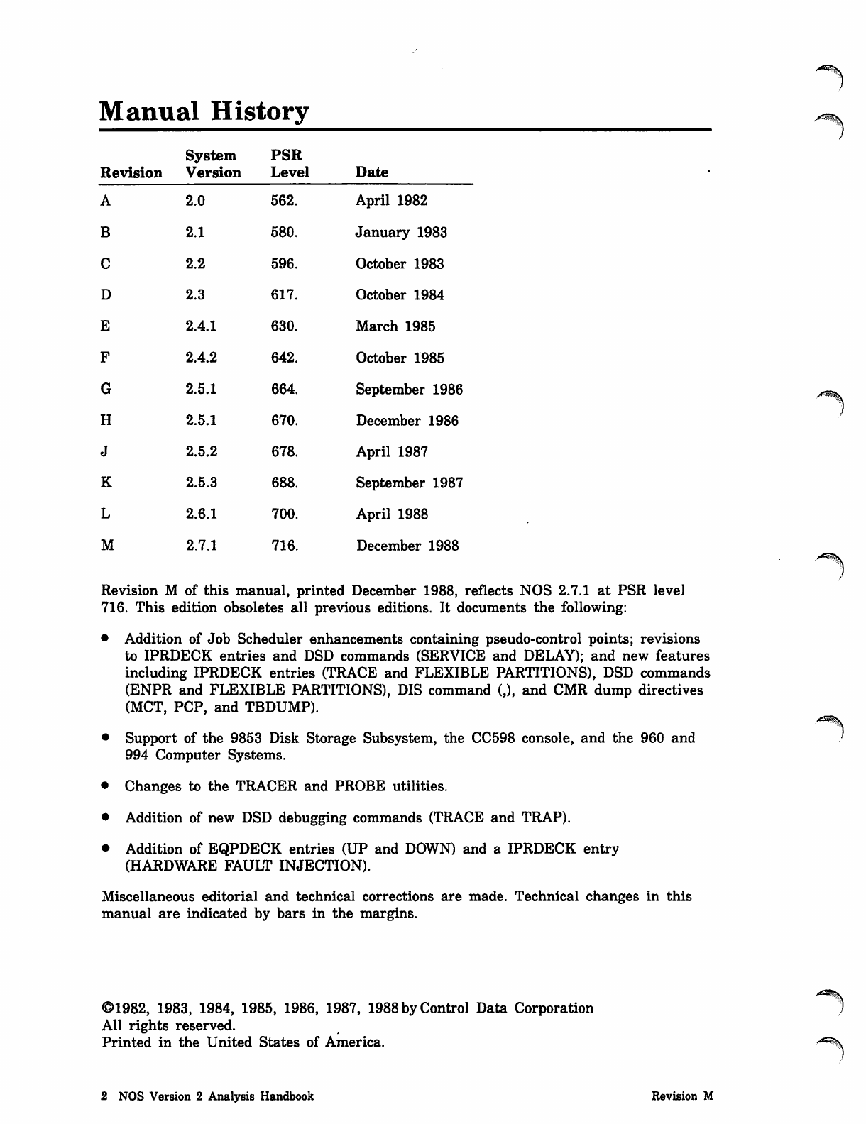
Manual History
Revision System
Version
PSR
Level Date
A2.0 562. April 1982
B2.1 580. January 1983
C2.2 596. October 1983
D2.3 617. October 1984
E2.4.1 630. March 1985
F2.4.2 642. October 1985
G2.5.1 664. September 1986
H2.5.1 670. December 1986
J2.5.2 678. April 1987
K2.5.3 688. September 1987
L2.6.1 700. April 1988
M2.7.1 716. December 1988
Revision M of this manual, printed December 1988, reflects NOS 2.7.1 at PSR level
716. This edition obsoletes all previous editions. It documents the following:
• Addition of Job Scheduler enhancements containing pseudo-control points; revisions
to IPRDECK entries and DSD commands (SERVICE and DELAY); and new features
including IPRDECK entries (TRACE and FLEXIBLE PARTITIONS), DSD commands
(ENPR and FLEXIBLE PARTITIONS), DIS command (,), and CMR dump directives
(MCT, PCP, and TBDUMP).
• Support of the 9853 Disk Storage Subsystem, the CC598 console, and the 960 and
994 Computer Systems.
• Changes to the TRACER and PROBE utilities.
• Addition of new DSD debugging commands (TRACE and TRAP).
• Addition of EQPDECK entries (UP and DOWN) and a IPRDECK entry
(HARDWARE FAULT INJECTION).
Miscellaneous editorial and technical corrections are made. Technical changes in this
manual are indicated by bars in the margins.
©1982, 1983, 1984, 1985, 1986, 1987, 1988 by Control Data Corporation
All rights reserved.
Printed in the United States of America. /^^S
2 NOS Version 2 Analysis Handbook Revision M
Contents
r
About This Manual 11
Audience 11
Organization 11
Conventions 12
Related Publications 13
Submitting Comments 20
CYBER Software Support
Hotline 20
Disclaimer 20
Controlware Utilities 1-1
Loading Controlware 1-1
Dumping Controlware 1-4
Deadstart '.. 2-1
Modifying the CMRDECK 2-3
Modifying the EQPDECK 2-4
Modifying the APRDECKs 2-22
Modifying the IPRDECK 2-23
L o a d i n g t h e S y s t e m 2 - 2 4
Initiating Job Processing 2-26
Preparing for Recovery Deadstart 2-28
Le ve l 0 In it ia l De ad st ar t 2- 3 6
Error Processing 2-36
Deadstart Decks 3-1
CMRDECK 3-2
EQPDECK 3-13
APRDECK 3-103
IPRDECK 3-107
LIBDECK 3-159
DIS Operations 4-1
DIS Job Dayfile Display (A) 4-3
DIS Job Status Display (B) 4-4
DIS Memory Displays (C, D, F,
G ) 4 - 6
DIS Exchange Package Display
(X) 4-8
DIS Directory Display (Z) 4-9
Console Operation 4-10
Display Selection Commands 4-13
DIS Keyboard Entries 4-14
Memory E n try Comma n ds 4-18
PP Call Commands 4-20
DSD Commands 5-1
Display Selection Commands 5-2
Dayfile Commands 5-3
Queued File Utility Commands ... 5-4
Job Processing Control
Commands 5-4
Peripheral Equipment Control
Commands 5-24
Subsystem Control Commands 5-50
System Control Commands 5-56
Secured System Control
Commands 5-70
Memory E n try Comma n ds 5-72
Channel Control Commands 5-74
Extended Memory Flag Register
Commands 5-75
Breakpoint Package Commands .. 5-75
Debugging Commands 5-84
Express Deadstart Dump
Interpreter (DSDI) 6-1
Calling the Express Deadstart
Dump Interpreter. 6-3
Input Directives 6-6
Interactive Use of DSDI 6-55
Printer Output Listing Examples . 6-65
Install Command 7-1
K-Display Utilities 8-1
FLAW K Display 8-3
I N I T I A L I Z E K D i s p l a y 8 - 8
Machine Recovery (MREC)
Utility K Display 8-16
MREC Procedures 8-17
MREC Unit and Controller
Reservations 8-23
Mass Storage Extended
Subsystem (MSE) K Display 8-25
Network Access Method (NAM)
K Display. 8-27
Queue File Transfer Facility
(QTF) K Display 8-41
Revision M Contents 3
REDEFINE K Display 8-61
Remote Batch Facility (RBF) K
Display 8-72
Remote Host Facility (RHF) K
Display 8-75
SCOPE 2 Station Facility (SSF)
K Displays 8-85
File Transfer Limit Commands ... 8-87
Transaction Facility (TAF) K
Displays 8-89
L-Display Utilities 9-1
FOTD L Display 9-2
LIDOU L Display 9-3
QDSPLAY L Display 9-6
SCTD L Display 9-10
S D S P L A Y L D i s p l a y 9 - 1 2
SUBSYST L Display 9-20
LID/RHF Configuration Files 10-1
LID Configuration File 10-1
RHF Configuration Files 10-9
QTF Configuration Requirements 10-23
Mass Storage Extended
Subsystem (MSE). 11-1
Introduction 11-1
MSE Utilities 11-13
MSE Operational Procedures 11-78
Tape Alternate Storage 12-1
Introduction 12-1
MAGNET Command 12-8
GENPFD Utility 12-9
Multimainframe Operations 13-1
Introduction 13-1
Linked SDM Operation 13-2
Independent SDM Operation 13-10
NAD Maintenance Utilities 14-1
Dump NAD Memory (DMPNAD) . 14-1
Maintenance Host Facility
(MHF) 14-3
Listing NAD Dumps 14-3
Network Operations 15-1
Network Organization 15-1
NAM Startup 15-5
NAM Shutdown 15-8
Network Control by HOP 15-9
Network Control by NOP 15-21
Network Control by DOP 15-43
Recent HISTORY Command 15-52
Report Unsolicited Status
Command 15-53
Send Message Command 15-54
Status Network Element
Command 15-55
Summary of Network Operation
Commands 15-59
Network Utilities 16-1
NAM Initialization (NAMI) 16-2
Network Dump Collector
(COLLECT) 16-6
Load File Generator (LFG) 16-9
NPU Dump Analyzer (NDA) .... 16-12
PIP Dump Analyzer (LISTPPM) . 16-31
A I P T r a c e W i t h I A F 1 6 - 3 2
Network Description Files 16-34
IAF Stimulator 16-36
Permanent File Utilities 17-1
Introduction 17-1
Calling the Utilities 17-37
Parameters for the Permanent
File Utilities 17-46
Permanent File Utility Routines 17-61
Queued/DayfUe Utilities 18-1
Queued File Utilities 18-1
Dayfile Dumping Utilities 18-56
SYSEDIT 19-1
Directives 19-3
Record Types 19-9
System File Initialization 20-1
ISF 20-1
Deadstart Sequencing 20-4
,(<S^u
' '**^S\
4 NOS Version 2 Analysis Handbook Revision M
T r a c e r / P r o b e U t i l i t i e s 2 1 - 1
Tracer Utility 21-1
PROBE Utility 21-37
Character Sets A-l
Character Set Anomolies A-2
C h a r a c t e r S e t T a b l e s A - 3
Glossary B-l
Scope 2 Station Facility C-l
Equipment Configuration C-l
SSF File Transfers C-2
Error Logout C-4
Status/Control Register
Simulator D-l
Using the Simulator D-2
Simulator Commands D-5
580 Programmable Format
Control E-l
Building Programmable Format
Control Arrays E-2
Adding Programmable Format
Control Arrays E-3
533/536, 537, and 585 Printer
Electronic Vertical Format Unit
(EVFU) F-l
Figures
2-1. Deadstart Process 2-1
2-2. Equipment Status Display 2-9
2-3. Mass Storage Status Display ... 2-13
2-4. Mass Storage Initialization
Status Display 2-16
2-5. Controlware Status Display 2-19
2-6. Disk Thresholds Display 2-20
2-7. Level 3 Deadstart Left Screen
Display. 2-31
2-8. Level 3 Deadstart Right Screen
Display. 2-32
3-1. Expander Addressing Map 3-49
3-2. 844 Expander Configuration
With 20 Drives 3-50
EVFU Directives for 533/536
Printers. F-l
881/883 Pack Reformatting
Utility G-l
FORMAT Command G-2
Input Formats G-4
Output Formats G-6
Accessing Disk Devices G-ll
N O S / V E A d d r e s s F o r m a t s H - l
Management Of Storage Media
Defects 1-1
Detecting Failing Devices 1-1
Dealing With Known Media
Defects 1-3
Display Disk File (DDF) Utility ... J-l
Bringing Up DDF J-l
Keyboard Input J-4
Console Messages J-5
DDF Commands J-6
DDF Examples J-12
Pack Recovery J-16
PACKER Utility K-l
Operational Overview K-l
Command Format K-4
PACKER Examples K-6
3-3. Vertically Adjacent Three-Unit
Device 3-51
3-4. Horizontally Adjacent Two-Unit
Device 3-52
3-5. Hardware Configured into
Seven Devices 3-53
3-6. Example of Ranges of Service
Class Priorities 3-117
4-1. DIS Job Dayfile Display (A) .... 4-3
4-2. DIS Job Status Display (B) 4-4
4-3. DIS Data Storage Display (F) ... 4-6
4-4. DIS Program Storage Display
(G) 4-7
4-5. DIS Exchange Package Display
(X) 4-8
Revision M Contents 5
4-6. DIS Directory Display (Z) 4-9
5-1. Record of Original Values in
W,M Display (Delay Values) 5-12
5-2. Record of Original Values in L
Display SDSPLAY 5-16
5-3. Record of Original Values in L
Display SDSPLAY 5-23
5-4. PP Breakpoint V Display 5-78
5-5. CPUMTR Breakpoint Display .. 5-82
6-1. C Directive Output 6-57
6-2. CP Directive Output 6-58
6-3. D Directive Output 6-59
6-4. PP Directive Output 6-60
6-5. Q Directive Output 6-61
6-6. Sample Alternate Directives
File 6-64
6-7. Sample PP Directive Output ... 6-66
6-8. Sample AP Directive Output ... 6-67
6-9. Sample CP Directive Output ... 6-68
6-10. Sample MST Directive Output 6-73
6-11. Sample C Directive Output ... 6-74
6-12. Sample FNT Directive Output 6-75
6-13. Sample PRORF Directive
Output 6-76
8-1. FLAW K Display (Left Screen) .. 8-3
8-2. FLAW K Display (Right
Screen) 8-4
8-3. FLAW Utility K Display (Left
Screen) 8-7
8-4. INITIALIZE Command K
Display. 8-9
8-5. Machine Configurations 8-16
8-6. MREC K Display (Left Screen) . 8-18
8-7. MREC K Display (Right
Screen) (Page 1 of 2) 8-21
8-8. MREC K Display (Right
Screen) (Page 2 of 2) 8-21
8-9. MSE K Display (Message
Format) 8-26
8-10. MSE K Display (Storage
Module Format) 8-26
8-11. NAM K-Display Format 8-27
8-12. NAM K Display 8-28
8-13. NAM Status Display 8-37
8-14. Connection Slot Array and
PID/Selection Class Matrix 8-42
8-15. QTF HELP K Display (Right
Screen) 8-50
8-16. General Format of QTF Status
K Display 8-53
8-17. QTF STATUS.PID K Display .. 8-55
8-18. QTF STATUS,SC K Display ... 8-57
8-19. QTF STATUS/TRANSFER K
Display. 8-59
8-20. REDEFINE K Display (Left
Screen) 8-63
8-21. REDEFINE K Display (Right
Screen) 8-63
8-22. Reconfiguration Run Output .. 8-67
8-23. RBF K Display 8-72
8-24. Sample LCN 8-77
8-25. Application Table Display 8-79
8-26. Network Path Table Display .. 8-81
8-27. TAF Initialization K Display
(Left Screen) 8-89
8-28. TAF Status K Display (Left
Screen) 8-94
8-29. CRMTASK Commands K
Display (Left Screen) 8-100
8-30. CRM Status K Display (Left
Screen) 8-102
8-31. CRM Data Base Status K
Display (Left Screen) 8-102
8-32. CRM File Status K Display
(Left Screen) 8-103
9-1. FOTD L Display 9-2
9- 2 . LI DO U L Di spl ay ( LI D ) 9- 4
9-3. LIDOU L Display (HELP)
( P a g e 1 o f 2 ) 9 - 4
9-4. LIDOU L Display (HELP)
( P a g e 2 o f 2 ) 9 - 5
9-5. Initial QDSPLAY L Display
( P a g e 1 o f 2 ) 9 - 7
9-6. Initial QDSPLAY L Display
( P a g e 2 o f 2 ) 9 - 7
9-7. SCTD L Display (Page 1 of 2) . 9-11
9-8. SCTD L Display (Page 2 of 2) . 9-11
9-9. SDSPLAY-HELP Display (Page
1 o f 3 ) 9 - 1 2
9-10. SDSPLAY-HELP Display
( P a g e 2 o f 3 ) 9 - 1 3
9-11. SDSPLAY-HELP Display
( P a g e 3 o f 3 ) 9 - 1 3
9-12. SDSPLAY-CLASS Display
( P a g e 1 o f 3 ) 9 - 1 4
9-13. SDSPLAY-CLASS Display
( P a g e 2 o f 3 ) 9 - 1 5
9-14. SDSPLAY-CLASS Display
( P a g e 3 o f 3 ) 9 - 1 5
10-1. Equipment Configuration 10-4
10-2. LIDCMid Files for Example
Equipment Configuration. 10-5
10-3. Sample LCN Network 10-20
6 NOS Version 2 Analysis Handbook Revision M
/0*S.
10-4. Network Configuration
Statements for the RHF on
Mainframe MFA 10-21
10-5. Network Configuration
Statements for the RHF on
Mainframe MFD 10-22
10-6. Procedure File Example 10-26
11-1. SSLABEL Report File 11-23
11-2. SSMOVE Report: List of
Directives 11-37
11-3. SSMOVE Report: Run-time
Parameter Values 11-37
11-4. SSMOVE Report: Optional List
of Files 11-38
11-5. SSMOVE Report: Device
Status Report 11-39
11-6. SSMOVE Report: Destage
Abandonment 11-39
11-7. SSVAL Validation Report .... 11-48
11-8. SSUSE Basic Report 11-54
11-9. SSUSE Optional Report A ... 11-56
11-10. SSUSE Optional Report B .. 11-57
11-11. SSUSE Optional Report C .. 11-58
11-12. SSUSE Optional Report D .. 11-59
11-13. SSDEBUG: Executing SSVAL
in Problem-Fixing Mode 11-65
11-14. Full Stripe Disk File Format 11-67
11-15. Partial Stripe Disk File
Format 11-68
1 1 - 1 6 . S M K D i s p l a y 1 1 - 7 6
11-17. CU K Display 11-77
13-1. Deadstarting a Machine in a
Multimainframe Complex 13-5
15-1. Sample 255x NPU Network ... 15-3
16-1. Sample NDA Output File .... 16-19
16-2. Sample Session File With
Tasks for Use by STIMULA 16-38
16-3. Sample Session for Use by
STIMULA 16-39
16-4. Sample Session File for
Internal Stimulation 16-41
16-5. STIMULA K Display (Left
Screen) 16-41
16-6. STIMULA Parameters (Left
Screen) 16-43
16-7. STIMULA K-Display
Commands (Right Screen) 16-46
16-8. Parameter Matrix (Left
Screen) 16-49
16-9. Mixed Mode Parameters
(Right Screen) 16-49
16-10. Output Statistics 16-51
16-11. Postprocessing Example 16-52
17-1. Functional Overview of the
Permanent File Utility Overlays... 17-1
17-2. Example of Multifile Archive
File Structure 17-3
17-3. Track Reservation Table
Word 17-22
17-4. Bit Settings for Track Link
Bytes 17-23
17-5. Linkage Format With
Example 17-24
17-6. Example of Families in Two
Configurations 17-26
17-7. Example of Transferring
Family Access 17-28
17-8. Initial Permanent File
Utilities K Display (Left Screen).. 17-39
17-9. Permanent File Utilities K
Display (Right Screen) 17-39
17-10. PFDUMP K Display (Left
Screen) (Page 1 of 5) 17-41
17-11. PFDUMP K Display (Left
Screen) (Page 2 of 5) 17-41
17-12. PFDUMP K Display (Left
Screen) (Page 3 of 5) 17-42
17-13. PFDUMP K Display (Left
Screen) (Page 4 of 5) 17-42
17-14. PFDUMP K Display (Left
Screen) (Page 5 of 5) 17-43
17-15. Sample Directory Produced
by PFATC,LO=T 17-65
17-16. Sample Directory Produced
by
PFCAT,LO = T,DN=40,UI = 4054... 17-67
17-17. Mass Storage Table Report . 17-68
17-18. Cumulative Statistics by
User Index PFCAT,LO = S,DN = 40. 17-69
17-19. Cumulative Statistics for
Entire Device
P F C AT, L O = S , D N = 40 1 7 - 7 0
17-20. Catalog of Catalog Image
Record 17-78
17-21. PFDUMP/PFLOAD Example
(Sheet 1 of 3) 17-85
17-22. PFDUMP/PFLOAD Example
(Sheet 2 of 3) 17-86
17-23. PFDUMP/PFLOAD Example
(Sheet 3 of 3) 17-87
18-1. QFSP K Display (Left Screen) 18-3
18-2. QFSP K Display (Right
Screen) (Page 1 of 4) 18-5
18-3. QFSP K Display (Right
Screen) (Page 2 of 4) 18-5
Revision M Contents 7
18-4. QFSP K Display (Right
Screen) (Page 3 of 4) 18-6
18-5. QFSP K Display (Right
Screen) (Page 4 of 4) 18-6
18-6. DFTERM K Display (Left
Screen) 18-29
18-7. DFTERM Dayfile List (Right
Screen) 18-30
18-8. QALTER/QFTLIST K Display
(Left Screen) (Page 1 of 3). 18-33
18-9. QALTER/QFTLIST K Display
(Left Screen) (Page 2 of 3) 18-33
18-10. QALTER/QFTLIST K Display
(Left Screen) (Page 3 of 3) 18-34
18-11. QALTER/QFTLIST LIST
Command Display (Right Screen).. 18-35
18-12. QALTER/QFTLIST LIST=qft
Command Display (Right Screen).. 18-35
18-13. QALTER Printer
Listing/Output File 18-36
18-14. Initial QDUMP K Display
(Left Screen) (Page 1 of 3) 18-38
18-15. Initial QDUMP K Display
(Left Screen) (Page 2 of 3) 18-38
18-16. Initial QDUMP K Display
(Left Screen) (Page 3 of 3) 18-39
18-17. Secondary QDUMP K
Display (Left Screen) 18-39
18-18. QDUMP Output File 18-40
18-19. QLOAD K Display (Left
Screen) (Page 1 of 3) 18-43
18-20. QLOAD K Display (Left
Screen) (Page 2 of 3) 18-43
18-21. QLOAD K Display (Left
Screen) (Page 3 of 3) 18-44
18-22. QLOAD Output File 18-44
Tables
2 - 1 . E Q P D E C K E n t r i e s 2 - 5
2-2. Levels of System Deadstart:
I n f o r m a t i o n R e c o v e r e d 2 - 2 9
2-3. Mass Storage Device Recovery . 2-38
3-1. Table of Central Memory Sizes. 3-12
3-2. Required and Optional
Keywords 3-19
3-3. Mass Storage Functions for
Various Device Types 3-42
3-4. Mass Storage Configuration for
Two Systems at One Site 3-44
3-5. PF Entry Parameter Settings
(type, dm, name, device, and sm)... 3-82
18-23. Initial QMOVE K Display
(Left Screen) (Page 1 of 3) 18-47
18-24. Initial QMOVE K Display
(Left Screen) (Page 2 of 3) 18-47
18-25. Initial QMOVE K Display
(Left Screen) (Page 3 of 3) 18-48
18-26. Secondary QMOVE K Display
(Left Screen) 18-48
18-27. QMOVE Output File 18-49
18-28. Initial QREC K Display (Left
Screen) (Page 1 of 3) 18-52
18-29. Initial QREC K Display (Left
Screen) (Page 2 of 3) 18-53
18-30. Initial QREC K Display (Left
Screen) (Page 3 of 3) 18-53
18-31. Inactive Queues K Display
(Right Screen) 18-54
18-32. Secondary QREC K Display
(Left Screen) 18-54
18 - 33 . QR EC O u tp ut Fi le 1 8 -5 5
21-1. Example of TRACER Output .. 21-9
21-2. Example of PROBE Output .. 21-39
A-l. Conversion Differences A-17
D-l. Simulator K Display (Left
Screen) D-3
D-2. Simulator Commands K
Display (Right Screen) D-4
F-l. EVFU Load File F-4
G-l. FORMAT Output,
MODE=RESTORR G-7
G-2. FORMAT Output,
MODE=ALTER G-9
G-3. FORMAT Output,
MODE = FETCH G-10
3-6. Information for Setting or
C l e a r i n g F l a w A r e a s . 3 - 1 0 6
3-7. Example Set of Job Control
Parameters, Part L 3-115
3-8. Example Set of Job Control
Parameters, Part II 3-116
3-9. CPM Default Values for ni .... 3-119
4-1. PP Call Formats 4-20
8-1. Flawing Information for Disks
a n d E x t e n d e d M e m o r y 8 - 7
8-2. Device Initialization Options ... 8-10
8-3. Track Flawing Options 8-11
8-4. MREC Parameters 8-20
A^S
8 NOS Version 2 Analysis Handbook Revision M
00$S
8-5. MREC Commands 8-20
8-6. NA M K -Disp l ay Fiel d s 8-27
8-7. NAM Mode Commands 8-30
8-8. Equipment Requirements for
Reconfiguration 8-61
8-9. Reconfiguration Parameters 8-65
8-10. Reconfiguration Commands ... 8-66
10-1. Suggested Code Conversion
Parameters 10-17
15-1. Parameter Record Feature
Descriptions 15-7
15-2. NS Activity 15-14
15-3. Load/Dump Status Messages . 15-14
17-1. Permanent File Utility
Parameters 17-46
18-1. Queued File Utility
Parameters (DFTERM through
QFTLIST) 18-12
18-2. Queued File Utility
Parameters (QLIST through
QREC) 18-13
20-1. Initialize and Release
Parameters of Fast-Attach Files 20-3
21-1. Data Items 21-19
A-l. Character Sets for Interactive
Jobs. A-5
A-2. Character Sets for Batch Jobs .. A-9
A-3. ASCII to 6/12-Bit Display Code
Conversion A-13
A-4. Nine-Track ASCII Coded Tape
Conversion A-18
A-5. Nine-Track EBCDIC Coded
Tape Conversion A-20
A-6. Seven-Track Coded Tape
Conversions A-23
E-l. Released Programmable
Format Control Arrays E-4
F-l. Released EVFU Load Image:
Print Lines and Channel Numbers.. F-5
r
0m*<
Revision M Contents 9

0m>K
r
0m\
About This Manual
This manual describes the CONTROL DATA® Network Operating System (NOS)
Version 2. NOS 2 operates on the following computer systems:
• CDC® CYBER 180 Computer Systems Models 810, 830, 835, 840, 845, 850, 855,
860, 870, 960, 990, 994, and 995
• CDC CYBER 170 Computer Systems Models 171, 172, 173, 174, 175, 176, 720, 730,
740, 750, 760, 815, 825, 835, 845, 855, 865, and 875
• CDC CYBER 70 Computer Systems Models 71, 72, 73, and 74
• CDC 6000 Computer Systems
Audience
This manual assumes you are a site analyst. It assumes you are familiar with the
hardware of your computer system(s) and that you understand the functions of the
various components of NOS.
Organization
This manual includes information required for the day-to-day maintenance of the
operating system and for troubleshooting. Topics discussed include the mass storage
subsystems, network operations, the K and L utilities, backing up and reloading files,
deadstart, and DIS operations.
Since the sections of the manual are self-contained in that they do not build on each
other, the sections are ordered alphabetically by title. The appendixes include character
set tables; a glossary; and descriptions of the SCOPE 2 Station Facility, the
status/control register simulator, programmable format control for 580 printers, disk
pack reformatting for 881/883 units, address formats for NOS/VE, management of
storage media defects, and the display disk file utility.
Revision M About This Manual 11
Conventions
The following conventions are used in this manual:
examples Examples of user entries and computer responses are shown in a
font that resembles computer output.
lowercase In a format, lowercase letters represent values you choose.
Numbers All numbers are decimal unless otherwise noted.
UPPERCASE In a format, uppercase letters represent reserved words defined by
the system for specific purposes. You must use these words exactly
as shown.
Vertical bar A vertical bar in the margin indicates a technical change.
The CDC 18002-2 console is available as an option for CYBER 180 Models 810 and 830
Systems using NOS 2.3, PSR level 617 or later operating systems. This product -^
includes a CDC 634B display terminal (also known as the 721-21 display terminal) and )
an AV117A cable. This console is referred to throughout the manual as the CC634B.
The CDC 19003 console is available as an option for certain CYBER 180-class
machines. This product includes a video monitor; keyboard; 40-Mbyte hard disk
(Winchester) drive; 1.2-Mbyte, 5-1/2-in floppy disk drive; 640-Kbyte RAM memory; one
parallel printer port; and nine RS-232-C serial ports. This console is referred to
throughout this manual as the CC598B console.
Models 815, 825, 835, 845, and 855 of the CYBER 170 Computer Systems share many **\
of the functional and architectural attributes of the CYBER 180 Computer Systems.
This manual uses the term CYBER 180-class machines when describing these similar
models collectively.
Extended memory for models 865 and 875 and CYBER 180-class machines is unified
extended memory (UEM) and may also include either extended core storage (ECS),
extended semiconductor memory (ESM), or STORNET. Extended memory for model 176
is large central memory extended (LCME) and may also include ECS, ESM, or
STORNET. Extended memory for all other NOS computer systems is either ECS, ESM,
o r S T O R N E T . 1
In this manual, ECS refers to both ECS, ESM, and STORNET; and extended memory
refers to all forms of extended memory unless otherwise noted. However, when
referencing extended memory in the context of a linked shared device multimainframe
complex or distributive data path (DDP) access, UEM and LCME are excluded. ECS,
ESM, and STORNET are the only forms of extended memory that can be shared in a
linked shared device multimainframe complex and can be accessed by a DDP.
(Manuals dealing with the various form of extended memory are listed, under Related
Publications.)
12 NOS Version 2 Analysis Handbook Revision M
0$ms
0^S.
Related Publications
AU of the following manuals are available through Control Data sales offices or
through:
Control Data
Technology and Distribution Services
308 North Dale Street
St. Paul, MN 55103
The reader should be thoroughly familiar with the material in the following NOS
publications.
Publication
Manual Title Number
NOS Version 2 Operations Handbook 60459310
NOS Version 2 Reference Set, Volume 2, Guide to System Usage 60459670
NOS Version 2 Reference Set, Volume 3, System Commands 60459680
The following lists contain manuals that provide additional information about NOS and
its product set. For the reader's convenience, these are grouped according to topic:
CDCNET manuals, hardware manuals, NOS 2 manuals, and optional product manuals.
In addition, the NOS System Information manual contains brief descriptions of all NOS
operating system and NOS product set manuals. It is accessed by logging into NOS and
entering the EXPLAIN command.
Revision M About This Manual 13
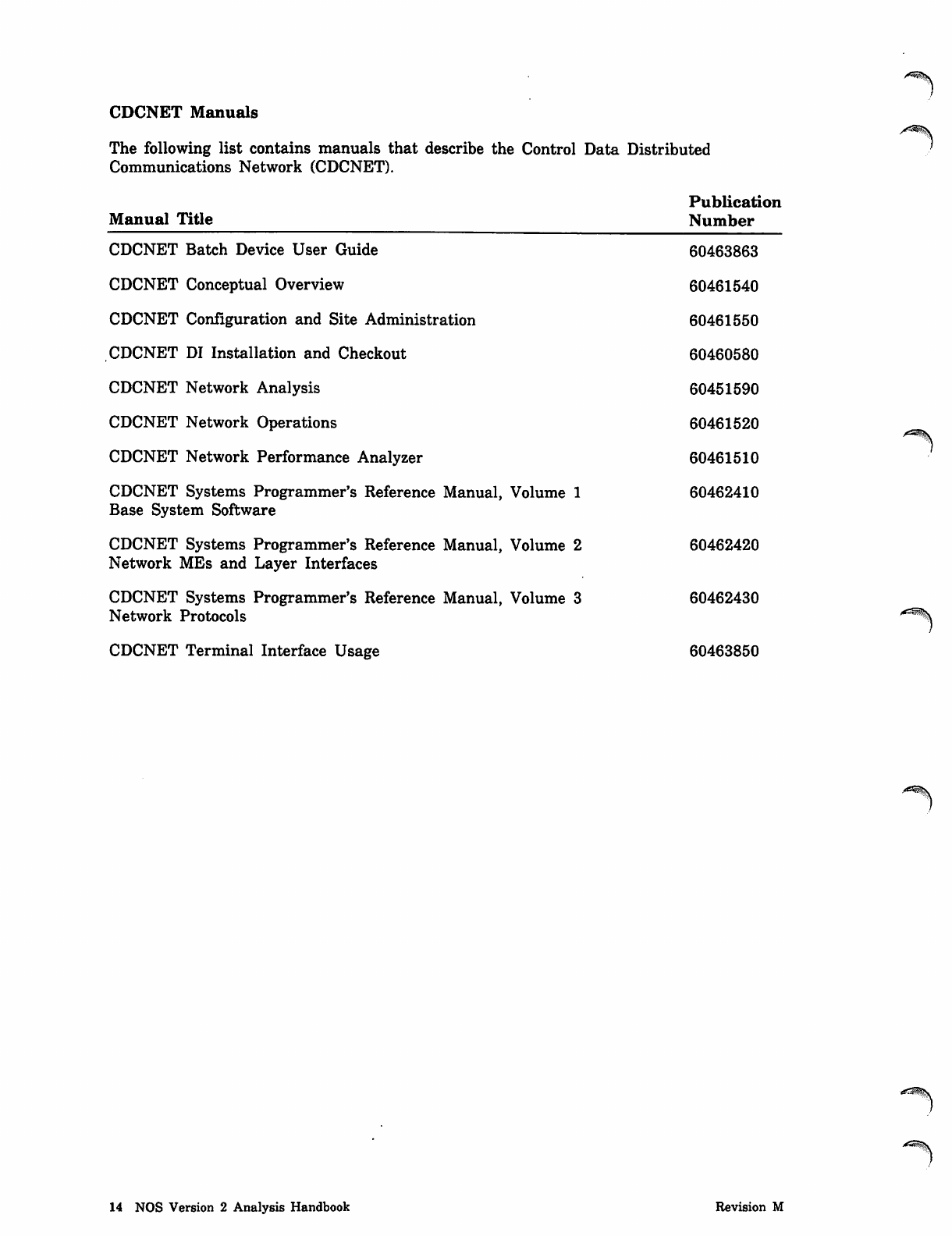
CDCNET Manuals
The following list contains manuals that describe the Control Data Distributed
Communications Network (CDCNET).
Manual Title
CDCNET Batch Device User Guide
CDCNET Conceptual Overview
CDCNET Configuration and Site Administration
CDCNET DI Installation and Checkout
CDCNET Network Analysis
CDCNET Network Operations
CDCNET Network Performance Analyzer
CDCNET Systems Programmer's Reference Manual, Volume 1
Base System Software
CDCNET Systems Programmer's Reference Manual, Volume 2
Network MEs and Layer Interfaces
CDCNET Systems Programmer's Reference Manual, Volume 3
Network Protocols
CDCNET Terminal Interface Usage
Publication
Number
60463863
60461540
60461550
60460580
60451590
60461520
60461510
60462410
60462420
60462430
60463850
y^^SK
14 NOS Version 2 Analysis Handbook Revision M
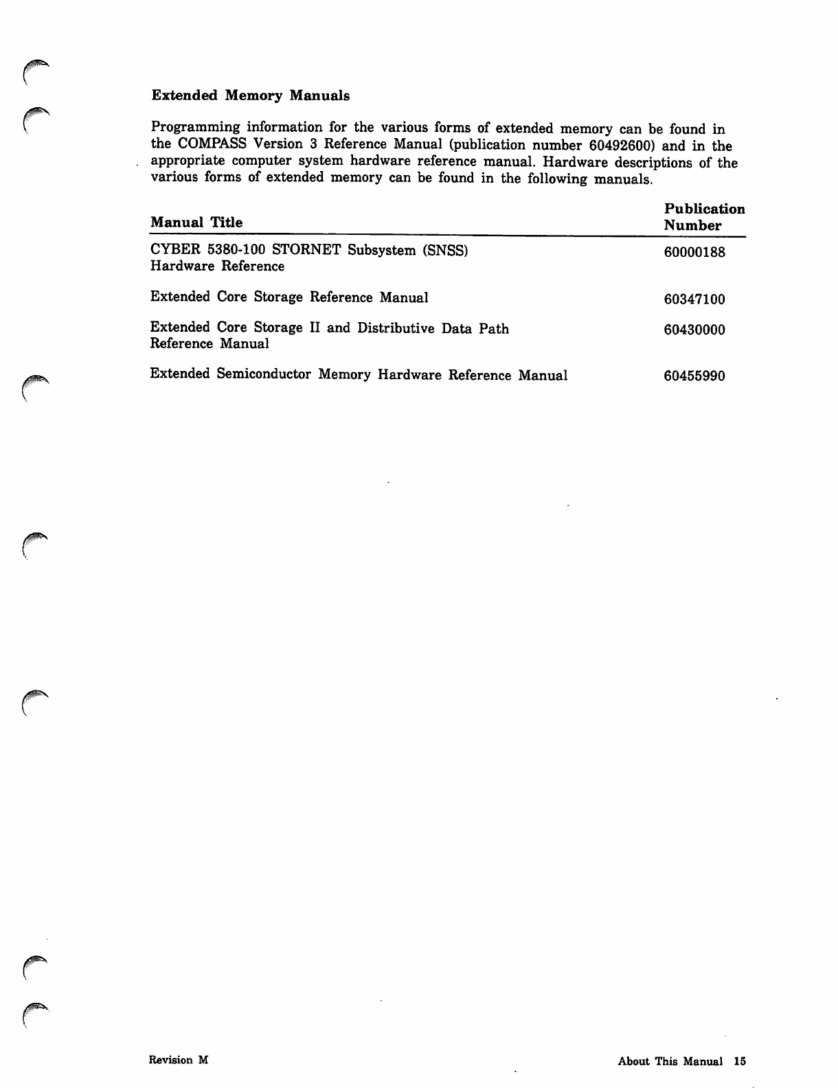
Extended Memory Manuals
Programming information for the various forms of extended memory can be found in
the COMPASS Version 3 Reference Manual (publication number 60492600) and in the
appropriate computer system hardware reference manual. Hardware descriptions of the
various forms of extended memory can be found in the following manuals.
Publication
Manual Title Number
CYBER 5380-100 STORNET Subsystem (SNSS) 60000188
Hardware Reference
Extended Core Storage Reference Manual 60347100
Extended Core Storage II and Distributive Data Path 60430000
Reference Manual
Extended Semiconductor Memory Hardware Reference Manual 60455990
0ims
0$ms.
Revision M About This Manual 15
/^ ■S<§\
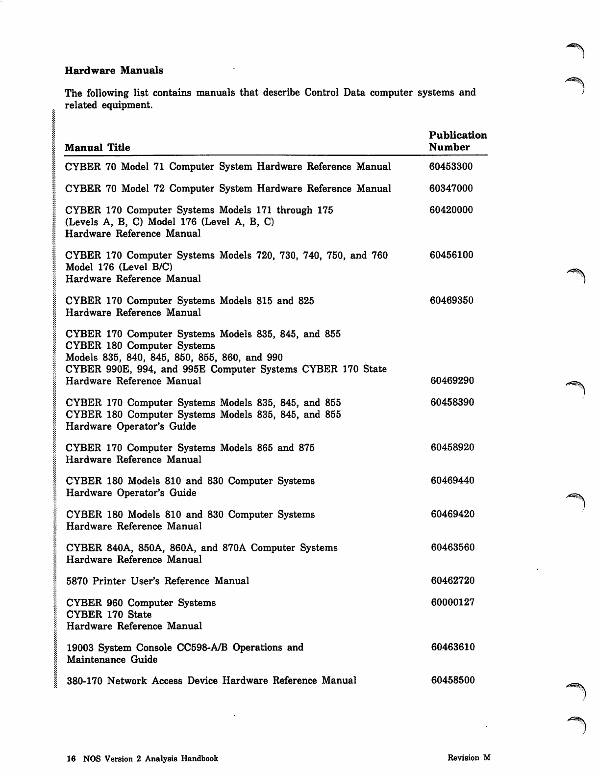
Hardware Manuals
The following list contains manuals that describe Control Data computer systems and
related equipment.
Manual Title
Publication
Number
CYBER 70 Model 71 Computer System Hardware Reference Manual 60453300
CYBER 70 Model 72 Computer System Hardware Reference Manual 60347000
CYBER 170 Computer Systems Models 171 through 175 60420000
(Levels A, B, C) Model 176 (Level A, B, C)
Hardware Reference Manual
CYBER 170 Computer Systems Models 720, 730, 740, 750, and 760 60456100
Model 176 (Level B/C)
Hardware Reference Manual
CYBER 170 Computer Systems Models 815 and 825 60469350
Hardware Reference Manual
CYBER 170 Computer Systems Models 835, 845, and 855
CYBER 180 Computer Systems
Models 835, 840, 845, 850, 855, 860, and 990
CYBER 990E, 994, and 995E Computer Systems CYBER 170 State
Hardware Reference Manual 60469290
CYBER 170 Computer Systems Models 835, 845, and 855 60458390
CYBER 180 Computer Systems Models 835, 845, and 855
Hardware Operator's Guide
CYBER 170 Computer Systems Models 865 and 875 60458920
Hardware Reference Manual
CYBER 180 Models 810 and 830 Computer Systems 60469440
Hardware Operator's Guide
CYBER 180 Models 810 and 830 Computer Systems 60469420
Hardware Reference Manual
CYBER 840A, 850A, 860A, and 870A Computer Systems 60463560
Hardware Reference Manual
5870 Printer User's Reference Manual 60462720
CYBER 960 Computer Systems 60000127
CYBER 170 State
Hardware Reference Manual
19003 System Console CC598-A/B Operations and 60463610
Maintenance Guide
380-170 Network Access Device Hardware Reference Manual 60458500
>S3SN
16 NOS Version 2 Analysis Handbook Revision M
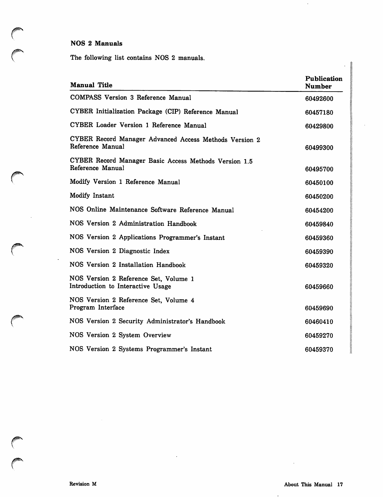
NOS 2 Manuals
The following list contains NOS 2 manuals.
Manual Title
COMPASS Version 3 Reference Manual
CYBER Initialization Package (CIP) Reference Manual
CYBER Loader Version 1 Reference Manual
CYBER Record Manager Advanced Access Methods Version 2
Reference Manual
CYBER Record Manager Basic Access Methods Version 1.5
Reference Manual
Modify Version 1 Reference Manual
Modify Instant
NOS Online Maintenance Software Reference Manual
NOS Version 2 Administration Handbook
NOS Version 2 Applications Programmer's Instant
NOS Version 2 Diagnostic Index
NOS Version 2 Installation Handbook
NOS Version 2 Reference Set, Volume 1
Introduction to Interactive Usage
NOS Version 2 Reference Set, Volume 4
Program Interface
NOS Version 2 Security Administrator's Handbook
NOS Version 2 System Overview
NOS Version 2 Systems Programmer's Instant
Publication
Number
60492600
60457180
60429800
60499300
60495700
60450100
60450200
60454200
60459840
60459360
60459390
60459320
60459660
60459690
60460410
60459270
60459370
Revision M About This Manual 17
>fi5^
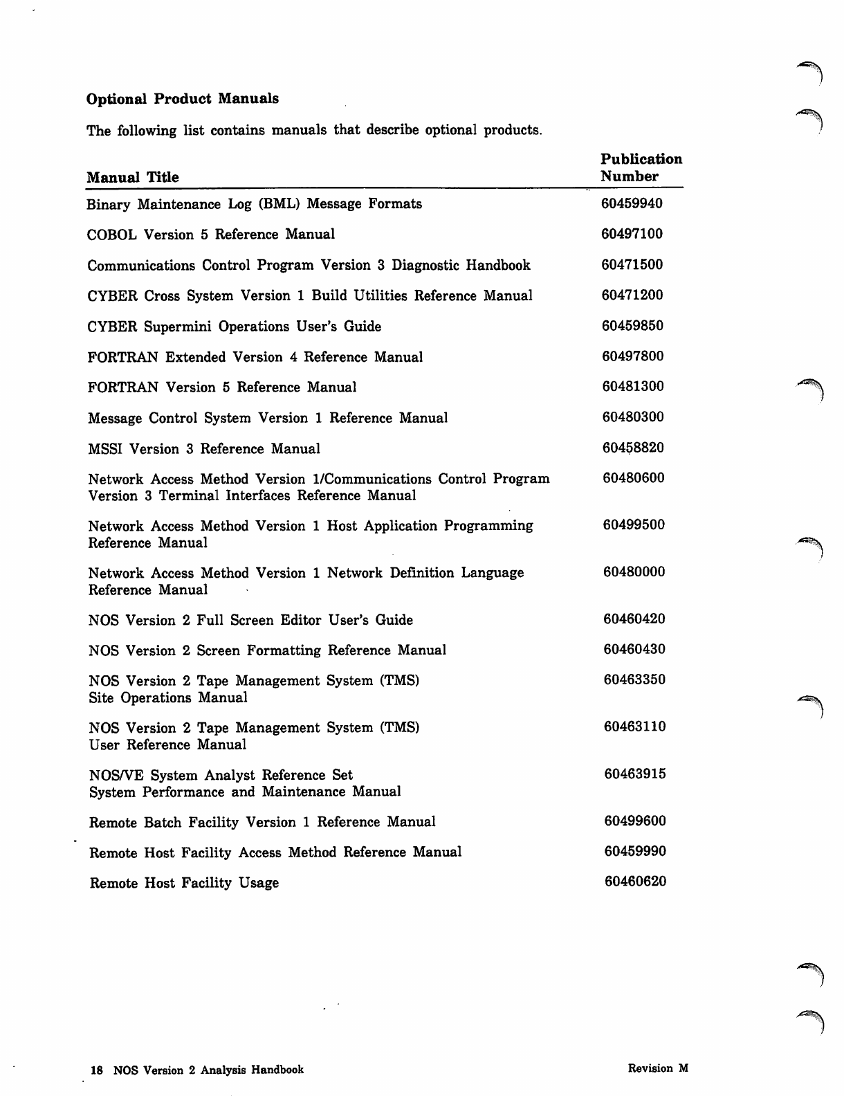
Optional Product Manuals
The following list contains manuals that describe optional products.
Publication
Manual Title Number
Binary Maintenance Log (BML) Message Formats 60459940
COBOL Version 5 Reference Manual 60497100
Communications Control Program Version 3 Diagnostic Handbook 60471500
CYBER Cross System Version 1 Build Utilities Reference Manual 60471200
CYBER Supermini Operations User's Guide 60459850
FORTRAN Extended Version 4 Reference Manual 60497800
FORTRAN Version 5 Reference Manual 60481300
Message Control System Version 1 Reference Manual 60480300
MSSI Version 3 Reference Manual 60458820
Network Access Method Version 1/Communications Control Program 60480600
Version 3 Terminal Interfaces Reference Manual
Network Access Method Version 1 Host Application Programming 60499500
Reference Manual
Network Access Method Version 1 Network Definition Language 60480000
Reference Manual
NOS Version 2 Full Screen Editor User's Guide 60460420
N O S Ve r s i o n 2 Sc r e e n F o r m a t t i n g Re f e r e n c e M a n u a l 60 4 6 0 4 3 0
NOS Version 2 Tape Management System (TMS) 60463350
Site Operations Manual
N O S V e r s i o n 2 Ta p e M a n a g e m e n t S y s t e m ( T M S ) 6 0 4 6 3 1 1 0
User Reference Manual
NOS/VE System Analyst Reference Set 60463915
System Performance and Maintenance Manual
Remote Batch Facility Version 1 Reference Manual 60499600
Remote Host Facility Access Method Reference Manual 60459990
Remote Host Facility Usage 60460620
><^^y
18 NOS Version 2 Analysis Handbook Revision M
yams
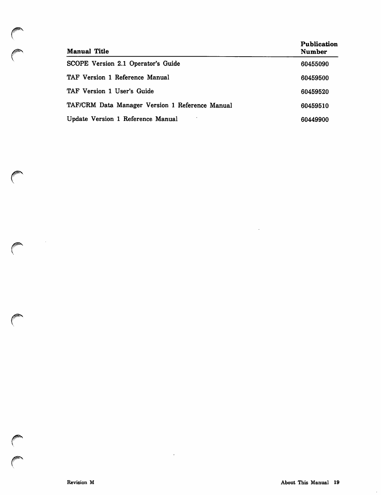
Publication
Manual Title Number
SCOPE Version 2.1 Operator's Guide 60455090
TAF Version 1 Reference Manual 60459500
TAF Version 1 User's Guide 60459520
TA F / C R M D a t a Ma n a g e r Ve r s i o n 1 R e f e r e n c e Ma n u a l 60 4 5 9 5 1 0
Update Version 1 Reference Manual 60449900
j0m\.
Revision M About This Manual 19
Submitting Comments
The last page of this manual is a comment sheet. Please use it to give your opinion on
the manual's usability, to suggest specific improvements, and to report any errors. If
the comment sheet has already been used, you can mail your comments to:
Control Data
Technology and Publications Division, ARH219
4201 Lexington Avenue North
St. Paul, MN 55126-6198
Additionally, if you have access to SOLVER, an online facility for reporting problems,
you can use it to submit comments about the manual. Use NS2 as the product
identifier. Include the name and publication number of the manual.
Address questions about the physical packaging and/or distribution of printed manuals
to Literature and Distribution Services at the following address:
Control Data ^
Technology and Publications Services
308 North Dale Street
St. Paul, Minnesota 55103
or you can call (612) 292-2101. If you are a Control Data employee, call (612)
292-2100.
CYBER Software Support Hotline
Control Data's CYBER Software Support maintains a hotline to assist you if you have
trouble using our products. If you need help beyond that provided in the documentation
or find that the product does not perform as described, call one of the following
numbers and a support analyst will work with you.
From the USA and Canada: (800) 345-9903
From other countries: (612) 851-4131
Disclaimer
NOS and its product set are intended to be used only as described in this document.
Control Data cannot be responsible for the proper functioning of undescribed features or
parameters.
20 NOS Version 2 Analysis Handbook Revision M
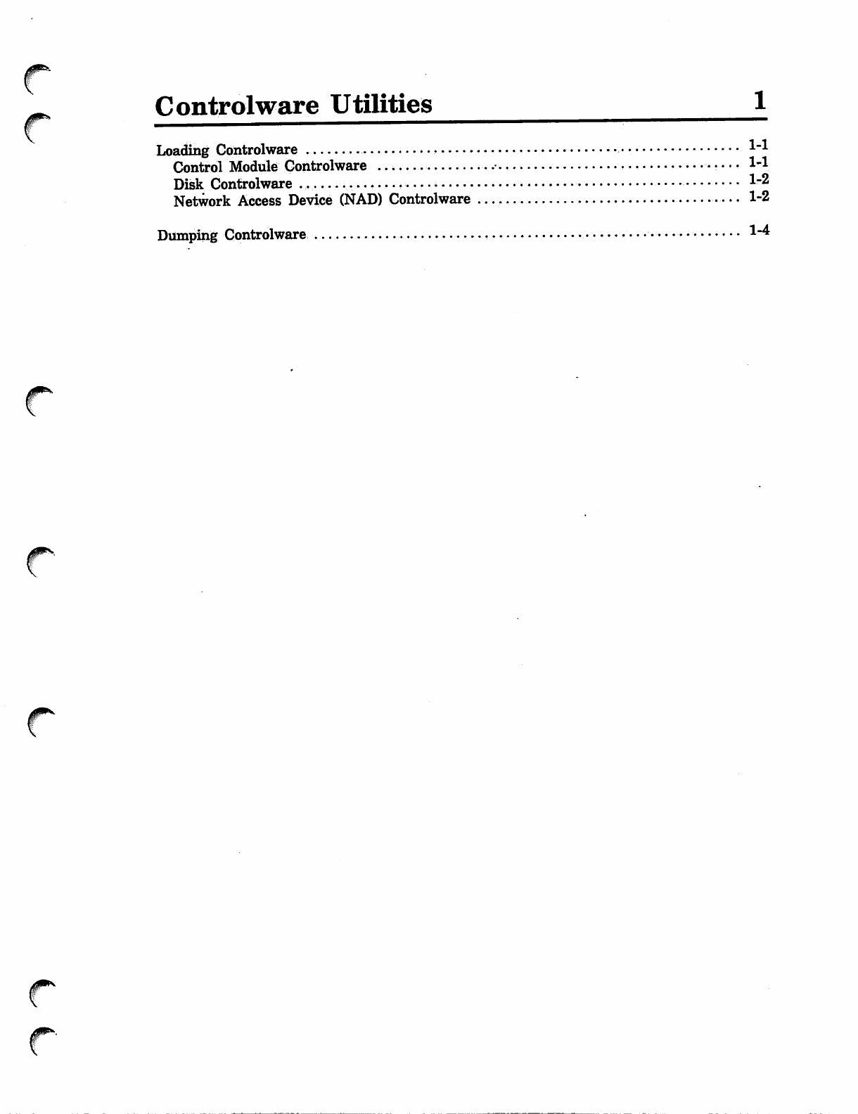
Controlware Utilities
Loading Controlware • 1"!
Control Module Controlware ■■ • • • • • 1 - 1
Disk Controlware ..... ......... ■. ■ 1 - 2
Network Access Device (NAD) Controlware 1-2
Dumping Controlware ....... 1-4
(P*

v_,
0$m*t.
Controlware Utilities
This section describes the utilities used for loading and dumping controlware.
Loading Controlware
By using the LOADBC utility, you can download control module controlware, disk
controlware, or network access device (NAD) controlware to the associated controller.
Control Module Controlware
You can use the LOADBC utility to load controlware into a control module for the 834
or 836 Disk Storage Subsystem. The calling job must be of system origin or you must
be validated for system origin privileges, and the system must be in engineering mode
(refer to the DSD ENABLE command in section 5). LOADBC will issue appropriate
messages to indicate the success or failure of the attempt to load controlware.
The format of the command is:
LOADBC,EQ=est,F=loadfile.
Parameter Description
EQ=est est is the EST ordinal of the control module in which to load the
controlware.
F = loadfile Name of the local file from which control module controlware is to
be loaded. If F = loadfile is specified, local file loadfile must contain
the control module controlware in binary format and an appropriate
header (refer to the NOS Version 2 Installation Handbook). If
F = loadfile is omitted, controlware is read from the system library
SYSTEM.
Revision M Controlware Utilities 1-1
Disk Controlware
Disk Controlware
You can initiate downloading of disk controlware only from the system console. Also,
you can load the disk controlware to a channel only if it is either active or down and
unassigned. The calling job must be of system origin or you must be validated for
system origin privileges. The system must be in engineering mode (refer to the DSD
ENABLE command in section 5). LOADBC will issue appropriate messages to indicate
the success or failure of the disk controlware load attempt.
The format of the command is:
LOADBC,C=ch,F=loadfile,D=dumpflle.
Parameter Description
C=ch ch is a 2-digit octal number of the channel to which the disk
controlware is to be loaded. The controlware can be loaded only if
the channel status is UP or if the channel status is DOWN and not
assigned to a maintenance user.
F = loadfile Name of the local file from which disk controlware is to be loaded.
If F=loadfile is specified, local file loadfile must contain the disk
controlware in binary format and an appropriate header (refer to
the NOS Version 2 Installation Handbook). If F = loadfile is omitted,
controlware is read from the system library SYSTEM.
D=dumpfile Name of the local file to which 7155/7165/7255 disk controlware is
to be dumped before reloading. This parameter is ignored for other
types of controllers and an informative message is issued. LOADBC
performs a binary comparison between the old and new controlware
and writes this data to a file that can be processed by DSDI by
using the DMB parameter (refer to section 6 for information on
DSDI).
Network Access Device (NAD) Controlware
The LOADBC utility can be used to load NAD controlware into local NADs (380-170)
and remote NADs (380-170, 380-200, 380-370, and 380-110). Since the NAD controlware
is not automatically loaded at deadstart, LOADBC must be used before a local NAD
can be used by the operating system. NAD controlware may be automatically loaded by
the Remote Host Facility (RHF) when RHF is initiated. Refer to the RHF K display in
section 8.
LOADBC can be called from the console or a batch job. When loading 380-170
controlware into a local NAD, the EST entry associated with the NAD's channel
number must be OFF or the controlware-not-loaded flag must be set.
When loading a remote NAD, a local NAD that is not reserved for maintenance must
be defined in the EST. The EST entry must be ON. Controlware must be loaded and
running in the local NAD before loading the remote NAD.
Remote NAD loading operations can occur concurrently with RHF use of the local
NAD. However, extreme care should be exercised when performing a remote NAD load
to ensure that the correct remote NAD is being loaded and that the remote NAD is
not being used by the mainframe to which it is connected. LOADBC will issue
appropriate messages to indicate the success or failure of the NAD controlware load
attempt.
1-2 NOS Version 2 Analysis Handbook Revision M
^*®^Ss\
Network Access Device (NAD) Controlware
/0!m^.t
The format of the command is:
LOADBC,Pi,P2, •••,Pn-
Pi Description
C=ch
F=filename
The 2-digit octal number of the channel to which the NAD
controlware is to be loaded. This parameter is required.
Name of the local file from which NAD controlware is to be loaded.
If F=filename is specified, local file filename must contain the
NAD controlware in binary format and an appropriate header (refer
to the NOS Version 2 Installation Handbook). If F=filename is not
specified, the NAD controlware type specified by the TY parameter
is read from the system library SYSTEM.
The following parameters apply only when loading remote NAD controlware.
Parameter Description
AC=aaaa
LT = totlt2t3
ND = nn
TY = value
The 4-digit hexadecimal number specifying the remote NAD's access
code (refer to the RHF K display in section 8). The default is
AC = 0000.
The 4-digit binary bit pattern specifying the local trunk control
units (TCUs) that are enabled. At least one TCU enable must be
specified for remote NAD controlware loading. tn = l enables TCUn.
For example, LT=1010 indicates that the local TCUs 0 and 2 are
enabled.
The 2-digit hexadecimal number specifying the remote NAD's
address (refer to the RHF K display in section 8). This parameter
is required for remote NAD loads.
Type of controlware to be loaded.
value Description
170
IBM
CYBER 170 controlware (380-170)
IBM controlware (380-370)
MIN Minicomputer controlware (380-110)
The default value is TY=170.
Under certain conditions, a remote NAD loading operation will fail on the first attempt
but a second loading attempt will succeed. This loading problem can be prevented by
always preceding a remote NAD loading operation with a remote NAD dumping
operation to ensure the remote NAD controlware is halted before loading is attempted.
For example, to load a remote NAD with NAD address 7F and access code F0F0
connected to TCU 0 of the local NAD on channel 5, enter the following commands.
X.DMPNAD(CH=05,ND=7F,AC=FOFO,LT=1000)
X.LOADBC(C=05,ND=7F,AC=F0F0,LT=1000)
Revision M Controlware Utilities 1-3
Dumping Controlware
Dumping Controlware
The DMPCCC utility provides the capability to dynamically dump the CYBER channel J
coupler (CCC) memory in an online environment. The calling job must be of system
origin or you must be validated for system origin privileges, and the system must be
in engineering mode (refer to the DSD ENABLE command in section 5).
The format of the command is:
DMPCCC,C=ch,L=out file.
Parameter Description
C=ch ch is a 1- or 2-digit octal number of the channel from which the
CCC memory is to be dumped. The specified channel number must
be in the range from 0 to 13s or from 208 to 33s. The default is
C = 0.
L=outfile The 1- to 7-character name of the file to which the dump is to be ^v
written. The default is L=OUTPUT. 1
DMPCCC lists the CCC memory in line format. Each line consists of 16 CCC memory
words in hexadecimal format. Repetitive lines are suppressed.
1-4 NOS Version 2 Analysis Handbook Revision M
f"'
{*'
xf^'
Deadstart 2
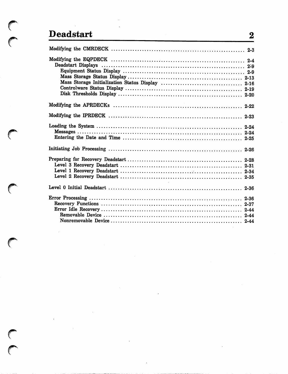
Modifying the CMRDECK 2-3
Modifying the EQPDECK .......... 2-4
Deadstart Displays _ 2-9
Equipment Status Display # 2-9
Mass Storage Status Display . 2-13
Mass Storage Initialization Status Display 2-16
Controlware Status Display . . 2-19
Disk Thresholds Display 2-20
Modifying the APRDECKs 2-22
Modifying the IPRDECK 2-23
Loading the System 2-24
Messages .. 2-24
Entering the Date and Time 2-25
Initiating Job Processing . 2-26
Preparing for Recovery Deadstart , 2-28
Level 3 Recovery Deadstart 2-31
Level 1 Recovery Deadstart 2-34
Level 2 Recovery Deadstart .. , 2-35
Level 0 Initial Deadstart 2-36
Error Processing 2-36
Recovery Functions ............... 2-37
Error Idle Recovery 2-44
Removable Device 2-44
Nonremovable Device 2-44

V.
Deadstart
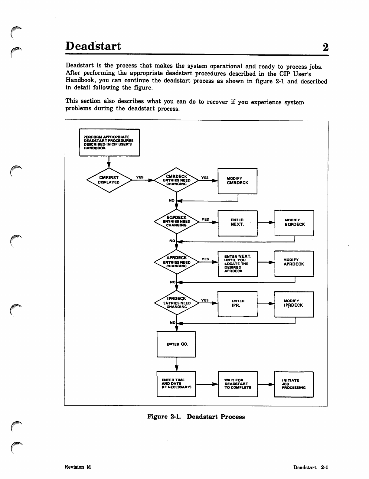
Deadstart is the process that makes the system operational and ready to process jobs.
After performing the appropriate deadstart procedures described in the CIP User's
Handbook, you can continue the deadstart process as shown in figure 2-1 and described
in detail following the figure.
This section also describes what you can do to recover if you experience system
problems during the deadstart process.
PERFORM APPROPRIATE
DEADSTART PROCEDURES
OESCRIBED IN CIP USER'S
HANDBOOK
MODIFY
CMRDECK
ENTER
NEXT.
MODIFY
EQPDECK
ENTER NEXT.
UNTIL YOU
LOCATE THE
DESIRED
APRDECK
MODIFY
APRDECK
ENTER
IPR.
MODIFY
IPRDECK
ENTER TIME
AND DATE
(IF NECESSARY)
WAIT FOR
DEADSTART
TO COMPLETE
INITIATE
JOB
PROCESSING
Figure 2-1. Deadstart Process
Revision M Deadstart 2-1
Deadstart
NOTE
Modifying the deadstart decks (CMRDECK, EQPDECK, APRDECKs, and IPRDECK) ""'***)
does not apply to a level 3 recovery deadstart. Modifications made during the last
level 0, 1, or 2 deadstart are recovered during a level 3 recovery deadstart.
2-2 NOS Version 2 Analysis Handbook Revision M
0$m\.
r
Modifying the CMRDECK
Modifying the CMRDECK
If bit 6 of word 13 (word 12 for warmstart on a CYBER 70 or 6000 Computer System
with an active PP) is set (ppp = 001), or if you select the D = Y option on the *P*
display, an instruction display entitled CMRINST appears on the console screen(s) after
the CTI displays on a level 0, 1, or 2 deadstart. .All valid CMRDECK entries are
defined in this display. Several of the entries listed are assigned system default values.
These values are assumed if the entries do not appear in the CMRDECK being used.
To view the contents of the CMRDECK being used, toggle from the CMRINST display
to the CMRDECK display. If either the CMRDECK or CMRINST overflows two
screens, the display can be paged.
Modify the CMRDECK by entering the appropriate changes or additions from the
console keyboard. These entries can be made while either CMRDECK or CMRINST is
being displayed. Generally, each console entry supersedes the value currently specified
in the CMRDECK (or default value in CMRINST).
Refer to section 3, Deadstart Decks, for complete information on all CMRDECK
entries.
NOTE
The modified CMRDECK remains in effect only until the next level 0 deadstart is
performed. Changes to the CMRDECK are not recovered for the next deadstart unless
a new deadstart file is created. If you want these changes to take place on the next
level 0 deadstart, make the appropriate changes to the CMRDECK after NOS is up
and running and use LIBEDIT to replace the record on the deadstart file.
After all CMRDECK modifications have been made and you want to modify an
EQPDECK, APRDECK, or IPRDECK, enter:
NEXT.
Refer to Modifying the EQPDECK, Modifying the APRDECKs, or Modifying the
IPRDECK in this section. Otherwise, to indicate that all modifications to the
CMRDECK are complete and you want to begin loading the system, enter:
GO.
Revision M Deadstart 2-3
Modifying the EQPDECK
Modifying the EQPDECK
After completing all CMRDECK modifications, you can also modify the default
EQPDECK, an APRDECK, or the IPRDECK being used. If no changes need to be
made to any EQPDECK, but you do need to modify an APRDECK or the IPRDECK,
refer to Modifying the APRDECKs or Modifying the IPRDECK later in this section.
To modify an EQPDECK, enter
NEXT.
while the CMRDECK or CMRINST is being displayed.
You can make changes when the EQPDECK, EQPINST, or any one of the deadstart
displays is displayed at the console screen (refer to Deadstart Displays described later
in this section).
Table 2-1 describes the entries that can be made only at the console keyboard at
deadstart time and cannot be stored in the EQPDECK on the deadstart file. Refer to s*%i
section 3, Deadstart Decks, for complete information concerning all EQPDECK
entries.
After making the changes to EQPDECK you can toggle through the deadstart
displays to ensure all the changes are made.
NOTE
The modified EQPDECK remains in effect only until the next level 0 deadstart is
performed. Changes to the EQPDECK are not recovered for the next deadstart unless
a new deadstart file is created. If you want these changes to take place on the next
level 0 deadstart, make the appropriate changes to the EQPDECK after NOS is up
and running and use LIBEDIT to replace the record on the deadstart file.
After all EQPDECK modifications have been made and you want to modify an
APRDECK or IPRDECK, enter:
NEXT.
Refer to Modifying the APRDECKs or Modifying the IPRDECK later in this section.
Otherwise, to indicate that all modifications to the EQPDECK are complete and you
want to begin loading the system, enter:
GO.
2-4 NOS Version 2 Analysis Handbook Revision M
Modifying the EQPDECK
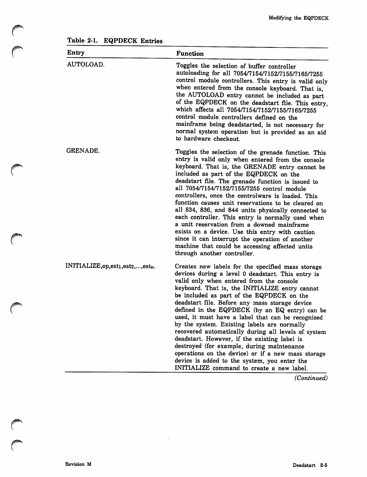
Table 2-1. EQPDECK Entries
Entry
AUTOLOAD.
GRENADE.
0P*\
INITIALIZE ,op,esti ,est2,... ,estn.
Function
Toggles the selection of buffer controller
autoloading for all 7054/7154/7152/7155/7165/7255
control module controllers. This entry is valid only
when entered from the console keyboard. That is,
the AUTOLOAD entry cannot be included as part
of the EQPDECK on the deadstart file. This entry,
which affects all 7054/7154/7152/7155/7165/7255
control module controllers defined on the
mainframe being deadstarted, is not necessary for
normal system operation but is provided as an aid
to hardware checkout.
Toggles the selection of the grenade function. This
entry is valid only when entered from the console
keyboard. That is, the GRENADE entry cannot be
included as part of the EQPDECK on the
deadstart file. The grenade function is issued to
all 7054/7154/7152/7155/7255 control module
controllers, once the controlware is loaded. This
function causes unit reservations to be cleared on
all 834, 836, and 844 units physically connected to
each controller. This entry is normally used when
a unit reservation from a downed mainframe
exists on a device. Use this entry with caution
since it can interrupt the operation of another
machine that could be accessing affected units
through another controller.
Creates new labels for the specified mass storage
devices during a level 0 deadstart. This entry is
valid only when entered from the console
keyboard. That is, the INITIALIZE entry cannot
be included as part of the EQPDECK on the
deadstart file. Before any mass storage device
defined in the EQPDECK (by an EQ entry) can be
used, it must have a label that can be recognized
by the system. Existing labels are normally
recovered automatically during all levels of system
deadstart. However, if the existing label is
destroyed (for example, during maintenance
operations on the device) or if a new mass storage
device is added to the system, you enter the
INITIALIZE command to create a new label.
(Continued)
Revision M Deadstart 2-5
Modifying the EQPDECK
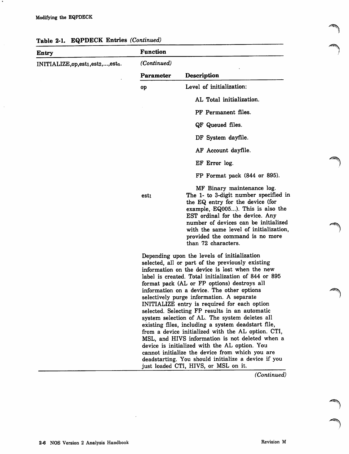
Table 2-1. EQPDECK Entries (Continued)
Entry
INITIALIZE,op,esti,est2,...,estn.
Function
■"^5\
(Continued)
Parameter Description
op Level of initialization:
AL Total initialization.
PF Permanent files.
QF Queued files.
DF System dayfile.
AF Account dayfile.
EF Error log.
FP Format pack (844 or 895).
MF Binary maintenance log.
esti The 1- to 3-digit number specified in
the EQ entry for the device (for
example, EQ005...). This is also the
EST ordinal for the device. Any
number of devices can be initialized
with the same level of initialization,
provided the command is no more
than 72 characters.
Depending upon the levels of initialization
selected, all or part of the previously existing
information on the device is lost when the new
label is created. Total initialization of 844 or 895
format pack (AL or FP options) destroys all
information on a device. The other options
selectively purge information. A separate
INITIALIZE entry is required for each option
selected. Selecting FP results in an automatic
system selection of AL. The system deletes all
existing files, including a system deadstart file,
from a device initialized with the AL option. CTI,
MSL, and HIVS information is not deleted when a
device is initialized with the AL option. You
cannot initialize the device from which you are
deadstarting. You should initialize a device if you
just loaded CTI, HIVS, or MSL on it.
(Continued)
2-6 NOS Version 2 Analysis Handbook Revision M
Modifying the EQPDECK
0m*\
Table 2-1. EQPDECK Entries (Continued)
Entry Function
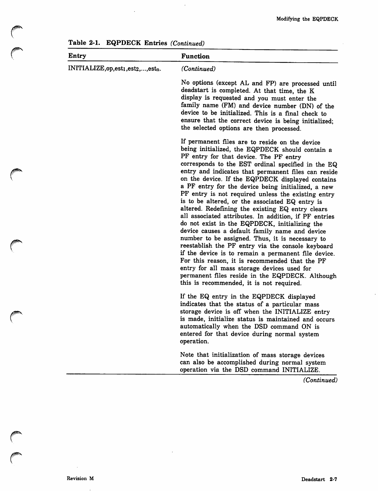
INITIALIZE,op,esti ,est2,... ,estn. (Continued)
No options (except AL and FP) are processed until
deadstart is completed. At that time, the K
display is requested and you must enter the
family name (FM) and device number (DN) of the
device to be initialized. This is a final check to
ensure that the correct device is being initialized;
the selected options are then processed.
If permanent files are to reside on the device
being initialized, the EQPDECK should contain a
PF entry for that device. The PF entry
corresponds to the EST ordinal specified in the EQ
entry and indicates that permanent files can reside
on the device. If the EQPDECK displayed contains
a PF entry for the device being initialized, a new
PF entry is not required unless the existing entry
is to be altered, or the associated EQ entry is
altered. Redefining the existing EQ entry clears
all associated attributes. In addition, if PF entries
do not exist in the EQPDECK, initializing the
device causes a default family name and device
number to be assigned. Thus, it is necessary to
reestablish the PF entry via the console keyboard
if the device is to remain a permanent file device.
For this reason, it is recommended that the PF
entry for all mass storage devices used for
permanent files reside in the EQPDECK. Although
this is recommended, it is not required.
If the EQ entry in the EQPDECK displayed
indicates that the status of a particular mass
storage device is off when the INITIALIZE entry
is made, initialize status is maintained and occurs
automatically when the DSD command ON is
entered for that device during normal system
operation.
Note that initialization of mass storage devices
can also be accomplished during normal system
operation via the DSD command INITIALIZE.
(Continued)
Revision M Deadstart 2-7
Modifying the EQPDECK
Table 2-1. EQPDECK Entries (Continued)
Entry Function
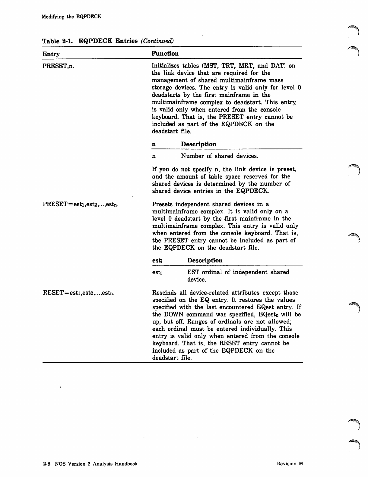
PRESET,n.
PRESET=esti ,est2,...,estn.
Initializes tables (MST, TRT, MRT, and DAT) on
the link device that are required for the
management of shared multimainframe mass
storage devices. The entry is valid only for level 0
deadstarts by the first mainframe in the
multimainframe complex to deadstart. This entry
is valid only when entered from the console
keyboard. That is, the PRESET entry cannot be
included as part of the EQPDECK on the
deadstart file.
nDescription
n Number of shared devices.
If you do not specify n, the link device is preset,
and the amount of table space reserved for the
shared devices is determined by the number of
shared device entries in the EQPDECK.
Presets independent shared devices in a
multimainframe complex. It is valid only on a
level 0 deadstart by the first mainframe in the
multimainframe complex. This entry is valid only
when entered from the console keyboard. That is,
the PRESET entry cannot be included as part of
the EQPDECK on the deadstart file.
esti Description
esti EST ordinal of independent shared
device.
RESET=esti ,est2,... ,estn. Rescinds all device-related attributes except those
specified on the EQ entry. It restores the values
specified with the last encountered EQest entry. If
the DOWN command was specified, EQestn will be
up, but off. Ranges of ordinals are not allowed;
each ordinal must be entered individually. This
entry is valid only when entered from the console
keyboard. That is, the RESET entry cannot be
included as part of the EQPDECK on the
deadstart file.
y=S^\
2-8 NOS Version 2 Analysis Handbook Revision M
Deadstart Displays
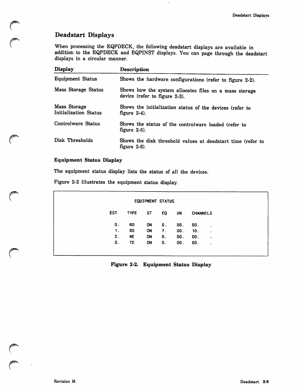
Deadstart Displays
When processing the EQPDECK, the following deadstart displays are available in
addition to the EQPDECK and EQPINST displays. You can page through the deadstart
displays in a circular manner.
Display Description
Equipment Status
Mass Storage Status
Mass Storage
Initialization Status
Controlware Status
Disk Thresholds
Shows the hardware configurations (refer to figure 2-2).
Shows how the system allocates files on a mass storage
device (refer to figure 2-3).
Shows the initialization status of the devices (refer to
figure 2-4).
Shows the status of the controlware loaded (refer to
figure 2-5).
Shows the disk threshold values at deadstart time (refer to
figure 2-6).
Equipment Status Display
The equipment status display lists the status of all the devices.
Figure 2-2 illustrates the equipment status display.
EQUIPMENT STATUS
EST TYPE ST EQ UN CHANNELS
0. RD ON 0. 00. 00.
1. DS ON 7. 00. 10.
2. NE ON 0. 00. 00.
3. TE ON 0. 00. 00.
Figure 2-2. Equipment Status Display
Revision M Deadstart 2-9
Equipment Status Display
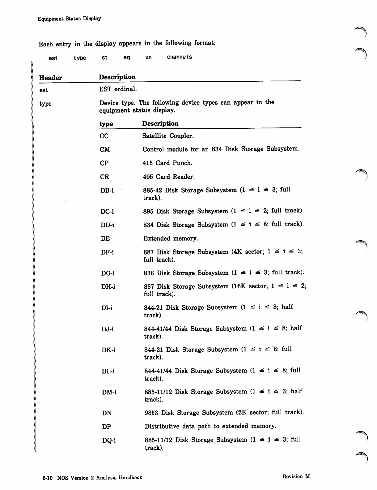
Each entry in the display appears in the following format:
est type st eq un channels
Header Description
| est EST ordinal.
| type Device type. The following device types can appear in the
I equipment status display.
| type Description
CC Satellite Coupler.
CM Control module for an 834 Disk Storage Subsystem.
CP 415 Card Punch.
CR 405 Card Reader.
DB-i 885-42 Disk Storage Subsystem (1 ^ i ^ 3; full
track).
DC-i 895 Disk Storage Subsystem (1 ^ i ^ 2; full track).
DD-i 834 Disk Storage Subsystem. (1 ^ i ^ 8; full track).
DE Extended memory.
DF-i 887 Disk Storage Subsystem (4K sector; 1 ^ i ^ 3;
full track).
DG-i 836 Disk Storage Subsystem (1 ^ i ^ 3; full track).
DH-i 887 Disk Storage Subsystem (16K sector; 1 ^ i ^ 2;
full track).
Dl-i 844-21 Disk Storage Subsystem (1 ^ i ^ 8; half
track).
DJ-i 844-41/44 Disk Storage Subsystem (1 ^ i ^ 8; half
track).
DK-i 844-21 Disk Storage Subsystem (1 ^ i ^ "8; full
track).
DL-i 844-41/44 Disk Storage Subsystem (1 ^ i ^ 8; full
track).
DM-i 885-11/12 Disk Storage Subsystem (1 ^ i ^ 3; half
track).
DN 9853 Disk Storage Subsystem (2K sector; full track).
DP Distributive data path to extended memory.
DQ-i 885-11/12 Disk Storage Subsystem (1 ^ i ^ 3; full
track).
2-10 NOS Version 2 Analysis Handbook Revision M
Equipment Status Display
0SS
Header Description
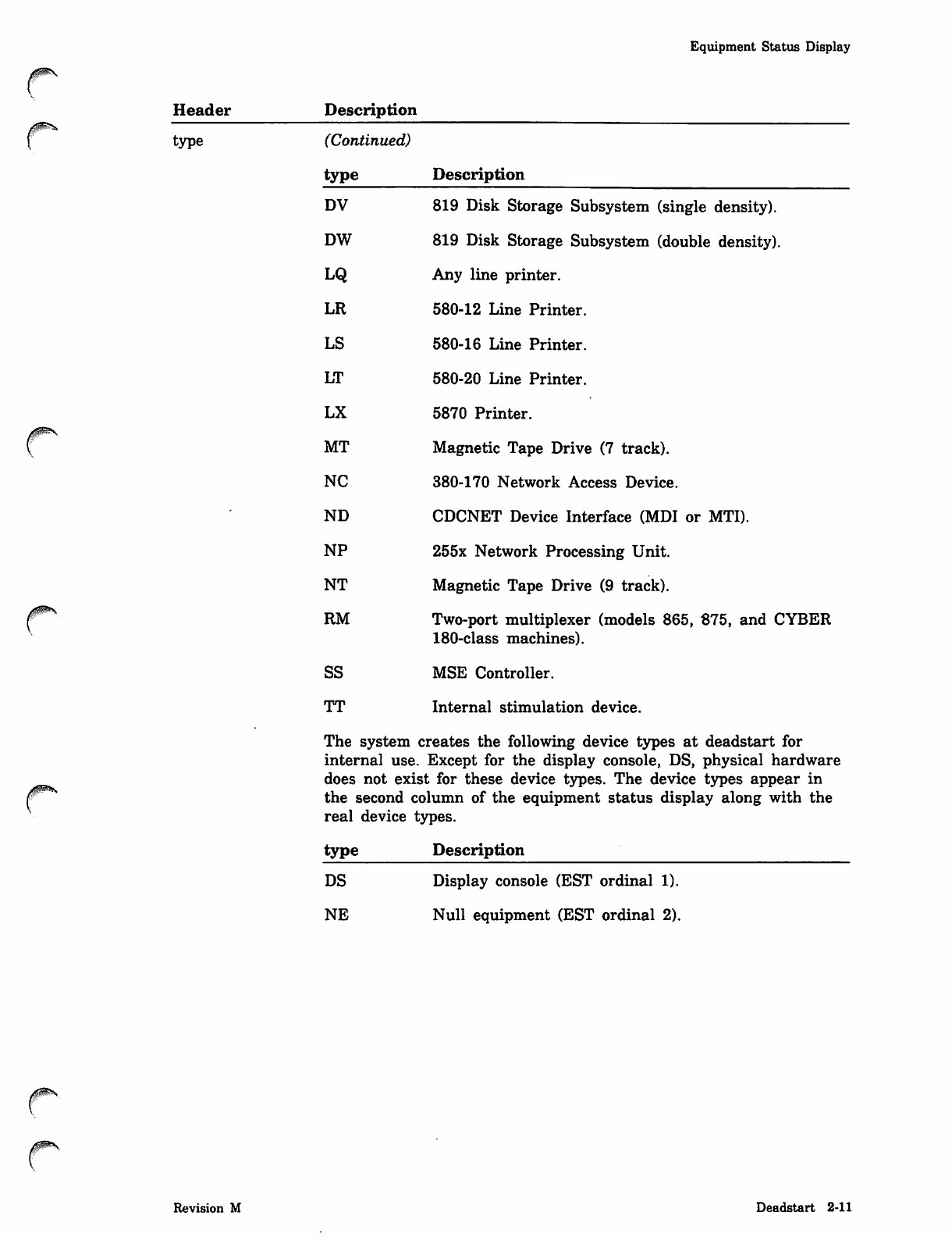
type (Continued)
type Description
DV 819 Disk Storage Subsystem (single density).
DW 819 Disk Storage Subsystem (double density).
LQ Any line printer.
LR 580-12 Line Printer.
LS 580-16 Line Printer.
LT 580-20 Line Printer.
LX 5870 Printer.
MT Magnetic Tape Drive (7 track).
NC 380-170 Network Access Device.
ND CDCNET Device Interface (MDI or MTI).
NP 255x Network Processing Unit.
NT Magnetic Tape Drive (9 track).
RM Two-port multiplexer (models 865, 875, and CYBER
180-class machines).
SS MSE Controller.
T T I n t e r n a l s t i m u l a t i o n d e v i c e .
The system creates the following device types at deadstart for
internal use. Except for the display console, DS, physical hardware
does not exist for these device types. The device types appear in
the second column of the equipment status display along with the
real device types.
type Description
DS Display console (EST ordinal 1).
NE Null equipment (EST ordinal 2).
Revision M Deadstart 2-11
Equipment Status Display
Header
type
st
eq
un
channels
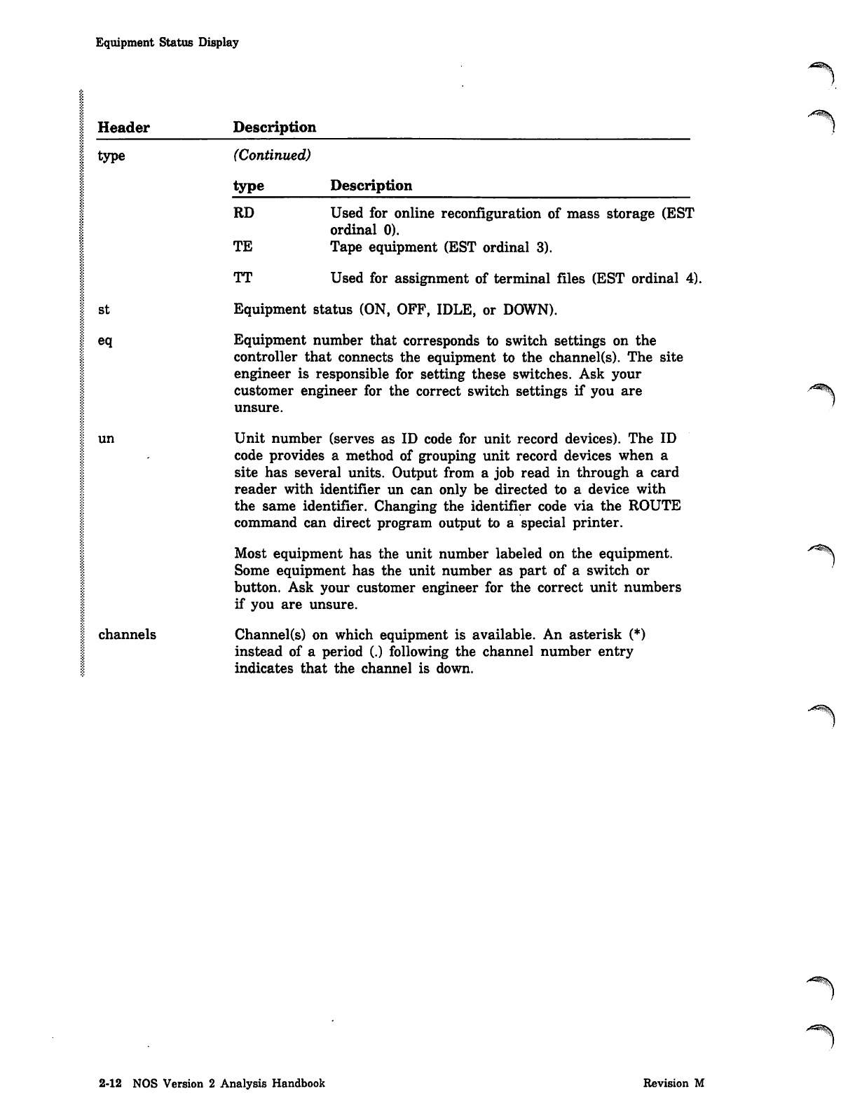
Description
(Continued)
type Description
RD
TE
Used for online reconfiguration of mass storage (EST
ordinal 0).
Tape equipment (EST ordinal 3).
TT Used for assignment of terminal files (EST ordinal 4).
Equipment status (ON, OFF, IDLE, or DOWN).
Equipment number that corresponds to switch settings on the
controller that connects the equipment to the channel(s). The site
engineer is responsible for setting these switches. Ask your
customer engineer for the correct switch settings if you are
unsure.
Unit number (serves as ID code for unit record devices). The ID
code provides a method of grouping unit record devices when a
site has several units. Output from a job read in through a card
reader with identifier un can only be directed to a device with
the same identifier. Changing the identifier code via the ROUTE
command can direct program output to a special printer.
Most equipment has the unit number labeled on the equipment.
Some equipment has the unit number as part of a switch or
button. Ask your customer engineer for the correct unit numbers
if you are unsure.
Channel(s) on which equipment is available. An asterisk (*)
instead of a period (.) following the channel number entry
indicates that the channel is down.
2-12 NOS Version 2 Analysis Handbook Revision M
Mass Storage Status Display
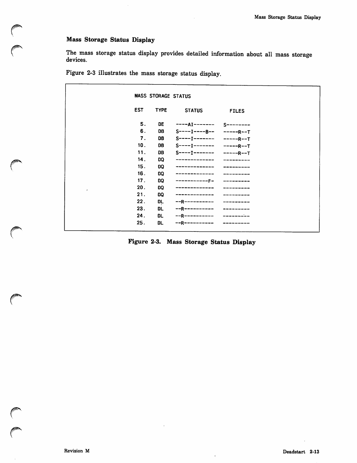
Mass Storage Status Display
The mass storage status display provides detailed information about all mass storage
devices.
Figure 2-3 illustrates the mass storage status display.
0m\.
v
MASS STORAGE STATUS
EST TYPE
5. DE
6. DB
7. DB
10. DB
11. DB
14. DQ
15. DQ
16. DQ
17. DQ
20. DQ
21. DQ
22. DL
23. DL
24. DL
25. DL
STATUS
B—
A]
S 3
S—
S—
S—
F-
~R—
—R—
—R—
—R—
FILES
S
R--T
R--T
R—T
R—T
Figure 2-3. Mass Storage Status Display
Revision M Deadstart 2-13
Mass Storage Status Display
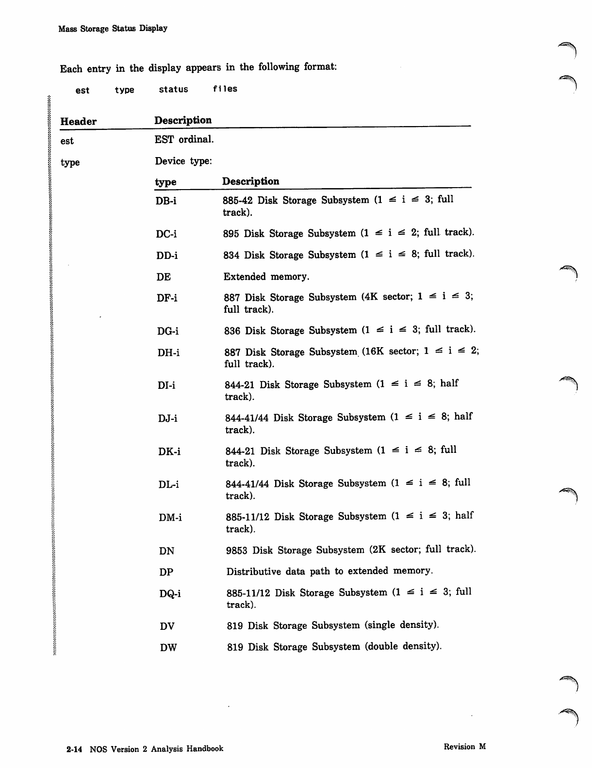
Each entry in the display appears in the following format:
est type status files
Header Description
est EST ordinal,
type Device type:
type Description
DB-i 885-42 Disk Storage Subsystem (1 ^ i ^ 3; full
track).
DC-i 895 Disk Storage Subsystem (1 ^ i ^ 2; full track).
DD-i 834 Disk Storage Subsystem (1 ^ i ^ 8; full track).
DE Extended memory.
DF-i 887 Disk Storage Subsystem (4K sector; 1 ^ i ^ 3;
full track).
DG-i 836 Disk Storage Subsystem (1 ^ i ^ 3; full track).
DH-i 887 Disk Storage Subsystem (16K sector; 1 ^ i ^ 2;
full track).
Dl-i 844-21 Disk Storage Subsystem (1 ^ i ^ 8; half
track).
DJ-i 844-41/44 Disk Storage Subsystem (1 ^ i ^ 8; half
track).
DK-i 844-21 Disk Storage Subsystem (1 ^ i ^ 8; full
track).
DL-i 844-41/44 Disk Storage Subsystem (1 ^ i ^ 8; full
track).
DM-i 885-11/12 Disk Storage Subsystem (1 ^ i ^ 3; half
track).
DN 9853 Disk Storage Subsystem (2K sector; full track).
DP Distributive data path to extended memory.
DQ-i 885-11/12 Disk Storage Subsystem (1 ^ i ^ 3; full
track).
DV 819 Disk Storage Subsystem (single density).
DW 819 Disk Storage Subsystem (double density).
,tf*3^v
2-14 NOS Version 2 Analysis Handbook Revision M
Mass Storage Status Display
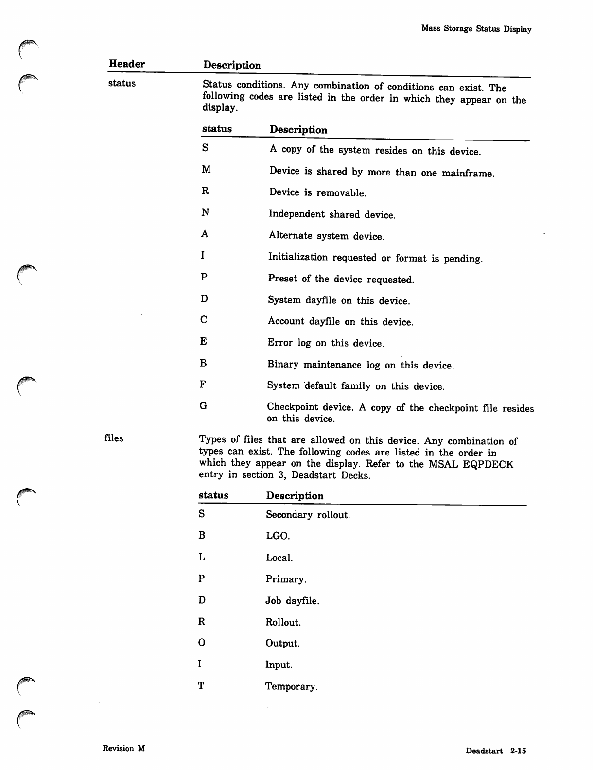
Header
status
files
Description
Status conditions. Any combination of conditions can exist. The
following codes are listed in the order in which they appear on the
display.
status Description
S
M
R
N
A
I
P
D
C
E
B
F
G
A copy of the system resides on this device.
Device is shared by more than one mainframe.
Device is removable.
Independent shared device.
Alternate system device.
Initialization requested or format is pending.
Preset of the device requested.
System dayfile on this device.
Account dayfile on this device.
Error log on this device.
Binary maintenance log on this device.
System "default family on this device.
Checkpoint device. A copy of the checkpoint file resides
on this device.
Types of files that are allowed on this device. Any combination of
types can exist. The following codes are listed in the order in
which they appear on the display. Refer to the MSAL EQPDECK
entry in section 3, Deadstart Decks.
status Description
SSecondary rollout.
BLGO.
LLocal.
PPrimary.
D Job dayfile.
RRollout.
0Output.
IInput.
TTemporary.
Revision M Deadstart. 2-15
Mass Storage Initialization Status Display
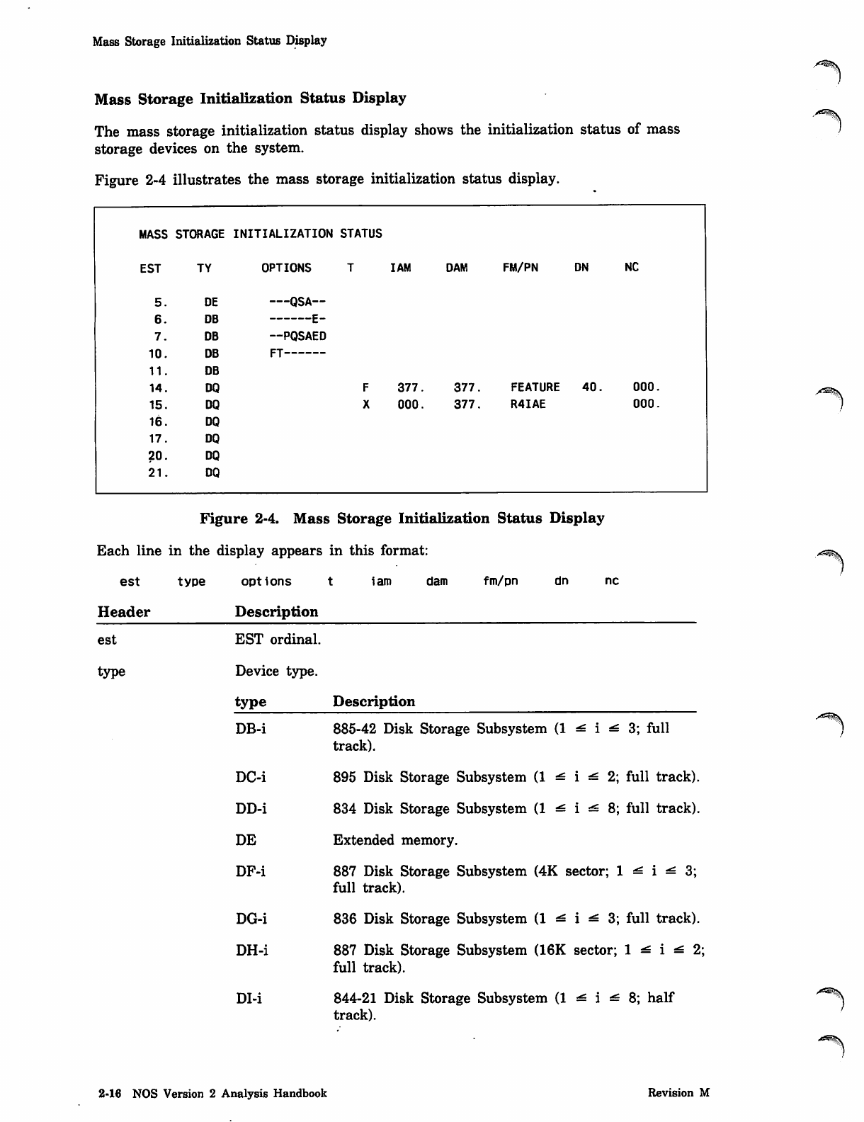
Mass Storage Initialization Status Display
The mass storage initialization status display shows the initialization status of mass
storage devices on the system.
Figure 2-4 illustrates the mass storage initialization status display.
MASS STORAGE INITIALIZATION STATUS
EST TY OPTIONS I AM DAM FM/PN DN NC
5. DE QSA--
6. DB E-
7. DB —PQSAED
10. DB FT
11. DB
14. DQ 377. 377. FEATURE 40. 000.
15. DQ 000. 377. R4IAE 000.
16. DQ
17. DQ
20. DQ
21. DQ
Figure 2-4. Mass Storage Initialization Status Display
Each line in the display appears in this format:
est type options t iam dam fm/pn dn nc
Header Description
est EST ordinal.
type Device type.
type Description
DB-i 885-42 Disk Storage Subsystem (1 ^ i ^ 3; full ]
track).
DC-i 895 Disk Storage Subsystem (1 ^ i ^ 2; full track).
DD-i 834 Disk Storage Subsystem (1 ^ i ^ 8; full track).
DE Extended memory.
DF-i 887 Disk Storage Subsystem (4K sector; 1 ^ i -£ 3;
full track).
DG-i 836 Disk Storage Subsystem (1 ^ i ^ 3; full track).
DH-i 887 Disk Storage Subsystem (16K sector; 1 ^ i ^ 2;
full track).
Dl-i 844-21 Disk Storage Subsystem (1 *s i ^ 8; half ^^
track).
2-16 NOS Version 2 Analysis Handbook Revision M
Mass Storage Initialization Status Display
rHeader
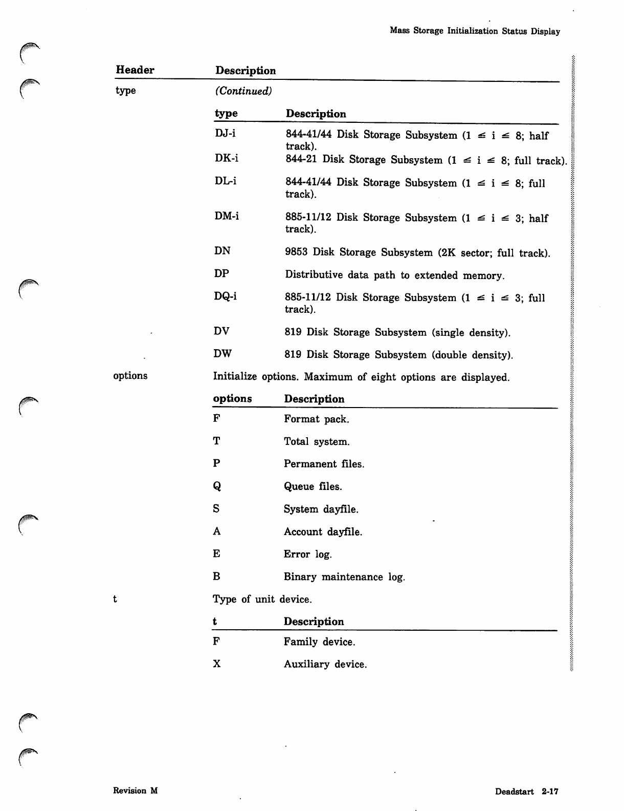
type
options
Description
(Continued)
type Description
DJ-i
DK-i
DL-i
DM-i
DN
DP
DQ-i
844-41/44 Disk Storage Subsystem (1 ^ i ^ 8; half
track).
844-21 Disk Storage Subsystem (1 «s i ^ 8; full track).
844-41/44 Disk Storage Subsystem (1 ^ i ^ 8; full
track).
885-11/12 Disk Storage Subsystem (1 ^ i as 3; half
track).
9853 Disk Storage Subsystem (2K sector; full track).
Distributive data path to extended memory.
885-11/12 Disk Storage Subsystem (1 ^ i ^ 3; full
track).
DV 819 Disk Storage Subsystem (single density).
DW 819 Disk Storage Subsystem (double density).
Initialize options. Maximum of eight options are displayed.
options Description
FFormat pack.
TTotal system.
PPermanent files.
Q Queue files.
sSystem dayfile.
AAccount dayfile.
EError log.
BBinary maintenance log.
Type of unit device.
t Description
F
X
Family device.
Auxiliary device.
0ms
Revision M Deadstart 2-17
Mass Storage Initialization Status Display
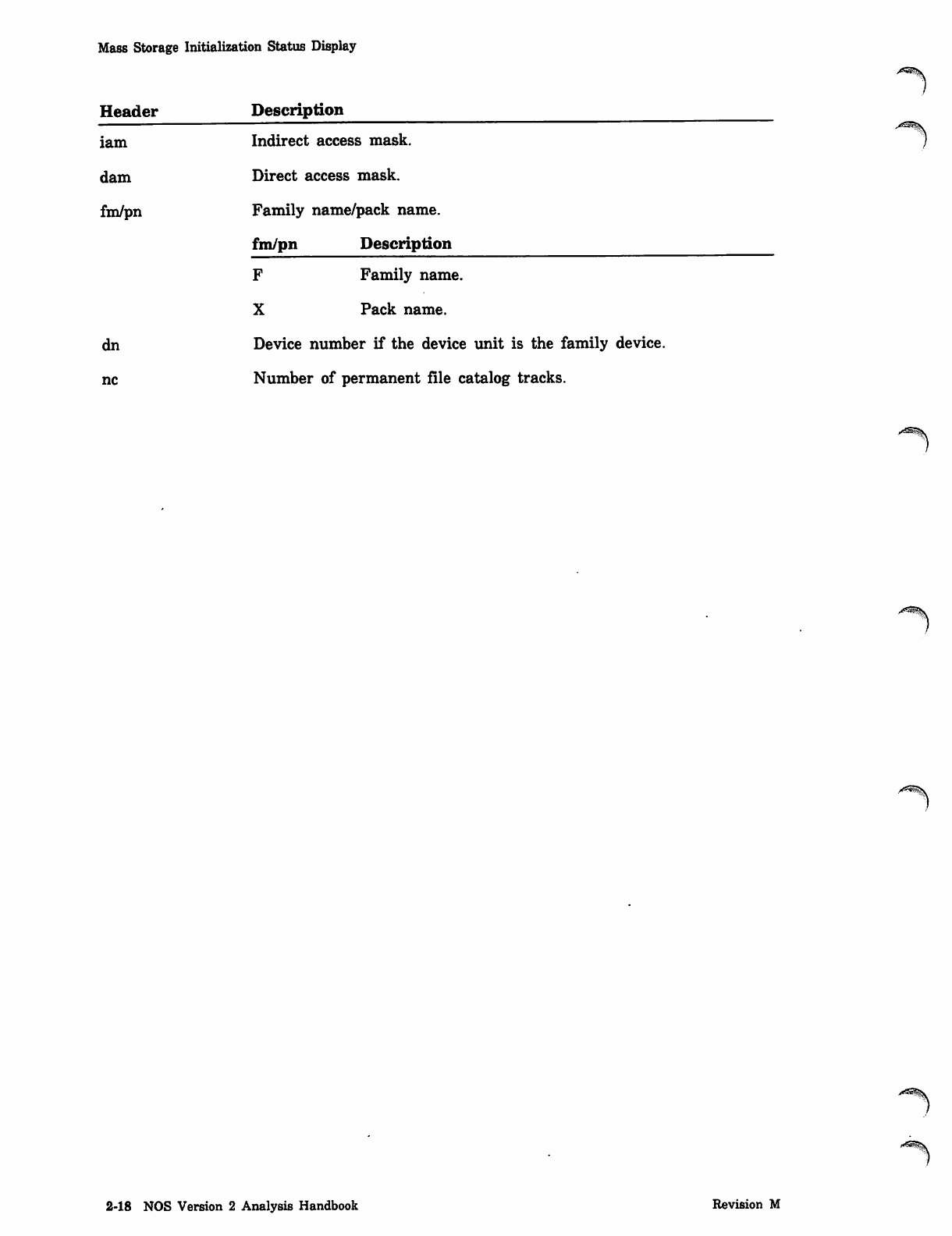
Header Description
iam Indirect access mask,
dam Direct access mask,
fm/pn Family name/pack name.
fm/pn Description
F Family name.
X Pack name,
dn Device number if the device unit is the family device,
nc Number of permanent file catalog tracks.
2-18 NOS Version 2 Analysis Handbook Revision M
/$foft\
jfiffiQifirSy
Controlware Status Display
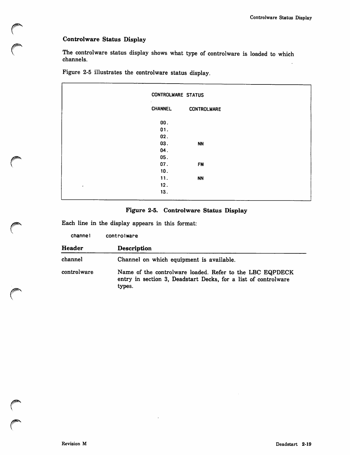
Controlware Status Display
The controlware status display shows what type of controlware is loaded to which
channels.
Figure 2-5 illustrates the controlware status display.
CONTROLWARE STATUS
CHANNEL CONTROLWARE
00.
01.
02.
03. NN
04.
05.
07. FM
10.
11. NN
12.
13.
Figure 2-5. Controlware Status Display
Each line in the display appears in this format:
channel controlware
Header Description
channel
controlware
Channel on which equipment is available.
Name of the controlware loaded. Refer to the LBC EQPDECK
entry in section 3, Deadstart Decks, for a list of controlware
types.
Revision M Deadstart 2-19
Disk Thresholds Display
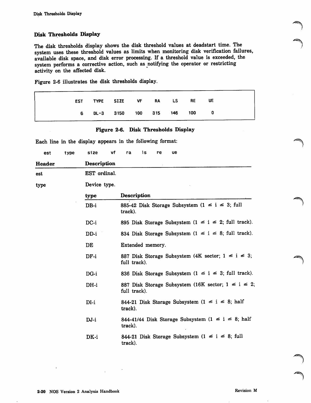
Disk Thresholds Display
The disk thresholds display shows the disk threshold values at deadstart time. The
system uses these threshold values as limits when monitoring disk verification failures,
available disk space, and disk error processing. If a threshold value is exceeded, the
system performs a corrective action, such as notifying the operator or restricting
activity on the affected disk.
Figure 2-6 illustrates the disk thresholds display.
EST TYPE SIZE VF RA LS RE UE
6DL-3 3150 100 315 146 100
Figure 2-6. Disk Thresholds Display
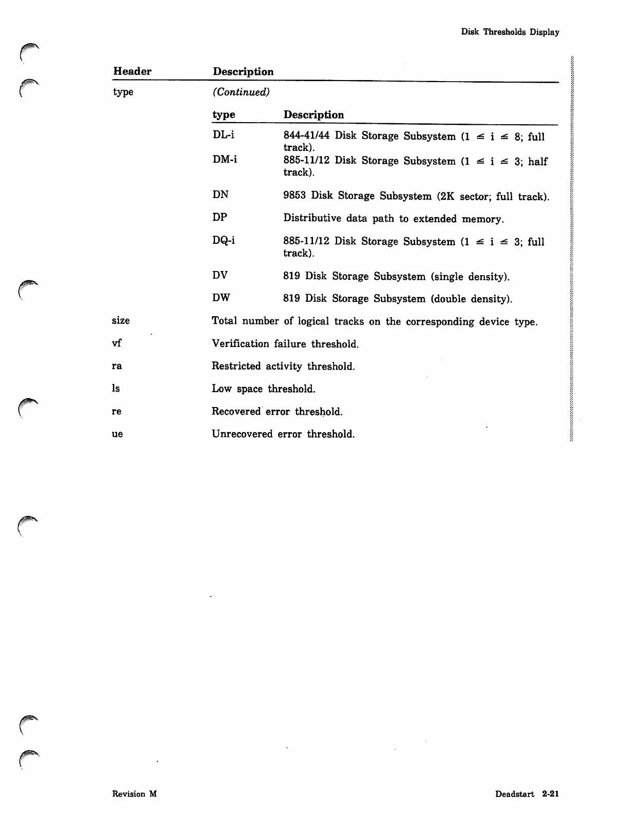
Each line in the display appears in the following format:
e s t t y p e s i z e v f r a i s r e u e
Header Description
est EST ordinal,
type Device type.
type Description
DB-i 885-42 Disk Storage Subsystem (1 ^ i ^ 3; full
track).
DC-i 895 Disk Storage Subsystem (1 ^ i ^ 2; full track).
DD-i 834 Disk Storage Subsystem (1 ^ i ^ 8; full track).
DE Extended memory.
DF-i 887 Disk Storage Subsystem (4K sector; 1 ^ i ^ 3;
full track).
DG-i 836 Disk Storage Subsystem (1 ^ i ^ 3; full track).
DH-i 887 Disk Storage Subsystem (16K sector; 1 ^ i ^ 2;
full track).
Dl-i 844-21 Disk Storage Subsystem (1 ^ i ^ 8; half
track).
DJ-i 844-41/44 Disk Storage Subsystem (1 ^ i ^ 8; half
track).
DK-i 844-21 Disk Storage Subsystem (1 ^ i ^ 8; full
track).
/<^^\
2-20 NOS Version 2 Analysis Handbook Revision M
Disk Thresholds Display
Header Description
type (Continued)
type Description
DL-i 844-41/44 Disk Storage Subsystem (1 ^ i ^ 8; full
track).
DM-i 885-11/12 Disk Storage Subsystem (1 -* i ss 3; half
track).
DN 9853 Disk Storage Subsystem (2K sector; full track).
DP Distributive data path to extended memory.
DQ-i 885-11/12 Disk Storage Subsystem (1 ^ i ^ 3; full
track).
DV 819 Disk Storage Subsystem (single density).
DW 819 Disk Storage Subsystem (double density),
size Total number of logical tracks on the corresponding device type,
vf Verification failure threshold,
r a R e s t r i c t e d a c t i v i t y t h r e s h o l d .
Is Low space threshold,
re Recovered error threshold,
ue Unrecovered error threshold.
Revision M Deadstart 2-21
Modifying the APRDECKs
Modifying the APRDECKs
After completing all EQPDECK modifications, you can also modify the default
APRDECK, the APRDECK for a specific equipment, or the IPRDECK being used. You
can modify an APRDECK only when you are initializing the corresponding equipment.
If no changes need to be made to any APRDECK, but you do need to modify the
IPRDECK, refer to Modifying the IPRDECK later in this section.
The APRDECK contains entries identifying areas of mass storage that are not usable
(flaws). The APRDECK used can vary from equipment to equipment. One of the
parameters specified when an equipment is defined in the EQPDECK is the
APRDECK number that applies to that equipment. The default (APRDOO) is selected
if this parameter is not specified.
To modify an APRDECK, enter
NEXT.
while the EQPDECK or EQPINST is being displayed. The APRINST display describes ^
the valid entries. You can toggle between the APRDECK and APRINST. Enter the
changes or additions to the APRDECK from the console keyboard (refer to section 3,
Deadstart Decks, for a description of the entries).
If there are no changes to the APRDECK displayed, enter
NEXT.
to go to the next APRDECK. Repeat this process until the appropriate APRDECK is
displayed or until you have changed all APRDECKs needing changes. '"^
After all APRDECK modifications are complete, you can skip to the IPRDECK by
entering:
IPR.
Refer to Modifying the IPRDECK, next, for more information. Otherwise, to indicate
that all modifications to the APRDECKs are complete and you want to begin loading
the system, enter:
GO.
2-22 NOS Version 2 Analysis Handbook Revision M
00®S
(
Modifying the IPRDECK
Modifying the IPRDECK
The IPRDECK contains installation parameters that describe the mode of system
operation. IPRDECK modification is seldom required during deadstart since nearly all
IPRDECK commands are also valid DSD commands that make the same changes
during normal system operation. Generally, installation parameters changed during
normal operations (with DSD commands or by modifying the IPRDECK) are retained
only across a level 3 recovery deadstart.
After entering
IPR.
when all the CMRDECK, EQPDECK, or APRDECK modifications are complete or after
repeatedly entering
NEXT.
to step through all the APRDECKs, the instruction display entitled IPRINST appears
on the console screen(s). This display defines all valid IPRDECK entries. Most of these
entries are also valid DSD commands.
To view the contents of the IPRDECK being used, toggle from the IPRINST display
to the IPRDECK display. If either the IPRDECK or IPRINST overflows two screens,
you can page the display.
Enter the appropriate changes or additions from the console keyboard. These entries
can be made while either IPRINST or IPRDECK is being displayed. A console entry
supersedes the value currently specified in the IPRDECK.
NOTE
The modified IPRDECK remains in effect only until the next level 0, 1, or 2
deadstart is performed. Changes to the IPRDECK are retained if a level 3 recovery
deadstart is performed. If you want these changes to take place on the next level 0
deadstart, make the appropriate changes to the IPRDECK after NOS is up and
running and use LIBEDIT to replace the record on the deadstart file.
For complete information concerning IPRDECK entries, refer to section 3, Deadstart
Decks, and to section 5, DSD Commands.
To indicate that changes to the CMRDECK, EQPDECK, APRDECK, and/or IPRDECK
are completed and you want to begin loading the system, enter:
GO.
Revision M Deadstart 2-23
Loading the System
Loading the System
If you are performing a level 0 or level 2 deadstart, the system library is
automatically loaded from the deadstart file to each mass storage device specified in
the EQPDECK as a system device. If no system device is specified, the system is
loaded on the first nonremovable mass storage device in the equipment status table.
Mass storage labels are validated for all levels of deadstart. This ensures that the
configuration matches the one specified in the EQPDECK. Normally, the device label
validation display appears for only a few seconds. However, this display remains
longer (from 30 seconds to 3 minutes) if 834, 836, 887, or 9853 disk units must first
be automatically spun up in order to validate their labels.
If you specify a level 1 or level 3 recovery deadstart, the system library is not
reloaded. In this case, the deadstart file is rewound and is not accessed again until
another deadstart operation is performed. The system library is recovered from
checkpoint information on mass storage. Central memory tables such as the system
file name table (FNT), executing job table (EJT), queued file table (QFT), equipment
status table (EST), and track reservation table (TRT) are either recovered from
checkpoint information for level 1 or from central memory (and the link device,
extended memory, if in multimainframe mode) for level 3.
Messages
If a deadstart error occurs, a message appears on the right console screen and,
depending upon the nature of the error, deadstart processing may halt. Refer to Error
Processing later in this section for complete information and corrective action. If the ^_
system is being loaded (level 0 or 2 only), the name of each system library program is j
also displayed on the right console screen as it is being loaded. This allows you to
monitor deadstart progress.
The left console screen may display the message ENTER DATE YY/MM/DD. You can
enter the date while the system is being loaded.
2-24 NOS Version 2 Analysis Handbook Revision M
Entering the Date and Time
Entering the Date and Time
Each time a system deadstart function is performed, it is necessary to enter the
current date and time (except for CYBER 180-class machines; they get the date and
time from CTI during deadstart). The system uses the date and time (updated every
second) for dayfile messages and for permanent file catalogs and directories for files
being accessed. This includes the creation, last modification, and last access date and
time for each permanent file in the system. It is important to enter the correct date
and time in order to accurately maintain these system records. If you are performing a
level 3 recovery deadstart, it is possible to recover the date and time from the previous
system deadstart. However, this is not recommended since the new date and time
recorded for system records would no longer be accurate.
When the system loading (or recovery) phase of deadstart is about to begin, the
system checks for the correct date and time. If CTI is unable to determine the correct
date and time or the mainframe is other than a CYBER 180-class, the following
message appears on the left console screen requesting entry of the current date.
ENTER DATE YY/MM/DD.
Enter the current date, followed by CR, in this format:
yy/mm/dd.
Entry Description
yy Year; 00 through 99.
mm Month; 01 through 12.
dd Day; 01 through nn (nn is the number of days in the month).
For deadstart levels 0, 1, and 2, pressing CR without first entering the date causes the
system to assume the date that the deadstart file was created. For a level 3 recovery
deadstart, pressing CR alone recovers both the previous date and time (time entered
during the last deadstart plus time accumulated until this deadstart).
When the system accepts the date entry, it displays the following request for entry of
the current time.
ENTER TIME HH.MM.SS.
Enter the current time in this format:
hh.mm.ss.
Entry Description
hh Hour; 00 through 23.
mm Minute; 00 through 59.
ss Second; 00 through 59.
For deadstart levels 0, 1, and 2, pressing CR without first entering the time causes the
system to set the time to 00.00.00. If you enter CR alone following the date prompt on
ra level 3 recovery, this prompt to enter time does not appear (the previous time is
Revision M Deadstart 2-25
Initiating Job Processing
Initiating Job Processing
DSD commands specified in the IPRDECK automatically initiate normal job processing
except on a level 3 recovery where you must enter AUTO. If a level 1 or level 3
recovery deadstart is being performed, the system recovers all jobs and active files and
resumes normal operation immediately. However, if an initial deadstart (level 0) or
level 2 recovery deadstart is being performed, job processing may not be initiated
immediately. The time of initiation depends upon the time it takes to load the system
from the deadstart file (you can monitor progress on the right console screen). If file
loading is not completed when the time entry is made, the DSD commands specified in
the IPRDECK are displayed on the left screen. Until file loading completes, you can
clear one or more of the DSD commands.
Clearing a command prevents it from being executed when file loading completes. In
this case, you must manually enter the commands necessary to initiate job processing
from the console keyboard.
To initiate job processing, enter either:
AUTO.
or
MAINTENANCE
Following entry of the AUTO or MAINTENANCE command during an initial (level 0)
deadstart, the deadstart sequencing process begins. Deadstart sequencing causes job
processing to be suspended until all system files in the default family are initiated. To
initiate a family other than the default, enter the command:
X.ISF(FM=family)
Parameter Description
family Alternate family of devices.
y ^ = 5 ^ >
For additional information concerning the ISF command and deadstart sequencing, refer
to section 20, System File Initialization.
2-26 NOS Version 2 Analysis Handbook Revision M
Initiating Job Processing
Normal job processing begins after the deadstart sequencing job completes. If the
J^v AUTO command is entered, the subsystems enabled in the IPRDECK are automatically
V assigned to specified control points. Assuming that all standard subsystems are set to
be enabled, the system calls them to specific control points as shown in the following
example:
Control Point Job Sequence
Number Name Activity
1 IAF Interactive Facility.
2 NAM Network Access Method.
3 RHF Remote Host Facility.
4 SMF Screen Management Facility.
Magnetic tape subsystem executive routine.
n-2x MAG
.2
n_1 BIO Central site batch input/output.
2
nRBF Remote Batch Facility.
.2
n + 1 S Y S S y s t e m .
The MAINTENANCE command performs the same function as the AUTO command.
Additionally, it assigns several maintenance routines, according to mainframe type, to
available control points and runs them as normal jobs with minimum queue and CPU
priorities. These are CPU or central memory test routines designed to detect hardware
errors. The routines display error messages either at the control point on the B,0
display or in the system error log. To display the error log, enter:
A,ERROR LOG.
You should monitor these routines from time to time. If a maintenance routine displays
an error message indicating a hardware malfunction occurred, call a customer engineer.
It is recommended that these programs be run at all times. The maintenance programs
use little memory, are run at minimum CPU and queue priority, and are automatically
^^ rolled out if necessary; thus, system performance is not severely affected. Descriptions
^^ of the maintenance routines are in the NOS Online Maintenance Software Reference
Manual.
You can use the SCHEDULE command to schedule jobs, but it does not initiate
subsystems or maintenance jobs. Refer to the NOS Version 2 Operations Handbook
for a description of the SCHEDULE command.
1. n is the number of control points defined by the NCP entry in the CMRDECK.
Revision M Deadstart 2-27
Preparing for Recovery Deadstart
Preparing for Recovery Deadstart
Sometimes during system operation an uncorrectable error occurs that prevents further
system activity. Often the situation can be corrected by deadstarting the system and
recovering prior activity. The success of such a recovery depends upon the severity of
the problem and the extent to which system information is destroyed. There are three
levels of recovery deadstart available (levels 1, 2, and 3). Table 2-2 lists each deadstart
level, including level 0 (initial deadstart), and describes the extent of recovery possible.
If the MS VALIDATION installation option is enabled during a level 1 or 2 recovery,
or if both the MS VALIDATION and PF VALIDATION options are enabled during a
level 3 recovery, the system:
• Verifies selected mass storage files.
• Checks files identified in the queued file table (QFT) to ensure that all tracks in
the chain are reserved and that no circular linkage exists.
• Depending on file type, checks the track reservation table (TRT) to ensure that
the file is preserved.
• Checks all preserved files for proper length.
If the system encounters a verification failure, it clears the queued file table entry but
does not release disk space assigned to the file. If a length error is detected, the
system sets error idle status and terminates recovery operations on the device. To
recover from an error idle condition, refer to Error Idle Recovery under Error
Processing later in this section.
During level 0 deadstart, the system verifies the length of preserved files regardless
of the setting of the MS VALIDATION option. If a length error is detected, the
system reads the disk chain to determine the correct length of the file, issues a
message to the B,0 display, and stops recovery of the device. To alter the EOI for
the file and proceed with recovery, enter:
GO,SYS. or GO,.
To terminate recovery of the device, enter:
PAUSE,SYS.
2-28 NOS Version 2 Analysis Handbook Revision M
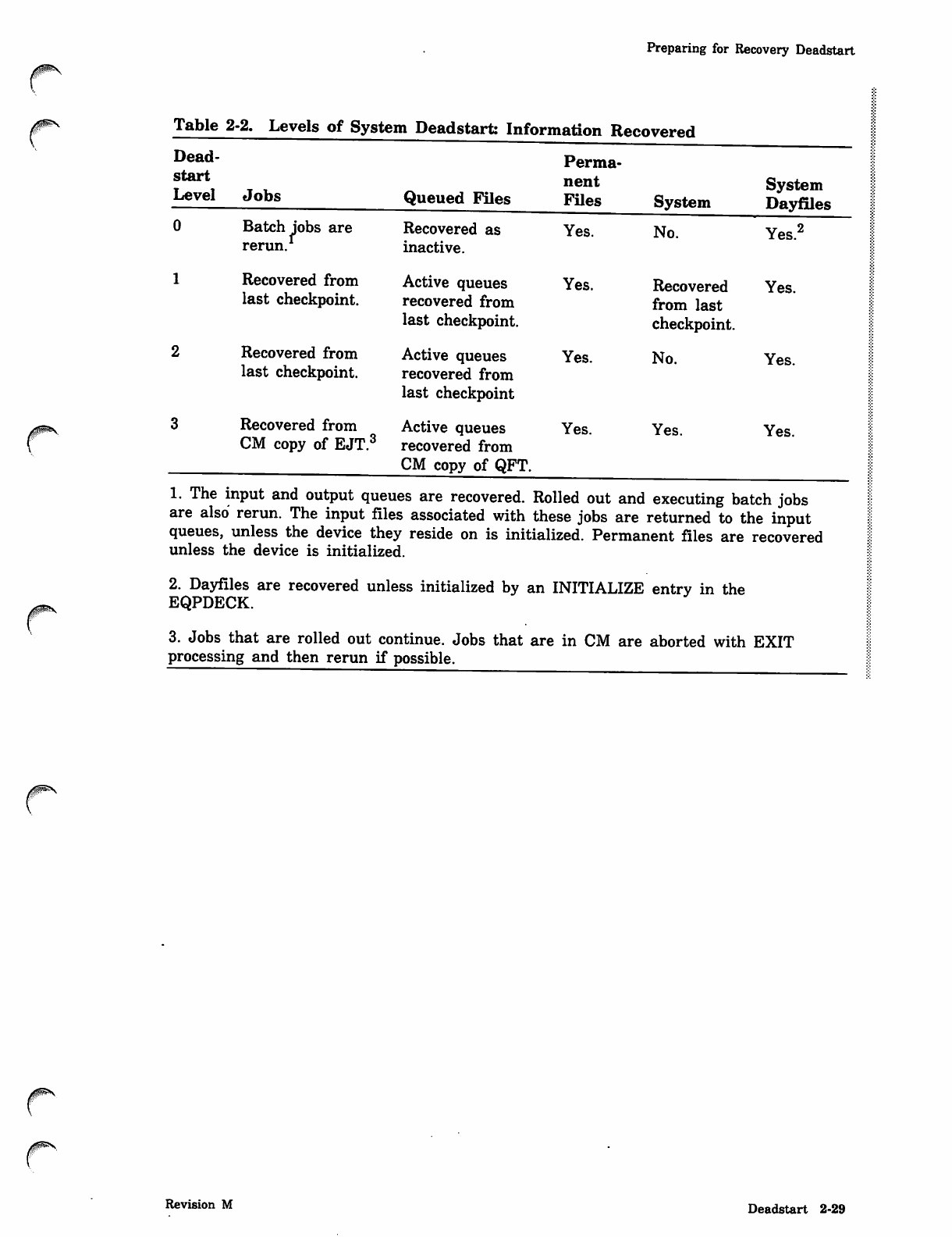
Preparing for Recovery Deadstart
y * ^ \ Table 2-2. Levels of System Deadstart: Information Recovered
Dead-
start
Level Jobs Queued Files
Perma
nent
Files
Yes.
System
No.
System
Dayfiles
0Batch jobs are
rerun. Recovered as
inactive. Yes.2
1Recovered from
last checkpoint.
Active queues
recovered from
last checkpoint.
Yes. Recovered
from last
checkpoint.
Yes.
2Recovered from
last checkpoint.
Active queues
recovered from
last checkpoint
Yes. No. Yes.
3Recovered from
CM copy of EJT.3
Active queues
recovered from
CM copy of QFT.
Yes. Yes. Yes.
1. The input and output queues are recovered. Rolled out and executing batch jobs
are also rerun. The input files associated with these jobs are returned to the input
queues, unless the device they reside on is initialized. Permanent files are recovered
unless the device is initialized.
2. Dayfiles are recovered unless initialized by an INITIALIZE entry in the
EQPDECK.
3. Jobs that are rolled out continue. Jobs that are in CM are aborted with EXIT
processing and then rerun if possible.
Revision M Deadstart 2-29
Preparing for Recovery Deadstart
CAUTION
Before attempting any level of recovery deadstart, whether it is a level 0, 1, 2, or 3 )
deadstart, enter a CHECKPOINT SYSTEM command, and wait for the CHECKPOINT
COMPLETE message to appear on the system console. The CHECKPOINT SYSTEM
performs the following functions:
1. All currently executing jobs are rolled out. (Ensures that these jobs can roll back
and continue executing after a level 3 deadstart.)
2. All mass storage tables and track reservation tables are copied to disk, and all
pending disk I/O operations are completed. (Ensures the integrity of the disks
after a level 0, 1, or 2 deadstart.)
3. A system checkpoint file (which includes a copy of all the system tables in central
memory) is written to disk. (Provides a system checkpoint file for a level 1 or 2
deadstart.)
If , du e t o a s y st em h an g or o th er p ro b l e m, i t i s n o t p o s si bl e to e nt er a . <* * % ^
CHECKPOINT SYSTEM, or if the CHECKPOINT COMPLETE message does not /
appear, the disk updates may not have been performed. If a level 0 deadstart is
performed at this time, permanent file information may be lost. To prevent such a
loss, always perform a level 3 deadstart after a system hang. Select the ABORT
option on the level 3 deadstart display to abandon the deadstart; the ABORT option
performs the disk updates and then abandons the deadstart.
The following topics provide general information concerning each level of system
deadstart and recommended steps of preparation.
2-30 NOS Version 2 Analysis Handbook Revision M
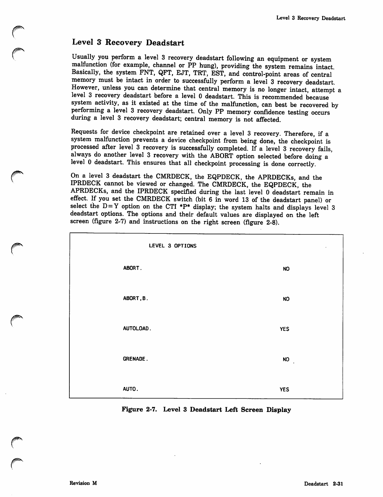
Level 3 Recovery Deadstart
Level 3 Recovery Deadstart
Usually you perform a level 3 recovery deadstart following an equipment or system
malfunction (for example, channel or PP hung), providing the system remains intact
Basically, the system FNT, QFT, EJT, TRT, EST, and control-point areas of central
memory must be intact in order to successfully perform a level 3 recovery deadstart.
However, unless you can determine that central memory is no longer intact, attempt a
level 3 recovery deadstart before a level 0 deadstart. This is recommended because
system activity, as it existed at the time of the malfunction, can best be recovered by
performing a level 3 recovery deadstart. Only PP memory confidence testing occurs
during a level 3 recovery deadstart; central memory is not affected.
Requests for device checkpoint are retained over a level 3 recovery. Therefore, if a
system malfunction prevents a device checkpoint from being done, the checkpoint is
processed after level 3 recovery is successfully completed. If a level 3 recovery fails,
always do another level 3 recovery with the ABORT option selected before doing a '
level 0 deadstart. This ensures that all checkpoint processing is done correctly.
f^' On a level 3 deadstart the CMRDECK, the EQPDECK, the APRDECKs, and the
IPRDECK cannot be viewed or changed. The CMRDECK, the EQPDECK, the
APRDECKs, and the IPRDECK specified during the last level 0 deadstart remain in
effect. If you set the CMRDECK switch (bit 6 in word 13 of the deadstart panel) or
select the D = Y option on the CTI *P* display; the system halts and displays level 3
deadstart options. The options and their default values are displayed on the left
screen (figure 2-7) and instructions on the right screen (figure 2-8).
LEVEL 3 OPTIONS
A B O R T . N O
ABORT,B. NO
AUTOLOAD. YES
GRENADE. NO
AUTO. YES
Figure 2-7. Level 3 Deadstart Left Screen Display
Revision M Deadstart 2-31
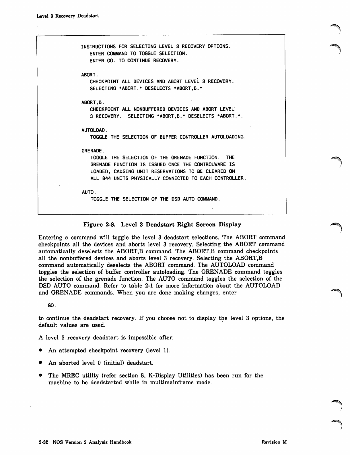
Level 3 Recovery Deadstart
INSTRUCTIONS FOR SELECTING LEVEL 3 RECOVERY OPTIONS.
ENTER COMMAND TO TOGGLE SELECTION.
ENTER GO. TO CONTINUE RECOVERY.
ABORT.
CHECKPOINT ALL DEVICES AND ABORT LEVEL 3 RECOVERY.
SELECTING -ABORT.* DESELECTS -ABORT,B.*
ABORT,B.
CHECKPOINT ALL NONBUFFERED DEVICES AND ABORT LEVEL
3 RECOVERY. SELECTING *ABORT,B.* DESELECTS -ABORT.*.
AUTOLOAD.
TOGGLE THE SELECTION OF BUFFER CONTROLLER AUTOLOADING.
GRENADE.
TOGGLE THE SELECTION OF THE GRENADE FUNCTION. THE
GRENADE FUNCTION IS ISSUED ONCE THE CONTROLWARE IS
LOADED, CAUSING UNIT RESERVATIONS TO BE CLEARED ON
ALL 844 UNITS PHYSICALLY CONNECTED TO EACH CONTROLLER.
AUTO.
TOGGLE THE SELECTION OF THE DSD AUTO COMMAND.
Figure 2-8. Level 3 Deadstart Right Screen Display
Entering a command will toggle the level 3 deadstart selections. The ABORT command
checkpoints all the devices and aborts level 3 recovery. Selecting the ABORT command
automatically deselects the ABORT,B command. The ABORT,B command checkpoints
all the nonbuffered devices and aborts level 3 recovery. Selecting the ABORT,B
command automatically deselects the ABORT command. The AUTOLOAD command
toggles the selection of buffer controller autoloading. The GRENADE command toggles
the selection of the grenade function. The AUTO command toggles the selection of the
DSD AUTO command. Refer to table 2-1 for more information about the AUTOLOAD
and GRENADE commands. When you are done making changes, enter ^
GO.
to continue the deadstart recovery. If you choose not to display the level 3 options, the
default values are used.
A level 3 recovery deadstart is impossible after:
• An attempted checkpoint recovery (level 1).
• An aborted level 0 (initial) deadstart.
• The MREC utility (refer section 8, K-Display Utilities) has been run for the
machine to be deadstarted while in multimainframe mode.
2-32 NOS Version 2 Analysis Handbook Revision M
Level 3 Recovery Deadstart
It is recommended that you stop system activity prior to beginning the system
deadstart procedure. To accomplish this, enter the following DSD commands:
Command Description
E,M.
UNLOCK.
CHECK POINT
SYSTEM.
STEP.
NOTE
Displays the disk status display (E,M).
Unlocks the system console. This command is necessary only if the
system console is locked.
Provides for termination of job processing and for writing the
contents of central memory tables to mass storage. For a complete
description of this process, refer to the CHECK POINT SYSTEM
command in section 5, DSD Commands.
Prevents the system from processing PP requests. This stops all
central memory input/output (I/O) operations. You should enter the
STEP command after all device checkpoints are completed.
Determine checkpoint status from the disk status display (E,M)
(refer to the NOS Version 2 Operations Handbook).
To recover interactive users after a level 3 recovery, sense switch 1 must be set in
the IAF procedure. Sense switch 1 is set by default in the released IAF procedure.
Revision M Deadstart 2-33
Level 1 Recovery Deadstart
Level 1 Recovery Deadstart
Usually you perform a level 1 recovery deadstart to resume normal processing
following maintenance procedures. The system, all jobs, and all active files are
recovered from checkpoint information on mass storage.
NOTE
A level 1 recovery deadstart is not intended to be a recovery process after a system/
equipment malfunction. You should never attempt it after a level 3 recovery
deadstart fails.
Level 1 recovery is also useful in system test situations. If two systems are being
alternated, separate mass storage devices and tapes must be available for both
systems. Tapes are not repositioned after a level 1 deadstart. Thus, if a job was
previously assigned to the tape unit that has been used for deadstarting, the job cannot
be recovered. The tape unit should be left unloaded after recovery until it is no longer
assigned to the job (job aborted).
The following rules apply when performing a level 1 recovery deadstart.
• The DSD command CHECK POINT SYSTEM must have been successfully
completed immediately before the end of the last NOS operating period.
« The contents of the extended memory must not be destroyed from the time of the
CHECK POINT SYSTEM command.
® Memory dumps must be completed before level 1 recovery deadstart begins since
memory confidence testing destroys the contents of both central memory (except '^
on CYBER 180-class machines) and PPs.
• The mass storage equipment configuration must be the same as specified during
the most recent level 0 deadstart; that is, the same EQPDECK must be used.
© The system devices (mass storage devices on which the system library resides)
must be the same as or fewer than those specified during the most recent level 0
deadstart.
It is recommended that you stop system activity before beginning the system deadstart /es%,
procedure. To accomplish this, enter the following DSD commands:
Command Description _____
UNLOCK. Necessary only if console is currently locked.
CHECK POINT Provides for termination of job processing and for writing the
SYSTEM. contents of central memory tables to mass storage.
STEP. Prevents the system from processing PP requests. This stops all
central memory I/O operations.
2. Separate tapes are necessary only if tape jobs are being checkpointed.
2-34 NOS Version 2 Analysis Handbook Revision M
Level 2 Recovery Deadstart
Level 2 Recovery Deadstart
0ms
V Usually you perform level 2 recovery deadstart in system test situations; it is not
recommended for the normal production environment. If you select level 2 recovery, all
jobs and active files are recovered from checkpoint information on mass storage as in
level 1 recovery. However, no attempt is made to recover the system. Instead, the
system is loaded from the deadstart file as in level 0 deadstart. In all other respects,
level 2 recovery is identical to that described for level 1, and all level 1 rules apply'
Revision M Deadstart 2-35
Level 0 Initial Deadstart
Level 0 Initial Deadstart
Use level 0 or initial deadstart in cases where a recovery deadstart is not possible.
This is a complete or initial load from the deadstart file. Only preserved files, which
include permanent files, queued files, and system dayfiles, are recovered (preserved
files are recovered on all levels of system deadstart). Because memory confidence
testing destroys the contents of central memory (except on CYBER 180-class machines)
and PPs, all memory dumps must be completed before deadstart begins.
NOTE
If the machine is the first machine being deadstarted in a shared device
multimainframe environment, you must enter a PRESET command (refer to section
13, Multimainframe Operations).
Error Processing
If no CTI display appears when you initiate a deadstart, perform the following steps as
needed. After each step, reinitiate the deadstart to see if the problem has been
eliminated.
Deadstart from tape:3
1. If the unit select switch on the deadstart tape unit is not on (tape does not move),
check the channel, controller, and unit selections on the deadstart panel or display
to ensure they are set correctly.
2. If the unit select switch is on, the correct unit was selected; however, check word
11 of the deadstart panel or display to ensure it is set correctly.
3. Ensure that a 7-track tape is not mounted on a 9-track drive or vice versa. Also,
ensure that a deadstart tape is not mounted on a tape unit that does not support
the density of the deadstart tape.
4. Ensure that the deadstart tape is an l-format unlabeled tape.
5. Ensure that the card reader and tape unit (667 or 669 only) are not on the same ^\
channel and that the card reader is not on a channel with a PP. Also, ensure
that two or more units do not have the same physical unit number.
6. If still no display appears after initiating the deadstart, there might be a parity
error on one of the first records of the deadstart tape or the magnetic tape
controller might have detected a channel parity error on a CYBER 170 Computer
System.
3. When deadstarting a CYBER 180-class machine, the disk containing the CIP module must be used.
2-36 NOS Version 2 Analysis Handbook Revision M
Recovery Functions
[ Deadstart from disk:
1. Ensure that disk power is on and the disk is ready for operation.
2. Ensure that the disk has the CIP module loaded.
3. Ensure that the deadstart panel or display is set correctly.
4. Select an alternate channel.
5. If still no display appears after initiating the deadstart, there might be a parity
error on one of the first records of the deadstart file or the disk controller might
have detected a channel parity error on a CYBER 170 Computer System.
For a proper understanding of the problems that can occur during deadstart, you
should be familiar with several basic concepts. For example, because most errors that
occur involve mass storage devices, you should be familiar with their use in the
system. Each mass storage device has a label that contains descriptive information
about its contents. For certain levels of recovery deadstart, this information must be
consistent with corresponding information either contained in central memory or
provided through deadstart procedures. Conflicts can result in the system issuing
deadstart error messages. An attempt is made to recover all mass storage devices
defined in the EST during all levels of system deadstart.
Recovery Functions
The specific recovery function performed depends upon the level of deadstart selected.
Table 2-3 describes the recovery function performed for each deadstart level and the
types of errors you can encounter. The system response to errors and the recommended
action are also listed.
Refer to the NOS Version 2 Operations Handbook for information concerning all
deadstart messages.
Revision M Deadstart 2-37
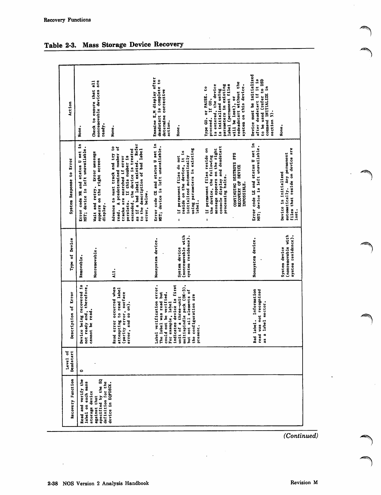
Recovery Functions
Table 2-3. Mass Storage Device Recovery
■'<:S%v
i J o
8 «
M 0 1 > n
t l W T J
oi c <s
X O 91
tO E U
*J X i O >H
11
g-
k . J -
O f H E
»H Ck
TJ «k« rH
0> 0» 91
u i a i x
T l 9 1 r H
u . •
h U T J T )
4 1 0 > 0 )
X S i t t X
H - H o
3 H b
6 0 ) X O
U 01
D < H C
< H > r t O
X C l 9 1 - t
k l t i J P k l
r a o .
IM Q> rH Ti
U i X k . it
U T J U
t o n rH
• « J P u
c o t j t j j p
u g i < t
0 3 T J 0 1
H t l U f kl
» 0 1 <H U
u u kl
i i K a o kl
CL 01 tO 4J 91
TJ
«l
una
01 h h t n
0 1 6 0 < D J C • r H O
O U C 0 1 k l O t a k i c
k > - H W H r H U •M «H O "H
> C W r l k l r H k l k l
r A ) x i s a < * i 3 > ■H M* U
I O T J C O - H k l O 0 1 C - H k l K
t u a s i t n • 3 K « J O J = T J T < O l r H
9 Q ( i w e u
< 0 £ D 0 1 » H O U ^ « l <
O . k i 0 ) E B ^ 9 1 • » « J P » k l M
i m n - h t o * » j : k l * - r t - >
hH »-H Gtokiki
O T J r H t O d O I -
k l O M
« t j t j a s
o i t o u t u r H t a e
• • k H « a k i o 9 1 0 01 rH
Bumk l C
01 « «H Q T J ( I I J U ^ I I 1 0
O « u h « j p t j 6
o i e c 6 - H « o i
O l c
-4 SO U O k i t t ) ID NH
•h oiuuHsaiHtiu
6 . o u x - i t a t o
■H 01 JP B
> k i B
kl 91
s n i i
>%kftntDft)fg-Ha>>% 01 tx
PJ TJ TJ to as W Q . - H - t C U r t 9 k i C O tr.
ce
kl
Cl D O S k l k i 01
U H
fig
^4 N-l 00 ki cc 0 1 X
k l > > k l 01 00-H CO t k , CO to
OVH T J 6 k i T J
- J N - l t o » - H
CO CO 3 01 0) to to
O * t l 01 Ol O JB TJ >. M t n >
ki rH kl o u 9 t o
BT , T J ^s k l B
B r t d t n O 6 B 1 9 3
o i > e 01 <k l O 18 r CO HI
H I I O CO - 4 C O I d O O) kl
■M TJ kl kl <M 01 CO >«kl IM
v - 3 01 IU X kl CO rH tv, TJ 01
kl kl 10 rH <0 U O B r H
kl j C k l U O . X
B - 5 . t a -» CO
"' IS pa
O l 0 1 to 4 1 0 1 P. H 0 0 isrH 3"BENk. B O CO TJ B
not • r l N H in 01
eu 6 > V S I C O
i t 0 1 H H 0 1 £8a. 0 1 c i
TJ -H
Vt}t
Ck-H kl g"S 0 1 TJ to 0 01
o . t o O O 83 o >
U 01
- h j p 01 co B O
«M 01 B n t o i m X e » O k i
i t u e s i a .KKn9 r - 8h
k i s n
1ii d r
B - H k .
CO kl
n c j t o
x * - M X
t l k l
01 to
O 0 C O 4J
> k l r H CO
0 1 3 t
a t u n
US*
U O k , o
kl 00 k) TJ
01 01 0)
O rH TJ
■H JO N*
> 10 CO
01 > 01
T J O k l
a
e o i a
01 ki 0)
k l B k l
C O O C O
> . B > ,
t n * t r a
kl
IS
kl <r» Ux
k l • •H 1 O
3 T J ■Mtl
JO 4) k i O c o
CO H w t l to
B B
to -H 01 ?«801 kl JP • 01
kl 01 ti 01 CD oi ■H
>01 O.—1 kl
01 k i 0 1
Si. Ol J B V
TJ UHH
TJ -H oc
r H k l a. CO CO B CS
01 O 0) IM
X c k> <M Ck kl kl
set to O U l O
Tl TJ Cl T B ci 01
■Hk l i t
0 ) 3 ki TJ T i - * U l Ol 0)
■S O B 3 3 j:ki
H O t u Tt 3 S X ki a.
k>
oCl
IM Ol ti
cL.
01
kl
o
BrH
rH 01
01 tn J9
Xi tO to
aarH
tn
ki Ou
44 ty
a
Xjp ti to
ti TJ
0) nH
M•H
co IM •rt 01
B 6 u
-rt Cl nH
■001 •M
oo a 0> Ol
C O C l k l - r t
at -( co eg a tj tj
(Continued)
ytSS^K
2-38 NOS Version 2 Analysis Handbook Revision M
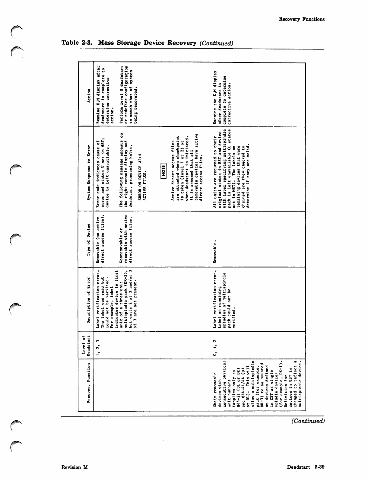
Recovery Functions
Table 2-3. Mass Storage Device Recovery (Continued)
m k i e
0 ) O k , o
k i k i A h e SK
( M J J W 0 1 03
C O 0 ) 0 ) C B k l r 4 9 1
t a o i t j m c o e u c
C B - r t
S s 0 > > « S 3 > >
C O r H - 1 0 ) 0 0 1 0 • r t » ) B •
H b l l T J - r t T J r t M 6
C k B t l I M I M •
Bc o o o i o e o t j Z k ) k l H
er t O k , O 9 1 - k l 0 1 k l
T J k l r H O k l k l C d C O T J C l
k> C D O U t o 0 ) k l C O
Cl s r - < c i > o i x > ( U C A O
<
xamlne E, eadstart eterntne ctlon. erform le r redefin o match t elng reco Examine thi after dead: complete ti corrective
H T J T J C 0 O . O k l j O
0 1 O S
4 1 r H 3
B01 C l T J k l
O k l 9> k . - h c W
I T _ o TJ nH N H > N - l k l
> M H I B T J C O N - l k i g l kl 0 1 0 1 C k 0 )
o t n k i b o i o O k l t> £ T J C O r
kl X * 1 0 C B r - 4 t X to CO k l - r t z j 6 4 1 O T J
o0 1 0 1 © C O * < i T J k l N - i O M k l n H
kl I B C r i C k > , k l I M O < M k l - 4 0 1 O C r H 9 1 r t
M3 H X O . B J - ' 0 ) -t
H > kJfBrJOlOlStTJtQ
to CO CO COrHIQX CB.fi U B t o C O • Q r t r i 9 1 >
u u h C k j r w c o o o - t X c n T J H J P o i k l J <
oo i T , c i t a u , m k l C J oicoeotojptscioi
uc o c s t o o o - M e o 3 . u B — t n a t o - t C U C H O J | l b
o i 7 t o t j c CJ 01 j r o i > H k . H H H U £ I t
Ol k l = > t o t o - t I C a X rH k l O < M 3 B f * . C O ( J
01 C O E C O 0 1 o > t i 01 kl k l H U H > 0 1 0 ! > s
BC I C 9 3 0 1 H 0 ) M l . kl > k . T J > O S 0 1 H C O X 0 ) B C U
MttuePtiox
0N - i 3 e o o i > s n O TJ OJ e) 01 41 CO
Ck T J k i k , c n C l M b ] 01 01 r H k l E T J 0 ) 3 0 1 3 r t X k l
CD E C O l M 0 0 E O O r t k i X T T 0 ) 3 C l C U k l C k > k l
01 n - i M S J E O k , l - l n J O TJ t t 0 1 o U t O 0 1 k l • 4 1 t M
OS 0 > > H H U B , Z h T J C O C CB i h g I S k l I M « » ■. T J 4 > n H
4 1 » O k l 01 01 CO JP C O r H 0 1 H u
eTJTJCO Oklkl tt] O kl Ot TJ CO M s r . t i h c o o o t o o i
0) O S r t r t X k i C £ > > « CO ra > c i t i r t X X 6 C
kl O t O r t 0 0 C O O h - r t k l B • r l O 9 1 N H r t I C B l N r t T J H
CR C l O r t k l D C ( - k i 0 1 01 E k . B B H H B E c j B
. >. I h t i C l w i < n K U ( J M t a x k l 0 1 T i 3 H n H r t e t i
CR 0 O - - • T J 1 0 n £ < 0 )
k i U > 0 1 0 ) 1 0
U b | | X X «
C O 0 1 T J H k l T J
■H » i m k . T J t a x a t c s h o i
—'NHuUkiEnki
h b H O I I l l £ I I
< o 3 Q . t n k . u t j
• 0 1
0 1 « - « > •
> C O - r t 0 1
N H t t l k l 0 )
01 k l r H C J < H
Cl C J H C B H
C O I M k l I M
>O X
01 O C O 4 - 1 C O
a6 C O I I r t I D
s ^ 0 1 - H S U
MH O J P O
00 1 O 1 9 0 1 O
r H C B > H I I 01
01 x o x JP
CL t t i t B C O k i to
>s > C l 0 1 > C l
H
Remo dtre Nonr remo dire 01
OS
• M » f l
k , C O - " • k . 0 1
o L i m k . O H
ki k > t a r ^ | 0 k i T J
OU 3 T J < m S ^ - n . • k , E
u0 1 J P 0 1 k i o T J t i 0 1 - H
uN H O H W C C B.
to C < B t u H H C f O O )
o t o n h o i 3 a i t n
c e c c n
O E r t 0 1
IM nHOIIiJPOII ci <""• oi r t H u j p
ck l m 0 1 C O C l 0 1 C O t i
t o > h n i i i o . k a
k l E T t
t e h 3 k i
BC l « ! > M o c i t e b o
OT l « I I • | l £ t l k l r t E c
HI M X I X C J T J k l —i C M o IM 01 IM
UH - i T J C r t t i O t )
Ou liHUCtntOCOT k . H r
>M o i a i o e c j n h u o i O i 6 t n 3 T J
M> < C ( U U O r 1 b > O 0 ) O 0 >
Cl c o x c o o t n c r a h c i h
01 H H T J « U — 1 3 H H T J n W
£Q J i M H U i l f t 1 1 O C J l r l
J l I I 3 H j h h u J P J P r t C l M
COXOOBESSuh
j h u t i i N H 3 e j j o
tr B C l. CO 41
_ 3 _ i i d a >
I M < - l
0 k ,
to fvl
- 4 k l
OJ 01
5> TJ CM
01 <0
J 0 1
o-*
H 0 1 * t e •
Bt e h t j . - » OJ
0C l H T J • O J T J — M t l
r t A " ) H C I I l l « 1 t n o r t
kl CC OiSOHrtHEBOl U r t C J >
Cl 41 >» klO-rt9 0.0.3rtrtt5 o H 0 1
c— . j r t n e o < » t o o t . ( - > M TJ
3X CL ^bCCIrtOeniCU '3 CO 0)
u. r e x t r . - H o < r r t u x t o - t - t t i w
> M 4 1 u c ^ X — ' 4 ) 4 1 « > — i
U J k . 0 1
9*. O - t > 9 1 O t — 1 - 3 X C O C l B . C E O " C
ue 3 r t X 0 < ? £ m 4 ) t n - c B C T , i J C
o> 4 i M E m > — ' 1 o c u n i o - h
>t . e n 3 s e > ^ ■ i t i u u h o i x m o i t j a
oOICIErt-H^-^-. «rt >I-HHS)H 41 01 K
oE O 0 1 h C M 0 0 J 3 < — 0 1 t O T J C C l 0 0 r t
01 rtrttnual QOJ^rt-BWBtirt rt C ki
oc t O > C H C v < T T J r t C J 1 r t O u -
£noc«4cio-ig^eeo.u,ii
> t e r t
0 1 X 3
UTIUSwCOigOltaODHtvOt j c i e
(Continued)
Revision M Deadstart 2-39
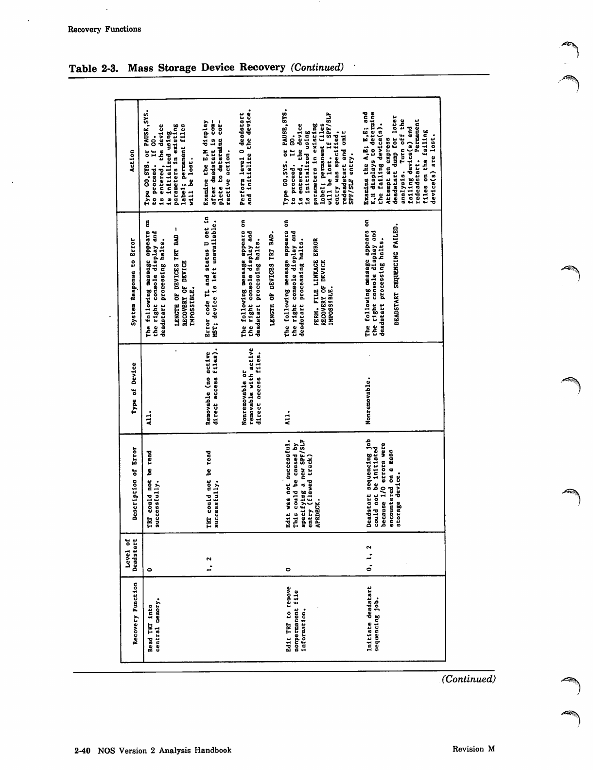
Recovery Functions
Table 2-3. Mass Storage Device Recovery (Continued)
.-^mu.
in
S*
W
0 1 0 0 C O
o o y _ B 0 )
t n H 0 0 r t r H
9 . > 6 k l r t
< Q 4 ) r t O I M
Om O TJ 03 rt
3 K k l
k i I M 0 1 4 1 E
O H f O 4 )
ij «e e •
• N r t Q k l
C O • » H B C O
> i T J T J rr t S d t, O
CO Ol SI CO ti 01 H
« 0 1 t i r t 0 1 a
© O 0 1 k l k l 4 1
O O k l r t C J — X
u 6 e fl rt
0 1 O . 0 1 H a 4 ) H
5 . t i x h
t s o c o a e g < o h
HUHHB.H 3
IBM
H O O
kl S» • O l 0 0 C O - n .
09 01 t H C l B 0 1 O h
TJ TJ C O r t 0 0 r t r t 0 u • k l
CO S • > C k l r t C O T J r t
<Q0lrt0!IM 41 B
C m C J T J t H r t I M r t O
01 41
T J X
X t i p •
• ki C B
tl 3 X k l r t U i
ok i I M C J 0 ) C r t T J
SI O r - i X T J 0 1 O B *
bl CO 01 O H M k l 4 1 C C • U C O > t
r N r t C O k l a k i
C O • - t , B 0 9 C O k l k l
> • T J T J r t C O E O U C
u k l r t 01 rt
Ol co ol k l > H
X T J T J C l oi a
H r t lAOISICOlHOIHacOOl
kl » O J k l r t J ) C i . « k l
01 TJ kl 01 Eb O u t i n u o i 3 r a t v
B > ( 9 O k l r t U — X t 3 r 3
k l C B S H 3 r , C 0 t Or t t i 0 1 H
B 4 1 k l k l
O r t
IM 0 1 C l 4 ) r t a l 4 1 r t l i o i - n n
a ) k i s i t l H T J C L t i X r t k l T J U .
X >M rt 41 0 1 B rococo te a Tt e si o.
W 1 0 O . t i Oh 03 ( r t k l r t H O . H 3 C J I h t n
Cd 01 03 qj kl TJ 4)
H 6 B 0 0
I ^ I M C O
CO Ih im
_ CO O O <-*
r t 0 ) U H C O 0 1 H O
_ . 6 w 0 - a r t
k i o i C k a k , o i u h
t k i o >
<c o u s
0 1 ! » . 0 0 T J
X t o E 6
k l H r t C O k l
an
4 1 O H
B H t O
r t T J U J
co se oi
X - X
W W k l
ta cs rt eo a o w
C k k l C O E T J 0 1
B 0 3 > » h o ) t o t l
0 1 T J H H 0 1 4 > r t
k l C O « 3 r t T J r t >
k l 0 ) B C B 0 1 H 0 1
< TJ IB UH ti UH TJ
k> B
r t t j »
a C B
ri
0 1 C O ca » r i
O.SU
Ck CB rt f- CO >
CO rt CB od 3 a
ax k l B
01 CO Id CB 3
00 rt 00 in kl
co tj e fit o k i
C O r t UH
a oi co Id TJ 01
4] rt CO
B 0 01 e rt
MCB
a a U. CO
00 6 o Ul r t H
B 0 U Cu (H
t\ t i e u S" 00 01
3OS l-l o l c i
O k l k l SC CO T J r t
r t X I h fiCO O 8 >
rt CO <e U V
O H k l TJ
UJ ti CO
TJ as ki
o —
01 01 03 k , f - l
X X 0 1 bISH k l T J
. 2
c o p a
, ki
"to 2 *
• X f H
e o C O
5 8
0 O C J
c o c i
0 0 B O
3
O kl kl
r t X t i
r t 0 0 t o
01 01 CB
X X 0 1
fH kl T J
6. SK kl
a t o r t
e g h t o
ax
a > a
0 0 r t o o
CB TJ 6
C B r t
CO 01 CO
8 H C OO 0 1
CB Cl
0 0 B O
B O t i
r t c i a
3
O k l k l
r t X k l
H 00 C B
OrtM
Uh ti CO
TJ
II 01 CB
X X 01
H k l T J
• > to
sss r t 0 0 t o t o ,
O r t M <
O X
kl CO
I I r t 0 9
H 3 0 1
rt SHrt
3x i n
UH
CO
Cft V O t M
01 CO CO o
U 3 _ 1 0
ucb 3 m
3 Cl 41 kl
CO
0 1 T J
kl X 10 01
o3
B TJ 00 CB
r i B H
co 3 r t U J
S >»Nrta)
>Cl UH
&3
11
Tt SN tkl
k l W C l k , p
r t r t 0 1 k l C S
tj x a b Ou
W H « 41 <
tn X O T3 >
-n» 01 01
k l « J r H t i TJ
e g b O l k i 0 )
CO TJ
T J r t
01 5
2 -*
01 Ui
•H 01
II H
(Continued)
2-40 NOS Version 2 Analysis Handbook Revision M
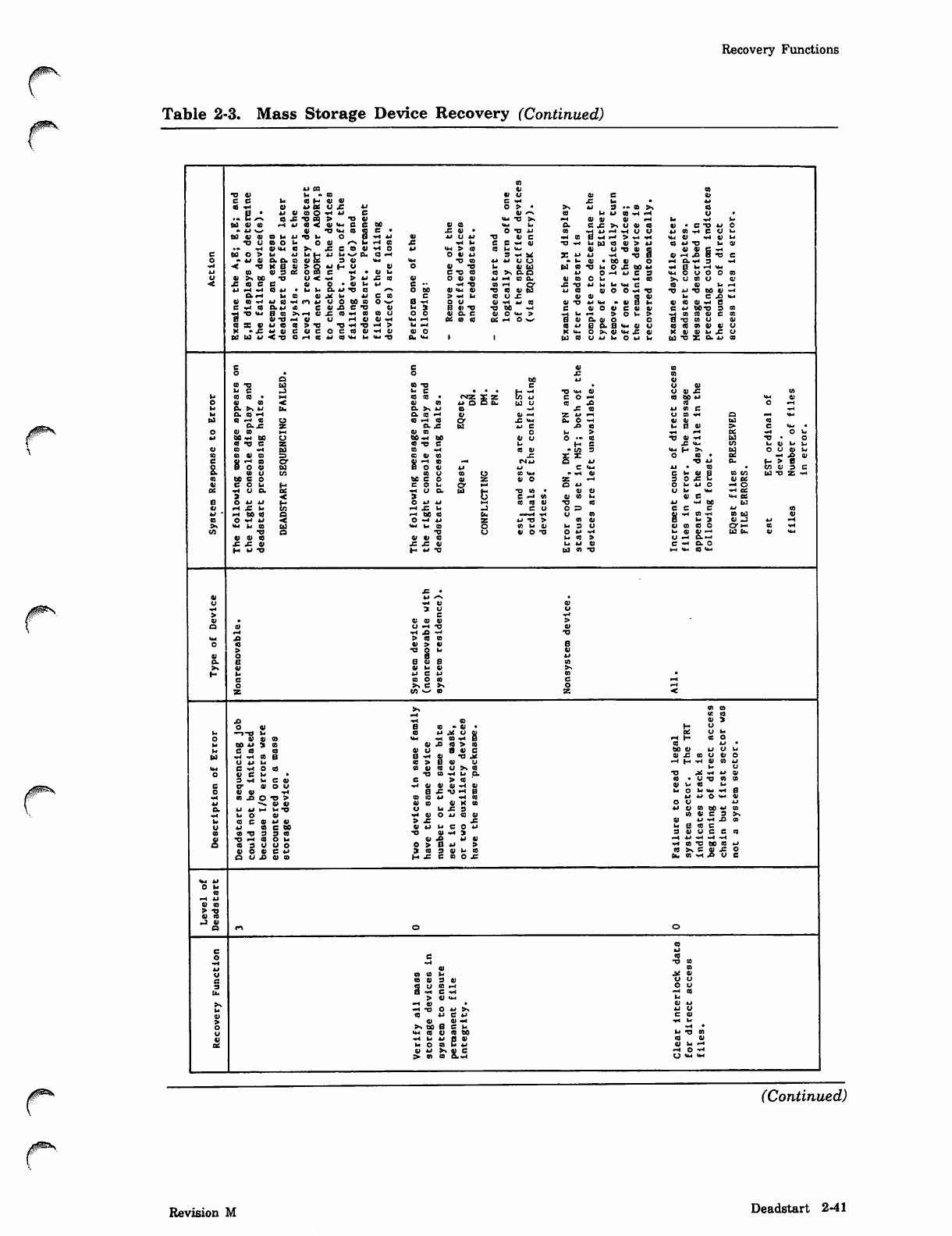
Recovery Functions
Table 2-3. Mass Storage Device Recovery (Continued)
v i C Q
CO
01 CB
T J 0 1 t i « C 9 0 1 C l 01 01
B 6 k i C B H 0 1 0 1 B t . k . r 4J
A r t 0 ) k l O C O X k l o > • Sk kl 3 — 0 9 9 K CB
B r M C l O O r t M B
. « C < k C B X T J m > T 3 4 I
00 41 CO HklCO<!oiUuBEOO
0 1 ' K CB k l C O r t « r t Cl
U H T J S k 0 1 0 1 0 1 H k > r t t -
c i a U H k l B X S k U 0 1 C B 0 1 r C T J k l e
• k l w 0 > T J U H B J C O B r X 0 1 r O T J 1 4 CO ^rt H T t C l C l k l C O r t B O k ,
tdvaicokikiTjti o Brtki O l k l C J k l T J 0 1 E r t 0 3 r - i > ^ ^ 4 U i 0 1 r t I I M
TJUCOOk, O 41 s*xkirta X r t t i E B r t 0 1 T J r t l i b l C O I ) > k l e g u t j l i o i
. - r t 4 1 U j C S k X B O O I H O k i u h > e g t o U U i 01 ci tj oi g
r t T J 8 0 1 0 1 E r t
I I r t X B T J E
B t fl O > k l U U h U U V D , Q H
• u « a o . o o i c s o ) u h O o i k i 3 r t ^ X k i kl
OU h T J C O k l k l C l C J . k . I I • 0 0 O O r t a r t 3 r t
Ti < TJKBSJSrQklknCI II
c b i i 3 o : o n e n h • a , k ,
O O l T J t i 0 1 b l W e g T J l i O X 0 0 k l — i B t i - 4 U H
U h 5 C l O 0 C O
14 B T J t O C B 9 K a o h k i E 3
U o i s k o o t j t i < T t > k i x t e 0 1 O 0 1 0 1 k l r t t o a . o i a 0 I . r t C B S k c j c a c j 4 '
«t X C B B B 0 1 O • 4 1 U u 6 • • r t T J C B
eg oi w
X T J k l l i k . N H C e g w k , r t
k i r t r t t o m • i n k , a k i t j a « ~ O 0 0 I I U i 4 ) T J k i e g OJ O O r t T J T J U T J 0 0 O J r t
a r t t i O o i j ^ k , k i c c c _ B > r t l i C O C l X 01 01 e g 0 1
• 0 1 I k ,
k . 6 X u h
I ) t O H M O r t M M C l O C O I ) 0 < r t O r t O C l O l r t m e g 0 1 T J M U h 0 ) t o 0 1 r t 0
B r t a C U u < £ 6 0 1 X 6 T J 0 1 k l 3 B 0 1 T J T J 0 0 r t 0 1 o 0 1 B 4 1 0 1 B k l O O T J 3 0 9
r t T J U H B O S S k h C X C O r t C O C O C J
0 4 1 T J r t 4 1 C J r t 4 1 C J r t
O O 4 1 a E 0 1 O U i > B S S > O k , > r t t n e g c j b e o
8 T J 0 1 t l 4 1
u h r t o i o e g o s H O S r t a oi
b a o o
tSSCIMOC3>TJ TJnHT3HS> t i - i C B M B U h 4 1 C l e g t o c n o i o i c i
X -X MSIBOIBOBCBOIrtCI 91 O K u . O 9 K 0 1 U h X 0 1 X 0 1 0 1 k i X C l
C d I d k l < T J O H ( I I O U H M u h T J a u h i i b l < 0 C l M k . O M U b l T J X a k l O B
c E 01 09
o • 01
ca oo 41
C O T O b l C O TJ C l 0 1
t i B h k , 6 • • •
Lo < j T J U H 4) U 0 1 X 09
ti 0 3 C B • r H t o e g • c m s b J E 5 =
0 1 0 ) X i O O O u
B O e g e o k i Ui 01
0 0 1 C O < I d U to to
ti a S k k l b . a s k k i a to u t o E
ba t o h c u a r t t i 0 1 H Z M C l 0 1 T t O
bl 1 0 H 0 3 C J C B r t O J O X U H 0 . 0 0 1 4 1 I d
a x z a x b l M B eg M B 0 1 >
O 0 1 C O r t 0 1 0 9 k, r t r t O S 0 w
M 0 0 r t 0 0 C J 0 0 r t 0 0 0 1 C l o . . T J I I r t b l TJ
C S T J 6 S E t O T J 6 k> X U h C O O J t i I n
41 C O r t b l
a o i o s p C O r t 1 0 4 1 - t o U h ( - 9 K t d
O 1 0 r S
O 4 1 k i
- t X V
CO C Q 0 1 C O §*
Bc j h c b t y
fl O 4 1 b l
4 1 H D r t
B O 0 1 k l
(Mm T J k l O u f- > B
aM B Uh k l • C B • eo 0 1 3 B
c o c j t o a o e o c j CO U4 01 B t i 0 1 R C O C O
3 0 X C B J O C
blT J S C r t
09 0 0 B O 0 0 E O 0 1 Z 0 1 O
01 B O I h C h b o t . e y f a k i O k . k l O - H O
a r t c j a e e - c j a W g t j t e • 01 41 O k . U H - t o t
3 < 6 r t « 1 4 1 t o Ih « J 6 U h O C
B O k l k l f _ O k l k l r t t e e g 0 1 TJ eg k l r t 0 0 I d
oH X l i C O r t X k l - 3 B O O r t B E 6 " 09
1 4 • r t 0 0 « C r t e e a b . Cl CO 0 1 r t 0 9 - r t C B b l
a k , 3 o j r t OJ
aO r t k l H S O r t M X t l T 3 > 01 II rt
SK u h k , C O b l u h k . c o O B w 4 1 k , 3 CJ U c o ( 0 0 C 7 > - • tn nH
cn T J O T J C J 0 1 0 T J O k l M 4 1 0 1 H t o b .
O i o i C B 4 i o i a M 1 0 C J - 4 a r t
x x o i X X 0 1 I h k l 01 6 h a o
H k l T J l - l k l T J b l 0 9 TJ r t U H C B U h
01
X •
M . i - *
Cl T l V 41
-i 3 c l Cl
>Ert
41 4 1 0 J 0 1
a41
rt
C J r t T J
r t X H
41
TJ
X > e g c o
0«3
9>
O l » 0 1
t j o u 0)
CJ kl
a 6 B 4 1 B CO
9k Ol 0 1 k , 0 1 9k
Hti
B
O
z
k l E k l
BOO)
S K 6 9 k
C O < r t C O
CO
B
O
Z
-4
<
SK c o t s
-4 t c t s
Xt , O 4 1 3
O 0 1 B a • o i • H c l
k, -TTJ ti 0 3 k l J t C l C J
U H r t C O r t B
g C C l k i
O 0 1 0 1 o H H e s O
u0 0 k l 3 C O 0 1 X 0 3 > o e g u i •
k, B C B I S 0 1 O 8 O l B 0 0 4 1 k l C l I h
Cd r t r t C O B
O k l U
B r t C J T J J *
t a > B o i c i
0 1 X 0 9 C l I I O
— 1 ( r t r t 0 1 C O k l
UH e t i o t o co oi a u Sk eg k . C J
o0 1 6 k i •
3 r t t i S O l
- a o r t u a
B s » e g •
T J J S r t M 0 1
1 0 • C l T J C O 0 9
B C O l O C l r t 0 1 0 1 0 1 H 0 1 O i M e g u
O 0 1 0 1 H B X -u rt B I n O t i I M r t B
rt t n x o t j > C O C O k l r t 1 0 u u > O u t 4 1
kl v . O l 0 1 a i e C J X e o O O k l
aO l < X 3 k l 4 ) 0 9 0 0 k l C O
U O 0 1 r t o i O k i e g o i C S 0 1 E 3 S K
k> « 3 B 0 ) k l O l > X X 0 1 U n H X 0 9
Cl k l C O B 0 0 I I k l k i E 0 k l t i B e g E
03 C B T J 3 3 C O T J 0 1 r t 3 3 0 1 U C B 1 0
h
T J i H C B O t i 0 1 X k l 0 1 n « M r t - i n H
« J 3 C l C l o 0 > B M > r t C O T J 0 0 C B M
O l O 0 1 B k l 3 1 8 3 0 1 k . C O I B S k 6 O J X O
b i t n n H X C l B
a c j x ai to (-■ X 6 BOX
U h k l
0 t i
to
- 4 k l
01 C O
> T J
0) a
- 1 0 1
ert
CB
B
oB
u
<9
rt T J 0 9
01 09
CJ n a i n a i o j
sC O 0 ) 3 I I t l C l
3a c i t o r t
B r t B r t
O C l
tk r t C B
> 0 1 U H ti
Sk r t O • 0 1 M
ti r t T J O M S k M C l
a> e g k i 6 k i E 0 1
>0 1 0 1 r t r t k ,
o9 k 0 0 B 6 l i r t r
Cl u h t o o i t o e o b T J 0 1
01 r t k l k l fl 0 1
t i O 0 9 t , M
I B 0 1
Of 0 1 k l r t
0 1 k l S k 4 1 B
> o o e g a r t
H O H
C J U H U H
/fF*> (Continued)
Revision M Deadstart 2-41
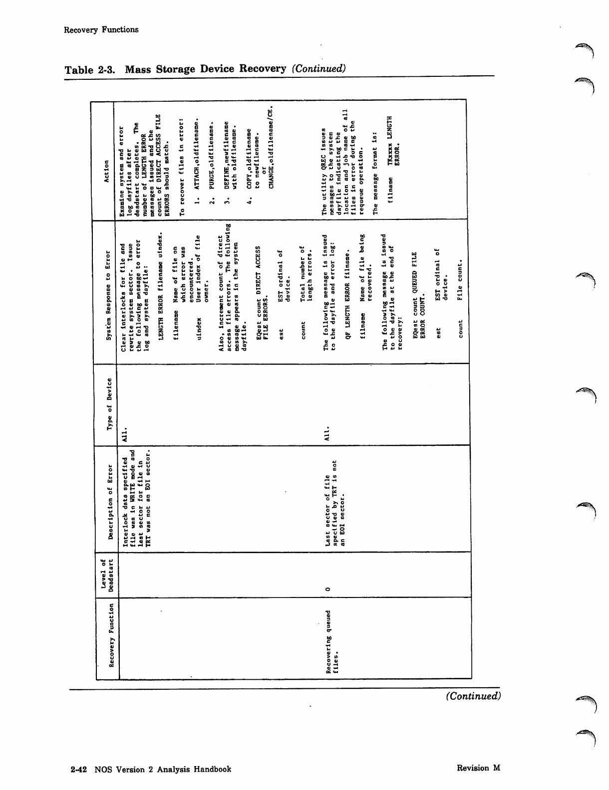
Recovery Functions
Table 2-3. Mass Storage Device Recovery (Continued)
.-■h-Shu, a
B to
0 1 t i a -
u c o O b l
s a o i tl r O
SkH
09 rt kl Uh
U h I h O
OJ 5k «
B e g k i k i 0 0
TJ Ut
tl 10
3 I d T J H
C O O S r H UJ
CO rH 3
T t C l O
U h 3 r t r t 1 1
• O 0 1 U u U H r H
H 6 T J T J T t
3 01 X OJ DO
C O k i u B B
rt 9k 00 E k.
£ g
I d 0 1 ki
S X C O
rt X TJ O
t - i I n k l O
oi
rt TJ ti k,
9k O TJ B ki 01
u k i e e g s i a
0 0 H r t 3
r t T J D 0 1
X O 0 1 3
O U K
0 9 B O
c o s a t
E09 Ui I H r t 0) co
0eg r t 0 kl
41 • 0
T J U H CO
9k
bl
to
8iu U h 1 ) CO to
k l r . rt O J X O X
CO UH ti I H 0 1 01
0 1 H iu 0 1 T J ki
0 0 r t Uh 01 W B kl
CO UH B r t 3 •
X 3 k, O S >
Uh 0 t i 01 C J k .
S"" fiT* C l 0 1
Oi to B 0 9 M t i ca
BOZ301 S> B k .
PC jj w eg B 0*
C k l DC 3 O
0 OC
3 9 k t i T l Cl PC
0 e o eg O H to bl
B01 6 U i
H T J TJ rt 41 0) co bl
0 B rH CO 00
&,H
bl rt - CO eg
rJ UH O 01 09 UH I d b .
a c j 09 9k
X O H C J a)
r t r t 0 1
r t u . t ;
r t 0 3 0 0
II
BOH bE
6 r t 3 SP
N H U H 0 O
3 9 k Cl CJ
o a
r t T J 9k k i e c
HIh in o
O OJ OJ O J o c
u h X O-oc
.***^k
41 kl
NH
Uh TJ 0)
>H 01 CO
tl rH
^H rt
aid
0 9 f -
UH
rn
«J
14 uh CB
CO
TJ ki kl
rt
.X kl
Cl 03 Cl
0os OJ 01
-4 in eg
ti
01 ki
kl rH
BNH co
MUh rH
T O
u u bi
CO 41
(Continued)
2-42 NOS Version 2 Analysis Handbook Revision M
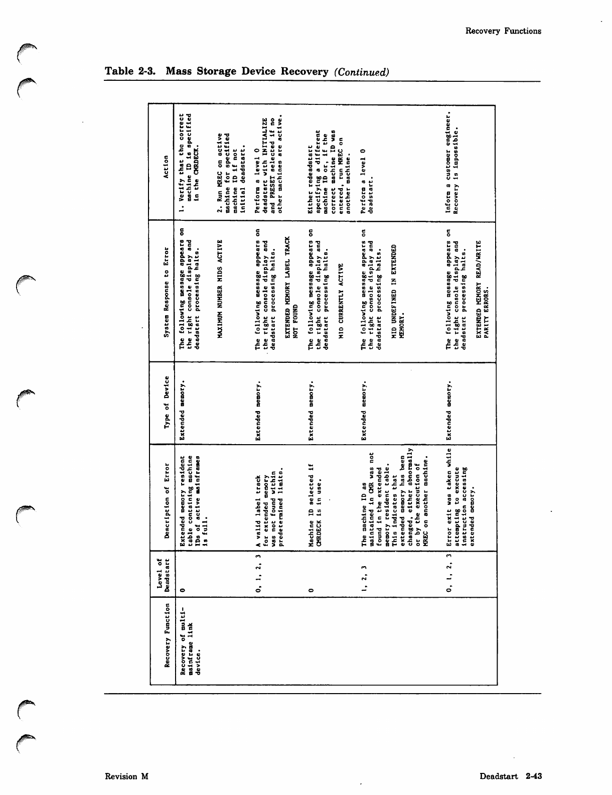
Recovery Functions
0ms
JtrW^K.
Table 2-3. Mass Storage Device Recovery (Continued)
k l T J
O 01 t d 0 0 1 41
0 1 T l N 6 > II
t i U h E •
t i T t J l u t l k i e s H 0 1
O C l 41 TJ S"s B 01 CB 0 0 h
Cl 01 > 0 1 0 1 X 3 E X
ar t - t H T J t i M 01 *rt
4 1 C O r k l U h r H I I I I k l o i O
X U O H k l k l O Z k i t < b U H U H r t b c n
k l c s u B J O O k l m o e g CB Uh rt b i • 01 O
c
ot , t d
k i q 41 E eg
B S . k l
H o i
0 1 X H c s
k l r t 0 1
CO TJ r. c £S —t
01 8 §■
• O K O C O U h C O > M 01 01 T J M r t k l r t
4J r t T J c i r t a E 0 3 I B O X E X 01 09
ok l C J O k i e g r t 3 H 0 1 C l 3 C l rt 3 0 9
<t 01 b l O O C J H X t j o o 0 e g b t o C l r t
9 k C 4 1 Oj UH H TJ eg ki bl cj 4 1 E r t 6 t O M
U h r t X b CO es t i r t CO SK
r t X k l 41 0 1 H essB 9 k I I U T J b B <S
I h C J B B C e g U U h B t l 01 01 b M B 0 1
41 eg B
> B r t
3 r t r t — O SB Ou k, 0 1 n H r t 0 1 U X O D > b >
O t X X U l ■M TJ 4i X C l X M 01 M U H T J O O
C l ( J r t t i e g t j X M 0 1 C l t i
rt a e g o k l o b t o U h C l
• g es E
<N g B rt I I I I C u B C 4 J t t l B 4 1
O u t j e g o bl co B u si a P u T J > t a t
Ee B Bc
oO
a t j c j
C S T J bl CO TJ t n t j i n t j Id
t i B M B < .
e g a r c c
b B b C O b B ku
ue g e g • c b e g • e g t o • t d t o e g r
0 0 ) C B
O. Sk M « , c s h
a s k m 4 1 c s
a 9 k k i 2.sk2 § O i a
6.5km
•w a a - H a o h _ ) a t s r t a t s h i d a eg rt
U3 eg rt eg a r t e g i d < 0 rt eg e g h t o H eg rt as
ax CO a x c o ax a x x ax
OBJ S3 0 1 0 9 <
0 0 r t o o J o i t o O J 0 9 C d oi cs
Ai 00 rt CO 6 0 r t 0 0 f- 0 C - r t 0 0 6 0 r t 0 0
e g t j E
eg tj c es TJ B C B T J 6 0 3 T J C Z
tu a r t 0 9 r t 9 - C S r t ■<0 ) r t r t C S r t 9-
CO 03 01 CO 06 c o o i c o o c 0 9 I I C S c s b j t n CS OJ CS o s •
cJ l H 0 3
a o o i bl C J r t o o
fl O 4 1 X
b j h m
B o o i
9" o j r t i n o OJ rt CS o t o
aCB i- B O O ) b l B O 0 1 X ot
eo ci I D C J W C O CJ i n o z to Cl Si
co PS0 0 0 6 O X 0 0 6 O 0 0 E O r n 0 0 B O
£B O M B O M O 6 O l i bl E O b U . E O b OC
r t c i a r t c i a a z
3 U 3
r t c i a oc r t c i a i d r t c i a a t d
3
x
3oc 3 O td
B
Ol O M k l
H X t i O k l k l P O
r t X k . Z U .
O M M
H X b
S3
CJ O k i k i Z
r t X b 5 S-
OC
O M 1 4
h j e b §£
uH 0 0 C S r t 0 0 C S b l h 0 0 e g r t 0 0 1 0 h o o e g b i r t
aO r t M O r t M U . U t
U H M c s X O
O H M O r t M © O r t M f P C
9k U H t i C S U H U C O U H b C O H U h b 6 S X <
CO TJ T J b l Z TJ T J X TJ b l 0 .
01 oi eg 01 01 CO 01 Ol eg oi oi eg O i oi eg
X X o i X X 0 1 X X 0 1 X X O J X X b j
( - . M T J H k l T J ( - k l T J h " T J H k l T J
01
Cl
Tt 9k Sk 9k 9s 9k
>ki In
01
o
UH
o
41
B01
8
41
B
0J
s
TJ TJ TJ TJ TJ
2. 01 41 Ol 01 01
TJ TJ TJ TJ TJ
>K
H01 41 01
uM M kl 14
XX X X X
bl bl bl bl Id
9k OJ
M
M 0 1 C S B H
6 6 O J
C J r t 8
t j X e g
0 1 e g o >
ti
o,-. 0 ) T J 4 1 iiE'Srt 0 1 0 0
ti r t c l b B e s e g u « h O X E k l B
kl 81 ts Uh M S k n h m TJ 3 T J X k l r a C c c i 0 1 3 r t
Ul 4 1 B B C l k . X r t 0 1 . E Q t S I S X O 0 3 JC Cl 03
b t C B Q k l B
M B r t r t
k l 0 1 g ] r t 1 ) M X X C O r t B CO 01 09
00 eg
9 k E 1
Cl to o j X k i u kl M X 0 1
ok l 0 1 3 r H 0 1 3 a x m 9 k b 3 b 01 Cl 9s
t i r t c a o i b c o b I I C l O J 0 9 U
BO E I I - 4 T J T J 0 1 E H E 0 1 0 1 O X O l X
8 u l X k l
e g o t o
o B rt > 41 TJ E 01 CO rt r t 01 T J 1 4 3 k i
NH Ol eg rt
B M M
X 4 1 3 6 I I X H C S 0 1 r t 41 O
kl I B T J O r t O n E T J M 0 9 C l B 0 1 B k l 0 0 o
a E u H r . r t O J O J r t 01 CB r t 6 r t
T J O e g . X E E b T J T J - X X r t U TJ
b 0 1 c i - i T J M k l 4 1 0 1 * C l r t r t B I I T J k l E 01 M Cl 41
Cl T J U H r t r t * O M B CJ e g t o 9 s r t T J 0 1 O a 3 TJ
cc E o i O 3 r t o i B 0 1 r t t d a m t j b 6 0 0 9 k b fl b
h
0 1 r t i m e g t j x a C C o t o
o i r t s a r t 0 1 C X t o O 0 1 k i CJ
k i X e s > t i C O I I Cl oc k i e g I d b M C S
X e s d m o e g I . £5 X t o O 0 1 X X X b £ b M 6
C d M r t r t < u i 3 a I n B U h a H 0 1 C l O X I d S 3 r t 01
rt Cl
U H t i
O M
CB CM r\ CM
H k l
oi a
> T J rt
o t o
^ c j
B
O
Tt rt
ukJ
Sl
a2 at
3B B
Pw
u h r t
9k
b01
01 9 k B
>k . e g •
o01 Ih 1)
tl > U H o
01 o e. rt
BJ! C l r t >
01 S3 1)
O f fl T J
Revision M Deadstart 2-43
Error Idle Recovery
Error Idle Recovery
Setting the device error idle status helps to prevent error propagation by inhibiting
new file assignment on the device and by inhibiting any new PFM, PFLOAD, or
QLOAD activity from occurring on the device. The error idle status is indicated by the
EI error code on the E,M display. Error idle status is set when:
• Mass storage read or write errors occur in the catalog or permit chains.
© There is an incorrect user index in the permit sector.
® Direct or indirect access files are too long or too short.
Correcting the error idle condition requires total initialization of the affected device.
This can be accomplished online for a removable device, but must be performed during
a level 0 deadstart for a nonremovable device. Suggested recovery procedures follow.
Removable Device
1. Dump inactive queued files, if present on the device (QDUMP).
2. Dump permanent files (PFDUMP).
3. Perform a total initialization of the device (INITIALIZE,AL,est.). If the error idle
status was caused by a mass storage error, the appropriate track should be
flawed.
4. Reload inactive queued files, if applicable (QLOAD).
5. Reload permanent files (PFLOAD).
Nonremovable Device
1. Dump queued files (QDUMP).
2. Terminate any dayfiles that must be saved (DFTERM).
3. Dump permanent files (PFDUMP).
4. Idle the system and perform a level 0 deadstart.
5. Perform a total initialization of the device affected by the error idle condition
(INITIALIZE,AL,est.). If the error idle status was caused by a mass storage error,
the appropriate track should be flawed.
6. Reload queued files (QLOAD).
7. Reload permanent files (PFLOAD).
2-44 NOS Version 2 Analysis Handbook Revision M
Deadstart Decks
jp^
^
CMRDECK .. .... 3-2
Central Memory Descriptions .. 3.3
EQPDECK 3.13
Dayfile Descriptions 3_jg
General Description of Equipment Assignment Entries . 3-18
Clear EST Assignment Entry ........ 3-18
Equipment Assignments: Nonmass Storage 3-21
Nonstandard Equipment EST Entry '.[] 3-21
Pseudoequipments 3_22
Unit Record Equipment EST Entry 3-23
Magnetic Tape Equipment EST Entry ..... 3-27
M a s s S t o r a g e E x t e n d e d S u b s y s t e m E S T E n t r y . . . 3 - 3 0
Stimulator Equipment EST Entry ... .... .' 3.31
Network Processing Unit EST Entry 3-32
CDCNET Device Interface EST Entry .'!."".!!.!!!!!...'..'.'!.'.'!!!! 3-34
Network Access Device EST Entry 3.35
Two-Port Multiplexer EST Entry 3-36
MAP III or IV Equipment EST Entry 3-37
6683 Satellite Coupler EST Entry .. 3-38
CYBERPLUS Ring Port EST Entry ...'. 3-39
Equipment -Assignments: Mass Storage 3-40
NOS Mass Storage Concepts 3-41
Alternate System Device 3-41
Alternate Permanent File Family 3-44
Auxiliary Device , 3.45
Family Device 3.46
Link Device 3-46
Master Device .. 3.46
Multispindle Device 3-48
844 Expander .... 3.48
Nonremovable Device 3.54
Removable Device .. 3-54
Shared Device 3.54
System Device 3-54
Temporary File Device .... 3-54
Buffered Disks .,-. 3-55
Extended Memory Overview ........... 3-56
Physical Configuration 3-56
Logical Configuration 3.57
CM and UEM Size Specification and Determination 3-59
Simultaneous Use of Two Types of Extended Memory ... 3-59
Specifying Ranges of EST Ordinals 3-6O
-ESQ — Disk Equipment EST Entry 3-60
EQ — Control Module EST Entry 3-66
EQ — Extended Memory EST Entry 3-68
Examples of EQPDECK Entries for Extended Memory 3-72
Single Mainframe Examples 3.72
Multimainframe Examples 3.75
MSAL — Mass Storage Allocation Control Entry 3-78
DOWN — Down Channel Entry 3-80
UP — Up Channel Entry 3-80
PF — Permanent Files Device Assignment Entry 3-81
^%
SYSTEM — System Library Device Assignment Entry .-...■ 3-85
A S R — A l t e r n a t e S y s t e m L i b r a r y D e v i c e A s s i g n m e n t E n t r y 3 - 8 6 ^ v
SGKP — System Checkpoint File Device Assignment Entry 3-86 f
FAMILY — Default Family Name Assignment Entry . 3-87
REMOVE — Removable Device Assignment Entry 3-87
SHARE — Shared Deyice Entry ......... .. .. 3-88
ISHARE — Independent Shared Device Entry 3-89
LBC — Load Buffer Controllers Entry 3-90
XM — Declare Extended Memory Space for Buffers or User Access 3-92
UEMIN — UEM Equipment Initialization 3-93
ACCESS — Set Access Level Limits , 3-94
THRESHOLD — Set Disk Thresholds 3-95
EQPDECK Entries Made Only During Deadstart 3-96
AUTOLOAD — Toggle Autoloading 3-96
GRENADE — Clear Unit Reservations ....... 3-96
INITIALIZE — Initialization Entry ... 3-96
PRESET — Preset the Link Device Entry . 3-101
PRESET — Preset the Independent Shared Device Entry ... 3-102 ^^
RESET — Reset Device Attributes 3-102 ^
APRDECK 3-103
APRDECK Format ,. 3-103
CAF — Clear All Flaw Reservations .. 3-104
SLF — Set Logical Flaws on Any Mass Storage Device , 3-105
CLF — Clear Logical Flaws on .Any Mass Storage Device 3-105
SPF .— Set Physical Extended Memory Track or Disk Area Flaws 3-105
CPF — Clear Physical Extended Memory Track or Disk Area Flaws 3-106
IPRDECK . , 3-107 1
Job Control Information ....... 3-108
Job Scheduling .... ■.....■ 3-108
Control Points ... • • • 3-110
Pseudo-control Points ...... .. 3-111
Number of Control Points and Pseudo-control Points Available ............ 3-111
M e m o r y C o n t r o l . • • • • • • 3 - 1 1 2
Example of Job Control Parameters 3-112
IPRDECK Entries Made Only During Deadstart .3-118
COMLIB 3-118
C P M . ■•■ ■• 3 - 1 1 8
CSM • 3-121
DISK VALIDATION ., 3-121
D S D . . . • • • 3 - 1 2 2
EI ............... .- 3-123
EOTJSNDED STACK PURGING 3-123
HARDWARE FAULT INJECTION 3-123
KEYPM 3-124
MEMORY CLEARING 3-124
MICRO . ....... 3-125
NAMIAF -.. 3-125
PROBE 3-125
SCP • 3-126
SCRSIM 3-126
SECCATS 3-127
SPC - 3-127
SPD 3-128
SPL 3-128
SPW 3-128
^s'
f^
M^
SUBCP 3_12o,
TCVM 3_129
TDEN 3_130
T D T R • • 3 _ 1 3 0
™S- ..3-131
TMSTO. 3-131
TRACE 3-132
IPRDECK Entries '.[ .. .][[......... .....'.. \..' 3.133
Subsystems 3 233
AUTORESTART '.'.'.'.'.'.'"" " * " 3.136
CARTRIDGE PF STAGING ............'.'.......... 3-136
GLASS 3^37
CPTT ,. 3-138
DEBUG 3.138
DELAY . 3_139
DDP ROLLOUT PATH "*."". " 3.140
dfpt. ..;;;;;:::;:; 3-uo
ENGR 3_U1
FLEXIBLE PARTITIONS 3-141
LOCK .'....'..'.'.'.'.'.'.'.'.'. 3-142
LOGGING 3.142
MASTERMSE ' '" '" 3.143
M S V A L I D A T I O N . " * ' 3 . 1 4 3
OQSH 3.144
PCLASS 3.144
PF VALIDATION 3.145
PRIVILEGED ANALYST MODE 3-145
PRIVILEGED RDF 3-146
QUEUE .....' 3.146
REMOVABLE PACKS 3-148
RESIDENT RDF 3.449
SECONDARY USER COMMANDS 3-149
SECURES 3-150
SERVICE 3-151
SPINDOWN 3-156
SRST 3-156
SYSTEM DEBUG 3-157
TAPE PF STAGING 3-158
UNLOCK 3-158
USER EXTENDED MEMORY ,..,.. 3-158
LIBDECK 3-159

0ms
Deadstart Decks
Deadstart decks are text records that reside on the deadstart file. This section
describes the following deadstart decks.
Deck Description
CMRDECK Central memory resident deck.
EQPDECK Equipment deck.
APRDECK Auxiliary mass storage parameter deck.
IPRDECK System installation parameter deck.
LIBDECK System library deck.
This section contains detailed information about how you can modify the released
versions of the deadstart decks.
jg^S
Revision M Deadstart Decks 3-1
CMRDECK
CMRDECK
The central memory resident deck (CMRDECK) resides on the deadstart file as a text
record that is processed during system initialization. It contains entries defining the
following types of information.
• Central memory.
• Table sizes.
• Configuration information not oriented to equipment.
The deadstart file can contain up to 1008 CMRDECKs. Having several CMRDECKs on
the same deadstart file is advantageous because one file can deadstart several
configurations. You can obtain a listing of all CMRDECKs by accessing the system file
SYSTEM with an ASSIGN or COMMON command, then using the T parameter on the
CATALOG command (refer to the NOS Version 2 Reference Set, Volume 3 for more
information concerning these commands). CMRDECKs are named CMRDnn, where nn
is from 00 to 778.
You can modify the released settings of the CMRDECK in two ways: type a new
entry when the CMRDECK is displayed during deadstart, or create a new deadstart
file. The usual method of modifying a CMRDECK follows.
1. Deadstart, using the released deadstart file, and select the CMRINST and the
CMRDECK to be displayed (refer to section 2, Deadstart).
CMRINST lists all valid CMRDECK entries. Default values, described in this
section, are assumed if the entries do not appear in the CMRDECK being used. If
either CMRDECK or CMRINST overflows two screens, you can page the display.
2. Modify the released version of CMRDECK by entering the changes or additions
from the system console while either the CMRDECK or CMRINST is displayed.
Each console entry supersedes the value currently specified in the CMRDECK (or
the default value).
NOTE
The modified CMRDECK remains in effect only until the next deadstart is
performed, except for a level 3 deadstart. That is, changes to the CMRDECK are
not recovered across level 0, 1, and 2 deadstarts unless a new deadstart file is
created to reflect them.
3. To expedite subsequent deadstarts, modify the CMRDECK on the deadstart file
using SYSGEN (refer to the NOS Version 2 Installation Handbook).
When constructing or modifying a CMRDECK, separate parameters with commas and
terminate each entry with a period. When an error exists in an entry in a CMRDECK
on the deadstart file, the CMRDECK is displayed and the error is indicated. This
occurs even if you do not select the display CMRDECK option.
/*s%
'^ H,
3-2 NOS Version 2 Analysis Handbook Revision M
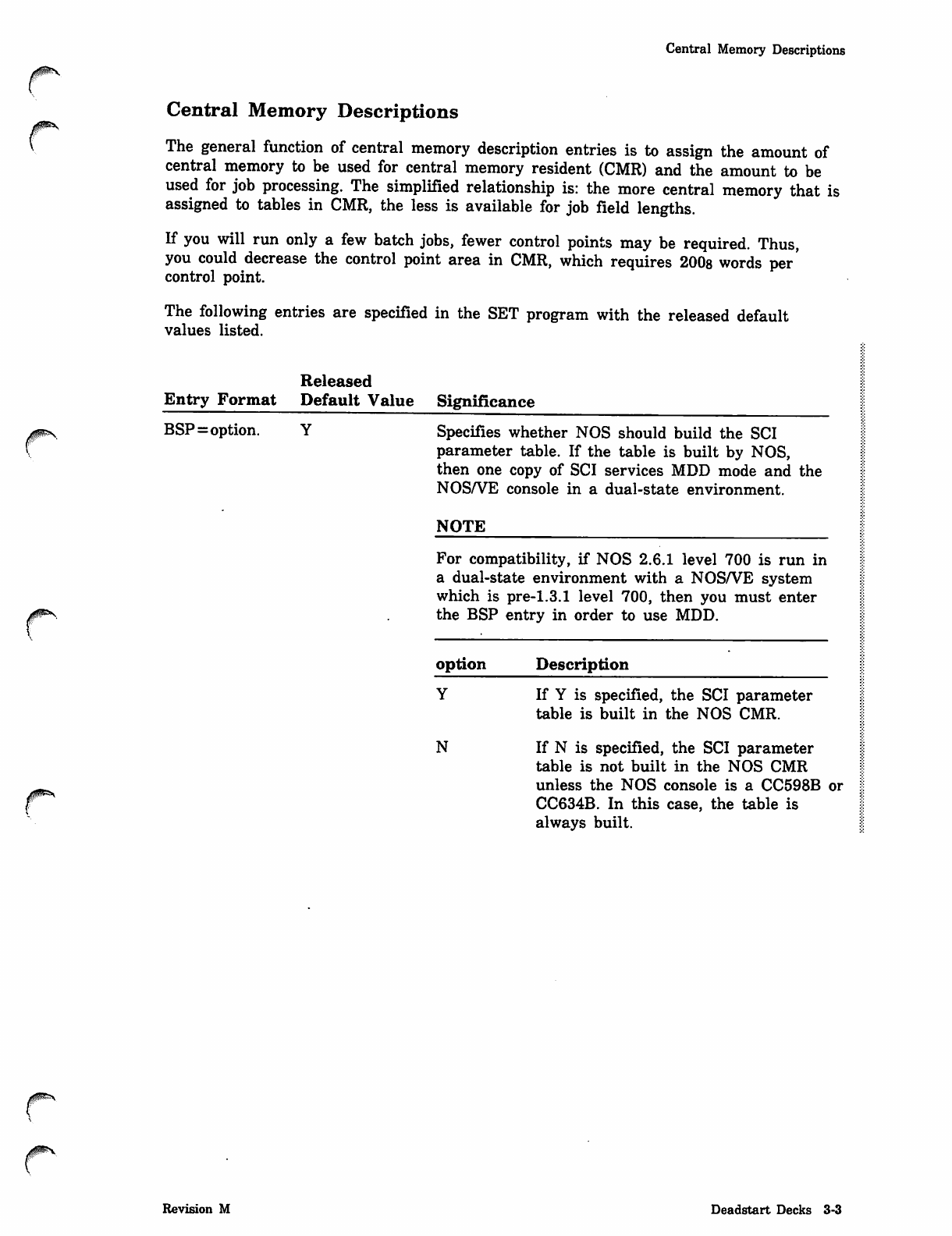
Central Memory Descriptions
Central Memory Descriptions
The general function of central memory description entries is to assign the amount of
central memory to be used for central memory resident (CMR) and the amount to be
used for job processing. The simplified relationship is: the more central memory that is
assigned to tables in CMR, the less is available for job field lengths.
If you will run only a few batch jobs, fewer control points may be required. Thus,
you could decrease the control point area in CMR, which requires 2008 words per
control point.
The following entries are specified in the SET program with the released default
values listed.
Entry Format
Released
Default Value Significance
/ms. BSP=option. Specifies whether NOS should build the SCI
parameter table. If the table is built by NOS,
then one copy of SCI services MDD mode and the
NOS/VE console in a dual-state environment.
NOTE
For compatibility, if NOS 2.6.1 level 700 is run in
a dual-state environment with a NOS/VE system
which is pre-1.3.1 level 700, then you must enter
the BSP entry in order to use MDD.
option
Y
N
Description
If Y is specified, the SCI parameter
table is built in the NOS CMR.
If N is specified, the SCI parameter
table is not built in the NOS CMR
unless the NOS console is a CC598B or
CC634B. In this case, the table is
always built.
Revision M Deadstart Decks 3-3
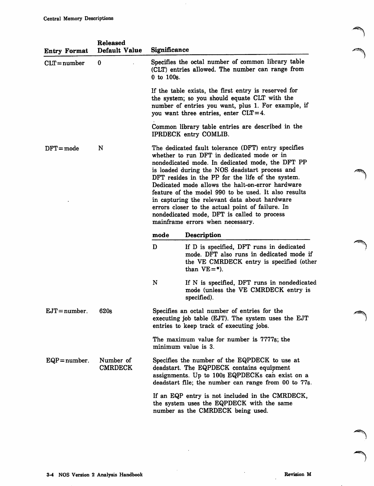
Central Memory Descriptions
Entry Format
Released
Default Value
C LT = n u m b e r 0
DFT=mode
EJT=number. 6208
EQP = number. Number of
CMRDECK
Significance
Specifies the octal number of common library table
(CLT) entries allowed. The number can range from
0 to 1008.
If the table exists, the first entry is reserved for
the system; so you should equate CLT with the
number of entries you want, plus 1. For example, if
you want three entries, enter CLT=4.
Common library table entries are described in the
IPRDECK entry COMLIB.
The dedicated fault tolerance (DFT) entry specifies
whether to run DFT in dedicated mode or in
nondedicated mode. In dedicated mode, the DFT PP
is loaded during the NOS deadstart process and
DFT resides in the PP for the life of the system.
Dedicated mode allows the halt-on-error hardware
feature of the model 990 to be used. It also results
in capturing the relevant data about hardware
errors closer to the actual point of failure. In
nondedicated mode, DFT is called to process
mainframe errors when necessary.
mode Description
D
N
If D is specified, DFT runs in dedicated
mode. DFT also runs in dedicated mode if
the VE CMRDECK entry is specified (other
than VE = *).
If N is specified, DFT runs in nondedicated
mode (unless the VE CMRDECK entry is
specified).
Specifies an octal number of entries for the
executing job table (EJT). The system uses the EJT
entries to keep track of executing jobs.
The maximum value for number is 7777s; the
minimum value is 3.
Specifies the number of the EQPDECK to use at
deadstart. The EQPDECK contains equipment
assignments. Up to 1008 EQPDECKs can exist on a
deadstart file; the number can range from 00 to 77s.
If an EQP entry is not included in the CMRDECK,
the system uses the EQPDECK with the same
number as the CMRDECK being used.
3-4 NOS Version 2 Analysis Handbook Revision M
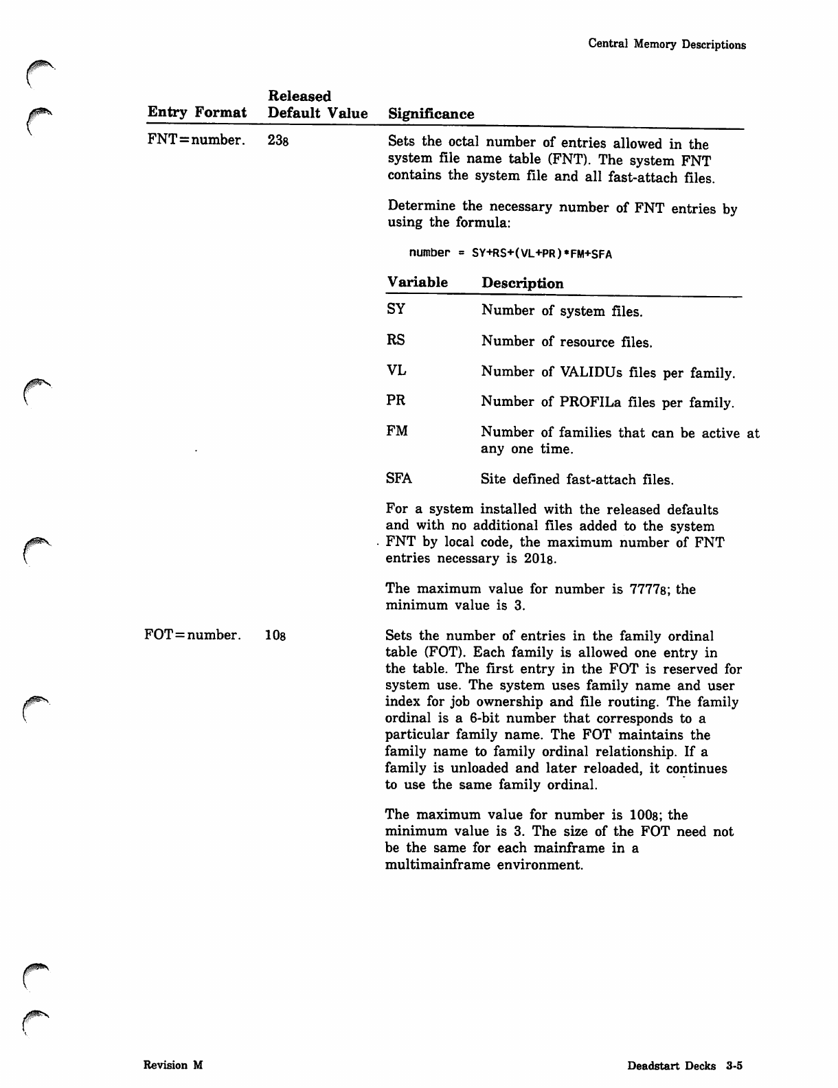
Central Memory Descriptions
Released
Entry Format Default Value Significance
FNT=number. 23s
FOT=number. 108
Sets the octal number of entries allowed in the
system file name table (FNT). The system FNT
contains the system file and all fast-attach files.
Determine the necessary number of FNT entries by
using the formula:
number = SY+RS+(VL+PR)*FM+SFA
Variable Description
SY
RS
VL
PR
FM
SEA
Number of system files.
Number of resource files.
Number of VALIDUs files per family.
Number of PROFILa files per family.
Number of families that can be active at
any one time.
Site defined fast-attach files.
For a system installed with the released defaults
and with no additional files added to the system
FNT by local code, the maximum number of FNT
entries necessary is 2018.
The maximum value for number is 7777s; the
minimum value is 3.
Sets the number of entries in the family ordinal
table (FOT). Each family is allowed one entry in
the table. The first entry in the FOT is reserved for
system use. The system uses family name and user
index for job ownership and file routing. The family
ordinal is a 6-bit number that corresponds to a
particular family name. The FOT maintains the
family name to family ordinal relationship. If a
family is unloaded and later reloaded, it continues
to use the same family ordinal.
The maximum value for number is 100s; the
minimum value is 3. The size of the FOT need not
be the same for each mainframe in a
multimainframe environment.
Revision M Deadstart Decks 3-5
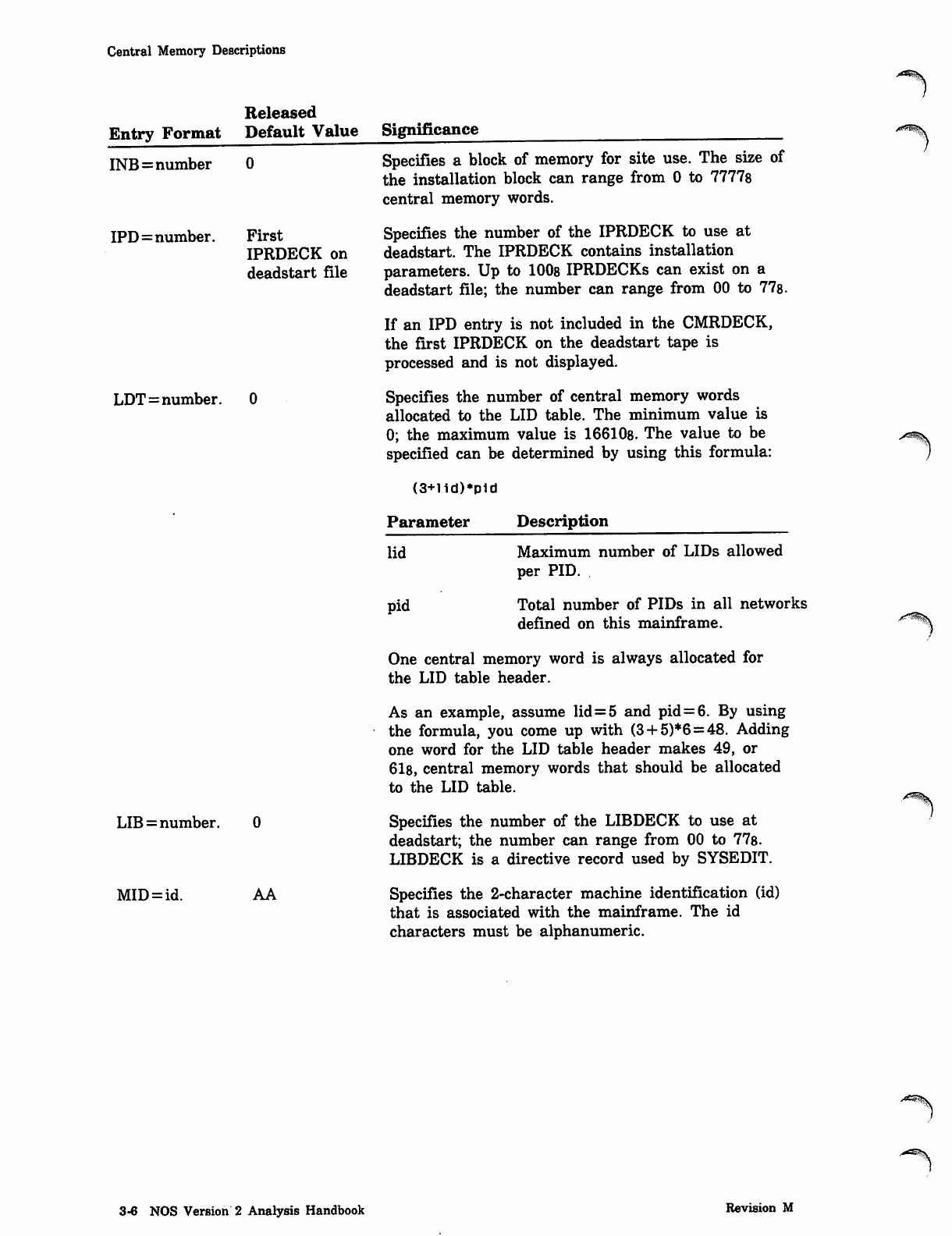
Central Memory Descriptions
Released
Entry Format Default Value Significance
INB=number 0
IPD=number. First
IPRDECK on
deadstart file
LDT = number. 0
LIB = number. 0
MID=id. AA
Specifies a block of memory for site use. The size of
the installation block can range from 0 to 77778
central memory words.
Specifies the number of the IPRDECK to use at
deadstart. The IPRDECK contains installation
parameters. Up to 100s IPRDECKs can exist on a
deadstart file; the number can range from 00 to 77s.
If an IPD entry is not included in the CMRDECK,
the first IPRDECK on the deadstart tape is
processed and is not displayed.
Specifies the number of central memory words
allocated to the LID table. The minimum value is
0; the maximum value is 16610s. The value to be
specified can be determined by using this formula:
(3+lid)*pid
Parameter Description
lid
pid
Maximum number of LIDs allowed
per PID.
Total number of PIDs in all networks
defined on this mainframe.
One central memory word is always allocated for
the LID table header.
As an example, assume lid = 5 and pid=6. By using
the formula, you come up with (3 + 5)*6 = 48. Adding
one word for the LID table header makes 49, or
618, central memory words that should be allocated
to the LID table.
Specifies the number of the LIBDECK to use at
deadstart; the number can range from 00 to 77s.
LIBDECK is a directive record used by SYSEDIT.
Specifies the 2-character machine identification (id)
that is associated with the mainframe. The id
characters must be alphanumeric.
jr«£-fflroSv
3-6 NOS Version 2 Analysis Handbook Revision M
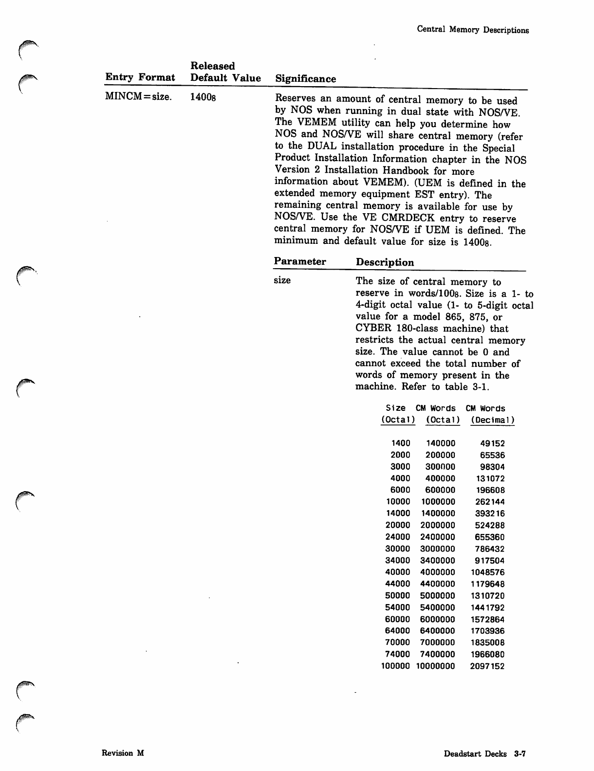
Central Memory Descriptions
Entry Format
Released
Default Value Significance
MINCM = size. 14008 Reserves an amount of central memory to be used
by NOS when running in dual state with NOS/VE.
The VEMEM utility can help you determine how
NOS and NOS/VE will share central memory (refer
to the DUAL installation procedure in the Special
Product Installation Information chapter in the NOS
Version 2 Installation Handbook for more
information about VEMEM). (UEM is defined in the
extended memory equipment EST entry). The
remaining central memory is available for use by
NOS/VE. Use the VE CMRDECK entry to reserve
central memory for NOS/VE if UEM is defined. The
minimum and default value for size is 1400s.
Parameter Description
size The size of central memory to
reserve in words/1008. Size is a 1- to
4-digit octal value (1- to 5-digit octal
value for a model 865, 875, or
CYBER 180-class machine) that
restricts the actual central memory
size. The value cannot be 0 and
cannot exceed the total number of
words of memory present in the
machine. Refer to table 3-1.
Size CM Words CM Words
(Octal) (Octal) (Decimal)
1400 140000 49152
2000 200000 65536
3000 300000 98304
4000 400000 131072
6000 600000 196608
10000 1000000 262144
14000 1400000 393216
20000 2000000 524288
24000 2400000 655360
30000 3000000 786432
34000 3400000 917504
40000 4000000 1048576
44000 4400000 1179648
50000 5000000 1310720
54000 5400000 1441792
60000 6000000 1572864
64000 6400000 1703936
70000 7000000 1835008
74000 7400000 1966080
100000 10000000 2097152
Revision M Deadstart Decks 3-7
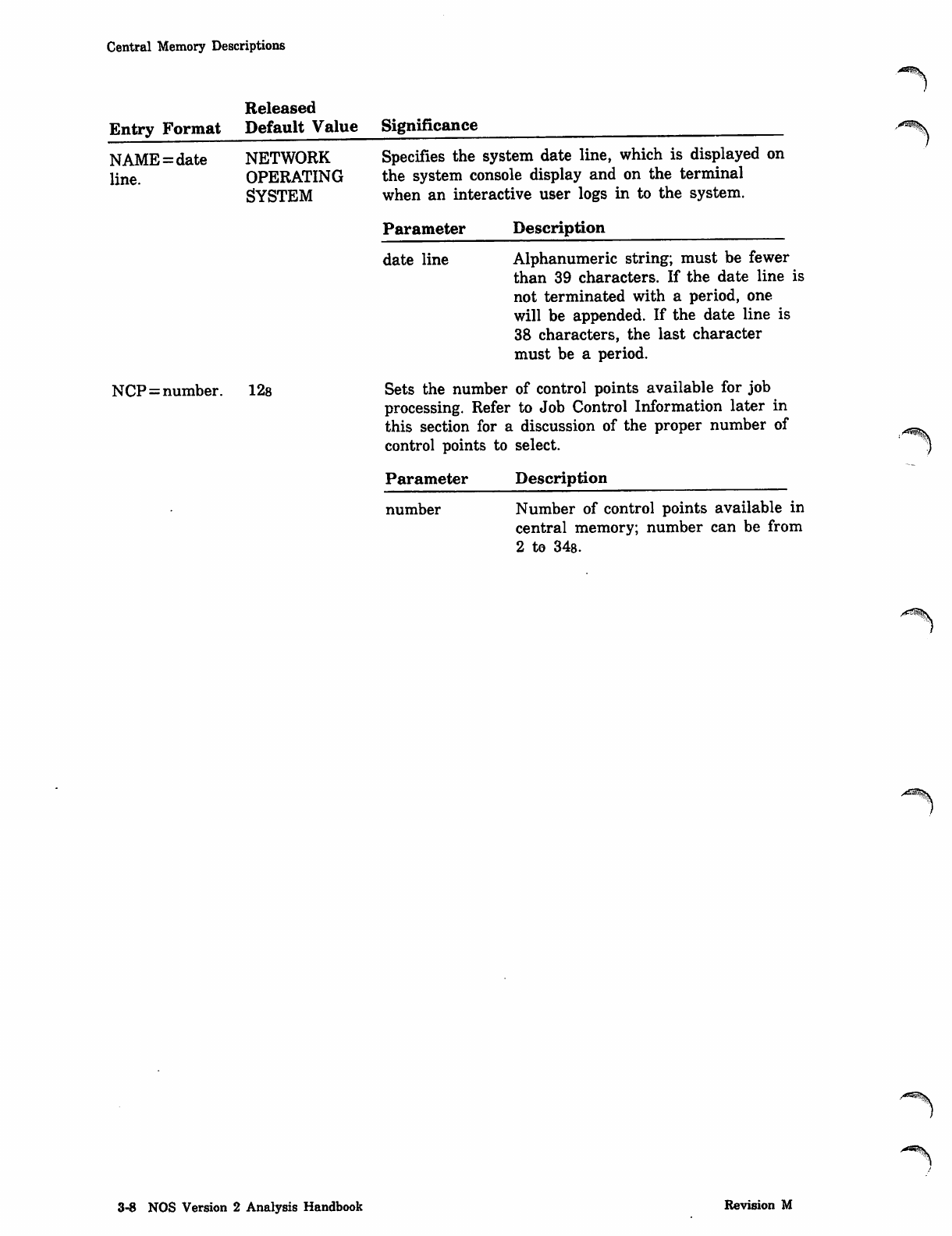
Central Memory Descriptions
Entry Format
NAME=date
line.
Released
Default Value Significance
NETWORK
OPERATING
SYSTEM
NCP = number. 12s
Specifies the system date line, which is displayed on
the system console display and on the terminal
when an interactive user logs in to the system.
Parameter Description
date line Alphanumeric string; must be fewer
than 39 characters. If the date line is
not terminated with a period, one
will be appended. If the date line is
38 characters, the last character
must be a period.
Sets the number of control points available for job
processing. Refer to Job Control Information later in
this section for a discussion of the proper number of
control points to select.
Parameter Description
number Number of control points available in
central memory; number can be from
2 to 348.
3-8 NOS Version 2 Analysis Handbook Revision M
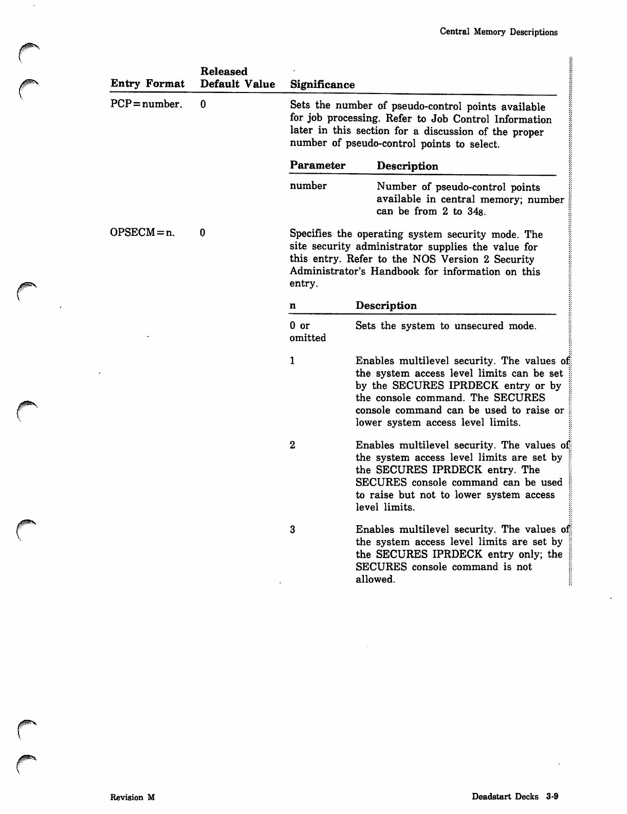
Central Memory Descriptions
Released
Entry Format Default Value Significance
PCP=number. 0 Sets the number of pseudo-control points available
for job processing. Refer to Job Control Information
later in this section for a discussion of the proper
number of pseudo-control points to select.
Parameter Description
number Number of pseudo-control points
available in central memory; number
can be from 2 to 34s.
OPSECM = n. 0 Specifies the operating system security mode. The
site security administrator supplies the value for
this entry. Refer to the NOS Version 2 Security
Administrator's Handbook for information on this
entry.
n Description
0 or Sets the system to unsecured mode,
omitted
1 Enables multilevel security. The values oft
the system access level limits can be set |
by the SECURES IPRDECK entry or by |
the console command. The SECURES
console command can be used to raise or |
lower system access level limits.
2 Enables multilevel security. The values oft
the system access level limits are set by I
the SECURES IPRDECK entry. The
SECURES console command can be used |
to raise but not to lower system access
level limits.
3 Enables multilevel security. The values of|
the system access level limits are set by |
the SECURES IPRDECK entry only; the j
SECURES console command is not
allowed.
Revision M Deadstart Decks 3-9
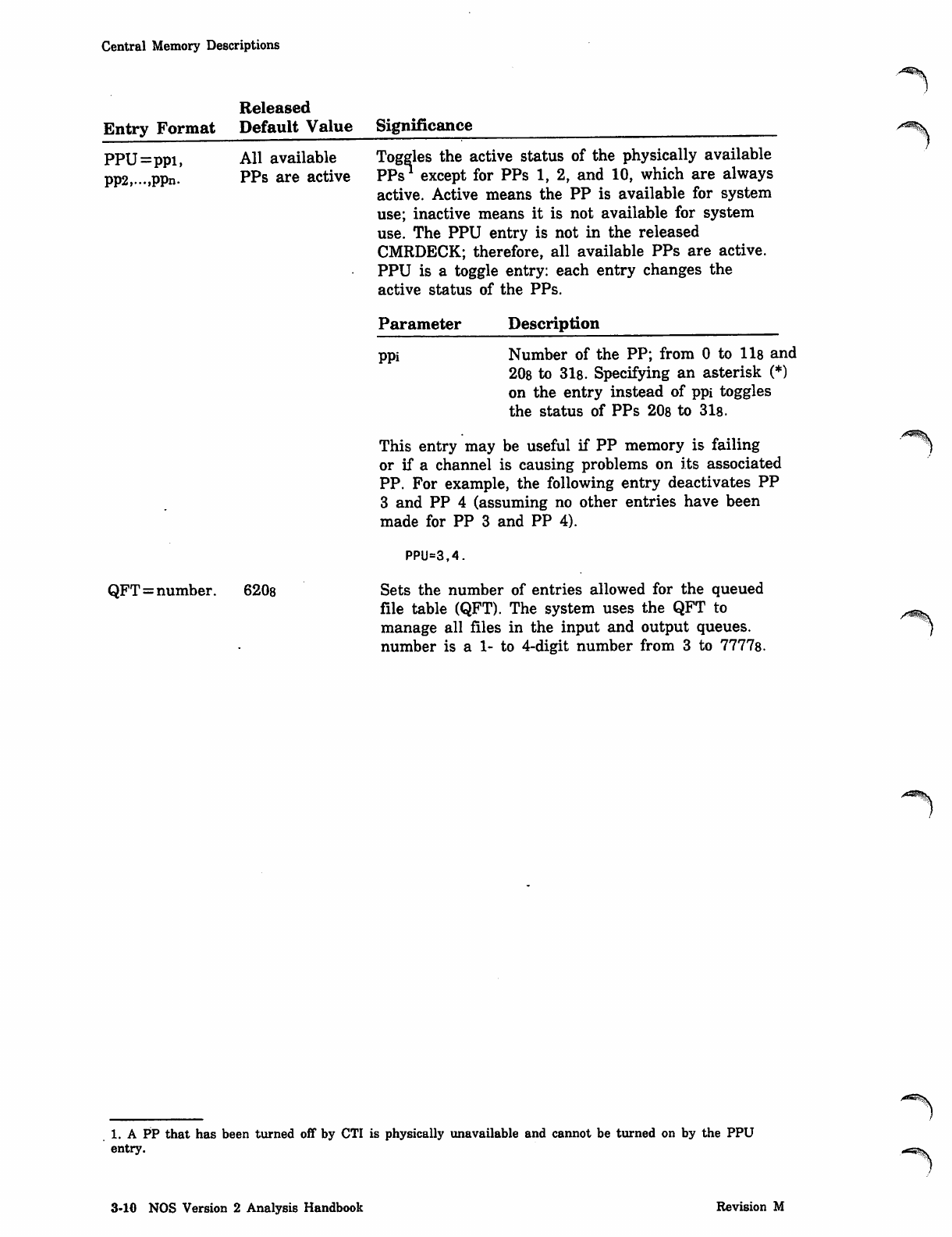
Central Memory Descriptions
Entry Format
Released
Default Value Significance
PPU=ppi,
PP2,...,PPn.
All available
PPs are active
QFT = number. 620s
Toggles the active status of the physically available
PPs except for PPs 1, 2, and 10, which are always
active. Active means the PP is available for system
use; inactive means it is not available for system
use. The PPU entry is not in the released
CMRDECK; therefore, all available PPs are active.
PPU is a toggle entry: each entry changes the
active status of the PPs.
/«^!\
Parameter Description
ppi Number of the PP; from 0 to lis and
208 to 318. Specifying an asterisk (*)
on the entry instead of ppi toggles
the status of PPs 20s to 31s.
This entry may be useful if PP memory is failing
or if a channel is causing problems on its associated
PP. For example, the following entry deactivates PP
3 and PP 4 (assuming no other entries have been
made for PP 3 and PP 4).
PPU=3,4.
Sets the number of entries allowed for the queued
file table (QFT). The system uses the QFT to
manage all files in the input and output queues,
number is a 1- to 4-digit number from 3 to 77778.
^ftsj.
1. APP that has been turned off by CTI is physically unavailable and cannot be turned on by the PPU
entry.
3-10 NOS Version 2 Analysis Handbook Revision M
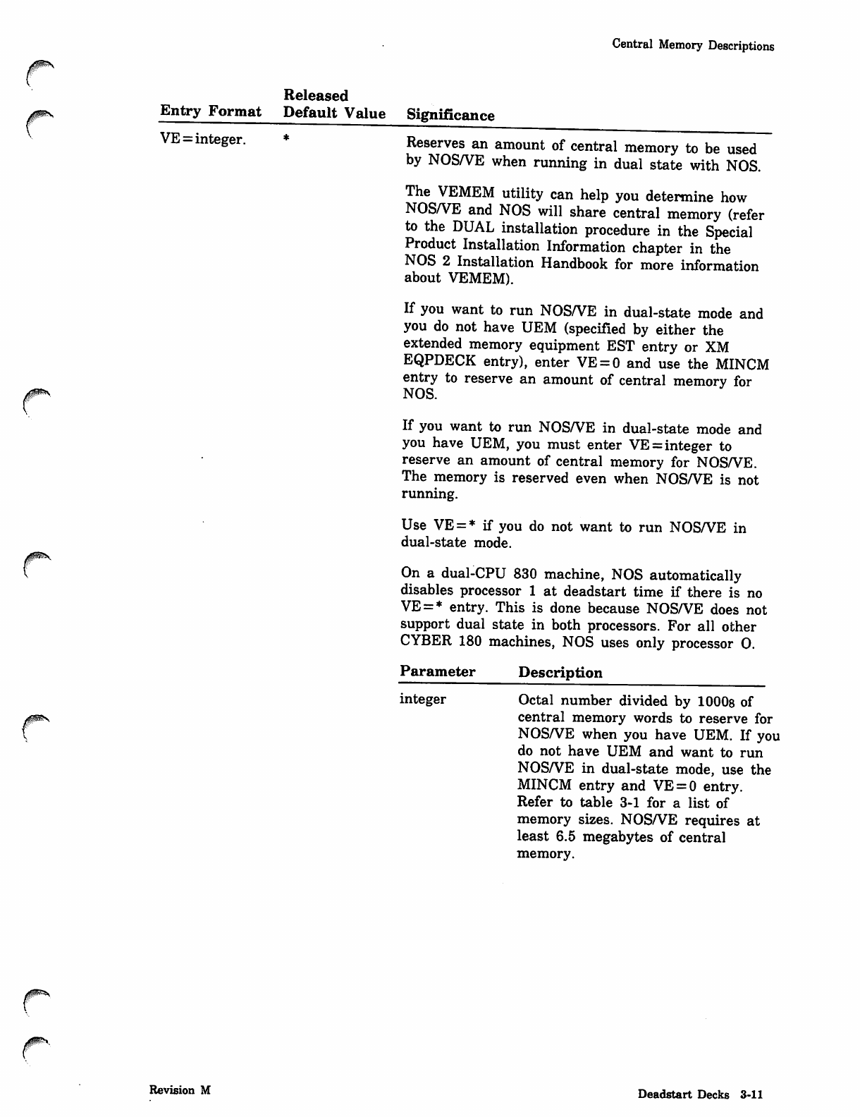
Central Memory Descriptions
rEntry Format
Released
Default Value
VE = integer.
r
Significance
Reserves an amount of central memory to be used
by NOS/VE when running in dual state with NOS.
The VEMEM utility can help you determine how
NOS/VE and NOS will share central memory (refer
to the DUAL installation procedure in the Special
Product Installation Information chapter in the
NOS 2 Installation Handbook for more information
about VEMEM).
If you want to run NOS/VE in dual-state mode and
you do not have UEM (specified by either the
extended memory equipment EST entry or XM
EQPDECK entry), enter VE = 0 and use the MINCM
entry to reserve an amount of central memory for
NOS.
If you want to run NOS/VE in dual-state mode and
you have UEM, you must enter VE = integer to
reserve an amount of central memory for NOS/VE.
The memory is reserved even when NOS/VE is not
running.
Use VE = * if you do not want to run NOS/VE in
dual-state mode.
On a dual-CPU 830 machine, NOS automatically
disables processor 1 at deadstart time if there is no
VE = * entry. This is done because NOS/VE does not
support dual state in both processors. For all other
CYBER 180 machines, NOS uses only processor 0.
Parameter Description
integer Octal number divided by 1000s of
central memory words to reserve for
NOS/VE when you have UEM. If you
do not have UEM and want to run
NOS/VE in dual-state mode, use the
MINCM entry and VE = 0 entry.
Refer to table 3-1 for a list of
memory sizes. NOS/VE requires at
least 6.5 megabytes of central
memory.
Revision M Deadstart Decks 3-11
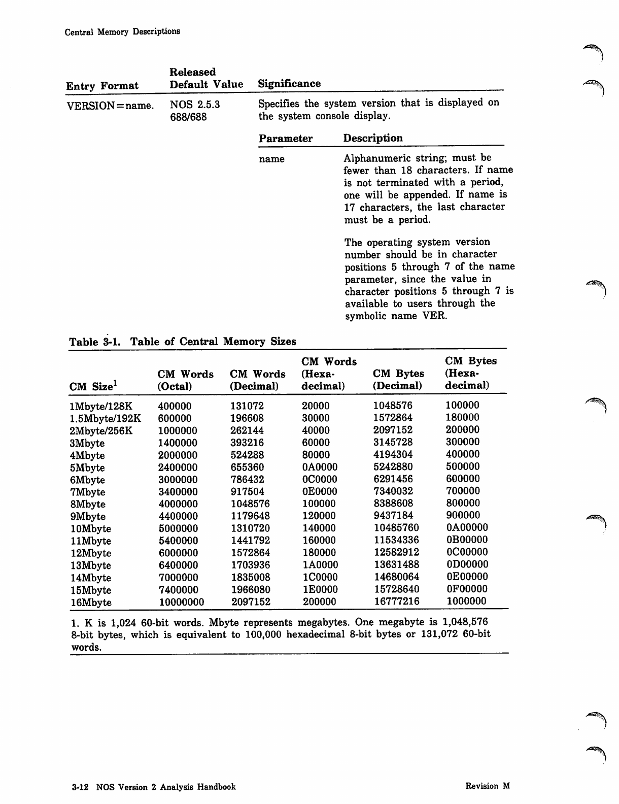
Central Memory Descriptions
Entry Format
Released
Default Value Significance
VERSION=name. NOS 2.5.3
688/688
Specifies the system version that is displayed on
the system console display.
Parameter Description
name Alphanumeric string; must be
fewer than 18 characters. If name
is not terminated with a period,
one will be appended. If name is
17 characters, the last character
must be a period.
The operating system version
number should be in character
positions 5 through 7 of the name
parameter, since the value in
character positions 5 through 7 is
available to users through the
symbolic name VER.
Table 3-1. Table of Central Memory Sizes
CM Words CM Bytes
CM Words CM Words (Hexa CM Bytes (Hexa
CM Size1 (Octal) (Decimal) decimal) (Decimal) decimal)
lMbyte/128K 400000 131072 20000 1048576 100000
1.5Mbyte/192K 600000 196608 30000 1572864 180000
2Mbyte/256K 1000000 262144 40000 2097152 200000
3Mbyte 1400000 393216 60000 3145728 300000
4Mbyte 2000000 524288 80000 4194304 400000
5Mbyte 2400000 655360 OAOO00 5242880 500000
6Mbyte 3000000 786432 ocoooo 6291456 600000
7Mbyte 3400000 917504 OE0O00 7340032 700000
8Mbyte 4000000 1048576 100000 8388608 800000
9Mbyte 4400000 1179648 120000 9437184 900000
10Mbyte 5000000 1310720 140000 10485760 0A00000
11Mbyte 5400000 1441792 160000 11534336 0B00000
12Mbyte 6000000 1572864 180000 12582912 0C00000
13Mbyte 6400000 1703936 1A0000 13631488 0D00O00
14Mbyte 7000000 1835008 1C0000 14680064 0E00000
15Mbyte 7400000 1966080 1E0000 15728640 0F00000
16Mbyte 10000000 2097152 200000 16777216 1000000
■'*:^%\
A*^*S
1. K is 1,024 60-bit words. Mbyte represents megabytes. One megabyte is 1,048,576
8-bit bytes, which is equivalent to 100,000 hexadecimal 8-bit bytes or 131,072 60-bit
words.
3-12 NOS Version 2 Analysis Handbook Revision M
EQPDECK
r
i^S
EQPDECK
The equipment deck (EQPDECK) resides on the deadstart file as a text record that is
processed during system initialization. It contains entries defining the following types of
information.
• Dayfile buffer size.
• Hardware configuration.
• File residence on mass storage devices.
• Permanent file family residence.
• Multimainframe configurations.
• Software attributes associated with hardware (such as forms code).
An EQPDECK entry is described under the type of information it defines.
The deadstart file can contain up to 100s EQPDECKs. Having several EQPDECKs on
the same deadstart file is advantageous because one file can deadstart several
configurations. You can obtain a listing of all EQPDECKs by accessing the system
file SYSTEM with a COMMON command, then using the T parameter on the
CATALOG command (refer to the NOS Version 2 Reference Set, Volume 3 for more
information concerning these commands). EQPDECKs are named EQPDnn, where nn
is from 00 to 77s.
rYou can modify the released settings of the EQPDECK in two ways: type a newentry when the EQPDECK is displayed during deadstart, or create a new deadstart
file. The usual method of modifying an EQPDECK follows.
1. Deadstart, using the released deadstart file, and select the EQPINST and the
EQPDECK to be displayed (refer to section 2, Deadstart).
EQPINST lists all valid EQPDECK entries. Default values, described in this
section, are assumed if the entries do not appear in the EQPDECK being used. If
either EQPDECK or EQPINST overflows two screens, you can page the display.
^^ 2. Modify the released version of EQPDECK by entering the changes or additions
from the system console while either the EQPDECK or EQPINST is displayed.
Each console entry supersedes the value currently specified in the EQPDECK (or
the default value).
NOTE
The modified EQPDECK remains in effect only until the next level 0, 1, or 2
deadstart is performed. That is, changes to the EQPDECK are retained across a
level 3 deadstart, but not across a level 0, 1, or 2 deadstart (unless a new
deadstart file is created to reflect them).
3. To expedite subsequent deadstarts, modify the EQPDECK on the deadstart file
using SYSGEN (refer to the NOS Version 2 Installation Handbook).
Several equipment status displays are available during deadstart (refer to section 2,
Deadstart).
jp*.
Revision M Deadstart Decks 3-13
EQPDECK
When constructing or modifying an EQPDECK, the following restrictions apply:
© The equipment assignment entry (EQ) must precede any other assignments for a
device (such as assigning it for permanent file, system, or temporary file use). If
you redefine the EQ entry (by clearing the entry and retyping a new entry or by
changing the device type in the entry), reenter all other assignments for that
equipment. If you need to modify an EQ entry, you need only enter the changes
rather than reentering the entire entry. You do not need to reenter other
assignments for that equipment. This is especially useful for changing channels or
units and for reconfiguring around hardware malfunctions.
Example:
The following mass storage assignments are in the EQPDECK.
EQ7=DI,ST=ON,UN=60,CH=1.
PF=7,F,125,125,SYSTEM,3,200.
If you want to specify unit 70 rather than 60, you need only enter:
EQ7=DI,UN=70.
You.do not need to modify the PF entry.
• EST ordinals range from 1 to 777s. This range depends on the value of ESMX
(refer to PPCOM parameters in the NOS Version 2 Installation Handbook).
Ordinals 1 through 4 are reserved for pseudoequipment EST entries that are
automatically defined by the system and cannot be changed. Ordinal 5 is reserved
for extended memory if it is used as a link device in a multimainframe
environment (refer to EQ - Extended Memory EST Entry later in this section).
Otherwise, EST ordinal 5 can be used for any equipment type.
• The device from which you are deadstarting must be defined.
• Commas must separate parameters.
• A period must terminate each entry.
• Except where explicitly specified that controllers and/or equipment can be shared
between mainframes, assume they cannot be shared. For example, NOS does not
support sharing a two-channel tape controller between mainframes; nor does it
support sharing mass storage controllers, except as specified in section 13,
Multimainframe Operations.
When an error exists in an entry in an EQPDECK on the deadstart file, the
EQPDECK is displayed and the error is indicated. This occurs even if you do not select
the display EQPDECK option or if you enter GO after displaying the EQPDECK.
.■^%j.
3-14 NOS Version 2 Analysis Handbook Revision M
J^S.
J^S
Dayfile Descriptions
Dayfile Descriptions
One of the functions of dayfile description entries is to assign the amount of central
memory to be used for buffers. The more central memory assigned to dayfile buffers in
CMR, the less central memory available for job field lengths.
If, for example, you need a large portion of central memory to run a job, it might be
advisable to decrease the size of the dayfile buffers area in CMR to accommodate that
job. However, when dayfile buffers are smaller, the information stored in them is
written to mass storage more often, which requires more system overhead.
The following entries are specified in the SET program with the released default
values listed.
Entry Format
Released
Default Value Significance
ACCOUNT=est,length. 400s Sets the residence of the account dayfile
and the length of the account dayfile
buffer.
The account dayfile is an accounting
record containing information such as
type and quantity of resources used, and
job and execution times. This account
information is written to the central
memory account dayfile buffer during job
processing; the central memory buffer is
written to mass storage when it is full.
The account dayfile buffer resides in
CMR in the dayfile buffer area.
Parameter Description
est
length
The 1- to 3-digit octal
equipment status table
(EST) ordinal of the
equipment on which the
account dayfile is to
reside. A null value means
the system uses the first
system device it can find.
If the existing account
dayfile is recovered, the
account dayfile buffer
resides on that equipment
and the est parameter is
ignored.
The 3- or 4-digit octal
length of the account
dayfile buffer in CMR;
must be a multiple of 100s
and less than or equal to
10008. If 0 (zero) is
specified, messages issued
to the account dayfile are
discarded.
Revision M Deadstart Decks 3-15
Dayfile Descriptions
Entry Format
Released
Default Value
DAYFILE=est,length. 400s
ERRLOG=est,length. 1008
Significance
Sets the residence of the system dayfile
and the length of the system dayfile
buffer.
The dayfile buffer contains the dayfile
information, which is maintained in the
same way as the account dayfile buffer. It
resides in CMR in the dayfile buffer area.
Parameter Description
est The 1- to 3-digit octal EST
ordinal of equipment on
which the dayfile is to
reside. A null value means
the system uses the first
system device it can find.
The residence of this dayfile
is normally determined by
the recovery of the existing
dayfile. Use this parameter
if no system dayfiles are
recovered.
length The 3- or 4-digit octal
length of the system dayfile
buffer in CMR; must be a
multiple of 100s and less
than or equal to 10008. If 0
is specified, messages issued
to the system dayfile are
discarded.
Sets the residence of the error log and the
length of the error log buffer.
The error log is a record of hardware
error and status messages. This
information is maintained in the same way
as the account dayfile buffer.
Parameter Description
est The 1- to 3-digit octal EST
ordinal of equipment on
which the error log is to
reside. A null value means
the system uses the first
system device it can find
the existing error log is
recovered, the error log
buffer resides on that
equipment and the est
parameter is ignored.
If
3-16 NOS Version 2 Analysis Handbook Revision M
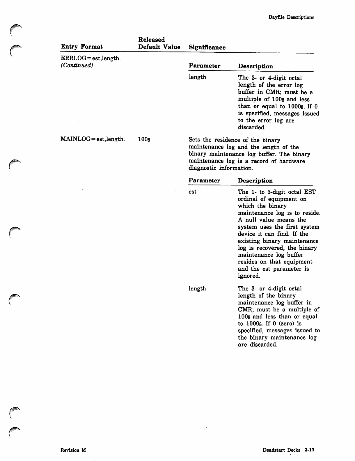
Dayfile Descriptions
0$ms Entry Format
Released
Default Value Significance
ERRLOG=est,length.
(Continued) Parameter Description
MAINLOG=est,length. 1008
yfP^N.
length The 3- or 4-digit octal
length of the error log
buffer in CMR; must be a
multiple of 100s and less
than or equal to 10008. If 0
is specified, messages issued
to the error log are
discarded.
Sets the residence of the binary
maintenance log and the length of the
binary maintenance log buffer. The binary
maintenance log is a record of hardware
diagnostic information.
Parameter
est
length
Description
The 1- to 3-digit octal EST
ordinal of equipment on
which the binary
maintenance log is to reside.
A null value means the
system uses the first system
device it can find. If the
existing binary maintenance
log is recovered, the binary
maintenance log buffer
resides on that equipment
and the est parameter is
ignored.
The 3- or 4-digit octal
length of the binary
maintenance log buffer in
CMR; must be a multiple of
1008 and less than or equal
to 10008. If 0 (zero) is
specified, messages issued to
the binary maintenance log
are discarded.
j0m\
Revision M Deadstart Decks 3-17
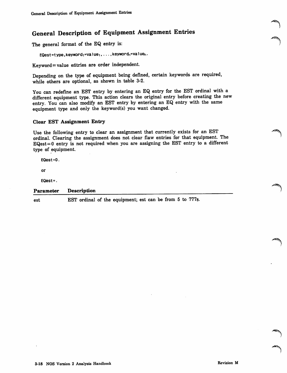
S ^ ^ S
General Description of Equipment Assignment Entries
General Description of Equipment Assignment Entries
The general format of the EQ entry is:
EQest =type,keywordi=valuei,... ,keywordn=valuen.
Keyword=value entries are order independent.
Depending on the type of equipment being defined, certain keywords are required,
while others are optional, as shown in table 3-2.
You can redefine an EST entry by entering an EQ entry for the EST ordinal with a
different equipment type. This action clears the original entry before creating the new
entry. You can also modify an EST entry by entering an EQ entry with the same
equipment type and only the keyword(s) you want changed.
Clear EST Assignment Entry
Use the following entry to clear an assignment that currently exists for an EST -*a%.
ordinal. Clearing the assignment does not clear flaw entries for that equipment. The
EQest=0 entry is not required when you are assigning the EST entry to a different
type of equipment.
EQest=0.
or
EQest=.
Parameter Description
est EST ordinal of the equipment; est can be from 5 to 777s.
3-18 NOS Version 2 Analysis Handbook Revision M
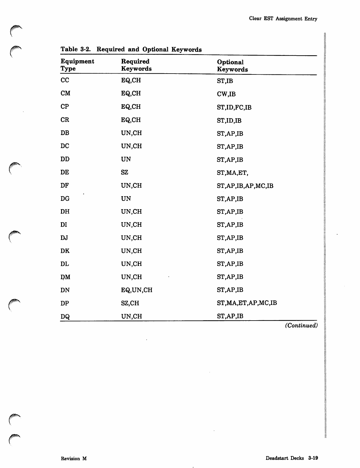
Clear EST Assignment Entry
rTable 3-2. Required and Optional Keywords
Equipment
Type
Required
Keywords
CC EQ,CH
CM EQ,CH
CP EQ,CH
CR EQ,CH
DB UN,CH
DC UN,CH
0m*s,
DD
DE
UN
SZ
DF UN,CH
DG UN
DH UN,CH
DI UN,CH
DJ UN,CH
DK UN,CH
DL UN,CH
DM UN,CH
DN EQ,UN,CH
00&S DP SZ,CH
DQ UN,CH
Optional
Keywords
ST,IB
CW,IB
ST,ID,FC,IB
ST,ID,IB
ST,AP,IB
ST,AP,IB
ST,AP,IB
ST,MA,ET,
ST,AP,IB,AP,MC,IB
ST,AP,IB
ST,AP,IB
ST,AP,IB
ST,AP,IB
ST,AP,IB
ST,AP,IB
ST,AP,IB
ST,AP,IB
ST,MA,ET,AP,MC,IB
ST,AP,IB
(Continued)
Revision M Deadstart Decks 3-19
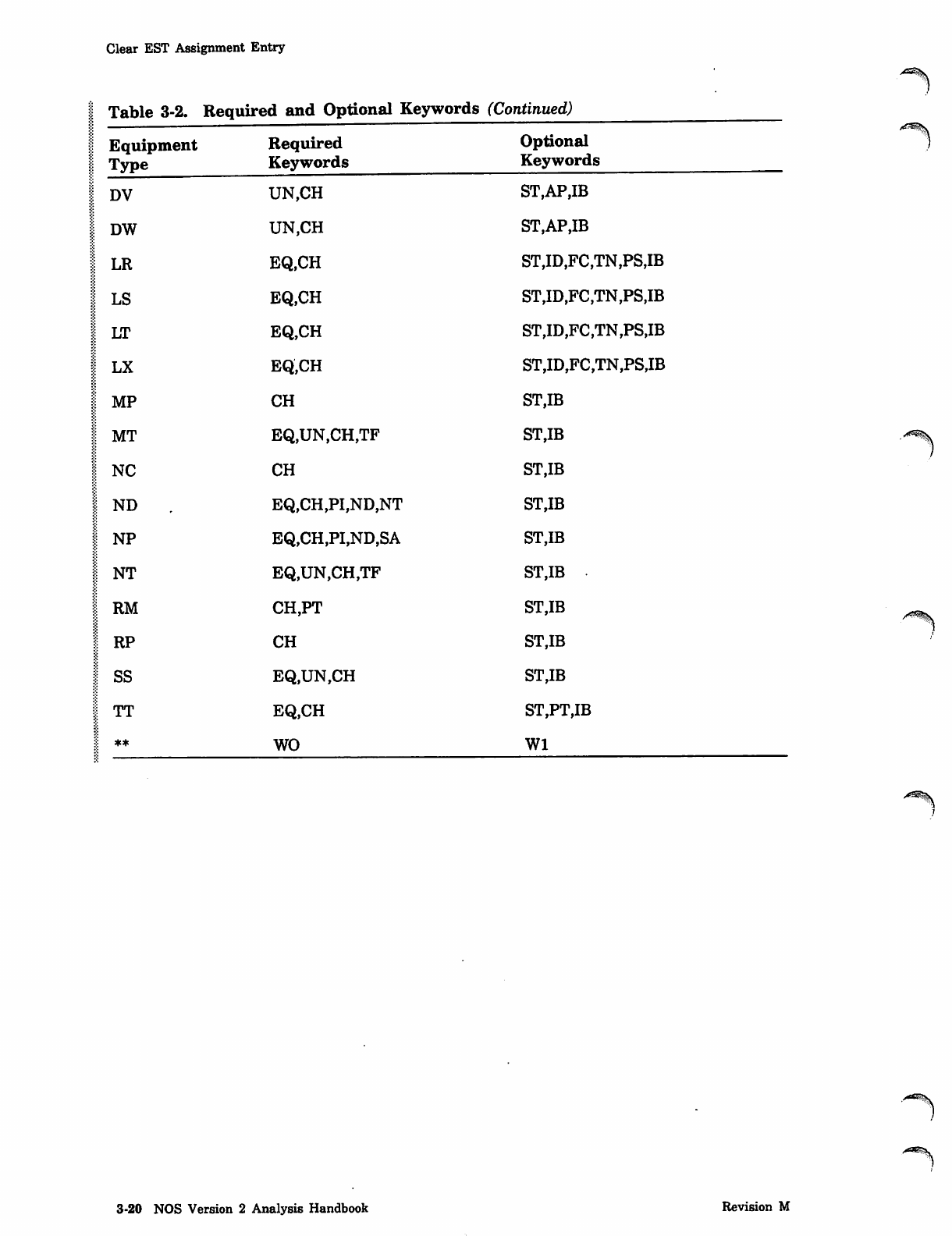
Clear EST Assignment Entry
Table 3-2. Required and Optional Keywords (Continued)
Equipment
Type
Required
Keywords
Optional
Keywords
DV UN,CH ST,AP,IB
DW UN,CH ST,AP,IB
LR EQ.CH ST,ID,FC,TN,PS,IB
LS EQ,CH ST,ID,FC,TN,PS,IB
LT EQ,CH ST,ID,FC,TN,PS,IB
LX EQ,CH ST,ID,FC,TN,PS,IB
MP CH ST,IB
MT EQ,UN,CH,TF ST,IB
NC CH ST.IB
ND EQ,CH,PI,ND,NT ST,IB
NP EQ,CH,PI,ND,SA ST,IB
NT EQ,UN,CH,TF ST,IB
RM CH,PT ST,IB
RP CH ST,IB
SS EQ,UN,CH ST,IB
TT EQ.CH ST,PT,IB
** WO WI
>^^.
3-20 NOS Version 2 Analysis Handbook Revision M
y^s
yfPN
yams
Equipment Assignments: Nonmass Storage
Equipment Assignments: Nonmass Storage
The following EST entries are described in this subsection.
Nonstandard equipment
Pseudoequipments
Unit record equipment
Magnetic tape equipment
Mass Storage Extended Subsystem equipment
Stimulator equipment
Network processing unit
CDCNET device interface
Network access device
Two-port multiplexer
MAP III or IV equipment
6683 Satellite Coupler
CYBERPLUS ring port equipment
Nonstandard Equipment EST Entry
The nonstandard equipment EST entry allows you to define nonstandard equipment or
to add site debugging modifications.
Use the following format to enter the actual octal value that is to reside at that EST
ordinal.
EQest=**,Wo=valueo,Wi=valuei
Parameter Description
est
valuei
EST ordinal of the equipment; est can be from 5 to 777s.
The 1- to 20-digit octal value; this value is entered in the EST word i
for the specified ordinal. The word is right-justified and zero-filled if
valuei has fewer than 20 digits.
Revision M Deadstart Decks 3-21
Pseudoequipments
Pseudoequipments
The system automatically defines EST ordinals 0 through 4 as pseudoequipment EST
entries; they cannot be used for other equipment definitions. You cannot declare,
change, or remove pseudoequipments.
EST Ordinal
Ordinal 0 (RD)
Ordinal 1 (DS)
Ordinal 2 (NE)
Ordinal 3 (TE)
Ordinal 4 (TT)
Description
This ordinal reserves an EST entry and MST entry to be used for
device reconfiguration.
This ordinal represents the system display console.
The system uses 2 internally to signify that a file is assigned, but
that no space exists on the device. If a read is tried,
end-of-information (EOI) status occurs. If a write is attempted, the
data is discarded.
For example, you can use ordinal 2 with the permanent file utility
(PFDUMP) to validate the integrity of a permanent file device,
without taking the time to actually create a dump file on tape. In
this case, enter:
X.DIS.
ASSIGN,NE,TAPE.
PFDUMP.
This causes all dump data to be discarded, even though the
permanent file device is read and informative messages about the
permanent file device are issued to the system console. These
messages are described in the NOS Version 2 Operations Handbook.
If an association is established between file name and volume serial
number with an ASSIGN, LABEL, REQUEST, or VSN command,
the system automatically enters EQ3 in the file's FNT/FST entry.
When a tape having the desired volume serial number is assigned
to the file, the system replaces EQ3 in the file's FNT/FST entry
with the EST ordinal of the tape unit on which the tape is
mounted. If a file that has had the file name and volume serial
number association established by a VSN command is returned
prior to attempting to assign the tape equipment to the file, the
FNT/FST entry is canceled.
The system assigns to this equipment a file used for either input
from or output to an interactive terminal. This allows the system
to determine whether a file requires the special handling needed to
accomplish terminal input/output. Byte 4, set by the NAMIAF
IPRDECK entry, contains the number of network terminals.
^ms
3-22 NOS Version 2 Analysis Handbook Revision M
Unit Record Equipment EST Entry
Unit Record Equipment EST Entry
A unit record equipment EST entry defines channel connected card readers, card
punches, and line printers.
Unit record equipment connected to RHF or PSU through communications ports are
defined in the network configuration files rather than with individual EST entries.
EQest=type,ST=status,TN=tn,EQ=eq,CH=ch,lD=id,FC=fc,PS=ps,lB=ib.
or
EQest=type-P,ST=status,TN=tn,EQ=eqfCH=ch,ID=id,FC=fc,PS=ps,IB=1b.
Parameter Description
est EST ordinal of the unit record equipment; from 5 to 7778.
type Unit record equipment type; NOS supports the following unit record
equipments.
type Equipment
Card reader
CR 405-3447/3649
Card punch
CP 415-3446/3644
CP 415-30
Line printer
LR 580-12
LS 580-16
LT 580-20
LX 5870
P Specifies that a 580 printer is equipped with a programmable format
controller.
Revision M Deadstart Decks 3-23
Unit Record Equipment EST Entry
Parameter Description
TN=tn Print train for local batch line printer; from 1 to 7. NOS supports the
following print trains.
tn Print Train Description
0 595-1/596-1 CDC graphic 63/64-character set.
1 595-1/596-1 CDC graphic 63/64-character set.
4 595-6/596-6 ASCII graphic 95-character set or ASCII graphic
63/64-character set.
5 595-5/596-5 ASCII graphic 63/64-character set.
6 595-6/596-6 ASCII graphic 95-character set.
7 595-6/596-6 ASCII graphic 95-character set or ASCII graphic
63/64-character set.
If you set a nonsupported print train value, tn defaults to a supported
value. If you omit tn or specify 2 or 3, the actual value of tn is 1.
If an invalid external characteristic (EC)2 is specified, the queued file
processor cannot output the file. The following shows which files will
print and which files will not print for a given print train selection.
Print Train
Selected
Will Print File
With Specified EC
Will Not Print File
With Specified EC
0None, B4, B6 A4, A6, A9
1None, B4, B6 A4, A6, A9
4None, A4, A6, A9 B4, B6
5None, A4, A6 B4, B6, A9
6A9 None, B4, B6, A4, A6
7None, B4, B6, A4,
A9 A6,
ST=status Specifies
enter om
whether unit record equipment
s of these values:
is available for system use;
status Description
ON Unit record equipment is available.
OFF Unit record equipment is ignored during system operation.
2. Refer to the NOS Version 2 Reference Set, Volume 3 for a discussion of-the ROUTE command EC
parameter.
3-24 NOS Version 2 Analysis Handbook Revision M
0^*S.
r
Unit Record Equipment EST Entry
Parameter Description
EQ=eq Controller number for equipment; from 0 to 7. To determine the number
for most unit record equipment, look at the dial switch on the controller.
To determine the equipment number for an LX printer, use the following
equation:
eq * 2 + 1 = addr
where addr is the 5870 host address obtained from the 5870 installer.
CH = ch Number of channel to which unit record equipment is connected; from 0
to 138 and from 20s to 338.
NOTE
/$P^V
If you want to use a card reader to perform a coldstart on a 66x tape
controller, the card reader must be available on channel 12s, 13s,
328, or 338.
To ensure that all printers are restored to their original states (such as
8 lines per inch and auto page eject) after a master clear has been
issued, all unit record equipment should be available on dedicated
channels. If it is not, printers revert to 6 lines per inch, and no auto
page eject status after a master clear is issued.
ID=id The 1- or 2-digit octal numeric identifier assigned to the device; from 0
to 678. This id is assigned to any output created by a job. For card
readers, all jobs loaded from this card reader are assigned the
identifier id.
FC = fc The 2-character optional forms code assigned to a line printer or card
punch. If the forms code is not present, the forms code field is cleared.
The forms code must either be null (not specified) or in the range from
AA to 99.
NOTE
The forms code cannot be assigned to a card reader.
Revision M Deadstart Decks 3-25
Unit Record Equipment EST Entry
Parameter Description
PS=ps
IB=ib
Examples:
Paper size, L or S, for local batch line printer. Default is L.
ps Description
Long (11 inch) paper will be mounted.
Short (8 1/2 inch) paper will be mounted.
The 1- to 4-digit octal value; this value is entered in the installation
byte for the specified EST ordinal. Refer to EST Formats in the NOS
Version 2 Systems Programmer's Instant.
EQ11=CR,ST=ON,EQ=4,CH=12.
EQ11=CP,EQ=5,CH=12,ST=0N.
EQ20=LR,ST=ON,CH=12,EQ=6,ID=15,FC=AA.
EQ21=CR,ID=15,ST=ON,EQ=7,CH=12.
EQ22=LT-P,TN=6,ST=0N,EQ=2,CH=12.
/A^^^L
3-26 NOS Version 2 Analysis Handbook Revision M
Aims.
0ms
Magnetic Tape Equipment EST Entry
Magnetic Tape Equipment EST Entry
The released tape subsystem supports a maximum of 16 magnetic tape units. The
minimum number of magnetic tape units that NOS requires is one 639 667 669 677
679, or 698. The format of the entry is: '
EQest =MT-n,ST=statusfEQ=eq,UN=un,CH=ch1/ch2,TF=tf,IB=ib.-
or
EQest =NT-n,ST=status,EQ=eq,UN=un,CH=ch1/ch2,TF=tfIlB=ib.
Parameter Description
est EST ordinal of the tape unit; from 5 to 777s. Refer to the MT-n or
NT-n parameter.
MT-n Equipment type; MT specifies 7-track tape units, and NT specifies
or 9-track tape units, n is the total number of magnetic tape units
NT-n connected to the controller, from 1 to 20s for 677, 679, and 698 units
with a 7021-31/32 controller and from 1 to 10s for 667 and 669 units
with a 7021-21/22 controller. The system automatically generates n
EST entries with consecutive EST ordinals beginning with the ordinal
specified in the est parameter. The n units begin with the unit number
specified in the UN=un parameter.
For 639 units, n should not be specified; if it is specified, it should be
given a value of 0 (zero).
NOTE
To clear an MT-n or NT-n assignment, enter an EQest=0 entry for all
n units. For example, to clear EQ50 = MT-4,ST=ON,..., enter:
EQ50=0.
EQ51=0.
EQ52=0.
EQ53=0.
Revision M Deadstart Decks 3-27
Magnetic Tape Equipment EST Entry
Parameter Description
ST=status Indicates whether the tape unit is available for access; enter one of
these values:
status Description
ON Magnetic tape unit is available for access.
OFF Magnetic tape unit is ignored during system operation.
DOWN All access to the magnetic tape unit is inhibited for the
operating system and user jobs. Specify DOWN if the
equipment is malfunctioning and access is not desirable or the
unit is to be used by NOS/VE in a dual-state environment
(669, 679, and 698 units only).3
EQ=eq Controller number for the tape unit; from 0 to 7. This number is usually
0 unless the controller is switched to a different number. Ask your
customer engineer for the correct number if you are unsure.
UN=un Number of the lowest numbered magnetic tape unit to be processed;
units must have consecutive physical unit numbers; from 0 to 7 for 667
and 669 units or from 0 to 17s for 677, 679, and 698 units. The unit
number is on the front of the tape unit, either as a switch or a label.
CH = chi Number of the channel(s) to which the tape unit is connected; from 0 to
138 and from 20s to 33s.
A controller can be connected to one or two channels, depending on the
controller model. However, a maximum of two channels can be handled
regardless of the number of controllers.
3. If a magnetic tape unit is accessible from more than one mainframe, concurrent use must be disabled by
one of these methods: set access switches on the tape controller so that only one mainframe can access the
unit at any time or make sure that the EST entry for each shared unit is defined as ON in only one of the
mainframes.
3-28 NOS Version 2 Analysis Handbook Revision M
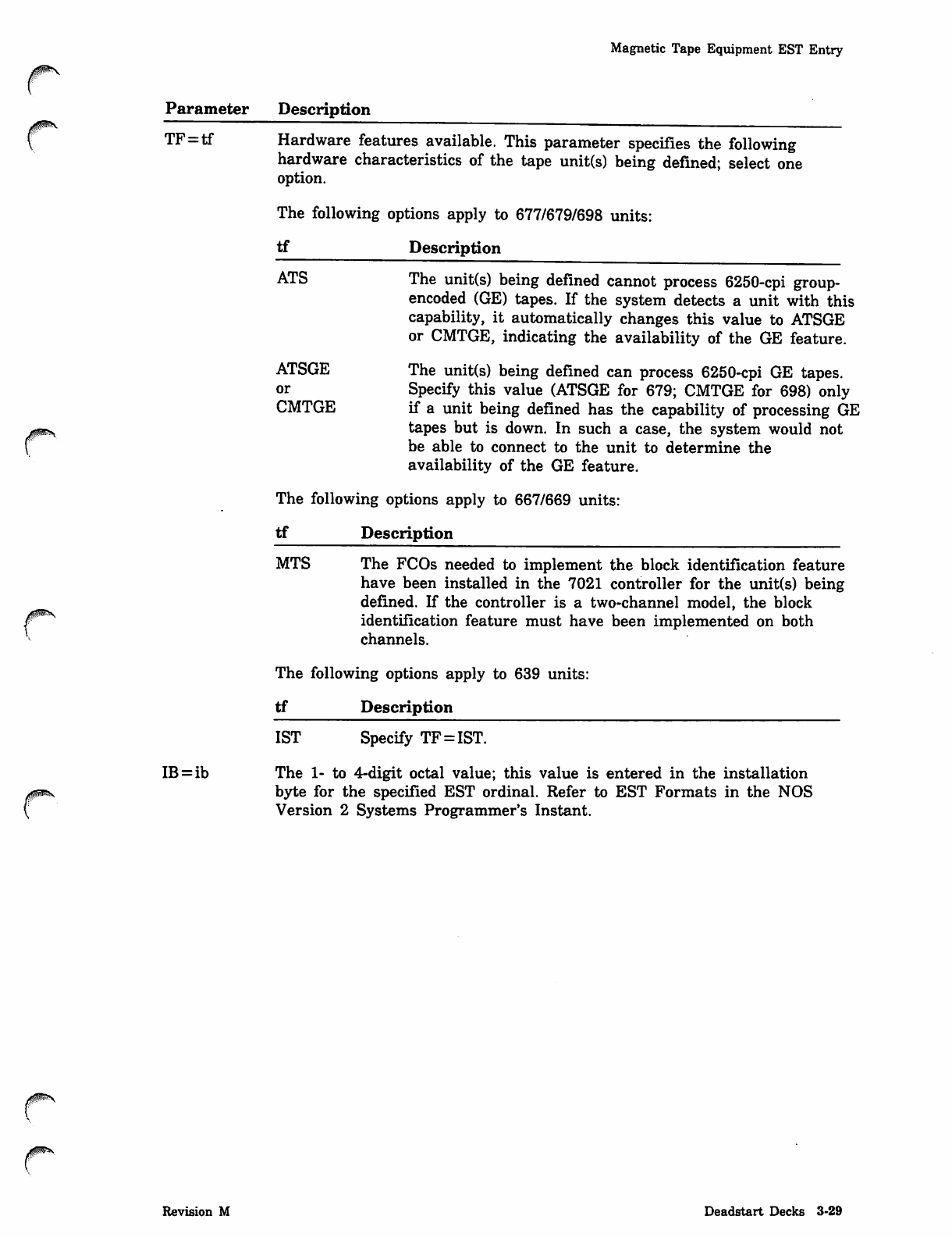
0^&t
Magnetic Tape Equipment EST Entry
Parameter Description
TF=tf Hardware features available. This parameter specifies the following
hardware characteristics of the tape unit(s) being defined; select one
option.
The following options apply to 677/679/698 units:
tf Description
ATS The unit(s) being defined cannot process 6250-cpi group-
encoded (GE) tapes. If the system detects a unit with this
capability, it automatically changes this value to ATSGE
or CMTGE, indicating the availability of the GE feature.
ATSGE The unit(s) being defined can process 6250-cpi GE tapes,
or Specify this value (ATSGE for 679; CMTGE for 698) only
CMTGE if a unit being defined has the capability of processing GE
tapes but is down. In such a case, the system would not
be able to connect to the unit to determine the
availability of the GE feature.
The following options apply to 667/669 units:
tf Description
MTS The FCOs needed to implement the block identification feature
have been installed in the 7021 controller for the unit(s) being
defined. If the controller is a two-channel model, the block
identification feature must have been implemented on both
channels.
The following options apply to 639 units:
tf Description
IST Specify TF=IST.
IB=ib The 1- to 4-digit octal value; this value is entered in the installation
byte for the specified EST ordinal. Refer to EST Formats in the NOS
Version 2 Systems Programmer's Instant.
Revision M Deadstart Decks 3-29
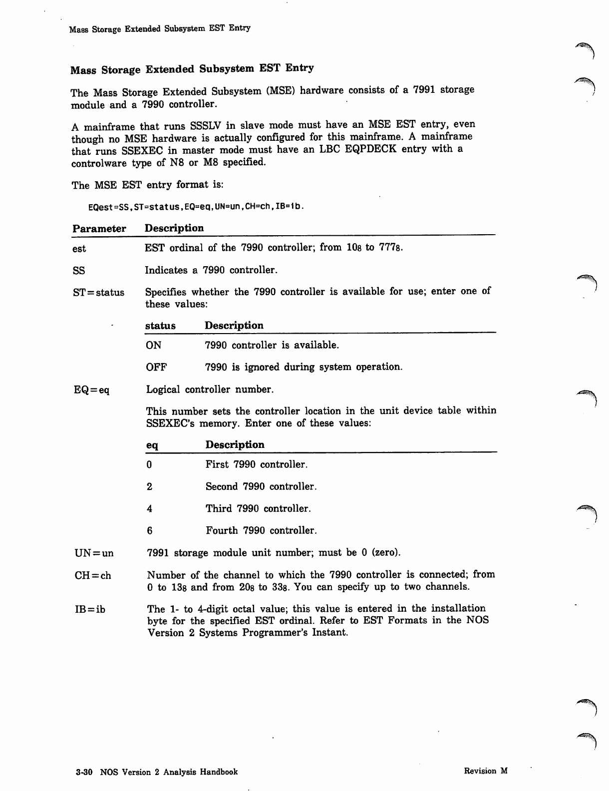
Mass Storage Extended Subsystem EST Entry
Mass Storage Extended Subsystem EST Entry
The Mass Storage Extended Subsystem (MSE) hardware consists of a 7991 storage
module and a 7990 controller.
A mainframe that runs SSSLV in slave mode must have an MSE EST entry, even
though no MSE hardware is actually configured for this mainframe. A mainframe
that runs SSEXEC in master mode must have an LBC EQPDECK entry with a
controlware type of N8 or M8 specified.
The MSE EST entry format is:
EQest=SS,ST=status,EQ=eq,UN=un,CH=ch,IB=1b.
Parameter Description
est
SS
ST=status
EQ = eq
UN=un
CH = ch
IB=ib
EST ordinal of the 7990 controller; from 10s to 777s.
Indicates a 7990 controller.
Specifies whether the 7990 controller is available for use; enter one of
these values:
status Description
ON 7990 controller is available.
OFF 7990 is ignored during system operation.
Logical controller number.
This number sets the controller location in the unit device table within
SSEXEC's memory. Enter one of these values:
eq Description
First 7990 controller.
Second 7990 controller.
Third 7990 controller.
Fourth 7990 controller.
7991 storage module unit number; must be 0 (zero).
Number of the channel to which the 7990 controller is connected; from
0 to 138 and from 20s to 33s. You can specify up to two channels.
The 1- to 4-digit octal value; this value is entered in the installation
byte for the specified EST ordinal. Refer to EST Formats in the NOS
Version 2 Systems Programmer's Instant.
<^^Y
3-30 NOS Version 2 Analysis Handbook Revision M
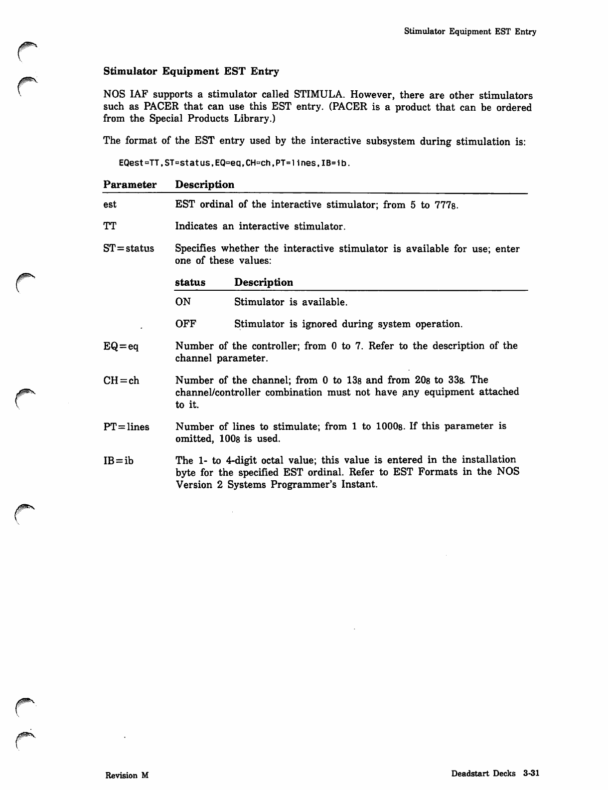
0ms.
Stimulator Equipment EST Entry
Stimulator Equipment EST Entry
NOS IAF supports a stimulator called STIMULA. However, there are other stimulators
such as PACER that can use this EST entry. (PACER is a product that can be ordered
from the Special Products Library.)
The format of the EST entry used by the interactive subsystem during stimulation is:
EQest=TT,ST=status>EQ=eq,CH=ch,PT=lines,IB=ib.
Parameter Description
est
TT
ST=status
EQ = eq
CH=ch
PT=lines
IB = ib
EST ordinal of the interactive stimulator; from 5 to 7778.
Indicates an interactive stimulator.
Specifies whether the interactive stimulator is available for use; enter
one of these values:
status Description
ON Stimulator is available.
OFF Stimulator is ignored during system operation.
Number of the controller; from 0 to 7. Refer to the description of the
channel parameter.
Number of the channel; from 0 to 13s and from 20s to 33s. The
channel/controller combination must not have any equipment attached
to it.
Number of lines to stimulate; from 1 to 10008. If this parameter is
omitted, 1008 is used.
The 1- to 4-digit octal value; this value is entered in the installation
byte for the specified EST ordinal. Refer to EST Formats in the NOS
Version 2 Systems Programmer's Instant.
0S^s.
Revision M Deadstart Decks 3-31
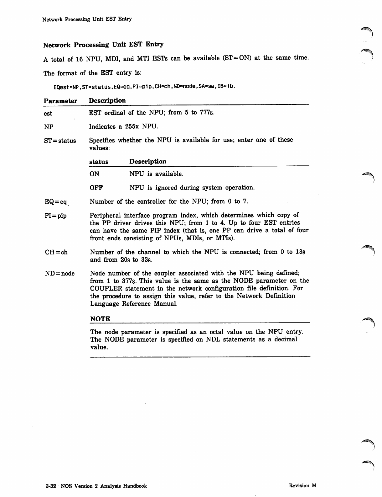
Network Processing Unit EST Entry
Network Processing Unit EST Entry
A total of 16 NPU, MDI, and MTI ESTs can be available (ST=ON) at the same time.
The format of the EST entry is:
EQest=NP,ST=status,EQ=eq,PI=plp,CH=ch,ND=node,SA=sa,IB=ib.
Parameter Description ^^^^
est
NP
ST = status
EQ=eq
PI=pip
CH=ch
ND=node
EST ordinal of the NPU; from 5 to 7778.
Indicates a 255x NPU.
Specifies whether the NPU is available for use; enter one of these
values:
status Description
ON NPU is available.
OFF NPU is ignored during system operation.
Number of the controller for the NPU; from 0 to 7.
Peripheral interface program index, which determines which copy of
the PP driver drives this NPU; from 1 to 4. Up to four EST entries
can have the same PIP index (that is, one PP can drive a total of four
front ends consisting of NPUs, MDIs, or MTIs).
Number of the channel to which the NPU is connected; from 0 to 13s
and from 20s to 33s.
Node number of the coupler associated with the NPU being defined;
from 1 to 3778. This value is the same as the NODE parameter on the
COUPLER statement in the network configuration file definition. For
the procedure to assign this value, refer to the Network Definition
Language Reference Manual.
NOTE
The node parameter is specified as an octal value on the NPU entry.
The NODE parameter is specified on NDL statements as a decimal
value.
3-32 NOS Version 2 Analysis Handbook Revision M
Network Processing Unit EST Entry
JpN.
/fP^V
Parameter Description
SA = sa
IB=ib
Example:
System autostart module (SAM) flag (refer to CCP in the NAM Host
Application Programming Reference Manual). This parameter is required.
sa Description
ON SAM is present on the NPU.
OFF SAM is absent. The host attempts to load the system autostart
module program (SAM-P) to the NPU if the NPU is down.
If an NPU is channel-connected to a single host in a single-host
network, the NPU does not need a SAM. However, if an NPU is
channel-connected to two hosts, the NPU should have a SAM; otherwise,
both hosts might attempt to reload SAM-P if the NPU is down. This
requires operator intervention to resolve the problem. The NPU EST
entries for both hosts should specify SA=ON.
The 1- to 4-digit octal value; this value is entered in the installation
byte for the specified EST ordinal. Refer to EST Formats in the NOS
Version 2 Systems Programmer's Instant.
Assume that three NPUs exist on channels 4, 5, and 6, all with controller 7. The
NPUs are connected to coupler nodes 2, 8, and 11, respectively. The NPU on channel
5 has a system autostart module; the others do not. The first two NPUs are to be
driven by the same PP. The EST entries for these NPUs follow.
EQ70=NP,ST=ON,CH=4,EQ=7,PI=1,ND=2,SA=OFF.
r
EQ71=NP,ST=0N,CH=5,EQ=7,PI=1,ND=10,SA=ON.
EQ72=NP,ST=0N,CH=6,EQ=7,PI=2,ND=13,SA=0FF.
The NDLP input for the network configuration would include the following statements
(refer to the Network Definition Language Reference Manual for a complete
description of these statements).
CPL1: C0UPLERN0DE=2,HNAME=H0ST1.
CPL2: C0UPLERN0DE=8,HNAME=H0ST1.
CPL3: COUPLERNODE=11,HNAME =HOST1.
The node parameter of the EST entry and NODE on the COUPLER statement have
the same numeric values, in this case 2, 8 (10s), and 11 (13s).
Revision M Deadstart Decks 3-33
CDCNET Device Interface EST Entry
CDCNET Device Interface EST Entry
Each mainframe device interface (MDI) or mainframe terminal interface (MTI) in a
CDCNET network that is connected to a CYBER mainframe must have an EST entry.
A total of 16 MDI, MTI, and NPU ESTs can.be available (ST=ON) at the same time.
The format of the EST entry is:
EQest=ND,ST=status,EQ=eq,PI=pip,CH=ch,ND=node,NT=node,IB=ib.
Parameter Description
est
ND
ST=status
EST ordinal of the MDI or MTI; from 5 to 7778.
Indicates an MDI or MTI.
Specifies whether the MDI or MTI is available for use; enter one of
these values:
status Description
EQ=eq
PI=pip
CH = ch
ND=node4
NT=node4
IB = ib
ON MDI or MTI is available.
OFF MDI or MTI is ignored during system operation.
Number of the controller for the MDI or MTI; from 0 to 7.
Peripheral interface program (PIP) index, which determines which copy
of the PP driver drives this MDI or MTI; from 1 to 4. Up to four EST
entries can have the same PIP index (that is, one PP can drive a total
of four front ends consisting of MDIs, MTIs, or NPUs).
Number of the channel to which the MDI or MTI is connected; from 0
to 138 and from 208 to 33s.
Node number of the coupler associated with the MDI or MTI being
defined; from 1 to 377s.
Node number of the MDI or MTI; from 1 to 377s. This node number
identifies the Control Data Network Architecture (CDNA) transport
function.
The 1- to 4-digit octal value; this value is entered in the installation
byte for the specified EST ordinal. Refer to EST Formats in the NOS
Version 2 Systems Programmer's Instant.
The node numbers assigned to an MDI or MTI must be consistent with those assigned
to a 255x NPU network configuration defined through NDL. To minimize the impact on
existing 255x NPU networks, assign node numbers as follows:
1. Assign the lowest node numbers to NPU coupler nodes.
2. Reserve node numbers subsequent to those assigned in step 1 for NPU nodes.
3. Assign the remaining node numbers to MDI or MTI coupler nodes.
4. Reserve one node number to identify the CDNA transport function.
4. The procedure for assigning node numbers and creating network configuration file definitions is described
in the Network Definition Language Reference Manual.
3-34 NOS Version 2 Analysis Handbook Revision M
Network Access Device EST Entry
Network Access Device EST Entry
The format for the network access device (NAD) EST entry is:
EQest=NC,ST=status,CH=ch,IB=ib.
Parameter Description
est
NC
ST---status
CH=ch
IB=ib
EST ordinal of the NAD; from 5 to 7778.
Indicates a NAD.
Specifies whether the NAD is available for use; enter one of these
values:
status Description
ON NAD is available.
OFF NAD is ignored during system operation.
Number of the channel to which the NAD is connected; from 0 to 138
and from 20s to 33s.
The 1- to 4-digit octal value; this value is entered in the installation
byte for the specified EST ordinal. Refer to EST Formats in the NOS
Version 2 Systems Programmer's Instant.
j^S.
Revision M Deadstart Decks 3-35
Two-Port Multiplexer EST Entry
Two-Port Multiplexer EST Entry
The two-port multiplexer (TPM) must be described in the EST to allow use of the
Remote Diagnostic Facility (RDF) on models 865 and 875 and CYBER 180-class
machines.
The format of the TPM EST entry is:
EQest=RM,ST=status,PT=pt,CH=ch,IB=ib.
Parameter Description
est
RM
ST=status
PT=pt
CH=ch
IB=ib
The 1- to 3-digit octal EST ordinal of the TPM; 5 to 777s.
TPM equipment type.
Specifies whether the TPM is available for use; enter one of these
values:
status Description
ON TPM is available.
OFF TPM is ignored during system operation.
Port number to be used by RDF; 0 or 1. RDF normally uses port 1.
RDF and the system console cannot use the same port number.
Channel number on models 865 and 875 and CYBER 180-class
machines; channel 15 is required.
The 1- to 4-digit octal value;.this value is entered in the installation
byte for the specified EST ordinal. Refer to EST Formats in the NOS
Version 2 Systems Programmer's Instant.
y=**ss$v
3-36 NOS Version 2 Analysis Handbook Revision M
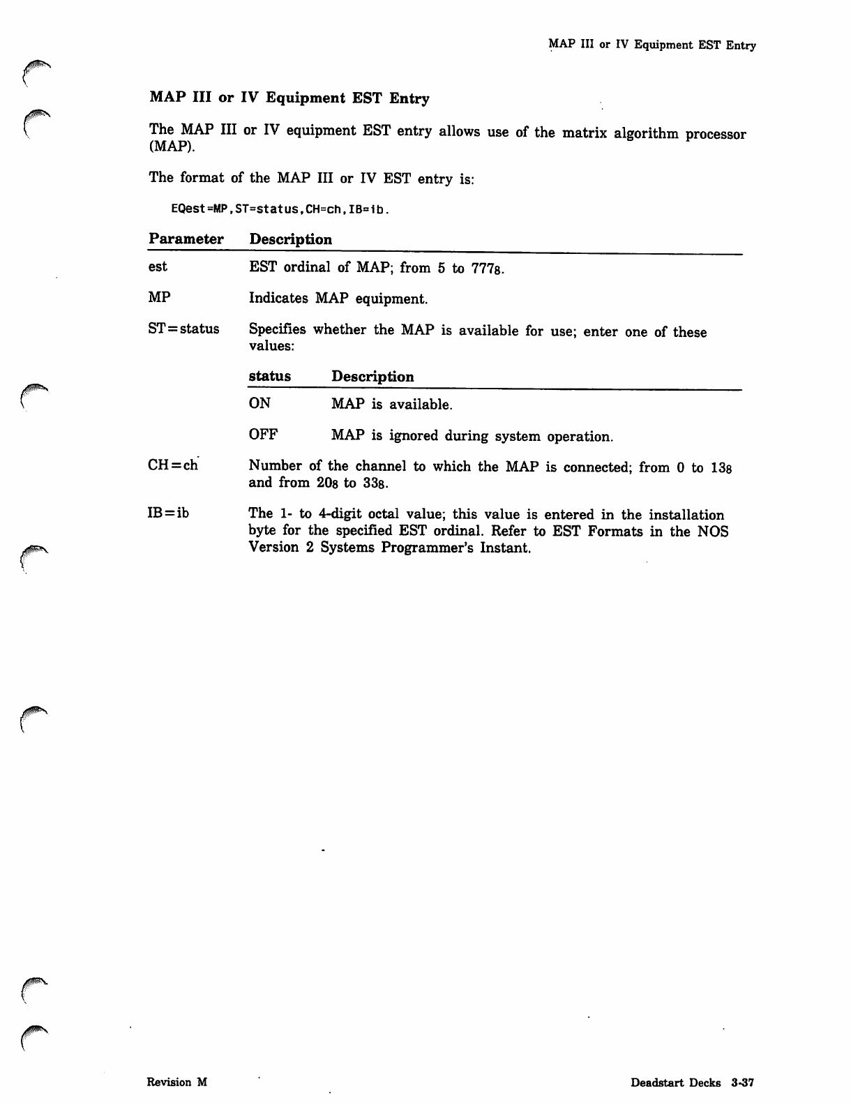
^PN
MAP III or IV Equipment EST Entry
MAP III or IV Equipment EST Entry
The MAP III or IV equipment EST entry allows use of the matrix algorithm processor
(MAP).
The format of the MAP III or IV EST entry is:
EQest=MP,ST=status,CH=ch,IB=ib.
Parameter Description
est EST ordinal of MAP; from 5 to 777s.
MP Indicates MAP equipment.
ST=status Specifies whether the MAP is available for use; enter one of these
values:
status Description
ON MAP is available.
OFF MAP is ignored during system operation.
CH=ch Number of the channel to which the MAP is connected; from 0 to 13s
and from 20s to 338.
IB=ib The 1- to 4-digit octal value; this value is entered in the installation
byte for the specified EST ordinal. Refer to EST Formats in the NOS
Version 2 Systems Programmer's Instant.
Revision M Deadstart Decks 3-37
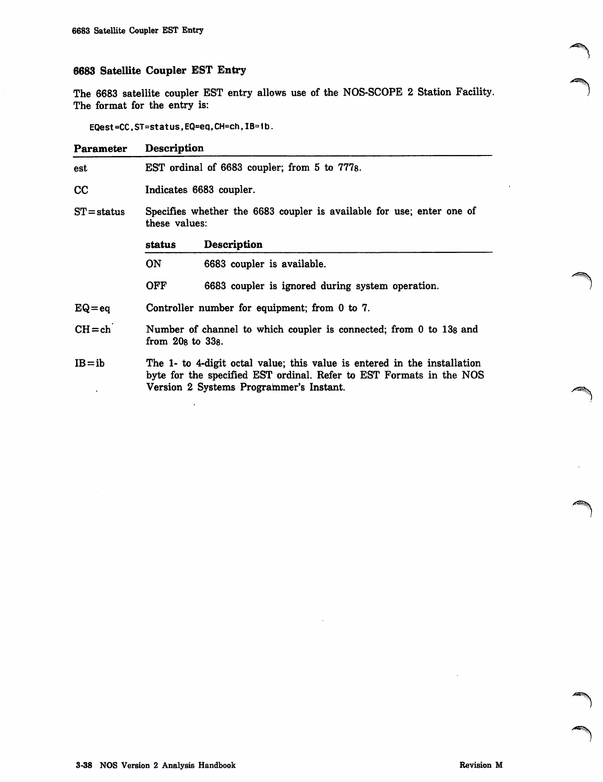
6683 Satellite Coupler EST Entry
6683 Satellite Coupler EST Entry
The 6683 satellite coupler EST entry allows use of the NOS-SCOPE 2 Station Facility.
The format for the entry is:
EQest=CC.ST=status,EQ=eq,CH=chfIB=1b.
Parameter Description
est EST ordinal of 6683 coupler; from 5 to 777s.
CC Indicates 6683 coupler.
ST=status Specifies whether the 6683 coupler is available for use; enter one of
these values:
status Description
ON 6683 coupler is available.
OFF 6683 coupler is ignored during system operation.
EQ=eq Controller number for equipment; from 0 to 7.
CH=ch Number of channel to which coupler is connected; from 0 to 138 and
from 208 to 33s.
IB=ib The 1- to 4-digit octal value; this value is entered in the installation
byte for the specified EST ordinal. Refer to EST Formats in the NOS
Version 2 Systems Programmer's Instant.
3-38 NOS Version 2 Analysis Handbook Revision M
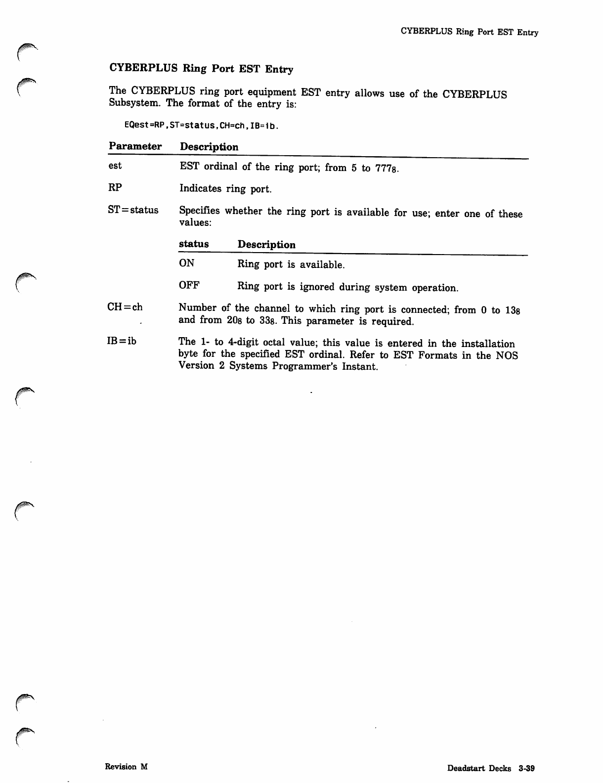
CYBERPLUS Ring Port EST Entry
CYBERPLUS Ring Port EST Entry
The CYBERPLUS ring port equipment EST entry allows use of the CYBERPLUS
Subsystem. The format of the entry is:
EQest=RP,ST=status,CH=ch,lB=ib.
Parameter Description
est
RP
ST=status
CH=ch
IB = ib
0ms
EST ordinal of the ring port; from 5 to 777s.
Indicates ring port.
Specifies whether the ring port is available for use; enter one of these
values:
status Description
ON Ring port is available.
OFF Ring port is ignored during system operation.
Number of the channel to which ring port is connected; from 0 to 13s
and from 208 to 33s. This parameter is required.
The 1- to 4-digit octal value; this value is entered in the installation
byte for the specified EST ordinal. Refer to EST Formats in the NOS
Version 2 Systems Programmer's Instant.
Revision M Deadstart Decks 3-39
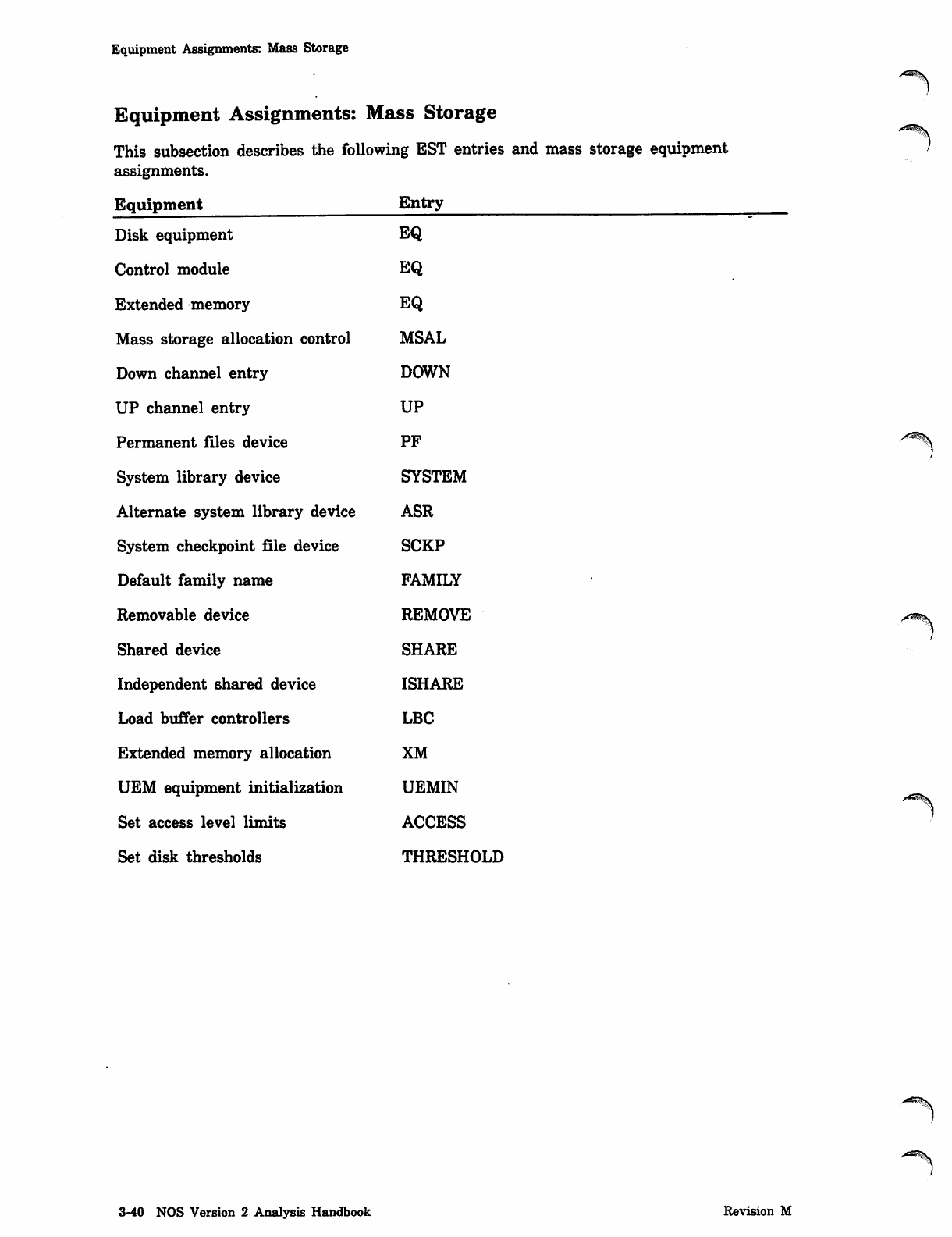
Equipment Assignments: Mass Storage
Equipment Assignments: Mass Storage
This subsection describes the following EST entries and mass storage equipment
assignments.
Equipment
Disk equipment
Control module
Extended memory
Mass storage allocation control
Down channel entry
UP channel entry
Permanent files device
System library device
Alternate system library device
System checkpoint file device
Default family name
Removable device
Shared device
Independent shared device
Load buffer controllers
Extended memory allocation
UEM equipment initialization
Set access level limits
Set disk thresholds
Entry
EQ
EQ
EQ
MSAL
DOWN
UP
PF
SYSTEM
ASR
SCKP
FAMILY
REMOVE
SHARE
ISHARE
LBC
XM
UEMIN
ACCESS
THRESHOLD
3-40 NOS Version 2 Analysis Handbook Revision M
NOS Mass Storage Concepts
NOS Mass Storage Concepts
( Following are descriptions that define the NOS mass storage terminology and
summarize the kinds of mass storage equipment assignments that can be specified in
the EQPDECK. Table 3-3 summarizes the various functions that a particular mass
storage device can serve. For example, if a device is an alternate system device (listed
under the Alternate System column in table 3-3), then it cannot be a system device; it
can contain temporary files, direct access files, and indirect access files; it can be a
master device or a nonmaster device; it cannot be removable; it can be either an
auxiliary device or a family device; and it can be a shared device or a link device.
Alternate System Device
Whereas a system device contains all the routines in the system library, an alternate
system device contains copies of selected system library routines. The ASR entry in the
EQPDECK (refer to ASR - Alternate System Library Device Assignment Entry later in
this section) specifies which mass storage devices are to be alternate system devices;
the *AD LIBDECK entry on the deadstart file specifies which system library routines
are to reside on these alternate system devices. During system processing, the routines
on the alternate system device are used instead of the ones on the system device.
This feature allows each routine in the system library to reside on the mass storage
device that is most appropriate to the routine's use. For example, instead of using an
844 system device, a routine that is frequently used could use extended memory,
which has a faster transfer rate, as an alternate system device.
NOTE
0ms
f Use care when specifying alternate system devices. A mistake could result in no
alternate system device defined. For example, suppose you specify the following in
your EQPDECK:
ASR=7.
ASR=11.
and you specify the following in the corresponding LIBDECK:
*AD,5,ABS/COMPASS
•AD.11.PP/1SJ
Since the system could not match equipment numbers between the EQPDECK and
the corresponding LIBDECK, the system library routine COMPASS will not be on
equipment 7 or 5. However, 1SJ will be on equipment 11 as specified.
Revision M Deadstart Decks 3-41
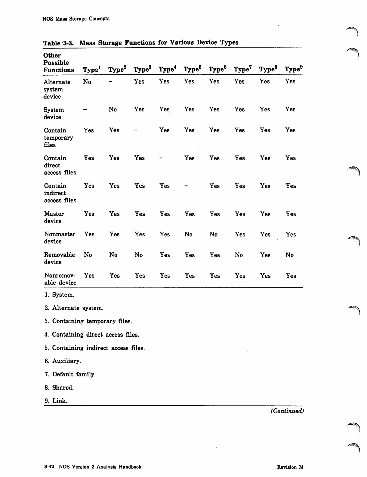
NOS Mass Storage Concepts
Table 3-3. Mass Storage Functions for Various Device Types
Other
Possible
Functions Type1 Type2 Type3 Type4 Type5 Type6 Type7 Type8 Type9
Alternate No Yes Yes Yes Yes Yes Yes Yes
system
device
System
device
No Yes Yes Yes Yes Yes Yes Yes
Contain Yes Yes Yes Yes Yes Yes Yes Yes
temporary
files
Contain
direct
access files
Yes Yes Yes mm Yes Yes Yes Yes Yes
Contain
indirect
access files
Yes Yes Yes Yes Yes Yes Yes Yes
Master
device
Yes Yes Yes Yes Yes Yes Yes Yes Yes
Nonmaster
device
Yes Yes Yes Yes No No Yes Yes Yes
Removable
device
No No No Yes Yes Yes No Yes No
Nonremov
able device
Yes Yes Yes Yes Yes Yes Yes Yes Yes
1. System.
2. Alternate system.
3. Containing temporary files.
4. Containing direct access files.
5. Containing indirect access files.
6. Auxiliary.
7. Default family.
8. Shared.
9. Link.
,A*^S
(Continued)
3-42 NOS Version 2 Analysis Handbook Revision M
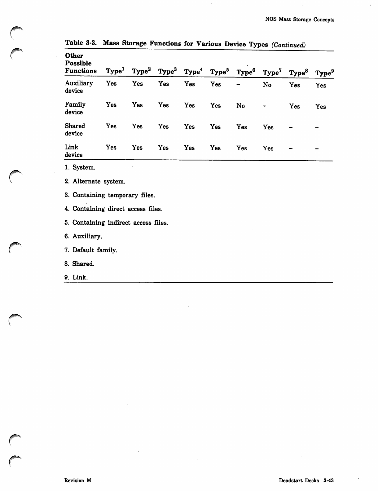
yf^V
NOS Mass Storage Concepts
Table 3-3. Mass Storage Functions for Various Device Types (Continued)
Other
Possible
Functions Type1 Type2 Type3 Type4 Type5 Type6 Type7 Type8 Type9
A u x i l i a r y Y e s Y e s Y e s Y e s Y e s - N o Y e s Y e s
device
F a m i l y Y e s Y e s Y e s Y e s Y e s N o - Y e s Y e s
device
S h a r e d Y e s Y e s Y e s Y e s Y e s Y e s Y e s
device
L i n k Y e s Y e s Y e s Y e s Y e s Y e s Y e s
device
1. System.
2. Alternate system.
3. Containing temporary files.
4. Containing direct access files.
5. Containing indirect access files.
6. Auxiliary.
7. Default family.
8. Shared.
9. Link.
Revision M Deadstart Decks 3-43
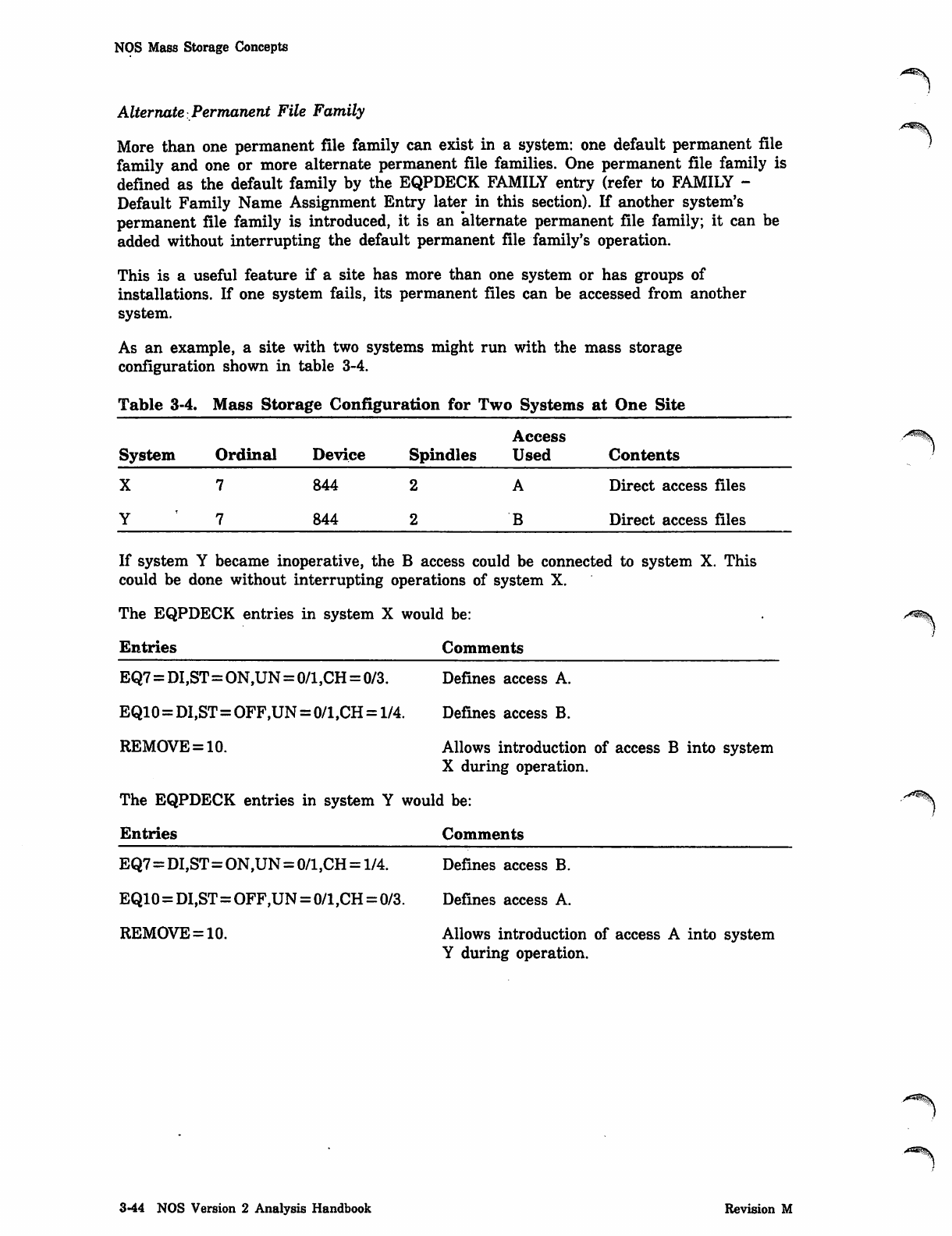
NOS Mass Storage Concepts
Alternate Permanent File Family
More than one permanent file family can exist in a system: one default permanent file
family and one or more alternate permanent file families. One permanent file family is
defined as the default family by the EQPDECK FAMILY entry (refer to FAMILY -
Default Family Name Assignment Entry later in this section). If another system's
permanent file family is introduced, it is an "alternate permanent file family; it can be
added without interrupting the default permanent file family's operation.
This is a useful feature if a site has more than one system or has groups of
installations. If one system fails, its permanent files can be accessed from another
system.
As an example, a site with two systems might run with the mass storage
configuration shown in table 3-4.
Table 3-4. Mass Storage Configuration for Two Systems at One Site
System Ordinal Device Spindles
Access
Used Contents
X
Y
7
7
844
844
Direct access files
Direct access files
If system Y became inoperative, the B access could be connected to system X. This
could be done without interrupting operations of system X.
The EQPDECK entries in system X would be:
Entries Comments
EQ7=DI,ST=ON,UN = 0/l,CH = 0/3.
EQ10 = DI,ST=OFF,UN = 0/1.CH = 1/4.
REMOVE=10.
Defines access A.
Defines access B.
Allows introduction of access B into system
X during operation.
The EQPDECK entries in system Y would be:
Entries Comments
EQ7=DI,ST=ON,UN=0/1 ,CH = 1/4.
EQ10 = DI,ST=OFF,UN = 0/l,CH = 0/3.
REMOVE = 10.
Defines access B.
Defines access A.
Allows introduction of access A into system
Y during operation.
3-44 NOS Version 2 Analysis Handbook Revision M
0f&S
NOS Mass Storage Concepts
To allow for introduction of an alternate permanent file family:
1. Define the equipment to be introduced or removed in the EQPDECKs for both
systems (refer to the previous example).
2. Specify all of the equipment that may be introduced or removed during system
processing as removable.
3. When you want to introduce the equipment into a system, use the ON operator
command to indicate that the equipment that was set to the OFF position in the
system in.operation is now available. This introduces the alternate permanent file
family.
4. Enable the validation files for the family by entering X.ISF(FM=familyname).
Refer to section 20, System File Initialization.
Auxiliary Device
An auxiliary device is a mass storage device that is not part of a family. It is a
supplementary permanent file storage device, which may be privately owned (PRIVATE)
or may be shared by many users (PUBLIC). An auxiliary device resides on either a
removable or nonremovable device. On the permanent file entry (PF) for an auxiliary
device (for both a removable device and a fixed device without packs), a pack name is
specified instead of a family name.
Refer to the NOS Version 2 Reference Set, Volume 3, for additional information
about private and public auxiliary devices.
As an example, four 844 spindles to be used as a public auxiliary device could be
defined as follows:
EQ6=DI,ST=0N,UN=174,CH=2.
PF=6,X,name.
Private auxiliary devices can be created only after the system is up and running. An
operator can make a public device a private device by entering the INITIALIZE
command with the UN and TY=X parameters (refer to section 8, K-Display
Utilities).
Revision M Deadstart Decks 3-45
NOS Mass Storage Concepts
Family Device /^s
A family device is a mass storage device that is part of a family. It can be either a
removable device or a nonremovable device. The only difference between the two is
that a nonremovable device containing permanent files can also contain a copy of the
system library and/or temporary files. Refer to Alternate Permanent File Family earlier
in this section.
On the PF entry, the family name is important if two systems' permanent files are to
run on the same system. A user can only use one family of permanent files at one
time; if the user does not specify one, the default FAMILY entry is used.
A family device can contain direct and indirect access files. These files are defined in
the NOS Version 2 Reference Set, Volume 3. The files that are allowed are set by
the device mask and secondary mask on the PF entry.
Link Device
Either extended core storage or extended semiconductor memory or STORNET is the
medium through which several computer systems are linked to form a multimainframe
operating environment (shared MMF). The link device contains the information
necessary to manage the mass storage that can be shared by more than one
mainframe. For a description of shared mass storage, refer to SHARE - Shared Device
Entry and ISHARE - Independent Shared Device Entry later in this section.
Master Device
The master device contains all of the permanent file catalog entries, indirect access
files, and file permits for a specific user. If permanent file access is required, the user's
master device must be available on the system, unless all access is to be to an
auxiliary device. The user index and family name uniquely describe a user's master
device.
Each master device is organized into five logical sections.
1. Allocation information.
A master device, like all mass storage devices, maintains device labels and track ^^^
reservation tables (TRTs). 1
The device label contains information describing the device, such as family name
and user mask, as well as locations of permit and catalog information and indirect
access files. Refer to the INITIALIZE - Initialization Entry later in this section.
The TRT is the key to allocating information on the master device and to
describing the physical layout of data on the device. Refer to APRDECK later in
this section.
2. Catalog information.
Catalog entries are used to determine the locations and attributes of permanent
files. The catalogs for a master device are allocated to contain catalog entries for
a specific group of user indexes. A particular catalog track may contain entries
for many users, the number depending upon the number of catalog tracks defined
for the device. The user index provides the mechanism for differentiating between
user's files on a particular catalog track.
3-46 NOS Version 2 Analysis Handbook Revision M
NOS Mass Storage Concepts
3. Permit information.
Users can explicitly or implicitly allow other users to access their permanent files.
Refer to the PERMIT command in the NOS Version 2 Reference Set, Volume 3.
Information describing the permission for all permanent files is in the permit file.
Catalog entries contain a relative sector address within this permit file for
permissions that have been granted for the file.
4. Indirect access files.
The master device contains all of the user's indirect access files. These files can
be accessed by commands that generate working copies for manipulation by the
user.
5. Direct access files.
Direct access files can reside either on the master device or on another device in
the family, depending on the device masks specified on the PF entries. Direct
access files are files that can be accessed at their location on mass storage. A
working copy is not generated, so any updates or alterations made to the files are
permanent.
Revision M Deadstart Decks 3-47
NOS Mass Storage Concepts
Multispindle Device
To accommodate files that are larger than one device, you can specify multispindle
device assignments. Up to eight spindles of 844 disk drives or up to three spindles of
885 disk drives can be included in the equipment definition of one logical device, when
the device is first defined. All spindles must be available for access whenever the
device is accessed.
Multispindle devices are treated as one logical device, having a track size equal to n
times the single-spindle track size (n is the number of spindles in the device). The
tracks of an n-spindle device are broken down into n equally-sized segments, each
having a length equal to the single-spindle track size. Each segment is contained on
a different physical unit.
844 Expander
A nonexpanded controller can have up to eight disk drives connected to it. Each of the
connection paths is called a port and is identified by a port number ranging from 0 to ^^
7. An expander (10304 extender) is a hardware device that can be connected between j
controllers and 844 disk drives to increase the number of disk drives that each
controller can access.
The expander can be used only with 844-21 drives, although all equipment definitions
and equipment driving software support the 64-drive addressing scheme for both
844-21 (DI/DK) and 844-41 (DJ/DL) type equipment.
Each expander consists of either two or four expansion elements. An expansion
element connects to a single controller port and forms a connection path from that
port to from one through eight disk drives. The connection paths between an
expansion element and the eight possible disk drives are called ranks and are
identified by a rank number ranging from 0 to 7. Two expanders with four expansion
elements each can be connected to a single controller to allow that controller to
access a maximum of 64 disk drives. Each expansion element, however, is logically
independent and, as such, could be connected to any port of any controller.
3-48 NOS Version 2 Analysis Handbook Revision M
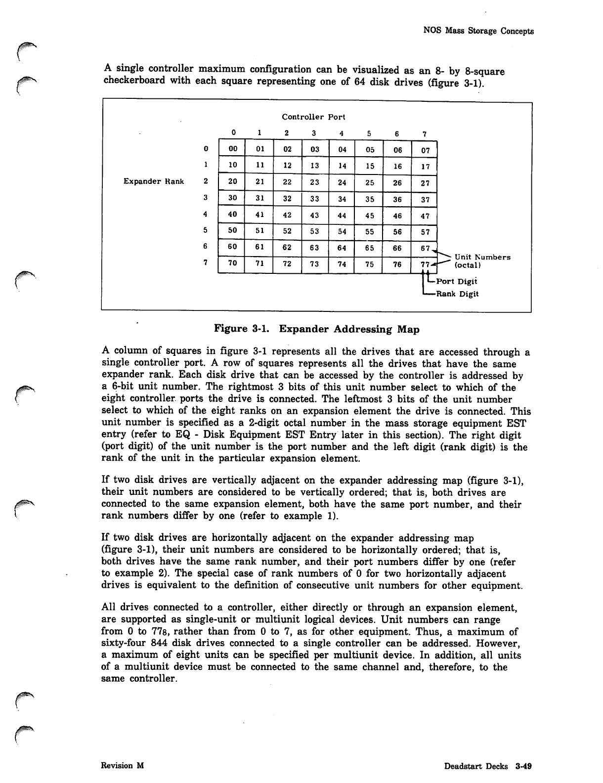
NOS Mass Storage Concepts
A single controller maximum configuration can be visualized as an 8- by 8-square
checkerboard with each square representing one of 64 disk drives (figure 3-1).
0ms,
0H$mS
Expander Rank
Controller
2 3
Port
4
00 01 02 03 04 05 06 07
_^ Unit Numbers
""^ (octal)
10 11 12 13 14 15 16 17
20 21 22 23 24 25 26 27
30 31 32 33 34 35 36 37
40 41 42 43 44 45 46 47
50 51 52 53 54 55 56 57
60 61 62 63 64 65 66 67,,
70 71 72 73 74 75 76 77-*
tPort Digit
Rank Digit
Figure 3-1. Expander Addressing Map
A column of squares in figure 3-1 represents all the drives that are accessed through a
single controller port. A row of squares represents all the drives that have the same
expander rank. Each disk drive that can be accessed by the controller is addressed by
a 6-bit unit number. The rightmost 3 bits of this unit number select to which of the
eight controller ports the drive is connected. The leftmost 3 bits of the unit number
select to which of the eight ranks on an expansion element the drive is connected. This
unit number is specified as a 2-digit octal number in the mass storage equipment EST
entry (refer to EQ - Disk Equipment EST Entry later in this section). The right digit
(port digit) of the unit number is the port number and the left digit (rank digit) is the
rank of the unit in the particular expansion element.
If two disk drives are vertically adjacent on the expander addressing map (figure 3-1),
their unit numbers are considered to be vertically ordered; that is, both drives are
connected to the same expansion element, both have the same port number, and their
rank numbers differ by one (refer to example 1).
If two disk drives are horizontally adjacent on the expander addressing map
(figure 3-1), their unit numbers are considered to be horizontally ordered; that is,
both drives have the same rank number, and their port numbers differ by one (refer
to example 2). The special case of rank numbers of 0 for two horizontally adjacent
drives is equivalent to the definition of consecutive unit numbers for other equipment.
All drives connected to a controller, either directly or through an expansion element,
are supported as single-unit or multiunit logical devices. Unit numbers can range
from 0 to 778, rather than from 0 to 7, as for other equipment. Thus, a maximum of
sixty-four 844 disk drives connected to a single controller can be addressed. However,
a maximum of eight units can be specified per multiunit device. In addition, all units
of a multiunit device must be connected to the same channel and, therefore, to the
same controller.
Revision M Deadstart Decks 3-49
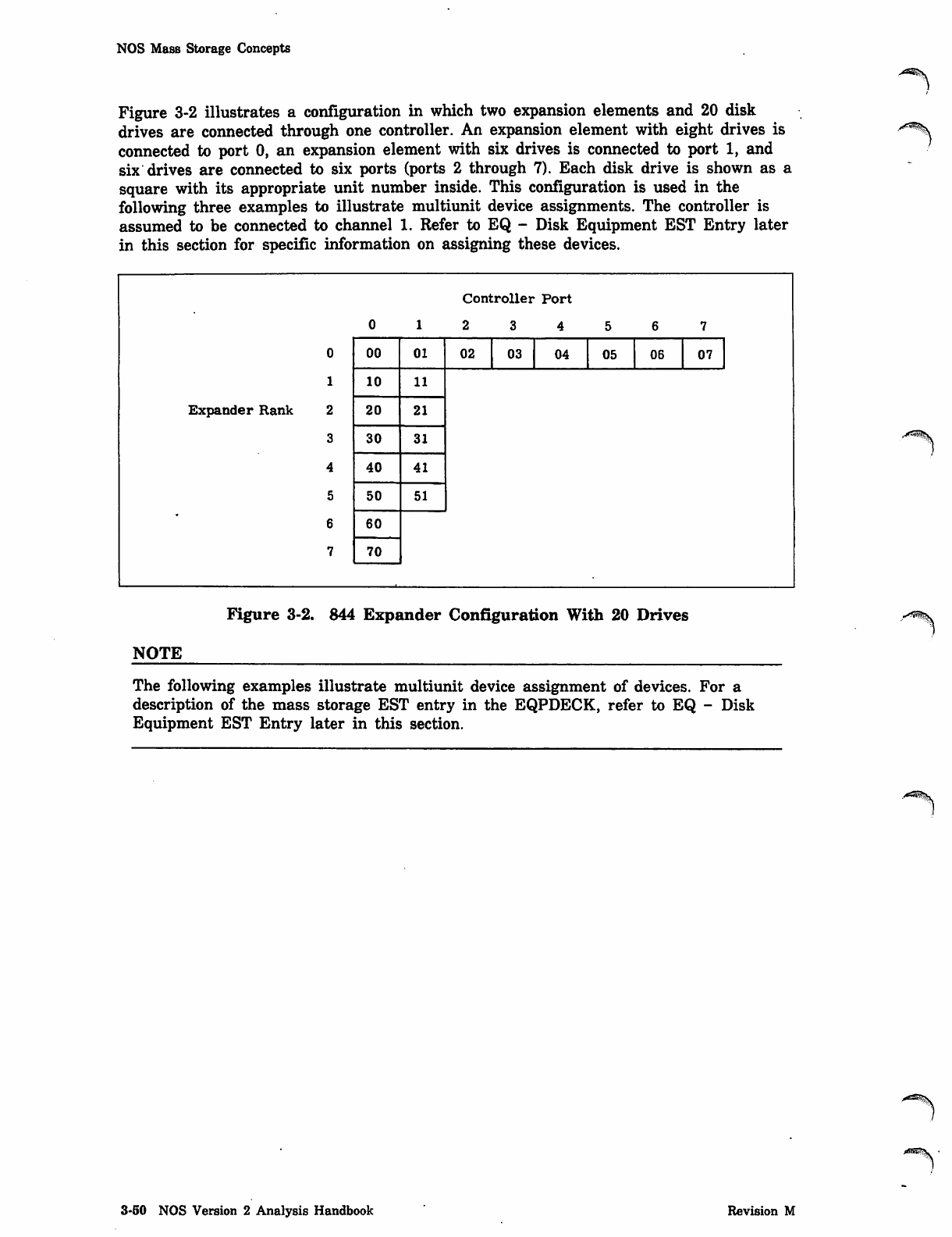
NOS Mass Storage Concepts
Figure 3-2 illustrates a configuration in which two expansion elements and 20 disk
drives are connected through one controller. An expansion element with eight drives is
connected to port 0, an expansion element with six drives is connected to port 1, and
six drives are connected to six ports (ports 2 through 7). Each disk drive is shown as a
square with its appropriate unit number inside. This configuration is used in the
following three examples to illustrate multiunit device assignments. The controller is
assumed to be connected to channel 1. Refer to EQ - Disk Equipment EST Entry later
in this section for specific information on assigning these devices.
Expander Rank
Controller Port
2 3 4
00 01 02 03 04 05 06 07
10 11
20 21
30 31
40 41
50 51
60
70
Figure 3-2. 844 Expander Configuration With 20 Drives
NOTE
The following examples illustrate multiunit device assignment of devices. For a
description of the mass storage EST entry in the EQPDECK, refer to EQ - Disk
Equipment EST Entry later in this section.
3-50 NOS Version 2 Analysis Handbook Revision M
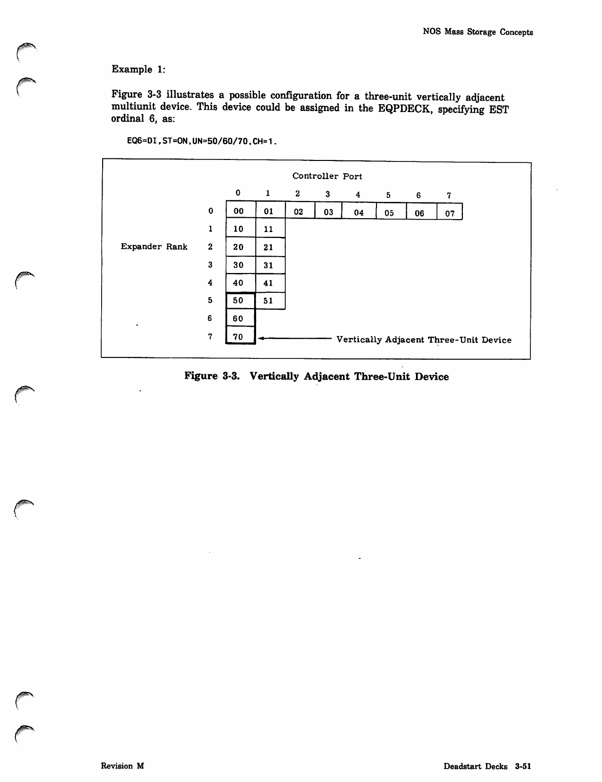
NOS Mass Storage Concepts
Example 1:
Figure 3-3 illustrates a possible configuration for a three-unit vertically adjacent
multiunit device. This device could be assigned in the EQPDECK, specifying EST
ordinal 6, as:
EQ6=DI,ST=ON,UN=50/60/70,CH=1.
Expander Rank
Controller Port
2 3 4 5 6 7
00 01 02 03 04 05 06 07
10 11
20 21
30 31
40 41
50 51
60
70 vertically Auiaceni xnree-unu uevice
Figure 3-3. Vertically Adjacent Three-Unit Device
Revision M Deadstart Decks 3-51
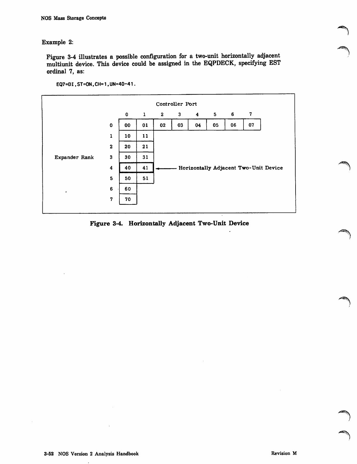
NOS Mass Storage Concepts
Example 2:
Figure 3-4 illustrates a possible configuration for a two-unit horizontally adjacent
multiunit device. This device could be assigned in the EQPDECK, specifying EST
ordinal 7, as:
EQ7=DI,ST=0N,CH=1,UN=40-41
Expander Rank
Controller Port
2 3 4 5 6 7
00 01 02 03 04 05 06 07
10 11
20 21
30 31
40 41
50 51
60
70
Figure 3-4. Horizontally Adjacent Two-Unit Device
3-52 NOS Version 2 Analysis Handbook Revision M
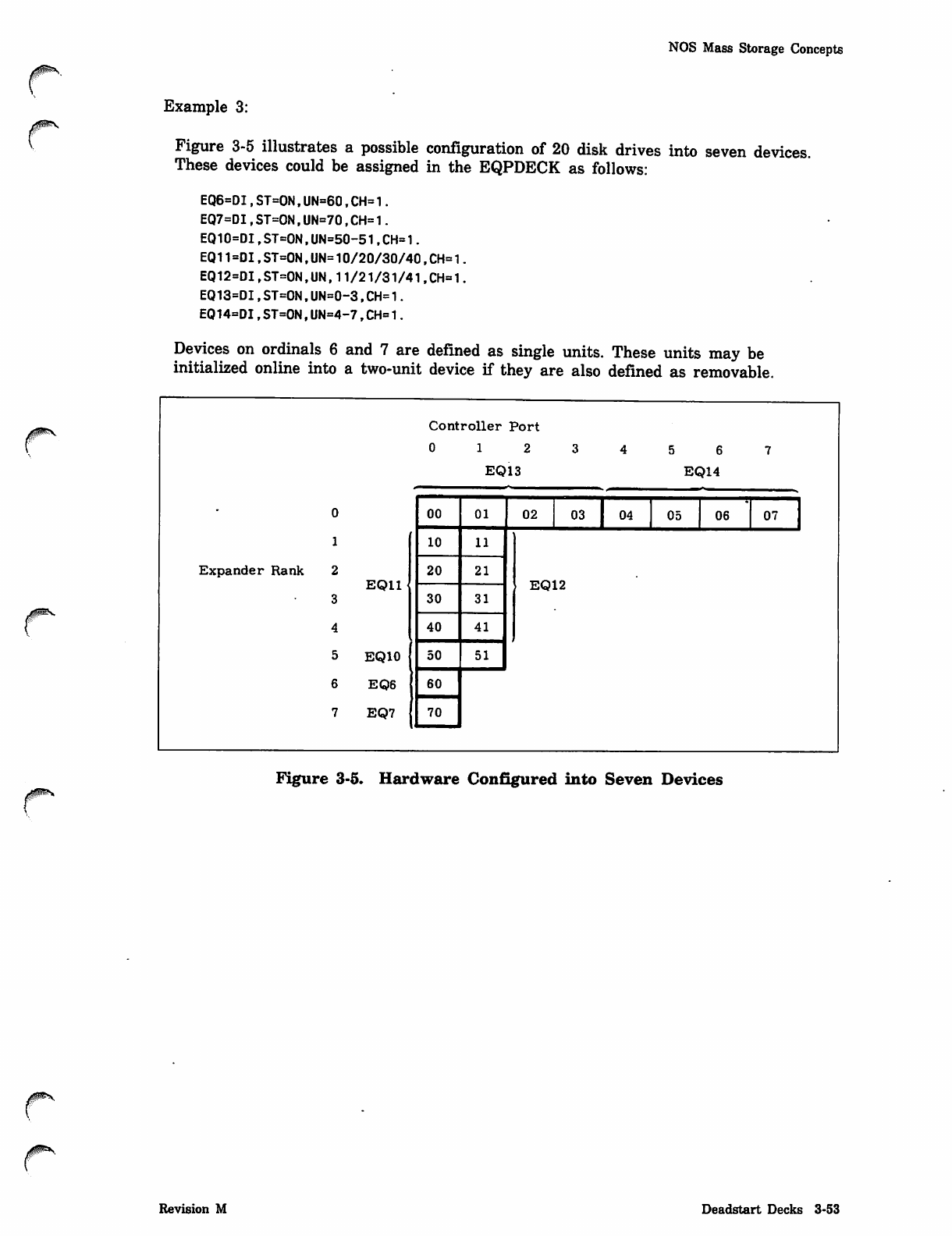
NOS Mass Storage Concepts
Example 3:
Figure 3-5 illustrates a possible configuration of 20 disk drives into seven devices.
These devices could be assigned in the EQPDECK as follows:
EQ6=DI,ST=ON,UN=60,CH=1.
EQ7=DI,ST=0N,UN=70,CH=1.
EQ10=DI,ST=ON,UN=50-51,CH=1.
EQ11=DI,ST=0N,UN=10/20/30/40,CH=1.
EQ12=DI,ST=ON,UN,11/21/31/41,CH=1.
EQ13=DI,ST=0N,UN=0-3,CH=1.
EQ14=DI,ST=0N,UN=4-7,CH=1.
Devices on ordinals 6 and 7 are defined as single units. These units may be
initialized online into a two-unit device if they are also defined as removable.
Expander Rank
EQll
EQ10
EQ6
EQ7
Controller Port
0 1 2 3
EQ13
5 6
EQ14
00 01 02 03 04 05 06 07
10 11
EQ12
20 21
30 31
40 41
50 51
60
70
j/ms
Figure 3-5. Hardware Configured into Seven Devices
Revision M Deadstart Decks 3-53
NOS Mass Storage Concepts
Nonremovable Device
S*^S
A nonremovable device cannot be physically removed during system operation. It can 1
contain a copy of the system library, which means it is a system device; it can also be
available for temporary files. It may or may not contain permanent files.
Removable Device
A removable device can be logically or physically added or removed during system
operation without causing system malfunction.
A device is specified as removable with the REMOVE entry in the EQPDECK.
During deadstart, a removable device is recovered just as is any other mass storage
device, if the status is on. If the device is not available, then the status is displayed
for the operator (E,M display).
Removable devices can contain permanent files but cannot contain the system library
or temporary files, because a device containing active files (such as temporary or ^^
library files) cannot be removed from the system. A removable device can be either /^\
an auxiliary device or an alternate permanent file family device.
Shared Device
A shared device contains permanent files that can be accessed by more than one
mainframe. To have these permanent files accessible to the mainframe, the device must
be defined as shared in the mainframe. Refer to SHARE - Shared Device Entry and
ISHARE - Independent Shared Device Entry later in this section.
A shared device can be removable. However, when unloading a shared device, it must }
be in global unload status before you remove it. Refer to the DSD commands
UNLOAD and MOUNT in section 5 for more information concerning removable
shared devices.
System Device
The system device is a nonremovable device on which the system library resides. It can
also contain permanent and temporary files.
Temporary File Device
The temporary file device is a nonremovable device on which the following temporary
system files reside:
• Library files
• Local files
© Queued files
• Rollout files
• System files
• Timed/event rollout files ^^s.
3-54 NOS Version 2 Analysis Handbook Revision M
Ji^V
NOS Mass Storage Concepts
Buffered Disks
Buffered disks are those disks for which the system provides an extended memory data
buffer. The following buffered disks are supported on the mainframes indicated:
• The 819 Disk Storage Subsystem is available only on model 176. The buffer is
kept in LCME.
• The 885-42 Disk Storage Subsystem is available on all models except CYBER
180-class machines and model 176. The buffer is kept in ESM.
• The 895 Disk Storage Subsystem is available on all CYBER 180-class machines
except models 810, 815, 825, and 830. The buffer is kept in UEM.
• The 887 and 9853 Disk Storage Subsystems are available only on models 860,
960, 990, and 995. The buffer is kept in UEM.
• Buffered disks are not available on models 810, 815, 825, and 830.
Using extended memory as a data buffer provides the following capabilities.
• The system treats the buffer as a disk cache so that multiple requests for a
particular disk data block can potentially be satisfied by doing only one disk read.
• The system buffers data to maintain maximum transfer rates regardless of the
user's buffer size.
To maintain maximum transfer rates, a CPU program that resides in CPUMTR
controls the buffered disk I/O request processing. The system maintains the standard
disk I/O interface to the user's programs.
The buffered disk error reporting process logs read/write errors in the binary
maintenance log. An unrecovered read/write error is also logged in the system error
log and an error message appears at the system control point. The binary
maintenance log must be processed by the Hardware Performance Analyzer (HPA) to
get detailed information concerning buffered device errors.
The amount of I/O buffer space in extended memory is important to system
performance. Refer to XM - Declare Extended Memory Space for Buffers or User
Access later in this section.
There may be situations when a particular user job runs slower with buffered disks.
This happens if the job issues CIO reads when a buffer is full or issues CIO writes
when a buffer is empty. (Both cases indicate inefficient programming techniques.) You
can speed up the job by entering the DSD command ENABLE,LOGGING. The system
will perform faster I/O and issue warning messages to the job dayfile.
Revision M Deadstart Decks 3-55
NOS Mass Storage Concepts
Extended Memory Overview
Extended memory (EM) refers to the five types of additional memory used by NOS to
supplement central memory space and connect mainframes. This extended memory can
be used to store programs and data, but not to execute programs. Shown below are the
five types of extended memory and the mainframes that support each type. Also shown
are the maximum EM size supported by each mainframe, how each mainframe connects
to the extended memory, and what buffered devices are supported for each EM type.
Extended
Memory Mainframe
Maximum
Size
Mainframe
Connection
Buffered
Device 5
ECS All 2MW CPU port,6 DDP
ESM All 16MW CPU port,6 LSP 885-42
LCME 176 2MW CPU port 819
STORNET A ll " 4MW LSP
UEM 815,825,835,865,875
810,830
840,845,850,855,860,
870, 910
990,995
2MW
8MW
16MW
8MW
No connection,
part of mainframe's
main memory
895, 887,
9853
Physical Configuration
Extended core storage (ECS) is an external memory available for all mainframes. ECS
connects to the mainframe using either a CPU port6 or a distributive data path (DDP)
through a peripheral processor.
Extended semiconductor memory (ESM) is an external memory available for all
mainframes. ESM connects to the mainframe using either a CPU port or a low-speed
port (LSP) through a peripheral processor.
Large central memory extended (LCME) is an external memory available only for
model 176 mainframes. LCME connects to the model 176 using a central processor
unit (CPU) port.
STORNET is an external memory available for all CYBER 170 and CYBER 180
mainframes. STORNET connects to the mainframe using a low-speed port (LSP)
through a peripheral processor.
<^^5S
5. The buffered devices shown are not necessarily supported on all of the mainframe types indicated.
6. A CPU port connection is not available on CYBER 180-class machines. CPU port on model 176 machines
can only connect to LCME.
3-56 NOS Version 2 Analysis Handbook Revision M
NOS Mass Storage Concepts
Unified extended memory (UEM) is a part of the mainframe's main memory and is
separated from central memory by a partition defined at deadstart time by the site.
All extended memory except STORNET is accessed by special instructions
Instructions exist for multiple word transfers (FORTRAN: Level 1 variables;
COMPASS: RE/WE instructions) and single word transfers (FORTRAN- Level 2
variables; COMPASS: RX/WX instructions). The multiple word transfers are available
on all mainframe types; the single word transfers are available only with LCME and
UEM on models 176, 865, 875, and CYBER 180-class machines.
Logical Configuration
Extended memory can be used for several purposes. The physical characteristics of the
various extended memory types differ, which affects the ways in which extended
memory can best be used. The possibilities are:
• To connect mainframes in a multimainframe environment (ESM, ECS and
STORNET).
• To store system routines and data files (all EM types).
• To supplement user central memory space (all EM types except STORNET).
• To provide a cache buffer for buffered I/O devices (LCME, ESM, and UEM).
ESM, ECS, or STORNET can be used as a link device to interconnect mainframes in a
multimainframe environment. UEM cannot be used as the link device since it is part
of a mainframe's main memory. For additional information concerning multimainframe
operations, refer to section 13, Multimainframe Operations.
Extended memory can be used as a mass storage device. The following system files
can be made extended memory resident as opposed to using central memory or disk
space.
System Files Description
Operating system
Temporary and
rollout
Secondary rollout
The alternate system residency EQPDECK entry ASR defines a
device to be an alternate system device. LIBDECK directives
specify which system library routines are to be placed on the
alternate system device.
The EQPDECK entry MSAL,T=est. or MSAL,R=est., where est
is the EST ordinal of the EM device, causes the system to use
extended memory as a mass storage device for temporary files or
rollout files.
The EQPDECK entry MSAL,S=est., where est is the EST ordinal
of the EM device, causes jobs that are less than a specified size
to be rolled out to extended memory. The IPRDECK entry SRST
defines the size of the rollout files allowed in extended memory.
Revision M Deadstart Decks 3-57
NOS Mass Storage Concepts
System files should be placed in extended memory only if a performance improvement
can be gained. Whether performance improves or not depends on your production
environment, including memory and input/output requirements, available central and
extended memory, and available disk units and channels.
The amount of memory available to a user job can be increased by defining
user-accessible extended memory. NOS allows user data structures to reside in
memory external to the job's field length. (Refer to COMPASS and FORTRAN
reference manuals.)
A portion of extended memory is reserved for users by the XM EQPDECK entry. The
user's memory is reserved in allocation units dependent on the amount of
user-accessible extended memory defined at deadstart. The minimum allocation unit
(user EM block size [M = million] UEBS) varies as follows. Service limits are defined
for the user in the IPRDECK in UEBS units.
At least But less than Allocation unit (UEBS)
1000 words
IM words
2M words
4M words
8M words
IM words
2M words
4M words
8M words
16M words
10008
2000s
40008
100008
20000s
This means that if you define 3 million words of user-accessible extended memory and
a user executes RFL(EC=1), that user will be assigned 40008 words of extended
memory.
Extended memory provides a cache buffer for buffered I/O devices. Space is allocated
by the system for buffered I/O with the XM EQPDECK entry. In most cases, system
performance improves as the amount of extended memory defined for buffered I/O
increases. However, ample space must be available for other uses.
3-58 NOS Version 2 Analysis Handbook Revision M
00&S
NOS Mass Storage Concepts
CM and UEM Size Specification and Determination
When UEM is defined, its size is specified on the EQ EQPDECK entry for UEM. For
models 865 and 875, the remaining memory is used for central memory. On CYBER
180-class machines, the remaining memory is divided between native mode (NOS/VE or
EI) and central memory. If running in dual-state mode, the VE CMRDECK entry
specifies the memory for NOS/VE. If running NOS only, central memory size equals
the total memory size minus the EM size minus the EI size.
Simultaneous Use of Two Types of Extended Memory
NOS allows the simultaneous use of two types of extended memory in the following
cases
•
Models 865 and 875 can access both UEM and ESM/ECS simultaneously. The
recommended use of this combination of extended memory is to define ESM/ECS
for system file residence and/or as a link device in a multimainframe environment
and to define UEM for user-accessible extended memory. Since the main memory
size for models 865 and 875 is limited to two million words, central memory space
is given up for any UEM defined. Also, since ESM/ECS is an external device,
fewer memory conflicts result when it is accessed rather than UEM.
In this case, an EQ entry is required in the EQPDECK for ESM/ECS as well as
ASR and MSAL entries, as desired. User access is restricted to UEM via the XM
entry when the EM parameter is specified.
CYBER 180-class machines can also access both UEM and ESM/ECS/STORNET
simultaneously. The purpose of the ESM/ECS/STORNET access is to allow
connection of CYBER 180-class machines into a multimainframe environment. In
this case, ESM/ECS is defined in the EQPDECK as the link device and UEM is
defined for system files, I/O buffers, and user-accessible extended memory.
An EQ EQPDECK entry is required for both ESM/ECS/STORNET, but is not
required for UEM. The ESM/ECS/STORNET EQ entry defines the extended
memory as a link device via the LSP/DDP. The UEM EQ, if present, entry allows
the use of extended memory as a mass storage device. An XM entry allocates
extended memory for buffered I/O and user access.
Revision M Deadstart Decks 3-59
Specifying Ranges of EST Ordinals
Specifying Ranges of EST Ordinals
Several EQPDECK entries allow you to specify multiple EST ordinals in the same
entry. For example, instead of entering
REMOVE=6,7,10,11,12.
you can enter:
REMOVE=6-12.
Ranges of ordinals can be mixed with individual ordinals, such as:
REMOVE=6,10-16.23.
Empty ordinals within a range are ignored. For example, specifying a range of 6
through 12 will ignore an unassigned ordinal 7. However, inappropriate devices
within a range or specified individually (such as specifying a printer as a removable
device) are diagnosed as errors.
EQ — Disk Equipment EST Entry
The purpose of the mass storage equipment (EQ) entries is to describe all mass storage
peripheral equipment. This includes disk equipment and extended memory equipment.
NOS requires that at least 6 million words of mass storage be available.
There can be up to 200 logical mass storage devices, and therefore, up to 200 mass
storage EST entries (this number does not include ordinals 0 through 4, which are
reserved for specific uses). An entry, however, can refer to more than one physical ^^\
unit. For example, two 885 spindles can be defined as either two logical devices with
two EQ entries or as one logical device with one EQ entry.
A unit is a dual-access unit if it is accessed by one mainframe through two different
controller-channel access routes. To define a unit as a dual-access unit with its EQ
entry, specify two channel parameters. The channels should be from two controllers.
Only one channel of a dual-channel access controller is recommended for use on a
single mainframe, since using both channels of the controller results in a performance
degradation rather than an improvement. Therefore, if both channel accesses of a
controller are physically connected to the same mainframe, you should define only
one of them on an EQ entry.
NOTE
A device's EQ entry must precede any of the following entries for that device: ASR,
MSAL, REMOVE, PF, SYSTEM, FAMILY, INITIALIZE, SHARE, ISHARE, ACCESS,
and THRESHOLD. If you redefine a device's EQ entry, then you must also redefine
those entries.
y*^%.
3-60 NOS Version 2 Analysis Handbook Revision M
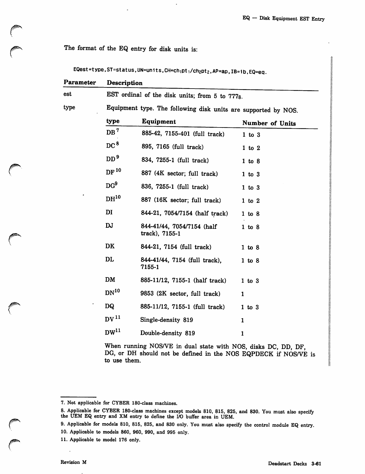
EQ — Disk Equipment EST Entry
0ams
The format of the EQ entry for disk units is:
EQest =type,ST=status,UN=units,CH=ch,pt1/ch2pt2.AP=ap,IB=ib,EQ=eq.
Parameter Description
est EST ordinal of the disk units; from 5 to 777s.
type Equipment type. The following disk units are supported by NOS.
type Equipment Number of Units
DB7 885-42, 7155-401 (full track) 1 to 3
D C 8 8 9 5 , 7 1 6 5 ( f u l l t r a c k ) 1 t o 2
DD9 834, 7255-1 (full track) 1 to 8
DF10 887 (4K sector; full track) 1 to 3
DG9 836, 7255-1 (full track) 1 to 3
DH10 887 (16K sector; full track) 1 to 2
DI 844-21, 7054/7154 (half track) 1 to 8
DJ 844-41/44, 7054/7154 (half 1 to 8
track), 7155-1
D K 8 4 4 - 2 1 , 7 1 5 4 ( f u l l t r a c k ) 1 t o 8
DL 844-41/44, 7154 (full track), 1 to 8
7155-1
DM 885-11/12, 7155-1 (half track) 1 to 3
DN10 9853 (2K sector, full track) 1
f^ DQ 885-11/12, 7155-1 (full track) 1 to 3
DVn Single-density 819 1
DW11 Double-density 819 1
When running NOS/VE in dual state with NOS, disks DC, DD, DF,
DG, or DH should not be defined in the NOS EQPDECK if NOS/VE is
to use them.
7. Not applicable for CYBER 180-class machines.
8. Applicable for CYBER 180-class machines except models 810, 815, 825, and 830. You must also specify
the UEM EQ entry and XM entry to define the I/O buffer area in UEM.
9. Applicable for models 810, 815, 825, and 830 only. You must also specify the control module EQ entry.
10. Applicable to models 860, 960, 990, and 995 only.
11. Applicable to model 176 only.
Revision M Deadstart Decks 3-61
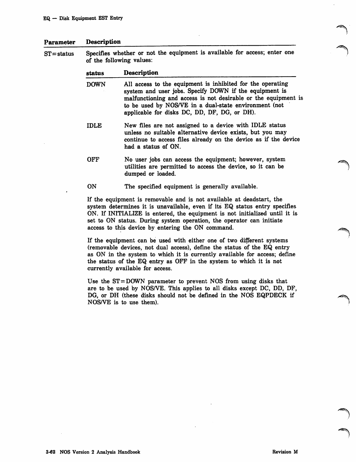
EQ — Disk Equipment EST Entry
Parameter Description
ST=status Specifies whether or not the equipment is available for access; enter one
of the following values:
status Description
DOWN
IDLE
OFF
ON
All access to the equipment is inhibited for the operating
system and user jobs. Specify DOWN if the equipment is
malfunctioning and access is not desirable or the equipment is
to be used by NOS/VE in a dual-state environment (not
applicable for disks DC, DD, DF, DG, or DH).
New files are not assigned to a device with IDLE status
unless no suitable alternative device exists, but you may
continue to access files already on the device as if the device
had a status of ON.
No user jobs can access the equipment; however, system
utilities are permitted to access the device, so it can be
dumped or loaded.
The specified equipment is generally available.
If the equipment is removable and is not available at deadstart, the
system determines it is unavailable, even if its EQ status entry specifies
ON. If INITIALIZE is entered, the equipment is not initialized until it is
set to ON status. During system operation, the operator can initiate
access to this device by entering the ON command.
If the equipment can be used with either one of two different systems
(removable devices, not dual access), define the status of the EQ entry
as ON in the system to which it is currently available for access; define
the status of the EQ entry as OFF in the system to which it is not
currently available for access.
Use the ST=DOWN parameter to prevent NOS from using disks that
are to be used by NOS/VE. This applies to all disks except DC, DD, DF,
DG, or DH (these disks should not be defined in the NOS EQPDECK if
NOS/VE is to use them).
3-62 NOS Version 2 Analysis Handbook Revision M
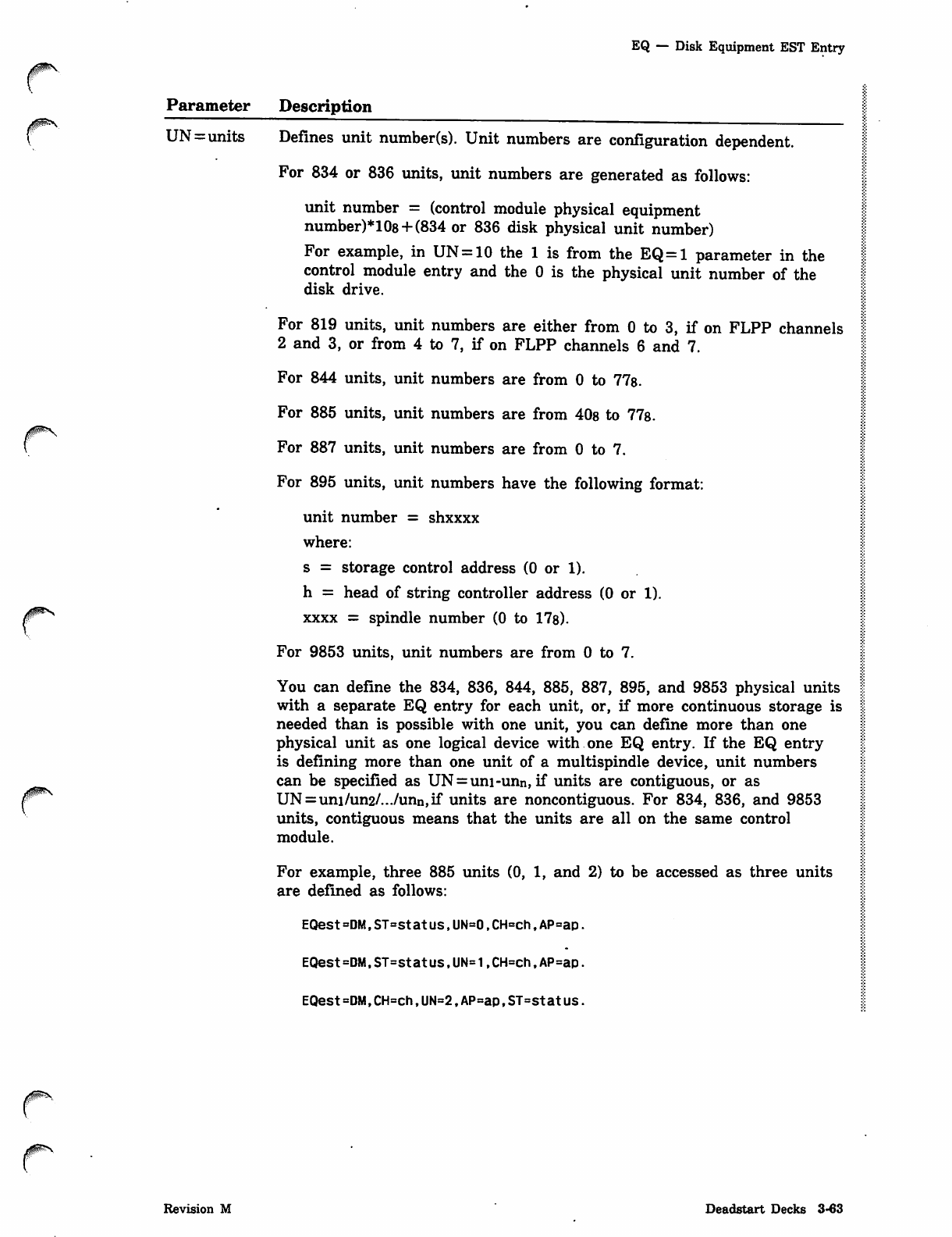
EQ — Disk Equipment EST Entry
Parameter Description
J ^ N
UN=units Defines unit number(s). Unit numbers are configuration dependent.
For 834 or 836 units, unit numbers are generated as follows:
unit number = (control module physical equipment
number)*108 + (834 or 836 disk physical unit number)
For example, in UN = 10 the 1 is from the EQ = 1 parameter in the
control module entry and the 0 is the physical unit number of the
disk drive.
For 819 units, unit numbers are either from 0 to 3, if on FLPP channels
2 and 3, or from 4 to 7, if on FLPP channels 6 and 7.
For 844 units, unit numbers are from 0 to 77s.
For 885 units, unit numbers are from 40s to 77s.
For 887 units, unit numbers are from 0 to 7.
For 895 units, unit numbers have the following format:
unit number = shxxxx
where:
s = storage control address (0 or 1).
h = head of string controller address (0 or 1).
xxxx = spindle number (0 to 17s).
For 9853 units, unit numbers are from 0 to 7.
You can define the 834, 836, 844, 885, 887, 895, and 9853 physical units
with a separate EQ entry for each unit, or, if more continuous storage is
needed than is possible with one unit, you can define more than one
physical unit as one logical device with one EQ entry. If the EQ entry
is defining more than one unit of a multispindle device, unit numbers
can be specified as UN=um-unn, if units are contiguous, or as
UN=uni/un2/.../unn,if units are noncontiguous. For 834, 836, and 9853
units, contiguous means that the units are all on the same control
module.
For example, three 885 units (0, 1, and 2) to be accessed as three units
are defined as follows:
EQest=DM,ST=status,UN=0,CH=ch,AP=ap.
EQest=DM,ST=status,UN=l,CH=ch,AP=ap.
EQest =DM,CH=ch,UN=2,AP=ap,ST=stat us.
Revision M Deadstart Decks 3-63
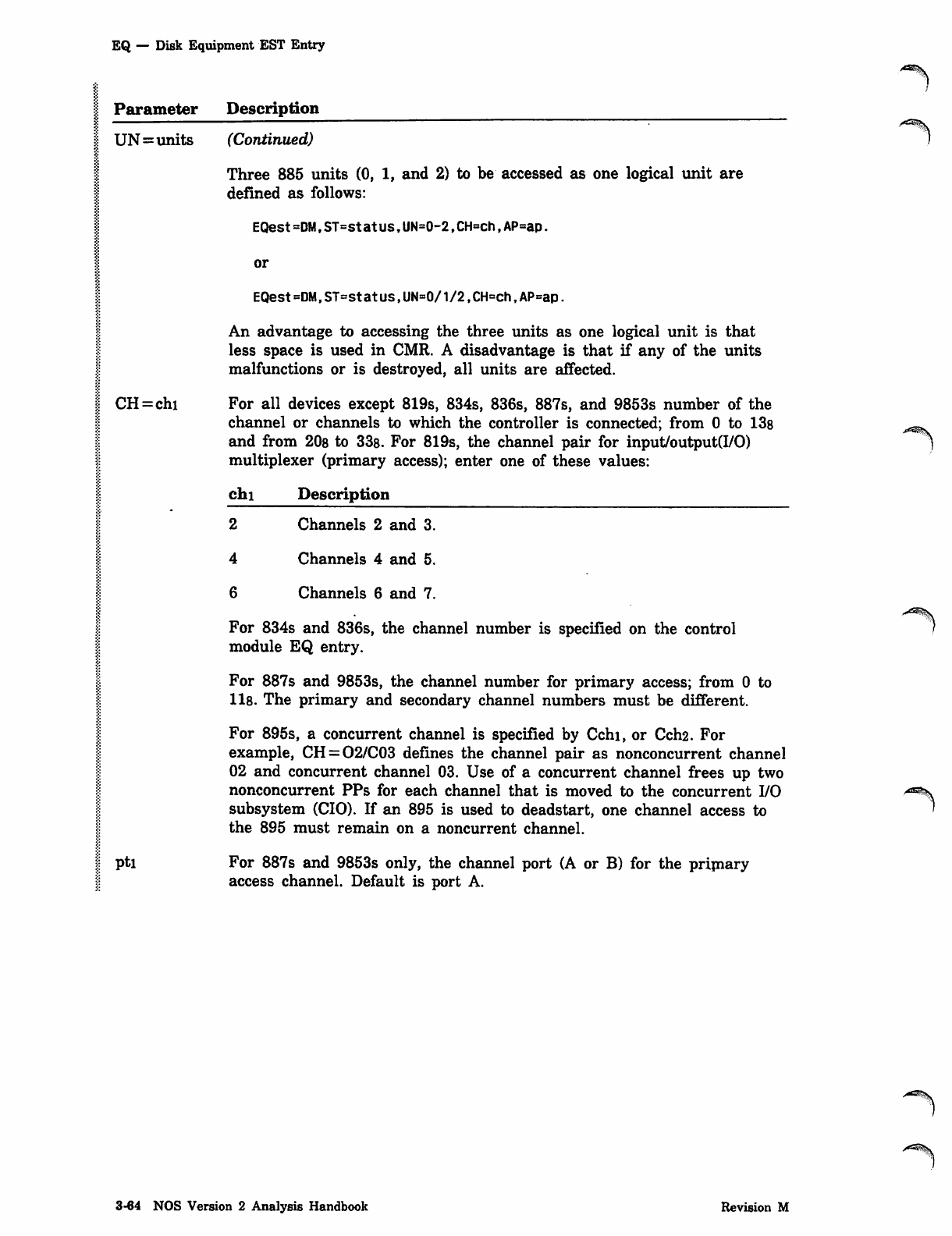
EQ — Disk Equipment EST Entry
Parameter Description
UN=units (Continued) y-a^i\
Three 885 units (0, 1, and 2) to be accessed as one logical unit are
defined as follows:
EQest =DM,ST=status,UN=0-2,CH=ch,AP=ap.
or
| CH=chi
I Pti
EQest=DM,ST=status,UN=0/1/2,CH=ch,AP=ap.
An advantage to accessing the three units as one logical unit is that
less space is used in CMR. A disadvantage is that if any of the units
malfunctions or is destroyed, all units are affected.
For all devices except 819s, 834s, 836s, 887s, and 9853s number of the
channel or channels to which the controller is connected; from 0 to 13s
and from 20s to 33s. For 819s, the channel pair for input/output(I/0)
multiplexer (primary access); enter one of these values:
c h i D e s c r i p t i o n
2 Channels 2 and 3.
4 Channels 4 and 5.
6 Channels 6 and 7.
For 834s and 836s, the channel number is specified on the control
module EQ entry.
For 887s and 9853s, the channel number for primary access; from 0 to
lis. The primary and secondary channel numbers must be different.
For 895s, a concurrent channel is specified by Cchi, or Cch2. For
example, CH = O2/C03 defines the channel pair as nonconcurrent channel
02 and concurrent channel 03. Use of a concurrent channel frees up two
nonconcurrent PPs for each channel that is moved to the concurrent I/O
subsystem (CIO). If an 895 is used to deadstart, one channel access to
the 895 must remain on a noncurrent channel.
For 887s and 9853s only, the channel port (A or B) for the primary
access channel. Default is port A.
A^S\
3-64 NOS Version 2 Analysis Handbook Revision M
EQ — Disk Equipment EST Entry
Parameter Description
/ch2 For all devices except 819s, 834s, 836s, 887s, and 9853s indicates
dual-access unit; cannot be 0; chi and ch2 should be connected to
different controllers. The system balances channel activity on dual-access
units. The balancing is done by alternately checking chi and ch2 for
availability. cti2 is assigned first if it is free. However,MTR logically
reverses chi and ch2 during system operation.
For 819s, the secondary access channel pair; one of the values described
for chi.
For 834s and 836s, dual access is indicated on the control module EQ
entry.
For 887s and 9853s, the channel number for secondary access; from 0 to
118. The primary and secondary channel numbers must be different.
pt2 For 887s and 9853s only, the channel port (A or B) for the secondary
access channel. Default is port A.
AP=ap The 1- or 2-digit octal number that indicates which APRDECK to use. If
AP=ap is omitted, the first APRDECK, APRD00, is assumed.
IB=ib The 1- to 4-digit octal value; this value is entered in the installation
byte for the specified EST ordinal. Refer to EST Formats in the NOS
Version 2 Systems Programmer's Instant.
j0^s EQ=eq Control module number for the 9853 disk. Control module numbers are
f f r o m 0 t o 7 .
JJ0^*
Revision M Deadstart Decks 3-65
EQ — Control Module EST Entry
EQ —■ Control Module EST Entry
An 834 or 836 Disk Storage Subsystem consists of from one to eight 834 or from one
to three 836 disk units and the corresponding control modules. To be operational, both
the disk units and the control modules must be defined in the EQPDECK. The EQ
entry for the 834 or 836 disk units is described under EQ - Disk Equipment EST
Entry earlier in this section. The description of the EQ entry for a control module
follows.
A control module for the 834 or 836 Disk Storage Subsystem is a controller that
drives up to four 834 or three 836 disks and that interfaces with the operating
system using one or two 7255-1 adapters (one per channel). The control module EQ
entry is used to:
• Specify the channels to be used to access the 834 or 836 drives defined on the
control module. Channel entries are not allowed on the 834 or 836 disk unit EQ
entries.
• Specify what level of controlware is to be loaded into the control module during *aS*^
deadstart or when you use a LOADBC command.
• Allow maintenance access to a control module without affecting other control
modules on the same channel(s).
The format of the control module entry is:
EQest =CM, EQ=eq, CH=ch, /ch2, CW=cw, I B=1 b.
Parameter Description a^^\
est EST ordinal of the control module; from 5 to 7778-
EQ=eq Physical equipment number of the control module; from 0 to 7. Each
control module must be assigned a unique equipment number.
CH=chi Number of the channel to which the control module is connected; from
0 to 138 and from 20s to 338.
/ch2 Indicates a dual-access control module; from 1 to 138 and from 20s j^m.
t o 3 3 s . " ^
3-66 NOS Version 2 Analysis Handbook Revision M
EQ — Control Module EST Entry
Parameter Description
0 ^ S " ■
( CW=cw Indicates the control module type and whether controlware is to be
installed in the control module during deadstart. The control module
load sequence takes at least 15 seconds for each control module. It is
advised that you load controlware only when necessary, cw can be one of
these values:
cw Description
0&&S
CM Control module for 834 disk. Install controlware (default).
NCM Control module for 834 disk. Do not install controlware.
C2 Control module for 836 disk. Install controlware.
NC2 Control module for 836 disk. Do not install controlware.
IB=ib The 1- to 4-digit octal value; this value is entered in the installation
byte for the specified EST ordinal. Refer to EST Formats in the NOS
Version 2 Systems Programmer's Instant.
Revision M Deadstart Decks 3-67
EQ — Extended Memory EST Entry
EQ — Extended Memory EST Entry
NOS supports the following types of extended memory.
• Large Central Memory Extended (LCME)
• Extended Core Storage (ECS)
• Extended Semiconductor Memory (ESM)
• Unified Extended Memory (UEM)
• STORNET
Refer to the Extended Memory Overview earlier in this section for an explanation of
the various physical and logical configurations using extended memory. Also refer to
the Examples of EQPDECK Entries for Extended Memory to see examples of how to
use EQPDECK entries to define extended memory for both single mainframe and
multimainframe configurations.
You can use extended memory as an alternate system residency for often accessed
system routines. The faster access may result in a performance improvement.
However, you should use caution when placing system routines in UEM to avoid
possible performance degradation instead of an improvement. This can happen because
a portion of central memory is reserved for UEM and therefore that portion is
unavailable to users. Also, accessing the system routines that reside in UEM may
require additional CPU overhead. Use the ACPD and PROBE utilities (refer to
TRACER/PROBE Utilities, section 21) to determine the impact on system resources
when using UEM.
NOTE
If extended memory is not included in the hardware configuration, do not make an
extended memory EST entry.
The format of the entry is:
EQest=typefST=status,MA=niorJe,ET=xmem/ddp/nc,SZ=size,CH=chi/ch2,AP=ap,MC=mc,IB=ib.
Parameter Description
est EST ordinal of the extended memory equipment; from 5 to 777s. If you
are using extended memory as a link device in a multimainframe
environment, est must be ordinal 5. Otherwise, extended memory can
be defined as any EST ordinal in the given range.
type Extended memory equipment type; enter one of these values:
type Description
DE DDP or LSP is not available.
DP DDP or LSP is available (not applicable for UEM).
/*w%\
3-68 NOS Version 2 Analysis Handbook Revision M
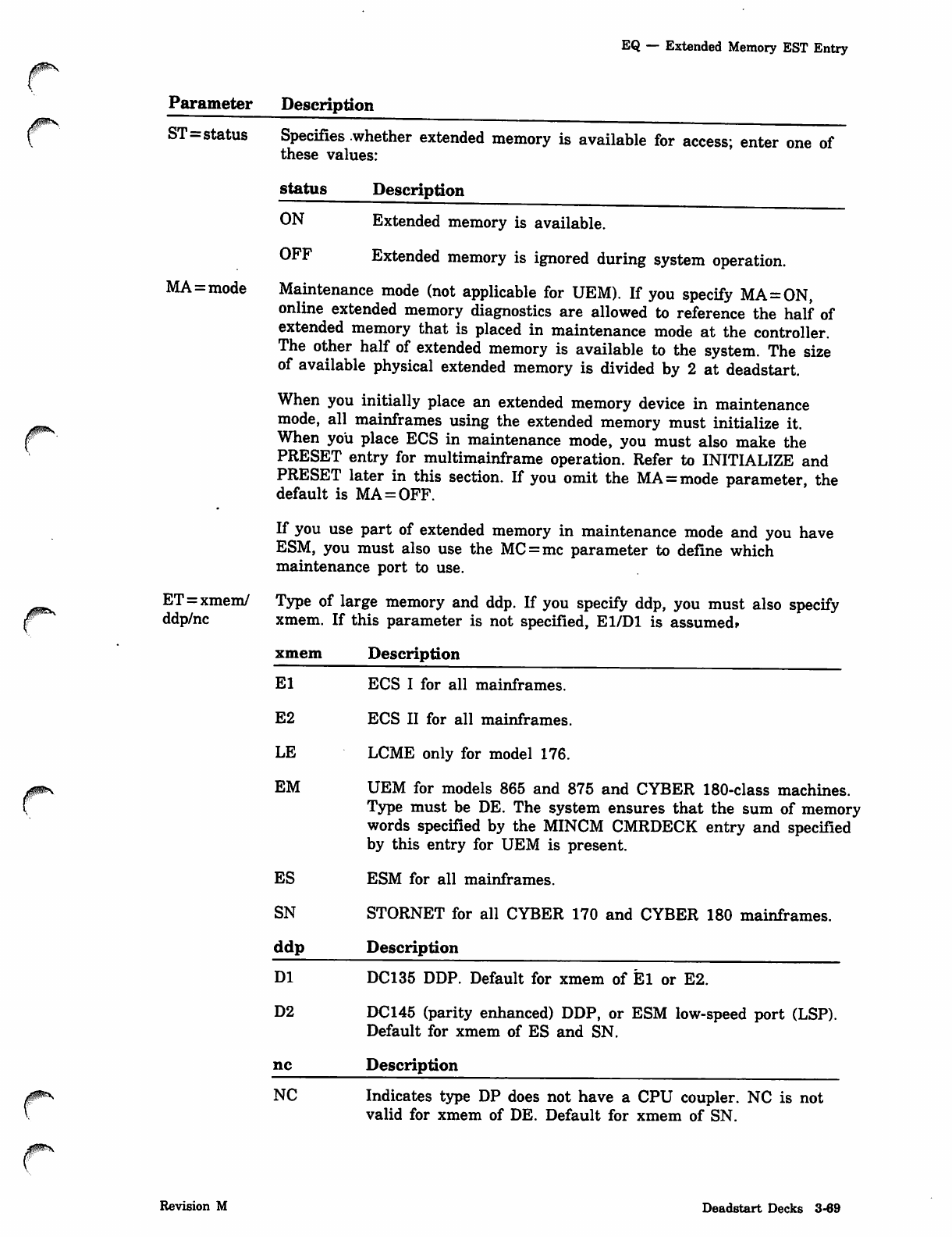
EQ — Extended Memory EST Entry
Parameter Description
ST=status Specifies whether extended memory is available for access; enter one of
these values:
status Description
ON Extended memory is available.
MA=mode
OFF Extended memory is ignored during system operation.
Maintenance mode (not applicable for UEM). If you specify MA=ON,
online extended memory diagnostics are allowed to reference the half of
extended memory that is placed in maintenance mode at the controller.
The other half of extended memory is available to the system. The size
of available physical extended memory is divided by 2 at deadstart.
When you initially place an extended memory device in maintenance
mode, all mainframes using the extended memory must initialize it.
When you place ECS in maintenance mode, you must also make the
PRESET entry for multimainframe operation. Refer to INITIALIZE and
PRESET later in this section. If you omit the MA = mode parameter, the
default is MA=OFF.
If you use part of extended memory in maintenance mode and you have
ESM, you must also use the MC=mc parameter to define which
maintenance port to use.
ET=xmem/ Type of large memory and ddp. If you specify ddp, you must also specify
ddp/nc xmem. If this parameter is not specified, El/Dl is assumed*
xmem Description
El
E2
LE
EM
ES
SN
ddp
ECS I for all mainframes.
ECS II for all mainframes.
LCME only for model 176.
UEM for models 865 and 875 and CYBER 180-class machines.
Type must be DE. The system ensures that the sum of memory
words specified by the MINCM CMRDECK entry and specified
by this entry for UEM is present.
ESM for all mainframes.
STORNET for all CYBER 170 and CYBER 180 mainframes.
Description
DI DC135 DDP. Default for xmem of El or E2.
D2 DC145 (parity enhanced) DDP, or ESM low-speed port (LSP).
Default for xmem of ES and SN.
nc Description
NC Indicates type DP does not have a CPU coupler. NC is not
valid for xmem of DE. Default for xmem of SN.
Revision M Deadstart Decks 3-69
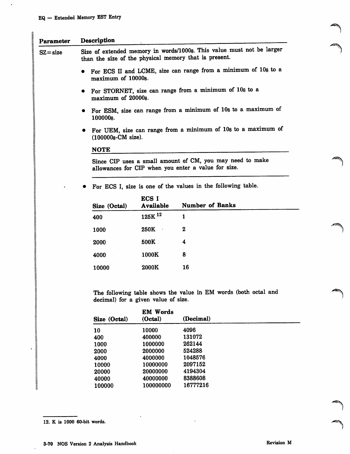
EQ — Extended Memory EST Entry
Parameter Description
I SZ=size Size of extended memory in words/10008. This value must not be larger
than the size of the physical memory that is present.
• For ECS II and LCME, size can range from a minimum of 108 to a
maximum of 100008.
• For STORNET, size can range from a minimum of 10s to a
maximum of 20000s.
• For ESM, size can range from a minimum of 108 to a maximum of
1000008.
• For UEM, size can range from a minimum of 108 to a maximum of
(1000008-CM size).
NOTE
Since CIP uses a small amount of CM, you may need to make
allowances for CIP when you enter a value for size.
• For ECS I, size is one of the values in the following table.
ECS I
Size (Octal) Available Number of Banks
400
1000
2000
4000
10000
125K12
250K
500K
1000K
2000K 16
The following table shows the value in EM words (both octal and
decimal) for a given value of size.
EM Words
Size (Octal) (Octal) (Decimal)
10 10000 4096
400 400000 131072
1000 1000000 262144
2000 2000000 524288
4000 4000000 1048576
10000 10000000 2097152
20000 20000000 4194304
40000 40000000 8388608
100000 100000000 16777216
12. K is 1000 60-bit words.
3-70 NOS Version 2 Analysis Handbook Revision M
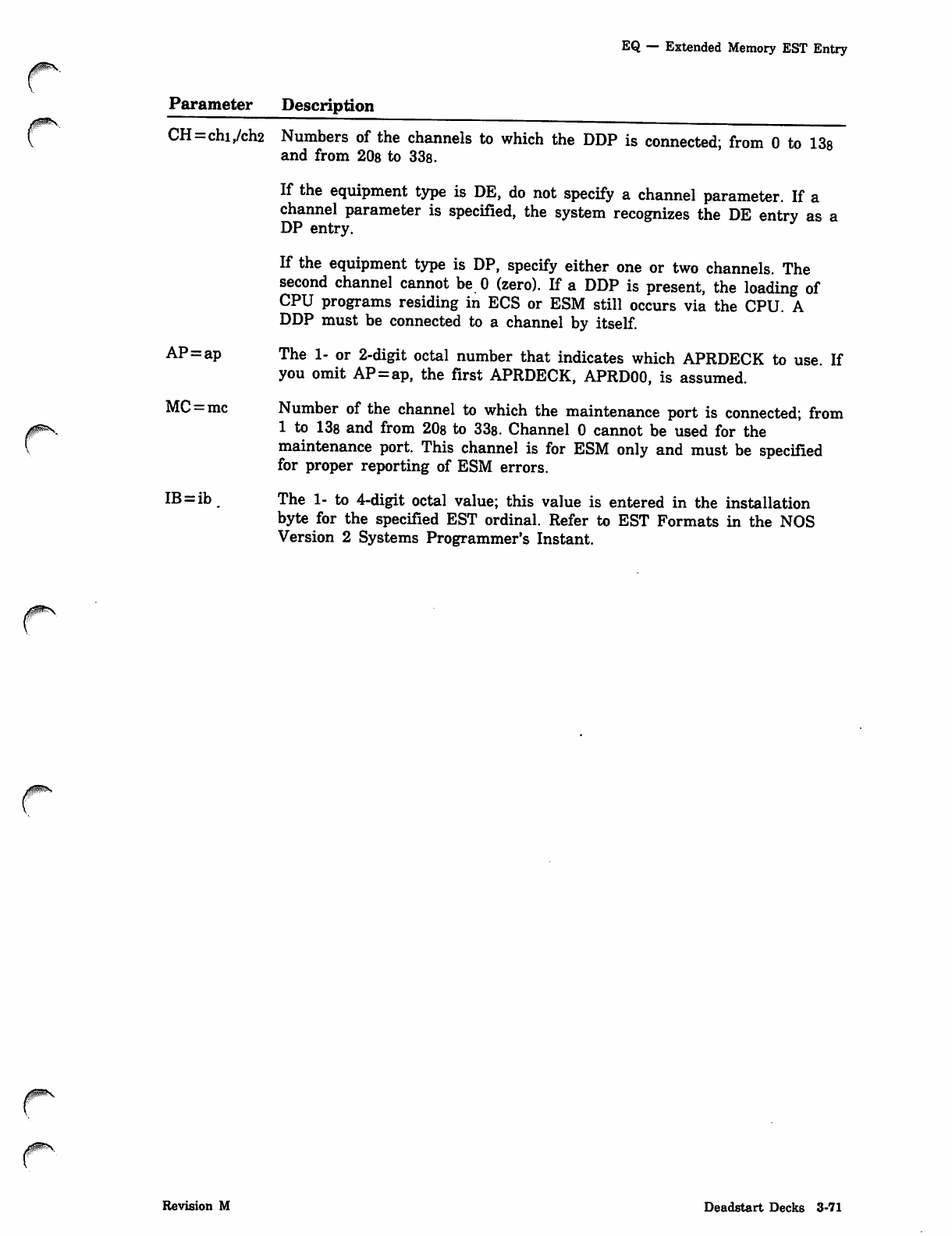
EQ — Extended Memory EST Entry
Parameter Description
CH=chi,/ch2
AP=ap
MC=mc
IB=ib
Numbers of the channels to which the DDP is connected; from 0 to 13s
and from 20s to 33s.
If the equipment type is DE, do not specify a channel parameter. If a
channel parameter is specified, the system recognizes the DE entry as a
DP entry.
If the equipment type is DP, specify either one or two channels. The
second channel cannot be 0 (zero). If a DDP is present, the loading of
CPU programs residing in ECS or ESM still occurs via the CPU. A
DDP must be connected to a channel by itself.
The 1- or 2-digit octal number that indicates which APRDECK to use. If
you omit AP=ap, the first APRDECK, APRD00, is assumed.
Number of the channel to which the maintenance port is connected; from
1 to 138 and from 20s to 33s. Channel 0 cannot be used for the
maintenance port. This channel is for ESM only and must be specified
for proper reporting of ESM errors.
The 1- to 4-digit octal value; this value is entered in the installation
byte for the specified EST ordinal. Refer to EST Formats in the NOS
Version 2 Systems Programmer's Instant.
Revision M Deadstart Decks 3-71
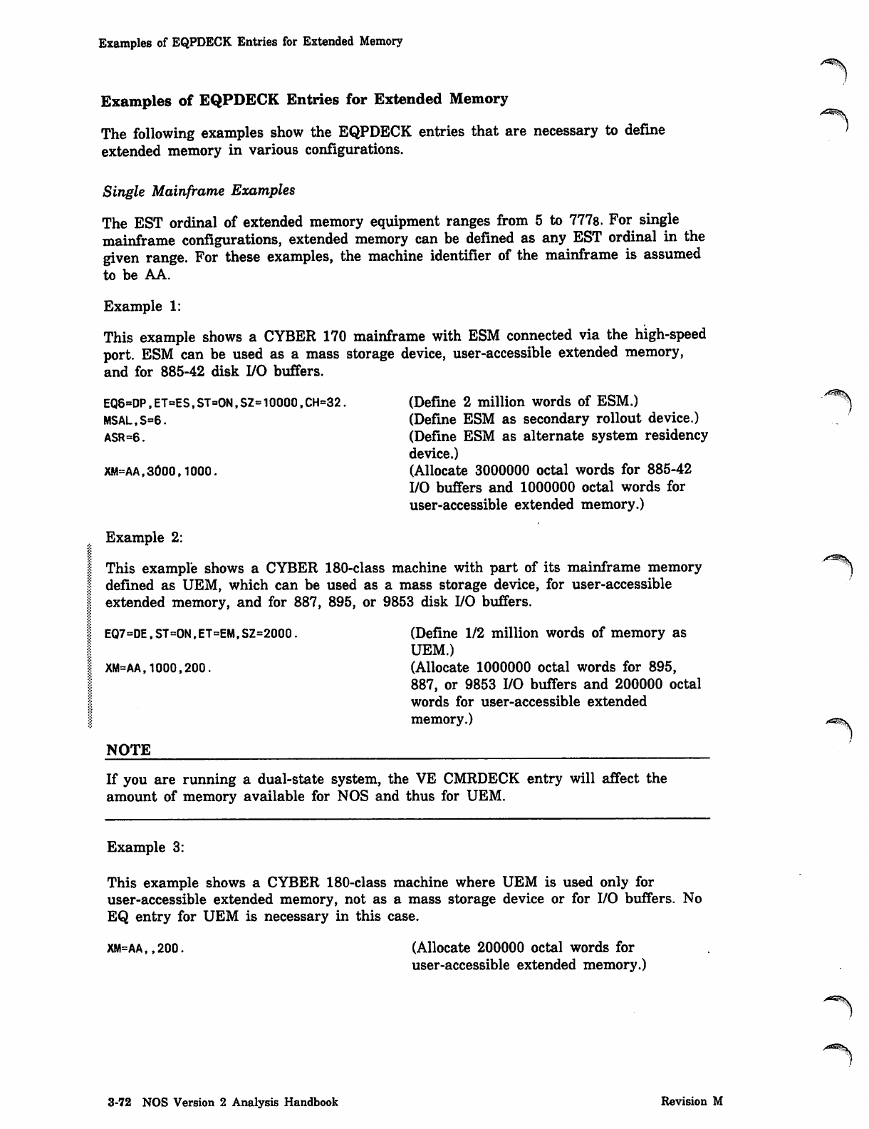
Examples of EQPDECK Entries for Extended Memory
Examples of EQPDECK Entries for Extended Memory
The following examples show the EQPDECK entries that are necessary to define
extended memory in various configurations.
Single Mainframe Examples
The EST ordinal of extended memory equipment ranges from 5 to 7778. For single
mainframe configurations, extended memory can be defined as any EST ordinal in the
given range. For these examples, the machine identifier of the mainframe is assumed
to be .AA.
Example 1:
This example shows a CYBER 170 mainframe with ESM connected via the high-speed
port. ESM can be used as a mass storage device, user-accessible extended memory,
and for 885-42 disk I/O buffers.
EQ6=DP,ET=ES,ST=ON,S2=10000,CH=32,
MSAL,S=6.
ASR=6.
XM=AA,3000,1000.
Example 2:
(Define 2 million words of ESM.)
(Define ESM as secondary rollout device.)
(Define ESM as alternate system residency
device.)
(Allocate 3000000 octal words for 885-42
I/O buffers and 1000000 octal words for
user-accessible extended memory.)
This example shows a CYBER 180-class machine with part of its mainframe memory
defined as UEM, which can be used as a mass storage device, for user-accessible
extended memory, and for 887, 895, or 9853 disk I/O buffers.
EQ7=DE,ST=ONfET=EM,SZ=2000
XM-AA,1000,200.
NOTE
(Define 1/2 million words of memory as
UEM.)
(Allocate 1000000 octal words for 895,
887, or 9853 I/O buffers and 200000 octal
words for user-accessible extended
memory.)
If you are running a dual-state system, the VE CMRDECK entry will affect the
amount of memory available for NOS and thus for UEM.
Example 3:
This example shows a CYBER 180-class machine where UEM is used only for
user-accessible extended memory, not as a mass storage device or for I/O buffers. No
EQ entry for UEM is necessary in this case.
XM=AA,,200, (Allocate 200000 octal words for
user-accessible extended memory.)
3-72 NOS Version 2 Analysis Handbook Revision M
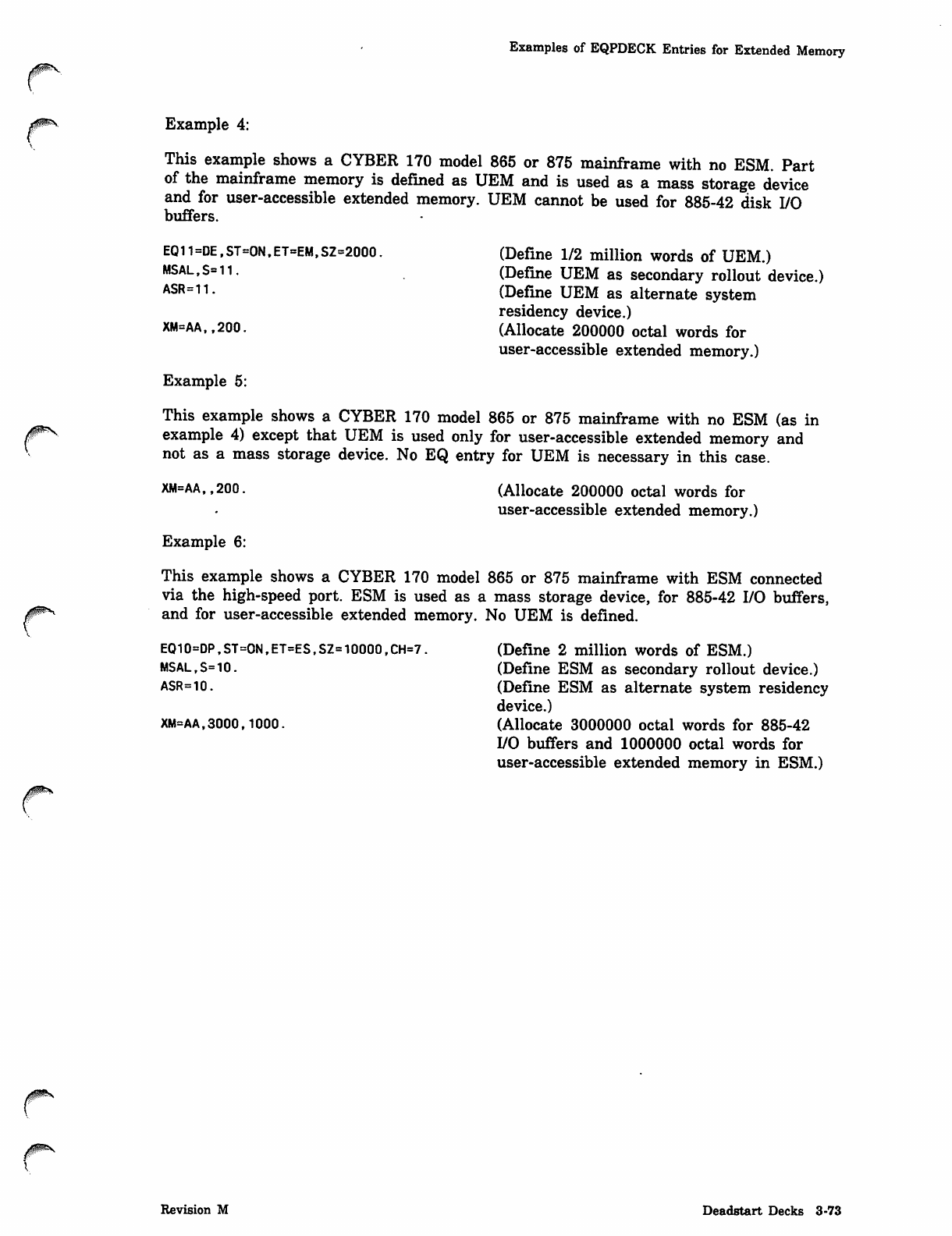
Examples of EQPDECK Entries for Extended Memory
08&*\ Example 4:
This example shows a CYBER 170 model 865 or 875 mainframe with no ESM. Part
of the mainframe memory is defined as UEM and is used as a mass storage device
and for user-accessible extended memory. UEM cannot be used for 885-42 disk I/O
buffers.
EQ11=DE,ST>ON,ET=EM,SZ=2000
MSAL,S=11.
ASR=11.
XM=AA.,200.
Example 5:
(Define 1/2 million words of UEM.)
(Define UEM as secondary rollout device.)
(Define UEM as alternate system
residency device.)
(Allocate 200000 octal words for
user-accessible extended memory.)
This example shows a CYBER 170 model 865 or 875 mainframe with no ESM (as in
example 4) except that UEM is used only for user-accessible extended memory and
not as a mass storage device. No EQ entry for UEM is necessary in this case.
XM=AA,,200.
Example 6:
(Allocate 200000 octal words for
user-accessible extended memory.)
This example shows a CYBER 170 model 865 or 875 mainframe with ESM connected
via the high-speed port. ESM is used as a mass storage device, for 885-42 I/O buffers,
and for user-accessible extended memory. No UEM is defined.
EQ10=DP,ST=ON,ET=ES,SZ=10000,CH=7
MSAL,S=10.
ASR=10.
XM=AA,3000,1000.
(Define 2 million words of ESM.)
(Define ESM as secondary rollout device.)
(Define ESM as alternate system residency
device.)
(Allocate 3000000 octal words for 885-42
I/O buffers and 1000000 octal words for
user-accessible extended memory in ESM.)
Revision M Deadstart Decks 3-73
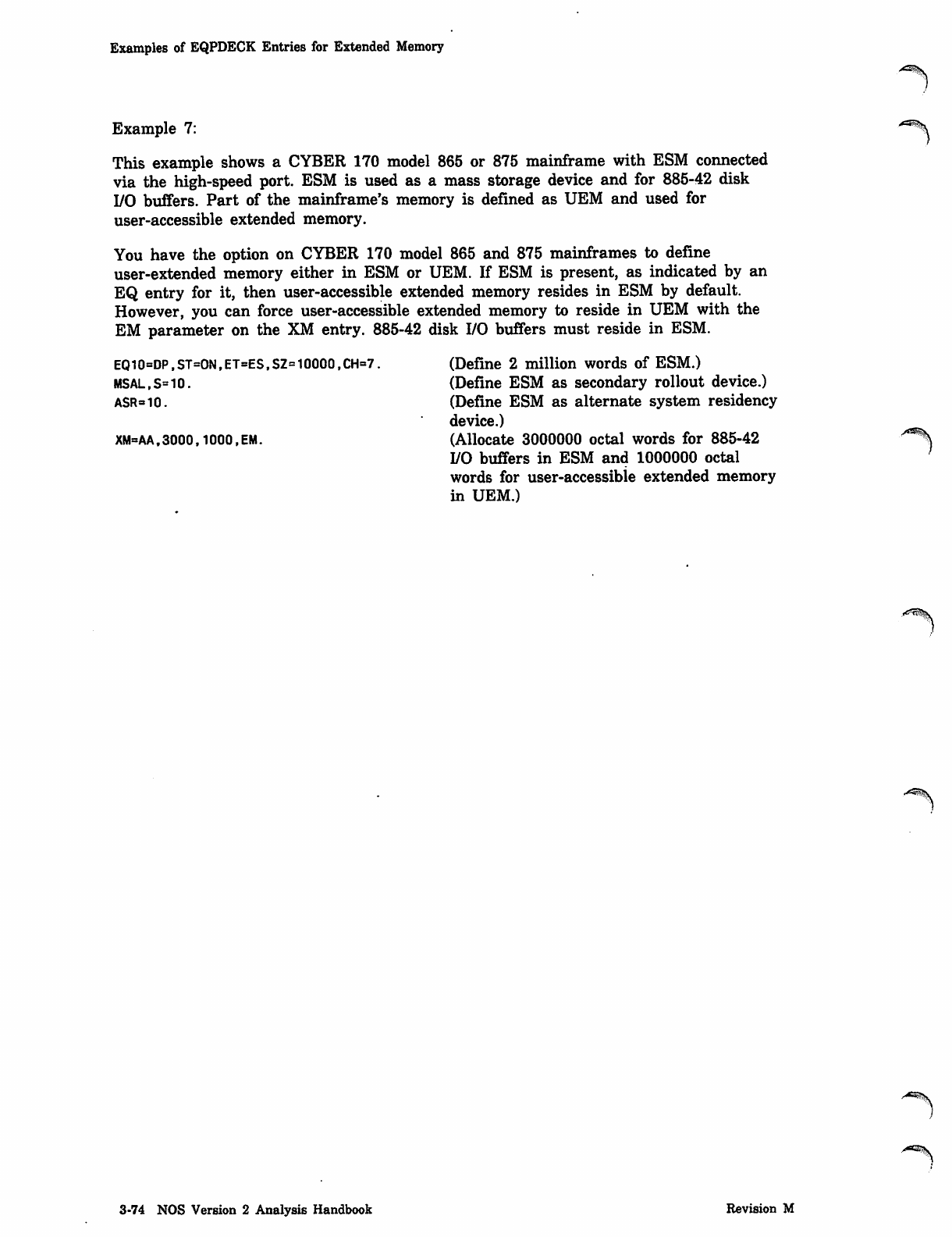
Examples of EQPDECK Entries for Extended Memory
Example 7:
This example shows a CYBER 170 model 865 or 875 mainframe with ESM connected
via the high-speed port. ESM is used as a mass storage device and for 885-42 disk
I/O buffers. Part of the mainframe's memory is defined as UEM and used for
user-accessible extended memory.
You have the option on CYBER 170 model 865 and 875 mainframes to define
user-extended memory either in ESM or UEM. If ESM is present, as indicated by an
EQ entry for it, then user-accessible extended memory resides in ESM by default.
However, you can force user-accessible extended memory to reside in UEM with the
EM parameter on the XM entry. 885-42 disk I/O buffers must reside in ESM.
H^ifSgs
EQ10=DP,ST=ON,ET=ES,SZ=10000,CH=7
MSAL,S=10.
ASR=10.
XM=AA,3000,1000,EM.
(Define 2 million words of ESM.)
(Define ESM as secondary rollout device.)
(Define ESM as alternate system residency
device.)
(Allocate 3000000 octal words for 885-42
I/O buffers in ESM and 1000000 octal
words for user-accessible extended memory
in UEM.)
A**3S
3-74 NOS Version 2 Analysis Handbook Revision M
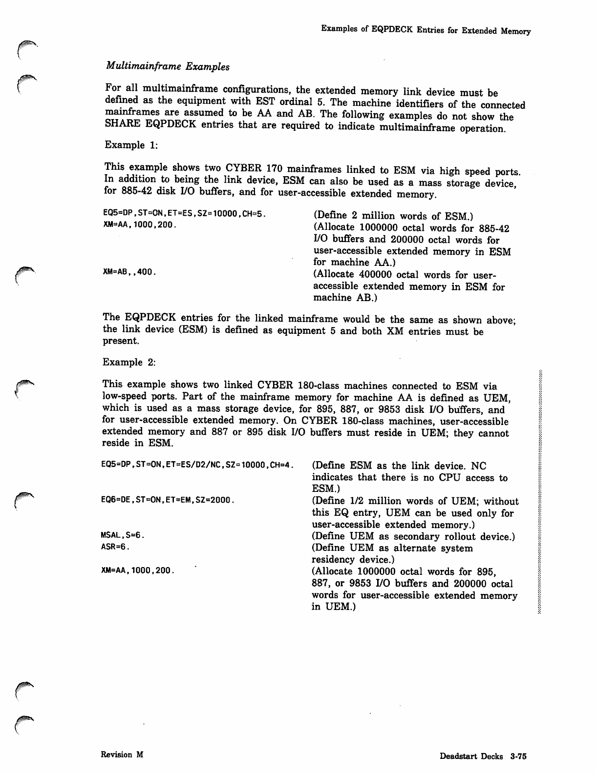
Examples of EQPDECK Entries for Extended Memory
JPV.
Multimainframe Examples
For all multimainframe configurations, the extended memory link device must be
defined as the equipment with EST ordinal 5. The machine identifiers of the connected
mainframes are assumed to be AA and AB. The following examples do not show the
SHARE EQPDECK entries that are required to indicate multimainframe operation.
Example 1:
This example shows two CYBER 170 mainframes linked to ESM via high speed ports.
In addition to being the link device, ESM can also be used as a mass storage device,
for 885-42 disk I/O buffers, and for user-accessible extended memory.
EQ5=DP,ST=0N,ET=ES,SZ=10000,CH=5.
XM=AA,1000,200. (Define 2 million words of ESM.)
(Allocate 1000000 octal words for 885-42
I/O buffers and 200000 octal words for
user-accessible extended memory in ESM
for machine AA.)
XM=AB,,400. (Allocate 400000 octal words for user-
accessible extended memory in ESM for
machine AB.)
The EQPDECK entries for the linked mainframe would be the same as shown above;
the link device (ESM) is defined as equipment 5 and both XM entries must be
present.
Example 2:
This example shows two linked CYBER 180-class machines connected to ESM via
low-speed ports. Part of the mainframe memory for machine AA is defined as UEM,
which is used as a mass storage device, for 895, 887, or 9853 disk I/O buffers, and
for user-accessible extended memory. On CYBER 180-class machines, user-accessible
extended memory and 887 or 895 disk I/O buffers must reside in UEM; they cannot
reside in ESM.
EQ5=DP,ST=0N,ET=ES/D2/NC,SZ=10000,CH=4
EQ6=DE,ST=0N,ET=EM,SZ=2000
MSAL,S=6.
ASR=6.
XM=AA,1000,200
(Define ESM as the link device. NC
indicates that there is no CPU access to
ESM.)
(Define 1/2 million words of UEM; without
this EQ entry, UEM can be used only for
user-accessible extended memory.)
(Define UEM as secondary rollout device.)
(Define UEM as alternate system
residency device.)
(Allocate 1000000 octal words for 895,
887, or 9853 I/O buffers and 200000 octal
words for user-accessible extended memory
in UEM.)
Revision M Deadstart Decks 3-75
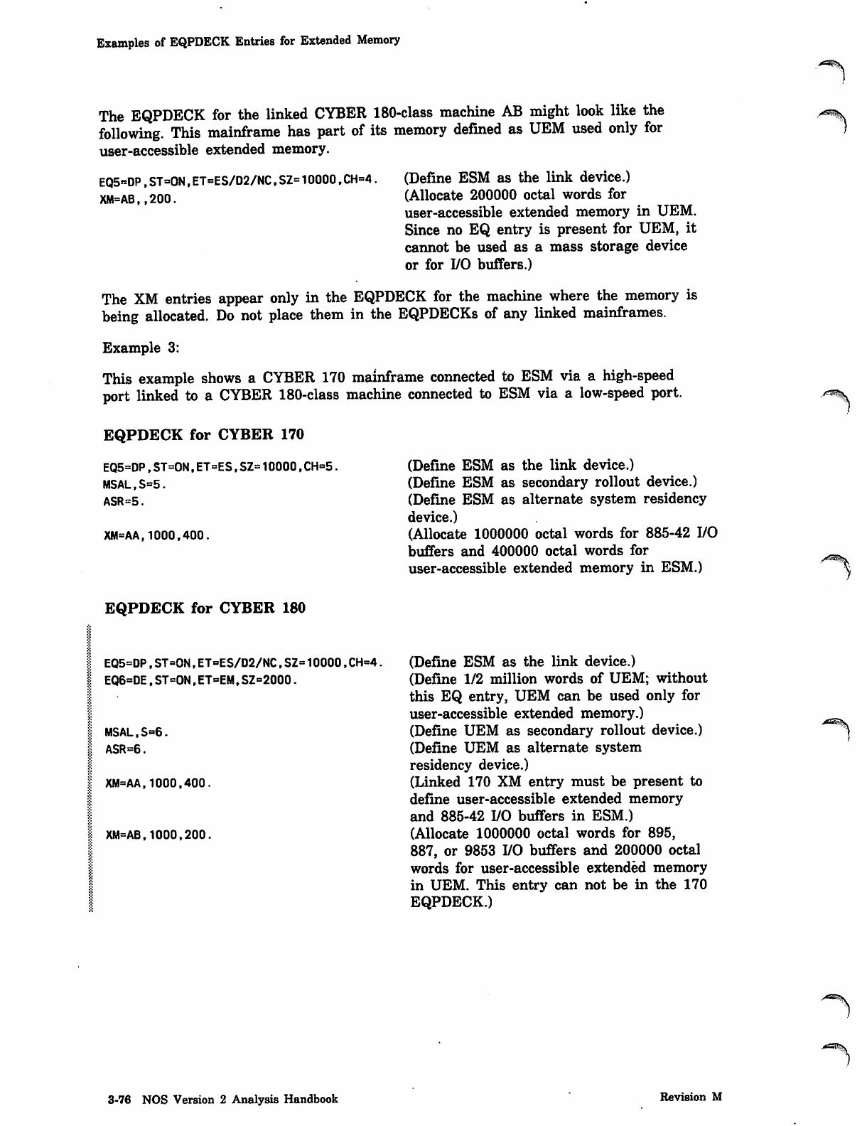
Examples of EQPDECK Entries for Extended Memory
The EQPDECK for the linked CYBER 180-class machine AB might look like the
following. This mainframe has part of its memory defined as UEM used only for
user-accessible extended memory.
EQ5«DP,ST=ON,ET=ES/D2/NC,SZ=10000,CH=4.
XM=AB,,200.
(Define ESM as the link device.)
(Allocate 200000 octal words for
user-accessible extended memory in UEM.
Since no EQ entry is present for UEM, it
cannot be used as a mass storage device
or for I/O buffers.)
The XM entries appear only in the EQPDECK for the machine where the memory is
being allocated. Do not place them in the EQPDECKs of any linked mainframes.
Example 3:
This example shows a CYBER 170 mainframe connected to ESM via a high-speed
port linked to a CYBER 180-class machine connected to ESM via a low-speed port.
EQPDECK for CYBER 170
EQ5=DP,ST=ON,ET=ES,SZ=10000,CH=5.
MSAL,S=5.
ASR=5.
XM=AA,1000,400.
(Define ESM as the link device.)
(Define ESM as secondary rollout device.)
(Define ESM as alternate system residency
device.)
(Allocate 1000000 octal words for 885-42 I/O
buffers and 400000 octal words for
user-accessible extended memory in ESM.) ~*
EQPDECK for CYBER 180
| EQ5=DP,ST=ON,ET=ES/D2/NC,SZ=10000,CH=4.
| EQ6=DE,ST=ON,ET=EM,SZ=2000.
| MSAL,S=6.
I ASR=6.
XM^AA,1000,400
| XM=AB,1000,200
(Define ESM as the link device.)
(Define 1/2 million words of UEM; without
this EQ entry, UEM can be used only for
user-accessible extended memory.)
(Define UEM as secondary rollout device.)
(Define UEM as alternate system
residency device.)
(Linked 170 XM entry must be present to
define user-accessible extended memory
and 885-42 I/O buffers in ESM.)
(Allocate 1000000 octal words for 895,
887, or 9853 I/O buffers and 200000 octal
words for user-accessible extended memory
in UEM. This entry can not be in the 170
EQPDECK.)
>tf^ v
3-76 NOS Version 2 Analysis Handbook Revision M
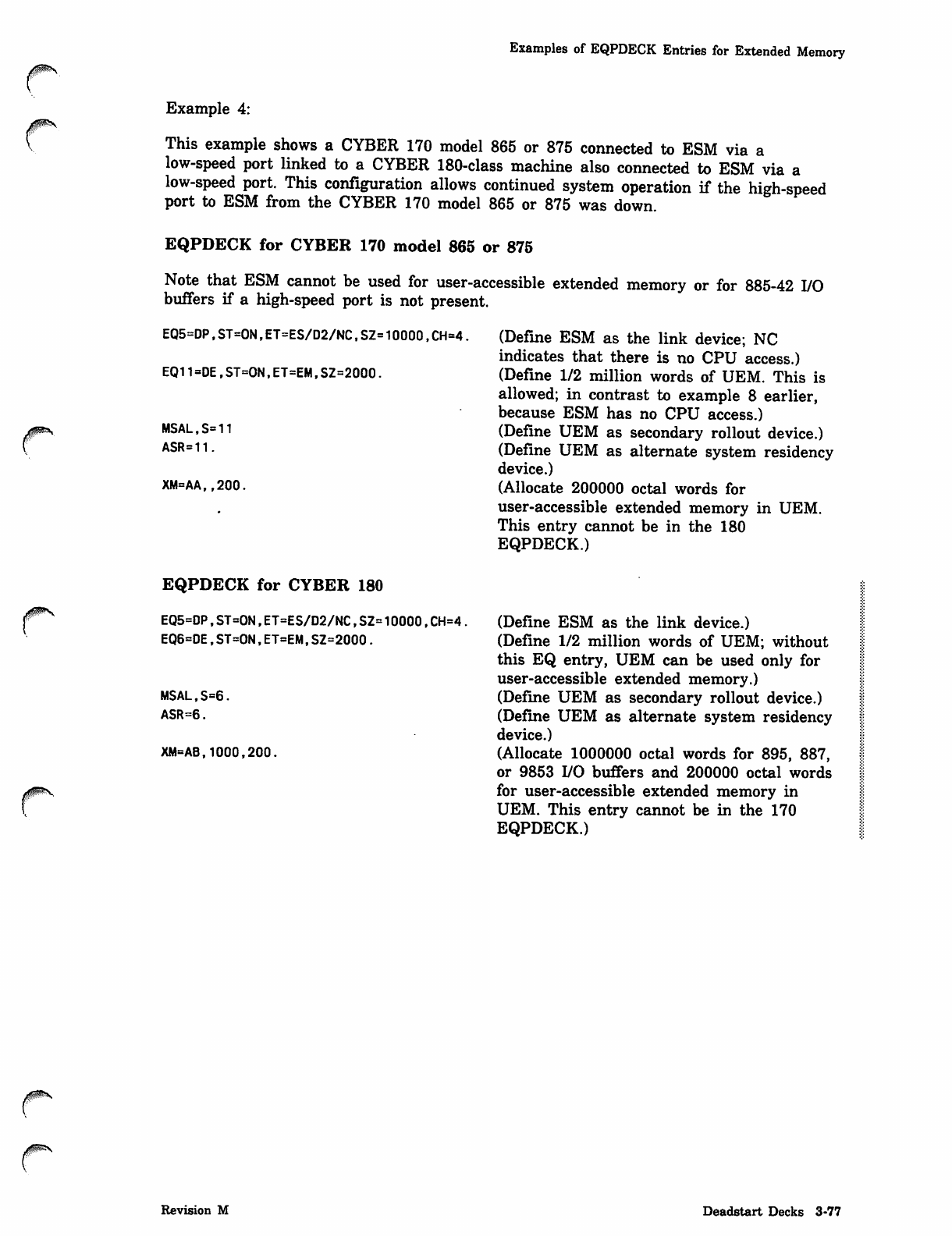
y$$S
Examples of EQPDECK Entries for Extended Memory
Example 4:
This example shows a CYBER 170 model 865 or 875 connected to ESM via a
low-speed port linked to a CYBER 180-class machine also connected to ESM via a
low-speed port. This configuration allows continued system operation if the high-speed
port to ESM from the CYBER 170 model 865 or 875 was down.
EQPDECK for CYBER 170 model 865 or 875
Note that ESM cannot be used for user-accessible extended memory or for 885-42 I/O
buffers if a high-speed port is not present.
EQ5=DP,ST=ONFET=ES/D2/NC.SZ=10000,CH=4. (Define ESM as the link device; NC
indicates that there is no CPU access.)
EQ11=DE,ST=ON,ET=EM,SZ=2000. (Define 1/2 million words of UEM. This is
allowed; in contrast to example 8 earlier,
because ESM has no CPU access.)
MSAL,S=11 (Define UEM as secondary rollout device.)
ASR=11. (Define UEM as alternate system residency
device.)
XM=AA,,200. (Allocate 200000 octal words for
user-accessible extended memory in UEM.
This entry cannot be in the 180
EQPDECK.)
EQPDECK for CYBER 180
EQ5=DP,ST=ON,ET=ES/D2/NC,SZ=10000,CH=4. (Define ESM as the link device.)
EQ6=DE,ST=ON,ET=EM,SZ=2000. (Define 1/2 million words of UEM; without
this EQ entry, UEM can be used only for
user-accessible extended memory.)
msal,S=6. (Define UEM as secondary rollout device.)
ASR=6. (Define UEM as alternate system residency
device.)
XM=AB, 1000,200. (Allocate 1000000 octal words for 895, 887,
or 9853 I/O buffers and 200000 octal words
for user-accessible extended memory in
UEM. This entry cannot be in the 170
EQPDECK.)
Revision M Deadstart Decks 3-77
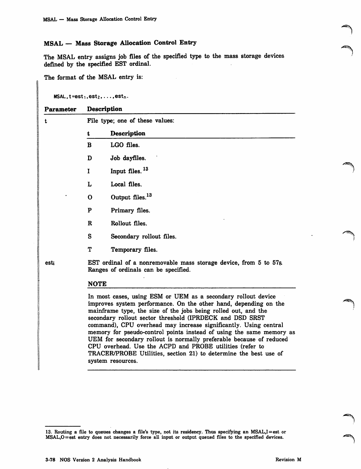
MSAL — Mass Storage Allocation Control Entry
MSAL — Mass Storage Allocation Control Entry
The MSAL entry assigns job files of the specified type to the mass storage devices
defined by the specified EST ordinal.
The format of the MSAL entry is:
:::
I MSAL,t=esti,est2,. ..,estn.
I Parameter Description
I t File type; one of these values:
I t Description
I B L G O fi l e s .
I D Job dayfiles.
I I Input files.13
I L Local files.
O Output fi l es.13
'f.
I P Primary files.
I R Rollout files.
S Secondary rollout files.
I T Temporary files.
I esti EST ordinal of a nonremovable mass storage device, from 5 to 57a
f Ranges of ordinals can be specified.
I N O T E
In most cases, using ESM or UEM as a secondary rollout device
improves system performance. On the other hand, depending on the '^]
I mainframe type, the size of the jobs being rolled out, and the
secondary rollout sector threshold (IPRDECK and DSD SRST
command), CPU overhead may increase significantly. Using central
memory for pseudo-control points instead of using the same memory as
UEM for secondary rollout is normally preferable because of reduced
CPU overhead. Use the ACPD and PROBE utilities (refer to
TRACER/PROBE Utilities, section 21) to determine the best use of
system resources.
13. Routing a file to queues changes a file's type, not its residency. Thus specifying an MSAL,I=est or
MSAL,0=est entry does not necessarily force all input or output queued files to the specified devices.
3-78 NOS Version 2 Analysis Handbook Revision M
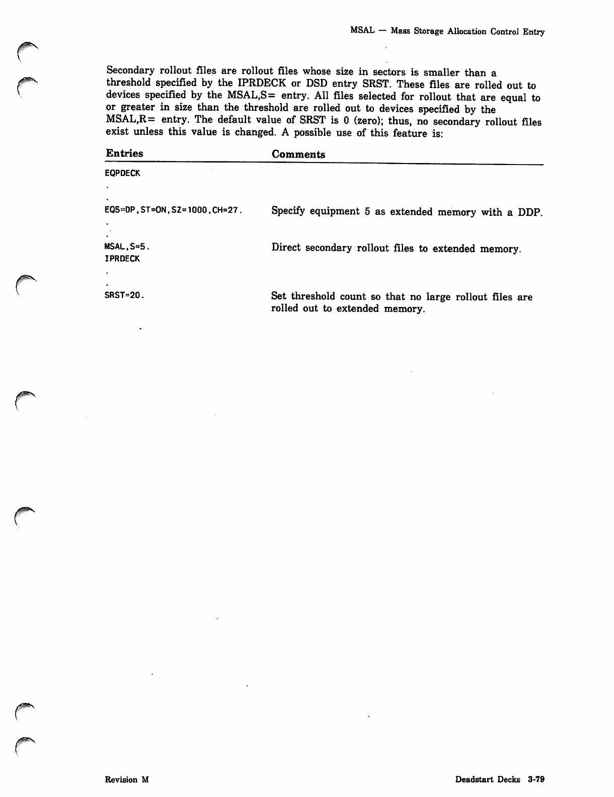
0ms.
MSAL — Mass Storage Allocation Control Entry
Secondary rollout files are rollout files whose size in sectors is smaller than a
threshold specified by the IPRDECK or DSD entry SRST. These files are rolled out to
devices specified by the MSAL,S= entry. All files selected for rollout that are equal to
or greater in size than the threshold are rolled out to devices specified by the
MSAL,R= entry. The default value of SRST is 0 (zero); thus, no secondary rollout files
exist unless this value is changed. A possible use of this feature is:
Entries Comments
EQPDECK
EQ5=DP,ST=ON,SZ=1000,CH=27. Specify equipment 5 as extended memory with a DDP.
MSAL,S=5. Direct secondary rollout files to extended memory.
IPRDECK
SRST=20. Set threshold count so that no large rollout files are
rolled out to extended memory.
Revision M Deadstart Decks 3-79
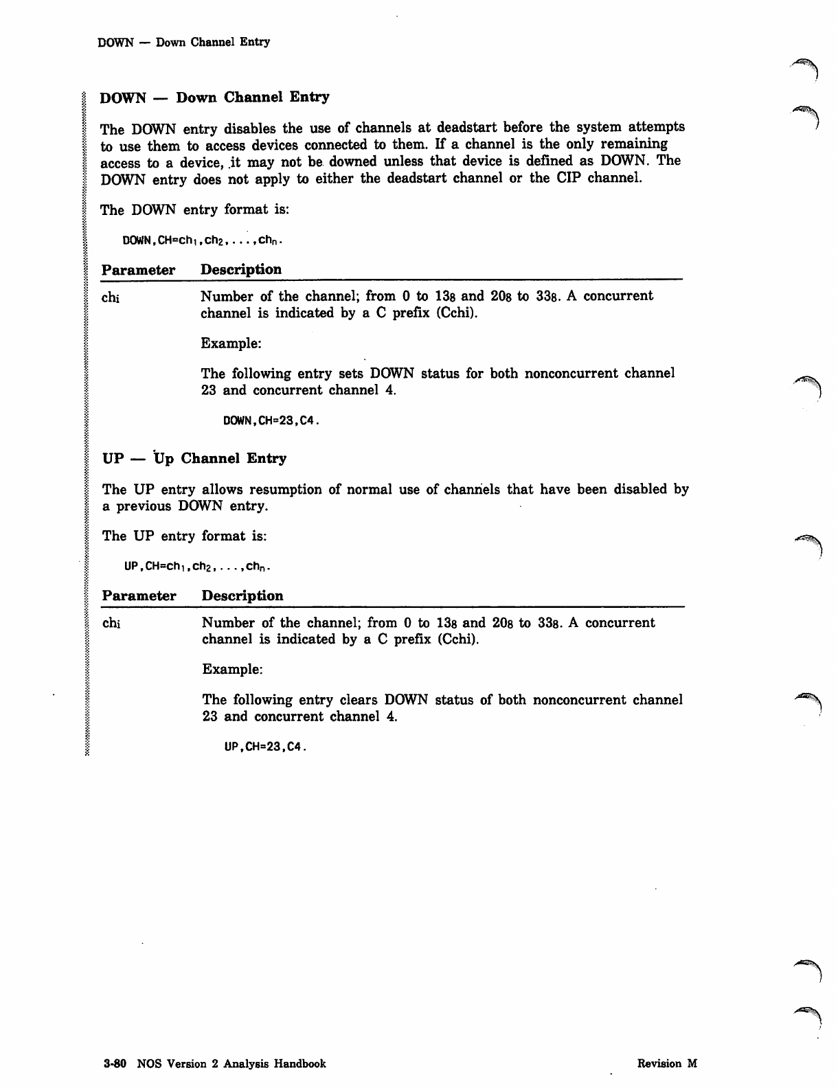
DOWN — Down Channel Entry
| DOWN — Down Channel Entry
I The DOWN entry disables the use of channels at deadstart before the system attempts /
I to use them to access devices connected to them. If a channel is the only remaining
| access to a device, .it may not be downed unless that device is defined as DOWN. The
I DOWN entry does not apply to either the deadstart channel or the CIP channel.
| The DOWN entry format is:
| DOWN,CH=ch1fch2 chn.
| Parameter Description
| chi Number of the channel; from 0 to 13s and 208 to 338. A concurrent
channel is indicated by a C prefix (Cchi).
| Example:
| The following entry sets DOWN status for both nonconcurrent channel yrt_
23 and concurrent channel 4. ^
| D0WN,CH=23,C4.
| UP — Up Channel Entry
| The UP entry allows resumption of normal use of channels that have been disabled by
| a previous DOWN entry.
| The UP entry format is: ^=^
UP,CH=ch1tch2,...,chn.
| Parameter Description
I chi Number of the channel; from 0 to 13s and 20s to 33s. A concurrent
channel is indicated by a C prefix (Cchi).
I Example:
The following entry clears DOWN status of both nonconcurrent channel ***\
23 and concurrent channel 4.
I UP,CH=23,C4.
3-80 NOS Version 2 Analysis Handbook Revision M
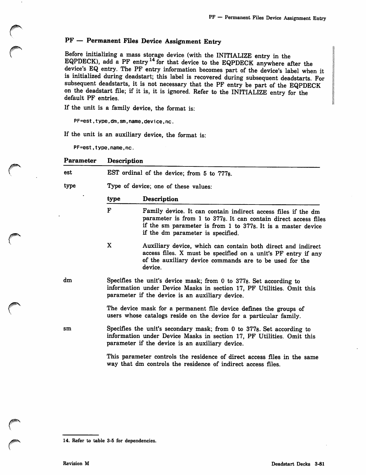
jgjffe\
0n^S
PF — Permanent Files Device Assignment Entry
PF — Permanent Files Device Assignment Entry
Before initializing a mass storage device (with the INITIALIZE entry in the
EQPDECK), add a PF entryu for that device to the EQPDECK anywhere after the
device's EQ entry. The PF entry information becomes part of the device's label when it
is initialized during deadstart; this label is recovered during subsequent deadstarts. For
subsequent deadstarts, it is not necessary that the PF entry be part of the EQPDECK
on the deadstart file; if it is, it is ignored. Refer to the INITIALIZE entry for the
default PF entries.
If the unit is a family device, the format is:
PF=est,type,dm.sm,name,device,nc.
If the unit is an auxiliary device, the format is:
PF=est,type,name,nc.
Parameter Description
est EST ordinal of the device; from 5 to 7778.
type Type of device; one of these values:
type Description
F Family device. It can contain indirect access files if the dm
parameter is from 1 to 377s. It can contain direct access files
if the sm parameter is from 1 to 377s. It is a master device
if the dm parameter is specified.
X Auxiliary device, which can contain both direct and indirect
access files. X must be specified on a unit's PF entry if any
of the auxiliary device commands are to be used for the
device.
dm Specifies the unit's device mask; from 0 to 3778. Set according to
information under Device Masks in section 17, PF Utilities. Omit this
parameter if the device is an auxiliary device.
The device mask for a permanent file device defines the groups of
users whose catalogs reside on the device for a particular family.
sm Specifies the unit's secondary mask; from 0 to 3778. Set according to
information under Device Masks in section 17, PF Utilities. Omit this
parameter if the device is an auxiliary device.
This parameter controls the residence of direct access files in the same
way that dm controls the residence of indirect access files.
14. Refer to table 3-5 for dependencies.
Revision M Deadstart Decks 3-81
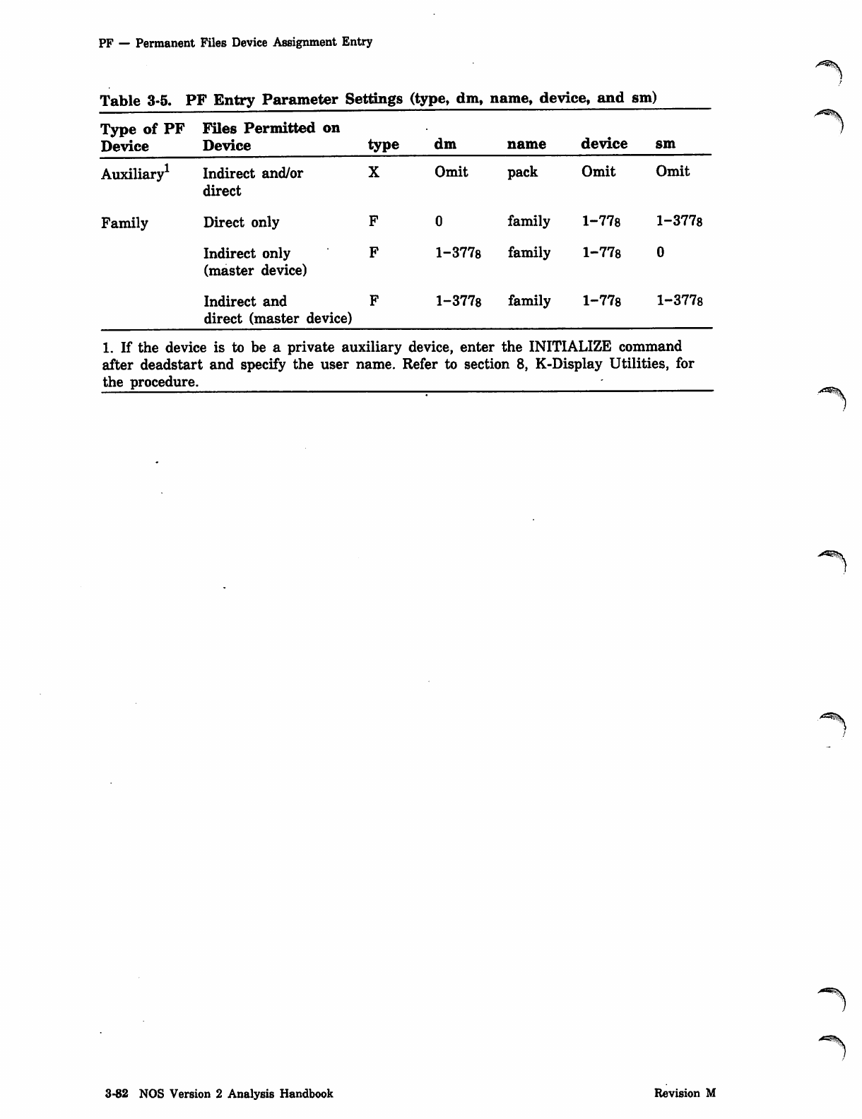
PF — Permanent Files Device Assignment Entry
Table 3-5. PF Entry Parameter Settings (type, dm, name, device, and sm)
dm
Type of PF Files Permitted on
Device Device type name d e v i c e s m
Auxiliary
Family
Indirect and/or X
direct
Direct only F
Indirect only F
(master device)
Indirect and F
direct (master device)
Omit pack Omit
0 family 1-778
1-3778 family 1-778
Omit
1-3778
0
1-3778 family l-77s 1-3778
1. If the device is to be a private auxiliary device, enter the INITIALIZE command
after deadstart and specify the user name. Refer to section 8, K-Display Utilities, for
the procedure. -
^\
3-82 NOS Version 2 Analysis Handbook Revision M
PF — Permanent Files Device Assignment Entry
cParameter Description
name
device
Designates either the name of the family to which the unit belongs or
its pack name if it is an auxiliary device; from 1 to 7 alphanumeric
characters. Do not use the family name 0: it is reserved.
The family name describes the permanent file devices available to a
user. A family may consist of from 1 to 63 logical devices; however,
the master devices within the family must have device masks totaling
3778 if all possible user indexes are to be accommodated.
Usually a system runs with one family of permanent file devices
available. But you can activate additional families on a system, in order
to allow the users of these families to access their permanent files
through an alternate system. This might be helpful if one system
supplies backup service to another system. When more than one family
is active on a system, users with matching user indexes access the same
permanent files on a public auxiliary device. You can avoid this
situation by predetermining a range of user indexes for each family
running on a system. When a new family is introduced into a system,
its user indexes should be checked against those of the family or
families currently running and any matching indexes should be changed.
Refer to the IPRDECK entry COMLIB later in this section.
The pack name is the unique 7-character name associated with an
auxiliary device. An auxiliary device is a self-contained permanent file
device: all permanent files (whether direct or indirect access) represented
by the catalogs on the device reside on that device. To access a file on
an auxiliary device, users must specify the pack name as part of the
permanent file request. The pack name is used instead of the usual
algorithm for determining catalog location (user masks and family
name). An auxiliary device can be private or public. Any user who
knows the pack name and has the appropriate permissions and
validations can access files on an auxiliary device. Only the owner user
name can create files on a private auxiliary device (perform DEFINE,
SAVE, or REPLACE requests).
Number of the device in the family; from 1 to 77s. Omit this parameter
if the device is an auxiliary device.
A permanent file that does not reside on the master device has a device
number in the catalog entry or on the master device. The device number
specifies on which alternate device within the family the file resides.
15. If not otherwise specified, the default family name becomes part of the tape label information. It is
checked and verified if the user specifies the FA=A parameter on a command. Refer to the NOS Version 2
Reference Set, Volume 3 for a discussion of FA=A.
Revision M Deadstart Decks 3-83
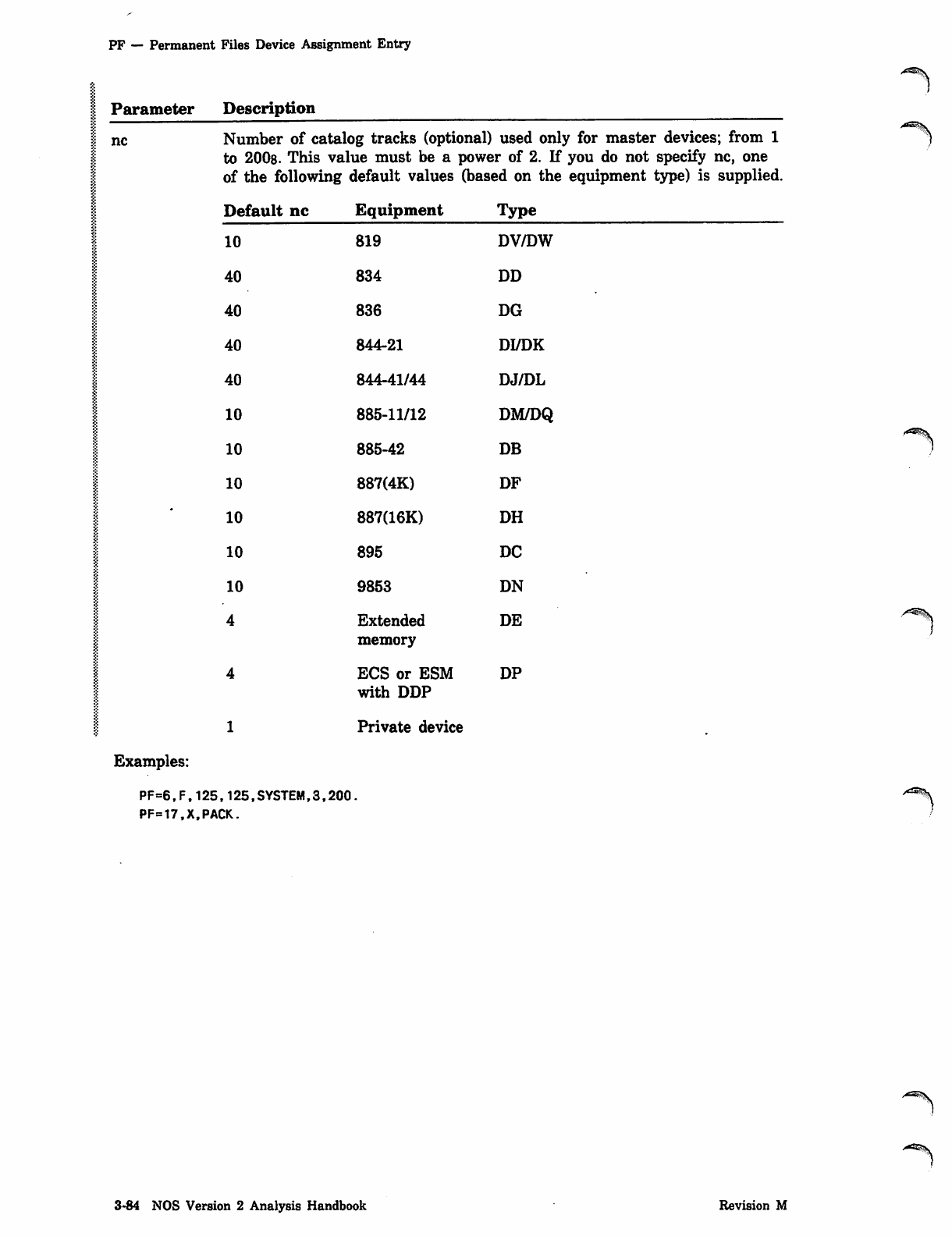
PF — Permanent Files Device Assignment Entry
nc
Parameter Description
Number of catalog tracks (optional) used only for master devices; from 1
to 2008. This value must be a power of 2. If you do not specify nc, one
of the following default values (based on the equipment type) is supplied.
Default nc Equipment Type
10 819 DV/DW
40 834 DD
40 836 DG
40 844-21 DI/DK
40 844-41/44 DJ/DL
10 885-11/12 DM/DQ
10 885-42 DB
10 887(4K) DF
10 887U6K) DH
10 895 DC
10 9853 DN
4Extended
memory
DE
4ECS or ESM
with DDP
DP
1Private device
Examples:
PF=6,F,125,125,SYSTEM,3,200
PF=17,X,PACK.
3-84 NOS Version 2 Analysis Handbook Revision M
SYSTEM — System Library Device Assignment Entry
0m**.
SYSTEM — System Library Device Assignment Entry
The SYSTEM entry specifies which mass storage devices are to contain copies of the
NOS system library from the deadstart file. A system device can be any disk storage
device as well as extended memory.
Throughput can be greatly improved by specifying more than one system device For
example, if two system devices are specified and they are on different channels, the
time required to access system programs can be reduced. When the channel for one
system device is busy, the other is accessed. Also, if hardware problems occur on one
system device, the other system device can still be accessed. A good general rule is
to have one copy of the NOS system library per pair of channels with a maximum of
three copies. This allows alternate access to the system library while saving mass
storage space.
The following restrictions apply.
• The EQ entry for a system device cannot have the status set to OFF.
• A REMOVE entry cannot exist in the EQPDECK for a device being specified as a
system device.
• If more than one device is specified as a system device, all devices specified must
be of the same type and have the same number of spindles. For example, if there
are two system devices and the equipment EST ordinal for one of them specifies
DI (single spindle), the equipment EST ordinal for the other one must also specify
DI (single spindle).
• If no devices are specified as system devices, the system library resides on the
first nonremovable mass storage device.
• An ASR entry cannot exist in the EQPDECK for a device being specified as a
system device.
The SYSTEM entry format is:
SYSTEM=est1fest2 estn.
Parameter Description
esti EST ordinal of the device to contain a copy of the system library on
the deadstart file; from 5 to 37s . The EQ entry must be set to ON
status. One or more ordinals can be specified with one SYSTEM entry.
Ranges of ordinals can be specified. The maximum number of system
devices allowed depends upon the value of MXSY (refer to COMSMSC
Parameters in the NOS Version 2 Installation Handbook).
Revision M Deadstart Decks 3-85
ASR — Alternate System Library Device Assignment Entry.
ASR — Alternate System Library Device Assignment Entry
This entry specifies which mass storage devices are to be alternate system devices. An
alternate system device is a mass storage device on which duplicate copies of system
routines can be placed by the system, either for faster access than is possible from a
system device or because they are frequently used programs. The following restrictions
apply.
• The device must be a mass storage device, including extended memory.
• The device cannot be a removable device.
• The device cannot be a system device.
When loading a system routine, the system will access the routine from the alternate
system device if practical. However, if the alternate system device is down or its access
is more congested than the system device, the system will access the routine from the
system device.
The procedure for selecting the records to be placed on the alternate device is in
LIBDECK.
The ASR entry format is:
ASR=est1,est2,....estn.
Parameter Description
esti EST ordinal of mass storage device to be used as an alternative
system device; from 5 to 37s. Ranges of ordinals can be specified.
SCKP — System Checkpoint File Device Assignment Entry
The SCKP entry specifies on which mass storage devices the checkpoint file is to
reside. This entry is processed during a level 0, 1, or 2 deadstart. If no checkpoint
devices are defined, the checkpoint file will reside on the first default mass storage
device.
A level 0 deadstart clears the checkpoint status on all mass storage devices. To clear
the checkpoint status for a specific mass storage device, use the RESET entry.
The SCKP entry format is:
SCKP=esti,est2,...,estn.
Parameter Description
esti EST ordinal of the mass storage device to be defined as a system
checkpoint file device; from 5 to 7778. Ranges of ordinals can be
specified.
3-86 NOS Version 2 Analysis Handbook Revision M
0ms.
0^s
FAMILY — Default Family Name Assignment Entry
FAMILY — Default Family Name Assignment Entry
The FAMILY entry defines the default family. The family that is to be defined as the
default family may reside on more than one device. The EST ordinal of any device
within the family can be specified on the FAMILY entry, except in the following
situation. If the member of the family whose device mask will have bit 27 (200s in
mask) set is being initialized, the FAMILY entry must specify the ordinal of this
device. In all cases, the FAMILY entry must follow the EQ entry for the device
specified.
The following restrictions apply.
• The status parameter for a default family device's EQ entry cannot be set to OFF.
• A REMOVE entry cannot exist in the EQPDECK for a device being specified as a
default family device.
The FAMILY entry format is:
FAMlLY=est.
Parameter Description
est ' EST ordinal number of the mass storage device that the system
automatically uses to determine your family when you do not specify a
family name at login or job initiation; from 5 to 7778.
REMOVE — Removable Device Assignment Entry
If a mass storage device is to be considered removable, you must specify it as such at
deadstart with the REMOVE entry. This allows it to be introduced or removed during
system operation. A device specified as removable cannot also have associated with it
an ASR, SYSTEM, MSAL, FAMILY, DAYFILE, ACCOUNT, ERRLOG, or MAINLOG
entry (refer to Dayfile Descriptions earlier in this section for the last four entries).
The format is:
REMOVE=esti,est2....,estn.
Parameter Description
esti EST ordinal of mass storage device that is to be removable; from 5 to
7778. One or more ordinals may be specified with one REMOVE entry.
Ranges of ordinals can be specified.
Revision M Deadstart Decks 3-87
SHARE — Shared Device Entry
SHARE — Shared Device Entry
This entry identifies the rotating mass storage devices to be shared through a link
device (ECS, ESM, or STORNET) by from two to eight mainframes in a
multimainframe complex. The tables necessary for the management of these devices
(MST, TRT, MRT, and DAT) are maintained on the link device. The presence of the
SHARE entry implies a multimainframe complex; shared status will be set for the link
device. If the link device is the only device to be shared, it must be specified in the
SHARE entry. If the SHARE entry is specified, the ISHARE entry must be omitted.
Refer to PRESET - Preset the Link Device Entry later in this section.
Following is a list of the equipment types that can be shared.
Equipment Type
ECS without DDP DE
or
ESM without LSP
ECS with DDP DP
or ESM with low-speed port (LSP)
or STORNET
844-21 * DI/DK
844-41/44 DJ/DL
885-11/12 DM/DQ
The format of SHARE is: >^
SHARE=esti,est2,...,estn.
Parameter Description
esti EST ordinal of the mass storage device being shared; from 5 to 777s
(EST ordinal 5 is reserved for the link device). Ranges of ordinals can
be specified.
Refer to section 13, Multimainframe Operations, for suggestions on shared device /*^v
configurations.
3-88 NOS Version 2 Analysis Handbook Revision M
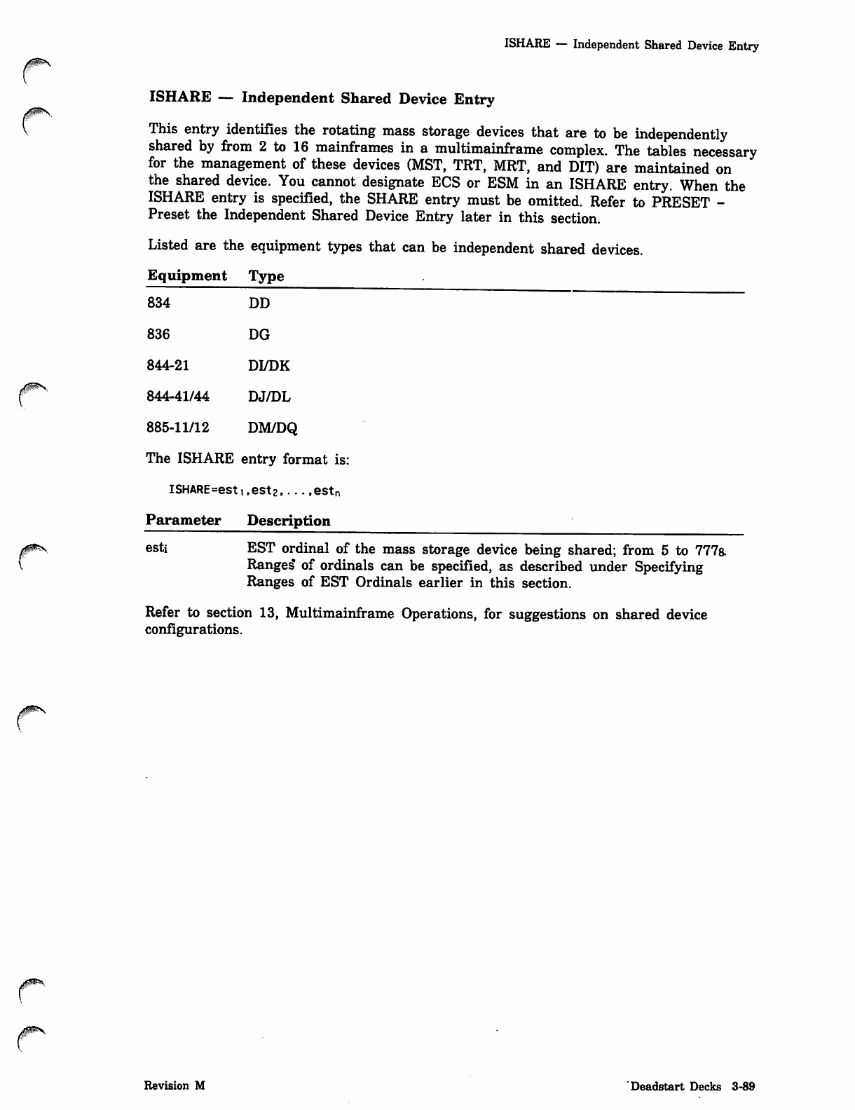
ISHARE — Independent Shared Device Entry
ISHARE — Independent Shared Device Entry
This entry identifies the rotating mass storage devices that are to be independently
shared by from 2 to 16 mainframes in a multimainframe complex. The tables necessary
for the management of these devices (MST, TRT, MRT, and DIT) are maintained on
the shared device. You cannot designate ECS or ESM in an ISHARE entry. When the
ISHARE entry is specified, the SHARE entry must be omitted. Refer to PRESET -
Preset the Independent Shared Device Entry later in this section.
Listed are the equipment types that can be independent shared devices.
Equipment Type
8 3 4 D D
8 3 6 D G
844-21 DI/DK
f^ 844-41/44 DJ/DL
885-11/12 DM/DQ
The ISHARE entry format is:
ISHARE=esti .est 2 estn
Parameter Description
esti EST ordinal of the mass storage device being shared; from 5 to 7778.
Ranges* of ordinals can be specified, as described under Specifying
Ranges of EST Ordinals earlier in this section.
Refer to section 13, Multimainframe Operations, for suggestions on shared device
configurations.
Revision M Deadstart Decks 3-89
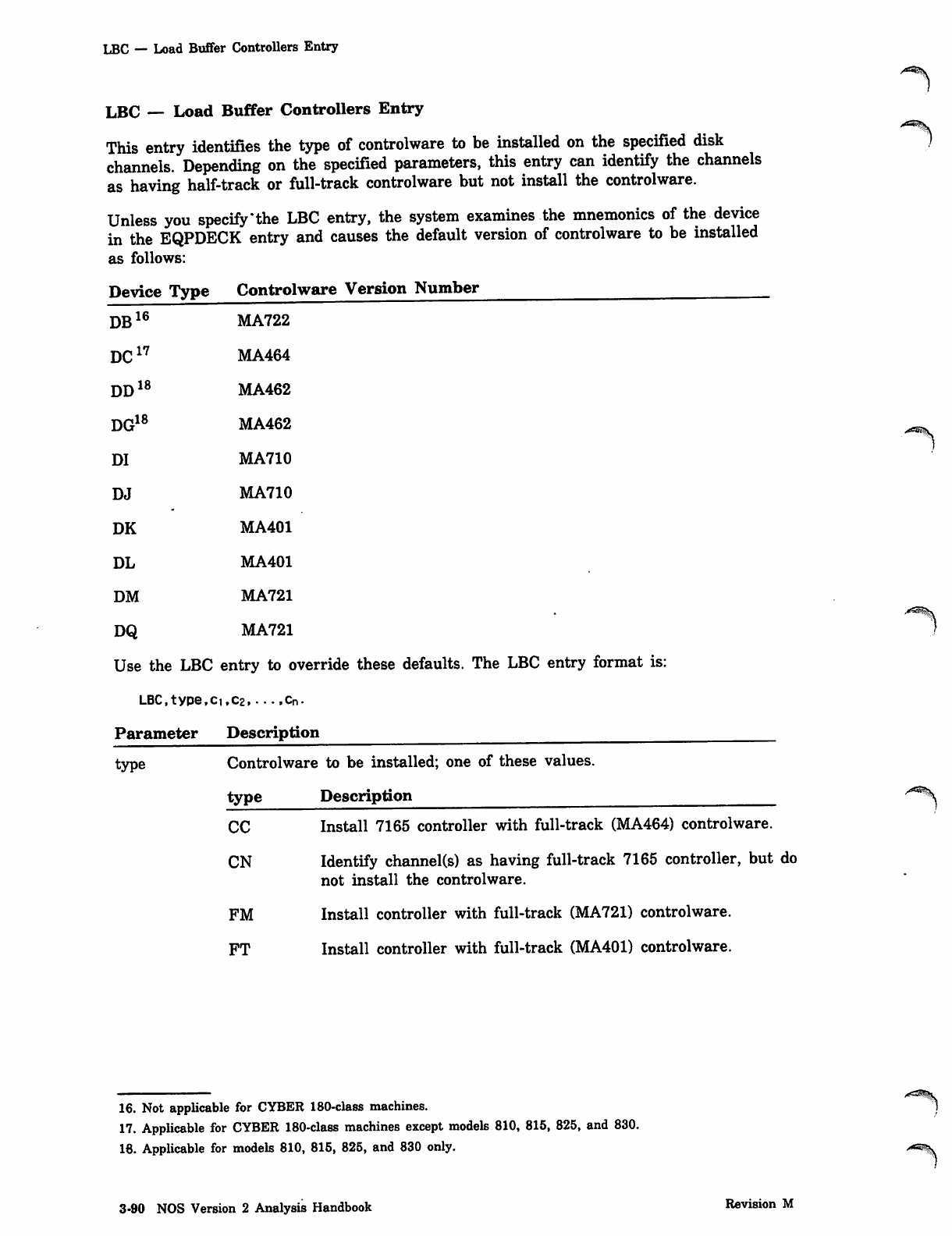
LBC — Load Buffer Controllers Entry
LBC — Load Buffer Controllers Entry
This entry identifies the type of controlware to be installed on the specified disk
channels. Depending on the specified parameters, this entry can identify the channels
as having half-track or full-track controlware but not install the controlware.
Unless you specify'the LBC entry, the system examines the mnemonics of the device
in the EQPDECK entry and causes the default version of controlware to be installed
as follows:
Device Type Controlware Version Number
DB16 MA722
DC17 MA464
DD18 MA462
DG18 MA462
DI MA710
DJ MA710
DK MA401
DL MA401
DM MA721
DQ MA721
Use the LBC entry to override these defaults. The LBC entry format is:
LBC,type, ci,C2,....cn.
Parameter Description
type Controlware to be installed; one of these values.
type Description ^\
CC Install 7165 controller with full-track (MA464) controlware.
CN Identify channel(s) as having full-track 7165 controller, but do
not install the controlware.
FM Install controller with full-track (MA721) controlware.
FT Install controller with full-track (MA401) controlware.
16. Not applicable for CYBER 180-class machines.
17. Applicable for CYBER 180-class machines except models 810, 815, 825, and 830.
18. Applicable for models 810, 815, 825, and 830 only. >«s%
3-90 NOS Version 2 Analysis Handbook Revision M
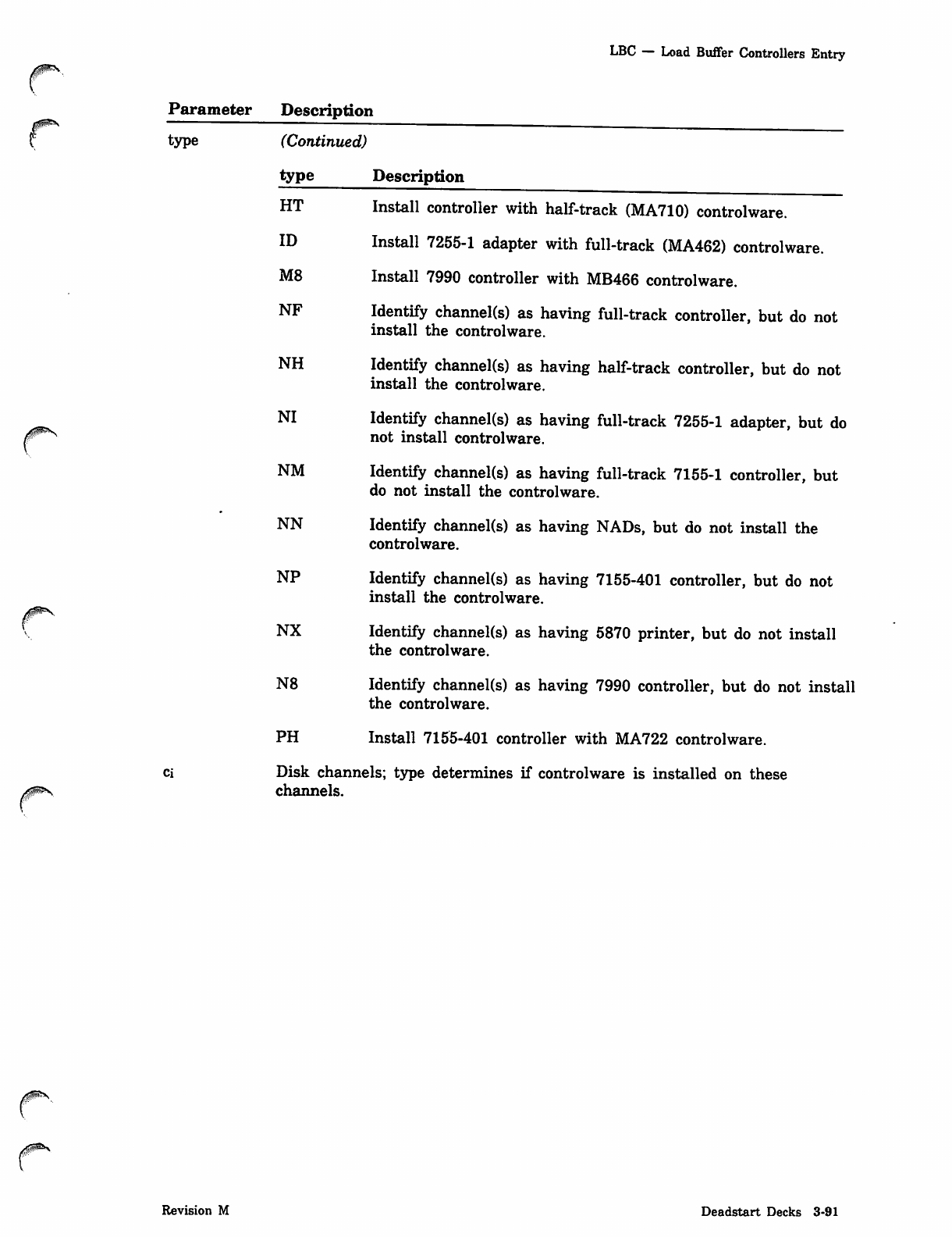
LBC — Load Buffer Controllers Entry
Parameter Description
type (Continued)
t y p e D e s c r i p t i o n
yms.
HT Install controller with half-track (MA710) controlware.
ID Install 7255-1 adapter with full-track (MA462) controlware.
M8 Install 7990 controller with MB466 controlware.
NF Identify channel(s) as having full-track controller, but do not
install the controlware.
NH Identify channel(s) as having half-track controller, but do not
install the controlware.
NI Identify channel(s) as having full-track 7255-1 adapter, but do
not install controlware.
NM Identify channel(s) as having full-track 7155-1 controller, but
do not install the controlware.
NN Identify channel(s) as having NADs, but do not install the
controlware.
NP Identify channel(s) as having 7155-401 controller, but do not
install the controlware.
NX Identify channel(s) as having 5870 printer, but do not install
the controlware.
N8 Identify channel(s) as having 7990 controller, but do not install
the controlware.
PH Install 7155-401 controller with MA722 controlware.
ci Disk channels; type determines if controlware is installed on these
channels.
Revision M Deadstart Decks 3-91
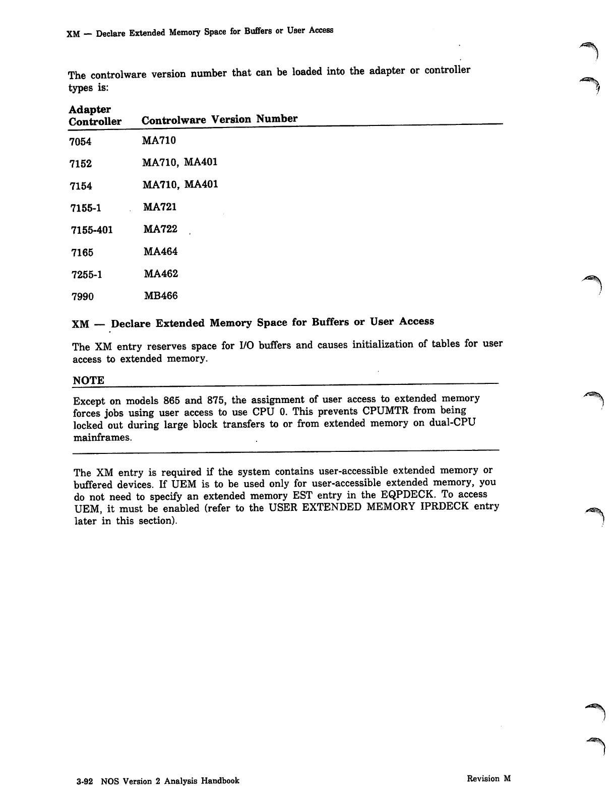
XM — Declare Extended Memory Space for Buffers or User Access
The controlware version number that can be loaded into the adapter or controller i***MS
t y p e s i s : f f
Adapter
Controller Controlware Version Number
7054 MA710
7 1 5 2 M A 7 1 0 , M A 4 0 1
7 1 5 4 M A 7 1 0 , M A 4 0 1
7155-1 MA721
7155-401 MA722
7165 MA464
7255-1 MA462
7990 MB466
XM — Declare Extended Memory Space for Buffers or User Access
The XM entry reserves space for I/O buffers and causes initialization of tables for user
access to extended memory.
NOTE
Except on models 865 and 875, the assignment of user access to extended memory ^^
forces jobs using user access to use CPU 0. This prevents CPUMTR from being
locked out during large block transfers to or from extended memory on dual-CPU
mainframes.
The XM entry is required if the system contains user-accessible extended memory or
buffered devices. If UEM is to be used only for user-accessible extended memory, you
do not need to specify an extended memory EST entry in the EQPDECK. To access
UEM, it must be enabled (refer to the USER EXTENDED MEMORY IPRDECK entry
later in this section).
3-92 NOS Version 2 Analysis Handbook Revision M
UEMIN — UEM Equipment Initialization
The XM entry format is:
XM=id,iob,uec,EM.
Parameter Description
id Identifier of the mainframe that will access the reserved extended
memory space; id is required.
If an XM entry refers to shared extended memory (ECS or ESM as a
link device), the XM entry must be present in the EQPDECKs of all
linked mainframes. If an XM entry refers to nonshared extended
memory (UEM), the XM entry must be present only in the EQPDECK
for its own mainframe.
iob Number of words/10008 reserved for buffers for DB, DC, DF, DH, DN,
DV, or DW devices; from 40s to 37770s. This value is limited by'the '
amount of memory available; either physically present or logically
available (allocated in the CMRDECK and EQPDECK entries). The
optimum number of words to reserve is the amount left after the
alternate system library and user-accessible extended memory are
taken into account. If no buffered devices are defined, enter 0.
uec Number of words/10008 of extended memory to reserve for user access;
maximum value is 777408. This value is limited by the amount of
memory available; either physically present or logically available
(allocated in the CMRDECK and EQPDECK entries).
EM For models 865 and 875 and CYBER 180-class machines,
user-accessible extended memory can be allocated in UEM without
allocating UEM as an equipment. If you want only user-accessible
extended memory in UEM, clear or do not specify an extended memory
EST entry in the EQPDECK and enter XM with the uec size and the
EM keyword.
For models 865 and 875, if you specify EM, user-accessible extended
memory is allocated in UEM regardless of the presence of ECS or
ESM; if you omit EM, user-accessible extended memory is allocated in
the device defined in the extended memory EST entry.
UEMIN — UEM Equipment Initialization
The UEMIN entry enables full initialization for UEM equipment during a level 0
deadstart. It is equivalent to an INITIALIZE,AL,est entry. The UEMIN entry can be
included as part of the EQPDECK on the deadstart file or it can be entered from the
system console at deadstart time. If the UEMIN entry is being used, the EQ entry for
the DE equipment is required. If you enter UEMIN when it's already set, it disables
the automatic initialization of UEM. The UEMIN format is:
UEMIN.
H$PP5\
Revision M Deadstart Decks 3-93
ACCESS — Set Access Level Limits
ACCESS — Set Access Level Limits
The ACCESS entry allows you to specify equipment access level limits for mass
storage, magnetic tape, two-port multiplexer, stimulator multiplexer, and unit record
type equipment. This entry is invalid for other types of equipment. This entry
determines the upper and lower limits for the range of access levels of the data
allowed to be read from or written to the equipment. The default equipment access
level limits are zero; no secure data can be read from or written on the equipment.
Values for this entry should be supplied by a site security administrator.
If you want the equipment access level limits specified by this entry to become the
device access level limits for mass storage equipment, that equipment must be
initialized. Refer to the NOS Version 2 Security Administrator's Handbook for more
information about equipment access and device access level limits.
This entry is ignored if the system is running in unsecured mode.
The format of the ACCESS entry is:
ACCESS,1ower,upper,ord11st.
Parameter Description
.,rf^\
lower * Access level name specified in deck COMSMLS (refer to the NOS
Version 2 Installation Handbook) corresponding to the desired lower
limit.
upper Access level name specified in deck COMSMLS corresponding to the
desired upper limit.
ordlist One or more EST ordinals, separated by commas, or a range of
ordinals as described in Specifying Ranges of EST Ordinals earlier in
this section.
/ • ^
3-94 NOS Version 2 Analysis Handbook Revision M
THRESHOLD — Set Disk Thresholds
0ims.
THRESHOLD — Set Disk Thresholds
The THRESHOLD entry enables you to set threshold values for the disk storage
devices specified by EST ordinals. The system uses these threshold values as limits
when monitoring disk verification failures, available disk space, and disk error
processing. If a threshold value is exceeded, the system performs a corrective action,
such as notifying the operator or restricting activity on the affected disk. The format of
the THRESHOLD entry is:
THRESHOLD,type=value,ordlist.
Parameter Description
type
value
ordlist
You can specify one of the following threshold types. Refer to the DSD
THRESHOLD command in section 5 for additional information.
type Description
VF
RA
LS
RE
UE
Verification failure threshold (default).
Restricted activity threshold.
Low space threshold.
Recovered error threshold.
Unrecovered error threshold.
The threshold value can range from 0 to 3777s. If the value parameter
is omitted, the following default values are used.
type value
VF
RA
LS
RE
UE
1/8 of the number of tracks on the device.
1/16 of the number of tracks on the device.
50s
0
Enter one or more EST ordinals, separated by commas, or a range of
ordinals as described in Specifying Ranges of EST Ordinals earlier in
this section.
Revision M Deadstart Decks 3-95
EQPDECK Entries Made Only During Deadstart
A*ms
EQPDECK Entries Made Only During Deadstart
The following entries are valid only from the system console at deadstart time. They '
cannot be included as part of the EQPDECK on the deadstart file.
AUTOLOAD — Toggle Autoloading
The AUTOLOAD entry toggles the selection of buffer controller autoloading for all
7054/7154/7152/7155/7165 controllers and the 7255 adapter. The AUTOLOAD format is:
AUTOLOAD.
GRENADE — Clear Unit Reservations
The GRENADE entry causes unit reservations to be cleared on all 844 units physically
connected to each 7054/7154/7152/7155 controller and any 834 or 836 units connected to
a 7255 adapter. The GRENADE format is:
GRENADE. )
INITIALIZE — Initialization Entry
To use a mass storage device that is defined with an EQ entry, it must have a label.
A label is written on a device when you initialize it by using either the INITIALIZE
command, during system operation, or the INITIALIZE entry in the EQPDECK, when
it is displayed at the system console at deadstart time.
A mass storage device's label is contained on a logical track (usually track 0). It *^^
contains information about the allocation and characteristics of a device (and its
units, if there is more than one unit on a device). This information is in the form of
a label sector for the first unit, a TRT for the device, and a label sector for each
unit.
Initialization does not automatically occur at each deadstart because mass storage
device labels are recovered during all deadstarts. Therefore, initialize a device only in
the following situations.
• To add a new mass storage device (no label exists on the device) use the ^^
INITIALIZE entry.
• If parts of the label on a permanent file device have been destroyed by
maintenance operations (permanent files having been dumped to another device
before diagnostics were run), use the INITIALIZE entry during deadstart to write
a new label. Then reload the permanent files.
• If a device (usually a private auxiliary, public auxiliary, or alternate permanent
file family device) is added to a system during operation, use the DSD
INITIALIZE command to initialize it if it does not have a valid label on it when
it is added to the system.
• When an extended memory device is initially placed in maintenance mode, all
mainframes using extended memory must initialize it (the maintenance mode
parameter is described under EQ - Extended Memory EST Entry earlier in this
section). You must also enter the PRESET entry for multimainframe operation. ^a^
3-96 NOS Version 2 Analysis Handbook Revision M
0ms.
INITIALIZE — Initialization Entry
During a deadstart, the INITIALIZE entry has the following characteristics.
• During a level 0 deadstart, it can be entered at the system console only when the
EQPDECK is displayed. It can be entered anywhere after the EQ entry for the
device.
If it is placed in the deadstart file EQPDECK, the system issues the error
message INCORRECT ENTRY when the EQPDECK is read from the tape.
• A total initialization (op=AL) assumes that no valuable information exists on the
device and creates a new label. When the new label is created, all previously
existing information on the device, except CTI, CDA, HIVS, and MSL, is lost.
• If the EQ status for the device is OFF when INITIALIZE is entered, initialization
of the device occurs whenever the device is set to ON status by the operator with
the DSD ON command during normal system operation.
• If the device is not a master device, INITIALIZE (op=AL) only writes a label; if
it is a master device, then it also initializes the catalog track and writes EOIs at
the beginning of the permit track, the indirect access track (data chain), and each
catalog track.
• During a deadstart initialization (op=AL), all flaw reservations specified for a
device are lost and must be reentered, except for 844 type devices with
factory-formatted disk packs.
• During an initialize format pack (op=FP) for an 895 disk, NOS only formats
those cylinders it plans to use in large record format. NOS does not format the
disk cylinders occupied by CIP.
NOTE
If a disk deadstart is in progress, the deadstart disk cannot be initialized. An
attempt to initialize it will result in the system issuing the error message
INCORRECT ENTRY.
The format of INITIALIZE is:
INITIALIZE,op,est,,est2 estn.
Parameter Description
op Level of initialization; one of these values:
op Description
AF Initialize account dayfile.
AL Total initialization. For an 895 disk, the AL parameter is
equivalent to the FP parameter if an initial install of CIP was
done or if CIP was released.
DF Initialize system dayfile.
EF Initialize error log.
Revision M Deadstart Decks 3-97
INITIALIZE — Initialization Entry
Parameter Description
op (Continued) ^fsm%^
op Description
FP Initialize format pack (an automatic selection of AL also occurs).
This option applies to 844 and 895 disks only.
MF Initialize binary maintenance log.
PF Initialize permanent files.
QF Initialize queued files.
esti EST ordinal of mass storage device to be initialized; from 5 to 7778.
If the ordinal refers to a family permanent file device, then family
name, device number, and mask (if it is a master device) are specified
on the PF entry.
If it is an auxiliary device, the pack name is specified on the PF entry.
Total initialization (op=AL or FP) is the only initialization that is independent of the
content of the pack, if the initialization occurs during deadstart. If the initialization is
done while the system is running, it is applied to the device after the check mass
storage (CMS) routine has recovered it. If CMS cannot recover the device, the
initialization is similar to a deadstart initialization (that is, all information on the
device is lost).
The device number, family name, and device masks can only be changed during a
total initialization. Since all devices may contain permanent files, you should include
a PF entry for a device when performing a total initialization. If you do not, the
device is assigned a default family name, device number, and device masks. It is
possible that these parameters may conflict with other devices in the system. If a
conflict occurs, resolve it by using PF entries.
If you initialize a nonremovable device without a PF entry, the device mask and
secondary mask default to 377s for the smallest EST ordinal larger than 5. For all
other equipment, including equipment 5, the default masks are set to 0 (zero). The '*4S5%,
default family name is SYSTid (where id is the machine identifier). The default '
device numbers begin at 1 and increase by 1 (starting with EST ordinal 5) for each
device that you initialize without a PF entry.
The INITIALIZE entry operates in conjunction with the dayfile entries DAYFILE,
ACCOUNT, ERRLOG, and MAINLOG (refer to Dayfile Descriptions earlier in this
section) to determine where the dayfiles actually reside. The following examples
illustrate the various cases. Assume that the system has three mass storage devices
(EST ordinals 6, 7, and 10).
3-98 NOS Version 2 Analysis Handbook Revision M
INITIALIZE — Initialization Entry
Example 1:
For this example, no dayfile entries are made and no previous dayfiles exist.
The following EQPDECK entry is made.
INITIALIZE,AL,6,7,10.
All dayfiles reside on ordinal 6.
Example 2:
In this example dayfile entries are made, but no previous dayfiles exist.
The following EQPDECK entries are made.
DAYFILE=6,200.
ACCOUNT=7,200.
ERRLOG=10.
MAINLOG=10,200.
INITIALIZE,AL,6,7,10.
In this case, the dayfiles reside on the indicated devices (system dayfile on ordinal 6,
account' dayfile on ordinal 7, error log and binary maintenance log on ordinal 10).
The default buffer length is used for the error log buffer.
Example 3:
In this example, dayfile entries are made and previous dayfiles do exist.
Assume that the EQPDECK entries in example 2 are used.
Since a total initialization has been done on each device, no dayfiles are recovered.
They reside on the indicated devices.
Example 4:
In this example, dayfile entries are made, previous dayfiles exist, but no dayfile
initialization entries are made.
The following EQPDECK entries are made.
DAYFILE=6.
ACCOUNT=7.
ERRLOG=10.
INITIALIZE,PF.6.
The dayfiles may already reside on the specified devices, or they may reside on some
combination of the possible devices. In either case, since no dayfile initialization
entries are made, the old dayfiles are recovered. The residence of these dayfiles is
governed by the residence of the old dayfiles. The PF initialization entry returns all
permanent file space and relabels the device based on the recovered device
parameters. The dayfiles and queued files on this device are not affected by this
entry.
Revision M Deadstart Decks 3-99
INITIALIZE — Initialization Entry
Example 5:
In this example, dayfile entries are made, previous dayfiles exist, no dayfile
initialization entries are made, and duplicate dayfiles are in existence.
Assume that the EQPDECK entries in example 4 are used.
For the dayfiles that do not have duplicates, the residence is defined by the current
residence of the files, not the EQPDECK entries. But assume that an error log is
recovered from ordinals 6 and 10. In this case, the most recent file becomes the
active error log. Its previous residence overrides the EQPDECK entry. The other file
becomes an inactive error log (an entry exists in the mass storage table of the device
pointing to the inactive file, but the file is not in use by the system).
To produce an inactive error log, the site must run in the following manner.
1. Assume an 844 disk subsystem with two or more spindles is being used. Run with
unit 1 equated to EQ6 and unit 0 unused.
2. Redeadstart, equate unit 0 to EQ6, and do not use unit 1. 1
3. Redeadstart, equate unit 0 to EQ6, and unit 1 to EQ7.
Since unit 0 has the most recent copy of the error log, this copy would become an
active error log and the copy on unit 1 would become an inactive error log.
Example 6:
In this example, dayfile entries are made, the previous dayfiles from example 2 exist, ^^
and initialization entries are made. )
The following EQPDECK entries are made.
DAYFILE=7.
ACCOUNT=7.
ERRLOG*10,300.
MAINLOG=10.
INITIALIZER, 6.
INITIALIZE,QF,6.
In this case, the account dayfile is recovered and continued on ordinal 7. The binary
maintenance log is recovered and continued on ordinal 10 with a CM buffer length of
100. The error log is recovered and continued on ordinal 10 with a CM buffer of 300s
words. The system dayfile space on ordinal 6 (from example 2) is released and the
new system dayfile starts on ordinal 7. The QF initialization entry releases all space
reserved by queued files on ordinal 6.
The CM buffer length is not affected by dayfile recovery. It is always specified by the
values defined in the EQPDECK entries. If no buffer length entries exist, the system
default values are used.
r"5*%
3-100 NOS Version 2 Analysis Handbook Revision M
PRESET — Preset the Link Device Entry
PRESET — Preset the Link Device Entry
This entry defines allocation space and initializes the tables (MST, TRT, MRT, and
DAT) on the link device that are required for management of shared multimainframe
mass storage devices. The entry is valid only for level 0 deadstarts by the first
mainframe in the multimainframe complex to deadstart.
Once PRESET is issued, the SHARE entry is disabled. Therefore, all SHARE entries
must precede the PRESET entry. The PRESET entry has two formats:
PRESET.
or
PRESET,n.
Parameter Description
n Number of shared devices; from 1 to 77s.
If you specify n, space is allocated for the specified number of shared devices. Use this
entry when the total number of shared devices is greater than the number of shared
devices defined in the EQPDECK of the first mainframe in the multimainframe
complex to do a level 0 deadstart.
If you do not specify n, the link device is preset, and the amount of table space
reserved for the shared devices is determined by the number of shared entries in the
EQPDECK.
Revision M Deadstart Decks 3-101
PRESET — Preset the Independent Shared Device Entry
PRESET — Preset the Independent Shared Device Entry
This entry presets the independent shared devices in a multimainframe complex. The )
MST, TRT, MRT, and DIT are maintained on the mass storage device itself and are
not affected by the PRESET entry. This entry is used in conjunction with the ISHARE
entry. It is valid only on a level 0 deadstart by the first mainframe in the
multimainframe complex to deadstart. All ISHARE entries must precede the PRESET
entry.
The format is:
PRESET=est1,est2,...,estn.
Parameter Description
esti EST ordinal of the ISHARE device; from 5 to 777s. Ranges of ordinals
can be specified, as described under Specifying Ranges of EST Ordinals
earlier in this section.
Refer to section 13, Multimainframe Operations, for suggestions on shared device ^]
configurations.
WARNING
If a PRESET is entered for a device that is already in use by a second machine in a
multimainframe complex, system failures may occur on both machines, and data on
the device may be destroyed.
If a PRESET is entered for a device while a second machine in a multimainframe
complex is down, and if that second machine later attempts to perform a level 3 /a(S%
deadstart and use that device, system failures may occur on both machines, and data
on the device may be destroyed.
RESET — Reset Device Attributes
The RESET entry rescinds all device-related attributes resulting from entries such as
REMOVE, SYSTEM, MSAL, and so on. It restores the values specified with the last
EQest entry encountered. The format is: ^^
RESET=est 1,est z....,estn •
Ranges of ordinals are not allowed; each ordinal must be entered individually.
z^SSv
3-102 NOS Version 2 Analysis Handbook Revision M
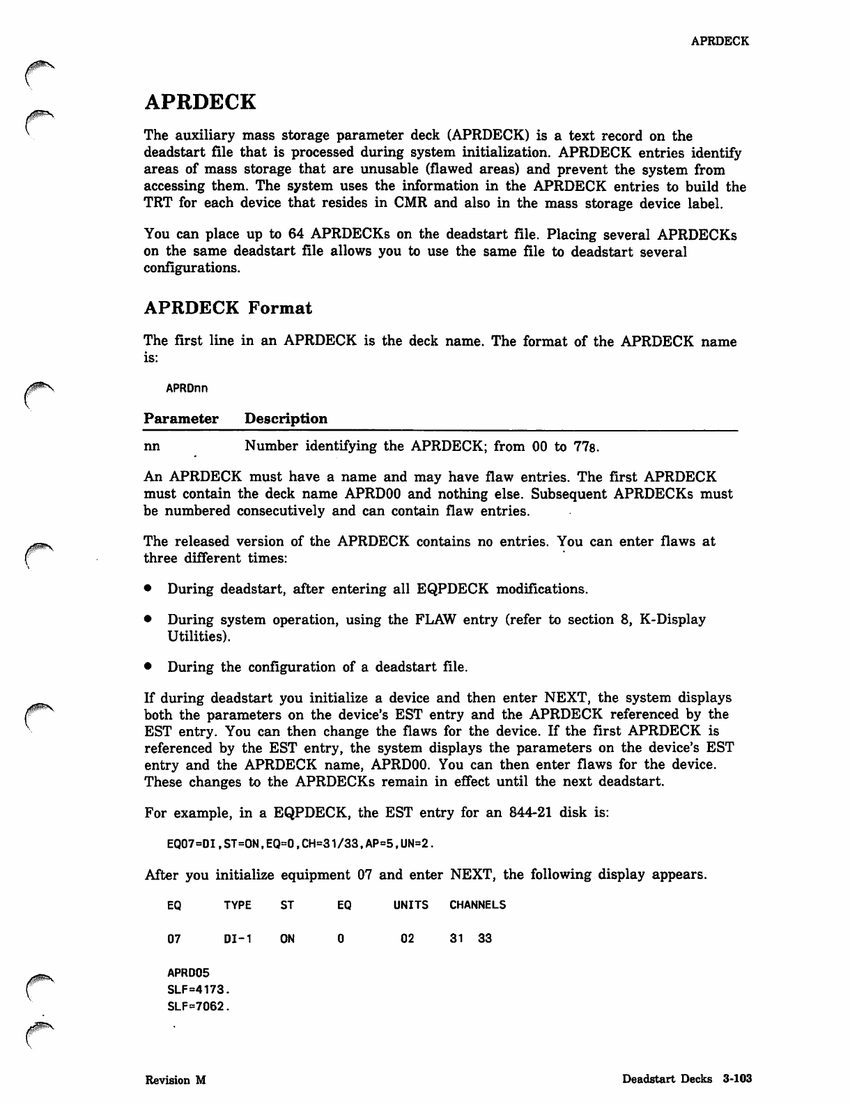
APRDECK
APRDECK
The auxiliary mass storage parameter deck (APRDECK) is a text record on the
deadstart file that is processed during system initialization. APRDECK entries identify
areas of mass storage that are unusable (flawed areas) and prevent the system from
accessing them. The system uses the information in the APRDECK entries to build the
TRT for each device that resides in CMR and also in the mass storage device label.
You can place up to 64 APRDECKs on the deadstart file. Placing several APRDECKs
on the same deadstart file allows you to use the same file to deadstart several
configurations.
APRDECK Format
The first line in an APRDECK is the deck name. The format of the APRDECK name
is:
APRDnn
Parameter Description
nn Number identifying the APRDECK; from 00 to 77s.
An APRDECK must have a name and may have flaw entries. The first APRDECK
must contain the deck name APRD00 and nothing else. Subsequent APRDECKs must
be numbered consecutively and can contain flaw entries.
^^ The released version of the APRDECK contains no entries. You can enter flaws at
{ three different times:
• During deadstart, after entering all EQPDECK modifications.
• During system operation, using the FLAW entry (refer to section 8, K-Display
Utilities).
• During the configuration of a deadstart file.
If during deadstart you initialize a device and then enter NEXT, the system displays
f^ both the parameters on the device's EST entry and the APRDECK referenced by the
EST entry. You can then change the flaws for the device. If the first APRDECK is
referenced by the EST entry, the system displays the parameters on the device's EST
entry and the APRDECK name, APRD00. You can then enter flaws for the device.
These changes to the APRDECKs remain in effect until the next deadstart.
For example, in a EQPDECK, the EST entry for an 844-21 disk is:
EQ07=DI,ST=0N,EQ=0,CH=31/33,AP=5,UN=2.
After you initialize equipment 07 and enter NEXT, the following display appears.
EQ TYPE ST EQ UNITS CHANNELS
0 7 D I - 1 O N 0 0 2 3 1 3 3
APRD05
SLF=4173.
SLF=7062.
Revision M Deadstart Decks 3-103
CAF — Clear All Flaw Reservations
The APRDECK entries described in this section are those to be used for entering /4esm.
flaws during deadstart or during the configuration of the deadstart file. Use the )
entries as follows.
• Use the CAF entry to clear all flaw reservations on a device.
• Use the SPF entry to specify the physical address of a flaw in extended memory.
(If a reservation for that physical address already exists, it remains in effect.)
• Use the SPF entry to specify the cylinder, track, and sector of a flaw in a disk.
(If a reservation for that physical area already exists, it remains in effect.)
• Use the CPF entry to cancel a particular SPF entry.
• Use the SLF entry to specify the logical address of a flaw. (If a reservation for
that logical address already exists, it remains in effect.)
• Use the CLF entry to cancel an SLF entry.
NOTE
All numeric values entered in the APRDECK must be entered in octal.
Either obtain flaw addresses from a customer engineer, or run the MST (mass storage
test) on the device to determine the bad areas. MST specifies the physical address of
flaws.
The system reads the flaw information recorded on the utility flaw map of an
881/883/885 disk pack during the initialization of 844/885 equipment and reserves the
appropriate areas. For multiunit devices, the flaw reservation is the union of all
utility flaw maps. This automatic flawing process occurs in addition to any
APRDECK entries. However, you cannot clear areas recorded as flawed on the utility
flaw map of an 881/883/885 disk pack with the CAF entry. Refer to appendix G for
information on clearing these flaws.
You can list all APRDECKs on the deadstart file by accessing the system file
SYSTEM with an ASSIGN or COMMON command, then using the T parameter on
the CATALOG command. Refer to the NOS Version 2 Reference Set, Volume 3 for
more information.
CAF — Clear All Flaw Reservations
The CAF entry clears all flaw reservations previously made with SLF or SPF entries.
The format is:
CAF.
3-104 NOS Version 2 Analysis Handbook Revision M
0m*s
SLF — Set Logical Flaws on Any Mass Storage Device
SLF — Set Logical Flaws on Any Mass Storage Device
Use this entry to specify the logical address of a flaw. If the track was previously
reserved, that reservation remains in effect. The format is:
SLF=track.
Parameter Description
track Logical track number. Refer to table 3-6 for valid ranges of track
numbers.
CLF — Clear Logical Flaws on Any Mass Storage Device
To cancel a reservation made with an SLF entry, enter the identical track number
using the CLF entry. The format is:
CLF=track.
Parameter Description
track Logical track number. Refer to table 3-6 for valid ranges of track
numbers.
SPF — Set Physical Extended Memory Track or Disk Area Flaws
Two formats exist for the SPF entry. One format prevents the system from using
blocks (tracks) of extended memory. The other format prevents the system from using
sectors on disks.
Use the following SPF format to prevent the system from using blocks (tracks) of
extended memory.
SPF=Aaddress.
or
SPF=Aaddressi-Aaddress2.
Parameter Description
Aaddress The 1- to 7-digit octal logical address in a track of extended memory;
track containing the absolute address is reserved. The letter A must
precede the address.
Aaddressi Lowest (Aaddressi) and highest (Aaddress2) addresses in a range of
Aaddress2 logical addresses in one or more tracks of extended memory. All tracks
in the range are reserved. The letter A must precede the addresses;
the hyphen is required.
Use the following SPF format to prevent the system from using sectors on disks.
SPF=Ccylinder,Ttrack,Ssector.
Revision M Deadstart Decks 3-105
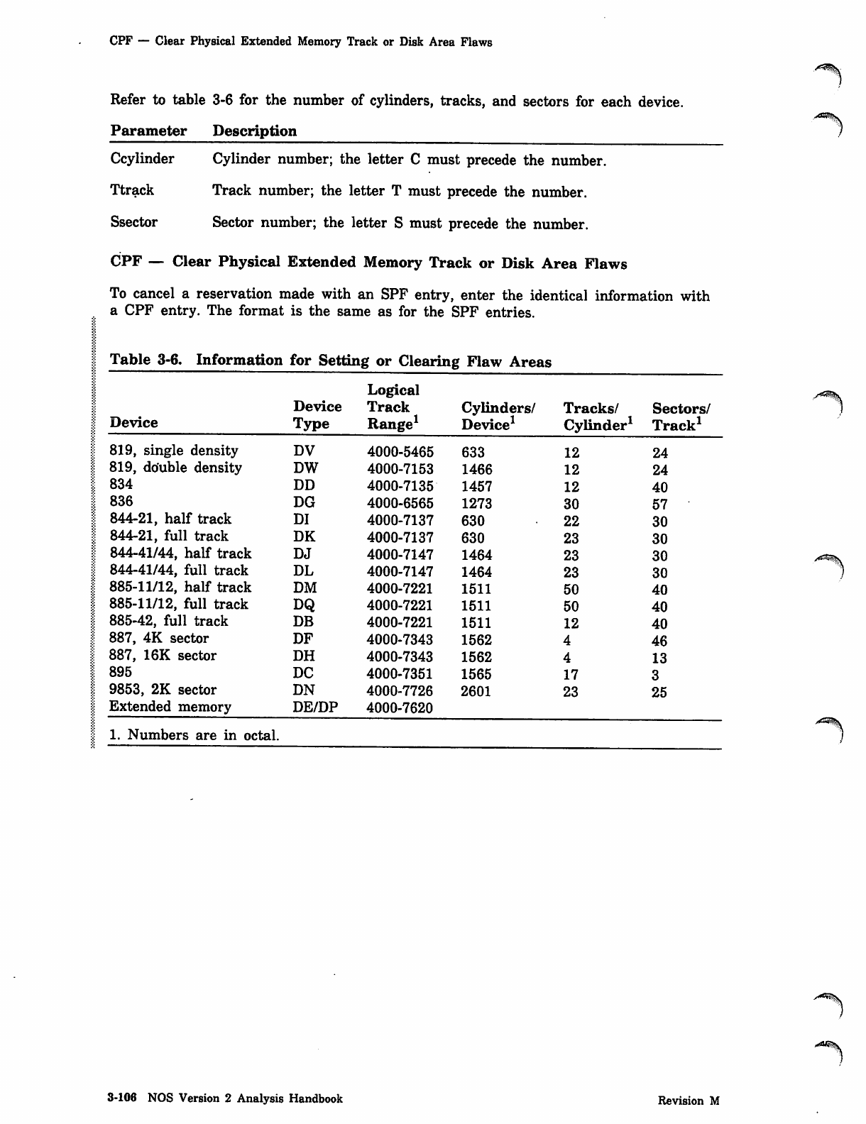
CPF — Clear Physical Extended Memory Track or Disk Area Flaws
Refer to table 3-6 for the number of cylinders, tracks, and sectors for each device.
Parameter Description
Ccylinder Cylinder number; the letter C must precede the number.
Ttrack Track number; the letter T must precede the number.
Ssector Sector number; the letter S must precede the number.
CPF — Clear Physical Extended Memory Track or Disk Area Flaws
To cancel a reservation made with an SPF entry, enter the identical information with
a CPF entry. The format is the same as for the SPF entries.
Table 3-6. Information for Setting or Clearing Flaw Areas
Logical
Device Track Cylinders/ Tracks/ Sectors/
Device Type Range1 Device1 Cylinder1 Track1
819, single density DV 4000-5465 633 12 24
819, double density DW 4000-7153 1466 12 24
834 DD 4000-7135 1457 12 40
836 DG 4000-6565 1273 30 57
844-21, half track DI 4000-7137 630 22 30
844-21, full track DK 4000-7137 630 23 30
844-41/44, half track DJ 4000-7147 1464 23 30
844-41/44, full track DL 4000-7147 1464 23 30
885-11/12, half track DM 4000-7221 1511 50 40
885-11/12, full track DQ 4000-7221 1511 50 40
885-42, full track DB 4000-7221 1511 12 40
887, 4K sector DF 4000-7343 1562 46
887, 16K sector DH 4000-7343 1562 13
895 DC 4000-7351 1565 17
9853, 2K sector DN 4000-7726 2601 23 25
Extended memory DE/DP 4000-7620
1. Numbers are in octal.
3-106 NOS Version 2 Analysis Handbook Revision M
0^s
r
/0m*..
IPRDECK
IPRDECK
The IPRDECK contains the system installation parameters that determine the system's
operation mode. From 1 to 64 IPRDECKs can exist on a deadstart file. The IPD entry
in the CMRDECK specifies which IPRDECK to use. If you omit the IPD entry, the
system uses the first IPRDECK on the deadstart file. IPRDECKs are named IPRDnn,
where nn is from 00 to 77s.
There are two IPRDECK console displays. The initial display, IPRINST, is an
instruction display. It gives a brief description of all valid IPRDECK entries. The
second display is the current IPRDECK. If either display overflows two screens, you
can page the display.
You can modify the IPRDECK by entering the appropriate changes or additions from
the console keyboard. Make these entries while either the IPRINST or IPRDECK is
displayed. Each console entry supersedes the value currently specified in the
IPRDECK.
NOTE
Changes made to the IPRDECK at deadstart time will be recovered across a level 3
deadstart; but not across a level 0, level 1, or level 2 deadstart. To make these
changes permanent, you must create a new deadstart file with these changes
incorporated into the IPRDECK.
You can list all IPRDECKs on your system by accessing the system file SYSTEM
with a COMMON command, then using the T parameter on the CATALOG command.
Refer to the NOS Version 2 Reference Set, Volume 3 for more information concerning
these commands.
Most of the IPRDECK entries are also valid DSD commands that can be used to
make changes during system operation. Changes to the IPRDECK using DSD
commands are retained after a level 3 deadstart, but not after a level 0, level 1, or
level 2 deadstart.
Revision M Deadstart Decks 3-107
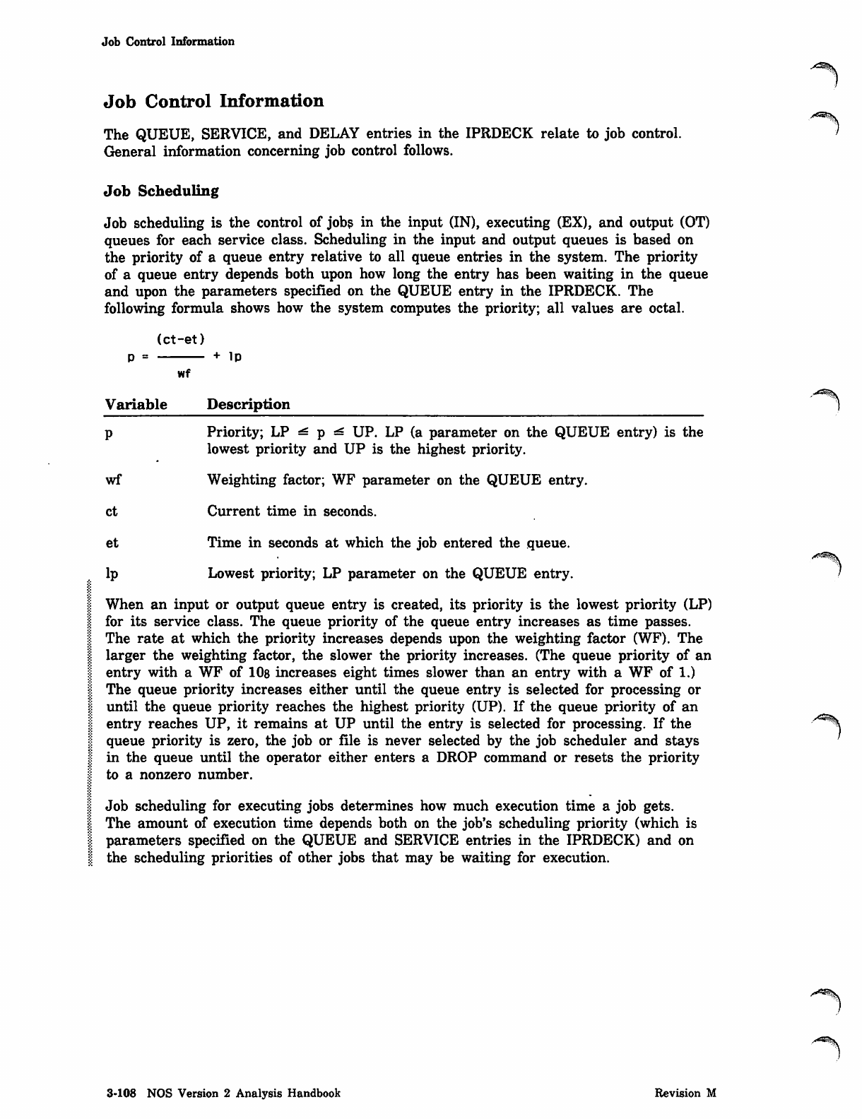
Job Control Information
Job Control Information
The QUEUE, SERVICE, and DELAY entries in the IPRDECK relate to job control. '
General information concerning job control follows.
Job Scheduling
Job scheduling is the control of jobs in the input (IN), executing (EX), and output (OT)
queues for each service class. Scheduling in the input and output queues is based on
the priority of a queue entry relative to all queue entries in the system. The priority
of a queue entry depends both upon how long the entry has been waiting in the queue
and upon the parameters specified on the QUEUE entry in the IPRDECK. The
following formula shows how the system computes the priority; all values are octal.
(ct-et)
p » + l p
wf
Variable Description 1
p Priority; LP ^ p ^ UP. LP (a parameter on the QUEUE entry) is the
lowest priority and UP is the highest priority.
wf Weighting factor; WF parameter on the QUEUE entry.
ct Current time in seconds.
et Time in seconds at which the job entered the queue.
lp Lowest priority; LP parameter on the QUEUE entry.
When an input or output queue entry is created, its priority is the lowest priority (LP)
for its service class. The queue priority of the queue entry increases as time passes.
The rate at which the priority increases depends upon the weighting factor (WF). The
larger the weighting factor, the slower the priority increases. (The queue priority of an
entry with a WF of 108 increases eight times slower than an entry with a WF of 1.)
The queue priority increases either until the queue entry is selected for processing or
until the queue priority reaches the highest priority (UP). If the queue priority of an
entry reaches UP, it remains at UP until the entry is selected for processing. If the •y(!S%
queue priority is zero, the job or file is never selected by the job scheduler and stays '
in the queue until the operator either enters a DROP command or resets the priority
to a nonzero number.
Job scheduling for executing jobs determines how much execution time a job gets.
The amount of execution time depends both on the job's scheduling priority (which is
parameters specified on the QUEUE and SERVICE entries in the IPRDECK) and on
the scheduling priorities of other jobs that may be waiting for execution.
3-108 NOS Version 2 Analysis Handbook Revision M
0$ms.
Job Scheduling
When a job in the input queue is selected for execution, it gets an initial priority (IP;
a parameter on the QUEUE entry) for the execution queue. Scheduling priority
increases for a job in the execution queue in the same way as in the input and
output queues. After the job is scheduled to a control point, its scheduling priority
does not age; it is set to fixed values that are changed only when specific events
occur. Initially, the job's scheduling priority is set to the upper priority bound for its
service class (the value of the UP parameter on the QUEUE entry). The job's
scheduling priority remains at this fixed value until the job exceeds either its control
point time slice or its central memory time slice.
If the job exceeds its control point time slice (the CT parameter on the SERVICE
entry), its scheduling priority is lowered to the control point slice priority (the CP
parameter on the SERVICE entry). If the job exceeds its central memory time slice
(the CM parameter on the SERVICE entry) for the first time, its scheduling priority
is lowered to the initial lower priority (the IL parameter on the QUEUE entry); if
the job exceeds its central memory time slice for a second or subsequent time, its
scheduling priority is lowered to the lower priority bound (the LP parameter on the
QUEUE entry).
Exceeding the CP or CM slice does not, by itself, force a job to roll out. A job
remains at a control point until the job scheduler determines that it needs this job's
control 'point and/or memory for a job with a higher priority. If a job rolls out, either
to mass storage or to a pseudo-control point, its scheduling priority starts at the
current value and begins to age upward (in the same fashion as input and output
queue files). When the job scheduler again selects this job to run at a control point,
its scheduling priority is again set to UP.
For interactive jobs, there is an additional execution queue priority, TP (a parameter
on the SERVICE entry). It is assigned to the execution queue entry of a job
restarting after terminal I/O. The value of TP aids response time to program
prompts. Also, for interactive jobs, the initial priority (IP) has an added significance.
In addition to being the priority at which jobs are scheduled from the input queue to
the execution queue, IP is the priority assigned when a terminal command is entered.
Using separate TP and IP parameters allows the system to give faster responses to
users interacting with a job. To achieve this, a value for the TP parameter slightly
greater than the value for the IP parameter is recommended (refer to tables 3-7 and
3-8 and figure 3-6).
The relative values of the QUEUE and SERVICE parameters, both among service
classes and within a service class, affect system performance. For an example of
ranges of service class priorities, refer to figure 3-6. For an example set of specific
entries for the QUEUE and SERVICE parameters, refer to tables 3-7 and 3-8.
Revision M Deadstart Decks 3-109
Job Scheduling
Control Points
A job leaves a central memory control point when any of the following conditions are
present:
• A job completes, aborts, or is suspended.
• A system request causes a job to be rolled out to wait for a resource to become
available or for a specified time period to elapse.
Such system requests include a job request for a tape or disk pack, a ROLLOUT
command, and execution of the ROLLOUT macro.
• Terminal input/output is required.
A job leaves central memory when the following conditions occur:
- The system requests terminal input and typeahead input is not available.
- You request terminal output and the recall parameter is specified on the
request.
- You issue a RECALL macro after a request for terminal output that omitted
the recall parameter.
• The control point is made available for a higher priority job.
This ensures reasonable service to all users in the system. The operating system
controls the amount of time each type of job can be at a control point. This
ensures that one job does not monopolize system resources.
When a job is rolled out, the priority increases as time passes, giving that job a better
chance to be selected for execution again. When the job is selected and rolled in, its
priority is changed to the value of the UP parameter on the QUEUE entry, and the
job scheduling priority cycle begins again. This description on job rollout applies to
local batch, remote batch, and interactive jobs that are not doing interactive I/O. For
interactive jobs that do terminal I/O within a time slice, scheduling priority is slightly
different. When I/O is complete and input, for example, is available, the system assigns
the rolled-out job the terminal I/O scheduling priority (TP parameter on the SERVICE
entry). The TP parameter can be used to give the job a priority equal to the priority of ^^
jobs still within their initial time slice, an advantage over jobs in a second time slice, /^%
and a larger advantage over jobs in a third or higher time slice.
If a job at a control point exceeds the central memory time slice and it is not a
subsystem, the scheduling priority is set to the initial lower or lower bound priority
(the IL or LP parameter on the QUEUE entry) for its service class. Thus, any job in
the queue with a higher priority forces the executing job with the lower priority to
be rolled out. The rolled-out job ages normally until its priority is higher than the
priorities of either the jobs in the input queue or a job that is executing; then it is
again scheduled to a control point.
Once a job is scheduled, it is desirable to use the resources allocated before another
job forces it out. If a job maintained its scheduling priority when it was assigned to a
control point, another job could age past that job and force it to be rolled out before
it had an opportunity to use its time slice. For this reason, when a job is assigned to
a control point and its priority is within the queue aging range, it is given a priority
equal to the highest priority (the UP parameter in the QUEUE entry) for its service
class.
3-110 NOS Version 2 Analysis Handbook Revision M
/S*!\
j^^Nt
0^S
/im^s
0^S
Job Scheduling
Pseudo-control Points
If pseudo-control points are defined, a job that is forced out of a control point may
remain in central memory at a pseudo-control point, rather than being rolled out to a
mass storage device.
• If the job is preempted by a higher priority job, the scheduling priority stays the
same.
• If the job's control-point time slice has expired, the scheduling priority drops to
the control-point slice priority.
Jobs with the following characteristics are excluded from using pseudo-control points:
• Connection to a system control point.
• Accumulator overflow flags set.
• Assigned to the first control point or the last control point.
• Error flag set.
Number of Control Points and Pseudo-control Points Available
Selecting the number of control points available on the system depends on the amount
of memory space available, the job mix, and the mode in which the system is being
run. Up to 348 control points can be defined. Each control point needs 2008 words of
CMR space. For example, if an installation is running only TAF, then four or five
control points may suffice. On the other hand, if the system is running a large number
of interactive terminals with heavy permanent file activity, 20 or more control points
may be needed. You may need to study memory and control point use in order to
correctly determine the setting of this option. The DSD W,R display and/or the ACPD
and PROBE utilities may be useful in making this determination.
• If memory use is high and control point use is low, select fewer control points.
• If control point use is high and memory use is low, select more control points.
Selecting the number of pseudo-control points depends on the same variables that are
used to determine the number of control points. Up to 34s pseudo-control points can
be defined. The pseudo-control points provide more effective use of central memory in
environments where an insufficient number of control points create a system
bottleneck. Like a control point, each pseudo-control point needs 200s words of CMR
space.
• If memory use is high and control point use is lower, do not select any
pseudo-control points.
• If control point use is high and memory use is low, select pseudo-control points.
Revision M Deadstart Decks 3-111
Memory Control
Memory Control
You can control the maximum memory allowed for job types and for service classes x /
with the parameters you specify on the SERVICE and DELAY entries in the
IPRDECK.
These parameters specify these lengths:
• Maximum field length divided by 1008 for a job in a service class.
Maximum field length divided by 1008 for all jobs of the specified service class.
Maximum extended memory length in words divided by 10008 for a job in a
service class.
Maximum extended memory length in words divided by 1000s for all jobs of the
specified service class.
• Amount of central or extended memory to leave between job field length, if
possible.
Initially, the scheduler attempts to find the highest priority job that meets the memory
constraints. However, if the scheduler is unable to schedule a job and has explicitly
rejected one or more jobs because the total field length or the total extended memory
field length for a service class would be exceeded, it attempts to schedule a job a
second time if flexible partitions are enabled (refer to FLEXIBLE PARTITIONS in this
section). During this second attempt, any job that requires other jobs to be rolled out is
not scheduled; otherwise, the constraints (service class total field length and total
extended memory field length) are ignored, and the job is scheduled at the lower bound
priority, LP (a parameter on the QUEUE entry). This means that the constraints are
applied as long as there are enough jobs of each service class. However, if central
memory is unused and no other jobs are available, the scheduler attempts to schedule
the jobs without the constraints.
All of these parameters can be changed by using the SERVICE, QUEUE, and DELAY
entries.
Example of Job Control Parameters
An example set of entries for the job control parameters is shown in tables 3-7 and
3-8. These entries fall within the example of ranges of service class priorities shown in
figure 3-6. Neither the specific entries nor the ranges are recommended; they are
strictly examples to aid you in selecting QUEUE and SERVICE entry parameters.
The following discussion indicates the significance of the values chosen and how they
relate to each other.
The entry (lowest) priority (LP parameter in the QUEUE entry) of the system service
class input queue is higher than all entry priorities, except the network supervision
and subsystem entry priorities, because it is assumed that an operator-initiated job
should receive prompt attention. A system job rolls out any batch job. The entry
priority (LP) of the network supervision service class input queue is set high to
ensure adequate response time from network programs and facilities such as CS, NS,
and NVF.
.•*^\
3-112 NOS Version 2 Analysis Handbook Revision M
Example of Job Control Parameters
The queue priorities for local batch, remote batch, and detached jobs are similar. The
time slice for detached jobs is shorter than for the local batch and remote batch jobs.
The assumption is that detached jobs need less CPU time than either local batch or
remote batch jobs.
The queue priorities are explained under Job Scheduling earlier in this section.
The time slices for the various service classes reflect the following objectives:
• To keep system jobs with their high entry priority from monopolizing system
resources.
• To keep at a minimum rollout activity caused by diagnostics running as
maintenance service class jobs.
• To allow most interactive jobs to compile, load, and begin execution in one time
slice.
• To give batch jobs a large time slice, because little is gained from rolling out
batch jobs. There is no problem with the time slices for batch jobs compared to
interactive jobs, because, with the priorities shown, an interactive job generally
causes a batch job to roll out.
• To ensure prompt service to all interactive users, without employing an excessive
number of rollouts, by setting the time slices for interactive jobs low. The time
slice parameters are critical to good interactive performance. In some cases,
depending on the system load, job size, and so forth, it may be desirable to
change these parameters during operation.
Revision M Deadstart Decks 3-113
Example of Job Control Parameters
Interactive performance is sensitive to the relative values of the QUEUE and SERVICE
scheduling parameters, both within a service class and among service classes. Tables
3-7 and 3-8 show almost no overlaps of values except that local batch, remote batch,
and detached jobs could age slightly past interactive jobs if they remained rolled out
for a very long time (about 26 minutes). For the interactive service class, the range
between entry (lowest) priorities and the highest priority is wide, so that few jobs are
at the highest priority simultaneously. If many jobs reach the highest priority, their
priorities are the same, and the order in which the jobs entered the queue is lost. The
job scheduler selects jobs with equal queue priority in a random manner. The terminal
I/O priority (TP) is set slightly higher than the initial priority (IP) to reduce response
time for the user interacting with a job as compared to the user initiating a new job
step. This parameter setting improves the perceived responsiveness of the system for
the interactive users.
The CPU priorities reflect the following objectives.
• The maintenance service class jobs are run at the lowest priority. This handles
the background CPU and memory diagnostics.
• All other jobs, except network supervision service class jobs, run at the same
priority. It is generally not desirable to run one class of jobs at a higher priority
than another because the system would roll in jobs that occupy memory without
executing, until they exceed the central memory time slice.
• The network supervision service class is set high to ensure adequate performance
from network programs and facilities such as CS, NS, and.NVF.
3-114 NOS Version 2 Analysis Handbook Revision M
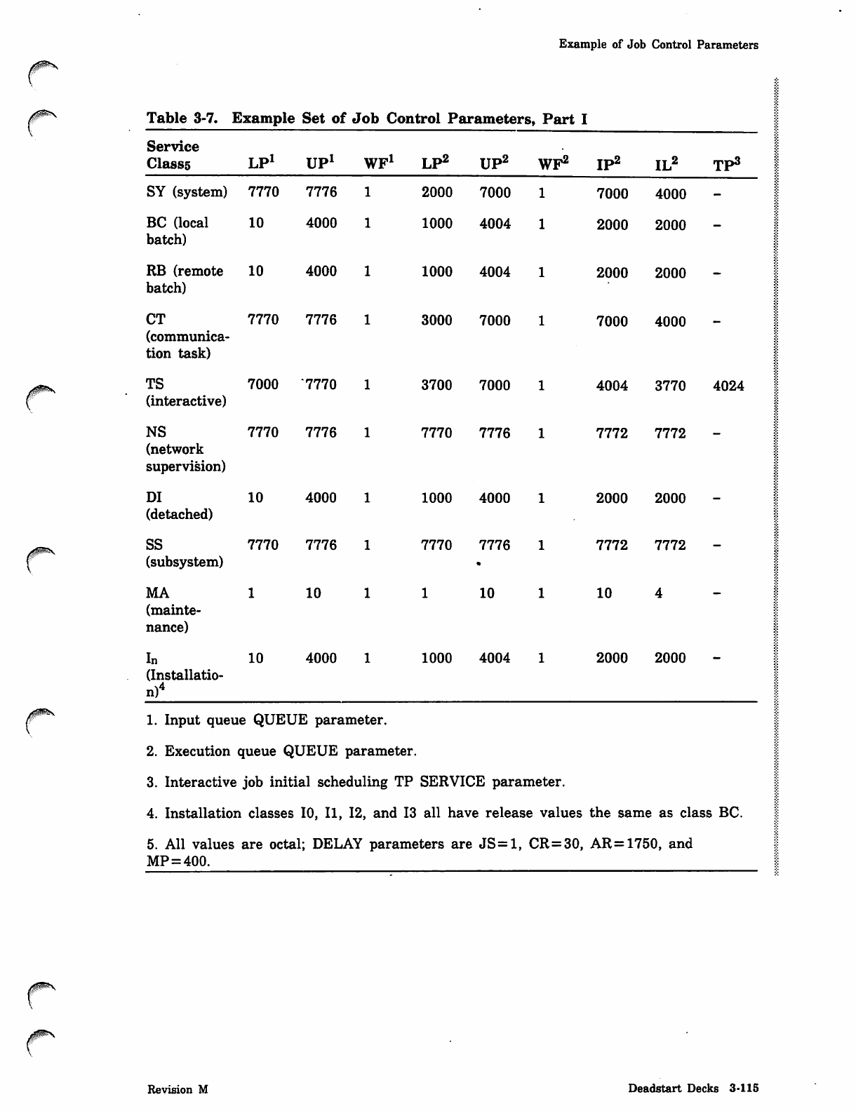
Example of Job Control Parameters
Table 3-7. Example Set of Job Control Parameters, Part I
Service
Classs LP1 UP1 WF1 LP2 U P 2 W F 2 I P 2 IL2
4000
TP3
SY (system) 7770 7776 2000 7 0 0 0 1 7000
BC (local
batch)
10 4000 1000 4 0 0 4 1 2000 2000
RB (remote
batch)
10 4000 1000 4 0 0 4 1 2000 2000
CT 7770 7776 3000 7 0 0 0 1 7000 4000
(communica
tion task)
TS
(interactive)
7000 "7770 3700 7 0 0 0 1 4004 3770 4024
NS
(network
7770 7776 7770 7 7 7 6 1 7772 7772
supervision)
DI
(detached)
10 4000 1000 4 0 0 0 1 2000 2000
SS
(subsystem)
7770 7776 7770 7 7 7 6 1
•7772 7772
MA
(mainte
nance)
10 1 0 1 10
In
(Installatio-
n)4
10 4000 1000 4 0 0 4 1 2000 2000
1. Input queue QUEUE parameter.
2. Execution queue QUEUE parameter.
3. Interactive job initial scheduling TP SERVICE parameter.
4. Installation classes 10, II, 12, and 13 all have release values the same as class BC.
5. All values are octal; DELAY parameters are JS=1, CR=30, AR=1750, and
MP = 400.
Revision M Deadstart Decks 3-115
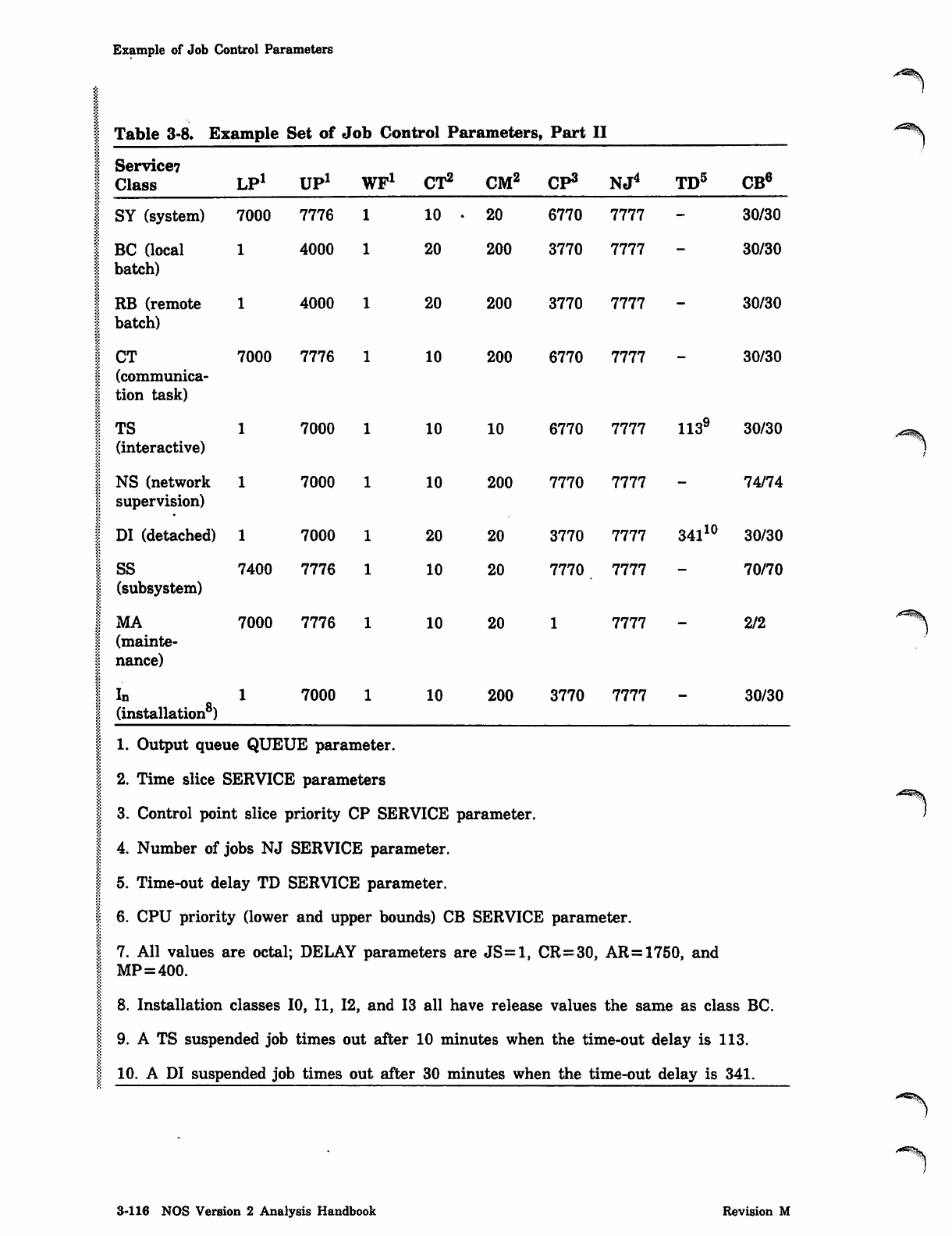
Example of Job Control Parameters
Table 3-8. Example Set of Job Control Parameters, Part II
Service?
Class LP1 UP1 WF1 CT2 CM2 CP3 NJ4 TD4
| SY (system) 7000 7 7 7 6 1
| BC (local
| batch)
4 0 0 0 1
| RB (remote
| batch)
4 0 0 0 1
1 CT
| (communica-
| tion task)
7000 7 7 7 6 1
1 TS
| (interactive)
7 0 0 0 1
| NS (network
| supervision)
7 0 0 0 1
| DI (detached) 7 0 0 0 1
1 SS
| (subsystem)
7400 7 7 7 6 1
j M A
| (mainte-
7000 7 7 7 6 1
| nance)
j In
| (installation8)
7 0 0 0 1
1 0 • 2 0 6 7 7 0 7 7 7 7
20 200 3770 7777
20 200 3770 7777
10 200 6770 7777
10 200 7770 7777
1 0 2 0 7777
10 200 3770 7777
CB
30/30
30/30
30/30
30/30
10 10 6770 7777 1139 30/30
74/74
20 20 3770 7777 34110 30/30
10 20 7770 7777 - 70/70
2/2
30/30
| 1. Output queue QUEUE parameter.
| 2. Time slice SERVICE parameters
I 3. Control point slice priority CP SERVICE parameter.
| 4. Number of jobs NJ SERVICE parameter.
j 5. Time-out delay TD SERVICE parameter.
| 6. CPU priority (lower and upper bounds) CB SERVICE parameter.
| 7. All values are octal; DELAY parameters are JS=1, CR=30, AR=1750, and
| MP=400.
I 8. Installation classes 10, II, 12, and 13 all have release values the same as class BC.
| 9. A TS suspended job times out after 10 minutes when the time-out delay is 113.
| 10. A DI suspended job times out after 30 minutes when the time-out delay is 341.
3-116 NOS Version 2 Analysis Handbook Revision M
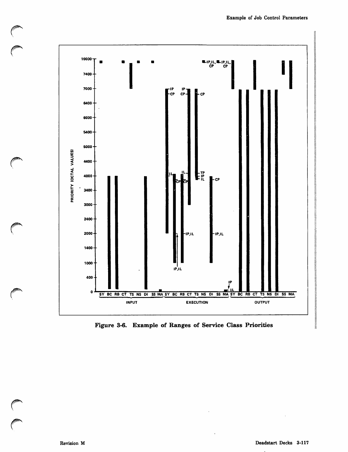
Example of Job Control Parameters
10000-r
7400 --
7000--
6400--
6000
5400--
5000 --
4400--
4000 --
3400--
3000--
2400--
2000
1400--
1000--
400- •
-IP.IL, B-IP.IL,
C P C P
IP IP-—
-CP CP- i-CP
IU IL.
CP CP
■TP
•IP
IL B-CP
-I P.I L
IP.IL
IP.IL
IP
Jk.
SY BC RB CT TS NS DI SS IMA SY BC RB CT TS NS DI SS MA SY BC RB CT TS NS DI SS MA
INPUT EXECUTION OUTPUT
r
Figure 3-6. Example of Ranges of Service Class Priorities
Revision M Deadstart Decks 3-117
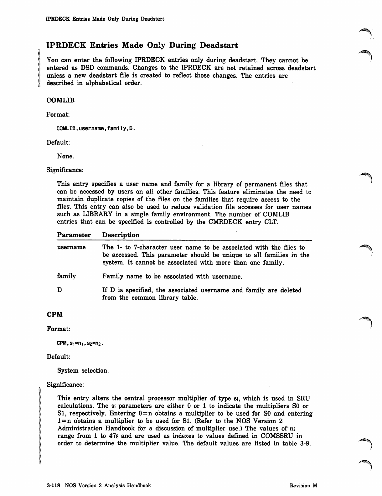
IPRDECK Entries Made Only During Deadstart
IPRDECK Entries Made Only During Deadstart
You can enter the following IPRDECK entries only during deadstart. They cannot be
entered as DSD commands. Changes to the IPRDECK are not retained across deadstart
unless a new deadstart file is created to reflect those changes. The entries are
described in alphabetical order.
COMLIB
Format:
COMLIB,username,family,D.
Default:
None.
Significance:
This entry specifies a user name and family for a library of permanent files that
can be accessed by users on all other families. This feature eliminates the need to
maintain duplicate copies of the files on the families that require access to the
files-. This entry can also be used to reduce validation file accesses for user names
such as LIBRARY in a single family environment. The number of COMLIB
entries that can be specified is controlled by the CMRDECK entry CLT.
Parameter Description
username The 1- to 7-character user name to be associated with the files to
be accessed. This parameter should be unique to all families in the
system. It cannot be associated with more than one family.
family Family name to be associated with username.
D If D is specified, the associated username and family are deleted
from the common library table.
CPM
Format:
CPM, Si =11!, 52^2.
Default:
System selection.
Significance:
This entry alters the central processor multiplier of type si, which is used in SRU
calculations. The si parameters are either 0 or 1 to indicate the multipliers SO or
Sl, respectively. Entering 0=n obtains a multiplier to be used for SO and entering
l = n obtains a multiplier to be used for Sl. (Refer to the NOS Version 2
Administration Handbook for a discussion of multiplier use.) The values of ni
range from 1 to 47s and are used as indexes to values defined in COMSSRU in
order to determine the multiplier value. The default values are listed in table 3-9. ^35%
/<^^\
3-118 NOS Version 2 Analysis Handbook Revision M
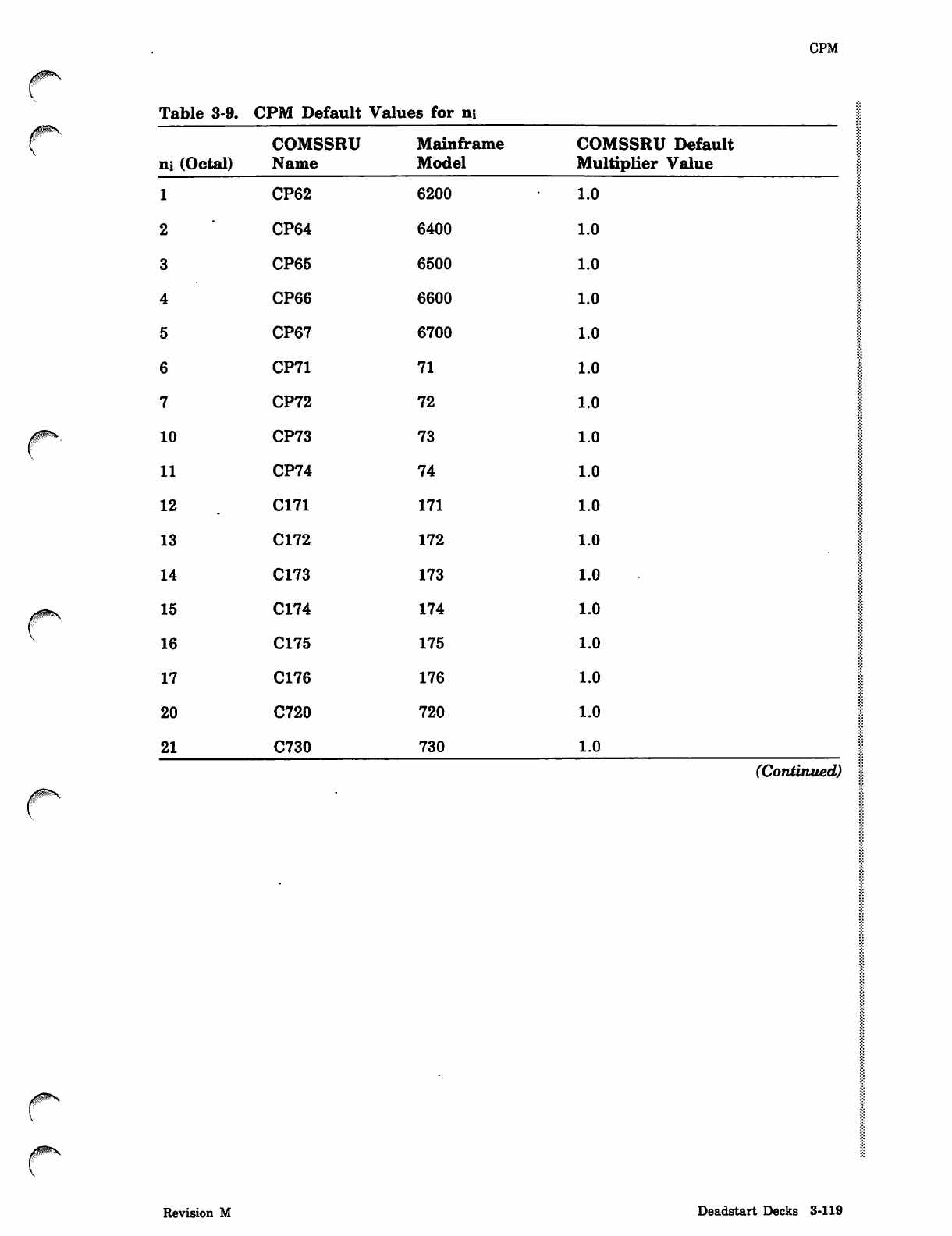
CPM
Table 3-9. CPM Default Values for n\
COMSSRU Mainframe COMSSRU Default
ni (Octal) Name Model Multiplier Value
1CP62 6200 1.0
2CP64 6400 1.0
3CP65 6500 1.0
4CP66 6600 1.0
5CP67 6700 1.0
6 CP71 71 1.0
7CP72 72 1.0
10 CP73 73 1.0
11 CP74 74 1.0
12 C171 171 1.0
13 C172 172 1.0
14 C173 173 1.0
15 C174 174 1.0
16 C175 175 1.0
17 C176 176 1.0
20 C720 720 1.0
21 C730 730 1.0
(Continued)
0$ms
Revision M Deadstart Decks 3-119
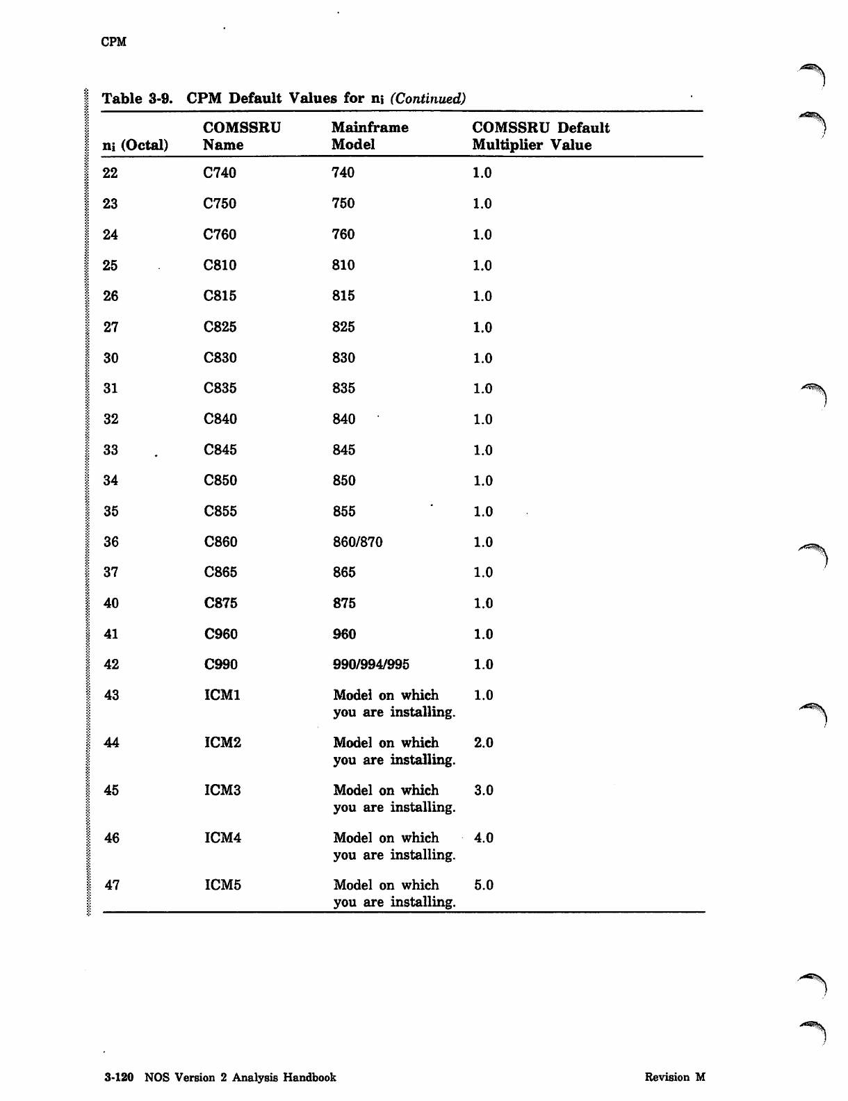
CPM
Table 3-9. CPM Default Values for ni (Continued)
COMSSRU Mainframe COMSSRU Default
ni (Octal) Name Model Multiplier Value
22 C740 740 1.0
23 C750 750 1.0
24 C760 760 1.0
25 C810 810 1.0
26 C815 815 1.0
27 C825 825 1.0
30 C830 830 1.0
31 C835 835 1.0
32 C840 840 1.0
33 C845 845 1.0
34 C850 850 1.0
35 C855 855 1.0
36 C860 860/870 1.0
37 C865 865 1.0
40 C875 875 1.0
41 C960 960 1.0
42 C990 990/994/995 1.0
43 ICM1 Model on which 1.0
you are installing.
44 ICM2 Model on which 2.0
you are installing.
45 ICM3 Model on which 3.0
you are installing.
46 ICM4 Model on which 4.0
you are installing.
47 ICM5 Model on which 5.0
you are installing.
3-120 NOS Version 2 Analysis Handbook Revision M
CSM
0jms
0m\
CSM
Format:
CSM=csm.
Default:
64
Significance:
This entry sets the operating system character set mode. To change the character
set mode for the products, a change must be made in IPARAMS, and the products
must be reassembled.
csm Description
63 63-character set.
64 64-character set.
The system assumes a 64-character set if there is no CSM entry in the current
IPRDECK.
NOTE
Unpredictable and possibly serious problems occur if the operating system is
operating in one character set and the products are operating in another.
Therefore, ensure that all installed products and the operating system are in the
same mode.
DISK VALIDATION
Format:
ENABLE,DISK VALIDATION.
DISABLE,DISK VALIDATION.
Default:
Enabled.
Significance:
NOS performs hardware verification on each mass storage device during the
deadstart process before users are allowed to access the device. The hardware
verification sequence includes writing data to the disk, reading the data from the
disk, and finally comparing the read data with the write data to ensure integrity.
For 887 and 9853 disks, the hardware verification includes running in-line
diagnostics. Since the diagnostics verify the quality of the disk media more
completely, it is advantageous to run them. These diagnostics take approximately
3 minutes to execute, during which time the 887 or 9853 disk is not available for
use. In order to keep deadstart time to a minimum (such as, during testing), disk
validation can be disabled using the DISABLE,DISK VALIDATION command.
Revision M Deadstart Decks 3-121
DSD
DSD
Format:
DSD, level ,commandi#command2#.. .#commandn
Default:
None.
Significance:
This entry specifies the initial command(s) to be executed by the DSD program
when the deadstart is complete. The commands can be the minimum number of
characters recognizable by DSD but must include terminating characters. Only the
last DSD entry on the IPRDECK for a given deadstart level is processed; other
DSD entries for the same level are ignored. The DSD entry cannot exceed one
line and a maximum of 60 characters can be specified.
Parameter Description )
level Level of deadstart (0, 1, or 2).
commandi DSD command to be executed for the level of deadstart specified.
Several commands can be specified by separating them with the #
(6-bit display code 60) or % (6-bit display code 63) character. These
characters may misposition parts of the console display of
IPRDECK if they appear as the upper 6 bits in a byte.
If you specify a series of commands including DSD display selection
commands, the display selection commands must be the last
commands. Failure to do so results in the system ignoring any
commands following the DSD display selection commands.
Examples:
DSD,0,MAI%X.QREC(PO=N)
DSD,0,X.QREC(PO=N)#SET,AEIQ.#QB.
3-122 NOS Version 2 Analysis Handbook Revision M
EI
r
00?S
EI
Format:
EI =nn 1, nri2,..., nnx.
Default:
None.
Significance:
The EI entry should be used to ensure loading of the correct environment
interface for the operating system. This entry specifies up to six 2-character
environment interface names, one of which must be loaded while deadstarting a
CYBER 180-class machine. The deadstart will not be allowed to continue if the
environment interface loaded by CTI is not one of those specified by the EI entry.
You will have to load the correct environment interface or modify the EI entry in
the IPRDECK. If an EI entry is not present, you will not be warned at deadstart.
EXTENDED STACK PURGING
Formats:
ENABLE,EXTENDED STACK PURGING.
DISABLE,EXTENDED STACK PURGING.
Default:
Disabled.
Significance:
These entries specify the default action for instruction-stack purging for
nonsystem-origin jobs on CYBER 180-class machines. Refer to the MODE macro in
the NOS Version 2 Reference Set, Volume 4 for a description of instruction-stack
purging.
HARDWARE FAULT INJECTION
Formats:
ENABLE,HARDWARE FAULT INJECTION.
DISABLE,HARDWARE FAULT INJECTION.
Default:
Disabled.
Significance:
The entries enable and disable the simulation of hardware faults by normal jobs
executing special instructions. This simulation is intended for test purposes only,
and should not be enabled on a production system.
Revision M Deadstart Decks 3-123
KEYPM
KEYPM
Format:
KEYPM»cc.
Default:
26
Significance:
This entry specifies the keypunch mode to be assumed during system operation.
cc Description
2 6 0 2 6 k e y p u n c h m o d e .
2 9 0 2 9 k e y p u n c h m o d e .
This entry is used for all batch jobs submitted if the keypunch mode is not
specified on the job command. This does not apply to RBF.
MEMORY CLEARING
Formats:
ENABLE,MEMORY CLEARING.
DISABLE,MEMORY CLEARING.
Default:
Disabled.
Significance:
When memory clearing is enabled, central and extended memory are cleared when
released from a job (that is, when a job is rolled out, terminates, or reduces its
field length). When memory clearing is disabled, memory is cleared only when a a*z®s
job requests additional memory. ■
3-124 NOS Version 2 Analysis Handbook Revision M
/$85»s
yms.
MICRO
MICRO
Format:
MICRO=namei, name2 name?.
Default:
None.
Significance:
The MICRO entry should be used to ensure loading of the correct microcode for
the operating system. This entry specifies up to seven 7-character microcode
names, one of which must be loaded while deadstarting a CYBER 180-class
machine. The deadstart will not be allowed to continue if the microcode loaded by
CTI is not one of those specified by the MICRO entry. You will have to load the
correct microcode or modify the MICRO entry in the IPRDECK. If a MICRO entry
is not present, you will not be warned at deadstart.
NAMIAF
Format:
NAMIAF=maxt.
Default:
2008
Significance:
This entry specifies the number of network terminals that can be connected to
IAF at one time. The maximum number of terminals IAF can support is 1039.
However, this value is dependent on the number of network terminals, multiplexer
ports, and stimulator ports specified in the deadstart decks.
Parameter Description
maxt Total number of network terminals; maxt can range from 1
to 14408.
PROBE
Formats:
ENABLE,PROBE.
DISABLE,PROBE.
Default:
Disabled.
Significance:
These entries enable and disable the data gathering facility of CPUMTR.
Revision M Deadstart Decks 3-125
SCP
SCP
Formats:
ENABLE,SCP.
DISABLE,SCP.
Default:
Disabled.
Significance:
These entries specify whether to use the system control point facility. You must
enable SCP if CDCS, IAF, MAP, MCS, MSE, NAM, NVE, PLA, RBF, RHF, SMF,
SSF, or TAF will be used. If none of these will be used, leave SCP disabled so
that more CMR space is available.
SCRSIM
Formats:
ENABLE,SCRSIM.
DISABLE,SCRSIM.
Default:
Disabled.
Significance:
These entries enable or disable the simulation of the status/control register using
the interlock register on CYBER 70 Computer Systems (refer to appendix D for
information on the SCRSIM simulator).
3-126 NOS Version 2 Analysis Handbook Revision M
J0$^\
SECCATS
SECCATS
Format:
SECCATS=cat i,cat2, -..,catn.
Default:
All categories are enabled.
Significance:
This entry specifies the security access categories that will be allowed in the
system for processing when the system is in a secured mode. The values should
be supplied by a site security administrator. Refer to the NOS Version 2 Security
Administrator's Handbook.
Parameter Description
cati Category names specified in deck COMSMLS corresponding to the
desired access categories. Initially, all categories are enabled. The
first SECCATS entry clears all categories, then sets the specified
categories. Subsequent SECCATS entries set additional categories:
Enables all 32 categories.
Disables all 32 categories.
SECCATS=ALL.
SECCATS=NUL.
SPC
Format:
SPC,d=lines.
Defaults:
64 lines at 6 lines per inch.
85 lines at 8 lines per inch.
Significance:
This entry specifies the charge in number of lines for a page of printed output at
the specified print density on non-PFC printers.
Parameter Description
d Density in lines per inch; d can be 6 or 8 lines per inch, but must
be specified in octal (6 or 10s).
lines Lines per page; lines can range from 16 to 255, but must be
specified in octal (20s to 377s).
Revision M Deadstart Decks 3-127
SPD
SPD
Format:
SPD=d.
Default:
6
Significance:
This entry specifies the assumed density for printed output.
d Description
6 6 lines per inch.
108 8 lines per inch.
SPL
Format:
SPL=length.
Default:
60
Significance:
This entry specifies the assumed page length in number of lines for printed
output; length can range from 16 to 255, but must be specified in
octal (208 to 3778).
SPW
Format:
SPW=width.
Default:
136
Significance:
This entry specifies the assumed page width in number of characters for printed
output; width can range from 40 to 136, but must be specified in octal (508
to 2108).
■"^Sn
3-128 NOS Version 2 Analysis Handbook Revision M
SUBCP
SUBCP
Formats:
ENABLE,SUBCP.
DISABLE.SUBCP.
Default:
Disabled.
Significance:
These entries specify whether CPUMTR is to be initialized to handle subcontrol
point (TAF) processing.
If SUBCP is disabled, CPUMTR is not initialized to handle subcontrol point
processing. If you are not running TAF and if no user applications use subcontrol
point processing, disable SUBCP so that CPUMTR uses less central memory.
TCVM
Format":
TCVM=mode
Default:
( ^ A S
Significance:
This entry sets the tape conversion mode to be assumed during system operation.
mode Description
AS ASCII 9-track conversion.
US ANSI (previously known as USASI) 9-track conversion (same as AS).
EB EBCDIC 9-track conversion.
Revision M Deadstart Decks 3-129
TDEN
TDEN
Format: /
TDEN=denslty.
Default:
HY for 7-track tapes.
PE for 9-track tapes.
Significance:
This entry sets the system tape density. When the density is set, any tape unit
accessed is automatically set to this density unless specified otherwise by a
magnetic tape request. Two TDEN entries may be present, one for 7 track and
one for 9 track.
density Description
LO 200 cpi (7 track).
H I . 5 5 6 c p i ( 7 t r a c k ) .
H Y 8 0 0 c p i ( 7 t r a c k ) .
HD 800 cpi (9 track).
P E 1 6 0 0 c p i ( 9 t r a c k ) .
GE 6250 cpi (9 track).
TDTR
Format:
TDTR=tracktype.
Default:
NT
Significance:
This entry sets the default track type.
tracktype Description
MT 7 track.
NT 9 track.
3-130 NOS Version 2 Analysis Handbook Revision M
TMS
TMS
Formats:
ENABLE,TMS.
DISABLE,TMS.
Default:
Disabled.
Significance:
These entries enable and disable the Tape Management System (TMS). These
entries are meaningless if the TMS binaries are not installed in the deadstart file.
TMSTO
V Format:
TMSTO,N=tO,S=tO.
Default:
N=TC,S=FC
Significance:
( This entry specifies the default values for the TMS tape options parameter for the
LABEL command and the LABEL macro. The N parameter specifies the default
for nonsystem origin jobs and the S parameter specifies the default for system
origin jobs.
to Description
TC Sets the default to TO=TC (TMS processing with catalog error checking).
TE Sets the default to TO=TE (TMS processing without catalog error
(^ checking).
FC Sets the default to TO=FC (non-TMS processing with catalog error
checking).
FE Sets the default to TO = FE (non-TMS processing without catalog error
checking).
This entry is meaningless if TMS is disabled.
Revision M Deadstart Decks 3-131
TRACE
TRACE
Formats:
ENABLE,TRACE.
DISABLE,TRACE.
Default:
Disabled.
Significance:
The entries enable or disable specification of monitor functions and other system
data to be traced, the TRACE and TRAP capabilities. To use these capabilities,
ENABLE,SYSTEM DEBUG, must also be entered.
j^S^v
3-132 NOS Version 2 Analysis Handbook Revision M
IPRDECK Entries
IPRDECK Entries
You can enter the following IPRDECK entries during deadstart and online during
system operation using the L display or DSD commands. The reason for entering them
online is to change the system's operation between deadstarts. Entries made during
system operation are not retained across deadstarts. Entries made during deadstart are
not retained across deadstarts unless a new deadstart file is created to reflect the
changes.
A description of the enabling and disabling of subsystems follows. The remaining
IPRDECK entries are described in alphabetical order.
Subsystems
You can initiate a subsystem by either of the following methods:
• Enter an explicit call to the subsystem procedure using a DSD command. The
command format is:
su b fff f
Variable Description
sub 3-character mnemonic for the name of the subsystem and subffff is
the name of the subsystem procedure (refer to Subsystem Control
Commands in section 5).
• Enter the DSD command AUTO or MAINTENANCE. This will initiate calls to all
subsystems that are currently enabled. The calls will be to subsystem procedures
with the same name as the name of the subsystem. You can choose to have either
the AUTO command or the MAINTENANCE command issued automatically at
deadstart time by specifying the command on the DSD entry in the IPRDECK.
A subsystem procedure may be either a record in the deadstart file or a permanent file
under system user name SYSTEMX (user index 377777s). If a subsystem procedure
with the same name is present in both places, the permanent file copy will be used.
Note that a *PROC is required in the LIBDECK for any procedure in the deadstart
file.
NOTE
Before you initiate a subsystem that uses the system control point facility (such as
NAM or CDCS), you must enable the system control point facility with the
ENABLE,SCP IPRDECK entry. Refer to SCP earlier in this section.
All subsystems, except BIO and MAG, are disabled by default. You can enable or
disable a subsystem by using IPRDECK entries or by using the SUBSYST L-display
utility. (For information about the SUBSYST L display, refer to the NOS Version 2
Operations Handbook.)
The IPRDECK entries that enable and disable subsystems may also assign a default
control point for a subsystem. Thus, even if you do not want to enable a subsystem,
you may want to explicitly disable a subsystem with an IPRDECK entry to assign a
default control point for the subsystem.
Revision M Deadstart Decks 3-133
Subsystems
Use these IPRDECK entries to enable or disable a subsystem:
ENABLE,subsystem,cp.
DISABLE,subsystem,cp.
Parameter Description
subsystem Three characters that select the desired subsystem; one of these values:
subsystem Description
BIO
CDC
IAF
MAG
MAP
MCS
MSE
NAM
NVE
PLA
RBF
RDF
RHF
SMF
SSF
STM
TAF
Local batch I/O for central site line printers, card
readers, and card punches.
CYBER Database Control System.
Interactive Facility. Do not specify the cp parameter on
the ENABLE entry for IAF.
Magnetic Tape Subsystem. Enable MAG if removable
auxiliary packs are used. Disabling MAG frees a control
point for other use.
MAP III or MAP IV.
Message Control System.
Mass Storage Extended Subsystem.
Network Access Method.
NOS/VE dual state.
Plato-NAM Interface.
Remote Batch Facility.
Remote Diagnostic Facility. Do not specify the CP
parameter on the ENABLE entry for RDF.
Remote Host Facility.
Screen Management Facility.
NOS-SCOPE 2 Station Facility.
STIMULA. Do not specify the cp parameter on the
ENABLE entry for STM.
Transaction Facility.
r ^ ^ \
3-134 NOS Version 2 Analysis Handbook Revision M
Subsystems
Parameter Description
r^ subsystem (Continued)
NOTE
When MCS and RBF are started by the NAMI startup master file, the
ENABLE and DISABLE commands are ignored.
If an ENABLE is made for NVE and the subsystem procedure name is
also NVE, use the DSD IPRDECK entry to automatically down any
channels that NOS/VE uses.
C
CP Control point where the subsystem will reside. If you omit cp, the
current control point is used. If you enter 0 (zero) as the control point,
the subsystem may reside at any available control point. If you enter -n
as the control point, the subsystem's control point will be relative to the
system control point (-1 would be the last control point before the
system control point).
Omit cp for IAF, RDF, and STM.
0ms.
Revision M Deadstart Decks 3-135
^m?\
AUTORESTART
AUTORESTART
Formats:
ENABLE,AUTORESTART.
DISABLE,AUTORESTART.
Default:
Disabled.
Significance:
These entries enable or disable the AUTORESTART installation parameter. If
AUTORESTART is enabled and if step mode is set during an environmental
shutdown, the system automatically clears step mode when the power environment
returns to normal. All jobs waiting in the input and rollout queues are initiated
by performing the processing associated with the DSD AUTO command. This
recovery process requires no operator interaction.
CARTRIDGE PF STAGING
Formats:
ENABLE,CARTRIDGE PF STAGING.
DISABLE.CARTRIDGE PF STAGING.
Default: ■'
Disabled.
Significance:
These entries specify whether permanent files that reside on MSE are staged to
disk. If disabled, jobs that attempt to access MSE-resident files are aborted.
3-136 NOS Version 2 Analysis Handbook Revision M
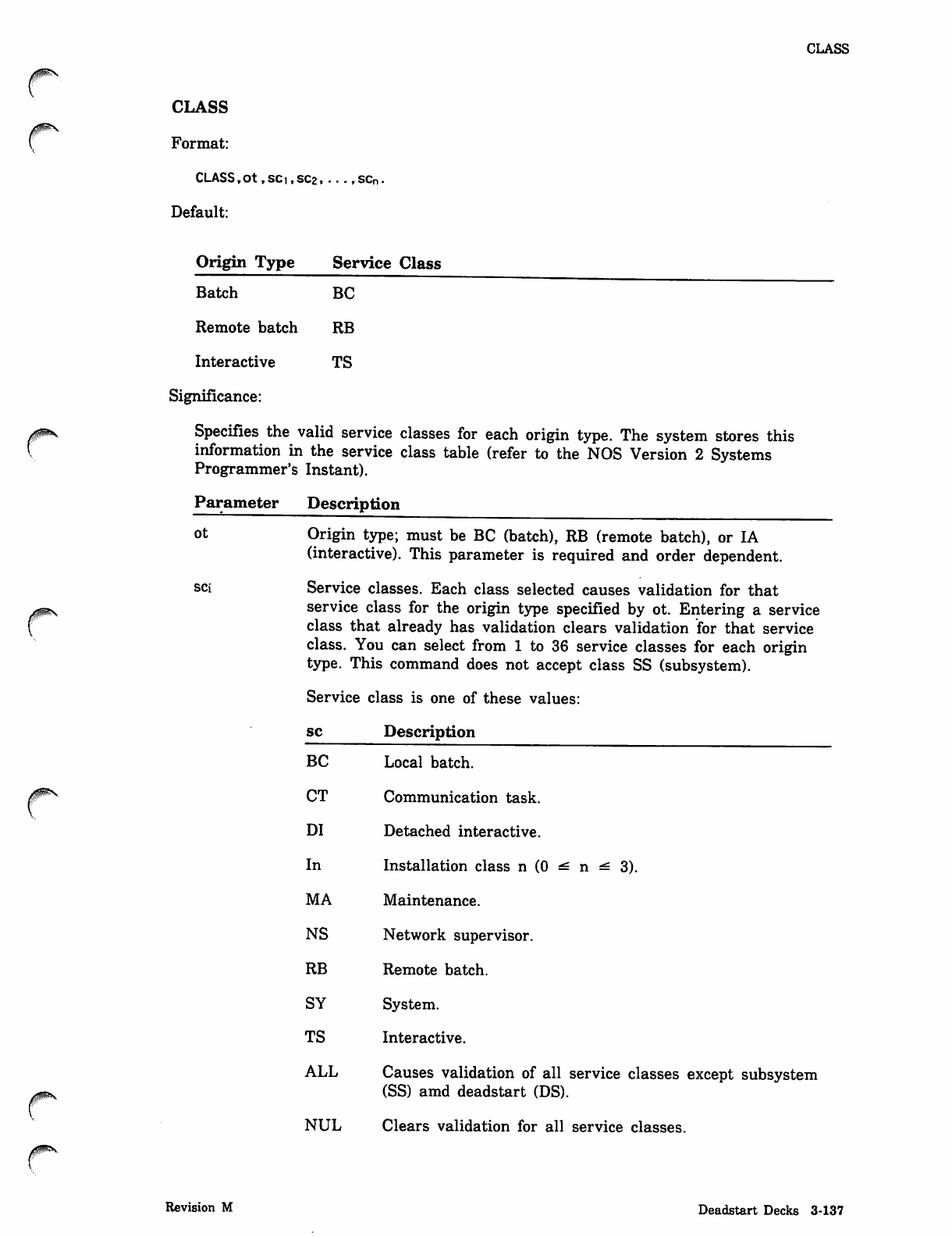
CLASS
jg^V
CLASS
Format:
CLASS,Ot ,SCi,SC2, ...,scn.
Default:
Origin Type Service Class
Batch BC
Remote batch RB
Interactive TS
Significance:
Specifies the valid service classes for each origin type. The system stores this
information in the service class table (refer to the NOS Version 2 Systems
Programmer's Instant).
Parameter Description
ot Origin type; must be BC (batch), RB (remote batch), or IA
(interactive). This parameter is required and order dependent.
sci Service classes. Each class selected causes validation for that
service class for the origin type specified by ot. Entering a service
class that already has validation clears validation for that service
class. You can select from 1 to 36 service classes for each origin
type. This command does not accept class SS (subsystem).
Service class is one of these values:
sc Description
BC Local batch.
CT Communication task.
DI Detached interactive.
In Installation class n (0 ^ n ^ 3).
MA Maintenance.
NS Network supervisor.
RB Remote batch.
SY System.
T S I n t e r a c t i v e .
ALL Causes validation of all service classes except subsystem
(SS) amd deadstart (DS).
NUL Clears validation for all service classes.
Revision M Deadstart Decks 3-137
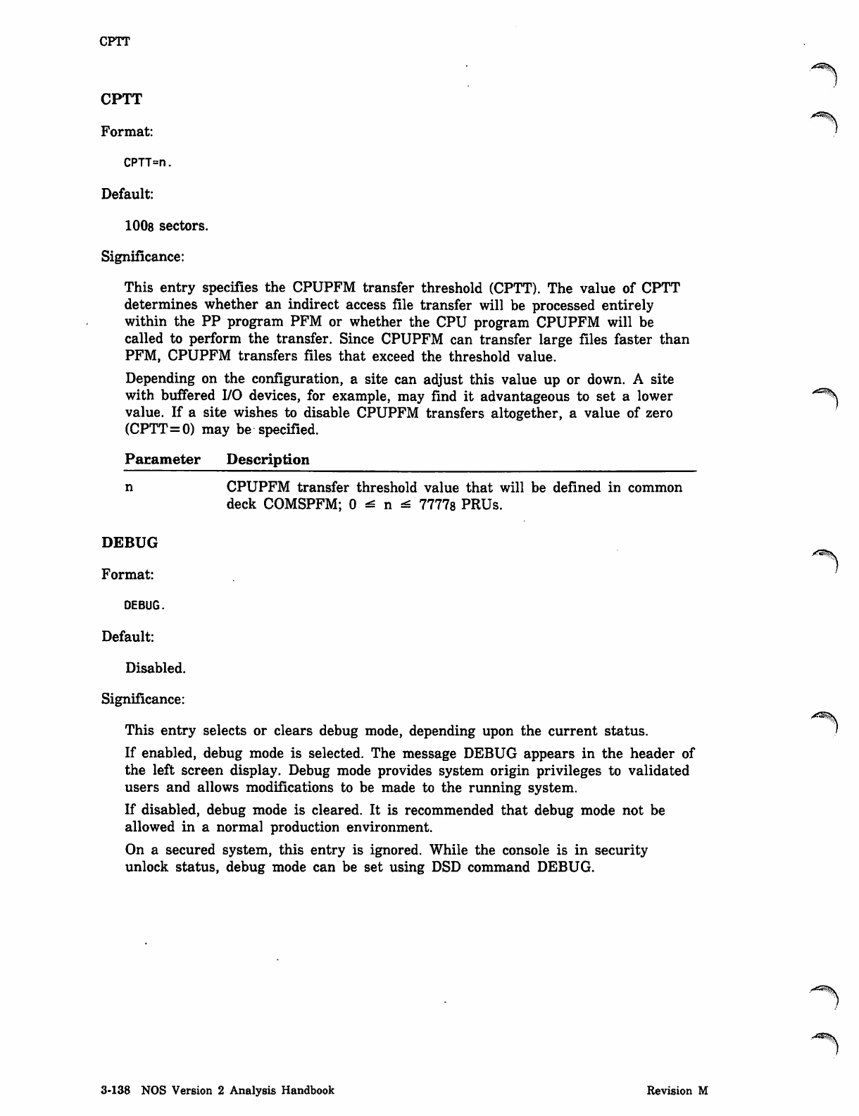
CPTT
CPTT
Format:
CPTT=n.
Default:
1008 sectors.
Significance:
This entry specifies the CPUPFM transfer threshold (CPTT). The value of CPTT
determines whether an indirect access file transfer will be processed entirely
within the PP program PFM or whether the CPU program CPUPFM will be
called to perform the transfer. Since CPUPFM can transfer large files faster than
PFM, CPUPFM transfers files that exceed the threshold value.
Depending on the configuration, a site can adjust this value up or down. A site
with buffered I/O devices, for example, may find it advantageous to set a lower "^
value. If a site wishes to disable CPUPFM transfers altogether, a value of zero
(CPTT=0) may be specified.
Parameter Description
n CPUPFM transfer threshold value that will be defined in common
deck COMSPFM; 0 ^ n ^ 7777s PRUs.
DEBUG
Format:
DEBUG.
Default:
Disabled.
Significance:
This entry selects or clears debug mode, depending upon the current status.
If enabled, debug mode is selected. The message DEBUG appears in the header of
the left screen display. Debug mode provides system origin privileges to validated
users and allows modifications to be made to the running system.
If disabled, debug mode is cleared. It is recommended that debug mode not be
allowed in a normal production environment.
On a secured system, this entry is ignored. While the console is in security
unlock status, debug mode can be set using DSD command DEBUG.
3-138 NOS Version 2 Analysis Handbook Revision M
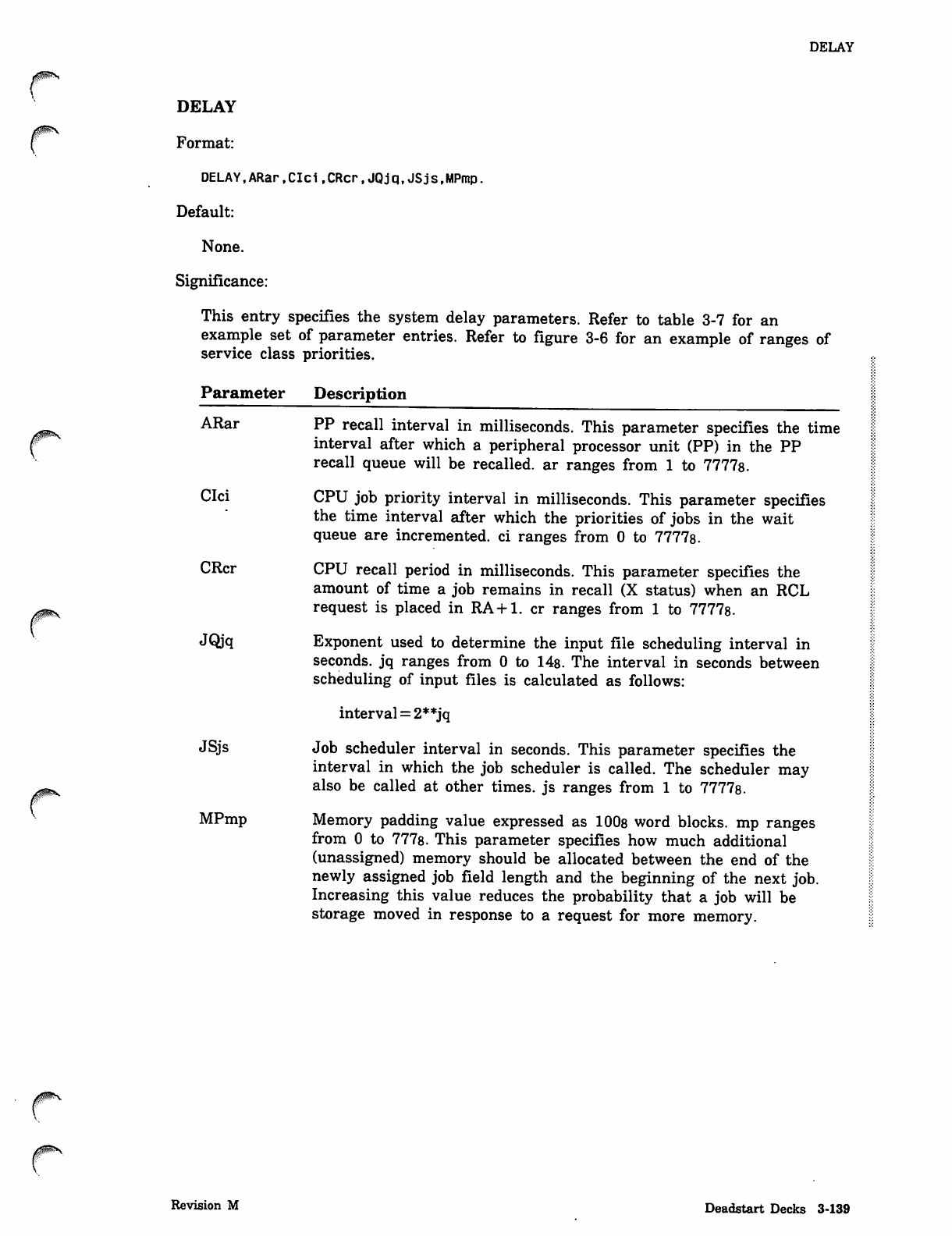
DELAY
DELAY
Format:
DELAY,ARar.CIci.CRcr.JQjq.JSjs.MPmp.
Default:
None.
Significance:
This entry specifies the system delay parameters. Refer to table 3-7 for an
example set of parameter entries. Refer to figure 3-6 for an example of ranges of
service class priorities.
Parameter Description
ARar
CIci
CRcr
JQjq
r
JSjs
MPmp
PP recall interval in milliseconds. This parameter specifies the time
interval after which a peripheral processor unit (PP) in the PP
recall queue will be recalled, ar ranges from 1 to 77778.
CPU job priority interval in milliseconds. This parameter specifies
the time interval after which the priorities of jobs in the wait
queue are incremented, ci ranges from 0 to 7777s.
CPU recall period in milliseconds. This parameter specifies the
amount of time a job remains in recall (X status) when an RCL
request is placed in RA + 1. cr ranges from 1 to 77778.
Exponent used to determine the input file scheduling interval in
seconds, jq ranges from 0 to 14s. The interval in seconds between
scheduling of input files is calculated as follows:
interval = 2**jq
Job scheduler interval in seconds. This parameter specifies the
interval in which the job scheduler is called. The scheduler may
also be called at other times, js ranges from 1 to 7777s.
Memory padding value expressed as 100s word blocks, mp ranges
from 0 to 7778. This parameter specifies how much additional
(unassigned) memory should be allocated between the end of the
newly assigned job field length and the beginning of the next job.
Increasing this value reduces the probability that a job will be
storage moved in response to a request for more memory.
Revision M Deadstart Decks 3-139
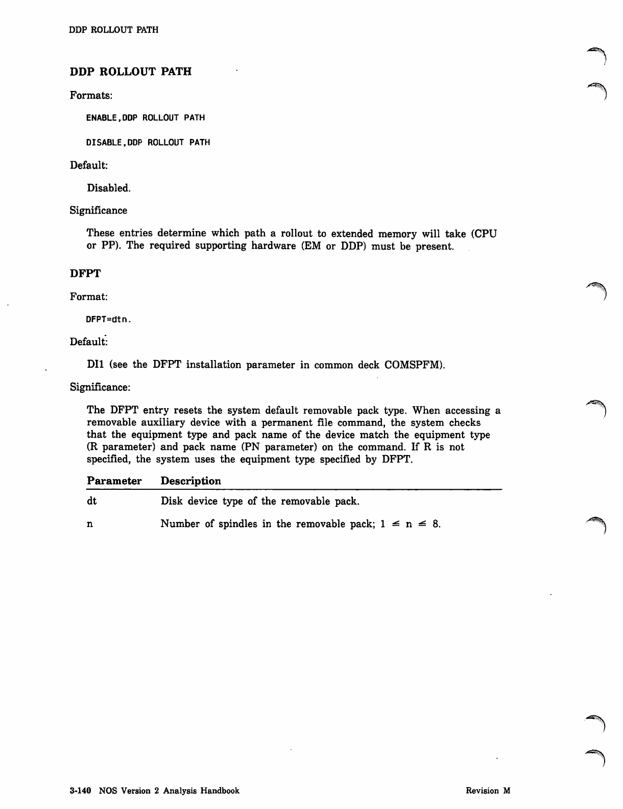
DDP ROLLOUT PATH
DDP ROLLOUT PATH
Formats:
ENABLE,DDP ROLLOUT PATH
DISABLE,DDP ROLLOUT PATH
Default:
Disabled.
Significance
These entries determine which path a rollout to extended memory will take (CPU
or PP). The required supporting hardware (EM or DDP) must be present.
DFPT
Format:
DFPT=dtn.
Default:
DI1 (see the DFPT installation parameter in common deck COMSPFM).
Significance:
The DFPT entry resets the system default removable pack type. When accessing a j
removable auxiliary device with a permanent file command, the system checks
that the equipment type and pack name of the device match the equipment type
(R parameter) and pack name (PN parameter) on the command. If R is not
specified, the system uses the equipment type specified by DFPT.
Parameter Description
dt Disk device type of the removable pack.
n Number of spindles in the removable pack; 1 ^ n ^ 8. '"^
3-140 NOS Version 2 Analysis Handbook Revision M
ENGR
ENGR
Formats:
ENABLE,ENGR.
DISABLE,ENGR.
Default:
Disabled.
Significance:
These entries enable or disable engineering mode. If enabled, the ENGR message
appears in the header of the left screen display. Engineering mode allows the
peripheral processing unit (PPU)/hardware diagnostics and the 881/883 pack
reformatting utility FORMAT to run while the system is in operation.
On a secured system, these entries are ignored. When the console is in security
unlock status, engineering mode can be enabled using the DSD command
ENABLE,ENGR.
FLEXIBLE PARTITIONS
Formats:
ENABLE,FLEXIBLE PARTITIONS.
DISABLE,FLEXIBLE PARTITIONS.
Default:
Enabled.
Significance:
This entry enables or disables flexible memory partitioning. The job scheduler
attempts to use memory space to the greatest extent possible when flexible
partitions are enabled. Some service classes may be allotted more total memory
space than memory partitioning constraints normally allow. If flexible partitions
are disabled, the total memory used by jobs of a given service class are never
allowed to exceed the maximum specified on the SERVICE command (AM and EM
parameters).
Revision M Deadstart Decks 3-141
LOCK
LOCK
Format:
LOCK.
Default:
Unlocked.
Significance:
This entry specifies the system is locked. This software function prevents entry of
restricted commands; all other DSD commands can be entered. The console is
normally locked when the system is being used in a production environment.
LOGGING
Formats:
ENABLE,LOGGING.
DISABLE,LOGGING.
Default:
Disabled.
Significance:
These entries specify whether dayfile messages intended for system analysis are
logged in the dayfile. Typical messages deal with informing the user that the
program is making inefficient CIO calls, such as reading to a full buffer or
writing from an empty buffer. The dayfile messages are documented in an
appendix of the NOS Version 2 Operations Handbook.
3-142 NOS Version 2 Analysis Handbook Revision M
MASTER MSE
MASTER MSE
Formats:
ENABLE,MASTER MSE
DISABLE,MASTER MSE
Default:
Disabled.
Significance:
These entries specify whether the MSE executive program (SSEXEC), when
initialized, is to run in master (enabled) or slave (disabled) mode.
MS VALIDATION
Formats:
ENABLE,MS VALIDATION.
DISABLE,MS VALIDATION.
Default:
Disabled.
Significance:
This entry enables or disables mass storage validation. If enabled, CMR is
increased by 48 words, and the system verifies that, for each mass storage device,
the sum of the counts of unreserved tracks and preserved files equals values
specified in the device's mass storage table.
If the device is a master device (contains user catalogs), the system also verifies
these conditions:
• The device's track reservation table (TRT) specifies that the first tracks of the
indirect access file chain and the permit area are reserved and preserved.
The label track is linked to the first catalog track.
The number of catalog tracks is a power of 2.
The catalog chain is reserved, of correct length, and contiguous if flagged as
such in the device's MST.
To enable/disable mass storage validation with a DSD command entry, enable the
validation in the IPRDECK during a level 0, 1, or 2 deadstart.
Revision M Deadstart Decks 3-143
OQSH
OQSH
Format:
OQSH=level.
Default:
None.
Significance:
This entry specifies the value of the output queue special handling (OQSH) level.
Output files with an access level equal to or greater than the output queue
special handling level will remain in the queue until released by the DSD
command RELEASE. When no OQSH level or access level name LVLO is selected,
all files will be processed. The value for this entry is supplied by the site security
administrator.
Parameter Description
Access level name specified in deck COMSMLS (refer to the NOS
Version 2 Installation Handbook) that corresponds to the desired
output queue special handling level.
level
PCLASS
Format:
CLASS, SCO,SCi , ....SC7 .
Default:
None.
Significance:
Specifies the service class associated with each priority level (PO through P7) for
selection on the Job command (refer to the NOS Version 2 Reference Set,
Volume 3).
Parameter Description
SCi The 2-character service class symbol. Because parameters are
positional, a comma must appear for any null parameter. The
default for a null parameter is that no service class will be
associated with the priority level represented by the null
parameter's position in the string. This command does not accept
the SS (subsystem) service class. Refer to the SERVICE IPRDECK
entry later in this section for a list of service classes.
.imfejjjV
3-144 NOS Version 2 Analysis Handbook Revision M
PF VALIDATION
PF VALIDATION
Formats:
ENABLE,PF VALIDATION.
DISABLE,PF VALIDATION.
Default:
Disabled.
Significance:
These entries enable or disable preserved file (PF) validation. If enabled, the
system aborts an attach of a direct access permanent file if its end-of-information
(EOI) was altered during recovery of the file. If NA (no abort) is specified on the
attach request, the system attaches the file.
If mass storage validation is also enabled, TRT verification of preserved files
takes place during a level 3 deadstart as follows:
• For all files, the system ensures that all tracks are reserved and that no
circular linkage exists.
• For all queued, permanent direct-access, and fast-attach files, the system also
ensures that the first track is preserved.
If mass storage validation is enabled on a level 1 or 2 deadstart, TRT verification
takes place automatically, regardless of the status of PF VALIDATION.
PRIVILEGED ANALYST MODE
Formats:
ENABLE,PRIVILEGED ANALYST MODE.
DISABLE,PRIVILEGED ANALYST MODE.
Default:
Disabled.
Significance:
These entries enable or disable privileged analyst mode operations. If enabled, a
user validated with AW = CPAM (refer to the NOS Version 2 Administration
Handbook for information on MODVAL validation) is permitted to read system
status information (such as the system dayfile, account file and error log) using a
nonsystem-origin job. On a secured system, this entry is ignored. Refer to the
DSD ENABLE/DISABLE command in section 5 for more details.
Revision M Deadstart Decks 3-145
PRIVILEGED RDF
PRIVILEGED RDF
Formats:
ENABLE,PRIVILEGED RDF.
DISABLE,PRIVILEGED RDF.
Default:
Disabled.
Significance:
These entries enable or disable privileged mode of RDF. If enabled, a user's
commands are checked to ensure that a maintenance function is being performed.
QUEUE
Format:
QUEUE,sc,qt,IL11,IPip,LPlp,UPup,WFwf.
Default:
None.
Significance:
This entry specifies the queue priorities associated with the input, executing, and
output queues for each job service class. Refer to table 3-7 for an example set of
parameter entries and to figure 3-6 for an example of ranges of service class
priorities.
Parameter Description
sc Service class.
sc Description
BC Local batch.
CT Communication task.
DI Detached interactive.
In Installation class n (0
MA Maintenance.
NS Network supervisor.
RB Remote batch.
SS Subsystem.
SY System.
TS Interactive.
n *- 3).
<<<3^\
3-146 NOS Version 2 Analysis Handbook Revision M
QUEUE
Parameter Description
qt
ILil
rIPip
LPlp
rUPup
WFwf
r
Job queue type.
qt Description
EX Executing jobs.
IN Input queued files.
OT Output queued files.
Priority a job receives when it initially exhausts its CM time slice
(refer to the SERVICE command CM parameter). Thereafter,
whenever the CM time slice is exhausted the job's priority will be
set to the value of lp. il ranges from 0 to 7777s, but must be in the
range of values for lp and up. This parameter is valid only for
executing jobs (EX).
Initial priority only for an executing batch job or for an interactive
job when a terminal command is entered. Online interactive jobs
with terminal I/O available are scheduled at tp priority (refer to the
SERVICE command TP parameter), ip ranges from 0 to 7777s, but
must be in the range of values for lp and up.
Lowest priority. For an input or output queue file, the priority
assigned to a file or job entering the queue. For an executing job,
the priority assigned to job which has exceeded a non-initial CM
slice. The IL value is used for the first CM slice, lp ranges from 0 to
77778, but must be less than the value of up.
Highest priority. For input and output queues, this is the highest
priority a file can reach in that queue; aging stops when this priority
is reached. For the execution queue, this is the priority assigned to a
job when initially assigned to a control point, up ranges from 0 to
77778, but must be greater than the value of lp.
Weighting factor for queue priority calculation; wf must be a power
of 2, from 1 to 40008. The smaller the weighting factor, the faster
the queue entry reaches its highest priority.
jp»\
Revision M Deadstart Decks 3-147
REMOVABLE PACKS
REMOVABLE PACKS
Formats:
ENABLE,REMOVABLE PACKS.
DISABLE,REMOVABLE PACKS.
Default:
Enabled.
Significance:
These entries enable or disable automatic label checking for mass storage devices
that are defined as removable.
If enabled, automatic label checking occurs. This status must be available to
perform label verification before removable devices can be accessed.
If disabled, any removable devices introduced into the system will not be
recognized.
y*^\
,>«^SK
3-148 NOS Version 2 Analysis Handbook Revision M
RESIDENT RDF
RESIDENT RDF
Formats:
ENABLE,RESIDENT RDF.
DISABLE.RESIDENT RDF.
Default:
Disabled.
Significance:
These entries enable or disable resident mode of RDF. While in resident mode,
RDF remains active, regardless of terminal inactivity, until RDF is disabled.
When resident mode is disabled, RDF becomes inactive if no one is logged on at
the remote diagnostic terminal for 15 minutes.
SECONDARY USER COMMANDS
Formats:
ENABLE.SECONDARY USER COMMANDS.
DISABLE,SECONDARY USER COMMANDS.
Default:
Disabled.
Significance:
The enable option allows jobs to issue more than one USER command. These
entries are ignored on a secured system since secondary USER commands are not
allowed on a secured system.
Revision M Deadstart Decks 3-149
SECURES
SECURES
Format:
SECURES,0t,LA=1a,UA=ua.
Default:
The security access limits of the system origin type (SY) are set to access level
name LVLO. All security access limits for other origin types are set to system
limits.
Significance:
This entry specifies system limits for the system origin type (ot equals SY) or
limits for other origin types (ot equals BC, IA, or RB). System limits define the
highest and lowest levels allowed in the system. No job may execute and no file
may be accessed or created at a level outside this range.
Limits for origin types other than SY must be within the system limits. If origin /*%
type SY is specified, limits for all origin types are set to the selected values.
Both la and ua must be entered; they can be set to the same value, restricting
system access or a particular origin type access to a single level. These values are
supplied by a site security administrator.
This entry is not meaningful in an unsecured system.
Parameter Description
ot Origin type.
ot Description
S Y S y s t e m .
BC Batch.
IA Interactive.
RB Remote batch.
la Access level name specified in deck COMSMLS (refer to the NOS
Version 2 Installation Handbook) corresponding to the desired lower
access level limit.
ua Access level name specified in deck COMSMLS corresponding to the
desired upper access level limit.
3-150 NOS Version 2 Analysis Handbook Revision M
SERVICE
SERVICE
Format:
SERVICE,sc.AMam.CBlpup,CMcm.CPcp.CScs.CTct.DSds.DTsc.ECec.EMem.FCfc.FLfl,
FSfs.NJnj.SDsd.TDtd.TPtp.
Default:
None.
Significance:
This entry specifies the service limits associated with each service class. Refer to
table 3-7 for an example set of parameter entries and to figure 3-6 for an
example of ranges of service class priorities.
Parameter Descri
Service
iption
sc 5 class; one of these values:
sc Description
•BC Local batch.
CT Communication task.
DI Detached interactive.
In Installation class n (0 -£ n -£ 3).
MA Maintenance.
NS Network supervisor.
RB Remote batch.
SS Subsystem.
SY System.
TS Interactive.
AMam Maximum field length divided by 100s for all jobs of the specified
service class. This parameter partitions central memory by limiting the
field length available to each service class. For example, if scheduling
a job to a control point would cause the AM value for its service class
to be exceeded for its service class, it may not be scheduled until the -
required field length is available. This means that a lower priority job
from a different service class may be scheduled first. However, a job
that would cause the AM value for its service class to be exceeded,
can be scheduled to a control point if not enough jobs in other service
classes exist to fill central memory and FLEXIBLE PARTITIONS is
enabled. The system attempts to use central memory to its greatest
capacity, am ranges from 0 to 77777s.
Revision M Deadstart Decks 3-151
SERVICE
Parameter Description
CBlpup
CMcm
CPcp
Upper and lower bound CPU priorities.
Value Description
lp
up
Lower bound CPU priority, lp ranges from 0 to 77s.
Upper bound CPU priority, up ranges from 0 to 77s, but
must be equal or larger than the value of lp.
Central memory time slice in seconds. This parameter specifies the
maximum amount of time a job of the specified service class can remain
in central memory either at a control point or at a pseudo-control point
before its priority is set to the lower boundary. When the job initially
exhausts its CM time slice, this lower boundary is the value of il.
Subsequently, when the job exhausts its CM time slice, this lower
boundary is the value of lp (refer to the QUEUE command IL and LP
parameters), cm ranges from 0 to 7777s.
Control point slice priority. This parameter specifies the value of the
scheduling priroity which will be set after a job has been at a control
point for ct seconds. The priority specified must be greater than or equal
to the lower bound and less than or equal to the upper bound execution
queue scheduling priorities specified by the CB parameter
(lp ^ cp ^ up). Refer to the QUEUE command LP and UP parameters.
3-152 NOS Version 2 Analysis Handbook Revision M
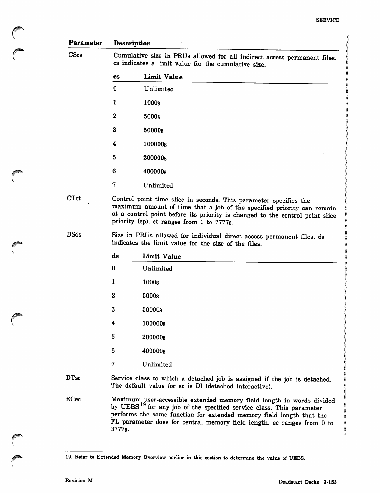
/ms
0ps
SERVICE
Parameter Description
CScs Cumulative size in PRUs allowed for all indirect access permanent files.
cs indicates a limit value for the cumulative size.
cs Limit Value
0 Unlimited
1 1000s
2 5000s
3 500008
4 1000008
5 200000s
6 4000008
7 Unlimited
CTct Control point time slice in seconds. This parameter specifies the
maximum amount of time that a job of the specified priority can remain
at a control point before its priority is changed to the control point slice
priority (cp). ct ranges from 1 to 7777s.
DSds Size in PRUs allowed for individual direct access permanent files, ds
indicates the limit value for the size of the files.
ds Limit Value
0Unlimited
110008
250008
350000s
41000008
52000008
64000008
7Unlimited
DTsc Service class to which a detached job is assigned if the job is detached.
The default value for sc is DI (detached interactive).
ECec Maximum user-accessible extended memory field length in words divided
by UEBS for any job of the specified service class. This parameter
performs the same function for extended memory field length that the
FL parameter does for central memory field length, ec ranges from 0 to
37778.
19. Refer to Extended Memory Overview earlier in this section to determine the value of UEBS.
Revision M Deadstart Decks 3-153
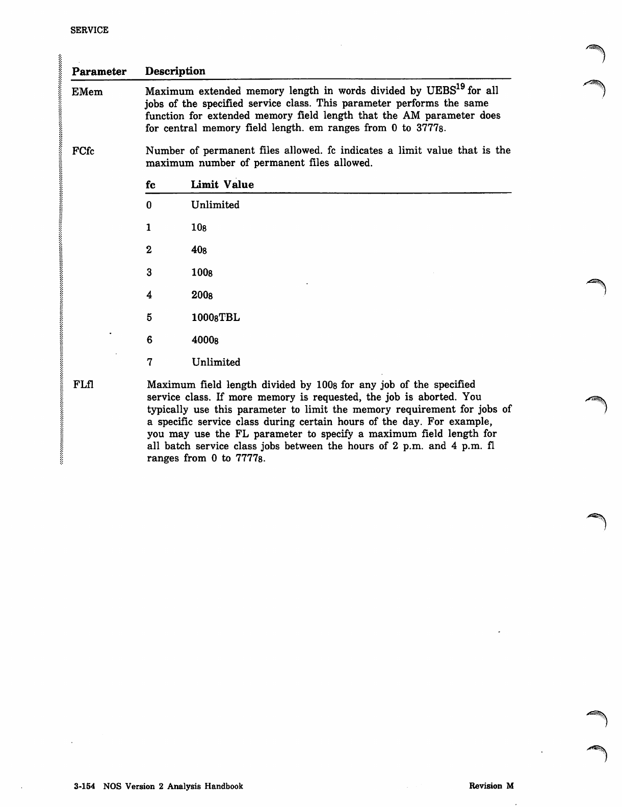
SERVICE
EMem
FCfc
Parameter Description
Maximum extended memory length in words divided by UEBS for all
jobs of the specified service class. This parameter performs the same
function for extended memory field length that the AM parameter does
for central memory field length, em ranges from 0 to 37778.
Number of permanent files allowed, fc indicates a limit value that is the
maximum number of permanent files allowed.
fc Limit Value
Unlimited
108
408
FLfl
3 1 0 0 8
4 2 0 0 8
5 10008TBL
6 40008
7 Unlimited
Maximum field length divided by 1008 for any job of the specified
service class. If more memory is requested, the job is aborted. You
typically use this parameter to limit the memory requirement for jobs of
a specific service class during certain hours of the day. For example,
you may use the FL parameter to specify a maximum field length for
all batch service class jobs between the hours of 2 p.m. and 4 p.m. fl
ranges from 0 to 7777s.
3-154 NOS Version 2 Analysis Handbook Revision M
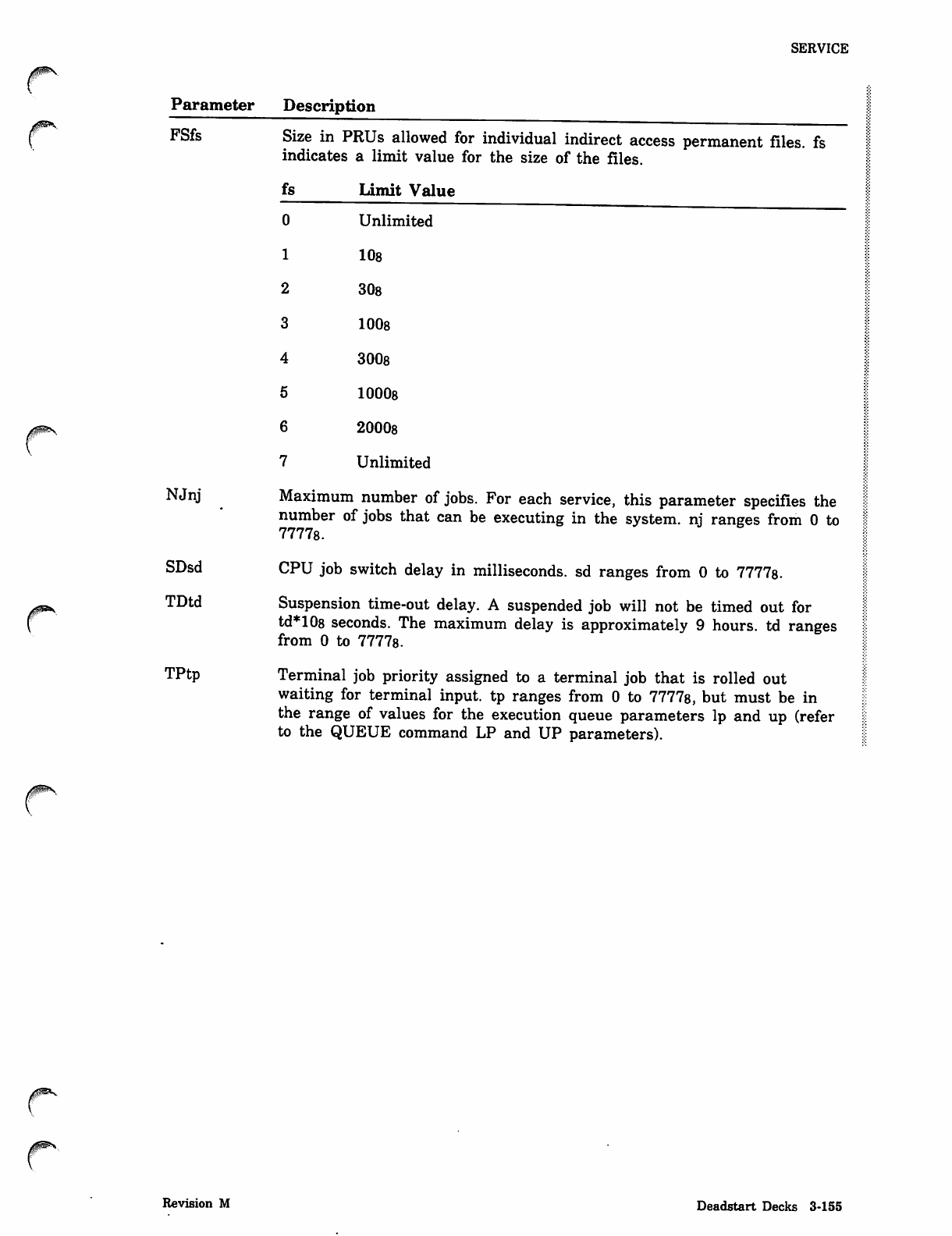
SERVICE
Parameter Description
FSfs
NJnj
SDsd
TDtd
TPtp
Size in PRUs allowed for individual indirect access permanent files, fs
indicates a limit value for the size of the files.
fs Limit Value
Unlimited
10s
30s
1008
3008
1000s
2000s
Unlimited
Maximum number of jobs. For each service, this parameter specifies the
number of jobs that can be executing in the system, nj ranges from 0 to
7777s.
CPU job switch delay in milliseconds, sd ranges from 0 to 7777s.
Suspension time-out delay. A suspended job will not be timed out for
td*108 seconds. The maximum delay is approximately 9 hours, td ranges
from 0 to 7777s.
Terminal job priority assigned to a terminal job that is rolled out
waiting for terminal input, tp ranges from 0 to 7777s, but must be in
the range of values for the execution queue parameters lp and up (refer
to the QUEUE command LP and UP parameters).
Revision M Deadstart Decks 3-155
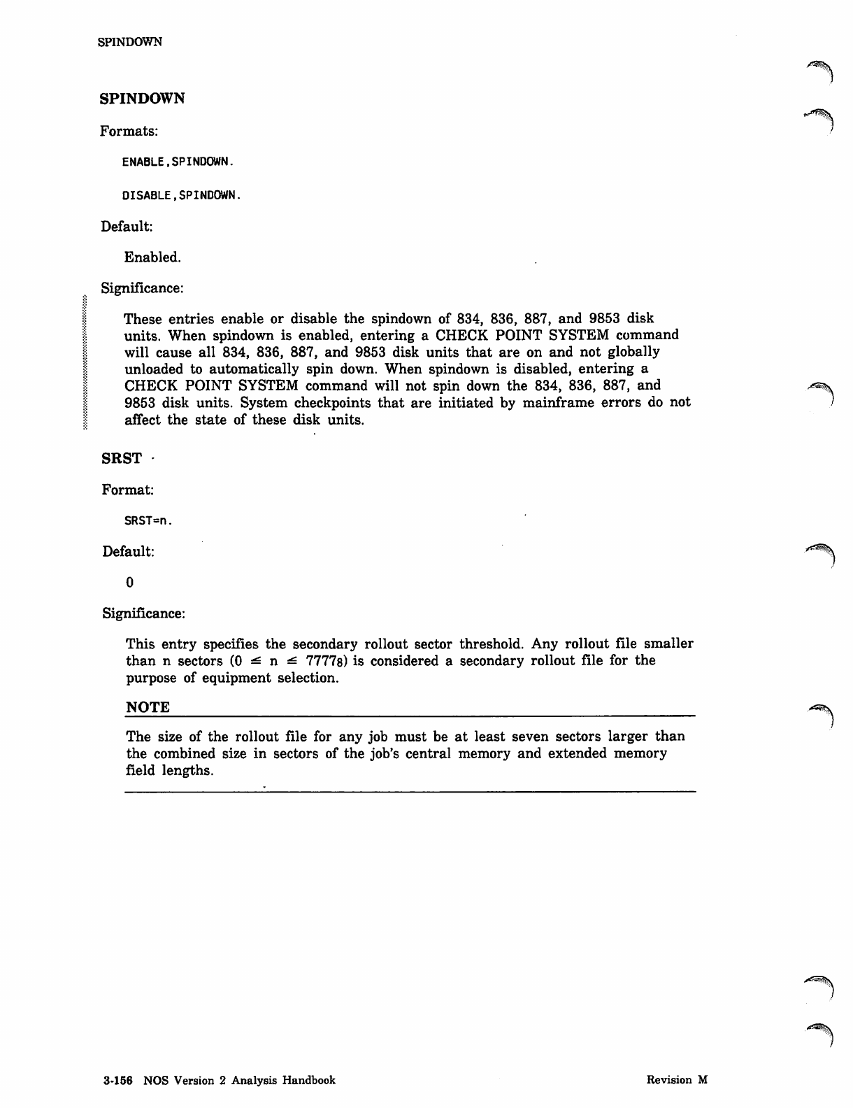
SPINDOWN
SPINDOWN
Formats:
ENABLE,SPINDOWN.
DISABLE,SPINDOWN.
Default:
Enabled.
Significance:
These entries enable or disable the spindown of 834, 836, 887, and 9853 disk
units. When spindown is enabled, entering a CHECK POINT SYSTEM command
will cause all 834, 836, 887, and 9853 disk units that are on and not globally
unloaded to automatically spin down. When spindown is disabled, entering a
CHECK POINT SYSTEM command will not spin down the 834, 836, 887, and
9853 disk units. System checkpoints that are initiated by mainframe errors do not
affect the state of these disk units.
SRST
Format:
SRST=n.
Default:
0
Significance:
This entry specifies the secondary rollout sector threshold. Any rollout file smaller
than n sectors (0 ^ n ^ 7777s) is considered a secondary rollout file for the
purpose of equipment selection.
NOTE
The size of the rollout file for any job must be at least seven sectors larger than
the combined size in sectors of the job's central memory and extended memory
field lengths.
•■•"**%
3-156 NOS Version 2 Analysis Handbook Revision M
SYSTEM DEBUG
SYSTEM DEBUG
Formats:
ENABLE,SYSTEM DEBUG.
DISABLE,SYSTEM DEBUG.
Default:
Disabled.
Significance:
These entries enable or disable the system debug mode of operation. When the
system is in system debug mode, it is less tolerant of system errors; that is, it is
more likely to hang upon experiencing errors. When the system is not in system
debug mode, it rates system errors as critical or noncritical. For critical errors,
rthe system partially or totally interrupts system operation to tend to the errors.
For noncritical errors, the system logs them in the binary maintenance log (BML)
and inasmuch as possible allows system operation to proceed. You can initiate the
system debug mode with the DSD ENABLE command or the corresponding
IPRDECK entry.
There is another system state called debug mode, which is conceptually different
from that of system debug mode. Debug mode is the state of the system where a
user with system origin privileges can make modifications to the running system.
You can initiate this mode of operation with the DSD command DEBUG. The left
screen header of the system console indicates whether the system is in debug
mode or not.
Revision M Deadstart Decks 3-157
TAPE PF STAGING
TAPE PF STAGING
Formats:
ENABLE,TAPE PF STAGING.
DISABLE.TAPE PF STAGING.
Default:
Disabled.
Significance:
These entries specify whether permanent files that reside on tape alternate
storage are staged to disk. If disabled, jobs that attempt to access tape alternate
storage resident files are aborted.
UNLOCK
Format:
UNLOCK.
Default:
Unlocked.
Significance:
This entry specifies the system console is unlocked. All DSD commands can be
entered when the console is unlocked. The console is usually locked when the
system is being used in a production environment. Refer to LOCK earlier in this
section.
USER EXTENDED MEMORY
Formats:
ENABLE,USER EXTENDED MEMORY. /
DISABLE,USER EXTENDED MEMORY.
Default:
Disabled.
Significance:
These entries enable or disable scheduling of jobs that access user extended
memory.
3-158 NOS Version 2 Analysis Handbook Revision M
/P*\
LIBDECK
LIBDECK
LIBDECK is a SYSEDIT directive record on the deadstart file. SYSEDIT reads
LIBDECK during the system load. LIBDECK specifies program residence, field length,
record type, and parameter format.
Up to 64 LIBDECK records can be placed on the deadstart file. LIBDECKs are
named LIBDnn, where nn is 00 to 77s. A specific record can be selected with a
LIB = n entry in CMRDECK. The multiple deadstart deck capability enables the use
of a single deadstart file on virtually any system configuration.
You can list all LIBDECKs on the deadstart file by accessing the system file
SYSTEM with a COMMON command, then using the T parameter on the CATALOG
command. Refer to the NOS Version 2 Reference Set, Volume 3 for more information
concerning these commands.
The following list provides brief descriptions of SYSEDIT directives acceptable in
LIBDECK. Complete descriptions of all SYSEDIT directives are in section 19,
SYSEDIT. A list of valid record types follows the directives.
Directive Format
*AD,nn,tyi/reci,ty2/rec2,...,tyn/recn
*CM,tyi/reci,ty2/rec2,...,tyn/recn
*FL,tyi/reci-fli,ty2/rec2-fl2,...,
tyn/recn-fln
*MS,tyi/reci ,ty2/rec2,... ,tyn/recn
Significance
Specifies the alternate device to be
used in addition to the system
device(s) for storing ABS, OVL, PP,
and REL type records, nn is either
the EST ordinal or the equipment
type, tyi is the record type, and reci
is the record name.
Defines record reci of type tyi as
being central memory resident; valid
only for record types ABS, OVL, or
PP. Like any other job in NOS,
SYSEDIT has a field length
restriction of 3760008 central
memory words. You cannot use more
than approximately 326000s central
memory words (3760008-500008 words
for SYSEDIT's program FL) when
defining records to be central
memory resident.
Record reci of type tyi is loaded with
a field length specified by fli (fli is
field length divided by 100s).
Defines record reci of type tyi as
being mass storage resident. This is
the default residence for routines
with no storage area specified in
LIBDECK.
Revision M Deadstart Decks 3-159
LIBDECK
Directive Format Significance
♦PROC,reci,rec2,...,recn Defines record reci of type PROC as a
procedure file.
*SC,tyi/reci,ty2/rec2,..., Defines record reci of type tyi as
tyn/recn product set format commands. The
command parameters are processed in
product set format (refer to the NOS
Version 2 Reference Set, Volume 3).
*/ comments Defines comment lines.
The following record types may be specified in SYSEDIT directives. Some directives do
not allow all types.
Type (tyi) Description
ABS Multiple entry point overlay.
CAP Fast dynamic load capsule.
OPL Modify old program library deck.
OPLC Modify old program library common deck.
OPLD Modify old program library directory.
OVL Central processor overlay.
PP 12-bit peripheral processor program. )
PPL 16-bit peripheral processor program (CYBER 180 models only).
PPU First-level peripheral processor (FLPP) program (model 176 only).
PROC Procedure.
REL Relocatable central processor program.
TEXT Unrecognizable as one of the other types.
ULIB User library program.
3-160 NOS Version 2 Analysis Handbook Revision M
f*»
f^
DIS Operations 4
DIS Job Dayfile Display (A) 4.3
DIS Job Status Display (B) 4.4
DIS Memory Displays (C, D, F, G) . 4-6
DIS Exchange Package Display (X) 4.8
DIS Directory Display (Z) 4.9
Console Operation 4-10
Display Selection Commands 4.13
DIS Keyboard Entries 4-14
Memory Entry Commands 4-18
PP Call Commands , 4-20

*■)■
"S
..*%
'3
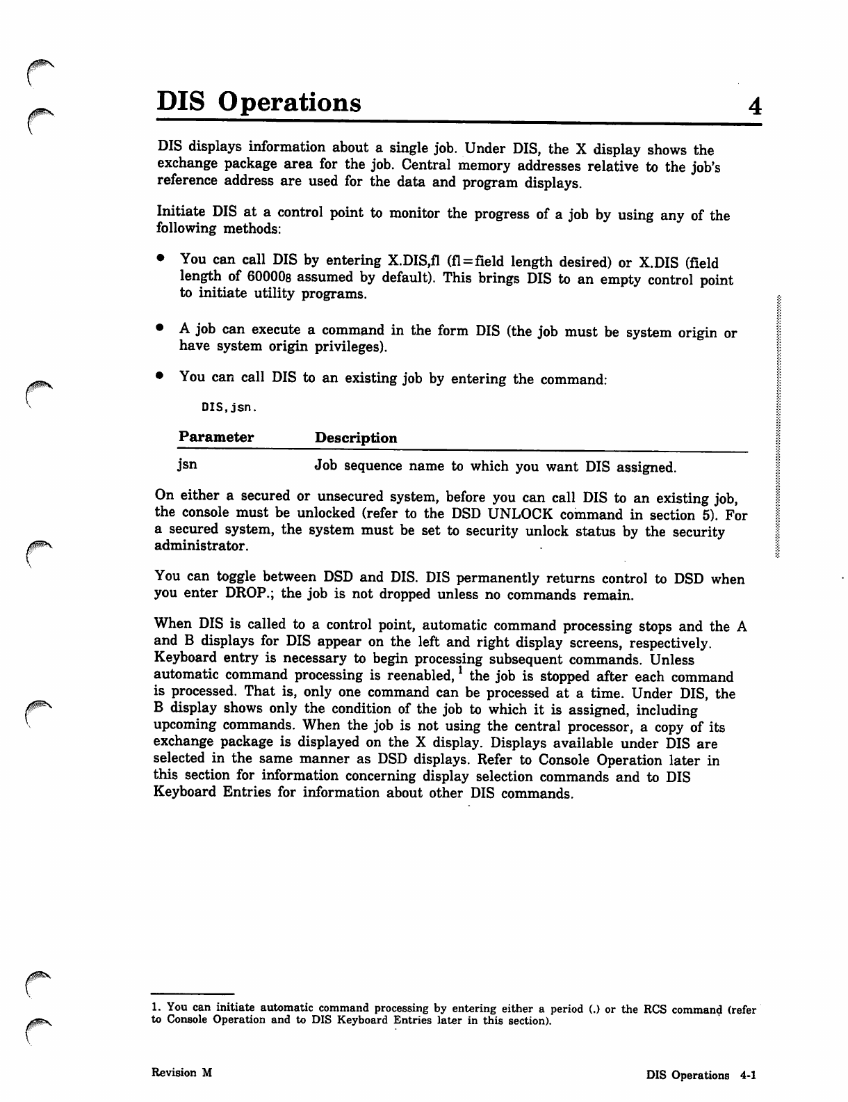
DIS Operations
DIS displays information about a single job. Under DIS, the X display shows the
exchange package area for the job. Central memory addresses relative to the job's
reference address are used for the data and program displays.
Initiate DIS at a control point to monitor the progress of a job by using any of the
following methods:
•You can call DIS by entering X.DIS,fl (fl=field length desired) or X.DIS (field
length of 600008 assumed by default). This brings DIS to an empty control point
to initiate utility programs.
A job can execute a command in the form DIS (the job must be system origin or
have system origin privileges).
You can call DIS to an existing job by entering the command:
DIS,jsn.
Parameter Description
jsn Job sequence name to which you want DIS assigned.
On either a secured or unsecured system, before you can call DIS to an existing job,
the console must be unlocked (refer to the DSD UNLOCK command in section 5). For
a secured system, the system must be set to security unlock status by the security
administrator.
You can toggle between DSD and DIS. DIS permanently returns control to DSD when
you enter DROP.; the job is not dropped unless no commands remain.
When DIS is called to a control point, automatic command processing stops and the A
and B displays for DIS appear on the left and right display screens, respectively.
Keyboard entry is necessary to begin processing subsequent commands. Unless
automatic command processing is reenabled,* the job is stopped after each command
is processed. That is, only one command can be processed at a time. Under DIS, the
#^ B display shows only the condition of the job to which it is assigned, including
^ upcoming commands. When the job is not using the central processor, a copy of its
exchange package is displayed on the X display. Displays available under DIS are
selected in the same manner as DSD displays. Refer to Console Operation later in
this section for information concerning display selection commands and to DIS
Keyboard Entries for information about other DIS commands.
1. You can initiate automatic command processing by entering either a period (.) or the RCS command (refer
to Console Operation and to DIS Keyboard Entries later in this section).
Revision M DIS Operations 4-1
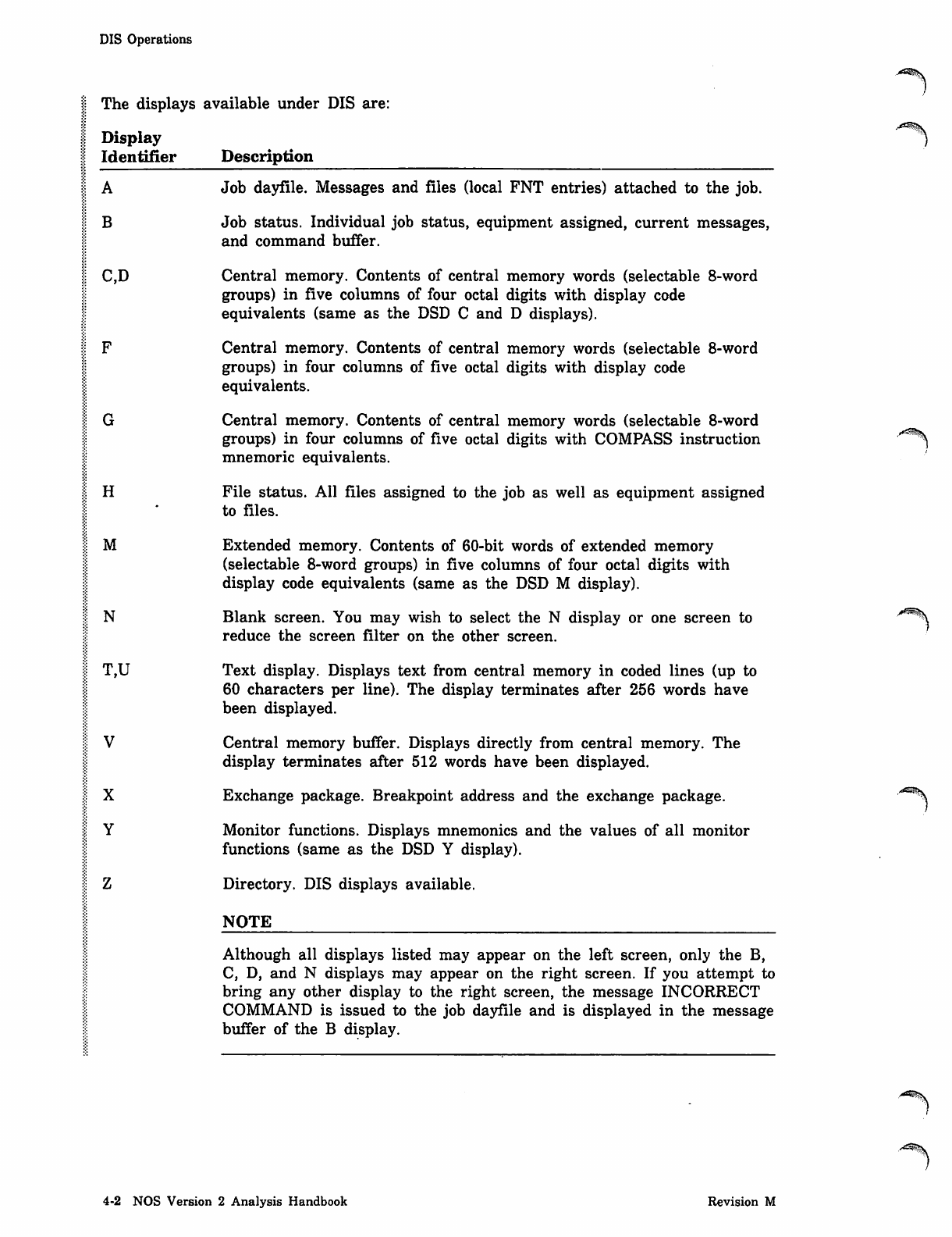
DIS Operations
The displays available under DIS are:
Display
Identifier Description
A Job dayfile. Messages and files (local FNT entries) attached to the job.
B Job status. Individual job status, equipment assigned, current messages,
and command buffer.
C,D Central memory. Contents of central memory words (selectable 8-word
groups) in five columns of four octal digits with display code
equivalents (same as the DSD C and D displays).
F Central memory. Contents of central memory words (selectable 8-word
groups) in four columns of five octal digits with display code
equivalents.
G Central memory. Contents of central memory words (selectable 8-word
groups) in four columns of five octal digits with COMPASS instruction "*^
mnemoric equivalents.
H File status. All files assigned to the job as well as equipment assigned
to files.
M Extended memory. Contents of 60-bit words of extended memory
(selectable 8-word groups) in five columns of four octal digits with
display code equivalents (same as the DSD M display).
N Blank screen. You may wish to select the N display or one screen to /0m\
reduce the screen filter on the other screen.
T,U Text display. Displays text from central memory in coded lines (up to
60 characters per line). The display terminates after 256 words have
been displayed.
V Central memory buffer. Displays directly from central memory. The
display terminates after 512 words have been displayed.
X E x c h a n g e p a c k a g e . B r e a k p o i n t a d d r e s s a n d t h e e x c h a n g e p a c k a g e . / - " * \
Y Monitor functions. Displays mnemonics and the values of all monitor
functions (same as the DSD Y display).
Z Directory. DIS displays available.
NOTE
Although all displays listed may appear on the left screen, only the B,
C, D, and N displays may appear on the right screen. If you attempt to
bring any other display to the right screen, the message INCORRECT
COMMAND is issued to the job dayfile and is displayed in the message
buffer of the B display.
4-2 NOS Version 2 Analysis Handbook Revision M
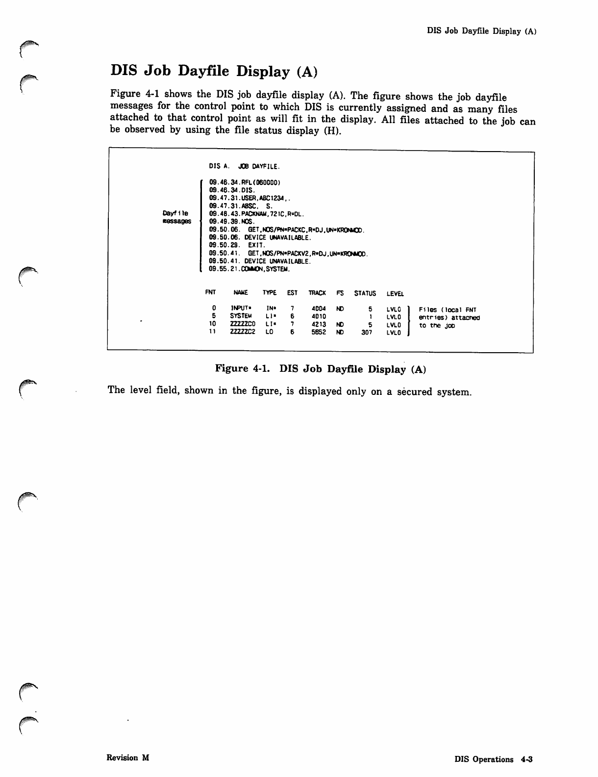
DIS Job Dayfile Display (A)
DIS Job Dayfile Display (A)
Figure 4-1 shows the DIS job dayfile display (A). The figure shows the job dayfile
messages for the control point to which DIS is currently assigned and as many files
attached to that control point as will fit in the display. All files attached to the job can
be observed by using the file status display (H).
DIS A. XB DAYFILE.
09.46.34.RFL(060000)
09.46.34.DIS.
09.47.31.USER.ABC1234,.
09.47.31.ABSC. S.
Dayfile 09.48.43.PACKNAM,721C.R-DL.
sessages 09.49.39.NOS.
09.50.06. 6ET.N0S/PN«PACKC.R"DJ.UN«KRONM0D.
09.50.06. DEVICE UNAVAILABLE.
09.50.29. EXIT.
09.50.41. 6ET.NOS/PN-PACKV2.R»DJ.UN-KRCNM0D.
09.50.41. DEVICE UNAVAILABLE.
09.55.21.COMMON.SYSTEM.
FNT NAM E TY PE EST TR ACK FS S TATUS LEVEL
0 I N P U T - I N » 7 4 0 0 4 N D 5 LVLO Files (local fnt
5 S Y S T E M L l » 6 4 0 1 0 1 LVLO entries) attacned
1 0 Z Z Z Z Z C O L I > 7 4 2 1 3 N D 5 LVLO to the joo
1 1 Z Z Z Z Z C 2 L O 6 5 6 5 2 N D 3 0 7 LVLO
Figure 4-1. DIS Job Dayfile Display (A)
The level field, shown in the figure, is displayed only on a secured system.
yms
Revision M DIS Operations 4-3
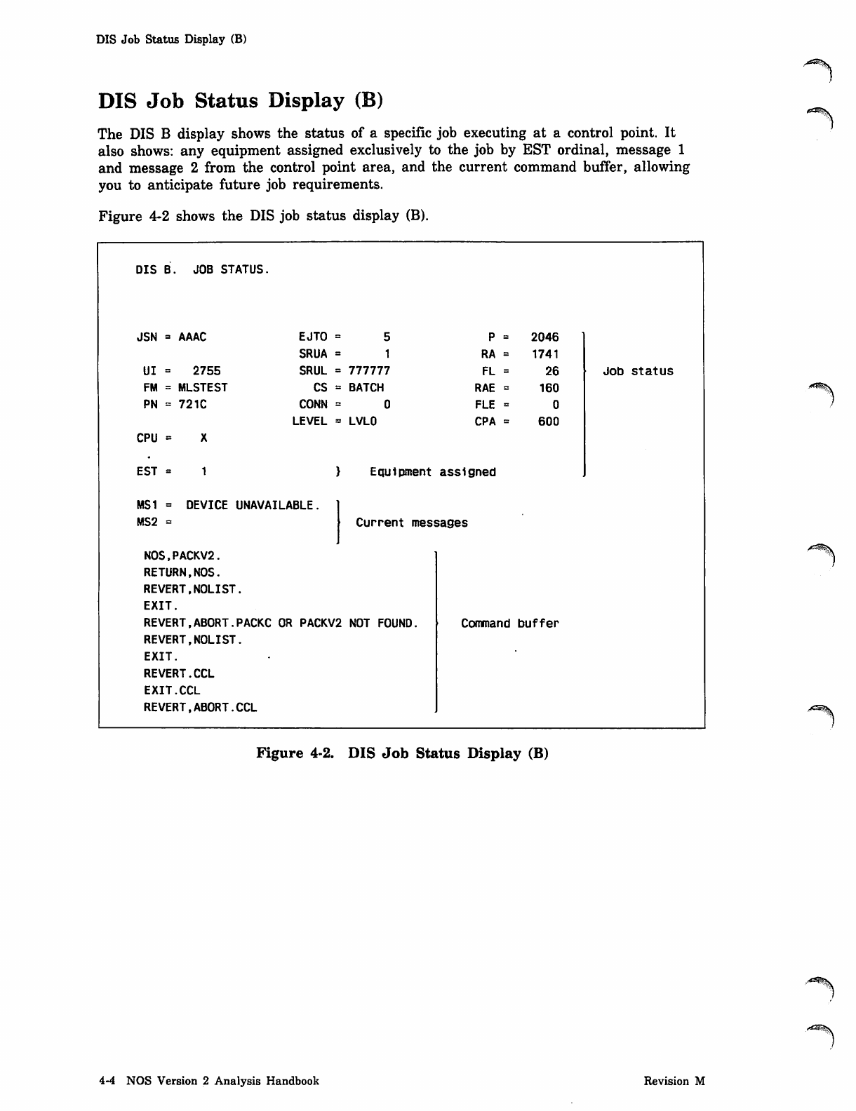
DIS Job Status Display (B)
Aa!S^S.
DIS Job Status Display (B)
The DIS B display shows the status of a specific job executing at a control point. It
also shows: any equipment assigned exclusively to the job by EST ordinal, message 1
and message 2 from the control point area, and the current command buffer, allowing
you to anticipate future job requirements.
Figure 4-2 shows the DIS job status display (B).
DIS B. JOB STATUS.
J S N = A A A C E J T O = 5 P = 2046
S R U A = 1 R A » 1741
U I = 2 7 5 5 S R U L = 7 7 7 7 7 7 F L = 26 Job status
F M = M L S T E S T C S » B A T C H R A E = 160
P N = 7 2 1 C C O N N = 0 F L E =
L E V E L = L V L O C P A = 600
C P U = X
EST - 1 } Equipment assigned
MS1 = DEVICE UNAVAILABLE.
MS2 = Current messages
NOS.PACKV2.
RETURN,NOS.
REVERT,NOLIST.
EXIT.
REVERT,ABORT.PACKC OR PACKV2 NOT FOUND. Command b u f f e r
REVERT,NOLIST.
EXIT.
REVERT.CCL
EXIT.CCL
REVERT,ABORT.CCL
Figure 4-2. DIS Job Status Display (B)
4-4 NOS Version 2 Analysis Handbook Revision M
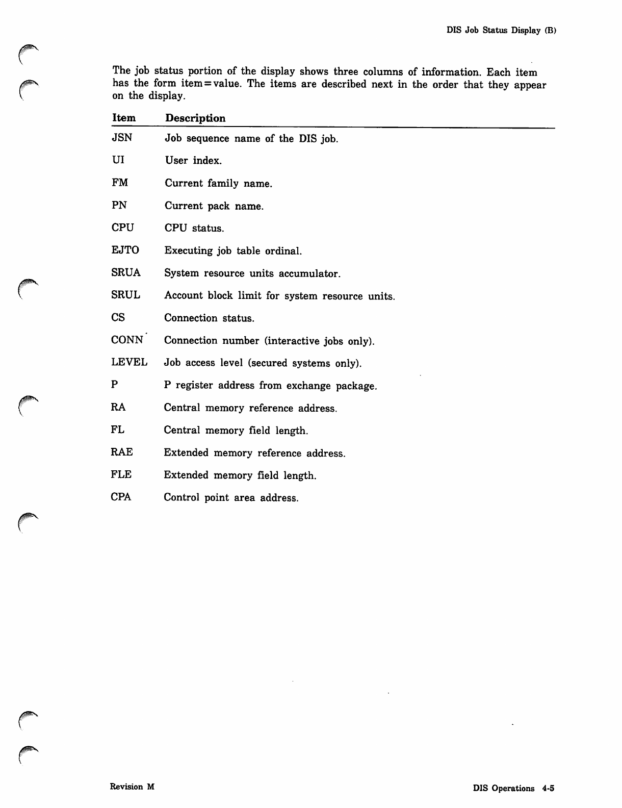
DIS Job Status Display (B)
A^S.
/^eJm^v
The job status portion of the display shows three columns of information. Each item
has the form item=value. The items are described next in the order that they appear
on the display.
Item Description
JSN Job sequence name of the DIS job.
UI User index.
FM Current family name.
PN Current pack name.
CPU CPU status.
EJTO Executing job table ordinal.
SRUA System resource units accumulator.
SRUL Account block limit for system resource units.
CS Connection status.
CONN Connection number (interactive jobs only).
LEVEL Job access level (secured systems only).
P P register address from exchange package.
RA Central memory reference address.
FL Central memory field length.
RAE Extended memory reference address.
FLE Extended memory field length.
CPA Control point area address.
Revision M DIS Operations 4-5
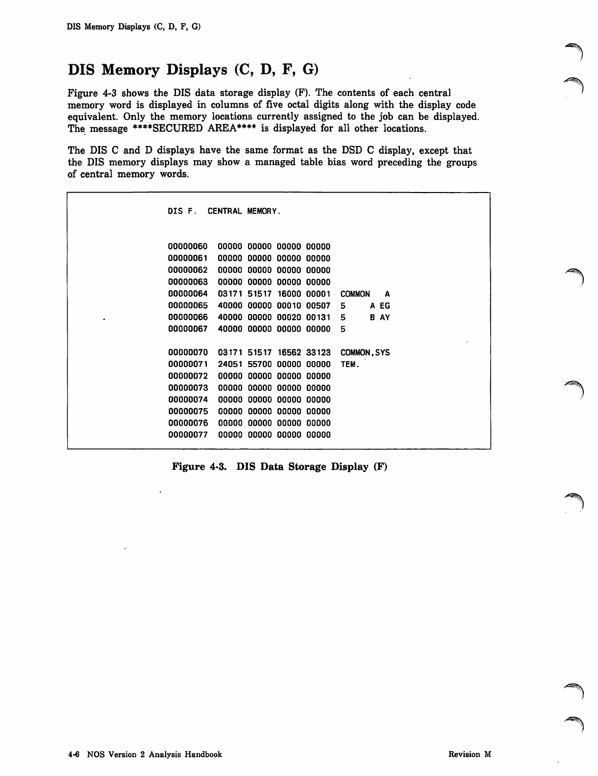
DIS Memory Displays (C, D, F, G)
DIS Memory Displays (C, D, F, G)
Figure 4-3 shows the DIS data storage display (F). The contents of each central
memory word is displayed in columns of five octal digits along with the display code
equivalent. Only the memory locations currently assigned to the job can be displayed.
The message ****SECURED AREA**** is displayed for all other locations.
The DIS C and D displays have the same format as the DSD C display, except that
the DIS memory displays may show a managed table bias word preceding the groups
of central memory words.
DIS F. CENTRAL MEMORY.
00000060 00000 00000 OOOOO OOOOO
00000061 ooooo 00000 OOOOO 00000
00000062 00000 00000 OOOOO OOOOO
00000063 OOOOO OOOOO OOOOO 00000
00000064 03171 51517 16000 00001 COMMON A
00000065 40000 00000 00010 00507 5 A E G
00000066 40000 00000 00020 00131 5 B A Y
00000067 40000 OOOOO OOOOO OOOOO
00000070 03171 51517 16562 33123 COMMON,SYS
00000071 24051 55700 00000 00000 TEM.
00000072 00000 00000 OOOOO OOOOO
00000073 00000 00000 OOOOO 00000
00000074 00000 00000 OOOOO OOOOO
00000075 00000 00000 OOOOO OOOOO
00000076 00000 OOOOO 00000 00000
00000077 OOOOO 00000 OOOOO OOOOO
Figure 4-3. DIS Data Storage Display (F)
4-6 NOS Version 2 Analysis Handbook Revision M
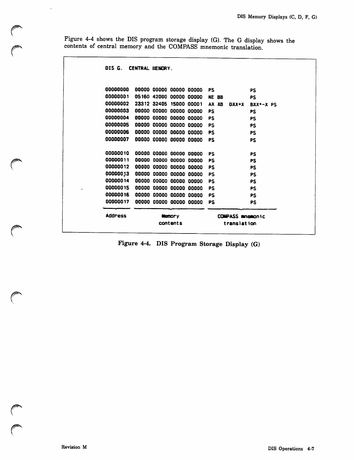
DIS Memory Displays (C, D, F, G)
Figure 4-4 shows the DIS program storage display (G). The G display shows the
contents of central memory and the COMPASS mnemonic translation.
OIS G. CENTRAL E8EMORY.
OOOOOOOO
00000001
00000002
00000003
00000004
00000005
00000006
00000007
00000010
00000011
00000012
000000.13
00000014
00000015
00000016
00000017
Address
00000 00000 00000 00000
05160 42000 00000 00000
23312 32405 15000 00001
00000 00000 00000 00000
00000 00000 00000 00000
00000 00000 00000 00000
00000 00000 00000 00000
00000 00000 00000 00000
00000
00000
00000
00000
00000
00000
ooooo
ooooo
ooooo
ooooo
ooooo
ooooo
ooooo
ooooo
ooooo
ooooo
ooooo
ooooo
ooooo
ooooo
ooooo
ooooo
ooooo
ooooo
ooooo
ooooo
ooooo
ooooo
ooooo
00Q00
ooooo
ooooo
PS
NE BB
AX XB
PS
PS
PS
PS
PS
PS
PS
PS
PS
PS
PS
PS
PS
DXX+X
PS
PS
BXX°-X PS
PS
PS
PS
PS
PS
PS
PS
PS
PS
PS
PS
PS
PS
Memory
contents
COMPASS aneaontc
translation
Figure 4-4. DIS Program Storage Display (G)
Revision M DIS Operations 4-7
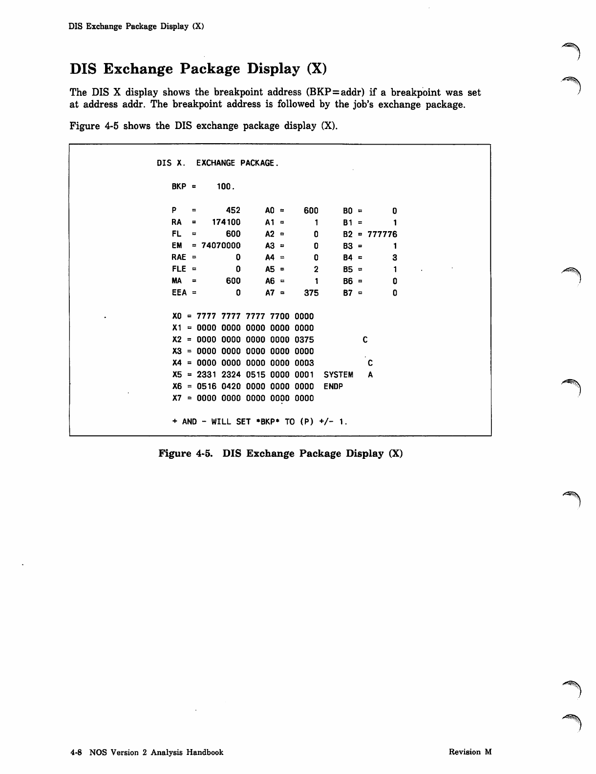
DIS Exchange Package Display (X)
DIS Exchange Package Display (X)
The DIS X display shows the breakpoint address (BKP=addr) if a breakpoint was set
at address addr. The breakpoint address is followed by the job's exchange package.
Figure 4-5 shows the DIS exchange package display (X).
DIS X. EXCHANGE PACKAGE.
BKP I00.
P=452 AO = 600 BO =
RA 174100 A1 = B1 =
FL 600 A2 = B2 » 777776
EM = 74070000 A3 = B3 -
RAE A4 = B4 =
FLE A5 = B5 =
MA 600 A6 = B6 =
EEA A7 = 375 B7 =
XO = 7777 7777 7777 7700 0000
X1 = oooo 0000 0000 0000 0000
X2 = oooo 0000 0000 0000 0375
X3 = oooo 0000 0000 0000 0000
X4 = oooo 0000 oooo oooo 0003
X5 = 2331 2324 0515 0000 0001 SYSTEM A
X6 = 0516 0420 oooo oooo 0000 ENDP
X7 = 0000 0000 oooo oooo 0000
+ AND - WILL SET *BKP* TO (P) +/- 1.
Figure 4-5. DIS Exchange Package Display (X)
4-8 NOS Version 2 Analysis Handbook Revision M
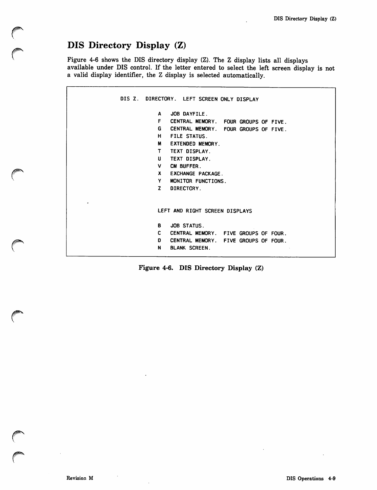
DIS Directory Display (Z)
DIS Directory Display (Z)
Figure 4-6 shows the DIS directory display (Z). The Z display lists all displays
available under DIS control. If the letter entered to select the left screen display is not
a valid display identifier, the Z display is selected automatically.
DIS Z. DIRECTORY. LEFT SCREEN ONLY DISPLAY
A JOB DAYFILE.
F CENTRAL MEMORY.
G CENTRAL MEMORY.
H FILE STATUS.
M EXTENDED MEMORY.
T TEXT DISPLAY.
U TEXT DISPLAY.
V CM BUFFER.
X EXCHANGE PACKAGE.
Y MONITOR FUNCTIONS
Z DIRECTORY.
LEFT AND RIGHT SCREEN DISPLAYS
FOUR GROUPS OF FIVE
FOUR GROUPS OF FIVE
BJOB STATUS.
CCENTRAL MEMORY. FIVE GROUPS OF FOUR
DCENTRAL MEMORY. FIVE GROUPS OF FOUR
NBLANK SCREEN.
Figure 4-6. DIS Directory Display (Z)
0ms
Revision M DIS Operations 4-9
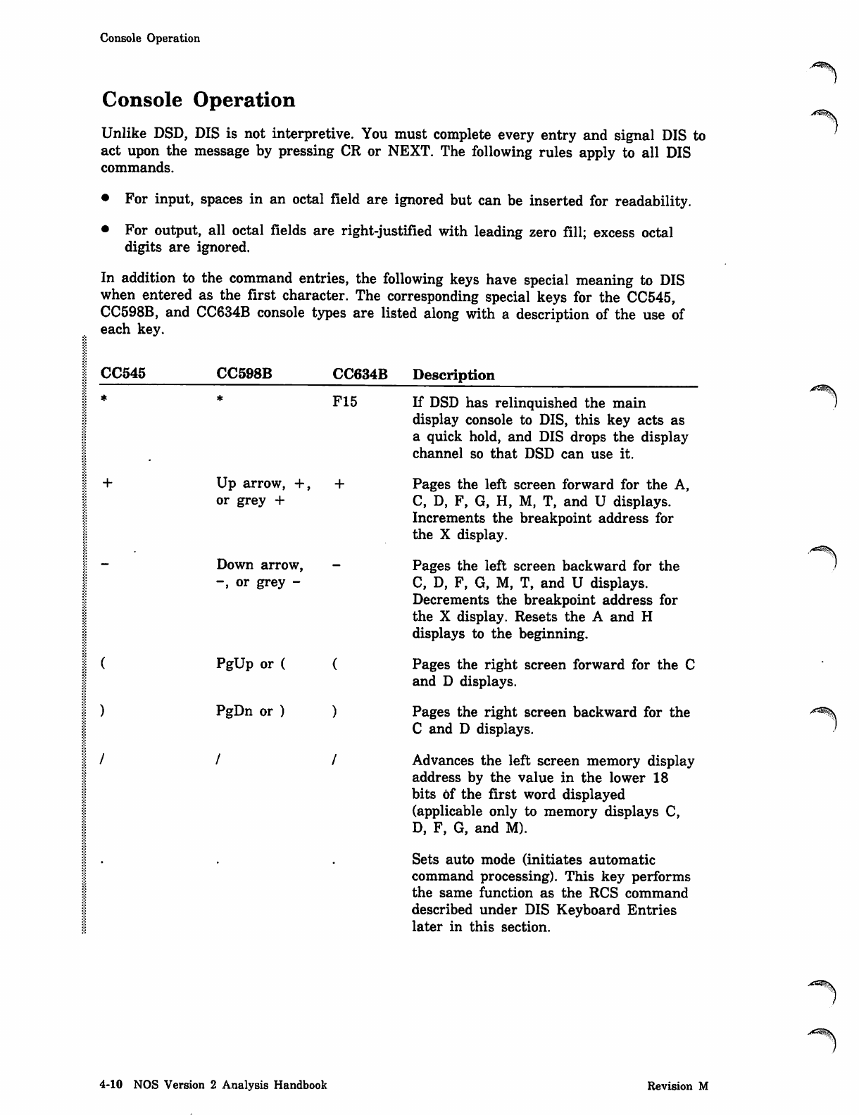
Console Operation
Console Operation
Unlike DSD, DIS is not interpretive. You must complete every entry and signal DIS to
act upon the message by pressing CR or NEXT. The following rules apply to all DIS
commands.
• For input, spaces in an octal field are ignored but can be inserted for readability.
• For output, all octal fields are right-justified with leading zero fill; excess octal
digits are ignored.
In addition to the command entries, the following keys have special meaning to DIS
when entered as the first character. The corresponding special keys for the CC545,
CC598B, and CC634B console types are listed along with a description of the use of
each key.
CC545 CC598B CC634B Description
+
F15
Up arrow, +, +
or grey +
Down arrow,
-, or grey -
P g U p o r ( (
P g D n o r ) )
/ /
If DSD has relinquished the main
display console to DIS, this key acts as
a quick hold, and DIS drops the display
channel so that DSD can use it.
Pages the left screen forward for the A,
C, D, F, G, H, M, T, and U displays.
Increments the breakpoint address for
the X display.
Pages the left screen backward for the
C, D, F, G, M, T, and U displays.
Decrements the breakpoint address for
the X display. Resets the A and H
displays to the beginning.
Pages the right screen forward for the C
and D displays.
Pages the right screen backward for the
C and D displays.
Advances the left screen memory display
address by the value in the lower 18
bits of the first word displayed
(applicable only to memory displays C,
D, F, G, and M).
Sets auto mode (initiates automatic
command processing). This key performs
the same function as the RCS command
described under DIS Keyboard Entries
later in this section.
X ^ X
/<^lsN.
4-10 NOS Version 2 Analysis Handbook Revision M
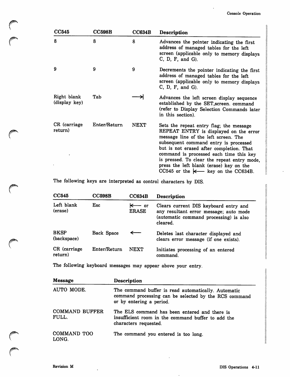
Console Operation
rCC545 CC598B CC634B Description
8 8 8
Right blank
(display key)
CR (carriage
return)
Tab
Enter/Return NEXT
Advances the pointer indicating the first
address of managed tables for the left
screen (applicable only to memory displays
C, D, F, and G).
Decrements the pointer indicating the first
address of managed tables for the left
screen (applicable only to memory displays
C, D, F, and G).
Advances the left screen display sequence
established by the SET,screen. command
(refer to Display Selection Commands later
in this section).
Sets the repeat entry flag; the message
REPEAT ENTRY is displayed on the error
message line of the left screen. The
subsequent command entry is processed
but is not erased after completion. That
command is processed each time this key
is pressed. To clear the repeat entry mode,
press the left blank (erase) key on the
CC545 or the |< key on the CC634B.
The following keys are interpreted as control characters by DIS.
CC545
Left blank
(erase)
BKSP
(backspace)
CR (carriage
return)
CC598B CC634B Description
Esc |< or Clears current DIS keyboard entry and
ERASE any resultant error message; auto mode
(automatic command processing) is also
cleared.
Back Space <
Enter/Return NEXT
The following keyboard messages may appear above your entry
Deletes last character displayed and
clears error message (if one exists).
Initiates processing of an entered
command.
Message Description
yms
AUTO MODE.
COMMAND BUFFER
FULL.
COMMAND TOO
LONG.
The command buffer is read automatically. Automatic
command processing can be selected by the RCS command
or by entering a period.
The ELS command has been entered and there is
insufficient room in the command buffer to add the
characters requested.
The command you entered is too long.
Revision M DIS Operations 4-11
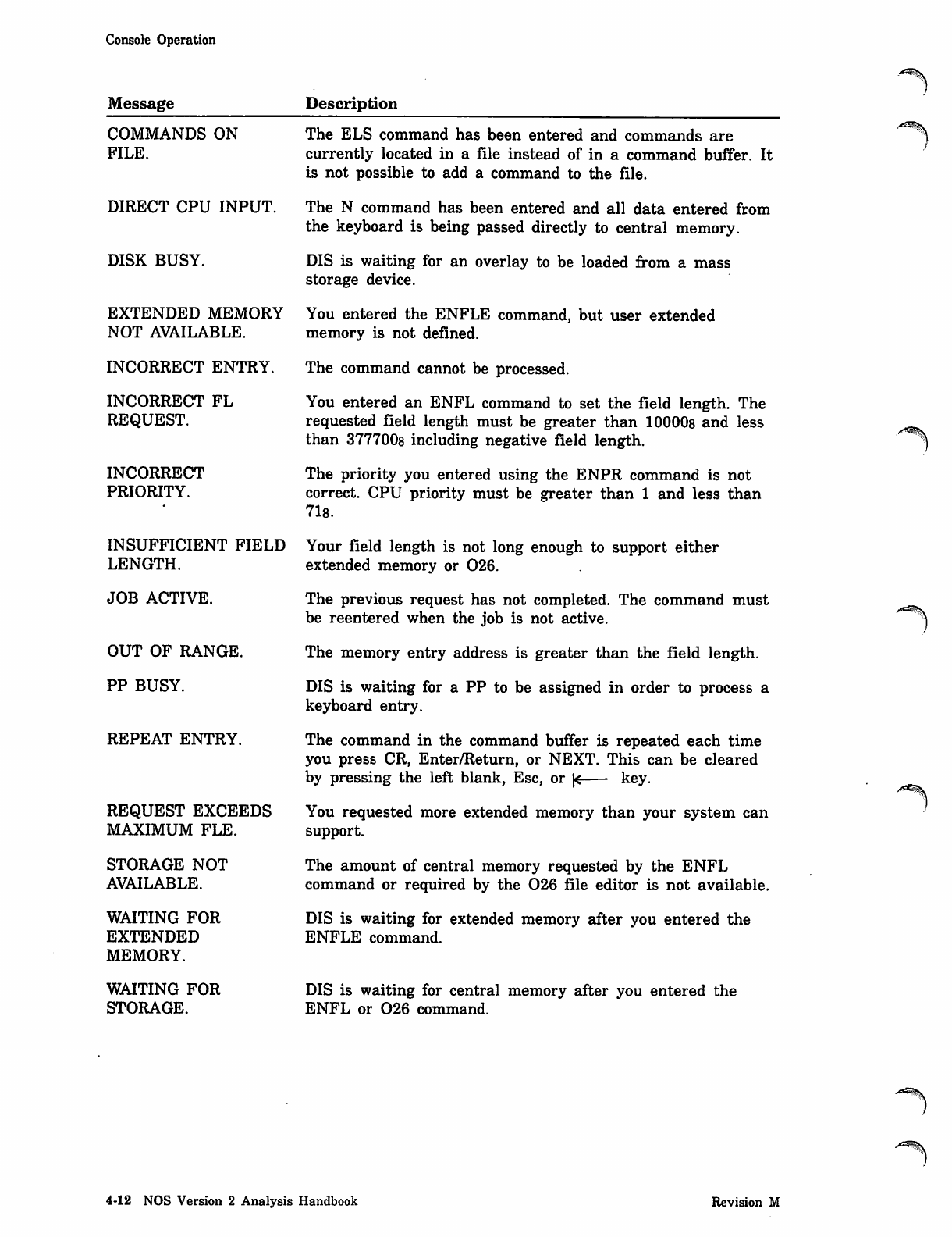
Console Operation
Message Description
COMMANDS ON
FILE.
DIRECT CPU INPUT.
DISK BUSY.
EXTENDED MEMORY
NOT AVAILABLE.
The ELS command has been entered and commands are
currently located in a file instead of in a command buffer. It
is not possible to add a command to the file.
The N command has been entered and all data entered from
the keyboard is being passed directly to central memory.
DIS is waiting for an overlay to be loaded from a mass
storage device.
You entered the ENFLE command, but user extended
memory is not defined.
INCORRECT ENTRY. The command cannot be processed.
INCORRECT FL
REQUEST.
INCORRECT
PRIORITY.
INSUFFICIENT FIELD
LENGTH.
JOB ACTIVE.
OUT OF RANGE.
PP BUSY.
REPEAT ENTRY.
REQUEST EXCEEDS
MAXIMUM FLE.
STORAGE NOT
AVAILABLE.
WAITING FOR
EXTENDED
MEMORY.
WAITING FOR
STORAGE.
You entered an ENFL command to set the field length. The
requested field length must be greater than 100008 and less
than 3777008 including negative field length.
The priority you entered using the ENPR command is not
correct. CPU priority must be greater than 1 and less than
718.
Your field length is not long enough to support either
extended memory or 026.
The previous request has not completed. The command must
be reentered when the job is not active.
The memory entry address is greater than the field length.
DIS is waiting for a PP to be assigned in order to process a
keyboard entry.
The command in the command buffer is repeated each time
you press CR, Enter/Return, or NEXT. This can be cleared
by pressing the left blank, Esc, or |< key.
You requested more extended memory than your system can
support.
The amount of central memory requested by the ENFL
command or required by the 026 file editor is not available.
DIS is waiting for extended memory after you entered the
ENFLE command.
DIS is waiting for central memory after you entered the
ENFL or 026 command.
4-12 NOS Version 2 Analysis Handbook Revision M
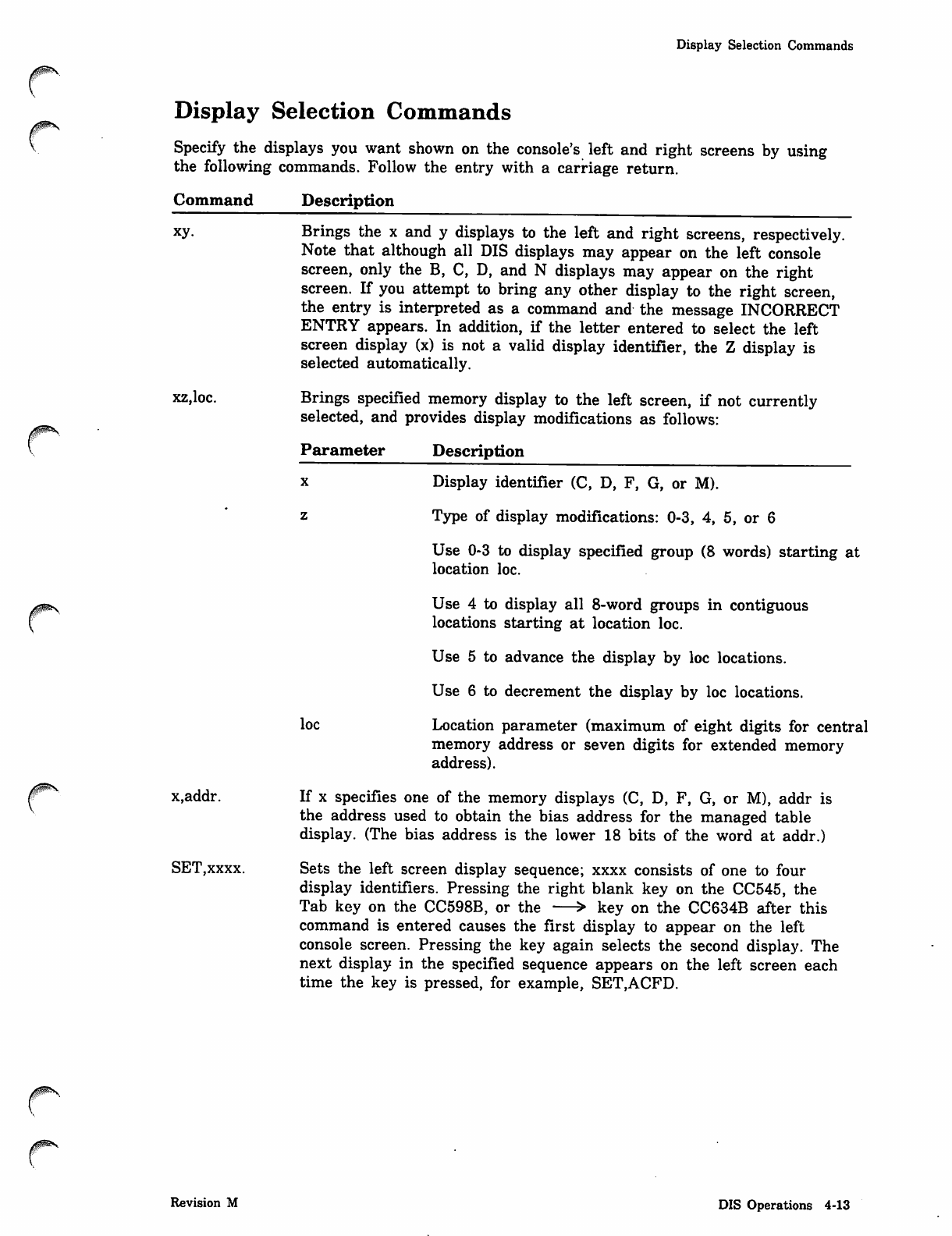
Display Selection Commands
Display Selection Commands
Specify the displays you want shown on the console's left and right screens by using
the following commands. Follow the entry with a carriage return.
Command
xy.
xz,loc.
x.addr.
SET.xxxx.
Description
Brings the x and y displays to the left and right screens, respectively.
Note that although all DIS displays may appear on the left console
screen, only the B, C, D, and N displays may appear on the right
screen. If you attempt to bring any other display to the right screen,
the entry is interpreted as a command and the message INCORRECT
ENTRY appears. In addition, if the letter entered to select the left
screen display (x) is not a valid display identifier, the Z display is
selected automatically.
Brings specified memory display to the left screen, if not currently
selected, and provides display modifications as follows:
Parameter Description
loc
Display identifier (C, D, F, G, or M).
Type of display modifications: 0-3, 4, 5, or 6
Use 0-3 to display specified group (8 words) starting at
location loc.
Use 4 to display all 8-word groups in contiguous
locations starting at location loc.
Use 5 to advance the display by loc locations.
Use 6 to decrement the display by loc locations.
Location parameter (maximum of eight digits for central
memory address or seven digits for extended memory
address).
If x specifies one of the memory displays (C, D, F, G, or M), addr is
the address used to obtain the bias address for the managed table
display. (The bias address is the lower 18 bits of the word at addr.)
Sets the left screen display sequence; xxxx consists of one to four
display identifiers. Pressing the right blank key on the CC545, the
Tab key on the CC598B, or the —> key on the CC634B after this
command is entered causes the first display to appear on the left
console screen. Pressing the key again selects the second display. The
next display in the specified sequence appears on the left screen each
time the key is pressed, for example, SET,ACFD.
Revision M DIS Operations 4-13
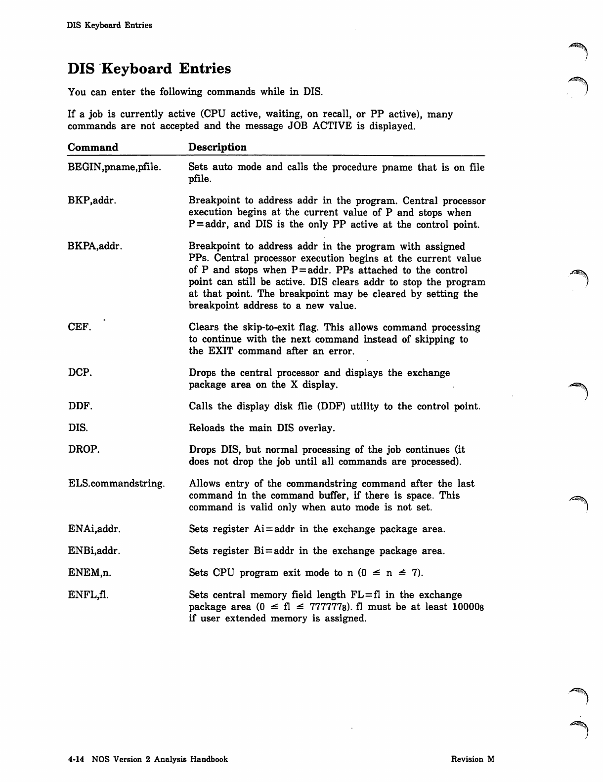
DIS Keyboard Entries
DIS Keyboard Entries
You can enter the following commands while in DIS.
If a job is currently active (CPU active, waiting, on recall, or PP active), many
commands are not accepted and the message JOB ACTIVE is displayed.
Command Description
BEGIN ,pname,pfile.
BKP,addr.
BKPA,addr.
CEF.
DCP.
DDF.
DIS.
DROP.
ELS.commandstring.
ENAi,addr.
ENBi,addr.
ENEM,n.
ENFL,fl.
Sets auto mode and calls the procedure pname that is on file
pfile.
Breakpoint to address addr in the program. Central processor
execution begins at the current value of P and stops when
P=addr, and DIS is the only PP active at the control point.
Breakpoint to address addr in the program with assigned
PPs. Central processor execution begins at the current value
of P and stops when P = addr. PPs attached to the control
point can still be active. DIS clears addr to stop the program
at that point. The breakpoint may be cleared by setting the
breakpoint address to a new value.
Clears the skip-to-exit flag. This allows command processing
to continue with the next command instead of skipping to
the EXIT command after an error.
Drops the central processor and displays the exchange
package area on the X display.
Calls the display disk file (DDF) utility to the control point.
Reloads the main DIS overlay.
Drops DIS, but normal processing of the job continues (it
does not drop the job until all commands are processed).
Allows entry of the commandstring command after the last
command in the command buffer, if there is space. This
command is valid only when auto mode is not set.
Sets register Ai = addr in the exchange package area.
Sets register Bi=addr in the exchange package area.
Sets CPU program exit mode to n (0 ^ n ^ 7).
Sets central memory field length FL=fl in the exchange
package area (0 ^ fl ^ 777777s). fl must be at least 100008
if user extended memory is assigned.
sfMS
4-14 NOS Version 2 Analysis Handbook Revision M
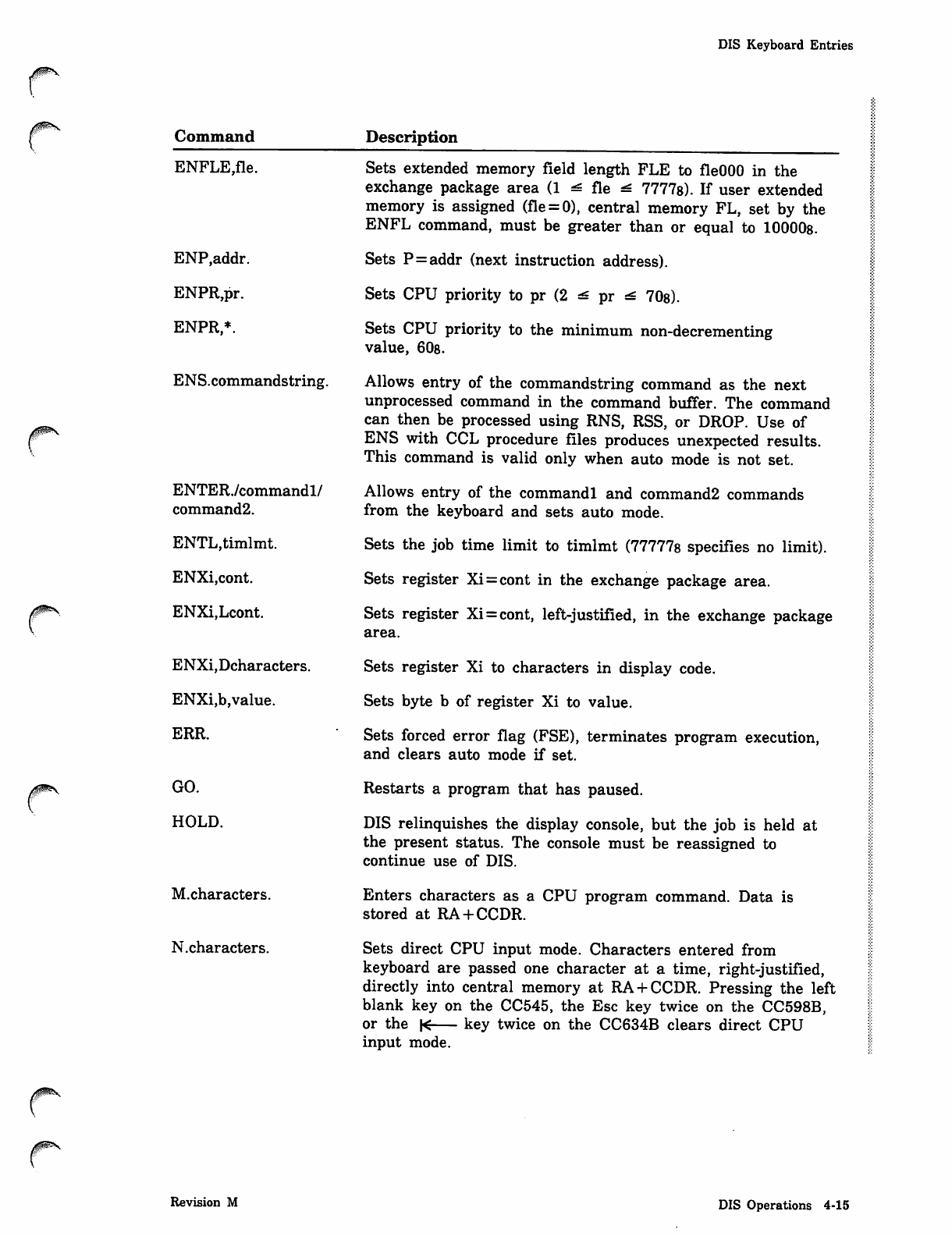
DIS Keyboard Entries
rCommand Description
ENFLE,fle.
ENP,addr.
ENPR,pr.
ENPR,*.
ENS.commandstring.
ENTERVcommandl/
command2.
ENTL,timlmt.
ENXi,cont.
ENXi,Lcont.
ENXi,Dcharacters.
ENXi,b,value.
ERR.
GO.
HOLD.
M.characters.
N.characters.
Sets extended memory field length FLE to fleOOO in the
exchange package area (1 ^ fie ^ 7777s). If user extended
memory is assigned (fle = 0), central memory FL, set by the
ENFL command, must be greater than or equal to 10000s.
Sets P=addr (next instruction address).
Sets CPU priority to pr (2 ^ pr ^ 70s).
Sets CPU priority to the minimum non-decrementing
value, 60s.
Allows entry of the commandstring command as the next
unprocessed command in the command buffer. The command
can then be processed using RNS, RSS, or DROP. Use of
ENS with CCL procedure files produces unexpected results.
This command is valid only when auto mode is not set.
Allows entry of the commandl and command2 commands
from the keyboard and sets auto mode.
Sets the job time limit to timlmt (77777s specifies no limit).
Sets register Xi = cont in the exchange package area.
Sets register Xi = cont, left-justified, in the exchange package
area.
Sets register Xi to characters in display code.
Sets byte b of register Xi to value.
Sets forced error flag (FSE), terminates program execution,
and clears auto mode if set.
Restarts a program that has paused.
DIS relinquishes the display console, but the job is held at
the present status. The console must be reassigned to
continue use of DIS.
Enters characters as a CPU program command. Data is
stored at RA + CCDR.
Sets direct CPU input mode. Characters entered from
keyboard are passed one character at a time, right-justified,
directly into central memory at RA + CCDR. Pressing the left
blank key on the CC545, the Esc key twice on the CC598B,
or the K key twice on the CC634B clears direct CPU
input mode.
Revision M DIS Operations 4-15
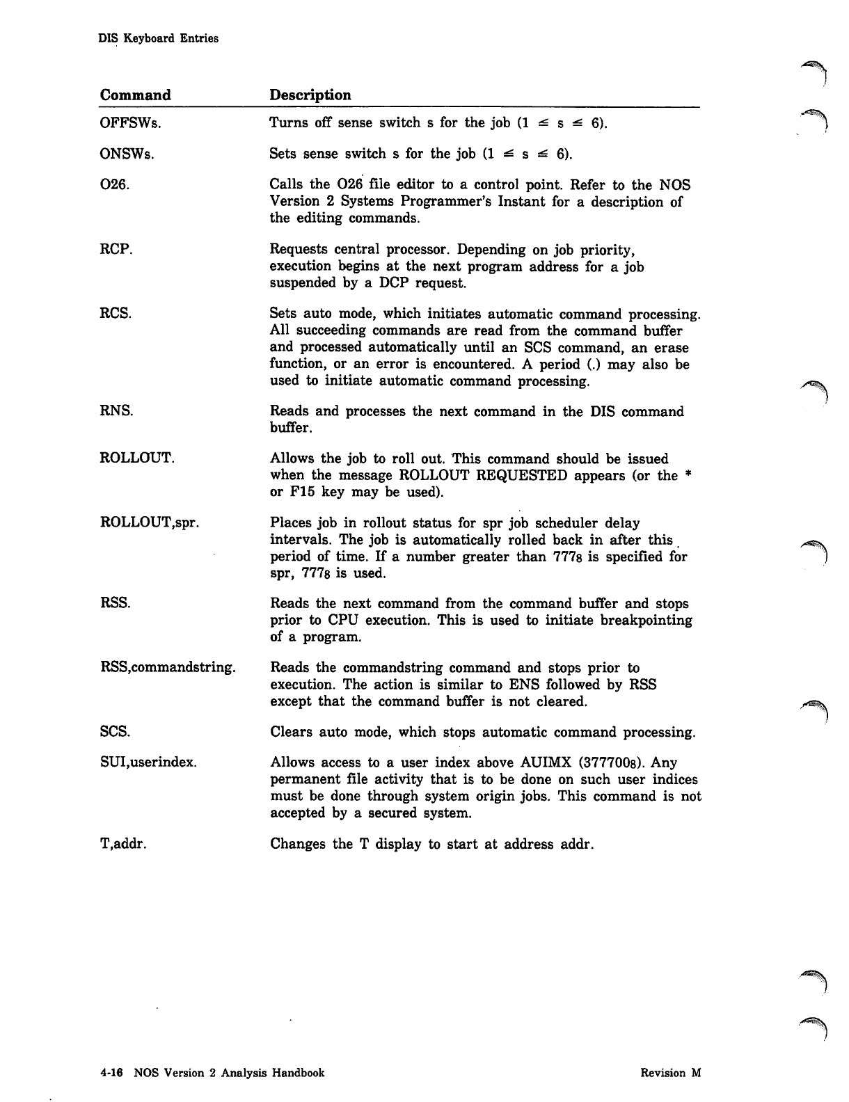
DIS Keyboard Entries
Command Description
OFFSWs.
ONSWs.
026.
RCP.
RCS.
RNS.
ROLLOUT.
ROLLOUT,spr.
RSS.
RSS,commandstring.
SCS.
SULuserindex.
T,addr.
Turns off sense switch s for the job (1 ^ s ^ 6).
Sets sense switch s for the job (1 ^ s ^ 6).
Calls the 026 file editor to a control point. Refer to the NOS
Version 2 Systems Programmer's Instant for a description of
the editing commands.
Requests central processor. Depending on job priority,
execution begins at the next program address for a job
suspended by a DCP request.
Sets auto mode, which initiates automatic command processing.
All succeeding commands are read from the command buffer
and processed automatically until an SCS command, an erase
function, or an error is encountered. A period (.) may also be
used to initiate automatic command processing.
Reads and processes the next command in the DIS command
buffer.
Allows the job to roll out. This command should be issued
when the message ROLLOUT REQUESTED appears (or the *
or F15 key may be used).
Places job in rollout status for spr job scheduler delay
intervals. The job is automatically rolled back in after this
period of time. If a number greater than 7778 is specified for
spr, 7778 is used.
Reads the next command from the command buffer and stops
prior to CPU execution. This is used to initiate breakpointing
of a program.
Reads the commandstring command and stops prior to
execution. The action is similar to ENS followed by RSS
except that the command buffer is not cleared.
Clears auto mode, which stops automatic command processing.
Allows access to a user index above AUIMX (377700s). Any
permanent file activity that is to be done on such user indices
must be done through system origin jobs. This command is not
accepted by a secured system.
Changes the T display to start at address addr.
4-16 NOS Version 2 Analysis Handbook Revision M

DIS Keyboard Entries
Command
U,addr.
UCC=c
V,addr.
X.commandstring.
* commandstring.
commandstring.
Description
Changes the U display to start at address addr.
Sets the uppercase character c. This command does not
terminate with a period.
Changes the V display to start at address addr.
Processes commandstring as the next command. Only the first
50 characters following X are used. This may be used to enter
a leading slant or a command that is the same as DIS
display.
If an asterisk (*) followed by a blank and commandstring is
encountered during automatic command processing (auto
mode), commandstring is interpreted as a direct DIS display
selection command. For example, * C4,100. will set the left
screen display to the central memory C display at address
100. Using this feature, it is possible to set up procedure files
that use DIS to breakpoint a program to a desired stopping
point.
Processes commandstring as a command if it is not a
recognizable DIS command.
Calls the 026 file editor to a control point. Refer to the NOS
Version 2 Systems Programmer's Instant for a description of
the editing commands. (This command is the same as the
026 command.)
Revision M DIS Operations 4-17
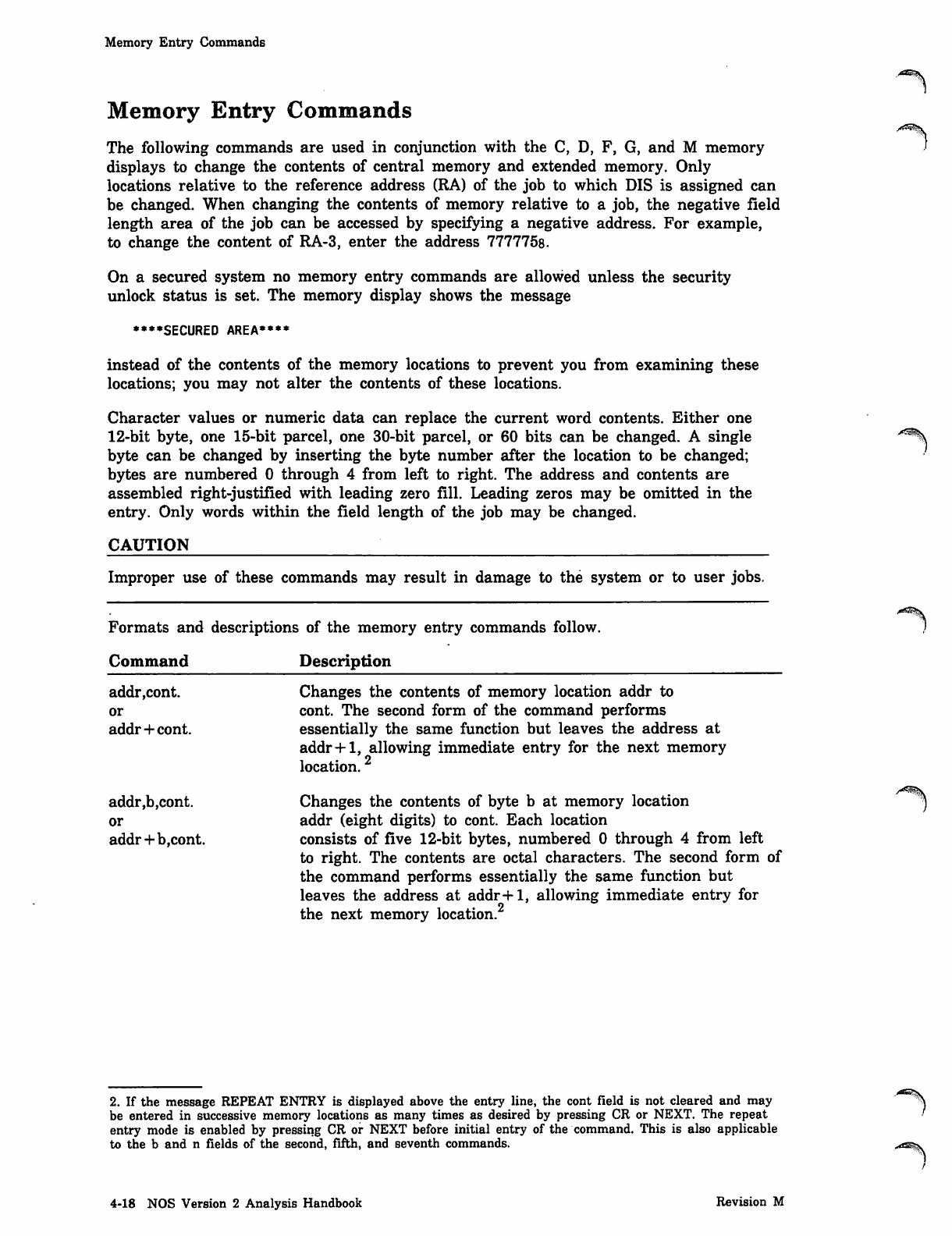
Memory Entry Commands
Memory Entry Commands
The following commands are used in conjunction with the C, D, F, G, and M memory
displays to change the contents of central memory and extended memory. Only
locations relative to the reference address (RA) of the job to which DIS is assigned can
be changed. When changing the contents of memory relative to a job, the negative field
length area of the job can be accessed by specifying a negative address. For example,
to change the content of RA-3, enter the address 777775s.
On a secured system no memory entry commands are allowed unless the security
unlock status is set. The memory display shows the message
••••SECURED AREA****
instead of the contents of the memory locations to prevent you from examining these
locations; you may not alter the contents of these locations.
Character values or numeric data can replace the current word contents. Either one
12-bit byte, one 15-bit parcel, one 30-bit parcel, or 60 bits can be changed. A single ""^
byte can be changed by inserting the byte number after the location to be changed;
bytes are numbered 0 through 4 from left to right. The address and contents are
assembled right-justified with leading zero fill. Leading zeros may be omitted in the
entry. Only words within the field length of the job may be changed.
CAUTION
Improper use of these commands may result in damage to the system or to user jobs.
Formats and descriptions of the memory entry commands follow. )
Command Description
addr,cont. Changes the contents of memory location addr to
o r c o n t . T h e s e c o n d f o r m o f t h e c o m m a n d p e r f o r m s
addr+cont. essentially the same function but leaves the address at
addr + 1, allowing immediate entry for the next memory
location.
a d d r , b , c o n t . C h a n g e s t h e c o n t e n t s o f b y t e b a t m e m o r y l o c a t i o n / ^ ^
or addr (eight digits) to cont. Each location
addr+b,cont. consists of five 12-bit bytes, numbered 0 through 4 from left
to right. The contents are octal characters. The second form of
the command performs essentially the same function but
leaves the address at addr+1, allowing immediate entry for
the next memory location.
2. If the message REPEAT ENTRY is displayed above the entry line, the cont field is not cleared and may ^^S
be entered in successive memory locations as many times as desired by pressing CR or NEXT. The repeat
entry mode is enabled by pressing CR or NEXT before initial entry of the command. This is also applicable
to the b and n fields of the second, fifth, and seventh commands.
4-18 NOS Version 2 Analysis Handbook Revision M
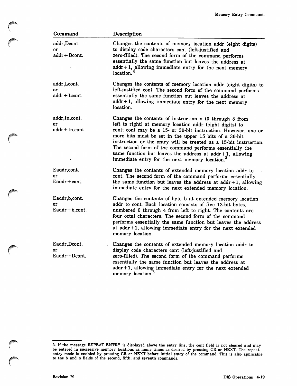
Memory Entry Commands
Command
igffrSi
Description
addr,Dcont.
or
addr + Dcont.
addr,Lcont.
or
addr + Lcont.
addr,In,cont.
or
addr + In,cont.
Eaddr ,cont.
or
Eaddr + cont.
Eaddr,b,cont.
or
Eaddr+ b,cont.
Eaddr,Dcont.
or
Eaddr + Dcont.
Changes the contents of memory location addr (eight digits)
to display code characters cont (left-justified and
zero-filled). The second form of the command performs
essentially the same function but leaves the address at
addr+1, allowing immediate entry for the next memory
location.
Changes the contents of memory location addr (eight digits) to
left-justified cont. The second form of the command performs
essentially the same function but leaves the address at
addr + 1, allowing immediate entry for the next memory
location.
Changes the contents of instruction n (0 through 3 from
left to right) at memory location addr (eight digits) to
cont; cont may be a 15- or 30-bit instruction. However, one or
more bits must be set in the upper 15 bits of a 30-bit
instruction or the entry will be treated as a 15-bit instruction.
The second form of the command performs essentially the
same function but leaves the address at addr + 1, allowing
immediate entry for the next memory location.3
Changes the contents of extended memory location addr to
cont. The second form of the command performs essentially
the same function but leaves the address at addr + 1, allowing
immediate entry for the next extended memory location.
Changes the contents of byte b at extended memory location
addr to cont. Each location consists of five 12-bit bytes,
numbered 0 through 4 from left to right. The contents are
four octal characters. The second form of the command
performs essentially the same function but leaves the address
at addr + 1, allowing immediate entry for the next extended
memory location.
Changes the contents of extended memory location addr to
display code characters cont (left-justified and
zero-filled). The second form of the command performs
essentially the same function but leaves the address at
addr + 1, allowing immediate entry for the next extended
memory location.
3. If the message REPEAT ENTRY is displayed above the entry line, the cont field is not cleared and may
be entered in successive memory locations as many times as desired by pressing CR or NEXT. The repeat
entry mode is enabled by pressing CR or NEXT before initial entry of the command. This is also applicable
to the b and n fields of the second, fifth, and seventh commands.
Revision M DIS Operations 4-19
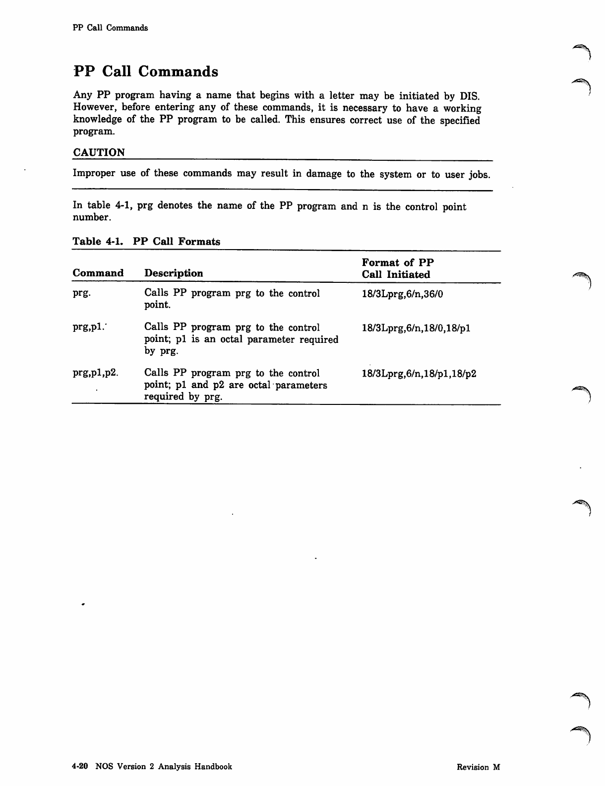
PP Call Commands
PP Call Commands
Any PP program having a name that begins with a letter may be initiated by DIS.
However, before entering any of these commands, it is necessary to have a working
knowledge of the PP program to be called. This ensures correct use of the specified
program.
CAUTION
Improper use of these commands may result in damage to the system or to user jobs.
In table 4-1, prg denotes the name of the PP program and n is the control point
number.
Table 4-1. PP Call Formats
Command Description
prg. Calls PP program prg to the control
point.
prg,pl.* Calls PP program prg to the control
point; pl is an octal parameter required
by prg.
prg,pl,p2. Calls PP program prg to the control
point; pl and p2 are octal parameters
required by prg.
Format of PP
Call Initiated
18/3Lprg,6/n,36/0
18/3Lprg,6/n,18/0,18/pl
18/3Lprg,6/n,18/pl,18/p2
/^®Sk
4-20 NOS Version 2 Analysis Handbook Revision M
0ms
0^ DSD Commands 5
Display Selection Commands 5.2
Dayfile Commands 5.3
Queued File Utility Commands 5.4
Job Processing Control Commands 5.4
General Job Control Commands 5-4
Interactive Job Control Commands 5-8
Job Communication Commands 5-9
Job Flow Commands 5-10
Peripheral Equipment Control Commands 5-24
Subsystem Control Commands 5-50
System Control Commands 5-56
Secured System Control Commands 5-70
Memory Entry Commands 5-72
Channel Control Commands 5-74
Extended Memory Flag Register Commands 5-75
r^ Breakpoint Package Commands , 5-75
- PP Breakpoint Commands 5-75
V Display 5-77
PP Breakpoint Precautions 5-79
CPUMTR Breakpoint Commands 5-80
CPUMTR Breakpoint Display (C Display) 5-81
CPUMTR Breakpoint Precautions 5-83
f^ Debugging Commands 5-84

V^ J
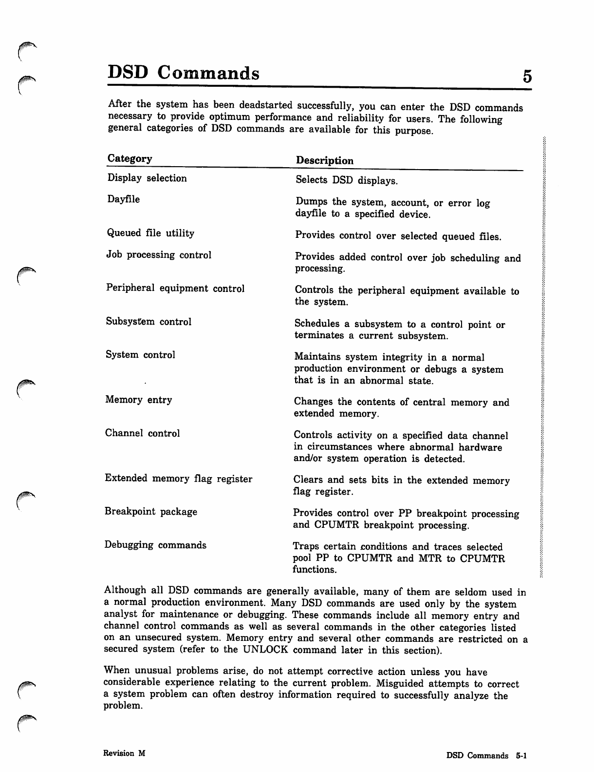
DSD Commands
After the system has been deadstarted successfully, you can enter the DSD commands
necessary to provide optimum performance and reliability for users. The following
general categories of DSD commands are available for this purpose.
Category Description
Display selection
Dayfile
Queued file utility
Job processing control
Peripheral equipment control
Subsystem control
System control
Memory entry
Channel control
Extended memory flag register
Breakpoint package
Debugging commands
Selects DSD displays.
Dumps the system, account, or error log
dayfile to a specified device.
Provides control over selected queued files.
Provides added control over job scheduling and
processing.
Controls the peripheral equipment available to
the system.
Schedules a subsystem to a control point or
terminates a current subsystem.
Maintains system integrity in a normal
production environment or debugs a system
that is in an abnormal state.
Changes the contents of central memory and
extended memory.
Controls activity on a specified data channel
in circumstances where abnormal hardware
and/or system operation is detected.
Clears and sets bits in the extended memory
flag register.
Provides control over PP breakpoint processing
and CPUMTR breakpoint processing.
Traps certain conditions and traces selected
pool PP to CPUMTR and MTR to CPUMTR
functions.
Although all DSD commands are generally available, many of them are seldom used in
a normal production environment. Many DSD commands are used only by the system
analyst for maintenance or debugging. These commands include all memory entry and
channel control commands as well as several commands in the other categories listed
on an unsecured system. Memory entry and several other commands are restricted on a
secured system (refer to the UNLOCK command later in this section).
When unusual problems arise, do not attempt corrective action unless you have
considerable experience relating to the current problem. Misguided attempts to correct
a system problem can often destroy information required to successfully analyze the
problem.
Revision M DSD Commands 5-1
Display Selection Commands
To assist customer engineers and software analysts in tracking problems, the system
enters the first characters (up to 25) of the following commands into the error log ^^\
after each execution.
DOWN,param.
FORM,param.
IDLE,param.
INITIALIZE,param.
LOG,param.
OFF,param.
ON,param.
REDEFINE.param.
99.
Memory entry commands
Channel control commands
Any other commands that you specify at installation time
These commands are prefixed by the characters DS in the error log but otherwise
appear exactly as they are entered. This feature can be enabled and disabled using the "^)
99 command (refer to System Control Commands later in this section).
The manner in which the DSD commands are entered and the use of special keyboard
characters are described in the NOS Version 2 Operations Handbook. Command
formats are fixed field; that is, the fields in the command format must be specified as
shown. Embedded blanks are allowed in octal fields. Leading spaces in command
entries are not allowed.
Display Selection Commands ^
The system display program DSD generates system-oriented displays. You can select
any of the DSD displays with the following DSD command:
xy.
where x and y represent the letter designation (screen identifier) of the displays.
Display x appears on the left screen and display y appears on the right screen. If x
and y are identical, both screens display the same information, except for the B and ^^
P displays when using the CC598B or CC634B console. Refer to the NOS Version 2 '
Operations Handbook for details concerning the DSD display formats and keyboard
operating instructions. You can specify a sequence of DSD displays that you want
displayed on the left screen. To preselect the left screen display sequence, enter the
following DSD command:
SET,screens.
where screens represents a string of four letters (screen identifiers) designating any
four DSD displays. Usually you specify four different displays although DSD accepts
any four valid screen identifiers. Refer to the NOS Version 2 Operations Handbook for
DSD displays and keyboard operating instructions.
5-2 NOS Version 2 Analysis Handbook Revision M
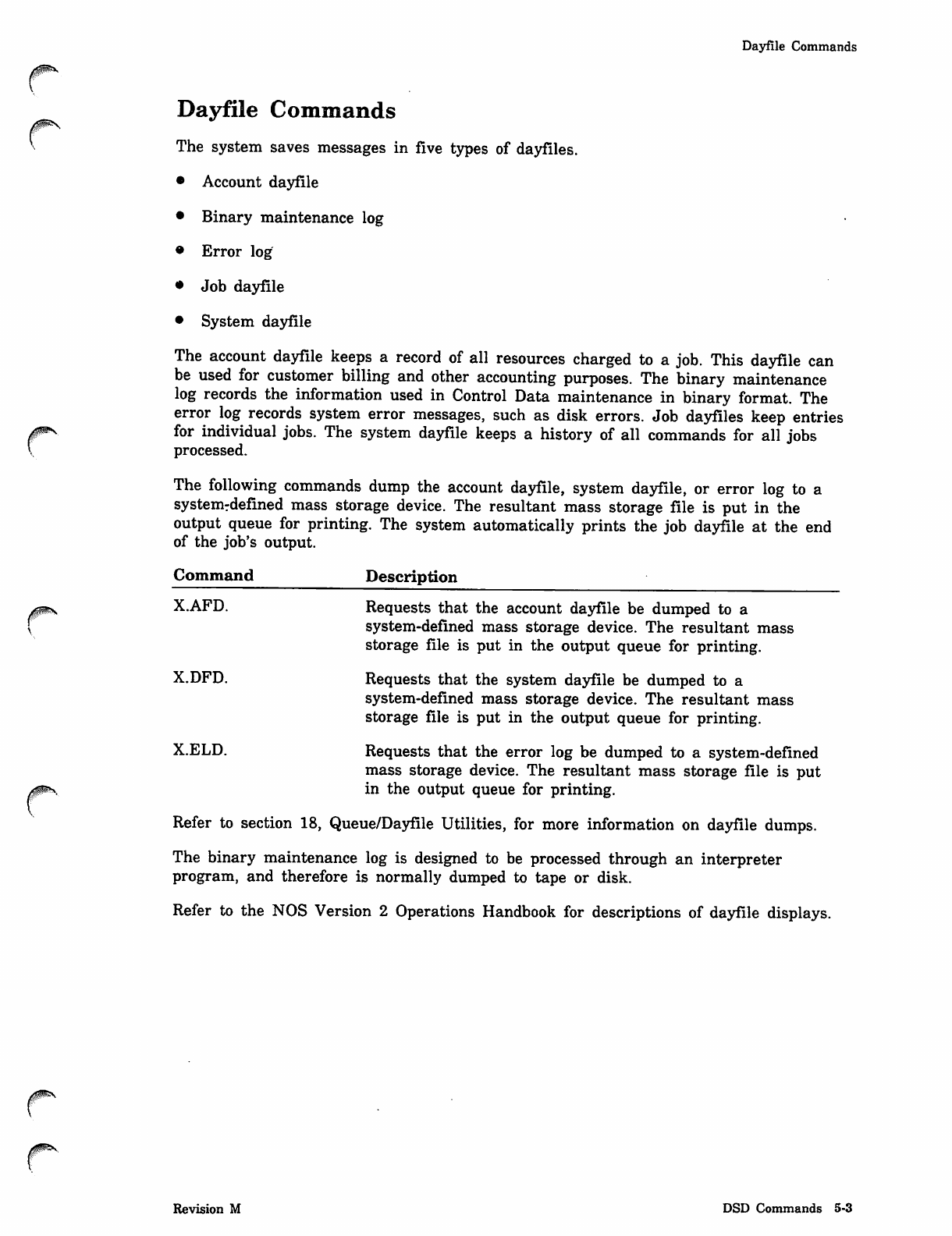
Dayfile Commands
Dayfile Commands
The system saves messages in five types of dayfiles.
• Account dayfile
• Binary maintenance log
• Error log
• Job dayfile
• System dayfile
The account dayfile keeps a record of all resources charged to a job. This dayfile can
be used for customer billing and other accounting purposes. The binary maintenance
log records the information used in Control Data maintenance in binary format. The
error log records system error messages, such as disk errors. Job dayfiles keep entries
for individual jobs. The system dayfile keeps a history of all commands for all jobs
processed.
The following commands dump the account dayfile, system dayfile, or error log to a
systemrdefined mass storage device. The resultant mass storage file is put in the
output queue for printing. The system automatically prints the job dayfile at the end
of the job's output.
Command Description
^wn X.AFD. Requests that the account dayfile be dumped to a
system-defined mass storage device. The resultant mass
storage file is put in the output queue for printing.
X.DFD. Requests that the system dayfile be dumped to a
system-defined mass storage device. The resultant mass
storage file is put in the output queue for printing.
X.ELD. Requests that the error log be dumped to a system-defined
mass storage device. The resultant mass storage file is put
in the output queue for printing.
Refer to section 18, Queue/Dayfile Utilities, for more information on dayfile dumps.
The binary maintenance log is designed to be processed through an interpreter
program, and therefore is normally dumped to tape or disk.
Refer to the NOS Version 2 Operations Handbook for descriptions of dayfile displays.
Revision M DSD Commands 5-3
Queued File Utility Commands
Queued File Utility Commands
The following commands are used to control queued input and output files.
Command Description
X.QREC Deactivates or activates selected queued files and purges selected
inactive queued files.
X.QMOVE Moves queued files from one mass storage device to another.
Refer to section 18, Queue/Dayfile Utilities, for more information on queued file utility
commands.
Job Processing Control Commands
Under normal circumstances, control over job processing is performed automatically by
the system. Although the following commands may not be used frequently, they provide ^_
an added measure of control over job processing. ^
General Job Control Commands
Several of the commands described here change internal system parameters which
control job scheduling and processing. Give careful consideration to their use since job
flow and overall system performance can be affected. Refer to the individual command
descriptions for further information.
Command Description >*^\
CKPJsn. Checkpoints the job with job sequence name jsn. The
checkpoint information includes a copy of the job's field length,
the system information used for job control, and the name and
contents of all local files currently assigned to the control
point. It is the responsibility of the user's job to establish a
magnetic tape or mass storage permanent file to receive the
checkpoint information. Otherwise, checkpoint information is
automatically written to a local file named CCCCCCC and is
not available if a restart becomes necessary (restart is ■^s\
user-controlled and is accomplished using the RESTART
command). Refer to the NOS Version 2 Reference Set, Volume
3 for supplementary information concerning the
checkpoint/restart feature available to users.
NOTE
If the current job command has secure system memory (SSM)
status set, the job cannot be checkpointed. SSM status is set
for certain jobs to prevent dumping of the job's field length.
Subsystems cannot be checkpointed.
^3ss!\
5-4 NOS Version 2 Analysis Handbook Revision M
General Job Control Commands
Command
DROP,jsn,qt,ujn.
ENPR,jsn,pr.
ENPRJsn,*.
ENQP,jsn,pr.
Description
Drops the job with job sequence name jsn from the queue qt
where it currently resides. If a jsn is not specified, a 1- to
7-character user job name ujn can be specified after the queue
type.
The console must be unlocked to use this form of the DROP
command. If no jsn or ujn is specified, all jobs in the specified
queue type are dropped. If the queue type is not specified, the
default is the executing queue.
The DROP command cannot be used to terminate a subsystem.
Also the DROP command will not terminate an interactive
user's session (this can be done only with a KILL command).
The queue type is one of the following:
qt Queue Type
ALL
EX
IN
PL
PR
PU
WT
All jobs and queued files.
All jobs in the executing queue (including the rolled
out jobs).
All jobs in the input queue.
All jobs in the plot queue.
All jobs in the print queue.
All jobs in the punch queue.
All jobs in the wait queue.
Sets CPU priority to pr (2 ^ pr ^ 70s).
Sets CPU priority to the minimum non-decrementing
value, 60s.
Enters queue priority of pr for a queue type file with job
sequence name jsn. The value of pr can range from the
minimum to the maximum for the job's service class. If the
priority is zero, an input file is not scheduled back to a
control point automatically. The value specified overrides the
current queue priority for the file. The current queue priority
can either be increased or decreased using this command.
Revision M DSD Commands 5-5
General Job Control Commands
Command
KILLjsn.
Description
Drops the job with job sequence name jsn from the executing
job table (EJT) without exit processing. If you want the job to
proceed with exit processing, use the DROP command. The
KILL command cannot be used to drop a subsystem.
KILL is the only command that immediately terminates an
interactive user's session. The DROP and OVERRIDE
commands only terminate the current job step and do not log
the user out of the system. There will be no recoverable job
after you issue the KILL command.
NOTE
Before initiating the command, ensure that the correct job
sequence name has been specified.
OVERRIDEJsn.
In some cases, a KILL command will be intercepted by a job's
reprieve processing. If the job does not terminate after
finishing its reprieve processing, issue another KILL command
to terminate the job.
Certain types of job processing are unaffected by the DROP,
KILL, or STOP commands. These include operations such as
setting permanent file device interlocks, interlocking
files/tracks, clearing VSN entries, and waiting for certain
types of tape/PP activity to end. The OVERRIDE command
terminates this type of processing and drops the job with job
sequence name jsn from the executing job table regardless of
queue priority. The OVERRIDE command will not terminate
an interactive user's session (this can be done only with a
KILL command). Unlock the console (refer to the UNLOCK
command later in this section) to enter this command. Use of
this command is recorded in the error log.
NOTE
Exercise extreme caution in using the OVERRIDE command.
Undesirable situations (such as interlocks being left set, VSN
entries remaining uncleared, or certain tape/PP activities left
outstanding) could occur that would cause potentially
damaging system activity. Never use this command during
normal operations.
5-6 NOS Version 2 Analysis Handbook Revision M
General Job Control Commands
Command
RERUNJsn.
ROLLIN,jsn,L.
ROLLOUT,jsn,sd.
Description
Terminates the job with job sequence name jsn, then reruns
the job from the beginning. The job must be in rerun status
as set by the RERUN command or macro.
Allows the job defined by job sequence name jsn to be
scheduled to an available control point. L is optional; if
omitted, the job can be selected by the scheduler for rollout.
Removes the currently executing job with job sequence name
jsn and makes it a rolled out job. A subsystem cannot be
rolled out. sd is the number of scheduler intervals before the
job can be scheduled again. The acceptable range for sd is
between 0 and 777s. If sd is not present or is 0, the job is not
scheduled back to a control point automatically. That is, your
action is required to return the job to a control point. This
can be done by using the ROLLIN command.
The amount of time required for one job scheduler interval is
initially set in the IPRDECK but may be changed by using
the DELAY command (JS parameter) described later in this
section. Normally, it is a 1-second interval.
Revision M DSD Commands 5-7
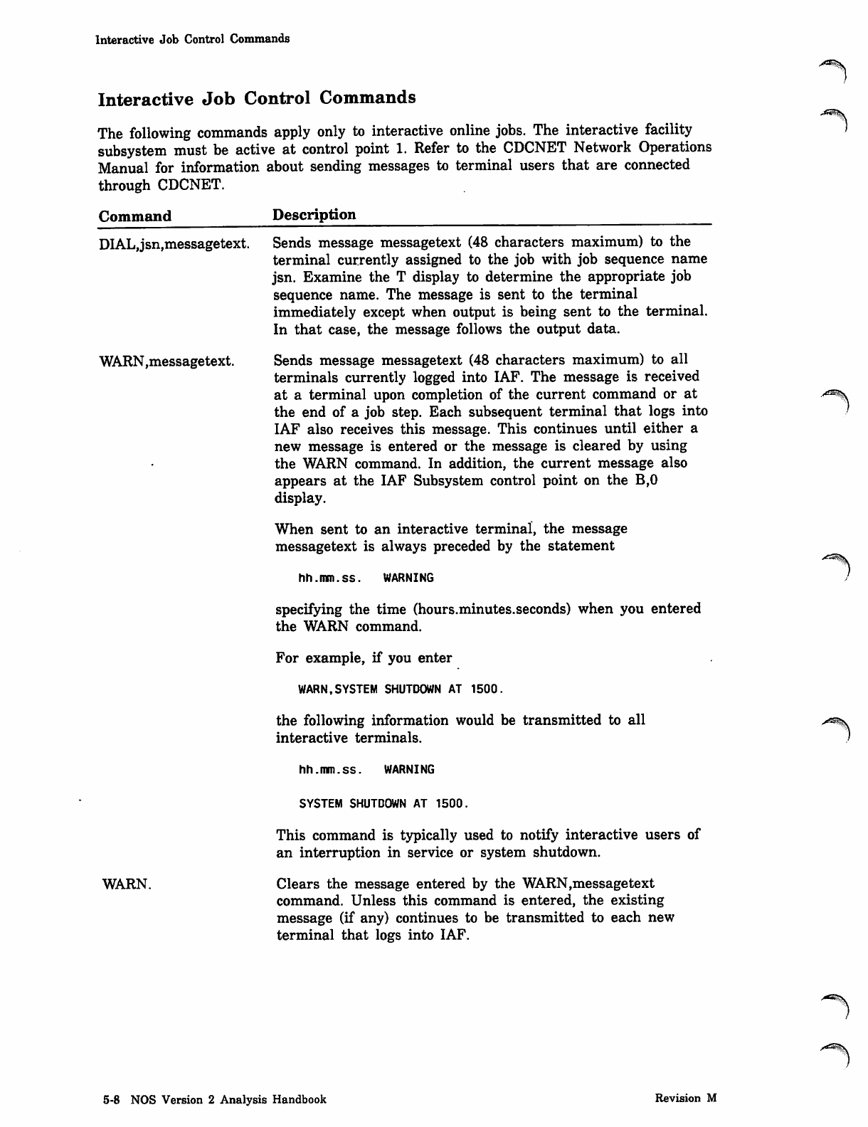
Interactive Job Control Commands
a&$S
Interactive Job Control Commands
The following commands apply only to interactive online jobs. The interactive facility
subsystem must be active at control point 1. Refer to the CDCNET Network Operations
Manual for information about sending messages to terminal users that are connected
through CDCNET.
Command
WARN,messagetext.
Description
DIAL,jsn,messagetext. Sends message messagetext (48 characters maximum) to the
terminal currently assigned to the job with job sequence name
jsn. Examine the T display to determine the appropriate job
sequence name. The message is sent to the terminal
immediately except when output is being sent to the terminal.
In that case, the message follows the output data.
Sends message messagetext (48 characters maximum) to all
terminals currently logged into IAF. The message is received
at a terminal upon completion of the current command or at
the end of a job step. Each subsequent terminal that logs into
IAF also receives this message. This continues until either a
new message is entered or the message is cleared by using
the WARN command. In addition, the current message also
appears at the IAF Subsystem control point on the B,0
display.
When sent to an interactive terminal, the message
messagetext is always preceded by the statement
hh.mm.ss. WARNING
specifying the time (hours.minutes.seconds) when you entered
the WARN command.
For example, if you enter
WARN,SYSTEM SHUTDOWN AT 1500.
the following information would be transmitted to all
interactive terminals.
hh.mm.ss. WARNING
WARN.
SYSTEM SHUTDOWN AT 1500.
This command is typically used to notify interactive users of
an interruption in service or system shutdown.
Clears the message entered by the WARN,messagetext
command. Unless this command is entered, the existing
message (if any) continues to be transmitted to each new
terminal that logs into IAF.
5-8 NOS Version 2 Analysis Handbook Revision M
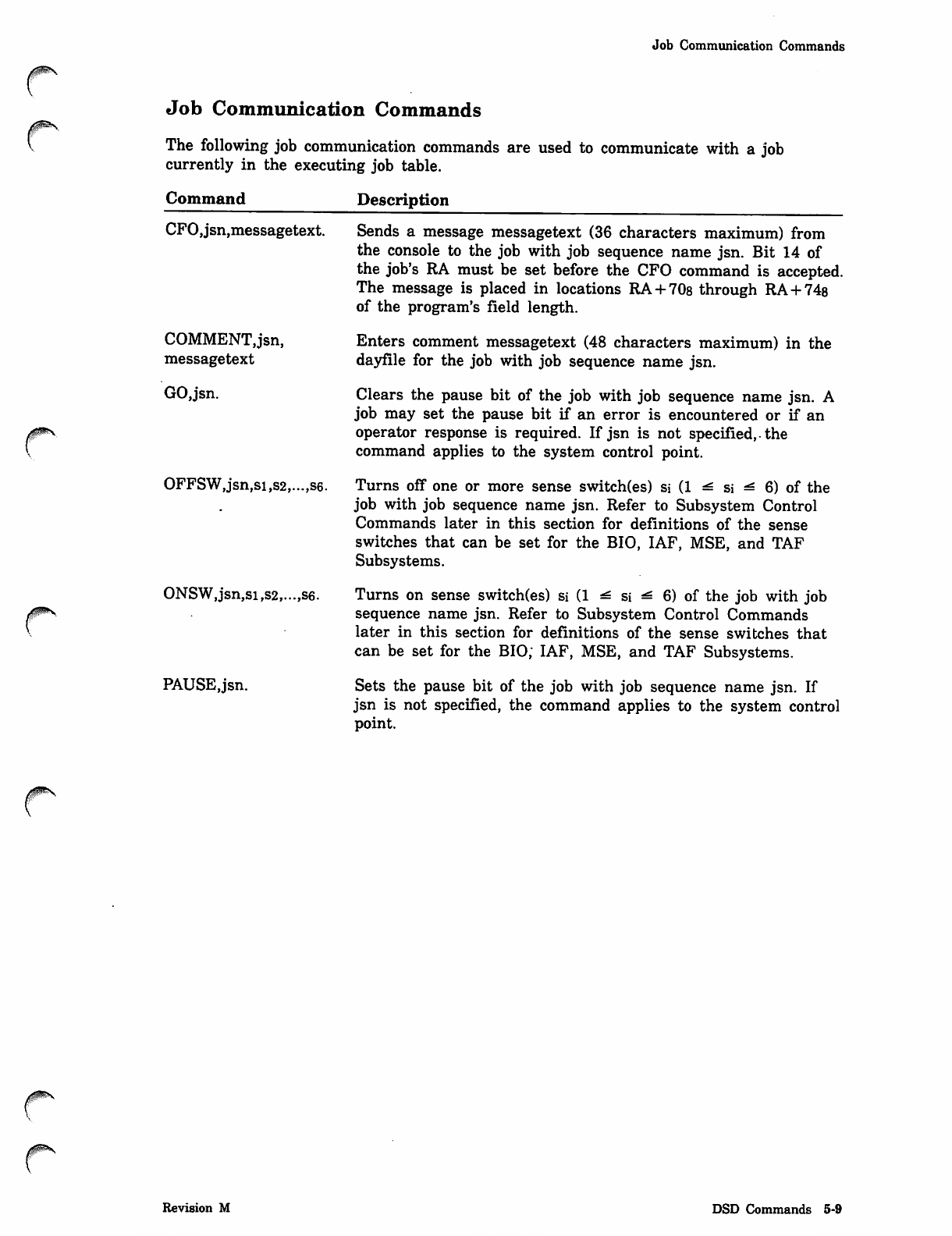
Job Communication Commands
Job Communication Commands
The following job communication commands are used to communicate with a job
currently in the executing job table.
Command Description
CFO,jsn,messagetext.
COMMENTjsn,
messagetext
GO, jsn.
OFFSW,jsn,si,S2,...,se.
ONSW,jsn,si,s2,...,S6.
PAUSEJsn.
Sends a message messagetext (36 characters maximum) from
the console to the job with job sequence name jsn. Bit 14 of
the job's RA must be set before the CFO command is accepted.
The message is placed in locations RA + 70s through RA + 74s
of the program's field length.
Enters comment messagetext (48 characters maximum) in the
dayfile for the job with job sequence name jsn.
Clears the pause bit of the job with job sequence name jsn. A
job may set the pause bit if an error is encountered or if an
operator response is required. If jsn is not specified,, the
command applies to the system control point.
Turns off one or more sense switch(es) si (1 ^ si ^ 6) of the
job with job sequence name jsn. Refer to Subsystem Control
Commands later in this section for definitions of the sense
switches that can be set for the BIO, IAF, MSE, and TAF
Subsystems.
Turns on sense switch(es) si (1 ^ si ^ 6) of the job with job
sequence name jsn. Refer to Subsystem Control Commands
later in this section for definitions of the sense switches that
can be set for the BIO, IAF, MSE, and TAF Subsystems.
Sets the pause bit of the job with job sequence name jsn. If
jsn is not specified, the command applies to the system control
point.
Revision M DSD Commands 5-9
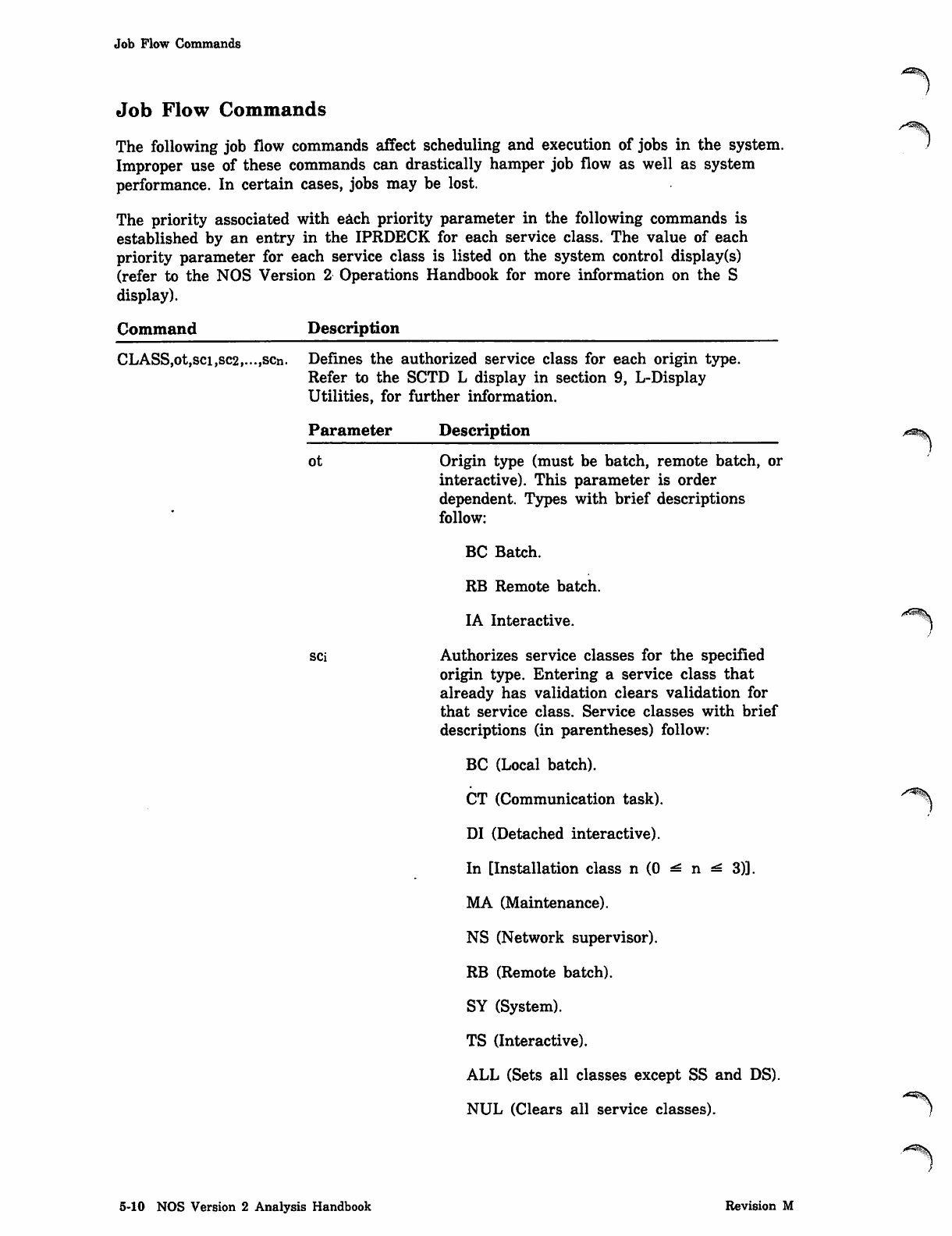
Job Flow Commands
Job Flow Commands
The following job flow commands affect scheduling and execution of jobs in the system. )
Improper use of these commands can drastically hamper job flow as well as system
performance. In certain cases, jobs may be lost.
The priority associated with each priority parameter in the following commands is
established by an entry in the IPRDECK for each service class. The value of each
priority parameter for each service class is listed on the system control display(s)
(refer to the NOS Version 2 Operations Handbook for more information on the S
display).
Command Description
CLASS,ot,sci,sc2,.-.scn. Defines the authorized service class for each origin type.
Refer to the SCTD L display in section 9, L-Display
Utilities, for further information.
Parameter Description Ams
ot Origin type (must be batch, remote batch, or
interactive). This parameter is order
dependent. Types with brief descriptions
follow:
BC Batch.
RB Remote batch.
IA Interactive. "^%^
sci Authorizes service classes for the specified
origin type. Entering a service class that
already has validation clears validation for
that service class. Service classes with brief
descriptions (in parentheses) follow:
BC (Local batch).
CT (Communication task). ""^
DI (Detached interactive).
In [Installation class n (0 ^ n ^ 3)].
MA (Maintenance).
NS (Network supervisor).
RB (Remote batch).
SY (System).
TS (Interactive).
ALL (Sets all classes except SS and DS).
NUL (Clears all service classes). )
5-10 NOS Version 2 Analysis Handbook Revision M
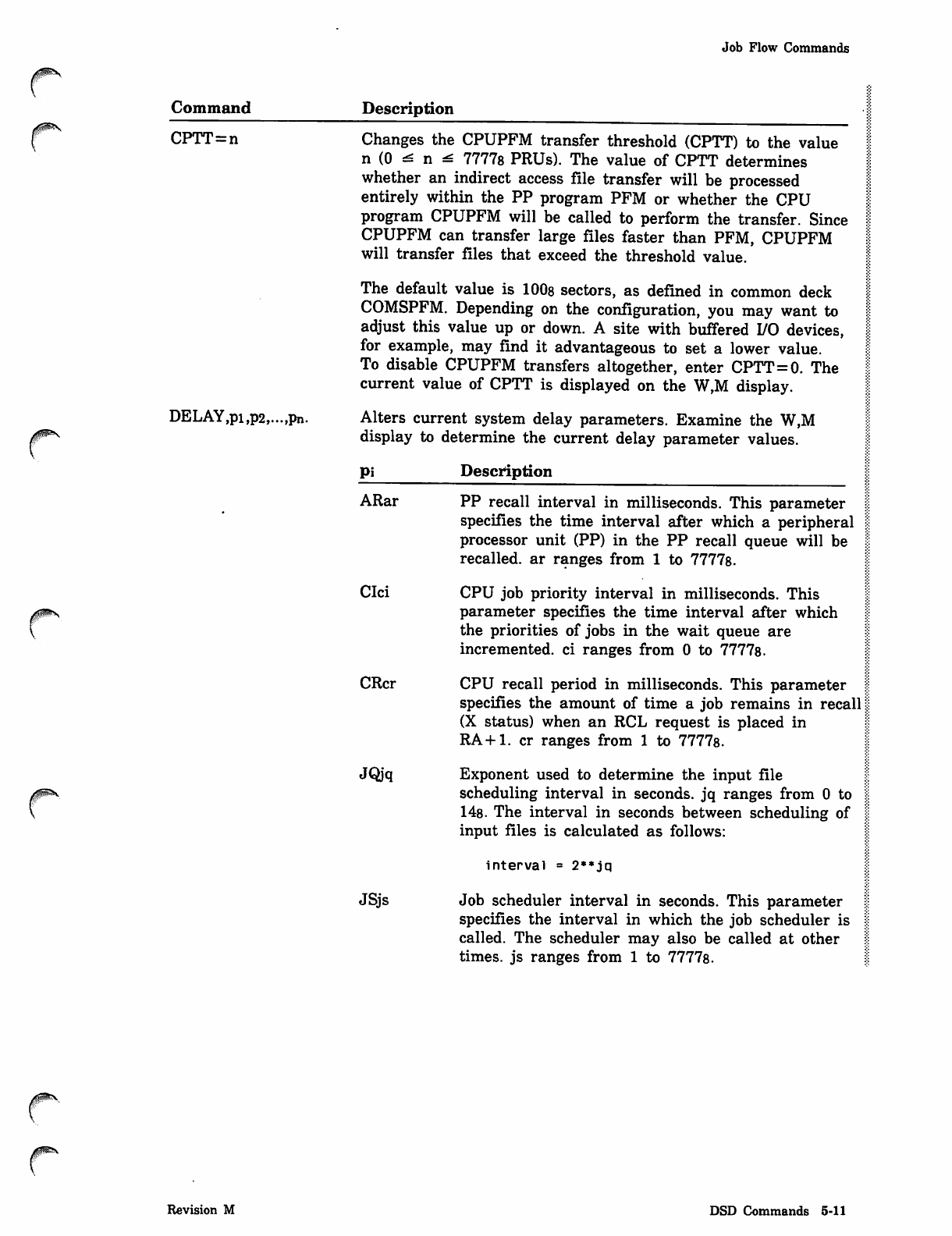
Job Flow Commands
0^S
rCommand
CPTT=n
DELAY,pi,p2,...,pn.
J0^!s\
r
Description
Changes the CPUPFM transfer threshold (CPTT) to the value
n (0 *s n ^ 77778 PRUs). The value of CPTT determines
whether an indirect access file transfer will be processed
entirely within the PP program PFM or whether the CPU
program CPUPFM will be called to perform the transfer. Since
CPUPFM can transfer large files faster than PFM, CPUPFM
will transfer files that exceed the threshold value.
The default value is 100s sectors, as defined in common deck
COMSPFM. Depending on the configuration, you may want to
adjust this value up or down. A site with buffered I/O devices,
for example, may find it advantageous to set a lower value.
To disable CPUPFM transfers altogether, enter CPTT=0. The
current value of CPTT is displayed on the W,M display.
Alters current system delay parameters. Examine the W,M
display to determine the current delay parameter values.
Pi
ARar
CIci
CRcr
JQjq
JSjs
Description
PP recall interval in milliseconds. This parameter
specifies the time interval after which a peripheral
processor unit (PP) in the PP recall queue will be
recalled, ar ranges from 1 to 7777s.
CPU job priority interval in milliseconds. This
parameter specifies the time interval after which
the priorities of jobs in the wait queue are
incremented, ci ranges from 0 to 7777s.
CPU recall period in milliseconds. This parameter
specifies the amount of time a job remains in recall
(X status) when an RCL request is placed in
RA+1. cr ranges from 1 to 7777s.
Exponent used to determine the input file
scheduling interval in seconds, jq ranges from 0 to i
148. The interval in seconds between scheduling of
input files is calculated as follows:
interval = 2**jq
Job scheduler interval in seconds. This parameter
specifies the interval in which the job scheduler is \
called. The scheduler may also be called at other
times, js ranges from 1 to 7777s.
Revision M DSD Commands 5-11
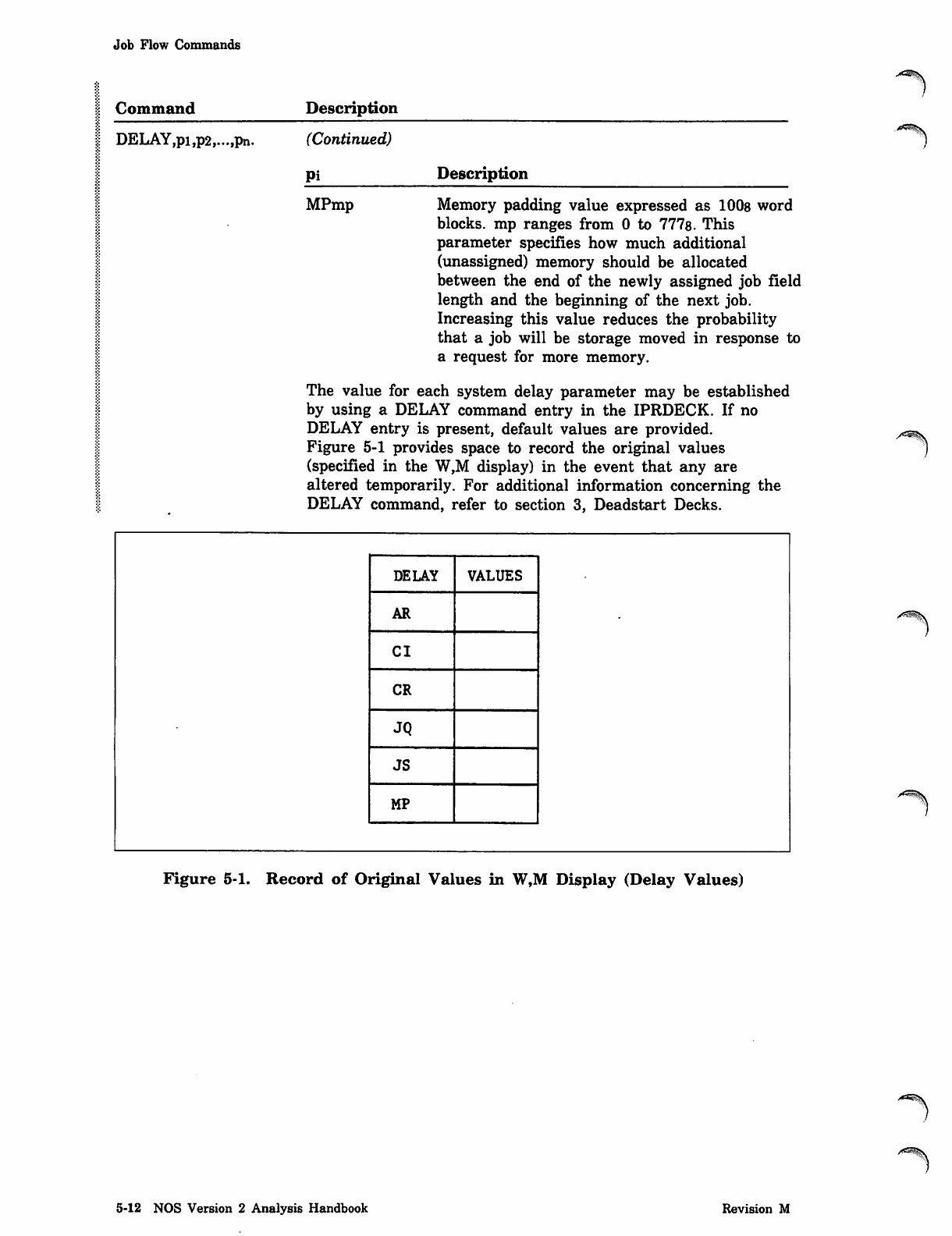
Job Flow Commands
Command Description
| DELAY,pi,p2,...,pn. (Continued)
Pi Description
MPmp Memory padding value expressed as 100s word
blocks, mp ranges from 0 to 777s. This
parameter specifies how much additional
(unassigned) memory should be allocated
between the end of the newly assigned job field
length and the beginning of the next job.
Increasing this value reduces the probability
that a job will be storage moved in response to
a request for more memory.
The value for each system delay parameter may be established
by using a DELAY command entry in the IPRDECK. If no
DELAY entry is present, default values are provided.
Figure 5-1 provides space to record the original values
(specified in the W,M display) in the event that any are
altered temporarily. For additional information concerning the
DELAY command, refer to section 3, Deadstart Decks.
DELAY VALUES
AR
CI
CR
JQ
JS
MP
Figure 5-1. Record of Original Values in W,M Display (Delay Values)
5-12 NOS Version 2 Analysis Handbook Revision M
Job Flow.Commands
rCommand Description
PCLASS,sco,sci,...,sc7. Selects the service class associated with each priority level
(pothrough P7) on the Job command. This parameter is order
dependent; a comma must appear for any parameters not
specified. The default for any parameters not specified is 0
(zero). Subsystem (SS) service class is not allowed with this •
command. Refer to the SCTD L display in section 9, L-Display
Utilities, for more information.
sci is a 2-character service class parameter. Entries are listed
and briefly described below.
sci Description
BC Local batch.
CT Communication task.
DI Detached interactive.
In Installation class n (0 *s n ^ 3).
MA Maintenance.
NS Network supervisor.
RB Remote batch.
SY System.
TS Interactive.
Revision M DSD Commands 5-13
Job Flow Commands
Command
QUEUE,sc,qt,qpi,
qp2„...,qpn.
Description
Alters the queue priorities qpi associated with the input,
executing, and output queues qt for each service class sc.
Examine the L display SDSPLAY to determine the priority
values currently associated with each service class.
sc Description
BC Local batch.
CT Communication task.
DI D eta ch ed i n te ra c ti ve.
In Installation class n (0 ^ n =£ 3).
MA Maintenance.
NS Network supervisor.
R B R e m o t e b a t c h .
SS Subsystem.
SY System.
T S I n t e r a c t i v e .
There are three job queue types.
qt Description
EX
IN
OT
Executing.
Input.
Output.
5-14 NOS Version 2 Analysis Handbook Revision M
Job Flow Commands
Command Description
{' QUEUE,sc,qt,qpi, (Continued)
qp2„...,qpn.
There are five priorities.
qpi Description
ILil Priority a job receives when it initially exhausts I
its CM time slice (refer to the SERVICE
command CM parameter). Thereafter, whenever |
the CM time slice is exhausted, the job's
priority will be set to the value of lp. il ranges |
from 0 to 77778, but must be in the range of
values for lp and up. This parameter is valid
only for executing jobs (EX).
IPip Initial scheduling priority for an executing batch!
job or for an interactive job when a terminal
command is entered. Online interactive jobs withf
terminal I/O available are scheduled at tp
priority (refer to the SERVICE command TP
parameter), ip ranges from 0 to 7777s, but mustf
be in the range of values for lp and up.
LPlp Lowest priority. For an input or output queue
file, the priority assigned to a file or job
entering the designated queue. For an executing!
job, the priority assigned to a job which has
exceeded a non-initial CM slice. The IL value is I
used for the first CM slice, lp ranges from 0 to |
77778, but must be less than the value of up.
UPup Highest priority. For input and output queues,
this is the highest priority a file can reach in
that queue; aging stops when this priority is
reached. For the execution queue, this is the
priority assigned to a job when initially assigned;:
to a control point, up ranges from 0 to 7777s,
but must be greater than the value of lp.
WFwf Weighting factor wf for queue priority
calculation, wf must be a power of 2, from 1
to 40008. The smaller the weighting factor, the 1
faster the queue entry reaches its highest
priority.
The priority associated with each queue is established by
using QUEUE command entries in the IPRDECK for each
service class. These entries normally reflect the ideal queue
priorities for the job mix of the particular installation. The
values specified in the IPRDECK are considered critical to
optimum system performance and are not normally altered.
Figure 5-2 provides space to record the original values
specified in the L display SDSPLAY. For additional
information on the QUEUE command, refer to section 3,
Deadstart Decks.
Revision M DSD Commands 5-15
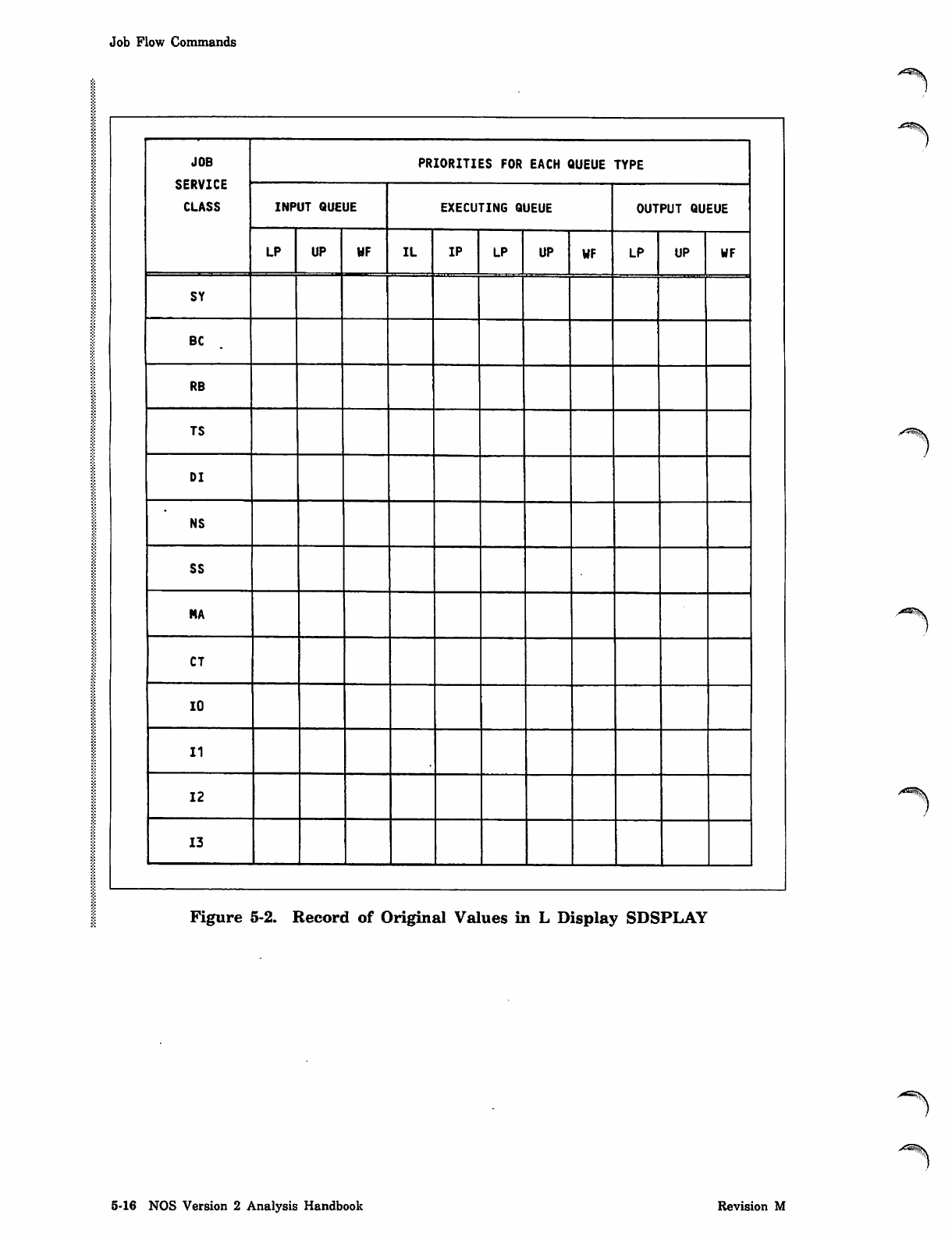
Job Flow Commands
JOB
SERVICE
CLASS
PRIORITIES FOR EACH QUEUE TYPE
INPUT QUEUE EXECUTIN6 QUEUE OUTPUT QUEUE
LP UP UF IL IP LP UP UF LP UP UF
SY
BC
RB
TS
DI
NS
SS
NA
CT
10
11
12
13
Figure 5-2. Record of Original Values in L Display SDSPLAY
yS^s.
>«C^v
5-16 NOS Version 2 Analysis Handbook Revision M
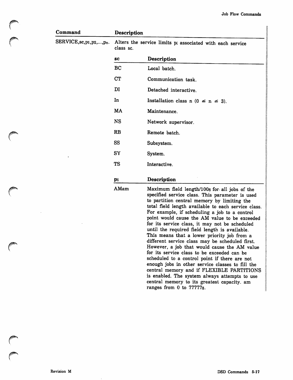
Job Flow Commands
JP*\
Command Description
SERVICE,sc,pi,p2,. ..,pn. Alters the service limits pi associated with each service
class sc.
sc Description
BC Local batch.
CT Communication task.
DI Detached interactive.
In Installation class n (0 ^ n ^ 3).
MA Maintenance.
NS Network supervisor.
RB Remote batch.
SS Subsystem.
SY System.
TS Interactive.
Pi Description
AMam Maximum field length/100s for- all jobs of the
specified service class. This parameter is used
to partition central memory by limiting the
total field length available to each service class.
For example, if scheduling a job to a control
point would cause the AM value to be exceeded
for its service class, it may not be scheduled
until the required field length is available.
This means that a lower priority job from a
different service class may be scheduled first.
However, a job that would cause the AM value
for its service class to be exceeded can be
scheduled to a control point if there are not
enough jobs in other service classes to fill the
central memory and if FLEXIBLE PARTITIONS
is enabled. The system always attempts to use
central memory to its greatest capacity, am
ranges from 0 to 77777s.
Revision M DSD Commands 5-17
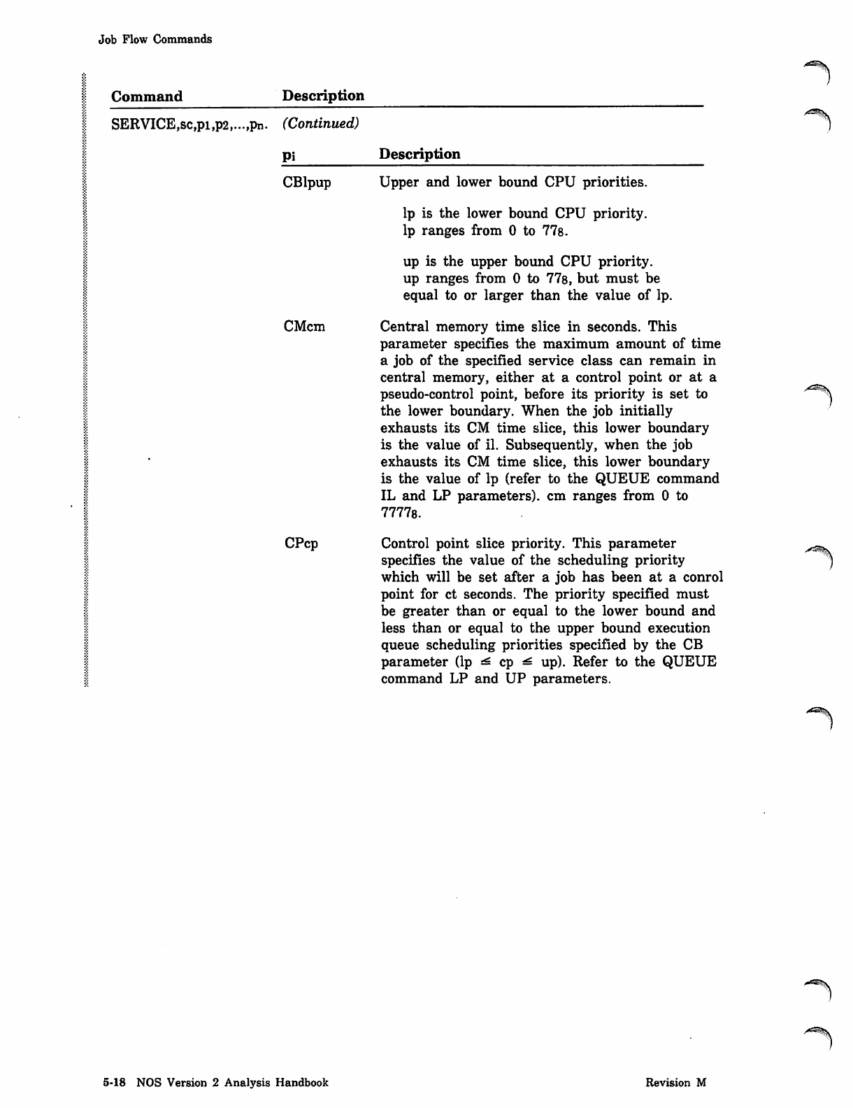
Job Flow Commands
Command Description
SERVICE ,sc,pi ,p2,... ,pn. (Continued)
pi Description
CBlpup
CMcm
CPcp
Upper and lower bound CPU priorities.
lp is the lower bound CPU priority,
lp ranges from 0 to 77s.
up is the upper bound CPU priority,
up ranges from 0 to 77s, but must be
equal to or larger than the value of lp.
Central memory time slice in seconds. This
parameter specifies the maximum amount of time
a job of the specified service class can remain in
central memory, either at a control point or at a
pseudo-control point, before its priority is set to
the lower boundary. When the job initially
exhausts its CM time slice, this lower boundary
is the value of il. Subsequently, when the job
exhausts its CM time slice, this lower boundary
is the value of lp (refer to the QUEUE command
IL and LP parameters), cm ranges from 0 to
77778.
Control point slice priority. This parameter
specifies the value of the scheduling priority
which will be set after a job has been at a conrol
point for ct seconds. The priority specified must
be greater than or equal to the lower bound and
less than or equal to the upper bound execution
queue scheduling priorities specified by the CB
parameter (lp ^ cp ^ up). Refer to the QUEUE
command LP and UP parameters.
'"<%Y
^^S
5-18 NOS Version 2 Analysis Handbook Revision M
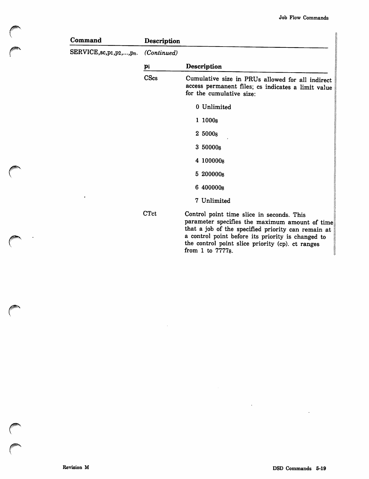
Job Flow Commands
jjgfPS
Command Description
SERVICE,sc,pi ,p2,...,pn. (Continued)
Pi
CScs
J&Ray
CTct
Description
Cumulative size in PRUs allowed for all indirect
access permanent files; cs indicates a limit value
for the cumulative size:
0 Unlimited
1 10008
2 5000s
3 50000s
4 1000008
5 2000008
6 400000s
7 Unlimited
Control point time slice in seconds. This
parameter specifies the maximum amount of time:
that a job of the specified priority can remain at j
a control point before its priority is changed to
the control point slice priority (cp). ct ranges
from 1 to 77778.
JfP*V
0ms
Revision M DSD Commands 5-19
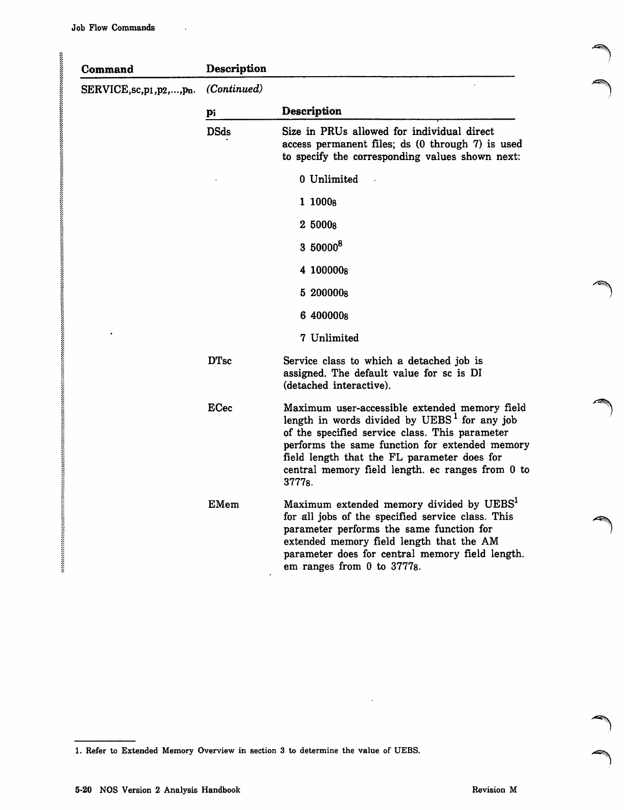
Job Flow Commands
Command Description
SERVICE,sc,pi,p2,...,pn. (Continued)
Pi
DSds
DTsc
ECec
EMem
Description
Size in PRUs allowed for individual direct
access permanent files; ds (0 through 7) is used
to specify the corresponding values shown next:
0 Unlimited
1 10008
2 50008
3 500008
4 100000s
5 2000008
6 4000008
7 Unlimited
Service class to which a detached job is
assigned. The default value for sc is DI
(detached interactive).
Maximum user-accessible extended memory field
length in words divided by UEBS* for any job
of the specified service class. This parameter
performs the same function for extended memory
field length that the FL parameter does for
central memory field length, ec ranges from 0 to
3777s.
Maximum extended memory divided by UEBS
for all jobs of the specified service class. This
parameter performs the same function for
extended memory field length that the AM
parameter does for central memory field length,
em ranges from 0 to 3777s.
1. Refer to Extended Memory Overview in section 3 to determine the value of UEBS.
5-20 NOS Version 2 Analysis Handbook Revision M
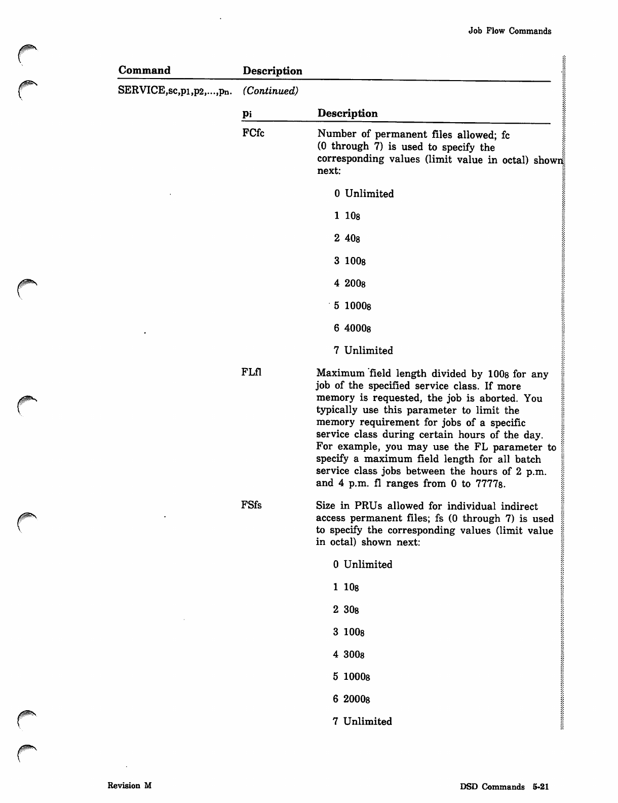
Job Flow Commands
Command Description
SERVICE,sc,pi,p2,...,pn. (Continued)
Pi
FCfc
FLfl
FSfs
Description
Number of permanent files allowed; fo
(0 through 7) is used to specify the
corresponding values (limit value in octal) shownf
next:
0 Unlimited
1 108
2 40s
3 1008
4 2008
5 10008
6 40008
7 Unlimited
Maximum field length divided by 100s for any
job of the specified service class. If more
memory is requested, the job is aborted. You
typically use this parameter to limit the
memory requirement for jobs of a specific
service class during certain hours of the day.
For example, you may use the FL parameter to I
specify a maximum field length for all batch
service class jobs between the hours of 2 p.m.
and 4 p.m. fl ranges from 0 to 7777s.
Size in PRUs allowed for individual indirect
access permanent files; fs (0 through 7) is used |
to specify the corresponding values (limit value |
in octal) shown next:
0 Unlimited
1 108
2 30s
3 1008
4 300s
5 10008
6 20008
7 Unlimited
Revision M DSD Commands 5-21
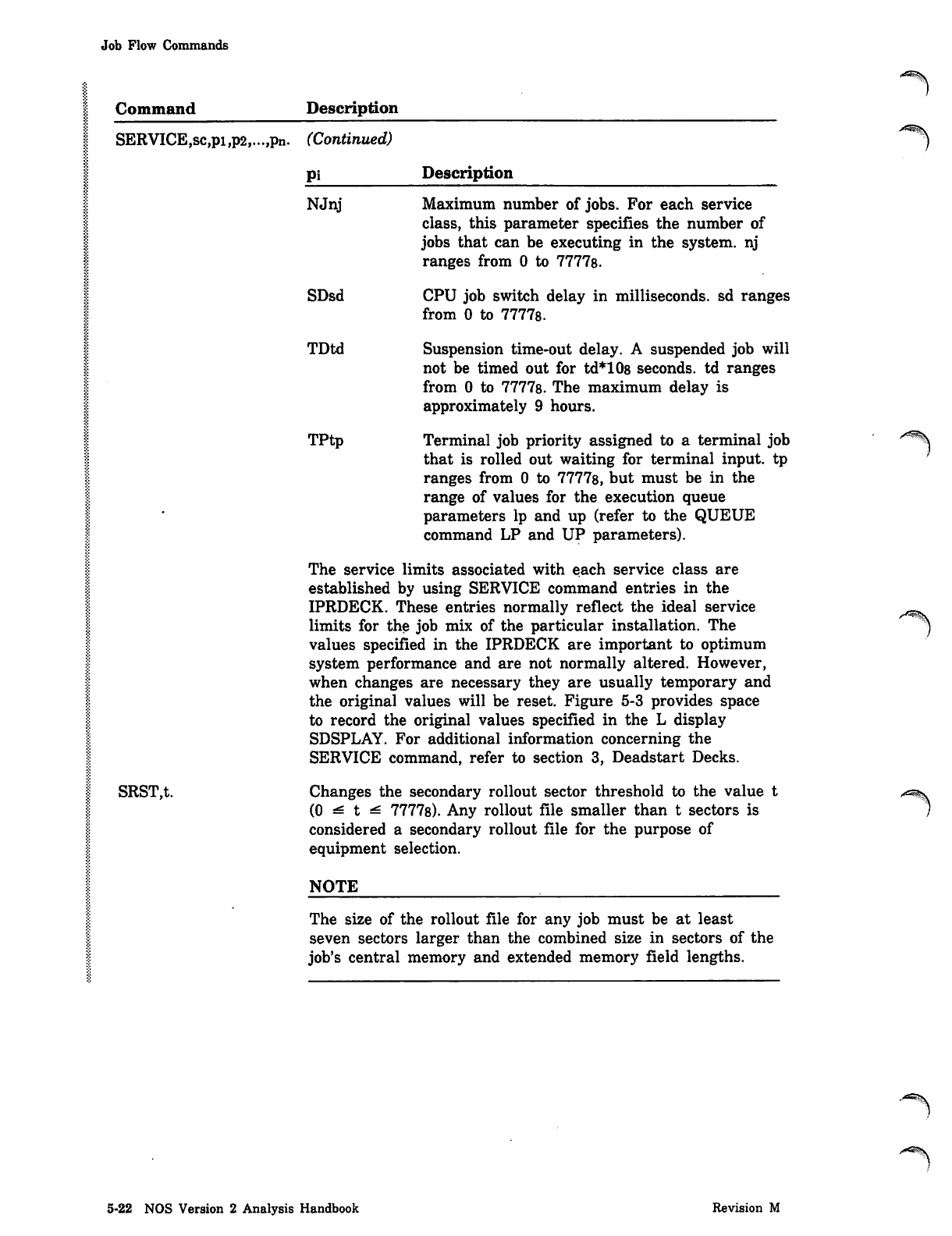
Job Flow Commands
Command Description
SERVICE ,sc,pi ,p2,... ,pn. (Continued)
Pi
SRST,t.
Description
NJnj Maximum number of jobs. For each service
class, this parameter specifies the number of
jobs that can be executing in the system, nj
ranges from 0 to 77778.
SDsd CPU job switch delay in milliseconds, sd ranges
from 0 to 77778.
TDtd Suspension time-out delay. A suspended job will
not be timed out for td*10s seconds, td ranges
from 0 to 77778. The maximum delay is
approximately 9 hours.
TPtp Terminal job priority assigned to a terminal job
that is rolled out waiting for terminal input, tp
ranges from 0 to 7777s, but must be in the
range of values for the execution queue
parameters lp and up (refer to the QUEUE
command LP and UP parameters).
The service limits associated with each service class are
established by using SERVICE command entries in the
IPRDECK. These entries normally reflect the ideal service
limits for the job mix of the particular installation. The
values specified in the IPRDECK are important to optimum
system performance and are not normally altered. However,
when changes are necessary they are usually temporary and
the original values will be reset. Figure 5-3 provides space
to record the original values specified in the L display
SDSPLAY. For additional information concerning the
SERVICE command, refer to section 3, Deadstart Decks.
Changes the secondary rollout sector threshold to the value t
(0 s£ t ^ 77778). Any rollout file smaller than t sectors is
considered a secondary rollout file for the purpose of
equipment selection.
NOTE
The size of the rollout file for any job must be at least
seven sectors larger than the combined size in sectors of the
job's central memory and extended memory field lengths.
/^^\
A^^S.
■^^s
5-22 NOS Version 2 Analysis Handbook Revision M
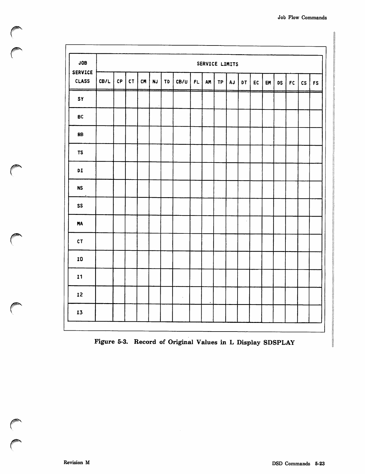
Job Flow Commands
vfitftafy
/0^S
JOB
SERVICE
CLASS
SERVICE LIMITS
CB/L CP CT CM NJ TD CB/U FL AM TP AJ DT EC EM DS FC CS FS
SY
BC
RB
TS
DI
NS
SS
NA
CT
IO
11
12
13
Figure 5-3. Record of Original Values in L Display SDSPLAY
Revision M DSD Commands 5-23
Peripheral Equipment Control Commands
Peripheral Equipment Control Commands
The commands described in this category provide control of the channel-connected
peripheral equipment available to the system. To control unit record equipment that is
connected through communications ports, use the RBF K display described in section 8
and the PSU K display described in the NOS Version 2 Operations Handbook. You
should become familiar with the following DSD displays, which are closely associated
with the use of these and other commands described throughout this section.
• Equipment status display (E,A).
• Disk configuration display (E,C).
• Disk errors display (E,E).
• Family status display (E,F).
• Disk thresholds display (E,H).
• Disk status display (E,M).
• Resource requests display (E,P).
• Tape status display (E,T).
• BIO status display (I).
A complete description of each of these displays is given in the NOS Version 2
Operations Handbook.
Command Description
ASSIGN,jsn,est. Assigns equipment defined by EST ordinal est (normally a
tape unit) to the job with job sequence name jsn. This
command is entered in response to a flashing REQUEST
message. Use of this command for assignment of a tape unit
should not normally be required because tape assignment is
performed automatically when a volume serial number (VSN)
is specified in the job request. However, if a VSN is not ^.
specified in the job request for a labeled or unlabeled tape, the j
REQUEST message appears at the job's control point (on the
B,0 display), and the ASSIGN command must be entered to
assign a tape unit to the job.
BKSP,est,rr. Backspaces rr octal logical records on the print file for the
BIO equipment defined by EST ordinal est. When rr is not
specified, the default is one record.
BKSPF,est,ff. Backspaces ff octal files on the print file for the BIO
equipment defined by EST ordinal est. When ff is not
specified, the default is one file.
" * )
2. Operation of peripheral equipment is described in the NOS Version 2 Operations Handbook.
5-24 NOS Version 2 Analysis Handbook Revision M
Peripheral Equipment Control Commands
Command Description
BKSPRU,est,ss.
CONTINUE,est.
DOWN,CH = ch,
EQ=est.
or
DOWN,CCH=cch,
EQ=est.
or
DOWN,MCH = ch,
EQ=est.
or
DOWN,EQ=est.
Backspaces ss physical record units (PRUs) on the print file
for the BIO equipment defined by EST ordinal est. The PRU
count, ss, must be specified. There is no default setting.
Printing resumes at the beginning of a line.
Resumes printing on the BIO equipment defined by EST
ordinal est.
The first two forms of the command disallow the use of
channel ch or concurrent channel cch for the mass storage
device specified by EST ordinal est. If the EQ = est
parameter is omitted, channel ch or cch is disallowed for
all devices in the EST. The EQ=est parameter cannot be
specified if the CH=ch or CCH=cch parameter specifies a
magnetic tape channel. Use of all ports of a concurrent
channel is disallowed.
If channel ch or cch is the only channel available to a mass
storage device, its use is disallowed providing the device is
down. If channel ch or cch is
• not defined as a magnetic tape or mass storage channel
• the last active channel on an equipment that is not
globally unloaded (status N on the E,M display)
• a nonimpact printer channel and any equipment on the
channel is logically ON or assigned to a control point
the command is ignored and the following message appears on
the left screen.
INCORRECT ENTRY
Correct the entry and retry the command.
The third form of the command disallows the use of MUX
channel ch for the equipment specified by EST ordinal est
(this form applies only to model 176). If the EQ=est
parameter is omitted, MUX channel ch is disallowed for all
equipments in the EST.
The fourth form of the command disallows the use of
equipment with EST ordinal est for all channels. It disallows
all access to the equipment by the operating system and user
jobs. This device state is used to allow diagnostic routines
exclusive use of the device for problem isolation and for
preventing access to a device that is being repaired.
Revision M DSD Commands 5-25
Peripheral Equipment Control Commands
Command Description
DOWN,CH=ch,
EQ=est.
(Continued)
This command also clears the SUSPCT state for a tape unit
that is currently unavailable (but not OFF or DOWN) because
an unrecovered hardware or tape I/O error has occurred on
the tape or unit. This command can be entered followed by
the ON,EQ=est command to restore the unit to service after a
customer engineer has checked it out, or the unit has been
tested following Control Data's recommended procedures:
You receive an error message if you attempt to DOWN
equipment:
• That already has a DOWN status.
• That is assigned to a job.
• That is the last system device not DOWN.3
• That contains the system dayfile, account file error log, or
maintenance log.
In these cases, the following message appears.
INCORRECT ENTRY
Correct the entry and retry the command.
NOTE
This command should be used with caution since it directly
affects the operation of system peripheral equipment.
DOWN,MID=mid. Confirms that a machine running in low-speed port
multimainframe mode with machine identifier mid is down.
Enter this command in response to a request at the system
control point of the form:
IF mid DOWN ENTER *D0WN,MID=mid*
Make this entry if the machine is down; otherwise, clear the
message by entering:
GO,SYS.
,A^^S
3. Applies only to mass storage equipment.
<^fe\
5-26 NOS Version 2 Analysis Handbook Revision M
Peripheral Equipment Control Commands
Command
END,est,rc.
yms
FORM,est,fc.
ID,est,id.
Description
Terminates the current operation on the BIO equipment
defined by EST ordinal est. If est defines a line printer or
card punch, BIO then assigns the next available file to that
equipment. If est defines a card reader that is actively reading
cards when END,est is entered, the job terminates at the last
card read. The next card is treated as the beginning of a new
job. If another card deck follows the end-of-information card
(multipunch 6/7/8/9), it is processed normally.
If est defines a card reader that is stopped because of a
compare error when END,est. is entered, perform the following
steps:
1. Remove the remainder of the card deck, except the
end-of-information card, from the card reader input hopper.
2. Ready the card reader to read the end-of-information card.
The job terminates; and if another card deck follows the
end-of-information card, it is processed normally.
The re parameter cancels a portion of the repeat count
specified for that equipment (refer to the REPEAT command
later in this section). For example, if the current operation on
equipment est had been set to be repeated five times
(operation performed six times), entering a value of 4 for re
would permit the operation to be performed just two times. If
the repeat count is zero, this command performs the END
operation once.
Assigns a 2-character forms code fc to the BIO line printer or
card punch defined by EST ordinal est. Only those files in the
output queue assigned the forms code fc are directed to
equipment est. A user can assign a forms code to an output
file using the ROUTE command. (For a description of the
ROUTE command, refer to the NOS Version 2 Reference Set,
Volume 3.) The value of the forms code can range from AA to
99. If the forms code is not present, the current forms code
field is cleared (value is null).
Assigns a numeric identifier id to the card punch, card reader,
or printer defined by EST ordinal est. The value of the
identifier can range from 00 to 67s. Only those files in the
proper queue with an identifier equal to id are directed to the
card punch or printer defined by est. Refer to the LOAD
command in this section to assign an identifier to a queue
type file. All subsequent jobs loaded from card reader est are
assigned the identifier id.
r
Revision M DSD Commands 5-27
Peripheral Equipment Control Commands
Command
IDLE,EQ=est.
Description
Use this command when you want to continue using the disk
storage device specified by EST ordinal est even though it is
failing occasionally. When the IDLE command is used in
conjunction with the THRESHOLD command, it allows some
degree of flexibility in deciding when to repair such a device.
New files will not be assigned to a device with IDLE status
unless no suitable alternative device exists, but files already
on the device may continue to be accessed as if the device had
a status of ON. If the device is a spun down 834, 836, 887, or
9853 drive, it will be automatically spun up. It may take up
to 3 minutes to spin up the device.
Suppose a failing disk storage device causes the system to set
the device's status to OFF. Suppose also that the device is
failing infrequently, for example, once or twice per hour, and
contains several permanent files that must remain available
during peak production periods. In this situation, you may use
the THRESHOLD command to increase the verification failure
threshold and then use the IDLE command to allow continued
use of the device. This device could then be repaired after the
peak production period has passed, causing less disturbance to
system users.
NOTE
The decision to continue using a failing device should be made
under the advisement of a customer engineer. If there is a
good chance of data corruption due to the nature of the
failure, it may be best to leave the device OFF until it can be
repaired.
If you enter an IDLE command for a device with a status of
OFF or DOWN, the system performs a device verification to
ensure the hardware is usable and the disk pack contains
valid data. If this verification fails and the verification failure
threshold is exceeded, the device state remains unchanged.
However, if the device verification finds no errors the device's
state changes to IDLE, the verification failure count (displayed
on the E,H display) is set to zero, and any jobs that were
rolled out waiting for the device are allowed to continue
processing.
5-28 NOS Version 2 Analysis Handbook Revision M
Peripheral Equipment Control Commands
yms
Command
IDLE,EQ = est.
IDLEFAMILY,est.
Description
(Continued)
If you attempt to change a device's state to IDLE, the message
INCORRECT ENTRY appears if one of the following
conditions is true:
• The device is already IDLE.
• The device is DOWN and assigned to a job.
• The device is DOWN and no channels are UP for the
device.
If you enter IDLE for a device with a status of ON, the
verification process is not performed; the device state is simply
changed to IDLE.
If you enter IDLE for a device other than a disk, the IDLE
command is ignored.
This command performs one of the two following functions,
depending on the status of the family.
• If the family is active, the IDLEFAMILY command
deactivates it by aborting all new jobs and USER
commands for the family on the equipment specified by
EST ordinal est. Jobs in progress are allowed to complete.
ISF and permanent file utilities, such as PFDUMP, can be
used on the inactive family.
• If the family is inactive, the IDLEFAMILY command
activates it. Jobs can then access the family on the
equipment specified by EST ordinal est.
The FAMC column of the E,F display shows the number of
jobs in progress on the equipment.
Revision M DSD Commands 5-29
Peripheral Equipment Control Commands
Command Description
INITIALIZE,op,esti,
est2,...,est5.
Reverses current setting of initialize option op for mass
storage devices defined by EST ordinals est (maximum of five
devices). Examine the E,A display to determine correct EST
ordinals.
op Level of Initialization
AF Initialize inactive account dayfile.
AL Total initialization.
DF Initialize inactive system dayfile.
EF Initialize inactive error log.
FP Format pending.4
FT Total initialization as full-track device.5
HT Total initialization as half-track device.5
MF Initialize binary maintenance log.
PF Initialize permanent files.
QF Initialize inactive queue files.
This command provides the capability to initialize and flaw
tracks on any mass storage device during normal system
operation. Each time this command is entered it is logged in
the error log.
If local unload (L) status is set for the device, the INITIALIZE
command is ignored and the following message appears on the
left console screen.
INCORRECT ENTRY
However, the INITIALIZE command is allowed to execute
while local unload status is set if an error code (CE, IL, LE)
is set.
4. Sets format pending bit in the MST for 881/883 pack reformatting. Refer to the description of the
FORMAT program in appendix G.
5. Device must be removable.
5-30 NOS Version 2 Analysis Handbook Revision M
Peripheral Equipment Control Commands
rCommand Description
INITIALIZE,op,esti,
est2,...,est5.
(Continued)
Entry of this command does not in itself initialize the
specified device. It merely sets initialize status for the device
so that it may be initialized. However, if fast attach files
(special system files) are active on the specified device and
initialization level of AL or PF is specified, initialize status
cannot be set until these files are returned. In this case, the
message
FAST ATTACH FILES ON DEVICE.
appears at the system control point on the system status
display (B,0). Refer to the description of this message in the
NOS Version 2 Operations Handbook for additional
information.
The procedure involved in initializing a mass storage device is
described in section 8, K-Display Utilities, under the heading
Initialize K Display. The following describes system activity
when initialization occurs.
If the device is shared in a multimainframe environment,
initialization does not proceed until all other mainframes
sharing the device have processed an UNLOAD command for
the device and user counts on all machines are zero. If all
machines have not unloaded the device, this control point
message is displayed:
EQest BUSY ON 10=1d.
Variable Description
est
id
EST ordinal.
Machine identifier of the first machine found
without unload status set.
Revision M DSD Commands 5-31
Peripheral Equipment Control Commands
Command Description
INITIALIZE,op,esti,
est2,...,est5.
LOAD,est,id.
(Continued)
If initialize status is set on this device for another mainframe,
the INITIALIZE command is ignored and this message appears
at the system control point on the system status display (B,0):
INITIALIZE PENDING ON THIS DEVICE.
When the AL initialization option is specified, the label on the
device to be initialized is either updated or a new label is
created. If the label on the device is bad or cannot be
recognized, the new label is created and all current data on
the device is lost. If the label is found to be good, it is
updated and all permanent file information is cleared. In this
case, system library or temporary files (local, rollout, and so
forth) residing on the device are not disturbed. If the device
being initialized is a master device, the system scans all other
mass storage devices in the family that contain direct access
files and releases the space for files with catalogs on this
device. If the device being initialized contains direct access
files, the system scans all other master devices and sets the
catalog entries on those devices to indicate that the files were
purged. All or part of the permanent file system can be
initialized and then reloaded if necessary (refer to the
description of permanent file utilities in section 17, Permanent
File Utilities.
Requests that a job be loaded from equipment defined by EST
ordinal est (normally tape unit). The job is assigned a numeric
identifier id ranging from 00 to 67s. If id is not specified, it
defaults to 00. Examine the E,A display to determine the EST
ordinal of the equipment to be used.
/s?v
5-32 NOS Version 2 Analysis Handbook Revision M
Peripheral Equipment Control Commands
r
rCommand
MOUNT,est,P.
Description
Clears the local unload (L) and global unload (N) status for a
mass storage device and reactivates the device. If the device is
a spun down 834 or 836 drive, it will be automatically spun
up. The device is defined by EST ordinal est (examine the E,A
display to determine the EST ordinal).
When you specify P in the MOUNT command for an
independent shared device in a multimainframe environment,
the system presets the device with EST ordinal est. The preset
(P) option can be specified only on the first mainframe to
access the device.
If the device defined by EST ordinal is not a mass storage
device, the MOUNT command is ignored and this message
appears on the left console screen:
INCORRECT EQUIPMENT.
If the device is shared in a multimainframe environment and
another mainframe has an unsatisfied initialize request
pending for that device, the MOUNT command is ignored and
this message appears at the system control point on the
system status display (B,0):
INITIALIZE PENDING ON THIS DEVICE.
Revision M DSD Commands 5-33
Peripheral Equipment Control Commands
Command
MSAL,t=esti,
est2,...,estn.
Description
Assigns job files of type t to mass storage devices defined by
EST ordinals esti. The specified mass storage device must be
nonremovable. A limit of 47 devices may be specified on a
single entry. Examine the disk status display (E,M) to
determine if the device is nonremovable.
t Description
BLGO.
D Job dayfile.
I Input.
L Local.
O Output.
P Primary.
R Rollout.
S Secondary rollout.
T Temporary.
If no devices are specified for a file type, the system selects a
temporary device.
Secondary rollout files do not exist until the command
SRST=t (where t is the size in sectors of the file, from 0 to
77778) defines a threshold; the default value of a threshold is
0. All rollout files smaller than the threshold are secondary
rollout files. These files are assigned to the devices specified
with the MSAL,S command.
All files greater than or equal to the threshold are assigned to
the rollout file devices (MSAL,R command).
The following example illustrates a use for secondary rollout
files. Equipment 5 is extended memory via DDP. Secondary
rollout files to extended memory is assigned by
MSAL,S=5.
5-34 NOS Version 2 Analysis Handbook Revision M
Command
MSAL,t=esti,
est2,...,estn.
Peripheral Equipment Control Commands
Description
(Continued)
The threshold count is set by the SRST command so that
rolled out files under 20 sectors long are assigned to extended
memory. For additional information concerning the SRST
command, refer to section 3, Deadstart Decks.
EQPDECK
EQ005=DP,ST=0N,SZ=4000,CH=30.
MSAL,S=5.
IPRDECK
SRST=20
NEXTREEL,est. Indicates to the system that you have verified that the correct
tape has been mounted (or is about to be mounted) on the
specified tape drive. You enter this command in response to a
CHECK AND MOUNT message on the E,P display.
The system issues the CHECK AND MOUNT message
whenever it unloads an unlabeled tape as a result of a ring
conflict or an end-of-reel condition. This message reminds you
that the specified tape unit is still assigned to a job and is
not available for general use. The system only issues this
message if the COMSMTX installation parameter PONR is 1.
0ms
Revision M DSD Commands 5-35
Peripheral Equipment Control Commands
Command Description
OFF,EQ=est. Logically turns off the device defined by EST ordinal est. This
command allows you to logically remove a device from the
operating environment so that no user access of the device is
permitted. If a user job attempts to access the device, it is
rolled out to wait for the device status to become ON or
IDLE. However, system utilities are permitted to access the
device, so it can be dumped or loaded. If the device is a spun
down 834, 836, 887, or 9853 drive, it will be automatically
spun up. It may take up to 3 minutes to spin up the device.
If you enter the OFF command for a device with a status of
DOWN, the system performs a verification of the device label.
This provides assurance that the correct pack is mounted on
the drive and the controller is accessing the right drive after
a repair action.
If you attempt to change a device's state to OFF, the message
INCORRECT ENTRY appears if one of the following
conditions is true:
• The device is already OFF.
• The device is DOWN and assigned to a job.
• The device is DOWN and no channels are UP for the
device.
Examine the E,A display to determine the EST ordinal and
current status (ON, OFF, IDLE, or DOWN) of the device. If
est specifies a disk storage device and the system library or
temporary files (local, rollout, and so forth) reside on that
device, it should not be turned off. Examine the disk status
display (E,M) to determine which disk storage devices have
system residency or allow system allocation of temporary files.
In addition, if an MSAL entry is currently specified for a disk
storage device, it is cleared when that device is turned off.
The MSAL designation is not reset automatically when the
device is turned back on and must be reset manually (if
necessary) using the DSD command MSAL.
This command also clears the SUSPCT state for a tape unit
that is currently unavailable (but not OFF or DOWN) because
an unrecovered hardware or tape I/O error has occurred on
the tape or unit. This command can be entered followed by
the ON,EQ=est command to restore the unit to service after a
customer engineer has checked it out, or the unit has been
tested following Control Data's recommended procedures.
yS&V
5-36 NOS Version 2 Analysis Handbook Revision M
Peripheral Equipment Control Commands
Command
ON,EQ=est.
PRSIZE,est,ps.
Description
Logically turns on the device defined by EST ordinal est. This
command allows you to activate a device currently having
OFF status in the EST. If the device is a spun down 834, 836,
887, or 9853 drive, it will be automatically spun up. Examine
the E,A display to determine the EST ordinal and current
status (ON, OFF, IDLE, or DOWN) of the device.
Use this command to bring a disk storage device back into
use following its repair. You can also use the ON command
after repairing a controller that provides the only access to a
disk storage device.
When you enter ON for a device with a status of OFF or
DOWN, the device's state does not change to ON immediately.
First the system attempts to verify that the drive and
channels accessing the device are usable and the data on the
disk pack is in the proper format. If this verification process
fails and the verification failure threshold is exceeded, the
system sets the device's state to OFF. If the verification finds
no errors, the device's state changes to ON, the verification
failure count (displayed on the E,H display) is set to zero, and
any jobs that were rolled out waiting for the device are
allowed to continue processing.
If you enter ON for device with a status of IDLE, the
verification process is not performed; the device's state simply
changes to ON.
If you attempt to change a device's state to ON, the message
INCORRECT ENTRY appears if one of the following
conditions is true:
• The device is already ON.
• The device is DOWN and assigned to a job.
• The device is DOWN and no channels are UP for the
device.
Sets the paper status ps to short (S) or long (L) paper for the
printer with EST ordinal est. Short paper has a form length of
8.5 inches and long paper has a form length of 11 inches.
Revision M DSD Commands 5-37
Peripheral Equipment Control Commands
Command
REPEAT,jsn,rc.6
REPRINT,est,pr.
REPUNCH,est,pr.
RETRY,est.
Description
Alters the repeat count for the queue file specified by job
sequence name jsn. If the file is still in the queue, the repeat
count for the file is set to re. If the file is already being
processed by BIO, the remaining repeat count for the file is
increased by re. The maximum value that can be entered for
re is 778. The default value for re is 1.
Terminates the current operation on the BIO printer
equipment defined by EST ordinal est and reenters the job in
the print queue with a queue priority specified by prOO
(service class minimum ^ prOO ^ service class maximum;
refer to the S display in the NOS Version 2 Operations
Handbook; pr value is multiplied by 100s internally). If pr is
not specified, the service class default priority is assigned.
Terminates the current operation on the BIO card punch
equipment defined by EST ordinal est and reenters the job in
the punch queue with a queue priority specified by prOO
(service class minimum ^ prOO ^ service class maximum;
refer to the S display in the NOS Version 2 Operations
Handbook; pr value is multiplied by 1008 internally). If pr is
not specified, the service class default priority is assigned.
Reissues a tape operation that previously aborted with one of
the following load point errors appearing in the E,P display:
CLEANER FAULT
READ ID BURST
WRITE ID BURST
est represents the EST ordinal of the tape unit where the load
point error occurred. Examine the E,P display to determine
the EST ordinal. The tape unit must be ready before you
enter the RETRY command. Examine the E,T display to
ensure that the tape is loaded and the tape unit is ready.
The RETRY command is to be used after the system detects a
load point error on a tape. Upon detecting such an error, the
system issues an error message to the E,P display and unloads
the tape. The operator then has the opportunity to fix the
failing tape or tape drive. Upon completing this step, the
operator reloads the tape on the same tape unit and enters
the RETRY command. The system then reissues the tape
operation. If the failure cannot be fixed at this time, the
operator should enter the TERMINATE command to abort the
recovery attempt.
6. When the current BIO operation is repeated, maximum line and card limits are reinitialized prior to
printing or punching of the file being processed. User control limits apply individually to each output file
copy produced.
5-38 NOS Version 2 Analysis Handbook Revision M
Peripheral Equipment Control Commands
Command
SCRATCH,est.
SECUREQ,est,
LA = lowerlevel,
UA=upperlevel.
SKIP,est,rr.
SKIPF,est,ff.
Description
Declares the tape mounted on an unassigned magnetic tape
unit, defined by EST ordinal est, to be a scratch tape. This
command enables a tape to be available to satisfy scratch
VSN requests and still be assigned by its original VSN Thus
the VSN defined on the tape (in VOL1 label) is not redefined'
as scratch although the VSN will appear as SCRATCH on the
tape status display (E,T).
Scratch status is retained for only one job assignment. This
allows a tape to be used for scratch purposes on a temporary
basis. For example, a job requests a tape mounted on the tape
unit defined in this command by specifying the current VSN
for that tape in the request. The tape is then assigned to the
job as a scratch tape (the original VSN is retained and not
made scratch). When that job releases the tape, SCRATCH
status is cleared, and unless this command is entered again,
that tape would not be assigned as a scratch tape in future'
requests. To determine if SCRATCH status is in effect for a
tape, monitor the tape status display (E,T).
Changes the equipment access level limits for the unit record
equipment with EST ordinal est. On a secured system, only
files that have access levels within these limits can be printed
on the specified equipment. The original limits are set during
deadstart by the ACCESS command entries in the EQPDECK.
The parameters LA = lowerlevel and UA = upperlevel specify
the lower and upper access level limits for the equipment.
NOTE
On a secured system this command is accepted only if a
security administrator has placed the system in security
unlock status.
Skips forward rr octal logical records on the print file for the
BIO equipment defined by EST ordinal est. When rr is not
specified the default is one record.
Skips forward ff octal files on the print file for the BIO
equipment defined by EST ordinal est. When ff is not specified
the default is one file.
Revision M DSD Commands 5-39
Peripheral Equipment Control Commands
Command
SKIPRU,est,ss.
SPINDOWN,est.
SPINUP,est.
Description
Skips forward ss PRUs on the print file for the BIO
equipment defined by EST ordinal est. All parameters must be
specified; there are no default settings. The PRU count, ss, is
limited to 10s PRUs (the current buffer size) plus the number
of PRUs remaining in the buffer. If the buffer was empty, ss
would be limited to 20s PRUs. If ss is larger than the number
of PRUs remaining in the buffer, the buffer is filled again and
the additional PRUs are skipped on the new print file. For
example, if five PRUs remained in the print file and ss was
specified as 10, the remaining five PRUs would be skipped,
the buffer filled again, and five additional PRUs skipped.
Printing resumes at the beginning of a line.
Spins down the 834, 836, 887, or 9853 disk storage device
defined by EST ordinal est. To enter this command, the
console must be unlocked (refer to the UNLOCK command
later in this section).
Spins up the 834, 836, 887, or 9853 disk storage device
defined by EST ordinal est.
STOP,est.
NOTE
Spinning down an 834, 836, 887, or 9853 disk storage device
that does not have global unload status (N), can cause mass
storage device status errors or permanent file errors when the
device is spun up.
Stops printing on the BIO equipment defined by EST ordinal
est.
^s
5-40 NOS Version 2 Analysis Handbook Revision M
Peripheral Equipment Control Commands
Command
SUPPRESS,est.
TEMP=esti,
est2,...,estn.
jp^s.
TERMINATE,est.
Description
Suppresses automatic printer carriage control on the BIO line
printer defined by EST ordinal est. This command stops the
page eject function on the line printer to provide a continuous
listing for the current job.
Reverses current set or clear condition of temporary file status
for mass storage devices defined by EST ordinals esti. When
temporary file status is set, the system can use the specified
device for allocation of temporary files. This command is not
valid if the device specified is defined as removable. Examine
the disk status display (E,M) to determine:
• The EST ordinal of the device.
• If the device is defined as removable.
• If temporary file status is currently selected (set) for the
device.
Aborts a tape load point error recovery attempt (refer to the
RETRY command in this section), est represents the EST
ordinal of the tape unit where the load point error occurred.
Examine the E,P display to determine the EST ordinal.
The TERMINATE command also clears the error message in
the E,P display and issues the error message to the system
dayfile.
Revision M DSD Commands 5-41
Peripheral Equipment Control Commands
Command Description
THRESHOLD, You can use the THRESHOLD command to set disk storage
type=value, device thresholds for the devices defined by EST ordinals esti.
esti,est2,...,estn. You must specify at least one EST ordinal. Use this command
in conjunction with the IDLE command. You can specify one
of the following threshold types. If no threshold type is
specified, VF is assumed.
type Description
VF Verification failure threshold. Each time an
unrecovered error occurs on a device, the system
performs a device verification. If the error occurs
again during the verification process and the error is
in the device or in the only available channel or in
controlled access to the device, the verification failure
count is incremented and compared with the
verification failure threshold. If the threshold is
exceeded, the system sets the device's state to OFF.
If the threshold is not exceeded, the device's state is
set to IDLE to restrict allocation of new files on the
device. Because a disk storage error can cause a job
to abort, it is important to understand that the higher
this threshold is set the more jobs that may abort
before the system sets the device's state to OFF. By
setting the verification failure threshold to a value
greater than zero, you can continue to use a failing
device. Do this only when the failures are relatively
infrequent, the failures do not cause corruption of
permanent files, and the device is essential during the
next several hours of production. After the peak hours
of production, the device can be repaired during a
planned corrective maintenance period.
RA Restricted activity threshold. When the available
space on a device falls below this threshold, new files
are not assigned to the device unless no other
suitable device is available.
LS Low space threshold. When the available space on a
device falls below this threshold, the operator is
notified on the A.OPERATOR display.
RE Recovered error threshold. Each time a recovered
error occurs on a disk storage device a count is
incremented and checked against the recovered error
threshold for that device. If the threshold is exceeded,
the operator is notified on the A,OPERATOR display.
UE Unrecovered error threshold. Each time an
unrecovered error occurs on a disk storage device a
count is incremented and checked against the
unrecovered error threshold for that device. If the
threshold is exceeded, the operator is notified on the
A,OPERATOR display.
v^^v
5-42 NOS Version 2 Analysis Handbook Revision M
Peripheral Equipment Control Commands
Command
THRESHOLD,
type = value,
esti,est2,.-->estn.
TRAIN,est,t.
Description
(Continued)
The threshold value can range from 0 to 3777s. Specify a
threshold value of * to obtain the default value for the
specified type, for example, THRESHOLD,RA=*,21*. The
following default values are used.
type value
VF
RA
LS
RE
UE
1/8 of the number of tracks on the device
1/16 of the number of tracks on the device
50s
0
Assigns or changes print train identifier t of the line printer
defined by EST ordinal est. This command can set the
identification if it was not specified in the EQ entry of the
EQPDECK, or change an identification previously included in
the EQPDECK. An LR designation in the EQ entry indicates
a 580-12 line printer, LS is a 580-16 line printer, LT is a
580-20 line printer, and LX is a 5870 printer. Print trains
supported for the 580 printers are 595-1/596-1, 595-5/596-5,
and 595-6/596-6. The print train supported for the 5870 printer
is t = 7. The t field specifies the print train.
t Description
0 595-1/596-1 (CDC graphic 63/64-character set);
default.
595-1/596-1 (CDC graphic 63/64-character set).
Reserved for future use.
Reserved for future use.7
595-6/596-6 (ASCII graphic 63/64-character set or
ASCII graphic 95-character set).
595-6/596-6 (ASCII graphic 63/64-character set).
595-6/596-6 (ASCII graphic 95-character set).
595-6/596-6 (ASCII graphic 63/64-character set or
ASCII graphic 95-character set).
7. These values are allowed but will default to 595-1/596-1.
Revision M DSD Commands 5-43
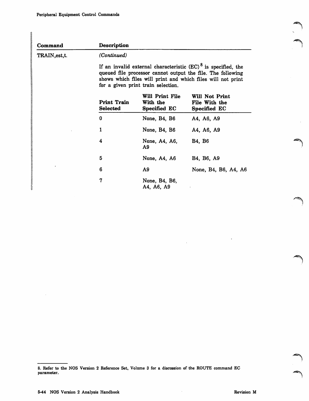
Peripheral Equipment Control Commands
Command
TRAIN,est,t.
Description
(Continued)
If an invalid external characteristic (EC)8 is specified, the
queued file processor cannot output the file. The following
shows which files will print and which files will not print
for a given print train selection.
Will Print File Will Not Print
Print Train With the FUe With the
Selected Specified EC Specified EC
0None, B4, B6 A4, A6, A9
1None, B4, B6 A4, A6, A9
4None, A4, A6,
A9 B4, B6
5None, A4, A6 B4, B6, A9
6A9 None, B4, B6, A4, A6
7None, B4, B6,
A4, A6, A9
y^BB\
8. Refer to the NOS Version 2 Reference Set, Volume 3 for a discussion of the ROUTE command EC
parameter.
5-44 NOS Version 2 Analysis Handbook Revision M
Peripheral Equipment Control Commands
Command Description
UNLOAD,est. Physically unloads a tape or logically removes a removable
disk storage device from the operating system. The device to
be unloaded is defined by EST ordinal est (examine the E,A
display to determine the EST ordinal). Also, in a
multimainframe environment, the UNLOAD command must
be issued if another mainframe wants to initialize a shared
mass storage device, whether the device is removable or
nonremovable (refer to the INITIALIZE command earlier in
this section). If a magnetic tape is specified, the tape is
physically unloaded. If a removable disk storage device is
specified, you can dismount the disk pack on that device
after all activity on the device has been completed.
NOTE
If a nonremovable shared mass storage device is to be
specified, the console must be unlocked (refer to the
UNLOCK command later in this section).
Magnetic tape units:
If a tape is currently assigned to a job, it cannot be
unloaded. If you attempt to unload it, the UNLOAD
command is ignored and this message appears on the left
console screen:
UNIT NOT AVAILABLE
Examine the tape status display (E,T) before entering the
UNLOAD command to determine if the tape to be unloaded
is currently assigned to a job. If the tape is not currently
assigned, entering this command unloads the specified tape.
Mass storage devices:
The UNLOAD command is valid for any shared mass
storage device in a multimainframe environment for the
purpose of initialization. Otherwise, the command is valid
only for removable devices. (Only removable devices may be
physically removed by unloading.) After entering the
UNLOAD command, monitor the disk status display (E,M).
Execution of this command immediately causes local unload
(L) status to appear in the STATUS field for that device.
While L status is displayed, no new users are permitted to
access files on the device. A user currently accessing files on
the device can continue while at least one direct access file
from the device is attached to the job. When the user count
is zero and there are no checkpoint requests pending, one of
the following two actions occurs.
Revision M DSD Commands 5-45
Peripheral Equipment Control Commands
Command
UNLOAD,est.
Description
(Continued)
• If the device is removable and the L status is set in all
machines accessing the device, global unload (N) status is
displayed. This indicates that the device may now be
physically dismounted.
NOTE
If a multispindle family is mounted on a single spindle
device, only the first device shows the global unload status.
• If an initialize is pending on the device and all other
machines accessing the device have L status set, the
initialization proceeds. However, initialization cannot take
place if the device has been unloaded.
NOTE
A device should be physically dismounted only if global
unload status (N) is displayed on all machines accessing
the device.
If a removable pack is dismounted before the N status is
displayed, the following may occur.
• Mass storage device status errors.
• Permanent file errors when the pack is remounted at some
later date.
• If another pack has been mounted, accesses made by a
previously attached user may destroy information on the
new pack or the user may retrieve information from the
new device which he is not necessarily privileged to access.
Mass storage device status errors are also possible in this
situation.
NOTE
If the Mass Storage Extended Subsystem (MSE) is active,
it must be idled before unloading a removable family pack
which has MSE files. After dismounting the family pack,
MSE can be initialized again.
^^S
5-46 NOS Version 2 Analysis Handbook Revision M
Peripheral Equipment Control Commands
Command Description
UP,CH=ch.
or
UP,MCH=ch.9
or
UP,CCH=cch,
EQ=est.
VALIDATE,est.
VSN,est,.
The first two forms of the command allow resumption of
normal use of channel ch by magnetic tape units or
mass storage devices, reversing the effects of the
DOWN command.
The third form of the command allows resumption of normal
use of both ports of concurrent channel cch for the mass
storage device specified by EST ordinal est. If the EQ=est
parameter is omitted, channel cch resumes normal use for
all devices in the EST.
If you enter UP for a channel (ch or cch) that is already
UP, the following message appears on the console:
INCORRECT ENTRY
If the channel is already up, no further action is necessary.
Causes validation of mass storage tables associated with the
equipment defined by EST ordinal est. The equipment must
be available mass storage and the MS VALIDATION option
must have been selected in the IPRDECK at deadstart.
Declares the tape mounted on an unassigned magnetic tape
unit, defined by EST ordinal est, to be a scratch tape. This
command is similar in function to the SCRATCH command
in that it enables a tape to be available to satisfy scratch
VSN requests. However, if the tape is labeled and a write
function is performed, the VSN specified in the VOL1 label
will be rewritten as a scratch VSN, destroying the original
VSN and making the tape available for future scratch VSN
requests. The VSN also appears as ***est (est is the ordinal
of the est) on the tape status display (E,T). Refer to the'
VSN,est,vsn command, next, for a discussion of the
INCORRECT ENTRY message which is also applicable to
VSN,est,.
9. Model 176 only.
Revision M DSD Commands 5-47
Peripheral Equipment Control Commands
Command Description
VSN,est,vsn.10 Assigns VSN vsn to an unassigned magnetic tape unit defined
by EST ordinal est. This command allows you to specify a
1- to 6-character VSN for a mounted, unlabeled tape so it may
be assigned and referenced automatically. For example, when
a job specifies a VSN in the request for an unlabeled tape, an
entry for that job appears in the resource requests display
(E,P). This display indicates the job sequence name of the job,
the type of tape unit, 7 track (MT) or 9 track (HD, PE, or
GE), on which the tape is to be mounted, the required VSN,
user name of the job, and the required write ring status (IN
or OUT). If the correct tape is not currently mounted, mount
the tape on an available unit (ensuring that track type and
write ring status are correct), ready the unit, and enter this
command. The system equates the VSN you enter with that
specified by the job and assigns the tape automatically upon
demand. ^,
If the tape mounted on the tape unit defined by EST ordinal
est is a labeled tape, has already had a VSN assigned by
console command, or has not yet been checked for a label by
the magnetic tape subsystem, this command is ignored. The
message
INCORRECT ENTRY
a p p e a r s o n t h e l e f t c o n s o l e sc r e e n . To c h a n g e a V S N _ ^ ~
previously assigned by this command, clear the first VSN by 1
entering:
VSN,est.
est Description
est EST ordinal of the tape unit.
/<ss^\
10. Special characters cannot be entered using this command. If a special character is encountered in vsn,
the VSN entered is truncated at the character preceding the special character.
5-48 NOS Version 2 Analysis Handbook Revision M
Peripheral Equipment Control Commands
Command Description
VSN,est,vsn. (Continued)
This command can then be entered:
VSN,est,vsn.
Parameter Description
e s t E S T o r d i n a l o f t h e t a p e u n i t .
vsn New VSN.
00^\
(The preceding message and procedure for changing a VSN are
also applicable to the VSN,est,. command.)
If a job specifies a VSN in the request for a labeled tape,
assignment occurs automatically, without your intervention,
unless the correct tape is not mounted. In this case, an entry
is formed in the resource requests display (E,P), which
describes the tape to be mounted. When the tape is mounted
and the tape unit made ready, assignment occurs
automatically without additional intervention by you. For
multireel files, automatic tape assignment occurs only if the
tape units on which the tapes are mounted are similar and on
the same channel(s). That is, if the first reel of the file is on
a 669 tape unit on channels 13 and 33, all subsequent reels
must be on a 669 unit on channels 13 and 33. When assigning
tapes, models 679-2, 679-3, and 679-4 drives (800/1600 cpi) are
similar. Also models 679-5, 679-6, and 679-7 drives (1600/6250
cpi) are similar.
If two or more unassigned tapes having identical VSNs are
mounted on units of the same track type, the message
REQUEST,dt,vsn
appears on the B,0 display. The dt field is either the device
type MT or the density requirement HD, PE, or GE; vsn is
the VSN required.
You must assign one of the tapes using the ASSIGN
command. If the duplicate VSNs are SCRATCH, the resource
executive routine assigns one automatically.
NOTE
It is not possible to specify a VSN of SCRATCH with this
command since only six characters may be used to define a
VSN. To define a scratch tape (used to satisfy scratch VSN
requests), refer to the description of the SCRATCH command
earlier in this section.
Revision M DSD Commands 5-49
Subsystem Control Commands
Subsystem Control Commands
The commands that follow provide control over which subsystems are to be used. When
a system deadstart is performed, parameters specified in the IPRDECK determine
which subsystems initially are available. Scheduling other subsystems to a control point
or terminating a current subsystem depends on your action.
When a subsystem is scheduled to a specific control point, any job currently assigned
to that control point is rolled out if it is not another subsystem or special system job.
However, if the job cannot be rolled out, the command used to call the subsystem
would not be valid. In this case, either terminate the job (if the subsystem required
that control point) or specify another control point for the subsystem using the
SUBSYST L-display utility (refer to section 9, L-Display Utilities, for more
information).
Command
BIO.
Description
Calls the Batch Input/Output (BIO) Subsystem. BIO must be
active in order to use any of the local batch peripheral
devices. BIO equipment activity can be monitored on the I
display (refer to the NOS Version 2 Operations Handbook).
Response to line printer errors is controlled by setting sense
switch 1 or 2 as follows:
Entry Response
CDCffff. n
IAFffff.11
ONSW,BIO,1. Lines causing print error messages are not
flagged or retried.
ONSW,BIO,2. Lines causing print error messages are
flagged and retried. The printer halts and is
placed on hold until you correct the error
and enter CONTINUE,est. The line reprints
and printing continues.
Calls the CYBER Database Control System (CDCS). CDCfiff
calls a procedure file named CDCfiff under the system user
index to initiate the CDCS Subsystem.
Calls the Interactive Facility (IAF) Subsystem to control
point 1. IAFffff calls a procedure file named IAFffff under
the system user index to initiate the IAF Subsystem. The
IAF Subsystem must be active before jobs can be entered
from an interactive terminal. Use the T display to monitor
activity at the IAF Subsystem control point.
11. The characters ffff are optional; if required, installation personnel must supply the necessary 1 to 4
alphanumeric characters.
5-50 NOS Version 2 Analysis Handbook Revision M
Subsystem Control Commands
0^S
ysRS.
Command Description
IAFffff. (Continued)
Several options are available to control the operation of IAF.
Select these options by setting sense switches after the
subsystem is initiated. Although normal operation does not
require these sense switches to be set, sense switch 5
(ONSW,LAF,5) is set by default when the IAF Subsystem is
initiated. Once set, the sense switches may be turned off again
by entering OFFSW,IAF,s (s is the sense switch number.)
Entry
/tf^^V,
Response
ONSW,IAF,l. When the IAF Subsystem is terminated (by
an IDLE,IAF command), enter users into a
detached state and inhibit restarting
operations.
ONSW,IAF,2. The IAF Subsystem will not reload after an
abort. This option releases the output file to
the output queue.
ONSW,IAF,3. Aborts the IAF Subsystem on all abnormal
conditions. This ensures that the subsystem
does not continue to operate if an internal
malfunction occurs. This may be used with
sense switch 5 to enable an analyst to
determine the problem. Some conditions cause
the IAF Subsystem to abort even though
sense switch 3 is not set.
ONSW,IAF,4. Enables a dump on normal termination. This
option should be activated whenever a dump
is desired after the IDLE.IAF command.
ONSW,IAF,5. Dumps information to the output file after the
IAF Subsystem is dropped or aborted. This
option provides a listing that may assist an
analyst in determining the problem that
existed when the subsystem dropped or
aborted. This sense switch is set by default
when the IAF Subsystem is activated.
ONSW,IAF,6. Releases the output file containing dump
information written after the IAF Subsystem
is dropped or aborted (refer to the
ONSW,IAF,5 option) immediately after the
dump is taken. When sense switch 6 is not
set, the output file is not released until the
IAF Subsystem is terminated. It is then
printed with the job dayfile. This switch
applies only when sense switch 5 is set.
Revision M DSD Commands 5-51
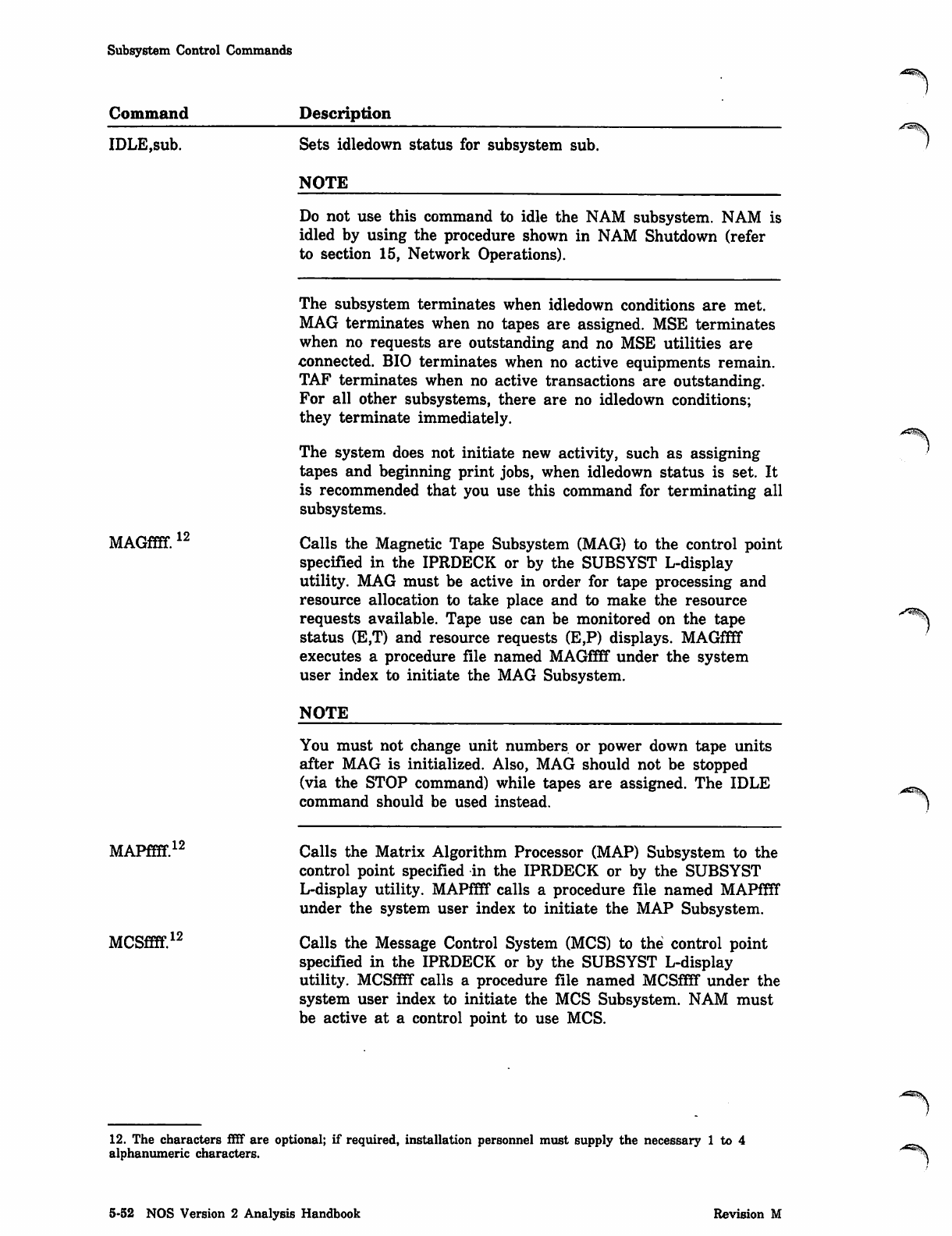
Subsystem Control Commands
Command
IDLE,sub.
Description
Sets idledown status for subsystem sub.
NOTE
MAGffff.12
Do not use this command to idle the NAM subsystem. NAM is
idled by using the procedure shown in NAM Shutdown (refer
to section 15, Network Operations).
The subsystem terminates when idledown conditions are met.
MAG terminates when no tapes are assigned. MSE terminates
when no requests are outstanding and no MSE utilities are
connected. BIO terminates when no active equipments remain.
TAF terminates when no active transactions are outstanding.
For all other subsystems, there are no idledown conditions;
they terminate immediately.
The system does not initiate new activity, such as assigning
tapes and beginning print jobs, when idledown status is set. It
is recommended that you use this command for terminating all
subsystems.
Calls the Magnetic Tape Subsystem (MAG) to the control point
specified in the IPRDECK or by the SUBSYST L-display
utility. MAG must be active in order for tape processing and
resource allocation to take place and to make the resource
requests available. Tape use can be monitored on the tape
status (E,T) and resource requests (E,P) displays. MAGffff
executes a procedure file named MAGffff under the system
user index to initiate the MAG Subsystem.
NOTE
You must not change unit numbers or power down tape units
after MAG is initialized. Also, MAG should not be stopped
(via the STOP command) while tapes are assigned. The IDLE
command should be used instead.
MAPffff.12
MCSffff. 12
Calls the Matrix Algorithm Processor (MAP) Subsystem to the
control point specified in the IPRDECK or by the SUBSYST
L-display utility. MAPffff calls a procedure file named MAPffff
under the system user index to initiate the MAP Subsystem.
Calls the Message Control System (MCS) to the control point
specified in the IPRDECK or by the SUBSYST L-display
utility. MCSffff calls a procedure file named MCSffff under the
system user index to initiate the MCS Subsystem. NAM must
be active at a control point to use MCS.
12. The characters ffff are optional; if required, installation personnel must supply the necessary 1 to 4
alphanumeric characters.
5-52 NOS Version 2 Analysis Handbook Revision M
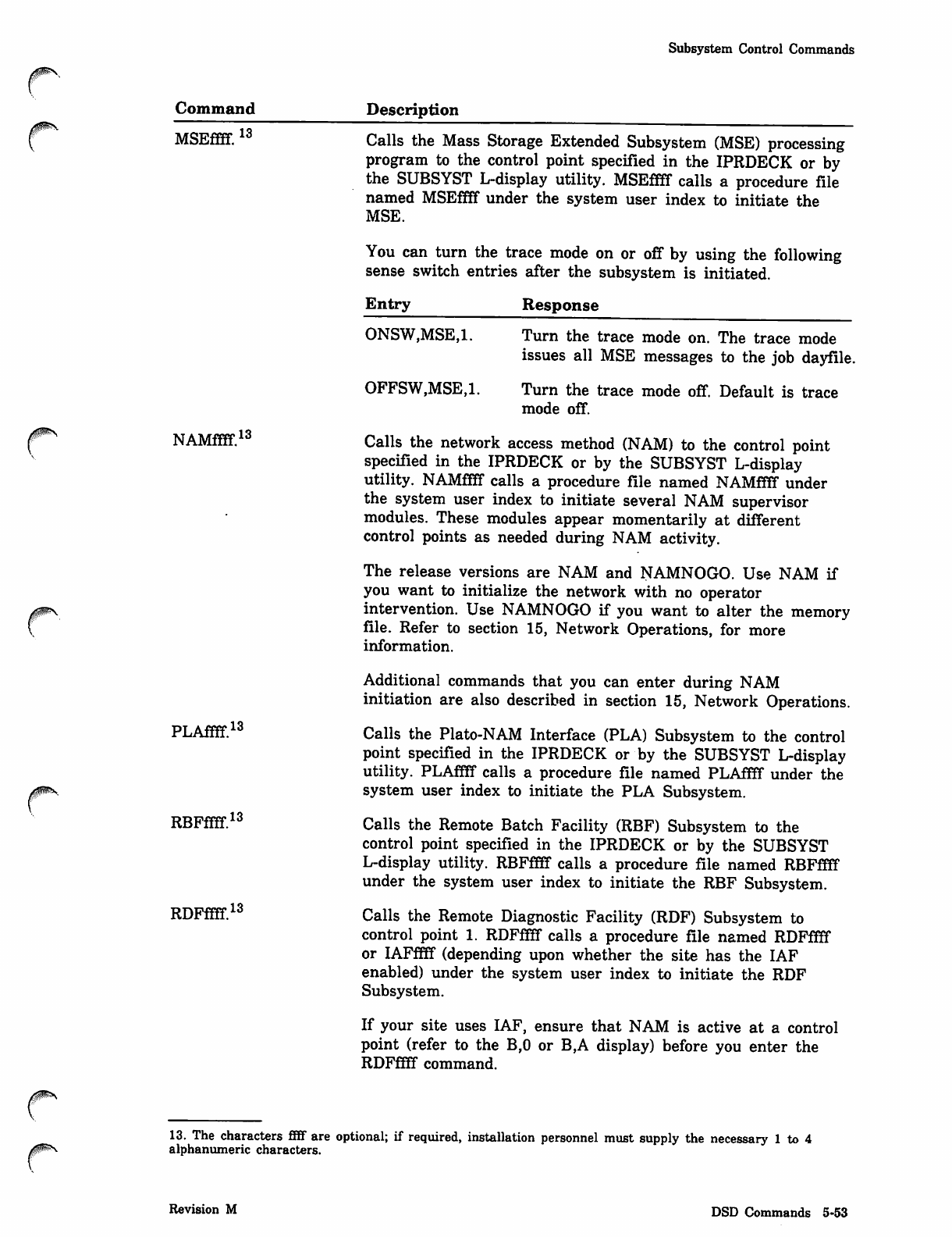
Subsystem Control Commands
Command Description
MSEffff. 13
NAMffff.13
yiflppSi,
PLAffff.13
RBFffff.13
RDFffff.13
Calls the Mass Storage Extended Subsystem (MSE) processing
program to the control point specified in the IPRDECK or by
the SUBSYST L-display utility. MSEffff calls a procedure file
named MSEffff under the system user index to initiate the
MSE.
You can turn the trace mode on or off by using the following
sense switch entries after the subsystem is initiated.
Entry Response
ONSW,MSE,l.
OFFSW,MSE,l.
Turn the trace mode on. The trace mode
issues all MSE messages to the job dayfile.
Turn the trace mode off. Default is trace
mode off.
Calls the network access method (NAM) to the control point
specified in the IPRDECK or by the SUBSYST L-display
utility. NAMffff calls a procedure file named NAMffff under
the system user index to initiate several NAM supervisor
modules. These modules appear momentarily at different
control points as needed during NAM activity.
The release versions are NAM and NAMNOGO. Use NAM if
you want to initialize the network with no operator
intervention. Use NAMNOGO if you want to alter the memory
file. Refer to section 15, Network Operations, for more
information.
Additional commands that you can enter during NAM
initiation are also described in section 15, Network Operations.
Calls the Plato-NAM Interface (PLA) Subsystem to the control
point specified in the IPRDECK or by the SUBSYST L-display
utility. PLAffff calls a procedure file named PLAffff under the
system user index to initiate the PLA Subsystem.
Calls the Remote Batch Facility (RBF) Subsystem to the
control point specified in the IPRDECK or by the SUBSYST
L-display utility. RBFffff calls a procedure file named RBFffff
under the system user index to initiate the RBF Subsystem.
Calls the Remote Diagnostic Facility (RDF) Subsystem to
control point 1. RDFffff calls a procedure file named RDFffff
or IAFffff (depending upon whether the site has the IAF
enabled) under the system user index to initiate the RDF
Subsystem.
If your site uses IAF, ensure that NAM is active at a control
point (refer to the B,0 or B,A display) before you enter the
RDFffff command.
13. The characters ffff are optional; if required, installation personnel must supply the necessary 1 to 4
alphanumeric characters.
Revision M DSD Commands 5-53
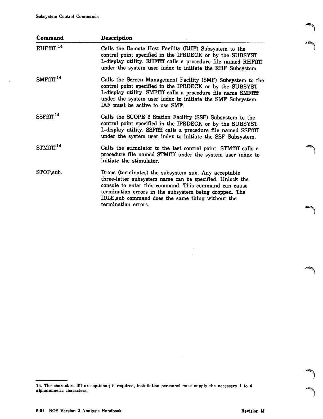
Subsystem Control Commands
Command
RHFffff.14
SMFffff. 14
SSFffff.14
STMffff. 14
STOP,sub.
Description
Calls the Remote Host Facility (RHF) Subsystem to the
control point specified in the IPRDECK or by the SUBSYST
L-display utility. RHFffff calls a procedure file named RHFffff
under the system user index to initiate the RHF Subsystem.
Calls the Screen Management Facility (SMF) Subsystem to the
control point specified in the IPRDECK or by the SUBSYST
L-display utility. SMFffff calls a procedure file name SMFffff
under the system user index to initiate the SMF Subsystem.
IAF must be active to use SMF.
Calls the SCOPE 2 Station Facility (SSF) Subsystem to the
control point specified in the IPRDECK or by the SUBSYST
L-display utility. SSFffff calls a procedure file named SSFffff
under the system user index to initiate the SSF Subsystem.
Calls the stimulator to the last control point. STMffff calls a
procedure file named STMffff under the system user index to
initiate the stimulator.
Drops (terminates) the subsystem sub. Any acceptable
three-letter subsystem name can be specified. Unlock the
console to enter this command. This command can cause
termination errors in the subsystem being dropped. The
IDLE,sub command does the same thing without the
termination errors.
14. The characters ffff are optional; if required, installation personnel must supply the necessary 1 to 4
alphanumeric characters.
5-54 NOS Version 2 Analysis Handbook Revision M
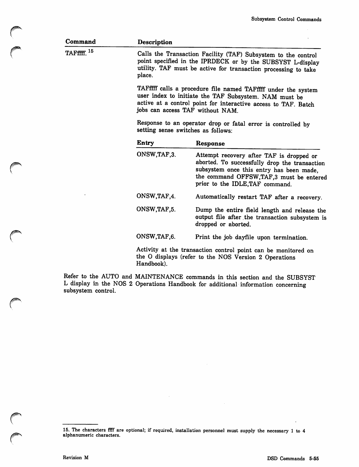
Subsystem Control Commands
Command
TAFffff.15
Description
Calls the Transaction Facility (TAF) Subsystem to the control
point specified in the IPRDECK or by the SUBSYST L-display
utility. TAF must be active for transaction processing to take
place.
TAFffff calls a procedure file named TAFffff under the system
user index to initiate the TAF Subsystem. NAM must be
active at a control point for interactive access to TAF. Batch
jobs can access TAF without NAM.
Response to an operator drop or fatal error is controlled by
setting sense switches as follows:
Entry Response
ONSW,TAF,3. Attempt recovery after TAF is dropped or
aborted. To successfully drop the transaction
subsystem once this entry has been made,
the command OFFSW,TAF,3 must be entered
prior to the IDLE,TAF command.
ONSW,TAF,4. Automatically restart TAF after a recovery.
ONSW,TAF,5. Dump the entire field length and release the
output file after.the transaction subsystem is
dropped or aborted.
ONSW,TAF,6. Print the job dayfile upon termination.
Activity at the transaction control point can be monitored on
the O displays (refer to the NOS Version 2 Operations
Handbook).
Refer to the AUTO and MAINTENANCE commands in this section and the SUBSYST
L display in the NOS 2 Operations Handbook for additional information concerning
subsystem control.
15. The characters ffff are optional; if required, installation personnel must supply the necessary 1 to 4
alphanumeric characters.
Revision M DSD Commands 5-55
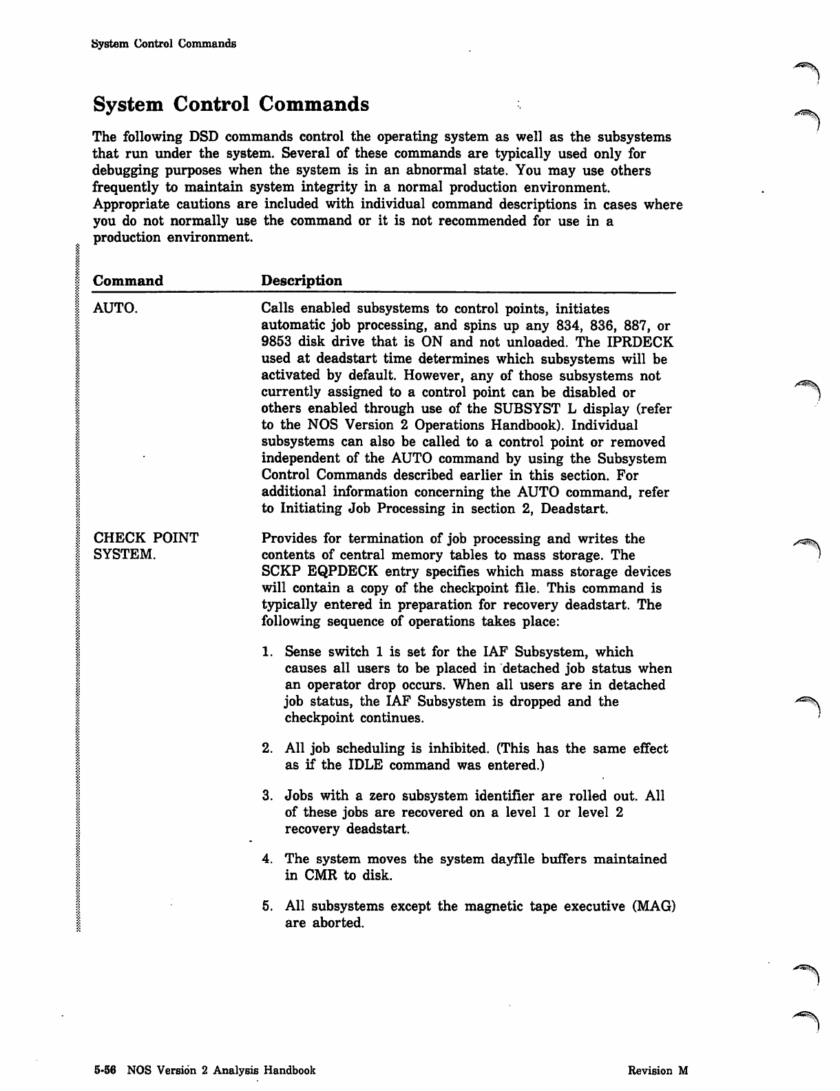
System Control Commands
System Control Commands
The following DSD commands control the operating system as well as the subsystems
that run under the system. Several of these commands are typically used only for
debugging purposes when the system is in an abnormal state. You may use others
frequently to maintain system integrity in a normal production environment.
Appropriate cautions are included with individual command descriptions in cases where
you do not normally use the command or it is not recommended for use in a
production environment.
y^^^V
Command Description
AUTO.
CHECK POINT
SYSTEM.
Calls enabled subsystems to control points, initiates
automatic job processing, and spins up any 834, 836, 887, or
9853 disk drive that is ON and not unloaded. The IPRDECK
used at deadstart time determines which subsystems will be
activated by default. However, any of those subsystems not
currently assigned to a control point can be disabled or
others enabled through use of the SUBSYST L display (refer
to the NOS Version 2 Operations Handbook). Individual
subsystems can also be called to a control point or removed
independent of the AUTO command by using the Subsystem
Control Commands described earlier in this section. For
additional information concerning the AUTO command, refer
to Initiating Job Processing in section 2, Deadstart.
Provides for termination of job processing and writes the
contents of central memory tables to mass storage. The
SCKP EQPDECK entry specifies which mass storage devices
will contain a copy of the checkpoint file. This command is
typically entered in preparation for recovery deadstart. The
following sequence of operations takes place:
1. Sense switch 1 is set for the IAF Subsystem, which
causes all users to be placed in detached job status when
an operator drop occurs. When all users are in detached
job status, the IAF Subsystem is dropped and the
checkpoint continues.
2. All job scheduling is inhibited. (This has the same effect
as if the IDLE command was entered.)
3. Jobs with a zero subsystem identifier are rolled out. All
of these jobs are recovered on a level 1 or level 2
recovery deadstart.
4. The system moves the system dayfile buffers maintained
in CMR to disk.
5. All subsystems except the magnetic tape executive (MAG)
are aborted.
sA^^%\
^i^S
5-56 NOS Version 2 Analysis Handbook Revision M
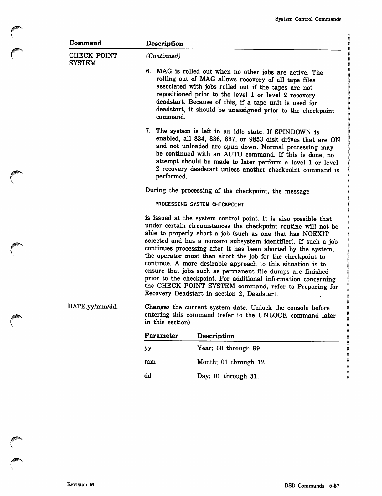
System Control Commands
Command
CHECK POINT
SYSTEM.
0& S
DATE.yy/mm/dd.
r
Description
(Continued)
6. MAG is rolled out when no other jobs are active. The
rolling out of MAG allows recovery of all tape files
associated with jobs rolled out if the tapes are not
repositioned prior to the level 1 or level 2 recovery
deadstart. Because of this, if a tape unit is used for
deadstart, it should be unassigned prior to the checkpoint
command.
7. The system is left in an idle state. If SPINDOWN is
enabled, all 834, 836, 887, or 9853 disk drives that are ON
and not unloaded are spun down. Normal processing may
be continued with an AUTO command. If this is done, no
attempt should be made to later perform a level 1 or level
2 recovery deadstart unless another checkpoint command is
performed.
During the processing of the checkpoint, the message
PROCESSING SYSTEM CHECKPOINT
is issued at the system control point. It is also possible that
under certain circumstances the checkpoint routine will not be
able to properly abort a job (such as one that has NOEXIT
selected and has a nonzero subsystem identifier). If such a job
continues processing after it has been aborted by the system,
the operator must then abort the job for the checkpoint to
continue. A more desirable approach to this situation is to
ensure that jobs such as permanent file dumps are finished
prior to the checkpoint. For additional information concerning
the CHECK POINT SYSTEM command, refer to Preparing for
Recovery Deadstart in section 2, Deadstart.
Changes the current system date. Unlock the console before
entering this command (refer to the UNLOCK command later
in this section).
Parameter Description
yy
mm
dd
Year; 00 through 99.
Month; 01 through 12.
Day; 01 through 31.
zgp?\
Revision M DSD Commands 5-57
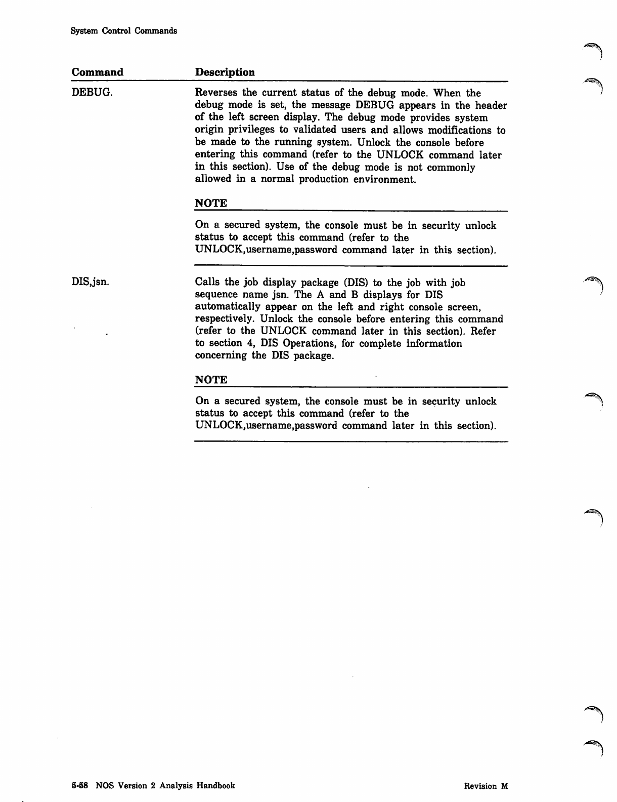
System Control Commands
Command
DEBUG.
Description
Reverses the current status of the debug mode. When the
debug mode is set, the message DEBUG appears in the header
of the left screen display. The debug mode provides system
origin privileges to validated users and allows modifications to
be made to the running system. Unlock the console before
entering this command (refer to the UNLOCK command later
in this section). Use of the debug mode is not commonly
allowed in a normal production environment.
NOTE
DIS.jsn.
On a secured system, the console must be in security unlock
status to accept this command (refer to the
UNLOCK,username,password command later in this section).
Calls the job display package (DIS) to the job with job
sequence name jsn. The A and B displays for DIS
automatically appear on the left and right console screen,
respectively. Unlock the console before entering this command
(refer to the UNLOCK command later in this section). Refer
to section 4, DIS Operations, for complete information
concerning the DIS package.
NOTE
On a secured system, the console must be in security unlock
status to accept this command (refer to the
UNLOCK,username,password command later in this section).
■j**l^\
5-58 NOS Version 2 Analysis Handbook Revision M
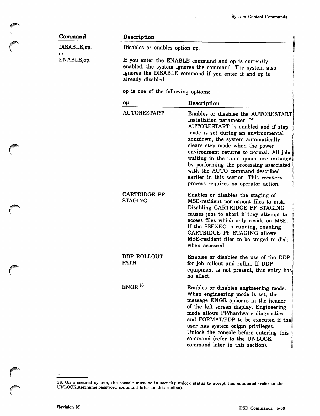
System Control Commands
J$M&rrnz\^
Command
DISABLE,op.
or
ENABLE,op.
Description
Disables or enables option op.
If you enter the ENABLE command and op is currently
enabled, the system ignores the command. The system also
ignores the DISABLE command if you enter it and op is
already disabled.
op is one of the following options:
op
AUTORESTART
CARTRIDGE PF
STAGING
DDP ROLLOUT
PATH
ENGR16
Description
Enables or disables the AUTORESTART^
installation parameter. If
AUTORESTART is enabled and if step |
mode is set during an environmental
shutdown, the system automatically
clears step mode when the power
environment returns to normal. All jobsl
waiting in the input queue are initiated!
by performing the processing associated |
with the AUTO command described
earlier in this section. This recovery
process requires no operator action.
Enables or disables the staging of
MSE-resident permanent files to disk.
Disabling CARTRIDGE PF STAGING
causes jobs to abort if they attempt to I
access files which only reside on MSE.
If the SSEXEC is running, enabling
CARTRIDGE PF STAGING allows
MSE-resident files to be staged to disk |
when accessed.
Enables or disables the use of the DDP I
for job rollout and rollin. If DDP
equipment is not present, this entry hasl
no effect.
Enables or disables engineering mode.
When engineering mode is set, the
message ENGR appears in the header §
of the left screen display. Engineering |
mode allows PP/hardware diagnostics
and FORMAT/FDP to be executed if the!
user has system origin privileges.
Unlock the console before entering this |
command (refer to the UNLOCK
command later in this section).
16. On a secured system, the console must be in security unlock status to accept this command (refer to the
UNLOCK,username,password command later in this section).
Revision M DSD Commands 5-59
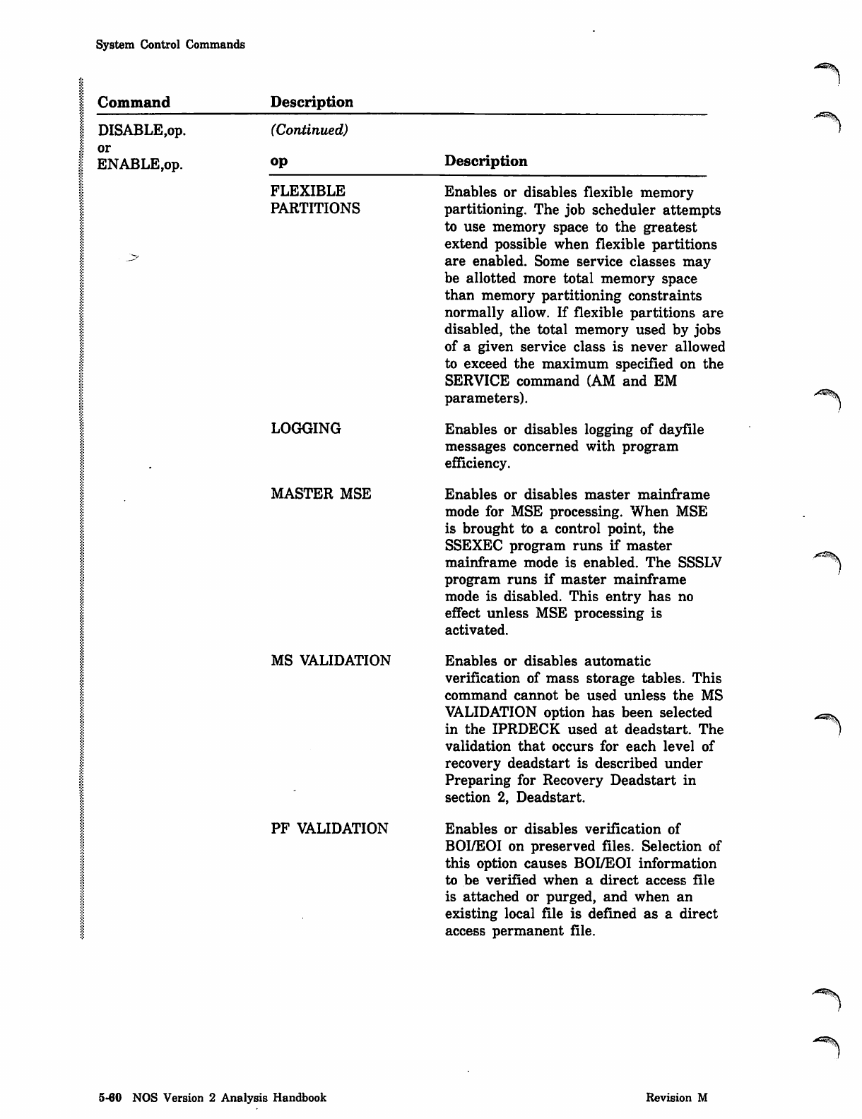
System Control Commands
Command Description
DISABLE,op.
or
ENABLE,op.
(Continued)
op
FLEXIBLE
PARTITIONS
LOGGING
MASTER MSE
MS VALIDATION
PF VALIDATION
Description
Enables or disables flexible memory
partitioning. The job scheduler attempts
to use memory space to the greatest
extend possible when flexible partitions
are enabled. Some service classes may
be allotted more total memory space
than memory partitioning constraints
normally allow. If flexible partitions are
disabled, the total memory used by jobs
of a given service class is never allowed
to exceed the maximum specified on the
SERVICE command (AM and EM
parameters).
Enables or disables logging of dayfile
messages concerned with program
efficiency.
Enables or disables master mainframe
mode for MSE processing. When MSE
is brought to a control point, the
SSEXEC program runs if master
mainframe mode is enabled. The SSSLV
program runs if master mainframe
mode is disabled. This entry has no
effect unless MSE processing is
activated.
Enables or disables automatic
verification of mass storage tables. This
command cannot be used unless the MS
VALIDATION option has been selected
in the IPRDECK used at deadstart. The
validation that occurs for each level of
recovery deadstart is described under
Preparing for Recovery Deadstart in
section 2, Deadstart.
Enables or disables verification of
BOI/EOI on preserved files. Selection of
this option causes BOI/EOI information
to be verified when a direct access file
is attached or purged, and when an
existing local file is defined as a direct
access permanent file.
•»"SfS\
5-60 NOS Version 2 Analysis Handbook Revision M
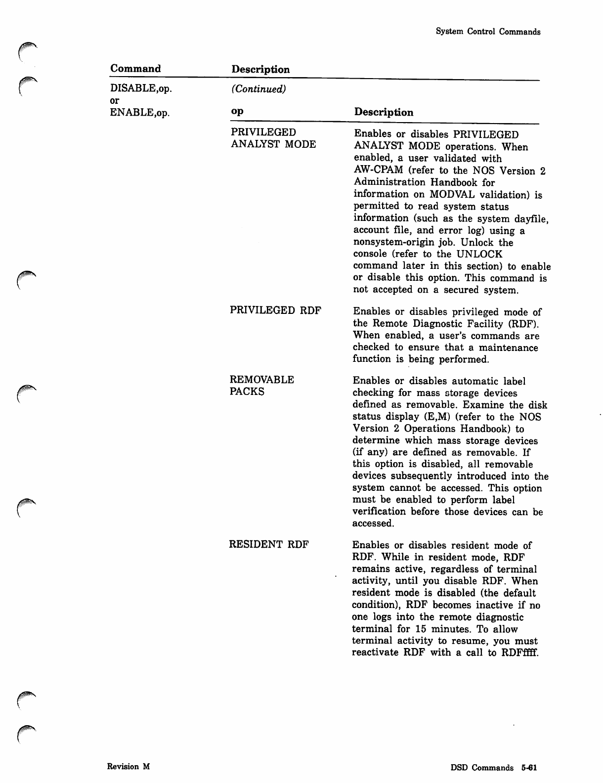
System Control Commands
Command Description
DISABLE,op.
or
ENABLE,op.
(Continued)
op
PRIVILEGED
ANALYST MODE
/|Ife\
PRIVILEGED RDF
REMOVABLE
PACKS
RESIDENT RDF
Description
Enables or disables PRIVILEGED
ANALYST MODE operations. When
enabled, a user validated with
AW-CPAM (refer to the NOS Version 2
Administration Handbook for
information on MODVAL validation) is
permitted to read system status
information (such as the system dayfile,
account file, and error log) using a
nonsystem-origin job. Unlock the
console (refer to the UNLOCK
command later in this section) to enable
or disable this option. This command is
not accepted on a secured system.
Enables or disables privileged mode of
the Remote Diagnostic Facility (RDF).
When enabled, a user's commands are
checked to ensure that a maintenance
function is being performed.
Enables or disables automatic label
checking for mass storage devices
defined as removable. Examine the disk
status display (E,M) (refer to the NOS
Version 2 Operations Handbook) to
determine which mass storage devices
(if any) are defined as removable. If
this option is disabled, all removable
devices subsequently introduced into the
system cannot be accessed. This option
must be enabled to perform label
verification before those devices can be
accessed.
Enables or disables resident mode of
RDF. While in resident mode, RDF
remains active, regardless of terminal
activity, until you disable RDF. When
resident mode is disabled (the default
condition), RDF becomes inactive if no
one logs into the remote diagnostic
terminal for 15 minutes. To allow
terminal activity to resume, you must
reactivate RDF with a call to RDFffff.
/5^s
Revision M DSD Commands 5-61
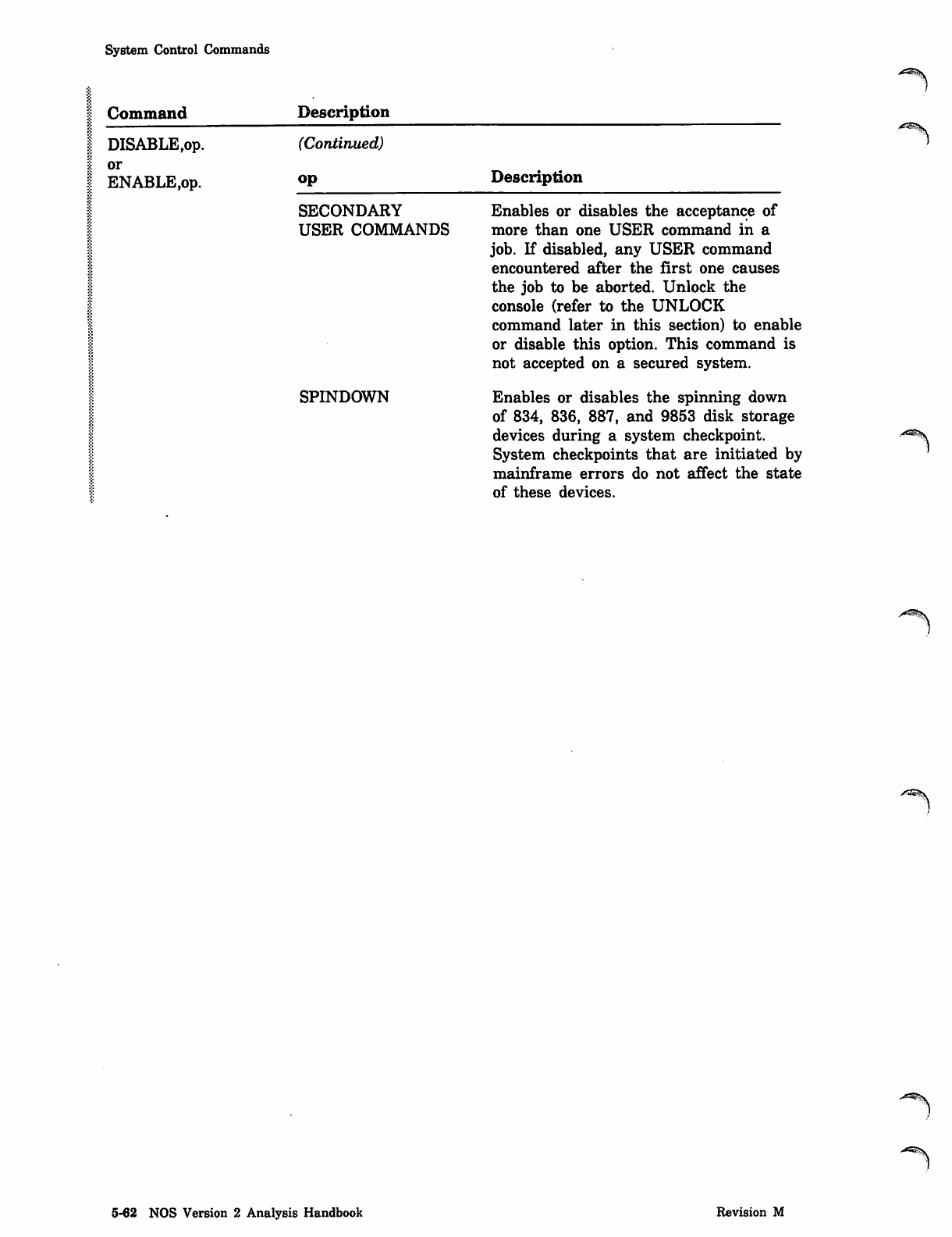
System Control Commands
Command Description
DISABLE,op.
or
ENABLE,op.
(Continued)
op Description
SECONDARY
USER COMMANDS
SPINDOWN
Enables or disables the acceptance of
more than one USER command in a
job. If disabled, any USER command
encountered after the first one causes
the job to be aborted. Unlock the
console (refer to the UNLOCK
command later in this section) to enable
or disable this option. This command is
not accepted on a secured system.
Enables or disables the spinning down
of 834, 836, 887, and 9853 disk storage
devices during a system checkpoint.
System checkpoints that are initiated by
mainframe errors do not affect the state
of these devices.
r-^^K
V**Bffl^\
>ssev
5-62 NOS Version 2 Analysis Handbook Revision M
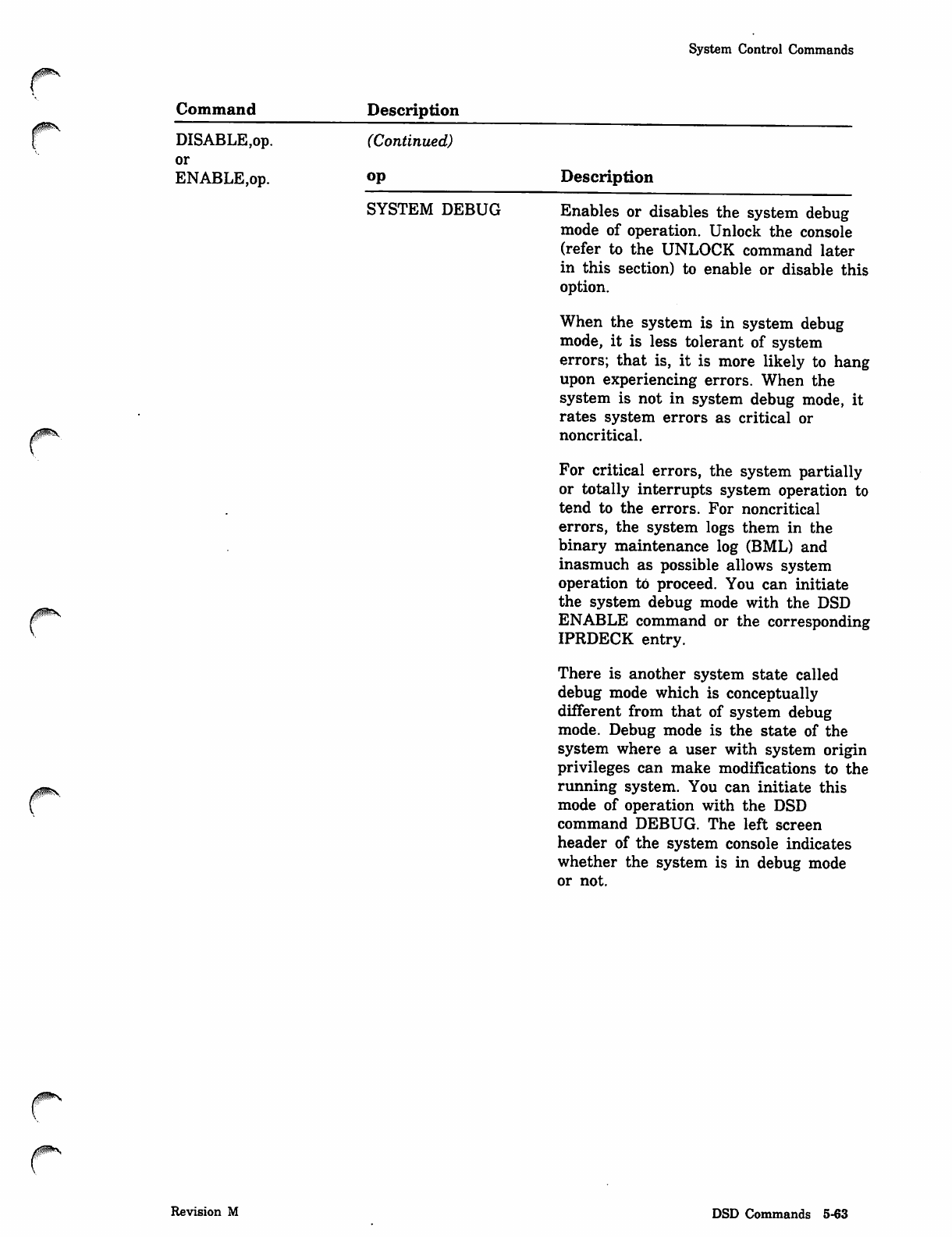
System Control Commands
Command Description
DISABLE,op.
or
ENABLE,op.
(Continued)
op
SYSTEM DEBUG
r
Description
Enables or disables the system debug
mode of operation. Unlock the console
(refer to the UNLOCK command later
in this section) to enable or disable this
option.
When the system is in system debug
mode, it is less tolerant of system
errors; that is, it is more likely to hang
upon experiencing errors. When the
system is not in system debug mode, it
rates system errors as critical or
noncritical.
For critical errors, the system partially
or totally interrupts system operation to
tend to the errors. For noncritical
errors, the system logs them in the
binary maintenance log (BML) and
inasmuch as possible allows system
operation to proceed. You can initiate
the system debug mode with the DSD
ENABLE command or the corresponding
IPRDECK entry.
There is another system state called
debug mode which is conceptually
different from that of system debug
mode. Debug mode is the state of the
system where a user with system origin
privileges can make modifications to the
running system. You can initiate this
mode of operation with the DSD
command DEBUG. The left screen
header of the system console indicates
whether the system is in debug mode
or not.
0ims
Revision M DSD Commands 5-63
System Control Commands
Command Description
DISABLE,op.
or
ENABLE,op.
IDLE.
K.messagetext
L.messagetext
LOCK.
(Continued)
op Description
TAPE PF STAGING
USER EXTENDED
MEMORY
Enables or disables the staging of tape
alternate storage resident files to disk.
Disabling TAPE PF STAGING causes
jobs to abort if they attempt to access
files which only reside on tape alternate
storage.
Enables or disables use of the user
accessible area of extended memory. If
disabled, no job can access the user
area of extended memory and, other
than subsystems, all jobs currently
accessing the area are rolled out.
Prevents any new jobs from being scheduled to a control point
but does not terminate the jobs currently assigned. If a job is
rolled out while this command is in effect, it will not be
scheduled back to a control point until the AUTO,
MAINTENANCE, or SCHEDULE command is entered.
Allows entry of data messagetext in the user- or
system-defined CPU buffer for control when the K display is
active. Refer to section 8, K-Display Utilities, for information
about the K display.
Allows entry of data messagetext in the user- or
system-defined CPU buffer for control when the L display is
active. Refer to section 9, L-Display Utilities, for information
about the L display.
Locks the console keyboard. This command prevents entry of
restricted commands (refer to the UNLOCK command later in
this section for a list of restricted commands). All other DSD
commands can be entered when the console is locked. The
console is normally locked when the system is being used in a
production environment.
^"^^\
5-64 NOS Version 2 Analysis Handbook Revision M
System Control Commands
Command
MAINTENANCE.
SCHEDULE
STEP.
Description
This command performs the same functions as the AUTO
command but additionally starts several maintenance routines.
Refer to Initiating Job Processing in section 2, Deadstart, for
complete information concerning this command.
Initiates automatic job processing (reversing the effect of a
previous IDLE command), but does not initiate subsystems as
the AUTO command does.
Sets the monitor in step mode. Setting the monitor in step
mode stops all central memory I/O operations and prevents the
system from processing PP requests when the next monitor
function is encountered. Pressing the space bar releases the
present step and stops again for each subsequent monitor
function. If a DSD command is entered while the system is
in step mode and all PPs are assigned, it is possible the
request cannot be satisfied. In that case, the screen(s) blinks
until you correct the condition by clearing the entry.
When step mode is set, the message STEP appears in the
header of the left screen display. Unlock the console before
entering this command (refer to the UNLOCK command later
in this section).
This command is generally used for debugging purposes and
should not be used in a normal production environment. In
addition, the system may set step mode automatically upon
detection of a main power failure or abnormal environmental
condition.
17. Monitor functions are described in the NOS Version 2 Systems Programmer's Instant.
Revision M DSD Commands 5-65
System Control Commands
>*^^v
Command
STEP,jsn,ff,b,v.
or
STEP„ff,b,v.
TIME.hh.mm.ss.
Description
Sets step mode for the job with job sequence name jsn
(first form of the command) or all jobs (second form of the
command) at the next occurrence of monitor function ff when
output register byte b has value v.
If jsn is specified (first form of the command), the monitor
function ff, the output register byte number b, and the output
register value v can be optionally specified for more precise
control of when the step mode is executed. The values for b
can be from 0 to 4; the values for v can be from 0 to 7777s.
If jsn is not specified (second form of the command), the
monitor function ff must be specified. The output register byte
number b and value v can be optionally specified for more
precise control of when the step mode is executed. The values
for b can be from 0 to 4; the values for v can be from 0
to 77778.
For either form of the command, pressing the spacebar
releases the current step and steps the job or system at the
next occurrence of the monitor function ff, if specified, or the
next monitor function from the job if the first form is used
and no monitor function is specified.
Using the second form of the command may stop all central
memory I/O operations and prevent the system from processing
PP requests. If a DSD command is entered while the system
is in step mode and all PPs are assigned, it is possible the
request cannot be satisfied. In this case, the screens blink
until you clear the entry. The message STEP followed by the
monitor function number ff (if specified) appears in the header
of the left screen displays while this command is in effect.
The console must be unlocked before entry of this command is
permitted (refer to the UNLOCK command later in this
section).
These commands are generally used only for debugging
purposes. Do not enter these commands if the system has
automatically set step mode because of a power failure or
abnormal environmental condition.
Changes the current system time. Unlock the console before
entering this command (refer to the UNLOCK command later
in this section).
Parameter Description
hh
mm
ss
Hour; 00 through 23.
Minute; 00 through 59.
Second; 00 through 59
y ^ ^ \
5-66 NOS Version 2 Analysis Handbook Revision M
System Control Commands
Command Description
UNLOCK. Unlocks the console keyboard. When this command is active,
the message UNLOCK appears in the header of the left screen
display. Although all DSD commands can be entered when the
console is unlocked, the following commands are restricted to
entry only when the console is unlocked.
DATE.yy/mm/dd.18
DEBUG.
DISABLE,PRIVILEGED ANALYST MODE.19
DISABLE.SECONDARY USER COMMANDS.19
DISABLE,SYSTEM DEBUG.
DROP„qt,ujn.
ENABLE,ENGR.18
ENABLE,PRIVILEGED ANALYST MODE.19
ENABLE,SECONDARY USER COMMANDS.19
ENABLE,SYSTEM DEBUG.
OVERRIDEJsn.
SPINDOWN,est.
STEP.
STEP,jsn,ff,b,v.
STOP,sub.
TIME.hh.mm.ss.18
UNLOAD,est. (est specifies a nonremovable shared mass
storage device)
UNSTEP.
All memory entry commands18
All channel control commands
All extended memory flag register commands
All breakpoint package commands18
18. Refer to Secured System Control Commands later in this section for information on unlocking the console
keyboard on a secured system.
19. Not allowed on secured systems.
Revision M DSD Commands 5-67
System Control Command's
Command
UNLOCK.
UNSTEP.
X.MDD(p)
Description
(Continued)
Always lock the console when the system is being used in a
production environment. However, you can unlock the console
to enter the STEP command if a system failure requiring a
recovery deadstart occurs (refer to Preparing for Recovery
Deadstart in section 2, Deadstart).
Clears step mode. This command clears the effect of any
format of STEP command. Unlock the console before entering
this command (refer to the UNLOCK command later in this
section). If the system has set step mode because of a main
power failure or abnormal environmental condition, do not
enter this command until the conditions that caused the
automatic setting have returned to normal.
Refer to Secured System Control Commands later in this
section for information on unlocking the console keyboard on a
secured system.
Initiates the monitor display driver (MDD). MDD is a PP
program and is independent of the operating system. Refer to
the CYBER Initialization Package User's Handbook for more
information.
Parameter Description
X.name.
or
X.name(parameters)
or
X.name,fl.
p Port number parameter. If you enter 1, the first
port is connected. If you enter 2, the second
port is connected. If you do not specify this
parameter, the second port is connected by
default.
Calls a system program or utility specified by name
to an available control point. If parameters are to
be passed to the program, the second form of the command
is used where (parameters)the parameters. In both the
first and second form of the command, the field length
specified in the library for the command is used. If no field
length is specified in the library, a value of 600008 is
assumed. If a field length different from the default is
required, the third form of the command is used. The field
length is specified by fl. Only the first 58 characters following
X. are used.
■^^s
■^\
5-68 NOS Version 2 Analysis Handbook Revision M
System Control Commands
Command Description
99. Disables or enables syntax overlay processing and logging of
DSD commands in the system dayfile and error log. That is,
depending upon current status, syntax overlay processing and
logging are reversed. When this mode is enabled, 99 appears
on the left screen header.
r
When syntax overlay processing and logging of DSD commands
is disabled, DSD does not allow you to enter any command
requiring the loading of an overlay from mass storage. Disable
overlay loading only when the system is in an abnormal state
to prevent PPs from being requested when they cannot
perform the necessary tasks (for example, when a system disk
channel is hung). A 99 command that enables logging will be
logged itself, but a 99 command which disables logging will
not be logged.
This command is normally used only for debugging purposes.
When the system is in an abnormal state, the commands that
require entry of the 99 command depend on which syntax
overlays for DSD are in central memory.
Revision M DSD Commands 5-69
Secured System Control Commands
Secured System Control Commands
The following commands are allowed only on a secured system.
Command
OQSH=level.
RELEASEjsn.
SECURES,ot,
LA=lowerlevel,
UA = upperlevel.
Description
Specifies the output queue special handling (OQSH) level on a
secured system. The (OQSH) level is set initially during
deadstart by the OQSH IPRDECK entry. The current OQSH
level appears on the DSD S display. The OQSH command can
be entered at any time from the system console to change the
current level. Output files with an access level greater than or
equal to the OQSH level specified in this command are not
printed but remain in the queue until released by the operator
(refer to the RELEASE command, next). If level is set to the
lowest access level or no level is specified, no files are held in
the queue.
Allows the operator to release a file from the output queue
whose access level is equal to or above the OQSH level on a
secured system. Output queue files and their access levels can
be examined using the DSD Q display. The output file with
job sequence name jsn is released from the output queue and
is processed by the Batch Input/Output Subsystem. The
RELEASE command can be entered at any time from the
system console. Other restrictions based on device access levels
and file access levels set by your site continue to apply.
Sets the security access level limits for the system
(ot=SY) or the security access level limits for a
particular origin type (ot=IA, BC, or RB). The system limits
determine the range of access levels allowed in the system;
jobs may not execute at an access level outside this range,
and files may not be created or accessed at an access level
outside this range. Origin type limits determine the range as
it applies to jobs of one particular origin type. By default, all
origin type limits are the same as the system limits.
The options available for using this command to change the
system limits (that is, whether they can be raised, lowered, or
both) are controlled by the OPSECM CMRDECK entry (refer
to section 3, Deadstart Decks). The origin type limits for
ot=IA, BC, and RB can be changed to any values within the
system limits. When the system limits are changed (ot=SY),
all origin type limits are reset to the new system limits.
The parameters LA and UA specify the lov/er and upper
access level limits. Both parameters must be specified. The
value corresponding to the lower access level must be less
than or equal to the value corresponding to the upper access
level.
5-70 NOS Version 2 Analysis Handbook Revision M
Secured System Control Commands
y^^^s
Command Description
UNLOCK,username,
password.
y^$s
Unlocks the console keyboard for special commands when
the system is running in secured mode. When this command is
entered, the message SECURITY UNLOCK appears in the
header on the left screen display. If the system is running in
secured mode, the following commands are restricted to entry
only when the console is in security unlock status.
DATE.yy/mm/dd.
X.DDF.
DEBUG.
DISJsn.
ENABLE,ENGR.
QDSPLAYJsn.
SECURES,ot,LA=lowerlevel,UA=upperlevel.
SECUREQ,est,LA = lowerlevel,UA = upperlevel.
TIME.hh.mm.ss.
All memory entry commands.
All PP breakpoint commands.
All CPUMTR breakpoint commands.
In addition, the memory displays are partially disabled on a
secured system unless the console is in security unlock status.
If you attempt to display anything outside of the system
tables, a memory display shows the following message instead
of the contents of the memory locations.
****SECURED AREA****
Revision M DSD Commands 5-71
Memory Entry Commands
Memory Entry Commands
The following commands are used to change the contents of central memory and
extended memory. Either absolute locations or those relative to a specific job's
reference address (RA) can be changed.
CAUTION
Use these commands with extreme caution to avoid damage to the system or to user
jobs.
Before entering these commands you must unlock the console keyboard (refer to the
UNLOCK command earlier in this section). On a secured system, the console must be
in security unlock status. To change central memory, you must bring a central memory
display (C, D, F, or G) to the left screen. To change extended memory, you must bring
the M display to the left screen. It is this display that controls whether the memory
entry commands change absolute memory locations or relative memory locations.
For example, if you enter
C , .
to bring up the C display, any memory entry commands entered make changes to
absolute memory locations. If you enter
C.jsn.
where jsn is a valid job sequence name, any memory entry commands entered make ■'***%
changes to memory locations relative to the job's RA.
Character values or numeric data can replace the current word contents. Either one
12-bit byte or a 60-bit word can be changed. A single byte can be changed by
inserting the byte number after the location; bytes are numbered 0 through 4 from
left to right. The address and contents are assembled right-justified with zeros filling
unused leading positions. Leading zeros may be omitted in the entry.
When you are changing the contents of memory relative to a specific job (a valid job
sequence name was specified when the memory display was brought to the left ""^
screen), the negative field length area of the job can be accessed. This area is
accessed by specifying a negative address in the memory entry command. For
example, to change the contents of word RA-3, you enter the address 77777775s.
On an unsecured system when you are changing a memory location relative to a
specific job's RA, the system checks for field length violations. If you specify an
address larger than your job's RA plus field length, you cannot change its contents.
On a secured system no memory entry commands are allowed unless the security
unlock status is set. The memory display shows the message
♦••"SECURED AREA****
instead of the contents of the memory locations to prevent you from examining these
locations; you may not alter the contents of these locations. When you are displaying
absolute memory you can see only the system tables.
/**S\
5-72 NOS Version 2 Analysis Handbook Revision M
Memory Entry Commands
Formats and descriptions for these commands are:
Command
addr,cont.
or
addr+cont.20
addr,b,cont.
or
addr+b,cont.20
addr,Dcont.
or
addr+Dcont.20
Eaddr,c.ont.
or
Eaddr + cont.20
Description
Changes the contents of central memory location addr
(maximum of eight digits) tc cont (maximum of 20
digits). The second form of the command performs essentially
the same function but is used when it is necessary to change
successive memory locations.
Changes the contents of byte b at central memory location
addr (maximum of eight digits) to cont. Each location
consists of five 12-bit bytes, numbered 0 through 4 from left
to right. The contents are four octal characters. The second
form of the command performs essentially the same function
but is used when it is necessary to change successive memory
locations.
Changes the contents of central memory location addr
(maximum of eight digits) to display code characters cont
(left-justified and zero-filled). The second form of the command
performs essentially the same function but is used when it is
necessary to change successive memory locations.
Changes the contents of extended memory location addr
(maximum of seven digits) to cont (maximum of 20 digits).
The second form of the command performs essentially the
same function but is used when it is necessary to change
successive extended memory locations.
Eaddr,b,cont.
or
Eaddr+ b,cont.20
Eaddr,Dcont.
or
Eaddr+ Dcont.20
Changes the contents of byte b at extended memory location
addr (maximum of seven digits) to cont. Each location
consists of five 12-bit bytes, numbered 0 through 4 from left
to right. The contents are four octal characters. The second
form of the command performs essentially the same function
but is used when it is necessary to change successive extended
memory locations.
Changes the contents of extended memory location addr
(maximum of seven digits) to display code characters
cont (left-justified and zero-filled). The second form of the
command performs essentially the same function but is used
when it is necessary to change successive extended memory
locations.
20. If the + sign is specified, the address is incremented by one location (addr + 1) after the initial entry is
processed; the - sign causes the address to be decremented by one location (addr-1). This allows immediate
entry for the next (or previous) memory location. If the message REPEAT ENTRY is displayed above the
entry, the cont field is not cleared and can be entered in successive memory locations as many times as
desired.
Revision M DSD Commands 5-73
Channel Control Commands
Channel Control Commands
The following commands enable control activity on a specified data channel in
circumstances where abnormal hardware and/or system operation is detected. Extreme
caution must be exercised if any of these commands are entered during normal system
operation. In addition, the console keyboard must be unlocked before entry of any of
these commands is permitted (refer to the UNLOCK command earlier in this section).
DSD does not reserve the channel specified in any of the channel control commands.
The channels are numbered 0 to 13s in a 10 PP system and 0 to 13s, 20s to 33s in a
20 PP system.
CAUTION
Extreme caution must be exercised when using the following channel control
commands.
Command Description
ACN,cc.
DCH,cc.
DCN,cc.
FCN,cc,func.
IAN,cc.
LDC,nnnn.
MCH,cc.
OAN,cc.
Activates channel cc. This command alerts and prepares
peripheral equipment on channel cc for the exchange of data.
Drops channel cc. This is a software function to release the
current reservation of channel cc.
Deactivates channel cc. As a result, peripheral equipment on
channel cc stops and any current I/O operation is terminated.
Outputs a function code func to channel cc. This releases all
equipment selections on that channel. If func is not specified,
a zero function code (no activity) is output.
Inputs data to the pseudo A register from channel cc.
Loads the pseudo A register with nnnn (normally a
peripheral equipment function code). The current value of
nnnn is shown in the channel status display (W,C).
Master clears and removes all 3000 Computer Systems
peripheral equipment selections on channel cc (6681 function
code 17008 is issued).
Outputs the contents of the pseudo A register to channel cc.
5-74 NOS Version 2 Analysis Handbook Revision M
0$m\
00!&\
Extended Memory Flag Register Commands
Extended Memory Flag Register Commands
The extended memory flag register commands are used to set or clear specific bits in
the extended memory flag register. These commands are typically used when debugging
a problem in a multimainframe environment. The console must be unlocked (refer to
the UNLOCK command earlier in this section).
CAUTION
Extreme caution must be exercised when using these commands.
Command Description
CFR,bb. Clears the extended memory flag register bit bb
(0 ^ bb ^ 17).
SFR,bb. Sets the extended memory flag register bit bb
j p v ( 0 ^ b b ^ 1 7 ) .
Breakpoint Package Commands
The breakpoint package consists of a set of DSD commands that controls PP breakpoint
processing and CPUMTR breakpoint processing.
PP Breakpoint Commands
y^\ The following DSD commands control PP breakpoint processing. These commands and
V the DSD V display enable you to communicate with the PP breakpoint package. The V
display is described following the command descriptions. The PP breakpoint commands
require that the system console be unlocked (refer to the UNLOCK command earlier in
this section); on a secured system, the console must be in security unlock status.
CAUTION
Use these commands with extreme caution to avoid damage to the system or to user
jobs. Incorrect usage may cause a system to hang up and require a deadstart.
NOTE
Breakpoint can be set for only one PP program at a time. Before setting breakpoint
for another program, it must be cleared on the first program.
Revision M DSD Commands 5-75
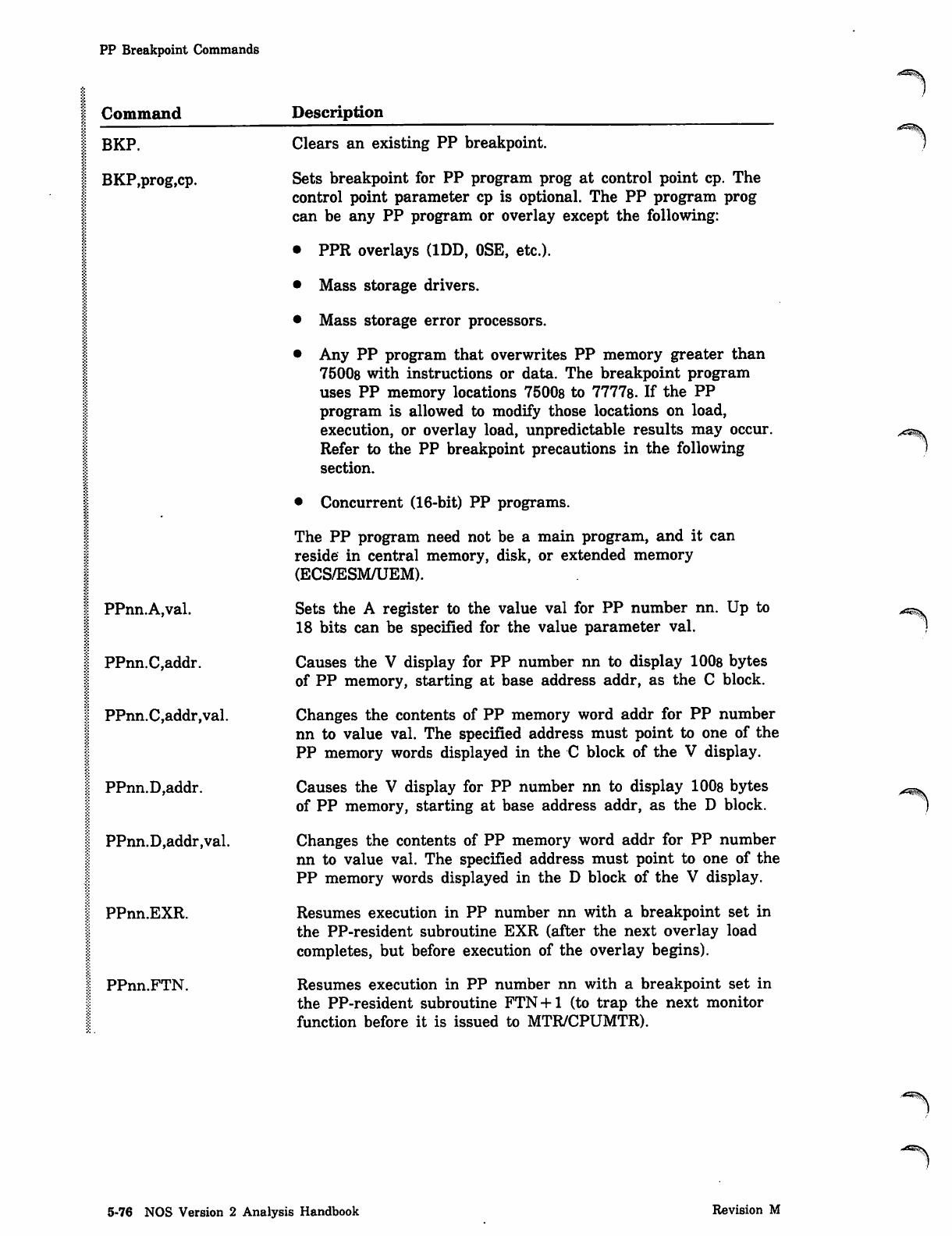
PP Breakpoint Commands
Command Description
| BKP.
| BKP,prog,cp.
| PPnn.A,val.
I PPnn.C,addr.
| PPnn.C,addr,val.
| PPnn.D,addr.
| PPnn.D,addr,val.
§ PPnn.EXR.
I PPnn.FTN.
Clears an existing PP breakpoint.
Sets breakpoint for PP program prog at control point cp. The
control point parameter cp is optional. The PP program prog
can be any PP program or overlay except the following:
• PPR overlays (1DD, OSE, etc.).
• Mass storage drivers.
• Mass storage error processors.
• Any PP program that overwrites PP memory greater than
75008 with instructions or data. The breakpoint program
uses PP memory locations 75008 to 77778. If the PP
program is allowed to modify those locations on load,
execution, or overlay load, unpredictable results may occur.
Refer to the PP breakpoint precautions in the following
section.
• Concurrent (16-bit) PP programs.
The PP program need not be a main program, and it can
reside in central memory, disk, or extended memory
(ECS/ESM/UEM).
Sets the A register to the value val for PP number nn. Up to
18 bits can be specified for the value parameter val.
Causes the V display for PP number nn to display 100s bytes
of PP memory, starting at base address addr, as the C block.
Changes the contents of PP memory word addr for PP number
nn to value val. The specified address must point to one of the
PP memory words displayed in the C block of the V display.
Causes the V display for PP number nn to display 1008 bytes
of PP memory, starting at base address addr, as the D block.
Changes the contents of PP memory word addr for PP number
nn to value val. The specified address must point to one of the
PP memory words displayed in the D block of the V display.
Resumes execution in PP number nn with a breakpoint set in
the PP-resident subroutine EXR (after the next overlay load
completes, but before execution of the overlay begins).
Resumes execution in PP number nn with a breakpoint set in
the PP-resident subroutine FTN + 1 (to trap the next monitor
function before it is issued to MTR/CPUMTR).
^<«S5sV
5-76 NOS Version 2 Analysis Handbook Revision M
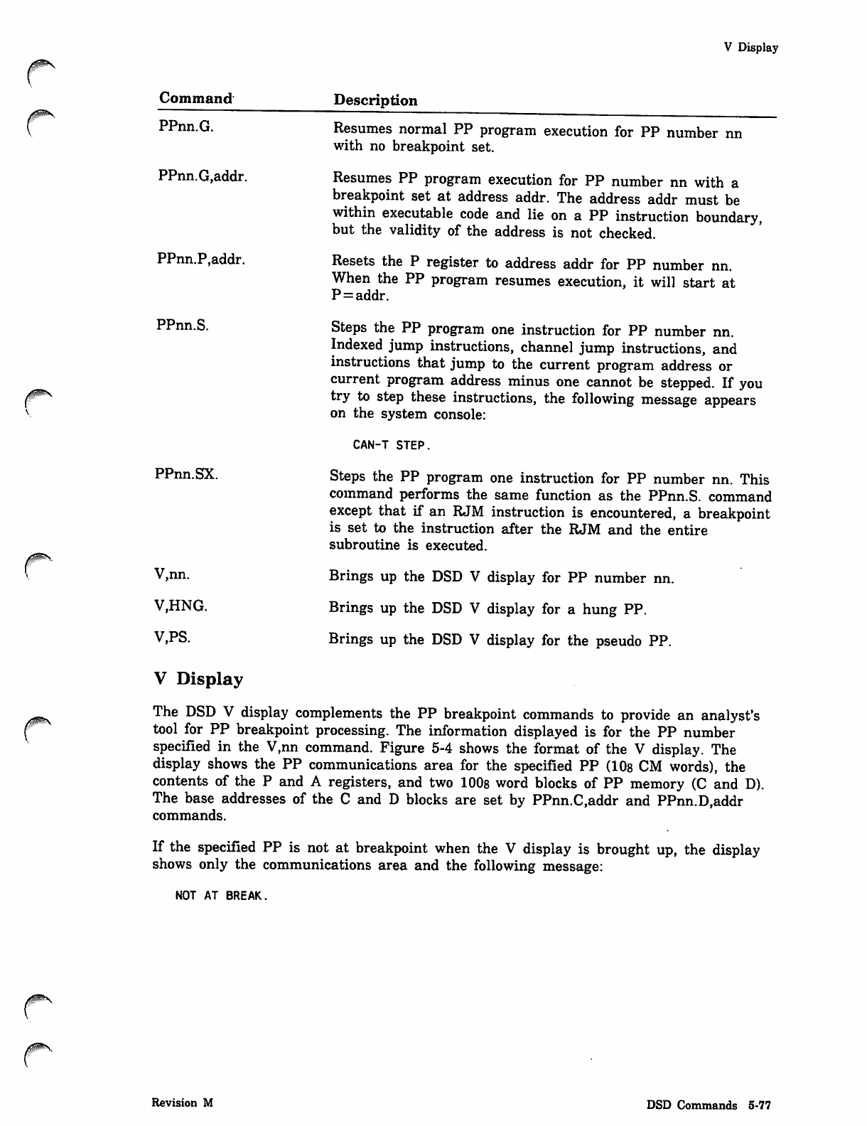
V Display
00^S
0&%S
Command
PPnn.G.
PPnn.G,addr.
PPnn.P,addr.
PPnn.S.
PPnn.SX.
V,nn.
V,HNG.
V,PS.
V Display
Description
Resumes normal PP program execution for PP number nn
with no breakpoint set.
Resumes PP program execution for PP number nn with a
breakpoint set at address addr. The address addr must be
within executable code and lie on a PP instruction boundary,
but the validity of the address is not checked.
Resets the P register to address addr for PP number nn.
When the PP program resumes execution, it will start at
P = addr.
Steps the PP program one instruction for PP number nn.
Indexed jump instructions, channel jump instructions, and
instructions that jump to the current program address or
current program address minus one cannot be stepped. If you
try to step these instructions, the following message appears
on the system console:
CAN-T STEP.
Steps the PP program one instruction for PP number nn. This
command performs the same function as the PPnn.S. command
except that if an RJM instruction is encountered, a breakpoint
is set to the instruction after the RJM and the entire
subroutine is executed.
Brings up the DSD V display for PP number nn.
Brings up the DSD V display for a hung PP.
Brings up the DSD V display for the pseudo PP.
The DSD V display complements the PP breakpoint commands to provide an analyst's
tool for PP breakpoint processing. The information displayed is for the PP number
specified in the V,nn command. Figure 5-4 shows the format of the V display. The
display shows the PP communications area for the specified PP (10s CM words), the
contents of the P and A registers, and two 1008 word blocks of PP memory (C and D).
The base addresses of the C and D blocks are set by PPnn.C,addr and PPnn.D,addr
commands.
If the specified PP is not at breakpoint when the V display is brought up, the display
shows only the communications area and the following message:
NOT AT BREAK.
Revision M DSD Commands 5-77
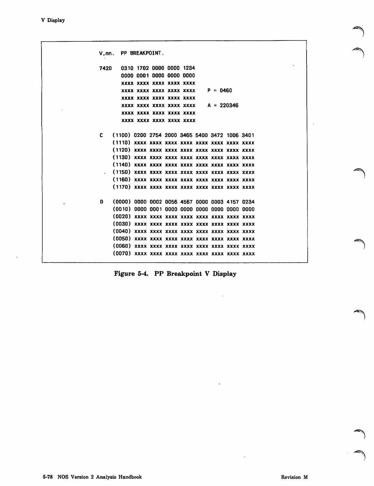
V Display
V,nn PP BREAKPOINT.
7420 0310 1702 oooo 0000 1234
0000 0001 OOOO OOOO OOOO
xxxx xxxx xxxx xxxx xxxx
xxxx xxxx xxxx xxxx xxxx = 0460
xxxx xxxx xxxx xxxx xxxx
xxxx xxxx xxxx xxxx xxxx A = 220346
xxxx xxxx xxxx xxxx xxxx
xxxx xxxx xxxx xxxx xxxx
C(1100) 0200 2754 2000 3465 5400 3472 1006 3401
(1110) xxxx xxxx xxxx xxxx xxxx xxxx xxxx xxxx
(1120) xxxx xxxx xxxx xxxx xxxx xxxx xxxx xxxx
(1130) xxxx xxxx xxxx xxxx xxxx xxxx xxxx xxxx
(1140) xxxx xxxx xxxx xxxx xxxx xxxx xxxx xxxx
(1150) xxxx xxxx xxxx xxxx xxxx xxxx xxxx xxxx
(1160) xxxx xxxx xxxx xxxx xxxx xxxx xxxx xxxx
(1170) xxxx xxxx xxxx xxxx xxxx xxxx xxxx xxxx
D(0000) oooo 0002 0056 4567 oooo 0003 4157 0234
(0010) OOOO 0001 0000 OOOO oooo OOOO oooo oooo
(0020) xxxx xxxx xxxx xxxx xxxx xxxx xxxx xxxx
(0030) xxxx xxxx xxxx xxxx xxxx xxxx xxxx xxxx
(0040) xxxx xxxx xxxx xxxx xxxx xxxx xxxx xxxx
(0050) xxxx xxxx xxxx xxxx xxxx xxxx xxxx xxxx
(0060) xxxx xxxx xxxx xxxx xxxx xxxx xxxx xxxx
(0070) xxxx xxxx xxxx xxxx xxxx xxxx xxxx xxxx
y^*feav
Figure 5-4. PP Breakpoint V Display
-*^\
5-78 NOS Version 2 Analysis Handbook Revision M
PP Breakpoint Precautions
PP Breakpoint Precautions
The following precautions and information are important to the successful use of the
PP breakpoint package.
• The breakpoint must be set in executable code and must lie on a PP instruction
boundary.
• When a breakpoint is set, two words of PP memory are replaced with the
following:
RJM BKP
When the breakpoint is hit, the two replaced words are immediately restored.
However, 16-bit instructions are not restored properly since they revert to 12-bit
instructions.
• The PP breakpoint package uses PP locations 7500s through 7777s. If these
locations are altered by the running PP, the system will probably fail.
• If the PP program being breakpointed encounters a mass storage error, the mass
storage driver's error processor will overlay the PP breakpoint code, and will
probably crash the operating system.
• If the PP program being breakpointed performs code modification on the
instruction at the address at which the breakpoint has been set, unpredictable
results may occur.
• The PP breakpoint package cannot be used on DIS or 026. However, it can be
used on other PPs at the same control point as DIS or 026.
• The PP breakpoint information (BKP,prog) remains set until BKP is entered or a
SYSEDIT or any level of deadstart is performed.
Revision M DSD Commands 5-79
CPUMTR Breakpoint Commands
CPUMTR Breakpoint Commands
The following DSD commands control CPUMTR breakpoint processing. These commands
and the DSD C display enable you to communicate with the CPUMTR breakpoint
package. The C display is described following the command descriptions. The CPUMTR
breakpoint commands require that the system console be unlocked (refer to the
UNLOCK command earlier in this section); on a secured system, the console must be
in security unlock status.
CAUTION
Use these commands with extreme caution to avoid damage to the system or to user
jobs. Incorrect usage may cause a system to hang up and require a deadstart.
NOTE
Only one CPUMTR breakpoint can be set at a time. Any existing breakpoint is
cleared when you enter a CPB,BKP,... command.
Command Description
CPB,BKP,addr.
CPB,BKPy/addr.
CPB,BKP,/bbbb/addr.
CPB,DSP.
CPB,DSP,addr.
CPB,DSP,//addr.
CPB,DSP,/bbbb/addr.
CPB,DSP +
CPB,DSP-
Sets breakpoint at absolute address addr. Restarts execution,
if the CPU is waiting for a GO.
Sets breakpoint at CPUMTR relative address addr. Restarts
execution, if the CPU is waiting for a GO.
Sets breakpoint at address addr in CPUMTR block bbbb.
Restarts execution, if the CPU is waiting for a GO.
Brings up the CPUMTR breakpoint variant of the C display
on the left screen if the C display is not already active.
Causes the memory block in the C display to begin at the
breakpoint address.
Brings up the CPUMTR breakpoint variant of the C display
on the left screen if the C display is not already active.
Causes the memory block in the C display to begin at
absolute address addr.
Brings up the CPUMTR breakpoint variant of the C display
on the left screen if the C display is not already active.
Causes the memory block in the C display to begin at
CPUMTR relative address addr.
Brings up the CPUMTR breakpoint variant of the C display
on the left screen if the C display is not already active.
Causes the memory block in the C display to begin at
address addr in CPUMTR block bbbb.
Brings up the CPUMTR breakpoint variant of the C display
on the left screen if the C display is not already active.
Advances each of the memory block addresses by 10s.
Brings up the CPUMTR breakpoint variant of the C display
on the left screen if the C display is not already active.
Decrements each of the memory block addresses by 10s. ^ ^ 5 \
5-80 NOS Version 2 Analysis Handbook Revision M
0$m\
CPUMTR Breakpoint Display (C Display)
Command Description
CPB,GO. Clears any breakpoint that is set and allows CPUMTR to
restore its registers and continue execution.
CPB,P+ Sets breakpoint at the address following the current
breakpoint address and restarts execution, if the CPU is
waiting for a GO.
CPB,P- Sets breakpoint at the address preceding the current
breakpoint address and restarts execution, if the CPU is
waiting for a GO.
CPUMTR Breakpoint Display (C Display)
The CPUMTR breakpoint display is a variant of the DSD C display that is formatted
for use in CPUMTR breakpoint processing. This display is initiated by entering one of
the CPB,DSP commands. Figure 5-5 shows the format of the CPUMTR breakpoint
display. The display consists of the 208-word exchange package from the current or last
breakpoint (displayed in 5 groups of 4 octal digits per line). All exchange package
information is displayed except RA, FL, RAE, FLE, and MA. The P address shown is
the actual breakpoint address.
The exchange package is followed by two 108-word blocks of central memory
(displayed in 4 groups of 5 octal digits per line). The address of the memory block to
be displayed can be specified using one of the CPB,DSP commands. Even if the
address specified in the CPB,DSP command is a relative address, the addresses shown
in the display are absolute; thus, giving the actual location in memory of the
displayed data.
Revision M DSD Commands 5-81
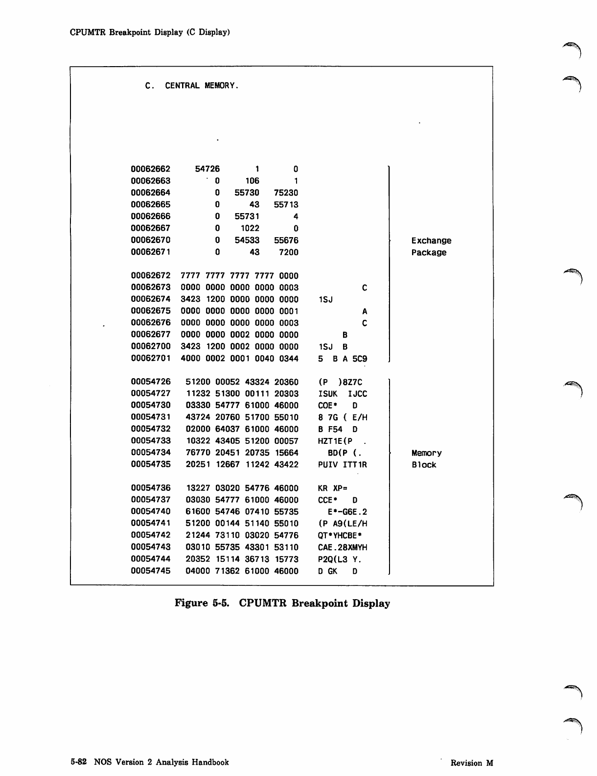
CPUMTR Breakpoint Display (C Display)
C. CENTRAL MEMORY.
00062662 5 4 7 2 6 1 0
00062663 0 1 0 6 1
00062664 0 55730 75230
00062665 0 4 3 5 5 7 1 3
00062666 0 5 5 7 3 1 4
00062667 0 1 0 2 2 0
00062670 0 54533 55676 Exchange
00062671 0 4 3 7 2 0 0 Package
00062672 7777 7777 7777 7777 0000
00062673 0000 0000 0000 0000 0003
00062674 3423 1200 0000 0000 0000 1SJ
00062675 0000 0000 0000 0000 0001
00062676 OOOO OOOO OOOO OOOO 0003
00062677 OOOO OOOO 0002 OOOO oooo
00062700 3423 1200 0002 OOOO OOOO 1SJ B
00062701 4000 0002 0001 0040 0344 5 B A 5C9
00054726 51200 00052 43324 20360 (P )8Z7C
00054727 11232 51300 00111 20303 ISUK IJCC
00054730 03330 54777 61000 46000 COE* D
00054731 43724 20760 51700 55010 8 7G ( E/H
00054732 02000 64037 61000 46000 B F54 D
00054733 10322 43405 51200 00057 HZT1E(P .
00054734 76770 20451 20735 15664 BD(P (. Memory
00054735 20251 12667 11242 43422 PUIV ITT1R Block
00054736 13227 03020 54776 46000 KR XP=
00054737 03030 54777 61000 46000 CCE* D
00054740 61600 54746 07410 55735 E*-G6E.2
00054741 51200 00144 51140 55010 (P A9(LE/H
00054742 21244 73110 03020 54776 QT*YHCBE*
00054743 03010 55735 43301 53110 CAE.28XMYH
00054744 20352 15114 36713 15773 P2Q(L3 Y.
00054745 04000 71362 61000 46000 D GK D
,^ms
Figure 5-5. CPUMTR Breakpoint Display
5-82 NOS Version 2 Analysis Handbook Revision M
j|^V
CPUMTR Breakpoint Precautions
CPUMTR Breakpoint Precautions
The following precautions and information are important to the successful use of the
CPUMTR breakpoint package.
• The breakpoint must be set in executable code.
© When a breakpoint is set, DSD stores RJ BKP at the specified address. When the
breakpoint address is hit, CPUMTR saves all of the registers in the display area,
clears the breakpoint, and then waits to receive a GO. The message CPUMTR
BREAKPOINT HIT is displayed at the system control point.
a From the time that the breakpoint is hit until the CPU continues, the system
clock stops. Therefore, you should reset the system clock (with the DSD TIME
command) after you have finished breakpoint processing.
© A CPUMTR breakpoint can be set in monitor mode or program mode. However,
alternating between the modes is not advised. Going from monitor to program
mode is probably safe, but going from program to monitor mode is almost certain
to fail causing CPUMTR to abort with the following message issued to the system
console:
CPUMTR ERROR EXIT.
« Since the C display is resident in RPL, changing displays is allowed (before the
breakpoint is hit) because you can always return to the C display. However, once
the breakpoint is hit until the CPU continues, CPUMTR is hung. This means that
all activity in the system stops until the CPU restarts. If DSD attempts to
request a monitor function, the following message appears in the B display:
NO MONITOR RESPONSE.
This is normal since CPUMTR is hung in the breakpoint code and the message
may be ignored. In this case, the DSD request that required the monitor function
is not processed.
• If you attempt to reference a CPUMTR block that is not loaded, the following
message appears on the system console:
INCORRECT ENTRY.
• The C display retains the last addresses displayed. For example, if you change to
another display and then come back to the C display it will still show the same
absolute addresses.
• Once a breakpoint has been hit and CPUMTR is waiting for a CPB,GO (or
another CPB,BKP) command, the contents of any register or memory location can
be changed by using the normal memory entry commands. To change a register,
simply change the corresponding memory location on the C display (as initiated by
the CPB,DSP command). The exchange package shown on the C display will be
reloaded to display the actual registers when execution resumes.
NOTE
Since CPUMTR has been halted, any memory entries made at this time must be
preceded by a 99 command to disable DSD syntax overlay processing and the
logging of the command to the error log.
Revision M DSD Commands 5-83
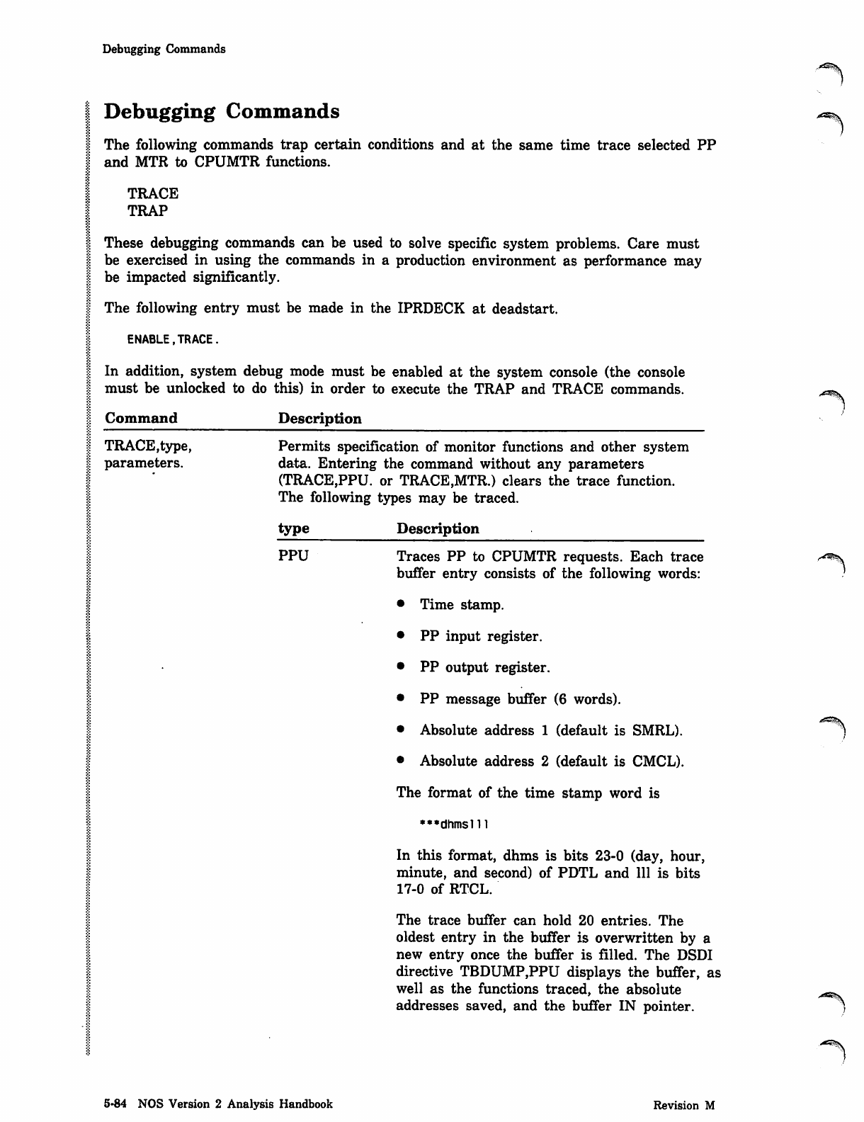
Debugging Commands
Debugging Commands
The following commands trap certain conditions and at the same time trace selected PP
and MTR to CPUMTR functions.
TRACE
TRAP
These debugging commands can be used to solve specific system problems. Care must
be exercised in using the commands in a production environment as performance may
be impacted significantly.
The following entry must be made in the IPRDECK at deadstart.
ENABLE.TRACE.
In addition, system debug mode must be enabled at the system console (the console
must be unlocked to do this) in order to execute the TRAP and TRACE commands.
Command Description
TRACE.type, Permits specification of monitor functions and other system
parameters. data. Entering the command without any parameters
(TRACE,PPU. or TRACE,MTR.) clears the trace function.
The following types may be traced.
type Description
PPU Traces PP to CPUMTR requests. Each trace
buffer entry consists of the following words:
• Time stamp.
• PP input register.
• PP output register.
• PP message buffer (6 words).
• Absolute address 1 (default is SMRL).
• Absolute address 2 (default is CMCL).
The format of the time stamp word is
•••dhmslll
In this format, dhms is bits 23-0 (day, hour,
minute, and second) of PDTL and 111 is bits
17-0 of RTCL.
The trace buffer can hold 20 entries. The
oldest entry in the buffer is overwritten by a
new entry once the buffer is filled. The DSDI
directive TBDUMP,PPU displays the buffer, as
well as the functions traced, the absolute
addresses saved, and the buffer IN pointer.
^^5V
5-84 NOS Version 2 Analysis Handbook Revision M
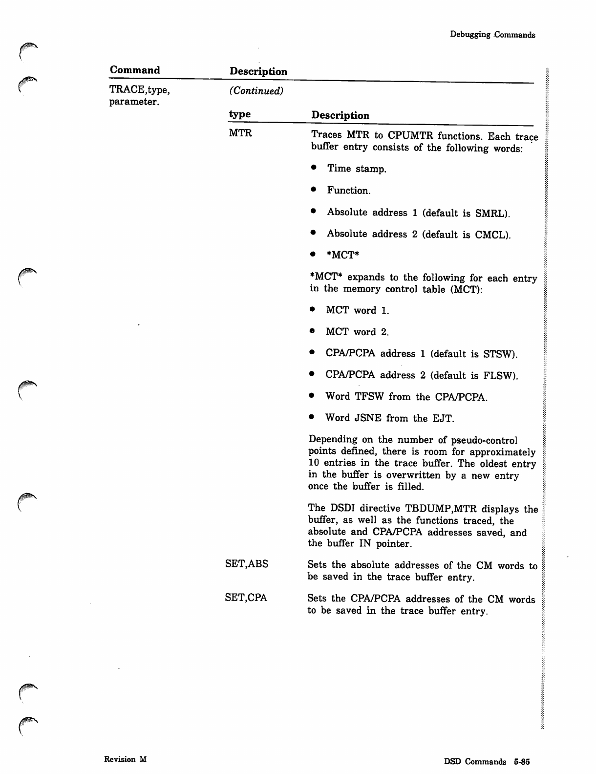
Debugging Commands
Command Description
TRACE,type,
parameter.
(Continued)
type
MTR
00S.
SET,ABS
SET,CPA
Description
Traces MTR to CPUMTR functions. Each trace
buffer entry consists of the following words:
Time stamp.
Function.
Absolute address 1 (default is SMRL).
Absolute address 2 (default is CMCL).
*MCT*
MCT* expands to the following for each entry
in the memory control table (MCT):
MCT word 1.
MCT word 2.
CPA/PCPA address 1 (default is STSW).
CPA/PCPA address 2 (default is FLSW).
Word TFSW from the CPA/PCPA.
Word JSNE from the EJT.
Depending on the number of pseudo-control
points defined, there is room for approximately
10 entries in the trace buffer. The oldest entry
in the buffer is overwritten by a new entry
once the buffer is filled.
The DSDI directive TBDUMP,MTR displays the
buffer, as well as the functions traced, the
absolute and CPA/PCPA addresses saved, and
the buffer IN pointer.
Sets the absolute addresses of the CM words to
be saved in the trace buffer entry.
Sets the CPA/PCPA addresses of the CM words
to be saved in the trace buffer entry.
yHflmm&y
Revision M DSD Commands 5-85
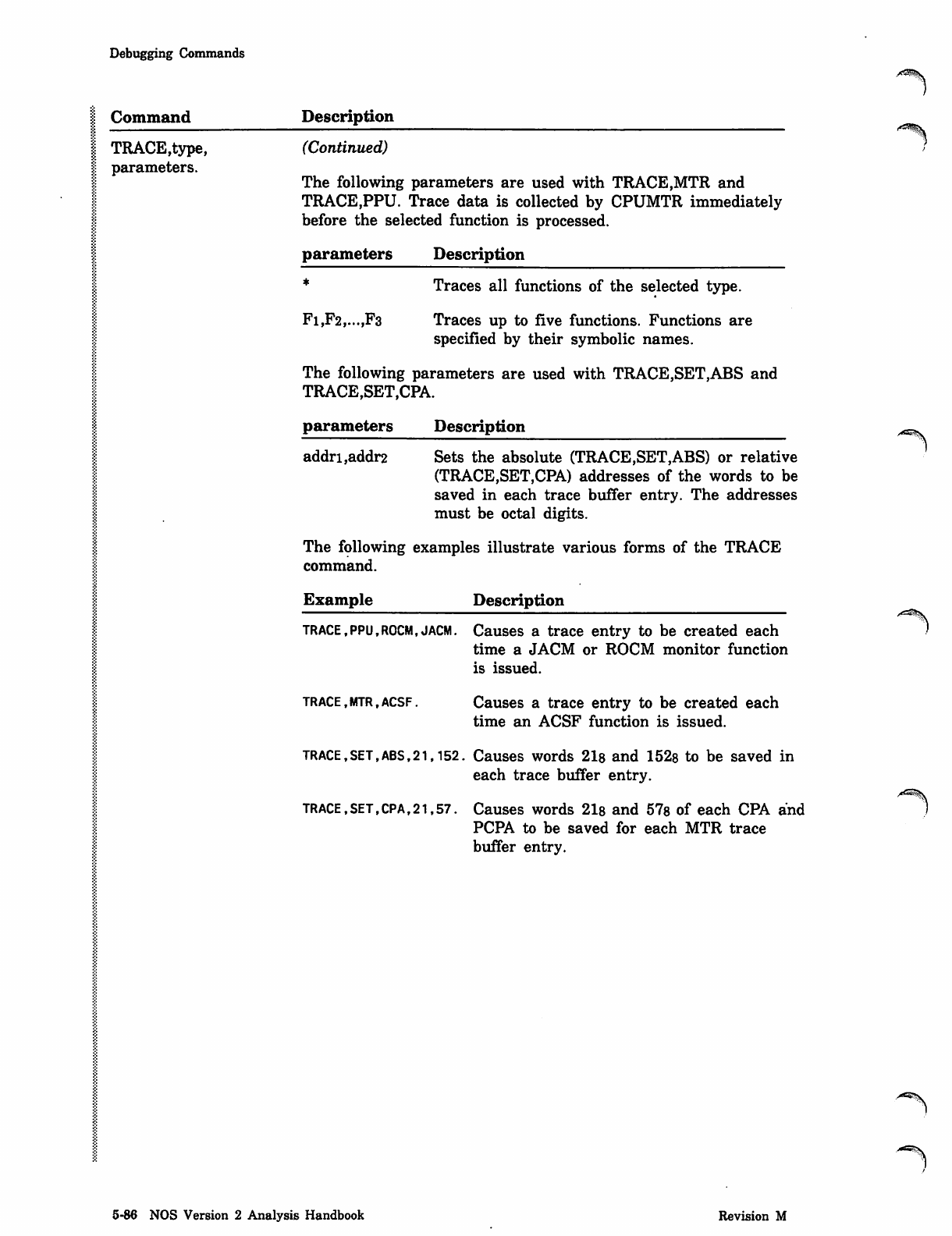
Debugging Commands
I Command Description
I TRACE,type,
| parameters.
(Continued)
The following parameters are used with TRACE,MTR and
TRACE,PPU. Trace data is collected by CPUMTR immediately
before the selected function is processed.
parameters Description
* Traces all functions of the selected type.
Fi,F2,...,F3 Traces up to five functions. Functions are
specified by their symbolic names.
The following parameters are used with TRACE,SET,ABS and
TRACE,SET,CPA.
parameters Description
addri,addr2 Sets the absolute (TRACE,SET,ABS) or relative
(TRACE,SET,CPA) addresses of the words to be
saved in each trace buffer entry. The addresses
must be octal digits.
The following examples illustrate various forms of the TRACE
command.
.^S^y
Example Description
TRACE, PPU, ROCM, j ACM. Causes a trace entry to be created each
time a JACM or ROCM monitor function
is issued.
TRACE,MTR,ACSF. Causes a trace entry to be created each
time an ACSF function is issued.
TRACE,SET,ABS,21,152. Causes words 21s and 152s to be saved in
each trace buffer entry.
TRACE, SET, CP A, 21,57. Causes words 21s and 57s of each CPA and
PCPA to be saved for each MTR trace
buffer entry.
/*^™^*K
><5^v
5-86 NOS Version 2 Analysis Handbook Revision M
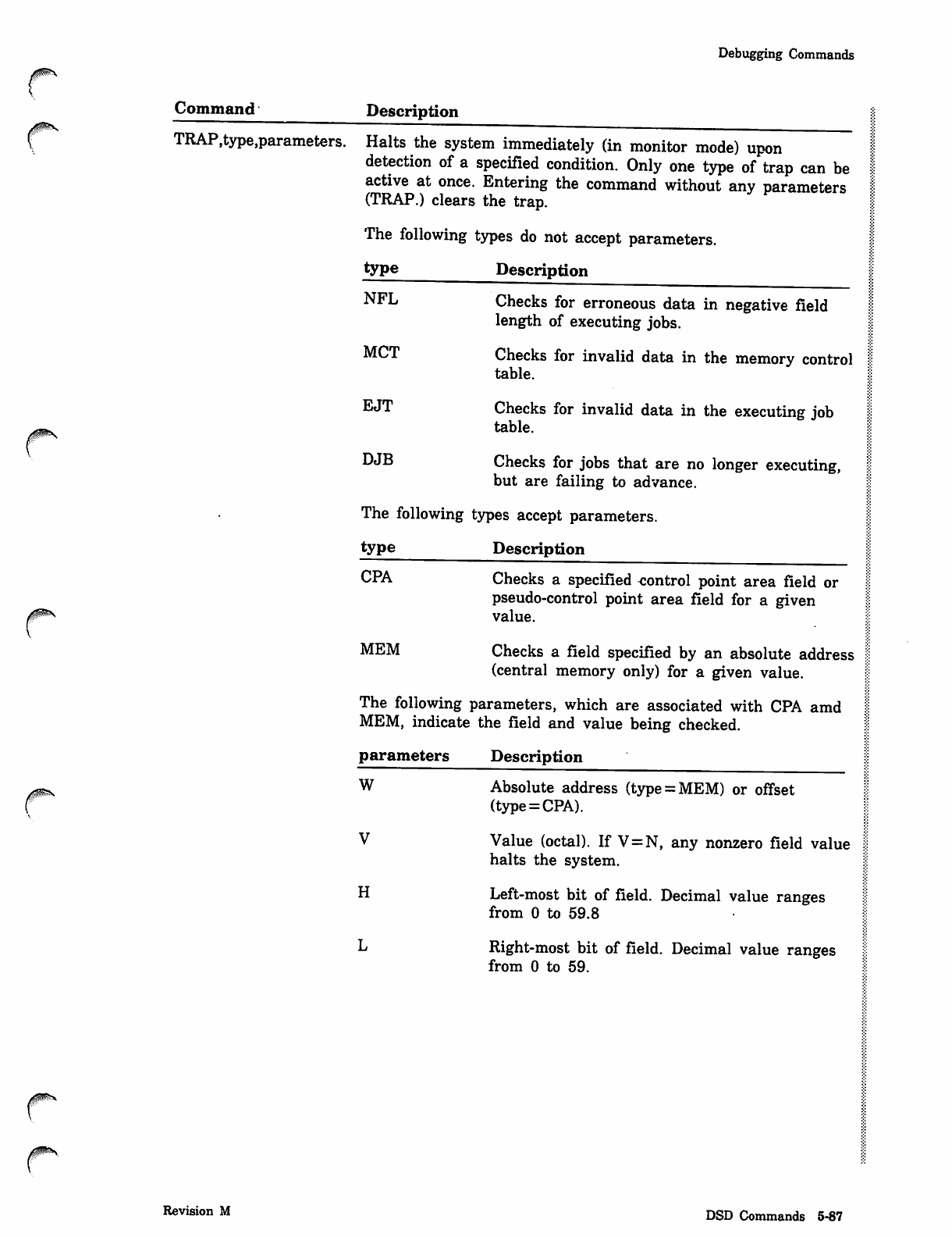
Debugging Commands
Command Description
TRAP,type,parameters. Halts the system immediately (in monitor mode) upon
detection of a specified condition. Only one type of trap can be
active at once. Entering the command without any parameters
(TRAP.) clears the trap.
The following types do not accept parameters.
type Description
jHv&tizis
NFL Checks for erroneous data in negative field
length of executing jobs.
MCT Checks for invalid data in the memory control
table.
EJT Checks for invalid data in the executing job
table.
DJB Checks for jobs that are no longer executing,
but are failing to advance.
The following types accept parameters.
type Description
CPA Checks a specified control point area field or
pseudo-control point area field for a given
value.
MEM Checks a field specified by an absolute address
(central memory only) for a given value.
The following parameters, which are associated with CPA amd
MEM, indicate the field and value being checked.
parameters Description
W Absolute address (type = MEM) or offset
(type = CPA).
V Value (octal). If V=N, any nonzero field value
halts the system.
H Left-most bit of field. Decimal value ranges
from 0 to 59.8
L Right-most bit of field. Decimal value ranges
from 0 to 59.
Revision M DSD Commands 5-87
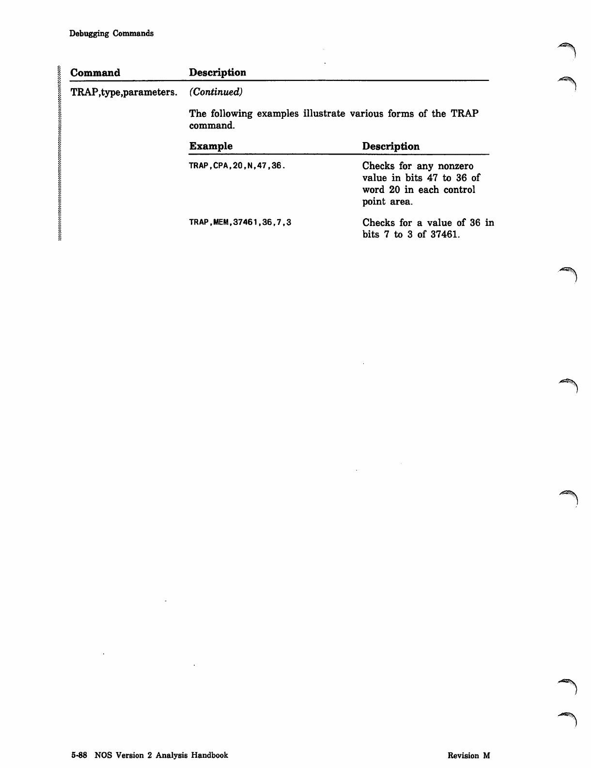
Debugging Commands
Command Description
| TRAP,type,parameters. (Continued)
The following examples illustrate various forms of the TRAP
command.
Example Description
TRAP,CPA,20,N,47,36. Checks for any nonzero
value in bits 47 to 36 of
word 20 in each control
point area.
TRAP,MEM,37461,36,7,3 Checks for a value of 36 in
bits 7 to 3 of 37461.
5-88 NOS Version 2 Analysis Handbook Revision M
(* Express Deadstart Dump Interpreter
(DSDI)
j^N
f^'
C a l l i n g t h e E x p r e s s D e a d s t a r t D u m p I n t e r p r e t e r 6 - 3
Input Directives 6-6
Directive Format 6-7
List Control Directives 6-8
EJ — Force Page Eject 6-8
EJOFF — Turn Off Auto Page Eject 6-8
EJON — Turn On Auto Page Eject 6-8
PD — Reset Print Line Density . 6-8
*. — Comment in Subtitle Line . 6-9
File Manipulation and Control Directives 6-10
DISPOSE — Dispose Alternate List File to Print Queue 6-10
OUTPUT — Assign Output to Alternate List File 6-10
READ — Read Alternate Directives File 6-11
REWIND — Rewind File 6-11
Central Memory/Extended Memory Dump Directives 6-12
Dump Control Directives 6-12
ALLMEM — Extend Central Memory Dumps 6-12
CM — Set Memory Type to Central Memory 6-12
EC — Set Memory Type to Extended Memory • 6-13
RA — Reset Reference Address 6-13
RAC — Reset Reference Address to RA of Control Point 6-14
. UEC — Set Memory Type to User-Access Extended Memory f>14
Memory Dump Directives ... . 6-15
C — Dump Memory in Instruction Parcel Format . 6-15
D — Dump Memory in Byte Format 6-16
E — Dump Memory in Word Format 6-16
I — Dump 64-Bit Memory in Instruction Parcel Format 6-17
W — Dump 64-Bit Memory in Word Format 6-18
PP Dump Directives 6-19
AP — Dump Analysis of PP and PP Memory in Octal Line Format . 6-19
M P P — M o v e P P 6 - 2 0
P — Dump PP Memory in Octal Block Format 6-20
PF. — Dump FLPP Memory in Octal Block Format 6-21
PMS — Read PP Select Switches 6-21
PO — Dump 16-Bit PP Memory in Octal Block Format 6-22
PX — Dump 16-Bit PP Memory in Hexadecimal Block Format 6-22
Q — D u m p P P M e m o r y i n O c t a l L i n e F o r m a t 6 - 2 3
QF — Dump FLPP Memory in Octal Line Format 6-23
QOA — Dump 16-Bit PP Memory in Octal/ASCII Line Format 6-24
QOD — Dump 16-Bit PP Memory in Octal/Display Line Format 6-24
QXA — Dump 16-Bit PP Memory in Hexadecimal/ASCII Line Format 6-25
QXD — Dump 16-Bit PP Memory in Hexadecimal/Display Line Format 6-25
CMR Dump Directives 6-26
ACCOUNT — Dump Account Dayfile Buffer 6-26
CBT — Dump Control Buffer Table 6-27
CCT — Dump Channel Control Table 6-27
CP — Dump Active Control Point Areas 6-28
CPO — Reset Default list Options 6-30
CT — Dump Channel Tables 6-30
DAYFILE — Dump System Dayfile Buffer 6-30
DB — Dump Disk Buffers 6-30
DBW — Dump Buffered Device/Buffer Statistics/PP-I/O Buffer Link Tables .. 6-31
DDB — Dump Dayfile Dump Buffer 6-31
DP — Dump Dayfile Buffer Pointers 6-31
EICB — Dump Environment Interface Communication Buffer 6-31
EJT — Dump Executing Job Table .... 6-31
EPB — Dump Extended Memdry/PP Buffer 6-32
ERRLOG — Dump Error Log Buffer ..... 6-32
EST — Dump Equipment Status Table 6-32
FNT —- Dump System File Name/File Status Table .... 6-32
FOT — Dump Family Ordinal Table 6-32
HAT— Dump Hash Table 6-33
J C — D u m p J o b C o n t r o l A r e a f o r E a c h S e r v i c e C l a s s 6 - 3 3
LC— Dump Low Central Memory ....... 6-33
LDIS — Dump L-Display Buffer 6-34
LIDT — Dump Logical Identifier Table 6-34
MAINLOG — Dump Binary Maintenance Log Buffer 6-34
MCT — Dump Memory Control Table . .... 6-34
MST — Dump Mass Storage/Track Reservation Tables 6-35
MTR — Dump CPU Monitor . ..... 6-35
MTRQUEUE — Dump CPUMTR Request and Recall Queues . 6-36
ODIS — Dump Operator Display Buffer 6-36
PCP — Dump Pseudo-control Point ... 6-36
PLD' — Dump Peripheral Library Directory ..... 6-37
PP — Dump PP Communication Areas 6-37
PROBE — Dump PROBE Data Tables 6-37
PST— Dump Program Status Table and Entry Point Directory .... 6-37
PUT — Dump Physical Unit Table 6-38
QFT — Dump Queued File Table ........-. .. 6-38
RCL — Dump Resident Central Library 6-38
RPL — Dump Resident Peripheral Library 6-39
SAB — Dump System Attribute Block ... 6-39
SDA — Dump Extended Statistical Data Area .......;.. 6-39
SECDED — Dump SECDED Identifier Table................................ 6-39
SST — Dump Subsystem Control Point/Subsystem Assignment Tables 6-40
TBDUMP — Dump Trace Buffer ..... 6-40
Subsystem Dump/Analysis Directives .... 6-41
BATCHIO (BIO) — Dump Associated Memory for Analysis 6-41
IAF — Dump Associated Memory for Analysis ...... 6-42
MAGNET (MAG) — Dump Associated Memory for Analysis 6-44
RHF — Dump Associated Memory for Analysis .... 6-45
Hardware Register Dump Directives 6-46
FMFREG ■— Dump PP Registers . 6-46
IOUCR — Dump Concurrent PP Channel Registers .. ... . 6-46
IOUMR — Dump IOU Maintenance Registers . .,..• 6-46
LP VA — L oa d C en tr al M e mo ry P VA i n t o P se ud o R e g is te r 6 - 4 7
MEMMR — Dump Memory Maintenance Registers 6-47
PROCA — Dump Processor Operand Cache 6-48
PROCW — Dump Processor Controlware Part Number and Revision Level... 6-48
PROMR — Dump Processor Maintenance Registers .. 6-48
PROPM — Dump Processor Page Map . 6-49
PRORF — Dump Processor Register File .... ...., ..."... 6-49
PROSM— Dump Processor Segment Map 6-49
PROXP — Dump Processor Exchange Package 6-50
SC — Dump S/C Register 6-50
SETCPU— Set CPU Number 6-50
SETIOU — Set PP Dump Defaults 6-51
SETJPS— Change the JPS Register Value 6-51 ^*%
~)
SETRMA — Convert Address into RMA 6-52
SETVEP — Set Virtual Address Parameters 6-52
TRACEBK — Traceback Stack Frame Save Area . 6-53
XP - Dump Deadstart Exchange Package 6-53
Buffer Controller Directive 6-54
Interactive Use of DSDI "6-55
Terminal Output Directives 6-57
C — Dump Memory in Instruction Parcel Format 6-57
CP — Dump Active Control Point Areas 6-58
D — Dump Memory in Byte Format 6-59
PP — Dump PP Communication Areas 6-60
Q — Dump PP Memory in Line Format 6-61
QOA, QOD, QXA, QXD •— Dump 16-Bit PP Memory in Line Format 6-62
Example of DSDI Terminal Use 6-63
Printer Output Listing Examples 6-65
/p*
(P*
j ^ v
P^

^ Express Deadstart Dump Interpreter
f ( D S D I ) 6
The deadstart dump interpreter (DSDI) is a utility program that converts selected
portions of the binary information on an express deadstart dump (EDD) file into reports
to be listed. The EDD file is generated on magnetic tape by the EDD utility, which
may be run at deadstart time after a system malfunction has occurred. Refer to the
CIP User's Handbook for complete information concerning the use of EDD.
Selection of data to be listed by DSDI is provided through input directives, either on
an input file or on the DSDI command. Normal octal dumps of central memory,
extended memory, and PP memory can be produced by these directives as well as
specially formatted dumps of specific system tables and buffers.
EDD and DSDI offer these features:
® The EDD tape file contains a dump of memory, the executing exchange packages,
the CYBER 170 status and control (S/C) registers, where applicable; maintenance
registers for models 865 and 875 and CYBER 180-class machines, register file,
exchange package, processor control store, processor operand cache, processor page
map, processor segment map, where applicable; and all PPs except for PPO, which
can be saved by either copying it to another PP or by biasing the PP switch on
the deadstart panel. EDD can optionally dump all or part of extended memory and
the selected buffer controllers. EDD and DSDI permit analysis of a system
malfunction to be performed entirely offline.
• Because DSDI copies the EDD file to a word-addressable random file on mass
storage, dump data can be accessed in any order.
• EDD requires only a small amount of time during deadstart because the data is
transferred in binary form to magnetic tape.
© The tape file created by EDD can be retained on magnetic tape or mass storage
until it is no longer needed. Thus, a selective listing can be generated at any
time.
y™srw?v
General information from the EDD file appears in the title and subtitle line of
each page of listed output. The first 50 columns of each input directive are
included in the title line of the output list it produces. An input directive is
provided that enables insertion of comments into the subtitle line.
Use of DSDI is possible from an interactive terminal as well as from the batch
environment. The output produced by several directives is formatted for terminal
output (72 columns). From a batch environment, output is formatted for a
136-column printer.
Revision M Express Deadstart Dump Interpreter (DSDI) 6-1
Express Deadstart Dump Interpreter (DSDI)
DSDI can also be used to create a message file containing the contents of the
maintenance registers (input/output unit, memory, and processor) that were dumped to
the EDD file for CYBER 180-class machines. This message file, which is similar in
format to the binary maintenance log (BML), can then be analyzed by an interpreter
progam, such as the Hardware Performance Analyzer (HPA), to produce maintenance
register reports. Refer to the IOUMR, MEMMR, and PROMR DSDI input directives
later in this section for additional information.
DSDI writes up to three messages to this message file: one message each for
input/output unit errors, memory errors, and processor errors. If the status summary
register for a particular element is zero (signifying no errors for that element), DSDI
does not write the corresponding message to the message file.
In addition, the message file contains messages for any errors that were detected by
the dedicated fault tolerance (DFT) processor but not yet written to the BML at the
time the EDD file was created. These messages are identical in format to the ones that
would have been written to the BML by the normal logging process.
J^MW^V
6-2 NOS Version 2 Analysis Handbook Revision M
/0m»._
Calling the Express Deadstart Dump Interpreter
Calling the Express Deadstart Dump Interpreter
Processing of the EDD file is initiated with the DSDI command. The format of the
command is:
DSDI,plFp2 pn.
Each parameter pi is either a keyword or a keyword equated to a value. All
parameters are optional and order independent.
Pi
B=bmlfile
B omitted
D
D omitted
DMB
DMB omitted
Description
The 1- to 7-character name of the message file on which the
maintenance register messages and unlogged DFT error
messages are to be written. The message file is similar in
format to the BML and can be analyzed by HPA. This
parameter is valid only if maintenance register messages or
unlogged DFT error messages have been dumped to the EDD
file.
No message file is to be created.
This parameter creates a random dump file with the same name
as the EDD file and returns the original EDD file. The created
file can then be used as the dump file on subsequent executions
of DSDI, eliminating the need to read the entire dump tape on
each call.
No random dump file is to be created.
A binary dump file produced by the DMB or LOADBC command
is to be analyzed instead of an EDD file.
EDD file is to be analyzed.
When the DMB parameter is specified for a DMB-created dump,
DSDI uses directives as though the job were running at control
point 1. The DMB command dumps the exchange package,
central memory, and extended memory in binary (refer to the
NOS Version 2 Reference Set, Volume 3). Use the following
directives to dump selected portions of memory to be analyzed.
Directive Description
CP,1
RAC,1/C,fwa,lwa
RAC,1/D,fwa,lwa
RA,0/EC/C,fwa,lwa
'RA,0/EC/D,fwa,lwa
Dump exchange package.
Dump central memory in C format.
Dump central memory in D format.
Dump extended memory in C format.
Dump extended memory in D format.
Revision M Express Deadstart Dump Interpreter (DSDI) 6-3
Calling the Express Deadstart Dump Interpreter
Pi Description
DMB omitted
F=dumpfile
F omitted
I=infile
I omitted
L=outfile
L omitted
NR
NR omitted
P
P omitted
PD = n
(Continued)
fwa and lwa are the first and last word addresses of memory to
be dumped. When this parameter is specified to analyze a
LOADBC controlware dump, the only DSDI directive that can be
used is:
BCDUMP/ops.
Refer to the BCDUMP directive described later in this section
for a description of the ops parameter.
The 1- to 7-character name of the EDD file that DSDI will
interpret.
Same as F=DUMP.
The 1- to 7-character name of file on which input directives are
written.
Same as I=INPUT.
The 1- to 7-character name of file on which list output is to be
written. The user must save or print the file.
Same as L=OUTPUT, except that the file is automatically
printed.
EDD file is not to be rewound.
EDD file is to be rewound before processing.
CMR pointers from the running system are to be used. Selecting
this parameter causes the CMR pointers from the running
system to be used to locate tables and buffer areas on the EDD
file. This parameter is typically used when it is known that the
CMR pointers on the EDD file were destroyed by system
malfunction. Directives used to dump CMR will dump the
pointers contained on the EDD file, not those from the running
system.
This parameter should be used only when the configuration of
the running system is the same as the system in use when the
EDD file was created.
CMR pointers from EDD file are to be used.
Print density in number of lpi (3, 4, 6, or 8).
, ^ ^ \
6-4 NOS Version 2 Analysis Handbook Revision M
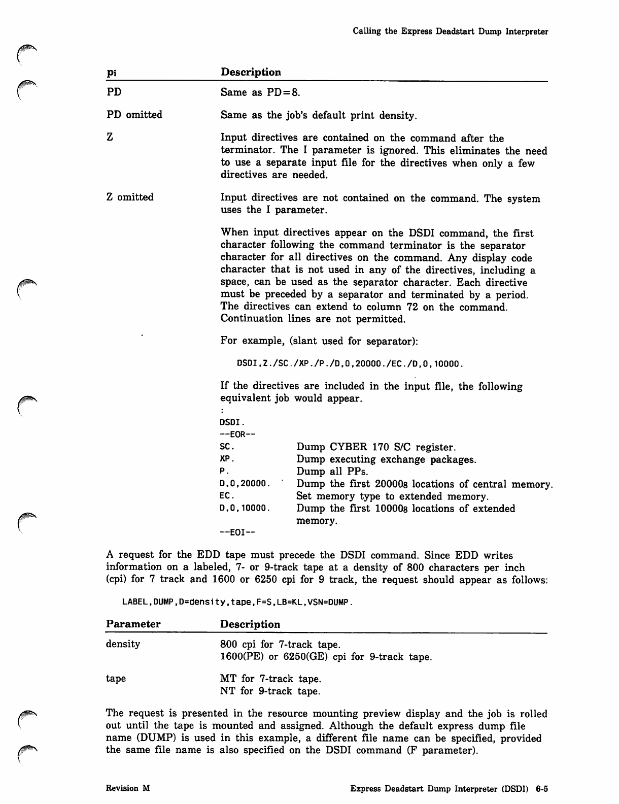
Calling the Express Deadstart Dump Interpreter
Pi Description
PD
PD omitted
Z
Z omitted
Same as PD = 8.
Same as the job's default print density.
Input directives are contained on the command after the
terminator. The I parameter is ignored. This eliminates the need
to use a separate input file for the directives when only a few
directives are needed.
Input directives are not contained on the command. The system
uses the I parameter.
When input directives appear on the DSDI command, the first
character following the command terminator is the separator
character for all directives on the command. Any display code
character that is not used in any of the directives, including a
space, can be used as the separator character. Each directive
must be preceded by a separator and terminated by a period.
The directives can extend to column 72 on the command.
Continuation lines are not permitted.
For example, (slant used for separator):
DSDI,Z./SC./XP./P./D,0,20000./EC./D,0,10000.
If the directives are included in the input file, the following
equivalent job would appear.
DSDI.
—EOR—
SC.
XP.
p.
D,0,20000.
EC.
D,0,10000.
—EOI—
Dump CYBER 170 S/C register.
Dump executing exchange packages.
Dump all PPs.
Dump the first 20000s locations of central memory.
Set memory type to extended memory.
Dump the first 10000s locations of extended
memory.
A request for the EDD tape must precede the DSDI command. Since EDD writes
information on a labeled, 7- or 9-track tape at a density of 800 characters per inch
(cpi) for 7 track and 1600 or 6250 cpi for 9 track, the request should appear as follows:
LABEL,DUMP,D=density,tape,F=S,LB=KL,VSN=DUMP.
Parameter Description
density
tape
800 cpi for 7-track tape.
1600(PE) or 6250(GE) cpi for 9-track tape.
MT for 7-track tape.
NT for 9-track tape.
The request is presented in the resource mounting preview display and the job is rolled
out until the tape is mounted and assigned. Although the default express dump file
name (DUMP) is used in this example, a different file name can be specified, provided
the same file name is also specified on the DSDI command (F parameter).
Revision M Express Deadstart Dump Interpreter (DSDI) 6-5
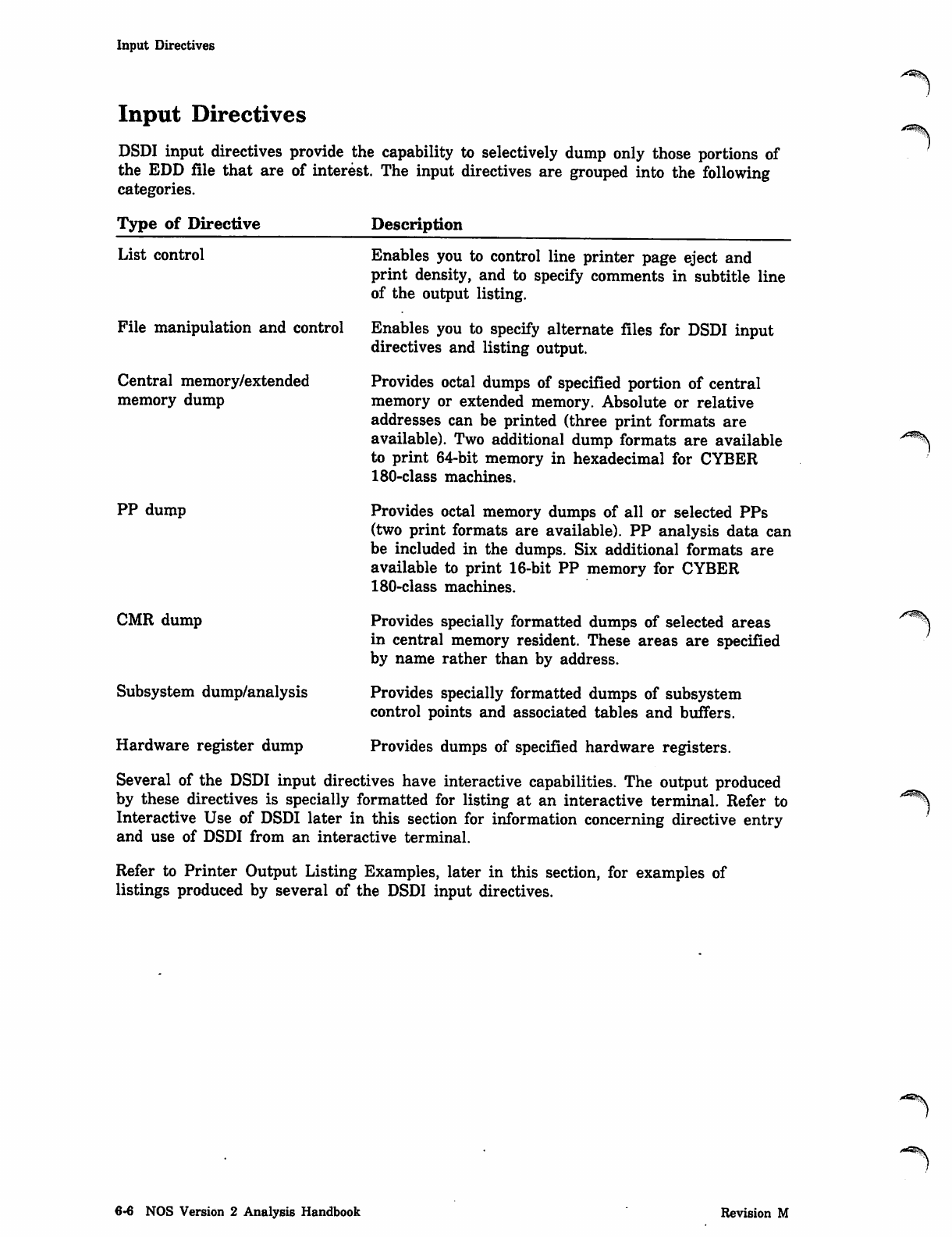
Input Directives
Input Directives
DSDI input directives provide the capability to selectively dump only those portions of
the EDD file that are of interest. The input directives are grouped into the following
categories.
Type of Directive Description
List control
File manipulation and control
Central memory/extended
memory dump
PP dump
CMR dump
Subsystem dump/analysis
Hardware register dump
Enables you to control line printer page eject and
print density, and to specify comments in subtitle line
of the output listing.
Enables you to specify alternate files for DSDI input
directives and listing output.
Provides octal dumps of specified portion of central
memory or extended memory. Absolute or relative
addresses can be printed (three print formats are
available). Two additional dump formats are available
to print 64-bit memory in hexadecimal for CYBER
180-class machines.
Provides octal memory dumps of all or selected PPs
(two print formats are available). PP analysis data can
be included in the dumps. Six additional formats are
available to print 16-bit PP memory for CYBER
180-class machines.
Provides specially formatted dumps of selected areas
in central memory resident. These areas are specified
by name rather than by address.
Provides specially formatted dumps of subsystem
control points and associated tables and buffers.
Provides dumps of specified hardware registers.
y*^Hj!y
Several of the DSDI input directives have interactive capabilities. The output produced
by these directives is specially formatted for listing at an interactive terminal. Refer to
Interactive Use of DSDI later in this section for information concerning directive entry
and use of DSDI from an interactive terminal.
Refer to Printer Output Listing Examples, later in this section, for examples of
listings produced by several of the DSDI input directives.
6-6 NOS Version 2 Analysis Handbook Revision M
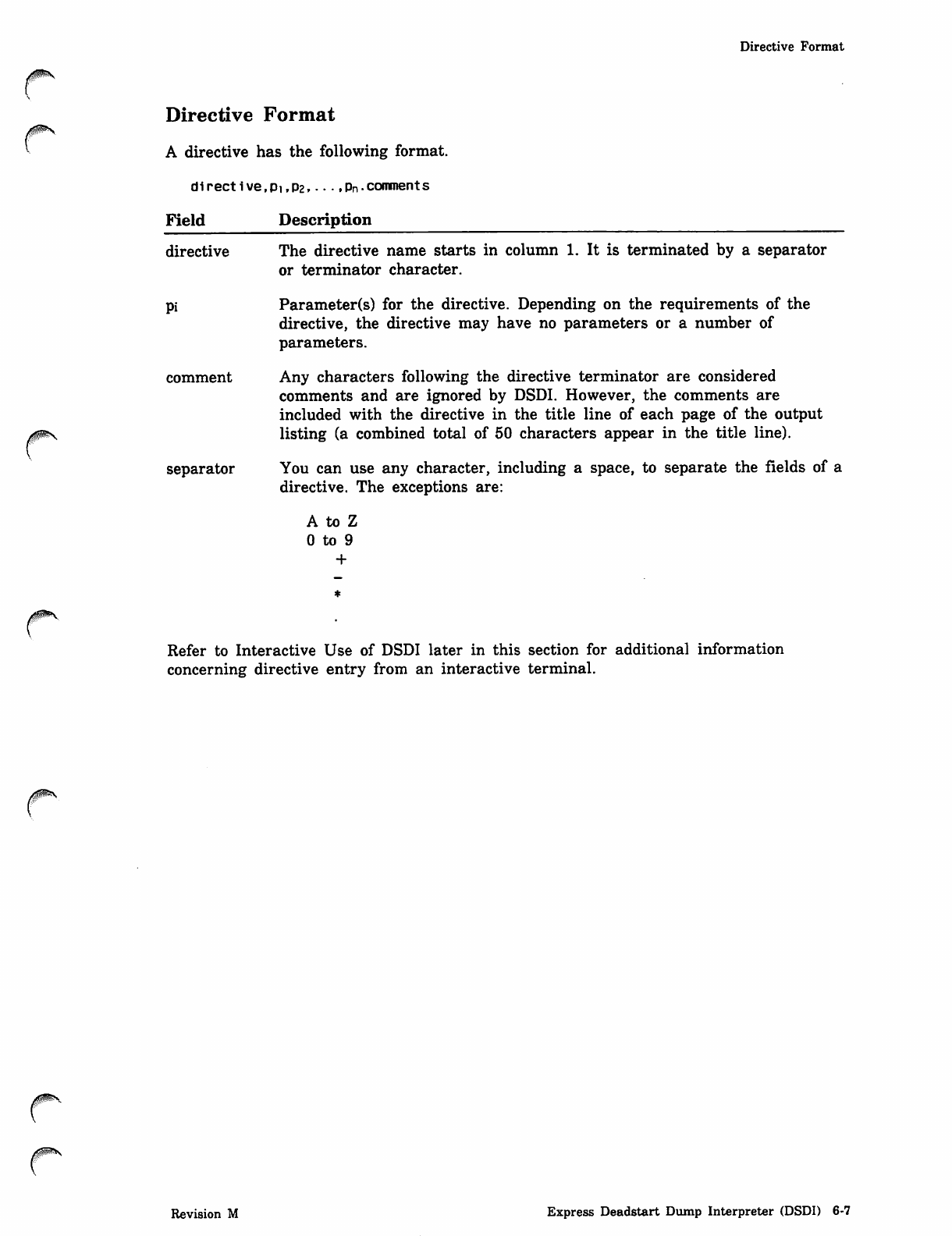
Directive Format
Directive Format
A directive has the following format.
directive, Pi ,P2,.•-.Pn-comments
Field Description
directive The directive name starts in column 1. It is terminated by a separator
or terminator character.
pi Parameter(s) for the directive. Depending on the requirements of the
directive, the directive may have no parameters or a number of
parameters.
comment Any characters following the directive terminator are considered
comments and are ignored by DSDI. However, the comments are
included with the directive in the title line of each page of the output
listing (a combined total of 50 characters appear in the title line).
separator You can use any character, including a space, to separate the fields of a
directive. The exceptions are:
A to Z
0 to 9
+
Refer to Interactive Use of DSDI later in this section for additional information
concerning directive entry from an interactive terminal.
Revision M Express Deadstart Dump Interpreter (DSDI) 6-7
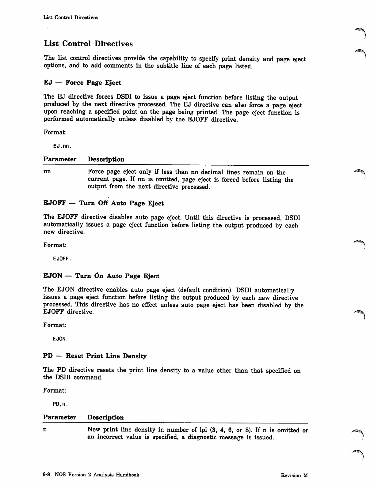
List Control Directives
List Control Directives
The list control directives provide the capability to specify print density and page eject
options, and to add comments in the subtitle line of each page listed.
EJ — Force Page Eject
The EJ directive forces DSDI to issue a page eject function before listing the output
produced by the next directive processed. The EJ directive can also force a page eject
upon reaching a specified point on the page being printed. The page eject function is
performed automatically unless disabled by the EJOFF directive.
Format:
EJ,nn.
Parameter
nn
Description
Force page eject only if less than nn decimal lines remain on the
current page. If nn is omitted, page eject is forced before listing the
output from the next directive processed.
EJOFF — Turn Off Auto Page Eject
The EJOFF directive disables auto page eject. Until this directive is processed, DSDI
automatically issues a page eject function before listing the output produced by each
new directive.
Format:
EJOFF.
EJON — Turn On Auto Page Eject
The EJON directive enables auto page eject (default condition). DSDI automatically
issues a page eject function before listing the output produced by each new directive
processed. This directive has no effect unless auto page eject has been disabled by the
EJOFF directive.
Format:
EJON.
PD — Reset Print Line Density
The PD directive resets the print line density to a value other than that specified on
the DSDI command.
Format:
PD.n.
Parameter Description
New print line density in number of lpi (3, 4, 6, or 8). If n is omitted or
an incorrect value is specified, a diagnostic message is issued.
6-8 NOS Version 2 Analysis Handbook Revision M
*. — Comment in Subtitle Line
*. — Comment in Subtitle Line
The *. directive specifies a comment that appears in the subtitle line of each page
listed.
Format:
*.ccc...ccc
Parameter Description
ccc...ccc Comment; up to 36 characters are printed.
Revision M Express Deadstart Dump Interpreter (DSDI) 6-9
File Manipulation and Control Directives
File Manipulation and Control Directives
File manipulation and control directives provide the capability to specify alternate files
for DSDI input directives and listing output.
DISPOSE — Dispose Alternate List File to Print Queue
The DISPOSE directive causes the alternate list file specified by the OUTPUT directive
to be disposed to the print queue. DSDI listing output then resumes on the original
output file. This directive has no effect unless output has previously been assigned to
an alternate list file (refer to the OUTPUT directive, next). Refer to Interactive Use of
DSDI later in this section for additional information concerning use of this directive
from an interactive terminal.
Format:
DISPOSE,username.
Parameter Description
username User name under which the remote batch terminal to receive the
listing is logged in. If username is omitted, the listing is printed at a
central site line printer.
OUTPUT — Assign Output to Alternate List File
The OUTPUT directive temporarily assigns DSDI listing output to a file other than
that specified on the DSDI command. When the alternate file is disposed to the print
queue (refer to the DISPOSE directive, above), output resumes on the original output
file. If the alternate file is not disposed, both the original and the alternate output files
remain at the job control point as local files. Refer to Interactive Use of DSDI later in
this section for additional information concerning use of this directive from an
interactive terminal.
Format:
OUTPUT.filename.
Parameter Description
filename Name of alternate list file (from 1 to 7 characters). Only one alternate
output file may be active at a time; filename cannot be the same name
as the normal output file. If filename is omitted, the system assumes
file name ALTRNT.
■<-=5\
6-10 NOS Version 2 Analysis Handbook Revision M
READ — Read Alternate Directives File
READ — Read Alternate Directives File
The READ directive causes DSDI to temporarily stop reading the current directives file
and begin reading directives from the specified record on the named alternate file or
from the current position if the record name is omitted. DSDI reads from the specified
alternate directives file until an end-of-record is encountered (end-of-file or empty
record if * is specified) and then resumes with the next directive on the original input
directives file.
Format:
READ.filename,rec,*.
Parameter Description
filename Name of alternate directives file (local file).
rec Optional record name. If rec is specified, file filename is searched for
record rec from the current position to end-of-file or an empty record. If
rec is not found, DSDI issues an error message. If rec is not specified,
DSDI reads directives from the current position to end-of-record. Records
must be in text format where the first word of the record is the record
name, unless the file is assigned to an interactive terminal; then,
directives may be entered directly.
* Optional character specifying that DSDI is to read directives from all
records until an end-of-file or an empty record is encountered.
REWIND — Rewind File
The REWIND directive repositions the specified file to beginning-of-information.
Format:
REWIND,filename.
Parameter Description
filename Name of file to be rewound.
Revision M Express Deadstart Dump Interpreter (DSDI) 6-11
Central Memory/Extended Memory Dump Directives
Central Memory/Extended Memory Dump Directives
The central memory/extended memory dump directives provide the capability to dump
any portion of central memory or extended memory in instruction parcel, byte, or word
format. There are 6-bit display code character equivalents included with each format.
Either absolute or relative memory locations may be dumped. Refer to CMR Dump
Directives later in this section for directives used to dump specific portions of NOS
central memory resident (CMR).
Dump Control Directives
Dump control directives select the type of memory to be dumped (central memory or
extended memory) and the addressing mode to be used (absolute or relative).
ALLMEM — Extend Central Memory Dumps
The ALLMEM directive enables central memory dumps to extend past the central
memory boundary on machines with central memory extension. ^^
Format:
ALLMEM.
CM — Set Memory Type to Central Memory
The CM directive specifies that subsequent C, D, and E directives dump central
memory locations. Unless the EC or TJEC directive is specified, central memory ^^
locations are dumped by default. '^^j
Format:
CM.
6-12 NOS Version 2 Analysis Handbook Revision M
Dump Control Directives
EC — Set Memory Type to Extended Memory
The EC directive specifies that subsequent C, D, and E directives dump extended
memory or unified extended memory (UEM) locations. Unless the EC or UEC directive
is specified, central memory locations are dumped by default.
Format:
EC,emid.
or
EC.emid.fwa.
Parameter Description
emid Extended memory identification; emid can be UEM or ESM. If emid is
omitted, UEM is assumed. This parameter is useful only on models 865,
875, and CYBER 180-class machines since all other models have only
one type of extended memory available.
fwa First word address (fwa) divided by 1000s. fwa is added to the fwa and
last word address (lwa) parameters in subsequent C, D, and E directives
when dumping UEM. If fwa is omitted, DSDI determines the beginning
of unified extended memory from the pointer in CMR and adds it to the
fwa and lwa parameters of the C, D, and E directives.
This parameter is ignored on any machine other than models 865 and
875 and CYBER 180-class machines.
RA — Reset Reference Address
The RA directive specifies that subsequent C, D, and E directives dump memory
locations relative to a specified reference address. Unless the RA or RAC directive is
entered, absolute memory locations are dumped by default.
Format:
RA.nnnnnnn.
Parameter Description
nnnnnnn Reference address; addresses specified on subsequent C, D, and E
directives are relative to this address.
Clearing the reference address specified on the most recent RA or RAC directive
reenables absolute addressing. This is done by entering the RA directive in this format:
RA.O.
Revision M Express Deadstart Dump Interpreter (DSDI) 6-13
Dump Control Directives
RAC — Reset Reference Address to RA of Control Point
The RAC directive specifies that subsequent C, D, and E directives dump memory 1
locations relative to the reference address of a specified control point. Unless the RA or
RAC directive is entered, absolute memory locations are dumped by default.
Format:
RAC,nn.
Parameter Description
nn Control point number; addresses specified on subsequent C, D, and E
directives are relative to the reference address of this control point.
Refer to the description of the RA directive to reenable absolute addressing.
UEC — Set Memory Type to User-Access Extended Memory
The UEC directive specifies that subsequent C, D, and E directives dump 7
user-accessible extended memory locations. Unless the EC or UEC directive is specified,
central memory locations are dumped by default.
Format:
UEC,fwa.
Parameter Description
fwa First word address divided by 1000s for user-accessible extended memory. ^\
fwa is added to the fwa and lwa parameters in subsequent C, D, and E
directives. If fwa is omitted, DSDI determines the beginning of
user-accessible extended memory from the pointer in CMR and adds it to
the fwa and lwa parameters of the C, D, and E directives.
.as^S
6-14 NOS Version 2 Analysis Handbook Revision M
yms
Memory Dump Directives
Memory Dump Directives
Memory dump directives specify the area of memory to be dumped and determine the
format of the output listing (refer to Printer Output Listing Examples later in this
section for a sample output listing). The CM and EC or UEC directives determine the
type of memory to be dumped (default is central memory). Absolute memory locations
are dumped unless relative addressing has been enabled (refer to RA and RAC
directives earlier in this section).
C — Dump Memory in Instruction Parcel Format
The C directive causes the specified locations of central memory or extended memory to
be dumped in four groups of five octal digits (three words per line) with 6-bit display
code character equivalents. Repetitive data is suppressed.
Format:
C,fwa,lwa.
jpfev
Parameter Description
fwa
lwa
First word address to be dumped (mandatory).
Last word address, plus one location, to be dumped. If lwa is omitted,
fwa+1 is assumed by default.
The output listing is read from top to bottom by column rather than across the page.
Refer to Interactive Use of DSDI later in this section for additional information
concerning use of this directive from an interactive terminal.
Revision M Express Deadstart Dump Interpreter (DSDI) 6-15
Memory Dump Directives
D — Dump Memory in Byte Format
The D directive causes the specified locations of central memory or extended memory
to be dumped in five groups of four octal digits (three words per line) with 6-bit
display code character equivalents. Repetitive data is suppressed.
Format:
D,fwa,lwa.
Parameter Description
fwa
lwa
First word address to be dumped (mandatory).
Last word address, plus one location, to be dumped. If lwa is omitted,
fwa+1 is assumed by default.
The output listing is read from top to bottom by column rather than across the page.
Refer to Interactive Use of DSDI later in this section for additional information
concerning use of this directive from an interactive terminal.
E — Dump Memory in Word Format
The E directive causes the specified locations in central memory or extended memory
to be dumped in word format (four words per line) with 6-bit display code character
equivalents.
Format:
E,fwa,lwa.
Parameter Description
fwa First word address to be dumped (mandatory).
lwa Last word address, plus one location, to be dumped. If lwa is omitted,
fwa+1 is assumed by default.
.-^^SivX
6-16 NOS Version 2 Analysis Handbook Revision M
>ffiififfitfSV
Memory Dump Directives
/ — Dump 64-Bit Memory in Instruction Parcel Format
The I directive is valid on CYBER 180-class machines only. It prints the specified
locations of central memory in four groups of four hexadecimal digits (three words per
line) with 7-bit ASCII code character equivalents. The second format is for NOS/VE
dumps.
Format:
I,fba,lba,ei.
or
I.fba,lba,asid.
Parameter Description
fba First byte address (fba), hexadecimal, to be printed (mandatory).
lba Last byte address (lba), plus one location, to be printed. If lba is
omitted, fba+8 is assumed by default.
ei If ei is 1, fba and lba specify byte addresses relative to byte 0 of the
environment interface. If ei is omitted, fba and lba specify absolute byte
addresses.
asid Specifies an actual segment identifier (ASID) for NOS/VE dumps. If you
specify this parameter, the fba and lba parameters must represent byte
offsets and have values in the range of from 0 to 7FFFFFFF
hexadecimal. This parameter is optional.
When you call DSDI from a batch job the output from this directive is printed in three
columns, read from top to bottom, one column at a time. When you call DSDI from an
interactive job the words are displayed one word per line.
For NOS/VE dumps, the addresses given for the fba and lba parameters must be real
memory addresses (RMAs) or, when translated to system virtual addresses (SVAs), the
actual segment identifiers (ASIDs) must match. Refer to appendix H for NOS/VE
address formats to use with the DSDI utility.
Revision M Express Deadstart Dump Interpreter (DSDI) 6-17
Memory Dump Directives
W — Dump 64-Bit Memory in Word Format
The W directive is valid on CYBER 180-class machines only. It prints the specified
locations of 64-bit memory in hexadecimal (4 words of 16 digits per line) with 7-bit
ASCII code character equivalents. The second format is for NOS/VE dumps.
Format:
W,fba,lba,el.
or
W,fba,lba,asid.
Parameter Description
fba First byte address, hexadecimal, to be printed (mandatory).
lba Last byte address, plus one location, to be printed. If lba is omitted,
fba+8 is assumed by default. ^
ei If ei is 1, fba and lba specify byte addresses relative to byte 0 of the
environment interface. If ei is omitted, fba and lba specify absolute byte
addresses.
asid Specifies an actual segment identifier (ASID) for NOS/VE dumps. If you
specify this parameter, the fba and lba parameters must represent byte
offsets and have values in the range of from 0 to 7FFFFFFF
hexadecimal. This parameter is optional.
For NOS/VE dumps, the addresses given for the fba and lba parameters must be real
memory addresses (RMAs), or when translated to system virtual addresses (SVAs), the
actual segment identifiers (ASIDs) must match. Refer to appendix H for NOS/VE
address formats to use with the DSDI utility.
6-18 NOS Version 2 Analysis Handbook Revision M
PP Dump Directives
PP Dump Directives
PP dump directives provide the capability to obtain a memory dump of all or selected
PPs. Two dump formats are available, block format and line format.
AP — Dump Analysis of PP and PP Memory in Octal Line Format
The AP directive causes PP memory to be dumped in line format with 6-bit display
code character equivalents (same format as the Q directive). Repetitive lines are
suppressed and zero bytes are represented by hyphens (—). An analysis of the PP is
printed before the memory dump. Analysis data includes the associated PP
communications area, resident entry point call addresses, read-only variables in direct
cells, and the values of the P, Q, K, and A registers (only applies to certain CYBER
180 class machines). Certain direct cell variables are verified and those in error are
indicated.
NOTE
Correct operation of this directive requires that the PP communication area on the
EDD file be intact.
Format!
P,ni,n2 nm.
Parameter Description
n» Number of PP to be dumped or a program name. If a program name is
specified, all PPs executing that program are dumped. A warning
message is issued if an incorrect number is specified or the program
name is not found in any PP. If ni is omitted, all active PPs are
dumped.
Refer to Printer Output Listing Examples for a sample of the printer output listing
produced by this directive.
Revision M Express Deadstart Dump Interpreter (DSDI) 6-19
MPP — Move PP
MPP — Move PP
The MPP directive causes the correct logical PP to be dumped if the logical position of
PPOO has been changed prior to the full dump to tape. If the PPS-O/PPS-1 toggle
switch has been toggled, the n parameter should not be specified. If PPOO has to be
moved to another PP via a deadstart panel program, the n parameter should be
specified.
Format:
MPP.n.
Parameter Description
Number of PP to which PPOO was moved, n cannot equal 0. If n is
omitted, 10 is assumed (CYBER 170 and CYBER 70 Computer Systems
with 20 PPs).
P — Dump PP Memory in Octal Block Format
The P directive causes PP memory to be dumped in block format, where each block
represents 64 words of memory. The blocks are read by column (top to bottom), where
each column contains eight 12-bit words in octal format numbered 0 through 7. There
are eight columns in each block, numbered 0 through 7. Repetitive data is not
suppressed and zero words are represented by hyphens (—). For models 865 and 875,
bytes 77768 and 77778 contain the PP's R register.
Format:
P»ni,n2,...,nm.
Parameter Description
ni Number of PP to be dumped. If omitted, all PPs are dumped.
r^^S,
6-20 NOS Version 2 Analysis Handbook Revision M
0$**\.
yims
PF — Dump FLPP Memory in Octal Block Format
PF — Dump FLPP Memory in Octal Block Format
The PF directive causes first-level peripheral processor (FLPP)* memory to be dumped
in block format, where each block represents 64 words of memory. The blocks are read
by column (top to bottom), where each column contains eight 12-bit words in octal
format numbered 0 through 7. There are eight columns in each block, numbered 0
through 7. Repetitive data is not suppressed and zero words are represented by
hyphens (—).
Format:
PF,n1,n2,...,nII).
Parameter Description
m Number of FLPP to be dumped. If omitted, all FLPPs are dumped.
PMS — Read PP Select Switches
The PMS directive causes the dump of the S/C register (maintenance register for
models 865 and 875) to be read to determine the current value of the PP memory
select switches and the correct logical PP to be dumped, if the logical position of PPOO
has been changed prior to the full dump to tape. If the PP memory select switches
have been changed, this directive should be specified with the binary value of the
switches prior to the change. This directive is meaningful only on a CYBER 170
Computer System with the exception of models 815, 825, 835, 845, and 855.
Format:
PMS,n.
Parameter Description
n Previous select switch setting; 0 through lis. If n is the same value as
that read from the S/C register, this directive is not meaningful.
1. Hardware manuals define peripheral processors making up a peripheral processor subsystem as PPs, and
the first-level peripheral processors as peripheral processing units (PPUs). In this manual, first-level
peripheral processors are referred to as FLPPs. FLPPs are available only on model 176.
Revision M Express Deadstart Dump Interpreter (DSDI) 6-21
PO — Dump 16-Bit PP Memory in Octal Block Format
PO — Dump 16-Bit PP Memory in Octal Block Format
The PO directive is valid on CYBER 180-class machines only. It prints PP memory in
block format, where each block represents 64 words of memory. DSDI represents each
16-bit word by six octal digits. Words whose upper 4 bits are zero are represented by
four octal digits. Blocks are read by columns (top to bottom), where each column
contains eight 16-bit words numbered 0 through 7. There are eight columns in each
block, numbered 0 through 7. Repetitive data is not suppressed and zero words are
represented by hyphens (—). The PP's R register is displayed preceding the first line
of the dump.
,*^\
Format:
P0,ni,n2,...,nm.
Parameter Description
ni Number of PP to be dumped. If omitted, all PPs are printed.
PX — Dump 16-Bit PP Memory in Hexadecimal Block Format
The PX directive is valid on CYBER 180-class machines only. It prints 16-bit memory
in block format, where each block represents 256 words of memory. Each 16-bit word is
represented by four hexadecimal digits. Blocks are read by columns (top to bottom),
where each column contains sixteen 16-bit words in hexadecimal format numbered 0
through F. There are 16 columns in each block, numbered 0 through F. Repetitive data
is not suppressed and zero words are represented by hyphens (—). The PP's R register
is displayed preceding the first line of the dump.
Format:
PX,n1fn2 nm.
Parameter Description
ni Number of PP to be printed. If omitted, all PPs are printed.
,^^y
6-22 NOS Version 2 Analysis Handbook Revision M
yams
Q — Dump PP Memory in Octal Line Format
Q — Dump PP Memory in Octal Line Format
The Q directive causes PP memory to be dumped in line format with 6-bit display code
character equivalents. Each line contains 16 bytes (PP words) printed in two sets of 8
bytes in octal format. Each set consists of an address, 8 bytes, and display code
character equivalents. Repetitive lines are suppressed and zero bytes are represented by
hyphens (—). Refer to Interactive Use of DSDI later in this section for additional
information concerning use of this directive from an interactive terminal.
Format:
Q,ni,n2,...,nm.
Parameter Description
ni Number of PP to be dumped. If omitted, all PPs are dumped.
QF — Dump FLPP Memory in Octal Line Format
The QF directive causes FLPP memory to be dumped in line format with 6-bit display
code character equivalents. Each line contains 16 bytes printed in two sets of 8 bytes
in octal format. Each set consists of an address, 8 data bytes, and 6-bit display code
character equivalents. Repetitive lines are suppressed and zero bytes are represented by
hyphens (—).
Format:
QF,n1fn2, . - -,nm.
Parameter Description
ni Number of FLPP to be dumped. If omitted, all FLPPs are dumped.
2. Hardware manuals define peripheral processors making up a peripheral processor subsystem as PPs, and
the first-level peripheral processors as peripheral processing units (PPUs). In this manual, first-level
0^s peripheral processors are referred to as FLPPs. FLPPs are available only on model 176.
Revision M Express Deadstart Dump Interpreter (DSDI) 6-23
QOA — Dump 16-Bit PP Memory in Octal/ASCII Line Format
QOA — Dump 16-Bit PP Memory in Octal/ASCII Line Format
The QOA directive is valid on CYBER 180-class machines only. It prints PP memory "l
in line format with 7-bit ASCII code character representation. Each line contains 16
words printed in two sets of eight. Each set consists of an octal address, eight words
(six digits per word if the upper 4 bits are nonzero, four digits otherwise), and 7-bit
ASCII code character equivalents. Repetitive lines are suppressed and zero words are
represented by hyphens (—). The PP's R register is displayed preceding the first line
of the dump. Refer to Interactive Use of DSDI later in this section for additional
information concerning use of this directive from an interactive terminal.
Format:
QOA,n1fn2,. ...nm.
Parameter Description
m Number of PP to be printed. If omitted, all PPs are printed.
QOD — Dump 16-Bit PP Memory in Octal/Display line Format
The QOD directive is valid on CYBER 180-class machines only. It prints PP memory
in line format with 6-bit display code character representation. Each line contains 16
words printed in two sets of eight. Each set consists of an octal address, eight words
(six digits per word if the upper 4 bits are nonzero, four digits otherwise), and 6-bit
display code character equivalents. Repetitive lines are suppressed and zero words are
represented by hyphens (—). The PP's R register is displayed preceding the first line
of the dump. Refer to Interactive Use of DSDI later in this section for additional
information concerning use of this directive from an interactive terminal.
Format:
Q0D,n,,n2 nm.
Parameter Description
m Number of PP to be printed. If omitted, all PPs are printed.
6-24 NOS Version 2 Analysis Handbook Revision M
QXA — Dump 16-Bit PP Memory in Hexadecimal/ASCII Line Format
QXA — Dump 16-Bit PP Memory in Hexadecimal/ASCII Line Format
The QXA directive is valid on CYBER 180-class machines only. It prints PP memory
in line format with 7-bit ASCII code character representation. Each line contains 16
words printed in two sets of eight. Each set consists of a hexadecimal address, eight
words (four hexadecimal digits per word), and 7-bit ASCII code character equivalents.
Repetitive lines are suppressed and zero words are represented by hyphens (—). The
PP's R register is displayed preceding the first line of the dump. Refer to Interactive
Use of DSDI later in this section for additional information concerning use of this
directive from an interactive terminal.
Format:
QXA,n,,n2,...,nm.
Parameter Description
ni Number of PP to be printed. If omitted, all PPs are printed.
QXD — Dump 16-Bit PP Memory in Hexadecimal/Display Line Format
The QXD directive is valid on CYBER 180-class machines only. It prints PP memory
in line format with 6-bit display code character representation. Each line contains 16
words printed in two sets of eight. Each set consists of a hexadecimal address, eight
words (four hexadecimal digits per word), and 6-bit display code character equivalents.
Repetitive lines are suppressed and zero words are represented by hyphens (—). The
PP's R register is displayed preceding the first line of the dump. Refer to Interactive
Use of DSDI later in this section for additional information concerning use of this
directive from an interactive terminal.
Format:
QXD,n,,n2,...,nm.
Parameter Description
ni Number of PP to be printed. If omitted, all PPs are printed.
Revision M Express Deadstart Dump Interpreter (DSDI) 6-25
CMR Dump Directives
CMR Dump Directives
The CMR dump directives provide the capability to selectively dump specified areas of
central memory resident. Refer to the NOS Version 2 Systems Programmer's Instant
for detailed illustrations of central memory resident.
Successful use of the CMR dump directives is dependent upon the integrity of central
memory resident at the time EDD was performed. Most important is the integrity of
the CMR pointers on the EDD file. If these pointers are not intact, the dump
produced by DSDI may prove meaningless. Thus, if it is suspected that the CMR
pointers are not intact, specifying the P keyword on the DSDI command allows DSDI
to use the CMR pointers from the running system. This option should be used only
when the configuration of the running system is the same as the system in use at
the time the EDD file was created. If the CMR pointers on the EDD file are not
intact, the integrity of the other areas of central memory is also questionable. In this
case, the output produced by the CMR dump directives may be unpredictable.
ACCOUNT — Dump Account Dayfile Buffer
The ACCOUNT directive causes the account dayfile pointers and buffer to be dumped
in word format (four words per line) with 6-bit display code character equivalents. This
format is the same format as that for the E memory dump directive. This directive
also dumps the buffer in a line-by-line format, as on the DSD A display.
Format:
ACCOUNT.
.<b3bSX
6-26 NOS Version 2 Analysis Handbook Revision M
00S.
00&S
CBT — Dump Control Buffer Table
CBT — Dump Control Buffer Table
The CBT directive causes all control buffer table entries to be dumped unless ordinal
numbers are specified, then only the specified control buffer table entries are dumped.
The dump is formatted to reflect the appropriate parameter fields for each word.
Control buffer table entries that are output to a printer are listed in two columns. The
format is the same format as that for the MST directive. The control buffer table
entries can also be output to a terminal, but only when ordinal numbers are specified.
Control buffer table entries that are output to a terminal are listed in a single column
format.
Format:
CBT,ni,n2,...,nra.
Parameter Description
ni Ordinal number of the control buffer table entry to be dumped. If ni is
omitted, all control buffer table entries are dumped.
CCT — Dump Channel Control Table
The CGT directive causes all nonzero channel control table entries to be dumped unless
ordinal numbers are specified, then only the specified channel control table entries are
dumped. The dump is formatted to reflect the appropriate parameter fields for each
word. Channel control table entries that are output to a printer are listed in two
columns. The format is the same format as that for the MST directive. The channel
control table entries can also be output to a terminal, but only when ordinal numbers
are specified. Channel control table entries that are output to a terminal are listed in
a single column format.
Format:
C C T, n i , n 2 , . . . , n r a .
Parameter Description
ni Ordinal number of the channel control table entry to be dumped. If m is
omitted, all nonzero channel control table entries are dumped.
Revision M Express Deadstart Dump Interpreter (DSDI) 6-27
CP — Dump Active Control Point Areas
CP — Dump Active Control Point Areas
The CP directive causes all active control point areas, or a selected subset, to be
dumped. List options provide the capability to dump only desired portions of the control
point area and other control point related data. Specified without any parameters, the
CP directive dumps all active control point areas and pseudo-control point areas. Refer
to Interactive Use of DSDI later in this section for additional information concerning
use of this directive from an interactive terminal.
Format:
CP.
or
CP,ni/opSi,n2/ops2,.. .tnm/oj3Sm.
Parameter Description
m Control point number.
0Psi List options; a string of up to 10 characters indicating the portion of the
control point area, or control point related data, to be dumped. If list
options are specified, they apply only to the control point number with
which they are associated. Valid options are:
opsi Description
/*^V
X Dumps the exchange package, parameter summary, control
point's entry in the executing job table, and contents of the
memory locations indicated by the values in each exchange
package register. These register values are treated as
relative addresses within the field length; invalid addresses
are represented with contents of zero.
The current command and special entry point parameters are
not printed for the system control point. Refer to Printer
Output Listing Examples later in this section for a sample of
the printer output listing produced.
T Provides a detailed dump of the control point area with a
description of each parameter field and NOSTEXT symbol for
each word.
A Dumps the job dayfile pointers and buffer in word format
with 6-bit display code character equivalents. This format is
the same format as the E memory dump directive. This
option also dumps the buffer in a line-by-line format, as on
the DSD A display.
F3 Provides a dump of the 3-word FNT entry, EST, and mass
storage track chain, if one exists, for all files attached to the
specified control point.
aX^s
3. This option does not dump information for the system control point.
6-28 NOS Version 2 Analysis Handbook Revision M
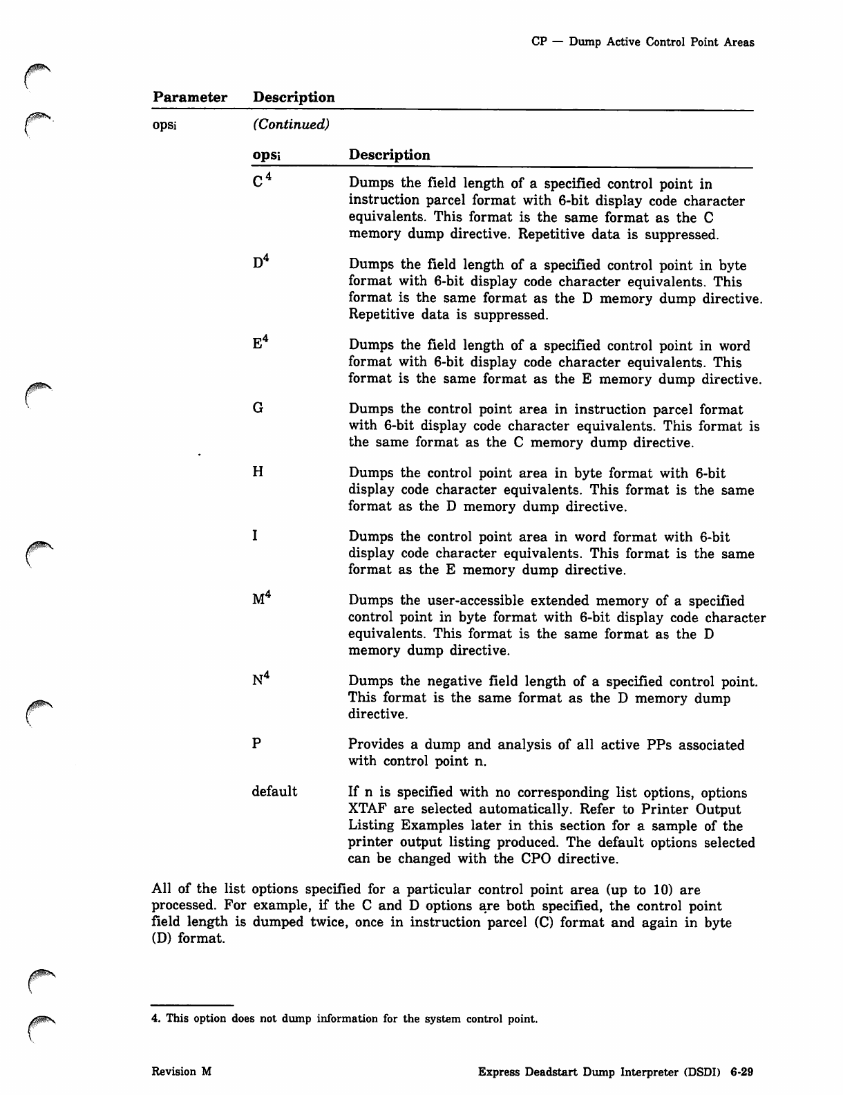
CP — Dump Active Control Point Areas
Parameter Description
opsi (Continued)
opsi Description
C Dumps the field length of a specified control point in
instruction parcel format with 6-bit display code character
equivalents. This format is the same format as the C
memory dump directive. Repetitive data is suppressed.
D Dumps the field length of a specified control point in byte
format with 6-bit display code character equivalents. This
format is the same format as the D memory dump directive.
Repetitive data is suppressed.
E Dumps the field length of a specified control point in word
format with 6-bit display code character equivalents. This
format is the same format as the E memory dump directive.
G Dumps the control point area in instruction parcel format
with 6-bit display code character equivalents. This format is
the same format as the C memory dump directive.
H Dumps the control point area in byte format with 6-bit
display code character equivalents. This format is the same
format as the D memory dump directive.
I Dumps the control point area in word format with 6-bit
display code character equivalents. This format is the same
format as the E memory dump directive.
M Dumps the user-accessible extended memory of a specified
control point in byte format with 6-bit display code character
equivalents. This format is the same format as the D
memory dump directive.
N Dumps the negative field length of a specified control point.
This format is the same format as the D memory dump
directive.
P Provides a dump and analysis of all active PPs associated
with control point n.
default If n is specified with no corresponding list options, options
XTAF are selected automatically. Refer to Printer Output
Listing Examples later in this section for a sample of the
printer output listing produced. The default options selected
can be changed with the CPO directive.
All of the list options specified for a particular control point area (up to 10) are
processed. For example, if the C and D options are both specified, the control point
field length is dumped twice, once in instruction parcel (C) format and again in byte
(D) format.
4. This option does not dump information for the system control point.
Revision M Express Deadstart Dump Interpreter (DSDI) 6-29
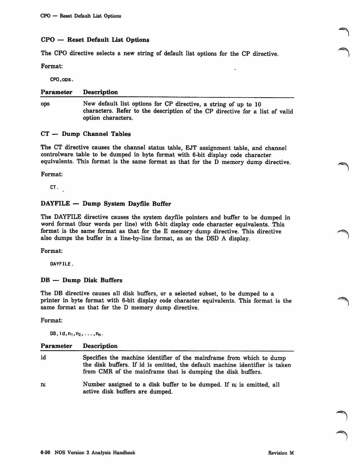
CPO — Reset Default List Options
CPO — Reset Default List Options
The CPO directive selects a new string of default list options for the CP directive.
Format:
CPO,ops.
Parameter Description
ops New default list options for CP directive, a string of up to 10
characters. Refer to the description of the CP directive for a list of valid
option characters.
CT — Dump Channel Tables
The CT directive causes the channel status table, EJT assignment table, and channel
controlware table to be dumped in byte format with 6-bit display code character
equivalents. This format is the same format as that for the D memory dump directive.
Format:
CT.
DAYFILE — Dump System Dayfile Buffer
The DAYFILE directive causes the system dayfile pointers and buffer to be dumped in
word format (four words per line) with 6-bit display code character equivalents. This
format is the same format as that for the E memory dump directive. This directive
also dumps the buffer in a line-by-line format, as on the DSD A display.
Format:
DAYFILE.
DB — Dump Disk Buffers
The DB directive causes all disk buffers, or a selected subset, to be dumped to a
printer in byte format with 6-bit display code character equivalents. This format is the
same format as that for the D memory dump directive.
Format:
DB,id,ni,n2 nm.
Parameter Description
id Specifies the machine identifier of the mainframe from which to dump
the disk buffers. If id is omitted, the default machine identifier is taken
from CMR of the mainframe that is dumping the disk buffers.
ni Number assigned to a disk buffer to be dumped. If ni is omitted, all
active disk buffers are dumped.
. ^ " s ^ V
6-30 NOS Version 2 Analysis Handbook Revision M
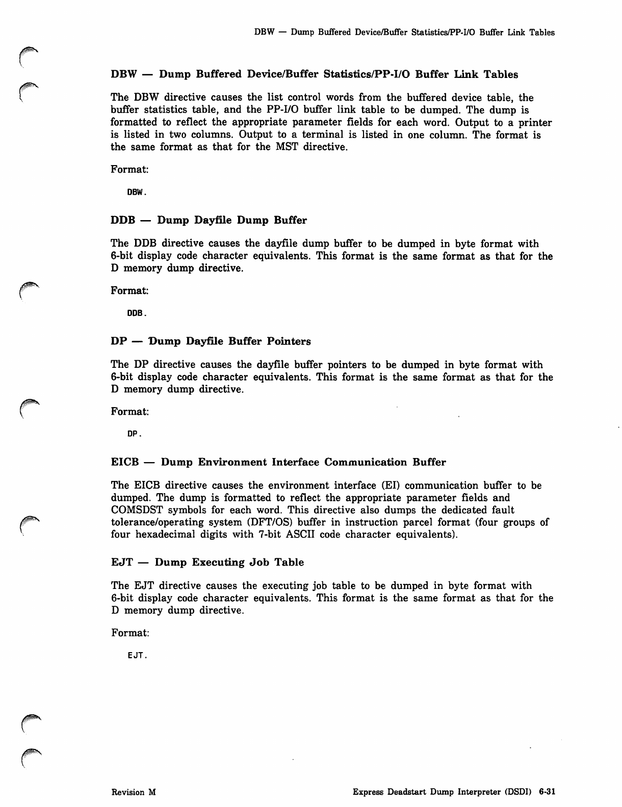
DBW — Dump Buffered Device/Buffer Statistics/PP-I/O Buffer Link Tables
DBW — Dump Buffered Device/Buffer Statistics/PP-I/O Buffer Link Tables
The DBW directive causes the list control words from the buffered device table, the
buffer statistics table, and the PP-I/O buffer link table to be dumped. The dump is
formatted to reflect the appropriate parameter fields for each word. Output to a printer
is listed in two columns. Output to a terminal is listed in one column. The format is
the same format as that for the MST directive.
Format:
DBW.
DDB — Dump Dayfile Dump Buffer
The DDB directive causes the dayfile dump buffer to be dumped in byte format with
6-bit display code character equivalents. This format is the same format as that for the
D memory dump directive.
Format:
DDB.
DP — Dump Dayfile Buffer Pointers
The DP directive causes the dayfile buffer pointers to be dumped in byte format with
6-bit display code character equivalents. This format is the same format as that for the
D memory dump directive.
Format:
DP.
EICB — Dump Environment Interface Communication Buffer
The EICB directive causes the environment interface (EI) communication buffer to be
dumped. The dump is formatted to reflect the appropriate parameter fields and
COMSDST symbols for each word. This directive also dumps the dedicated fault
tolerance/operating system (DFT/OS) buffer in instruction parcel format (four groups of
four hexadecimal digits with 7-bit ASCII code character equivalents).
EJT — Dump Executing Job Table
The EJT directive causes the executing job table to be dumped in byte format with
6-bit display code character equivalents. This format is the same format as that for the
D memory dump directive.
Format:
EJT.
Revision M Express Deadstart Dump Interpreter (DSDI) 6-31
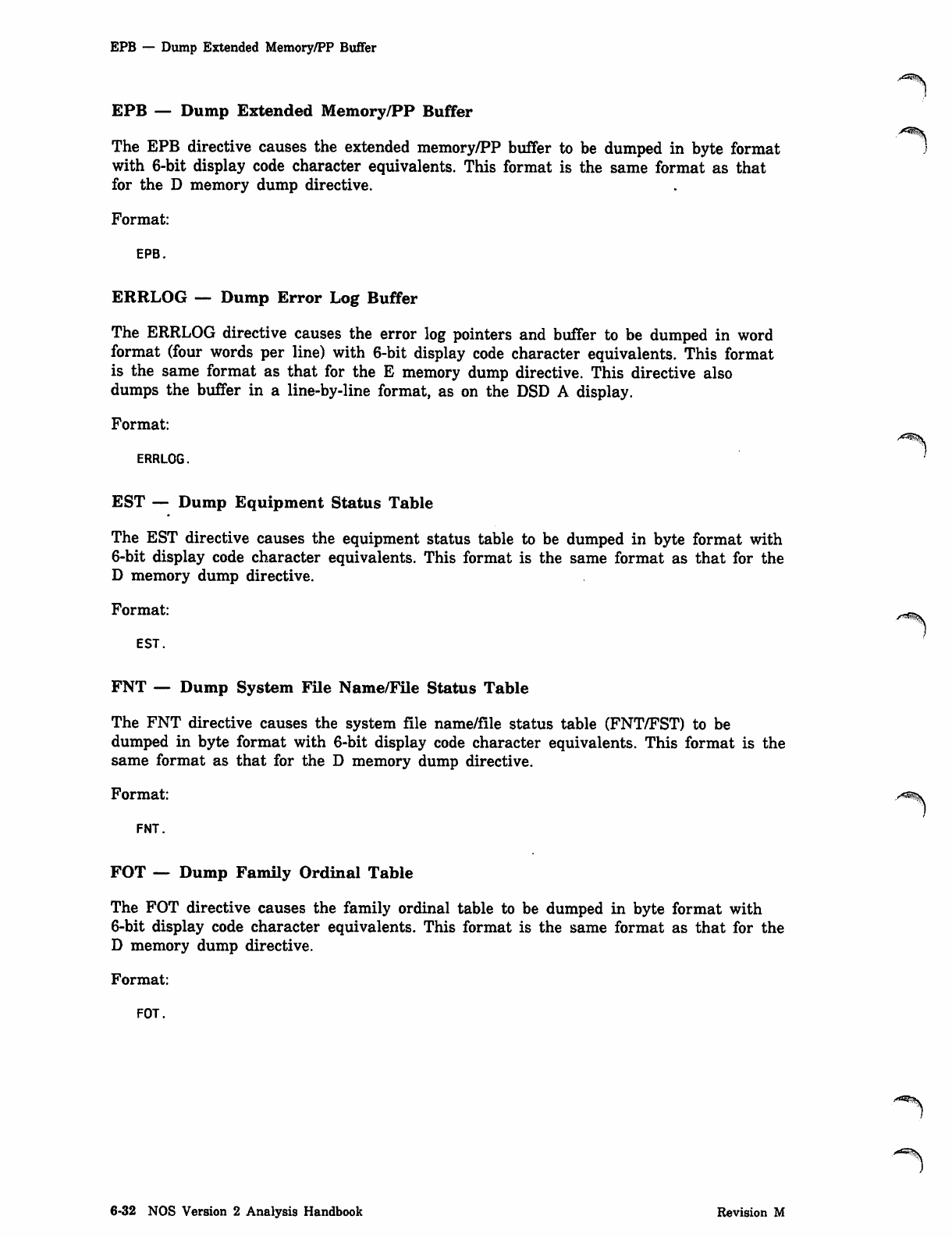
EPB — Dump Extended Memory/PP Buffer
EPB — Dump Extended Memory/PP Buffer
The EPB directive causes the extended memory/PP buffer to be dumped in byte format
with 6-bit display code character equivalents. This format is the same format as that
for the D memory dump directive.
Format:
EPB.
ERRLOG — Dump Error Log Buffer
The ERRLOG directive causes the error log pointers and buffer to be dumped in word
format (four words per line) with 6-bit display code character equivalents. This format
is the same format as that for the E memory dump directive. This directive also
dumps the buffer in a line-by-line format, as on the DSD A display.
Format:
ERRLOG.
EST — Dump Equipment Status Table
The EST directive causes the equipment status table to be dumped in byte format with
6-bit display code character equivalents. This format is the same format as that for the
D memory dump directive.
Format:
EST.
FNT — Dump System File Name/File Status Table
The FNT directive causes the system file name/file status table (FNT/FST) to be
dumped in byte format with 6-bit display code character equivalents. This format is the
same format as that for the D memory dump directive.
Format:
FNT.
FOT — Dump Family Ordinal Table
The FOT directive causes the family ordinal table to be dumped in byte format with
6-bit display code character equivalents. This format is the same format as that for the
D memory dump directive.
Format:
FOT.
-/°fiS%
6-32 NOS Version 2 Analysis Handbook Revision M
y^PS^v
HAT — Dump Hash Table
HAT — Dump Hash Table
The HAT directive causes all nonzero hash table entries to be dumped unless ordinal
numbers are specified, in which case only the specified hash table entries are dumped.
The dump is formatted to reflect the appropriate parameter fields for each word. Hash
table entries that are output to a printer are listed in two columns. The format is the
same format as that for the MST directive. The hash table entries can also be output
to a terminal, but only when ordinal numbers are specified. Hash table entries that are
output to a terminal are listed in a single-column format.
Format:
H AT, n i , n 2 , . . . , n m .
Parameter Description
ni Ordinal number of the hash table entry to be dumped. If ni is omitted,
all nonzero hash table entries are dumped.
JC — Dump Job Control Area for Each Service Class
The JC directive causes the job control area for each job service class to be dumped.
The dump is formatted to reflect the appropriate parameter fields and NOSTEXT
symbol for each word. This directive also dumps the service class control table (SCT) in
a line-by-line format.
Format:
JC.
LC — Dump Low Central Memory
The LC directive causes DSDI to dump the contents of low central memory (that is,
central memory locations 0 through 177s). Each word is divided into the appropriate
parameter fields. Each field is listed on a separate line with a description of the
parameter. The absolute address and 6-bit display code character equivalents are also
listed for each word.
Format:
LC.
Revision M Express Deadstart Dump Interpreter (DSDI) 6-33
LDIS — Dump L-Display Buffer
LDIS — Dump L-Display Buffer
The LDIS directive causes the L-display buffer to be dumped in instruction parcel
format with 6-bit display code character equivalents. This format is the same format as
that for the C memory dump directive.
Format:
LDIS.
LIDT — Dump Logical Identifier Table
The LIDT directive causes the logical identifier table to be dumped in byte format with
6-bit display code character equivalents. This format is the same format as that for the
D memory dump directive.
Format:
LIDT.
MAINLOG — Dump Binary Maintenance Log Buffer
The MAINLOG directive dumps the binary maintenance log pointers and buffer in word
format, four words per line, with 6-bit display code character equivalents.
Format:
MAINLOG.
MCT — Dump Memory Control Table
The MCT directive dumps the contents of the memory control table (MCT). For each
control point and pseudo-control point, there are two lines. The first line displays the
control point (or pseudo-control point) having the next lower reference address, the one
having the next higher reference address, the unassigned CM Fl/lOOs between the
control point (or pseudo-control point) having the next higher reference address, and
the job's reference address and field length. The second line displays the corresponding r^\
information for extended memory. '
Format:
MCT.
6-34 NOS Version 2 Analysis Handbook Revision M
0ms
0ms
yrtftsfflm^K
MST — Dump Mass Storage/Track Reservation Tables
MST — Dump Mass Storage/Track Reservation Tables
The MST directive causes all mass storage and track reservation tables to be dumped
unless EST ordinals are specified, in which case only the specified MSTs are dumped.
The dump format for the mass storage tables reflects the appropriate parameter fields
and NOSTEXT symbol of each word. The portion of the dump describing the track
reservation tables is presented in byte format with 6-bit display code character
equivalents. The track link byte ordinal and status bits (three groups of 4 bits) are
indicated for each word. Refer to Printer Output Listing Examples later in this section
for a sample of the printer output listing produced by this directive.
Format:
MST,esti,est2,....estn -
Parameter Description
esti EST ordinal of equipment whose mass storage table is to be dumped. If
esti is omitted, all mass storage and track reservation tables are
dumped.
MTR — Dump CPU Monitor
The MTR directive causes the CPU monitor to be dumped. Exchange packages are
dumped in exchange package format while the program area is dumped, using relative
addressing, in instruction parcel format with 6-bit display code character equivalents.
This format is the same format as that for the C memory dump directive.
Format:
MTR.
j#^V
Revision M Express Deadstart Dump Interpreter (DSDI) 6-35
MTRQUEUE — Dump CPUMTR Request and Recall Queues
MTRQUEUE — Dump CPUMTR Request and Recall Queues
The MTRQUEUE directive causes all CPUMTR request and recall queues, or a selected
subset, to be dumped.
Format:
MTRQUEUE,idents.
Parameter Description
idents A string of up to four characters indicating the queues to be dumped.
The queue identifiers can be specified in any order and are dumped in
the order specified. Default is to dump all four queues. Valid queue
identifiers are:
idents Queue Name
C CPUCIO request.
P PP request.
R Recall.
W CPU request.
ODIS — Dump Operator Display Buffer
The ODIS directive causes the operator display buffer (used for communication between
an operator and a remote diagnostic user) to be dumped in instruction parcel format "a^\
with 6-bit display code character equivalents. This format is the same format as that
for the C memory dump directive.
Format:
ODIS.
PCP — Dump Pseudo-control Point
The PCP directive causes all active pseudo-control point areas, or a selected subset, to
be dumped. The format is the same as that for the CP control point dump directive.
,'*^^\
6-36 NOS Version 2 Analysis Handbook Revision M
0SS
PLD — Dump Peripheral Library Directory
PLD — Dump Peripheral Library Directory
The PLD directive causes the PP library directory to be dumped in byte format with
6-bit display code character equivalents. This format is the same format as that for the
D memory dump directive.
Format:
PLD.
PP — Dump PP Communication Areas
The PP directive causes the contents of all PP communication areas to be dumped in
byte format with 6-bit display code character equivalents. This format is the same
format as that for the D memory dump directive. The control point assignment,
channel assignment, and monitor function are listed with each communication area.
Refer to Printer Output Listing Examples later in this section for a sample of the
printer output listing produced by this directive. Refer to Interactive Use of DSDI later
in this section for additional information concerning use of this directive from an
interactive terminal.
Format:
PP.
PROBE — Dump PROBE Data Tables
The PROBE directive causes the PROBE data tables to be dumped in byte format with
6-bit display code character equivalents.
Format:
PROBE.
PST — Dump Program Status Table and Entry Point Directory
The PST directive causes the program status table and the entry point directory to be
dumped in byte format with 6-bit display code character equivalents. This format is the
same format as that for the D memory dump directive.
Format:
PST.
Revision M Express Deadstart Dump Interpreter (DSDI) 6-37
PUT — Dump Physical Unit Table
PUT — Dump Physical Unit Table
The PUT directive causes all nonzero physical unit table entries to be dumped unless
ordinal numbers are specified, then only the specified physical unit table entries are
dumped. The dump is formatted to reflect the appropriate parameter fields for each
word. Physical unit table entries that are output to a printer are listed in two columns.
The format is the same format as that for the MST directive. The physical unit table
entries can also be output to a terminal, but only when ordinal numbers are specified.
Physical unit table entries that are output to a terminal are listed in a single column
format.
Format:
PUT,n!,n2 nm.
Parameter Description
ni Ordinal number of the physical unit table entry to be dumped. If ni is
omitted, all nonzero physical unit table entries are dumped.
QFT — Dump Queued File Table
The QF.T directive causes the queued file table to be dumped in byte format with 6-bit
display code character equivalents. This format is the same format as that for the D
memory dump directive.
Format:
QFT.
RCL — Dump Resident Central Library
The RCL directive causes the resident CPU library to be dumped in instruction parcel
format with 6-bit display code character equivalents. This format is the same format as
that for the C memory dump directive. A warning is printed if the resident central
library is empty.
Format:
RCL.
6-38 NOS Version 2 Analysis Handbook Revision M
0m**~
/|fBN
RPL — Dump Resident Peripheral Library
RPL — Dump Resident Peripheral Library
The RPL directive causes the resident PP library to be dumped in byte format with
6-bit display code character equivalents. This format is the same format as that for the
D memory dump directive. A header line for each PP program dumped indicates the
name of the program and its length in bytes. Each succeeding line contains 10 bytes
(two central memory words) of the PP program. The PP address of the first byte in
each line, relative to address zero of the PP, is also listed.
Format:
RPL.
SAB — Dump System Attribute Block
The SAB directive causes the system attribute block to be dumped in byte format with
6-bit display code character equivalents. This format is the same format as that for the
D memory dump directive.
SDA — Dump Extended Statistical Data Area
The SDA directive causes the extended statistical data area to be dumped. Each word
is divided into the appropriate parameter fields and is listed with a description of the
parameter. The absolute address and 6-bit display code character equivalents are also
listed for each word.
Format:
SDA.
SECDED — Dump SECDED Identifier Table
The SECDED directive causes the single error correction double error detection
(SECDED) identifier table to be dumped in byte format with 6-bit display code
character equivalents. This format is the same format as that for the D memory dump
directive.
Format:
SECDED.
Revision M Express Deadstart Dump Interpreter (DSDI) 6-39
SST — Dump Subsystem Control Point/Subsystem Assignment Tables
SST — Dump Subsystem Control Point/Subsystem Assignment Tables
The SST directive causes the subsystem control point table and subsystem assignment
table to be dumped in byte format with 6-bit display code character equivalents. This
format is the same format as that for the D memory dump directive.
Format:
SST.
TBDUMP — Dump Trace Buffer
The TBDUMP directive dumps the specified trace buffer. The functions traced are
listed, followed by the absolute and control point area addresses that were saved, and
the buffer IN pointer. The trace buffer data is displayed in the same format as that for
the D memory dump directive.
Format:
TBDUMP,MTR.
or .
TBDUMP,PPU,
Parameter Description
MTR
PPU
MTR to CPUMTR function trace buffer.
PP to CPUMTR function trace buffer.
>*^v
6-40 NOS Version 2 Analysis Handbook Revision M
0$ms
y$*s
Subsystem Dump/Analysis Directives
Subsystem Dump/Analysis Directives
The subsystem dump/analysis directives provide the capability to selectively dump
portions of central and/or PP memory associated with a specific subsystem (BIO, IAF,
MAG, and RHF). Although many other directives already described in this section can
be used to dump the same areas of memory, these directives dump those areas most
frequently analyzed when subsystem-related malfunctions occur. In addition, many of
the dumps are specially formatted to provide a detailed description of the area being
dumped. If the specified subsystem was not active at the time the EDD file was
created, an error message is issued.
BATCHIO (BIO) — Dump Associated Memory for Analysis
The BATCHIO directive causes the areas of central and/or PP memory that are most
frequently analyzed when BATCHIO malfunctions are indicated to be dumped. The
areas and type of memory dumped are determined by the list options specified.
Formats:
BATCH10,ops.
or
BIO,ops.
Parameter Description
°PS List options; a string of characters indicating the areas of memory to be
dumped. If no options are specified, all three options (PBN) are selected
by default and are processed in order as listed.
ops Description
P Provides analysis and full memory dump of PPs having
resident copies of 1CD, 110, QAP, QAC, or DSP. The output
listing generated is the same (in format and content) as that
produced by entering the AP directive in this format:
AP,1CD,1I0,QAP,QACfDSP.
Refer to the description of the AP directive earlier in this
section for additional information.
B Provides specially formatted dumps of each active BATCHIO
buffer point. Included with the dump of each buffer point is
the associated equipment type and FET, as well as EST and
FNT/FST entries.
N Provides a dump of the negative field length associated with
the BATCHIO control point in byte format with 6-bit display
code character equivalents. This format is the same format as
that for the D memory dump directive.
Revision M Express Deadstart Dump Interpreter (DSDI) 6-41
IAF — Dump Associated Memory for Analysis
IAF — Dump Associated Memory for Analysis
The IAF directive causes the areas of central and/or PP memory that are most
frequently analyzed when IAF malfunctions to be dumped. The areas and type of
memory are determined by the list options specified. The IAF current entry word
(SSPA) is always printed at the beginning of the listing, in byte format, regardless of
which list options are specified.
Format:
IAF,ops.
Parameter Description
ops List options; a string of up to five characters indicating the areas of
memory to be dumped. If no options are specified, four options (ETLP)
are selected by default and processed in order as listed.
ops Description
C Provides analysis of the IAF command table.
E Dumps the IAF reentry table in byte format (two words per
line) with 6-bit display code character equivalents. The first
word in each line is preceded by its ordinal within the
table.
T Provides a specially formatted dump of the IAF terminal
table in which each word reflects the appropriate parameter
fields. The message status table entry is included when "*^\
dumping network terminal tables. In addition, each word is
preceded by a description of the parameter fields and its
COMSREM symbol. Terminal table entries that are empty,
except for having status bit 0 in word 3 (VROT entry) set,
are not printed.
L Provides a dump of pot link table and all pots. The pot link
table is dumped in byte format with pot link byte ordinals
indicated for each word, but no 6-bit display code character ^^
equivalents. Repetitive pot link table entries are suppressed. '^7
The pots are dumped in word format, three lines per pot,
with the first line containing only the pot number.
6-42 NOS Version 2 Analysis Handbook Revision M
IAF — Dump Associated Memory for Analysis
Parameter Description
ops (Continued)
ops Description
Provides analysis and full memory dump of all PPs having
resident copies of TLX, 1TA, ITN, and 1T0. This option also
provides an analysis and dump of all PPs having resident
copies of 1R0 and 1RI that are associated with control points
of interactive origin. The output listing generated is the same
(in format and content) as that produced by entering the AP
directive in this format:
AP.TLX,1TA,1TN,1T0,1R0,1RI.
The exception is that the AP directive also dumps all PPs
having copies of 1RO and 1RI rather than only those
associated with control points of interactive origin. Refer to
the description of the AP directive, earlier in this section, for
additional information.
/gS*y
Revision M Express Deadstart Dump Interpreter (DSDI) 6-43
MAGNET (MAG) — Dump Associated Memory for Analysis
MAGNET (MAG) — Dump Associated Memory for Analysis
The MAGNET directive causes the areas of central and/or PP memory that are most 1
frequently analyzed when a malfunction within the Magnetic Tape Subsystem is
indicated to be dumped. The areas and type of memory dumped are determined by the
list options specified.
Format:
MAGNET,ops.
or
MAG,ops.
Parameter Description
ops List options; a string of characters indicating the areas of memory to
be dumped. If no options are specified, all four options (UQSP) are
selected by default and are processed in order as listed. ***h
ops Description
U Provides a specially formatted dump of the Magnetic Tape
Subsystem unit descriptor tables with associated FET, EST,
and FNT/FST. Each word of a unit descriptor table is
formatted to reflect appropriate parameter fields. In addition,
each word is preceded by a description of the parameter
fields and its COMSMTX symbol. If extended labels are
present, they appear with the FET in the output listing. The "^
FET also indicates the address and control point number of
the user.
Q Provides a dump of the Magnetic Tape Subsystem queue
table in byte format (two words per line) with 6-bit display
code character equivalents. The first word in each line is
preceded by its ordinal within the table.
S Provides a dump of the Magnetic Tape Subsystem active
stage job table, staging tape VSN list, and stage request ^^)
table, if they are defined. The tables are dumped in byte
format (two words per line) with 6-bit display code character
equivalents. The first word in each line is preceded by its
ordinal within the table.
P Provides analysis and full memory dump of all PPs having
resident copies of IMT. The output listing generated is the
same (in format and content) as that produced by entering
the AP directive in this format:
AP.1MT.
Refer to the description of the AP directive earlier in this
section for additional information.
6-44 NOS Version 2 Analysis Handbook Revision M
RHF — Dump Associated Memory for Analysis
RHF — Dump Associated Memory for Analysis
The RHF directive causes the areas of central and/or PP memory that are most
frequently analyzed when RHF malfunctions are indicated to be dumped. The areas and
type of memory dumped are determined by the list options specified.
Format:
RHF,ops.
Parameter Description
ops List options; a string of characters indicating the areas of memory to be
dumped. If no options are specified, all three options (ACP) are selected
by default and are processed in order as listed.
ops Description
A Provides a dump of the RHF dayfile buffer in word format
/^ with 6-bit display code character equivalents. This format is
the same format as that for the E memory dump directive.
This option also dumps a standard dayfile.
C Provides a dump of the RHF field length in byte format with
6-bit display code character equivalents. This format is the
same format as that for the D memory dump directive.
>sffff\
Provides analysis and full memory dump of all active PPs
associated with the control point.
Revision M Express Deadstart Dump Interpreter (DSDI) 6-45
Hardware Register Dump Directives
Hardware Register Dump Directives
The hardware register dump directives provide the capability to dump specified
hardware registers.
FMFREG — Dump PP Registers
The FMFREG directive is valid on CYBER 180-class machines only. For each PP
register (P, Q, K, A) stored while processing a fatal mainframe error, DSDI prints the
PP register contents.
Format:
FMFREG.
IOUCR — Dump Concurrent PP Channel Registers
The IOUCR directive is valid only on CYBER machines that support concurrent
channels and concurrent PPs. For each concurrent PP channel specified, DSDI prints
the channel number, channel type, IOU status register contents, T register contents,
fault status mask, and test mode operand generator. The channel number and channel
type are octal; all of the other fields are hexadecimal.
Format:
IOUCR,chi,ch2,...,chn.
Parameter Description
chi Channel number of the concurrent PP channel register to be printed. If
omitted, all concurrent PP channel registers are printed.
IOUMR — Dump IOU Maintenance Registers
The IOUMR directive is valid on CYBER 180-class machines only. For each
input/output unit (IOU) maintenance register specified, DSDI prints the hexadecimal
register number, the register contents, and the register description. For registers
containing error indicators, DSDI prints a description of each error.
Format:
IOUMR,first,last.
Parameter Description
first First register (hexadecimal) to be printed. If omitted, printing begins
with register 00.
last Last register +1 (hexadecimal) to be printed. If omitted, printing ends
with register first+1.
If no parameters are specified, DSDI prints all maintenance registers.
^WsSky
6-46 NOS Version 2 Analysis Handbook Revision M
0*®**..
LPVA — Load Central Memory PVA into Pseudo Register
LPVA — Load Central Memory PVA into Pseudo Register
The LPVA directive is valid on CYBER 180-class machines only. You use this directive
when you are doing an analysis of a NOS/VE dump tape. It retrieves a copy of 48 bits
starting at the specified address and loads them into the pseudo register named process
virtual address (PVA). This value is printed at your terminal and saved for use by
subsequent directives.
Format:
LPVA,address,offset.
Parameter Description
address Specifies the beginning byte address of the 48 bits loaded into PVA.
You can enter this parameter in any of the acceptable NOS/VE address
formats. Refer to appendix H for NOS/VE address formats to use with
the DSDI utility. This parameter is required.
offset Specifies the hexadecimal number of bytes from the start-address to
begin loading the 48-bit address. This parameter is optional.
MEMMR — Dump Memory Maintenance Registers
The MEMMR directive is valid on CYBER 180-class machines only. For each memory
maintenance register specified, DSDI prints the hexadecimal register number, the
register contents, and the register description. For registers containing error indicators,
DSDI prints a description of each error.
Format:
MEMMR,first,last.
Parameter Description
first First register (hexadecimal) to be printed. If omitted, printing begins
with register 00.
last Last register+ 1 (hexadecimal) to be printed. If omitted, printing ends
with register first+1.
If no parameters are specified, DSDI prints all maintenance registers.
Revision M Express Deadstart Dump Interpreter (DSDI) 6-47
PROCA — Dump Processor Operand Cache
PROCA — Dump Processor Operand Cache
The PROCA directive is valid on CYBER 180 model 990 and 995 machines only. This ^
directive prints the contents of the processor operand cache (POC) record from the EDD
file. The dump format has three columns. The first column contains the specified word
numbers, the second column contains the contents of the corresponding words from the
control memory part of the POC record in hexadecimal, and the third column contains
the contents of the corresponding words from the data memory part of the POC record
in hexadecimal.
Format:
PROCA,first,last.
Parameter Description
first First word number (hexadecimal) to be printed. If omitted, printing
begins with word 0.
last Last word number (hexadecimal) to be printed. If you specify first but
omit last, printing ends with word first+1. If you omit both first and
last, printing ends with word FFFi6.
PROCW — Dump Processor Controlware Part Number and Revision Level
The PROCW directive is valid on CYBER 180-class machines only. It prints the
processor controlware part number and the revision level. For model 990 and 995
machines, DSDI extracts the controlware revision level and date from the last 256-bit
word of the processor control store (PCS) record from the EDD file. <*^
Format:
PROCW.
PRO MR — Dump Processor Maintenance Registers
The PROMR directive is valid on CYBER 180-class machines only. For each processor
maintenance register specified, DSDI prints the hexadecimal register number, the
register contents, and the register description. For registers containing error indicators, ^\
descriptions of each error are printed.
Format:
PROMR,first,last.
Parameter Description
first First register (hexadecimal) to be printed. If omitted, printing begins
with register 00.
last Last register+1 (hexadecimal) to be printed. If omitted, printing ends
with register first-I-1.
If no parameters are specified, all maintenance registers for both processors are
printed. If first and last are specified, then the specified registers are dumped for all
processors.
6-48 NOS Version 2 Analysis Handbook Revision M
PROPM — Dump Processor Page Map
PROPM — Dump Processor Page Map
The PROPM directive is valid on CYBER 180 model 990 and 995 machines only. The
directive prints the contents of the processor page map (PPM) record from the EDD
file. The listing consists of 128 data lines plus column headings. Each line contains a
set number (0 to 3), the entry number (0 to lFi6) within its set, and the contents of
that entry in hexadecimal.
Format:
PROPM.
PRORF — Dump Processor Register File
The PRORF directive is valid on CYBER 180-class machines only. For all CYBER
180-class machines except models 990 and 995, it prints the maintenance channel
interface port number followed by the hexadecimal register number and contents of
each processor register specified.
Format:
PRORF,first,last.
Parameter Description
first First register to be printed. If omitted, printing begins with register 00.
last Last register +1 to be printed. If omitted, printing ends with register
first+1.
If no parameters are specified, the entire register file for both processors is printed. If
first and last are specified, then the specified registers are dumped for all processors.
For CYBER 180 model 990 and 995 machines, enter the PRORF directive without
parameters. DSDI produces a listing of the entire contents of each of the following
records from the EDD file: PRF, PIS, PRG, and PRH. Refer to Printer Output Listing
Examples later in this section for a sample of the listing DSDI produces for model 990
and 995 machines.
PROSM — Dump Processor Segment Map
The PROSM directive is valid on CYBER 180 model 990 and 995 machines only. The
directive prints the contents of the processor segment map (PSM) record from the EDD
file. The listing consists of 64 data lines plus column headings. Each line contains a
set number (0 or 1), the entry number (0 to lFi6) within its set, and the contents of
that entry in hexadecimal.
Format:
PROSM.
yms
Revision M Express Deadstart Dump Interpreter (DSDI) 6-49
PROXP —- Dump Processor Exchange Package
PROXP — Dump Processor Exchange Package
The PROXP directive is valid on CYBER 180-class machines only. It prints the
maintenance channel interface port number followed by the hexadecimal register
number, the contents of each processor register, and (for most registers) a description
of the register's contents. The exchange packages for all processors are printed.
Format:
PROXP.
For NOS/VE dumps, use the following format:
PROXP,address.
Parameter Description
address Specifies the first byte address of the exchange package. You can enter
this parameter in any of the acceptable NOS/VE address formats. Refer
to appendix H for NOS/VE address formats to use with the DSDI
utility. If you omit this parameter, the current contents of the central
processor registers are printed. If the memory address you specify is
for the stack frame save area, the only registers printed are the
registers recorded in the save area.
SC — Dump S/C Register
The SC directive is valid only on CYBER 170 Computer Systems with the exception of
models 815, 825, 835, 845, and 855; it causes the S/C registers (maintenance registers a^s
for models 865 and 875) to be dumped. ■■ '
Format:
SC.
SETCPU — Set CPU Number
The SETCPU directive is valid on any CYBER model that supports 170 mode in both
CPUs. It sets up processor pointers for the CPU specified in the directive. "^l
Format:
SETCPU,number.
Parameter Description
number Specifies the number of the CPU (0 or 1). Default is 0.
6-50 NOS Version 2 Analysis Handbook Revision M
0ms
SETIOU — Set PP Dump Defaults
SETIOU — Set PP Dump Defaults
The SETIOU directive presets the parameter defaults for processing PP memory dumps
to allow printing of concurrent PP memory.
Format:
SETIOU,opt ion.
Parameter Description
option Specifies whether to process concurrent PPs or nonconcurrent PPs. If no
option is specified, option N is assumed.
option Description
Process concurrent PPs to allow printing 8192 words of
concurrent PP memory. This option is valid only on CYBER
machines that support concurrent channels and concurrent
PPs.
N Process nonconcurrent PPs to allow printing 4096 words of PP
memory.
>#^N
SETJPS — Change the JPS Register Value
The SETJPS directive is valid on CYBER 180-class machines only. You use this
directive when you are doing an analysis of a NOS/VE dump tape. It sets the pseudo
register named job process state (JPS) to a value different than the value of the JPS
register found in the dump.
Format:
SETJPS,address.
Parameter Description
address Specifies the location of, or the actual new value for, the JPS register.
You can enter this parameter in any of the acceptable NOS/VE address
formats. Refer to appendix H for NOS/VE address formats to use with
the DSDI utility. If you specify address as a process virtual address
(PVA) or system virtual address (SVA), the system loads the value stored
at that location into the pseudo JPS register. If you specify address as a
real memory address (RMA), the system loads that value into the pseudo
JPS register. This parameter is required.
Revision M Express Deadstart Dump Interpreter (DSDI) 6-51
SETRMA — Convert Address into RMA
SETRMA — Convert Address into RMA
The SETRMA directive is valid on CYBER 180-class machines only. You use this
directive when you are doing an analysis of a NOS/VE dump tape. It converts the
specified address into a real memory address (RMA) and saves that value in a pseudo
register (called RMA) for use in subsequent directives.
Format:
SETRMA,address.
Parameter Description
address Specifies the address to be converted to an RMA. You can enter this
parameter in any of the acceptable NOS/VE address formats. Refer to
appendix H for NOS/VE address formats to use with the DSDI utility.
This parameter is required.
>^™^v
SETVEP — Set Virtual Address Parameters
The SETVEP directive is valid on CYBER 180-class machines only. You can use this
directive when you are doing an analysis of a NOS/VE dump tape. It changes the
virtual .memory parameters used for the NOS/VE DSDI memory display directives (I
and W).
Format:
SETVEP,address,lengthtmask,mps.
Parameter Description
address
length
mask
mps
Specifies the beginning address of the page table as a hexadecimal
number of from 1 to 6 digits. This parameter is required.
Specifies the length of the page table as a hexadecimal number of from
1 to 6 digits. This parameter is required.
Specifies the value of the page size mask as a hexadecimal number of
from 1 to 6 digits. This parameter is required.
Specifies the contents of the pseudo register named monitor process state
(MPS) as a hexadecimal number of from 1 to 6 digits. This parameter is
required.
6-52 NOS Version 2 Analysis Handbook Revision M
TRACEBK — Traceback Stack Frame Save Area
TRACEBK — Traceback Stack Frame Save Area
The TRACEBK directive is valid on CYBER 180-class machines only. You use this
directive when you are doing an analysis of a NOS/VE dump tape. It displays the
exchange package found at the specified address; and, for each stack frame, the module
name and contents of the registers saved.
Format:
TRACEBK,address.
Parameter Description
address Specifies the address of the exchange package where the traceback
starts. You can enter this parameter in any of the acceptable NOS/VE
address formats. Refer to appendix H for NOS/VE address formats to use
with the DSDI utility. If you omit this parameter, the system uses the
exchange package currently in the central processor.
0ms.
( If you enter this directive interactively, the output includes just the minimum save
area (the P register and address registers AO, Al, and A2). If you enter this directive
in a batch job with line printer output, the output contains the entire stack frame as
saved by the task. The actual contents depends on the information saved by the task.
XP - Dump Deadstart Exchange Package
The XP directive causes the CPU exchange package executing at the time of deadstart
to be dumped. If there are two CPUs in the system, both exchange packages in
0s execution at the time of deadstart are dumped.
Format:
XP.
Revision M Express Deadstart Dump Interpreter (DSDI) 6-53
Buffer Controller Directive
Buffer Controller Directive
The buffer controller directive provides the capability to dump specified buffer
controllers and list verification information for controlware dump files produced by the
LOADBC utility. The BCDUMP directive causes the selected buffer controllers to be
dumped.
Format:
BCDUMP/ops.
or
BCDUMP ,CCi,CC2 ccn.
or
BCDUMP,CCi/OPSi ,CC2/0PS2, . . . ?CCn/0PSn.
Parameter Description "^
cci Channel number of buffer controller to be dumped. If no channels are
specified, all buffer controllers are dumped.
opsi List options; a character string indicating the line format, interpretation,
and verification of the selected buffer controllers to be dumped. If no
options are specified, options H and D are selected by default.
opsi Line Format
H Hexadecimal line format (default).
0 Octal line format.
Options A and D indicate interpretation.
opsi Interpretation
A 7-bit ASCII code interpretation.
D 6-bit display code interpretation (default). ^^\
The following options indicate verification.
opsi Verification
V List verification information (used with the controlware
dump file produced by the LOADBC utility).
V omitted Do not list verification information.
6-54 NOS Version 2 Analysis Handbook Revision M
0^s.
jgpsv
Interactive Use of DSDI
Interactive Use of DSDI
Incorporated within DSDI is an interactive facility that allows several of the directives
already described in this section to be entered interactively from a terminal. This
interactive facility is designed to provide the following additional capabilities.
• Allows preliminary examination of the EDD file to determine which areas should
be listed in detail at a line printer.
• Allows examination of certain areas of the EDD file not listed during normal
operational procedures following a system malfunction. Typically, predefined
portions of the EDD file are listed following a system malfunction.
• Allows online examination of the EDD file from a remote location.
Refer to Example of DSDI Terminal Use later in this section for an example showing
interactive use of DSDI.
When the DSDI command is entered from an interactive terminal, there will be a 10-
to 60-second delay before input directives can be entered. During this delay, DSDI is
copying the EDD file to a random-access mass storage file. The length of the delay
depends on device speed and current system activity. When DSDI is able to accept
input directives, it will issue the following prompt to the terminal.
ENTER DIRECTIVES- -
?
Directives are entered following the question mark prompt. Only one directive can be
entered at a time, and each directive is restricted to one line. The format is the same
as described for batch input (refer to Directive Format earlier in this section).
Generally, any of the DSDI input directives can be entered at an interactive terminal.
However, the output produced by many of the directives is formatted for listing only
at a line printer (136 columns) and cannot be listed at the terminal (72 columns).
The L parameter on the DSDI command initially determines the disposition of the list
output. If a file name is not specified, list output is assigned to file OUTPUT by
default (that is, the terminal). In this case, entry of directives that produce output
that cannot be listed at the terminal results in the message:
DIRECTIVE RESTRICTED TO PRINTER OUTPUT.
If a list output file name is specified on the DSDI command, all input directives can be
entered at the terminal. All list output (including error messages) is written to the
specified file.
Revision M Express Deadstart Dump Interpreter (DSDI) 6-55
Interactive Use of DSDI
These two input directives are provided to further control the disposition of list output:
Directive Description
OUTPUT,filename. Assigns output to alternate file filename (file name OUTPUT
is not allowed; that is, alternate list output cannot be assigned
to the terminal). If filename is omitted, the system assumes
file name ALTRNT. While this directive is active, all input
directives can be entered at the terminal. All list output
(except error messages) is written to file filename and is
formatted for transmission to a line printer. Error messages
are written directly to the terminal.
DISPOSE. Disposes the alternate list file (specified in the OUTPUT
directive) to the print queue. Output will be printed at the
central site line printer. All subsequent list output resumes on
the original output file specified on the DSDI command.
Refer to File Manipulation and Control Directives earlier in this section for additional
information concerning use of these directives.
6-56 NOS Version 2 Analysis Handbook Revision M
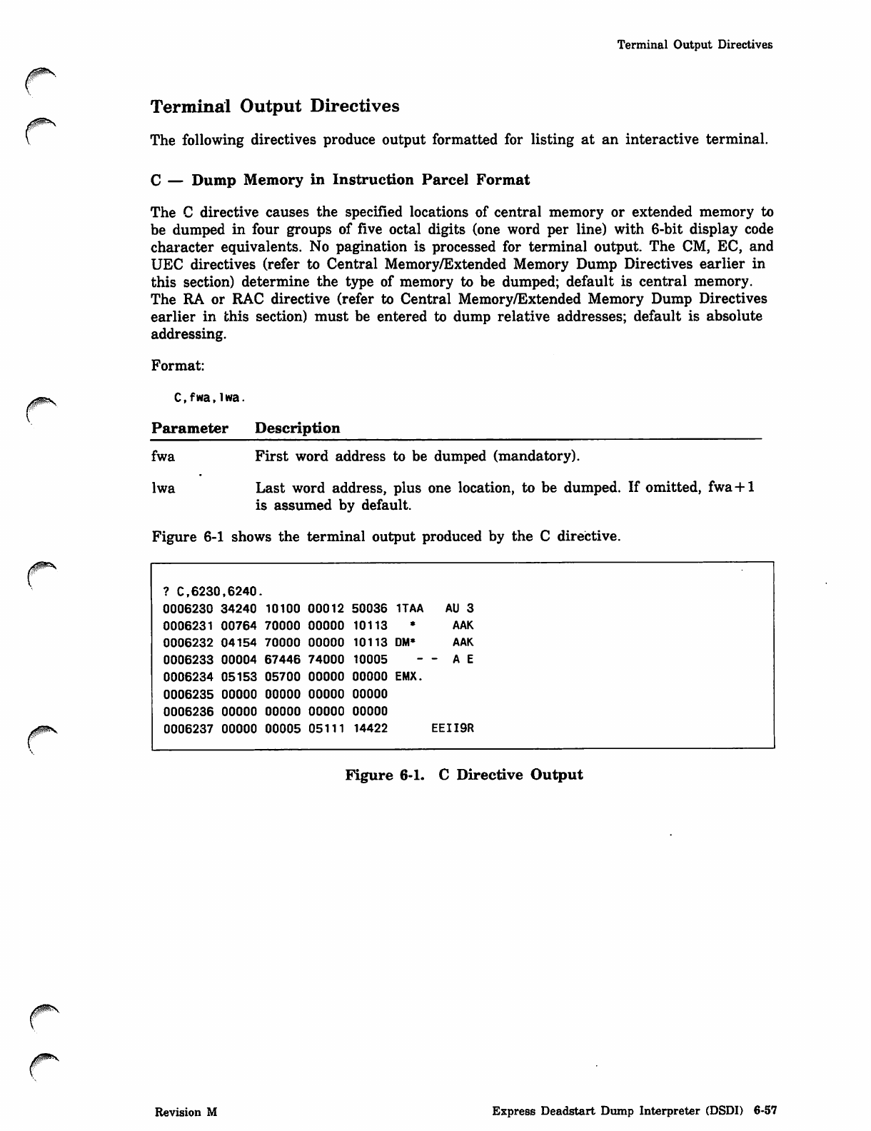
yms
Terminal Output Directives
Terminal Output Directives
The following directives produce output formatted for listing at an interactive terminal.
C — Dump Memory in Instruction Parcel Format
The C directive causes the specified locations of central memory or extended memory to
be dumped in four groups of five octal digits (one word per line) with 6-bit display code
character equivalents. No pagination is processed for terminal output. The CM, EC, and
UEC directives (refer to Central Memory/Extended Memory Dump Directives earlier in
this section) determine the type of memory to be dumped; default is central memory.
The RA or RAC directive (refer to Central Memory/Extended Memory Dump Directives
earlier in this section) must be entered to dump relative addresses; default is absolute
addressing.
Format:
C, fwa, l wa.
Parameter Description
fwa
lwa
First word address to be dumped (mandatory).
Last word address, plus one location, to be dumped. If omitted, fwa+l
is assumed by default.
Figure 6-1 shows the terminal output produced by the C directive.
? C,6230,6240
0006230 34240 10100 00012 50036 1TAA AU 3
0006231 00764 70000 ooooo 10113 AAK
0006232 04154 70000 ooooo 10113 DM* AAK
0006233 00004 67446 74000 10005 - A E
0006234 05153 05700 ooooo ooooo EMX.
0006235 ooooo ooooo ooooo ooooo
0006236 ooooo ooooo ooooo ooooo
0006237 ooooo 00005 05111 14422 EEII9R
Figure 6-1. C Directive Output
Revision M Express Deadstart Dump Interpreter (DSDI) 6-57
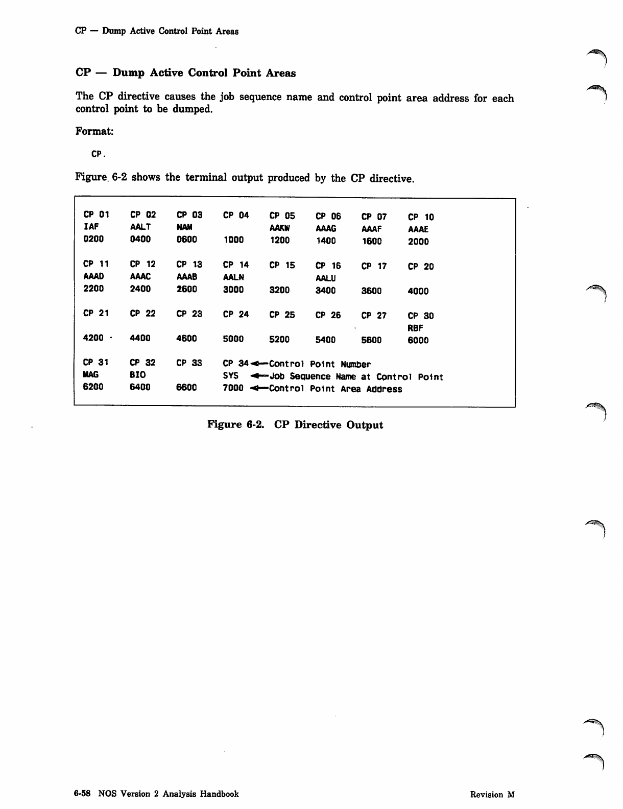
CP — Dump Active Control Point Areas
CP — Dump Active Control Point Areas
The CP directive causes the job sequence name and control point area address for each 1
control point to be dumped.
Format:
CP.
Figure. 6-2 shows the terminal output produced by the CP directive.
CP 01 C P 02 C P 0 3 C P 0 4 CP 0 5 CP 0 6 C P 07 C P 1 0
IAF AALT NAM AAKW AAAG AAAF AAAE
0200 0400 0600 1000 1200 1400 1600 2000
CP 11 C P 1 2 CP 1 3 C P 1 4 CP 1 5 CP 16 C P 1 7 CP 20
AAAD AAAC AAAB AALN AALU
2200 2400 2600 3000 3200 3400 3600 4000
CP 21 C P 22 C P 2 3 C P 2 4 CP 2 5 CP 2 6 C P 27 C P 3 0
RBF
4200 • 4400 4600 5000 5200 5400 5600 6000
CP 31 CP 32 CP 33 CP 34 •<—Control Point Number
" A G B I O S Y S « * — J o b S e q u e n c e N a m e a t C o n t r o l P o i n t
6200 6400 6600 7000 •<— Control Point Area Address
Figure 6-2. CP Directive Output
6-58 NOS Version 2 Analysis Handbook Revision M
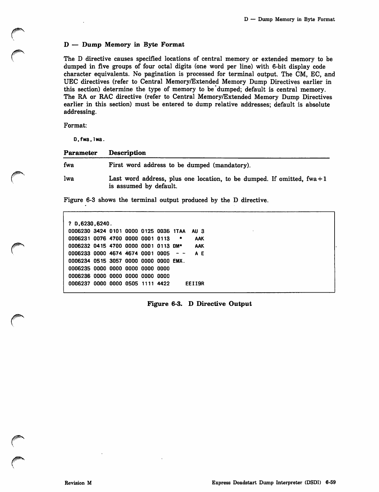
D — Dump Memory in Byte Format
D — Dump Memory in Byte Format
The D directive causes specified locations of central memory or extended memory to be
dumped in five groups of four octal digits (one word per line) with 6-bit display code
character equivalents. No pagination is processed for terminal output. The CM, EC, and
UEC directives (refer to Central Memory/Extended Memory Dump Directives earlier in
this section) determine the type of memory to be "dumped; default is central memory.
The RA or RAC directive (refer to Central Memory/Extended Memory Dump Directives
earlier in this section) must be entered to dump relative addresses; default is absolute
addressing.
Format:
D,fwa,lwa.
Parameter Description
fwa
lwa
First word address to be dumped (mandatory).
Last word address, plus one location, to be dumped. If omitted, fwa+1
is assumed by default.
r
J ^ W y,
Figure 6-3 shows the terminal output produced by the D directive.
? D,6230,6240.
0006230 3424 0101 0000 0125 0036 1TAA AU 3
0006231 0076 4700 0000 0001 0113 * AAK
0006232 0415 4700 0000 0001 0113 DM* AAK
0006233 0000 4674 4674 0001 0005 - - A E
0006234 0515 3057 0000 0000 0000 EMX.
0006235 0000 0000 0000 0000 0000
0006236 0000 0000 0000 0000 0000
0006237 0000 0000 0505 1111 4422 EEII9R
Figure 6-3. D Directive Output
Revision M Express Deadstart Dump Interpreter (DSDI) 6-59
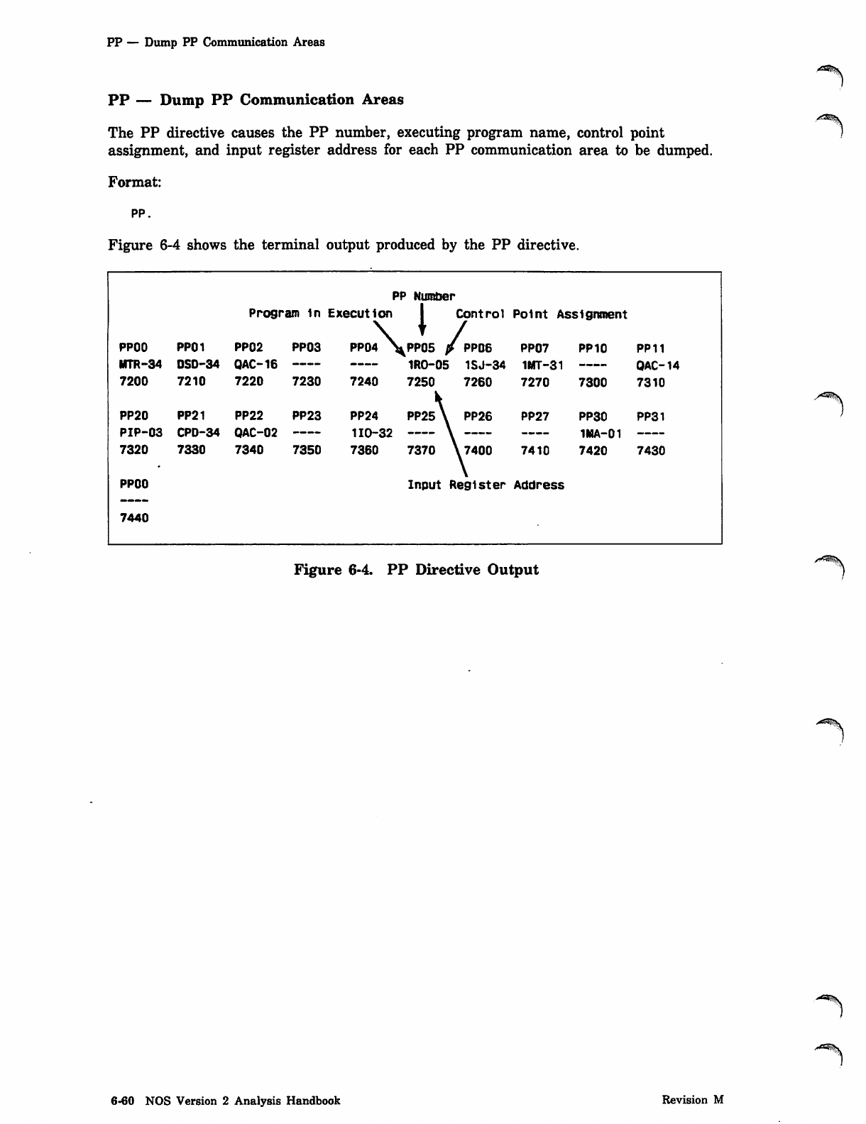
PP — Dump PP Communication Areas
PP — Dump PP Communication Areas
The PP directive causes the PP number, executing program name, control point
assignment, and input register address for each PP communication area to be dumped.
Format:
pp.
Figure 6-4 shows the terminal output produced by the PP directive.
PP Number
Program in Execution 1 Control
\ /
Point Assignment
PPOO PP01 PP02 PP03 PP04 \^PP05 /PP06 PP07 PP10 PP11
WTR-34 OSD-34 QAC-16 1RO-05 1SJ-34 1WT-31 OAC-14
7200 7210 7220 7230 7240 7250 7260 7270 7300 7310
PP20 PP21 PP22 PP23 PP24 PP25 \ PP26 PP27 PP30 PP31
PIP-03 CPD-34 QAC-02 110-32 1MA-01
7320 7330 7340 7350 7360 7 3 7 0 \ 7 4 0 0 7410 7420 7430
PPOO Input Register Address
7440
y*3i|y
Figure 6-4. PP Directive Output
"**%*
6-60 NOS Version 2 Analysis Handbook Revision M
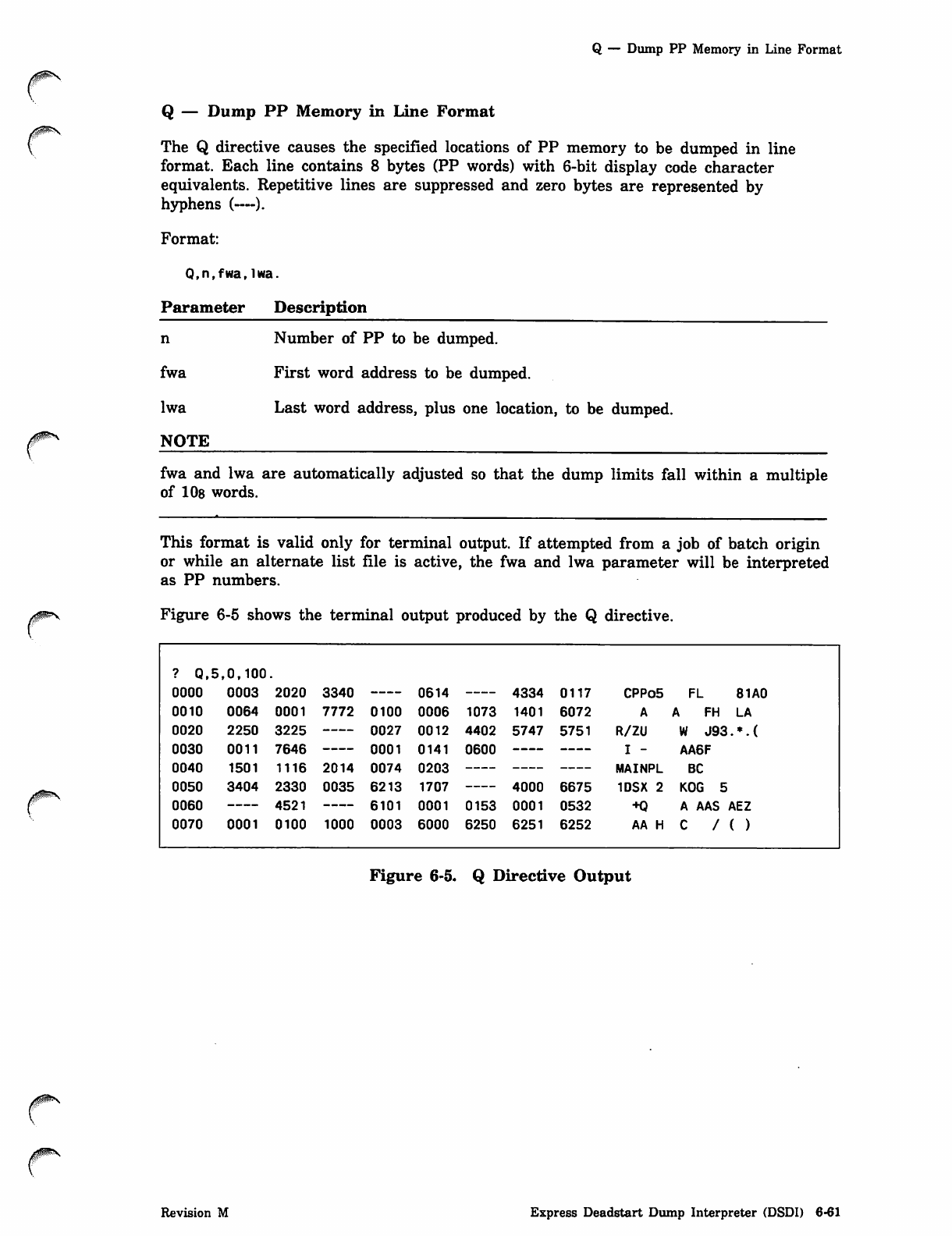
00ms
r
r
00S
Q — Dump PP Memory in Line Format
Q — Dump PP Memory in Line Format
The Q directive causes the specified locations of PP memory to be dumped in line
format. Each line contains 8 bytes (PP words) with 6-bit display code character
equivalents. Repetitive lines are suppressed and zero bytes are represented by
hyphens (—).
Format:
Q,n,fwa,lwa.
Parameter Description
n
fwa
lwa
NOTE
Number of PP to be dumped.
First word address to be dumped.
Last word address, plus one location, to be dumped.
fwa and lwa are automatically adjusted so that the dump limits fall within a multiple
of 108 words.
This format is valid only for terminal output. If attempted from a job of batch origin
or while an alternate list file is active, the fwa and lwa parameter will be interpreted
as PP numbers.
Figure 6-5 shows the terminal output produced by the Q directive.
? Q . 5 ,0,100
0000 0003 2020 3340 0614 4334 0117 CPPo5 FL 81A0
0010 0064 0001 7772 0100 0006 1073 1401 6072 A F H L A
0020 2250 3225 0027 0012 4402 5747 5751 R/2U W J93.*.(
0030 0011 7646 0001 0141 0600 I - AA6F
0040 1501 1116 2014 0074 0203 MAINPL BC
0050 3404 2330 0035 6213 1707 4000 6675 1DSX 2 KOG 5
0060 4521 6101 0001 0153 0001 0532 +Q A AAS AE2
0070 0001 0100 1000 0003 6000 6250 6251 6252 AA H C / ( )
Figure 6-5. Q Directive Output
Revision M Express Deadstart Dump Interpreter (DSDI) 6-61
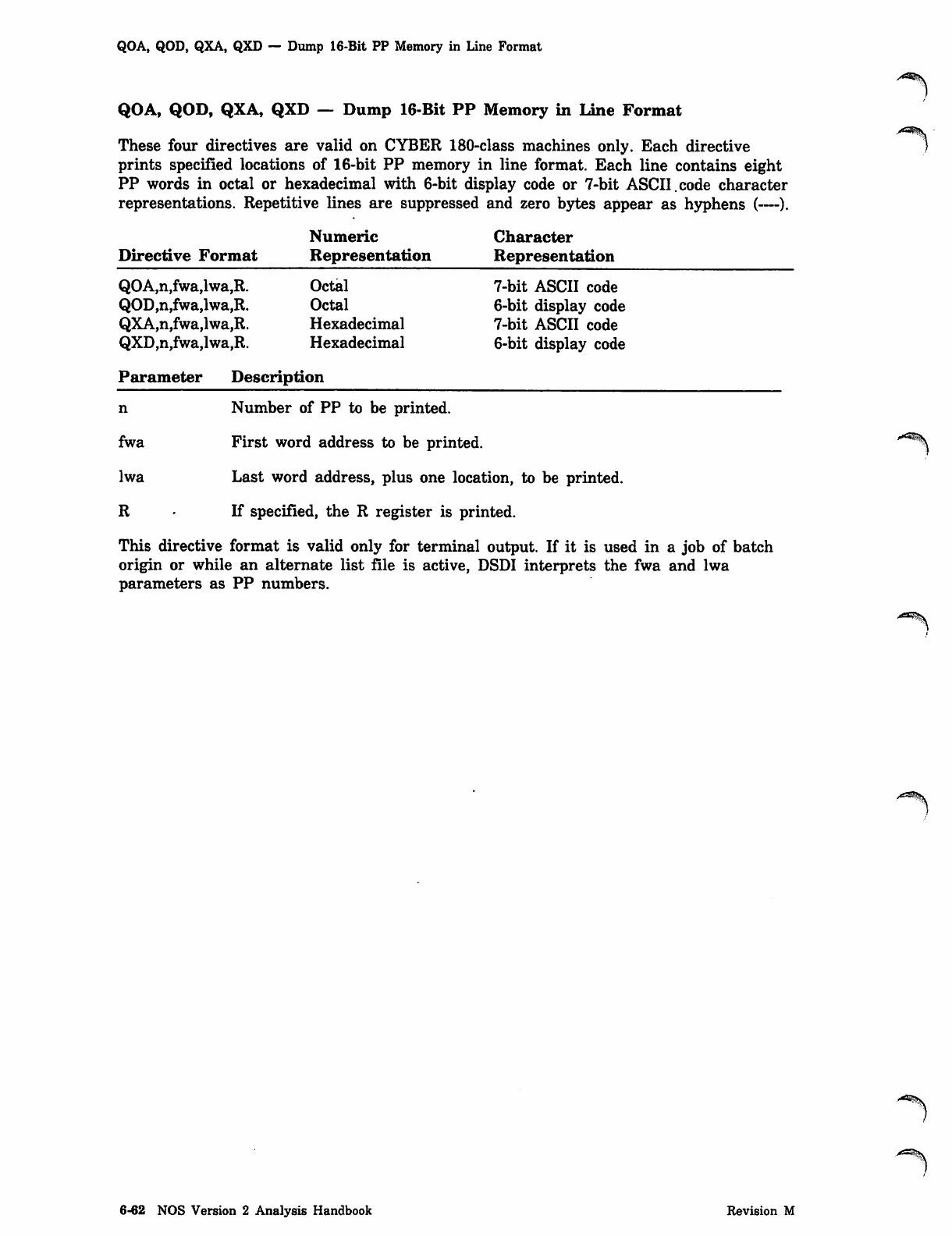
QOA, QOD, QXA, QXD — Dump 16-Bit PP Memory in Line Format
QOA, QOD, QXA, QXD — Dump 16-Bit PP Memory in line Format
These four directives are valid on CYBER 180-class machines only. Each directive
prints specified locations of 16-bit PP memory in line format. Each line contains eight
PP words in octal or hexadecimal with 6-bit display code or 7-bit ASCII.code character
representations. Repetitive lines are suppressed and zero bytes appear as hyphens (—).
Numeric Character
Directive Format Representation Representation
QOA,n,fwa,lwa,R. Octal 7-bit ASCII code
QOD,n,fwa,lwa,R. Octal 6-bit display code
Q X A , n , f w a , l w a , R . H e x a d e c i m a l 7 - b i t A S C I I c o d e
QXD,n,fwa,lwa,R. Hexadecimal 6-bit display code
Parameter Description
n Number of PP to be printed.
fwa First word address to be printed.
lwa Last word address, plus one location, to be printed.
R If specified, the R register is printed.
This directive format is valid only for terminal output. If it is used in a job of batch
origin or while an alternate list file is active, DSDI interprets the fwa and lwa
parameters as PP numbers.
6-62 NOS Version 2 Analysis Handbook Revision M
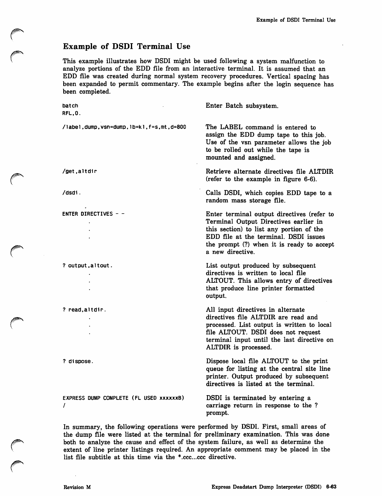
Example of DSDI Terminal Use
0ms
r
Example of DSDI Terminal Use
This example illustrates how DSDI might be used following a system malfunction to
analyze portions of the EDD file from an interactive terminal. It is assumed that an
EDD file was created during normal system recovery procedures. Vertical spacing has
been expanded to permit commentary. The example begins after the login sequence has
been completed.
batch
RFL.O.
/label,dump,vsn=dump,lb=kl,f=s,mt,d=800
/get.altdir
/ d s d i .
ENTER DIRECTIVES - -
? output,a 1 tout
? read.altdir
? dispose.
EXPRESS DUMP COMPLETE (FL USED XXXXXXB)
/
Enter Batch subsystem.
The LABEL command is entered to
assign the EDD dump tape to this job.
Use of the vsn parameter allows the job
to be rolled out while the tape is
mounted and assigned.
Retrieve alternate directives file ALTDIR
(refer to the example in figure 6-6).
Calls DSDI, which copies EDD tape to a
random mass storage file.
Enter terminal output directives (refer to
Terminal Output Directives earlier in
this section) to list any portion of the
EDD file at the terminal. DSDI issues
the prompt (?) when it is ready to accept
a new directive.
List output produced by subsequent
directives is written to local file
ALTOUT. This allows entry of directives
that produce line printer formatted
output.
All input directives in alternate
directives file ALTDIR are read and
processed. List output is written to local
file ALTOUT. DSDI does not request
terminal input until the last directive on
ALTDIR is processed.
Dispose local file ALTOUT to the print
queue for listing at the central site line
printer. Output produced by subsequent
directives is listed at the terminal.
DSDI is terminated by entering a
carriage return in response to the ?
prompt.
In summary, the following operations were performed by DSDI. First, small areas of
the dump file were listed at the terminal for preliminary examination. This was done
both to analyze the cause and effect of the system failure, as well as determine the
extent of line printer listings required. An appropriate comment may be placed in the
list file subtitle at this time via the *.ccc...ccc directive.
Revision M Express Deadstart Dump Interpreter (DSDI) 6-63
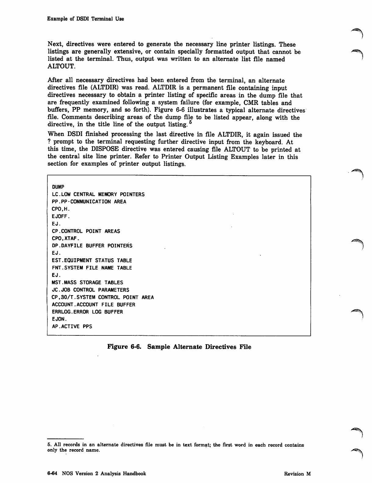
Example of DSDI Terminal Use
Next, directives were entered to generate the necessary line printer listings. These
listings are generally extensive, or contain specially formatted output that cannot be
listed at the terminal. Thus, output was written to an alternate list file named
ALTOUT.
After all necessary directives had been entered from the terminal, an alternate
directives file (ALTDIR) was read. ALTDIR is a permanent file containing input
directives necessary to obtain a printer listing of specific areas in the dump file that
are frequently examined following a system failure (for example, CMR tables and
buffers, PP memory, and so forth). Figure 6-6 illustrates a typical alternate directives
file. Comments describing areas of the dump file to be listed appear, along with the
directive, in the title line of the output listing.5
When DSDI finished processing the last directive in file ALTDIR, it again issued the
? prompt to the terminal requesting further directive input from the keyboard. At
this time, the DISPOSE directive was entered causing file ALTOUT to be printed at
the central site line printer. Refer to Printer Output Listing Examples later in this
section for examples of printer output listings.
DUMP
LC.LOW CENTRAL MEMORY POINTERS
PP.PP-COMMUNICATION AREA
CPO.H.
EJOFF.
EJ.
CP.CONTROL POINT AREAS
CPO.XTAF.
DP.DAYFILE BUFFER POINTERS
EJ.
EST.EQUIPMENT STATUS TABLE
FNT.SYSTEM FILE NAME TABLE
EJ.
MST.MASS STORAGE TABLES
JC.JOB CONTROL PARAMETERS
CP.30/T.SYSTEM CONTROL POINT AREA
ACCOUNT.ACCOUNT FILE BUFFER
ERRLOG.ERROR LOG BUFFER
EJON.
AP.ACTIVE PPS
Figure 6-6. Sample Alternate Directives File
5. All records in an alternate directives file must be in text format; the first word in each record contains
only the record name.
6-64 NOS Version 2 Analysis Handbook Revision M
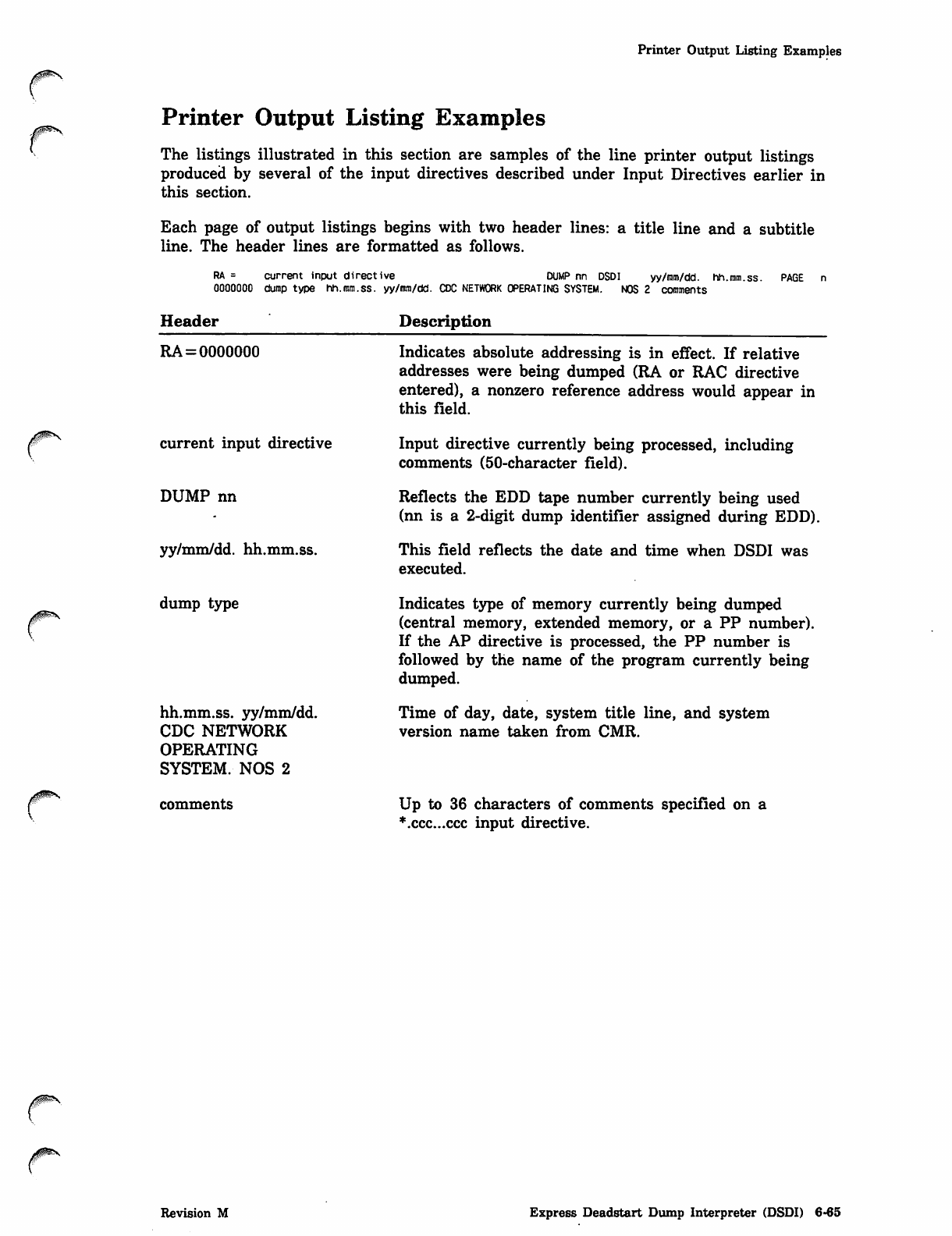
Printer Output Listing Examples
Printer Output Listing Examples
The listings illustrated in this section are samples of the line printer output listings
produced by several of the input directives described under Input Directives earlier in
this section.
Each page of output listings begins with two header lines: a title line and a subtitle
line. The header lines are formatted as follows.
RA = current input directive DUMP nn DSDI yy/mm/dd. hh.mm.ss.
0000000 dump type hh.mm.ss. yy/mm/dd. CDC NETWORK OPERATING SYSTEM. NOS 2 comments PAGE n
Header Description
RA = 0000000
current input directive
DUMP nn
yy/mm/dd. hh.mm.ss.
dump type
hh.mm.ss. yy/mm/dd.
CDC NETWORK
OPERATING
SYSTEM. NOS 2
Indicates absolute addressing is in effect. If relative
addresses were being dumped (RA or RAC directive
entered), a nonzero reference address would appear in
this field.
Input directive currently being processed, including
comments (50-character field).
Reflects the EDD tape number currently being used
(nn is a 2-digit dump identifier assigned during EDD).
This field reflects the date and time when DSDI was
executed.
Indicates type of memory currently being dumped
(central memory, extended memory, or a PP number).
If the AP directive is processed, the PP number is
followed by the name of the program currently being
dumped.
Time of day, date, system title line, and system
version name taken from CMR.
comments Up to 36 characters of comments specified on a
*.ccc...ccc input directive.
Revision M Express Deadstart Dump Interpreter (DSDI) 6-65
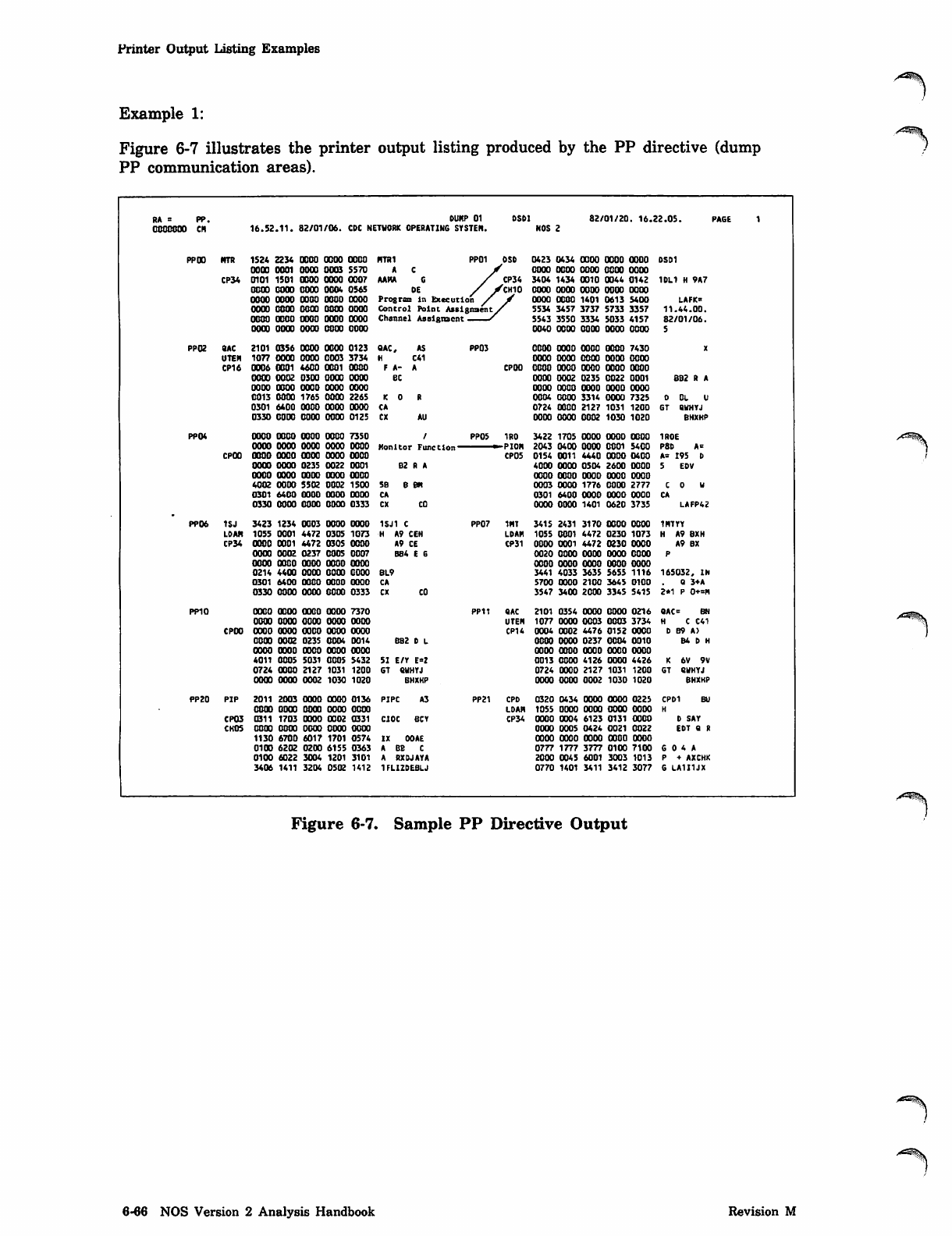
Printer Output Listing Examples
Example 1:
Figure 6-7 illustrates the printer output listing produced by the PP directive (dump
PP communication areas).
RA = P P. OURP 01 D S D I 8 2 / 0 1 / 2 0 . 16.22.05. PAGE
CC0DO0O CN 16.52.11. 82/01/06. CDC NETWORK OPERATING SYSTEM. NOS 2
PPOO MTR 1524 2234 MOO OOOO OOOO HTR1 PP01 OSD 0423 0434 WOO OOOO OOOO DSD1
OOOO 0001 OOOO 0003 5570 A C OOOO OOOO OOOO COM OOOO
CP34 0101 1501 OOOO OOOO 0007 A A K A G CP34 3404 1434 0010 W44 0142 1DL1 H 9A7
OOOO OOOO OOOO 0004 0565 OE / ><CH10 OOOO OOOO OOOO OOOO OOOO
OOOO OOOO OOOO oooo oooo P r o g r a m I n E x e c u t i o n / OOOO WOO 1401 0613 54W LAFK"
oooo oooo oooo oooo oooo Control Point AsBlgrtnent, 5534 3457 3737 5733 3357 11.44.00.
oooo oooo oooo oooo oooo Channel Asslgnscnt S543 3550 3334 5033 4157 82/01/06.
oooo oooo oooo oooo oooo W4 0 W W O O W OOW OOW
PP02 RAC 2101 0356 0000 0000 0123 SAC, AS PP03 OOW OWO WOO woo 7430
UTER 1077 OOOO OOOO 0003 3734 H C 4 1 OOW OOW WW W W O OW
CP16 0006 0001 4600 0001 OOOO F A - A CPOO OOOO OWO OOW woo woo
OOOO 0002 0300 OOOO OOOO ec WW 0002 0 235 0022 0001 BB2 R A
OOOO OOOO OOOO OOOO oooo WW WOO OWO OWO OOW
0013 0000 1765 0000 2265 K 0 R W 04 W W 3 31 4 OOW 7325 0 O L l l
0301 6400 WOO OOOO OOOO CA 0724 WOO 2127 1031 1200 GT BWHYJ
0330 OOOO OOOO OOOO 0125 C X A U W W W W 0 0 0 2 1030 1020 BHXKP
PPW OOOO OOOO OOOO OOOO 7350 PP05 1R0 3422 1705 WW OWO WOO 1R0E
OOOO OOOO OOOO oooo oooo
oooo oooo oooo oooo oooo
2043 04W WW
0154 W11 4440
0001 5400
WOO 0400
PSD A<=
As 195 DCPOO CP05
0000 OOOO 0235 0022 0001 B2 R A 40W W W 0 5 0 4 26W WOO 5 E D V
OOOO oooo oooo oooo oooo WW WOO OWO OWO WOO
4002 OOOO 5502 0002 1500 S B B B R 0003 WW 1776 OOW 2777 COW
0301 6400 OOOO OOOO OOOO CA 0301 6400 OWO WOO WOO CA
0330 OOOO OOOO OOOO 0333 C X C O OOW OOW 1401 0620 3735 LAFP4Z
PP06 1SJ 3423 1234 0003 OOOO OOOO 1SJ1 C PP07 1RT 3415 2431 3170 OOOO WW 1HTYY
LDAR 1055 0001 4472 0305 1073 H A9 CEN LDAR 1055 W01 4472 0230 1073 H A9 BXH
CP34 OOOO 0001 4472 0305 OOOO A9 CE CP31 WW 0W1 4472 0230 OWO A9 BX
OOOO 0002 0237 0005 0007 BS4 E 6 0020 OOW WW OOW OOW
OOOO OOOO OOOO WOO OOOO WOO OWO WOO WOO WW
0214 4400 OOOO OOOO OOOO 8L9 3441 4033 3635 5655 111 6 1 6503 2 , I N
0301 6400 OOOO OOOO OOOO CA 57W WOO 2100 3645 0100 Q 3+A
0330 OOOO OOOO OOOO 0333 C X C O 3S47 34W 20W 3345 5415 2*1 P 0*=R
PP10 OOOO OOOO OOOO OOOO 7370
OOOO OOW OOOO OOOO oooo
PP11 QAC
UTER
2101 03S4 OOW
1077 OOW W03
OOW
0003
0216
3734
QAC= BN
H C C 4 1
CPOO oooo oooo oooo oooo oooo
OOOO 0002 0235 0004 0014 BB2 D L
CPI 4 0W4 0002 4476
OOW OWO 0237
0152
W04
OWO
0010
D B9 A)
B4 D H
OOOO oooo oooo oooo oooo WW WOO OWO OWO OWO
4011 0005 5031 0005 5432 51 E/Y E=2 0013 OOW 4126 OOW 4426 K 6 V 9 W
0724 OOOO 2127 1031 1200 6T QWHTJ 0724 OWO 2127 1031 1200 GT QWHYJ
OOOO OOOO 0002 1030 1020 BHXKP OOW OOW 0W2 1030 1020 BHXKP
PP20 PIP 2011 2003 OOOO OOOO 0136
OOOO OOOO OOOO OOOO OOOO
PIPC A3 PP21 CPO
LDAR
0320 0434 OOW
1055 OOW WW
OOW
OOW
0225
WW
CPD1 BU
H
CP03 0311 17D3 OOOO 0002 0331 CIO C B CY CP34 WOO 0W4 6123 0131 WOO D SAY
CH05 OOOO OOOO OOOO OOOO OOOO
1130 6700 6017 1701 0574
0100 6202 0200 6155 0363
0100 6022 3004 1201 3101
3406 1411 3204 0502 1412
IX OOAE
A B B C
A RXDJAYA
1FLIZDEBLJ
OOW 0005 0424
OOW WOO WW
0777 1777 3777
20W 0045 6001
0770 1401 3411
W21
WOO
01W
3W3
3412
0022
OWO
71W
1013
3077
EOT Q fi
G 0 4 A
P ♦ AXCKK
G LA1I1JX
Figure 6-7. Sample PP Directive Output
,*^^.
6-66 NOS Version 2 Analysis Handbook Revision M
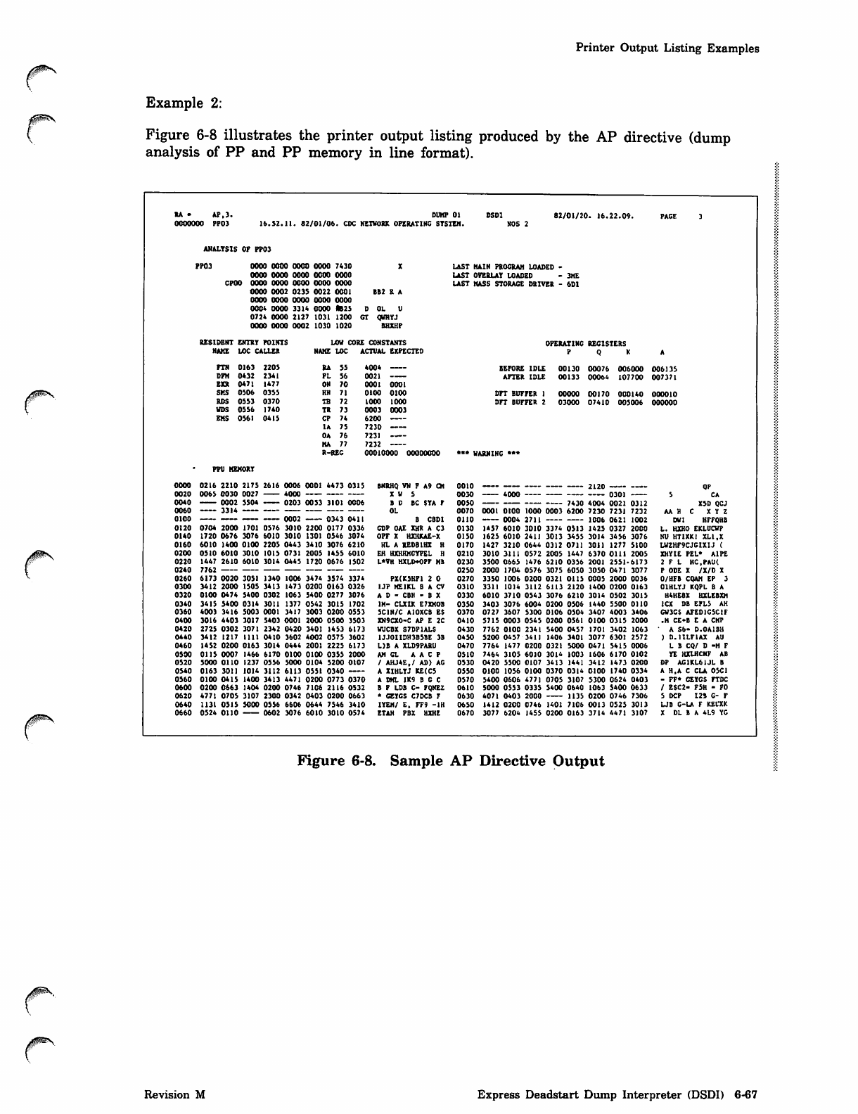
Printer Output Listing Examples
Example 2:
Figure 6-8 illustrates the printer output listing produced by the AP directive (dump
analysis of PP and PP memory in line format).
I A • AP.3. DUMP 01 DSDI 82/01/20. 16.22.09. P A G E 3
0000000 FP03 6 .52 11. 62/01/06. CDC NETWORK OPERATING SYSTEM. NOS 2
ANALYSIS OP PP03
PP03 OOOO OOW OOW OOW 743D
OOOO OOW OOW WW OWO
LAST HAIN PROGRAM LOADED -
LAST OVERLAY LOADED - 3ME
CPOO 0000 OOW OOW WW OOW UST MASS STORAGE DRIVER - 6DI
OOW 0W2 0235 W22 W01 BB2 R A
WW OOW OOW WW WW
0004 OOW 3314 OOW «B25 D O L U
0724 OOW 2127 1031 12W GT OVHYJ
OOW WW 0002 1030 1020 BHXKP
RESIDENT DORY POINTS LOW CORE CONSTANTS OPERATING REGISTERS
NAME LOC CALLER NAME LOC ACTUAL EXPECTED Q K
FTN 0163 2205 R A 5 5 4 W 4 BEFORE IDLE 00130 0W76 006000 W6135
DFM 0432 2341 P L 5 6 W 2 1 AF T E R ID L E W1 3 3 00 0 6 4 1 07 7W W7371
EXS 0471 1477 O N 7 0 0 0 0 1 0 W 1
SKS 0506 0355 H N 7 1 0 1 W O I W DFT BUFFER 1 OOOOO W 1 7 0 0 0 0 14 0 000010
RDS 0553 0370 I B 7 2 1 0 W 1 0 W DFT BUFFER 2 030W 0 7 41 0 W S W 6 OOOOOO
VDS 0556 1740 T R 7 3 0 W 3 0 W 3
EMS 0561 0415 C P 7 4 6 2 W
I A 7 5 7 2 3 0
O A 7 6 7 2 3 1
M A 7 7 7 2 3 2
R-REC W010W0 OOOOOOOO ••• WARNING •**
PPU KEKORT
OOOO 0216 2210 2175 2616 0W6 W01 4473 0315 BMRHQ VN F A9 CM 0010 2120 qp
0020 W65 0030 0027 40W ~_ -— X V 5 0030 40W 0301 5 C A
0040 0002 5504 0203 W53 3101 W06 B D DC $YA P W50 7*30 4W4 0021 0312 X5D QCJ
0060 3314 —- —- OL 0070 O W I OIW 10W 0W3 62W 7230 723) 7232 A A H C X Y Z
0100 —— ——• —— W02 0343 0411 B C8DI OHO W04 2711 1006 0621 1002 DWI H F F QHB
0120 0704 2000 1701 0576 3010 22W 0177 0336 COP OAE XHR A C3 0130 1457 6010 3010 3374 0513 1425 0327 2000 L. HXHO EKLUCWP
0140 1720 0676 3076 6010 3010 1301 0546 3074 OFT X HXHKAE-X 0150 1625 60)0 2411 3013 3455 30)4 3456 3076 KU HTIXK1 XL1.X
0160 6010 14W 01W 2205 0443 3410 3076 6210 HL A IE081HI H 0170 1427 3210 0644 0312 0711 3011 1277 5100 LUZHF9CJGIXU (
0200 0510 6010 3010 1015 0731 2005 1455 6010 EH HXHKKCYPEL H 0210 3010 3111 0572 2005 1447 6370 0111 2W5 XHYIE PEL* A1PE
0220 1447 2610 6010 1014 0445 1720 0676 1502 L*VH HXLD+OPF Ml 0230 3500 0665 1476 6210 0356 2001 2551-6173 2 F L HC,PAU(
0240 7762 0250 2W0 1704 0576 3075 6050 3050 0471 3077 P ODE X /X/D X
0260 6173 0020 3051 1340 1006 3474 3574 3374 PXCK5HF) 2 0 0270 3350 IW6 0200 0321 0115 W05 2W0 0036 O/HFB CQAM EP 3
0300 3412 20W 1505 3413 1473 0200 0163 0326 UP ME1KL B A CT 0310 3311 1014 3112 6113 2120 I4W 0200 0163 01HLYJ KQPL B A
0320 0100 0474 5400 0302 1063 5400 0277 3076 A D - CBH - B X 0330 6010 3710 0543 3076 6210 3014 0502 3015 H4HE8X HXLEBXM
0340 34IS 5*00 0314 3011 1377 0542 3015 1702 IH- CLXIX E7XK0B 0350 3403 3076 6004 02W 0506 1440 5500 OHO 1CX DB EFL5 AH
0360 4003 3416 5W3 W01 3417 3003 02W 0553 SC1N/C AIOXCB E5 0370 0727 3607 5300 0106 0504 3407 4W3 3406 GW3CS AFED1CSC1F
0400 3016 4403 3017 5403 W01 2000 0506 3503 XN9CX0-C AP E 2C 0410 5715 0W3 0545 0200 0561 OIW 0315 20W .H CE+B E A CHT
0420 2725 0302 3071 2342 0420 340) 1453 6173 VUCBX S7DP1ALS 0430 7762 0100 2341 5400 0457 1701 3402 1063 ' A S6- D.0A1BH
0440 3412 1217 1111 0410 3602 4W2 0575 3602 1JJOIIDH3B5BE 3B 0450 5200 0457 3411 1406 3401 3077 6301 2572 ) 0.11LF1AX AU
0460 1452 02W 0163 3014 0444 2001 2225 6173 DB A XLD9PARU 0470 7764 1477 0200 0321 5000 0471 5415 0W6 L B CQ/ D -H F
0590 0115 0W7 1466 6170 01W OIW 0355 2000 AM CL A A C P 0510 7464 3105 60)0 3014 1003 1606 6170 0102 YE HXLHCHF AB
0520 SOW 0110 1237 0556 5000 0104 52W 0107 / AHJ4E,/ AD) AC 0530 0420 55W 0107 3413 1441 3412 1473 0200 DP AC1KL61JL B
0540 0163 301) 1014 3112 6113 0551 0340 A XIHLTJ KE(C5 0550 0100 1056 OIW 0370 0314 0100 1740 0334 A H,A C CU 05C1
0560 01W 0415 14W 3413 4471 02W 0773 0370 A DHL IK9 B C C 0570 54W 0606 4771 0705 3107 S3W 0624 0403 - FF* CEYCS FTDC
0600 02W 0663 1404 02W 0746 7106 2116 0532 B P LDB C- FQNEZ 0610 5000 0553 0335 54W 0640 1063 S4W 0633 / ESC2- F5H - FO
0620 4771 0705 3107 2300 0342 0403 0200 0663 » GETGS C7DCB F 0630 4 0 7 1 0 4 0 3 2 0 0 0 1 1 3 5 02W 0746 7306 5 D C P I2S C- F
0640 1131 0515 5C00 0556 6606 0644 7546 3410 IYEH/ E. FF9 -IH 0650 1412 02O0 0746 1401 7106 W13 0525 3013 UB G-U F KECXK
0660 0524 0110 0602 3076 6010 3010 0574 ETAH PBX HXHE 0670 3077 6204 1455 02W 0163 3714 4471 3107 X DL B A 4L9 YG
Figure 6-8. Sample AP Directive Output
0$ms.
Revision M Express Deadstart Dump Interpreter (DSDI) 6-67
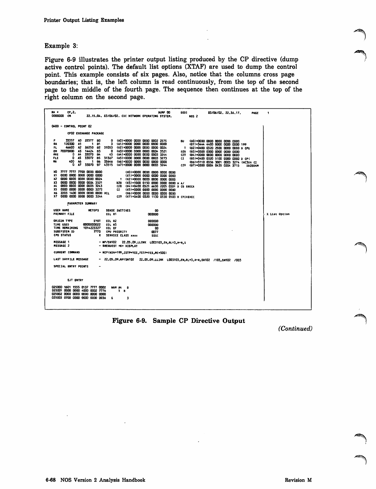
Printer Output Listing Examples
Example 3:
Figure 6-9 illustrates the printer output listing produced by the CP directive (dump
active control points). The default list options (XTAF) are used to dump the control
point. This example consists of six pages. Also, notice that the columns cross page
boundaries; that is, the left column is read continuously, from the top of the second
page to the middle of the fourth page. The sequence then continues at the top of the
right column on the second page.
y*SW|L
RA « CP,2. DUMP 00 OSOI 83/06/02. 22.36.17. PA6E
0OQ0000 CH 22.15.04. 83/06/02. CDC NETWORK OPERATING SYSTEM. NOS 2
0400 - CONTROL POINT 02
CP02 EXCHANGE PACKAGE
P 33357 AO 22577 BO 0 (A0)«OOW OOW OOW 0002 2575 BU (80>*WW OWO WW WW OWO
RA 120300 A1 1 Bl 3 (AD'OOW OOW WOO WOO WOO <B1>°3444 4400 OOW WW OOW 199
FL 46600 A2 26250 82 31053 <A2)*00W OWO WW OWO 0024 T (82>«04W 0320 25W OWO OWO D CPU
EH 70070000 A3 14424 B3 0 (AS)=0000 OOW OOW 0004 3521 028 (B3>*00W OOW WW WW OOW
ME 0 A4 33070 B4 43 <A4)>0WO WW WW 0003 3244 CZ9 (84)*OW0 WW OWO 0000 OWO
FLE 0 AS 33072 B5 31367 <A5)*0OW OOW WW 0W3 3273 CZ (B5)>04W 0320 51W OWO OWO D CP<
RA 400 A6 1 B6 33646 CA6)-W00 OWO WW OWO WOO <86)*S110 0336 3001 W03 3274 (HC3XA «
0 A7 33070 B7 43515 <A7)»0DW WW WW W03 3244 CZ9 <87>"00W 0004 0435 0204 3715 DD2BD4H
XO 7777 7777 7700 OOW WW <X0>«WW WW WOO WOO WW
XI WW OOW OOW WW OWO CX1)«0OW OOW WW OOW OWO
X 2 W W W W W W W W W 2 4 T ( X 2 ) * W W W W W W O W O O W O
X3 OWO OOW OOW 0004 3521 D2R (X3)*10W 0150 OOW WW OOW H A/
X4 WOO WOO WW W03 3243 C7.8 (X4><04W 0321 6630 2205 0301 D ca XRECA
X S O O W W W W W 0 0 0 3 3 2 7 3 C Z ( X 5 > > 0 0 M O O W W W W W W W
X 6 2 2 0 3 1 4 W W W W W W W R C L < X 6 ) » W W W W W W W W W W
X7 OOW WW OOOO W03 3244 CZ9 (X7)=04W 0320 1130 0530 0503 D CPIXEXEC
PARARETER SUHRART
USER NAHE NETOPS SENSE SWITCHES W
P R I M A R Y F I L E C C L R 1 O O W W X Llct Option
ORIGIN TYPE SYOT CCL R2 DWOW
TIRE USED WWWW22 CCL R3 OWWO
TIRE REMAINING 1014223327 CCL EF 00
SUBSYSTEM ID 7770 CPU PRIORITY 0077
CPU STATUS X SERVICE CLASS x««« SSSC
RESSA6E 1 - NP/SN102 22.05.09.LLINK LW3103,EN,AL=S,H-N,S
R E S S A G E 2 - S R E Q U E S T * K * D I S P L A Y
CURRENT COWARD - NIP<NIN«199,ISTP»YES,FSTP»YES,RC«5W)
LAST DAYFILE RESSA6E - 22.05.09.NP/SN102 22.0S.O9.LLINK LW3103,EN,RL*3,M-N,SH102 /1D3.SN102 /003
SPECIAL ENTRY POINTS
EJT ENTRY
02SW0 1601 1555 0137 7777 0002 NAM A4 B
025001 OOW OOOO 40W 0002 7776 5 B
025W2 OWO WOO WW WW WOO
0 2 5 W 3 0 7 W W W W W W W W 3 6 G 3
Figure 6-9. Sample CP Directive Output
(Continued)
6-68 NOS Version 2 Analysis Handbook Revision M
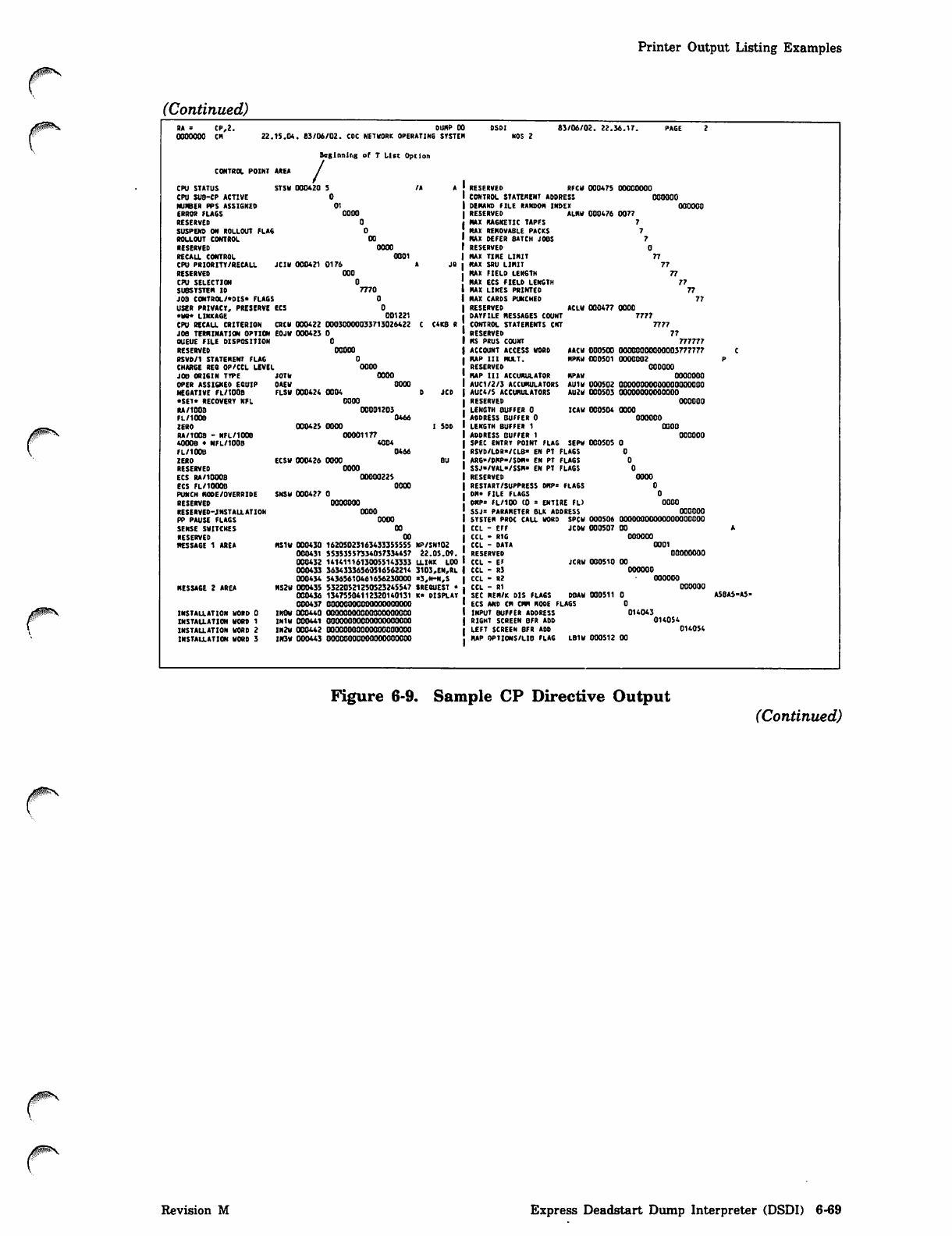
Printer Output Listing Examples
(Continued)
RA = CP,2. Ximf 00 DSDI 83/06/02. 22.36.17. PAGE 2
0 0 0 0 0 0 0 C M 2 2 IS.04. 83/06/02. CDC NETWORK OPERATING SYSTEM NOS 2
Beginning of T List Option
CONTROL POINT A R E A /
CPU STATUS STSW 000420 5 /A RESERVED RFCW W047S OOOOOOOO
CPU SU8-CP ACTIVE CONTROL STATEMENT ADDRESS WOWO
NUIBER FPS ASSIGNED 01 DEMAND FILE RANDOM INDEX OOOOOO
ERROR FLAGS OOOO RESERVED ALMW 000476 0077
RESERVED MAX MAGNETIC TAPFS
S U S P E N D O N R O L L O U T F L A 6 0 MAX REMOVABLE PACKS
ROLLOUT CONTROL 00 MAX DEFER BATCH JOBS
RESERVED OOW RESERVED
RECALL CONTROL W01 MAX TINE LIMIT 77
CPU PRIORITY/RECALL JCIW 000421 0 1 7 6 JO MAX SRU LIMIT 77
RESERVED WO MAX FIELD LENGTH 77
CPU SELECTION MAX ECS FIELD LENGTH 77
SUBSYSTEM ID 7770 MAX LINES PRINTED 77
JOS CONTROL/*0IS* FLAGS 0 MAX CARDS PUNCHED 77
USER PRIVACY, PRESERVE E C S 0 RESERVED ACLW 000477 OOW
•NS* LINKAGE 001221 DAYFILE MESSAGES COUNT 7777
CPU RECALL CRITERION CRCW 0004 22 000 3000 0033713 0264 22 C C 4 K8 R CONTROL STATEMENTS CN1 7777
JOB TERMINATION OPTION EOJW 000423 0 RESERVED 77
QUEUE FILE DISPOSITION MS PRUS COUNT 777777
RESERVED OOOOO ACCOUNT ACCESS WORD AACW 000500 OOOCOQOOQOO0O3777777 C
RSVD/1 STATEMENT FLAG M A P III M U LT. MPKW W0S01 0 0 0 0 0 0 2 P
CHAR6E REG OP/CCL LEVEL OOOO RESERVED WWW
JOB ORIGIN TYPE J O T W O O W HAP III ACCUMULATOR MPAW 0000000
OPER ASSIGNED ED.UIP O A E V O O O O AUC1/2/3 ACCUMULATORS AU1W 000502 OOOOOOOOOOOOOOOOOOOO
NEGATIVE FL/IOOB FLSW 0 00424 W 04 JCD AUC4/S ACCUMULATORS A U 2W 00050 3 0 000000 0 000000
•SET* RECOVERY NFL OOW RESERVED WOWO
RA/IOOB 0000120J LENGTH BUFFER 0 ICAW W0S04 OOOO
FL/1008 0446 ADDRESS BUFFER 0 OOOOOO
ZERO 000425 OOOO SDD LENGTH BUFFER 1 OOOO
RA/IOCB - NFL/1006 00W1177 ADDRESS BUFFER 1 oooooo
40008 ♦ NFL/1009 4004 SPEC ENTRY POINT FLAG SEPW W0S05
FL/10OB 0466 RSVD/LOR«/CLB* EN PI FLA6S
ZERO ECSW 000426 OOOO BU ARG>/DNP'/SDRs EN PT FLAGS
RESERVED OOW SSJ«/VAL«/SS*» EN PT FLAGS
ECS RA/10WB 00000225 RESERVED oooo
ECS FL/10008 OOW RESTART/SUPPRESS OHP* FLA6S
PUNCH MODE/OVERRIDE SNSW 000427 0 DM* FILE FLAGS
RESERVED WWOX OM P* FL/1 00 (0 = ENT IRE FL ) oooo
RESERVED-JNSTALLATION WW S5J= PARAMETER 6LK ADDRESS oooooo
PP PAUSE FLAGS OOW SYSTEM PROC CALL WORD SPCW W0506 oooooooooooooooooooo
SENSE SWITCHES 00 CCL - EFF JCDW 000507 0 0 A
RESERVED CCL - RI G oooooo
MESSAGE 1 AREA HS1W 000430 16205025163433355555 NP/SN102 CCL - DATA 0001
000431 5S3S3557334057S34457 2 2 . 0 5 . 0 9 . RESERVED oooooooo
000432 14141116130055143333 LLIHK LW CCL - EF JCRW 000510 00
000433 36341336S60SI6562214 3103,EN,RL CCL - R3 oooooo
000434 54365610461656230000 «3,H-N,S CCL - R2 oooooo
MESSAGE 2 AREA NS2W 000435 53220521250523245547 SRE8UEST • CCL - R1 oooooo
000436 13475504112320140131 * • D I S PL AY SEC NEN/K DIS FUGS DBAW X0511 0 A S B A S ' A S -
000437 OOOOOOWWOOOOOOOOOO ECS AND CD CMF1 KOOE FLAGS
INSTALLATION WORD 0 INOW 000440 OOOOOOOOOOOOOOOOOOOO INPUT BUFFER ADDRESS 014043
INSTALLATION WORD 1 INlW 000441 WOOWOOGOOOOOOCWOO RIGHT SCREEN BFR ADD 014054
INSTALLATION WORD 2 IN2W 000442 OOWOWOOOOOWOOOOW LEFT SCREEN BFR ADD 014054
INSTALLATION WORD 3 IN3W 000443 OOOOOOOOOOOOOOOOOOOO HAP OPTIONS/LIB FLAG LB1W 000512 00
Figure 6-9. Sample CP Directive Output
(Continued)
Revision M Express Deadstart Dump Interpreter (DSDI) 6-69
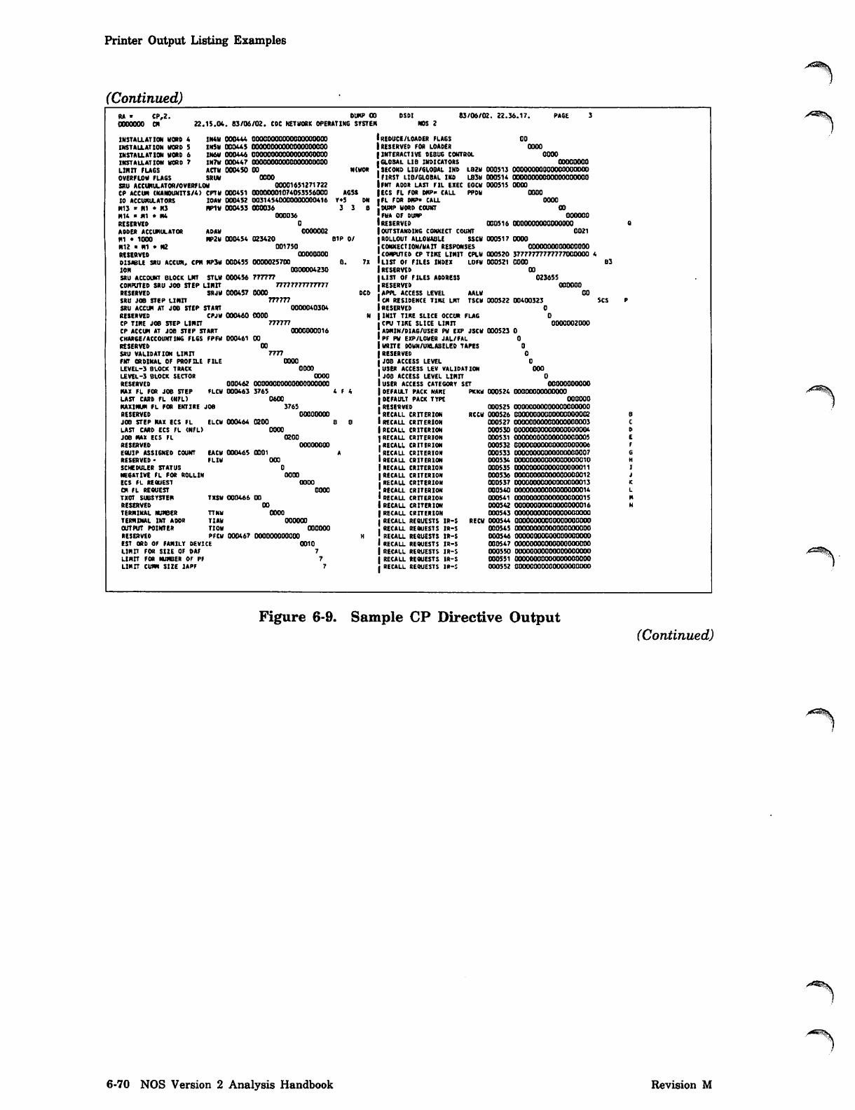
Printer Output Listing Examples
(Continued)
C P, 2 . 83/06/02. 22.36.17.
O W O W O C H 2 2 15.04. 83/06/02 . CDC NET WORK OP ERATING SYSTE
INSTALLATION WORD 4 IN4M 000444 OOOOOOOOOOOOOOOOOOOO
INSTALLATION WORD 5 I N S W 0 0 0 4 4 5 O W W W W W W W W W O
INSTALLATION WORD 6 IN6W 000446 OOOOOOOOOOOOOOOOOOOO
INSTALLATION WORD 7 IN7W 000447 OOOOOOOOOOOOOOOOOOOO
L I M I T F U G S A C T W 0 0 0 4 5 0 0 0 N ( W O R
OVERFLOW FUGS S R U W O O W
SRU ACCUMULATOR/OVERFLOW 00001651271722
CP ACCUM (NANOUNITS/4) C P T W 000 4 5 1 0 OOO W O 1 O 7 4O5 3 5 5 6 W 0 A 6SS
(0 ACCUMULATORS IOAW 000452 O0314540O0OO0OOO0416 Y»S DN
M13 x HI ♦ H3 H P 1 W 0 0 0 4 5 3 0 0 W 3 6 3 3 B
H14 ■ JTI * H4 000036
RESERVED
ADDER ACCUMULATOR ADAW 0000002
M l • 1 0 0 0 H P 2 N W 0 4 5 4 0 2 3 4 2 0 S I P 0 /
H12 • M1 • R2 001750
RESERVED OOOOOOOO
DISABLE SRU ACCUM, CPM RP3W W0455 0000025700 B. 7X
ION 0000004230
SRU ACCOUNT BLOCK LRT S TLW 00045 6 77777 7
COMPUTED SRU JOB STEP LIMIT 77777777777777
RESERVED S R J W 0 0 0 4 5 7 O W O D C D
SRU JOB STEP LIMIT 777777
SRU ACCUM AT JOB STEP S T A R T 0 0 0 0 0 4 0 3 0 4
RESERVED CPJW 000460 WOO N
CP TIME JOB STEP LIMIT 777777
CP ACCUM AT JOB STEP START 0000000016
CHARGE/ACCOUNTING FLGS FPFW 000461 00
RESERVED
SRU VALIDATION LIMIT 7777
FNT ORDINAL OF PROFILE F I L E O O O O
LEVEL-3 BLOCK TRACK OOOO
LEVEL-3 BLOCK SECTOR OOOO
RESERVED 000462 OOOOOOOOOOOOOOOOOOOO
MAX FL FOR JOB STEP F L C W 0 0 0 4 6 3 3 7 6 5 4 F 4
LAST CARD FL (NFL) 06W
MAXIMUM FL FOR ENTIRE J O B 3 7 6 5
RESERVED OOOOOOOO
JOB STEP RAX ECS FL E L C W 0 0 0 4 6 4 0 2 0 0 B 8
LAST CARD ECS FL (NFL) OOOO
JOB MAX ECS FL 0200
RESERVED OOOOOOOO
E0U1P ASSIGNED COUNT E A C W 0 0 0 4 6 5 0 0 0 1 A
RESERVED• F L I W 0 0 0
SCHEDULER STATUS
NE6ATIVE FL FOR ROLLIN OOOO
ECS FL REQUEST OOOO
CM FL REQUEST OOOO
TXOT SUBSYSTEM TXSW 000466 00
RESERVED
TERMINAL NUMBER T T N W O O W
TERMINAL INT ADDR T I A W O O O O O O
OUTPUT POINTER T I O N O O O O O O
RESERVED PFCW 000467 OOOOOOOOOOOO H
EST ORD OF FAMILY DEVICE 0010
LIMIT FOR SIZE OF OAF
LIMIT FOR NUMBER OF P
LIMIT CUNM SIZE 1APF
NOS 2
REDUCE/LOADER FLAGS
RESERVED FOR LOADER
INTERACTIVE DEBUG CONTROL
GLOBAL LIB INDICATORS
SECOND LIB/GLOBAL IND LB2W 0W513
F I R S T LIB / G L OBA L I N D L B3W 0 W 5 14
FNT ADDR LAST FIL EXEC EOCW 0W51S
ECS FL FOR DMP> CALL PPDW
FL FOR DMP« CALL
DUMP WORD COUNT
FWA OF DUMP
RESERVED 000516
OUTSTANDING CONNECT COUNT
ROLLOUT ALLOWABLE SSCW 000517
CONNECTION/WAIT RESPONSES
COMPUTED CP TIRE LIMIT CPLW 000520
LIST OF FILES INDEX LOFW 000521
RESERVED
LIST OF FILES ADDRESS
RESERVED
A P P L A C C E S S L E V E L A A L W
CM RESIDENCE TIME LMT TSCN
RESERVED
INIT TIRE SLICE OCCUR FUG
CPU TIME SLICE LIMIT
ADMIN/D1AG/USER PW EXP JSCW 000523
PF PW EXP/LOVER JAL/FAL
WRITE DOWN/UNLABELED TAPES
RESERVED
JOB ACCESS LEVEL
USER ACCESS LEV VALIDATION
JOB ACCESS LEVEL LIMIT
USER ACCESS CATEGORY SET
DEFAULT PACK NAME PKNW 0W524
DEFAULT PACK TYPE
RESERVED 000525
RECALL CRITERION RCCW 0W526
RECALL CRITERION 000527
RECALL CRITERION 0W530
RECALL CRITERION 000531
RECALL CRITERION 000532
RECAU CRITERION 0WS33
RECALL CRITERION 000534
RECAU CRITERION 000535
RECALL CRITERION 000536
RECAU CRITERION 000537
RECAU CRITERION 000540
RECAU CRITERION 000541
RECAU CRITERION 000542
RECAU CRITERION 000543
RECALL RESUESTS IR-S RECW 000544
RECAU RESUESTS IR-S 00054S
RECAU REQUESTS IR-S 0W546
RECAU REQUESTS IR-S 000547
RECALL REQUESTS IR-S 000550
RECAU REQUESTS IR-S 0W551
RECALL REQUESTS IR-S 000552
OOW
OOW
OWWWO
WWWWDWOOOOOOOW
OOOOOOOOOOOOOOOOOOOO
oooo oooo
oooo
00
oooooo
woooooowowwo
0021
OOW
0000000000000000
S7777777777777000000 4
OOW
00
023655
000522 00400323
000
oooowooow
oooooooooooow
oooooo
oooooooooooooooooooo
00000OOWO0OO00W002
00000000000000000003
00000000000000000004
ODOOO00OO0OOOOOOOW5
00000000000000000006
00OOO0O0OOOOOOWW07
D0OOOOO0OOOW0OO0O1O
0D00000000W000O0O11
00000000000000000012
00000000000000000013
00000000000000000014
03000000000000000015
WO0W0OO0O0W0W016
ooooooooowwwooooa
oooooooooooooooooooo
oooooooooooooooooooo
oooooooooooooooooooo
oooooooooooooooooooo
ooooooowwooooooow
oooooooooooooooooooo
oooooooooooooooooooo
Figure 6-9. Sample CP Directive Output
(Continued)
6-70 NOS Version 2 Analysis Handbook Revision M
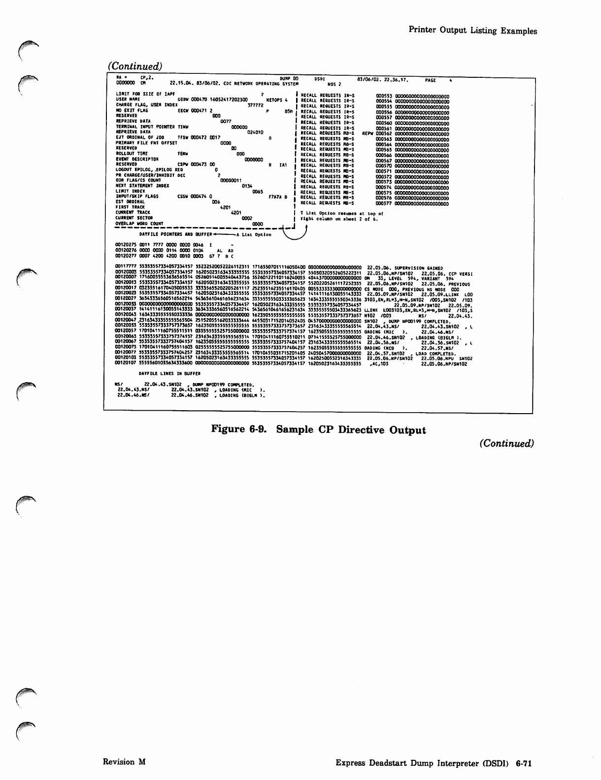
Printer Output Listing Examples
r(Continued)
0000000 CM 22.15.04. 83/06/02,
DUMP 00
CDC NETWORK OPERATING SYSTEM 83/06/02. 22.36.17.
LIMIT FOR SIZE OF IAPF 7
USER NAME UIDW 000470 16052417202300
CHARGE FUG, USER INDEX 377772
NO EXIT FLA6 EECW 0W471 2
RESERVED 000
REPRIEVE DATA 0077
TERMINAL INPUT POINTER TINW WWOO
REPRIEVE DATA 024010
EJT OROINAL OF JOB TFSW 000472 0017
PRIMARY FILE FNT OFFSET OOOO
RESERVED DO
ROLLOUT TIME TERN 000
EVENT DESCRIPTOR OOOOOCO
RESERVED CSPW 000473 00
LOGOUT EPILOG, .EPILOG REQ 0
PR CHARGE/USER/INHIBIT OEC 2
EOR FUG/CS COUNT OOO0OO11
NEXT STATEMENT INDEX 0134
LIMIT INDEX
INPUT/SKIP FLAGS
EST OROINAL
FIRST TRACK
CURRENT TRACK
CURRENT SECTOR
OVERLAP WORD COUNT
CSSW 000474 0 0065
I RECALL REQUESTS IR-S
| RECAU REQUESTS IR-S
j RECALL REQUESTS IR-S
I l RECALL REQUESTS IR-S
! RECAU REQUESTS IR-S
J RECAU REQUESTS IR-S
I RECA U REQU ESTS I R-S
| RECAU REQUESTS MB-S
j RECAU REQUESTS FB-S
! RECALL REQUESTS H8-S
• RECAU REQUESTS MB-S
I RECAU RESUESTS MB-S
| RECAU REQUESTS HB-S
j RECAU RESUESTS MB-S
j RECAU REQUESTS HB-S
J RECAU REQUESTS MB-S
I RECAU RESUESTS MB-S
I RECAU REQUESTS KB-S
j RECAU REQUESTS MB-S
• RECAU REQUESTS MB-S
j RECAU REQUESTS MB-S
| T Un Option rc«ua«t
I right colian oa «h««t
000553
0W554
000555
000556
000557
000560
000561
REPW 0W562
W0563
000564
0W565
0WS66
000567
000570
W0S71
000572
000573
0WS74
0W575
000576
000577
OOOOOOOOOOOOOOOOOOOO
WWWOOOWWOOWOW
OOOOOOOOOOOOOOOOOOOO
OOOOOOOOOOOOOOOOOOOO
OOOOOOWWWWOWOOO
OOOWOOOOWOOQOWOW
OWWWOWOOWOOWDO
OOOOOOOOOOOOOOOOOOOO
OOOOOOOOOOOOOOOOOOOO
OOOOOOOOOOOOOOOOOOOO
OOOOWOOOOWOOWOWO
OOOOOOOOOOOOOOOOOOOO
OOOOOOOOOOOOOOOOOOOO
WOWWOOOWWOOOOW
woooooowoawooww
oooooooooooooooooooo
owwwowowoowwo
oooooooooooooooooooo
oooooooooooooooooooo
oooooooooooooooooooo
oooooooooooooooooooo
DAYFILE POINTERS AND BUFFER
— — l - J ♦
• - A L i s t O p t i o n \ y
00120275 0011 7777 OOW WOO 0046
00120276 MOO OOOO 0114 OOW 0104
00120277 0007 4200 42W W10 Q003 G7 7 H C
W117777
00120003
00120007
00120013
00120017
00120023
00120027
00120033
00120037
00120043
W12W47
00120053
W120057
0012W63
00120067
00120073
00120077
00120103
WI 20107
55353557334057334157
55353557334057334157
17160055553636565514
55353557334057334157
0323551617O4O5OO5S33
55353557334057334457
36343336560516562214
WWWWOWOWWWW
14141116130055143333
16343335S5SSS0333336
.23163433355555565504
55353557333757373657
17010411160755511511
SS3SS5S7333757374157
55353557333757404157
17010411160755511603
55353557333757404257
55353557334057334157
S55S56010356343336W
55232520052226112311
16205023163433355555
05260514005540443756
16205023163433355555
33335655202205261117
162050231634333S5SSS
54365610461656231634
55353557334057334457
36343336560516562214
OOWOOOOWOOWWWOO
25152055162033333444
16235055555555555555
O355555552575500OO00
23163433355555565514
1623S0SS5S55S555SSSS
02555555525755000000
23163433355555565514
16205023163433355555
OOOOOOOOOOOOOOOOOOOO
171655O7O11116OS04OO
55353557334057334157
552601221101162400S5
55353SS7334057334157
25235516235516170405
55353557334057334457
3335SSS5S03333365623
1620502316343335S5S5
54365610461656231634
16235055555555555555
44550317152014052405
55353557333757373657
55333557333757374157
17010411160755510211
55353557333757404157
55353557333757404257
17010455031715201405
SS3S3557334057334157
55353557334057334157
OOOOOOOOOOOOOOUOOOOO
55030320552605222311
40443700000000000000
55202205261117252355
00553333330000000000
14141116130OS5143333
16343335S5S550343336
55353557334057334457
33355555503433365623
55353557333757373657
04 570000000000000000
23163433355555565514
16235055555555555555
071415SS52S75S0OMM
23163433355555565514
16235055555555555555
240S04S700000WOOWO
16202500552316343335
16205023163433355555
22.05.06. SUPERVISION GAINED
22.05.06.NP/SN102 22.05.06. CCP VERSI
ON 33, LEVEL 594, VARIANT 594
22.05.06.HP/SN102 22.05.06. PREVIOUS
CS NODE 000, PREVIOUS NS NODE WO
22.05.09.NP/SN102 22.0S.09.LLINK LOO
31O3,EN,RL'3,H-N,SN102 /W3,SN102 /103
22.05.09.NP/SN102 22.05.09.
U1NK LW3103,EN,RL'3,H-N,SN102 /103,S
N102 /003 NS/ 22.04.43.
SN102 , DUMP NP00199 COMPLETED.
22.04.43.NS/ 22.04.43.SN102 , L
OADING (MIC ). 22.04.46.NS/
22.04.46.SN102 , LOADING (BIGLM ).
22.04.56.HS/ 22.04.56.SN102 , L
OADING (NCB ). 22.04.57.NS/
22.04.57.SN102 , LOAD COMPLETED.
22.O5.O6.NP/SN102 22.05.06.NPU SN102
,AC,103 22.05.06.NP/SN102
DAYFILE LINES IN BUFFER
NS/ 22.04.43.SN102 , DUMP NP00199 COMPLETED.
22.04.43.NS/ 22.04.43.SN102 , LOADING (NIC ).
22.04.46.NS/ 22.04.46.SN102 , LOADING (B1GLN >.
Figure 6-9. Sample CP Directive Output
(Continued)
Revision M Express Deadstart Dump Interpreter (DSDI) 6-71
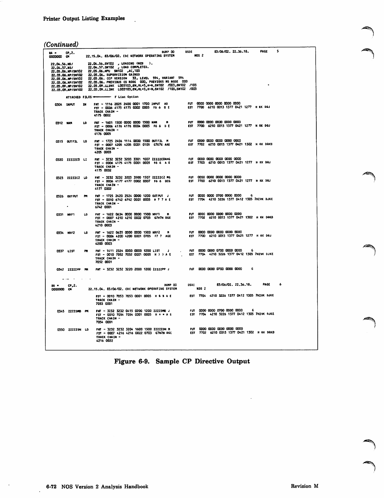
Printer Output Listing Examples
■^^s
(Continued)
ooooow CP,2.
CR 22.15.04. 83/06/02.
DUMP W
CDC NETWORK OPERATING SYSTER NOS 2
83/06/02. 22.36.18.
22.04.56.NS/
22.04.57.HS/
22.05.06.NP/SN102
22.05.06.NP/SN102
22.05.06.NP/SN102
22.05.06.NP/SN102
22.05.09.HP/SN102
Z2.05.09.NP/SN1O2
ATTACKED F
0304 INPUT I
22.04.56.SN102 , LOADING (NCB X.
22.04.57.SN102 , LOAD COMPLETED.
22.05.06.NPU SN102 ,AC,103
22.05.06. SUPERVISION GAINED
22.05.06. CCP VERSION 33, LEVEL 594, VARIANT 594
22.05.06. PREVIOUS CS NODE OW, PREVIWS NS NODE 000
22.05.09. LLINK LW3103,EN,RL»3,H-N,SN102 /W3,SN102 /103
22.05.09.LLINK L003103,EN,RL»3,H-N,SN102 /103,SN102 /003
F Ll»t Option
FNT - 1116 2025 24W W01 17W INPUT AO
FST - 0006 4175 4175 0002 0W5 F6 6 B E
TRACK CHAIN -
4175 0002
FN T - 1 601 1 5W W W W W 1 3W N A R R
FST - 0006 4176 4176 0004 0W5 F6 6 D E
FUT WOO OOW WW WOO WW
EST 77W 6210 0013 1377 0421 127? H KK DOJ
FUT OWO OWO WW WW WOO
EST 77W 6210 0013 1377 0421 1277 H KK DQJ
TRACK CHAIN -
4176 0W5
0315 OUTFIL LO FNT - 1725 2406
FST - 0W7 4205
TRACK CHAIN -
4205 0003
1114 WW 15W OUTFIL M
4205 0W1 0105 G7E7E AAE
FUT
EST
OOW WOO WOO OOW woo
7702 6210 W13 1377 0421 1302 H KK DBKB
0320 ZZZZZCO LI FNT - 3232 3232
FST - 0006 4175
TRACK CHAIN -
4175 W02
3203 3301 1007 ZZZZZCOAHG
4175 0W1 W05 F6 6 A E
FUT
EST
W W W W W O O W W W O O
77W 6210 W13 1377 0421 1277 H KK DSJ
0323 ZZZZZC2 LO FNT - 3232 3232
FST - W06 4177
TRACK CHAIN -
4177 0002
3203 3SW 1507 ZZZZZC2 MG
4177 0W2 0307 F6 6 8CG
FUT
EST
O O W W W W W W W W O O
77W 6210 0013 1377 0421 1277 H KK DGJ
0326 OUTPUT PR FNT - 172S 2420
FST - W10 6742
TRACK CHAIN -
6742 0W1
2524 OOW 1200 OUT PUT J
6742 0W1 0005 H 7 7 A E
FUT
EST
W O O O O W 0 7 0 0 O O W W O O G
7704 4210 3226 1377 0412 130S 7HZVK DJKE
0331 NRF1 LO FHT - 1622 0634
FST - 0W7 4210
TRACK CHAIN -
4210 W03
W W W W 1 5 W N R F 1 H
4210 0002 0705 G7H7H BGE
FUT
EST
W O O W O O W W W O O W W
7702 6210 W13 1377 0421 1302 H XK 0«KB
0334 NRF2 LO FNT - 1622 0635 WW WW 1500 NRF 2 H
FST - 0006 42W 4200 0W1 0705 F7 7 AGE
TRACK CHAIN -
42W 0003
FUT
EST
O O W W W W W W W W O O
77W 6210 W13 1377 0421 1277 H KK DSJ
0337 LIST PR FNT - 1411 2324 WOO WOO 1200 LIST J
FST - W10 7052 7052 0001 WD5 H ) ) A E
TRACK CHAIN -
7052 W01
FUT
EST
O O O O O O W 0 7 W W W W W G
7704 4210 3226 1377 0412 1305 7HZVK DJKE
0342 ZZZZZPP PR FNT - 3232 3232 3220 2000 1200 ZZZZZPP J FUT W W W W 0 7 0 0 O O W W O O G
RA ■
OOOOOW
CP,2.
CM 22 .15.04. 83/06/02.
DUMP OO
CDC NETWORK OPERATING SYSTER
DSDI 83/06/02. 22.36.18.
NOS 2
P A 6 E 6
FST - W10 7053
TRACK CHAIN -
7053 0W1
7 0 5 3 W 0 1 O W S H S 1 A E EST 7704 4210 3226 1377 0412 1305 7HZVK DJKE
0345 ZZZZORB PM FNT - 3232 3232
FST - 0010 7054
TRACK CHAIN -
7054 0W1
0415 02W 1200 ZZZZDMB J
7 0 5 4 0 W 1 W 0 5 H = ■ A E
FUT
EST
W W W O O 0 7 W W W W O O G
7704 4210 3226 1377 0412 1305 7HZVK DJKE
0350 ZZZZZDN LO FNT - 3232 3232
FST - 0007 4216
TRACK CHAIN -
4216 W22
3204 1600 1500 ZZZZZDN H
4216 0022 0703 G7N7N RGC
FUT
EST
WW WOO WW WW WOO
7702 6210 0013 1377 0421 1302 H KK DOKB
Figure 6-9. Sample CP Directive Output
6-72 NOS Version 2 Analysis Handbook Revision M
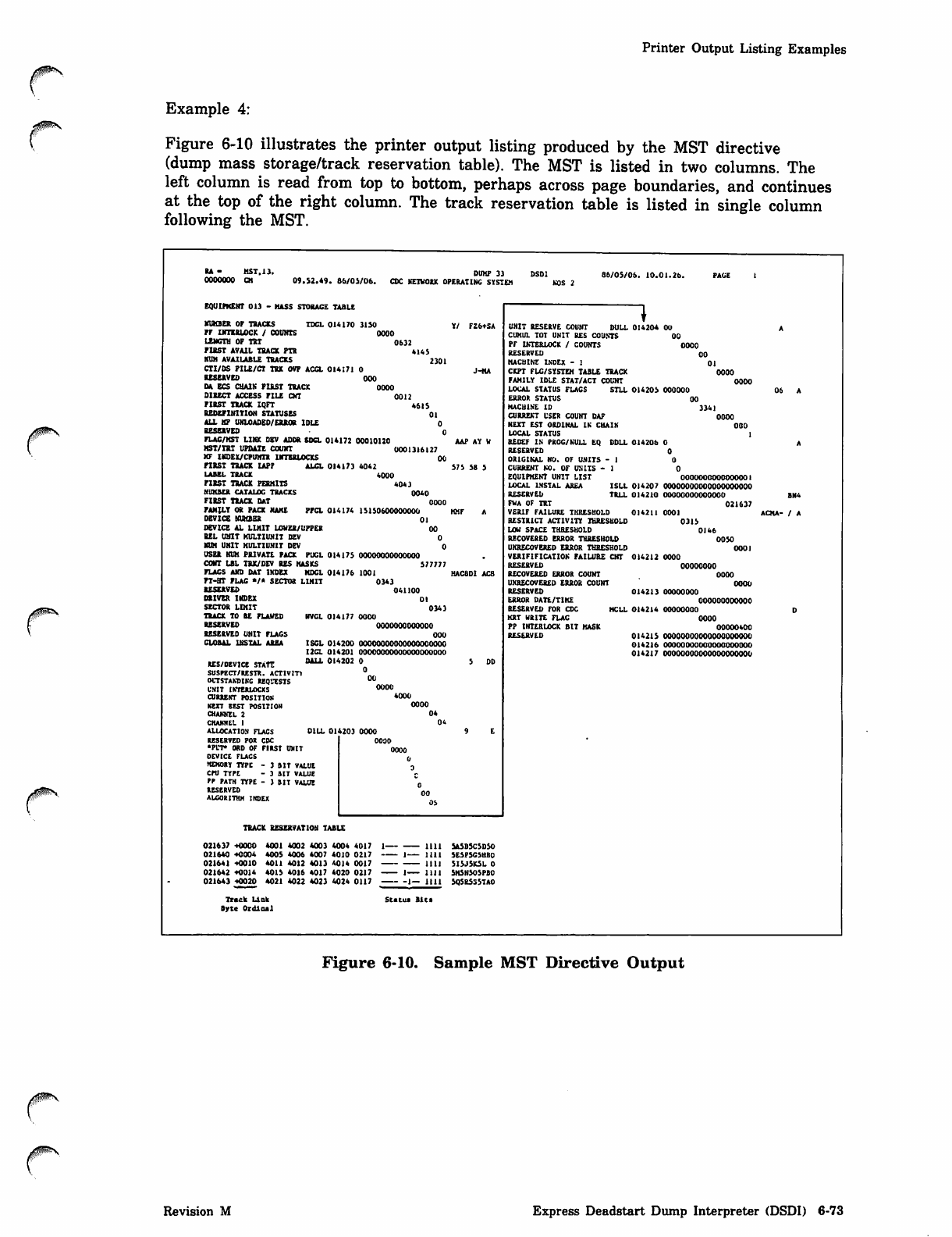
Printer Output Listing Examples
Example 4:
Figure 6-10 illustrates the printer output listing produced by the MST directive
(dump mass storage/track reservation table). The MST is listed in two columns. The
left column is read from top to bottom, perhaps across page boundaries, and continues
at the top of the right column. The track reservation table is listed in single column
following the MST.
R A - K S T . 1 3 . D U M P 2 2 DSDI 86/05/06. 10.01.2b. PAGE 1
O0OO0W CH 09.52.49. 86/05/06. CDC NETWORK OPERATING SYST
EQUIPMENT 013 - MASS STORAGE TABLE
t i l N O S 2
UHIT RESERVE COUNT DULL 014204
KUHBER OF TRACKS IDOL 014170 31S0 Y/ FZ6+SA OU
tr INTERLOCK / COUNTS 0000 CUKUL TOT UNIT RES COUNTS 00
LENCTH OF TRT 0632 PF INTERLOCK / COUNTS OOOO
FIRST AVAIL TRACK PTR *U5 RESERVED 00
0)
HUM AVAILABLE TRACKS 2301 MACHINE INDEX - 1
CTI/DS PILB/CT ISX OVF ACCL 014171 0 j-ha CKPT FLG/SYSTEH TABLE TRACK OOOO
RESERVED 000 FAMILY IDLE STAT/ACT COUNT WOO
DA ECS CHAIN FIRST TRACK 0000 LOCAL STATUS FLACS STLL 014205 OOOOOO 0 6 A
DIRECT ACCESS FILE CRT 0012 ERROR STATUS 00
FIRST TRACK IQFT *6I5 MACHINE ID 334)
REDEFINITION STATUSES 01 CURRENT USER COUNT DAP OOOO
ALL KF UKLOADE0/ESROR IDLE 0 NEXT EST ORDINAL IK CHAIN 000
RESERVED 0 LOCAL STATUS
FLAC/KST LIKK OSV ADDR SDCL 014172 00010120 AAP AY W SEDEF IN PROC/HULL EQ DDLL 01420b
HST/TRT UPDATE COUNT 0001316127 RESERVED
XF INDEX/CPUMIR INTERLOCKS 00 ORIGINAL NO. OF UNITS - 1
FIRST TRACK LAPF ALCL 014173 4042 575 58 5 CURRENT NO. OF UNITS - I
LABEL TRACK 4000 EQUIPMENT UNIT LIST 0000000000000001
FIRST TRACK PERMITS 4043 LOCAL 1NSTAL AREA ISLL 014207 oooooooooooooooooooo
NUHBER. CATALOG TRACKS 0040 RESERVED TRLL 014210 00000000000000 BH4
FIRST TtACK DAT OOOO FWA OF TRT 021637
FAMILY OR PACK NAHE FFCL 014174 1515060000000b KHF A VER1F FAILURE THRESHOLD 0)4211 0001 ACMA- / A
DEVICE NUHBER 01 RESTRICT ACTIVITY THRESHOLD 03)5
DEVICE AL LIMIT LOWES/UPPER 00 LOU SPACE THRESHOLD 0)46
REL UHIT KULTIUNIT DEV 0 RECOVERED ERROR THRESHOLD 0050
MM UNIT KULTIUNIT DEV 0 UNRECOVERED ERROR THRESHOLD 000)
USER NUM PRIVATE PACK FUGL 014175 00000000000000 VERIFIFICATION FAILURE CUT 0)4212 OOOO
C O N T L B L T R K / D E V R E S M A S K S 5 7 7 7 7 7 RESERVED OOOOOOOO
FLAGS AND DAT INDEX MDCL 014176 1001 HAC8DI ACS RECOVERED ERROR COUNT OOOO
FT-HT FLAG •/« SECTOR LIMIT 0343 UNRECOVERED ERROR COUNT oooo
RESERVED 041100 RESERVED 014213 oooooooo
DRIVER INDEX ol ERROR DATE/TIKE oooooooooooo
SECTOR LIMIT 0343 RESERVED FOR CDC HCLL 014214 oooooooo
TRACK TO BE FLAWED HVCL 014177 OOOO MST WRITE FLAG oooo
RESERVED OOOOOOOOOOOOO PP INTERLOCK BIT MASK 00000400
RESERVED UHIT rLAGS 000 RESERVED 014215 OOOOOOOOOOOOOOOOOOOO
CLOBAL LHSIAL AREA ISGL 014200 OOOOOOOOOOOOOOOOOOOO 014216 oooooooooooooooooooo
I2GL 014201 OOOOOOOOOOOOOOOOOOOO 014217 oooooooooooooooooooo
RES/DEVKE STATS "^ 0,4M2 ° 5 0D
SUSPECT/REST*. ACTIvm °
OLTSTAKDIKG REQITST5 00
UNIT INTERLOCKS °000
CURRENT POSITION *0°0
NEXT JEST POSITION WOO
CHANNEL 2 04
CHANNEL 1 04
ALLOCATION FLAGS DILL 014203 OOOO 9 E
RESERVED POR CDC 0030
•PIT* ORD OF FIRST UNIT OOOO
DEVICE FLACS
MEHORK TYPE - 3 BIT VALUE
CPU TYPE - 3 SIT VALUE
PP PATH TYPE - I BIT VALUE "„
RESERVED 00
05
ALGORITHM INDEX
TRACK RESERVATION TABIX
021637 40000 4001 4002 4003 4W4 4017 1 1111 SA5B5C5D50
021640 *0004 4005 4006 4007 4010 0217 1 1111 5E5P5C5HB0
021641 -KW10 4011 4012 4013 4014 W17 1111 5I5J5K5L 0
021642 «0014 4013 4016 4017 4020 0217 1 1111 5HSN5O5PB0
021643 tO020 4021 4022 4023 U.1 2 4 0 11 7 1 — 1111 5 Q S R 5 S 5 TA O
Track Link S t at u* B i t *
Byte Ordinal
Figure 6-10. Sample MST Directive Output
Revision M Express Deadstart Dump Interpreter (DSDI) 6-73
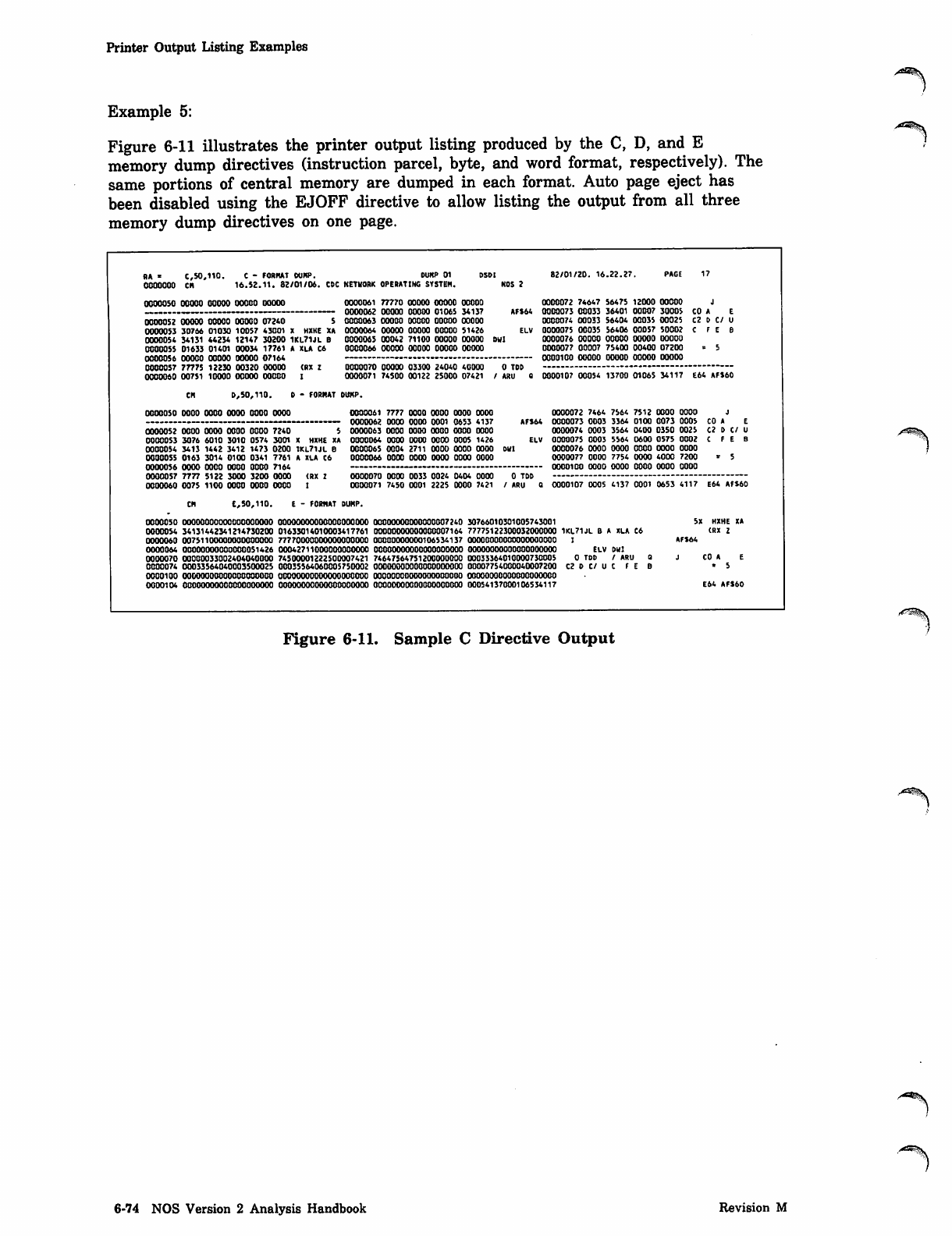
Printer Output Listing Examples
Example 5:
Figure 6-11 illustrates the printer output listing produced by the C, D, and E
memory dump directives (instruction parcel, byte, and word format, respectively). The
same portions of central memory are dumped in each format. Auto page eject has
been disabled using the EJOFF directive to allow listing the output from all three
memory dump directives on one page.
C,50,110. C - FORMAT OUKP.
16.52.11. 82/01/06.
OUHP 01
CSC NETWORK OPERATING SYSTEM.
OOOWSO WWO 00OW OWOO OOOOO
WW052 OOOW OOWO WWO 07240 S
OOOW53 30766 01030 10057 43001 X HXHE XA
0000054 34131 44234 12147 302W 1KL71JL B
W0WS5 01633 01401 0W34 17761 A XLA C6
OOW0S6 OOWO WOW WWO 07164
0WWS7 77775 12230 W320 OWW (RX Z
WOW60 W751 1W00 WOW WOOO I
W00061
00W062
W00063
0000064
OOW065
0000066
77770
OOOW
OOOOO
OQOOO
W042
WWO
WWO WWO
OWW 01065
OOOW WOOO
OOOW OOWO
71100 WOOO
WOW OWOO
ooooo
34137
WOW
51426
WOW
OOOW
82/01/20. 16.22.27.
WW072 74647 56475 12W0 WOOO
OOW073 00033 36401 W007 30005
W00074 W033 56404 W035 00025
0000075 W03S 56406 W057 50002
W00076 WOOO OOOOO OOWO WOW
0WW77 OW07 754W 004W 07200
W00100 OOWO OOWO OOOW OWOO
CO A
C2 0
00WO70
0000071
OOOW
74500
033W 24040
W122 250W
40000
07421
0 TOO
/ ARU 0 W00107 W054 13700 01065 34117 E64 AFS60
CH 0,50,110,
OOOCOSO WOO WOO WW OOOO
0 - FORMAT OUKP.
OOW
OOOW52
00W0S3
W00054
OW0055
000WS6
OW0057
0000060
WW050
WW054
0000060
00W064
000W70
0000074
W00100
WW104
WW
3076
3413
0163
OOW
7777
W75
CN
WW
6010
1442
3014
WOO
5122
11 W
WOO OOOO
3010 0574
3412 1473
0100 0341
WOO OOOO
3W0 3200
WOO WOO
E,50,110.
7 2 4 0 5
3001 X HXHE XA
0200 1KL71JL 6
7761 A XLA C6
7164
W W ( R X I
W W I
0000061 7777 OWO WOO WOO WW
OOW062 WW WW W01 0653 4137
00W063 OOW WW WOO WW WOO
0000064 WW OOW WW 0005 1426
W00065 W04 2711 WOO OWO WOO
O00W66 OOW OOW OOW OOW OOW
0000070 WW 0033 0024 0404 OOW
WW071 7450 W01 2225 WOO 7421
0000072 7464 7564 7512 WOO OWO J
AFS64 W00073 W03 3364 OIW 0073 0005 CO A E
0000074 0003 3564 0400 0350 0025 C2 0 C/ U
ELV OOW075 0W3 5564 06W 0575 0002 C F E B
WI W00076 OWO OOW OOOO OWO OOOO
0WW77 OOOO 7754 OOW 40W 72W * 5
0000100 WOO WOO OOOO WOO WOO
0 T0t>
ARU 8 W00107 0005 4137 0001 0653 4117 E64 AFS60
FORMAT OUHP.
OOOWOOOOWOOOWWW OOOOOWWWWOOWWO W0OO0WW0W0007240 30766010301005743001
341314423412147302W 01633014010W3417761 0W0WOOOOW0O007164 777751223W0320WW0 1KL71JL B A XLA C
W7511WWW0W000W 7777OWO0WWWWW0 00000000000106534137 OOWOOOOOOWOOWOWO I
000W0W0WW0051426 WO42711OW0W00OOW OOOOOOOWOOWOOOOWO OOOOOOOOOOOOOOOOOOOO ELV 0W1
W00W330024O4O4O0W 74500W122250W07421 746475647512WW00W 000333640100W730005 0 TOO / ARU
OW33564040003SOW25 0003SS6406000S7SOW2 OOWOWWOOOOOOOWW 0000775400W4W072W C2 0 C/ U C Ft
WWOWWOWOOOQWOO wooowwwwowoow owoowwwwwooooo wwowooowoooowoo
000WWW0WW00O0W 00OOOOWO0W0000O0W OOOOOOOWWOOWOOOW 00054137000106534117
HXHE XA
(RX 1
Figure 6-11. Sample C Directive Output
6-74 NOS Version 2 Analysis Handbook Revision M
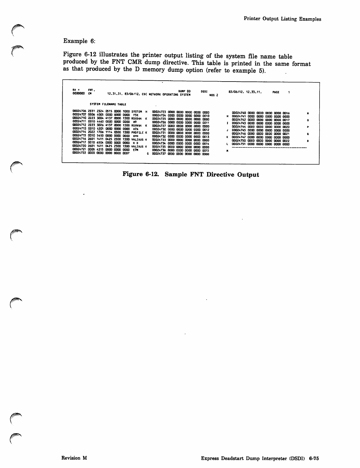
Printer Output Listing Examples
Example 6:
Figure 6-12 illustrates the printer output listing of the system file name table
produced by the FNT CMR dump directive. This table is printed in the same format
as that produced by the D memory dump option (refer to example 5).
RA =
wwwo FNT.
CN 12.31.31. 83/06/12. COC OUKP 00 DSDI
NETWORK OPERATING SYSTEM NOS 2 83/06/12. 12.33.11. PAGE 1
SYSTEM FILENAME TABLE
0W247O6
W024707
2331 2324 0515 OOW 1W0 SYSTEM
W06 4005 OOW WW OOW FSE 00024723 OOW WW OWO WW WOO
00024724 OOW OOW WW OOW W10 W024740 OWO WOO WW WW W16
H 0W24741 OOW OOW OOW OOW WW
0W24710 2223 3004 4137 OWO 13W RSX064 0W2472S OOW WW WW WW WW W024742 OOW OOW OOW OOW W17
0W24711
W024712
0010 4463 OOW OOW OOW H9 W024726 OOW WW OOW WW 0011 I 00024743 WW WW OOW OOW WW
2223 3026 4137 OOW 13W R5XV64 OW24727 OOW WW WW OWO OWO 0W24744 OOW WOO OOW WW 0020
0W24713 0010 4201 OOW OOW OOW H7A 00024730 OOOO WW OOW OOW W12 J 0W24745 WW WW OOW OOW OOW
00024714 2022 1706 1114 03W 13W PROFILC W024731 WW WOO WW WW WOO 00024746 OOW WOO WW WW W21
0W24715 W10 5410 OOW WW WW H'H 0W24732 OOW OOW OOW WW W13 K W024747 OOW OOW OOW OOW WW
00024716
0W24717
2601 1411 0425 23W 13W VALIDUS 00024733 WOO OOW WW WW OWO 00024750 OWO WW WW WW W22
0010 6504 OOW OOW OOW H 0 0W24734 OWO OOW OOW WW W14 L W024751 OOW OOW OOW OOW OOW
tWixfiO 2601 1411 0425 23W 13W VALIOUS 00024735 WW WW WW WW WOO
W024721 WOS 4215 OOW OOW OOW E7N 0W24736 WW OOW WW WW 0015
00024722 0000 WW WW WOO W07 00024737 OOOO WW WW WW OOW
Figure 6-12. Sample FNT Directive Output
0$ss
Revision M Express Deadstart Dump Interpreter (DSDI) 6-75
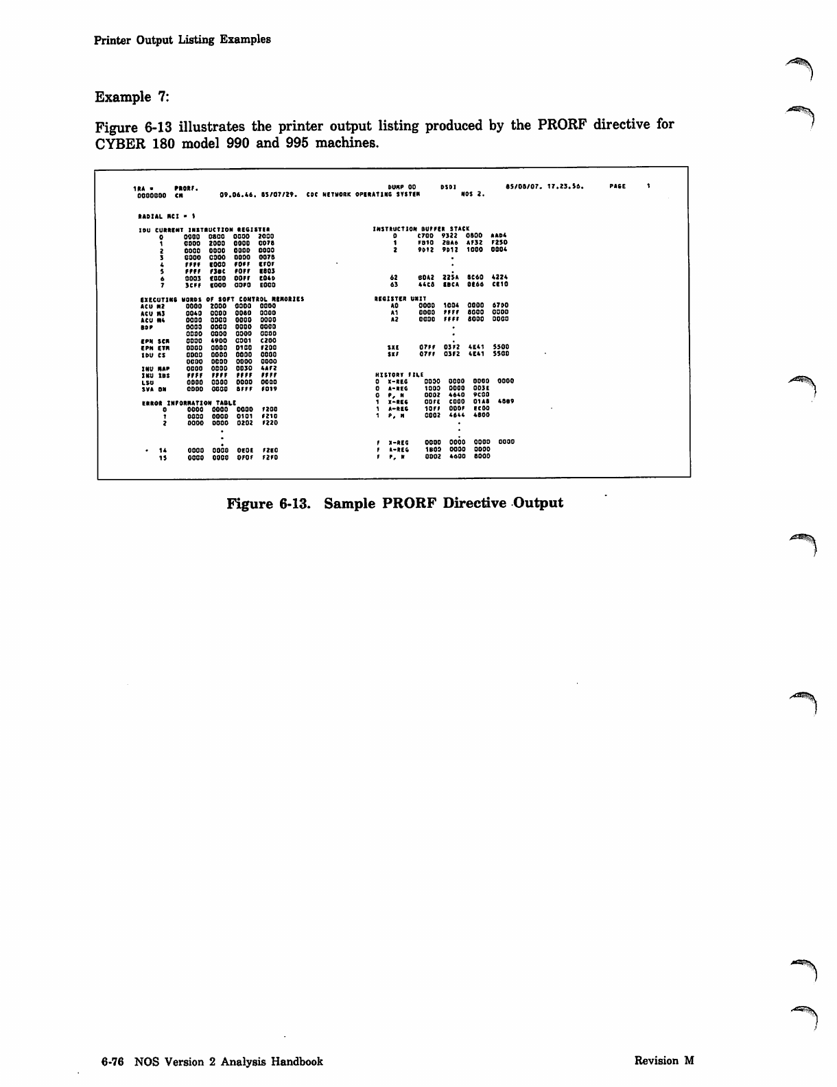
Printer Output Listing Examples
Example 7:
Figure 6-13 illustrates the printer output listing produced by the PRORF directive for
CYBER 180 model 990 and 995 machines.
1 R A • P R O R F .
0000000 CH 09.06.46. 85/07/2*.
ftUNP 00
COC NETWORK OPERATING SYSTEM
8S/08/07. 17.23.56.
RADIAL HCI « 1
IOU CURRENT INSTRUCTION REGISTER
0 0000 0800 0000 2000
1 OOOO 2000 0000 007B
2 0080 0000 0000 0000
3 0000 0000 0000 0078
4 FFFF EOOO FOFF EFOF
5 FFFF F30C FOFF 1603
6 0003 EOOO OOFF CO40
7 SCFf EOOO OQFO EOOO
EXECUTINS WORDS OF SOFT CONTROL MEMORIES
ACU HZ OOOO 2000 oooo OOOO
ACU H3 0040 OOOO 0060 OOOO
ACU M4 OOOO OOOO oooo OOOO
BOP OOOO 0800 oooo OOOO
OOOO OOOO oooo 0800
EPN SCH OOOO 4V00 C001 C200
epn tin OOOO OOOO 0100 F200
IBU CS OOOO OOOO oooo OOOO
OODO OOOO oooo OOOO
INU MAP OOOO OOOO 0030 4AF2
INU IBS FFFF FFFF FFFF FFFF
LSO OBOO OOOO OOOO OOOO
SVA BN ODOO oooo BFFF F019
ERROR INFORMATION TABLE
0 OOOO OOOO OOOO F200
1 OOOO OOOO 0101 FZ10
2 OOOO OOOO 0202 F220
OOOO OOOO OEOE F2E0
OOOO OOOO OFOF F2F0
INSTRUCTION BUFFER STACK
0 C70D 9322 OBOO AAOA
1 F81Q 2BA6 AF32 F2S0
2 »»«2 9012 1000 0004
63 8042 225* 6C60 4224
44C6 EBCA 8E66 CI10
REGISTER UNIT
AO OOOO 1004 OOOO 67»0
A1 OOOO FFFF 8000 OOOD
A2 OOOO FFFF 8000 OOOO
OFFF 03F2 4E41 5500
07FF 03F2 4E41 5300
HISTORT FILE
0 X-REG 0030 OOOO OOOO OOOO
0 A-REC 1003 OOOO OOSE
0 P, N 0002 4640 9C00
1 X-RE4 OOFt COOO 01 AS 48B9
1 A-REC 10FF OOOF ECOO
1 P, N 0002 4644 4B00
X-REO OOOO OOOO OOOO OOOO
A-RES 1B03 OODO OOOO
r, H 00 02 46 00 8 000
Figure 6-13. Sample PRORF Directive Output
6-76 NOS Version 2 Analysis Handbook Revision M

Install Command
NOS allows you to deadstart from a disk rather than from a tape. To deadstart from a
disk, you must first use the INSTALL command to install a deadstart file that you
specify to a deadstart disk. The disk that you select must be available on a single-unit
device such as an 844 or 885-11/12,1 and must have the Common Test and
Initialization (CTI) software. (For more information about CTI, refer to the CYBER
Initialization Package User's Handbook.) If the deadstart disk is a shared device in a
multimainframe environment, a full INITIALIZE must have been previously done. The
calling job must be of system origin or you must be validated for system origin
privileges and the system must be in debug mode. In addition, in a secured system,
INSTALL is allowed only from jobs with security administrator privileges.
You must re-execute the INSTALL command if a full INITIALIZE becomes necessary,
because PFDUMP and PFLOAD do not dump or load the system deadstart file (SDF).
The format of the command is:
INSTALL.filename,EQest.
Parameter Description
filename Disk file (assigned to the job) to be installed as an SDF. Default is
SYSTEM, which must be assigned to the job. The name SDF is a
reserved file name and cannot be specified for filename.
INSTALL stops reading the system deadstart file at the first EOF;
therefore, the new running system does not include any changes made
through SYSEDIT after a previous deadstart.
If the deadstart file to be installed is on tape, it must first be copied
to disk before INSTALL can be used.
NOTE
est
The deadstart file to be installed must contain a valid OPLD directory.
Note that when you use LIBEDIT to update a deadstart file and write
the new deadstart file directly to tape, the OPLD record on the tape
will not contain valid disk addresses. Therefore, if you want the
deadstart file on tape and you intend to later use the INSTALL
command on the deadstart file, you should have LIBEDIT write the
new deadstart file to disk, and then copy the file to tape using the
COPY command (refer to the NOS 2 Reference Set, Volume 3).
EST ordinal of the deadstart disk on which file filename is to be
installed.
1. The system deadstart file cannot be installed to an 819, 885-42, 887, or 9853 disk.
Revision M Install Command 7-1

?*%
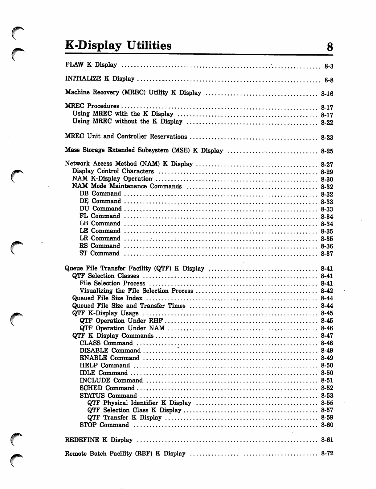
f^'
f^
K-Display Utilities 8
FLAW K Display 3.3
INITIALIZE K Display 8-8
Machine Recovery (MREC) Utility K Display 8-16
MREC Procedures 8-17
Using MREC with the K Display .. 8-17
Using MREC without the K Display 8-22
MREC Unit and Controller Reservations 8-23
Mass Storage Extended Subsystem (MSE) K Display 8-25
Network Access Method (NAM) K Display 8-27
Display Control Characters 8-29
NAM K-Display Operation 8-30
NAM Mode Maintenance Commands 8-32
DB Command 8-32
DE Command 8-33
DU Command 8-33
FL Command 8-34
LB Command 8-34
LE Command 8-35
LR Command ... 8-35
RS Command 8-36
ST Command , 8-37
Queue File Transfer Facility (QTF) K Display f 8-41
QTF Selection Classes . 8-41
File Selection Process . 8-41
Visualizing the File Selection Process 8-42
Queued File Size Index 8-44
Queued File Size and Transfer Times 8-44
QTF K-Display Usage 8-45
QTF Operation Under RHF 8-45
QTF Operation Under NAM 8-46
QTF K Display Commands 8-47
CLASS Command 8-48
DISABLE Command 8-49
ENABLE Command 8-49
HELP Command 8-50
IDLE Command 8-50
INCLUDE Command 8-51
SCHED Command 8-52
STATUS Command 8-53
QTF Physical Identifier K Display 8-55
QTF Selection Class K Display 8-57
QTF Transfer K Display 8-59
STOP Command 8-60
REDEFINE K Display 8-61
Remote Batch Facility (RBF) K Display 8-72
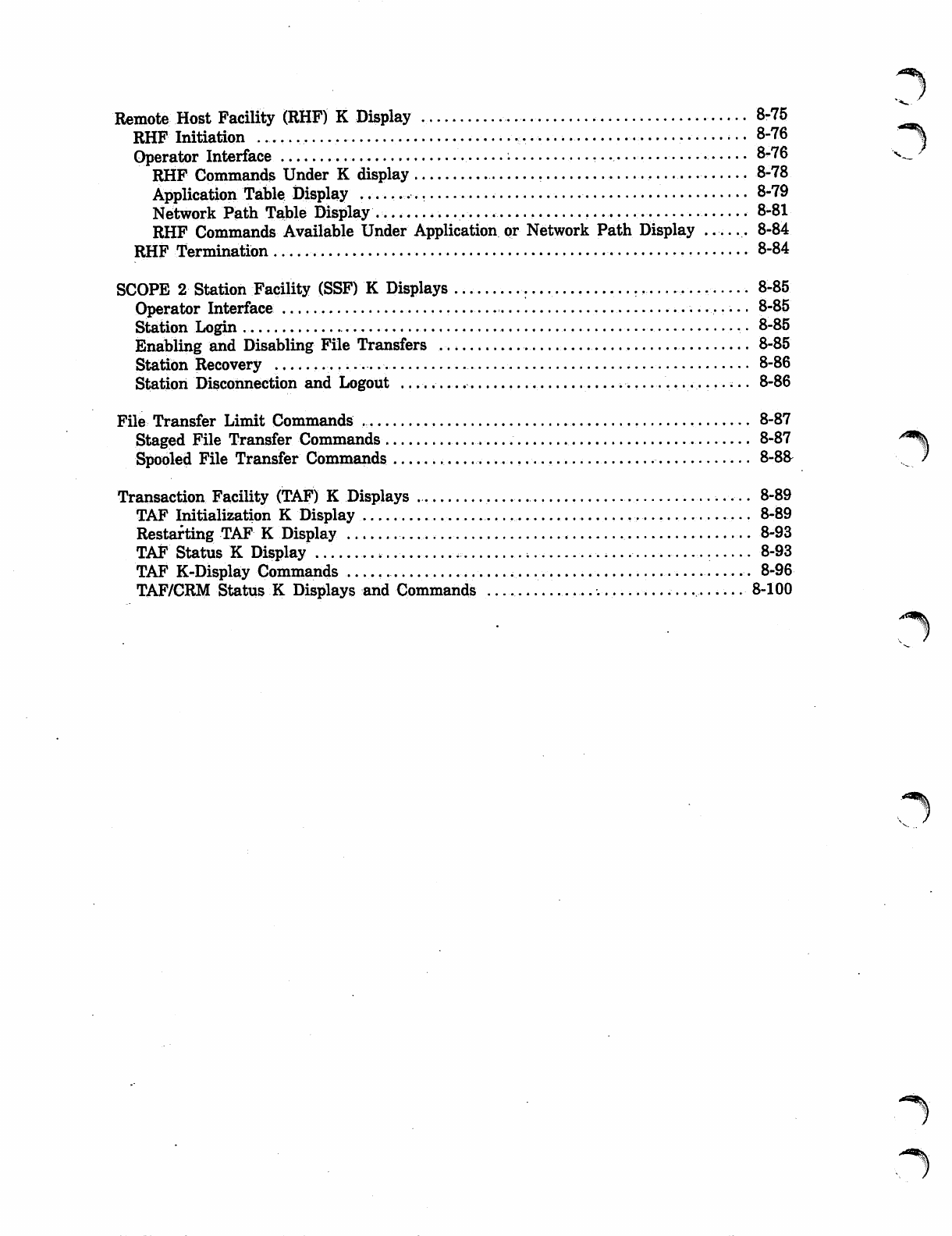
Remote Host Facility (RHF) K Display . , 8-75
RHF Initiation >. 8-76
Operator Interface : 8-76
RHF Commands Under K display , 8-78
Application Table Display — 8-79
Network Path Table Display ................ 8-81
RHF Commands Available Under Application or Network Path Display ...... 8-84
RHF Termination 8-84
SCOPE 2 Station Facility (SSF) K Displays ...... , 8-85
Operator Interface ....— 8-85
Station Login 8-85
Enabling and Disabling File Transfers 8-85
Station Recovery .-.. 8-86
S t a t i o n D i s c o n n e c t i o n a n d L o g o u t . . . . . — . . . . . . . . . . . . . . ; . . 8 - 8 6
File Transfer Limit Commands ,,. 8-87
Staged File Transfer Commands 8-87
Spooled File Transfer Commands 8-8&
Transaction Facility (TAF) K Displays ... .... 8-89
TAF Initialization K Display ,-,. 8-89
Restarting TAF K Display 8-93
TAF Status K Display 8-93
TAF K-Display Commands . 8-96
TAF/CRM Status K Dis p l ays and Comman d s . . ........... . . ...... 8-100
^%
~)
^%
K-Display Utilities
This section documents the K displays listed next, along with the utilities used to
present them. Other K-display utilities described elsewhere in this manual include the
permanent file utilities, queued file utilities, and the status/control register simulator.
K-display utilities described in other manuals include those for the CDCNET network
(refer to the CDCNET network manuals) and the printer support utility (refer to the
NOS Version 2 Operations Handbook).
K Display
FLAW
INITIALIZE
Machine Recovery (MREC)
Mass Storage Extended Subsystem
(MSE)
Network Access Method (NAM)
Queue File Transfer Facility (QTF)
REDEFINE
Remote Batch Facility (RBF)
Remote Host Facility (RHF)
SCOPE 2 Station Facility (SSF)
Transaction Facility (TAF)
Description
Disk flaw mapping.
Disk initialization.
Multimainframe device recovery.
K display of the MSE.
Operator interface to NAM.
K display of the QTF application.
Online reconfiguration display.
K display of the RBF Subsystem.
K display of the RHF Subsystem.
K display of the SSF Subsystem.
K display of the TAF Subsystem.
Revision M K-Display Utilities 8-1
K-Display Utilities
/*^k
By using the K display, a job can place information on the console screen and receive
information from the keyboard. The information is passed to the job by DSD. Normally, a*^%
these displays are used for utility programs. '
The job first issues a request message on the B,0 display, asking you to bring up the
K display.
When this happens, enter:
K.jsn.
jsn Description
jsn Job sequence name of the requesting job.
Once the display is assigned to a job, you can enter data by typing K. followed by
data. The data is transferred to a specified area of the job's field length when you
terminate the entry. If more than 50 characters are entered as data, the message
LINE TOO LONG. /^^
appears on the screen. DSD does not accept the entry until the data string is
shortened.
K displays are job oriented. The job sequence name associated with each K display
appears at the top of the screen next to the display designator and name.
All parameter entries must be prefixed by K period (K.). However, after pressing CR
or NEXT for the first parameter entry, everything but the K. is erased. This allows
another parameter to be entered without entering K. first. All examples in this /SS%.
section show K. although you may not have to enter it. If you have to enter a DSD
command during parameter entry, backspace to erase the K., enter the command, and
then continue parameter entry by entering K. and the parameter.
8-2 NOS Version 2 Analysis Handbook Revision M
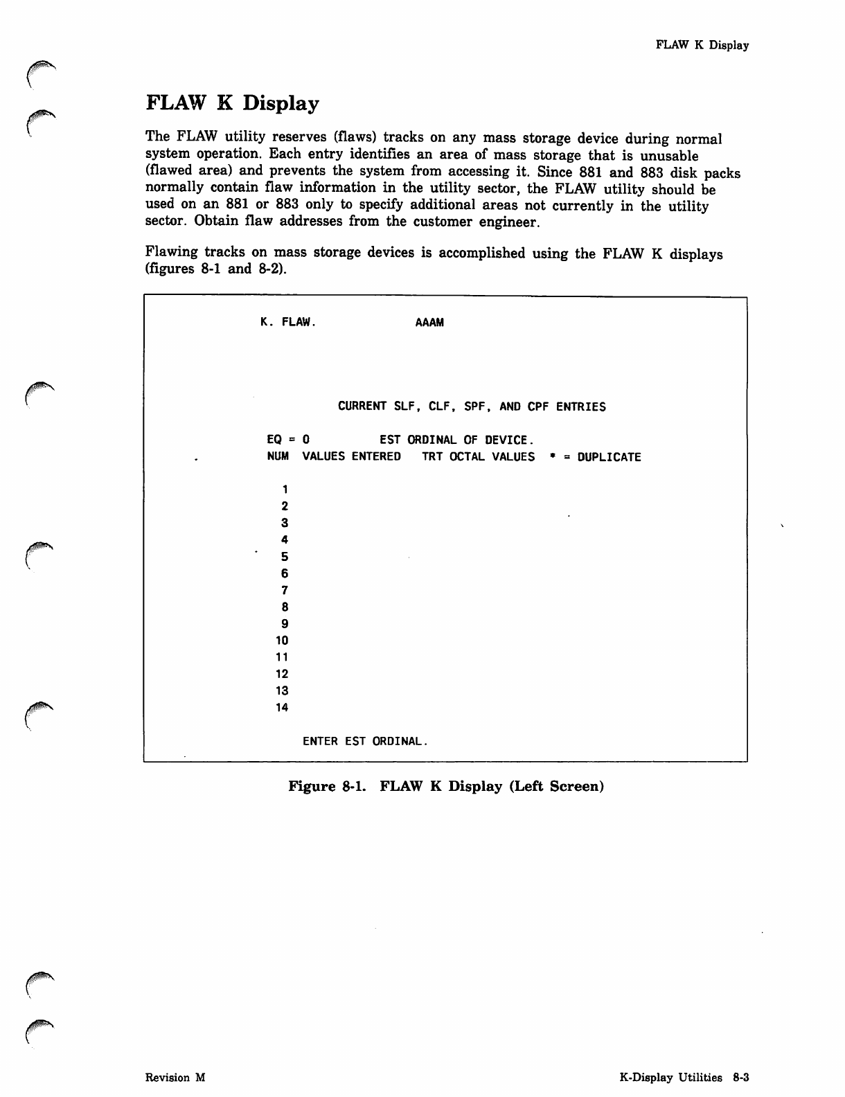
FLAW K Display
FLAW K Display
The FLAW utility reserves (flaws) tracks on any mass storage device during normal
system operation. Each entry identifies an area of mass storage that is unusable
(flawed area) and prevents the system from accessing it. Since 881 and 883 disk packs
normally contain flaw information in the utility sector, the FLAW utility should be
used on an 881 or 883 only to specify additional areas not currently in the utility
sector. Obtain flaw addresses from the customer engineer.
Flawing tracks on mass storage devices is accomplished using the FLAW K displays
(figures 8-1 and 8-2).
K . F L A W . A A A M
CURRENT SLF, CLF. SPF, AND CPF ENTRIES
EQ = 0 EST ORDINAL OF DEVICE.
NUM VALUES ENTERED TRT OCTAL VALUES • = DUPLICATE
1
2
3
4
5
6
7
8
9
10
11
12
13
14
ENTER EST ORDINAL.
Figure 8-1. FLAW K Display (Left Screen)
Revision M K-Display Utilities 8-3
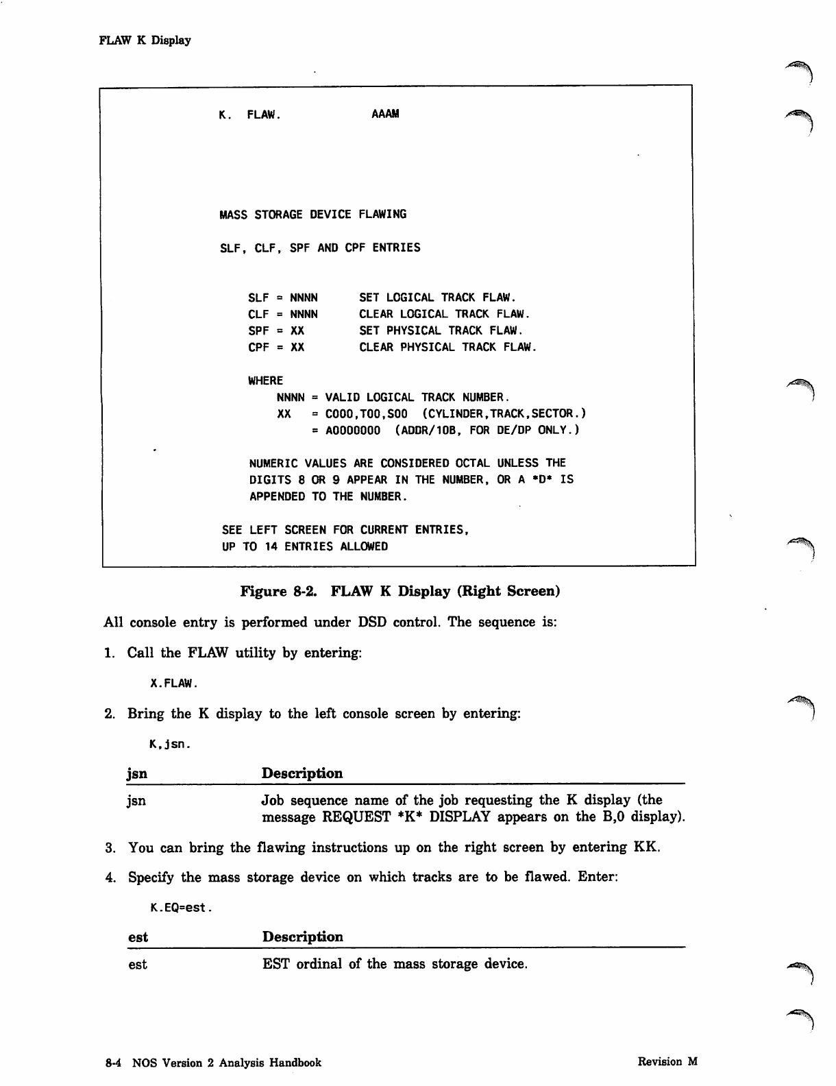
FLAW K Display
FLAW. AAAM
MASS STORAGE DEVICE FLAWING
SLF, CLF, SPF AND CPF ENTRIES
SLF = NNNN SET LOGICAL TRACK FLAW.
CLF = NNNN CLEAR LOGICAL TRACK FLAW.
SPF = XX SET PHYSICAL TRACK FLAW.
CPF = XX CLEAR PHYSICAL TRACK FLAW.
WHERE
NNNN = VALID LOGICAL TRACK NUMBER.
XX = COO0.T00.SO0 (CYLINDER,TRACK.SECTOR.)
= A0000000 (ADDR/1OB, FOR DE/DP ONLY.)
NUMERIC VALUES ARE CONSIDERED OCTAL UNLESS THE
DIGITS 8 OR 9 APPEAR IN THE NUMBER, OR A *D* IS
APPENDED TO THE NUMBER.
SEE LEFT SCREEN FOR CURRENT ENTRIES,
UP TO 14 ENTRIES ALLOWED
Figure 8-2. FLAW K Display (Right Screen)
All console entry is performed under DSD control. The sequence is:
1. Call the FLAW utility by entering:
X.FLAW.
2. Bring the K display to the left console screen by entering:
K.jsn.
jsn Description
jsn Job sequence name of the job requesting the K display (the
message REQUEST *K* DISPLAY appears on the B,0 display).
3. You can bring the flawing instructions up on the right screen by entering KK.
4. Specify the mass storage device on which tracks are to be flawed. Enter:
K.EQ=est.
est Description
est EST ordinal of the mass storage device.
^^*\
8-4 NOS Version 2 Analysis Handbook Revision M
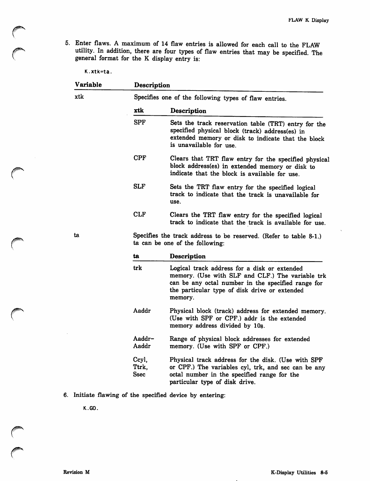
0f^S
FLAW K Display
5. Enter flaws. A maximum of 14 flaw entries is allowed for each call to the FLAW
utility. In addition, there are four types of flaw entries that may be specified. The
general format for the K display entry is:
K.xtk=ta.
Variable Description
xtk Specifies one of the following types of flaw entries.
xtk Description
SPF Sets the track reservation table (TRT) entry for the
specified physical block (track) address(es) in
extended memory or disk to indicate that the block
is unavailable for use.
CPF Clears that TRT flaw entry for the specified physical
block address(es) in extended memory or disk to
indicate that the block is available for use.
SLF Sets the TRT flaw entry for the specified logical
track to indicate that the track is unavailable for
use.
CLF Clears the TRT flaw entry for the specified logical
track to indicate that the track is available for use.
ta Specifies the track address to be reserved. (Refer to table 8-1.)
ta can be one of the following:
ta Description
trk Logical track address for a disk or extended
memory. (Use with SLF and CLF.) The variable trk
can be any octal number in the specified range for
the particular type of disk drive or extended
memory.
Aaddr Physical block (track) address for extended memory.
(Use with SPF or CPF.) addr is the extended
memory address divided by 108.
Aaddr- Range of physical block addresses for extended
Aaddr memory. (Use with SPF or CPF.)
Ccyl, Physical track address for the disk. (Use with SPF
Ttrk, or CPF.) The variables cyl, trk, and sec can be any
Ssec octal number in the specified range for the
particular type of disk drive.
6. Initiate flawing of the specified device by entering:
K.GO.
Revision M K-Display Utilities 8-5
FLAW K Display
The FLAW utility provides two messages in the system dayfile that indicate the results
of the flawing operation. The first message is: ^^\
nn TRACKS FLAWED.
nn Description
nn Octal number of tracks that were successfully flawed.
The second message appears only if some of the flaws specified were not processed.
This occurs when the track specified for flawing is already reserved by the system (but
not as a flawed track). In this case, the following message also appears in the system
dayfile.
nn FLAWS NOT PROCESSED,list.
Variable Description
nn Octal number of flaws not processed.
list List of the logical tracks that were not flawed.
The entries described here are similar to those entered in the APRDECK (refer to
section 3, Deadstart Decks) for flawing a device at deadstart time. However, the flaw
entries specified using the FLAW utility or DSD command INITIALIZE are not
recovered if the device is initialized at deadstart time. Only the flaw entries specified
in the APRDECK will be recovered. If a device is initialized during normal system
operation (INITIALIZE command), all flaws specified in the devices TRT, including ^
those entered using the FLAW utility or INITIALIZE command, will be recovered
providing the device has a good label at the time of initialization. If the label is bad, '**%.
or cannot be recognized, all current flaws are cleared. The left console screen
(figure 8-3) shows all flaw entries made through the FLAW utility and INITIALIZE
command. It lists the flaw entry and its logical track equivalent. If the same logical
track is referenced by more than one flaw entry, an asterisk appears to the right of
those entries, so that you are aware that only the last entry takes effect.
8-6 NOS Version 2 Analysis Handbook Revision M
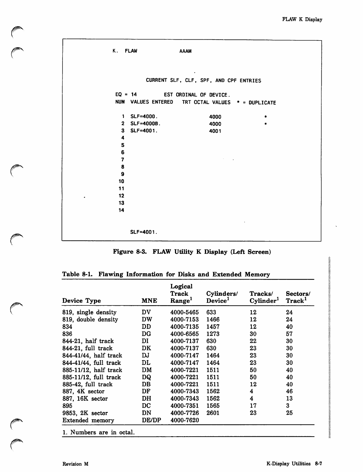
FLAW K Display
r
00&S
K . F L A W A A A M
CURRENT SLF, CLF, SPF. AND CPF ENTRIES
EQ = 14 EST ORDINAL OF DEVICE.
NUM VALUES ENTERED TRT OCTAL VALUES * = DUPLICATE
1SLF=4000. 4000 *
2SLF=4000B. 4000 *
3SLF=4001. 4001
4
5
6
7
8
9
10
11
12
13
14
SLF=4001.
Figure 8-3. FLAW Utility K Display (Left Screen)
Table 8-1. Flawing Information for Disks and Extended Memory
Logical
Track Cylinders/ Tracks/ Sectors/
Device Type MNE Range1 Device1 Cylinder1 Track1
819, single density DV 4000-5465 633 12 24
819, double density DW 4000-7153 1466 12 24
834 DD 4000-7135 1457 12 40
836 DG 4000-6565 1273 30 57
844-21, half track DI 4000-7137 630 22 30
844-21, full track DK 4000-7137 630 23 30
844-41/44, half track DJ 4000-7147 1464 23 30
844-41/44, full track DL 4000-7147 1464 23 30
885-11/12, half track DM 4000-7221 1511 50 40
885-11/12, full track DQ 4000-7221 1511 50 40
885-42, full track DB 4000-7221 1511 12 40
887, 4K sector DF 4000-7343 1562 46
887, 16K sector DH 4000-7343 1562 13
895 DC 4000-7351 1565 17
9853, 2K sector DN 4000-7726 2601 23 25
Extended memory DE/DP 4000-7620
1. Numbers are in octal.
Revision M K-Display Utilities 8-7
INITIALIZE K Display
INITIALIZE K Display
The INITIALIZE command can be used to reconfigure certain removable devices (844-21
and 844-41/44) to suit your needs. For example, if you currently have two single-unit
844 packs (DK-ls), both packs can be initialized and linked together to form a
multispindle device (DK-2). However, this can be done only if the devices to be linked
meet the following requirements:
• Same device type.
• Same channels.
• Same share status (shared or nonshared).
• Removable.
• Not currently in use.
The INITIALIZE command must be entered to set the initialize status for each device
to be chained. Current multispindle devices can also be initialized providing all packs
that form the device are mounted in a logical order as determined by the unit numbers
list on the E,C display. It is only necessary to enter the INITIALIZE command for the
first unit of a current multispindle device. The format of the INITIALIZE command is
described in section 5, DSD Commands.
NOTE
Examine the FAMC and DAFC fields in the family status display (E,F) before
entering the INITIALIZE command. The user count for the device must be zero before ^s%
this command is valid. /
8-8 NOS Version 2 Analysis Handbook Revision M
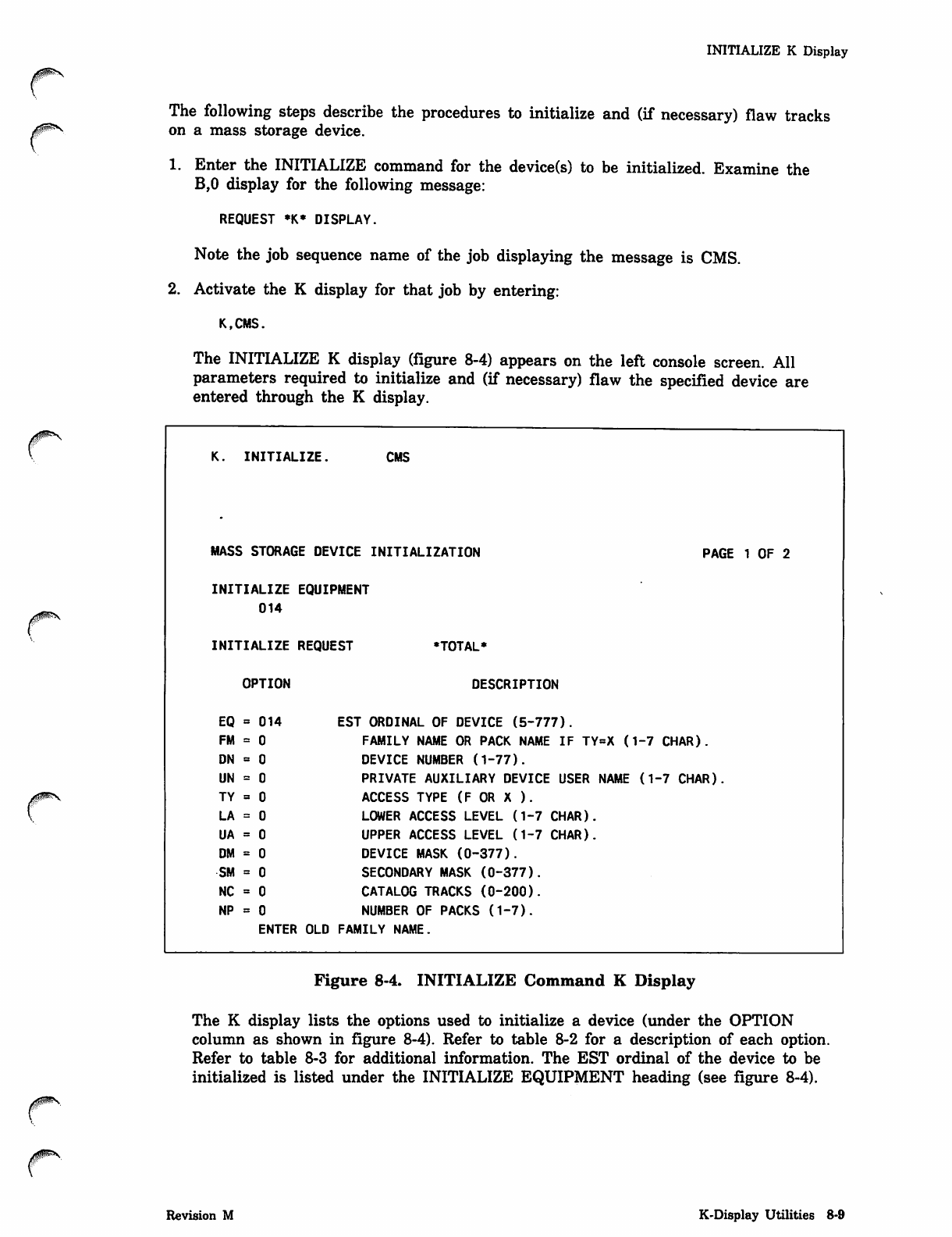
0^S
yims
INITIALIZE K Display
The following steps describe the procedures to initialize and (if necessary) flaw tracks
on a mass storage device.
1. Enter the INITIALIZE command for the device(s) to be initialized. Examine the
B,0 display for the following message:
REQUEST *K* DISPLAY.
Note the job sequence name of the job displaying the message is CMS.
2. Activate the K display for that job by entering:
K.CMS.
The INITIALIZE K display (figure 8-4) appears on the left console screen. All
parameters required to initialize and (if necessary) flaw the specified device are
entered through the K display.
ypPk\
K. INITIALIZE. CMS
MASS STORAGE DEVICE INITIALIZATION PAGE 1 OF 2
INITIALIZE EQUIPMENT
014
INITIALIZE REQUEST *TOTAL*
OPTION DESCRIPTION
EQ = 014 EST ORDINAL OF DEVICE (5-777).
FM = 0 FAMILY NAME OR PACK NAME IF TY=X (1-7 CHAR).
DN = 0 DEVICE NUMBER (1-77).
UN = 0 PRIVATE AUXILIARY DEVICE USER NAME (1-7 CHAR).
TY o 0 ACCESS TYPE (F OR X ).
LA = 0 LOWER ACCESS LEVEL (1-7 CHAR).
UA = 0 UPPER ACCESS LEVEL (1-7 CHAR).
DM = 0 DEVICE MASK (0-377).
SM = 0 SECONDARY MASK (0-377).
NC = 0 CATALOG TRACKS (0-200).
NP = 0 NUMBER OF PACKS (1-7).
ENTER OLD FAMILY NAME.
Figure 8-4. INITIALIZE Command K Display
The K display lists the options used to initialize a device (under the OPTION
column as shown in figure 8-4). Refer to table 8-2 for a description of each option.
Refer to table 8-3 for additional information. The EST ordinal of the device to be
initialized is listed under the INITIALIZE EQUIPMENT heading (see figure 8-4).
Revision M K-Display Utilities 8-9
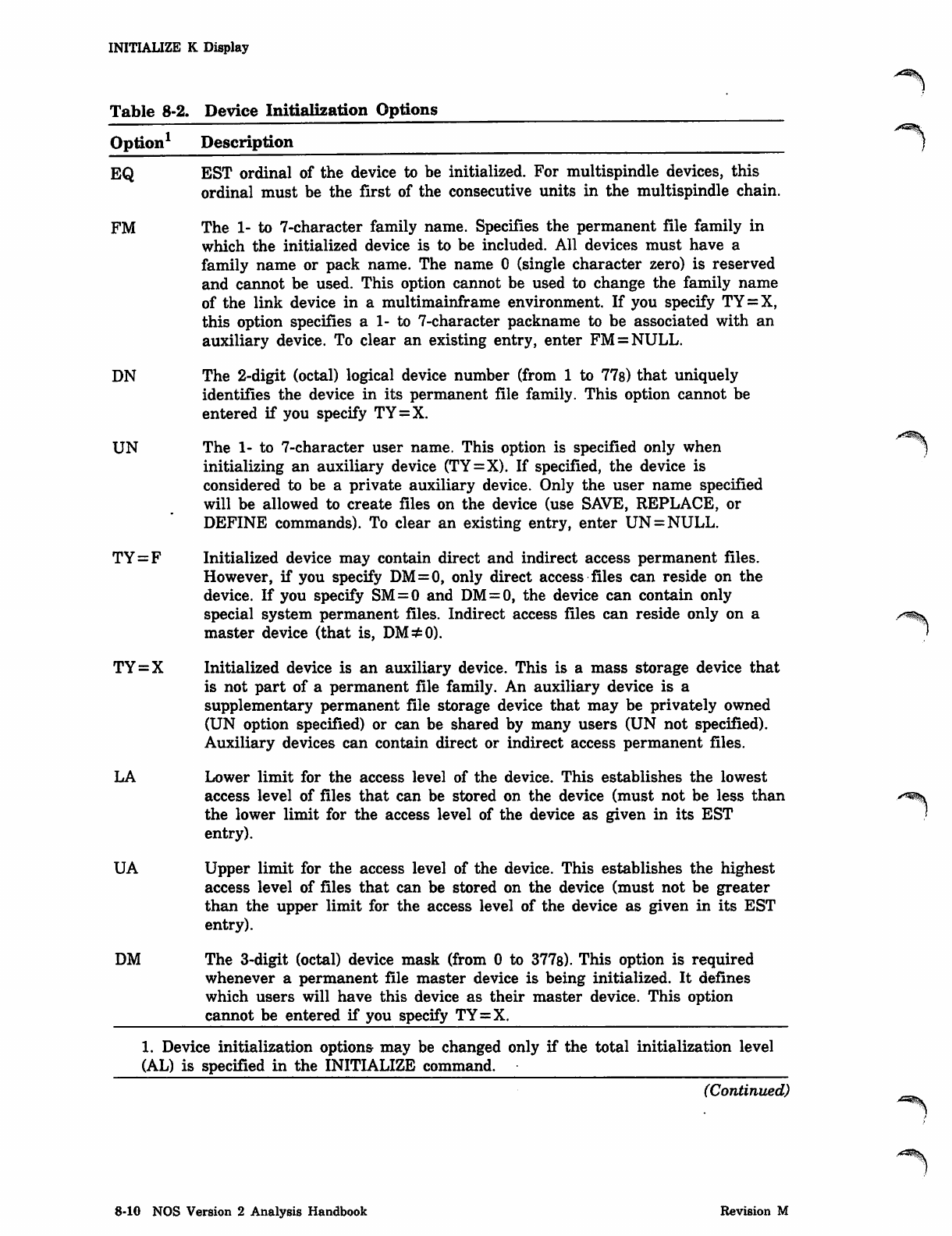
INITIALIZE K Display
Table 8-2. Device Initialization Options
Option1 Description )
EQ EST ordinal of the device to be initialized. For multispindle devices, this
ordinal must be the first of the consecutive units in the multispindle chain.
FM The 1- to 7-character family name. Specifies the permanent file family in
which the initialized device is to be included. All devices must have a
family name or pack name. The name 0 (single character zero) is reserved
and cannot be used. This option cannot be used to change the family name
of the link device in a multimainframe environment. If you specify TY=X,
this option specifies a 1- to 7-character packname to be associated with an
auxiliary device. To clear an existing entry, enter FM=NULL.
DN The 2-digit (octal) logical device number (from 1 to 77s) that uniquely
identifies the device in its permanent file family. This option cannot be
entered if you specify TY=X.
UN The 1- to 7-character user name. This option is specified only when ")
initializing an auxiliary device (TY=X). If specified, the device is
considered to be a private auxiliary device. Only the user name specified
will be allowed to create files on the device (use SAVE, REPLACE, or
DEFINE commands). To clear an existing entry, enter UN = NULL.
TY=F Initialized device may contain direct and indirect access permanent files.
However, if you specify DM=0, only direct access files can reside on the
device. If you specify SM=0 and DM=0, the device can contain only
special system permanent files. Indirect access files can reside only on a .A*ms
master device (that is, DM=£0). )
TY=X Initialized device is an auxiliary device. This is a mass storage device that
is not part of a permanent file family. An auxiliary device is a
supplementary permanent file storage device that may be privately owned
(UN option specified) or can be shared by many users (UN not specified).
Auxiliary devices can contain direct or indirect access permanent files.
LA Lower limit for the access level of the device. This establishes the lowest
access level of files that can be stored on the device (must not be less than .-*ms
the lower limit for the access level of the device as given in its EST '
entry).
UA Upper limit for the access level of the device. This establishes the highest
access level of files that can be stored on the device (must not be greater
than the upper limit for the access level of the device as given in its EST
entry).
DM The 3-digit (octal) device mask (from 0 to 377s). This option is required
whenever a permanent file master device is being initialized. It defines
which users will have this device as their master device. This option
cannot be entered if you specify TY=X.
1. Device initialization options may be changed only if the total initialization level
(AL) is specified in the INITIALIZE command.
(Continued) _^
8-10 NOS Version 2 Analysis Handbook Revision M
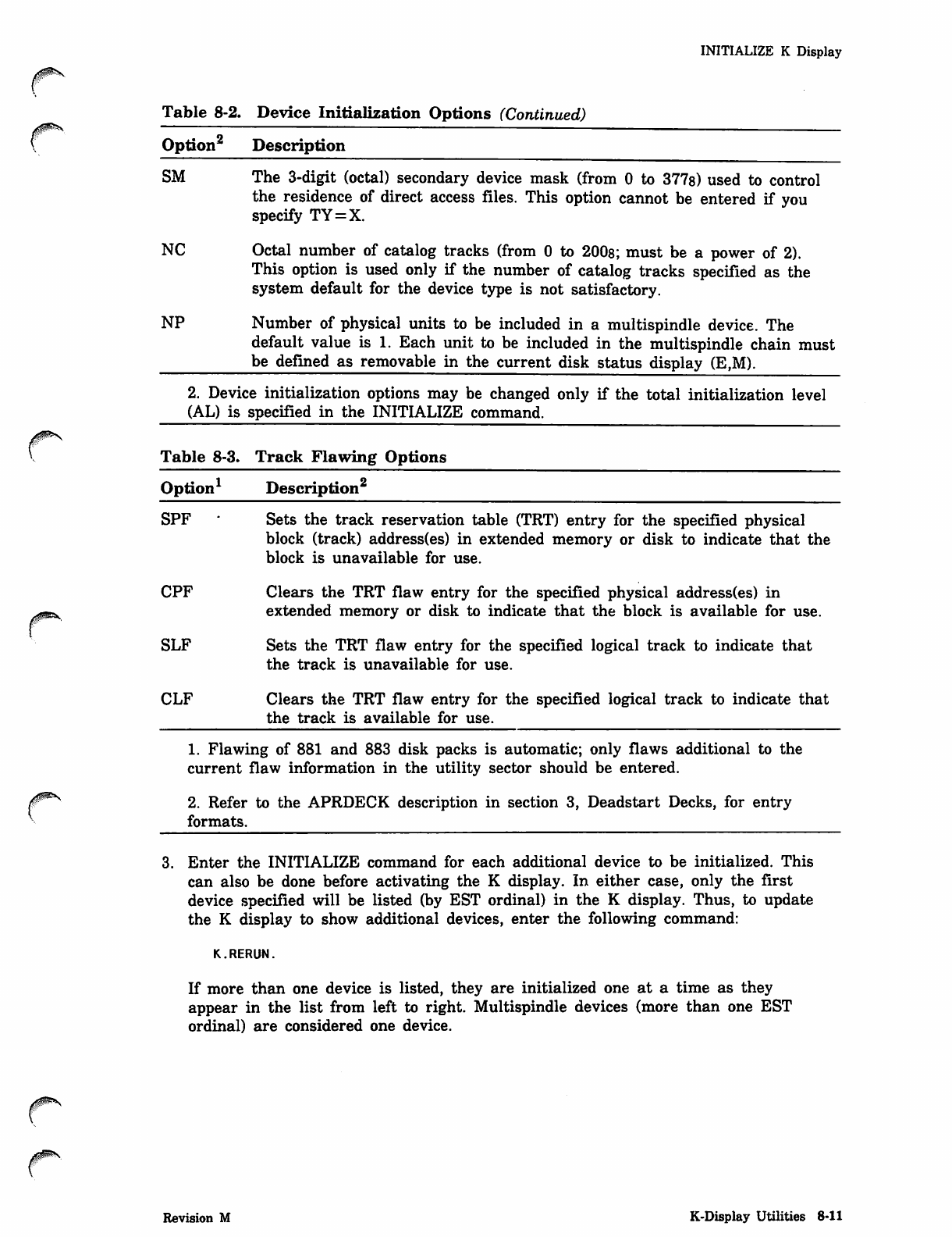
/uSSS*^
A0&\
INITIALIZE K Display
Table 8-2. Device Initialization Options (Continued)
Option2 Description
SM The 3-digit (octal) secondary device mask (from 0 to 377s) used to control
the residence of direct access files. This option cannot be entered if you
specify TY=X.
NC Octal number of catalog tracks (from 0 to 200s; must be a power of 2).
This option is used only if the number of catalog tracks specified as the
system default for the device type is not satisfactory.
NP Number of physical units to be included in a multispindle device. The
default value is 1. Each unit to be included in the multispindle chain must
be defined as removable in the current disk status display (E,M).
2. Device initialization options may be changed only if the total initialization level
(AL) is specified in the INITIALIZE command.
Table 8-3. Track Flawing Options
Option1 Description2
SPF Sets the track reservation table (TRT) entry for the specified physical
block (track) address(es) in extended memory or disk to indicate that the
block is unavailable for use.
CPF Clears the TRT flaw entry for the specified physical address(es) in
extended memory or disk to indicate that the block is available for use.
SLF Sets the TRT flaw entry for the specified logical track to indicate that
the track is unavailable for use.
CLF Clears the TRT flaw entry for the specified logical track to indicate that
the track is available for use.
1. Flawing of 881 and 883 disk packs is automatic; only flaws additional to the
current flaw information in the utility sector should be entered.
2. Refer to the APRDECK description in section 3, Deadstart Decks, for entry
formats.
3. Enter the INITIALIZE command for each additional device to be initialized. This
can also be done before activating the K display. In either case, only the first
device specified will be listed (by EST ordinal) in the K display. Thus, to update
the K display to show additional devices, enter the following command:
K.RERUN.
If more than one device is listed, they are initialized one at a time as they
appear in the list from left to right. Multispindle devices (more than one EST
ordinal) are considered one device.
Revision M K-Display Utilities 8-11
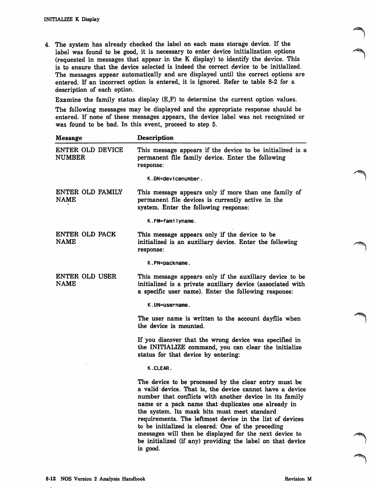
INITIALIZE K Display
The system has already checked the label on each mass storage device. If the
label was found to be good, it is necessary to enter device initialization options
(requested in messages that appear in the K display) to identify the device. This
is to ensure that the device selected is indeed the correct device to be initialized.
The messages appear automatically and are displayed until the correct options are
entered. If an incorrect option is entered, it is ignored. Refer to table 8-2 for a
description of each option.
Examine the family status display (E,F) to determine the current option values.
The following messages may be displayed and the appropriate response should be
entered. If none of these messages appears, the device label was not recognized or
was found to be bad. In this event, proceed to step 5.
Message Description
ENTER OLD DEVICE
NUMBER
This message appears if the device to be initialized is a
permanent file family device. Enter the following
response:
Aeims
ENTER OLD FAMILY
NAME
ENTER OLD PACK
NAME
ENTER OLD USER
NAME
K.DN=dev i cenumber.
This message appears only if more than one family of
permanent file devices is currently active in the
system. Enter the following response:
K.FM=familyname.
This message appears only if the device to be
initialized is an auxiliary device. Enter the following
response:
K.PN=packname.
This message appears only if the auxiliary device to be
initialized is a private auxiliary device (associated with
a specific user name). Enter the following response:
K.UN=username.
The user name is written to the account dayfile when
the device is mounted.
If you discover that the wrong device was specified in
the INITIALIZE command, you can clear the initialize
status for that device by entering:
K.CLEAR.
The device to be processed by the clear entry must be
a valid device. That is, the device cannot have a device
number that conflicts with another device in its family
name or a pack name that duplicates one already in
the system. Its mask bits must meet standard
requirements. The leftmost device in the list of devices
to be initialized is cleared: One of the preceding
messages will then be displayed for the next device to
be initialized (if any) providing the label on that device
is good.
8-12 NOS Version 2 Analysis Handbook Revision M
INITIALIZE K Display
5. When the following message appears on the K display, enter the options that
specify the new characteristics to be associated with the device when it is
initialized (refer to tables 8-2 and 8-3).
ENTER PARAMETERS
The new options can be entered as a string or one at a time. For example:
K.optioni=valuei,...,optionn=valuen.
or
K.optioni=valuei.
K.option2=value2.
K.optionn=valuen.
If flaw entries are to be specified (refer to table 8-3), they must be entered singly,
as shown in the last example. If the label on the device being initialized was
good, all current flaws on that device are normally recovered. However, if the
label was not recognized or was bad, the flaw entries cannot be recovered and
must be entered (if necessary) using this mechanism. A maximum of 14 flaw
entries are permitted. In addition to the SLF, CLF, SPF, and CPF entries, the
flaw information recorded in the utility sector on an 881, 883, or 885 disk pack is
read during initialization of 844 equipment, and the appropriate areas are
reserved by the system automatically.
If the NP option is specified (NP > 1), the device is to be initialized as a
multispindle device. In this case, the number of packs specified by NP indicates
the number of spindles to be linked. This is the next n number of devices waiting
to be initialized. Each device must be defined as removable and mounted on
consecutive physical unit numbers. To determine if a device is defined as
removable, examine the disk status display (E,M). If the units are configured
correctly, the label on each unit is checked. If any label is not recognized or is
bad, that unit is free for initialization and chaining. However, if the label is good,
the message
ENTER IDENTITY OF EQest
appears in the K display (est is the EST ordinal of the device). Enter one of the
following responses.
K.DN=devi cenumber.
K.FM=fami 1yname,DN=devicenumber.
K.PN=packname.
K.PN=packname,UN=username.
This is a precautionary measure to ensure that the devices specified are the
correct devices to be chained.
6. After all the necessary options have been entered for a specific device, enter the
following command to proceed with the initialization.
K.GO.
If more devices are waiting to be initialized, repeat steps 4 through 6 of this
procedure for each device.
Revision M K-Display Utilities 8-13
INITIALIZE K Display
Example 1:
Suppose you want to create and initialize a multispindle device by linking spindles
from two separate units. Assume your EQPDECK has the following entries:
EQ40=DL,ST=OFF,UN=4,CH=27/30.
EQ41=DL,ST=OFF,UN=5,CH=27/30.
and you want to initialize multispindle device EQ40, which consists of units 4 and 5.
Enter the following commands:
ON,40.
ON,41.
INITIALIZE.AL,40,41.
MOUNT,40.
MOUNT,41.
K.CMS.
Enter device initialization options as described in steps 4 and 5.
K.NP=2.
When the message ENTER IDENTITY OF EQest appears in the K display, respond as
described in step 5.
K.GO.
8-14 NOS Version 2 Analysis Handbook Revision M
INITIALIZE K Display
0ms
Example 2:
Assume that you want to initialize a multispindle device and your EQPDECK already
defines the device as a multispindle device:
EQ40=DL,ST=OFF,UN=4/5,CH=27/30.
In this case, enter the following commands:
ON.40.
INITIALIZE,AL,40.
MOUNT,40.
K.CMS.
Enter device initialization options as described in steps 4 and 5.
K.GO.
Example 3:
Suppose you want to initialize a single-spindle device and your EQPDECK defines the
device as a multispindle device:
E04ODL,ST=OFF,UN=4/5,CH=27/30.
Mount the pack you want to initialize on unit 4 and enter the following commands:
ON,40.
INITIALIZE.AL.40.
MOUNT,40.
K.CMS.
Enter device initialization options as described in steps 4 and 5.
K.PN=1.
K.GO.
0ms
Revision M K-Display Utilities 8-15
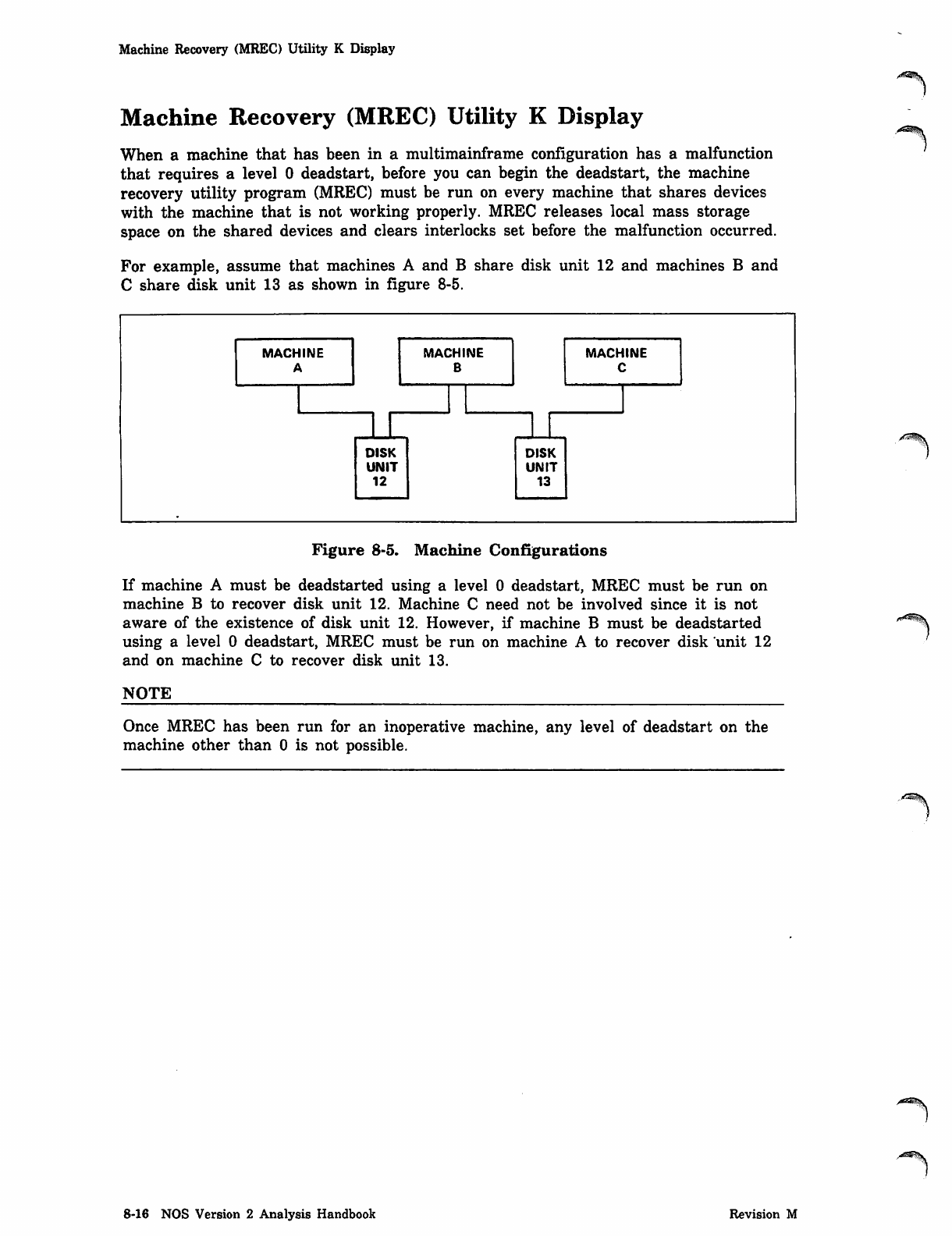
Machine Recovery (MREC) Utility K Display
Machine Recovery (MREC) Utility K Display
When a machine that has been in a multimainframe configuration has a malfunction
that requires a level 0 deadstart, before you can begin the deadstart, the machine
recovery utility program (MREC) must be run on every machine that shares devices
with the machine that is not working properly. MREC releases local mass storage
space on the shared devices and clears interlocks set before the malfunction occurred.
For example, assume that machines A and B share disk unit 12 and machines B and
C share disk unit 13 as shown in figure 8-5.
MACHINE MACHINE MACHINE
A B C
DISK DISK
UNIT UNIT
12 13
Figure 8-5. Machine Configurations
If machine A must be deadstarted using a level 0 deadstart, MREC must be run on
machine B to recover disk unit 12. Machine C need not be involved since it is not
aware of the existence of disk unit 12. However, if machine B must be deadstarted
using a level 0 deadstart, MREC must be run on machine A to recover disk unit 12
and on machine C to recover disk unit 13.
NOTE
Once MREC has been run for an inoperative machine, any level of deadstart on the
machine other than 0 is not possible.
8-16 NOS Version 2 Analysis Handbook Revision M
/#^V
MREC Procedures
MREC Procedures
The MREC utility can be used through keyboard entry to a K display or by direct
keyboard entry under DSD or DIS control without using the K display.
Using MREC with the K Display
The following procedure describes K-display usage for MREC operations.
1. Call the MREC utility by entering this DSD command:1
X.MREC.
2. Examine the DSD system status display (B,0). When MREC is scheduled to a
control point, it is indicated on the B,0 display. The message
REQUEST *K* DISPLAY
appears in the message field for that control point.
3. Activate the K display for that control point by entering:
K.jsn.
jsn Description
jsn MREC job sequence name.
The K display for MREC (figure 8-6) appears on the left console screen.
The MREC left screen K display lists all of the devices that are shared by the
machine on which MREC is being run. The machine identifier (MID) of this
machine is also given. Information describing the shared devices is given in the
following format.
eq type un dn fm/pn mids sharing device
Header Description
eq EST ordinal of the shared device,
type Device type,
un Unit number of the device,
dn Device number,
fm/pn Family name/pack name.
mids sharing Machine identifiers of other machines that are currently
device accessing the device. If there is an * by the machine
identifier, the machine is determined to be down.
1. Under DIS control, the command MREC calls the MREC utility.
Revision M K-Display Utilities 8-17
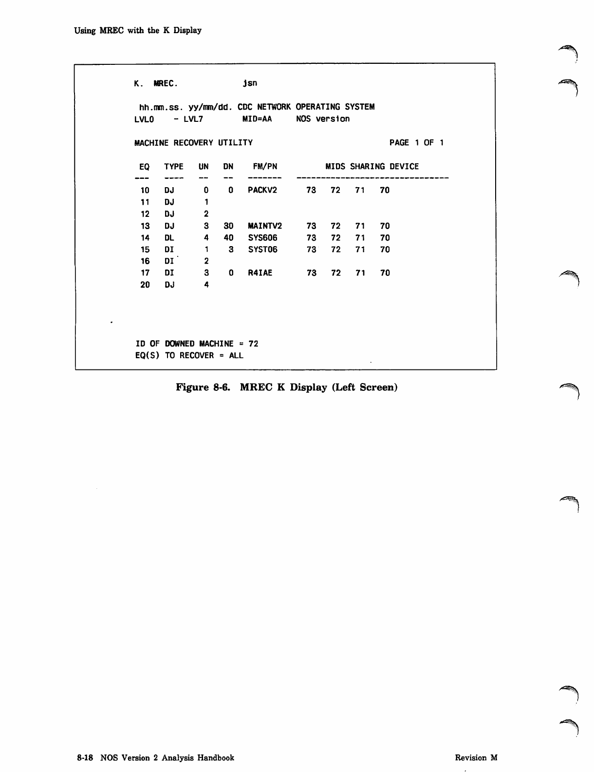
Using MREC with the K Display
K. MREC. jsn
hh.mm.ss . yy/mm/dd. CDC NETWORK OPERATING SYSTEM
LVLO LVL7 MID=AA NOS version
MACHINE RECOVERY UTILITY PAGE 1 OF 1
EQ TYPE UN DN FM/PN MIDS SHARING DEVICE
10 DJ PACKV2 73 72 71 70
11 DJ
12 DJ
13 DJ 30 MAINTV2 73 72 71 70
14 DL 40 SYS606 73 72 71 70
15 DI SYST06 73 72 71 70
16 DI
17 DI R4IAE 73 72 71 70
20 DJ
ID OF DOWNED MACHINE = 72
EQ(S) TO RECOVER = ALL
y^^lt
Figure 8-6. MREC K Display (Left Screen)
8-18 NOS Version 2 Analysis Handbook Revision M
Using MREC with the K Display
4. The MREC right screen K display contains the parameters and commands that
may be selected. Refer to table 8-4 (MREC parameters) and table 8-5 (MREC
commands) for more information. To activate the MREC right screen K display
(figures 8-7 and 8-8), enter:
KK.
5. Enter the MREC parameters in the following format:
K.parami=valuei,param2=value2 paranv1=valuen.
The parameters entered (and error messages, if any) are displayed on the lower
portion of the MREC left screen K display.
6. If you want to reset the parameters to their default values or refresh the device
descriptions on the MREC left screen K display, enter:
K.RERUN.
The parameters can then be reentered.
7. Enter the desired parameters and initiate MREC processing by entering:
K.GO.
When processing is complete, the message
PROCESSING COMPLETE
appears at the bottom of the left screen.
8. After all MREC operations are complete, end the MREC utility by entering:
K.STOP.
Revision M K-Display Utilities 8-19
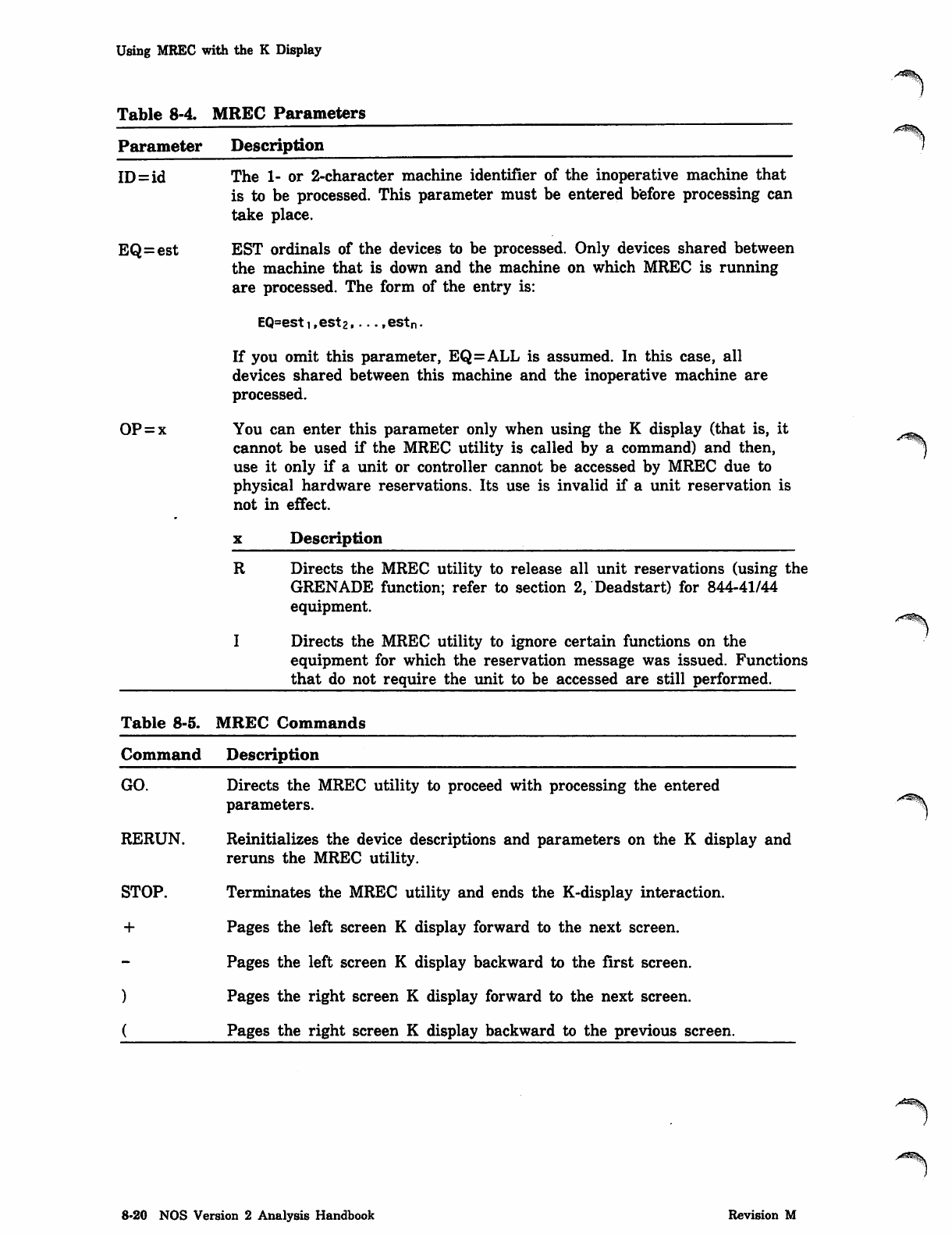
Using MREC with the K Display
Table 8-4. MREC Parameters
Parameter Description
ID=id
EQ=est
OP = x
The 1- or 2-character machine identifier of the inoperative machine that
is to be processed. This parameter must be entered before processing can
take place.
EST ordinals of the devices to be processed. Only devices shared between
the machine that is down and the machine on which MREC is running
are processed. The form of the entry is:
EQ=esti,est2,....estn.
If you omit this parameter, EQ=ALL is assumed. In this case, all
devices shared between this machine and the inoperative machine are
processed.
You can enter this parameter only when using the K display (that is, it
cannot be used if the MREC utility is called by a command) and then,
use it only if a unit or controller cannot be accessed by MREC due to
physical hardware reservations. Its use is invalid if a unit reservation is
not in effect.
x D e s c r i p t i o n
R Directs the MREC utility to release all unit reservations (using the
GRENADE function; refer to section 2, Deadstart) for 844-41/44
equipment.
I Directs the MREC utility to ignore certain functions on the
equipment for which the reservation message was issued. Functions
that do not require the unit to be accessed are still performed.
Table 8-5. MREC Commands
Command Description
GO. Directs the MREC utility to proceed with processing the entered
parameters.
RERUN. Reinitializes the device descriptions and parameters on the K display and
reruns the MREC utility.
STOP. Terminates the MREC utility and ends the K-display interaction.
+ Pages the left screen K display forward to the next screen.
Pages the left screen K display backward to the first screen.
) Pages the right screen K display forward to the next screen.
( Pages the right screen K display backward to the previous screen.
■«*^ii\
8-20 NOS Version 2 Analysis Handbook Revision M
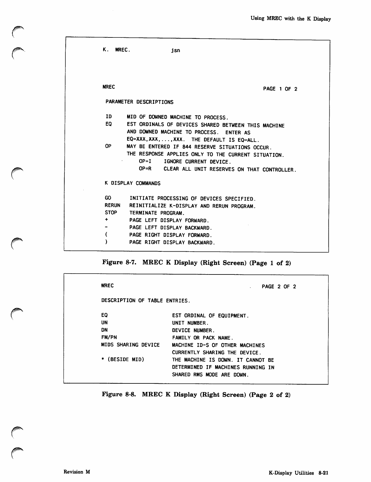
/$m\
0ms
Using MREC with the K Display
MREC. jsn
MREC
PARAMETER DESCRIPTIONS
PAGE 1 OF 2
ID
EQ
OP
MID OF DOWNED MACHINE TO PROCESS.
EST ORDINALS OF DEVICES SHARED BETWEEN THIS MACHINE
AND DOWNED MACHINE TO PROCESS. ENTER AS
EQ=XXX,XXX XXX. THE DEFAULT IS EQ=ALL.
MAY BE ENTERED IF 844 RESERVE SITUATIONS OCCUR.
THE RESPONSE APPLIES ONLY TO THE CURRENT SITUATION.
OP=I IGNORE CURRENT DEVICE.
OP=R CLEAR ALL UNIT RESERVES ON THAT CONTROLLER
K DISPLAY COMMANDS
GO
RERUN
STOP
+
INITIATE PROCESSING OF DEVICES SPECIFIED.
REINITIALIZE K-DISPLAY AND RERUN PROGRAM.
TERMINATE PROGRAM.
PAGE LEFT DISPLAY FORWARD.
PAGE LEFT DISPLAY BACKWARD.
PAGE RIGHT DISPLAY FORWARD.
PAGE RIGHT DISPLAY BACKWARD.
Figure 8-7. MREC K Display (Right Screen) (Page 1 of 2)
MREC
DESCRIPTION OF TABLE ENTRIES.
PAGE 2 OF 2
EQ
UN
DN
FM/PN
MIDS SHARING DEVICE
* (BESIDE MID)
EST ORDINAL OF EQUIPMENT.
UNIT NUMBER.
DEVICE NUMBER.
FAMILY OR PACK NAME.
MACHINE ID-S OF OTHER MACHINES
CURRENTLY SHARING THE DEVICE.
THE MACHINE IS DOWN. IT CANNOT BE
DETERMINED IF MACHINES RUNNING IN
SHARED RMS MODE ARE DOWN.
Figure 8-8. MREC K Display (Right Screen) (Page 2 of 2)
Revision M K-Display Utilities 8-21
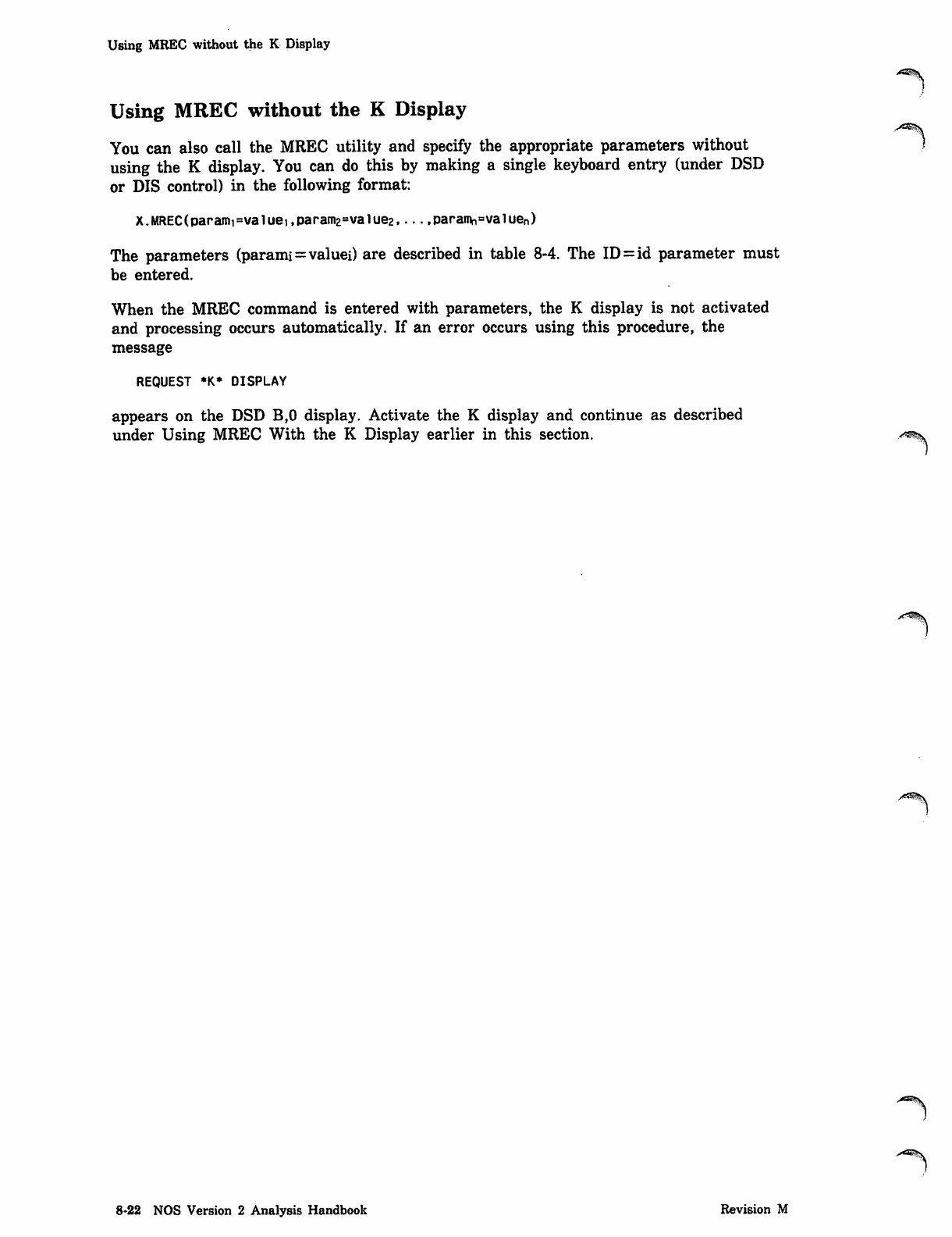
Using MREC without the K Display
Using MREC without the K Display
You can also call the MREC utility and specify the appropriate parameters without
using the K display. You can do this by making a single keyboard entry (under DSD
or DIS control) in the following format:
X.MREC(param1=valuei,param2=value2 paramn=valuen)
The parameters (parami = valuei) are described in table 8-4. The ID = id parameter must
be entered.
When the MREC command is entered with parameters, the K display is not activated
and processing occurs automatically. If an error occurs using this procedure, the
message
REQUEST *K* DISPLAY
appears on the DSD B,0 display. Activate the K display and continue as described
under Using MREC With the K Display earlier in this section. ^^
8-22 NOS Version 2 Analysis Handbook Revision M
0ims
/0ms
MREC Unit and Controller Reservations
MREC Unit and Controller Reservations
When attempting to access a device, MREC may find the controller access or unit
reserved by another machine. When this occurs, the following message appears on the
left screen K display.
EQest,CHCC, CONTROLLER RESERVED.
or
EQest,UNUU, UNIT RESERVED.
Variable Description
e s t E S T o r d i n a l o f t h e d e v i c e .
cc Channel number.
uu Physical unit number (from 0 to 778).
Assuming the inoperative machine is the machine holding the reservation, you can
clear the reservation or direct MREC to clear it by using the following procedures:
To clear a controller reservation, initiate deadstart on the machine that is down.
To clear a unit reservation, perform one of the following procedures:
• On a device that is connected to a 7155 controller, initiate deadstart on the
machine that is down.
• On a device that is not connected to a 7155 controller, toggle the OFF LINE/ON
LINE switch on the back of the drive to OFF LINE and then back to ON LINE.
• If none of the preceding procedures can be performed, select the OP = R parameter
to clear an 844 device reservation.
Revision M K-Display Utilities 8-23
MREC Unit and Controller Reservations
NOTE
Do not select the OP=R parameter unless the other reservation clearing procedures
cannot be performed. It is recommended that all machines in a multimainframe
environment be put in IDLE status or put in STEP mode when you select the OP=R
parameter.
Once the correct action has been taken, enter
K.GO.
to continue processing. If the reservation is still not cleared, the appropriate reserved
message reappears on the left screen K display. Repeat one of the reservation clearing
procedures described above or enter:
K.OP=I.
This directs the MREC utility to ignore certain functions on the device. Processing may
then continue.
If a device or controller in an independent shared device multimainframe environment
is reserved by a down machine, the previously mentioned messages appear on the
system 'status display (B,0) instead of on the K display. Use the procedures already
described to clear the reservation.
8-24 NOS Version 2 Analysis Handbook Revision M
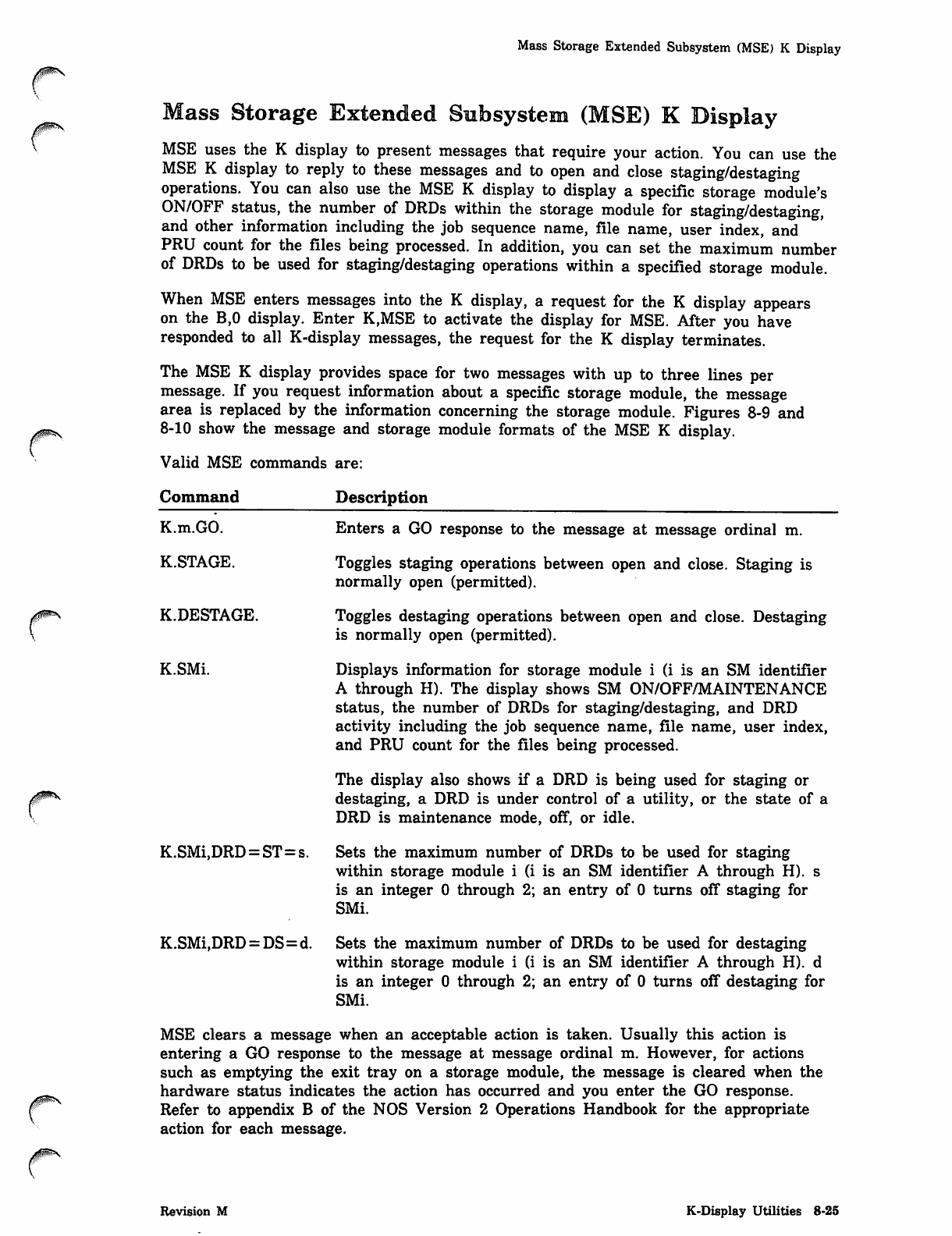
00ms
Mass Storage Extended Subsystem (MSE) K Display
Mass Storage Extended Subsystem (MSE) K Display
MSE uses the K display to present messages that require your action. You can use the
MSE K display to reply to these messages and to open and close staging/destaging
operations. You can also use the MSE K display to display a specific storage module's
ON/OFF status, the number of DRDs within the storage module for staging/destaging,
and other information including the job sequence name, file name, user index, and
PRU count for the files being processed. In addition, you can set the maximum number
of DRDs to be used for staging/destaging operations within a specified storage module.
When MSE enters messages into the K display, a request for the K display appears
on the B,0 display. Enter K,MSE to activate the display for MSE. After you have
responded to all K-display messages, the request for the K display terminates.
The MSE K display provides space for two messages with up to three lines per
message. If you request information about a specific storage module, the message
area is replaced by the information concerning the storage module. Figures 8-9 and
8-10 show the message and storage module formats of the MSE K display.
Valid MSE commands are:
Command Description
K.m.GO.
K.STAGE.
K.DESTAGE.
K.SMi.
K.SMi,DRD=ST=s.
K.SMi,DRD=DS=d.
Enters a GO response to the message at message ordinal m.
Toggles staging operations between open and close. Staging is
normally open (permitted).
Toggles destaging operations between open and close. Destaging
is normally open (permitted).
Displays information for storage module i (i is an SM identifier
A through H). The display shows SM ON/OFF/MAINTENANCE
status, the number of DRDs for staging/destaging, and DRD
activity including the job sequence name, file name, user index,
and PRU count for the files being processed.
The display also shows if a DRD is being used for staging or
destaging, a DRD is under control of a utility, or the state of a
DRD is maintenance mode, off, or idle.
Sets the maximum number of DRDs to be used for staging
within storage module i (i is an SM identifier A through H). s
is an integer 0 through 2; an entry of 0 turns off staging for
SMi.
Sets the maximum number of DRDs to be used for destaging
within storage module i (i is an SM identifier A through H). d
is an integer 0 through 2; an entry of 0 turns off destaging for
SMi.
0^S.
MSE clears a message when an acceptable action is taken. Usually this action is
entering a GO response to the message at message ordinal m. However, for actions
such as emptying the exit tray on a storage module, the message is cleared when the
hardware status indicates the action has occurred and you enter the GO response.
Refer to appendix B of the NOS Version 2 Operations Handbook for the appropriate
action for each message.
Revision M K-Display Utilities 8-25
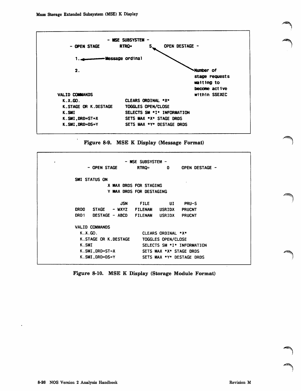
Mass Storage Extended Subsystem (MSE) K Display
- MSE SUBSYSTEM -
- OPEN STAGE R T R Q * 5 OPEN DESTAGE -
1 . - # — —-Message ordinal
2. *Number of
stage requests
Malting to
become active
VALID COMMANDS within SSEXEC
K.X.GO. CLEARS ORDINAL *X*
K.STAGE OR K.DESTAGE TOGGLES OPEN/CLOSE
K.SMI SELECTS SM • I* INFORMATION
K.SMI.DRD°ST"X SETS MAX »X* STAGE DRDS
K.SMI,DRD=DS=Y SETS MAX •¥• DESTAGE DRDS
A^S
Figure 8-9. MSE K Display (Message Format)
- MSE SUBSYSTEM -
- OPEN STAGE R T R Q = 0 OPEN DESTAGE -
SMI STATUS ON
X MAX DRDS FOR STAGING
Y MAX DRDS FOR DESTAGING
JSN FILE UI PRU-S
DRDO STAGE - WXYZ FILENAM USRIDX PRUCNT
DRD1 DESTAGE - ABCD FILENAM USRIDX PRUCNT
VALID COMMANDS
K.X.GO. CLEARS ORDINAL *X*
K.STAGE OR K.DESTAGE TOGGLES OPEN/CLOSE
K.SMI SELECTS SM *I* INFORMATION
K.SMI,DRD=ST=X SETS MAX *X* STAGE DRDS
K.SMI,DRD=DS=Y SETS MAX *Y* DESTAGE DRDS
Figure 8-10. MSE K Display (Storage Module Format)
8-26 NOS Version 2 Analysis Handbook Revision M
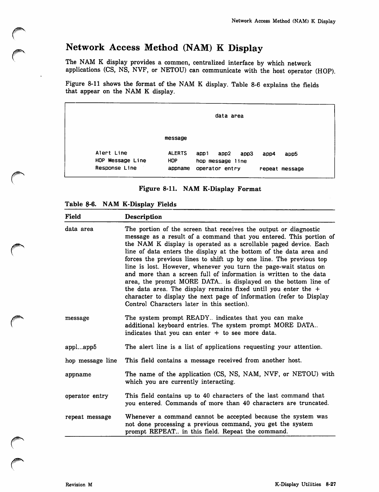
Network Access Method (NAM) K Display
Network Access Method (NAM) K Display
The NAM K display provides a common, centralized interface by which network
applications (CS, NS, NVF, or NETOU) can communicate with the host operator (HOP).
Figure 8-11 shows the format of the NAM K display. Table 8-6 explains the fields
that appear on the NAM K display.
message
data area
Alert Line ALERTS appl app2 app3 app4 app5
HOP Message Line HOP hop message 1i ne
Response Line appname operator entry repeat message
Figure 8-11. NAM K-Display Format
Table 8-6. NAM K-Display Fields
Field Description
data area
r
message
The portion of the screen that receives the output or diagnostic
message as a result of a command that you entered. This portion of
the NAM K display is operated as a scrollable paged device. Each
line of data enters the display at the bottom of the data area and
forces the previous lines to shift up by one line. The previous top
line is lost. However, whenever you turn the page-wait status on
and more than a screen full of information is written to the data
area, the prompt MORE DATA., is displayed on the bottom line of
the data area. The display remains fixed until you enter the +
character to display the next page of information (refer to Display
Control Characters later in this section).
The system prompt READY., indicates that you can make
additional keyboard entries. The system prompt MORE DATA.,
indicates that you can enter + to see more data.
appl...app5 The alert line is a list of applications requesting your attention,
hop message line This field contains a message received from another host,
appname
operator entry
repeat message
The name of the application (CS, NS, NAM, NVF, or NETOU) with
which you are currently interacting.
This field contains up to 40 characters of the last command that
you entered. Commands of more than 40 characters are truncated.
Whenever a command cannot be accepted because the system was
not done processing a previous command, you get the system
prompt REPEAT., in this field. Repeat the command.
Revision M K-Display Utilities 8-27
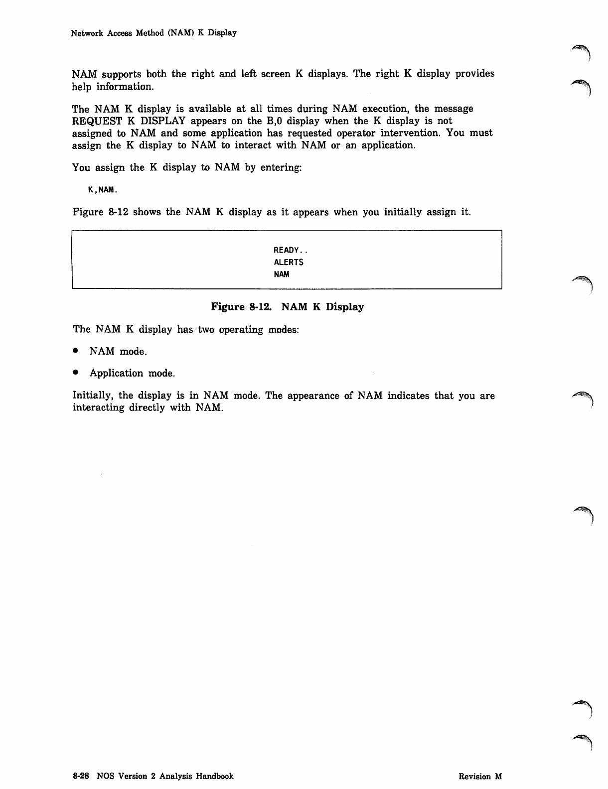
Network Access Method (NAM) K Display
NAM supports both the right and left screen K displays. The right K display provides
help information. "**%.
The NAM K display is available at all times during NAM execution, the message
REQUEST K DISPLAY appears on the B,0 display when the K display is not
assigned to NAM and some application has requested operator intervention. You must
assign the K display to NAM to interact with NAM or an application.
You assign the K display to NAM by entering:
K.NAM.
Figure 8-12 shows the NAM K display as it appears when you initially assign it.
READY..
ALERTS
NAM
Figure 8-12. NAM K Display
The NAM K display has two operating modes:
• NAM mode.
• Application mode.
Initially, the display is in NAM mode. The appearance of NAM indicates that you are
interacting directly with NAM.
8-28 NOS Version 2 Analysis Handbook Revision M
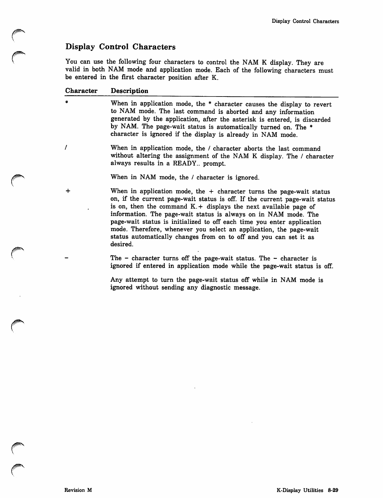
Display Control Characters
Display Control Characters
You can use the following four characters to control the NAM K display. They are
valid in both NAM mode and application mode. Each of the following characters must
be entered in the first character position after K.
Character Description
r
When in application mode, the * character causes the display to revert
to NAM mode. The last command is aborted and any information
generated by the application, after the asterisk is entered, is discarded
by NAM. The page-wait status is automatically turned on. The *
character is ignored if the display is already in NAM mode.
When in application mode, the / character aborts the last command
without altering the assignment of the NAM K display. The / character
always results in a READY., prompt.
When in NAM mode, the / character is ignored.
When in application mode, the + character turns the page-wait status
on, if the current page-wait status is off. If the current page-wait status
is on, then the command K.+ displays the next available page of
information. The page-wait status is always on in NAM mode. The
page-wait status is initialized to off each time you enter application
mode. Therefore, whenever you select an application, the page-wait
status automatically changes from on to off and you can set it as
desired.
The - character turns off the page-wait status. The - character is
ignored if entered in application mode while the page-wait status is off.
Any attempt to turn the page-wait status off while in NAM mode is
ignored without sending any diagnostic message.
Revision M K-Display Utilities 8-29
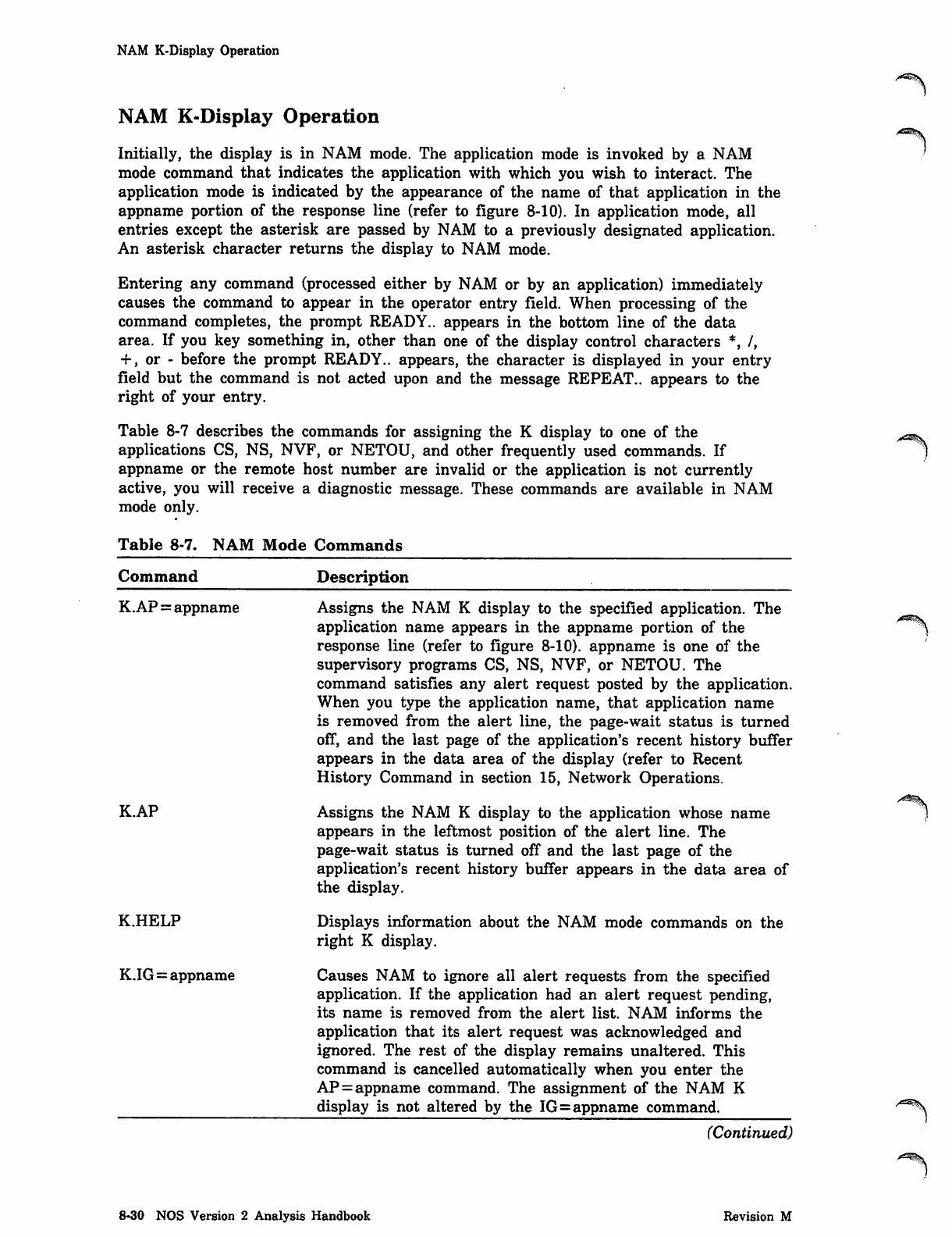
NAM K-Display Operation
NAM K-Display Operation
Initially, the display is in NAM mode. The application mode is invoked by a NAM
mode command that indicates the application with which you wish to interact. The
application mode is indicated by the appearance of the name of that application in the
appname portion of the response line (refer to figure 8-10). In application mode, all
entries except the asterisk are passed by NAM to a previously designated application.
An asterisk character returns the display to NAM mode.
Entering any command (processed either by NAM or by an application) immediately
causes the command to appear in the operator entry field. When processing of the
command completes, the prompt READY., appears in the bottom line of the data
area. If you key something in, other than one of the display control characters *, /,
+ , or - before the prompt READY., appears, the character is displayed in your entry
field but the command is not acted upon and the message REPEAT., appears to the
right of your entry.
Table 8-7 describes the commands for assigning the K display to one of the
applications CS, NS, NVF, or NETOU, and other frequently used commands. If
appname or the remote host number are invalid or the application is not currently
active, you will receive a diagnostic message. These commands are available in NAM
mode only.
Table 8-7. NAM Mode Commands
Command Description
K.AP = appname
K.AP
K.HELP
K.IG=appname
Assigns the NAM K display to the specified application. The
application name appears in the appname portion of the
response line (refer to figure 8-10). appname is one of the
supervisory programs CS, NS, NVF, or NETOU. The
command satisfies any alert request posted by the application.
When you type the application name, that application name
is removed from the alert line, the page-wait status is turned
off, and the last page of the application's recent history buffer
appears in the data area of the display (refer to Recent
History Command in section 15, Network Operations.
Assigns the NAM K display to the application whose name
appears in the leftmost position of the alert line. The
page-wait status is turned off and the last page of the
application's recent history buffer appears in the data area of
the display.
Displays information about the NAM mode commands on the
right K display.
Causes NAM to ignore all alert requests from the specified
application. If the application had an alert request pending,
its name is removed from the alert list. NAM informs the
application that its alert request was acknowledged and
ignored. The rest of the display remains unaltered. This
command is cancelled automatically when you enter the
AP = appname command. The assignment of the NAM K
display is not altered by the IG=appname command.
(Continued)
.A^m\
8-30 NOS Version 2 Analysis Handbook Revision M
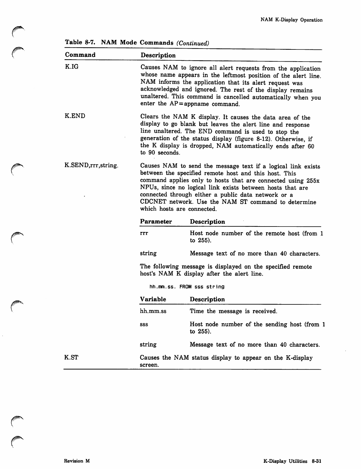
NAM K-Display Operation
Table 8-7. NAM Mode Commands (Continued)
Command
K.IG
K.END
K.SEND,rrr,string.
Description
Causes NAM to ignore all alert requests from the application
whose name appears in the leftmost position of the alert line.
NAM informs the application that its alert request was
acknowledged and ignored. The rest of the display remains
unaltered. This command is cancelled automatically when you
enter the AP=appname command.
Clears the NAM K display. It causes the data area of the
display to go blank but leaves the alert line and response
line unaltered. The END command is used to stop the
generation of the status display (figure 8-12). Otherwise, if
the K display is dropped, NAM automatically ends after 60
to 90 seconds.
Causes NAM to send the message text if a logical link exists
between the specified remote host and this host. This
command applies only to hosts that are connected using 255x
NPUs, since no logical link exists between hosts that are
connected through either a public data network or a
CDCNET network. Use the NAM ST command to determine
which hosts are connected.
Parameter Description
rrr Host node number of the remote host (from 1
to 255).
0*^S
string Message text of no more than 40 characters.
The following message is displayed on the specified remote
host's NAM K display after the alert line.
hh.mm.ss. FROM sss string
Variable Description
hh.mm.ss
sss
string
Time the message is received.
Host node number of the sending host (from 1
to 255).
Message text of no more than 40 characters.
K.ST Causes the NAM status display to appear on the K-display
screen.
Revision M K-Display Utilities 8-31
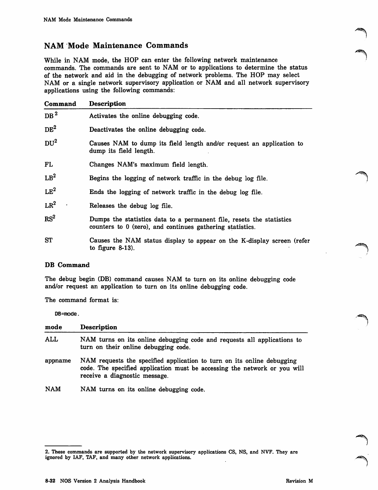
NAM Mode Maintenance Commands
NAM Mode Maintenance Commands
While in NAM mode, the HOP can enter the following network maintenance
commands. The commands are sent to NAM or to applications to determine the status
of the network and aid in the debugging of network problems. The HOP may select
NAM or a single network supervisory application or NAM and all network supervisory
applications using the following commands:
Command Description
DB2 Activates the online debugging code.
DE2 Deactivates the online debugging code.
DU2 Causes NAM to dump its field length and/or request an application to
dump its field length.
FL Changes NAM's maximum field length.
LB2 Begins the logging of network traffic in the debug log file.
LE2 Ends the logging of network traffic in the debug log file.
LR Releases the debug log file.
RS Dumps the statistics data to a permanent file, resets the statistics
counters to 0 (zero), and continues gathering statistics.
ST Causes the NAM status display to appear on the K-display screen (refer
to figure 8-13).
DB Command
The debug begin (DB) command causes NAM to turn on its online debugging code
and/or request an application to turn on its online debugging code.
The command format is:
DB=mode.
m o d e D e s c r i p t i o n
ALL NAM turns on its online debugging code and requests all applications to
turn on their online debugging code.
appname NAM requests the specified application to turn on its online debugging
code. The specified application must be accessing the network or you will
receive a diagnostic message.
NAM NAM turns on its online debugging code.
2. These commands are supported by the network supervisory applications CS, NS, and NVF. They are
ignored by IAF, TAF, and many other network applications.
8-32 NOS Version 2 Analysis Handbook Revision M
/*'^%k
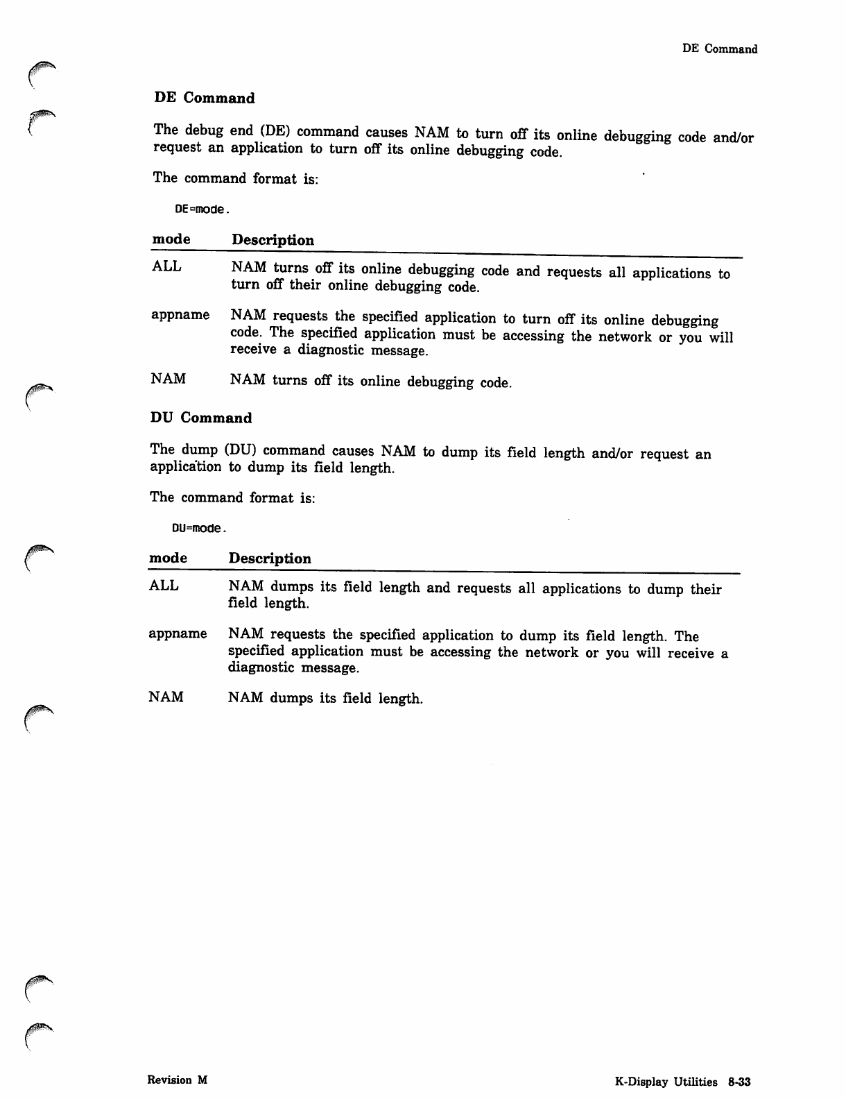
DE Command
DE Command
The debug end (DE) command causes NAM to turn off its online debugging code and/or
request an application to turn off its online debugging code.
The command format is:
DE=mode.
m o d e D e s c r i p t i o n
ALL NAM turns off its online debugging code and requests all applications to
turn off their online debugging code.
appname NAM requests the specified application to turn off its online debugging
code. The specified application must be accessing the network or you will
receive a diagnostic message.
NAM NAM turns off its online debugging code.
DU Command
The dump (DU) command causes NAM to dump its field length and/or request an
application to dump its field length.
The command format is:
DU=mode.
m o d e D e s c r i p t i o n
ALL NAM dumps its field length and requests all applications to dump their
field length.
appname NAM requests the specified application to dump its field length. The
specified application must be accessing the network or you will receive a
diagnostic message.
NAM NAM dumps its field length.
Revision M K-Display Utilities 8-33
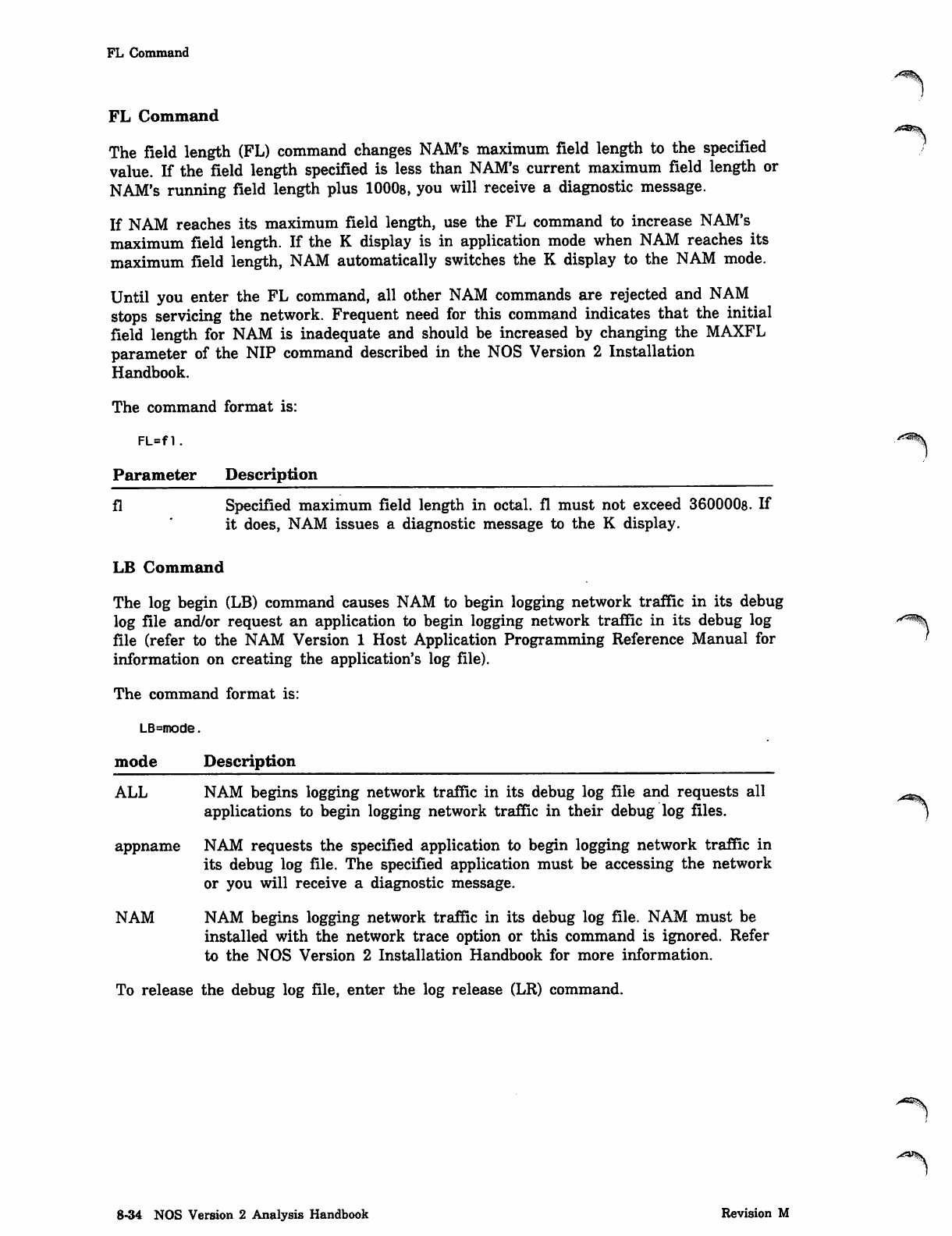
FL Command
FL Command
The field length (FL) command changes NAM's maximum field length to the specified
value. If the field length specified is less than NAM's current maximum field length or
NAM's running field length plus 10008, you will receive a diagnostic message.
If NAM reaches its maximum field length, use the FL command to increase NAM's
maximum field length. If the K display is in application mode when NAM reaches its
maximum field length, NAM automatically switches the K display to the NAM mode.
Until you enter the FL command, all other NAM commands are rejected and NAM
stops servicing the network. Frequent need for this command indicates that the initial
field length for NAM is inadequate and should be increased by changing the MAXFL
parameter of the NIP command described in the NOS Version 2 Installation
Handbook.
The command format is:
FL=fl.
Parameter Description ^
fl Specified maximum field length in octal, fl must not exceed 3600008. If
it does, NAM issues a diagnostic message to the K display.
LB Command
The log begin (LB) command causes NAM to begin logging network traffic in its debug
log file and/or request an application to begin logging network traffic in its debug log
file (refer to the NAM Version 1 Host Application Programming Reference Manual for
information on creating the application's log file).
The command format is:
LB-mode.
mode Description ^
ALL NAM begins logging network traffic in its debug log file and requests all
applications to begin logging network traffic in their debug log files.
appname NAM requests the specified application to begin logging network traffic in
its debug log file. The specified application must be accessing the network
or you will receive a diagnostic message.
NAM NAM begins logging network traffic in its debug log file. NAM must be
installed with the network trace option or this command is ignored. Refer
to the NOS Version 2 Installation Handbook for more information.
To release the debug log file, enter the log release (LR) command.
y*^^?\
<**^
''**%.
8-34 NOS Version 2 Analysis Handbook Revision M
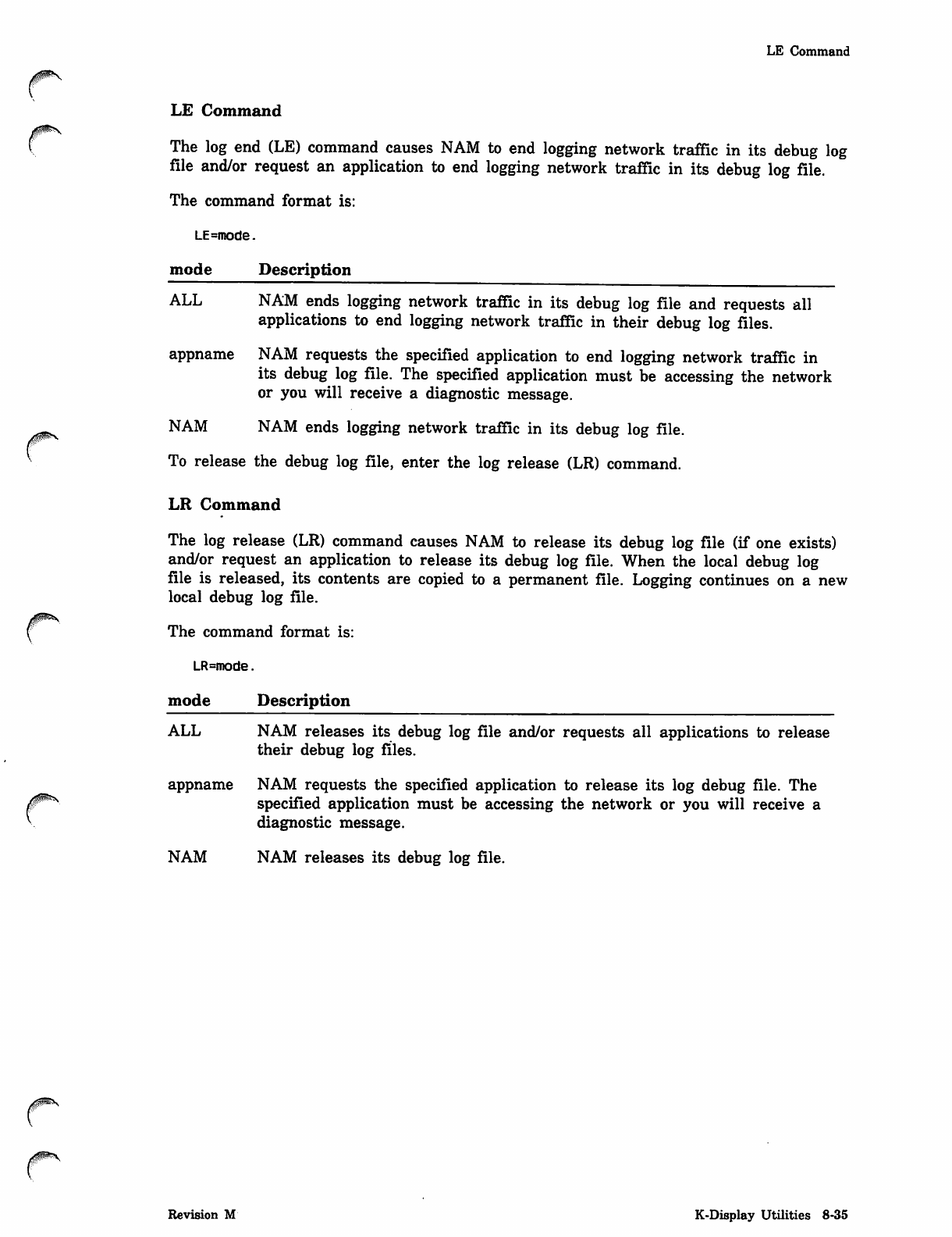
LE Command
LE Command
The log end (LE) command causes NAM to end logging network traffic in its debug log
file and/or request an application to end logging network traffic in its debug log file.
The command format is:
LE=mode.
mode Description
ALL NjAJVI ends logging network traffic in its debug log file and requests all
applications to end logging network traffic in their debug log files.
appname NAM requests the specified application to end logging network traffic in
its debug log file. The specified application must be accessing the network
or you will receive a diagnostic message.
NAM NAM ends logging network traffic in its debug log file.
To release the debug log file, enter the log release (LR) command.
r
LR Command
The log release (LR) command causes NAM to release its debug log file (if one exists)
and/or request an application to release its debug log file. When the local debug log
file is released, its contents are copied to a permanent file. Logging continues on a new
local debug log file.
The command format is:
LR=mode.
m o d e D e s c r i p t i o n
ALL NAM releases its debug log file and/or requests all applications to release
their debug log files.
appname NAM requests the specified application to release its log debug file. The
specified application must be accessing the network or you will receive a
diagnostic message.
NAM NAM releases its debug log file.
Revision M K-Display Utilities 8-35
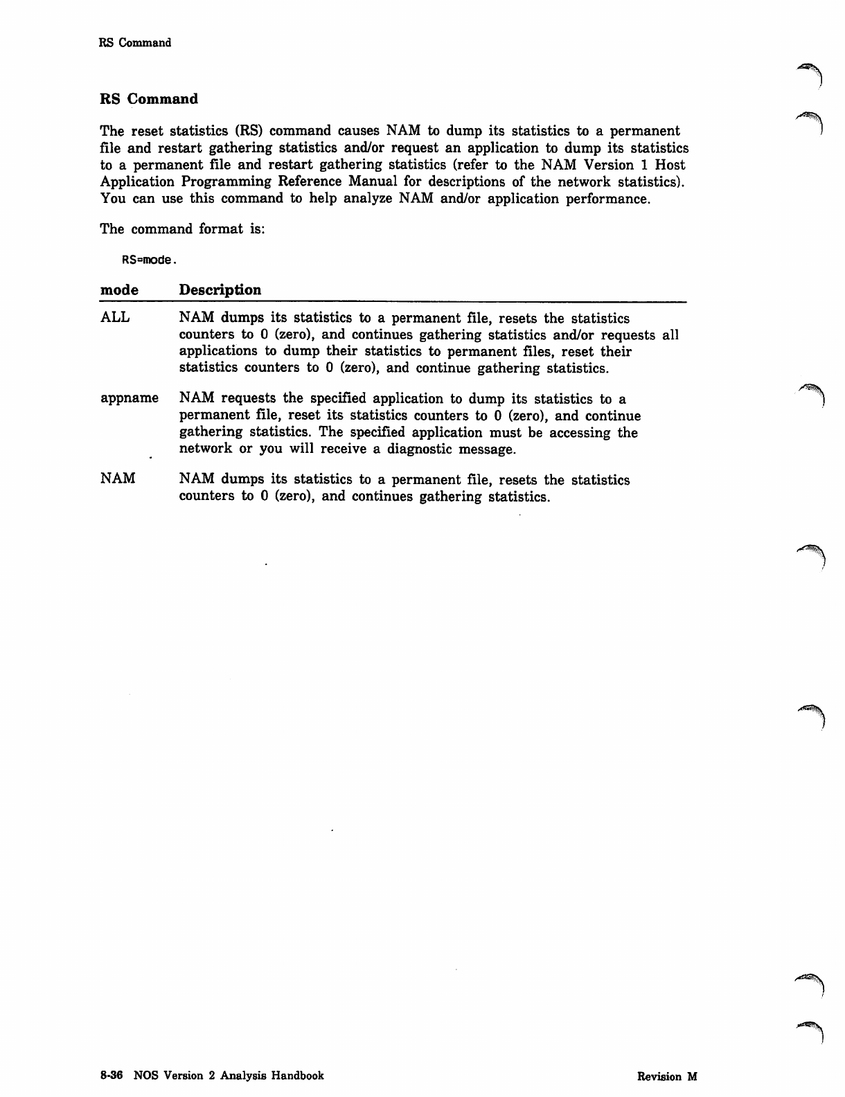
RS Command
RS Command
The reset statistics (RS) command causes NAM to dump its statistics to a permanent
file and restart gathering statistics and/or request an application to dump its statistics
to a permanent file and restart gathering statistics (refer to the NAM Version 1 Host
Application Programming Reference Manual for descriptions of the network statistics).
You can use this command to help analyze NAM and/or application performance.
The command format is:
RS=mode.
mode Description
ALL NAM dumps its statistics to a permanent file, resets the statistics
counters to 0 (zero), and continues gathering statistics and/or requests all
applications to dump their statistics to permanent files, reset their
statistics counters to 0 (zero), and continue gathering statistics.
a p p n a m e N A M r e q u e s t s t h e sp e c i fi e d a p p l i c a t i o n t o d u m p i t s s t a t i s t i c s t o a ]
permanent file, reset its statistics counters to 0 (zero), and continue
gathering statistics. The specified application must be accessing the
network or you will receive a diagnostic message.
NAM NAM dumps its statistics to a permanent file, resets the statistics
counters to 0 (zero), and continues gathering statistics.
8-36 NOS Version 2 Analysis Handbook Revision M
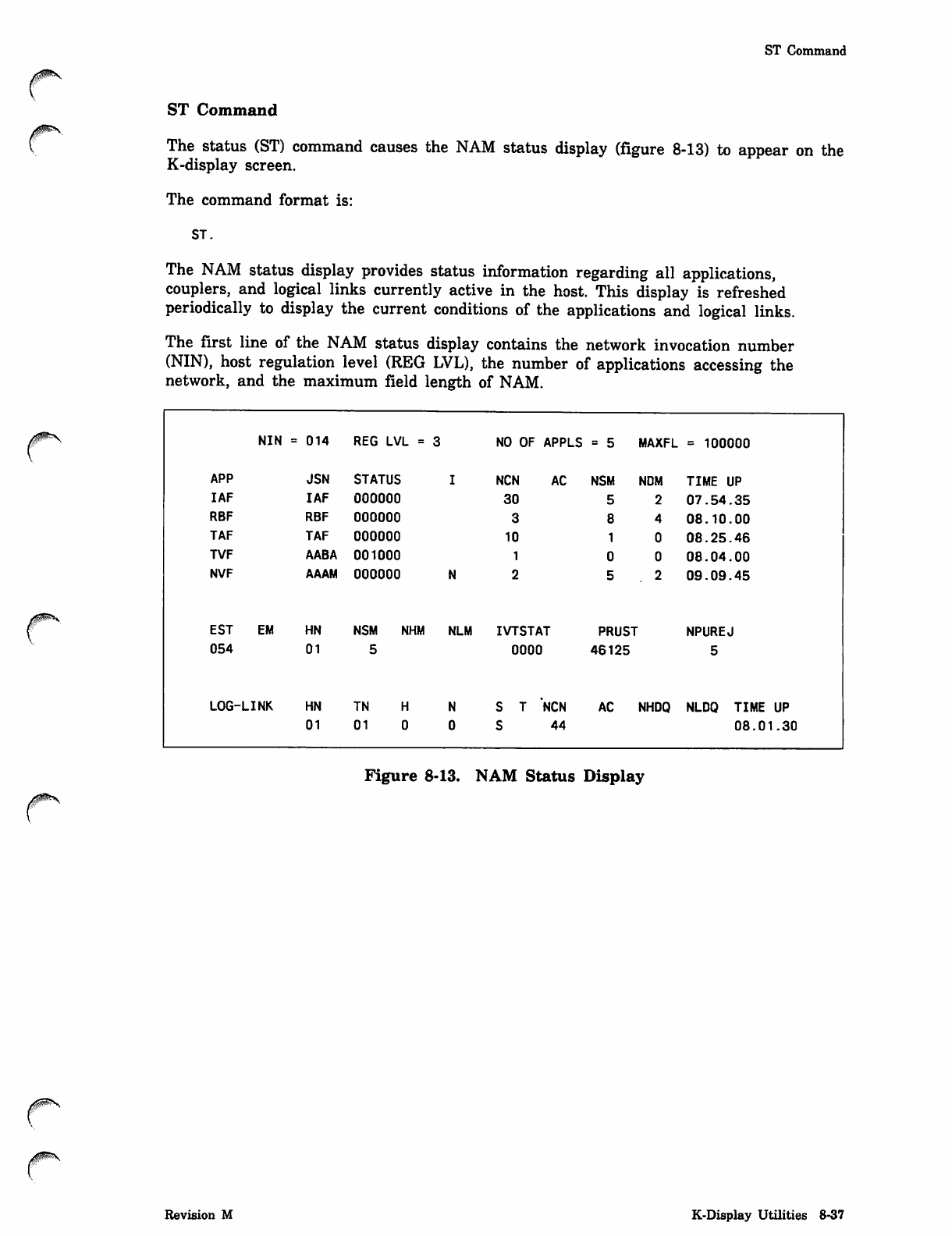
ST Command
ST Command
The status (ST) command causes the NAM status display (figure 8-13) to appear on the
K-display screen.
The command format is:
S T.
The NAM status display provides status information regarding all applications,
couplers, and logical links currently active in the host. This display is refreshed
periodically to display the current conditions of the applications and logical links.
The first line of the NAM status display contains the network invocation number
(NIN), host regulation level (REG LVL), the number of applications accessing the
network, and the maximum field length of NAM.
0^ms NIN = 014 REG LVL = NO OF APPLS = 5 MAXFL = 100000
APP JSN STATUS N C N A C NSM NDM TIME UP
IAF IAF oooooo 30 07.54.35
RBF RBF oooooo 08.10.00
TAF TAF oooooo 10 08.25.46
TVF AABA 001000 08.04.00
NVF AAAM oooooo 09.09.45
EST EM HN NSM NHM NLM IVTSTAT PRUST NPUREJ
054 01 0000 46125
LOG- LINK HN T N H S T NCN AC NHDQ NLDQ TIME UP
01 0 1 0 S 4 4 08.01.30
Figure 8-13. NAM Status Display
Revision M K-Display Utilities 8-37
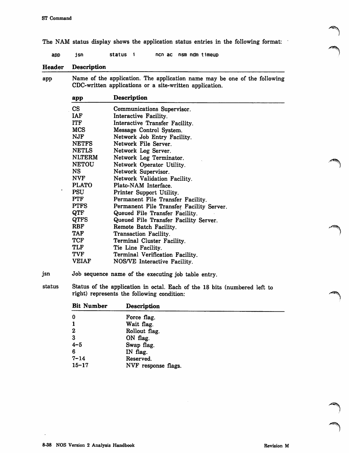
ST Command
The NAM status display shows the application status entries in the following format:
app
app
jsn
status
jsn s t a t u s 1 ncn ac nsm ndm timeup
Header Description
Name of the application. The application name may be one of the following
CDC-written applications or a site-written application.
app Description
CS Communications Supervisor.
IAF Interactive Facility.
I T F I n t e r a c t i v e Tr a n s f e r Fa c i l i t y.
MCS Message Control System.
N J F N e t w or k J o b E n tr y F a c i l i t y.
NETFS Network File Server.
NETLS Network Log Server.
NLTERM Network Log Terminator.
NETOU Network Operator Utility.
NS Network Supervisor.
NVF Network Validation Facility.
PLATO Plato-NAM Interface.
PSU Printer Support Utility.
PTF Permanent File Transfer Facility.
PTFS Permanent File Transfer Facility Server.
QTF Queued File Transfer Facility.
QTFS Queued File Transfer Facility Server.
R B F Re m o t e Ba t c h F a c i l i t y.
TAF Transaction Facility.
TCF Terminal Cluster Facility.
TLF Tie Line Facility.
TVF Terminal Verification Facility.
VEIAF NOS/VE Interactive Facility.
Job sequence name of the executing job table entry.
Status of the application in octal. Each of the 18 bits (numbered left to
right) represents the following condition:
/J^tK
Bit Number Description
0
1
2
3
4-5
6
7-14
15-17
Force flag.
Wait flag.
Rollout flag.
ON flag.
Swap flag.
IN flag.
Reserved.
NVF response flags.
8-38 NOS Version 2 Analysis Handbook Revision M
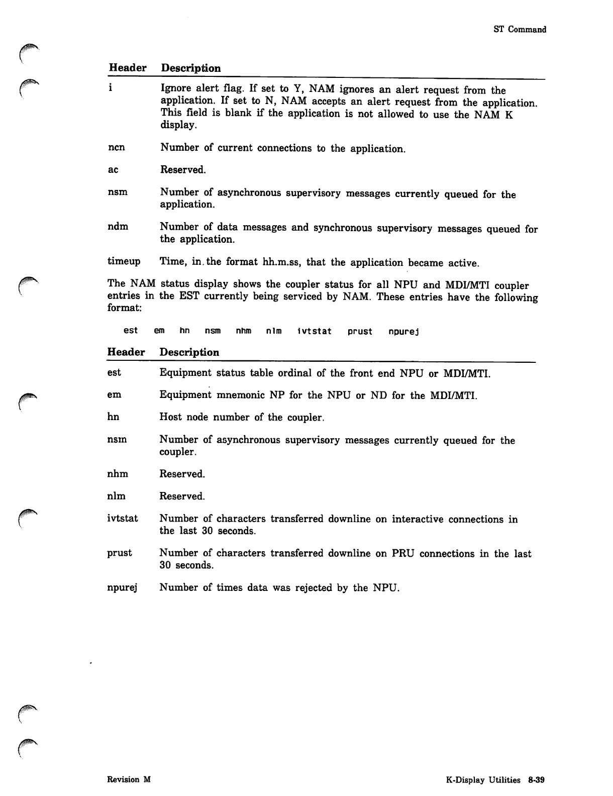
ST Command
^ m s
0§ms.
Header Description
ncn
ac
nsm
ndm
Ignore alert flag. If set to Y, NAM ignores an alert request from the
application. If set to N, NAM accepts an alert request from the application.
This field is blank if the application is not allowed to use the NAM K
display.
Number of current connections to the application.
Reserved.
Number of asynchronous supervisory messages currently queued for the
application.
Number of data messages and synchronous supervisory messages queued for
the application.
timeup Time, in. the format hh.m.ss, that the application became active.
The NAM status display shows the coupler status for all NPU and MDI/MTI coupler
entries in the EST currently being serviced by NAM. These entries have the following
format:
nsmest em hn
Header Description
nhm nlm Ivtstat prust npurej
est Equipment status table ordinal of the front end NPU or MDI/MTI.
em Equipment mnemonic NP for the NPU or ND for the MDI/MTI.
hn Host node number of the coupler.
nsm Number of asynchronous supervisory messages currently queued for the
coupler.
nhm Reserved.
nlm Reserved.
ivtstat Number of characters transferred downline on interactive connections in
the last 30 seconds.
prust Number of characters transferred downline on PRU connections in the last
30 seconds.
npurej Number of times data was rejected by the NPU.
Revision M K-Display Utilities 8-39
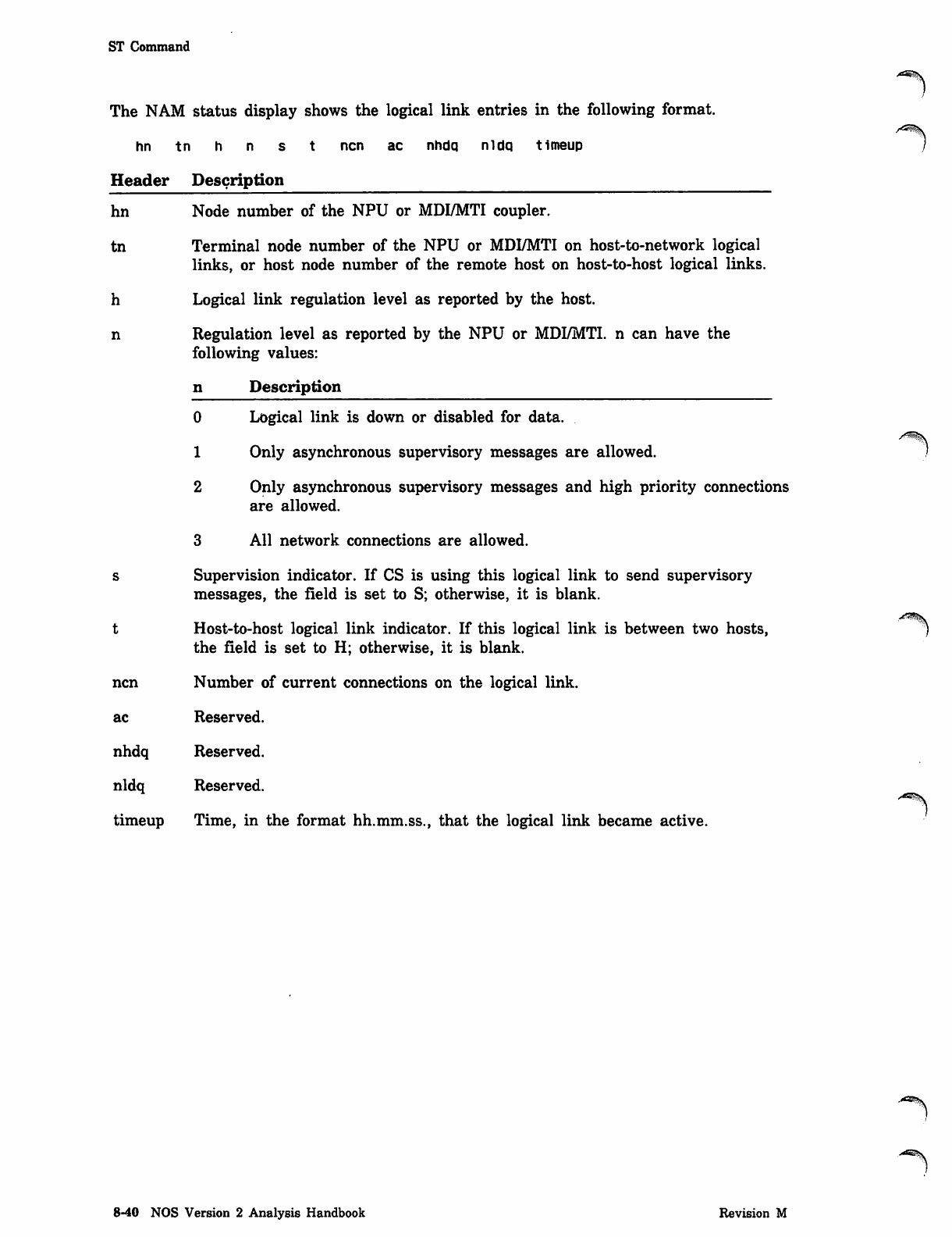
ST Command
The NAM status display shows the logical link entries in the following format,
h n t n h n s t n c n a c n h d q n l d q t i m e u p
Header Description
hn Node number of the NPU or MDI/MTI coupler.
tn Terminal node number of the NPU or MDI/MTI on host-to-network logical
links, or host node number of the remote host on host-to-host logical links.
h Logical link regulation level as reported by the host.
n Regulation level as reported by the NPU or MDI/MTI. n can have the
following values:
n Description
0 Logical link is down or disabled for data.
1 Only asynchronous supervisory messages are allowed.
2 Only asynchronous supervisory messages and high priority connections
are allowed.
3 All network connections are allowed.
s Supervision indicator. If CS is using this logical link to send supervisory
messages, the field is set to S; otherwise, it is blank.
t Host-to-host logical link indicator. If this logical link is between two hosts, ")
the field is set to H; otherwise, it is blank.
ncn Number of current connections on the logical link.
a c R e s e r v e d .
nhdq Reserved.
nldq Reserved.
timeup Time, in the format hh.mm.ss., that the logical link became active.
8-40 NOS Version 2 Analysis Handbook Revision M
Queue File Transfer Facility (QTF) K Display
Queue File Transfer Facility (QTF) K Display
The QTF utility provides a multistreaming capability for transferring queued files
between mainframes using connections through RHF or NAM. QTF allows you to
specify which files are to be transferred. You do this by defining a set of selection
classes. You can define or modify values for selection classes using the CLASS
command described later in this subsection. You can specify a range of file sizes and
the maximum number of simultaneous connections allowed. You can also specify a
number of reserved connections that cannot be used by lower-priority selection classes.
QTF Selection Classes
Selection classes are designated by a single letter in the range from A to L. Selection
class A is the highest priority, and L is the lowest priority.
QTF uses selection classes to find files to assign to the PIDs (physical identifiers) for
remote hosts. Associated with each PID is one or more LIDs (logical identifiers). The
/^N system PID/LID table is created by system program CLDT from the LID configuration
file LIDCMid (refer to LID Configuration File in section 10) and is viewed and
modified using the L-display utility LIDOU (refer to LIDOU L Display in section 9).
QTF reads the system PID/LID table to determine which PIDs have connections
through RHF or NAM and which LIDs are associated with each PID.
File Selection Process
Each copy of QTF has a fixed number of connection slots available. The goal of the
QTF file. scheduling algorithm is to find files for as many of these connection slots as
possible within the constraints of the selection class definitions. On each pass through
its file selection process, QTF proceeds through all defined selection classes from the
highest priority A to the lowest priority L. For each selection class, QTF attempts to
find one file for each available PID that does not already have a file assigned. The file
selection process continues until one of the following occurs:
• All connection slots are in use, or
• All PID/selection class combinations have been checked and
- Are in use, or
- Are unavailable (disabled or the maximum number of connections per selection
class has been reached), or
- No files were found.
• The sum of the reserved connections for higher-priority selection classes is equal
to or exceeds the number of free connection slots.
Revision M K-Display Utilities 8-41
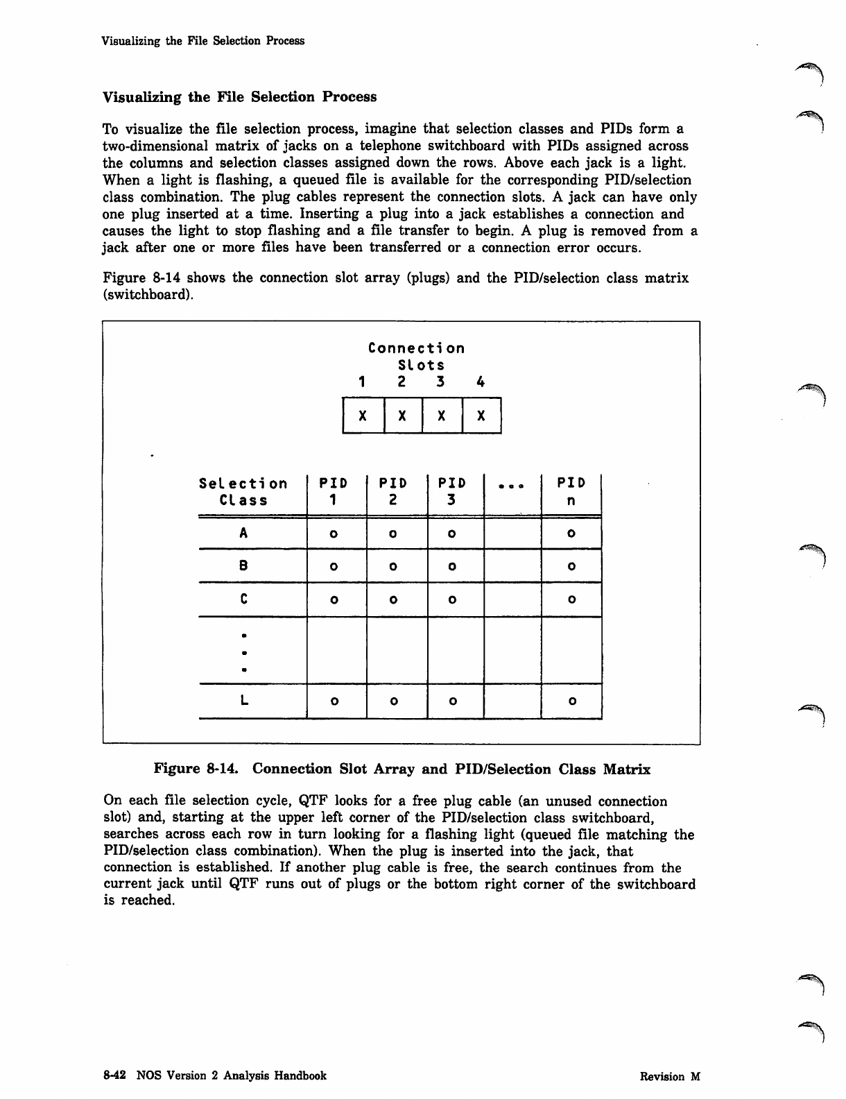
Visualizing the File Selection Process
A ^ ^ S
Visualizing tbe File Selection Process
To visualize the file selection process, imagine that selection classes and PIDs form a
two-dimensional matrix of jacks on a telephone switchboard with PIDs assigned across
the columns and selection classes assigned down the rows. Above each jack is a light.
When a light is flashing, a queued file is available for the corresponding PID/selection
class combination. The plug cables represent the connection slots. A jack can have only
one plug inserted at a time. Inserting a plug into a jack establishes a connection and
causes the light to stop flashing and a file transfer to begin. A plug is removed from a
jack after one or more files have been transferred or a connection error occurs.
Figure 8-14 shows the connection slot array (plugs) and the PID/selection class matrix
(switchboard).
Connecti on
S l o t s
1 2 3 4
XXXX
SeLecti on
Class
PID
1
PID
2
PID
3
• s a PID
n
A o 0 0 0
B0 0 0 0
C0 0 0 0
L0 0 o0
Figure 8-14. Connection Slot Array and PID/Selection Class Matrix
On each file selection cycle, QTF looks for a free plug cable (an unused connection
slot) and, starting at the upper left corner of the PID/selection class switchboard,
searches across each row in turn looking for a flashing light (queued file matching the
PID/selection class combination). When the plug is inserted into the jack, that
connection is established. If another plug cable is free, the search continues from the
current jack until QTF runs out of plugs or the bottom right corner of the switchboard
is reached.
8-42 NOS Version 2 Analysis Handbook Revision M
Visualizing the File Selection Process
For each selection class row for which a reserved number of connections is defined,
QTF checks the number of plugs inserted in that row when the rightmost jack for the
row is reached. If the number of plugs inserted is less than the number of reserved
connections, QTF places enough plugs in unused jacks in that row until the number of
reserved jacks is filled, only one free plug remains, or the row is filled; whichever
occurs first.
For each selection class row for which a maximum number of connections is defined
and the maximum is reached, QTF continues searching at the leftmost jack of the
next row down.
You can minimize the number of different operating system calls QTF must make to
cover all of the switchboard jacks. Do this by either minimizing the number of
selection classes (number of rows) or by defining overlapping selection criteria for
selection classes. For example, if selection classes A, B, and C all have the same file
size index range, and QTF does not find a file for a PID in selection class row A,
QTF can consider selection class rows B and C checked as well. If selection class D
has a different, nonoverlapping file size index range, QTF must call the operating
system to check the jacks in selection class D regardless of the results of the checks
for selection classes A, B, and C (assuming that the file selection process has not yet
terminated).
Revision M K-Display Utilities 8-43
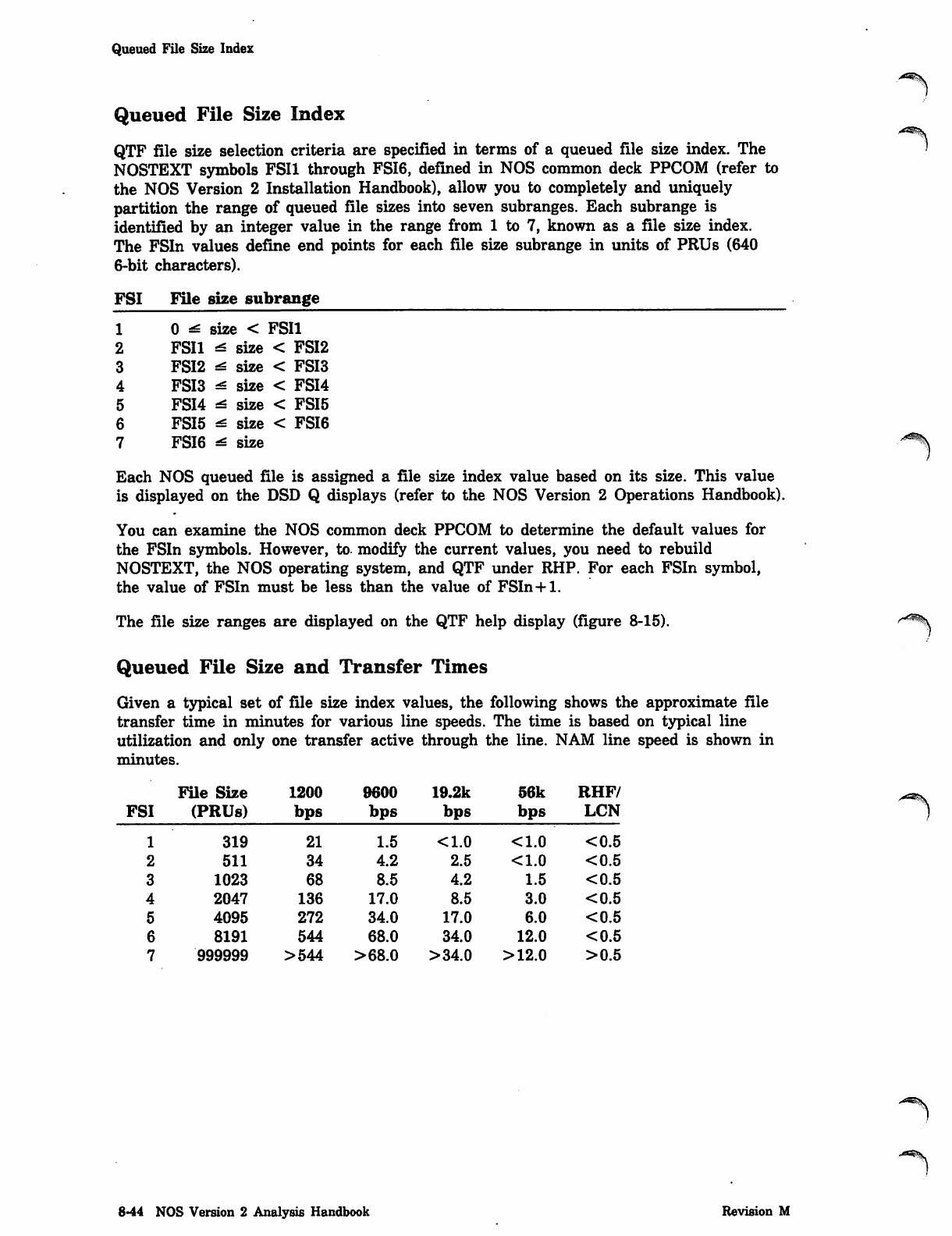
Queued File Size Index
Queued File Size Index
QTF file size selection criteria are specified in terms of a queued file size index. The
NOSTEXT symbols FSI1 through FSI6, defined in NOS common deck PPCOM (refer to
the NOS Version 2 Installation Handbook), allow you to completely and uniquely
partition the range of queued file sizes into seven subranges. Each subrange is
identified by an integer value in the range from 1 to 7, known as a file size index.
The FSIn values define end points for each file size subrange in units of PRUs (640
6-bit characters).
FSI File size subrange
1 0 ^ size < FSI1
2 FSI1 ^ size < FSI2
3 FSI2 ^ size < FSI3
4 FSI3 ^ size < FSI4
5 FSI4 as size < FSI5
6 FSI5 ^ size < FSI6
7 F S I 6 ^ s i z e
Each NOS queued file is assigned a file size index value based on its size. This value
is displayed on the DSD Q displays (refer to the NOS Version 2 Operations Handbook).
You can examine the NOS common deck PPCOM to determine the default values for
the FSIn symbols. However, to modify the current values, you need to rebuild
NOSTEXT, the NOS operating system, and QTF under RHP. For each FSIn symbol,
the value of FSIn must be less than the value of FSIn+1.
The file size ranges are displayed on the QTF help display (figure 8-15). A-m^
Queued File Size and Transfer Times
Given a typical set of file size index values, the following shows the approximate file
transfer time in minutes for various line speeds. The time is based on typical line
utilization and only one transfer active through the line. NAM line speed is shown in
minutes.
FUe Size 1200 9600 19.2k 56k RHF/
FSI (PRUs) bps bps bps bps LCN
1319 21 1.5 <1.0 <1.0 <0.5
2511 34 4.2 2.5 <1.0 <0.5
31023 68 8.5 4.2 1.5 <0.5
42047 136 17.0 8.5 3.0 <0.5
54095 272 34.0 17.0 6.0 <0.5
68191 544 68.0 34.0 12.0 <0.5
999999 >544 >68.0 >34.0 >12.0 >0.5
8-44 NOS Version 2 Analysis Handbook Revision M
0$ms
QTF K-Display Usage
QTF K-Display Usage
The following procedures describe DSD K-display usage for QTF operations. QTF is
used by both the RHF and NAM subsystems.
QTF Operation Under RHF
Normally, QTF is defined as an autostart application in the RHF configuration file
(refer to RHF Configuration Files in section 10). That means a QTF job starts
automatically when the RHF subsystem is initiated. The RHF application table K
display shows how many copies of QTF are defined and how many copies are currently
active.
QTF terminates when the K.IDLE command terminates the RHF subsystem. To
manually terminate a copy of QTF, bring up the RHF application table display by
entering the following commands:
K.RHF.
K.APPL.
When the display appears, enter:
DISABLE,ord.
where ord is the ordinal of an active QTF in the RHF application table display. The
message QTF, NETWORK IDLEDOWN IN PROGRESS should appear in the QTF job
dayfile. QTF completes any files in progress and then ends. If QTF does not terminate
within a reasonable amount of time, use the DSD DROP command to terminate QTF.
If a fault condition occurs, QTF normally restarts itself. To manually restart QTF,
bring up the RHF application table display by entering the following commands:
K.RHF.
K.APPL.
When the display appears, enter:
ENABLE,ord.
where ord is the QTF ordinal in the RHF application table display.
You can determine the jsn of QTF by using the DSD system status display (B,0) and
the RHF application table display. When QTF is active at a control point, it is
indicated on the B,0 display.
Activate the K display for that QTF by entering:
K.jsn.
where jsn is the job sequence name for QTF. The QTF transfer display appears on the
left screen.
Revision M K-Display Utilities 8-45
QTF Operation Under NAM
QTF Operation Under NAM
Normally, QTF is started by NAMI during NAM subsystem initiation. The NAM status
K display shows how many copies of QTF are currently active.
QTF terminates automatically when the NAM subsystem is terminated. To manually
terminate a copy of QTF, use the NVF IDLE or DISABLE commands (refer to NVF
Control Commands in section 15) to either idle QTF or immediately terminate QTF.
Enter the following commands:
K.NAM.
K . * .
K.AP=NVF.
K.IDLE,AP=QTF. or K.DISABLE,AP<=QTF.
The message QTF, NETWORK IDLEDOWN IN PROGRESS or QTF, NETWORK
SHUTDOWN should appear in the QTF job dayfile. If the IDLE,AP=QTF command is
used, QTF completes any files in progress and then ends. If QTF does not terminate
within a reasonable amount of time, use the DISABLE,AP=QTF command or DSD
DROP command to terminate QTF.
If a fault condition occurs, QTF normally restarts itself. To manually restart QTF,
enter the following command (refer to the NAMI command in section 16):
X.NAMI(RS=QT)
You can determine the jsn of QTF by using the NAM status K display. Bring up the
NAM status K display by entering the following commands:
K.NAM.
K . * .
K.ST.
Activate the K display for that QTF by entering the following command:
K.jsn.
where jsn is the job sequence name for QTF. The QTF transfer display appears on the
left screen.
,-/^^.
.A^m^
8-46 NOS Version 2 Analysis Handbook Revision M
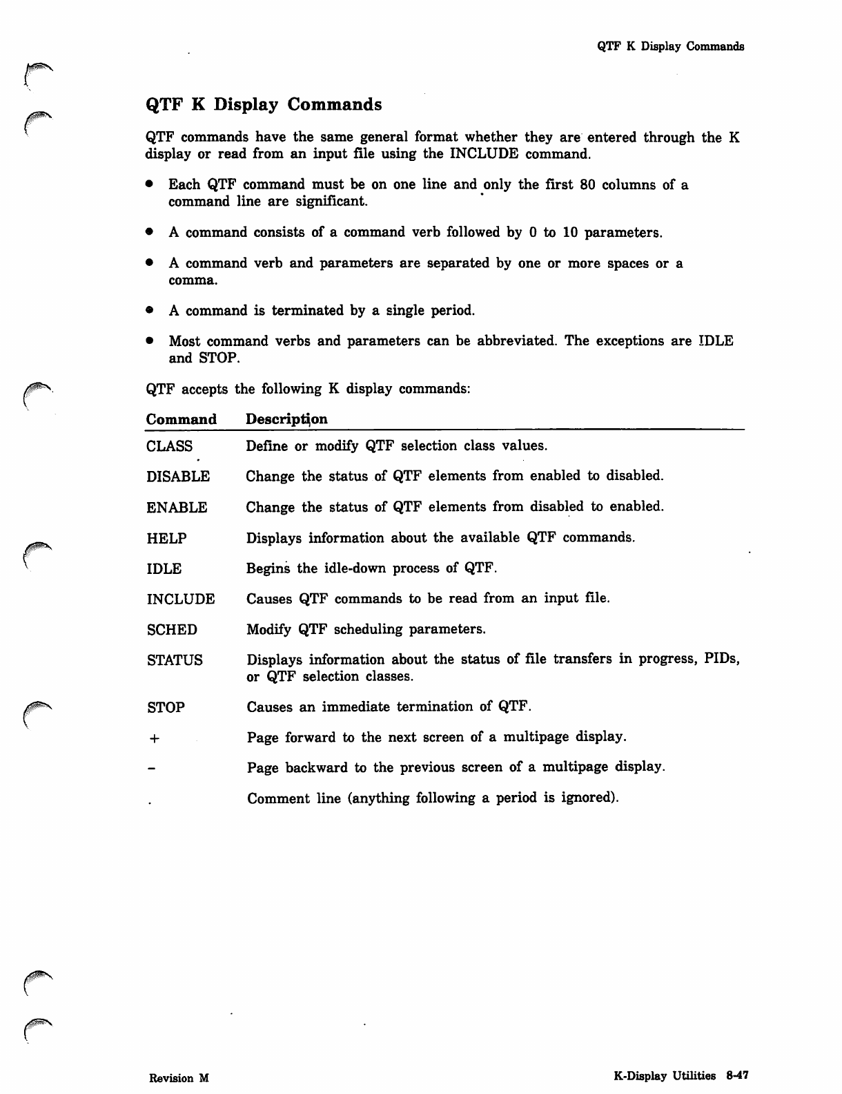
QTF K Display Commands
r
QTF K Display Commands
QTF commands have the same general format whether they are entered through the K
display or read from an input file using the INCLUDE command.
• Each QTF command must be on one line and only the first 80 columns of a
command line are significant.
• A command consists of a command verb followed by 0 to 10 parameters.
• A command verb and parameters are separated by one or more spaces or a
comma.
• A command is terminated by a single period.
• Most command verbs and parameters can be abbreviated. The exceptions are IDLE
and STOP.
QTF accepts the following K display commands:
Command Description
CLASS Define or modify QTF selection class values.
DISABLE Change the status of QTF elements from enabled to disabled.
ENABLE Change the status of QTF elements from disabled to enabled.
HELP Displays information about the available QTF commands.
IDLE Begins the idle-down process of QTF.
INCLUDE Causes QTF commands to be read from an input file.
SCHED Modify QTF scheduling parameters.
STATUS Displays information about the status of file transfers in progress, PIDs,
or QTF selection classes.
STOP Causes an immediate termination of QTF.
+ Page forward to the next screen of a multipage display.
Page backward to the previous screen of a multipage display.
Comment line (anything following a period is ignored).
/$pn
Revision M K-Display Utilities 8-47
CLASS Command
CLASS Command
The CLASS command allows you to define or modify QTF selection class values.
The command format is:
K.CLASS,SC=selclass,FSI=fs1,MAXIMUM=max,RESERVE=res.
Parameter Description
selclass Selection class name; specify one character in the range from A to L.
Selection class A is the highest priority class and L is the lowest
priority class. This parameter is required.
File size index; specify the file size index or range of indexes using
one of the following formats:
fsi
Format Description
fsi File size index in the range from 1 to 7.
fsil..fsiu , File size index range, where fsil ^ fsiu.
* An * specifies all file sizes. It is equivalent to entering
1..7. If FSI is omitted, the default is FSI=*.
max Maximum connections; specify the maximum number of simultaneous
connections for files in this selection class in the range from 0 to the
maximum available connections (specified by the MAXCONS parameter
in the QTF SCHED command) or specify *. If 0 or * is specified, all
connections can be used for files in this selection class. However, only
one connection per PID per selection class is permitted. Default
is 0 or *.
res Reserved connections; specify the number of connections reserved for
files in this selection class in the range from 0 to the maximum
available connections (specified by the MAXCONS parameter in the
QTF SCHED command). If zero is specified, no connections are
reserved for this selection class. For each selection class, the number
of available connections is reduced by the sum of reserved connections
for all higher-priority selection classes. To prevent a possible
overcommitment of connections, QTF allows only mxcons-1 connections
to be reserved. Default is zero.
The following default selection class is defined at QTF initiation:
CLASS,SC=A,FSI»•,MAXIMUM**,RESERVE=0.
which allows one file transfer to any one remote host with no restrictions on file size
and no reserved connections. To modify the default selection class or define other
classes, use additional CLASS commands.
z«*^^.
8-48 NOS Version 2 Analysis Handbook Revision M
DISABLE Command
r
DISABLE Command
The DISABLE command changes the status of the selected QTF elements from enabled
to disabled.
The command format is:
K.DISABLE,element.
Parameter Description
element One of the following:
PID=pid
SC = selclass
SC = selclass,PID=pid
Option Description
pid Physical identifier of a given mainframe. Specify PID = * to
disable all PIDs.
selclass Selection class in the range from A to L. Specify SC = * to
disable all selection classes.
ENABLE Command
The ENABLE command changes the status of the selected QTF elements from disabled
to enabled.
The command format is:
K.ENABLE,element.
Parameter Description
element One of the following:
PID=pid
SC = selclass
SC = selclass,PID=pid
Option Description
pid Physical identifier of a given mainframe. Specify PID=* to
enable all PIDs.
selclass Selection class in the range from A to L. Specify SC = * to
enable all selection classes.
Revision M K-Display Utilities 8-49
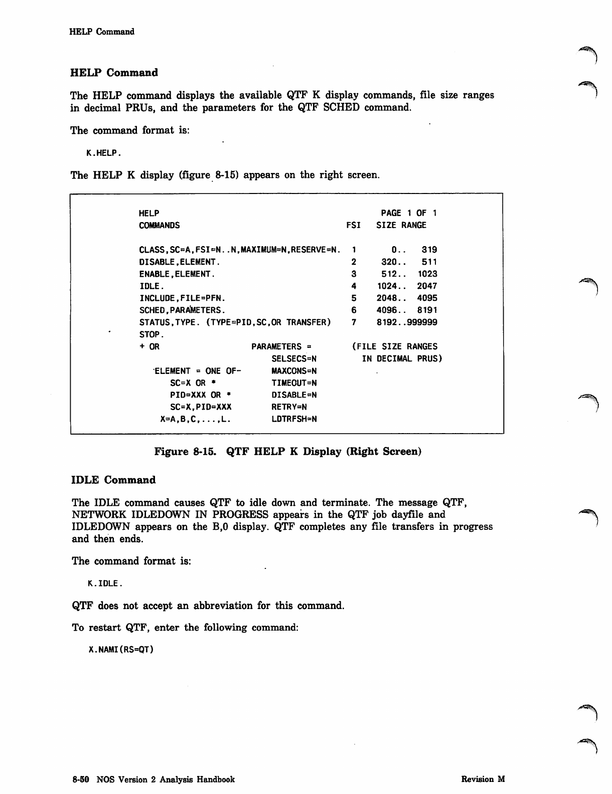
HELP Command
HELP Command
The HELP command displays the available QTF K display commands, file size ranges
in decimal PRUs, and the parameters for the QTF SCHED command.
The command format is:
K.HELP.
The HELP K display (figure 8-15) appears on the right screen.
HELP PAGE 1 OF 1
COMMANDS FSI SIZE 1RANGE
CLASS,SC=A,FSI=N..N, MAXIMUMS, RESERVED. 0. 319
DISABLE,ELEMENT. 320. 511
ENABLE.ELEMENT. 512. 1023
IDLE. 1024. . 20 47
INCLUDE,FILE=PFN. 2048. . 40 95
SCHED,PARAMETERS. 4096. . 8191
STATUS,TYPE. (TYPE=PID,SC,OR TRANSFER) 8192. .999999
*STOP.
+ OR PARAMETERS = (FILE SIZE RANGES
SELSECS=N IN DECIMAL PRUS)
ELEMENT = ONE OF- MAXCONS=N
SC=X OR * TIMEOUT=N
PID=XXX OR * DISABLED
SC=X,PID=XXX RETRY=N
X=A,B,C L. LDTRFSH»N
Figure 8-15. QTF HELP K Display (Right Screen)
IDLE Command
The IDLE command causes QTF to idle down and terminate. The message QTF,
NETWORK IDLEDOWN IN PROGRESS appears in the QTF job dayfile and
IDLEDOWN appears on the B,0 display. QTF completes any file transfers in progress
and then ends.
The command format is:
K.IDLE.
QTF does not accept an abbreviation for this command.
To restart QTF, enter the following command:
X.NAMI(RS=QT)
•^585\
8-50 NOS Version 2 Analysis Handbook Revision M
INCLUDE Command
INCLUDE Command
The INCLUDE command causes QTF to rewind the specified input file and begin
processing QTF commands from that file.
The command format is:
K.INCLUDE,FILE=infile.
Parameter Description
infile File name from which QTF commands are to be processed. QTF
searches for a local file with name infile. If the local file is not found,
QTF attempts to GET or ATTACH permanent file infile from user
name SYSTEMX. If QTF performs a GET or ATTACH, it returns the
file after processing all of the commands. This parameter is required.
A file of QTF commands processed by using the INCLUDE command can itself contain
another INCLUDE command. Upon executing the second INCLUDE command, QTF
switches to the new file and does not read anything following the INCLUDE command
in the old file.
Revision M K-Display Utilities 8-51
SCHED Command
SCHED Command
The SCHED command allows you to modify QTF scheduling parameters.
The command format is:
K.SCHED,SELSECS=se1 sees,MAXCONS=mxcons,TIME0UT=tmom1 ns,
DISABLE=d1sm1ns,RETRY=maxrtry,LDTRFSH=1dtm1ns.
Parameter Description
selsecs File selection recall period in the range from 1 to 4095 seconds;
specifies the minimum amount of time between attempts to acquire
new queued files. Whenever QTF is unable to fill all connection slots
with files, it waits selsecs seconds before again attempting to acquire
files for unused slots. Default is 20 seconds.
mxcons Maximum simultaneous connection slots (to all hosts) in the range
from 1 to 4. Default is 4 connections.
tmomins Timeout period in the range from 1 to 60 minutes; specifies the
maximum amount of time QTF waits for a reply from a remote host or
access method. For the RHF variant of QTF, tmomins also specifies
how long QTF waits for NAD code conversion resources when
applicable. Default is 2 minutes.
dismins Disable period in the range from 1 to 60 minutes; specifies the amount
of time for which QTF will not attempt transfers to a PID after an
error occurs. You can use the ENABLE command to clear the error
disabled condition. Default is 2 minutes.
maxrtry Maximum retries in the range from 1 to 50 retries; specifies the
maximum number of immediate retries that QTF attempts to complete
a file transfer before error disabling the PID. When QTF cannot
complete a connection request (the connection is rejected by the local
or remote access method or QTFS), QTF disables the PID without any
immediate retrys. Once the PID is disabled, QTF returns the file to
the local queue and does not attempt to acquire any files for LIDs
associated with the PID until either dismins minutes have elapsed or
you use the ENABLE,PID command to enable the PID. Default is 2
retries.
ldtmins PID/LID table refresh period in the range from 1 to 60 minutes;
specifies how often QTF updates its internal tables from the system
PID/LID table. Default is 2 minutes.
.-^%.
8-52 NOS Version 2 Analysis Handbook Revision M
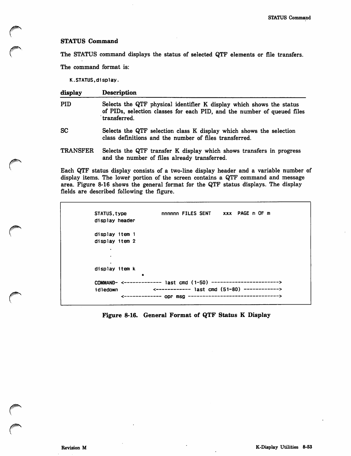
STATUS Command
STATUS Command
The STATUS command displays the status of selected QTF elements or file transfers.
The command format is:
K.STATUS,display.
display Description
PID Selects the QTF physical identifier K display which shows the status
of PIDs, selection classes for each PID, and the number of queued files
transferred.
SC Selects the QTF selection class K display which shows the selection
class definitions and the number of files transferred.
TRANSFER Selects the QTF transfer K display which shows transfers in progress
and the number of files already transferred.
Each QTF status display consists of a two-line display header and a variable number of
display items. The lower portion of the screen contains a QTF command and message
area. Figure 8-16 shows the general format for the QTF status displays. The display
fields are described following the figure.
STATUS,type nnnnnn FILES SENT xxx PAGE n OF m
display header
display item 1
display item 2
display item k
COMMAND- < last cmd (1-50) >
Idledown < last cmd (51-80) >
< o p r m s g >
Figure 8-16. General Format of QTF Status K Display
Revision M K-Display Utilities 8-53
STATUS Command
Field Description
type Display type; PID, SC, or TRANSFER.
nnnnnn Number of queued files transferred.
xxx Access method; RHF or NAM.
n Current page number.
m Maximum page number.
last cmd The last QTF command processed. If the command is incorrect, an asterisk
(*) appears in the line above the command to show the approximate
position of the character or parameter in error. If the error is in the
second part of the command (positions 51 to 80), a plus sign (+) appears
instead of an asterisk.
idledown This field contains the message *IDLEDOWN* if QTF is in idle-down
mode; otherwise, this field is blank.
opr msg This field contains an operator message about the last QTF command
processed. Refer to the NOS Version 2 Operations Handbook for message
descriptions.
,,>=^S\
8-54 NOS Version 2 Analysis Handbook Revision M
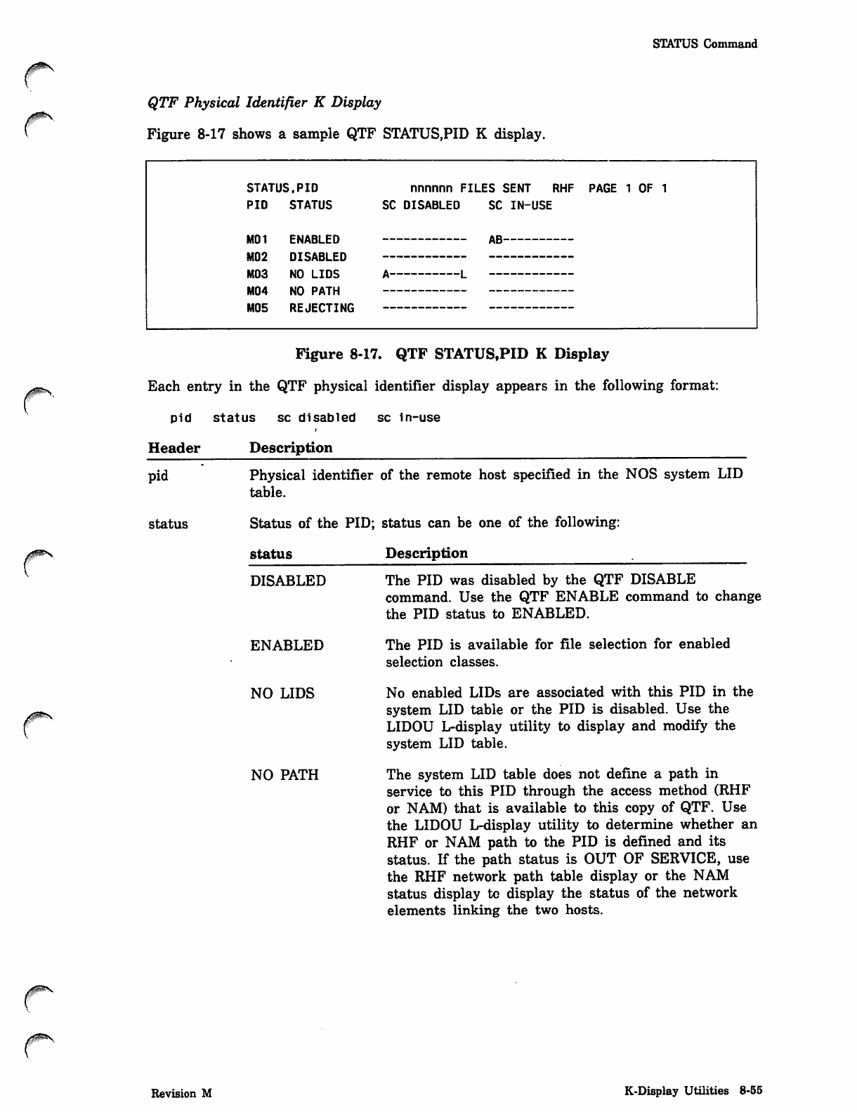
STATUS Command
QTF Physical Identifier K Display
Figure 8-17 shows a sample QTF STATUS.PID K display.
STATUS,PID nnnnnn FILES SENT RHF PAGE 1 OF 1
PID STATUS SC DISABLED SC IN-USE
M01 ENABLED
M02 DISABLED
M03 NO LIDS i\———————\_ —————
M04 NO PATH
M05 REJECTING
Figure 8-17. QTF STATUS.PID K Display
Each entry in the QTF physical identifier display appears in the following format:
pid status sc disabled sc in-use
Header Description
pid
status
Physical identifier of the remote host specified in the NOS system LID
table.
Status of the PID; status can be one of the following:
status Description
DISABLED
ENABLED
NO LIDS
NO PATH
The PID was disabled by the QTF DISjABLE
command. Use the QTF ENABLE command to change
the PID status to ENABLED.
The PID is available for file selection for enabled
selection classes.
No enabled LIDs are associated with this PID in the
system LID table or the PID is disabled. Use the
LIDOU L-display utility to display and modify the
system LID table.
The system LID table does not define a path in
service to this PID through the access method (RHF
or NAM) that is available to this copy of QTF. Use
the LIDOU L-display utility to determine whether an
RHF or NAM path to the PID is defined and its
status. If the path status is OUT OF SERVICE, use
the RHF network path table display or the NAM
status display to display the status of the network
elements linking the two hosts.
Revision M K-Display Utilities 8-55
STATUS Command
Header Description
status (Continued)
status Description
REJECTING
sc disabled
sc m-use
QTF has temporarily disabled file transfers to the PID
because QTF was unable to establish a connection to
the PID or was unable to successfully transfer a file
after the maximum number of retries. QTF returns the
PID to ENABLED status after the specified disable
period has elapsed. (Refer to the QTF SCHED command
for descriptions of the RETRY and DISABLE
parameters.) You can use the QTF ENABLE command
to immediately return the PID to ENABLED status. If
the PID returns to REJECTING status, examine the
QTF dayfile to determine whether a connection reject
or a particular file is causing the problem.
Currently, for RHF paths and for some types of NAM
paths, the path status in the system LID table does not
reflect the status of the remote PID or access method
but rather the status of the local host network elements
used to access the PID. Thus, a remote host may be
out-of-service (due to scheduled maintenance, for
example), yet the local system LID table shows the
path status as IN SERVICE. Each time the disable
period elapses, QTF attempts to send files to the PID.
If the access method rejects the connection, QTF
returns the PID to REJECTING status.
Selection classes that are unavailable for this PID. They were disabled
by the QTF DISABLE command. Use the QTF ENABLE command to
enable a particular PID and selection class combination.
Selection classes currently in use for this PID. The QTF transfer display
shows the ordinals for connection slots and the selection class associated
with each slot.
8-56 NOS Version 2 Analysis Handbook Revision M
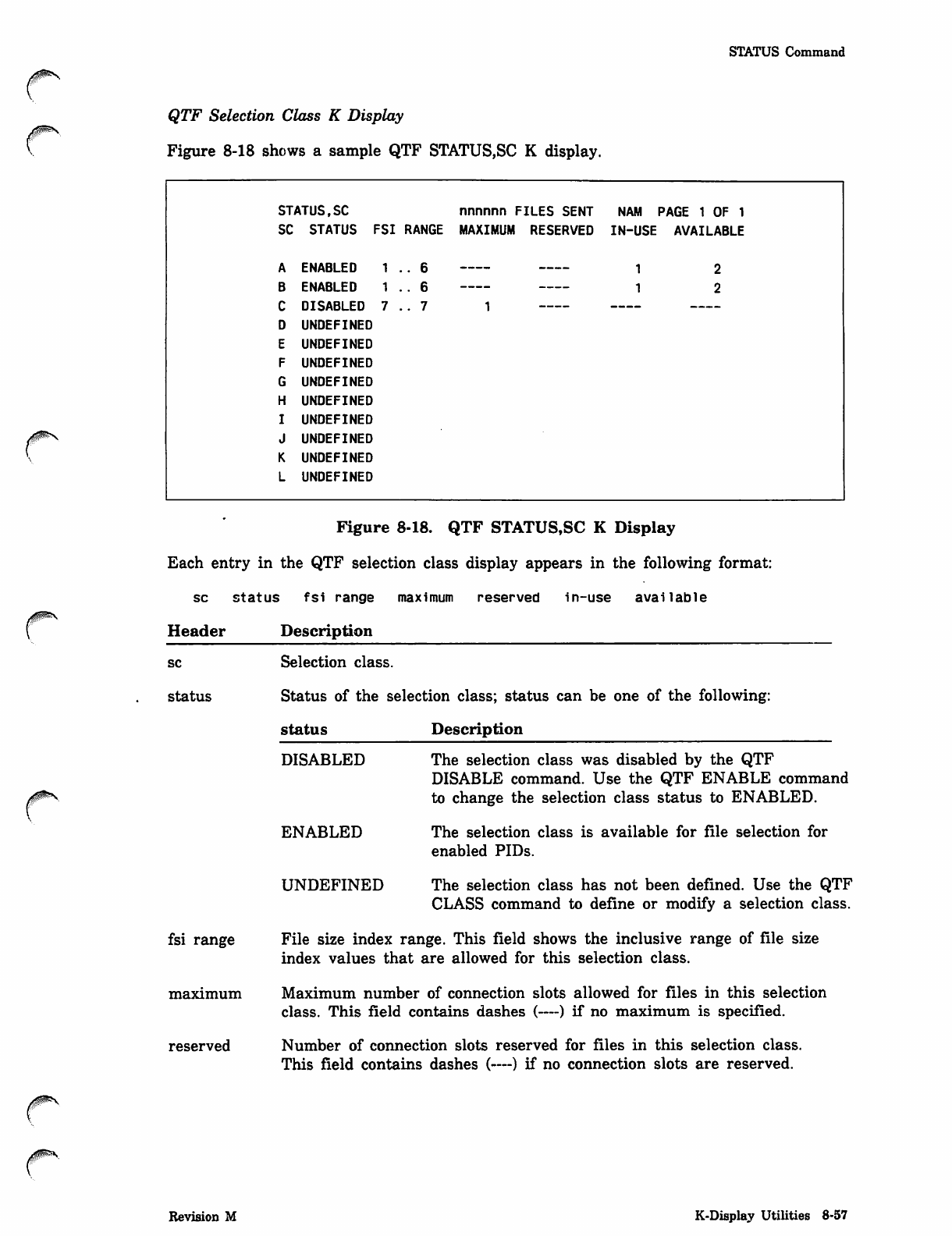
STATUS Command
QTF Selection Class K Display
Figure 8-18 shows a sample QTF STATUS,SC K display.
STATUS,SC nnnnnn FILES SENT NAM PAGE 1 OF 1
SC STATUS FSI RANGE MAXIMUM RESERVED IN-USE AVAILABLE
A ENABLED .. 6 1 2
B ENABLED .. 6 1 2
C DISABLED .. 7
D UNDEFINED
E UNDEFINED
F UNDEFINED
G UNDEFINED
H UNDEFINED
I UNDEFINED
J UNDEFINED
K UNDEFINED
L UNDEFINED
Figure 8-18. QTF STATUS,SC K Display
Each entry in the QTF selection class display appears in the following format:
sc status fsi range maximum reserved in-use available
Header Description
sc
status
fsi range
maximum
reserved
Selection class.
Status of the selection class; status can be one of the following:
status Description
DISABLED The selection class was disabled by the QTF
DISABLE command. Use the QTF ENABLE command
to change the selection class status to ENABLED.
ENABLED The selection class is available for file selection for
enabled PIDs.
UNDEFINED The selection class has not been defined. Use the QTF
CLASS command to define or modify a selection class.
File size index range. This field shows the inclusive range of file size
index values that are allowed for this selection class.
Maximum number of connection slots allowed for files in this selection
class. This field contains dashes (—) if no maximum is specified.
Number of connection slots reserved for files in this selection class.
This field contains dashes (—) if no connection slots are reserved.
Revision M K-Display Utilities 8-57
STATUS Command
Header
m-use
Description
Number of connection slots that have been assigned files in this
selection class. This field contains dashes (—) if no connection slots are
in use.
available Number of free connection slots available for assigning files in this
selection class. This field contains dashes (—) if no connection slots are
available.
^■a^v
""^\
8-58 NOS Version 2 Analysis Handbook Revision M
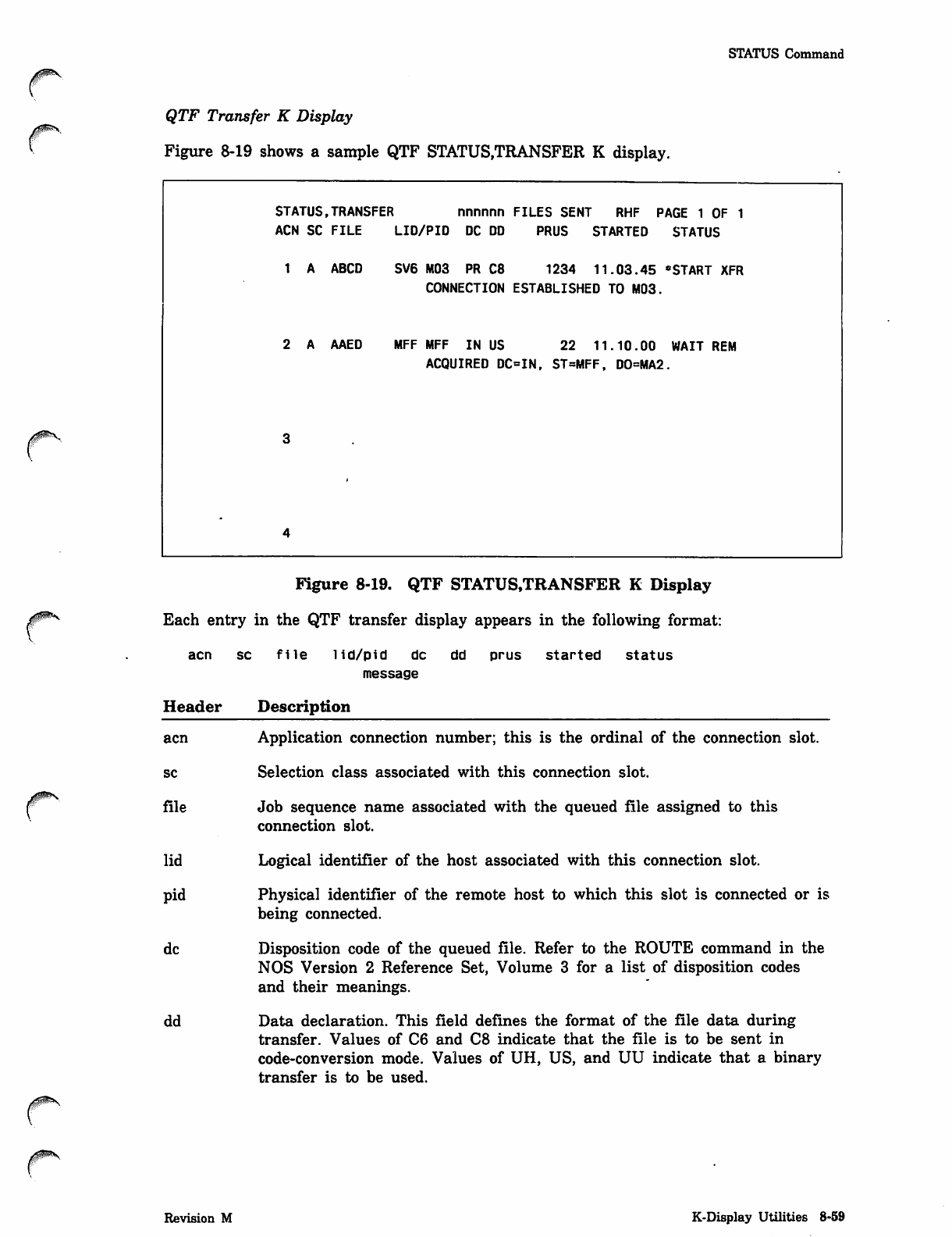
STATUS Command
QTF Transfer K Display
Figure 8-19 shows a sample QTF STATUS,TRANSFER K display.
STATUS,TRANSFER nnnnnn FILES SENT RHF PAGE 1 OF 1
ACN SC FILE LID/PID DC DD PRUS STARTED STATUS
1 A ABCD SV6 M03 PR C8 1234 11.03.45 *START XFR
CONNECTION ESTABLISHED TO M03.
2 A AAED MFF MFF IN US 22 11.10.00 WAIT REM
ACQUIRED DC=IN, ST=MFF, D0=MA2.
3
4
00ms
Figure 8-19. QTF STATUS/TRANSFER K Display
Each entry in the QTF transfer display appears in the following format:
acn sc file lid/pid dc dd prus started status1 id/pid dc
message
Header Description
r
acn
sc
file
lid
pid
dc
dd
Application connection number; this is the ordinal of the connection slot.
Selection class associated with this connection slot.
Job sequence name associated with the queued file assigned to this
connection slot.
Logical identifier of the host associated with this connection slot.
Physical identifier of the remote host to which this slot is connected or is
being connected.
Disposition code of the queued file. Refer to the ROUTE command in the
NOS Version 2 Reference Set, Volume 3 for a list of disposition codes
and their meanings.
Data declaration. This field defines the format of the file data during
transfer. Values of C6 and C8 indicate that the file is to be sent in
code-conversion mode. Values of UH, US, and UU indicate that a binary
transfer is to be used.
Revision M K-Display Utilities 8-59
STOP Command
Header Description
prus
started
status
message
Size of the file in physical record units (PRUs) in decimal. One PRU
contains the equivalent of 640 6-bit characters.
This field shows the time (hh.mm.ss) at which the connection to the remote
host was initiated. The time is updated when the connection* is established
and at the beginning of each file transfer sequence.
Status of the connection or file transfer; status can be one of the following:
status Description
ACQ FILE File has been acquired.
CONNECT Issuing connect request.
END CONN Connection terminating.
FILE XFR File transfer in progress.
IDLE Connection established.
QUEUED File transfer successful.
START XFR Initiating file transfer.
STOP XFR File transfer completing.
WAIT ACQ Waiting for acquire queued file response.
WAIT REM Waiting for response from remote host or access method.
This field contains the last dayfile message issued by QTF for this
connection slot. Refer to the NOS Version 2 Operations Handbook for
message descriptions.
STOP Command
The STOP command causes QTF to terminate immediately. The message QTF,
NETWORK SHUTDOWN appears in the QTF job dayfile. QTF abandons any file
transfers in progress, returns files to the system I/O queues, and ends.
The command format is:
K.STOP.
QTF does not accept an abbreviation for this command.
8-60 NOS Version 2 Analysis Handbook Revision M
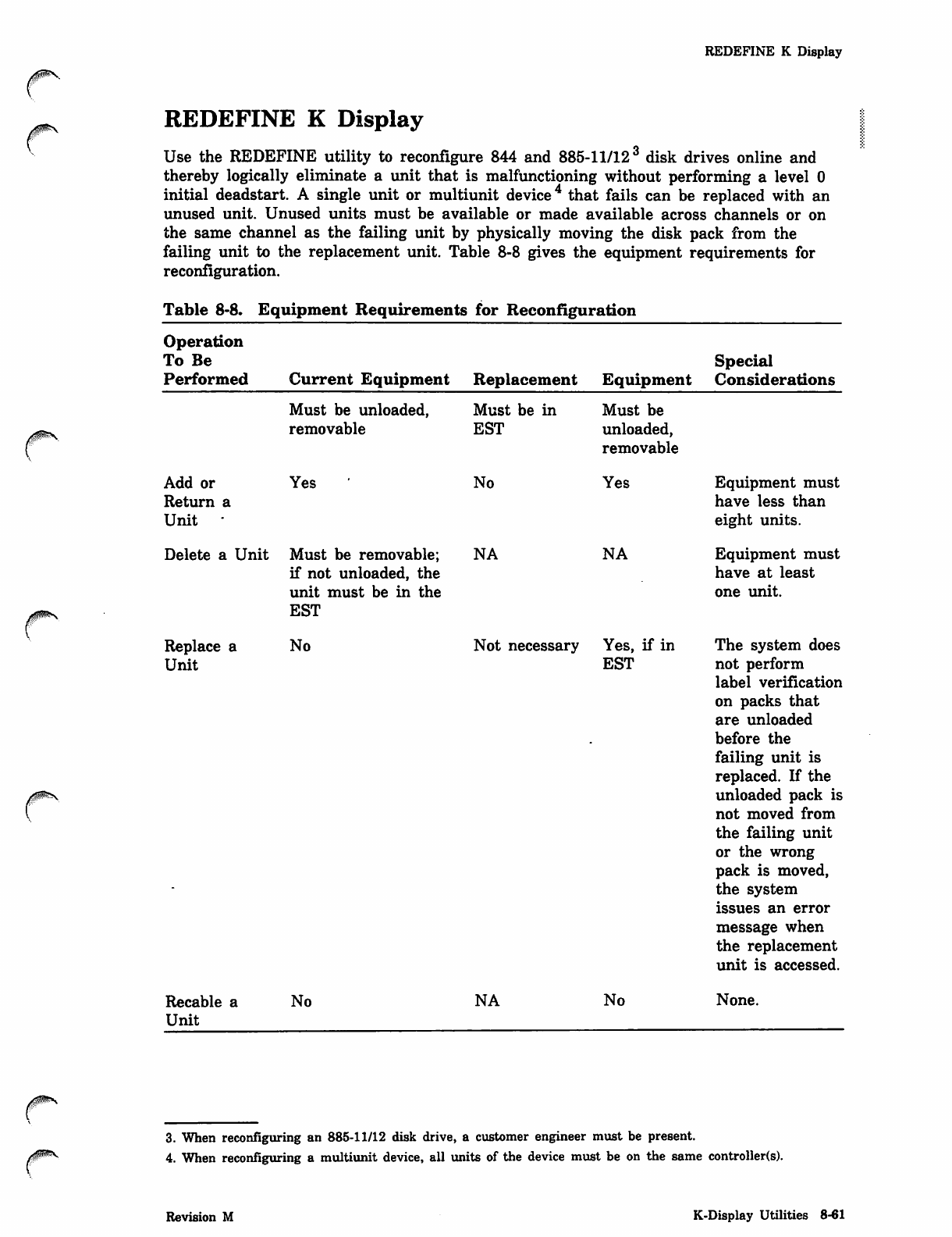
REDEFINE K Display
REDEFINE K Display
Use the REDEFINE utility to reconfigure 844 and 885-11/123 disk drives online and
thereby logically eliminate a unit that is malfunctioning without performing a level 0
initial deadstart. A single unit or multiunit device4 that fails can be replaced with an
unused unit. Unused units must be available or made available across channels or on
the same channel as the failing unit by physically moving the disk pack from the
failing unit to the replacement unit. Table 8-8 gives the equipment requirements for
reconfiguration.
Table 8-8. Equipment Requirements for Reconfiguration
r
r
Operation
To Be Special
Performed Current Equipment Replacement Equipment Considerations
Must be unloaded, Must be in Must be
removable EST unloaded,
removable
Add or Yes No Yes Equipment must
Return a have less than
Unit eight units.
Delete a Unit Must be removable;
if not unloaded, the
unit must be in the
EST
NA NA Equipment must
have at least
one unit.
Replace a No Not necessary Yes, if in The system does
Unit EST not perform
label verification
on packs that
are unloaded
before the
failing unit is
replaced. If the
unloaded pack is
not moved from
the failing unit
or the wrong
pack is moved,
the system
issues an error
message when
the replacement
unit is accessed.
Recable a No NA No None.
Unit
3. When reconfiguring an 885-11/12 disk drive, a customer engineer must be present.
4. When reconfiguring a multiunit device, all units of the device must be on the same controller(s).
Revision M K-Display Utilities 8-61
REDEFINE K Display
NOTE
■'*^%k
There are special cases when you cannot perform an online reconfiguration. In these
cases, you must perform a level 0 deadstart and define the failing device to another
drive. The special cases are:
• Reconfiguring an 885-11/12 disk drive that is the only system device defined.
• Reconfiguring an 844 or 885-11/12 disk drive that is the only temporary device
defined.
• Reconfiguring a device designated as an independent shared device.
• Reconfiguring an 819 or 885-42 disk drive.
The reconfiguration sequence follows:
1. Request the reconfiguration of the disk device defined by EST ordinal est by
entering:
REDEFINE,est.
The.message REQUEST *K* DISPLAY appears at the appropriate control point on
the system status display (B,0). You can reenter the REDEFINE command as
many times as there are devices to be reconfigured. Multispindle devices that
include two or more units are considered to be one device.
If an INITIALIZE command is being processed, the REDEFINE entry is not
processed until the initialization is complete.
2. Bring the initial REDEFINE K display (see figure 8-20) to the left console screen
by entering:
K.jsn.
jsn Description
jsn Job sequence name of the requesting job.
To bring up the right console screen K display, enter: /*^\
KK.
As shown in the left screen of figure 8-20, the current EST description of the
device being reconfigured appears under the heading CURRENT EQUIPMENT
CONFIGURATION. The EST description of the device as changes are made
appears under the heading REQUESTED EQUIPMENT CONFIGURATION. Any
devices listed under IDLED EQUIPMENTS are devices that have been previously
selected by your REDEFINE command but have yet to be processed in the
reconfiguration run.
The left screen K display may not list all relevant devices. If more than one
device is listed, they are processed one at a time as they appear in the list with
one exception: all shared devices are processed prior to nonshared devices.
8-62 NOS Version 2 Analysis Handbook Revision M
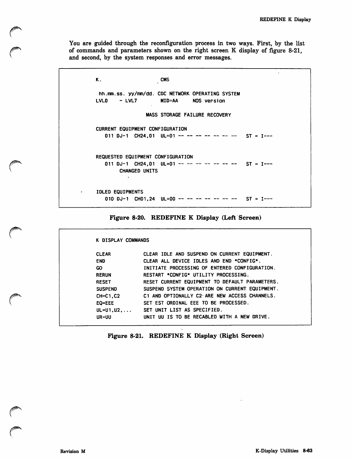
REDEFINE K Display
You are guided through the reconfiguration process in two ways. First, by the list
of commands and parameters shown on the right screen K display of figure 8-21,
and second, by the system responses and error messages.
yd^ptoSV,
CMS
hh.mm.ss. yy/mm/dd. CDC NETWORK OPERATING SYSTEM
LVLO - LVL7 MID=AA NOS version
MASS STORAGE FAILURE RECOVERY
CURRENT EQUIPMENT CONFIGURATION
011 DJ-1 CH24.01 UL=01
REQUESTED EQUIPMENT CONFIGURATION
011 DJ-1 CH24.01 UL=01
CHANGED UNITS
IDLED EQUIPMENTS
010 DJ-1 CH01.24 UL=00
ST = I
ST = I
ST « I
Figure 8-20. REDEFINE K Display (Left Screen)
K DISPLAY COMMANDS
CLEAR CLEAR IDLE AND SUSPEND ON CURRENT EQUIPMENT.
END CLEAR ALL DEVICE IDLES AND END *CONFIG*.
GO INITIATE PROCESSING OF ENTERED CONFIGURATION.
RERUN RESTART *CONFIG* UTILITY PROCESSING.
RESET RESET CURRENT EQUIPMENT TO DEFAULT PARAMETERS.
SUSPEND SUSPEND SYSTEM OPERATION ON CURRENT EQUIPMENT.
CH=C1,C2 C1 AND OPTIONALLY C2-ARE NEW ACCESS CHANNELS.
EQ=EEE SET EST ORDINAL EEE TO BE PROCESSED.
UL=U1,U2,... SET UNIT LIST AS SPECIFIED.
UR=UU UNIT UU IS TO BE RECABLED WITH A NEW DRIVE.
Figure 8-21. REDEFINE K Display (Right Screen)
Revision M K-Display Utilities 8-63
REDEFINE K Display
3. Enter all of the valid parameters (refer to table 8-9) that define the
reconfiguration characteristics for the specified device. Parameters are entered ^^v
singly. Parameters are processed left to right; no terminator is necessary. ?
If you enter an incorrect parameter (for example, the wrong channel number), the
error can be corrected by entering the correct parameter.
4. Enter
K.GO
to initiate processing of the parameters when all parameters and commands (refer
to table 8-10) have been entered for the specific device. Enter this command after
each set of parameters to signal the system to go ahead with the reconfiguration
you have defined. If more devices remain to be reconfigured, repeat steps 3 and 4.
5. Enter
K.END
to end a reconfiguration run when there are no more devices to be processed.
8-64 NOS Version 2 Analysis Handbook Revision M
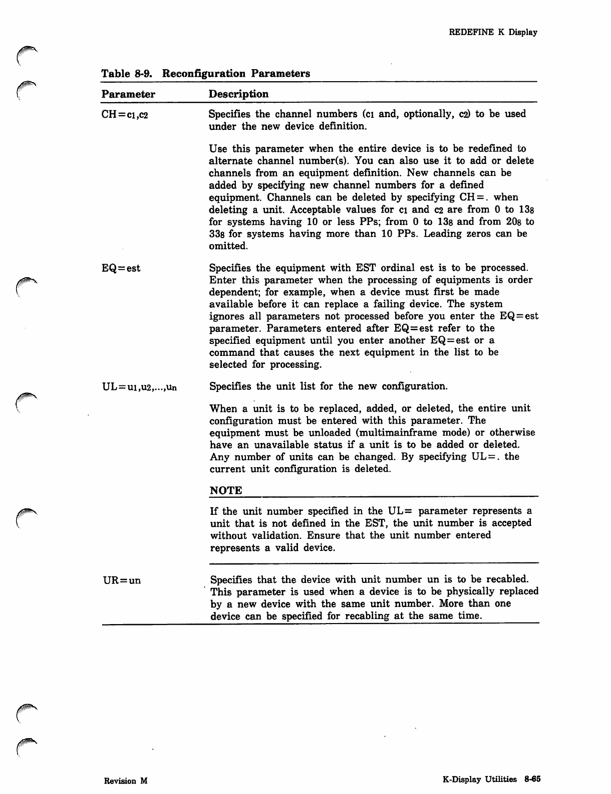
REDEFINE K Display
Table 8-9. Reconfiguration Parameters
Parameter Description
0$ms.
CH=ci,C2 Specifies the channel numbers (ci and, optionally, C2) to be used
under the new device definition.
Use this parameter when the entire device is to be redefined to
alternate channel number(s). You can also use it to add or delete
channels from an equipment definition. New channels can be
added by specifying new channel numbers for a defined
equipment. Channels can be deleted by specifying CH = . when
deleting a unit. Acceptable values for ci and C2 are from 0 to 13s
for systems having 10 or less PPs; from 0 to 13s and from 20s to
338 for systems having more than 10 PPs. Leading zeros can be
omitted.
EQ=est Specifies the equipment with EST ordinal est is to be processed.
Enter this parameter when the processing of equipments is order
dependent; for example, when a device must first be made
available before it can replace a failing device. The system
ignores all parameters not processed before you enter the EQ = est
parameter. Parameters entered after EQ=est refer to the
specified equipment until you enter another EQ = est or a
command that causes the next equipment in the list to be
selected for processing.
UL=ui,u2,...,Un Specifies the unit list for the new configuration.
When a unit is to be replaced, added, or deleted, the entire unit
configuration must be entered with this parameter. The
equipment must be unloaded (multimainframe mode) or otherwise
have an unavailable status if a unit is to be added or deleted.
Any number of units can be changed. By specifying UL = . the
current unit configuration is deleted.
NOTE
If the unit number specified in the UL= parameter represents a
unit that is not defined in the EST, the unit number is accepted
without validation. Ensure that the unit number entered
represents a valid device.
UR=un Specifies that the device with unit number un is to be recabled.
This parameter is used when a device is to be physically replaced
by a new device with the same unit number. More than one
device can be specified for recabling at the same time.
jtg^S.
Revision M K-Display Utilities 8-65
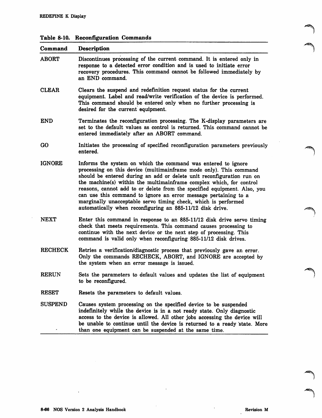
REDEFINE K Display
Table 8-10. Reconfiguration Commands
Command Description
ABORT Discontinues processing of the current command. It is entered only in
response to a detected error condition and is used to initiate error
recovery procedures. This command cannot be followed immediately by
an END command.
CLEAR Clears the suspend and redefinition request status for the current
equipment. Label and read/write verification of the device is performed.
This command should be entered only when no further processing is
desired for the current equipment.
END Terminates the reconfiguration processing. The K-display parameters are
set to the default values as control is returned. This command cannot be
entered immediately after an ABORT command.
GO Initiates the processing of specified reconfiguration parameters previously
entered.
IGNORE Informs the system on which the command was entered to ignore
processing on this device (multimainframe mode only). This command
should be entered during an add or delete unit reconfiguration run on
the machine(s) within the multimainframe complex which, for control
reasons, cannot add to or delete from the specified equipment. Also, you
can use this command to ignore an error message pertaining to a
marginally unacceptable servo timing check, which is performed
automatically when reconfiguring an 885-11/12 disk drive.
NEXT Enter this command in response to an 885-11/12 disk drive servo timing
check that meets requirements. This command causes processing to
continue with the next device or the next step of processing. This
command is valid only when reconfiguring 885-11/12 disk drives.
RECHECK Retries a verification/diagnostic process that previously gave an error.
Only the commands RECHECK, ABORT, and IGNORE are accepted by
the system when an error message is issued.
RERUN Sets the parameters to default values and updates the list of equipment
to be reconfigured.
RESET Resets the parameters to default values.
SUSPEND Causes system processing on the specified device to be suspended
indefinitely while the device is in a not ready state. Only diagnostic
access to the device is allowed. All other jobs accessing the device will
be unable to continue until the device is returned to a ready state. More
than one equipment can be suspended at the same time.
8-66 NOS Version 2 Analysis Handbook Revision M
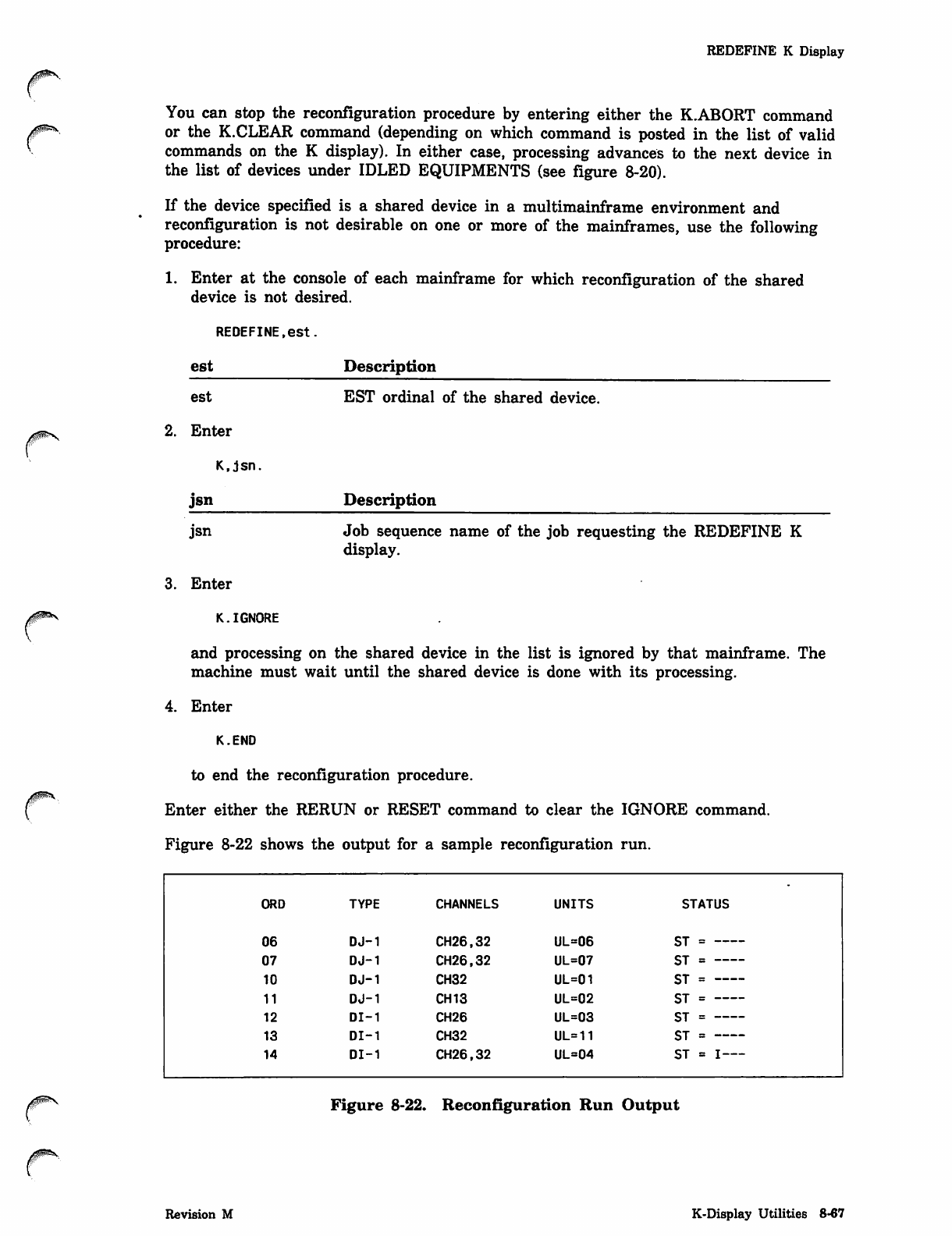
REDEFINE K Display
You can stop the reconfiguration procedure by entering either the K.ABORT command
/#^ or the K.CLEAR command (depending on which command is posted in the list of valid
*• commands on the K display). In either case, processing advances to the next device in
the list of devices under IDLED EQUIPMENTS (see figure 8-20).
If the device specified is a shared device in a multimainframe environment and
reconfiguration is not desirable on one or more of the mainframes, use the following
procedure:
1. Enter at the console of each mainframe for which reconfiguration of the shared
device is not desired.
REDEFINE,est.
est Description
est EST ordinal of the shared device.
*s^ 2. Enter
K.jsn.
jsn Description
jsn Job sequence name of the job requesting the REDEFINE K
display.
3. Enter
K.IGNORE
and processing on the shared device in the list is ignored by that mainframe. The
machine must wait until the shared device is done with its processing.
4. Enter
K.END
to end the reconfiguration procedure.
Enter either the RERUN or RESET command to clear the IGNORE command.
Figure 8-22 shows the output for a sample reconfiguration run.
ORD TYPE CHANNELS UNITS STATUS
06 DJ-1 CH26.32 UL=06 ST =
07 DJ-1 CH26.32 UL=07 ST =
10 DJ-1 CH32 UL=01 ST =
11 DJ-1 CH13 UL=02 ST =
12 DI-1 CH26 UL=03 ST =
13 DI-1 CH32 UL=11 ST =
14 DI-1 CH26,32 UL=04 ST = I
/^N Figure 8-22. Reconfiguration Run Output
Revision M K-Display Utilities 8-67
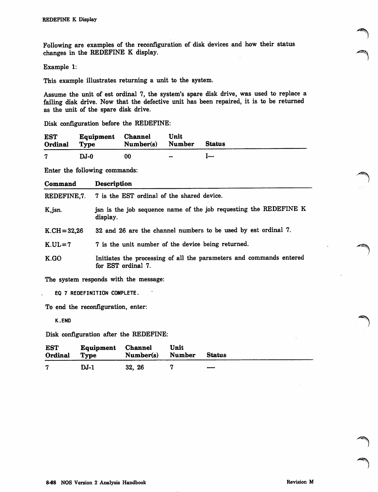
REDEFINE K Display
Following are examples of the reconfiguration of disk devices and how their status
changes in the REDEFINE K display. /*=%
Example 1:
This example illustrates returning a unit to the system.
Assume the unit of est ordinal 7, the system's spare disk drive, was used to replace a
failing disk drive. Now that the defective unit has been repaired, it is to be returned
as the unit of the spare disk drive.
Disk configuration before the REDEFINE:
EST Equipment Channel Unit
Ordinal Type Number(s) Number Status
7 D J - 0 0 0 - I - -
Enter the following commands:
Command Description
REDEFINE,7. 7 is the EST ordinal of the shared device.
K,jsn. jsn is the job sequence name of the job requesting the REDEFINE K
display.
K.CH = 32,26 32 and 26 are the channel numbers to be used by est ordinal 7.
K.UL=7 7 is the unit number of the device being returned.
K.GO Initiates the processing of all the parameters and commands entered
for EST ordinal 7.
The system responds with the message:
EQ 7 REDEFINITION COMPLETE.
To end the reconfiguration, enter:
K.END
Disk configuration after the REDEFINE:
EST Equipment Channel Unit
Ordinal Type Number(s) Number Status
7 D J - 1 3 2 , 2 6 7
8-68 NOS Version 2 Analysis Handbook Revision M
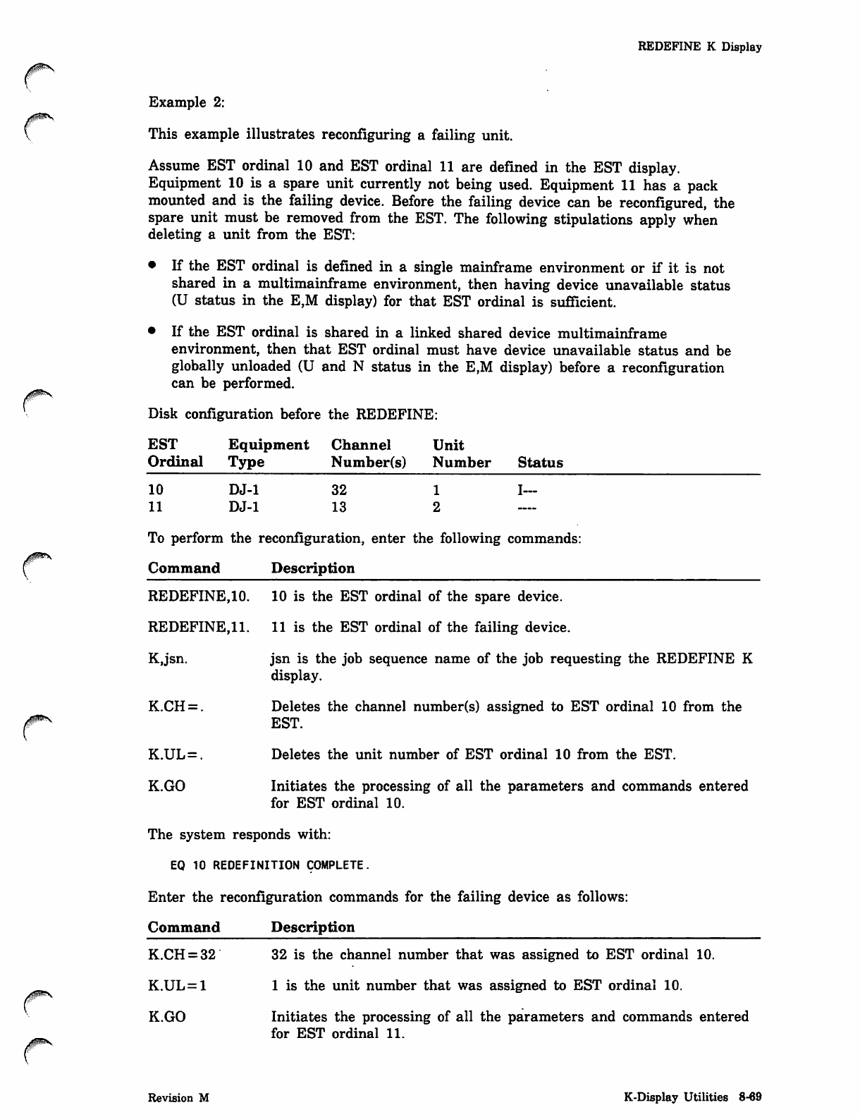
0$ms.
REDEFINE K Display
Example 2:
This example illustrates reconfiguring a failing unit.
Assume EST ordinal 10 and EST ordinal 11 are defined in the EST display.
Equipment 10 is a spare unit currently not being used. Equipment 11 has a pack
mounted and is the failing device. Before the failing device can be reconfigured, the
spare unit must be removed from the EST. The following stipulations apply when
deleting a unit from the EST:
• If the EST ordinal is defined in a single mainframe environment or if it is not
shared in a multimainframe environment, then having device unavailable status
(U status in the E,M display) for that EST ordinal is sufficient.
• If the EST ordinal is shared in a linked shared device multimainframe
environment, then that EST ordinal must have device unavailable status and be
globally unloaded (U and N status in the E,M display) before a reconfiguration
can be performed.
Disk configuration before the REDEFINE:
EST Equipment Channel Unit
Ordinal Type Number(s) Number Status
1 0 D J - 1 3 2 1 I —
1 1 D J - 1 1 3 2
To perform the reconfiguration, enter the following commands:
Command Description
REDEFINE,10. 10 is the EST ordinal of the spare device.
REDEFINE,11. 11 is the EST ordinal of the failing device.
KJsn. jsn is the job sequence name of the job requesting the REDEFINE K
display.
K.CH = . Deletes the channel number(s) assigned to EST ordinal 10 from the
EST.
K.UL=. Deletes the unit number of EST ordinal 10 from the EST.
K.GO Initiates the processing of all the parameters and commands entered
for EST ordinal 10.
The system responds with:
EQ 10 REDEFINITION COMPLETE.
Enter the reconfiguration commands for the failing device as follows:
Command Description
K.CH = 32 32 is the channel number that was assigned to EST ordinal 10.
K.UL = 1 1 is the unit number that was assigned to EST ordinal 10.
K.GO Initiates the processing of all the parameters and commands entered
for EST ordinal 11.
Revision M K-Display Utilities 8-69
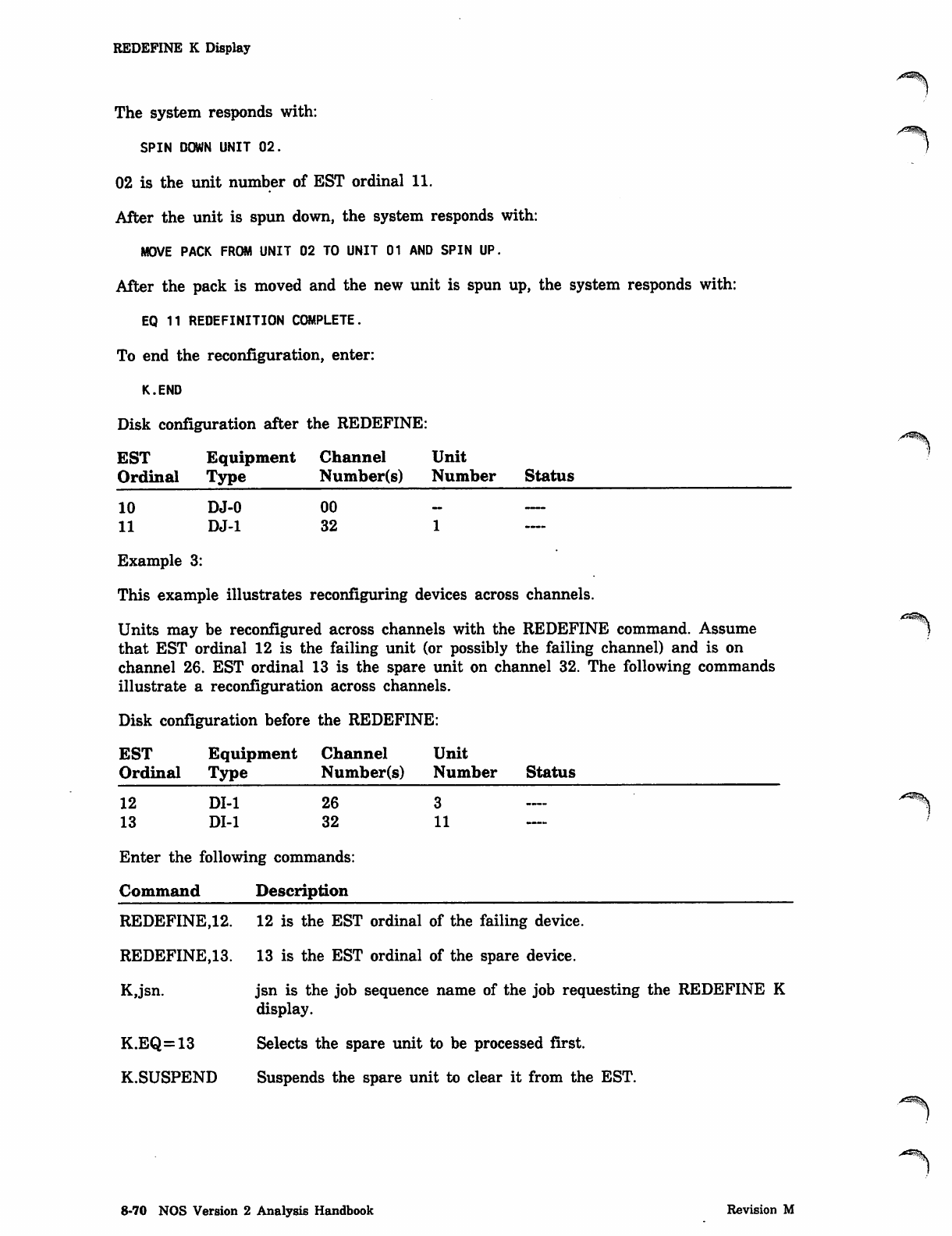
REDEFINE K Display
The system responds with:
SPIN DOWN UNIT 02.
02 is the unit number of EST ordinal 11.
After the unit is spun down, the system responds with:
MOVE PACK FROM UNIT 02 TO UNIT 01 AND SPIN UP.
After the pack is moved and the new unit is spun up, the system responds with:
EQ 11 REDEFINITION COMPLETE.
To end the reconfiguration, enter:
K.END
Disk configuration after the REDEFINE:
EST Equipment Channel Unit
Ordinal Type Number(s) Number Status
1 0 D J - 0 0 0
1 1 D J - 1 3 2 1
Example 3:
This example illustrates reconfiguring devices across channels.
Units may be reconfigured across channels with the REDEFINE command. Assume )
that EST ordinal 12 is the failing unit (or possibly the failing channel) and is on
channel 26. EST ordinal 13 is the spare unit on channel 32. The following commands
illustrate a reconfiguration across channels.
Disk configuration before the REDEFINE:
EST Equipment Channel Unit
Ordinal Type Number(s) Number Status
1 2 D I - 1 2 6 3
1 3 D I - 1 3 2 1 1
Enter the following commands:
Command Description
REDEFINE,12. 12 is the EST ordinal of the failing device.
REDEFINE,13. 13 is the EST ordinal of the spare device.
K,jsn. jsn is the job sequence name of the job requesting the REDEFINE K
display.
K.EQ=13 Selects the spare unit to be processed first.
K. SUSPEND Suspends the spare unit to clear it from the EST.
8-70 NOS Version 2 Analysis Handbook Revision M
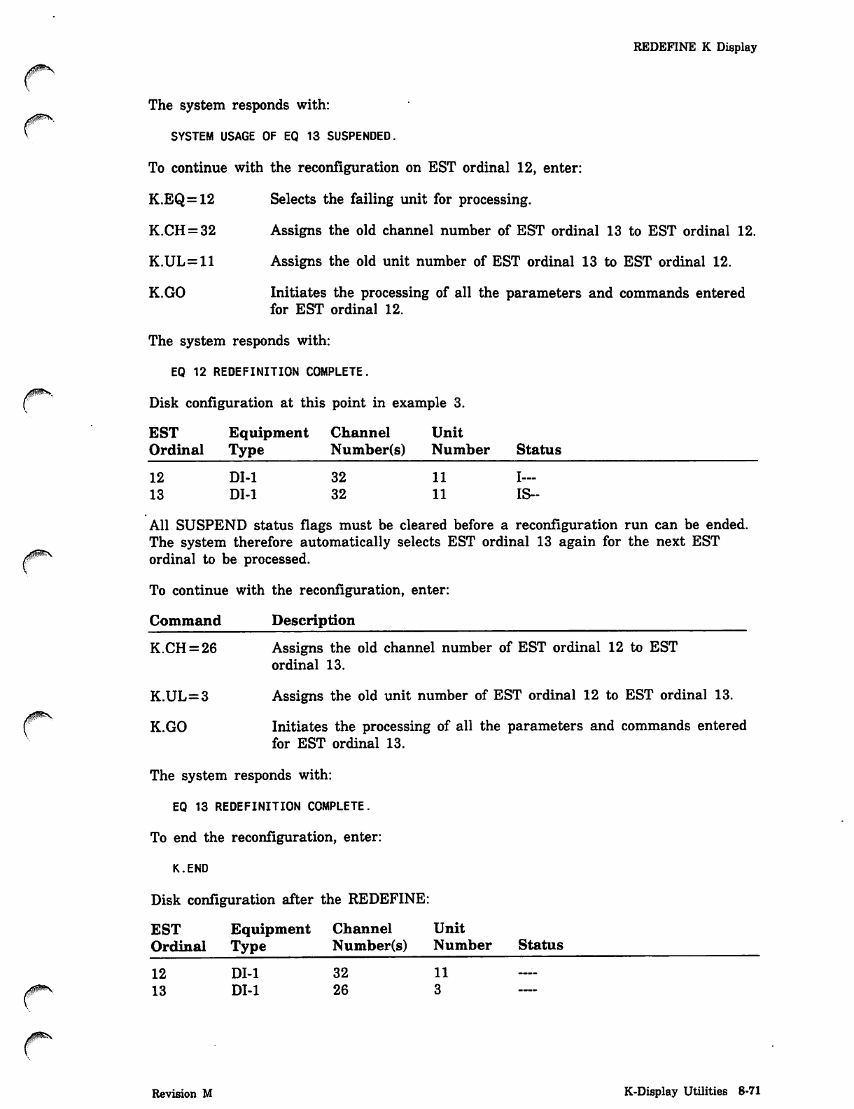
/g^v
J^^S.
REDEFINE K Display
The system responds with:
SYSTEM USAGE OF EQ 13 SUSPENDED.
To continue with the reconfiguration on EST ordinal 12, enter:
K.EQ=12 Selects the failing unit for processing.
K.CH = 32 Assigns the old channel number of EST ordinal 13 to EST ordinal 12.
K.UL=11 Assigns the old unit number of EST ordinal 13 to EST ordinal 12.
K.GO Initiates the processing of all the parameters and commands entered
for EST ordinal 12.
The system responds with:
EQ 12 REDEFINITION COMPLETE.
Disk configuration at this point in example 3.
EST Equipment Channel Unit
Ordinal Type Number(s) Number Status
12 DI-1 32 11 I—
13 DI-1 32 11 IS-
All SUSPEND status flags must be cleared before a reconfiguration run can be ended.
The system therefore automatically selects EST ordinal 13 again for the next EST
ordinal to be processed.
To continue with the reconfiguration, enter:
Command Description
K.CH = 26 Assigns the old channel number of EST ordinal 12 to EST
ordinal 13.
K.UL=3 Assigns the old unit number of EST ordinal 12 to EST ordinal 13.
K.GO Initiates the processing of all the parameters and commands entered
for EST ordinal 13.
The system responds with:
EQ 13 REDEFINITION COMPLETE.
To end the reconfiguration, enter:
K.END
Disk configuration after the REDEFINE:
EST Equipment Channel Unit
Ordinal Type Number(s) Number Status
1 2 D I - 1 3 2 1 1
1 3 D I - 1 2 6 3
Revision M K-Display Utilities 8-71
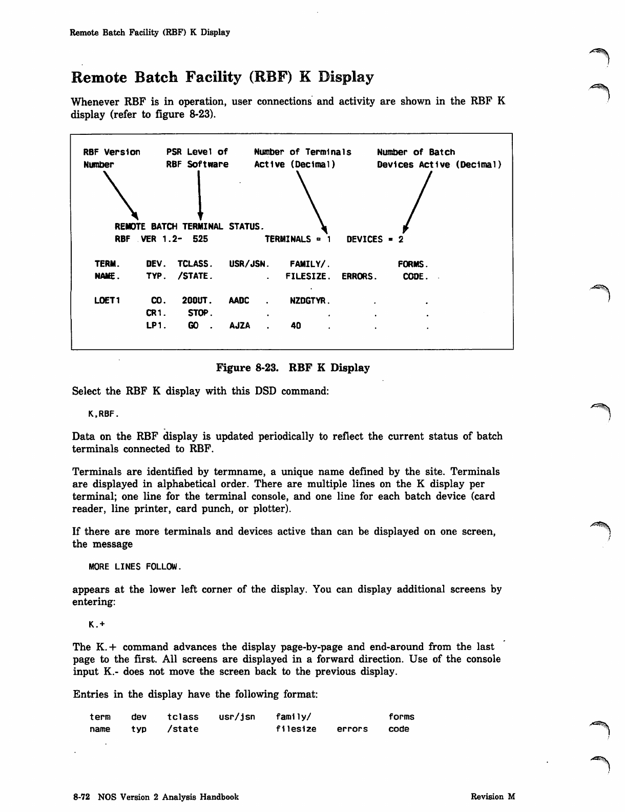
Remote Batch Facility (RBF) K Display
Remote Batch Facility (RBF) K Display
Whenever RBF is in operation, user connections and activity are shown in the RBF K
display (refer to figure 8-23).
RBF Version PSR Level of Number of Terminals Number of Batch
Number RBF Software Active (Decimal) Devices Active (Decimal)
REMOTE BATCH TERMINAL STATUS.
RBF VER 1.2- 525 TERMINALS = 1 DEVICES - 2
TERM. DEV. TCLASS. USR/JSN. FAMILY/.
NAME. TYP. /STATE. FILESIZE. ERRORS.
LOET1 CO. 200UT. AADC NZDGTYR.
CR1. STOP.
L P 1 . G O . A J Z A 4 0
FORMS
CODE
Figure 8-23. RBF K Display
Select the RBF K display with this DSD command:
K.RBF.
Data on the RBF display is updated periodically to reflect the current status of batch
terminals connected to RBF.
Terminals are identified by termname, a unique name defined by the site. Terminals
are displayed in alphabetical order. There are multiple lines on the K display per
terminal; one line for the terminal console, and one line for each batch device (card
reader, line printer, card punch, or plotter).
If there are more terminals and devices active than can be displayed on one screen,
the message
MORE LINES FOLLOW.
appears at the lower left corner of the display. You can display additional screens by
entering:
K.+
The K.+ command advances the display page-by-page and end-around from the last
page to the first. All screens are displayed in a forward direction. Use of the console
input K.- does not move the screen back to the previous display.
Entries in the display have the following format:
term dev tclass usr/jsn family/
name typ /state filesize errors
forms
code
8-72 NOS Version 2 Analysis Handbook Revision M
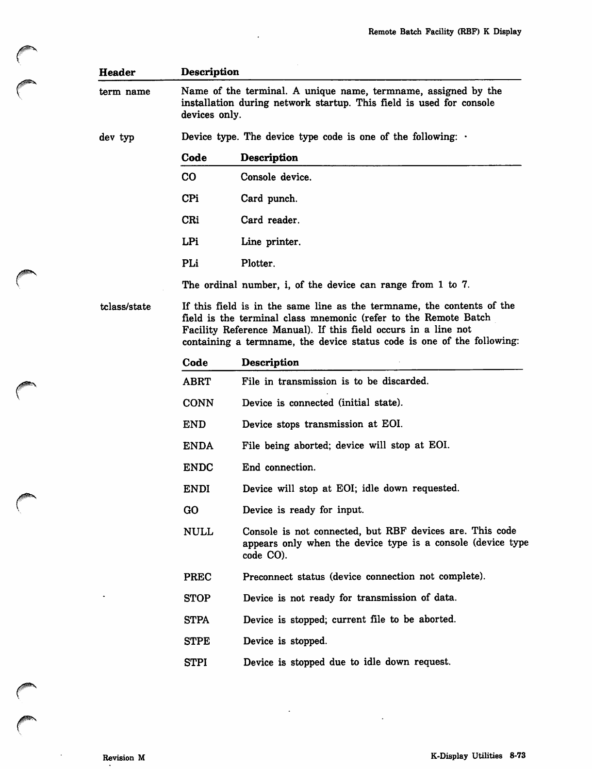
Remote Batch Facility (RBF) K Display
Header
term name
dev typ
tclass/state
Description
Name of the terminal. A unique name, termname, assigned by the
installation during network startup. This field is used for console
devices only.
Device type. The device type code is one of the following: •
Code Description
CO
CPi
CRi
LPi
PLi
Console device.
Card punch.
Card reader.
Line printer.
Plotter.
The ordinal number, i, of the device can range from 1 to 7.
If this field is in the same line as the termname, the contents of the
field is the terminal class mnemonic (refer to the Remote Batch
Facility Reference Manual). If this field occurs in a line not
containing a termname, the device status code is one of the following:
Code Description
ABRT File in transmission is to be discarded.
CONN Device is connected (initial state).
END Device stops transmission at EOI.
ENDA File being aborted; device will stop at EOI.
ENDC End connection.
ENDI Device will stop at EOI; idle down requested.
GO Device is ready for input.
NULL Console is not connected, but RBF devices are. This code
appears only when the device type is a console (device type
code CO).
PREC Preconnect status (device connection not complete).
STOP Device is not ready for transmission of data.
STPA Device is stopped; current file to be aborted.
STPE Device is stopped.
STPI Device is stopped due to idle down request.
Revision M K-Display Utilities 8-73
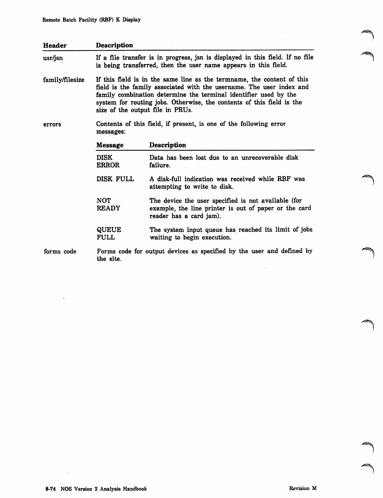
Remote Batch Facility (RBF) K Display
Header Description
usr/jsn
family/filesize
errors
forms code
If a file transfer is in progress, jsn is displayed in this field. If no file
is being transferred, then the user name appears in this field.
If this field is in the same line as the termname, the content of this
field is the family associated with the username. The user index and
family combination determine the terminal identifier used by the
system for routing jobs. Otherwise, the contents of this field is the
size of the output file in PRUs.
Contents of this field, if present, is one of the following error
messages:
Message Description
DISK Data has been lost due to an unrecoverable disk
ERROR failure.
DISK FULL A disk-full indication was received while RBF was
attempting to write to disk.
NOT The device the user specified is not available (for
READY example, the line printer is out of paper or the card
reader has a card jam).
QUEUE The system input queue has reached its limit of jobs
FULL waiting to begin execution.
Forms code for output devices as specified by the user and defined by
the site.
8-74 NOS Version 2 Analysis Handbook Revision M
Remote Host Facility (RHF) K Display
/fpSN
Remote Host Facility (RHF) K Display
The Remote Host Facility (RHF) links NOS to a loosely coupled network (LCN)
providing transfer of permanent files, queued files, and maintenance facilities for the
LCN hardware. Each system in an LCN configuration is connected to one or more LCN
trunks by network access devices (NADs). Several types of NADs are available,
allowing the connection of various types of computer systems to an LCN. Each system
has an RHF that provides some or all of the following capabilities.
RHF runs at a control point and contains an operator interface package, control
tables, network application code, and the PP routines that drive the RHF network
hardware.
The following applications are also available as part of RHF:
Application Description
PTF, PTFS Permanent File Transfer Facility (PTF) and Permanent File Transfer
Facility Servicer (PTFS). PTF and PTFS provide users access to remote
permanent files. A local user activates PTF with the MFLINK
command (refer to the NOS Version 2 Reference Set, Volume 3). When
a remote user enters the MFLINK command, RHF activates a PTFS
application on the local host to service the remote request.
MHF Maintenance Host Facility (MHF). MHF automatically loads
controlware of local NADs during RHF initiation and performs
maintenance logging. If a local NAD fails while RHF is active, MHF
automatically dumps the NAD's memory to a permanent file and
reloads the controlware, for a description of LNAD statement
parameters that control automatic NAD dumping and loading (refer to
section 10, LID/RHF Configuration Files).
MHF also periodically checks all local NADs and any remote NADs
enabled for logging (refer to the network path table display described
later in this section) and copies new NAD error log entries to the
binary maintenance log (BML).
MHF starts automatically when RHF is initiated and remains active
until RHF terminates.
QTF, QTFS Queue File Transfer Facility (QTF) and Queue File Transfer Facility
Servicer (QTFS). QTF and QTFS allow you to transfer input and
output files to a remote system. When RHF is initiated, the system
automatically activates QTF. When a remote host QTF application has
a file to transfer, RHF initiates QTFS on the local host to service the
remote request.
The following subsections describe the initiation, operation, control, and termination of
the RHF.
Revision M K-Display Utilities 8-75
RHF Initiation
RHF Initiation
Before network operation can begin, you must initiate RHF using the DSD RHFffff
command (refer to section 5, DSD Commands).
When RHF is initiated, it starts all enabled applications defined by the network
configuration as autostart applications (refer to RHF Configuration Files in
section 10). These applications are typically MHF and QTF.
Application MHF loads controlware into all local NADs that are defined in RHF's
configuration with AUTOLOAD=YES and have an EST status of ON.
Operator Interface
The operator interface for RHF consists of using the following displays:
Display Description
Application table Lists all active applications. '*s^\
Network path table Shows how the remote hosts are connected to the local host.
An example of each display is shown later in this section. To understand how to use
the information provided in the displays it is helpful to understand the sample LCN
network shown in figure 8-24.
8-76 NOS Version 2 Analysis Handbook Revision M
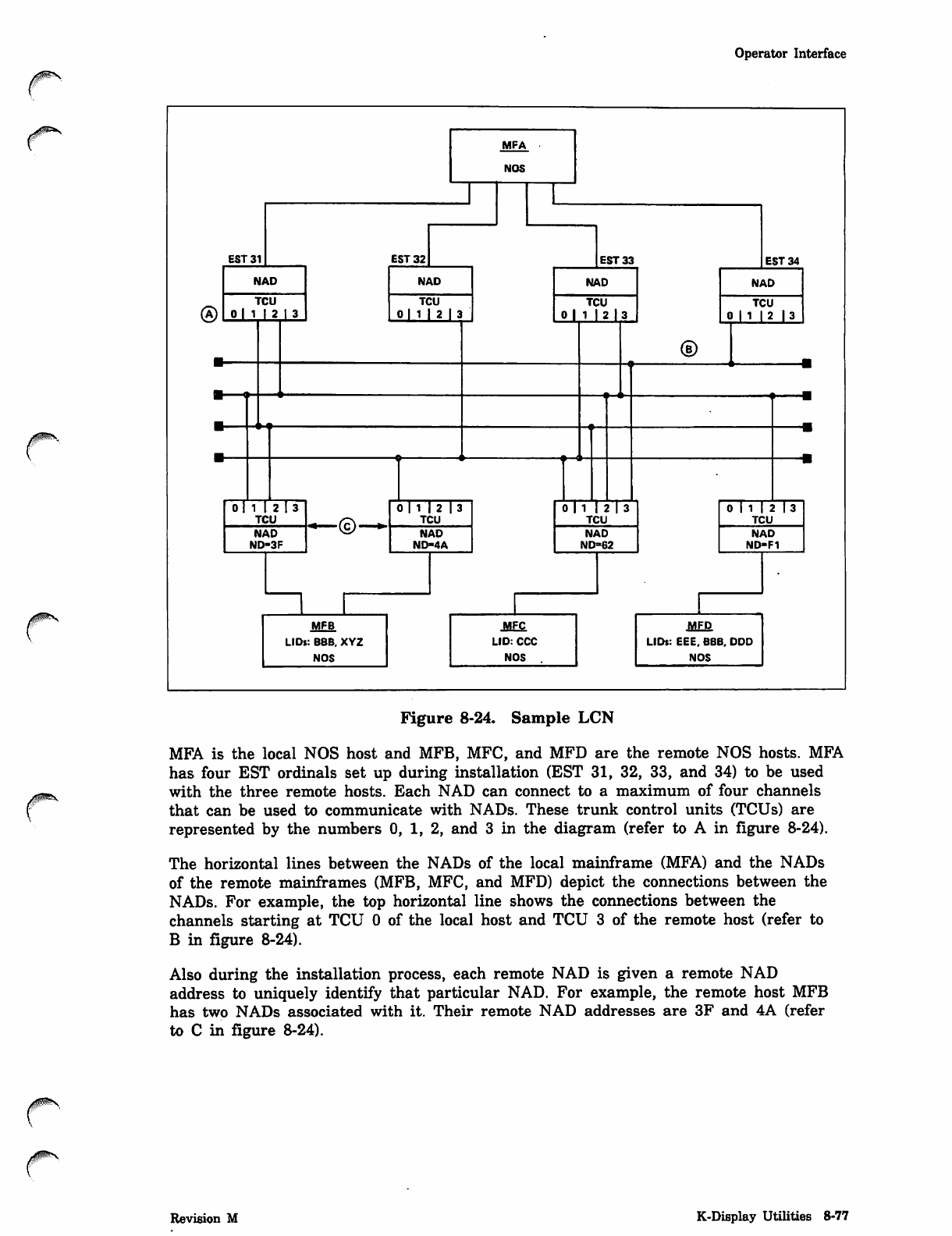
Operator Interface
r
MFA
NOS
EST 31
®
EST 32
NAD
TCU
1 I 2
NAD
TCU
0 I 1 I 2 | 3
Oil I 2 I 3
TCU
NAD
ND-3F
■©•
EST 33
NAD
TCU
0|1 I 2 I 3
0 I 1 | 2 | 3
TCU
NAD
ND-4A
t-*
EST 34
NAD
TCU
0 | 1 | 2 | 3
®
0 | 1 | 2 | 3
TCU
NAD
ND-G2
MFB
LIDs: BBB. XYZ
NOS
0 I 1 | 2 I 3
TCU
NAD
ND-F1
MFC MFD
LID: CCC LIDs: EEE, BBB. DDD
NOS NOS
Figure 8-24. Sample LCN
MFA is the local NOS host and MFB, MFC, and MFD are the remote NOS hosts. MFA
has four EST ordinals set up during installation (EST 31, 32, 33, and 34) to be used
with the three remote hosts. Each NAD can connect to a maximum of four channels
that can be used to communicate with NADs. These trunk control units (TCUs) are
represented by the numbers 0, 1, 2, and 3 in the diagram (refer to A in figure 8-24).
The horizontal lines between the NADs of the local mainframe (MFA) and the NADs
of the remote mainframes (MFB, MFC, and MFD) depict the connections between the
NADs. For example, the top horizontal line shows the connections between the
channels starting at TCU 0 of the local host and TCU 3 of the remote host (refer to
B in figure 8-24).
Also during the installation process, each remote NAD is given a remote NAD
address to uniquely identify that particular NAD. For example, the remote host MFB
has two NADs associated with it. Their remote NAD addresses are 3F and 4A (refer
to C in figure 8-24).
Revision M K-Display Utilities 8-77
RHF Commands Under K display
RHF Commands Under K display
Use the RHF K display to communicate with RHF. Bring up this display with this
DSD command:
K.RHF.
Two K displays are available under RHF, the application table display (see figure 8-25)
and the network path table display (see figure 8-26). When you first enter K,RHF, the
application table display appears. The next time and subsequent times you enter
K,RHF, the display that appears will be either the application table or the network
path table, whichever was displayed last.
The following commands are available under the RHF K display:
Command Function
APPL
IDLE
PATH
ord,ND=rna,AC = mac,
DD=dd,RT=rteb,
LT=lteb,LOG=status
+
Displays the application table (see figure 8-25).
Begins the idle-down process of RHF and all its associated
applications.
Displays the network path table (see figure 8-26).
Modifies entries associated with the network path table
display ordinal ord.
Pages the current display forward.
Pages the current display backward.
.jj££f?$£iV
8-78 NOS Version 2 Analysis Handbook Revision M
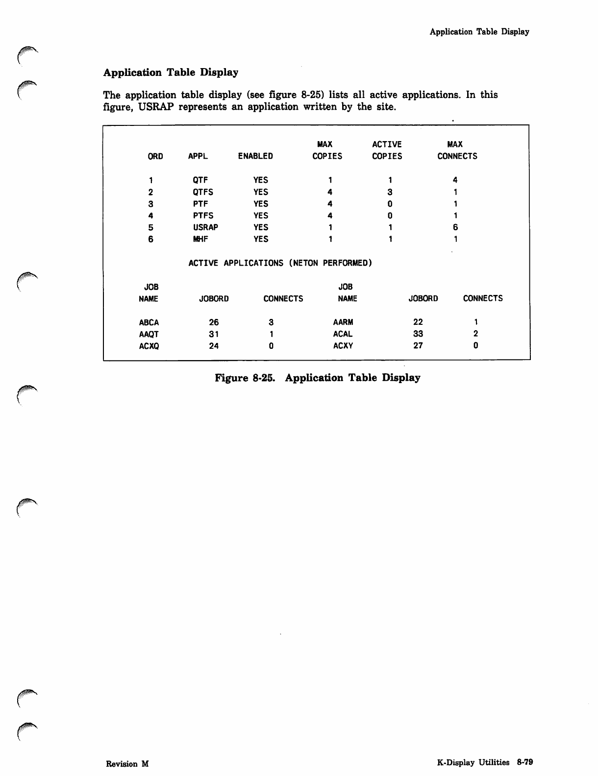
Application Table Display
Application Table Display
The application table display (see figure 8-25) lists all active applications. In this
figure, USRAP represents an application written by the site.
r
MAX ACTIVE MAX
ORD APPL ENABLED COPIES COPIES CONNECTS
1QTF YES
2QTFS YES
3PTF YES
4PTFS YES
5USRAP YES
6MHF YES
ACTIVE APPLICATIONS (NETON PERFORMED)
JOB JOB
NAME JOBORD CONNECTS NAME JOBORD CONNECTS
ABCA 26 AARM 22
AAQT 31 ACAL 33
ACXQ 24 ACXY 27
Figure 8-25. Application Table Display
/ ^ ^ V
Revision M K-Display Utilities 8-79
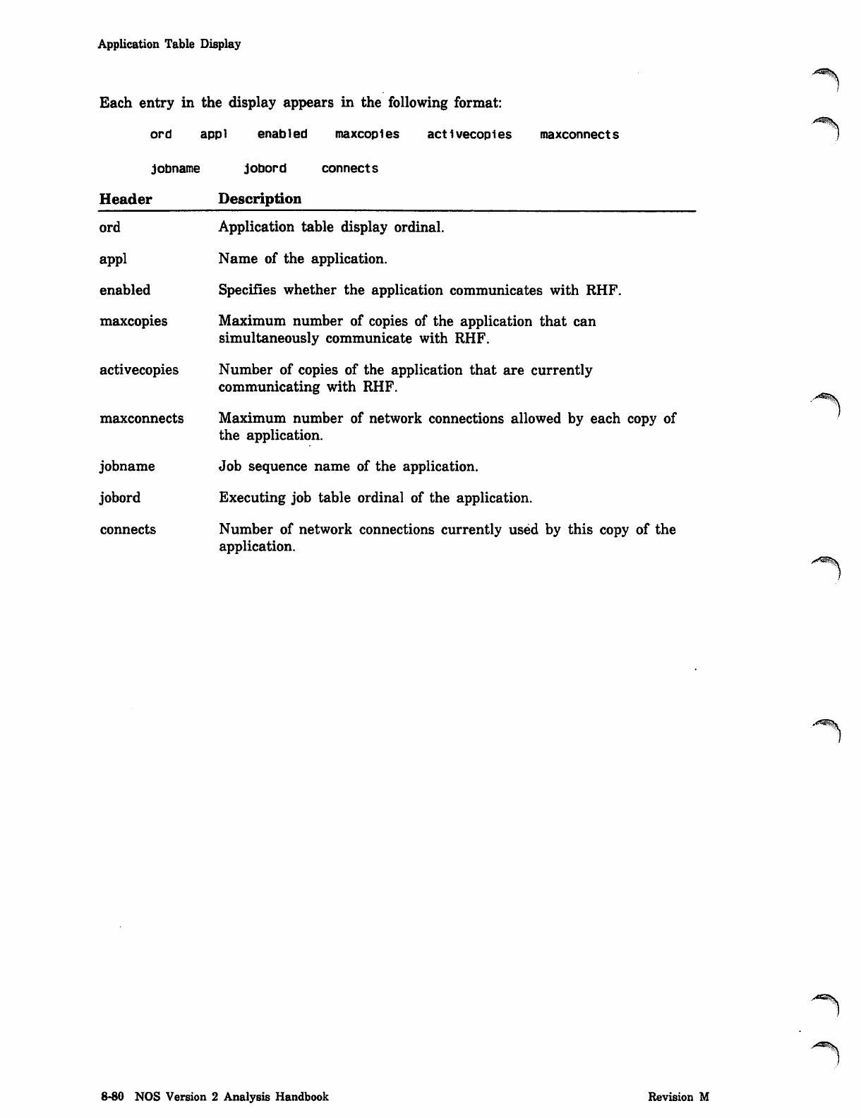
Application Table Display
Each entry in the display appears in the following format:
ord appl enabled maxcoples actlvecopies maxconnects
jobname jobord connects
Header Description
ord Application table display ordinal.
appl Name of the application.
enabled Specifies whether the application communicates with RHF.
maxcopies Maximum number of copies of the application that can
simultaneously communicate with RHF.
activecopies Number of copies of the application that are currently
communicating with RHF.
maxconnects Maximum number of network connections allowed by each copy of
the application.
jobname Job sequence name of the application.
jobord Executing job table ordinal of the application.
connects Number of network connections currently used by this copy of the
application.
8-80 NOS Version 2 Analysis Handbook Revision M
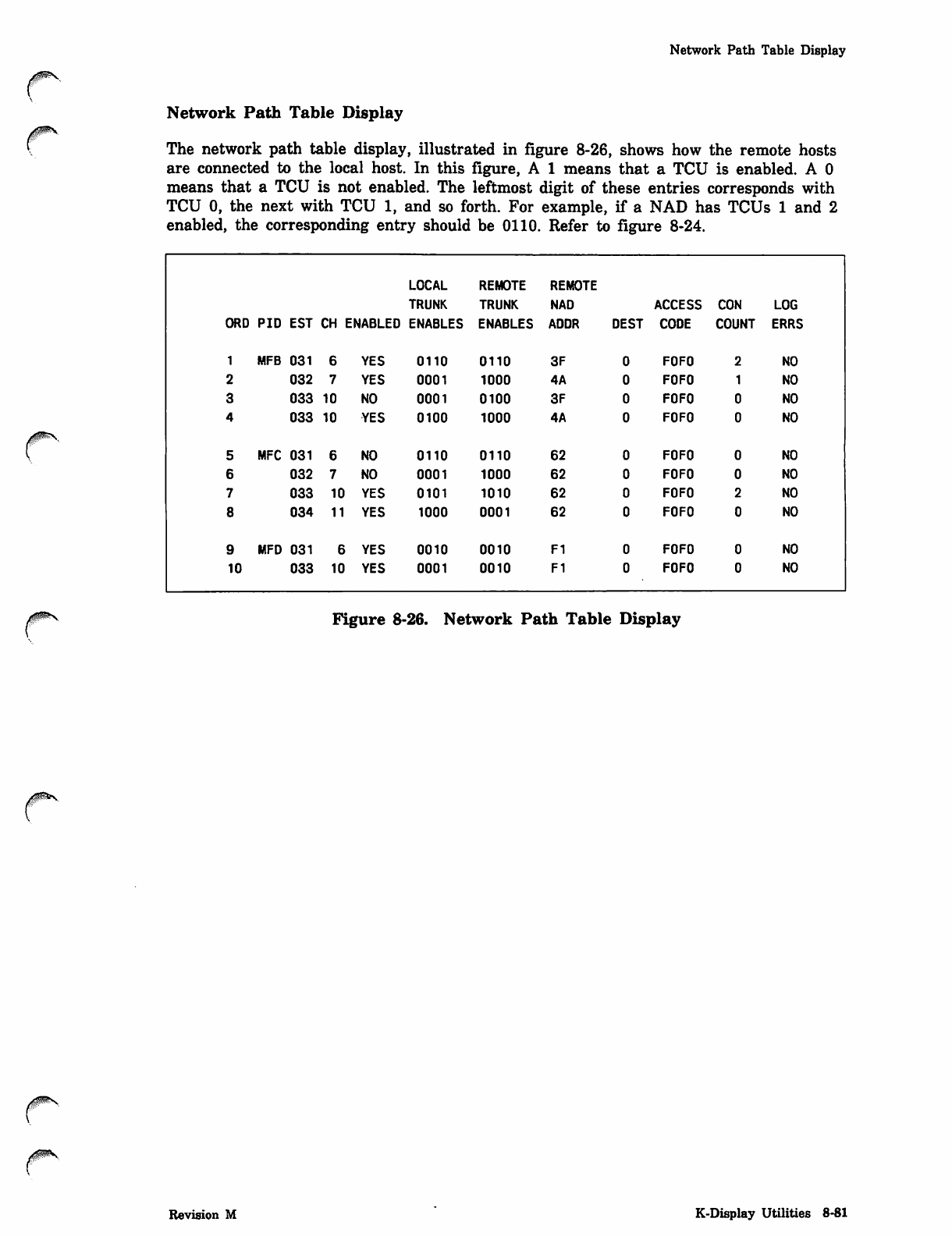
Network Path Table Display
Network Path Table Display
The network path table display, illustrated in figure 8-26, shows how the remote hosts
are connected to the local host. In this figure, A 1 means that a TCU is enabled. A 0
means that a TCU is not enabled. The leftmost digit of these entries corresponds with
TCU 0, the next with TCU 1, and so forth. For example, if a NAD has TCUs 1 and 2
enabled, the corresponding entry should be 0110. Refer to figure 8-24.
LOCAL REMOTE REMOTE
TRUNK TRUNK NAD ACCESS CON LOG
ORD PID EST CH ENABLED ENABLES ENABLES ADDR DEST CODE COUNT ERRS
1 M F B 031 YES 0110 0110 3F F0F0 NO
2032 YES 0001 1000 4A F0F0 NO
3033 10 NO 0001 0100 3F F0F0 NO
4033 10 YES 0100 1000 4A F0F0 NO
5 M F C 031 NO 0110 0110 62 F0F0 NO
6032 NO 0001 1000 62 F0F0 NO
7033 10 YES 0101 1010 62 F0F0 NO
8034 11 YES 1000 0001 62 F0F0 NO
9 M F D 031 YES 0010 0010 F1 F0F0 NO
10 033 10 YES 0001 0010 F1 F0F0 NO
Figure 8-26. Network Path Table Display
Revision M K-Display Utilities 8-81
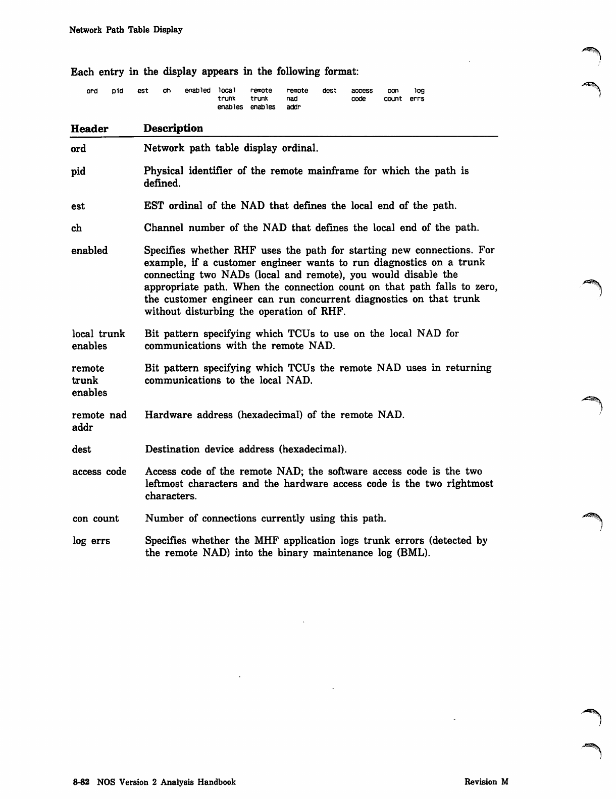
Network Path Table Display
Each entry in the display appears in the following format:
ord pid est ch
Header
ord
pid
est
ch
enabled
local trunk
enables
remote
trunk
enables
remote nad
addr
dest
access code
con count
log errs
enabled local remote remote
t r u n k t r u n k n a d
enables enables addr
dest access con log
code count errs
Description
Network path table display ordinal.
Physical identifier of the remote mainframe for which the path is
defined.
EST ordinal of the NAD that defines the local end of the path.
Channel number of the NAD that defines the local end of the path.
Specifies whether RHF uses the path for starting new connections. For
example, if a customer engineer wants to run diagnostics on a trunk
connecting two NADs (local and remote), you would disable the
appropriate path. When the connection count on that path falls to zero,
the customer engineer can run concurrent diagnostics on that trunk
without disturbing the operation of RHF.
Bit pattern specifying which TCUs to use on the local NAD for
communications with the remote NAD.
Bit pattern specifying which TCUs the remote NAD uses in returning
communications to the local NAD.
Hardware address (hexadecimal) of the remote NAD.
Destination device address (hexadecimal).
Access code of the remote NAD; the software access code is the two
leftmost characters and the hardware access code is the two rightmost
characters.
Number of connections currently using this path.
Specifies whether the MHF application logs trunk errors (detected by
the remote NAD) into the binary maintenance log (BML).
8-82 NOS Version 2 Analysis Handbook Revision M
Network Path Table Display
When the network path table is displayed, you can enter the following command to
make changes.
ord,ND=rna,AC=rnac,DD=dd.RT=rteb,LT=lteb,LOG=status.
Parameter Description
ord Network path table display ordinal.
rna New remote NAD address in hexadecimal.
rnac New remote NAD access code in hexadecimal.
dd New remote NAD destination device address in hexadecimal.
rteb New remote trunk enable bit pattern (nonzero 4-bit binary number
with the leftmost bit representing TCU 0).
lteb New local trunk enable bit pattern (nonzero 4-bit binary number with
the leftmost bit representing TCU 0). The same number of bits must
be set for both RT and LT or the command will be rejected.
status Status of error logging for the specified remote NAD. Enter YES to
have MHF periodically copy the trunk errors occurring on the specified
remote NAD to the binary maintenance log (BML). MHF does not copy
trunk errors when you enter NO.
ord is the only required parameter and it must come first. All other parameters are
optional and can appear in any order, but at least one, besides ord, must be present.
NOTE
Any change to rna, dd, or status for a given path results in an equivalent change for
all paths using that remote NAD. This is because rna, dd, and status are associated
with the remote NAD rather than the path to the remote NAD.
When RHF finds a faulty local NAD, it turns off the NAD's EST entry, activates the
MHF application, and issues the following job dayfile message:
RHF, NAD ON EST est HAS BEEN TURNED OFF
MHF dumps the NAD's memory, reloads the NAD's controlware, and turns on the
NAD's EST entry.
When RHF finds a path configured to use a faulty or nonexistent local NAD trunk
control unit (TCU), it disables the path and notifies you with the following message
on the B,0 display:
RHF,BAD TCU ON PATH XXX, PATH TURNED OFF.
Use the GO,RHF command to acknowledge the message.
Revision M K-Display Utilities 8-83
RHF Commands Available Under Application or Network Path Display
RHF Commands Available Under Application or Network Path Display
When the application table or network path table is displayed, you can enter the
following commands to enable or disable the application or network path.
ENABLE,ord.
or
DISABLE,ord.
Parameter Description
ord Ordinal of the application or network path on the current display.
For example, if the application table display is up, EN ABLE,ord enables the application
specified by the display ordinal ord.
If an application is being enabled (whether currently enabled or disabled) and that
application is defined as an autostart application, RHF initiates a copy of that .^^s
application. This feature may be used, for example, if the MHF application is
normally disabled and you want to start logging NAD errors. It may also be used if
the copy of the QTF application has been dropped accidentally and a new copy of the
QTF application must be started.
RHF Termination
You can terminate an RHF operation using the IDLE command.
The command format is:
IDLE.
When you enter the IDLE command the system waits for applications to stop and the
message IDLE-DOWN IN PROGRESS appears on the system status display. When
activity stops, the system drops RHF and the message RHF ENDED appears. The
IDLE command allows a gradual shutdown of RHF activities. No new connections are
allowed.
8-84 NOS Version 2 Analysis Handbook Revision M
SCOPE 2 Station Facility (SSF) K Displays
SCOPE 2 Station Facility (SSF) K Displays
The following commands control operation of the SSF Subsystem. Initiate the SSF
Subsystem before issuing any commands. SSF can be initiated automatically when the
system is brought up, either manually by entering an SSFffff command, or by entering
the ENABLE,SSF command.
Operator Interface
The SSF uses the K display for operator communications; therefore, the K display must
be assigned to SSF before any other SSF Subsystem commands can be entered. Use the
following command to assign the K display to SSF.
K.SSF.
Station Login
After SSF is assigned to a control point, SSF searches the equipment status table
(EST) for a SCOPE 2 communication coupler. If SSF finds an available coupler, it asks
the SCOPE 2 mainframe to establish communications. If no coupler is found, a message
appears at the console indicating that SSF is ready to log in to a SCOPE 2 mainframe.
To log in, first enter an ON command (refer to section 5, DSD Commands, for a
description of the ON command), then enter the following command:
K.LOGIN.
Enabling and Disabling File Transfers
File transfers between NOS and SCOPE 2 must be enabled before actual file transfers
can begin; however, this occurs automatically when the SSF Subsystem is logged in.
You can disable file transfers by entering the following command:
K.OFFSTAT.X.
Parameter Description
x Specifies the SCOPE 2 mainframe PID.
When you enter a K.OFFSTAT command, file transfers in progress are completed, but
no new file transfers are initiated. This command does not affect command, display, or
message processing.
File transfers can be reenabled using the following command:
K.ONSTAT.x.
Parameter Description
x Specifies the SCOPE 2 mainframe PID.
5. Refer to appendix C for more information on the SSF Subsystem.
Revision M K-Display Utilities 8-85
Station Recovery
Station Recovery
If NOS fails, follow the SSF initiation procedure as described in section 5, DSD
Commands, to recover the station. SSF does not require reinitiation if SCOPE 2 fails
or if there is an FLPP failure that results in a reload of the FLPP.
Station Disconnection and Logout
Station disconnection refers to the termination of communications between SSF and
SCOPE 2 as a result of a hardware or software error or as a result of an operator
command. When the disconnection occurs, all pending requests to the SCOPE 2
mainframe (such as screen refreshes, messages, and acknowledgments) are dropped.
Before entering an operator command to disconnect SCOPE 2, you should perform the
following steps:
1. Idle down the file transfers by entering the K.OFFSTAT command. The station is
idle when all staging SPOT jobs are finished and the spooling SPOT job has been
swapped out.
2. If the system is in restricted or privileged mode, enter the CLROP command to
relinquish operator control of SCOPE 2. Refer to the SCOPE 2.1 Operator's Guide
for a description of the CLROP command.
To disconnect the SCOPE 2 mainframe, you can either drop the station control point by
issuing a STOP or IDLE Subsystem command as described in section 5, DSD
Commands, or you can log out of a specific SCOPE 2 mainframe by using the following
command:
K.LOGOUT.
or
K.LOGOUT,p1d.
Parameter Description
pid PID of the mainframe you want to disconnect (required only in a
multimainframe environment).
8-86 NOS Version 2 Analysis Handbook Revision M
File Transfer Limit Commands
File Transfer Limit Commands
The following commands allow you to set limits on the number of file transfers that
can be in progress concurrently for various types of file operations. The system default
value for each of the following commands is 2; however, the default values can be
changed, as an installation option, when SSF is installed. Refer to the NOS Version 2
Installation Handbook for more information on the default values for file transfer limit
commands.
Staged File Transfer Commands
The following commands control the number of concurrent SPOT jobs performing staged
file operations:
Command Description
K.PURGE,pid,n.
K.READTP,pid,n.
K.WRITETP,pid,n.
K.GETPF,pid,n.
K.SAVEPF,pid,n.
Specifies the maximum number of concurrent SPOT jobs allowed
to purge files from a NOS permanent file device, pid is the PID of
the SCOPE 2 mainframe, n is the maximum number of purge
operations (0 ^ n^ 7).
Specifies the maximum number of concurrent SPOT jobs allowed
to read tape files from NOS to SCOPE 2. pid is the PID of the
SCOPE 2 mainframe, n is the maximum number of read
operations (0 ^ n ^ 7).
Specifies the maximum number of concurrent SPOT jobs allowed
to write tape files from SCOPE 2 to NOS. pid is the PID of the
SCOPE 2 mainframe, n is the maximum number of write
operations (0 ^ n ^ 7).
Specifies the maximum number of concurrent SPOT jobs allowed
to read permanent files from NOS to SCOPE 2. pid is the PID of
the SCOPE 2 mainframe, n is the maximum number of permanent
file read operations (0 ^ n ^ 7).
Specifies the maximum number of concurrent SPOT jobs allowed
to write files from SCOPE 2 to a NOS permanent file device, pid
is the PID of the SCOPE 2 mainframe, n is the maximum number
of permanent file write operations (0 ^ n ^ 7).
V^Sfflfv
Revision M K-Display Utilities 8-87
Spooled File Transfer Commands
Spooled File Transfer Commands
The following commands control the number of I/O files that the spooling SPOT job
xSTA can transfer concurrently. Separate limits can be defined for both input and
output files; however, the system limits the combined total of input and output files to
four concurrent transfers.
Command Description
K.INPUT,pid,n. Specifies the maximum number of concurrent input file transfers
from NOS terminals to SCOPE 2. pid is the PID of the SCOPE 2
mainframe, n is the maximum number of input files (0 ^ n ^ 4).
K.OUTPUT,pid,n. Specifies the maximum number of concurrent output file transfers
from SCOPE 2 to NOS terminals, pid is the PID of the SCOPE 2
mainframe, n is the maximum number of output files
(0 ^ n ^ 4).
■^
8-88 NOS Version 2 Analysis Handbook Revision M
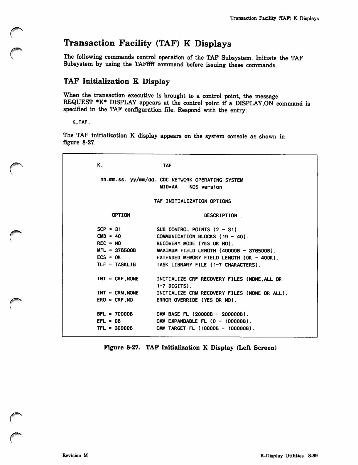
Transaction Facility (TAF) K Displays
Transaction Facility (TAF) K Displays
The following commands control operation of the TAF Subsystem. Initiate the TAF
Subsystem by using the TAFffff command before issuing these commands.
TAF Initialization K Display
When the transaction executive is brought to a control point, the message
REQUEST *K* DISPLAY appears at the control point if a DISPLAY,ON command is
specified in the TAF configuration file. Respond with the entry:
K . TA F.
The TAF initialization K display appears on the system console as shown in
figure 8-27.
TAF
hh.mm.ss. yy/mm/dd. CDC NETWORK OPERATING SYSTEM
MID=AA NOS version
TAF INITIALIZATION OPTIONS
OPTION DESCRIPTION
SCP = 31 SUB CONTROL POINTS (2 - 31).
CMB = 40 COMMUNICATION BLOCKS (19 - 40).
REC = NO RECOVERY MODE (YES OR NO).
MFL = 376500B MAXIMUM FIELD LENGTH (40000B - 376500B).
ECS = OK EXTENDED MEMORY FIELD LENGTH (OK - 400K).
TLF = TASKLIB TASK LIBRARY FILE (1-7 CHARACTERS).
INITIALIZE CRF RECOVERY FILES (NONE,ALL OR
1-7 DIGITS).
INT = CRM,NONE INITIALIZE CRM RECOVERY FILES (NONE OR ALL)
ERO = CRF,NO ERROR OVERRIDE (YES OR NO).
BFL = 70000B CMM BASE FL (20000B - 200000B).
EFL = OB CMM EXPANDABLE FL (0 - 100000B).
TFL = 30000B CMM TARGET FL (10000B - 100000B).
INT = CRF,NONE
r
Figure 8-27. TAF Initialization K Display (Left Screen)
Revision M K-Display Utilities 8-89
TAF Initialization K Display
Any of the following initialization commands can then be entered. If no values are to
be changed, enter the command:
K.END
Values are decimal unless otherwise indicated.
Command Description
K.BFL=n Changes the starting and minimum field length allocated by TAF to
CRM (200008 ^ n ^ 200000s). Default is 70000s.
K.CMB=n Changes the maximum number of communication blocks allowed to
the TAF Subsystem (19 ^ n ^ 40). Default is 40.
K.ECS=n Sets the extended memory field length to be used by the
transaction executive; n is octal thousands of words. Default is 0.
K.EFL=n Changes the maximum additional central memory field length made
available to CRM for buffers and capsules (0 ^ n ^ 100000s).
Default is 0.
K.END Ends input of the transaction executive initialization parameters.
Initialization is completed when the TAF status K display appears
(figure 8-28).
K.ERO=CRF,op Specifies whether to override certain I/O and logic errors when
processing the communication recovery files (CRF).
op Description
NO Aborts if I/O or logic errors are encountered while
processing the communication recovery files. This is the
default setting.
YES I/O or logic errors encountered on a run unit header
record result in the loss of that run unit with no
indication to the terminal user. The loss is noted on the
recovery report.
I/O or logic errors encountered on a message record
within a run unit result in a loss of that run unit. A
status field is set in the run unit header, allowing TAF to
inform the terminal user of the run unit loss.
I/O or logic errors encountered on the CRF header record
result in an unconditional abort of the TAF Subsystem.
A ^ S
8-90 NOS Version 2 Analysis Handbook Revision M
TAF Initialization K Display
Command Description
K.GO
K.INT=typ,fileid
Ends input of the transaction executive initialization parameters.
Initialization is complete when the TAF status K display appears
(figure 8-28).
Specifies which communication recovery files (CRF) are to be
initialized. This is the only way to initialize a CRF. Files specified
on a RECOVER command in the TAF configuration file and
specified in this command are initialized. Files specified on a
RECOVER command but not specified in this command are used for
recovery.
This command also specifies whether CYBER record manager
(CRM) data base recovery files are initialized or recovered. For
CRM recovery files, this command is valid regardless of TAF
assembly parameters.
typ
CRF
CRM
fileid
Description
Communication recovery files. This parameter is valid
only if the installation parameter IPTAR equals 1.
CYBER Record Manager after-image and before-image
recovery files.
Description
n A digit from 1 to 7 that defines a CRF to be initialized.
The digit corresponds to the ID parameter on the
RECOVER command in the TAF configuration file. This
parameter is not valid for CRM recovery files.
ALL If typ is CRF, all communication recovery files defined by
RECOVER commands in the TAF configuration file are
initialized. If typ is CRM, all CRM recovery files are
initialized.
This parameter must be used with caution when typ is
CRM since the CRM update history currently on the
after-image recovery files is lost.
NONE If typ is CRF, communication recovery files are
initialized; all communication recovery files specified in
RECOVER commands in the TAF configuration file are
recovered. If typ is CRM, all CRM data bases are
recovered based on information in the existing recovery
files. No CRM recovery files are initialized. This fileid is
the default for both typ=CRF and typ=CRM.
Revision M K-Display Utilities 8-91
TAF Initialization K Display
Command
K.MFL=n
K.REC=a
K.SCP=n
K.STOP
K.TFL=n
Description
K.TLF=filename
Sets the maximum field length to be used by the transaction
executive (400008 ^ n ^ 376500s). Default is 376500s.
Specifies whether to set the recovery bit in the user area of each
terminal status table entry (YES or NO). If YES, the user recovery
bit is set. If NO, the value of the user recovery bit is not changed
from what it was before the command was issued. Default is NO.
Changes the number of subcontrol points (2 ^ n < 31). Default
is 31.
Aborts the TAF Subsystem initialization unconditionally.
Changes the value used as the upper bound for TARGET. This is
the amount of memory CRM uses for data and index blocks
(100008 ^ n ^ 1000008). Default is 300008. For more information,
refer to the CYBER Record Manager Advanced Access Methods
Version 2 Reference Manual.
Changes the name of the system task library file (any valid file
name). Default is TASKLIB.
8-92 NOS Version 2 Analysis Handbook Revision M
0ms
Restarting TAF K Display
Restarting TAF K Display
On a level 3 recovery deadstart, or if the TAF Subsystem aborts, the TAF procedure
file will automatically restart TAF by transferring control to the TAF automatic
recovery program, if sense switch 4 is set. The TAF automatic recovery program
recovers the central memory pointers and variables defined during TAF initialization.
If a DISPLAY,ON command is in the TAF configuration file, the automatic recovery
program brings up the K display on the left console screen. This display is identical
to the TAF initialization K display, except that values specified by the TAF
initialization commands replace any default values that were in the TAF initialization
K display.
TAF Status K Display
When the TAF Subsystem is executing, the TAF status K display (figure 8-28)
indicates the:
• Latest transaction sequence number.
• Number of words of unused memory.
• Maximum field length.
• Global task dump limit.
• Subsystem default values for memory dump parameters.
The subsystem default values are used to control memory dumps when parameters are
not included in the CMDUMP or DSDUMP command. Any of these default values can
be changed by specifying the corresponding parameter in the K.DSDUMP command.
Revision M K-Display Utilities 8-93
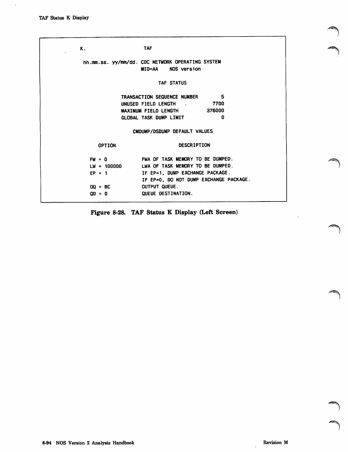
TAF Status K Display
hh.mm.ss. yy/mm/dd.
TAF
CDC NETWORK OPERATING SYSTEM
MID=AA NOS version
TAF STATUS
TRANSACTION SEQUENCE NUMBER 5
UNUSED FIELD LENGTH 7700
MAXIMUM FIELD LENGTH 376000
GLOBAL TASK DUMP LIMIT 0
CMDUMP/DSDUMP DEFAULT VALUES
OPTION DESCRIPTION
FW = 0 FWA OF TASK MEMORY TO BE DUMPED.
LW = 100000 LWA OF TASK MEMORY TO BE DUMPED.
EP = 1 IF EP=1, DUMP EXCHANGE PACKAGE.
IF EP»0, DO NOT DUMP EXCHANGE PACKAGE
OQ = BC OUTPUT QUEUE.
QD « 0 QUEUE DESTINATION.
Figure 8-28. TAF Status K Display (Left Screen)
/■SS8|v
>*ffi%v
8-94 NOS Version 2 Analysis Handbook Revision M
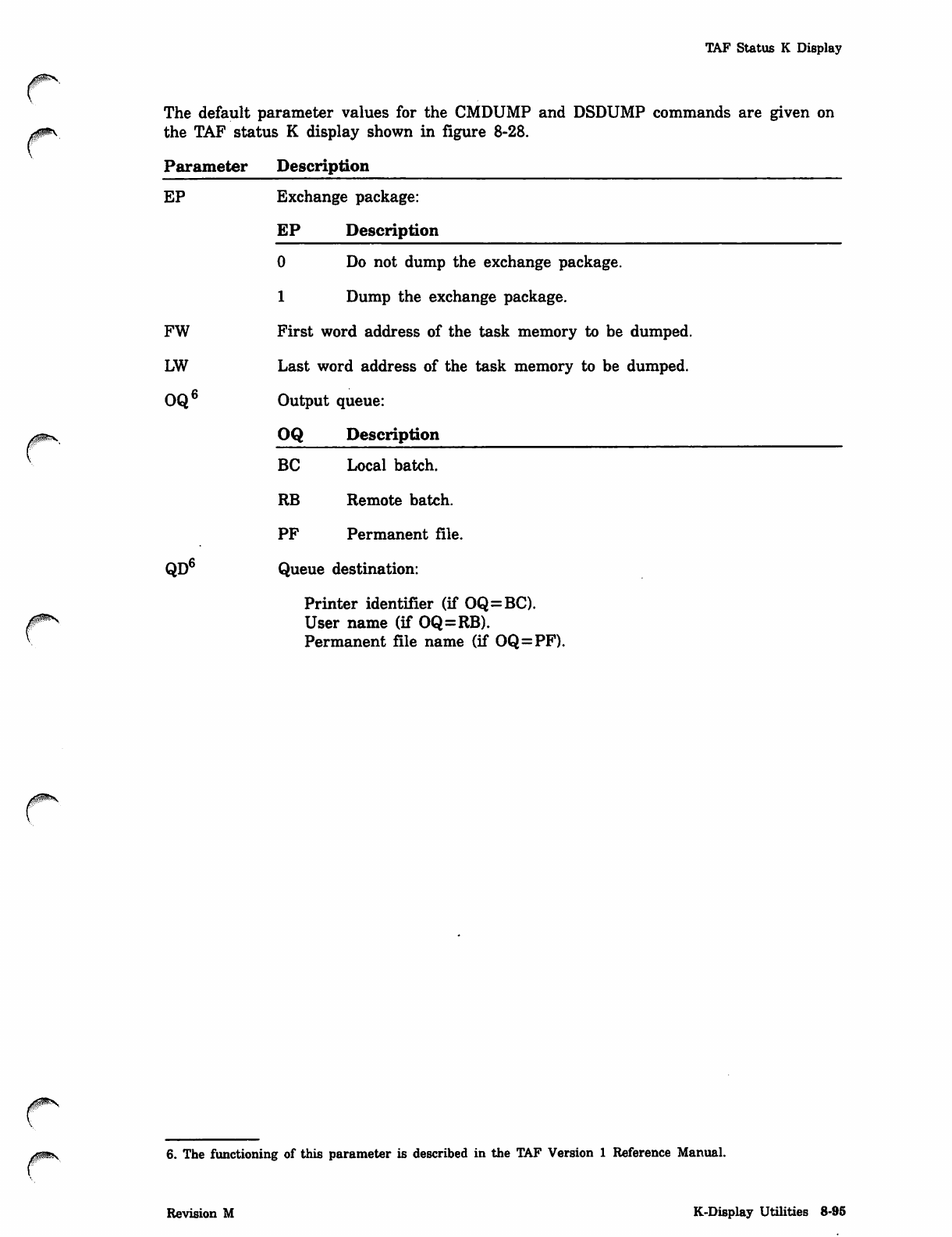
TAF Status K Display
The default parameter values for the CMDUMP and DSDUMP commands are given on
the TAF status K display shown in figure 8-28.
Parameter Description
EP Exchange package:
EP Description
0 Do not dump the exchange package.
1 Dump the exchange package.
FW First word address of the task memory to be dumped.
LW Last word address of the task memory to be dumped.
OQ6 Output queue:
O Q D e s c r i p t i o n
BC Local batch.
RB Remote batch.
PF Permanent file.
QD6 Queue destination:
Printer identifier (if OQ=BC).
User name (if OQ=RB).
Permanent file name (if OQ=PF).
6. The functioning of this parameter is described in the TAF Version 1 Reference Manual.
Revision M K-Display Utilities 8-95
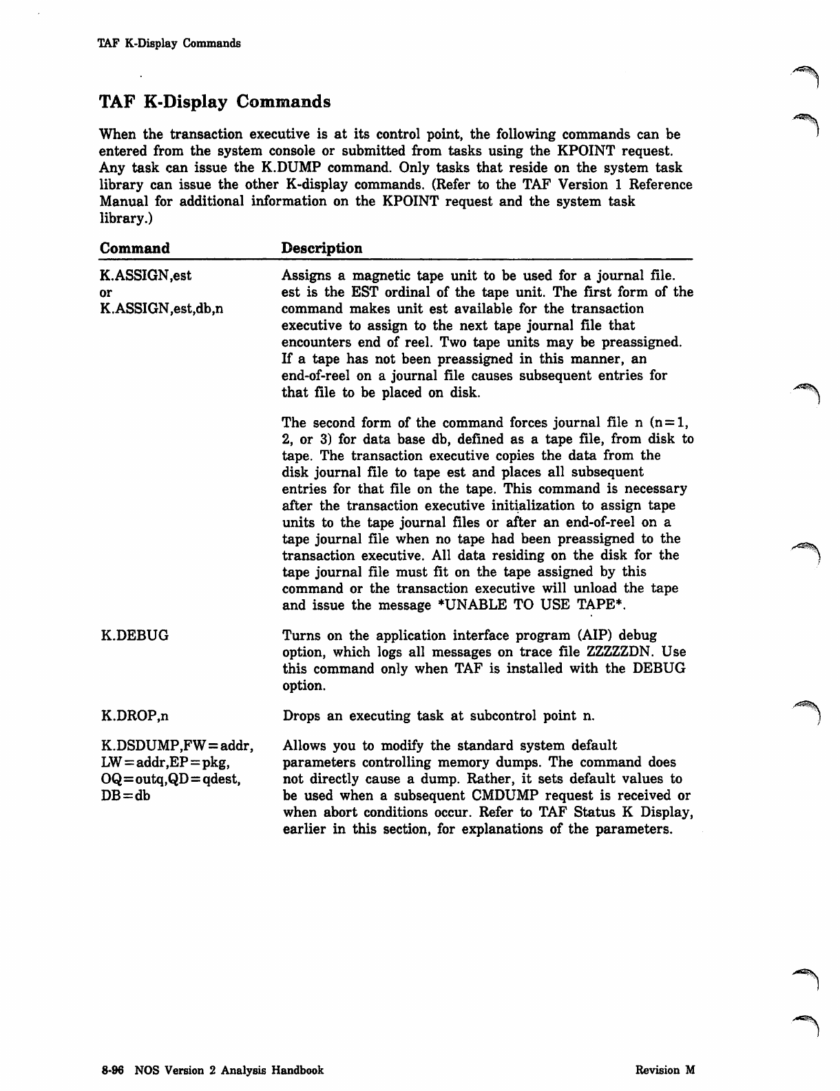
TAF K-Display Commands
TAF K-Display Commands
When the transaction executive is at its control point, the following commands can be
entered from the system console or submitted from tasks using the KPOINT request.
Any task can issue the K.DUMP command. Only tasks that reside on the system task
library can issue the other K-display commands. (Refer to the TAF Version 1 Reference
Manual for additional information on the KPOINT request and the system task
library.)
Command
K.ASSIGN.est
or
K.ASSIGN,est,db,n
K.DEBUG
K.DROP,n
Description
K.DSDUMP,FW=addr,
LW=addr,EP=pkg,
OQ=outq,QD = qdest,
DB=db
Assigns a magnetic tape unit to be used for a journal file,
est is the EST ordinal of the tape unit. The first form of the
command makes unit est available for the transaction
executive to assign to the next tape journal file that
encounters end of reel. Two tape units may be preassigned.
If a tape has not been preassigned in this manner, an
end-of-reel on a journal file causes subsequent entries for
that file to be placed on disk.
The second form of the command forces journal file n (n = l,
2, or 3) for data base db, defined as a tape file, from disk to
tape. The transaction executive copies the data from the
disk journal file to tape est and places all subsequent
entries for that file on the tape. This command is necessary
after the transaction executive initialization to assign tape
units to the tape journal files or after an end-of-reel on a
tape journal file when no tape had been preassigned to the
transaction executive. All data residing on the disk for the
tape journal file must fit on the tape assigned by this
command or the transaction executive will unload the tape
and issue the message *UNABLE TO USE TAPE*.
Turns on the application interface program (AIP) debug
option, which logs all messages on trace file ZZZZZDN. Use
this command only when TAF is installed with the DEBUG
option.
Drops an executing task at subcontrol point n.
Allows you to modify the standard system default
parameters controlling memory dumps. The command does
not directly cause a dump. Rather, it sets default values to
be used when a subsequent CMDUMP request is received or
when abort conditions occur. Refer to TAF Status K Display,
earlier in this section, for explanations of the parameters.
z<^\
8-96 NOS Version 2 Analysis Handbook Revision M
TAF K-Display Commands
Command
K.DUMP,fwa,lwa
J$3zm^\
0nms
Description
Dumps all or part of the field length of the Transaction
Facility from the first word address (fwa) to the last word
address (lwa) of the area to be dumped. The default value
for fwa is 0 and for lwa is 377777s. The default base is
octal. If no parameters are specified, the entire field length
is dumped. The output is routed to a printer that has an ID
of 0.
Unlike other K-display commands, the K.DUMP command
can be issued from any task. Other K-display commands can
be issued by tasks only if they are on the system task
library (refer to the TAF Version 1 Reference Manual).
Since secure information may be contained in a dump of the
Transaction Facility, the following safeguards have been set
up to protect dumped information; however, the installation
must take the ultimate responsibility for the protection of
dumped information.
• The global task dump limit (GTDL) can be set by the
K.DUMPLIM command to limit the number of times the
K.DUMP command can be issued from tasks. The initial
value of the GTDL is 0 (zero), so the K.DUMP command
is disabled from use by a task by default.
• For all dumps of the Transaction Facility, whether you
initiated it or a task did, a one-page header precedes the
dump. This header page indicates the output is secure
and should be given only to the TAF central site systems
analyst.
• When the Transaction Facility is dumped, the message
TAF FIELD LENGTH DUMP RELEASED is issued to
the system dayfile, the Transaction Facility dayfile, and
line one of the control point.
Revision M K-Display Utilities 8-97
TAF K-Display Commands
Command Description
K.DUMPLIM,n
K.IDLE
K.JEND,db,n
K.MAXFL,n
K.MESSAGE,TN=b.
message
Sets GTDL to value n (0 ^ n ^ 9999999). If n is not
specified, the GTDL is set to 0.
The GTDL is the number of times the K.DUMP command
can be issued from tasks. This value is displayed on the
TAF status K display shown in figure 8-28. The initial value
of the GTDL is 0. When the GTDL is 0, no dumps of the
Transaction Facility can occur from tasks. Thus, the
K.DUMP command is disabled from tasks by default.
To enable the K.DUMP command for tasks, issue the
K.DUMPLIM command to set the GTDL to a value greater
than zero. Each time a task issues a K.DUMP command,
the GTDL is decreased by one until it equals zero. When
the first K.DUMP command is issued from a task with the
GTDL equal to zero, the message
GLOBAL TASK DUMP LIMIT EXHAUSTED
is issued to the Transaction Facility dayfile, the system
dayfile, and line one of the control point. Also, the message
DUMPS.LOST
is displayed on the K display in place of the value of the
GTDL. This message remains until the value of GTDL is set
to a value greater than or equal to zero. The K.DUMPLIM
command should be used with care in system tasks, since
this might allow unauthorized users to alter the GTDL.
Idles down the transaction control point. Once idle down has
been initiated, no new transactions will be permitted but
currently executing transactions will be allowed to finish.
Forces end-of-reel processing (writes an EOI and rewinds the
file) on tape journal file n of data base db. If n is not a
tape journal file, the command is ignored.
Alters the transaction executive maximum field length. The
transaction executive does not attempt to obtain more than
n words of storage. This command is rejected if the value
for n is more than 376500s or less than the field length
currently required for TAF.
Directs the transaction executive to send message to a
terminal specified by terminal name b.
^®^Si
>^^^V
8-98 NOS Version 2 Analysis Handbook Revision M
TAF K-Display Commands
Command
K.NODEBUG
K.OFFTASK,a,db
K.ONTASK.a.db
K.ROLLTIM,nnnnnn
K.SWITCH
Description
K.TBCON,nn
K.TST,TN = a,DB=db,
UU = nnnn,UL=mmmm,
NN = b
Turns off the application interface program (AIP) debug
option, which logs all messages on trace file ZZZZZDN. Use
this command only when TAF is installed with the DEBUG
option.
Disables the use of task a, where a is the task name in the
data base db task library directory (dbTASKL). The data
base name db is not specified for tasks in the system task
library.
Reverses the effect of a previous OFFTASK command for the
specified task a in the data base db task library directory
(dbTASKL). The data base name db is not specified for tasks
in the system task library (TASKLIB).
Changes the amount of time that TAF will retain its field
length between communication input messages; nnnnnn is
specified in units of milliseconds. Refer to the installation
parameter ITRTL in the NOS Version 2 Installation
Handbook.
Causes the console K display to change to a display listing
all allowable TAF K display commands. When K.SWITCH is
entered a second time, the previous K display returns. This
command activates task KDIS and forces TAF to remain
rolled in.
Changes the number of TAF/CRM batch concurrency users;
nn is less than or equal to the value specified on the
TBCON command in TAF's configuration file (TCF).
Changes entries in the terminal status table for terminal a.
The following entries can be changed: data base name db,
user area upper 12 bits (nnnn), user area lower 12 bits
(mmmm), and new terminal name b. The changes do not
affect the network and simulation files. Do not use this
command if the terminal is logged in.
Revision M K-Display Utilities 8-99
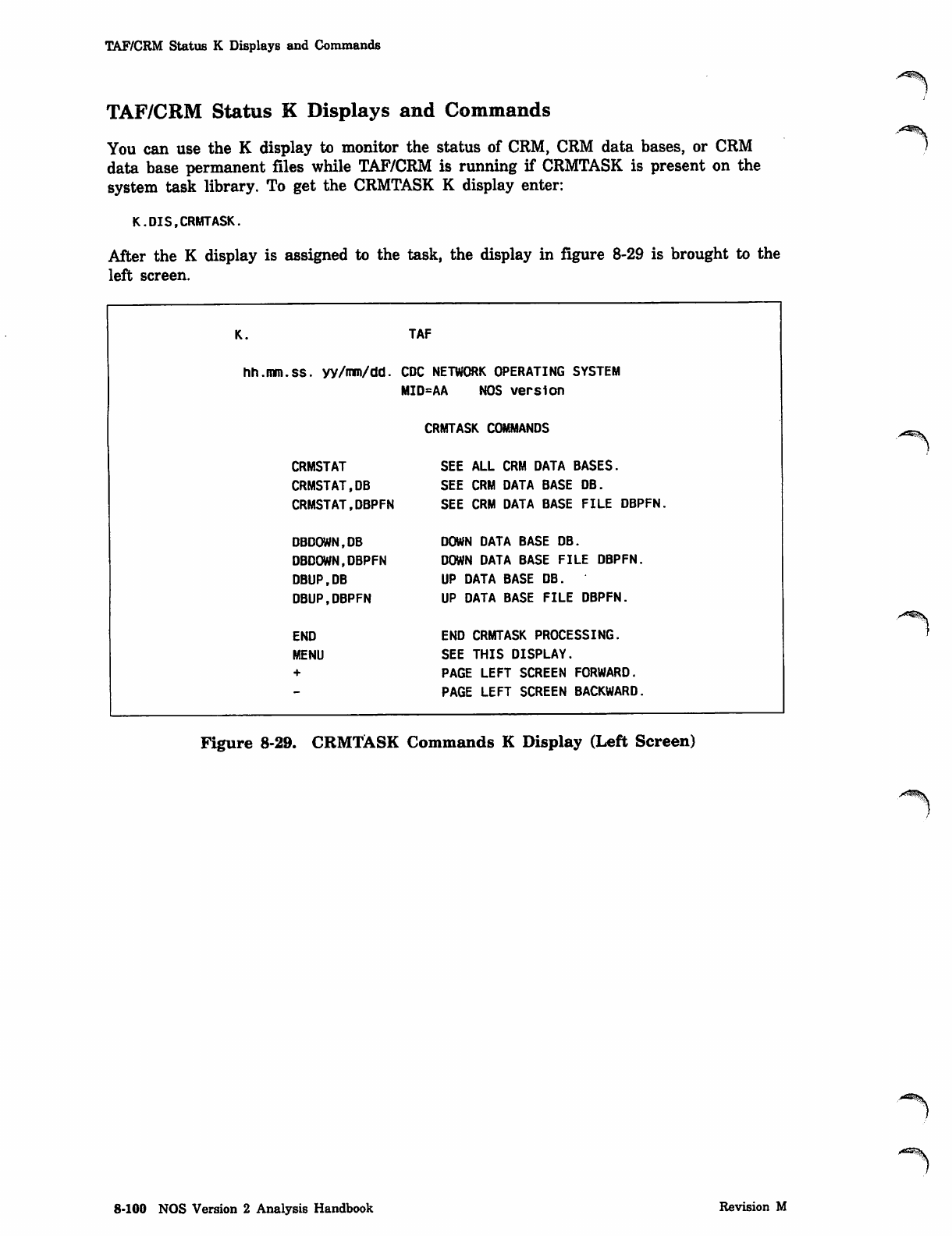
TAF/CRM Status K Displays and Commands
TAF/CRM Status K Displays and Commands
You can use the K display to monitor the status of CRM, CRM data bases, or CRM
data base permanent files while TAF/CRM is running if CRMTASK is present on the
system task library. To get the CRMTASK K display enter:
K.DIS,CRMTASK.
After the K display is assigned to the task, the display in figure 8-29 is brought to the
left screen.
TAF
hh.mm.ss. yy/mm/dd. CDC NETWORK OPERATING SYSTEM
MID=AA NOS version
CRMTASK COMMANDS
CRMSTAT SEE ALL CRM DATA BASES.
CRMSTAT.DB SEE CRM DATA BASE DB.
CRMSTAT,DBPFN SEE CRM DATA BASE FILE DBPFN.
DBDOWN,DB DOWN DATA BASE DB.
DBDOWN,DBPFN DOWN DATA BASE FILE DBPFN.
DBUP.DB UP DATA BA SE D B.
DBUP,DBPFN UP DATA BASE FILE DBPFN.
END END CRMTASK PROCESSING.
MENU SEE THIS DISPLAY.
+ PAGE LEFT SCREEN FORWARD.
PAGE LEFT SCREEN BACKWARD.
Figure 8-29. CRMTASK Commands K Display (Left Screen)
■^Sfev
8-100 NOS Version 2 Analysis Handbook Revision M
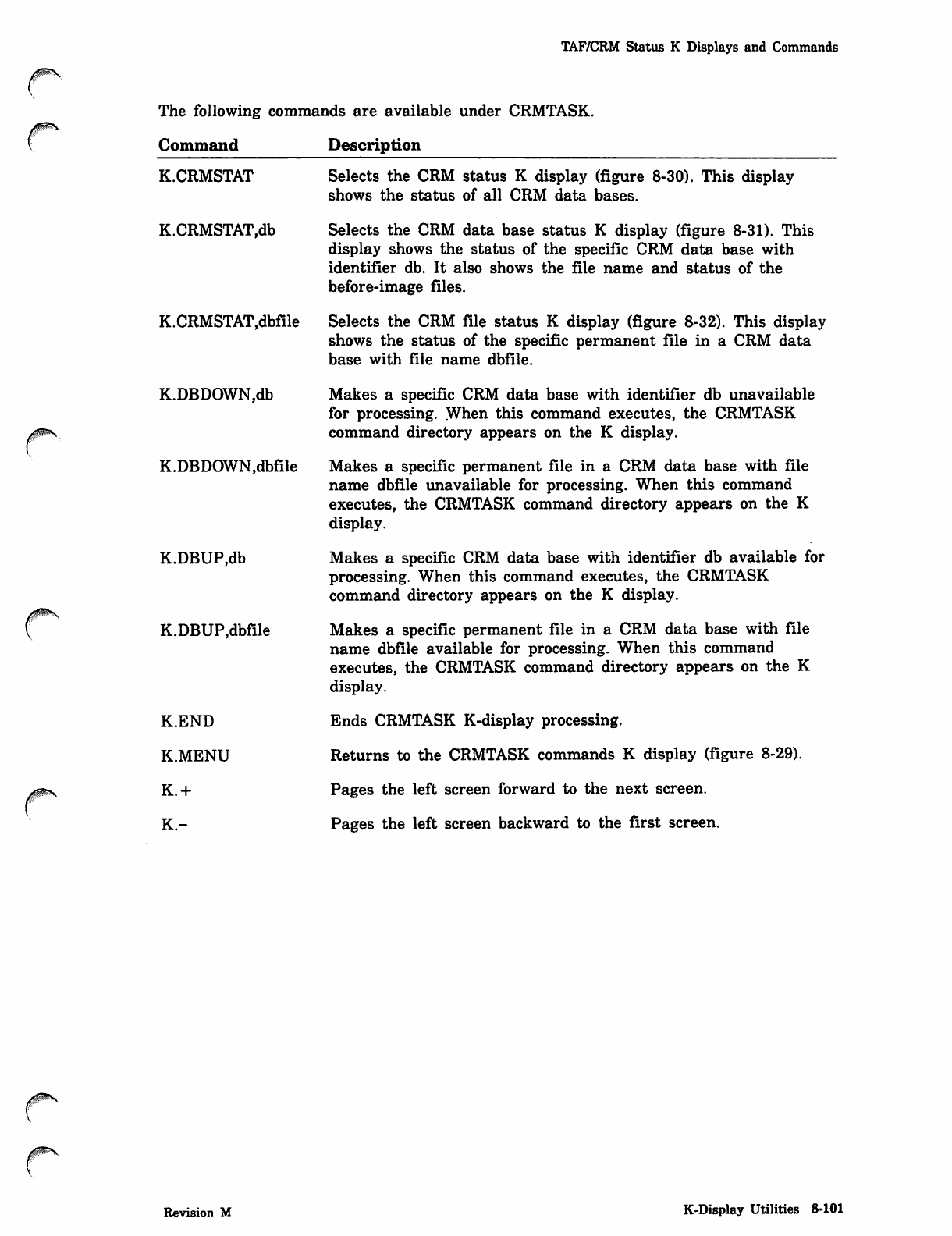
TAF/CRM Status K Displays and Commands
0m^-..
The following commands are available under CRMTASK.
Command Description
K.CRMSTAT
K.CRMSTAT,db
K.CRMSTAT,dbfile
K.DBDOWN,db
K.DBDOWN,dbfile
K.DBUP,db
K.DBUP,dbfile
K.END
K.MENU
K.+
K-
Selects the CRM status K display (figure 8-30). This display
shows the status of all CRM data bases.
Selects the CRM data base status K display (figure 8-31). This
display shows the status of the specific CRM data base with
identifier db. It also shows the file name and status of the
before-image files.
Selects the CRM file status K display (figure 8-32). This display
shows the status of the specific permanent file in a CRM data
base with file name dbfile.
Makes a specific CRM data base with identifier db unavailable
for processing. When this command executes, the CRMTASK
command directory appears on the K display.
Makes a specific permanent file in a CRM data base with file
name dbfile unavailable for processing. When this command
executes, the CRMTASK command directory appears on the K
display.
Makes a specific CRM data base with identifier db available for
processing. When this command executes, the CRMTASK
command directory appears on the K display.
Makes a specific permanent file in a CRM data base with file
name dbfile available for processing. When this command
executes, the CRMTASK command directory appears on the K
display.
Ends CRMTASK K-display processing.
Returns to the CRMTASK commands K display (figure 8-29).
Pages the left screen forward to the next screen.
Pages the left screen backward to the first screen.
Revision M K-Display Utilities 8-101
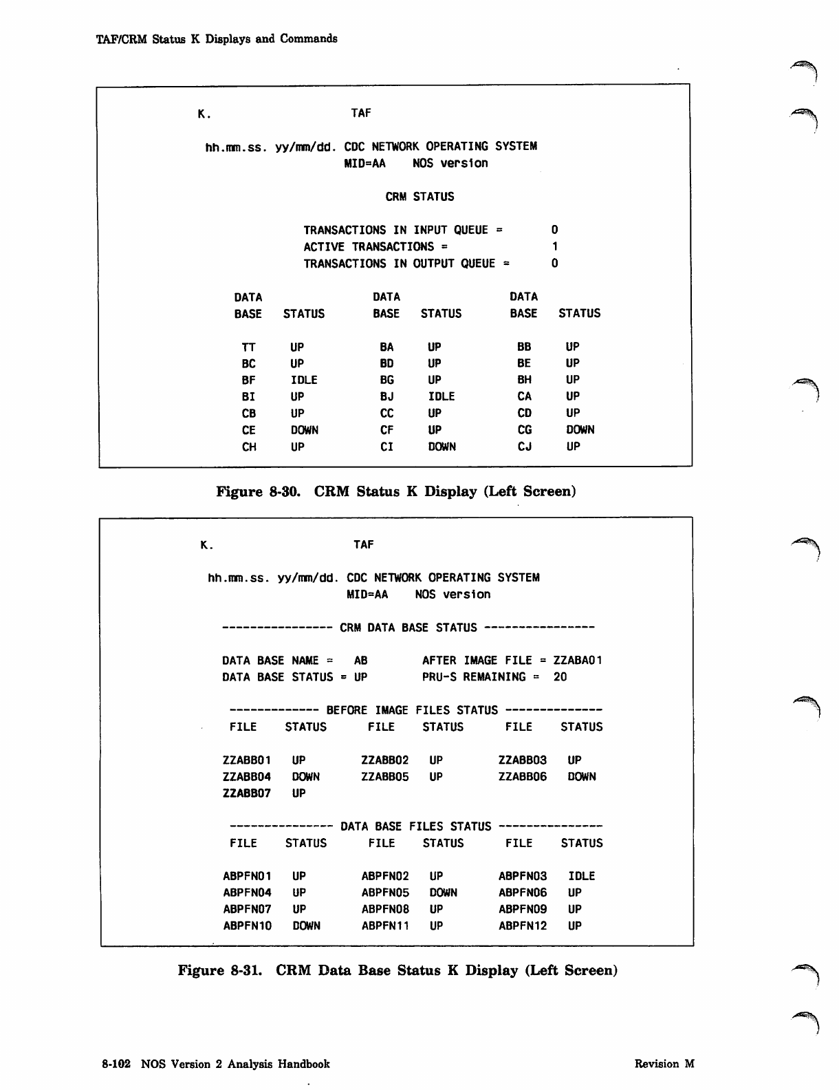
TAF/CRM Status K Displays and Commands
TAF
hh.mm.ss. yy/mm/dd. CDC NETWORK OPERATING SYSTEM
MID'=AA
CRM
NOS version
STATUS
TRANSACTIONS IN INPUT QUEUE ss
ACTIVE TRANSACTIONS =
TRANSACTIONS IN OUTPUT QUEUE
DATA DATA DATA
BASE STATUS BASE STATUS BASE STATUS
TT UP BA UP BB UP
BC UP BD UP BE UP
BF IDLE BG UP BH UP
BI UP BJ IDLE CA UP
CB UP CC UP CD UP
CE DOWN CF UP CG DOWN
CH UP CI DOWN CJ UP
./<a^8k
Figure 8-30. CRM Status K Display (Left Screen)
K. TAF
hh.mm.ss. yy/mm/dd CDC NETWORK OPERATING SYSTEM
MID=AA NOS version
DATA BASE NAME = AB AFTER IMAGE FILE = ZZABA01
DATA BASE STATUS = UP PRU-S REMAINING = 20
ocrunt XRiMut riuto oihiuo
FILE STATUS F I L E S TAT U S F I L E STATUS
ZZABB01 UP ZZABB02 UP ZZABB03 UP
ZZABB04 DOWN ZZABB05 UP ZZABB06 DOWN
ZZABB07 UP
FILE STATUS F I L E S TAT U S F I L E STATUS
ABPFN01 UP ABPFN02 UP ABPFN03 IDLE
ABPFN04 UP ABPFN05 DOWN ABPFN06 UP
ABPFN07 UP ABPFN08 UP ABPFN09 UP
ABPFN10 DOWN ABPFN11 UP ABPFN12 UP
/^SftjSk
Figure 8-31. CRM Data Base Status K Display (Left Screen)
8-102 NOS Version 2 Analysis Handbook Revision M
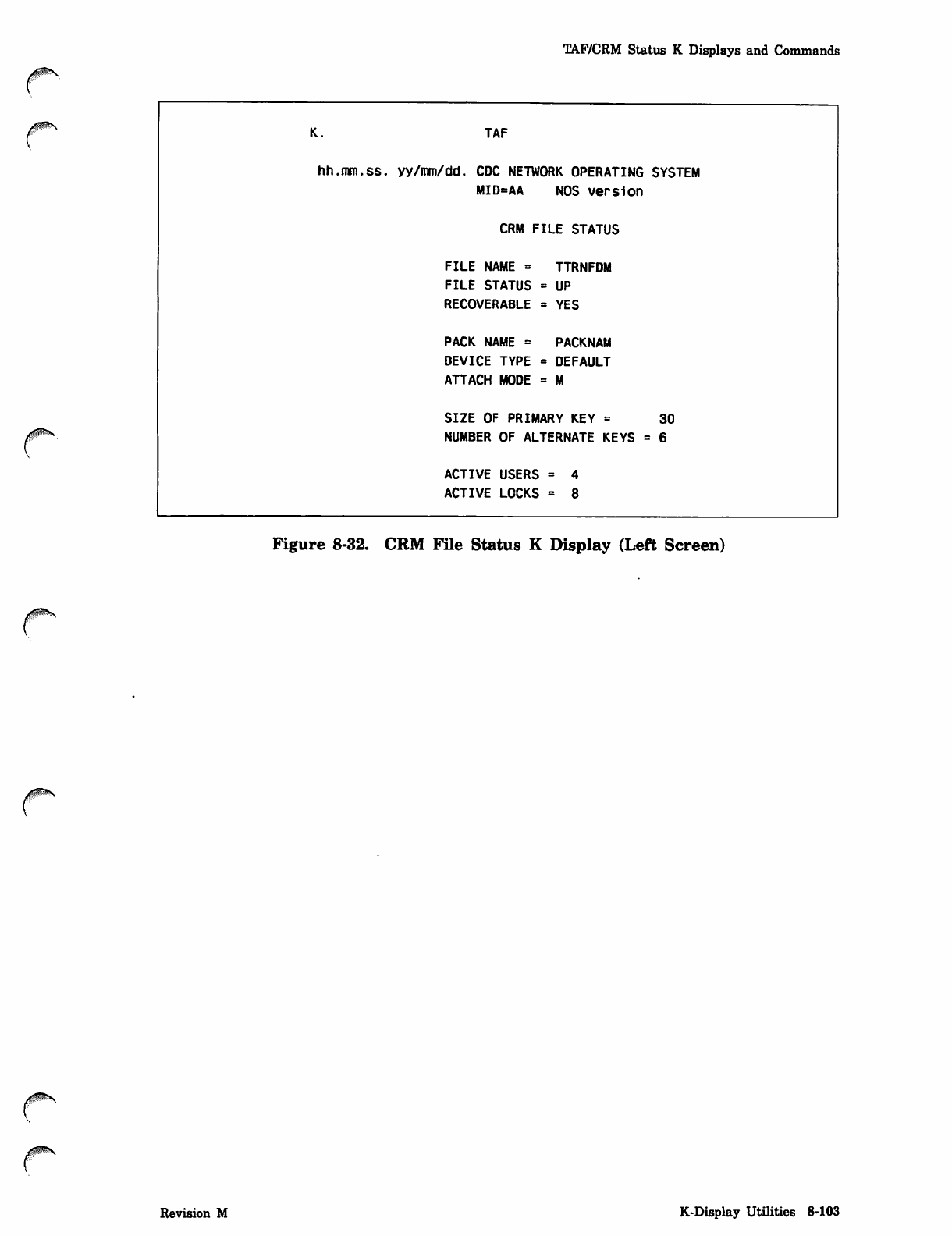
TAF/CRM Status K Displays and Commands
TAF
hh.mm.ss. yy/mm/dd. CDC NETWORK OPERATING SYSTEM
MID=AA NOS version
CRM FILE STATUS
FILE NAME = TTRNFDM
FILE STATUS = UP
RECOVERABLE = YES
PACK NAME = PACKNAM
DEVICE TYPE = DEFAULT
ATTACH MODE = M
SIZE OF PRIMARY KEY = 30
NUMBER OF ALTERNATE KEYS = 6
ACTIVE USERS = 4
ACTIVE LOCKS = 8
Figure 8-32. CRM File Status K Display (Left Screen)
Revision M K-Display Utilities 8-103

jr**'*
^
f^
L-Display Utilities 9
FOTD L Display 9-2
LIDOU L Display 9-3
QDSPLAY L Display 9-6
SCTD L Display . 9-10
SDSPLAY L Display 9-12
SDSPLAY Commands 9-16
Changing System Attributes . 9-17
L.keyword=value Commands 9-17
SUBSYST L Display 9-20

v_
v~
**%.
* " %
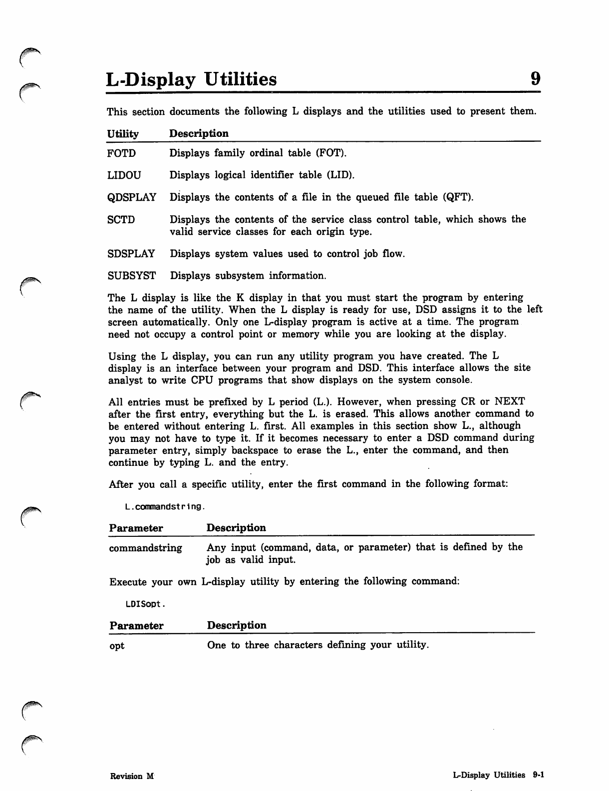
yams.
L-Display Utilities
This section documents the following L displays and the utilities used to present them.
Utility Description
FOTD Displays family ordinal table (FOT).
LIDOU Displays logical identifier table (LID).
QDSPLAY Displays the contents of a file in the queued file table (QFT).
SCTD Displays the contents of the service class control table, which shows the
valid service classes for each origin type.
SDSPLAY Displays system values used to control job flow.
SUBSYST Displays subsystem information.
The L display is like the K display in that you must start the program by entering
the name of the utility. When the L display is ready for use, DSD assigns it to the left
screen automatically. Only one L-display program is active at a time. The program
need not occupy a control point or memory while you are looking at the display.
Using the L display, you can run any utility program you have created. The L
display is an interface between your program and DSD. This interface allows the site
analyst to write CPU programs that show displays on the system console.
All entries must be prefixed by L period (L.). However, when pressing CR or NEXT
after the first entry, everything but the L. is erased. This allows another command to
be entered without entering L. first. All examples in this section show L., although
you may not have to type it. If it becomes necessary to enter a DSD command during
parameter entry, simply backspace to erase the L., enter the command, and then
continue by typing L. and the entry.
After you call a specific utility, enter the first command in the following format:
L.commandst ring.
Parameter Description
commandstring Any input (command, data, or parameter) that is defined by the
job as valid input.
Execute your own L-display utility by entering the following command:
LDISopt.
Parameter Description
opt One to three characters defining your utility.
Revision M L-Display Utilities 9-1
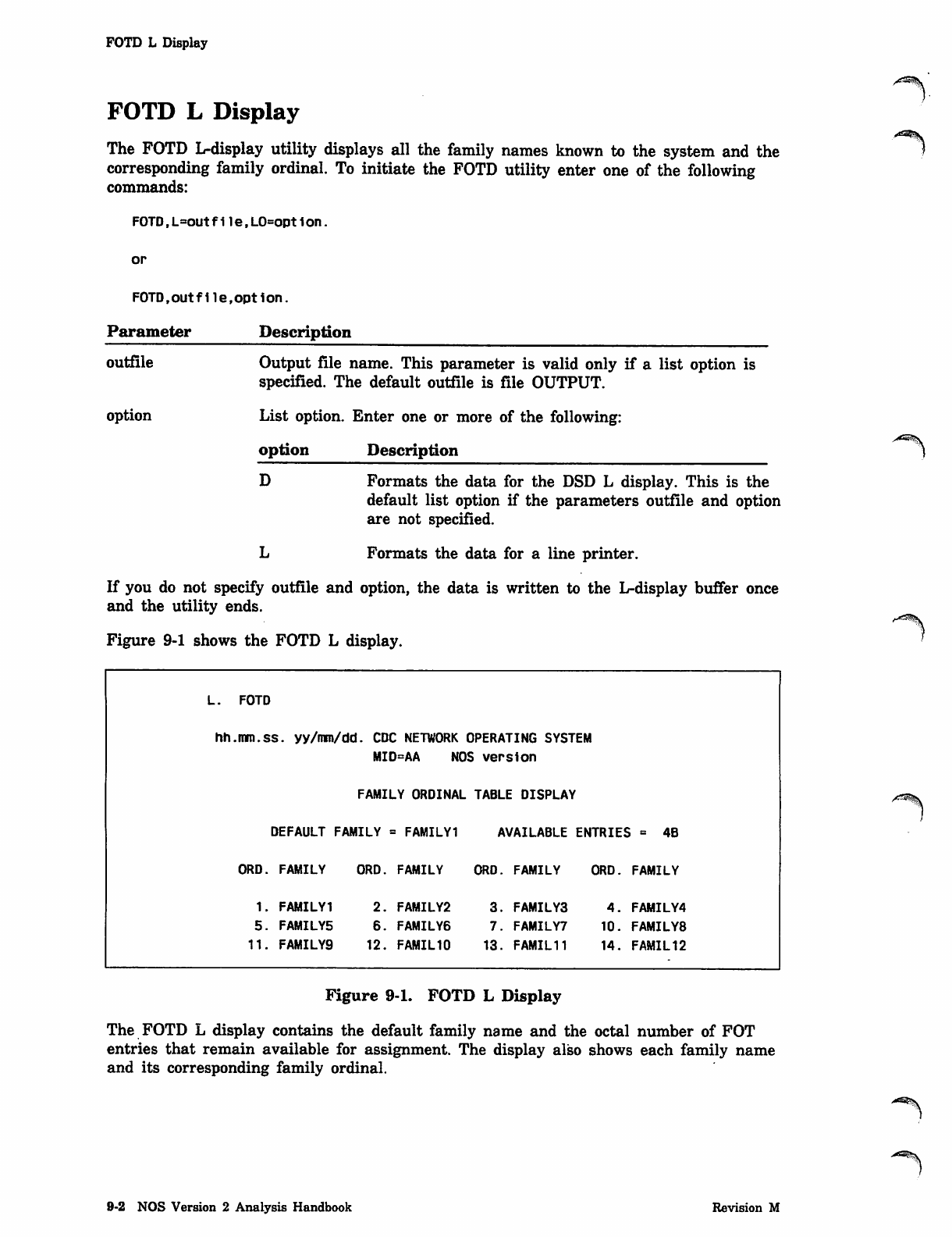
FOTD L Display
FOTD L Display
The FOTD L-display utility displays all the family names known to the system and the
corresponding family ordinal. To initiate the FOTD utility enter one of the following
commands:
FOTD,L=out file,LO=opt1on.
or
FOTD.outflle,option.
Parameter Description
outfile Output file name. This parameter is valid only if a list option is
specified. The default outfile is file OUTPUT.
option List option. Enter one or more of the following:
option Description
D Formats the data for the DSD L display. This is the
default list option if the parameters outfile and option
are not specified.
L Formats the data for a line printer.
If you do not specify outfile and option, the data is written to the L-display buffer once
and the utility ends.
Figure 9-1 shows the FOTD L display.
/*&%.
L. FOTD
hh.mm.ss. yy/mm/dd. CDC NETWORK OPERATING SYSTEM
MID-AA NOS version
FAMILY ORDINAL TABLE DISPLAY
DEFAULT FAMILY = FAMILY1 AVAILABLE ENTRIES = 4B
ORD. FAMILY ORD. FAMILY ORD. FAMILY ORD. FAMILY
1. FAMILY1 2. FAMILY2 3. FAMILY3 4. FAMILY4
5. FAMILY5 6. FAMILY6 7. FAMILY7 10. FAMILY8
11. FAMILY9 12. FAMIL10 13. FAMIL11 14. FAMIL12
Figure 9-1. FOTD L Display
The FOTD L display contains the default family name and the octal number of FOT
entries that remain available for assignment. The display also shows each family name
and its corresponding family ordinal.
9-2 NOS Version 2 Analysis Handbook Revision M

LIDOU L Display
*^s LIDOU L Display
The LIDOU utility displays the LID table configuration and allows you to add or delete
LIDs, LID attributes, and PID attributes in the LID table configuration. This modified
configuration is retained across a level 1, 2, or 3 recovery deadstart. A level 0
deadstart causes a return to the configuration defined by the LID configuration file.
To initiate the LIDOU utility, enter one of the following commands:
LIDOU.
or
LIDOU,I=1nf1le,L=outfile.
The first command format can be entered only from the console under DSD control;
also, all input and output is processed using the LIDOU L display. Figure 9-2 shows
the initial LIDOU L display (LID display).
NOTE
The information shown in figure 9-2 corresponds to the sample LCN shown in
section 8.
From this display you can select the HELP display shown in figures 9-3 and 9-4. You
can toggle between these two L displays as described in the HELP display.
The second command format can be entered under DIS control or by a system origin
batch job. In either case, the I and L parameters must be specified.
Parameter
I=infile
L=outfile
Description
LIDOU reads input directives from file infile. Valid input
directives are the same as the commands shown in the HELP L
display (figure 9-3) without the L. prefix and without the BACK,
HELP, +, or - commands.
LIDOU writes output to file outfile.
Revision M L-Display Utilities 9-3
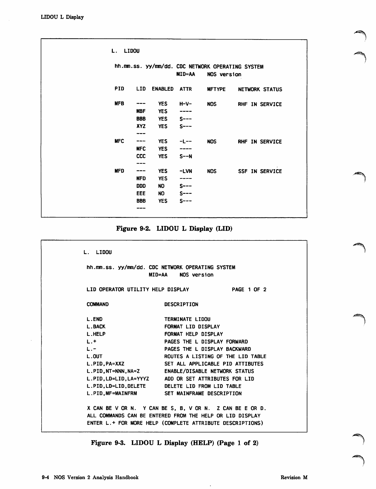
LIDOU L Display
L. LIDOU
hh.mm ss. yy/mm/dd. CDC NETWORK OPERATING SYSTEM
MID=AA NOS version
PID LID ENABLED ATTR MFTYPE NETWORK STATUS
MFB YES H-V- NOS RHF IN SERVICE
MBF YES
BBB YES s—
XYZ YES s—
MFC YES -L-- NOS RHF IN SERVICE
MFC YES
CCC YES S—N
MFD YES -LVN NOS SSF IN SERVICE
MFD YES
DDD NO s—
EEE NO
BBB YES
«_•-
Figure 9-2. LIDOU L Display (LID)
L. LIDOU
hh.mm.ss. yy/mm/dd. CDC NETWORK OPERATING SYSTEM
MID* =AA NOS version
LID OPERATOR UTILITY HELP DISPLAY PAGE 1 OF 2
COMMAND DESCRIPTION
L.END TERMINATE LIDOU
L.BACK FORMAT LID DISPLAY
L.HELP FORMAT HELP DISPLAY
L.+ PAGES THE L DISPLAY FORWARD
L.- PAGES THE L DISPLAY BACKWARD
L.OUT ROUTES A LISTING OF THE LID TABLE
L.PID,PA=XXZ SET ALL APPLICABLE PID ATTIBUTES
L.PID,NT=NNN,NA=Z ENABLE/DISABLE NETWORK STATUS
L.PID,LD=LID,LA=YYYZ ADD OR SET ATTRIBUTES FOR LID
L.PID,LD=LID,DELETE DELETE LID FROM LID TABLE
L.PID,MF=MAINFRM SET MAINFRAME DESCRIPTION
X CAN BE V OR N. Y CAN BE S, B, V OR N. Z CAN BE E OR D.
ALL COMMANDS CAN BE ENTERED FROM THE HELP OR LID DISPLAY
ENTER L.+ FOR MORE HELP (COMPLETE ATTRIBUTE DESCRIPTIONS)
Figure 9-3. LIDOU L Display (HELP) (Page 1 of 2)
9-4 NOS Version 2 Analysis Handbook Revision M
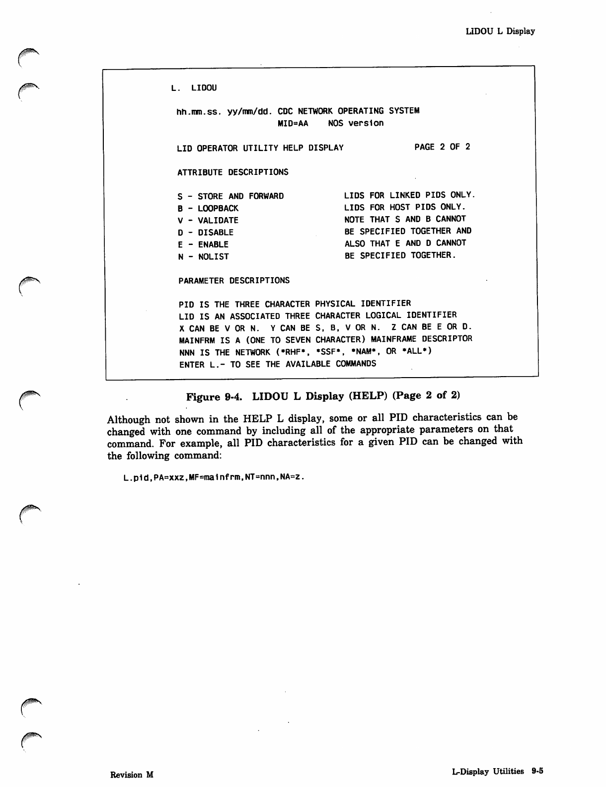
LIDOU L Display
L. LIDOU
hh.mm.ss. yy/mm/dd. CDC NETWORK OPERATING SYSTEM
MID=AA NOS version
LID OPERATOR UTILITY HELP DISPLAY
ATTRIBUTE DESCRIPTIONS
S - STORE AND FORWARD
B - LOOPBACK
V - VALIDATE
D - DISABLE
E - ENABLE
N - NOLIST
PARAMETER DESCRIPTIONS
PID IS THE THREE CHARACTER PHYSICAL IDENTIFIER
LID IS AN ASSOCIATED THREE CHARACTER LOGICAL IDENTIFIER
X CAN BE V OR N. Y CAN BE S, B, V OR N. Z CAN BE E OR D.
MAINFRM IS A (ONE TO SEVEN CHARACTER) MAINFRAME DESCRIPTOR
NNN IS THE NETWORK (-RHF*, *SSF*. *NAM*. OR *ALL*)
ENTER L.- TO SEE THE AVAILABLE COMMANDS
PAGE 2 OF 2
LIDS FOR LINKED PIDS ONLY.
LIDS FOR HOST PIDS ONLY.
NOTE THAT S AND B CANNOT
BE SPECIFIED TOGETHER AND
ALSO THAT E AND D CANNOT
BE SPECIFIED TOGETHER.
Figure 9-4. LIDOU L Display (HELP) (Page 2 of 2)
Although not shown in the HELP L display, some or all PID characteristics can be
changed with one command by including all of the appropriate parameters on that
command. For example, all PID characteristics for a given PID can be changed with
the following command:
L.pid,PA=xxz,MF=ma1nfrm,NT=nnn,NA=z.
Revision M L-Display Utilities 9-5
QDSPLAY L Display
QDSPLAY L Display
The DSD utility QDSPLAY displays the content of a queued file listed in the queued
file table (QFT). ASCII8 files are automatically translated into display code before they
are displayed.
NOTE
On a secured system, the console must be in security unlock status to accept this
command (refer to the UNLOCK,username,password command in section 5).
To bring the QDSPLAY L display to the left console screen, enter the following
command:
QDSPLAY,jsn.
Parameter Description
jsn Job sequence name of the queued file you want to examine.
Figures 9-5 and 9-6 show the initial QDSPLAY L display.
/*^^S
9-6 NOS Version 2 Analysis Handbook Revision M
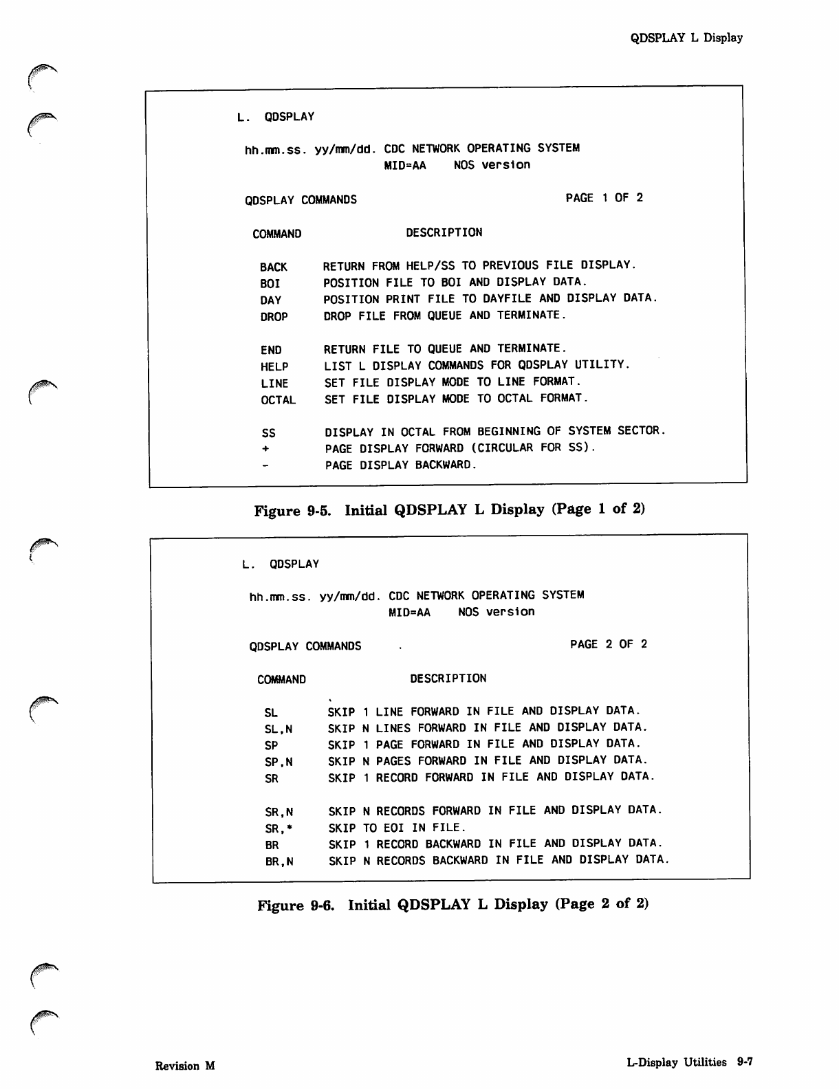
QDSPLAY L Display
.. QDSPLAY
hh.mm.ss. yy/mm/dd. CDC NETWORK OPERATING SYSTEM
MID=AA NOS version
QDSPLAY COMMANDS
COMMAND
PAGE 1 OF 2
DESCRIPTION
BACK RETURN FROM HELP/SS TO PREVIOUS FILE DISPLAY.
BOI POSITION FILE TO BOI AND DISPLAY DATA.
DAY POSITION PRINT FILE TO DAYFILE AND DISPLAY DATA.
DROP DROP FILE FROM QUEUE AND TERMINATE.
END RETURN FILE TO QUEUE AND TERMINATE.
HELP LIST L DISPLAY COMMANDS FOR QDSPLAY UTILITY.
LINE SET FILE DISPLAY MODE TO LINE FORMAT.
OCTAL SET FILE DISPLAY MODE TO OCTAL FORMAT.
SS DISPLAY IN OCTAL FROM BEGINNING OF SYSTEM SECTOR
+ PAGE DISPLAY FORWARD (CIRCULAR FOR SS).
PAGE DISPLAY BACKWARD.
Figure 9-5. Initial QDSPLAY L Display (Page 1 of 2)
QDSPLAY
hh.mm.ss. yy/mm/dd
QDSPLAY COMMANDS
CDC NETWORK OPERATING SYSTEM
MID=AA NOS version
PAGE 2 OF 2
COMMAND
SL
SL.N
SP
SP.N
SR
SR.N
SR,*
BR
BR.N
DESCRIPTION
SKIP 1 LINE FORWARD IN FILE AND DISPLAY DATA.
SKIP N LINES FORWARD IN FILE AND DISPLAY DATA.
SKIP 1 PAGE FORWARD IN FILE AND DISPLAY DATA.
SKIP N PAGES FORWARD IN FILE AND DISPLAY DATA.
SKIP 1 RECORD FORWARD IN FILE AND DISPLAY DATA.
SKIP N RECORDS FORWARD IN FILE AND DISPLAY DATA.
SKIP TO EOI IN FILE.
SKIP 1 RECORD BACKWARD IN FILE AND DISPLAY DATA.
SKIP N RECORDS BACKWARD IN FILE AND DISPLAY DATA.
Figure 9-6. Initial QDSPLAY L Display (Page 2 of 2)
Revision M L-Display Utilities 9-7
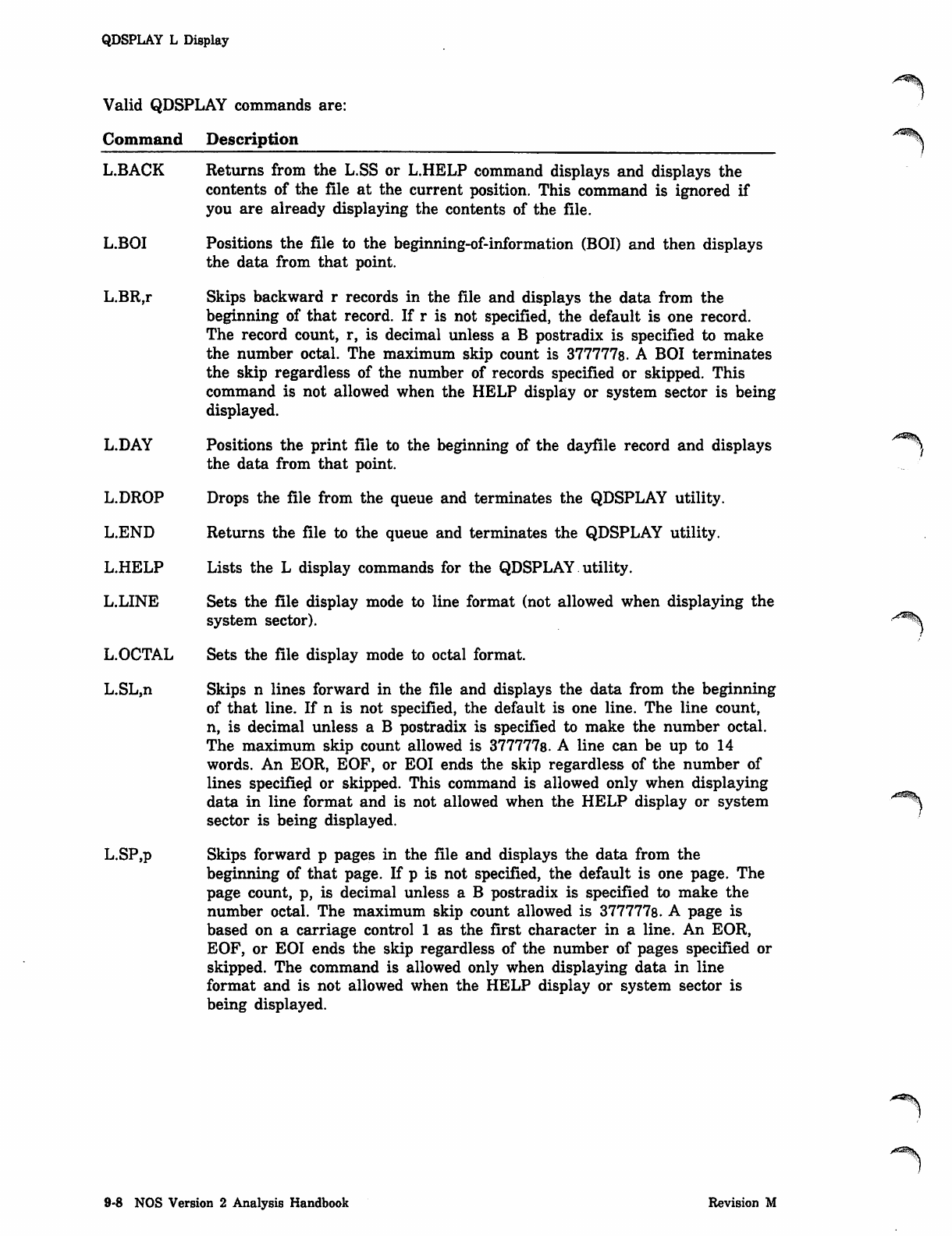
QDSPLAY L Display
Valid QDSPLAY commands are:
Command Description
L.BACK Returns from the L.SS or L.HELP command displays and displays the
contents of the file at the current position. This command is ignored if
you are already displaying the contents of the file.
L.BOI Positions the file to the beginning-of-information (BOI) and then displays
the data from that point.
L.BR,r Skips backward r records in the file and displays the data from the
beginning of that record. If r is not specified, the default is one record.
The record count, r, is decimal unless a B postradix is specified to make
the number octal. The maximum skip count is 3777778. A BOI terminates
the skip regardless of the number of records specified or skipped. This
command is not allowed when the HELP display or system sector is being
displayed.
L.DAY Positions the print file to the beginning of the dayfile record and displays
the data from that point.
L.DROP Drops the file from the queue and terminates the QDSPLAY utility.
L.END Returns the file to the queue and terminates the QDSPLAY utility.
L.HELP Lists the L display commands for the QDSPLAY utility.
L.LINE Sets the file display mode to line format (not allowed when displaying the
system sector).
L.OCTAL Sets the file display mode to octal format.
L.SL,n Skips n lines forward in the file and displays the data from the beginning
of that line. If n is not specified, the default is one line. The line count,
n, is decimal unless a B postradix is specified to make the number octal.
The maximum skip count allowed is 377777s. A line can be up to 14
words. An EOR, EOF, or EOI ends the skip regardless of the number of
lines specifiepl or skipped. This command is allowed only when displaying
data in line format and is not allowed when the HELP display or system
sector is being displayed.
L.SP,p Skips forward p pages in the file and displays the data from the
beginning of that page. If p is not specified, the default is one page. The
page count, p, is decimal unless a B postradix is specified to make the
number octal. The maximum skip count allowed is 377777s. A page is
based on a carriage control 1 as the first character in a line. An EOR,
EOF, or EOI ends the skip regardless of the number of pages specified or
skipped. The command is allowed only when displaying data in line
format and is not allowed when the HELP display or system sector is
being displayed.
a*^$k
9-8 NOS Version 2 Analysis Handbook Revision M
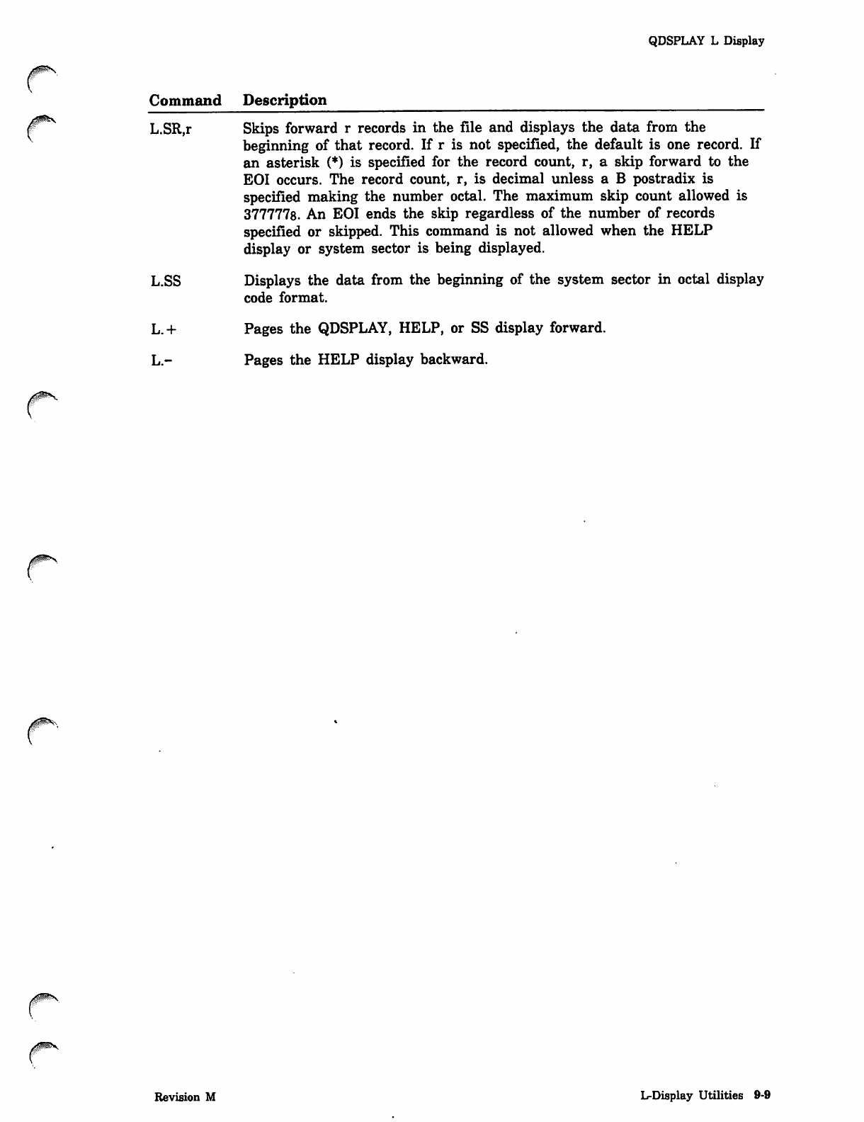
QDSPLAY L Display
Command Description
f^ L.SR,r Skips forward r records in the file and displays the data from the
beginning of that record. If r is not specified, the default is one record. If
an asterisk (*) is specified for the record count, r, a skip forward to the
EOI occurs. The record count, r, is decimal unless a B postradix is
specified making the number octal. The maximum skip count allowed is
3777778. An EOI ends the skip regardless of the number of records
specified or skipped. This command is not allowed when the HELP
display or system sector is being displayed.
L.SS Displays the data from the beginning of the system sector in octal display
code format.
L.+ Pages the QDSPLAY, HELP, or SS display forward.
L.- Pages the HELP display backward.
Revision M L-Display Utilities 9-9
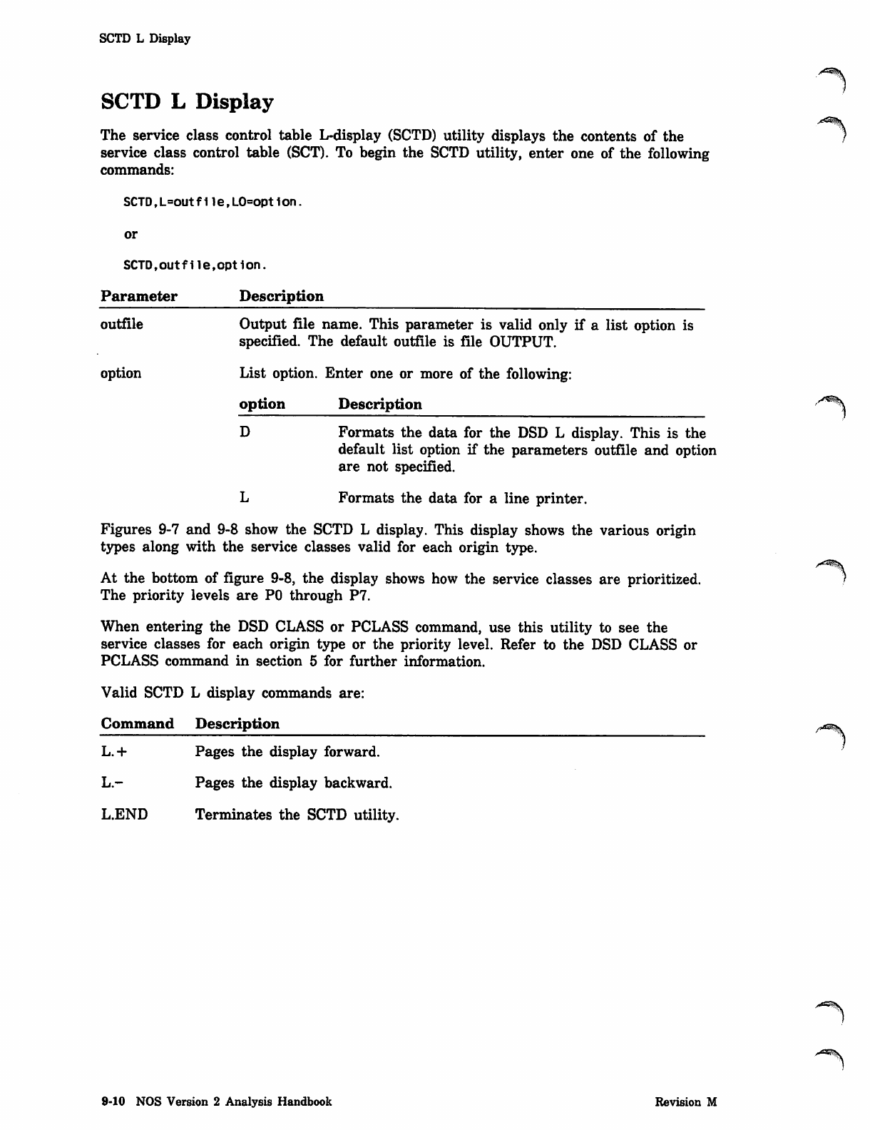
SCTD L Display
SCTD L Display
The service class control table L-display (SCTD) utility displays the contents of the
service class control table (SCT). To begin the SCTD utility, enter one of the following
commands:
SCTD,L=out file,LO=opt1on.
or
SCTD,outfile,option.
Parameter Description
outfile Output file name. This parameter is valid only if a list option is
specified. The default outfile is file OUTPUT.
option List option. Enter one or more of the following:
option Description
D Formats the data for the DSD L display. This is the
default list option if the parameters outfile and option
are not specified.
L Formats the data for a line printer.
Figures 9-7 and 9-8 show the SCTD L display. This display shows the various origin
types along with the service classes valid for each origin type.
At the bottom of figure 9-8, the display shows how the service classes are prioritized.
The priority levels are PO through P7.
When entering the DSD CLASS or PCLASS command, use this utility to see the
service classes for each origin type or the priority level. Refer to the DSD CLASS or
PCLASS command in section 5 for further information.
Valid SCTD L display commands are:
Command Description
L.+ Pages the display forward.
L.- Pages the display backward.
L.END Terminates the SCTD utility.
,«^^H
-^•^V
9-10 NOS Version 2 Analysis Handbook Revision M
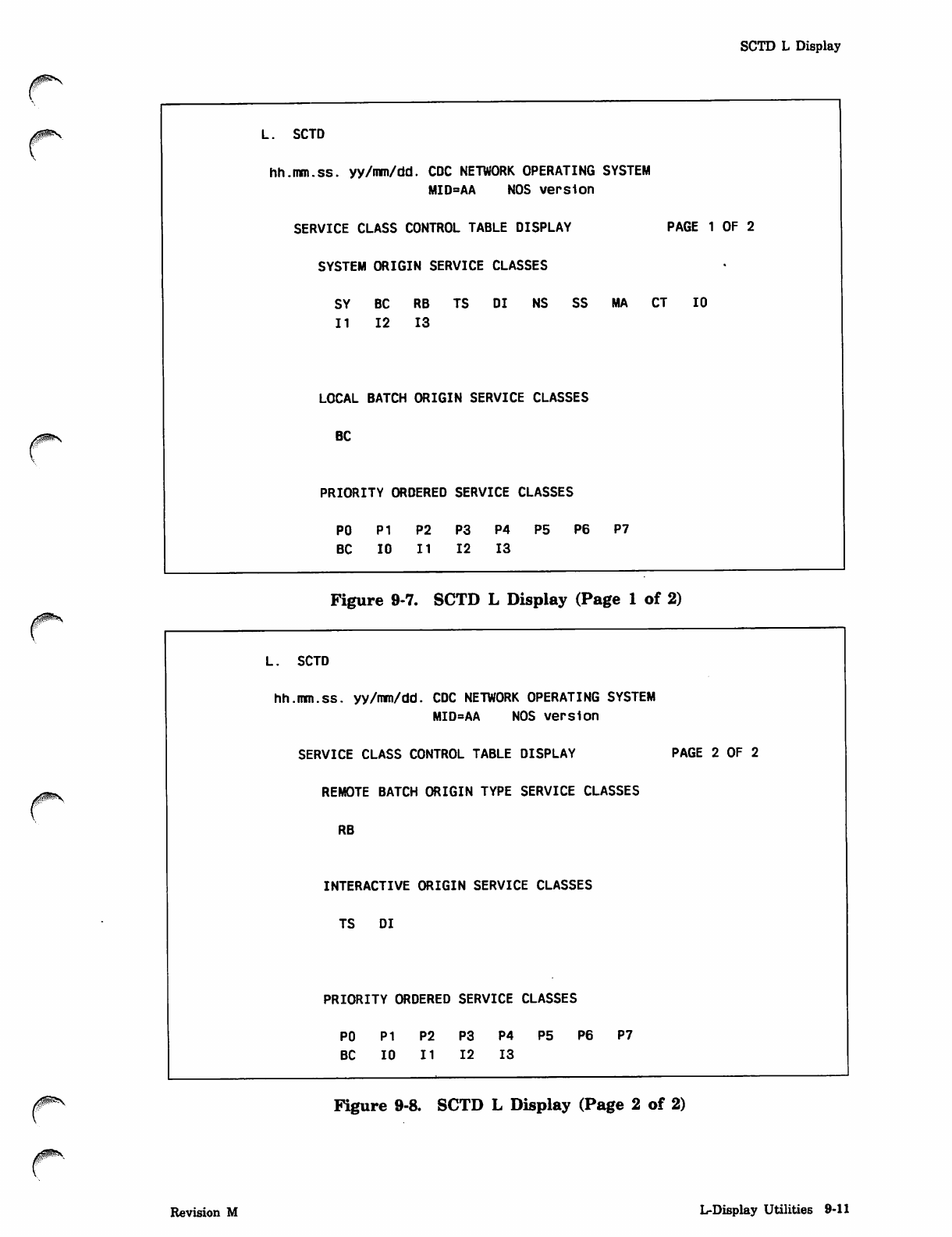
SCTD L Display
L. SCTD
hh.mm.ss. yy/mm/dd. CDC NETWORK OPERATING SYSTEM
MID=AA NOS version
SERVICE CLASS CONTROL TABLE DISPLAY PAGE 1 OF 2
SYSTEM ORIGIN SERVICE CLASSES
S Y B C R B T S D I N S S S M A C T 1 0
1 1 1 2 1 3
LOCAL BATCH ORIGIN SERVICE CLASSES
BC
PRIORITY ORDERED SERVICE CLASSES
P O P 1 P 2 P 3 P 4 P 5 P 6 P 7
B C 1 0 1 1 1 2 1 3
Figure 9-7. SCTD L Display (Page 1 of 2)
L. SCTD
hh.mm.ss. yy/mm/dd. CDC NETWORK OPERATING SYSTEM
MID=AA NOS version
SERVICE CLASS CONTROL TABLE DISPLAY PAGE 2 OF 2
REMOTE BATCH ORIGIN TYPE SERVICE CLASSES
RB
INTERACTIVE ORIGIN SERVICE CLASSES
T S D I
PRIORITY ORDERED SERVICE CLASSES
P O P 1 P 2 P 3 P 4 P 5 P 6 P 7
B C 1 0 1 1 1 2 1 3
Z*^ Figure 9-8. SCTD L Display (Page 2 of 2)
Revision M L-Display Utilities 9-11
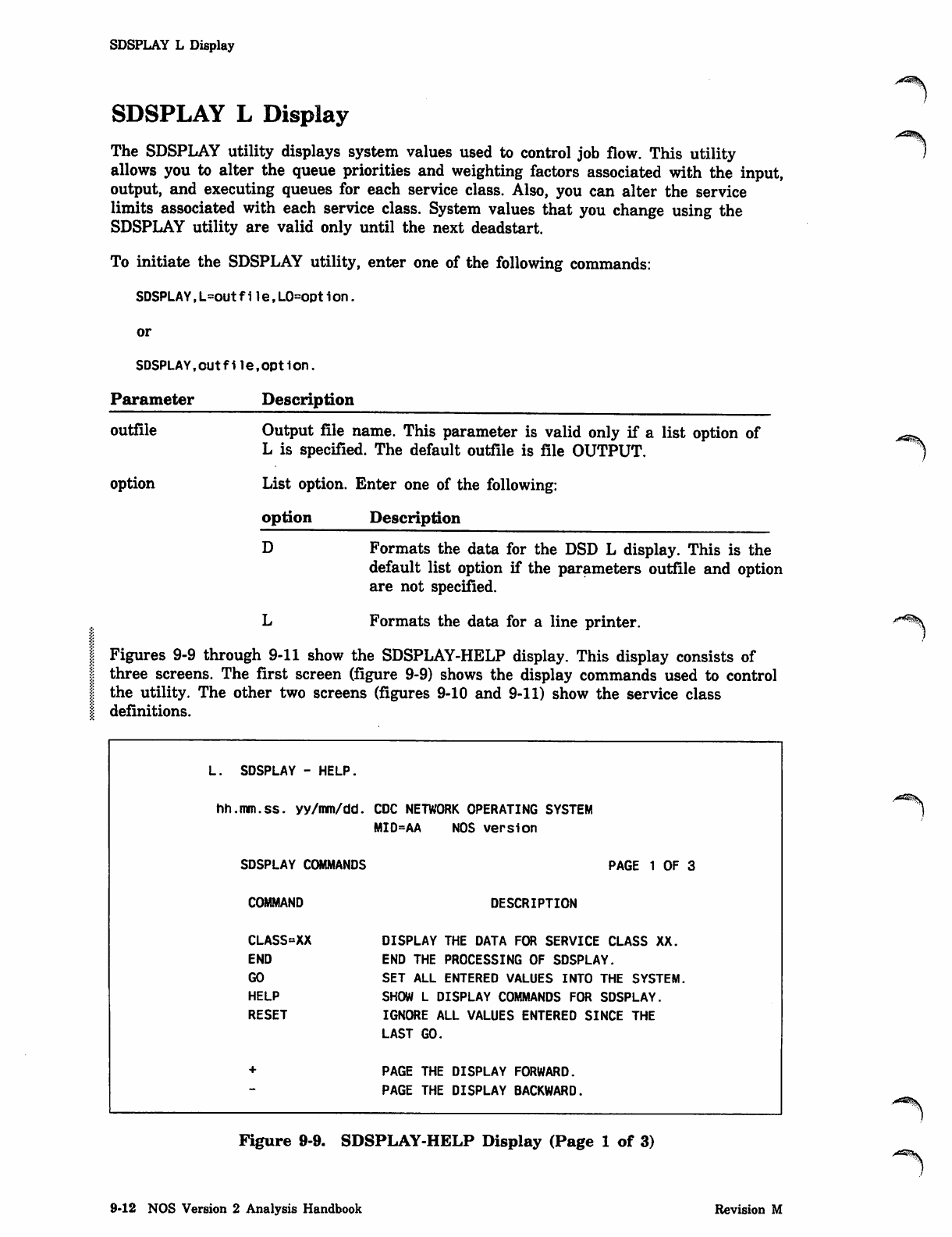
SDSPLAY L Display
SDSPLAY L Display
The SDSPLAY utility displays system values used to control job flow. This utility
allows you to alter the queue priorities and weighting factors associated with the input,
output, and executing queues for each service class. Also, you can alter the service
limits associated with each service class. System values that you change using the
SDSPLAY utility are valid only until the next deadstart.
To initiate the SDSPLAY utility, enter one of the following commands:
SDSPLAY,L=out file,L0=opt1on.
or
SDSPLAY,out f11e,opt 1on.
Parameter Description
outfile
option
Output file name. This parameter is valid only if a list option of
L is specified. The default outfile is file OUTPUT.
List option. Enter one of the following:
option Description
D Formats the data for the DSD L display. This is the
default list option if the parameters outfile and option
are not specified.
L Formats the data for a line printer.
Figures 9-9 through 9-11 show the SDSPLAY-HELP display. This display consists of
three screens. The first screen (figure 9-9) shows the display commands used to control
the utility. The other two screens (figures 9-10 and 9-11) show the service class
definitions.
L. SDSPLAY - HELP.
hh.mm.ss. yy/mm/dd. CDC NETWORK OPERATING SYSTEM
MID=AA NOS version
SDSPLAY COMMANDS PAGE 1 OF 3
COMMAND DESCRIPTION
CLASS=XX DISPLAY THE DATA FOR SERVICE CLASS XX.
END END THE PROCESSING OF SDSPLAY.
GO SET ALL ENTERED VALUES INTO THE SYSTEM.
HELP SHOW L DISPLAY COMMANDS FOR SDSPLAY.
RESET IGNORE ALL VALUES ENTERED SINCE THE
LAST GO.
+PAGE THE DISPLAY FORWARD.
—PAGE THE DISPLAY BACKWARD.
Figure 9-9. SDSPLAY-HELP Display (Page 1 of 3)
9-12 NOS Version 2 Analysis Handbook Revision M
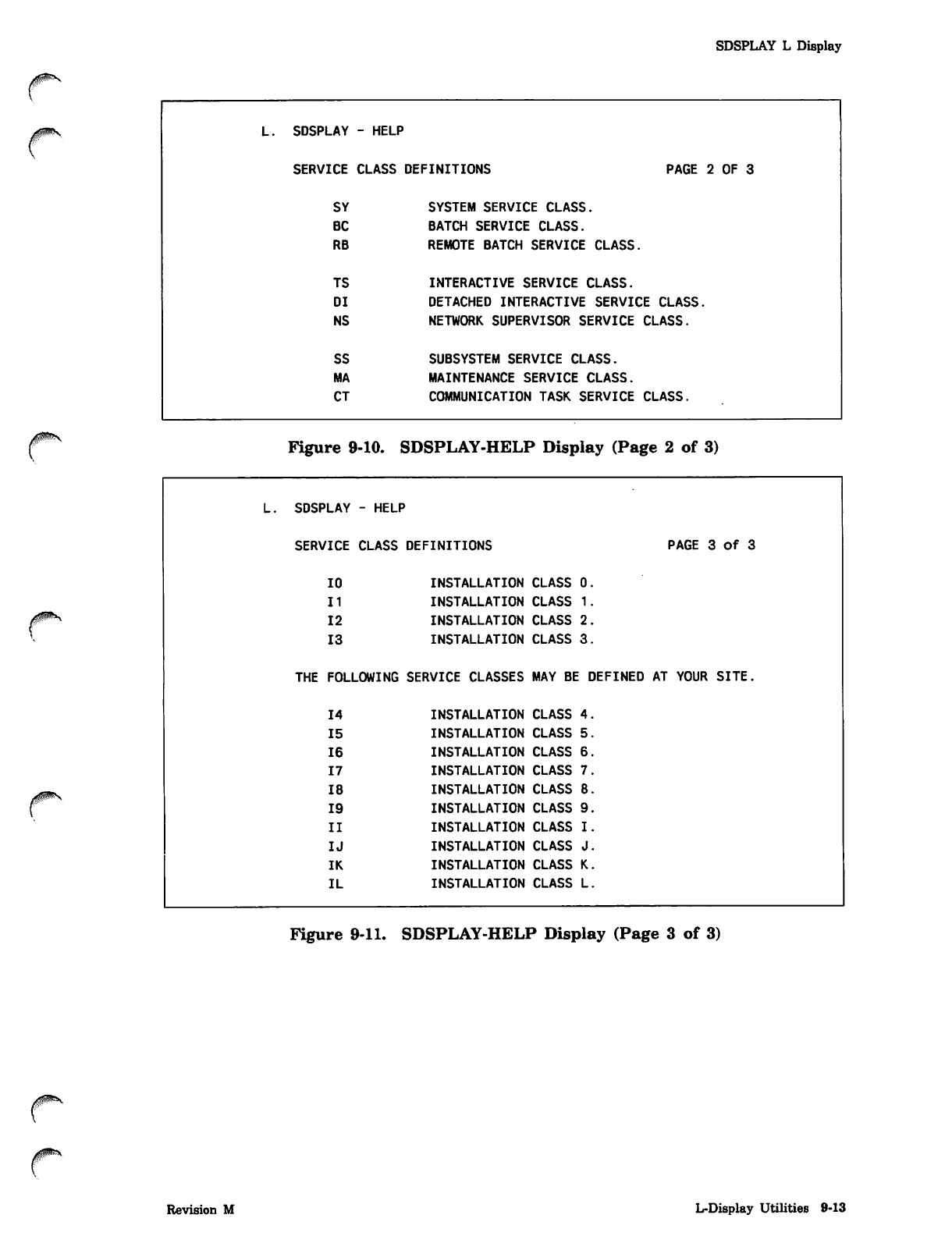
SDSPLAY L Display
L. SDSPLAY - HELP
SERVICE CLASS DEFINITIONS PAGE 2 OF 3
SY SYSTEM SERVICE CLASS.
BC BATCH SERVICE CLASS.
RB REMOTE BATCH SERVICE CLASS.
TS INTERACTIVE SERVICE CLASS.
DI DETACHED INTERACTIVE SERVICE CLASS.
NS NETWORK SUPERVISOR SERVICE CLASS.
SS SUBSYSTEM SERVICE CLASS.
MA MAINTENANCE SERVICE CLASS.
CT COMMUNICATION TASK SERVICE CLASS.
Figure 9-10. SDSPLAY-HELP Display (Page 2 of 3)
0ms
L. SDSPLAY - HELP
SERVICE CLASS DEFINITIONS PAGE 3 Of 3
10 INSTALLATION CLASS 0.
11 INSTALLATION CLASS 1.
12 INSTALLATION CLASS 2.
13 INSTALLATION CLASS 3.
THE FOLLOWING SERVICE CLASSES MAY BE DEFINED AT YOUR SITE.
14 INSTALLATION CLASS 4.
15 INSTALLATION CLASS 5.
16 INSTALLATION CLASS 6.
17 INSTALLATION CLASS 7.
18 INSTALLATION CLASS 8.
19 INSTALLATION CLASS 9.
II INSTALLATION CLASS I.
IJ INSTALLATION CLASS J.
IK INSTALLATION CLASS K.
IL INSTALLATION CLASS L.
Figure 9-11. SDSPLAY-HELP Display (Page 3 of 3)
0ms.
Revision M L-Display Utilities 9-13
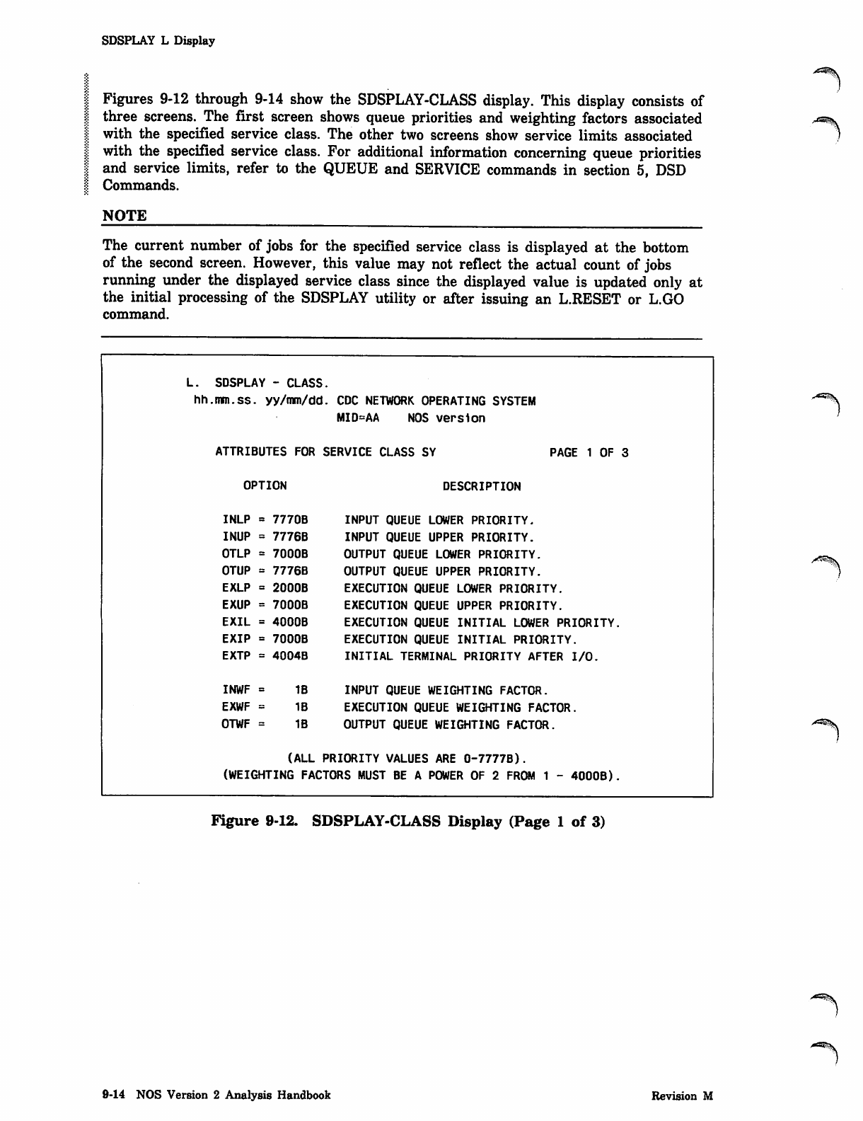
SDSPLAY L Display
Figures 9-12 through 9-14 show the SDSPLAY-CLASS display. This display consists of
three screens. The first screen shows queue priorities and weighting factors associated r*m\.
with the specified service class. The other two screens show service limits associated 1
with the specified service class. For additional information concerning queue priorities
and service limits, refer to the QUEUE and SERVICE commands in section 5, DSD
Commands.
NOTE
The current number of jobs for the specified service class is displayed at the bottom
of the second screen. However, this value may not reflect the actual count of jobs
running under the displayed service class since the displayed value is updated only at
the initial processing of the SDSPLAY utility or after issuing an L.RESET or L.GO
command.
L. SDSPLAY - CLASS,
hh.mm.ss. yy/mm/dd. CDC NETWORK OPERATING SYSTEM
MID=AA NOS version
ATTRIBUTES FOR SERVICE CLASS SY PAGE 1 OF 3
OPTION DESCRIPTION
INPUT QUEUE LOWER PRIORITY.
INPUT QUEUE UPPER PRIORITY.
OUTPUT QUEUE LOWER PRIORITY.
OUTPUT QUEUE UPPER PRIORITY.
EXECUTION QUEUE LOWER PRIORITY.
EXECUTION QUEUE UPPER PRIORITY.
EXECUTION QUEUE INITIAL LOWER PRIORITY.
EXECUTION QUEUE INITIAL PRIORITY.
INITIAL TERMINAL PRIORITY AFTER I/O.
INPUT QUEUE WEIGHTING FACTOR.
EXECUTION QUEUE WEIGHTING FACTOR.
OUTPUT QUEUE WEIGHTING FACTOR.
(ALL PRIORITY VALUES ARE 0-7777B).
(WEIGHTING FACTORS MUST BE A POWER OF 2 FROM 1 - 4000B).
INLP 7770B
INUP 7776B
OTLP 7000B
OTUP 7776B
EXLP 2000B
EXUP 7000B
EXIL 4000B
EXIP 7000B
EXTP 4004B
INWF ss 1B
EXWF 1B
OTWF 1B
Figure 9-12. SDSPLAY-CLASS Display (Page 1 of 3)
9-14 NOS Version 2 Analysis Handbook Revision M
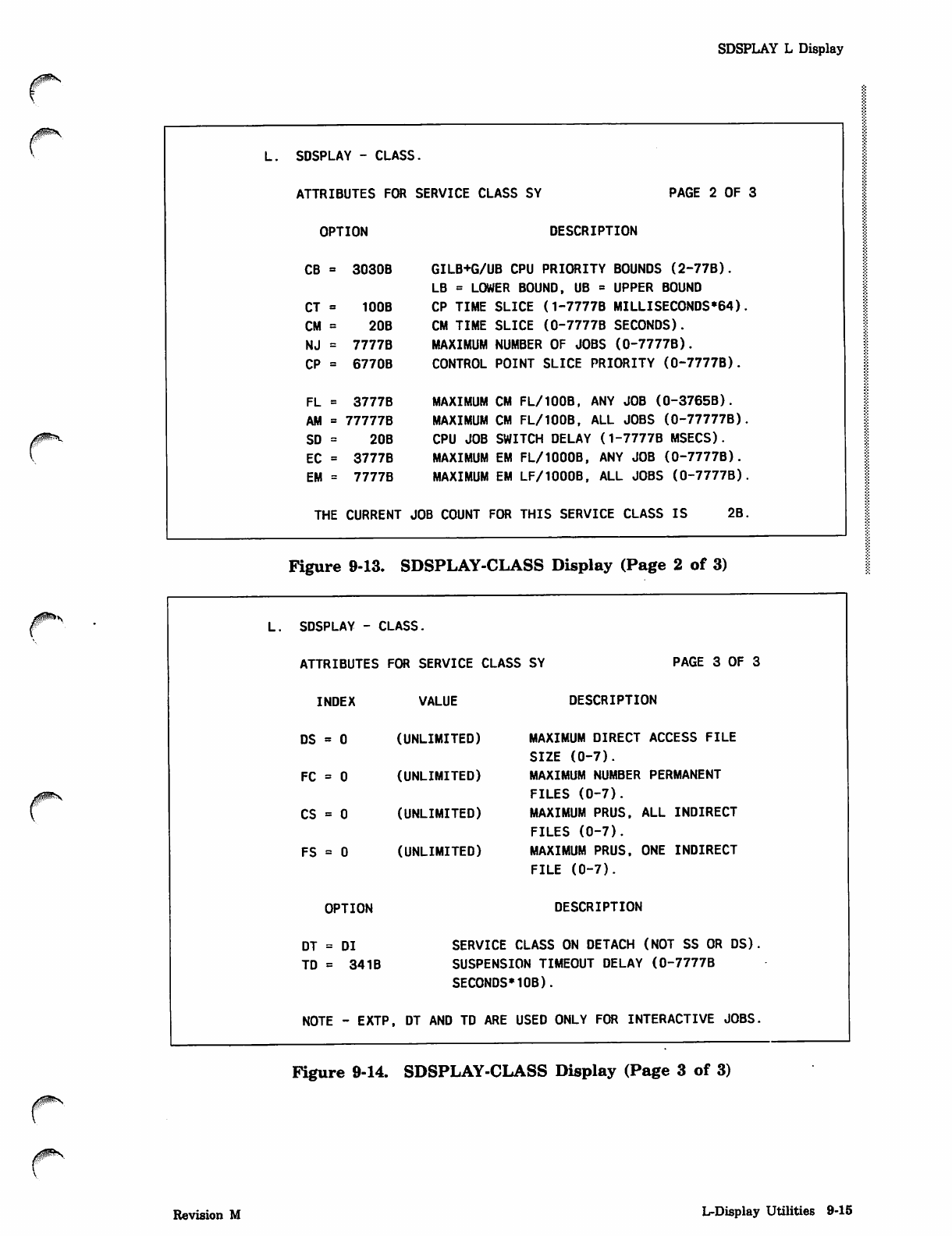
SDSPLAY L Display
0R0"S
L. SDSPLAY - CLASS.
ATTRIBUTES FOR SERVICE CLASS SY PAGE 2 OF 3
OPTION
CB = 3030B
DESCRIPTION
CT 100B
CM 20B
NJ 7777B
CP 6770B
FL 3777B
AM 77777B
SD 20B
EC 3777B
EM 7777B
GILB+G/UB CPU PRIORITY BOUNDS (2-77B).
LB = LOWER BOUND, UB = UPPER BOUND
CP TIME SLICE (1-7777B MILLISEC0NDS*64).
CM TIME SLICE (0-7777B SECONDS).
MAXIMUM NUMBER OF JOBS (0-7777B).
CONTROL POINT SLICE PRIORITY (0-7777B).
MAXIMUM CM FL/100B, ANY JOB (0-3765B).
MAXIMUM CM FL/100B, ALL JOBS (0-77777B)
CPU JOB SWITCH DELAY (1-7777B MSECS).
MAXIMUM EM FL/1000B, ANY JOB (0-7777B).
MAXIMUM EM LF/1000B, ALL JOBS (0-7777B)
THE CURRENT JOB COUNT FOR THIS SERVICE CLASS IS 2B.
Figure 9-13. SDSPLAY-CLASS Display (Page 2 of 3)
L. SDSPLAY - CLASS.
ATTRIBUTES F O R S E R V I C E C L A S S S Y P A G E 3 O F 3
INDEX VALUE DESCRIPTION
DS = 0 (UNLIMITED) MAXIMUM DIRECT ACCESS FILE
SIZE (0-7).
FC = 0 (UNLIMITED) MAXIMUM NUMBER PERMANENT
FILES (0-7).
CS = 0 (UNLIMITED) MAXIMUM PRUS, ALL INDIRECT
FILES (0-7).
FS = 0 (UNLIMITED) MAXIMUM PRUS, ONE INDIRECT
FILE (0-7).
OPTION DESCRIPTION
DT = DI SERVICE CLASS ON DETACH (NOT SS OR DS).
TD = 341B SUSPENSION TIMEOUT DELAY (0-7777B
SECONDS" MOB).
NOTE - EXTF>, DT AND TD ARE USED ONLY FOR INTERACTIVE JOBS.
Figure 9-14. SDSPLAY-CLASS Display (Page 3 of 3)
Revision M L-Display Utilities 9-15
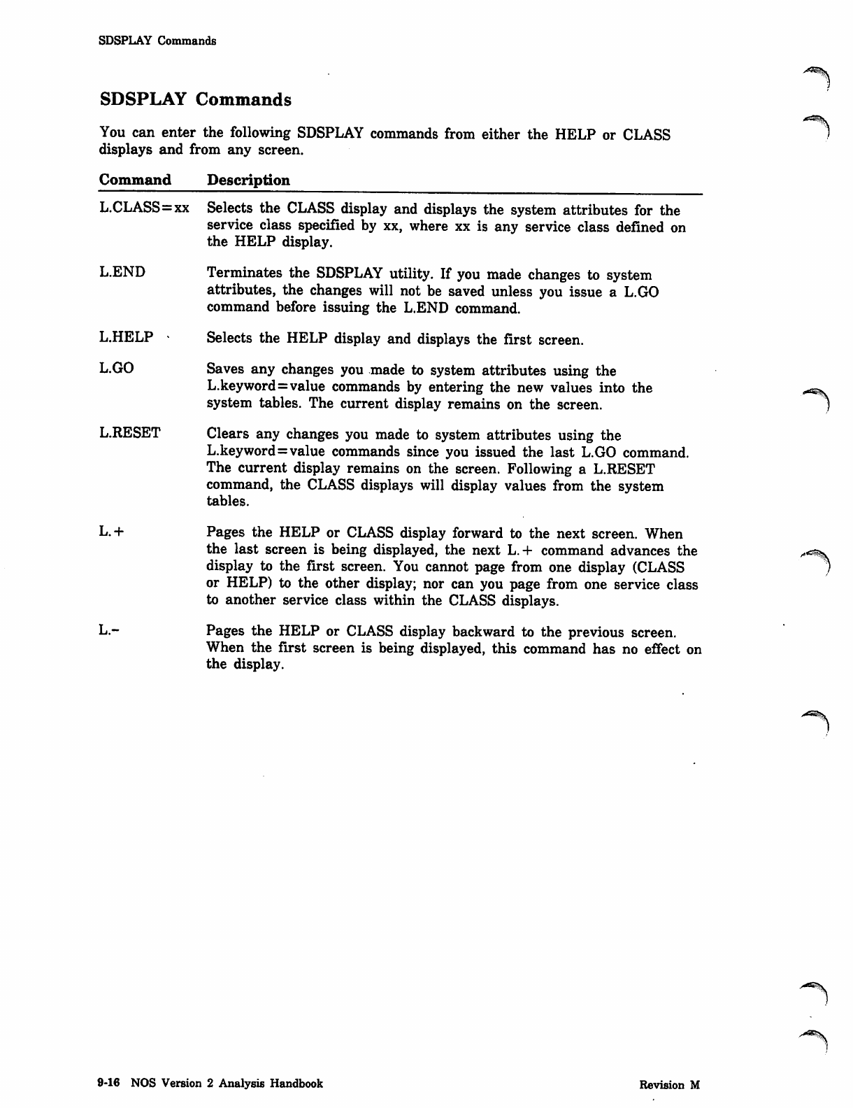
SDSPLAY Commands
SDSPLAY Commands
You can enter the following SDSPLAY commands from either the HELP or CLASS
displays and from any screen.
Command Description
L.CLASS=xx
L.END
L.HELP *
L.GO
L.RESET
L.+
L.-
Selects the CLASS display and displays the system attributes for the
service class specified by xx, where xx is any service class defined on
the HELP display.
Terminates the SDSPLAY utility. If you made changes to system
attributes, the changes will not be saved unless you issue a L.GO
command before issuing the L.END command.
Selects the HELP display and displays the first screen.
Saves any changes you made to system attributes using the
L.keyword=value commands by entering the new values into the
system tables. The current display remains on the screen.
Clears any changes you made to system attributes using the
L.keyword=value commands since you issued the last L.GO command.
The current display remains on the screen. Following a L.RESET
command, the CLASS displays will display values from the system
tables.
Pages the HELP or CLASS display forward to the next screen. When
the last screen is being displayed, the next L.+ command advances the
display to the first screen. You cannot page from one display (CLASS
or HELP) to the other display; nor can you page from one service class
to another service class within the CLASS displays.
Pages the HELP or CLASS display backward to the previous screen.
When the first screen is being displayed, this command has no effect on
the display.
"">
9-16 NOS Version 2 Analysis Handbook Revision M
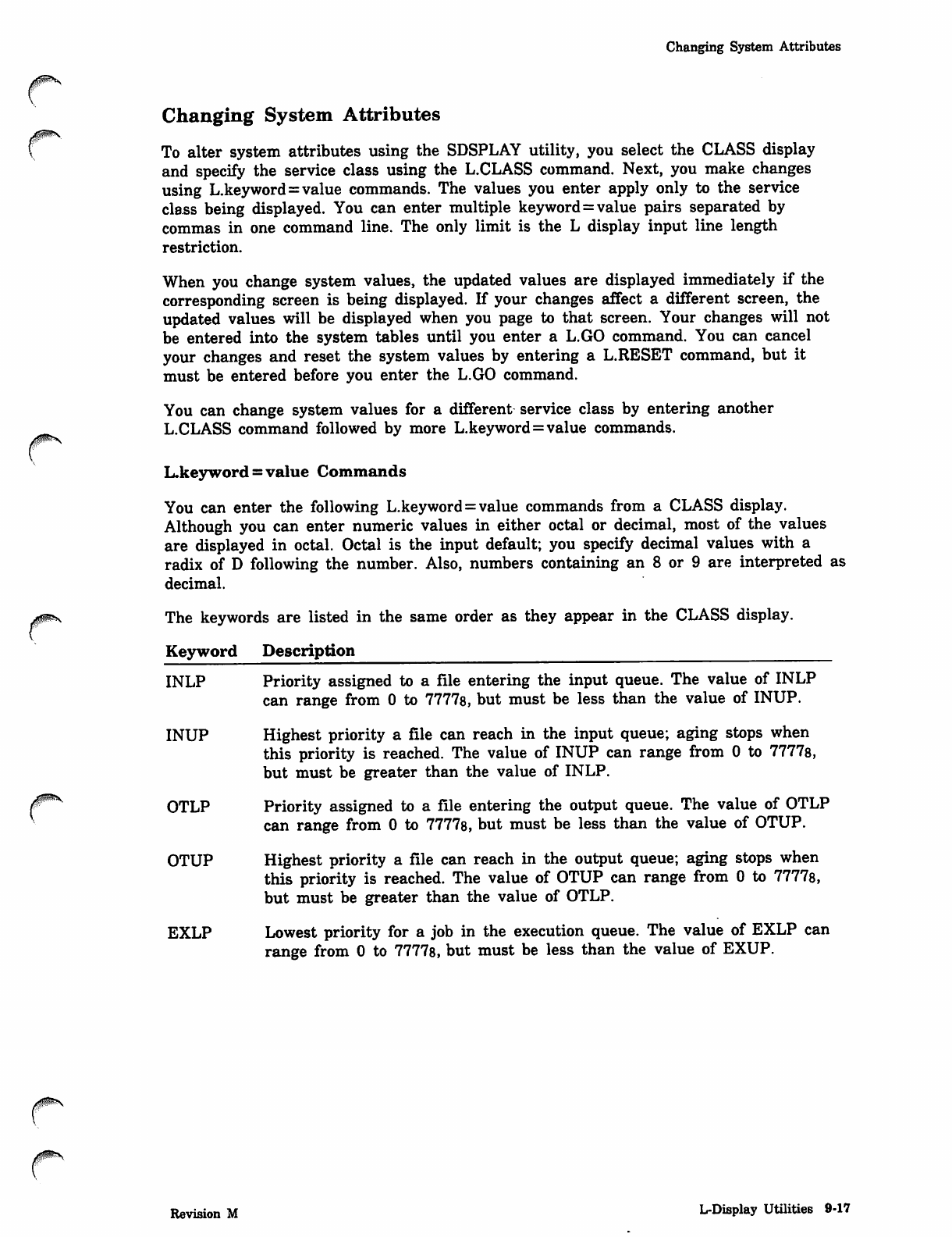
Changing System Attributes
y#flfl$£Vv
Changing System Attributes
To alter system attributes using the SDSPLAY utility, you select the CLASS display
and specify the service class using the L.CLASS command. Next, you make changes
using L.keyword = value commands. The values you enter apply only to the service
class being displayed. You can enter multiple keyword=value pairs separated by
commas in one command line. The only limit is the L display input line length
restriction.
When you change system values, the updated values are displayed immediately if the
corresponding screen is being displayed. If your changes affect a different screen, the
updated values will be displayed when you page to that screen. Your changes will not
be entered into the system tables until you enter a L.GO command. You can cancel
your changes and reset the system values by entering a L.RESET command, but it
must be entered before you enter the L.GO command.
You can change system values for a different service class by entering another
L.CLASS command followed by more L.keyword=value commands.
Lukeyword = value Commands
You can enter the following L.keyword = value commands from a CLASS display.
Although you can enter numeric values in either octal or decimal, most of the values
are displayed in octal. Octal is the input default; you specify decimal values with a
radix of D following the number. Also, numbers containing an 8 or 9 are interpreted as
decimal.
The keywords are listed in the same order as they appear in the CLASS display.
Keyword Description
INLP Priority assigned to a file entering the input queue. The value of INLP
can range from 0 to 7777s, but must be less than the value of INUP.
INUP Highest priority a file can reach in the input queue; aging stops when
this priority is reached. The value of INUP can range from 0 to 7777s,
but must be greater than the value of INLP.
OTLP Priority assigned to a file entering the output queue. The value of OTLP
can range from 0 to 7777s, but must be less than the value of OTUP.
OTUP Highest priority a file can reach in the output queue; aging stops when
this priority is reached. The value of OTUP can range from 0 to 77778,
but must be greater than the value of OTLP.
EXLP Lowest priority for a job in the execution queue. The value of EXLP can
range from 0 to 7777s, but must be less than the value of EXUP.
Revision M L-Display Utilities 9-17
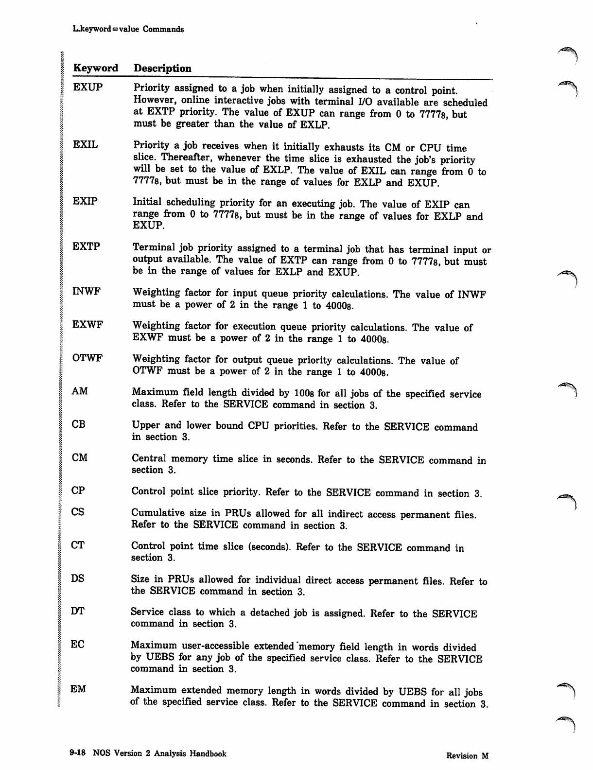
L.keyword=value Commands
| Keyword Description
| EXUP
J EXIL
j EXIP
| EXTP
| INWF
| EXWF
j OTWF
| A M
I CB
1 CM
I CP
j CS
I CT
I DS
I DT
1 EC
I EM
Priority assigned to a job when initially assigned to a control point.
However, online interactive jobs with terminal I/O available are scheduled
at EXTP priority. The value of EXUP can range from 0 to 7777s, but
must be greater than the value of EXLP.
Priority a job receives when it initially exhausts its CM or CPU time
slice. Thereafter, whenever the time slice is exhausted the job's priority
will be set to the value of EXLP. The value of EXIL can range from 0 to
77778, but must be in the range of values for EXLP and EXUP.
Initial scheduling priority for an executing job. The value of EXIP can
range from 0 to 7777s, but must be in the range of values for EXLP and
EXUP.
Terminal job priority assigned to a terminal job that has terminal input or
output available. The value of EXTP can range from 0 to 7777s, but must
be in the range of values for EXLP and EXUP.
Weighting factor for input queue priority calculations. The value of INWF
must be a power of 2 in the range 1 to 4000s.
Weighting factor for execution queue priority calculations. The value of
EXWF must be a power of 2 in the range 1 to 4000s.
Weighting factor for output queue priority calculations. The value of
OTWF must be a power of 2 in the range 1 to 4000s.
Maximum field length divided by 100s for all jobs of the specified service
class. Refer to the SERVICE command in section 3.
Upper and lower bound CPU priorities. Refer to the SERVICE command
in section 3.
Central memory time slice in seconds. Refer to the SERVICE command in
section 3.
Control point slice priority. Refer to the SERVICE command in section 3.
Cumulative size in PRUs allowed for all indirect access permanent files.
Refer to the SERVICE command in section 3.
Control point time slice (seconds). Refer to the SERVICE command in
section 3.
Size in PRUs allowed for individual direct access permanent files. Refer to
the SERVICE command in section 3.
Service class to which a detached job is assigned. Refer to the SERVICE
command in section 3.
Maximum user-accessible extended 'memory field length in words divided
by UEBS for any job of the specified service class. Refer to the SERVICE
command in section 3.
Maximum extended memory length in words divided by UEBS for all jobs
of the specified service class. Refer to the SERVICE command in section 3.
/***%.
9-18 NOS Version 2 Analysis Handbook Revision M
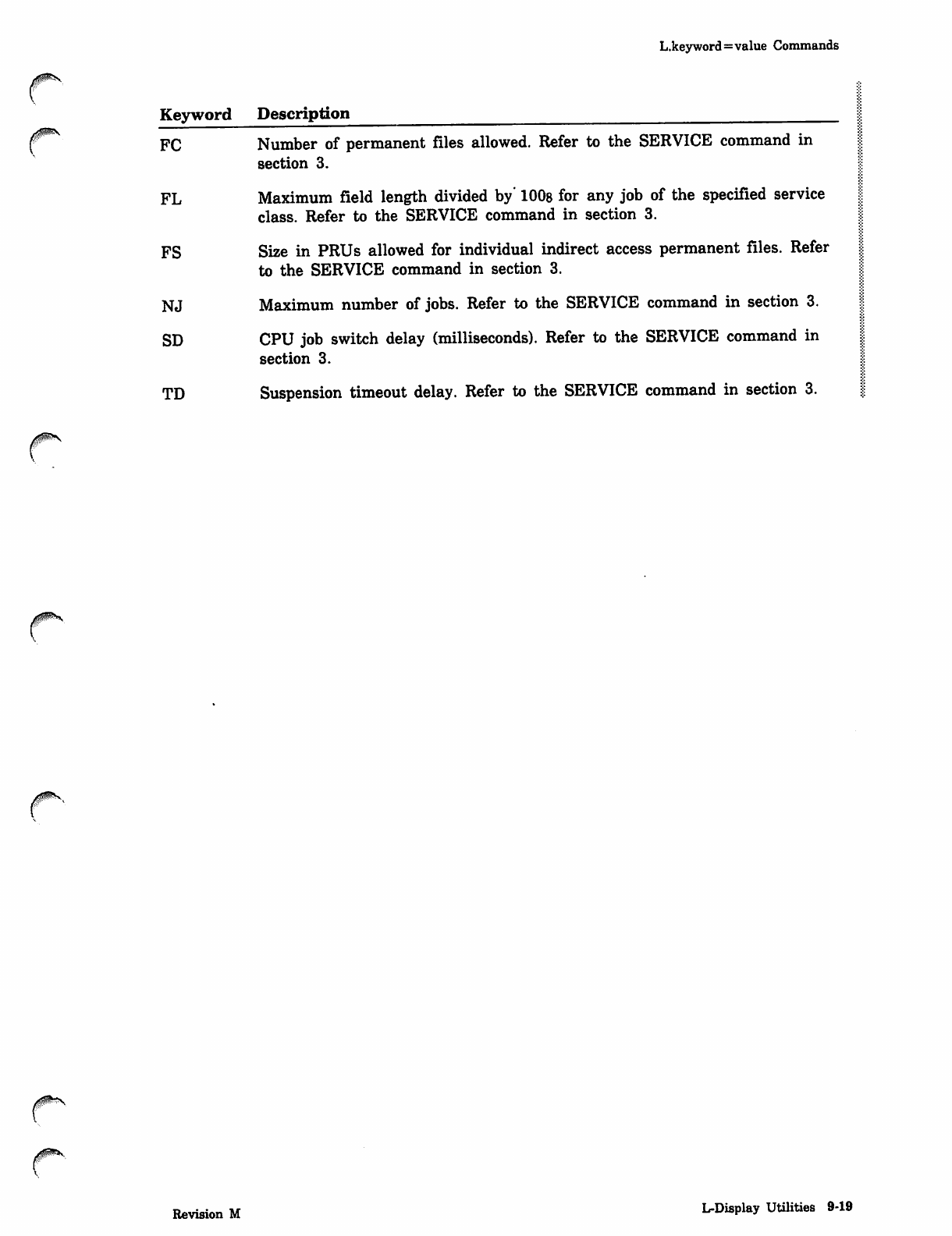
L.keyword=value Commands
Keyword Description
FC Number of permanent files allowed. Refer to the SERVICE command in
section 3.
FL Maximum field length divided by' 100s for any job of the specified service
class. Refer to the SERVICE command in section 3.
FS Size in PRUs allowed for individual indirect access permanent files. Refer
to the SERVICE command in section 3.
NJ Maximum number of jobs. Refer to the SERVICE command in section 3.
SD CPU job switch delay (milliseconds). Refer to the SERVICE command in
section 3.
TD Suspension timeout delay. Refer to the SERVICE command in section 3.
Revision M L-Display Utilities 9-19
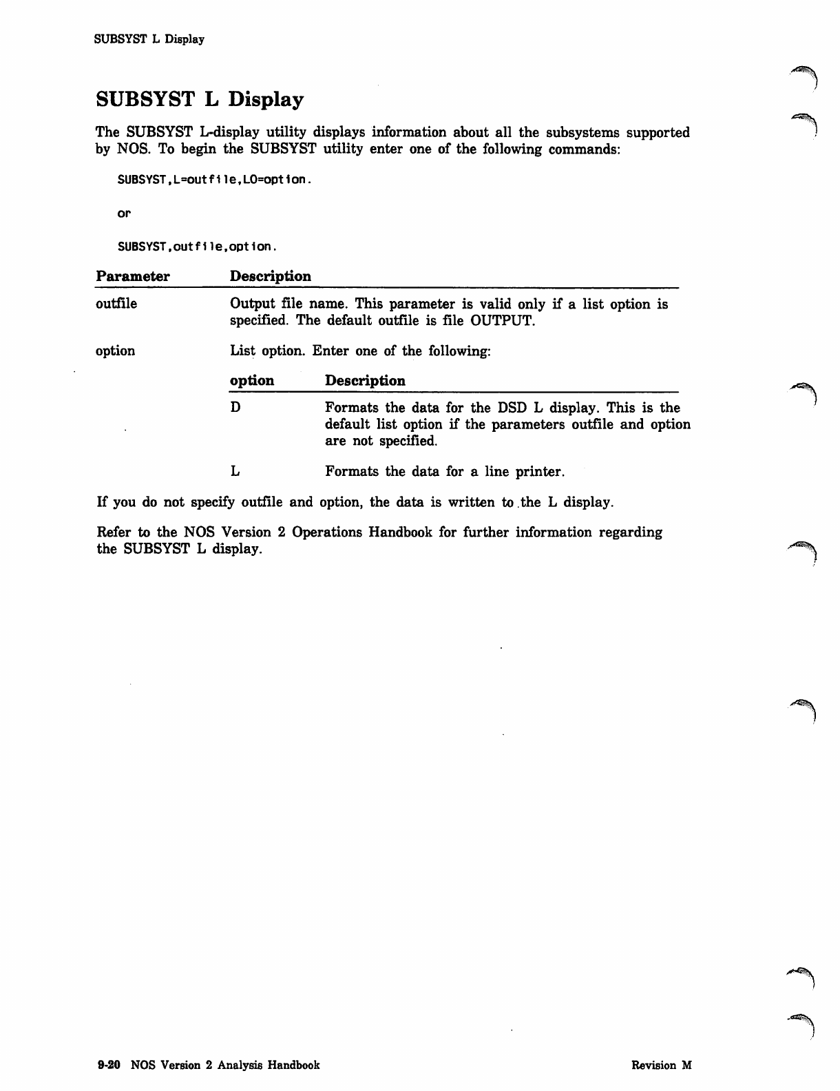
SUBSYST L Display
SUBSYST L Display
The SUBSYST L-display utility displays information about all the subsystems supported
by NOS. To begin the SUBSYST utility enter one of the following commands:
SUBSYST,L=out f11e,LO=opt1on.
or
SUBSYST,outfile,opt ion.
Parameter Description
outfile Output file name. This parameter is valid only if a list option is
specified. The default outfile is file OUTPUT.
option List option. Enter one of the following:
option Description
D Formats the data for the DSD L display. This is the
default list option if the parameters outfile and option
are not specified.
L Formats the data for a line printer.
If you do not specify outfile and option, the data is written to the L display.
Refer to the NOS Version 2 Operations Handbook for further information regarding
the SUBSYST L display.
9-20 NOS Version 2 Analysis Handbook Revision M
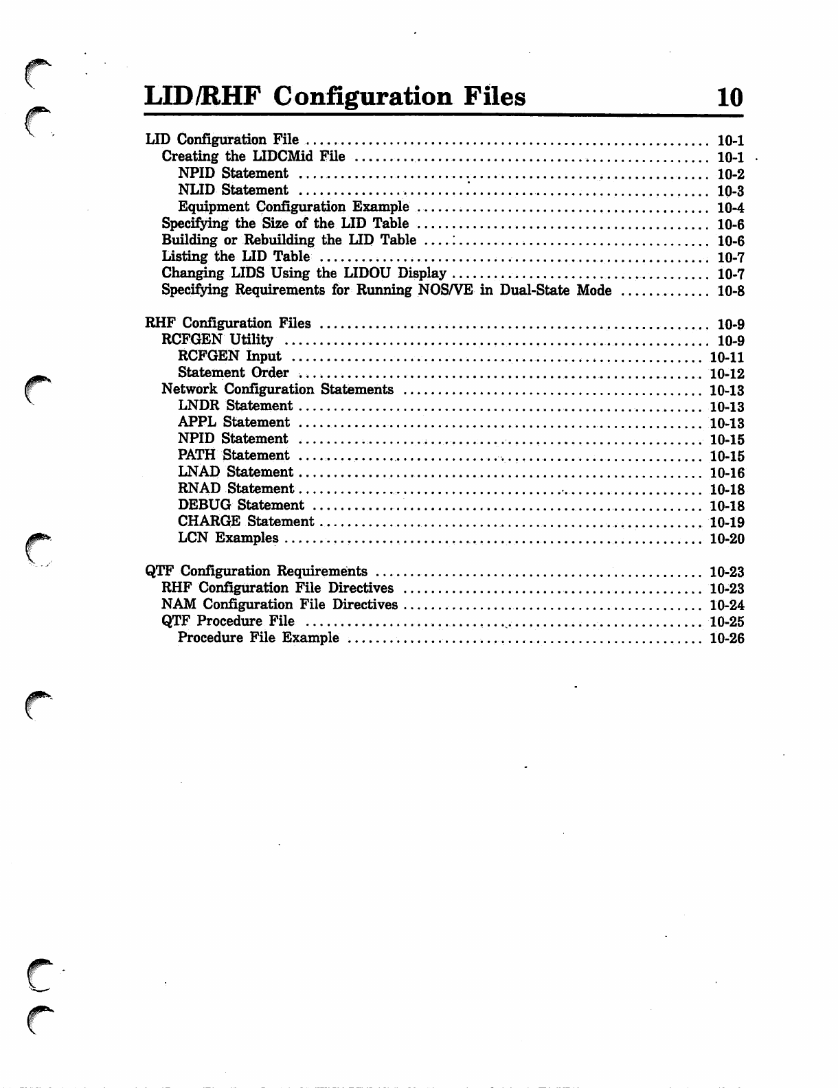
0*
IT
LID/RHF Configuration Files 10
LID Configuration File 10-1
Creating the LIDCMid File 10-1
NPID Statement 10-2
NLID Statement . ." 10-3
Equipment Configuration Example 10-4
Specifying the Size of the LID Table 10-6
Building or Rebuilding the LID Table ....: 10-6
Listing the LID Table 10-7
Changing LIDS Using the LIDOU Display 10-7
Specifying Requirements for Running NOS/VE in Dual-State Mode 10-8
RHF Configuration Files 10-9
RCFGEN Utility 10-9
RCFGEN Input 10-11
Statement Order 10-12
Network Configuration Statements 10-13
LNDR Statement 10-13
APPL Statement 10-13
NPID Statement 10-15
PATH Statement , 10-15
LNAD Statement 10-16
RNAD Statement 10-18
DEBUG Statement 10-18
CHARGE Statement , 10-19
LCN Examples ... 10-20
QTF Configuration Requirements 10-23
RHF Configuration File Directives 10-23
NAM Configuration File Directives 10-24
QTF Procedure File ... v. 10-25
Procedure File Example 10-26

jrfffiP&V
LID/RHF Configuration Files 10
This section contains information about LID configuration files, RHF configuration files,
and QTF configuration requirements.
LID Configuration File
You create a LID configuration file to define the physical and logical machines
available for your system. After a level 0 deadstart, the system program CLDT
searches for the LID configuration file on user index 377777s. It will use the
information in this file to generate a logical identifier table (LDT) in central memory.
This section describes how to create and maintain the LID configuration file
(LIDCMid). Specifically, how to:
• Create the LIDCMid file using NPID and NLID configuration statements.
• Specify the size of the LID table using the CMRDECK LDT entry.
• Build or rebuild the LID table using the X.CLDT command.
• List the current LID table using the LISTLID command.
• Change LIDs and LID attributes using the LIDOU display.
• Specify the requirements for running NOS/VE in dual-state mode.
Creating the LIDCMid File
The first line of the LIDCMid file should be a 1- to 7-character name for the LID
configuration file. Use this format for naming the file:
LIDCMid
Value Description
id 2-character machine identifier for the mainframe.
You can place comment lines in the file by putting an asterisk in column 1 or by
putting the word COMMENT beginning in column one.
Example:
LIDCM64
•LIDCMID FILE FOR MAINFRAME 64.
You should define each PID (physical identifier) and all the LIDs (logical identifiers)
associated with the PID by using NPID and NLID statements.
Revision M LID/RHF Configuration Piles 10-1
NPID Statement
NPID Statement
Use one NPID statement to define each physical mainframe available to your system.
Use this format for the NPID statement:
NPID,PID=p1d,ENABLED=statUS,MFTYPE=type,AT=at,NETDIS=SUb.
Parameter Description
PID=pid
ENABLED=status
MFTYPE=type
AT=at
NETDIS=sub
Physical identifier; pid is the 3-character physical identifier for
the mainframe. For NOS, pid should be Mid, where id is the
2-character machine identifier defined by the MID=id
CMRDECK entry. Required.
Specifies whether the mainframe identified by PID is available.
You can enter YES or NO. Default is YES.
Mainframe type; type is any 1- to 7-character string specifying
the mainframe type or mainframe identifier (for example,
NOSBE, NOS, CY200, NOSMF2, CLSH1). Required.
Specifies the attribute associated with the mainframe identified
by PID. You can specify multiple attributes by using a slant
separator (AT=VALID/NLIST) or by repeating the parameter
(AT=VALID.AT=NLIST).
y<^KT^k
at Description
VALID
NVALID
NLIST
Specifies that USER command prevalidation is
required. This parameter causes the local host to
verify that a user is authorized. This prevalidation
is performed in addition to the normal user
validation performed at the remote host.
Specifies that USER command prevalidation is not
required.
Specifies that this PID is not available to the end
user through the LISTLID command.
The default attributes are: USER command prevalidation is not
required and PID is listable using the LISTLID command.
Specifies which network accesses to the mainframe identified by
PID are disabled. By default, all network accesses are enabled.
You should not specify NETDIS for the host PID. Any
combination of network accesses may be used (for example,
NETDIS=RHF/SSF).
sub Description
NAM
RHF
SSF
Network Access Method.
Remote Host Facility.
SCOPE Station Facility.
10-2 NOS Version 2 Analysis Handbook Revision M
NLID Statement
j^pKsy
NLID Statement
Use NLID statements after each NPID statement to define the relationship between
each PID and its associated LIDs and the attributes of the LIDs. Use this format for
the NLID statement:
NLID,LID=1i d,ENABLED=Stat US,AT=at
Parameter Description
LID=lid
ENABLED=status
AT=at
00$S
Logical identifier; lid is the 3-character logical identifier for the
mainframe identified by the last NPID statement. One lid entry
must be the same as the last pid. Required.
Specifies whether the mainframe identified by LID is available.
You can enter YES or NO. Default is YES.
Specifies the attribute associated with the mainframe identified
by LID. You can specify multiple attributes by using a slant
separator (AT=STOREF/VALID) or by repeating the parameter
(AT=STOREF,AT=VALID).
at
LOOPB
STOREF
VALID
NVALID
NLIST
Description
Loopback capability for RHF testing. This testing
can be performed on one mainframe with one
NAD. The attribute of LOOPB is valid only for
LIDs defined for the host (local) mainframe.
You should not specify the LOOPB attribute if the
STOREF attribute is specified.
Store and forward capability indicating that the
specified mainframe will act as part of the
network in store and forward mode. Data will
pass through the machine and into the network.
You should not specify the STOREF attribute if
the LOOPB attribute is specified.
Specifies that USER command prevalidation is
required and can be specified only if the STOREF
attribute is specified. This parameter causes the
mainframe defined as being in store and forward
mode (AT=STOREF) to verify that a user is
authorized. This prevalidation is performed in
addition to the normal user validation performed
at the remote host that processes the job.
Specifies that USER command prevalidation is not
required and can be specified only if the STOREF
attribute is specified.
Specifies that this LID is not available to the end
user through the LISTLID command. LIDs with
this attribute might be reserved for onsite
maintenance purposes.
Revision M LID/RHF Configuration Files 10-3
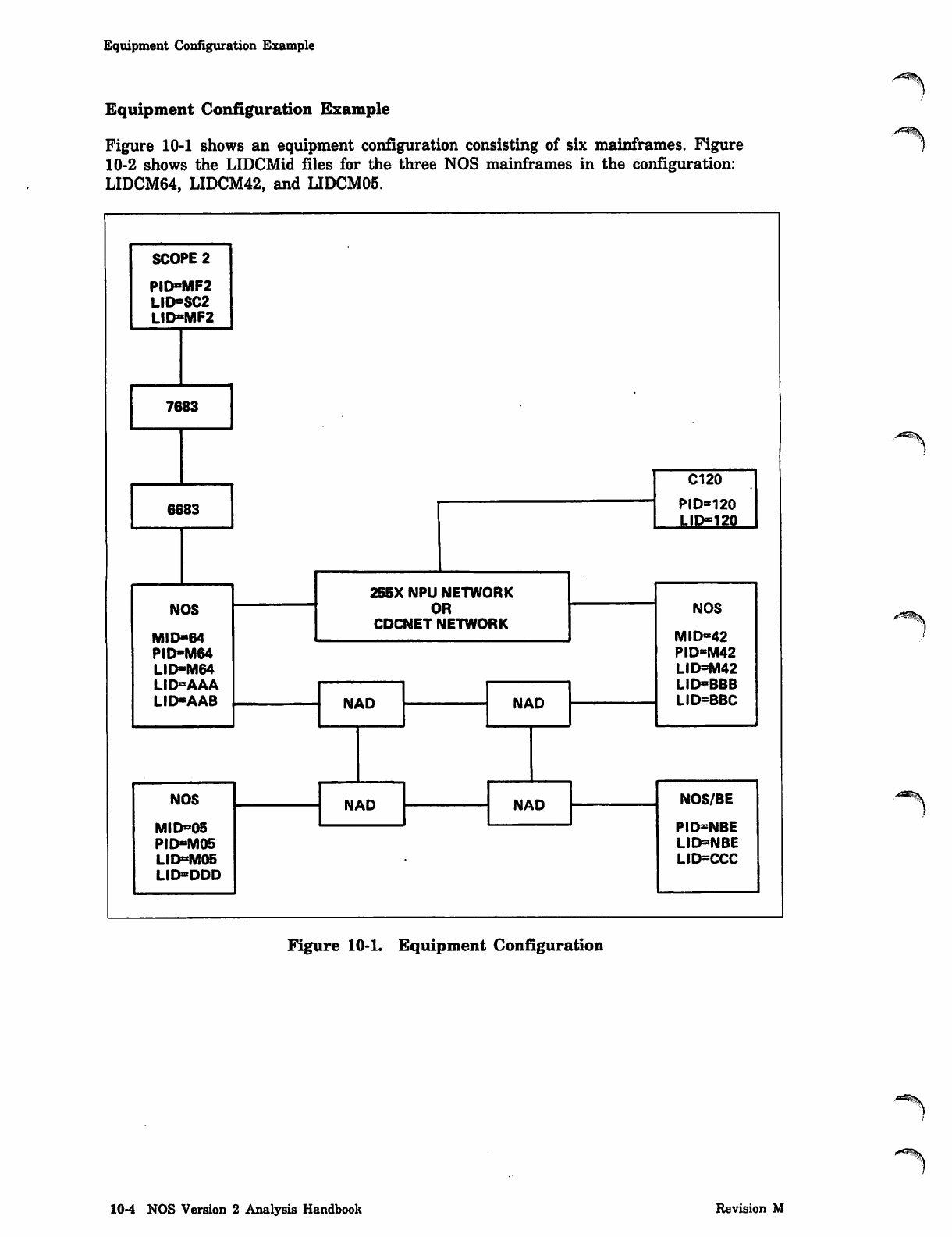
Equipment Configuration Example
Equipment Configuration Example
Figure 10-1 shows an equipment configuration consisting of six mainframes. Figure
10-2 shows the LIDCMid files for the three NOS mainframes in the configuration:
LIDCM64, LIDCM42, and LIDCM05.
SCOPE 2
PID-MF2
LID-SC2
LID-MF2
7683
C120
PID«120
LID-120
6683
2S5X NPU NETWORK
OR
CDCNET NETWORK
NOS
MID-64
PID-M64
LID-M64
LID" AAA
LID-AAB
NOS
MID-42
PID-M42
LID=M42
LID=BBB
LID=BBC
NAD NAD
NOS
MID°05
PID-M05
LID«M05
LID»DDD
NAD NAD NOS/BE
PID=NBE
LID=NBE
LID=CCC
>*SS^v
Figure 10-1. Equipment Configuration
10-4 NOS Version 2 Analysis Handbook Revision M
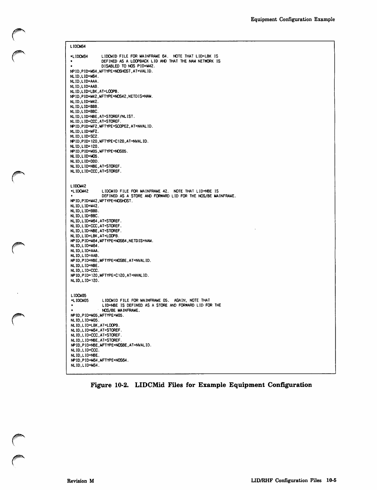
Equipment Configuration Example
LIDCM64
•LIDCM64 LIDCMID FILE FOR MAINFRAME 64. NOTE THAT LID=LBK IS
• DEFINED AS A LOOPBACK LID AND THAT THE NAM NETWORK IS
DISABLED TO NOS PID=M42.
NPID,PID=M64,MFTYPE=NOSHOST,AT=VALID.
NLID.L1D=M64.
NLID,LID=AAA.
NLID.LID=AAB.
NLID.LID=LBK,AT=LOOPB.
NPID.PID=M42.MFTYPE=NOS42,NETDIS=NAM.
NLID.LID=M42.
NLID,LID=BBB.
NLID.LID=BBC.
NLID.LID=NBE,AT=STOREF/NLIST.
NLID,LID=CCC,AT=STOREF.
NPID,PID=MF2,MFTYPE=SC0PE2,AT=NVAL1D.
NLID,LID=MF2.
NLID,LID=SC2.
NPID.PID=120,MFTYPE=C120,AT=NVALID.
NLID,LID=120.
NPID,PID=M05,MFTYPE=NOS05.
NLID.LID-M05.
NL1D.LID=DDD.
NLID.LID=NBE,AT=STOREF.
NLID.LID=CCC,AT=STOREF.
LIDCM42
•LIDCM42 LIDCMID FILE FOR MAINFRAME 42. NOTE THAT LID=NBE IS
DEFINED AS A STORE AND FORWARD LID FOR THE NOS/BE MAINFRAME.
NPID.PID=M42,MFTYPE=NOSHOST.
NLID,LID=M42.
NLID.LID=BBB.
NLID.LID=BBC.
NLID,LID=M64,AT=STOREF.
NLID.LID=CCC.AT=STOREF.
NLID,LID=NBE.AT=STOREF.
NLID,LID=LBK.AT=LOOPB.
NPID,PID=M64,MFTYPE=N0S64,NETDIS=NAM.
NLID.LID=M64.
NLID,LID=AAA.
NLID.LID=AAB.
NPID.PID=NBE,MFTYPE=NOSBE,AT=NVALID.
NLID,LID=NBE.
NLID,LID=CCC.
NPID,PID=120,MFTYPE=C120.AT=NVALID.
NLID.LID=120.
LIDCM05
•LIDCM05 LIDCMID FILE FOR MAINFRAME 05. AGAIN, NOTE THAT
LID=NBE IS DEFINED AS A STORE AND FORWARD LID FOR THE
NOS/BE MAINFRAME.
NPID,PID=M05,MFTYPE=M05.
NLID.LID=M05.
NLID.LID=LBK,AT=LOOPB.
NLID,LID=M64,AT=STOREF.
NLID,LID=CCC.AT=STOREF.
NLID,LID=NBE,AT=STOREF.
NPID,P1D=NBE,MFTYPE=N0SBE,AT=NVALID.
NLID,LID=CCC.
NLID.LID=NBE.
NPID.PID=M64,MFTYPE=N0S64.
NLID.LID=M64.
Figure 10-2. LIDCMid Files for Example Equipment Configuration
Revision M LID/RHF Configuration Files 10-5
Specifying the Size of the LID Table
Specifying the Size of the LID Table
You should specify the size of the LID table (LDT) in central memory with this
CMRDECK entry:
LDT=nnnn.
Value Description
nnnn Number of central memory words allocated to the LDT
(default=1, minimum=0, maximum=11008).
You can calculate the value for nnnn by using this formula:
(3+lid)*p1d
Value Description
lid Maximum number of LIDs allowed per PID.
p i d To t a l n u m b e r o f P I D s i n a l l n e t w o r k s .
Building or Rebuilding the LID Table
When you deadstart the system, the system program CDLT automatically looks for the
LIDCMid file under user index 377777s. It will use the file to automatically create the
LID table in central memory.
If the system cannot find the file, or if there are errors in the file, an error message ^^
will be displayed in the dayfile. You can then create or correct your LIDCMid. file ^)
and execute the X.CLDT command to build or rebuild the LID table in central
memory.
To build or rebuild the LID table in central memory, follow these steps:
1. Create or correct your LIDCMid file and ensure that the file is stored as an
indirect access file on user index 377777s.
2. Ensure that all subsystems that access the LID table (NAM, RHF, and SSF) are
not active.
3. Enter this command:
X.CLDT
The system will build or rebuild the LID table in central memory.
10-6 NOS Version 2 Analysis Handbook Revision M
Listing the LID Table
Listing the LID Table
You can use the LISTLID command to list the configuration of the LID table. The
LISTLID command can be executed through an interactive or batch environment. Use
this format for the command:
LISTLID,LID=lid.PID=p1d,L=l1st
Parameter Description
LID = lid
PID or PID=pid
L=list
List the attributes of PIDs in which LID lid exists. LID lid
must be enabled and it must be a listable LID. If the LID
keyword is specified, a LID value lid must also be specified. If
the LID keyword is omitted, the default is to list all listable
LIDs.
List the attributes of a given LID (LID=lid specified) or all
LIDs (LID omitted) under a given PID (PID=pid specified) or
all PIDs (PID specified). If the PID keyword is omitted, the
default is to list all listable LIDs specified by the LID
parameter.
Specifies the local file to which all listable output is to be
written. If the L keyword is omitted, the default is file
OUTPUT.
Changing LIDS Using the LIDOU Display
You can change LIDs by using the LIDOU display. Refer to section 9, L-Display
Utilities, for information about the LIDOU display.
00S
Revision M UD/RHF Configuration Files 10-7
Specifying Requirements for Running NOS/VE in Dual-State Mode
Specifying Requirements for Running NOS/VE in Dual-State Mode
You must create the appropriate configuration files before users can route batch jobs
from the NOS side of a dual-state system to the NOS/VE side.
You must define the LIDs for NOS/VE batch jobs in the LIDCMid file. You can
define a maximum of 30 NOS/VE LIDs.
Create the indirect access file LIDVEid (id is a 2-character machine identifier for the
mainframe) on user index 377777s. The LIDVEid file is used by the dual-state IRHF
job. This file contains the LIDs to be used for NOS/VE batch jobs, in the following
format:
nvelld 1
nvelid 2
nvelld 30
Each LID must be on a separate line. ■'^\
In the LIDCMid file used by CLDT, you should use an NPID statement to define a
PID for the NOS/VE side of your dual-state system and include NLID statements for
each of the LIDs in the LIDVEid file. The PID value used is not significant but must
be unique. In a QTF network environment, you should also define the NOS/VE LIDs
as store and forward (AT=STOREF) under the NOS host PID to allow storing and
forwarding of batch jobs from other hosts through the NOS side of a dual-state
system to the NOS/VE side.
10-8 NOS Version 2 Analysis Handbook Revision M
RHF Configuration Files
RHF Configuration Files
You must define the RHF configurations including all NADs, applications, and physical
identifiers (PIDs) to be used by or accessible to RHF. You may define multiple
configurations. Each RHF in the network must have its own definition of the
configuration; each definition will be different from the definition of the configuration
for other RHFs in the network. Use the RCFGEN utility to define these configurations.
RCFGEN Utility
The RCFGEN utility reads network configuration statements to create the RHF
configuration record, which RHF uses to define the network and determine proper
access.
Each configuration record has a name of one to seven letters or digits, starting with
a letter. The default name set by RCFGEN when creating a record (and used by RHF
when searching for a record) is RCFpid, where pid is the three-character physical
^^ identifier of the host. You can use the RN=recname parameter on the RCFGEN and
RHF commands to specify a different configuration record name.
When RHF is initiated, it searches for the specified configuration record first on local
file RCFILE, then on permanent file RCFpid (user name SYSTEMX, direct or indirect
access), and finally on the system library.
By default, RHF searches for configuration record name RCFpid. If you provide a
subsystem procedure file for RHF, you can use the command RHF.RN = recname to
specify a different name. Refer to the NOS Version 2 Installation Handbook for
[^ information about creating a procedure file for RHF.
Revision M LID/RHF Configuration Files 10-9
RCFGEN Utility
The following command calls the RCFGEN utility.
RCFGEN,1=i nput,L=1i st,O=out put,RN=recname,LO=opt i on.comment s
The parameters are order independent and optional; if omitted, the defaults are used.
P a r a m e t e r D e s c r i p t i o n
I=input
L=list
0=output
RN = recname
L0=option
comments
Specifies the local file from which the network configuration
statements are to be read. The default is file INPUT. If only the
keyword I is specified, file COMPILE is used.
Specifies the local file to which all listable output is to be
written. The default is file OUTPUT.
Specifies the local file to which the configuration tables are to
be written. The default is file RCFILE.
Specifies the name given to the configuration record being
generated. The default name, RCFpid, is used if RN is omitted,
if only the keyword RN is specified, or if recname is 0.
Specifies the list options used when generating listable output. If
LO is omitted or option is 0, only the network configuration
statements and diagnostics are listed. If only the keyword LO is
specified, macro definitions and table-generating definitions are
also listed. LO=ALL specifies all list options. (The non-default
list options may help analysis of RCFGEN or RHF problems.)
Specifies an optional 1- to 70-character string that is placed in
the prefix table of the configuration record being generated.
(During initiation, RHF displays the string in the job dayfile.)
10-10 NOS Version 2 Analysis Handbook Revision M
RCFGEN Input
RCFGEN Input
The input to RCFGEN consists of network configuration statements. The syntax of
these statements conforms to COMPASS statements. Configuration statements (except
LNAD and RNAD statements) must not start before character position 3.
Use the following network configuration statements.
S t a t e m e n t D e s c r i p t i o n
LNDR
APPL
NPID
PATH
LNAD
RNAD
DEBUG
CHARGE
Defines the maximum number of local NAD drivers (NDRs)
allowed to execute at one time.
Defines application programs that are allowed to access RHF.
Defines the physical identifier of a remote mainframe.
Defines the paths to a remote mainframe through the LCN
network.
Defines information necessary to address local NADs.
Defines the addressing information necessary to access a
remote NAD.
Defines debug parameters.
Defines the charge that is transferred to a user control point
for each RHF call.
Revision M LID/RHF Configuration Files 10-11
Statement Order
Statement Order
Network configuration statements must be specified in the following order to properly
define a network.
1. LNDR statement (if necessary).
2. APPL statement to define application programs.
3. Sets of NPID and PATH statements that define all portions of the network. The
PATH statement must be associated with a given physical mainframe (NPID
statement). The following structure is required of these statements when defining
a network:
a. NPID statement.
b. All paths (PATH statement) associated with the preceding NPID.
4. LNAD statements to define local NADs.
5. RNAD statements to define hardware addressing of remote NADs.
6. DEBUG and CHARGE statements (order independent).
At least one of each configuration statement is required in the configuration file with
the exceptions of the LNDR, DEBUG, and CHARGE statements. Defaults are specified
in the individual statement descriptions.
/*^%
10-12 NOS Version 2 Analysis Handbook Revision M
Network Configuration Statements
Network Configuration Statements
The network configuration statements are described in the order that they must be
specified to define a network.
r
LNDR Statement
The maximum number of NAD drivers is the maximum number of PPs that may
contain a NAD driver at one time, regardless of the number of NADs and the number
of drivers allowed per NAD.
To define the maximum NDRs allowed for all NADs, enter:
LNDR MAXNDRS=nn
P a r a m e t e r D e s c r i p t i o n
MAXNDRS=nn Maximum number of PPs that may contain NDRs at any one
time. Default is 4. The maximum value is the number of PPs
available for NAD drivers, nn must not be less than the
largest value specified for MAXNDRS on any LNAD statement.
0^s
APPL Statement
Each application definition uses additional RHF field length. This additional field
length is equal to mxcopys*(5 + 3*mxcons) central memory words (mxcopys and mxcons
are defined below). To define an RHF application, enter:
APPL NAME=name,ENABLED=statUS,MXC0NS=mxcons,MXCOPYS=mxcopys,SVR=status,
ASTART=stat us,SYS0RG=st at us
Parameter
NAME=name
ENABLED=status
MXCONS=mxcons
MXCOPYS=mxcopys
Description
Application name; name is 1- to 7-alphanumeric characters,
where the first character must be alphabetic. Required.
Availability of the application when RHF is initiated,
status may be YES or NO. Default is YES.
Maximum simultaneous connections that are allowed for
this application. The maximum value for mxcons is 127.
Default is 1.
Maximum number of simultaneously active copies of this
application that are allowed. The maximum value for
mxcopys is 127. Default is 1.
Revision M LID/RHF Configuration Files 10-13
APPL Statement
Parameter
/ * ^ ! \
Description
ASTART=status
SYSORG=status
SVR=status Servicer program status; specifies if the application is a
servicer, that is, an application program that is started
automatically by RHF upon request of an application
program on another host, status may be YES or NO.
Default is NO.
Application startup status; specifies whether the application
is started when RHF is initiated or when the operator
enables the application, status may be YES or NO. If NO is
specified, the application is started by the user, or for a
servicer application, by a request from a remote application.
Default is NO.
System origin status; specifies whether the application must
have privileged application status to gain access to RHF.
status may be YES or NO. If status is YES, the application
must have an SSJ= entry point and be loaded from the
system library. If status is NO, the application need not
reside on a system library; however, the user must have
CUCP (system control point) validation. Default is YES.
In determining the number of allowed connections and copies of an application, note
that each NAD has a maximum of 127 active connections. This number is restricted to
35 during NAD controlware loading but may be increased by modifying the appropriate
NAD controlware load parameters in LOADBC.
When defining the APPL statements you must follow certain restrictions for
system-supplied applications QTF, QTFS, PTF, PTFS, and ITF. The maximum
simultaneous connections should be set to one (default) for QTFS, PTF, and PTFS.
The maximum number of simultaneously active copies should be set to one (default)
for QTF and ITF. The maximum simultaneous connections for QTF should be set to
four unless installation parameters ACNMAXC for QTF and MAXFILEXFR for FIP
are changed. The SVR=YES parameter must be specified for QTFS and PTFS and
must not be specified for QTF, PTF, or ITF. ASTART=YES should be specified for
QTF.
For ITF, the maximum simultaneous connections should be equal to the value of the
PI parameter on the ITF command in the JOBITF record on the NAMI startup
master file. The released default is 2.
The MHF application is defined by default in RHF's configuration file; no separate
definition is needed. If you choose to define MHF, you must specify ASTART=YES to
allow initial loading of controlware into local NADs.
■^^k
10-14 NOS Version 2 Analysis Handbook Revision M
NPID Statement
yms
NPID Statement
Each remote mainframe definition requires three words in RHF's field length. To define
a remote mainframe, enter:
NPID PID=pid,ENABLED=statUS,MFTYPE=type
Parameter Description
PID=pid Physical identifier of the remote mainframe; pid must be a
unique 3-character physical identifier. Required.
ENABLED = status
MFTYPE=type
Availability of the mainframe identified by PID. status
may be YES or NO. Default is YES.
Mainframe type; type is any 1- to 7-character string
specifying the mainframe type or mainframe identifier. For
example, you could use NOS1, NOS2, NOS/BE, or CY200.
Required.
PATH Statement
Every path defined for a remote mainframe requires two words in RHF's field length.
To define a path for a remote mainframe, enter:
PATH ENABLED=status,LT=tttt,RT=rrrr,RNAD=raddr,LNAD=laddr,AC=aaaa
Parameter Description
ENABLED = status
LT=tttt
RT = rrrr
Availability of the path when RHF is initialized, status
may be YES or NO. Default is YES.
Local trunk control units (TCUs) enabled; tttt is a 4-digit
nonzero binary number indicating the network trunk
connections for the local NAD. Required.
Remote TCUs enabled; rrrr is a 4-digit nonzero binary
number indicating the network trunk connections for the
remote NAD. Required.
Symbolic address of the remote NAD entry for this path
referenced in the RNAD statement. Required.
RNAD=raddr
LNAD=laddr
AC = aaaa
At least one PATH statement is required for each PID defined
Symbolic address of the local NAD entry for this path
referenced in the LNAD statement. Required.
Access code; aaaa is a 4-digit hexadecimal access code for
the remote NAD. Default is 0.
jA&$&S
Revision M LID/RHF Configuration Files 10-15
LNAD Statement
LNAD Statement
Each local NAD definition requires five words in RHF's field length. To define a local
NAD, enter:
laddr LNAD CH=ch,MAXNDRS=n,DEDICATE=status,CMPATHS=nn,CMBUFFS=nn,
AUTODUMP=statUS,AUTOLOAD=StatUS,TRACE=t rw,LOG=statUS
Parameter Description
laddr
CH=ch
MAXNDRS=n
DEDICATE = status
CMPATHS=nn
CMBUFFS=nn
AUTODUMP=status
AUTOLOAD = status
Symbolic address referenced in a preceding PATH
statement. This parameter is required and must begin in
character position 1 or 2.
Channel number; ch is a 2-digit octal number of the
channel to which the NAD is connected.
Maximum number of NAD drivers that may be assigned at
one time to this NAD. n can be from 1 to 3. Default is 1.
Dedicated channel status; specifies whether the driver will
always hold the NAD channel reservation between
consecutive blocks of one I/O request, status may be YES
or NO. Default is YES. YES should be specified unless
some non-CDC driver requires high-performance access to
the NAD channel.
Maximum number of convert mode paths. You can specify
a number from 0 to 63. The default is 0. If nn is 0, then
code conversion is done in the CPU. Refer to table 10-1
for additional information.
Maximum number of convert mode buffers. You can specify
a number from 0 to 63. The default is 0. Refer to table
10-1 for additional information.
Automatic dump status; specifies whether RHF will
automatically dump the NAD's memory if the NAD fails,
status may be YES or NO. Default is NO. (YES is
intended for fault analysis along with
TRACE = YES/FULL).
Automatic load status; specifies whether RHF will
automatically load the NAD's controlware during
initialization and reload the NAD if it fails, status may be
YES or NO. Default is YES.
10-16 NOS Version 2 Analysis Handbook Revision M
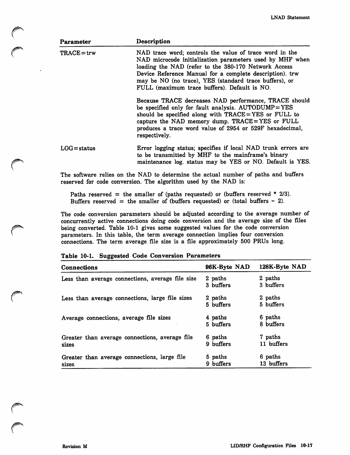
LNAD Statement
Parameter Description
TRACE=trw
00&S
r
LOG=status
NAD trace word; controls the value of trace word in the
NAD microcode initialization parameters used by MHF when
loading the NAD (refer to the 380-170 Network Access
Device Reference Manual for a complete description), trw
may be NO (no trace), YES (standard trace buffers), or
FULL (maximum trace buffers). Default is NO.
Because TRACE decreases NAD performance, TRACE should
be specified only for fault analysis. AUTODUMP=YES
should be specified along with TRACE = YES or FULL to
capture the NAD memory dump. TRACE = YES or FULL
produces a trace word value of 2954 or 529F hexadecimal,
respectively.
Error logging status; specifies if local NAD trunk errors are
to be transmitted by MHF to the mainframe's binary
maintenance log. status may be YES or NO. Default is YES.
The software relies on the NAD to determine the actual number of paths and buffers
reserved for code conversion. The algorithm used by the NAD is:
Paths reserved = the smaller of (paths requested) or (buffers reserved * 2/3).
Buffers reserved = the smaller of (buffers requested) or (total buffers - 2).
The code conversion parameters should be adjusted according to the average number of
concurrently active connections doing code conversion and the average size of the files
being converted. Table 10-1 gives some suggested values for the code conversion
parameters. In this table, the term average connection implies four conversion
connections. The term average file size is a file approximately 500 PRUs long.
Table 10-1. Suggested Code Conversion Parameters
Connections 96K-Byte NAD 128K-Byte NAD
Less than average connections, average file size 2 paths
3 buffers
Less than average connections, large file sizes 2 paths
5 buffers
Average connections, average file sizes 4 paths
5 Duffers
Greater than average connections, average file 6 paths
sizes 9 buffers
Greater than average connections, large file 5 paths
sizes 9 buffers
2 paths
3 buffers
2 paths
5 Duffers
6 paths
8 buffers
7 paths
11 buffers
6 paths
13 buffers
r
Revision M LID/RHF Configuration Files 10-17
RNAD Statement
RNAD Statement
Every remote NAD defined requires four words in RHF's field length. To define a
remote NAD, enter:
raddr RNAD ND=nn,DD=d,LOG=status
Parameter Description
,>e'^%\
raddr
ND=nn
DD=d
LOG=status
Symbolic address referenced in a preceding PATH
statement. This parameter is required and must begin in
character position 1 or 2.
Remote NAD address; nn is a 2-digit hexadecimal address
of the remote NAD. Default is 0.
Remote NAD exit port; d is a 1-digit hexadecimal address
of the exit port of the remote NAD. Default is 0.
Error logging status; specifies if remote NAD trunk errors
are to be recorded by MHF in the mainframe's binary
maintenance log. status may be YES or NO. Default is
NO. Do not specify LOG=YES if the defined NAD is a
local NAD (as in the case of a loopback path). Instead, use
the LOG parameter on the LNAD statement to control
error logging.
DEBUG Statement
The DEBUG statement controls the manner in which RHF uses queue entries.
DEBUG TRACE=statUS
Parameter
TRACE = status
Description
RHF trace status; specifies whether the RHF trace is on
or off. status may be YES or NO. Default is NO. NO
specifies that RHF trace is off and queue entries freed by
RHF are placed at the top of the empty queue and reused
immediately. RHF uses a slightly smaller amount of
processing time when the RHF trace is off. Default is NO.
YES specifies that RHF trace is on and a queue entry is
reused only after all queue entries ahead of it have been
used. Also, when the RHF trace is on, you can use it for
analysis of an RHF dump and resolution of the associated
RHF problem.
T ^ S
10-18 NOS Version 2 Analysis Handbook Revision M
J<nlif^^\
CHARGE Statement
CHARGE Statement
The CHARGE statement specifies the amount of system resources a user control point
is charged for an RHF call. RHF distinguishes two different types of calls; those that
require a large amount of processing time and those that require a small amount of
processing time.
CHARGE TYPE=type,CPA=cpa,CPB=cpb,IO=io,CMFL=cm,PP=pp
P a r a m e t e r D e s c r i p t i o n
TYPE=type Type of call for which the charge is being specified.
Type Description
Requires small amount of RHF processing time.
Requires large amount of RHF processing time.
CPA=cpa
CPB = cpb
IO=io
CMFL=cm
PP=pp
Time to be charged for central processor cpa (decimal
milliseconds). Default is 2 milliseconds for a type 1 call; 10
milliseconds for a type 2 call.
Time to be charged for central processor cpb (decimal
milliseconds). Default is 0.
Input/output time to be charged (decimal milliseconds). Default
is 0.
Central memory field length to be charged, cm is the field
length in octal divided by 100s. Default is 10s.
PP time to be charged (decimal milliseconds). Default is 0.
A CHARGE statement is not required. You may, however, enter two CHARGE
statements: one for type 1 calls, a second for type 2 calls.
Revision M LID/RHF Configuration Files 10-19
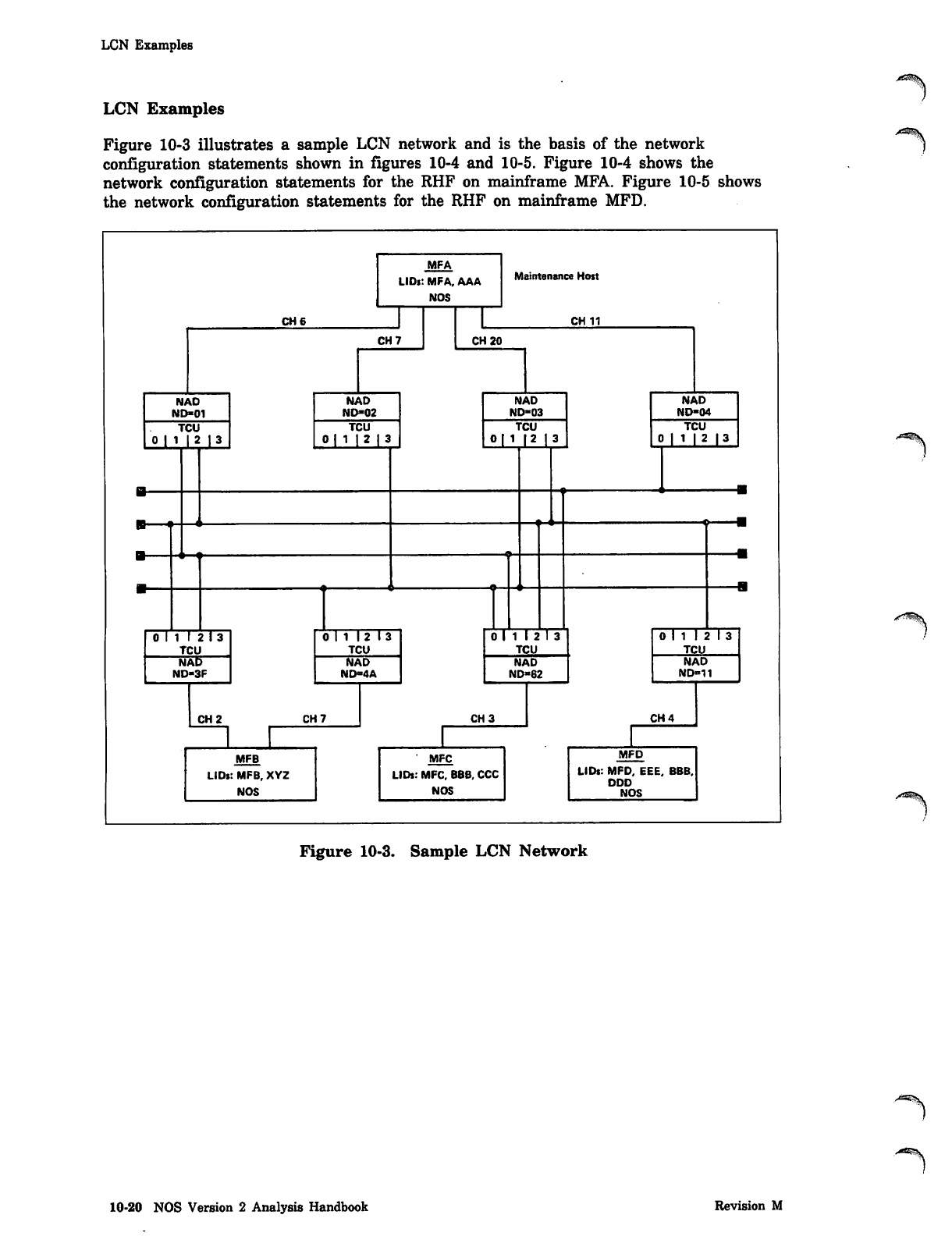
LCN Examples
LCN Examples
Figure 10-3 illustrates a sample LCN network and is the basis of the network
configuration statements shown in figures 10-4 and 10-5. Figure 10-4 shows the
network configuration statements for the RHF on mainframe MFA. Figure 10-5 shows
the network configuration statements for the RHF on mainframe MFD.
NAD
ND-01
TCU
0 11 12 13
B-
B-
0 I 1 12 13
TCU
NAD
ND-3F
CH2
MFA
LIDs: MFA. AAA
NOS
CH6
CH7
NAD
ND-02
TCU
0 1 1 1 2 1 3
O i l 1 2 1 3
TCU
NAD
ND-4A
CH7
MFB MFC
LIDs: MFB, XYZ LIDs: MFC, BBB, CCC
NOS NOS
Maintenance Host
CH 11
CH20
NAD
ND-03
TCU
O| 1 [2 j 3
#-*
0 I 1 I 2 I 3
TCU
NAD
ND-62
CH3
NAD
ND-04
TCU
oLLLill
Oil 1 2 I 3
TCU
NAD
ND=11
CH4
MFD
LIDs: MFD, EEE, BBB,
DDD
NOS
Figure 10-3. Sample LCN Network
^)
10-20 NOS Version 2 Analysis Handbook Revision M
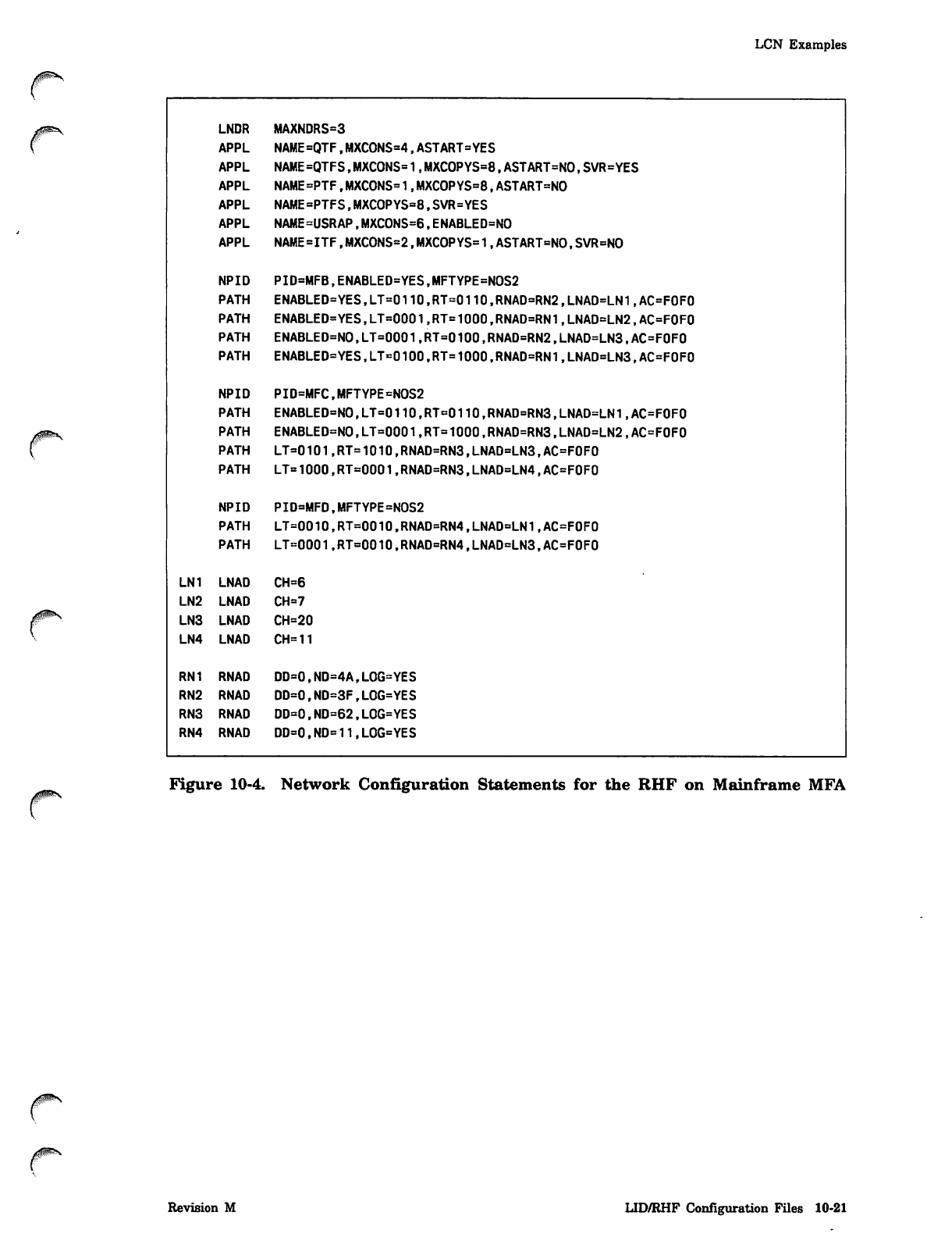
LCN Examples
LNDR MAXNDRS=3
APPL NAME=QTF,MXC0NS=4,ASTART=YES
APPL NAME =QTFS,MXC0NS=1,MXCOPYS=8,ASTART=NO,SVR=YES
APPL NAME=PTF,MXCONS=1,MXCOPYS=8,ASTART=NO
APPL NAME=PTFS,MXC0PYS=8,SVR=YES
APPL NAME=USRAP,MXCONS=6,ENABLED=NO
APPL NAME=ITF,MXC0NS=2,MXCOPYS=1,ASTART=NO,SVR=NO
NPID PID=MFB,ENABLED=YES,MFTYPE=NOS2
PATH ENABLED=YES,LT=0110,RT=0110,RNAD=RN2,LNAD=LN1,AC=FOFO
PATH ENABLED=YES,LT=0001,RT=1000,RNAD=RN1,LNAD=LN2,AC=F0F0
PATH ENABLED=NO,LT=0001,RT=0100,RNAD=RN2,LNAD=LN3,AC=F0F0
PATH ENABLED=YES,LT=0100,RT=1000,RNAD=RN1,LNAD=LN3,AC=F0F0
NPID PID=MFC.MFTYPE=N0S2
PATH ENABLED=NO,LT=0110,RT=0110,RNAD=RN3,LNAD=LN1,AC=F0F0
PATH ENABLED=NO,LT=0001,RT=1000,RNAD=RN3,LNAD=LN2,AC=F0F0
PATH LT=0101,RT=1010,RNAD=RN3,LNAD=LN3,AC=F0F0
PATH LT=1000,RT=0001,RNAD=RN3,LNAD=LN4,AC=F0F0
NPID PID=MFD,MFTYPE=N0S2
PATH LT=0010,RT=0010,RNAD=RN4,LNAD=LN1,AC=F0F0
PATH LT=0001,RT=0010,RNAD=RN4,LNAD=LN3,AC=F0F0
LN1 LNAD CH=6
LN2 LNAD CH=7
LN3 LNAD CH=20
LN4 LNAD CH=11
RN1 RNAD DD=0,ND=4A,L0G=YES
RN2 RNAD DD=0,ND=3F,L0G=YES
RN3 RNAD DD=0,ND=62,L0G=YES
RN4 RNAD DD=0,ND=11,L0G=YES
Figure 10-4. Network Configuration Statements for the RHF on Mainframe MFA
Revision M LID/RHF Configuration Files 10-21
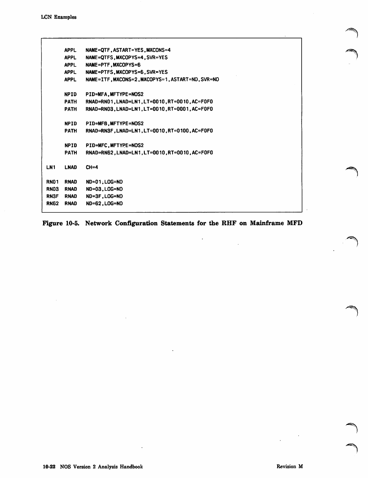
LCN Examples
APPL NAME=QTF,ASTART=YES,MXC0NS=4
APPL NAME=QTFS,MXC0PYS=4,SVR=YES
APPL NAME=PTF,MXCOPYS»6
APPL NAME=PTFS,MXC0PYS=6,SVR-YES
APPL NAME=ITF,MXC0NS=2,MXCOPYS=1,ASTART=NO,SVR=NO
NPID PID=MFA,MFTYPE=NOS2
PATH RNAD=RN01,LNAD=LN1,LT=0010,RT=0010,AC=F0F0
PATH RNAD=RN03, LNAD=LN 1, LT<=0010, RT=0001, AC=F0F0
NPID PID=MFB,MFTYPE=N0S2
PATH RNAD=RN3F,LNAD=LN1,LT=0010,RT=0100,AC=F0F0
NPID PID=MFC,MFTYPE=NOS2
PATH RNAD=RN62,LNAD=LN1,LT=0010,RT=0010,AC=F0F0
LN1 LNAD CH=4
RN01 RNAD ND=01,LOG=NO
RN03 RNAD ND=03,LOG=NO
RN3F RNAD ND=3F,L0G=N0
RN62 RNAD ND=62,L0G=N0
/^^^k
Figure 10-5. Network Configuration Statements for the RHF on Mainframe MFD
|,^®K
>^^8\
10-22 NOS Version 2 Analysis Handbook Revision M
0$*S
008S,
0^S.
QTF Configuration Requirements
QTF Configuration Requirements
You must create the appropriate configuration files before you can perform queued file
transfers using RHF or NAM.
RHF Configuration File Directives
For each copy of QTF that you want RHF to start automatically on a NOS host, you
must include the following network configuration statement in the RCFGEN input file
for that host:
APPL NAME=QTF.MXC0NS=4,ASTART=YES
Refer to the APPL statement under RHF Configuration Files earlier in this section.
Each copy of QTF will establish at most four simultaneous connections. For most
RHF configurations, a single copy of QTF should be sufficient.
To allow a NOS host to receive queued files, you must include the following network
configuration statement in the RCFGEN input file for that host:
APPL NAME=QTFS,SVR=YES,MXCOPYS=n
where n is the maximum number of QTFS servers you want to have active. Each copy
of QTFS services one connection.
Refer to the appropriate reference manuals for other RHF implementations for
information on how to configure non-NOS QTF and QTFS applications and
connections.
Revision M LID/RHF Configuration Files 10-23
NAM Configuration File Directives
NAM Configuration File Directives
In the NDLP input file, you must include QTFS OUTCALL statements for each PID to
which you want to transfer queued files and one APPL statement for QTF:
QTF: APPL,PRIV,PRU,NETXFR,MXCOPY=n.
where n is the maximum number of QTF initiators you want to have active.
Parameter records in the NAMI job record file NAMSTRT specify which applications
NAM automatically starts. Each default parameter record produced when QTF is
installed includes one JOB(JOBQTF,QT) directive. To automatically start more than
one copy of QTF, you can add additional job records to the NAMSTRT file and must
add additional JOB directives to each parameter record desired. Refer to the NAM5 -
Network Access Methods Version 1 subsection of the Special Product Installation
Information section of the NOS Version 2 Installation Handbook for more information
on NAMI job records.
Each copy of QTF will establish at most four simultaneous connections for file
transfers. For many NAM configurations, a single copy of QTF should be sufficient.
You might consider using more than one copy of QTF if you expect a large number
of queued file transfers over slow communication lines.
To allow a NOS host to receive queued files, you must include in the NDLP input
file for that host one or more QTFS INCALL statements and one APPL statement for
QTFS:
QTFS: APPL,RS,PRIV,PRU,NETXFR,MXC0PY=n.
where n is the maximum number of QTFS servers you want to have active. Each copy
of QTFS services one connection. Refer to the Network Access Method Network
Definition Language Reference Manual for more information on APPL, INCALL, and
OUTCALL statements.
The default NAMI parameter records include a JOB(JOBQTFS,QS) directive. The
JOBQTFS job record creates or modifies permanent file ZZQTFS, which contains the
job file submitted by NAM to start a new copy of QTFS when necessary.
10-24 NOS Version 2 Analysis Handbook Revision M
QTF Procedure File
QTF Procedure File
The QTF procedure file contains a set of default initialization commands for each of
the two QTF variants, RHF and NAM. You can edit the commands in the procedure
and capture the modified procedure in a new system file without rebuilding QTF, or
you can include UPDATE modifications in the USER file for the RHP installation
procedure. The QTF procedure is deck QTFPROC on the RHPlpsrin program library
file (refer to the NOS Version 2 Installation Handbook).
For the NAM variant, another option is to modify the JOBQTF record (on file
NAMSTRT), which is used to start QTF at NAM initiation.
Format of the call to the QTF procedure file is:
QTF,variant,I=inflie.
Parameter Description
variant
infile
RHF or NAM, identifies which QTF variant to initiate. The
default is RHF.
File name from which initialization commands are to be
processed. Default is to use the commands for the variant
included in the QTF procedure file. QTF reads the
initialization commands until end-of-record. Each command on
the file is a separate line (equivalent to a K-display entry
without the K. prefix). Specifying I = infile is equivalent to
entering the command K.INCLUDE,FILE = infile.
00^S
/SS*V
Revision M LID/RHF Configuration Files 10-25
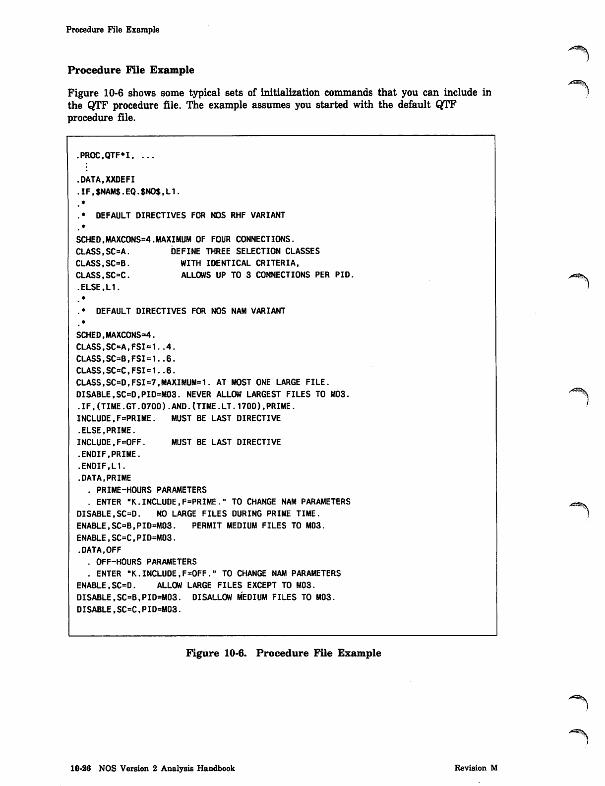
Procedure File Example
Procedure File Example
Figure 10-6 shows some typical sets of initialization commands that you can include in
the QTF procedure file. The example assumes you started with the default QTF
procedure file.
A^m$\
,PROC,QTF*I, ...
DATA,XXDEFI
IF,$NAM$.EQ.$NO$.L1.
*
* DEFAULT DIRECTIVES FOR NOS RHF VARIANT
*
SCHED,MAXCONS=4.MAXIMUM OF FOUR CONNECTIONS.
CLASS,SC=A. DEFINE THREE SELECTION CLASSES
CLASS,SC=B. WITH IDENTICAL CRITERIA,
CLASS,SC=C. ALLOWS UP TO 3 CONNECTIONS PER PID.
.ELSE.L1.
^ •
.* DEFAULT DIRECTIVES FOR NOS NAM VARIANT
•
SCHED,MAXC0NS=4.
CLASS.SC=A,FSI=1..4.
CLASS,SC=B,FSI=1..6.
CLASS,SC=C,FSI=1..6.
CLASS, SC=D, FSI =7, MAXIMUMS. AT MOST ONE LARGE FILE.
DISABLE,SC=D,PID=M03. NEVER ALLOW LARGEST FILES TO M03.
.IF,(TIME.GT.0700).AND.(TIME.LT.1700),PRIME.
INCLUDE,F=PRIME. MUST BE LAST DIRECTIVE
.ELSE,PRIME.
INCLUDE,F«=OFF. MUST BE LAST DIRECTIVE
.ENDIF,PRIME.
.ENDIF,Ll.
.DATA,PRIME
. PRIME-HOURS PARAMETERS
. ENTER "K.INCLUDE,F=PRIME." TO CHANGE NAM PARAMETERS
DISABLE,SC=D. NO LARGE FILES DURING PRIME TIME.
ENABLE,SC=B,PID=M03. PERMIT MEDIUM FILES TO M03.
ENABLE,SC=C,PID=M03.
.DATA,OFF
. OFF-HOURS PARAMETERS
. ENTER "K.INCLUDE,F=OFF." TO CHANGE NAM PARAMETERS
ENABLE,SC=D. ALLOW LARGE FILES EXCEPT TO M03.
DISABLE,SC=B,PID=M03. DISALLOW MEDIUM FILES TO M03.
DISABLE,SC=C,PID=M03.
A^ms
■^^s
Figure 10-6. Procedure File Example
10-26 NOS Version 2 Analysis Handbook Revision M
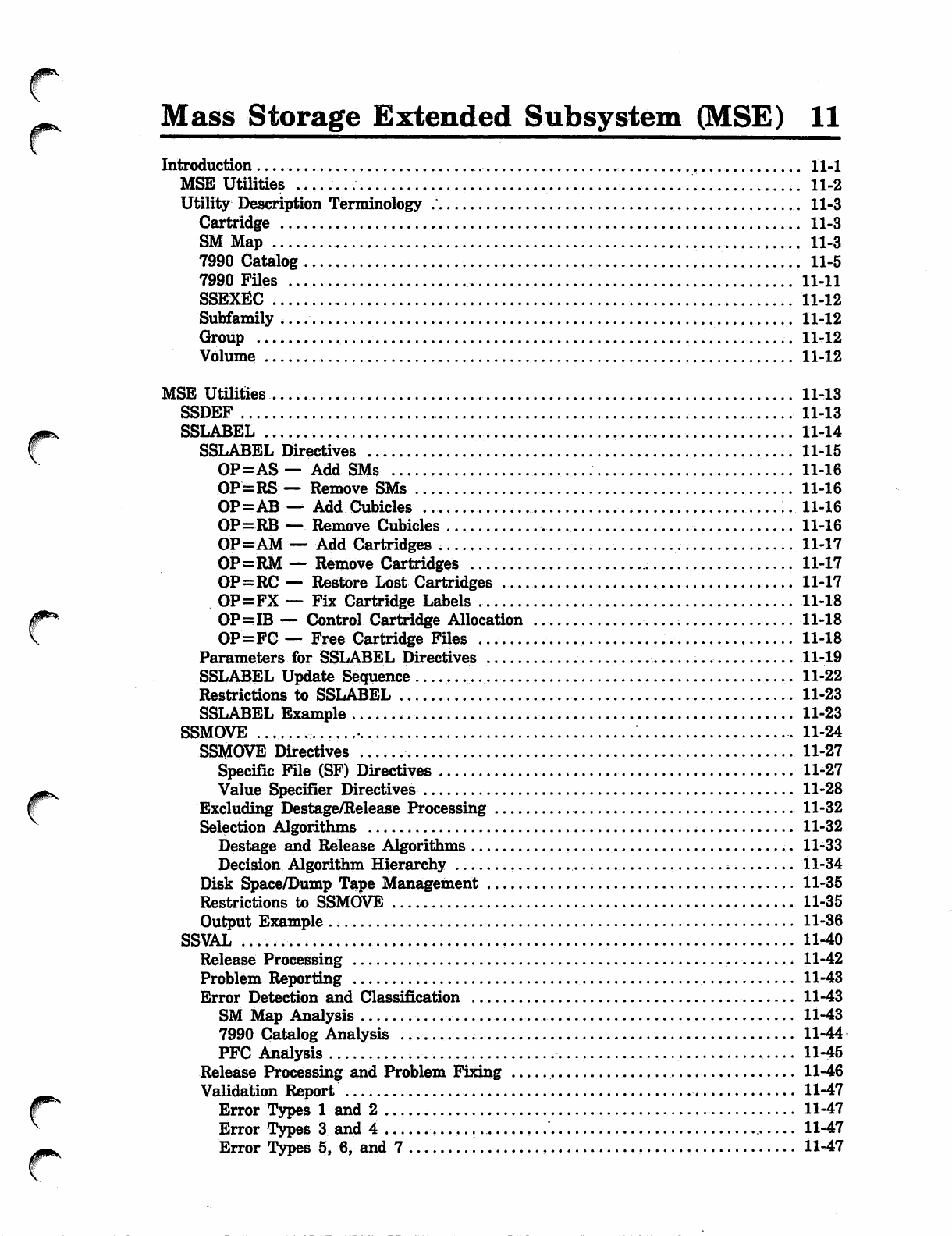
0^
^^
0*
Mass Storage Extended Subsystem (MSE) 11
Introduction 11-1
MSE Utilities 11-2
Utility Description Terminology .'. 11-3
Cartridge 11-3
S M M a p . . 1 1 - 3
7990 Catalog , 11-5
7990 Files 11-11
SSEXEC 11-12
Subfamily .... 11-12
Group .. 11-12
Volume 11-12
MSE Utilities 11-13
SSDEF 11-13
SSLABEL 11-14
SSLABEL Directives 11-15
OP=AS — Add SMs 11-16
OP=RS — Remove SMs 11-16
OP=AB — Add Cubicles :.. 11-16
OP=RB —. Remove Cubicles 11-16
OP-AM — Add Cartridges . . 11-17
OP=RM — Remove Cartridges 11-17
OP=RC — Restore Lost Cartridges 11-17
OP=FX — Fix Cartridge Labels 11-18
OP=IB — Control Cartridge Allocation 11-18
OP=FC — Free Cartridge Files 11-18
Parameters for SSLABEL Directives 11-19
SSLABEL Update Sequence .. 11-22
Restrictions to SSLABEL 11-23
SSLABEL Example 11-23
SSMOVE ■ . . . 1 1 - 2 4
SSMOVE Directives 11-27
Specific File (SF) Directives 11-27
Value Specifier Directives 11-28
Excluding Destage/Release Processing 11-32
Selection Algorithms . 11-32
Destage and Release Algorithms ... 11-33
Decision Algorithm Hierarchy 11-34
Disk Space/Dump Tape Management 11-35
Restrictions to SSMOVE 11-35
Output Example 11-36
SSVAL 11-40
Release Processing .. 11-42
Problem Reporting 11-43
Error Detection and Classification 11-43
SM Map Analysis 11-43
7990 Catalog Analysis 11-44
PFC Analysis 11-45
Release Processing and Problem Fixing 11-46
Validation Report 11-47
E r r o r T y p e s 1 a n d 2 1 1 - 4 7
E r r o r T y p e s 3 a n d 4 1 1 - 4 7
E r r o r T y p e s 5 , 6 , a n d 7 1 1 - 4 7
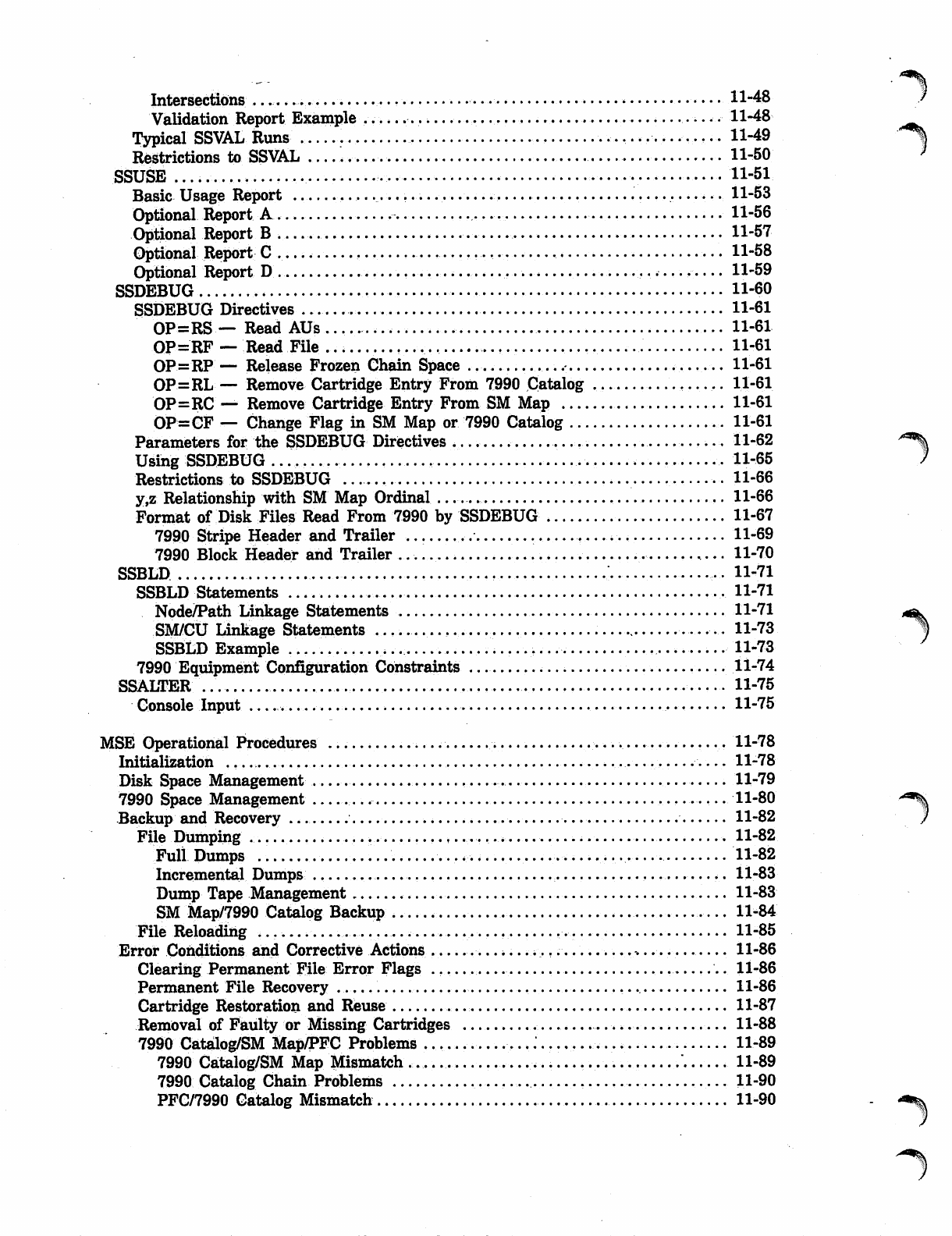
Intersections ,... ■. . . . - — • 1 1 - 4 8
Validation Report Example 11-48
Typical SSVAL Runs 11-49
Restrictions to SSVAL ..... .... H-50
SSUSE • H-51
Basic Usage Report ................ . 11-53
Optional Report A 11-56
Optional Report B , .. 11-57
Optional Report C ......■ . H - 5 8
Optional Report D ... 11-59
SSDEBUG H-60
SSDEBUG Directives 11-61
OP=RS.— Read AUs 11-61
OP=RF — Read File , 11-61
O P - R P — R e l e a s e F r o z e n C h a i n S p a c e , . . . . . . . 11 - 6 1
OP=RL — Remove Cartridge Entry From 7990 Catalog 1.1-61
OP=RC — Remove Cartridge Entry From SM Map 11-61
OP-CF — Change Flag in SM Map or 7990 Catalog 11-61
Parameters for the SSDEBUG Directives ... 11-62
Using SSDEBUG ............. 11-65
Restrictions to SSDEBUG ,. 11-66
y,z Relationship with SM Map Ordinal 11-66
Format of Disk Files Read From 7990 by SSDEBUG 11-67
7990 Stripe Header and Trailer 11-69
7990 Block Header and Trailer 11-70
SSBLD .. H-71
SSBLD Statements .... 11-71
Node/Path Linkage Statements 11-71
SM/CU Linkage Statements 11-73
SSBLD Example ., 11-73
7990 Equipment Configuration Constraints 11-74
SSALTER 11-75
Console Input 11-75
MSE Operational Procedures .... 11-78
Initialization 11-78
Disk Space Management — 11-79
7990 Space Management 11-80
Backup and Recovery — 11-82
File Dumping ■...- ... 11-82
Full Dumps ,, 11-82
Incremental Dumps .. 11-83
Dump Tape Management 11-83
SM Map/7990 Catalog Backup 11-84
File Reloading ....... ............. .., 11-85
Error Conditions and Corrective Actions 11-86
C l e a r i n g P e r m a n e n t F i l e E r r o r F l a g s . . . . . . . . . . 1 1 - 8 6
Permanent File Recovery ...... 11-86
Cartridge Restoration and Reuse 11-87
Removal of Faulty or Missing Cartridges 11-88
7990 Catalog/SM Map/PFC Problems 11.-89
7990 Catalog/SM Map Mismatch . ..... 11-89
7990 Catalog Chain Problems 11-90
PFC/7990 Catalog Mismatch 11-90
~)
^%
Mass Storage Extended Subsystem (MSE) 11
r
Introduction
The Mass Storage Extended Subsystem (MSE) is the product consisting of the 7990
hardware, the channel interface, the diagnostics, and the operational software.
The 7990 hardware is a large-capacity online mass storage device, which is a
cost-effective extension to the disk file storage system and an alternative to
conventional magnetic tape storage. Storing files on the 7990 retains the security, data
integrity, and online access capabilities provided by disk and reduces the operational
and data integrity problems caused by storing, retrieving, and mounting tape volumes.
You can use both the 7990 and magnetic tapes to protect files from hardware and
system failures.
The 7990 hardware is composed of the following components:
Component Description
Cartridge
7991 Storage
Module (SM)
7990 Control
Unit (CU)
A plastic housing that encloses magnetic tape on which data is
stored under program control. This cartridge is compatible with an
IBM 3850 cartridge.
The hardware unit that houses up to 312 usable data cartridges.
The SM also consists of the cartridge accessor unit, which picks
cartridges from and puts cartridges in their cubicles, and one or
two data recording drives (DRD), which read data from and write
data to the cartridges. The cubicles are assigned coordinate
locations that are identified by the ordered pair (y,z), where the z
axis is horizontal and the y axis is vertical.
The hardware unit that is the controller for up to four 7991 SMs.
The CU acts like a tape controller for up to four IBM channel
interfaces and includes one or two data recording controllers
(DRCs). The MSE software supports up to two IBM channel
interfaces per CYBER mainframe.
Revision M Mass Storage Extended Subsystem (MSE) 11-1
MSE Utilities
MSE Utilities
The basic function of MSE is to store data on the 7990 and move it to disk upon
request for access by an authorized user. Control of file movement between a disk and
a 7990 is transparent to the applications programmer; however, there are operational
changes and additions that site personnel should note. These include modifications to
operational procedures in the areas of permanent file backup, permanent file recovery,
and disk space management. In addition, new MSE utilities are introduced. Detailed
information about the call and operation of each MSE utility, listed next, is included in
this section.
Utility
SSDEF
SSLABEL
SSMOVE
SSVAL
SSUSE
SSDEBUG
SSBLD
SSALTER
Description
Creates the system files (SM maps and 7990 catalogs) necessary for
MSE processing.
Manages allocation of cubicles and assignment of cartridges in
the SM.
Controls the destaging of files (creating 7990 images) and the
release of disk space.
Controls the release of 7990 space and analyzes the SM maps, 7990
catalogs, and PFC entries to identify and flag discrepancies within
these three components.
Provides reports on the assignment and availability of cartridges
and cubicles within an SM.
Corrects error conditions detected by SSVAL and recovers data from
7990 cartridges.
Builds the unit device table (UDT) for SSEXEC. The UDT describes
the 7990 hardware configuration.
Provides dynamic modification of the 7990 hardware configuration.
11-2 NOS Version 2 Analysis Handbook Revision M
0ms
Utility Description Terminology
Utility Description Terminology
Review the following terms; they are defined as used in the descriptions of the MSE
utilities later in this section.
Cartridge
A cartridge is the 7990 storage component consisting of magnetic tape. The 7990
hardware always writes or reads 6652 8-bit byte records, called stripes, to or from the
magnetic tape. Each cartridge has 27,087 stripes. The first 20 stripes contain a
manufacturer's label. The second 20 stripes contain a 7990 cartridge label written by
the SSLABEL utility. The remaining 27,047 stripes are organized into software-defined
allocation units (AUs) of 14 stripes each for a total of 1931 AUs per cartridge.
An allocation unit is the smallest allocatable portion of a cartridge. One or more AUs
may be allocated to contain data for a single file. The allocated AUs for each file are
organized into volumes (definition follows), which are chained together in the 7990
catalog to identify the sequence of AUs that must be accessed in order to read a file.
A head-of-chain (HOC) flag identifies the first volume in the chain, a link field
identifies the next volume in the chain, and an end-of-chain (EOC) flag identifies the
last volume in the chain.
The addition, removal, and reassignment of cartridges are managed by the MSE
utilities. The cartridge labels, and also the 7990 catalogs and SM maps (definitions
following), contain information concerning the location and content of the cartridges.
The descriptions of the MSE utilities later in this section contain further information
on cartridge management.
SM Map
An SM map is a direct access permanent file that contains information indicating how
cubicles in an SM are assigned to a family and identifying the cartridges that reside in
the SM. There is one SM map for each SM in the configuration. The permanent file
name of the SM map is SMMAPi, where i is the SM identifier (a letter from A to H);
its user index is 377760s; and its family is the default family on the mainframe on
which SSEXEC executes (refer to the definition of SSEXEC later in this section).
An SM map contains an entry for each possible coordinate pair (y,z) that identifies a
cubicle in the SM, from (0,0), which is bottom left, to (21,15), which is upper right.
Certain coordinate pairs are reserved for customer engineering use, system use, and
diagnostic purposes.
Revision M Mass Storage Extended Subsystem (MSE) 11-3
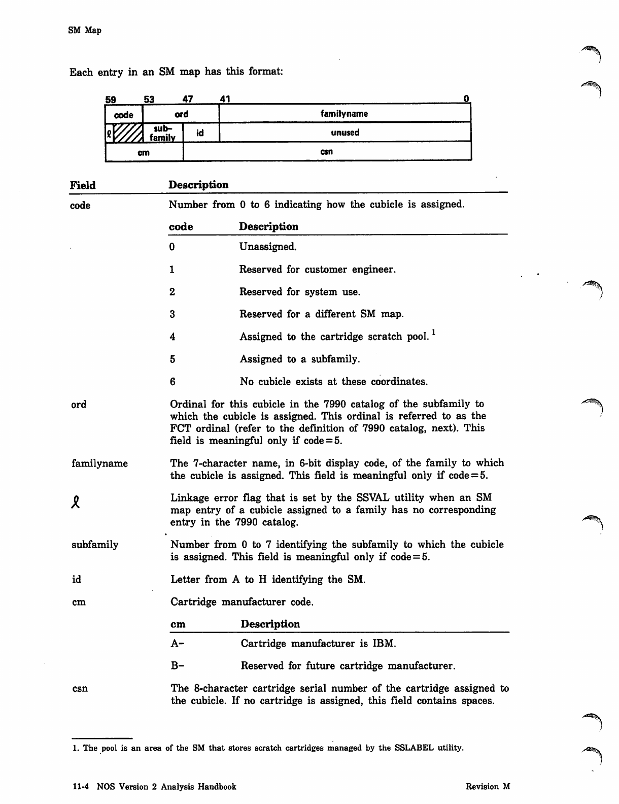
SM Map
Each entry in an SM map has this format:
59 53 47 41
code ord familyname
6'///A sub
family id unused
cm csn
Field Description
code
ord
familyname
X
subfamily
id
cm
Number from 0 to 6 indicating how the cubicle is assigned.
c o d e D e s c r i p t i o n
Unassigned.
Reserved for customer engineer.
Reserved for system use.
Reserved for a different SM map.
Assigned to the cartridge scratch pool.
Assigned to a subfamily.
No cubicle exists at these coordinates.
Ordinal for this cubicle in the 7990 catalog of the subfamily to
which the cubicle is assigned. This ordinal is referred to as the
FCT ordinal (refer to the definition of 7990 catalog, next). This
field is meaningful only if code = 5.
The 7-character name, in 6-bit display code, of the family to which
the cubicle is assigned. This field is meaningful only if code = 5.
Linkage error flag that is set by the SSVAL utility when an SM
map entry of a cubicle assigned to a family has no corresponding
entry in the 7990 catalog.
Number from 0 to 7 identifying the subfamily to which the cubicle
is assigned. This field is meaningful only if code = 5.
Letter from A to H identifying the SM.
Cartridge manufacturer code.
cm Description
A-
B-
Cartridge manufacturer is IBM.
Reserved for future cartridge manufacturer.
csn The 8-character cartridge serial number of the cartridge assigned to
the cubicle. If no cartridge is assigned, this field contains spaces.
1. The pool is an area of the SM that stores scratch cartridges managed by the SSLABEL utility. . ^ ^ \
11-4 NOS Version 2 Analysis Handbook Revision M
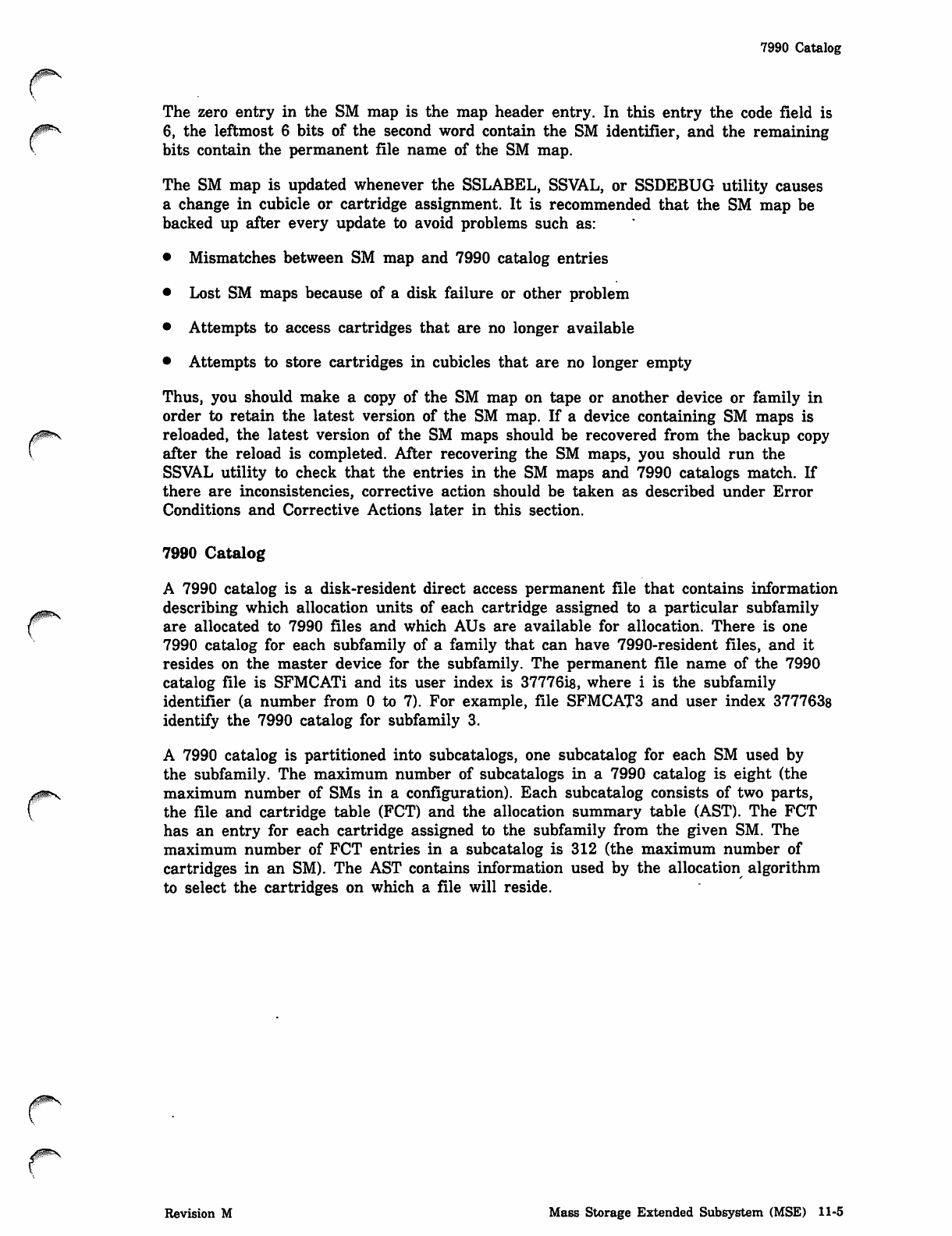
y < ^ \
7990 Catalog
The zero entry in the SM map is the map header entry. In this entry the code field is
6, the leftmost 6 bits of the second word contain the SM identifier, and the remaining
bits contain the permanent file name of the SM map.
The SM map is updated whenever the SSLABEL, SSVAL, or SSDEBUG utility causes
a change in cubicle or cartridge assignment. It is recommended that the SM map be
backed up after every update to avoid problems such as:
• Mismatches between SM map and 7990 catalog entries
• Lost SM maps because of a disk failure or other problem
• Attempts to access cartridges that are no longer available
• Attempts to store cartridges in cubicles that are no longer empty
Thus, you should make a copy of the SM map on tape or another device or family in
order to retain the latest version of the SM map. If a device containing SM maps is
reloaded, the latest version of the SM maps should be recovered from the backup copy
after the reload is completed. After recovering the SM maps, you should run the
SSVAL utility to check that the entries in the SM maps and 7990 catalogs match. If
there are inconsistencies, corrective action should be taken as described under Error
Conditions and Corrective Actions later in this section.
7990 Catalog
A 7990 catalog is a disk-resident direct access permanent file that contains information
describing which allocation units of each cartridge assigned to a particular subfamily
are allocated to 7990 files and which AUs are available for allocation. There is one
7990 catalog for each subfamily of a family that can have 7990-resident files, and it
resides on the master device for the subfamily. The permanent file name of the 7990
catalog file is SFMCATi and its user index is 37776is, where i is the subfamily
identifier (a number from 0 to 7). For example, file SFMCAT3 and user index 377763s
identify the 7990 catalog for subfamily 3.
A 7990 catalog is partitioned into subcatalogs, one subcatalog for each SM used by
the subfamily. The maximum number of subcatalogs in a 7990 catalog is eight (the
maximum number of SMs in a configuration). Each subcatalog consists of two parts,
the file and cartridge table (FCT) and the allocation summary table (AST). The FCT
has an entry for each cartridge assigned to the subfamily from the given SM. The
maximum number of FCT entries in a subcatalog is 312 (the maximum number of
cartridges in an SM). The AST contains information used by the allocation algorithm
to select the cartridges on which a file will reside.
Revision M Mass Storage Extended Subsystem (MSE) 11-5
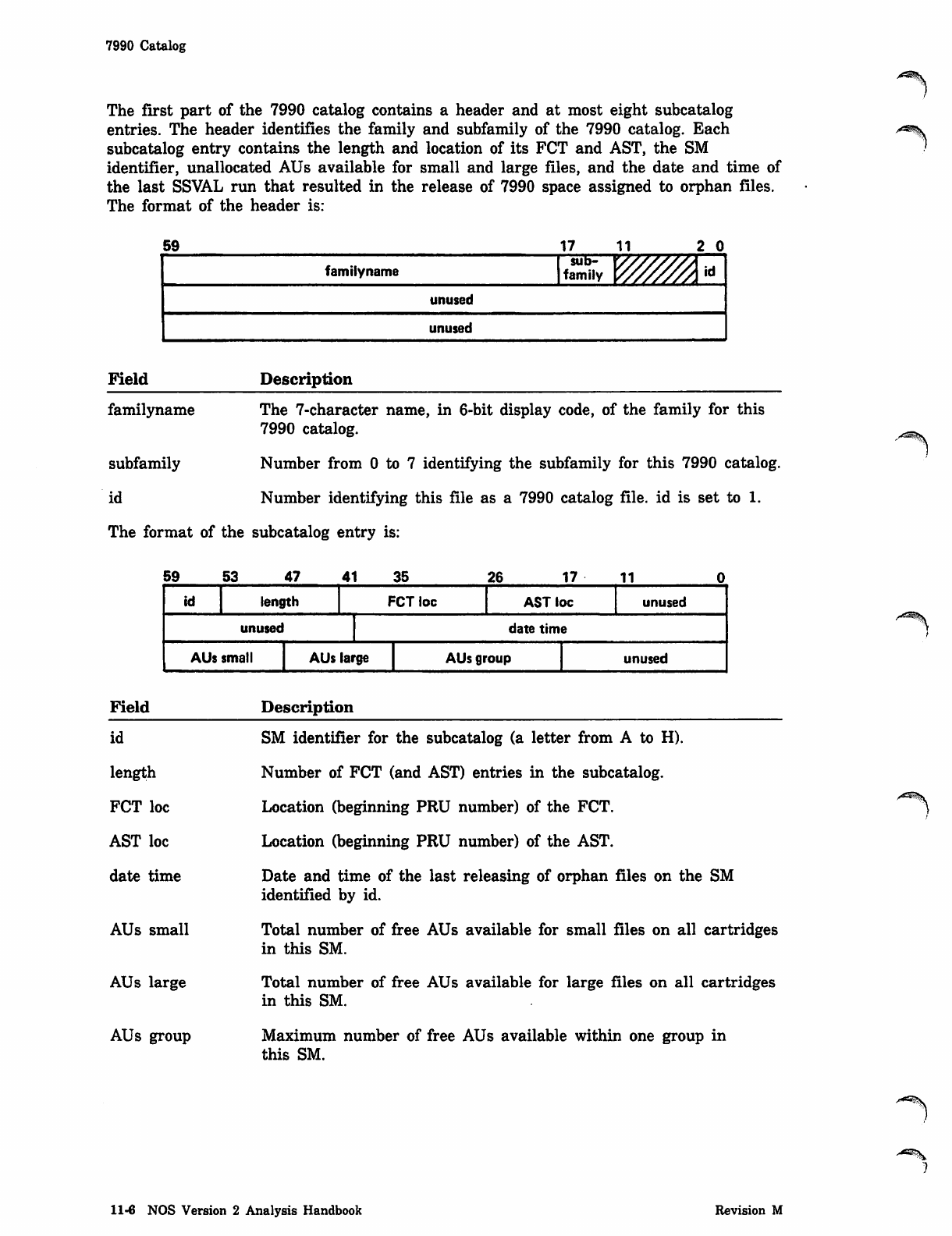
7990 Catalog
The first part of the 7990 catalog contains a header and at most eight subcatalog
entries. The header identifies the family and subfamily of the 7990 catalog. Each
subcatalog entry contains the length and location of its FCT and AST, the SM
identifier, unallocated AUs available for small and large files, and the date and time of
the last SSVAL run that resulted in the release of 7990 space assigned to orphan files.
The format of the header is:
59 17 11 2 0
familyname sub
family W////A id
unused
unused
Field Description
familyname The 7-character name, in 6-bit display code, of the family for this
7990 catalog.
subfamily Number from 0 to 7 identifying the subfamily for this 7990 catalog,
id Number identifying this file as a 7990 catalog file, id is set to 1.
The format of the subcatalog entry is:
59 53 47 41 135 26 17 11
id length FCT loc AST loc unused
unused date time
AUs small AUs large AUs group unused
Field Description
SM identifier for the subcatalog (a letter from A to H).
Number of FCT (and AST) entries in the subcatalog.
Location (beginning PRU number) of the FCT.
Location (beginning PRU number) of the AST.
Date and time of the last releasing of orphan files on the SM
identified by id.
Total number of free AUs available for small files on all cartridges
in this SM.
Total number of free AUs available for large files on all cartridges
in this SM.
Maximum number of free AUs available within one group in
this SM.
id
length
FCT loc
AST loc
date time
AUs small
AUs large
AUs group
s*^S,
1
11-6 NOS Version 2 Analysis Handbook Revision M
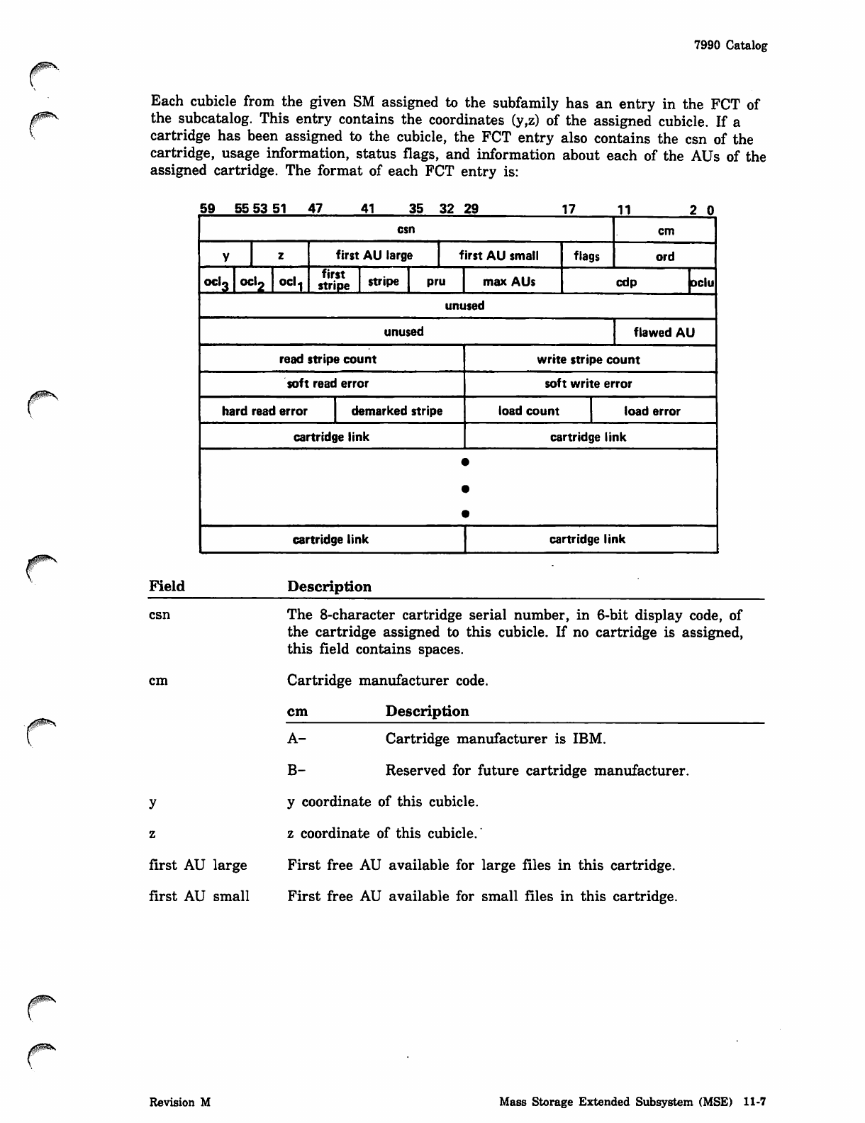
7990 Catalog
Each cubicle from the given SM assigned to the subfamily has an entry in the FCT of
the subcatalog. This entry contains the coordinates (y,z) of the assigned cubicle. If a
cartridge has been assigned to the cubicle, the FCT entry also contains the csn of the
cartridge, usage information, status flags, and information about each of the AUs of the
assigned cartridge. The format of each FCT entry is:
59 55 53 51 47 41 35 32 29 17 11 2 0
csn cm
yzfirst AU large first AU small flags ord
ocU ocl2 OCl.|
first
stripe stripe pru max AUs cdp oclu
unused
unused flawed AU
read stripe count write stripe count
soft read error soft write error
hard read error demarked stripe load count load error
cartridge link cartridge link
•
•
•
cartridge link cartridge link
Field Description
csn
cm
y
z
first AU large
first AU small
The 8-character cartridge serial number, in 6-bit display code, of
the cartridge assigned to this cubicle. If no cartridge is assigned,
this field contains spaces.
Cartridge manufacturer code.
cm Description
A - C a r t r i d g e ma n u f a c t u r e r is IB M .
B- Reserved for future cartridge manufacturer.
y coordinate of this cubicle.
z coordinate of this cubicle.
First free AU available for large files in this cartridge.
First free AU available for small files in this cartridge.
Revision M Mass Storage Extended Subsystem (MSE) 11-7
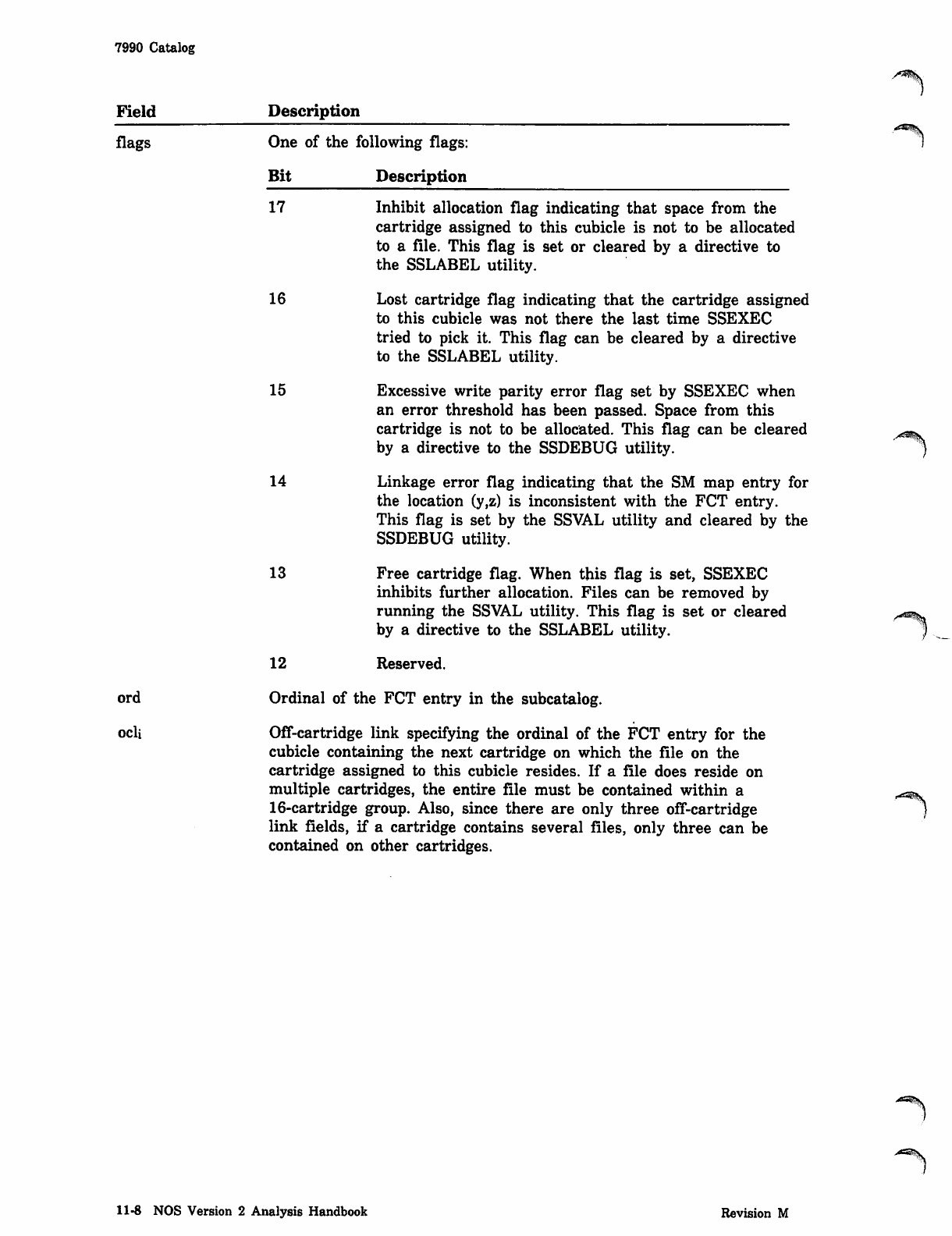
7990 Catalog
Field Description
flags One of the following flags:
Bit Description
17 Inhibit allocation flag indicating that space from the
cartridge assigned to this cubicle is not to be allocated
to a file. This flag is set or cleared by a directive to
the SSLABEL utility.
16 Lost cartridge flag indicating that the cartridge assigned
to this cubicle was not there the last time SSEXEC
tried to pick it. This flag can be cleared by a directive
to the SSLABEL utility.
15 Excessive write parity error flag set by SSEXEC when
an error threshold has been passed. Space from this
cartridge is not to be allocated. This flag can be cleared /tmk^
by a directive to the SSDEBUG utility. )
14 Linkage error flag indicating that the SM map entry for
the location (y,z) is inconsistent with the FCT entry.
This flag is set by the SSVAL utility and cleared by the
SSDEBUG utility.
13 Free cartridge flag. When this flag is set, SSEXEC
inhibits further allocation. Files can be removed by
running the SSVAL utility. This flag is set or cleared
by a directive to the SSLABEL utility.
12 Reserved.
ord Ordinal of the FCT entry in the subcatalog.
ocli Off-cartridge link specifying the ordinal of the FCT entry for the
cubicle containing the next cartridge on which the file on the
cartridge assigned to this cubicle resides. If a file does reside on
multiple cartridges, the entire file must be contained within a ^s^
16-cartridge group. Also, since there are only three off-cartridge j
link fields, if a cartridge contains several files, only three can be
contained on other cartridges.
11-8 NOS Version 2 Analysis Handbook Revision M
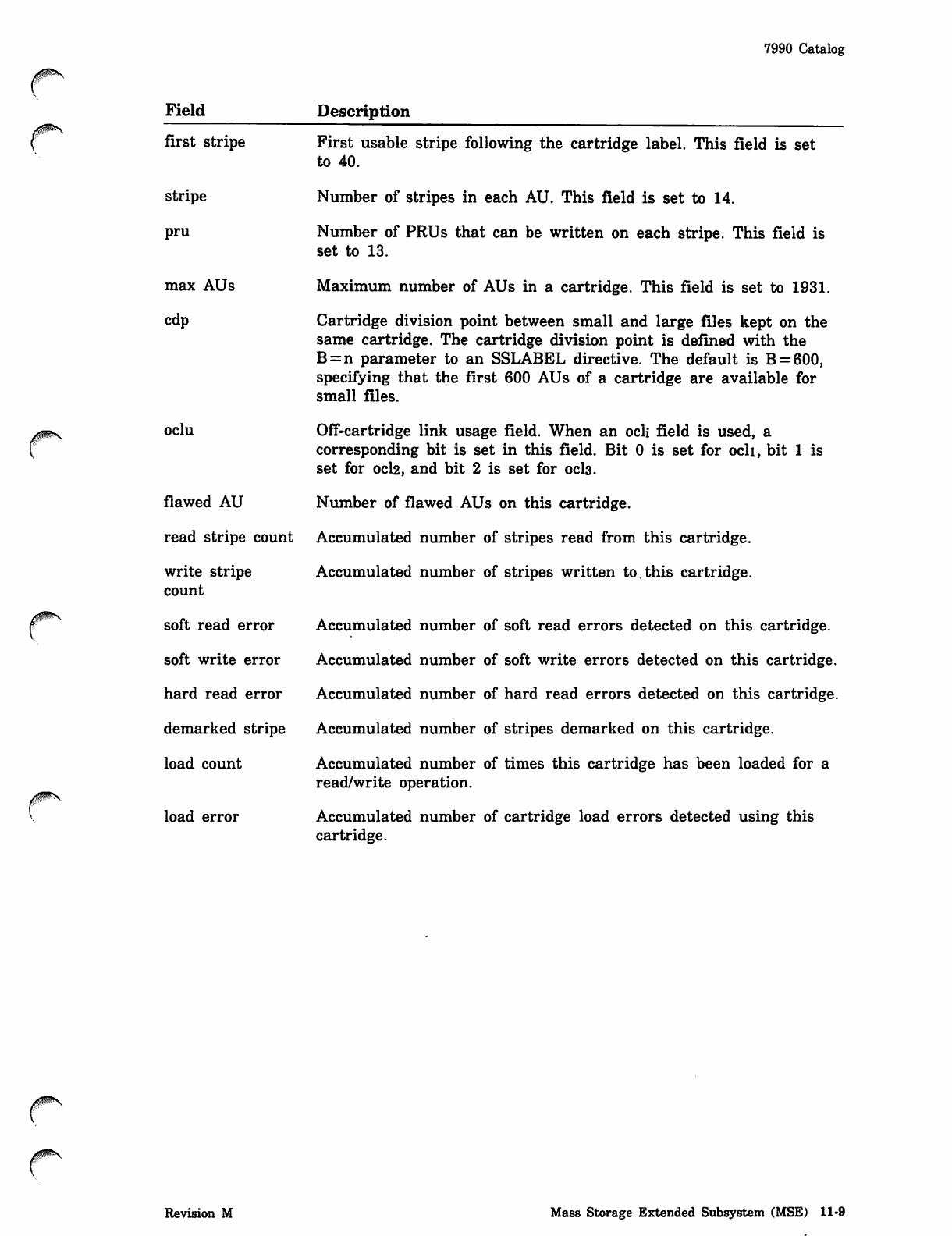
7990 Catalog
r
Field
first stripe
stripe
pru
max AUs
cdp
oclu
flawed AU
read stripe count
write stripe
count
soft read error
soft write error
hard read error
demarked stripe
load count
load error
Description
First usable stripe following the cartridge label. This field is set
to 40.
Number of stripes in each AU. This field is set to 14.
Number of PRUs that can be written on each stripe. This field is
set to 13.
Maximum number of AUs in a cartridge. This field is set to 1931.
Cartridge division point between small and large files kept on the
same cartridge. The cartridge division point is defined with the
B=n parameter to an SSLABEL directive. The default is B = 600,
specifying that the first 600 AUs of a cartridge are available for
small files.
Off-cartridge link usage field. When an ocli field is used, a
corresponding bit is set in this field. Bit 0 is set for ocli, bit 1 is
set for ock, and bit 2 is set for ocl3.
Number of flawed AUs on this cartridge.
Accumulated number of stripes read from this cartridge.
Accumulated number of stripes written to this cartridge.
Accumulated number of soft read errors detected on this cartridge.
Accumulated number of soft write errors detected on this cartridge.
Accumulated number of hard read errors detected on this cartridge.
Accumulated number of stripes demarked on this cartridge.
Accumulated number of times this cartridge has been loaded for a
read/write operation.
Accumulated number of cartridge load errors detected using this
cartridge.
Revision M Mass Storage Extended Subsystem (MSE) 11-9
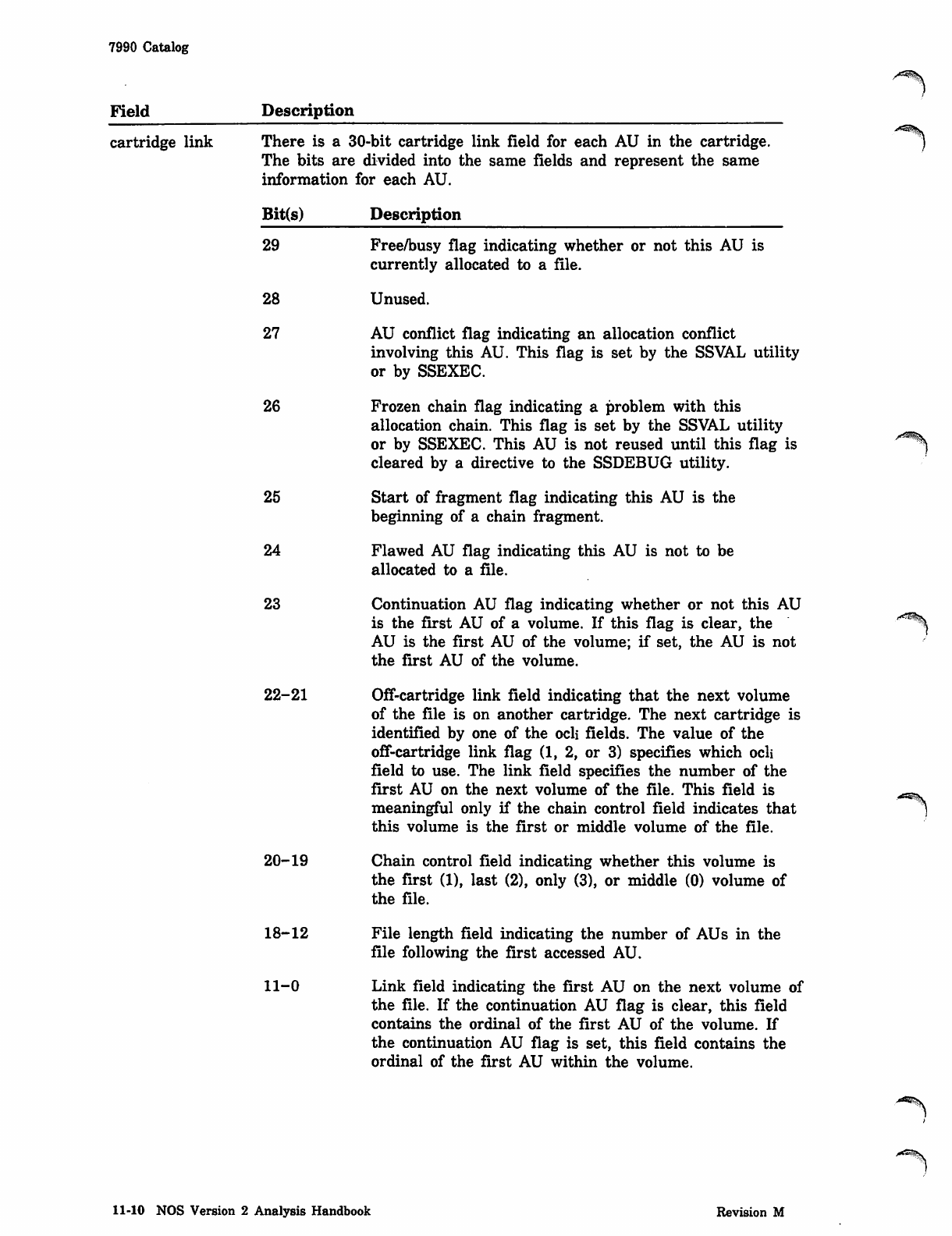
7990 Catalog
Field Description
j*S$S
cartridge link There is a 30-bit cartridge link field for each AU in the cartridge. j
The bits are divided into the same fields and represent the same
information for each AU.
Bit(s) Description
29 Free/busy flag indicating whether or not this AU is
currently allocated to a file.
28 Unused.
27 AU conflict flag indicating an allocation conflict
involving this AU. This flag is set by the SSVAL utility
or by SSEXEC.
26 Frozen chain flag indicating a problem with this
allocation chain. This flag is set by the SSVAL utility
or by SSEXEC. This AU is not reused until this flag is '^
cleared by a directive to the SSDEBUG utility.
25 Start of fragment flag indicating this AU is the
beginning of a chain fragment.
24 Flawed AU flag indicating this AU is not to be
allocated to a file.
23 Continuation AU flag indicating whether or not this AU
is the first AU of a volume. If this flag is clear, the "'^^
AU is the first AU of the volume; if set, the AU is not
the first AU of the volume.
22-21 Off-cartridge link field indicating that the next volume
of the file is on another cartridge. The next cartridge is
identified by one of the ocli fields. The value of the
off-cartridge link flag (1, 2, or 3) specifies which ocli
field to use. The link field specifies the number of the
first AU on the next volume of the file. This field is ^^
meaningful only if the chain control field indicates that ]
this volume is the first or middle volume of the file.
20-19 Chain control field indicating whether this volume is
the first (1), last (2), only (3), or middle (0) volume of
the file.
18-12 File length field indicating the number of AUs in the
file following the first accessed AU.
11-0 Link field indicating the first AU on the next volume of
the file. If the continuation AU flag is clear, this field
contains the ordinal of the first AU of the volume. If
the continuation AU flag is set, this field contains the
ordinal of the first AU within the volume.
11-10 NOS Version 2 Analysis Handbook Revision M
j^ms
7990 Files
The 7990 catalog is updated whenever the SSLABEL, SSMOVE, SSVAL, or SSDEBUG
utility causes a change in cartridge or cubicle assignment that affects the subfamily.
Because the 7990 catalog for a subfamily resides on its master device, it will be
backed up by PFDUMP whenever the master device for the subfamily is dumped.
Consequently, when PFLOAD reloads all files, the 7990 catalogs are automatically
recovered and all 7990-resident files as indicated in a recovered PFC will also have
entries in the recovered 7990 catalog. Thus, no special operational procedures are
needed to back up a 7990 catalog. It is possible, however, that the 7990 catalog will be
inconsistent with the SM maps or cartridge labels. If such inconsistencies do exist,
corrective action will have to be taken as described under Error Conditions and
Corrective Actions later in this section.
7990 Files
In an MSE environment, permanent files can be categorized according to whether or
not they reside on 7990. A disk file is a permanent file that resides on disk but not on
7990. A 7990 file is a permanent file that resides on 7990 and may or may not also
reside on disk, depending on how the disk space is managed (refer to Disk Space
Management later in this section). Depending on backup requirements (BR parameters),
both disk and 7990 files can also have backup images on tape (refer to the NOS
Version 2 Reference Set, Volume 3).
When a user defines a direct access file, initially it is a disk file. A disk file becomes
a 7990 file when it is destaged to 7990; that is, an image of the file is created on
7990. Files are destaged through use of the SSMOVE utility, which is run periodically
to manage disk space. When SSMOVE is run, files are destaged to 7990 and/or their
disk space released depending on certain file characteristics (refer to SSMOVE later
in this section). Thus, after an SSMOVE run a file can reside on disk, on 7990, or on
both. If the file does have a 7990 image, the asa field in the PFC entry for the file
indicates the location of the 7990 copy.
When a user attaches a 7990 file, it is staged to disk from 7990 (that is, a disk
image is created) if the file is not on disk. If a direct access file is attached in write
mode, the AFOBS flag is set in the PFC entry for that file. The current version of
the file resides on disk only. If an indirect access file is replaced or appended to, the
asa field is cleared in the PFC entry for that file. Setting the AFOBS flag or clearing
the asa in the PFC ensures that the current version of the file will be copied to 7990
when that file is again selected for being released from disk.
If the file is purged, its disk space, but not its 7990 space, is immediately released.
The SSVAL utility must be run to release 7990 space allocated to purged files. Thus,
because a purged file has no PFC entry linking to its 7990 catalog entry, the 7990
image that still exists before SSVAL is run is called an orphan file. However, a user
can never access an orphan file.
When a file is destaged to 7990, control information is written on each stripe to
which the file data is written. This information is sufficient to identify the file.
Revision M Mass Storage Extended Subsystem (MSE) 11-11
SSEXEC
SSEXEC
SSEXEC is the main processing program that is responsible for controlling MSE
activities. The MSE utilities issue requests to SSEXEC to destage files from disk to
7990, purge unneeded 7990 files, label or relabel cartridges, update SM maps and 7990
catalogs, and so forth. In a multimainframe environment, two versions of this program
exist: the mainframe to which the 7990 device is physically connected (the master
mainframe) has a program called SSEXEC, and all other mainframes (the slave
mainframes) have a program called SSSLV. Refer to section 13, Multimainframe
Operations, for more information.
Subfamily
Each permanent file family consists of eight subfamilies, subfamily 0 through
subfamily 7. The lower 3 bits of the user index identify the subfamily to which a user
belongs. For example, a user whose index ends in 3 (or Oil in bit notation) belongs to
subfamily 3. When the SSDEF utility is run to create MSE system files, the SM maps
are created on the master device under user index 377760s (subfamily 0) and one 7990
catalog is created under each user index 37776is (subfamily i), i=0,1,2,...,7. When the
SSLABEL utility is used to assign an SM, cubicle, or cartridge to a family, it is
possible to specify assignment to particular subfamilies of the family.
Group
A group is a software-defined structure for allocating cartridges within a subfamily. A
group of cartridges is a number of cartridges (up to 16) in which files belonging to a
subfamily can reside. Any file can overflow from one cartridge in a group to any other
cartridge in the same group. However, no file can overflow from a cartridge in one
group to any cartridge in another group. Cartridges are placed in or removed from
specific groups by using the SSLABEL utility. The SSVAL utility compares the 7990
catalogs (for each subfamily) with the same information obtained from the PFC entries.
Volume
A volume is a software-defined structure used to simplify the allocation and access of
large 7990 files. Up to 128 consecutive AUs in a cartridge that have the same status
(either allocated or hot allocated) are considered to belong to the same volume. These
consecutive AUs are composed of stripes that all have the same volume serial number
(a physical identifier that is written to the tape on the cartridge). The MSE software
fills cartridges (unallocated volumes) from the beginning to the end with no rewinding.
This action minimizes repositioning of the tape in a cartridge for multivolume files.
When a file is staged back to disk, the control information on each stripe is verified.
If a discrepancy is detected, an error message is issued, the file stage is aborted, an
error flag is set in the PFC entry to indicate that the 7990 file could not be accessed,
and the AU conflict flag is set in the 7990 catalog entry for the particular
cartridge(s) and AU(s).
<^ES3s
11-12 NOS Version 2 Analysis Handbook Revision M
0^\.
MSE Utilities
MSE Utilities
MSE utilities are described next. All of these utilities must be run from system origin
jobs. In a multimainframe environment, the SSDEF, SSUSE, and SSBLD utilities can
be run on any mainframe that has access to the family being processed. However, the
remaining utilities must be run on the mainframe on which SSEXEC executes.
SSDEF
SSDEF creates the system files (SM maps and 7990 catalogs) that are necessary for
MSE processing. If an SM is added to the 7990 hardware configuration, SSDEF is used
to create the SM map for that SM. If a family is to be permitted to have 7990-resident
files, SSDEF is used to create the eight 7990 catalogs for that family (one catalog for
each subfamily).
NOTE
If the SM parameter is specified, SSDEF will create an SM map for the specified SM
(refer to the definition of SM map earlier in this section). It is recommended that the
SM map be copied on tape or on another device or family immediately after it is
created.
The format of the SSDEF command is:
SSDEF,Pi,P2-
pi Description
FM=familyname Family for which 7990 catalogs are to be created, one catalog for
each subfamily.
FM Same as FM = system default family.
FM omitted No 7990 catalogs are to be created. SM = id or SM must be
specified.
SM=id SM identifier of the SM for which an SM map is to be created; id
is a letter from A to H.
SM Same as SM=A.
SM omitted No SM map is to be created. FM = familyname or FM must be
specified.
Example:
SSDEF,SM=B.
SMMAPB, the SM map for SM B, is created, and its entries are as described in the
previous definition of SM map earlier in this section. However, since SSDEF does not
assign cubicles, the entries for cubicles available for use initially indicate that the
cubicles are unassigned.
Revision M Mass Storage Extended Subsystem (MSE) 11-13
SSLABEL
SSLABEL
SSLABEL manages cartridge assignment and cubicle allocation in an SM. The following
functions are performed through use of directives to SSLABEL.
Add an SM to a subfamily (AS directive).
Remove an SM from a subfamily (RS directive).
Add cubicles to a subfamily, the pool, or the reserved area (AB directive).
Remove cubicles from a subfamily, the pool, or the reserved area (RB directive).
Add cartridges to a subfamily or the pool (AM directive).
Remove cartridges from a subfamily or the pool (RM directive).
Restore an abnormally removed cartridge (RC directive).
Repair a cartridge label or overwrite a family label (FX directive).
Inhibit or allow further allocation of files to a cartridge (IB directive).
Initiate freeing all files from an existing cartridge (FC directive).
Input to SSLABEL is via a directive file. SSLABEL reads the appropriate SM maps
and 7990 catalogs to determine how to process each directive and then issues requests
to SSEXEC to read and/or write cartridge labels and to update the SM maps and 7990
catalogs. SSLABEL generates a report detailing the action taken for each input ^^
directive. If the assignment information or cartridge label is not appropriate or conflicts j
with data in the SM map or 7990 catalog, the cartridge label information is included
on this report and the cartridge is put into the exit tray. It may be possible to restore
such a cartridge, as described under Cartridge Restoration and Reuse later in this
section.
NOTE
SSLABEL updates the SM map for the specified SM (refer to the definition of SM map
earlier in this section). It is recommended that the SM map be copied on tape or on
another device or family immediately after each update. i
11-14 NOS Version 2 Analysis Handbook Revision M
SSLABEL Directives
The format of the SSLABEL command is:
SSLABEL,Pi,P2.
pi Description
I=filename File containing the directives to SSLABEL.
I S a m e a s I = I N P U T .
I o m i t t e d S a m e a s I = I N P U T.
L=filename File on which listable output is to be written.
L Same as L=OUTPUT.
L = 0 N o o u t p u t fi l e i s t o b e g e n e r a t e d .
L o m i t t e d Sa m e a s L = O U T P U T.
V Z Directives are contained on the SSLABEL command. The I
parameter is ignored.
Z omitted Directives are contained on the file specified by the I parameter.
SSLABEL Directives
The directives to SSLABEL can be specified on a separate file (specified by the I
parameter) or after the SSLABEL command (Z specified). If on the input file, each
^ directive must be specified on a separate line using the OP=directive option.
Parameters for a directive are on the same line, are separated by commas, and end
with a period:
0P=directive,Pi,P2,...,pn.
Example 1:
SSLABEL,I=DIRFILE.
/^ DIRFILE is the directive file; it contains the following directives:
0P=AM,N=4,PK=D.
OP=RM,CN=44455566,FM,SB=1,PK=F.
Two directives to SSLABEL are specified. OP=AM adds four cartridges to the pool of
SM A (SM parameter not specified). OP=RM removes the cartridge whose csn is
44455566 from subfamily 1 of the default family. (Refer to the following descriptions of
directives and parameters.)
If the directives are contained on the command, they follow the command terminator.
The first character following the terminator is the separator. Any character that does
not appear in any of the directives can be used as the separator character. Each
directive must be preceded by the separator and terminated by a period.
Revision M Mass Storage Extended Subsystem (MSE) 11-15
SSLABEL Directives
Example 2:
SSLABEL,Z./0P=AM,N=4,PK=D./0P=RM,CN=44455566,FM,SB=1,PK=F.
The slant is used as the separator. This command performs the same functions as those
in the preceding example.
The following directives are available with SSLABEL. Some of these directives cause
cartridges to be physically moved to and from cubicles and the input or exit tray
(refer to OP=AM, OP=RM, OP=RC, and OP=FX in the following paragraphs). The
remaining directives cause only logical operations to occur, updating the MSE system
files. Descriptions of the parameters for these directives follow the directives.
OP=AS — Add SMs
OP=AS adds an SM to a subfamily. The 7990 catalog for the specified subfamily is
updated to reflect that cartridges and permanent files for the subfamily can reside on
the specified SM. This directive, however, does not manipulate cartridges or cubicles.
OP=RS — Remove SMs
OP = RS removes an SM from a subfamily. The 7990 catalog for the specified subfamily
is updated to reflect that cartridges and permanent files for the subfamily cannot
reside on the specified SM. Before OP=RS can be specified, all cubicles in the specified
SM must have been removed previously from the family (refer to the OP=RB
directive). This directive, however, does not manipulate cartridges or cubicles.
OP=AB — Add Cubicles
OP=AB adds an unassigned cubicle within an SM to a subfamily (PT=F), the pool
(PT=P), or the reserved area of the SM (PT=R). More than one cubicle (N = n) can be
added at a time. Specific cubicles (YI and Zl parameters) can be added, but they must
be currently unassigned. For PT=R, YI and Zl must be used to add multiple cubicles;
N=n is not valid. The SM map is updated to reflect the new assignment of cubicles.
When PT=R is specified, the cubicle is reserved to a different SM map. Cubicles
reserved for system use, storage module maintenance, or customer engineering use are
reserved at compile time. Cubicles assigned to the pool are not assigned to a family or
subfamily.
OP=RB — Remove Cubicles
OP=RB removes an assigned empty cubicle from a subfamily (PK=F), the pool
(PK=P), or the reserved area of the SM (PK=R). More than one cubicle (N = n) can be
removed at a time. SSLABEL reads the SM map and selects the first empty cubicle
assigned to the subfamily, pool, or reserved area to be removed. Specific cubicles (YI
and Zl parameters) can be removed, but they must be empty. The SM map is updated
to reflect that the cubicles are unassigned.
11-16 NOS Version 2 Analysis Handbook Revision M
0ms
SSLABEL Directives
OP=AM — Add Cartridges
OP=AM adds a cartridge to either a specific subfamily (PT=F) or the pool (PT = P).
SSLABEL selects the first empty cubicle assigned to the subfamily or pool as the new
location for the cartridge. More than one cartridge (N=n) can be added at a time or a
specific cartridge (CN=csn) from the pool can be added to a subfamily. The SM map,
7990 catalog, and cartridge label are updated to reflect the new assignment of the
cartridge. Cartridges added to a subfamily may be added to a specific group using the
GR=n parameter. If cartridges are added to the pool, the GR=n parameter is not
valid. The small and large boundaries for file size are specified by the B=n parameter
with the OP=AM option. Default is B = 600, implying that the first 600 AUs of the
cartridge are available for small files. Cartridges added to the pool are not assigned to
a family or subfamily. A customer engineer cartridge can be stored into location (0,0)
or (0,15) by using the CC = loc parameter.
OP=RM — Remove Cartridges
OP=RM either removes an empty cartridge from a subfamily (PK = F) and moves the
cartridge to the pool (PT=P) or it moves any cartridge from the pool (PK=P) and
moves it to the exit tray (PT=D). Any cartridge currently assigned to a subfamily
cannot be removed unless it is empty; that is, all AUs must be unallocated. To remove
a cartridge that is not empty, first use the OP = FC directive to free up the cartridge.
If the cartridge specified by the CN = csn parameter is lost (does not reside in its
assigned cubicle) and if the cartridge is assigned to a family, the LT parameter should
be specified. This allows the appropriate entries in the SM map and 7990 catalog to be
deleted even though the cartridge is not available to have its label updated. If LT is
not specified, an error message is issued and SSLABEL aborts. SSLABEL will not
update the SM map and 7990 catalog with the LT parameter unless the lost cartridge
flag is set in the 7990 catalog. SSLABEL will set the lost cartridge flag if SSLABEL is
run to remove a cartridge that is not present.
If the cartridge specified by the CN=csn parameter is lost and it is in the pool, then
the LT parameter should not be used. Rather, SSDEBUG must be run to remove the
SM map entry and SSLABEL must be run to reassign the cartridge to the pool.
A specified number (N = n) of cartridges may be removed from a group of a subfamily
by using the GR=n parameter.
OP=RC — Restore Lost Cartridges
OP=RC restores to its proper cubicle a cartridge that was inadvertently removed from
an SM. If restoration is successful, the lost flag in the 7990 catalog is cleared. If data
recorded on the cartridge label does not agree with the information in the 7990 catalog
and the SM map entry for the cubicle to which the cartridge is to be restored, the
cartridge label information is reported and the cartridge is put into the exit tray for
use in further processing of the cartridge.
NOTE
Not more than one lost cartridge can be restored at a time using the OP = RC
directive. Also, since customer engineer cartridges do not exist in the SM map,
OP=RC will not restore a cartridge to a customer engineer cartridge cubicle.
Revision M Mass Storage Extended Subsystem (MSE) 11-17
SSLABEL Directives
OP=FX— Fix Cartridge Labels
OP=FX writes a scratch label on a cartridge identified by the CN=csn parameter and
adds the cartridge to the pool. This directive is intended for use when a cartridge label
has been destroyed, but the cartridge itself is not physically damaged and can be
reused. It can also be used when a cartridge with a family label is to be assigned to a
different subfamily using the OP=AM directive, but it is not feasible to first remove
the cartridge normally using the OP=RM directive. For example, if SSLABEL is run
to add a cartridge to a subfamily, and a system failure occurs before the 7990 catalog
and SM map are updated but after the cartridge is relabeled, then the cartridge label
does not match the corresponding entries in the 7990 catalog and SM map. Hence,
OP=RM cannot be used to remove the cartridge from the subfamily, but OP=FX can
be used to rewrite the cartridge label and then OP=AM can be used to add the
cartridge to a subfamily. However, if a family label is to be overwritten, the
FM=familyname and SB = subfamily parameters must identify the family and subfamily
to which the cartridge was assigned. The SM map and 7990 catalog are updated to
reflect the new cartridge label.
OP=RM cannot be used with the LT parameter to remove pool cartridges. SSLABEL
sets the SM map error flag because no 7990 catalog entries exist for pool cartridges.
Use SSDEBUG to remove pool cartridges.
OP=IB — Control Cartridge Allocation
OP=IB sets or clears the inhibit allocation flag in the 7990 catalog entry for the
specific cartridge (CN=csn). If the flag is set (ON), SSEXEC does not allocate new
7990 files to this cartridge. If the flag is cleared (OF), allocation of files to this
cartridge is enabled.
OP=FC — Free Cartridge Files
OP=FC sets or clears the free cartridge flag in the 7990 catalog entry for the specified
cartridge (CN = csn). If the flag is set (ON), SSEXEC will inhibit further allocation.
Files can be removed by running the SSVAL utility. Refer to the free cartridge
discussion under SSVAL later in this section. If the SM map entry is missing,
SSDEBUG must be used to set the free cartridge flag. Refer to the discussion under
SSDEBUG later in this section.
y^^.
^^\
11-18 NOS Version 2 Analysis Handbook Revision M
Parameters for SSLABEL Directives
Parameters for SSLABEL Directives
The descriptions of the parameters to the SSLABEL directives follow. Not all
parameters are valid with all directives, as indicated.
Pi Description
B=n
B omitted
CC=loc
CM=A-
CM
CM omitted
CN=csn
CN
CN omitted
Number of AUs on this cartridge to be used to store small files.
The remaining AUs (1931-n) are reserved for large files. The
distinction between small and large files is controlled by an
assembly parameter. B=n is valid only with OP=AM.
Same as B=600.
Location into which the cartridge is to be stored.
loc Description
A Store cartridge into location (0,0).
B Store cartridge into location (0,1 5).
Any value of CC other than A or B is not accepted.
Cartridge manufacturer code is A-, indicating IBM.
Same as CM=A-.
Same as CM=A-.
Cartridge serial number of the cartridge to be added, removed, or
repaired; not valid if PK=pkloc is specified. If CN = csn is specified,
n must be 1 if N = n is specified.
Cartridge serial number of the cartridge is not specified.
Same as CN.
FM=familyname Family to which SSLABEL adds or from which it removes a
cartridge or SM. With OP=FX, this parameter specifies the family
to which the cartridge was assigned.
FM Same as FM = system default family.
FM omitted Same as FM = system default family.
GR=n Group to which SSLABEL adds or from which it removes a
cartridge; 1 ^ n ^ 20. With OP=AM, this parameter is ignored if
PT=P is specified. GR=n is valid only with OP=AM or OP=RM.
GR Not permitted.
GR omitted Default groups are chosen sequentially. SSVAL runs most efficiently
if SSLABEL chooses the default groups.
Revision M Mass Storage Extended Subsystem (MSE) 11-19
Parameters for SSLABEL Directives
Pi Description
LT
LT omitted
N=n
N
N omitted
OF
ON
PK=pkloc
SM map and 7990 catalog entries are to be updated, even though
the cartridge is lost and its label cannot be updated; valid only
with OP = RM.
If the cartridge is lost and OP=RM is specified, an error message
is issued and SSLABEL aborts.
Number of cartridges or cubicles to be added, removed, or repaired;
1 ^ n ^ 100; not valid if PT=R is specified. If CN = csn is
specified, n must be 1.
Same as N = l.
Same as N = l.
The inhibit allocation flag or free cartridge flag in the 7990 catalog
is to be cleared; valid only with OP=IB or OP=FC.
The inhibit allocation flag or free cartridge flag in the 7990 catalog
is to be set; valid only with OP=IB or OP=FC.
Location from which the cartridge or cubicle is to be picked; not
valid if CN=csn is specified.
PK
PK omitted
pkloc Description
D
R
Cartridge is to be picked from the input tray. PK = D is
valid only with OP=AM, OP=RC, or OP=FX.
Cartridge or cubicle is to be picked from the specified
family (FM=familyname) and subfamily
(SB = subfamily). PK=F is valid only with OP=RM or
OP=RB.
Cartridge or cubicle is to be picked from the pool.
PK=P is valid only with OP=AM, OP=RM, or
OP=RB. PK=P is not valid if PT=P is specified.
Cubicle is to be picked from the reserved area of the
SM. PK=R is valid only with OP=RB.
Same as PK=P.
Same as PK=P.
'*a^\
11-20 NOS Version 2 Analysis Handbook Revision M
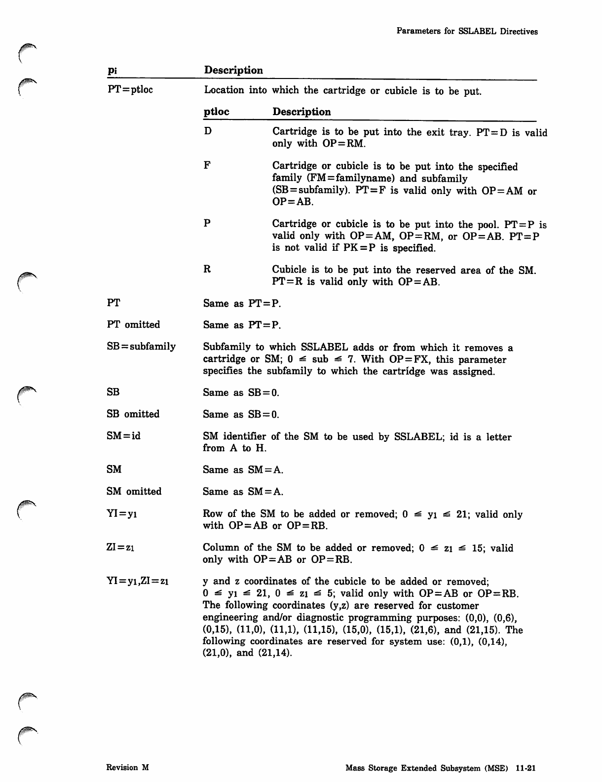
Parameters for SSLABEL Directives
Pi Description
r
PT=ptloc
PT
PT omitted
SB = subfamily
SB
SB omitted
SM=id
SM
SM omitted
YI=yi
ZI=zi
YI=yi,ZI = zi
Location into which the cartridge or cubicle is to be put.
ptloc Description
D
R
Cartridge is to be put into the exit tray. PT=D is valid
only with OP=RM.
Cartridge or cubicle is to be put into the specified
family (FM=familyname) and subfamily
(SB=subfamily). PT=F is valid only with OP=AM or
OP=AB.
Cartridge or cubicle is to be put into the pool. PT=P is
valid only with OP=AM, OP=RM, or OP=AB. PT=P
is not valid if PK = P is specified.
Cubicle is to be put into the reserved area of the SM.
PT=R is valid only with OP=AB.
Same as PT=P.
Same as PT=P.
Subfamily to which SSLABEL adds or from which it removes a
cartridge or SM; 0 ^ sub ^ 7. With OP=FX, this parameter
specifies the subfamily to which the cartridge was assigned.
Same as SB = 0.
Same as SB = 0.
SM identifier of the SM to be used by SSLABEL; id is a letter
from A to H.
Same as SM=A.
Same as SM=A.
Row of the SM to be added or removed; 0 ^ yi ^ 21; valid only
with OP=AB or OP = RB.
Column of the SM to be added or removed; 0 ^ zi *£ 15; valid
only with OP=AB or OP=RB.
y and z coordinates of the cubicle to be added or removed;
0 ^ yi ^ 21, 0 ^ zi ^ 5; valid only with OP=AB or OP=RB.
The following coordinates (y,z) are reserved for customer
engineering and/or diagnostic programming purposes: (0,0), (0,6),
(0,15), (11,0), (11,1), (11,15), (15,0), (15,1), (21,6), and (21,15). The
following coordinates are reserved for system use: (0,1), (0,14),
(21,0), and (21,14).
Revision M Mass Storage Extended Subsystem (MSE) 11-21
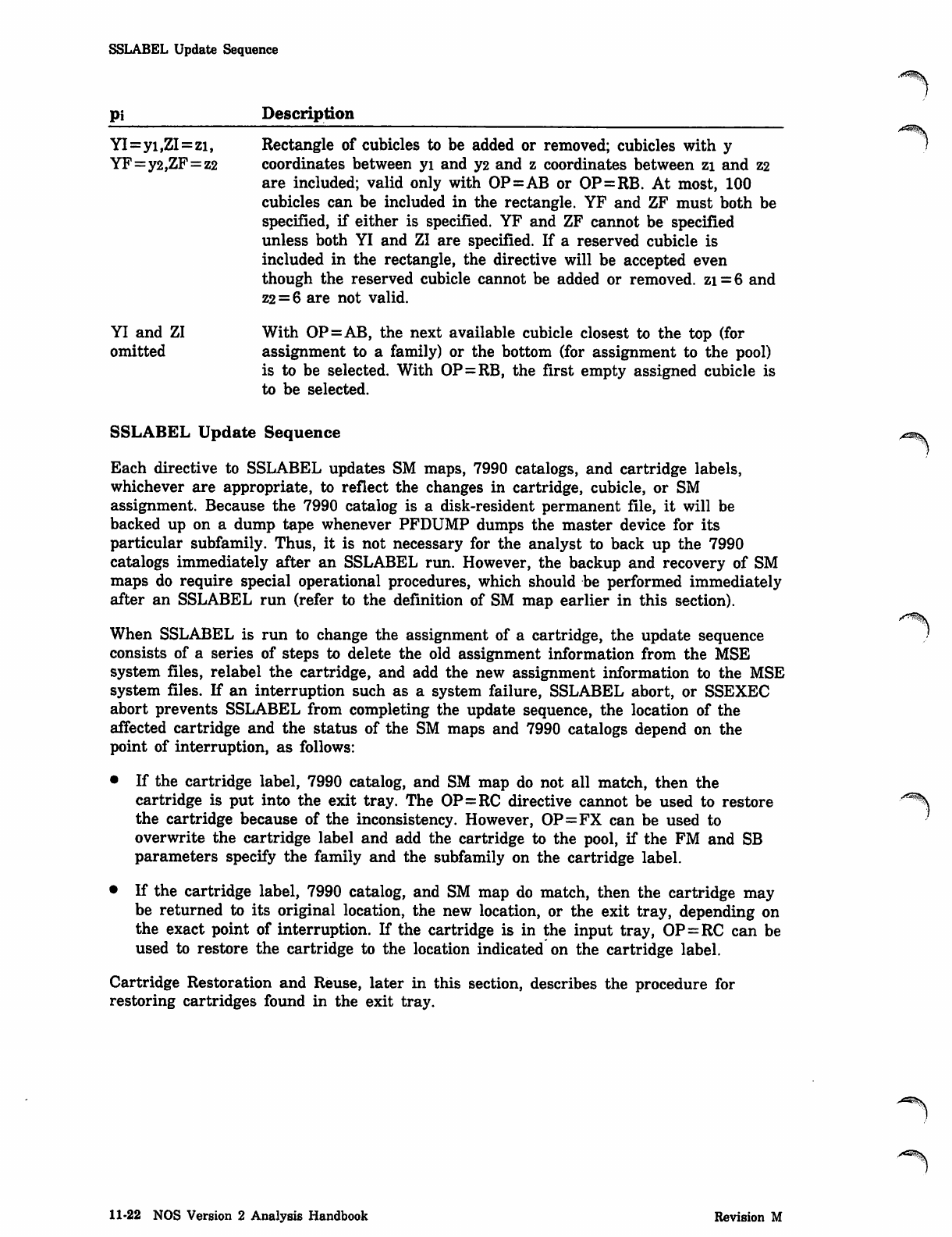
SSLABEL Update Sequence
pi Description
YI=yi,ZI = zi, Rectangle of cubicles to be added or removed; cubicles with y
YF=y2,ZF=z2 coordinates between yi and y2 and z coordinates between zi and Z2
are included; valid only with OP=AB or OP=RB. At most, 100
cubicles can be included in the rectangle. YF and ZF must both be
specified, if either is specified. YF and ZF cannot be specified
unless both YI and ZI are specified. If a reserved cubicle is
included in the rectangle, the directive will be accepted even
though the reserved cubicle cannot be added or removed. zi = 6 and
Z2 = 6 are not valid.
YI and ZI With OP=AB, the next available cubicle closest to the top (for
omitted assignment to a family) or the bottom (for assignment to the pool)
is to be selected. With OP=RB, the first empty assigned cubicle is
to be selected.
SSLABEL Update Sequence
Each directive to SSLABEL updates SM maps, 7990 catalogs, and cartridge labels,
whichever are appropriate, to reflect the changes in cartridge, cubicle, or SM
assignment. Because the 7990 catalog is a disk-resident permanent file, it will be
backed up on a dump tape whenever PFDUMP dumps the master device for its
particular subfamily. Thus, it is not necessary for the analyst to back up the 7990
catalogs immediately after an SSLABEL run. However, the backup and recovery of SM
maps do require special operational procedures, which should be performed immediately
after an SSLABEL run (refer to the definition of SM map earlier in this section).
When SSLABEL is run to change the assignment of a cartridge, the update sequence
consists of a series of steps to delete the old assignment information from the MSE
system files, relabel the cartridge, and add the new assignment information to the MSE
system files. If an interruption such as a system failure, SSLABEL abort, or SSEXEC
abort prevents SSLABEL from completing the update sequence, the location of the
affected cartridge and the status of the SM maps and 7990 catalogs depend on the
point of interruption, as follows:
• If the cartridge label, 7990 catalog, and SM map do not all match, then the
cartridge is put into the exit tray. The OP=RC directive cannot be used to restore
the cartridge because of the inconsistency. However, OP=FX can be used to
overwrite the cartridge label and add the cartridge to the pool, if the FM and SB
parameters specify the family and the subfamily on the cartridge label.
• If the cartridge label, 7990 catalog, and SM map do match, then the cartridge may
be returned to its original location, the new location, or the exit tray, depending on
the exact point of interruption. If the cartridge is in the input tray, OP=RC can be
used to restore the cartridge to the location indicated on the cartridge label.
Cartridge Restoration and Reuse, later in this section, describes the procedure for
restoring cartridges found in the exit tray.
i^^.
y*J*S^.
11-22 NOS Version 2 Analysis Handbook Revision M
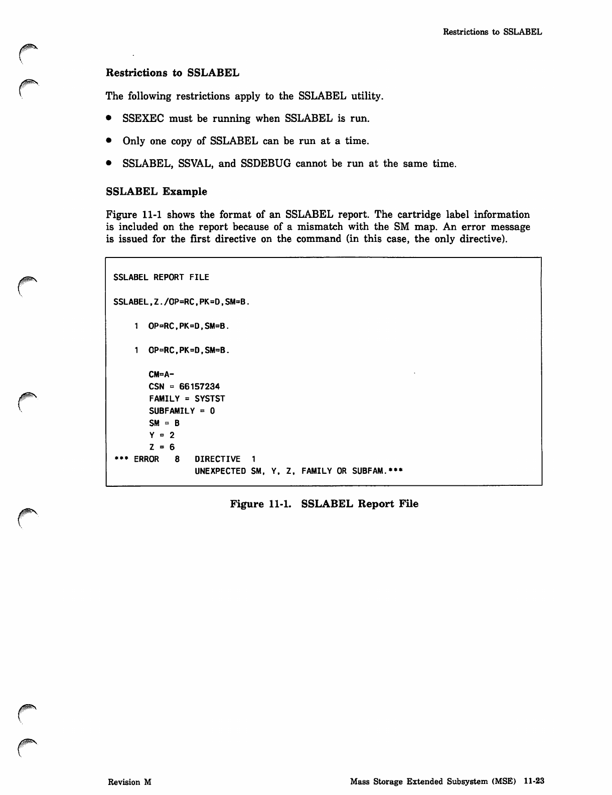
^Px
Restrictions to SSLABEL
Restrictions to SSLABEL
The following restrictions apply to the SSLABEL utility.
• SSEXEC must be running when SSLABEL is run.
• Only one copy of SSLABEL can be run at a time.
• SSLABEL, SSVAL, and SSDEBUG cannot be run at the same time.
SSLABEL Example
Figure 11-1 shows the format of an SSLABEL report. The cartridge label information
is included on the report because of a mismatch with the SM map. An error message
is issued for the first directive on the command (in this case, the only directive).
SSLABEL REPORT FILE
SSLABEL,Z./0P=RC,PK=D,SM=B.
1 OP=RC,PK=D,SM=B.
1 0P=RC,PK=D,SM=B.
CM=A-
CSN = 66157234
FAMILY = SYSTST
SUBFAMILY = 0
SM = B
Y = 2
Z = 6
*** ERROR 8 DIRECTIVE 1
UNEXPECTED SM, Y, Z, FAMILY OR SUBFAM.***
Figure 11-1. SSLABEL Report File
Revision M Mass Storage Extended Subsystem (MSE) 11-23
SSMOVE
SSMOVE
SSMOVE manages disk and 7990 residence. That is, SSMOVE determines which files
should be left on disk, which files should be released from disk and moved to 7990,
and which files should be resident both on disk and on 7990.
The selection process includes algorithms that weigh certain file characteristics, as
follows:
• Files are selected for destaging to 7990 based on file length, time since the last
update, and the preferred residence specified by the user.
• Files are selected for release from disk based on time since the last access and the
backup requirement specified by the user.
SSMOVE reads the PFC entries for a particular family and calculates release and
destage values (refer to Selection Algorithms later in this section) for each file to
determine its residence. If a file has both disk and 7990 images but is to reside only
on 7990, SSMOVE releases the disk space for the file. For files that do not have a J^\
7990 image, SSMOVE creates entries on the SSMOVE/SSEXEC communication file,
MVOCOM, to identify the files to be destaged and to specify whether or not the file's
disk space is to be released upon completion of the destage. SSEXEC then processes
each destage and destage/release request on MVOCOM.
SSMOVE generates an output report that includes a list of input directives to
SSMOVE, site-defined values used in the destage/release decision-making process, files
selected for processing, and a summary of the number of files expected to reside on
each device after destage/release processing.
11-24 NOS Version 2 Analysis Handbook Revision M
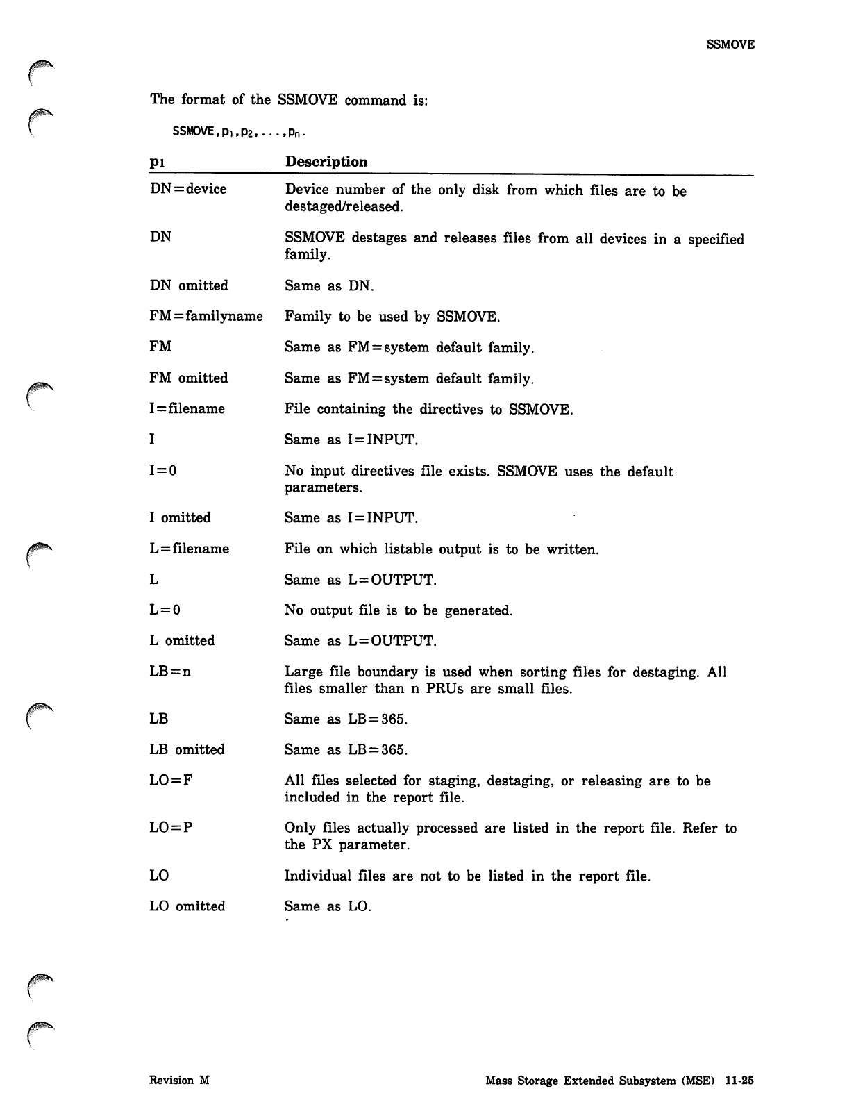
SSMOVE
0am\.
The format of the
SSMOVE,pi,p2...
Pl
SSMOVE command is:
• .Pn-
Description
DN=device
DN
DN omitted
FM=familyname
FM
FM omitted
I=filename
I
1 = 0
I omitted
L=filename
L
L = 0
L omitted
LB = n
LB
LB omitted
LO = F
LO = P
LO
LO omitted
Device number of the only disk from which files are to be
destaged/released.
SSMOVE destages and releases files from all devices in a specified
family.
Same as DN.
Family to be used by SSMOVE.
Same as FM = system default family.
Same as FM = system default family.
File containing the directives to SSMOVE.
Same as I = INPUT.
No input directives file exists. SSMOVE uses the default
parameters.
Same as I = INPUT.
File on which listable output is to be written.
Same as L=OUTPUT.
No output file is to be generated.
Same as L=OUTPUT.
Large file boundary is used when sorting files for destaging. All
files smaller than n PRUs are small files.
Same as LB = 365.
Same as LB = 365.
All files selected for staging, destaging, or releasing are to be
included in the report file.
Only files actually processed are listed in the report file. Refer to
the PX parameter.
Individual files are not to be listed in the report file.
Same as LO.
Revision M Mass Storage Extended Subsystem (MSE) 11-25
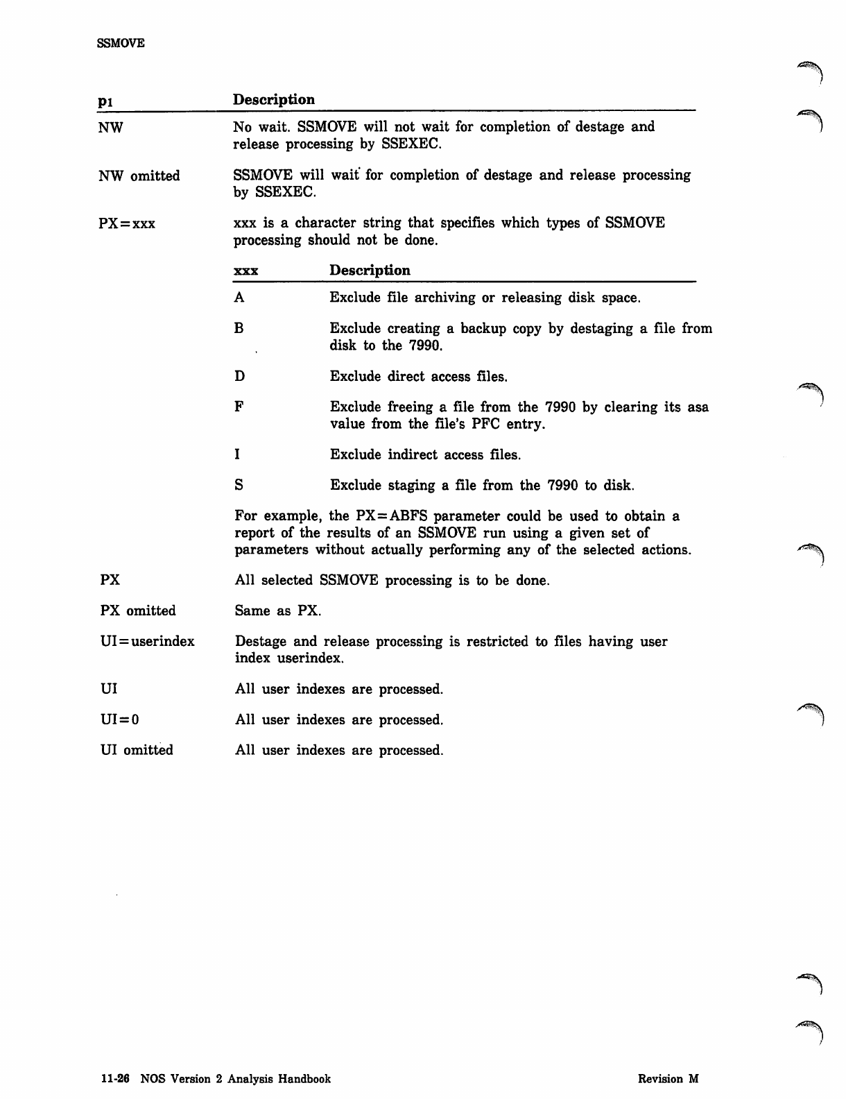
SSMOVE
Pl
NW
NW omitted
PX=xxx
PX
PX omitted
UI=userindex
UI
UI = 0
UI omitted
Description
No wait. SSMOVE will not wait for completion of destage and
release processing by SSEXEC.
SSMOVE will wait for completion of destage and release processing
by SSEXEC.
xxx is a character string that specifies which types of SSMOVE
processing should not be done.
xxx Description
A
B
D
F
I
S
Exclude file archiving or releasing disk space.
Exclude creating a backup copy by destaging a file from
disk to the 7990.
Exclude direct access files.
Exclude freeing a file from the 7990 by clearing its asa
value from the file's PFC entry.
Exclude indirect access files.
Exclude staging a file from the 7990 to disk.
For example, the PX=ABFS parameter could be used to obtain a
report of the results of an SSMOVE run using a given set of
parameters without actually performing any of the selected actions.
All selected SSMOVE processing is to be done.
Same as PX.
Destage and release processing is restricted to files having user
index userindex.
All user indexes are processed.
All user indexes are processed.
All user indexes are processed.
11-26 NOS Version 2 Analysis Handbook Revision M
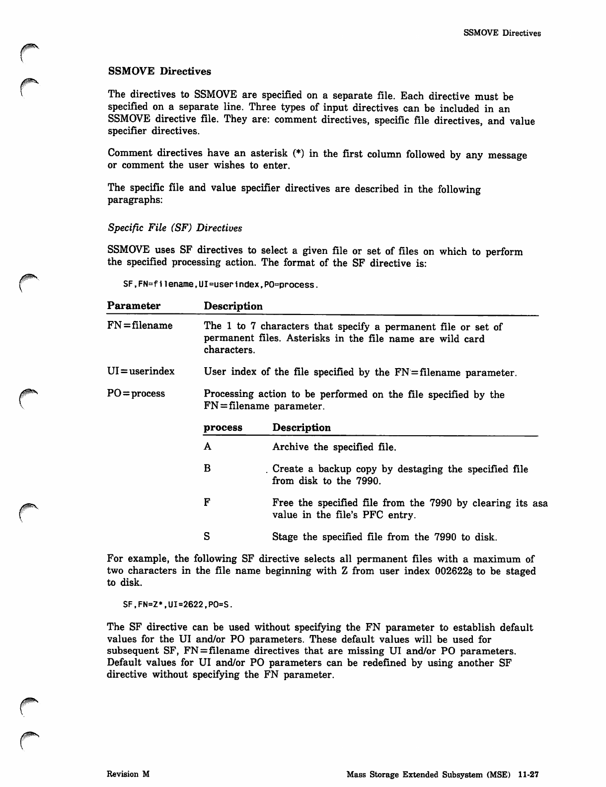
SSMOVE Directives
SSMOVE Directives
The directives to SSMOVE are specified on a separate file. Each directive must be
specified on a separate line. Three types of input directives can be included in an
SSMOVE directive file. They are: comment directives, specific file directives, and value
specifier directives.
Comment directives have an asterisk (*) in the first column followed by any message
or comment the user wishes to enter.
The specific file and value specifier directives are described in the following
paragraphs:
Specific File (SF) Directives
SSMOVE uses SF directives to select a given file or set of files on which to perform
the specified processing action. The format of the SF directive is:
SF,FN=filename,UI=userindex,PO=process.
Parameter Description
FN=filename The 1 to 7 characters that specify a permanent file or set of
permanent files. Asterisks in the file name are wild card
characters.
UI=userindex User index of the file specified by the FN=filename parameter.
PO=process Processing action to be performed on the file specified by the
FN=filename parameter.
process Description
A A r c h i v e t h e s p e c i fi e d fi l e .
B . Create a backup copy by destaging the specified file
from disk to the 7990.
F Free the specified file from the 7990 by clearing its asa
value in the file's PFC entry.
S Stage the specified file from the 7990 to disk.
For example, the following SF directive selects all permanent files with a maximum of
two characters in the file name beginning with Z from user index 002622s to be staged
to disk.
SF,FN=Z*,UI=2622,PO=S.
The SF directive can be used without specifying the FN parameter to establish default
values for the UI and/or PO parameters. These default values will be used for
subsequent SF, FN=filename directives that are missing UI and/or PO parameters.
Default values for UI and/or PO parameters can be redefined by using another SF
directive without specifying the FN parameter.
Revision M Mass Storage Extended Subsystem (MSE) 11-27
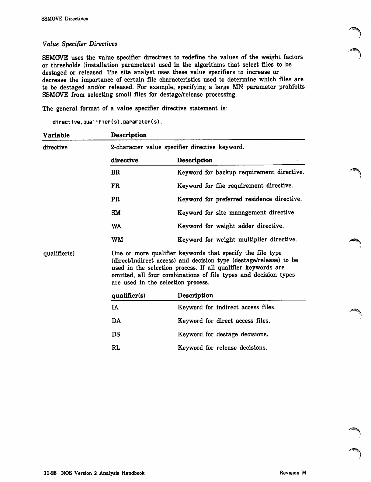
SSMOVE Directives
Value Specifier Directives
SSMOVE uses the value specifier directives to redefine the values of the weight factors
or thresholds (installation parameters) used in the algorithms that select files to be
destaged or released. The site analyst uses these value specifiers to increase or
decrease the importance of certain file characteristics used to determine which files are
to be destaged and/or released. For example, specifying a large MN parameter prohibits
SSMOVE from selecting small files for destage/release processing.
The general format of a value specifier directive statement is:
directive,qualifier(s).parameter(s).
Variable
directive
qualifier(s)
Description
2-character value specifier directive keyword.
directive Description
BR
FR
PR
SM
WA
WM
Keyword for backup requirement directive.
Keyword for file requirement directive.
Keyword for preferred residence directive.
Keyword for site management directive.
Keyword for weight adder directive.
Keyword for weight multiplier directive.
One or more qualifier keywords that specify the file type
(direct/indirect access) and decision type (destage/release) to be
used in the selection process. If all qualifier keywords are
omitted, all four combinations of file types and decision types
are used in the selection process.
qualifier(s) Description
IA
DA
DS
RL
Keyword for indirect access files.
Keyword for direct access files.
Keyword for destage decisions.
Keyword for release decisions.
11-28 NOS Version 2 Analysis Handbook Revision M
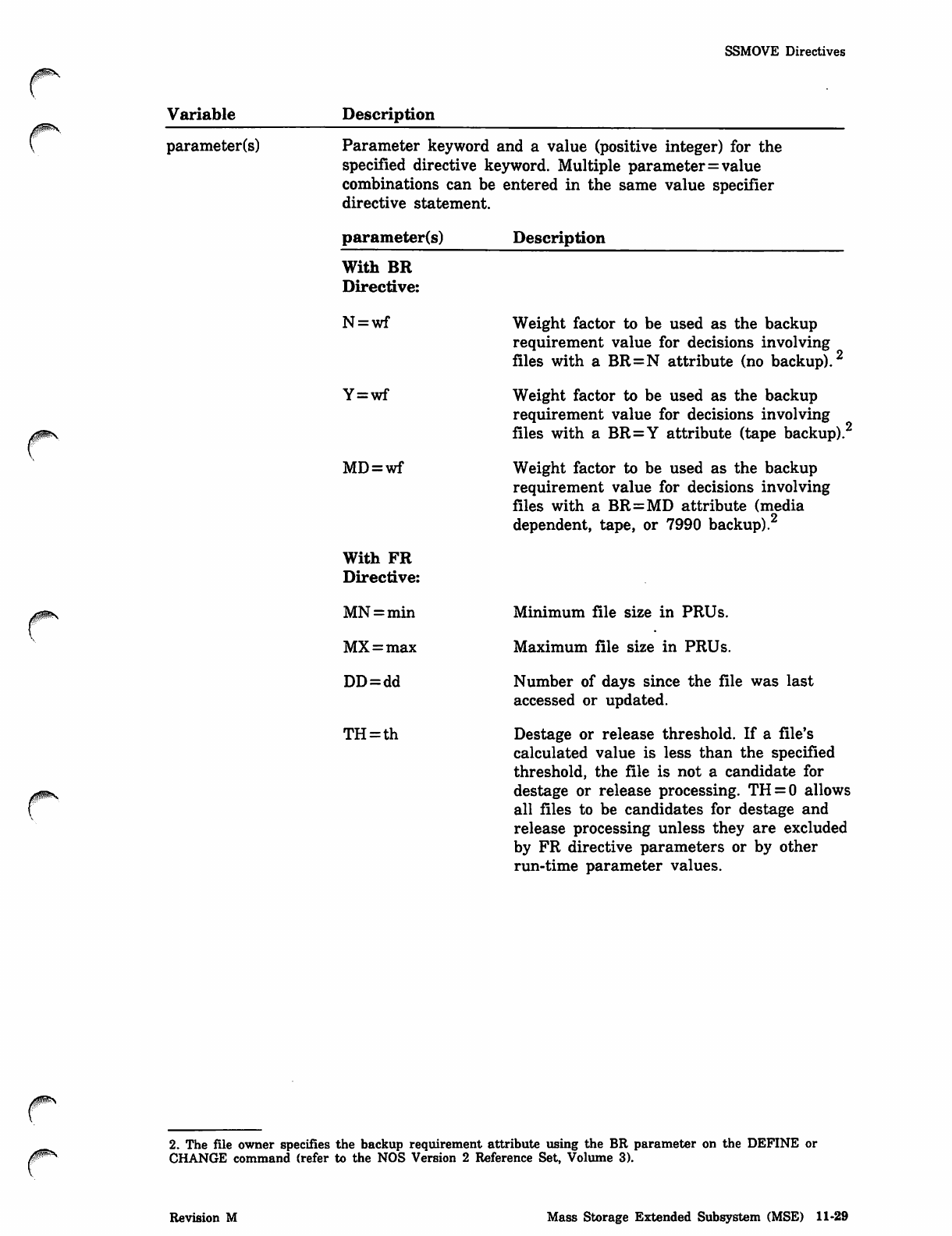
SSMOVE Directives
Variable Description
parameter(s) Parameter keyword and a value (positive integer) for the
specified directive keyword. Multiple parameter=value
combinations can be entered in the same value specifier
directive statement.
parameter(s) Description
With BR
Directive:
N=wf
Y=wf
MD = wf
With FR
Directive:
Weight factor to be used as the backup
requirement value for decisions involving
files with a BR=N attribute (no backup).2
Weight factor to be used as the backup
requirement value for decisions involving
files with a BR=Y attribute (tape backup).
Weight factor to be used as the backup
requirement value for decisions involving
files with a BR=MD attribute (media
dependent, tape, or 7990 backup).
/ffllSP*^
MN = min
MX=max
DD=dd
TH = th
Minimum file size in PRUs.
Maximum file size in PRUs.
Number of days since the file was last
accessed or updated.
Destage or release threshold. If a file's
calculated value is less than the specified
threshold, the file is not a candidate for
destage or release processing. TH = 0 allows
all files to be candidates for destage and
release processing unless they are excluded
by FR directive parameters or by other
run-time parameter values.
/f!$"X 2. The file owner specifies the backup requirement attribute using the BR parameter on the DEFINE or
CHANGE command (refer to the NOS Version 2 Reference Set, Volume 3).
Revision M Mass Storage Extended Subsystem (MSE) 11-29
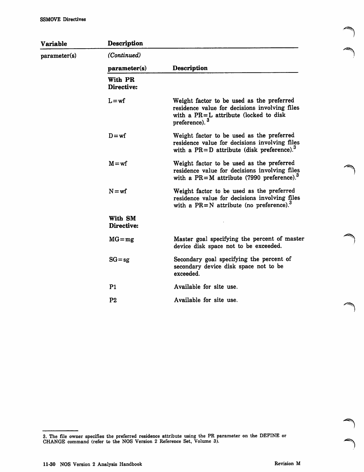
SSMOVE Directives
Variable
parameter(s)
Description
(Continued)
parameter(s)
With PR
Directive:
L = wf
D = wf
M=wf
N = w f
With SM
Directive:
MG=mg
SG=sg
Pl
P2
Description
Weight factor to be used as the preferred
residence value for decisions involving files
with a PR=L attribute (locked to disk
preference).
Weight factor to be used as the preferred
residence value for decisions involving files
with a PR=D attribute (disk preference).3
Weight factor to be used as the preferred
residence value for decisions involving files
with a PR=M attribute (7990 preference).3
Weight factor to be used as the preferred
residence value for decisions involving files
with a PR=N attribute (no preference).3
Master goal specifying the percent of master
device disk space not to be exceeded.
Secondary goal specifying the percent of
secondary device disk space not to be
exceeded.
Available for site use.
Available for site use.
^S^X
3. The file owner specifies the preferred residence attribute using the PR parameter on the DEFINE or
CHANGE command (refer to the NOS Version 2 Reference Set, Volume 3).
11-30 NOS Version 2 Analysis Handbook Revision M
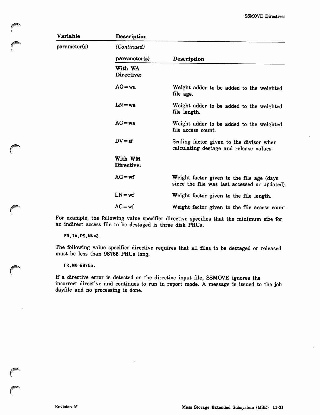
SSMOVE Directives
Variable Description
/ i ^ \
parameter(s) (Continued)
parameter(s)
With WA
Directive:
AG=wa
LN = wa
AC = wa
DV=sf
With WM
Directive:
AG=wf
LN = wf
AC = wf
Description
Weight adder to be added to the weighted
file age.
Weight adder to be added to the weighted
file length.
Weight adder to be added to the weighted
file access count.
Scaling factor given to the divisor when
calculating destage and release values.
Weight factor given to the file age (days
since the file was last accessed or updated).
Weight factor given to the file length.
Weight factor given to the file access count.
For example, the following value specifier directive specifies that the minimum size for
an indirect access file to be destaged is three disk PRUs.
FR,IA,DS,MN=3.
The following value specifier directive requires that all files to be destaged or released
must be less than 98765 PRUs long.
FR,MX=98765.
If a directive error is detected on the directive input file, SSMOVE ignores the
incorrect directive and continues to run in report mode. A message is issued to the job
dayfile and no processing is done.
Revision M Mass Storage Extended Subsystem (MSE) 11-31
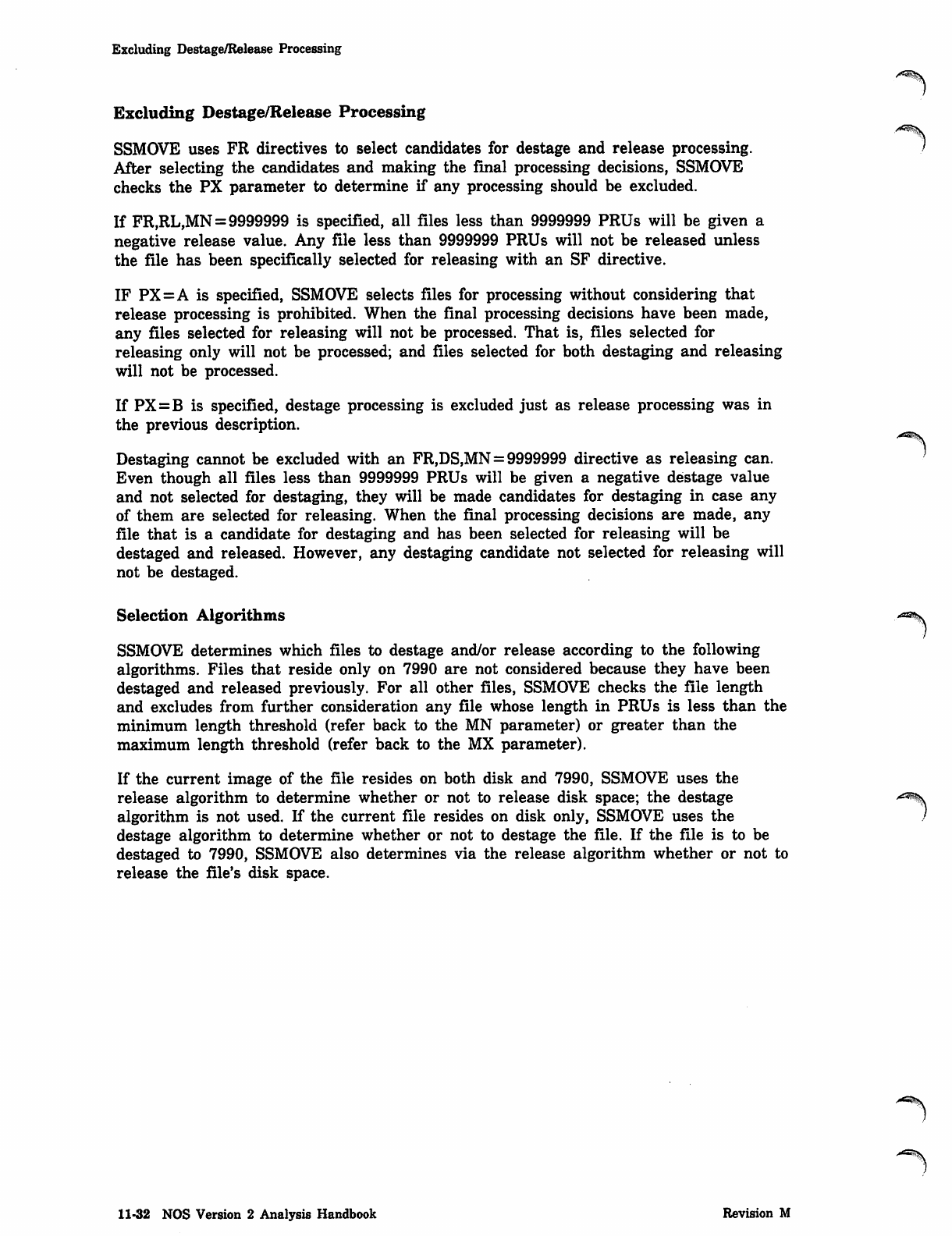
Excluding Destage/Release Processing
Excluding Destage/Release Processing
SSMOVE uses FR directives to select candidates for destage and release processing.
After selecting the candidates and making the final processing decisions, SSMOVE
checks the PX parameter to determine if any processing should be excluded.
If FR,RL,MN=9999999 is specified, all files less than 9999999 PRUs will be given a
negative release value. Any file less than 9999999 PRUs will not be released unless
the file has been specifically selected for releasing with an SF directive.
IF PX=A is specified, SSMOVE selects files for processing without considering that
release processing is prohibited. When the final processing decisions have been made,
any files selected for releasing will not be processed. That is, files selected for
releasing only will not be processed; and files selected for both destaging and releasing
will not be processed.
If PX=B is specified, destage processing is excluded just as release processing was in
the previous description.
Destaging cannot be excluded with an FR,DS,MN = 9999999 directive as releasing can.
Even though all files less than 9999999 PRUs will be given a negative destage value
and not selected for destaging, they will be made candidates for destaging in case any
of them are selected for releasing. When the final processing decisions are made, any
file that is a candidate for destaging and has been selected for releasing will be
destaged and released. However, any destaging candidate not selected for releasing will
not be destaged.
Selection Algorithms
SSMOVE determines which files to destage and/or release according to the following
algorithms. Files that reside only on 7990 are not considered because they have been
destaged and released previously. For all other files, SSMOVE checks the file length
and excludes from further consideration any file whose length in PRUs is less than the
minimum length threshold (refer back to the MN parameter) or greater than the
maximum length threshold (refer back to the MX parameter).
If the current image of the file resides on both disk and 7990, SSMOVE uses the
release algorithm to determine whether or not to release disk space; the destage
algorithm is not used. If the current file resides on disk only, SSMOVE uses the
destage algorithm to determine whether or not to destage the file. If the file is to be
destaged to 7990, SSMOVE also determines via the release algorithm whether or not to
release the file's disk space.
> ^ ^ v
11-32 NOS Version 2 Analysis Handbook Revision M
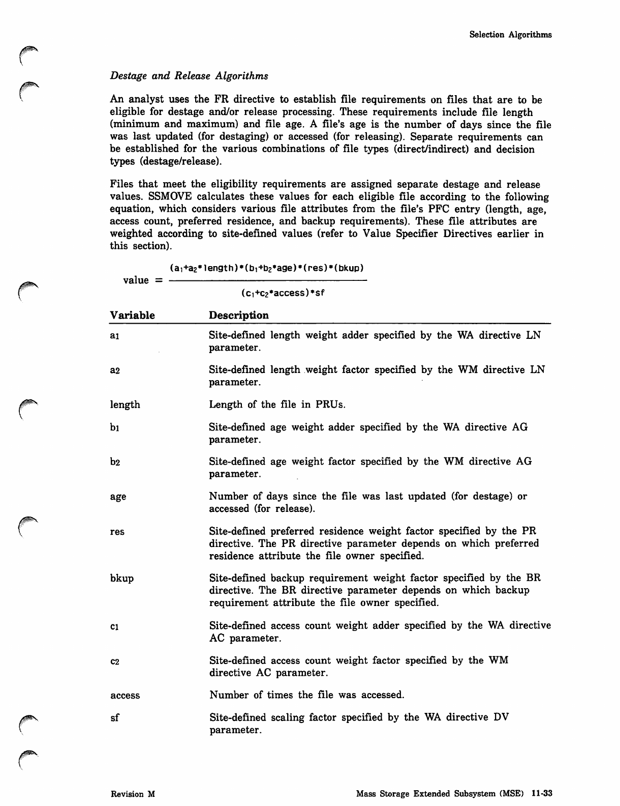
Selection Algorithms
Destage and Release Algorithms
An analyst uses the FR directive to establish file requirements on files that are to be
eligible for destage and/or release processing. These requirements include file length
(minimum and maximum) and file age. A file's age is the number of days since the file
was last updated (for destaging) or accessed (for releasing). Separate requirements can
be established for the various combinations of file types (direct/indirect) and decision
types (destage/release).
Files that meet the eligibility requirements are assigned separate destage and release
values. SSMOVE calculates these values for each eligible file according to the following
equation, which considers various file attributes from the file's PFC entry (length, age,
access count, preferred residence, and backup requirements). These file attributes are
weighted according to site-defined values (refer to Value Specifier Directives earlier in
this section).
value =
(ai+a2* length) •(b1+b2*age)*(res)*(bkup)
(ci+C2*access)»sf
Variable Description
r
ai
a2
length
bi
b2
age
res
bkup
ci
C2
access
sf
Site-defined length weight adder specified by the WA directive LN
parameter.
Site-defined length weight factor specified by the WM directive LN
parameter.
Length of the file in PRUs.
Site-defined age weight adder specified by the WA directive AG
parameter.
Site-defined age weight factor specified by the WM directive AG
parameter.
Number of days since the file was last updated (for destage) or
accessed (for release).
Site-defined preferred residence weight factor specified by the PR
directive. The PR directive parameter depends on which preferred
residence attribute the file owner specified.
Site-defined backup requirement weight factor specified by the BR
directive. The BR directive parameter depends on which backup
requirement attribute the file owner specified.
Site-defined access count weight adder specified by the WA directive
AC parameter.
Site-defined access count weight factor specified by the WM
directive AC parameter.
Number of times the file was accessed.
Site-defined scaling factor specified by the WA directive DV
parameter.
Revision M Mass Storage Extended Subsystem (MSE) 11-33
Selection Algorithms
If a file's destage/release value exceeds a site-defined threshold (FR directive TH
parameter), the file is selected for destage/release processing. Conversely, if the file's s^s
destage/release value does not exceed the threshold, the file is not considered for )
destage/release processing.
Files eligible for releasing are sorted according to their release values. The files on
each disk with the greatest release values are selected to be released. When enough
files have been selected and released, the site-defined disk space availability goals will
be achieved.
Decision Algorithm Hierarchy
Several different functions of SSMOVE can lead to apparent contradictory processing
decisions. The decisions are made using the following rules, which are listed in order
of precedence.
1. SSMOVE does not consider any files for processing if they are excluded by the
PX=I, PX = D, or UI parameters to SSMOVE or if the file has a PR=L attribute.
2. Files identified for specific processing using the SF directive are selected for the
specified processing regardless of the file requirements controlled by the FR
directive.
3. If DN = 0, all files that meet the destage requirements are selected to be destaged.
Otherwise, only files on the specified device are destaged.
4. No file with a BR=Y attribute will be selected to be released (including files
specified for processing with an SF directive) if the file data has not been included
in a full or incremental dump using PFDUMP.
5. If DN = 0, all files that meet the release requirements are selected to be released, if
needed, to meet the disk space availability goals. Otherwise, only files on the
specified device are released.
6. If a file is selected for a specific processing action (such as destage) and the
corresponding action is precluded by a PX parameter (in this case, PX=B), then the
selected action is not performed. In all cases, however, the SSMOVE device status
report is based on which files were selected for processing rather than whether the
PX parameter actually allowed the selected processing to occur.
0^^\
11-34 NOS Version 2 Analysis Handbook Revision M
Disk Space/Dump Tape Management
Disk Space/Dump Tape Management
As more disk-resident files are created and more 7990-resident files are staged to disk,
it will be necessary to monitor the availability of disk space. It is recommended that
SSMOVE be used as a periodic disk space management procedure to avoid frequent
disk-full conditions (refer to Disk Space Management later in this section). SSMOVE
can also be used to reduce the amount of data written on dump tapes and thereby
avoid mamtaining large numbers of dump tapes. This is accomplished by destaging to
7990 and/or releasing disk space of files that need not be on the dump tape (refer to
Dump Tape Management later in this section).
An analyst can specify what percent of disk space is to contain indirect access files
and what percent is to contain direct access files. For direct access files, the analyst
can further specify the percent of master device and/or secondary device disk space.
These percent values are applied to all devices in the family on which SSMOVE is
run or a specific device can be managed by using the DN parameter to SSMOVE.
The specified percentages of disk space are considered to be goals in that other
site-defined constraints and file-busy conditions may make it impossible to achieve
these goals.
Restrictions to SSMOVE
The following restrictions apply to the SSMOVE utility.
• Only one copy of SSMOVE can be run at a time when it is in the process of
destaging files. A second SSMOVE aborts if the first one has not completed.
• SSMOVE and PFDUMP should not be run at the same time.
• SSMOVE cannot be run when SSVAL is running.
Revision M Mass Storage Extended Subsystem (MSE) 11-35
Output Example
Output Example
The SSMOVE report consists of the following five sections:
1. A list of directives (figure 11-2) from the input directive file plus any diagnostic
messages.
2. A list of run-time parameter values (figure 11-3) used in the release and destage
decision-making process. These values consist of the site-defined, assembly-time
values as modified by the value specifier directives.
3. An optional list of the files (figure 11-4) selected for processing. This list shows the
file name, file type, user index, length, date, access count, processing action, and
destage and release values.
4. A device status report (figure 11-5) that includes a summary of the number of files
and total file length expected to reside on each device as a result of release
processing. Also, a subfamily report that includes a summary (for each subfamily) of
the number of files and file length for files to be destaged, files that reside only on
7990, and files that reside on 7990 and disk.
5. A destage abandonment report (figure 11-6) that is not produced if the NW
parameter is specified. This report provides a list of the number of files not
destaged and an optional list of the abandoned files. It also provides an updated
device status report reflecting only the files that were destaged.
,^*fe\
A^S
11-36 NOS Version 2 Analysis Handbook Revision M
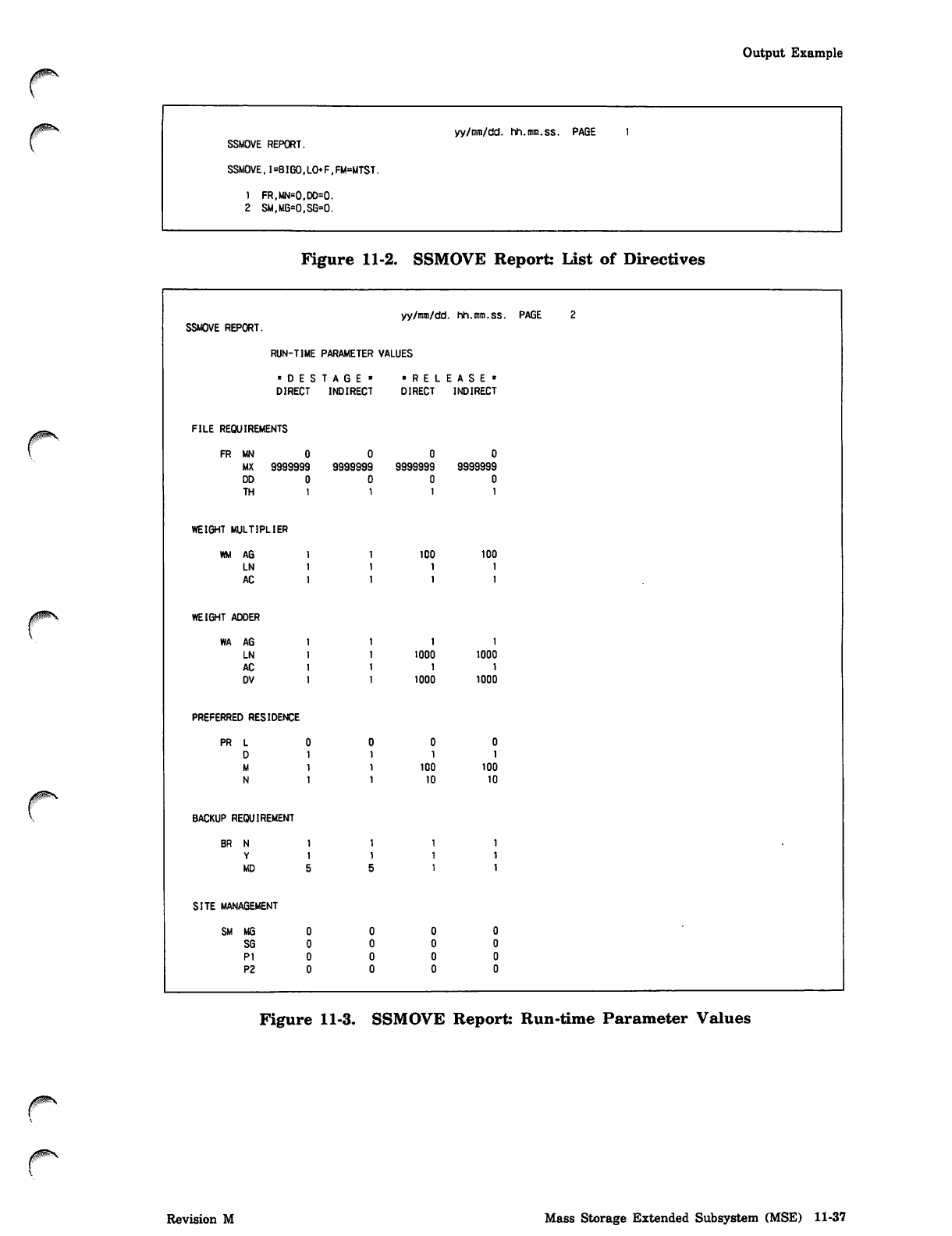
Output Example
/ffty
SSMOVE REPORT.
SSMOVE,I=B1GO.LO* F.FM=MTST.
1 FR,MN=0,DD=0.
2 SM,MG=0.SG=0.
yy/mm/dd. hh.mm.ss. PAGE
Figure 11-2. SSMOVE Report: List of Directives
SSMOVE REPORT.
yy/mm/dd. hh.mm.ss. PAGE
RUN-TIME PARAMETER VALUES
« O E S
DIRECT
TAGE«
INDIRECT
•REL
DIRECT
EASE*
INDIRECT
FILE REQUIREMENTS
F R M N 0
MX 9999999
D D 0
T H 1
9999999
0
1
9999999
0
1
9999999
0
1
WEIGHT MULTIPLIER
WM AG
LN
AC
100
1
1
100
1
1
WEIGHT ADDER
WA AG
LN
AC
DV
1000
1
1000
1000
1
1000
PREFERRED RESIDENCE
PR L
D
M
N
100
10
100
10
BACKUP REQUIREMENT
BR N
Y
MD
SITE MANAGEMENT
SM MG
SG
PI
P2
Figure 11-3. SSMOVE Report: Run-time Parameter Values
yms
Revision M Mass Storage Extended Subsystem (MSE) 11-37
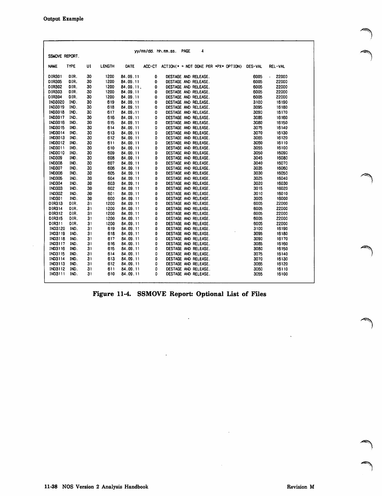
Output Example
yy/mm/dd. hri.mm .ss . PAG E 4
SSMOVE REPORT.
NAME TYPE UI LENGTH DATE ACC-CT ACTION{« = NOT DONE PER »PX* OPTION) DES-VAL REL-VAL
DIR301 DIR. 30 1200 84.09.1 1 0 DESTAGE AND RELEASE. 6005 • 22000
DIR305 DIR. 30 1200 84.09.1 1 0 DESTAGE AND RELEASE. 6005 22000
DIR302 DIR. 30 1200 84.09.1 1 . 0 DESTAGE AND RELEASE. 6005 22000
DIR303 DIR. 30 1200 84.09.1 1 0 DESTAGE AND RELEASE. 6005 22000
DIR304 DIR. 30 1200 84.09.1 1 0 DESTAGE AND RELEASE. 6005 22000
IND3020 IND. 30 619 84.09.1 1 0 DESTAGE AND RELEASE. 3100 16190
IND3019 IND. 30 618 84.09.1 1 0 DESTAGE AND RELEASE. 3095 16180
IND3018 IND. 30 617 84.09,1 1 0 DESTAGE AND RELEASE. 3090 16170
IND3017 IND. 30 616 84.09.1 1 0 DESTAGE AND RELEASE. 3085 16160
IND3016 IND. 30 615 84.09.1 1 0 DESTAGE AND RELEASE. 3080 16150
IND3015 IND. 30 614 84.09.1 1 0 DESTAGE AND RELEASE. 3075 16140
1ND3014 IND. 30 613 84.09.1 1 0 DESTAGE AND RELEASE. 3070 16130
IND3013 IND. 30 612 84.09.1 1 0 DESTAGE AND RELEASE. 3065 16120
IND3012 IND. 30 611 84.09.1 1 0 DESTAGE AND RELEASE. 3060 16110
IND3011 IND. 30 610 84.09.1 1 0 DESTAGE AND RELEASE. 3055 16100
IND3010 IND. 30 609 84.09.1 1 0 DESTAGE AND RELEASE. 3050 16090
IND309 IND. 30 608 84.09.1 1 0 DESTAGE AND RELEASE. 3045 16080
IND308 IND. 30 607 84.09.1 1 0 DESTAGE AND RELEASE. 3040 16070
IND307 IND. 30 606 84.09.1 1 0 DESTAGE AND RELEASE. 3035 16060
IND306 IND. 30 605 84.09.1 1 0 DESTAGE AND RELEASE. 3030 16050
IND305 IND. 30 604 84.09.1 1 0 DESTAGE AND RELEASE. 3025 16040
IND304 IND. 30 603 84.09.1 1 0 DESTAGE AND RELEASE. 3020 16030
1^303 IND. 30 602 84.09.1 1 0 DESTAGE AND RELEASE. 3015 16020
IND302 IND. 30 601 84.09.1 1 0 DESTAGE AND RELEASE. 3010 16010
IND301 IND. 30 600 84.09.1 1 0 DESTAGE AND RELEASE. 3005 16000
DIR313 DIR. 31 1200 84.09.1 1 0 DESTAGE AND RELEASE. 6005 22000
DIR314 DIR. 31 1200 84.09.1 1 0 DESTAGE AND RELEASE. 6005 22000
DIR312 DIR. 31 1200 84.09.1 1 0 DESTAGE AND RELEASE. 6005 22000
DIR315 DIR. 31 1200 84.09.1 1 0 DESTAGE AND RELEASE. 6005 22000
DIR311 DIR. 31 1200 84.09.1 1 0 DESTAGE AND RELEASE. 6005 22000
IND3120 IND. 31 619 84.09.1 1 0 DESTAGE AND RELEASE. 3100 16190
1ND3119 IND. 31 618 84.09.1 1 0 DESTAGE AND RELEASE. 3095 16180
IND3118 IND. 31 617 84.09.1 1 0 DESTAGE AND RELEASE. 3090 16170
IND3117 IND. 31 616 84.09.1 1 0 DESTAGE AND RELEASE. 3085 16160
IND3116 IND. 31 615 84.09.1 1 0 DESTAGE AND RELEASE. 3080 16150
IND3115 IND. 31 614 84.09.1 1 0 DESTAGE AND RELEASE. 3075 16140
IND3114 IND. 31 613 84.09.1 1 0 DESTAGE AND RELEASE. 3070 16130
IND3113 IND. 31 612 84.09.1 1 0 DESTAGE AND RELEASE. 3065 16120
IND3112 IND. 31 611 84.09.1 1 0 DESTAGE AND RELEASE. 3060 16110
IND3111 IND. 31 610 84.09.1 1 0 DESTAGE AND RELEASE. 3055 16100
Figure 11-4. SSMOVE Report: Optional list of Files
11-38 NOS Version 2 Analysis Handbook Revision M
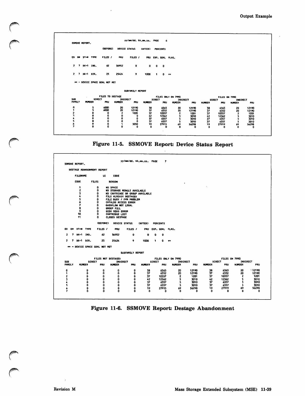
Output Example
SSKOVE REPORT.
yy/m/dd. hh.ua.ss. PAGE 6
(BEFORE) DEVICE STATUS (AFTER) MR CENTS
EO Bll DT-N TYPE FILES / PRU FILES / PRU EXP. GOAL FLA6.
2 7 D K - 1 I K S . 6 2 3 6 9 5 2 0 0 0 0
2 7 M C - 1 D I R . 2 3 2 5 4 2 * y 1 0 0 8 1 0 • •
•* - DEVICE SPACE GOAL NOT KET
SU8FANILT REPORT
FILES TO DESTAGE FILES ONLY ON 7990 FILES ON 7990
SUB DIRECT INDIRECT DIRECT INDIRECT DIRECT INDIRECT
FAMILY MKSER PSU NWBER PRU NUMBER PRU NWtBER PRU NUMBER PRU NUN9ER PRU
6000
MOO
0
to 12190 6363 20 12190 I(8 6363 20 12190
n12190 6352 20 12190 3 6352 20 12190
21201 10357 1 2 0 1 ] 10S57 1201
0 0 12362 3 0 1 0 I 12362 3010
0 0 6357 3 0 1 0 : 6357 3010
0 0 6357 3 0 1 0 2 6357 3010
13050 27915 69 56298 27919 69 56298
00 0 0 0 0 0 0 0 0
Figure 11-5. SSMOVE Report: Device Status Report
yRrS
SSKOVE REPORT.
DESTAGE ABANDONMENT REPORT
FILENAME UI
yy/aa/dd. hh.ca.ss. PAGE
1 0 NO SPACE
2 0 NO STORAGE NODULE AVAILABLE
3 0 KO CARTRIDGE OR GROUP AVAILABLE
*0FILE ALREADY DESTAGED
5 0 FILE BUST / PFN PROBLEM
«0CATALOG ACCESS ERROR
7 0 OVERFLOW NOT LEGAL
8 0 GROUP FULL
9001SK READ ERROR
10 CARTRIDGE LOST
11 CLOSED DESTAGE
(BEFORE) DEVICE STATUS (AFTER) PERCENTS
E O D N D T - N T Y P E F I L E S / P R U F I L E S I P R U E X P. G O A L F L A G .
2 7 D K - 1 I N D . 6 2 3 6 9 5 2 0 0 0 0
7 DK-1 DIR. 23 2542* 1008
** - DEVICE SPACE GOAL NOT NET
SUBFAMILY REPORT
FILES NOT DESTAGED FILES ONLY ON 7990 FILES ON 7990
SUB DIRECT INDIRECT DIRECT INDIRECT DIRECT INDIRECT
FAMILY NUMBER PRU NUMBER PRU NUMBER PRU NUMBER PRU NUMBER PRU NUMBER PRU
38 6363
37 6352
37 10357
42 12362
37 6357
37 6357
19 27915
0 0
20 12190
20 12190
21201
53010
53010
53010
69 56298
0 0
38 6363
37 6352
37 10357
42 12362
37 6357
37 6357
19 27919
0 0
20 -12190
20 12190
21201
53010
53010
53010
69 56298
0 0
Figure 11-6. SSMOVE Report: Destage Abandonment
Revision M Mass Storage Extended Subsystem (MSE) 11-39
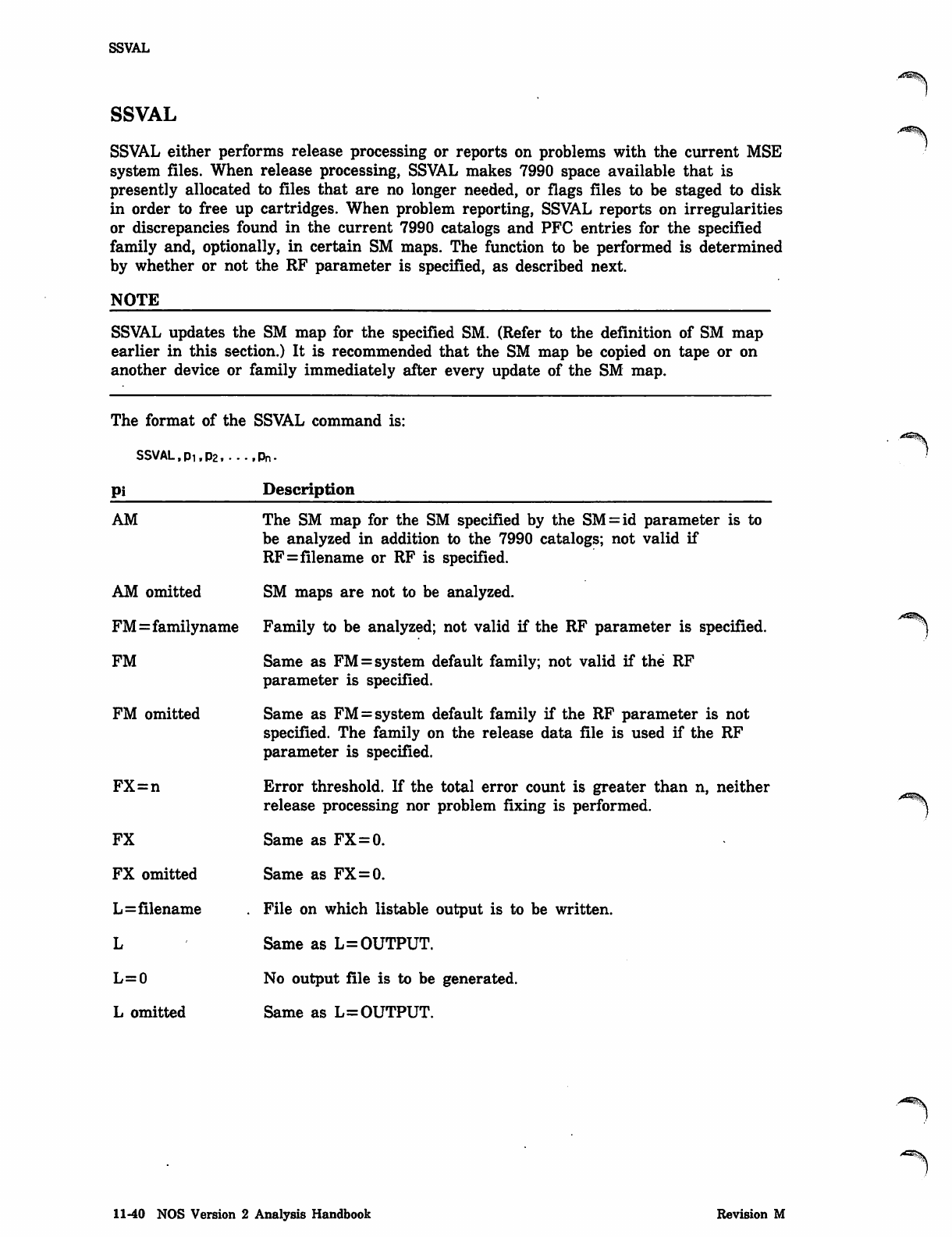
SSVAL
SSVAL
SSVAL either performs release processing or reports on problems with the current MSE
system files. When release processing, SSVAL makes 7990 space available that is
presently allocated to files that are no longer needed, or flags files to be staged to disk
in order to free up cartridges. When problem reporting, SSVAL reports on irregularities
or discrepancies found in the current 7990 catalogs and PFC entries for the specified
family and, optionally, in certain SM maps. The function to be performed is determined
by whether or not the RF parameter is specified, as described next.
NOTE
SSVAL updates the SM map for the specified SM. (Refer to the definition of SM map
earlier in this section.) It is recommended that the SM map be copied on tape or on
another device or family immediately after every update of the SM map.
The format of the
SSVAL,pi,P2,...
Pi
SSVAL command is:
Description
AM
AM omitted
FM=familyname
FM
FM omitted
FX=n
FX
FX omitted
L=filename
L
L=0
L omitted
The SM map for the SM specified by the SM = id parameter is to
be analyzed in addition to the 7990 catalogs; not valid if
RF=filename or RF is specified.
SM maps are not to be analyzed.
Family to be analyzed; not valid if the RF parameter is specified.
Same as FM = system default family; not valid if the RF
parameter is specified.
Same as FM = system default family if the RF parameter is not
specified. The family on the release data file is used if the RF
parameter is specified.
Error threshold. If the total error count is greater than n, neither
release processing nor problem fixing is performed.
Same as FX=0.
Same as FX=0.
File on which listable output is to be written.
Same as L= OUTPUT.
No output file is to be generated.
Same as L=OUTPUT.
'*=%.
11-40 NOS Version 2 Analysis Handbook Revision M
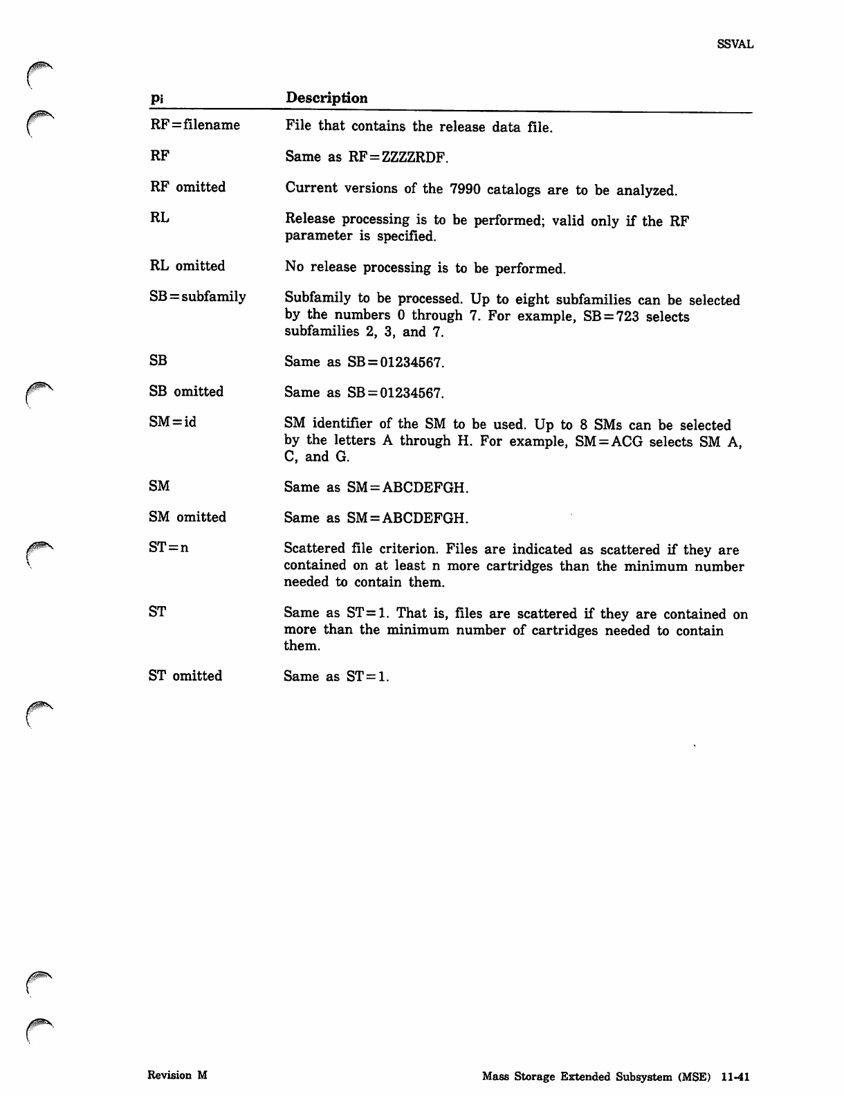
SSVAL
Pi
RF=filename
RF
RF omitted
RL
RL omitted
SB = subfamily
SB
SB omitted
SM = id
SM
SM omitted
ST=n
ST
ST omitted
Description
File that contains the release data file.
Same as RF=ZZZZRDF.
Current versions of the 7990 catalogs are to be analyzed.
Release processing is to be performed; valid only if the RF
parameter is specified.
No release processing is to be performed.
Subfamily to be processed. Up to eight subfamilies can be selected
by the numbers 0 through 7. For example, SB = 723 selects
subfamilies 2, 3, and 7.
Same as SB=01234567.
Same as SB = 01234567.
SM identifier of the SM to be used. Up to 8 SMs can be selected
by the letters A through H. For example, SM = ACG selects SM A,
C, and G.
Same as SM=ABCDEFGH.
Same as SM=ABCDEFGH.
Scattered file criterion. Files are indicated as scattered if they are
contained on at least n more cartridges than the minimum number
needed to contain them.
Same as ST=1. That is, files are scattered if they are contained on
more than the minimum number of cartridges needed to contain
them.
Same as ST=1.
Revision M Mass Storage Extended Subsystem (MSE) 11-41
Release Processing
Release Processing
If RF=filename or RF is specified, SSVAL determines which 7990 files are no longer /
needed and issues a request to SSEXEC to purge these files so their 7990 space can be
reused. The procedure is for SSVAL to analyze copies of the 7990 catalogs and PFC
entries for the specified family that are contained on the release data file (RDF)
specified by the RF parameter. Those 7990 files described in a 7990 catalog but not
having a PFC entry (that is, orphans) can be purged. During the analysis (refer to
both 7990 Catalog Analysis and PFC Analysis later in this section), SSVAL keeps track
of the error conditions it discovers, and if the error count is less than or equal to the
threshold specified by the FX parameter, release processing is performed if RL is
specified. That is, trouble-free orphans are purged and their 7990 space is made
available for reuse. The current 7990 catalog is updated to reflect that these files no
longer exist. A validation report is issued that lists the errors encountered, the number
of trouble-free orphans, and the amount of released 7990 space. If RL is not specified,
no release processing is performed but the validation report is issued, which lists the
errors encountered, the number of trouble-free orphans, and the amount of releasable
7990 space. xs?v
The RDF used for this analysis is a file produced during a previous PFDUMP run
and it contains versions of the 7990 catalogs and PFC entries that were current at
the time of the dump. The site analyst chooses which RDF to use depending on how
long after a file was purged he/she wants to wait before releasing 7990 space. For
example, the site analyst might run SSVAL every week for release processing
purposes and use the RDF from the previous week's full dump. There are some
restrictions as to which RDFs can be used (refer to 7990 Space Management later in
this section).
Unlike the purging of disk-only files, where the file space on disk is immediately 1
made available for reassignment, the MSE software will not immediately free up a
permanent file's 7990 space following a purge of the associated disk copy of the
permanent file (assuming both a 7990 and a disk permanent file image). The reason
for not freeing up the subject 7990 space is that a subsequent PFLOAD, following a
disk failure, could reload the PFC entry for the associated permanent file. Therefore,
7990 space for purged permanent files that were resident on the 7990 must not be
made available for reuse until the possibility of such a recovery action cannot occur.
The site analyst determines which dump tapes can and cannot be used for reloading /*^
files and PFC entries following a disk failure. When a PFDUMP is taken, two files
are normally produced: the actual dump file used with PFLOAD to perform a
recovery, and the RDF file to be used with SSVAL to make 7990 space available after
purging files.
Using an RDF file allows the corresponding dump tape to be used (later dump tapes
are also allowable), but earlier dump tapes are not allowed. Because the MSE
software cannot control which dump tapes actually are used in reloading, it is the
site analyst's responsibility to observe the above restriction.
The concurrent execution of PFDUMP with OP=S not specified and SSVAL with RL
specified causes SSVAL to run very slowly. PFDUMP acquires and keeps the PF
utility interlock for its duration, and this gives the appearance that SSVAL is hung,
when it is actually just waiting. Therefore, operations personnel should not attempt to
run both of these utilities with the above options at the same time.
If the RF parameter is not specified, SSVAL will set the free file flag for all files }
that totally or partially reside on all cartridges on which the free cartridge flag is
set. -sbv
11-42 NOS Version 2 Analysis Handbook Revision M
Problem Reporting
Problem Reporting
If RF=filename or RF is not specified, SSVAL reports on problems with the current
7990 catalogs and PFC entries for the specified family. If AM is specified, problems
with SM maps are also included in the report. SSVAL examines the MSE system files
and PFC entries and searches for problem chains and fragments, problem asa values,
and SM map/7990 catalog mismatches. The procedures SSVAL uses to detect and
classify inconsistencies and discrepancies are described next, under Error Detection and
Classification. SSVAL keeps track of the error conditions, if any, and if the error count
is less than or equal to the threshold specified by the FX parameter, problem fixing is
performed. That is, SSVAL sets flags in the appropriate entries of the SM map, 7990
catalog, and/or PFC entries to prevent propagation of errors due to the inconsistencies
or discrepancies found and to permit error recovery by the SSDEBUG utility. A count
of the errors is recorded in the job dayfile. A validation report is issued, which lists
the errors encountered, the number of trouble-free orphans, and the amount of
releasable 7990 space.
NOTE
For release processing or problem fixing, SSVAL predicts what it expects to happen
(if no problems occur) prior to doing the releasing or fixing. If SSVAL encounters
problems, the reports may not reflect the actual status of the cartridges. In this case,
run SSVAL in report mode following the release processing or problem fixing to
verify the actual status of the 7990 catalogs and cartridges.
Error Detection and Classification
SSVAL detects and classifies errors according to the following procedures. During the
SM map analysis, SSVAL detects and classifies errors in the SM map. During the 7990
catalog analysis, SSVAL detects errors with chains of AUs; during the PFC analysis,
SSVAL classifies these errors. Whenever an error is encountered, the total error count
is increased by 1. The action taken for each type of error is discussed under Release
Processing and Problem Fixing later in this section.
SM Map Analysis
If the AM option is specified, SSVAL attempts to locate problems with SM map entries
by comparing the 7990 catalogs and the SM map. For each coordinate pair (y,z) in a
7990 catalog entry, SSVAL locates the corresponding SM map entry. A type 1 error
exists if the code field in the SM map entry is not 5 (assigned to a subfamily), or if
the family, subfamily, or csn fields in the SM map entry do not match those in the
corresponding 7990 catalog entry. SSVAL also scans the SM map for all other entries
assigned to the subfamily and reports as a type 2 error any of these entries that does
not have a corresponding 7990 catalog entry.
Revision M Mass Storage Extended Subsystem (MSE) 11-43
Error Detection and Classification
7990 Catalog Analysis
The 7990 catalog analysis locates problems with chains of AUs (refer to the definition
of cartridge earlier in this section) and identifies on each HOC whether any of the
following problems exist or whether any part of the 7990 files resides on a cartridge
that is lost or has excessive write parity errors.
SSVAL scans the 7990 catalog for HOC entries that are allocated and follows each
chain until it terminates. Normal termination occurs with an EOC entry. Abnormal
termination occurs when no EOC is found, an AU links to an unallocated AU, or an
AU links to an AU previously found in the chain being followed (looping chain).
During the chain scans, the following types of chains can be encountered; they are
linkage problems that are identified on the HOC entry.
Chain Description
Intersecting More than one chain links to the same AU.
Scattered file The number of cartridges used for the file exceeds the value
specified by the ST parameter.
SSVAL also locates any AUs that are allocated but were not on any chain being
followed. Such AUs are linked together to form partial chains without an HOC. These
partial chains are called fragments and the first AU in a fragment is designated as the
start of fragment. Each fragment chain is followed until it terminates. The abnormal
termination conditions previously listed can also occur with fragments. Intersections can
occur, but a fragment chain that intersects the start of another fragment chain is not
an intersection; rather, one is the tail end of the other. •*^^\
>^*S\
11-44 NOS Version 2 Analysis Handbook Revision M

ymm*\
Error Detection and Classification
PFC Analysis
The PFC analysis is performed to classify the errors encountered on chains during the
7990 catalog analysis. For each PFC entry with asa=£0 (the file has a 7990 image and
the asa value identifies the first AU in the chain containing the file), SSVAL classifies
the following errors. Error type 3 exists if the asa value is invalid. Error type 4 exists
for any of the following reasons:
• The AU specified by the asa value is not allocated or is not an HOC entry.
• The chain does not terminate normally.
• The chain intersects with another chain or fragment.
• More than one PFC entry points to the chain.
• The chain includes a cartridge for which the lost or excessive parity error flag is
set.
SSVAL also classifies the following error conditions:
• Error type 5 exists if an orphan chain terminates abnormally or intersects with
other chains or fragments. Trouble-free orphans (chains without a PFC entry
pointing to them and without linkage problems) are not classified as errors.
• Error type 6 exists if an orphan is a fragment.
• Error type 7 exists if a chain or fragment points to an unallocated AU.
SSVAL generates informational report messages if either of the following conditions is
true.
• The system error flag is set in the PFC.
• The read error flag is set in the PFC.
Revision M Mass Storage Extended Subsystem (MSE) 11-45
Release Processing and Problem Fixing
Release Processing and Problem Fixing
If the total error count calculated during the analyses described previously exceeds the
value specified by the FX parameter, then neither release processing nor action to flag
or fix the detected error conditions is performed. The validation report, however, is
produced. Otherwise, action taken depends on the parameter specified and the type of
errors found, as follows.
If SSVAL was run for release processing purposes (RF=filename or RF specified),
SSVAL issues a request to SSEXEC to release trouble-free orphans if RL was
specified. If RL was not specified, no release processing is performed. If SSVAL was
run for problem reporting purposes (RF omitted and FX=n, where n is greater than
the number of validation errors), the following action is taken.
• For error type 1, the linkage error flag is set in the 7990 catalog entry.
• For error type 2, the linkage error flag is set in the SM map entry.
• For error type 3, there are three alternatives:
- If the file also has a disk image, the asa field in the PFC entry is cleared.
Thus, the good disk image will not be released and the file is accessible even
if the 7990 image cannot be retrieved.
- If the file does not have a disk image, no action is taken.
- However, if the disk image can be reloaded from tape, it is recommended that
the file be reloaded using PFLOAD with OP=Z so that the asa field will be
cleared.
• For error type 4, the action taken is both that taken for error type 3 and that
taken for error type 5, 6, or 7.
• For error type 5, 6, or 7, the frozen flag is set in the 7990 catalog entry for the
initial AU on the problem chain or fragment. This enables the problem
chain/fragment/AU to be made available to the SSDEBUG utility, but prevents
these AUs from being overwritten until then. Thus, the SSDEBUG utility can be
used to inspect or save data from the corresponding AUs or cartridges. If the AUs
are not allocated, the inhibit flag is also set in the 7990 catalog for that cartridge
so that no new files will overwrite any data that might be on the cartridge.
11-46 NOS Version 2 Analysis Handbook Revision M
jf^v
0ims
Validation Report
Validation Report
The validation report consists of a report heading and a series of report groups for
each subfamily and SM being reported on. The heading identifies the subfamily, the
SM, whether or not there are any problems, and the last purge date and time for the
SM (the last time orphans on this SM were released). There is one report group for
each error detected, and the actual information recorded in a report group depends on
the type of error, as described next. Each report group, however, contains the following
items:
• Error type (a number from 1 to 7).
• Identification (refer to the particular error type, described next).
• Chain information (7990 catalog ordinal, AU number, A or U designation for
allocated or unallocated, H or E designation for HOC or EOC).
• Error description.
After the last report group, the validation report lists the number of trouble-free
orphans, the amount of released or releasable 7990 space, the total number of errors
detected, and whether or not the MSE system files were updated.
Error Types 1 and 2
Error types 1 and 2 identify mismatches between the SM map and the 7990 catalog. In
the validation report, the identification field lists the 7990 catalog ordinal, the y and z
coordinates, and the csn of the cartridge in error. The chain field is blank because
problem chains are not identified as either error type 1 or 2. The analyst should run
the SSUSE utility to produce a detailed report of the appropriate SM map and 7990
catalog entries to determine the exact problem.
Error Types 3 and 4
Error types 3 and 4 identify problem chains and problem asa values. In the validation
report, the identification field lists the permanent file name and user index of the
affected file; the dump control date and time (from the PFC entry for the file) to
identify the backup file, if any; and the letter N (no) or Y (yes) to indicate whether or
not the file has a disk image. The chain field lists the 7990 catalog ordinal and volume
number for all AUs in the affected chain. An A or U indicates whether each AU is
allocated or unallocated, and an H or E identifies the HOC or EOC. An error
description is printed for each error detected; one chain can have several errors.
Error Types 5, 6, and 7
Error types 5, 6, and 7 identify problem orphans, fragments, and problem unallocated
AUs. In the validation report, the information reported is the same as for error types 3
and 4, except for the identification field. Instead of the permanent file identification,
the word ORPHAN (error type 5), FRAGMENT (error type 6), or UNALLOCATED
(error type 7) is printed. Error type 7 is an unallocated AU that is pointed to by a
chain or fragment. Each such AU is also reported with the chain for the corresponding
orphan or fragment.
Revision M Mass Storage Extended Subsystem (MSE) 11-47
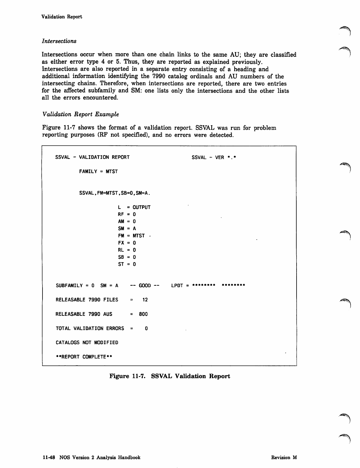
Validation Report
Intersections
Intersections occur when more than one chain links to the same AU; they are classified
as either error type 4 or 5. Thus, they are reported as explained previously.
Intersections are also reported in a separate entry consisting of a heading and
additional information identifying the 7990 catalog ordinals and AU numbers of the
intersecting chains. Therefore, when intersections are reported, there are two entries
for the affected subfamily and SM: one lists only the intersections and the other lists
all the errors encountered.
Validation Report Example
Figure 11-7 shows the format of a validation report. SSVAL was run for problem
reporting purposes (RF not specified), and no errors were detected.
SSVAL - VALIDATION REPORT SSVAL - VER •.*
FAMILY = MTST
SSVAL,FM=MTST,SB =0,SM=A.
L= OUTPUT
RF = 0
AM = 0
SM = A
FM = MTST •
FX = 0
RL = 0
SB = 0
ST = 0
SUBFAMILY =0 SM = A — GOOD ~ LPDT - ******** ********
RELEASABLE 7990 FILES 12
RELEASABLE 7990 AUS = 800
TOTAL VALIDATION ERRORS
CATALOGS NOT MODIFIED
••REPORT COMPLETE**
^S^S
Figure 11-7. SSVAL Validation Report
11-48 NOS Version 2 Analysis Handbook Revision M
0ms
Typical SSVAL Runs
Typical SSVAL Runs
As described previously, SSVAL is run either to make 7990 space available for reuse or
to report on problems with the current MSE system files and/or PFC entries. The
following examples show typical SSVAL runs that may be used periodically for these
purposes.
Example 1:
The following SSVAL command causes 7990 space to be made available for reuse.
SSVAL,RF=DUMP1,RL.
DUMP1 is the release data file produced by a previous PFDUMP run from which
SSVAL can identify all the 7990 files that were orphans at the time of the dump. If no
error conditions are detected in the 7990 catalog and PFC entries contained on file
DUMP1 (FX=0 by default), the orphans are purged and the 7990 space assigned to
them is released. The last purge date and time field in the subcatalog (in the 7990
catalog) for each SM for each subfamily is updated to the time of the SSVAL run if
any file from that SM is purged. This is to ensure that a subsequent SSVAL run does
not release the same space a second time, as the 7990 space may be reallocated to a
new file.
If errors were detected, they are listed on the validation report and release processing
is not performed. This is indicated by the CATALOGS NOT MODIFIED message at
the end of the validation report. The analyst can rerun SSVAL with the following
command to ensure that release processing is performed (n is the number of errors
detected during the previous SSVAL run).
SSVAL,RF=DUMP1,RL,FX=n.
After this SSVAL run has completed, an analysis of the current version of the SM
map, 7990 catalog, and PFC entries should be made to determine whether or not the
errors detected in the first SSVAL run exist in the current MSE system files and PFC
entries. This is accomplished using the command:
SSVAL,FM=fam i1yname.AM.
familyname is that on the release data file, DUMP1.
Example 2:
Upon completion of any device reload that includes recovery of a 7990 catalog and/or
SM map, SSVAL should be run to determine whether any SM map/7990 catalog
mismatches exist. The following call accomplishes this.
SSVAL ,FM=f ami 1 yname, SB=ni,n2 nh,AM.
familyname is that for which recovery was done; ni,n2,...,nhare the affected subfamilies
if just some of the devices of the family were reloaded.
Revision M Mass Storage Extended Subsystem (MSE) 11-49
Restrictions to SSVAL
SSVAL analyzes the SM map, 7990 catalog, and PFC entries for the subfamilies
specified by the SB parameter and reports any discrepancies or inconsistencies. For ^^
example, if the recovery was not scheduled and SSLABEL was run to add or remove '
cartridges or cubicles from one of the affected subfamilies after the last incremental or
full dump for these subfamilies, then the SM map will reflect the results of the
SSLABEL run but the 7990 catalog will not. Such mismatches will be reported on the
validation report.
If the following SSVAL command is then made, the errors detected during the
previous run will be flagged, as described previously under Release Processing and
Problem Fixing.
SSVAL, FM=f am il yname ,SB=ni,n2,... ,nh,AM,FX=n.
familyname and m,n2,...,nhare the same as in the previous SSVAL run; n is the
number of errors detected during the previous run. After investigating the cause of
these errors, the analyst can run the SSDEBUG utility to correct the error conditions
(refer to SSDEBUG later in this section).
If a device reload includes recovery of all SM maps (default family, user
index=3777608), the latest SM maps should be recovered from backup copies. Then
each family that has 7990-resident files should be analyzed using the following
command to detect SM map/7990 catalog mismatches.
SSVAL, FM=f ami 1 yname, AM.
It is recommended that the previous SSVAL run be made periodically to check whether
any unexpected error conditions exist. As the site analyst becomes more familiar with
MSE processing, these periodic SSVAL runs can be done less frequently. "^)
Restrictions to SSVAL
The following restrictions apply to the SSVAL utility.
• SSVAL cannot be run when SSMOVE is in the process of destaging files.
• Only one copy of SSVAL can be run at a time.
• SSVAL, SSLABEL, and SSDEBUG cannot be run at the same time. ^^
11-50 NOS Version 2 Analysis Handbook Revision M
SSUSE
0$ms
00b\
SSUSE
SSUSE reads data in the 7990 catalogs and SM maps and produces reports on the
availability of space on 7990 cartridges and the allocation of cubicle space within an
SM. The reports may not be completely up to date because the 7990 catalogs and SM
maps can be updated while the reports are being generated.
The types of reports that SSUSE generates are:
Report Description
Basic usage report
Optional report A
Optional report B
Optional report C
Optional report D
Usage report that lists general information about the use of
each SM in a subfamily.
SM map report that lists the contents of an SM as described
in the SM map.
Cartridge summary report that lists general status information
for each cartridge entry in the 7990 catalog. The report
identifies the available AUs and flags set for each cartridge in
the 7990 catalog.
Detailed cartridge report that lists cartridge usage information
for each cartridge entry in the 7990 catalog.
Detailed AU status report that lists AU status information for
each entry in the 7990 catalog plus cartridge usage
information.
The format of the SSUSE command is:
SSUSE,p,,p2 Pn-
pi Description
CM=A-
CM
CM omitted
CN=csn
CN
CN omitted
FM=familyname
FM
FM omitted
L=filename
L
Cartridge manufacturer code is A-, indicating IBM.
Same as CM=A-.
Same as CM=A-.
Cartridge serial number of a specific cartridge. The CN = csn
parameter is valid only if the OP=D parameter is specified.
Cartridge serial number is not specified.
Same as CN.
Family to be reported on.
Same as FM = system default family.
Same as FM = system default family.
File on which listable output is to be written.
Same as L=OUTPUT.
Revision M Mass Storage Extended Subsystem (MSE) 11-51
SSUSE
Report
L=0
L omitted
OP=op
OP
OP omitted
SB=subfamily
SB
SB omitted
SM = id
SM
SM omitted
Description
No output file is to be generated.
Same as L=OUTPUT.
Type of report to be generated. Multiple options can be specified
(for example, OP=AB).
op Description
A
B
C
D
Optional report A and basic usage report.
Optional report B and basic usage report.
Optional report C and basic usage report.
Optional report D and basic usage report.
Basic usage report only is to be generated.
Same as OP.
Subfamily to be reported on. Up to eight subfamilies can be
selected by the numbers 0 through 7. For example, SB = 0273
selects subfamilies 0, 2, 3, and 7.
Same as SB = 01234567.
Same as SB = 01234567.
SM identifier of the SM to be used. Up to eight SMs can be
selected by the letters A through H. For example, SM = AGC
selects SM A, C, and G.
Same as SM=A.
Same as SM=A.
» < s § \
^
11-52 NOS Version 2 Analysis Handbook Revision M
Basic Usage Report
Basic Usage Report
The basic usage report includes a title line, which identifies the family and SM being
reported on. The statistics in this report contain data for each group followed by totals
for SMs and subfamilies. The following items are listed.
• Number of cubicles reserved for each subfamily.
• Number of cartridges in each subfamily.
• Number of unassigned and unflagged AUs for small files.
• Number of unassigned and unflagged AUs for large files.
• Number of flagged cartridges.
• Number of flagged AUs.
• If any empty cubicles are assigned, they are listed first for each subfamily. This
line shows a hyphen (-) as the group designator since groups are assigned only to
cartridges.
Figure 11-8 shows the format of a basic usage report.
Revision M Mass Storage Extended Subsystem (MSE) 11-53
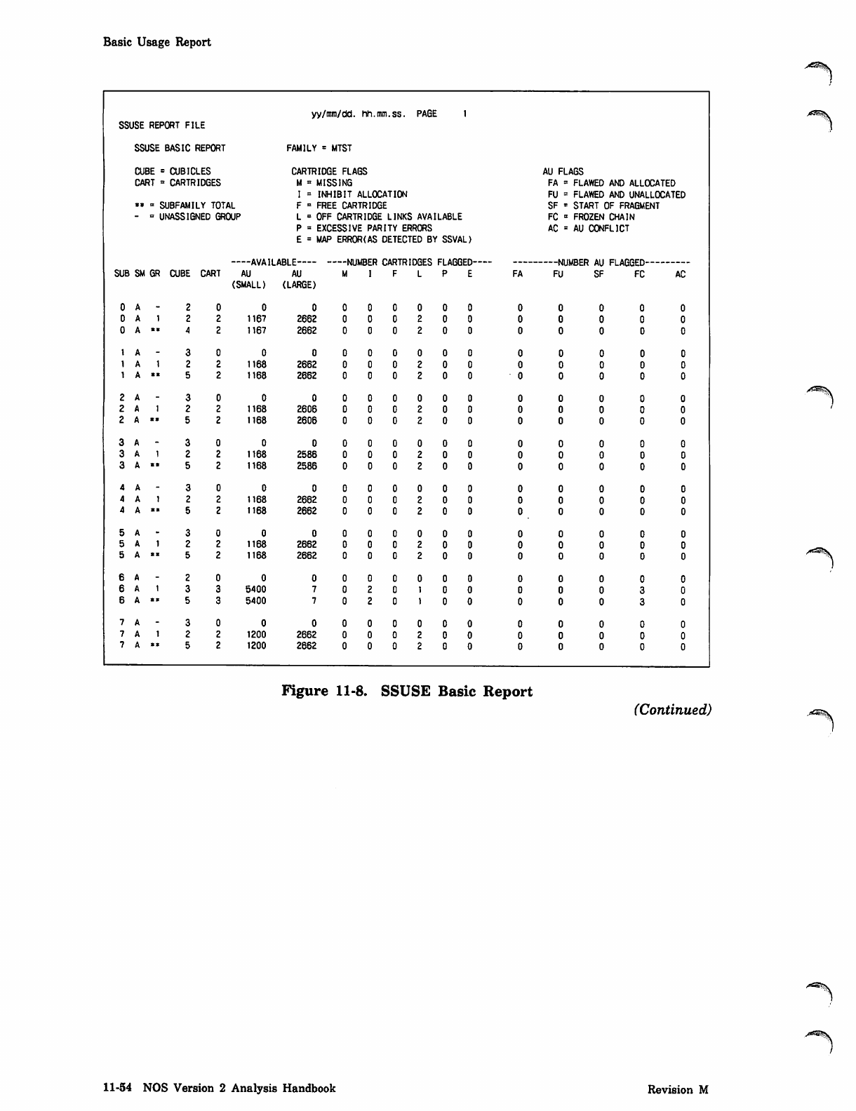
Basic Usage Report
yy/mm/dd. hh.mm .ss. PAGE
SSUSE REPORT FILE
SSUSE BASIC REPORT FAMILY * MTST
CUBE = CUBICLES CARTRIDGE FLAGS AU FLAGS
CART = CARTRIDGES M = MISSING FA = FLAWED AND ALLOCATED
I = INHIBIT ALLOCATION FU = FLAWED AND UNALLOCATED
** = SUBFAMILY TOTAL F = FREE CARTRIDGE SF = START OF FRAGMENT
-= UNASSIGNED GROUP L = OFF CARTRIDGE LINKS AVAILABLE FC ■FROZEN CHAIN
P = EXCESSIVE PARITY ERRORS AC = AU CONFLICT
E = MAP ERROR(AS DETECTED BY SSVAL)
k n i t / n C D P A D T D T P l f t C C c i A fi fi c r i
SUB SM GR CUBE CART
—nvnunout.
A U A U
na
MFA F U S F F C AC
(SMALL) (LARGE)
0 A
0 A 1167 2662
0 A SX 1167 2662
1 A
1 A 1168 2662
1 A sz 1168 2662
2 A
2 A 1168 2606
2 A ■ s 1168 2606
3 A
3 A 1168 2586
3 A ■ s 1168 2586
4 A
4 A 1168 2662
4 A ss 1168 2662
5 A
5 A 1168 2662
5 A ss 1168 2662
6 A
6 A 5400
6 A ss 5400
7 A
7 A 1200 2662
7 A ** 1200 2662
Figure 11-8. SSUSE Basic Report
(Continued)
A ^ S
11-54 NOS Version 2 Analysis Handbook Revision M
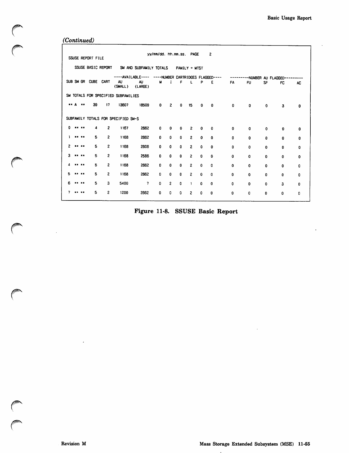
Basic Usage Report
0$m\.
jffl^ffi^.^
0m\
(Continued)
SSUSE REPORT FILE yy/mm/dd. hh. mm.ss. PAGE
SSUSE BASIC REPORT SM AND SUBFAMILY TOTALS FAMILY = MTST
SUB SM GR CUBE CART
AVAILABLE
A U A U
(SMALL) (LARGE)
NUMBER CARTRIDGES FLAGGED
M I F L P E
ER AU FL
SFFA FU FC AC
SM TOTALS FOR SPECIFIED SUBFAMILIES
■« A « 3 9 17 13607 18509 15
SUBFAMILY TOTALS FOR SPECIFIED SM-S
0 s s s s 4 1167 2662
1 s s . . 5 1168 2662
2 s s s s 5 1168 2606
3 " « 5 1168 2586
4 s s s s 5 1168 2662
5 " « 5 1168 2662
6 • • « 5 5400
7 s s s s 5 1200 2662
Figure 11-8. SSUSE Basic Report
Revision M Mass Storage Extended Subsystem (MSE) 11-55
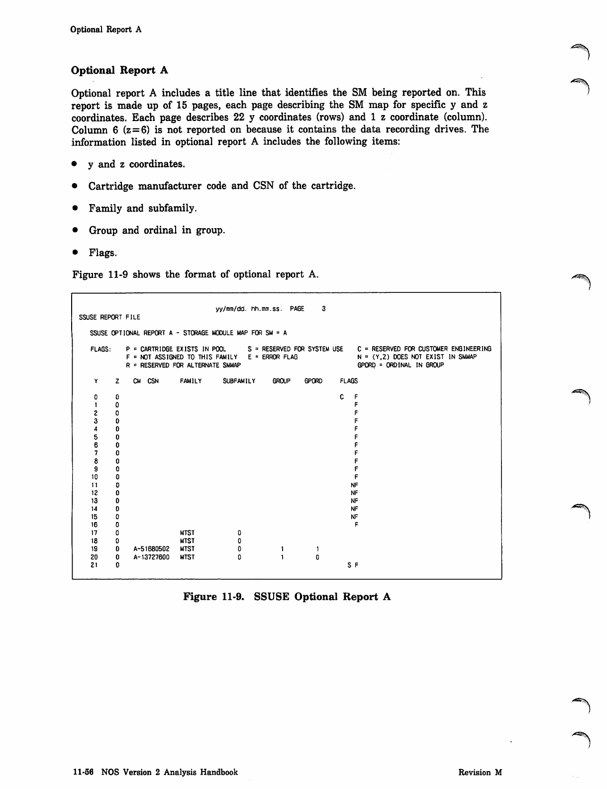
Optional Report A
Optional Report A
Optional report A includes a title line that identifies the SM being reported on. This
report is made up of 15 pages, each page describing the SM map for specific y and z
coordinates. Each page describes 22 y coordinates (rows) and 1 z coordinate (column).
Column 6 (z=6) is not reported on because it contains the data recording drives. The
information listed in optional report A includes the following items:
• y and z coordinates.
• Cartridge manufacturer code and CSN of the cartridge.
• Family and subfamily.
• Group and ordinal in group.
• Flags.
Figure 11-9 shows the format of optional report A.
yy/mm/dd hh mm.ss. PAGE
SSUSE REPORT FILE
SSUSE OPTIONAL REPORT A - STORAGE MODULE MAP FOR SM = A
FLAGS: P = CARTRIDGE EXISTS IN POOL S = RESERVED FOR SYSTEM USE C = RESERVED FOR CUSTOMER ENGINEERING
F = NOT ASSIGNED TO THIS FAMILY E = ERROR FLAG N = (Y,Z) DOES NOT EXIST IN SMMAP
R = RESERVED FOR ALTERNATE SMMAP GPORD = ORDINAL IN GROUP
Y Z CM CSN FAMILY SUBFAMILY GROUP GPORD FLAGS
0
1
0
0
CF
F
2 0 F
3 0 F
4 0 F
5 0 F
6 0 F
7 0 F
8 0 F
90 F
10
11 NF
12 NF
13 NF
14 NF
15 NF
16
17 MTST
18 MTST
19 A-51680502 MTST
20 A-13727600 MTST
21 S F
>^ 5S \
Figure 11-9. SSUSE Optional Report A
11-56 NOS Version 2 Analysis Handbook Revision M
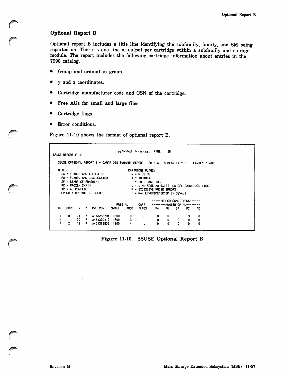
Optional Report B
0^S
Optional Report B
Optional report B includes a title line identifying the subfamily, family, and SM being
reported on. There is one line of output per cartridge within a subfamily and storage
module. The report includes the following cartridge information about entries in the
7990 catalog.
• Group and ordinal in group.
• y and z coordinates.
• Cartridge manufacturer code and CSN of the cartridge.
• Free AUs for small and large files.
• Cartridge flags.
• Error conditions.
Figure 11-10 shows the format of optional report B.
SSUSE REPORT FILE
yy/mm/dd. hh.mm.ss. PAGE 25
SSUSE OPTIONAL REPORT B - CARTRIDGE SUMMARY REPORT SM » A SUBFAMILY = 6 FAMILY = MTST
NOTES:
FA = FLAWED AND ALLOCATED
FU = FLAWED AND UNALLXATED
SF = START OF FRAGMENT
FC = FROZEN CHAIN
AC = AU CONFLICT
GPORD = ORDINAL IN GROUP
CARTRIDGE FLAGS:
M = MISSING
I = INHIBIT
F = FREE CARTRIDGE
L = LINK(FREE AU EXIST, NO OFF CARTRIDGE LINK)
P = EXCESSIVE WRITE ERRORS
E = MAP ERROR(DETECTED BY SSVAL)
GP GPORD CM CSN
FREE AU
SMALL LARGE
1 0 2 1 7 A - 1 3 2 6 8 7 9 4 1 8 0 0 0
1 1 2 0 7 A - 5 1 3 2 9 4 1 2 1 8 0 0 3
1 2 1 9 7 A - 5 1 3 2 8 8 3 9 1 8 0 0 4
CART
FLA6S
I L
FA
0
0
0
-ERROR CONDITIONS
—NUMBER OF AU
F U S F F C A C
/Gw&H&'X,
Figure 11-10. SSUSE Optional Report B
Revision M Mass Storage Extended Subsystem (MSE) 11-57
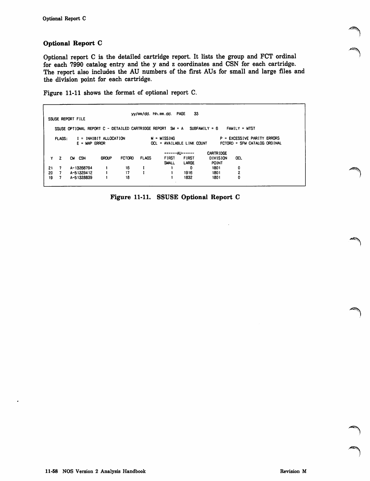
Optional Report C
Optional Report C
Optional report C is the detailed cartridge report. It lists the group and FCT ordinal
for each 7990 catalog entry and the y and z coordinates and CSN for each cartridge.
The report also includes the AU numbers of the first AUs for small and large files and
the division point for each cartridge.
Figure 11-11 shows the format of optional report C.
yy/mm/dd. hh.mm.dd. PAGE 33
SSUSE REPORT FILE
SSUSE OPTIONAL REPORT C - DETAILED CARTRIDGE REPORT SM = A SUBFAMILY = 6 FAMILY = MTST
FLAGS: I = INHIBIT ALLOCATION
E = MAP ERROR
M =
XL
MISSING P = EXCESSIVE PARITY ERRORS
= AVAILABLE LINK COUNT FCTORD = SFM CATALOG ORDINAL
Y
21
20
19
CM CSN
A-13268794
A-51329412
A-51328839
GROUP
1
1
1
FCTORD
16
17
18
FLAGS
I
I
FIRST
SMALL
1
1
1
AU CARTRIDGE
FIRST DIVISION
LARGE POINT
0 1 8 0 1
1916 1801
1832 1801
CCL
0
2
0
Figure 11-11. SSUSE Optional Report C
11-58 NOS Version 2 Analysis Handbook Revision M
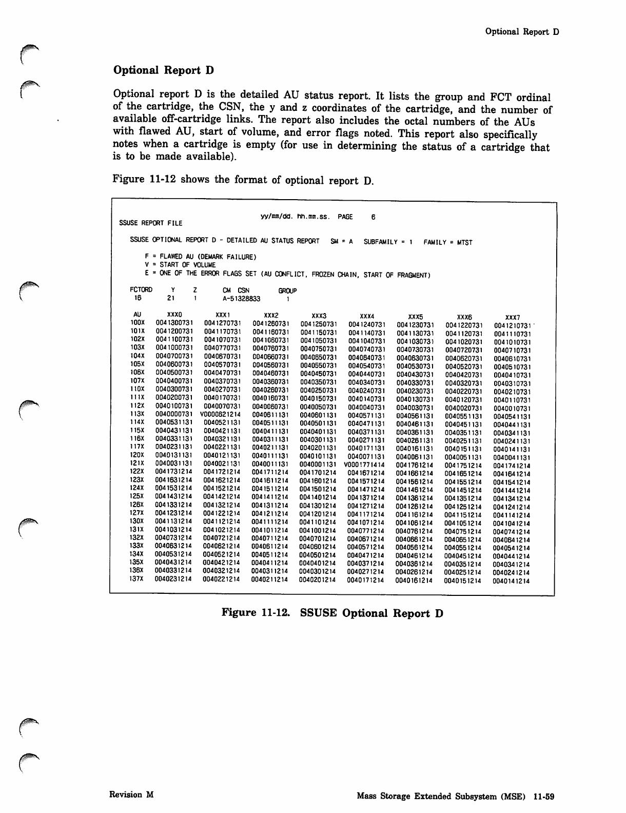
0^S
j^s
Optional Report D
Optional Report D
Optional report D is the detailed AU status report. It lists the group and FCT ordinal
of the cartridge, the CSN, the y and z coordinates of the cartridge, and the number of
available off-cartridge links. The report also includes the octal numbers of the AUs
with flawed AU, start of volume, and error flags noted. This report also specifically
notes when a cartridge is empty (for use in determining the status of a cartridge that
is to be made available).
Figure 11-12 shows the format of optional report D.
0$$k®\
r
<0$s
SSUSE REPORT FILE yy/mm/dd. hh.mm.ss. PAGE
SSUSE OPTIONAL REPORT D - DETAILED AU STATUS REPORT SM = A SUBFAMILY = 1 FAMILY = MTST
F = FLAWED AU (DEMARK FAILURE)
V = START OF VOLUME
E = ONE OF THE ERROR FLAGS SET (AU CONFLICT, FROZEN CHAIN. START OF FRAGMENT)
F C T O R D Y Z C M C S N G R O U P
16 2 1 1 A-51328833 1
AU XXXO XXX1 XXX2 XXX3 XXX4 XXX5 XXX6 XXX7
100X 0041300731 0041270731 0041260731 0041250731 0041240731 0041230731 0041220731 0041210731'
101X 0041200731 0041170731 0041160731 0041150731 0041140731 0041130731 0041120731 0041110731
102X 0041100731 0041070731 0041060731 0041050731 0041040731 0041030731 0041020731 0041010731
103X 0041000731 0040770731 0040760731 0040750731 0040740731 0040730731 0040720731 0040710731
104X 0040700731 0040670731 0040660731 0040650731 0040640731 0040630731 0040620731 0040610731
105X 0040600731 0040570731 0040560731 0040550731 0040540731 0040530731 0040520731 0040510731
106X 0040500731 0040470731 0040460731 0040450731 0040440731 0040430731 0040420731 0040410731
107X 0040400731 0040370731 0040360731 0040350731 0040340731 0040330731 0040320731 0040310731
110X 0040300731 0040270731 0040260731 0040250731 0040240731 0040230731 0040220731 0040210731
111X 0040200731 0040170731 0040160731 0040150731 0040140731 0040130731 0040120731 0040110731
112X 0040100731 0040070731 0040060731 0040050731 0040040731 0040030731 0040020731 0040010731
113X 0040000731 V0000621214 0040611131 0040601131 0040571131 0040561131 0040551131 0040541131
114X 0040531131 0040521131 0040511131 0040501131 0040471131 0040461131 0040451131 0040441131
115X 0040431131 0040421131 0040411131 0040401131 0040371131 0040361131 0040351131 0040341131
116X 0040331131 0040321131 0040311131 0040301131 0040271131 0040261131 0040251131 0040241131
117X 0040231131 0040221131 0040211131 0040201131 0040171131 0040161131 0040151131 0040141131
120X 0040131131 0040121131 0040111131 0040101131 0040071131 0040061131 0040051131 0040041131
121X 0040031131 0040021131 0040011131 0040001131 V0001771414 0041761214 0041751214 0041741214
122X 0041731214 0041721214 0041711214 0041701214 0041671214 0041661214 0041651214 0041641214
123X 0041631214 0041621214 0041611214 0041601214 0041571214 0041561214 0041551214 0041541214
I24X 0041531214 0041521214 0041511214 0041501214 0041471214 0041461214 0041451214 0041441214
125X 0041431214 0041421214 0041411214 0041401214 0041371214 0041361214 0041351214 0041341214
126X 0041331214 0041321214 0041311214 0041301214 0041271214 0041261214 0041251214 0041241214
127X 0041231214 0041221214 0041211214 0041201214 0041171214 0041161214 0041151214 0041141214
130X 0041131214 0041121214 0041111214 0041101214 0041071214 0041061214 0041051214 0041041214
131X 0041031214 0041021214 0041011214 0041001214 0040771214 0040761214 0040751214 0040741214
132X 0040731214 0040721214 0040711214 0040701214 0040671214 0040661214 0040651214 0040641214
133X 0040631214 0040621214 0040611214 0040601214 0040571214 0040561214 0040551214 0040541214
134X 0040531214 0040521214 0040511214 0040501214 0040471214 0040461214 0040451214 0040441214
135X 0040431214 0040421214 0040411214 0040401214 0040371214 0040361214 0040351214 0040341214
136X 0040331214 0040321214 0040311214 0040301214 0040271214 0040261214 0040251214 0040241214
137X 0040231214 0040221214 0040211214 0040201214 0040171214 0040161214 0040151214 0040141214
Figure 11-12. SSUSE Optional Report D
Revision M Mass Storage Extended Subsystem (MSE) 11-59
SSDEBUG
SSDEBUG
SSDEBUG allows the analyst to update appropriate entries in the SM maps and/or
7990 catalogs and thereby resolve inconsistencies reported by the SSVAL utility.
SSDEBUG can also copy data from selected 7990 files or cartridges to disk. This
function of SSDEBUG is intended for use when errors such as unrecoverable read
errors do not allow successful staging of a 7990 file.
NOTE
SSDEBUG updates the SM map for the specified SM. (Refer to the definition of SM
map earlier in this section.) It is recommended that the SM map is copied on tape or
on another device or family immediately after every update of the SM map.
Input to SSDEBUG is via a directive file. Refer to SSLABEL, earlier in this section,
for a description of the directive file format.
The format of the SSDEBUG command is:
SSDEBUG, pi, P2.P3-
pi Description
I=filename
I
I omitted
L=filename
L
L=0
L omitted
Z
Z omitted
File on which directives are written.
Same as I=INPUT.
Same as I = INPUT.
File on which listable output is to be written.
Same as L=OUTPUT.
No output file is to be generated.
Same as L=OUTPUT.
Directives are contained on the SSDEBUG command. The
I parameter is ignored.
Directives are contained on the file specified by the I parameter.
11-60 NOS Version 2 Analysis Handbook Revision M
/ ^ p ^ \
SSDEBUG Directives
SSDEBUG Directives
The following directives are available with SSDEBUG. The descriptions of the
parameters for these directives follow this listing of directives.
OP=RS — Read AUs
OP=RS reads selected AUs of a cartridge identified by its csn (CN=csn) or y and z
coordinates (YI and ZI parameters). The SM parameter specifies the SM where the
cartridge resides. The range of AUs to be read is specified by the SL and SU
parameters. The AUs are written to the file specified by the PF parameter. All CYBER
data plus 7990 and CRC data, including header and trailer information, is returned.
The analyst can write an application program to reconstruct the permanent file by
stripping off all CYBER or 7990 related control information. Refer to Format of Disk
Files Read From 7990 by SSDEBUG later in this section for a description of the
control information written to disk along with the disk file contents.
OP=RF — Read File
OP = RF reads the file whose alternate storage address is specified by the FO, SB, SM,
and ST parameters. The file is written to the file specified by the PF parameter. All
data, including header and trailer information, is returned (refer to Format of Disk
Files Read From 7990 by SSDEBUG later in this section).
OP=RP — Release Frozen Chain Space
OP=RP clears flags in the 7990 catalog and releases 7990 space for the chain whose
alternate storage address is specified by the FO, SB, SM, and ST parameters.
OP=RL — Remove Cartridge Entry From 7990 Catalog
OP=RL removes a 7990 catalog entry that is not linked properly to the SM map. The
FO, SB, and SM parameters identify the 7990 catalog entry to be removed.
OP=RC — Remove Cartridge Entry From SM Map
OP=RC removes an SM map entry that does not have a corresponding FCT entry in
the 7990 catalog. The SM, YI, and ZI parameters identify the SM map entry to be
removed. The cartridge at the particular location (y,z) is put into the exit tray and the
SM map entry is changed to unassigned. The SM map should be backed up
immediately after the SSDEBUG run to ensure consistency with cartridge labels and
7990 catalogs (refer to the definition of SM map earlier in this section).
A scratch label is written on the cartridge prior to it being replaced in the exit tray,
but the cartridge history information remains intact.
OP=CF — Change Flag in SM Map or 7990 Catalog
OP = CF sets or clears flags in the SM map or 7990 catalog. The FL and ON or OF
parameters indicate the flag type and the action to be taken. The appropriate FCT
entry or SM map entry is determined from the CN, FO, or YI and ZI parameters. For
FCT flags (FL=AC, FC, or SF), the analyst can specify either a single AU using the
ST parameter or a range of AUs using the SL and SU parameters.
Revision M Mass Storage Extended Subsystem (MSE) 11-61
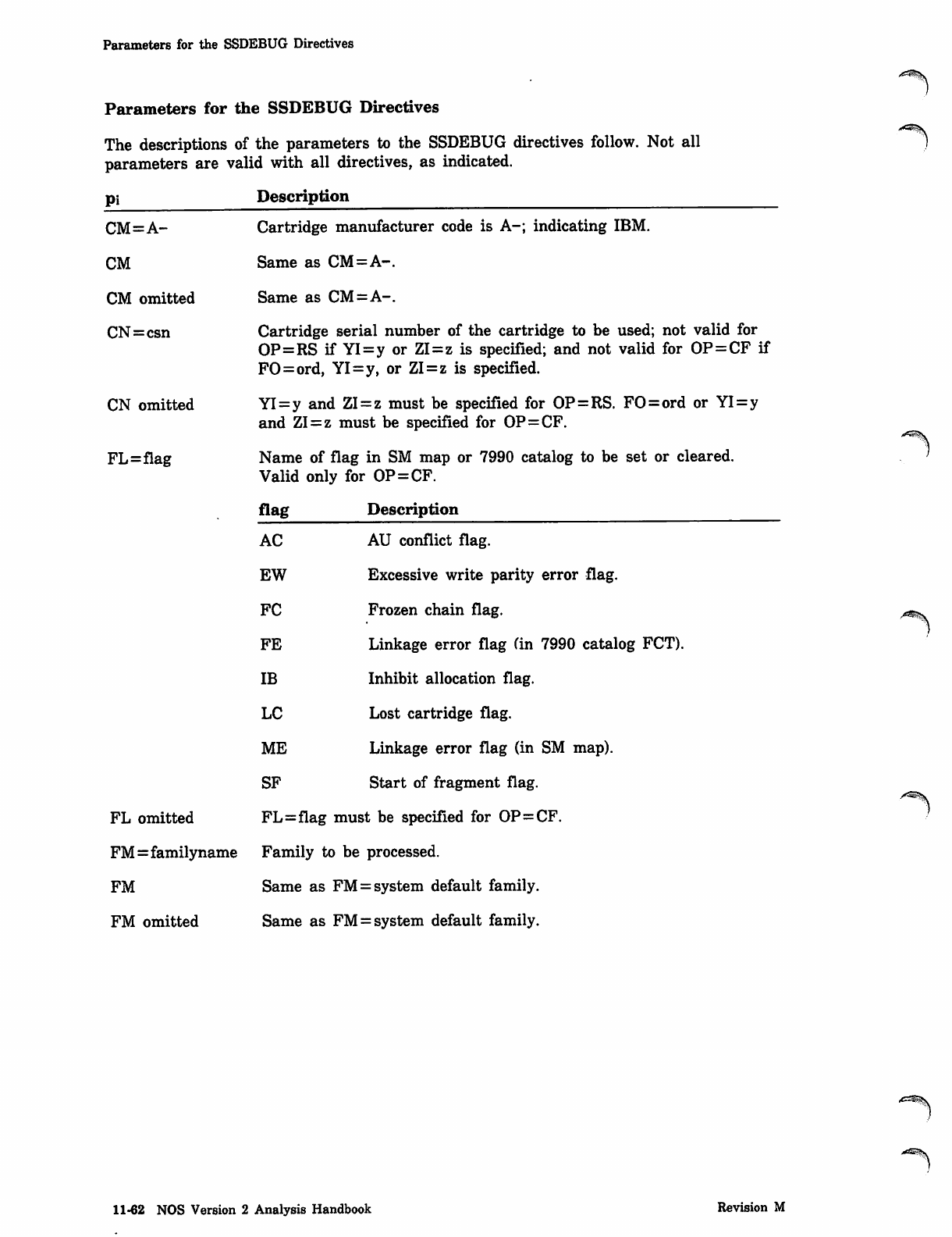
Parameters for the SSDEBUG Directives
Parameters for the SSDEBUG Directives
The descriptions of the parameters to the SSDEBUG directives follow. Not all
parameters are valid with all directives, as indicated.
.•^tf^V
Pi
CM=A-
CM
CM omitted
CN=csn
CN omitted
FL=flag
Description
Cartridge manufacturer code is A-; indicating IBM.
Same as CM=A-.
Same as CM=A-.
Cartridge serial number of the cartridge to be used; not valid for
OP=RS if YI=y or ZI = z is specified; and not valid for OP=CF if
FO=ord, YI=y, or ZI=z is specified.
YI=y and ZI = z must be specified for OP=RS. FO=ord or YI=y
and ZI = z must be specified for OP=CF.
Name of flag in SM map or 7990 catalog to be set or cleared.
Valid only for OP=CF.
flag Description
FL omitted
FM=familyname
FM
FM omitted
AC AU conflict flag.
EW Excessive write parity error flag.
FC Frozen chain flag.
FE Linkage error flag (in 7990 catalog FCT).
IB Inhibit allocation flag.
LC Lost cartridge flag.
ME Linkage error flag (in SM map).
SF Start of fragment flag.
FL=flag must be specified for OP = CF.
Family to be processed.
Same as FM = system default family.
Same as FM = system default family.
^^v
11-62 NOS Version 2 Analysis Handbook Revision M
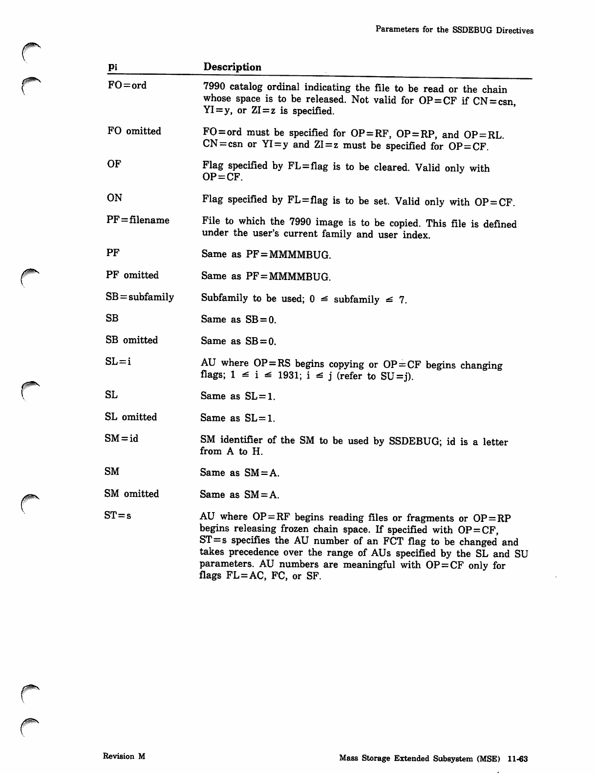
Parameters for the SSDEBUG Directives
r
Pi Description
FO=ord
FO omitted
OF
ON
PF=filename
PF
PF omitted
SB = subfamily
SB
SB omitted
SL=i
SL
SL omitted
SM=id
SM
SM omitted
ST=s
7990 catalog ordinal indicating the file to be read or the chain
whose space is to be released. Not valid for OP=CF if CN = csn,
YI=y, or ZI=z is specified.
FO=ord must be specified for OP = RF, OP = RP, and OP = RL.
CN = csn or YI=y and ZI=z must be specified for OP=CF.
Flag specified by FL=flag is to be cleared. Valid only with
OP = CF.
Flag specified by FL=flag is to be set. Valid only with OP=CF.
File to which the 7990 image is to be copied. This file is defined
under the user's current family and user index.
Same as PF=MMMMBUG.
Same as PF=MMMMBUG.
Subfamily to be used; 0 ^ subfamily ^ 7.
Same as SB = 0.
Same as SB = 0.
AU where OP=RS begins copying or OP = CF begins changing
flags; 1 ^ i ^ 1931; i ^ j (refer to SU=j).
Same as SL=1.
Same as SL=1.
SM identifier of the SM to be used by SSDEBUG; id is a letter
from A to H.
Same as SM=A.
Same as SM=A.
AU where OP = RF begins reading files or fragments or OP = RP
begins releasing frozen chain space. If specified with OP=CF,
ST=s specifies the AU number of an FCT flag to be changed and
takes precedence over the range of AUs specified by the SL and SU
parameters. AU numbers are meaningful with OP = CF only for
flags FL=AC, FC, or SF.
Revision M Mass Storage Extended Subsystem (MSE) 11-63
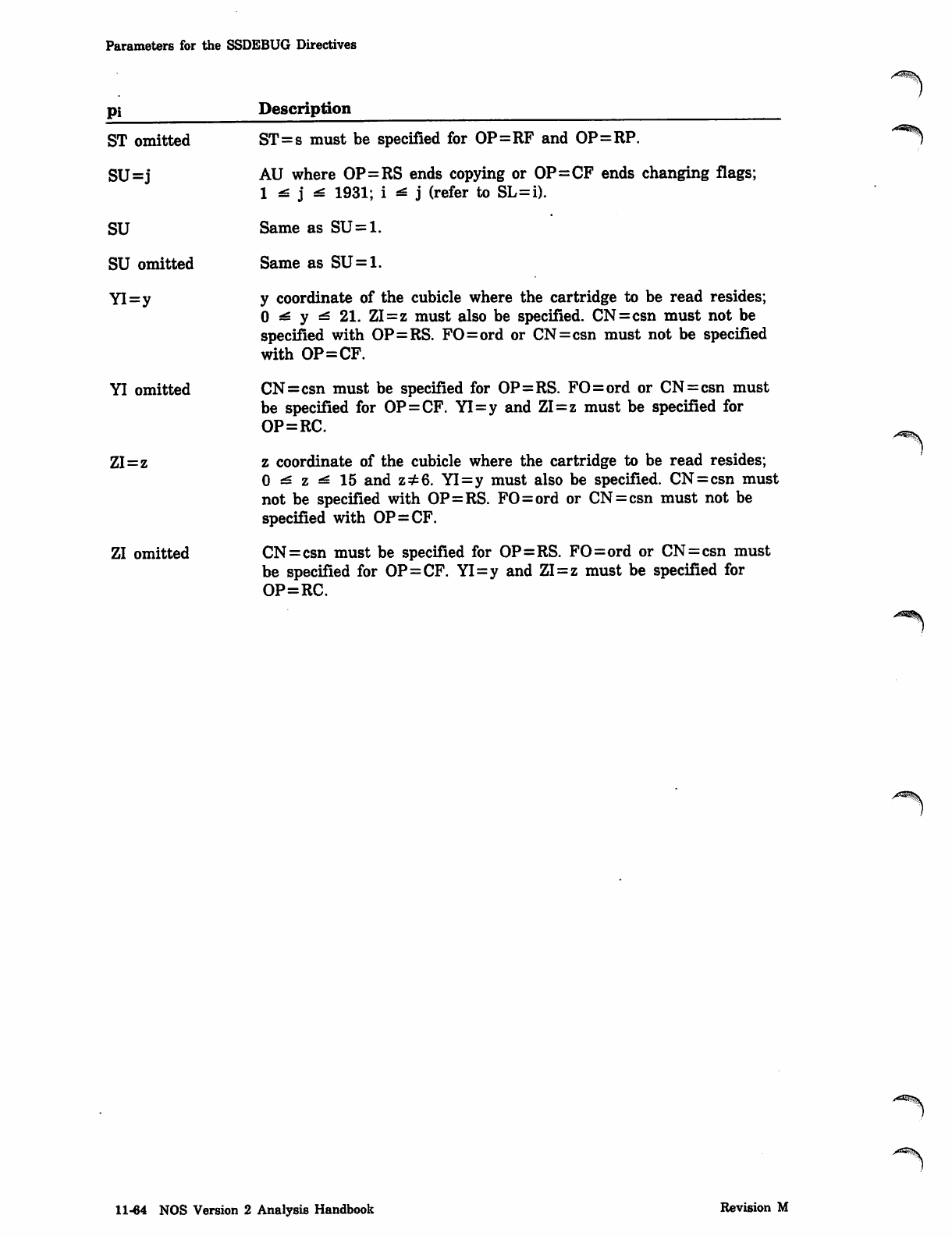
Parameters for the SSDEBUG Directives
Pi
ST omitted
SU=j
SU
SU omitted
YI=y
YI omitted
ZI=z
ZI omitted
Description
ST=s must be specified for OP=RF and OP=RP.
AU where OP=RS ends copying or OP=CF ends changing flags;
1 ^ j ^ 1931; i ^ j (refer to SL=i).
Same as SU=1.
Same as SU = 1.
y coordinate of the cubicle where the cartridge to be read resides;
0 *£. y *s 21. ZI=z must also be specified. CN=csn must not be
specified with OP=RS. FO=ord or CN=csn must not be specified
with OP=CF.
CN=csn must be specified for OP=RS. FO=ord or CN=csn must
be specified for OP=CF. YI=y and ZI=z must be specified for
OP=RC.
z coordinate of the cubicle where the cartridge to be read resides;
0 ^ z ^ 15 and z*6. YI=y must also be specified. CN=csn must
not be specified with OP=RS. FO=ord or CN = csn must not be
specified with OP=CF.
CN=csn must be specified for OP=RS. FO=ord or CN = csn must
be specified for OP=CF. YI=y and ZI=z must be specified for
OP=RC.
11-64 NOS Version 2 Analysis Handbook Revision M
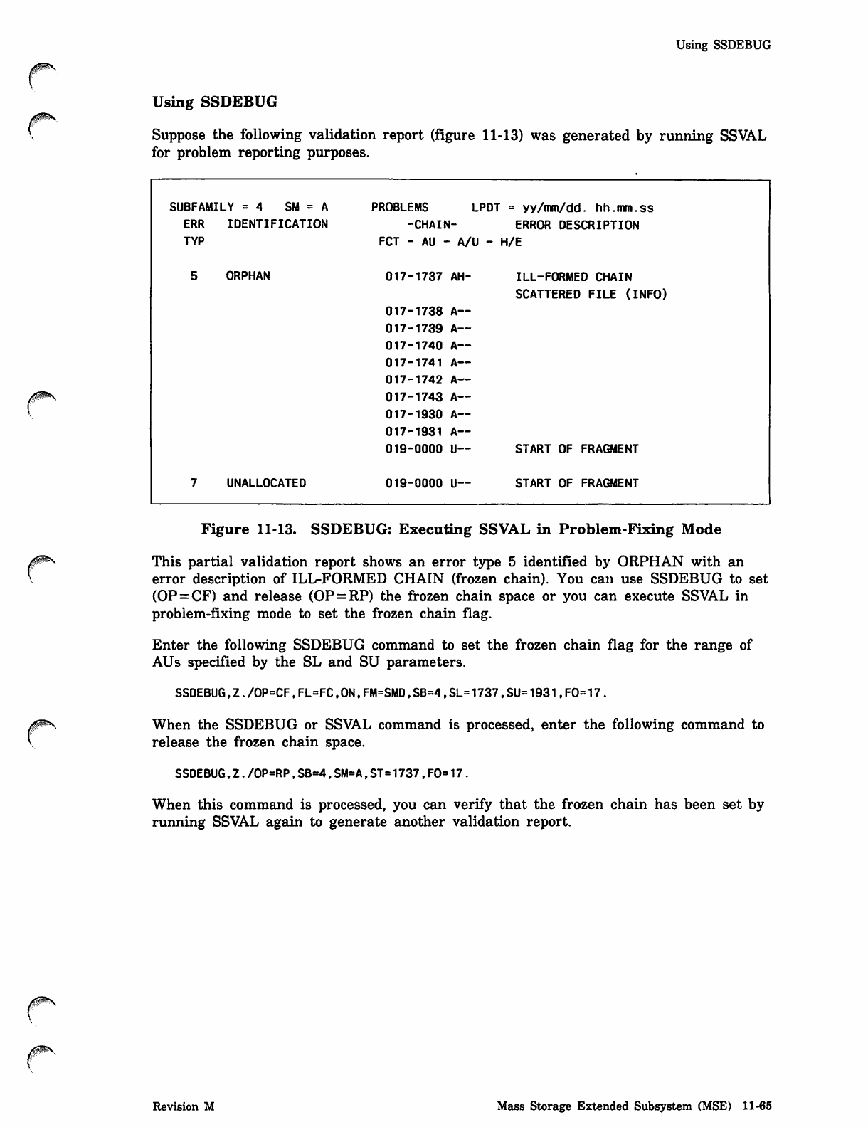
Using SSDEBUG
Using SSDEBUG
Suppose the following validation report (figure 11-13) was generated by running SSVAL
for problem reporting purposes.
SUBFAMILY =4 SM = PROBLEMS LPD1 = yy/mm/dd. hh.mm.ss
ERR IDENTIFICATION -CHAIN- ERROR DESCRIPTION
TYP FCT - AU -- A/U - H/E
5 ORPHAN 017-1737
017-1738
017-1739
017-1740
017-1741
017-1742
017-1743
017-1930
017-1931
AH-
A—
A—
A~
A—
A—
A—
A—
A—
ILL-FORMED CHAIN
SCATTERED FILE (INFO)
019-0000 U~ START OF FRAGMENT
7 UNALLOCATED 019-0000 u— START OF FRAGMENT
Figure 11-13. SSDEBUG: Executing SSVAL in Problem-Fixing Mode
This partial validation report shows an error type 5 identified by ORPHAN with an
error description of ILL-FORMED CHAIN (frozen chain). You can use SSDEBUG to set
(OP=CF) and release (OP=RP) the frozen chain space or you can execute SSVAL in
problem-fixing mode to set the frozen chain flag.
Enter the following SSDEBUG command to set the frozen chain flag for the range of
AUs specified by the SL and SU parameters.
SSDEBUG,Z./OP=CF,FL=FC,ON,FM=SMD,SB=4,SL=1737,SU=1931,F0=17.
When the SSDEBUG or SSVAL command is processed, enter the following command to
release the frozen chain space.
SSDEBUG,Z./0P=RP,SB=4,SM=A,ST=1737,FO=17.
When this command is processed, you can verify that the frozen chain has been set by
running SSVAL again to generate another validation report.
0$m\.
Revision M Mass Storage Extended Subsystem (MSE) 11-65
Restrictions to SSDEBUG
Restrictions to SSDEBUG
The following restrictions apply to the SSDEBUG utility.
© SSEXEC must be running when SSDEBUG is run.
• Only one copy of SSDEBUG can be run at one time.
© SSDEBUG, SSVAL, and SSLABEL cannot be run at the same time.
y,z Relationship with SM Map Ordinal
A one-to-one functional mapping exists between coordinate pairs and the ordinal entries
within the SM map. To determine the coordinate pair (y,z) from the SM map ordinal
(ord), use the following equations:
y = (352-ord)/l6
z = 352-ord-16y
To determine the SM map ordinal (ord) from the coordinate pair (y,z), use the following
equation:
ord=352-z-16y
A^Sl.
11-66 NOS Version 2 Analysis Handbook Revision M
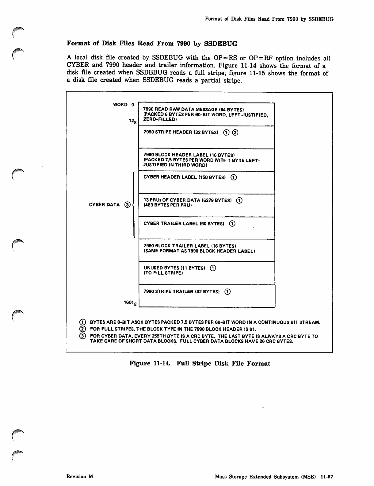
0ms
Format of Disk Files Read From 7990 by SSDEBUG
Format of Disk Files Read From 7990 by SSDEBUG
A local disk file created by SSDEBUG with the OP=RS or OP=RF option includes all
CYBER and 7990 header and trailer information. Figure 11-14 shows the format of a
disk file created when SSDEBUG reads a full stripe; figure 11-15 shows the format of
a disk file created when SSDEBUG reads a partial stripe.
word o
12c
CYBER DATA © \
1601,
7990 READ RAW DATA MESSAGE (64 BYTES)
(PACKED 6 BYTES PER 60-BIT WORD, LEFT-JUSTIFIED
ZERO-FILLED)
7990 STRIPE HEADER (32 BYTES) © ©
7990 BLOCK HEADER LABEL (16 BYTES)
(PACKED 7.5 BYTES PER WORD WITH 1 BYTE LEFT-
JUSTIFIED IN THIRD WORD)
CYBER HEADER LABEL (150 BYTES) ©
13 PRUs OF CYBER DATA (6279 BYTES) ©
(483 BYTES PER PRU)
CYBER TRAILER LABEL (90 BYTES) ©
7990 BLOCK TRAILER LABEL (16 BYTES)
(SAME FORMAT AS 7990 BLOCK HEADER LABEL)
UNUSED BYTES (11 BYTES) ©
(TO FILL STRIPE)
7990 STRIPE TRAILER (32 BYTES) ©
© BYTES ARE 8-BIT ASCII BYTES PACKED 7.5 BYTES PER 60-BIT WORD IN A CONTINUOUS BIT STREAM.
© FOR FULL STRIPES, THE BLOCK TYPE IN THE 7990 BLOCK HEADER IS 01.
(f) FOR CYBER DATA. EVERY 255TH BYTE IS A CRC BYTE. THE LAST BYTE IS ALWAYS A CRC BYTE TO
TAKE CARE OF SHORT DATA BLOCKS. FULL CYBER DATA BLOCKS HAVE 26 CRC BYTES.
Figure 11-14. Full Stripe Disk File Format
yi$RS
Revision M Mass Storage Extended Subsystem (MSE) 11-67
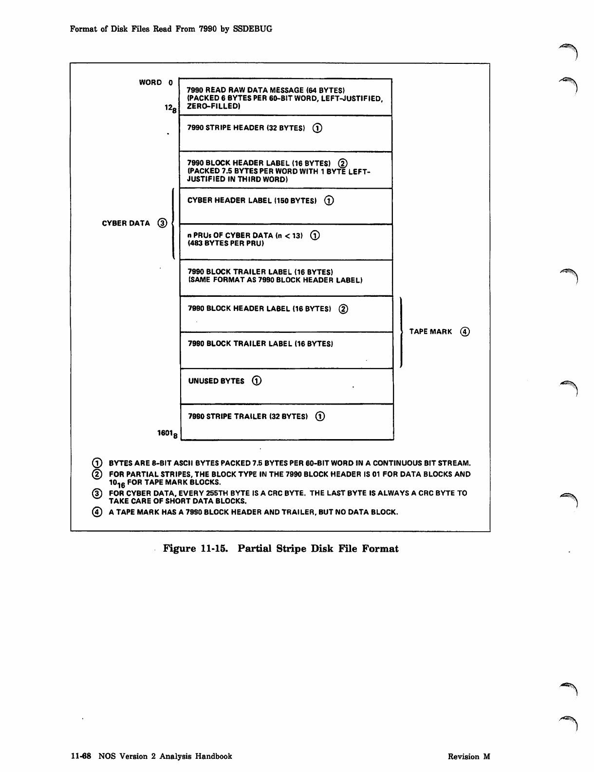
Format of Disk Files Read From 7990 by SSDEBUG
A^ ^S .
WORD 0
12c
CYBER DATA ©
1601.
7990 READ RAW DATA MESSAGE (64 BYTES)
(PACKED 6 BYTES PER 60-BIT WORD, LEFT-JUSTIFIED,
ZERO-FILLED)
7990 STRIPE HEADER (32 BYTES) ©
7990 BLOCK HEADER LABEL (16 BYTES) ©
(PACKED 7.5 BYTES PER WORD WITH 1 BYTE LEFT-
JUSTIFIED IN THIRD WORD)
CYBER HEADER LABEL 1150 BYTES) ©
n PRUs OF CYBER DATA (n < 13) ©
(483 BYTES PER PRU)
7990 BLOCK TRAILER LABEL (16 BYTES)
(SAME FORMAT AS 7990 BLOCK HEADER LABEL)
7990 BLOCK HEADER LABEL (16 BYTES) ©
7930 BLOCK TRAILER LABEL (16 BYTES)
UNUSED BYTES ©
7980 STRIPE TRAILER (32 BYTES) ©
TAPE MARK ©
© BYTES ARE 8-BIT ASCII BYTES PACKED 7.5 BYTES PER 60-BIT WORD IN A CONTINUOUS BIT STREAM.
© FOR PARTIAL STRIPES, THE BLOCK TYPE IN THE 7990 BLOCK HEADER IS 01 FOR DATA BLOCKS AND
1016 FOR TAPE MARK BLOCKS.
(3) FOR CYBER DATA, EVERY 255TH BYTE IS A CRC BYTE. THE LAST BYTE IS ALWAYS A CRC BYTE TO
TAKE CARE OF SHORT DATA BLOCKS.
0 A TAPE MARK HAS A 7990 BLOCK HEADER AND TRAILER, BUT NO DATA BLOCK.
Figure 11-15. Partial Stripe Disk File Format
11-68 NOS Version 2 Analysis Handbook Revision M
Format of Disk Files Read From 7990 by SSDEBUG
0ms
7990 Stripe Header and Trailer
The 7990 stripe header is a 32-byte block that occupies the first 32 bytes of the stripe;
the 7990 stripe trailer occupies the last 32 bytes. The 7990 stripe header and trailer
have the same format.
Bytes
0-5
6-7
8-9
A-B
C-D
E-1D
1E-1F
Description
Volume serial number. A 6-character string specifying the volume
serial number of the stripe.
Version number. Two characters specifying the version number
associated with the volume serial number.
File number. Two characters specifying the number of the file
within the volume.
Logical stripe number. Relative stripe number within the volume.
The logical stripe number may not correlate with the physical
stripe number due to demarked stripes.
Address of last block trailer. Byte number, within the stripe, of the
first byte of the last block trailer.
Reserved.
Checksum. Chosen such that the sum, modulo 65536, of all bytes in
the header equals zero.
Revision M Mass Storage Extended Subsystem (MSE) 11-69
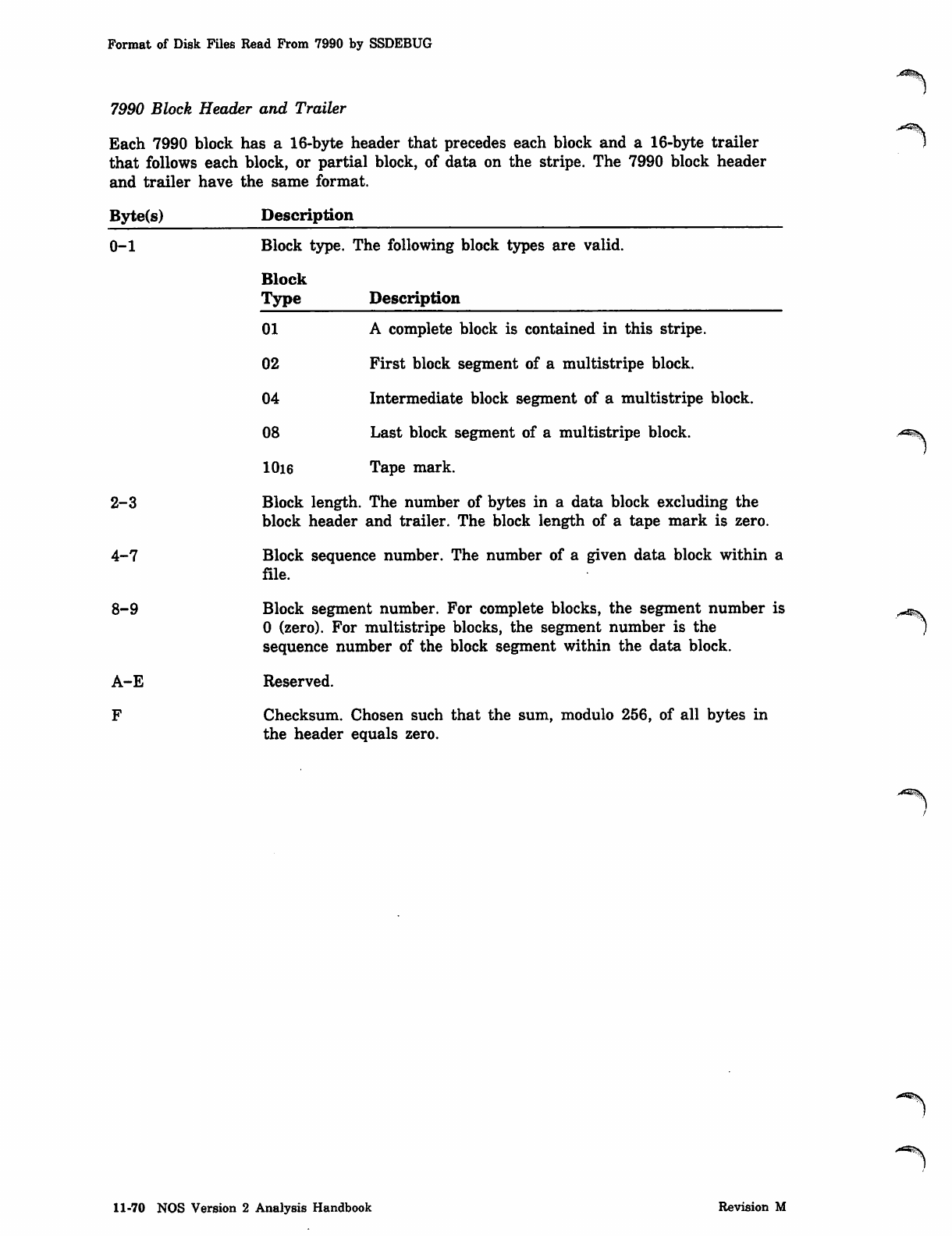
Format of Disk Files Read From 7990 by SSDEBUG
7990 Block Header and Trailer
Each 7990 block has a 16-byte header that precedes each block and a 16-byte trailer
that follows each block, or partial block, of data on the stripe. The 7990 block header
and trailer have the same format.
Byte(s)
0-1
2-3
4-7
8-9
A-E
F
Description
Block type. The following block types are valid.
Description
Block
Type
01
02
04
08
1016
A complete block is contained in this stripe.
First block segment of a multistripe block.
Intermediate block segment of a multistripe block.
Last block segment of a multistripe block.
Tape mark.
Block length. The number of bytes in a data block excluding the
block header and trailer. The block length of a tape mark is zero.
Block sequence number. The number of a given data block within a
file.
Block segment number. For complete blocks, the segment number is
0 (zero). For multistripe blocks, the segment number is the
sequence number of the block segment within the data block.
Reserved.
Checksum. Chosen such that the sum, modulo 256, of all bytes in
the header equals zero.
^*<^x
i<^^\
<>^53Sv
11-70 NOS Version 2 Analysis Handbook Revision M
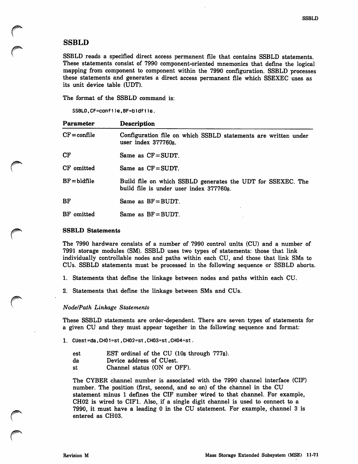
0^iu_
r
/#^V
SSBLD
SSBLD
SSBLD reads a specified direct access permanent file that contains SSBLD statements.
These statements consist of 7990 component-oriented mnemonics that define the logical
mapping from component to component within the 7990 configuration. SSBLD processes
these statements and generates a direct access permanent file which SSEXEC uses as
its unit device table (UDT).
The format of the SSBLD command is:
SSBLD,CF=confile,BF=bldfile.
Parameter Description
CF=confile Configuration file on which SSBLD statements are written under
user index 377760s.
CF Same as CF=SUDT.
CF omitted Same as CF=SUDT.
BF=bldfile Build file on which SSBLD generates the UDT for SSEXEC. The
build file is under user index 377760s.
BF Same as BF=BUDT.
BF omitted Same as BF = BUDT.
SSBLD Statements
The 7990 hardware consists of a number of 7990 control units (CU) and a number of
7991 storage modules (SM). SSBLD uses two types of statements: those that link
individually controllable nodes and paths within each CU, and those that link SMs to
CUs. SSBLD statements must be processed in the following sequence or SSBLD aborts.
1. Statements that define the linkage between nodes and paths within each CU.
2. Statements that define the linkage between SMs and CUs.
NodelPath Linkage Statements
These SSBLD statements are order-dependent. There are seven types of statements for
a given CU and they must appear together in the following sequence and format:
1. CUest=da,CH01=st,CH02=st,CH03=st,CH04=st.
est EST ordinal of the CU (10s through 777s).
da Device address of CUest.
st Channel status (ON or OFF).
The CYBER channel number is associated with the 7990 channel interface (CIF)
number. The position (first, second, and so on) of the channel in the CU
statement minus 1 defines the CIF number wired to that channel. For example,
CH02 is wired to CIF1. Also, if a single digit channel is used to connect to a
7990, it must have a leading 0 in the CU statement. For example, channel 3 is
entered as CH03.
Revision M Mass Storage Extended Subsystem (MSE) 11-71
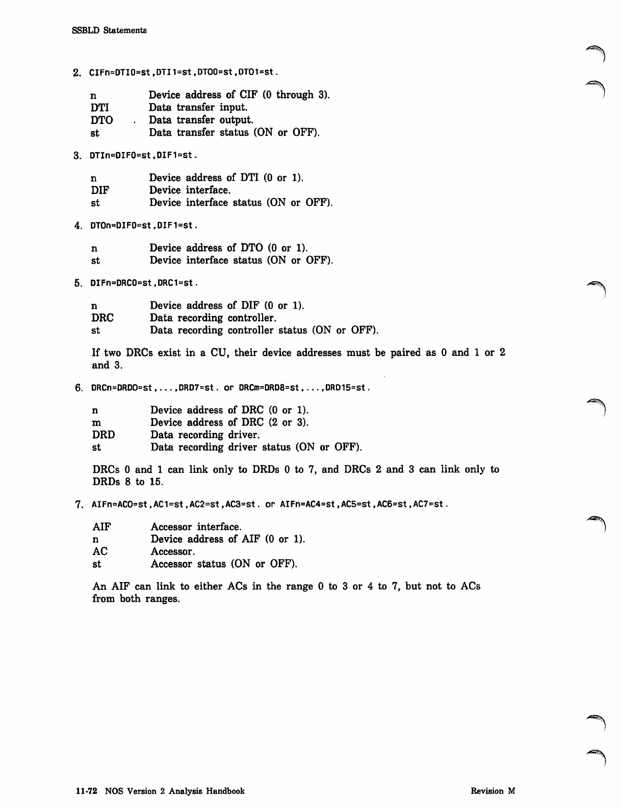
SSBLD Statements
2. CIFn=DTIO=St,DTI1=St,DTO0=St,DT01=St.
n Device address of CIF (0 through 3).
DTI Data transfer input.
DTO Data transfer output.
st Data transfer status (ON or OFF).
3. DTIn=DIF0=St,DIF1=St.
n Device address of DTI (0 or 1).
DIF Device interface.
st Device interface status (ON or OFF).
4. DTOn=DIF0=st,DIF1=st.
n Device address of DTO (0 or 1).
st Device interface status (ON or OFF).
5. DIFn=DRC0=st,DRC1=st.
n Device address of DIF (0 or 1).
DRC Data recording controller.
st Data recording controller status (ON or OFF).
If two DRCs exist in a CU, their device addresses must be paired as 0 and 1 or 2
and 3.
6. DRCn=DRDO=st DRD7=st. or DRCm=DRD8=St....,DRD15=St.
n Device address of DRC (0 or 1).
m Device address of DRC (2 or 3).
DRD Data recording driver.
st Data recording driver status (ON or OFF).
DRCs 0 and 1 can link only to DRDs 0 to 7, and DRCs 2 and 3 can link only to
DRDs 8 to 15.
7. AIFn=ACO=st,AC1=St,AC2=st,AC3=St. or AIFn=AC4=st,AC5=St,AC6=St,AC7=st.
A^m\
AIF Accessor interface. )
n Device address of AIF (0 or 1).
AC Accessor.
st Accessor status (ON or OFF).
An AIF can link to either ACs in the range 0 to 3 or 4 to 7, but not to ACs
from both ranges.
11-72 NOS Version 2 Analysis Handbook Revision M
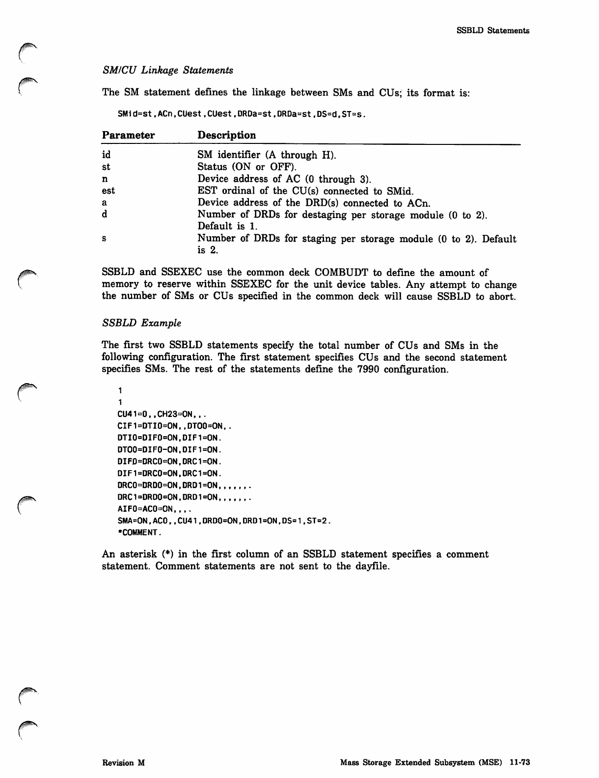
yffl^Bfc^
0$ms
SSBLD Statements
SMICU Linkage Statements
The SM statement defines the linkage between SMs and CUs; its format is:
SMi d=st,ACn,CUest,CUest,DRDa=st,DRDa=st,DS=d,ST=s.
Parameter Description
id SM identifier (A through H).
st Status (ON or OFF).
n Device address of AC (0 through 3).
est EST ordinal of the CU(s) connected to SMid.
a Device addr e ss o f t h e D RD(s) conne c t ed t o ACn.
d Number of DRDs for destaging per storage module (0 to 2).
Default is 1.
s Number of DRDs for staging per storage module (0 to 2). Default
is 2.
SSBLD and SSEXEC use the common deck COMBUDT to define the amount of
memory to reserve within SSEXEC for the unit device tables. Any attempt to change
the number of SMs or CUs specified in the common deck will cause SSBLD to abort.
SSBLD Example
The first two SSBLD statements specify the total number of CUs and SMs in the
following configuration. The first statement specifies CUs and the second statement
specifies SMs. The rest of the statements define the 7990 configuration.
1
1
CU41=0,,CH23=ON,f.
CIF1=DTI0=ON,,DTO0=ON,.
DTI0=DIF0=ON,DIF1=ON.
DTO0=DIF0-ON,DIF1=ON.
DIFD=DRC0=ON,DRC1=ON.
DIF1=DRC0=ON,DRC1=ON.
DRC0=DRD0=ON,DRD1=ON
DRC1=DRD0=ON,DRD1=ON,,,,,,.
AIF0=AC0=ON,,,.
SMA=ON,ACO,,CU41,DRD0=ON,DRD1=ON,DS=1,ST=2.
•COMMENT.
An asterisk (*) in the first column of an SSBLD statement specifies a comment
statement. Comment statements are not sent to the dayfile.
Revision M Mass Storage Extended Subsystem (MSE) 11-73
7990 Equipment Configuration Constraints
7990 Equipment Configuration Constraints
Control paths and data paths within the 7990 configuration have certain constraints
placed upon the allowable device addresses of the accessors and DRDs. The accessor
numbers and corresponding DRD numbers are:
Accessor
Number DRD Numbers
0 0 or 1
1 2 or 3
2 4 or 5
36 or 7
Accessors and DRDs that are to be coupled to two controllers must have the same path
numbers assigned from each controller. For example, if an accessor is plugged into ^^
accessor path 2 of CU1, then a DRD on the same storage module must be coupled to a ^^
DRC path of 4 or 5 from CU1. If a second controller is to be attached to this same
storage module, then the other accessor port must also be plugged into accessor path 2
of CU2 and a DRD must be coupled to a DRC path of 4 or 5 from CU2.
11-74 NOS Version 2 Analysis Handbook Revision M
yam**.
SSALTER
SSALTER
SSALTER displays the current 7990 hardware configuration and allows an analyst to
change the status of certain elements in the 7990 configuration. SSALTER works with
SSEXEC to make the specified changes to the existing 7990 configuration.
The initial 7990 configuration file is built by the SSBLD utility and stored as a
permanent file (default file name is BUDT) under user index 377760s on the default
family. This configuration file is the unit device table read by SSEXEC during
initialization.
SSALTER can be run at SSEXEC initialization time or at any time after SSEXEC
has been initialized. SSALTER aborts if SSEXEC is not executing.
Console Input
SSALTER can be executed only from the system console. Input from the console
requires the following sequence of entries and responses:
1. Call SSALTER by entering:
X.SSALTER.
The B,0 display indicates the job sequence name (jsn) of SSALTER. To the right
of the entry appears the message:
REQUEST *K* DISPLAY
2. Activate the K display for that control point by entering:
K, jsn.
In this entry, jsn is the job sequence name of SSALTER as specified on the B,0
display.
3. Select the desired K display by entering one of the following:
K.SM=id.
This entry selects the SM K display (figure 11-16), which shows the 7990
configuration of the storage module and DRDs complete with status information
(id is the SM identifier, A through H).
K.CUest.
This entry selects the CU K display (figure 11-17), which shows the status of
various paths/nodes in the specified control unit (est is the EST ordinal of the
CU).
Revision M Mass Storage Extended Subsystem (MSE) 11-75
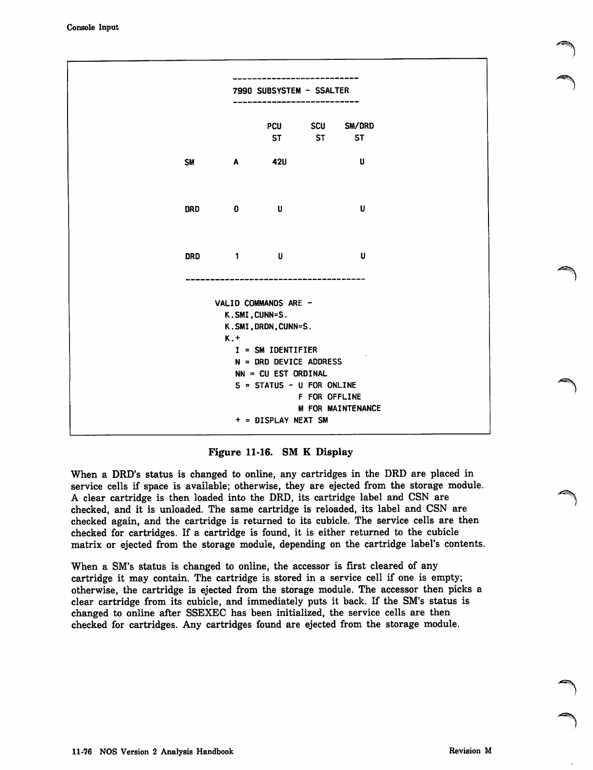
Console Input
SM
DRD
7990 SUBSYSTEM - SSALTER
PCU SCU SM/DRD
ST ST ST
A42U
0 U
DRD U U
VALID COMMANDS ARE -
K.SMI ,CUNN=S.
K.SMI ,DRDN,CUNN=S.
K.+
I = SM IDENTIFIER
N = DRD DEVICE ADDRESS
NN = CU EST ORDINAL
S = STATUS - U FOR ONLINE
F FOR OFFLINE
M FOR MAINTENANCE
+ = DISPLAY NEXT SM
,A*^S\
Figure 11-16. SM K Display
When a DRD's status is changed to online, any cartridges in the DRD are placed in
service cells if space is available; otherwise, they are ejected from the storage module.
A clear cartridge is then loaded into the DRD, its cartridge label and CSN are
checked, and it is unloaded. The same cartridge is reloaded, its label and CSN are
checked again, and the cartridge is returned to its cubicle. The service cells are then
checked for cartridges. If a cartridge is found, it is either returned to the cubicle
matrix or ejected from the storage module, depending on the cartridge label's contents.
When a SM's status is changed to online, the accessor is first cleared of any
cartridge it may contain. The cartridge is stored in a service cell if one is empty;
otherwise, the cartridge is ejected from the storage module. The accessor then picks a
clear cartridge from its cubicle, and immediately puts it back. If the SM's status is
changed to online after SSEXEC has been initialized, the service cells are then
checked for cartridges. Any cartridges found are ejected from the storage module.
11-76 NOS Version 2 Analysis Handbook Revision M
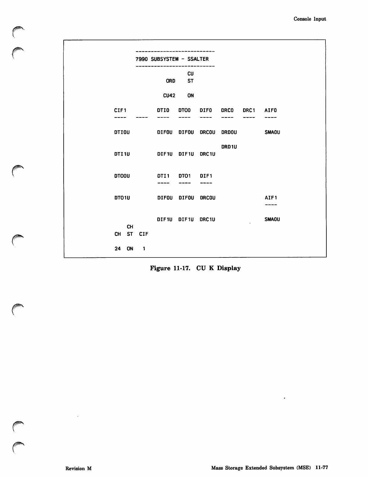
Console Input
00&S
r
7990 SUBSYSTEM - SSALTER
CU
ORD ST
CU42 ON
CIF1 DTIO DTOO DIFO DRCO DRC1 AIFO
DTIOU DIFOU DIFOU DRCOU DRDOU
DRD1U
SMAOU
DTI1U DIF1U DIF1U DRC1U
DTOOU DTI1 DT01 DIF1
DT01U DIFOU DIFOU DRCOU AIF1
DIF1U DIF1U DRC1U SMAOU
CH
CH ST CIF
24 ON
Figure 11-17. CU K Display
Revision M Mass Storage Extended Subsystem (MSE) 11-77
MSE Operational Procedures
MSE Operational Procedures
Next is a summary of the operational procedures used in an MSE environment. These
procedures include modifications to existing procedures and new MSE procedures,
especially in the areas of permanent file backup and reloading and disk space
management. Refer to the descriptions of the appropriate utilities for details about
these operational procedures.
Initialization
MSE processing is initiated when the SSDEF utility is run to create the system files
necessary to allow storage of files on 7990. SSDEF creates both an SM map for each
SM that is to store file data on cartridges and eight 7990 catalogs (one for each
subfamily) for each family that is to have 7990-resident files. Once these system files
have been created, the SSLABEL utility can then be run to allocate portions of the SM
to each subfamily and to initialize cartridges for use by files belonging to these
subfamilies. Note that SSEXEC need not be executing when SSDEF is run, but
SSEXEC must be executing when SSLABEL is run. ^
When permanent files are defined, they reside on disk until the SSMOVE utility is
run. Depending on the parameters specified, SSMOVE can destage files to 7990 and
release the disk space assigned to files so that it is available for general use.
^tfSx&V
11-78 NOS Version 2 Analysis Handbook Revision M
Disk Space Management
Disk Space Management
The availability of disk space must be managed more frequently in an MSE
environment than in a non-MSE environment. This is necessary because 7990-resident
files must be staged to disk before a user can access them, and their disk space is not
immediately released upon completion of the jobs that attached the files. Consequently,
disks are apt to approach a disk-full condition unless the SSMOVE utility is used
periodically to release disk space.
The SSMOVE utility destages selected files to 7990 and optionally releases their disk
space. It is recommended that the site analyst use SSMOVE as part of a periodic disk
space management procedure and also just prior to a full dump to reduce the amount
of data dumped to tape. (Refer to Dump Tape Management later in this section.)
The E,M display can be used to monitor the tracks on a device or set of devices.
When too few tracks (as defined by the installation) are available on the direct access
devices for a family or subfamily, the SSMOVE utility should be run. SSMOVE reads
the PFC entries for the specified family, selects certain files to reside on 7990, and
decides which files should be released from disk.
Files can be destaged to 7990 without their disk space being released. This
destage-only feature can be used prior to a routine backup dump to create 7990
images for files with the BR=MD attribute and thereby eliminate the need to include
them on a backup dump tape. (Refer to Dump Tape Management later in this
section.) Having a 7990 image also provides backup for the file in special cases where
the permanent file is being updated at the same time PFDUMP is being run.
The destage-only feature can also be used to allow disk space to become available
immediately when SSMOVE is run again. That is, SSMOVE can directly release disk
space of files that have both disk and 7990 images but are to reside on 7990 only.
However, for files that have no 7990 image, there is a delay before the disk space
can be released because these files must first be destaged to 7990.
Permanent file PFGMSE1 contains sample procedures FREEDSK and DESTAGE to
show how a site may use SSMOVE for disk space management. FREEDSK waits in
the rollout queue for a low disk space threshold flag to be set. FREEDSK is then
rolled in for execution and calls SSMOVE to release disk space. The DESTAGE
procedure calls SSMOVE at set times to destage files to 7990 whose file size in PRUs
falls within the range specified by the MN = min and MX=max parameters. Each site
can change the SSMOVE parameters and directives in the sample procedures to
satisfy their requirements.
NOTE
Before using the FREEDSK and DESTAGE procedures, you must call the SSCONTL
procedure to build the programs necessary to monitor the low disk space threshold
and the time.
j * W " S
Revision M Mass Storage Extended Subsystem (MSE) 11-79
7990 Space Management
7990 Space Management
The availability of 7990 space must be managed because 7990 space is not ■>
automatically released when a permanent file is purged. This allows you to perform a
permanent file recovery to a time prior to the purging of the file. On a typical dump
tape, the entry for a 7990-resident file includes the PFC and permit entries, but not
the file data. A subsequent reload operation recovers only what was dumped; the PFC
and permit information, but not the file data. Thus, 7990 space for a purged permanent
file cannot be released until you no longer need to recover the file data, because the
file data resides on 7990 only and typically not on any dump tape.
A 7990-resident file is stored only on the cartridges within the cubicles of SMs
assigned to a subfamily. When destaging a file to 7990, SSEXEC selects the SM with
the most space available. If no SM has enough free space to store the file being
destaged, SSEXEC abandons that destage request, issues a message to the dayfile,
and continues to destage other files that fit on the available 7990 space. To avoid
this problem, use the SSVAL utility periodically to release 7990 space for purged
files, thereby making it available for reuse. ^s^
"i
When you want to reuse 7990 space currently allocated to files that have been
purged, he/she runs SSVAL with the RF and RL parameters specified. The RF
parameter specifies an RDF, which is an auxiliary file produced by the permanent
file utility PFDUMP and which contains versions of the 7990 catalogs and PFC
entries that were current at the time of the dump. SSVAL examines the RDF to
identify unneeded 7990 files (those without PFC entries) and their 7990 space is
released. Choose which RDF to use based on the date and time of the dump that
produced it. That is, a particular RDF is used only if there is no need for a
permanent file recovery to a time prior to the dump that produced the RDF. **^
Once an RDF is used by SSVAL to release 7990 space, you should discard it and any
other RDFs for the same set of devices. These RDFs cannot be used as input to
SSVAL in any future run. The MSE software does not permit an RDF to be specified
by the RF parameter on an SSVAL call, unless it was produced by PFDUMP after
the last SSVAL run that released 7990 space was completed. This prevents the
inadvertent release of 7990 space that was previously released and reassigned to a
file.
11-80 NOS Version 2 Analysis Handbook Revision M
0^S
7990 Space Management
Example 1:
Assume that two PFDUMPs were run a week apart producing two release data files,
RDF1 and RDF2. Assume, also, that according to both RDF1 and RDF2, file AFILE
is an orphan (it has been purged but still resides on 7990). If the following call to
SSVAL is made, the 7990 space assigned to AFILE is released and made available for
reuse, if no errors were encountered.
SSVAL,RF=RDF1,RL.
Now, suppose that a new file, BFILE, which did not exist when RDF1 and RDF2 were
produced, is assigned to the 7990 space on which AFILE has resided. If SSVAL were to
accept either RDF1 or RDF2 on a subsequent SSVAL call, the 7990 space allocated to
file AFILE (which is now the space where BFILE resides) is released. However, any
RDF created after the SSVAL run that purged AFILE would not have an entry for
AFILE and, hence, SSVAL would not inadvertently release the 7990 space presently
allocated to BFILE.
After SSVAL uses a release data file to release 7990 space, the corresponding backup
tape from PFDUMP is the oldest tape that should be used for the first reel of a
future incremental load. The first reel determines which files are to be reloaded
according to the CIR on the tape (refer to PFLOAD in section 17, Permanent File
Utilities). Use of an older tape as the first reel can allow the PFC entry for a purged
file to be restored even though its 7990 space may have been reassigned. The MSE
software does not prevent loading from the wrong dump tape, but does detect as an
error an attempt to stage a file whose data was overwritten (see Example 2).
Example 2:
Assume that RDF1 and RDF2 are as in the previous example, and that file CFILE is
an orphan according to RDF2, but not according to RDF1. The following SSVAL call
releases 7990 space allocated to CFILE.
SSVAL,RF=RDF2,RL.
Now suppose that the dump tape created by the PFDUMP run that produced RDF1 is
used as the first reel of an incremental PFLOAD. Then the PFC and permit entries for
file CFILE are reloaded, but, in fact, file CFILE does not exist on 7990. This will be
detected as an error when a user attempts to attach CFILE.
Revision M Mass Storage Extended Subsystem (MSE) 11-81
Backup and Recovery
Backup and Recovery
Permanent file backup and recovery methods in an MSE environment are similar to
those in a non-MSE environment. It is assumed that most sites with disk-resident
permanent files have a file backup procedure consisting of a full dump followed by a
series of incremental dumps. The assumed reload procedure is to load from tapes
starting with the most recent incremental dump tape and continuing through older
incremental dump tapes until the most recent full dump tape is processed. These
procedures can be modified as follows to accommodate 7990-resident files.
/ * ^ K
File Dumping
The normal backup dump procedure is to dump files based on the modification date
field in the PFC entries for the files. New parameters to PFDUMP provide the
capability to dump files that have been modified during a certain interval, which is
useful in recycling old dump tapes (refer to Dump Tape Management later in this
section). For files that reside only on 7990, you can either stage the file to disk and
thereby include it in the dump or suppress staging and include only the file's PFC and
permit information on the dump tape. If the device or family being dumped has
7990-resident files, the following procedures should be included with the normal
dumping procedures.
Full Dumps
Full dumps should be performed as usual, but OP=S should be specified on the call to
PFDUMP to suppress staging. Thus, all files on disk are dumped but only the PFC and
permit entries for 7990 files without disk images are included in the dump. It is
unnecessary and not feasible to dump the files that reside only on 7990. Specify OP=S
and SD on the call to PFDUMP; use the RD=filename parameter at your own
discretion.
Parameter
OP=S
SD
RD=filename
Description
Selects no staging. If the SD option was inadvertently used on any
previous nonincremental dump, an incremental dump should be
taken prior to the full dump.
Updates the dump date/time field on each master device dumped to
permit files created or modified prior to this dump to be released
when SSMOVE is run again. Refer to Destage and Release
Algorithms earlier in this section.
Specifies that PFDUMP is to write a release data file to be used
later by SSVAL. RD=filename is included or excluded on a call to
PFDUMP depending on how often you want to purge unneeded
7990 files.
.<^s£v
11-82 NOS Version 2 Analysis Handbook Revision M
0$m\
0m*s
File Dumping
Incremental Dumps
Incremental dumps should be performed as usual. No staging should occur because any
files that were created or modified since the last dump will still be on disk if a tape
backup is required. The following parameters should be specified on the call to
PFDUMP.
Parameter Description
OP=M Selects incremental dumps.
SD Updates the date/time field on each master device dumped, as
previously described for full dumps.
AD=yymmdd Selects the date just prior to the previous incremental or full dump
and of the device. Hence, all files not included in the last dump are
AT=hhmmss dumped.
The following parameters should be used with caution.
Parameter Description
OP = S Selects no staging. If the SD option was inadvertently used on any
recent partial dump, OP=S should not be specified so any file with
a BR=Y attribute that had its disk space inadvertently released
will be included in the dump.
RD=filename Specifies that PFDUMP is to write a release data file to be used
later by SSVAL, as previously described for full dumps.
Dump Tape Management
In a non-MSE environment, it is possible to make all previous dump tapes available for
use after a full dump is completed. However, in an MSE environment, such dump tape
recycling cannot occur because files that have resided only on 7990 for some time are
probably not included on any recent dump tape. When a low percentage of files on a
tape are active files, it is possible to redump any remaining files in order to recycle
the tape by running PFDUMP and specifying OP=M, BD, and BT parameters, but not
specifying the OP = S parameter.4 This performs a dump of all files that were last
dumped before the date and time specified on the PFDUMP call. If necessary, files will
be staged in from 7990; after the dump is completed, the disk space for these staged
files is released. Thus, files that might not be on any dump tape made after the date
specified by the BD parameter are dumped and tapes created before this date can be
recycled.
4. It is possible to specify the AD and AT parameters also, thereby dumping files that were dumped during
an interval after the date and time specified by AD and AT and before the date and time specified by BD
and BT (refer to parameters for PFDUMP). This performs a dump of all files last dumped during the
interval specified (including 7990-resident files) and allows your site to recycle all dump tapes created
during this interval.
Revision M Mass Storage Extended Subsystem (MSE) 11-83
File Dumping
The number of dump tapes created can be reduced by using SSMOVE to reduce the
amount of data written on these dump tapes. If SSMOVE is run prior to an
incremental dump, files with the BR=MD attribute can be destaged to 7990 and
excluded from the dump. That is, the incremental dump will exclude the files with a
BR=MD attribute that are on both 7990 and disk. If SSMOVE is run prior to a full
dump, disk space for files that do not have to be on disk can be released and these
files are not written on the dump tape. The following procedure involving dumps and
SSMOVE runs can be used for efficiency.
1. Run SSMOVE to destage files with the BR=MD attribute.
2. Take an incremental dump to back up files with the BR=Y attribute.
3. Run SSMOVE to release the disk images of files backed up in step 2.
4. Take a full dump to reduce the number of dump tapes involved if a reload is
required.
SM Map/7990 Catalog Backup
An SM map is created for each SM in an MSE environment and is updated by the
SSLABEL, SSVAL, and SSDEBUG utilities. (Refer to the definition of SM map earlier
in this section.) It is recommended that the SM map be copied on tape or on another
device or family immediately after every update of the SM map. PFDUMP can be used
to do this by dumping user index 377760s with FM equal the default system family
name, but only if SSEXEC is not running. When SSEXEC is executing, it has the SM
map files attached in modify mode; hence, PFDUMP will not dump the SM maps.
If the device containing subfamily 0 of the default family is reloaded, the latest SM
maps should be recovered from the backup copies. After recovering the SM maps, run
the SSVAL utility with the AM and FM parameters specified to ensure that the SM
map and 7990 catalog entries match. If they do not, corrective action should be taken
as described in Error Conditions and Corrective Actions later in this section. Failure
to retain or recover the latest SM maps can cause problems with future SSLABEL
runs (refer to the definition of SM map earlier in this section).
A 7990 catalog is created for each subfamily of a family that can have 7990-resident
files and is updated by the SSLABEL, SSMOVE, SSVAL, and SSDEBUG utilities.
When PFDUMP copies permanent files to tape for a master device or all devices in a
family, it ensures that corresponding 7990 catalogs are also dumped. (If SSEXEC has
a 7990 catalog attached in modify mode, PFDUMP interfaces with SSEXEC so that
the 7990 catalog is included on the dump tape. While PFDUMP is accessing the 7990
catalog, any file destage requests for that subfamily are delayed.) Consequently, if
PFLOAD is used to reload all files, the 7990 catalogs are automatically recovered and
entries for all 7990-resident files reflected in recovered PFC entries will exist in the
recovered 7990 catalog.
If PFLOAD is run after the SSLABEL utility has updated the 7990 catalog and SM
map but before the 7990 catalog has been backed up, the recovered 7990 catalog will
not match exactly the corresponding SM map. In this case, recovery procedures (as
described in 7990* Catalog/SM Map Mismatch later in this section) must be taken to
bring the SM map, 7990 catalog, and cartridge label information into agreement.
/^^s\
A^ms
r-c%\
11-84 NOS Version 2 Analysis Handbook Revision M
File Reloading
File Reloading
PFLOAD runs should be made as usual. PFLOAD reads the CIR records from the most
recent incremental dump tape to control loading of file data and PFC and permit
information. For 7990-resident only files, PFLOAD reloads only the PFC and permit
information (if PFDUMP dumped only this information). The following situations
involve PFLOAD in an MSE environment.
• If one device needs to be reloaded, the DN or TD parameter specifies the device.
The OP=Z and UD parameters should not be specified.
• If PFLOAD is used for other than a device recovery, both OP=Z and UD should
be specified. The OP = Z parameter ensures that the PFC entry does not link to a
7990 file that may no longer exist, and UD ensures that the file is included in
the next incremental or full dump.
• If a file has a nonzero asa value in its PFC entry (indicating that the file has a
7990 image), the SSCVER flag in the PFC entry will be set when the PFC and
permit information are reloaded. If the file is successfully staged to disk when it
is attached, this flag is cleared. Otherwise, the flag remains set. This can be used
to indicate the possibility of an operational error, such as omitting OP=Z when a
file or set of files is reloaded from an obsolete dump tape.
• If any unscheduled device reload that includes recovery of a 7990 catalog and/or
SM map is made, SSVAL should be run with the AM and FM parameters
specified. SSVAL examines the PFC entries for 7990-resident files, the 7990
catalog, and the SM map to detect any error conditions that exist.
• If dumping a file to tape from one user and then reloading the file to a different
user, you must use the OP=Z parameter on the PFLOAD utility. Otherwise the
PFC entry still points to the old SFMCAT, which causes an error indication for
the file.
0^\\
Revision M Mass Storage Extended Subsystem (MSE) 11-85
Error Conditions and Corrective Actions
Error Conditions and Corrective Actions
It is possible for operational, hardware, or software malfunctions to cause a variety of
error conditions to exist or appear to exist in the 7990 catalogs, SM maps, PFC
entries, or cartridge labels. The SSVAL utility can analyze the 7990 catalogs, SM maps,
and PFC entries to detect these errors, and the SSLABEL utility can identify problems
with cartridge labels. The following paragraphs describe some specific error conditions
and the actions that should be taken to correct them. Most of the errors are caused
either by incorrect operational procedures that result in the recovery of the wrong
version of an MSE system file, or by abnormal termination of SSEXEC or MSE utility
processing, which can interrupt the updating of an MSE system file.
Clearing Permanent File Error Flags
The permanent file error flags that have been set by SSEXEC in the PFC can be
cleared by the CE parameter of the CHANGE command. The job must be of system
origin.
Permanent File Recovery
If a permanent file cannot be accessed or is included by SSVAL on the validation
report, try the following procedures to recover a copy of the file.
1. Attach the file. If the file has a disk image or can be staged in from 7990, the
file data will be available on disk and can be copied to another file. SSVAL
should then be run as described in step 2.
2. If the file cannot be attached, reload the file from a dump tape using PFLOAD ^"^%
with OP=Z. To identify the PFDUMP run that saved a backup copy of the file,
check the output from SSVAL or PFCAT, which includes date and time fields from
the PFC entry for the file. Depending on the BR attribute (backup requirement) of
the file, a backup copy on a dump tape may not exist.
If the file can be reloaded to disk, SSVAL should be run as follows:
SSVAL,FM=fami 1yname,SB=subfamily,FX=n,AM.
familyname and subfamily identify the family and subfamily of the recovered file
and n is sufficiently large that the fixing/flagging will be done. SSVAL sets the
obsolete flag in the PFC entry because the file now has a disk image; thus the
file is disassociated from the error condition. The error condition may still exist in
the 7990 catalog or SM map, but you can analyze it and correct the error by
using the SSDEBUG utility. Before using SSDEBUG to correct the error, you
should take an incremental dump so the old PFC entry with an asa value
pointing to a problem 7990-resident file will not be reloaded if a device reload
occurs before the next scheduled backup dump.
3. If steps 1 and 2 fail, try to regenerate the file. Depending on the particular
problem and status of the cartridges to which the file was destaged, the OP=RF
or OP=RS directive to SSDEBUG might recover the file data.
4. If the file cannot be recovered, purge it so there is no PFC entry pointing to a
problem 7990-resident file.
11-86 NOS Version 2 Analysis Handbook Revision M
Cartridge Restoration and Reuse
J$$™&\
Cartridge Restoration and Reuse
If a cartridge is unexpectedly found anywhere outside its assigned cubicle, follow these
steps to restore the cartridge so it can be used again:
1. Put the cartridge in the input tray of the SM to which it is assumed to belong
and run SSLABEL with the OP=RS directive. If the cartridge label information
agrees with the SM map entry for the cubicle with the coordinates (y,z) written
on the cartridge label, the cartridge will be restored to that cubicle and the 7990
catalog entry for the cartridge is updated to clear the lost flag. Otherwise, the
cartridge is put in the exit tray and the cartridge label information is included in
the output from SSLABEL.
2. If the cartridge was not restored to its SM cubicle, examine the label information
reported by SSLABEL. If the cartridge is assigned to a different SM, repeat step 1
using the correct SM. If the family name is blank, the cartridge has a scratch
label and can be assigned normally with the OP = AM directive to SSLABEL.
3. If steps 1 and 2 fail, examine the SM map entry for the cubicle with the
coordinates (y,z) written on the cartridge label to see how the cubicle is assigned.
Examine the cartridge, if any, in this cubicle. Also, it might be useful to run
SSVAL to ensure the SM map and 7990 catalog entries for the cartridge match or
to identify affected permanent files, if any, if they do not match.
4. If step 3 does not produce any useful information and the cartridge cannot be
restored, use the OP=FX directive to SSLABEL to rewrite the cartridge label and
thereby make a scratch cartridge. It might be useful to first run SSDEBUG with
the OP = RS directive to preserve the data on the cartridge.
0$&S,
Revision M Mass Storage Extended Subsystem (MSE) 11-87
Removal of Faulty or Missing Cartridges
Removal of Faulty or Missing Cartridges
Follow these steps to remove a cartridge that has unrecoverable errors, or to release
the SM map entry for a cartridge that is missing.
For unallocated cartridges:
1. Attempt to remove the cartridge with the SSLABEL OP=RM directive.
2. If CARTRIDGE NOT FOUND is reported, repeat step 1 specifying the LT
parameter.
3. If CARTRIDGE NOT EMPTY is reported, at least one AU on the cartridge is still
allocated.
For allocated cartridges:
1. Use the SSLABEL OP=FC directive to inhibit further allocation of the cartridge.
2. Run SSVAL specifying the AM parameter. Examine the report for possible
discrepancies between the SM map, 7990 catalog, and PFC entries related to this
cartridge.
3. If no 7990 catalog entry corresponds to the SM map entry, use the OP = RC
directive to SSDEBUG to remove the map entry.
4. If no discrepancy is reported by SSVAL, the affected files should be attached in
write mode (if possible), reloaded using PFLOAD with the OP=Z parameter, or
purged. Then SSVAL release processing should be done to release the 7990 space
on the cartridge, and the cartridge can be removed with the SSLABEL OP=RM
directive.
>c^.
11-88 NOS Version 2 Analysis Handbook Revision M
7990 Catalog/SM Map/PFC Problems
7990 Catalog/SM Map/PFC Problems
If error conditions exist in the 7990 catalogs or SM maps, the recovery procedure is to
correct the appropriate entry rather than reload the entire file. Reloading other than
the latest copy of the SM map is not feasible because it can contain entries for several
families and these entries would not be up to date. Reloading an old copy of the 7990
catalog is not desirable because any permanent file that was destaged and released
from disk since the last incremental dump will be lost. The following paragraphs
describe corrective action for specific problems with 7990 catalogs, SM maps, or PFC
entries.
7990 CatalogISM Map Mismatch
The following examples of 7990 catalog/SM map mismatches can appear as error type 1
or 2 on the SSVAL output report, which identifies the mismatch and the permanent
files or orphans affected. Before taking any corrective action, the analyst should ensure
that operational errors did not result in loading the wrong version of the SM map or
7990 catalog.
• If a cartridge has a 7990 catalog entry indicating that all AUs on the cartridge
are available for allocation but is not identified in any SM map entry (type 1
mismatch), use the OP = RL directive to SSDEBUG to remove the 7990 catalog
entry for the cartridge.
• If a cartridge is identified in an SM map entry but has no 7990 catalog entry
(type 2 mismatch), use the OP=RC directive to SSDEBUG to update the SM map
entry to unassigned and empty status. This directive will write a scratch label for
the cartridge, if any, and place the cartridge in the exit tray.
• If a cartridge has a 7990 catalog entry indicating that at least one AU on the
cartridge is allocated, recover the disk space for the affected permanent file, if
any, or purge the file. Run SSVAL to purge unneeded 7990 files and thereby
make the cartridge unallocated. Use the OP = RL directive to SSDEBUG to remove
the 7990 catalog entry for the cartridge.
NOTE
It sometimes takes two SSVAL/SSDEBUG runs to completely clear up type 1 or type
2 errors. Therefore, it is recommended that SSVAL be rerun with the AM parameter
after an SSDEBUG run using OP=RC or OP=RL.
Revision M Mass Storage Extended Subsystem (MSE) 11-89
7990 Catalog/SM Map/PFC Problems
7990 Catalog Chain Problems
AUs that are allocated to a 7990-resident file are chained together in the 7990 catalog
to identify the sequence of AUs that contain the file. (Refer to the definition of
cartridge earlier in this section.) For most files, the AUs in the chain reside on the
same cartridge. Hence, one disk access is sufficient to update information for the entire
chain at one time. However, a 7990-resident file can reside on several cartridges, and
several disk accesses may be necessary to update its chain. If SSEXEC is interrupted
during such an update, the resultant chain will be incomplete. SSVAL identifies
incomplete chains as error type 4, 5, or 6 on the validation report. The following are
types of incomplete chains.
• If an incomplete chain is produced while a 7990-resident file is being purged, it is
a chain fragment (one without an HOC entry).
• If an incomplete chain is produced while a file is being destaged to 7990, it is an
ill-formed chain (one without an EOC entry).
• If an ill-formed chain is not corrected, the AU that should have been linked to it -^%,
may be reused and become part of a good chain. Although the ill-formed chain
may appear to be complete, the ill-formed chain and the good chain are
intersecting.
The corrective action for any of these bad chain conditions is:
1. Run SSVAL with the FM parameter specified and use a sufficiently large FX=n
value so that SSVAL updates the 7990 catalog entries affected by the problem
chains.
2. Recover the permanent files, if any, that have 7990 images potentially affected by
these error conditions. (The SSVAL report identifies these files.) Use the procedure
described under Permanent File Recovery earlier in this section.
3. Take an incremental or full backup dump. This prevents PFC entries with
inaccurate asa values or problem 7990 chains from being recovered if a device
reload is necessary.
4. Run SSDEBUG with the OP=RP directive to make each AU on the problem chain
available for allocation. Thus, the AUs can be included in a new chain without /SiB%
any problems. In the case of intersecting chains, all chains that have an AU in '
common with another chain should be released before any further destage
attempts; otherwise, errors will occur when a user tries to attach a file that is
contained on an intersecting chain.
PFC/7990 Catalog Mismatch
It is possible that an old version of a 7990 catalog can be reloaded because of incorrect
operational procedures. If so, the asa value in the PFC entry for a file can be invalid
according to the obsolete 7990 catalog or can point to a problem chain. If the correct
version of the 7990 catalog is available on tape, it should be reloaded. If it is not
available, the following action is appropriate. If the file also has a disk image, SSVAL
should be run to clear the asa field in the PFC entry. If there is no disk image, the
analyst should reload the file from tape, if possible, and then run SSVAL to clear the
asa value.
11-90 NOS Version 2 Analysis Handbook Revision M
#^
Tape Alternate Storage 12
Introduction........... 12-1
Tape Alternate Storage Terminology 12-1
Organization and Management of Destage Dump Tapes 12-3
Tape Characteristics 12-3
Tape Data Format 12-3
Destaging Files to Tape 12-3
Releasing Disk Space 12-5
R e s t o r i n g D e s t a g e d F i l e s t o D i s k R e s i d e n c e 1 2 - 6
Modifying Destaged Files .... , 12-7
Recycling Destage Dump Tapes 12-7
MAGNET Command 12-8
GENPFD Utility 12-9
Calling the GENPFD Utility 12-9
GENPFD Input Directives 12-10
File Selection Processing ...: .. 12-13
Limitations 12-13
0^*.
0m^-


j0^ahjix\
Tape Alternate Storage 12
Introduction
This section describes the use of magnetic tape as an alternate storage medium for
NOS permanent files.
Tape Alternate Storage Terminology
The following terms apply to the use of tape alternate storage.
Alternate Storage
The storage of permanent file data on external media other than mass storage
such as tape alternate storage or MSE. When a file resides on alternate storage,
the file's permanent file catalog (PFC) entry and permit data still reside on disk,
but the disk space occupied by the file data can be released.
Alternate Storage Address (ASA)
The pointers in a file's PFC entry that point to the location of the file data on
tape alternate storage or MSE.
Destage Dump Tapes
Tapes that contain files that were destaged from disk using the PFDUMP utility
with the DT parameter specified.
Destaging
The process of creating an alternate storage copy of a file on tape alternate
storage or MSE. Files are destaged to tape alternate storage when the site
executes PFDUMP with the DT parameter specified. Files are destaged to MSE
when the site executes SSMOVE with the appropriate parameters.
Permanent File Catalog (PFC)
The system catalog containing the file name, owner identification, disk pointers,
alternate storage pointers, and other attributes of a permanent file. Refer to
Permanent File Catalog Entry in section 17, Permanent File Utilities, for the
format of the PFC entry.
Primary VSN
The volume serial number (VSN) of a single reel destage dump tape or the VSN
of the first reel of a multireel set of destage dump tapes. The VSN must be two
alphanumeric characters followed by a four-digit decimal number; the number
must be in the range 0000 through 4095.
Revision M Tape Alternate Storage 12-1
Tape Alternate Storage Terminology
Secondary VSN
The VSN of a single reel destage dump tape or the VSN of the first reel of a
multireel set of destage dump tapes having a sequence number (the last four
characters of the VSN) in the range 5000 through 9095. The existence of a
secondary VSN assumes the existence of a primary VSN having the same
two-character prefix and a sequence numbeF of 5000 less. The primary and
secondary VSN tapes, or multireel sets of tapes, are assumed to contain identical
data although the individual reels of multireel sets cannot be assumed to be
identical.
Staging
The process of restoring file data to disk residence from a copy on alternate
storage. Staging is initiated when a user executes an APPEND, ATTACH, GET, or
OLD command for a file that is not currently disk resident.
,/*®^\
12-2 NOS Version 2 Analysis Handbook Revision M
0^S
0i^s
0ms.
Organization and Management of Destage Dump Tapes
Organization and Management of Destage Dump Tapes
The tape characteristics and data format required for destage dump tapes are described
below, followed by some of the procedures required to manage destage dump tapes.
Tape Characteristics
Destage dump tapes must be labeled, I format, and nine track. The tapes can be
written at any nine-track tape density. It is possible to have multireel sets of tapes,
but normally single reels are created whenever possible to avoid the overhead of reel
switching when restoring files to disk. The VSN of the first reel of a set of destage
dump tapes must be in the following format:
ppnnnn
where pp is a prefix consisting of any two alphanumeric characters and nnnn is a
decimal sequence number in the range from 0000 through 4095 or in the range from
5000 through 9095. If the sequence number is 5000 or greater, the secondary tape set
is assumed to be a duplicate of a primary tape set that has the same prefix and a
sequence number of 5000 less.
Tape Data Format
All destage dump tapes are written by PFDUMP and have exactly the same format as
other tapes written by PFDUMP including file permits. However, no PFC-only files are
present on destage dump tapes. It is also possible to load, copy, or list files from a
destage dump tape using the PFLOAD, PFCOPY, or PFATC utility, respectively.
Destaging Files to Tape
Destage dump tapes are created by executing PFDUMP with the DT (destage to tape)
parameter specified. When the DT parameter is used, PFDUMP verifies the following:
• The dump file specified by the T parameter must be assigned to a nine track, I
format, labeled tape. The VSN must be in the format ppnnnn as described earlier
(refer to Tape Characteristics) and the sequence number must be in the range
from 0000 to 4095.
• If a verify file is specified (VF parameter), it too must be assigned to a nine
track, I format, labeled tape and its VSN must have the following relation to the
VSN for the primary dump tape: the two-character prefix must be the same and
the sequence number must be greater by 5000.
After the dump tape or tapes are successfully written, PFDUMP enters the primary
dump tape VSN in the PFC entries of the dumped files. If a verify file is written, a
flag is also set in the PFC entry indicating the existence of the secondary VSN. At
this point, the disk space of the dumped files can be released, if necessary, if the file's
backup requirements are satisfied.
Revision M Tape Alternate Storage 12-3
Destaging Files to Tape
Although general PFDUMP selection parameters can be used to directly select files for
a destage dump, sites will normally use a separate file selection utility such as
GENPFD to perform this function. (The GENPFD utility is described later in this
section.) This procedure has the following advantages:
• Files can be prioritized by the time since they were last accessed or modified.
• Special user index or file name patterns can be special cased according to site
requirements.
• The GENPFD selection utility can select files that will reasonably fill a single
tape reel without overflowing to additional reels. The creation of single reel tapes
is desirable because it avoids the overhead of reel switching when files are
restored to disk.
When a file selection program such as GENPFD is used for destage processing, the
following sequence of events should be followed:
1. Execute PFDUMP with the IP (inhibit processing) and DT (destage to tape) **%,
parameters specified and the summary file selected with the S parameter.
Specifying PFDUMP parameters such as LS, US, BD, BT, etc., can be used to
screen out desired classes of files. The TA=N and CA=N parameters can be used
to exclude files that already have current alternate storage copies (from previous
destage dumps).
2. Execute the file selection program (GENPFD) using the PFDUMP summary file as
input. The file selection utility writes UI and PF utility directives for the selected
files to the utility directives file.
3. Reexecute PFDUMP (with the same parameters as specified in step 1, but without
specifying the IP parameter) using the utility directives file generated in step 2 as
an input file.
When a destage dump is performed, files on user name SYSTEMX and on the MSE
catalog user names SUBFAMO through SUBFAM7 are unconditionally excluded even if
they meet the selection criteria.
Example:
Destage enough files to fill one tape (alternate storage) with files from family TEST
whose data has not been modified since 87/07/01 and have not already been destaged.
PFDUMP,FM=TEST,DT,OP=T,BD=870701,TA=N,IP,S.
REWIND,SUMMARY.
RETURN,UDIR.
GENPFD,PO=D.
REWIND,UDIR.
PFDUMP,FM=TEST,DT,OP=T,BD=870701,TA=N,I=UDIR.
In this destaging example, if GENPFD does not find enough files to fill a 2400-foot
tape at GE density, the utility will not generate a UDIR file. This will cause the
second PFDUMP to abort without dumping any files.
y**«^V
SWt$K
12-4 NOS Version 2 Analysis Handbook Revision M
0^S.
Releasing Disk Space
Releasing Disk Space
The disk space of a file that resides on tape alternate storage or MSE can be released
if the file's backup requirements are met. The BR parameter on the DEFINE, SAVE,
and CHANGE commands allows a user to specify a backup requirement of Y (yes), MD
(media dependent), or N (none).
Parameter
Option Description
BR=Y The disk space of a file with a backup requirement of BR=Y can be
released if either of the following conditions is satisfied:
• At least two copies of the file data exist on alternate storage media.
This could be one copy on MSE and one copy on tape or two copies
(primary and secondary VSNs) on tape.
• One copy of the file data exists on an alternate storage medium
(either MSE or tape) and the release inhibit date/time of either the
file's master device or the file's residency device (as set by a
PFDUMP with the SD parameter specified) is greater than the file's
utility control date/time.
BR=MD The disk space of a file with a backup requirement of BR=MD can be
released if the following condition is satisfied:
• One copy of the file data exists on MSE or tape alternate storage.
The PFREL utility is used to perform the releasing of disk space. As with PFDUMP,
PFREL can be used with a file selection utility such as GENPFD in the following
sequence of steps:
1. Execute PFREL with the IP (inhibit processing) parameter specified and the
summary file selected with the S parameter. Files can be excluded by specifying
selection parameters. In particular, OP=A can be used with the BD and BT
parameters to exclude files that have been accessed recently.
2. Execute the file selection program using the PFREL summary file as input. The
0^^ file selection utility writes UI and PF utility directives for the selected files to the
utility directives file.
3. Reexecute PFREL (with the same parameters as specified in step 1, but without
specifying the IP parameter) using the utility directives file generated in step 2 as
an input file.
The PFREL utility can be used to release the disk space of files that reside on MSE as
well as those files that reside on tape alternate storage. However, the MSE utility
SSMOVE performs release processing only for MSE resident files. PFREL does not
release the disk space of files cataloged on user name SYSTEMX or on the MSE
catalog user names SUBFAMO through SUBFAM7 even if the selection criteria are met.
Revision M Tape Alternate Storage 12-5
Restoring Destaged Files to Disk Residence
Example 1:
The following example illustrates releasing disk space for destaged files.
Release the disk space for all files from family TEST that have not been accessed
since 87/07/01 and for which backup requirements have been met.
PFREL,FM=TEST,OP=A,BD=870701.
Example 2:
Using the same file selection criteria as in example 1, release enough files so that
10008 tracks are available on device number 40 and 12008 tracks are available on
device number 41.
PFREL,FM=TEST,OP=A,BD=870701,S,IP.
REWIND,SUMMARY.
RETURN,UDIR.
GENPFD,PO=R,Z./RL,40,1000/RL,41,1200
REWIND,UDIR.
PFREL,FM=TEST,I=UDIR.
Restoring Destaged Files to Disk Residence
A file that does not reside on disk is restored to disk residence (staged) when a user
accesses the file with an APPEND, ATTACH, GET, or OLD command. If the RT (real
time) parameter is specified on an ATTACH, GET, or OLD command and staging is
required, the job continues executing without waiting for the staging operation to
complete. In this case, the caller must subsequently reissue the ATTACH, GET, or
OLD command to access the file after the staging operation completes.
NOTE
In order to allow staging of files from tape alternate storage to disk, the site must
enter the ENABLE,TAPE PF STAGING command (via DSD or IPRDECK) and must
specify the SJ parameter on the MAGNET command in the MAG subsystem startup
procedure.
,/«8^.
12-6 NOS Version 2 Analysis Handbook Revision M
yfl$^\
Modifying Destaged Files
Modifying Destaged Files
When you modify a file having a copy or copies on alternate storage media, the data
on alternate storage is no longer current. Therefore, when a direct access file is
attached in a writable mode or an indirect access file is saved or replaced, the system
removes the pointers to all alternate storage copies in the file's PFC entry. At this
point, the file has to be destaged again (to tape or MSE) if it is to reside on alternate
storage.
Recycling Destage Dump Tapes
As files are modified and purged over a period of time, new destage dump tapes are
created and the percentage of active files on older destage dump tapes decreases.
Destage dump tape recycling consists of procedures to move the remaining active files'
data on old destage dump tapes to new destage dump tapes so that the old tapes can
be reused. Performing a destage PFDUMP (DT parameter) with staging enabled (OP=S
not specified) of all files on a tape or set of tapes copies all file data to a new tape
and changes all alternate storage references from the old tapes to the new tape.
Since only a subset of the files on tapes selected for recycling are typically active, a
site normally wants to include other files to fill a new tape. The following example
illustrates this procedure.
PFDUMP,IP,S,DT,FM=TEST,TA=N,TA=AB0005,TA=AB0006.
GENPFD,OP=D,Z./SV,AB0005/SV,AB0006/DL,2200/DT,0
REWIND,UDIR.
PFDUMP,DT,FM=TEST,I=UDIR.
The TA parameters on the first PFDUMP command select files residing on VSNs
AB0005 and AB0006 (the tapes being recycled) and files not residing on tape alternate
storage as candidates for destage. The SV directives cause GENPED to select all files
residing on VSNs AB0005 and AB0006 regardless of the priority of the modification
date derived priority and priority group. GENPFD selects other files using the normal
priority criteria to satisfy the destage limit specified by the DL directive. The DT
(destage threshold) directive performs a recycle dump even if there are not enough files
selected to fill the tape.
To help determine which destage dump tape VSNs should be recycled, you may want
to write a program that reads the PFCAT summary file and generates a list of how
many files are still active on each destage dump tape VSN.
You can determine if any current files reside on a particular destage dump tape VSN
by executing PFCAT with the TA=vsn parameter specified.
After you perform a recycle dump for a tape or a set of tapes, the tapes cannot be
reused until a full or incremental PFDUMP has been performed on the affected
devices. Without this PFDUMP, a permanent file reload could cause some of the
reloaded PFC entries to refer to tapes that no longer exist. To prevent this problem,
a tape recycling operation should always be immediately followed by a full or
incremental PFDUMP.
Revision M Tape Alternate Storage 12-7
MAGNET Command
MAGNET Command
The MAGNET command has two parameters that must be used in a tape alternate
storage environment. The SJ parameter controls the maximum number of staging jobs
that can be active concurrently to stage files to disk from tape alternate storage; and
the SV parameter controls the maximum number of staging request VSNs that can be
displayed on the DSD E,P display. Refer to the NOS Version 2 Operations Handbook
for a description of the DSD E,P display.
The MAGNET command has the following format:
MAGNET,SJ=msj,SV=mvd.
Parameter Description
SJ=msj Specifies the maximum number of staging jobs that can be active at
the same time (0 ^ msj ^ 30s). The default is SJ = 0; staging is not
allowed.
NOTE
The SJ parameter must be specified or staging from tape alternate
storage to disk will not be allowed.
SV = mvd Specifies the maximum number of requests for staging tape VSNs to
display on the DSD E,P display (1 ^ mvd ^ 77s). The default is
SV = 178. Requests for staging tape VSNs will appear first on the E,P
display (before the normal tape requests) and can be distinguished by -'frmh
having a JSN of SYS and a user name of (STAGE). '
12-8 NOS Version 2 Analysis Handbook Revision M
GENPFD Utility
GENPFD Utility
The GENPFD utility controls file selection processing. It reads a summary file created
by one of the permanent file utilities and uses the information to generate file
selection directives for subsequent permanent file utility operations.
Calling the GENPFD Utility
You call the GENPFD utility by executing the GENPFD command. The format of the
command is:
GENPFD,I=i nput,S=summary,UD=udi r,PO=opt,Z.di rect i ves
Parameter Description
I = input
S=summary
UD = udir
PO = opt
directives
The 1- to 7-character name of the file from which directives are read.
The default file name is INPUT.
The 1- to 7-character name of the summary file previously created by
a permanent file utility. The default file name is SUMMARY. This file
is used as input to GENPFD.
The 1- to 7-character name of the utility directives file to be created.
This file is used for subsequent permanent file utility operations such
as destaging files and releasing disk space. The default file name is
UDIR.
The processing option that specifies whether to select files for destage
processing or releasing disk space. Acceptable values for opt are:
opt Description
D Select files for destage processing.
R Select files for releasing disk space.
Input directives are contained on the GENPFD command following the
terminator. If the Z parameter is specified, the I parameter is ignored.
This eliminates the need to use a separate input file for the directives
when only a few directives are needed.
When input directives appear on the GENPFD command, the first
character following the command terminator is the separator character
for all directives on the command. Any display code character that is
not used in any of the directives, including a space, can be used as the
separator character. Each directive must be preceded by a separator.
The directives can extend to column 72 on the command. Continuation
lines are not permitted.
For example, (slant used for separator):
GENPFD, POD, Z. /D=PE/DL, 2200/SF, 3456
Revision M Tape Alternate Storage 12-9
GENPFD Input Directives
GENPFD Input Directives
The GENPFD input directives provide the capability to selectively choose files for
processing. The GENPFD utility accepts the following input directives:
Directive Description
D=density
DL.limit
DT,threshold
PG,pi,p2,p3
Density of the destage dump tape that will be written by the
destaging operation. Acceptable values for density are:
density Description
HD
PE
GE
1600
6250
800 cpi
1600 cpi
6250 cpi
1600 cpi
6250 cpi
The default density is 6250.
Destage size limit in feet of tape used with the PO=D option. (1-
to 10-digit number, assumed decimal unless a B radix is specified).
This directive specifies the maximum combined size of all selected
files. It is intended to prevent writing beyond the end of reel when
selecting files for destaging with the PFDUMP utility. If selection
of a file causes the limit to be exceeded, the file is skipped and
the next lowest priority file is examined. The default limit is 2200;
this allows for a significant number of tape errors on a 2400 foot
reel of tape.
Destage size threshold in feet of tape used with the PO = D option.
(1- to 10-digit number, assumed decimal unless a B radix is
specified). Specifies the minimum combined size of all selected
files. If the combined size of all selected files is less than the
threshold, no utility directives file will be generated. This directive
is used to ensure that enough files can be selected on a destage
dump to reasonably fill a tape reel. The default value is 90
percent of the limit specified for DL.
Define preferred residence priority groups. The default is T,MN,D.
The parameters pn are strings of preferred residence mnemonics
which define the priority groups used in file selection. The groups
are defined in order of decreasing priority. The default value
defines three groups: 1) a high priority group consisting of files
with PR=T (tape alternate storage residence preferred); 2) a
medium priority group consisting of files having PR=M (alternate
storage residence preferred) and PR=N (no preferred residence);
and 3) a low priority group consisting of files having PR=D (disk
residence preferred). Files having PR=L (file locked to disk) are
excluded from selection.
12-10 NOS Version 2 Analysis Handbook Revision M
GENPFD Input Directives
rDirective Description
PG,pl,p2,p3 (Continued)
It is possible to define other than three groups. For example, the
following entry:
PG.TMNDL
places all files in one group, effectively causing preferred residence
to be ignored. The following entry defines four groups.
It is possible to define other than three groups. For example, the
following entry:
PG.TMNDL
places all files in one group, effectively causing preferred residence
to be ignored.
PG.T.M.N.D
If a preferred residence type is not specified, files having that value
are excluded from selection unless they are selected explicitly with
an SF or SV directive. The following entry causes files with PR=D
or PR=L to be excluded:
PG.TMN
RL,dn,tracks Define the track release limit for device number dn or device
RL,dt,tracks type dt. A device type is specified as a mass storage equipment
mnemonic followed by a unit count. Files residing on a device are
not released unless you enter an RL directive specifying either the
device number or the device's type. A device number entry takes
precedence over a device type entry if both apply. Files residing on
the applicable device or devices are released until the number of
available tracks reaches the specified limit. No release processing is
performed for the device if the number of available tracks is equal
to or greater than the specified limit. For example, the following
device number entry:
RL.40,300
specifies that files should be released on device 40 until there are
300 available tracks. If 300 tracks are already available, no files
will be released.
The following device type entry:
RL.DQ2.250
specifies a release limit of 250 tracks for each two-spindle 885
device for which a limit has not been specified by device number.
n
Revision M Tape Alternate Storage 12-11
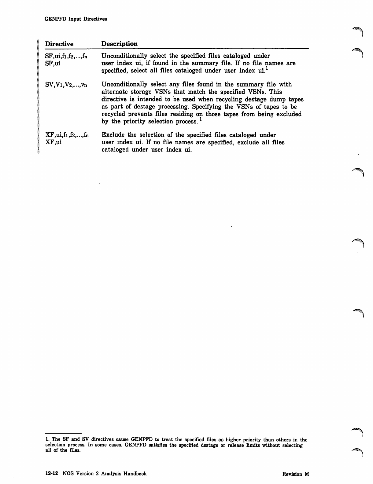
GENPFD Input Directives
Directive Description
SF,ui,fi,f2,...,fn Unconditionally select the specified files cataloged under
SF,ui user index ui, if found in the summary file. If no file names are
specified, select all files cataloged under user index ui.
SV,Vi,V2 vn Unconditionally select any files found in the summary file with
alternate storage VSNs that match the specified VSNs. This
directive is intended to be used when recycling destage dump tapes
as part of destage processing. Specifying the VSNs of tapes to be
recycled prevents files residing on those tapes from being excluded
by the priority selection process.1
XF,ui,fi,f2,...,fn Exclude the selection of the specified files cataloged under
XF,ui user index ui. If no file names are specified, exclude all files
cataloged under user index ui.
1. The SF and SV directives cause GENPFD to treat the specified files as higher priority than others in the
selection process. In some cases, GENPFD satisfies the specified destage or release limits without selecting
all of the files. •>*^\
12-12 NOS Version 2 Analysis Handbook Revision M
0Xts
File Selection Processing
File Selection Processing
The GENPFD utility sorts the candidate files into preferred residence priority groups
as determined by the PG directive. Within each group, each file is assigned a priority
based on the time elapsed since the last access (if PO = R) or last data modification (if
PO=D) with older files receiving higher priorities. Files selected with SF directives or
files residing on VSNs selected with SV directives are given a higher priority than
other files to force selection.
For destage processing, files are selected beginning with the highest priority until the
destage limit is reached. The permanent file utility parameters UI and PF are
written to the utility directives file for each selected file unless the combined length
of the selected files is less than the destage threshold (either the default or an
explicit nonzero value specified in the DT directive).
For release processing, files residing on devices specified by RL directives are selected
for release until the defined limit for each device is reached. The permanent file
utility parameters UI and PF are written to the utility directives file for all files
selected for release.
Limitations
GENPFD can process a maximum of 80 RL directives and a total of 1000 SF, SV, and
XF directives. Each directive counts as one entry, whether or not it contains a file
name or VSN. Each file name or VSN on a directive after the intial one counts as an
additional entry.
Revision M Tape Alternate Storage 12-13

^^
f^
^
f
Multimainframe Operations 13
Introduction 13-1
Linked SDM Operation 13-2
Deadstart 13-3
Shared Mass Storage 13-6
Configuring Shared Mass Storage Devices 13-6
Device Access Tables 13-6
Mass Storage Recovery Tables 13-7
Device Initialization 13-7
Device Unload 13-8
Device Recovery .. 13-8
Device Checkpoint 13-9
MSE Processing 13-9
Independent SDM Operation 13-10
Deadstart , 13-10
Shared Mass Storage 13-12
Configuring Shared Mass Storage Devices 13-13
Device Index Tables ,... 13-14
Mass Storage Recovery Tables 13-14
Device Initialization 13-14
Device Unload 13-15
Device Recovery , 13-15
Device Checkpoint 13-16
MSE Processing .-....' 13-16

Multimainframe Operations 13
Introduction
Multimainframe operation provides mechanisms by which more than one computer can
share mass storage devices. Each mainframe in a multimainframe configuration has
access to the shared mass storage devices and their preserved files. Preserved files are
those files that are retained across a level 0 deadstart (nonsystem recovery). Types of
preserved files are permanent files, queued files, and system dayfiles.
There are two types of multimainframe configurations:
• Linked shared device multimainframe (SDM).
• Independent shared device multimainframe.
The main difference between the two SDM configurations is their method of
maintaining the critical device tables necessary to control shared mass storage and
intermainframe communications. Linked SDM configurations maintain the critical
device tables in extended memory, while independent SDM configurations maintain the
tables on each shared mass storage device. Because the independent SDM
configurations maintain the tables on the shared devices, it causes some performance
degradation.
Each mainframe in a multimainframe configuration can operate in multimainframe
mode or in standalone mode; however, two machines may not access the same device
unless both are in multimainframe mode. A device is considered shared if it can be
accessed by more than one of the mainframes; it need not be accessible to all
mainframes in the complex.
The fact that a computer is operating as part of a multimainframe complex is not
apparent to the user, except for some degrading of performance for the independent
SDM. However, there are operational changes and additions that the operator should
note. These include deadstart commands, displays, online commands necessary in the
event of an interruption on one of the sharing mainframes, and the UNLOAD/MOUNT
process for removable devices.
Recovery allows a machine to either join other machines operational in a
multimainframe complex or to operate in a standalone mode. The standalone system is
not allowed to use the same mass storage devices as other machines. In the event of a
system interruption to one machine, it is possible to operate the remaining machines in
a multimainframe environment.
Automatic detection of extended memory is not provided, because it is not possible to
determine its absence and continue to run on all machine types. For example, a 6600
will hang if an attempt is made to execute an extended memory instruction without
extended memory. Extended memory status is checked during deadstart when
processing an extended memory entry in the EQPDECK.
Except where explicitly specified that controllers and/or equipment can be shared
between mainframes, assume they cannot be shared. For example, NOS does not
support sharing a two-channel tape controller between mainframes; nor does it support
sharing mass storage controllers except as specified in this section.
Revision M Multimainframe Operations 13-1
Linked SDM Operation
Linked SDM Operation
In a linked SDM complex, up to seven computers can access mass storage devices. Any
combination of 1 to 7 model 71, 72, 73, 74, 171, 172, 173, 174, 175, 176, 720, 730, 740,
750, 760, 865, 875, CYBER 180-class machines or 6000 Computer Systems mainframes
can be used. Most mainframes require one CPU port connected to extended memory.
The exception is CYBER 180-class machines which must be connected to extended
memory through a low-speed port (LSP) or a distributive data path (DDP) instead of a
CPU port. Shared mass storage devices supported are: 844 (single and double density),
885-11/12, and extended memory.
Extended memory is the means for controlling shared mass storage and intermainframe
communications. Each mainframe has a port into extended memory through which
system activity is controlled. In order to control shared mass storage devices, several
extended memory resident tables are required. The device access table (DAT) contains
the logical description (family name/pack name and device number) of each mass
storage device (shared or nonshared) that is accessible by any machine in the linked
SDM complex. For each device in the DAT that is to be accessed by more than one
machine, a corresponding MST (image of central memory resident MST) and TRT also
reside in extended memory. In addition, a machine recovery table (MRT) exists in
extended memory for each machine and device (that is, there are as many MRTs for
each shared device as there are mainframes in the complex).
If MSE is used, one mainframe in the linked SDM complex is physically connected to
7990 and is called the master mainframe; all other mainframes in the complex can
access 7990 files and are called slave mainframes. SSEXEC runs on the master
mainframe and is the main processing program that controls MSE activity. SSSLV runs
on each slave mainframe and communicates with SSEXEC to retrieve files from 7990
in response to ATTACH requests by jobs running on the slave mainframes.
j^^S,
13-2 NOS Version 2 Analysis Handbook Revision M
Deadstart
0m*.
Deadstart
A linked SDM environment is defined at deadstart by CMRDECK and EQPDECK
entries in each machine. Use the following entries to do this.
CMRDECK Entry Description
MID=id.
EQPDECK Entry
2-character machine identification. This
identification is used to associate a specific machine
with its access to a shared device. It is required,
however, even if no devices are shared during
system operation. This id must be unique for each
machine in the complex. If id is omitted, the
default value is MID=AA.
Description
SHARE=esti ,est2,...,estn.
PRESET,n.
EST ordinals of the mass storage devices that will
be shared with other machines in the linked SDM
complex. The MST/TRT for each device resides in
extended memory.
Total number of devices to be shared by all
mainframes in the complex. You can specify this
entry only at the system console. You must specify
the PRESET entry on a level 0 deadstart on the
first machine to be deadstarted in the linked SDM
complex. This entry initializes the flag register and
extended memory resident tables. If n is omitted,
the default value is the number of shared devices
defined for the particular machine.
These entries are also described in section 3, Deadstart Decks.
Because in a linked SDM complex two or more machines can utilize the same mass
storage devices, the device assignments and EQPDECKs of all machines are
interrelated. Care must be taken to ensure proper EQPDECK settings for each machine
to obtain the desired device configuration. The following items are important in
obtaining this proper device configuration.
• Each machine must specify a unique machine identification (using the MID entry in
the CMRDECK). This identification associates a particular machine with its files on
a shared device. There are no external characteristics associated with this
identification. However, if the machine identification specified on a machine
deadstarting into a multimainframe complex is identical to a machine identification
on a machine already operating, the deadstart process halts and an appropriate
message is displayed.
• The assignment of shared mass storage devices should be made properly to ensure
the recoverability of the device and the proper operation of the system (refer to
Shared Mass Storage later in this section).
• If SHARE EQPDECK entries are present, an extended memory entry (DE or DP
equipment type) must also be present in the EQPDECK. If none is found, an error
message is given to the operator indicating that no link device has been defined.
Revision M Multimainframe Operations 13-3
Deadstart
• The first machine deadstarted (level 0 only) must specify the PRESET EQPDECK
entry. This command causes tables to be preset in extended memory, and in so
doing, assures that no other machine has arrived at the same point in the
deadstart sequence and is attempting the same thing. These other machines
should not have the PRESET entry specified during deadstart. All other machines
that arrive at that point in the deadstart process display a message indicating
that they are waiting for deadstart on the preset machine. A machine that does
not preset extended memory has no means of detecting whether extended memory
has been preset previously by another machine. Therefore, the operator must
ensure that extended memory has been preset by a prior deadstart before
deadstarting another machine that is to be in the multimainframe complex.
• If extended memory is initially placed in maintenance mode (half of extended
memory used for online diagnostics), the first machine deadstarted in a complex
must have the INITIALIZE and PRESET EQPDECK entries specified when
deadstarting (level 0 only). The remaining machines must have the extended
memory size correspondingly reduced in their EQPDECKs.
When a mainframe joins a linked SDM complex, it is associated with an identification
that it utilizes during system operation but which is independent of the machine
identification. This association is done during deadstart, when the machine investigates
the multimainframe tables residing on the link device and places its machine
identification in an empty slot of the seven that are available. Associated with each
slot is a unique machine index and a unique machine mask, which the machine uses
either to index itself into various MMF tables or to identify itself in these tables.
When performing a level 0 recovery deadstart on one of the machines, the MREC
utility should be run on some or all of the remaining machines before the deadstart
proceeds. The purpose of this utility is to clear interlocks held by the machine to be
deadstarted that have not been cleared by CPUMTR. It can also recover mass storage
space on a shared device that is currently not accessible because of a machine
interruption (necessitating a level 0 deadstart). MREC may have to be run from more
than one machine since it affects only shared devices (that is, devices specified on the
SHARE EQPDECK entry) of the machine on which MREC is run. If the interrupted
machine shares different devices with different machines, MREC must be run from
enough machines to account for all devices shared with the interrupted machine. The
interface to the MREC utility is described in section 8, K-Display Utilities.
If a level 3 recovery deadstart will be performed, extended memory must be intact as
well as CMR. For a level 1 or 2 recovery in a linked SDM environment, extended
memory must be intact.
Figure 13-1 illustrates the steps generally needed to deadstart a machine in a
multimainframe complex.
13-4 NOS Version 2 Analysis Handbook Revision M
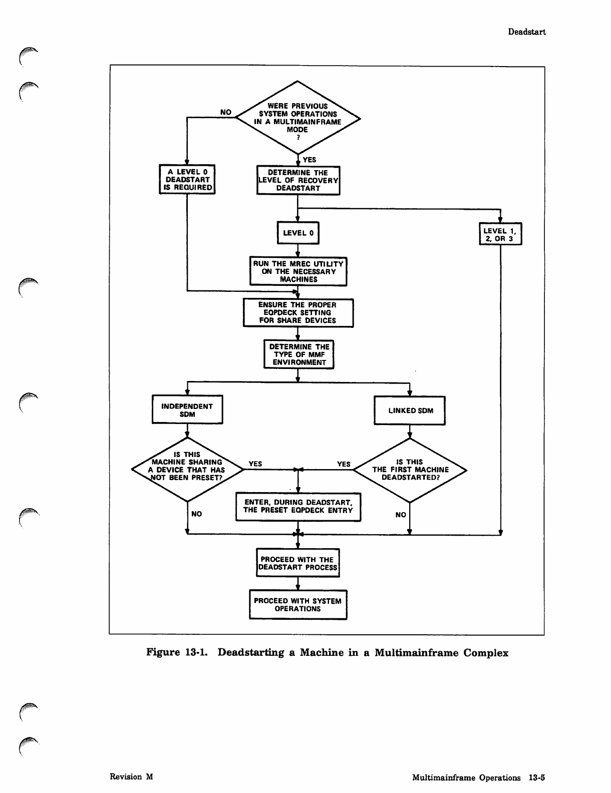
Deadstart
A LEVEL 0
DEADSTART
IS REQUIRED
DETERMINE THE
LEVEL OF RECOVERY
DEADSTART
LEVEL 0 LEVEL 1,
2. OR 3
RUN THE MREC UTILITY
ON THE NECESSARY
MACHINES
3"
ENSURE THE PROPER
EQPDECK SETTING
FOR SHARE DEVICES
DETERMINE THE
TYPE OF MMF
ENVIRONMENT
INDEPENDENT
SDM
IS THIS
MACHINE SHARING'
A DEVICE THAT HAS
JOT BEEN PRESET?.
NO
YES YES
ENTER. DURING DEADSTART.
THE PRESET EQPDECK ENTRY NO
PROCEED WITH THE
DEADSTART PROCESS
PROCEED WITH SYSTEM
OPERATIONS
Figure 13-1. Deadstarting a Machine in a Multimainframe Complex
Revision M Multimainframe Operations 13-5
Shared Mass Storage
Shared Mass Storage
A major reason for operating a multimainframe complex is to be able to share mass
storage devices between machines. Thus, the users of two systems may be able to
utilize the same files if these files reside on a shared mass storage device. Having the
ability to share files between systems also means that several additional procedures are
required when operating a multimainframe complex. Additional consideration must also
be given when configuring mass storage devices. This material, which is unique to
multimainframe operation, is discussed in the following paragraphs.
Configuring Shared Mass Storage Devices
Some consideration should be given as to which devices should be made shared devices
and which ones should not. Since a shared device contains preserved files that can be
accessed by more than one machine, it must be physically connected to and logically
defined (as shared) by each machine sharing the device. If one device of a family is
defined as shared, then normally all devices in the family should be defined as shared
for accessibility. If a removable device will be treated as shared, it must be defined as
removable in each machine sharing it. If a shared device is not removable, additional
use of the device (beyond preserved files) is defined by each machine, independently of
any other machine definition (that is, each machine specifies whether the device is to
contain such things as a copy of the system or temporary files).
There is no real advantage to having nonpreserved files on a shared device, unless
spreading them across shared devices outweighs having them on a dedicated device. A
key factor is drive and controller contention. Another factor is whether or not enough
drives and accesses to those drives are available to warrant spreading temporary files ^^^
across several devices from all systems. Also, additional overhead is incurred by the *^)
system for each shared device. This includes additional CMR space for each device
(1008 CM words) and additional time that is required to maintain the device-related
tables (such as the MST or the TRT) on the link device. These factors must be
weighed to determine how best to configure shared devices.
Device Access Tables
In a linked SDM complex, mainframes use DATs to determine device usage. The DATs
identify the status of all shared and nonshared devices for the mainframes in the "^
complex. One DAT for each machine resides in extended memory.
In order to minimize configuration problems, shared removable equipment should be
configured the same way on all machines in the complex. For example, if one system
defines three shared units as three single-unit devices and another system defines the
same units as one three-unit device, the first system can accommodate a two-unit
device on these units, whereas the second system would consider it an error. Unless
the configurations are the same on all machines, any devices mounted on those drives
may not necessarily be recoverable on all machines.
NOTE
RESEX considers only the configuration of the machine on which it is executing in
its overcommitment algorithm.
13-6 NOS Version 2 Analysis Handbook Revision M
0im\
Mass Storage Recovery Tables
Mass Storage Recovery Tables
One problem that is created by having more than one machine sharing a mass storage
device is that of recovering the mass storage space and interlocks of a machine, if it
requires recovery processing. This problem is solved by defining a table that provides
the information needed to recover the mass storage space of a machine and by having
a machine recovery utility that performs the recovery. The table is called the mass
storage recovery table (MRT). There is one MRT for each mainframe per device. It tells
which tracks are interlocked and which tracks are first tracks of files local to a
particular machine. The MRT is utilized by CPUMTR on another machine to clear
track interlocks and by the MREC utility on another machine to recover the mass
storage space of the interrupted machine. For specific information on the MRT, refer to
the NOS Version 2 Systems Programmer's Instant.
Device Initialization
To initialize a mass storage device, it is necessary first to prevent any new activity
from starting up on the device, then to wait until all current activity has completed,
and finally to interlock the device and proceed with initialization. To accomplish this
on shared mass storage devices in a linked SDM environment, follow these steps:
1. Enter the DSD UNLOAD command. All machines sharing the device must unload
it to prevent any new activity. (This command can be used for both removable
and nonremovable shared devices.)
2. Enter the DSD INITIALIZE command on the machine from which the
initialization is to take place. If you enter the INITIALIZE command from another
machine, an error message is displayed. Refer to the NOS Version 2 Operations
Handbook for error messages.
3. The machine from which the INITIALIZE command was entered monitors the
status of the other machines that are sharing the device. Once they have unloaded
the device and user activity has ceased, the device tables are updated and the
device is checkpointed.
4. To activate the device on the other machines, enter the DSD MOUNT command
from each machine. This command clears the UNLOAD status. If initialization is
still in progress on another machine when you enter a MOUNT command, the
MOUNT process is terminated with an error. Refer to the NOS Version 2
Operations Handbook for error messages.
Revision M Multimainframe Operations 13-7
Device Unload
Device Unload
In a linked SDM environment, unloading a device involves more than it does under a
one-machine system. A device can be unloaded from a machine (referred to as a local
unload), or it can be unloaded from the entire multimainframe complex (referred to as
a global unload). A device can be physically removed from the complex only after a
global unload has been accomplished. This is the general procedure to complete a
global unload:
1. Enter the UNLOAD command from each machine. This is an indication to the
machine that no new accesses should be initiated. You must enter this command
from each machine sharing the device.
2. When all local unloads are set and user access has ceased, global unload status is
set if the device is a removable device. This global unload status is displayed on
all machines, indicating that there is no activity on the device from any machine
and that the device may be physically unloaded.
3. You can then switch packs and enter the MOUNT command at the console to ^^
initiate recovery of the device. The MOUNT command clears the global unload
status and the local unload status on the machine from which it was entered and
indicates that this machine is now accessing the device. All other machines
continue to ignore the device until you enter the MOUNT command on each
machine. The MOUNT command does nothing if local unload status is not set on
the machine.
Device Recovery
Deadstart and online recovery methods are similar in logic for recovering mass storage
devices.
When a device is recovered in a linked SDM complex, the DAT in extended memory
is interlocked while a check is made to see if an entry exists for this device. The
presence of an entry indicates that another machine is also accessing the device. If
an entry is found and the machine recovering the device has not been instructed to
share it, an error is indicated and recovery halts with an appropriate message
displayed. If the machine already accessing the device is not allowing it to be shared, ^^
the same error condition occurs. Therefore, if a device is being accessed, another '^^S
machine can recover that device only if the recovering machine and the accessing
machine use the device in a multimainframe mode.
NOTE
If two devices recovered on separate machines have the same family name/device
number or pack name, there is no method of determining whether or not they are the
same device if both are shared. If they are different devices, they are both destroyed
when used.
13-8 NOS Version 2 Analysis Handbook Revision M
/ ^ • N
0Bto\
Device Checkpoint
Device Checkpoint
Local MST information for each machine that shares a mass storage device is
maintained on the device. MST information for other machines may also be present on
the device. The information for each machine is kept in one sector on the label track
following the TRT sectors. Entries for up to 31 unique machine identifiers can exist.
During checkpoint, only the local MST information of the machine performing the
checkpoint is updated. Since local MST information for many machines is kept on the
device, updating of all these areas by one machine could cause a loss of information
needed if the device were to be used with another system.
For shared devices in a linked SDM complex, duplication of checkpointing by more
than one machine is prevented. If a machine attempts to checkpoint a shared device
and determines that a second machine is performing the checkpoint (a checkpoint
request bit is set in the local MST area of the second machine), no action is taken.
Only one checkpoint bit is set at any given time for a device.
MSE Processing
Unlike most other mass storage devices, the 7990 is not shared by mainframes. Rather,
7990 is physically connected to and driven by one mainframe called the master
mainframe. All other mainframes that share permanent files with the master
mainframe are called slave mainframes. The disks to which 7990-resident files are
staged must be shared devices and accessible by all mainframes.
SSEXEC runs on the master mainframe and is the main program that controls MSE
processing activities. You can activate SSEXEC by entering the following DSD
commands at the system console.
L.SUBSYST.
ENABLE,MASTER MSE.
L.END.
MSEffff.
SSSLV runs on each slave mainframe and is the program that supports file retrieval
from a 7990 for jobs running on a slave mainframe. You can activate SSSLV by
entering the following DSD commands at the system console.
L.SUBSYST.
DISABLE,MASTER MSE.
L.END.
MSEffff.
When a job running on a slave mainframe attaches a 7990-resident file that has no
disk image, SSSLV is requested to stage the file to disk. However, SSSLV cannot access
7990 directly. SSSLV must communicate with SSEXEC, which stages the file to a
shared disk and then notifies SSSLV when the file is available. SSSLV then causes the
requesting job to be resumed so that the file ATTACH can complete.
The permanent files used for communication between SSEXEC and SSSLV are
initialized and recovered automatically and require no backup or recovery processing.
The name of the permanent file used by SSSLV running on mainframe i (i = l, 2, 3,
4) to send requests to SSEXEC is STBMNOi. The name of the permanent file used by
SSEXEC to respond to all requests by all SSSLVs is MTBSPFN. These files belong to
the family that contains extended memory and are saved under the user index
3777608.
Revision M Multimainframe Operations 13-9
Independent SDM Operation
J,*^%v
Independent SDM Operation
In an independent SDM complex, up to 16 computers can access shared mass storage
devices. Any combination of from 1 to 16 model 71, 72, 73, 74, 171, 172, 173, 174, 175,
176, 720, 730, 740, 750, 760, 865, 875, CYBER 180-class machines, or 6000 Computer
Systems mainframes can be used. Shared mass storage devices supported are 844
(single and double density) and 885-11/12 (single and double density).
Each shared device contains in its label track all of the tables necessary to control
multimainframe access. These tables include the MST, TRT, device index table (DIT),
and MRT for each mainframe sharing the device. Whenever a mainframe needs to
access a shared device, it is necessary for the mainframe to ensure its copies of these
tables are up-to-date.
One or more of the mainframes can have extended memory, but each mainframe's
extended memory must be used as a nonshared device.
If MSE is used, one mainframe in the independent SDM complex is physically ^^^
connected to 7990 and only that mainframe can access it. 1
Deadstart
An independent SDM environment is defined at deadstart by CMRDECK and
EQPDECK entries in each machine. Use the following entries to do this.
CMRDECK Entry Description
MID=id. 2-character machine identification. This
identification is used to associate a specific
machine with its access to a shared device. It is
required, however, even if no devices are shared
during system operation. This id must be unique
for each machine in the complex. If id is omitted,
the default value is MID=AA.
EQPDECK Entry Description
ISHARE = esti,est2,...,estn. EST ordinals of the mass storage devices that will ^^)
be independently shared with other machines in
the multimainframe complex. The ISHARE entry
must precede the PRESET entry. The MST/TRT
resides on each shared device.
PRESET=esti,est2,...,estn. EST ordinal of the shared mass storage device to
be preset. You can specify this entry only at the
system console. Several machines at level 0
deadstart may need the PRESET entry. The
PRESET entry is specified only on a level 0
deadstart by the first machine accessing the device
and must follow the ISHARE entry. PRESET
initializes the tables residing on the label track of
the shared devices.
These entries are also described in section 3, Deadstart Decks.
13-10 NOS Version 2 Analysis Handbook Revision M
Deadstart
Since in an independent SDM complex two or more machines can utilize the same
rmass storage devices, the device assignments and EQPDECKs of all machines are
interrelated. Care must be taken to ensure proper EQPDECK settings for each machine
to obtain the desired device configuration. The following items are important in
obtaining this proper device configuration.
• Each machine must specify a unique machine identification (using the MID entry
in the CMRDECK). This identification associates a particular machine with its
files on a shared device. There are no external characteristics associated with this
identification. However, if the machine identification specified on a machine
deadstarting into a multimainframe complex is identical to a machine
identification on a machine already operating, the deadstart process halts and an
appropriate message is displayed.
• The assignment of shared mass storage devices should be made properly to ensure
the recoverability of the device and the proper operation of the system (refer to
Shared Mass Storage, next).
Each machine must specify the ISHARE=est EQPDECK entry to inform the
system that devices will be shared in the independent shared device mode.
If you need to deadstart an interrupted mainframe in an independent SDM
environment, you should put the nonfailing mainframes in STEP mode before
deadstarting the interrupted mainframe.
On a level 0 deadstart, any shared device that has not been shared prior to this
deadstart must include the PRESET entry in its definition.
On a level 0 deadstart, if a device was previously shared by the deadstarting
machine, the MRT and DIT device resident tables must be zeroed out.
- If the machines that share the device are not currently running, the device
must be preset or initialized to zero out the tables.
- If any machine that shares the device is running, the machine recovery utility
(MREC) must be run from a running machine to remove the machine
identification of any machines that are not currently running and to clear all
interlocks held by these machines.
On a level 0 deadstart, if a device was previously shared by a machine other than
the deadstarting machine, the MRT and DIT device resident tables may or may
not have to be zeroed out.
- If another machine that is sharing the device is running, the device must not
be preset.
- If no machines that will be sharing the device are running and one or more of
them will be deadstarted at a level 1, 2, or 3, the device must not be preset.
- If all machines that will be sharing the device are not currently running and
all will be deadstarted at level 0, the device can be preset or initialized.
•
Revision M Multimainframe Operations 13-11
Shared Mass Storage
When performing a level 0 recovery deadstart on one of the machines, the MREC
utility should be run on some or all of the remaining machines before the deadstart
proceeds. The purpose of this utility is to clear interlocks held by the machine to be
deadstarted that have not been cleared by CPUMTR. It can also recover mass storage
space on a shared device that is currently not accessible because of a machine
interruption (necessitating a level 0 deadstart). MREC may have to be run from more
than one machine since it affects only shared devices (that is, devices specified on the
ISHARE EQPDECK entry) of the machine on which MREC is run. If the interrupted
machine shares different devices with different machines, MREC must be run from
enough machines to account for all devices shared with the interrupted machine. The
interface to the MREC utility is described in section 8, K-Display Utilities.
In an independent SDM complex, as in a standalone system, critical tables that reside
on the device must be intact for a level 1, 2, or 3 deadstart recovery.
Figure 13-1 illustrates the steps generally needed to deadstart a machine in a
multimainframe complex.
Shared Mass Storage
A major reason for operating a multimainframe complex is to be able to share mass
storage devices between machines. Thus, the users of two systems may be able to
utilize the same files if these files reside on a shared mass storage device. Having the
ability to share files between systems also means that several additional procedures are
required when operating a multimainframe complex. Additional consideration must also
be given when configuring mass storage devices. This material, which is unique to
multimainframe operation, is discussed next.
/^at^y
13-12 NOS Version 2 Analysis Handbook Revision M
Configuring Shared Mass Storage Devices
Configuring Shared Mass Storage Devices
Some consideration should be given as to which devices should be made shared devices
and which ones should not. Since a shared device contains preserved files that can be
accessed by more than one machine, it must be physically connected to and logically
defined (as shared) by each machine sharing the device. If one device of a family is
defined as shared, then normally all devices in the family should be defined as shared
for accessibility. If a removable device will be treated as shared, it must be defined as
removable in each machine sharing it. If a shared device is not removable, additional
use of the device (beyond preserved files) is defined by each machine, independently of
any other machine definition (that is, each machine specifies whether the device is to
contain such things as a copy of the system or temporary files).
There is no real advantage to having nonpreserved files on a shared device, unless
spreading them across shared devices outweighs having them on a dedicated device. A
key factor is drive and controller contention. Another factor is whether or not enough
drives and accesses to those drives are available to warrant spreading temporary files
across several devices from all systems. Also, additional overhead is incurred by the
system for each shared device. This includes additional CMR space for each device
(1008 CM words) and additional time that is required to maintain the device-related
tables (such as the MST or the TRT) on the link device. These factors must be
weighed to determine how best to configure shared devices.
In an independent SDM complex, where device-related tables are maintained on the
device itself, system performance degradation can occur if the shared devices are not
properly configured. Since the device must be accessed every time its tables in CMR
are not up to date, drive and controller contention is increased and system
performance is affected. To reduce the impact on system performance you can:
• Put the system and temporary files on nonshared devices.
• Put only those fast-attach files that must be global on shared devices.
• Use multiple channels and multiple controllers to improve performance and
provide additional paths to shared devices.
Revision M Multimainframe Operations 13-13
Device Index Tables
Device Index Tables
In an independent SDM complex, mainframes use DITs to determine device usage. The
DITs contain the MIDs of the mainframes that can access the shared device. The
shared device maintains a DIT for each mainframe that shares it. The DITs reside on
each shared device within the MST on the device's label track.
Mass Storage Recovery Tables
One problem that is created by having more than one machine sharing a mass storage
device is that of recovering the mass storage space and interlocks of a machine, if it
requires recovery processing. This problem is solved by defining a table that provides
the information needed to recover the mass storage space of a machine and by having
a machine recovery utility that performs the recovery. The table is called the MRT.
There is one MRT for each mainframe per device. It tells which tracks are interlocked
and which tracks are first tracks of files local to a particular machine. The MRT is
utilized by CPUMTR on another machine to clear track interlocks and by the MREC
utility on another machine to recover the mass storage space of the interrupted ■/*ss\
machine. For specific information on the MRT, refer to trie NOS Version 2 Systems
Programmer's Instant.
Device Initialization
To initialize a mass storage device, it is necessary first to prevent any new activity
from starting up on the device, then to wait until all current activity has completed,
and finally to interlock the device and proceed with initialization. To accomplish this
on shared mass storage devices in an independent SDM environment, follow these "£S%
steps: 7
1. Enter the DSD UNLOAD command. All machines sharing the device must unload
it to prevent any new activity. (This command can be used for both removable
and nonremovable shared devices.)
2. Enter the DSD INITIALIZE command on the machine from which the
initialization is to take place. Each entry of the INITIALIZE command toggles
INITIALIZE on and off. If two machines in the complex enter the INITIALIZE
command, the INITIALIZE command is toggled off and no error message is /*=%,
displayed. '
3. The machine from which the INITIALIZE command was entered monitors the
status of the other machines that are sharing the device. Once they have unloaded
the device and user activity has ceased, the device tables are updated.
4. To activate the device on the other machines, enter the DSD MOUNT command
from each machine. This command clears the UNLOAD status. If initialization is
still in progress on another machine when you enter a MOUNT command, the
machine waits for INITIALIZE to finish and then continues with the MOUNT
process.
13-14 NOS Version 2 Analysis Handbook Revision M
Device Unload
Device Unload
In an independent SDM environment, unloading a device involves more than it does
under a one-machine system. A device can be unloaded from a machine (referred to as
a local unload), or it can be unloaded from the entire multimainframe complex
(referred to as a global unload). A device can be physically removed from the complex
only after a global unload has been accomplished. This is the general procedure to
complete a global unload:
1. Enter the UNLOAD command from each machine. This is an indication to the
machine that no new accesses should be initiated. You must enter this command
from each machine sharing the device.
2. When all local unloads are set and user access has ceased, global unload status is
set if the device is a removable device. This global unload status is displayed on
all machines, indicating that there is no activity on the device from any machine
and that the device may be physically unloaded.
3. You can then switch packs and enter the MOUNT command at the console to
initiate recovery of the device. The MOUNT command clears the global unload
status and the local unload status on the machine from which it was entered and
indicates that this machine is now accessing the device. All other machines
continue to ignore the device until you enter the MOUNT command on each
machine. The MOUNT command does nothing if local unload status is not set on
the machine.
4. A pack that has not been previously mounted in this system must be preset with
a MOUNT,est,P command.
Device Recovery
Deadstart and online recovery methods are similar in logic for recovering mass storage
devices.
For a machine to recover a device in an independent SDM complex, the MID of the
machine must be in the device's DIT. If the MID is not in the DIT, an error message
is issued and recovery is impossible. When recovering a device in a standalone
environment, the device is not checked if it is/was an independent shared device.
Revision M Multimainframe Operations 13-15
Device Checkpoint
Device Checkpoint
Local MST information for each machine that shares a mass storage device is
maintained on the device. MST information for other machines may also be present on
the device. The information for each machine is kept in one sector on the label track
following the TRT sectors. Entries for up to 31 unique machine identifiers can exist.
During checkpoint, only the local MST information of the machine performing the
checkpoint is updated. Since local MST information for many machines is kept on the
device, updating of all these areas by one machine could cause a loss of information
needed if the device were to be used with another system.
In an independent SDM complex, the MST and TRT information is maintained on the
device. If the MST and/or TRT information changes during a device access, the
system updates the MST and/or TRT information making it unnecessary for the
system to periodically checkpoint the device.
MSE Processing
Unlike most other mass storage devices, the 7990 is not shared by mainframes. Rather,
7990 is physically connected to and driven by one mainframe. The only machine that
can access the 7990-resident files is the physically connected independent SDM. MSE
processing is the same in an independent SDM environment as it is in a single
mainframe environment. Refer to section 11, Mass Storage Extended Subsystem.
13-16 NOS Version 2 Analysis Handbook Revision M
NAD Maintenance Utilities 14
Dump NAD Memory (DMPNAD) 14«1
Maintenance Host Facility (MHF) 14-3
Listing NAD Dumps I4.3
f^
r

v..
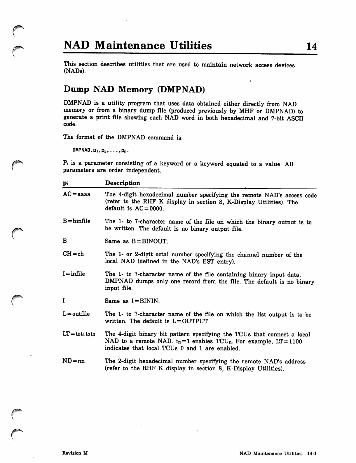
NAD Maintenance Utilities 14
This section describes utilities that are used to maintain network access devices
(NADs).
Dump NAD Memory (DMPNAD)
DMPNAD is a utility program that uses data obtained either directly from NAD
memory or from a binary dump file (produced previously by MHF or DMPNAD) to
generate a print file showing each NAD word in both hexadecimal and 7-bit ASCII
code.
The format of the DMPNAD command is:
DMPNAD,plfp2 pn.
Pi is a parameter consisting of a keyword or a keyword equated to a value. All
parameters are order independent.
Pi Description
AC = aaaa The 4-digit hexadecimal number specifying the remote NAD's access code
(refer to the RHF K display in section 8, K-Display Utilities). The
default is AC = 0000.
B=binfile The 1- to 7-character name of the file on which the binary output is to
be written. The default is no binary output file.
B Same as B=BINOUT.
CH = ch The 1- or 2-digit octal number specifying the channel number of the
local NAD (defined in the NAD's EST entry).
I = infile The 1- to 7-character name of the file containing binary input data.
DMPNAD dumps only one record from the file. The default is no binary
input file.
I S a m e a s I = B I N I N .
L=outfile The 1- to 7-character name of the file on which the list output is to be
written. The default is L=OUTPUT.
LT=totit2t3 The 4-digit binary bit pattern specifying the TCUs that connect a local
NAD to a remote NAD. tn = l enables TCUn. For example, LT=1100
indicates that local TCUs 0 and 1 are enabled.
ND=nn The 2-digit hexadecimal number specifying the remote NAD's address
(refer to the RHF K display in section 8, K-Display Utilities).
0$^S^
Revision M NAD Maintenance Utilities 14-1
Dump NAD Memory (DMPNAD)
The DMPNAD utility can be called from the console or a batch job. The calling job
must be of system origin or you must be validated for system origin privileges. You ^\
normally include the channel number on the DMPNAD command to specify which local
NAD is to be dumped. The dump can also be saved as a binary output file (B
parameter) which can be listed later.
DMPNAD can dump either a local NAD (380-170 NAD connected to the host
mainframe using a channel and configured in the EST) or a remote NAD (any 380
NAD accessible to a local NAD using a loosely-coupled network trunk). For a local
NAD dump, the EST entry associated with the local NAD's channel number must be
OFF or the controlware-not-loaded flag must be set. Since the local NAD dumping
process stops all NAD activity, the NAD controlware must be reloaded using
LOADBC (refer to section 1, Controlware Utilities) before the local NAD can be used
by the operating system.
Remote NAD dumping is selected by specifying the remote NAD to be dumped (AC
and ND parameters), the local NAD's channel number used to access the remote
NAD (CH parameter), and the TCU used to connect the local NAD to the remote ^~
NAD (LT parameter). For remote NAD dumping, the local NAD must be loaded and 1
running and its EST entry must be ON.
Remote NAD dumping operations can occur concurrently with RHF use of the local
NAD. However, extreme care should be exercised when performing a remote NAD
dump to ensure that the correct remote NAD is being dumped and that the remote
NAD is not being used by the mainframe to which it is connected. After the remote
NAD dumping operation, the NAD controlware must be reloaded into the remote
NAD before it can be used by the remote mainframe.
When the I parameter is specified, DMPNAD will list a binary file that was saved
earlier. Since no NAD access is required, no special privileges are required by the
calling job.
14-2 NOS Version 2 Analysis Handbook Revision M
Maintenance Host Facility (MHF)
Maintenance Host Facility (MHF)
yams
™i" is a utilitv Program that executes while RHF is active. MHF periodically copies
t>£t? •er-1.r l0gS to the binary maintenance kg. loads microcode into local NADs during
RHF initiation, and dumps and reloads local NADs that fail. MHF uses a copy of the
network description table obtained directly from RHF to determine which NADs to loe
dump, and/or load. 6'
You control MHF operation by setting the AUTOLOAD, AUTODUMP TRACE and
LOG parameters in the LNAD and RNAD directives for RCFGEN, which generates
the RHF configuration file (refer to section 10, LID/RHF Configuration Files) You
can control the remote NAD LOG parameter on RHF's network path table display
(refer to section 8, K-Display Utilities). If you specify AUTODUMP = YES for local
S^5.^?J -SaVeS NA° memory dumPs as Celled binary records on permanent file
ND* Mid (id is the host mainframe identifier) under user name SYSTEMX Each
record label contains the record name NDMPLch (ch is the NAD's channel number)
record number, and the date and time of the dump. MHF puts this dump information
in the following sequence of job dayfile messages:
MHF, NAD DUMP RECORD NAME = NDMPLch
MHF, RECORD NO.0000 TIME = hh.nm.ss
MHF, FILE = NDFMid DATE = yy/mn/dd
When loading a local NAD, MHF obtains the controlware from the system and uses a
default set of controlware initialization parameters that it adjusts to suit the NAD's
memory size.
Listing NAD Dumps
To list a NAD dump, you must be validated to obtain access to the NAD dump
permanent file NDFMid (id is the host mainframe identifier).
You can either use ITEMIZE to locate a particular record on permanent file NDFMid
or obtain the record number from MHF's dayfile, and then use DMPNAD to list the
dump record. (ITEMIZE shows the record name, record number, date, and time
corresponding to MHF's dayfile messages.)
The following example lists dump record 4 of permanent file NDFM64:
ATTACH,NDFM64/UN=SYSTEMX.
ITEMIZE,NDFM64. Check ITEMIZE output for the record number
SKIPR,NDFM64.3. Skip to the fourth record.
dmpnad,i=ndfm64,l=list. List the fourth record on file LIST.
RETURN,NDFM64..
A0$S,
Revision M NAD Maintenance Utilities 14-3

f^)
f**
^v
Network Operations 15
Network Organization 15.1
NAM Startup X5.5
Initiating NAM Without Operator Intervention 15.5
Altering the Memory File 15_6
NAM Shutdown 15.3
Network Control by HOP 15.9
Disabling and Enabling of Couplers 15-9
Status Message Formats for HOP 15-9
Unsolicited Status Reports for HOP 15-10
HOP Commands 15-11
NS Control Commands 15-11
C a n c e l A l t e r n a t e N P U L o a d F i l e C o m m a n d . . 1 5 - 1 1
Change NPU Load File Command 15-12
NPU Load Status Command -15-12
Specific NPU 15-12
All NPUs 15-13
Status Response 15-13
NS Recent HISTORY Command 15-14
NVF Control Commands 15-15
Disable Host Element Command , 15-15
Enable Application Command 15-16
Idle Host Element Command 15-16
NVF Recent HISTORY Command 15-18
Status Host Element Command 15-18
Particular Host Element .. 15-18
Network Applications 15-19
Active Network Applications 15-19
Terminal Devices 15-19
Users (Specified Application) 15-20
Network Control by NOP .. 15-21
Becoming a NOP ." 15-21
Status Message Formats for NOP 15-23
Unsolicited Status Reports for NOP 15-25
NOP Commands 15-26
ALERT Command 15-26
CONTROL Command 15-27
Disable Network Element Command 15-29
Single Element 15-29
Trunk ... 15-30
SVCs 15-31
DISABLE Processing 15-31
Enable Network Element Command 15-33
Single Element 15-33
Trunk 15-34
Disabled Elements 15-34
Disabled Elements (All NPUs) 15-35
Disabled Terminals 15-35
SVCs 15-36
ENABLE Processing 15-36
NPU GO Command 15-37
NPU LOAD Command .... .... 15-38
Specified NPU .. 15-38
All NPUs ....,.............................;............. 15-39
NPU Memory DUMP Command , 15-40
Specified NPU 15-40
All NPUs 15-40
Send Message Command ..... 15-41
Network Control by DOP. * 15-43
Becoming a DOP ... 15-43
Status Message Formats for DOP 15-45
U n s o l i c i t e d S t a t u s R e p o r t s f o r D O P . - . . . . . - . . . 1 5 - 4 8
DOP Commands , , 15-48
CS Information Command 15-48
NPU Diagnostic Test Command ....... 15-50
TST Drop Option.. 15-50
T S T M e s s a g e O p t i o n • - • • . - . ■> 15-51
TST Request Option , 15-51
Recent HISTORY Command ,. 15-52
Report Unsolicited Status Command , 15-53
Send Message Command • • • 15-54
Status Network Element Command 15-55
Particular Element ..-..- . 15-55
All Elements 15-56
Terminal Devices 15-57
NPUs 15-57
SVCs 15-58
Summary of Network Operation Commands ..— 15-59
Control Commands for HOP 15-59
NAM K Display 15-59
NAM Startup 15-59
NAM Shutdown 15-59
NAM Mode Commands 15-60
NS Control Commands ......... 15-61
NVF Control Commands 15-61
Control Commands for HOP and NOP 15-62
Control Commands for HOP, NOP, and DOP 15-62
Control Commands for COP . 15-62
yzms.
Network Operations ^^_^ 15
The commands described in this section are used when the network access method
(NAM) is being initialized or is active. They initialize and control the network
processing units (NPUs), device interfaces (DIs), trunks, lines, terminals, and
application programs under network supervision.
NAM supports two types of networks: the 255x NPU network and the CDCNET
network. Throughout this section, the term network refers to the 255x NPU network.
However, whenever a statement is applicable to both network types, both types are
named explicitly.
NAM controls the CDCNET network by sending commands to an application called
Network Operator Utility (NETOU). This NAM application is also known as the
network operations server. For further information on controlling the CDCNET
network, refer to the CDCNET Network Operations Manual and the CDCNET
Network Analysis Manual.
Network Organization
Initiating NAM (refer to the DSD NAM command in section 5, DSD Commands) causes
NAM, and the communications supervisor (CS), network supervisor (NS), network
validation facility (NVF), and terminal verification facility (TVF) to be loaded and
initiated at control points. Refer to the NAM/CCP 3 Terminal Interfaces Reference
Manual for more information on TVF. CS provides control and status of the NPUs and
all of their communication lines and terminals. NS loads and dumps all of the NPUs
in the communication network. NVF validates terminal users and applications, as they
attempt to access the network.
Multiple hosts may belong to the network. Hosts may assume one or more
supervisory roles in the network. Each host will have a copy of NVF that will
validate users connecting to and applications executing in that host. NVF provides
these services for both the 255x NPU network and the CDCNET network. The
supervisors CS and NS may execute in any or all of the CYBER hosts. Whenever an
NPU needs to be loaded, it may request any copy of NS to perform the load (not
always the same copy). Once an NPU is running, it may request any copy of CS to
supervise it. Each NPU will have a preferred copy of CS, but it may request
supervision from an alternate copy of CS if its preferred CS is not available. In any
case, the network is always capable of functioning without any one or more of its
hosts.
Revision M Network Operations 15-1
Network Organization
Whenever a CDCNET mainframe device interface (MDI) or mainframe terminal
interface (MTI) must be loaded, it requests the services of a CDCNET job called
INITMDI, which is responsible for loading and dumping the MDIs and MTIs. NAM
automatically starts INITMDI upon demand.
Whenever a terminal device interface (TDI) or a network device interface (NDI) must
be loaded, the MDI helping in the load process establishes a connection through NAM
to the NAM application called the Network File Server (NETFS), which controls the
loading and dumping of TDIs and NDIs.
The 255x NPU network consists of channels, couplers, lines, logical links, NPUs,
terminals, and trunks (refer to figure 15-1) connected to the host computer.
• A channel is a data path on which a peripheral device controller can be accessed.
• A coupler is a hardware element that links an NPU to a channel.
• A line is the circuit that connects a terminal to an NPU.
• A logical link is a logical path connecting a coupler and an NPU or two couplers.
• An NPU is the communications controller that transmits data between terminals
and a host computer or between two host computers.
• A public data network is an X.25 packet switching network (PSN). Terminals,
NPUs, and foreign hosts can be connected to a PSN to exchange data.
• A terminal is a device by which a user supplies input messages to, and accepts
output messages from, an application program.
• A trunk is the communication line connecting two NPUs.
The CDCNET network consists of channels, couplers, lines, logical links, device
interfaces (MDIs/MTIs/NDIs/TDIs), terminals, and trunks. For definitions of CDCNET
terminology, refer to the CDCNET Conceptual Overview Manual.
.«*SJ!Sy
15-2 NOS Version 2 Analysis Handbook Revision M
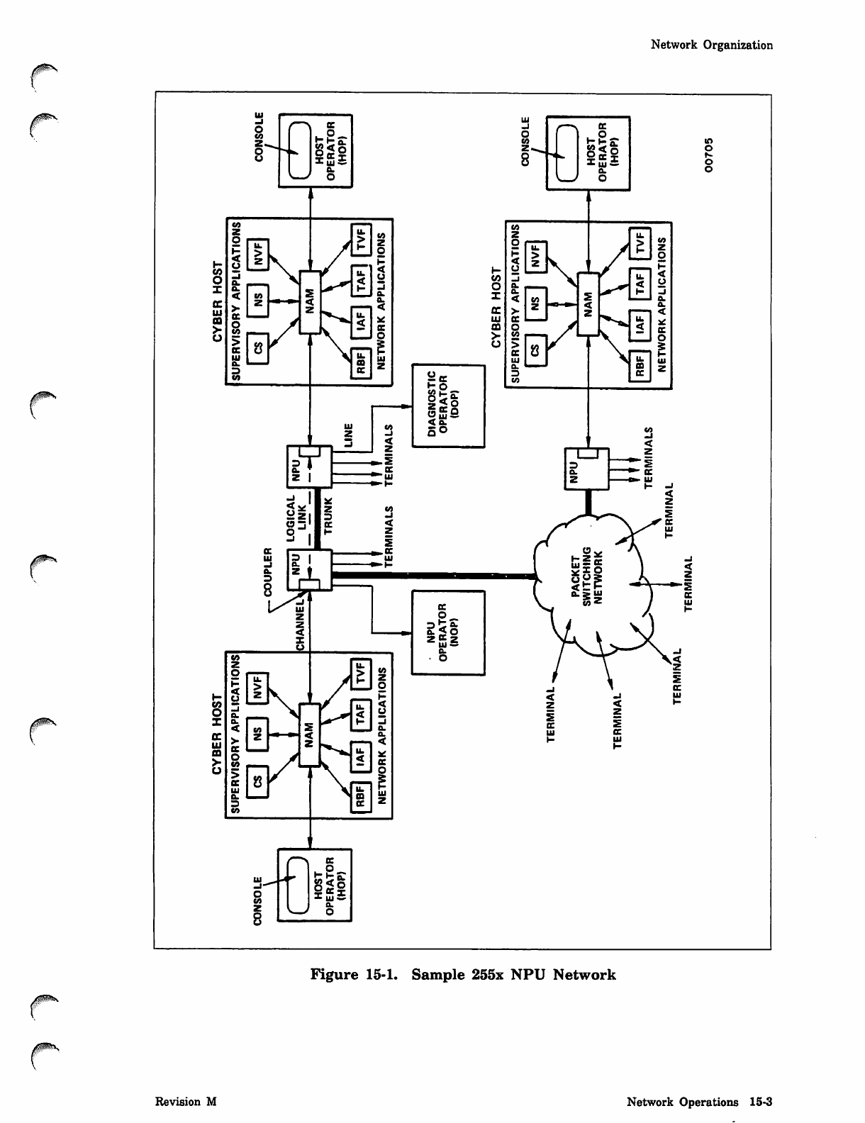
Network Organization
r
0^S
illz ff x
Ju m s
o
r~s
a.
O
P
o ui a
so
0^1
j cc
c
o_
2£5
ft.
• o
Figure 15-1. Sample 255x NPU Network
Revision M Network Operations 15-3
Network Organization
Network host products (NHP) is the network software residing on the CYBER host.
NHP recognizes four types of network operators: the host operator, the NPU operator,
the diagnostic operator, and the CDCNET operator. A host operator (HOP) resides at
the system console, initiates NAM, and can control 255x NPU network and CDCNET
network elements being supervised by this host. An NPU operator (NOP) resides at a
terminal and controls 255x NPU network elements (such as lines, logical links, NPUs,
terminals, and trunks). A diagnostic operator (DOP) resides at a terminal and monitors
and tests communication lines on the 255x NPU network.
A CDCNET operator (COP) resides at either the system console or a terminal and
controls CDCNET network elements (such as lines, terminals, trunks, and DIs
associated with CDCNET).
The HOP can always perform COP, NOP, and DOP functions regardless of the
existence of COPs, NOPs, and DOPs. NOPs can perform all DOP functions regardless
of the existence of DOPs. CS supports up to 10 concurrent NOP and DOP connections
in addition to one HOP connection. NS and NVF support only the HOP connection.
The HOP can communicate with NAM and any of the supervisors (CS, NS, NETOU,
or NVF) executing in its host. COPs can communicate only with NETOU. Refer to
the CDCNET Network Operations Manual for additional information. NOPs and DOPs
can communicate with any CS executing in any host to which the operator has
access. However, a NOP or DOP can communicate with only one CS at a time. A
NOP or DOP can monitor and control only those elements owned by NPUs being
supervised by their CS.
Each NPU in the network is controlled by the HOP and, optionally, one NOP
connected to its supervising CS. A HOP controls all NPUs supervised by CS. Each
NOP connected to CS can control one or more NPUs.
15-4 NOS Version 2 Analysis Handbook Revision M
0m\
NAM Startup
NAM Startup
If the NPUs in the network were running version 3.5 or earlier Communications
Control Program (CCP), you must master clear all local NPUs before initiating NAM.
If the NPUs were running version 3.6 or 3.7 of CCP, then master clear NPUs only if
the running version is not the desired version.
You initiate NAM by entering:
NAM.
or
NAMNOGO.
NAM1 and NAMNOGO are names of procedure files that are called when the HOP
initiates NAM.
The first time the network is initiated the NAMNOGO procedure must be used to
create a memory file (refer to the NOS Version 2 Installation Handbook). The
memory file contains the name of the master file, the last parameter record, and the
network invocation number (NIN) used. The NIN is incremented by 1 every time
NAM is started. The NIN is displayed in the NAM K display. If the network has
been previously initiated, a memory file exists and the NAM procedure file may be
used.
Initiating NAM Without Operator Intervention
If you initiate NAM by entering
NAM.
o
NAM is brought up without further operator action. This results in starting the
network using the previously specified master file and the parameter record RESTRT.
1. Any procedure file of the form NAMffff is allowed.
2. Any procedure file of the form NAMffff is allowed.
Revision M Network Operations 15-5
Altering the Memory File
Altering the Memory File
If you initiate NAM by entering
NAMNOGO.
NAM displays the message:
ENTER DESIRED OPTION
You reply to this message with a CFO command in this format:
CFO,NAM.Pi,p2,...Pn.
pi is a parameter consisting of a keyword equated to a value. All parameters are order
independent.
Pi
MFN=filename
UN = username
PW=password
Description
Permanent file name of the master file to be used. The master
file contains all the information needed to initiate the network.
Once this parameter is specified all subsequent network
initiations use this master file until a new master file is
specified. The master file resides in the system default family
and must be permitted to SYSTEMX. If this parameter is not
specified, NAMSTRT is assumed. Refer to NAM Procedure File
in the NOS Version 2 Installation Handbook for further
information about file NAMSTRT.
User name for the master file. If this parameter is not specified,
NETOPS is assumed.
Password associated with the master file user name.
-*mcy^.
15-6 NOS Version 2 Analysis Handbook Revision M
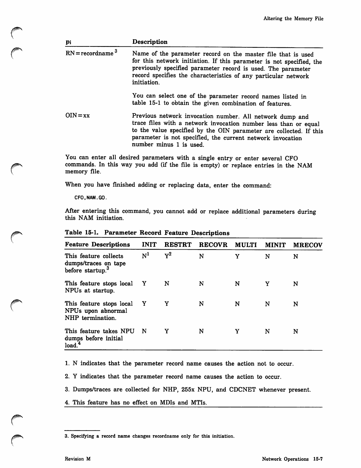
Altering the Memory File
pi Description
RN = recordname3 Name of the parameter record on the master file that is used
for this network initiation. If this parameter is not specified, the
previously specified parameter record is used. The parameter
record specifies the characteristics of any particular network
initiation.
You can select one of the parameter record names listed in
table 15-1 to obtain the given combination of features.
OIN=xx Previous network invocation number. All network dump and
trace files with a network invocation number less than or equal
to the value specified by the OIN parameter are collected. If this
parameter is not specified, the current network invocation
number minus 1 is used.
You can enter all desired parameters with a single entry or enter several CFO
commands. In this way you add (if the file is empty) or replace entries in the NAM
memory file.
When you have finished adding or replacing data, enter the command:
CFO,NAM.GO.
After entering this command, you cannot add or replace additional parameters during
this NAM initiation.
Table 15-1. Parameter Record Feature Descriptions
Feature Descriptions INIT RESTRT RECOVR MULTI MINIT MRECOV
This feature collects N1 Y2 N Y N N
dumps/traces on tape
before startup
T h i s f e a t u r e s t o p s l o c a l Y N N N Y N
NPUs at startup.
^ This feature stops local
■ NPUs upon abnormal
NHP termination.
N N N N
T h i s f e a t u r e t a k e s N P U N Y N Y N N
dumps before initial
load.4
1. N indicates that the parameter record name causes the action not to occur.
2. Y indicates that the parameter record name causes the action to occur.
3. Dumps/traces are collected for NHP, 255x NPU, and CDCNET whenever present.
4. This feature has no effect on MDIs and MTIs.
3. Specifying a record name changes recordname only for this initiation.
Revision M Network Operations 15-7
NAM Shutdown
NAM Shutdown
NAM is idled by assigning the K display to the application NVF, followed by entering
the DISABLE,HOST or IDLE,HOST command.
The sequence of commands is:
K.AP=NVF.
K. DISABLE,HOST.
or
K.IDLE,HOST.
Use the IDLE command for a graceful shutdown, and the DISABLE command for an
immediate shutdown.
15-8 NOS Version 2 Analysis Handbook Revision M
^psv
r
0ms
Network Control by HOP
Network Control by HOP
The commands described next are available only to the HOP. The HOP can perform all
functions of the NPU operator, CDCNET operator, and diagnostic operator as well as
those unique to the HOP. The commands unique to the HOP are processed by NS and
NVF.
Disabling and Enabling of Couplers
The HOP enables either an NPU or MDI/MTI coupler using the DSD ON command
and disables the coupler using the DSD OFF command. You can examine the NP
equipment entry on the E,A display to determine the EST ordinal. When an active
coupler is turned OFF, NAM stops communicating with that coupler. The coupler is not
used again until it is turned ON while NAM is executing. When a coupler is turned
ON, NAM automatically begins to communicate with the NPU or MDI/MTI connected
across the coupler.
Status Message Formats for HOP
The HOP commands cause various status messages to be displayed at the system
console. The normal response to a STATUS command consists of a single status line for
each referenced element.
Following are the general formats for these status messages.
Message Type Format
Application status line
Terminal status line
User status line
APPL: name,status,conncount.mxcopies,jsn,restart.
TERM: name,username,hh.mm.ss,app1name/acn,ah.am.as,dt
USER: name,termname,hh.mm.ss,app1name/acn,ah.am.as,dt
In the preceding status message general formats the following variables are used.
Variable Description
acn Connection number for the connected application.
ah.am.as Time of the connection to the application (hours, minutes, and seconds).
applname Name of the connected application.
conncount Count of the active connections to this application.
dt Device type.
hh.mm.ss Time of the system or host login (hours, minutes, and seconds).
jsn Job sequence name of the application.
mxcopies Maximum number of copies of this application that can be running at
one time.
0Z3S.
Revision M Network Operations 15-9
Unsolicited Status Reports for HOP
name
restart
status
termname
username
yrt^^.
Variable Description
Name of the specified element.
If the characters RS are present, they indicate that NVF will
automatically start up a copy of this application to complete a
connection request for it.
Status of the application. The application program is initially set to
either an enabled or disabled state. Enabled application programs
become active when they start executing. The application program is in
one of these states:
status Description
AC
DI
DN
EN
Application is active (you can establish a connection to the
application).
Application is disabled.
Application is down (the application failed; NAM tables are
being cleared up).
Application is enabled.
Name of the terminal at which the user resides.
Login user name of the terminal user.
Unsolicited Status Reports for HOP
Each time a significant event occurs, CS, NS, or NVF updates its recent history buffer
(refer to Recent HISTORY Command later in this section) and logs the event in the
NAM dayfile. CS, NS, or NVF then sends a report about the event, called the
unsolicited status report, to the HOP. The HOP can get unsolicited status reports from
CS, NS, or NVF by assigning the NAM K display to that particular application. Refer
to section 8, K-Display Utilities, for information on how to assign the NAM K display.
Unsolicited status reports are time-stamped whereas solicited status reports are not
time-stamped.
If an unsolicited status report is important enough to require alerting the operator or
system analyst, NS, CS, or NVF will display its application name on the alert line of
the NAM K-display unless the NAM K-display is already assigned to that application.
The operator or system analyst should then assign the NAM K-display to the
application and follow the procedures indicated in the NOS Version 2 Operations
Handbook for the appropriate alert message.
Refer to the CDCNET Network Operations Manual for NETOU's treatment of
unsolicited information for the CDCNET operator.
15-10 NOS Version 2 Analysis Handbook Revision M
HOP Commands
HOP Commands
The HOP must assign the NAM K display to a supervisory application (CS, NS, or
NVF) before entering any of the following commands. Refer to section 8, K-Display
Utilities, for information on how to assign the NAM K display. CS, NS, and NVF
support both the right and left K-displays. The right K-display provides help
information.
All HOP commands consist of a command verb and, sometimes, one or more
parameters. The commands must begin in the first character position after K. and
contain no blanks. The terminator (.) is optional. Some command verbs and
parameters can be shortened to a 2- or 3-character abbreviation. You can mix
abbreviated and unabbreviated command verbs and parameters in all network
commands. Parameters are order independent except where noted.
NS Control Commands
The HOP assigns the NAM K display to NS to enter the following commands. The NS
control commands do not apply to the CDCNET network.
Cancel Alternate NPU Load File Command
After using a FILE command, the HOP can instruct NS to return to the use of the
default NPU load file for loading all NPUs by specifying the NOFILE command.
The command format is:
NOFILE.
or
NO.
Revision M Network Operations 15-11
Change NPU Load File Command
Change NPU Load File Command
The HOP can assign an alternate load file to NS for loading a specific NPU with the
FILE command.
The command format is:
FILE,NPU=npuname,NLF=loadfile,UN=username,PW=password.
or
FI,NP=npuname,NL=1oadf ile,UN=username,PW=password.
Parameter Description
npuname Name of the NPU.
loadfile Name of the alternate load file loadfile.
username Username of the user to which file loadfile belongs.
password Password for the username to which file loadfile belongs.
The next load of the specified NPU will be from the alternate load file. You can return
to the default NPU load file by using the NOFILE command.
NPU Load Status Command
The HOP can request the current load/dump status of a specific NPU or all NPUs
using the STATUS command. ^
There are two forms of the STATUS command.
Specific NPU
The first form requests the current load/dump status of a specific NPU.
The command format is:
STATUS. NPU=npuname. "*^
or
ST,NP=npuname.
15-12 NOS Version 2 Analysis Handbook Revision M
0jms
NPU Load Status Command
All NPUs
The second form requests the current load/dump status of all NPUs.
The command format is:
STATUS,NPUS.
or
ST.NPS.
^^m^\
Status Response
The normal status response consists of four lines of information for each NPU, as
shown below.
npuname NN=nid NBS=nid,n1d,nid,nid,nid,nid EC=errcnt
LDS=1dcnt LD=yy/mm/dd LT=hh.mm.ss
dflag dmpfile HALT ffff DD=yy/mm/dd DT=hh.mm.ss
message
Status
npuname
NN=nid
NBS=nid,...,nid
EC = errcnt
LDS=ldcnt
LD = yy/mm/dd
LT = hh.mm.ss
dflag
dmpfile
ffff
Description
Name of the network processing unit.
Node number of the NPU identified by npuname.
Node numbers of up to six neighboring NPUs or couplers.
Protocol error count. Number of dump/load service messages
received from the NPU that violated the NPU dump/load
protocol.
Number of attempted loads of this NPU.
Date in year, month, and day when the most recent load
attempt of this NPU occurred.
Time in hours, minutes, and seconds when the most recent load
attempt of this NPU occurred.
NPU memory dump indicator; one of the following:
dflag Description
DUMP Dump NPU before a load.
NODUMP No NPU dump before a load.
blank NPU is not currently being loaded.
Name of the most recent NPU dump file.
Halt code (halt codes are described in the CCP 3 Diagnostic
Handbook).
Revision M Network Operations 15-13
NS Recent HISTORY Command
Status Description
DD=yy/mm/dd
DT=hh/mm/ss
Date in year, month, and day when the most recent dump of this
NPU occurred.
Time in hours, minutes, and seconds when the most recent dump
of this NPU occurred.
message Message is the NS activity and its associated status (table 15-2).
Table 15-2 describes NS activity and its associated status.
Table 15-2. NS Activity
Activity Status Description
SAMLOAD
DUMP/LOAD
DUMP
LOAD
STARTED
COMPLETED
ABORTED - error
REQUESTED
STARTED
COMPLETED
ABORTED-error
modname
COMPLETED
ABORTED - error
error is any of the messages listed in
table 15-3.
error is any of the messages listed in
table 15-3.
modname is the name of the system module
being loaded, error is any of the messages
listed in table 15-3.
Table 15-3 lists the error messages associated with NS activity status.
Table 15-3. Load/Dump Status Messages
Error Message Description
TIMEOUT
RETRY TIMEOUT
FILE ERRORS
PREEMPTED
No response was received from the NPU during a preset
time-out period.
Only abnormal responses were received from the NPU during a
preset time-out period.
Irrecoverable I/O error occurred on the network configuration file
or network load file.
An incomplete SAM load or dump/load sequence was interrupted
by a request from the same NPU to initiate a new SAM load.
NS Recent HISTORY Command
The HISTORY command requests a display of recent unsolicited status reports from NS
(refer to Recent HISTORY Command later in this section for further information).
15-14 NOS Version 2 Analysis Handbook Revision M
Jfpp>*\
NVF Control Commands
NVF Control Commands
The HOP assigns the NAM K display to the network validation facility (NVF) to enter
the following commands.
Disable Host Element Command
The HOP uses the DISABLE command to force immediate termination of a particular
application or all host network operations.
The command format is:
DISABLE,operat1on.
or
DI.operation.
Parameter Description
operation One of the following:
operation
Keyword
Abbreviation Description
APPL=
applicationname
AP applicationname is the name of the
application to be disabled. If more
than one copy of an application is
allowed, then applicationname can
be a 1- to 5-character root name
specifying that all copies of the
named application are affected.
HOST HO
Results of using the DISABLE,APPL command:
• The status of the named application is changed from enabled (EN), active (AC), or
down (DN) to disabled (DI), thereby prohibiting the application from accessing the
255x NPU network or CDCNET network.
• If the application is active at the time the command is entered, NAM requests the
application to immediately terminate access to the 255x NPU network or
CDCNET network. If the application remains active for an undue period of time
after entering this command, the HOP can resort to the DSD DROP or STOP
command (refer to section 5, DSD Commands).
Revision M Network Operations 15-15
Enable Application Command
Results of using the DISABLE,HOST command:
• NAM requests that all active applications in the host immediately terminate their
access to both the 255x NPU network and CDCNET network.
• When all applications (including CS, NS, and NETOU) terminate their access to
the corresponding network, NAM and NVF also terminate.
• If NAM or NVF do not terminate, enter the STATUS,APPL command to
determine which application has not terminated. You can then use the DSD DROP
or STOP command to drop the application.
Enable Application Command
The HOP uses the ENABLE command to change the status of a network application
from disabled (DI) to enabled (EN). The application status becomes active (AC) when
the application begins to access the network.
The command format is: /f^\
ENABLE,APPL-app1i cat i onname.
or
EN,AP-app1i cat i onname.
Parameter Description
applicationname Name of the application to be enabled. If more than one copy of
an application is allowed, then applicationname can be a 1- to
5-character root name specifying that all copies of the named
application are affected.
Idle Host Element Command
The IDLE command terminates execution of an individual application or all host
network operations.
The command format is:
IDLE,operation.
or
ID,operation.
15-16 NOS Version 2 Analysis Handbook Revision M
Idle Host Element Command
Parameter Description
P
operation One of the following:
operation
Keyword
Abbreviation Description
APPL=
applicationname
AP applicationname is the name of the
application to be idled. If more than
one copy of an application is
allowed, then applicationname can
be a 1- to 5-character root name
specifying that all copies of the
named application are affected.
HOST HO
Results of using the IDLE,APPL command:
• The application is warned of an imminent shutdown.
• The application completes any operations in progress but does not allow any new
connections.
• When all users are disconnected, the application terminates normally.
Results of using the IDLE.HOST command:
• Applications are warned of an imminent shutdown.
• New application requests to access either the 255x NPU network or CDCNET
network are rejected.
• New application to application connections are rejected.
• New terminal connections to the host from either the 255x NPU network or the
CDCNET network are rejected by NAM.
• CS warns all connected NOPs and DOPs that shutdown of the network is
imminent. CS terminates when all NOPs and DOPs end their connections to CS.
COPs must be warned separately using CDCNET network operator commands.
• NS ignores any new dump or load requests from NPUs. Any ongoing dump and
load processes are completed normally before NS terminates,
• Requests for MDI/MTI loads and dumps continue to be honored and NAM
continues to start INITMDI. However, requests for loading and dumping other DIs
are rejected, since connection requests from MDIs to NETFS are refused.
• When all applications (including NS, CS, and NETOU) terminate their access to
the network, NAM and NVF also terminate. If an application does not terminate,
use the DISABLE command to request immediate termination of network activity
in the host.
Revision M Network Operations 15-17
NVF Recent HISTORY Command
NVF Recent HISTORY Command
The HISTORY command requests a display of recent unsolicited status reports from
NVF (refer to Recent HISTORY Command later in this section for further information).
Status Host Element Command
Host elements are the applications associated with the host, terminals currently
connected to the host, and users currently logged in to the host. With the STATUS
command a HOP can status a single application, terminal device, or user name; or all
applications, terminal devices, or users connected to a given application.
There are five forms of the STATUS command. Refer to Status Message Formats for
HOP, earlier in this section, for the format of the status line returned.
Particular Host Element
The first form requests the status of a particular host element.
The command format is:
STATUS,element.
or
ST,element
Parameter Description
element One of the following. (If the following elementname is the name of an
application and more than one copy of the application is allowed, then
elementname can be a 1- to 5-character root name specifying that all
copies of the named application are affected.)
element Keyword
Abbreviation Description
APPL= AP
elementname
TERM= TE
elementname4
UNAME= UN
elementname
elementname is the name of the
element whose status is desired.
elementname is the name of the
element whose status is desired.
elementname is the name of the
element whose status is desired.
4. elementname may be the terminal name of a CDCNET terminal. Terminal names for CDCNET are
assigned dynamically and are not associated with terminal names specified in the network configuration file.
15-18 NOS Version 2 Analysis Handbook Revision M
Status Host Element Command
Network Applications
The second form requests the status of all network applications in the host.
The command format is:
STATUS.APPLS.
or
ST,APS.
0$ms
Active Network Applications
The third form requests the status of all active network applications in the host.
The command format is:
STATUS.APPLS,AC.
or
ST,APS,AC.
Terminal Devices
The fourth form requests the status of all terminal devices connected to the specified
application or logged in under the specified user name.
The command format is:
STATUS.TERMS,termelement.
or
ST,TES,t erme1ement.
Parameter Description
termelement One of the following:
termelement
APPL=
elementname
UNAME =
elementname
Keyword
Abbreviation Description
AP
UN
elementname is the name of the
desired application or user.
elementname is the name of the
desired application or user.
Revision M Network Operations 15-19
Status Host Element Command
Users (Specified Application)
The fifth form requests the status of all users connected to the specified application.
The command format is:
STATUS,UNAMES,APPL=app1i cat i onname.
or
ST,UNS,AP=app1i cat i onname.
Parameter Description
applicationname Name of the desired application.
15-20 NOS Version 2 Analysis Handbook Revision M
Network Control by NOP
Network Control by NOP
The commands described later in this section are available to both HOPs and NOPs.
The NOPs can perform all functions of the diagnostic operators as well as those uniaue
to NOPs.
The controlling NOP (refer to CONTROL command later in this section) is
responsible for controlling one or more NPUs and its associated couplers, lines,
logical links, terminal devices, and trunks.
A controlling NOP can control any of the NPUs supervised by a CS and shares that
responsibility with the HOP. The controlling NOP and HOP must, therefore,
coordinate their activities.
CS does not control or report the status of CDCNET network elements; therefore,
none of the following commands apply to CDCNET.
Becoming a NOP
To become a NOP, you must be authorized by site personnel to access the CS
application and to become a controlling NOP.
After initiation of the network, you become a NOP as follows:
1. Log in as described in the NOS Version 2 Reference Set, Volume 2.
2. In response to the APPLICATION: prompt, enter:
CS
3. The system responds:
HELLO, YOU ARE NOW AN NPU OPERATOR
T h i s m e s s a g e i s f o l l o w e d b y t h e p ro m p t :
READY..
You can now enter the NOP commands described later in this section.
You can cancel a command that results in a large volume of output by entering the
interruption or termination sequence (refer to the NOS Version 2 Reference Set,
Volume 3).
NOTE
Use caution when cancelling output because unsolicited status messages could also be
discarded.
Revision M Network Operations 15-21
Becoming a NOP
When you cancel output, the message
OUTPUT DISCARDED
READY..
or
OUTPUT DISCARDED..
appears at the terminal at the point from which the data was discarded.
If the terminal is in page wait mode,5 you must press CR after every page of output
before more output can be sent to the terminal.
To relinquish NOP status, enter one of the following.
• To log out and end the terminal connection to the host, enter:
GOODBYE
or
BYE
or
LOGOUT
• To initiate a new login dialog, enter:
HELLO
or
LOGIN
• To remain logged in and be prompted for another application, enter:
END
• To remain logged in and be switched automatically to the application named '^S
applname, enter:
END,app1 name
5. Use a hardcopy device for NOP terminals; this prevents the paging problem and provides a permanent
log of network events. '*ss%.
15-22 NOS Version 2 Analysis Handbook Revision M
Status Message Formats for NOP
Status Message Formats for NOP
Some of the NOP commands cause various status messages to be displayed on your
terminal. The normal response to a STATUS command is one line of text returned
when status is requested for a coupler, line, NPU, or terminal device. Two text lines
can be returned when status is requested for logical links or trunks (if the CS to
which you are connected is supervising NPUs at each end of the element, a line of text
is returned for each end of the logical link or trunk). For multiple element status
commands, a response is generated for all elements expressed or implied in the
command. For example, a status request for all terminals on an NPU begins with a
status report (text line) for the NPU. This is followed by a status report for the first
active (AC) line on the NPU. A status report for each terminal device configured on
the line follows. This is followed by a status report of the next active line and so on.
The response to the ENABLE or DISABLE command is a status report for each
element affected by that command.
Following are the general formats for these status messages.
Message Type Format
Coupler status line
Line status line
Logical link status line
NPU status line
Archetype switched virtual
circuit (SVC) status line
Terminal device status line
Trunk status line
CPLER: name,stat us,nodenum,npuname1/cp1num.
LINE: name,status,1inetype,npuname1/port.
LLINK: name,status,RL=n,loglinktype,npuname1/nodenum,
npuname2/nodenum.
NPU: name,status,nodenum,gostatus,dump.
SVC: atname.EN=ennum,DI=dinum,AC=acnum,stip.
TERM: name,status,dt/tc,/hostnid,linename/al/a2,ldstat.
TRUNK: name,status,1inetype.npunamel/port,npuname2/port
Revision M Network Operations 15-23
Status Message Formats for NOP
In the preceding status message general formats the following variables are used.
Variable Description
acnum Number of SVCs of the element that are in an active state
(from 0 to 255).
atname Name of the archetype SVC element.
al First level address (cluster address, configuration ordinal).
a2 Second level address (terminal address, stream number).
cplnum Coupler number for the indicated NPU.
dinum Number of SVCs of the element that are in a disabled state (from 0
to 255).
dt Device type (CON, CR, LP, CP, PL).
dump NPU dump flag (ON or OFF).
ennum Number of SVCs of the element that are in an enabled state (from 0
to 255).
gostatus Go status of the NPU (if waiting for GO, NEEDGO appears).
hostnid Host (coupler) node number of the host to which the terminal is currently
connected.
ldstat Load status of the trunk (LDDI means the trunk is disabled for loading;
LDEN means the trunk is enabled for loading).
linename Name of the line to which the terminal device is connected.
linetype Line type (refer to the NDL Reference Manual).
loglinktype Logical link type (H-N for host to NPU, H-H for host to host).
name Name of the element.
nodenum Node number of a coupler or NPU.
npunamel Name of an NPU that supports or is connected to the element (also the
name of the NPU that reported the status).
npuname2 Name of the NPU at the other end of the logical link or trunk.
port Port number of the line or trunk on the indicated NPU.
>ea^s\
15-24 NOS Version 2 Analysis Handbook Revision M
Unsolicited Status Reports for NOP
X^^y
Variable Description
RL=n
status
stip
tc
Regulation level currently in effect.
Network elements are initially set to either a disabled or enabled state.
Initially enabled elements automatically become active during the course
of normal network operation. Every network element (such as line, logical
link, NPU, or trunk) is in one of the following states.
status Description
AC
DI
DN
EN
NC
Network element is active. An element becomes active when it
is enabled and is handling network data traffic.
Network element is disabled. The element cannot become active
unless enabled by an operator command.
Network element is down. A failure was detected that
terminated data traffic for the element. If the failure condition
ceases, the element returns to an enabled status.
Network element is enabled. It was enabled by the operator
and is in a physically operative condition.
Network element is not configured. The NPU does not
recognize the element.
SubTIP type (PAD or APPL).
Terminal class.
Unsolicited Status Reports for NOP
Each time a significant event occurs, CS updates its recent history buffer (refer to
Recent HISTORY Command later in this section) and logs the event in the NAM
dayfile. CS then sends a report about the event, called the unsolicited status report, to
all NOPs who have selected to receive unsolicited status reports from the NPU (refer
to Report Unsolicited Status Command later in this section). Unsolicited status reports
are time-stamped whereas solicited status reports are not time-stamped.
A single unsolicited status report occurs as a result of an element recovery or failure.
An unsolicited status message is sent when an NPU joins the network. Batches of
unsolicited status reports can occur as a result of an operator command to enable all
elements of a given type (refer to Enable Network Element Command later in this
section).
Revision M Network Operations 15-25
NOP Commands
NOP Commands
All NOP commands consist of a command verb and, sometimes, one or more
parameters. The commands must begin in the first character position and contain no
blanks. The terminator (.) is optional. Some command verbs and parameters can be
shortened to a 2- or 3-character abbreviation. You can mix abbreviated and
unabbreviated command verbs and parameters in all network commands. Parameters
are order independent except where noted. You can enter commands pertaining only to
the NPUs supervised by the CS to which you are connected.
To enter the following commands you must control the NPU (refer to CONTROL
Command later in this section).
ALERT Command
The ALERT command changes the threshold that CS uses for alerting the HOP and
the controlling NOP of NPU saturation.
The command format is:
ALERT,CP=cpuse,BU=buff.element.
or
AL,CP=cpuse,BU=buff.element
Parameter Description
cpuse
buff
element
Percent of the NPU central processor currently in use (from 50 to 100
percent).
Number of available NPU data buffers (from 0 to 500).
One of the following:
element Keyword
Abbreviation Description
NPU = npuname NP
NPUS NPS
npuname is the name of the NPU
supervised by your CS.
If the CPU usage reported to CS by the NPU is greater than cpuse, the HOP and the
controlling NOP are alerted. If the buffer availability reported to CS by the NPU is
less than buff, the HOP and the controlling NOP are alerted. To turn off all messages,
set CP=100 and BU = 0.
15-26 NOS Version 2 Analysis Handbook Revision M
/ms.
CONTROL Command
CONTROL Command
After establishing communication with a CS, you can gain or lose control of one or
more NPUs supervised by your CS with the CONTROL command.
The command format is:
CONTROL,opt ion,status.
or
CO,opt ion,status.
Parameter Description
option One of the following:
option
NPU=npuname
Keyword
Abbreviation Description
NP npuname is the name of the
NPU.
NPUS NPS
AUTO AU
status ON or OFF.
The NPU = npuname option allows you to gain control of a specific NPU. The NPUS
option allows you to gain control over all uncontrolled NPUs currently supervised by
your CS. The AUTO option allows you to gain control over all uncontrolled NPUs
currently supervised by your CS and all other uncontrolled NPUs that may later come
under the supervision of your CS. The AUTO option can be cancelled by entering any
valid CONTROL command with the OFF status specified.
Revision M Network Operations 15-27
CONTROL Command
y^>k
Example:
Suppose there are four NPUs (1, 2, 3, and 4) available to be controlled in the
network. The first NOP logs in to CS and controls NPU 1. The second NOP
establishes a connection to CS and enters the CONTROL,AUTO,ON command. The
second NOP becomes the controlling NOP and controls all of the uncontrolled NPUs
(in this example 2, 3, and 4). When the first NOP relinquishes control of NPU 1,
that NPU is then controlled by the second NOP. The second NOP also controls all of
the new NPUs joining the network automatically.
If no other NOP exists for the NPUs specified, the response to a request for control
consists of a list of the NPUs you now control followed by a READY., prompt;
otherwise, you receive a diagnostic messsage.
Since a HOP automatically controls all NPUs being supervised by a CS, the
CONTROL commands are not used by the HOP. Whenever a NOP loses control of an
NPU for any reason (including ending the connection to CS or the failure of some
network element that was supporting the connection to CS), CS informs the HOP and
all other connected NOPs by sending an unsolicited status report.
If any NOP has AUTO control status, the operators are informed of the identity of
the controlling NOP. Whenever a CS gains supervision of a new NPU, the HOP, all
NOPs, and all DOPs are informed that the NPU is being supervised.
,^53^.
15-28 NOS Version 2 Analysis Handbook Revision M
Disable Network Element Command
Disable Network Element Command
The controlling NOP changes the status of a network element from enabled (EN),
active (AC), or down (DN), to disabled (DI) by the DISABLE command.
There are three forms of the DISABLE command. Refer to Status Message Formats
for NOP, earlier in this section, for the format of the status line returned.
Single Element
The first form disables a single element in a network.
The command format is:
DISABLE,element.
or
DI,element.
Parameter Description
element One of the following:
element Keyword
Abbreviation Description
LINE =
elementname
LLINK =
elementname
TERM =
elementname
TRUNK=
elementname
LI
LL
TE
TR
elementname is the name of the
element to be disabled.
elementname is the name of the
element to be disabled.
elementname is the name of the
element to be disabled.
elementname is the name of the
element to be disabled.
For a logical link or trunk, if the element is active when the command is entered, all
data traffic through the element is terminated and the affected host application
programs and terminal users are notified. For a line or terminal, if the element is
active when the command is entered, all data traffic through the element is terminated
and only the affected host application programs are notified.
Revision M Network Operations 15-29
Disable Network Element Command
Trunk
The second form disables a trunk for loading.
The command format is:
DISABLE,TRUNK=trunkname,LD.
or
DI,TRUNK=trunkname,LD.
Parameter Description
trunkname Name of trunk to be disabled for loading.
If the trunk is enabled, it will still be enabled after this command is issued, but it will
be disabled for loading.
15-30 NOS Version 2 Analysis Handbook Revision M
Disable Network Element Command
SVCs
The third form disables archetypical switched virtual circuits (SVCs) that are in an
enabled state.
The command format is:
DISABLE,SVC=atname,NCIR=numcir.
or
DI,SV=atname,NC=numc1r.
Parameter Description
atname Archetypical SVC name,
numcir Number of SVCs to change from an enabled state to a disabled state.
DISABLE Processing
This form of the DISABLE command allows you to decrease the number of enabled
SVCs for a particular X.25 subTIP type. If the number of enabled SVCs is greater than
or equal to numcir, then the number of disabled SVCs is increased by numcir and the
number of enabled SVCs is decreased by numcir. If the number of enabled SVCs is less
than numcir, then the number of disabled SVCs is increased by the number of
available enabled SVCs and the number of enabled SVCs is set to zero. Disabling SVCs
has no effect on active SVCs. If, for a particular SVC element, the command could not
be executed, an unsolicited status report is sent to you giving the reason the command
was not executed.
The NPUs affected by the command send an unsolicited status report indicating the
new status for the element.
Revision M Network Operations 15-31
Disable Network Element Command
Trunks and logical links can have two owning NPUs (one at each end of the trunk or
logical link). When two NPUs are involved and both are supervised by your CS, the
DISABLE,TRUNK and DISABLE,LLINK commands are processed as follows:
• If one of the NPUs is local and one is remote, the command is forwarded to the
local NPU.
• If both of the NPUs are local or both are remote, the command is forwarded to
the NPU with the lower node number.
• If your CS supervises only one of the NPUs, the command is forwarded to that
NPU.
In either case, the trunk or logical link enters the disabled (DI) state at the owning
NPU that receives the DISABLE command and is detected as being down (DN) by the
other NPU. Both of these changes are reported to CS, which informs all operators of
the changes by sending unsolicited status reports.
If a single NPU owns both ends of the link, the command is forwarded to that NPU.
This status change is also reported by sending unsolicited status reports.
Disabling a trunk can cause one or more logical links to go down. The owning NPUs
report the failure of these links by sending unsolicited status reports.
NOTE
No attempt is made to protect you from disabling network elements that support your
connection to CS. You may lose contact with CS as a result of such a command.
When this happens, you may need to use another terminal or the host console to
enable the disabled network element.
"=Sf%v
15-32 NOS Version 2 Analysis Handbook Revision M
/$*N
Enable Network Element Command
Enable Network Element Command
The controlling NOP changes the status of one or more network elements from disabled
(DI) to enabled (EN), allowing the element(s) to become active for data traffic by the
ENABLE command.
There are six forms of the ENABLE command. Refer to the Status Message Formats
for NOP, earlier in this section, for the format of the status line returned.
jf^S
Single Element
The first form enables a single element in the network.
The command format is:
ENABLE,element.
or
EN,element.
Parameter Description
element One of the following:
element
LINE =
elementname
LLINK =
elementname
TERM =
elementname
TRUNK=
elementname
Keyword
Abbreviation Description
LI
LL
TE
TR
elementname is the name of the
element to be enabled.
elementname is the name of the
element to be enabled.
elementname is the name of the
element to be enabled.
elementname is the name of the
element to be enabled.
Revision M Network Operations 15-33
Enable Network Element Command
Trunk
The second form enables a trunk for loading. It will also enable the trunk if it is
disabled.
The command format is:
ENABLE,TRUNK=trunkname,LD.
or
EN,TRUNK=t runkname,LD.
Parameter Description
trunkname Name of the trunk to be enabled for loading.
Disabled Elements
The third form enables all disabled elements of the specified type on an NPU.
The command format is:
ENABLE,e1ement,NPU=npuname.
or
EN,e1ement,NP=npuname.
Parameter Description
element One of the following:
element Keyword Abbreviation
LINES LIS
LLINKS LLS
TERMS TES
TRUNKS TRS
npuname Name of an NPU.
>cC®%.
->s%.
15-34 NOS Version 2 Analysis Handbook Revision M
j0$8%5!\
Enable Network Element Command
Disabled Elements (All NPUs)
The fourth form enables all disabled elements of the specified type on all NPUs.
The command format is:
ENABLE,element,NPUS.
or
EN,element,NPS.
Parameter Description
operation One of the following:
element Keyword Abbreviation
LINES LIS
LLINKS LLS
TERMS TES
TRUNKS TRS
Disabled Terminals
The fifth form enables all disabled terminals on a line.
The command format is:
ENABLE,TERMS,LINE=termline.
or
EN,TES,LI=termline.
Parameter Description
termline Name of the line to which terminals are connected.
Revision M Network Operations 15-35
Enable Network Element Command
SVCs
The sixth form enables SVCs that are in a disabled state.
The command format is:
ENABLE,SVC=atname,NCIR=numci r.
or
EN,SV=atname,NC=numcir.
Parameter Description
atname Archetype SVC name.
numcir Number of SVCs to change from a disabled state to an enabled state.
ENABLE Processing
The ENABLE,TRUNK and ENABLE.LLINK commands are forwarded to both of the
owning NPUs (one at each end of the trunk or logical link) if both are supervised by
your CS. Enabling a trunk can cause one or more logical links with a down status to
become enabled or active. Status changes resulting from enabling a trunk or logical
link are reported by the owning NPUs by sending unsolicited status reports.
Enabling a trunk can cause CS to become available to an NPU and, therefore, allow
CS to gain control of an NPU.
The ENABLE command allows you to enable all lines or terminal devices on an
NPU. When you enable all lines or terminal devices of a given type on an NPU or
all terminals on a line, the NPU or line affected by the command sends an
unsolicited status report telling you how many elements of the given type are
curently disabled. The NPU then sends unsolicited status reports telling the new
status of each element for which the command was executed. If, for a particular
element, the command could not be executed, an unsolicited status report is sent to
you giving the reason the command was not executed.
The ENABLE,SVC command allows you to increase the number of enabled SVCs for
a particular X.25 subTIP type. If the number of disabled SVCs is greater than or
equal to numcir, then the number of enabled SVCs is increased by numcir. If the
number of disabled SVCs is less than numcir, then the number of enabled SVCs is
increased by the number of disabled SVCs and the number of disabled SVCs is set to
zero. Enabling SVCs has no effect on active SVCs. If, for a particular SVC element,
the command could not be executed, an unsolicited status report is sent to you giving
the reason the command was not executed.
••"*%
/4*iSX
15-36 NOS Version 2 Analysis Handbook Revision M
yf^SSi^
/ ^ S
NPU GO Command
NPU GO Command
After establishing a connection with CS, the newly supervised NPU may ask for a GO
command from the controlling NOP.
The GO command format is:
GO,NPU=npuname.
or
GO.NP-npuname.
Parameter Description
npuname Network defined name of the NPU.
If there is a controlling NOP for the NPU when CS receives a GO request, the GO
request is relayed to the controlling NOP and to the HOP. If there is no controlling
NOP, the GO request is relayed to the HOP and to all currently connected NOPs. The
HOP or controlling NOP (if there is one) can, as needed, request status information or
enable/disable network elements. Thus, the controlling NOP can control the initial
status or the network elements connected to or supported by a given NPU prior to that
NPU beginning terminal operations.
The GO request message is repeated periodically until an operator takes control of
the NPU and enters the GO command.
Upon entry of the GO command the NPU proceeds to activate lines and accept
terminal connections.
Revision M Network Operations 15-37
NPU LOAD Command
NPU LOAD Command
.j^s\
The LOAD command causes an active (AC) NPU or all active NPUS to be stopped, 1
reloaded, and reactivated.
There are two forms of the LOAD command.
Specified NPU
The first form causes the specified NPU to be stopped, reloaded, and reactivated.
The command format is:
LOAD,NPU=npuname,dumpopt i on.
or
LO,NP=npuname,dumpopt ion.
Parameter Description
npuname Name of the NPU.
dumpoption Optional dump parameter; one of the following:
dumpoption Keyword Abbreviation
DUMP DU
NDMP ND
If the DUMP option is specified, a memory dump of the NPU is taken prior to
reloading. If the NDMP option is specified, the NPU is reloaded without taking a
memory dump. If the dump status is not specified, taking a memory dump depends
upon the setting of the dump flag. Refer to NPU Memory Dump Command, next, for
more information. The DUMP or NDMP option is in effect only for the immediate load.
It has no permanent effect on the NPU memory dump flag.
When an NPU executes a LOAD command, the CS connection to that NPU is lost
during the dump/load process. The trunks and logical links supported by the NPU are r*^s
detected as down (DN) by the NPUs at the other ends of the trunks and logical )
links. All of the appropriate operators receive corresponding unsolicited status reports.
15-38 NOS Version 2 Analysis Handbook Revision M
NPU LOAD Command
r
r
All NPUs
The second form causes all active NPUs to be stopped, reloaded, and reactivated.
The command format is:
LOAD,NPUS,dumpopt i on.
or
LO,NPS,dumpopt i on.
Parameter Description
dumpoption Optional parameter; one of the following:
dumpoption Keyword Abbreviation
DUMP DU
NDMP ND
If the DUMP option is specified, a memory dump of all active NPUs (supervised by
this host) is taken prior to reloading. If the NDMP option is specified, the NPUs are
reloaded without taking a memory dump. If the dump status is not specified, taking a
memory dump depends upon the setting of the dump flag. Refer to NPU Memory Dump
Command, next, for more information. The DUMP or NDMP option is in effect only for
the immediate load. It has no permanent effect on the NPUs memory dump flag.
When all of the NPUs execute LOAD commands, the corresponding CS connections to
the NPUs are lost during the dump/load process. The trunks and logical links
supported by the NPUs are detected as down (DN) by the NPUs at the other ends of
the trunks and the logical links. The appropriate operators receive corresponding
unsolicited status reports.
Revision M Network Operations 15-39
NPU Memory DUMP Command
NPU Memory DUMP Command
The DUMP command causes the memory dump flag to be reset for the specified NPU
or NPUs. Initially, this reset condition is set independently for every NPU in the
network and is specified on the NPU statement (refer to the NDL Reference Manual
for more information on the NPU statements).
There are two forms of the DUMP command.
Specified NPU
The first form causes a memory dump of the specified NPU to be taken.
The command format is:
DUMP,NPU=npuname,stat us.
or
DU,NP=npuname,status.
Parameter Description
npuname Name of the NPU.
status ON or OFF.
All NPUs
The second form causes a memory dump of all NPUs to be taken.
The command format is:
DUMP,NPUS.status.
or
DU.NPS,status.
Parameter Description '^^
status ON or OFF.
If status is ON, a memory dump will be taken the next time the NPU is reloaded
(unless overridden by the LOAD command). If status is OFF, a memory dump will not
be taken the next time the NPU is reloaded (unless overridden by the LOAD
command).
15-40 NOS Version 2 Analysis Handbook Revision M
Send Message Command
rSend Message Command
A controlling NOP can send a message to the HOP or any terminal device user or
group of terminal device users using the SEND command. The NOP can address the
message to a single user or to all users on the specified line, logical link, NPU, or all
NPUs under the supervision of the CS.
The HOP cannot use the HOST element to send a message.
The command format is:
SEND,e1ement,MSG=message.
or
y^P*S
SE,e1ement,MS=message.
Parameter Description
element One of the following
element
LINE =
elementname
LLINK =
elementname
NPU=
elementname
TERM=
elementname
HOST
NPUS
Keyword
Abbreviation
LI
LL
NP
TE
HO
NPS
Description
elementname is the name of the
element to which the message is
addressed.
elementname is the name of the
element to which the message is
addressed.
elementname is the name of the
element to which the message is
addressed.
elementname is the name of the
element to which the message is
addressed.
message Text message of no more than 50 characters. If more than 50
characters are entered, a diagnostic message is issued. The
MSG=message parameter is order dependent and must appear as the
last parameter of the command.
Revision M Network Operations 15-41
Send Message Command
CS, upon accepting a SEND command, does not issue the READY., prompt until
processing of the SEND command has completed, to prevent an NPU from being /^
flooded with operator messages. CS sends a message to you as each NPU receives the /
SEND command. When processing is complete, CS sends the READY., message.
If a terminal is specified as the network element, it must be an interactive terminal
device. Otherwise, an error message is issued to the sender.
If the element referenced by a SEND command is not currently active or enabled,
you receive an error message. This error message is followed by a status line for the
element; the operator is thus informed why the message could not be delivered. The
status text line is followed by the READY., prompt.
15-42 NOS Version 2 Analysis Handbook Revision M
Network Control by DOP
0ms.
Network Control by DOP
0$ms
The commands described next are available to the HOPs, NOPs, and DOPs, but not
COPs. All DOPs can obtain unsolicited status reports and use status and diagnostic
commands.
Becoming a DOP
To become a DOP you must be authorized by site personnel to access CS.
After initiation of the network, you become a DOP as follows:
1. Log in as described in the NOS Version 2 Reference Set, Volume 2.
2. In response to the APPLICATION: prompt, enter:
CS
f 3. The system responds:
HELLO, YOU ARE NOW A DIAGNOSTIC OPERATOR
This message is followed by the prompt:
READY..
You can now enter the DOP commands described later in this section.
/^ You can cancel a command that results in a large volume of output by entering the
interruption or termination sequence (refer to the NOS Version 2 Reference Set,
Volume 3).
NOTE
0$m\
Use caution when cancelling output because unsolicited status messages could also be
discarded.
When you cancel output, the message
OUTPUT DISCARDED
READY..
or
OUTPUT DISCARDED..
appears at the terminal at the point from which the data was discarded.
Revision M Network Operations 15-43
Becoming a DOP
If the terminal is in page wait mode,6 you must press CR after every page of output
before more output can be sent to the terminal. "^
To relinquish DOP status, enter one of the following:
• To logout and end the terminal connection to the host, enter:
GOODBYE
or
BYE
or
LOGOUT
• To initiate a new login dialog, enter:
HELLO
or
LOGIN
• To remain logged in and be prompted for another application, enter:
END
• To remain logged in and be switched automatically to the application named
appmame, enter: }
END,appiname
S^?sS
6. Use a hardcopy device for DOP terminals; this prevents the paging problem and provides a permanent
log of network events.
15-44 NOS Version 2 Analysis Handbook Revision M
Status Message Formats for DOP
Status Message Formats for DOP
Some of the DOP commands cause various status messages to be displayed on your
terminal. The normal response to a STATUS command is one line of text returned
when status is requested for a coupler, line, NPU, or terminal device. Two text lines
can be returned when status is requested for logical links or trunks (if the CS to
which you are connected is supervising NPUs at each end of the element, a line of text
is returned for each end of the logical link or trunk). For multiple element status
commands, a response is generated for all elements expressed or implied in the
command. For example, a status request for all terminals on an NPU begins with a
status report (text line) for the NPU. This is followed by a status report for the first
active (AC) line on the NPU. A status report for each terminal device configured on
the line follows. This is followed by a status report of the next active line and so on.
The following are the general formats for these status messages.
Message Type Format
Coupler status line
Line status line
Logical link status line
NPU status line
Archetype switched virtual
circuit (SVC) status line
CPLER: name,status,nodenum,npuname1/cpinum.
LINE: name,status, 1 Inetype,npunamel/port.
LLINK: name,status,RL=n,loglinktype,npuname!/nodenum,
npuname2/nodenum.
NPU: name,stat us,nodenum,gostat us,dump.
SVC: atname,EN=ennum,DI=dinum,AC=acnum,stip.
Terminal device status line TERM: name,status,dt/tc,/hostnid, 1 inename/a 1 /a2.
Trunk status line TRUNK: name,status,1inetype,npunamel/port,npuname2/port
j#\
Revision M Network Operations 15-45
Status Message Formats for DOP
In the preceding
Variable
status message general formats the following variables are used.
Description
acnum Number of SVCs of the element that are in an active state (from 0
to 255).
atname Name of the archetype SVC element.
al First level address (cluster address, configuration ordinal).
a2 Second level address (terminal address, stream number).
cplnum Coupler number for the indicated NPU.
dinum Number of SVCs of the element that are in a disabled state (from 0
to 255).
dt Device type (CON, CR, LP, CP, PL).
dump NPU dump flag (ON or OFF).
ennum Number of SVCs of the element that are in an enabled state (from 0
to 255).
gostatus Go status of the NPU (if waiting for GO, NEEDGO appears).
hostnid Host (coupler) node number of the host to which the terminal is
currently connected.
linename Name of the line to which the terminal device is connected.
linetype Line type (refer to the NDL Reference Manual).
loglinktype Logical link type (H-N for host to NPU, H-H for host to host).
name Name of the element.
nodenum Node number of a coupler or NPU.
npunamel Name of an NPU that supports or is connected to the element (also
the name of the NPU that reported the status).
npuname2 Name of the NPU at the other end of the logical link or trunk.
port Port number of the line or trunk on the indicated NPU.
RL=n Regulation level currently in effect.
A*^S
15-46 NOS Version 2 Analysis Handbook Revision M
Status Message Formats for DOP
Variable
status
Description
Network elements are initially set to either a disabled or enabled
state. Initially enabled elements automatically become active during
the course of normal network operation. Every network element (such
as line, logical link, NPU, or trunk) is in one of the following states.
status Description
AC
DI
DN
EN
NC
Network element is active. An element becomes active
when it is enabled and is handling network data traffic.
Network element is disabled. The element cannot become
active unless enabled by an operator command.
Network element is down. A failure was detected that
terminated data traffic for the element. If the failure
condition ceases, the element returns to an enabled
status.
Network element is enabled. It was enabled by the
operator and is in a physically operative condition.
Network element is not configured. The NPU does not
recognize the element.
stip
tc
SubTIP type (PAD or APPL).
Terminal class.
Revision M Network Operations 15-47
Unsolicited Status Reports for DOP
Unsolicited Status Reports for DOP
Each time a significant event occurs, CS updates its recent history buffer (refer to
Recent HISTORY Command later in this section) and logs the event in the NAM
dayfile. CS then sends a report about the event, called the unsolicited status report, to
all DOPs who have selected to receive unsolicited status reports from the NPU (refer
to Report Unsolicited Status Command later in this section). Unsolicited status reports
are time-stamped whereas solicited status reports are not time-stamped.
DOP Commands
All DOP commands consist of a command verb and, sometimes, one or more
parameters. The command must begin in the first character position and contain no
blanks. The terminator (.) is optional. Some command verbs and parameters can be
shortened to a 2- or 3-character abbreviation. You can mix abbreviated and
unabbreviated command verbs and parameters in all network commands. Parameters
are order independent except where noted. You can enter commands pertaining only to
the NPUs supervised by the CS to which you are connected. '*s%
CS Information Command
You can access information about all operators and NPUs connected to and supervised
by your CS with the INFO command.
The command format is:
INFO.
or
IN.
The response lines are an operator information line and an NPU information line for
each operator (DOP and NOP) and for each NPU supervised by a CS, respectively.
The format of the operator information line is:
DOP: termname,username,acn. '^^%
NOP: termname,username,acn,auto.
15-48 NOS Version 2 Analysis Handbook Revision M
CS Information Command
The format of the NPU information line is:
NPU: npuname,status,nodenum,go-status,nopname.
In the preceding information line formats the following variables are used.
Variable Description
acn CS application connection number.
auto Control status of the NOP (if the NOP is an auto control NOP, AUTO
appears). Refer to the NOP CONTROL command described earlier in
this section.
nodenum Node number of the NPU.
nopname Terminal name of the NOP that is controlling the NPU. If the NPU
has no controlling NOP, the field is blank.
npuname Name of the supervised NPU.
status Status of the NPU. (AC if the NPU is active, MI if the NPU is in a
mismatch condition).
termname Name of the terminal at which the DOP or NOP resides.
username User name of the DOP or NOP.
go-status If the NPU is waiting for GO, NEEDGO is displayed.
Revision M Network Operations 15-49
NPU Diagnostic Test Command
NPU Diagnostic Test Command
The TST command allows any operator to request, interact with, or terminate the
diagnostic program within any NPU supervised by a CS.
The command format is:
TST,NPU=npuname,opt i on.
or
TS,NP=npuname,option.
Parameter Description
npuname
option
Name of the NPU containing the diagnostic program with which the
operator wants to communicate.
One of the following
option
Keyword
Abbreviation
,yrfiepRj\
Description
DROP
MSG=
message
REQUEST
DR
MS
RE
message is the command that
controls the execution of the
diagnostic program in the NPU.
CS keeps track of which NPUs are currently running diagnostic tests and which
operators are using them. A single operator is permitted to perform diagnostic tests in
several different NPUs simultaneously. All operators can interact with the diagnostics
in a single NPU, but only one operator can run the diagnostics.
TST Drop Option
The DROP parameter cancels your diagnostic program reservation in the specified
NPU. All diagnostics currently being performed by you in the specified NPU are
terminated. If the diagnostic program is not executing, the TST command is ignored
and an error message is returned.
15-50 NOS Version 2 Analysis Handbook Revision M
TST Message Option
TST Message Option
The MSG=message parameter allows you to interact with an NPU diagnostic program.
It allows you to send a command message in the form of a text string to the diagnostic
program in the specified NPU. A typical use of the message option is to initiate and
terminate diagnostic tests. The option is accepted only if you previously entered and
confirmed a REQUEST option; otherwise, an error message is received. Refer to the
CCP 3 Diagnostic Handbook for more information.
The diagnostic program sends text messages through CS to you. The message is an
unsolicited status report with this format:
FROM npuname/DIAGNOSTIC: TO termname:
messagetext
Variable Description
npuname Name of the NPU.
f termname Name of your terminal.
messagetext Message from the diagnostic program.
TST Request Option
The REQUEST parameter allows you to initiate interaction with an NPU diagnostic
program. An NPU diagnostic program is assigned to you until one of these events
occurs:
• You drop the diagnostic program (by sending a TST command with the DROP
option).
• The connection between you and CS is terminated for any reason.
• Supervision of the NPU is lost by CS.
Revision M Network Operations 15-51
Recent HISTORY Command
Recent HISTORY Command
The HISTORY command requests a display of the recent unsolicited status reports from
aCS.
The command format is:
HISTORY,ALL.
or
HI,ALL.
If the ALL option is not used, only the last (most recent) page (based on your
terminal's page size) of the unsolicited status reports is displayed.
Any DOP or NOP can enter the HISTORY command to obtain reports from CS.
A HOP can enter the HISTORY command to obtain reports from CS, NS, or NVF ^%
after assigning the NAM K display to the desired application (refer to section 8,
K-Display Utilities, for more information on the NAM K display).
Each application maintains a separate record of the most recent significant NPU load,
DOP, NOP, or HOP events. The occurrence of these various significant events
prompts the sending of an unsolicited status report to all appropriate operators. All
reports are temporarily available through the HISTORY command and are
permanently recorded in the NAM dayfile.
A CDCNET operator can enter the DISPLAY_ALARM_HISTORY command to obtain ^%
reports from NETOU. Refer to the CDCNET Network Operations Manual for more '
information about this command.
15-52 NOS Version 2 Analysis Handbook Revision M
/0m\.
Report Unsolicited Status Command
Report Unsolicited Status Command
The REPORT command requests a CS to report all unsolicited status messages from an
NPU.
The command format is:
REPORT,e1ement,opt i on
or
RE,element.option
Parameter Description
element One of the following:
element Keyword
Abbreviation Description
NPU = npuname NP npuname is the name of the
NPU.
NPUS NPS
option ON or OFF. If option is not specified, OFF is assumed. If option is
ON, CS reports all unsolicited status messages until you turn
reporting off.
Initially, HOPs do not receive reports for any NPUs supervised by a CS, but
controlling NOPs receive reports for the NPUs they control. Other NOPs and DOPs do
not receive any reports. However, any operator can use this command to request
unsolicited status reports from any NPU supervised by a CS.
Revision M Network Operations 15-53
Send Message Command
Send Message Command
A DOP can send a message to any of the other operators (HOP, NOPs, and other
DOPs) connected to the same CS using the SEND command.
The command format is:
SEND,element,MSG=message
or
SE,e1ement,MS=message
Parameter Description
s^mK
element One of the following:
element Keyword
Abbreviation Description
TERM=termname TE termname is the name of the
terminal to which the message
is addressed.
HOST HO
message Text message of no more than 50 characters. If more than 50
characters are entered, an error message is issued. The
MSG=message parameter is order dependent and must appear as the
last parameter of the command.
If a terminal device is specified as the network element, it must be an interactive
terminal device currently connected to your CS. Otherwise, an error message is issued
to the sender.
If you specify HOST, the message is sent to the HOP of the host to which you are
connected.
If the element referenced by a SEND command is not currently connected to a CS,
you receive a diagnostic message. The diagnostic message is followed by the READY.,
prompt.
15-54 NOS Version 2 Analysis Handbook Revision M
Status Network Element Command
Status Network Element Command
You request a CS to display status information on the various 255x NPU network
elements (such as couplers, NPUs, and trunks) with the STATUS command.
There are five forms of the STATUS command. Refer to the Status Message Formats
for DOP, earlier in this section, for the format of the status line returned.
Particular Element
The first form requests the status of a particular element in the network.
The command format is:
STATUS,element.
or
ST,e1ement.
Parameter Description
element One of the following:
element
CPLER=
elementname
LINE =
elementname
LLINK =
elementname
NPU =
elementname
SVC=
elementname
TERM =
elementname
TRUNK=
elementname
Keyword
Abbreviation Description
CP
LI
LL
NP
SV
TE
TR
elementname is the name of the
element whose status is desired.
elementname is the name of the
element whose status is desired.
elementname is the name of the
element whose status is desired.
elementname is the name of the
element whose status is desired.
elementname is the name of the
element whose status is desired.
elementname is the name of the
element whose status is desired.
elementname is the name of the
element whose status is desired.
/A^S
Revision M Network Operations 15-55
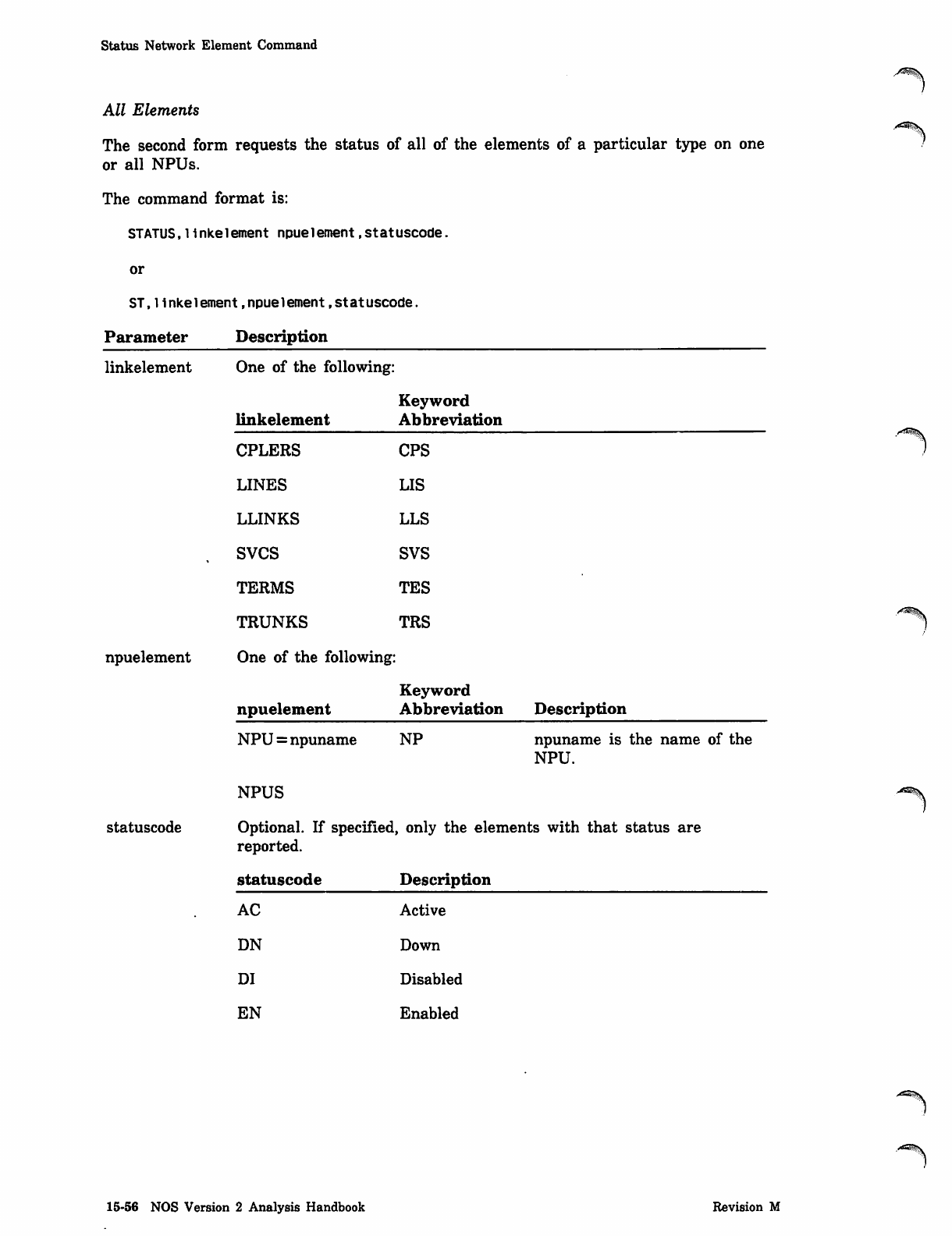
Status Network Element Command
All Elements
The second form requests the status of all of the elements of a particular type on one
or all NPUs.
The command format is:
STATUS,1inkelement npue1ement,statuscode.
or
ST,1inkelement,npue1ement,st at uscode.
Parameter Description
linkelement One of the following
linkelement Keyword
Abbreviation
CPLERS CPS
LINES LIS
LLINKS LLS
,SVCS SVS
TERMS TES
TRUNKS TRS
npuelement One of the following
npuelement
Keyword
Abbreviation Description
NPU = npuname NP npuname is the name of the
NPU.
NPUS
statuscode Optional. If specified, only the elements with that status are
reported.
statuscode
AC
DN
DI
EN
Description
Active
Down
Disabled
Enabled
15-56 NOS Version 2 Analysis Handbook Revision M
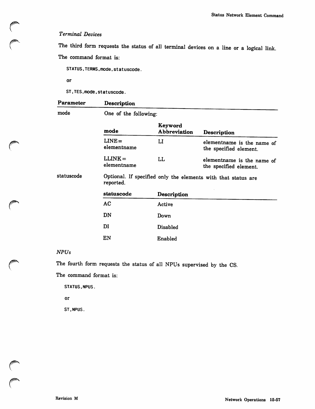
0imu..
Status Network Element Command
Terminal Devices
The third form requests the status of all terminal devices on a line or a logical link.
The command format is:
STATUS,TERMS,mode,st at uscode.
or
ST,TES,mode,st at uscode.
Parameter Description
mode One of the following
mode Keyword
Abbreviation Description
LINE =
elementname
L I e l e m e n t n a m e i s t h e n a m e o f
the specified element.
LLINK =
elementname
LL elementname is the name of
the specified element.
statuscode Optional. If specified
reported.
i only the elements with that status are
statuscode
AC
Description
Active
DN Down
DI Disabled
EN Enabled
NPUs
The fourth form requests the status of all NPUs supervised by the CS.
The command format is:
STATUS,NPUS.
or
ST,NPUS.
Revision M Network Operations 15-57
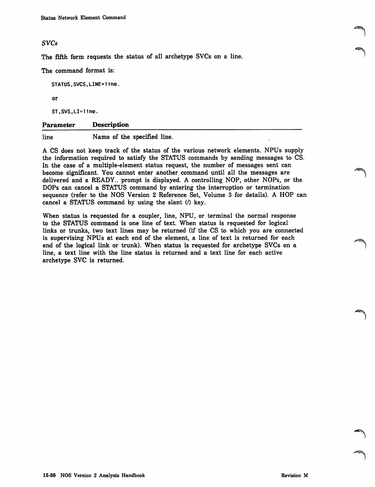
Status Network Element Command
SVCs
The fifth form requests the status of all archetype SVCs on a line.
The command format is:
STATUS,SVCS,LINE=line.
or
ST,SVS,LI=line.
Parameter Description
line Name of the specified line.
A CS does not keep track of the status of the various network elements. NPUs supply
the information required to satisfy the STATUS commands by sending messages to CS.
In the case of a multiple-element status request, the number of messages sent can
become significant. You cannot enter another command until all the messages are ^^
delivered and a READY., prompt is displayed. A controlling NOP, other NOPs, or the
DOPs can cancel a STATUS command by entering the interruption or termination
sequence (refer to the NOS Version 2 Reference Set, Volume 3 for details). A HOP can
cancel a STATUS command by using the slant (/) key.
When status is requested for a coupler, line, NPU, or terminal the normal response
to the STATUS command is one line of text. When status is requested for logical
links or trunks, two text lines may be returned (if the CS to which you are connected
is supervising NPUs at each end of the element, a line of text is returned for each /rt?_
end of the logical link or trunk). When status is requested for archetype SVCs on a j
line, a text line with the line status is returned and a text line for each active
archetype SVC is returned.
A&e&S
_,*33gv
15-58 NOS Version 2 Analysis Handbook Revision M
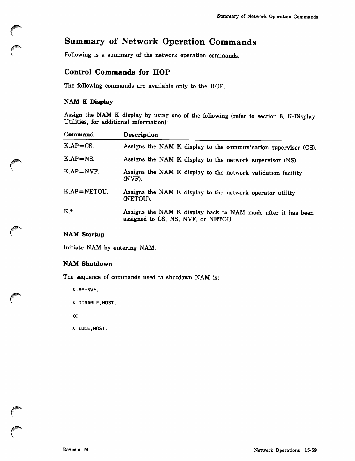
j/p^?V
Summary of Network Operation Commands
Summary of Network Operation Commands
Following is a summary of the network operation commands.
Control Commands for HOP
The following commands are available only to the HOP.
NAM K Display
Assign the NAM K display by using one of the following (refer to section 8, K-Display
Utilities, for additional information):
Command Description
K.AP=CS. Assigns the NAM K display to the communication supervisor (CS).
K.AP = NS. Assigns the NAM K display to the network supervisor (NS).
K.AP = NVF. Assigns the NAM K display to the network validation facility
(NVF).
K.AP = NETOU. Assigns the NAM K display to the network operator utility
(NETOU).
K.* Assigns the NAM K display back to NAM mode after it has been
assigned to CS, NS, NVF, or NETOU.
NAM Startup
Initiate NAM by entering NAM.
NAM Shutdown
The sequence of commands used to shutdown NAM is:
K.AP=NVF.
K.DISABLE,HOST.
or
K.IDLE,HOST.
Revision M Network Operations 15-59
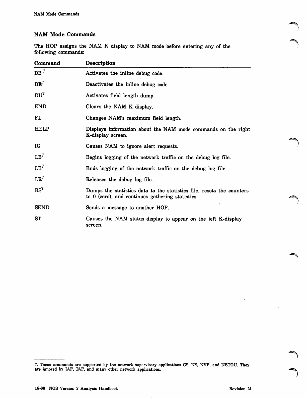
NAM Mode Commands
NAM Mode Commands
The HOP assigns the NAM K display to NAM mode before entering any of the
following commands:
Command
DB'
DE7
DU7
END
FL
HELP
IG
LB7
LE7
LR7
RS7
SEND
ST
Description
Activates the inline debug code.
Deactivates the inline debug code.
Activates field length dump.
Clears the NAM K display.
Changes NAM's maximum field length.
Displays information about the NAM mode commands on the right
K-display screen.
Causes NAM to ignore alert requests.
Begins logging of the network traffic on the debug log file.
Ends logging of the network traffic on the debug log file.
Releases the debug log file.
Dumps the statistics data to the statistics file, resets the counters
to 0 (zero), and continues gathering statistics.
Sends a message to another HOP.
Causes the NAM status display to appear on the left K-display
screen.
/*^^\
7. These commands are supported by the network supervisory applications CS, NS, NVF, and NETOU. They
are ignored by IAF, TAF, and many other network applications.
15-60 NOS Version 2 Analysis Handbook Revision M
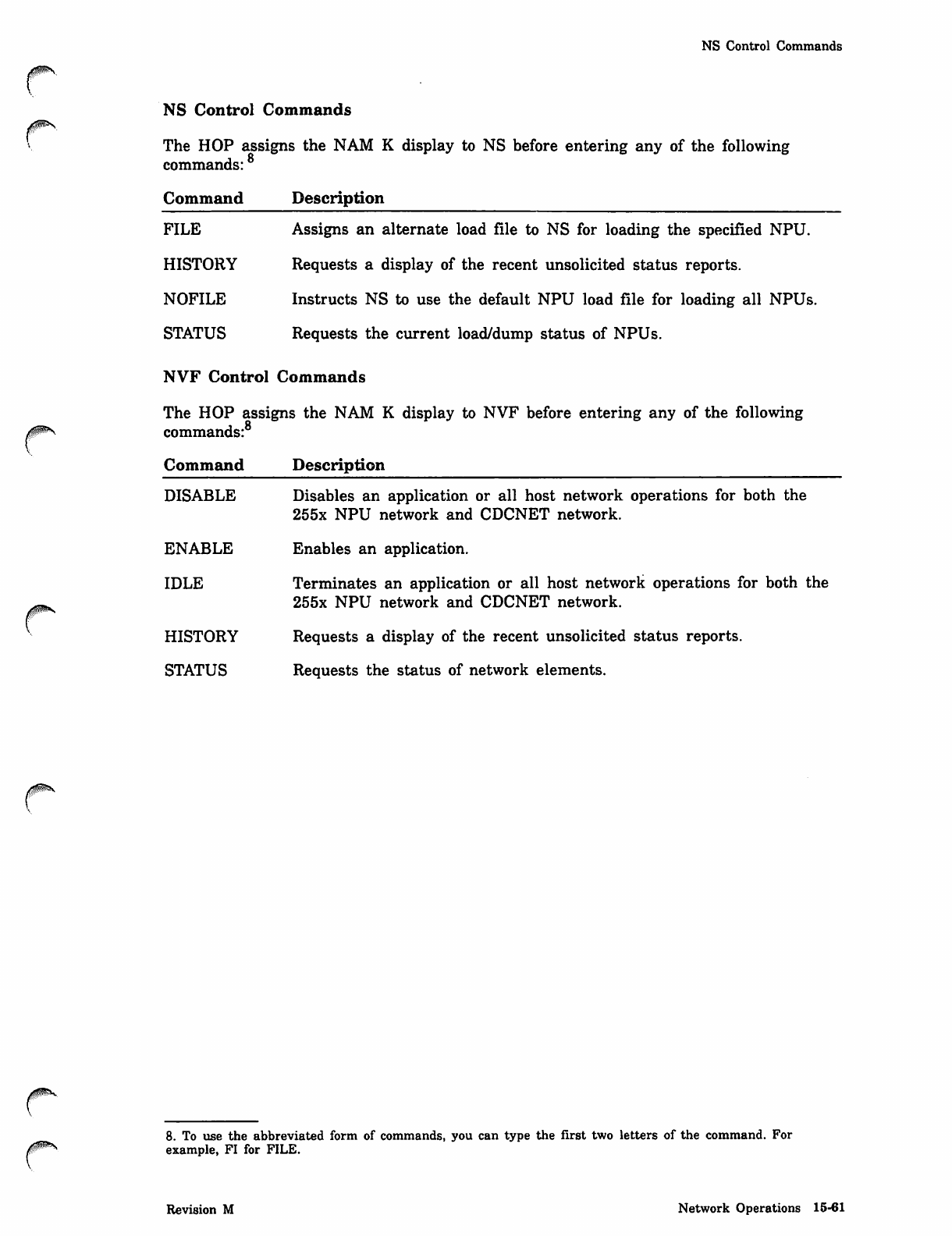
NS Control Commands
0ms
NS Control Commands
The HOP assigns the NAM K display to NS before entering any of the following
commands:
Command Description
FILE Assigns an alternate load file to NS for loading the specified NPU.
HISTORY Requests a display of the recent unsolicited status reports.
NOFILE Instructs NS to use the default NPU load file for loading all NPUs.
STATUS Requests the current load/dump status of NPUs.
NVF Control Commands
The HOP assigns the NAM K display to NVF before entering any of the following
commands:
Command Description
DISABLE Disables an application or all host network operations for both the
255x NPU network and CDCNET network.
ENABLE Enables an application.
IDLE Terminates an application or all host network operations for both the
255x NPU network and CDCNET network.
HISTORY Requests a display of the recent unsolicited status reports.
STATUS Requests the status of network elements.
n8. To use the abbreviated form of commands, you can type the first two letters of the command. For
example, FI for FILE.
Revision M Network Operations 15-61
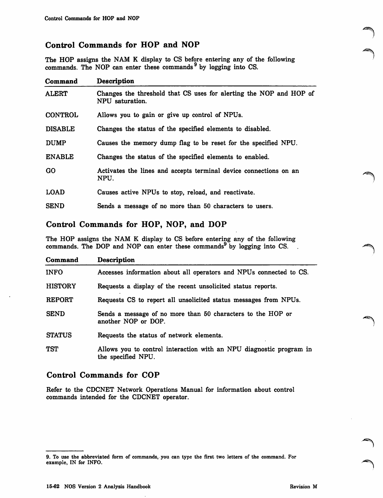
Control Commands for HOP and NOP
Control Commands for HOP and NOP
The HOP assigns the NAM K display to CS before entering any of the following
commands. The NOP can enter these commands by logging into CS.
Command Description
ALERT Changes the threshold that CS uses for alerting the NOP and HOP of
NPU saturation.
CONTROL Allows you to gain or give up control of NPUs.
DISABLE Changes the status of the specified elements to disabled.
DUMP Causes the memory dump flag to be reset for the specified NPU.
ENABLE Changes the status of the specified elements to enabled.
GO Activates the lines and accepts terminal device connections on an
NPU.
LOAD Causes active NPUs to stop, reload, and reactivate.
SEND Sends a message of no more than 50 characters to users.
Control Commands for HOP, NOP, and DOP
The HOP assigns the NAM K display to CS before entering any of the following
commands. The DOP and NOP can enter these commands by logging into CS.
Command Description
INFO Accesses information about all operators and NPUs connected to CS.
HISTORY Requests a display of the recent unsolicited status reports.
REPORT Requests CS to report all unsolicited status messages from NPUs.
SEND Sends a message of no more than 50 characters to the HOP or
another NOP or DOP.
STATUS Requests the status of network elements.
TST Allows you to control interaction with an NPU diagnostic program in
the specified NPU.
Control Commands for COP
Refer to the CDCNET Network Operations Manual for information about control
commands intended for the CDCNET operator.
9. To use the abbreviated form of commands, you can type the first two letters of the command. For
example, IN for INFO. ,^*^n
15-62 NOS Version 2 Analysis Handbook Revision M
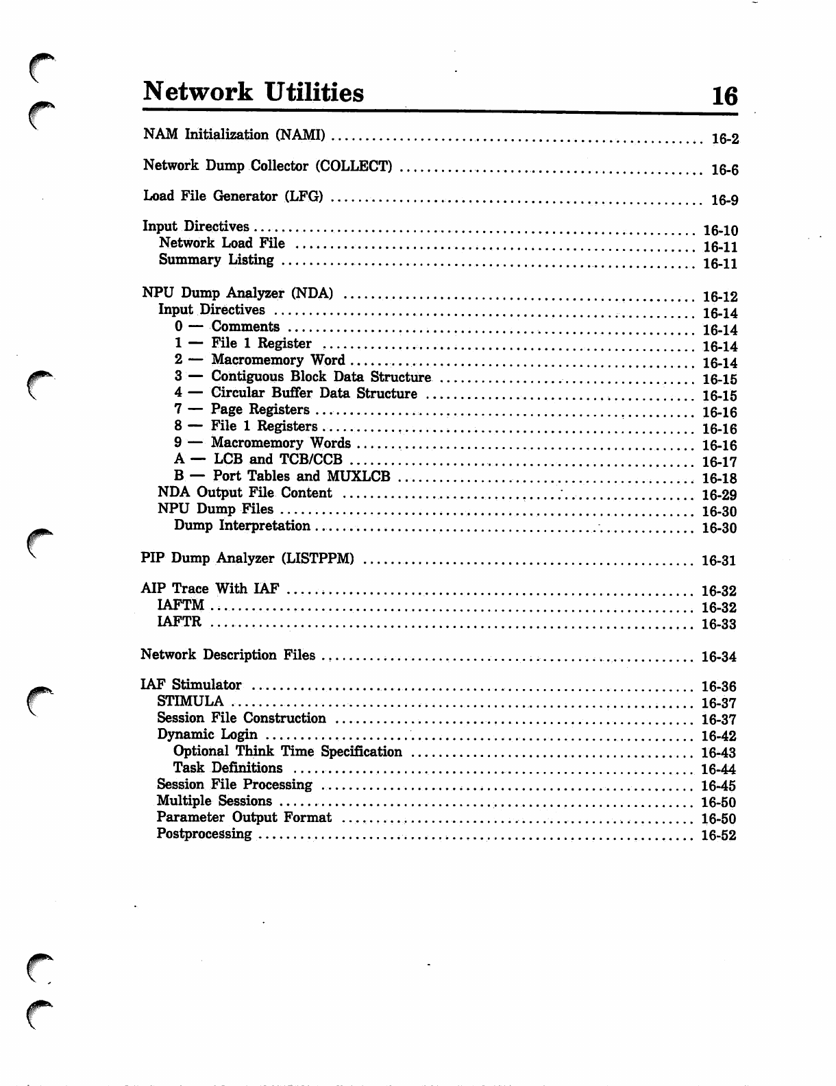
f- Network Utilities 16
NAM Initialization (NAMI) # ig_2
Network Dump Collector (COLLECT) 16-6
Load File Generator (LFG) lg_9
Input Directives 16-10
Network Load File 16-11
Summary Listing 16-11
NPU Dump Analyzer (NDA) 16-12
Input Directives ..'.. 16-14
0 — Comments 16-14
1 — File 1 Register , 16-14
2 — Macromemory Word 16-14
3 — Contiguous Block Data Structure 16-15
4 — Circular Buffer Data Structure 16-15
7 — Page Registers 16-16
8 — File 1 Registers , 16-16
9 — Macromemory Words 16-16
A — LCB and TCB/CCB 16-17
B.— Port Tables and MUXLCB 16-18
NDA Output File Content 16-29
NPU Dump Files 16-30
Dump Interpretation 16-30
PIP Dump Analyzer (LISTPPM) 16-31
AIP Trace With IAF 16-32
IAFTM 16-32
IAFTR 16-33
Network Description Files , 16-34
IAF Stimulator 16-36
STIMULA .. 16-37
Session File Construction 16-37
Dynamic Login 16-42
Optional Think Time Specification 16-43
Task Definitions 16-44
Session File Processing 16-45
Multiple Sessions 16-50
Parameter Output Format , 16-50
Postprocessing 16-52
^

0$ms
Network Utilities 16
NAM supports two types of networks: the 255x NPU network and the CDCNET
network. Throughout this section, the term network refers to the 255x NPU network.
However, whenever a statement is applicable to both network types, both types are
named explicitly.
This section describes the following utilities and files involved in the operation of the
networks and interactive subsystems of NOS.
• NAM Initialization (NAMI). This utility controls the network software startup
process.
9 Network Dump Collector (COLLECT). This utility produces tape files from the
various NPU, CDCNET device interface, and host dump, trace, statistics, and list
files that were generated by any abnormal termination of either the 255x NPU
network or the CDCNET network.
• Load File Generator (LFG). This utility produces a direct access file used by the
Network Access Method (NAM) to perform the downline load of network
processing units (NPUs).
• NPU Dump Analyzer (NDA). This utility produces readable listings from dump
files produced when NAM dumps NPUs.
• PIP Dump Analyzer (LISTPPM). This utility program converts binary records from
the peripheral interface package (PIP) memory dump file into a report listed in
byte format.
• Application Interface Program (AIP) Trace. This utility produces a trace file of the
messages transferred between an application program and NAM. The information
contained in this trace can be useful in tracking network problems and in
debugging application programs.
•
•
Network description files. Network description files are used by the Transaction
Facility (TAF) to describe user access characteristics defined by terminal definition
directives.
IAF stimulator. The IAF stimulator is a collection of programs that artificially
loads the system to analyze the effects of such a load on system performance and
reliability.
Other utilities used with the CDCNET network are documented in the CDCNET
Network Analysis Manual.
Revision M Network Utilities 16-1
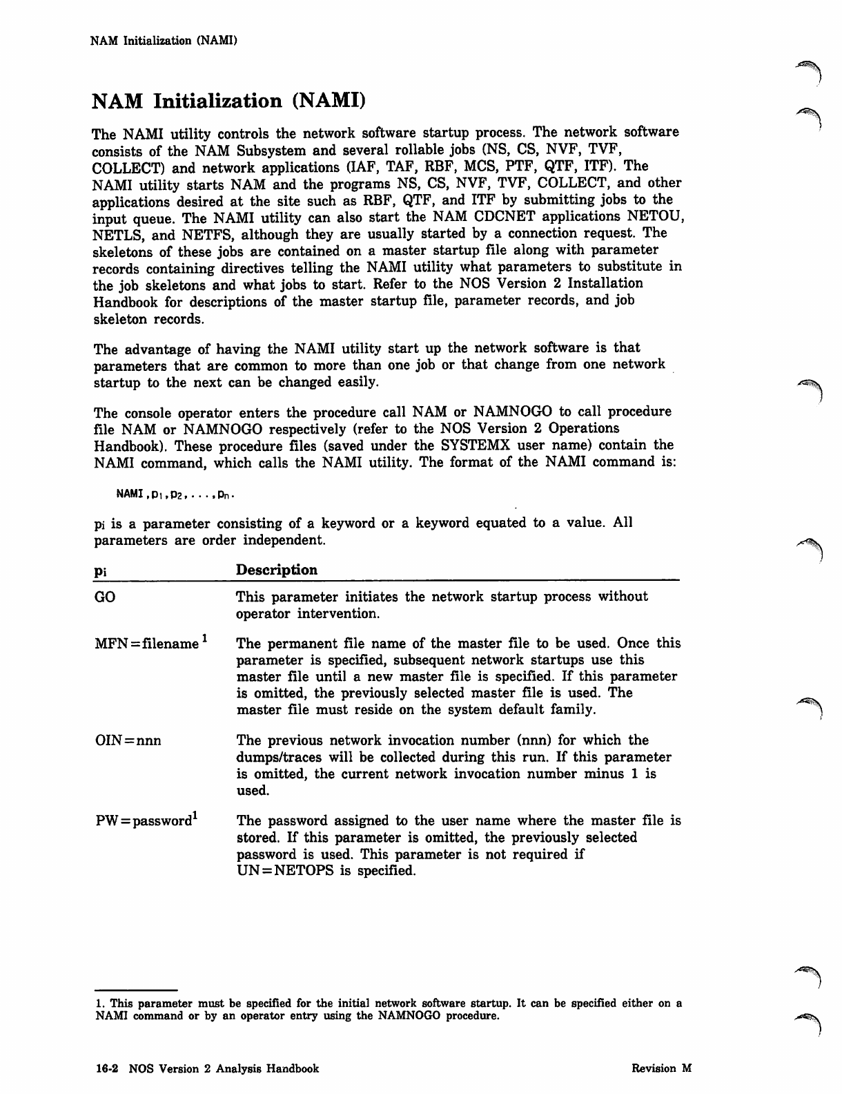
NAM Initialization (NAMI)
NAM Initialization (NAMI)
The NAMI utility controls the network software startup process. The network software
consists of the NAM Subsystem and several rollable jobs (NS, CS, NVF, TVF,
COLLECT) and network applications (IAF, TAF, RBF, MCS, PTF, QTF, ITF). The
NAMI utility starts NAM and the programs NS, CS, NVF, TVF, COLLECT, and other
applications desired at the site such as RBF, QTF, and ITF by submitting jobs to the
input queue. The NAMI utility can also start the NAM CDCNET applications NETOU,
NETLS, and NETFS, although they are usually started by a connection request. The
skeletons of these jobs are contained on a master startup file along with parameter
records containing directives telling the NAMI utility what parameters to substitute in
the job skeletons and what jobs to start. Refer to the NOS Version 2 Installation
Handbook for descriptions of the master startup file, parameter records, and job
skeleton records.
The advantage of having the NAMI utility start up the network software is that
parameters that are common to more than one job or that change from one network
startup to the next can be changed easily.
The console operator enters the procedure call NAM or NAMNOGO to call procedure
file NAM or NAMNOGO respectively (refer to the NOS Version 2 Operations
Handbook). These procedure files (saved under the SYSTEMX user name) contain the
NAMI command, which calls the NAMI utility. The format of the NAMI command is:
NAMI.P1.P2 pn.
pi is a parameter consisting of a keyword or a keyword equated to a value. All
parameters are order independent.
Pi Description
GO
MFN=filename
OIN=nnn
PW=password1
This parameter initiates the network startup process without
operator intervention.
The permanent file name of the master file to be used. Once this
parameter is specified, subsequent network startups use this
master file until a new master file is specified. If this parameter
is omitted, the previously selected master file is used. The
master file must reside on the system default family.
The previous network invocation number (nnn) for which the
dumps/traces will be collected during this run. If this parameter
is omitted, the current network invocation number minus 1 is
used.
The password assigned to the user name where the master file is
stored. If this parameter is omitted, the previously selected
password is used. This parameter is not required if
UN=NETOPS is specified.
1. This parameter must be specified for the initial network software startup. It can be specified either on a
NAMI command or by an operator entry using the NAMNOGO procedure.
16-2 NOS Version 2 Analysis Handbook Revision M
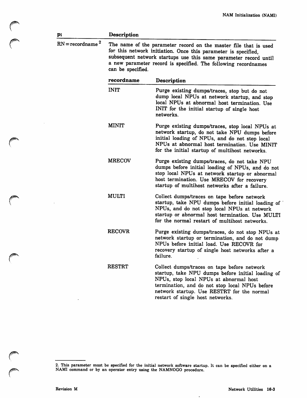
NAM Initialization (NAMI)
0ms
Pi Description
RN = recordname 2 The name of the parameter record on the master file that is used
for this network initiation. Once this parameter is specified,
subsequent network startups use this same parameter record until
a new parameter record is specified. The following recordnames
can be specified.
recordname
INIT
MINIT
MRECOV
MULTI
RECOVR
RESTRT
Description
Purge existing dumps/traces, stop but do not
dump local NPUs at network startup, and stop
local NPUs at abnormal host termination. Use
INIT for the initial startup of single host
networks.
Purge existing dumps/traces, stop local NPUs at
network startup, do not take NPU dumps before
initial loading of NPUs, and do not stop local
NPUs at abnormal host termination. Use MINIT
for the initial startup of multihost networks.
Purge existing dumps/traces, do not take NPU
dumps before initial loading of NPUs, and do not
stop local NPUs at network startup or abnormal
host termination. Use MRECOV for recovery
startup of multihost networks after a failure.
Collect dumps/traces on tape before network
startup, take NPU dumps before initial loading of
NPUs, and do not stop local NPUs at network
startup or abnormal host termination. Use MULTI
for the normal restart of multihost networks.
Purge existing dumps/traces, do not stop NPUs at
network startup or termination, and do not dump
NPUs before initial load. Use RECOVR for
recovery startup of single host networks after a
failure.
Collect dumps/traces on tape before network
startup, take NPU dumps before initial loading of
NPUs, stop local NPUs at abnormal host
termination, and do not stop local NPUs before
network startup. Use RESTRT for the normal
restart of single host networks.
2. This parameter must be specified for the initial network software startup. It can be specified either on a
NAMI command or by an operator entry using the NAMNOGO procedure.
Revision M Network Utilities 16-3
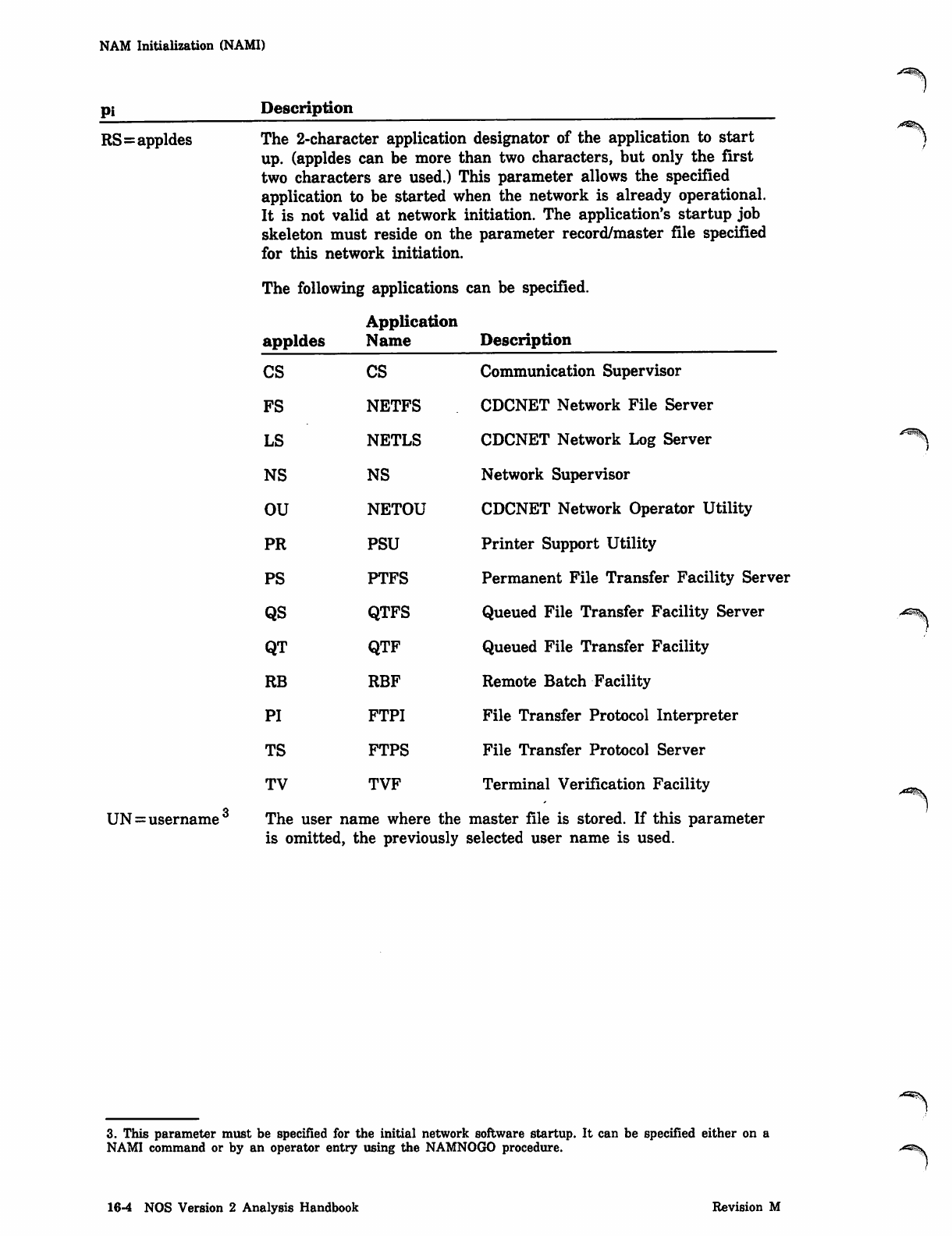
NAM Initialization (NAMI)
Pi Description
RS=appldes The 2-character application designator of the application to start
up. (appldes can be more than two characters, but only the first
two characters are used.) This parameter allows the specified
application to be started when the network is already operational.
It is not valid at network initiation. The application's startup job
skeleton must reside on the parameter record/master file specified
for this network initiation.
The following applications can be specified.
Application
appldes Name
CS
FS
LS
NS
OU
PR
PS
QS
QT
RB
PI
TS
TV
Description
CS
NETFS
NETLS
NS
NETOU
PSU
PTFS
QTFS
QTF
RBF
FTPI
FTPS
TVF
UN = username 3 The user name where the
is omitted, the previously
Communication Supervisor
CDCNET Network File Server
CDCNET Network Log Server
Network Supervisor
CDCNET Network Operator Utility
Printer Support Utility
Permanent File Transfer Facility Server
Queued File Transfer Facility Server
Queued File Transfer Facility
Remote Batch Facility
File Transfer Protocol Interpreter
File Transfer Protocol Server
Terminal Verification Facility
master file is stored. If this parameter
selected user name is used.
3. This parameter must be specified for the initial network software startup. It can be specified either on a
NAMI command or by an operator entry using the NAMNOGO procedure.
16-4 NOS Version 2 Analysis Handbook Revision M
jP^v
NAM Initialization (NAMI)
The first time the network startup process is executed, a permanent file is created
using a network invocation number of 1 and parameters from the NAMI command. The
initial call to NAMI must specify the filename, password, and username of the master
file and parameter record to be used or the console operator must enter them using
NAMNOGO.
On subsequent network startup operations, a permanent file exists and contains the
names of the last used master file, parameter record, and network invocation number.
Parameters from this permanent file will be used to start up the network unless
overridden by parameters from the NAMI command or parameters entered by the
console operator using NAMNOGO. The NAMI command parameters take precedence
over the permanent file parameters, and operator entries take precedence over
parameters from either the NAMI command or the permanent file.
r
Revision M Network Utilities 16-5
Network Dump Collector (COLLECT)
Network Dump Collector (COLLECT)
The COLLECT utility is a program that produces three local files: one of the various
host dump, trace, statistics, and list files that result from any abnormal termination of
the network, one of any NPU dump files, and one of any MDI/MTI/NDI/TDI dump files.
The collected files may be copied to the three local files and then purged, or copied
and not purged. The local files will then be copied to tapes. There is also an option to
purge the collected files without copying them to the local files. The format of the
COLLECT command is:
COLLECT,NIN=nnn,NOPURGE,NOSAVE.
Parameter Description
NIN=nnn The 1- to 3-character network invocation number that indicates the
upper limit of the invocation numbers to be collected. All files with an
NIN value from 1 to nnn are copied to the local file. If NIN = nnn is
omitted, the default value is 1.
NOTE
NPUs that stop when the host network software terminates are
dumped during the subsequent network invocation. Therefore, the
network invocation number of these dumps is 1 greater than the
dumps of the host programs taken at the time of the termination.
NOPURGE Specifies that no purging activity will take place after the collected
files are copied to the local files. If NOPURGE is omitted, the collected ^%
files are purged after they are copied to the local files. NOPURGE '
should not be specified if NOSAVE is specified.
NOSAVE Specifies that the collection process is not performed and the files
indicated by NIN=nnn are purged. NOSAVE should not be specified if
NOPURGE is used.
The COLLECT utility is automatically initiated by the network startup job (NAMI)
upon each invocation of the network. (COLLECT may not be automatically initiated if
the master file has been modified.) The utility receives an NIN value of the last
network invocation number. The current network will be initiated with an incremented
value of NIN. For example, on the fifth initiation of the network the COLLECT utility
has a command call of
COLLECT,NIN=004.
and the network is initiated with an NIN of 005.
•"*=%\
16-6 NOS Version 2 Analysis Handbook Revision M
y^fr^rj^
Network Dump Collector (COLLECT)
The COLLECT utility processes all dump, trace, statistics, and list files whose file
names are in the form:
pptsnnn
Variable Description
pp 2-character product prefix.
PP Description
CS Communication Supervisor
DI,...,DR,DS,...,D9 MDI/MTI/NDI/TDI Dumps
FS Network File Server
IA Interactive Facility
/^ IN INITMDI Program
IT Interactive Transfer Facility
LS Network Log Server
NI Network Interface Package
NP Network Processing Unit
NS Network Supervisor
NV Network Validation Facility
OS Network Operator Server
PR Printer Support Utility
PS Permanent File Transfer Facility Server
QS Queued File Transfer Facility Server
QT Queued File Transfer Facility
RB Remote Batch Facility
TI File Transfer Protocol Interpreter
TS File Transfer Protocol Server
TV Terminal Verification Facility
Revision M Network Utilities 16-7
Network Dump Collector (COLLECT)
Variable Description
tType of file.
t Description
D
L
S
T
Dump file.
List file.
Statistics file.
Trace file.
s
nnn
Subtype 0, 1, 2, or 3 for the file.
Network invocation number in the range 000 through 999.
In the case of NPU dumps (pp=NP), ts is a unique hexadecimal number identifying
the dump. In the case of DI dumps (pp = DI to DZ, or DI to D9), ts is a unique
character string identifying the dump. This character string is in the range from AA to
99. In the case of dayfile dumps, ts is DA. The files produced by the COLLECT utility
each have one file with many records. Each dump, trace, statistics, or list file is copied
to a local file as one or more records, where the first record copied is preceded by a
2-word record containing the original file name. This format enables an ITEMIZE or
CATALOG of a COLLECT utility local file to show which collected files were copied to
the local file.
The COLLECT utility assigns each file a file name of the form:
Form Description
DUMPnnn For host dump, trace, statistics, or list files, nnn is the network
invocation number from the COLLECT command.
DUNPnnn For NPU dump files, nnn is the network invocation number from the
COLLECT command.
DMDInnn For DI dump files, nnn is the network invocation number from the
COLLECT command.
The local files are copied to magnetic tape (or other operator-assigned equipment) if the
RESTRT or MULTI startup procedure is selected. Once the files are successfully copied,
COLLECT will be executed again to purge the collected files.
The COLLECT utility purges all dump and trace files without collecting them on a
local file if the INIT, MINIT, MRECOV, or RECOVR startup procedure is selected.
16-8 NOS Version 2 Analysis Handbook Revision M
0^S
Load File Generator (LFG)
Load File Generator (LFG)
LFG is a utility program that reformats Communications Control Program (CCP) files
for subsequent use by the network supervisor of NAM to load NPUs. LFG accepts one
or more input files in single or multifile format and produces a single network load file
(NLF) for use by the network supervisor.
LFG is invoked with this command:
L F G , p 1 t P 2 P n -
pi is a parameter consisting of a keyword or a keyword equated to a value. All
parameters are optional and order independent.
pi Description
BC-nn This parameter specifies the maximum number of load service
messages in a network load file record. It is used to optimize
NPU loads. 1 ^ nn ^ 64.
BC omitted Same as BC = 64.
I = infile The 1- to 7-character name of the file on which the input
directives are written.
I om i tt e d Sa me a s I = IN PU T.
L = outfile The 1- to 7-character name of the file on which the summary
listing is to be written.
L=0 Suppress the summary listing. If an error is detected an error
message is written to file OUTPUT.
L omitted Same as L=OUTPUT.
NLF = loadfile The 1- to 7-character name of the network load file.
NLF omitted Same as NLF = NLF.
Z An input directive is contained on the command after the
terminator. The I parameter is ignored. This eliminates the need
to use a separate input directive file when there are only a few
input directives.
When the input directive appears on the LFG command, the first
character following the command terminator is the separator
character. Any character that is not used in the input directive
can be used as the separator character. The input directive must
be preceded by a separator and terminated by a blank, period, or
the end of the input line (column 72).
For example, (slant used for separator):
LFG,Z./*FILE,PFILE1.PFILE2.
Z omitted Input directives are not contained on the command. The system
uses the I parameter.
Revision M Network Utilities 16-9
Input Directives
Input Directives
Input directives have this format:
♦FILE.filenamei.filename2,... .filenamen.
An input" directive begins with an asterisk followed by the directive identifier FILE and
a string of file names. The directive identifier and file names are separated by
commas. If a specified file is empty, LFG ignores it. LFG scans a directive until it
detects a terminator or the end of the directive line (column 72). A directive is
terminated by a blank, period, or the end of the line. If an asterisk is not specified,
LFG assumes *FILE and proceeds to read file names. LFG continues to read input
directives until the end of the record.
Each file specified by filename contains a load partition or a program initiation
control block (PICB) for LFG to reformat. These files are created by the CCP
installation process (refer to the NOS Version 2 Installation Handbook). A load
partition is any loadable software module that can be loaded into an NPU during one
operation. For example, all of the software for CCP can be loaded into an NPU as
one load partition. A PICB consists of a sequence of commands that controls the load
or dump operations. For each step in a PICB that specifies a load operation there is
a corresponding load partition.
The names of the input files can be specified on the LFG command (Z parameter) or
in a separate file (I = infile parameter). In either case, these files must be local to the
job that runs LFG. LFG does not rewind the input files.
If the input directives are written on a separate record in a batch job (I = INPUT),
the job format is:
ujn.
USER,username,password,fami 1yname.
LFG,I=INPUT.
—EOR--
•FILE,AFILE1,
•FILE,BFILE1,
•FILE.CFILE1,
—EOI—
.AFILEn.
.BFILEn.
.CFILEn.
file INPUT
"^55\
16-10 NOS Version 2 Analysis Handbook Revision M
Network Load File
Network Load File
The network load file produced by LFG is a random access file with the local file
name specified by the NLF parameter of the LFG command. The default network load
file name is NLF.
Summary Listing
The summary listing produced by LFG is a summary of the network load file contents.
The summary is written on the file specified by the L parameter of the LFG command.
The default summary file name is OUTPUT. Error messages produced by LFG are also
written on this file. The summary listing format is:
NO. PARTITION NAME INPUT FILE RECORDS
1 P N 1 A F I L E 1 3
2 P N 2 A F I L E 2 7
3 P N 3 A F I L E 3 2
Field Description
NO. Line number of the summary listing.
PARTITION Name of the load partition or PICB for LFG to reformat.
NAME
INPUT FILE Name of the input file on which the load partition or PICB
resides.
RECORDS Number of records in the load partition or PICB.
Revision M Network Utilities 16-11
NPU Dump Analyzer (NDA)
NPU Dump Analyzer (NDA)
NDA is a utility program that produces a readable printout from the NPU dump file.
The NPU dump file may contain one or more dump records, which are created by the
network supervisor during the initiation or reloading of a failed NPU. NDA reports
depict the state of an NPU at the time a dump is generated. NDA uses the following
local scratch files during its processing: NEUFILE, ZZZZINP, and FDMP.
NDA is accessed by a command that allows selection of:
• Dumps from/to specific NPU macromemory addresses.
• Listing options.
• The input directive file.
• The output file.
The format of the command for the NPU Dump Analyzer is: ^^
NDA.PLP2.. ...Pn-
Each parameter is a keyword or a keyword equated to a value. All parameters are
optional and order independent. If a parameter is not specified, a default value is
assumed. If the same keyword is specified more than once, the last (rightmost)
occurrence of the keyword overrides all previous ones. Invalid or undefined parameters
cause the run to terminate.
pi Description A<ms
BA=addr The 1- to 6-digit hexadecimal address within the NPU
macromemory at which the dump report begins. Default is
BA=address of the actual beginning of the dump. This parameter
is valid only if parameter LO=M, LO=E, or input directive 9 is
specified.
EA=addr The 1- to 6-digit hexadecimal address within the NPU
macromemory at which the dump report ends. Default is
EA=address of the actual end of the dump. This parameter is
valid only if parameter LO = M, LO = E, or input directive 9 is
specified.
I=infile The 1- to 7-character name of the input directive file. If there is
no input directive file, 1=0 (zero) must be specified. Default is
I = INPUT.
L=outfile The 1- to 7-character name of the output file. Default is
L=OUTPUT.
^Kjv
16-12 NOS Version 2 Analysis Handbook Revision M
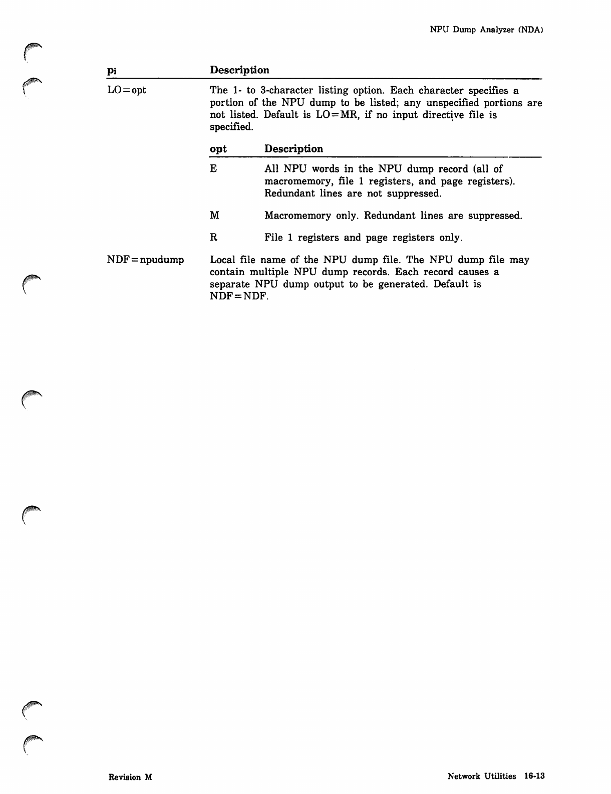
NPU Dump Analyzer (NDA)
pi Description
LO=opt The 1- to 3-character listing option. Each character specifies a
portion of the NPU dump to be listed; any unspecified portions are
not listed. Default is LO=MR, if no input directive file is
specified.
opt Description
E All NPU words in the NPU dump record (all of
macromemory, file 1 registers, and page registers).
Redundant lines are not suppressed.
M Macromemory only. Redundant lines are suppressed.
R File 1 registers and page registers only.
NDF = npudump Local file name of the NPU dump file. The NPU dump file may
r contain multiple NPU dump records. Each record causes a
separate NPU dump output to be generated. Default is
NDF = NDF.
Revision M Network Utilities 16-13
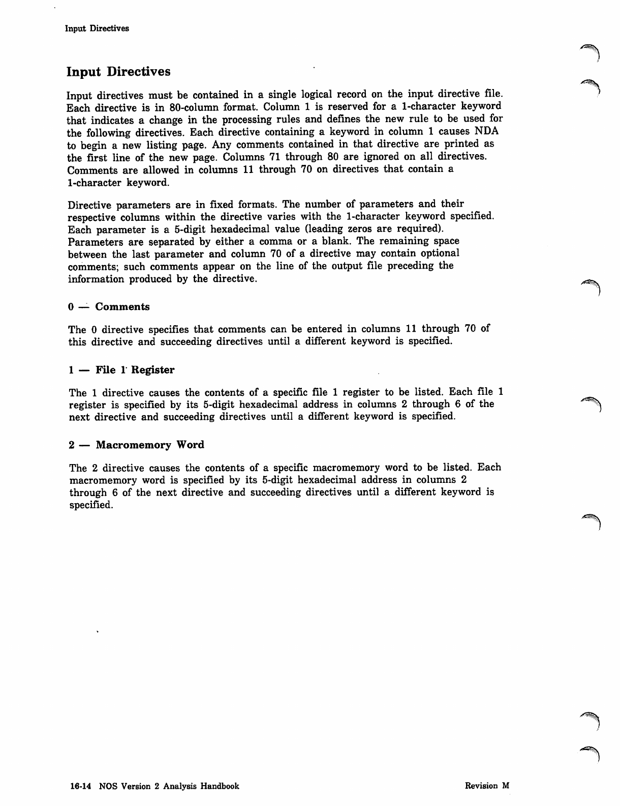
Input Directives
Input Directives
Input directives must be contained in a single logical record on the input directive file.
Each directive is in 80-column format. Column 1 is reserved for a 1-character keyword
that indicates a change in the processing rules and defines the new rule to be used for
the following directives. Each directive containing a keyword in column 1 causes NDA
to begin a new listing page. Any comments contained in that directive are printed as
the first line of the new page. Columns 71 through 80 are ignored on all directives.
Comments are allowed in columns 11 through 70 on directives that contain a
1-character keyword.
Directive parameters are in fixed formats. The number of parameters and their
respective columns within the directive varies with the 1-character keyword specified.
Each parameter is a 5-digit hexadecimal value (leading zeros are required).
Parameters are separated by either a comma or a blank. The remaining space
between the last parameter and column 70 of a directive may contain optional
comments; such comments appear on the line of the output file preceding the
information produced by the directive.
0 — Comments
The 0 directive specifies that comments can be entered in columns 11 through 70 of
this directive and succeeding directives until a different keyword is specified.
1 — File r Register
The 1 directive causes the contents of a specific file 1 register to be listed. Each file 1
register is specified by its 5-digit hexadecimal address in columns 2 through 6 of the
next directive and succeeding directives until a different keyword is specified.
^^ms
2 — Macromemory Word
The 2 directive causes the contents of a specific macromemory word to be listed. Each
macromemory word is specified by its 5-digit hexadecimal address in columns 2
through 6 of the next directive and succeeding directives until a different keyword is
specified.
^ a s v
16-14 NOS Version 2 Analysis Handbook Revision M
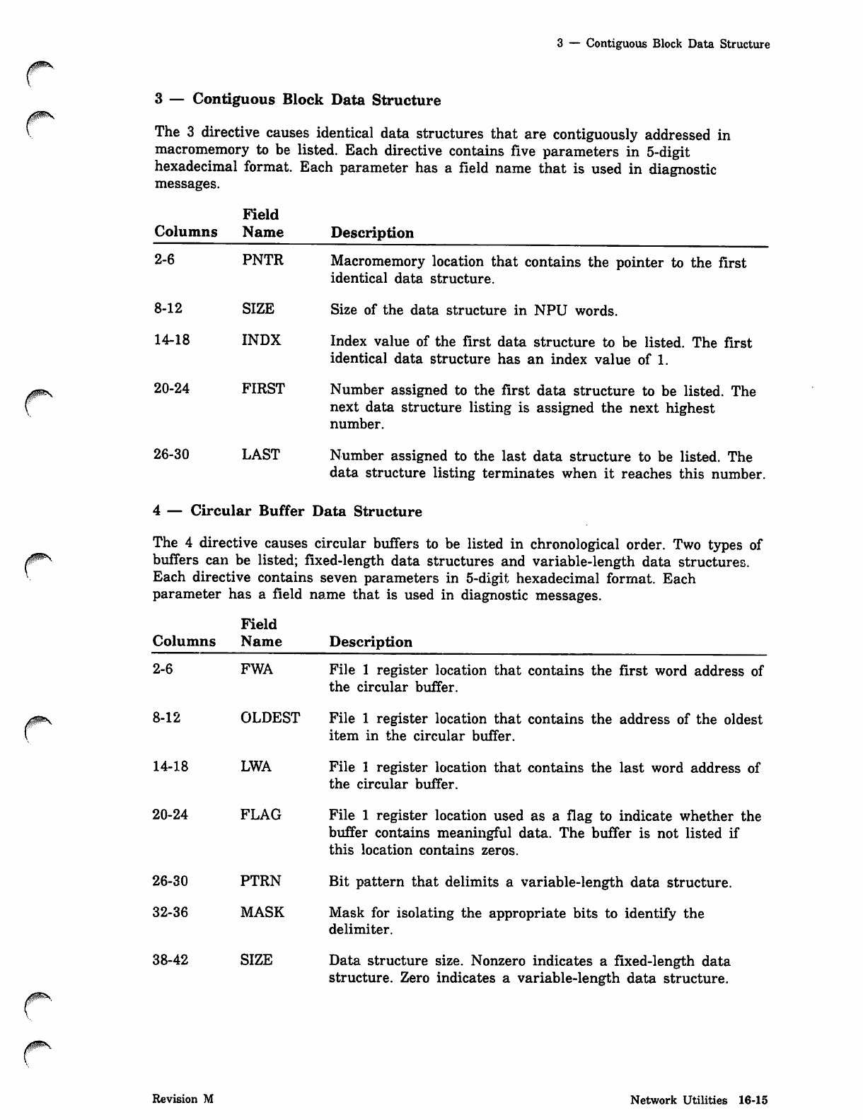
3 — Contiguous Block Data Structure
0ms
3 — Contiguous Block Data Structure
The 3 directive causes identical data structures that are contiguously addressed in
macromemory to be listed. Each directive contains five parameters in 5-digit
hexadecimal format. Each parameter has a field name that is used in diagnostic
messages.
Columns
Field
Name Description
2-6 PNTR Macromemory location that contains the pointer to the first
identical data structure.
8-12 SIZE Size of the data structure in NPU words.
14-18 INDX Index value of the first data structure to be listed. The first
identical data structure has an index value of 1.
20-24 FIRST Number assigned to the first data structure to be listed. The
next data structure listing is assigned the next highest
number.
26-30 LAST Number assigned to the last data structure to be listed. The
data structure listing terminates when it reaches this number.
4 — Circular Buffer Data Structure
The 4 directive causes circular buffers to be listed in chronological order. Two types of
buffers can be listed; fixed-length data structures and variable-length data structures.
Each directive contains seven parameters in 5-digit hexadecimal format. Each
parameter has a field name that is used in diagnostic messages.
Field
Columns Name Description
2-6 FWA File 1 register location that contains the first word address of
the circular buffer.
r8-12 OLDEST
14-18 LWA
20-24 FLAG
26-30 PTRN
32-36 MASK
38-42
File 1 register location that contains the address of the oldest
item in the circular buffer.
File 1 register location that contains the last word address of
the circular buffer.
File 1 register location used as a flag to indicate whether the
buffer contains meaningful data. The buffer is not listed if
this location contains zeros.
Bit pattern that delimits a variable-length data structure.
Mask for isolating the appropriate bits to identify the
delimiter.
SIZE Data structure size. Nonzero indicates a fixed-length data
structure. Zero indicates a variable-length data structure.
Revision M Network Utilities 16-15
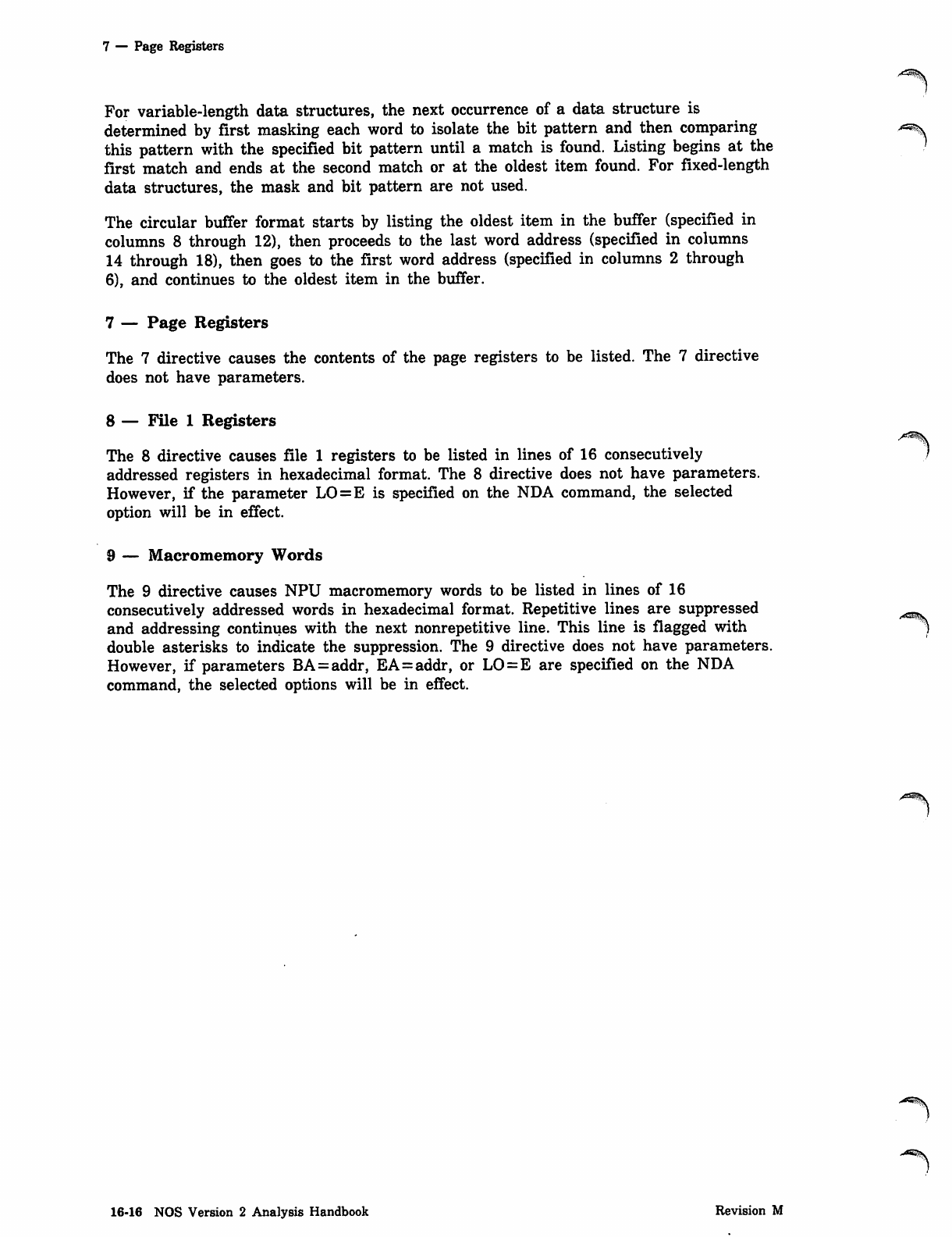
7 — Page Registers
For variable-length data structures, the next occurrence of a data structure is
determined by first masking each word to isolate the bit pattern and then comparing a*^.
this pattern with the specified bit pattern until a match is found. Listing begins at the '
first match and ends at the second match or at the oldest item found. For fixed-length
data structures, the mask and bit pattern are not used.
The circular buffer format starts by listing the oldest item in the buffer (specified in
columns 8 through 12), then proceeds to the last word address (specified in columns
14 through 18), then goes to the first word address (specified in columns 2 through
6), and continues to the oldest item in the buffer.
7 — Page Registers
The 7 directive causes the contents of the page registers to be listed. The 7 directive
does not have parameters.
8 — File 1 Registers
The 8 directive causes file 1 registers to be listed in lines of 16 consecutively /
addressed registers in hexadecimal format. The 8 directive does not have parameters.
However, if the parameter LO=E is specified on the NDA command, the selected
option will be in effect.
9 — Macromemory Words
The 9 directive causes NPU macromemory words to be listed in lines of 16
consecutively addressed words in hexadecimal format. Repetitive lines are suppressed ^^^
and addressing continues with the next nonrepetitive line. This line is flagged with 1
double asterisks to indicate the suppression. The 9 directive does not have parameters.
However, if parameters BA=addr, EA=addr, or LO = E are specified on the NDA
command, the selected options will be in effect.
16-16 NOS Version 2 Analysis Handbook Revision M
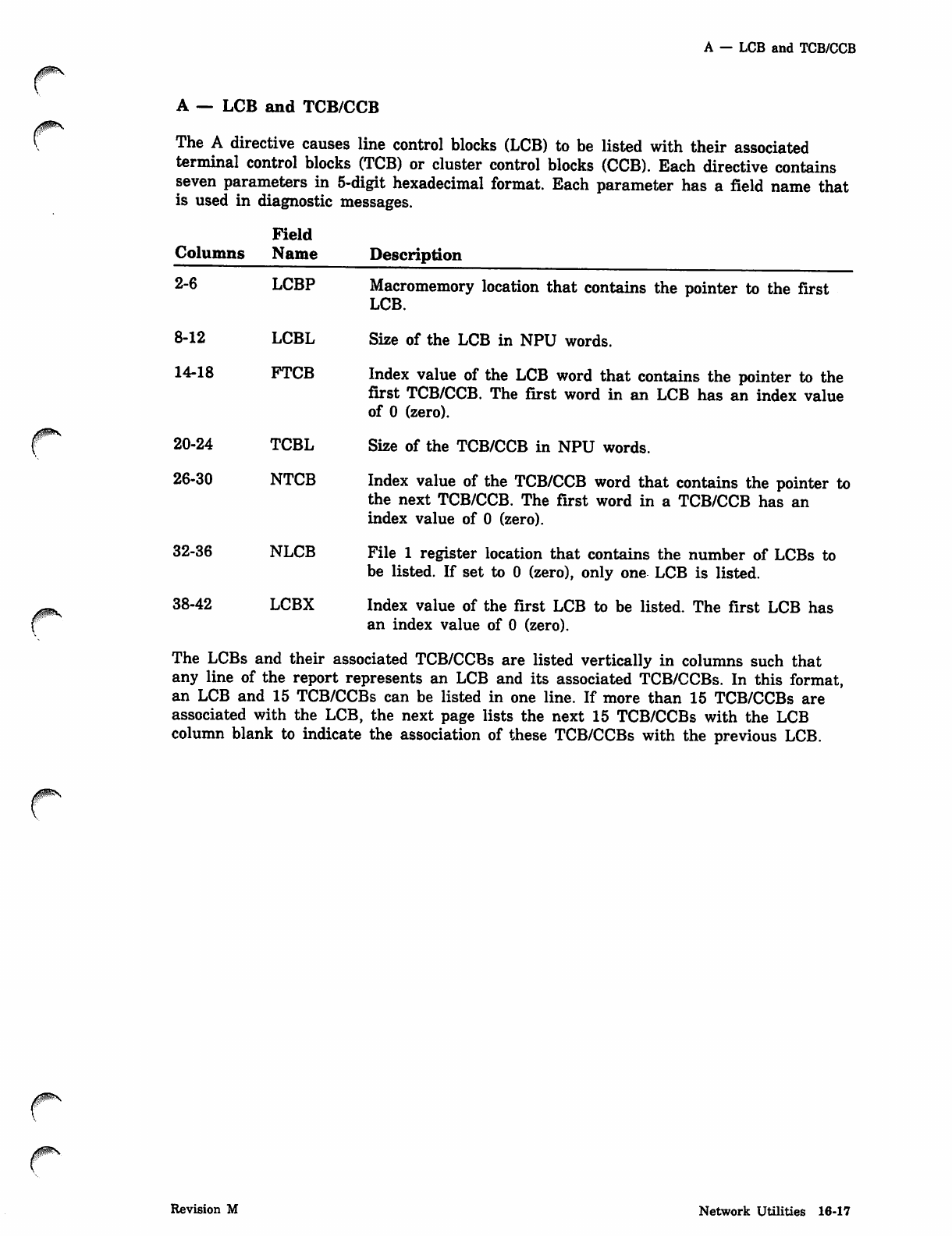
A — LCB and TCB/CCB
A — LCB and TCB/CCB
The A directive causes line control blocks (LCB) to be listed with their associated
terminal control blocks (TCB) or cluster control blocks (CCB). Each directive contains
seven parameters in 5-digit hexadecimal format. Each parameter has a field name that
is used in diagnostic messages.
Columns
Field
Name Description
2-6
8-12
14-18
20-24
26-30
32-36
38-42
LCBP Macromemory location that contains the pointer to the first
LCB.
LCBL Size of the LCB in NPU words.
FTCB Index value of the LCB word that contains the pointer to the
first TCB/CCB. The first word in an LCB has an index value
of 0 (zero).
TCBL Size of the TCB/CCB in NPU words.
NTCB Index value of the TCB/CCB word that contains the pointer to
the next TCB/CCB. The first word in a TCB/CCB has an
index value of 0 (zero).
NLCB File 1 register location that contains the number of LCBs to
be listed. If set to 0 (zero), only one LCB is listed.
LCBX Index value of the first LCB to be listed. The first LCB has
an index value of 0 (zero).
The LCBs and their associated TCB/CCBs are listed vertically in columns such that
any line of the report represents an LCB and its associated TCB/CCBs. In this format,
an LCB and 15 TCB/CCBs can be listed in one line. If more than 15 TCB/CCBs are
associated with the LCB, the next page lists the next 15 TCB/CCBs with the LCB
column blank to indicate the association of these TCB/CCBs with the previous LCB.
/fs^S.
Revision M Network Utilities 16-17
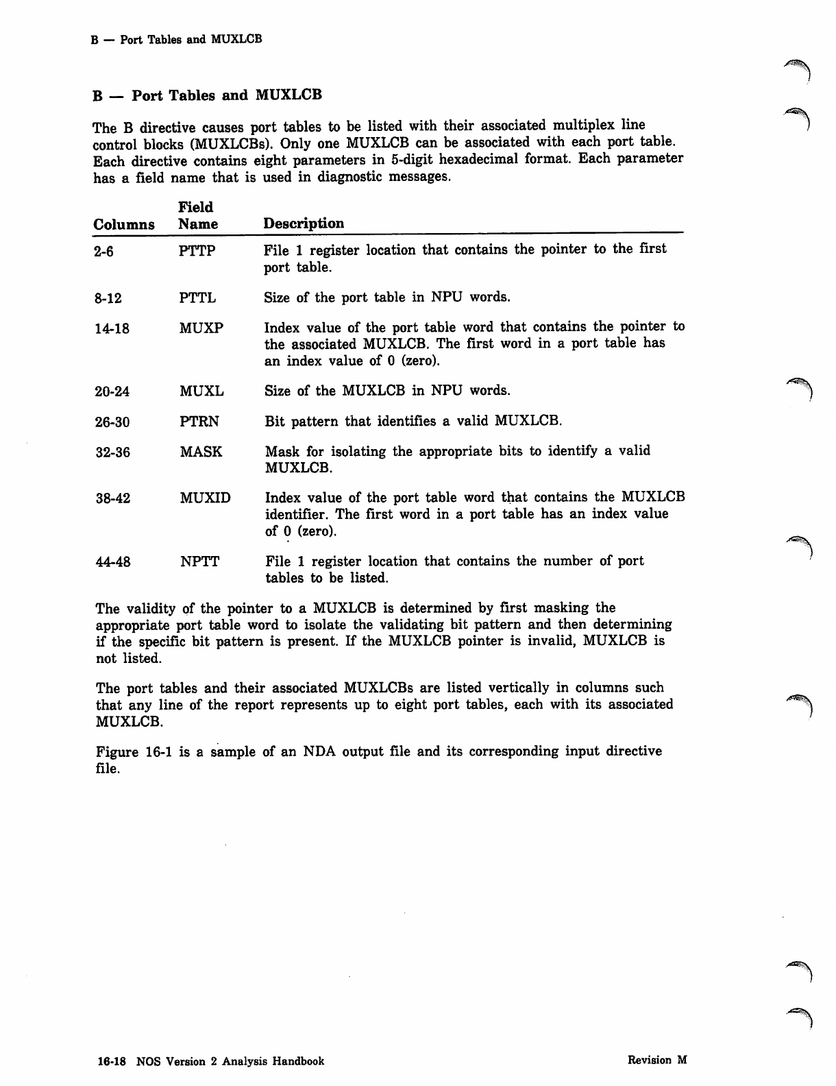
B — Port Tables and MUXLCB
B — Port Tables and MUXLCB
The B directive causes port tables to be listed with their associated multiplex line
control blocks (MUXLCBs). Only one MUXLCB can be associated with each port table.
Each directive contains eight parameters in 5-digit hexadecimal format. Each parameter
has a field name that is used in diagnostic messages.
Columns
Field
Name Description
2-6 PTTP File 1 register location that contains the pointer to the first
port table.
8-12 PTTL Size of the port table in NPU words.
14-18 MUXP Index value of the port table word that contains the pointer to
the associated MUXLCB. The first word in a port table has
an index value of 0 (zero).
20-24 MUXL Size of the MUXLCB in NPU words.
26-30 PTRN Bit pattern that identifies a valid MUXLCB.
32-36 MASK Mask for isolating the appropriate bits to identify a valid
MUXLCB.
38-42 MUXID Index value of the port table word that contains the MUXLCB
identifier. The first word in a port table has an index value
of 0 (zero).
44-48 NPTT File 1 register location that contains the number of port
tables to be listed.
The validity pf the pointer to a MUXLCB is determined by first masking the
appropriate port table word to isolate the validating bit pattern and then determining
if the specific bit pattern is present. If the MUXLCB pointer is invalid, MUXLCB is
not listed.
The port tables and their associated MUXLCBs are listed vertically in columns such
that any line of the report represents up to eight port tables, each with its associated
MUXLCB.
Figure 16-1 is a sample of an NDA output file and its corresponding input directive
file.
16-18 NOS Version 2 Analysis Handbook Revision M
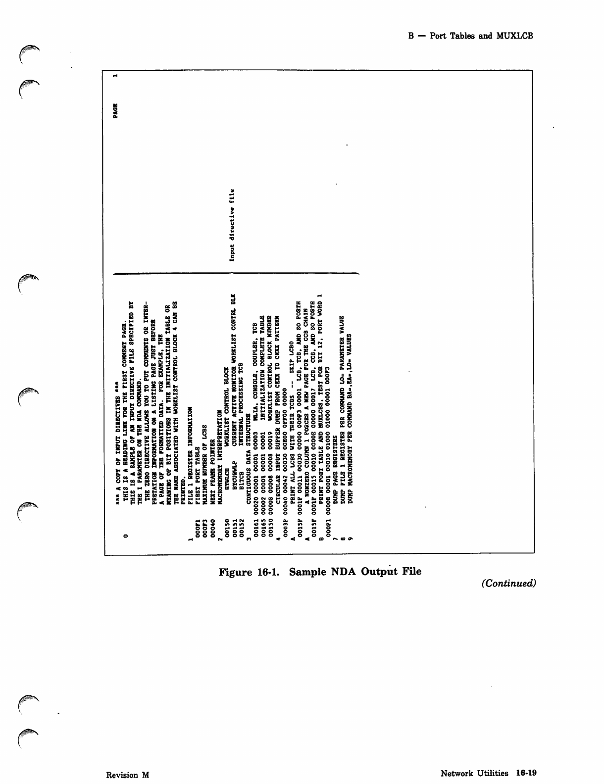
B — Port Tables and MUXLCB
ooo
o 5 o
r t r , r i r t r l r t O r t i t
O O O o o o o o o
o o o o o o o o o
Figure 16-1. Sample NDA Output File (Continued)
Revision M Network Utilities 16-19
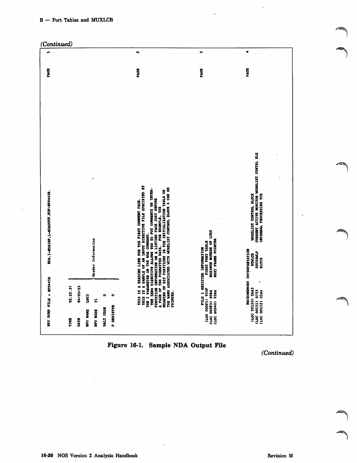
B — Port Tables and MUXLCB
(Continued)
* H -
■> 3 «si MMM
M »H
ess
8 S
HMO
fc. H 5 u.
f a% H H
« Du 9 M
B O 2 X
o < <
i* in co co
•bb.no
O k> «
OOO
§ss
s<S&S
Figure 16-1. Sample NDA Output File
(Continued)
16-20 NOS Version 2 Analysis Handbook Revision M
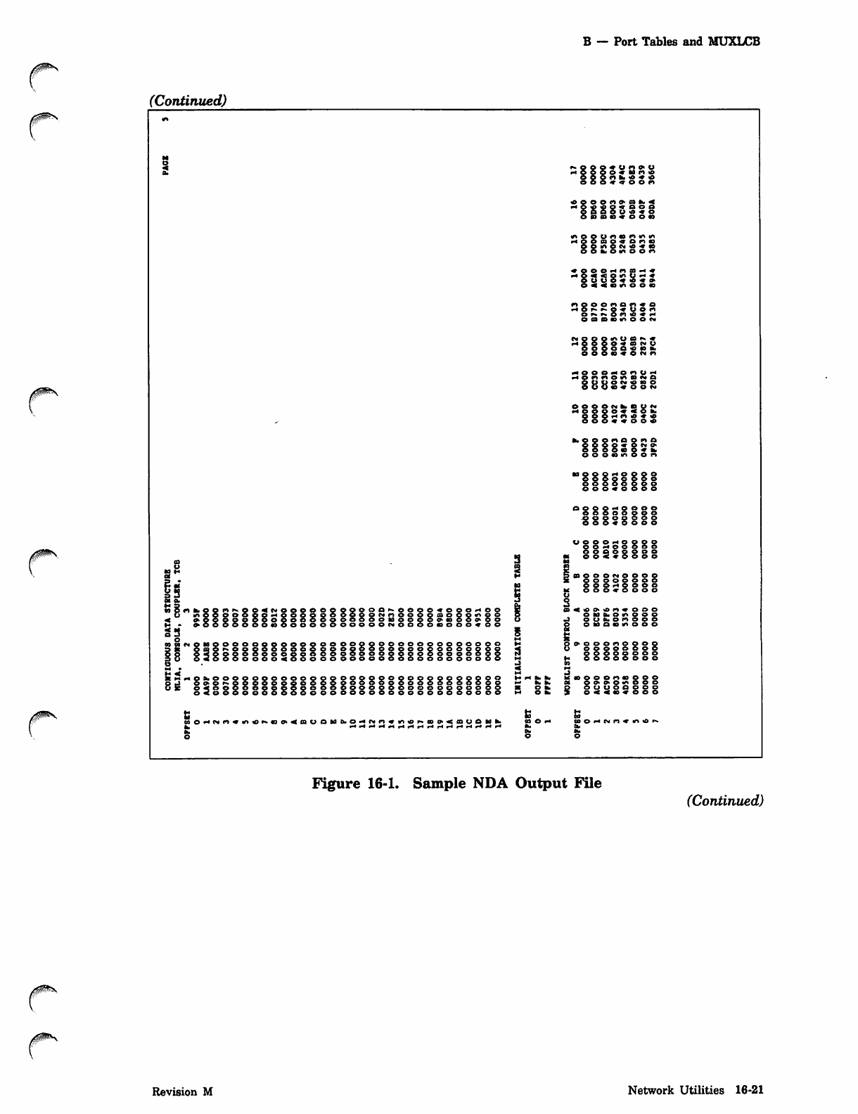
B — Port Tables and MUXLCB
(Continued)
c
r->Q04r"OppOOQOQQOO>-OOpO«OOOr4
ooSpio55ooooooocMnoooQoaoQO«t
8OOOOQOOOOQOOOOOI0OOOO9>»OOa»OOOOOOOOOOOOOOONOOOOBOOO*
3-1 S:SSSloSSiSSSl§iSSSSiSSSSS§SS8
Stoppoopppppoooopoopoooooooooo
<oooooo5o5ooooooooooooooooooo
09 O !oaoOMO.o-4(xn«m«r>(oo><cauO
■ • u a «* tt
■ o it it r» <o
> » h. <e> « <o
<«oon
«ooon»ni><
S S S o u > o « o
o»a>e«oo*>
AOOunannm
^Oono-vono
I «m k» « •»
> «i o o r>
SS:
o o <h n a •< «
u8o4««»
< « «3 tn o O a
80 O m o. n « or- r» p ■» U O cl
Or>r--O<n<£*<-I
oaoomooN
<«OOOmU03i««
H55oo«ai«o
Soooa«o».
5oo«o«©r<n
-■OOO.MOmU.-1
HOnnonBNB
5poo(v«nO
OOO«0«OOM
ooooNh.no*>
<*PPP©««Oh.
0pp<-><*>>0*<0
ooo««oo*>
foonoonB
Q S O « O M Ch
5 5 © a 9 * h.
ooonmoon
fOOHOOSO
o S 00 o o o
0000000
ooo«oooo
OOOOOOOOO
oooooooo
§0000000o o « O o o o
ooooooooo
80 no © p o oo a o p © o o
oo<«oooo
goooNaooB
80000000O O ri p O O O
OOOVOOOO
0<<o»ion«ooo
OMObOnpoo
O ootbomooo
OklOOtnOOO
INITIALIZATION OOPP rrrr
p0>OOO(-lOQOQ
0 OOOOOOOO
ppppoooo
f oooooooo
n
0
wnpoontopoo
H OCftOftpinOOO
O OUUOOOOO
5 o«««o«ooo
t3
mot DOHNn«iniI>N
Figure 16-1. Sample NDA Output File (Continued)
Revision M Network Utilities 16-21
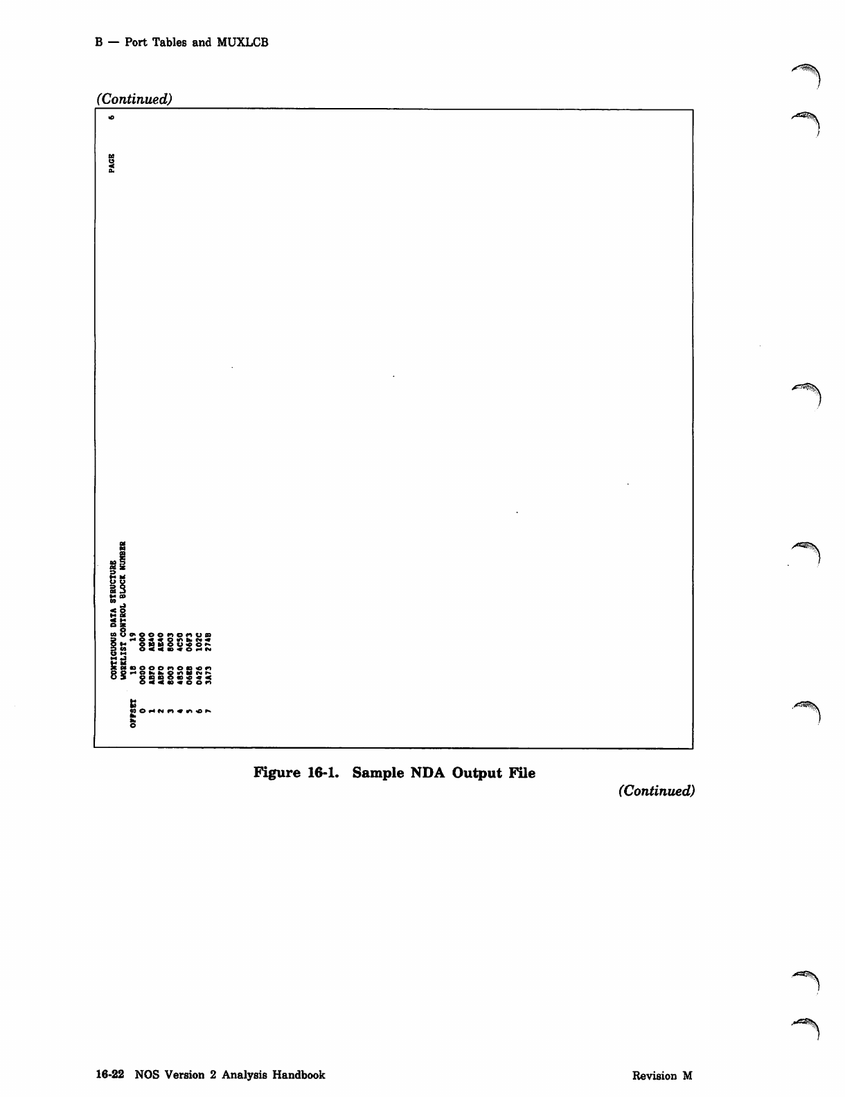
B — Port Tables and MUXLCB
(Continued)
nuotpoomor)
oh onm8u«
Sen O 3 « ■> « o
O w
M .3
XMaaooonots
8Pr.QH.hOMMS p a a © «> «
© « < co « o o m
M O i
Z*6^^
Figure 16-1. Sample NDA Output File
(Continued)
16-22 NOS Version 2 Analysis Handbook Revision M
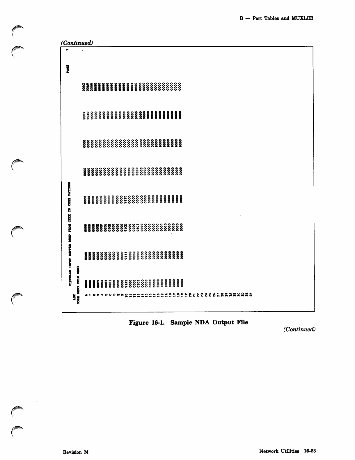
B — Port Tables and MUXLCB
(Continued)
iopo©opoopoompopopoop©ooo
SoOPPPOPPPPQOOppppOPOpOO
8ooS5ppSp5p5oo55oop55ooSrtoo©ooo©o55oe©ooo5ooooo
Mopooopopoopcpooooogoo'
ooooPOoeoooppoopQ©©©©'
©OoSooo5S5o5oooo5oooo
siiisigiiisssiss:
asfiB- a a - &0S0£88ooo©
SSoSSSssSciSoooSSSSooooooo
ao99929999P95£SS£xxxgXXX
SQo5o099999*b©09 222222S22S
oooooooopo^ppooopoopooog
oSoooooooochooo oooooooooo
B
o
8oppMfc.«tap9POP9r<PPoogooooo©poppooooouoouooooogooos
o> o555ppoppoMpo^)00oooopopp
S 55ooSSoS5oo»ooo5oooooooo©
s> p p o o o 9 o e 9 9 •>• © o o 90 p o o o p o o 9 ©
m 5opooppppp'-oooooo6oogoooo
5 5 5 o o 5 5 S 5 5 r* o 9 g 99 9 0 9 9 9 9 © © 2
H ooooooooo©»oooooooooooooo
M t t
5 3 Qoo»«nHoooNOpg»25222SSSSS
5 o 5 5 5 o o o o o o o « o 5 o 00 5 5 6 0 o o p o o
° « 8giii88S8ss:iisii§siiiiii8
K« * ufi«hS3SS:S25SS52ilS3!:8SK5SS!558Si5S8S8ft
Figure 16-1. Sample NDA Output File (Continued)
Revision M Network Utilities 16-23
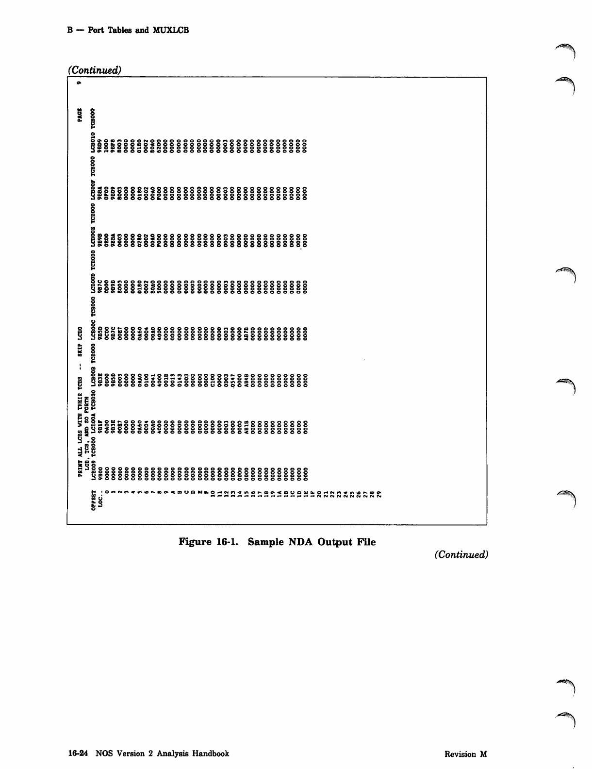
B — Port Tables and MUXLCB
(Continued)
ox a
US
OOmOOONOpOOOOOOOi
Sk.OPO»9<OpppPPOO
a O O O H p O M p p p O O O O i
r-io>eooooa><oOoooooo<
omoooooooooooo
§0000000000000iiggggggsisss
<o»nppocMOppp
moop$9cqo<p5o
0>00>D
>opppmooo©o©oooop<
__ .. ... .. .. .-joppopopoopooooppi
o88h.oS88S8e©888S8888S8ooo'
g (0
_ §a
DMB
o» o o- •
gpppmppoooooooppo
ooppooooooppopoo
890oooopopppoooooOOOOOOOOO©'"ooooo
o
ouommopotMOpp
mr.90>99©no«]po<
oaaoooopi-ipoop
J»o»noooocom©
00 o o ©
§0 o p p
9 9 9 S
oooo
§00000000000
_00000000000
999999990000
'OOOOOOPOOOOO
8S£!
ggg!
0*0909
<o<Spo
* 5 o 0 0 o
o o © « © o gggg
O O O O 1 §onooaoooooooo
OOOO'-OpOOOOOO
_oo©5oa©5p5oooo
oooooSoooooooo
8 g
g ta
m n 8°f 22Q9ri9<>n
•nppp«0'*0'4i-i
caaooo<^4pop9
00-000000*00
nnoopo
« 0 o o 5 o
© 8 8 8 g C
mr»omoooooooo©
eop«p«ooooopppo
•Hpom&moooooooop
ooo<ooooooooo
M X I
M F
ac m 1
g
0
38
g h. © M r- 1
S3 H © n M 1 go ♦ 1•O O ' g§
OOOOO
§9onooo>ooooooooo
_OOOpOr<909PPPOpO
888 ooooo ooooo
o<ooooooooo
a ty
to o
.J O O O 1
§0 9 1
n © 1
o © I
09000900
llgggggg
oooooooo
009909
80000©o o o o o _ . .
ooooooooo
g 9000000000
oooooooooo- - - 0 9 0 0 0 0 0 0
oooooooo
g . o n t x n + ^ i o r . .
Figure 16-1. Sample NDA Output File
(Continued)
16-24 NOS Version 2 Analysis Handbook Revision M
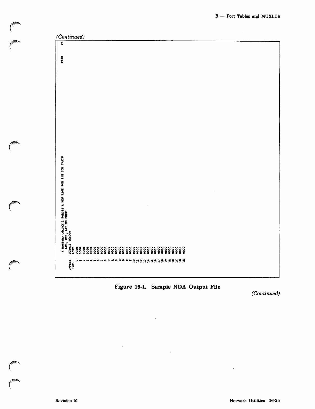
B — Port Tables and MUXLCB
(Continued)
Sjo«mooooooooooooooooooooooooooooooo
(dbjoopoooooooooooopooooooooooooooo
< ouooOoooooooOoooooooooopoooooggog
2e>ooooe>oooo©oooooooooooooooo©oooe
H 'OHnn«m«NB»<giu(IHk.O'4Nn«in<sio»<oUQI]
Figure 16-1. Sample NDA Output File
(Continued)
Revision M Network Utilities 16-25
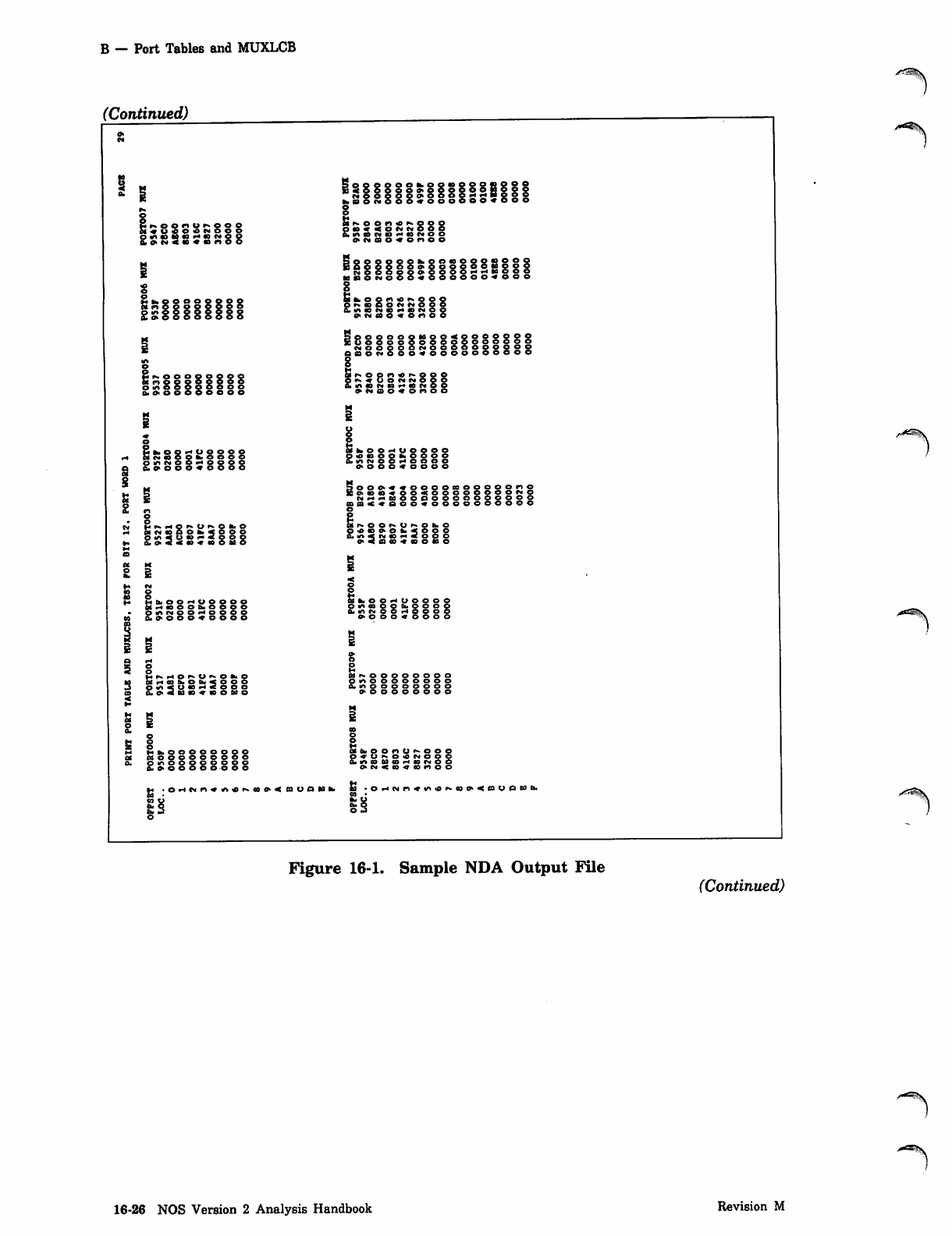
B — Port Tables and MUXLCB
(Continued)
Sr»oor»o»-ggg
ScuSoonooo
2mn£«HSN09o»N3co«anoo
§h. 9 o
2 e» o o
C r. O O O <
anooo
o « © 9 9 v
0.0.00000000
S S o o
- E 8 k. © O © Ort © O O 9
o>ooo*oooo
s
s
a I © h. < i. .
2tfl<U«f< JOO»J<a«(o»
HCbOOr-lUOOOO
H«1C0OOh.OppO
0m«MO0r4OO©9
0,0000*0000
Hr»iHOF»0»-0h.g
« r t « k . O h < 0 0 0
o«><u*b<-i«90o
a.e><uce*»©Mo
Hkoaooaooo
caooooooogo
SmooooooooOKOOOOOOOO
§S8g8giS:ili§g8gli
g
Mr>oon«r>-992
S « « < O N N O O OH I C N D O D N O O
o><wmo*or>oo
isgggggsgiggggsgg
MOOOOOO.O©©©'4'"4*3©©
ioB5fJoPO*5SSooo*oo
8
SsssssKggg
&n«NRH«MOO
»Nao«onoo
isgggggggggggggggg
wooppowooooogooop
omo«Mooo*oooooooooo
8
ShOpnitNOOO
5r.*Qor«c«o99
e»r«a>o«Of»oo
MlbOO^UOpOO
Sdoophoaao
tftCVOOr^OOOO
0>OOO«OOOO
& :
a o
b. o
OHMn«m<M»< muOH
ocfc**ooooco©oo©on
~>~uS000O0o50ppO
««Qoe«oooooooooca a
o
fi.
£«B»Ot.<OQO
».<NCf< JOOO
»<aa«SOKO
OOr>Ur>©b.O
HhOOriUOOOO
Om«o9ph.po©p
a.mcwoO'HOOoo
»ooo«oooo
Mf-OOpOOOOO
omooooooop
0.100000000
OKOOOOOOOO
0.moHa>wtofMOO
»N<«4i>noo
(d • O r< Nr>*«n4>r>cao««cauOHh.
Figure 16-1. Sample NDA Output File (Continued)
^*s
16-26 NOS Version 2 Analysis Handbook Revision M
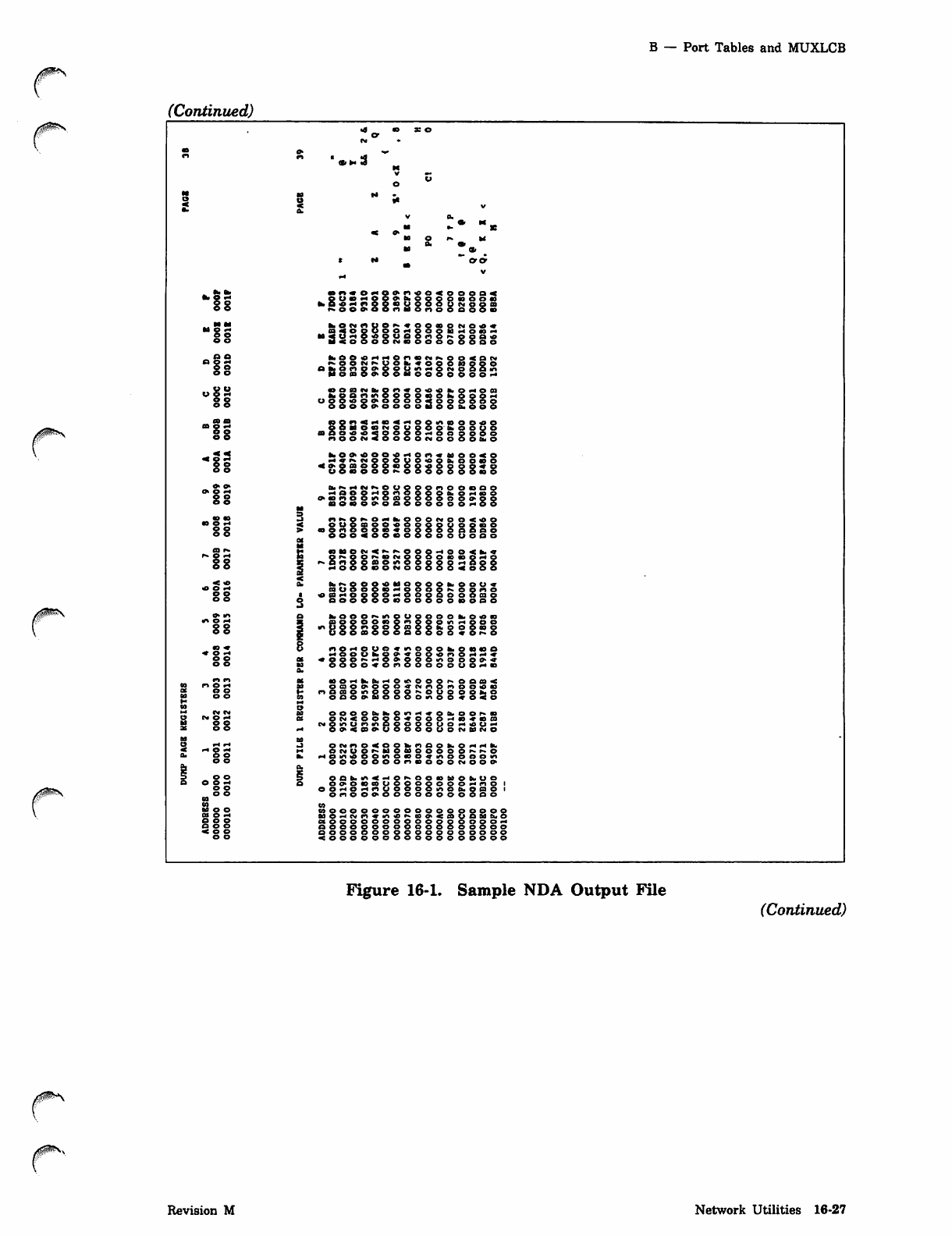
B — Port Tables and MUXLCB
(Continued)
2 ~
SUB.O ri
o . O O
fc- © cm i
CO < o
S i j n i< o •
0 C '
38
o> o i a y o o 8 u
nionoo
n -e ©
88
o8S
88
18
O. O rt
88
•a co
*8S
o o
CQ r»
r. O r4
88
< •
* © n
88
l> «n
88
o o
IM © ri
88
< m 9 M
e u 5 ©
o . ° °
5 o o
5 O © r t
88
fc. O O
»». O ©
aiion
M O D
■ on
a. o a
° 8 8 S
§82
aoa«
no©
h. o e>>
rt * r»
< o- 9 a
U 5 CO
HOO
> co m o
a o co
© o 8
8 « oo o
B H O
8S 8
r4 O 5
OOO
<g 9 o
o 5 CM
O H H O
IM r~ O o
o> 5 ©
<m h> p »
rt in © o
8»ooooo
< r t m <
© a c» o
£388
OOOO
NOOO
o o 5 co
OOP"
NhOU
onoa
oooo
««• O — fc.
oooo
O O CO «
4000
«■<*.*.
O N O N
o ao o <n
o o> o <*
* o o
HOO
o © n
co o ©
n co im
h> « o
O m r,
M O O
« 9 ■
O 5 I
© O .
O O I
n © 9
§82
Son
hob
V. 9 - 9
SON
8 H r C
*• 9
o o 5
r . O O
O O ft}
© IM ©
ooo
> <o fc. p
i O h. 5
: o o o
i o a a.
an e p
© fc. S
oop
ooo
« M ©
gfc.o
88888
8 o ©
o © ©
OOP
OOP
© 5 5
© 9 9
o 5 5
© 5 9
o © 5
n o o
© fc. o
© o p
o o 5
<M o o
88S
ooo
-, o o
O CO »
883
O O <
O O CO
O 9 03
OOO
g o *
CO r,
get <oo o
< O IM
88S
©OH
n © a
ill
888
o 5 o
O h . o
© < o
p co o
5 * p
5 co 5
soo
HOO
288
< «o 9
86 5o o
ooo
< fc. «
9 w o
iss
t«.i»ggg<oi«io9©©i«.©oo»
ouoooco^ooop.ppno
panoggo^ooooooomp
aooooooooooooooo
fc. o o © . m
oinoo
SiaOO
O O h. O o a
O tn r, 9 O o
fc. 9 o 5 co ©
OO « O t » o
§onOHH«
•n o O 9 tu *
OOOOOOHC0
■>oiifc.fc..-<Otf»oogr. oogx
gco©o>ppo*iMnornoooco
apopooo.oopooibO
OO©9fc>fc.©an«4*©h.aOP-C0
§N<oooo«oooHig«aB
■nunmOOOOOUOHOUH
0><CDO>UOOOOOOIMMIMO
OakiKHaKOosHohUO
oo>ocosouooogooo>-irio ■
oo.-io.-imuooo5inob.gB)© I
OcnOOOOOOOOOOOOOO
ta
OOOOOOOOOOOOOOOOOO
MO~4<vr>*inor-BO«<caVBMh.O
cuooooooogooopoooo-*
ooooppoooooooooooo
oooooooooooooooooo
oooooooooooooooooo
Figure 16-1. Sample NDA Output File
(Continued)
00*>S
Revision M Network Utilities 16-27
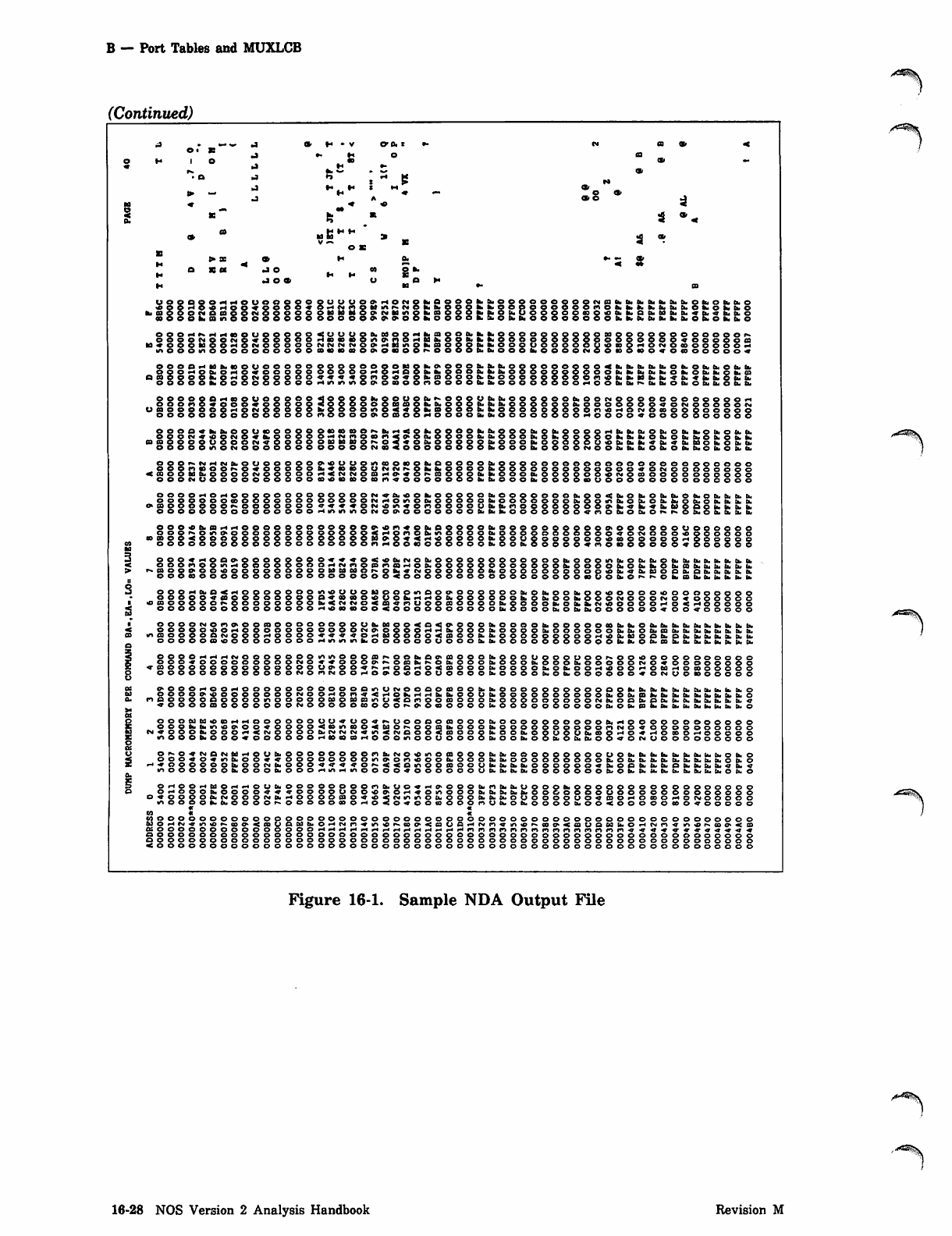
B — Port Tables and MUXLCB
(Continued)
O V t - l - V C O . I • -
O fc. O h. fc. o
O fc. O fc. fc. o
8 0 r j ;o a
O * O CO O O 1
OOf*Mfc.C0OOO©OOO9OOOOO9O*lgfc.0>©gOfc.fc.fc<OOpppOpPO<fc.h.t].t].h.©fc.Ob.h.
o<->ph.oiHp«ooooooooooi-io>*eoh.h<gogfc.&ta.oo©©9g9ooofc.ibfc.h.b.ofc.ob.ib
§ogfc.p-4p»poogg****gcngo*gtbmgggCbt>.gggoggooonofciDbMb.ib*b.*(bfc.oOfc.5©5o5oooOHinm«nSoOoaoonooooti.h.oo©oo©oOf-ioofc.h.t>.|i.b.Ob.ofc.b.
o o o r >
U a o o o
moooooprHpiMpgog
oooooooooooSoO
O fc . b.
8 1 b 0 0b. b .
fc.Ofc.fc.
8 9fc.90UOfc.i>-©99pfc.fc.ooo9©ob.ooiM999oooo©ooooH
OOpUa}pb.fc.pOOfc.fc.fc.pOp5ppCbPOOOOOO*OCM - -
00«->0<*0fc>moooci.tb0000p90p0r)0<-i0rv0(000
0000*0000
O O O © CM
o © © o p
ooooo
© a « f c , » . o
O CM * O p CM
oooo oooooo©
vwix*x***r.B.rt
t> n CM m O <0 tt rt
OUfc-fc.pl--0<
OOOOOCMa3<
. - OOtbCbOOSCfcSfc'
« O f c . o o g g g f c . o o o f c . o g <
-©oofc.ooob.o5'ooooo
OOgr4fc.fc.fc.Ob.Ofc.fc.Ofc.Ob.fc.
f900fc.fc.fc.0h.0b.fc.0fc.0blb
OUOfc.h.h.«Cb«h.blOh.Ofc.b.
MOOtbfc.b.OtbOfc.b.Ob.Ofc.b.
gOi>>NiHNliOUOOOOOe<«UUOlll«OOOtiOOOOO
On«OOOr-p*pOOOOfc.«COtOOUMCMr-pibCbOOOO
OpfcIfc.OOOOCMppPOOr4«MCMgmrHO«Or- - - - -
CM O O o O © o * o o o o o o a h. o © S p O O O C M p C O po a u S o o o o
ooooooooo
CMpOOOOOOO
OOOOOOOOO
ooooooooo
OOOpr40HOOppOOO©00900CM*tbOpfc.OpopOb.pppO©©Ofc.
OO©OOC0OOOOOOOOO©OOtMr<OinOCbOOOOOh<OOO- - - - '
§N«n«onoo " _CMPOOOOOO
omoooooor-0000
oooooooooooo O © * 4 m t n
O fc.
9 9 p f c . f c .
_ .. _,0<h.©b.gb.fc.0fc.0fc.b.fc.tb
90fc.99mb.0fc.efc.fc.9h.0fc.fc.fc.fc.
_OgoOOOb.*h.*h.C0pOOh.b.h.b.
000©00©*r.Oh<OCbOr.r-ota.Ofc.b.fc.h.
OOOOCbC0^l^lOpOOOOOOOgOOOOm«Ofc.OpOOOfc.OOpOOpppppOOC__
ggg*>otn»o©oogggggg©gg£.-<gi"iofc.inogggfc<ooo©oooo©oo*g'CMOoo
ooog<opopopooooogoooofciop*<Mopooofc.pou9ooooooocoopooo
OOOOOOOOOOOOOOOOOOOOr)^OO«0OOOOOOtb0Ob.OO0OO«nOC0OOOOO
990090909— ooooo
00900
000*-HpOo
0©0<n©©inH
oopooooo
OOO99*C0OO6OOpOO o
(OOOOOOf-pOOppOOO b.
ooooooo5oo55ooo rt
a««ao«uotcHHoiiiP
' <r.cMp<cq*r>u©©cop
O CO CO o © © fc. o h. h* 1 - . O p < _ _ _ _
0<<H©0000
00*00000
O O O O O O ri I _..._ .cobOfc.fc.op8.
OOOOOOUOOOfc.fc.OOOO888001-fOfc.tt-OOfc.Ofc.fc.h.fc.h.b.h.
OOOOh.fc.©b.a-h>fc.fc.h.b.b.b.b.
§ggo>4.4l-icMoooooogv>tnoogor«ooh<o.o>a>ogofc.gpouooouoor-ooooooooooooo
OO«OOOOO00OOCMO**OOOOr-Oafc.r.OCa.00Ofc.OOOChOOOfc.OOOO©(MO*OOOOOOOO
mogoooggogooooouc>oo*p-rHOOrHo<CDOoob.oopoti.ofc.oorHooO'-oedr-iocoooooo
888 O O O CM o 0 0 r - . 0 0 . 0 0 0 0 OOOODbOOOOfc.Oh.OOOOOO«OIMUOC0OOOOO
0000000
uOOOOOi—
* O O O O O 1
ooofcieoocsH
OOOtbtbtnoo
M«ggofc.©oo
•nooob.o©o
Or40ri*<HO».Hr4fc.b.OOUfc.l fc.fc.fc.fc.b.tbfc.b.b.fa.b.0
ogagggh.ooooo©©©oofc.<-.o©©ooooooooo
OC0b.OOOb.OOOOOO9POOrilMO*OOOOOOOOOO
8 U p U h . C 0 p r 4 O « r H O C 0 O r 4 O O O O Of c . O C b b . O O * O M U O O O O O O O O OOOo5h.OOfc.O
Or-0*CMOCMMHpUfc.pOOOOOp©mb.CMOO
O00«o«mb.00»*00000000inoor.o_ __ __. _____ __ ,- ~'~ ~ CbOPCMfc>ggg«*««p^<<OinOOnOOUh>b.fc.b.OOOOOO«D»Opfc.b.h-0fc.fc.tbfci*_.*
__ ..00©fc.fc.OOOOOOO©OUO
Cl.pnopofc.ggofc.fc.pp9090gopfc.pfc.tbb.
fc
>fc.OOOfc.OOO.-lin.-iinoOOO«OOOOOOOh.fc.b.b<OOOOOOOb.O
h.-._.fc._._.Ob.O
fc.b.fc.h.b.b.OfciO
fc.Ofc.fc.tbfc.*—.*
fc.li.h.b.fc.B-rb.b.Ob.0
O l-l © O rt I_ __ _pd«*0Ufc>0OO0O0Opr>b.UO«**OOpOfc.r'-fc.fc.UQO0fc.000000QO9©O0OOOOO
O_000fc.OOOO***0g0gU00OOOr4«0inOOOfc.fcifc.b.fc.OOOO00OUOOOOO00O000O0
P010«O<CMinanOh.OOOfc.h.fc.OUO0OOUO*CDO^OC0OrHOCMOOO0O
Ub.0h.0000fc.00<00000CC>0*00000
§ 0 f c .O fc. M000CMt_.i-.OO_
b.OO©Or.OOOOO0_O oooooo
s a « «
cooooooooooooooooooooooooooooooooooooooooooooooooooooooooo
fc)0>-<iM*ino*-»o<muofcibO.-<Nrn*mor-»o<mOO<*iMn«nor-ao<muaC->lbOr4CMfn*inor.<DO<B9
0SgooooooOOOOOOOOp4^r4rHMr4P'r4fHr4r4_i-irHmmr>ininnmninn<ncnnnri**«****««***
000000000000000000009000000000000000000000000000000000000
000000000000000000900000000000000000000000000000000000000
<oooooooooooooooooooooooooooooooooooooooooooooooooooooooo
Figure 16-1. Sample NDA Output File
16-28 NOS Version 2 Analysis Handbook Revision M
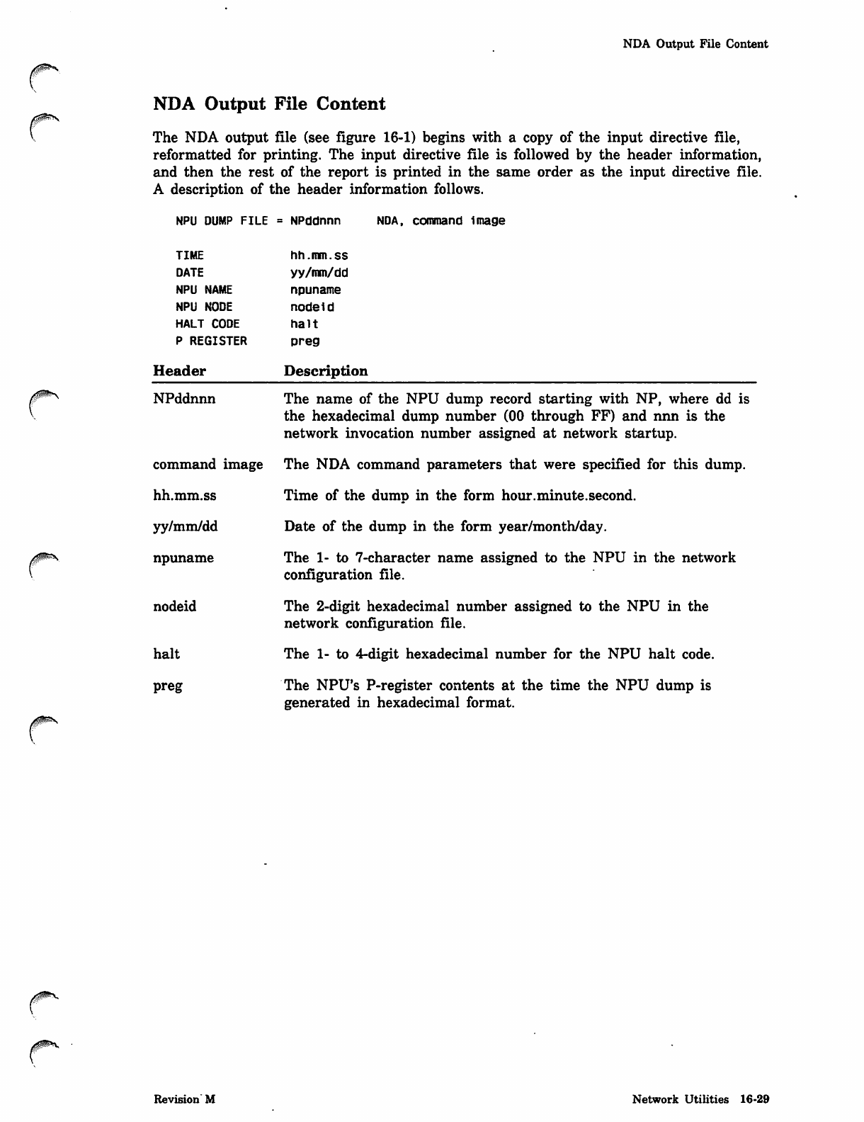
/|^*v
NDA Output File Content
NDA Output File Content
The NDA output file (see figure 16-1) begins with a copy of the input directive file,
reformatted for printing. The input directive file is followed by the header information,
and then the rest of the report is printed in the same order as the input directive file.
A description of the header information follows.
NPU DUMP FILE = NPddnnn NDA, conmand image
TIME
DATE
NPU NAME
NPU NODE
HALT CODE
P REGISTER
Header
hh.mm.ss
yy/mm/dd
npuname
nodeid
halt
preg
Description
NPddnnn
command image
hh.mm.ss
yy/mm/dd
npuname
nodeid
halt
preg
The name of the NPU dump record starting with NP, where dd is
the hexadecimal dump number (00 through FF) and nnn is the
network invocation number assigned at network startup.
The NDA command parameters that were specified for this dump.
Time of the dump in the form hour.minute.second.
Date of the dump in the form year/month/day.
The 1- to 7-character name assigned to the NPU in the network
configuration file.
The 2-digit hexadecimal number assigned to the NPU in the
network configuration file.
The 1- to 4-digit hexadecimal number for the NPU halt code.
The NPU's P-register contents at the time the NPU dump is
generated in hexadecimal format.
Revision' M Network Utilities 16-29
NPU Dump Files
NPU Dump Files
Each NPU dump file is written as a single-record direct access permanent file when an
NPU dump is taken. Individual NPU dump files are named NPddnnn, where dd is a
unique hexadecimal dump number consecutively assigned in the range 00 through FF
and nnn is the network invocation number assigned at network startup.
Dump Interpretation
When a halt occurs, halt codes are usually sent to the network operator controlling the
NPU. (Halt codes are described in the CCP 3 Diagnostic Handbook.) If a halt occurs
after loading but before completion of initialization, or the system becomes trapped in a
loop during initialization (before the CCP header prints), dump interpretation may be
necessary to determine which halt has occurred, or in which subroutine of the
initiation section the program is looping.
When interpreting the NPU dump listing to determine the cause of a halt or loop,
first examine the contents of memory location 30i6. If the content of that location is
nonzero, a halt has occurred; the halt code value is contained in that location.
If memory location 30i6 equals zero after a halt during initialization, find the address
table that begins at fixed memory address 150i6. The last nonzero entry in this table
is the address of NPINTAB. (This is the table that is displayed at the end of a
successful initialization. NPINTAB has a fixed address.) The NPISFL entry in the
NPINTAB table contains the flags that mark the initialization subroutines that have
completed running when the loop occurred.
16-30 NOS Version 2 Analysis Handbook Revision M
0ms
PIP Dump Analyzer (USTPPM)
PIP Dump Analyzer (LISTPPM)
The peripheral interface package (PIP) Dump Analyzer (LISTPPM) is a utility program
that converts all available PIP dump binary records on the PIP memory dump file into
a report to be listed in byte format. The PIP PP memory dump file is created as local
file ZZZZZPP by NAM when the operator drops the network or NAM detects fatal
network errors.
The format of the command for the PIP Dump Analyzer is:
LISTPPM,B=pipfile,L=OUtf1le.
The parameters are order independent. Invalid or undefined parameters cause
termination of the run.
Parameter Description ^ ^^
B=pipfile Local file name of the PIP PP memory dump file. Default is
B=ZZZZZPP.
L=outfile Local file name of the output file. Default is L=OUTPUT.
Revision M Network Utilities 16-31
AIP Trace With IAF
AIP Trace With IAF
The AIP trace utility produces a trace file of the messages transferred between IAF
and NAM. This file, produced as a local file named ZZZZZDN at IAF's control point,
contains information that can be useful in tracking network problems and in debugging
application programs. However, the data in this file is in compressed format and hence
the debug log file processor (DLFP) must be used to analyze the trace file. Refer to the
NAM Version 1/ CCP Version 3 Reference Manual for details about the trace output
and the use of DLFP.
Select whether or not to use the AIP trace mode of operation when entering the DSD
command, IAFffff, to initialize IAF. This command selects a procedure file that
contains the IAFEX command. The T parameter on the IAFEX command determines
whether or not AIP trace mode is to be in effect and also the number of messages to
be contained on the trace file. The format of the IAFEX command is:
IAFEX,T=count.
Parameter Description ]
T=count 5000 ^ count ^ 9999999. Message count specifying the number of
messages that are to be logged on the trace file before that file is
released to the system for processing. If T=* is specified, the trace file
is processed only after IAF is terminated.
T Same as T=16200.
T=0 AIP trace mode is not selected.
T omitted Same as T=0.
Two procedure files are provided for use with the AIP trace, IAFTM and IAFTR. You
can create other procedure files using different T parameters on the IAFEX command.
IAFTM
IAFTM is a procedure file that contains the IAFEX,T=* command, which causes the
trace file ZZZZZDN to be processed only after IAF is terminated. The IAFTM procedure
file also includes the commands necessary to process the ZZZZZDN trace file. Also, all
messages logged on the trace file are written to the output file and then sent to a
printer.
16-32 NOS Version 2 Analysis Handbook Revision M
/0$^\
/$P^\
r
IAFTR
IAFTR
IAFTR is a procedure file that contains the IAFEX,T command, which causes the trace
file ZZZZZDN to be processed after every 16,200 messages have been transferred
between IAF and NAM. A local file called TRACIAF is required by the IAFEX,T
command in order to process the trace file. TRACIAF contains a command record,
which is copied to the first record of the ZZZZZDN trace file by IAF. Trace information
is then written to file ZZZZZDN, starting at the next record. This makes file ZZZZZDN
suitable for submission as a batch job. The format of the TRACIAF file should be:
ujn.
USER.username,password,fami 1yname.
DLFP ,
NOTE
When system activity is very high, the potential exists for these problems to occur if
the AIP trace is used:
• If the system load remains at a very high level for a long period of time, a
system hang due to PP saturation could occur.
• If mass storage requirements become great, the ZZZZZDN trace file could reach
track limit. If so, IAF would stop and wait for resources to become available.
Both of the preceding problems are unlikely to occur in most situations. Also, the
risk of reaching track limit can be minimized by selecting a message count on the
IAFEX command that causes the trace file to be processed and released after the
specified number of messages have been logged. This lowers the mass storage
requirements. There are some problems that can only be solved by using the AIP
trace. For these problems, do not hesitate to use the AIP trace since any risk
involved is minimal.
Revision M Network Utilities 16-33
Network Description Files
Network Description Files
The network description files describe the physical and logical configuration of
hardware and software elements that comprise the terminal network. They are
important to the proper functioning of the TAF and NAM Subsystems of NOS as well
as the QTF/PTF applications if the file transfer capability with NAM is a desired
feature. Depending on which subsystems a site has, from one to three such files may
be used on a single mainframe. Each file has the following unique function and/or
construction.
F i l e N a m e D e s c r i p t i o n
LCFFILE and Local configuration file and network configuration file that must be
NCFFILE present if NAM is used. They are created by the network definition
language processor (NDLP) from source text prepared according to
specifications given in the Network Definition Language Reference
Manual.
NCTFi5 Network description file that must be used if the Transaction ^^
Facility (TAF) is used. The site analyst prepares this file according
to the following specifications.
Under standard operating conditions, the network subsystems expect LCFFILE and
NCFFILE to be permanent, direct access files stored under user name NETADMN.
These files may be private with read permission given to user name NETOPS,
semiprivate, or public. LCFFILE and NCFFILE are binary files created by NDLP;
NCTFi is a text file composed of terminal definition directives. The text file is
interpreted by code in common deck COMCRTN to produce tables used by TAF during
system operation. TAF expects NCTFi to be a direct access public file stored under the
SYSTEMX user index (377777s).
A terminal definition directive can be up to 90 columns but only columns 1 through
72 are interpreted. Any line containing an asterisk in column 1 is a comment and is
ignored.
4. For information about network description files associated with the CDCNET network, refer to the /"^%
CDCNET Network Analysis Manual.
5. i is the network file identifier as specified in the TAF configuration file (refer to the TAF Reference
Manual).
16-34 NOS Version 2 Analysis Handbook Revision M
Network Description Files
0ms
The following format shows the terminal definition directive. No embedded blanks are
allowed.
/terminal name ,pi,P2 Pn*
Parameter Description
terminalname The 1- to 7-character alphanumeric name that uniquely identifies the
terminal; terminalname must be specified. When NCTFi is created,
terminalname must agree with any automatic login user name.
Pi Description
TT=*ID Terminal type identified by terminal operator entry.
A TAF terminal is defined with the previous parameter,
as well as the following, which are unique to TAF.
DB=db The 2-character data base name to be used by the
terminal.
IS=stat Initial on/off status of the terminal; stat can be either
ON or OFF. Default is ON.
RS=n Data base read security (from 0 to 7). Default is 0.
UA=n 24 bits defining the user argument area (from 0 to
777777778). Default is 0.
US=n Data base update security (from 0 to 7). Default is 0.
To use the permanent file and queued file transfer capability with NAM, you must
specify certain NDL statements when creating the local configuration file, as follows:
• Specify application statements with the PRU and NETXFR parameters for
applications QTF, QTFS, PTF, and PTFS (QTFS and PTFS require the RS
parameter).
• Specify the MXCOPY parameters for these applications depending on expected
usage. Suggested values are MXCOPY = 4 for QTF, and MXCOPY =14 for QTFS,
PTF, and PTFS.
• Specify the INCALL and OUTCALL statements as needed.
Refer to the Network Definition Language Reference Manual for NDL statement
formats.
Revision M Network Utilities 16-35
IAF Stimulator
IAF Stimulator
The IAF stimulator is a collection of central memory and peripheral processor
programs that enters a hypothetical work load (called a session or script file) into the
system to analyze the effects of such a load on response time and system reliability.
The IAF stimulator consists of a central memory program (STIMULA) and a
peripheral processor program (ITS).
To use the stimulator:
1. Create the hypothetical load (refer to Session File Construction later in this
section).
2. Process these jobs using stimulator commands at the system console (refer to
Session File Processing later in this section).
Multiple IAF stimulator sessions are described under Multiple Sessions later in this
section. Errors that can occur while the IAF stimulator software is in use are described '*a%
in the NOS Version 2 Operations Handbook.
16-36 NOS Version 2 Analysis Handbook Revision M
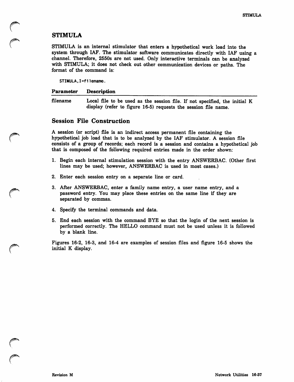
yams
STIMULA
STIMULA
STIMULA is an internal stimulator that enters a hypothetical work load into the
system through IAF. The stimulator software communicates directly with IAF using a
channel. Therefore, 2550s are not used. Only interactive terminals can be analyzed
with STIMULA; it does not check out other communication devices or paths. The
format of the command is:
STIMULA,I=f1lename.
Parameter Description
filename Local file to be used as the session file. If not specified, the initial K
display (refer to figure 16-5) requests the session file name.
Session File Construction
A session (or script) file is an indirect access permanent file containing the
hypothetical job load that is to be analyzed by the IAF stimulator. A session file
consists of a group of records; each record is a session and contains a hypothetical job
that is composed of the following required entries made in the order shown:
1. Begin each internal stimulation session with the entry ANSWERBAC. (Other first
lines may be used; however, ANSWERBAC is used in most cases.)
2. Enter each session entry on a separate line or card.
3. After ANSWERBAC, enter a family name entry, a user name entry, and a
password entry. You may place these entries on the same line if they are
separated by commas.
4. Specify the terminal commands and data.
5. End each session with the command BYE so that the login of the next session is
performed correctly. The HELLO command must not be used unless it is followed
by a blank line.
Figures 16-2, 16-3, and 16-4 are examples of session files and figure 16-5 shows the
initial K display.
Revision M Network Utilities 16-37
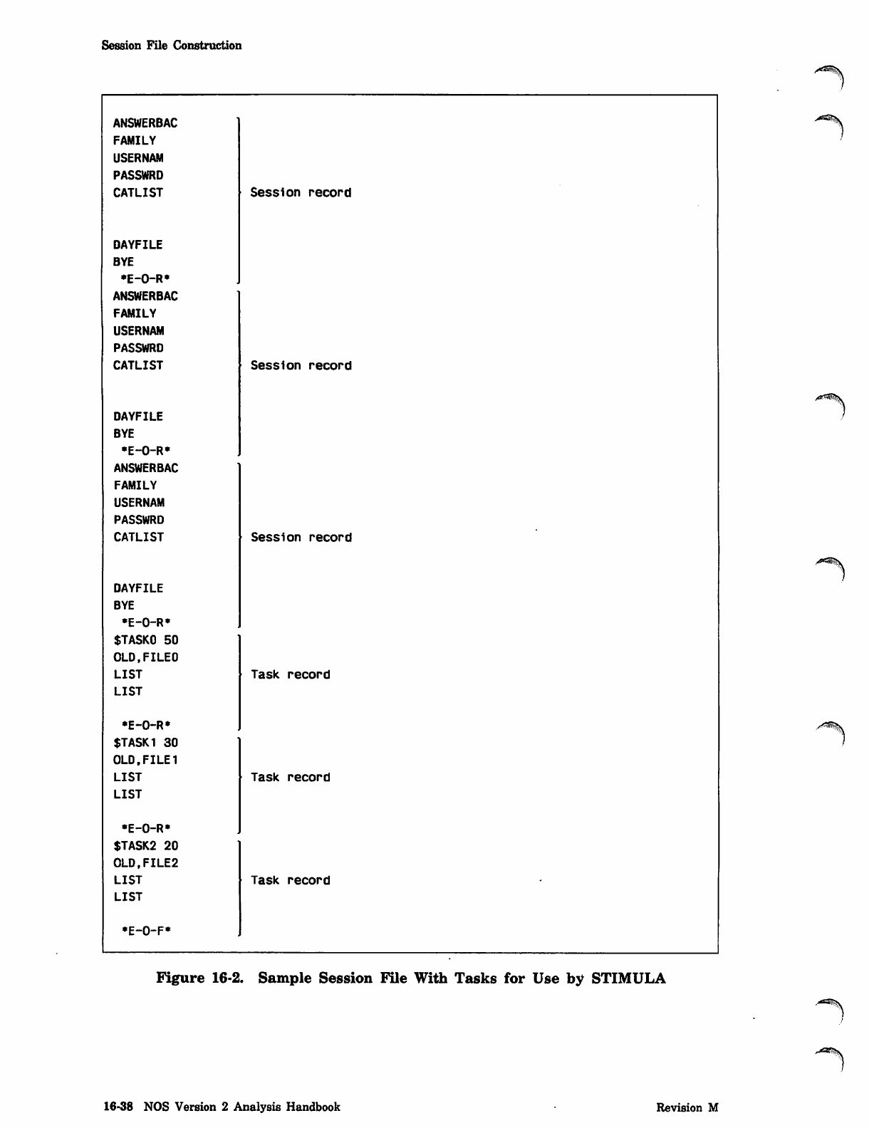
Session File Construction
ANSWERBAC
FAMILY
USERNAM
PASSWRD
CATLIST Session record
DAYFILE
BYE
•E-O-R*
ANSWERBAC
FAMILY
USERNAM
PASSWRD
CATLIST Session record
DAYFILE
BYE
•E-O-R*
ANSWERBAC
FAMILY
USERNAM
PASSWRD
CATLIST Session record
DAYFILE
BYE
*E-0-R*
$TASK0 50
OLD.FILE0
LIST Task record
LIST
•E-O-R*
STASK1 30
OLD,FILE 1
LIST Task record
LIST
•E-O-R*
$TASK2 20
0LD.FILE2
LIST Task record
LIST
•E-O-F*
Figure 16-2. Sample Session File With Tasks for Use by STIMULA
16-38 NOS Version 2 Analysis Handbook Revision M
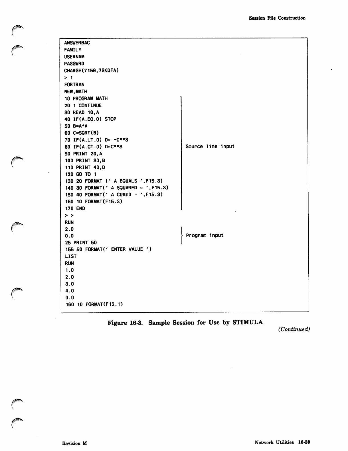
Session FUe Construction
0ims
0$m*\
ANSWERBAC
FAMILY
USERNAM
PASSWRD
CHARGE(7159,73KDFA)
> 1
FORTRAN
NEW.MATH
10 PROGRAM MATH
20 1 CONTINUE
30 READ 10,A
40 IF(A.EQ.O) STOP
50 B=A*A
60 C=SQRT(B)
70 IF(A.LT.O) D= -C**3
80 IF(A.GT.O) D=C**3
90 PRINT 20,A
100 PRINT 30,B
110 PRINT 40,D
120 GO TO 1
130 20 FORMAT (' A EQUALS ',F15.3)
140 30 FORMATC A SQUARED = '.F15.3)
150 40 FORMATC A CUBED = '.F15.3)
160 10 FORMAT(F15.3)
170 END
> >
RUN
2.0
0.0
25 PRINT 50
155 50 FORMATC ENTER VALUE ')
LIST
RUN
1.0
2.0
3.0
4.0
0.0
160 10 F0RMAT(F12.1)
Source 11ne 1nput
Program Input
Figure 16-3. Sample Session for Use by STIMULA (Continued)
Revision M Network Utilities 16-39
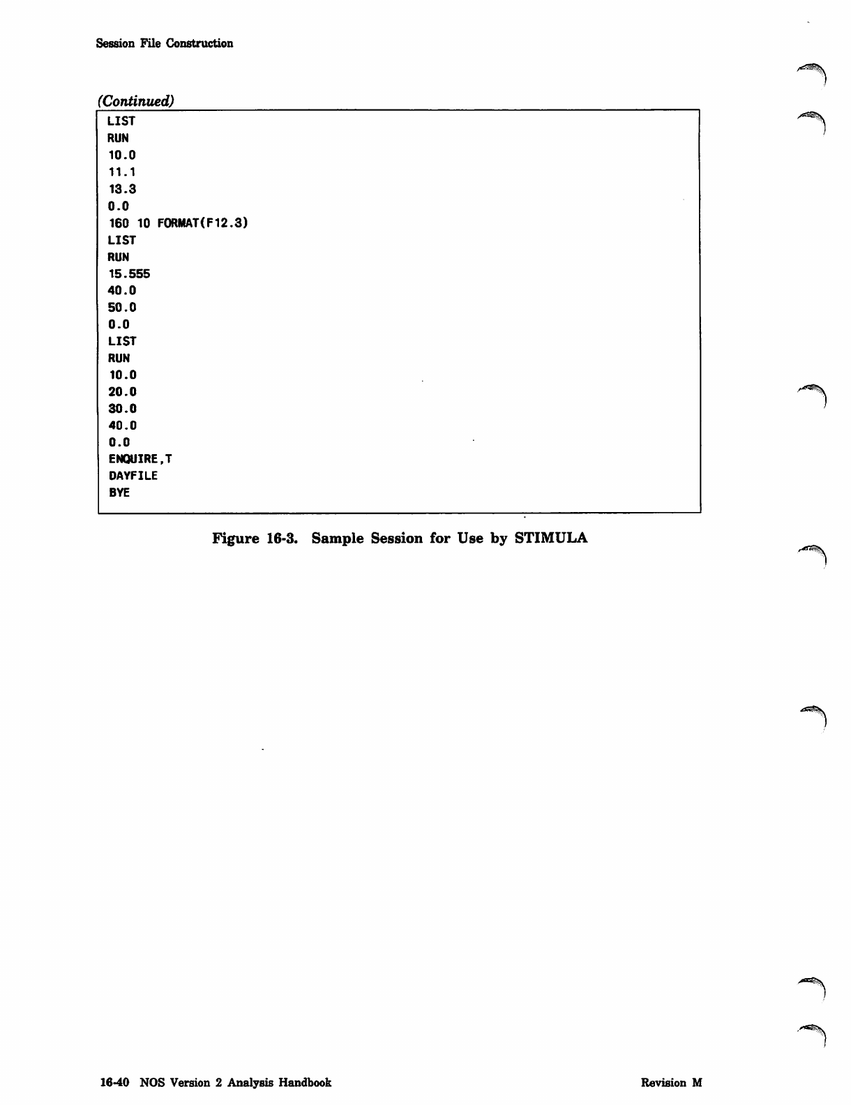
Session File Construction
(Continued)
LIST
RUN
10.0
11.1
13.3
0.0
160 10 FORMAT(F12.3)
LIST
RUN
15.555
40.0
50.0
0.0
LIST
RUN
10.0
20.0
30.0
40.0
0.0
ENQUIRE,T
DAYFILE
BYE
Figure 16-3. Sample Session for Use by STIMULA
16-40 NOS Version 2 Analysis Handbook Revision M
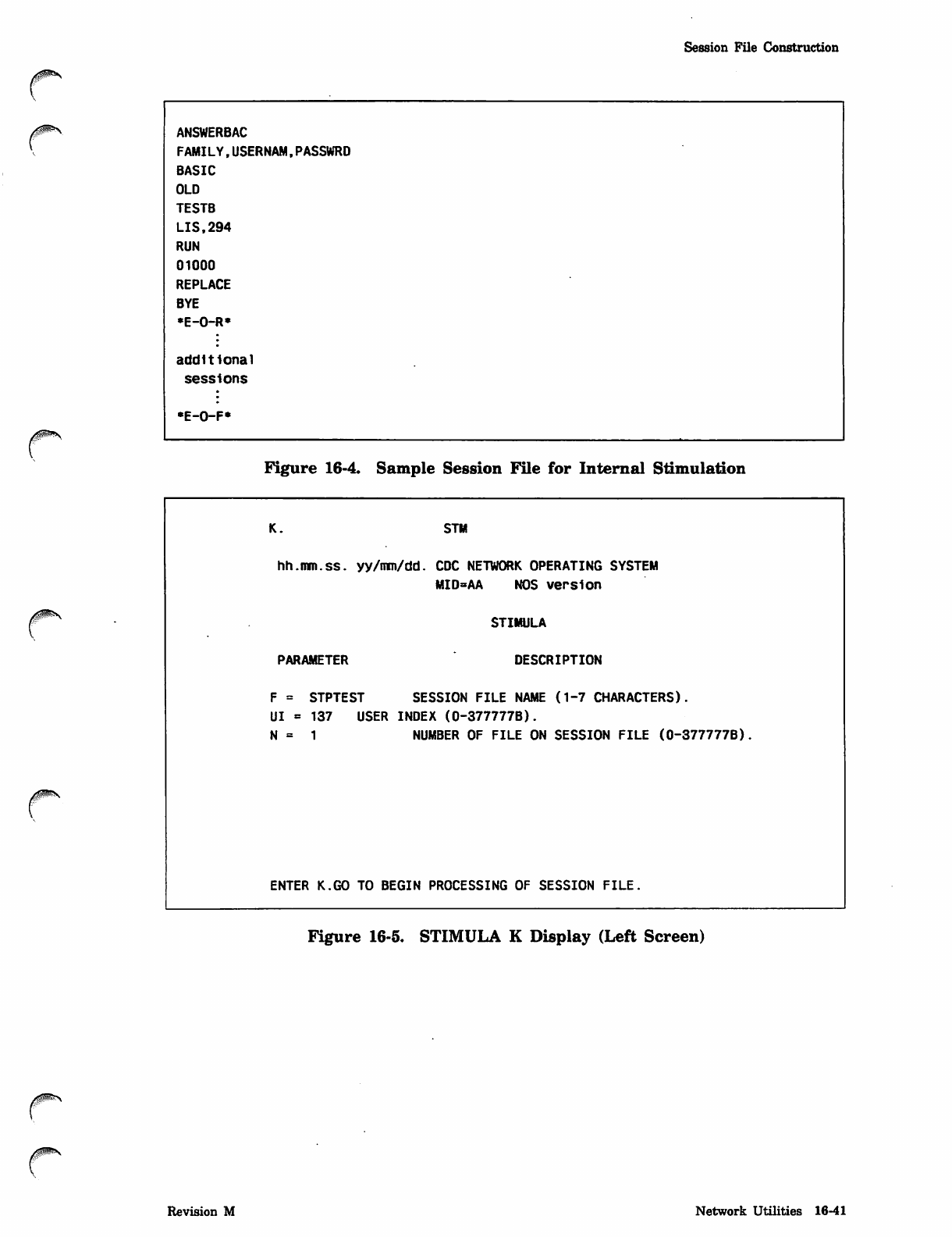
Session File Construction
ANSWERBAC
FAMILY,USERNAM,PASSWRD
BASIC
OLD
TESTB
LIS,294
RUN
01000
REPLACE
BYE
•E-O-R*
additional
sessions
•E-O-F*
Figure 16-4. Sample Session File for Internal Stimulation
r
K. STM
hh. mm.ss. yy/mm/dd. CDC NETWORK OPERATING SYSTEM
MID=AA NOS version
STIMULA
PARAMETER DESCRIPTION
F =
UI «
N =
STPTEST SESSION FILE NAME (1-7 CHARACTERS).
= 137 USER INDEX (0-377777B).
1 NUMBER OF FILE ON SESSION FILE (0-377777B).
ENTER K.GO TO BEGIN PROCESSING OF SESSION FILE.
y^WSy
Figure 16-5. STIMULA K Display (Left Screen)
Revision M Network Utilities 16-41
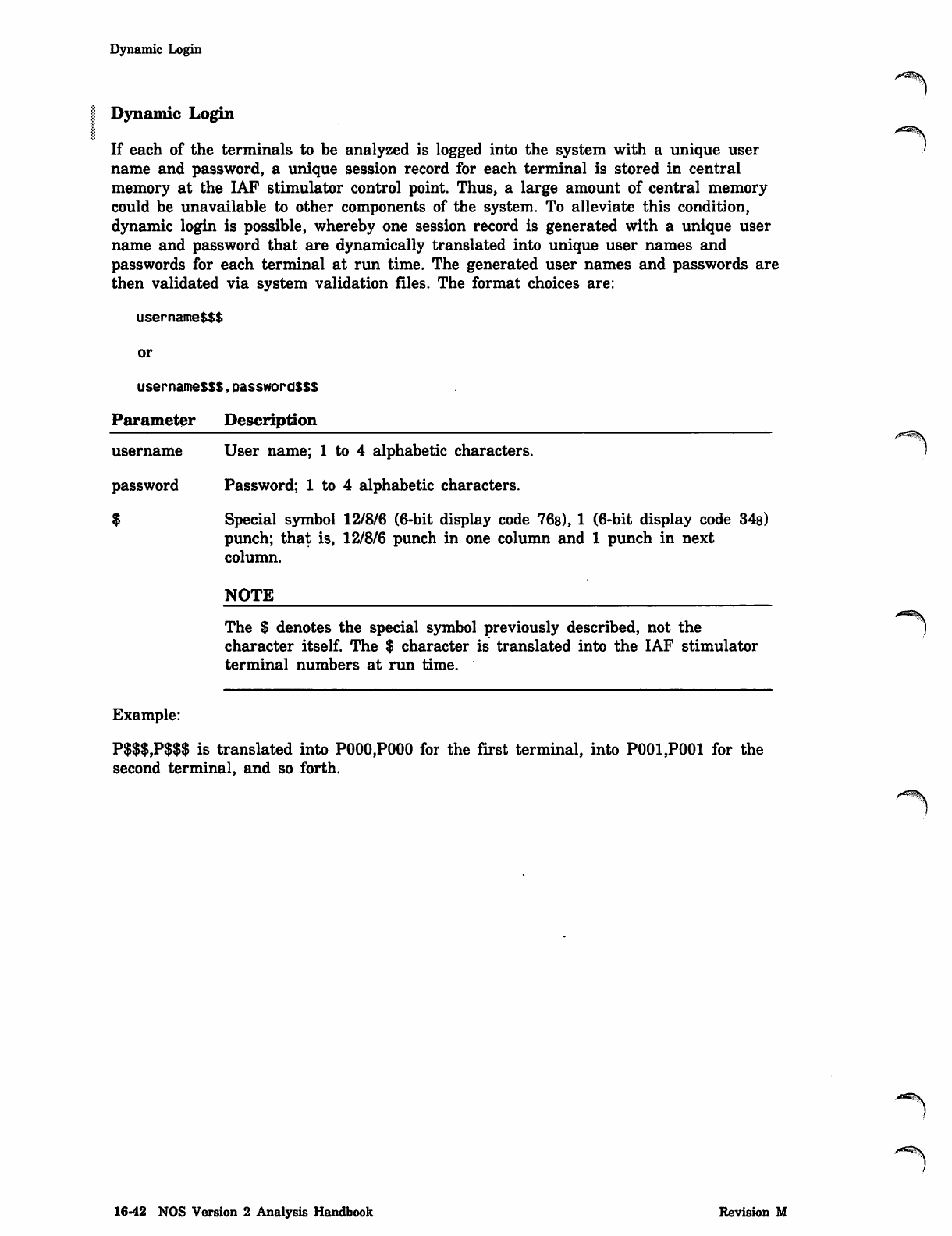
Dynamic Login
Dynamic Login
If each of the terminals to be analyzed is logged into the system with a unique user
name and password, a unique session record for each terminal is stored in central
memory at the IAF stimulator control point. Thus, a large amount of central memory
could be unavailable to other components of the system. To alleviate this condition,
dynamic login is possible, whereby one session record is generated with a unique user
name and password that are dynamically translated into unique user names and
passwords for each terminal at run time. The generated user names and passwords are
then validated via system validation files. The format choices are:
username$$$
or
username$$$,password$$$
Parameter Description
username User name; 1 to 4 alphabetic characters.
password Password; 1 to 4 alphabetic characters.
$ Special symbol 12/8/6 (6-bit display code 76s), 1 (6-bit display code 34s)
punch; that is, 12/8/6 punch in one column and 1 punch in next
column.
NOTE
The $ denotes the special symbol previously described, not the
character itself. The $ character is translated into the IAF stimulator
terminal numbers at run time.
<^®5\
Example:
P$$$,P$$$ is translated into P000,P000 for the first terminal, into P001,P001 for the
second terminal, and so forth.
16-42 NOS Version 2 Analysis Handbook Revision M
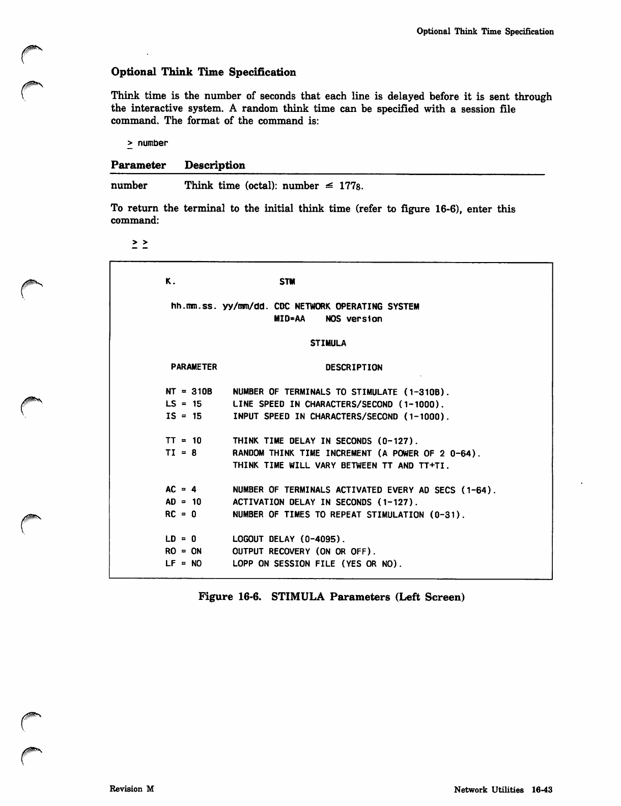
Optional Think Time Specification
Optional Think Time Specification
Think time is the number of seconds that each line is delayed before it is sent through
the interactive system. A random think time can be specified with a session file
command. The format of the command is:
> number
Parameter Description
number Think time (octal): number ^ 1778.
To return the terminal to the initial think time (refer to figure 16-6), enter this
command:
K . S T M
hh.mm.ss. yy/mm/dd. CDC NETWORK OPERATING SYSTEM
MID*AA NOS version
STIMULA
PARAMETER DESCRIPTION
NT = 310B NUMBER OF TERMINALS TO STIMULATE (1-310B).
LS = 15 LINE SPEED IN CHARACTERS/SECOND (1-1000).
IS = 15 INPUT SPEED IN CHARACTERS/SECOND (1-1000).
TT = 10 THINK TIME DELAY IN SECONDS (0-127).
TI = 8 RANDOM THINK TIME INCREMENT (A POWER OF 2 0-64).
THINK TIME WILL VARY BETWEEN TT AND TT+TI.
AC = 4 NUMBER OF TERMINALS ACTIVATED EVERY AD SECS (1-64)
AD = 10 ACTIVATION DELAY IN SECONDS (1-127).
RC = 0 NUMBER OF TIMES TO REPEAT STIMULATION (0-31).
LD = 0 LOGOUT DELAY (0-4095).
RO = ON OUTPUT RECOVERY (ON OR OFF).
LF = NO LOPP ON SESSION FILE (YES OR NO).
Figure 16-6. STIMULA Parameters (Left Screen)
Revision M Network Utilities 16-43
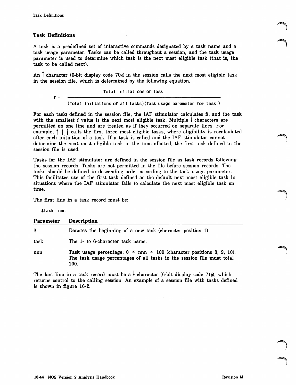
Task Definitions
Task Definitions A*ms
A task is a predefined set of interactive commands designated by a task name and a .)
task usage parameter. Tasks can be called throughout a session, and the task usage
parameter is used to determine which task is the next most eligible task (that is, the
task to be called next).
An I character (6-bit display code 70s) in the session calls the next most eligible task
in the session file, which is determined by the following equation.
Total initiations of task*
fiat
(Total Initiations of all tasks)(Task usage parameter for taski)
For each taski defined in the session file, the IAF stimulator calculates fi, and the task
with the smallest f value is the next most eligible task. Multiple \ characters are
permitted on one line and are treated as if they occurred on separate lines. For
example, ttt ca^s the ^rs^ three most eligible tasks, where eligibility is recalculated
after each initiation of a task. If a task is called and the IAF stimulator cannot a^^s
determine the next most eligible task in the time allotted, the first task defined in the
session file is used.
Tasks for the IAF stimulator are defined in the session file as task records following
the session records. Tasks are not permitted in the file before session records. The
tasks should be defined in descending order according to the task usage parameter.
This facilitates use of the first task defined as the default next most eligible task in
situations where the IAF stimulator fails to calculate the next most eligible task on
time.
The first line in a task record must be:
$task nnn
Parameter Description
$ Denotes the beginning of a new task (character position 1).
task The 1- to 6-character task name.
nnn Task usage percentage; 0 ^ nnn ^ 100 (character positions 8, 9, 10).
The task usage percentages of all tasks in the session file must total
100.
The last line in a task record must be a I character (6-bit display code 71s), which
returns control to the calling session. An example of a session file with tasks defined
is shown in figure 16-2.
16-44 NOS Version 2 Analysis Handbook Revision M
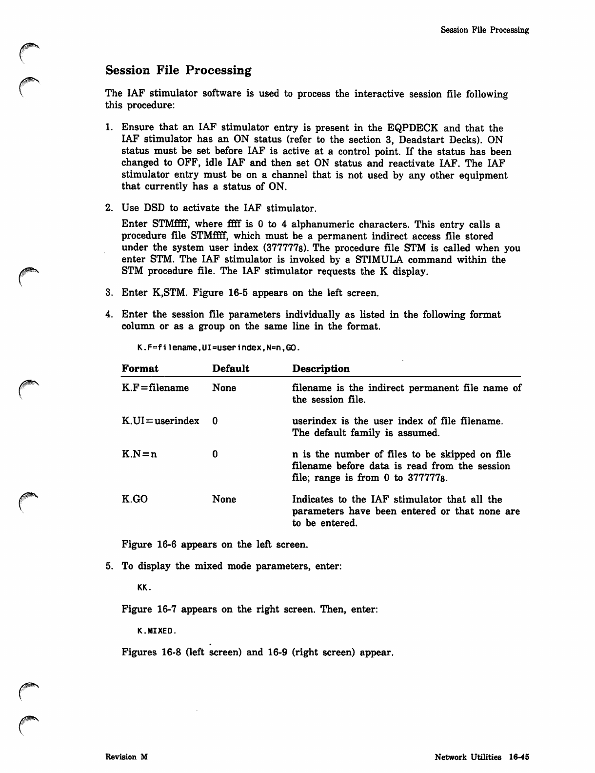
Session File Processing
Session File Processing
The IAF stimulator software is used to process the interactive session file following
this procedure:
1. Ensure that an IAF stimulator entry is present in the EQPDECK and that the
IAF stimulator has an ON status (refer to the section 3, Deadstart Decks). ON
status must be set before IAF is active at a control point. If the status has been
changed to OFF, idle IAF and then set ON status and reactivate IAF. The IAF
stimulator entry must be on a channel that is not used by any other equipment
that currently has a status of ON.
2. Use DSD to activate the IAF stimulator.
Enter STMflff, where ffff is 0 to 4 alphanumeric characters. This entry calls a
procedure file STMffff, which must be a permanent indirect access file stored
under the system user index (377777s). The procedure file STM is called when you
enter STM. The IAF stimulator is invoked by a STIMULA command within the
STM procedure file. The IAF stimulator requests the K display.
3. Enter K,STM. Figure 16-5 appears on the left screen.
4. Enter the session file parameters individually as listed in the following format
column or as a group on the same line in the format.
K.F=f1lename,UI=userindex,N=n,GO.
Format Default Description
K.F=filename None
K.UI=userindex 0
K.N=n
K.GO None
filename is the indirect permanent file name of
the session file.
userindex is the user index of file filename.
The default family is assumed.
n is the number of files to be skipped on file
filename before data is read from the session
file; range is from 0 to 377777s.
Indicates to the IAF stimulator that all the
parameters have been entered or that none are
to be entered.
Figure 16-6 appears on the left screen.
To display the mixed mode parameters, enter:
KK.
Figure 16-7 appears on the right screen. Then, enter:
K.MIXED.
Figures 16-8 (left screen) and 16-9 (right screen) appear.
Revision M Network Utilities 16-45
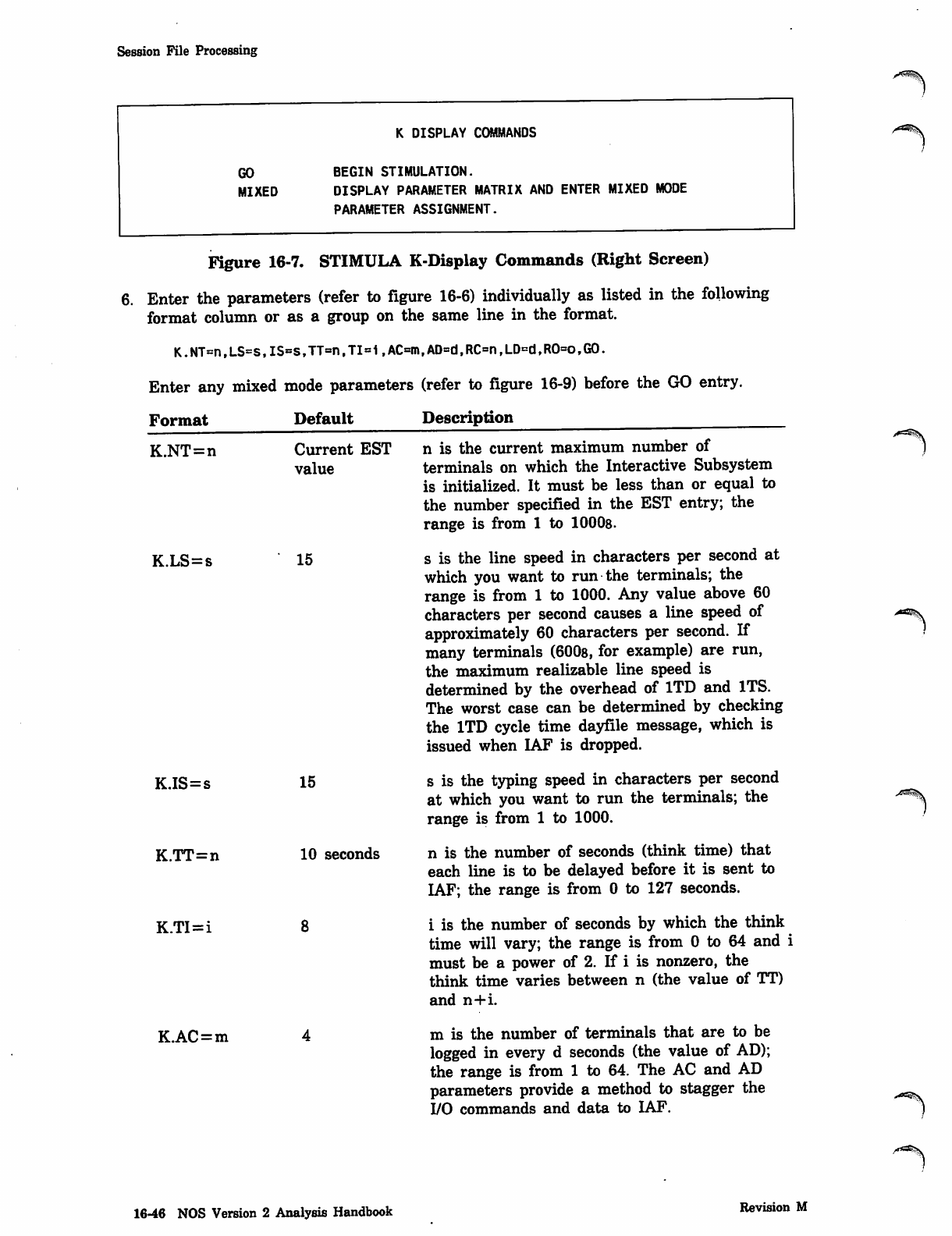
Session File Processing
K DISPLAY COMMANDS
GO BEGIN STIMULATION.
MIXED DISPLAY PARAMETER MATRIX AND ENTER MIXED MODE
PARAMETER ASSIGNMENT.
Figure 16-7. STIMULA K-Display Commands (Right Screen)
6. Enter the parameters (refer to figure 16-6) individually as listed in the following
format column or as a group on the same line in the format.
K.NT=n,LS=s,IS=s,TT=n,TI=1,AC=m,AD=d,RC=n,LD=d,RO=o,GO.
Enter any mixed mode parameters (refer to figure 16-9) before the GO entry.
Format Default Description
K.NT=n
K.LS=s
K.IS=s
K.TT=n
K.TI=i
K.AC = m
Current EST n is the current maximum number of
value terminals on which the Interactive Subsystem
is initialized. It must be less than or equal to
the number specified in the EST entry; the
range is from 1 to 10008.
15 s is the line speed in characters per second at
which you want to run the terminals; the
range is from 1 to 1000. Any value above 60
characters per second causes a line speed of
approximately 60 characters per second. If
many terminals (6008, for example) are run,
the maximum realizable line speed is
determined by the overhead of 1TD and ITS.
The worst case can be determined by checking
the 1TD cycle time dayfile message, which is
issued when IAF is dropped.
15 s is the typing speed in characters per second
at which you want to run the terminals; the
range is from 1 to 1000.
10 seconds n is the number of seconds (think time) that
each line is to be delayed before it is sent to
IAF; the range is from 0 to 127 seconds.
8 i is the number of seconds by which the think
time will vary; the range is from 0 to 64 and i
must be a power of 2. If i is nonzero, the
think time varies between n (the value of TT)
and n+i.
4 m is the number of terminals that are to be
logged in every d seconds (the value of AD);
the range is from 1 to 64. The AC and AD
parameters provide a method to stagger the
I/O commands and data to IAF.
16-46 NOS Version 2 Analysis Handbook Revision M
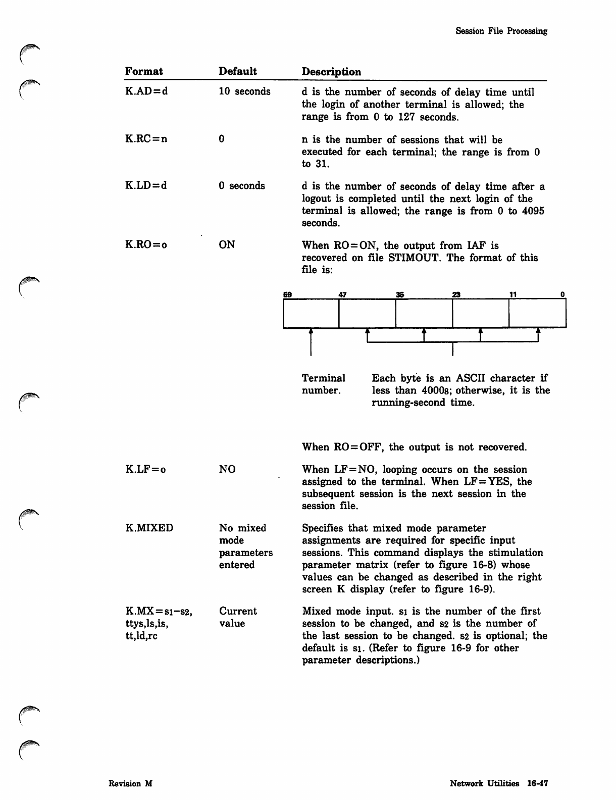
Session File Processing
00&\
Format Default Description
K.AD=d
K.RC=n
K.LD=d
10 seconds
0 seconds
K.RO=o ON
j0*M^\
d is the number of seconds of delay time until
the login of another terminal is allowed; the
range is from 0 to 127 seconds.
n is the number of sessions that will be
executed for each terminal; the range is from 0
to 31.
d is the number of seconds of delay time after a
logout is completed until the next login of the
terminal is allowed; the range is from 0 to 4095
seconds.
When RO=ON, the output from IAF is
recovered on file STIMOUT. The format of this
file is:
69 47 38 23 11
-> t
Terminal Each byte is an ASCII character if
number. less than 4000s; otherwise, it is the
running-second time.
y ^ s
K.LF=o
K.MIXED
K.MX=si-s2,
ttys,ls,is,
tt,ld,rc
When RO=OFF, the output is not recovered.
NO When LF=NO, looping occurs on the session
assigned to the terminal. When LF=YES, the
subsequent session is the next session in the
session file.
No mixed Specifies that mixed mode parameter
mode assignments are required for specific input
parameters sessions. This command displays the stimulation
entered parameter matrix (refer to figure 16-8) whose
values can be changed as described in the right
screen K display (refer to figure 16-9).
Current Mixed mode input, si is the number of the first
value session to be changed, and S2 is the number of
the last session to be changed. S2 is optional; the
default is si. (Refer to figure 16-9 for other
parameter descriptions.)
00ms
Revision M Network Utilities 16-47
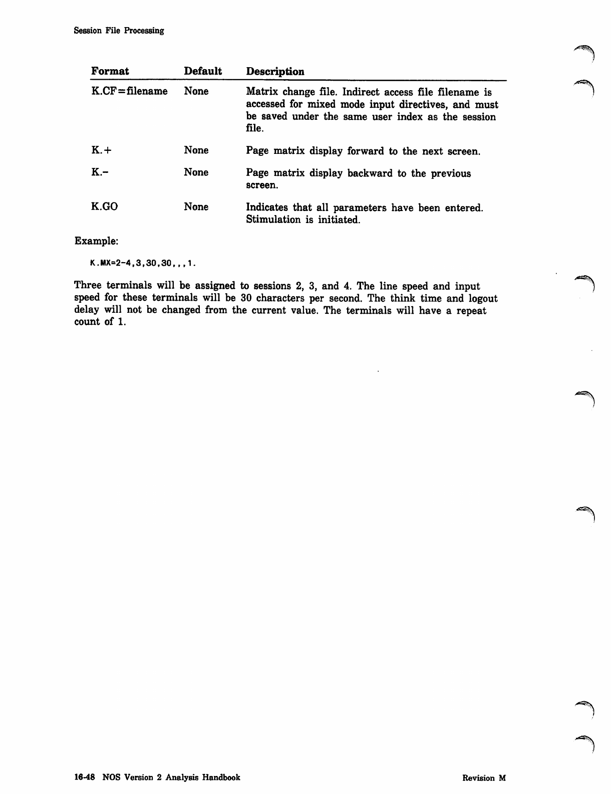
Session File Processing
Format Default Description
K.CF=filename None
K.+
K-
K.GO
None
None
None
Matrix change file. Indirect access file filename is
accessed for mixed mode input directives, and must
be saved under the same user index as the session
file.
Page matrix display forward to the next screen.
Page matrix display backward to the previous
screen.
Indicates that all parameters have been entered.
Stimulation is initiated.
/*""*8S\
Example:
K.MX=2-4,3,30,30.,,1.
Three terminals will be assigned to sessions 2, 3, and 4. The line speed and input
speed for these terminals will be 30 characters per second. The think time and logout
delay will not be changed from the current value. The terminals will have a repeat
count of 1.
16-48 NOS Version 2 Analysis Handbook Revision M
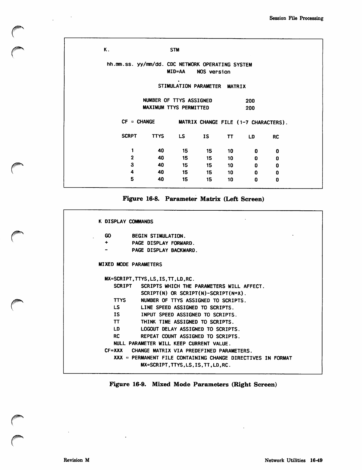
Session File Processing
Xp^^y K . S T M
hh.mm.ss. yy/mm/dd. CDC NETWORK OPERATING SYSTEM
MID=AA NOS version
STIMULATION PARAMETER MATRIX
NUMBER OF TTYS ASSIGNED 200
MAXIMUM TTYS PERMITTED 200
CF = CHANGE MATRIX CHANGE FILE (1-7 CHARACTERS).
SCRPT TTYS LS IS TT LD RC
1 4 0 1 5 15 10
2 4 0 1 5 15 10
3 4 0 1 5 15 10
4 4 0 1 5 15 10
5 4 0 1 5 15 10
Figure 16-8. Parameter Matrix (Left Screen)
K DISPLAY COMMANDS
GO BEGIN STIMULATION.
+ PAGE DISPLAY FORWARD.
PAGE DISPLAY BACKWARD.
MIXED MODE PARAMETERS
MX=SCRIPT,TTYS,LS,IS,TT,LD,RC.
SCRIPT SCRIPTS WHICH THE PARAMETERS WILL AFFECT.
SCRIPT(N) OR SCRIPT(N)-SCRIPT(N+X).
TTYS NUMBER OF TTYS ASSIGNED TO SCRIPTS.
LS LINE SPEED ASSIGNED TO SCRIPTS.
IS INPUT SPEED ASSIGNED TO SCRIPTS.
TT THINK TIME ASSIGNED TO SCRIPTS.
LD LOGOUT DELAY ASSIGNED TO SCRIPTS.
RC REPEAT COUNT ASSIGNED TO SCRIPTS.
NULL PARAMETER WILL KEEP CURRENT VALUE.
CF=XXX CHANGE MATRIX VIA PREDEFINED PARAMETERS.
XXX = PERMANENT FILE CONTAINING CHANGE DIRECTIVES IN FORMAT
MX=SCRIPT,TTYS,LS,IS,TT,LD,RC.
Figure 16-9. Mixed Mode Parameters (Right Screen)
Revision M Network Utilities 16-49
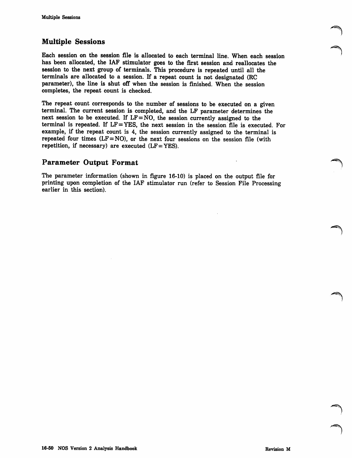
Multiple Sessions
Multiple Sessions
Each session on the session file is allocated to each terminal line. When each session
has been allocated, the IAF stimulator goes to the first session and reallocates the
session to the next group of terminals. This procedure is repeated until all the
terminals are allocated to a session. If a repeat count is not designated (RC
parameter), the line is shut off when the session is finished. When the session
completes, the repeat count is checked.
The repeat count corresponds to the number of sessions to be executed on a given
terminal. The current session is completed, and the LF parameter determines the
next session to be executed. If LF=NO, the session currently assigned to the
terminal is repeated. If LF=YES, the next session in the session file is executed. For
example, if the repeat count is 4, the session currently assigned to the terminal is
repeated four times (LF=NO), or the next four sessions on the session file (with
repetition, if necessary) are executed (LF=YES).
Parameter Output Format ""^
The parameter information (shown in figure 16-10) is placed on the output file for
printing upon completion of the IAF stimulator run (refer to Session File Processing
earlier in this section).
16-50 NOS Version 2 Analysis Handbook Revision M
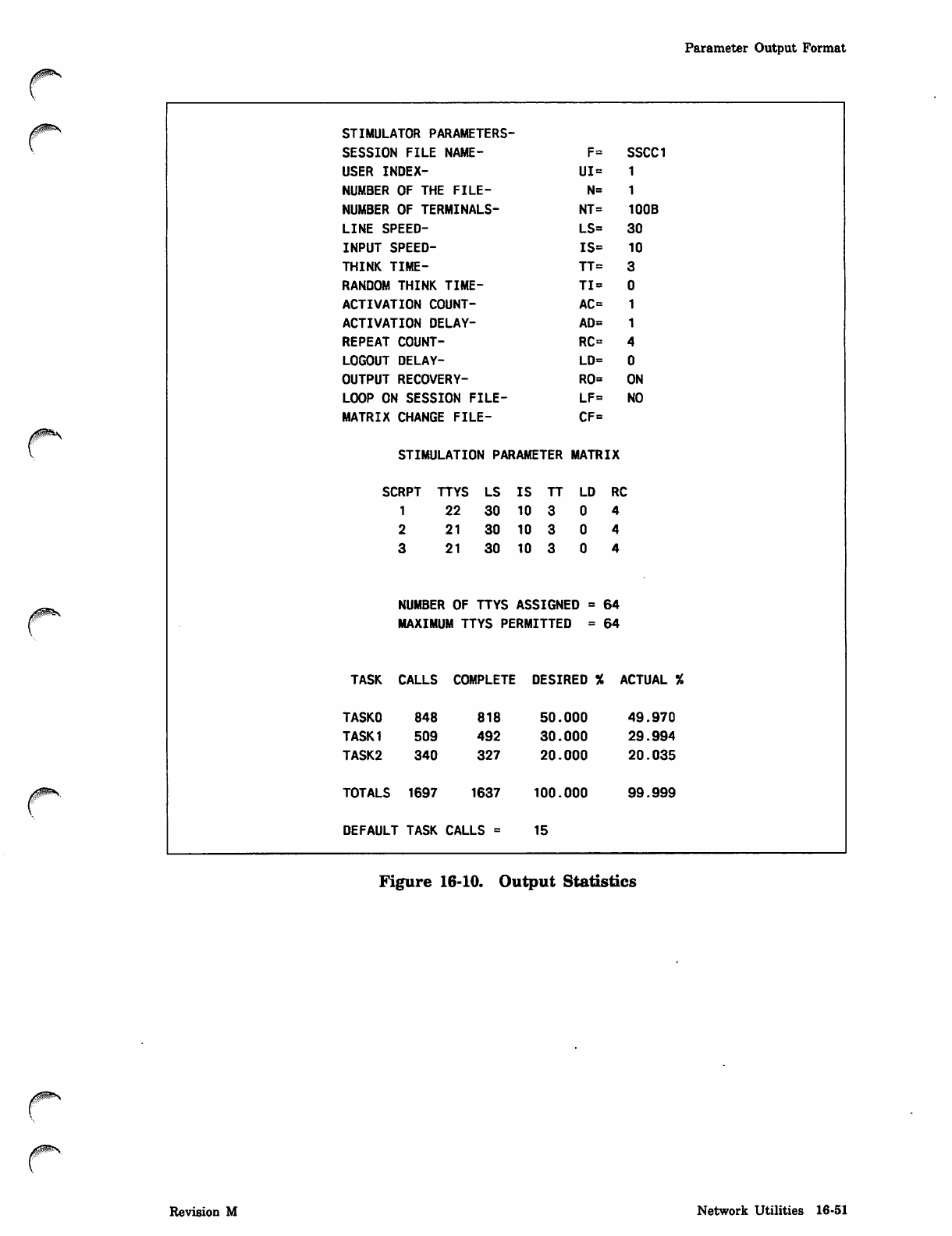
Parameter Output Format
r
0ms.
STIMULATOR PARAMETERS-
SESSION FILE NAME- F= SSCC1
USER INDEX- UI =
NUMBER OF THE FILE- N=
NUMBER OF TERMINALS- NT= 100B
LINE SPEED- LS= 30
INPUT SPEED- IS= 10
THINK TIME- TT=
RANDOM THINK TIME- TI =
ACTIVATION COUNT- AC=
ACTIVATION DELAY- AD=
REPEAT COUNT- RC=
LOGOUT DELAY- LD=
OUTPUT RECOVERY- RO= ON
LOOP ON SESSION FILE- LF= NO
MATRIX CHANGE FILE- CF=
STIMULATION PARAMETER MATRIX
SCRPT TTYS LS IS TT LD RC
122 30 10
221 30 10
321 30 10
NUMBER OF TTYS ASSIGNED = 64
MAXIMUM TTYS PERMITTED = 64
TASK CALLS COMPLETE DESIRED % ACTUAL %
TASK0 848 818 50.000 49.970
TASK1 509 492 30.000 29.994
TASK2 340 327 20.000 20.035
TOTALS 1697 1637 100.000 99.999
DEFAULT TASK CALLS = 15
Figure 16-10. Output Statistics
Revision M Network Utilities 16-51
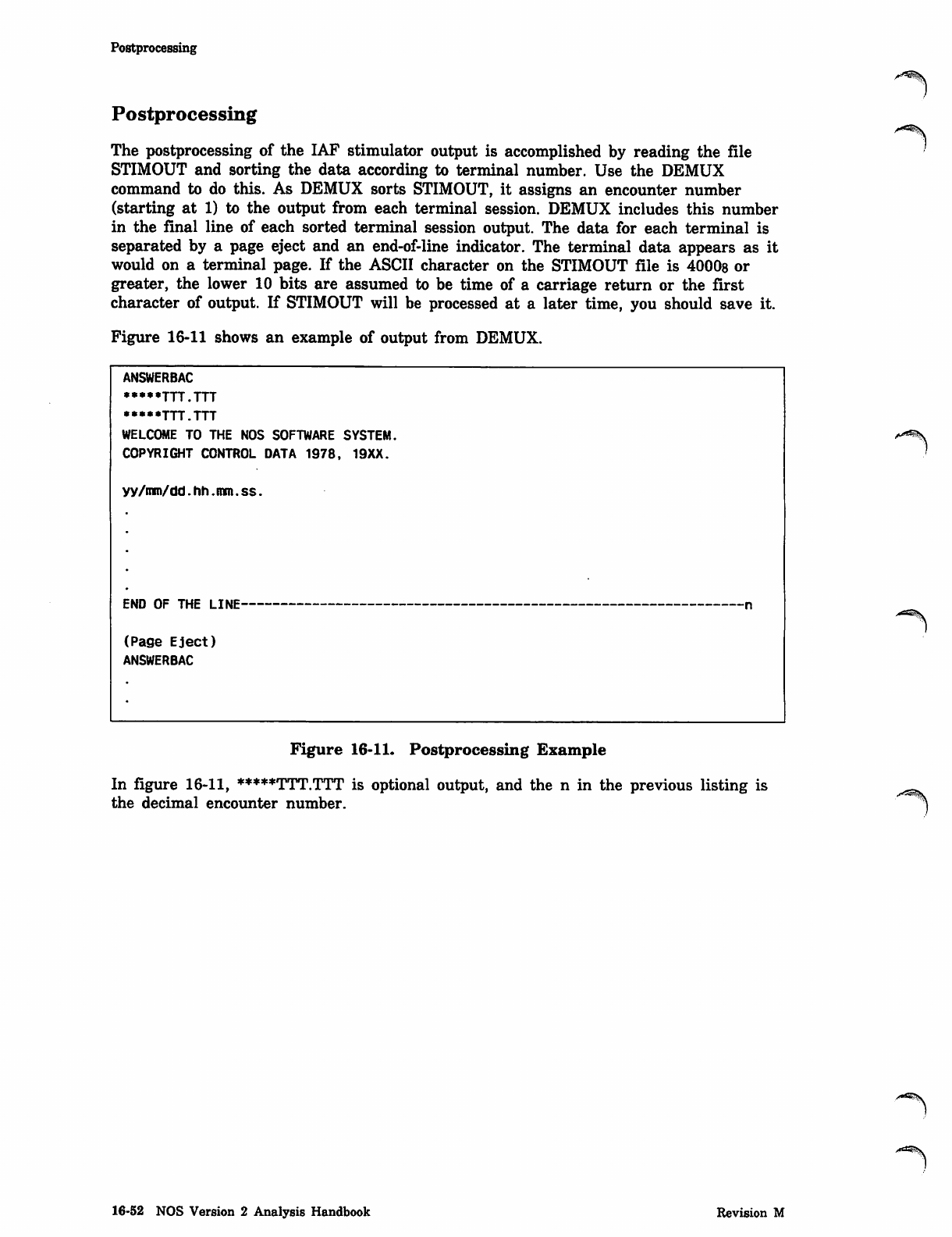
Postprocessing
Postprocessing
The postprocessing of the IAF stimulator output is accomplished by reading the file
STIMOUT and sorting the data according to terminal number. Use the DEMUX
command to do this. As DEMUX sorts STIMOUT, it assigns an encounter number
(starting at 1) to the output from each terminal session. DEMUX includes this number
in the final line of each sorted terminal session output. The data for each terminal is
separated by a page eject and an end-of-line indicator. The terminal data appears as it
would on a terminal page. If the ASCII character on the STIMOUT file is 4000s or
greater, the lower 10 bits are assumed to be time of a carriage return or the first
character of output. If STIMOUT will be processed at a later time, you should save it.
Figure 16-11 shows an example of output from DEMUX.
ANSWERBAC
WELCOME TO THE NOS SOFTWARE SYSTEM.
COPYRIGHT CONTROL DATA 1978, 19XX.
yy/mm/dd.hh.mm.ss.
E N D O F T H E L I N E n
(Page Eject)
ANSWERBAC
A^^S,
Figure 16-11. Postprocessing Example
In figure 16-11, *****TTT.TTT is optional output, and the n in the previous listing is
the decimal encounter number. ^*^^\
/"^S\
16-52 NOS Version 2 Analysis Handbook Revision M
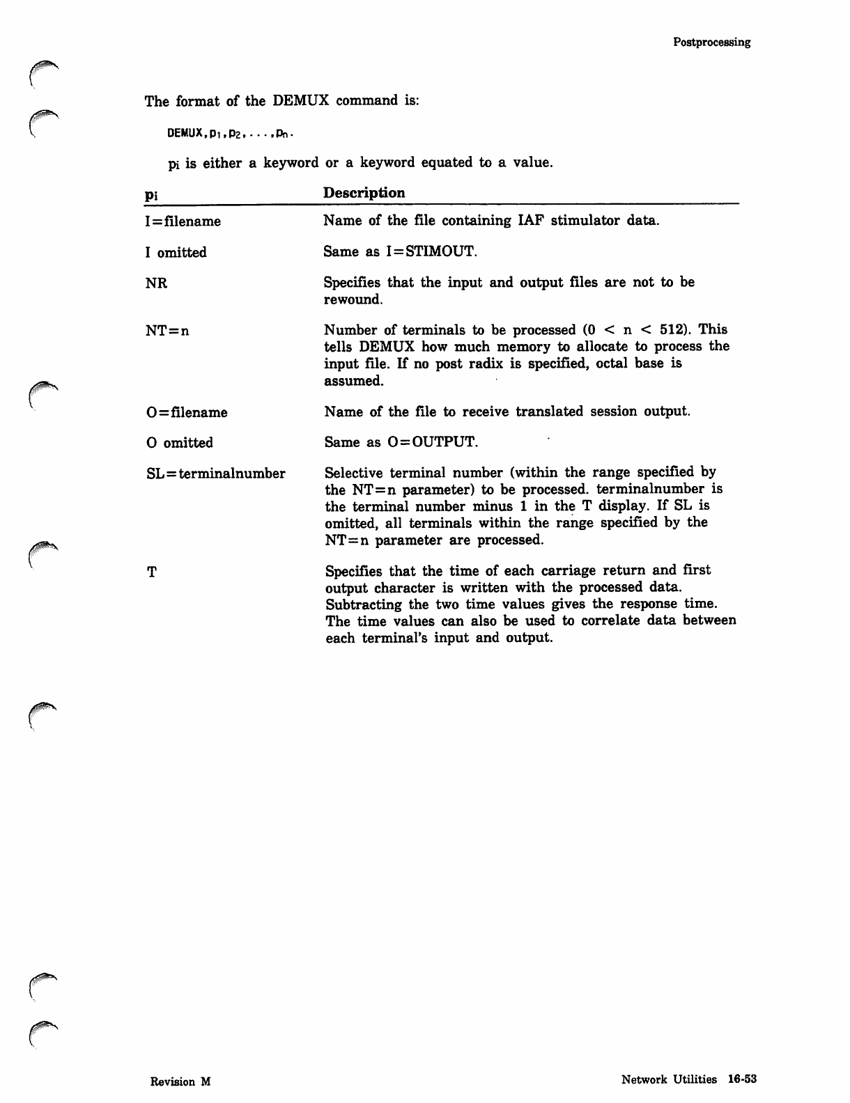
Postprocessing
The format of the DEMUX command is:
DEMUX,P!,p2 Pn-
pi is either a keyword or a keyword equated to a value.
pi Description
I=filename
I omitted
NR
NT=n
0=filename
O omitted
SL=terminalnumber
Name of the file containing IAF stimulator data.
Same as I=STIMOUT.
Specifies that the input and output files are not to be
rewound.
Number of terminals to be processed (0 < n < 512). This
tells DEMUX how much memory to allocate to process the
input file. If no post radix is specified, octal base is
assumed.
Name of the file to receive translated session output.
Same as 0=OUTPUT.
Selective terminal number (within the range specified by
the NT=n parameter) to be processed, terminalnumber is
the terminal number minus 1 in the T display. If SL is
omitted, all terminals within the range specified by the
NT=n parameter are processed.
Specifies that the time of each carriage return and first
output character is written with the processed data.
Subtracting the two time values gives the response time.
The time values can also be used to correlate data between
each terminal's input and output.
Revision M Network Utilities 16-53
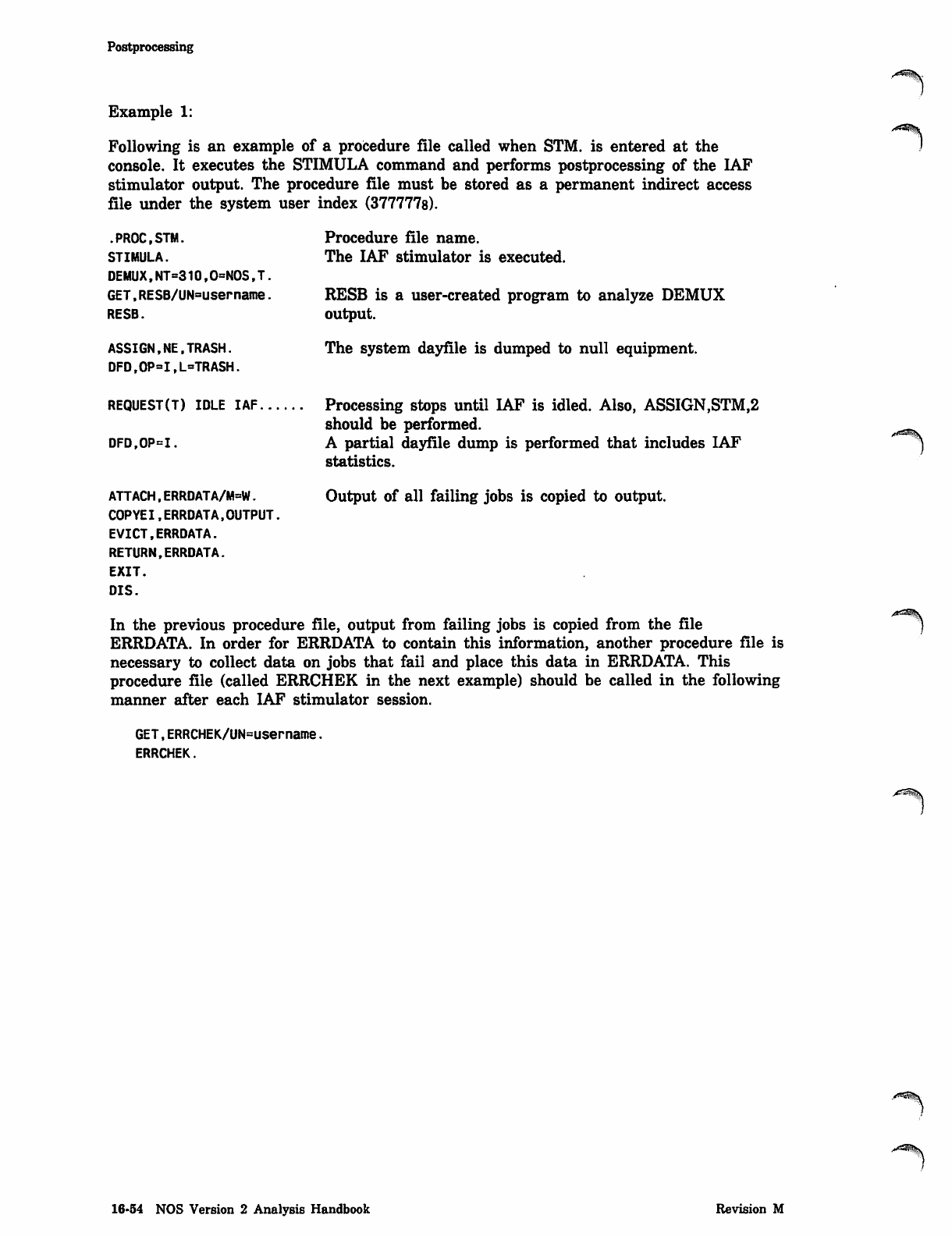
Postprocessing
Example 1:
Following is an example of a procedure file called when STM. is entered at the
console. It executes the STIMULA command and performs postprocessing of the IAF
stimulator output. The procedure file must be stored as a permanent indirect access
file under the system user index (377777s).
.PROC,STM.
STIMULA.
DEMUX,NT=310,0=NOS,T.
GET,RESB/UN=username.
RESB.
ASSIGN,NE.TRASH.
DFD,OP=I,L=TRASH.
Procedure file name.
The IAF stimulator is executed.
RESB is a user-created program to analyze DEMUX
output.
The system dayfile is dumped to null equipment.
REQUEST(T) IDLE IAF.
DFD,OP=I.
Processing stops until IAF is idled. Also, ASSIGN,STM,2
should be performed.
A partial dayfile dump is performed that includes IAF
statistics.
Output of all failing jobs is copied to output.
ATTACH,ERRDATA/M=W.
COPYEI,ERRDATA,OUTPUT.
EVICT,ERRDATA.
RETURN,ERRDATA.
EXIT.
DIS.
In the previous procedure file, output from failing jobs is copied from the file
ERRDATA. In order for ERRDATA to contain this information, another procedure file is
necessary to collect data on jobs that fail and place this data in ERRDATA. This
procedure file (called ERRCHEK in the next example) should be called in the following
manner after each IAF stimulator session.
GET,ERRCHEK/UN=username.
ERRCHEK.
16-54 NOS Version 2 Analysis Handbook Revision M
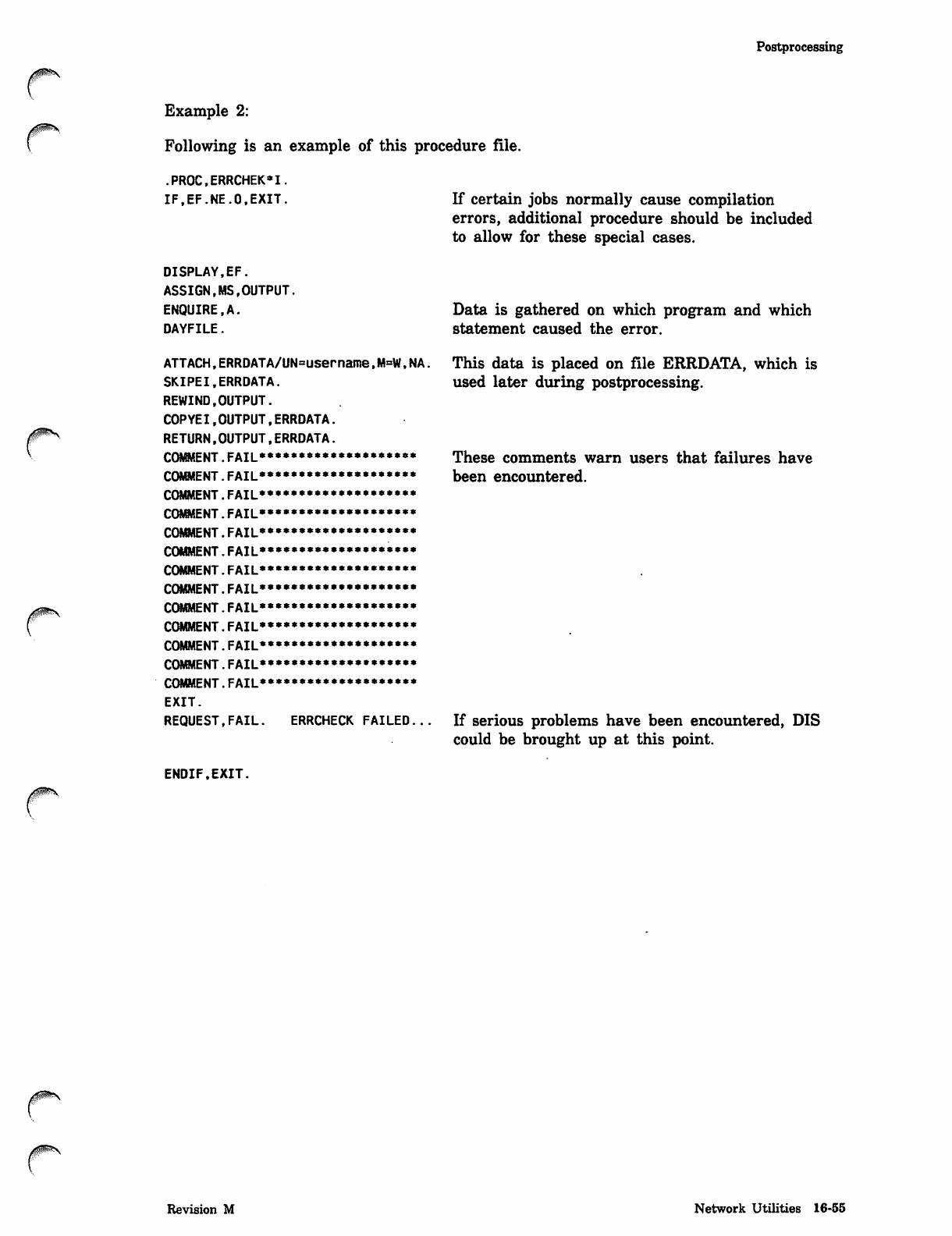
Postprocessing
yms
r
/! ^^ \
Example 2:
Following is an example of this procedure file.
.PROC,ERRCHEK*I.
IF.EF.NE.O.EXIT.
DISPLAY,EF.
ASSIGN,MS,OUTPUT.
ENQUIRE,A.
DAYFILE.
ATTACH,ERRDATA/UN=USername,M=W,NA.
SKIPEI,ERRDATA.
REWIND,OUTPUT.
COPYEI,OUTPUT,ERRDATA.
RETURN,OUTPUT,ERRDATA.
COMMENT.FAIL*
COMMENT.FAIL
COMMENT.FAIL
COMMENT.FAIL
COMMENT.FAIL
COMMENT.FAIL
COMMENT.FAIL
COMMENT.FAIL
COMMENT.FAIL
COMMENT.FAIL
COMMENT.FAIL
COMMENT.FAIL
COMMENT.FAIL
EXIT.
REQUEST,FAIL. ERRCHECK FAILED.
ENDIF,EXIT.
If certain jobs normally cause compilation
errors, additional procedure should be included
to allow for these special cases.
Data is gathered on which program and which
statement caused the error.
This data is placed on file ERRDATA, which is
used later during postprocessing.
These comments warn users that failures have
been encountered.
If serious problems have been encountered, DIS
could be brought up at this point.
Revision M Network Utilities 16-55
Postprocessing
Care should be taken when comparing response times between different versions of the
operating system with the IAF stimulator. Other factors may have a significant impact /*^\
on response time. Be aware of these factors:
• The entire parameter set should be the same for each IAF stimulator run. The
rate of activation of terminals, for example, can significantly impact response
time.
• The hardware configurations must be identical. If an attempt is made to measure
small differences, all devices that cannot be restored to their original state
(normally temporary devices) should be deadstarted and fully initialized.
• If the possibility exists that permanent files have been destroyed, these files
should be restored before each run. This can be accomplished easily by
maintaining a copy of all required files under a user name not used during the
stimulation. A procedure file can then be called to restore the files before each
IAF stimulator run. This is important when stimulation loads are causing
abnormal job failures. A REPLACE shortly after an unexpected abort may cause ^^
incorrect information to be written, for example. '"^^
• Job processing must be the same for each IAF stimulator run. When many
terminals are to be analyzed, random job failures may be overlooked. These
failures may, however, affect the entire results of the IAF stimulator run. To
minimize this problem, it is necessary to check errors in all sessions quickly and
easily. This can be done by using the procedures described earlier in this section.
By using the preceding techniques and procedures and observing the restrictions, it
becomes easier to use the IAF stimulator to check performance and reliability and to /*s^
obtain meaningful data from the system. )
16-56 NOS Version 2 Analysis Handbook Revision M
0"
0^
Permanent File Utilities 17
Introduction .mmm- -«-
Utility Description Terminology ... 17-2
A r c h i v e F i l e " ] ' y , «
Alternate Storage ' 'V» «
Destaging and Staging Files .■.......'.'!!."!!.'!!..'!.'!.".'!!!!!!!!! 17-3
User Index ... ...". 17-4
Device Masks m 17-5
Device Mask . 17-5
Secondary Mask ..; .................. 17-7
Mass Storage Table 17-9
Catalog Track [[[[" .............. 17.9
Permanent File Catalog Entry 17-11
Track Reservation Table (TRT) 17-22
Family • .'.'.'.'.'.'.'.'.'.'.'.'.'.'.'..'.'.'.'.'..'. 17-25
Summary File 17-29
Calling the Utilities 17-37
Console Input .t ..... 17-37
DIS Input 17-44
Batch Input 17-44
Terminal Input 17-45
Procedure Files 17-45
Parameters for the Permanent File Utilities 17-46
Description of Permanent File Utility Parameters 17-48
Preassigning the Archive File . 17-60
Permanent File Utility Routines 17-61
Catalog Archive File (PFATC) 17-66
Catalog Permanent File Device (PFCAT) 17-66
Copy Archive File (PFCOPY) . '. 17.72
Dump Permanent File (PFDUMP) 17-72
PFDUMP in a Secured System 17-73
I n c r e m e n t a l P e r m a n e n t F i l e S y s t e m D u m p 1 7 - 7 3
Partial Permanent File System Dump 17-74
Full Permanent File Dump 17-74
PFDUMP File Interlocking .-., 17-74
PFDUMP in an MSE or Tape Alternate Storage Environment 17-74
PFDUMP Protected Files 17-76
Load Permanent File (PFLOAD) 17-77
Catalog Image Record 17-79
PFLOAD Selection Process 17-80
Family Reconfiguration 17-82
PFLOAD in an MSE or Tape Alternate Storage Environment 17-83
PFDUMP/PFLOAD Example .,..-.. 17-84
Release Disk Space (PFREL) 17-92
4^*

^_
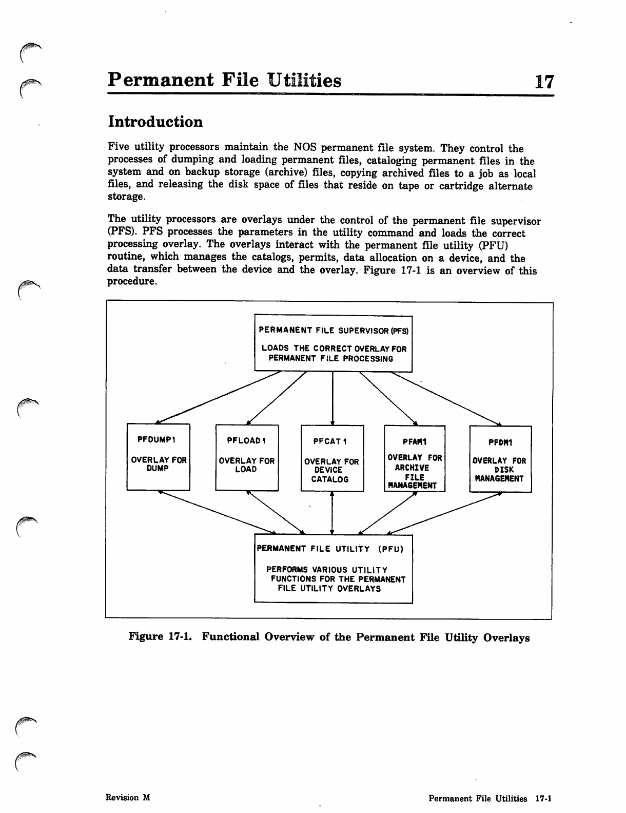
Permanent File Utilities 17
Introduction
Five utility processors maintain the NOS permanent file system. They control the
processes of dumping and loading permanent files, cataloging permanent files in the
system and on backup storage (archive) files, copying archived files to a job as local
files, and releasing the disk space of files that reside on tape or cartridge alternate
storage.
The utility processors are overlays under the control of the permanent file supervisor
(PFS). PFS processes the parameters in the utility command and loads the correct
processing overlay. The overlays interact with the permanent file utility (PFU)
routine, which manages the catalogs, permits, data allocation on a device, and the
data transfer between the device and the overlay. Figure 17-1 is an overview of this
procedure.
z^m^s.
PERMANENT FILE SUPERVISOR (PFS)
LOADS THE CORRECT OVERLAY FOR
PERMANENT FILE PROCESSING
PFDUMP1
OVERLAY FOR
DUMP
PFLOAD1
OVERLAY FOR
LOAD
PFCAT 1
OVERLAY FOR
DEVICE
CATALOG
PFAM
OVERLAY FOR
ARCHIVE
FILE
MANAGEMENT
PFDM1
OVERLAY FOR
DISK
MANAGEMENT
PERMANENT FILE UTILITY (PFU)
PERFORMS VARIOUS UTILITY
FUNCTIONS FOR THE PERMANENT
FILE UTILITY OVERLAYS
Figure 17-1. Functional Overview of the Permanent File Utility Overlays
Revision M Permanent File Utilities 17-1
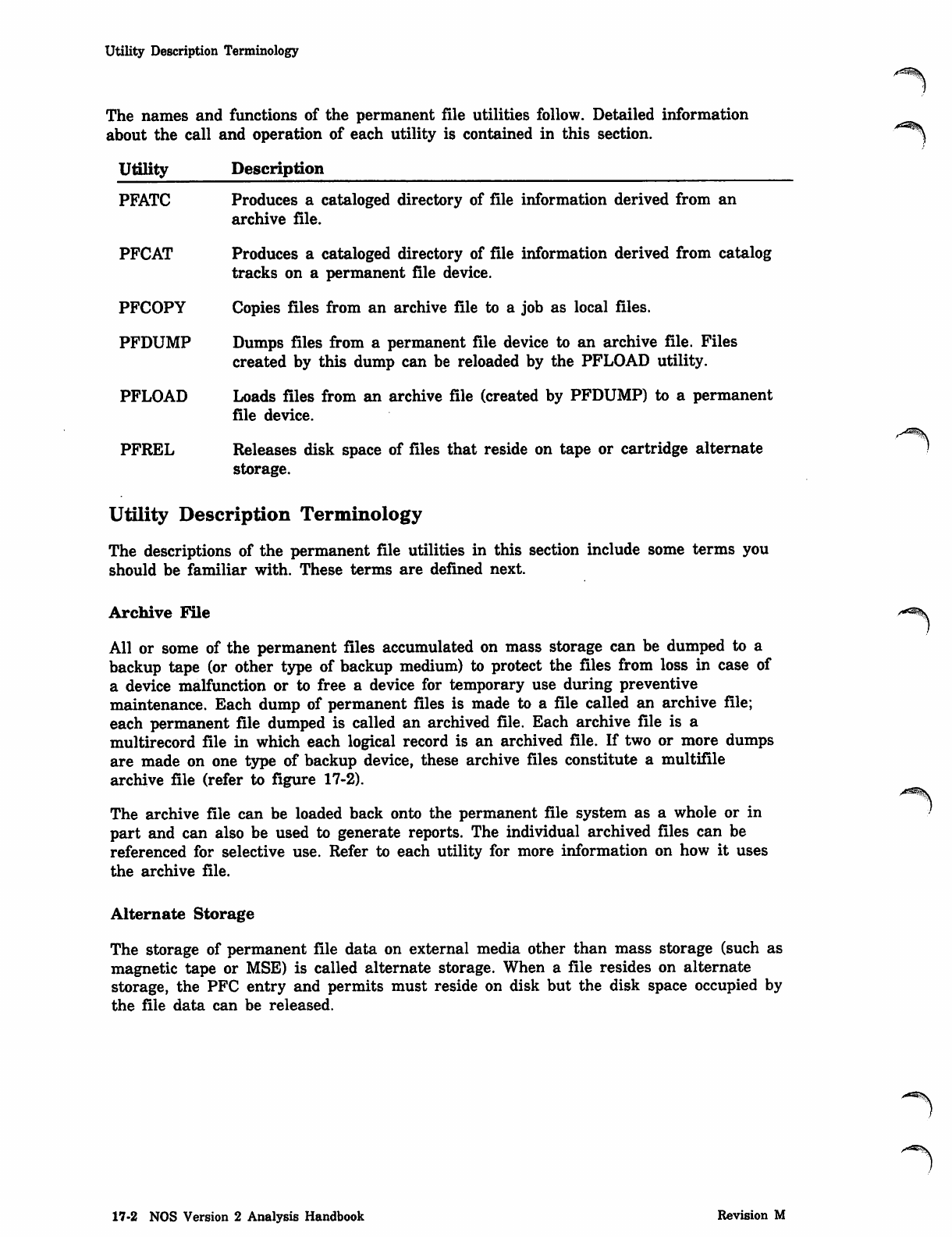
Utility Description Terminology
The names and functions of the permanent file utilities follow. Detailed information
about the call and operation of each utility is contained in this section. "^\
Utility Description
PFATC Produces a cataloged directory of file information derived from an
archive file.
PFCAT Produces a cataloged directory of file information derived from catalog
tracks on a permanent file device.
PFCOPY Copies files from an archive file to a job as local files.
PFDUMP Dumps files from a permanent file device to an archive file. Files
created by this dump can be reloaded by the PFLOAD utility.
PFLOAD Loads files from an archive file (created by PFDUMP) to a permanent
file device.
PFREL Releases disk space of files that reside on tape or cartridge alternate
storage.
Utility Description Terminology
The descriptions of the permanent file utilities in this section include some terms you
should be familiar with. These terms are defined next.
Archive File
All or some of the permanent files accumulated on mass storage can be dumped to a
backup tape (or other type of backup medium) to protect the files from loss in case of
a device malfunction or to free a device for temporary use during preventive
maintenance. Each dump of permanent files is made to a file called an archive file;
each permanent file dumped is called an archived file. Each archive file is a
multirecord file in which each logical record is an archived file. If two or more dumps
are made on one type of backup device, these archive files constitute a multifile
archive file (refer to figure 17-2).
The archive file can be loaded back onto the permanent file system as a whole or in
part and can also be used to generate reports. The individual archived files can be
referenced for selective use. Refer to each utility for more information on how it uses
the archive file.
Alternate Storage
The storage of permanent file data on external media other than mass storage (such as
magnetic tape or MSE) is called alternate storage. When a file resides on alternate
storage, the PFC entry and permits must reside on disk but the disk space occupied by
the file data can be released.
,<^S^v
17-2 NOS Version 2 Analysis Handbook Revision M
0ms
Destaging and Staging Files
ARCHIVE FILE A
(3 LOGICAL RECORDS)
+ ARCHIVE FILE B
(2 LOGICAL RECORDS)
FILE1
MULTI FILE
ARCHIVE
FILE
EOR
PERMANENT
FILE SYSTEM FILE2
FILE1
FILE2
FILE 3
FILE4
FILE5
EOR
FILE3
UUMr A -————'
DUMP B
EOR
EOF
FILE 4
EOR
FILES
EOR
EOF
EOF
Figure 17-2. Example of Multifile Archive File Structure
Destaging and Staging Files
The process of copying file data to tape alternate storage or MSE from disk residence
is called destaging the file. File destaging to tape is initiated by using the PFDUMP
utility; destaging to MSE is initiated by using the SSMOVE utility.
The process of restoring file data to disk residence from a copy on alternate storage
is called staging the file. File staging is initiated by entering an ATTACH, GET,
OLD, or APPEND command for a file that is not currently disk resident.
Revision M Permanent File Utilities 17-3
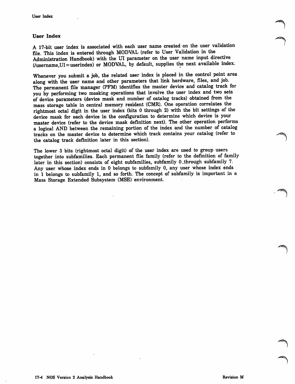
User Index
User Index
A 17-bit user index is associated with each user name created on the user validation
file. This index is entered through MODVAL (refer to User Validation in the
Administration Handbook) with the UI parameter on the user name input directive
(/username,UI=userindex) or MODVAL, by default, supplies the next available index.
Whenever you submit a job, the related user index is placed in the control point area
along with the user name and other parameters that link hardware, files, and job.
The permanent file manager (PFM) identifies the master device and catalog track for
you by performing two masking operations that involve the user index and two sets
of device parameters (device mask and number of catalog tracks) obtained from the
mass storage table in central memory resident (CMR). One operation correlates the
rightmost octal digit in the user index (bits 0 through 2) with the bit settings of the
device mask for each device in the configuration to determine which device is your
master device (refer to the device mask definition next). The other operation performs
a logical AND between the remaining portion of the index and the number of catalog
tracks on the master device to determine which track contains your catalog (refer to
the catalog track definition later in this section).
The lower 3 bits (rightmost octal digit) of the user index are used to group users
together into subfamilies. Each permanent file family (refer to the definition of family
later in this section) consists of eight subfamilies, subfamily 0 .through subfamily 7.
Any user whose index ends in 0 belongs to subfamily 0, any user whose index ends
in 1 belongs to subfamily 1, and so forth. The concept of subfamily is important in a
Mass Storage Extended Subsystem (MSE) environment.
17-4 NOS Version 2 Analysis Handbook Revision M
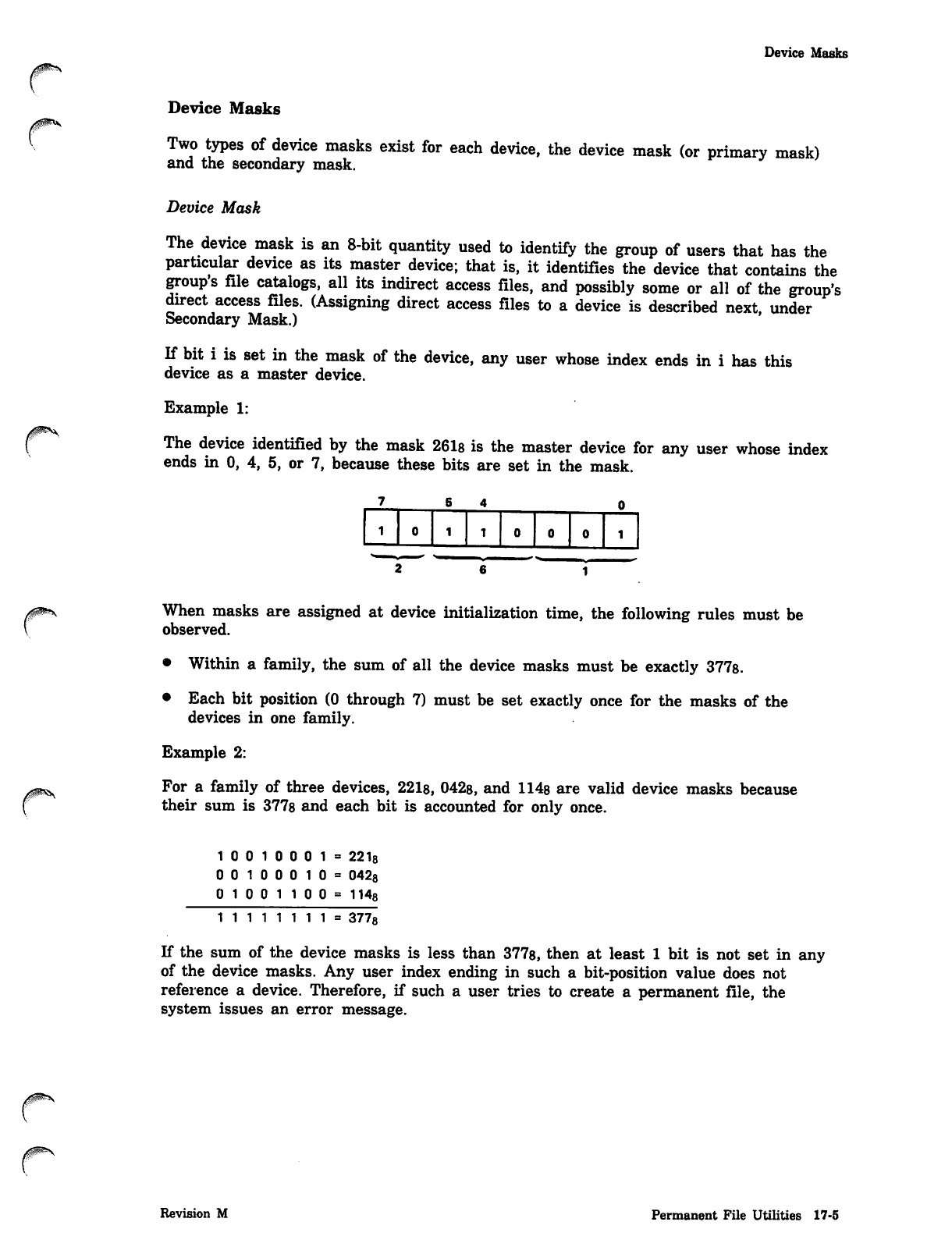
Device Masks
Device Masks
Two types of device masks exist for each device, the device mask (or primary mask)
and the secondary mask.
Device Mask
The device mask is an 8-bit quantity used to identify the group of users that has the
particular device as its master device; that is, it identifies the device that contains the
group's file catalogs, all its indirect access files, and possibly some or all of the group's
direct access files. (Assigning direct access files to a device is described next, under
Secondary Mask.)
If bit i is set in the mask of the device, any user whose index ends in i has this
device as a master device.
Example 1:
The device identified by the mask 2618 is the master device for any user whose index
ends in 0, 4, 5, or 7, because these bits are set in the mask.
7S 4 0
10 1 1 0 0 0 1
r
When masks are assigned at device initialization time, the following rules must be
observed.
• Within a family, the sum of all the device masks must be exactly 377s.
• Each bit position (0 through 7) must be set exactly once for the masks of the
devices in one family.
Example 2:
For a family of three devices, 221s, 042s, and 114s are valid device masks because
their sum is 377s and each bit is accounted for only once.
10 0 10 0 0 1= 2218
0 0 10 0 0 10= 0428
0 10 0 1 1 0 0 = 1148
1 1 1 1 1 1 1 1 = 3 7 7 8
If the sum of the device masks is less than 377s, then at least 1 bit is not set in any
of the device masks. Any user index ending in such a bit-position value does not
reference a device. Therefore, if such a user tries to create a permanent file, the
system issues an error message.
Revision M Permanent File Utilities 17-5
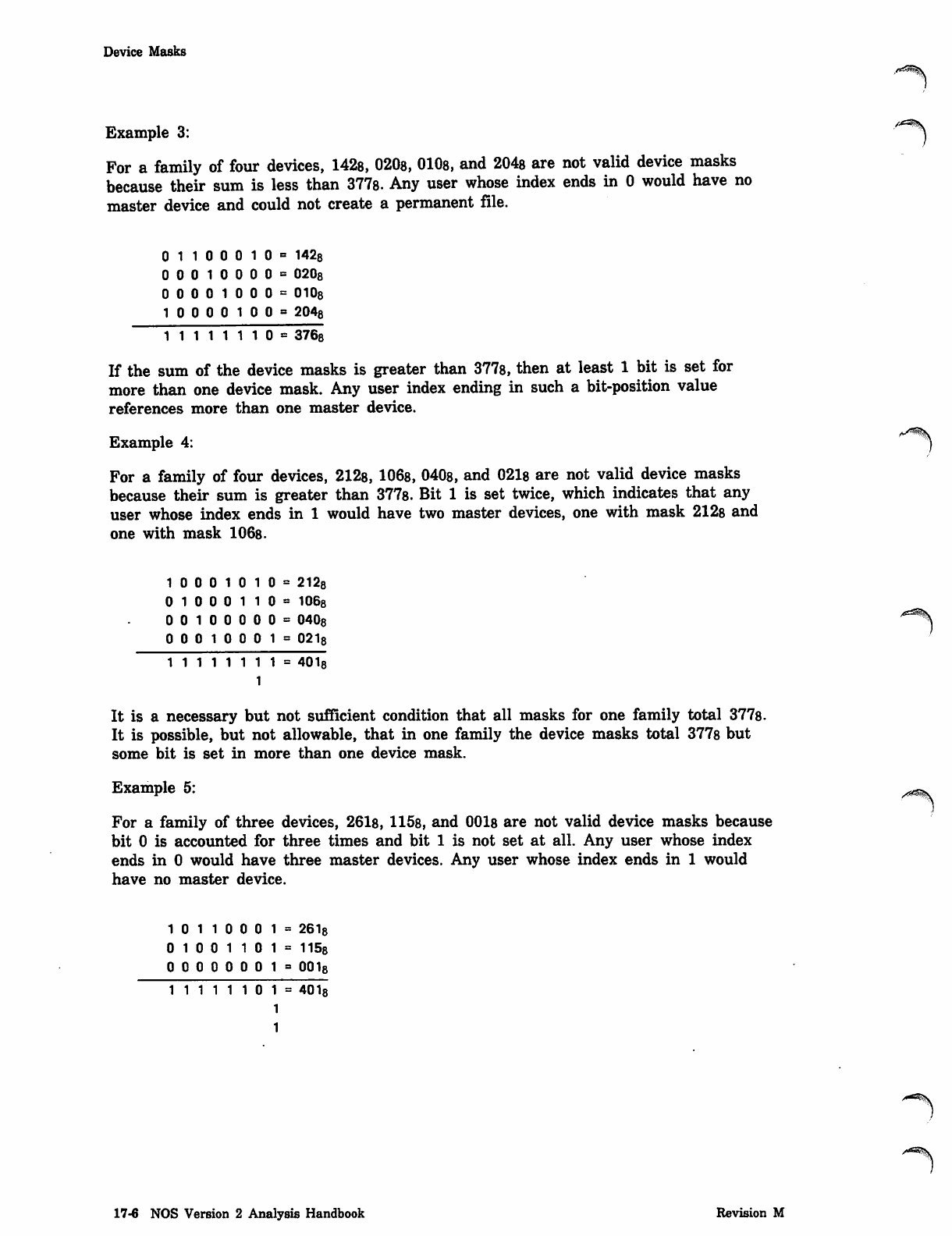
Device Masks
Example 3: '^
For a family of four devices, 1428, 0208, 0108, and 2048 are not valid device masks
because their sum is less than 3778. Any user whose index ends in 0 would have no
master device and could not create a permanent file.
0 110 0 0 10= 1428
00010000° 0208
00001000= 0108
10 0 0 0 10 0= 2048
1 1 1 1 1 1 1 0 = 3 7 6 8
If the sum of the device masks is greater than 3778, then at least 1 bit is set for
more than one device mask. Any user index ending in such a bit-position value
references more than one master device.
Example 4: )
For a family of four devices, 2128, 1068, 0408, and 0218 are not valid device masks
because their sum is greater than 3778. Bit 1 is set twice, which indicates that any
user whose index ends in 1 would have two master devices, one with mask 212s and
one with mask 1068-
10 0 0 10 10= 2128
0 10 0 0 110= 1068
00100000= 0408
0 0 0 10 0 0 1= 0218
1 1 1 1 1 1 1 1 = 4 0 1 8
1
It is a necessary but not sufficient condition that all masks for one family total 3778.
It is possible, but not allowable, that in one family the device masks total 377s but
some bit is set in more than one device mask.
Example 5: /^
For a family of three devices, 2618, 1158, and 0018 are not valid device masks because
bit 0 is accounted for three times and bit 1 is not set at all. Any user whose index
ends in 0 would have three master devices. Any user whose index ends in 1 would
have no master device.
10 110 0 0 1= 2618
0 1 0 0 1 1 0 1 = 1158
00000001= 0018
1 1 1 1 1 1 0 1 = 4 0 1 8
1
1
/rfSSV
17-6 NOS Version 2 Analysis Handbook Revision M
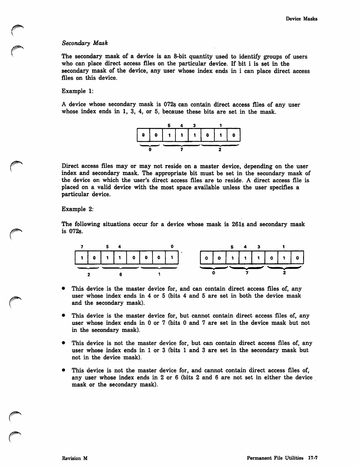
Device Masks
Secondary Mask
The secondary mask of a device is an 8-bit quantity used to identify groups of users
who can place direct access files on the particular device. If bit i is set in the
secondary mask of the device, any user whose index ends in i can place direct access
files on this device.
Example 1:
A device whose secondary mask is 0728 can contain direct access files of any user
whose index ends in 1, 3, 4, or 5. because these bits are set in the mask.
6 4 3 1
0 0 1 1 1 0 1 0
tmXXXmXXXXXaSrOaXmXmXmXX^T' ^M^^^^^^^^^^^^^^^* ^^^^^y^M"**^
Direct access files may or may not reside on a master device, depending on the user
index and secondary mask. The appropriate bit must be set in the secondary mask of
the device on which the user's direct access files are to reside. A direct access file is
placed on a valid device with the most space available unless the user specifies a
particular device.
Example 2:
The following situations occur for a device whose mask is 2618 and secondary mask
is 0728.
7 5 4 0 5 4 3 1
10110001 00111010
6 1
• This device is the master device for, and can contain direct access files of, any
user whose index ends in 4 or 5 (bits 4 and 5 are set in both the device mask
and the secondary mask).
• This device is the master device for, but cannot contain direct access files of, any
user whose index ends in 0 or 7 (bits 0 and 7 are set in the device mask but not
in the secondary mask).
• This device is not the master device for, but can contain direct access files of, any
user whose index ends in 1 or 3 (bits 1 and 3 are set in the secondary mask but
not in the device mask).
• This device is not the master device for, and cannot contain direct access files of,
any user whose index ends in 2 or 6 (bits 2 and 6 are not set in either the device
mask or the secondary mask).
Revision M Permanent File Utilities 17-7
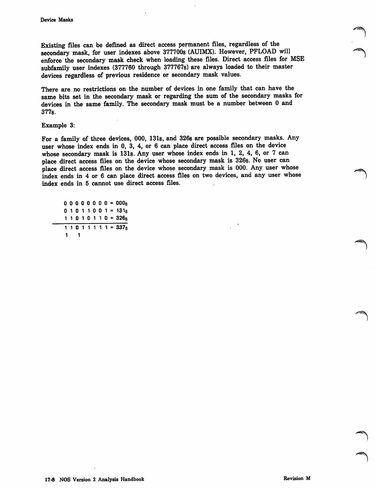
Device Masks
Existing files can be defined as direct access permanent files, regardless of the
secondary mask, for user indexes above 377700s (AUIMX). However, PFLOAD will ^
enforce the secondary mask check when loading these files. Direct access files for MSE
subfamily user indexes (377760 through 377767s) are always loaded to their master
devices regardless of previous residence or secondary mask values.
There are no restrictions on the number of devices in one family that can have the
same bits set in the secondary mask or regarding the sum of the secondary masks for
devices in the same family. The secondary mask must be a number between 0 and
3778.
Example 3:
For a family of three devices, 000, 131s, and 326s are possible secondary masks. Any
user whose index ends in 0, 3, 4, or 6 can place direct access files on the device
whose secondary mask is 1318. Any user whose index ends in 1, 2, 4, 6, or 7 can
place direct access files on the device whose secondary mask is 3268. No user can
place direct access files on the device whose secondary mask is 000. Any user whose ^^^
index ends in 4 or 6 can place direct access files on two devices, and any user whose ^)
index ends in 5 cannot use direct access files.
0 0 0 0 = 000s
0 1 0 1 = 1318
1 1 0 1 = 3268
1 1 0 1 = 3378
1 1
17-8 NOS Version 2 Analysis Handbook Revision M
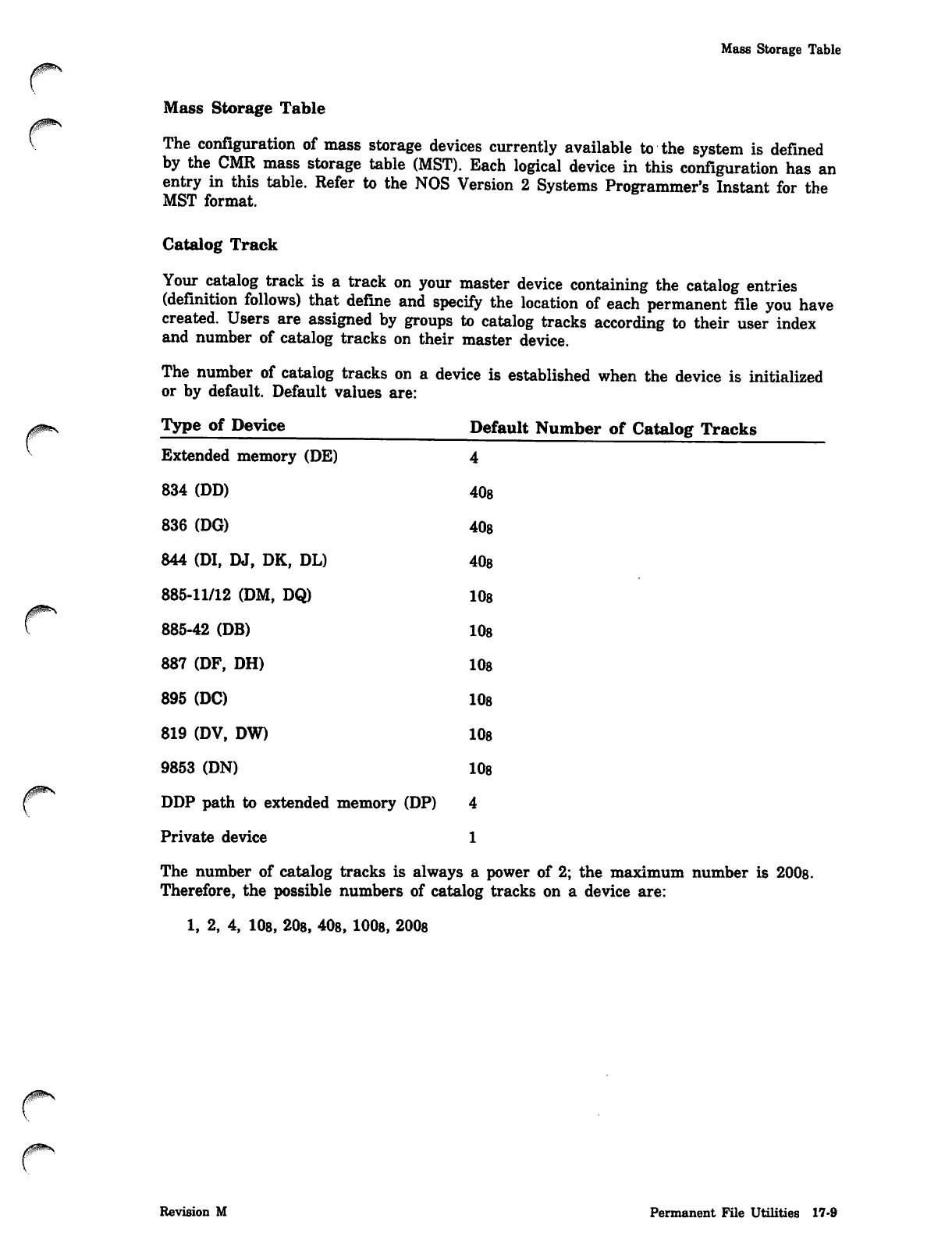
Mass Storage Table
Mass Storage Table
The configuration of mass storage devices currently available to the system is defined
by the CMR mass storage table (MST). Each logical device in this configuration has an
entry in this table. Refer to the NOS Version 2 Systems Programmer's Instant for the
MST format.
Catalog Track
Your catalog track is a track on your master device containing the catalog entries
(definition follows) that define and specify the location of each permanent file you have
created. Users are assigned by groups to catalog tracks according to their user index
and number of catalog tracks on their master device.
The number of catalog tracks on a device is established when the device is initialized
or by default. Default values are:
Type of Device Default Number of Catalog Tracks
Extended memory (DE) 4
834 (DD) 408
836 (DG) 408
844 (DI, DJ, DK, DL) 40s
885-11/12 (DM, DQ) 10s
885-42 (DB) 10s
8 8 7 ( D F , D H ) 1 0 s
895 (DC) 10s
8 1 9 ( D V , D W ) 1 0 s
9853 (DN) 10s
DDP path to extended memory (DP) 4
Private device 1
The number of catalog tracks is always a power of 2; the maximum number is 200s.
Therefore, the possible numbers of catalog tracks on a device are:
1, 2, 4, 108, 208, 408, 1008, 2008
Revision M Permanent File Utilities 17-9
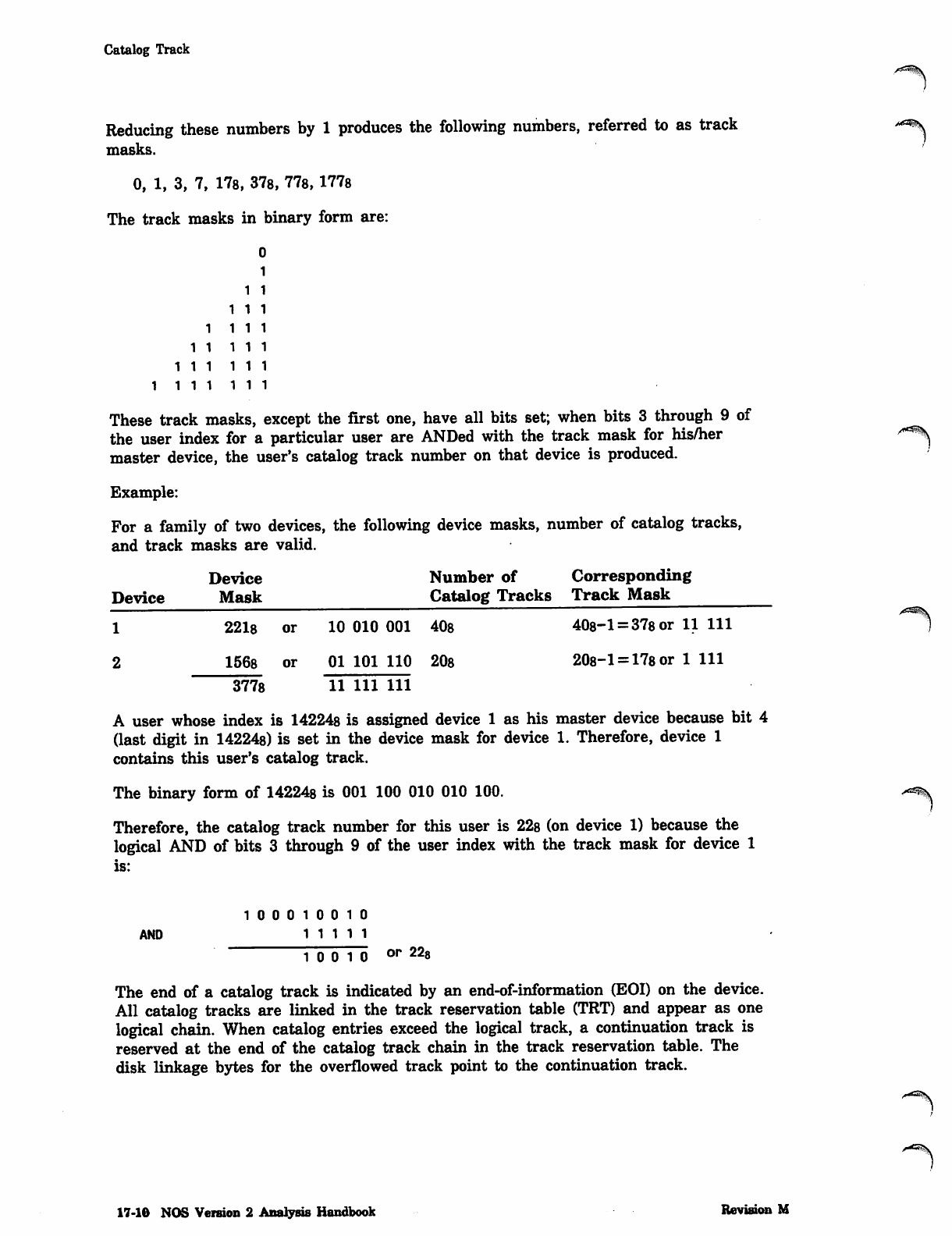
Catalog Track
Reducing these numbers by 1 produces the following numbers, referred to as track
masks.
0, 1, 3, 7, 17s, 378, 77s, 177s
The track masks in binary form are:
0
1
1 1
1 1 1
1111
These track masks, except the first one, have all bits set; when bits 3 through 9 of
the user index for a particular user are ANDed with the track mask for his/her
master device, the user's catalog track number on that device is produced.
Example:
For a family of two devices, the following device masks, number of catalog tracks,
and track masks are valid.
Device
Device
Mask
Number of Corresponding
Catalog Tracks Track Mask
2218 or
1568 or
10 010 001 408
01 101 110 208
408-1 = 378 or 11 111
208-1 = 178 or 1 HI
3778 11 111 111
A user whose index is 14224s is assigned device 1 as his master device because bit 4
(last digit in 14224s) is set in the device mask for device 1. Therefore, device 1
contains this user's catalog track.
The binary form of 14224s is 001 100 010 010 100.
Therefore, the catalog track number for this user is 22s (on device 1) because the
logical AND of bits 3 through 9 of the user index with the track mask for device 1
is:
AND
10 0 0 10 0 10
11111
10 0 10 or 228
The end of a catalog track is indicated by an end-of-information (EOI) on the device.
All catalog tracks are linked in the track reservation table (TRT) and appear as one
logical chain. When catalog entries exceed the logical track, a continuation track is
reserved at the end of the catalog track chain in the track reservation table. The
disk linkage bytes for the overflowed track point to the continuation track.
17-10 NOS Version 2 Analysis Handbook Revision M
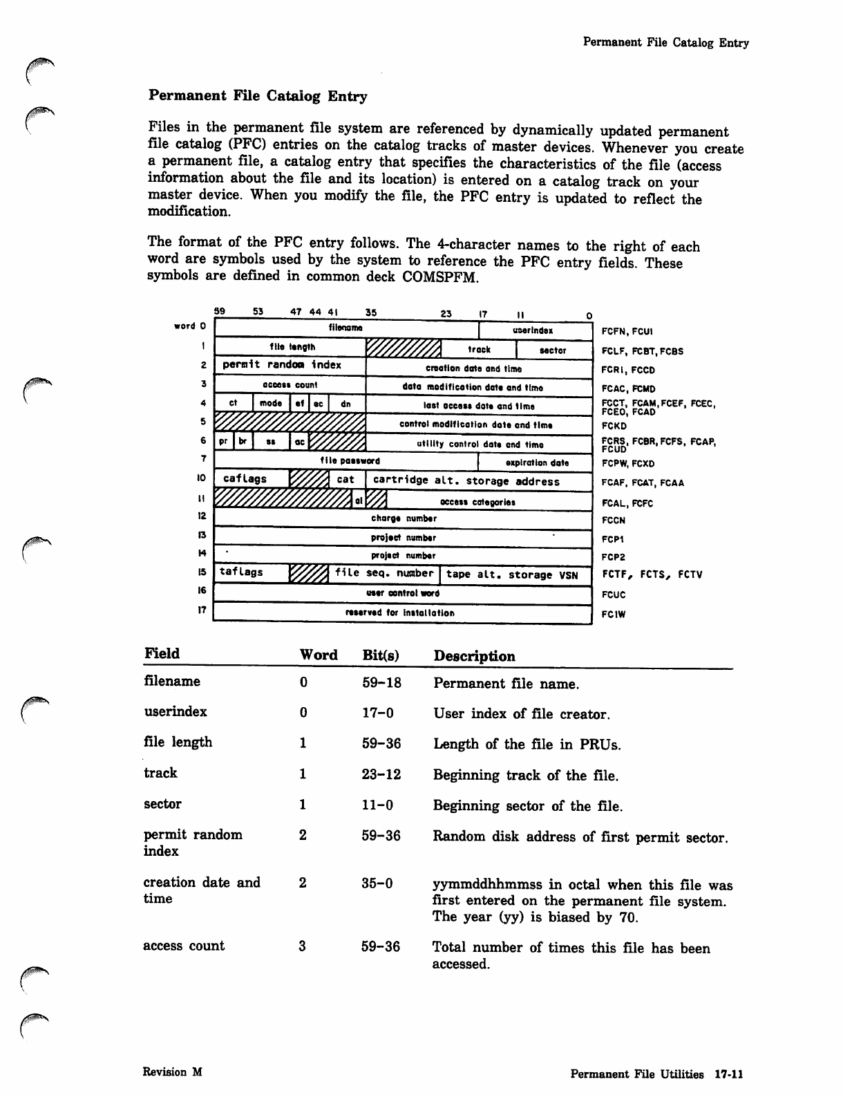
Permanent File Catalog Entry
Permanent File Catalog Entry
Files in the permanent file system are referenced by dynamically updated permanent
file catalog (PFC) entries on the catalog tracks of master devices. Whenever you create
a permanent file, a catalog entry that specifies the characteristics of the file (access
information about the file and its location) is entered on a catalog track on your
master device. When you modify the file, the PFC entry is updated to reflect the
modification.
The format of the PFC entry follows. The 4-character names to the right of each
word are symbols used by the system to reference the PFC entry fields. These
symbols are defined in common deck COMSPFM.
59 53 47 44 41 35 23 17 I I 0
word 0 filename userindex
1file length w//y//A track sector
2P« rmit randon index creation date and time
3access count data modification date and time
4ct mode ef ec dn last access dote and time
5/ > > ^ > > % ^ ^ < ^ ^ > ^ control modification date and time
6pr *i «• wwzmiA utility control date and time
7file password expiration date
IO -**» WaVa. cat cartridge alt. storage address
II v///y//y//yy//yyA%z* V/a. access categories
12 charge number
13 project number
14 project number
15 taf lags \20fli f^Le seq* nLaaber tape alt. storage VSN
16 tieer central word
17 reserved for installation
FCFN.FCUI
FCLF, FCBT, FCBS
FCRI, FCCD
FCAC, FCMD
FCCT, FCAM.FCEF, FCEC.
FCEO, FCAD
FCKD
FCRS, FCBR.FCFS, FCAP,
FCUD
FCPW, FCXD
FCAF, FCAT, FCAA
FCAL, FCFC
FCCN
FCP1
FCP2
FCTF, FCTS, FCTV
FCUC
FCIW
Field Word Bit(s) Description
filename 0
userindex 0
file length 1
track 1
sector 1
p e r m i t r a n d o m 2
index
creation date and 2
time
access count 3
59-18 Permanent file name.
17-0 User index of file creator.
59-36 Length of the file in PRUs.
23-12 Beginning track of the file.
11-0 Beginning sector of the file.
59-36 Random disk address of first permit sector.
35-0 yymmddhhmmss in octal when this file was
first entered on the permanent file system.
The year (yy) is biased by 70.
59-36 Total number of times this file has been
accessed.
Revision M Permanent File Utilities 17-11
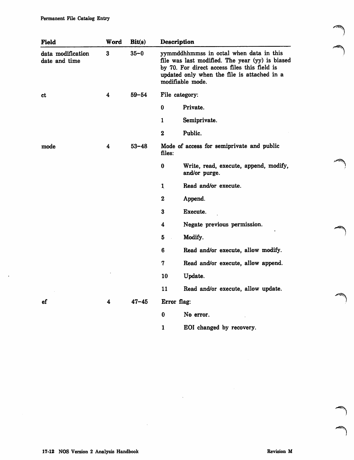
Permanent File Catalog Entry
Field Word Bit(s) Description
data modification
date and time
ct
mode
ef
35-0 yymmddhhmmss in octal when data in this
file was last modified. The year (yy) is biased
by 70. For direct access files this field is
updated only when the file is attached in a
modifiable mode.
59-54 File category:
0 Private.
1 Semiprivate.
2 Public.
53-48 Mode of access for semiprivate and public
files:
0 Write, read, execute, append, modify,
and/or purge.
1 Read and/or execute.
2 Append.
3 Execute.
4 Negate previous permission.
5 Modify.
6 Read and/or execute, allow modify.
7 Read and/or execute, allow append.
10 Update.
11 Read and/or execute, allow update.
47-45 Error flag:
0 N o e r r o r .
1 EOI changed by recovery.
~*)
17-12 NOS Version 2 Analysis Handbook Revision M
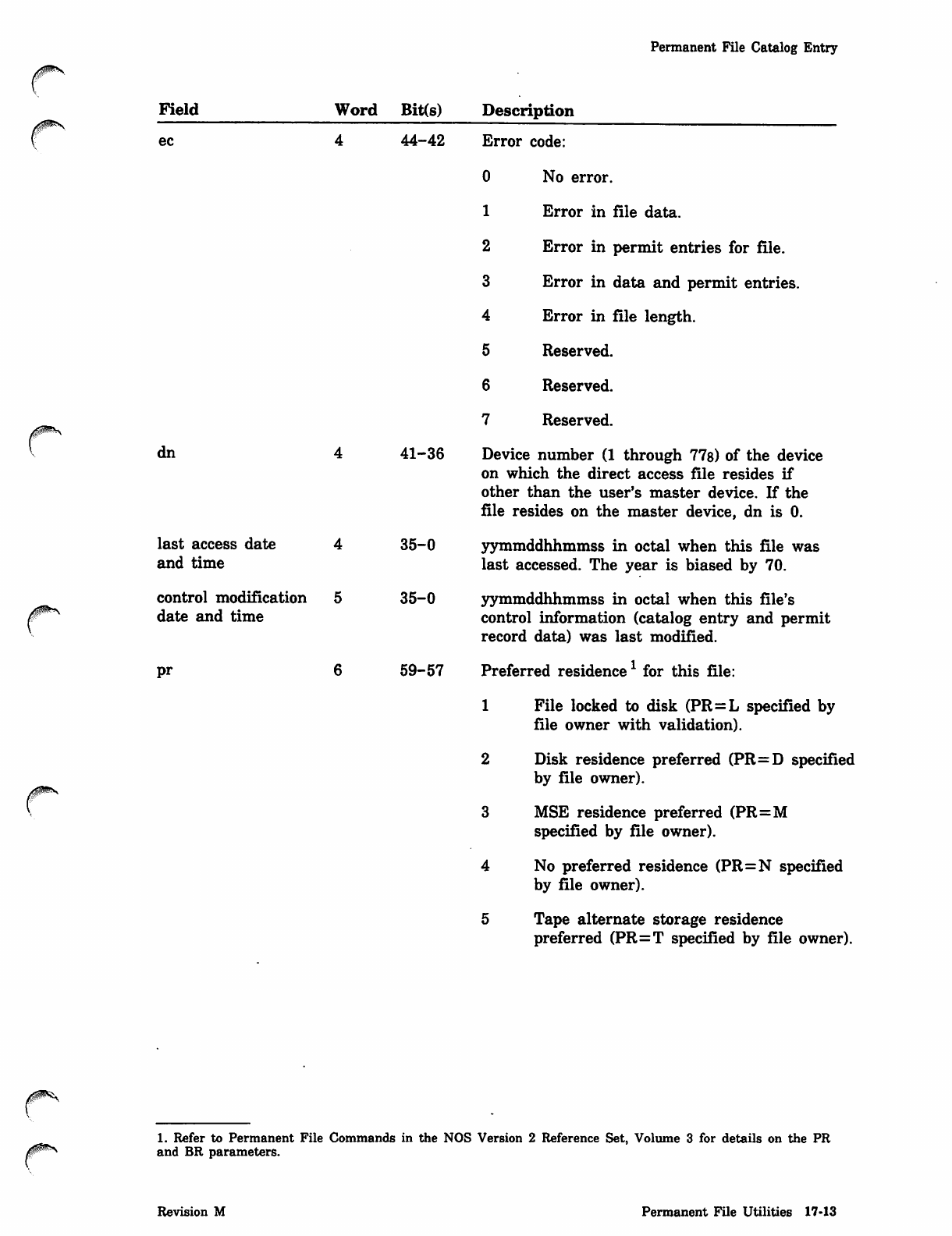
Permanent File Catalog Entry
Field
ec
Word Bit(s) Description
444-42 Error code:
0 No error.
1 Error in file data.
2Error in permit entries for file.
3Error in data and permit entries.
4 Error in file length.
5Reserved.
6Reserved.
7Reserved.
dn
last access date 4
and time
control modification 5
date and time
pr
41-36 Device number (1 through 77s) of the device
on which the direct access file resides if
other than the user's master device. If the
file resides on the master device, dn is 0.
35-0 yymmddhhmmss in octal when this file was
last accessed. The year is biased by 70.
35-0 yymmddhhmmss in octal when this file's
control information (catalog entry and permit
record data) was last modified.
59-57 Preferred residence1 for this file:
1 File locked to disk (PR=L specified by
file owner with validation).
2 Disk residence preferred (PR=D specified
by file owner).
3 MSE residence preferred (PR=M
specified by file owner).
4 No preferred residence (PR=N specified
by file owner).
5 Tape alternate storage residence
preferred (PR=T specified by file owner).
1. Refer to Permanent File Commands in the NOS Version 2 Reference Set, Volume 3 for details on the PR
and BR parameters.
Revision M Permanent File Utilities 17-13
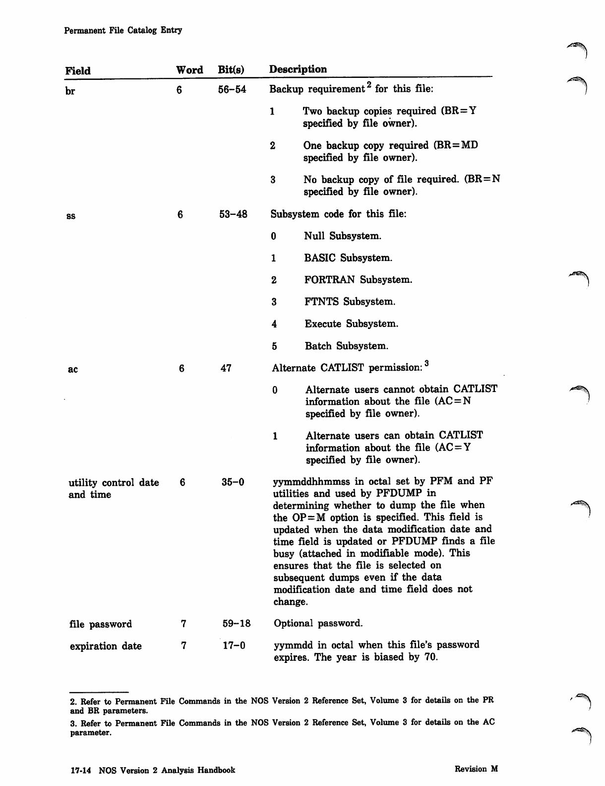
Permanent File Catalog Entry
Field Word Bit(s) Description
br
ss
ac
utility control date
and time
file password
expiration date
56-54 Backup requirement for this file:
1 Two backup copies required (BR=Y
specified by file owner).
2 One backup copy required (BR=MD
specified by file owner).
3 No backup copy of file required. (BR=N
specified by file owner).
53-48 Subsystem code for this file:
0 Null Subsystem.
1 BASIC Subsystem.
2 FORTRAN Subsystem.
3 FTNTS Subsystem.
4 Execute Subsystem.
5 Batch Subsystem.
47 Alternate CATLIST permission:3
0 Alternate users cannot obtain CATLIST
information about the file (AC=N
specified by file owner).
1 Alternate users can obtain CATLIST
information about the file (AC=Y
specified by file owner).
35-0 yymmddhhmmss in octal set by PFM and PF
utilities and used by PFDUMP in
determining whether to dump the file when
the OP=M option is specified. This field is
updated when the data modification date and
time field is updated or PFDUMP finds a file
busy (attached in modifiable mode). This
ensures that the file is selected on
subsequent dumps even if the data
modification date and time field does not
change.
59-18 Optional password.
17-0 yymmdd in octal when this file's password
expires. The year is biased by 70.
2. Refer to Permanent File Commands in the NOS Version 2 Reference Set, Volume 3 for details on the PR
and BR parameters.
3. Refer to Permanent File Commands in the NOS Version 2 Reference Set, Volume 3 for details on the AC
parameter.
17-14 NOS Version 2 Analysis Handbook Revision M
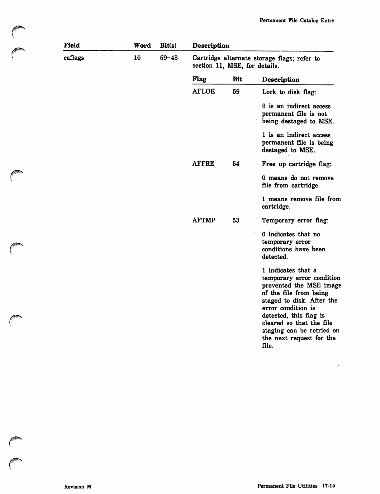
Permanent File Catalog Entry
Field Word Bit(s) Description
cafiags 10 59-48 Cartridge alternate storage flags; refer to
section 11, MSE, for details.
Flag Bit Description
A F L O K 5 9 L o c k t o d i s k fl a g :
0 is an indirect access
permanent file is not
being destaged to MSE.
1 is an indirect access
permanent file is being
destaged to MSE.
AFFRE 54 Free up cartridge flag:
0 means do not remove
file from cartridge.
1 means remove file from
cartridge.
AFTMP 53 Temporary error flag:
0 indicates that no
temporary error
conditions have been
detected.
1 indicates that a
temporary error condition
prevented the MSE image
of the file from being
staged to disk. After the
error condition is
detected, this flag is
cleared so that the file
staging can be retried on
the next request for the
file.
jg^ss.
Revision M Permanent File Utilities 17-15
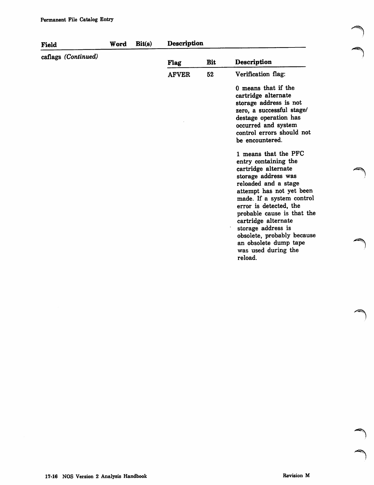
Permanent File Catalog Entry
Field Word Bit(s) Description
caflags (Continued) Flag Bit Description
AFVER 52 Verification flag:
0 means that if the
cartridge alternate
storage address is not
zero, a successful stage/
destage operation has
occurred and system
control errors should not
be encountered.
1 means that the PFC
entry containing the
cartridge alternate a*s®s
storage address was )
reloaded and a stage
attempt has not yet been
made. If a system control
error is detected, the
probable cause is that the
cartridge alternate
storage address is
obsolete, probably because
an obsolete dump tape "^
was used during the
reload.
17-16 NOS Version 2 Analysis Handbook Revision M
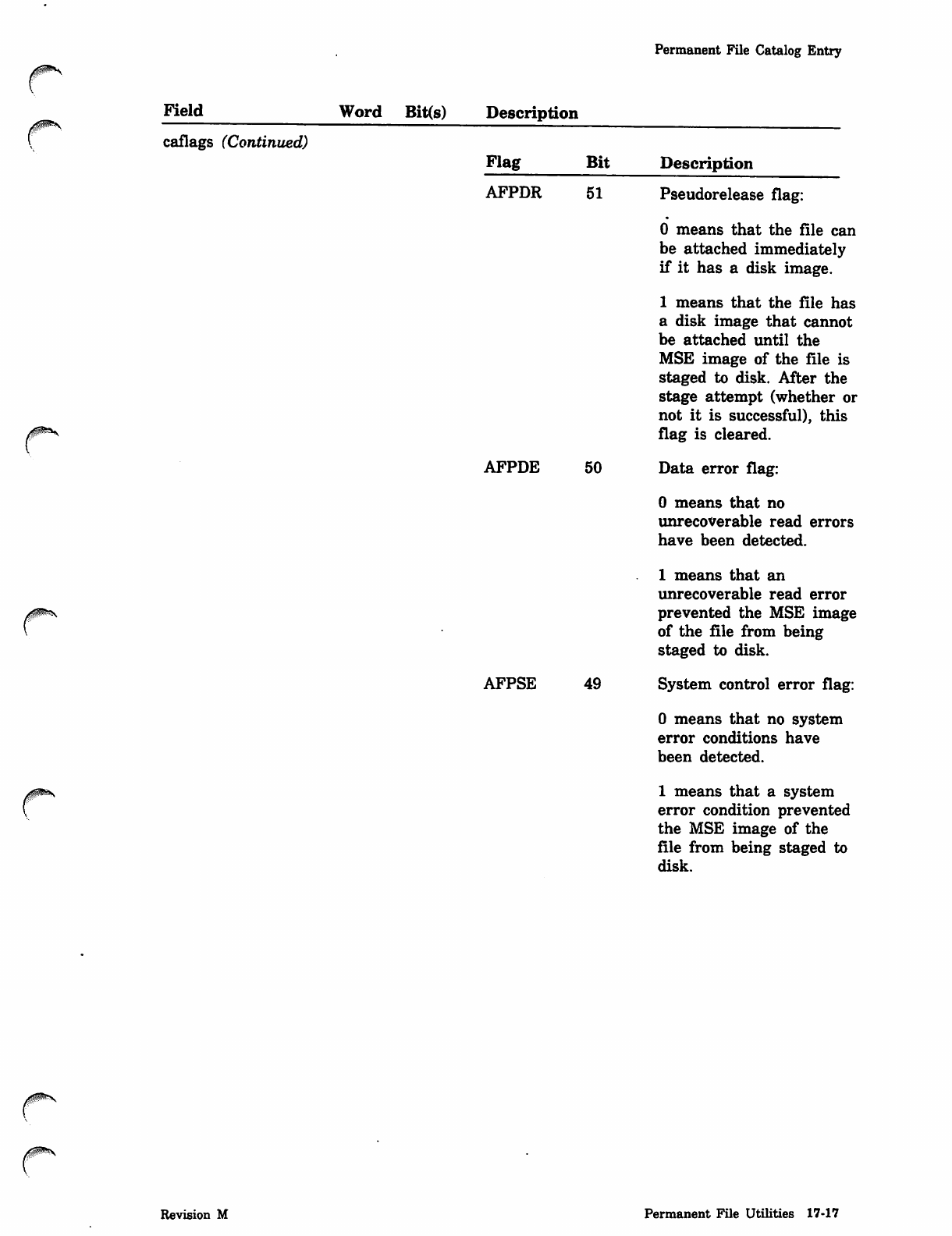
Permanent File Catalog Entry
00ms,
Field Word Bit(s) Description
caflags (Continued)
Flag Bit Description
AFPDR 51 Pseudorelease flag:
0 means that the file can
be attached immediately
if it has a disk image.
1 means that the file has
a disk image that cannot
be attached until the
MSE image of the file is
staged to disk. After the
stage attempt (whether or
not it is successful), this
flag is cleared.
A F P D E 5 0 D a t a e r r o r fl a g :
0 means that no
unrecoverable read errors
have been detected.
1 means that an
unrecoverable read error
prevented the MSE image
of the file from being
staged to disk.
AFPSE 49 System control error flag:
0 means that no system
error conditions have
been detected.
1 means that a system
error condition prevented
the MSE image of the
file from being staged to
disk.
Revision M Permanent File Utilities 17-17
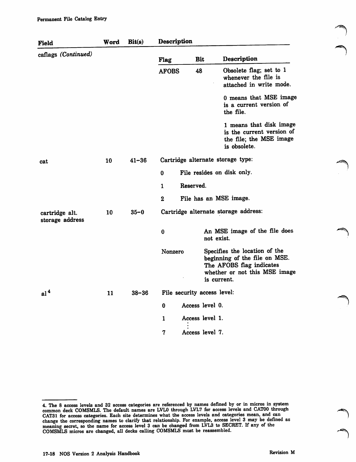
Permanent File Catalog Entry
Field Word Bit(s) Description
caflags (Continued) Flag Bit Description
cat 10 41-36
cartridge alt.
storage address
10 35-0
al 11 38-36
AFOBS 48 Obsolete flag; set to 1
whenever the file is
attached in write mode.
0 means that MSE image
is a current version of
the file.
1 means that disk image
is the current version of
the file; the MSE image
is obsolete.
Cartridge alternate storage type:
0 File resides on disk only.
1 Reserved.
2 File has an MSE image.
Cartridge alternate storage address:
0 A n M S E i m a g e o f t h e fi l e d o e s
not exist.
Nonzero Specifies the location of the
beginning of the file on MSE.
The AFOBS flag indicates
whether or not this MSE image
is current.
File security access level:
0 Access level 0.
1 Access level 1.
7 Access level 7.
4. The 8 access levels and 32 access categories are referenced by names defined by or in micros in system
common deck COMSMLS. The default names are LVLO through LVL7 for access levels and CATOO through
CAT31 for access categories. Each site determines what the access levels and categories mean, and can
change the corresponding names to clarify that relationship. For example, access level 3 may be defined as
meaning secret, so the name for access level 3 can be changed from LVL3 to SECRET. If any of the
COMSMLS micros are changed, all decks calling COMSMLS must be reassembled.
17-18 NOS Version 2 Analysis Handbook Revision M
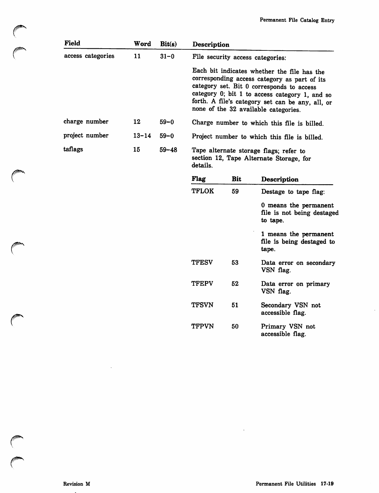
0ms
Field
access categories
charge number
project number
taflags
12 59-0
13-14 59-0
15 59-48
Permanent File Catalog Entry
Word Bit(s) Description
11 31-0 File security access categories:
Each bit indicates whether the file has the
corresponding access category as part of its
category set. Bit 0 corresponds to access
category 0; bit 1 to access category 1, and so
forth. A file's category set can be any, all, or
none of the 32 available categories.
Charge number to which this file is billed.
Project number to which this file is billed.
Tape alternate storage flags; refer to
section 12, Tape Alternate Storage, for
details.
Flag Bit
TFLOK 59
Description
Destage to tape flag:
0 means the permanent
file is not being destaged
to tape.
1 means the permanent
file is being destaged to
tape.
TFESV 53 Data error on secondary
VSN flag.
TFEPV 52 Data error on primary
VSN flag.
TFSVN 51 Secondary VSN not
accessible flag.
TFPVN 50 Primary VSN not
accessible flag.
Revision M Permanent File Utilities 17-19
Permanent File Catalog Entry
Field Word Bit(s) Description
taflags (Continued) Flag Bit Description
TFSVS 49 Secondary VSN exists
flag:
0 indicates a secondary
VSN does not exist.
1 indicates a secondary
VSN does exist.
TFVER 48 PFLOAD verification flag:
0 means that if the tape
alternate storage VSN
pointer is not zero, a /X_
successful stage/destage ]
operation has occurred
and system control errors
should not be
encountered.
1 means that if the PFC
entry containing the tape
alternate storage VSN
pointer was reloaded and s*ss
a stage attempt has not )
yet been made. If a
system control error is
detected, the probable
cause is that the tape
alternate storage VSN
pointer is obsolete,
probably because an
obsolete dump tape was
used during the reload. <-a%
17-20 NOS Version 2 Analysis Handbook Revision M
Permanent File Catalog Entry
Field Word Bit(s) Description
file seq. number
tape alt. storage
VSN
15 41-24
15 23-0
user control word 16 59-0
Sequence number of the file on the dump
tape produced by PFDUMP.
Tape alternate storage VSN pointer in the
following format:
12/cc, 12/nnnn
where cc is any two alphanumeric characters
and nnnn is a 12-bit binary integer.
The tape's primary VSN is cc followed by
nnnn converted to a decimal integer in the
range of 0000 to 4095 with leading zeros.
The secondary VSN, if it exists, is derived by
adding 5000 to the primary VSN.
User control information.
igp>>\
Revision M Permanent File Utilities 17-21
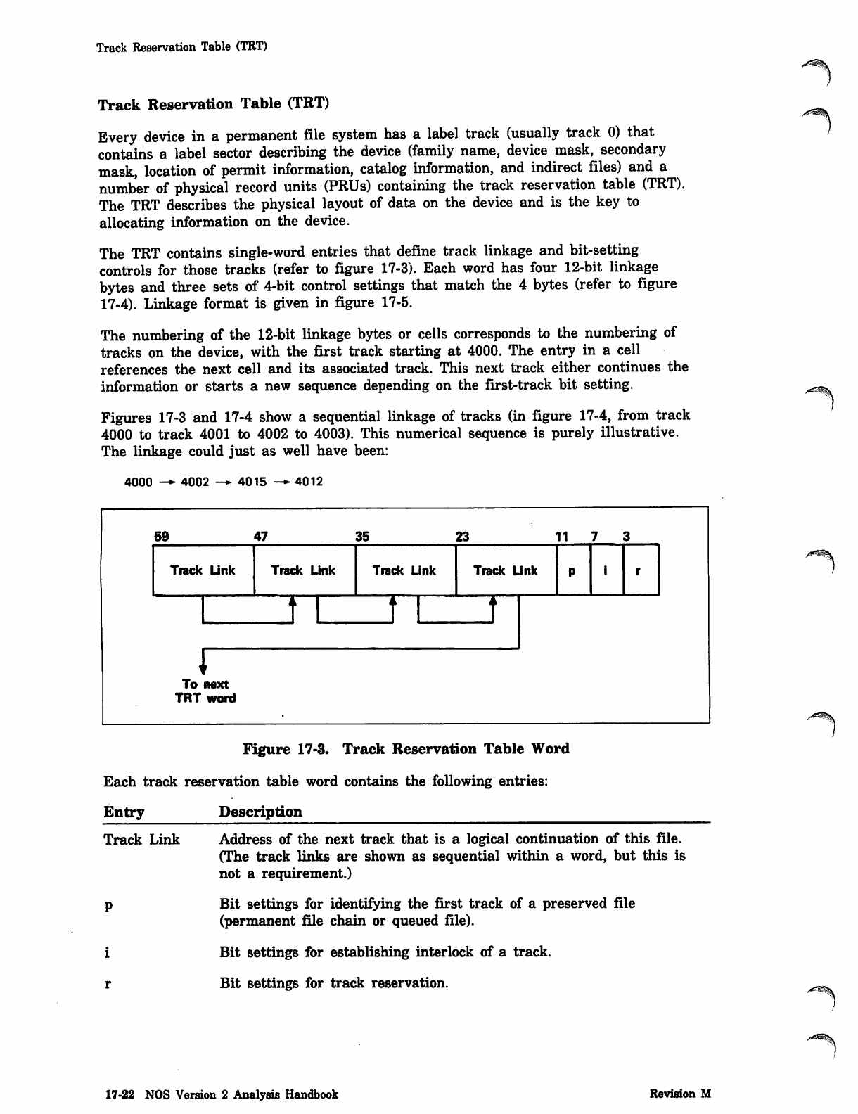
Track Reservation Table (TRT)
Track Reservation Table (TRT)
Every device in a permanent file system has a label track (usually track 0) that
contains a label sector describing the device (family name, device mask, secondary
mask, location of permit information, catalog information, and indirect files) and a
number of physical record units (PRUs) containing the track reservation table (TRT).
The TRT describes the physical layout of data on the device and is the key to
allocating information on the device.
The TRT contains single-word entries that define track linkage and bit-setting
controls for those tracks (refer to figure 17-3). Each word has four 12-bit linkage
bytes and three sets of 4-bit control settings that match the 4 bytes (refer to figure
17-4). Linkage format is given in figure 17-5.
The numbering of the 12-bit linkage bytes or cells corresponds to the numbering of
tracks on the device, with the first track starting at 4000. The entry in a cell
references the next cell and its associated track. This next track either continues the
information or starts a new sequence depending on the first-track bit setting.
Figures 17-3 and 17-4 show a sequential linkage of tracks (in figure 17-4, from track
4000 to track 4001 to 4002 to 4003). This numerical sequence is purely illustrative.
The linkage could just as well have been:
4000 — 4002 — 4015 — 4012
y^^k
59 47 35 23 1 1 7
Track Link Track Link Track Link Track Link
t
\
To
TRT
next
word
Figure 17-3. Track Reservation Table Word
Each track reservation table word contains the following entries:
Entry Description
Track Link Address of the next track that is a logical continuation of this file.
(The track links are shown as sequential within a word, but this is
not a requirement.)
Bit settings for identifying the first track of a preserved file
(permanent file chain or queued file).
Bit settings for establishing interlock of a track.
Bit settings for track reservation.
17-22 NOS Version 2 Analysis Handbook Revision M
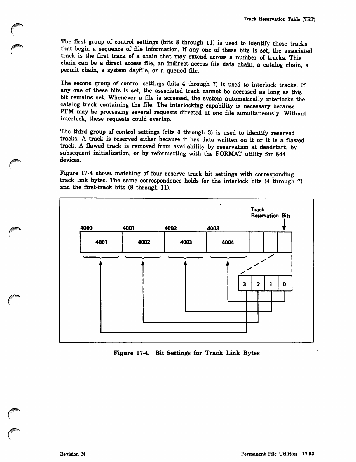
Track Reservation Table (TRT)
The first group of control settings (bits 8 through 11) is used to identify those tracks
that begin a sequence of file information. If any one of these bits is set, the associated
track is the first track of a chain that may extend across a number of tracks. This
chain can be a direct access file, an indirect access file data chain, a catalog chain, a
permit chain, a system dayfile, or a queued file.
The second group of control settings (bits 4 through 7) is used to interlock tracks. If
any one of these bits is set, the associated track cannot be accessed as long as this
bit remains set. Whenever a file is accessed, the system automatically interlocks the
catalog track containing the file. The interlocking capability is necessary because
PFM may be processing several requests directed at one file simultaneously. Without
interlock, these requests could overlap.
The third group of control settings (bits 0 through 3) is used to identify reserved
tracks. A track is reserved either because it has data written on it or it is a flawed
track. A flawed track is removed from availability by reservation at deadstart, by
subsequent initialization, or by reformatting with the FORMAT utility for 844
devices.
Figure 17-4 shows matching of four reserve track bit settings with corresponding
track link bytes. The same correspondence holds for the interlock bits (4 through 7)
and the first-track bits (8 through 11).
Figure 17-4. Bit Settings for Track Link Bytes
Revision M Permanent File Utilities 17-23
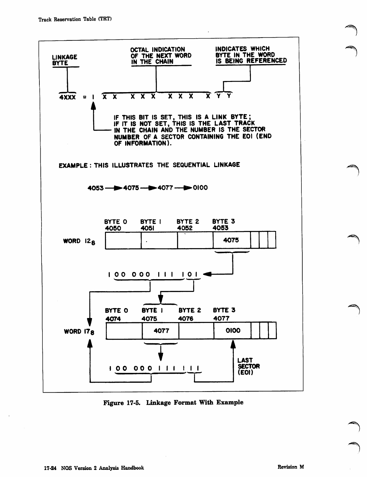
Track Reservation Table (TRT)
LINKAGE
BYTE
i
OCTAL INDICATION
OF THE NEXT WORD
IN THE CHAIN
INDICATES WHICH
BYTE IN THE WORD
IS BEING REFERENCED
JZ
4 X X X = I X X X X X X X X X Y Y
LIF THIS BIT IS SET, THIS IS A LINK BYTE;
IF IT IS NOT SET, THIS IS THE LAST TRACK
IN THE CHAIN AND THE NUMBER IS THE SECTOR
NUMBER OF A SECTOR CONTAINING THE EOI (END
OF INFORMATION).
EXAMPLE : THIS ILLUSTRATES THE SEQUENTIAL LINKAGE
4053 4075 •4077—▶OIOO
B Y T E 0 B Y T E
4050 4051
B Y T E 2 B Y T E 3
4052 4053
WORD I28 4075
1 0 0 0 0 0 I I I 1 0 1
f
f
WORD I78
B Y T E 0 B Y T E I B Y T E 2
4074 4075 4076
BYTE 3
4077
4077 OIOO
I
I 0 0 0 0 0 I I I I I I
LAST
SECTOR
(EOI)
Figure 17-5. Linkage Format With Example
a^S
17-24 NOS Version 2 Analysis Handbook Revision M
Family
Family
00ms
A family is a collection of from 1 to 63 logical devices identified by a 1- to 7-character
family name. Users and their files are grouped together according to the family
available to them. Usually, the grouping is within the configuration on which these
users normally run jobs. However, a family can be connected to any configuration and
still relate to the same users and files.
An auxiliary device, identified by a 1- to 7-character pack name, is a single device
that is not included in any family and can be accessed by validated users from any
family. An auxiliary device provides users with an alternative to the master devices
for storing and accessing permanent files. Use of auxiliary devices enables an analyst
to provide special sets of permanent files for selected users or for designated periods.
For example, an auxiliary device could be made available from 1200 to 1700 every
day for any properly validated user.
A permanent file device is either a member of a family or an auxiliary device.
-p^ Permanent files on a family device are accessed through user catalogs contained on a
( master device within the family. The user catalogs that reference permanent files on
an auxiliary device are contained on that device; that is, an auxiliary device is a
self-contained entity.
Families and auxiliary devices are defined at initialization time by the PF entry in
the EQPDECK or by the DSD INITIALIZE command. Normally, a configuration has
one family available. Additional families can be defined or introduced (on removable
devices) in the same configuration. If more than one family is available in a
configuration, you supply the family name at login or on the USER command. The
default family is used if no family name is supplied.5 Any job can change its
associated family name by using the USER command to specify the new family
name. 6 A system origin job can use the FAMILY command to change the family
name associated with the job. If the FAMILY command is included in any nonsystem
origin job, the job aborts.
The FAMILY command is valid for unsecured systems only.
The format of the FAMILY command is:
FAMILY,fami 1yname.
Paramete r D e scription
familyname The 1- to 7-character name of a family of permanent file devices. If
omitted, the default family name specified at deadstart is assumed.
0@ms
5. The default family name is specified at deadstart time with the EQPDECK FAMILY entry and cannot be
changed dynamically.
6. Refer to the IPRDECK entry in section 2, Deadstart Decks, and to the DSD command ENABLE,
SECONDARY USER COMMANDS in section 5, DSD Commands; also refer to the USER command in the
NOS Version 2 Reference Set, Volume 3.
Revision M Permanent File Utilities 17-25
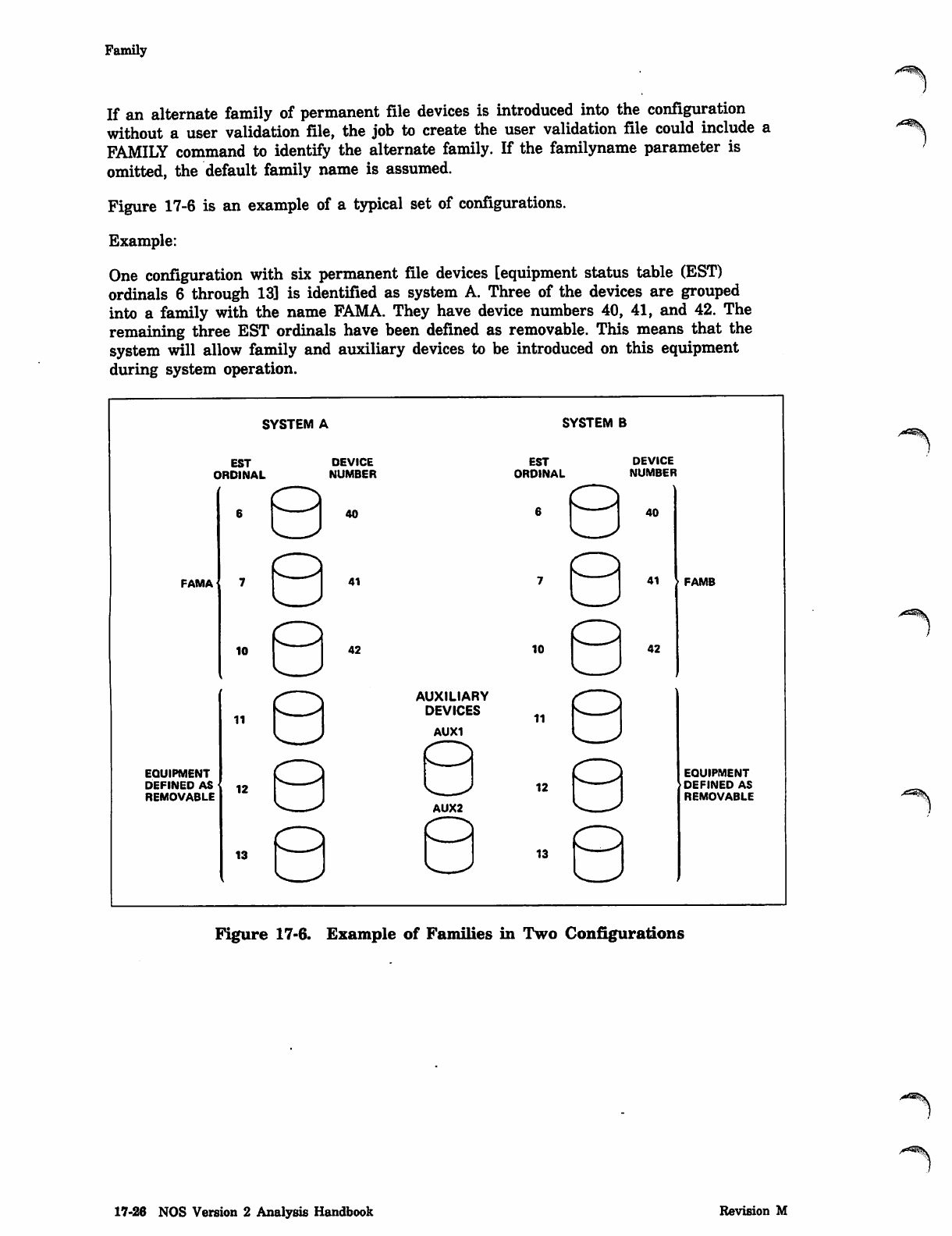
Family
If an alternate family of permanent file devices is introduced into the configuration
without a user validation file, the job to create the user validation file could include a
FAMILY command to identify the alternate family. If the familyname parameter is
omitted, the default family name is assumed.
Figure 17-6 is an example of a typical set of configurations.
Example:
One configuration with six permanent file devices [equipment status table (EST)
ordinals 6 through 13] is identified as system A. Three of the devices are grouped
into a family with the name FAMA. They have device numbers 40, 41, and 42. The
remaining three EST ordinals have been defined as removable. This means that the
system will allow family and auxiliary devices to be introduced on this equipment
during system operation.
SYSTEM A
FAMA
EQUIPMENT
DEFINED AS
REMOVABLE
SYSTEM B
EST DEVICE
OROINAL NUMBER
40
AUXILIARY
DEVICES
AUX1
10
11
12
13
} FAMB
EQUIPMENT
}DEFINED AS
REMOVABLE
Figure 17-6. Example of Families in Two Configurations
17-26 NOS Version 2 Analysis Handbook Revision M
0$ms.
00m\
Family
A second configuration with six permanent file devices is identified as system B. Three
of the devices have been grouped into a family with the name FAMB. They also have
device numbers 40, 41, and 42. The remaining three pieces of equipment have been
defined as removable.
Two auxiliary devices are available to both systems. These have the pack names
AUX1 and AUX2.
Users of FAMA would normally run jobs on system A. Users of FAMB would
normally run jobs on system B.
The removable equipment on system A (EST ordinals 11, 12, and 13) could be used
for two purposes:
•To mount auxiliary devices AUX1 and/or AUX2 as required by users of FAMA.
If users of FAMB need access to AUX1 and/or AUX2, these auxiliary devices
will have to be mounted on some combination of equipment defined by EST
ordinals 11, 12, and 13 on system B.
To mount FAMB devices when they are no longer accessible through system B.
In this case, users of FAMB will have to transfer their access to system A. This
transfer could involve moving disk packs from equipment defined by EST
ordinals 6, 7, and 10 in system B to equipment defined by EST ordinals 11, 12,
and 13 in system A, or system A could already have alternate channel
connections to equipment defined by EST ordinals 6, 7, and 10 in system B but
would define them as EST ordinals 11, 12, and 13 in its own system. If the
users of FAMB access their files through system A, they submit their jobs to
system A or dial into system A using a different telephone number. (They would
dial the same number if communication gear is switched.) The ISF command
must be used to make the validation file from FAMB available on system A.
Assuming that access to all of FAMB is transferred from system B to system A,
the new array of system A will be as illustrated in figure 17-7. System A now
has two families, its original default family FAMA and the newly attached
family FAMB whose devices now have the EST ordinals 11, 12, and 13. Its
device numbers (40, 41, and 42) remain the same. The device numbers happen
to be the same as those used within FAMA but device numbers provide
uniqueness only among devices within a family. Accordingly, total uniqueness of
a device is provided by the combination of family name and device number.
Users of FAMA will still be able to access their files without specifying the
family name since FAMA is still the default for system A. However, users of
FAMB will have to specify to system A that they belong to FAMB either at
login or on the USER command.
If another equipment (EST ordinal 14) were available on system A, either
auxiliary pack AUX1 or AUX2 could be mounted on it and users from either
family could access files on this pack.
Revision M Permanent File Utilities 17-27
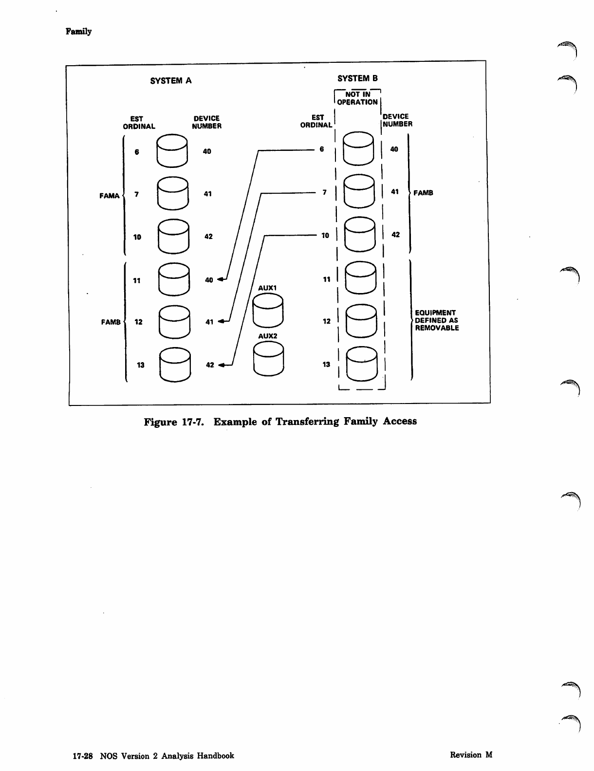
Family
SYSTEM A SYSTEM B
1 noTTn '
1 operation 1
EST DEVICE
ORDINAL NUMBER
EST 'DEVICE
ORDINAL1 1 NUMBER
6 h A 4 0 6 | h ^ 1 flO
' ^ J .
FAMA •8" 7 1 r—H 1 ^1 FAMB
LJ
1 0 Y \ « 1 0 1 1 1 1 4 1
| (^J |
1 1 p A 4 0 ♦/
/ / A U X 1
78
/ A U X 2
»j8! 1
FAMB 1 2 h 1 4 1 - ^
■IB!
EQUIPMENT
DEFINED AS
REMOVABLE
. g .j;8 -LSI
Figure 17-7. Example of Transferring Family Access
17-28 NOS Version 2 Analysis Handbook Revision M
Summary File
Summary FUe
Any of the permanent file utilities can create a summary file containing utility
processing information. The summary file is a machine-readable version of the
information available on the utility output file. This summary file is used as input by
the utility GENPFD; however, a site-written utility could use this information to
generate selection directives for permanent file utility operations such as destaging files
and releasing disk space, or to obtain permanent file statistics for billing, and so forth.
The summary file consists of a prefix table followed by a system identifier block, a
device status block, an archive file identifier block, CIR entries block(s), and PFC
entries block(s). The format of the prefix block allows you to use the CATALOG
command (refer to the NOS Version 2 Reference Set, Volume 3) to display some
information about the contents of the summary file and the environment in which the
summary file was created.
Additional block types may be added in future releases of NOS; thus, any site-written
utility should be coded to skip (and ignore) any block types other than the ones
documented here.
The format of the summary file follows:
Revision M Permanent File Utilities 17-29
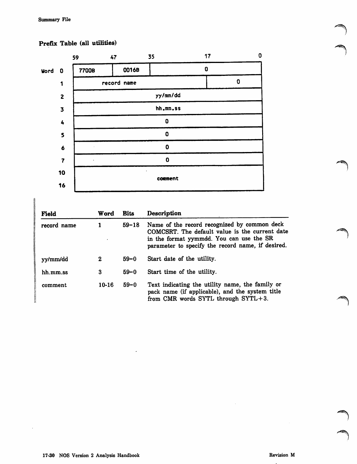
Summary File
Prefix Table (all utilities)
5 9 4 7
Word 0
1
2
3
A
5
6
7
10
16
35 17
[ 7700B 0016B
record name
yy/ram/dd
hh.mm.ss
0
0
0
0
comment
Field Word Bits Description
record name 1 59-18 Name of the record recognized by common deck
COMCSRT. The default value is the current date
in the format yymmdd. You can use the SR
parameter to specify the record name, if desired.
y y / m m / d d 2 5 9 - 0 S t a r t d a t e o f t h e u t i l i t y.
hh.mm.ss 3 59-0 Start time of the utility.
comment 10-16 59-0 Text indicating the utility name, the family or
pack name (if applicable), and the system title
from CMR words SYTL through SYTL+3.
/*S5Sv
17-30 NOS Version 2 Analysis Handbook Revision M
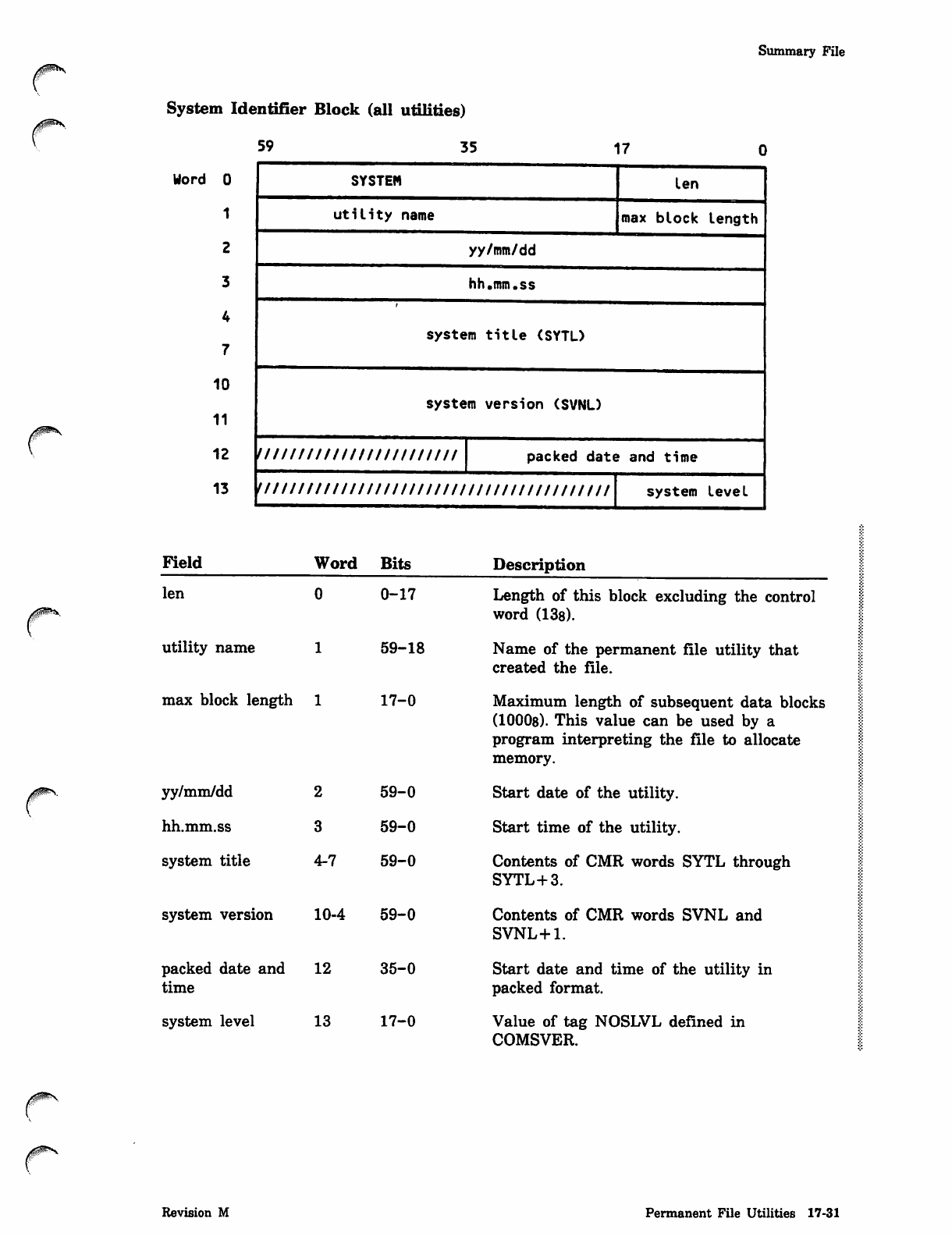
Summary File
r
System Identifier Block (all utilities)
5 9 3 5
Word 0
1
2
3
4
7
10
11
SYSTEM
utility name
yy/mm/dd
hh.mm.ss
system title (SYTL)
17
len
max block length
system version (SVNL)
12 IIIIIIIIIUIIIIIIIIIIHI packed date and time
13 till/Iflllllllllllllllll/llllllllliiiii/ii system level
Field Word Bits Description
l e n 0 0 - 1 7
utility name 1 59-18
max block length 1 17-0
yy/mm/dd
hh.mm.ss
system title
2 5 9 - 0
3 5 9 - 0
4-7 59-0
system version 10-4 59-0
packed date and 12 35-0
time
system level 13 17-0
Length of this block excluding the control
word (138).
Name of the permanent file utility that
created the file.
Maximum length of subsequent data blocks
(10008). This value can be used by a
program interpreting the file to allocate
memory.
Start date of the utility.
Start time of the utility.
Contents of CMR words SYTL through
SYTL+3.
Contents of CMR words SVNL and
SVNL+1.
Start date and time of the utility in
packed format.
Value of tag NOSLVL defined in
COMSVER.
Revision M Permanent File Utilities 17-31
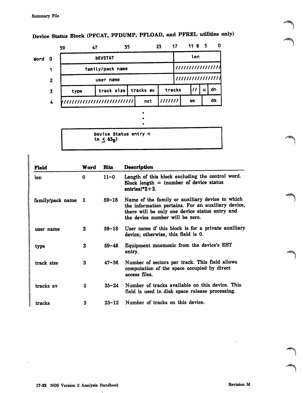
Summary File
Device Status Block (PFCAT, PFDUMP, PFLOAD, and PFREL utilities only)
4 7 3 5 2 3 1 7 1 1 8 5 0
Word 0
1
2
3
4
59
[ D E V S T A T len
family/pack name /////////////////
user name /////////////////
type track size tracks av tracks // dn
'////////////////////////// net /////// sm dm
Device Status entry n
(n < 638) /•"^SsK
I Field Word Bits Description
len
family/pack name 1
user name 2
t y p e 3
track size 3
tracks av 3
tracks 3
11-0 Length of this block excluding the control word.
Block length = (number of device status
entries)*2+2.
59-18 Name of the family or auxiliary device to which
the information pertains. For an auxiliary device,
there will be only one device status entry and
the device number will be zero.
59-18 User name if this block is for a private auxiliary
device; otherwise, this field is 0.
59-48 Equipment mnemonic from the device's EST
entry.
47-36 Number of sectors per track. This field allows
computation of the space occupied by direct
access files.
35-24 Number of tracks available on this device. This
field is used in disk space release processing.
23-12 Number of tracks on this device.
esSSjv
17-32 NOS Version 2 Analysis Handbook Revision M
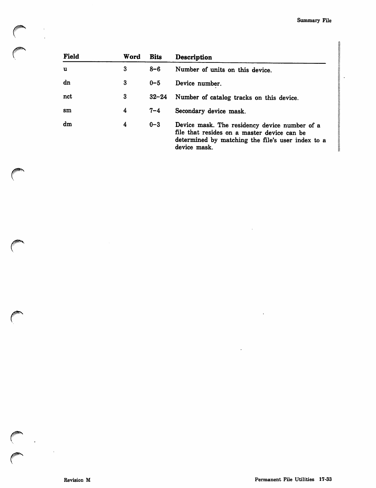
Summary File
Field Word Bits Description
u 3 8-6 Number of units on this device.
dn 3 0-5 Device number.
net 3 32-24 Number of catalog tracks on this device.
sm 4 7-4 Secondary device mask.
dm 4 0-3 Device mask. The residency device number of a
file that resides on a master device can be
determined by matching the file's user index to a
device mask.
Revision M Permanent File Utilities 17-33
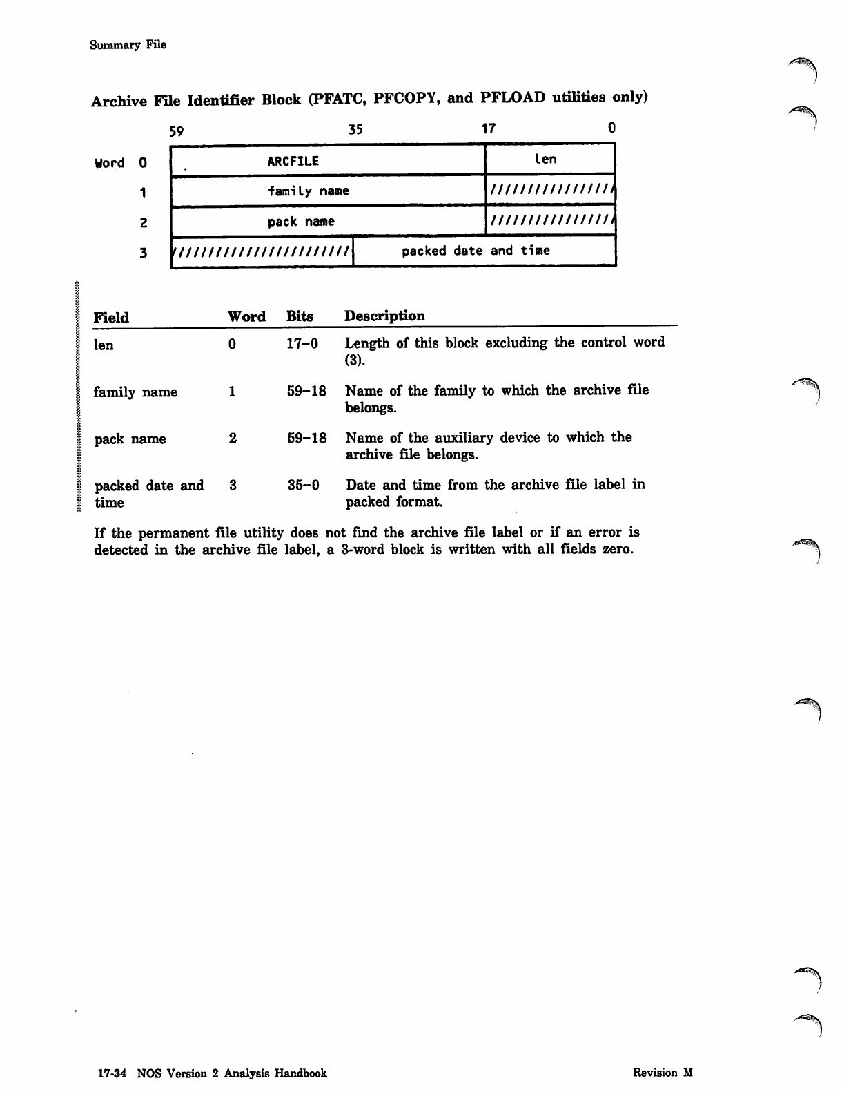
Summary File
Archive FUe Identifier Block (PFATC, PFCOPY, and PFLOAD utilities only)
5 9 3 5 1 7 0
Word 0
1
2
3
ARCFILE len
family name /////////////////
pack name ////////////////)
nilllllllllllllllllllll packed date and time
Field Word Bits Description
len
family name
pack name
packed date and
time
0 17-0 Length of this block excluding the control word
(3).
1 59-18 Name of the family to which the archive file
belongs.
2 59-18 Name of the auxiliary device to which the
archive file belongs.
3 35-0 Date and time from the archive file label in
packed format.
' ^ ^
If the permanent file utility does not find the archive file label or if an error is
detected in the archive file label, a 3-word block is written with all fields zero.
17-34 NOS Version 2 Analysis Handbook Revision M
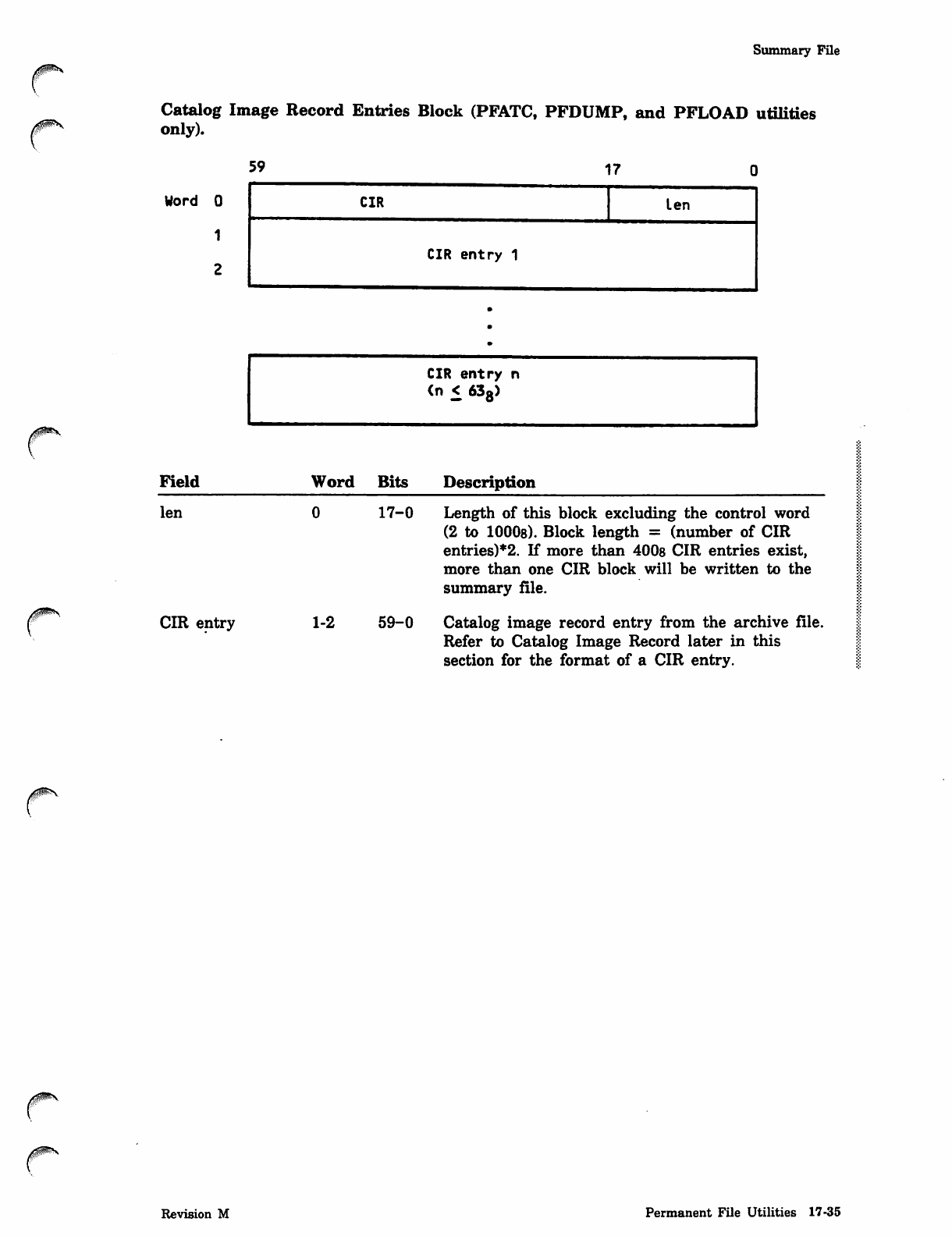
Summary File
Catalog Image Record Entries Block (PFATC, PFDUMP, and PFLOAD utilities
only).
Field
len
CIR entry n
<n < 638)
Word Bits Description
CIR entry
0 17-0 Length of this block excluding the control word
(2 to 10008). Block length = (number of CIR
entries)*2. If more than 4008 CIR entries exist,
more than one CIR block will be written to the
summary file.
1-2 59-0 Catalog image record entry from the archive file.
Refer to Catalog Image Record later in this
section for the format of a CIR entry.
Revision M Permanent File Utilities 17-35
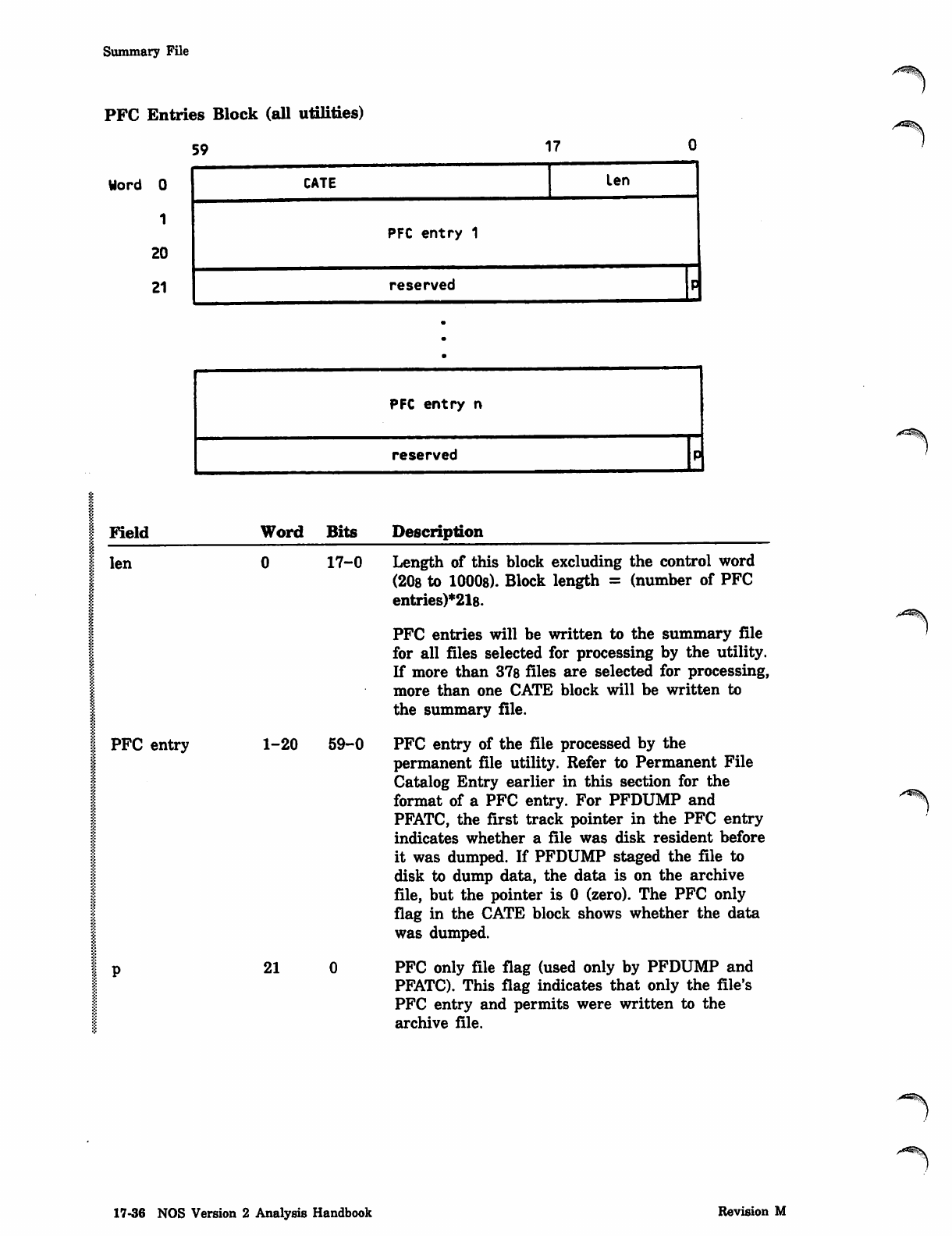
Summary File
PFC Entries Block (all utilities)
59
Word 0
17
1
20
21
CATE
PFC entry 1
reserved
len
PFC entry n
reserved
Field Wo r d Bi t s D e s c r i p t i o n
len 17-0
| PFC entry 1-20 59-0
21
Length of this block excluding the control word
(208 to 10008). Block length = (number of PFC
entries)*2l8.
PFC entries will be written to the summary file
for all files selected for processing by the utility.
If more than 378 files are selected for processing,
more than one CATE block will be written to
the summary file.
PFC entry of the file processed by the
permanent file utility. Refer to Permanent File
Catalog Entry earlier in this section for the
format of a PFC entry. For PFDUMP and
PFATC, the first track pointer in the PFC entry
indicates whether a file was disk resident before
it was dumped. If PFDUMP staged the file to
disk to dump data, the data is on the archive
file, but the pointer is 0 (zero). The PFC only
flag in the CATE block shows whether the data
was dumped.
PFC only file flag (used only by PFDUMP and
PFATC). This flag indicates that only the file's
PFC entry and permits were written to the
archive file.
17-36 NOS Version 2 Analysis Handbook Revision M
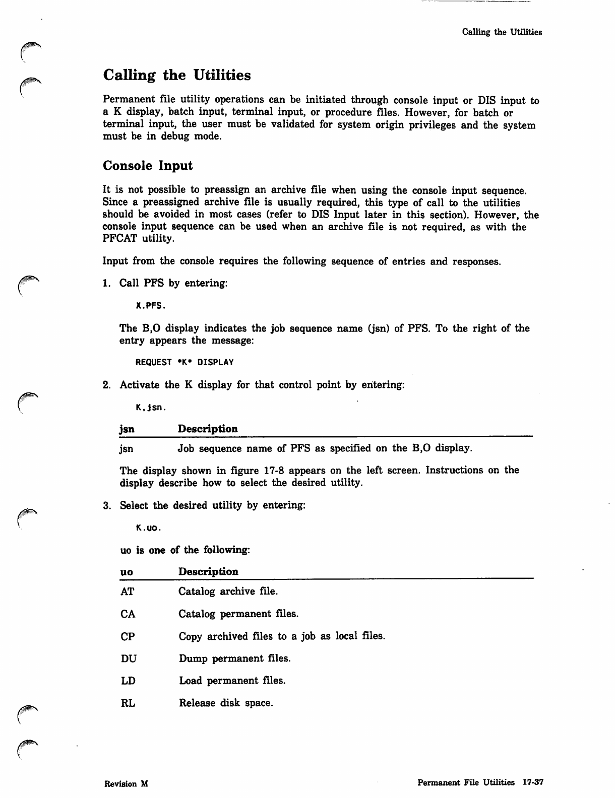
0ms
C
Calling the Utilities
Calling the Utilities
Permanent file utility operations can be initiated through console input or DIS input to
a K display, batch input, terminal input, or procedure files. However, for batch or
terminal input, the user must be validated for system origin privileges and the system
must be in debug mode.
Console Input
It is not possible to preassign an archive file when using the console input sequence.
Since a preassigned archive file is usually required, this type of call to the utilities
should be avoided in most cases (refer to DIS Input later in this section). However, the
console input sequence can be used when an archive file is not required, as with the
PFCAT utility.
Input from the console requires the following sequence of entries and responses.
1. Call PFS by entering:
X.PFS.
The B,0 display indicates the job sequence name (jsn) of PFS. To the right of the
entry appears the message:
REQUEST »K* DISPLAY
2. Activate the K display for that control point by entering:
K.jsn.
jsn Description _^____
jsn Job sequence name of PFS as specified on the B,0 display.
The display shown in figure 17-8 appears on the left screen. Instructions on the
display describe how to select the desired utility.
3. Select the desired utility by entering:
K.uo.
uo is one of the following:
uo Description
AT Catalog archive file.
CA Catalog permanent files.
CP Copy archived files to a job as local files.
DU Dump permanent files.
LD Load permanent files.
RL Release disk space.
Revision M Permanent File Utilities 17-37
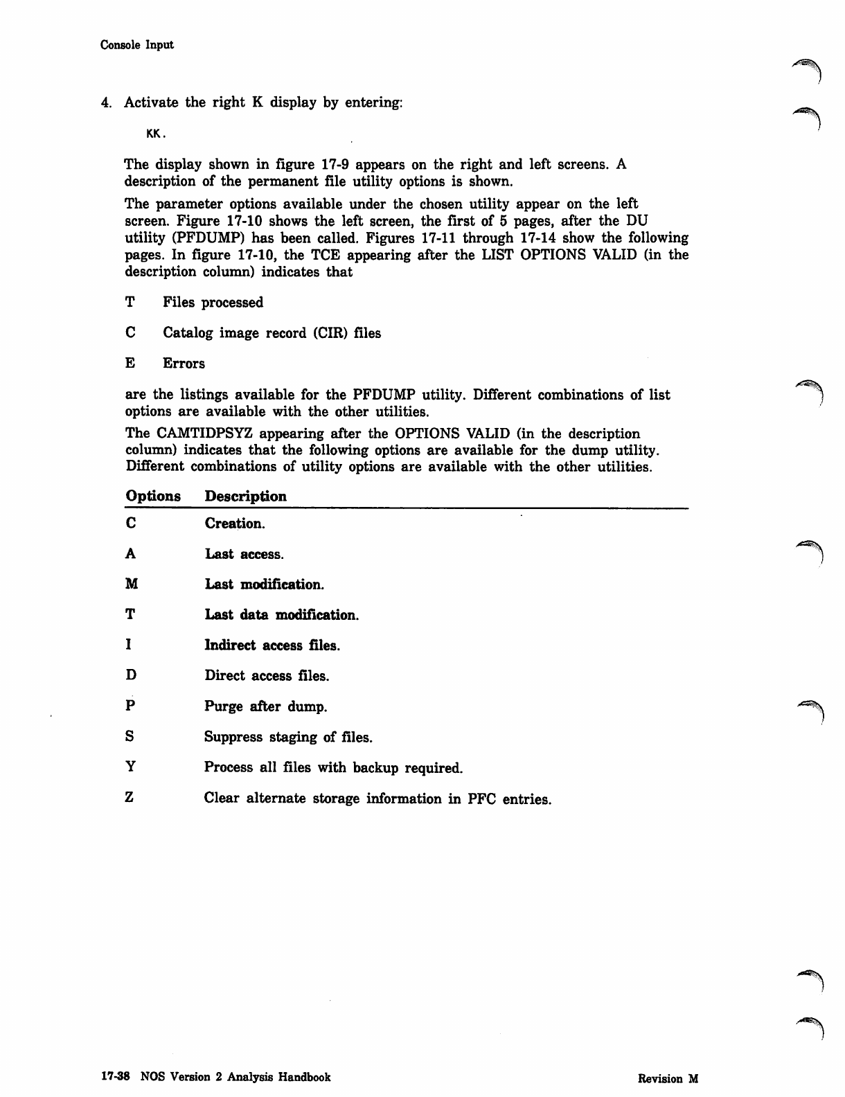
Console Input
4. Activate the right K display by entering:
KK.
The display shown in figure 17-9 appears on the right and left screens. A
description of the permanent file utility options is shown.
The parameter options available under the chosen utility appear on the left
screen. Figure 17-10 shows the left screen, the first of 5 pages, after the DU
utility (PFDUMP) has been called. Figures 17-11 through 17-14 show the following
pages. In figure 17-10, the TCE appearing after the LIST OPTIONS VALID (in the
description column) indicates that
T Files processed
C Catalog image record (CIR) files
E Errors
are the listings available for the PFDUMP utility. Different combinations of list )
options are available with the other utilities.
The CAMTIDPSYZ appearing after the OPTIONS VALID (in the description
column) indicates that the following options are available for the dump utility.
Different combinations of utility options are available with the other utilities.
Options Description
C Creation.
A Last access.
M Last modification.
T Last data modification.
I Indirect access files.
D Direct access files.
P Purge after dump. 'ss\
S Suppress staging of files.
Y Process all files with backup required.
Z Clear alternate storage information in PFC entries.
17-38 NOS Version 2 Analysis Handbook Revision M
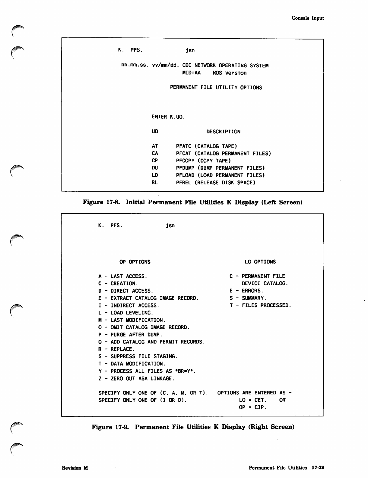
Console Input
K. PFS. jsn
hh.mm.ss. yy/mm/dd. CDC NETWORK OPERATING SYSTEM
MID=AA NOS version
PERMANENT FILE UTILITY OPTIONS
ENTER K.UO.
UO DESCRIPTION
AT PFATC (CATALOG TAPE)
CA PFCAT (CATALOG PERMANENT FILES)
CP PFCOPY (COPY TAPE)
DU PFDUMP (DUMP PERMANENT FILES)
LD PFLOAD (LOAD PERMANENT FILES)
RL PFREL (RELEASE DISK SPACE)
Figure 17-8. Initial Permanent File Utilities K Display (Left Screen)
0m&\
K. PFS. jsn
OP OPTIONS LO OPTIONS
A - LAST ACCESS. C - PERMANENT FILE
C - CREATION. DEVICE CATALOG.
D - DIRECT ACCESS. E - ERRORS.
E - EXTRACT CATALOG IMAGE RECORD. S - SUMMARY.
I - INDIRECT ACCESS. T - FILES PROCESSED.
L - LOAD LEVELING.
M - LAST MODIFICATION.
0 - OMIT CATALOG IMAGE RECORD.
P - PURGE AFTER DUMP.
Q - ADD CATALOG AND PERMIT RECORDS.
R - REPLACE.
S - SUPPRESS FILE STAGING.
T - DATA MODIFICATION.
Y - PROCESS ALL FILES AS *BR=Y».
Z - ZERO OUT ASA LINKAGE.
SPECIFY ONLY ONE OF (C, A, M, OR T). OPTIONS ARE ENTERED AS -
SPECIFY ONLY ONE OF (I OR D). LO = CET. OR'
OP = CIP.
Figure 17-9. Permanent File Utilities K Display (Right Screen)
Revision M Permanent File Utilities 17-39
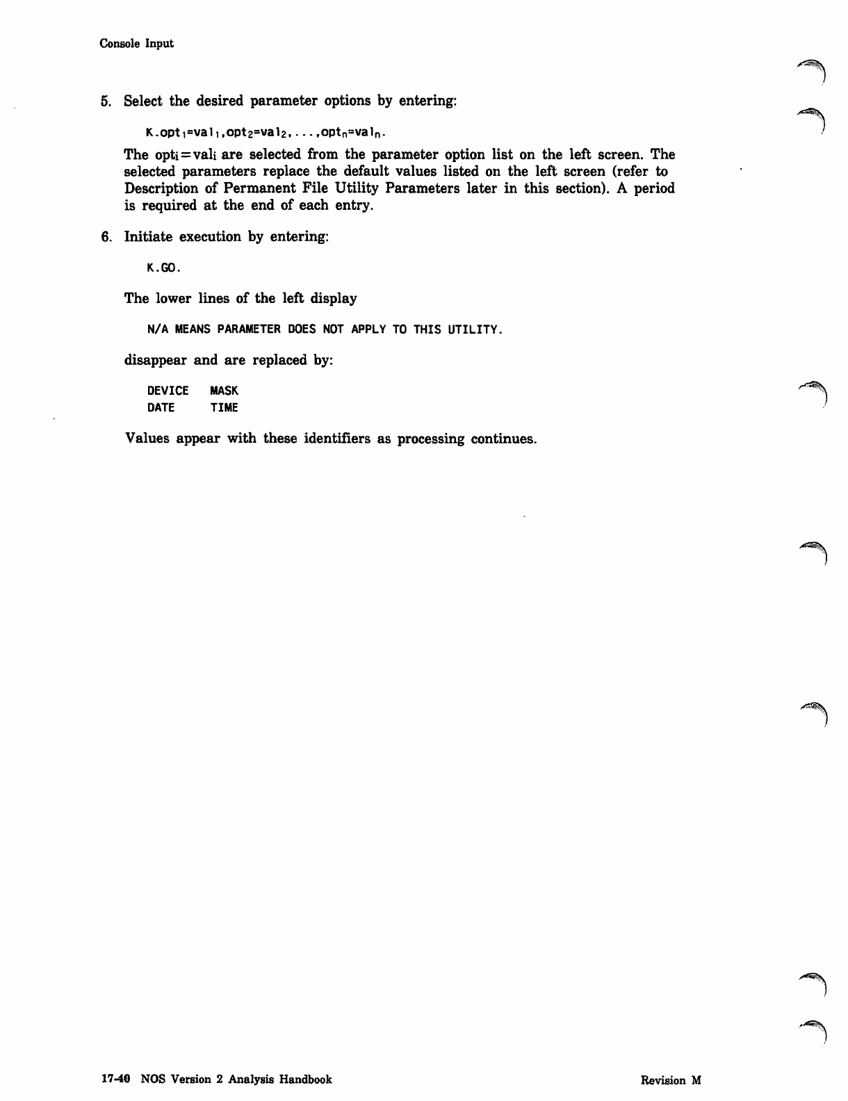
Console Input
5. Select the desired parameter options by entering:
K.opti=vali,opt2=val2. ■-.,optn=valn.
The opti=vali are selected from the parameter option list on the left screen. The
selected parameters replace the default values listed on the left screen (refer to
Description of Permanent File Utility Parameters later in this section). A period
is required at the end of each entry.
6. Initiate execution by entering:
K.GO.
The lower lines of the left display
N/A MEANS PARAMETER DOES NOT APPLY TO THIS UTILITY,
disappear and are replaced by:
DEVICE MASK
DATE TIME
Values appear with these identifiers as processing continues.
17-40 NOS Version 2 Analysis Handbook Revision M
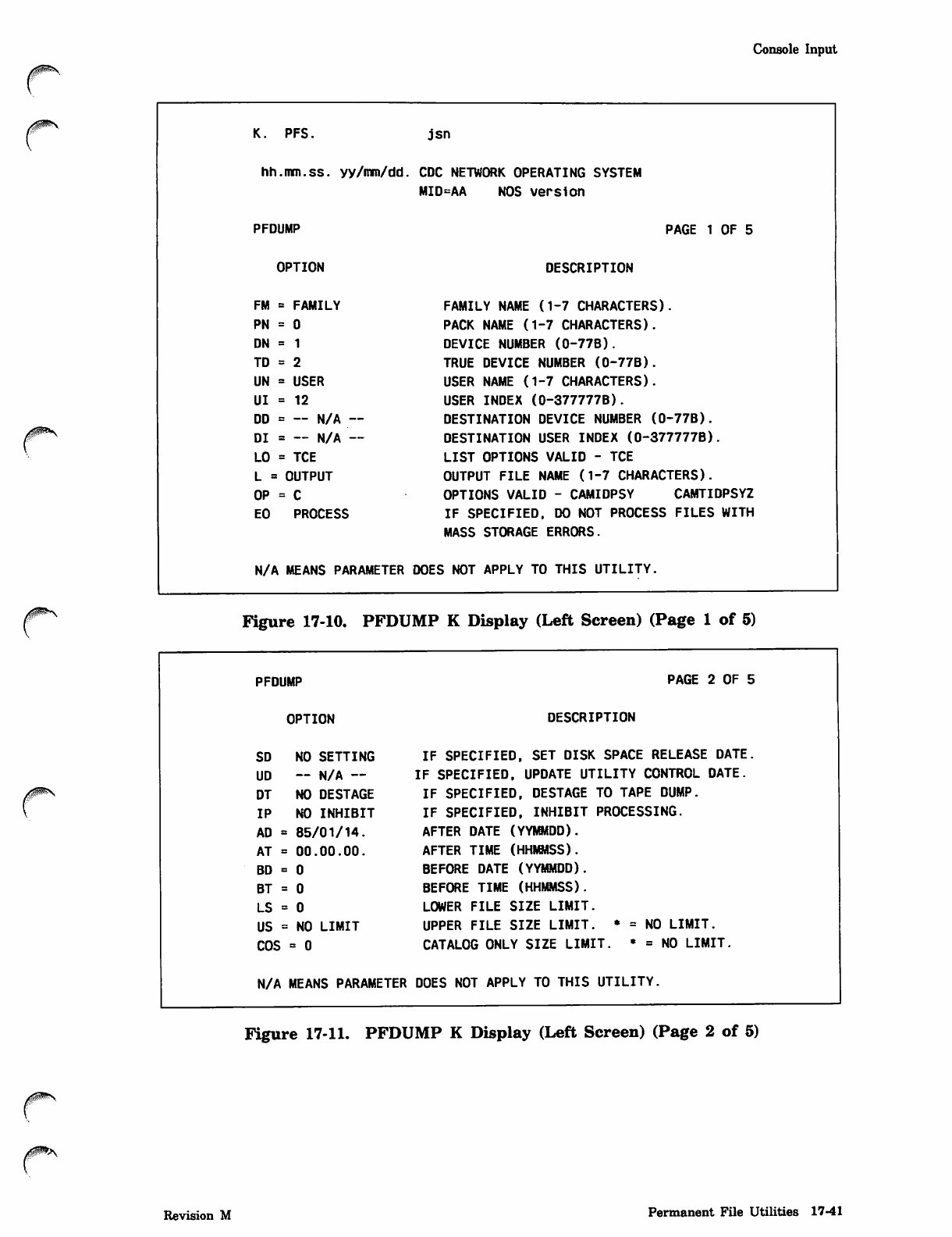
Console Input
K. PFS. jsn
hh.mm.ss. yy/mm/dd. CDC NETWORK OPERATING SYSTEM
MID=AA NOS version
PFDUMP PAGE 1 OF 5
OPTION DESCRIPTION
FM = FAMILY FAMILY NAME (1-7 CHARACTERS).
PN = 0 PACK NAME (1-7 CHARACTERS).
DN = 1 DEVICE NUMBER (0-77B).
TD = 2 TRUE DEVICE NUMBER (0-77B).
UN = USER USER NAME (1-7 CHARACTERS).
UI = 12 USER INDEX (0-377777B).
DD = — N/A — DESTINATION DEVICE NUMBER (0-77B).
DI = -- N/A ~ DESTINATION USER INDEX (0-377777B).
LO = TCE LIST OPTIONS VALID - TCE
L = OUTPUT OUTPUT FILE NAME (1-7 CHARACTERS).
OP = C OPTIONS VALID - CAMIDPSY CAMTIDPSYZ
EO PROCESS IF SPECIFIED, DO NOT PROCESS FILES WITH
MASS STORAGE ERRORS.
N/A MEANS PARAMETER DOES NOT APPLY TO THIS UTILITY.
Figure 17-10. PFDUMP K Display (Left Screen) (Page 1 of 5)
PFDUMP
OPTION
SD NO SETTING
UD N/A —
DT NO DESTAGE
IP NO INHIBIT
AD « 85/01/14.
AT = 00 00.00.
BD = 0
BT = 0
LS = 0
US = NO LIMIT
COS = 0
N/A MEANS PARAMETER
PAGE 2 OF 5
DESCRIPTION
IF SPECIFIED, SET DISK SPACE RELEASE DATE
IF SPECIFIED, UPDATE UTILITY CONTROL DATE.
IF SPECIFIED, DESTAGE TO TAPE DUMP.
IF SPECIFIED, INHIBIT PROCESSING.
AFTER DATE (YYMMDD).
AFTER TIME (HHMMSS).
BEFORE DATE (YYMMDD).
BEFORE TIME (HHMMSS).
LOWER FILE SIZE LIMIT.
UPPER FILE SIZE LIMIT. • = NO LIMIT.
CATALOG ONLY SIZE LIMIT. • = NO LIMIT.
Figure 17-11. PFDUMP K Display (Left Screen) (Page 2 of 5)
Revision M Permanent File Utilities 17-41
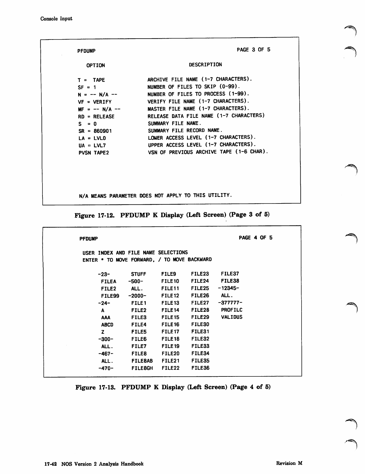
Console Input
PFDUMP
OPTION
T = TAPE
SF = 1
N = — N/A -
VF = VERIFY
MF = ~ N/A
RD = RELEASE
S= 0
SR = 860901
LA = LVLO
UA = LVL7
PVSN TAPE2
PAGE 3 OF 5
DESCRIPTION
ARCHIVE FILE NAME (1-7 CHARACTERS).
NUMBER OF FILES TO SKIP (0-99).
NUMBER OF FILES TO PROCESS (1-99).
VERIFY FILE NAME (1-7 CHARACTERS).
MASTER FILE NAME (1-7 CHARACTERS).
RELEASE DATA FILE NAME (1-7 CHARACTERS)
SUMMARY FILE NAME.
SUMMARY FILE RECORD NAME.
LOWER ACCESS LEVEL (1-7 CHARACTERS).
UPPER ACCESS LEVEL (1-7 CHARACTERS).
VSN OF PREVIOUS ARCHIVE TAPE (1-6 CHAR)
N/A MEANS PARAMETER DOES NOT APPLY TO THIS UTILITY.
Figure 17-12. PFDUMP K Display (Left Screen) (Page 3 of 5)
PFDUMP PAGE 4 OF 5
USER INDEX AND FILE NAME SELECTIONS
ENTER * TO MOVE FORWARD, / TO MOVE BACKWARD
-23- STUFF FILE9 FILE23 FILE37
FILEA -500- FILE 10 FILE24 FILE38
FILE2 ALL. FILE11 FILE25 -12345-
FILE99 -2000- FILE12 FILE26 ALL.
-24- FILE1 FILE13 FILE27 -377777-
AFILE2 FILE 14 FILE28 PROFILC
AAA FILE3 FILE 15 FILE29 VALIDUS
ABCD FILE4 FILE 16 FILE30
ZFILE5 FILE17 FILE31
-300- FILE6 FILE18 FILE32
ALL. FILE7 FILE19 FILE33
-467- FILE8 FILE20 FILE34
ALL. FILE8AB FILE21 FILE35
-470- FILE8GH FILE22 FILE36
Figure 17-13. PFDUMP K Display (Left Screen) (Page 4 of 5)
/,B"feN
17-42 NOS Version 2 Analysis Handbook Revision M
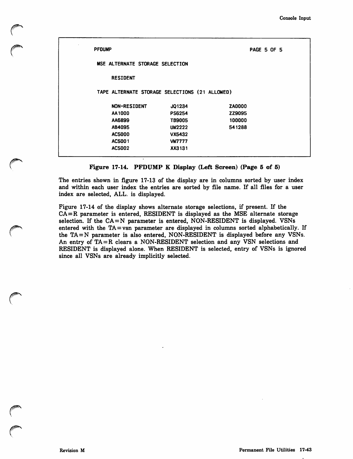
Console Input
PFDUMP PAGE 5 OF 5
MSE ALTERNATE
RESIDENT
STORAGE SELECTION
TAPE ALTERNATE STORAGE SELECTIONS (21 ALLOWED)
NON-RESIDENT JQ1234 ZA0000
AA1000 PS6254 ZZ9095
AA6899 TB9005 100000
AB4095 UW2222 541288
AC5000 VX5432
AC5001 VW7777
AC5002 XX3131
Figure 17-14. PFDUMP K Display (Left Screen) (Page 5 of 5)
The entries shown in figure 17-13 of the display are in columns sorted by user index
and within each user index the entries are sorted by file name. If all files for a user
index are selected, ALL. is displayed.
Figure 17-14 of the display shows alternate storage selections, if present. If the
CA=R parameter is entered, RESIDENT is displayed as the MSE alternate storage
selection. If the CA=N parameter is entered, NON-RESIDENT is displayed. VSNs
entered with the TA=vsn parameter are displayed in columns sorted alphabetically. If
the TA=N parameter is also entered, NON-RESIDENT is displayed before any VSNs.
An entry of TA=R clears a NON-RESIDENT selection and any VSN selections and
RESIDENT is displayed alone. When RESIDENT is selected, entry of VSNs is ignored
since all VSNs are already implicitly selected.
Revision M Permanent File Utilities 17-43
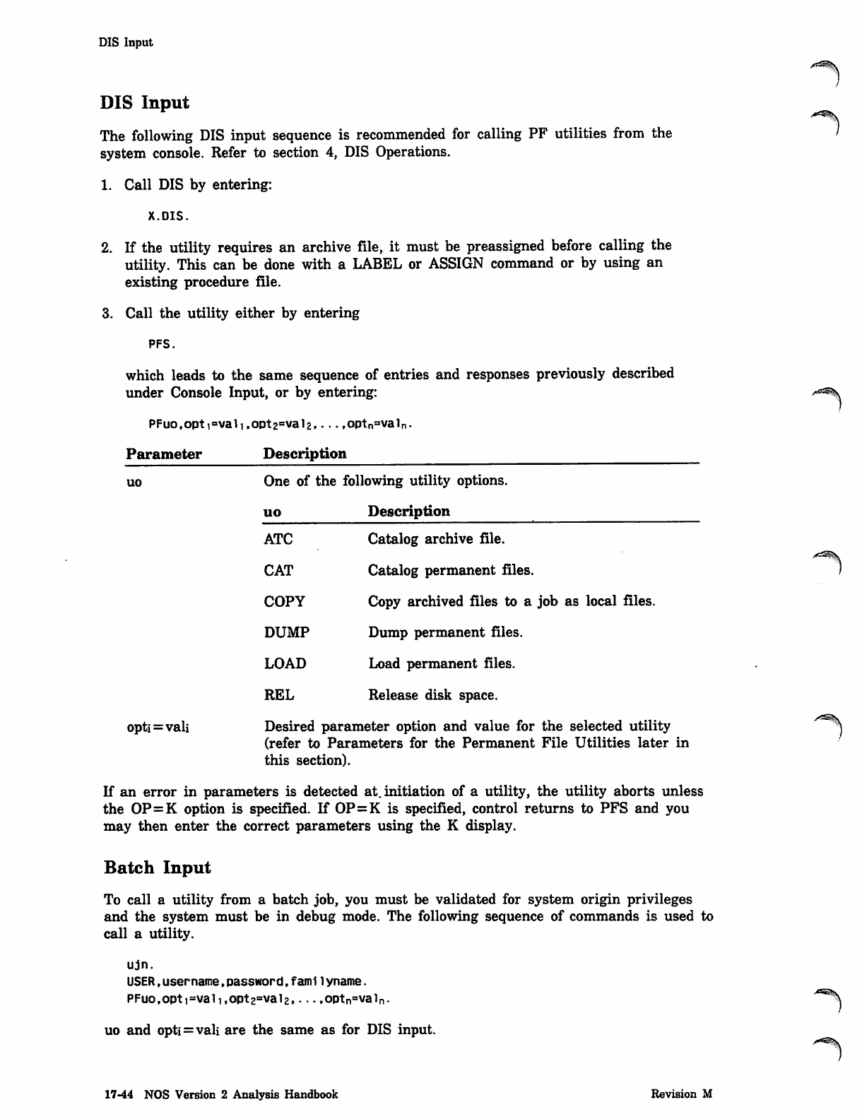
DIS Input
DIS Input
The following DIS input sequence is recommended for calling PF utilities from the
system console. Refer to section 4, DIS Operations.
1. Call DIS by entering:
X.DIS.
2. If the utility requires an archive file, it must be preassigned before calling the
utility. This can be done with a LABEL or ASSIGN command or by using an
existing procedure file.
3. Call the utility either by entering
PFS.
which leads to the same sequence of entries and responses previously described
under Console Input, or by entering:
PFuo,opti=vali,ODt2=val2 optn=valn.
Parameter Description
uo One of the following utility options.
uo Description
AT C C a t a l o g a r c h i v e fi l e .
CAT Catalog permanent files.
COPY Copy archived files to a job as local files.
DUMP Dump permanent files.
LOAD Load permanent files.
REL Release disk space.
opti = vali Desired parameter option and value for the selected utility
(refer to Parameters for the Permanent File Utilities later in
this section).
If an error in parameters is detected at. initiation of a utility, the utility aborts unless
the OP=K option is specified. If OP=K is specified, control returns to PFS and you
may then enter the correct parameters using the K display.
Batch Input
To call a utility from a batch job, you must be validated for system origin privileges
and the system must be in debug mode. The following sequence of commands is used to
call a utility.
ujn.
USER,username,password,fami 1yname.
PFuo,opti=vali,opt2=val2, • • .,optn=valn. >c^
uo and opti = vali are the same as for DIS input.
17-44 NOS Version 2 Analysis Handbook Revision M
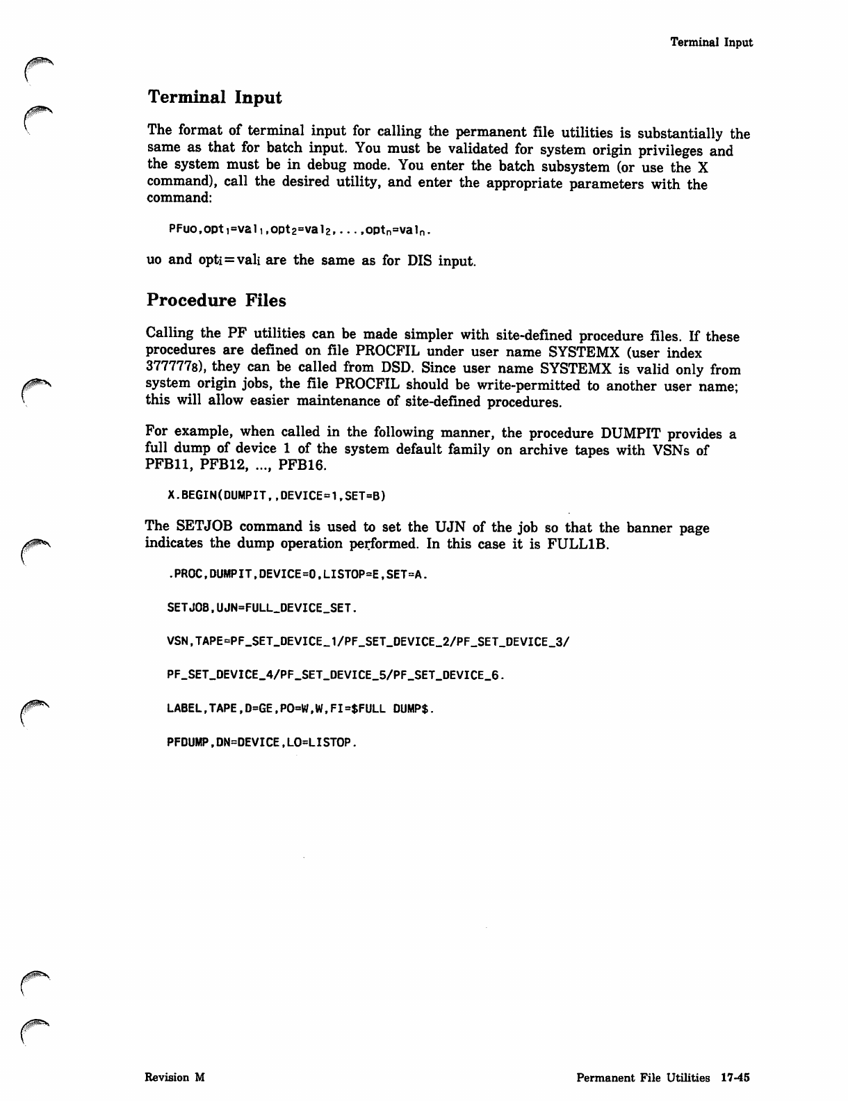
y<S35fr*^
Terminal Input
Terminal Input
The format of terminal input for calling the permanent file utilities is substantially the
same as that for batch input. You must be validated for system origin privileges and
the system must be in debug mode. You enter the batch subsystem (or use the X
command), call the desired utility, and enter the appropriate parameters with the
command:
PFuo,opti=vali,opt2=val2r..•,optn=valn.
uo and opti=vali are the same as for DIS input.
Procedure Files
Calling the PF utilities can be made simpler with site-defined procedure files. If these
procedures are defined on file PROCFIL under user name SYSTEMX (user index
3777778), they can be called from DSD. Since user name SYSTEMX is valid only from
/0^s system origin jobs, the file PROCFIL should be write-permitted to another user name;
V this will allow easier maintenance of site-defined procedures.
For example, when called in the following manner, the procedure DUMPIT provides a
full dump of device 1 of the system default family on archive tapes with VSNs of
PFB11, PFB12, ..., PFB16.
X.BEGIN(DUMPIT,,DEVICE=1,SET=B)
The SETJOB command is used to set the UJN of the job so that the banner page
indicates the dump operation performed. In this case it is FULL1B.
.PROC,DUMPIT,DEVICE=0.LISTOP=E,SET=A.
SETJOB,UJN=FULL_DEVICE_SET.
VSN,TAPE=PF_SET_DEVICE_1/PF_SET_DEVICE_2/PF_SET_DEVICE_3/
PF_SET_DEVICE_4/PF_SET_DEVICE_5/PF_SET_DEVICE_6.
LABEL,TAPE,D=GE,PO=W.W,FI=$FULL DUMP$.
PFDUMP,DN=DEVICE,LO=LISTOP.
Revision M Permanent File Utilities 17-45
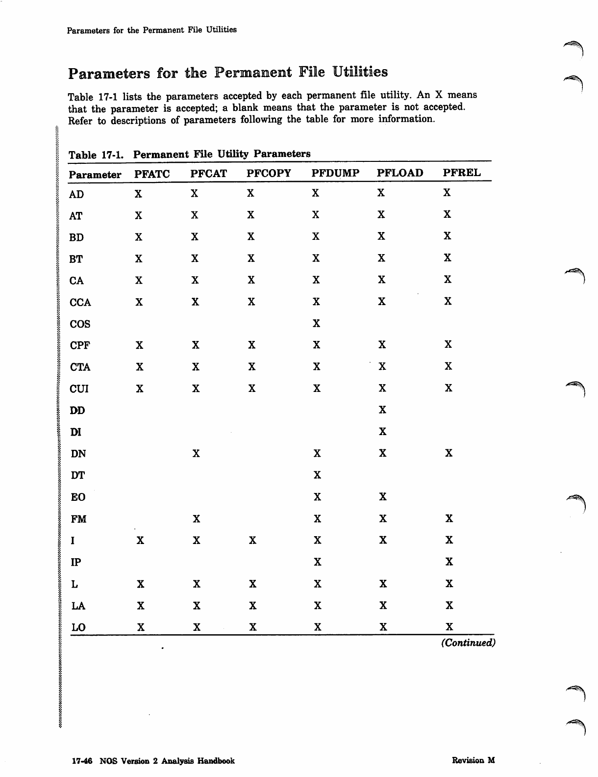
Parameters for the Permanent File Utilities
Parameters for the Permanent File Utilities
Table 17-1 lists the parameters accepted by each permanent file utility. An X means
that the parameter is accepted; a blank means that the parameter is not accepted.
Refer to descriptions of parameters following the table for more information.
Table 17-1. Permanent File Utility Parameters
Parameter PFATC PFCAT PFCOPY PFDUMP PFLOAD PFREL
| AD
I AT
1 BD
I
I BT
j CA
! CCA
K
I COS
I CPF
g
j CIA
I CUI
| DD
| DI
I DN
1 DT
g
I E0
1 FM
I
I l
I ip
s
i l
I L A
1 LO
(Continued)
17-46 NOS Version 2 Analysis Handbook Revision M
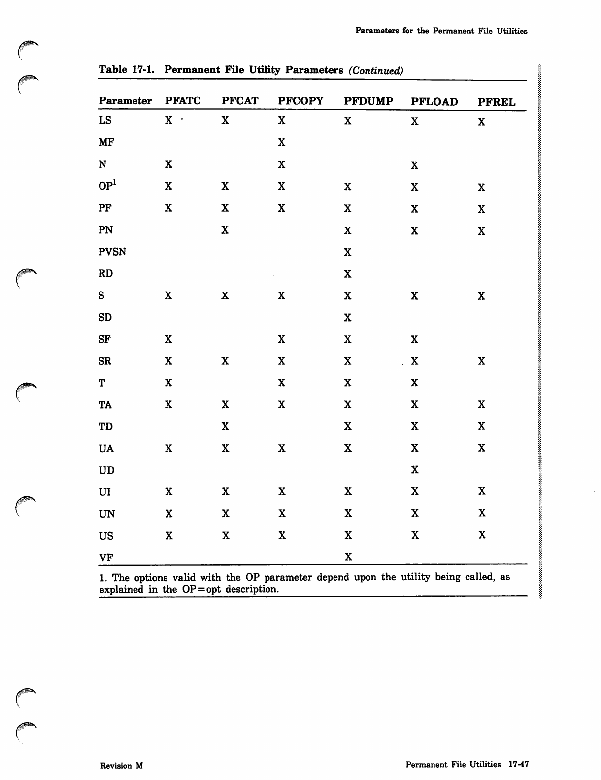
Parameters for the Permanent File Utilities
Table 17-1. Permanent File Utility Parameters (Continued)
Parameter PFATC PFCAT PFCOPY PFDUMP PFLOAD PFREL
LS
MF
N
OP1
PF
PN
PVSN
RD
S
SD
SF
SR
T
TA
TD
UA
UD
UI
UN
US
VF
1. The options valid with the OP parameter depend upon
explained in the OP=opt description.
the utility being called, as
Revision M Permanent File Utilities 17-47
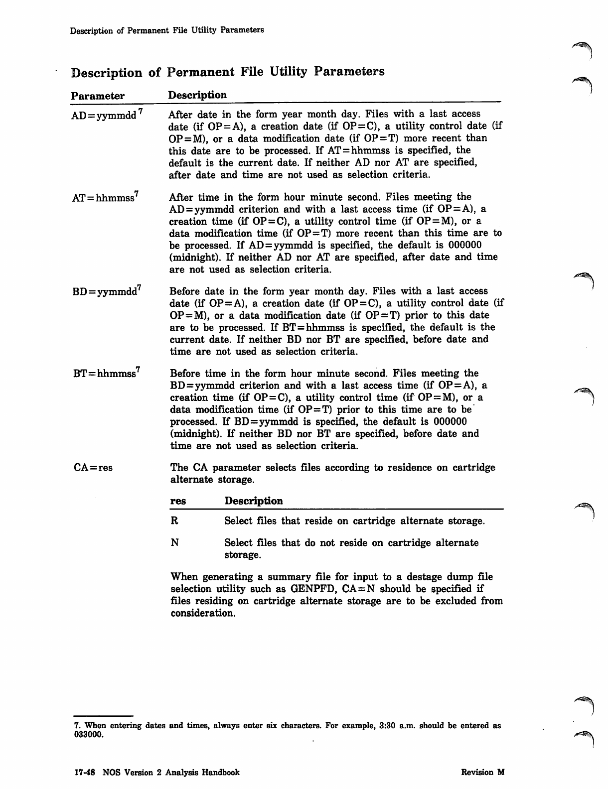
Description of Permanent File Utility Parameters
Description of Permanent File Utility Parameters
Parameter
AD=yymmdd
AT=hhmmss7
BD = yymmdd
BT=hhmmss7
CA=res
Description
After date in the form year month day. Files with a last access
date (if OP=A), a creation date (if OP=C), a utility control date (if
OP=M), or a data modification date (if OP=T) more recent than
this date are to be processed. If AT=hhmmss is specified, the
default is the current date. If neither AD nor AT are specified,
after date and time are not used as selection criteria.
After time in the form hour minute second. Files meeting the
AD = yymmdd criterion and with a last access time (if OP=A), a
creation time (if OP=C), a utility control time (if OP=M), or a
data modification time (if OP=T) more recent than this time are to
be processed. If AD=yymmdd is specified, the default is 000000
(midnight). If neither AD nor AT are specified, after date and time
are not used as selection criteria.
Before date in the form year month day. Files with a last access
date (if OP=A), a creation date (if OP=C), a utility control date (if
OP=M), or a data modification date (if OP=T) prior to this date
are to be processed. If BT=hhmmss is specified, the default is the
current date. If neither BD nor BT are specified, before date and
time are not used as selection criteria.
Before time in the form hour minute second. Files meeting the
BD=yymmdd criterion and with a last access time (if OP=A), a
creation time (if OP=C), a utility control time (if OP=M), or a
data modification time (if OP=T) prior to this time are to be
processed. If BD=yymmdd is specified, the default is 000000
(midnight). If neither BD nor BT are specified, before date and
time are not used as selection criteria.
The CA parameter selects files according to residence on cartridge
alternate storage.
res Description
R
N
Select files that reside on cartridge alternate storage.
Select files that do not reside on cartridge alternate
storage.
When generating a summary file for input to a destage dump file
selection utility such as GENPFD, CA=N should be specified if
files residing on cartridge alternate storage are to be excluded from
consideration.
7. When entering dates and times, always enter six characters. For example, 3:30 a.m. should be entered as
033000.
/*^^v
17-48 NOS Version 2 Analysis Handbook Revision M
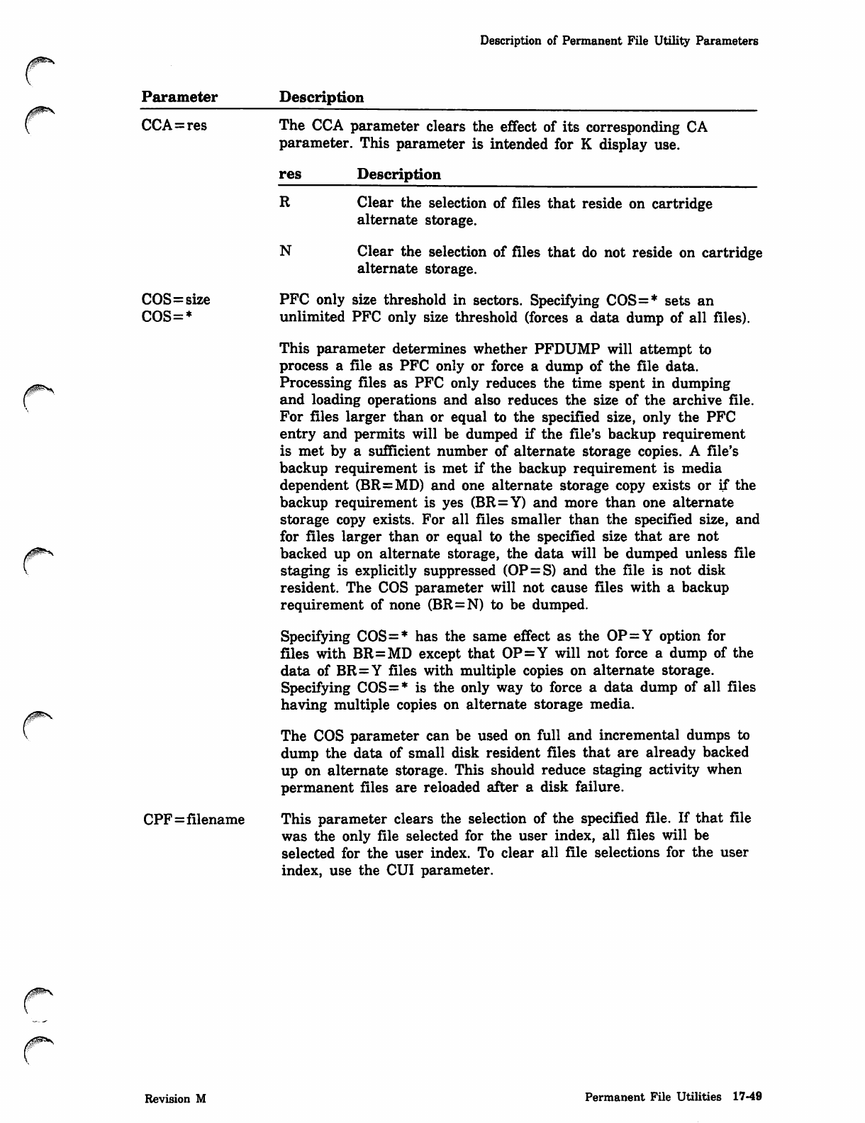
Description of Permanent File Utility Parameters
Parameter
CCA=res
COS=size
COS=*
yms.
CPF=filename
Description
The CCA parameter clears the effect of its corresponding CA
parameter. This parameter is intended for K display use.
res Description
R
N
Clear the selection of files that reside on cartridge
alternate storage.
Clear the selection of files that do not reside on cartridge
alternate storage.
PFC only size threshold in sectors. Specifying COS=* sets an
unlimited PFC only size threshold (forces a data dump of all files).
This parameter determines whether PFDUMP will attempt to
process a file as PFC only or force a dump of the file data.
Processing files as PFC only reduces the time spent in dumping
and loading operations and also reduces the size of the archive file.
For files larger than or equal to the specified size, only the PFC
entry and permits will be dumped if the file's backup requirement
is met by a sufficient number of alternate storage copies. A file's
backup requirement is met if the backup requirement is media
dependent (BR=MD) and one alternate storage copy exists or if the
backup requirement is yes (BR=Y) and more than one alternate
storage copy exists. For all files smaller than the specified size, and
for files larger than or equal to the specified size that are not
backed up on alternate storage, the data will be dumped unless file
staging is explicitly suppressed (OP=S) and the file is not disk
resident. The COS parameter will not cause files with a backup
requirement of none (BR=N) to be dumped.
Specifying COS=* has the same effect as the OP=Y option for
files with BR=MD except that OP=Y will not force a dump of the
data of BR=Y files with multiple copies on alternate storage.
Specifying COS=* is the only way to force a data dump of all files
having multiple copies on alternate storage media.
The COS parameter can be used on full and incremental dumps to
dump the data of small disk resident files that are already backed
up on alternate storage. This should reduce staging activity when
permanent files are reloaded after a disk failure.
This parameter clears the selection of the specified file. If that file
was the only file selected for the user index, all files will be
selected for the user index. To clear all file selections for the user
index, use the CUI parameter.
Revision M Permanent File Utilities 17-49
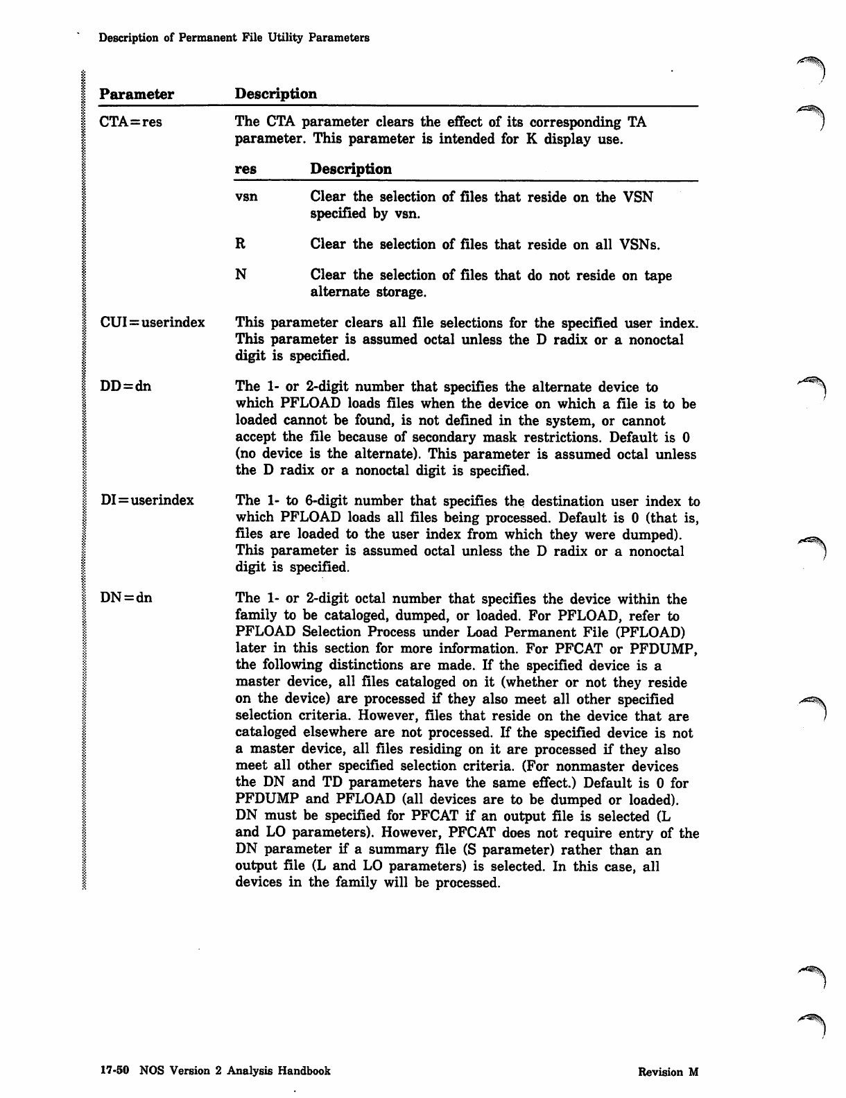
Description of Permanent File Utility Parameters
Parameter Description
CTA=res The CTA parameter clears the effect of its corresponding TA
parameter. This parameter is intended for K display use.
res Description
vsn Clear the selection of files that reside on the VSN
specified by vsn.
R Clear the selection of files that reside on all VSNs.
N Clear the selection of files that do not reside on tape
alternate storage.
CUI=userindex This parameter clears all file selections for the specified user index.
This parameter is assumed octal unless the D radix or a nonoctal
digit is specified.
DD=dn The 1- or 2-digit number that specifies the alternate device to
which PFLOAD loads files when the device on which a file is to be
loaded cannot be found, is not defined in the system, or cannot
accept the file because of secondary mask restrictions. Default is 0
(no device is the alternate). This parameter is assumed octal unless
the D radix or a nonoctal digit is specified.
DI=userindex The 1- to 6-digit number that specifies the destination user index to
which PFLOAD loads all files being processed. Default is 0 (that is,
files are loaded to the user index from which they were dumped).
This parameter is assumed octal unless the D radix or a nonoctal
digit is specified.
DN=dn The 1- or 2-digit octal number that specifies the device within the
family to be cataloged, dumped, or loaded. For PFLOAD, refer to
PFLOAD Selection Process under Load Permanent File (PFLOAD)
later in this section for more information. For PFCAT or PFDUMP,
the following distinctions are made. If the specified device is a
master device, all files cataloged on it (whether or not they reside
on the device) are processed if they also meet all other specified
selection criteria. However, files that reside on the device that are
cataloged elsewhere are not processed. If the specified device is not
a master device, all files residing on it are processed if they also
meet all other specified selection criteria. (For nonmaster devices
the DN and TD parameters have the same effect.) Default is 0 for
PFDUMP and PFLOAD (all devices are to be dumped or loaded).
DN must be specified for PFCAT if an output file is selected (L
and LO parameters). However, PFCAT does not require entry of the
DN parameter if a summary file (S parameter) rather than an
output file (L and LO parameters) is selected. In this case, all
devices in the family will be processed.
/<*2%v
17-50 NOS Version 2 Analysis Handbook Revision M
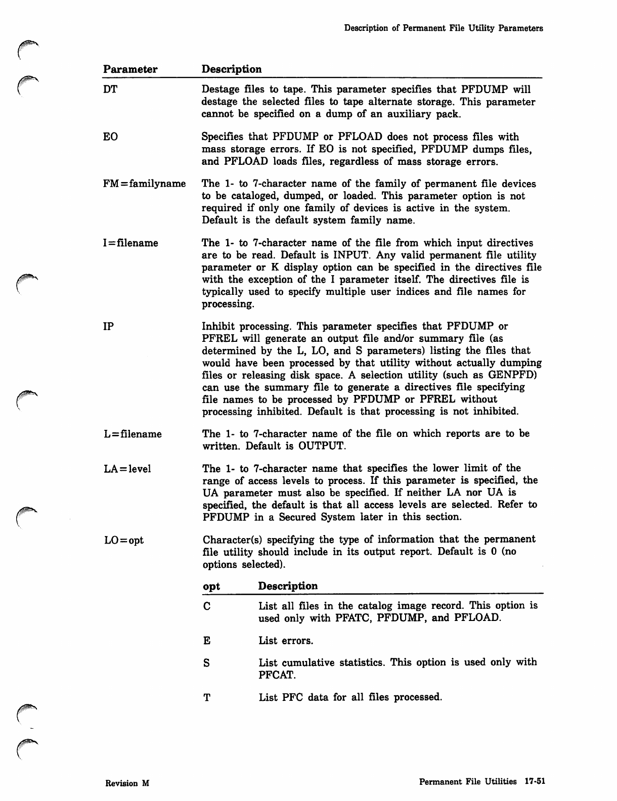
Description of Permanent File Utility Parameters
Parameter Description
DT
EO
FM=familyname
I=filename
IP
L=filename
LA=level
LO=opt
Destage files to tape. This parameter specifies that PFDUMP will
destage the selected files to tape alternate storage. This parameter
cannot be specified on a dump of an auxiliary pack.
Specifies that PFDUMP or PFLOAD does not process files with
mass storage errors. If EO is not specified, PFDUMP dumps files,
and PFLOAD loads files, regardless of mass storage errors.
The 1- to 7-character name of the family of permanent file devices
to be cataloged, dumped, or loaded. This parameter option is not
required if only one family of devices is active in the system.
Default is the default system family name.
The 1- to 7-character name of the file from which input directives
are to be read. Default is INPUT. Any valid permanent file utility
parameter or K display option can be specified in the directives file
with the exception of the I parameter itself. The directives file is
typically used to specify multiple user indices and file names for
processing.
Inhibit processing. This parameter specifies that PFDUMP or
PFREL will generate an output file and/or summary file (as
determined by the L, LO, and S parameters) listing the files that
would have been processed by that utility without actually dumping
files or releasing disk space. A selection Utility (such as GENPFD)
can use the summary file to generate a directives file specifying
file names to be processed by PFDUMP or PFREL without
processing inhibited. Default is that processing is not inhibited.
The 1- to 7-character name of the file on which reports are to be
written. Default is OUTPUT.
The 1- to 7-character name that specifies the lower limit of the
range of access levels to process. If this parameter is specified, the
UA parameter must also be specified. If neither LA nor UA is
specified, the default is that all access levels are selected. Refer to
PFDUMP in a Secured System later in this section.
Character(s) specifying the type of information that the permanent
file utility should include in its output report. Default is 0 (no
options selected).
opt Description
List all files in the catalog image record. This option is
used only with PFATC, PFDUMP, and PFLOAD.
E List errors.
List cumulative statistics. This option is used only with
PFCAT.
List PFC data for all files processed.
Revision M Permanent File Utilities 17-51

Description of Permanent File Utility Parameters
Parameter
LS=size
MF=filename
N=n
OP=opt
Description
Lower size limit in sectors. When specified, only files of size
greater than or equal to the lower size limit will be processed. For
PFDUMP, the file size limit is checked before the COS parameter
(if COS is specified).
The 1- to 7-character name of the master file to which PFCOPY
copies all the files extracted from a designated archive file. Default
is no name; that is, the archived files are copied as individual files
retaining their permanent file names.
This option allows you to extract a file from an archive file and
change its name as a local file.
The 1- or 2-digit number that specifies the number of archive files
on a multifile archive file to be processed. If n=0, one file is
processed. Default is 1. This parameter is assumed decimal unless
the B radix is specified.
The 1- to 7-character string specifying the utility options that
control the processing of files. Many of the options require
additional parameters to complete the definition of the OP selection.
Default is 0 (no options selected).
/*^\
opt Description
K Specifies that the K display should be brought up if an
error is detected when processing input parameters and
directives in PFS. If OP=K is not specified, the permanent
file utility will abort if such an error is detected (which
allows exit processing to be programmed within the calling
procedure).
Only one of options A, C, M, or T can be used at a time. Each of
these options requires one of the following to be specified.
• Specify BD/BT to select all files having a last access date/time
(if OP=A), a creation date/time (if OP=C), a utility control
date/time (if OP=M), or a data modification date/time (if
OP=T) prior to this date/time.
• Specify AD/AT to select all files having a last access date/time
(if OP=A), a creation date/time (if OP=C), a utility control
date/time (if OP=M), or a data modification date/time (if
OP=T) more recent than this date/time.
• Specify both BD/BT and AD/AT to select all files having a last
access date/time (if OP=A), a creation date/time (if OP=C), a
utility control date/time (if OP=M), or a data modification
date/time (if OP=T) in the interval defined by these
dates/times. The date/time specified by BD/BT must be more
recent than the date/time specified by AD/AT to properly define
an interval.
^*§5\
17-52 NOS Version 2 Analysis Handbook Revision M
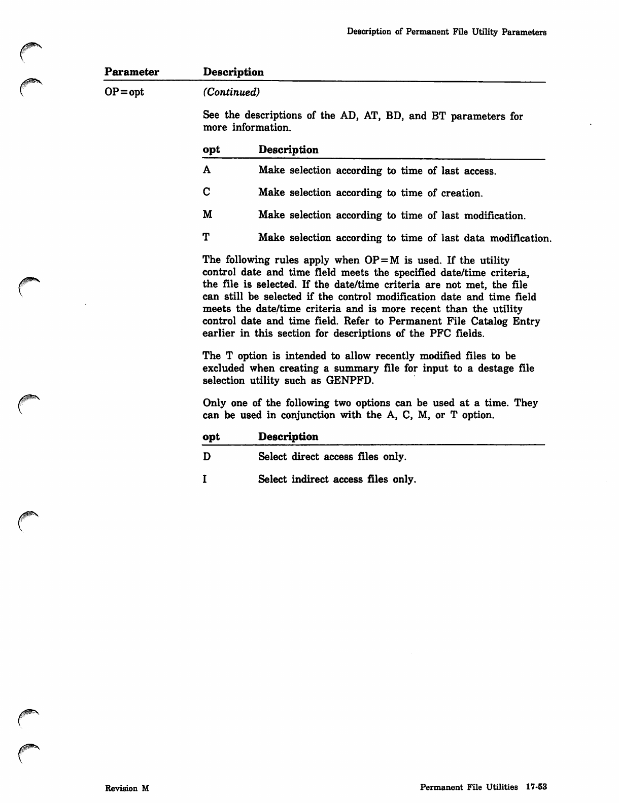
Description of Permanent File Utility Parameters
Parameter Description
OP=opt (Continued)
See the descriptions of the AD, AT, BD, and BT parameters for
more information.
opt Description
A Make selection according to time of last access.
C Make selection according to time of creation.
M Make selection according to time of last modification.
T Make selection according to time of last data modification.
The following rules apply when OP=M is used. If the utility
control date and time field meets the specified date/time criteria,
the file is selected. If the date/time criteria are not met, the file
can still be selected if the control modification date and time field
meets the date/time criteria and is more recent than the utility
control date and time field. Refer to Permanent File Catalog Entry
earlier in this section for descriptions of the PFC fields.
The T option is intended to allow recently modified files to be
excluded when creating a summary file for input to a destage file
selection utility such as GENPFD.
Only one of the following two options can be used at a time. They
can be used in conjunction with the A, C, M, or T option.
opt Description
D Select direct access files only.
I Select indirect access files only.
Revision M Permanent File Utilities 17-53
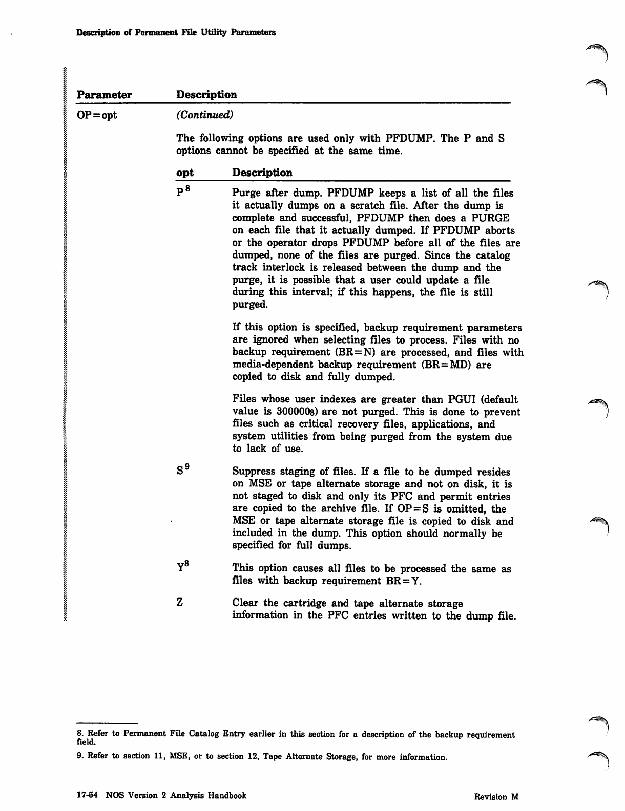
Description of Permanent File Utility Parameters
I Parameter Description
OP=opt (Continued)
The following options are used only with PFDUMP. The P and S
options cannot be specified at the same time.
opt Description
P8 Purge after dump. PFDUMP keeps a list of all the files
it actually dumps on a scratch file. After the dump is
complete and successful, PFDUMP then does a PURGE
on each file that it actually dumped. If PFDUMP aborts
or the operator drops PFDUMP before all of the files are
dumped, none of the files are purged. Since the catalog
track interlock is released between the dump and the
purge, it is possible that a user could update a file ^^
during this interval; if this happens, the file is still j
purged.
If this option is specified, backup requirement parameters
are ignored when selecting files to process. Files with no
backup requirement (BR=N) are processed, and files with
media-dependent backup requirement (BR=MD) are
copied to disk and fully dumped.
Files whose user indexes are greater than PGUI (default
value is 300000s) are not purged. This is done to prevent
files such as critical recovery files, applications, and
system utilities from being purged from the system due
to lack of use.
S9 Suppress staging of files. If a file to be dumped resides
on MSE or tape alternate storage and not on disk, it is
not staged to disk and only its PFC and permit entries
are copied to the archive file. If OP = S is omitted, the
MSE or tape alternate storage file is copied to disk and
included in the dump. This option should normally be
specified for full dumps.
Q
Y This option causes all files to be processed the same as
files with backup requirement BR=Y.
Z Clear the cartridge and tape alternate storage
information in the PFC entries written to the dump file.
8. Refer to Permanent File Catalog Entry earlier in this section for a description of the backup requirement
field.
9. Refer to section 11, MSE, or to section 12, Tape Alternate Storage, for more information.
17-54 NOS Version 2 Analysis Handbook Revision M
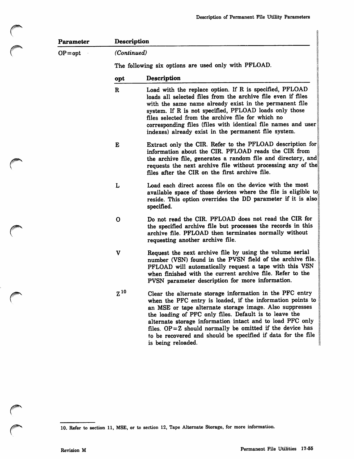
Description of Permanent File Utility Parameters
Parameter Description
OP=opt (Continued)
The following six options are used only with PFLOAD.
opt Description
yams,
r
R Load with the replace option. If R is specified, PFLOAD j
loads all selected files from the archive file even if files
with the same name already exist in the permanent file
system. If R is not specified, PFLOAD loads only those
files selected from the archive file for which no
corresponding files (files with identical file names and userf
indexes) already exist in the permanent file system. |
E Extract only the CIR. Refer to the PFLOAD description fbr|
information about the CIR. PFLOAD reads the CIR from
the archive file, generates a random file and directory, and|
requests the next archive file without processing any of the§
files after the CIR on the first archive file.
L Load each direct access file on the device with the most
available space of those devices where the file is eligible to|
reside. This option overrides the DD parameter if it is also|
specified. |
0 Do not read the CIR. PFLOAD does not read the CIR for |
the specified archive file but processes the records in this |
archive file. PFLOAD then terminates normally without
requesting another archive file.
V Request the next archive file by using the volume serial
number (VSN) found in the PVSN field of the archive file. |
PFLOAD will automatically request a tape with this VSN I
when finished with the current archive file. Refer to the |
PVSN parameter description for more information.
Z10 Clear the alternate storage information in the PFC entry |
when the PFC entry is loaded, if the information points to f
an MSE or tape alternate storage image. Also suppresses |
the loading of PFC only files. Default is to leave the f
alternate storage information intact and to load PFC only I
files. OP=Z should normally be omitted if the device has j
to be recovered and should be specified if data for the file l
is being reloaded.
0^^ 10. Refer to section 11, MSE, or to section 12, Tape Alternate Storage, for more information.
Revision M Permanent File Utilities 17-55
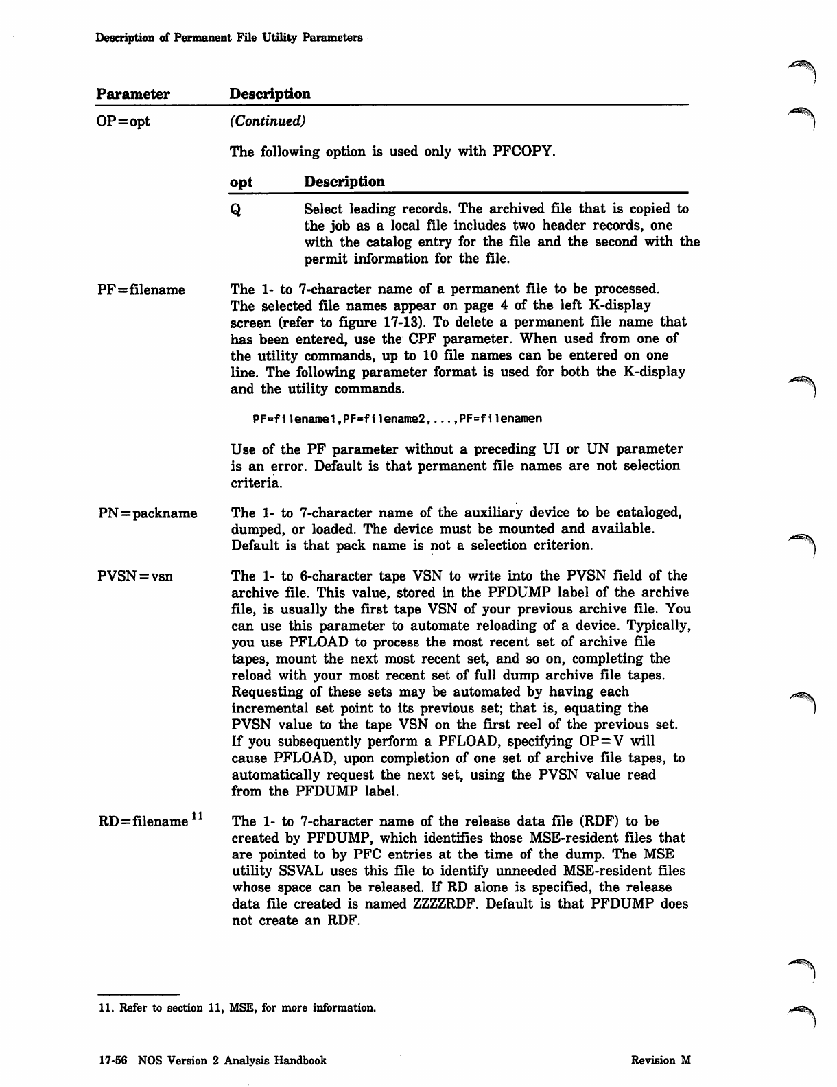
Description of Permanent File Utility Parameters
Parameter
OP=opt
PF=filename
PN=packname
PVSN = vsn
Description
RD=filename11
(Continued)
The following option is used only with PFCOPY.
opt Description
QSelect leading records. The archived file that is copied to
the job as a local file includes two header records, one
with the catalog entry for the file and the second with the
permit information for the file.
The 1- to 7-character name of a permanent file to be processed.
The selected file names appear on page 4 of the left K-display
screen (refer to figure 17-13). To delete a permanent file name that
has been entered, use the CPF parameter. When used from one of
the utility commands, up to 10 file names can be entered on one
line. The following parameter format is used for both the K-display
and the utility commands.
PF=f1lenamel,PF=filename2,...,PF=filenamen
Use of the PF parameter without a preceding UI or UN parameter
is an error. Default is that permanent file names are not selection
criteria.
The 1- to 7-character name of the auxiliary device to be cataloged,
dumped, or loaded. The device must be mounted and available.
Default is that pack name is not a selection criterion.
The 1- to 6-character tape VSN to write into the PVSN field of the
archive file. This value, stored in the PFDUMP label of the archive
file, is usually the first tape VSN of your previous archive file. You
can use this parameter to automate reloading of a device. Typically,
you use PFLOAD to process the most recent set of archive file
tapes, mount the next most recent set, and so on, completing the
reload with your most recent set of full dump archive file tapes.
Requesting of these sets may be automated by having each
incremental set point to its previous set; that is, equating the
PVSN value to the tape VSN on the first reel of the previous set.
If you subsequently perform a PFLOAD, specifying OP=V will
cause PFLOAD, upon completion of one set of archive file tapes, to
automatically request the next set, using the PVSN value read
from the PFDUMP label.
The 1- to 7-character name of the release data file (RDF) to be
created by PFDUMP, which identifies those MSE-resident files that
are pointed to by PFC entries at the time of the dump. The MSE
utility SSVAL uses this file to identify unneeded MSE-resident files
whose space can be released. If RD alone is specified, the release
data file created is named ZZZZRDF. Default is that PFDUMP does
not create an RDF.
11. Refer to section 11, MSE, for more information.
17-56 NOS Version 2 Analysis Handbook Revision M
Description of Permanent File Utility Parameters
Parameter Description
SD 12
S=filename The 1- to 7-character name of a summary file generated by the
permanent file utilities. Default is SUMMARY. The summary file
contains the PFC entries for those files processed by the utility.
Refer to Summary File earlier in this section for additional
information and the format of the summary file. For the PFCAT
utility, a summary file and an output file (L and LO parameters)
cannot be specified simultaneously.
Specifies that PFDUMP is to enter the date and time when the.
dump was initiated into the inhibit date/time field of the master
device. This date/time entry is used by PFDUMP, PFREL, and by
the MSE utility SSMOVE to determine whether the disk image of a
file can be released. If a file was last modified before this
date/time, this PFDUMP is considered a backup copy for the
purpose of satisfying the user-specified backup requirement (BR) for
that file. Refer to PFDUMP in an MSE or Tape Alternate Storage
Environment later in this section for more information.
The 1- or 2-digit number that specifies the number of archive files
on a multifile archive file to be skipped before processing begins.
Default is 0. This parameter is assumed decimal unless the B radix
is specified.
The 1- to 7-character name of the summary file record generated
by the permanent file utilities. Default is the current date in the
form yymmdd. The specified record name will be written to the
prefix table of the record generated. Refer to Summary File earlier
in this section for the format of the prefix table.
T=filename The 1- to 7-character name of the file on which to store or read
archive files. Usually, filename is a tape, but it can be a mass
storage device. Default is TAPE.
TA=res The TA parameter selects files according to residence on the
specified tape alternate storage VSN.
SF=n
SR=recordname
res Description
vsn Select tape alternate storage resident files that reside on
the VSN specified by vsn.
R Select tape alternate storage resident files that reside on
all VSNs.
N Select files that do not reside on tape alternate storage.
When selecting files to be destaged to tape alternate storage,
TA=N should be specified to prevent selection of files already
destaged to other tapes.
12. Refer to section 11, MSE, for more information.
Revision M Permanent File Utilities 17-57
Description of Permanent File Utility Parameters
Parameter Description
1 TD=dn
UA=level
UD 13
UI = userindex
I UN=username
The 1- or 2-digit octal number that specifies the device within the
family to be dumped or loaded. This is the device number specified
by the EQPDECK PF entry for the device. You can determine
which device number to use within the family by referring to the
DSD Family Status Display (E,F) described in the NOS Version 2
Operations Handbook.
For PFLOAD refer to PFLOAD Selection Process under Load
Permanent File (PFLOAD) later in this section for more
information. For PFDUMP, the following distinctions are made. If
the specified device is a master device, all files cataloged and/or
residing on it are processed if they meet all other specified
selection criteria. If the specified device is not a master device, all
files residing on it are processed if they also meet all other
specified selection criteria. (For nonmaster devices the DN and TD
parameters have the same effect.) Default is 0 (all devices are to
be dumped or loaded).
The 1- to 7-character name that specifies the upper limit of the
range of access levels to process. If this parameter is specified, the
LA parameter must also be specified. If neither LA nor UA is
specified, the default is that all access levels are selected. Refer to
PFDUMP in a Secured System later in this section.
Specifies that PFLOAD is to update the utility control date and
time field in the PFC entry for the file being loaded. This ensures
that the file will be considered for inclusion in the next
incremental dump. UD should normally be specified when a
particular user's files are being reloaded, but should normally be
omitted when a full device is being reloaded.
The 1- to 6-digit number that specifies the user index under which
files to be processed are located. If UI is specified, DN need not be
specified because the utility will locate the proper device. Default is
that user index is not a selection criterion. This parameter is
assumed octal unless the D radix or a nonoctal digit is specified.
If no file selections are in effect for the affected user index at the
time of entry, the UI parameter selects all files for the user index
and also specifies the user index to be assumed for subsequent PF
directives. If file selections are already in effect for the user index,
the UI parameter simply sets the assumed user index for
subsequent PF directives.
The 1- to 7-character user name associated with the PN parameter.
The user name must match information in the MST for the
specified pack name. If UN is specified and PN is not, the utility
will convert username to a user index. If, in addition, DN is not
specified, the utility will locate the proper device in the family.
Default is that user name is not a selection criterion.
13. Refer to section 11, MSE, for more information.
17-58 NOS Version 2 Analysis Handbook Revision M
Description of Permanent File Utility Parameters
Parameter Description
UN=username
US=size
VF=filename
(Continued)
If no file selections are in effect for the affected user index at the
time of entry, the UN parameter selects all files for the user index
and also specifies the user index to be assumed for subsequent PF
directives. If file selections are in effect for the user index, the UN
parameter simply sets the assumed user index for subsequent PF
directives.
Upper size limit in sectors. When specified, only files of size less
than or equal to the upper size limit will be processed. For
PFDUMP, the file size limit is checked before the COS parameter
(if COS is specified).
The 1- to 7-character name that specifies that PFDUMP is to
produce a verify file which is a duplicate of the archive file it
creates. If VF alone is specified, the verify file is named PFVER.
Default is that no verify file is written.
Example:
The following series of commands creates a two-file archive file
(AA) and a matching verify file (BB). The VERIFY command
compares the accuracy of the duplication. (Refer to the NOS
Version 2 Reference Set, Volume 3 for a complete description of
VERIFY.)
Command Description
r
00!^*%,,
PFDUMP,T=AA, VF=BB.
PFDUMP,T=AA, VF=BB.
VERIFY,AA,BB,N = 0,A,R.
The dump is written on archive file
AA. A duplicate is written on the
verify file BB. PFDUMP does not
rewind after processing.
A second dump is written after the
first on both the archive (AA) and the
verify (BB) files. Each dump produces
a separate file on the archive and
verify files.
A binary comparison of AA and BB is
performed. If words do not match, this
command lists:
Record number
Word number within the record
Words from both files that do not match
N = 0 specifies that the verify
terminates when the first empty file is
encountered. The A parameter specifies
an abort if a mismatch is found. R
rewinds both files before and after the
verify.
Revision M Permanent File Utilities 17-59
Preassigning the Archive File
Preassigning the Archive File
In all permanent file utilities except PFCAT and PFREL, the archive file must be
preassigned. This can be done by using the LABEL or ASSIGN command. For example,
file assignment can be made with the following commands.
LABEL,TAPE.VSN=PFDUMP,NT,D=1600.
or
ASSIGN,NT,TAPE.
If no archive file is present, PFDUMP will write on a local mass storage file. The
other utilities will attempt to read an empty archive file and terminate. PFLOAD will
automatically request the assignment of any incremental or full dump archive tapes
needed after the first tape; the request will be for the same track type and density as
the first archive tape.
Further automation may be added by indicating all tape VSNs during PFDUMP /*aS^
and/or PFLOAD, which automates the archive tape VSN requests within one archive
file. This may be done through the VSN command (refer to Procedure Files earlier in
this section). You can also use the PFDUMP parameter PVSN and PFLOAD option
OP=V, which automates the archive tape VSN requests between archive files. Refer
to the PVSN parameter description for more information.
NOTE
The archive file is not rewound or unloaded before or after processing by any of the
utilities, except before a PFLOAD tape request.
17-60 NOS Version 2 Analysis Handbook Revision M
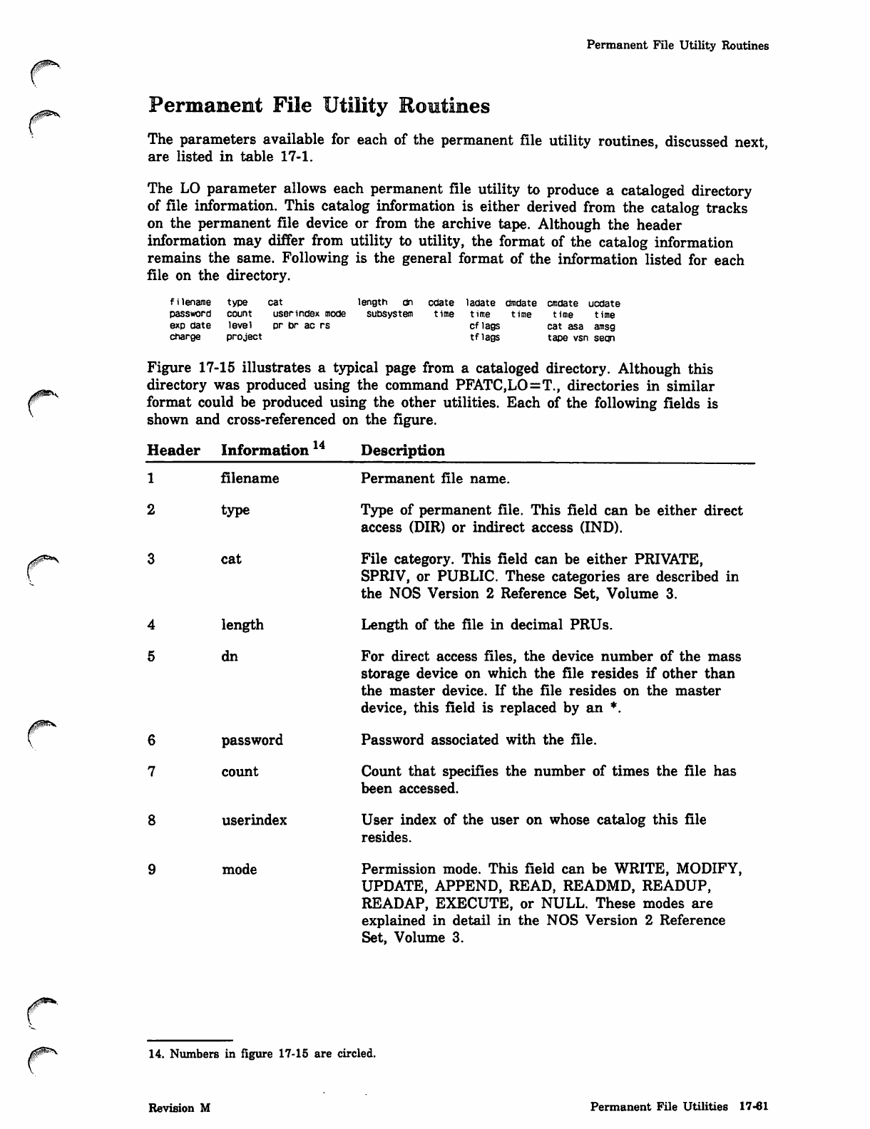
Permanent File Utility Routines
Permanent File Utility Routines
The parameters available for each of the permanent file utility routines, discussed next,
are listed in table 17-1.
The LO parameter allows each permanent file utility to produce a cataloged directory
of file information. This catalog information is either derived from the catalog tracks
on the permanent file device or from the archive tape. Although the header
information may differ from utility to utility, the format of the catalog information
remains the same. Following is the general format of the information listed for each
file on the directory.
filename type cat length dn edate ladate dmdate ondate ucdate
password count userindex mode subsystem time time time time time
exp date level pr br ac rs eflags cat asa amsg
charge project tflags tape vsn seqn
Figure 17-15 illustrates a typical page from a cataloged directory. Although this
directory was produced using the command PFATC,LO=T., directories in similar
format could be produced using the other utilities. Each of the following fields is
shown and cross-referenced on the figure.
Header Information14 Description
filename
type
cat
length
dn
6password
7count
8userindex
Permanent file name.
Type of permanent file. This field can be either direct
access (DIR) or indirect access (IND).
File category. This field can be either PRIVATE,
SPRIV, or PUBLIC. These categories are described in
the NOS Version 2 Reference Set, Volume 3.
Length of the file in decimal PRUs.
For direct access files, the device number of the mass
storage device on which the file resides if other than
the master device. If the file resides on the master
device, this field is replaced by an *.
Password associated with the file.
Count that specifies the number of times the file has
been accessed.
User index of the user on whose catalog this file
resides.
mode Permission mode. This field can be WRITE, MODIFY,
UPDATE, APPEND, READ, READMD, READUP,
READAP, EXECUTE, or NULL. These modes are
explained in detail in the NOS Version 2 Reference
Set, Volume 3.
14. Numbers in figure 17-15 are circled.
Revision M Permanent File Utilities 17-61
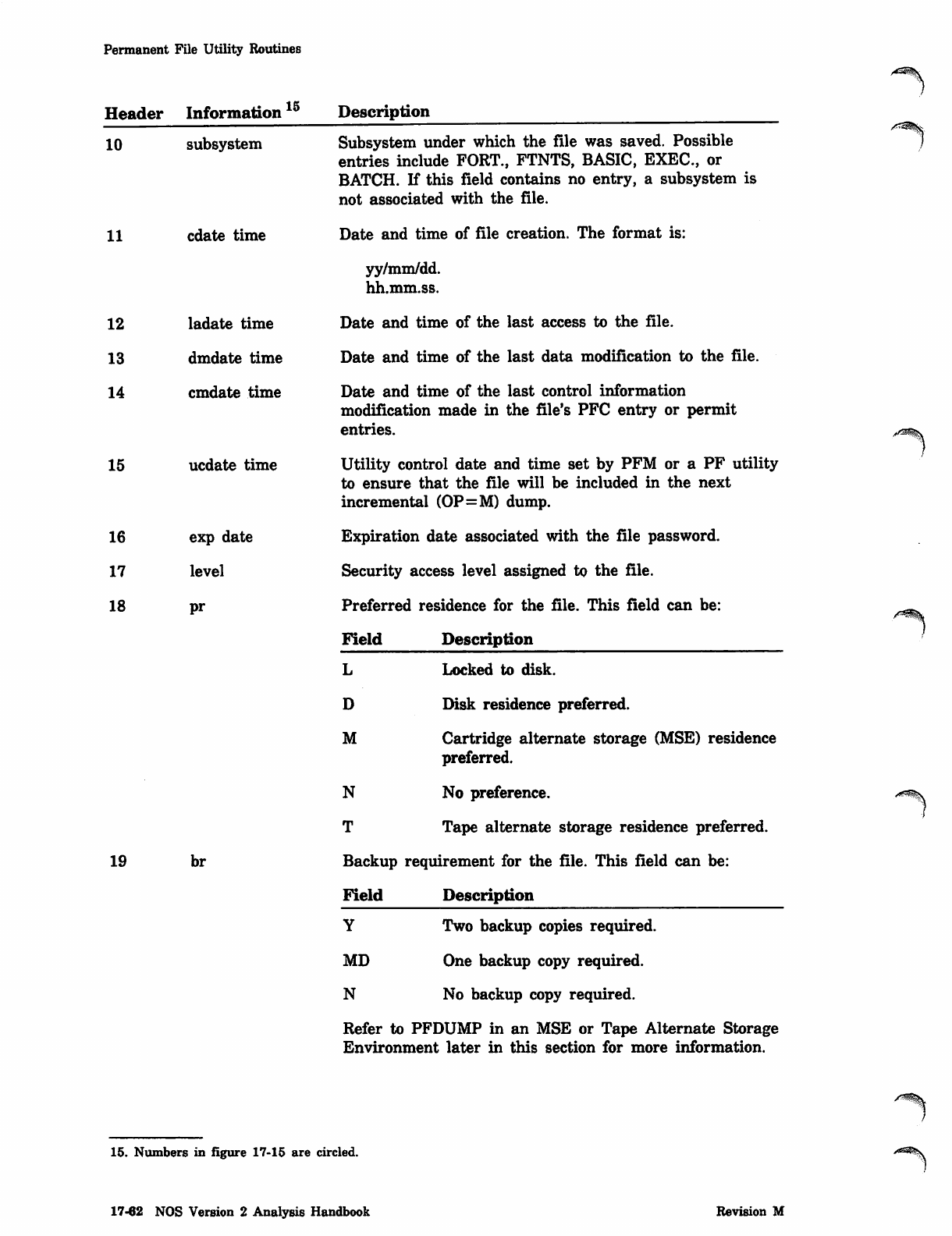
Permanent File Utility Routines
Header Information15 Description
10 subsystem Subsystem under which the file was saved. Possible
entries include FORT., FTNTS, BASIC, EXEC, or
BATCH. If this field contains no entry, a subsystem is
not associated with the file.
11 edate time Date and time of file creation. The format is:
yy/mm/dd.
hh.mm.ss.
Date and time of the last access to the file.
Date and time of the last data modification to the file.
Date and time of the last control information
modification made in the file's PFC entry or permit
entries.
Utility control date and time set by PFM or a PF utility
to ensure that the file will be included in the next
incremental (OP=M) dump.
Expiration date associated with the file password.
Security access level assigned to the file.
Preferred residence for the file. This field can be:
Field Description
L Locked to disk.
D Disk residence preferred.
M Cartridge alternate storage (MSE) residence
preferred.
N No preference.
T Tape alternate storage residence preferred.
1 9 b r B a c k u p r e q u i r e m e n t f o r t h e fi l e . T h i s fi e l d c a n b e :
Field Description
12 ladate time
13 dmdate time
14 cmdate time
15 ucdate time
16 exp date
17 level
18 pr
Y Two backup copies required.
MD One backup copy required.
N No backup copy required.
Refer to PFDUMP in an MSE or Tape Alternate Storage
Environment later in this section for more information.
15. Numbers in figure 17-15 are circled.
17-62 NOS Version 2 Analysis Handbook Revision M
/^1|»
•s^.
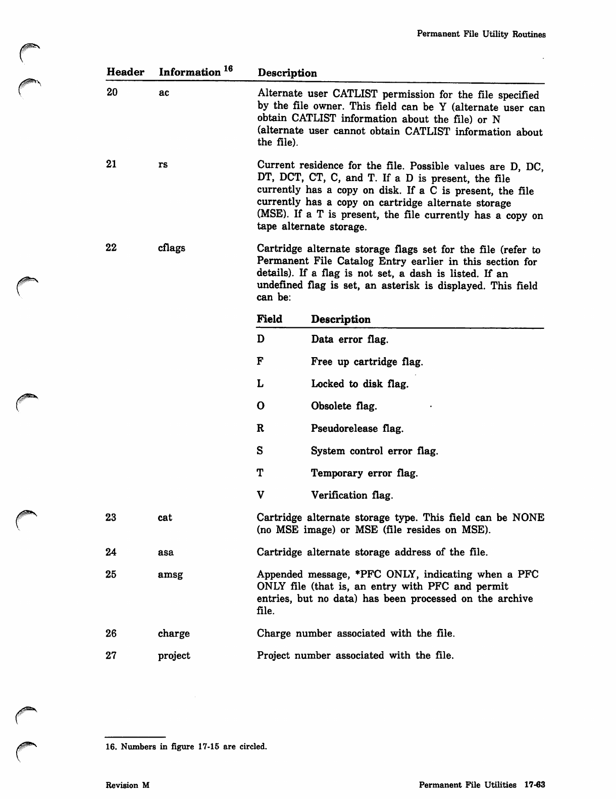
0ims
20 ac
21 rs
22 eflags
Permanent File Utility Routines
Header Information16 Description
Alternate user CATLIST permission for the file specified
by the file owner. This field can be Y (alternate user can
obtain CATLIST information about the file) or N
(alternate user cannot obtain CATLIST information about
the file).
Current residence for the file. Possible values are D, DC,
DT, DCT, CT, C, and T. If a D is present, the file
currently has a copy on disk. If a C is present, the file
currently has a copy on cartridge alternate storage
(MSE). If a T is present, the file currently has a copy on
tape alternate storage.
Cartridge alternate storage flags set for the file (refer to
Permanent File Catalog Entry earlier in this section for
details). If a flag is not set, a dash is listed. If an
undefined flag is set, an asterisk is displayed. This field
can be:
23
24
25
26
27
cat
asa
amsg
charge
project
Field Description
D Data error flag.
F Free up cartridge flag.
L Locked to disk flag.
0 Obsolete flag.
RPseudorelease flag.
SSystem control error flag.
TTemporary error flag.
VVerification flag.
Cartridge alternate storage type. This field can be NONE
(no MSE image) or MSE (file resides on MSE).
Cartridge alternate storage address of the file.
Appended message, *PFC ONLY, indicating when a PFC
ONLY file (that is, an entry with PFC and permit
entries, but no data) has been processed on the archive
file.
Charge number associated with the file.
Project number associated with the file.
16. Numbers in figure 17-15 are circled.
Revision M Permanent File Utilities 17-63
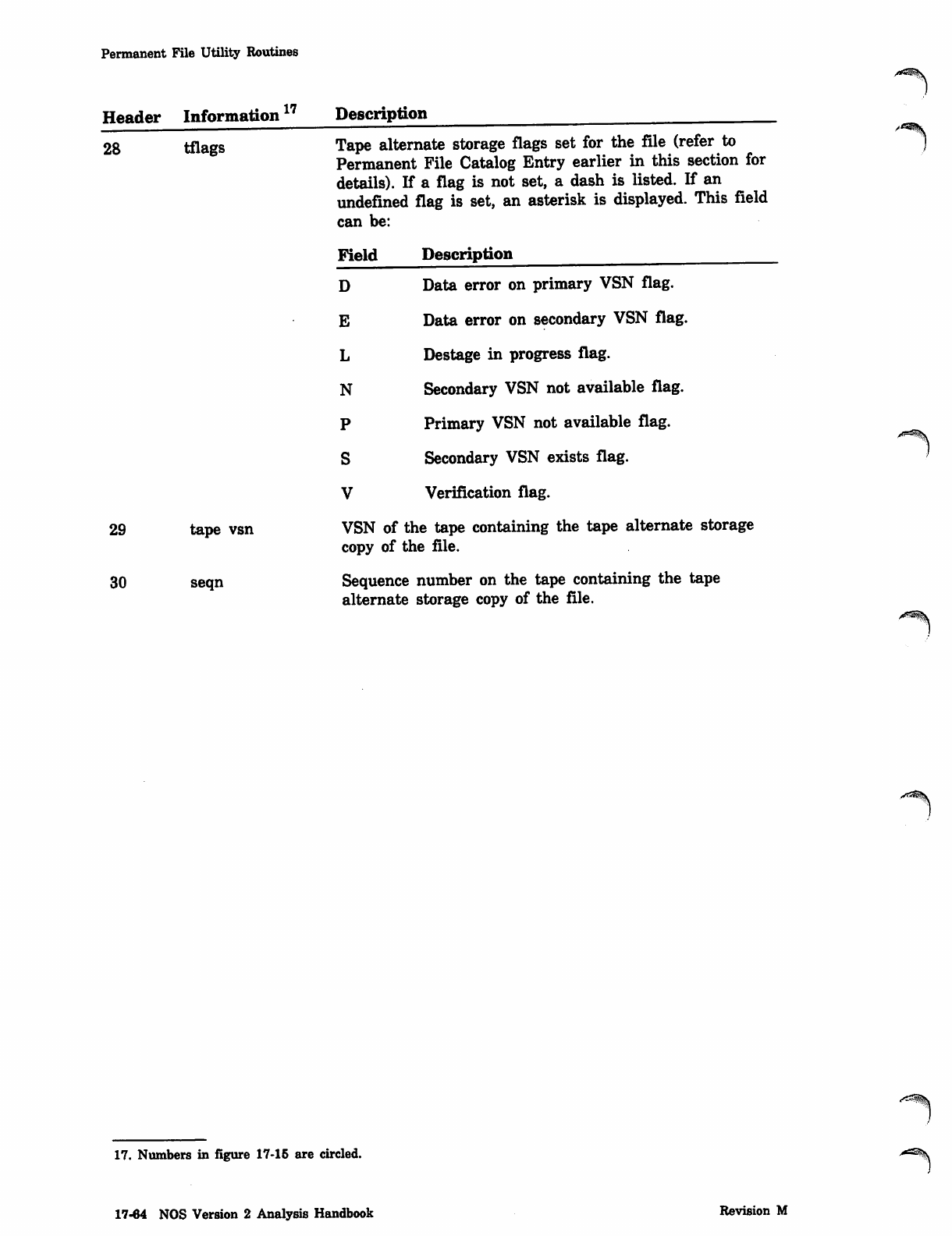
Permanent File Utility Routines
Header Information17 Description
28 tflags
29
30
tape vsn
seqn
Tape alternate storage flags set for the file (refer to
Permanent File Catalog Entry earlier in this section for
details). If a flag is not set, a dash is listed. If an
undefined flag is set, an asterisk is displayed. This field
can be:
Field Description ^
D
E
L
N
P
S
V
Data error on primary VSN flag.
Data error on secondary VSN flag.
Destage in progress flag.
Secondary VSN not available flag.
Primary VSN not available flag.
Secondary VSN exists flag.
Verification flag.
VSN of the tape containing the tape alternate storage
copy of the file.
Sequence number on the tape containing the tape
alternate storage copy of the file.
<^^%s
17. Numbers in figure 17-15 are circled.
17-64 NOS Version 2 Analysis Handbook Revision M
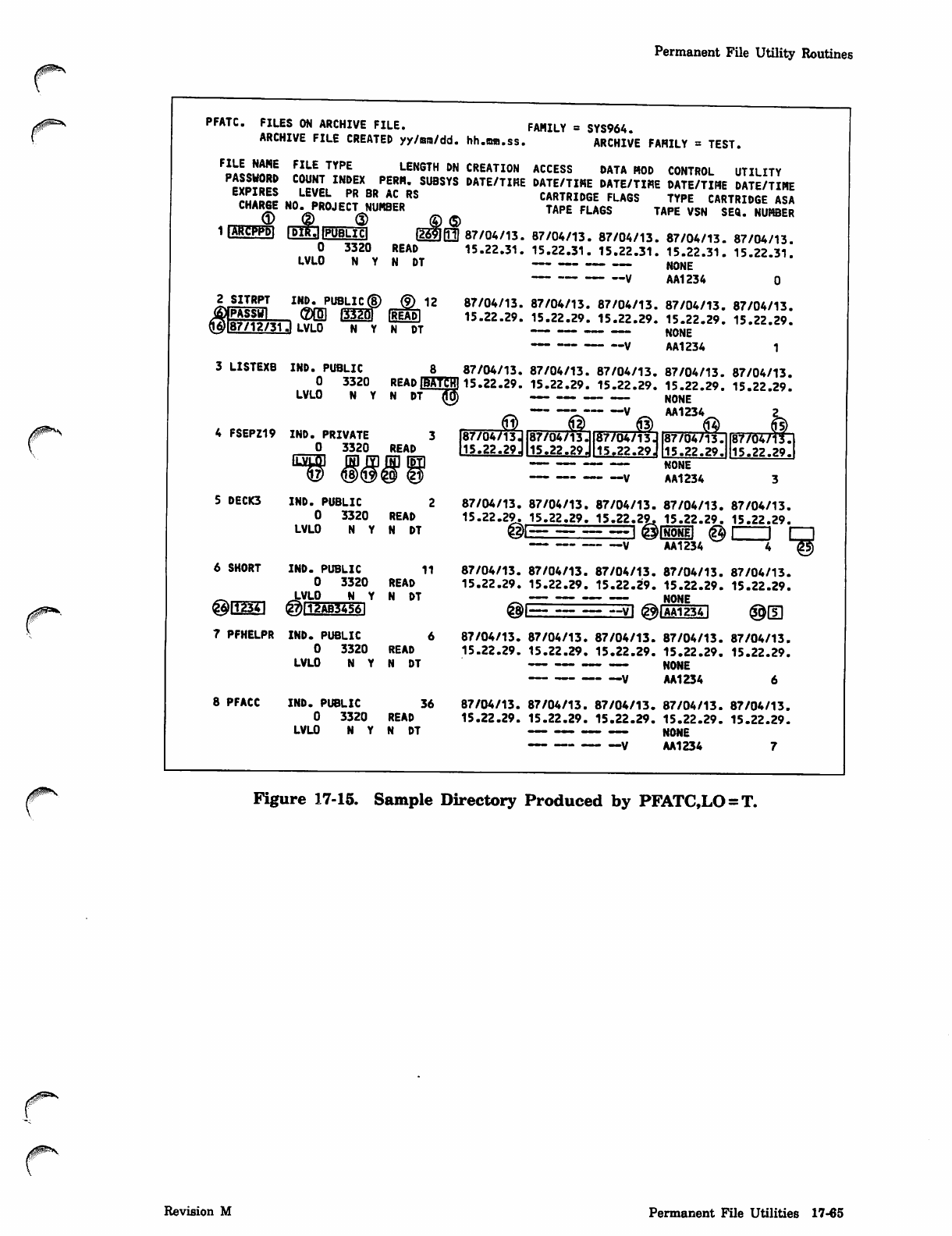
0j^S
Permanent File Utility Routines
0$ms
PFATC. FILES ON ARCHIVE FILE.
ARCHIVE FILE CREATED yy/ara/dd.
FILE NAME FILE TYPE LENGTH DN
PASSWORD COUNT INDEX PERU. SUBSYS
EXPIRES LEVEL PR BR AC RS
CHAR6E NO. PROJECT NUMBER
C D ® < 3 ) © ©
1 lAHCPfrbl rblltllPUBLicl fgggJBD
0 3 32 0 R EA D
LV L O N Y N D T
2 SITRPT IND. PUBLIC® (§) 12
pSsswI ®0 mm IreadI
87/12/31J LVLO N Y N DT
3 LISTEXB IND. PUBLIC 8
0 3320 READ IBATCHI
LV L O N Y N D T ( [ § 5
4 FSEPZ19 IND. PRIVATE 3
0 3 32 0 R EA D
FAMILY = SYS964.
hh.oa.ss. ARCHIVE FAHILY = TEST.
CREATION ACCESS DATA MOD CONTROL UTILITY
DATE/TIME DATE/TIME DATE/TIME DATE/TIME DATE/TIME
CARTRIDGE FLAGS TYPE CARTRIDGE ASA
TAPE FLA6S TAPE VSN SEQ. NUMBER
87/04/13. 87/04/13. 87/04/13. 87/04/13. 87/04/13.
15.22.31. 15.22.31. 15.22.31. 15.22.31. 15.22.31.
NONE
V A A 1 2 3 4 0
87/04/13. 87/04/13. 87/04/13. 87/04/13. 87/04/13.
15.22.29. 15.22.29. 15.22.29. 15.22.29. 15.22.29.
NONE
V A A 1 2 3 4 1
87/04/13. 87/04/13. 87/04/13. 87/04/13. 87/04/13.
15.22.29. 15.22.29. 15.22.29. 15.22.29. 15.22.29.
— N O N E
V ^ A A 1 2 3 4 2
^ J ® . S L S k f t
87/04/13
15.22.29
87/04/13
15.22.29
87/04/13
15.22.29
87/04/13.
15^22.29.
877547
15.22.29.
5 DECK3 IND. PUBLIC 2
0 3320 READ
L V L O N Y N D T
6 S H O R T I N D . P U B L I C 1 1
0 3 32 0 R EA D
_ _ J . V 1 0 N Y N D T
©ana @nMsnB
7 P F H E L P R I N D . P U B L I C 6
0 3 32 0 R EA D
LV L O N Y N D T
8 PFACC IND. PUBLIC 36
0 3 32 0 R EA D
LV L O N Y N D T
87/04/13. 87/04/13. 87/04/13.
15.22.29. 15.22.29. 15.22.29_,
87/04/13. 87/04/13. 87/04/13.
15.22.29. 15.22.29. 15.22.29.
NONE
AA1234
87/04/13.
15.22.29.
[none! @
AA1234
87/04/13.
15.22.29.
NONE
fivl VI ffilAA1234
87/04/13. 87/04/13. 87/04/13.
15.22.29. 15.22.29. 15.22.29.
87/04/13. 87/04/13. 87/04/13.
15.22.29. 15.22.29. 15.22.29.
87/04/13.
15.22.29,
NONE
AA1234
87/04/13.
15.22.29.
NONE
AA1234
87/04/13.
15.22.29.
LZZJ
4
87/04/13.
15.22.29,
87/04/13.
15.22.29.
87/04/13.
15.22.29.
Figure 17-15. Sample Directory Produced by PFATC,LO = T.
Revision M Permanent File Utilities 17-65
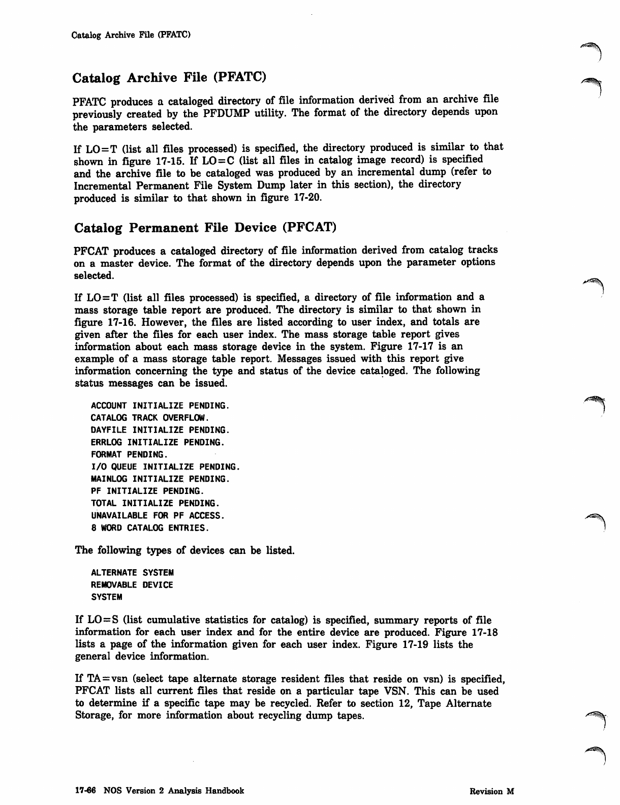
Catalog Archive File (PFATC)
Catalog Archive File (PFATC)
PFATC produces a cataloged directory of file information derived from an archive file
previously created by the PFDUMP utility. The format of the directory depends upon
the parameters selected.
If LO=T (list all files processed) is specified, the directory produced is similar to that
shown in figure 17-15. If LO=C (list all files in catalog image record) is specified
and the archive file to be cataloged was produced by an incremental dump (refer to
Incremental Permanent File System Dump later in this section), the directory
produced is similar to that shown in figure 17-20.
Catalog Permanent File Device (PFCAT)
PFCAT produces a cataloged directory of file information derived from catalog tracks
on a master device. The format of the directory depends upon the parameter options
selected.
If LO=T (list all files processed) is specified, a directory of file information and a
mass storage table report are produced. The directory is similar to that shown in
figure 17-16. However, the files are listed according to user index, and totals are
given after the files for each user index. The mass storage table report gives
information about each mass storage device in the system. Figure 17-17 is an
example of a mass storage table report. Messages issued with this report give
information concerning the type and status of the device cataloged. The following
status messages can be issued.
ACCOUNT INITIALIZE PENDING.
CATALOG TRACK OVERFLOW.
DAYFILE INITIALIZE PENDING.
ERRLOG INITIALIZE PENDING.
FORMAT PENDING.
I/O QUEUE INITIALIZE PENDING.
MAINLOG INITIALIZE PENDING.
PF INITIALIZE PENDING.
TOTAL INITIALIZE PENDING.
UNAVAILABLE FOR PF ACCESS.
8 WORD CATALOG ENTRIES.
The following types of devices can be listed.
ALTERNATE SYSTEM
REMOVABLE DEVICE
SYSTEM
If LO=S (list cumulative statistics for catalog) is specified, summary reports of file
information for each user index and for the entire device are produced. Figure 17-18
lists a page of the information given for each user index. Figure 17-19 lists the
general device information.
If TA=vsn (select tape alternate storage resident files that reside on vsn) is specified,
PFCAT lists all current files that reside on a particular tape VSN. This can be used
to determine if a specific tape may be recycled. Refer to section 12, Tape Alternate
Storage, for more information about recycling dump tapes.
17-66 NOS Version 2 Analysis Handbook Revision M
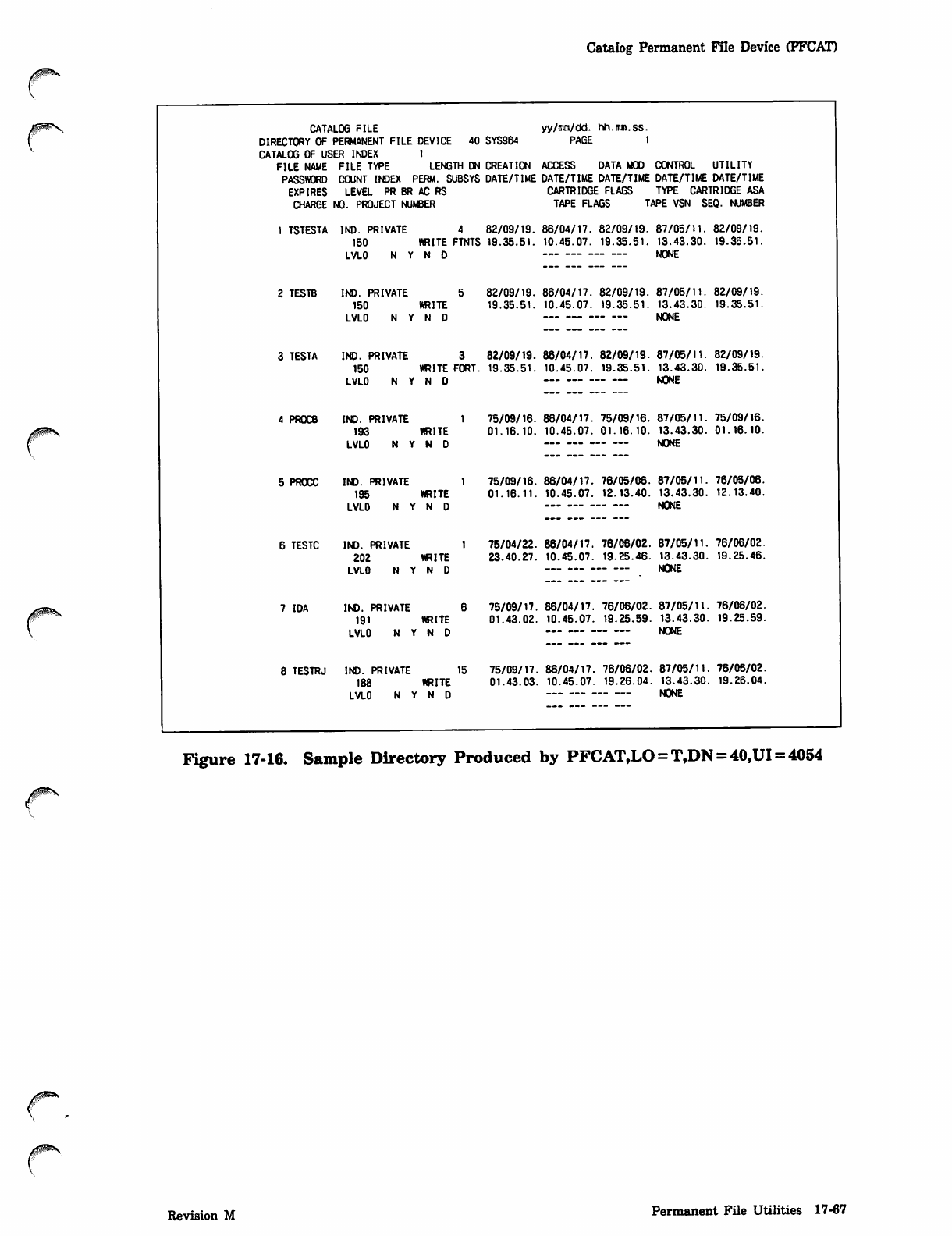
Catalog Permanent FUe Device (PFCAT)
CATALOG FILE yy/rom/dd. hh.mm.ss.
DIRECTORY OF PERMANENT FILE DEVICE 40 SYS964 PAGE 1
CATALOG OF USER INDEX t
FILE NAME FILE TYPE LENGTH DN CREATION ACCESS DATA MOD CONTROL UTILITY
PASSWORD COUNT INDEX PERM. SUBSYS DATE/TIME DATE/TIME DATE/TIME DATE/TIME DATE/TIME
EXPIRES LEVEL PR BR AC RS CARTRIDGE FLAGS TYPE CARTRIDGE ASA
CHARGE NO. PROJECT NUMBER TAPE FLAGS TAPE VSN SEQ. NUMBER
1 TSTESTA IND. PRIVATE 4 82/09/19. 86/04/17. 82/09/19. 87/05/11. 82/09/19.
150 WRITE FTNTS 19.35.51. 10.45.07. 19.35.51. 13.43.30. 19.35.51.
L V L O N Y N D N O N E
2 TESTB IND. PRIVATE 5 82/09/19.86/04/17.82/09/19.87/05/11.82/09/19.
150 WRITE 19.35.51. 10.45.07. 19.35.51. 13.43.30. 19.35.51.
L V L O N Y N D N O N E
3 TESTA IND. PRIVATE 3 82/09/19.86/04/17.82/09/19.87/05/11.82/09/19.
150 WRITE FORT. 19.35.51. 10.45.07. 19.35.51. 13.43.30. 19.35.51.
L V L O N Y N D — N O N E
4 PROCB IND. PRIVATE 1 75/09/16.86/04/17.75/09/16.87/05/11.75/09/16.
193 WRITE 01.16.10. 10.45.07. 01.16.10. 13.43.30. 01.16.10.
L V L O N Y N D N O N E
5 PRCCC IND. PRIVATE 1 75/09/16.86/04/17.76/05/06.87/05/11.76/05/06.
195 WRITE 01.16.11. 10.45.07. 12.13.40. 13.43.30. 12.13.40.
L V L O N Y N D N O N E
6 TE STC I ND. P RIVATE 1 7 5/0 4/2 2. 86 /04/17. 7 6/0 6/0 2. 87/05/ 11 . 7 6/0 6/0 2.
202 WRITE 23.40.27. 10.45.07. 19.25.46. 13.43.30. 19.25.46.
L V L O N Y N D N O N E
7 I D A I N D . P R I VAT E 6 7 5 / 0 9 / 1 7 . 8 6 / 0 4 / 1 7 . 7 6 / 0 6 / 0 2 . 8 7 / 0 5 / 11 . 7 6 / 0 6 / 0 2 .
191 WRITE 01.43.02. 10.45.07. 19.25.59. 13.43.30. 19.25.59.
L V L O N Y N D N O M E
8 TESTRJ IND. PRIVATE 15 75/09/17. 86/04/17. 76/06/02. 87/05/11. 76/06/02.
188 WRITE 01.43.03. 10.45.07. 19.26.04. 13.43.30. 19.26.04.
L V L O N Y N D - N O N E
Figure 17-16. Sample Directory Produced by PFCAT,LO = T,DN = 40,UI = 4054
J^**v
Revision M Permanent File Utilities 17-67
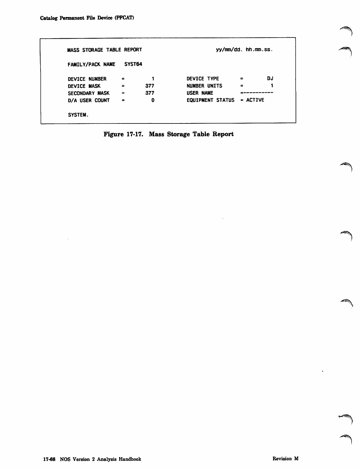
Catalog Permanent File Device (PFCAT)
MASS STORAGE TABLE REPORT yy/mm/dd. hh.mm.ss.
FAMILY/PACK NAME SYST64
DEVICE NUMBER DEVICE TYPE = DJ
DEVICE MASK
SECONDARY MASK
377
377
NUMBER UNITS = 1
UbtK NAME = —™~
D/A USER COUNT EQUIPMENT STATUS = ACTIVE
SYSTEM.
Figure 17-17. Mass Storage Table Report
•?^^\
17-68 NOS Version 2 Analysis Handbook Revision M
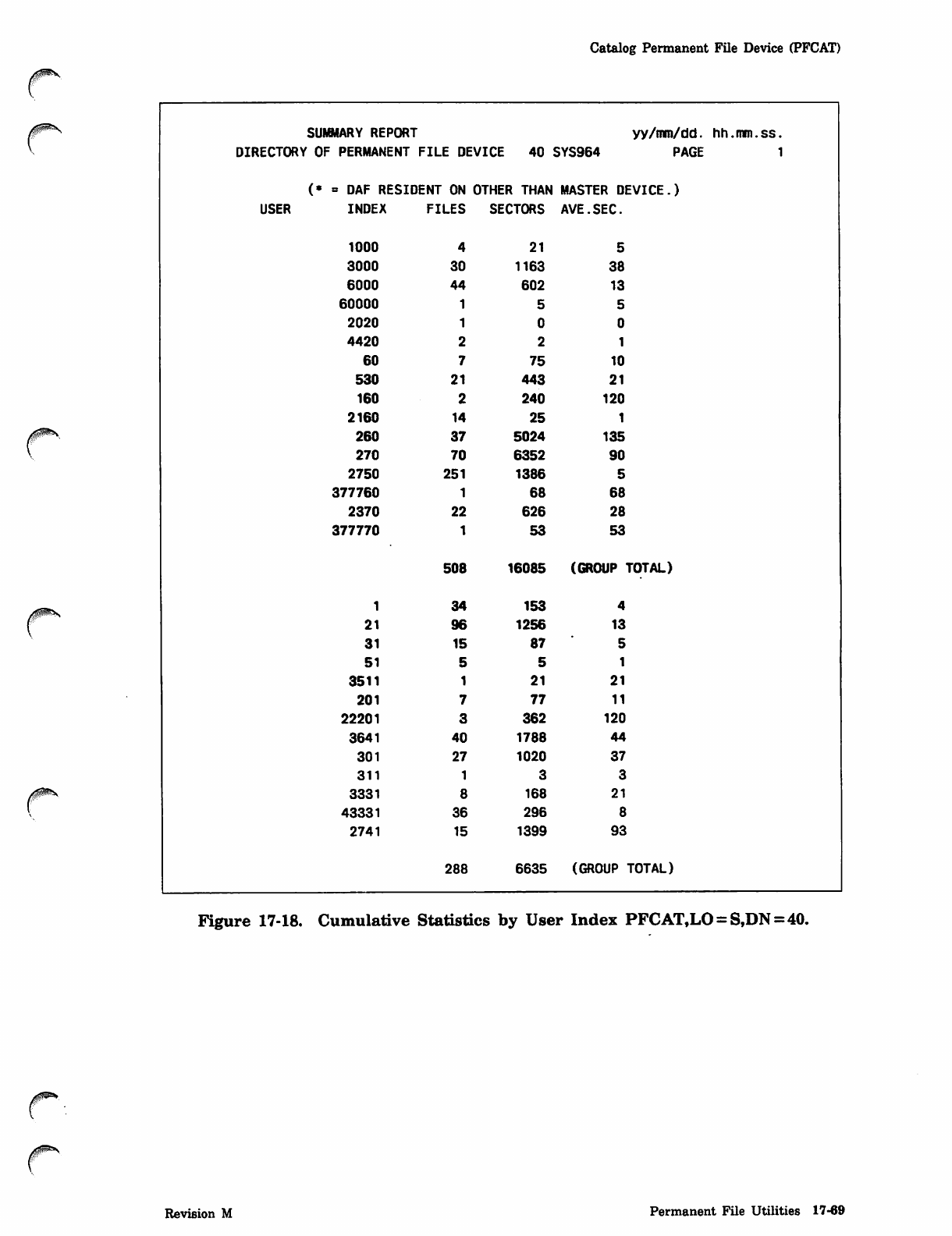
Catalog Permanent File Device (PFCAT)
yam^s
SUMMARY REPORT
DIRECTORY OF PERMANENT FILE DEVICE 40 SYS964
yy/mm/dd. hh.mm.ss.
P A G E 1
('
USER
= DAF RESIDENT ON OTHER THAN MASTER DEVICE.)
INDEX FILES SECTORS AVE.SEC.
1000 21
3000 30 1163 38
6000 44 602 13
60000
2020
4420
60 75 10
530 21 443 21
160 240 120
2160 14 25
260 37 5024 135
270 70 6352 90
2750 251 1386
377760 68 68
2370 22 626 28
377770 53 53
508 16085 (GROUP TOTAL)
134 153
21 96 1256 13
31 15 87
51
3511 21 21
201 77 11
22201 362 120
3641 40 1788 44
301 27 1020 37
311
3331 168 21
43331 36 296
2741 15 1399 93
288 6635 (GROUP TOTAL)
Figure 17-18. Cumulative Statistics by User Index PFCAT.LO = S,DN = 40.
Revision M Permanent File Utilities 17-69
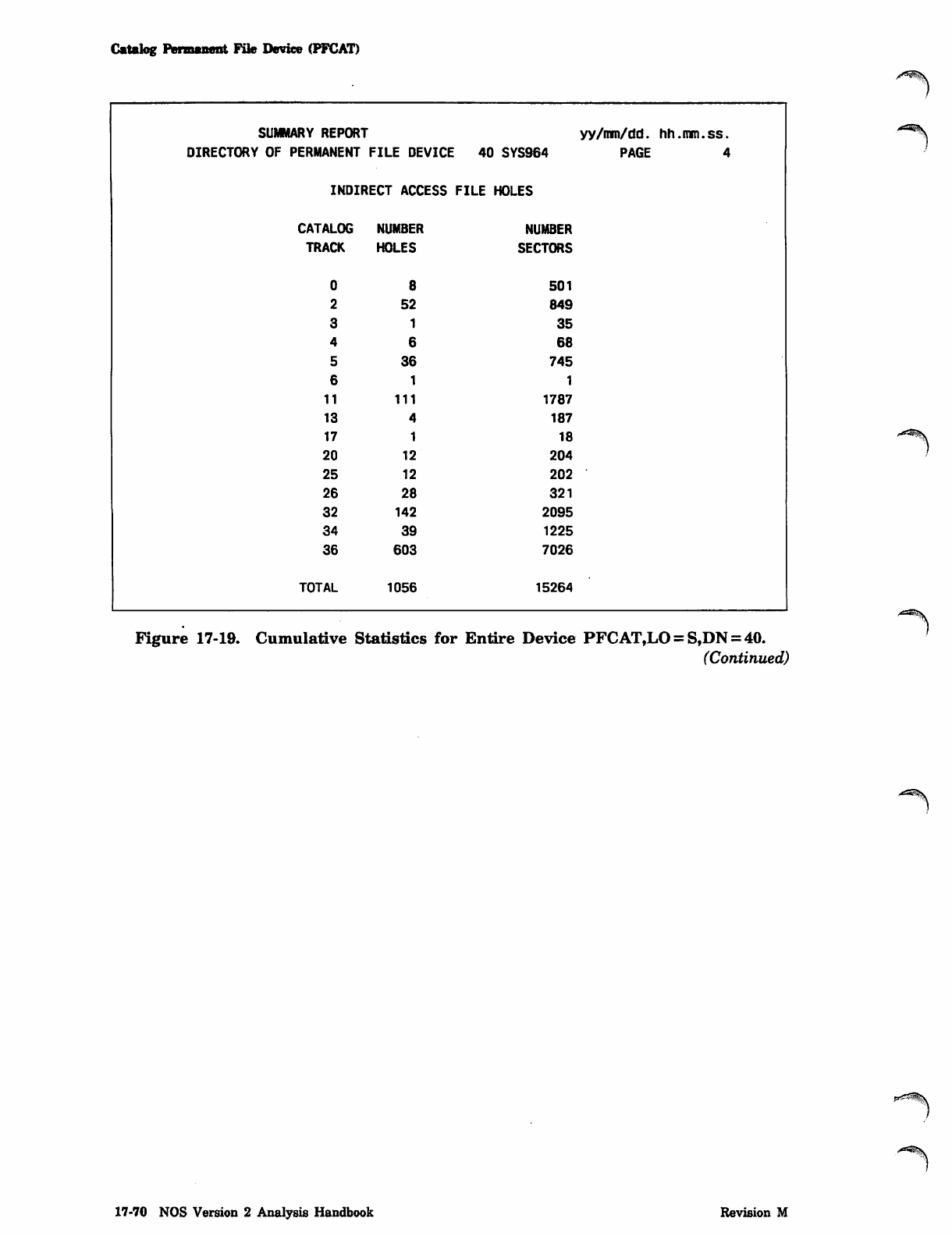
Catalog Permanent File Device (PFCAT)
SUMMARY REPORT yy/mm/dd. hh.mm.ss.
DIRECTORY OF PERMANENT FILE DEVICE 40 SYS964 PAGE 4
INDIRECT ACCESS FILE HOLES
CATALOG NUMBER NUMBER
TRACK HOLES SECTORS
08501
252 849
3135
4668
536 745
6 1 1
11 111 1787
13 187
17 18
20 12 204
25 12 202
26 28 321
32 142 2095
34 39 1225
36 603 7026
TOTAL 1056 15264
Figure 17-19. Cumulative Statistics for Entire Device PFCAT,LO = S,DN = 40.
(Continued)
17-70 NOS Version 2 Analysis Handbook Revision M
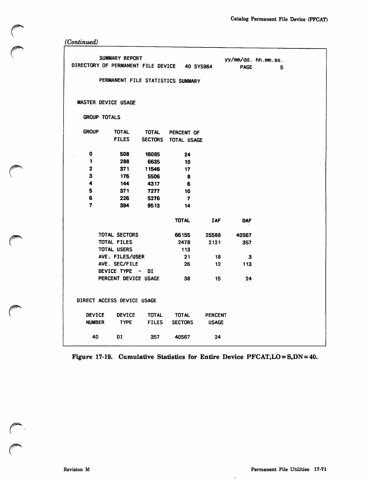
Catalog Permanent File Device (PFCAT)
r(Continued)
SUMMARY REPORT
DIRECTORY OF PERMANENT FILE DEVICE 40
yy/mm/dd. hh.mm
SYS964 PAGE
ss.
5
PERMANENT FILE STATISTICS SUMMARY
MASTER DEVICE USAGE
GROUP TOTALS
GROUP TOTAL
FILES
TOTAL
SECTORS
PERCENT OF
TOTAL USAGE
0
1
2
3
4
5
6
7
508
288
371
176
144
371
226
394
16085
6635
11546
5506
4317
7277
5276
9513
24
10
17
8
6
10
7
14
TOTAL IAF DAF
TOTAL SECTORS
TOTAL FILES
TOTAL USERS
AVE. FILES/USER
AVE. SEC/FILE
DEVICE TYPE - DI
PERCENT DEVICE USAGE
66155
2478
113
21
26
38
25588
2121
18
12
15
40567
357
3
113
24
DIRECT ACCESS DEVICE USAGE
DEVICE DEVICE
NUMBER TYPE
TOTAL
FILES
TOTAL
SECTORS
PERCENT
USAGE
4 0 D I 357 40567 24
Figure 17-19. Cumulative Statistics for Entire Device PFCAT;LO = S,DN = 40.
Revision M Permanent File Utilities 17-71
/^^Wv
Copy Archive FUe (PFCOPY)
Copy Archive File (PFCOPY)
PFCOPY extracts files from an archive file and copies them to one or more files local
to the job. The way the files are copied depends upon the parameter options selected.
If MF=filename is specified, all the files extracted from the archive file are copied to
one master file (filename) local to the job and they do not retain their permanent file
names.
In a secured system, the access level from the file's PFC entry is used to assign each
file to be copied to an appropriate mass storage device. If no device can be found that
allows the file to reside there, the PFCOPY utility skips the file and issues a
diagnostic message.
Dump Permanent File (PFDUMP)
PFDUMP copies (dumps) permanent files to backup storage (an archive file). Dumps
can be reloaded by the PFLOAD utility and can be accessed by the PFATC and
PFCOPY utilities for cataloging and copying. PFDUMP issues messages to the dayfile
indicating how many files were dumped and how many files were not dumped due to
errors. The type of dump taken depends upon the purpose of the dump and is
determined by the parameters selected. The defining characteristics of the three types
of dumps follow.
Types Characteristics '
Incremental OP=M is specified, and BD=yymmdd and BT=hhmmss are not
dump specified.
Partial dump Any dump that is not incremental and not full.
Full dump No file selection options (date/time interval, file size, file names,
etc.) except DN or TD are specified.
If PFDUMP encounters an unrecoverable parity error while writing the archive file,
several options are available via the K display. These options are described on the K
display. If the option to continue the dump on another reel of tape is selected (K.GO), ^^^
it may not be possible to recover in such a way as to ensure that the PFLOAD utility '^}
can successfully read the archive tape. At least the archived file being written at the
time of the error cannot be reloaded correctly.
17-72 NOS Version 2 Analysis Handbook Revision M
PFDUMP in a Secured System
PFDUMP in a Secured System
In a secured system, PFDUMP determines the maximum range of access levels that
can be dumped. If the LA and UA parameters have been used to select access level
limits, these limits will be used. If no access level limits were selected, PFDUMP uses
the device limits determined by taking the lowest lower access limit and the highest
upper access limit of all the devices to be dumped. The range of possible access levels
must be within the system access level limits or PFDUMP aborts the job and issues a
diagnostic message. The range of possible access levels must also be within the
equipment access level limits for the equipment (tape or mass storage) assigned to the
archive file and verify file (if one is being written). If not within the eguipment access
level limits, PFDUMP aborts the job and issues a diagnostic message.lg
Incremental Permanent File System Dump
An incremental dump copies those permanent files modified after a specified date; that
is, the OP=M option is specified together with the date (AD) and time (AT) options
but BD=yymmdd and BT=hhmmss are not specified. Other options specified on the
PFDUMP call can restrict the dump even further, but caution should be used when
doing so if the dumps are used as part of an incremental reload scheme.
For example, the command
PFDUMP,OP=MI,AD=790101,AT=100000.
causes only indirect access files (I parameter) modified after the specified date and
time to be dumped. Normal procedure at a site is to follow up this dump with
successive incremental dumps (usually with a periodic advancement of date and/or
time). This produces a series of archive files containing successive updating of all
files in the defined category. (These files can reside on one file: a multifile archive
file.) The archive files can then be incrementally loaded (refer to the PFLOAD utility
described later in this section) to return the most recently modified versions of the
archived files to the permanent file system.
Each incremental dump writes a record (or records) at the beginning of the archive
file it creates. The record contains catalog images (refer to Catalog Image Record
later in this section) of all files active on the device(s) being dumped when the dump
took place (files with no backup requirement (BR=N) are not included on the catalog
image record unless OP = Y is specified). This enables a future incremental load of
these files on a system or a device basis.
An example of incremental dumping is given under Load Permanent File (PFLOAD)
later in this section.
18. The system access level limits are displayed as part of the left screen header. The device access level
limits (for mass storage) and equipment access level limits (for magnetic tape) are displayed on the E,A
display. Refer to the NOS Version 2 Operations Handbook for display formats.
Revision M Permanent File Utilities 17-73
Partial Permanent File System Dump
Partial Permanent File System Dump
A partial dump copies permanent files according to any specified option(s), except
those defining a full or incremental dump. For example, the command
PFDUMP,OP=D.
is a partial dump of all direct access permanent files.19 Similarly, a dump of all files
created (OP=C) or accessed (OP=A) after a certain date is a partial dump.
A partial dump can dump files from a certain device (DN or TD option) or can dump
all files in the system (DN and TD not specified) that meet the criteria of the
specified options.
Full Permanent File Dump
19
A full dump copies all files in the system or those cataloged on a specified device; no
file selection options are specified except possibly DN (for a master device) or TD.
PFDUMP File Interlocking
PFDUMP interlocks a catalog track during the time it takes to dump all files whose
PFC entries reside on that catalog track. No permanent file commands are processed
on files whose PFC entries reside there until PFDUMP begins processing the next
catalog track but jobs with direct access files attached are unaffected. For this reason,
full permanent file dumps should not be done during heavy system use. An incremental
dump provides adequate backup with less interference to the running system. PFDUMP
skips any direct access files attached by jobs in write, modify, or append mode. Files
attached in a non-writable mode or in update mode are dumped.
PFDUMP in an MSE or Tape Alternate Storage Environment
Because a large percentage of the total permanent file data typically does not reside on
disk in a tape alternate storage or MSE environment, performing full backup dumps of
file data is impractical. Whether PFDUMP dumps the data of a selected file depends
on the user specified backup requirement, the PFDUMP parameters selected, and the
number of backup copies that exist. If these criteria do not require a data dump, only ^_
the file's PFC entry and permits are written to the dump file. ^j
The pertinent PFDUMP parameters are:
Parameter Description
OP=Y Treat all files as though the user specified a backup requirement of
yes (BR=Y).
COS=size PFC only size threshold. For all files with a file size greater than or
equal to the specified size and for which the file's backup
requirement is met by alternate storage copies, dump only the PFC
and permits (do not dump the file data even if the data is available
on disk).
OP=S Suppress staging of file data from alternate storage if a data dump
is selected and the file is not disk resident.
19. Files with a backup requirement of none (BR=N) are not dumped unless OP=Y is specified.
17-74 NOS Version 2 Analysis Handbook Revision M
0ms
PFDUMP in an MSE or Tape Alternate Storage Environment
The decision hierarchy for PFDUMP operations is as follows:
• If OP=Y is specified, force the file's backup requirement to yes (BR=Y).
• If the file backup requirement is none (BR=N), do not dump the file.
• If the file size is less than the value specified by the COS parameter, select a
data dump.
• If the file size is greater than or equal to the value specified by COS:
- and the backup requirement is media dependent (BR=MD) and no alternate
storage copy exists, select a data dump.
- and the backup requirement is media dependent (BR=MD) and at least one
alternate storage copy exists on MSE or tape, select a PFC and permits only
dump.
- and the backup requirement is yes (BR=Y) and less than two alternate
storage copies exist on MSE or tape, select a data dump.
- and the backup requirement is yes (BR=Y) and two or more alternate storage
copies exist on MSE or tape, select a PFC and permits only dump.
• If a PFC and permits only dump is selected, write the file's PFC entry and
permits to the dump file.
• If a data dump is selected:
f - and the file is disk resident, write the file's PFC entry, permits, and data to
the dump file.
- and the file is not disk resident and staging is not suppressed (OP=S
omitted), stage the file data to disk from MSE or tape alternate storage and
write the file's PFC entry, permits, and data to the dump file.
- and the file is not disk resident and staging is suppressed (OP=S specified),
write the file's PFC entry and permits to the dump file.
(^ A typical set of PFDUMP parameters that a site might use for full and incremental
backup dumps is:
OP=Y not specified.
COS set to some reasonably small value or zero (default is 0).
OP=S specified.
0^S
Revision M Permanent File Utilities 17-75
PFDUMP Protected Files
If only tape alternate storage is in use and secondary VSNs have been created on all
tape destaging operations, the OP = S option does not have to be specified since the ^^
backup requirement for all files is met. Specifying a nonzero value for COS may reduce '
the amount of staging activity following a permanent file reloading operation. However,
files larger than or equal to the COS value will have to be staged back to disk in such
a situation since only the PFC and permits will be reloaded. m
When a partial PFDUMP is performed to move files to a different user name, family,
or system, it may be desirable to force a dump of the file data and clear the
alternate storage information in the files' PFC entries depending on the situation. If
files are being moved to a user name on the same family or to a different family on
the same machine, there should be no need to dump the data of files residing only on
tape alternate storage since the ability to stage files from tape does not depend on
the family or user index under which a file is cataloged. If files are to be moved to a
remote machine or if any of the files have an image on MSE, the file data should be
dumped and the alternate storage information should be cleared either by PFDUMP
or on the subsequent PFLOAD. This can be accomplished by specifying the following
parameters:
OP=S not specified.
COS=* set to select unlimited PFC only size threshold.
OP=Z specified.
Unlimited COS must be specified to select a data dump for all files having a backup
requirement of yes (BR=Y). The OP=Z parameter could be specified on the PFLOAD
instead of the PFDUMP, but it is recommended that it be done at dump time so that
the operator does not have to remember to do it at load time.
PFDUMP Protected Files
When PFDUMP specifies purging of files (OP=P), files whose user indexes are greater
than PGUI (default value is 300000s) are not purged. This is done to prevent files such
as critical recovery files, applications, and system utilities from being purged from the
system due to lack of use.
17-76 NOS Version 2 Analysis Handbook Revision M
J0&\,
r
Load Permanent File (PFLOAD)
Load Permanent File (PFLOAD)
PFLOAD loads archived files produced by the PFDUMP utility back into the
permanent file system. The load can reestablish the permanent file system exactly as it
was at the time of the dump, or can load only a desired subset of files on the archive
file (as indicated by specified parameters). PFLOAD issues messages to the dayfile
indicating how many files were loaded and how many files with errors were
encountered.
If LO=T (list all files processed) is specified, the listing produced is similar to that
shown in figure 17-15. If LO=C (list all files in the catalog image record) is
specified, the listing produced is similar to that shown in figure 17-20.
The two types of loads available are incremental and nonincremental. An incremental
load builds up (increments) an accumulation of the most recently modified versions of
the files extracted from the archive files for loading. A series of archive files is read
in the reverse order of creation. The CIR created by the most recent incremental
dump is read and checked against the archived files on these files. If a file matches
an entry on the CIR, that file is a candidate for loading. A nonincremental load does
no CIR checking and uses only parameters specified on the PFLOAD call, if any, to
select candidates for loading.
Revision M Permanent File Utilities 17-77
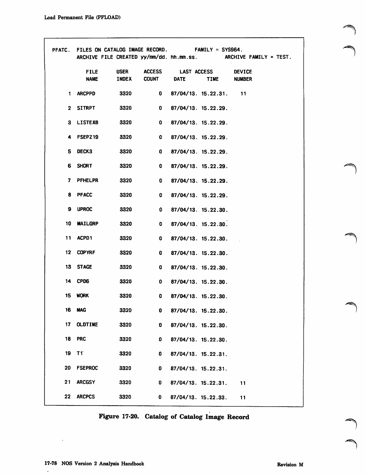
Load Permanent File (PFLOAD)
PFATC. FILES ON
ARCHIVE
CATALOG IMAGE RECORD.
FILE CREATED yy/mm/dd.
FAMILY = SYS964.
hh.mm.ss. ARCHIVE FAMILY = TEST.
FILE
NAME
USER
INDEX
ACCESS
COUNT
LAST ACCESS
DATE TIME
DEVICE
NUMBER
1ARCPPD 3320 87/04/13. 15.22.31. 11
2SITRPT 3320 87/04/13. 15.22.29.
3LISTEXB 3320 87/04/13. 15.22.29.
4FSEPZ19 3320 87/04/13. 15.22.29.
5DECK3 3320 87/04/13. 15.22.29.
6SHORT 3320 87/04/13. 15.22.29.
7PFHELPR 3320 87/04/13. 15.22.29.
8PFACC 3320 87/04/13. 15.22.29.
9UPROC 3320 87/04/13. 15.22.30.
10 MAILGRP 3320 87/04/13. 15.22.30.
11 ACPD1 3320 87/04/13. 15.22.30.
12 COPYRF 3320 87/04/13. 15.22.30.
13 STAGE 3320 87/04/13. 15.22.30.
14 CPD6 3320 87/04/13. 15.22.30.
15 WORK 3320 87/04/13. 15.22.30.
16 MAG 3320 87/04/13. 15.22.30.
17 OLDTIME 3320 87/04/13. 15.22.30.
18 PRC 3320 87/04/13. 15.22.30.
19 T1 3320 87/04/13. 15.22.31.
20 FSEPROC 3320 87/04/13. 15.22.31.
21 ARCGSY 3320 87/04/13. 15.22.31. 11
22 ARCPCS 3320 87/04/13. 15.22.33. 11
Figure 17-20. Catalog of Catalog Image Record ^*^%v
17-78 NOS Version 2 Analysis Handbook Revision M
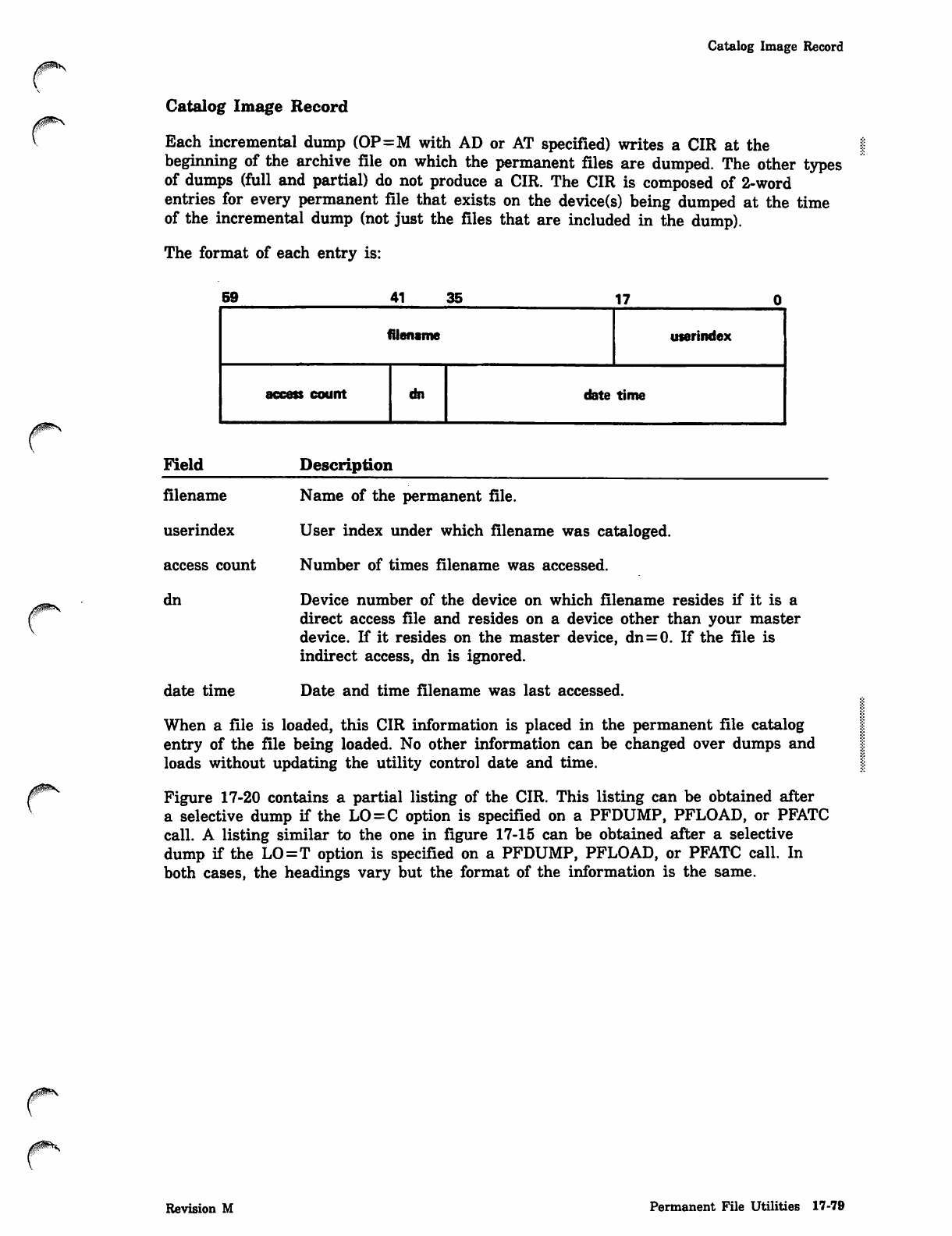
Catalog Image Record
0tms Catalog Image Record
Each incremental dump (OP=M with AD or AT specified) writes a CIR at the
beginning of the archive file on which the permanent files are dumped. The other types
of dumps (full and partial) do not produce a CIR. The CIR is composed of 2-word
entries for every permanent file that exists on the device(s) being dumped at the time
of the incremental dump (not just the files that are included in the dump).
The format of each entry is:
r
0ms
69 41 35 17
filename userindex
access count dn date time
Field Description
filename
userindex
access count
dn
date time
Name of the permanent file.
User index under which filename was cataloged.
Number of times filename was accessed.
Device number of the device on which filename resides if it is a
direct access file and resides on a device other than your master
device. If it resides on the master device, dn = 0. If the file is
indirect access, dn is ignored.
Date and time filename was last accessed.
When a file is loaded, this CIR information is placed in the permanent file catalog
entry of the file being loaded. No other information can be changed over dumps and
loads without updating the utility control date and time.
Figure 17-20 contains a partial listing of the CIR. This listing can be obtained after
a selective dump if the LO=C option is specified on a PFDUMP, PFLOAD, or PFATC
call. A listing similar to the one in figure 17-15 can be obtained after a selective
dump if the LO=T option is specified on a PFDUMP, PFLOAD, or PFATC call. In
both cases, the headings vary but the format of the information is the same.
Revision M Permanent File Utilities 17-79
PFLOAD Selection Process
PFLOAD Selection Process
Execution of the PFLOAD utility involves the following stages to determine which
permanent files (from the archive file) should be loaded and on which devices they
should reside.
1. If the DN, TD, or DD parameters are used, the device number specified refers to
a device in the running system and must exist in the family being loaded or
PFLOAD aborts and issues this message:
PFLOAD - DEVICE nn NOT FOUND.
2. If the specified parameters logically imply that no files can be selected (such as
OP=I, DN=n where n is not a master device), PFLOAD aborts and issues this
message:
PFLOAD - NO FILES SELECTED.
3. The user index mask for selecting files (based on the device mask of the device
specified by the DN and DI parameters) must be such that it is possible for some
files to be on the archive file. There must be some common bits between the
device mask of the archive file (written in the header record by PFDUMP) and
the device mask of the device specified by the DN parameter for PFLOAD. If no
common bits exist, PFLOAD aborts and issues this message:
PFLOAD - SELECTED FILES NOT ON ARCHIVE FILE.
4. For nonincremental loads, this stage of checking is bypassed and the entire
archive file to be loaded is passed on to the next stage.
The first step is to read the CIR from the most recent selective incremental dump
file and place it on a random file. Then the archive files are read in the reverse
order in which they were created (the most recently created file is read first).
Each file on an archive file is checked against the CIR on the random file for a
match of file name and user index (these fields describe a file uniquely in a
family). If a match is found, the file is a candidate for loading and moves to the
next stage of checking. Also, the file name and user index are zeroed out in the
corresponding CIR entry to prevent subsequent loading of older versions of the
same file. If a match is not found, the file is skipped because it has already been
accepted (it appeared on a previous archive file and a match with the CIR was
found) or has been purged. This process passes on only the latest versions of files
obtained from the archive files.
5. Only files that satisfy the criteria specified by the parameters on the PFLOAD
command are selected (date/time, direct or indirect, user index, file name, and so
forth). All other files are skipped.
/rfS8|k
17-80 NOS Version 2 Analysis Handbook Revision M
A^m\
0l$ms
PFLOAD Selection Process
The DN and TD parameters are used to select files from the archive file and to
determine the device on which the files should be loaded. The device number
specified refers to a device in the running system.
Indirect access files, if selected, are always loaded on the appropriate master
device (based on user index). Direct access files, if selected, are loaded on the
device on which they previously resided. This is the device number contained in
the file's PFC entry on the archive file. If the device number is 0, the file
previously resided on the master device and will be reloaded there.
It may not be possible to load a direct access file on the device on which it
previously resided because the device number may no longer exist or its secondary
mask may not allow it. (Refer to Device Masks earlier in this section for
additional information.) Either of these situations can occur as a result of a
reconfiguration of the permanent file system. In either case, if a direct access file
cannot be loaded, the DD parameter is checked. If an alternate device is specified
and its secondary mask allows it, the file is loaded on the alternate device.
Otherwise, the OP=L option is checked (see step 7). If the OP = L option is not
specified, PFLOAD skips the file and issues this message:
PFLOAD - ALTERNATE DEVICE NOT FOUND,FN=filename,Ul=userindex.
The DN parameter is used to select files from the archive file in the following
manner. If the device specified by DN (in the running system) is a master device,
all files (direct and indirect) that would be cataloged on the master device (files
with user indexes corresponding to that device's device mask) are selected. If the
device specified by DN is not a master device, only direct access files that
previously resided on the device (files with a device number of DN in their PFC
entry) are selected.
Similarly, the TD parameter is used to select files from the archive file in the
following manner. If the device specified by TD is a master device, all files that
were cataloged on it and all direct access files that previously resided on it are
selected. (This corresponds to the way the TD parameter is processed by
PFDUMP.) If the device specified by TD is not a master device, only direct access
files that previously resided on it are selected.
If neither the DN nor TD parameters are specified, all files meeting other
selection criteria are selected. Specifying both DN and TD has the same effect as
specifying only TD.
In all cases, the device masks and master device status for the devices specified
by the DN or TD parameters refer to the system in which PFLOAD is running,
not the system in which the files were dumped. The user index and device
number from the PFC on the archive file reflect the situation that existed at the
time the files were dumped.
If the OP=L option is specified, the device selected in step 6 (or the failure to
select a device) for the residence of a direct access file is ignored. PFLOAD
determines the device, among those devices where the file may reside (based on
the device mask), which has the most available space. The OP=L option is not
applicable to indirect access files since they must reside on the appropriate master
device.
Revision M Permanent File Utilities 17-81
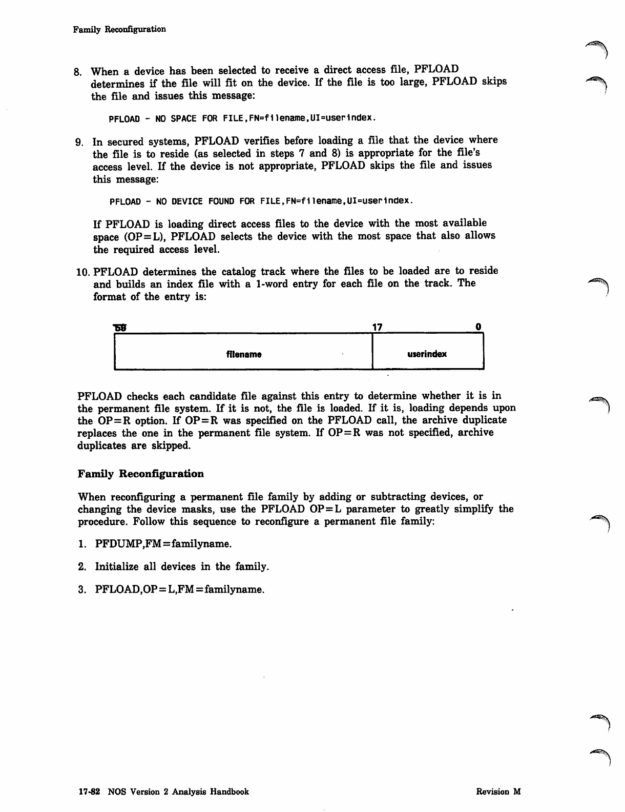
Family Reconfiguration
8. When a device has been selected to receive a direct access file, PFLOAD
determines if the file will fit on the device. If the file is too large, PFLOAD skips "^
the file and issues this message:
PFLOAD - NO SPACE FOR FILE,FN=f1lename,UI=userIndex.
9. In secured systems, PFLOAD verifies before loading a file that the device where
the file is to reside (as selected in steps 7 and 8) is appropriate for the file's
access level. If the device is not appropriate, PFLOAD skips the file and issues
this message:
PFLOAD - NO DEVICE FOUND FOR FlLE,FN=filename,UI=user1ndex.
If PFLOAD is loading direct access files to the device with the most available
space (OP=L), PFLOAD selects the device with the most space that also allows
the required access level.
10. PFLOAD determines the catalog track where the files to be loaded are to reside
and builds an index file with a 1-word entry for each file on the track. The ^%
format of the entry is:
- 5 * 1 7
filename userindex
PFLOAD checks each candidate file against this entry to determine whether it is in ^^
the permanent file system. If it is not, the file is loaded. If it is, loading depends upon 1
the OP=R option. If OP=R was specified on the PFLOAD call, the archive duplicate
replaces the one in the permanent file system. If OP=R was not specified, archive
duplicates are skipped.
Family Reconfiguration
When reconfiguring a permanent file family by adding or subtracting devices, or
changing the device masks, use the PFLOAD OP=L parameter to greatly simplify the
procedure. Follow this sequence to reconfigure a permanent file family: >*s^
1. PFDUMP,FM=familyname.
2. Initialize all devices in the family.
3. PFLOAD,OP=L,FM =familyname.
17-82 NOS Version 2 Analysis Handbook Revision M
0^S
PFLOAD in an MSE or Tape Alternate Storage Environment
PFLOAD in an MSE or Tape Alternate Storage Environment
In an MSE or tape alternate storage environment, an incremental load as described
previously is the typical reload procedure. PFLOAD uses the CIR from the first
incremental dump file to control the loading of file data and PFC and permit entries.
For files with alternate storage copies, the files' data may not have been copied to the
dump tape (refer to PFDUMP in an MSE or Tape Alternate Storage Environment
earlier in this section for more information on how PFDUMP decides whether to dump
a file's data or to dump only the file's PFC entry and permits). PFLOAD reloads only
what was dumped by PFDUMP. Thus, if the file data was included on the dump tape,
it will be reloaded to disk. If the file data was omitted from the dump tape, only the
PFC and permit information for the files will be reloaded. Refer to section 11, MSE, or
to section 12, Tape Alternate Storage, for further information on how the PFLOAD
utility is used in an MSE or tape alternate storage environment.
0$ms
Revision M Permanent File Utilities 17-83
PFDUMP/PFLOAD Example
PFDUMP/PFLOAD Example
In this example, permanent files created and modified on three devices are dumped
nine times. The action runs from March 1, 1982 (82.3.1) to March 10, 1982 (82.3.10).
To keep things simple, the time of day is not shown. Before the last dump, one of the
devices becomes inoperable. The example then shows how this device can be loaded
from the archive tapes. Following are the three devices.
Device Description
>»^K
40
41
42
A master device containing indirect access files only. Users with this
master device have their direct access files written on 41 or 42.
A master device containing indirect and direct access files. Direct access
files cataloged on this device may be written on 42 or this device.
A nonmaster device containing direct access files only. All files written on
this device will be cataloged on 40 or 41.
File names consist of a letter and a number. The letter identifies which device contains
the catalog entry for this file (A=device 40 and B=device 41). The number is the
same as the device on which the file is written.
Each file name is followed by a date in parentheses. This indicates either the day on
which the file was created or when it was last modified.
Figure 17-21 outlines the creation, modifications, and dumps that were made. There
is one particular action per column. The top of the column identifies the action and
the key parameters used by the utility. If an archive tape is produced, it is shown at
the bottom of the column. All files in the system are listed in each column. Those
files affected by the action are underscored.
- " ^ v
17-84 NOS Version 2 Analysis Handbook Revision M
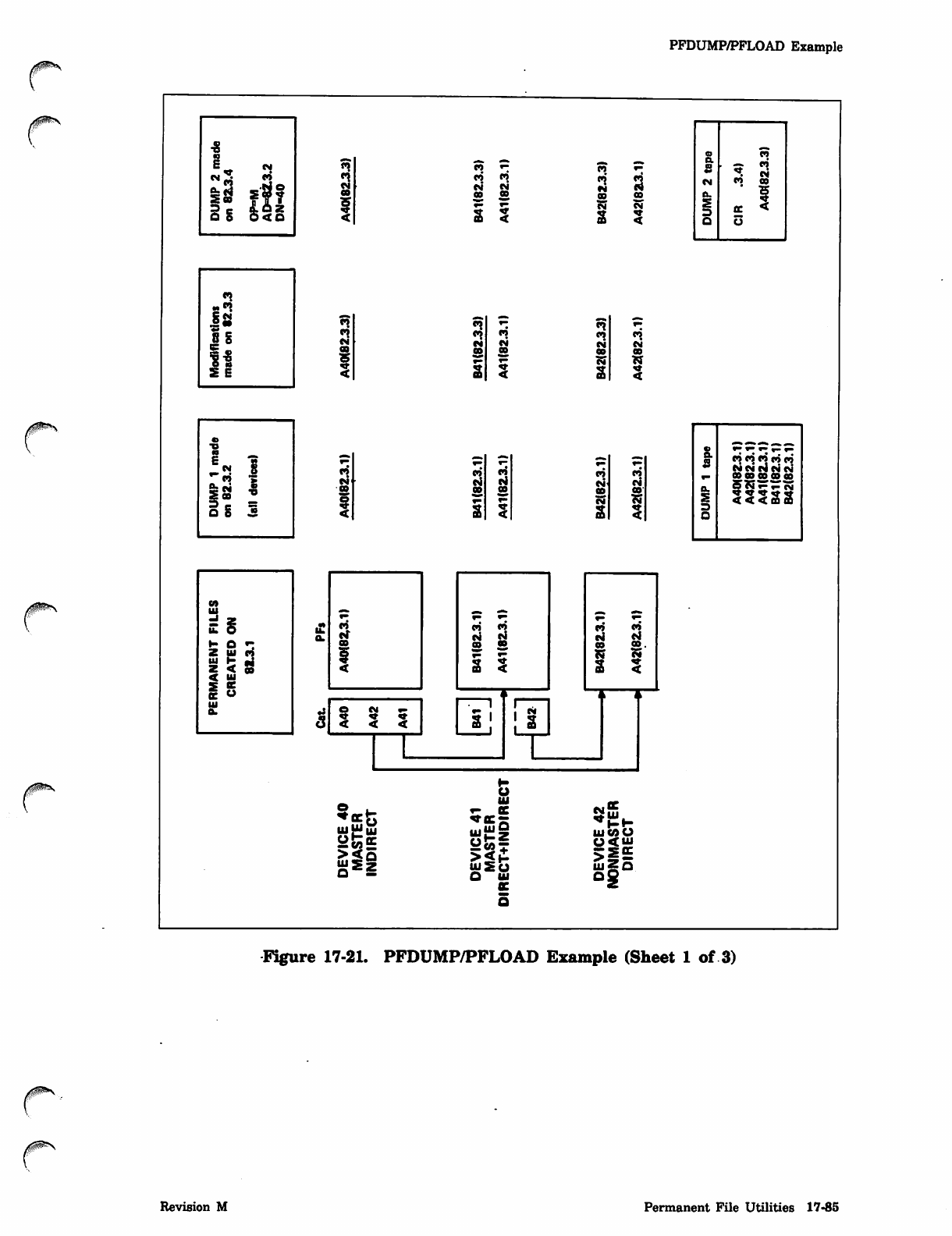
PFDUMP/PFLOAD Example
mCO
•8•3
n 2 « en cn
|S iff CO
¥
<
CM
•
<
<o •-
CM
CO CO
CM CM
2<
tn
a
a
Xi ' ^
CM
CM to 00
CU
s
3cc
au
/||S*\
r
«** cn
CM CM
00 CO
2 5
CM
CO
W
<
p•—
cn ri
*i r4
00 00
*»
2 5
»~ »~
cn cn
«N CM
CD 00
CM
2
a.
S
3A40O2.3.1) A42182.3.1)A4K82.3.1) B41 (82.3.1) B42(82.3.1)
O
w
UJ
Hf»
ZUl to
UJ ri
Z<CP
<Ul
yCB
oc
Ul
a.
•" » ^ ^
Om
en
or
00
<B4K82.3. A4K82.3 842(82.3. A4218Z3.
i L 1, J
«i O C M x t
(3 * * r * »
< < < 2 '
UJ^UJ
£>fcEE
><5 Scot
><£
uJSo
O u i
Ct
IUCOO
>S££
uZq
Og
Figure 17-21. PFDUMP/PFLOAD Example (Sheet 1 of 3)
Revision M Permanent File Utilities 17-85
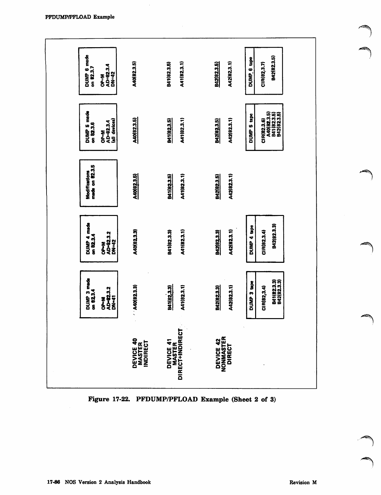
PFDUMP/PFLOAD Example
in
<•*
CM
00
I
45 1
-3
13
3f tit
00
¥
<
CM
»3 tn
1^ ike§s
cn
cn*
00
¥
«? *.
cn cn
eo 00 00
^T* <N
2 < 2
cn T~
cn vi
CM ti
ca to
f»
25
I
eo
2
UlUjUj
S2fcSE
><o
g s z
ui
fiC
5
cn
rJ
oo
<
«j
flc t n
^ C M *
co t o e o
S
2
e o ' * *
C C ™ *
5
3
00
Ti
5
U»U» UJ
at cn cn cn
CO^ 00 00 00
rr <! SO CO
T~ If)
Icn
CM ri
00 00
•» Ki
< 2
cn »•
cn cn
r4 tx
00 00
ntM
2 3
cn
a**• cn
*cn 00
a.
S
§
r4
00
cc
5
CM
2
3 §
o e n
2 3
2ui
UJWO
uJzo
oo
cncn
533
cn cn (0 00
«- CM
*: 00 22
oo
/ - ^ K
^^S
Figure 17-22. PFDUMP/PFLOAD Example (Sheet 2 of 3)
/-fiS*\
17-86 NOS Version 2 Analysis Handbook Revision M
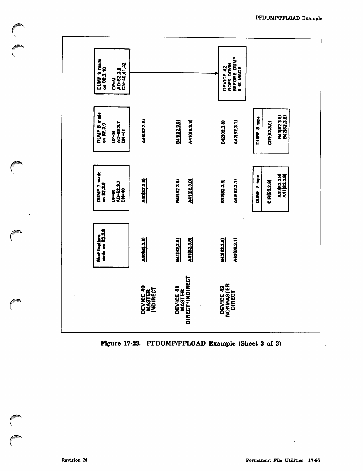
PFDUMP/PFLOAD Example
DEVICE 42 GOES DOWN BEFORE DUMP 9 IS MADE
* C M
E e c o *
is &l§
"5 3~
gg
en
ol
eo
S
CM
CO
3
ft OOOO
sS> ejen
CM CM
00 1* oooo
a. CM izn
S
3e22
Oo
•81fo. 00
•^S cn en
og
SS$ to
00
5<Q
«*i 3
o o o o
C M C M
2 3
s.
0
oooo
^-^ tn tn
O) CM CM-
r* CD 00
2
3
o«-
00 *»«•
oc <<
OCJ
«M
00 (4
eo
UjUllU
XO
ujUjO
><£
O u i
CE
5
2 <
™uj
UJCOO
>SE
uiZO
Og
Figure 17-23. PFDUMP/PFLOAD Example (Sheet 3 of 3)
s$&s
Revision M Permanent File Utilities 17-87
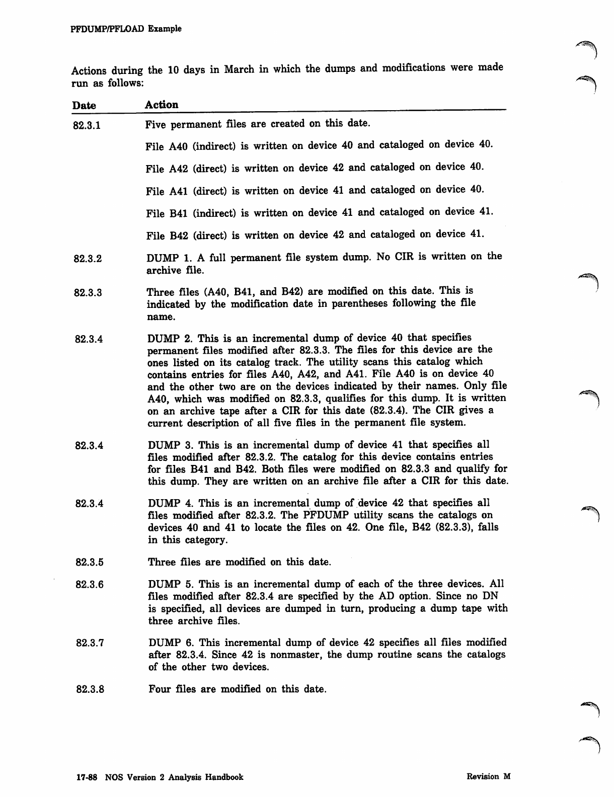
PFDUMP/PFLOAD Example
Actions during the 10 days in March in which the dumps and modifications were made
run as follows: ^
Date Action
82.3.1 Five permanent files are created on this date.
File A40 (indirect) is written on device 40 and cataloged on device 40.
File A42 (direct) is written on device 42 and cataloged on device 40.
File A41 (direct) is written on device 41 and cataloged on device 40.
File B41 (indirect) is written on device 41 and cataloged on device 41.
File B42 (direct) is written on device 42 and cataloged on device 41.
82.3.2 DUMP 1. A full permanent file system dump. No CIR is written on the
archive file.
82.3.3 Three files (A40, B41, and B42) are modified on this date. This is
indicated by the modification date in parentheses following the file
name.
82.3.4 DUMP 2. This is an incremental dump of device 40 that specifies
permanent files modified after 82.3.3. The files for this device are the
ones listed on its catalog track. The utility scans this catalog which
contains entries for files A40, A42, and A41. File A40 is on device 40
and the other two are on the devices indicated by their names. Only file
A40, which was modified on 82.3.3, qualifies for this dump. It is written ^^
on an archive tape after a CIR for this date (82.3.4). The CIR gives a
current description of all five files in the permanent file system.
82.3.4 DUMP 3. This is an incremental dump of device 41 that specifies all
files modified after 82.3.2. The catalog for this device contains entries
for files B41 and B42. Both files were modified on 82.3.3 and qualify for
this dump. They are written on an archive file after a CIR for this date.
82.3.4 DUMP 4. This is an incremental dump of device 42 that specifies all ^^
files modified after 82.3.2. The PFDUMP utility scans the catalogs on J-^
devices 40 and 41 to locate the files on 42. One file, B42 (82.3.3), falls
in this category.
82.3.5 Three files are modified on this date.
82.3.6 DUMP 5. This is an incremental dump of each of the three devices. All
files modified after 82.3.4 are specified by the AD option. Since no DN
is specified, all devices are dumped in turn, producing a dump tape with
three archive files.
82.3.7 DUMP 6. This incremental dump of device 42 specifies all files modified
after 82.3.4. Since 42 is nonmaster, the dump routine scans the catalogs
of the other two devices.
82.3.8 Four files are modified on this date.
17-88 NOS Version 2 Analysis Handbook Revision M
yims
PFDUMP/PFLOAD Example
Date Action
82.3.9 DUMP 7. An incremental dump of device 40 is made with AD=82.3.7.
Two files qualify.
82.3.9 DUMP 8. An incremental dump of device 41 is made with AD=82.3.7.
The catalog on device 41 contains entries for files B41 and B42. File
B41 is an indirect access file located on device 41, and file B42 is a
direct access file located on device 42. Both files were modified after
82.3.7 and are dumped.
82.3.10 DUMP 9. An incremental dump of devices 40, 41, and 42 is specified,
but device 42 becomes inoperable before the dump is made.
To reestablish permanent files on device 42 with the most recent modifications
available, the device is first initialized and then incrementally loaded, beginning with
the most recent incremental dump tape. Archive dump 8 is the most recent incremental
dump tape and accordingly contains the most recent CIR. This reel is assigned first
and then the CIR read onto a random file. The dump tapes are read in reverse order
with each file on each tape being checked against the CIR. Dump tapes 2 and 3 are
omitted since they do not involve device 42.
For each catalog track on device 42 that is to receive file entries, PFLOAD builds
and maintains an index file. Before each file can be loaded, PFLOAD checks the
index file to see if the file has already been loaded. If it has, the archive duplicate is
skipped; if not, the archive file is loaded and another entry goes into the index file.
r
Revision M Permanent File Utilities 17-89
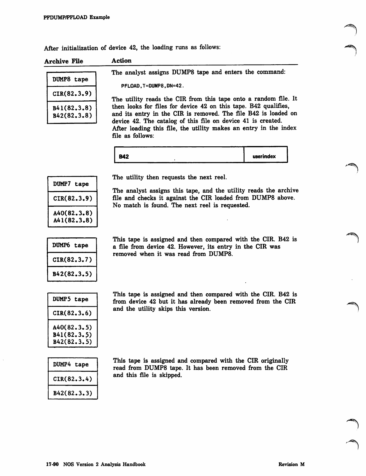
PFDUMP/PFLOAD Example
After initialization of device 42, the loading runs as follows:
Archive File
DUMP8 tape
CIR(82.3.9)
B41(82.3.8)
BA2(82.3.8)
Action
The analyst assigns DUMP8 tape and enters the command:
PFLOAD,T=DUMP8,DN=42.
The utility reads the CIR from this tape onto a random file. It
then looks for files for device 42 on this tape. B42 qualifies,
and its entry in the CIR is removed. The file B42 is loaded on
device 42. The catalog of this file on device 41 is created.
After loading this file, the utility makes an entry in the index
file as follows:
DOMP7 tape
CTR(82.3.9)
A40(82.3.8)
A41(82.3.8)
DUMP6 tape
CIR(82.3.7)
B42(82.3.5)
B42 userindex
The utility then requests the next reel.
The analyst assigns this tape, and the utility reads the archive
file and checks it against the CIR loaded from DUMP8 above.
No match is found. The next reel is requested.
This tape is assigned and then compared with the CIR. B42 is
a file from device 42. However, its entry in the CIR was
removed when it was read from DUMP8.
DUMP5 tape
CIR(82.3.6)
A40(82.3.5)
B4K82.3.5)
B42(82.3.*5)
This tape is assigned and then compared with the CIR. B42 is
from device 42 but it has already been removed from the CIR
and the utility skips this version.
DUMP4 tape
CIR(82.3.4)
B42(82.3.3)
This tape is assigned and compared with the CIR originally
read from DUMP8 tape. It has been removed from the CIR
and this file is skipped.
17-90 NOS Version 2 Analysis Handbook Revision M
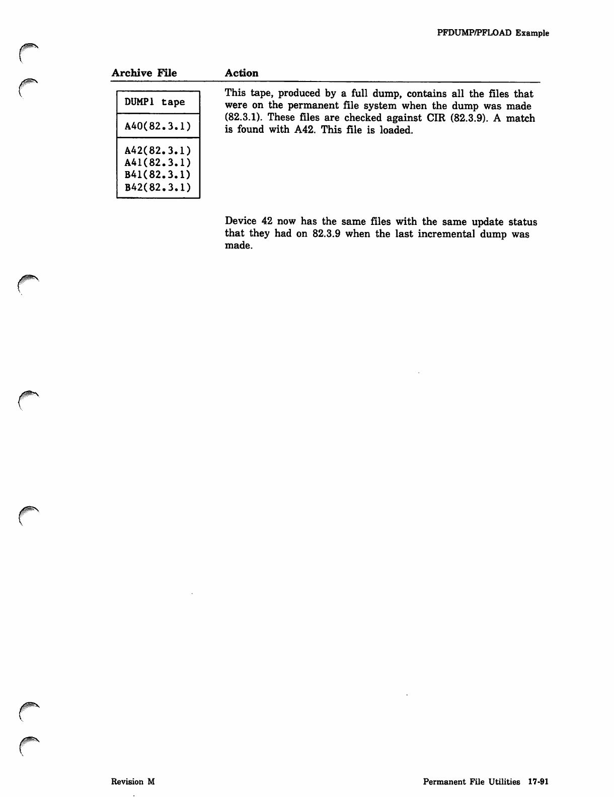
PFDUMP/PFLOAD Example
Archive File Action
DUMP1 tape
A40(82.3.1)
A42(82.3.1)
A41(82.3.1)
B41(82.3.1)
B42(82.3.1)
This tape, produced by a full dump, contains all the files that
were on the permanent file system when the dump was made
(82.3.1). These files are checked against CIR (82.3.9). A match
is found with A42. This file is loaded.
Device 42 now has the same files with the same update status
that they had on 82.3.9 when the last incremental dump was
made.
Revision M Permanent File Utilities 17-91
Release Disk Space (PFREL)
Release Disk Space (PFREL)
The PFREL utility releases the disk space of files that reside on tape alternate storage
or MSE if the files' backup requirements are met.20 PFREL can be called directly or
used with a file selection utility such as GENPFD in the following sequence.
First, execute PFREL with inhibit processing (IP parameter) and the summary file (S
parameter) selected. Files can be excluded by specifying selection parameters. In
particular, OP=A can be used with BD and BT to exclude files that have been
recently accessed. For this example, enter the following command.
PFREL, IP, S, OP=A, BD=yymmdd, BT=hhmmss, FM=f ami 1 yname.
Second, execute the file selection utility GENPFD using the summary file generated
in step 1 as input. A utility directives file will be generated containing the UI and
PF parameters for the selected files. Refer to section 12, Tape Alternate Storage, for
a description of the GENPFD utility.
Third, reexecute PFREL without specifying the IP parameter and using the utility
directives file generated in step 2 as input. For this example, enter the following
command.
PFREL,I=dirfile.
The PFREL utility will not release the disk space of files cataloged on user name
SYSTEMX or on the MSE user names SUBFAMO through SUBFAM7 even if the
selection criteria are met.
20. Refer to PFDUMP in an MSE or Tape Alternate Storage Environment earlier in this section for a
discussion of backup requirements. >-3B%.
17-92 NOS Version 2 Analysis Handbook Revision M
a^m\
Queued/Dayfile Utilities 18
Queued File Utilities .... 18-1
Calling the Queued File Utilities .• 18-2
Console Input 18-2
Batch Input .... 18-11
Terminal Input 18-11
Parameters for the Queued File Utilities 18-11
Description of Queued File Utility Parameters 18-14
File Preassignment 18-26
Active and Inactive Queued Files 18-26
Queued File Utility Routines 18-27
DFLIST is-27
DFTERM 18-27
LDLIST ...'....'. 18-31
QALTER , 18-31
QDUMP . 18-37
QFTLIST 18-41
QLIST 18-41
QLOAD 18-42
QMOVE 18-46
QREC 18-50
Dayfile Dumping Utilities 18-56
^^
/#•*■*<

'**\
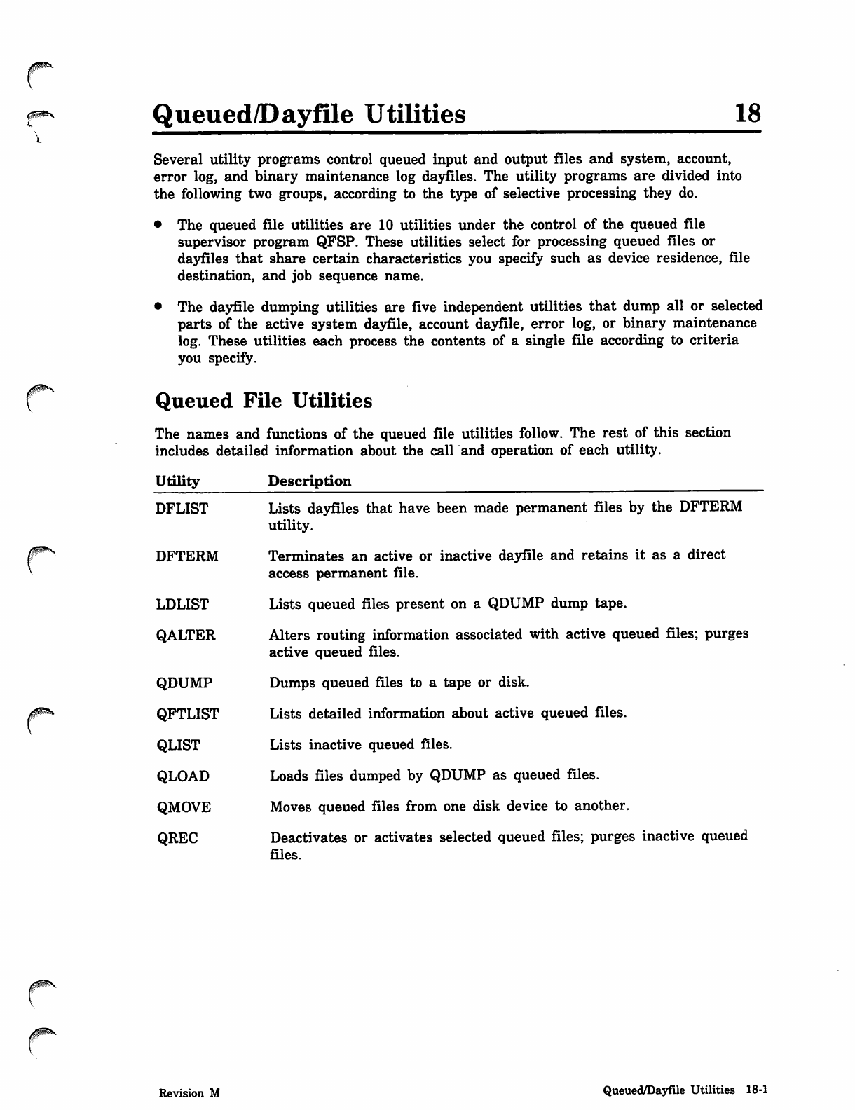
Queued/Dayfile Utilities 18
Several utility programs control queued input and output files and system, account,
error log, and binary maintenance log dayfiles. The utility programs are divided into
the following two groups, according to the type of selective processing they do.
• The queued file utilities are 10 utilities under the control of the queued file
supervisor program QFSP. These utilities select for processing queued files or
dayfiles that share certain characteristics you specify such as device residence, file
destination, and job sequence name.
• The dayfile dumping utilities are five independent utilities that dump all or selected
parts of the active system dayfile, account dayfile, error log, or binary maintenance
log. These utilities each process the contents of a single file according to criteria
you specify.
Queued File Utilities
The names and functions of the queued file utilities follow. The rest of this section
includes detailed information about the call and operation of each utility.
Utility Description
DFLIST Lists dayfiles that have been made permanent files by the DFTERM
utility.
DFTERM Terminates an active or inactive dayfile and retains it as a direct
access permanent file.
LDLIST Lists queued files present on a QDUMP dump tape.
QALTER Alters routing information associated with active queued files; purges
active queued files.
QDUMP Dumps queued files to a tape or disk.
QFTLIST Lists detailed information about active queued files.
QLIST Lists inactive queued files.
QLOAD Loads files dumped by QDUMP as queued files.
QMOVE Moves queued files from one disk device to another.
QREC Deactivates or activates selected queued files; purges inactive queued
files.
Revision M Queued/Dayfile Utilities 18-1
Calling the Queued File Utilities
Calling the Queued FUe Utilities
All queued file utility operations, except DFLIST, LDLIST, and QLIST, can be initiated
through console input to a K display. All queued file utilities except DFLIST,
DFTERM, QALTER, and QFTLIST can be initiated through entries made at the system
console (under DIS or DSD control, including procedure files), card input (batch), or
terminal entries. DFTERM, DFLIST, QALTER, and QFTLIST operation can be initiated
only through entries made at the system console. However, in all cases, for batch and
terminal input, you must be validated for system origin privileges, the system must be
in debug mode, and you must observe certain parameter order dependencies. Since
LDLIST, QDUMP, and QLOAD require preassignment of the dump file, only DIS,
batch, or terminal input is appropriate for these utilities. DFLIST, DFTERM, LDLIST,
QDUMP, QFTLIST, and QLIST can access files on an inaccessible device. QMOVE can
read files from an inaccessible device, but the job may get rolled out if QMOVE
attempts to move files to another inaccessible device. If this happens, drop the job and
attempt a QDUMP.
Console Input
Input from a console through a K display requires the following sequence of entries
and responses. These procedures do not apply to DFLIST, QLIST, or LDLIST, because
K displays are not available for these utilities.
1. Call QFSP by entering:
X.QFSP.
The B,0 display indicates the job sequence name of QFSP. To the right of the entry
this message appears:
REQUEST *K* DISPLAY
2. Activate the K display for that control point by entering:
K.jsn.
Parameter Description
y_
jsn Job sequence name of QFSP as specified on the B,0 display. "^S
The QFSP K display shown in figure 18-1 appears on the left screen. Instructions
on the display describe how to select the desired utility.
18-2 NOS Version 2 Analysis Handbook Revision M
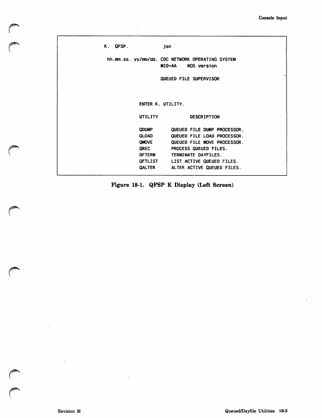
Console Input
yams.
K. QFSP. jsn
hh.mm.ss. yy/mm/dd. CDC NETWORK OPERATING SYSTEM
MID=AA NOS version
QUEUED FILE SUPERVISOR
ENTER K . UTILITY.
UTILITY DESCRIPTION
QDUMP QUEUED FILE DUMP PROCESSOR.
QLOAD QUEUED FILE LOAD PROCESSOR.
QMOVE QUEUED FILE MOVE PROCESSOR.
QREC PROCESS QUEUED FILES.
DFTERM TERMINATE DAYFILES.
QFTLIST LIST ACTIVE QUEUED FILES.
QALTER ALTER ACTIVE QUEUED FILES.
Figure 18-1. QFSP K Display (Left Screen)
0«^S
r
Revision M Queued/Dayfile Utilities 18-3
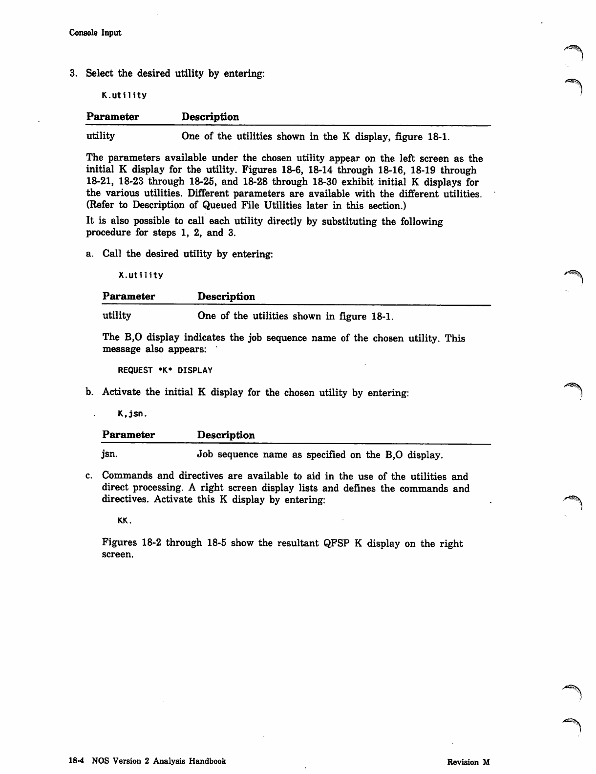
Console Input
3. Select the desired utility by entering:
K.utility
Parameter Description
utility One of the utilities shown in the K display, figure 18-1.
The parameters available under the chosen utility appear on the left screen as the
initial K display for the utility. Figures 18-6, 18-14 through 18-16, 18-19 through
18-21, 18-23 through 18-25, and 18-28 through 18-30 exhibit initial K displays for
the various utilities. Different parameters are available with the different utilities.
(Refer to Description of Queued File Utilities later in this section.)
It is also possible to call each utility directly by substituting the following
procedure for steps 1, 2, and 3.
a. Call the desired utility by entering:
X.utility
Parameter Description
utility One of the utilities shown in figure 18-1.
The B,0 display indicates the job sequence name of the chosen utility. This
message also appears:
REQUEST *K* DISPLAY
b. Activate the initial K display for the chosen utility by entering:
K.jsn.
Parameter Description
jsn. Job sequence name as specified on the B,0 display.
c. Commands and directives are available to aid in the use of the utilities and
direct processing. A right screen display lists and defines the commands and
directives. Activate this K display by entering:
KK.
Figures 18-2 through 18-5 show the resultant QFSP K display on the right
screen.
s&Ss
18-4 NOS Version 2 Analysis Handbook Revision M
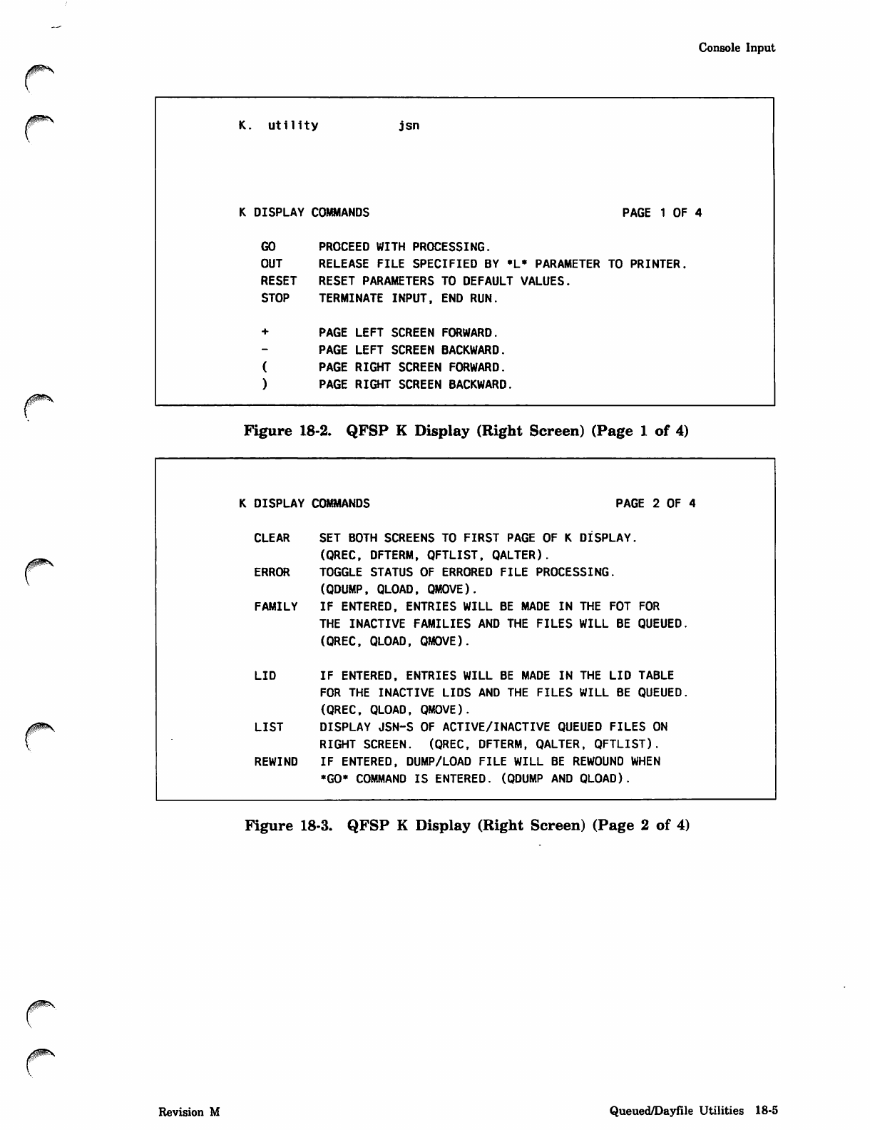
Console Input
K. utility jsn
K DISPLAY C O M M A N D S P A G E 1 O F 4
GO
OUT
RESET
STOP
PROCEED WITH PROCESSING.
RELEASE FILE SPECIFIED BY *L* PARAMETER TO PRINTER.
RESET PARAMETERS TO DEFAULT VALUES.
TERMINATE INPUT, END RUN.
+
(
)
PAGE LEFT SCREEN FORWARD.
PAGE LEFT SCREEN BACKWARD.
PAGE RIGHT SCREEN FORWARD.
PAGE RIGHT SCREEN BACKWARD.
Figure 18-2. QFSP K Display (Right Screen) (Page 1 of 4)
K DISPLAY COMMANDS PAGE 2 OF 4
CLEAR SET BOTH SCREENS TO FIRST PAGE OF K DISPLAY.
(QREC, DFTERM, QFTLIST, QALTER).
ERROR TOGGLE STATUS OF ERRORED FILE PROCESSING.
(QDUMP, QLOAD, QMOVE).
FAMILY IF ENTERED, ENTRIES WILL BE MADE IN THE FOT FOR
THE INACTIVE FAMILIES AND THE FILES WILL BE QUEUED,
(QREC, QLOAD, QMOVE).
LID IF ENTERED, ENTRIES WILL BE MADE IN THE LID TABLE
FOR THE INACTIVE LIDS AND THE FILES WILL BE QUEUED
(QREC, QLOAD, QMOVE).
LIST DISPLAY JSN-S OF ACTIVE/INACTIVE QUEUED FILES ON
RIGHT SCREEN. (QREC, DFTERM, QALTER, QFTLIST).
REWIND IF ENTERED, DUMP/LOAD FILE WILL BE REWOUND WHEN
•GO* COMMAND IS ENTERED. (QDUMP AND QLOAD).
Figure 18-3. QFSP K Display (Right Screen) (Page 2 of 4)
Revision M Queued/Dayfile Utilities 18-5
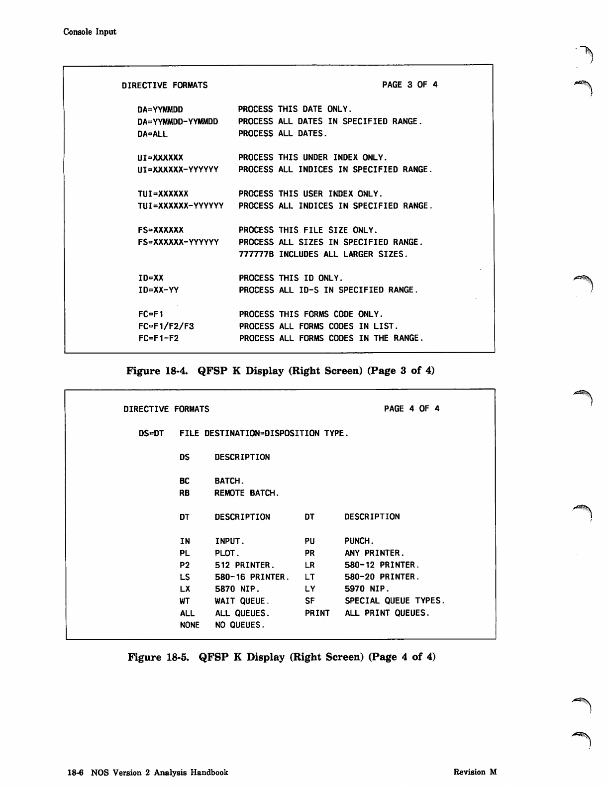
Console Input
>)
DIRECTIVE FORMATS PAGE 3 OF 4
DA=YYMMDD PROCESS THIS DATE ONLY.
DA=YYMMDD-YYMMDD PROCESS ALL DATES IN SPECIFIED RANGE.
DA=ALL PROCESS ALL DATES.
UI=XXXXXX PROCESS THIS UNDER INDEX ONLY.
UI=XXXXXX-YYYYYY PROCESS ALL INDICES IN SPECIFIED RANGE.
TUI=XXXXXX PROCESS THIS USER INDEX ONLY.
TUI=XXXXXX-YYYYYY PROCESS ALL INDICES IN SPECIFIED RANGE.
FS=XXXXXX PROCESS THIS FILE SIZE ONLY.
FS=XXXXXX-YYYYYY PROCESS ALL SIZES IN SPECIFIED RANGE.
777777B INCLUDES ALL LARGER SIZES.
ID=XX PROCESS THIS ID ONLY.
ID=XX-YY PROCESS ALL ID-S IN SPECIFIED RANGE.
FC=F1
FC=F1/F2/F3
FC=F1-F2
PROCESS THIS FORMS CODE ONLY.
PROCESS ALL FORMS CODES IN LIST.
PROCESS ALL FORMS CODES IN THE RANGE
Figure 18-4. QFSP K Display (Right Screen) (Page 3 of 4)
DIRECTIVE FORMATS PAGE 4 OF 4
DS=DT FILE DESTINATION=DISPOSITION TYPE.
DS DESCRIPTION
BC BATCH.
RB REMOTE BATCH.
DT DESCRIPTION DT DESCRIPTION
IN INPUT. PU PUNCH.
PL PLOT. PR ANY PRINTER.
P2 512 PRINTER. LR 580-12 PRINTER.
LS 580-16 PRINTER. LT 580-20 PRINTER.
LX 5870 NIP. LY 5970 NIP.
WT WAIT QUEUE. SF SPECIAL QUEUE TYPES.
ALL ALL QUEUES. PRINT ALL PRINT QUEUES.
NONE NO QUEUES.
Figure 18-5. QFSP K Display (Right Screen) (Page 4 of 4)
■^^s
18-6 NOS Version 2 Analysis Handbook Revision M
j^3*-
Console Input
Following is a list of the queued file utility commands included on the first two
pages of the QFSP K display (refer to figures 18-2 and 18-3) and a description
of each.
Command Description
CLEAR
ERROR
r
FAMILY
GO
LID
Used in conjunction with the LIST command; returns the right
screen K display to the list of processing commands initially
displayed (refer to figure 18-2) and returns the left screen K
display to the first page.
If the QDUMP utility is active, enabling this command causes
files on which unrecoverable read errors were encountered to be
dumped with the errors listed on the output file. Disabling this
command causes these files to be ignored. The default under
QDUMP is enabled.
If the QLOAD utility is active, enabling this command causes
such files to be loaded with the errors listed on the output file.
Disabling the command causes such files to be ignored. The
default under QLOAD is disabled.
If the QMOVE utility is active, enabling this command causes
such files to be moved with errors listed on the output file.
Disabling this command causes such files to be ignored. The
default under QMOVE is disabled.
Entry of this command toggles setting of this command.
Specifies whether or not files are queued when creation or
destination families are not active [not in family ordinal table
(FOT)]. Default is not to queue these files. When the FAMILY
command is specified, entries are made in the FOT for inactive
families and the files are queued. This command applies only to
the QLOAD, QMOVE, and QREC utilities.
Directs the active utility to proceed with the processing of the
entered parameters. When the processing is complete, the left
screen K display is reset to the default values.
Specifies whether or not files are queued when the creation
logical identifier (LID) is not in the LID table. Default is not to
queue these files. When the LID command is specified, entries
are made in the LID table and the files are queued. This
command applies only to the QLOAD, QMOVE, and QREC
utilities.
yflTJP^\
Revision M Queued/Dayfile Utilities 18-7
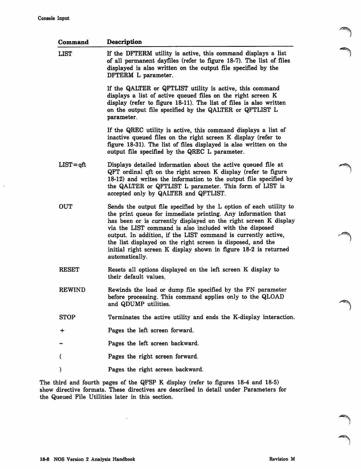
Console Input
Command
LIST
LIST=qft
OUT
RESET
REWIND
STOP
+
)
Description
If the DFTERM utility is active, this command displays a list
of all permanent dayfiles (refer to figure 18-7). The list of files
displayed is also written on the output file specified by the
DFTERM L parameter.
If the QALTER or QFTLIST utility is active, this command
displays a list of active queued files on the right screen K
display (refer to figure 18-11). The list of files is also written
on the output file specified by the QALTER or QFTLIST L
parameter.
If the QREC utility is active, this command displays a list of
inactive queued files on the right screen K display (refer to
figure 18-31). The list of files displayed is also written on the
output file specified by the QREC L parameter.
Displays detailed information about the active queued file at
QFT ordinal qft on the right screen K display (refer to figure
18-12) and writes the information to the output file specified by
the QALTER or QFTLIST L parameter. This form of LIST is
accepted only by QALTER and QFTLIST.
Sends the output file specified by the L option of each utility to
the print queue for immediate printing. Any information that
has been or is currently displayed on the right screen K display
via the LIST command is also included with the disposed
output. In addition, if the LIST command is currently active,
the list displayed on the right screen is disposed, and the
initial right screen K display shown in figure 18-2 is returned
automatically.
Resets all options displayed on the left screen K display to
their default values.
Rewinds the load or dump file specified by the FN parameter
before processing. This command applies only to the QLOAD
and QDUMP utilities.
Terminates the active utility and ends the K-display interaction.
Pages the left screen forward.
Pages the left screen backward.
Pages the right screen forward.
Pages the right screen backward.
The third and fourth pages of the QFSP K display (refer to figures 18-4 and 18-5)
show directive formats. These directives are described in detail under Parameters for
the Queued File Utilities later in this section.
j& * ®$S
f-*ms
18-8 NOS Version 2 Analysis Handbook Revision M
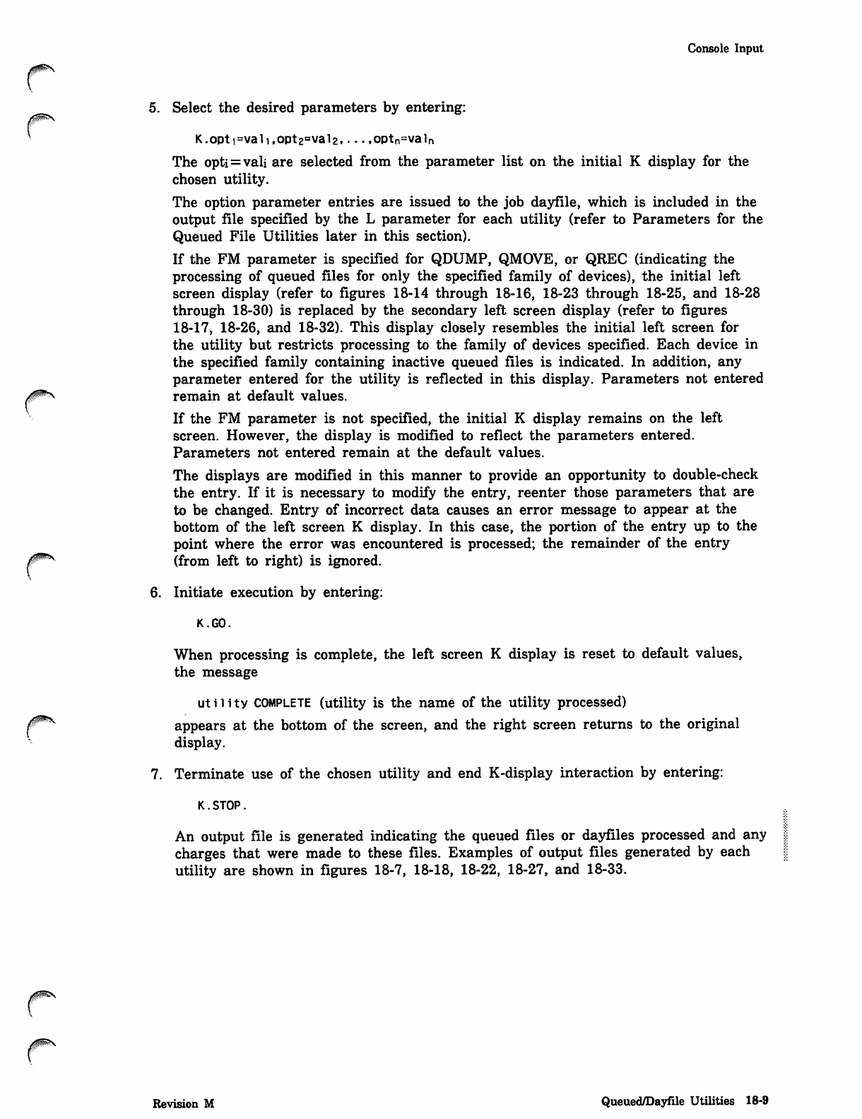
0$0S
Console Input
5. Select the desired parameters by entering:
K.opt1=vali,opt2=val2,•..,optn=valn
The opti = vali are selected from the parameter list on the initial K display for the
chosen utility.
The option parameter entries are issued to the job dayfile, which is included in the
output file specified by the L parameter for each utility (refer to Parameters for the
Queued File Utilities later in this section).
If the FM parameter is specified for QDUMP, QMOVE, or QREC (indicating the
processing of queued files for only the specified family of devices), the initial left
screen display (refer to figures 18-14 through 18-16, 18-23 through 18-25, and 18-28
through 18-30) is replaced by the secondary left screen display (refer to figures
18-17, 18-26, and 18-32). This display closely resembles the initial left screen for
the utility but restricts processing to the family of devices specified. Each device in
the specified family containing inactive queued files is indicated. In addition, any
parameter entered for the utility is reflected in this display. Parameters not entered
remain at default values.
If the FM parameter is not specified, the initial K display remains on the left
screen. However, the display is modified to reflect the parameters entered.
Parameters not entered remain at the default values.
The displays are modified in this manner to provide an opportunity to double-check
the entry. If it is necessary to modify the entry, reenter those parameters that are
to be changed. Entry of incorrect data causes an error message to appear at the
bottom of the left screen K display. In this case, the portion of the entry up to the
point where the error was encountered is processed; the remainder of the entry
(from left to right) is ignored.
6. Initiate execution by entering:
K.GO.
When processing is complete, the left screen K display is reset to default values,
the message
utility COMPLETE (utility is the name of the utility processed)
appears at the bottom of the screen, and the right screen returns to the original
display.
7. Terminate use of the chosen utility and end K-display interaction by entering:
K.STOP.
An output file is generated indicating the queued files or dayfiles processed and any
charges that were made to these files. Examples of output files generated by each
utility are shown in figures 18-7, 18-18, 18-22, 18-27, and 18-33.
Revision M Queued/Dayfile Utilities 18-9
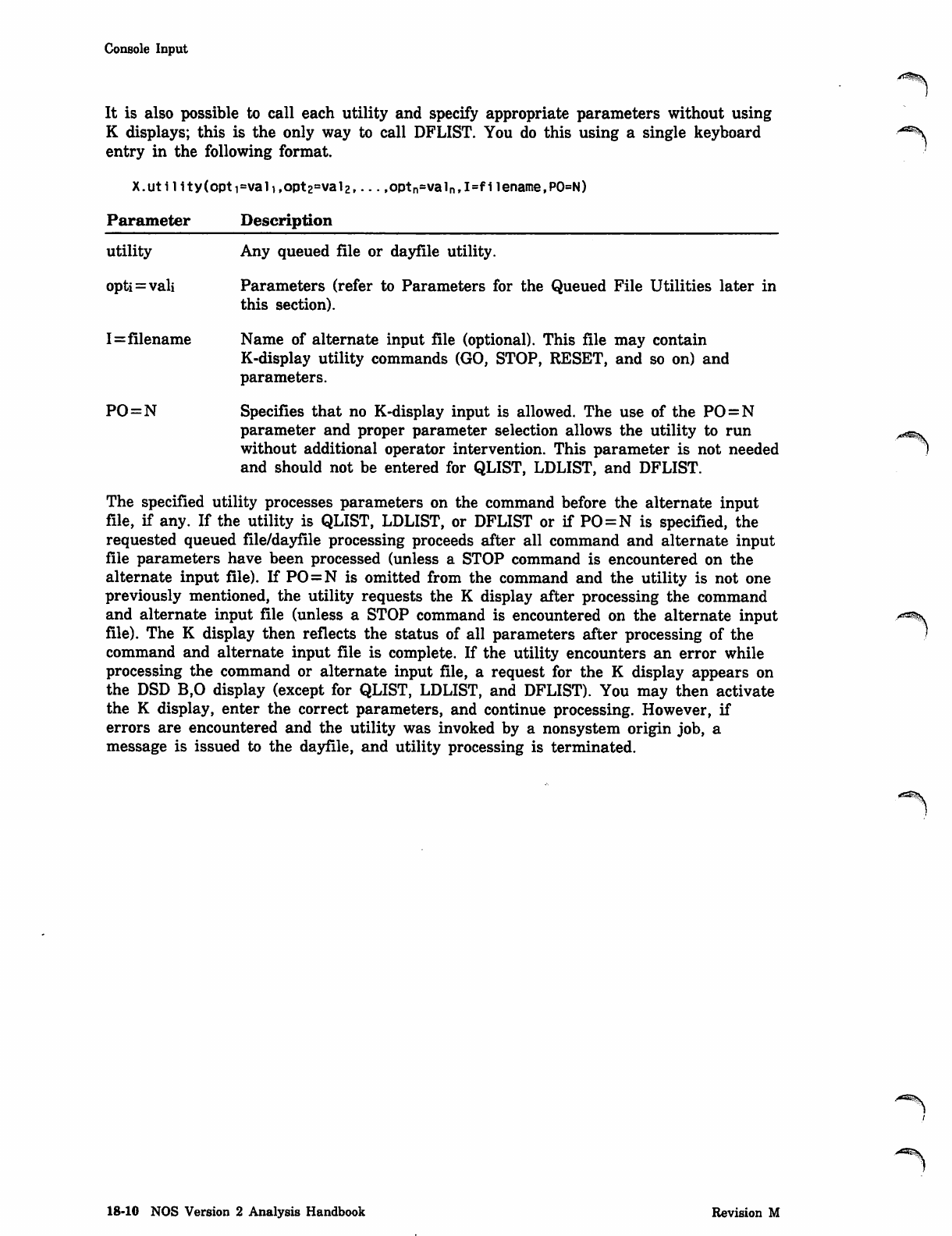
Console Input
It is also possible to call each utility and specify appropriate parameters without using
K displays; this is the only way to call DFLIST. You do this using a single keyboard •■"sss?\
entry in the following format. ■'
X.utility(opti=vali,opt2=val2 optn=va ln, I=fl lename, PO=N)
Parameter Description
utility Any queued file or dayfile utility.
opti=vali Parameters (refer to Parameters for the Queued File Utilities later in
this section).
I=filename Name of alternate input file (optional). This file may contain
K-display utility commands (GO, STOP, RESET, and so on) and
parameters.
PO=N Specifies that no K-display input is allowed. The use of the PO = N
parameter and proper parameter selection allows the utility to run
without additional operator intervention. This parameter is not needed
and should not be entered for QLIST, LDLIST, and DFLIST.
The specified utility processes parameters on the command before the alternate input
file, if any. If the utility is QLIST, LDLIST, or DFLIST or if PO=N is specified, the
requested queued file/dayfile processing proceeds after all command and alternate input
file parameters have been processed (unless a STOP command is encountered on the
alternate input file). If PO=N is omitted from the command and the utility is not one
previously mentioned, the utility requests the K display after processing the command
and alternate input file (unless a STOP command is encountered on the alternate input
file). The K display then reflects the status of all parameters after processing of the
command and alternate input file is complete. If the utility encounters an error while
processing the command or alternate input file, a request for the K display appears on
the DSD B,0 display (except for QLIST, LDLIST, and DFLIST). You may then activate
the K display, enter the correct parameters, and continue processing. However, if
errors are encountered and the utility was invoked by a nonsystem origin job, a
message is issued to the dayfile, and utility processing is terminated.
18-10 NOS Version 2 Analysis Handbook Revision M
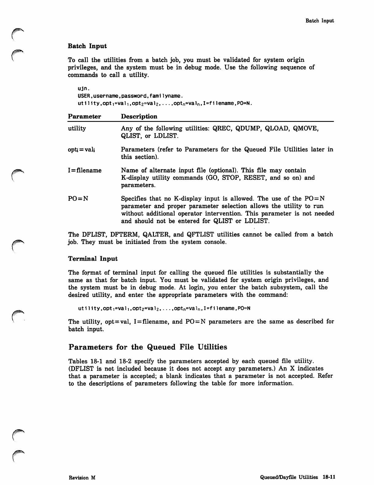
Batch Input
Batch Input
To call the utilities from a batch job, you must be validated for system origin
privileges, and the system must be in debug mode. Use the following sequence of
commands to call a utility.
ujn.
USER,username,password,fami 1yname.
uti 1 Ity,opti=vali,opt2=val2,... ,optn=valn,I=fi lename,PO=N.
Parameter Description
utility Any of the following utilities: QREC, QDUMP, QLOAD, QMOVE,
QLIST, or LDLIST.
opti = vali Parameters (refer to Parameters for the Queued File Utilities later in
this section).
I=filename Name of alternate input file (optional). This file may contain
K-display utility commands (GO, STOP, RESET, and so on) and
parameters.
PO=N Specifies that no K-display input is allowed. The use of the PO=N
parameter and proper parameter selection allows the utility to run
without additional operator intervention. This parameter is not needed
and should not be entered for QLIST or LDLIST.
The DFLIST, DFTERM, QALTER, and QFTLIST utilities cannot be called from a batch
job. They must be initiated from the system console.
Terminal Input
The format of terminal input for calling the queued file utilities is substantially the
same as that for batch input. You must be validated for system origin privileges, and
the system must be in debug mode. At login, you enter the batch subsystem, call the
desired utility, and enter the appropriate parameters with the command:
util1ty,opti=vali,opt2=val2, • • • ,optn=valn,I=f 1 lename,PO=N
The utility, opt=val, I=filename, and PO = N parameters are the same as described for
batch input.
Parameters for the Queued File Utilities
Tables 18-1 and 18-2 specify the parameters accepted by each queued file utility.
(DFLIST is not included because it does not accept any parameters.) An X indicates
that a parameter is accepted; a blank indicates that a parameter is not accepted. Refer
to the descriptions of parameters following the table for more information.
Revision M Queued/Dayfile Utilities 18-11
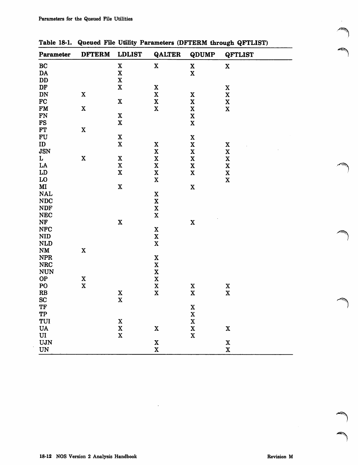
Parameters for the Queued File Utilities
Table 18-1. Queued File Utility Parameters (DFTERM through QFTLIST)
Parameter DFTERM LDLIST QALTER QDUMP QFTLIST
BC
DA
DD
DF
DN
FC
FM
FN
FS
FT
FU
ID
JSN
L
LA
LD
LO
MI
NAL
NDC
NDF
NEC
NF
NFC
NID
NLD
NM
NPR
NRC
NUN
OP
PO
RB
SC
TF
TP
TUI
UA
UI
UJN
UN
-^
18-12 NOS Version 2 Analysis Handbook Revision M
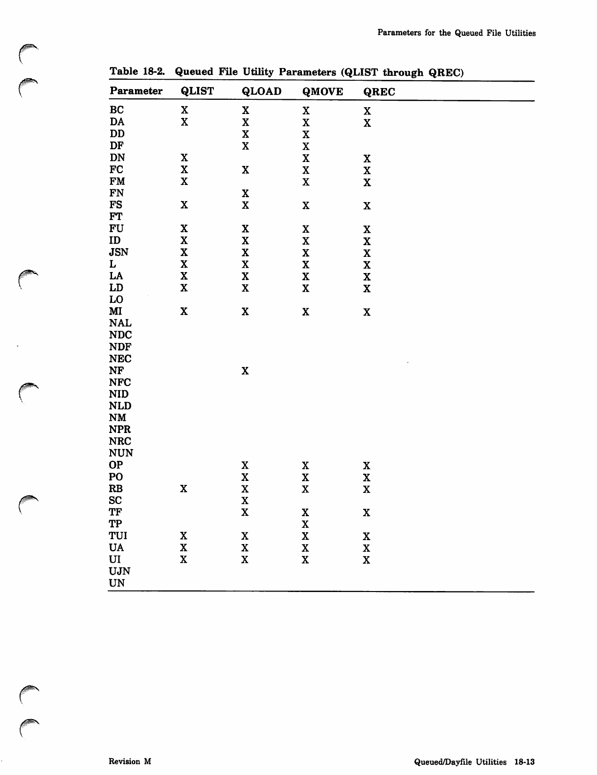
Parameters for the Queued File Utilities
^pfcs
Table 18-2. Queued File Utility Parameters (QLIST through QREC)
Parameter QLIST QLOAD QMOVE QREC
BC
DA
DD
DF
DN
FC
FM
FN
FS
FT
FU
ID
JSN
L
LA
LD
LO
MI
NAL
NDC
NDF
NEC
NF
NFC
NID
NLD
NM
NPR
NRC
NUN
OP
PO
RB
SC
TF
TP
TUI
UA
UI
UJN
UN
Revision M Queued/Dayfile Utilities 18-13
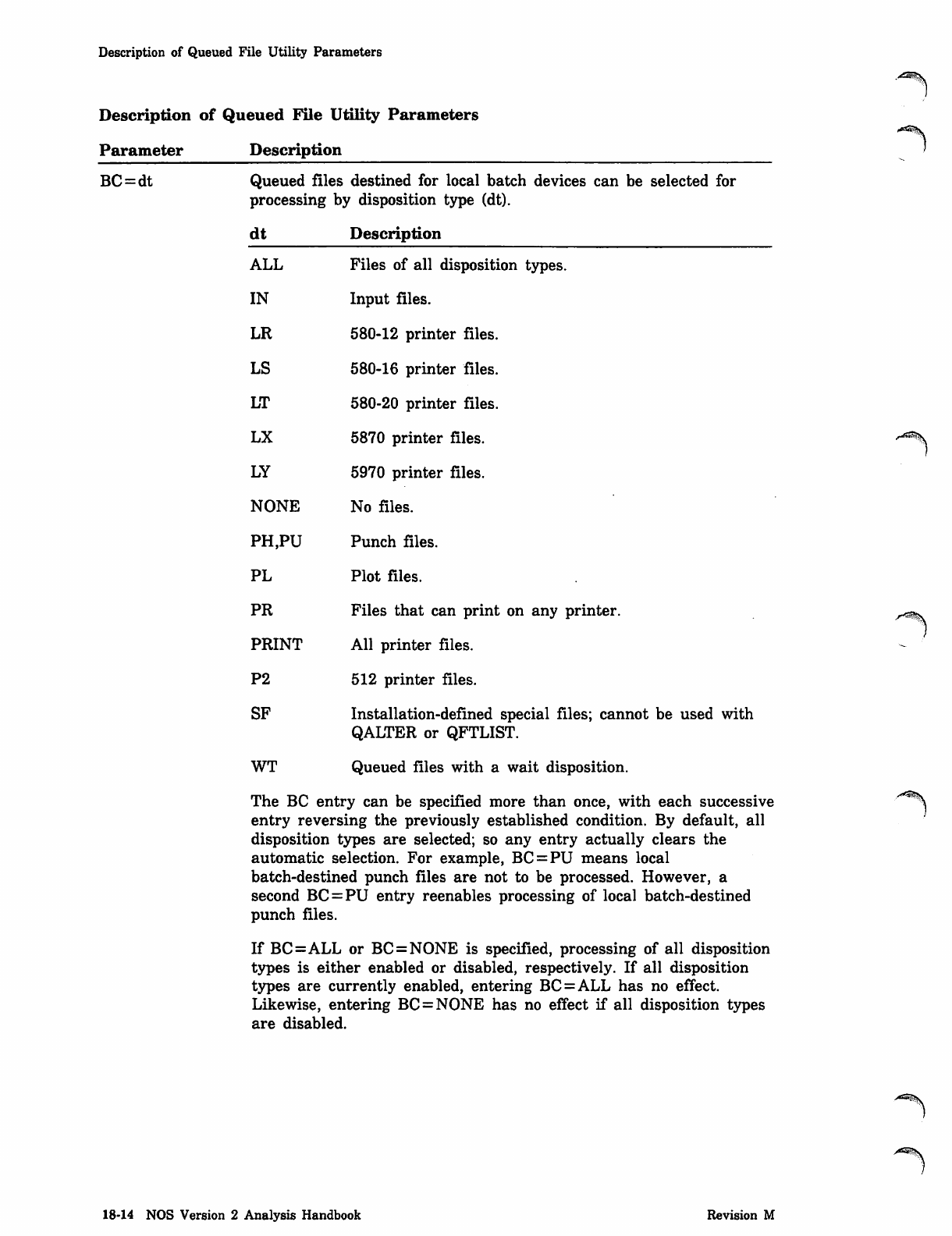
Description of Queued File Utility Parameters
Description of Queued File Utility Parameters
Parameter Description
BC=dt Queued files destined for local batch devices can be selected for
processing by disposition type (dt).
dt Description
ALL Files of all disposition types.
IN Input files.
LR 580-12 printer files.
LS 580-16 printer files.
LT 580-20 printer files.
LX 5870 printer files.
LY 5970 printer files.
NONE No files.
PH,PU Punch files.
PL Plot files.
PR Files that can print on any printer.
PRINT All printer files.
P2 512 printer files.
SF Installation-defined special files; cai
QALTER or QFTLIST.
WT Queued files with a wait disposition.
The BC entry can be specified more than once, with each successive
entry reversing the previously established condition. By default, all
disposition types are selected; so any entry actually clears the
automatic selection. For example, BC = PU means local
batch-destined punch files are not to be processed. However, a
second BC = PU entry reenables processing of local batch-destined
punch files.
If BC=ALL or BC = NONE is specified, processing of all disposition
types is either enabled or disabled, respectively. If all disposition
types are currently enabled, entering BC = ALL has no effect.
Likewise, entering BC=NONE has no effect if all disposition types
are disabled.
**-**^!?\
18-14 NOS Version 2 Analysis Handbook Revision M
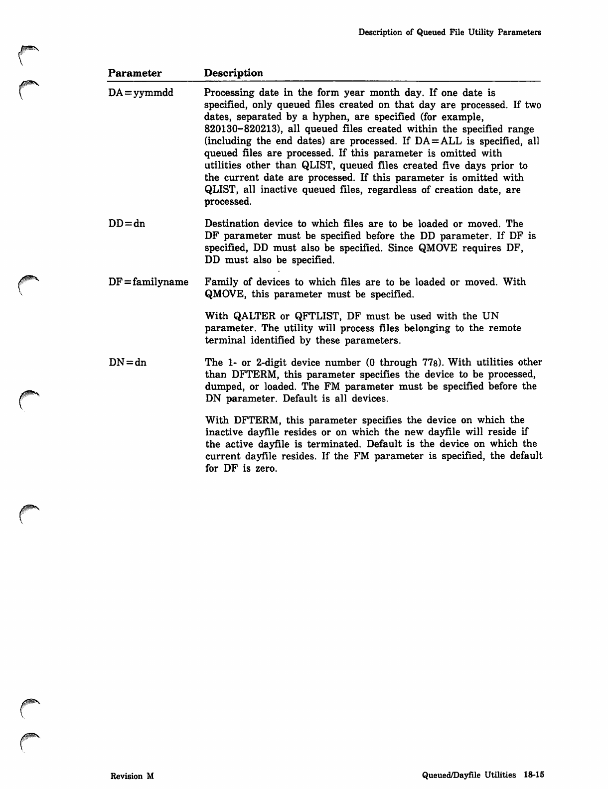
Description of Queued File Utility Parameters
Parameter Description
DA=yymmdd
DD=dn
DF=familyname
DN=dn
0$ms
Processing date in the form year month day. If one date is
specified, only queued files created on that day are processed. If two
dates, separated by a hyphen, are specified (for example,
820130-820213), all queued files created within the specified range
(including the end dates) are processed. If DA=ALL is specified, all
queued files are processed. If this parameter is omitted with
utilities other than QLIST, queued files created five days prior to
the current date are processed. If this parameter is omitted with
QLIST, all inactive queued files, regardless of creation date, are
processed.
Destination device to which files are to be loaded or moved. The
DF parameter must be specified before the DD parameter. If DF is
specified, DD must also be specified. Since QMOVE requires DF,
DD must also be specified.
Family of devices to which files are to be loaded or moved. With
QMOVE, this parameter must be specified.
With QALTER or QFTLIST, DF must be used with the UN
parameter. The utility will process files belonging to the remote
terminal identified by these parameters.
The 1- or 2-digit device number (0 through 77s). With utilities other
than DFTERM, this parameter specifies the device to be processed,
dumped, or loaded. The FM parameter must be specified before the
DN parameter. Default is all devices.
With DFTERM, this parameter specifies the device on which the
inactive dayfile resides or on which the new dayfile will reside if
the active dayfile is terminated. Default is the device on which the
current dayfile resides. If the FM parameter is specified, the default
for DF is zero.
ifi^N
/$m\
f
Revision M Queued/Dayfile Utilities 18-15
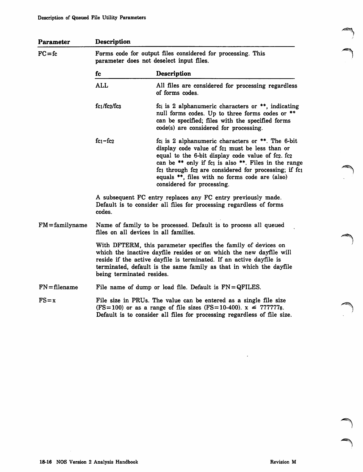
Description of Queued File Utility Parameters
Parameter
FC=fc
Description
FM=familyname
FN=filename
FS=x
Forms code for output files considered for processing. This
parameter does not deselect input files.
fc Description
ALL
fci/fC2/fC3
fci-fC2
All files are considered for processing regardless
of forms codes.
fci is 2 alphanumeric characters or **, indicating
null forms codes. Up to three forms codes or **
can be specified; files with the specified forms
code(s) are considered for processing.
fci is 2 alphanumeric characters or **. The 6-bit
display code value of fci must be less than or
equal to the 6-bit display code value of fc2. fc2
can be ** only if fci is also **. Files in the range
fci through fc2 are considered for processing; if fci
equals **, files with no forms code are (also)
considered for processing.
A subsequent FC entry replaces any FC entry previously made.
Default is to consider all files for processing regardless of forms
codes.
Name of family to be processed. Default is to process all queued
files on all devices in all families.
With DFTERM, this parameter specifies the family of devices on
which the inactive dayfile resides or on which the new dayfile will
reside if the active dayfile is terminated. If an active dayfile is
terminated, default is the same family as that in which the dayfile
being terminated resides.
File name of dump or load file. Default is FN = QFILES.
File size in PRUs. The value can be entered as a single file size
(FS=100) or as a range of file sizes (FS=10-400). x ^ 777777s.
Default is to consider all files for processing regardless of file size.
/C^>
18-16 NOS Version 2 Analysis Handbook Revision M
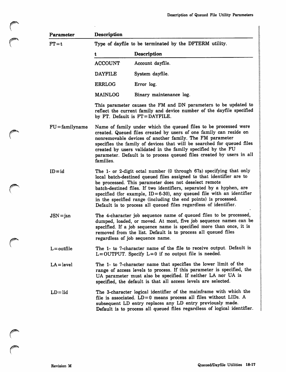
Description of Queued File Utility Parameters
Parameter Description
FT=t
FU=familyname
ID = id
iffP^^
JSN = jsn
L=outfile
LA = level
LD = lid
Type of dayfile to be terminated by the DFTERM utility.
t Description
ACCOUNT Account dayfile.
DAYFILE System dayfile.
ERRLOG Error log.
MAINLOG Binary maintenance log.
This parameter causes the FM and DN parameters to be updated to
reflect the current family and device number of the dayfile specified
by FT. Default is FT = DAYFILE.
Name of family under which the queued files to be processed were
created. Queued files created by users of one family can reside on
nonremovable devices of another family. The FM parameter
specifies the family of devices that will be searched for queued files
created by users validated in the family specified by the FU
parameter. Default is to process queued files created by users in all
families.
The 1- or 2-digit octal number (0 through 67s) specifying that only
local batch-destined queued files assigned to that identifier are to
be processed. This parameter does not deselect remote
batch-destined files. If two identifiers, separated by a hyphen, are
specified (for example, ID = 6-30), any queued file with an identifier
in the specified range (including the end points) is processed.
Default is to process all queued files regardless of identifier.
The 4-character job sequence name of queued files to be processed,
dumped, loaded, or moved. At most, five job sequence names can be
specified. If a job sequence name is specified more than once, it is
removed from the list. Default is to process all queued files
regardless of job sequence name.
The 1- to 7-character name of the file to receive output. Default is
L=OUTPUT. Specify L=0 if no output file is needed.
The 1- to 7-character name that specifies the lower limit of the
range of access levels to process. If this parameter is specified, the
UA parameter must also be specified. If neither LA nor UA is
specified, the default is that all access levels are selected.
The 3-character logical identifier of the mainframe with which the
file is associated. LD = 0 means process all files without LIDs. A
subsequent LD entry replaces any LD entry previously made.
Default is to process all queued files regardless of logical identifier.
Revision M Queued/Dayfile Utilities 18-17
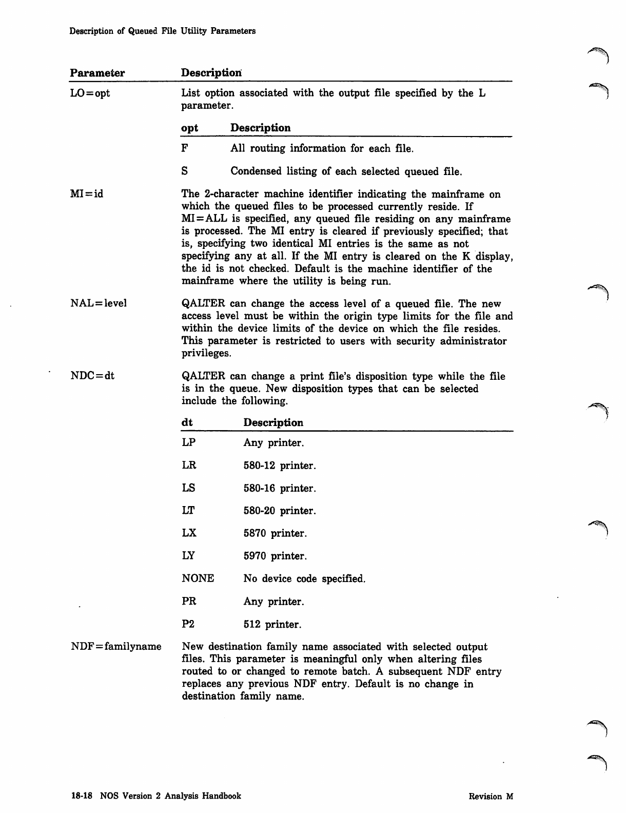
Description of Queued File Utility Parameters
Parameter
LO=opt
MI = id
NAL=level
NDC=dt
Description
NDF=familyname
List option associated with the output file specified by the L
parameter.
opt Description
F All routing information for each file.
S Condensed listing of each selected queued file.
The 2-character machine identifier indicating the mainframe on
which the queued files to be processed currently reside. If
MI=ALL is specified, any queued file residing on any mainframe
is processed. The MI entry is cleared if previously specified; that
is, specifying two identical MI entries is the same as not
specifying any at all. If the MI entry is cleared on the K display,
the id is not checked. Default is the machine identifier of the
mainframe where the utility is being run.
QALTER can change the access level of a queued file. The new
access level must be within the origin type limits for the file and
within the device limits of the device on which the file resides.
This parameter is restricted to users with security administrator
privileges.
QALTER can change a print file's disposition type while the file
is in the queue. New disposition types that can be selected
include the following.
dt Description
LP Any printer.
LR 580-12 printer.
LS 580-16 printer.
LT 580-20 printer.
LX 5870 printer.
LY 5970 printer.
NONE No device code specified.
PR Any printer.
P2 512 printer.
New destination family name associated with selected output
files. This parameter is meaningful only when altering files
routed to or changed to remote batch. A subsequent NDF entry
replaces any previous NDF entry. Default is no change in
destination family name.
18-18 NOS Version 2 Analysis Handbook Revision M
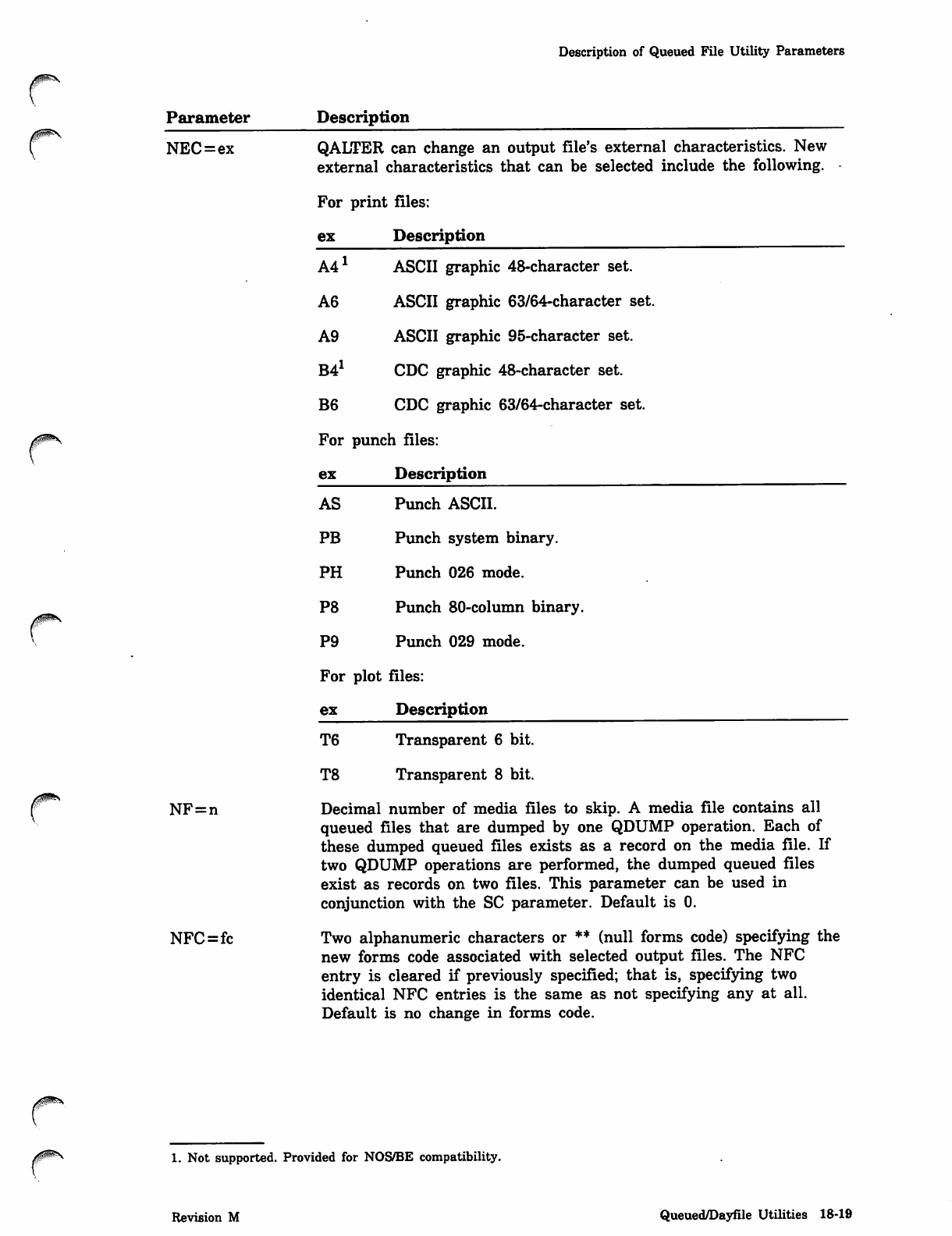
Description of Queued File Utility Parameters
rParameter Description
NEC=ex QALTER can change an output file's external characteristics. New
external characteristics that can be selected include the following.
r
For print files:
e x D e s c r i p t i o n
A41 ASCII graphic 48-character set.
A6 ASCII graphic 63/64-character set.
A9 ASCII graphic 95-character set.
B41 CDC graphic 48-character set.
B6 CDC graphic 63/64-character set.
For punch files:
e x D e s c r i p t i o n
AS Punch ASCII.
PB Punch system binary.
PH Punch 026 mode.
P8 Punch 80-column binary,
P9 Punch 029 mode.
For plot files:
e x D e s c r i p t i o n
T6 Transparent 6 bit.
T8 Transparent 8 bit.
NF=n Decimal number of media files to skip. A media file contains all
queued files that are dumped by one QDUMP operation. Each of
these dumped queued files exists as a record on the media file. If
two QDUMP operations are performed, the dumped queued files
exist as records on two files. This parameter can be used in
conjunction with the SC parameter. Default is 0.
NFC=fc Two alphanumeric characters or ** (null forms code) specifying the
new forms code associated with selected output files. The NFC
entry is cleared if previously specified; that is, specifying two
identical NFC entries is the same as not specifying any at all.
Default is no change in forms code.
1. Not supported. Provided for NOS/BE compatibility.
Revision M Queued/Dayfile Utilities 18-19
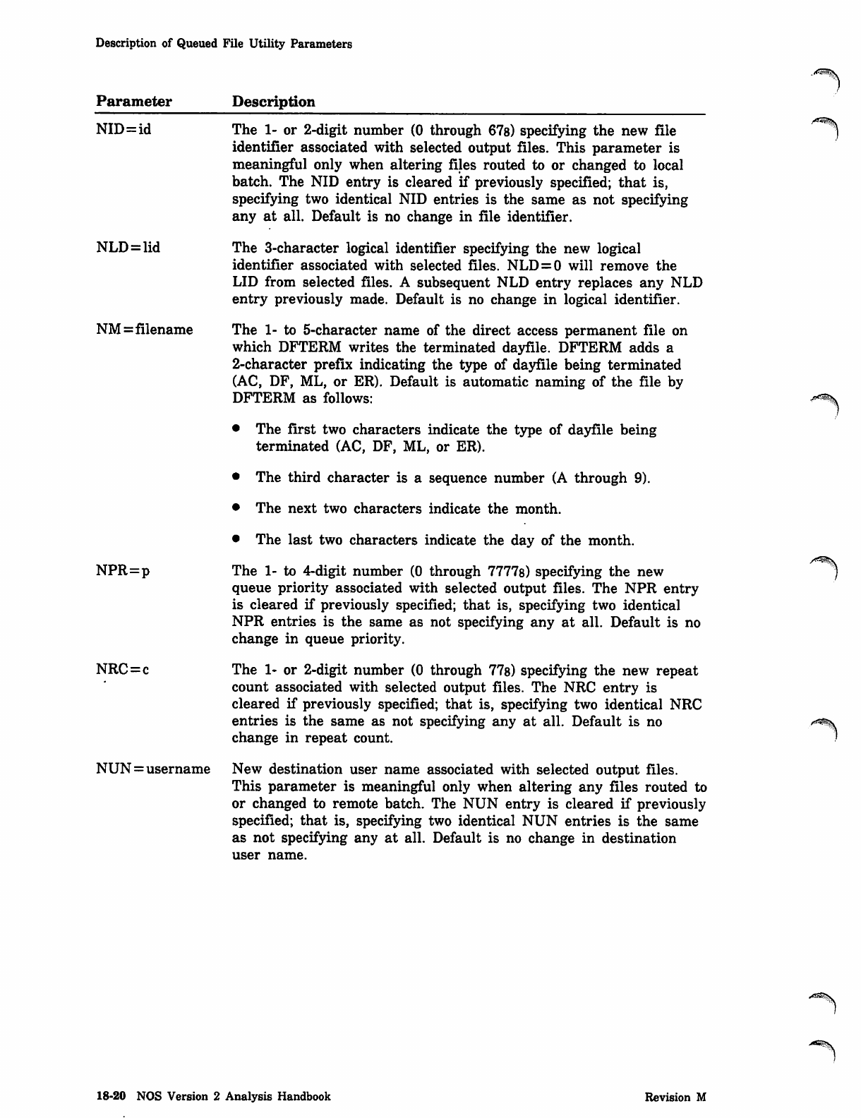
Description of Queued File Utility Parameters
Parameter
NID=id
NLD=lid
NM=filename
NPR=p
NRC=c
Description
NUN=username
The 1- or 2-digit number (0 through 67s) specifying the new file
identifier associated with selected output files. This parameter is
meaningful only when altering files routed to or changed to local
batch. The NID entry is cleared if previously specified; that is,
specifying two identical NID entries is the same as not specifying
any at all. Default is no change in file identifier.
The 3-character logical identifier specifying the new logical
identifier associated with selected files. NLD=0 will remove the
LID from selected files. A subsequent NLD entry replaces any NLD
entry previously made. Default is no change in logical identifier.
The 1- to 5-character name of the direct access permanent file on
which DFTERM writes the terminated dayfile. DFTERM adds a
2-character prefix indicating the type of dayfile being terminated
(AC, DF, ML, or ER). Default is automatic naming of the file by
DFTERM as follows:
• The first two characters indicate the type of dayfile being
terminated (AC, DF, ML, or ER).
• The third character is a sequence number (A through 9).
• The next two characters indicate the month.
• The last two characters indicate the day of the month.
The 1- to 4-digit number (0 through 7777s) specifying the new
queue priority associated with selected output files. The NPR entry
is cleared if previously specified; that is, specifying two identical
NPR entries is the same as not specifying any at all. Default is no
change in queue priority.
The 1- or 2-digit number (0 through 77s) specifying the new repeat
count associated with selected output files. The NRC entry is
cleared if previously specified; that is, specifying two identical NRC
entries is the same as not specifying any at all. Default is no
change in repeat count.
New destination user name associated with selected output files.
This parameter is meaningful only when altering any files routed to
or changed to remote batch. The NUN entry is cleared if previously
specified; that is, specifying two identical NUN entries is the same
as not specifying any at all. Default is no change in destination
user name.
18-20 NOS Version 2 Analysis Handbook Revision M
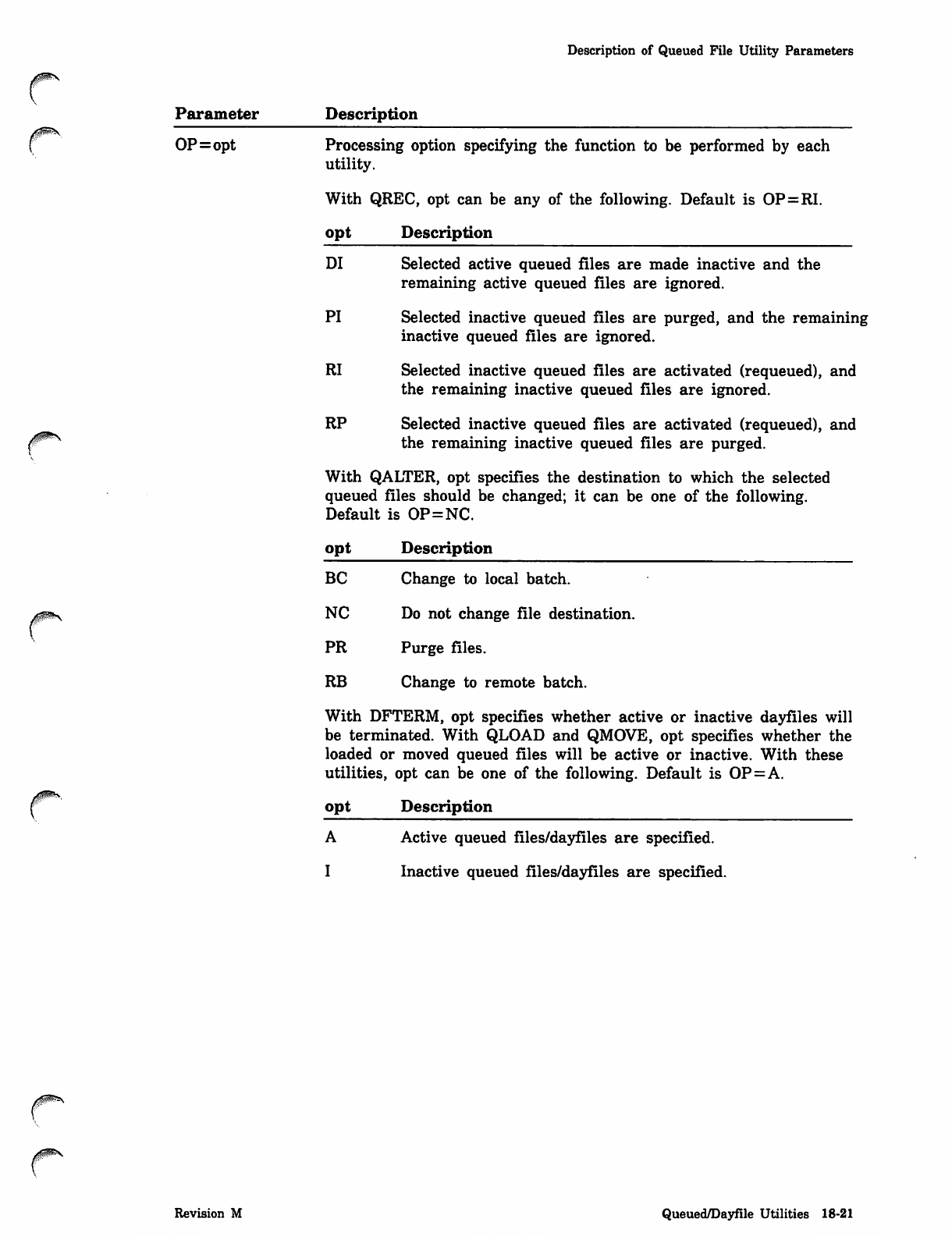
Description of Queued File Utility Parameters
Parameter Description
OP=opt Processing option specifying the function to be performed by each
utility.
With QREC, opt can be any of the following. Default is OP=RI.
opt Description
DI Selected active queued files are made inactive and the
remaining active queued files are ignored.
PI Selected inactive queued files are purged, and the remaining
inactive queued files are ignored.
RI Selected inactive queued files are activated (requeued), and
the remaining inactive queued files are ignored.
RP Selected inactive queued files are activated (requeued), and
the remaining inactive queued files are purged.
With QALTER, opt specifies the destination to which the selected
queued files should be changed; it can be one of the following.
Default is OP=NC.
opt Description
BC Change to local batch.
NC Do not change file destination.
P R P u r g e fi l e s .
RB Change to remote batch.
With DFTERM, opt specifies whether active or inactive dayfiles will
be terminated. With QLOAD and QMOVE, opt specifies whether the
loaded or moved queued files will be active or inactive. With these
utilities, opt can be one of the following. Default is OP=A.
opt Description
A Active queued files/dayfiles are specified.
I Inactive queued files/dayfiles are specified.
0A**\
Revision M Queued/Dayfile Utilities 18-21
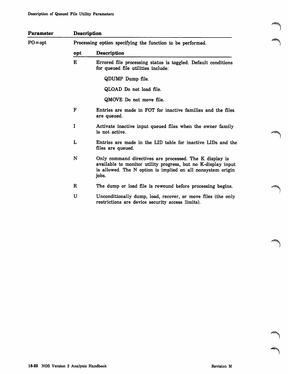
Description of Queued File Utility Parameters
Parameter Description
PO=opt Processing option specifying the function to be performed.
opt Description
E Errored file processing status is toggled. Default conditions
for queued file utilities include:
QDUMP Dump file.
QLOAD Do not load file.
QMOVE Do not move file.
F Entries are made in FOT for inactive families and the files
are queued.
I Activate inactive input queued files when the owner family
is not active.
L Entries are made in the LID table for inactive LIDs and the
files are queued.
N Only command directives are processed. The K display is
available to monitor utility progress, but no K-display input
is allowed. The N option is implied on all nonsystem origin
jobs.
R The dump or load file is rewound before processing begins.
U Unconditionally dump, load, recover, or move files (the only
restrictions are device security access limits).
/^?\
18-22 NOS Version 2 Analysis Handbook Revision M
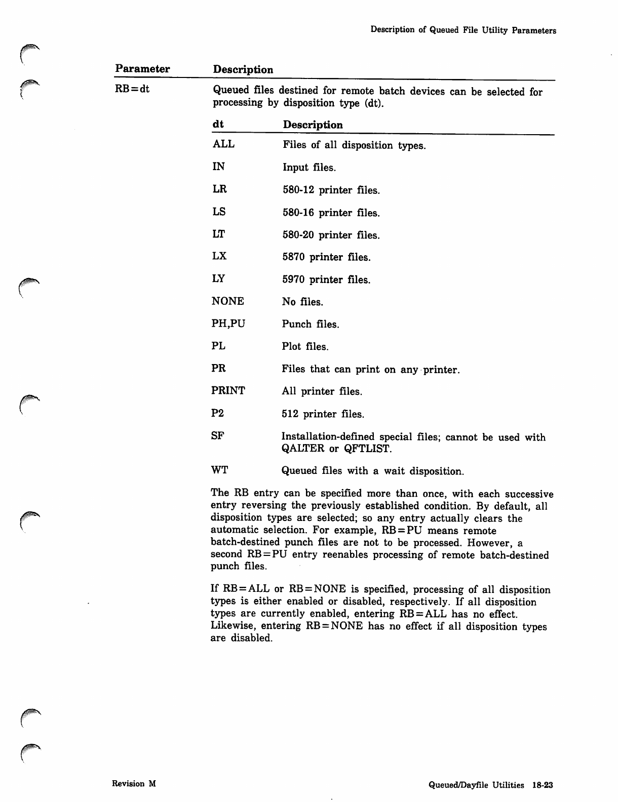
Description of Queued File Utility Parameters
Parameter Description
RB=dt
r
Queued files destined for remote batch devices can be selected for
processing by disposition type (dt).
dt Description
ALL Files of all disposition types.
IN Input files.
LR 580-12 printer files.
LS 580-16 printer files.
LT 580-20 printer files.
L X 5 8 7 0 p r i n t e r fi l e s .
LY 5970 printer files.
NONE No files.
PH,PU Punch files.
PL Plot files.
PR Files that can print on any printer.
P R I N T A l l p r i n t e r fi l e s .
P2 512 printer files.
SF Installation-defined special files; cannot be used with
QALTER or QFTLIST.
WT Queued files with a wait disposition.
The RB entry can be specified more than once, with each successive
entry reversing the previously established condition. By default, all
disposition types are selected; so any entry actually clears the
automatic selection. For example, RB = PU means remote
batch-destined punch files are not to be processed. However, a
second RB = PU entry reenables processing of remote batch-destined
punch files.
If RB = ALL or RB = NONE is specified, processing of all disposition
types is either enabled or disabled, respectively. If all disposition
types are currently enabled, entering RB = ALL has no effect.
Likewise, entering RB = NONE has no effect if all disposition types
are disabled.
Revision M Queued/Dayfile Utilities 18-23
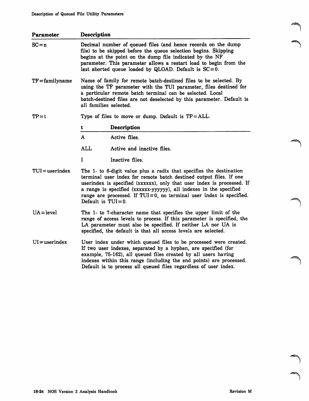
Description of Queued File Utility Parameters
Parameter Description
SC=n
TF=familyname
TP = t
Decimal number of queued files (and hence records on the dump
file) to be skipped before the queue selection begins. Skipping
begins at the point on the dump file indicated by the NF
parameter. This parameter allows a restart load to begin from the
last aborted queue loaded by QLOAD. Default is SC = 0.
Name of family for remote batch-destined files to be selected. By
using the TF parameter with the TUI parameter, files destined for
a particular remote batch terminal can be selected. Local
batch-destined files are not deselected by this parameter. Default is
all families selected.
Type of files to move or dump. Default is TP=ALL.
t Description
-^^i.
ALL
Active files.
Active and inactive files.
IInactive files.
TUI = userindex
UA=level
UI = userindex
The 1- to 6-digit value plus a radix that specifies the destination
terminal user index for remote batch destined output files. If one
userindex is specified (xxxxxx), only that user index is processed. If
a range is specified (xxxxxx-yyyyyy), all indexes in the specified
range are processed. If TUI = 0, no terminal user index is specified.
Default is TUI = 0.
The 1- to 7-character name that specifies the upper limit of the
range of access levels to process. If this parameter is specified, the
LA parameter must also be specified. If neither LA nor UA is
specified, the default is that all access levels are selected.
User index under which queued files to be processed were created.
If two user indexes, separated by a hyphen, are specified (for
example, 75-162), all queued files created by all users having
indexes within this range (including the end points) are processed.
Default is to process all queued files regardless of user index.
18-24 NOS Version 2 Analysis Handbook Revision M
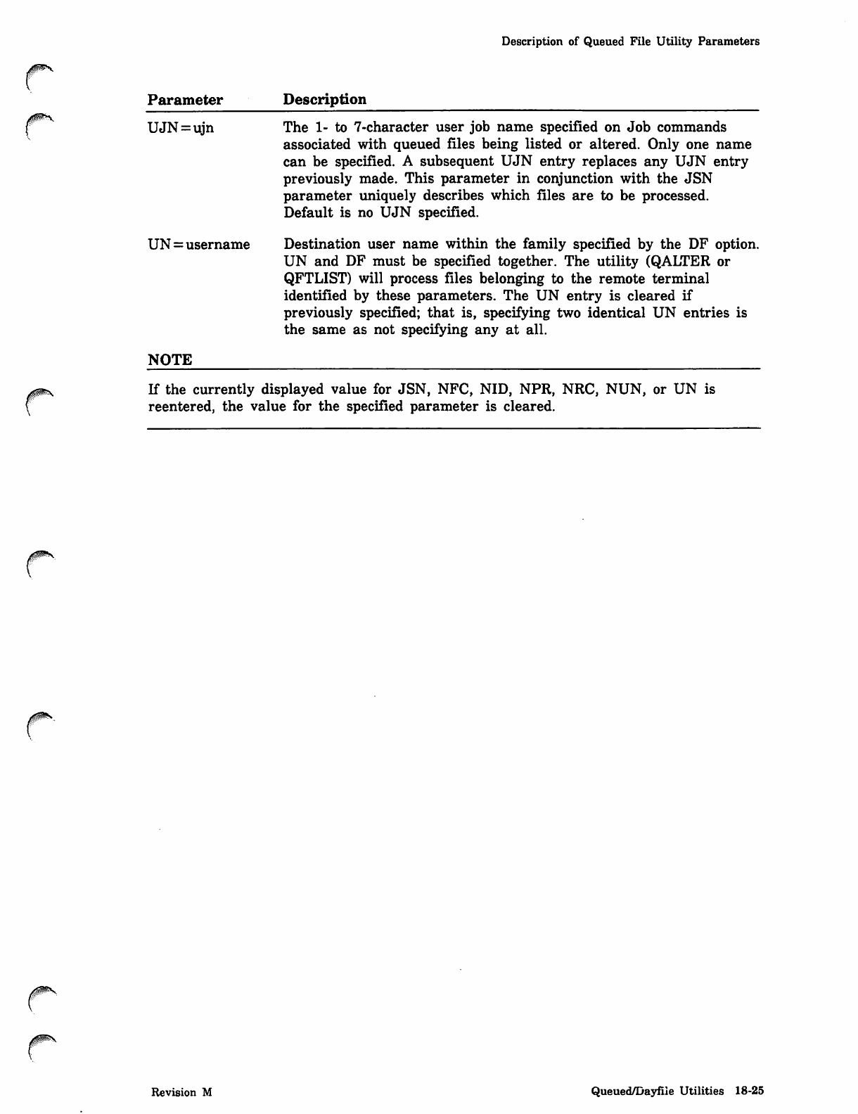
r 0 ^
Parameter
UJN = ujn
UN=username
Description of Queued File Utility Parameters
Description
The 1- to 7-character user job name specified on Job commands
associated with queued files being listed or altered. Only one name
can be specified. A subsequent UJN entry replaces any UJN entry
previously made. This parameter in conjunction with the JSN
parameter uniquely describes which files are to be processed.
Default is no UJN specified.
Destination user name within the family specified by the DF option.
UN and DF must be specified together. The utility (QALTER or
QFTLIST) will process files belonging to the remote terminal
identified by these parameters. The UN entry is cleared if
previously specified; that is, specifying two identical UN entries is
the same as not specifying any at all.
NOTE
If the currently displayed value for JSN, NFC, NID, NPR, NRC, NUN, or UN is
reentered, the value for the specified parameter is cleared.
r
Revision M Queued/Dayfile Utilities 18-25
File Preassignment
File Preassignment
When using the LDLIST, QDUMP, and QLOAD utilities, the dump or load file must be
preassigned. This can be done by using a LABEL or an ASSIGN command. For
example, the following commands can be used.
LABEL,QFILES,VSN=DMP1,D=HY.
or
ASSIGN,MS,QFILES.
If no dump file is present, QDUMP will write on a local mass storage file; LDLIST
and QLOAD will attempt to read an empty file and terminate.
Active and Inactive Queued Files
A queued file can be active or inactive. All queued files are originally active upon
entering a queue. A queued file is deactivated (made inactive) when its entry is
removed from the queued file table (QFT) and a corresponding entry is created in the
inactive queued file table (IQFT) on the mass storage device where the queued file
resides. An inactive queued file is activated when the entry from the IQFT is removed
and a corresponding entry is created in the QFT. Inactive queued files are not
considered for processing (other than by the queued file utilities), nor do they appear
on any DSD display.
Three queued file utilities can deactivate or activate queued files (QLOAD, QMOVE,
and QREC). QLOAD and QMOVE each transfer queued files from either tape or disk to
a disk device. Upon completion of the transfer, the utility leaves the queued files active
or inactive according to the parameters you have specified. QREC does not perform any
file transfer but only adjusts table entries as described in the preceding paragraph.
These three utilities have uses other than deactivation and activation of queued files
(refer to the description of the appropriate utility and parameters).
Queued files are also deactivated when they are recovered during a level 0 deadstart.
Such files can be activated automatically by an IPRDECK entry that invokes QREC
during a level 0 deadstart. Refer to section 3, Deadstart Decks, for further information
on IPRDECK.
'^St
18-26 NOS Version 2 Analysis Handbook Revision M
Queued File Utility Routines
Queued File Utility Routines
The queued file utility routines are described next. The parameters available for each
of the routines are listed in table 18-1. The K displays (if any) for each utility are
shown and contain lists of applicable parameters. Output formats for each utility are
also shown.
DFLIST
DFLIST generates a printer listing of all permanent files created by the DFTERM
utility.
DFLIST can be initiated only from the system console directly through this command:
X.DFLIST.
The output generated by DFLIST is the same as that produced by the LIST command
available under the DFTERM utility (refer to figure 18-7).
DFTERM
DFTERM terminates an active or inactive dayfile and retains it as a direct access
permanent file on user name SYSTEMX for later interrogation or processing. When an
active dayfile (that is, the current system dayfile, account dayfile, error log, or binary
maintenance log) is terminated, information in the central memory buffer for that
dayfile is written to mass storage to be included with the permanent file, and a new
active dayfile is started. The new dayfile can reside on the same device, or a new
^** device can be specified.
Terminating an inactive dayfile has no effect on the currently active dayfiles. Inactive
dayfiles are not used by the system. Furthermore, the presence of an inactive dayfile
in the system is possible only under unusual conditions. For example, if the system is
deadstarted and the device that previously contained the account dayfile is turned off, a
new account dayfile is started on another device. Two devices in the system now
contain account dayfiles. If both devices are turned on when the system is next
deadstarted, two account dayfiles are recovered. The most recent account dayfile is
made active and is used by the system. The remaining account dayfile is made
inactive.
The DFTERM utility can be initiated only from the system console through a K
display or directly through the DFTERM command. No batch or terminal input is
allowed.
When DFTERM is selected at the system console, the DFTERM K display appears on
the left screen. This display contains a list of all applicable options associated with
DFTERM, their default values, and a short description of each (refer to figure 18-6).
Revision M Queued/Dayfile Utilities 18-27
DFTERM
A list of the permanent dayfiles is displayed on the right screen when you enter this
command:
K.LIST.
When this command is processed, the right screen K display is automatically replaced
with the DFTERM dayfile list K display (refer to figure 18-7). The information
presented in this display is the same as that generated by the DFLIST utility.
If there are more files than can be displayed on one screen, a message appears at the
bottom of the screen indicating that more files exist. When the LIST command is
entered, a complete list of permanent dayfiles is written to the output file specified by
the DFTERM L parameter; thus, a complete printer listing is provided when the
DFTERM utility is terminated. If it is necessary to obtain the output listing
immediately, enter this command:
K.OUT.
When this command is processed, the initial right screen K display (a list of the "eS^
queued file utility commands) is automatically returned. However, if the OUT command
is not entered, the original right screen K display can be returned by entering the
CLEAR command.
After DFTERM processing is completed, an output file indicating the results of this
processing is generated if the LIST command has been entered at any time during
DFTERM operations. (Refer to figure 18-7, which shows essentially the same format.) If
the LIST command was not entered, no output file is generated.
18-28 NOS Version 2 Analysis Handbook Revision M
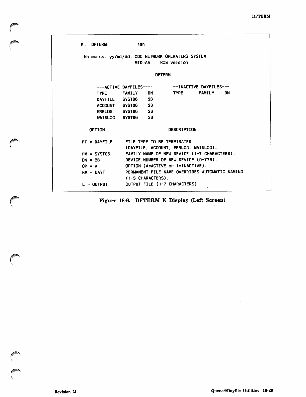
DFTERM
^PVs
K. DFTERM. jsn
hh.mm.ss. yy/mm/dd. CDC NETWORK OPERATING SYSTEM
MID=AA NOS version
DFTERM
ACTIVE DAYFILES —INACTIVE DAYFILES
TYPE F A M I L Y D N T Y P E F A M I L Y D N
DAYFILE SYST06 2B
ACCOUNT SYST06 2B
ERRLOG SYST06 2B
MAINLOG SYST06 2B
yam*..
OPTION DESCRIPTION
FT = DAYFILE FILE TYPE TO BE TERMINATED
(DAYFILE, ACCOUNT, ERRLOG, MAINLOG).
FM = SYST06 FAMILY NAME OF NEW DEVICE (1-7 CHARACTERS).
DN = 2B DEVICE NUMBER OF NEW DEVICE (0-77B).
OP = A OPTION (A=ACTIVE or I=INACTIVE).
NM = DAYF PERMANENT FILE NAME OVERRIDES AUTOMATIC NAMING
(1-5 CHARACTERS).
L = OUTPUT OUTPUT FILE (1-7 CHARACTERS).
Figure 18-6. DFTERM K Display (Left Screen)
Revision M Queued/Dayfile Utilities 18-29
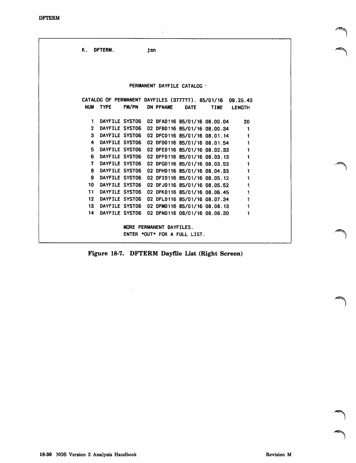
DFTERM
K. DFTERM. jsn
PERMANENT DAYFILE CATALOG '
CATALOG OF PERMANENT DAYFILES (377777). 85/01/16 09.25.43
NUM TYPE FM/PN DN PFNAME DATE TIME LENGTH
1DAYFILE SYST06 02 DFA0116 85/01/16 08.00.04 20
2DAYFILE SYST06 02 DFB0116 85/01/16 08.00.34 1
3DAYFILE SYST06 02 DF C0 116 85 /0 1/ 16 08 .0 1. 14 1
4DAYFILE SYST06 02 DF D0 116 85 /0 1/ 16 08 .0 1. 54 1
5DAYFILE SYST06 02 DFE0116 85/01/16 08.02.33 1
6DAYFILE SYST06 02 DFF0116 85/01/16 08.03.13 1
7DAYFILE SYST06 02 DFG0116 85/01/16 08.03.53 1
8DAYFILE SYST06 02 DF H0 116 85 /0 1/ 16 08 .0 4. 33 1
9DAYFILE SYST06 02 DFI0116 85/01/16 08.05.12 1
10 DAYFILE SYST06 02 DFJ0116 85/01/16 08.05.52 1
11 DAYFILE SYST06 02 DFK0116 85/01/16 08.06.45 1
12 DAYFILE SYST06 02 D FL 0 116 85 / 01 / 16 0 8. 0 7. 3 4 1
13 DAYFILE SYST06 02 D FM0 116 85/ 01/ 16 0 8.0 8.1 3 1
14 DAYFILE SYST06 0 2 D FN 0116 0 8/ 01 /1 6 0 8. 08 .30 1
MORE PERMANENT DAYFILES.
ENTER * OUT* FOR A FULL LIST.
Figure 18-7. DFTERM Dayfile list (Right Screen)
y ^ ® ^ V
18-30 NOS Version 2 Analysis Handbook Revision M
LDLIST
vgpSN.
r
LDLIST
LDLIST generates a printer listing of queued files present on a QDUMP dump tape.
Since LDLIST requires a QDUMP dump tape to be preassigned, it should be entered
from DIS or in a batch or terminal job in the form
LDLIST,opti=vali,opt2=val2,...,optn=valn.
opti=vali are parameters available for LDLIST.
The output generated by LDLIST is the same as that produced by QLOAD (refer to
figure 18-22).
QALTER
QALTER displays, lists, and/or alters routing and other information about active
queued files. The utility selects files for processing according to criteria you specify.
QALTER purges selected files from the system when you specify OP = PR.
You may alter the following information associated with the selected files.
File destination.
Access level (requires security administrator privileges).
Print file disposition type (device code).
External characteristics.
Destination LID.
Destination family (remote batch-destined files).
Destination user name (remote batch-destined files).
File identifier (local batch-destined files).
Forms code.
Priority of a queued file.
Repeat count.
Disposition type.
Revision M Queued/Dayfile Utilities 18-31
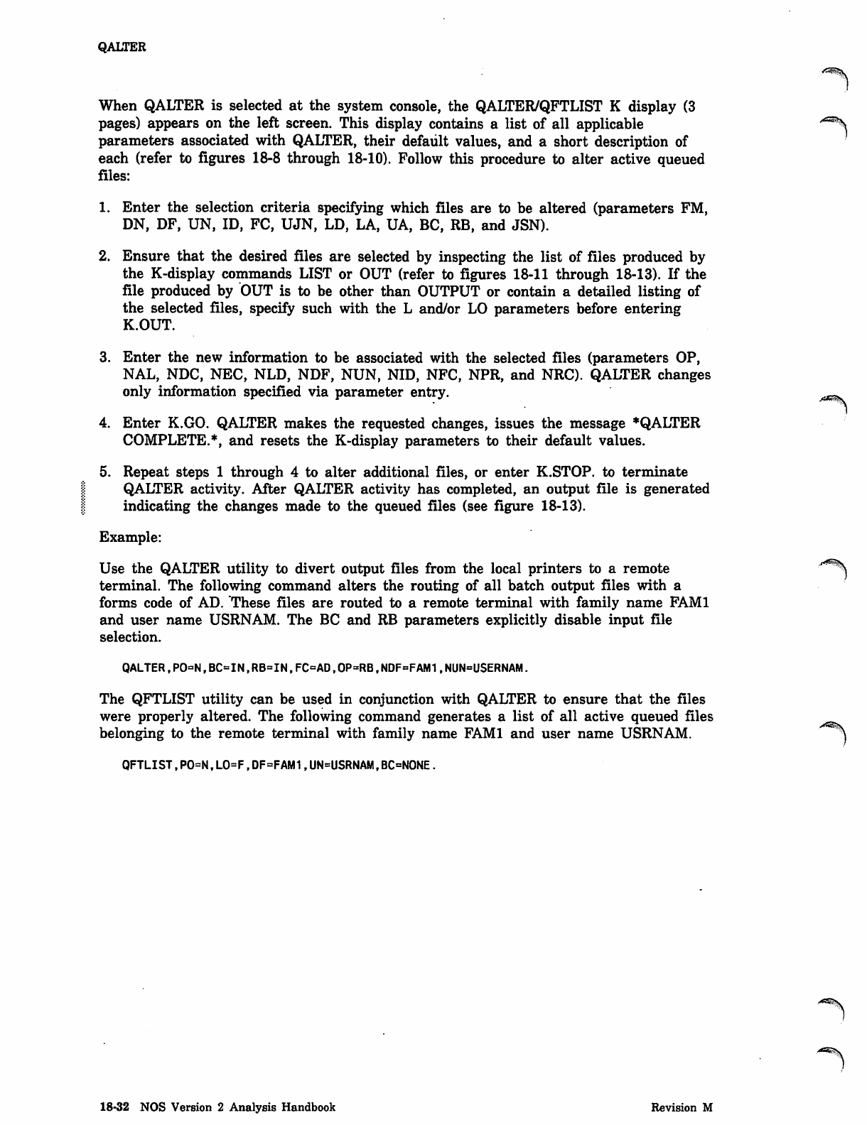
QALTER
When QALTER is selected at the system console, the QALTER/QFTLIST K display (3
pages) appears on the left screen. This display contains a list of all applicable ^^
parameters associated with QALTER, their default values, and a short description of
each (refer to figures 18-8 through 18-10). Follow this procedure to alter active queued
files:
1. Enter the selection criteria specifying which files are to be altered (parameters FM,
DN, DF, UN, ID, FC, UJN, LD, LA, UA, BC, RB, and JSN).
2. Ensure that the desired files are selected by inspecting the list of files produced by
the K-display commands LIST or OUT (refer to figures 18-11 through 18-13). If the
file produced by OUT is to be other than OUTPUT or contain a detailed listing of
the selected files, specify such with the L and/or LO parameters before entering
K.OUT.
3. Enter the new information to be associated with the selected files (parameters OP,
NAL, NDC, NEC, NLD, NDF, NUN, NID, NFC, NPR, and NRC). QALTER changes
only information specified via parameter entry.
4. Enter K.GO. QALTER makes the requested changes, issues the message *QALTER
COMPLETE.*, and resets the K-display parameters to their default values.
5. Repeat steps 1 through 4 to alter additional files, or enter K.STOP. to terminate
QALTER activity. After QALTER activity has completed, an output file is generated
indicating the changes made to the queued files (see figure 18-13).
Example:
Use the QALTER utility to divert output files from the local printers to a remote
terminal. The following command alters the routing of all batch output files with a
forms code of AD. "These files are routed to a remote terminal with family name FAM1
and user name USRNAM. The BC and RB parameters explicitly disable input file
selection.
QALTER,PO=N,BC=IN,RB=IN,FC=AD, OP=RB,NDF=FAM1,NUN=USERNAM.
The QFTLIST utility can be used in conjunction with QALTER to ensure that the files
were properly altered. The following command generates a list of all active queued files
belonging to the remote terminal with family name FAM1 and user name USRNAM. ^^\
QFTLIST,PO=N,L0=F,DF=FAM1,UN=USRNAM,BC=NONE.
.^ttfaV
18-32 NOS Version 2 Analysis Handbook Revision M
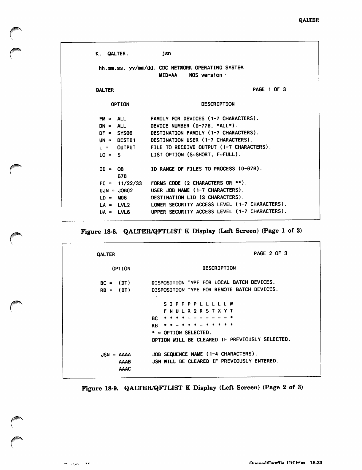
QALTER
QALTER. jsn
hh.mm.ss. yy/mm/dd. CDC NETWORK OPERATING SYSTEM
MID=AA NOS version •
DESCRIPTION
QALTER
OPTION
FM = ALL
DN = ALL
DF = SYS06
UN » DEST01
L = OUTPUT
LO =
ID » OB
67B
FC = 11/22/33
UJN = JOB02
LD = M06
LA = LVL2
UA = LVL6
PAGE 1 OF 3
FAMILY FOR DEVICES (1-7 CHARACTERS).
DEVICE NUMBER (0-77B, *ALL*).
DESTINATION FAMILY (1-7 CHARACTERS).
DESTINATION USER (1-7 CHARACTERS).
FILE TO RECEIVE OUTPUT (1-7 CHARACTERS).
LIST OPTION (S=SHORT, F=FULL).
ID RANGE OF FILES TO PROCESS (0-67B).
FORMS CODE (2 CHARACTERS OR ••).
USER JOB NAME (1-7 CHARACTERS).
DESTINATION LID (3 CHARACTERS).
LOWER SECURITY ACCESS LEVEL (1-7 CHARACTERS)
UPPER SECURITY ACCESS LEVEL (1-7 CHARACTERS)
Figure 18-8. QALTER/QFTLIST K Display (Left Screen) (Page 1 of 3)
0$ms.
QALTER
OPTION
BC = (DT)
RB = (DT)
PAGE 2 OF 3
DESCRIPTION
JSN = AAAA
AAAB
AAAC
DISPOSITION TYPE FOR LOCAL BATCH DEVICES.
DISPOSITION TYPE FOR REMOTE BATCH DEVICES.
SIPPPPLLLLLW
FNULR2RSTXYT
B C * * * * - *
* = OPTION SELECTED.
OPTION WILL BE CLEARED IF PREVIOUSLY SELECTED
JOB SEQUENCE NAME (1-4 CHARACTERS).
JSN WILL BE CLEARED IF PREVIOUSLY ENTERED.
Figure 18-9. QALTER/QFTLIST K Display (Left Screen) (Page 2 of 3)
Qnono^/notrfilo TItilit.ipR 18-33
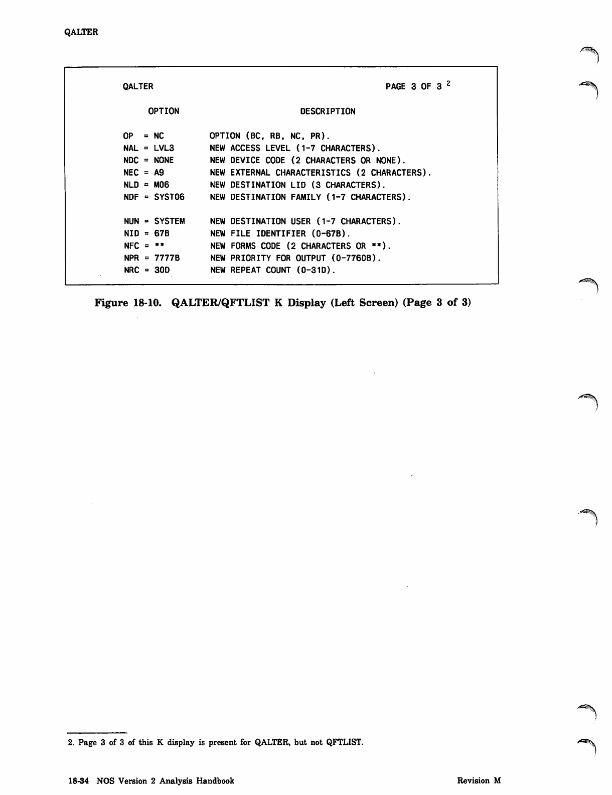
QALTER
>^|y
QALTER
OPTION
OP = NC
NAL = LVL3
NDC = NONE
NEC = A9
NLD = M06
NDF = SYST06
NUN = SYSTEM
NID = 67B
NFC = **
NPR = 7777B
NRC = 30D
PAGE 3 OF 3
DESCRIPTION
OPTION (BC, RB, NC, PR).
NEW ACCESS LEVEL (1-7 CHARACTERS).
NEW DEVICE CODE (2 CHARACTERS OR NONE).
NEW EXTERNAL CHARACTERISTICS (2 CHARACTERS)
NEW DESTINATION LID (3 CHARACTERS).
NEW DESTINATION FAMILY (1-7 CHARACTERS).
NEW DESTINATION USER (1-7 CHARACTERS).
NEW FILE IDENTIFIER (0-67B).
NEW FORMS CODE (2 CHARACTERS OR ••).
NEW PRIORITY FOR OUTPUT (0-7760B).
NEW REPEAT COUNT (0-31D).
Figure 18-10. QALTER/QFTLIST K Display (Left Screen) (Page 3 of 3)
/*^^V
2. Page 3 of 3 of this K display is present for QALTER, but not QFTLIST. A^\
18-34 NOS Version 2 Analysis Handbook Revision M
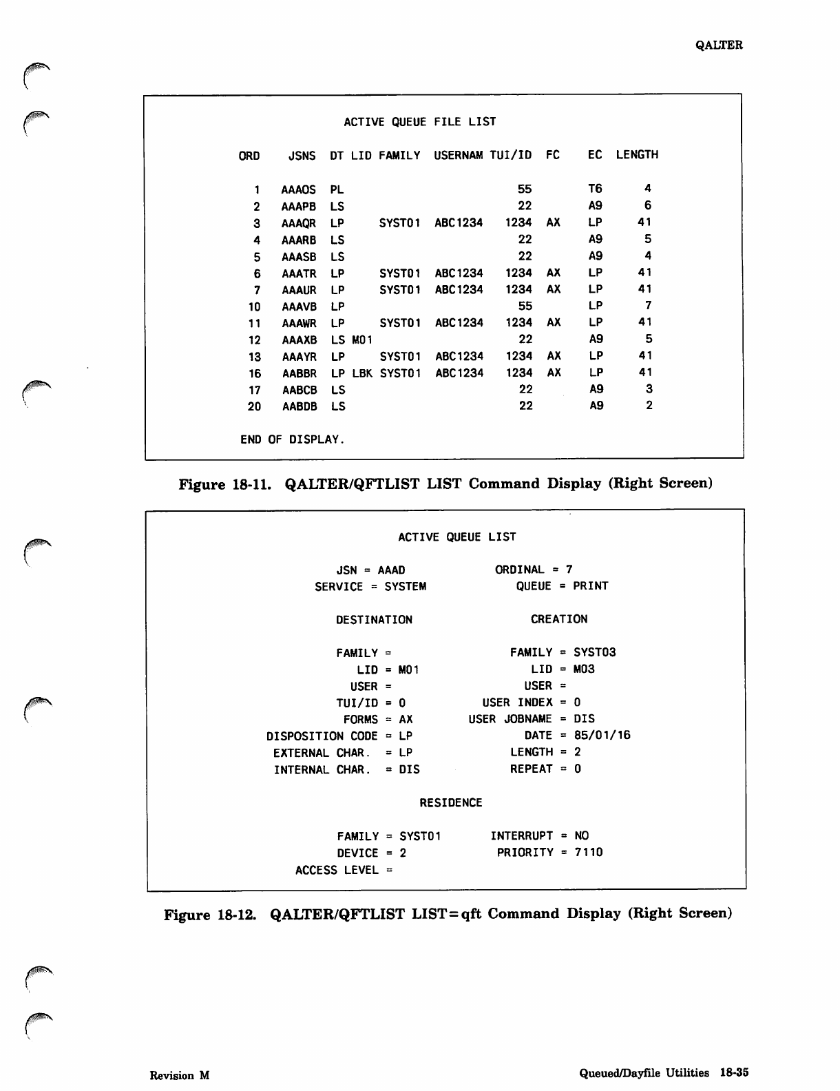
QALTER
ACTIVE QUEUE FILE LIST
ORD JSNS DT LID FAMILY USERNAM TUI/ID FC EC LENGTH
1AAAOS PL 55 T6
2AAAPB LS 22 A9
3AAAQR LP SYST01 ABC1234 1234 AX LP 41
4AAARB LS 22 A9
5AAASB LS 22 A9
6AAATR LP SYST01 ABC1234 1234 AX LP 41
7AAAUR LP SYST01 ABC1234 1234 AX LP 41
10 AAAVB LP 55 LP
11 AAAWR LP SYST01 ABC1234 1234 AX LP 41
12 AAAXB LS M01 22 A9
13 AAAYR LP SYST01 ABC1234 1234 AX LP 41
16 AABBR LP LBK SYST01 ABC1234 1234 AX LP 41
17 AABCB LS 22 A9
20 AABDB LS 22 A9
END OF DISPLAY.
Figure 18-11. QALTER/QFTLIST LIST Command Display (Right Screen)
ACTIVE QUEUE LIST
JSN = AAAD ORDINAL =
SERVICE = SYSTEM QUEUE = PRINT
DESTINATION CREATION
FAMILY FAMILY = SYST03
LID = M01 LID = M03
USER USER
TUI/ID = 0 USER INDEX = 0
FORMS = AX USER JOBNAME = DIS
DISPOSITION CODE = LP DATE = 85/01/16
EXTERNAL CHAR. = LP LENGTH = 2
INTERNAL CHAR. = DIS REPEAT = 0
RESIDENCE
FAMILY = SYST01 INTERRUPT = NO
DEVICE = 2 PRIORITY = 7110
ACCESS LEVEL
Figure 18-12. QALTER/QFTLIST LIST=qft Command Display (Right Screen)
Revision M Queued/Dayfile Utilities 18-35
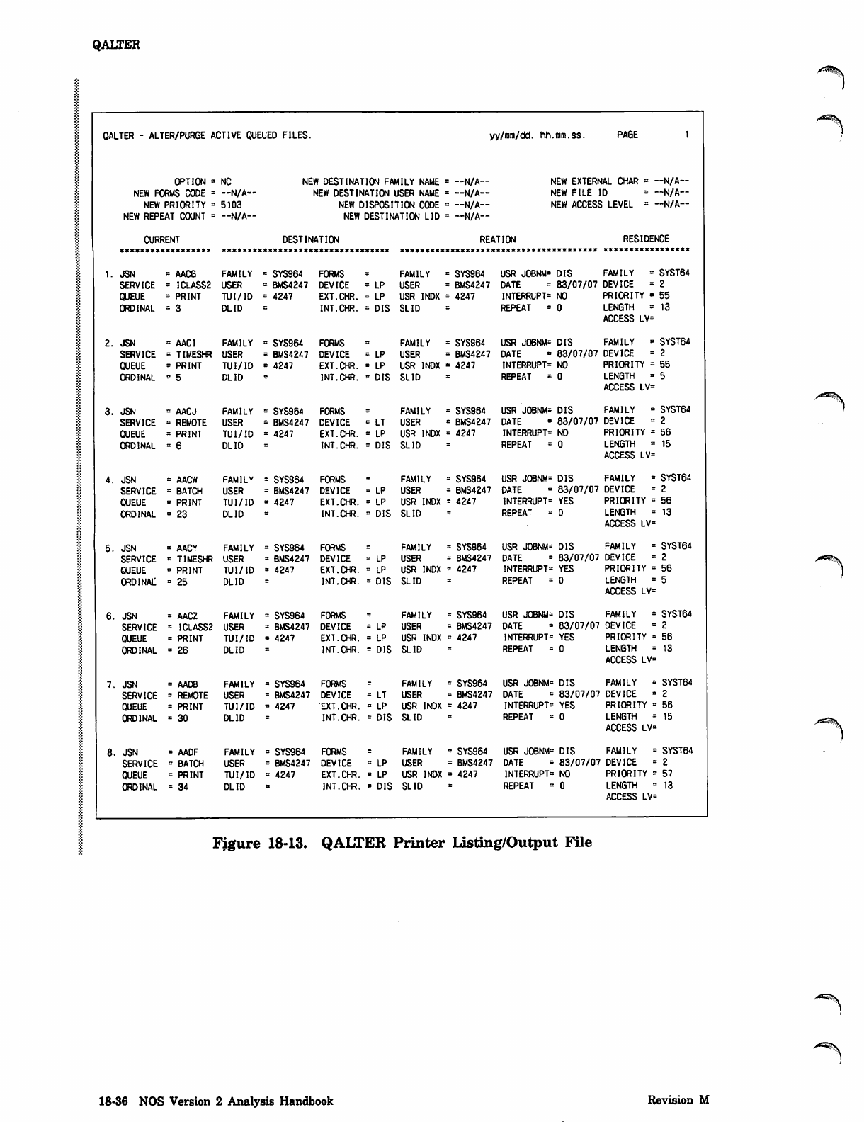
QALTER
A*^S
QALTER - ALTER/PURGE ACTIVE OUEUED FILES. yy/mm/dd. hh.mm.ss. PAGE
OPTION = NC NEW DESTINATION FAMILY NAME .. --N/A-- NEW EXTERNAL CHAR = --N/A—
NEW FORMS CODE = —N/A-- NEW DESTINATION USER NAME --N/A-- NEW FILE ID -N/A—
NEW PRIORITY = 5103 NEW DISPOSITION CODE --N/A-- NEW ACCESS LEVEL = --N/A—
NEW REPEAT COUNT = --N/A-- NEW DESTINATION LID --N/A--
CURRENT DESTINATION REATION RESIDENCE
IIIIIIIIIIUIIIIII iiiii>iiiititii»iitttiiiiiiiuii lII>IIIIIIIII<»lt»«»tl»»tIIIIIIUI IOIIIII1IIIIIIII
1. JSN « AAC6 FAMILY = SYS964 FORMS FAMILY SYS964 USR JOBNM= DIS FAMILY = SYST64
SERVICE = 1CLASS2 USER = BMS4247 DEVICE = LP USER BMS4247 DATE = 83/07/07 DEVICE =
QUEUE = PRINT TUI/1D = 4247 EXT.CHR. = LP USR INDX 4247 INTERRUPT= NO PRIORITY = 55
ORDINAL = 3 DLID INT.CHR. = DIS SLID REPEAT = 0 LENGTH =
ACCESS LV=
13
2. JSN « AACI FAMILY ■ SYS964 FORMS FAMILY SYS964 USR JOBNM= DIS FAMILY = SYST64
SERVICE = TIMESW USER = BMS4247 DEVICE = LP USER BMS4247 DATE = 83/07/07 DEVICE =
QUEUE = PRINT TUI/ID = 4247 EXT.CHR. = LP USR INDX 4247 INTERRUPT= NO PRIORITY = 55
ORDINAL = 5 DLID INT.CHR. = DIS SLID REPEAT = 0 LENGTH =
ACCESS LV=
3. JSN = AACJ FAMILY = SYS964 FORMS FAMILY SYS964 USR JOBNM= DIS FAMILY = SYST64
SERVICE = REMOTE USER = BMS4247 DEVICE = LT USER BMS4247 DATE = 83/07/07 DEVICE =
QUEUE = PRINT TUI/ID = 4247 EXT.CHR. = LP USR INDX 4247 INTERRUPT= NO PRIORITY = 56
ORDINAL = 6 DLID INT.CHR. = DIS SLID REPEAT = 0 LENGTH =
ACCESS LV=
15
4. JSN = AACW FAMILY = SYS964 FORMS FAMILY SYS964 USR JOBNM= DIS FAMILY = SYST64
SERVICE = BATCH USER = BMS4247 DEVICE = LP USER BMS4247 DATE = 83/07/07 DEVICE =
QUEUE = PRINT TUI/ID = 4247 EXT.CHR. = LP USR INDX 4247 1NTERRUPT= YES PRIORITY = 56
ORDINAL = 23 DLID INT.CHR. = DIS SLID REPEAT = 0 LENGTH =
ACCESS LV=
13
5. JSN = AACY FAMILY = SYS964 FORMS FAMILY SYS964 USR JOBNM= DIS FAMILY = SYST64
SERVICE = T1MESHR USER = BMS4247 DEVICE = LP USER BMS4247 DATE = 83/07/07 DEVICE =
QUEUE = PRINT TUI/ID = 4247 EXT.CHR. = LP USR INDX 4247 INTERRUPT= YES PRIORITY = 56
ORDINAL1 = 25 DLID INT.CHR. = DIS SLID REPEAT = 0 LENGTH =
JSN
SERVICE
QUEUE
ORDINAL
JSN
SERVICE
QUEUE
ORDINAL
8. JSN
SERVICE
QUEUE
ORDINAL
AACZ FAMILY
ICLASS2 USER
PRINT TUI/ID
26 DLID
AADB FAMILY
REMOTE USER
PRINT TUI/ID
30 DLID
AADF FAMILY
BATCH USER
PRINT TUI/ID
34 DLID
SYS964 FORMS
BMS4247 DEVICE
42 47 EXT.CH R.
INT.CHR.
SYS964 FORMS
BMS4247 DEVICE
4247 EXT.CHR.
INT.CHR.
SYS964 FORMS
BMS4247 DEVICE
42 47 EXT.CH R.
INT.CHR.
FAMILY
LP USER
LP USR INDX
DIS SLID
FAMILY
LT USER
LP USR INDX
DIS SLID
FAMILY
LP USER
LP USR INDX
DIS SLID
ACCESS LV=
SYS964 USR JOBNM= DIS FAMILY = SYST64
BMS4247 DATE = 83/07/07 DEVICE = 2
4247 INTERRUPT" YES PRIORITY = 56
R E P E A T = 0 L E N G T H = 1 3
ACCESS LV=
SYS964 USR JOBNM= DIS FAMILY = SYST64
BMS4247 DATE = 83/07/07 DEVICE = 2
4247 INTERRUPT* YES PRIORITY = 56
R E P E AT = 0 L E N G T H = 1 5
ACCESS LV=
SYS964 USR JOBNM=
BMS4247 DATE
4247 INTERRUPT'
REPEAT '-
DIS FAMILY = SYST64
83/07/07 DEVICE " 2
NO PRIORITY = 57
0 L E N G T H = 1 3
ACCESS LV=
/ ^ ^ \
Figure 18-13. QALTER Printer listing/Output File
A*ms
18-36 NOS Version 2 Analysis Handbook Revision M
QDUMP
QDUMP
QDUMP dumps selected queued files from a single device, a family of devices, or all
devices on the system. These queued files can be dumped to a tape or disk. When
active queued files are dumped, the QFT is searched to obtain the proper file. When
inactive queues are dumped, the IQFT is searched. QDUMP also provides a listing of
all files dumped with information about each file processed.
For a secured system, QDUMP determines the maximum range of access levels that
can be dumped. If the LA and UA parameters have been used to select access level
limits, these limits will be used. If no access level limits were selected, QDUMP uses
the device limits determined by taking the lowest lower access limit and the highest
upper access limit of all the devices to be processed. If this range of access levels is
not within the system access level limits, QDUMP issues a diagnostic message.
When QDUMP is selected at the system console, the initial QDUMP K display (3
pages) appears on the left screen. This display contains a list of all applicable options
associated with QDUMP, their default values, and a short description of each (refer to
figures 18-14 through 18-16).
If the FM parameter is specified, indicating dumping of queued files from a specified
family of devices, the initial QDUMP left screen K display is replaced by the secondary
QDUMP K display (refer to figure 18-17). This display closely resembles the initial
QDUMP display but restricts QDUMP processing to the family of devices specified.
Each device in the specified family containing inactive queued files is indicated. In
addition, any parameter entered for the QDUMP utility is reflected in this display.
Parameters not entered remain at default values. Only the first screen of the secondary
QDUMP K display is shown, since the second and third screens have the same format
as the corresponding screens of the initial QDUMP K display.
After QDUMP processing has been completed and K-display interaction has been
terminated by
K.STOP.
a QDUMP output file is generated, indicating all files dumped. Figure 18-18 is an
example of this output.
Revision M Queued/Dayfile Utilities 18-37
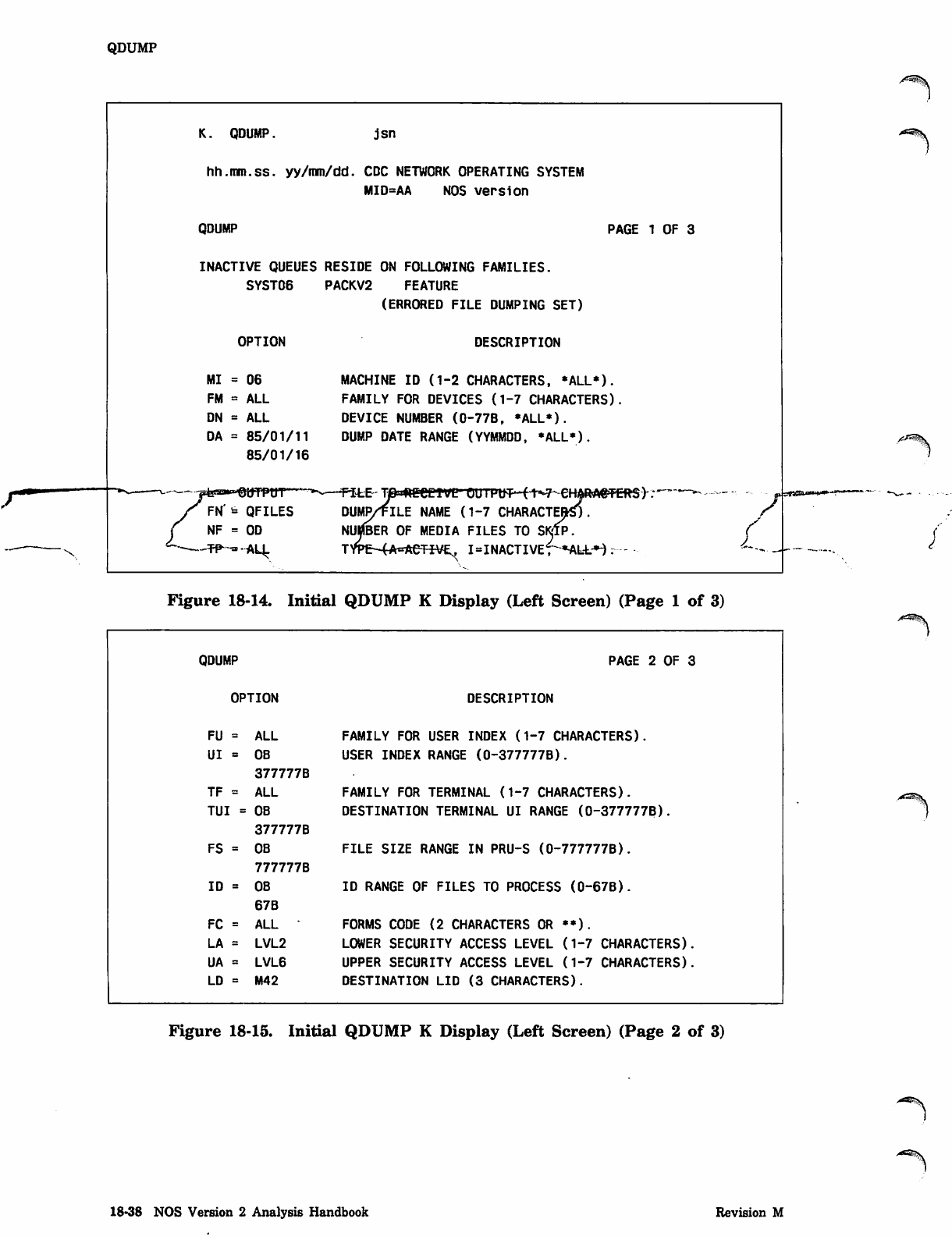
QDUMP
QDUMP. jsn
hh.mm.ss. yy/mm/dd. CDC NETWORK OPERATING SYSTEM
MID=AA NOS version
QDUMP
INACTIVE QUEUES RESIDE ON FOLLOWING FAMILIES.
SYST06 PACKV2 FEATURE
(ERRORED FILE DUMPING SET)
PAGE 1 OF 3
OPTION
MI = 06
FM = ALL
DN = ALL
DA = 85/01/11
85/01/16
DESCRIPTION
MACHINE ID (1-2 CHARACTERS, »ALL*).
FAMILY FOR DEVICES (1-7 CHARACTERS)
DEVICE NUMBER (0-77B, *ALL*).
DUMP DATE RANGE (YYMMDD, *ALL*).
•*"*—«fcE~ Tp«gCC!IV[! OUIHtfF-f'
FN'* QFILES DUMP/TILE NAME (1-7 CHARACTER
NF = OD NUIBER OF MEDIA FILES TO SKIP.
TP~'-AM_ TYPrMA^AeT-iVE^ I=INACTIVEr-*ALL-*} r
Figure 18-14. Initial QDUMP K Display (Left Screen) (Page 1 of 3)
QDUMP PAGE 2 OF 3
OPTION DESCRIPTION
FU = ALL FAMILY FOR USER INDEX (1-7 CHARACTERS).
UI » OB
377777B
USER INDEX RANGE (0-377777B).
TF = ALL FAMILY FOR TERMINAL (1-7 CHARACTERS).
TUI = OB
377777B
DESTINATION TERMINAL UI RANGE (0-377777B).
FS = OB
777777B
FILE SIZE RANGE IN PRU-S (0-777777B).
ID = OB
67B
ID RANGE OF FILES TO PROCESS (0-67B).
FC = ALL FORMS CODE (2 CHARACTERS OR ••).
LA = LVL2 LOWER SECURITY ACCESS LEVEL (1-7 CHARACTERS).
UA = LVL6 UPPER SECURITY ACCESS LEVEL (1-7 CHARACTERS).
LD = M42 DESTINATION LID (3 CHARACTERS).
Figure 18-15. Initial QDUMP K Display (Left Screen) (Page 2 of 3)
/•"Sgv
18-38 NOS Version 2 Analysis Handbook Revision M
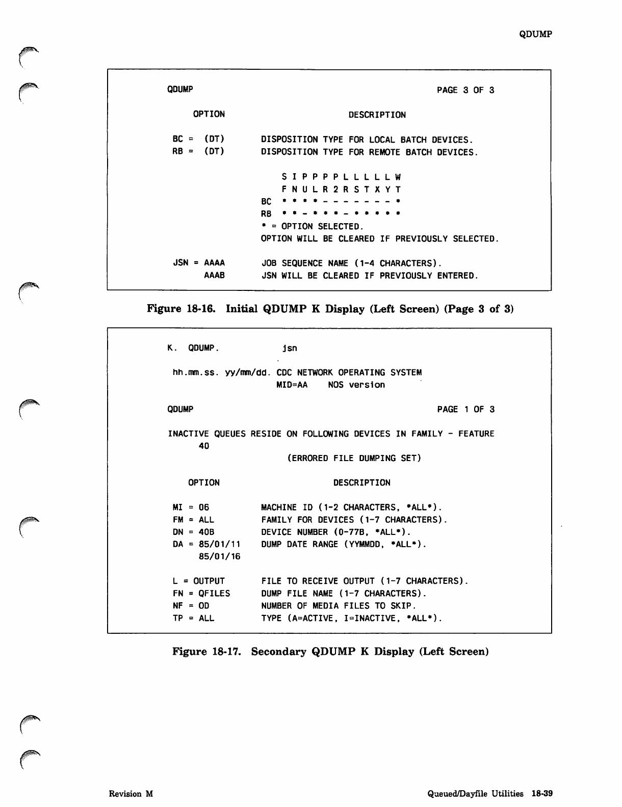
QDUMP
QDUMP PAGE 3 OF 3
OPTION DESCRIPTION
BC = (DT) DISPOSITION TYPE FOR LOCAL BATCH DEVICES.
RB = (DT) DISPOSITION TYPE FOR REMOTE BATCH DEVICES.
S I P P P P L L L L L W
F N U L R 2 R S T X Y T
BC **•*-------*
pg ••-*««_*»*•*
• = OPTION SELECTED.
OPTION WILL BE CLEARED IF PREVIOUSLY SELECTED.
JSN = AAAA JOB SEQUENCE NAME (1-4 CHARACTERS).
AAAB JSN WILL BE CLEARED IF PREVIOUSLY ENTERED.
Figure 18-16. Initial QDUMP K Display (Left Screen) (Page 3 of 3)
K. QDUMP. jsn
hh.mm.ss. yy/mm/dd. CDC NETWORK OPERATING SYSTEM
MID=AA NOS version
QDUMP PAGE 1 OF 3
INACTIVE QUEUES RESIDE ON FOLLOWING DEVICES IN FAMILY - FEATURE
40
(ERRORED FILE DUMPING SET)
OPTION DESCRIPTION
MI = 06 MACHINE ID (1-2 CHARACTERS, *ALL*).
FM = ALL FAMILY FOR DEVICES (1-7 CHARACTERS).
DN = 40B DEVICE NUMBER (0-77B, *ALL*).
DA = 85/01/11 DUMP DATE RANGE (YYMMDD, *ALL»).
85/01/16
L = OUTPUT FILE TO RECEIVE OUTPUT (1-7 CHARACTERS).
FN = QFILES DUMP FILE NAME (1-7 CHARACTERS).
NF = OD NUMBER OF MEDIA FILES TO SKIP.
TP = ALL TYPE (A=ACTIVE, I=INACTIVE, *ALL*).
Figure 18-17. Secondary QDUMP K Display (Left Screen)
Revision M Queued/Dayfile Utilities 18-39
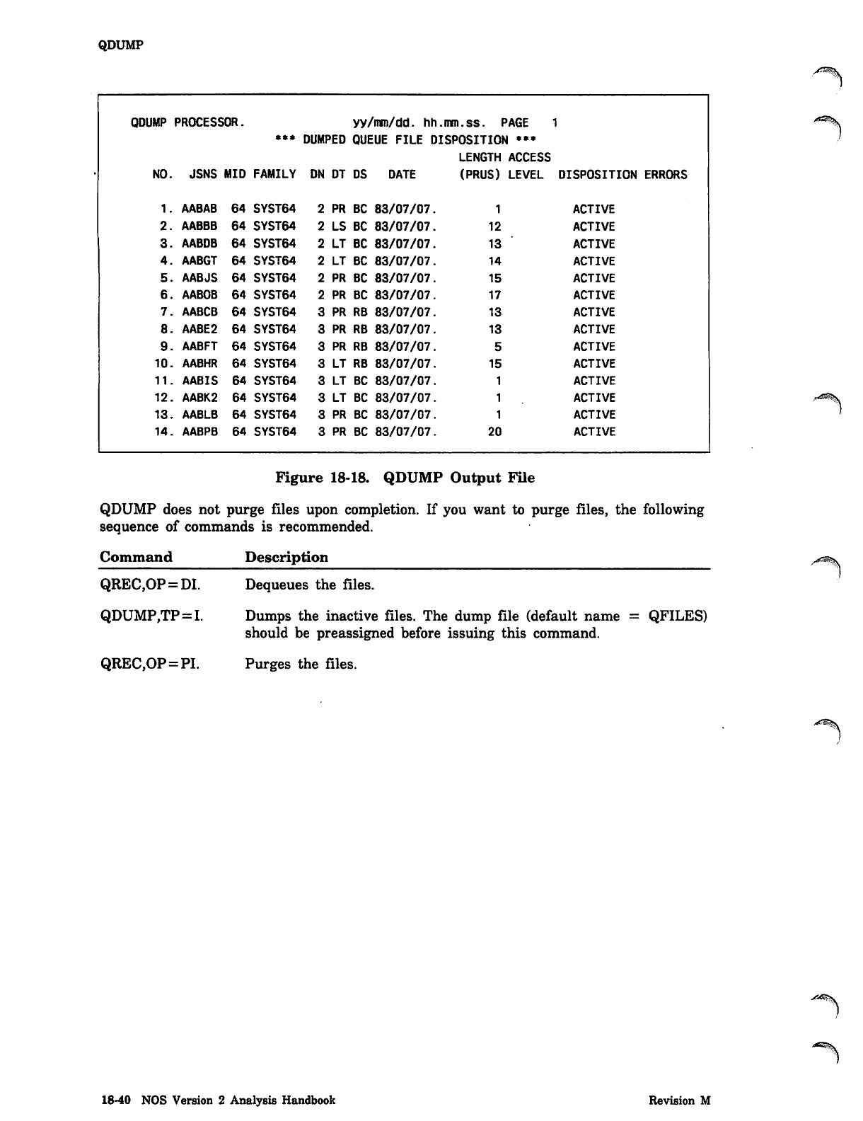
QDUMP
QDUMP PROCESSOR. yy/mm/dd. hh mm.ss. PAGE
*»* DUMPED QUEUE FILE DISPOSITION • **
LENGTH ACCESS
NO. JSNS MID FAMILY DN DT DS DATE (PRUS) LEVEL DISPOSITION ERRORS
1. AABAB 64 SYST64 2 PR BC 83/07/07. ACTIVE
2. AABBB 64 SYST64 2 LS BC 83/07/07. 12 ACTIVE
3. AABDB 64 SYST64 2 LT BC 83/07/07. 13 ACTIVE
4. AABGT 64 SYST64 2 LT BC 83/07/07. 14 ACTIVE
5. AABJS 64 SYST64 2 PR BC 83/07/07. 15 ACTIVE
6. AABOB 64 SYST64 2 PR BC 83/07/07. 17 ACTIVE
7. AABCB 64 SYST64 3 PR RB 83/07/07. 13 ACTIVE
8. AABE2 64 SYST64 3 PR RB 83/07/07. 13 ACTIVE
9. AABFT 64 SYST64 3 PR RB 83/07/07. ACTIVE
10. AABHR 64 SYST64 3 LT RB 83/07/07. 15 ACTIVE
11. AABIS 64 SYST64 3 LT BC 83/07/07. ACTIVE
12. AABK2 64 SYST64 3 LT BC 83/07/07. ACTIVE
13. AABLB 64 SYST64 3 PR BC 83/07/07. ACTIVE
14. AABPB 64 SYST64 3 PR BC 83/07/07. 20 ACTIVE
Figure 18-18. QDUMP Output File
QDUMP does not purge files upon completion. If you want to purge files, the following
sequence of commands is recommended.
Command Description
QREC,OP=DI.
QDUMP,TP = I.
QREC,OP=PI.
Dequeues the files.
Dumps the inactive files. The dump file (default name = QFILES)
should be preassigned before issuing this command.
Purges the files.
S**€?2>s
18-40 NOS Version 2 Analysis Handbook Revision M
jfms
y^s
r
QFTUST
QFTLIST
QFTLIST displays and/or lists routing and other information about active queued files.
Its operation is similar to that of QALTER, except file alteration or purging is not
allowed. When QFTLIST is selected at the system console, the QFTLIST K display
appears on the left screen. This display contains a list of all applicable parameters
associated with QFTLIST, their default values, and a short description of each (refer to
figures 18-8 through 18-10). The output generated by QFTLIST LIST and OUT
K-display commands (both printed and right screen K display) is similar or identical to
that produced by QALTER.
Example 1:
Use the QFTLIST utility to determine what actions are necessary to get queued files
processed by the RBF or BIO Subsystems. The following QFTLIST entry generates a
detailed list of queued files, from which forms code, id, and other destination routing
information can be determined. This information indicates what action must be taken
to have the files processed.
X.QFTLIST(PO=N,LO=F)
Example 2:
Use the QFTLIST utility to determine what queued files are routed to a particular
device. The following QFTLIST entry generates a list of all print files with forms code
of AA that are routed to a 580-20 (LT) printer. Input file selection is explicitly
disabled.
X.QFTLIST(PO=N,FC=AA,RB=IN,BC=NONE,BC=LT)
QLIST
QLIST lists inactive queued files, which may include all inactive queued files in the
system or a selected subset based on parameters specified when the utility is called.
The QLIST utility is not restricted to use from the system console. However, from the
system console, QLIST must be called directly with the following command. No
K-display interaction is available.
x.QLIST(opti=vali,opt2=val2, ■.-,optn=valn)
The applicable parameters associated with QLIST are the same as those used with the
QREC utility, except for the OP parameter. The OP parameter is not valid with
QLIST.
If all current inactive queued files are to be listed, no parameters need be specified. In
this case, the format of the QLIST call is:
X.QLIST.
The output generated by QLIST is the same as that produced by the LIST command
available under the QREC utility (refer to figure 18-31).
Revision M Queued/Dayfile Utilities 18-41
A^msx
QLOAD
QLOAD
QLOAD processes the dump files generated by QDUMP or other utilities using the
same format. QLOAD can selectively load the queued files from these dump files.
QLOAD can also list the contents of a dump file without loading any files.
For secured systems, the access level for each file selected to be loaded must be within
the file's origin type limits and the file must be assigned to an appropriate mass
storage device. If a selected file cannot be loaded, QLOAD issues a diagnostic message
and skips that file.
When QLOAD is selected at the system console, the QLOAD K display (3 pages)
appears on the left screen. This display contains a list of all applicable parameters
associated with QLOAD, their default values, and a short description of each (refer to
figures 18-19 through 18-21).
After QLOAD processing has been completed and K-display interaction has been
terminated by
K.STOP.
a QLOAD output file is generated, indicating all queued files which were contained on
the dump file, and whether they were loaded or not. Figure 18-22 contains an example
of this output.
Example:
Use the QDUMP and QLOAD utilities to dump queued files from one machine and
load them onto another. The following commands dump all punch files from machine ^*ms
AA. The QREC utility is used to dequeue the files and then purge them, because '
QDUMP does not purge files.
QREC,PO=N,I=DIRCTVS,OP=DI.
REWIND,DIRCTVS.
LABEL,QFILES,VSN=QUEUE,MT.
QDUMP,PO=N,I=DIRCTVS,TP=I.
REWIND,DIRCTVS.
QREC,PO=N,OP=PI,I=DIRCTVS.
File DIRCTVS is the input directive file that contains the following directives.
BC=NONE,BC=PH.
RB=NONE,RB=PH.
The following commands load the files dumped by the previous QDUMP onto another
machine.
LABEL,QFILES,VSN=QUEUE,MT.
QLOAD,PO=N,MI=AA,OP=A,DF=ALL.
18-42 NOS Version 2 Analysis Handbook Revision M
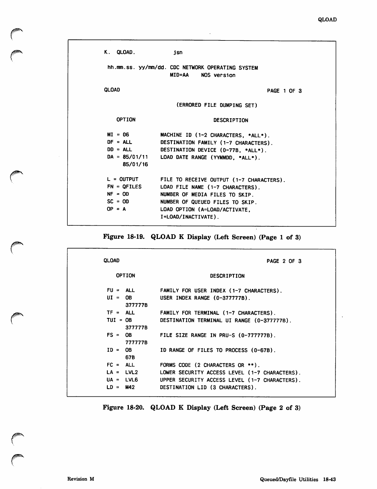
QLOAD
ypOB?5ky
QLOAD, jsn
hh.mm.ss. yy/mm/dd. CDC NETWORK OPERATING SYSTEM
MID=AA NOS version
QLOAD
OPTION
MI = 06
DF » ALL
DD = ALL
DA = 85/01/11
85/01/16
L = OUTPUT
FN = QFILES
NF = OD
SC = OD
OP = A
PAGE 1 OF 3
(ERRORED FILE DUMPING SET)
DESCRIPTION
MACHINE ID (1-2 CHARACTERS, *ALL*).
DESTINATION FAMILY (1-7 CHARACTERS)
DESTINATION DEVICE (0-77B, *ALL*).
LOAD DATE RANGE (YYMMDD, *ALL»).
FILE TO RECEIVE OUTPUT (1-7 CHARACTERS)
LOAD FILE NAME (1-7 CHARACTERS).
NUMBER OF MEDIA FILES TO SKIP.
NUMBER OF QUEUED FILES TO SKIP.
LOAD OPTION (A=LOAD/ACTIVATE,
I=LOAD/INACTIVATE).
Figure 18-19. QLOAD K Display (Left Screen) (Page 1 of 3)
QLOAD PAGE 2 OF 3
OPTION DESCRIPTION
FU = ALL FAMILY FOR USER INDEX (1-7 CHARACTERS).
UI = OB
377777B
USER INDEX RANGE (0-377777B).
TF = ALL FAMILY FOR TERMINAL (1-7 CHARACTERS).
TUI = OB
377777B
DESTINATION TERMINAL UI RANGE (0-377777B).
FS = OB
777777B
FILE SIZE RANGE IN PRU-S (0-777777B).
ID = OB
67B
ID RANGE OF FILES TO PROCESS (0-67B).
FC = ALL FORMS CODE (2 CHARACTERS OR •*).
LA = LVL2 LOWER SECURITY ACCESS LEVEL (1-7 CHARACTERS).
UA = LVL6 UPPER SECURITY ACCESS LEVEL (1-7 CHARACTERS).
LD = M42 DESTINATION LID (3 CHARACTERS).
Figure 18-20. QLOAD K Display (Left Screen) (Page 2 of 3)
Revision M Queued/Dayfile Utilities 18-43
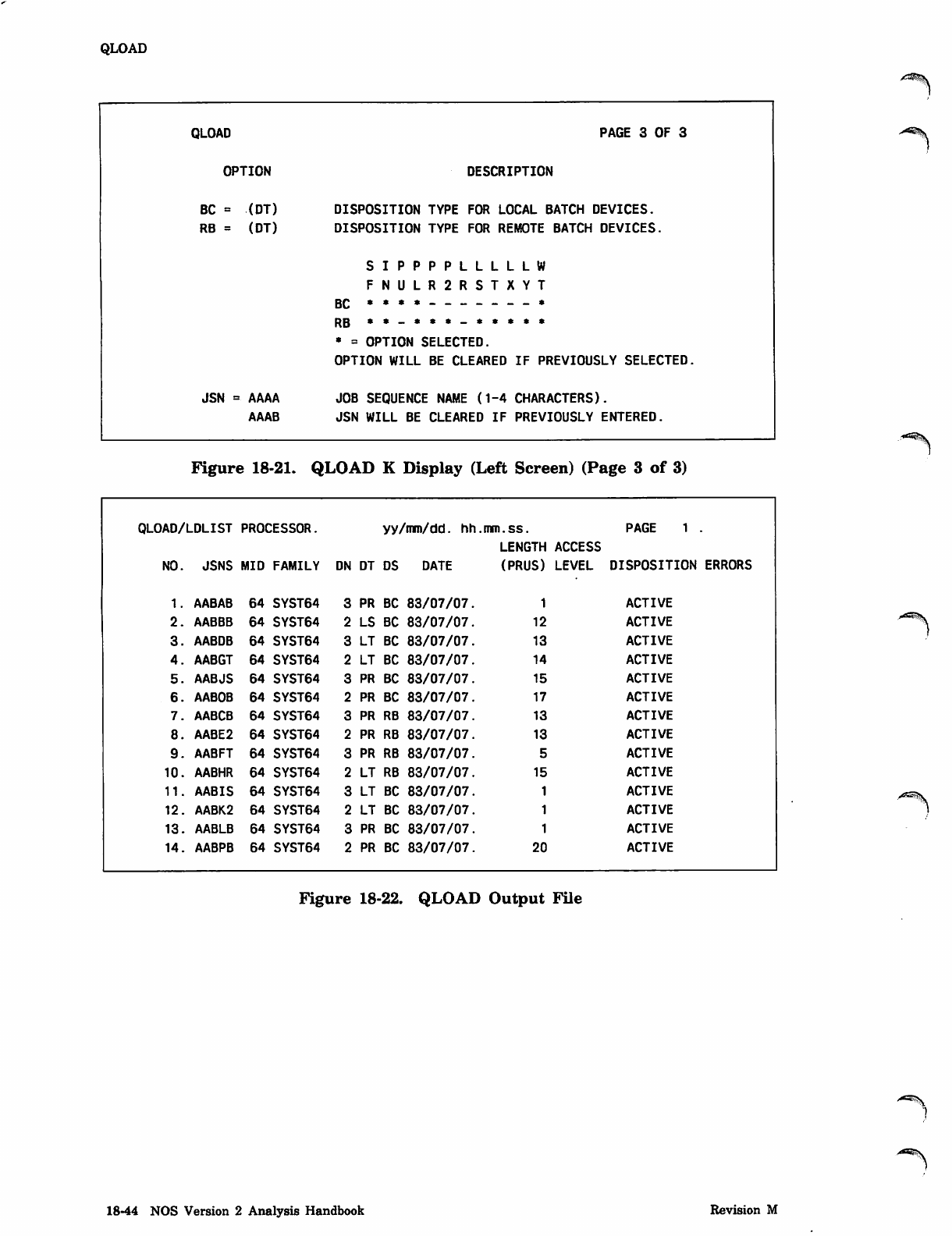
QLOAD
QLOAD PAGE 3 OF 3
OPTION DESCRIPTION
BC = (DT) DISPOSITION TYPE FOR LOCAL BATCH DEVICES.
RB = (DT) DISPOSITION TYPE FOR REMOTE BATCH DEVICES.
SIPPPPLLLLLW
FNULR2RSTXYT
BC ****-------*
PQ •*_«*•_*•***
* = OPTION SELECTED.
OPTION WILL BE CLEARED IF PREVIOUSLY SELECTED.
JSN = AAAA JOB SEQUENCE NAME (1-4 CHARACTERS).
AAAB JSN WILL BE CLEARED IF PREVIOUSLY ENTERED.
Figure 18-21. QLOAD K Display (Left Screen) (Page 3 of 3)
QLOAD/LDLIST PROCESSOR. yy/mm/dd. hh mm.ss. PAGE 1 .
LENGTH ACCESS
NO. JSNS MID FAMILY DN DT DS DATE (PRUS) LEVEL DISPOSITION ERRORS
1. AABAB 64 SYST64 PR BC 83/07/07. ACTIVE
2. AABBB 64 SYST64 LS BC 83/07/07. 12 ACTIVE
3. AABDB 64 SYST64 LT BC 83/07/07. 13 ACTIVE
4. AABGT 64 SYST64 LT BC 83/07/07. 14 ACTIVE
5. AABJS 64 SYST64 PR BC 83/07/07. 15 ACTIVE
6. AABOB 64 SYST64 PR BC 83/07/07. 17 ACTIVE
7. AABCB 64 SYST64 PR RB 83/07/07. 13 ACTIVE
8. AABE2 64 SYST64 PR RB 83/07/07. 13 ACTIVE
9. AABFT 64 SYST64 PR RB 83/07/07. ACTIVE
10. AABHR 64 SYST64 LT RB 83/07/07. 15 ACTIVE
11. AABIS 64 SYST64 LT BC 83/07/07. ACTIVE
12. AABK2 64 SYST64 LT BC 83/07/07. ACTIVE
13. AABLB 64 SYST64 PR BC 83/07/07. ACTIVE
14. AABPB 64 SYST64 PR BC 83/07/07. 20 ACTIVE
Figure 18-22. QLOAD Output File
-^^S\
18-44 NOS Version 2 Analysis Handbook Revision M
QMOVE
QMOVE
f QMOVE moves queued files from one disk device to another. It also produces a listing
of all files moved with information about each file processed.
For secured systems, the destination device for each file selected to be moved must
have access level limits that are appropriate to accept the file. If the file is being
reactivated as well as moved, its access level must be within the file's origin type
limits. If a selected file cannot be moved, QMOVE issues a diagnostic message and
skips that file.
When QMOVE is selected at the system console, the initial QMOVE K display
(3 pages) appears on the left screen. This display contains a list of all applicable
parameters associated with QMOVE, their default values, and a short description of
each (refer to figures 18-23 through 18-25).
If the FM parameter is specified, indicating the loading of queued files to a specified
family of devices, the initial QMOVE left screen K display is replaced by the secondary
/^ QMOVE K display (refer to figure 18-26). This display closely resembles the initial
QMOVE display but restricts QMOVE processing to the family of devices specified.
Each device in the specified family containing inactive queued files is indicated. In
addition, any parameter entered for the QMOVE utility is reflected in this display.
Parameters not entered remain at default values. Only the first screen of the secondary
QMOVE K display is shown, since the second and third screens have the same format
as the corresponding screens of the initial QMOVE K display.
After QMOVE processing has been completed and K-display interaction has been
terminated by
K.STOP.
a QMOVE output file is generated, indicating all files moved. Figure 18-27 contains an
example of this output.
Revision M Queued/Dayfile Utilities 18-45
QMOVE
Example 1:
If there are inactive queued files residing on a removable device, you can activate
these files but must first move them to a nonremovable device. This example shows
how to use the QMOVE utility to move queued files from the removable device with
family name SYSTEM and device number 45 to the nonremovable device with family
name FAM1 and device number 5. The following entries are made from DSD.
X.QFSP.
K.jsn. jsn is the job sequence name of QFSP.
K.QMOVE.
K.FM=SYSTEM,DN=45.
K.DF=FAM1,DD=5.
K-OP=A. The moved files are active.
K.GO,STOP.
Example 2:
This example exhibits the relationships among the ID, TF/TUI, and FC parameters. "^
(Refer to the descriptions of these parameters for the types of files affected by them.)
The following command moves all local batch-destined output files with ID=6 and all
remote batch-destined output files to device 3 in family SYS. The BC and RB
parameters explicitly disable input file processing.
QMOVE,PO=N,DF=SYS,DD=3,ID=6,BC=IN,RB=IN.
The following command performs the same function as the previous command except
that no remote batch files are moved.
QMOVE,PO=N,DF=SYS,DD=3,ID=6,BC=IN,RB=NONE.
18-46 NOS Version 2 Analysis Handbook Revision M
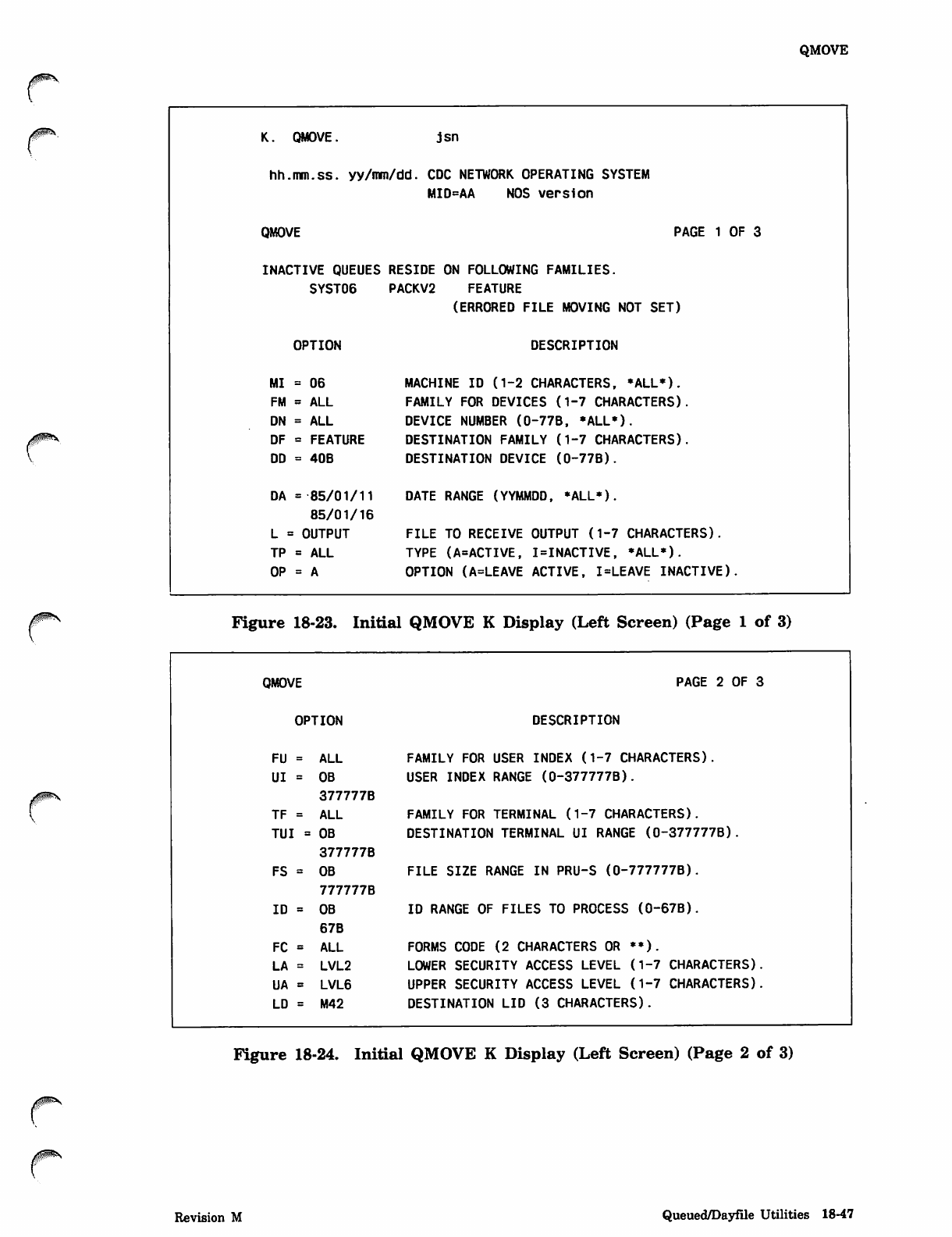
QMOVE
r
J^N
r
0§jm*\
K. QMOVE. jsn
hh.mm.ss. yy/mm/dd. CDC NETWORK OPERATING SYSTEM
MID=AA NOS version
QMOVE PAGE 1 OF 3
INACTIVE QUEUES RESIDE ON FOLLOWING FAMILIES.
SYST06 PACKV2 FEATURE
(ERRORED FILE MOVING NOT SET)
OPTION DESCRIPTION
MI = 06 MACHINE ID (1-2 CHARACTERS, *ALL*).
FM = ALL FAMILY FOR DEVICES (1-7 CHARACTERS).
DN = ALL DEVICE NUMBER (0-77B, *ALL*).
DF = FEATURE DESTINATION FAMILY (1-7 CHARACTERS).
DD = 40B DESTINATION DEVICE (0-77B).
DA =85/01/11 DATE RANGE (YYMMDD, *ALL*).
85/01/16
L = OUTPUT FILE TO RECEIVE OUTPUT (1-7 CHARACTERS).
TP = ALL TYPE (A=ACTIVE, I=INACTIVE, *ALL*).
OP = A OPTION (A=LEAVE ACTIVE, I=LEAVE INACTIVE).
Figure 18-23. Initial QMOVE K Display (Left Screen) (Page 1 of 3)
QMOVE PAGE 2 OF 3
OPTION DESCRIPTION
FU = ALL FAMILY FOR USER INDEX (1-7 CHARACTERS).
UI = OB
377777B
USER INDEX RANGE (0-377777B).
TF = ALL FAMILY FOR TERMINAL (1-7 CHARACTERS).
TUI = OB
377777B
DESTINATION TERMINAL UI RANGE (0-377777B).
FS = OB
777777B
FILE SIZE RANGE IN PRU-S (0-777777B).
ID = OB
67B
ID RANGE OF FILES TO PROCESS (0-67B).
FC = ALL FORMS CODE (2 CHARACTERS OR *•).
LA = LVL2 LOWER SECURITY ACCESS LEVEL (1-7 CHARACTERS).
UA = LVL6 UPPER SECURITY ACCESS LEVEL (1-7 CHARACTERS).
LD = M42 DESTINATION LID (3 CHARACTERS).
Figure 18-24. Initial QMOVE K Display (Left Screen) (Page 2 of 3)
Revision M Queued/Dayfile Utilities 18-47
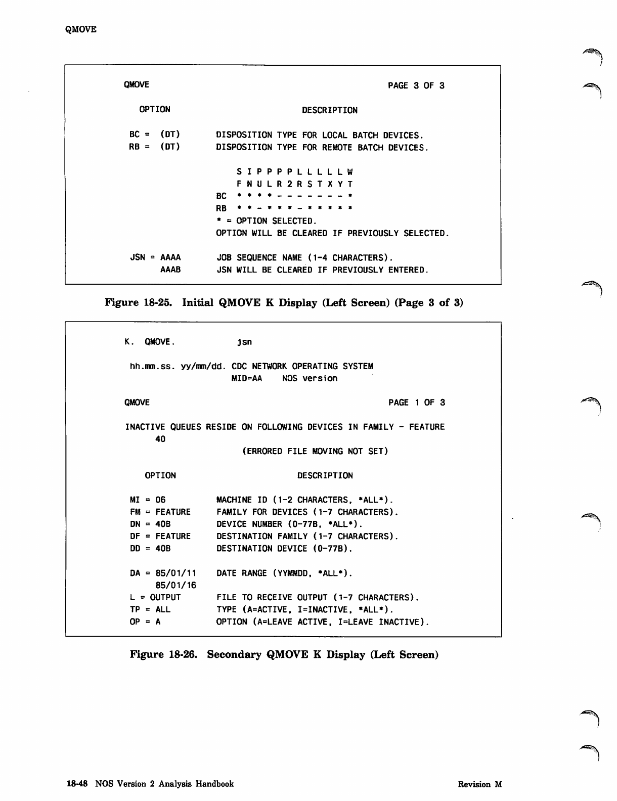
QMOVE
QMOVE
OPTION
BC = (D T )
R B = ( D T )
PAGE 3 OF 3
DESCRIPTION
JSN = AAAA
AAAB
DISPOSITION TYPE FOR LOCAL BATCH DEVICES.
DISPOSITION TYPE FOR REMOTE BATCH DEVICES.
SIPPPPLLLLLW
FNULR2RSTXYT
B C * * * * •
* = OPTION SELECTED.
OPTION WILL BE CLEARED IF PREVIOUSLY SELECTED.
JOB SEQUENCE NAME (1-4 CHARACTERS).
JSN WILL BE CLEARED IF PREVIOUSLY ENTERED.
Figure 18-25. Initial QMOVE K Display (Left Screen) (Page 3 of 3)
K. QMOVE. jsn
hh.mm.ss. yy/mm/dd. CDC NETWORK OPERATING SYSTEM
MID=AA NOS version
QMOVE PAGE 1 OF 3
INACTIVE QUEUES RESIDE ON FOLLOWING DEVICES IN FAMILY - FEATURE
40
(ERRORED FILE MOVING NOT SET)
OPTION DESCRIPTION
MI = 06 MACHINE ID (1-2 CHARACTERS, *ALL*).
FM = FEATURE FAMILY FOR DEVICES (1-7 CHARACTERS).
DN = 40B DEVICE NUMBER (0-77B, *ALL*).
DF = FEATURE DESTINATION FAMILY (1-7 CHARACTERS).
DD = 40B DESTINATION DEVICE (0-77B).
DA = 85/01/11 DATE RANGE (YYMMDD, *ALL*).
85/01/16
L = OUTPUT FILE TO RECEIVE OUTPUT (1-7 CHARACTERS).
TP = ALL TYPE (A=ACTIVE, I=INACTIVE, *ALL*).
OP = A OPTION (A=LEAVE ACTIVE, I=LEAVE INACTIVE).
Figure 18-26. Secondary QMOVE K Display (Left Screen)
/<s^is
18-48 NOS Version 2 Analysis Handbook Revision M
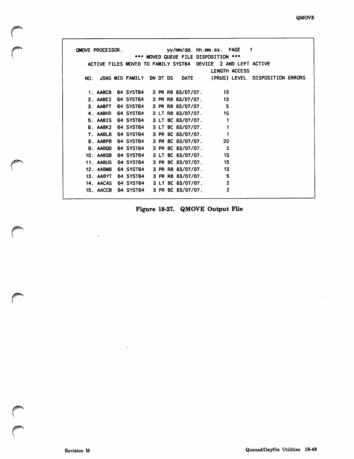
QMOVE
QMOVE PROCESSOR. yy/mm/dd. hh .mm.ss. PAGE 1
• ** MOVED QUEUE FILE DISPOSITION •••
ACTIVE FILES MOVED TO FAMILY SYST64 DEVICE 2 AND LEFT ACTIVE
LENGTH ACCESS
NO. JSNS MID FAMILY DN DT DS DATE (PRUS) LEVEL DISPOSITION ERRORS
1. AABCB 64 SYST64 3 PR RB 83/07/07. 13
2. AABE2 64 SYST64 3 PR RB 83/07/07. 13
3. AABFT 64 SYST64 3 PR RB 83/07/07.
4. AABHR 64 SYST64 3 LT RB 83/07/07. 15
5. AABIS 64 SYST64 3 LT BC 83/07/07.
6. AABK2 64 SYST64 3 LT BC 83/07/07.
7. AABLB 64 SYST64 3 PR BC 83/07/07.
8. AABPB 64 SYST64 3 PR BC 83/07/07. 20
9. AABQB 64 SYST64 3 PR BC 83/07/07.
10. AABSB 64 SYST64 3 LT BC 83/07/07. 13
11. AABUS 64 SYST64 3 PR BC 83/07/07. 15
12. AABWB 64 SYST64 3 PR RB 83/07/07. 13
13. AABYT 64 SYST64 3 PR RB 83/07/07.
14. AACAS 64 SYST64 3 LT BC 83/07/07.
15. AACCB 64 SYST64 3 PR BC 83/07/07.
Figure 18-27. QMOVE Output File
Revision M Queued/Dayfile Utilities 18-49
QREC
QREC
QREC deactivates or activates selected queued files and purges selected inactive queued
files.
For secured systems, the access level for any file selected to be reactivated must be
within the file's origin type limits. If a selected file cannot be processed, QREC issues
a diagnostic message and skips that file.
When QREC is selected at the system console, the initial QREC K display (3 pages)
appears on the left screen. This display contains a list of all applicable parameters
associated with QREC, their default values, and a short description of each (refer to
figures 18-28 through 18-30).
A complete list of current inactive queued files is displayed on the right screen when
you enter this command:
K.LIST.
When this command is processed, the right screen K display is automatically replaced
with the inactive queues K display (refer to figure 18-31). The information presented in
this display is the same as that generated by the QLIST utility. The list of files
displayed is also written to the output file specified by the QREC L parameter.
If the FM parameter is specified, indicating processing of queued files for a specified
family of devices, the initial QREC left screen K display is replaced by the secondary
QREC K display (refer to figure 18-32). This display closely resembles the initial
QREC display but restricts QREC processing to the family of devices specified. Each
device in the specified family containing inactive queued files is indicated. In addition, '*s%
any parameter entered for the QREC utility is reflected in this display. Parameters not ■
entered remain at default values. Only the first screen of the secondary QREC K
display is shown, since the second and third screens have the same format as the
corresponding screens of the initial QREC K display.
After QREC processing has been completed and K-display interaction has been
terminated by
K.STOP.
a QREC output file is generated, indicating the disposition of all queued files
processed. Figure 18-33 is an example of this output.
18-50 NOS Version 2 Analysis Handbook Revision M
/0m\
QREC
Example 1:
If the QFT is becoming full, you can enter QREC from DSD to dequeue active queued
files and free up QFT space. This QREC entry dequeues all queued files:
X.QREC(OP=DI,PO=N)
If RBF is not active, you are still able to dequeue remote batch files by using QREC.
This QREC entry dequeues all remote batch files:
X.QREC(OP=DI,BC=NONE,PO=N)
If these are queued files that previously had been dequeued, you can activate these
files with QREC. This QREC entry requeues all inactive queued files:
X.QREC(OP=RI,PO=NU)
Example 2:
Purge all queued files (active and inactive) on a particular device by using QREC
either with or without an input directive file. The first method involves two calls to
QREC. The first QREC call dequeues (makes inactive) all active queued files on the
device with family name SYSTEM and device number 1, and the second QREC call
purges all inactive (and hence all) queued files on that same device.
QREC,PO=N,OP=DI,FM=SYSTEM,DN= 1.
QREC,PO=N,OP=PI.FM=SYSTEM,DN=1.
The second method involves only one command call to QREC to perform the same
function as the first method:
QREC,I=DIR.
File DIR is the input directive file that contains the following directives.
0P=DI,FM=SYSTEM,DN=1.
GO.
OP=PI,FM=SYSTEM,DN=1.
GO,STOP.
Revision M Queued/Dayfile Utilities 18-51
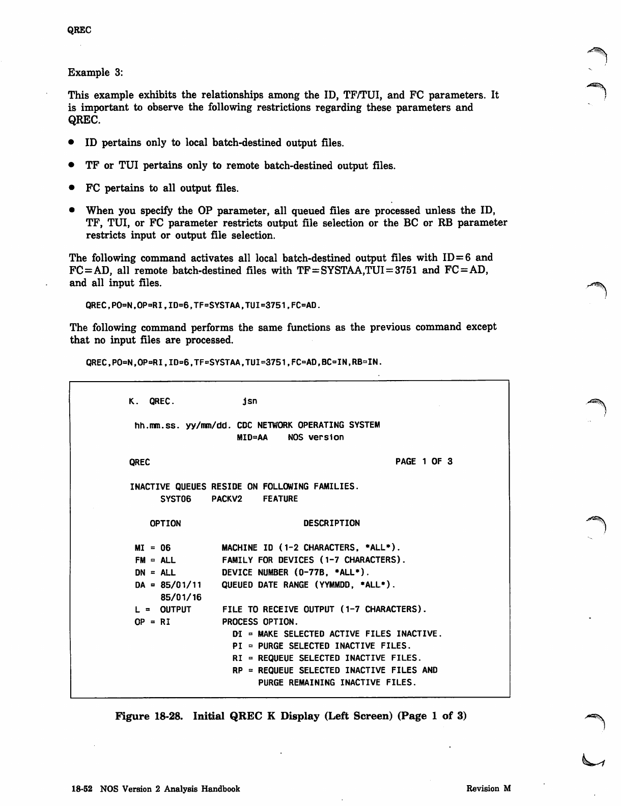
QREC
Example 3:
This example exhibits the relationships among the ID, TF/TUI, and FC parameters. It
is important to observe the following restrictions regarding these parameters and
QREC.
• ID pertains only to local batch-destined output files.
• TF or TUI pertains only to remote batch-destined output files.
• FC pertains to all output files.
• When you specify the OP parameter, all queued files are processed unless the ID,
TF, TUI, or FC parameter restricts output file selection or the BC or RB parameter
restricts input or output file selection.
The following command activates all local batch-destined output files with ID=6 and
FC=AD, all remote batch-destined files with TF=SYSTAA,TUI = 3751 and FC=AD,
and all input files.
QREC,P0=N,0P=RI,ID=6,TF=SYSTAA,TUI=3751,FC=AD.
The following command performs the same functions as the previous command except
that no input files are processed.
QREC,P0=N,0P=RI,ID=6,TF=SYSTAA,TUI=3751,FC=AD,BC=IN,RB=IN.
K. QREC. jsn
hh.mm.ss. yy/mm/dd. CDC NETWORK OPERATING SYSTEM
MID=AA NOS version
QREC PAGE 1 OF 3
INACTIVE QUEUES RESIDE ON FOLLOWING FAMILIES.
SYST06 PACKV2 FEATURE
OPTION DESCRIPTION
MI = 06 MACHINE ID (1-2 CHARACTERS, *ALL*).
FM = ALL FAMILY FOR DEVICES (1-7 CHARACTERS).
DN = ALL DEVICE NUMBER (0-77B, *ALL*).
DA = 85/01/11 QUEUED DATE RANGE (YYMMDD, *ALL*).
85/01/16
L = OUTPUT FILE TO RECEIVE OUTPUT (1-7 CHARACTERS).
OP = RI PROCESS OPTION.
Di = MAKE SELECTED ACTIVE FILES INACTIVE.
PI = PURGE SELECTED INACTIVE FILES.
RI = REQUEUE SELECTED INACTIVE FILES.
RP = REQUEUE SELECTED INACTIVE FILES AND
PURGE REMAINING INACTIVE FILES.
Figure 18-28. Initial QREC K Display (Left Screen) (Page 1 of 3)
18-52 NOS Version 2 Analysis Handbook Revision M
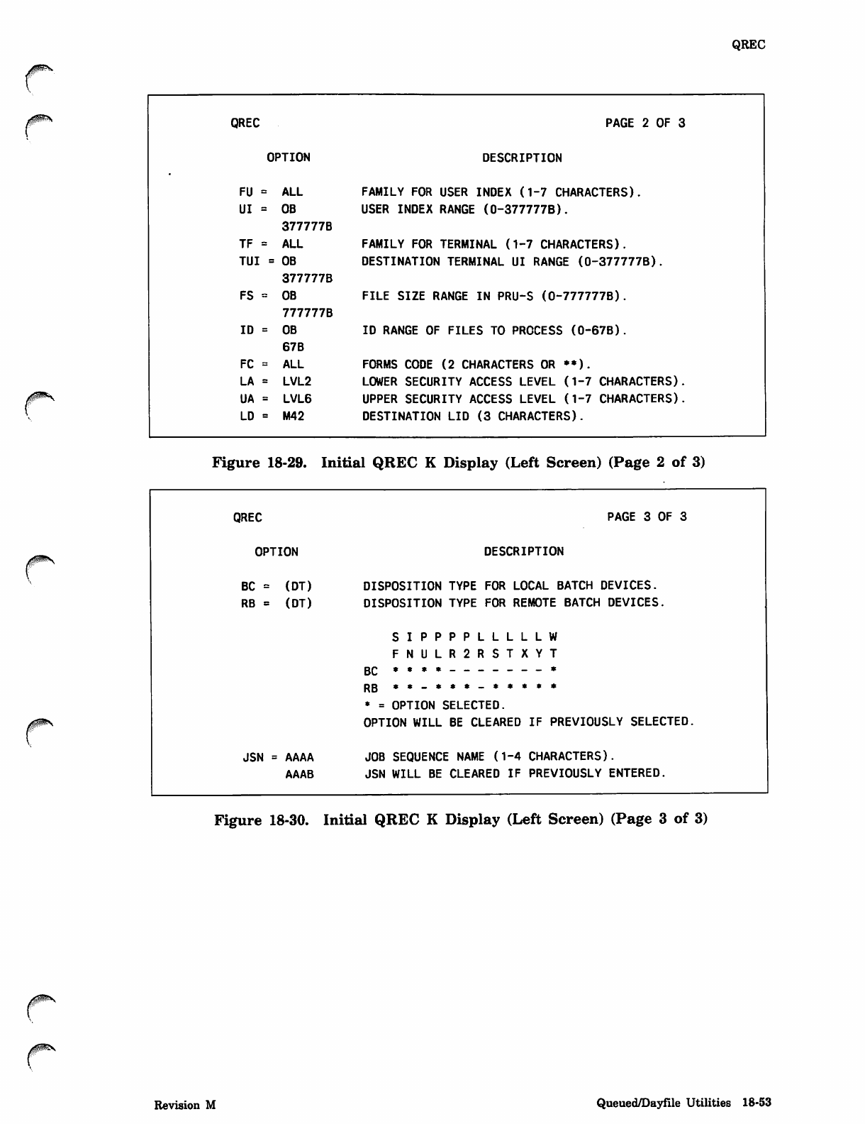
QREC
/£y$fo!\
QREC PAGE 2 OF 3
OPTION DESCRIPTION
FU = ALL FAMILY FOR USER INDEX (1-7 CHARACTERS).
UI = OB
377777B
USER INDEX RANGE (0-377777B).
TF = ALL FAMILY FOR TERMINAL (1-7 CHARACTERS).
TUI = OB
377777B
DESTINATION TERMINAL UI RANGE (0-377777B).
FS = OB
777777B
FILE SIZE RANGE IN PRU-S (0-777777B).
ID = OB
67B
ID RANGE OF FILES TO PROCESS (0-67B).
FC = ALL FORMS CODE (2 CHARACTERS OR **).
LA = LVL2 LOWER SECURITY ACCESS LEVEL (1-7 CHARACTERS).
UA = LVL6 UPPER SECURITY ACCESS LEVEL (1-7 CHARACTERS).
LD = M42 DESTINATION LID (3 CHARACTERS).
Figure 18-29. Initial QREC K Display (Left Screen) (Page 2 of 3)
QREC PAGE 3 OF 3
OPTION DESCRIPTION
BC = (DT) DISPOSITION TYPE FOR LOCAL BATCH DEVICES.
RB = (DT) DISPOSITION TYPE FOR REMOTE BATCH DEVICES.
S I P P P P L L L L L W
F N U L R 2 R S T X Y T
BC *•»*-------*
pg »»_»**_**»»*
* = OPTION SELECTED.
OPTION WILL BE CLEARED IF PREVIOUSLY SELECTED.
JSN = AAAA JOB SEQUENCE NAME (1-4 CHARACTERS).
AAAB JSN WILL BE CLEARED IF PREVIOUSLY ENTERED.
Figure 18-30. Initial QREC K Display (Left Screen) (Page 3 of 3)
Revision M Queued/Dayfile Utilities 18-53
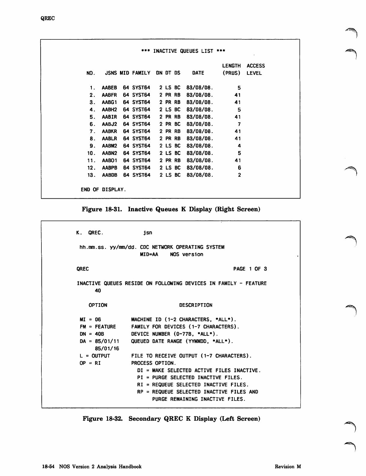
QREC
*** INACTIVE QUEUES LIST *•*
LENGTH ACCESS
NO. JSNS MID FAMILY DN DT DS DATE (PRUS) LEVEL
1. AABEB 64 SYST64 LS BC 83/08/08.
2. AABFR 64 SYST64 PR RB 83/08/08. 41
3. AABG1 64 SYST64 PR RB 83/08/08. 41
4. AABH2 64 SYST64 LS BC 83/08/08.
5. AABIR 64 SYST64 PR RB 83/08/08. 41
6. AABJ2 64 SYST64 PR BC 83/08/08.
7. AABKR 64 SYST64 PR RB 83/08/08. 41
8. AABLR 64 SYST64 PR RB 83/08/08. 41
9. AABM2 64 SYST64 LS BC 83/08/08.
10. AABN2 64 SYST64 LS BC 83/08/08.
11. AAB01 64 SYST64 PR RB 83/08/08. 41
12. AABPB 64 SYST64 LS BC 83/08/08.
13. AABDB 64 SYST64 LS BC 83/08/08.
END OF DISPLAY.
Figure 18-31. Inactive Queues K Display (Right Screen)
K. QREC. jsn
hh.mm.ss. yy/mm/dd. CDC NETWORK OPERATING SYSTEM
MID=AA NOS version
QREC PAGE 1 OF 3
INACTIVE QUEUES RESIDE ON FOLLOWING DEVICES IN FAMILY - FEATURE
40
OPTION DESCRIPTION
MI = 06 MACHINE ID (1-2 CHARACTERS, *ALL*).
FM = FEATURE FAMILY FOR DEVICES (1-7 CHARACTERS).
DN = 40B DEVICE NUMBER (0-77B, *ALL*).
DA = 85/01/11 QUEUED DATE RANGE (YYMMDD, *ALL*).
85/01/16
L = OUTPUT FILE TO RECEIVE OUTPUT (1-7 CHARACTERS).
OP = RI PROCESS OPTION.
DI = MAKE SELECTED ACTIVE FILES INACTIVE.
PI = PURGE SELECTED INACTIVE FILES.
RI = REQUEUE SELECTED INACTIVE FILES.
RP = REQUEUE SELECTED INACTIVE FILES AND
PURGE REMAINING INACTIVE FILES.
Figure 18-32. Secondary QREC K Display (Left Screen) s*^s
^^s.
18-54 NOS Version 2 Analysis Handbook Revision M
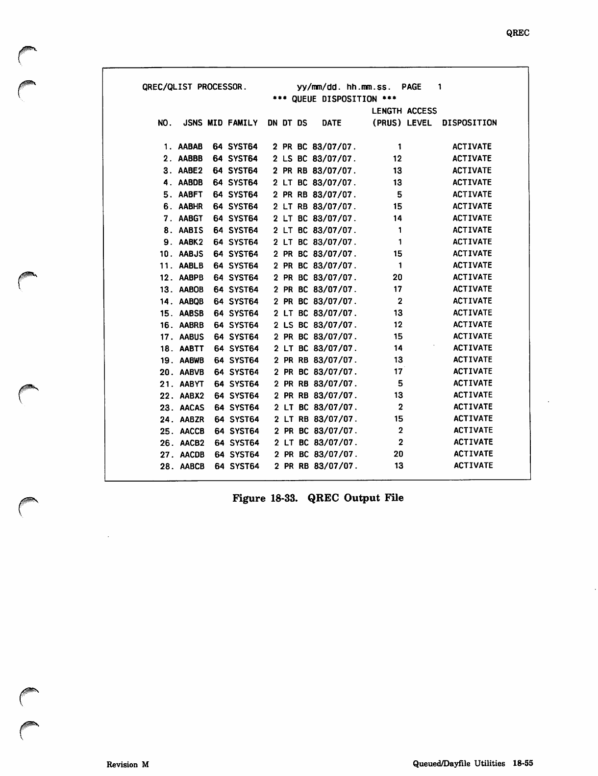
QREC
QREC/QLIST PROCESSOR.
NO. JSNS MID FAMILY
yy/mm/dd. hh.mm.ss. PAGE 1
*** QUEUE DISPOSITION ***
LENGTH ACCESS
DN DT DS DATE (PRUS) LEVEL DISPOSITION
1. AABAB 64 SYST64 PR BC 83/07/07. ACTIVATE
2. AABBB 64 SYST64 LS BC 83/07/07. 12 ACTIVATE
3. AABE2 64 SYST64 PR RB 83/07/07. 13 ACTIVATE
4. AABDB 64 SYST64 LT BC 83/07/07. 13 ACTIVATE
5. AABFT 64 SYST64 PR RB 83/07/07. ACTIVATE
6. AABHR 64 SYST64 LT RB 83/07/07. 15 ACTIVATE
7. AABGT 64 SYST64 LT BC 83/07/07. 14 ACTIVATE
8. AABIS 64 SYST64 LT BC 83/07/07. ACTIVATE
9. AABK2 64 SYST64 LT BC 83/07/07. ACTIVATE
10. AABJS 64 SYST64 PR BC 83/07/07. 15 ACTIVATE
11. AABLB 64 SYST64 PR BC 83/07/07. ACTIVATE
12. AABPB 64 SYST64 PR BC 83/07/07. 20 ACTIVATE
13. AABOB 64 SYST64 PR BC 83/07/07. 17 ACTIVATE
14. AABQB 64 SYST64 PR BC 83/07/07. ACTIVATE
15. AABSB 64 SYST64 LT BC 83/07/07. 13 ACTIVATE
16. AABRB 64 SYST64 LS BC 83/07/07. 12 ACTIVATE
17. AABUS 64 SYST64 PR BC 83/07/07. 15 ACTIVATE
18. AABTT 64 SYST64 LT BC 83/07/07. 14 ACTIVATE
19. AABWB 64 SYST64 PR RB 83/07/07. 13 ACTIVATE
20. AABVB 64 SYST64 PR BC 83/07/07. 17 ACTIVATE
21. AABYT 64 SYST64 PR RB 83/07/07. ACTIVATE
22. AABX2 64 SYST64 PR RB 83/07/07. 13 ACTIVATE
23. AACAS 64 SYST64 LT BC 83/07/07. ACTIVATE
24. AABZR 64 SYST64 LT RB 83/07/07. 15 ACTIVATE
25. AACCB 64 SYST64 PR BC 83/07/07. ACTIVATE
26. AACB2 64 SYST64 LT BC 83/07/07. ACTIVATE
27. AACDB 64 SYST64 PR BC 83/07/07. 20 ACTIVATE
28. AABCB 64 SYST64 PR RB 83/07/07. 13 ACTIVATE
0^^S
Figure 18-33. QREC Output File
Revision M Queued/Dayfile Utilities 18-55
Dayfile Dumping Utilities
Dayfile Dumping Utilities
The dayfile dumping utilities (AFD, DFD, ELD, GETLOG, MAINLOG) write all or
selected parts of the account dayfile, system dayfile, error log, or binary maintenance
log to a file. AFD, DFD, and ELD produce a listing (output) file. GETLOG writes the
error log, binary maintenance log, and an image of the equipment status table to files.
GETLOG is used to provide input to the Hardware Performance Analyzer (HPA).
MAINLOG produces its output in a binary format. A job using any of these utilities
must be of system origin, or you must have system origin privileges and the system
must be in debug mode. The following format is used to call the dayfile dumping
utilities.
A^^^S
utility,L=listfile,FR=string,OP=op,PD=pd,PL=pl,I=lnf11e.B»b1nflle,E»estfile.
or
ut1llty,Hstfi1e,string,op,pd,p1,1nfile,b1nflle,estf1le.
P a r a m e t e r D e s c r i p t i o n
utility
L=listfile
Utility called to perform the dayfile dump.
Utility Description
AFD Dump account dayfile.
DFD Dump system dayfile.
ELD Dump error log.
GETLOG Dump error log, binary maintenance log, and EST
image.
MAINLOG Dump binary maintenance log.
Output file containing the dayfile dump produced by AFD, DFD, or
ELD. For GETLOG, listfile is the file containing the error log. The
utility also places diagnostic messages in this file when various error
conditions occur. These messages begin with NOTICE*** to distinguish
them from the lines of the dayfile being processed; they are described
in the NOS Version 2 Operations Handbook.
The default name of listfile is OUTPUT for AFD, DFD, and ELD. The
default name is ERR for GETLOG. If L=0 is specified, no file is
written. L=listfile is not used with MAINLOG. The utility paginates
listfile if it is OUTPUT or if print density and page length are
specified.
/•***&s5y
r^^S
■'*S%v
18-56 NOS Version 2 Analysis Handbook Revision M
Dayfile Dumping Utilities
Parameter Description
0^S.
FR=string Search string for selective dayfile dumping. The utility searches the
dayfile for this string in the starting position of the field specified by
the OP=op parameter.
The string specified must begin with the first character in the field to
be searched. The time field begins with a blank.
If the string contains characters other than letters and numbers (such
as blanks), it must be enclosed by $ delimiters. A $ within the string
must be entered twice ($$) so it is not interpreted as a delimiter.
Interactive commands entered in the dayfile are preceded by a $
unless you were under the batch subsystem when you issued the
command. To search for an interactive command, the $ preceding the
command is replaced with two $s, and the command is enclosed by $
delimiters (for example, $$$OLD$).
If the string is found, the portion of the dayfile following the last
occurrence of the specified string is output. If the string is not found,
an informative message and the entire dayfile is output for jobs where
the output file is connected to a terminal; where the output file is not
connected to a terminal, the job receives only the informative message.
OP=op Dump option. If neither FR=string nor the OP dump option is
specified, default is OP = F for nonterminal output files. For terminal
output files, the default is OP=I. If FR is specified but OP is not,
default is OP = M.
op Description
F Full dayfile dump is taken.
I Incremental dump is taken. The dayfile is dumped starting from
the point of the last dayfile dump. AFD does not process the I
option when executed within a job with system origin privileges
that is not system origin.
J The job sequence name field in the dayfile is searched for the
string specified by FR=string. The dump begins from that
point.
M The message field in the dayfile is searched for the string
specified by FR = string. The dump begins from that point.
OP = M cannot be used with MAINLOG.
P Incremental dump is taken. The dayfile is dumped starting from
the point of the last dayfile dump with this job name.
T The time field in the dayfile is searched for the string specified
by FR=string. The dump begins from that point.
r
Revision M Queued/Dayfile Utilities 18-57
Dayfile Dumping Utilities
Parameter Description
PD=pd
PL=pl
I=infile
B=binfile
E=estfile
Print density in pd lines per inch (3, 4, 6, or 8). Default is PD=6. PD
cannot be used with MAINLOG.
Page length in pl lines per page. Default is based on the following
print densities. PL cannot be used with MAINLOG.
pd Default pl
30
40
60
80
An attached, terminated dayfile is to be used for input. For GETLOG,
infile is an attached terminated binary maintenance log. If omitted,
the utility uses the active dayfile for input.
File on which GETLOG and MAINLOG write the binary maintenance
log. These utilities write binfile with W-type records having C-type
blocking (refer to the CYBER Record Manager Basic Access Methods
Reference Manual for further information on record types and record
blocking). GETLOG and MAINLOG assume B=BML if this parameter
is omitted. If B = 0 is specified, no file is written.
File on which GETLOG writes an image of the equipment status table.
GETLOG assumes E=EST if this parameter is omitted. If E = 0 is
specified, no file is written.
18-58 NOS Version 2 Analysis Handbook Revision M
(*
SYSEDIT 19
Directives 19-3
*CM Directive ... .■ 13-3
*MS Directive 19-3
*AD Directive 19-4
*PROC Directive , 19-5
*SC Directive 19-6
*FL Directive 19-6
*/ Directive 19-7
♦DELETE Directive 19-7
*FILE Directive ,, 19-8
♦IGNORE Directive 19-8
*PPSYN Directive 19-8
Record Types 19-9
J^"
•f^
0s

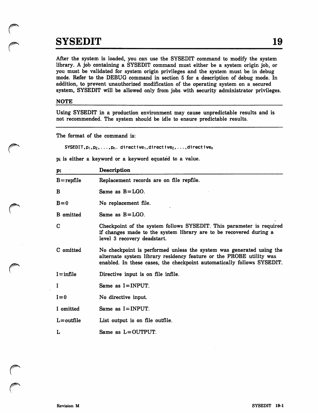
SYSEDIT 19
After the system is loaded, you can use the SYSEDIT command to modify the system
library. A job containing a SYSEDIT command must either be a system origin job, or
you must be validated for system origin privileges and the system must be in debug
mode. Refer to the DEBUG command in section 5 for a description of debug mode. In
addition, to prevent unauthorized modification of the operating system on a secured
system, SYSEDIT will be allowed only from jobs with security administrator privileges.
NOTE
Using SYSEDIT in a production environment may cause unpredictable results and is
not recommended. The system should be idle to ensure predictable results.
00*S
The format of the command is:
SYSEDIT,pi,p2,.. .,pn. directivei,direct1ve2 d1rectiven
pi is either a keyword or a keyword equated to a value.
pi Description
B=repfile Replacement records are on file repfile.
B Same as B=LGO.
B=0 No replacement file.
B omitted Same as B = LGO.
C Checkpoint of the system follows SYSEDIT. This parameter is required
if changes made to the system library are to be recovered during a
level 3 recovery deadstart.
C omitted No checkpoint is performed unless the system was generated using the
alternate system library residency feature or the PROBE utility was
enabled. In these cases, the checkpoint automatically follows SYSEDIT.
I=infile Directive input is on file infile.
I Same as I=INPUT.
1 = 0 No directive input.
I omitted Same as I = INPUT.
L=outfile List output is on file outfile.
L Same as L=OUTPUT.
Revision M SYSEDIT 19-1
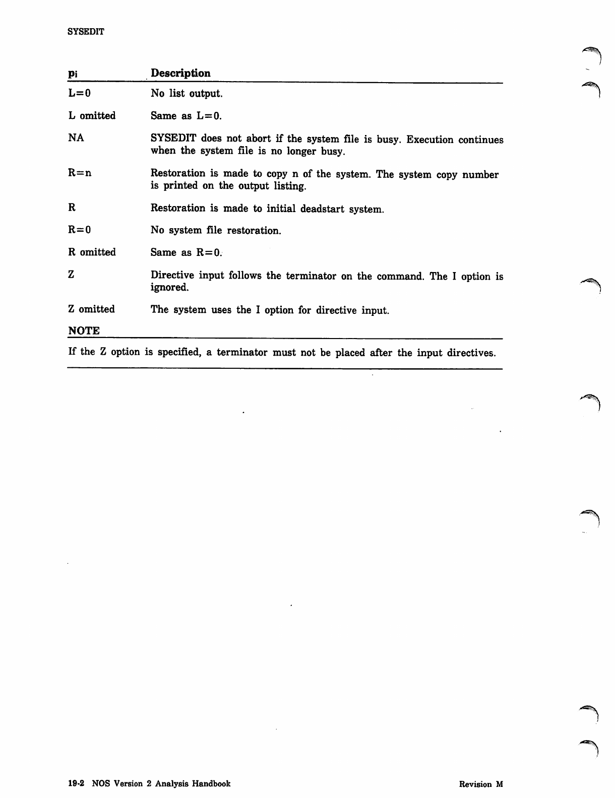
SYSEDIT
Pi Description
L=0 No list output.
L omitted Same as L=0.
NA SYSEDIT does not abort if the system file is busy. Execution continues
when the system file is no longer busy.
R=n Restoration is made to copy n of the system. The system copy number
is printed on the output listing.
R Restoration is made to initial deadstart system.
R = 0 N o s y s t e m fi l e r e s t o r a t i o n .
R omitted Same as R=0.
Z Directive input follows the terminator on the command. The I option is
ignored.
Z omitted The system uses the I option for directive input.
NOTE
If the Z option is specified, a terminator must not be placed after the input directives.
,aXt!s
19-2 NOS Version 2 Analysis Handbook Revision M
