NCB Large Fragment System Surgical Technique
2016-04-01
: Pdf Ncb Large Fragment System Surgical Technique NCB_Large_Fragment_System_Surgical_Technique 4 2016 pdf
Open the PDF directly: View PDF ![]() .
.
Page Count: 32

NCB®
Large Fragment
System
Surgical Technique

NCB® Large Fragment System – Surgical Technique 3
Table of Contents
Introduction 4
System Features 7
Indications and Contraindications 10
NCB Large Fragment Plate Positioning and Screw Fixation 10
NCB Screw Insertion 12
NCB Curved Femur Shaft Plate – Surgical Technique 14
NCB Straight Narrow Shaft Plate – Surgical Technique 19
Tips and Tricks for the NCB Large Fragment System 24
Post-Operative Treatment 25
Implant Removal 25
Product Information – Implants 26
Product Information – Instruments 29
Planning Aid 31

4NCB® Large Fragment System – Surgical Technique
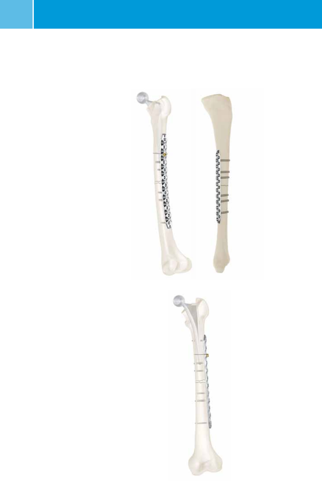
NCB Curved Femur Shaft Plate
NCB Straight Narrow Shaft Plate
Introduction
The NCB (Non-Contact Bridging) Large
Fragment System is a line of polyaxial
locking plates for the treatment of femur,
tibia and humerus shaft fractures. It con-
sists of a Curved Femur Shaft plate and a
Straight Narrow Shaft plate.
The NCB Curved Femur Shaft plate is also
included in the NCB Periprosthetic Femur
Polyaxial Locking Plate System.
NCB® Large Fragment System – Surgical Technique 5
Non
contact
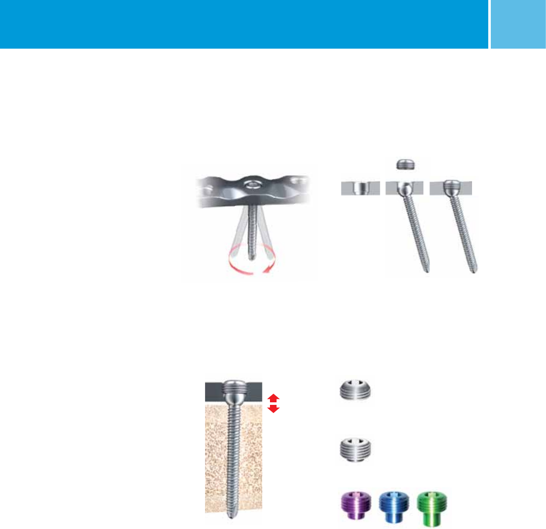
NCB 30° Cone Polyaxiality Angular stability with the NCB Locking Caps
NCB Non-Contact Bridging
Blind screw insert
Locking cap ∅ 8mm
Spacer 1 to 3 mm
30°
The NCB System Technology allows for
polyaxial screw placement (30° cone)
with screw locking achieved through the
use of locking caps that are threaded into
the plate holes. The locking construct
allows for improved stability especially
in osteopenic bone. Before locking,
the screws can act as lag screws and
be used for fracture reduction; a benefit
which is not offered with standard
locking systems.
In the locked mode, the NCB Large Frag-
ment
Plate acts as an internal fixator
without contact between the plate and
the bone surface, which may reduce the
risk of periosteal blood supply impair-
ment. This Non-Contact Bridging concept
can also be controlled specifically
through the use of 1, 2, or 3mm spacers,
which are threaded into the plate holes
prior to plate insertion.
6NCB® Large Fragment System – Surgical Technique
The surgical technique is based on well-
known standard plate osteosynthesis
techniques, which give the surgeon
tactile feedback regarding bone quality
during drilling and tightening of the
screws. In addition, with the use of
locking caps the screws can be locked
and made angularly stable.
The NCB Large Fragment System allows
for extensive flexibility in the treatment of
simple shaft fractures including peripros-
thetic fractures in the shaft. The polyaxial
NCB Plate technology, may allow for
bicortical screw fixation around the stem
of the implanted prosthesis. In this way,
the surgeon can achieve better construct
stability than with cables with less
damage to the soft tissue. And because
of the Non-Contact Bridging concept, the
risk to the periosteal blood supply may
be reduced.
Additionally, fixation using cables and
cable buttons is possible for those cases
where bicortical screw fixation cannot be
achieved. Both techniques (locking
screws and cables) may also be com-
bined. Blunt tip unicortical NCB Screws
are also available, creating a system
which offers comprehensive solutions for
these difficult fractures.
Fixation using uni- and
bicortical screws,
as well as cables and
cable buttons
Bicortical screw anchorage
(with or without IM device
inside) with NCB Screws
NCB® Large Fragment System – Surgical Technique 7
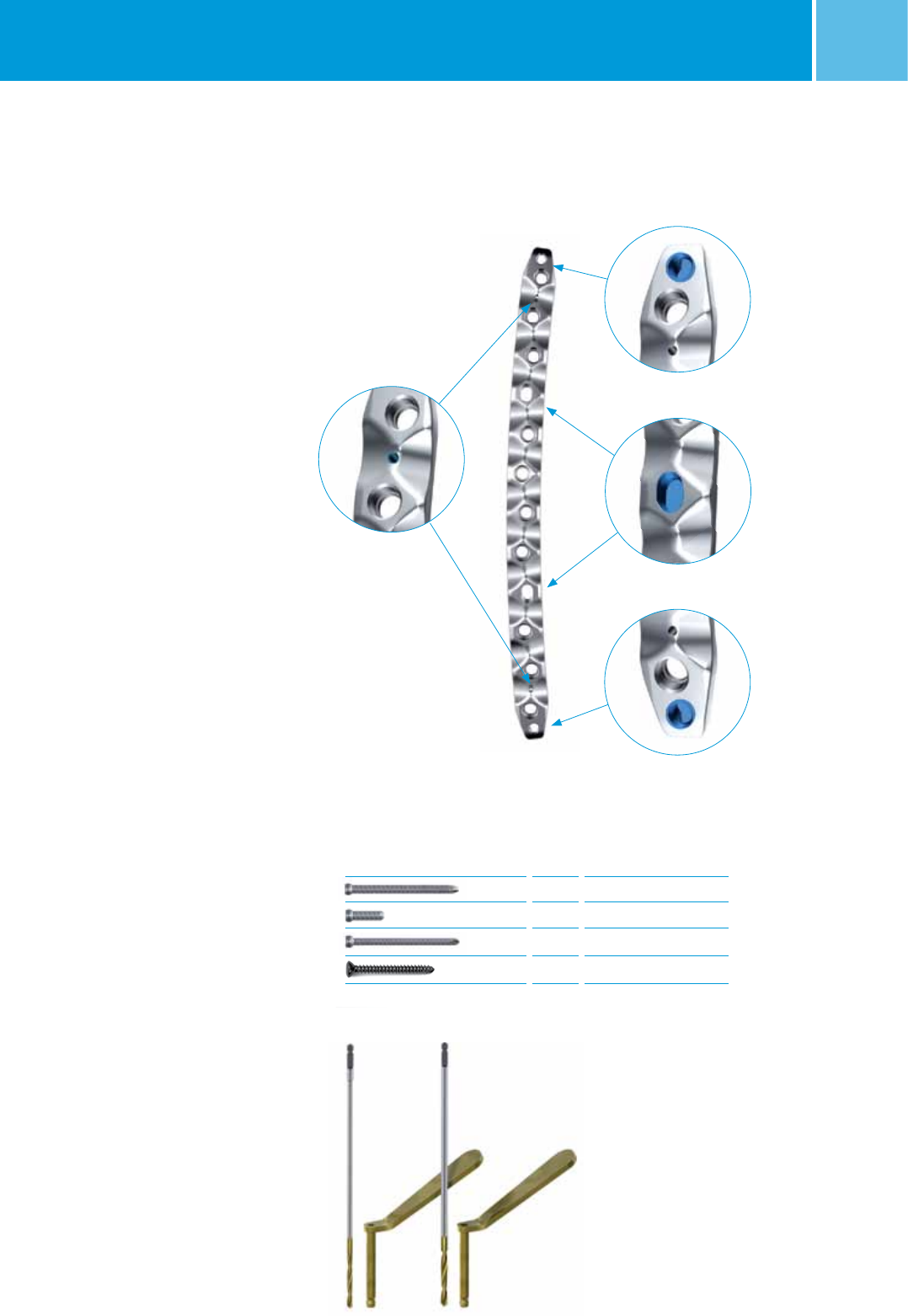
System Features
NCB Curved Femur Shaft Plate and
NCB Straight Narrow Shaft Plate
Symmetric Design
One plate for left and right long bones
due to symmetric design.
The NCB Straight Narrow Shaft Plate can
either be used for the tibia or humerus.
Whereas the NCB Curved Femur Shaft
Plate is specifically designed for the
femur.
Compression Slots
Two compression slots allow 1mm
of compression each.
K-Wire Holes
Two k-wire holes at each end of the plate
allow easier preliminary plate fixation.
Articulated Tension Device Holes
(only NCB Curved Femur Shaft Plate)
One hole at each end of the plate allows
for connection of the Articulated Tension
Device to achieve additional compression,
if needed.
Screw Options
Broad Screw Options
Three different NCB Screw types are
offered with the NCB Large Fragment
System, to allow both bicortical and
unicortical fixation.
3.5mm cortical screws are included for
additional fixation outside the NCB
Plates.
Specific Instruments for Periprosthetic
Fractures
Slightly oversized drill bits and drill guides
are offered with the NCB Large Fragment
System, to reduce the risk of cracks in
the cement mantle when placing screws
around a cemented prosthesis.
K-Wire Holes
Articulated Tension Device Hole
NCB Instruments for overdrilling into cement
Broad Screw Options ∅ mm Description
5 NCB Screws
5 NCB Unicortical Screws
4 NCB Screws
3.5 Cortical Screws
Articulated Tension Device Hole
Compression Slots
8NCB® Large Fragment System – Surgical Technique
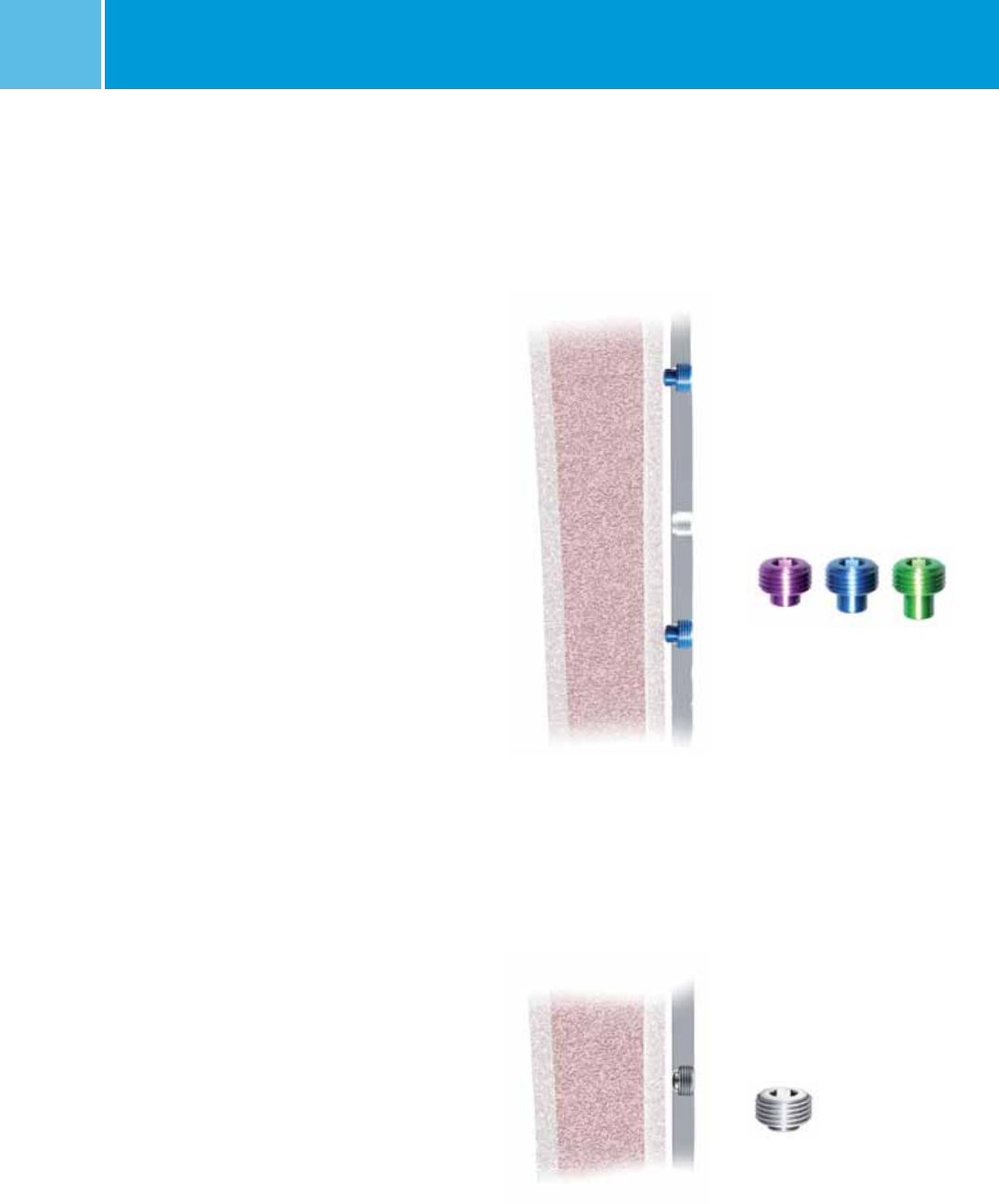
Two NCB Bone Spacers used
in the diaphyseal area of
a NCB Plate, to avoid contact
of the plate with the bone
(Non Contact Bridging)
NCB Bone Spacers (Optional)
Use at least two bone spacers in the
diaphyseal area of all NCB Plates, to
avoid contact of the plate with the bone
surface reducing the risk of periosteal
blood supply impairment.
The spacers may also be used if the
fracture has been reduced using a cable,
to avoid contact between the
plate and the cable.
The spacers are available in 1mm, 2mm
and 3mm (REF 02.03150.311 to 313)
sizes.
Note: Insert the bone spacers into the
NCB Plate or Screw holes before plate
insertion. The spacers are single use only,
and they can be removed after locking
the screws.
NCB Blind Screws inserted in
a NCB Plate to prevent bone
ingrowth
NCB Blind Screw Inserts (Optional)
To prevent bone ingrowth into empty NCB
Screw holes, use the NCB Blind Screw
inserts (REF 02.03150.310).
Note: Hand tighten only.
Blind screw insert
Spacer 1 to 3 mm
NCB® Large Fragment System – Surgical Technique 9
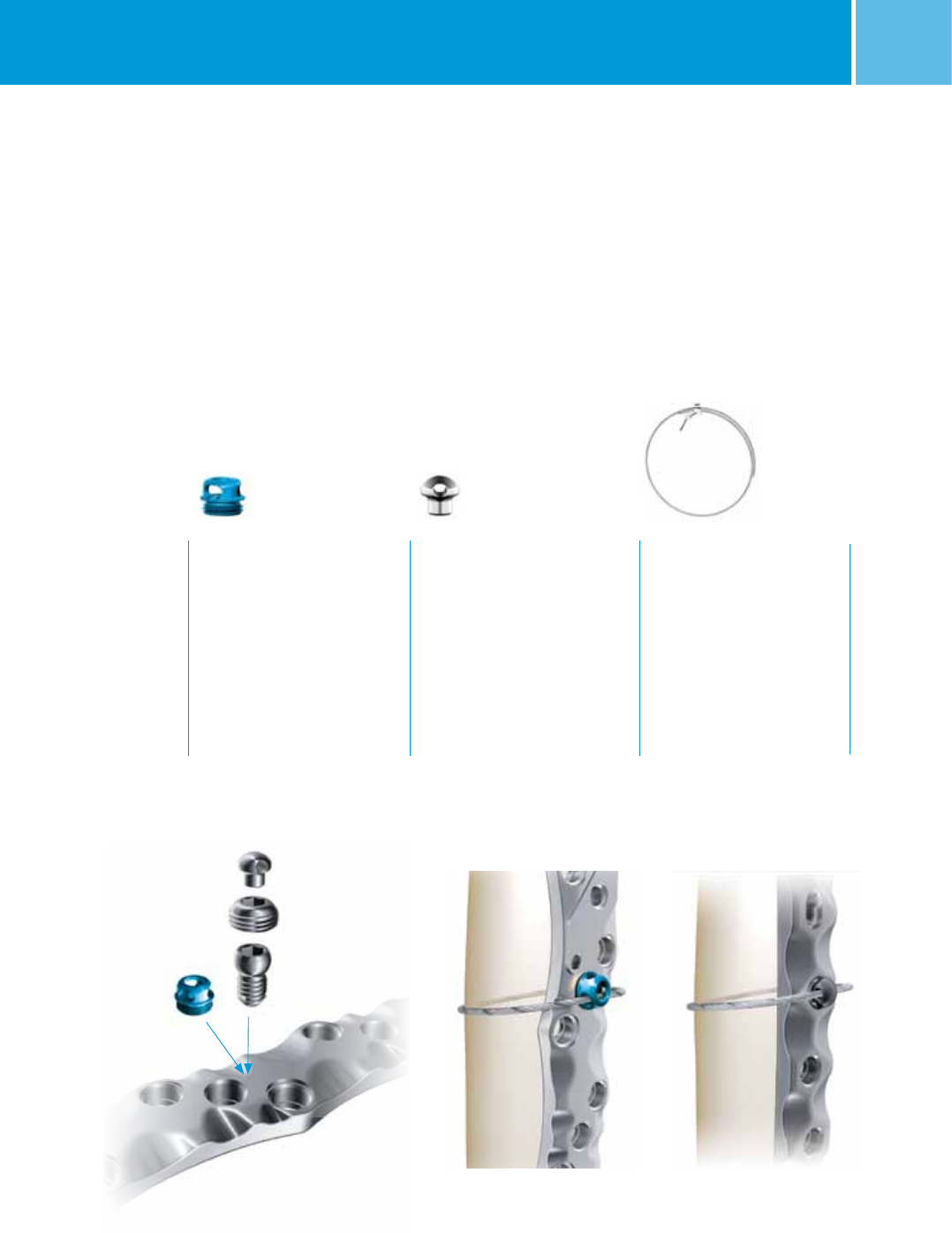
Cable Fixation Options
The following products from the Zimmer®
Cable-Ready® Cable Grip
System are compatible with the NCB
Large Fragment System:
Cable Fixation with
Hex Button
Cable Fixation Options
NCB Locking Plate
Cable Button, 2.5mm, Hex Drive
• Sterile
• Material: Ti-6Al-4V
(Tivanium® Alloy)
REF 47-2232-060-01
Application
This Cable Button is threaded
directly into the NCB Plate to
provide a positioning point for
the Cable
Hex Button, 3.5mm
• Sterile
• Material: C.P. Titanium
REF 00-2232-002-35
Application
This Hex Button fits into the
standard hex in the screw head
(3.5mm hex). Therefore, it can
be inserted into the NCB Screw
head, or into the NCB Locking Cap
Cable Assembly Cerclage,
1.8mm
• Sterile
• Material: CoCr
REF 00-2232-002-28
REF 00-2232-004-18
Cable Fixation with
Cable Button

10 NCB® Large Fragment System – Surgical Technique
Indications
The NCB Periprosthetic Femur Polyaxial
Locking Plate System is indicated for
temporary internal fixation and stabiliza-
tion of fractures and osteotomies of long
bones, including:
• Periprosthetic fractures
• Comminuted fractures
• Supracondylar fractures
• Fractures in osteopenic bone
• Nonunions
• Malunions
Indications and Contraindications
The NCB Straight Narrow Shaft Plate
is indicated for temporary internal
fixation and stabilization of humeral and
tibial
shaft fractures and osteotomies,
including:
• Periprosthetic fractures
• Comminuted fractures
• Fractures in osteopenic bone
• Nonunions
• Malunions
Contraindications
• All concomitant diseases that may
impair the fixation of the implant and/
or the success of the intervention
• Lack of bone substance or poor bone
quality which makes stable seating of
the implant impossible
• Acute or chronic, local or systemic
infections
• Allergy to the implanted materials
• Severe muscular, neural or vascular
diseases that endanger the extremities
involved
• Loose prosthesis, which requires
immediate revision.
Recommended Plate Positioning
• Ensure that the length of the NCB
Curved Femur Shaft Plate or NCB
Straight Narrow Shaft Plate allows for
screw placement proximal and distal of
the fracture zone and if present around
the existing prosthesis.
NCB Large Fragment Plate Positioning and Screw Fixation

NCB® Large Fragment System – Surgical Technique 11
Recommended NCB Screw
Fixation
The NCB Large Fragment System offers
three different types of polyaxial locking
screws, two of them are designed for
bicortical purchase, and one of them is
designed for unicortical purchase.
Recommended NCB Screw usage for NCB
Curved Femur Shaft Plate:
• Wherever possible, use 5.0mm bicorti-
cal NCB Screws.
• In periprosthetic fractures use two
bicortical 5.0mm NCB Screws close to
the fracture on each side of the frac-
ture.
• For thin cortical bone near the prosthe-
sis, the 4.0mm NCB Screws may be
used.
Screw Type Cortical
5mm
Cortical
4mm
Cortical
Blunt Tip
Cortical
3.5mm
Outer ∅5mm 4mm 5mm 3.5mm
Core ∅4.4mm 3.4mm 4.4mm 2.4mm
Length 22–85mm 20–70mm 10–20mm 20–40mm
REF
REF Sterile
02.03150.0xx
02.02150.0xx
02.03155.0xx
02.02155.0xx
02.03151.0xx
02.02151.0xx
00-4935-0xx-01
47-4935-0xx-01
Application Close to the fracture
area, in the shaft
area, or in case of a
periprosthetic fracture
where there is
no risk of hitting the
prosthesis
In tibia or humerus
bone and in case of a
periprosthetic fracture
away from the fracture
area to achieve bicorti-
cal fixation around the
prosthesis
For use when
bicortical fixation
cannot be achieved
Warning
If only unicortical
screws are used,
the use of cables is
required
Fixation of additional
bone fragments
Note: These screws can
be placed only outside
of the NCB Plates
NCB Screw portfolio for the NCB Large Fragment System
NCB Screws – Bicortical Unicortical
Recommended NCB Screw usage for NCB
Straight Narrow Shaft Plate:
• Use 4.0mm bicortical NCB Screws
wherever possible.
Drill Bit ∅4.3 / 4.5mm 3.3 / 3.5mm 4.3 / 4.5mm 2.5 / 3.5mm
Drill Bit REF 02.00024.002
02.00024.330
02.00024.118
02.00024.325
02.00024.002
02.00024.330
00-4806-110-25
00-4806-110-35
Drill Guide REF 02.00024.011
02.00024.331
02.00024.111
02.00024.326
02.00024.011
02.00024.331
00-4808-035-01
Tap REF 02.00024.341 02.00024.340 02.00024.341 00-4811-110-35

12 NCB® Large Fragment System – Surgical Technique
NCB Screw Insertion
For All Types of NCB Screws and
NCB Locking Caps
• Take care to avoid collision of the
screws by choosing the appropriate
plate holes and screw lengths.
• Press the NCB Drill Guide into the plate
hole perpendicular to the plate and
then tilt it in the preferred direction.
The drill guide needs to be in constant
contact with the bottom ring of the
hole. The guide limits the angulation to
15° from the perpendicular axis of the
plate or a cone of 30° for placing a
locked NCB Screw. Always use the drill
guide since it prevents selection of an
excessive screw angle and failure of
subsequent locking.
• Screws may be inserted under power
but should be final tightened by hand
only.
Note: Screws should not be locked until
both sides of the fragment have been
fixed.
• Lock the construct, insert and
tighten the NCB Locking Caps
(REF 02.03150.300) by using the NCB
Torque Limiting Screwdriver, 6Nm
(REF 02.00024.021) until a click sound
is heard. Make sure the screwdriver
is not tilted during its usage. If the
driver is tilted, it could damage the
hex drive and might complicate the
extraction of the implants.
Note: If using the NCB Straight Narrow
Shaft Plate for humerus shaft fractures
the use of NCB Torque Limiting Screw-
driver 4Nm (REF 02.00024.022) is also
acceptable.
• In case of periprosthetic fractures do
not hit the prosthesis with the tip of the
drill, tap or screw.
NCB Screw ∅ 5.0mm
1. To insert a 5.0mm NCB Screw
(REF 02.03150.xxx) use the 4.3mm
NCB Drill Guide (REF 02.00024.011)
and drill with the 4.3mm drill bit
(REF 02.00024.002).
In case of hard cortical bone or the
presence of a cement mantle, tap the
cortex with the 5.0mm NCB Tap
(REF 02.00024.341). Remove the
4.3mm NCB Drill Guide before using
the NCB Tap.
Note: Inserting screws in the presence of
a cement mantle can cause cracks, which
may cause loosening of the prosthesis.
Overdrilling by using a drill bit of a
slightly larger diameter (0.2mm) may
reduce cracking in the cement mantle
during screw insertion. Instead of the
4.3mm drill bit, use the 4.5mm drill bit
(REF 02.00024.330) and its corresponding
drill guide (REF 02.00024.331).1
2. Use the NCB Measuring Device
(REF 02.00024.005) to determine the
appropriate screw length and insert
the NCB Screw using the NCB Hexagonal
Screwdriver (REF 02.00024.023) or
screwdriver shaft (REF 02.00024.024).
3. To lock the construct, insert the NCB
Locking Caps (REF 02.03150.300) as
described at the beginning of this section.
NCB Unicortical Screw ∅ 5.0mm
1. To insert a 5.0mm NCB Unicortical
Screw (REF 02.03151.0xx) use
the 4.3mm NCB Drill Guide
(REF 02.00024.011) and drill with the
4.3mm drill bit (REF 02.00024.002).
In case of hard cortical bone or the
presence of cement mantle, tap the
cortex with the 5.0mm NCB Tap
(REF 02.00024.341). Remove the
4.3mm NCB Drill Guide before using
the NCB Tap.
Note: Inserting screws in the presence of
a cement mantle can cause cracks,
which may cause loosening of the
prosthesis. Overdrilling by using a drill bit
of a slightly larger diameter (0.2mm) may
reduce cracking in the cement mantle
during screw insertion. Instead of the
4.3mm drill bit, use the 4.5mm drill bit
(REF 02.00024.330) and its corresponding
drill guide (REF 02.00024.331).1
2. Use the NCB Measuring Device
(REF 02.00024.005) to determine the
appropriate screw length and
insert the NCB Unicortical Screw using
the NCB Hexagonal Screwdriver
(REF 02.00024.023).
Note: When using the NCB Measuring
Device to measure the length of the NCB
Unicortical Screw needed, the device will
not hook the far cortex of the bone. Use
the screw length measured. Do not use a
longer screw.
3. To lock the construct, insert the NCB
Locking Caps (REF 02.03150.300) as
described at the
beginning of this section.
1 J. Kampshoff et al.: The treatment of periprosthetic fractures with locking plates:
effect of drill and screw type on cement mantles: a biomechanical analysis,
Archives of Orthopedic and Trauma Surgery, Springer, March 2009.

NCB® Large Fragment System – Surgical Technique 13
NCB Screw ∅ 4.0mm
1. To insert a 4.0mm NCB Screw
(REF 02.03155.0xx) use the 3.3mm
NCB Drill Guide (REF 02.00024.111)
and drill with the 3.3mm drill bit
(REF 02.00024.118).
In case of hard cortical bone or the
presence of the cement
mantle, tap the
cortex with the 4.0mm
NCB
Tap
(
REF
02.00024.340). Remove the 3.3mm
NCB
Drill Guide before using the
NCB
Tap.
Note:
Inserting screws in the presence
of a cement mantle can cause cracks,
which may cause loosening of the pros-
thesis. Overdrilling by using a drill bit
of a slightly larger diameter (0.2mm) may
reduce cracking in the cement mantle
during screw insertion. Instead of the
3.3mm drill bit, use the 3.5mm drill bit
(
REF
02.00024.325) and its corresponding
drill guide (
REF
02.00024.326).
1
2. Use the
NCB
Measuring Device
(
REF
02.00024.005) to determine the
appropriate screw length and insert
the
NCB
Screw using the
NCB
Hexagonal
Screwdriver (
REF
02.00024.023) or
screwdriver shaft (
REF
02.00024.024).
3. To
lock the construct
, insert the
NCB
Locking Caps (
REF
02.03150.300) as
described at the
beginning of this section.
1 J. Kampshoff et al.: The treatment of periprosthetic fractures with locking plates:
effect of drill and screw type on cement mantles: a biomechanical analysis,
Archives of Orthopedic and Trauma Surgery, Springer, March 2009.

14 NCB® Large Fragment System – Surgical Technique
Preoperative Planning and
Patient Positioning
Preoperative Planning
Preoperative planning with adequate
x-rays and x-ray templates for
the NCB Curved Femur Shaft Plate
(Lit 06.02026.000) is strongly
recommended.
Patient in the lateral position
Patient in the supine position
NCB Curved Femur Shaft Plate – Surgical Technique
This allows determination of the proper
plate length, and the appropriate type
and position of screws, particularly in
the presence of prosthesis to prevent any
interference with the stem.
Determine which prosthesis has been
implanted by studying the x-rays, or using
the previous surgeon’s operative notes to
be prepared in case of revision, and
assess the stability of the prosthesis. If
the prosthesis is loose, the surgical plan
may change to include revision.
Patient Positioning
Lay the patient in the lateral position
or the supine position on a radiolucent
table. Support the knee, but allow the
leg to move freely. Perform the reduction
as necessary.
If intra-op fluoro is to be used, ensure
the fluoro machine is not blocked by
radioopaque bars of the operating table.
+H84406020260001/$100501E10K
© 2010. All rights reserved.
Zimmer GmbH, CH-8404 Winterthur,
Switzerland
Lit.No. 06.02026.000 – Ed. 5/2010 WL
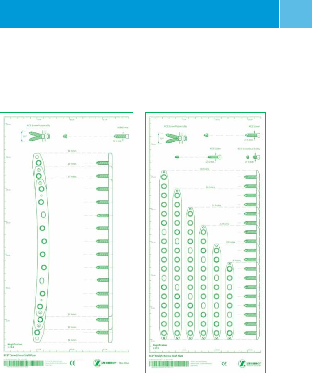
NCB
®
Curved Femur Shaft Plate
0086
10 cm 15 cm5 cm
Magnification
1.15:1
20 cm
15 cm
5 cm
25 cm
30 cm
35 cm
10 cm
10 cm 15 cm
5 cm
12 holes
14 holes
10 holes
12 holes
10 holes
14 holes
NCB Screw Polyaxiality NCB Screw
5 mm
30°

NCB® Large Fragment System – Surgical Technique 15
Incision and Intra-operative
Planning
Incision
Make the incision using the lateral
subvastus approach or incorporate the
existing incision, if applicable.
Avoid excessive stripping of the soft
tissues and keep the periosteum in-
tact.
Intra-operative Planning
Take complete x-rays of the femur in the
A/P and lateral view and if necessary,
also in the contra-lateral view, or a CT if
osteolysis is present to determine the
length of the prosthesis, as well as the
correct plate length to be implanted.
If desired, the NCB Curved Femur Shaft
Plate Provisional (REF 02.00024.358)
can be used to determine the suitable
implant length. Provisional is semi
radiolucent and intended to be used in
the open technique.
Warning:
Do not implant or bend the provisional.
There is only one provisional which
represents the 12 hole NCB Curved Femur
Shaft Plate. To use the provisional for the
next shorter implant size (10 hole plate),
two square holes are included:
– the proximal square hole indicates the
most proximal NCB Plate hole of the
next shorter implant size
– the distal square hole indicates the
most distal NCB Plate hole of the next
shorter implant size.
Incision
Exessive stripping of the
soft tissue avoided and
periosteum kept intact
NCB Curved Femur Shaft
Plate Provisional used for
intra-operative planning
(optional)
Next shorter
implant size
Last NCB Plate hole
Last NCB Plate hole
10 hole plate
Provisional
12 hole plate
Square holes are included
to indicate the next
shorter implant size
16 NCB® Large Fragment System – Surgical Technique
Reduction and Preliminary
Fixation
Reduce the fracture prior to inserting the
plate. Bone fragments may be secured with
2.0mm k-wires (REF 290.20.280) or clamps
such as pointed reduction forceps. Make
sure that preliminary fixation devices do
not interfere with the future location of the
plate and screws, or with the prosthesis.
Insertion of the NCB Curved Femur
Shaft Plate
The following example shows a case
without a prosthesis in-situ.
The NCB Curved Femur Shaft Plate is
placed on the lateral femur centered over
the fracture.
Temporarily fix the plate with two 2.0mm
k-wires (REF 290.20.280), one proximally
and one distally.
NCB Curved Femur Shaft Plate
centered over the fracture
and temporarily fixed with two
2.0mm k-wires
Compression guide placed so
that the drill hole is at the
end of the compression slots
farthest from the fracture site.
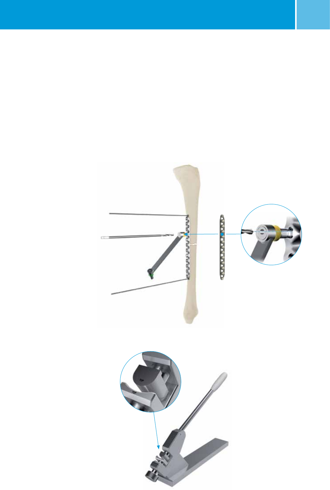
Correct orientation of the
concave Bending Press
insert: with the word “TOP”
etched on the top of the
insert
Note:
The NCB Curved Femur Shaft Plate is
anatomically shaped.
If additional contouring is
required, use the Bending Press
Inserts (REF 02.00024.315/6) and the
corresponding Bending Press
(REF 100.06.010).
Be aware that bending the plate may
decrease its fatigue strength.
Furthermore, the locking mechanism of
the NCB Screw hole may be damaged
and, therefore, may no longer function.
Do not use a hole that has been altered
by contouring for locking.
NCB® Large Fragment System – Surgical Technique 17
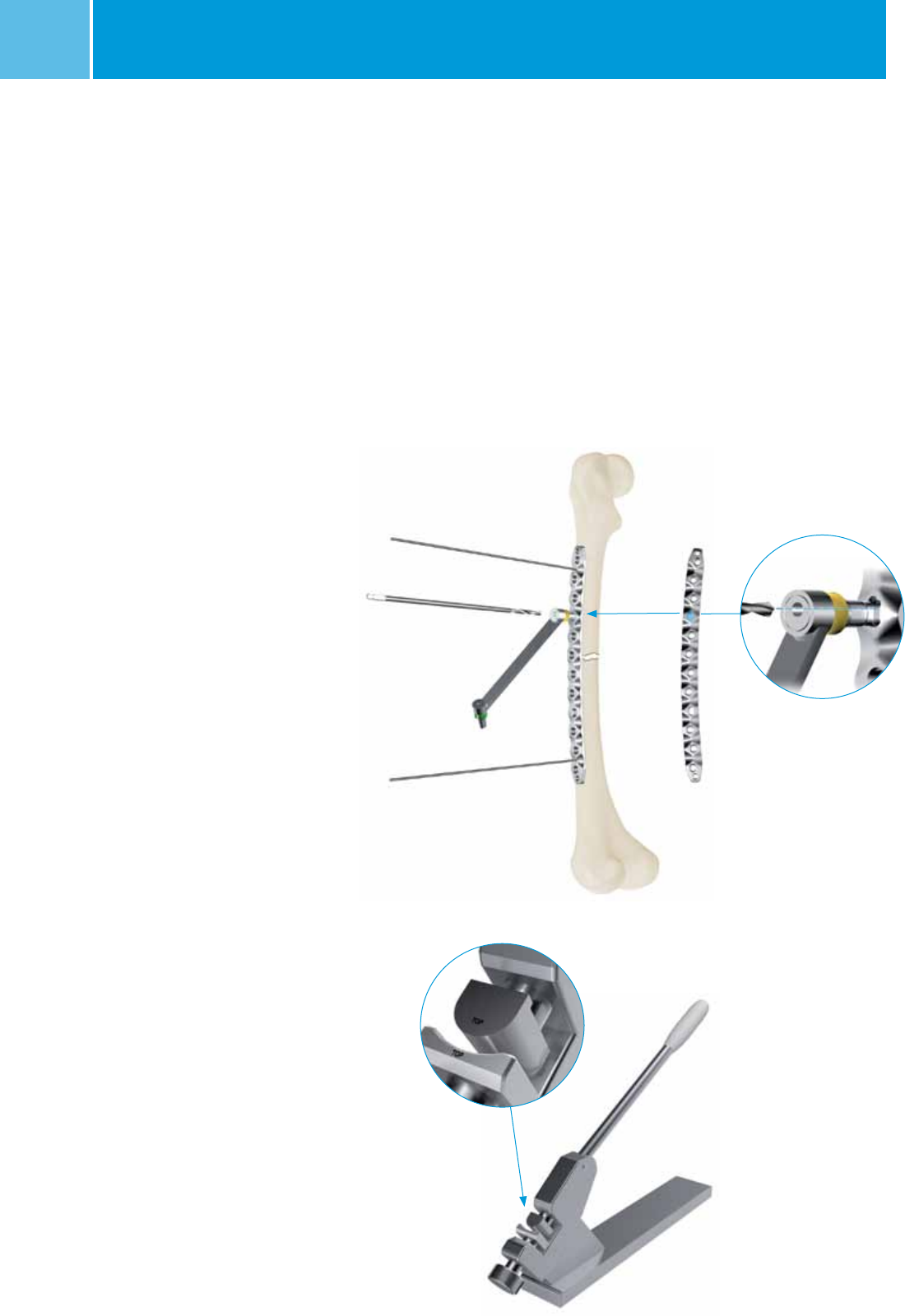
Insertion of the NCB Screws
The NCB Curved Femur Shaft Plate has two
compression slots to allow for axial
adjustment while positioning the plate,
as well as for axial compression.
Note: It is possible to get 1 or 2mm of
axial compression with the NCB Curved
Femur Shaft Plate. For 2mm of compres-
sion, insert the NCB Screws into the com-
pression holes first (like in the example
shown in this surgical technique).
For 1mm of compression, insert a NCB
Screw into a NCB Plate hole, and then use
the compression slot on the opposite side
of the fracture. If more compression is
needed, use the Articulated Tension Device
(REF 00-4817-005-00) after only one side
of the plate has been fixed. This instrument
can be attached to the bone, using a
4.0mm NCB Screw.
For screw selection and insertion, please
refer to pages 12–13.
Note: Screws should not be locked until
both sides of the fragment have been
fixed.
1. For 2.0mm of axial compression, drill
the first hole in one of the two compres-
sion slots in the compression position
using the NCB Compression Drill Guide for
5.0mm NCB Screws (REF 02.00024.335)
and the 4.3mm drill bit (REF 02.00024.002).
Place the compression guide so that the
drill hole is at the end of the compression
slots farthest from the fracture site.
Partially insert a 5.0mm NCB Screw into
the compression slot but do not tighten it.
First 5.0mm NCB Screw
partially inserted in one of
the two compression
slots without tightening it
Second 5.0mm NCB Screw
partially inserted in the
other compression slot with-
out tightening it, and k-wires
removed

18 NCB® Large Fragment System – Surgical Technique
2. Partially insert a 5.0mm NCB Screw into
the other compression slot, also in the
compression position, but do not tighten it.
3. Remove the two 2.0mm k-wires.
To achieve axial compression, tighten the
NCB Screws in the two compression slots
by using the NCB Hexagonal Screwdriver
(REF 02.00024.023).
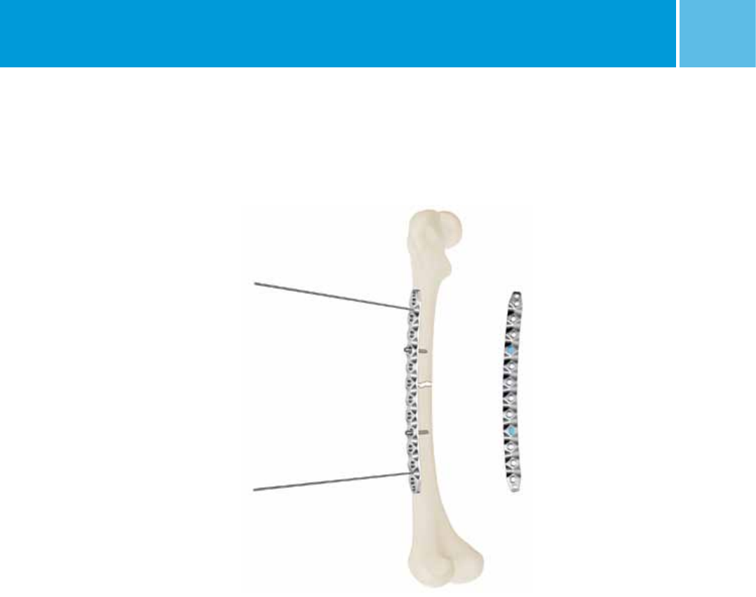
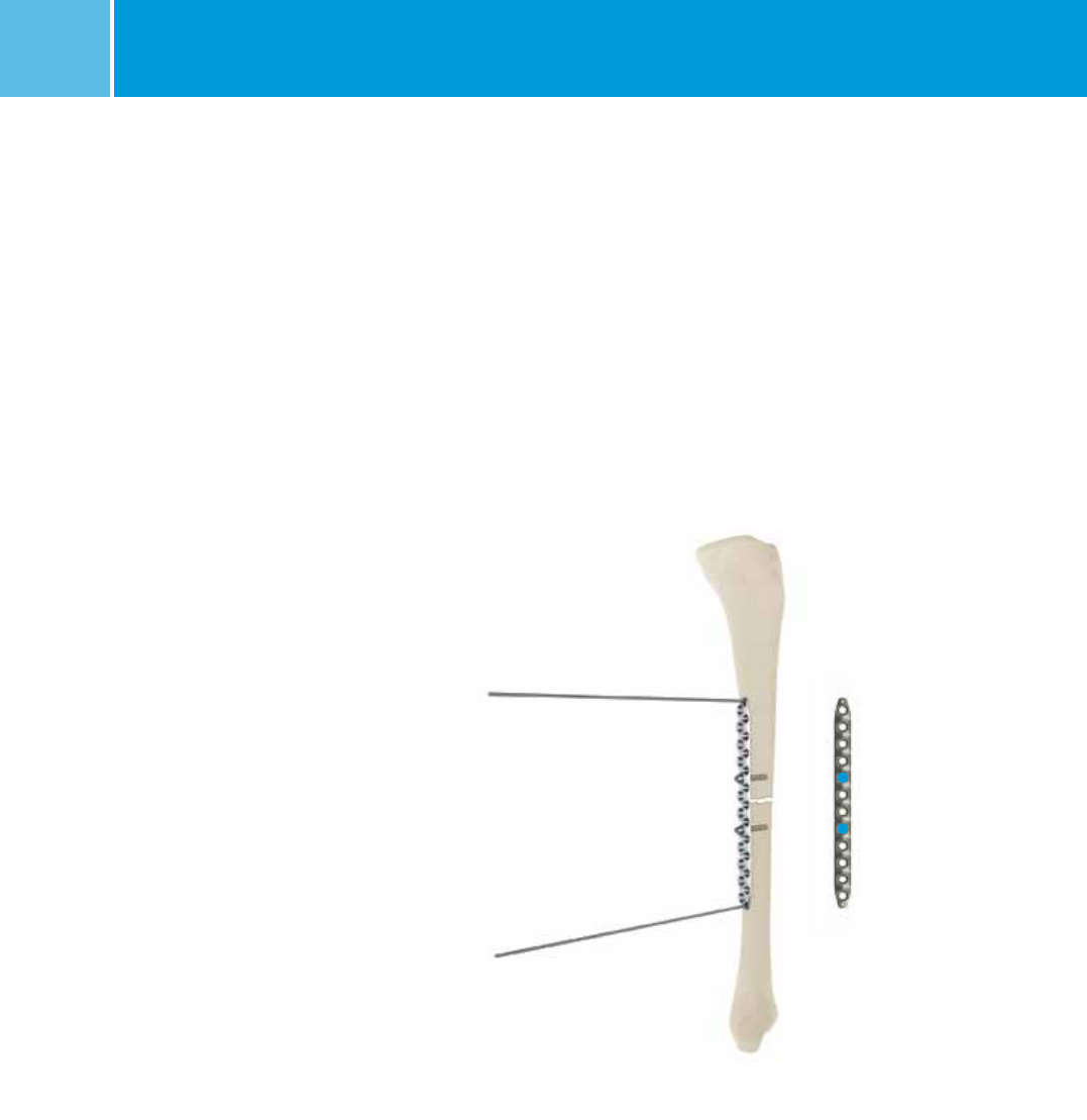
4. Insert additional 5.0mm NCB Screws
as necessary, first near the fracture site
and then proximal/distal to the fracture,
ensuring purchase in a minimum of six
cortices on each side of the fracture,
spaced on the entire length of the plate.
If desired, slightly loosen the 5.0mm NCB
Screws in the two compression slots to
avoid contact between the plate and the
bone.
K-wires removed and axial
compression achieved
by tightening the 5.0mm
NCB Screws in the two com-
pression slots
Additional 5.0mm NCB
Screws inserted as necessary
first near the fracture site
and then proximal/distal to
the fracture, ensuring
purchase in a minimum of
six cortices with the screws
on each side of the fracture
spaced on the entire length
of the plate

NCB® Large Fragment System – Surgical Technique 19
Preoperative Planning and
Patient Positioning
Preoperative Planning
Preoperative planning with adequate
x-rays and x-ray templates for
the NCB Straight Narrow Shaft Plate
(Lit 06.02263.000) is strongly
recommended.
NCB Straight Narrow Shaft Plate – Surgical Technique
This allows determination of the proper
plate length, and the appropriate type
and position of screws, particularly in the
presence of prosthesis to prevent any
interference with the stem.
In periprosthetic fractures determine
which prosthesis has been implanted by
studying the x-rays, or using the previous
surgeon’s operative notes to be prepared
in case of revision, and assess the stabili-
ty of the prosthesis. If the prosthesis is
loose, the surgical plan may change to
include revision.
Patient Positioning
Tibia – Lay the patient in the supine
position on a radiolucent table. Support
the knee, but allow the leg to move freely.
Perform the reduction as necessary.
Humerus – The patient is placed on the
operating table in the beachchair posi-
tion or supine position. After the patient
is in the correct position, the C-arm must
be adjusted so as to achieve the widest
possible view of the humerus.
If intra-op fluoro is to be used, ensure the
fluoro machine is not blocked by radioo-
paque bars of the operating table.
Patient in the beachchair position
Patient in the supine position
20 NCB® Large Fragment System – Surgical Technique
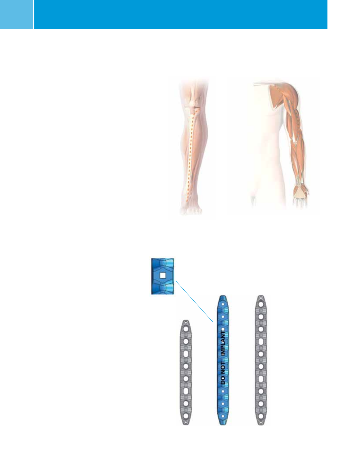
Incision and Intra-operative
Planning
Incision
Tibia: The anterior approach is the stan-
dard approach to the tibia, located 1cm
lateral to its anterior crest. Take care not
to compromise the great saphenous vein
and nerve.
Humerus: Plating of humeral shaft frac-
tures may be performed through the
anterolateral approach.
Intra-operative Planning
Take complete x-rays of the tibia or the
humerus respectively in the A/P and lat-
eral view and if necessary, also in the
contra-lateral view, or a CT if osteolysis is
present to determine the length of the
prosthesis, as well as the correct plate
length to be implanted.
If desired, the NCB Straight Narrow Shaft
Plate Provisionals (REF 02.00024.401 / REF
02.00024.402) can be used to determine
the suitable implant length. Provisionals
are semi radiolucent and intended to be
used in the open technique.
Warning:
Do not implant or bend the provisional.
Each provisional represents the implant
sizes it is labeled for, e.g. 10 or 16 holes.
To use the provisional for the next shorter
implant size (e.g. 8 or 14 hole plate), a
square hole is included:
– the square hole indicates the last
NCB hole of the next shorter implant
size.
Last NCB Plate hole
Square holes are included
to indicate the next shorter
implant size.
NCB Straight Narrow Shaft Plate Provisional
used for intraoperative planning.
8 holes 10 holes 10 holes
Provisional
NCB® Large Fragment System – Surgical Technique 21
Reduction and Preliminary
Fixation
Reduce the fracture prior to inserting the
plate. Bone fragments can be secured
with 2.0mm k-wires (REF 290.20.280) or
clamps such as pointed reduction for-
ceps. Make sure that preliminary fixation
devices do not interfere with the future
location of the plate and screws, or with
the prosthesis.
Insertion of the NCB Straight
Narrow Shaft Plate
The following example shows a tibia case
without a prosthesis in-situ. All steps are
also applicable for humerus shaft frac-
tures.
The NCB Straight Narrow Shaft Plate is
placed on the medial tibia or lateral
humerus centered over the fracture.
Temporarily fix the plate with two 2.0mm
k-wires (REF 290.20.280), one proximally
and one distally.
NCB Straight Narrow Shaft
Plate centered over the
fracture and temporarily fixed
with two 2.0mm k-wires
Compression guide placed so
that the drill hole is at the
end of the compression slots
farthest from the fracture site.
Correct orientation of the
concave Bending Press
insert: with the word “TOP”
etched on the top of the
insert
Note:
If contouring is required, use the Bending
Press Inserts (REF 02.00024.315/6) and
the corresponding Bending Press
(REF 100.06.010).
Alternatively, the large bending iron
(REF 02.00000.003) can be used as well.
Be aware that bending the plate may
decrease its fatigue strength.
Furthermore, the locking mechanism of
the NCB Screw hole may be damaged
and, therefore, may no longer function.
Do not use a hole that has been altered
by contouring for locking.
22 NCB® Large Fragment System – Surgical Technique
Insertion of the NCB Screws
The NCB Straight Narrow Shaft Plate has
two compression slots to allow for axial
adjustment while positioning the plate, as
well as for axial compression.
Note: If using the compression slots inser-
tion of 4mm NCB Screws is required.
Note: It is possible to get 1 or 2mm of
axial compression with the NCB Straight
Narrow Shaft Plate. For 2mm of compres-
sion, insert the NCB Screws into the com-
pression holes first (like in the example
shown in this surgical technique). For
1mm of compression, insert a NCB Screw
into a NCB Plate hole, and then use the
compression slot on the opposite side
of the fracture.
For screw selection and insertion, please
refer to pages 12–13.
Note: Screws should not be locked until
both sides of the fragment have been
fixed.
1. For 2.0mm of axial compression, drill the
first hole in one of the two compression
slots in the compression position
using the NCB Compression Drill Guide for
4.0mm NCB Screws (REF 02.00024.336)
and the 3.3mm drill bit (REF 02.00024.002).
Place the compression guide so that the
drill hole is at the end of the compression
slots farthest from the fracture site. Partial-
ly insert a 4.0mm NCB Screw into the com-
pression slot but do not tighten it.
First 4.0mm NCB Screw
partially inserted in one of
the two compression
slots without tightening it
Second 4.0mm NCB Screw
partially inserted in the
other compression slot with-
out tightening it, and k-wires
removed

NCB® Large Fragment System – Surgical Technique 23
2. Partially insert a 4.0mm NCB Screw into
the other compression slot, also in the
compression position, but do not tighten it.
3. Remove the two 2.0mm k-wires. To
achieve axial compression, tighten the
NCB Screws in the two compression slots
by using the NCB Hexagonal Screwdriver
(REF 02.00024.023).
4. Insert additional 4.0mm NCB Screws as
necessary, first near the fracture site and
then proximal/distal to the fracture, ensur-
ing purchase in a minimum of six cortices
on each side of the fracture, spaced on
the entire length of the plate.
If desired, slightly loosen the 4.0mm NCB
Screws in the two compression slots to
avoid contact between the plate and the
bone.
K-wires removed and axial
compression achieved
by tightening the 4.0mm
NCB Screws in the two com-
pression slots
Additional 4.0mm NCB
Screws inserted as necessary
first near the fracture site
and then proximal/distal to
the fracture, ensuring
purchase in a minimum of
six cortices with the screws
on each side of the fracture
spaced on the entire length
of the plate

24 NCB® Large Fragment System – Surgical Technique
1 J. Kampshoff et al.: The treatment of periprosthetic fractures with locking
plates: effect of drill and screw type on cement mantles: a biomechanical
analysis, Archives of Orthopedic and Trauma Surgery, Springer, March 2009.
Drilling into Cement Mantle
In patients with cemented prostheses,
the insertion of screws may occur in the
presence of a cement mantle. This can
cause cracks, which may cause loosening
of the prosthesis. Be careful not to hit
the prosthesis when tapping, drilling and
inserting screws.
Tips, which may Mitigate this Risk
• Use a lower speed for drilling into the
cement mantle to prevent overheating
and avoid cement melting
• Use a higher feed rate (increased drill
force)
• Use only new sharp drill bits. Change
drills frequently and do not use worn
ones
• Titanium nitride coated (gold) drill bits
are available:
• 3.5mm drill bit (REF 02.00024.325)
• 4.5mm drill bit (REF 02.00024.330)
• Use taps
• Overdrilling by using drill bits of a
slightly larger diameter (0.2mm) may
reduce cracking in the cement mantle
during screw insertion. In the NCB
Large Fragment set a 3.5mm drill bit
(REF 02.00024.325) can be used in
place of the 3.3mm drill bit, and a
4.5mm drill bit (REF 02.00024.330) can
be used in place of the 4.3mm drill bit.
These drill bits are available together
with their corresponding drill guides.
Note: Overdrilling the cement mantle by
0.2mm does reduce pull out strength
by about 20%. However, within the
cement mantle pull out strength is still
more than 2000 N.1
Drilling into Cortical Bone
In order to go around the stem of the
prosthesis and achieve bicortical
fixation, it may be necessary to drill
completely into cortical bone, which can
lead to heat necrosis of the bone.
Warning: Drilling and inserting screws
into the outer edge of the cortical bone
may also lead to cortical fracture.
Tips, which may Mitigate these Risks
• Use only new sharp drill bits. Change
drills frequently and do not use worn
ones
• Pull the drill bit out often and
clean its flutes
• Use extensive irrigating fluid (i.e.
saline water) directed at the point of
penetration of the cortex
• Use taps
• In case of thin bone cortex, away from
the fracture area, use NCB screws
of a smaller diameter like the 4.0mm
NCB Screws.
Metal Abrasion Wear
Metal abrasion wear due to contact
between screws, plates, prostheses,
cable buttons, and cables may occur.
Tip, which may Mitigate this Risk
Use only Zimmer products compatible
with the NCB Large Fragment System,
which are described in this
surgical technique.
Tips and Tricks for the NCB Large Fragment System used in periprosthetic fractures

NCB® Large Fragment System – Surgical Technique 25
To remove the NCB Large Fragment
Plates, first remove all locking caps
(REF 02.03150.300). Then, loosen all the
NCB Screws without completely removing
them (this prevents rotation of the
bone plate when removing the last
screw). Finally, completely remove all
NCB Screws.
Note: Make sure that the tip of the
NCB Hexagonal Screwdriver
(REF 02.00024.023) is correctly placed
in the hex drive of the locking caps and/
or NCB Screws. Failure to do so could
damage the hex drive and complicate the
extraction of the implant.
Removal Tip
In case of difficulties while loosening the
NCB Screws, tighten the screws slightly
before loosening them.
Post-operative treatment with locking
plates does not differ from conventional
internal fixation procedures. If there is
concern about stability, consider using
additional external fixation devices and/
or a cast/brace. Early range of motion
exercises of the involved joints may also
be beneficial. However, it is the respon-
sibility of the surgeon to determine
the most suitable post-operative care
depending on each patient’s health con-
dition.
Post-Operative Treatment
Implant Removal

26 NCB® Large Fragment System – Surgical Technique
Product Information – Implants
NCB Curved Femur Shaft Plates
REF REF Sterile Holes Length mm
02.03265.010 02.02265.010 10 210
02.03265.012 02.02265.012 12 249
02.03265.014 02.02265.014 14 289
NCB Straight Narrow Shaft Plate
REF REF Sterile Holes Length mm
02.03267.008 02.02267.008 8 118
02.03267.010 02.02267.010 10 146
02.03267.012 02.02267.012 12 174
02.03267.014 02.02267.014 14 202
02.03267.016 02.02267.016 16 230
02.03267.018 02.02267.018 18 258
Plates
Materials
NCB® Periprosthetic Plates and Screws are made of titanium alloy TiAlV,
Protasul®-64, ISO 5832-3, ASTM F136

NCB® Large Fragment System – Surgical Technique 27
NCB Locking Caps, Spacers, Blind Screw Inserts
REF REF Sterile Description
02.03150.300 02.02150.300 Locking cap
02.03150.310 02.02150.310 Blind screw insert
02.03150.311 02.02150.311 Spacer 1mm
02.03150.312 02.02150.312 Spacer 2mm
02.03150.313 02.02150.313 Spacer 3mm
NCB Screws, ∅ 5.0mm
REF REF Sterile Length mm
02.03150.022 02.02150.022 22
02.03150.024 02.02150.024 24
02.03150.026 02.02150.026 26
02.03150.028 02.02150.028 28
02.03150.030 02.02150.030 30
02.03150.032 02.02150.032 32
02.03150.034 02.02150.034 34
02.03150.036 02.02150.036 36
02.03150.038 02.02150.038 38
02.03150.040 02.02150.040 40
02.03150.042 02.02150.042 42
02.03150.044 02.02150.044 44
02.03150.046 02.02150.046 46
02.03150.048 02.02150.048 48
02.03150.050 02.02150.050 50
02.03150.055 02.02150.055 55
02.03150.060 02.02150.060 60
02.03150.065 02.02150.065 65
02.03150.070 02.02150.070 70
02.03150.075 02.02150.075 75
02.03150.080 02.02150.080 80
02.03150.085 02.02150.085 85
Screws*
Materials
NCB® Periprosthetic Plates and Screws are made of titanium alloy TiAlV,
Protasul®-64, ISO 5832-3, ASTM F136
* Compatible screw scope, may vary from screw scope in existing
NCB Instrument sets.
∅ 4.4 ∅ 6.2∅ 5
1.75
L
NCB Unicortical Screws, ∅ 5.0mm
REF REF Sterile Length mm
02.03151.010 02.02151.010 10
02.03151.012 02.02151.012 12
02.03151.014 02.02151.014 14
02.03151.016 02.02151.016 16
02.03151.018 02.02151.018 18
02.03151.020 02.02151.020 20
∅ 4.4 ∅ 6.2
∅ 5
L
1.75
NCB Screws, ∅ 4.0mm
REF REF Sterile Length mm
02.03155.020 02.02155.020 20
02.03155.022 02.02155.022 22
02.03155.024 02.02155.024 24
02.03155.026 02.02155.026 26
02.03155.028 02.02155.028 28
02.03155.030 02.02155.030 30
02.03155.032 02.02155.032 32
02.03155.034 02.02155.034 34
02.03155.036 02.02155.036 36
02.03155.038 02.02155.038 38
02.03155.040 02.02155.040 40
02.03155.042 02.02155.042 42
02.03155.044 02.02155.044 44
02.03155.046 02.02155.046 46
02.03155.048 02.02155.048 48
02.03155.050 02.02155.050 50
02.03155.055 02.02155.055 55
02.03155.060 02.02155.060 60
02.03155.065 02.02155.065 65
02.03155.070 02.02155.070 70
∅ 3.4 ∅ 6.2∅ 4
L
1.75

28 NCB® Large Fragment System – Surgical Technique
Cortical Screws, ∅ 3.5mm
REF REF Sterile Length mm
00-4935-020-01 47-4935-020-01 20
00-4935-022-01 47-4935-022-01 22
00-4935-024-01 47-4935-024-01 24
00-4935-026-01 47-4935-026-01 26
00-4935-028-01 47-4935-028-01 28
00-4935-030-01 47-4935-030-01 30
00-4935-032-01 47-4935-032-01 32
00-4935-034-01 47-4935-034-01 34
00-4935-036-01 47-4935-036-01 36
00-4935-038-01 47-4935-038-01 38
00-4935-040-01 47-4935-040-01 40
∅ 5.9∅ 3.5∅ 2.4
1.25
L
Cortical Screws, ∅ 3.5mm (EMEA only)
REF REF Sterile Length mm
02.03131.020 – 20
02.03131.022 – 22
02.03131.024 – 24
02.03131.026 – 26
02.03131.028 – 28
02.03131.030 – 30
02.03131.032 – 32
02.03131.034 – 34
02.03131.036 – 36
02.03131.038 – 38
02.03131.040 – 40
∅ 5.9∅ 3.5∅ 2.4
1.25
L
Compatible Zimmer Products with the NCB Large Fragment System
REF sterile Description
47-2232-060-01
NCB Polyaxial Locking Plate Cable Button, 2.5mm Hex Drive, Material: Ti-6Al-4V (Tivanium® Alloy)
00-2232-002-35 Hex Buttons, 3.5mm Hex, Material: C.P. Titanium
00-2232-002-28 Cable-Ready Cable Assembly Cerclage, ∅ 1.8mm, L. 914mm, Material: CoCr
00-2232-004-18 Cable-Ready Cable Assembly Cerclage, ∅ 1.8mm, L. 635mm, Material: CoCr

NCB® Large Fragment System – Surgical Technique 29
Product Information – Instruments
The NCB Straight Narrow Shaft plate and the NCB Curved Femur Shaft plate can be implanted using the following existing
instrument sets.
NCB Straight Narrow Shaft Plate NCB Curved Femur Shaft Plate
Anatomical Location Humeral Tibial Femoral
Systems Available
• NCB Proximal Humerus System
• NCB Periprosthetic
Femur Plate System
• NCB Proximal Tibial System
• NCB Periprosthetic
Femur Plate System
• NCB Distal Femur System
• NCB Periprosthetic
Femur Plate System
NCB Proximal
Humerus System
NCB Proximal Tibia
System
NCB Distal Femur
System
NCB Periprosthetic
Femur System
NCB Shaft Plate
Add-On Set
∅ 4.0mm NCB Screws,
14–65mm length
∅ 4.0mm NCB Screws,
14–90mm length
∅ 5.0mm NCB Screws,
14–85mm length
∅ 3.5mm Cortical
(for lagging outside
plate only,
50–85mm length)
∅ 4.0mm NCB Screws,
20–65mm length
∅ 5.0mm NCB Screws,
22–100mm length
∅ 5.0mm unicortical
NCB Screws,
10–20mm length
∅ 3.5mm Cortical
(for lagging outside
plate only,
20–40mm length)
Screw availability in NCB Instrument Sets
NCB Shaft Plate Add-On Set
REF sterile Description
00-4806-110-25 Drill Bit, Q/C, 2.5mm Dia, 110mm
00-4806-110-35 Drill Bit, Q/C, 3.5mm Dia, 110mm
00-4808-035-01 3.5mm/2.5mm Double Drill Sleeve
00-4809-035-00 Countersink, Q/C, for 3.5mm and 4.0mm screws
00-4810-002-01 Small Depth Gauge
00-4811-110-35 3.5mm Tap (2.5 Core Diameter)
00-4812-000-00 Self-holding screw forceps
00-4812-035-00 Small Hex Screwdriver, 2.5mm Hex
00-2360-165-25 Small Hex Screwdriver Shaft, with Q/C, 2.5mm Hex, 140mm
00-4812-035-05 Small Holding Sleeve for Small Hex Screwdriver
02.00024.336
NCB
Compression Drill Guide 4.0mm Screws
02.00024.360
NCB
Drill Bit ∅ 4.0mm, with quick coupling, L. 245mm
02.00024.361
NCB
Drill Guide ∅ 4.0mm, long
NCB Provisionals
REF Description
02.00024.358 NCB Curved Femur Shaft Plate Provisional, 10/12/14 hole plates
02.00024.401 NCB Straight Narrow Shaft Plate Provisional, 8/10/12 hole plates
02.00024.402 NCB Straight Narrow Shaft Plate Provisional, 14/16/18 hole plates
Optional Instruments
If using non-sterile plates the NCB Shaft Plate Add-On Set needs to be provided as well. Outside lag screw instrumentation can
also be found in the NCB Shaft Plate Add-On Set if needed.

30 NCB® Large Fragment System – Surgical Technique
NCB Instruments for Overdrilling into Cement for NCB Screws ∅ 4.0mm and 5.0mm
REF Description
02.00024.325 NCB Drill Bit ∅ 3.5mm, with quick coupling, L. 195mm
02.00024.326 NCB Drill Guide ∅ 3.5mm
02.00024.330 NCB Drill Bit ∅ 4.5mm, with quick coupling, L. 195mm
02.00024.331 NCB Drill Guide ∅ 4.5mm
NCB Compression Drill Guides
REF Description
02.00024.335 NCB Compression Drill Guide for ∅ 5.0mm screws
REF Description
02.02024.344 NCB Drill Bit ∅ 3.3mm, with quick coupling, L=245mm
02.02024.346 NCB Drill Bit ∅ 4.3mm, with quick coupling, L=245mm
02.02024.360 NCB Drill Bit ∅ 4.0mm, with quick coupling, L=245mm
Sterile Instruments
REF Description
00-5900-099-00 Generic Stackable Lid Assembly
02.00024.930 NCB Shaft Plate Add-On Set
02.00024.931 NCB Shaft Plate Add-On Set – Base
02.00024.932 NCB Shaft Plate Add-On Set – Screw Caddy
02.00024.933 NCB Shaft Plate Add-On Set – Top Tray
02.00024.934 NCB Shaft Plate Add-On Set – Bottom Tray
Graphic Cases for the NCB Shaft Plate Add-On Set
NCB Long Instruments
REF Description
02.00024.340 NCB Tap ∅ 4.0mm, with quick coupling, L. 250mm
02.00024.341 NCB Tap ∅ 5.0mm, with quick coupling, L. 250mm
02.00024.344 NCB Drill Bit ∅ 3.3mm, with quick coupling, L. 245mm
02.00024.345 NCB Drill Guide ∅ 3.3mm, long
02.00024.346 NCB Drill Bit ∅ 4.3mm, with quick coupling, L. 245mm
02.00024.347 NCB Drill Guide ∅ 4.3mm, long
Additional Instruments
NCB® Large Fragment System – Surgical Technique 31
Planning Aid
NCB Curved Femur Shaft Plate X-ray Template
Lit.No. 06.02026.000
Lit.No. 97-2370-050-03 (US only)
NCB Straight Narrow Shaft Plate X-ray Template
Lit.No. 06.02263.000
Lit.No. 97-2370-007-00 (US only)

Contact your Zimmer representative or visit us at www.zimmer.com
Copyright 2012 by Zimmer GmbH Printed in Switzerland Subject to change without notice
Lit.No. 06.02256.012 – Ed. 2012-10 ZHUB
Disclaimer
This documentation is intended exclusively for physicians and is not intended for laypersons.
Information on the products and procedures contained in this document is of a general nature and does not represent
and does not constitute medical advice or recommendations. Because this information does not purport to constitute
any diagnostic or therapeutic statement with regard to any individual medical case, each patient must be examined and
advised individually, and this document does not replace the need for such examination and/or advice in whole or in part.
Please refer to the package inserts for important product information, including, but not limited to, contraindications,
warnings, precautions, and adverse effects.
