NCB Proximal Humerus Surgical Technique System
2016-03-31
: Pdf Ncb Proximal Humerus System Surgical Technique NCB_Proximal_Humerus_System_Surgical_Technique 3 2016 pdf
Open the PDF directly: View PDF ![]() .
.
Page Count: 44
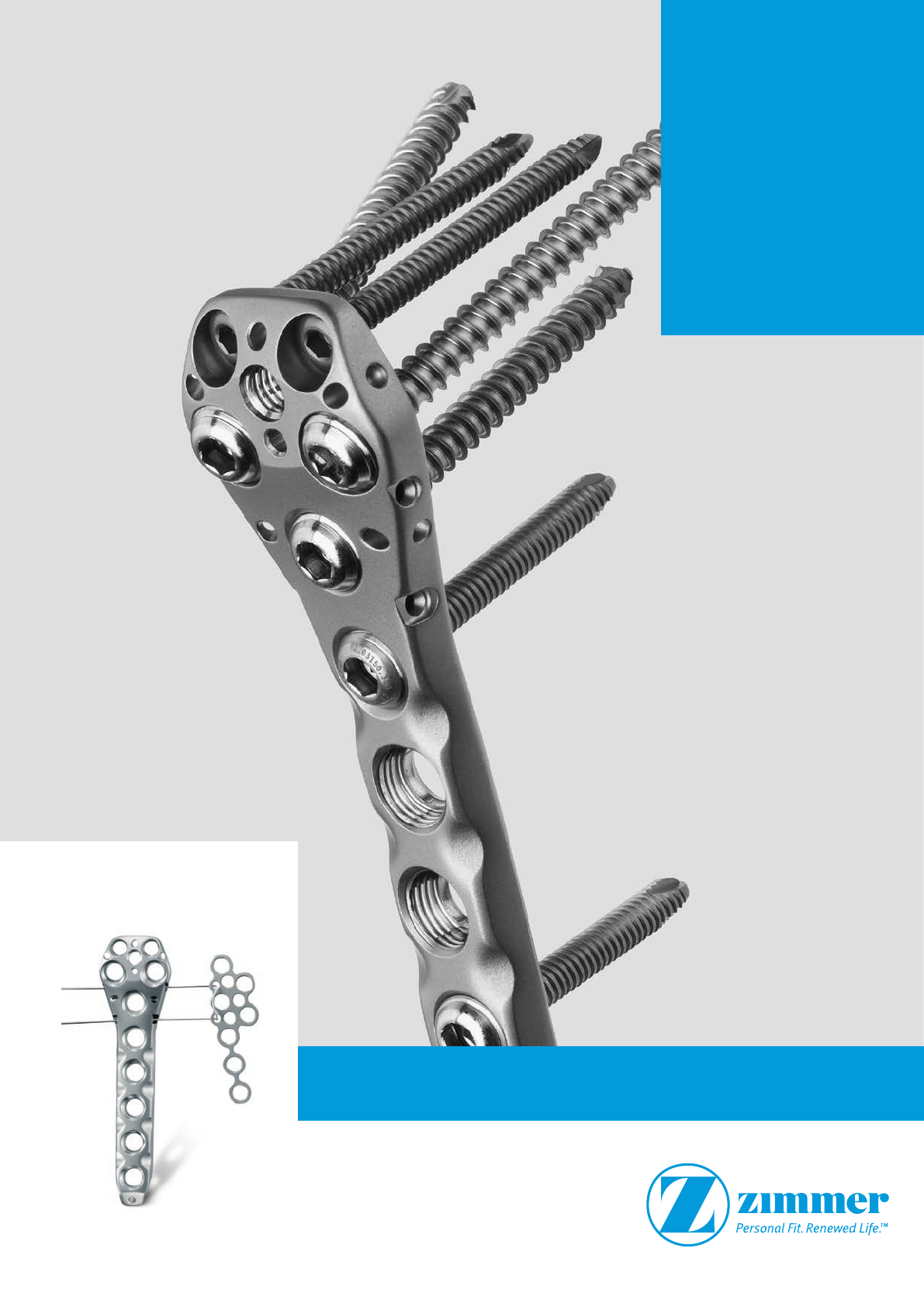
NCB® Proximal
Humerus
System
Surgical Technique

3
NCB® Proximal Humerus System – Surgical Technique
Surgical Technique
NCB Proximal Humerus
System
Table of Contents
Introduction 4
Cable Fixation Options 5
System Features 7
Indications 9
Contraindications 9
Fracture Classifications 9
Preoperative Planning and Patient Positioning 9
Sample Cases 10
Open Technique (Deltoid Pectoral Incision)
Deltoid Pectoral Incision 11
Insertion of the NCB-PH Plate and Fracture Reduction 11
NCB Screw Placement 13
Proximal 3.5 mm Locking Screw Placement (optional) 16
T-Minus Plate (optional) 19
Bone Spacer (optional) 21
Blind Screw Inserts and Sutures (optional) 21
MIS Technique*
(High Anterior/Lateral Deltoid Split Incision)
High Anterior/Lateral Deltoid Split Incision 22
Targeting Device 23
Insert the NCB-PH Plate 24
NCB Cannulated Screw Placement 25
Implant Removal 30
NCB Proximal Humerus – Information
Implants 31
Graphic Case for Open Technique 34
Standard Instruments 34
Implants for MIS Surgical Technique 36
Graphic Case for MIS Technique 37
MIS Instruments 38
T-Minus Module (optional) 39
T-Minus Instruments (optional) 40
Planning Aid 41
*MIS Minimally Invasive Solutions™ Technique by Zimmer
4NCB® Proximal Humerus System – Surgical Technique
Introduction
NCB Proximal Humerus
Osteosynthesis Plate
Solution for Proximal Humerus
Fractures
The NCB-PH (Non-Contact Bridging for
the Proximal Humerus) system is
an optimal solution for the treatment of
complex fractures of the proximal
humerus.
An additional extension T-minus plate
can be assembled with cerclage wire
technique for fixation of AP lesser
tuberosity fractures.
The system allows for polyaxial screw
placement (30°) with subsequent screw
locking for improved stability, especially
in osteopenic bone. Before locking, the
screws can act as lag screws and be
used for fracture reduction, a benefit
which is not offered with standard
locking systems.
In the locked mode the NCB-PH plate
acts as an internal fixator without con-
tact between the plate and the bone
surface reducing the risk of periosteal
blood supply impairment.
Materials: NCB plates and screws and 3.5 mm lock-
ing screws are made of Ti6Al4V, ISO 5832-3, ASTM
F136; the tuberculum minus plate is made of C.P.
titanium, ISO 5832-2, ASTM F67. The self tapping
cortical screw is made of Ti6Al7Nb, ISO 5832-11,
ASTM F1295.
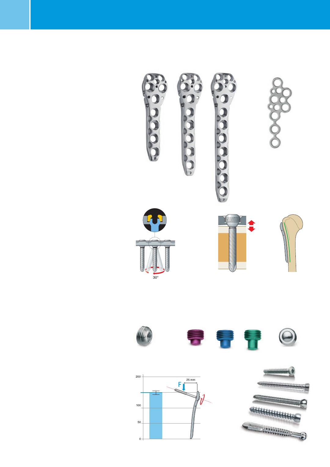
4-, 5- and 7-holes NCB plate
Spacer 1 to 3 mm Blind screw insert
Self-tapping screws:
3.5 mm cortical screws L= 20–40 mm
3.5 mm locking screws L= 20–50 mm
4.0 mm NCB screws L= 14–65mm
4.5 mm NCB cancellous screws L= 30–65mm
4.0 mm NCB MotionLoc® screws L= 24–46mm
7-holes T-minus plate
non
contact
Polyaxial screw placement with
subsequent locking option for
optimal system stability.
Non-Contact Bridging
ostesynthesis reduces the
risk of periosteal blood
impairment.
Anatomically contoured
plate. Forged titanium
alloy for better mechanical
strength.
4 Nm
Fastening torque
Angular stability of one NCB
locked screw
N (Newton)
(SD ±6 N)
150
Locking cap 8 mm
5
NCB® Proximal Humerus – Surgical Technique
* Not available in Europe, Middle East, and Africa
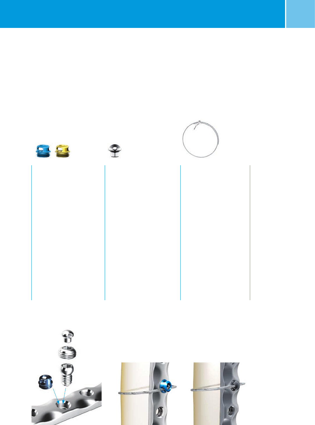
Cable Fixation Options
The following products from the Zimmer®
Cable-Ready® Cable Grip
System are compatible with the NCB
Proximal Humerus System.
See data sheet REF 97-2232-015-00 for
more specific instructions.
NCB Locking Plate
Cable Button, 2.5mm, Hex Drive
• Sterile
• Material: Ti6Al4V
REF 47-2232-060-00 Color: Gold*
REF 47-2232-060-01 Color: Blue
Application
This Cable Button is threaded
directly into the NCB Plate hole to
provide a positioning point for
the Cable.
Instructions
To insert, use the 2.5mm hex
screwdriver to thread the cable
button in to the plate hole. Do not
fully tighten to allow the slots in
the button to align with the cable.
To remove, use 2.5mm hex
screwdriver to unthread the cable
button from the plate hole.
Hex Button, 3.5mm
• Sterile
• Material: C.P. Titanium
REF 00-2232-002-35
Application
This Hex Button fits into the
standard hex in the screw head
(3.5mm hex). Therefore, it can
be inserted into the NCB Screw
head or into the NCB Locking
Cap.
Note: The Hex button is incom-
patible with the 2.5 mm Hex
of the 3.5 mm locking screws
(REF 00-2369-0xx-35 and
47-2369-0xx-35) and Cortical,
self-tapping screws (REF
02.03131.0xx).
Cable Assembly Cerclage,
1.8mm
• Sterile
• Material: CoCr
REF 00-2232-002-28
REF 00-2232-004-18
Cable Fixation with
Hex Button
Cable Fixation Options Cable Fixation with
Cable Button
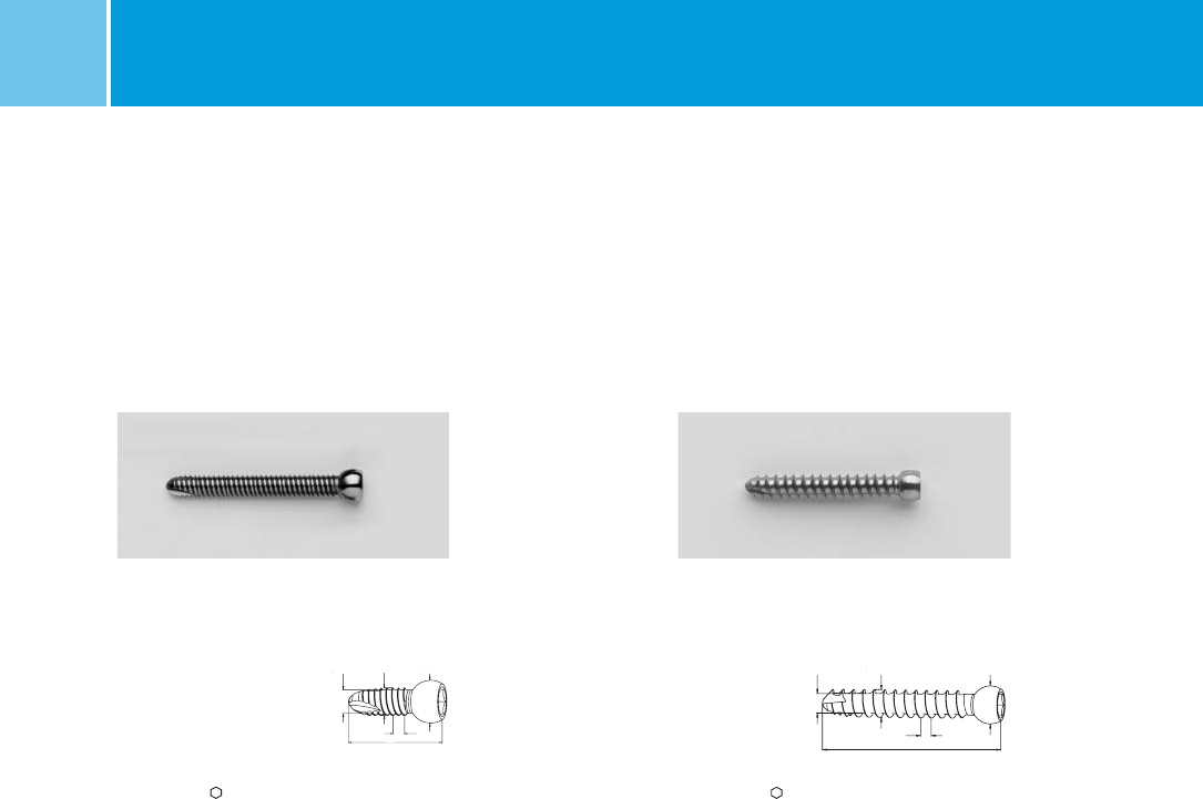
6NCB® Proximal Humerus – Surgical TechniqueNCB® Proximal Humerus System – Surgical Technique
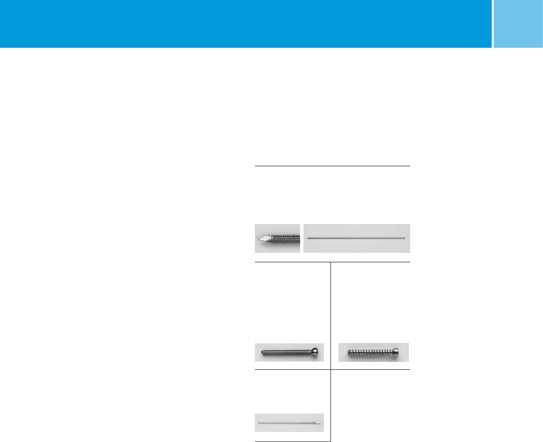
Increased core diameter 3.3 mm Spherical screw head with
standard 3.5 mm hexagonal drive
Self-drilling and
self-tapping screw tip
Double lead thread for fast
screw insertion for cortical
bone Cannulation for 1.6 mm
Guide Wire
Cancellous bone thread
Fully threaded
cancellous screws
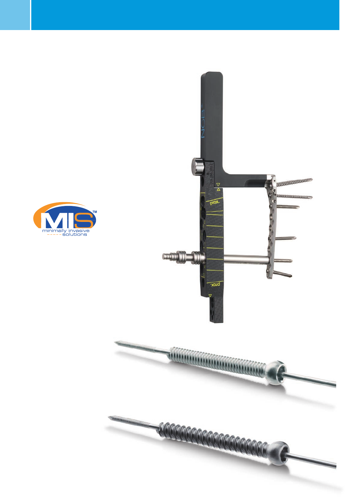
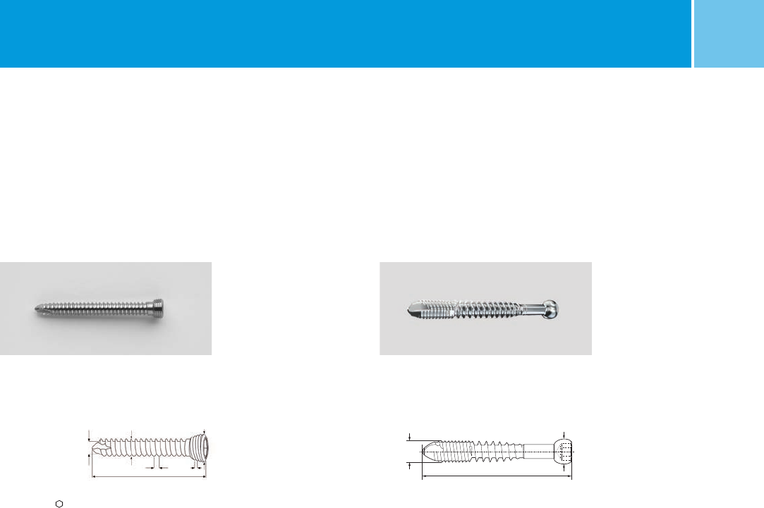
The NCB instrumentation is based on
well-known standard surgical tech-
niques and osteosynthesis instruments.
The NCB-PH plate can be applied in the
MIS* technique using a fully radiolucent
targeting device and can nu lated
cortical and cancellous screws with
cannulated instruments.
MIS radiolucent targeting device
MIS technique with a fully radiolucent
targeting device
4.0 mm NCB cannulated screw
4.5 mm NCB cannulated
cancellous screw
*MIS Minimally Invasive Solutions™ Technique by Zimmer
Targeting device and plate assembly
7
NCB® Proximal Humerus – Surgical Technique
System Features
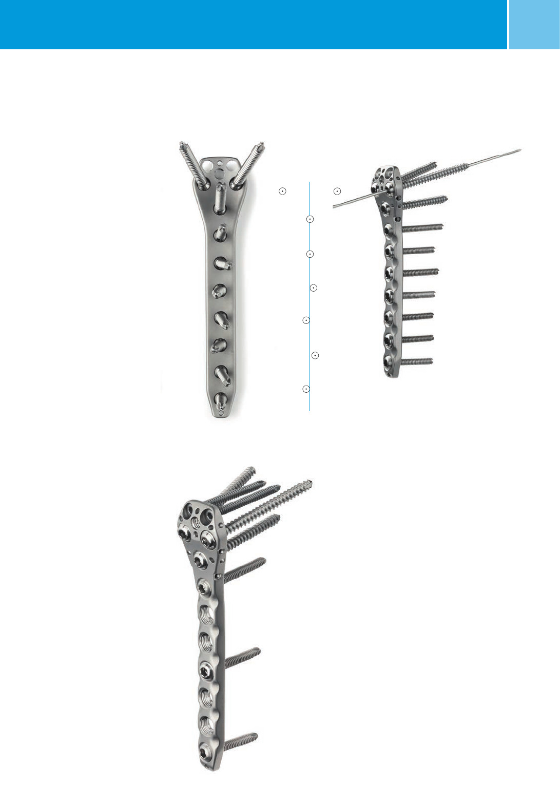
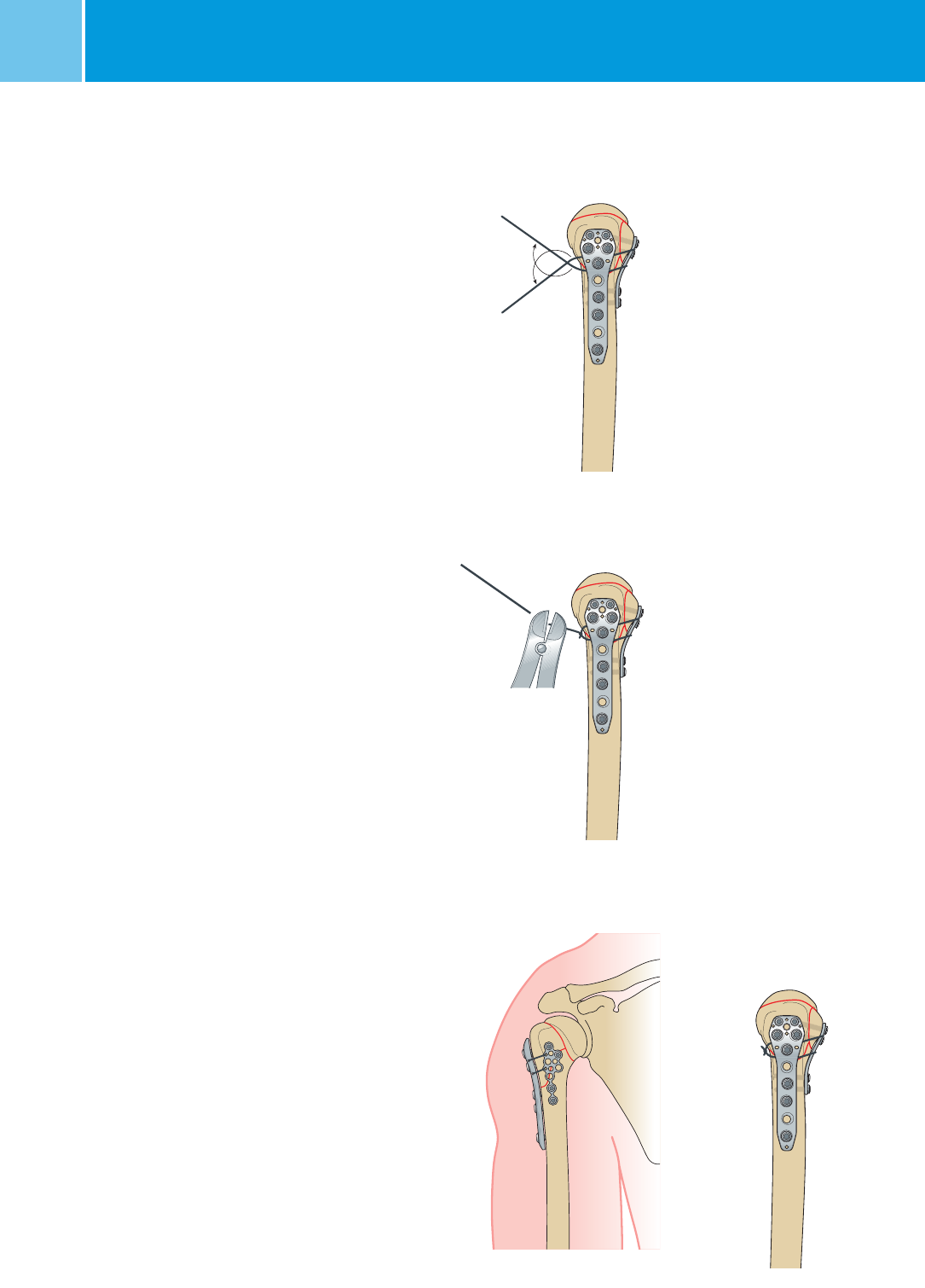
Divergent Screw Alignment
The targeting device ensures
divergent screw alignment for
increased pull-out resistance
in the metaphyseal and diaphyseal
regions.
3.5 mm Locking Screws
In order to increase the stabilization
of the proximal humeral head, two
additional locking screws (i.e. uniaxial
locking screws) may be placed in the
proximal humeral head
.
The screws are positioned in convergent
manner, in order to increase the pull-out
resistance in the humeral head.
NCB® Proximal Humerus System – Surgical Technique
8NCB® Proximal Humerus – Surgical TechniqueNCB® Proximal Humerus System – Surgical Technique
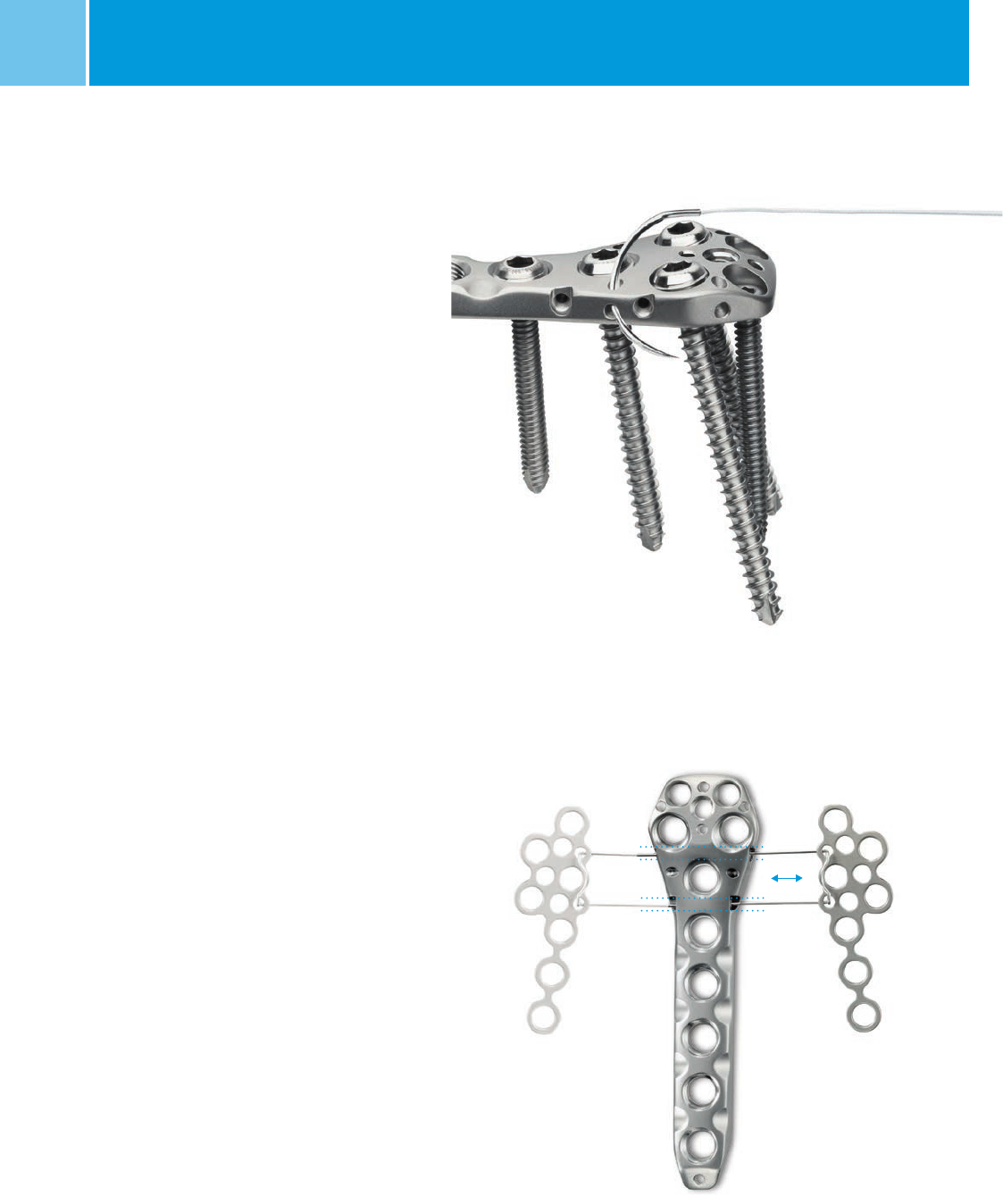
Oblique Holes for Sutures
Oblique holes 2 mm can be used
for sutures after plate osteosynthesis.
T-Minus Plate with Cerclage Wire
The plate is assembled to the NCB
humerus plate with a pre-bent U-shaped
cerclage wire 0.8 mm through two
holes at the side of the NCB plate.
The same plate can be used for left
and right.
9
NCB® Proximal Humerus – Surgical TechniqueNCB® Proximal Humerus System – Surgical Technique
Fracture Classifications
Indications for Open Technique
(Deltoid Pectoral Incision)
• Neer classification: 2-, 3-, 4-part
displaced fractures (anatomical neck,
surgical neck, tuberculum majus,
tuberculum minus and head splitting).
• AO classification: type 11 A, extracap-
sular, 2 fragments; type 11 B, partially
intracapsular, 3 fragments; type 11 C,
– intracapsular.
Indications for MIS Technique*
(Anterior/Lateral Deltoid Split
Incision)
• Neer classification: 2-part displaced
fractures.
• AO classification: type 11 A, extracap-
sular, 2 fragments.
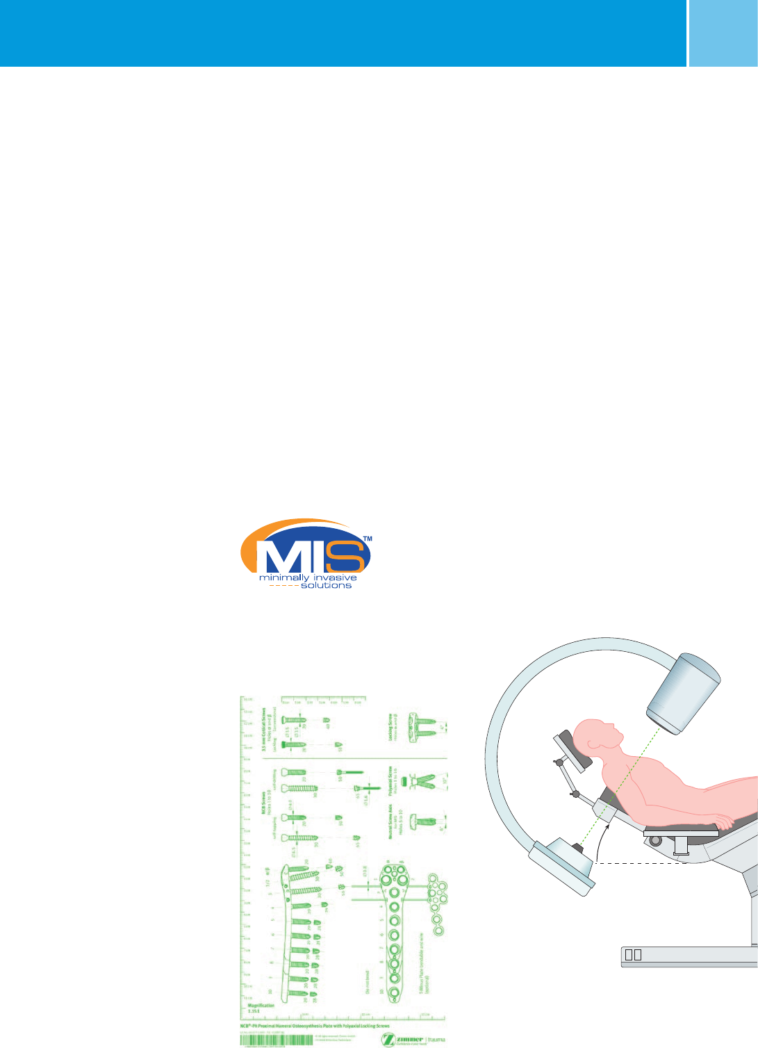
Preoperative Planning
and Patient Positioning
Preoperative Planning
An X ray of the injured shoulder on the
anteroposterior plane is essential for
preoperative planning. In addition, a “Y”
view, (perpendicular to the antero-
posterior view of the scapula is also
required).
A CT scan can also provide information
concerning the tuberosities.
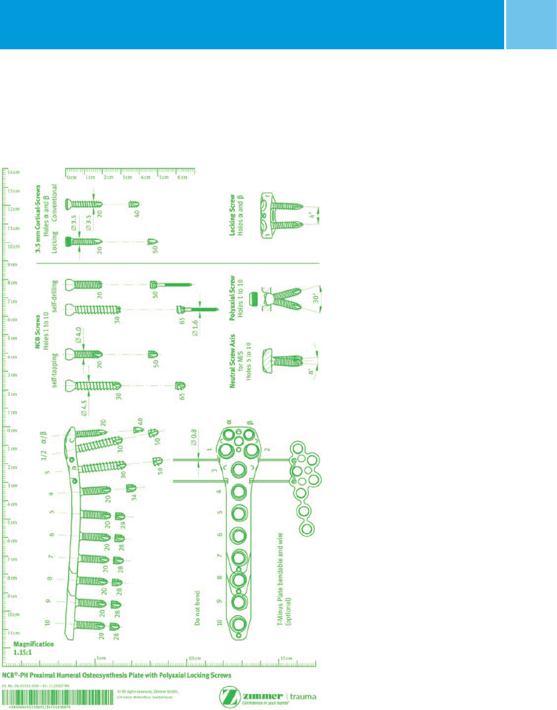
The use of the X ray template
(REF 06.01511.000) is recommended
for preoperative planning.
Positioning of the Patient
The patient is placed on the operating
table in the beachchair position.
After the patient is in the correct
position, the C-arm must be adjusted
so as to achieve the widest possible
view of the proximal humerus.
Indications
The NCB Polyaxial Locking Plate System
is indicated for temporary internal
fixation and stabilization of fractures
and osteotomies of long bones.
Note: The NCB Proximal Humerus plate
from the NCB Polyaxial Locking Plate
System is specifically designed for the
proximal humerus.
Contraindications
• All concomitant diseases that may
impair the fixation of the implant and/
or the success of the intervention.
• Lack of bone substance or poor bone
quality which makes stable seating of
the implant impossible.
• Acute or chronic, local or systemic
infections.
• Allergy to the implanted material.
• Severe muscular, neural or vascular
diseases that endanger the extremities
involved.
X ray template REF 06.01511.000
30°–45°
Patient positioning
10 NCB® Proximal Humerus – Surgical TechniqueNCB® Proximal Humerus System – Surgical Technique
30°
X ray directions
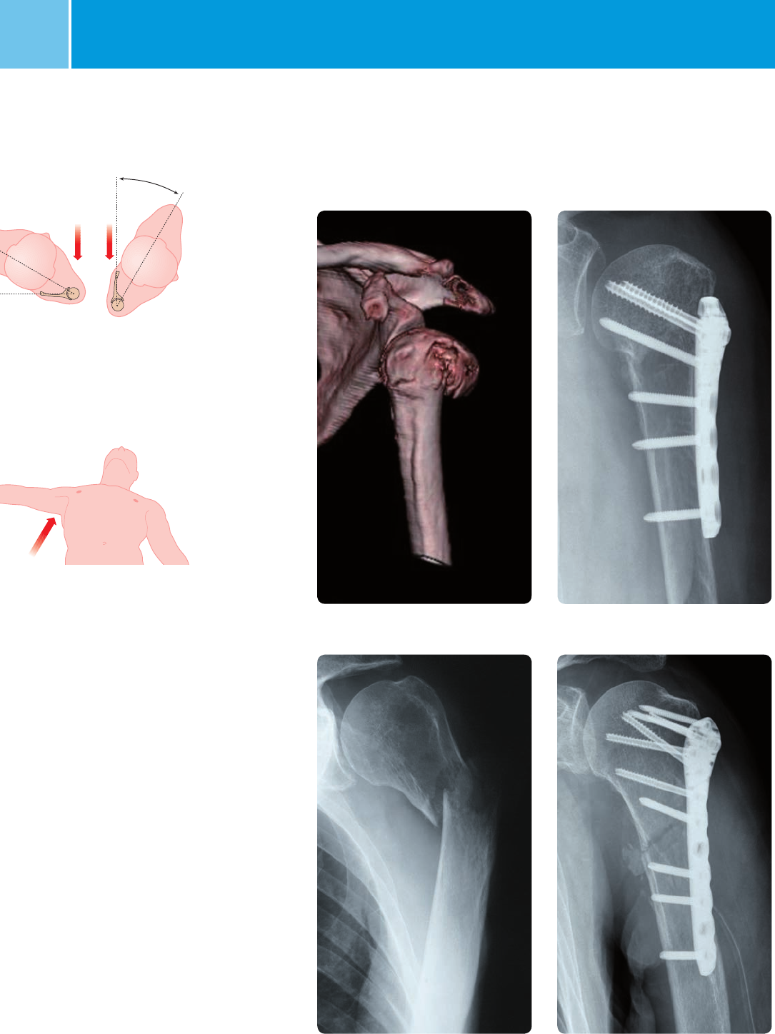
Sample Cases
Preoperative Postoperative, MIS* operation technique
Preoperative Postoperative, open operation technique
*MIS Minimally Invasive Solutions™ Technique by Zimmer
11
NCB® Proximal Humerus – Surgical TechniqueNCB® Proximal Humerus System – Surgical Technique
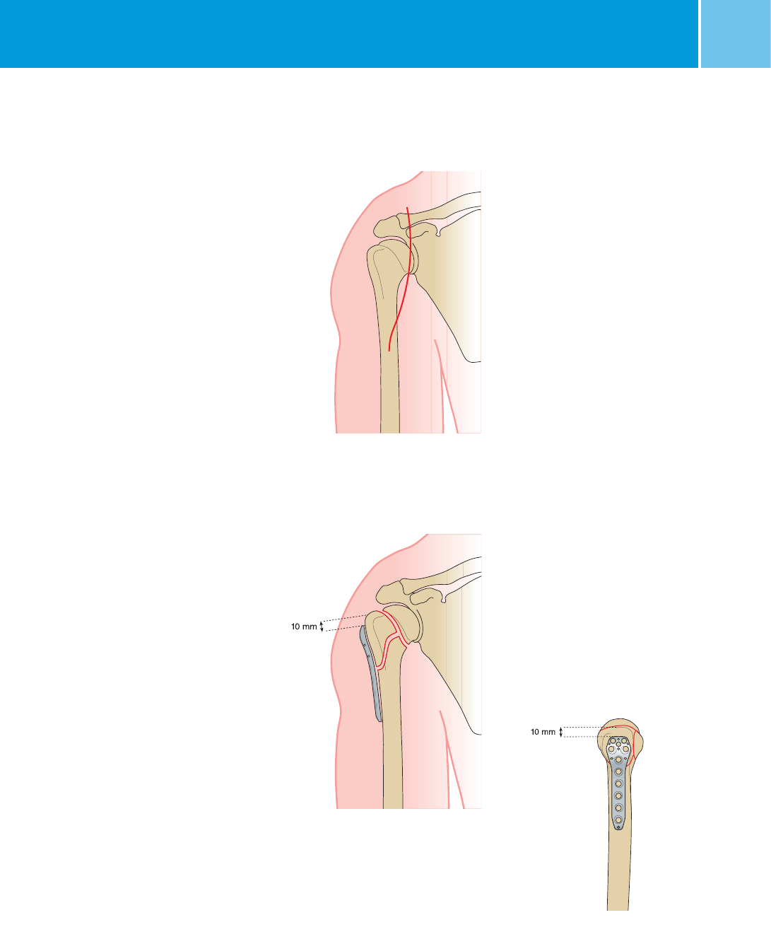
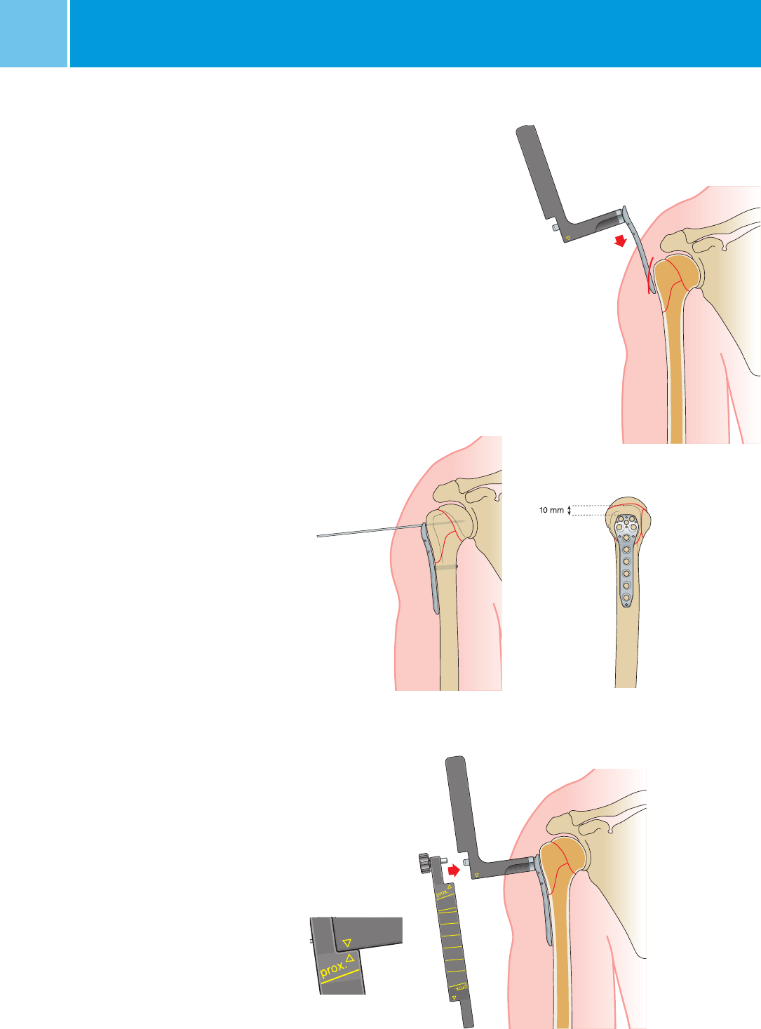
Insertion of NCB-PH Plate
and Fracture Reduction
Due to the anatomical contour, NCB
plates may act as a lateral guide for frac-
ture reduction.
Insert the NCB-PH plate (REF 02.02262.10x)
before fracture reduction.
Positioning from A-P view
The plate should be placed approx.
10 mm distal to the rotator cuff attach-
ment on the upper edge of the greater
tuberosity to avoid postoperative sub-
acrominal impingement.
Positioning from lateral view
The plate should be centered against the
lateral aspect of the greater tuberosity.
Note: The plate should not be bent, as
this might disrupt the function of the
locking mechanism.
Open Technique
Deltoid Pectoral Incision
For the open technique the delto-pectoral
incision is recommended.
Important: Care must be taken to avoid
damaging the axillary nerve and blood
supply to the bone fragments.
Deltoid pectoral incision
delto-pectoral
Insert the plate before
fracture reduction
12 NCB® Proximal Humerus – Surgical TechniqueNCB® Proximal Humerus System – Surgical Technique
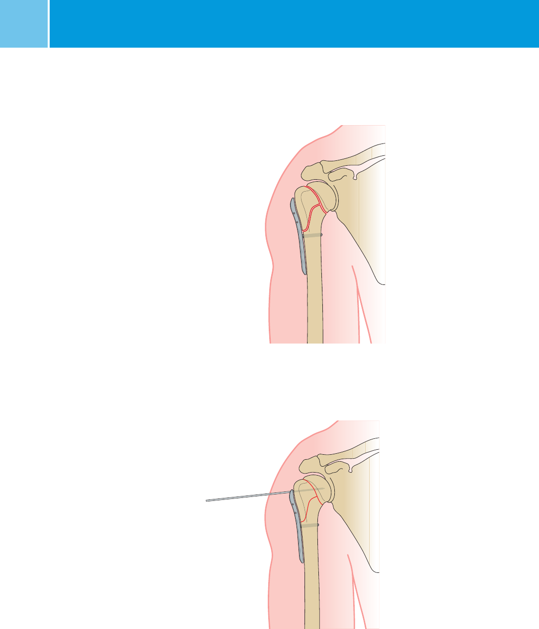
First place the distal screw closest
to the fracture line (see distal screw
placement). Tighten this screw and use
the plate for fracture reduction.
Place a 2 mm K-wire (REF 299.20.150)
at the proximal end of the plate and
use the plate-K-wire construct to secure
the reduction.
Complete the stabilization of the
fracture with the insertion of distal and
proximal NCB screws once good
fracture reduction has been achieved.
Insert the distal screw closest
to the fracture line
Use the plate for fracture reduction
13
NCB® Proximal Humerus – Surgical TechniqueNCB® Proximal Humerus System – Surgical Technique
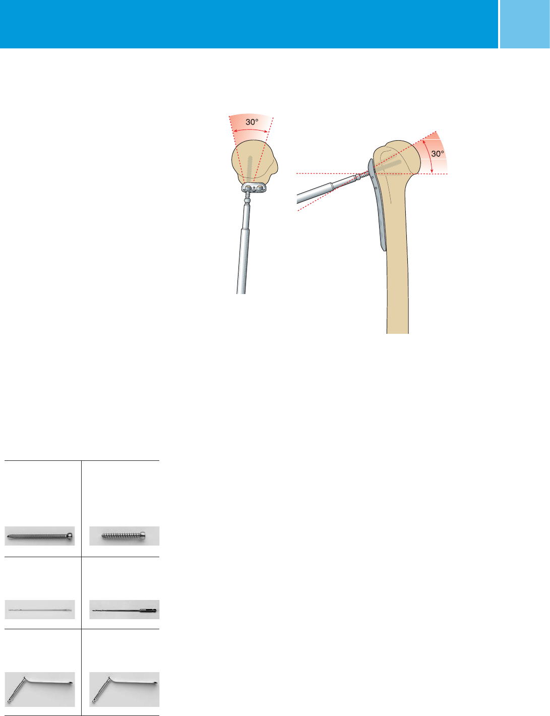
Possible range of screw angulation
in NCB plate holes.
NCB MotionLoc Screws
Zimmer MotionLoc Screw for NCB Polyaxial
Locking Plate System surgical technique
(REF 97-3161-002-00 or 97-3161-004-00)*
has specific instructions for the NCB
MotionLoc Screw.
2. Screw and Drill Dimensions
NCB self-tapping screw
and drill dimensions
Screw Type Screw Type
Cortical Cancellous
REF 02.0x155.0xx REF 02.0x159.0xx
4.0 mm 4.5 mm
L 14–65 mm L 30–65 mm
Drill Drill
REF 02.00024.118 REF 103.25.180
3.3 mm 2.5 mm
Drill guide Drill guide
REF 02.00024.111 REF 02.00024.010
3.3 mm 2.5 mm
NCB Screw Placement
1. Screw Angulation
30° screw angulation is possible for all
the NCB holes in the plate.
The placement of NCB screws depends
on the fracture type and the achieved
reduction.
Alternatively, it is possible to use the
cannulated NCB screws.
* 97-3161-002-00 is for countries where NCB MotionLoc screws are approved to be used with only NCB plates and
97-3161-004-00 is for countries where NCB MotionLoc screws are approved to be used with both NCB as well as
NCB Periprosthetic plates. See NCB MotionLoc package insert for approved plate/MotionLoc screw combinations.
14 NCB® Proximal Humerus – Surgical TechniqueNCB® Proximal Humerus System – Surgical Technique
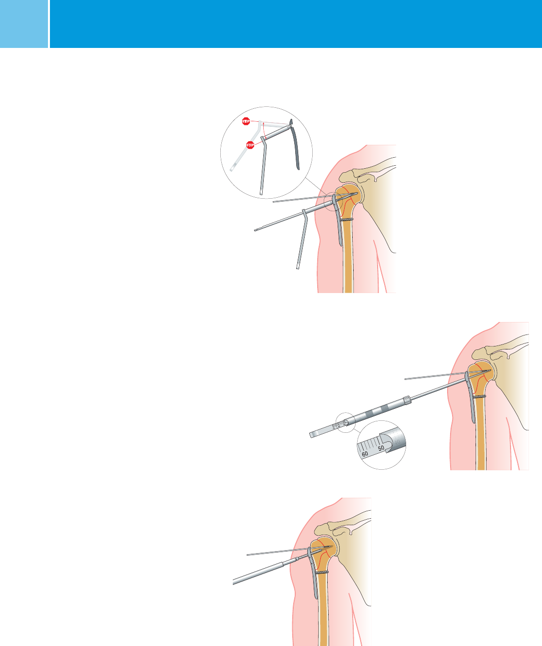
a) Proximal screw placement
When drilling the proximal screw holes,
the use of an image inten sifier is recom-
mended. Stop approximately 5 mm
before the subchondral bone.
For screw placement use the NCB drill
guide 2.5 mm (REF 02.00024.010) and
the two-fluted drill bit 2.5 mm
(REF 103.25.180). The drill guide allows
polyaxial screw placement. A stop is felt
at 30 degrees.
The screw length is measured with the
NCB depth gauge (REF 02.00024.214).
The appropriate screw length is chosen
from the screw rack.
Insert the self-tapping screw with
the NCB torque screwdriver
(REF 02.00024.022). For osteoporotic
bone use 4.5 mm
NCB cancellous
screws. Repeat this procedure
to place
all proximal bone screws.
Note: Hand tighten screws – do not use
power.
Important: When determing the proximal
screw length, the probability of bone
resorption and sintering at the fracture
site must be taken into account. Care
should be taken to ensure that the screw
tip is an adequate distance away from
the subchondral zone.
Exact screw setting with the
drill guide and drill
Measuring screw length
with the depth gauge
Insert the self-tapping screw
30°

15
NCB® Proximal Humerus – Surgical TechniqueNCB® Proximal Humerus System – Surgical Technique
b) Distal screw placement
Same screw placement procedure as
proximally.
For screw placement use the NCB drill
guide 3.3 mm (REF 02.00024.111)
and
the NCB drill bit 3.3 mm
(REF 02.00024.118).
The drill guide
allows polyaxial screw placement. A stop
is felt at 30 degrees. Insert the screw
using the NCB torque screwdriver
(REF 02.00024.022).
For optimal fixation, bicortical insertion
is recommended. Place at least 3 screws
below the fracture.
3. Add Locking Caps
To achieve angular stability, insert NCB
locking caps (REF 02.0x150.300) for
all screws with the
NCB
torque screw-
driver (REF 02.00024.022) until the
wrench declutches (clicking sound).
Note: Always use the
NCB
torque screw-
driver to tighten the locking caps and
make sure not to tilt the screwdriver dur-
ing its use. Failure to do so could dam-
age the hex drive of the locking cap and
might complicate later removal of the
implant. Bone spacers can be removed
and replaced with screws.
Insert the distal self-tapping screws
M8 locking cap placement,
tighten until wrench declutches
(click sound)
Final placement
16 NCB® Proximal Humerus – Surgical TechniqueNCB® Proximal Humerus System – Surgical Technique
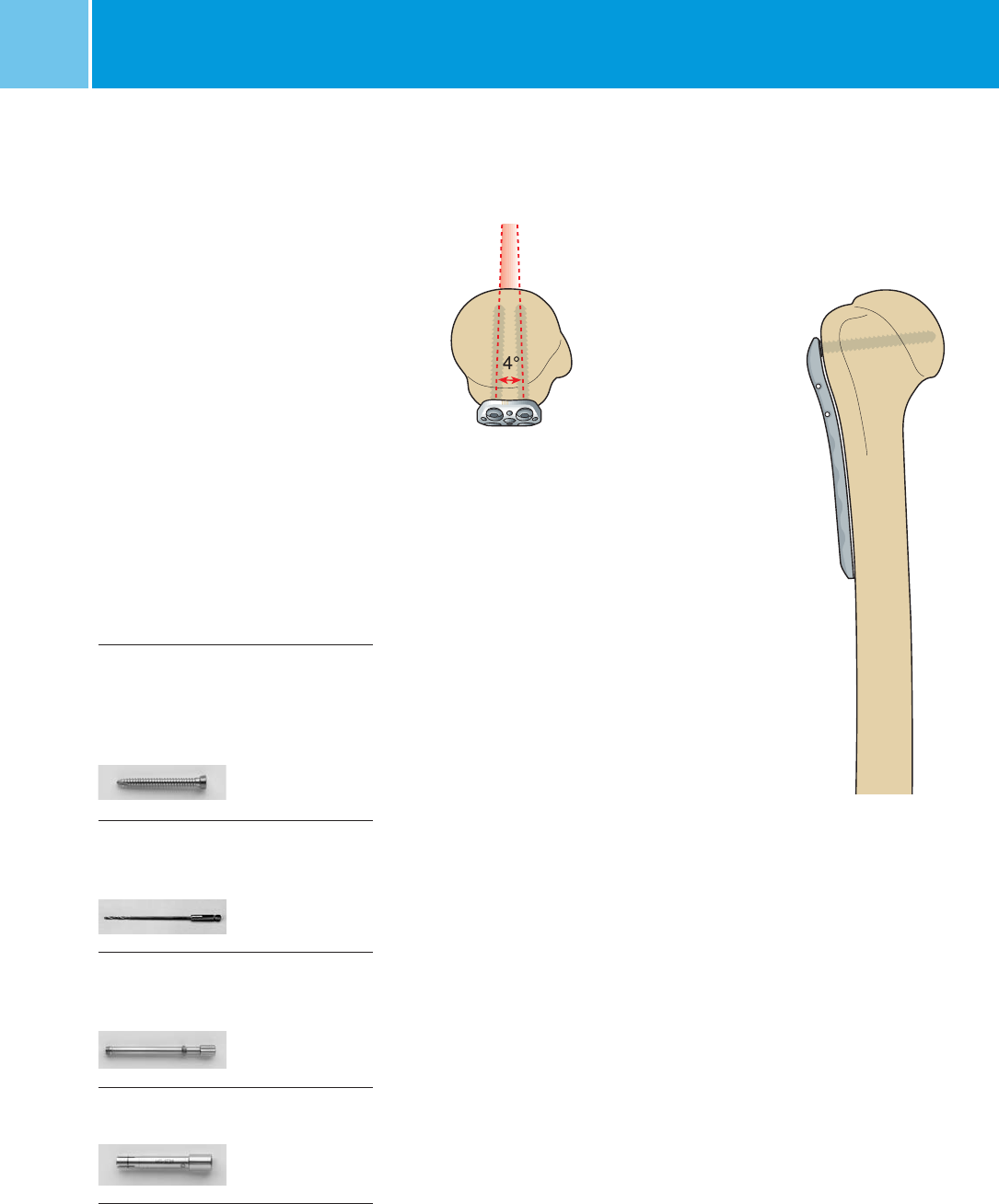
Proximal 3.5 mm
Locking Screw Placement
(optional)
Additionally, after reducing the fracture
with NCB screws, it is possible to
place 3.5 mm locking screws
(REF xx-2369-0xx-35), which are 4°
convergent, in the two proximal holes.
1. Screw and Drill Dimensions
3.5mm locking screw
and drill dimensions
Screw Type
Cortical
REF xx-2369-0xx-35
3.5 mm
L 20–50 mm
Drill
REF 103.25.180
2.5 mm
Drill guide
REF 02.00024.223
2.5 mm
Tissue protection sleeve
REF 02.00024.222
17
NCB® Proximal Humerus – Surgical TechniqueNCB® Proximal Humerus System – Surgical Technique
2. Drill Screw Holes
Hold the
NCB-
PH jig (REF 02.00024.220)
on the plate and finger tighten or
use the small hexagonal screwdriver
(REF 109.01.020) to tighten moderatly
the
NCB-
PH
connection screw
(REF 02.00024.221).
Insert the NCB-PH
tissue protection sleeve
(REF
02.00024.222
) and thread
the
NCB
-PH
drill guide (
REF
02.00024.223)
into the
plate hole. Then use the two-fluted
2.5 mm drill bit (REF 103.25.180) to drill
the screw hole.
18 NCB® Proximal Humerus – Surgical TechniqueNCB® Proximal Humerus System – Surgical Technique
3. Measure Screw Length
Remove the two-fluted drill bit 2.5 mm
(REF 103.25.180) and the
NCB-
PH drill
guide (REF 02.00024.223) and measure
the screw length with the small depth
gauge for the 3.5 mm screws
(REF 02.00024.216).
Important: When determing the proximal
screw length, the probability of bone
resorption and sintering at the fracture
site must be taken into account. Care
should be taken to ensure that the screw
tip is an adequate distance away from
the subchondral zone.
4. Insert the 3.5 mm
Locking Screws
Insert the appropriate 3.5 mm locking
screws (REF xx-2369-0xx-35) using
the small hexagonal screwdriver
(REF 109.01.020). Once the screw is
in place, remove the NCB-PH tissue
protection sleeve (REF 02.00024.222)
and repeat the procedure if the second
locking screw is needed. In order to
minimize the risk of failure in the screw
head hexagonal, it is recommended
to tighten these screws by hand only.
19
NCB® Proximal Humerus – Surgical TechniqueNCB® Proximal Humerus System – Surgical Technique
T-Minus Plate (optional)
1. Apply T-Minus Plate
For lesser tuberosity fractures it is
pos si ble to apply a small bendable
and cuttable plate with 7-holes
(REF 02.0x262.101). The plate is fixed
to the bone using 3.5 mm standard
self-tapping cortical screws
(REF 02.03131.0xx). The plate is assem-
bled to the NCB humerus plate with a
pre-bent U-shaped cerclage wire
0.8 mm (REF 02.0x362.108) through
two holes at the side of the NCB plate.
The same plate can be used for the left
and right humerus.
2. Drill Screw Holes
Use the standard double drill guide for
screws 2.5/3.5/4.0 (REF 100.40.035)
and the two-fluted drill bit 2.5 mm,
with quick coupling (REF 103.25.180) to
drill the holes.
3. Measure Screw Length
and Place Screws
Measure the appropriate screw
length with the small depth gauge, for
screws 3.5 mm (REF 02.00024.216).
Place the 3.5 mm self-tapping cortical
screw (REF 02.03131.0xx) with the small
hexagonal screwdriver (REF 109.01.020).
T-minus plate screw-placement
Drilling with a
standard double-drill guide
Apply T-minus plate to the bone
20 NCB® Proximal Humerus – Surgical TechniqueNCB® Proximal Humerus System – Surgical Technique
4. Twist the Wire
Twist the cerclage wire with wire-bend-
ing forceps (REF 100.11.155) and apply
some tension to the T-minus plate.
5. Cut the Wire
Cut off the remaining cerclage
wire with
a wire cutter (REF 100.11.115)
and bend
it along the side of the NCB plate.
Standard cerclage wire
technique is used
Cut off the remaining
cerclage wire
Applied T-minus plate and final
construct
21
NCB® Proximal Humerus – Surgical Technique
Blind Screw Inserts and
Sutures (optional)
NCB Blind Screw Insertion
To prevent bone ingrowth into empty
screw holes it is possible to use NCB
blind screw inserts (REF 02.0x150.310).
Insert the blind screw inserts using a
3.5 mm hexagonal screwdriver.
Note: Hand tighten only.
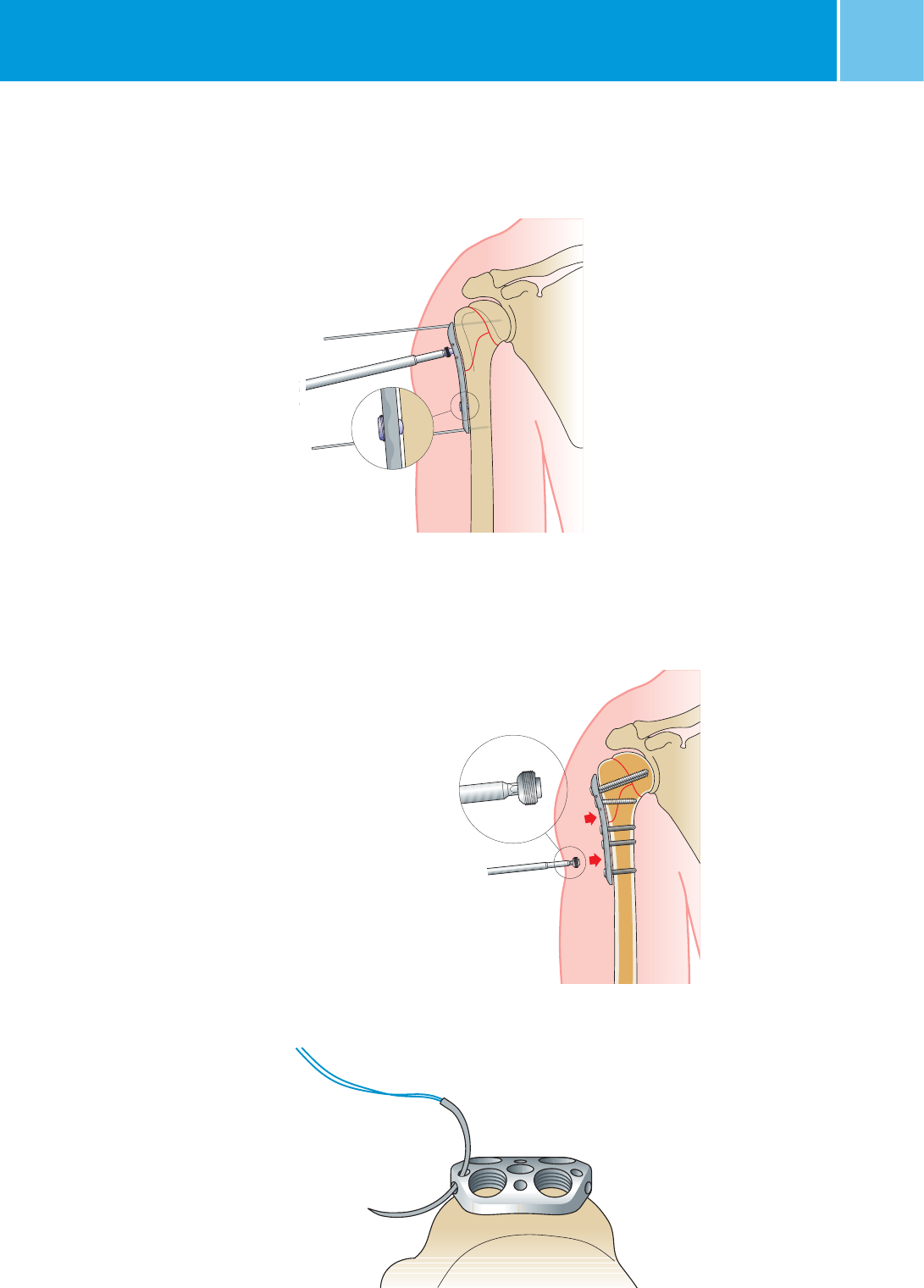
Sutures
Oblique holes 2 mm can be used
for sutures and reattachment of the
rotator cuff after the plate has been
fixed to the bone with screws.
NCB® Proximal Humerus System – Surgical Technique
NCB blind screw insertion
Oblique holes 2 mm for sutures proximally
Bone spacer 2 mm (blue) proximally and distally
Bone Spacer (optional)
You may temporarily insert bone spacers
into the locking holes to avoid perios -
teal blood flow impairment. Insert bone
spacer with a 3.5mm hexagonal screw-
driver Three. Lengths from 1 to 3 mm are
available.
Note: The spacers are single-use only.
They can be removed after locking the
screws.
Bone Spacer
REF-No Color Length
02.0x150.311 red 1 mm
02.0x150.312 blue 2 mm
02.0x150.313 green 3 mm
22 NCB® Proximal Humerus – Surgical TechniqueNCB® Proximal Humerus System – Surgical Technique
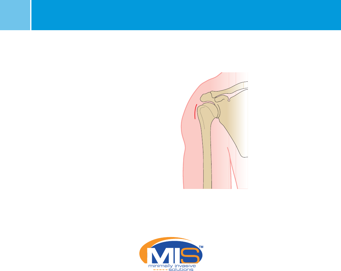
MIS Technique*
High Anterior/Lateral Deltoid
Split Incision
A high anterior/lateral deltoid split
incision is recommended.
Important: Care must be taken to avoid
damaging the axillary nerve and to
keep intact the blood supply of the bone
fragments.
1. Reduce the Fracture
Reduce the fracture and check under
image intensification.
The humeral head and tuberosity
fragments may be manipulated and
tem porary fixed with 2 mm Kirschner
wires (K-wires) (REF 299.20.150). K-wires
should be placed where they will not
interfere with the plate application.
Note: If the use of the additional 3.5 mm
locking screws is required, insert
these screws after the targeting device
is removed.
Incision for MIS technique
* MIS Minimally Invasive Solutions Technique by Zimmer
23
NCB® Proximal Humerus – Surgical TechniqueNCB® Proximal Humerus System – Surgical Technique
NCB screw hole numbering system
12
3
4
5
6
7
8
9
10
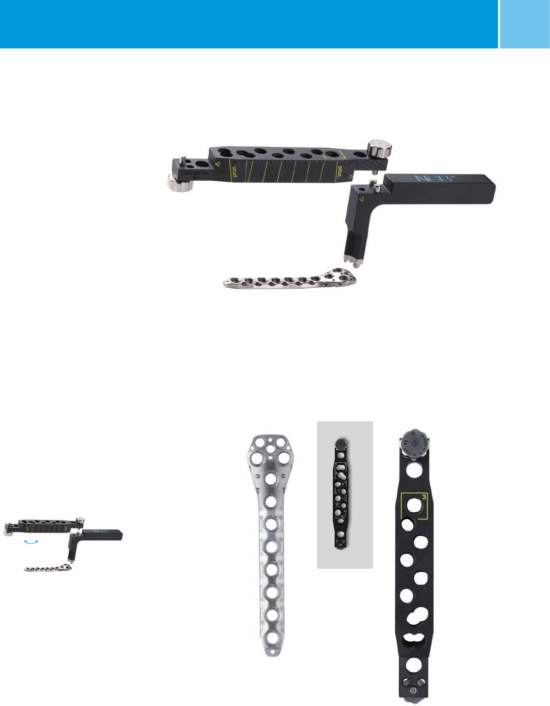
Targeting Device
Plate Hole Numbering System
To target the correct plate holes there
is a numbering system on the targeting
module (REF 02.00024.202).
The top side of the targeting module
is for the screw holes with numbers:
1–2–4–5–6–7–8–9–10
Turn the targeting module upside down
for the number:
3
Note: The plate should not be bent
since this might compromise the
function of the locking mechanism.
Assembly of the targeting device
24 NCB® Proximal Humerus – Surgical TechniqueNCB® Proximal Humerus System – Surgical Technique
Insert the NCB PH Plate
1. Assemble the MIS* radiolucent
targeting device
Assemble the radiolucent handle
(REF 02.00024.101) to the proximal end
of the NCB-PH plate using the NCB-PH
connection screw (REF 02.00024.103).
Use a 3.5 mm hexagonal screwdriver to
tighten the connection screw.
2. Inserting NCB PH Plate
Insert the plate (REF 02.02262.10x)
through the high anterior/lateral
deltoid split incision subcutaneously
along the proximal humerus.
Note: Attempt to get bone contact
immediately. Care must be taken
to avoid damaging the axillary nerve
and the vascularization of the
fragments.
3. Position NCB PH Plate to Bone
Positioning from A-P view
The plate should be placed approx.
10 mm distal to the rotator cuff
attachment on the upper edge of the
greater tuberosity to avoid postoperative
subacrominal impingement.
Positioning from lateral view
The plate should be centered
against the lateral aspect of the greater
tuberosity.
4. Assemble the Targeting Module
Attach the targeting module
(REF 02.00024.202) to the handle with the
hole numbering 1–2–4–5–6 –7–8–9–10
on the lateral side. Fit the yellow arrow-
head markings.
Insert the plate
Plate alignment 10 mm distal of edge greater
tuberosity and center against the lateral aspect
Yellow arrowhead
markings
Assemble the targeting module
*MIS Minimally Invasive Solutions™ Technique by Zimmer
25
NCB® Proximal Humerus – Surgical Technique
NCB Cannulated Screw
Placement
1. General Remarks
Placement of the NCB screws depends
on the fracture type and the reduction
achieved.
Two cannulated screw types are offered
with the NCB-PH System. Cancellous
NCB screws, preferably for the epiphysis
and metaphysis, as well as cortical NCB
screws which are optimal for placement
in the diaphysis. Both screw types are
self-drilling and self-tapping. The screws
can be precisely placed over the guide
wires. A tissue protection sleeve assem-
bly is used for guidance. A cannulated
drill bit can be used to predrill hard
cortical bone.
Note: Use the cannulated screws
only after insertion of 1.6 mm,
length
190 mm guide wire (REF 02.01362.116).
NCB® Proximal Humerus System – Surgical Technique
MIS* Technique
NCB Self-Drill Screw and Drill Dimensions
Guide wire
REF 02.01362.116
1.6 mm
L 190 mm
Screw Type Screw Type
Cannulated Cannulated
Cortical, self drilling Cancellous, self drilling
REF 02.0x157.0xx REF 02.0x160.0xx
4.0 mm 4.5 mm
L 14–65 mm L 30–65 mm
Drill
REF 02.00024.117
3.3 mm
*MIS Minimally Invasive Solutions™ Technique by Zimmer
26 NCB® Proximal Humerus – Surgical TechniqueNCB® Proximal Humerus System – Surgical Technique
Insert 1.6 mm guide wire
Find the distal center
Threaded part
to connect to
the NCB plate
Temporary plate fixation and placement
of the tissue protection sleeve
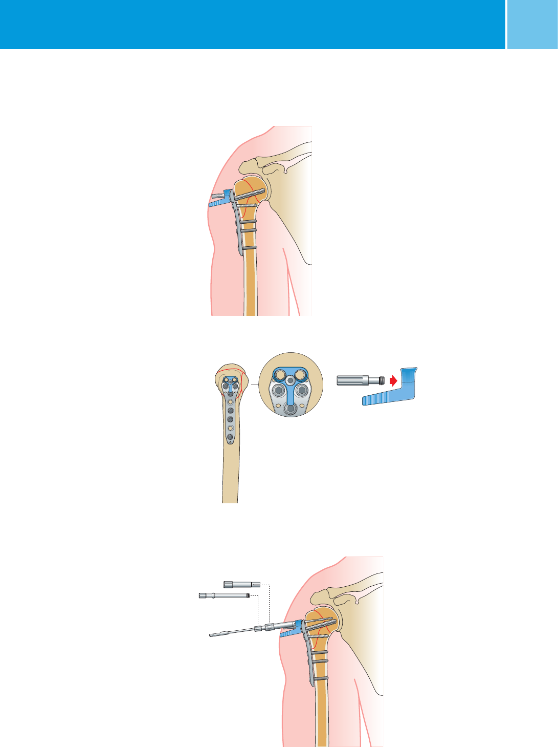
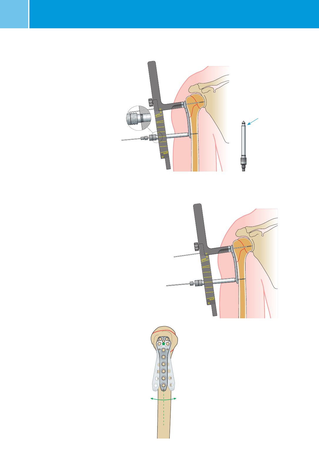
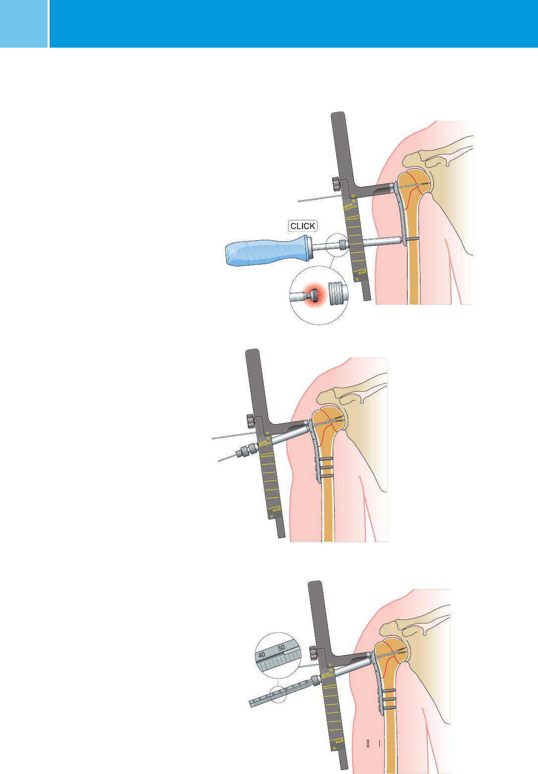
2. Temporary Plate Fixation
Proximally, the plate can be temporarily
fixed to the bone with a 1.6 mm
guide wire through the NCB-PH
connection screw (REF 02.00024.103)
of the targeting device.
To fix the plate distally, insert the
NCB Tissue Protection Sleeve assembly
1.6-
10 (REF 02.0024.213,
02.0024.114 to 116) through a skin
incision and screw the NCB-PH
drill
guide (REF 02.00024.114) into the
plate and then the NCB-PH soft tissue
protection sleeve (REF 02.00024.213)
into the targeting device.
Insert 1.6 mm guide wire with
a length of 190 mm (REF 02.01362.116)
and confirm the correct position with an
image intensifier.
Note: The distal center can be found
with
1.6 mm guide wire by finding the
anterior and posterior bone cortex and
putting the guide wire in the middle of
these two reference points.
27
NCB® Proximal Humerus – Surgical TechniqueNCB® Proximal Humerus System – Surgical Technique
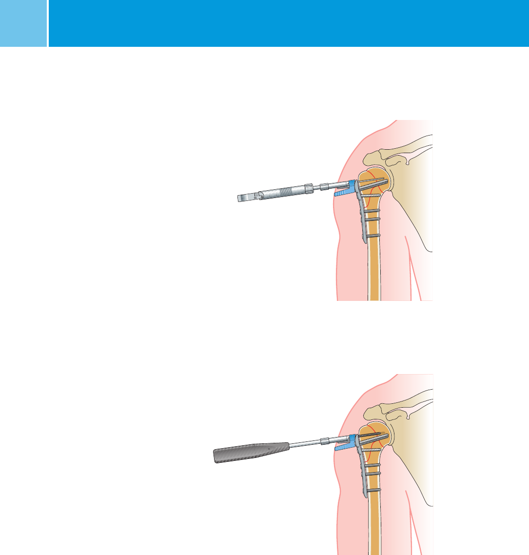
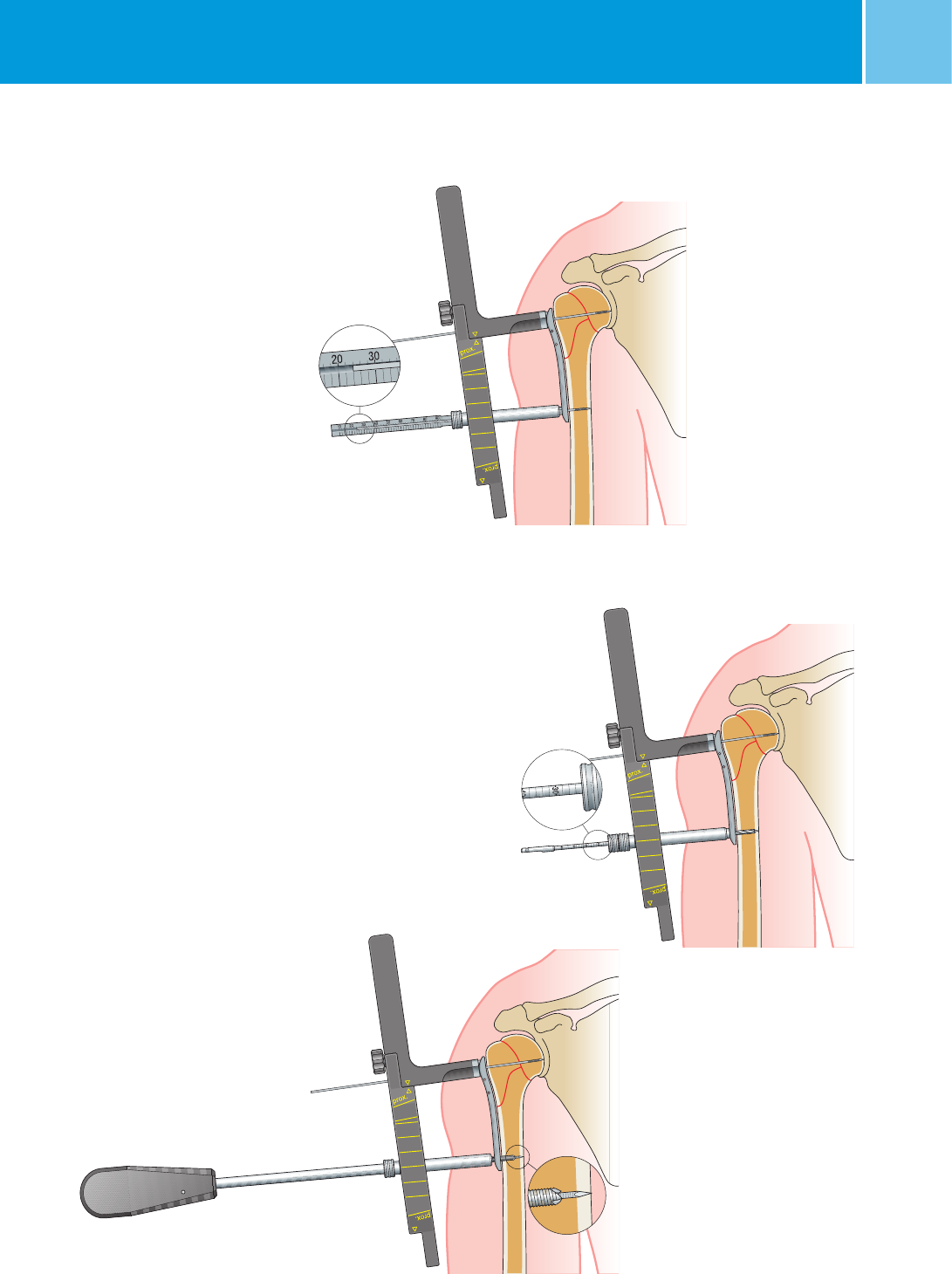
Insert the cannulated
self-drilling screw
3. Distal Cannulated Screw Placement
Determine the screw length from the
measurement with the NCB measuring
device gauge (REF 02.00024.219) along
the 1.6 mm guide wire (L = 190 mm
only).
Note: With this procedure the distance
from the plate to the tip of the measur-
ing device wire is measured.
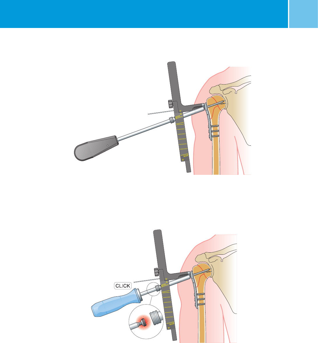
For hard cortical bone it is possible
to use the 3.3 mm NCB cannulated
drill bit (REF 02.00024.117) (only until
touching the second cortex, to make
sure that the guide wire does not fall
out). If the drill bit is used, the screw
length can be determined from the
scale on the drill bit shaft.
Use the cannulated hexagonal screw-
driver, hex 3.5 mm (REF 02.00024.120)
to insert the cannulated self-drilling
screw (REF 02.0x157.0xx) over the 1.6 mm
guide wire.
The NCB screws should be tightened
moderately to the bone.
Note: For adequate stable fixation,
bicortical screw insertion is recom-
mended.
Determine the screw length with
the scale on the drill bit shaft
Determine the screw length with
the depth gauge
28 NCB® Proximal Humerus – Surgical TechniqueNCB® Proximal Humerus System – Surgical Technique
5. Proximal Cannulated Screw
Placement
Insert
1.6 mm guide wire with a length
of 190 mm (REF 02.01362.116) close to
the subchondral bone and confirm the
correct position under image intensifi-
cation.
Measure the length with the NCB
measuring device (REF 02.00024.219)
along the 1.6 mm guide wire
(L = 190 mm only).
Note: With this procedure the distance
from the plate to the tip of the guide
wire is measured. Determine the screw
length by subtracting a sufficient
distance to make sure that the screw is
in an adequate distance from the joint.
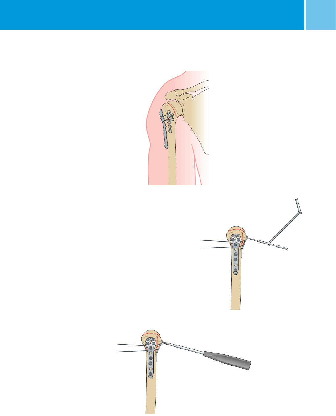
4. Achieve Angular Stability
To achieve angular stability remove the
guide wire and tighten the locking cap
(REF 02.0x150.300) with the NCB torque
screwdriver (REF 02.00024.022) until
the wrench declutches (clicking sound).
Note:
Always use the NCB torque screw-
driver to tighten the locking caps and
make sure not to tilt the screwdriver
during its usage.
Failure to do so could damage the hex
drive of the cap and might complicate
later extraction of the implant.
Insert the guide wire
Measuring screw length
Tighten the locking caps with
the NCB torque screwdriver
29
NCB® Proximal Humerus – Surgical TechniqueNCB® Proximal Humerus System – Surgical Technique
Use the cannulated hexagonal screw-
driver, hex 3.5 mm (REF 02.00024.120)
to
insert the cannulated self-drilling
cancellous screw (REF 02.0x160.0xx)
over
the 1.6 mm guide wire.
The NCB screws should only be
tightened moderately to the bone.
6. Achieve Angular Stability
To achieve angular stability, remove the
guide wire and tighten the locking cap
(REF 02.0x150.300) with the NCB torque
screwdriver (REF 02.00024.022) until the
wrench declutches (clicking sound).
Note:
Always use the NCB torque screw-
driver to tighten the locking caps and
make sure not to tilt the screwdriver
during its usage.
Failure to do so could damage the hex
driver of the locking cap and might com-
plicate
later extraction of the implant.
Tighten the locking caps
with the torque screwdriver
Insert the cannulated self-drilling
cancellous screw
30 NCB® Proximal Humerus – Surgical Technique
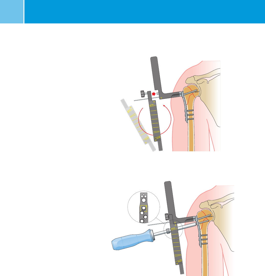
Position of the targeting module
to place screw no. 3
No. 3
NCB® Proximal Humerus System – Surgical Technique
7. Last Proximal Screw Placement (No. 3)
To place the last proximal screw, turn
the targeting module over and use hole
number 3. Fit the two yellow arrowhead
markings together. Then follow the
same screw placement procedure as
described in step 5–6.
Proximal 3.5 mm locking screw
placement
If the additional stabilization with
3.5 mm locking screws is required,
remove the targeting device and repeat
the sequence described on page 15.
Use of solid screws
If fixation with solid screws is preferred
,
use the NCB-PH MIS
drill bit
(REF 02.00024.215) and the NCB-PH
depth gauge (REF 02.00024.214) to drill
and measure the screw length.
Implant Removal
To remove the NCB-PH humerus plate,
first remove the 3.5 mm locking
screws; if they were used. Then remove
all locking caps (REF 02.0x150.300)
from the plate. Loosen all bone screws
and then remove all bone screws
completely. This prevents simultaneous
rotation of the plate when removing
the last bone screw.
Turn the targeting module upside down
and use the yellow top marking with
hole no. 3
31
NCB® Proximal Humerus – Surgical TechniqueNCB® Proximal Humerus System – Surgical Technique
NCB Proximal Humerus – Information
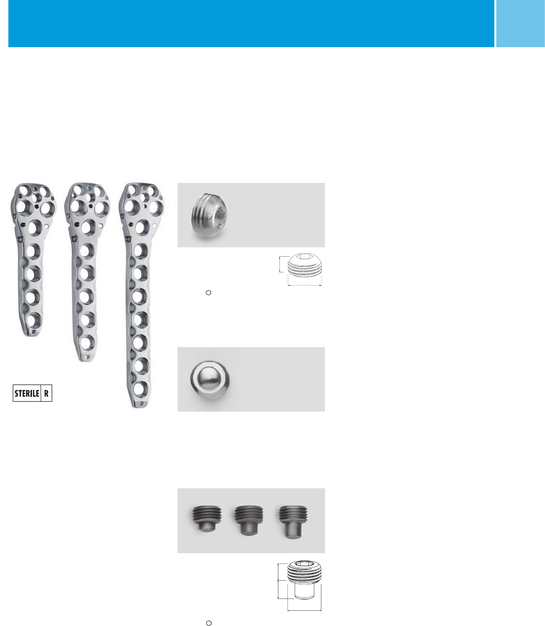
Implants
NCB® Locking cap
mm mm Quantity* REF (Non Sterile) REF (Sterile)
8 3.5 10 02.03150.300 02.02150.300
NCB® Blind screw
Quantity* REF (Non Sterile) REF (Sterile)
2 02.03150.310 02.02150.310
NCB® Spacer
(red, blue, green)
L mm mm Quantity* REF (Non Sterile) REF (Sterile)
1 3.5 – 02.03150.311 02.02150.311
2 3.5 2 02.03150.312 02.02150.312
3 3.5 – 02.03150.313 02.02150.313
L4.2
M 8 x 0.75
3.9
M 8 x 0.75
*Indicates the quantity of non sterile items in the standard graphic case.
** Not available in all countries.
Materials: The NCB plates and screws are made of Ti6Al4V, ISO 5832-3, ASTM F136.
Sterile packed
NCB®-PH plate
Holes L mm Quantity* REF (Sterile)
4 80 1 02.02262.104
5 93 1 02.02262.105
7 117 1 02.02262.107**
32 NCB® Proximal Humerus – Surgical Technique
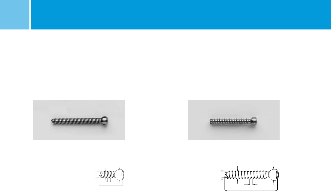
NCB® screw, self-tapping
L mm mm mm Quantity* REF (Non Sterile) REF (Sterile)
14 4 3.5 – 02.03155.014 02.02155.014
16 4 3.5 – 02.03155.016 02.02155.016
18 4 3.5 – 02.03155.018 02.02155.018
20 4 3.5 2 02.03155.020 02.02155.020
22 4 3.5 2 02.03155.022 02.02155.022
24 4 3.5 2 02.03155.024 02.02155.024
26 4 3.5 2 02.03155.026 02.02155.026
28 4 3.5 2 02.03155.028 02.02155.028
30 4 3.5 2 02.03155.030 02.02155.030
32 4 3.5 2 02.03155.032 02.02155.032
34 4 3.5 2 02.03155.034 02.02155.034
36 4 3.5 2 02.03155.036 02.02155.036
38 4 3.5 2 02.03155.038 02.02155.038
40 4 3.5 2 02.03155.040 02.02155.040
42 4 3.5 2 02.03155.042 02.02155.042
44 4 3.5 2 02.03155.044 02.02155.044
46 4 3.5 2 02.03155.046 02.02155.046
48 4 3.5 2 02.03155.048 02.02155.048
50 4 3.5 2 02.03155.050 02.02155.050
55 4 3.5 – 02.03155.055 02.02155.055
60 4 3.5 – 02.03155.060 02.02155.060
65 4 3.5 – 02.03155.065 02.02155.065
NCB® Proximal Humerus System – Surgical Technique
NCB® cancellous screw, self-tapping
L mm mm mm Quantity* REF (Non Sterile) REF (Sterile)
30 4.5 3.5 – 02.03159.030 02.02159.030
32 4.5 3.5 – 02.03159.032 02.02159.032
34 4.5 3.5 – 02.03159.034 02.02159.034
36 4.5 3.5 – 02.03159.036 02.02159.036
38 4.5 3.5 – 02.03159.038 02.02159.038
40 4.5 3.5 – 02.03159.040 02.02159.040
42 4.5 3.5 – 02.03159.042 02.02159.042
44 4.5 3.5 – 02.03159.044 02.02159.044
46 4.5 3.5 2 02.03159.046 02.02159.046
48 4.5 3.5 2 02.03159.048 02.02159.048
50 4.5 3.5 2 02.03159.050 02.02159.050
55 4.5 3.5 – 02.03159.055 02.02159.055
60 4.5 3.5 – 02.03159.060 02.02159.060
65 4.5 3.5 – 02.03159.065 02.02159.065
6.2 4.5 3.2
L
1.75
* Indicates the quantity of Non Sterile implants in the standard graphic case.
Materials: The NCB screws are made of Ti6Al4V, ISO 5832-3, ASTM F136.
6.2
4
3.4
L1.75
33
NCB® Proximal Humerus – Surgical Technique
NCB
®
MotionLoc
®
Screws (optional)
4.0 mm Cortical,
Self Tapping.
See surgical technique (REF 97-3161-002-00
or 97-3161-004-00)* for more specific instructions.
L mm mm REF (Non Sterile) REF (Sterile)
24 4.0 02.03162.024 02.02162.024
26 4.0 02.03162.026 02.02162.026
28 4.0 02.03162.028 02.02162.028
30 4.0 02.03162.030 02.02162.030
32 4.0 02.03162.032 02.02162.032
34 4.0 02.03162.034 02.02162.034
36 4.0 02.03162.036 02.02162.036
38 4.0 02.03162.038 02.02162.038
40 4.0 02.03162.040 02.02162.040
42 4.0 02.03162.042 02.02162.042
44 4.0 02.03162.044 02.02162.044
46 4.0 02.03162.046 02.02162.046
3.5 mm locking screws
(Non Sterile screws are included in the set ZS02.00024.796)
L mm mm mm Quantity*** REF (Non Sterile) REF (Sterile)
20 3.5 2.5 2 00-2369-020-35 47-2369-020-35
22 3.5 2.5 2 00-2369-022-35 47-2369-022-35
24 3.5 2.5 2 00-2369-024-35 47-2369-024-35
26 3.5 2.5 2 00-2369-026-35 47-2369-026-35
28 3.5 2.5 2 00-2369-028-35 47-2369-028-35
30 3.5 2.5 2 00-2369-030-35 47-2369-030-35
32 3.5 2.5 2 00-2369-032-35 47-2369-032-35
34 3.5 2.5 2 00-2369-034-35 47-2369-034-35
36 3.5 2.5 2 00-2369-036-35 47-2369-036-35
38 3.5 2.5 2 00-2369-038-35 47-2369-038-35
40 3.5 2.5 2 00-2369-040-35 47-2369-040-35
42 3.5 2.5 2 00-2369-042-35 47-2369-042-35
44 3.5 2.5 2 00-2369-044-35 47-2369-044-35
46 3.5 2.5 2 00-2369-046-35 47-2369-046-35
48 3.5 2.5 2 00-2369-048-35 47-2369-048-35
50 3.5 2.5 2 00-2369-050-35 47-2369-050-35
6.2 3.5 2.74
L
1.0 0.5
∅ 4∅ 6,2
L
Compatible Zimmer Products with the NCB Proximal Humerus System
REF Sterile Description
47-2232-060-00** NCB Polyaxial Locking Plate Cable Button, Gold, 2.5mm Hex Drive, Material: Ti6Al4V
47-2232-060-01 NCB Polyaxial Locking Plate Cable Button, Blue, 2.5mm Hex Drive, Material: Ti6Al4V
00-2232-002-35 Hex Buttons, 3.5mm Hex, Drive Material: C.P. Titanium
00-2232-002-28 Cable-Ready Cable Assembly Cerclage, Ø 1.8mm, L. 914mm, Material: CoCr
00-2232-004-18 Cable-Ready Cable Assembly Cerclage, Ø 1.8mm, L. 635mm, Material: CoCr
Materials: The 3.5 mm locking screws and NCB MotionLoc screws are made of Ti6Al4V, ISO 5832-3, ASTM F136.
* 97-3161-002-00 is for countries where NCB MotionLoc screws are approved to be used with only NCB plates and
97-3161-004-00 is for countries where NCB MotionLoc screws are approved to be used with both NCB as well as
NCB Periprosthetic plates. See NCB MotionLoc package insert for approved plate/MotionLoc screw combinations.
** Not available in Europe, Middle East and Africa.
*** Indicates the quantities of Non Sterile implants in the Ti 3.5 mm locking screw set ZS02.00024.796
34 NCB® Proximal Humerus – Surgical TechniqueNCB® Proximal Humerus System – Surgical Technique
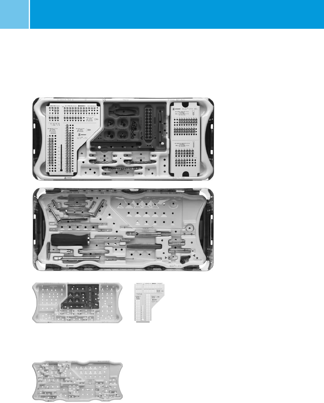
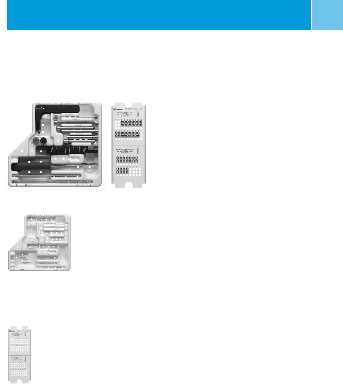
Graphic Case for Open Technique
NCB®-PH graphic case
module implants
Quantity* REF
1 02.00024.764
NCB®-PH graphic case
module instruments
Quantity* REF
1 02.00024.763
NCB®-PH graphic case module
screw rack standard
Quantity* REF
1 02.00024.765
NCB®-PH graphic case insert1)
(empty)
Quantity* REF
– 02.00024.766
NCB®-PH standard graphic case for open
technique (with standard instruments)
Unit REF
1 ZS02.00024.760
*Indicates the quantity in the standard graphic case.
1) Optional insert if ordered without MIS instruments.
NCB®-PH graphic case
cover
Quantity* REF
1 02.00024.701
NCB®-PH graphic case
base (Inox)
Quantity* REF
1 02.00024.702
35
NCB® Proximal Humerus – Surgical TechniqueNCB® Proximal Humerus System – Surgical Technique
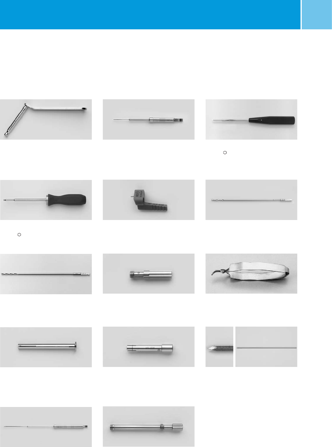
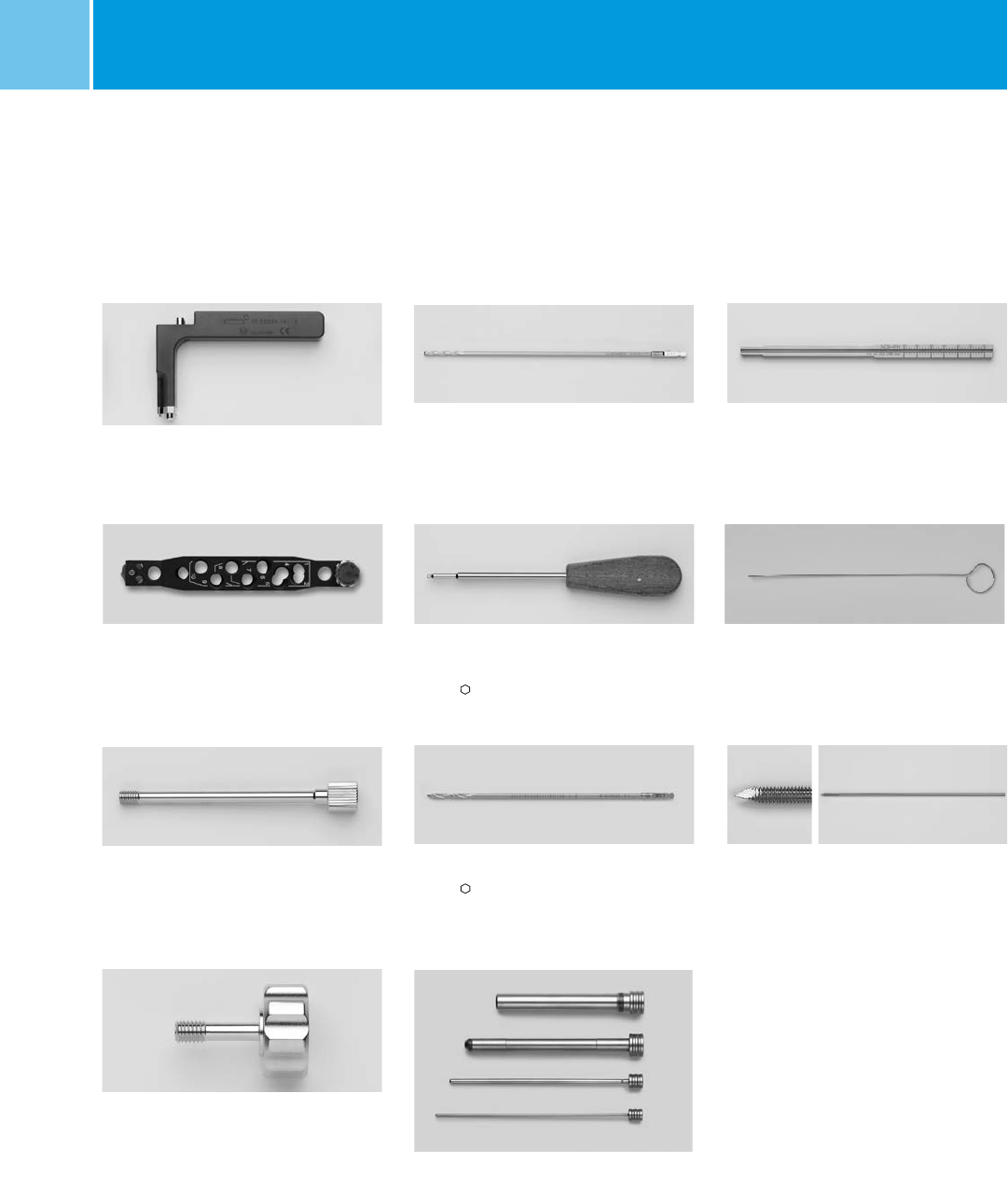
Standard Instruments
NCB® locking screw holder for 3.5 mm
hexagonal screwdriver
L mm Quantity* REF
95 1 02.00024.121
NCB®-PH jig for 3.5 mm locking screws
Quantity* REF
1 02.00024.220
NCB®-PH depth gauge
Quantity* REF
1 02.00024.214
NCB®-PH conn. screw for 02.00024.220
Quantity* REF
2 02.00024.221
NCB®-PH drill guide for 02.00024.220
mm Quantity* REF
2.5 2 02.00024.223
NCB®-PH tissue protection sleeve
for 02.00024.220
Quantity* REF
2 02.00024.222
Small depth gauge for 3.5 mm screws
Quantity* REF
1 02.00024.216
NCB® drill bit, with quick coupling
L mm mm Quantity* REF
195 3.3 2 02.00024.118
NCB®-PH torque screwdriver
L mm mm Quantity* REF
245 3.5 1 02.00024.022
Self-holding screw forceps
Quantity* REF
1 100.90.005
*Indicates the quantity in the standard graphic case.
NCB® drill guide
mm Quantity* REF
2.5 1 02.00024.010
3.3 1 02.00024.111
Small hexagonal screwdriver
L mm mm Quantity* REF
245 2.5 1 109.01.020
Two-fluted drill bit 2.5 mm
L mm Quantity* REF
180 2 103.25.180
Kirschner wire, with threaded tip
L mm mm Quantity* REF
150 2.0 4 299.20.150
36 NCB® Proximal Humerus – Surgical TechniqueNCB® Proximal Humerus System – Surgical Technique
NCB® cannulated screw
4, self-drill
L mm mm Quantity** REF (Non Sterile) REF (Sterile)
14 4 – 02.03157.014 02.02157.014
16 4 – 02.03157.016 02.02157.016
18 4 – 02.03157.018 02.02157.018
20 4 2 02.03157.020 02.02157.020
22 4 2 02.03157.022 02.02157.022
24 4 2 02.03157.024 02.02157.024
26 4 2 02.03157.026 02.02157.026
28 4 2 02.03157.028 02.02157.028
30 4 2 02.03157.030 02.02157.030
32 4 2 02.03157.032 02.02157.032
34 4 2 02.03157.034 02.02157.034
36 4 2 02.03157.036 02.02157.036
38 4 2 02.03157.038 02.02157.038
40 4 2 02.03157.040 02.02157.040
42 4 2 02.03157.042 02.02157.042
44 4 2 02.03157.044 02.02157.044
46 4 2 02.03157.046 02.02157.046
48 4 2 02.03157.048 02.02157.048
50 4 2 02.03157.050 02.02157.050
55 4 – 02.03157.055 02.02157.055
60 4 – 02.03157.060 02.02157.060
65 4 – 02.03157.065 02.02157.065
NCB® cannulated cancellous
screw 4.5, self-drill
L mm mm Quantity** REF (Non Sterile) REF (Sterile)
30 4.5 – 02.03160.030 02.02160.030
32 4.5 – 02.03160.032 02.02160.032
34 4.5 – 02.03160.034 02.02160.034
36 4.5 – 02.03160.036 02.02160.036
38 4.5 – 02.03160.038 02.02160.038
40 4.5 – 02.03160.040 02.02160.040
42 4.5 – 02.03160.042 02.02160.042
44 4.5 – 02.03160.044 02.02160.044
46 4.5 2 02.03160.046 02.02160.046
48 4.5 2 02.03160.048 02.02160.048
50 4.5 2 02.03160.050 02.02160.050
55 4.5 – 02.03160.055 02.02160.055
60 4.5 – 02.03160.060 02.02160.060
65 4.5 – 02.03160.065 02.02160.065
6.2
4.5
3.2
1.75
6.2
L
4
3.4
1.75
Implants for MIS* Surgical Technique
** Indicates the quantity of Non Sterile implants in the MIS graphic case module.
Materials: The NCB screws are made of Ti6Al4V, ISO 5832-3, ASTM F136.
L
* MIS Minimally Invasive Solutions Technique by Zimmer
37
Graphic Case for MIS Technique
NCB®-PH graphic case module
MIS instruments and screw rack
(with content)
Quantity** REF
– ZS02.00024.780
NCB®-PH graphic case
module MIS screw rack
Quantity** REF
1 02.00024.768
NCB®-PH graphic case
module MIS instruments
Quantity** REF
1 02.00024.767
**Indicates the quantity in the MIS graphic case module.
NCB® Proximal Humerus System – Surgical Technique
38 NCB® Proximal Humerus – Surgical TechniqueNCB® Proximal Humerus System – Surgical Technique
NCB®-PH fixation screw for
targeting device
Quantity** REF
2 02.00024.104
NCB®-PH connection screw for
targeting device
Quantity** REF
1 02.00024.103
NCB®-PH handle for targeting device
Quantity** REF
1 02.00024.101
NCB® cannulated drill bit with
quick coupling
L mm mm Quantity** REF
195 3.3 1 02.00024.117
NCB®-PH MIS drill bit
L mm mm Quantity** REF
230 3.3 1 02.00024.215
NCB®-PH tissue protection sleeves
Quantity** REF
10/8.0 2 02.00024.213
8/3.3 2 02.00024.114
3.3/1.6 2 02.00024.115
1.6 2 02.00024.116
NCB®-PH targeting module for
targeting device
Quantity** REF
1 02.00024.202
NCB®-PH/PT measuring device for
cannulated screws
Quantity** REF
1 02.00024.219
NCB®-PH Hexagonal screwdriver
cannulated short hex
L mm mm Quantity** REF
245 3.5 1 02.00024.120
MIS Instruments
**Indicates the quantity in the MIS graphic case module.
NCB® PH guide wire with threaded tip
L mm mm Quantity** REF
190 1.6 10 02.01362.116
Cleaning wire 1.6 mm
Quantity* REF
1 110.06.200
39
NCB® Proximal Humerus – Surgical TechniqueNCB® Proximal Humerus System – Surgical Technique
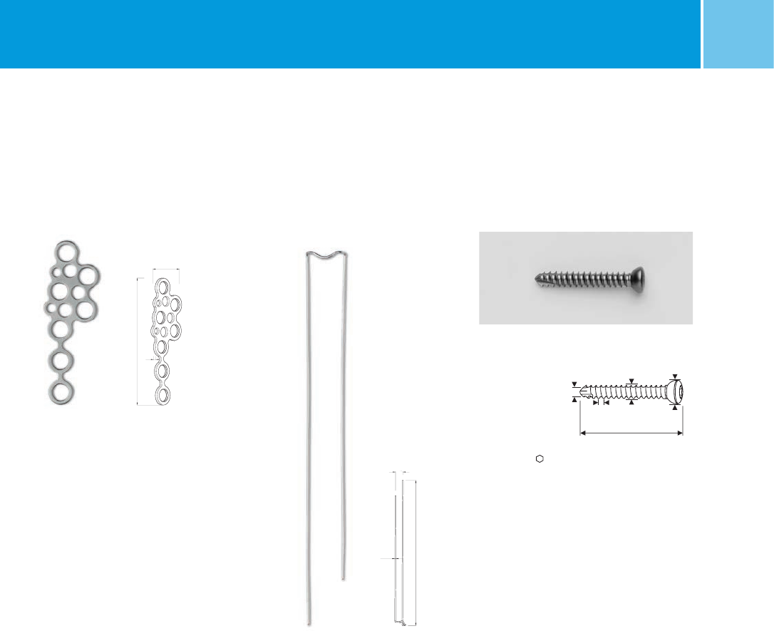
Cortical screw, self-tapping
L mm mm mm Quantity*** REF (Non Sterile)
20 3.5 2.5 2 02.03131.020
22 3.5 2.5 2 02.03131.022
24 3.5 2.5 2 02.03131.024
26 3.5 2.5 2 02.03131.026
28 3.5 2.5 2 02.03131.028
30 3.5 2.5 2 02.03131.030
32 3.5 2.5 2 02.03131.032
34 3.5 2.5 2 02.03131.034
36 3.5 2.5 2 02.03131.036
38 3.5 2.5 2 02.03131.038
40 3.5 2.5 2 02.03131.040
6
3.5
2.5
L
1.25
NCB® Cerclage wire for T-minus plate
Stainless Steel
L mm mm Quantity*** REF (Non Sterile) REF (Sterile)
115 0.8 2 02.01362.108 02.00362.108
11.5
115
0.8
NCB® T-minus plate, 7 holes
Holes Quantity*** REF (Non Sterile) REF (Sterile)
7 1 02.03262.101 02.02262.101
17.2
1.2
52
T-Minus Module (optional)
Implants and instrument set (REF ZS02.00024.790)
Material:The self tapping cortical screw is made of
Ti6Al7Nb, ISO 5832-11, ASTM F1295.
The tuberculum minus plate is made of C.P. titanium,
ISO 5832-2, ASTM F67.
*** Indicates the quantity of Non Sterile implants in the T-minus module.
40 NCB® Proximal Humerus – Surgical TechniqueNCB® Proximal Humerus System – Surgical Technique
Countersink, for quick coupling
3.5 and 4.0 mm
Quantity*** REF
1 108.01.035
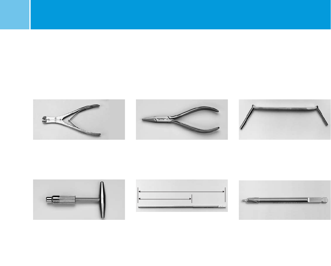
T-handle, with quick coupling for taps
Quantity*** REF
1 100.90.210
Wire bending forceps
L mm Quantity*** REF
140 1 100.11.155
T-Minus Instruments (optional)
Double drill guides 2.5 / 3.5 / 4.0
Quantity*** REF
1 100.40.035
Wire cutter, for wire max. 1.7 mm
L mm Quantity*** REF
165 1 100.11.115
*** Indicates the quantity in the T-minus module.
Tap for quick coupling
L mm l mm mm Quantity*** REF
110 50 3.5 1 106.35.110
L
l
41
NCB® Proximal Humerus – Surgical Technique
X ray template REF 06.01511.000
Planning Aid
NCB® Proximal Humerus System – Surgical Technique

42 NCB® Proximal Humerus – Surgical TechniqueNCB® Proximal Humerus System – Surgical Technique
Notes

43
NCB® Proximal Humerus – Surgical TechniqueNCB® Proximal Humerus System – Surgical Technique

Contact your Zimmer representative or visit us at www.zimmer.com
Disclaimer
This documentation is intended exclusively for physicians and is not intended for laypersons.
Information on the products and procedures contained in this document is of a general nature and does not represent
and does not constitute medical advice or recommendations. Because this information does not purport to constitute
any diagnostic or therapeutic statement with regard to any individual medical case, each patient must be examined and
advised individually, and this document does not replace the need for such examination and/or advice in whole or in part.
Please refer to the package inserts for important product information, including, but not limited to, indications,
contraindications, warnings, precautions, and adverse effects.
© 2015 by Zimmer GmbH Printed in Switzerland Subject to change without notice
Lit.No.06.01499.012 – Ed. 2015-08 ZHUB
