NCB® Proximal Tibia System Surgical Technique Ncb
2016-04-04
: Pdf Ncb-Proximal-Tibia-System-Surgical-Technique ncb-proximal-tibia-system-surgical-technique 4 2016 pdf
Open the PDF directly: View PDF ![]() .
.
Page Count: 36
NCB® Proximal
Tibia System
Surgical Technique

NCB® Proximal Tibia System– Surgical Technique 3
Surgical Technique
NCB Locking Plate
System for Proximal
Tibia
Table of Contents
Introduction 4
Plate Design 5
Screw Selection 5
Cable Fixation Options 6
MIS Radiolucent Targeting Device 7
System Features 7
Indications/Contraindications 8
Fracture Classification 8
Sample Cases 9
Preoperative Planning and Patient Positioning 11
Open Technique 12
Incision 12
Fracture Reduction 12
Optional: Bone Spacers 12
Insertion of NCB PT Plate 13
Insertion of NCB Screws 13
MIS Technique* 18
Plate Hole Numbering System 18
Incision and Fracture Reduction 18
Targeting Device Assembly 19
Insertion and Preliminary Fixation of NCB PT Plate 19
Insertion of NCB Screws in the Proximal Area 21
Insertion of NCB Screws in the Shaft 22
Implant Removal 24
Ordering Information 25
Implants 25
Graphic Case 28
Standard Instruments 29
MIS Instruments 30
Cannulated Option (Screws and Instruments) 32
Planning Aid 33
* MIS Minimally Invasive Solutions™ Technique
by Zimmer
4NCB® Proximal Tibia System – Surgical Technique
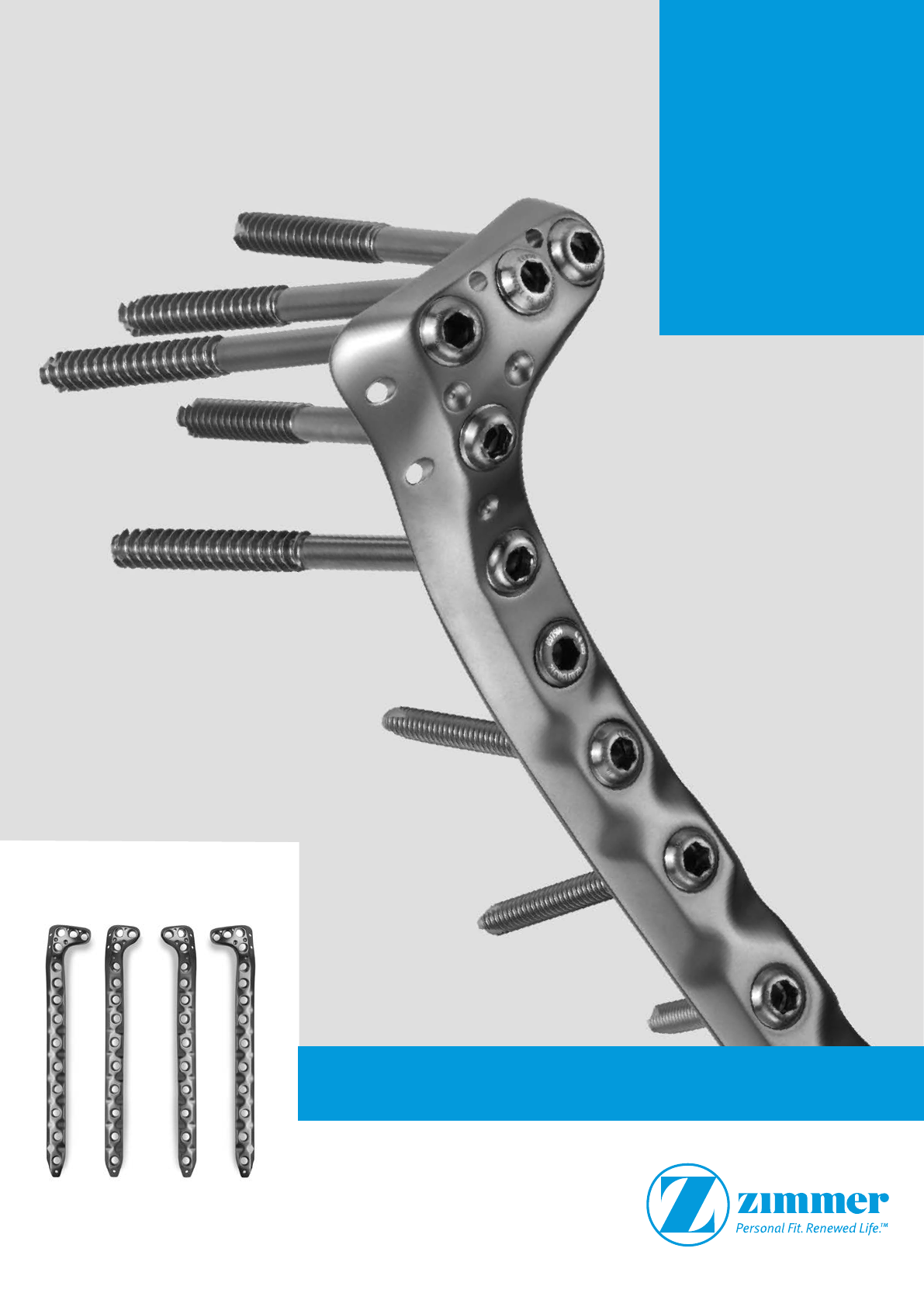
Introduction
The NCB PT (Non-Contact Bridging
for the Proximal Tibia) is an optimal
plate solution for the treatment of
complex fractures of the proximal tibia.
The system allows for polyaxial screw
placement (30°) with subsequent screw
locking. Before locking, the screws
can act as lag screws and be used for
fracture reduction; a benefit which
is not offered with standard locking
systems.
In the locked mode, NCB PT Plate late
acts as an internal fixator without
contact between the plate and the
bone surface reducing the risk of
periosteal blood supply impairment.
The surgical technique is based on
the well-known standard plate osteo-
synthesis technique which gives
to surgeon the feeling for bone quality
during drilling and tightening of the
screws. In the last step all screws can
be locked and made angularly stable.
The instrumentation includes a fully
radiolucent targeting device for a
minimally invasive surgical technique
(MIS).
Materials: NCB Plates and Screws are made
of Ti6Al4V, ISO 5832-3, ASTM F136
Blind screw insert
Implants are available with
2 or 3 proximal holes,
left and right. Plate length
varies from 5 to 9 shaft
holes for the 2-proximal hole
plate and between 3 and
13 shaft holes for the 3-proxi-
mal hole plate.
Polyaxial screw placement
with subsequent locking option
for optimal system stability.
Fracture reduction with a lag
screw possible.
Non-Contact Bridging
ostesynthesis reduces the
risk of periosteal blood
impairment.
Anatomically contoured
plate.
Non
contact
Locking cap ∅ 8 mm
Spacer 1 to 3 mm Angular stability of one NCB Locked Screw
6 Nm
Fastening torque
225 N
SD±10N
Anterior
Posterior
NCB® Proximal Tibia System– Surgical Technique 5
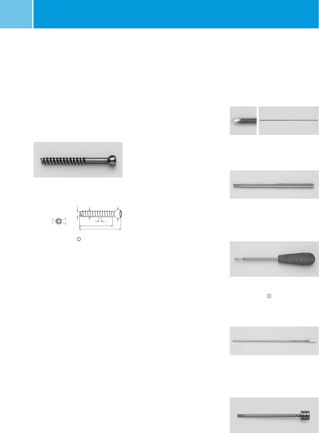
Standard Screws
(included in the screw set)
Cannulated Screws
(option)
Zimmer® MotionLoc® Screws
(option)
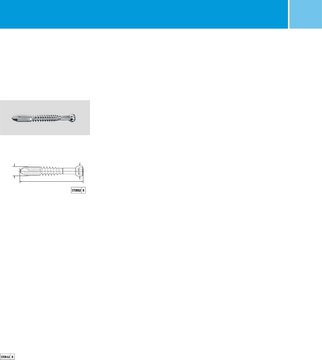
Cancellous screw ∅ 5.0 mm
self tapping, L 50–90 mm; 5 mm
L 95 & 100mm (not in set)
Cortical screw ∅ 4.0 mm
self tapping,
L 14–50 mm; 2 mm
L 50–90 mm; 5 mm
L 95 & 100mm (not in set)
Cortical screw self tapping
∅ 4 mm; L 24–46; 2 mm
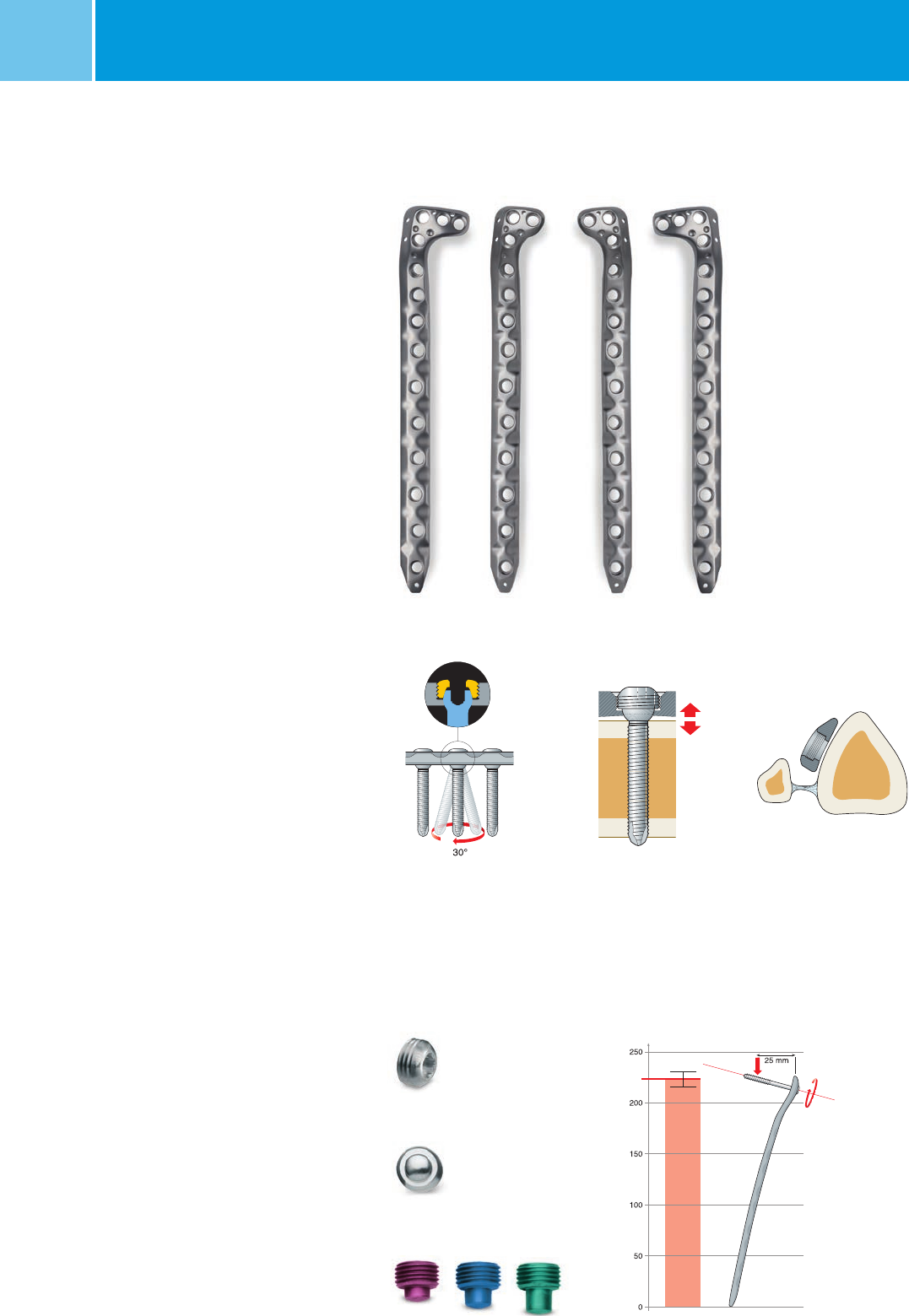
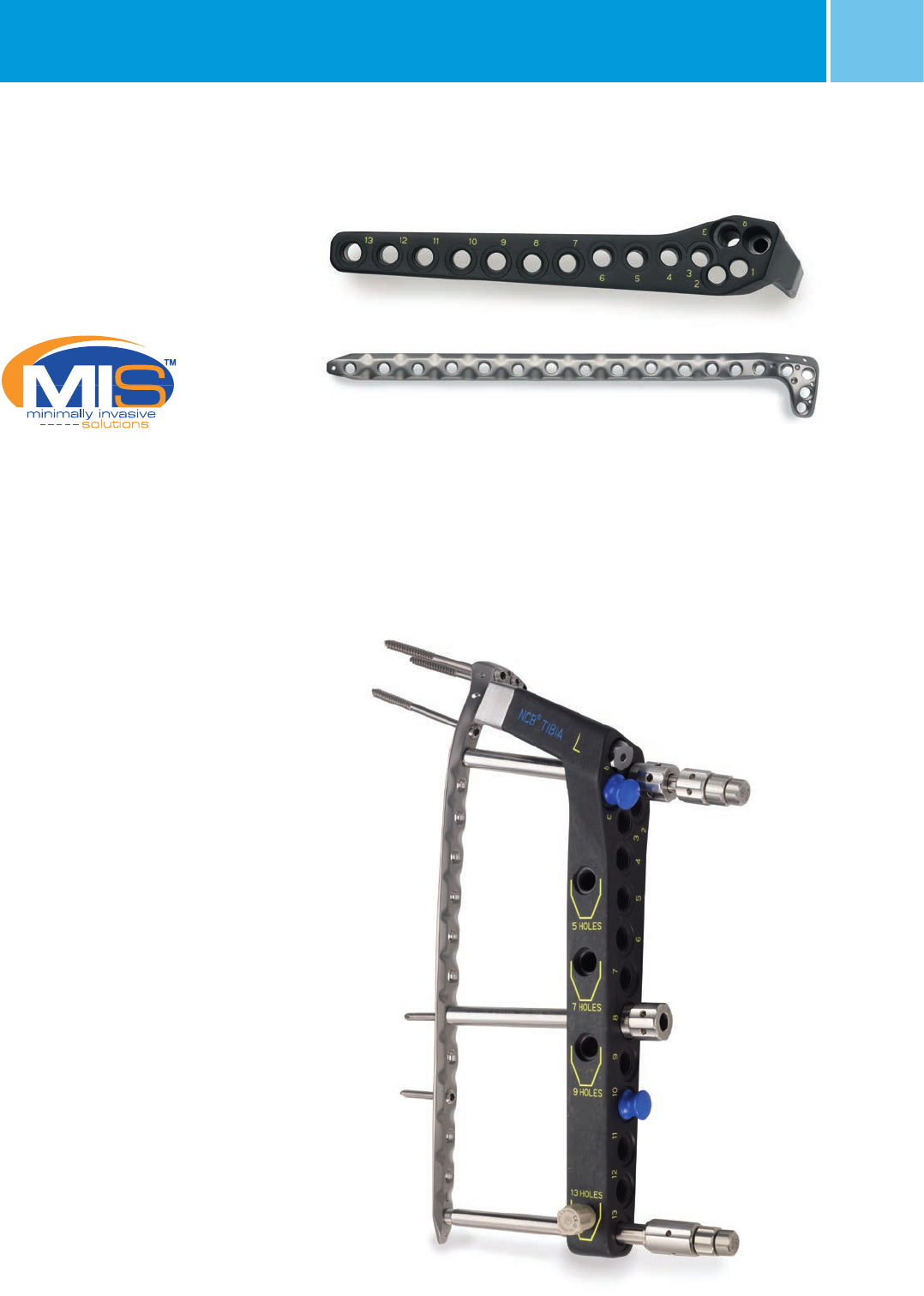
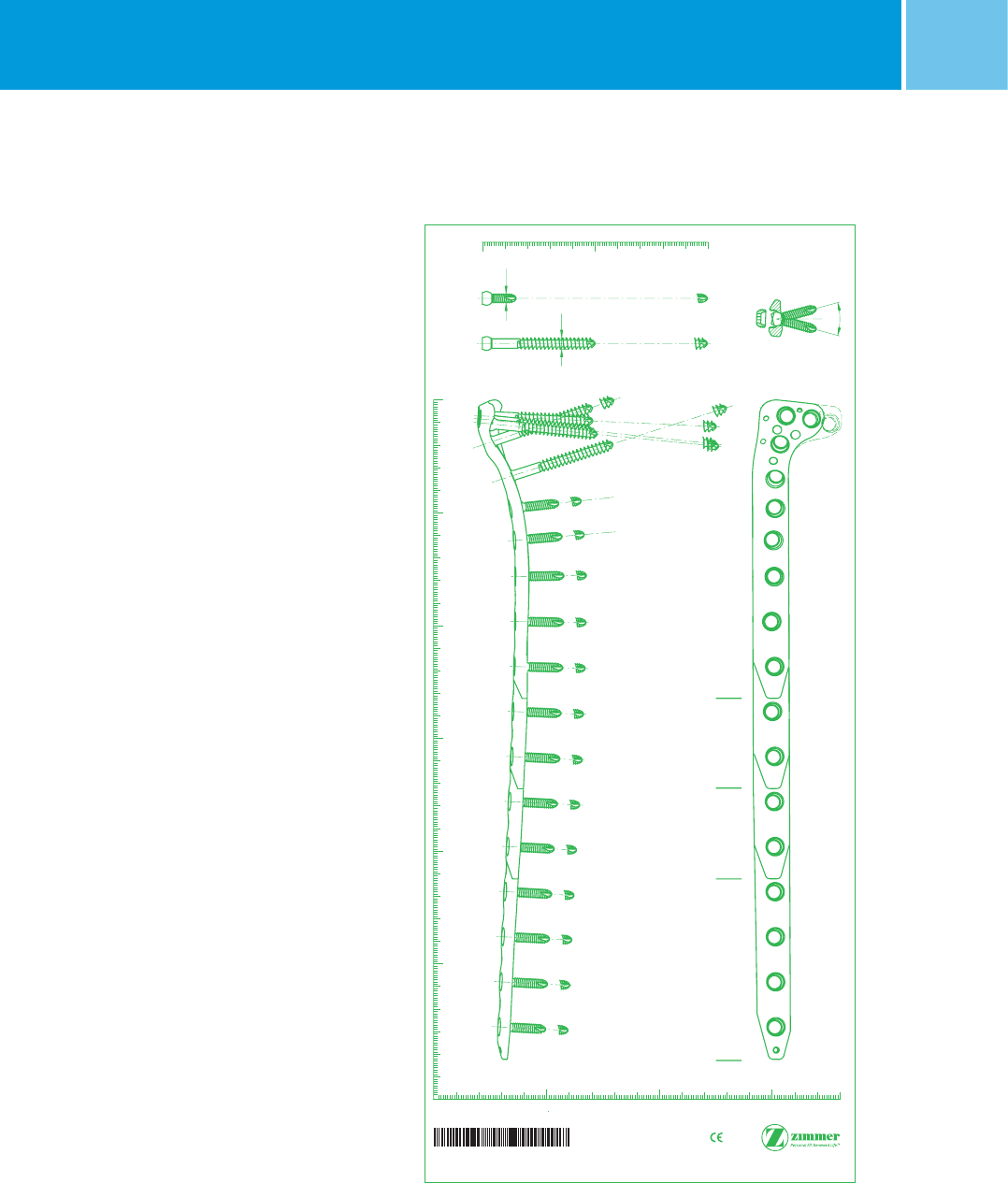
Plate Design
Two versions of the NCB PT Plate are
available: 2-proximal and 3-proximal
holes.
Due to the angular freedom of the
screws the whole plateau area can
be covered with both plates. The
2-proximal holes plate is recommended
when soft tissue coverage is a greater
concern.
The 3-proximal holes plate is recom-
mended when there is a higher concern
for supporting the tibial plateau
(e.g. severe intra-articular comminution).
Plate head has 6˚ posterior tilt to match
the lateral tibial contour.
Screw Selection
• Spherical screw head with standard
3.5 mm hexagonal drive
• Self-tapping screw tip (solid screws)
• Self-drilling and self-tapping screw
tip (cannulated screws)
• Double-lead thread for fast screw
insertion in cortical bone
Cannulation for
1.6 mm K-wire
Cancellous screw ∅ 4.5 mm self drill
L 50–100 mm; 5 mm
3-proximal holes plate
2-proximal holes plate
30°
6°
30°
6°
6NCB® Proximal Tibia System – Surgical Technique
Cable Fixation Options
The following products from the Zimmer®
Cable-Ready® Cable Grip System are
compatible with all plates in the NCB
Proximal Tibia System except for the
3 hole length tibial NCB plate with 3
proximal holes (REF 02.02261.203 and
02.02261.303)**. See data sheet
REF 97-2232-015-00 for more specific
instructions.
Cable Fixation with
Hex Button
Cable Fixation Options Cable Fixation with
Cable Button
NCB Locking Plate
Cable Button, 2.5mm, Hex Drive
• Sterile
• Material: Ti6Al4V
REF 47-2232-060-00 Color: Gold*
REF 47-2232-060-01 Color: Blue
Application
This Cable Button is threaded
directly into the NCB Plate hole to
provide a positioning point for
the Cable.
Instructions
To insert, use the 2.5mm hex
screwdriver to thread the cable
button into the plate hole. Do not
fully tighten to allow the slots in
the button to align with the cable.
To remove, use the 2.5mm hex
screwdriver to unthread the cable
button from the plate hole.
Hex Button, 3.5mm
• Sterile
• Material: C.P. Titanium
REF 00-2232-002-35
Application
This Hex Button fits into the
standard hex in the screw head
(3.5mm hex). Therefore, it can
be inserted into the NCB Screw
head, or into the NCB Locking
Cap.
Cable Assembly Cerclage,
1.8mm
• Sterile
• Material: CoCr
REF 00-2232-002-28
REF 00-2232-004-18
* Not available in Europe, Middle East and Africa.
** The 3 hole length tibial NCB plate with 3 proximal holes (REF 02.02261.203 and 02.02261.303) is a product
of BAAT Medical BV and is distributed by Zimmer only in Europe, Middle East, and Africa.
NCB® Proximal Tibia System– Surgical Technique 7
MIS Radiolucent Targeting
Device
MIS* operation technique with a
fully radiolucent targeting device.
In the metaphyseal region the targeting
device ensures divergent screw align-
ment for increased pull-out resistance.
System Features
• Polyaxial screw placement with
subsequent locking option;
• Anatomically contoured plate with
asymmetrical plate cross section
to facilitate anterolateral soft tissue
coverage;
• Plate head has 6˚ posterior tilt to
match the lateral tibial contour;
• Placement of divergent screws to
increase pull-out resistance;
• MIS Approach with a fully radiolucent
targeting device;
• NCB Cancellous Screws can be used
as lag screws to improve fracture
reduction;
• Use of conventional plating technique;
• Feeling of bone quality during inserting
and tightening of screws;
• The 2-proximal holes tibial plate is
available in 3 lengths, from 5 holes
(132 mm) to 9 holes (212 mm);
• The 3-proximal holes tibial plate is
available in 5 lengths, from 3 holes
(92 mm) to 13 holes (292 mm).
* MIS Minimally Invasive Solutions Technique by Zimmer
** The 3 hole length tibial NCB plate with 3 proximal holes (REF 02.02261.203 and 02.02261.303) is a product of BAAT Medical BV and is distributed by Zimmer
only in Europe, Middle East, and Africa.
Divergent screw alignment achieved using
the targeting device
NCB PT Plate System
Note: Do not use the MIS device with the
3 hole length tibial NCB plate with 3
proximal holes (REF 02.02261.203 and
02.02261.303)**
.
8NCB® Proximal Tibia System – Surgical Technique
Indications
The NCB Polyaxial Locking Plate System
is indicated for temporary internal
fixation and stabilization of fractures
and osteotomies of long bones.
Note: The NCB Proximal Tibia plate from
the NCB Polyaxial Locking Plate System
is specifically designed for the proximal
tibia.
Contraindications
• All concomitant diseases that may
impair the fixation of the implant and/
or the success of the intervention.
• Lack of bone substance or poor bone
quality which makes stable seating of
the implant impossible.
• Acute or chronic, local or systemic
infections.
• Allergy to the implanted material.
• Severe muscular, neural or vascular
diseases that endanger the extremi-
ties involved.
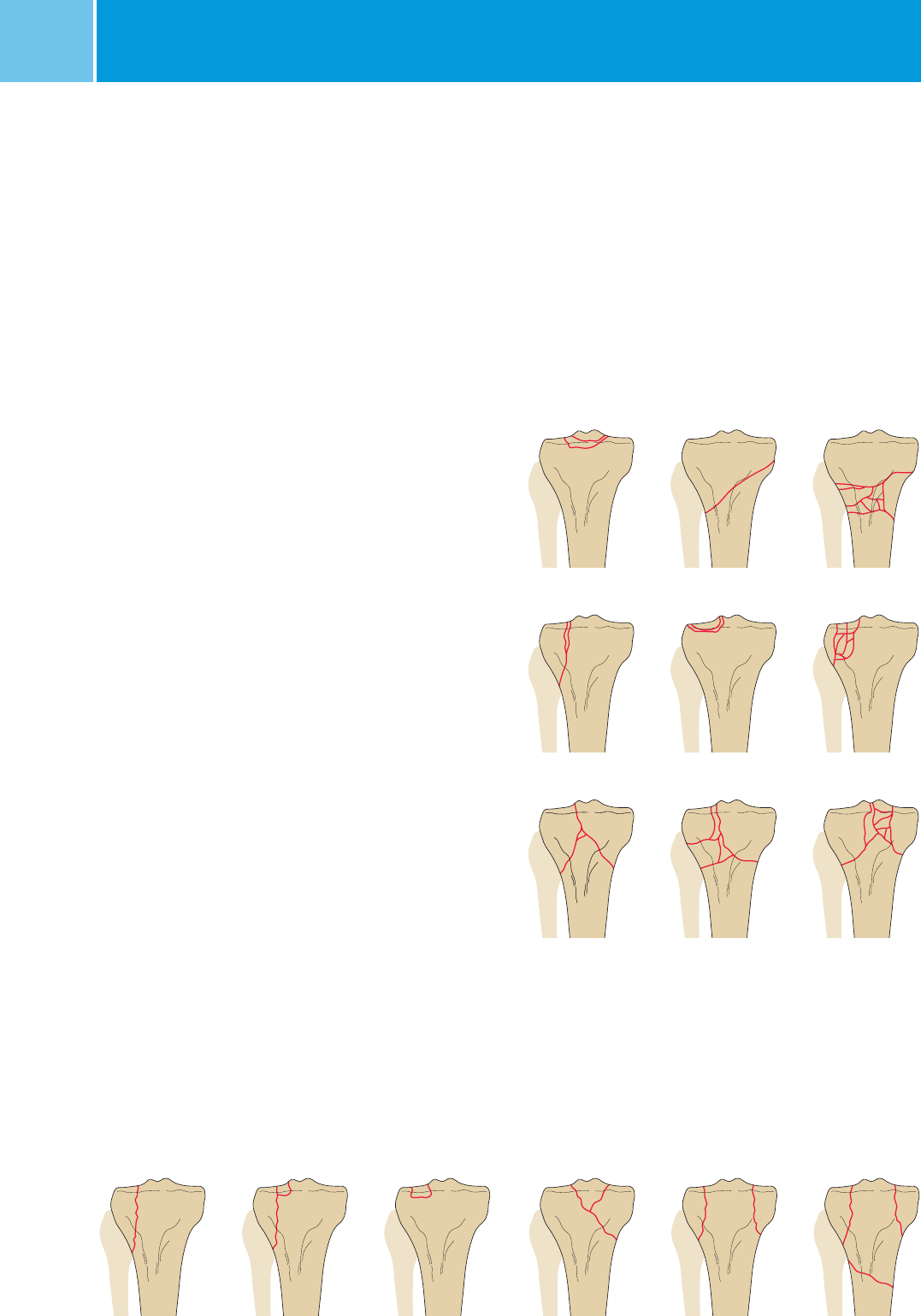
Fracture Classification
Comprehensive classifications for
proximal tibial fractures are the OTA
and the Schatzker classifications.
Stabilization with locking plates
is recommended for most of the 41-A
and C type of fracture according
to the OTA classification for long bone.
This includes comminuted fractures,
intra-articular and extra-articular condy-
lar fractures.
A1 A2 A3
B1 B2 B3
C1 C2 C3
Typ ITyp II Typ III Typ IV Typ
VT
yp VI
OTA Classification
Schatzker Classification
Note: Be sure to check for proper Regula-
tory approvals in your country prior to
using any products found in this surgical
technique. Some devices may not be
currently licensed with Health Canada.
Some device compatibilities may not
be approved for use by Health Canada.
NCB® Proximal Tibia System– Surgical Technique 9
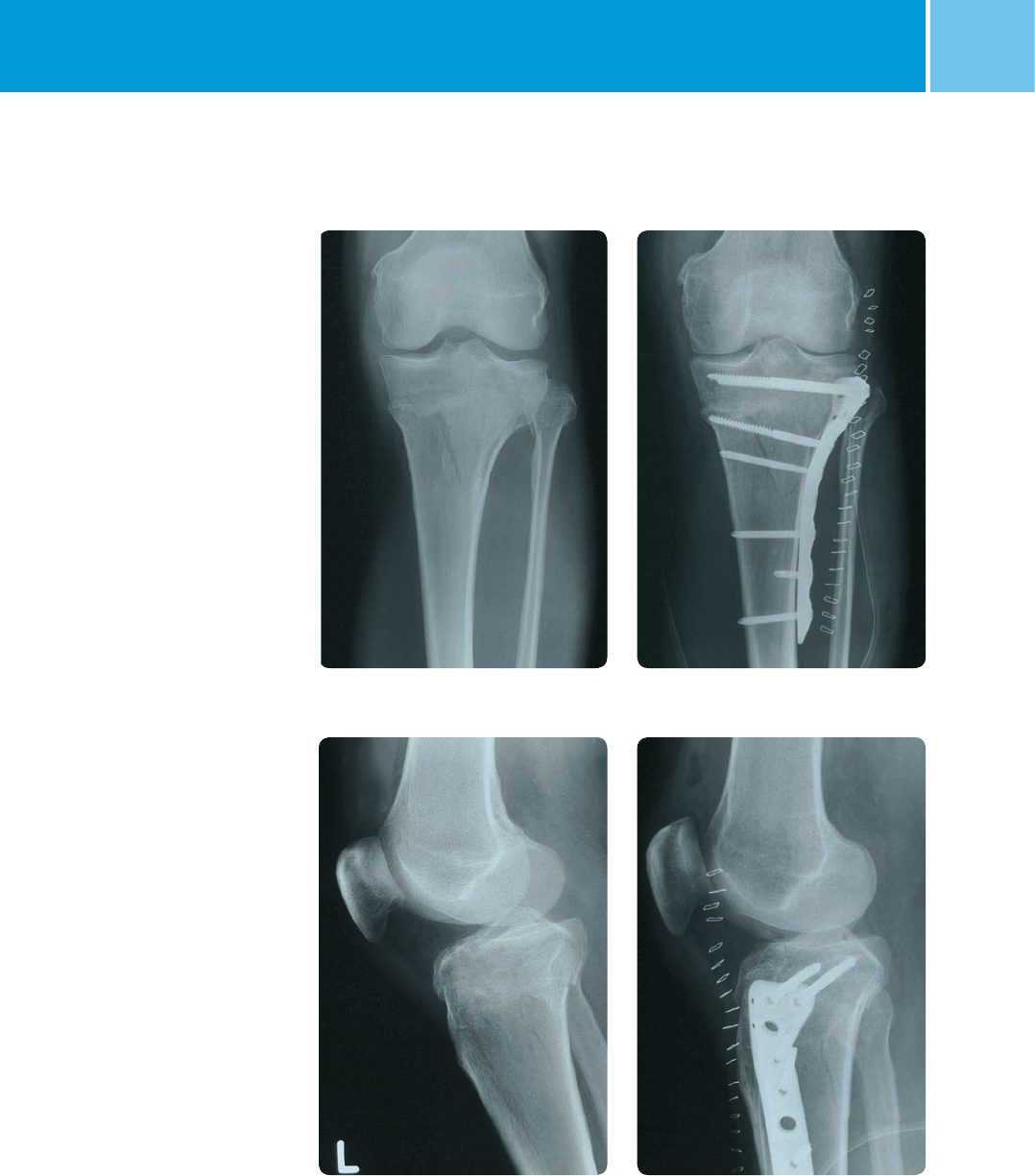
Sample Cases
Case 1: 41-C1 fracture
(OTA classification)
Postoperative
Preoperative
Preoperative
Postoperative
10 NCB® Proximal Tibia System – Surgical Technique
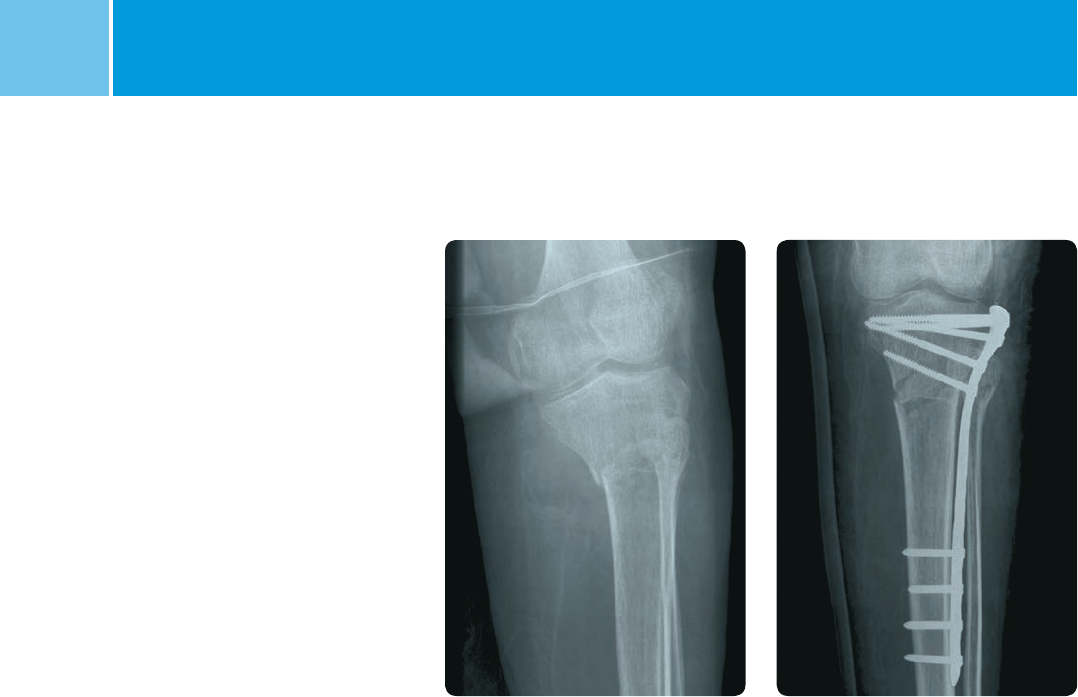
Case 2: 41-A2 fracture
(OTA classification,
MIS surgical procedure)
PostoperativePreoperative
NCB® Proximal Tibia System– Surgical Technique 11
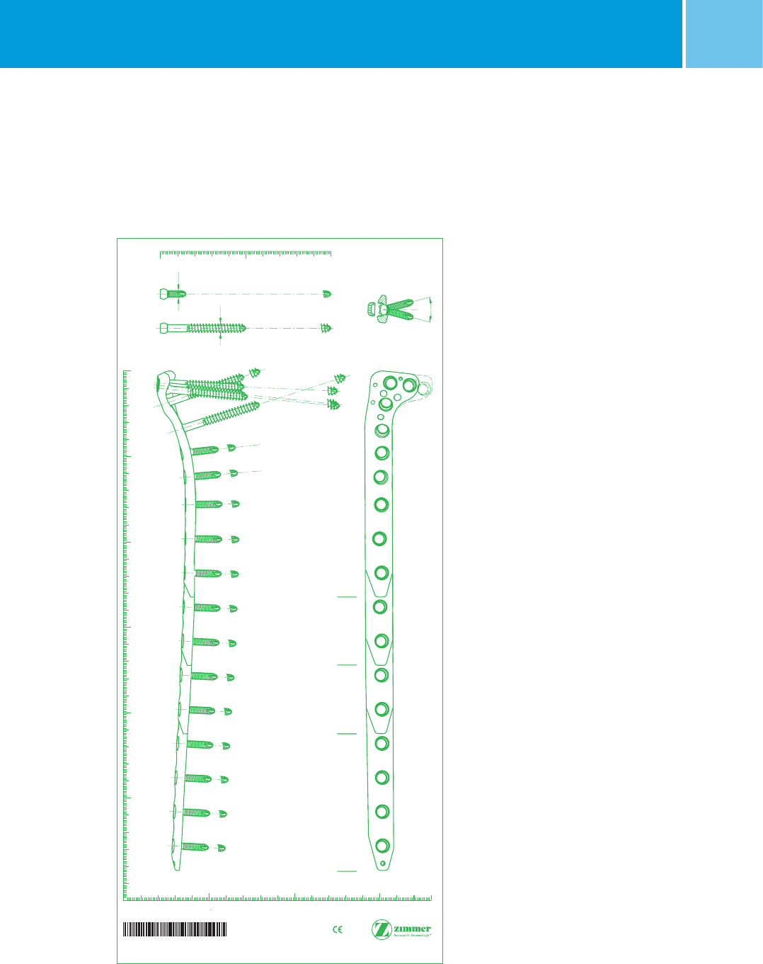
Preoperative Planning
and Patient Positioning
Select the appropriate length and type
of the NCB PT Plate using X rays and the
X ray template (REF 06.01365.000).
Based on the fracture type and the
specific patient condition determine
the surgical approach (i.e., open
technique or MIS) to be performed.
Place the patient in a supine position.
Lower the contralateral leg slightly
to make sure that lateral and AP X ray
views can be obtained clearly.
Support the knee while allowing the
leg to move freely.
Note: Do not use the x-ray template with
the 3 hole length tibial NCB plate with 3
proximal holes (REF 02.02261.203 and
02.02261.303)**.
+H84406013650001/$150501E15Z
NCB®-PT Proximal Lateral Tibial Osteosynthesis Plate, with Polyaxial Locking Screws
These reference numbers must correspond
to those of the prostheses to be implanted.
© 2015. All rights reserved, Zimmer GmbH,
Sulzerallee 8, CH-8404 Winterthur, Switzerland
Lit. No. 06.01365.000
5 cm 15 cm10 cm
Magnification
1.15:1
5 cm
10 cm
15 cm
20 cm
25 cm
0cm
0cm1cm 2cm3cm4cm5cm6cm7cm8cm9cm 10 cm
4567
14
NCB-Screws
self-tapping
Polyaxial Screw
100
100
50
50
60
100
50
αβγ
δ
ε
5 holes7 holes9 holes13 holes
δε1238910111213
α
β
γ
1
20
30
20
30
20
30
20
30
20
30
20
30
20
30
20
30
20
30
20
30
2
3
4
5
6
7
8
9
10
11
12
13
20
30
20
30
20
30
Right
AP View
Lateral View
Do not bend
Left/
∅ 4
∅ 5
30°
Choose plate type and length using the X ray template
** The 3 hole length tibial NCB plate with 3 proximal holes (REF 02.02261.203 and 02.02261.303) is a product of BAAT Medical BV and is distributed by Zimmer
only in Europe, Middle East, and Africa.
12 NCB® Proximal Tibia System – Surgical Technique
Open Technique
Incision
A lateral incision is recommended for
extra-articular and laterally based
type 41-B fractures, according to the
OTA classification.
For type 41-C fractures according to
the OTA classification with a complete
articular fracture, a straight antero-
lateral incision or short medial and
lateral incisions are recommended.
To facilitate fracture healing do not strip
the periosteum.
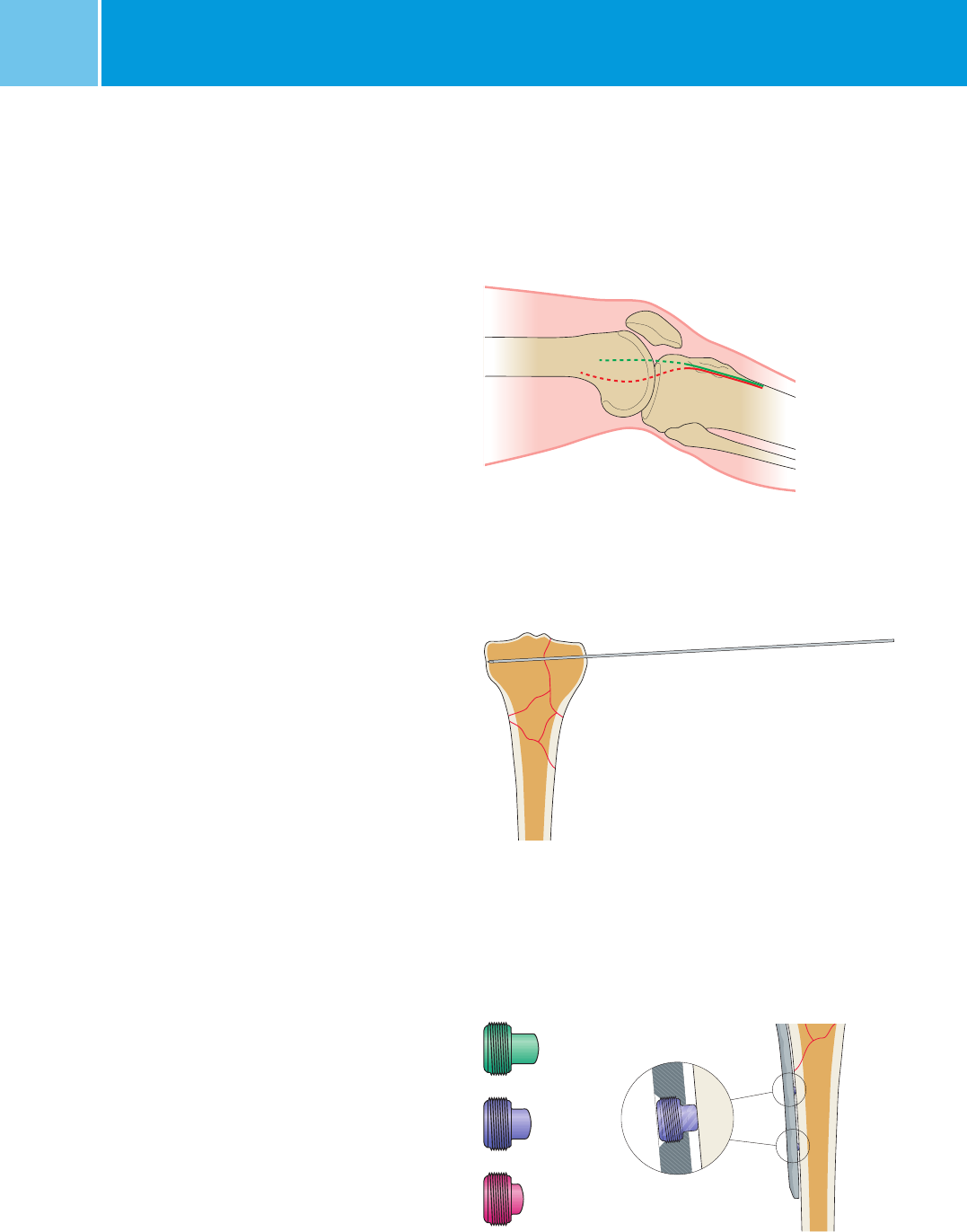
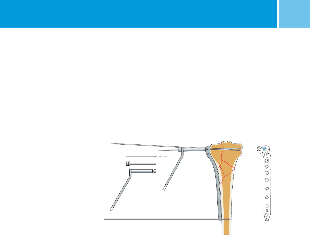
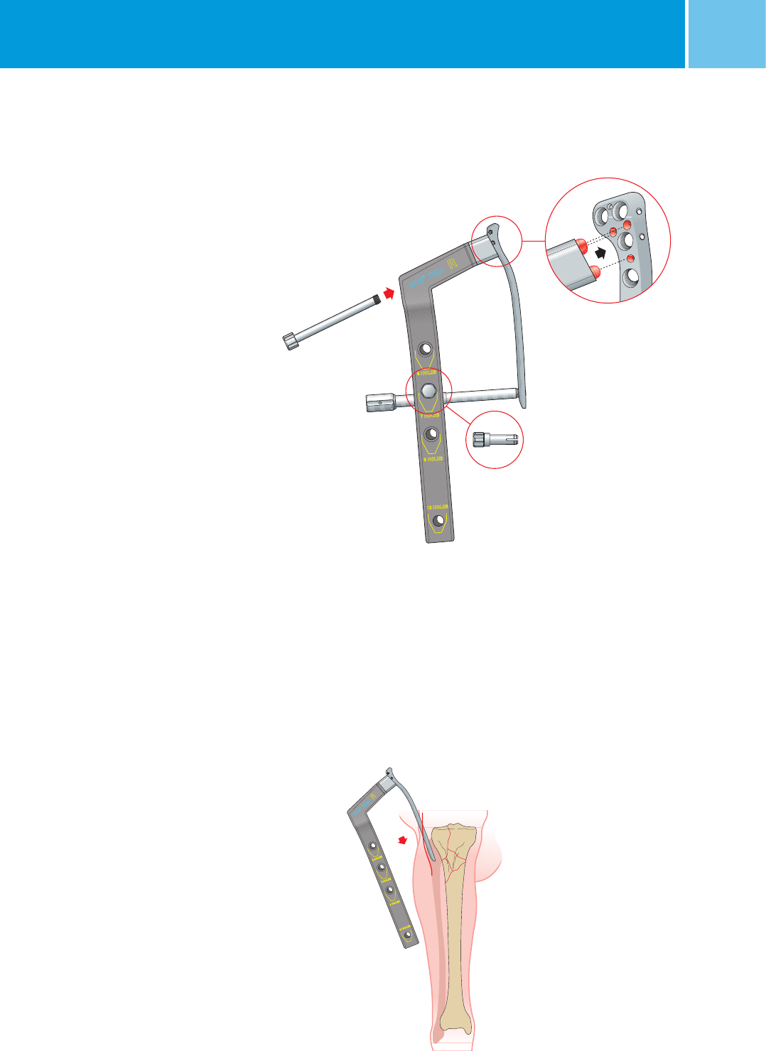
Fracture Reduction
Restore the articular surface (if needed)
and reduce the fracture prior to
inserting the plate. Bone fragments
can be secured with 2.0 mm K-wires
(REF 290.20.280). Make sure that
K-wires do not interfere with the future
location of the plate and screws.
Note: Check fragment position with an
image intensifier.
Optional: Bone Spacers
Two bone spacers can be used in
the diaphysis to avoid contact of the
plate with the bone surface reducing
the risk of periosteal blood supply
impairment.
The spacers are available in sizes
of 1 mm, 2 mm and 3 mm
(REF 02.0x150.311 to 313).
Note: Insert adequate bone spacers into
the plate before plate insertion using a
3.5mm hex screwdriver. Spacers are
single use only and they can be removed
after locking the screws.
3 mm
2 mm
1 mm
Temporary stabilization of the fracture
Use of bone spacers for non-contact bridging
Incision
NCB® Proximal Tibia System– Surgical Technique 13
Screw Type
Cancellous Cortical Cancellous cannulated
REF 02.0x152.0xx REF 02.0x155.0xx REF 02.0x158.0xx
5 mm 4 mm 4.5 mm
L 50–100 mm L 14–100 mm L 50–100 mm
Drill
REF 103.25.180 REF 02.00024.118 REF 02.00024.233
2.5 mm 3.3 mm 3.3 mm
Guide Wire REF 02.01362.116
1.6 mm, L 190 mm
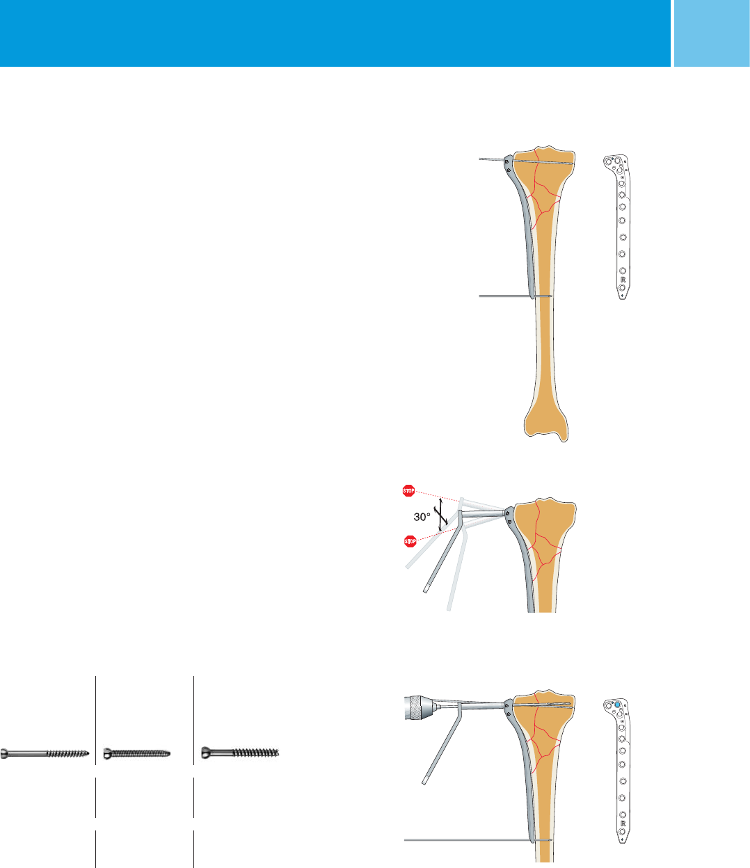
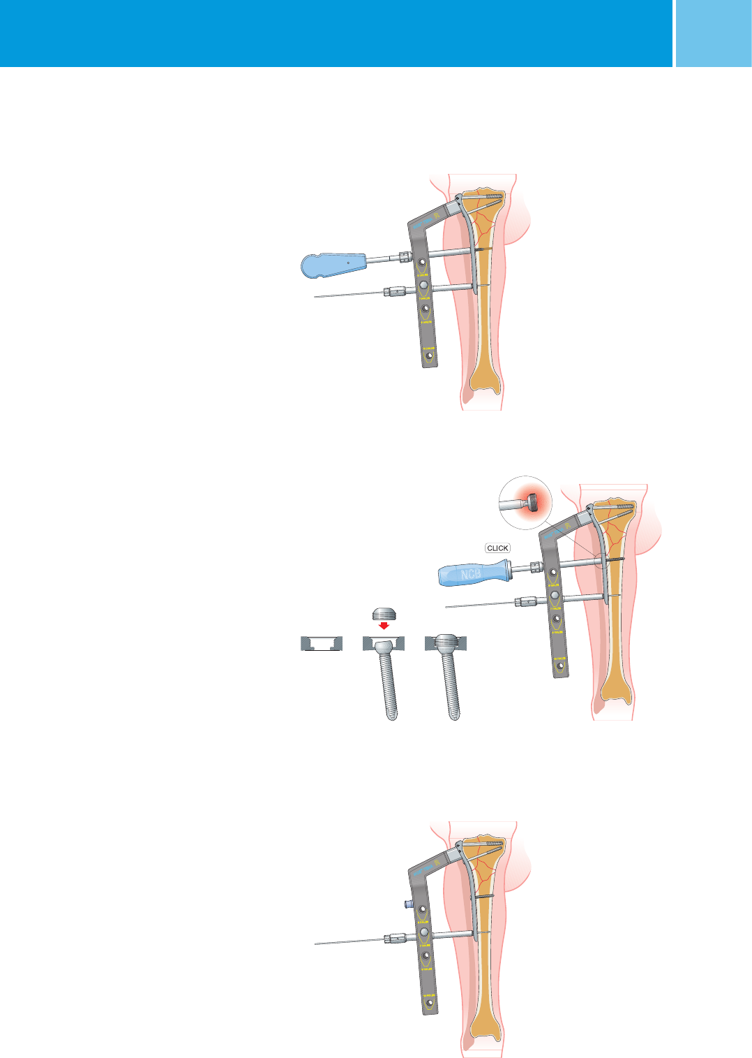
Insertion of NCB PT Plate
Insert the plate (REF 02.02261.xxx)
between the anterior tibialis muscle and
the periosteum.
The plate should be placed as close
as possible to the cartilage.
Temporarily fix the plate proximally and
distally with 2.0 mm K-wires through
the small holes in the plate.
Check the plate position and the fracture
alignment with an image intensifier in
both planes. Make sure the leg axis has
been restored.
Note: The plate is anatomically shaped.
Do not bend or contour the plate to
avoid damage of the locking mechanism.
Insertion of NCB Screws
A maximum of thirty degrees of screw
angulation is allowed in all plate holes.
Use the NCB Drill Guide to avoid exces-
sive screw angulation with consequent
failure of the locking mechanism.
Note: The ∅ 4 mm NCB MotionLoc
Screws are also compatible with all
plates in the Proximal Tibia Plate System
except for the 3 hole length tibial NCB
plates with 3 proximal holes
(REF
02.02261.203 and 02.02261.303)**.
See Zimmer MotionLoc surgical technique
(REF 97-3161-002-00 or 97-3161-004-00)*
for more specific instructions.
Drilling of the locking
holes
Use the NCB Drill Guide to avoid an inclination > 30°
Drilling
Temporarily fixation of the plate
Cancellous Screws
For the 5.0 mm cancellous screws (REF 02.0x152.xxx) use the NCB Drill
Guide 2.5 mm (REF 02.00024.010). To ensure correct use of the drill
guide, press the drill guide into the plate hole in a perpendicular
position and then tilt it into the preferred position. The drill guide
needs to be in constant contact with the bottom ring of the hole.
Use the 2.5 mm drill bit (REF 103.25.180) for the 5.0 mm cancellous
screws.
* 97-3161-002-00 is for countries where NCB MotionLoc screws are approved to be used with only NCB plates and 97-3161-004-00 is for countries where
NCB MotionLoc screws are approved to be used with both NCB as well as NCB Periprosthetic plates. See NCB MotionLoc package insert for approved plate/
MotionLoc screw combinations.
** The 3 hole length tibial NCB plate with 3 proximal holes (REF 02.02261.203 and 02.02261.303) is a product of BAAT Medical BV and is distributed
by Zimmer only in Europe, Middle East, and Africa
14 NCB® Proximal Tibia System – Surgical Technique
Use the NCB Depth Gauge
(REF 02.00024.005) to determine
the appropriate screw length.
Insert NCB Cancellous Screws using
the NCB PT Hexagonal Screwdriver,
(REF 02.00024.124) and apply compres-
sion if needed. Cancellous screws are
partially threaded and can be used as
lag screws.
Depending on fracture type, in the
epiphyseal and metaphyseal areas,
screws should be tightened to reduce
the fracture and obtain close contact
between the plate and the bone in order
to buttress the fracture.
Note: Tighten the bone screws by
hand only.
Repeat this procedure to insert all the
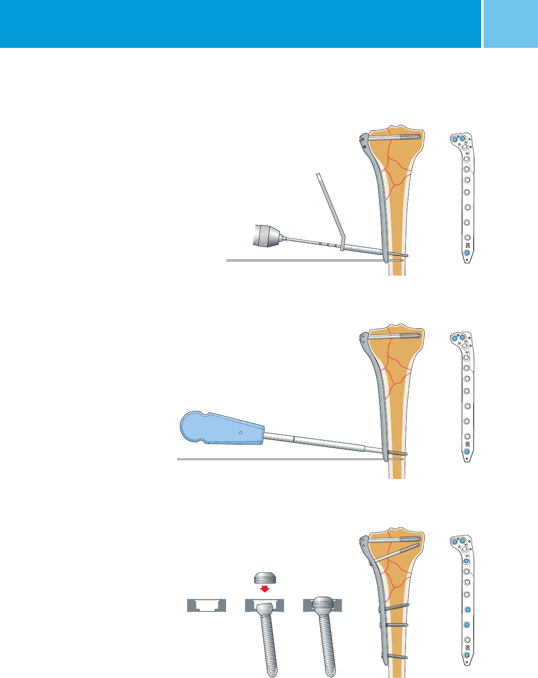
necessary NCB Cancellous Screws.
It is recommended that the most
proximal cancellous screws be placed
parallel to the tibia plateau.
Check the fracture reduction, plate
position and the leg axis with an
image intensifier.
To secure the angular stability insert the
NCB Locking Caps (REF 02.03150.300)
on all the cancellous screws used. Tighten
the locking caps with the NCB Torque
Screwdriver, 6 Nm (REF 02.00024.021)
until a clicking sound is heard.
Note: Always use the torque screwdriver
to tighten the locking caps and make
sure the screwdriver is not tilted during
its usage. Failure to do so could damage
the hex drive and might complicate
extraction of the implant.
Remove the proximal K-wire.
Determine screw length with the NCB Depth Gauge
Use the NCB PT Hexagonal Screwdriver to hand tighten the screw
and apply compression (if needed)
Possible setting of the most proximal cancellous screws
Insert the locking caps using the NCB Torque Screwdriver
to achieve 6 Nm
NCB® Proximal Tibia System– Surgical Technique 15
Optional
Cannulated Cancellous Screws
NCB Cannulated Cancellous Screws
are self-drilling and self-tapping. These
screws can be precisely placed over
the NCB Guide Wire, ∅ 1.6 mm.
A cannulated drill bit can be used to
pre-drill hard cortical bone.
Insertion of the ∅ 1.6 mm NCB
Guide Wire
Use the NCB Drill Guide to avoid exces-
sive angulation of the cannulated
screws with consequent failure of the
locking mechanism.
For the 4.5 mm cannulated cancellous
screws (REF 02.0x158.0xx) insert the
NCB PT Drill Guide ∅ 3.3/1.6 mm
(REF 02.00024.192) into the NCB Drill
Guide ∅ 3.3 mm (REF 02.00024.111).
Press the drill guide into the plate hole,
tilt it in the preferred position and insert
the NCB Guide Wire with threaded tip
(REF 02.01362.116).
Note: use only the NCB Guide Wire
(REF 02.01362.116) ∅ 1.6 mm,
L = 190 mm.
Failure to do so misleads the screw
length measurement.
Use the NCB Drill Guides to avoid an inclination 30° when inserting
the NCB 1.6 guide wire
16 NCB® Proximal Tibia System – Surgical Technique
Insertion of the Cannulated
Cancellous Screws
Remove the NCB Drill Guide ∅ 3.3 mm
(REF 02.00024.111) and NCB PT Drill
Guide ∅ 3.3/1.6 mm (REF 02.00024.192)
and determine the screw length from
the measurement with the NCB PH/PT
Measuring Device (REF 02.00024.219)
along the NCB Guide Wire.
For hard cortical bone it is possible to
use the ∅ 3.3 mm NCB PT Cannulated
Drill Bit (REF 02.00024.233).
Note: use the ∅ 3.3 mm NCB PT Cannu-
lated Drill Bit (REF 02.00024.233)
only for the first lateral cortex, to make
sure that the NCB Guide Wire does
not fall out.
Use the cannulated hexagonal screw-
driver (REF 02.00024.120) to insert
the cannulated self-drilling screws over
the 1.6 mm NCB Guide Wire.
To achieve the final angular stability
remove the NCB Guide Wire and tighten
the locking cap with the torque
screwdriver 6 Nm (REF 02.00024.021)
until the clicking sound is heard.
Note: it is important to remove the NCB
Guide Wire (REF 02.01362.116) prior to
inserting the locking cap
(REF 02.0x150.300) because the axial
directions for the cannulated screws and
locking cap may be different.
Measure the screw length with the
NCB PH/PT Measuring Device
Insert the cannulated screw with the
hexagonal cannulated screw driver
NCB® Proximal Tibia System– Surgical Technique 17
Cortical Screws
Bicortical insertion is recommended.
For the 4.0 mm cortical screws
(REF 02.0x155.0xx) use the NCB Drill
Guide 3.3 mm (REF 02.00024.111)
with the 3.3 mm drill bit
(REF 02.00024.118).
In case of hard cortical bone tap the
cortex with the NCB Tap
(REF 02.00024.040). Remove the
NCB Drill Guide 3.3 mm when using
the NCB Tap.
Measure the screw length and
insert NCB Cortical Screw using the
NCB Hexagonal Screwdriver
(REF 02.00024.124).
Note: Tighten the bone screws by
hand only.
Repeat this procedure to insert all the
needed NCB Cortical Screws.
Insert the NCB Locking Caps
(REF 02.x150.300) to secure the angular
stability as described for the cancellous
screws.
Remove the distal K-wire after complet-
ing screw insertions.
Insert cortical screws
Possible final screw settingInsert the locking caps using the NCB
Torque Screwdriver to achieve 6 Nm
18 NCB® Proximal Tibia System – Surgical Technique
MIS Technique
MIS is recommended for simple and/
or extra-articular fractures. An open
approach is recommended in the proxi-
mal area to restore the articular surface.
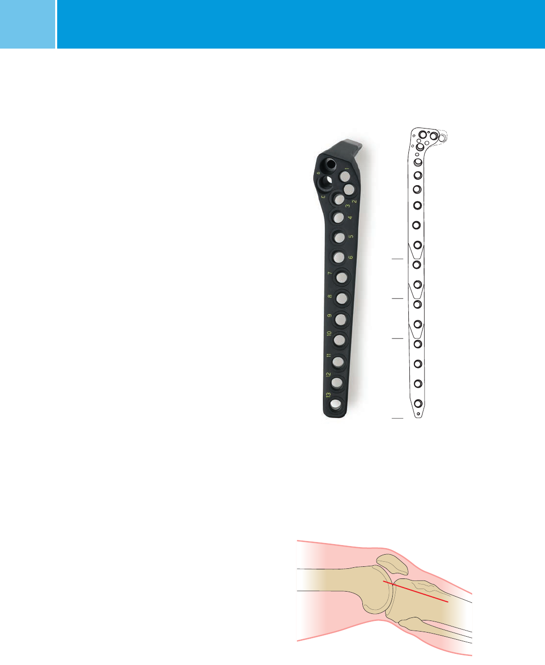
Plate Hole Numbering System
To target the correct plate holes there
is a numbering system on the targeting
devices (REF 02.00024.08x)
Screw holes in the proximal and meta-
physeal areas are indicated with Greek
letters (α, β, γ, δ and ε).
Screw holes in the shaft area are
indicated with Roman numbers (1 to 13
according to plate length).
Note: Do not use the MIS device with the
3 hole length tibial NCB plate with 3
proximal holes (REF 02.02261.203 and
02.02261.303)**.
Incision and Fracture Reduction
A lateral incision should start proximal
to Gerdy’s tubercle and should be
extended for about 50 mm distally.
Note: Incision length will vary according
to the type of fracture.
Reduce the fracture as described in the
open technique. Take care that K-wires
used to temporarily stabilize the fracture
do not interfere with the future plate
location.
Incision
4567
5 holes7 holes9 holes13 holes
δε1238910111213
α
β
γ
NCB Plate screw hole numbering system
** The 3 hole length tibial NCB plate with 3 proximal holes (REF 02.02261.203 and 02.02261.303) is a product of BAAT Medical BV and is distributed by Zimmer
only in Europe, Middle East, and Africa.
NCB® Proximal Tibia System– Surgical Technique 19
Targeting Device Assembly
Use the NCB PT right Targeting Device
(REF 02.00024.080) for NCB PT
Right Plates (REF 02.02261.xxx) and
the NCB PT Left Targeting Device
(REF 02.00024.081) for NCB PT Left
Plates (REF 02.02261.xxx).
Center the targeting device in the
specific indentations on the plate.
Insert and screw in the NCB PT Connec-
tion Bolt (REF 02.00024.083) in the “δ”
hole of the targeting device.
Note: To guarantee accurate assembly
of the plate/targeting device, insert the
NCB PT stabilization bolt
(REF 02.00024.084) into the targeting
device hole corresponding to the last
plate hole. Screw the NCB Stabilization
Bolt into the plate and insert the safety
lock pin (REF 02.00024.076) from the
anterior side.
Once the assembly of the plate/
targeting device has been accomplished,
tighten the NCB Connection Bolt
(REF 02.00024.083) with the screwdriver.
Remove the safety lock pin and the
NCB PT Stabilization Bolt in order to
insert the plate.
Insertion and Preliminary
Fixation of NCB PT Plate
Under the image intensifier insert the
plate between the anterior tibialis
muscle and the periosteum: keep the
distal end of the plate in continuous
contact with the bone surface during
insertion.
The plate should be placed as close
as possible to the joint line.
Connection bolt
Safety lock pin
Stabilization bolt
Assembly of the targeting device prior insertion
Slide the plate between the anterior tibialis muscle
and the periosteum
20 NCB® Proximal Tibia System – Surgical Technique
Insert a 2.0 mm K-wire through one of
the small proximal holes for temporary
fixation of the plate.
Make a stab incision at the most
distal plate hole.
Insert the NCB PT Stabilization Bolt
(REF 02.00024.084), the NCB PT K-Wire
Guide (REF 02.00024.092) and the
NCB PT Trocar (REF 02.00024.093) into
the corresponding hole on the targeting
device.
Screw the NCB PT Stabilization Bolt
(REF 02.00024.084) into the plate
and insert the safety lock pin
(REF 02.00024.076) as described
previously.
Center the distal part of the plate on
the bone using the image intensifier,
remove the NCB PT Trocar and insert
a 2.0 mm K-wire to fix the plate.
Close the plate targeting device configuration to guarantee correct
correspondence between the targeting device and plate holes
Center the distal part of the plate Temporary fixation of the plate
Anterior
Posterior
NCB® Proximal Tibia System– Surgical Technique 21
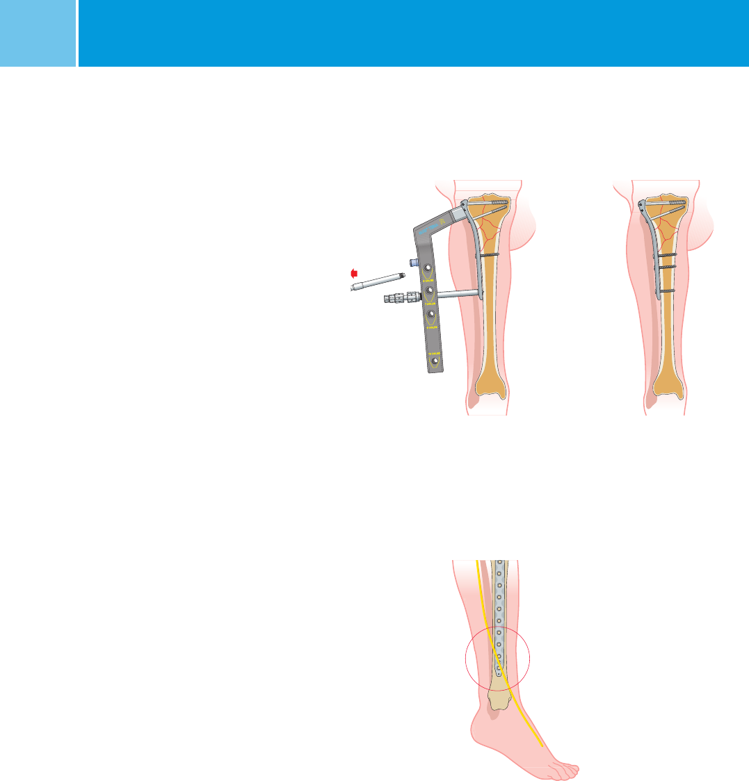
Insertion of NCB Screws
in the Proximal Area
Use the same procedure as described
in the open technique.
Repeat the procedure to insert the
appropriate number of proximal screws.
Note: Check the fracture reduction
and plate position under an image
intensifier.
Lock the screws as described in the
open technique.
Only the most proximal screws can
be inserted with open technique
when the targeting device is on.
The screw numbered “δ” needs to
be inserted when the targeting device
is removed at the end of surgery.
The screw numbered “δ” can be
inserted using the corresponding hole
on the targeting device following the
procedure described below.
Use the drill guide and drill
bit to insert cancellous screws
as described in the open
technique
Screw hole numbering
system
4567
5 holes7 holes9 holes13 holes
δε1238910111213
α
β
γ
22 NCB® Proximal Tibia System – Surgical Technique
Insert the tissue protection sleeve
Insertion of NCB Screws
in the Shaft
Make a stab incision to access the plate
hole and insert the tissue protection
sleeve assembly (REF 02.00024.090 to
093).
Screw the NCB PT Drill Guide
(REF 02.00024.091) into the plate and
then the NCB PT soft tissue protection
sleeve (REF 02.00024.090) into the
targeting device.
Remove the NCB PT Trocar and NCB PT
K-Wire Guide and insert the NCB PT
Drill Bit 3.3 mm (REF 02.00024.133)
when the 4.0 mm cortical screw is used.
Use the scale on the drill bit shaft
or the NCB PT Depth Gauge
(REF 02.00024.007) to determine the
appropriate screw length.
Alternative measuring of the screw
length with the NCB Depth Gauge
Drill the screw hole in the bone shaft
NCB® Proximal Tibia System– Surgical Technique 23
Remove the NCB PT Drill Guide and
insert the appropriate screw using
the NCB PT Hexagonal Screwdriver
(REF 02.00024.124).
Note: The screw is completely inserted
when the marker on the screwdriver
reaches the soft tissue protection sleeve.
Insert and tighten the locking cap
(REF 02.03150.300) with the NCB Torque
Screwdriver, 6 Nm (REF 02.00024.021)
until a clicking sound is heard.
Note: Always use the torque screwdriver
to tighten the locking caps and make
sure the screwdriver is not tilted during
its usage. Failure to do so could damage
the hex drive and might complicate
extraction of the implant.
Remove the NCB PT Soft Tissue Protec-
tion and insert the NCB Screw Marker
(REF 02.00024.077) to indicate that the
screw is placed and locked in the hole.
Repeat the described procedure to
insert additional screws.
Insert the screw in the bone shaft
Use the screw marker to indicate that the screw is inserted and
locked in the hole and proceed to insert additional screws
Insert the locking caps using the NCB Torque
Screwdriver to achieve 6 Nm
24 NCB® Proximal Tibia System – Surgical Technique
To place the most distal screw, exchange
the NCB Stabilization Bolt with the
NCB PT Drill Guide and protection sleeve
and follow the procedure described
above.
Unscrew the connecting bolt to remove
the targeting device.
Note: when using the long plate (i.e.
13 holes) the last three distal screws
may interfere with the Superficial
Peroneal nerve. Therefore, it is recom-
mended a slightly longer stab incision
to visualize and avoid damage to the
Superficial Peroneal nerve.
Implant Removal
To remove the NCB PT Plate, first remove
all the locking caps. Then loosen all the
NCB Bone Screws without completely
removing them (this prevents rotation of
the bone plate when removing the last
screw). Then, completely remove all the
bone screws.
Note: make sure that the tip of the
NCB PT Screwdriver (REF 02.00024.124)
is correctly placed in the hex drive
of the locking caps and/or NCB Screws.
Failure to do so could damage the
hex drive and complicate the extraction
of the implant.
Removal Tips
• Re-assemble the NCB Targeting
Device to remove the shaft screws
if the MIS approach was used
for implantation. The targeting device
ensures that the axial direction used
during implantation is considered.
• In case of difficulties in loosing the
NCB Screws, tighten the screws slightly
before loosening them.
Take care to avoid damage
of the Superficial Peroneal
nerve when using long plates
Remove the NCB Stabilization
Bolt and insert the NCB Protection
Sleeve to insert the most distal
cortical screw
Possible final screw setting
NCB® Proximal Tibia System– Surgical Technique 25
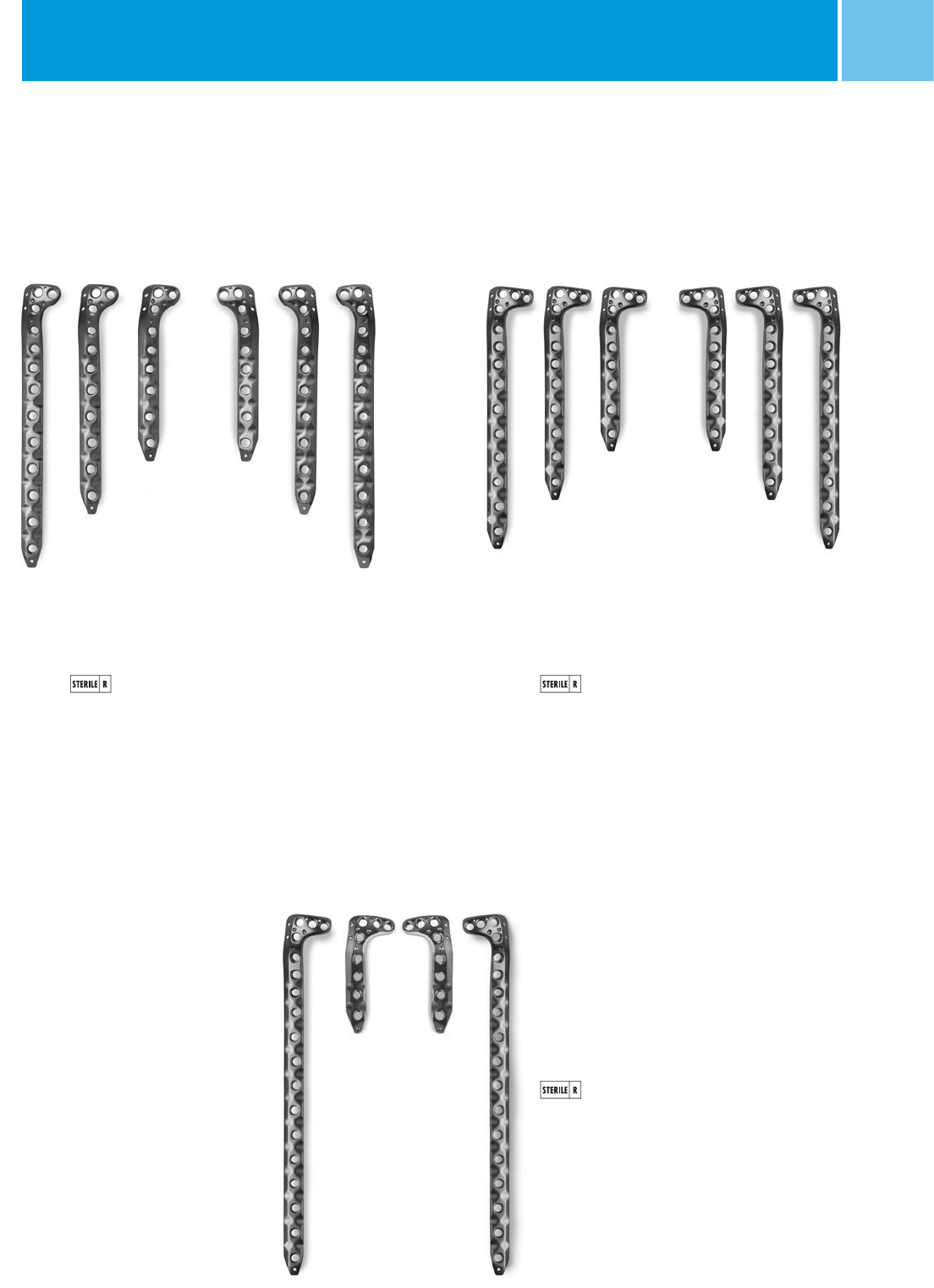
Ordering Information – Implants
NCB® PT 2-proximal hole plate set
REF
ZS 02.00024.820
sterile-packed
Quantity* Holes mm Side REF
1 5 132 left 02.02261.105
1 7 172 left 02.02261.107
1 9 212 left 02.02261.109
1 5 132 right 02.02261.005
1 7 172 right 02.02261.007
1 9 212 right 02.02261.009
* Indicates the quantity in the plate sets.
** The 3 hole length tibial NCB plate with 3 proximal holes (REF 02.02261.203 and 02.02261.303) is a product of BAAT Medical BV and is distributed by Zimmer only
in Europe, Middle East, and Africa.
NCB® PT 3-proximal hole plate set
REF
ZS 02.00024.830
sterile-packed
Quantity* Holes mm Side REF
1 5 132 left 02.02261.305
1 7 172 left 02.02261.307
1 9 212 left 02.02261.309
1 5 132 right 02.02261.205
1 7 172 right 02.02261.207
1 9 212 right 02.02261.209
NCB® PT 3-proximal hole plate (optional)
3 and 13 hole lengths
sterile-packed
Quantity* Holes mm Side REF
– 3 92 left 02.02261.303 **
– 3 92 right 02.02261.203 **
– 13 292 left 02.02261.313
– 13 292 right 02.02261.213
Materials: NCB Plates and Screws are made
of Ti6Al4V, ISO 5832-3, ASTM F136
26 NCB® Proximal Tibia System – Surgical Technique
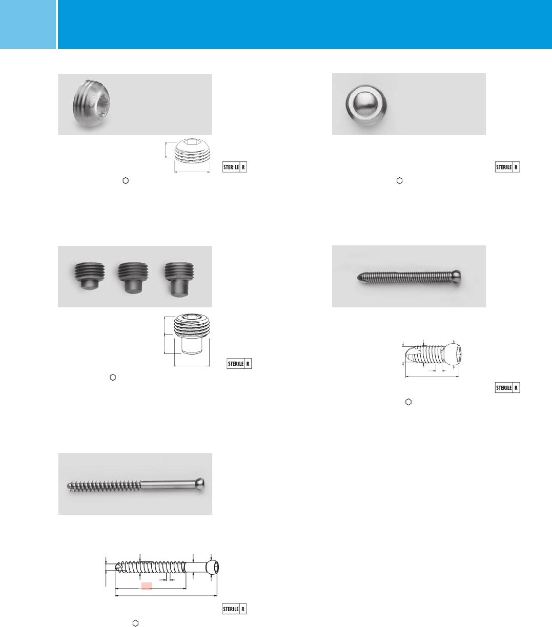
NCB® Cancellous Screw, thread length 32mm
Quantity* L mm ∅ mm mm REF (Non Sterile) REF (Sterile)
2 50 5.0 3.5 02.03152.050 02.02152.050
2 55 5.0 3.5 02.03152.055 02.02152.055
3 60 5.0 3.5 02.03152.060 02.02152.060
3 65 5.0 3.5 02.03152.065 02.02152.065
3 70 5.0 3.5 02.03152.070 02.02152.070
3 75 5.0 3.5 02.03152.075 02.02152.075
3 80 5.0 3.5 02.03152.080 02.02152.080
2 85 5.0 3.5 02.03152.085 02.02152.085
2 90 5.0 3.5 02.03152.090 02.02152.090
– 95 5.0 3.5 02.03152.095 02.02152.095
– 100 5.0 3.5 02.03152.100 02.02152.100
NCB® Screw, self-tapping
Quantity* L mm ∅ mm mm REF (Non Sterile) REF (Sterile)
2 14 4.0 3.5 02.03155.014 02.02155.014
2 16 4.0 3.5 02.03155.016 02.02155.016
2 18 4.0 3.5 02.03155.018 02.02155.018
2 20 4.0 3.5 02.03155.020 02.02155.020
2 22 4.0 3.5 02.03155.022 02.02155.022
2 24 4.0 3.5 02.03155.024 02.02155.024
2 26 4.0 3.5 02.03155.026 02.02155.026
2 28 4.0 3.5 02.03155.028 02.02155.028
2 30 4.0 3.5 02.03155.030 02.02155.030
2 32 4.0 3.5 02.03155.032 02.02155.032
4 34 4.0 3.5 02.03155.034 02.02155.034
4 36 4.0 3.5 02.03155.036 02.02155.036
4 38 4.0 3.5 02.03155.038 02.02155.038
4 40 4.0 3.5 02.03155.040 02.02155.040
4 42 4.0 3.5 02.03155.042 02.02155.042
4 44 4.0 3.5 02.03155.044 02.02155.044
2 46 4.0 3.5 02.03155.046 02.02155.046
2 48 4.0 3.5 02.03155.048 02.02155.048
2 50 4.0 3.5 02.03155.050 02.02155.050
2 55 4.0 3.5 02.03155.055 02.02155.055
2 60 4.0 3.5 02.03155.060 02.02155.060
2 65 4.0 3.5 02.03155.065 02.02155.065
2 70 4.0 3.5 02.03155.070 02.02155.070
2 75 4.0 3.5 02.03155.075 02.02155.075
2 80 4.0 3.5 02.03155.080 02.02155.080
2 85 4.0 3.5 02.03155.085 02.02155.085
2 90 4.0 3.5 02.03155.090 02.02155.090
– 95 4.0 3.5 02.03155.095 02.02155.095
– 100 4.0 3.5 02.03155.100 02.02155.100
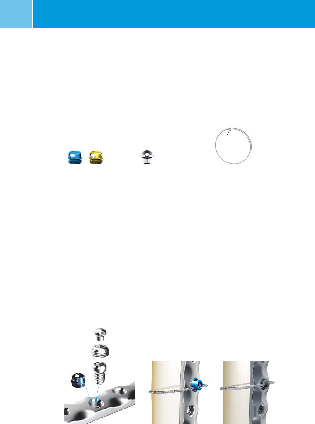
NCB® Blind Screw Insert
Quantity* ∅ mm mm REF (Non Sterile) REF (Sterile)
5 8 3.5 02.03150.310 02.02150.310
NCB® Spacer
(red, blue, green)
Quantity* L mm mm Color REF (Non Sterile) REF (Sterile)
2 1 3.5 red 02.03150.311 02.02150.311
2 2 3.5 blue 02.03150.312 02.02150.312
2 3 3.5 green 02.03150.313 02.02150.313
L4.2
M8 × 0.75
∅ 6.2
∅ 4
∅ 3.4
L1.75
∅ 6.2
∅ 4.2∅ 5
L
1.75
∅ 2.9
32
NCB® Locking Cap
Quantity* ∅ mm mm REF (Non Sterile) REF (Sterile)
15 8 3.5 02.03150.300 02.02150.300
3.9
M8 × 0.75
* Indicates the quantity of non sterile implants in the standard graphic case.
Materials: NCB Plates and Screws are made
of Ti6Al4V, ISO 5832-3, ASTM F136
NCB® Proximal Tibia System– Surgical Technique 27
NCB® MotionLoc® Screws, Ø 4.0mm Cortical,
Self Tapping, Ti6Al4V
L mm ∅ mm REF (Non Sterile) REF (Sterile)
24 4.0 02.03162.024 02.02162.024
26 4.0 02.03162.026 02.02162.026
28 4.0 02.03162.028 02.02162.028
30 4.0 02.03162.030 02.02162.030
32 4.0 02.03162.032 02.02162.032
34 4.0 02.03162.034 02.02162.034
36 4.0 02.03162.036 02.02162.036
38 4.0 02.03162.038 02.02162.038
40 4.0 02.03162.040 02.02162.040
42 4.0 02.03162.042 02.02162.042
44 4.0 02.03162.044 02.02162.044
46 4.0 02.03162.046 02.02162.046
∅ 4∅ 6,2
L
* Not available in Europe, Middle East and Africa.
** The MotionLoc screws and Cable Fixation options are compatible with all plates in the NCB Proximal Tibia System
except for the 3 hole length tibial NCB plate with 3 proximal holes (REF 02.02261.203 and 02.02261.303)
*** The 3 hole length tibial NCB plate with 3 proximal holes (REF 02.02261.203 and 02.02261.303) is a product of
BAAT Medical BV and is distributed by Zimmer only in Europe, Middle East, and Africa.
Cable Fixation Options
REF (Sterile) Description
47-2232-060-00* NCB Polyaxial Locking Plate Cable Button, Gold, 2.5mm Hex Drive, Material: Ti6Al4V
47-2232-060-01 NCB Polyaxial Locking Plate Cable Button, Blue, 2.5mm Hex Drive, Material: Ti6Al4V
00-2232-002-35 Hex Buttons, 3.5mm Hex, Material: C.P. Titanium
00-2232-004-28 Cable-Ready Cable Assembly Cerclage, ∅ 1.8mm, L 914mm, Material: CoCr
00-2232-004-18 Cable-Ready Cable Assembly Cerclage, ∅ 1.8mm, L 635mm, Material: CoCr
Materials: NCB Plates and Screws are made
of Ti6Al4V, ISO 5832-3, ASTM F136
Compatible Zimmer Products with the NCB Proximal Tibia System** (optional)
28 NCB® Proximal Tibia System – Surgical Technique
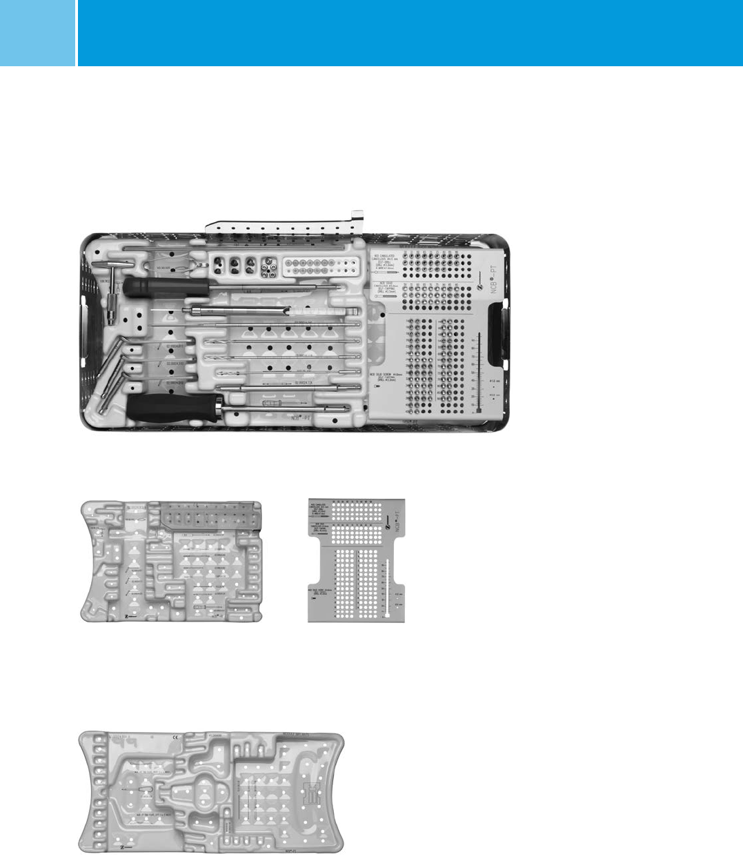
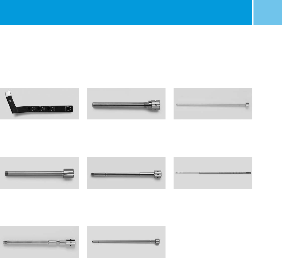
Graphic Case
NCB® PT Standard Graphic Case
for open technique; includes
REF 02.00024.801/.802/.803/.804/
.805
REF
with content ZS 02.00024.800
empty ZS 02.00024.810
NCB® PT Graphic Case, module
cannulated screws and implants
REF
02.00024.804
NCB® PT Graphic Case, module
screw rack
REF
02.00024.805
NCB® PT Graphic Case, lid
REF
02.00024.801
NCB® PT Graphic Case base (Inox)
REF
02.00024.802
NCB® PT Graphic Case, module
instruments
REF
02.00024.803
NCB® Proximal Tibia System– Surgical Technique 29
NCB® Drill Bit, with quick coupling
Quantity* L mm ∅ mm REF
1 195 4.3 02.00024.002
Standard Instruments
NCB® Drill Guide ∅ 2.5 mm for screws
∅ 5.0 cancellous
Quantity* ∅ mm REF
1 2.5 02.00024.010
NCB® Drill Guide 4.3 screws 5.0
Quantity* mm REF
1 4.3 02.00024.011
NCB® Torque Screwdriver, 6 Nm
Quantity* L mm ∅ mm REF
1 280 3.5 02.00024.021
NCB® Depth Gauge
Quantity* L mm ∅ mm REF
1 110 5.0/4.5/4.0 02.00024.005
NCB® PT Hexagonal Screwdriver, long
Quantity* L mm mm REF
1 275 3.5 02.00024.124
Two-fluted drill bit, with quick coupling
Quantity* L mm l mm ∅ mm REF
1 180 154 2.5 103.25.180
l
L
T-handle, with quick coupling
Quantity* REF
1 100.90.210
NCB® PT Tab 4 mm, with quick
coupling
Quantity* mm REF
1 4.0 02.00024.040
Screw forceps self-holding
Quantity* REF
1 100.90.005
NCB® Drill Guide ∅ 3.3 mm for
screws ∅ 4.0/4.5
Quantity* ∅ mm REF
1 3.3 02.00024.111
NCB® Drill Bit, with quick coupling
Quantity* L mm mm REF
1 195 3.3 02.00024.118
NCB® PT Hexagonal Screwdriver, shaft
Quantity* L mm mm REF
1 – 3.5 02.00024.027
Kirschner wire, stainless steel
Quantity* L mm mm REF
5 280 2.0 290.20.280
*Indicates the quantity in the standard graphic case.
30 NCB® Proximal Tibia System – Surgical Technique
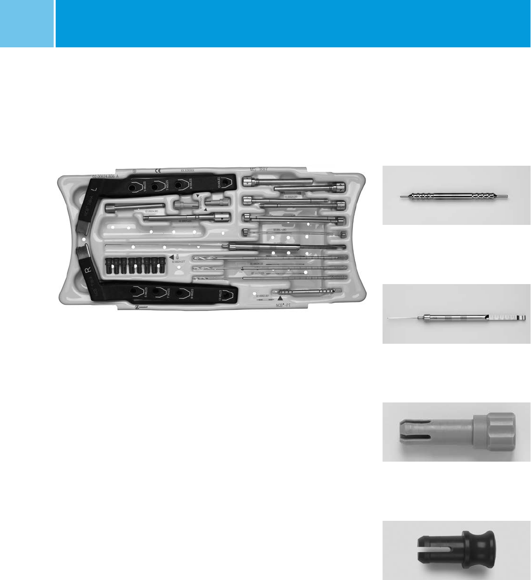
NCB® PT Graphic Case, for
MIS instruments
REF
with content ZS 02.00024.850
empty 02.00024.806
Assembly pin
Quantity** REF
1 02.00002.001
NCB® PT Depth Gauge
Quantity** REF
1 02.00024.007
NCB® Screw Marker for targeting device
Quantity** REF
8 02.00024.077
Safety lock pin for targeting device
Quantity** REF
2 02.00024.076
MIS Instruments
**Indicates the quantity in the MIS graphic case module.
NCB® Proximal Tibia System– Surgical Technique 31
NCB® PT Targeting Device
Quantity** Side REF
1 right 02.00024.080
1 left 02.00024.081
NCB® PT Stabilization Bolt for
targeting device
Quantity** REF
1 02.00024.084
NCB® PT K-Wire Guide ∅ 5.2/2 mm
Quantity** REF
2 02.00024.092
NCB® PT Trocar
Quantity** ∅ mm REF
2 2 02.00024.093
NCB® PT Drill Bit with quick coupling
Quantity** ∅ mm REF
1 2.5 02.00024.125
1 3.3 02.00024.133
1 4.3 02.00024.143
NCB® PT Soft Tissue Protection
sleeve ∅ 10.0/8.2 mm
Quantity** REF
2 02.00024.090
NCB® PT Connection Bolt
Quantity** REF
1 02.00024.083
NCB® PT Drill Guide 8.2/5.2 mm
Quantity** REF
2 02.00024.091
**Indicates the quantity in the MIS graphic case module.
32 NCB® Proximal Tibia System – Surgical Technique
Cannulated Options (Screws and Instruments)
NCB® PH Guide Wire with threaded tip
Quantity*** L mm mm REF
5 190 1.6 02.01362.116
NCB® PH/PT Measuring Device for
cannulated screws
Quantity*** REF
1 02.00024.219
NCB® PH Hexagonal Screwdriver
cannulated short hex
Quantity*** L mm mm REF
1 245 3.5 02.00024.120
NCB® PT Cannulated Drill Bit with
quick coupling
Quantity*** ∅ mm REF
1 3.3 02.00024.233
*** Indicates the quantity of instruments / non sterile implants included in the Ref. Number ZS 02.00024.840
NCB® Cannulated Cancellous Screw
∅ 4.5 mm, self-drill 24 mm thread length
Quantity*** L mm ∅ mm mm REF (Non Sterile) REF (Sterile)
2 50 4.5 3.5 02.03158.050 02.02158.050
2 55 4.5 3.5 02.03158.055 02.02158.055
3 60 4.5 3.5 02.03158.060 02.02158.060
3 65 4.5 3.5 02.03158.065 02.02158.065
3 70 4.5 3.5 02.03158.070 02.02158.070
3 75 4.5 3.5 02.03158.075 02.02158.075
3 80 4.5 3.5 02.03158.080 02.02158.080
2 85 4.5 3.5 02.03158.085 02.02158.085
2 90 4.5 3.5 02.03158.090 02.02158.090
– 95 4.5 3.5 02.03158.095 –
– 100 4.5 3.5 02.03158.100 –
∅ 3.5
∅ 1.75
∅ 3.2 ∅ 4.5 ∅ 6.2
1.75
L
24
NCB® PT Drill Guide 3.3/1.6 mm
Quantity*** REF
2 02.00024.192
Cannulated Screws and Instrument Set
REF
ZS 02.00024.840
Materials: NCB Plates and Screws are made
of Ti6Al4V, ISO 5832-3, ASTM F136
NCB® Proximal Tibia System– Surgical Technique 33
Planning Aid
X ray template REF 06.01365.000
+H84406013650001/$150501E15Z
NCB®-PT Proximal Lateral Tibial Osteosynthesis Plate, with Polyaxial Locking Screws
These reference numbers must correspond
to those of the prostheses to be implanted.
© 2015. All rights reserved, Zimmer GmbH,
Sulzerallee 8, CH-8404 Winterthur, Switzerland
Lit. No. 06.01365.000
5 cm 15 cm10 cm
Magnification
1.15:1
5 cm
10 cm
15 cm
20 cm
25 cm
0cm
0cm1cm 2cm3cm4cm5cm6cm7cm8cm9cm 10 cm
4567
14
NCB-Screws
self-tapping
Polyaxial Screw
100
100
50
50
60
100
50
αβγ
δ
ε
5 holes7 holes9 holes13 holes
δε1238910111213
α
β
γ
1
20
30
20
30
20
30
20
30
20
30
20
30
20
30
20
30
20
30
20
30
2
3
4
5
6
7
8
9
10
11
12
13
20
30
20
30
20
30
Right
AP View
Lateral View
Do not bend
Left/
∅ 4
∅ 5
30°

34 NCB® Proximal Tibia System – Surgical Technique
Notes

NCB® Proximal Tibia System– Surgical Technique 35

Lit.No. 06.01369.022 – Ed.2015-08
Contact your Zimmer representative or visit us at www.zimmer.com
Copyright 2015 by Zimmer GmbH Subject to change without notice
Disclaimer
This documentation is intended exclusively for physicians and is not intended for laypersons.
Information on the products and procedures contained in this document is of a general nature and does not represent
and does not constitute medical advice or recommendations. Because this information does not purport to constitute
any diagnostic or therapeutic statement with regard to any individual medical case, each patient must be examined and
advised individually, and this document does not replace the need for such examination and/or advice in whole or in part.
Please refer to the package inserts for important product information, including, but not limited to, indications,
contraindications, warnings, precautions, and adverse effects.
