Network_Access_Method_Ver_1_Host_Application_Programming_Ref_Man_60499500W_Apr87 Network Access Method Ver 1 Host Application Programming Ref Man 60499500W Apr87
Network_Access_Method_Ver_1_Host_Application_Programming_Ref_Man_60499500W_Apr87 Network_Access_Method_Ver_1_Host_Application_Programming_Ref_Man_60499500W_Apr87
User Manual: Pdf Network_Access_Method_Ver_1_Host_Application_Programming_Ref_Man_60499500W_Apr87
Open the PDF directly: View PDF ![]() .
.
Page Count: 356 [warning: Documents this large are best viewed by clicking the View PDF Link!]
60499500
CONTRpL DATA
/g^N
NETWORK PRODUCTS
NETWORK ACCESS METHOD
VERSION 1
HOST APPLICATION PROGRAMMING
REFERENCE MANUAL
CDC® OPERATING SYSTEM:
NOS 2
REVISION RECORD
Revision
A (12/01/76)
B (04/01/77)
C (07/01/77)
D (04/28/78)
E (08/15/78)
F (12/18/78)
G (01/15/79)
H (08/10/79)
J (12/11/79)
K (04/18/80)
L (10/31/80)
M (05/29/81)
N (02/26/82)
P (01/14/83)
R (09/30/83)
S (09/19/84)
T (09/30/85)
U (12/16/85)
V (07/31/86)
W (04/23/87)
Description
Original Release. PSR level 439.
Revised to PSR level 446 for technical corrections.
Revised to PSR level 452 for technical corrections.
Completely revised for NAM Version 1.1 release at PSR level 472 to include support of
remote and foreign NPUs, asynchronous and HASP TIPs, virtual terminals, IAF, and TVF.
Revised at PSR level 477 for technical corrections.
Revised at PSR level 485 for technical corrections.
Revised at PSR level 485 for additional technical corrections.
Revised to reflect release of NAM Version 1.2. Included are descriptions of the binary
debug log file and postprocessor, special editing support, and QTRM.
Revised to reflect addition of connection duplexing, upline block truncation, block
header break markers, QTRM connection switching, and various technical corrections.
Revised at PSR level 517 to reflect the addition of 714 printer support, and various
technical c o r r e c t i o ns.
Revised at PSR level 528 to reflect the addition of QTRM support of application-to-
application connections, the user-interrupt capability, and various technical
corrections.
Revised for NAM Version 1.3 release at PSR level 541 to include 2780/3780 terminal
support, changes to supervisory messages, PRU interface, and various technical
c o r r e c t i o n s .
Revised at PSR level 559 to reflect release of NAM Version 1.4, which supports NOS
Version 2.0 and includes the disable flag parameter on the LST/HDX/R supervisory
message and miscellaneous technical corrections.
Revised at PSR level 580 to reflect release of NAM Version 1.5 and CCP Version 3.5, which
run only under the NOS Version 2 operating system. This manual, which was previously
known as the NAM Reference Manual, is no longer applicable to products operating under
NOS 1. It has been reorganized to document information needed by a general networks
user, who must consider NAM as well as CCP when writing a network application. This is
a complete reprint.
Revised at PSR level 596 to reflect release of NAM Version 1.6 and CCP Version 3.6,
supporting multiple-host networks. This is a complete reprint.
Revised at PSR level 617 to reflect release of NAM Version 1.7 and CCP Version 3.7 to
document support of a 3270 bisynchronous terminal class and miscellaneous technical
c o r r e c t i o n s .
Revised at PSR level 642 to reflect release of NAM Version 1.8 and CCP Version 3.8. This
manual was previously known as the NAM Version 1/CCP Version 3 Host Application
Programming Reference Manual. Miscellaneous technical changes are included.
Revised at PSR level 647 to reflect release of NAM Version 1.8, CCP Version 3.8, and
CDCNET Version 1.0. Miscellaneous technical corrections are included.
Revised at PSR level 664 to reflect release of NAM Version 1.8, CCP Version 3.8, and
CDCNET Version 1.1. Miscellaneous technical, corrections are included.
Revised at PSR level 678 to reflect release of NAM Version 1.8, CCP Version 3.8, and
CDCNET Version 1.2. Miscellaenous technical corrections are included.
REVISION LETTERS I, 0, Q, AND X ARE NOT USED
©COPYRIGHT CONTROL DATA CORPORATION
1976, 1977, 1978, 1979, 1980, 1981,
1982, 1983, 1984, 1985, 1986, 1987
All Rights Reserved
Printed in the United States of America
Address comments concerning this manual to:
CONTROL DATA CORPORATION
Technology and Publications Division
P. 0. BOX 3492
SUNNYVALE, CALIFORNIA 94088-3492
or use Comment Sheet in the back of this manual
/-*a^.
ii 60499500 W
LIST OF EFFECTIVE PAGES
New features, as well as changes, deletions, and additions to information in this manual are indicated by bars
in the margins or by a dot near the page number if the entire page is affected. A bar by the page number
indicates pagination rather than content has changed.
Page
Front Cover
Title Page
ii
iii/iv
v
vi
vii/viii
ix thru xii
xiii/xiv
XV
1-1
1-2 thru 1-6
1-7
1-8
1-8.1
1-8.2
1-9 thru 1-14
2-1
2-2
2-3
2-4
2-5
2-6
2-7
2-8
2^9
2-10
2-11
2-12 thru 2-14
2-15 thru 2-18
2-19
2-20
2-21
2-22 thru 2-25
2-26
2-27
2-28
2-29
2-30 thru 2-33
2-34
2-35
2-36 thru 2-39
3-1
3-2 thru 3-6
3-7 thru 3-10
3-11
3-12
3-12.1/3-12.2
3-13 thru 3-16
3-17
3-18 thru 3-21
3-22
3-23
3-24
3-25
3-26
3-27
3-28
Revision Page
-3-29
-3-30
W3-30.1
W3-30.2
V3-31
u3-32 thru 3-44
V3-45
V3-46
V3-47 thru 3-50
T3-51 thru 3-53
R3-54 thru 3-57
U3-58
V3-59
V3-60
U3-61
U3-62 thru 3-68
T3-68.1 thru 3-68.6
U 3-69 thru 3-79
R3-80
R3-81
T4-1
R4-2
T4-3
R4-4
T4-4.1/4-4.2
R4-5 thru 4-10
U4-10.1
T4-10.2
S4-11 thru 4-15
U4-16
V 4-17 thru 4-19
U5-1
S5-2
T5-3
W5-4
T5-5
W5-6
T5-7 thru 5-11
W5-12
V5-13
U5-14
T5-15
U5-16
V5-17
U6-1
V6-2
V6-3
U6-4
T6-5
V6-6
T6-7
V6-8
W6-9
W6-10
T 6-11
V6-12
W6-13 thru 6-15
W6-16
Revision Page
V6-17
V7-1 thru 7-15
V7-16
V 7-17 thru 7-24
V7-25
T7-26 thru 7-38
V8-1
V 8-2 thru 8-12
T8-13
V 8-14 thru 8-34
T8-34.1
V8-34.2
V8-34.3/8-34.4
U 8-35 thru 8-66
W A-l thru A-3
VA-4
VA-5 thru A-19
U A-20 thru A-23
V A-24 thru A-32
U A-33 thru A-36
RA-3 7
RA-3 8
W A-3 9
WA-40 thru A-46
WA-47
VA-48
VB-l
VB-2
TB-2.1/B-2. 2
VB-3
TB-4
RB-5
VB-6
WB-7 thru B-9
R C-l thru C-l3
RD-l
TD-2
RIndex-1 thru -6
TComment Sheet/Mail
RBack Cover
T
T
R
T
T
V
T
T
S
S
R
R
T
W
R
V
R
V
Revision
R
R
T
R
T
R
R
V
w
V
V
V
V
T
R
S
R
S
T
R
T
T
S
R
S
R
W
H
W
T
T
V
V
T
U
V
V
V
W
60499500 W iii/iv

rj
i^k
r>
^
0*\
PREFACE
/fP^>N-
This manual supplies reference information to both
Network Access Method (NAM) Version 1.7 and Commu
nications Control Program (CCP) Version 3.7 users,
typically either programmers or analysts who are
writing a network application or who would like to
learn more about how the various portions of the
network fit together.
This manual describes how application programs
interface to the computer network. The NAM 1/CCP 3
Terminal Interface reference manual describes how
the terminal user gains access to these applica
t i o n s . A l s o , t h i s m a n u a l f a m i l i a r i z e s t h e r e a d e r
with the network processing unit (NPU) and the
Communications Control Program (CCP). Knowledge of
the NPU and CCP, however, is not necessary to write
an application program.
NAM and CCP operate under control of the NOS 2
operating system for the CONTROL DATA® CYBER 180
Computer Systems; CYBER 170 Computer Systems; CDC ®
CYBER 70 Computer System models 71, 72, 73, and 74;
and 6000 Computer Systems.
NAM i s the s ubset o f the h o st comp u ter s o ftware
that provides communication between an application
program in the host computer and other applica
tion p r o g r a m s o r devices a c c e s s i ng the network' s
resources.
The Communications Control Program is software that
resides in a 255x series network processing unit
that allows a device to access the host computer
over communications lines.
WHO SHOULD READ THIS
MANUAL
This manual is directed at a programmer or analyst
who is familiar with subsystem applications
programming, compiler and assembler programming
conventions, terminal communication protocols, other
network software products, and the programming
requirements of supported devices.
HOW THIS MANUAL IS
ORGANIZED
Section 1 introduces the NAM and CCP software.
Section 2 describes the protocols governing infor
mation exchanged for communication between NAM and
each application program, and between application
programs and their connections. Section 3 describes
the synchronous and asynchronous supervisory mes
sages used by application programs. Section 4
describes the language and internal interfaces
required by an application program. Section 5 dis
cusses the application interface program statements
used by NAM to access the network and to send and
receive messages. Section 6 discusses the structure
and execution of an application program job as a
batch or system origin type file. Section 7
contains a FORTRAN program using AIP; section 8
describes QTRM. Section 9 describes network
failure and techniques of recovery.
Additional reference information for the Communica
tions Control Program can be found in other network
product and operating system publications. Use
tabl e 0-1 t o l ocate t his inf o rmatio n .
TABLE 0-1. LOCATION OF CCP REFERENCE INFORMATION
Information
Manual That Contains Information
NOS
Version 2
Adminis
tration
Handbook
NAM 1/CCP 3
Terminal
Interfaces
Reference
Manual
NOS
Version 2
System
Analysis
Handbook
Communicat ions
Control Pro
gram Version 3
Diagnostic
Handbook
NOS
Version 2
Opera
tions
Handbook
Communications
Control Program
Internal
Maintenance
Specif icatlont
CCP overview, concepts,
and functions
Character sets
CCP glossary
Mnemonics
Statistics
Halt Codes
60499500 S
TABLE 0-1. LOCATION OF CCP REFERENCE INFORMATION (Contd)
Information
Manual That Contains Information
NOS
Version 2
Adminis
tration
Handbook
NAM 1/CCP 3
Terminal
Interfaces
Reference
Manual
NOS
Version 2
System
Analysis
Handbook
Communications
Control Pro
gram Version 3
Diagnostic
Handbook
NOS '
Version 2
Opera
tions
Handbook
Communications
Control Program
Internal
Maintenance
Specificatlont
Diagnostics
Customer Engineering
error messages
Dump information
NPU operating
i n s t r u c t i o n s
Memory map
Naming conventions
NPU dumping, loading,
and initializing
details
tAvailable from Software Manufacturing Distribution (SMD), 4201 Lexington Ave. North, Arden Hills,
Minnesota 55112
RELATED PUBLICATIONS
Related material is contained in the publications
listed below. Other manuals may be needed, such as
the hardware, firmware, or emulator software refer
ence manual for the devices serviced by a given
program. Also, communication standards and device
operating literature can be useful.
The Software Publications Release History gives the
titles and revision levels of software manuals
available for the Programming System Report (PSR)
level of NOS 2 and its product set installed at your
site.
The following manuals are of primary interests
Publication
Publication
Number
Network Products
Network Access Method Version
Network Definition Language
Reference Manual 60480000
Network Products
Network Access Method Version 1/
Communications Control Program Version 3
Terminal Interfaces Reference Manual 60480600
NOS Version 2 Reference Set, Volume 1
Introduction to Interactive Usage 60459660
NOS Version 2 Reference Set, Volume 3
System Commands 60459680
NOS Version 2 Reference Set, Volume 4
Program Interface 60459690
vi 60499500 S
The following manuals are of secondary interest:
/^^ Publication
Communications Control Program Version 3
Diagnostic Handbook
COMPASS Version 3
Reference Manual
COBOL Version 5
Reference Manual
CYBER Cross System Version 1
Build Utilities Reference Manual
CYBER Cross System Version 1
Macro Assembler Reference Manual
CYBER Cross System Version 1
Micro Assembler Reference Manual
CYBER Cross System Version 1
PASCAL Reference Manual
FORTRAN Version 5
Reference Manual
Hardware Performance Analyzer (HPA)
User Reference Manual
Message Control System Version 1
Reference Manual
NOS Version 2
Diagnostic Index
NOS Version 2
Installation Handbook
NOS Version 2
Manual Abstracts
NOS Version 2
Administration Handbook
NOS Version 2
Operations Handbook
NOS Version 2
Analysis Handbook
Network Products
Remote Batch Facility Version 1
Reference Manual
Software Publications Release History
TAF Version 1
Reference Manual
2551-1, 2551-2, 2552-2 Network Processor
Unit Hardware Reference Manual
2560 Series Synchronous Communications
Line Adapter Hardware Maintenance Manual
Publication
Number
60471500
60492600
60497100
60471200
96836500
96836400
96836100
60481300
60459460
60480300
60459390
60459320
60485500
60459840
60459310
60459300
60499600
60481000
60459500
60472800
74700700
60499500 S v i i
Publication
Publication Number
2561 Series Asynchronous Communications
Line Adapter Hardware Maintenance Manual 74700900
2563 Series SDLC Line Adapter
Hardware Maintenance Manual 74873290
CDC manuals can be ordered from Control Data Corporation,
Literature and Distribution Services, 308 North Dale Street,
St. Paul, Minnesota 55103.
This product is intended for use only as
described in this document. Control Data can
not be responsible for the proper functioning
of undescribed features or parameters.
viii 60499500 R
CONTENTS
NOTATIONS xiii
1 . N E T W O R K P R O D U C T S : A N O V E R V I E W 1 - 1
Computer Network 1-1
Communications Network 1-2
Services Network 1-2
Software Components of the Network 1-2
Network Access Method 1-2
Peripheral Interface Program 1-4
Network Interface Program 1-4
Application Interface Program 1-4
Queued Terminal Record Manager 1-4
Network Definition Language Processor 1-4
Network Supervisor 1-5
Communication Supervisor 1-5
Network Validation Facility 1-5
Network Utilities 1-5
Network Dump Analyzer 1-5
Load File Generator 1-5
Debug Log File Processor 1-6
Hardware Performance Analyzer 1-6
NAM Application Programs 1-6
CDC CYBER Cross System Software 1-6
Network Processing Unit and Communications
Control Program 1-6
Network Processing Unit 1-6
| Communications Control Program 1-7
Base System Software 1-7
| System Autostart Module 1-7
Service Module 1-8
Host Interface Program 1-8
Terminal Interface Program 1-8
Link Interface Program 1-8
Block Interface Program 1-8
In-Line and On-Line Diagnostics 1-8
NPU Console Debugging Aids 1-8
Performance and Statistics Programs 1-8
| The Packet Switching Network (PSN) 1-8
NAM Concepts 1-8
Virtual Terminals 1-9
Logical Connections 1-9
Owning Consoles 1-10
Network Access Method Operation 1-10
Application Program Concepts 1-12
Connection Processing Flow 1-12
Supported Terminals 1-12
2. INFORMATION PROTOCOLS 2-1
Information Flow 2-1
Structure Protocols 2-1
Physical Protocols and Network Blocks 2-1
Logical Protocol and Physical Blocks 2-1
Network Data Blocks 2-2
Transmission Blocks 2-4
Interactive Terminal Input Concepts 2-4
Line Mode Operation 2-4
Block Mode Operation 2-4
Physical and Logical Lines 2-5
End-of-Line Indicators 2-5
Multiple Logical Lines in One Message 2-5
End-of-Block Indicators 2-6
I n t e r a c t i v e Te r m i n a l O u t p u t C o n c e p t s 2 - 7
Batch Device Data 2-7
60499500 S
Application-to-Application Input and
Output Concepts 2-7
I n f o r m a t i o n I d e n t i fi c a t i o n P r o t o c o l s 2 - 7
Application Program Message Types 2-7
Application Block Types 2-7
Block Buffer Areas 2-8
Block Header Area 2-8
Block Text Area 2-8
Connection Identifiers 2-9
Application Connection Number 2-9
Application List Number 2-9
Data Message Content and Sequence Protocols 2-10
Interactive Virtual Terminal Data 2-10
Line Turnaround Convention 2-11
Interactive Virtual Terminal Exchange
Modes 2-11
Normalized Mode Operation 2-11
Upline Character Sets and Editing
Modes 2-12
Downline Character Sets 2-14
P a g e W i d t h a n d P a g e L e n g t h 2 - 1 4
Format Effectors 2-14
Transparent Mode Operation 2-19
Application-to-Application
Connection Data 2-22.1
Application Character Types 2-23
Character Byte Content 2-24
Block Header Content 2-24
Supervisory Message Content and Sequence
Protocols 2-31
Asynchronous Messages 2-35
Synchronous Messages 2-36
Block Header Content 2-36
3. SUPERVISORY MESSAGES 3-1
Message Mnemonics 3-1
Message Sequences 3-1
Connecting Devices to Applications 3-1
Connecting Applications to Applications 3-14
Monitoring Connections 3-24.1
Terminating Connections 3-24.2
Managing Connection Lists 3-25
Controlling List Polling 3-25
Controlling List Duplexing 3-26
Controlling Data Flow 3-29
Monitoring Downline Data 3-29
Controlling or Bypassing Upline and
Downline Data 3-35
Discarding Upline and Downline Data
on Applicatlon-to-Application
Connections 3-35
Discarding Downline Data on
Device-to-Application Connections 3-35
Bypassing Downline Data on an
Application-to-Application
Connection 3-35
Terminal Use of User Interrupts for
Priority Data 3-38
Controlling Upline Block Content 3-39
Converting and Repacking Data 3-39
Repacking Synchronous Supervisory
Message Blocks 3-41
Exchanging Transparent Data With Devices 3-42
Truncating Upline Blocks 3-42
Managing Device Characteristics 3-43
ix
Changing Device Characteristics
Requesting Device Characteristics
Host Operator Commands
Host Shutdown
Error Reporting
4. USER PROGRAM INTERFACE DESCRIPTIONS
Language Interfaces
Parameter List and Calling Sequence
Requirements
Predefined Symbolic Names
Predefied Symbolic Values
COMPASS Assembler Language
Application Interface Program
Macro Call Formats
Field Access Utilities
Compiler-Level Languages
Application Interface Program
Subroutine Call Formats
Field Access Utilities
Queued Terminal Record Manager
Utilities
Internal Interfaces
Application Interface Program and
Network Interface Program Communication
Worklist Processing
Parallel Mode Operation
Other Software Communication
5. APPLICATION INTERFACE PROGRAM
CALL STATEMENTS
Syntax
Network Access Statements
Connecting to Network (NETON)
Disconnecting From Network (NETOFF)
Network Block Input/Output Statements
Specific Connections
Inputing to Single Buffer (NETGET)
Inputing to Fragmented Buffer
Array (NETGETF)
Outputing From Single Buffer (NETPUT)
Outputing From Fragmented Buffer
Array (NETPUTF)
Connections on Lists
Inputing to Single Buffer (NETGETL)
Inputing to Fragmented Buffer
Array (NETGTFL)
Processing Control Statements
Suspending Processing (NETWAIT)
Controlling Parallel Mode (NETSETP)
Checking Completion of Worklist
Processing (NETCHEK)
3-45 Debugging Application Programs 6-6
3-54 Fatal Errors 6-6
3-56 Debugging Methods 6-6
3-60 Debug Log File and Associated
3-60 Utilities
Statistical File and Associated
6-16
Utilities 6-15
4-1 Dependencies for Program Use 6-16
4-1 Memory Requirements 6-17
4-1
4-1
4-2
7. SAMPLE FORTRAN PROGRAM 7-1
Configuration Requirements 7-1
4-2 Job Command Portion 7-1
Program Portion 7-1
4-2 Program Output 7-1
4-10
4-11
8. QUEUED TERMINAL RECORD MANAGER 8-1
4-12
4-12 Network Information Table 8-1
Subroutines 8-11
4-13 Initiating Network Access (QTOPEN) 8-11
4-15 Sending Data (QTPUT)
Obtaining Data or Connection
8-12
4-15 Status (QTGET) 8-13
4-15 Sending a Synchronous Supervisory
4-16 Message (QTTIP) 8-14
4-16 Linking an Application to Another
5-1
5-1
5-1
5-1
5-4
5-4
5-4
5-4
5-6
5-7
o
5-8
5-10
5-10
5-12
5-14
5-14
5-15
5-16
6. CHARACTERISTICS OF AN APPLICATION PROGRAM 6-1
NOS System Control Point Facility 6-1
Batch Job Structure 6-1
Commands 6-2
Job Identification 6-3
Program Content 6-3
Program Execution Through IAF 6-3
| Types of Application Programs 6-4
Disabled 6-5
Unique Identifier 6-5
Privileged 6-5
I Request Startable 6-6
Have More Than One Copy (on any One Host) 6-6
Restricted or General Access 6-6
Mandatory or Primary 6-6
Application (QTLINK)
Ending a Single Connection (QTENDT)
Ending Communication With the
Network (QTCLOSE)
Output Formatting and Editing
Format Effectors
Display-Code Output Editing
Output Queuing Using QTRM
Sample Program
9. NETWORK FAILURE AND RECOVERY
Application Programs
Host
Network Processing Unit
Logical Link
Trunk
Line
Terminal
APPENDIXES
Character Data Input, Output, and
Central Memory Representation
Diagnostic Messages
Glossary
8-14
8-14
8-15
8-15
8-16
8-16
8-16
8-18
9-1
9-1
9-1
9-1
9-1
9-1
9-1
9-1
A-l
B-l
C-l
D Application Program Call Statement Summary D-l
INDEX
FIGURES
1-1 Overview of a CDC Network 1-1
1-2 The Interfaces Between the Network
Product Elements 1-3
1-3 The Relationship Between the Parts of
the Co m m u n i c a t i ons C ontrol Prog r a m 1 - 7
1-4 Typical Connections in the Network 1-10
60499500 S
1-5 Network Access Method Components
1-6 Typical Application Program
Processing Flow
2-1 Physical and Logical Information
Structures
2-2 Block Reassembly Points
2-3 Application-to-Application Connection
Data Exchanges
2-4 Application Block Header Content for
Upline Network Data Blocks
2-5 Application Block Header Content for
Downline Network Data Blocks
2-6 Supervisory Message General Content,
Asynchronous Messages and Synchronous
Messages of Application Character
Type 2
2-7 Supervisory Message General Content,
Synchronous Messages of Application
Character Type 3
2-8 Application Block Header Content for
Upline Supervisory Messages
2-9 Application Block Header Content for
Downline Supervisory Messages
3-1 Supervisory Message Mnemonic Structure
3-2 Device-to-Applicatlon Connection
Supervisory Message Sequences
3-3 Connection-Request (CON/REQ/R)
Supervisory Message Format,
Device-to-Application Connections
3-4 Connection-Accepted (CON/REQ/N)
Supervisory Message Format,
All Connection Types
3-5 Connection-Rejected (CON/REQ/A)
Supervisory Message Format,
All Connection Types
3-6 Initial!zed-Connection (FC/INIT/R)
Supervisory Message Format
3-7 Connection-Initialized (FC/INIT/N)
Supervisory Message Format
3-8 Connection-Broken (CON/CB/R)
Supervisory Message Format
3-9 End-Connection (CON/END/R)
Supervisory Message Format
3-10 Connection-Ended (CON/END/N)
Supervisory Message Format
3-11 Application-to-Application Connection
Supervisory Message Sequences
3-12 Request-Application-Connection
(CON/ACRQ/R) Supervisory Message
Format
3-13 Application-Connection-Rej ect
(CON/ACRQ/A) Supervisory Message
Format
3-14 Connection-Request (CON/REQ/R) Super
visory Message Format, Application-
to-Application Connections
3-15 Connection Monitoring Message Sequences
3-16 Inactive-Connection (FC/INACT/R)
Supervisory Message Format
3-17 Connection Termination Message
Sequences
3-18 Connection List Polling Control
Message Sequences
3-19 Connection List Duplexing Message
Sequences
3-20 Turn-List-Processing-Off (LST/OFF/R)
Supervisory Message Format
3-21 Turn-Llst-Processing-On (LST/ON/R)
Supervisory Message Format
3-22 Change-Connection-List (LST/SWH/R)
Supervisory Message Format
3-2 3 Tu r n-On -Half -Dup lex-L ist- Proce ssin g
(LST/HDX/R) Supervisory Message
Format
1-11 3-24
1-13
3-25
2-2
2-3 3-26
2-23 3-27
2-25 3-28
2-29 3-29
3-30
3-31
2-32
3-32
2-34 3-33
2-36
3-34
2-38
3-1 3-35
3-5 3-36
3-6 3-37
3-38
3-12
3-39
3-13
3-40
3-14
3-41
3-14
3-42
3-15
3-43
3-16 3-44
3-16
3-45
3-17
3-46
3-18
3-20
3-23
3-24.1
3-24.1
3-24.2
3-26
3-26
3-27
3-27
3-27
3-28
3-47
3-48
3-49
3-50
3-51
3-52
3-53
3-54
Turn-On-Full-Duplex-List-Processing
(LST/FDX/R) Supervisory Message
Format 3-29
Block-Delivered (FC/ACK/R) Supervisory
Message Format 3-30
Block-Not-Delivered (FC/NAK/R)
Supervisory Message Format 3-30
Application-to-Application Connection
Bre a k a n d R e set M essage Se q u e n c e 3-31
Break (FC/BRK/R) Supervisory Message
Format 3-32
Reset (FC/RST/R) Supervisory Message
Format 3-32
Te r m i n al U ser-Ca u s e d B reak Se q u e n c e 3 - 33
User-Interrupt (INTR/USR/R) Supervisory
Message Format 3-33
Break-Indication-Marker (BI/MARK/R)
Supervisory Message Format 3-34
Application-Interrupt-Response
(INTR/RSP/R) Supervisory Message
Format 3-34
Resume-Output-Marker (RO/MARK/R)
Supervisory Message Format 3-34
Application-Interrupt (INTR/APP/R)
Supervisory Message Format 3-36
Application-Interrupt-Response
(INTR/RSP/R) Supervisory Message
Format 3-36
Terminate-Output-Marker (TO/MARK/R)
Supervisory Message Format 3-37
Downline Data Flow Control Supervisory
Message Sequences 3-37
User-Interrupt-Request (INTR/USR/R)
Supervisory Message Format for
Priority Data 3-38
User Interrupt for Priority Data
Supervisory Message Sequence 3-38
Change-Input-Character-Type
Supervisory Message Sequence 3-39
Change-Input-Character-Type (DC/CICT/R)
Supervisory Message Format 3-40
Block Truncation Supervisory Message
Sequence 3-42
Block Truncation (DC/TRU/R) Supervisory
Message Format 3-43
Terminal Characteristics Redefinition
Supervisory Message Sequences 3-45
Terminal-Characteristics-Redefined
(TCH/TCHAR/R) Supervisory Message
Format 3-46
Define-Terminal-Characteristics
(CTRL/DEF/R) Supervisory Message
Format 3-48
Define-Multiple-Terminal-Characteristics
(CTRL/CHAR/R) Supervisory Message
Format 3-49
Define-Multiple-Terminal-Characteristics
Abnormal Response (CTRL/CHAR/A)
Supervisory Message Format 3-50
Multiple-Terminal-Characterlstics-
Defined (CTRL/CHAR/N) Supervisory
Message Format 3-50
Request-Terminal-Characteristics
(CTRL/RTC/R) Supervisory Message
Format 3-55
Request-Terminal-Characteristics
Abnormal Response (CTRL/RTC/A)
Supervisory Message Format 3-55
Device-Characteristics-Definition
(CTRL/TCD/R) Supervisory Message
Format 3-56
Host Operator Command Supervisory
Message Sequences 3-57
60499500 S xi
3-55 Host Operator Request-to-Activate-
Debug-Code (HOP/DB/R) Supervisory
Message Format 3-57
3-56 Host Operator Request-to-Turn-Off-
Debug-Code (HOP/DE/R) Supervisory
Message Format 3-58
3-57 Host Operator Request-to-Dump-Field-
Length (HOP/DU/R) Supervisory
Message Format 3-58
3-58 Host Operator Request-to-Turn-AIP-
Traffic-Logging-On (HOP/TRACE/R)
Supervisory Message Format 3-58
3-59 Host Operator Request-to-Turn-AIP-
Traffic-Logging-Off (HOP/NOTR/R)
Supervisory Message Format 3-59
3-60 Host Operator Request-to-Release-
Debug-Log-File (HOP/REL/R)
Supervisory Message Format 3-59
3-61 Host Operator Request-to-Restart-
Statistics-Gathering (HOP/RS/R)
Supervisory Message Format 3-59
3-62 Host Shutdown Supervisory Message
Sequences
3-63 Host-Shutdown (SHUT/INSD/R) Supervisory
Message Format
3-64 Logical-Error Supervisory Message
Sequence
3-65 Logical-Error (ERR/LGL/R) Supervisory
Message Format
4-1 NFETCH Macro Call Format
4-2 NSTORE Macro Call Format
4-3 NFETCH Integer Function FORTRAN
Call Format
4-4 NSTORE Subroutine FORTRAN Call Format
4-5 QTRM Interface Level Analogy
5-1 NETON Statement FORTRAN Call Format
5-2 Supervisory Status Word Format
5-3 NETON Statement FORTRAN Example
5-4 NETOFF Statement FORTRAN Call Format
5-5 NETGET Statement FORTRAN Call Format
5-6 NETGET Statement FORTRAN 5 Examples
5-7 NETGETF Statement FORTRAN Call Format
5-8 NETGETF Statement Text Area Address
Array
5-9 NETGETF Statement FORTRAN 5 Examples
5-10 NETPUT Statement FORTRAN Call Format
5-11 NETPUT Statement FORTRAN 5 Example
5-12 NETPUTF Statement FORTRAN Call Format
5-13 NETPUTF Statement Text Area Address
Array
5-14 NETPUTF Statement FORTRAN 5 Example
5-15 NETGETL Statement FORTRAN Call Format
5-16 NETGETL Statement FORTRAN 5 Example
5-17 NETGTFL Statement FORTRAN Call Format
5-18 NETGTFL Statement Text Area Address
Array
5-19 NETGTFL Statement FORTRAN 5 Example
5-20 NETWAIT Statement FORTRAN Call Format
5-21 NETWAIT Statement FORTRAN 5 Examples
5-22 NETWAIT Statement FORTRAN Call Format
5-23 NETSETP and NETCHEK Statement
FORTRAN 5 Examples
5-24 NETCHEK Statement FORTRAN Call Format
6-1 Typical Job Structure for System Input
6-2 Interactive Program Execution Procedure
Example 6-3
6-3
6-4
6-5
6-6
6-7
6-8
6-9
6-10
6-11
6-12
6-13
6-14
6-15
7-1
3-60 7-2
7-3
3-61
7-4
3-61
7-5
3-62
4-10 8-1
4-11 8-2
8-3
4-12 8-4
4-13 8-5
4-14 8-6
5-2 8-7
5-3 8-8
5-3
5-4 8-9
5-4
5-5 8-10
5-6 8-11
8-12
5-7 8-13
5-7
5-8
5-8
5-9 TABI
5-9 l-l
5-10 1-2
5-11 2-1
5-12
5-12 2-2
5-13 2-3
5-14
5-14 2-4
5-15
5-15 2-5
3-1
5-16 3-2
5-17 4-1
6-2 4-2
4-3
NETDBG Utility FORTRAN Call Statement
Format 6-7
NETREL Utility FORTRAN Call Statement
Format 6-8
NETSETF Utility FORTRAN Call Statement
Format 6-8
NETLOG Utility FORTRAN Call Statement
Format 6-9
NETDMB Utility FORTRAN Call Statement
Format 6-9
D L F P C o m m a n d G e n e r a l F o r m a t 6 - 1 0
DLFP Command Examples 6-10
DLFP Directive Keyword Format 6-11
DLFP Directive Examples 6-12
General Format of DLFP Output 6-13
NETSTC Utility FORTRAN Call Statement
Format 6-15
NETLGS Utility FORTRAN Call Statement
Format 6-15
General Format of One Period Listing
in Statistical File 6-16
Command Portion of RMV3Job 7-1
Program Portion of RMV3 7-2
Possible Dialogs Supported by Sample
FORTRAN Program 7-25
Debug Log File Listing for Sample
FORTRAN Program 7-26
Statistical File Listing for Sample
FORTRAN Program 7-38
Network Information Table Format 8-2
QTOPEN Statement C OBOL C all Format 8-11
Q T P U T S t ate m e nt C O B O L C a l l F orm a t 8 -1 2
QT G E T S t a tem e n t COBO L C a ll Fo r m a t 8 -13
QTLINK S t a t ement COBOL C a l l F o r m at 8-14
QTENDT Statement COBOL Call Format 8-14
QTCLOSE Statement COBOL Call Format 8-15
Algorithm for Output Buffering
Using QTRM 8-17
Sample Program ECH0-RMV2 Source
Listing 8-19
ECH0-RMV2 Job Commands 8-25
Debug Log File Listing for ECH0 -RM V2 8 -26
St a t i sti c s F i le L i s t ing f o r E C H0- R M V- 2 8 -36
ECH0-RMV2 Sample Dialog 8-37
Device Types 1-9
Supported Terminal Classes 1-14
Default Message Delimiter and
Transmission Keys 2-6
Format Effector Operations for
Asynchronous and X.25 Consoles 2-15
Format Effector Operations for
Synchronous Consoles 2-20
Embedded Format Control Operations
for Consoles 2-21
Character Exchanges With Connections 2-25
Legal Supervisory Messages 3-2
Valid Field Numbers and Field Values 3-51
Reserved Symbols 4-3
AIP Internal Procedures 4-17
AIP Internal Tables and Blocks 4-18
,<^^\
/* ^\
| x i i 60499500 S
NOTATIONS
Throughout this manual, the following conventions
are used in the presentation of statement formats,
operator type-ins, and diagnostic messages:
<ct>
UPPERCASE
lowercase
[ ]
{ }
input parameter
Uppercase letters indicate
acronyms, words, or mne
monics either required by
the network software as
input, or produced as out
put.
Lowercase letters identify
variables for which values
are supplied by the NAM or
terminal user, or by the
network software as output.
Ellipsis indicates that
omitted entities repeat the
f o r m a n d f u n c t i o n o f t h e
entity last given.
S q u a r e b r a c k e t s e n c l o s e
entities that are optional;
if omission of any entity
causes the use of a default
entity, the default is
underlined.
Braces enclose entities from
which one must be chosen.
This t e rm Iden t i fies a n AIP
call statement parameter for
which values are supplied
to AIP by the programmer.
LF
©
HD
The <ct> symbol represents
the network control char
a c t e r d e fi n e d f o r t h e t e r
minal. This character must
be the first character of
the command entered.
The LF symbol represents a
one-line vertical reposi
tioning of the cursor or
output mechanism. LF also
designates a character or
character code associated
with such a line feed
operation.
A circle around a character
represents a character key
that is pressed in con
junction with a control
key (CTL, CNTRL, CONTRL,
CONTROL, or equivalent).
The boxed cr symbol repre
sents the terminal key that
causes message transmission;
usually, this key causes a
carriage return operation.
Transmission keys are
described in more detail in
section 2.
return parameter T h i s t erm ident i fi e s an A I P
call statement parameter
for which variables are
supplied to AIP by the pro
grammer and in which values
are placed by AIP.
Unless otherwise specified, all references to num
bers are to decimal values, all references to bytes
are to 8-bit bytes, and all references to characters
are to 7-bit ASCII-coded characters. Fields
defined as unused should not be assumed to contain
zeros.
60499500 R x i i i

0*%
0^t
0^%
NETWORK PRODUCTS: AN OVERVIEW
This section introduces the Control Data Corporation
CYBER 170 network products, their relationships to
each other, and their significance to the data com
munications user. Network products is a group of
programs and hardware that provides communications
services to geographically dispersed users.
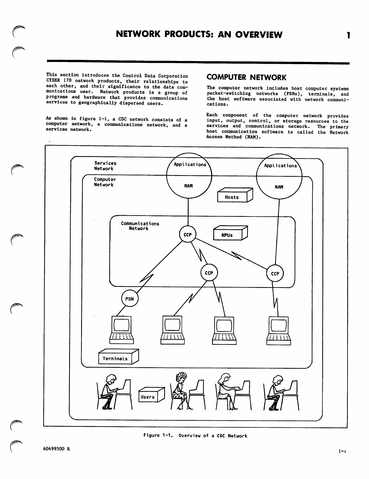
As shown in figure 1-1, a CDC network consists of a
computer network, a communications network, and a
services network.
COMPUTER NETWORK
The computer network includes host computer systems
packet-switching networks (PSNs), terminals, and
the host software associated with network communi
cations .
Each component of the computer network provides
input, output, control, or storage resources to the
services and communications network. The primary
host communication software is called the Network
Access Method (NAM).
/0™B\
Services
Network
Computer
Network
Communications
Network
Figure 1-1. Overview of a CDC Network
60499500 R l-l
COMMUNICATIONS NETWORK
The communications network includes network proc
essing units (NPUs) and the connecting communication
lines needed to transport blocks of data between
host computers and terminals. The primary CDC
softwa re in an NPU is c alled th e Com mun ication s
Control Program (CCP).
The size and complexity of a communications network
varies from a simple network with one local (front-
end) NPU, or a network with one local NPU and one
or more remote NPUs, to a more complex network with
multiple local NPUs and multiple remote NPUs.
Attached to these NPUs are terminal devices, such
as entry/display stations.
Because the communications network minimizes termi
nal type dependency and removes many of the terminal
switching operations from the host, the host can
process data more efficiently.
SERVICES NETWORK
The services network consists of the network appli
cation programs in each host computer and the users
of those programs. Each application program gives
th e terminal u ser or another application a sp ecific
data processing capability.
SOFTWARE COMPONENTS OF
THE NETWORK
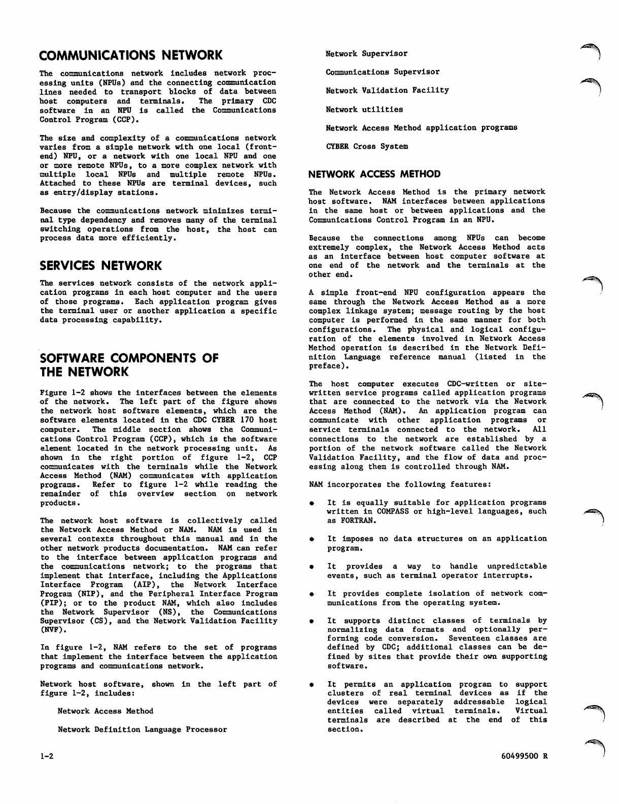
Figure 1-2 shows the interfaces between the elements
of the n e t w o r k. T h e l e f t part of t h e fi g u r e s hows
the network host software elements, which are the
software elements located in the CDC CYBER 170 host
computer. The middle section shows the Communi
cations Control Program (CCP), which is the software
element located in the network processing unit. As
shown in the right portion of figure 1-2, CCP
communicates with the terminals while the Network
Access Method (NAM) communicates with application
p r o g r a m s . R e f e r t o fi g u r e 1 - 2 w h i l e r e a d i n g t h e
remainder of this overview section on network
products.
The network host software is collectively called
the Network Access Method or NAM. NAM is used in
several contexts throughout this manual and in the
other network products documentation. NAM can refer
to the interface between application programs and
the communications network; to the programs that
implement that interface, including the Applications
Interface Program (AIP), the Network Interface
Program (NIP), and the Peripheral Interface Program
(PIP); or to the product NAM, which also includes
the Network Supervisor (NS), the Communications
Supervisor (CS), and the Network Validation Facility
(NVF).
In figure 1-2, NAM refers to the set of programs
that implement the interface between the application
programs and communications network.
Network host software, shown in the left part of
figure 1-2, includes:
Network Access Method
Network Definition Language Processor
1-2
Network Supervisor
Communications Supervisor
Network Validation Facility
Network utilities
Network Access Method application programs
CYBER Cross System
NETWORK ACCESS METHOD
The Network Access Method is the primary network
host software. NAM interfaces between applications
in the same host or between applications and the
Communications Control Program in an NPU.
Because the connections among NPUs can become
extremely complex, the Network Access Method acts
as an interface between host computer software at
one end o f t h e n e t w o r k a n d the terminals a t t h e
other end.
A simple front-end NPU configuration appears the
same through the Network Access Method as a more
complex linkage system; message routing by the host
computer is performed in the same manner for both
configurations. The physical and logical configu
ra tion of t he elements involved in Network Ac cess
Method operation Is described in the Network Defi
nition Language reference manual (listed in the
preface).
The host computer executes CDC-written or site-
written service programs called application programs
that are connected to the network via the Network
Access Method (NAM). An application program can
communicate with other application programs or
service terminals connected to the network. All
connections to the network are established by a
portion of the network software called the Network
Validation Facility, and the flow of data and proc
essing along them is controlled through NAM.
NAM incorporates the following features:
• It is equally suitable for application programs
written in COMPASS or high-level languages, such
as FORTRAN.
e It imposes no data structures on an application
program.
• I t p r o v i d e s a w a y t o h a n d l e u n p r e d i c t a b l e
events, such as terminal operator interrupts.
• It provides complete isolation of network com
munications from the operating system.
• It supports distinct classes of terminals by
normalizing data formats and optionally per
forming code conversion. Seventeen classes are
defined by CDC; additional classes can be de
fined by sites that provide their own supporting
software.
• It permits an application program to support
c l u s t e r s o f r e a l t e r m i n a l d e v i c e s a s i f t h e
devices were separately addressable logical
e n t i t i e s c a l l e d v i r t u a l t e r m i n a l s . V i r t u a l
terminals are described at the end of this
section.
60499500 R
"S
\
3 o o» I -i- Vt 01
o -» I +J o —'
CO -r- -r-
60499500 S 1-3
Basic services provided by NAM include: Network Interface Program
NAM establishes message paths (logical con
nections) between an application program and
terminals or between two applications (provided
both parties have the correct network access
security permissions).
NAM breaks logical connections when asked to by
the application program or the terminal, or when
network conditions make it necessary (for ex
ample, when a network shutdown occurs).
After logical connections have been established,
NAM passes incoming messages to the application,
and accepts and forwards outgoing messages from
the application.
NAM queues incoming messages until the appli
cation program requests them. This allows the
application to service its connections with
terminals and other applications in any desired
order.
NAM provides the application program with its
own set of protocols, making knowledge of de
tailed network protocols unnecessary.
For incoming traffic, NAM allows the application
program to group terminals with similar or re
lated processing needs.
NAM queues outgoing messages to regulate data
flow through the network.
NAM detects inactivity on any interactive data
path and reports the condition to the appli
cation program.
NAM resolves resource contention among appli
cation programs.
An installation option is available to log message
traffic for application program debugging. A second
installation option permits the logging of appli
cation program and message traffic statistics.
NAM consists of four major modules:
Peripheral Interface Program
Network Interface Program
Application Interface Program
Queued Terminal Record Manager
Peripheral Interface Program
The Peripheral Interface Program (PIP) is a periph
eral processor unit program that interfaces the
central processor executed routines of NAM to the
channel-connected local NPUs.
PIP moves blocks of data between the central memory
buffers of NAM and the NPU and reads and writes disk
| fi l e s u s e d b y b a t c h d e v i c e s o r f o r fi l e t r a n s f e r.
PIP also can detect when a local NPU needs initial
izing. If the NPU cannot start its own loading,
P I P r e q u e s t s th e n et w o r k s up e r v i s o r t o lo a d t h e
bootstrap program into the NPU.
1-4
The Network Interface Program (NIP) executes as a
system control point. NIP coordinates the use of
the communications network by all application pro
grams, buffers data between the application programs
and the network, and manages the logical connec
tions .
Each application program can have several connec
tions; each connection is associated with a terminal
device or with another application program. NIP
translates between network addresses and the more
convenient logical addresses that represent the
connection to the application. NIP also establishes
new connections as they are requested and terminates
connections that are no longer needed or that have
failed.
An application can request NAM to convert the data
on a logical connection f r o m t h e n e t w o r k f o r m a t .
Such conversions determine the format and encoding
of characters seen by the application.
Application Interface Program
The Application Interface Program (AIP) is a set of
subprograms and buffers that resides in the appli
cation program's field length and provides an
interface to NIP and the network. This manual is
primarily concerned with the use of AIP.
AIP statements are provided so that the application
program can connect to and disconnect from the net
work. AIP statements also control information
exchange between the application program and NAM
buffers. This information can be data, or it can
be supervisory messages that coordinate the appli
cation's execution with events that have occurred
in the network. NAM might pass a supervisory mes
sage to inform the application of a new connection
that is requesting service, or that a failure has
occurred. In the same way, the application program
uses supervisory messages to communicate with NAM
and the network elements.
Queued Terminal Record Manager
The Queued Terminal Record Manager (QTRM) is a set
of subprograms that resides in the application pro
gram's field length and provides a high level pro
cedural interface to the network. This package
permits indirect use of a subset of AIP's features
by programs with unsophisticated communications
requirements. This utility permits programs to
have a communications interface functionally similar
to their mass storage interface. QTRM is discussed
in section 8 of this book.
NETWORK DEFINITION LANGUAGE
PROCESSOR
Before the network software can route data through
the network and interface to operators for super
vision, the definition of the network configuation
must first be communicated to the software. The
Network Definition Language (NDL) is used to de
scribe this configuration. The Network Definition
La nguage proce ssor ( NDLP), a b atch u tility, t rans
lates this configuration and prepares a network
configuration file (NCF) and a local configuration
file (LCF).
60499500 S
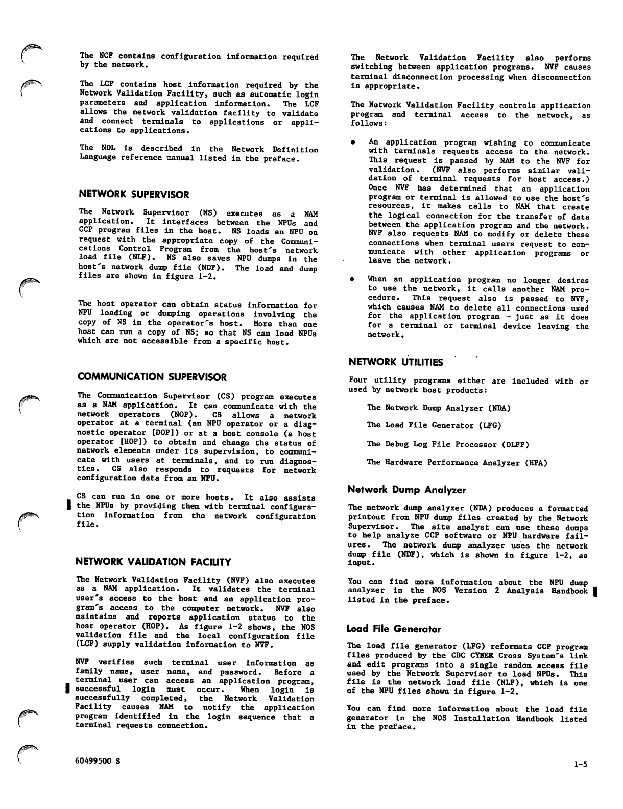
The NCF contains configuration information required
by the network.
The LCF contains host information required by the
Network Validation Facility, such as automatic login
parameters and application information. The LCF
allows the network validation facility to validate
and connect terminals to applications or appli
cations to applications.
The NDL is described in the Network Definition
Language reference manual listed in the preface.
NETWORK SUPERVISOR
The Network Supervisor (NS) executes as a NAM
application. It interfaces between the NPUs and
CCP program files in the host. NS loads an NPU on
request with the appropriate copy of the Communi
cations Control Program from the host's network
load file (NLF). NS also saves NPU dumps in the
host's network dump file (NDF). The load and dump
files are shown in figure 1-2.
The host operator can obtain status information for
NPU loading or dumping operations involving the
copy of NS in the operator's host. More than one
host can run a copy of NS; so that NS can load NPUs
which are not accessible from a specific host.
COMMUNICATION SUPERVISOR
The Communication Supervisor (CS) program executes
as a NAM application. It can communicate with the
n e t w o r k o p e r a t o r s ( N O P ) . C S a l l o w s a n e t w o r k
operator at a terminal (an NPU operator or a diag
nostic operator [DOP]) or at a host console (a host
operator [HOP]) to obtain and change the status of
network elements under its supervision, to communi
cate with users at terminals, and to run diagnos
tics. CS also responds to requests for network
configuration data from an NPU.
CS can run in one or more hosts. It also assists
| the NPUs by providing them with terminal configura
tion information from the network configuration
file.
NETWORK VALIDATION FACILITY
The Network Validation Facility (NVF) also executes
as a NAM application. It validates the terminal
user's access to the host and an application pro
gram's access to the computer network. NVF also
m a i n t a i n s a n d r e p o r t s a p p l i c a t i o n s t a t u s t o t h e
host operator (HOP). As figure 1-2 shows, the NOS
validation file and the local configuration file
(LCF) supply validation information to NVF.
NVF verifies such terminal user information as
family name, user name, and password. Before a
terminal user can access an application program,
| successful login must occur. When login is
successfully completed, the Network Validation
Facility causes NAM to notify the application
program identified in the login sequence that a
terminal requests connection.
The Network Validation Facility also performs
switching between application programs. NVF causes
terminal disconnection processing when disconnection
is appropriate.
The Network Validation Facility controls application
program and terminal access to the network, as
follows:
• An application program wishing to communicate
with terminals requests access to the network.
This request is passed by NAM to the NVF for
validation. (NVF also performs similar vali
d a ti o n o f t e rm i na l r e q u e s t s f o r h o s t a c ce s s. )
Once NVF has determined that an application
program or terminal is allowed to use the host's
resources, it makes calls to NAM that create
the logical connection for the transfer of data
between the application program and the network.
NVF also requests NAM to modify or delete these
connections when terminal users request to com
municate with other application programs or
leave the network.
• When an application program no longer desires
to use the network, it calls another NAM pro
cedure. This request also is passed to NVF,
which causes NAM to delete all connections used
for the application program - just as it does
for a terminal or terminal device leaving the
network.
NETWORK UTILITIES
Four utility programs either are included with or
used by network host products:
The Network Dump Analyzer (NDA)
The Load File Generator (LFG)
The Debug Log File Processor (DLFP)
The Hardware Performance Analyzer (HPA)
Network Dump Analyzer
The network dump analyzer (NDA) produces a formatted
printout from NPU dump files created by the Network
Superv iso r. The sit e ana lys t can use these dumps
to help analyze CCP software or NPU hardware fail
ures. The network dump analyzer uses the network
dump file (NDF), which is shown in figure 1-2, as
input.
You can find more information about the NPU dump
analyzer in the NOS Version 2 Analysis Handbook |
listed in the preface.
Load File Generator
The load file generator (LFG) reformats CCP program
files produced by the CDC CYBER Cross System's link
and edit programs into a single random access file
used by the Network Supervisor to load NPUs. This
file is the network load file (NLF), which is one
of the NPU files shown in figure 1-2.
You can find more information about the load file
generator in the NOS Installation Handbook listed
in the preface.
60499500 S 1-5
Debug Log File Processor
The debug log file processor (DLFP) converts the
debug log file generated by the Application Inter
face Program into a printable report. The program
mer can selectively list logged information through
DLFP directives.
You can find more information about the debug log
file processor in section 6 of this manual.
Hardware Performance Analyzer
A fourth utility program, the hardware performance
analyzer (HPA), is part of the NOS operating system.
This utility program produces reports from infor
mation on the account and error log dayfiles.
Network products software makes statistical, error,
and alarm message entries into these dayfiles.
You can find more information about the hardware
performance analyzer in the HPA reference manual
listed in the preface.
NAM APPLICATION PROGRAMS
The host computer executes CDC-written or site-
written service programs called application programs
that are connected to the network through NAM. An
application program can communicate with other
application programs or terminals connected to the
network.
The CDC-provided NAM application programs are:
Interactive Facility (IAF), which allows you to
create files and to create or execute programs
from a device without using card readers or line
printers. IAF is described in Volumes 1 and 3
of the NOS 2 Reference Set.
CDC CYBER CROSS SYSTEM SOFTWARE
The CDC CYBER Cross System software allows you to
install, modify, and maintain the CCP software. It
is composed of these programs:
PASCAL, which is a compiler patterned after
ALGOL-60. By using PASCAL, you can define tasks
in statements that are processed by the compiler
to yield a variable number of actual program
instructions.
Formatter, which reformats PASCAL output into
an object code format compatible with the com
munications processor macro assembler output
Macro Assembler, which assembles communications
processor macro memory source programs and
pr oduce s relocatable binary outpu t. T he source
programs are written with symbolic machine,
pseudo, and macro instructions.
Micro Assembler, which provides the language
needed to write a micro memory program. This
assembler translates symbolic source program
instructions into object machine instructions.
Link Editor, which accepts object program mod
ules and generates a memory image, suitable for
executing in the 255x NPU.
Autolink utility, which simplifies program
assignment and maximizes the amount of space
assigned to handling buffers.
Expand utility, which includes several hardware
and software variables used to define a CCP load
file for a given NPU configuration.
See the preface for manuals that contain more
information on the CDC CYBER Cross System.
Remote Batch Facility (RBF), which permits you
to enter a job file from a remote card reader
and to receive job output at a remote batch
device. RBF is described in the Remote Ba tch
Facility reference manual.
Transaction Facility (TAF), which permits you
to implement on-line transaction processing
under NOS by writing programs to be used by
terminals. TAF is described in the TAF
reference manual.
Terminal Verification Facility (TVF), which
p r o v i d e s t e s t s yo u c an u s e t o v e r i f y t h a t a n
interactive console is sending and receiving
d a t a c o r r e c t l y. T V F i s d i s c u s s e d i n t h e Te r
minal Interfaces reference manual.
Message Control System (MCS), which allows you
to queue, route, and journal messages between
COBOL programs and terminals. MCS is described
in the Message Control System reference manual.
The queue file transfer facility (QTF), which
a l l o w s y o u t o t r a n s f e r q u e u e fi l e s b e t w e e n
hosts. The use of this feature is described in
the NOS Version 1 Reference Set, Volume 3.
Permanent File Transfer Facility (PTF), which
allows you to transfer permanent files between
waits. The use of this feature is documented
in the NOS Version 2 Reference Set, Volume 3.
NETWORK PROCESSING UNIT
AND COMMUNICATIONS
CONTROL PROGRAM
This subsection discusses the following network
products, which are part of the communications
network and allow a terminal to access the host
computer over communication lines:
The 255x series network processing unit (NPU),
which connects a host to a terminal
The Communications Control Program (CCP), which
is the software in the NPU
The middle portion of figure 1-2 shows the communi
cations network.
NETWORK PROCESSING UNIT
An NPU handles front-end or remote data communica
tions for the CDC CYBER 170 host. The Communica
tions Control Program resides within the NPU.
To understand CCP, you must have a basic under
standing of the hardware on which CCP runs. Refer
to the hardware manuals listed in the preface for a
description of the hardware components of the NPU.
1-6 60499500 S
COMMUNICATIONS CONTROL PROGRAM
The Communications Control Program, which is the
software that executes in the 255x NPUs, consists
of:
Base system software
System autostart module program (SAM-P)
Service module (SVM)
Host Interface Program (HIP)
Terminal Interface Programs (TIPs)
Link Interface Program (LIP)
Block Interface Program (BIP)
In-line and on-line diagnostics
NPU console debugging aids
Performance and statistics programs
Figure 1-3 shows how the major parts of CCP relate
to each other.
Base System Software
The base system software executes programs, allo
cates buffers, handles interrupts, and supports
timing and data structures. It includes:
A system monitor, which controls the allocation
of resources for the communications processor
Timing services, which run those programs or
functions that are executed either periodically
or following a specific time lapse for the
processor
A m u l t i p l e x s u b s y s t e m , w h i c h i n t e r f a c e s w i t h
the 255x multiplexing hardware and performs
character-by-character processing of tasks
Interrupt handler, which controls the transi
tion of the communications processor between
different program interrupt levels
Initialization, which prepares the network for
on-line operation
Structure services, which build and maintain
internal tables used for routing data
Buffer maintenance, which dynamically allocates
memory in multiple buffer sizes for efficient
memory use
Worklist services, which provide logic for 255x
interprogram communication through the use of
w o r k l i s t s
Standard subroutines, which provide support
routines to handle arithmetic conversion, main
tain page registers, and do miscellaneous tasks
System Autostart Module
The system autostart module is an optional set of
hardware and software that begins the loading of
other CCP software from a host.
NPU
Console^
(HostV
SVM Debug
g i n g -
Aids
\HIP BIP
) 1 ixr
TIP
<Tfe SAM-P LIP
Cassette
Unit
ra
Terminals
NPU
Figure 1-3. The Relationship Between the Parts of the
Communications Control Program
60499500 S 1-7 |
Service Module
The service module (SVM) includes network control
functions and interface programs that provide a
common link to other elements of the communications
network. These programs:
Process commands from the host, called service
messages
Control line and terminal configuration
Report and respond to regulation and supervision
changes
Host Interface Program
The Host Interface Program (HIP) provides the soft
ware that links the host and a local NPU over a
channel. The HIP drives the CDC CYBER channel
coupler, transfers data, checks for errors, and
monitors for host failure and recovery.
This list includes only elements supported by re
leased versions of standard CDC network software.
Sites can add site-written Terminal Interface Pro
grams to extend CDC support to additional transmis
si o n p r o t ocols a n d t e r m inal cl a s s e s . T h i s m a nual
is concerned only with the transmission protocols
and terminal classes supported by CDC. Information
in this manual is valid for sites using extensions
to CCP only to the extent that those modifications
emulate the CDC-supported release version of CCP.
Link Interface Program
The Link Interface Program (LIP) transfers infor
mation over a trunk between NPUs.
Block Interface Program
The Block Interface Program (BIP) routes blocks of
data, processes service messages, and processes the
network block protocol.
Terminal Interface Program
The Terminal Interface Program (TIP) is a modular
program that provides protocol support and the con
trol needed to interchange data between a terminal
and other elements of CCP.
The TIP transforms application program data between
its virtual terminal format and the format required
by the transmission protocol and physical charac
teristics of the real terminals. CDC provides TIPs
for these transmission protocols:
• Asynchronous communication lines
• Synchronous communication lines for mode 4
terminals
• Bisynchronous communication lines for terminals
emulating the IBM HASP protocol
• X.25 packet and link level interfaces to a
packet-switching network (PSN) via high-level
data link control (HDLC) synchronous lines
• Bisynchronous communications lines for terminals
emulating the IBM 2780/3780 protocol
• 3270 Bisyn chronous com munications (BSC) oper
ating as multipoint data links
Eighteen classes of real terminals using these
protocols are supported. Each terminal class has
certain physical characteristics associated with
it. These associated characteristics are determined
by a terminal chosen as the archetype for the class,
but can be changed by either the application pro
gram or the terminal operator. The terminal class
i n it i al l y u s ed f o r a g i v e n r e a l t e r mi n al i s de t e r
mined by the way the terminal is configured in the
network configuration file; the network configura
tion file can also be used to change the character
i s t i c s i n i t i a l l y a s s o c i a t e d w i t h t h e t e r m i n a l f r o m
those of the archetype terminal. The association
of characteristics with a terminal is referred to
in networks documentation as terminal definition or
TERMDEF.
The terminal classes and archetype terminals for
each class are listed at the end of this section.
In-Line and On-Line Diagnostics
In-line and on-line diagnostics, which are produced
for the NPU, enable a NOP to isolate communications
line problems. Alarm, CE error, and statistics
service messages are the types of in-line diag
nostics. In-line diagnostics are generated auto
m a t i c a l l y. O n - l i n e d ia g n o s t i c s m u st b e r e q u e s t e d
from the NOP console.
NPU Console Debugging Aids
Debug aids provide test utilities for debugging
programs, taking memory snapshots, and dumping the
NPU during CCP program development or system |
failures.
Performance and Statistics Programs
These programs gather statistics on NPU and indi
vidual line performance, and periodically dispatch
theses statistics to the Communications Supervisor.
THE PACKET SWITCHING
NETWORK (PSN)
The packet switching network (PSN) is a value added
network you may subscribe to either from a CDC or a
foreign vendor who supports the X.25 CCITT recom
mendation (1980). Such networks are alternately
referred to as public data networks (PDNs).
NAM CONCEPTS
NAM is used by both application programs and por
tions of the network software. The features of NAM
permit programs to be written for the following
types of communication applications:
• Time-sharing communication services. A single
program provides this service when it interacts
with each terminal during a given time period. |
The CDC-written Interactive Facility is an
example of this type of application program.
z*^^\
1-8 60499500 S
0^\
• Transaction communication services. A single
program provides this service when it creates a
multi-threading interface for many terminals
using many task routines. Each terminal can
interact with many tasks or programs through
queues maintained by the program providing the
transaction service. The CDC-written Trans
a c ti o n F a ci l i t y i s a n ex a m p l e o f th i s t y pe o f
application program.
• Te l e p r o c e s s i n g c o m m u n i c a t i o n s e r v i c e s . A
single program provides this service when it
interacts with many terminals to perform a
single teleprocessing task for each. No task
queues are required. The CDC-written Terminal
Verification Facility is an example of this
type of application program.
The interactive virtual terminal concept makes it
unnecessary for an application programmer to provide
separate procedures to support differing implemen
t a t i o n s o f o n e f u n c t i o n o n a v a r i e t y of r e a l t e r
minals.
Any console or site-defined device (any device with
a device type of 0 or 12) can be serviced as an
interactive virtual terminal. An interactive
virtual terminal has an input and output device
which sends and receives logical lines of ASCII
characters. These logical lines are transformed
into or from physical lines of characters of the
code set appropriate for the real terminal. This
transformation is performed for the application
program by the Communications Control Program of
the network processing unit servicing the real
terminal.
VIRTUAL TERMINALS
The virtual terminal concept simplifies the proce
dure an application program must perform to service
a terminal.
Device types are used in a request for connection
from a terminal to an application (see section 3
for a discussion o f con nec tio n processin g). Device
types currently defined are listed in table 1-1.
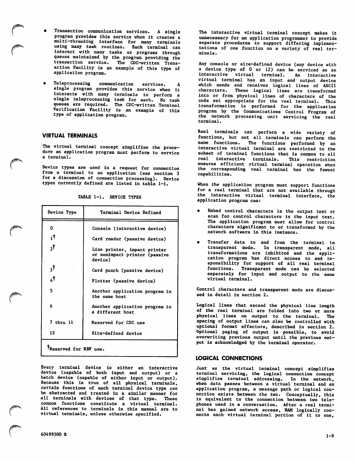
TABLE 1-1. DEVICE TYPES
Device Type Terminal Device Defined
0Console (i nte ractive dev ice )
it Card reader (passive device)
2t Line printer, impact printer
or nonimpact printer (passive
device)
3^ Card punch (passive device)
4t Plotter (passive device)
5Another application program in
the same host
6Another application program in
a different host
7 thru 11 Reserved for CDC use
12 Site-defined device
'Reserved for RBF use.
Every terminal device is either an interactive
device (capable of both input and output) or a
batch device (capable of either input or output).
Because this is true of all physical terminals,
certain functions of each terminal device type can
be abstracted and treated In a similar manner for
all terminals with devices of that type. These
c o m m o n f u n c t i o n s c o n s t i t u t e a v i r t u a l t e r m i n a l .
Al l r e f eren c e s t o t ermi n a l s i n t h is ma n u a l a re t o
virtual terminals, unless otherwise specified.
Real terminals can perform a wide variety of
functions, but not all terminals can perform the
same functions. The functions performed by an
interactive virtual terminal are restricted to the
subset of t erminal functio ns t hat i s common to a ll
real interactive terminals. This restriction
ensures efficient virtual terminal operation when
the corresponding real terminal has the fewest
capabilities.
When the application program must support functions
for a real terminal that are not available through
the interactive virtual terminal interface, the
application program can:
• Embed control characters in the output text or
scan for control characters in the input text.
The application program must allow for control
characters significant to or transformed by the
network software in this instance.
• Transfer data to and from the terminal in
transparent mode. In transparent mode, all
transformations are inhibited and the appli
cation program has direct access to and re
sponsibility for support of all real terminal
functions. Transparent mode can be selected
s e p a r a t e l y f o r i n p u t a n d o u t p u t t o t h e s a m e
virtual terminal.
Control characters and transparent mode are discus
sed in detail in section 2.
Logical lines that exceed the physical line length
of the real terminal are folded into two or more
physical lines on output to the terminal. The
spacing of output lines can also be controlled with
optional format effectors, described in section 2.
Optional paging of output is possible, to avoid
overwriting previous output until the previous out
put is acknowledged by the terminal operator.
LOGICAL CONNECTIONS
Just as the virtual terminal concept simplifies
terminal servicing, the logical connection concept
simplifies terminal addressing. In the network,
when data passes between a virtual terminal and an
application program, a message path or logical con
nection exists between the two. Conceptually, this
is equival e n t t o t h e connection b e t w e e n two tele
phones used in a conversation. After a real termi
nal has gained network access, NAM logically con
nects each virtual terminal portion of it to one,
60499500 R 1-9
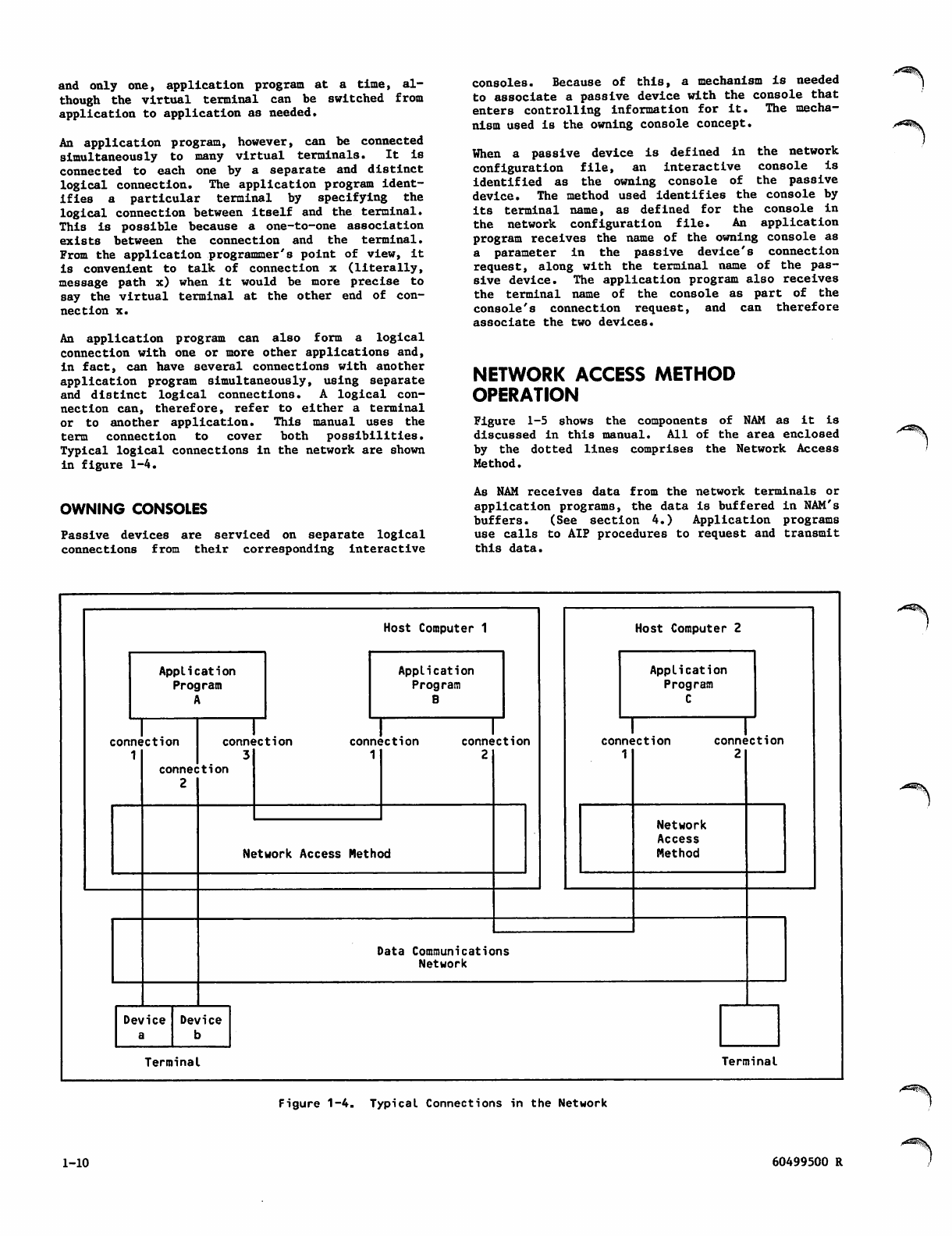
and only one, application program at a time, al
though the virtual terminal can be switched from
application to application as needed.
An application program, however, can be connected
simultaneously to many virtual terminals. It is
connected to each one by a separate and distinct
logical connection. The application program ident
i fi e s a p a r t i c u l a r t e r m i n a l b y s p e c i f y i n g t h e
logical connection between itself and the terminal.
This is possible because a one-to-one association
exists between the connection and the terminal.
From the application programmer's point of view, it
is convenient to talk of connection x (literally,
message path x) when it would be more precise to
say the virtual terminal at the other end of con
nection x.
An application program can also form a logical
connection with one or more other applications and,
in fact, can have several connections with another
application program simultaneously, using separate
and distinct logical connections. A logical con
n e c ti o n c an , t he r e fo r e , r ef e r to e i t he r a t erm i na l
or to another application. This manual uses the
term connection to cover both possibilities.
Typical logical connections in the network are shown
in figure 1-4.
OWNING CONSOLES
Passive devices are serviced on separate logical
c o n n e c t i o n s f r o m t h e i r c o r r e s p o n d i n g i n t e r a c t i v e
consoles. Because of this, a mechanism is needed
to associate a passive device with the console that
e n t e rs c on t r o l l in g in f o r ma t i o n f o r i t . T h e m e c h a
nism used is the owning console concept.
When a passive device is defined in the network
configuration file, an interactive console is
identified as the owning console of the passive
device. The method used identifies the console by
i t s t e rm i n a l n a me , as d e fi n e d f o r t h e c on s o l e i n
the network configuration file. An application
program receives the name of the owning console as
a parameter in the passive device's connection
request, along with the terminal name of the pas
sive device. The application program also receives
the terminal name of the console as part of the
console's connection request, and can therefore
associate the two devices.
NETWORK ACCESS METHOD
OPERATION
Figure 1-5 shows the components of NAM as it is
discussed in this manual. All of the area enclosed
by the dott ed l ines compris es t he N etwo rk Acc ess
Method.
As NAM receives data from the network terminals or
application programs, the data is buffered in NAM's
buffers. (See section 4.) Application programs
use calls to AIP procedures to request and transmit
this data.
Host Computer 1
Application
Program
A
connection
1
Application
Program
B
connection
3
connection
2
Device
a
connection
1
connection
2
Network Access Method
Host Computer 2
Application
Program
C
connection
1
connection
2
Network
Access
Method
Data Communications
Network
Device
b
Ter mina l Terminal
Figure 1-4. Typical Connections in the Network
1-10 60499500 R
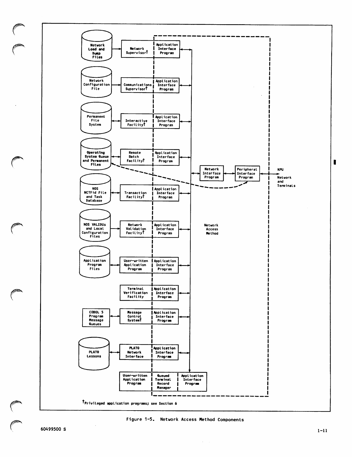
Network
Supervisor!
Communications
Supervisort
Interactive
Facilityt
Operating
System Queue
and Permanent
Files
Remote
Batch
F a c i l i t y t
Transaction
Facilityt
NOS VALIDUs
and Local
Configuration
Files
Terminal
Verification
F a c i l i t y
COBOL 5
Program
Message
Queues
Message
Control
Systemt
Application
Interface
Program
Application
Interface
Program
Application
Interface
Prog ram
Application
Interface
Program
Application
Interface
Program
Application
Interface
Program
Application
Interface
Program
Network
Interface
Program
Peripheral
Interface
Program
Network
Access
Method
NPU
■»•
Network
and
Terminals
'Privileged application programs; see Section 6
Figure 1-5. Network Access Method Components
60499500 S 1-11
Inbound data from an interactive virtual terminal
or another application is placed, unmodified, in
NIP's central memory buffers by PIP. These buffers
form an input queue associated with the logical
connection that originated the data. Data is
removed from this input queue when application pro
gram AIP statements request input from the logical
connection. T h e d a t a c a n b e t r a n s l a t e d a n d c o n
v e r t ed b y N I P f r om A S CII t o d i sp l a y c od e i f t he
application program has requested such conversion;
transparent data, as described in section 2, is
neither edited nor translated. NIP places the
t r a n s l a t e d o r t r a n s p a r e n t d a t a i n a d a t a b u f f e r
within the application program's field length.
This data buffer is established and maintained by
the application program.
O u t p u t f o r a n i n t e r a c t i v e v i r t u a l t e r m i n a l o r
another application is handled in the reverse
manner. The application program calls an AIP pro
cedure to send data on a logical connection. The
data is transferred from the program's field length
to an output queue within NIP's field length. From
th ere , it is p laced in o ne of P IP's o utput buffe rs,
according to its priority as a supervisory message,
low priority data, or high priority data, and to
its destination. Code conversion and translation,
if necessary, is done by PIP.
The files shown in figure 1-5 are maintained by
code independent of NAM. Named files in the figure
are discussed briefly in various portions of this
manual.
APPLICATION PROGRAM CONCEPTS
NAM requires an application program to reside at a
separate operating system control point. This
program contains calls to the AIP routines listed
in appendix D and described in sections 5 and 7.
These calls can be direct, or indirect through the
Queued Terminal Record Manager.
An application program begins accessing the network
by calling NETON. It transmits data through the
network by calling NETPUT or NETPUTF. It receives
data through the network by calling NETGET, NETGETL,
NETGETF, or NETGTFL.
An application program must contain buffers for
transmitted or received data. These buffers can be
either unified or fragmented central memory areas.
One buffer can be used for all logical connections,
or many unified buffers or fragments of a buffer
can be used for each logical connection.
An application program sends instructions to the
network software and receives operational infor
mation from the network software through supervisory
messages, as described in section 3. It must
contain procedures to formulate or process these
messages.
An application program can contain procedures that
optimize its use of central memory and the control
processor. AIP routines can make the program avail
able for rollout when the program has no data to
process (NETWAIT), or allow the program to perform
non network processing while waiting for completion
of a network processing task (NETSETP and NETCHEK).
An application program can compile statistics about
its functioning (NETSTC) that can be examined for I
application tuning. It can also cause trace dumps |
o f i t s n e t w o r k t r a f fi c ( N E T D B G ) . T h e t r a c e fi l e
generated can be dynamically disposed for storage,
processing (NETREL), and application debugging. |
An application program must contain a call to NETOFF
to terminate its access to the network. Application
programs using the optional code controlled by
NETDBG or NETSTC must also dispose of the local
files created by this code. (See section 6.)
CONNECTION PROCESSING FLOW
The functions performed by NAM and other software
described previously in this section can best be
summarized by tracing the job processing involved
for a single terminal and a single site-written
application program. Figure 1-6 is a generalized
version of this processing flow. Time elapses in
the figure from top to bottom. Program processing
begins from the left, terminal actions begin from
t h e r i g h t . D o t t e d l i n e s s e p a r a t e f u n c t i o n s f o r
each entity. When the boxes formed by solid or
dotted lines are aligned, the functions of the
entities involved are related. Actions for a batch
device (a passive device) differ from those shown
for an interactive terminal; the first two and last
three terminal actions are performed internally by
t h e N et w o rk Va li d a ti o n Fac i li t y f or b a t ch d e vi c e s
based upon login information supplied for the
device's owning console.
SUPPORTED TERMINALS
The network software, and therefore an application
program, can service any real terminal compatible
with one of the terminal classes listed in table
1-2. Each terminal class is identified by its
terminal class number, described in section 3 under
Managing Logical Connections. All terminal classes
are supported by the interactive virtual terminal
interface. When a mnemonic appears in table 1-2,
it indicates the archetype terminal supported for
the given terminal class and device type.
The archetype mnemonics are not used by the appli
c a t i o n p r o g r a m i n a n y f o r m ; t h e a r c h e t y p e s a r e
descr i b ed in m o r e detail i n t he Netwo r k Definiti o n
Language reference manual, where they are identified
by the same mnemonics. (See the preface.)
Site-modified versions of the network software can
service terminals in terminal classes other than
those listed. This manual applies only to support
of the terminal classes defined by CDC. Content of
this manual can be valid for site-defined terminal
classes; CDC is not responsible for deviations from
this manual attributable to support of site-defined
terminal classes.
1-12 60499500 S
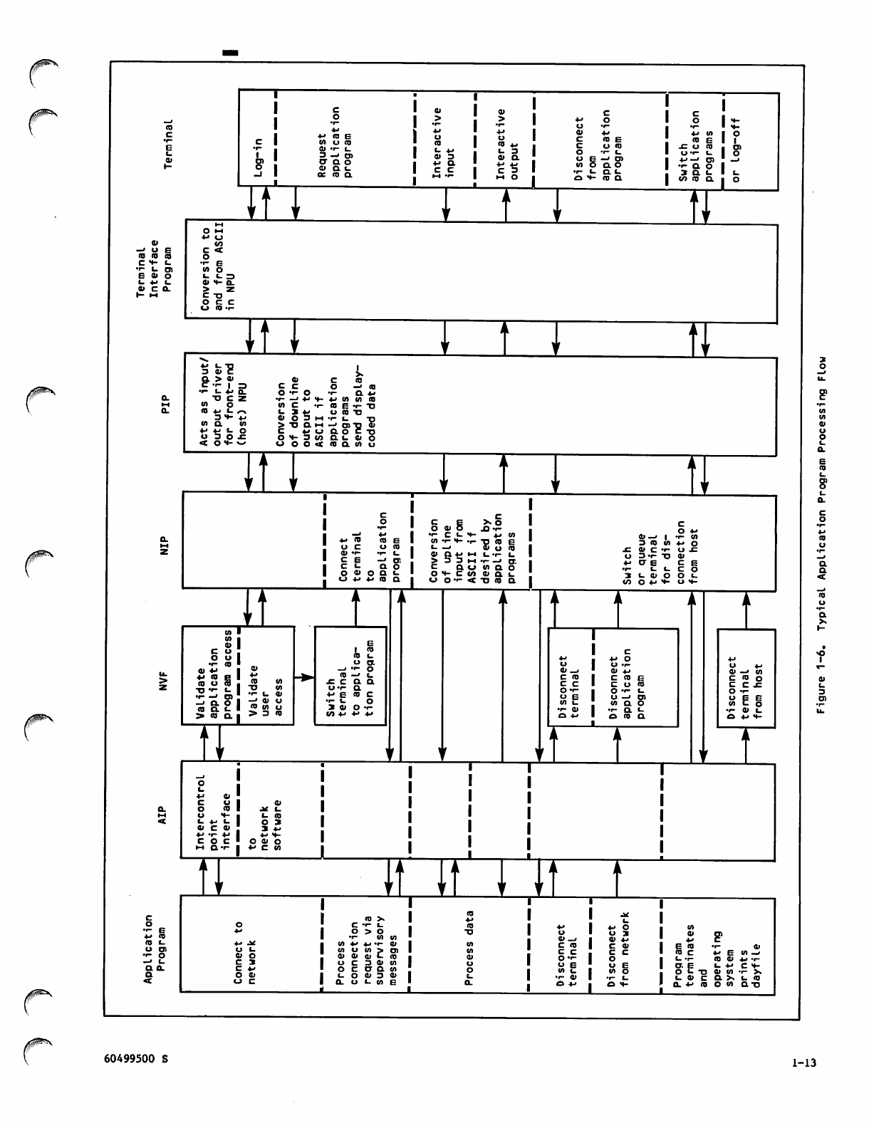
4->
4-» C O E
OT O C D
0) • r - I .
3—» o>
O- a o
a> a t .
Of co a.
I £
IT I
ai 91
>>■M
' O
+j 4-» 1 * 4-»
1 c C D E
CD 4-> ■ c
»- 4-» t - 3 • r - L .
0 ) 3 a i a f= — ' O )
4 - > C L ■cl S OT ao
t_ a «-
H H O • f - cd a
o I • « -
• I - t t -
4 - > O T I O
<0 G I I
£ U 1 0 | Ql
O ' l - t - I O
•*-'—' o) ! -j
• • - a o I
3 a c - I i _
CO CD O. ■ O
o •-•
• M « J
91 tO
— ' U C <
CO CO CO
C H - l_ • r - e
■1- l_ O) O T O
E 9 1 « - « - 3
t - f L. a> m- o.
« C a. > z
1 - I H C T J
o c c
O ( 0 - r -
3 cj* e
a > 9i
C - r - | = a> C C D
c c O — ' C O
T U + > 1 O t- o
a. T J C Z •r- —> 4- > •«- 4 J O T 0 3 C O
IH O T C > r -
a. I S V L n l > 3 4 - O C O T J
3H- 4-> 9 1 O 3 I H
— ' O > " 0 *
ft O C TJ
W D . O T > " O Q H
4 - > £ J f - O
U 3 O f C 4 - < C J
OH-3W a i. a> o
<OVw
j0X$£t*\
n~i
I
■M CO CO E
u c o c o
91 ••- -r- l_
C E - » O l
c « - a o
O O i o Q ( -
u 4-> 4-> co a
O U I
••- co ■ „,
« S ' m
o cS , ™
C O Q . I ^ 3
CD I_
O CT.
_. •■- O
CO —' «_
f c a a
O T O .
4-> E «0 C
• i - t o
3 0 > O -r-
</J 4-> 4J 4->
a> 6 +s OT
E
c
o -
••- C - -
OT -i- H- -r- TJ
t - _ . £ _
a* a. v «h i_ -r- t_
> 3 3 ih i- —» ct.
c a « _ > w a o
o h - c t n u a l
o o f « t t j c o a
O 4-
01—» | i- OT
3 10 OT 4-> O
f a > c f - o j c
o 3 «i- tj ai
4 - > O - E C E
•i- (.CCO
3 ( - 0 > O O L .
l/> O 4-> H- O •»-
f_ 4-> <- I
91 C 91 I
V T V I
c o c ■
••- e 4->
4-> CD
C D t _ 4 - > . *
U C T > U i -
• i - o 9 1 O
—> C_ C 3
a o_ C 4 -
aO 0 )
co x
c ••- «-
o > o
1 - 1 0 O T
OT *■> *J 'i- 01
OT O OT > Ol
CU 01 91 t- CO
U C 3 O l O T
o c ct a OT
i_ O 91 3 a>
a. u t- ca e
CT)
a>_j
c CO
c c
O'l-
O E
OT U
•i- a>a , I
4-> ■
4-> O
O • (-
0) 4-<
C C D E
C O C O
O f - i -
O —' O)
O T Q O
•i- a. c
e» co a
ai —i ot
C C O o
c c .c
O •! -
O E E
W C o
T 0 1 L
Ct 4-> H-
LTTI
4-> O
U 3
0) *->
I *
co c 4 - > E OT —>
i_ •!- co o> 4-> ••-
O. E t_ 4-> c *-
O I - - 0 01 OT • i - X
l _ o > C a x U C O
a. 4- co O " 1 Q T J
60499500 S 1-13
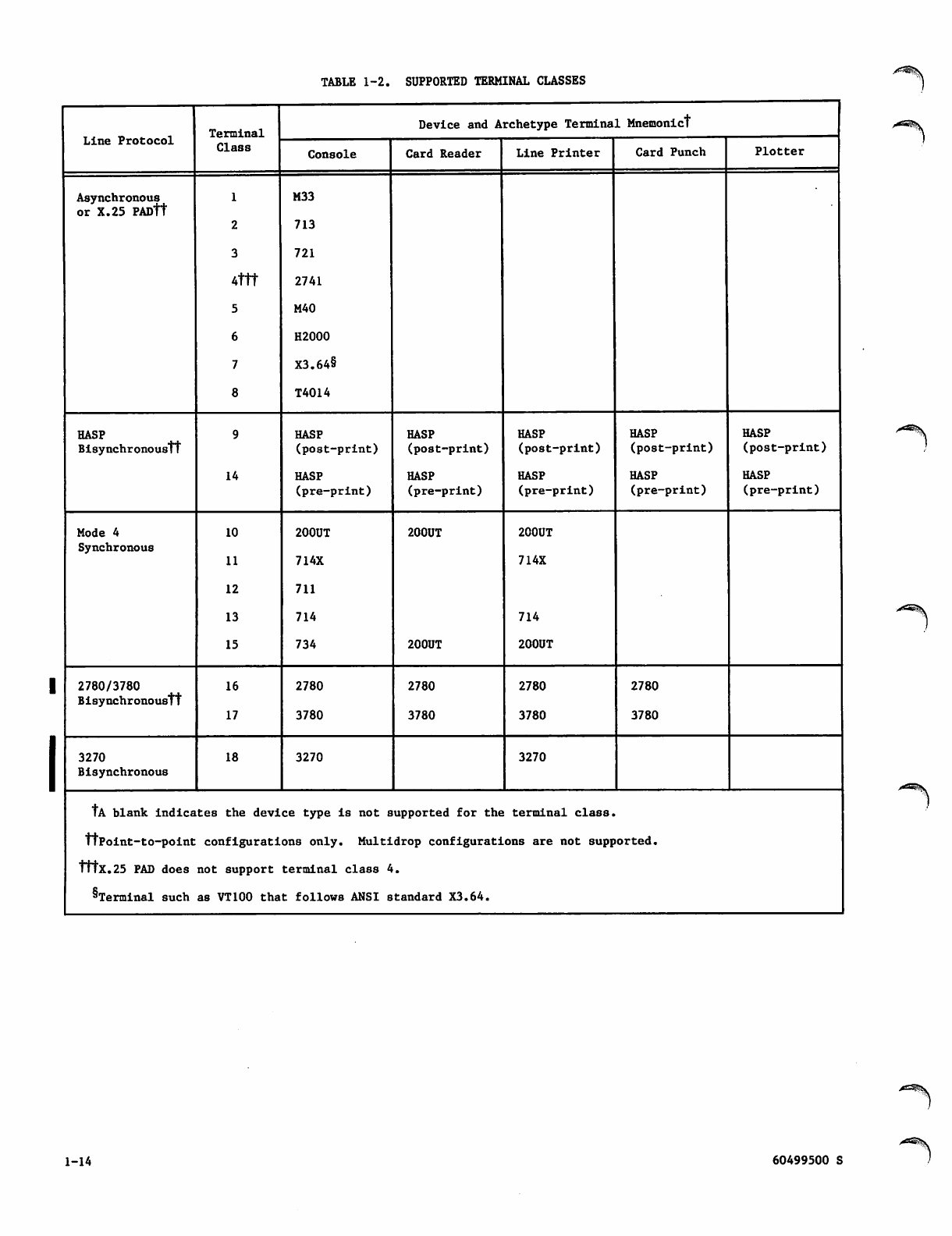
TABLE 1-2. SUPPORTED TERMINAL CLASSES
Line Protocol Terminal
Class
Device and Archetype Terminal Mnemonic!
Console Card Reader Lin e Print er Card Punch Plotter
Asynchronous
or X.25 PADtt
4ttt
5
6
7
8
M33
713
721
2741
M40
H2000
X3.64§
T4014
HASP
Bisynchronous!!
14
HASP
( p o s t - p r i n t )
HASP
(pre-print)
HASP
(post-print)
HASP
(pre-print)
HASP
( p o s t - p r i n t )
HASP
(pre-print)
HASP
( p o s t - p r i n t )
HASP
(pre-print)
HASP
(post-print)
HASP
(pre-print)
Mode 4
Synchronous
10
11
12
13
15
200UT
714X
711
714
734
200UT
200UT
200UT
714X
714
200UT
2780/3780
BisynchronousTt
16
17
2780
3780
2780
3780
2780
3780
2780
3780
3270
Bisynchronous
18 3270 3270
!A blank indicates the device type is not supported for the terminal class,
ttpoint-to-point configurations only. Multidrop configurations are not supported.
1 MX.25 PAD does not support terminal class 4.
^Terminal such as VT100 that follows ANSI standard X3.64.
1-14 60499500 S
/gP^V INFORMATION PROTOCOLS
This section describes the protocols governing
information exchanged for communication between the
Network Access Method (NAM) and each application
program, and between application programs and their
connections. The first portion of this section
defines the terms and concepts needed to understand
the description of information content in the
remainder of this section.
You should remember that parts of the network soft
ware are written as application programs and also
use these protocols. Some of the features and
options discussed in this and subsequent sections,
therefore, do not necessarily apply to site-written
application programs; such information is indicated
where it is described.
INFORMATION FLOW
Information flow in the network is defined from the
viewpoint of the host computer. Information coming
to t h e h o s t i s s a id t o b e t ravel i n g u p line; I n f o r
mation moving away from the host is said to be
traveling downline.
Information flow within a host computer is defined
from the viewpoint of a network application program.
Information coming to the application is said to be
traveling upline; information moving away from the
application is said to be traveling downline.
STRUCTURE PROTOCOLS
The network software uses structure protocols of
two types:
A logical protocol based on the concept of a
message
A physical protocol based on various definitions
of a block of data
The conditions that create a logical message and the
conventions governing the subdivision of messages
are influenced by the physical structure protocols
the network uses. The events involved in actually
creating a message are described later in this
section under the headings Interactive Terminal
I n p u t C o n c e p t s a n d I n t e r a c t i v e Te r m i n a l O u t p u t
Concepts.
PHYSICAL PROTOCOLS AND NETWORK
BLOCKS
Information exchanged with the network is either:
Data of no significance to the network software
Control information of significance only to the
network software
Exchanges of control information and data between
application programs, the network software, and a
terminal user occur in logical messages comprising
o n e o r m o r e p h y s i c a l n e t w o r k b l o c k s . A n e t w o r k
blo ck i s a phy sica l sub divi sion of a l ogic al entity.
A n e twork b l ock is a g rouping o f i nformat i o n with
known and controllable boundary conditions, such as
length, completeness of the unit of communication,
and so for t h . O t h e r n e t w o r k d o cumentation refers
to network blocks as network data blocks; this man
ual uses the term data block only when referring to
network blocks that do not contain control infor
mation.
Information exchanges between network processing
units and host computers or between application
programs use this physical structure protocol.
Such exchanges occur in single network blocks.
Information exchanges between network processing
units use a different physical structure protocol.
Such exchanges occur in sets of character and con
trol bytes called frames. The relationship of a
frame to a network block is not significant to an
application programmer; frames are not discussed in
this section.
Information exchanges between network processing
units and terminal devices use a third physical
structure protocol. Such exchanges occur in sets
of c h a racter a nd contr o l b ytes c a lled t r a n smissi o n
blocks.
Information exchanged between a network processing
unit and a public data network use packets as the
p h ys i ca l s t r uc t ur e p r o t o c ol . W h e n t h e a p p l i c a t i on
communicates with a terminal or other CDC host
applications, the relationship of a packet to a
network block is not significant to an application
programmer. Therefore, this relationship is not
discussed in this section.
However, the relationship of a packet to a network
block may be significant if the application is com
municating with a foreign host's application. The
mapping of network blocks into the X.25 protocol is
discussed in the Communications Control Program
Internal Maintenance Specifications.
LOGICAL PROTOCOL AND PHYSICAL
BLOCKS
Upline and downline information within the host and
NPUs is always grouped into physical network blocks.
Network data blocks are grouped into logical mes
sages. Messages exchanged between an NPU and a
device can also be grouped into physical trans
mission blocks of one or more logical messages.
Figure 2-1 shows these concepts.
60499500 S 2-1
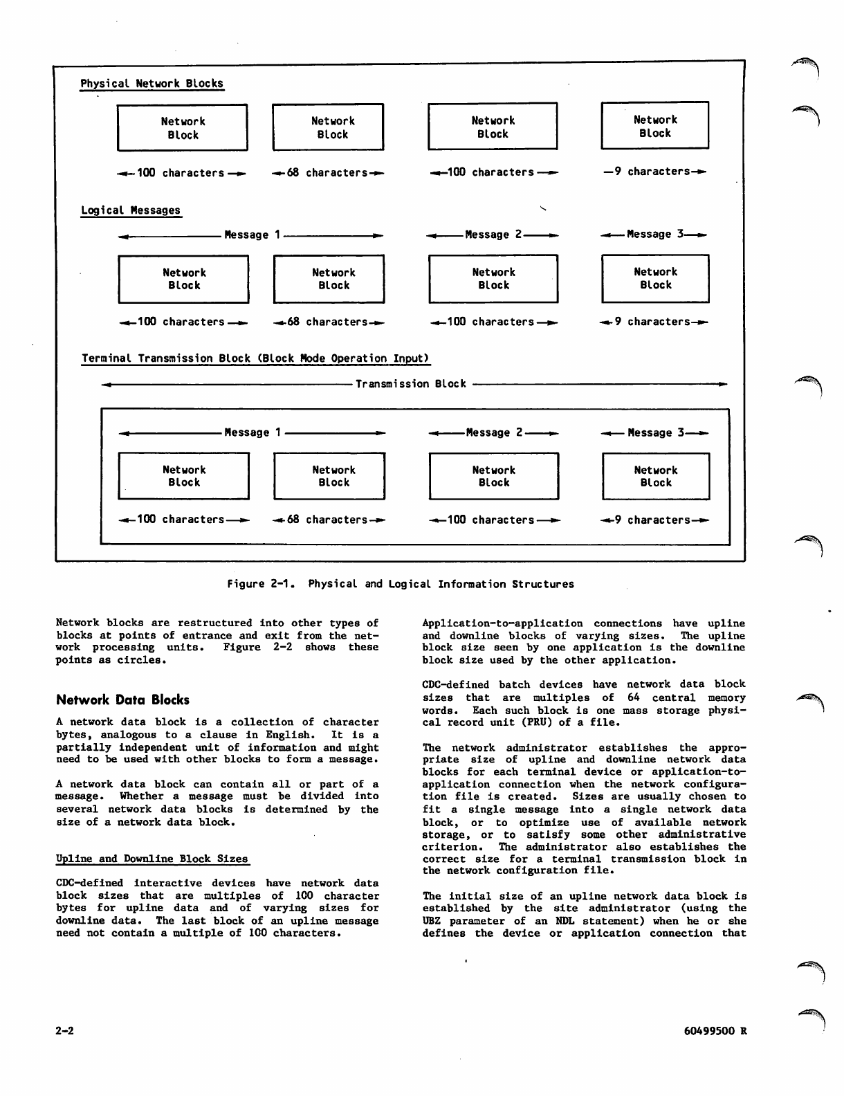
Physical Network Blocks
Network
Block
Network
Block
Network
Block
Network
Block
-•- 100 c haracte rs -•-68 characters-*- -•-100 characters —9 characters-**
Logical Messages
Network
Block Network
Block Network
Block Network
Block
-4-100 characters—»> -•-68 characters-*- -•-100 characters—%*■••9 characters-*-
Terminal Transmission Block (Block Mode Operation Input)
— Transmission Block
- * M e s s a g e -» Message 2 *■ ■+— Message 3—**■
Network
Block Network
Block Network
Block Network
Block
-•-100 characters—*- «*o8 characters-*- -•-100 characters—*■-*-9 characters-*-
Figure 2-1. Physical and Logical Information Structures
Network blocks are restructured into other types of
blocks at points of entrance and exit from the net
work processing units. Figure 2-2 shows these
points as circles.
Network Data Blocks
A network data block is a collection of character
bytes, analogous to a clause in English. It is a
partially independent unit of information and might
need to be used with other blocks to form a message.
A network data block can contain all or part of a
message. Whether a message must be divided into
several network data blocks is determined by the
size of a network data block.
Upline and Downline Block Sizes
CDC-defined interactive devices have network data
block sizes that are multiples of 100 character
b y t e s f o r u p l i n e d a t a a n d o f v a r y i n g s i z e s f o r
downline data. The last block of an upline message
need not contain a multiple of 100 characters.
Application-to-application connections have upline
and downline blocks of varying sizes. The upline
block size seen by one application is the downline
block size used by the other application.
CDC-defined batch devices have network data block
size8 that are multiples of 64 central memory
words. Each such block is one mass storage physi
cal record unit (PRU) of a file.
The network administrator establishes the appro
priate size of upline and downline network data
blocks for each terminal device or application-to-
application connection when the network configura
t i o n fi l e i s c r e a t e d . S i z e s a r e u s u a l l y c h os e n t o
fit a single message into a single network data
block, or to optimize use of available network
storage, or to satisfy some other administrative
criterion. The administrator also establishes the
c o rr e ct s i z e f or a t er m i n a l t r an s m i s s i o n b l o c k in
the network configuration file.
The initial size of an upline network data block is
established by the site administrator (using the
UBZ parameter of an NDL statement) when he or she
defines the device or application connection that
2-2 60499500 R
^=^JV
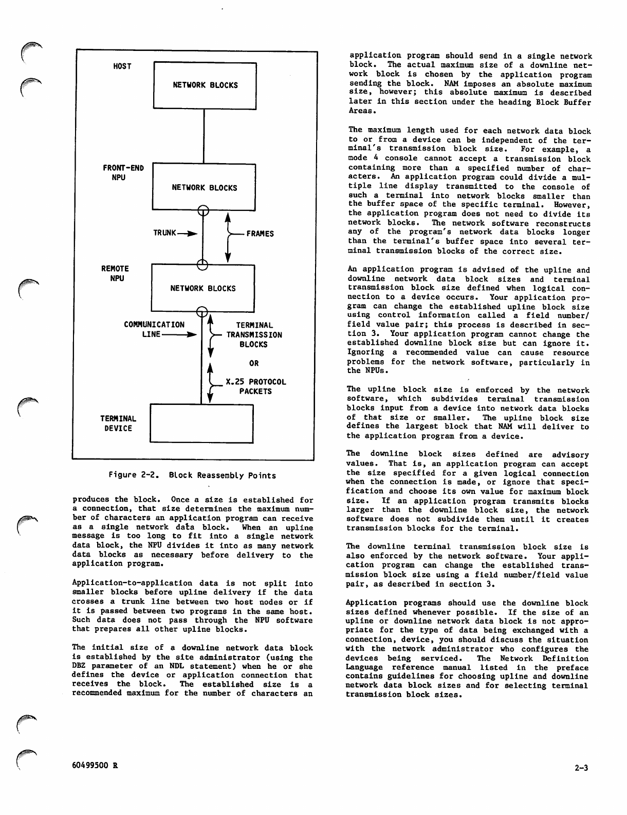
0^*^
HOST
NETWORK BLOCKS
FRONT-END
NPU
NETWORK BLOCKS
©-
TRUNK-
REMOTE
NPU
■e
FRAMES
NETWORK BLOCKS
8:
COMMUNICATION
LINE ▶
TERMINAL
DEVICE
J-
TERMINAL
TRANSMISSION
BLOCKS
OR
X.25 PROTOCOL
PACKETS
Figure 2-2. Block Reassembly Points
produces the block. Once a size is established for
a connection, that size determines the maximum num
ber of characters an application program can receive
as a 8ingle network data block. When an upline
message is too long to fit into a single network
data block, the NPU divides it into as many network
data blocks as necessary before delivery to the
application program.
Application-to-application data is not split into
smaller blocks before upline delivery if the data
crosses a trunk line between two host nodes or if
it is passed between two programs in the same host.
Such data does not pass through the NPU software
that prepares all other upline blocks.
The initial size of a downline network data block
is established by the site administrator (using the
DBZ parameter of an NDL statement) when he or she
defines the device or application connection that
receives the block. The established size is a
recommended maximum for the number of characters an
application program should send in a single network
block. The actual maximum size of a downline net
work block is chosen by the application program
sending the block. NAM imposes an absolute maximum
size, however; this absolute maximum is described
later in this section under the heading Block Buffer
Areas.
The maximum length used for each network data block
to or from a device can be independent of the ter
minal's transmission block size. For example, a
mode 4 console cannot accept a transmission block
containing more than a specified number of char
acters. An application program could divide a mul
tiple line display transmitted to the console of
such a terminal into network blocks smaller than
the buffer space of the specific terminal. However,
the application program does not need to divide its
network blocks. The network software reconstructs
any of the program's network data blocks longer
than the terminal's buffer space into several ter
minal transmission blocks of the correct size.
An application program is advised of the upline and
downline network data block sizes and terminal
transmission block size defined when logical con
nection to a device occurs. Your application pro
gr am can cha nge the established upl ine block size
using control information called a field number/
field value pair; this process is described in sec
tion 3. Your application program cannot change the
established downline block size but can ignore it.
Ignoring a recommended value can cause resource
problems for the network software, particularly in
the NPUs.
The upline block size is enforced by the network
s o f t w a r e , w h i c h s u b d i v i d e s t e r m i n a l t r a n s m i s s i o n
blocks input from a device into network data blocks
of that size or smaller. The upline block size
defines the largest block that NAM will deliver to
the application program from a device.
T h e d o w n l i n e b l o c k s i z e s d e fi n e d a r e a d v i s o r y
values. That is, an application program can accept
the size specified for a given logical connection
when the connection is made, or ignore that speci
fication and choose its own value for maximum block
size. If an application program transmits blocks
larger than the downline block size, the network
software does not subdivide them until it creates
transmission blocks for the terminal.
The downline terminal transmission block size is
also enforced by the network software. Your appli
cation program can change the established trans
mis sion bloc k siz e using a fi eld n umbe r/fi eld v alue
pair, as described in section 3.
Application programs should use the downline block
sizes defined whenever possible. If the size of an
upline or downline network data block is not appro
priate for the type of data being exchanged with a
connection, device, you should discuss the situation
with the network administrator who configures the
devices being serviced. The Network Definition
Language reference manual listed in the preface
contains guidelines for choosing upline and downline
network data block sizes and for selecting terminal
transmission block sizes.
60499500 R 2-3
Block Limits
Temporary network block storage (queuing) occurs
for upline and downline traffic at several points
In the network. The network adminstrator controls
the storage space required by controlling the net
work data block size and the number of blocks queued
in each direction.
The number of blocks queued depends on several
Network Definition Language (NDL) statement param
eters. One of those parameters, the ABL parameter,
establishes the application block limit. Another
NDL statement parameter, the UBL parameter, estab
lishes the upline block limit. The upline block
limit determines the number of upline blocks NAM
queues for your program before rejecting further
input.
The upline block limit can be changed by the appli
cation program, using control information called a
field number/field value pair. This process is
described in section 3.
The application block limit is another device or
application connection configuration parameter
received by an application program (as the abl
field value) when logical connection occurs. Your
a p pl i ca t i o n pr o gr a m c a nn o t s e n d m o r e t ha n t h a t
number of downline blocks for queuing within the
network. The use of the application block limit is
described in section 3 as part of the data flow
co n t r o l d escrip t i o n .
Transmission Blocks
Terminals send or receive data in physical groupings
of character bytes; these groupings are called
transmission blocks. The size of a downline trans
mis s ion b lock for a s peci fi c devi ce is a lso e stab
lished by the network administrator (using the XBZ
parameter o f a n N D L s t a tement). T h e value used
might be dictated by hardware requirements.
Transmission blocks exchanged with X.25 devices are
called packets and have different size and protocol
content requirements than transmission blocks
exchanged directly with a terminal. The network
administrator can control some of the character
istics of packets.
During upline transmissions from a device, the NPU
reassembles the terminal's transmission block into
network blocks. Each transmission block from a
CDC-defined batch device can contain part of a
single message, all of a single message, or several
messages. Each transmission block from a CDC-
defined console device can contain all of a single
message, or several messages.
During downline transmissions, the NPU resassembles
network blocks into terminal transmission blocks.
This conversion is done so that the application
program need not be concerned that output is
delivered in appropriately sized transmission
blocks when the terminal cannot process blocks
larger than a maximum size. Each transmission
block can contain part of a single message or all
of a single message; downline transmission blocks
do not contain more than one message.
INTERACTIVE TERMINAL INPUT
CONCEPTS
An interactive device can send or receive data in
two modes:
Normalized mode
Transparent mode
The significance o f these data modes is described
later in this section under Interactive Virtual
Terminal Data. The following discussion does not
apply to transparent mode data.
In normalized mode, an interactive device transmits
logical lines of data. Each logical line is analo
gous to an English sentence. It is a complete unit
of information.
The device can transmit these lines one at a time,
or in sets. It therefore can us e o n e o f t w o p o s
sible transmission modes.
If the device can transmit only one character or
one logical line in each transmission block, it is
operating in line mode. If the device can transmit
more than one logical line in a transmission block,
it is operating in block mode.
X.25 devices (terminal classes 1 through 3 and 5
through 8), HASP and 2780/3780 devices (terminal
classes 9, 14, 16, 17, and 18) always operate in
line mode. Mode 4 devices (terminal classes 10
through 13 and 15) always operate in block mode.
Only devices in terminal classes 1, 2, and 5
through 8 can operate in both modes.
Line Mode Operation
From a terminal user's viewpoint, transmitting a
single logical line at a time is a buffered line
mode form of input. Buffered line mode allows the
user to select either character-by-character or
line-by-line transmission (some devices have
switches to select either option) without distinc
tion. Each logical line is terminated by an end-
o f -l i n e i n d i c a to r ; t h is i nd i c a t o r m i g ht a l s o t r a ns
mit the line from the terminal, if the terminal
buffers lines of input. Each logical line becomes
a separate network message when the NPU receives it.
When the NPU is told that an interactive device is
operating in line mode, the NPU performs line turn
around for it. When a message is sent upline in
this mode, the NPU begins to send any downline data
available for the device. That is, output is
allowed after each logical line of input. (Refer
to the KB option for the IN command, described in
section 3.)
Block Mode Operation
Some devices can transmit many logical lines in a
single transmission block. (The terminal user
sometimes can select or override this condition with
a BLOCK or BATCH mode switch on the device.) Such
devices are called block mode terminals. Mode 4
devices, for example, are always treated as block
mode devices.
/-*^%.
2-4 60499500 S
Block mode terminals group logical lines in the
t e r m i n a l u n t i l t h e t r a n s m i s s i o n k e y i s p r e s s e d ;
these groups reach the network software as a single
tra nsmissi on blo ck. T he network soft ware forw ards
each message to the application program as a sepa
rate transmission; the effect resembles typeahead
entries from line mode terminals.
Each logical line within the input transmission
block ends with an end-of-line indicator. Each
transmission block is terminated by an end-of-block
indicator.
Whether each logical line in a transmission block
becomes a separate message or each transmission
block becomes a single message is initially deter
mined by the network administrator through the
device definition in the network configuration
file. Your application program or the terminal
user can change that mode (refer to the EL and EB
options of the EB command, described in section 3).
When the NPU is told an interactive device is oper
ating in block mode, the NPU does not perform line
turnaround for it until all of its current trans
mission block is received. When the terminal is
serviced in this mode, the NPU holds all downline
data available for the device until it detects the
end-of-block indicator. That is, output is allowed
after each logical line of input only if each logi
cal line of input is transmitted in a separate
block. (Refer to the BK and PT options for the IN
command, described in section 3.)
A terminal might have a block transmission key that
does not generate the end-of-block indicator. When
the block transmission key generates the end-of-line
ind i c a t o r, t h e t e rminal i s o p e r a t ing i n l i ne m o de,
and logical lines are transmitted from the terminal
as separate messages.
When the transmission key does not generate either
the currently defined end-of-line indicator or the
currently defined end-of-block indicator, the ter
minal user must be aware of the distinction. If
possible, the user should change the end-of-block
indicator to the code actually sent by the key. If
not possible, if the code sent by the key cannot be
determined, or if the key does not generate a code,
then the user must enter an indicator as the last
data character before pressing the transmission
key. These possible conditions exist:
If the transmission key is pressed immediately
aft e r press ing t h e key t hat g e nerat e s an e n d-
of-line indicator, a message is generated. This
result Is the same as if the device was opera
ting in line mode and the key generating an
end-of-line indicator had been pressed, or as
if the key generating an end-of-block indicator
had been pressed.
If the transmission key is pressed immediately
aft e r press ing t h e key t hat g e nerat e s an e n d-
o f - b l o c k i n d i c a t o r, a m e s s a g e i s g e n e r a t e d .
This r e s u l t i s t h e s a me a s i f t h e d e vice w as
operating in line mode and the key generating
an end-of-line indicator had been pressed, or
as if the transmission key had generated an
end-of-block indicator.
If the transmission key is pressed without
pressing an end-of-line key or end-of-block key
as the last prior activity, an incomplete mes
sage exists. The Terminal Interface Program
(TIP) generates an upline network data block if
enough information was received. If a downline
block is available for the device, the data
remains queued while the TIP waits for comple
tion of the input transmission block. This
situation exists until the terminal user enters
more data, ending with either an end-of-line or
an end-of-block indicator.
Physical and Logical Lines
A l o g i c a l l i n e o f i n p u t c a n c o n t a i n o n e o r m o r e
physical lines; a physical line ends when vertical
repositioning of the cursor or carriage occurs. If
the device recognizes a linefeed operation distinct
f r o m a c a rr i a ge r e tu r n o p e r at i on , a p hy s ic a l li n e
ends when a linefeed is entered. If no distinction
exists between vertical and horizontal reposition
ing, a physical line is identical to a logical line.
A physical line of input is relevant to the network
software only when a backspace character is proc
essed. Terminal users cannot backspace across
physical line boundaries to delete characters in
physical lines other than the current one.
A logical line of input always ends when an inter
active device transmits an end-of-line or end-of-
block indicator. An upline message is normally
tran s m i t t e d t o t h e h ost a s s o o n a s a l o g i cal l i ne
ends.
End-of-Line Indicators
The end-of-line indicator is initially established
by the network administrator when he or she defines
the device in the network configuration file. The
indicator is either a specific code, a code
sequence, or a specific condition associated with
use of a certain key or set of keys by the terminal
operator. The default keys for generating an end-
of-line indicator are shown in table 2-1.
Your application program or the terminal user can
change this indicator (refer to the EL command
options, described in section 3). The NPU normally
discards any end-of-line indicator character code
when it detects the end of a logical line.
Multiple Logical Lines in One Message
For upline data from an interactive device, the
network administrator can configure the device so
that the NPU ignores the character or event that
normally causes it to transmit a message as soon as
a logical line ends. Instead, he or she can make
the NPU use a different character or event to trig
ger transmission to the host. Your application
program or the terminal user can also make this
change (refer to the EB option of the EL command,
described in section 3).
r„
60499500 R 2-5
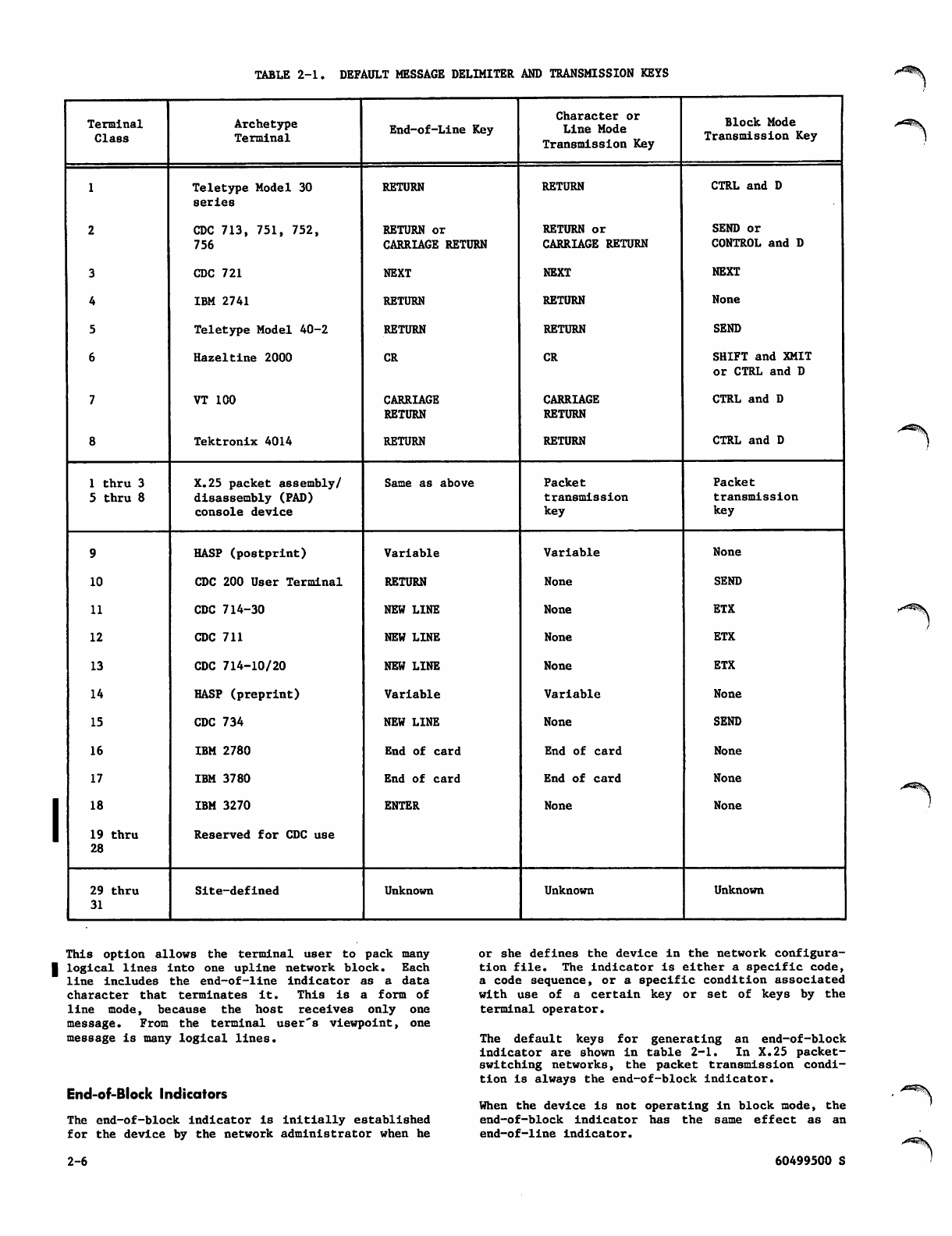
TABLE 2-1. DEFAULT MESSAGE DELIMITER AND TRANSMISSION KEYS
Terminal
Class
Archetype
Terminal End-of-Line Key
Character or
Line Mode
Transmission Key
Block Mode
Transmission Key
1
2
3
4
5
6
7
8
Teletype Model 30
series
CDC 713, 751, 752,
756
CDC 721
IBM 2741
Teletype Model 40-2
Hazeltine 2000
VT 100
Tektronix 4014
RETURN
RETURN or
CARRIAGE RETURN
NEXT
RETURN
RETURN
CR
CARRIAGE
RETURN
RETURN
RETURN
RETURN or
CARRIAGE RETURN
NEXT
RETURN
RETURN
CR
CARRIAGE
RETURN
RETURN
CTRL and D
SEND or
CONTROL and D
NEXT
None
SEND
SHIFT and XMIT
or CTRL and D
CTRL and D
CTRL and D
1 thru 3
5 thru 8
X.25 packet assembly/
disassembly (PAD)
console device
Same as above Packet
tra nsmissi on
key
Packet
tra nsmissi on
key
9
10
11
12
13
14
15
16
17
18
19 thru
28
HASP (postprint)
CDC 200 User Terminal
CDC 714-30
CDC 711
CDC 714-10/20
HASP (preprint)
CDC 734
IBM 2780
IBM 3780
IBM 3270
Reserved for CDC use
Variable
RETURN
NEW LINE
NEW LINE
NEW LINE
Variable
NEW LINE
End of card
End of card
ENTER
Variable
None
None
None
None
Variable
None
End of card
End of card
None
None
SEND
ETX
ETX
ETX
None
SEND
None
None
None
29 thru
31
Site-defined Unknown Unknown Unknown
This option allows the terminal user to pack many
■ logical lines into one upline network block. Each
line includes the end-of-line indicator as a data
c h a r a c t e r t h a t t e r m i n a t e s i t . T h i s i s a f o r m o f
line mode, because the host receives only one
message. From the terminal user's viewpoint, one
message is many logical lines.
End-of-Block Indicators
The end-of-block indicator is initially established
for the device by the network administrator when he
or she defines the device in the network configura
tion file. The indicator is either a specific code,
a code sequence, or a specific condition associated
with use of a certain key or set of keys by the
terminal operator.
T h e d e f a u l t k e y s f o r g e n e r a t i n g a n e n d - o f - b l o c k
indicator are shown in table 2-1. In X.25 packet-
switching networks, the packet transmission condi
tion Is always the end-of-block indicator.
When the device is not operating in block mode, the
end-of-block indicator has the same effect as an
end-of-line indicator.
2-6 60499500 S
0H&*\
Your application program or the terminal user can
change the end-of-block indicator (refer to the EB
co m m a nd, d e s crib e d i n s ect i o n 3 ). T h is in d i c ato r
normally is discarded when the last message from the
device is sent upline.
INTERACTIVE TERMINAL OUTPUT
CONCEPTS
A downline message can contain no logical lines (an
empty block or a transparent mode block) or many
logical lines of output. Each logical line can
contain many physical lines of output.
A logical line of output ends when the application
program embeds a code or set of bytes for that
purpose in the message, or when the block containing
the line ends. A downline message ends when an
application program indicates that condition.
Because downline messages can always contain more
than one logical line, an interactive device can
always receive the output equivalent of a multiple-
message block mode input transmission. The appli
cation program can group logical lines as necessary
to achieve that effect.
If a message fits into a downline network data
block, the block becomes a single-block message.
If one downline message cannot be fit into a single
network data block, the application program can
split it into as many blocks as necessary. An
application program generally sends a single
m e s sa g e (co n si s t in g o f a s m a n y l o g ic a l lin e s a s
necessary) as the response to one input message
from an interactive device.
BATCH DEVICE DATA
Batch devices can be serviced as site-defined device
types through the interactive virtual terminal
interface described later In this section. A sep
a r a t e s e t o f i n t e r f a c e p r o t o c o l s a l s o e x i s t s f o r
b a t c h d e v i c e s s e r v i c e d b y C D C - w r i t t e n Te r m i n a l
Interface Programs and application programs.
These programs require large amounts of data to be
exchanged between a host computer's mass storage
devices and CDC-defined batch devices. Such batch
data is therefore assembled into messages of one or
more network data blocks. Each network data block
contains one or more mass storage physical record
units (PRUs). Because only the CDC-written Remote
Batch Facility can use the special interface for
CDC-defined batch devices, the remainder of this
manual does not discuss the requirements this
interface imposes on batch data or batch device
support.
A p pl i c a t i o n p r og r a m s in d iff e re n t h o s t s ex c h a n g e
data by transferring the contents of 8-bit bytes
through the network, as if the data were sent to or
received from an interactive virtual terminal.
Application programs can exchange data only in
transparent mode. Upline and downline messages are
not subdivided into logical lines. Embedded codes
are not used to terminate lines or network data
blocks within the messages.
INFORMATION IDENTIFICATION
PROTOCOLS
CDC network host software uses four general con
v e n t i o n s f o r i d e n t i f y i n g n e t w o r k b l o c k s . T h e s e
conventions indicate the following things to the
application program sending or receiving the block:
The k ind o f mess a ge o f which t he blo ck is a
part; this is called the message type.
The kind of information within the block; this
is called the application block type.
The areas of host central memory containing the
block and containing information describing the
block; these are called the block buffer areas.
The s o urce o r d estinat i o n of the b l ock; t h ese
connection identifiers are called the applica
tion connection number and the application list
number.
The following subsections describe these conven
tions.
APPLICATION PROGRAM MESSAGE TYPES
An application program message is a complete logical
unit of information, comprising one or more physical
network blocks. A message can be a line of data to
or from a teletypewriter, a mass storage file, a
service request to NAM, or a screen of information
for a cathode ray tube.
There are two kinds of application messages, data
and supervisory. Data messages convey information
of significance only to a device user or to another
application program. Data messages can consist of
more than one network data block.
Supervisory messages convey information of signifi
cance only to the network software. Supervisory
messages consist of only one network block.
Supervisory messages are used by an application
program to control data messages between itself and
logical connections.
r
APPLICATION-TO-APPLICATION INPUT
AND OUTPUT CONCEPTS
Application programs within the same host exchange
data by transferring the contents of 60-bit central
memory words between control points. A program can
create a connection to itself and exchange data on
that connection.
APPLICATION BLOCK TYPES
The network block is the basic unit of information
exchange for the application program. There are
several types of network blocks that an application
program can exchange. Each type has an identifying
applica t i o n b lock type n u m ber assign e d t o i t. T h e
fo l l o wing t y p e s e xist :
60499500 R 2-7
Null blocks, which are dummy input blocks indi
cating the absence of any data or supervisory
information. These blocks have an application
block type number of 0.
Blocks containing portions of data messages, but
not terminating those messages. These blocks
have an application block type number of 1; such
blocks are called BLK blocks in other network
documentation.
B l o c ks t ha t te r m i n a t e d a t a me s s a ge s . T h e s e
blocks can include physically empty blocks when
such blocks convey logical information. Blocks
that terminate data messages have an application
block type number of 2; such blocks are called
MSG blocks in other network documentation.
Blocks constituting supervisory messages. These
blocks have an application block type number of
3; such blocks include the information in blocks
called CMD, BACK, BRK, ICMD, ICMDR, and other
acronyms in some network documentation.
Blocks containing portions of qualified data
messages, but not terminating those messages.
These blocks have an application block type
number of 6; such blocks are called QBLK blocks
in other network documentation.
Blocks that terminate qualified data messages.
These blocks can include physically empty
blocks when such blocks convey logical
information. Blocks that terminate qualified
data messages have an application block type
number of 7; such blocks are called QMSG blocks
in other network documentation.
Qualified data can be used only on application-to-
application connections. Such data has no special
significance to the CYBER 170 network software.
Qualified data is intended for application programs
in order for such programs to communicate control
information among themselves that is outside the
data stream but synchronous with it. For example,
user identification information (qualified data)
placed before data in transferring files.
Blocks with an application block type of 6 or 7
cannot be sent or received on the logical
connection between blocks with an application block
type of 1 or 2. Qualified data can only be sent or
received after an unqualified message ends or
before an unqualified message begins.
Block Header Area
Block header areas each contain a 60-bit word
describing the contents of a corresponding text
area. This block header word accompanies the block
i n t h e c o r r e s p o n d i n g b l o c k t e x t a r e a d u r i n g t h e
exchange between the application program and NAM.
For downline blocks, the application program creates
the block header and NAM interprets it. For upline
blocks, NAM creates the block header and the appli
cation program interprets it.
Because the contents of the header word depend on
the contents of the text area, the header word for
mats are described in this manual after the text
area content protocols are described. To simplify
the header area descriptions, they are presented in
four separate formats:
For upline network data blocks
For downline network data blocks
For upline supervisory message blocks
For downline supervisory message blocks
Block Text Area
A block text area is separately addressed from its
header area and need not be contiguous to it. The
text area contains the single network block
described by the header word in the header area.
Text areas can be of varying length, as necessary
to accommodate various block lengths. The text area
has a maximum length expressed as a whole number of
central memory words. Text areas can be up to 410
central memory words long.
The length of the text area used by the application
program is described to the network by the applica
tion program. The text area length must be calcu
lated from the maximum length of the blocks it will
contain.
Block length is distinct from text area length.
The length of a block depends on the type and use
of the block.
Null blocks have zero length and do not require any
central memory words for their text area. Other
block types have lengths expressed in character byte
units, although the bytes need not actually contain
characters.
^^Sk
BLOCK BUFFER AREAS
All network blocks are exchanged between the appli
cation program and the network software using two
kinds of buffers:
The block header area
The block text area
Blocks are always a whole number of character units
long but do not have to be a whole number of central
memory words long. Not all words in the text area
u s e d f o r a g i v e n b l o c k n e e d t o b e fi l l e d w i t h
meaningful information.
Supervisory message blocks are 1 through 410 words
lon g. Dat a blo cks h ave lengt hs o f zero up to the
maximum number of characters that can fit in the
maximum text area of 410 words, or 2043 characters,
whichever occurs first.
2-8 60499500 S
Downline messages containing more characters than
the text area can hold must be divided into several
network data blocks. Each such block must fit into
the text area. Each of these blocks should also
meet the network block size requirement and must be
transmitted separately.
Upline data blocks can be truncated to fit into the
existing text area. Alternatively, the application
program can use a large text area for large blocks
and a small text area for small blocks.
CONNECTION IDENTIFIERS
Two parameters identify and control the routing of
messages:
The application connection number
The application list number
Both p a r a m e t e r s a re u s e d i n AI P c a lls t hat f e tch
incoming network data blocks. The application con
nection number is used in the block header words of
outgoing blocks.
Application Connection Number
The application connection number is a 12-bit inte
ger used to address a particular logical connection.
The connection number can be used as an index into
a control structure (for example, the number of a
connection could be the ordinal of a corresponding
device table) or used in any other manner the
application chooses.
These connection numbers are assigned serially by
NAM for each application program. Numbers that
become available because of disconnections are
reassigned to subsequent connections.
A connection number of zero indicates the control
connection on which asynchronous supervisory mes
sages are sent and received. (See Supervisory Mes
sage Content and Sequence Protocols, later in this
section.)
Application List Number
NAM permits an application program to group connec
tions with similar processing requirements into
numbered lists. This is an efficiency feature,
relieving the application of the need to specify
individual connections each time upline block proc
e s s i n g i s r e q u i r e d . I n s t e a d , w h e n a r e q u e s t i s
made for a block from a connection on a list, any
device or application program connections with empty
input queues are automatically skipped and a block
from the first nonempty queue is returned. A single
null block is returned when none of the connections
on the list have any input queued.
T h i s f e a t u r e c a n b e u s e d i n m a n y k i n d s o f l i s t
structures. For example:
An application program must process input from
devices with large network block sizes (such as
interactive graphics terminals in a specific
terminal class) differently than input from
devices with small block sizes. This processing
occurs in different portions of the program
code; therefore, the application program assigns
the devices using large blocks to list 1 and
the devices using small blocks to list 2.
An application program treats all devices the
same and must process blocks from them on an
equal basis. Accordingly, it assigns them all
to the same list.
An application program services terminals in
four geographical areas; each must be treated
s e p a r a t e l y b e c a u s e o f v a r y i n g s t a t e l a w s .
Accordingly, they are assigned to lists 1
through 4.
An application program services devices that
should be treated the same, but with the fol
lowing complication: when the application has
received a block from a particular terminal, it
must perform some time-consuming function that
prevents it from immediately processing another
block from the same terminal. Accordingly, the
application places all connections on list 1 and
issues an input request on list 1. When a block
for connection x is returned, It temporarily
inhibits receipt of data on connection x before
it i s s ues the n ext inpu t r e quest. W h e n it can
accept another data block from the terminal
using logical connection x, the application
program sends a supervisory message to reverse
the effect of the temp ora ry i nhibiti on.
The parameter used for this kind of processing is
called the application list number. The application
list number is an integer from 0 through 63 speci
fied by the application program when it accepts a
connection. NAM links message input (upline) queues
of all connections that have been assigned the same
list number. An application program can request
blocks from these linked queues in rotation (with
out specifying individual connections) by including
the assigned application list number in a NETGETL
or NETGTFL statement (described in section 5).
Each list number identifies one connection list. A
connection list can be viewed as a table of connec
tion numbers. These connection numbers are entered
in the t a b l e i n the order i n w h i c h t he application
program assigns the connections to the list. When
the list is scanned for input from a connection,
the connections are examined in the order in which
they are entered in the table.
The application program explicitly assigns the list
number to each logical connection when the connec
tion is established. The logical connection cor
responding to application connection number zero
already exists when the application is connected to
the network. For this reason, application connec
tion number zero is automatically assigned to
application list number zero without program inter
vention.
The application program does not have to maintain
any tables associating connection numbers and list
numbers. The application program need not use list
processing at all.
60499500 R 2-9
DATA MESSAGE CONTENT
AND SEQUENCE PROTOCOLS
Data blocks consist of 1 through 410 60-bit words
or 1 through 2043 8-bit or 12-bit bytes. The
fields within these blocks convey information to or
from the terminal user. Data blocks have
associated block header words. These header words
convey information to the network software
concerning the contents of the corresponding text
area buffer.
Data blocks are sent and received through the
Application Interface Program routines described in
section 5. The application program fetches data
messages one block at a time. When the connection
q u e u e i s e mp t y, a n u l l b loc k w i th a n a p p li c a t ion
block type of zero is returned.
The network software provides a mechanism for the
application program to determine when data blocks
are queued. When a call to an AIP routine is com
pleted, a supervisory status word at a location
defined by the application program is updated to
indicate whether any data blocks are queued. As
long as the application program continues to make
calls to AIP routines, it can test the supervisory
status word periodically (instead of attempting to
f e t c h n u l l b lo c k s f r o m a l l a p p l i c a t i o n c o n n e c t i o n
numbers). The supervisory status word and the use
of NETWAIT are described in section 5.
The protocols for data message text and the use of
the text area buffer depend on whether the logical
connection Is with another application program, an
i n t e r a c t i v e v i r t u a l t e r m i n a l d e v i c e , o r a p a s s i v e
batch device. Blocks exchanged with other applica
tion programs in the same host have the fewest
r e q u ir e m e n t s a n d mo s t fl e x i b l e s t ru c t u r e . B l o c k s
exchanged with CDC-defined batch devices using the
special batch device protocol have the most
requirements and the le ast flexible structure.
Requirements for blocks exchanged with other appli
cation programs in the same host are covered in the
figures later in this section, and in section 3.
Blocks exchanged between application programs are
groups of binary character bytes with no parity,
equivalent to transparent mode data. Such blocks
can use the eighth bit of an 8-bit byte as data and
need not have the transparent mode bit set in their
block header; see the decriptions of transparent
mode and block header word content later in this
section.
The requirements for exchanging blocks with inter
active virtual terminal devices are described below.
Requirements for blocks exchanged with batch devices
through the special batch device Interface are not
described because that interface is available only
to RBF.
INTERACTIVE VIRTUAL TERMINAL DATA
An interactive virtual terminal can be either a
CDC-defined console device or a site-defined device.
An interactive virtual terminal can send and receive
data in two modes: normalized mode and transparent
mode. The format and content of data in these modes
is described later in this subsection. The charac
teristics of an interactive virtual terminal depend
on which data exchange mode is currently used.
I n n o r m a l i z e d m o d e , t h e c h a r a c t e r i s t i c s o f a n
interactive virtual terminal are as follows:
Input and output can occur simultaneously.
A page of output has infinite (no physical)
width; logical lines are divided automatically
as needed to fit the physical line restrictions
of the device.
A page of output has infinite (no physical)
length; sets of logical lines are divided auto
matically as needed to fit the physical
restrictions of the device page.
A logical line of output cannot be longer than
a single network block; a single message can
contain an infinite number of logical lines.
Characters are either 7-bit ASCII codes using
z e r o p a r i t y ( b i t 7 , t h e e i g h t h b i t , i s a l w a y s
zero in upline data and ignored in downline
data), or 6-bit display codes with no parity.
Logical lines of input are terminated by a
changeable character or condition; this ter
minator is the end-of-line or end-of-block
indicator described earlier in this section.
The input terminator is not part of the data
seen by an application program unless the
full-ASCII feature is used (this is explained
later in this subsection and in section 3 where
the FA command is described).
Logical lines of output are terminated by an
ASCII unit separator character code (US, repre
sented by the hexadecimal value IF) or the end
of a zero-byte terminated record. The applica
tion program places this terminator in the data.
No cursor positioning actions are required to
acknowledge receipt of input, and no timing
adjustments need to be made at the end of phys
ical output lines.
Logical lines can be divided into physical lines
by embedding optional format control characters
in downline blocks.
In transparent mode, the characteristics of an
interactive virtual terminal are as follows:
Input and output can occur simultaneously.
A page of output has infinite (no physical)
width.
A page of output has infinite (no physical)
length.
Characters are either 7-bit codes using zero
parity (bit 7, the eighth bit, is always zero
in upline data and ignored in downline data),
or codes of a terminal-dependent code set with
terminal-dependent parity.
Messages of input are terminated by a change
able character or condition; this terminator is
one of the message or mode delimiters described
later in this section. The mode delimiter is
not part of the data seen by an application
program.
/ 0 ^ ^ \
f^^K
2-10 60499500 R
ymS^N
Messages of output are terminated by a condition
or event chosen by an application program (each
network block is separately designated as
transparent or normalized when sent).
Cursor positioning actions might be required,
and timing adjustments might need to be made at
the end of physical output lines.
Line Turnaround Convention
The interactive virtual terminal concept imposes
some conventions on the content and sequencing of
blocks exchanged with an interactive device. The
primary convention of block sequencing involves the
direction and time of block transmission.
The application program can service an interactive
device on a connection as if the device always
operates in a full-duplex mode. That is, input and
output can occur independently; the terminal user
can enter several logical lines at once (an opera
tion called typeahead), without waiting for a
response to each line.
Application program input and output need not
alternate. However, some devices cannot actually
operate that way. To prevent a loss of synchroni
zation between input and output at such devices, a
line turnaround convention exists. This convention
consists of the following events.
After a block of type 2 (the end of a message) is
sent to a device, no more blocks should be sent
downline until at least one block is input from the
s a m e d e v i c e . A n a p p l i c a t i o n p r o g r a m t h e r e f o r e
should never send the last block of a message down
line until it is ready to wait for input.
A network data block of type 2 has special signifi
cance to the network software during output to an
interactive device. When such a block is the last
block of the output stream, the network software:
Unlocks the keyboard of an interactive device
being serviced as terminal class 4 (an IBM
2741).
Sends an X-ON code to start an automatic paper
tape input mechanism, if one has been defined
as the input mechanism for the device. Paper
tape operation is explained in more detail in
section 3 where the IN and OP commands are
described.
Starts polling devices in terminal classes 10
through 13 and 15 (mode 4 consoles), and
terminal class 18 (3270 consoles).
I d e n t i fi e s a n a u t o m a t i c i n p u t p r o m p t t o b e
returned, if the application program uses this
feature. When this feature is used, the network
soft w a r e delive r s the bloc k t o the d e v i ce and
r e t a i n s t h e fi r s t 2 0 c h a r a c t e r s i n t h e N P U ' s
input buffer. Subsequent input from the device
i s a tt a c he d t o t h e en d o f t he r e ta i ne d d at a .
(If more than one logical line is received from
t h e d e v i c e , t h e fi r s t i s a p p e n d e d t o t h e
retained data.) All logical lines are
transmitted to the host as received from the
device.
If the terminal is a half-duplex device, such as a
2741 or a paper tape reader/punch, it must enter
input before the network software will deliver
additional output messages. Other devices are not
subject to this restriction.
The requirement for an input block after a block of
type 2 is output can be satisfied in several ways
by terminal operators. An empty input line can be
entered and will reach the application program as a
block of type 2 but containing nothing. A line
containing data can be entered and will reach the
application program as one or more network data
blocks.
Devices can interrupt output by entering input.
When this occurs, the network software stops the
out put u ntil the t ermi n al u s er c omple tes t he inp ut
(using an end-of-line or end-of-block indicator).
Output then resumes at the next character of the
current physical and logical line.
INTERACTIVE VIRTUAL TERMINAL
EXCHANGE MODES
The conventions of block content depend on the mode
in which the block is exchanged. There are two
possible exchange modes, normalized mode and trans
parent mode. The latter is referred to in other
documentation as binary mode. This manual uses
transparent mode to indicate exchange of a block
that is not in normalized mode.
Normalized Mode Operation
The interactive virtual terminal interface assembles
message character streams into upline network data
b l o ck s f ro m t e r m i na l t ra n s mi s s io n b lo c k s. I t d is
assembles character streams from downline network
data blocks, reassembling them into terminal trans
mission blocks.
The assembly operation is controlled by the termi
nation of logical lines. The disassembly operation
can be controlled by the termination of messages.
The disassembly operation can also be modified by
format control characters embedded in each block,
and by the page width defined for the device (refer
to the PW command in section 3).
End of Logical Lines in Input
Logical lines reach an application program as one
or more network data blocks. Logical lines usually
end when a message ends and do not contain the
character or code sequence defined as the end-of-
line o r end -of -bl ock key.
However, two special cases exist. Logical lines do
contain the end-of-line or end-of-block codes when
the device is operating in full-ASCII editing mode
( d e s c r i b e d l a t e r i n t h i s s e c t i o n ) . L o g i c a l l i n e s
also contain the end-of-line code when the end-of-
line key is changed to be the default end-of-block
key for the device (see the EB option of the EL
command described in section 3). In the latter
case, the transmission block becomes a message, and
the logical lines within it have no effect on con
struction or type of network data blocks.
60499500 S 2-11
Logical and Physical Lines in Output
The application program does not need to equate a
logical line of output to a complete message nor
does it need to create a separate network block for
each physical line of output. A single logical line
can contain many complete physical lines. A single
block can contain many complete logical lines, and
a message can be one or many such blocks. A phys
ical or logical line cannot, however, be continued
from one block to another.
Upline Character Sets and Editing Modes
The network protocol permits entry from a device of
co des less tha n or equ al to 8 b its per character;
however, a normalized mode character always reaches
an application program as one of the 128 ASCII
characters defined in appendix A. Receipt of an
entered character by the application program depends
on the editing functions performed by the TIP.
Three editing modes exist for the TIP when it proc
esses normalized data:
Logical lines within downline blocks are ended by
an end-of-line indicator. Unlike the end-of-line
indicators used in upline blocks, downline blocks
always contain codes for the end-of-line function;
the codes used downline are always the same and
usually differ from the codes used upline. The
downline end-of-line indicator varies according to
th e ap plicatio n ch aracter type of the block; appli
cation character types are described later in this
section. Bytes used to store indicators must be
included when determining the number of characters
comprising a downline block.
The end-of-line indicator in 60-bit character bytes
(application character type 1) is determined by the
programs exchanging the block. No predefined end-
of-line indicator exists for that application char
acter type.
The end-of-line indicator in blocks using 8-bit
c h a r a c t e r s i n 8 - b i t o r 1 2 - b i t b y t e s ( a p p l i c a t i o n
character types 2 or 3) is determined by whether the
block is sent in normalized mode or transparent
mode (described later in this section). In trans
parent mode, no end-of-line indicator exists. In
normalized mode, the end-of-line indicator is the
ASCII unit separator character US.
The end-of-line indicator in blocks using 6-bit
character bytes (application character type 4) is
1 2 t o 6 6 b i t s o f z e r o ; t h e s e b i t s a r e r i g h t -
justified to fill the last central memory word
involved. This convention makes each logical line
the equivalent of a zero-byte terminated logical
record.
The 6-bit option requires a right-justified 12-bit
byte in at least one central memory word. On com
p u t e r s u s i n g t h e 6 4 - c h a r a c t e r s e t , t h e c o l o n i s
represented in 6-bit display code by six zero bits.
On such systems, if the application needs to send
colons to the terminal console in 6-bit display
code, care must be taken to make sure that a string
of colons is not interpreted as an end-of-line
indicator. A colon preceding the end-of-line indi
cator is considered as part of the indicator and not
as a colon when it occupies one of the two right
most character positions in the next-to-last central
memory word of the block or any of the eight left
most positions in the last word of the block.
All predefined end-of-line indicators embedded
within a block are discarded by the network soft
ware and produce no characters on the console output
device. The network software can perform carriage
or cursor repositioning when an end-of-line indica
tor is encountered; this operation is described
later in this section under Format Effectors.
Complete interactive virtual terminal editing
mode
Special editing mode
Full-ASCII mode
Devices always begin a connection with the network
in normalized mode. The initial upline editing mode
is established for each device when the device is
connected to the host. This mode is complete
editing. The application program or the terminal
u s e r c an c h an g e tha t m od e u s in g t he S E o r FA
commands, described in section 3.
Complete Editing
During complete editing operations, the following
hexadecimal character codes cannot be received by
the network application program:
00 (the ASCII character NUL)
OA (the ASCII character LF)
7F (the ASCII character DEL)
The backspace character code currently defined
for the device (see the BS command in section 3)
The end-of-line character currently defined for
the device (see the EL command in section 3)
T h e e n d - o f - b l o c k c h a r a c t e r c u r r e n t l y d e fi n e d
for the device (see the EB command in section 3)
The following hexadecimal character codes cannot be
received, if entered at certain points in a message:
02 (the ASCII character STX), if entered as the I
first character of a message |
11 (the ASCII character DC1) if it follows an
end-of-line or end-of-block character and the
TIP is supporting output control for the device
(see the Y option of the OC command in section
3)
13 (the ASCII character DC3) if it follows an
end-of-line or end-of-block character and the
TIP is supporting output control for the device
(see the Y option of the OC command in section
3).
/"^\
2-12 60499500 S
13 (the ASCII character DC3) if it follows an
end-of-line or end-of-block character and the
input mechanism is known to be a paper tape
reader (see the PT option of the IN command in
section 3)
The user-break-1 and user-break-2 character
codes currently defined for the terminal, if
entered as the only character in a message (see
the Bl and B2 commands in section 3)
The abort-output-block character code currently
defined for the terminal, if entered as the
only character in a message (see the AB command
in section 3)
The network control character currently defined
fo r the ter min al when it follows an end-of-line
or end-of-block character or when it is used
for such purposes as page turning (see the CT
command and the Y option of the PG command in
section 3)
The currently defined cancel input character is
always received at the end of the logical line it
cancel s. This charact er i s not data .
Special Editing
Special editing takes precedence over complete
editing. Special editing cannot occur if the ter
minal operates in block mode.
When special editing occurs, linefeed codes and the
currently defined backspace code are forwarded to
the application program as data. The network soft
ware sends appropriate responses to the device when
it receives these codes.
During special editing operations, the following
hexadecimal character codes cannot be received by
the network application program:
00 (the ASCII character NUL)
7F (the ASCII character DEL)
The end-of-line character currently defined for
the device (see the EL command in section 3)
T h e e n d - o f - b l o c k c h a r a c t e r c u r r e n t l y d e fi n e d
for the device (see the EB command in section 3)
The following hexadecimal character codes cannot be
received, if entered at certain points in a message:
11 ( t h e A SCII c h aracter DC1 ) i f i t f o l l o w s a n
end-of-line or end-of-block character and the
TIP is supporting output control for the device
(see the Y option of the OC command in section
3)
13 (the ASCII character DC3) if it follows an
end-of-line or end-of-block character and the
TIP is supporting output control for the device
(see the Y option of the OC command in section
3).
13 (the ASCII character DC3) if it follows an
end-of-line or end-of-block character and the
input mechanism is known to be a paper tape
reader (see the PT option of the IN command in
section 3)
02 (the ASCII character STX), if entered as the
first character of a message
The user-break-1 and user-break-2 character
codes currently defined for the terminal, if
entered as the only character in a message (see
the Bl and B2 commands in section 3)
Th e abort -output-blo ck charac ter cod e cu rre ntly
defined for the terminal, if entered as the only
character in a message (see the AB command in
section 3)
The network control character currently defined
fo r the ter min al when it follows an end-of-line
or end-of-block character or when it is used
for such purposes as page turning (see the CT
command and the Y option of the PG command in
section 3)
The currently defined cancel input character is
always received at the end of the logical line it
cancel s. This charact er i s not data .
Full-ASCII Editing
Full-ASCII editing takes precedence over special
editing or complete editing. When full-ASCII edit
ing occurs, almost all codes are forwarded to the
application program as data. The network software
does not perform actions at the terminal when it
receives the codes for backspace, abort-output-
block, cancel input message, user-break-1, or user-
break-2. These codes and the end-of-line and end-
of-block indicator codes are sent upline as data.
During full-ASCII editing operations, the following
hexadecimal character codes cannot be received by
the network application program:
00 (the ASCII character NUL) if it occurs after
the end-of-line or end-of-block indicator
0A ( t h e A S C II characte r L F ) i f it occurs a f t er
the end-of-line or end-of-block indicator
7F (the ASCII character DEL) if it occurs after
the end-of-line or end-of-block indicator
Th e network c ont rol character currently defi ned
for the terminal if it occurs after the end-of-
line or end-of-block indicator or when it is
used for such purposes as page turning (see the
CT command and the Y option of the PG command
in secti on 3)
The following hexadecimal character codes cannot be
received if entered at certain points in a message:
11 (the ASCII character DC1) if it follows an
end-of-line or end-of-block indicator and the
TIP is supporting output control for the device
(see the Y option of the 0C command in section
3)
13 (the ASCII character DC3) if it follows an |
end-of-line or end-of-block indicator and the
TIP is supporting output control for the device
(see the Y option of the OC command in section I
3 > I
60499500 S 2-13
13 (the ASCII character DC3) if it follows an
end-of-line or end-of-block indicator and is
explicitly supporting paper tape input from the
device (see the PT option of the IN command in
section 3).
The currently defined cancel input character is
always received as the last character of the logical
line it ended. This character is data.
Downline Character Sets
The network protocol permits transmission from a
network application program of any character code
l e s s t h a n o r e q u a l t o 8 b i t s . I f t h e a p p l i c a t i o n
program uses one of the application character types
that permits transmitting an 8-bit code (application
character types 2 and 3), it cannot use the upper
( e i g h t h ) b i t f o r d a t a u n l e s s i t i s t r a n s m i t t i n g i n
transparent mode.
In normalized mode, the application program can only
use the 128 ASCII characters defined in appendix
A. If the application program transmits a 7-bit
ASCII code, it cannot use the upper (eighth) bit
for parity; the network ignores the eighth bit in
downline normalized mode data.
Rece i p t o f a t r a n s mitted chara c t e r b y t h e d e vice
depends on the editing functions and character
transformations perfo r m e d b y t h e T I P. I n a d d i t i o n
to character codes altered during the translation
and substitution operations described elsewhere in
this section and in appendix A, the hexadecimal
character code IF (the ASCII character US used as a
downline block end-of-line indicator) cannot be
received by a device when the application program
transmits a block in normalized mode.
Page Width and Page Length
The application program receives an indication of
the page width and page length in effect for a
device when connection with the device first occurs.
The application program or the terminal user can
change the page width and page length in effect for
a device.
The Terminal Interface Program uses the page length
defined for the device to format physical lines
into physical pages or screens of output. The Ter
minal Interface Program uses the page width value
to transform logical lines of downline data into
physical lines of output.
For console devices defined as having hardcopy out
put mechanisms (see the PR option of the OP command
in section 3), a logical line of downline data con
taining more characters than the page width value
permits is divided into singly spaced physical
lines. These physical lines are equal to or shorter
than the page width in effect and are displayed
successively.
For all console devices, the page width is used as
part of the line-counting algorithm to determine
the page length. Each logical line is examined to
determine how many multiples of the page width (how
many physical lines) it contains. Each complete or
partial multiple counts as one line when the TIP
determines the page length.
Line counting begins at the beginning of each down
line message. The line counter is reset to zero
e a c h t i m e t h e p a g e l e n g t h o f t h e t e r m i n a l i s
reached, each time any input occurs, or when page
turning occurs during page waiting operation. Refer
to the PG, PW, and PL commands in section 3.
The physical line width of the device might be
smaller than the page width defined for the device.
When this happens, the effect of sending a logical
line of downline data containing more characters
than the physical line width permits depends on the
terminal hardware.
Format Effectors
An application program can control the presentation
of the characters within a data block by indicating
that the block contains format effectors. If the
application program chooses to do this, the first
c h a r a c t e r o f e a c h l o g i c a l l i n e w i t h i n t h e b l o c k
becomes a format effector. Format effector charac
ters cause predefined formatting operations when
the block is delivered to the device. The network
software discards these characters after interpre
tation; therefore, these characters do not appear
on the interactive terminal output device.
You must include format effector characters when
determining the number of characters comprising the
block. Format effector characters are excluded from
page width calculations.
Tables 2-2 and 2-3 describe the predefined opera
tions produced by each format effector character of
each terminal class. The Terminal Interface Program
performs the predefined format effector operation
by inserting the codes for the characters indicated
in the tables in place of the discarded format
e f f e c t o r c h a r a c t e r c o d e . T h e I n s e r t e d t e r m i n a l
codes are those of characters in the ASCII set
described in appendix A, with the exception that NL
indicates the terminal-defined new-line code
sequence.
Numbers preceding codes indicate the number of times
the codes are repeated in the inserted sequence.
Each line output to a console in terminal classes 9
t h r o u g h 1 8 l e a v e s t h e c u r s o r p o s i t i o n e d a t t h e I
beginning of the next physical line. Processing of
the next line takes this into account.
The format effector characters for clear screen and
home cursor operations (* and 1) receive special
treatment by the Terminal Interface Program when it
is performing a page wait function for the terminal.
(See the PG command in section 3.) If these char
acters are encountered when the TIP has output only
part of a page, the TIP pauses for terminal operator
acknowledgment of the partial page. When acknowl
edgment occurs, the format effector functions are
performed and output continues automatically. This
pause occurs without application program action or
knowledge.
I f t h e a pp l ic a t i o n p r o g r a m d oe s n o t i n d i c a te t h e
existence of format effectors, the first character
of each logical line does not act as a format
effector. These characters are output normally but
are preceded by the character codes necessary to
space one line before output. These default line-
spacing codes are the ones substituted when a blank
is used as a format effector.
2-14 60499500 S
> ^ \
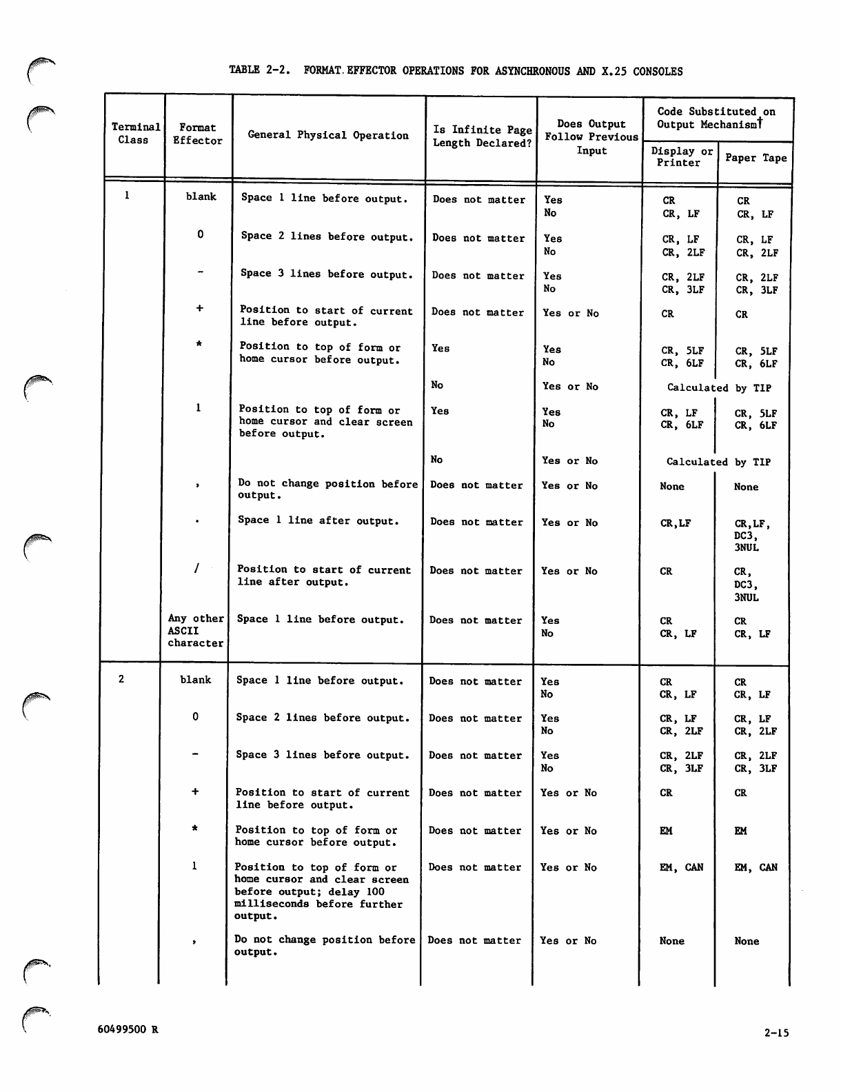
TABLE 2-2. FORMAT.EFFECTOR OPERATIONS FOR ASYNCHRONOUS AND X.25 CONSOLES
/$l^™^\
Terminal
Class
Format
Effector General Physical Operation
blank Space 1 line before output.
Space 2 lines before output.
Space 3 lines before output.
Position to start of current
line before output.
Position to top of form or
home cursor before output.
Position to top of form or
home cursor and clear screen
before output.
Do not change position before
output.
Space 1 line after output.
/ Position to start of current
l i n e a f te r o ut p ut .
Is Infinite P a g e
Length Declared?
Any other
ASCII
character
blank
Space 1 line before output.
Space 1 line before output.
Space 2 lines before output.
Space 3 lines before output.
Position to start of current
line before output.
Position to top of form or
home cursor before output.
Position to top of form or
home cursor and clear screen
before output; delay 100
milliseconds before further
output.
Do not change position before
output.
Does not matter
Does not matter
Does not matter
Does not matter
Yes
No
Yes
No
Does not matter
Does not matter
Does not matter
Does not matter
Does Output
Follow Previous
Input
Does not matter
Does not matter
Does not matter
Does not matter
Does not matter
Does not matter
Does not matter
Yes
No
Yes
No
Yes
No
Yes or No
Yes
No
Yes or No
Yes
No
Yes or No
Yes or No
Yes or No
Yes or No
Yes
No
Yes
No
Yes
No
Yes
No
Yes or No
Yes or No
Yes or No
Yes or No
Code Substituted on
Output Mechanismt
Display or
Printer
CR
CR, LF
CR, LF
CR, 2LF
CR, 2LF
CR, 3LF
CR
CR, 5LF
CR, 6LF
Paper Tape
CR
CR, LF
CR, LF
CR, 2LF
CR, 2LF
CR, 3LF
CR
CR, 5LF
CR, 6LF
Calculated by TIP
CR, LF
CR, 6LF
CR, 5LF
CR, 6LF
Calculated by TIP
None None
CR.LF
CR
CR
CR, LF
CR
CR, LF
CR, LF
CR, 2LF
CR, 2LF
CR, 3LF
CR
EM
EM, CAN
None
CR.LF,
DC3,
3NUL
CR,
DC3,
3NUL
CR
CR, LF
CR
CR, LF
CR, LF
CR, 2LF
CR, 2LF
CR, 3LF
CR
EM
EM, CAN
None
60499500 R 2-15
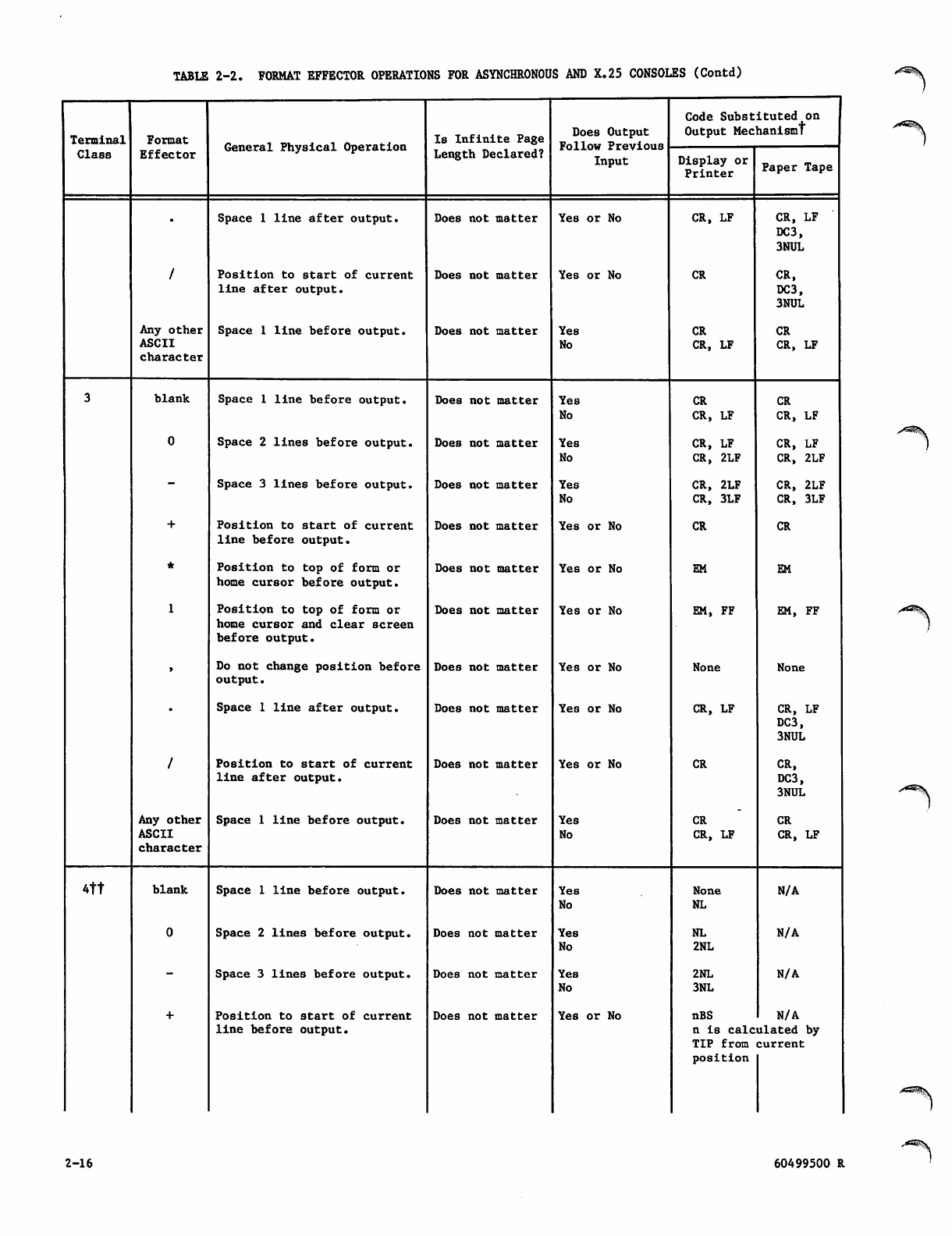
TABLE 2-2. FORMAT EFFECTOR OPERATIONS FOR ASYNCHRONOUS AND X.25 CONSOLES (Contd)
Terminal
Class
Format
Effector General Physical Operation Is Infinite Page
Length Declared?
Does Output
Follow Previous
Input
Code Substituted on
Output Mechanism!
Display or
Printer Paper Tape
•Space 1 line after output. Does not matter Yes or No CR, LF CR, LF
DC3,
3NUL
/Position to start of current
l i n e a f te r o ut p ut .
Does not matter Yes or No CR CR,
DC3,
3NUL
Any other
ASCII
character
Space 1 line before output. Does not matter Yes
No
CR
CR, LF
CR
CR, LF
3blank Space 1 line before output. Does not matter Yes
No
CR
CR, LF
CR
CR, LF
0Space 2 lines before output. Does not matter Yes
No
CR, LF
CR, 2LF
CR, LF
CR, 2LF
-Space 3 lines before output. Does not matter Yes
No CR, 2LF
CR, 3LF
CR, 2LF
CR, 3LF
+Position to start of current
line before output.
Does not matter Yes or No CR CR
*Position to top of form or
home cursor before output.
Does not matter Yes or No EM EM
1Position to top of form or
home cursor and clear screen
before output.
Does not matter Yes or No EM, FF EM, FF
»Do not change position before
output.
Does not matter Yes or No None None
•Space 1 line after output. Does not matter Yes or No CR, LF CR, LF
DC3,
3NUL
/Position to start of current
l i n e a f te r o ut p ut .
Does not matter Yes or No CR CR,
DC3,
3NUL
Any other
ASCII
character
Space 1 line before output. Does not matter Yes
No
CR
CR, LF
CR
CR, LF
4tt blank Space 1 line before output. Does not matter Yes
No
None
NL N/A
0Space 2 lines before output. Does not matter Yes
No
NL
2NL N/A
-Space 3 lines before output. Does not matter Yes
No
2NL
3NL
N/A
+Position to start of current
line before output.
Does not matter Yes or No nBS
n i s cal c
TIP from
position
N/A
ulated by
current
2-16 60499500 R
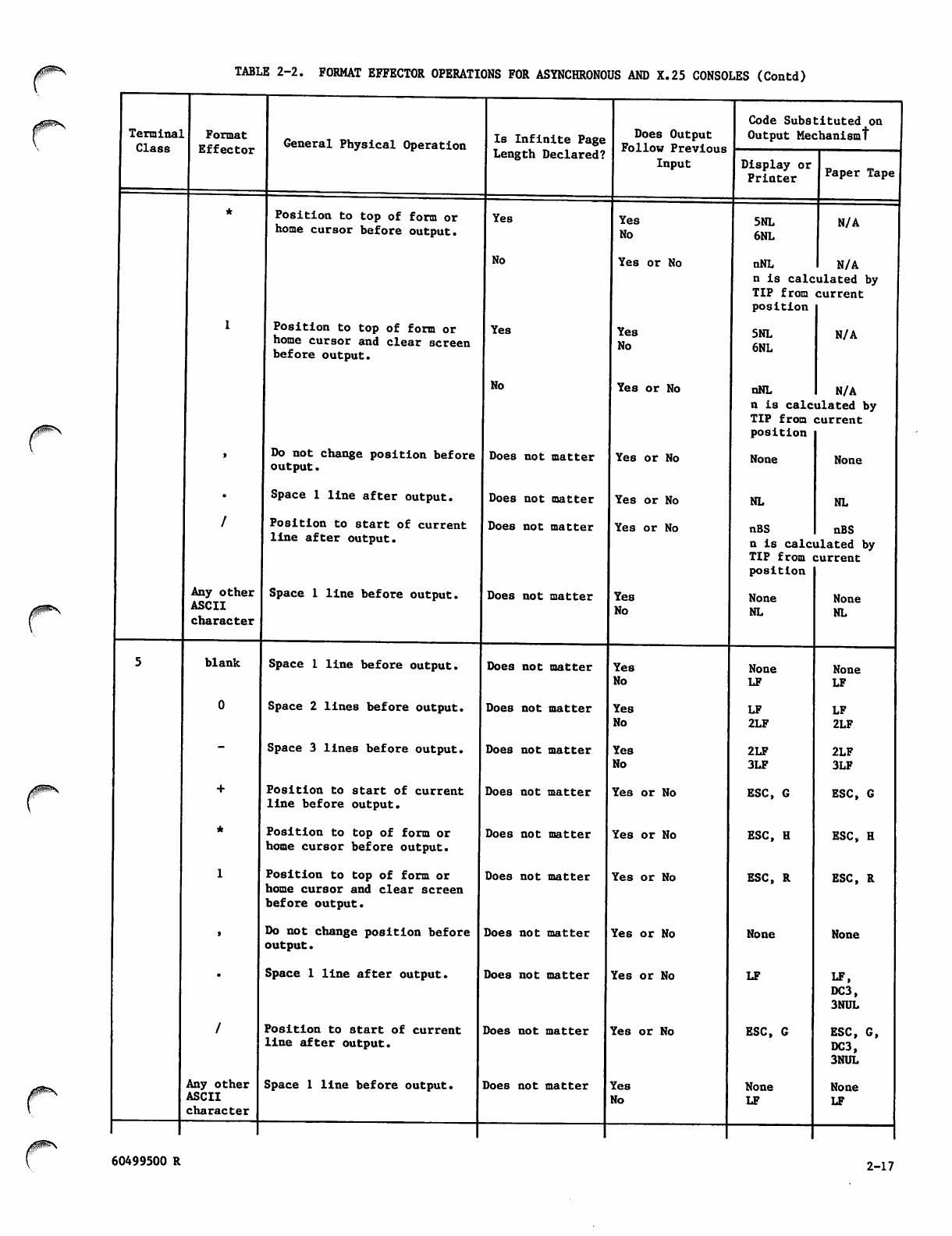
TABLE 2-2. FORMAT EFFECTOR OPERATIONS FOR ASYNCHRONOUS AND X.25 CONSOLES (Contd)
Terminal
Class
Format
Effector General Physical Operation
Position to top of form or
home cursor before output.
Is Infinite Page
Length Declared?
Position to top of form or
home cursor and clear screen
before output.
Any other
ASCII
character
blank
Do not change position before
output.
Space 1 line after output.
Position to start of current
l i n e a f te r o ut p ut .
Space 1 line before output.
Any other
ASCII
character
Space 1 line before output.
Space 2 lines before output.
Space 3 lines before output.
Position to start of current
line before output.
Position to top of form or
home cursor before output.
Position to top of form or
home cursor and clear screen
before output.
Do not change position before
output.
Space 1 line after output.
Position to start of current
l i n e a f te r o ut p ut .
Yes
No
Yes
No
Does not matter
Does not matter
Does not matter
Does not matter
Does Output
Follow Previous
Input
Space 1 line before output. Does not matter
Does not matter
Does not matter
Does not matter
Does not matter
Does not matter
Does not matter
Does not matter
Does not matter
Does not matter
Yes
No
Yes or No
Yes
No
Ye8 or No
Yes or No
Yes or No
Yes or No
Yes
No
Yes
No
Yes
No
Yes
No
Yes or No
Yes or No
Yes or No
Yes or No
Yes or No
Yes or No
Yes
No
Code Substituted on
Output Mechanism!
Display or
Printer
5NL
6NL
Paper Tape
N/A
nNL N/A
n is calculated by
TIP from current
position
5NL
6NL N/A
nNL N/A
n is calculated by
TIP from current
position
None
NL
nBS
None
NL
nBS
n is calculated by
TIP from current
position
None
NL
None
LF
LF
2LF
2LF
3LF
ESC, G
ESC, H
ESC, R
None
LF
ESC, G
None
LF
None
NL
None
LF
LF
2LF
2LF
3LF
ESC, G
ESC, H
ESC, R
None
LF,
DC3,
3NUL
ESC, G,
DC3,
3NUL
None
LF
60499500 R 2-17
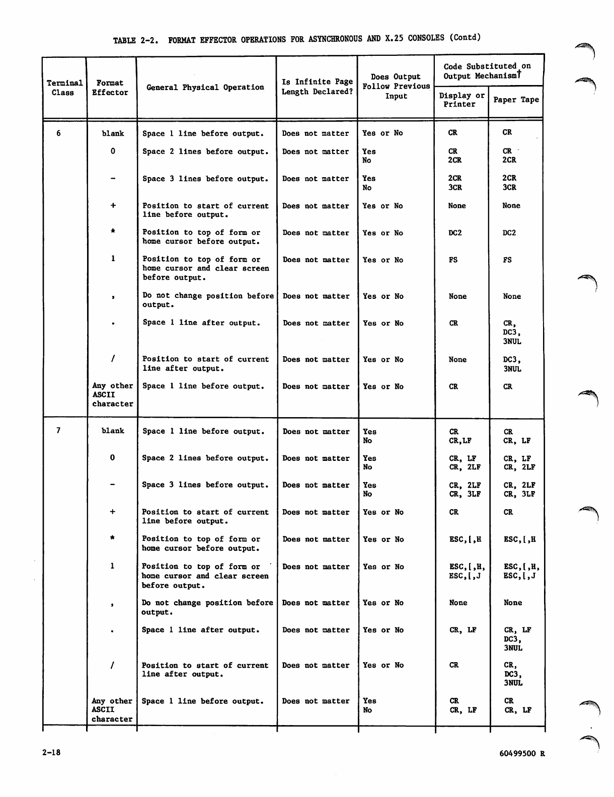
TABLE 2-2. FORMAT EFFECTOR OPERATIONS FOR ASYNCHRONOUS AND X.25 CONSOLES (Contd)
Terminal
Class
Format
Effector
blank
0
Any other
ASCII
character
blank
Any other
ASCII
character
General Physical Operation
Space 1 line before output.
Space 2 lines before output.
Space 3 lines before output.
Position to start of current
line before output.
Position to top of form or
home cursor before output.
Position to top of form or
home cursor and clear screen
before output.
Do not change position before
output.
Space 1 line after output.
Position to start of current
line after output.
Space 1 line before output.
Space 1 line before output.
Space 2 lines before output.
Space 3 lines before output.
Position to start of current
line before output.
Position to top of form or
home cursor before output.
Position to top of form or
home cursor and clear screen
before output.
Do not change position before
output.
Space 1 line after output.
Position to start of current
l i n e a f te r o ut p ut .
Space 1 line before output.
Is Infinite Page
Length Declared?
Does not matter
Does not matter
Does not matter
Does not matter
Does not matter
Does not matter
Does not matter
Does not matter
Does not matter
Does not matter
Does not matter
Does not matter
Does not matter
Does not matter
Does not matter
Does not matter
Does not matter
Doe8 not matter
Does not matter
Does not matter
Does Output
Follow Previous
Input
Yes or No
Yes
No
Yes
No
Yes or No
Yes or No
Yes or No
Yes or No
Yes or No
Yes or No
Yes or No
Yes
No
Yes
No
Yes
No
Yes or No
Yes or No
Yes or No
Yes or No
Yes or No
Yes or No
Yes
No
Code Substituted on
Output Mechanism!
Display or
Printer
CR
CR
2CR
2CR
3CR
None
DC2
FS
None
CR
None
CR
CR
ESC,[,H
ESC,[,H,
ESC,[,J
None
CR, LF
CR
CR
CR, LF
Paper Tape
CR
CR
2CR
2CR
3CR
None
DC2
FS
None
CR,
DC3,
3NUL
DC3,
3NUL
CR
CR CR
CR.LF CR, LF
CR, LF CR, LF
CR, 2LF CR, 2LF
CR, 2LF CR, 2LF
CR, 3LF CR, 3LF
CR
ESC,l,H
ESC,[,H,
ESC,I,J
None
CR, LF
DC3,
3NUL
CR,
DC3,
3NUL
CR
CR, LF
2-18 60499500 R
/*!^\
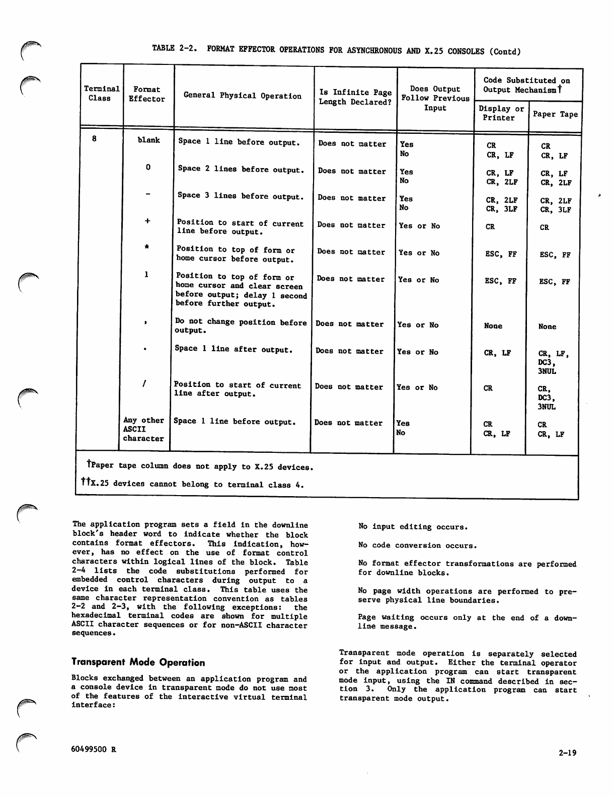
J0^\ TABLE 2-2. FORMAT EFFECTOR OPERATIONS FOR ASYNCHRONOUS AND X.25 CONSOLES (Contd)
/sspfev.
Terminal
Class
Format
Effector
blank
0
Any other
ASCII
character
General Physical Operation
Space 1 line before output.
Space 2 lines before output.
Space 3 lines before output.
Position to start of current
line before output.
Position to top of form or
home cursor before output.
Position to top of form or
home cursor and clear screen
before output; delay 1 second
before further output.
Do not change position before
output.
Space 1 line after output.
Position to start of current
l i n e a f te r o ut p ut .
Space 1 line before output.
Is Infinite Page
Length Declared?
Does Output
Follow Previous
Input
Does not matter
Does not matter
Does not matter
Does not matter
Does not matter
Does not matter
Does not matter
Does not matter
Does not matter
Does not matter
TPaper tape column does not apply to X.25 devices.
TTx.25 devices cannot belong to terminal class 4.
Yes
No
Yes
No
Yes
No
Yes or No
Yes or No
Yes or No
Yes or No
Yes or No
Yes or No
Yes
No
Code Substituted on
Output Mechanismt
Display or
Printer
CR
CR, LF
CR, LF
CR, 2LF
CR, 2LF
CR, 3LF
CR
ESC, FF
ESC, FF
None
CR, LF
CR
CR
CR, LF
Paper Tape
CR
CR, LF
CR, LF
CR, 2LF
CR, 2LF
CR, 3LF
CR
ESC, FF
ESC, FF
None
CR, LF,
DC3,
3NUL
CR,
DC3,
3NUL
CR
CR, LF
The application program sets a field in the downline
block's header word to indicate whether the block
contains format effectors. This indication, how
ever, has no effect on the use of format control
characters within logical lines of the block. Table
2-4 lists the code substitutions performed for
e m b e d d e d c o n t r o l c h a r a c t e r s d u r i n g o u t p u t t o a
device in each terminal class. This table uses the
same character representation convention as tables
2-2 and 2-3, with the following exceptions: the
hexadecimal terminal codes are shown for multiple
ASCII character sequences or for non-ASCII character
sequences.
Transparent Mode Operation
Blocks exchanged between an application program and
a console device in transparent mode do not use most
of the features of the interactive virtual terminal
interface:
No input editing occurs.
No code conversion occurs.
No format effector transformations are performed
for downline blocks.
No page width operations are performed to pre
serve physical line boundaries.
Page waiting occurs only at the end of a down
line message.
Transparent mode operation is separately selected
for input and output. Either the terminal operator
or the application program can start transparent
mode input, using the IN command described in sec
tion 3. Only the application program can start
transparent mode output.
60499500 R 2-19
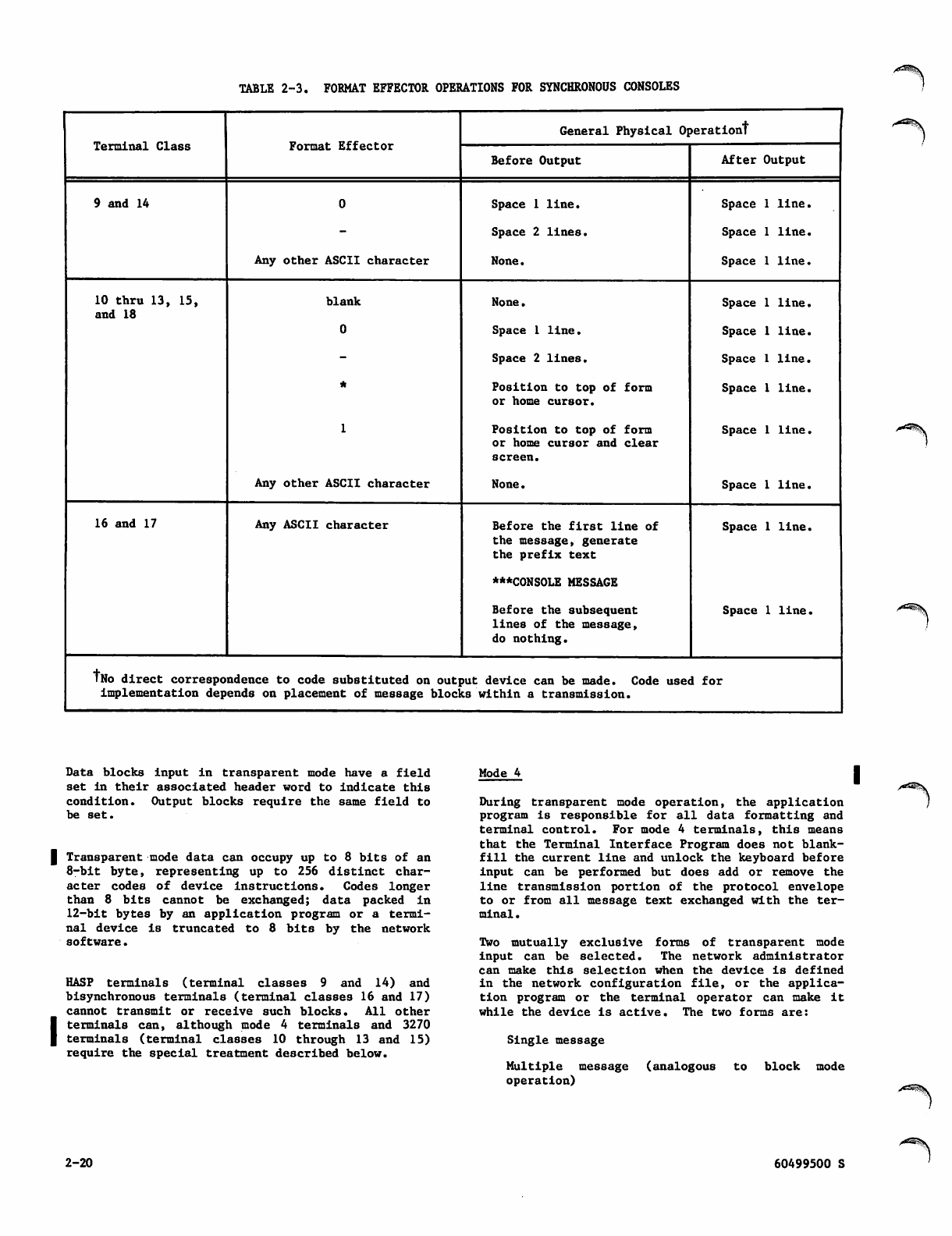
TABLE 2-3. FORMAT EFFECTOR OPERATIONS FOR SYNCHRONOUS CONSOLES
Terminal Class Format Effector
General Physical Operationt
Before Output After Output
9 and 14
Any other ASCII character
Space 1 line.
Space 2 lines.
None.
Space 1 line.
Space 1 line.
Space 1 line.
10 thru 13, 15,
and 18
blank
0
*
1
Any other ASCII character
None.
Space 1 line.
Space 2 lines.
Position to top of form
or home cursor.
Position to top of form
or home cursor and clear
screen.
None.
Space 1 line.
Space 1 line.
Space 1 line.
Space 1 line.
Space 1 line.
Space 1 line.
16 and 17 Any ASCII character Before t h e first l i n e o f
the message, generate
the prefix text
***C0NS0LE MESSAGE
Before the subsequent
lines of the message,
do nothing.
Space 1 line.
Space 1 line.
TNo direct correspondence to code substituted on output device can be made. Code used for
implementation depends on placement of message blocks within a transmission.
Data blocks input in transparent mode have a field
set in their associated header word to indicate this
condition. Output blocks require the same field to
be set.
| Transparent mode data can occupy up to 8 bits of an
8 - bi t b y t e , r e p r e s e n t i ng u p to 2 5 6 d i st i n c t ch a r
acter codes of device instructions. Codes longer
than 8 b its cann ot b e exc hanged; d ata p ack ed i n
12-bit bytes by an application program or a termi
nal device is truncated to 8 bits by the network
software.
HASP terminals (terminal classes 9 and 14) and
bisynchronous terminals (terminal classes 16 and 17)
cannot transmit or receive such blocks. All other
terminals can, although mode 4 terminals and 3270
terminals (terminal classes 10 through 13 and 15)
require the special treatment described below.
Mode 4
During transparent mode operation, the application
program is responsible for all data formatting and
terminal control. For mode 4 terminals, this means
that the Terminal Interface Program does not blank-
fill the current line and unlock the keyboard before
input can be performed but does add or remove the
line transmission portion of the protocol envelope
to or from all message text exchanged with the ter
minal.
Two m utually e xcl usiv e for ms o f tra nsp aren t mod e
in p u t c a n b e s e lecte d . Th e n e t w o rk a dmini s t r a t or
can make this selection when the device is defined
in the network configuration file, or the applica
tion program or the terminal operator can make it
while the device is active. The two forms are:
Single message
Multiple message
operation)
(analogous to block mode
2-20 60499500 S
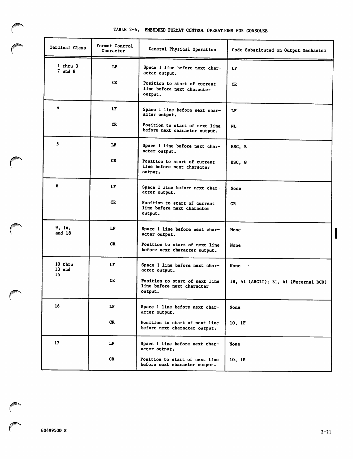
TABLE 2-4. EMBEDDED FORMAT CONTROL OPERATIONS FOR CONSOLES
/|P*y
Terminal Class
1 thru 3
7 and 8
9, 14,
and 18
10 thru
13 and
15
16
17
Format Control
Character
LF
CR
LF
CR
LF
CR
LF
CR
LF
CR
LF
CR
LF
CR
LF
CR
General Physical Operation
Space 1 line before next char
acter output.
Position to start of current
line before next character
output.
Code Substituted on Output Mechanism
Space 1 line before next char
acter output.
Pos itio n to s tart o f nex t line
before next character output.
Space 1 line before next char
acter output.
Position to start of current
line before next character
output.
LF
CR
LF
NL
ESC, B
ESC, G
Space 1 line before next char
acter output.
Position to start of current
line before next character
output.
Space 1 line before next char
acter output.
Position to start of next line
before next character output.
Space I line before next char
acter output.
Pos itio n to s tart o f nex t line
line before next character
output.
Space 1 line before next char
acter o u t p u t .
Position to start of next line
before next character output.
Space 1 line before next char
acter output.
Position to start of next line
before next character output.
None
CR
None
None
None
IB, 41 (ASCII); 31, 41 (External BCD)
None
10, IF
None
10, IE
60499500 S 2-21
Downline
The application constructs a screen-full of
protected/unprotected fields and supplies all the
d e s i r e d a t t r i b u t e c h a r a c t e r s a n d s c r e e n - b u f f e r -
addresses for the fields. The TIP is responsible
for preceding the block of output by SYNC-
characters, start-of-text, and escape-char, and
attaches ETX,CRC,PAD at the end. The TIP also
translates all downline data ASCII to EBCDIC and
performs SYNC-fill.
A typical start of a field would be:
SBA set-buffer-address x'll' all in ASCII
BA1 buffer-address-1
B A 2 b u f f e r - a d d r e 8 s - 2
ATT attribute-char
where the attribute-character determines the char
a c t e r i s t i c s o f t h e fi e l d :
- p rot ected
- unprotected
- intensified
- numeric shift
The application is also expected to insert the
cursor at a desired location.
Once transparent output is delivered to a 3270
terminal, the TIP assumes transparent input until a
non-transparent downline block is delivered to the
terminal.
To protect the integrity of the protocol, the TIP
replaces certain downline characters by NULLs. The
characters replaced are:
SOH, STX, ETX, EOT, ENQ, ACK,NAK, SYNC
Upline
Once transparent output is delivered, the TIP sends
to the host all modified, unprotected fields
received from the terminal including the SBA and
buffer-address-char 8 (2) of each field. The
terminal does not send the attribute characters
back to the TIP.
If the incoming text is larger than one trans
mission block (256 characters), the TIP will send
BLK/BLK/.../MSG
so that the application can reproduce a full screen.
Single-Message Input
For single-message input, one or more transparent
mode input delimiters are specified, using the DL
command options described in section 3. For
single-message input, when a message ends, trans
parent mode input ends. Transparent mode messages
need not be equivalent to normalized mode logical
lines.
Single-message transparent mode input ends when the
Terminal Interface Program encounters one of the
mode delimiter conditions. The delimiter condi
tions are:
2-22
Occurrence of a specific character code in the
input
Occurrence of a specific number of character
bytes in the input
Occurrence of a 200- to 400-millisecond timeout
in the input
Multiple-Message Input
For multiple-message input, the application program
or the terminal user defines one or two input
message-forwarding signals (equivalent to a normal
ized mode end-of-line indicator) and one or two
transparent mode input delimiters. Each message
ends at a mess age-forwarding signal; the last mes
sage ends when transparent input mode ends. The
message-forwarding signal and mode delimiters may
be modified as described under Changing Device
Characteristics in section 3.
The possible message-forwarding signals are:
Occurrence of a specific character code in the
input
Occurrence of a specific number of character
bytes in the input
The transparent mode delimiters are:
Two consecutive occurrences of a specific char
acter code (the message-forwarding signal)
A sequence of two character codes (a message-
forwarding code followed by a transparent mode
delimiter code)
Occurrence of a 200- to 400-millisecond timeout
in the input
Upline Message Blocks
A transparent mode input block is assembled each
time the network block size is reached or the Ter
minal Interface Program encounters a message-
forwarding signal. The last block in the last
message is assembled when the delimiter condition
is encountered. If the message-forwarding signal
is a specific character code, the TIP removes that
code from the character stream before assembling
the last block.
In transparent mode, the concept of a logical line
is not meaningful to the network software. Both the
end-of-line and end-of-block indicators are data
within a transparent message. These indicators
have no significance to the network software.
Transparent Mode Output
Transparent mode output data can be divided
arb i trari l y into b l ocks a n d mess a ges, provi d ed the
restrictions on network block size are met. A
transparent mode downline block ends when the last
character it contains is transferred to the network
(defined by the tic field in the block header,
described later in this section).
60499500 S
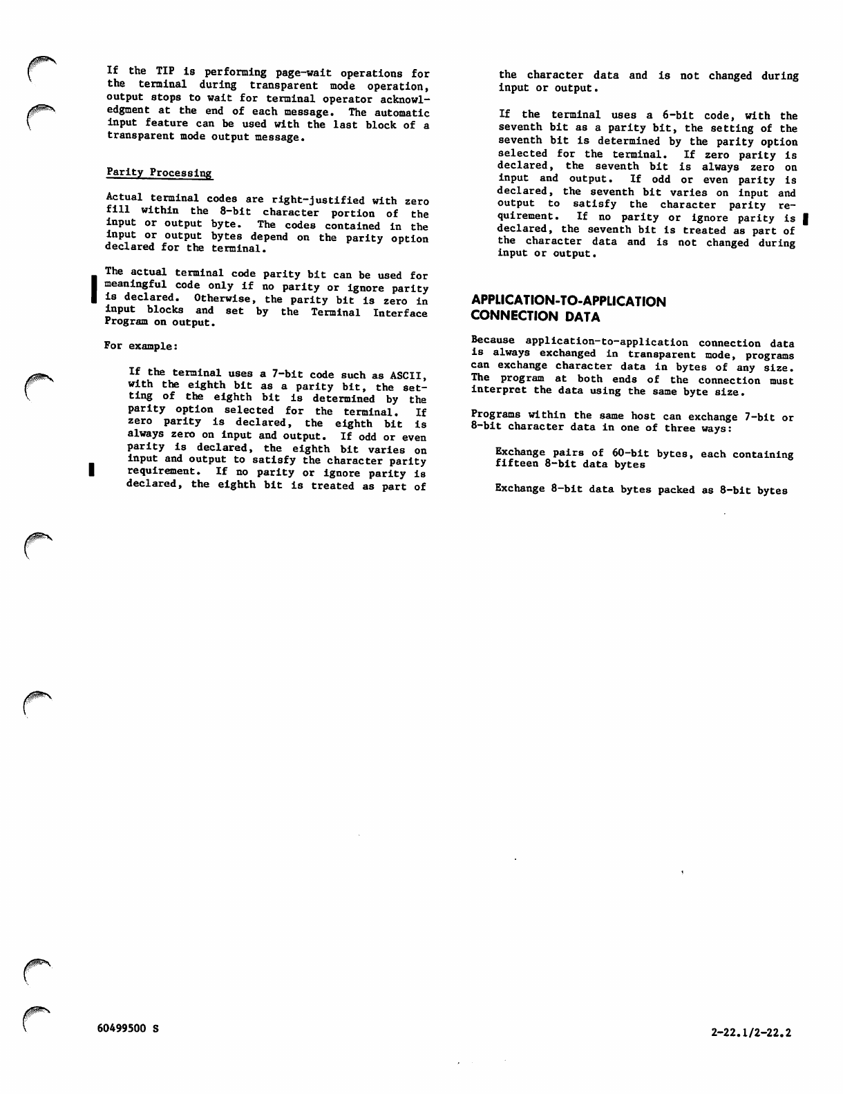
If the TIP is performing page-wait operations for
the terminal during transparent mode operation,
output stops to wait for terminal operator acknowl
edgment at the end of each message. The automatic
input feature can be used with the last block of a
transparent mode output message.
Parity Processing
Actual terminal codes are right-justified with zero
fill within the 8-bit character portion of the
input or output byte. The codes contained in the
input or output bytes depend on the parity option
declared for the terminal.
I The actual terminal code parity bit can be used for
meaningful code only if no parity or ignore parity
Is declared. Otherwise, the parity bit is zero in
input blocks and set by the Terminal Interface
Program on output.
For example:
If the terminal uses a 7-bit code such as ASCII,
with the eighth bit as a parity bit, the set
ting of the eighth bit is determined by the
parity option selected for the terminal. If
zero parity is declared, the eighth bit is
always zero on input and output. If odd or even
parity is declared, the eighth bit varies on
input and output to satisfy the character parity
| requirement. If no parity or ignore parity is
declared, the eighth bit is treated as part of
the c h a r a cter d a t a a n d is not c h a n g e d during
input or output.
If the terminal uses a 6-bit code, with the
sev enth bit a s a p arit y bit, the sett ing o f the
seventh bit is determined by the parity option
selected for the terminal. If zero parity is
declared, the seventh bit is always zero on
input and output. If odd or even parity is
declared, the seventh bit varies on input and
o u t p u t t o s a t i s f y t h e c h a r a c t e r p a r i t y r e
quirement. If no parity or ignore parity is |
declared, the seventh bit is treated as part of
the character data and is not changed during
input or output.
APPLICATION-TO-APPLICATION
CONNECTION DATA
Because application-to-application connection data
is always exchanged in transparent mode, programs
can exchange character data in bytes of any size.
The program at both ends of the connection must
interpret the data using the same byte size.
Programs within the same host can exchange 7-bit or
8-bit character data in one of three ways:
Exchange pairs of 60-bit bytes, each containing
fif t e e n 8 -bi t d a ta by t e s
Exchange 8-bit data bytes packed as 8-bit bytes
60499500 S 2-22.1/2-22.2

Exchange 8-bit data bytes packed within 12-bit
bytes
Each of these options corresponds to an application
character type, as described in the next subsection.
Programs in different hosts need not use the same
application character type.
Programs can exchange 6-bit character data in one
of two ways:
If both programs are in the same host, they can
exchange 60-bit bytes, each containing 6-bit
(or 6/12- bit) data b ytes .
They can exchange sets of fifteen 8-bit bytes,
corresponding to two central memory words per
set (twenty 6-bit characters).
Figure 2-3 illustrates these possibilities. The
p a r i t y b i t ( b i t 7 o f a n 8 - b i t by t e ) i s n o t a l t e r e d
d u r in g t ra n s mi s s io n t hr o u gh t h e n e t wo r k a n d c a n
always be used as data.
APPLICATION CHARACTER TYPES
Blocks always contain character bytes. These char
acter bytes can be of several lengths and can be
packed within bytes of several sizes. Each permit
ted combination of character byte length and packing
byte size i s c a l l e d a n a p p l i c a t i o n c h a r a c t e r t y p e .
There are several application character types sup
ported by the released version of the software:
One 60-bit character byte per 60-bit word
One 8-bit character byte per 8-bit byte
/gP^N
7- Bit or 8-Bit Data
Word 1
60-bit bytes
Byte 1
8-bit bytes
Word 2
Byte 2
12-bit bytes ^| ,^| I|g ~~ j^^ r^~
m m m w, m n
g % » mmm,
6-Bit or 6/12-Bit Data
Word 1 Word 2
60-bit bytes
Byte 1 Byte 2
8-bit bytes
LEGEND: Character byte boundary
| Network data byte boundary
Unused space
Figure 2-3. Application-to-Application Connection Data Exchanges
n ■
60499500 R 2-23
One 8-bit character byte per 12-bit byte
One 6-bit display code character byte per 6-bit
byte
B l o c k s tr a ns m it t ed t h r o u g h a n e t w o r k pr o c e s s i n g
unit always consist of 8-bit characters in 8-bit
bytes. An application program can use blocks of
this application character type, or have NAM convert
bl o c k s t o or f rom i t s o t h at t he ap p l i cati o n p r o
gram can use one of the remaining valid application
character types. Block conversion consists of byte
mapping and character code conversion.
For a downline network data block, NAM:
Performs no mapping or character code conversion
on 60-bit character bytes.
Performs no mapping or character code conversion
on 8-bit characters in 8-bit bytes; the parity
setting of the receiving device might cause the
upper or eighth bit (bit 7) of the byte to be
s e t .
Because conversion and mapping between 6-bit and 8-
bit characters involves a time-consuming character-
by-character replacement of the block's data, use
of a 6-bit display coded application character type
is not recommended and is restricted to blocks
exchanged with interactive devices. For efficiency,
8-bit byte characters are recommended for blocks
exchanged with devices or other application programs
through the interactive virtual terminal interface.
The application character type of an input block is
determined by the character type associated with
the logical connection. This association first
occurs when the connection is established. You can
change the association as necessary while the con
nection exists. The application character type of
a specific input block is always indicated by a
field in its associated block header word.
The application character type of an output block
is determined solely by a field in its associated
block header area. Input and output blocks trans
mitted over the same logical connection can there
fore have different application character types.
Performs no character code conversion on 12-bit
bytes but maps the 8-bit character to an 8-bit
b y t e b y d i s c a r d i n g t h e l e f t m o s t f o u r b i t s o f
the 12; the parity setting of the receiving
device might cause the upper or eighth bit (bit
7) of the byte to be set.
Maps 6-bit characters to 8-bit characters by
translating the former as 6-bit display code
and substituting the corresponding hexadecimal
code from the 128-character ASCII set.
For an upline network data block, NAM:
Performs no mapping or character code conversion
on 60-bit character bytes.
Performs no mapping or character conversion on
8-bit characters in 8-bit bytes; the parity
setting o f the sen ding dev ice might ca use the
upper or eighth bit (bit 7) of the byte to be
set if the data is sent in transparent mode.
Performs character mapping but no code conver
sion by right-justifying 8-bit characters in
1 2 - b i t b y t e s w i t h ze r o fi l l ; t h e p a r i t y s e t t i n g
of the sending device might cause the upper or
eighth bit (bit 7) of the byte to be set if the
data is sent in transparent mode.
Maps and converts 8-bit characters to 6-bit
c h a r a c t e r s b y t r a n s l a t i n g a l l A S C I I c o n t r o l
characters to display coded blanks, and trans
lating all hexadecimal ASCII character codes
between 60 and 7F to the display code equiva
lents of the hexadecimal ASCII character codes
40 to 5F. All other 7-bit ASCII codes are
translated to the display codes equivalent to
the CDC 63-character or 64-character subset of
the ASCII character set (refer to appendix A).
CHARACTER BYTE CONTENT
Blocks containing 8-bit characters can be exchanged
with an interactive device in normalized mode or in
transparent mode. Blocks exchanged in normalized
mode always contain 7-bit character codes from the
A S C I I c h a r a c t e r s e t , w i t h t h e e i g h t h b i t s e t t o
zero. Blocks exchanged in transparent mode can
contain 256 character codes from any character set
used by a terminal, with the setting of the eighth
bit determined by the parity processing selected
for the device. Normalized mode exchanges are the
initial mode. Blocks exchanged in transparent mode
are identified by a field in their associated block
header word.
Blocks exchanged with another application program
are always exchanged in transparent mode. Trans
parent mode is the initial and only exchange mode
for such connections. Such blocks need not have
transparent mode use identified by a field in their
associated block header word.
The legal combinations of character types, modes,
and uses are summarized in table 2-5. The mecha
nisms for declaring character types and exchange
modes are described in the Block Header Content
portion of this section and in section 3.
BLOCK HEADER CONTENT
The content of the block header word associated
with a data block depends on whether the application
program is sending or receiving the block. The
requirements for all header words associated with
upline data blocks are described in figure 2-4.
The requirements for all header words associated
with downline data blocks are described in fig
ure 2-5.
■^^\
2-24 60499500 R
Performs character mapping but no code conver
sion by right-justifying 8-bit characters in
1 2 - b i t b y t e s w i t h ze r o fi l l ; t h e p a r i t y s e t t i n g
of the sending device might cause the upper or
eighth bit (bit 7) of the byte to be set if the
data is sent in transparent mode.
Maps and converts 8-bit characters to 6-bit
characters by translating all ASCII control
characters to display coded blanks, and trans
lating all hexadecimal ASCII character codes
between 60 and 7F to the display code equiva
lents of the hexadecimal ASCII character codes
40 to 5F. All other 7-bit ASCII codes are
translated to the display codes equivalent to
the CDC 63-character or 64-character subset of
the ASCII character set (refer to appendix A).
Because conversion and mapping between 6-bit and 8-
bit characters involves a time-consuming character-
by-character replacement of the block's data, use
of a 6-bit display coded application character type
is not recommended and is restricted to blocks
exchanged with interactive devices. For efficiency,
8-bit byte characters are recommended for blocks
exchanged with devices or other application programs
through the interactive virtual terminal interface.
The application character type of an input block is
determined by the character type associated with
the logical connection. This association first
occurs when the connection is established. You can
change the association as necessary while the con
nection exists. The application character type of
a specific input block is always indicated by a
field in its associated block header word.
The a p p lication c h a r acter t y p e of an o u t p u t block
is determined solely by a field in its associated
block header area. Input and output blocks trans
mitted over the same logical connection can there
fore have different application character types.
CHARACTER BYTE CONTENT
Blocks containing 8-bit characters can be exchanged
with an interactive device in normalized mode or in
transparent mode. Blocks exchanged in normalized
mode always contain 7-bit character codes from the
A S C I I c h a r a c t e r s e t , w i t h t h e e i g h t h b i t s e t t o
zero. Blocks exchanged in transparent mode can
contain 256 character codes from any character set
used b y a te rminal, wit h the set tin g of the eighth
b i t d e te r m i n e d b y t h e p a ri t y p r o c e s s in g s e l ec t e d
for the device. Normalized mode exchanges are the
initial mode. Blocks exchanged in transparent mode
are identified by a field in their associated block
header word.
Blocks exchanged with another application program
are always exchanged in transparent mode. Trans
parent mode is the initial and only exchange mode
for such connections. Such blocks need not have
transparent mode use identified by a field in their
associated block header word.
The legal combinations of character types, modes,
and uses are summarized in table 2-5. The mecha
nisms for declaring character types and exchange
modes are described in the Block Header Content
portion of this section and in section 3.
60499500 T
BLOCK HEADER CONTENT
The content of the block header word associated
with a data block depends on whether the application
p r o g r a m i s s e n d i n g o r r e c e i v i n g t h e b l o c k . T h e
requirements for all header words associated with
u p l i n e d a t a b l o c k s a r e d e s c r i b e d i n fi g u r e 2 - 4 .
The requirements for all header words associated
with downline data blocks are described in
figure 2-5.
SUPERVISORY MESSAGE CONTENT
AND SEQUENCE PROTOCOLS
Supervisory message blocks consist of 1 to 410 60-
bit words or 1 to 2043 12-bit bytes. The fields
within these blocks convey information and instruc
tions to the network software, in a manner similar
to the character bytes of a data message block.
Supervisory messages are sent and received through
the same application program routines as are used
for data blocks. (See sections 4 and 5.) Supervi
sory messages have associated block header words,
just as data blocks do. These header words convey
infor mat ion to t he network sof twa re concerning the
contents of the corresponding text area buffer.
Supervisory messages have the general formats shown
in figures 2-6 and 2-7. A specific message contains
a fixed combination of four fields and can include
additional parameters. The individual messages
supported by the network software are described in
section 3. The fields are described below in the
order of their use, rather than in the order of
their occurrence within a supervisory message.
The first of the four fields common to all supervi
sory messages is the primary function code. The
primary function code is used to group supervisory
messages into related functions and determine their
routing within the network software.
Functions routed between NAM and the application
program are represented in figures 2-6 and 2-7 by
mnemonics. These mnemonics are defined in paren
theses after the corresponding function in the
following list:
Connection data flow control (FC)
Error reporting (ERR)
Device control (CTRL)
Connection list management (LST)
Connection characteristic definition (DC)
Interrupt request (INTR)
Connection control (CON)
Terminal characteristic definition (TCH)
Network shutdown (SHUT)
Host operator commands (HOP)
Terminate output (TO)
Break indication (Bl)
Resume output (RO)
2-25
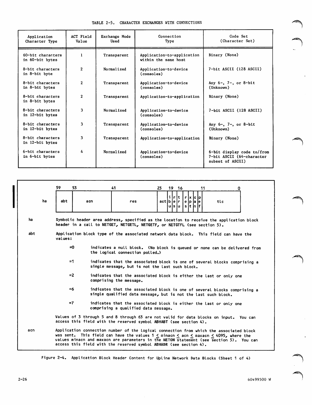
TABLE 2-5. CHARACTER EXCHANGES WITH CONNECTIONS
Application
Character Type
ACT Field
Value
Exchange Mode
Used
Connection
Type
Code Set
(Character Set)
60 -bi t ch ara cters
in 60-bit bytes
Transparent Application-to-application
within the same host
Binary (None)
8-bit characters
in 8-bit byte
Normalized Application-to-device
(consoles)
7-bit ASCII (128 ASCII)
8-bit characters
in 8-bit bytes Transparent Application-to-device
(consoles)
Any 6-, 7-, or 8-bit
(Unknown)
8-bit characters
in 8-bit bytes Transparent Application-to-application Binary (None)
8-bit characters
in 12-bit bytes
Normalized Application-to-device
(consoles)
7-bit ASCII (128 ASCII)
8-bit characters
in 12-bit bytes
Transparent Application-to-device
(consoles)
Any 6-, 7-, or 8-bit
(Unknown)
8-bit characters
in 12-bit bytes
Transparent Application-to-application Binary (None)
6-bit characters
in 6-bit bytes
Normalized Application-to-device
(consoles)
6-bit display code to/from
7-bit ASCII (64-character
subset of ASCII)
<*^^\
ha
abt
ha
59 53 41 23 19 16 11
i r t r XcP
abt a en res act t i c
Symbolic header area address, specified as the location to receive the application block
header in a call to NETGET, NETGETL, NETGETF, or NETGTFL (see section 5).
Application block type of the associated network data block. This field can have the
values:
=0 indicates a null block. (No block is queued or none can be delivered from
the logical connection polled.)
=1 indicates that the associated block is one of several blocks comprising a
single message, but is not the last such block.
= 2 in d i c a t e s t h a t th e a s s o c i a t e d bl o c k i s ei t h e r t h e la s t o r o n l y o n e
comprising the message.
=6 indicates that the associated block is one of several blocks comprising a
single qualified data message, but is not the last such block.
= 7 in d i c a t e s t h a t th e a s s o c i a t e d bl o c k i s ei t h e r t h e la s t o r o n l y o n e
comprising a qualified data message.
Values of 3 through 5 and 8 through 63 are not valid for data blocks on input. You can
access this field with the reserved symbol ABHABT (see section 4).
Application connection number of the logical connection from which the associated block
was sent. This field can have the values 1 £ minacn < acn £ maxacn < 4095, where the
values minacn and maxacn are parameters in the NETON statement (see section 5). You can
access this field with the reserved symbol ABHADR (see section 4).
Figure 2-4. Application Block Header Content for Upline Network Data Blocks (Sheet 1 of 4)
2-26 60499500 W
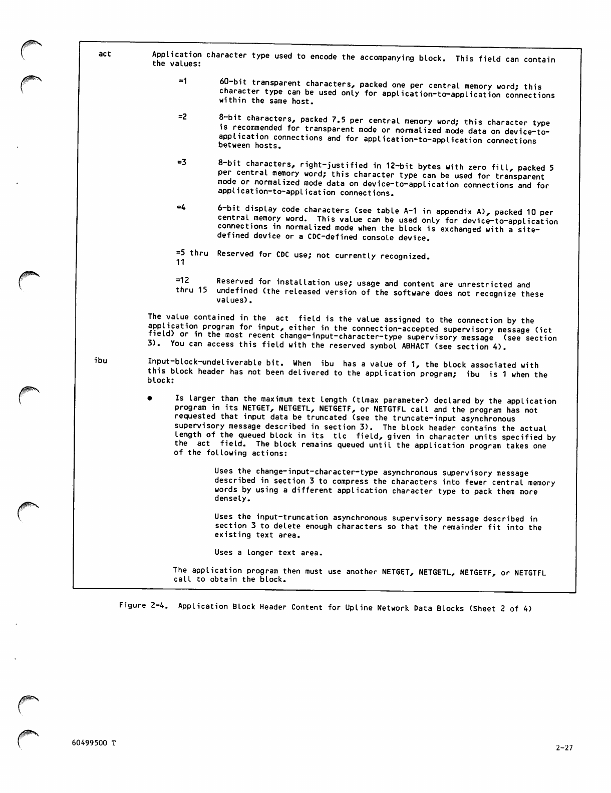
act Application character type used to encode the accompanying block,
the values:
=1
This field can contain
60-bit transparent characters, packed one per central memory word; this
character type can be used only for application-to-application connections
within the same host.
8-bit characters, packed 7.5 per central memory word; this character type
is recommended for transparent mode or normalized mode data on device-to-
application connections and for application-to-application connections
between hosts.
8-bit characters, right-justified in 12-bit bytes with zero fill, packed 5
per central memory word; this character type can be used for transparent
mode or normalized mode data on device-to-application connections and for
application-to-application connections.
6-bit display code characters (see table A-1 in appendix A), packed 10 per
central memory word. This value can be used only for device-to-application
connections in normalized mode when the block is exchanged with a site-
defined device or a CDC-defined console device.
=5 thru Reserved for CDC use; not currently recognized.
11
=2
=3
=4
=12
thru 15
Reserved for installation use; usage and content are unrestricted and
undefined (the released version of the software does not recognize these
values).
ibu
The value contained in the act field is the value assigned to the connection by the
application program for input, either in the connection-accepted supervisory message (ict
Tieicu or in the most recent change-input-character-type supervisory message (see section
3). You can access this field with the reserved symbol ABHACT (see section 4).
Input-block-undeliverable bit. When ibu has a value of 1, the block associated with
this block header has not been delivered to the application program; ibu is 1 when the
block:
• Is larger than the maximum text length (Umax parameter) declared by the application
program in its NETGET, NETGETL, NETGETF, or NETGTFL call and the program has not
requested that input data be truncated (see the truncate-input asynchronous
supervisory message described in section 3). The block header contains the actual
length o f the queued b l o ck in its t i c fi eld, given i n character u n i t s specified b y
the act field. The block remains queued until the application program takes one
of the following actions:
Uses the change-input-character-type asynchronous supervisory message
described in section 3 to compress the characters into fewer central memory
words by using a different application character type to pack them more
densely.
Uses the input-truncation asynchronous supervisory message described in
section 3 to delete enough characters so that the remainder fit into the
existing text area.
Uses a longer text area.
The application program then must use another NETGET, NETGETL, NETGETF, or NETGTFL
call to obtain the block.
Figure 2-4. Application Block Header Content for Upline Network Data Blocks (Sheet 2 of 4)
/$^>\
60499500 T 2-27
• Contains transparent mode data from a connection using an act value of 4. The
block header contains the actual length of the queued block in its tic field
(given in 8-bit bytes) and has an xpt value of 1 (see xpt field description).
The application program can:
Change the input character type for the connection to a value of 2 or 3,
using the change-input-character-type asynchronous supervisory message
described in section 3, then use a NETGET, NETGETL, NETGETF, or NETGTFL
call to obtain the block.
Use the change-input-character-type asynchronous supervisory message with a
set nxp bit as described in section 3; this discards the queued block and
all subsequent blocks of transparent data from the connection.
• Is queued on a connection between application programs within the same host and the
act value specified by your application does not match the act value specified by
the other application in its NETPUT call for the block. The application program can:
Change the input character type for the connection using the change-input-
character-type asynchronous supervisory message described in section 3,
then use a NETGET, NETGETL, NETGETF, or NETGTFL call to obtain the block.
You can access this field with the reserved symbol ABHIBU (see section 4).
res Reserved for CDC use.
tru Truncated data bit. When tru is 1, the block associated with this block header has been
truncated to fit into the text area used. When tru is 0, the block has not been
truncated. The tru bit cannot be 1 unless the application program has issued the data
truncation control asynchronous supervisory message described in section 3 and that
message affects transmissions on this connection. When truncation occurs, the tic field
contains the maximum number of complete transferred character bytes of the block. You can
access the tru field with the reserved symbol ABHTRU (see section 4).
xpt Transparent mode bit, indicating whether the accompanying block contains transparent mode
data. If your program chooses not to receive transparent mode input when it accepts a
connection or changes the input character type of the connection (nxp field, described in
section 3), an xpt value of 1 is received in a block with an abt of 0 (an empty block)
and indicates that one or more transparent mode blocks were discarded by the network
software.
If your program can receive transparent mode input, the interpretation of the value this
field contains depends on the act value used, as follows:
act=1, xpt should be ignored.
act=2, if the data is from a site-defined device or a CDC-defined console device:
xpt=0 indicates normalized mode data for which interactive virtual terminal
transformations were performed; 7-bit characters are from the
128-character ASCII set (see appendix A).
xpt=1 indicates transparent mode data for which no transformations were
performed; all eight bit positions might be used to form 256
characters, but the application program must correctly interpret the
format of such data.
act=2, if the data is from an application program:
xpt=0 indicates that the sending application program did not use an xpt
value of 1 in its block header for the accompanying block.
xpt=1 indicates that the sending application program used an xpt value of
1 in its block header for the accompanying block.
Figure 2-4. Application Block Header Content for Upline Network Data Blocks (Sheet 3 of 4)
2-28 60499500 W
pef
tic
act=3, if the data is from a site-defined device or a CDC-defined console device:
xpt=0 indicates normalized mode data for which interactive virtual terminal
transformations were performed; 7-bit characters are from the
128-character ASCII set (see appendix A).
xpt=1 indicates transparent mode data for which no transformations were
performed; all eight bit positions in the character portion of the
character byte might be used to form 256 characters, but the
application program, must correctly interpret the format of such data.
act=3, if the data is from an application program:
xpt=0 indicates that the sending application programt did not use an xpt
value of 1 in its block header for the accompanying block.
xpt=1 indicates that the sending application programt used an xpt value of
1 in its block header for the accompanying block.
act=4, if the data is from a site-defined device or a CDC-defined console device:
xpt=0 indicates normalized mode data for which interactive virtual terminal
transformations were performed; 6-bit characters are from the 6-bit
display code set (see table A-1 in appendix A).
xpt=1 indicates that the ibu bit is also set; the tic field contains the
actual block length in 8-bit characters (not in 6-bit characters).
Transparent mode is not supported for act=4; a change-input-
character-type supervisory message must be issued before the block
can be received (see section 3).
You can access this field with the reserved symbol ABHXPT (see section 4).
Cancel-input bit. When can is 1, the terminal operator used the cancel-input key
defined for the device or the break condition key (see BR command in section 3) to end the
text in the associated block. The associated block always has an abt of 2, and the data
is always from a console device. The cancel-input request also applies to any blocks with
an abt value of 1 that preceded this block; all blocks in the same message should be
discarded. You can access this field with the reserved symbol ABHCAN (see section 4).
Parity error flag bit. When pef is 1, the associated block contains a parity error in
one or more of its characters. You can access this field with the reserved symbol ABHBIT
(see section 4).
Text leng t h o f th e a s s o c i a t e d b l o c k , i n c h a r a c t e r u n i t s s p e c i fi e d b y t h e a c t fi e l d . The
equivalent length in central memory words can be computed as follows:
act=1, tic is the number of central memory words the block requires.
act=2, the number of central memory words the block requires is tic divided by
7.5, rounded upward to an integer.
act=3,
act=4,
act=5
t h r u
15
the number of central memory words the block requires is tic divided by
5, rounded upward to an integer.
the number of central memory words the block requires is tic divided by
10, rounded upward to an integer.
tic is undefined.
You can access this field with the reserved symbol ABHTLC (see section 4).
tThe xpt value will always be set to 0 in the upline network block if the data passes through a
packet switching network. Therefore, to get consistent results, it is strongly suggested that xpt=0
be used on all application-to-application connections.
Figure 2-4. Application Block Header Content for Upline Network Data Blocks (Sheet 4 of 4)
60499500 T 2-29
ha
abt
abn
act
ha
59 53 41 2 3 '19 1514131211
nnx nr
abt acn abn act t i c
Symbolic header area address, specified as the application block header's location in a
call to NETPUT or NETPUTF (see section 5).
Application block type of the accompanying network data block. This field can contain the
values:
=1, indicates that the accompanying block is one of several blocks comprising a
single message, but is not the last such block.
=2, in d i c a t e s t h at t h e a ccompanyi n g b l o c k i s e i ther t he l a s t o r o n l y o n e
comprising a message.
=6 indicates that the associated block is one of several blocks comprising a
single qualified data message, but is not the last such block.
= 7 in d i c a t e s t h a t th e a s s o c i a t e d bl o c k i s ei t h e r t h e la s t o r o n l y o n e
comprising a qualified data message.
Values of 0, 3 through 5, and 8 through 63 are not valid for data blocks on output. You
can access this field with the reserved symbol ABHABT (see section 4).
Application connection number of the logical connection to which the accompanying block
should be sent. This field can contain the values 1 £ minacn £ acn £ maxacn £ 4095, where
the values minacn and maxacn are parameters in the NETON statement (see section 5.) You
can access this field with the reserved symbol ABHADR (see section 4).
Application block number assigned to the block being sent. This field is an 18-bit
integer that identifies the block when the network software's processing of the block
returns certain supervisory messages (see section 3). You define the block number; it can
be:
A sequencing number
The block's central memory address
The block's mass storage address (physical record unit)
An index value for a block control array or table
An external label
You can access this field with the reserved symbol ABHABN (see section 4).
Application character type used to encode the accompanying block. This field can contain
the values:
=1, 60-bit transparent characters, packed one per central memory word; this
character type can be used only for application-to-application connections
within the same host.
=2, 8-bit characters, packed 7.5 per central memory word; this character type
is recommended for transparent mode data or normalized mode data on
device-to application connections or for application-to application
connections between hosts.
=3, 8-bit characters, right-justified in 12-bit bytes, packed 5 per central
memory word; this character type can be used for transparent mode or
normalized mode data on device-to-application connections, or for
application-to-application connections.
Figure 2-5. Application Block Header Content for Downline Network Data Blocks (Sheet 1 of 3)
2-30 60499500 W
/0£\,
ncp
nfe
xpt
=4, 6-bit display code characters (see table A-1 in appendix A), packed 10 per
central memory word. This value can be used only for normalized mode data
on application-to-terminal connections when the block is exchanged with a
site-defined device or a CDC-defined console device.
=5 thru Reserved for CDC use; not currently recognized.
11
=l2 ,c Re"^ved for installation use; usage and content are unrestricted and
thru 15 undefined (the released version of the software does not recognize these
values).
You can access this field with the reserved symbol ABHACT (see section 4).
No-cursor-positioning bit, indicating whether cursor positioning is to be disabled for the
input operation that immediately follows this output block. If ncp is 1, no cursor
positioning is to be performed for the next input operation; if ncp is 0, cursor
positioning can be performed for the next operation. This bit is ignored for blocks sent
on application-to-application connections and for blocks with an abt of 1 on
«HMrrJ0"aPPl1^ti0^C°nneCti0nS* Y°U Can access th1s fieLd with the reserved symbol
ABHNCP (see section 4).
No-format-effector bit, indicating whether the accompanying block contains format
henf'cto;s; .If "fe JsJ' there are no format effectors in the block; if nfe is 0, the
block contains format effectors requiring removal and interpretation. The nfe field
applies only to normalized mode data exchanged with a site-defined device or a CDC-defined
console device. You can access this field with the reserved symbol ABHNFE (see section 4).
Transparent mode bit, indicating whether the accompanying block contains transparent mode
data. The value used in this field depends on the act value used, as follows:
act=1, xpt value does not determine data translation and can be 1 or 0. A value
of 0 is recommended.
act=2, if the data is for a site-defined device or a CDC-defined console device:
xpt=0 indicates normalized mode data for which interactive virtual terminal
transformations should be performed; 7-bit characters are from the
128-character ASCII set (see appendix A).
xpt=1 indicates transparent mode data for which no transformations are to
be performed; all eight bit positions can be used to form 256
characters (if parity of none is used), but such data must be
cor rectl y form atte d for termi nal o utpu t .
act=2, if the data is for an application program, xpt does not affect data
translation and can be 1 or 0. For data passing through a public data
network, the receiving application will always see xpt=0. Therefore, it
is strongly recommended that a value of xpt=0 be used by the sender.
act=3, if the data is for a site-defined device or a CDC-defined console device:
xpt=0 indicates normalized mode data for which interactive virtual terminal
transformations should be performed; 7-bit characters are from the
128-character ASCII set (see appendix A).
xpt=1 indicates transparent mode data for which no transformations are
perfo rme d; all eight b it positions in t he character por tio n of the
character byte can be used to form 256 characters (if parity of none
is used), but such data must be correctly formatted for terminal
output.
ac t = 3 , i f t he d ata is f o r a n a ppli c a t i on pro g r a m, x pt d oes n o t a f f e c t d ata
translation and can be 1 or 0. For data passing through a public data
network, the receiving application will always see xpt=0. Therefore, it
is strongly recommended that a value of xpt=0 be used by the sender.
act=4, xpt value does not determine data translation and can be 1 or 0. A value
of 0 is recommended.
Figure 2-5. Application Block Header Content for Downline Network Data Blocks (Sh eet 2 of 3)
60499500 W 2-31
act=
other xpt is not defined.
You can access this field with the reserved symbol ABHXPT (see section 4).
nep No-echoplexing bit, indicating whether the next logical line of nontransparent input data
should not be echoplexed. If nep is 1 and the NPU is echoing characters back to the
terminal (Y value of EP command, described in NAM Version 1/CCP Version 3 Terminal
Interfaces reference manual), the NPU does not echo the next logical line from the
console. If nep is 0 and the NPU is echoing characters (Y value of EP command), the NPU
does echo the next logical line of input. This bit is ignored for blocks sent on
application-to-application connections and for blocks with an abt of 1 on
device-to-application connections. You can access this field with the reserved symbol
ABHNEP (see section 4).
res Reserved for CDC use. Reserved fields contain zero.
tic Text Length of the associated block, in character units specified by the act value. The
value to use in the tic field can be computed as follows:
act=1, tic is the number of central memory words occupied by the block.
act=2, tic is the number of complete central memory words occupied by the block
times 7.5, plus the number of complete character bytes used in any
remaining central memory word, rounded upward to an integer.
act=3, tic is the number of complete central memory words occupied by the block
times 5, plus the number of 12-bit character bytes used in any remaining
central memory word.
act=4, tic is the number of complete central memory words occupied by the block
times 10.
act=5 tic is not defined.
thru 15
The character count used as the text length must include any format effectors and
end-of-line indicator bytes contained in the block. You can access this field with the
reserved symbol ABHTLC (see section 4).
Figure 2-5. Application Block Header Content for Downline Network Data Blocks (Sheet 3 of 3)
The precise function of a message within a primary
function grouping is indicated by its secondary
function code, forming the fourth common field. The
mnemonic symbols used to identify these secondary
function codes are related to the use of the mes
sages. Mnemonics for these codes also appear in
figures 2-6 and 2-7 and in parentheses after the
secondary functions in the following list:
Request for logical connection (REQ)
End of connection (END)
Connection broken (CB)
Application-to-application connection request
(ACRQ)
Internal shutdown (INSD)
Inactive connection (INACT)
No acknowledgment (NAK)
Acknowledgment (ACK)
Reset (RST)
Break (BRK)
Logical problem (LGL)
Initialization (INIT)
Mark point in data (MARK)
Switch connection between lists (SWH)
Turn connection list processing off (OFF)
Turn connection list processing on (ON)
Turn half-duplex operation on for connection on
a list (HDX)
Turn full-duplex operation on for connection on
a list (FDX)
Begin truncating input on a connection (TRU)
Application interrupt request (APP)
User Interrupt request (USR) <*^Sv
2-32 60499500 W
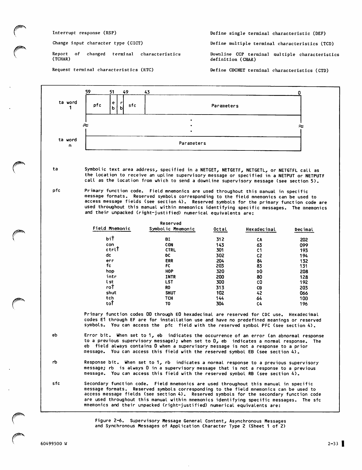
Interrupt response (RSP)
Change input character type (CICT)
Report of changed terminal characteristics
(TCHAR)
Request terminal characteristics (RTC)
Define single terminal characteristic (DEF)
Define multiple terminal characteristics (TCD)
Downline CCP terminal multiple characteristics
definition (CHAR)
Define CDCNET terminal characteristics (CTD)
ta word
1
ta word
n
ta
pfc
eb
rb
sfc
59 51 49 43
pfc sfc Parameters
•
/g^?N,
Parameters
Symbolic text area address, specified in a NETGET, NETGETF, NETGETL, or NETGTFL call as
the location to receive an upline supervisory message or specified in a NETPUT or NETPUTF
call as the location from which to send a downline supervisory message (see section 5).
Primary function code. Field mnemonics are used throughout this manual in specific
message formats. Reserved symbols corresponding to the field mnemonics can be used to
access message fields (see section 4). Reserved symbols for the primary function code are
used throughout this manual within mnemonics identifying specific messages. The mnemonics
and their unpacked (right-justified) numerical equivalents are:
Reserved
Field Mnemonic Symbolic Mmemonic Octal Hexadecimal Decimal
bit Bl 312 CA 202
con CON 143 63 099
ctrlt CTRL 301 C1 193
dc DC 302 C2 194
err ERR 204 84 132
fc FC 203 83 131
hop HOP 320 DO 208
intr INTR 200 80 128
1st LST 300 CO 192
rot RO 313 CB 203
shut SHUT 102 42 066
tch TCH 144 64 100
tot TO 304 C4 196
Primary function codes 00 through E0 hexadecimal are reserved for CDC use. Hexadecimal
codes E1 through EF are for installation use and have no predefined meanings or reserved
symbols. You can access the pfc field with the reserved symbol PFC (see section 4).
Error bit. When set to 1, eb indicates the occurrence of an error (an abnormal response
to a previous supervisory message); when set to 0, eb indicates a normal response. The
eb field always contains 0 when a supervisory message is not a response to a prior
message. You can access this field with the reserved symbol EB (see section 4).
Response bit. When set to 1, rb indicates a normal response to a previous supervisory
message; rb is always 0 in a supervisory message that is not a response to a previous
message. You can access this field with the reserved symbol RB (see section 4).
Secondary function code. Field mnemonics are used throughout this manual in specific
message formats. Reserved symbols corresponding to the field mnemonics can be used to
access message fields (see section 4). Reserved symbols for the secondary function code
are used throughout this manual within mnemonics identifying specific messages. The sfc
mmemonics and their unpacked (right-justified) numerical equivalents are:
Figure 2-6. Supervisory Message General Content, Asynchronous Messages
and Synchronous Messages of Application Character Type 2 (Sheet 1 of 2)
60499500 W 2-33 |
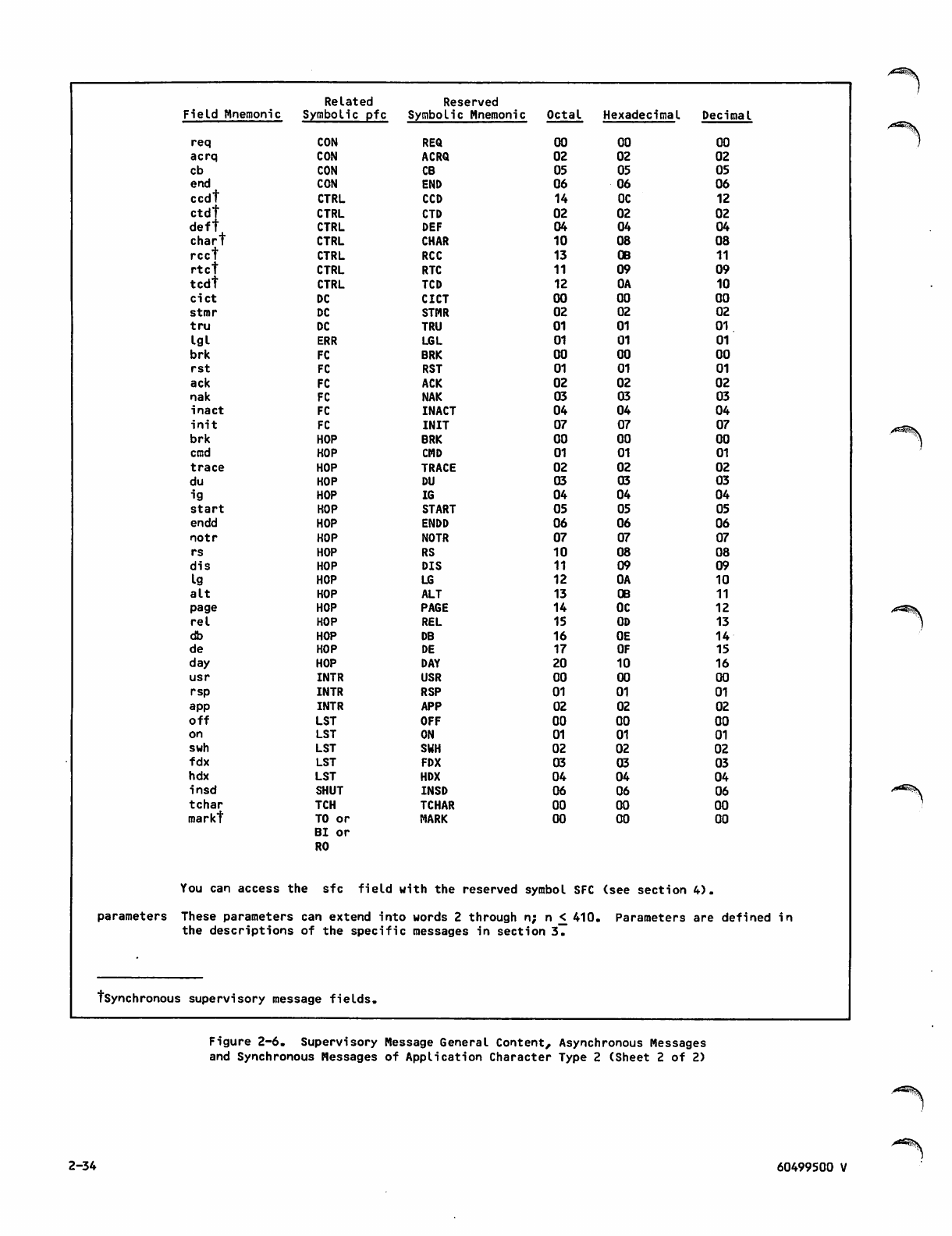
Related Reserved
Field Mnemonic Symbolic pfc Symbolic M nem oni c Octal Hexadecimal Decimal
req CON REQ 00 00 00
acrq CON ACRQ 02 02 02
cb CON CB 05 05 05
end CON END 06 06 06
ccdt CTRL CCD 14 OC 12
ctdt CTRL CTD 02 02 02
deft CTRL DEF 04 04 04
chart CTRL CHAR 10 08 08
rcct CTRL RCC 13 OB 11
rtct CTRL RTC 11 09 09
tcdt CTRL TCD 12 OA 10
cict DC CICT 00 00 00
stmr DC STMR 02 02 02
tru DC TRU 01 01 01
igi ERR LGL 01 01 01
brk FC BRK 00 00 00
rst FC RST 01 01 01
ack FC ACK 02 02 02
nak FC NAK 03 03 03
inact FC INACT 04 04 04
init FC INIT 07 07 07
brk HOP BRK 00 00 00
cmd HOP CMD 01 01 01
trace HOP TRACE 02 02 02
du HOP DU 03 03 03
ig HOP IG 04 04 04
start HOP START 05 05 05
endd HOP ENDD 06 06 06
n o t r HOP NOTR 07 07 07
rs HOP RS 10 08 08
dis HOP DIS 11 09 09
ig HOP LG 12 OA 10
alt HOP ALT 13 OB 11
page HOP PAGE 14 OC 12
re I HOP REL 15 OD 13
db HOP DB 16 OE 14
de HOP DE 17 OF 15
day HOP DAY 20 10 16
usr INTR USR 00 00 00
rsp INTR RSP 01 01 01
app INTR APP 02 02 02
off LST OFF 00 00 00
on LST ON 01 01 01
swh LST SWH 02 02 02
fdx LST FDX 03 03 03
hdx LST HDX 04 04 04
insd SHUT INSD 06 06 06
tchar TCH TCHAR 00 00 00
markt TO or
Bl or
RO
MARK 00 00 00
You can access the sfc field with the reserved symbol SFC (see section 4).
parameters These parameters can extend into words 2 through n; n < 410. Parameters are defined in
the des crip tio ns of the s p e c i fi c messages in section 3.
tsynchronous supervisory message fields.
Figure 2-6. Supervisory Message General Content, Asynchronous Messages
and Synchronous Messages of Application Character Type 2 (Sheet 2 of 2)
2-34
/^Sfey
60499500 V
/0^\
jPfc\
Functions routed between NAM and the application
program are represented in figures 2-6 and 2-7 by
mnemonics. These mnemonics are defined in paren
theses after the corresponding function in the
following list:
Connection data flow control (FC)
Error reporting (ERR)
Device control (CTRL)
Connection list management (LST)
Connection characteristic definition (DC)
Interrupt request (INTR)
Connection control (CON)
Terminal characteristic definition (TCH)
Network shutdown (SHUT)
Host operator commands (HOP)
Terminate output (TO)
Break indication (Bl)
Resume output (RO)
The precise function of a message within a primary
function grouping is indicated by its secondary
function code, forming the fourth common field. The
mnemonic symbols used to identify these secondary
function codes are related to the use of the mes
sages. Mnemonics for these codes also appear in
figures 2-6 and 2-7 and in parentheses after the
secondary functions in the following list:
Request for logical connection (REQ)
End of connection (END)
Connection broken (CB)
Application-to-application connection request
(ACRQ)
Internal shutdown (INSD)
Inactive connection (INACT)
No acknowledgment (NAK)
Acknowledgment (ACK)
Reset (RST)
Break (BRK)
Logical problem (LGL)
Initialization (INIT)
Mark point in data (MARK)
Switch connection between lists (SWH)
Turn connection list processing off (OFF)
Turn connection list processing on (ON)
Turn half-duplex operation on for connection on
a list (HDX)
Turn full-duplex operation on for connection on
a list (FDX)
Begin truncating input on a connection (TRU)
Application interrupt request (APP)
User interrupt request (USR)
Interrupt response (RSP)
Change input character type (CICT)
Report of changed terminal characteristics
(TCHAR)
Request terminal characteristics (RTC)
Define single terminal characteristic (DEF)
Upline terminal multiple characteristics defi
nition (TCD)
Downline terminal multiple characteristics def
inition (CHAR)
The second and third common fields are use d to
indicate whether the function was performed or not.
B y c o n v e n t i o n , t h e s e fi e l d s a r e c a l l e d t h e e r r o r
and response bits. The error bit is usually set to
indicate the message recipient's refusal to perform
the function; the response bit is set to indicate
the recipient's normal completion of the function.
Together, the four common fields define one super
visory message. Supervisory messages can be grouped
into two classes of sequencing protocol:
Asynchronous (the largest class)
Synchronous
ASYNCHRONOUS MESSAGES
Asynchronous supervisory messages are sent or
received separately from the stream of data message
blocks between an application program and a logical
connection. Their receipt or the need to send them
cannot be predicted from the generalized logic
required for data block processing. Such messages
a r e s a i d t o b e a s y n c h r o n o u s t o t h e d a t a b l o c k
stream.
All asynchronous messages are sent or received on a
special logical connection with the preassigned
application connection number of zero. The network
software preassigns this application connection
number to connection list zero.
All asynchronous supervisory messages are actually
sent to or received from software resident in the
host computer, although they may be reformatted by
this software for communication with software out
side of the host. These messages conform to the
requirements of application-to-application connec
tions. Asynchronous supervisory messages therefore
use an application character type of one. All
supervisory messages are assigned the nonzero
application block type of three.
60499500 R 2-35
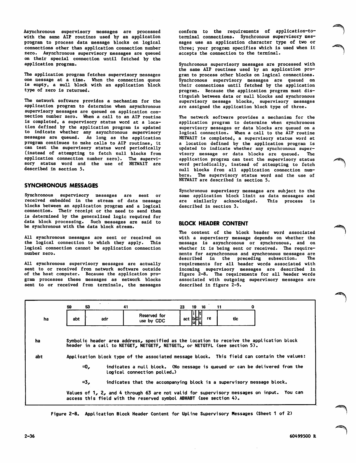
Asynchronous supervisory messages are processed
with the same AIP routines used by an application
program to process data message blocks on logical
connections other than application connection number
zero. Asynchronous supervisory messages are queued
on their special connection until fetched by the
application program.
The application program fetches supervisory messages
one message at a time. When the connection queue
is empty, a null block with an application block
type of zero is returned.
The network software provides a mechanism for the
application program to determine when asynchronous
supervisory messages are queued on application con
nection number zero. When a call to an AIP routine
is completed, a supervisory status word at a loca
tion defined by the application program is updated
to indicate whether any asynchronous supervisory
messages are queued. As long as the application
program continues to make calls to AIP routines, it
c a n t est t h e sup e r v is o r y sta t u s w ord p e rio d i cal l y
(instead of attempting to fetch null blocks from
appl icati o n conne ction n u mber zero) . The s uperv i
s o r y s t a t u s w o r d a n d t h e u s e o f N E T WA I T a r e
described in section 5.
SYNCHRONOUS MESSAGES
Synchronous supervisory messages are sent or
received embedded in the stream of data message
blocks between an application program and a logical
connection. Their receipt or the need to send them
is determined by the generalized logic required for
data block processing. Such messages are said to
be synchronous with the data block stream.
All synchronous messages are sent or received on
t h e l o gi c a l c on n e c ti o n t o w h i ch t h e y a p p ly. T hi s
logical connection cannot be application connection
number zero.
All synchronous supervisory messages are actually
sent to or received from network software outside
of the host computer. Because the application pro
gram processes these messages as network blocks
sent to or received from terminals, the messages
conform to the requirements of application-to-
terminal connections. Synchronous supervisory mes
sages use an application character type of two or
three; your program specifies which is used when it
accepts the connection to the terminal.
Synchronous supervisory messages are processed with
the same AIP routines used by an application pro
gram to process other blocks on logical connections.
Synchronous supervisory messages are queued on
their connections until fetched by the application
program. Because the application program must dis
tinguish between data or null blocks and synchronous
supervisory message blocks, supervisory messages
are assigned the application block type of three.
The network software provides a mechanism for the
application program to determine when synchronous
supervisory messages or data blocks are queued on a
logical connection. When a call to the AIP routine
NETWAIT is completed, a supervisory status word at
a location defined by the application program is
updated to indicate whether any synchronous super
visory message or data blocks are queued. The
application program can test the supervisory status
word periodically, instead of attempting to fetch
null blocks from all application connection num
bers. The supervisory status word and the use of
NETWAIT are described in section 5.
Synchronous supervisory messages are subject to the
same application block limit as data messages and
are similarly acknowledged. This process is
described in section 3.
BLOCK HEADER CONTENT
The content of the block header word associated
with a supervisory message depends on whether the
message is asynchronous or synchronous, and on
whether it Is being sent or received. The require
ments for asynchronous and synchronous messages are
described in the preceding subsection. The
requirements for all header words associated with
i n co m i n g su p e r v i s or y me s sa g e s a r e d es c r i b e d i n
figure 2-8. The requirements for all header words
associated with outgoing supervisory messages are
described in figure 2-9.
ha
ha
abt
59 53 41 23 1 9 1 6 11
abt adr Reserved for
use by CDC act b3 tic
Symbolic header area address, specified as the location to receive the application block
header in a call to NETGET, NETGETF, NETGETL, or NETGTFL (see section 5).
Application block type of the associated message block. This field can contain the values:
=0, indicates a null block. (No message is queued or can be delivered from the
logical connection polled.)
=3, indicates that the accompanying block is a supervisory message block.
Values of 1, 2, and 4 through 63 are not valid for supervisory messages on input. You can
access this field with the reserved symbol ABHABT (see section 4).
Figure 2-8. Application Block Header Content for Upline Supervisory Messages (Sheet 1 of 2)
2-36 60499500 R
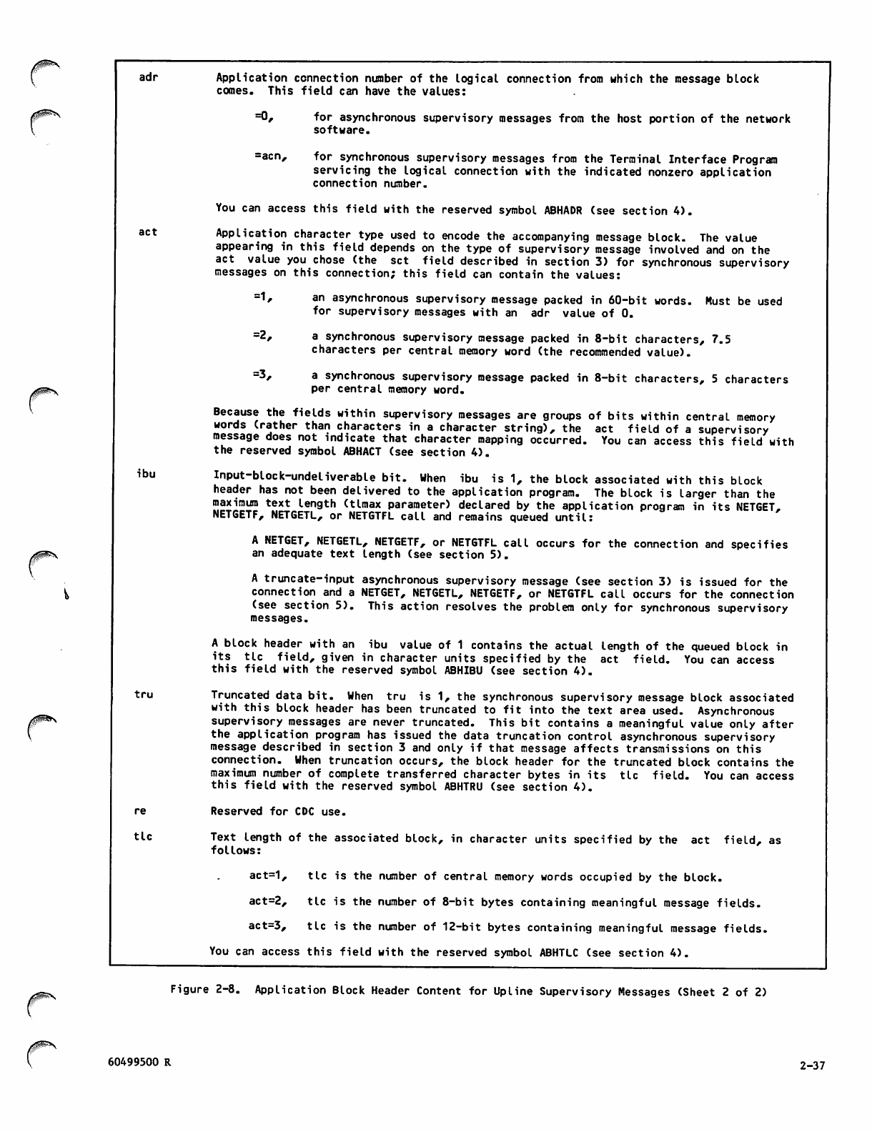
J^>\
adr
act
ibu
tru
re
tic
Application connection number of the logical connection from which the message block
comes. This field can have the values:
=0, for asynchronous supervisory messages from the host portion of the network
software.
=acn, for synchronous supervisory messages from the Terminal Interface Program
servicing the logical connection with the indicated nonzero application
connection number.
You can access this field with the reserved symbol ABHADR (see section 4).
Application character type used to encode the accompanying message block. The value
appearing in this field depends on the type of supervisory message involved and on the
act value you chose (the set field described in section 3) for synchronous supervisory
messages on this connection; this field can contain the values:
=1, an asynchronous supervisory message packed in 60-bit words. Must be used
for supervisory messages with an adr value of 0.
=2, a synchronous supervisory message packed in 8-bit characters, 7.5
characters per central memory word (the recommended value).
=3, a synchronous supervisory message packed in 8-bit characters, 5 characters
per central memory word.
Because the fields within supervisory messages are groups of bits within central memory
words (rather than characters in a character string), the act field of a supervisory
message does not indicate that character mapping occurred. You can access this field with
the reserved symbol ABHACT (see section 4).
Input-block-undeliverable bit. When ibu is 1, the block associated with this block
header has not been delivered to the application program. The block is larger than the
maximum text length (tlmax parameter) declared by the application program in its NETGET,
NETGETF, NETGETL, or NETGTFL call and remains queued until:
A NETGET, NETGETL, NETGETF, or NETGTFL call occurs for the connection and specifies
an adequate text length (see section 5).
A truncate-input asynchronous supervisory message (see section 3) is issued for the
connection and a NETGET, NETGETL, NETGETF, or NETGTFL call occurs for the connection
(see section 5). This action resolves the problem only for synchronous supervisory
messages.
A block header with an ibu value of 1 contains the actual length of the queued block in
its tic field, given in character units specified by the act field. You can access
this field with the reserved symbol ABHIBU (see section 4).
Truncated data bit. When tru is 1, the synchronous supervisory message block associated
with this block header has been truncated to fit into the text area used. Asynchronous
supervisory messages are never truncated. This bit contains a meaningful value only after
the application program has issued the data truncation control asynchronous supervisory
message described in section 3 and only if that message affects transmissions on this
connection. When truncation occurs, the block header for the truncated block contains the
maximum number of complete transferred character bytes in its tic field. You can access
this field with the reserved symbol ABHTRU (see section 4).
Reserved for CDC use.
Text length of the associated block, in character units specified by the act field, as
follows:
act=1, tic is the number of central memory words occupied by the block.
act=2, tic is the number of 8-bit bytes containing meaningful message fields.
act=3, tic is the number of 12-bit bytes containing meaningful message fields.
You can access this field with the reserved symbol ABHTLC (see section 4).
0^\ Figure 2-8. Application Block Header Content for Upline Supervisory Messages (Sheet 2 of 2)
60499500 R 2-37
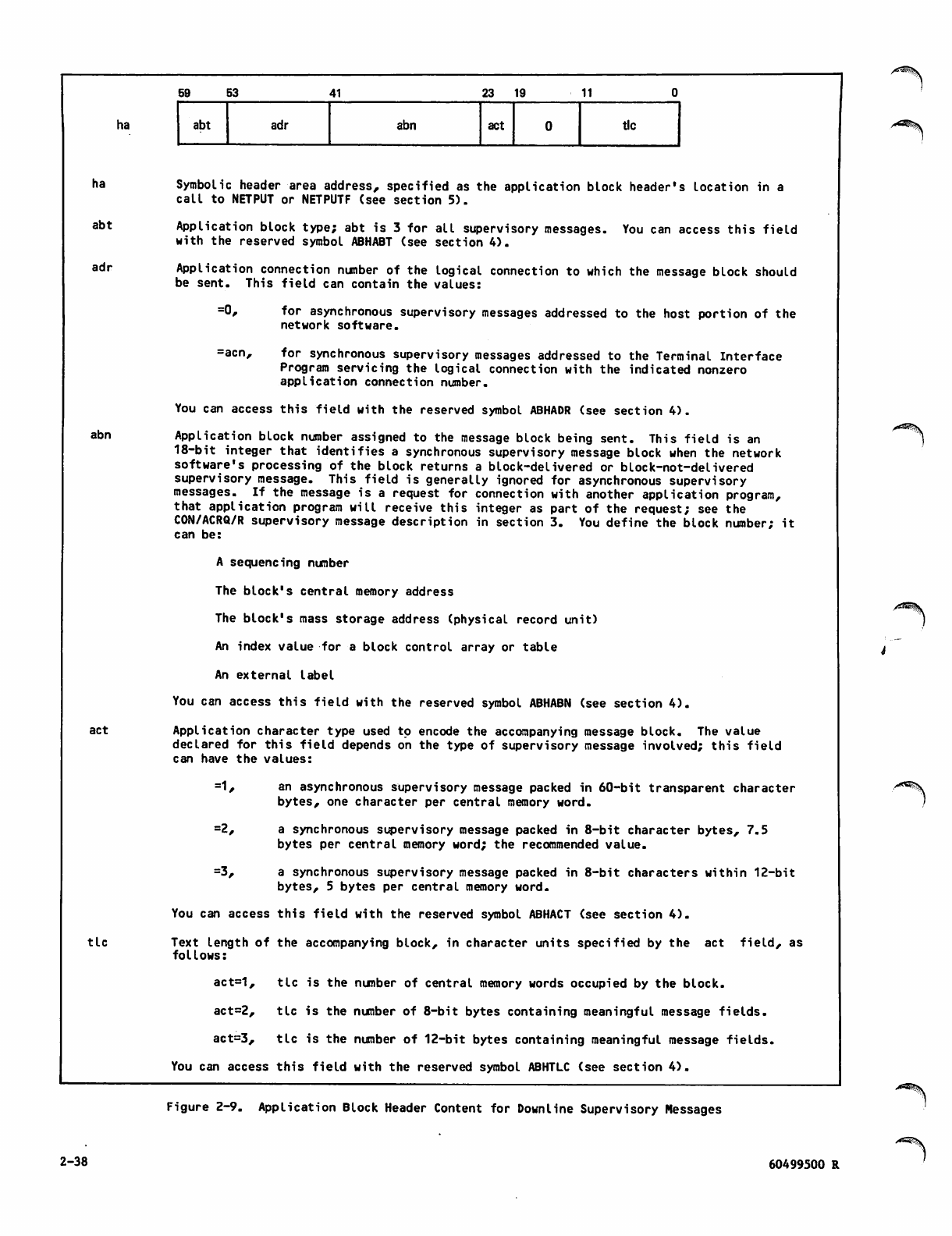
ha
ha
abt
adr
abn
act
tic
59 53 41 23 19 11
abt adr abn act tic
Symbolic header area address, specified as the application block header's location in a
call to NETPUT or NETPUTF (see section 5).
Application block type; abt is 3 for all supervisory messages. You can access this field
with the reserved symbol ABHABT (see section 4).
Application connection number of the logical connection to which the message block should
be sent. This field can contain the values:
=0, for asynchronous supervisory messages addressed to the host portion of the
network software.
=acn, for synchronous supervisory messages addressed to the Terminal Interface
Program servicing the logical connection with the indicated nonzero
application connection number.
You can access this field with the reserved symbol ABHADR (see section 4).
Application block number assigned to the message block being sent. This field is an
18-bit integer that identifies a synchronous supervisory message block when the network
software's processing of the block returns a block-delivered or block-not-delivered
supervisory message. This field is generally ignored for asynchronous supervisory
messages. If the message is a request for connection with another application program,
that application program will receive this integer as part of the request; see the
CON/ACRQ/R supervisory message description in section 3. You define the block number; it
can be:
A sequencing number
The block's central memory address
The block's mass storage address (physical record unit)
An index value for a block control array or table
An external label
You can access this field with the reserved symbol ABHABN (see section 4).
Application character type used to encode the accompanying message block. The value
declared for this field depends on the type of supervisory message involved; this field
can have the values:
=1, an asynchronous supervisory message packed in 60-bit transparent character
bytes, one character per central memory word.
=2, a synchronous supervisory message packed in 8-bit character bytes, 7.5
bytes per central memory word; the recommended value.
=3, a synchronous supervisory message packed in 8-bit characters within 12-bit
bytes, 5 bytes per central memory word.
You can access this field with the reserved symbol ABHACT (see section 4).
Text length of the accompanying block, in character units specified by the act field, as
follows:
act=1, tic is the number of central memory words occupied by the block.
act=2, tic is the number of 8-bit bytes containing meaningful message fields.
act=3, tic is the number of 12-bit bytes containing meaningful message fields.
You can access this field with the reserved symbol ABHTLC (see section 4).
Figure 2-9. Application Block Header Content for Downline Supervisory Messages
2-38 60499500 R
SUPERVISORY MESSAGES 3|
This section describes all synchronous and asyn
chronous supervisory messages that are legal for
application program communication with network
software. These messages are described in the con
text of their use.
MESSAGE MNEMONICS
Figure 2-6 in section 2 shows the general format of
a supervisory message. Note that this information
is i n t h e t e x t a r ea o f t h e m e ssage a n d m u s t be
accompanied by an application block header as
described in section 2. A supervisory message is
identified by the contents of its primary function
code field, error bit, response bit, and secondary
function code field. This allows a supervisory
message to be described by a mnemonic of the form
shown in figure 3-1. Although many combinations of
valid field values are possible, only certain com
binations are permitted. Table 3-1 lists these
legal messages alphabetically by mnemonic.
pfc/sfc/sm
pfc
sfc
sm
The reserved symbolic mnemonic for the
contents of the primary function code
field; this mnemonic can be any of those
list e d in fi g ure 2 - 6 in sect i on 2.
The reserved symbolic mnemonic of the
contents of the secondary function code
field; this mnemonic can be any of those
list e d in fi g ure 2 - 6 in sect i on 2,
provided the secondary function code is
legal for the primary function code used.
A letter indicating the combined settings
of the error and response bits; this
letter can be:
R Indicating an initial request
supervisory message (bit setting 00)
N Indicating a normal response
supervisory message (bit setting 01)
A Indicating an abnormal response
supervisory message (bit setting 10)
Figure 3-1. Supervisory Message
Mnemonic Structure
MESSAGE SEQUENCES
Supervisory messages are always used in stereotyped
sequences of one or more messages. Related messages
(messages distinguished by the use of the error or
response bits) are always part of multiple-message
sequences. The messages described in the following
subsections are discussed in the context of their
normal sequences. Each sequence Is illustrated with
a figure that shows the sender and recipient of the
messages in the sequence, and the direction of
transmission of each message (arrows).
Message sequences include the following:
Managing logical connections
Managing connection lists
Controlling data flow
Converting blocks
Truncating blocks
Managing terminal characteristics
Host operator communication
Host shutdown
Error reporting
MANAGING LOGICAL
CONNECTIONS
Five messages are used in connection management.
These are the CON/ACRQ, CON/REQ, CON/CB, CON/END,
and FC/INIT. These messages as well as examples of
how they are used in connecting devices to applica
tions, applications to applications, and later
terminating these connections are discussed in this
subsection.
CONNECTING DEVICES TO APPLICATIONS
After an application program has completed a NETON
call, connection-request supervisory messages are
sent to the application on behalf of each device
seeking connection. Request by request, the appli
cation must decide whether to accept or reject the
requested connection. Rejection might be neces
sary, for example, when the application program
receives a connection request for a card reader and
it does not support batch devices. To respond to a
connection-request-message, the application must
return one of two similar messages, indicating that
the application is either rejecting or accepting the
connection request. Figure 3-2 shows the common
message sequences in the connection establishment
process.
In this figure, arrows indicate the direction of
transmission of each message. The general term
Network Access Method (NAM) indicates the network
host software sending or receiving the message,
regardless o*f the software module actually involved.
60499500 R 3-1
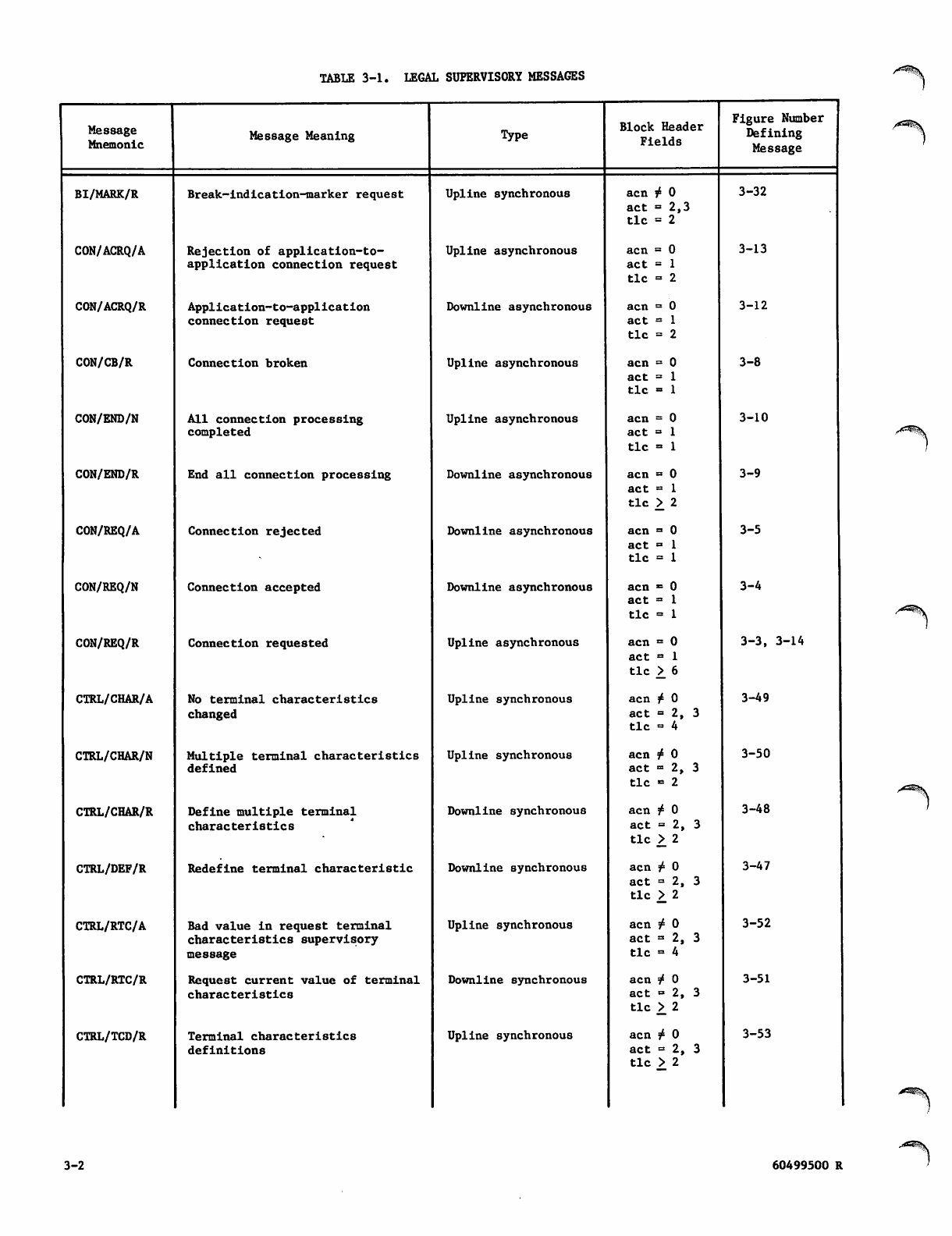
TABLE 3-1. LEGAL SUPERVISORY MESSAGES
Message
Mnemonic Message Meaning Type Block Header
Fields
Figure Number
Defining
Message
BI/MARK/R Break-indication-marker request Upline synchronous acn r* 0
act = 2,3
tic = 2
3-32
CON/ACRQ/A Rejection of application-to-
application connection request
Upline asynchronous acn = 0
act = 1
tic = 2
3-13
CON/ACRQ/R Application-to-application
connection request
Downline asynchronous acn = 0
act = 1
tic = 2
3-12
CON/CB/R Connection broken Upline asynchronous acn = 0
act = 1
tic - 1
3-8
CON/END/N All connection processing
completed
Upline asynchronous acn = 0
act = 1
tic = 1
3-10
CON/END/R End all connection processing Downline asynchronous acn = 0
act = 1
tic >^ 2
3-9
CON/REQ/A Connection rejected Downline asynchronous acn = 0
act = 1
tic = 1
3-5
CON/REQ/N Connection accepted Downline asynchronous acn ■* 0
act = 1
tic = 1
3-4
CON/REQ/R Connection requested Upline asynchronous acn = 0
act = 1
tic >_ 6
3-3, 3-14
CTRL/CHAR/A No terminal characteristics
changed
Upline synchronous acn £ 0
act = 2, 3
tic = 4
3-49
CTRL/CHAR/N Multiple terminal characteristics
defined Upline synchronous acn f 0
act = 2, 3
tic >= 2
3-50
CTRL/CHAR/R Define multiple terminal
characteristics
Downline synchronous acn £ 0
act = 2, 3
tic > 2
3-48
CTRL/DEF/R Redefine terminal characteristic Downline synchronous acn ^ 0
act = 2, 3
tic >. 2
3-47
CTRL/RTC/A Bad value in request terminal
characteristics supervisory
message
Upline synchronous acn ^ 0
act =■ 2, 3
tic = 4
3-52
CTRL/RTC/R Request current value of terminal
characteristics
Downline synchronous acn ^ 0
act = 2, 3
tic > 2
3-51
CTRL/TCD/R Terminal characteristics
definitions
Upline synchronous acn f 0
act = 2, 3
tic > 2
3-53
3-2 60499500 R
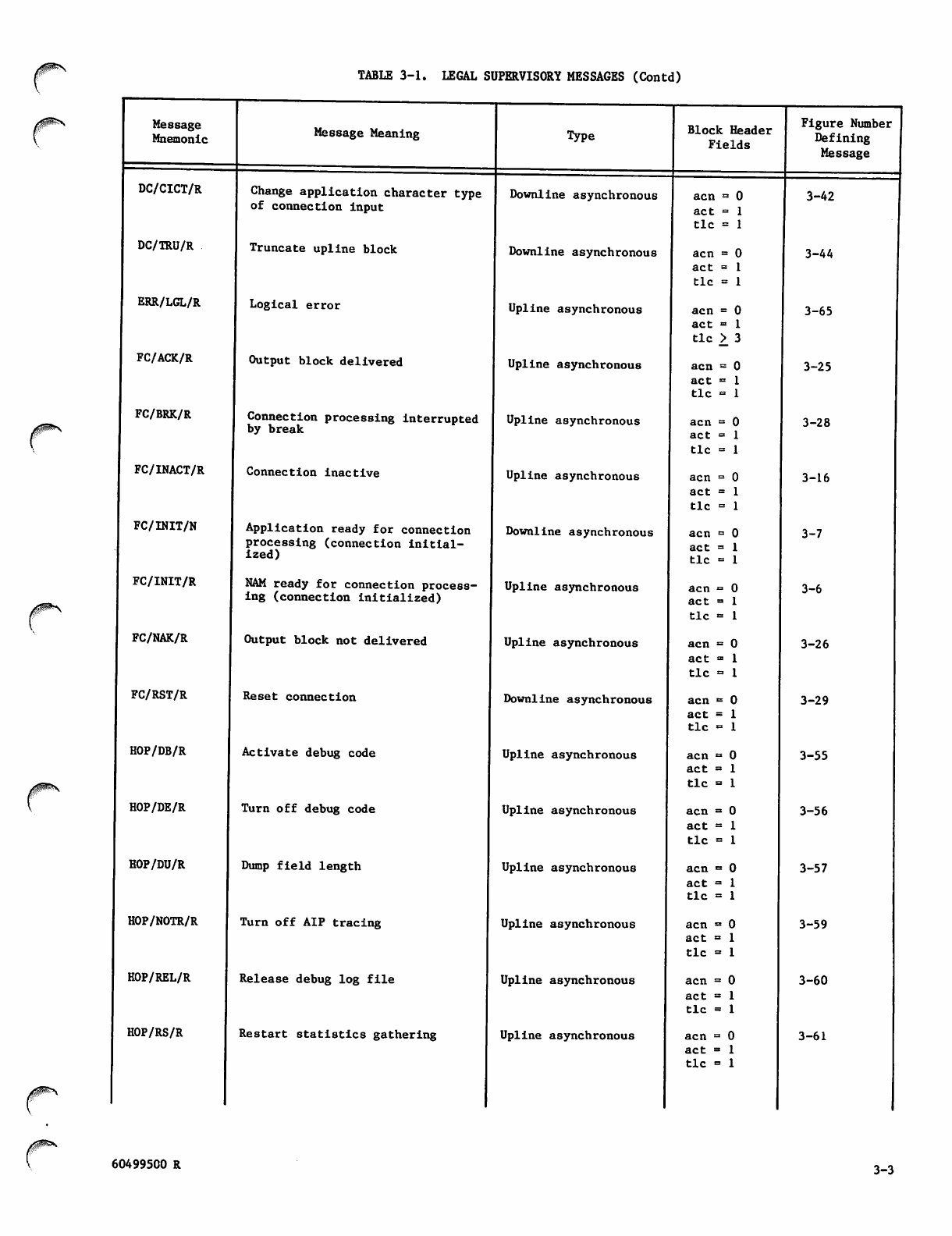
TABLE 3-1. LEGAL SUPERVISORY MESSAGES (Contd)
/^ff^*\
Message
Mnemonic
DC/CICT/R
DC/TRU/R
ERR/LGL/R
FC/ACK/R
FC/BRK/R
FC/INACT/R
FC/INIT/N
FC/INIT/R
FC/NAK/R
FC/RST/R
HOP/DB/R
HOP/DE/R
HOP/DU/R
HOP/NOTR/R
HOP/REL/R
HOP/RS/R
Message Meaning
Change application character type
of connection input
Truncate upline block
Type
Logical error
Output block delivered
Connection processing interrupted
by break
Connection inactive
Application ready for connection
processing (connection initial
ized)
NAM ready for connection process
ing (connection initialized)
Output block not delivered
Reset connection
Activate debug code
Turn off debug code
Dump field length
Turn off AIP tracing
Release debug log file
Restart statistics gathering
Downline asynchronous
Downline asynchronous
Upline asynchronous
Upline asynchronous
Upline asynchronous
Upline asynchronous
Downline asynchronous
Upline asynchronous
Upline asynchronous
Downline asynchronous
Upline asynchronous
Upline asynchronous
Upline asynchronous
Upline asynchronous
Upline asynchronous
Upline asynchronous
Block Header
Fields
Figure Number
Defining
Message
acn = 0
act =
t i c =
acn =
act =
t i c =
acn =
act «=
t i c >
acn =
act =
t i c =
acn =
act =
t i c =
acn =
act =
t i c =
acn =
act =
t i c =
acn =
act =
t i c =
acn =
act =
t i c =
acn =
act =
tic =
acn =
act =
t i c =
acn =
ac t -
t i c =
acn «=
act =
t i c =
acn =
act =
t i c =
acn =
act =
t i c =
acn =
act =
t i c =
3-42
3-44
3-65
3-25
3-28
3-16
3-7
3-6
3-26
3-29
3-55
3-56
3-57
3-59
3-60
3-61
60499500 R 3-3
TABLE 3-1. LEGAL SUPERVISORY MESSAGES (Contd) /*^st&V
Message
Mnemonic Message Meaning Type Block Header
Fields
Figure Number
Defining
Message
HOP/TRACE/R Turn on AIP tracing Upline asynchronous acn = 0
act = 1
tic - 1
3-58
INTR/APP/R Application interrupt request Downline asynchronous acn » 0
act = 1
tic - 1
3-35
INTR/RSP/R Interrupt response Downline or upline
asynchronous
acn = 0
act = 1
tic = 1
3-33, 3-36
INTR/USR/R User interrupt or user interrupt
request
Upline asynchronous acn = 0
act = 1
tic = 1
3-31, 3-39
LST/FDX/R Turn on full duplex operation for
connections in list
Downline asynchronous acn = 0
act = 1
tic «■ 1
3-24
LST/HDX/R Turn on half duplex operation for
connections in list
Downline asynchronous acn = 0
act ■ 1
tic = 1
3-23
LST/OFF/R Turn list processing for
connec tio n off
Downline asynchronous acn = 0
act = 1
tic = 1
3-20
LST/ON/R Turn list processing for
connection on
Downline asynchronous acn <= 0
act = 1
tic = 1
3-21
LST/SWH/R Switch application list number of
connection
Downline asynchronous acn = 0
act = 1
tic - 1
3-22
RO/MARK/R Resume output marker Downline synchronous acn f 0,
act = 2,3
tic » 2
3-34
SHUT/INSD/R Network shut-down in progress Upline asynchronous acn = 0
act = 1
tic » 1
3-63
TCH/TCHAR/R Terminal characteristics rede
fined Upline asynchronous acn = 0
act « 1
tic - 1
3-46
TO/MARK/R Terminate output marker Downline synchronous acn f 0
act = 2, 3
tic = 2
3-37
3-4 60499500 R
*^%H\
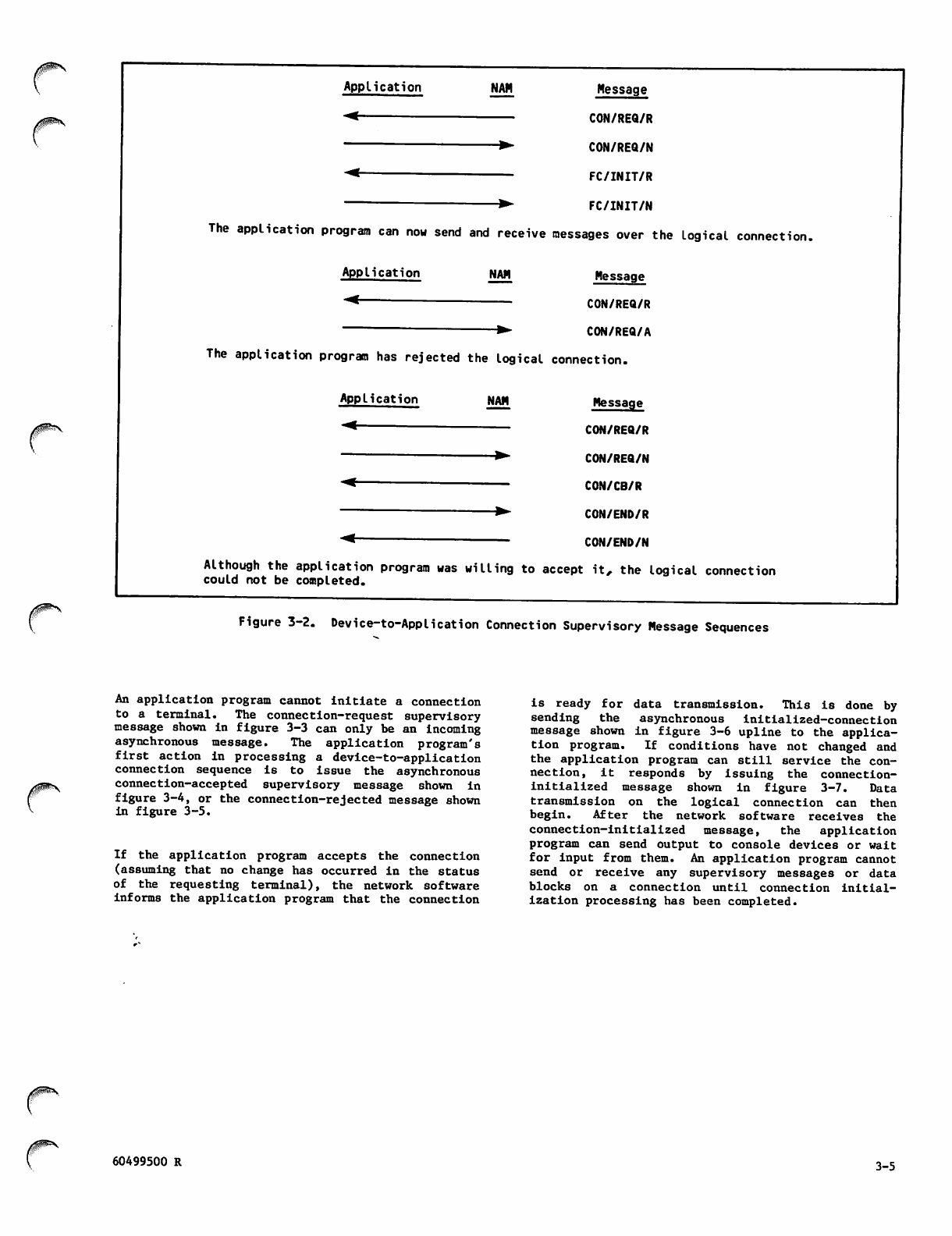
0jS^\
Application
-<
NAM Message
CON/REQ/R
CON/REQ/N
FC/INIT/R
FC/INIT/N
The application program can now send and receive messages over the logical connectii
Application NAM Message
CON/REQ/R
CON/REQ/A
The application program has rejected the logical connection.
Application NAM Message
CON/REQ/R
CON/REQ/N
CON/CB/R
-<
CON/END/R
CON/END/N
Although the application program was willing to accept it, the logical connection
could not be completed.
Figure 3-2. Device-to-Application Connection Supervisory Message Sequences
An application program cannot initiate a connection
to a terminal. The connection-request supervisory
message shown in figure 3-3 can only be an incoming
asynchronous message. The application program's
first action in processing a device-to-application
connection sequence is to issue the asynchronous
connection-accepted supervisory message shown in
figure 3-4, or the connection-rejected message shown
in figu r e 3 - 5 .
If the application program accepts the connection
(assuming that no change has occurred in the status
o f t h e requ e s tin g t e rmi n a l ), t h e n etw o r k soft w a re
informs the application program that the connection
is ready for data transmission. This is done by
sending the asynchronous initialized-connection
message shown in figure 3-6 upline to the applica
tion p r ogram. I f c ondition s h a ve not c h a n g ed and
the application program can still service the con
nection, it responds by issuing the connection-
i n i t i a l i z e d m e s s a g e s h o w n i n fi g u r e 3 - 7 . D a t a
transmission on the logical connection can then
begin. After the network software receives the
connection-initialized message, the application
program can send output to console devices or wait
for input from them. An application program cannot
send or receive any supervisory messages or data
blocks on a connection until connection initial
ization processing has been completed.
60499500 R 3-5
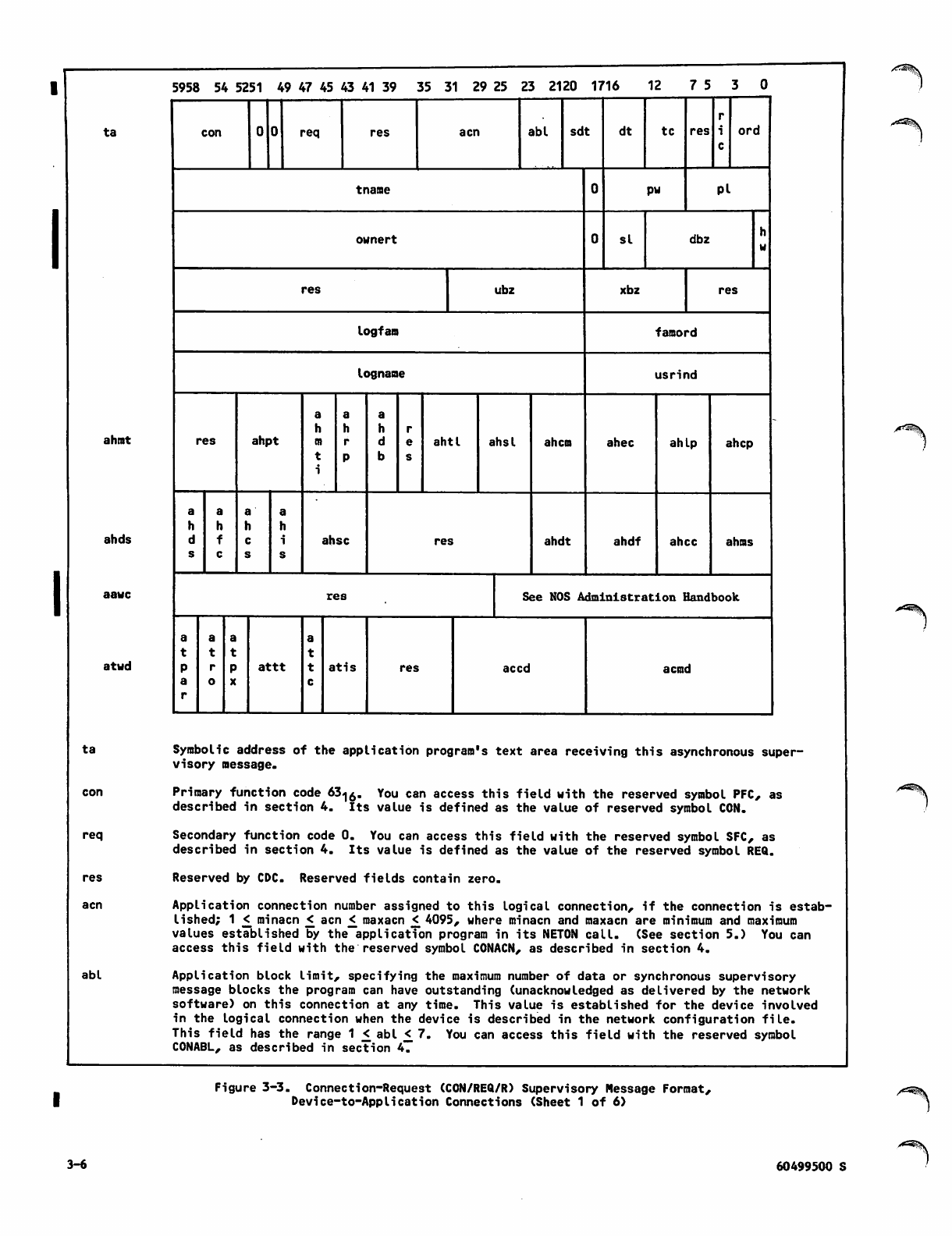
ta
ahmt
ahds
aawc
atwd
ta
req
res
acn
abl
5958 54 5251 49 47 45 43 41 39 35 31 29 25 23 2120 1716 12 7 5
con req res acn abl sdt dt tc res ord
tname pw Pi
ownert si dbz
res ubz xbz res
logfam famord
logname usrind
a a a
hhh r
res ahpt ahtl ahsl ahem ahec ahlp ahep
aaa a
h h h h
d f c iahsc res ahdt ahdf ahec ahms
s c s s
res See NOS Administration Handbook
a a a a
t t t t
PrPattt at is res accd a cmd
a o Xc
r
Symbolic address of the application program's text area receiving this asynchronous super
visory message.
Primary function code 63-|0. You can access this field with the reserved symbol PFC, as
described in section 4. Its value is defined as the value of reserved symbol CON.
Secondary function code 0. You can access this field with the reserved symbol SFC, as
described in section 4. Its value is defined as the value of the reserved symbol REQ.
Reserved by CDC. Reserved fields contain zero.
Application connection number assigned to this logical connection, if the connection is estab
lished; 1 £ minacn < acn < maxacn < 4095, where minacn and maxacn are minimum and maximum
values established by the application program in its NETON call. (See section 5.) You can
access this field with the reserved symbol CONACN, as described in section 4.
Application block limit, specifying the maximum number of data or synchronous supervisory
message blocks the program can have outstanding (unacknowledged as delivered by the network
software) on this connection at any time. This value is established for the device involved
in the logical connection when the device is described in the network configuration file.
This field has the range 1 < abl £ 7. You can access this field with the reserved symbol
CONABL, as described in section 4.
Figure 3-3. Connection-Request (CON/REQ/R) Supervisory Message Format,
Device-to-Application Connections (Sheet 1 of 6)
3-6 60499500 S
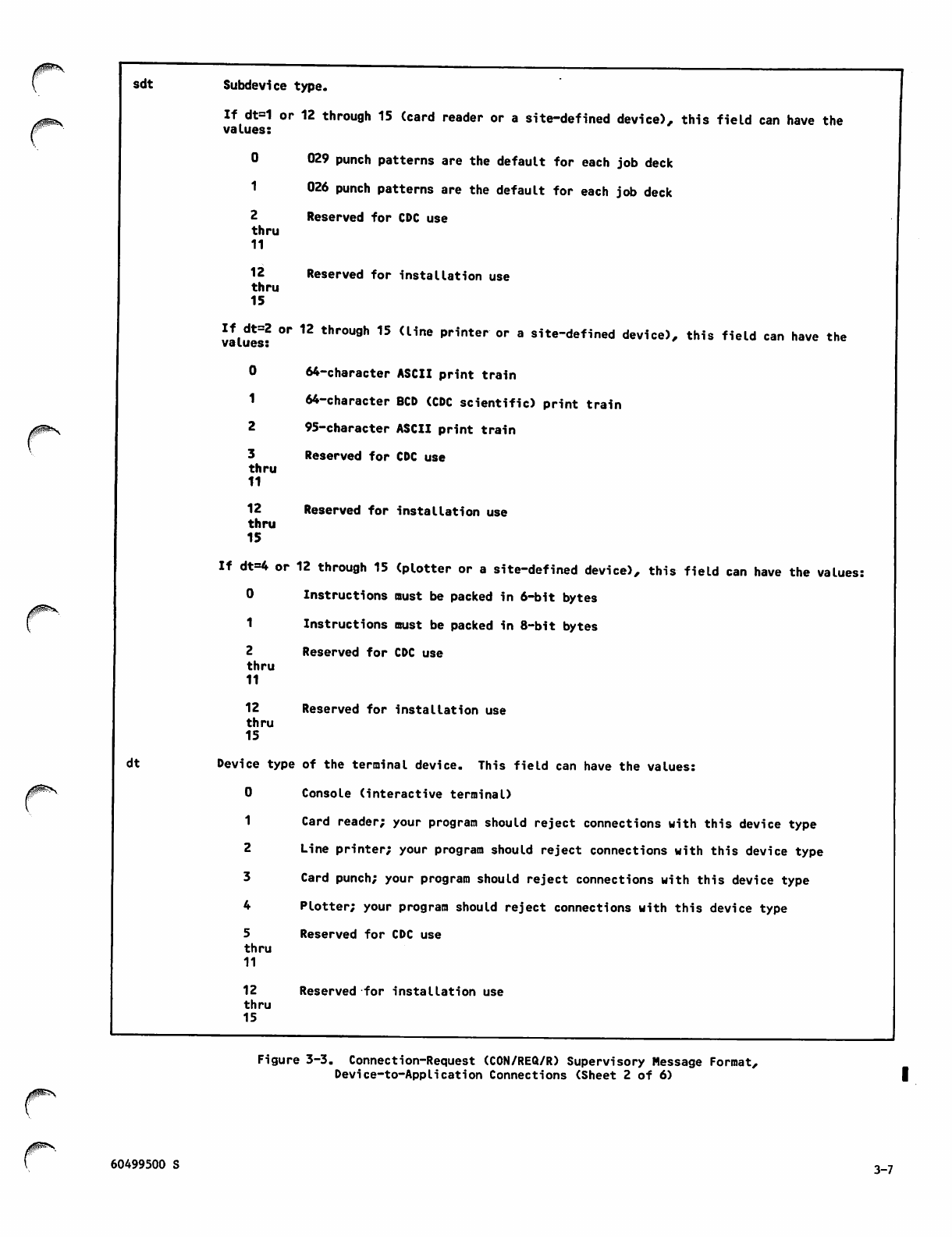
sdt
dt
Subdevice type.
If dt=1 or 12 through 15 (card reader or a site-defined device), this field can have the
values:
0
1
2
thru
11
12
thru
15
029 punch patterns are the default for each job deck
026 punch patterns are the default for each job deck
Reserved for CDC use
Reserved for installation use
If dt=2 or 12 through 15 (line printer or a site-defined device), this field can have the
values:
0
1
2
3
thru
11
12
thru
15
64-character ASCII print train
64-character BCD (CDC scientific) print train
95-character ASCII print train
Reserved for CDC use
Reserved for installation use
If dt=4 or 12 through 15 (plotter or a site-defined device), this field can have the values:
0 Instructions must be packed in 6-bit bytes
1 Instructions must be packed in 8-bit bytes
Reserved for CDC use
2
thru
11
12
thru
15
Reserved for installation use
Device type of the terminal device. This field can have the values:
0 Console (interactive terminal)
Card reader; your program should reject connections with this device type
Line printer; your program should reject connections with this device type
Card punch; your program should reject connections with this device type
Plotter; your program should reject connections with this device type
Reserved for CDC use
5
thru
11
12
thru
15
Reserved for installation use
Figure 3-3. Connection-Request (CON/REQ/R) Supervisory Message Format,
Device-to-Application Connections (Sheet 2 of 6)
60499500 S 3-7
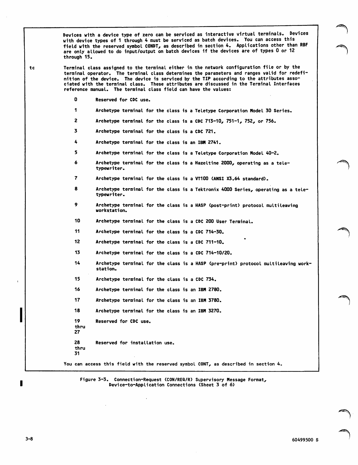
tc
Devices with a device type of zero can be serviced as interactive virtual terminals. Devices
with device types of 1 through 4 must be serviced as batch devices. You can access this
field with the reserved symbol CONDT, as described in section 4. Applications other than RBF
are only allowed to do input/output on batch devices if the devices are of types 0 or 12
through 15.
Terminal class assigned to the terminal either in the network configuration file or by the
terminal operator. The terminal class determines the parameters and ranges valid for redefi
nition of the device. The device is serviced by the TIP according to the attributes asso
ciated with the terminal class. These attributes are discussed in the Terminal Interfaces
reference manual. The terminal class field can have the values:
10
11
12
13
14
15
16
17
18
19
thru
27
28
thru
31
Reserved for CDC use.
Archetype terminal for the class i
Archetype terminal for the class i
Archetype terminal for the class i
Archetype terminal for the class i
Archetype terminal for the class i
Archetype terminal for the class i
typewriter.
Archetype terminal for the class i
s a Teletype Corporation Model 30 Series.
s a CDC 713-10, 751-1, 752, or 756.
s a CDC 721.
s an IBM 2741.
s a Teletype Corporation Model 40-2.
s a Hazeltine 2000, operating as a tele-
s a VT100 (ANSI X3.64 standard).
Archetype terminal for the class is a Tektronix 4000 Series, operating as a tele
typewriter.
Archetype terminal for the class is a HASP (post-print) protocol multileaving
workstation.
Archetype terminal for the class i
Archetype terminal for the class i
Archetype terminal for the class i
Archetype terminal for the class i
s a CDC 200 User Terminal,
s a CDC 714-30.
s a CDC 711-10.
s a CDC 714-10/20.
Archetype terminal for the class is a HASP (pre-print) protocol multileaving work
station.
Archetype terminal for the class is a CDC 734.
Archetype terminal for the class is an IBM 2780.
Archetype terminal for the class is an IBM 3780.
Archetype terminal for the class is an IBM 3270.
Reserved for CDC use.
Reserved for installation use.
You can access this field with the reserved symbol C0NT, as described in section 4.
Figure 3-3. Connection-Request (CON/REQ/R) Supervisory Message Format,
Device-to-Application Connections (Sheet 3 of 6)
3-8 60499500 S
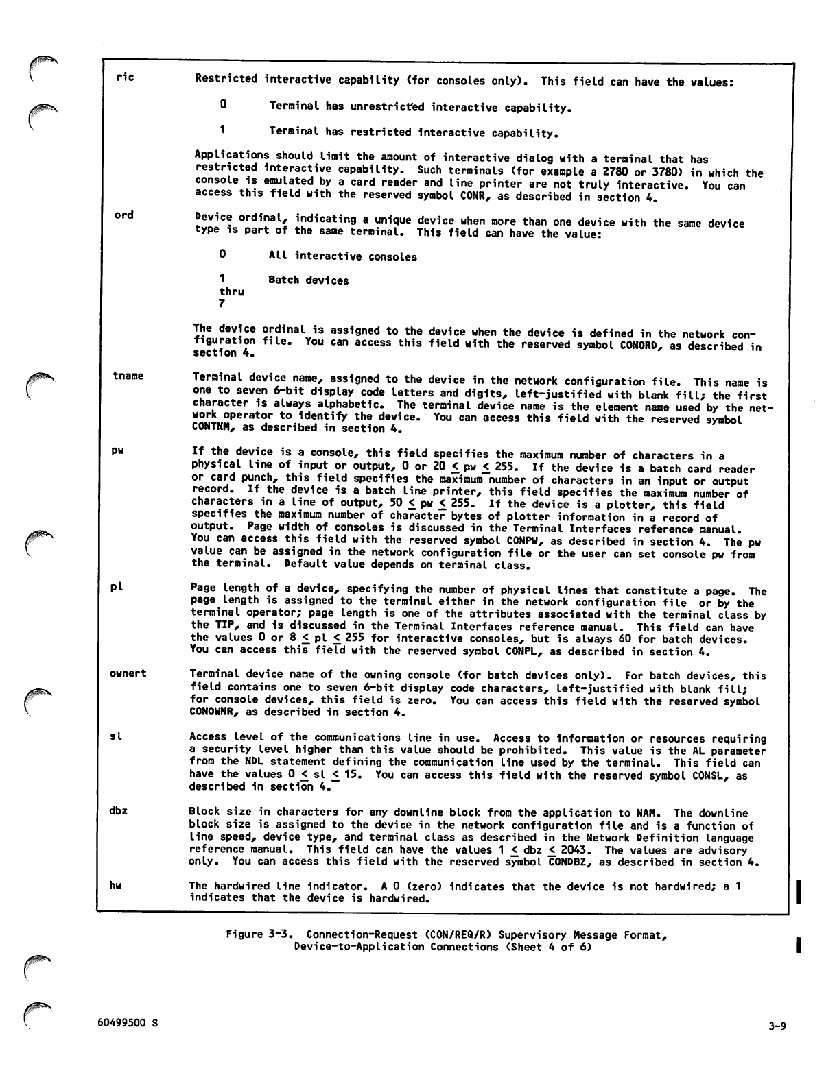
nc
ord
rf&F&'Xti
tname
pw
Pi
ownert
si
dbz
hw
Restricted interactive capability (for consoles only). This field can have the values:
0 Terminal has unrestricted interactive capability.
1 Termi n al h a s res t ricte d in t eract i ve c a pabil i ty.
Applications should limit the amount of interactive dialog with a terminal that has
restricted interactive capability. Such terminals (for example a 2780 or 3780) in which the
console is emulated by a card reader and line printer are not truly interactive. You can
access this field with the reserved symbol CONR, as described in section 4.
Device ordinal, indicating a unique device when more than one device with the same device
type is part of the same terminal. This field can have the value:
1
thru
7
All interactive consoles
Batch devices
The device ordinal is assigned to the device when the device is defined in the network con
figuration file. You can access this field with the reserved symbol C0N0RD, as described in
section 4.
Terminal device name, assigned to the device in the network configuration file. This name is
one to seven 6-bit display code letters and digits, left-justified with blank fill; the first
character is always alphabetic. The terminal device name is the element name used by the net
work operator to identify the device. You can access this field with the reserved symbol
CONTNM, as described in section 4.
If the device is a console, this field specifies the maximum number of characters in a
physical line of input or output, 0 or 20 £ pw £ 255. If the device is a batch card reader
or card punch, this field specifies the maximum number of characters in an input or output
record. If the device is a batch line printer, this field specifies the maximum number of
characters in a line of output, 50 £ pw £ 255. If the device is a plotter, this field
specifies the maximum number of character bytes of plotter information in a record of
output. Page width of consoles is discussed in the Terminal Interfaces reference manual.
You can access this field with the reserved symbol CONPU, as described in section 4. The pw
value can be assigned in the network configuration file or the user can set console pw from
the terminal. Default value depends on terminal class.
Page length of a device, specifying the number of physical lines that constitute a page. The
page length is assigned to the terminal either in the network configuration file or by the
terminal operator; page length is one of the attributes associated with the terminal class by
the TIP, and is discussed in the Terminal Interfaces reference manual. This field can have
the values 0 or 8 £ pi £255 for interactive consoles, but is always 60 for batch devices.
You can access this field with the reserved symbol CONPL, as described in section 4.
Terminal device name of the owning console (for batch devices only). For batch devices, this
field contains one to seven 6-bit display code characters, left-justified with blank fill;
for console devices, this field is zero. You can access this field with the reserved symbol
C0N0WNR, as described in section 4.
Access level of the communications line in use. Access to information or resources requiring
a security level higher than this value should be prohibited. This value is the AL parameter
from the NDL statement defining the communication line used by the terminal. This field can
have the values 0 £ si £ 15. You can access this field with the reserved symbol C0NSL, as
described in section 4.
Block size in characters for any downline block from the application to NAM. The downline
block size is assigned to the device in the network configuration file and is a function of
line speed, device type, and terminal class as described in the Network Definition language
reference manual. This field can have the values 1 £ dbz £ 2043. The values are advisory
only. You can access this field with the reserved symbol C0NDBZ, as described in section 4.
The hardwired line indicator. A 0 (zero) indicates that the device is not hardwired; a 1
indicates that the device is hardwired.
Figure 3-3. Connection-Request (CON/REQ/R) Supervisory Message Format,
Device-to-AppIication Connections (Sheet 4 of 6)
60499500 S 3-9
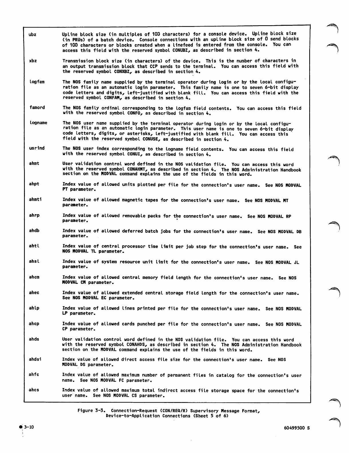
ubz Upline block size (in multiples of 100 characters) for a console device. Upline block size
(in PRUs) of a batch device. Console connections with an upline block size of 0 send blocks
of 100 characters or blocks created when a linefeed is entered from the console. You can
access this field with the reserved symbol CONUBZ, as described in section 4.
xbz Transmission block size (in characters) of the device. This is the number of characters in
an output transmission block that CCP sends to the terminal. You can access this field with
the reserved symbol CONXBZ, as described in section 4.
logfam The NOS family name supplied by the terminal operator during login or by the local configu
ration file as an automatic login parameter. This family name is one to seven 6-bit display
code letters and digits, left-justified with blank fill. You can access this field with the
reserved symbol CONFAM, as described in section 4.
famord The NOS family ordinal corresponding to the logfam field contents. You can access this field
with the reserved symbol C0NF0, as described in section 4.
logname The NOS user name supplied by the terminal operator during login or by the local configu
ration file as an automatic login parameter. This user name is one to seven 6-bit display
code letters, digits, or asterisks, left-justified with blank fill. You can access this
field with the reserved symbol CONUSE, as described in section 4.
usrind The NOS user index corresponding to the logname field contents. You can access this field
with the reserved symbol CONUI, as described in section 4.
ahmt User validation control word defined in the NOS validation file. You can access this word
with the reserved symbol CONAHMT, as described in section 4. The NOS Administration Handbook
section on the MODVAL command explains the use of the fields in this word.
ahpt Index value of allowed units plotted per file for the connection's user name. See NOS MODVAL
PT parameter.
ahmti Index value of allowed magnetic tapes for the connection's user name. See NOS MODVAL MT
parameter.
ahrp Index value of allowed removable packs for the connection's user name. See NOS MODVAL RP
parameter.
ahdb Index value of allowed deferred batch jobs for the connection's user name. See NOS MODVAL DB
parameter.
ahtl Index value of central processor time limit per job step for the connection's user name. See
NOS MODVAL TL parameter.
ahsl Index value of system resource unit limit for the connection's user name. See NOS MODVAL JL
parameter.
ahem Index value of allowed central memory field Length for the connection's user name. See NOS
MODVAL CM parameter.
ahec Index value of allowed extended central storage field length for the connection's user name.
See NOS MODVAL EC parameter.
ahlp Index value of allowed lines printed per file for the connection's user name. See NOS MODVAL
LP parameter.
ahep Index value of allowed cards punched per file for the connection's user name. See NOS MODVAL
CP parameter.
ahds User validation control word defined in the NOS validation file. You can access this word
with the reserved symbol CONAHDS, as described in section 4. The NOS Administration Handbook
section on the MODVAL command explains the use of the fields in this word.
ahdsi Index value of allowed direct access file size for the connection's user name. See NOS
MODVAL DS parameter.
ahfc Index value of allowed maximum number of permanent files in catalog for the connection's user
name. See NOS MODVAL FC parameter.
ahes Index value of allowed maximum total indirect access file storage space for the connection's
user name. See NOS MODVAL CS parameter.
Figure 3-3. Connection-Request (CON/REQ/R) Supervisory Message Format,
Device-to-Application Connections (Sheet 5 of 6)
3-10 60499500 S
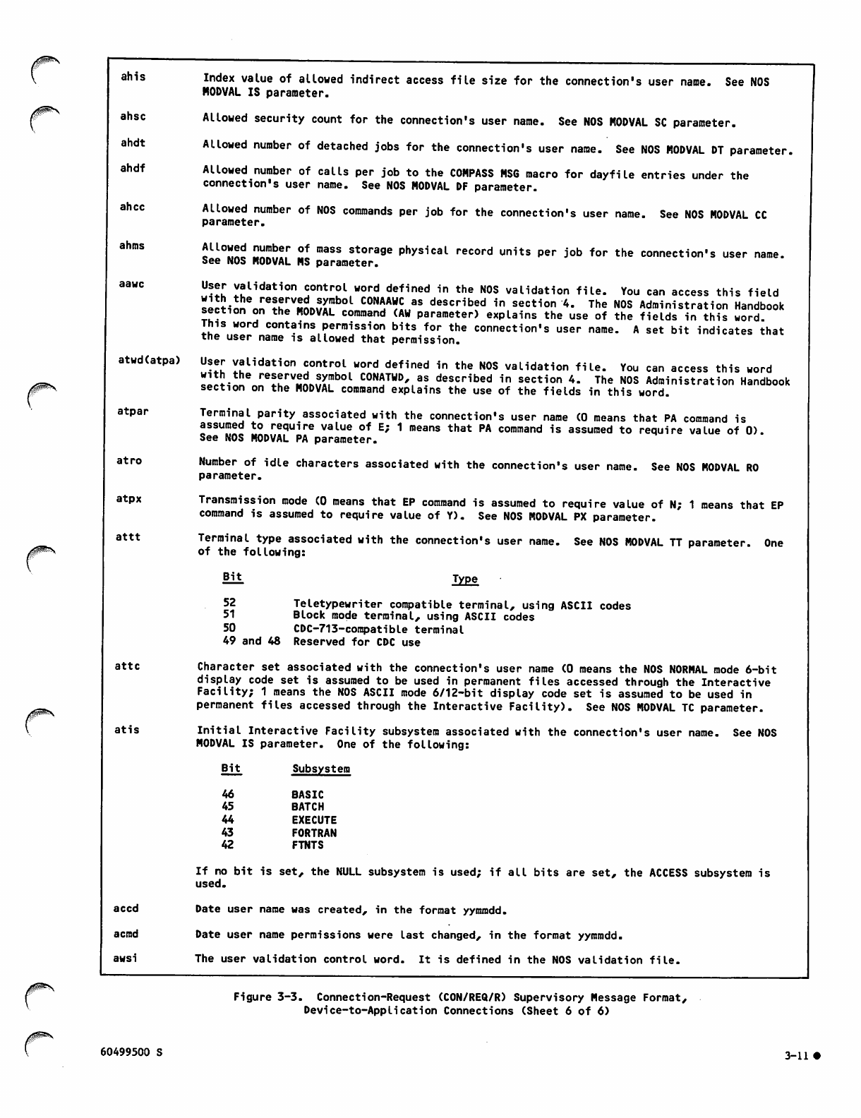
>£s$fr-\
/ ^ ^ \
ahis
ahsc
ahdt
ahdf
ahec
ahms
aawc
atwd(atpa)
atpar
a t r o
atpx
attt
attc
a t i s
accd
acmd
awsi
Index value of allowed indirect access file size for the connection's user name. See NOS
MODVAL IS parameter.
Allowed security count for the connection's user name. See NOS MODVAL SC parameter.
Allowed number of detached jobs for the connection's user name. See NOS MODVAL DT parameter.
Allowed number of calls per job to the COMPASS MS6 macro for dayfile entries under the
connection's user name. See NOS MODVAL DF parameter.
Allowed number of NOS commands per job for the connection's user name. See NOS MODVAL CC
parameter.
SU0^ D«I!!!!!.r °f n,aSS stora9e Physical record units per job for the connection's user name.
See NOS MODVAL MS parameter.
User validation control word defined in the NOS validation file. You can access this field
section^nethrSnnvi;rb0L Tl" desc"bed in section 4. The NOS Administration Handbook
section on the MODVAL command (AW parameter) explains the use of the fields in this word.
This word contains permission bits for the connection's user name. A set bit indicates that
the user name is allowed that permission.
User validation control word defined in the NOS validation file. You can access this word
Hl^lr? relZ™ZL?Z?b°l C0NATUD'as described in section 4. The NOS Administration Handbook
section on the MODVAL command explains the use of the fields in this word.
Terminal parity associated with the connection's user name (0 means that PA command is
assumed to require value of E; 1 means that PA command is assumed to require value of 0).
See NOS MODVAL PA parameter.
Number of idle characters associated with the connection's user name. See NOS MODVAL RO
parameter.
Transmission mode (0 means that EP command is assumed to require value of N; 1 means that EP
command is assumed to require value of Y). See NOS MODVAL PX parameter.
Terminal type associated with the connection's user name. See NOS MODVAL TT parameter. One
of the following:
Bit Type
52 Teletypewriter compatible terminal, using ASCII codes
51 Block mode terminal, using ASCII codes
50 CDC-713-compatible terminal
49 and 48 Reserved for CDC use
Character set associated with the connection's user name (0 means the NOS NORMAL mode 6-bit
display code set is assumed to be used in permanent files accessed through the Interactive
Facility; 1 means the NOS ASCII mode 6/12-bit display code set is assumed to be used in
permanent files accessed through the Interactive Facility). See NOS MODVAL TC parameter.
Initial Interactive Facility subsystem associated with the connection's user name. See NOS
MODVAL IS parameter. One of the following:
Bit Subsystem
46 BASIC
45 BATCH
44 EXECUTE
43 FORTRAN
42 FTNTS
If no bit is set, the NULL subsystem is used; if all bits are set, the ACCESS subsystem is
used.
Date user name was created, in the format yymmdd.
Date user name permissions were last changed, in the format yymmdd.
The user validation control word. It is defined in the NOS validation file.
Figure 3-3. Connection-Request (CON/REQ/R) Supervisory Message Format,
Device-to-Application Connections (Sheet 6 of 6)
60499500 S 3-11 •
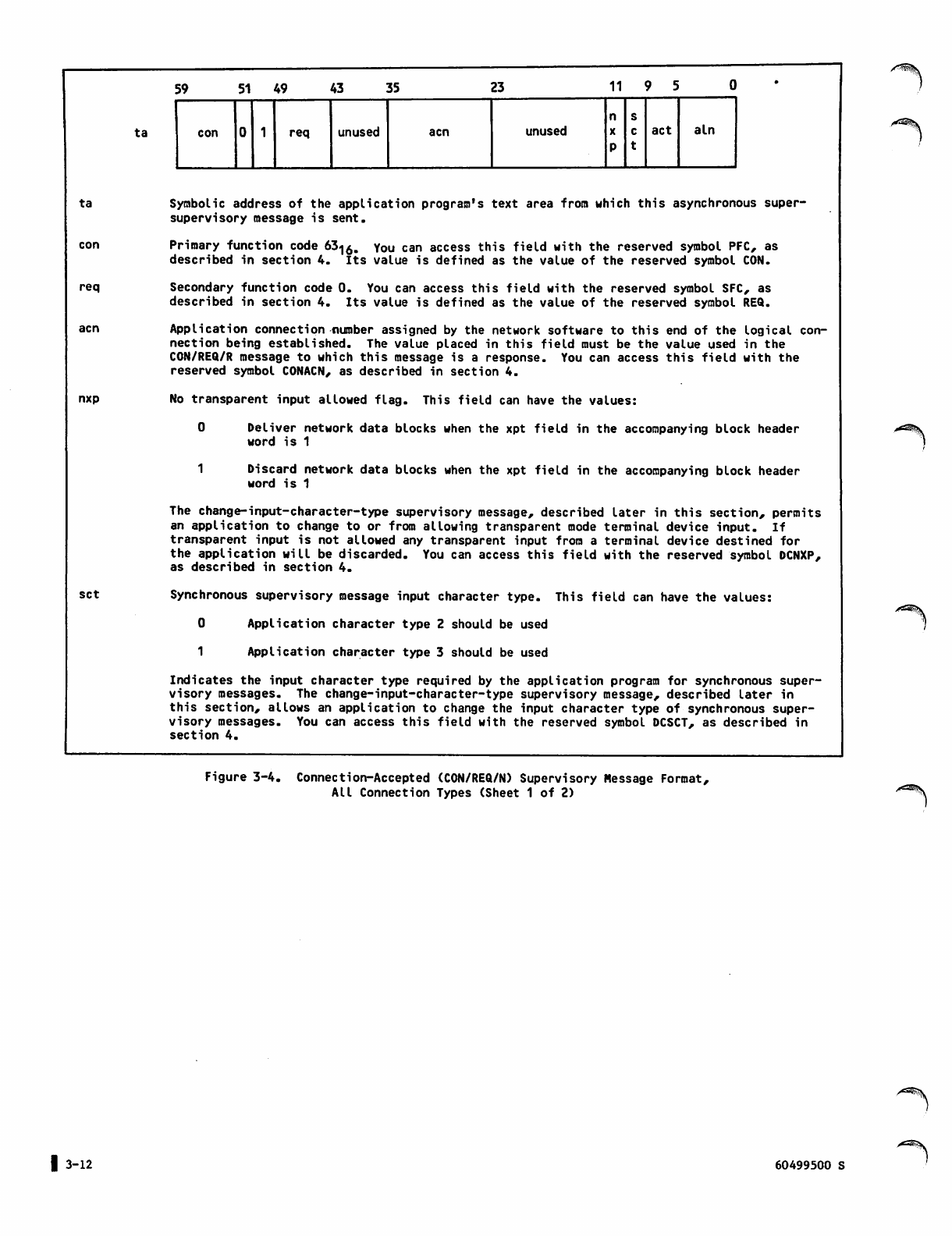
ta
con
req
nxp
set
ta
59 51 49 43 55 23 11 9 5
n s
con req unused acn unused act aln
Symbolic address of the application program's text area from which this asynchronous super-
supervisory message is sent.
Primary function code 63^Q. You can access this field with the reserved symbol PFC, as
described in section 4. Its value is defined as the value of the reserved symbol CON.
Secondary function code 0. You can access this field with the reserved symbol SFC, as
described in section 4. Its value is defined as the value of the reserved symbol REQ.
Application connection number assigned by the network software to this end of the logical con
nection being established. The value placed in this field must be the value used in the
CON/REQ/R message to which this message is a response. You can access this field with the
reserved symbol CONACN, as described in section 4.
No transparent input allowed flag. This field can have the values:
0 Deliver network data blocks when the xpt field in the accompanying block header
word is 1
1 Discard network data blocks when the xpt field in the accompanying block header
word is 1
The change-input-character-type supervisory message, described later in this section, permits
an application to change to or from allowing transparent mode terminal device input. If
transparent input is not allowed any transparent input from a terminal device destined for
the application will be discarded. You can access this field with the reserved symbol DCNXP,
as described in section 4.
Synchronous supervisory message input character type. This field can have the values:
0 Application character type 2 should be used
1Application character type 3 should be used
Indicates the input character type required by the application program for synchronous super
visory messages. The change-input-character-type supervisory message, described later in
this section, allows an application to change the input character type of synchronous super
visory messages. You can access this field with the reserved symbol DCSCT, as described in
section 4.
/*S5k
Figure 3-4. Connection-Accepted (CON/REQ/N) Supervisory Message Format,
All Connection Types (Sheet 1 of 2)
| 3-12 60499500 S
^^K
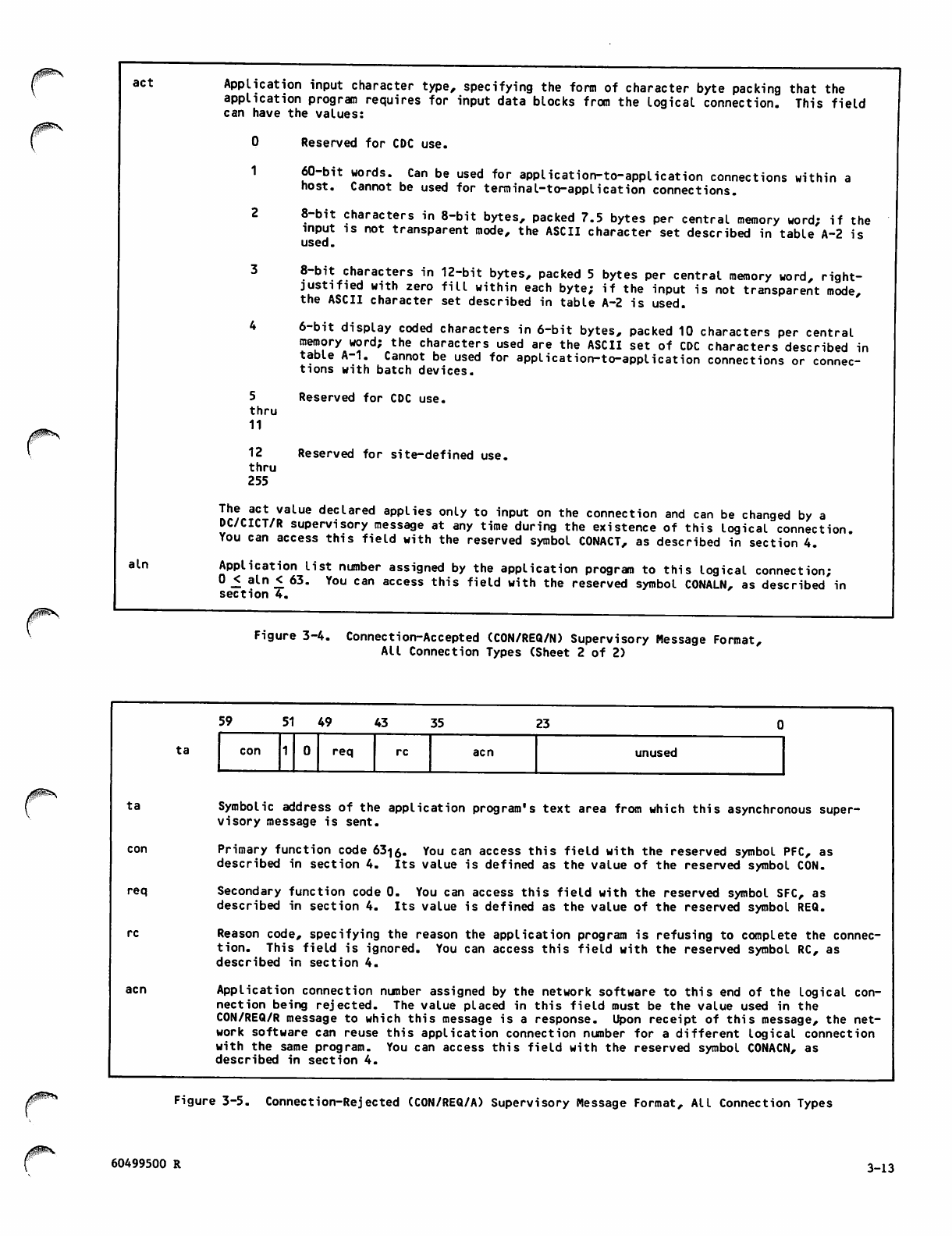
act
aln
Application input character type, specifying the form of character byte packing that the
application program requires for input data blocks from the logical connection. This field
can have the values:
Reserved for CDC use.
60-bit words. Can be used for application-to-application connections within a
host. Cannot be used for terminal-to-application connections.
8-bit characters in 8-bit bytes, packed 7.5 bytes per central memory word; if the
input is not transparent mode, the ASCII character set described in table A-2 is
used.
8-bit characters in 12-bit bytes, packed 5 bytes per central memory word, right-
justified with zero fill within each byte; if the input is not transparent mode,
the ASCII character set described in table A-2 is used.
6-bit display coded characters in 6-bit bytes, packed 10 characters per central
memory word; the characters used are the ASCII set of CDC characters described in
table A-1. Cannot be used for application-to-application connections or connec
tions with batch devices.
Reserved for CDC use.
Reserved for site-defined use.
5
thru
11
12
thru
255
The act value declared applies only to input on the connection and can be changed by a
DC/CICT/R supervisory message at any time during the existence of this logical connection.
You can access this field with the reserved symbol CONACT, as described in section 4.
Application list number assigned by the application program to this logical connection;
0£ aln £ 63. You can access this field with the reserved symbol CONALN, as described in
section 4.
Figure 3-4. Connection-Accepted (CON/REQ/N) Supervisory Message Format,
All Connection Types (Sheet 2 of 2)
r
ta
ta
req
/0^**
59 5 1 4 9 43 35 23
con req unused
Symbolic address of the application program's text area from which this asynchronous super
visory message is sent.
Primary function code 63-j0. You can access this field with the reserved symbol PFC, as
described in section 4. Its value is defined as the value of the reserved symbol CON.
Secondary function code 0. You can access this field with the reserved symbol SFC, as
described in section 4. Its value is defined as the value of the reserved symbol REQ.
Reason code, specifying the reason the application program is refusing to complete the connec
tion. This field is ignored. You can access this field with the reserved symbol RC, as
described in section 4.
Application connection number assigned by the network software to this end of the Logical con
nection being rejected. The value placed in this field must be the value used in the
CON/REQ/R message to which this message is a response. Upon receipt of this message, the net
work software can reuse this application connection number for a different logical connection
with the same program. You can access this field with the reserved symbol CONACN, as
described in section 4.
Figure 3-5. Connection-Rejected (CON/REQ/A) Supervisory Message Format, All Connection Types
60499500 R 3-13
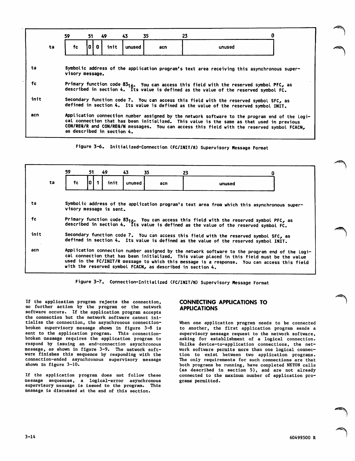
ta
ta
fc
init
acn
ta
ta
fc
init
59 51 49 43 35 23
fc init unused acn unused
Symbolic address of the application program's text area receiving this asynchronous super
visory message.
Primary function code 83-|0. You can access this field with the reserved symbol PFC, as
described in section 4. Its value is defined as the value of the reserved symbol FC.
Secondary function code 7. You can access this field with the reserved symbol SFC, as
defined in section 4. Its value is defined as the value of the reserved symbol INIT.
Application connection number assigned by the network software to the program end of the logi
cal connection that has been initialized. This value is the same as that used in previous
CON/REQ/R and CON/REQ/N messages. You can access this field with the reserved symbol FCACN,
as described in section 4.
Figure 3-6. Initialized-Connection (FC/INIT/R) Supervisory Message Format
59 51 49 43 35 23
fc init unused acn unused
Symbolic address of the application program's text area from which this asynchronous super
visory message is sent.
Primary function code 83<|6. You can access this field with the reserved symbol PFC, as
described in section 4. Its value is defined as the value of the reserved symbol FC.
Secondary function code 7. You can access this field with the reserved symbol SFC, as
defined in section 4. Its value is defined as the value of the reserved symbol INIT.
Application connection number assigned by the network software to the program end of the logi
cal connection that has been initialized. This value placed in this field roust be the value
used in the FC/INIT/R message to which this message is a response. You can access this field
with the reserved symbol FCACN, as described in section 4.
/A^k
Figure 3-7. Connection-Initialized (FC/INIT/N) Supervisory Message Format
If the application program rejects the connection,
no further action by the program or the network
software occurs. If the application program accepts
the connection but the network software cannot ini
tialize the connection, the asynchronous connection-
broken supervisory message shown in figure 3-8 is
sent to the application program. This connection-
broken message requires the application program to
respond by issuing an end-connection asynchronous
message, as shown in figure 3-9. The network soft
ware finishes this sequence by responding with the
connection-ended asynchronous supervisory message
shown in figure 3-10.
If the application program does not follow these
message sequences, a logical-error asynchronous
supervisory message is issued to the program. This
message is discussed at the end of this section.
CONNECTING APPLICATIONS TO
APPLICATIONS
When one application program needs to be connected
to another, the first application program sends a
supervisory message request to the network software,
asking for establishment of a logical connection.
Unlike device-to-application connections, the net
work software permits more than one logical connec
tion to exist between two application programs.
The only requirements for such connections are that
both programs be running, have completed NETON calls
(as described in section 5), and are not already
connected to the maximum number of application pro
grams permitted.
3-14 60499500 R
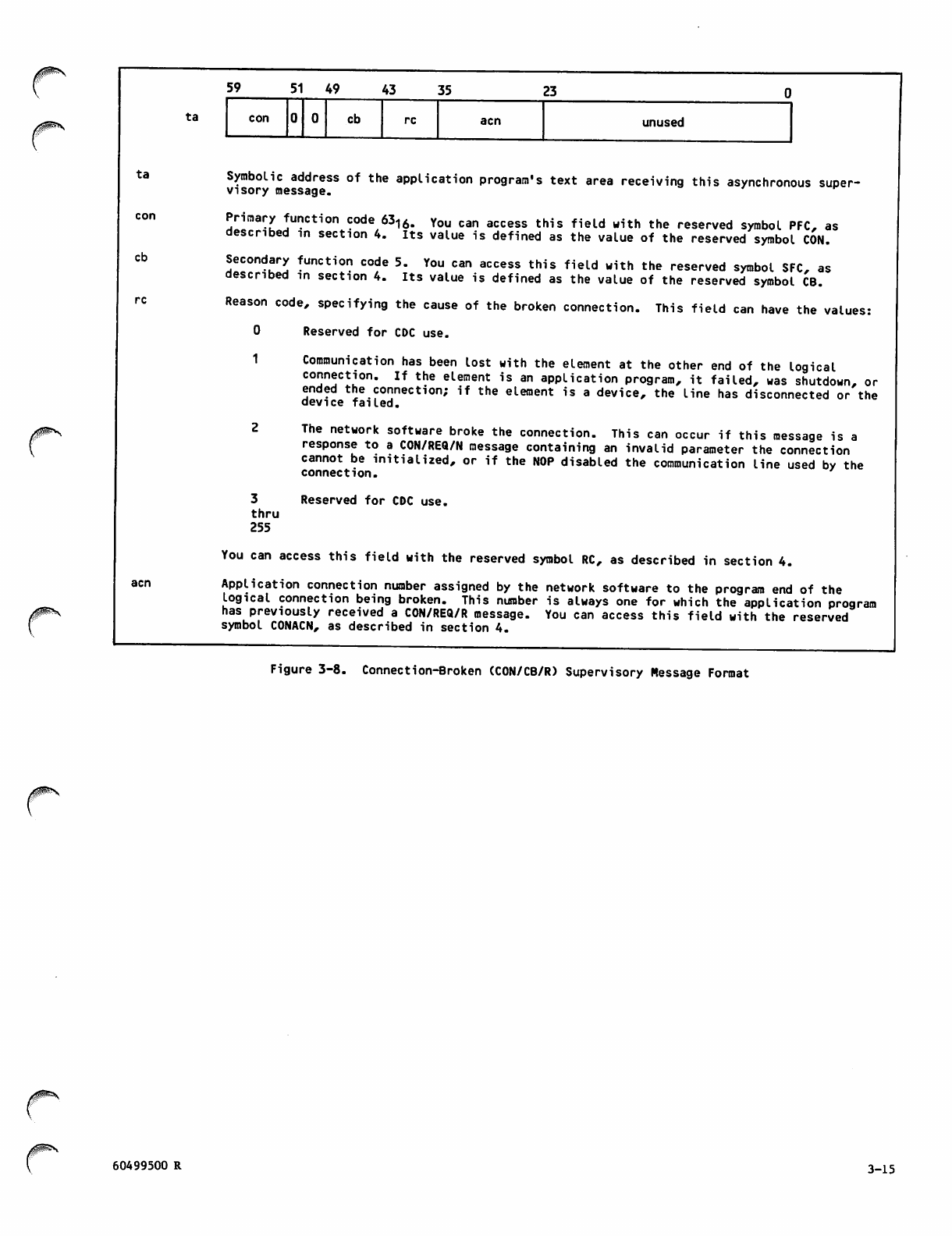
ta
cb
r
ta
59 5 1 4 9 43 35 23
con cb acn unused
Symbolic address of the application program's text area receiving this asynchronous super
visory message.
Primary function code 6316. You can access this field with the reserved symbol PFC, as
described in section 4. Its value is defined as the value of the reserved symbol CON.
Secondary function code 5. You can access this field with the reserved symbol SFC, as
described in section 4. Its value is defined as the value of the reserved symbol CB.
Reason code, specifying the cause of the broken connection. This field can have the values:
0 Reserved for CDC use.
1
3
thru
255
Communication has been lost with the element at the other end of the logical
connection. If the element is an application program, it failed, was shutdown, or
ended the connection; if the element is a device, the line has disconnected or the
device failed.
The network software broke the connection. This can occur if this message is a
response to a CON/REQ/N message containing an invalid parameter the connection
cannot be initialized, or if the NOP disabled the communication line used by the
connection.
Reserved for CDC use.
You can access this field with the reserved symbol RC, as described in section 4.
Application connection number assigned by the network software to the program end of the
logical connection being broken. This number is always one for which the application program
has previously received a CON/REQ/R message. You can access this field with the reserved
symbol CONACN, as described in section 4.
Figure 3-8. Connection-Broken (CON/CB/R) Supervisory Message Format
/0^\
60499500 R 3-15
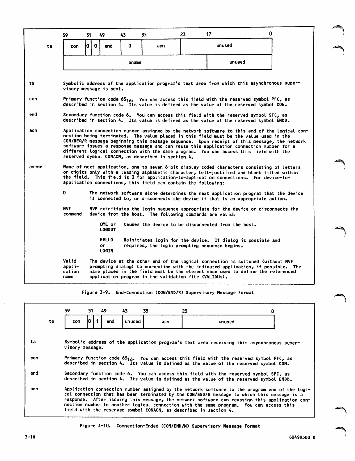
ta
ta
con
end
acn
aname
59 51 49 43 35 23 17
con end acn unused
aname unused
Symbolic address of the application program's text area from which this asynchronous super
visory message is sent.
Primary function code 63<j0. You can access this field with the reserved symbol PFC, as
described in section 4. Its value is defined as the value of the reserved symbol CON.
Secondary function code 6. You can access this field with the reserved symbol SFC, as
described in section 4. Its value is defined as the value of the reserved symbol ENDD.
Application connection number assigned by the network software to this end of the logical con
nection being terminated. The value placed in this field must be the value used in the
CON/REQ/R message beginning this message sequence. Upon receipt of this message, the network
software issues a response message and can reuse this application connection number for a
different logical connection with the same program. You can access this field with the
reserved symbol CONACN, as described in section 4.
Name of next application, one to seven 6-bit display coded characters consisting of letters
or digits only with a leading alphabetic character, left-justified and blank filled within
the field. This field is 0 for application-to-application connections. For device-to-
application connections, this field can contain the following:
0 The network software alone determines the next application program that the device
is connected to, or disconnects the device if that is an appropriate action.
NVF
command
NVF reinitiates the login sequence appropriate for the device or disconnects the
device from the host. The following commands are valid:
BYE or
LOGOUT
HELLO
or
LOGIN
Causes the device to be disconnected from the host.
Reinitiates login for the device. If dialog is possible and
required, the login prompting sequence begins.
Valid
appli
cation
name
The device at the other end of the logical connection is switched (without NVF
prompting dialog) to connection with the indicated application, if possible. The
name placed in the field must be the element name used to define the referenced
application program in the validation file (VALIDUs).
/(^Sk
Figure 3-9. End-Connection (CON/END/R) Supervisory Message Format
ta
ta
end
59 51 49 43 35 23
con end unused acn unused
Symbolic address of the application program's text area receiving this asynchronous super
visory message.
Primary function code 63<j0. You can access this field with the reserved symbol PFC, as
described in section 4. Its value is defined as the value of the reserved symbol CON.
Secondary function code 6. You can access this field with the reserved symbol SFC, as
described in section 4. Its value is defined as the value of the reserved symbol ENDD.
Application connection number assigned by the network software to the program end of the logi
cal connection that has been terminated by the CON/END/R message to which this message is a
response. After issuing this message, the network software can reassign this application con
nection number to another logical connection with the same program. You can access this
field with the reserved symbol CONACN, as described in section 4.
3-16
Figure 3-10. Connection-Ended (CON/END/N) Supervisory Message Format
60499500 R
«^^|L
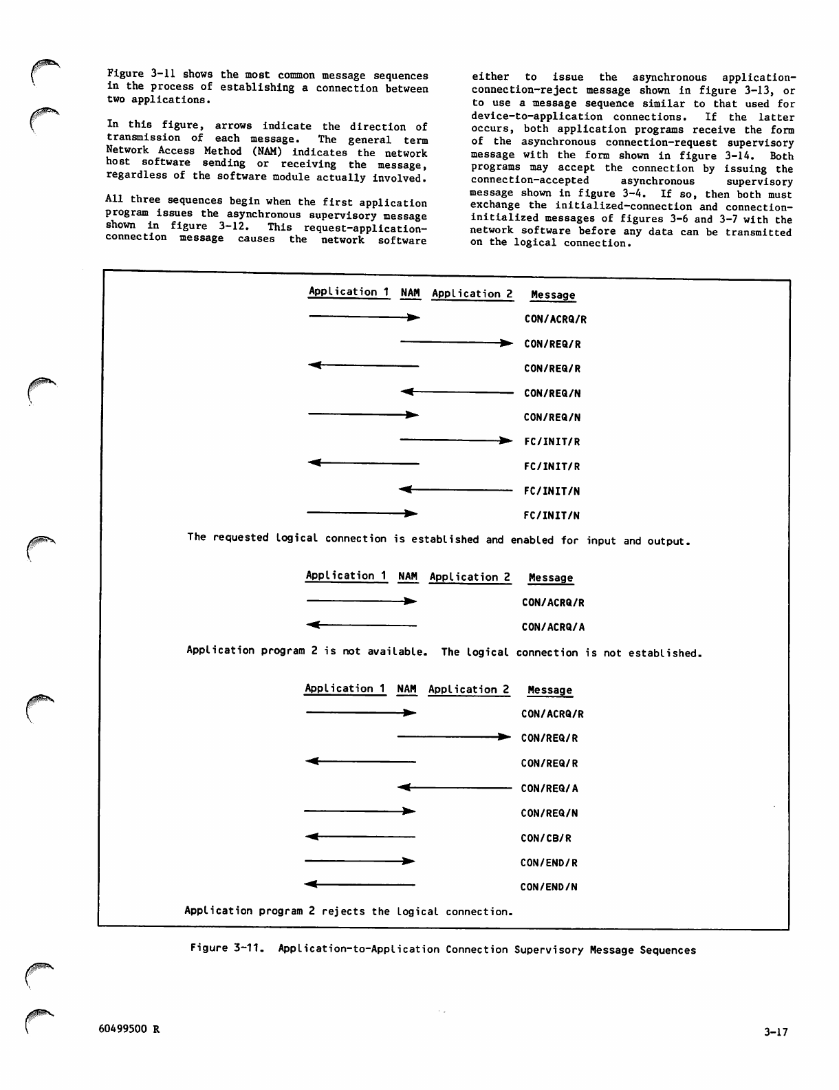
Figure 3-11 shows the most common message sequences
in the process of establishing a connection between
two applications.
In this figure, arrows indicate the direction of
transmission of each message. The general term
Network Access Method (NAM) indicates the network
host software sending or receiving the message,
regardless of the software module actually involved.
All three sequences begin when the first application
program issues the asynchronous supervisory message
shown in figure 3-12. This request-application-
connection message causes the network software
either to issue the asynchronous application-
connection-reject message shown in figure 3-13, or
to use a message sequence similar to that used for
device-to-application connections. If the latter
occurs, both application programs receive the form
of the asynchronous connection-request supervisory
message with the form shown in figure 3-14. Both
programs may accept the connection by issuing the
connection-accepted asynchronous supervisory
message shown in figure 3-4. If so, then both must
exchange the initialized-connection and connection-
initialized messages of figures 3-6 and 3-7 with the
network software before any data can be transmitted
on the logical connection.
Application 1 NAM Application 2 Message
▶ CON/ACRQ/R
' ▶ CON/REQ/R
"^ CON/REQ/R
-< CON/REQ/N
" ▶ CON/REQ/N
*>- FC/INIT/R
"^ FC/INIT/R
-< FC/INIT/N
—▶ FC/INIT/N
The requested logical connection is established and enabled for input and output.
Application 1 NAM Application 2 Message
▶ CON/ACRQ/R
~< CON/ACRQ/A
Application program 2 is not available. The logical connection is not established.
Application 1 NAM Application 2 Message
▶ CON/ACRQ/R
▶ CON/REQ/R
*^ CON/REQ/R
-<- CON/REQ/A
▶ CON/REQ/N
"< CON/CB/R
▶ CON/END/R
"^ CON/END/N
Application program 2 rejects the Logical connection.
Figure 3-11. AppLication-to-Application Connection Supervisory Message Sequences
60499500 R 3-17
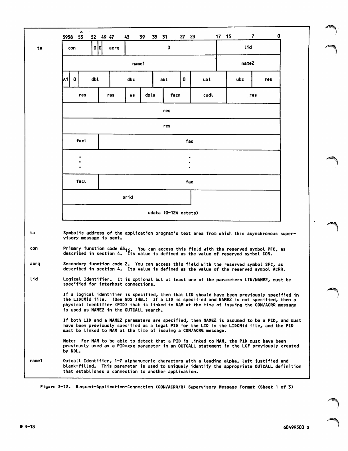
ta
ta
acrq
lid
namel
5958 55 52 49 47 43 59 35 "51 27 23 17 15
con acrq lid
namel naroe2
A1 dbl dbz abl ubl ubz res
res res ws dpls facn cud I res
res
res
facl fac
. .
facl fac
prid
udata (0-124 octets)
Symbolic address of the application program's text area from which this asynchronous super
visory message is sent.
Primary function code 63^Q. You can access this field with the reserved symbol PFC, as
described in section 4. Its value is defined as the value of reserved symbol CON.
Secondary function code 2. You can access this field with the reserved symbol SFC, as
described in section 4. Its value is defined as the value of the reserved symbol ACRQ.
Logical Identifier. It is optional but at least one of the parameters LID/NAME2, must be
specified for interhost connections.
If a logical identifier is specified, then that LID should have been previously specified in
the LIDCMid file. (See NOS IHB.) If a LID is specified and NAME2 is not specified, then a
physical identifier (PID) that is linked to NAM at the time of issuing the CON/ACRQ message
is used as NAME2 in the OUTCALL search.
If both LID and a NAME2 parameters are specified, then NAME2 is assumed to be a PID, and must
have been previously specified as a legal PID for the LID in the LIDCMid file, and the PID
must be linked to NAM at the time of issuing a CON/ACRQ message.
Note: For NAM to be able to detect that a PID is Linked to NAM, the PID must have been
previously used as a PID=xxx parameter in an OUTCALL statement in the LCF previously created
by NDL.
Outcall Identifier, 1-7 alphanumeric characters with a leading alpha, left justified and
blank-filled. This parameter is used to uniquely identify the appropriate OUTCALL definition
that establishes a connection to another application.
Figure 3-12. Request-Application-Connection (CON/ACRQ/R) Supervisory Message Format (Sheet 1 of 3)
• 3-18 60499500 S
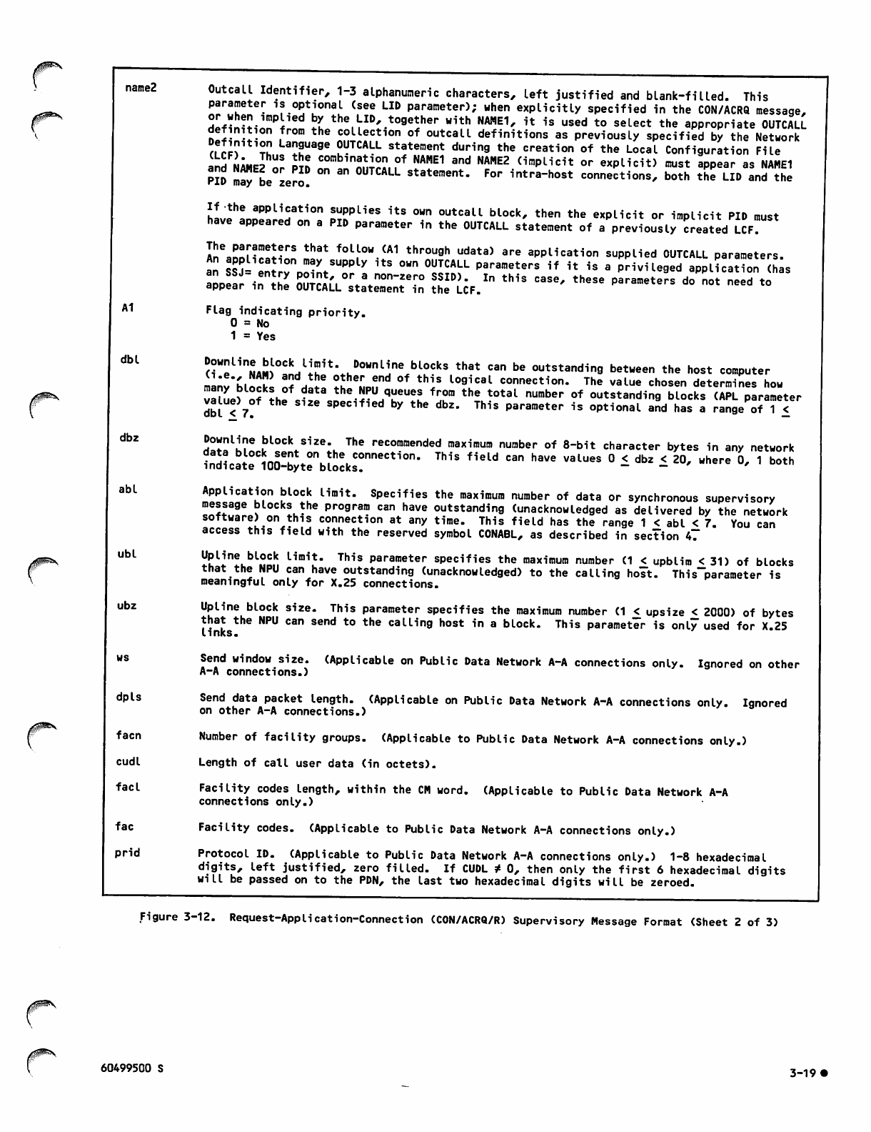
name2
A1
dbl
dbz
abl
ubl
ubz
0$^-
dpls
facn
cudl
facl
fac
prid
Outcall Identifier, 1-3 alphanumeric characters, left justified and blank-filled. This
parameter is optional (see LID parameter); when explicitly specified in the CON/ACRQ message,
HpfftEi^i X the LID, together with NAME1, it is used to seLect the appropriate OUTCALL
definition from the collection of outcall definitions as previously specified by the Network
all? t2 La"Suage ?VTCAITL statement during the creation of the Local Configuration File
and NAM J nr In nnr^, ,°f NAME1 and NAME2 (imPLi"t °r explicit) must appear as NAME1
PID mTy be zero! " statement. For intra-host connections, both the LID and the
If the application supplies its own outcall block, then the explicit or implicit PID must
have appeared on a PID parameter in the OUTCALL statement of a previously created LCF?
IneaPDMcat^n ilr foL,L°W "1 throu9h udata> are application supplied OUTCALL parameters,
an «J= entrv oointSUor^ ^ "" °S^L Parameters if " <• * privileged application (has
appear in tZ St?!,'.- A™""!*?0 S?ID)* ln th1s case' these Parameters do not need to
appear in the OUTCALL statement in the LCF.
Flag indicating priority.
0 = No
1 = Yes
^Un2ASJ°-l!rflISt'*hD0,inline*bl??k* th8t C3n bG outstandi"9 ^tween the host computer
ll'nl't\, l a"d the °*her end of this logical connection. The value chosen determines how
vl?J o\F the JT the.f V^U^ fT the t0taL number of outstanding blocks SS parameter
dbl < 7° specified by the dbz. This parameter is optional and has a range of 1 £
Wo!J2l|!?e bLocl< size- The recommended maximum number of 8-bit character bytes in any network
?n2?catri00^^rblocksC!nneCtiOn' ™S ""^ "" *"" "^ ° ~ dbZ * 2°' Hhere °' 1 b°th
Application block limit. Specifies the maximum number of data or synchronous supervisory
message blocks the program can have outstanding (unacknowledged as delivered by the network
software) on this connection at any time. This field has the range 1 < abl < 7. You can
access this field with the reserved symbol CONABL, as described in section 47
Upline block limit. This parameter specifies the maximum number (1 < upblim < 31) of blocks
that the NPU can have outstanding (unacknowledged) to the calling holt. This~parameter is
meaningful only for X.25 connections.
Upline block size. This parameter specifies the maximum number (1 £ upsize < 2000) of bytes
that the NPU can send to the calling host in a block. This parameter is only used for X.25
links.
Send window size. (Applicable on Public Data Network A-A connections only. Ignored on other
A-A connections.)
Send data packet length. (Applicable on Public Data Network A-A connections only. Ignored
on other A-A connections.)
Number of facility groups. (Applicable to Public Data Network A-A connections only.)
Length of call user data (in octets).
Facility codes length, within the CM word. (Applicable to Public Data Network A-A
connections only.)
Facility codes. (Applicable to Public Data Network A-A connections only.)
Protocol ID. (Applicable to Public Data Network A-A connections only.) 1-8 hexadecimal
digits, left justified, zero filled. If CUDL t 0, then only the first 6 hexadecimal digits
will be passed on to the PDN, the last two hexadecimal digits will be zeroed.
Figure 3-12. Request-Application-Connection (CON/ACRQ/R) Supervisory Message Format (Sheet 2 of 3)
60499500 S 3-19*
udata Call user data. If the destination host is a NOS system running network products, the first
12t octets must be of the form SSS DD AAAAAAA, where:
SSS
DD
AAAAAAA
is the 3 ASCII character equivalent of the SNODE (sendng node number) value,
right justified, zero-character filled.
is the 2 ASCII character string equivalent of the DHOST (destination host
number) value, right justified, zero-character filled.
is the 7 ASCII character string equivalent of the called applica- tion's
application name, left justified, blank-character filled.
The remainder of the UDATA filled (0-112 octets) will be passed to the called application as
user data.
At any rate, the called host/application if accessed through a public data network must be
able to support the Fast Select Facility, if more than 12 octets of information are specified.
Note: For applications accessing foreign hosts through a public data network the 4 octets of
the PRID field and the (up to) 124 octets of the UDATA field are combined into the (up to)
128 octets of used data as defined by the CCITT recommendation for X.25 networks.
TAn octet is 8 bits of information.
Figure 3-12. Request-Application-Connection (CON/ACRQ/R) Supervisory Message Format (Sheet 3 of 3)
ta
acrq
ta
59 51 49 43 35 17
con acrq re abn reserved
namel name2
Symbolic address of the application program's text area receiving this asynchronous super
visory message.
Primary function code 63^0. You can access this field with the reserved symbol PFC, as
described in section 4. Its value is defined as the value of reserved symbol CON.
Secondary function code 2. You can access this field with the reserved symbol SFC, as
described in section 4. Its value is defined as the value of the reserved symbol ACRQ.
Reason code, specifying the cause for rejecting the connection request. The field is
actually made up of two 4 bit subfields, rc1 and rc2. The rc1 field comprises bits 40-43 and
the rc2 field comprises bits 36-39.
The rc2 field is used so that the application can determine what action to take when it
receives a CON/ACRQ/A message and it provides some general information about the source of
the trouble. This field can have the following values:
1 = Critical error in call request detected by source host (only LID/PID/NDL
configuration changes or application code changes would solve the problem).
2 = Critical error in call request detected by destination host.
3 = Source host temporarily cannot make the connection (resources are currently not
available, but they might become available without operator intervention).
4 = Destination host temporarily cannot make the connection.
Figure 3-13. Application-Connection-Reject (CON/ACRQ/A) Supervisory Message Format (Sheet 1 of 4)
• 3-20 60499500 S
40^\
5 = Source host cannot make the connection for an indefinite period of time (resources
can be made available by operator intervention such as enabling a LID/PID, network
element, or bringing up a system or subsystem).
6 = Destination host cannot make the connection for an indefinite period of time.
Thus if rc2 = 1 or 2, the application would not try establishing the connection again, it
would notify the user and/or operator that the connection is not possible.
If rc2 =3 or 4 then the application can retry the CON/ACRQ message after a shorter period of
time, and if rc2 = 5 or 6 then it will retry the CON/ACRQ after a somewhat longer period of
time.
The rd field is used in combination with the rc2 field to uniquely identify the exact source
of the trouble, so that the user/operator can take the appropriate action to fix the
problem. The full 8 bit reason code field can therefore have the following values:
2 = Network error detected by destination host. Contact system analyst at destination
nost.
4 = Connection number conflict between source and destination host. Retry connection
request.
17 = Illegal LID/PID combination was specified. Correct LID/PID in OUTCALL block.
18 = Called application is not defined in system record (CONTNAP) at destination host.
Contact system analyst.
19 = Network Validation Facility (NVF) temporarily cannot process connection request.
Retry later.
20 = Called application cannot accept any more connections and another copy of the
application cannot be started up. Retry later.
22 = Called application is not running and cannot be started automatically. Contact
system analyst to start up called application.
33 = Calling application is not privileged, i.e., it is not allowed to issue OUTCALLS.
Contact system analyst to make the application a privileged application in the LCF.
34 = OUTCALL block has facility parameters greater than 4 octets in length. Correct the
OUTCALL block.
35 = NAM temporarily cannot complete the connection request because the (logical) link
to the destination host is not available. Retry Later.
37 = Specified PID is valid but is currently not available. Retry later.
38 = Called application is disabled. Contact system analyst to enable the application.
49 = Application specified its own OUTCALL parameters but there was no corresponding
OUTCALL entry in the LCF for the same PID. Correct the OUTCALL parameters in the
CON/ACRQ/A.
50 = OUTCALL block had user parameters greater than 124 octets in length. Correct the
OUTCALL block.
53 = Source host is not allowing any new connections because it is in idle or disabled
state. Retry Later.
54 = Destination host is not allowing any new connections because it is in idle or
disabled state. Retry later.
65 = Application specified its own OUTCALL parameters but there was no matching OUTCALL
entry in the LCF. Correct the OUTCALL parameters in the CON/ACRQ/R.
66 = Destination host could not find a matching INCALL block in its LCF. Correct the
OUTCALL block.
81 = Calling application has already reached its maximum number of allowed connections.
Retry later.
Figure 3-13. Application-Connection-Reject (CON/ACRQ/A) Supervisory Message Format (Sheet 2 of 4)
60499500 S 3_21#
82 = Name of application specified in CON/ACRQ is invalid. Correct the application.
97 = Retry limit has been reached for calling application. No more application to
application connection requests (CON/ACRQ/R) should be issued. The reason codes
for the previous CON/ACRQ/A should be analyzed.
98 = Destination host could not find a matching INCALL block in the LCF with a matching
facility code. Correct the facility code in the OUTCALL block.
100 = Network Validation Facility (NVF) in the destination host has not netted on yet.
Retry Later.
114 = Application requested Fast select but matching INCALL block in LCF at the
destination host does not have Fast select specified. Correct the OUTCALL block to
not select Fast select.
129 = No X25 TIP in NPU at source host. Contact system analyst to rebuild CCP with X25
TIP.
130 = Error in incoming call packet header. Contact system analyst about possible PSN
problem.
132 = Unknown packet from remote, i.e., the packet received is not a call accepted or
call connected. This is assumed to be caused by a call collision. Retry later.
133 = No available logical channel at source host, i.e., active number of SVCs are
greater than enabled SVCs. Contact the system analyst about enabling additional
SVCs.
134 = No available logical channel at destination host, i.e., active number of SVCs are
greater than enabled SVCs. Contact the system analyst at the destination host to
enable some more SVCs.
145 = X25 subtip not available in NPU at source host. Contact system analyst for
rebuilding CCP.
146 = X25 subtip not available in NPU at destination host. Contact system analyst at
destination site for rebuilding CCP.
147 = NPU at source host temporarily has no buffer space to support the connection.
Retry later.
148 = NPU at destination host temporarily has no buffer space to support the connection.
Retry later.
161 = Problem detected by X25 network at local host. PSN CCC=13. Local procedure
error. Clear problem with PSN administration.
162 = Remote host not known. Correct DD field in UDATA in OUTCALL entry in the LCF or in
the CON/ACRQ/R message.
163 = No connection available, i.e., all SVCs (outside lines) have been used. Retry
later.
164 = Problem detected by X25 network at destination host. PSN CCC=1. Number at
destination host is busy. Retry later.
165 = X25 line is down at source host. Retry later.
166 = X25 line is down at destination host. Retry later.
178 = Unknown subtip connection; i.e., the PRID field is not CO (PAD) or C1 (A-A). Fix
the PRID field in the OUTCALL entry in the LCF or in the CON/ACRQ/R message.
180 = Problem detected by X25 network. PSN CCC=5. PSN congestion. Retry later.
182 = CCP cannot complete the connection because the (logical) link at the destination
host is not up (enabled). The system analyst should be contacted to enable the
logical link.
Figure 3-13. Application-Connection-Reject (CON/ACRQ/A) Supervisory Message Format (Sheet 3 of 4)
• 3-22 60499500 S
dpls
fa en
cudl
facl
fac
prid
j0^\.
udata
Send data packet length, specifying the maximum number of data octets (8-bit bytes) an X 25
packet can contain. This parameter applies only to X.25 network application-to-application
connections and is ignored on other application-to-application connections. The dpls
£a,£aT?.ter 1s an aPP!:ication supplied OUTCALL parameter. An application can supply its own
OUTCALL parameters if it is a privileged application (SSJ= entry point, or a non-zero SSID)
This parameter does not need to appear in the OUTCALL statement in the LCF. You can access"
this field with the reserved symbol CONDPLS, as described in section 4.
Number of facility groups. This parameter applies only to X.25 network
aPP^t^-to-appli cation connecti°ns. The facn parameter is an application supplied
OUTCALL parameter. An application can supply its own OUTCALL parameters if it is a
privileged application (SSJ= entry point, or a non-zero SSID). In this case, the facn
parameter does not need to appear in the OUTCALL statement in the LCF. You can access this
field with the reserved symbol CONFACN, as described in section 4.
Length of user data (in octets). The cudl parameter is an application supplied OUTCALL
parameter. An application can supply its own OUTCALL parameters if it is a privileged
•PP uCa!nS!!,MSSJ= entry P<?int' or a non-2ero SSID>- This parameter does not need to appear
lS,0UTCAL statement in the LCF. You can access this field with the reserved symbol
CONAUDL, as described in section 4.
Facility code length, specifying the length of a facility field within the central memory
word. This parameter applies only to X.25 network application-to-application connections.
The facl parameter is an application supplied OUTCALL parameter. An application can supply
sc™?™ ^TCALL P^^ters if it is a privileged application (SSJ= entry point, or a non-zero
SSID). This parameter does not need to appear in the OUTCALL statement in the LCF.
Facility code, specifying the facility code for a facility field. This parameter applies
only to X.25 network application-to-application connections. The fac parameter is an
application supplied OUTCALL parameter. An application can supply its own OUTCALL parameters
if it is a privileged application (SSJ= entry point, or a non-zero SSID). This parameter
does not need to appear in the OUTCALL statement in the LCF.
The protocol identification. This parameter tells the PSN or remote node of a direct X.25
link how call user data is to be used. This parameter applies only to X.25 network
application-to-application connections and must be 1 to 8 hexadecimal digits, left-justified,
and zero-filled. If CUDL r 0, only the first 6 hexadecimal digits are passed to the X.25
network, and the last two hexadecimal digits are zeroed. The prid parameter is an
application supplied OUTCALL parameter. An application can supply its own OUTCALL parameters
if it is a privileged application (SSJ= entry point, or a non-zero SSID). This parameter
does not need to appear in the OUTCALL statement in the LCF.
Call user data. If the destination host is a NOS system running network products, the first
12T octets must be of the form sss dd aaaaaaa, where:
sss is the 3 character ASCII equivalent of the SNODE (sendng node number) value,
right-justified, zero filled.
dd is the 2 character ASCII equivalent of the DHOST (destination host number)
value, right-justified, zero filled.
aaaaaaa is the 7 character ASCII equivalent of the called application's application
name, left-justified, blank filled.
The remainder of the udata field (0-112 octets) is passed to the called application as user
data.
The called host/application (if accessed through an X.25 network) must be able to support the
Fast Select Facility, if more than 12 octets of information are specified.
Note: For applications accessing foreign hosts through an X.25 network, the 4 octets of the
PRID field and the (up to) 124 octets of the UDATA field are combined into the (up to) 128
octets of used data as defined by the CCITT recommendation for X.25 networks.
You cannot access this field with NFETCH.
tAn octet is 8 bits of informati<
Figure 3-12. Request-Application-Connection (CON/ACRQ/R) Supervisory Message Format (Sheet 3 of 3)
60499500 W 3-23
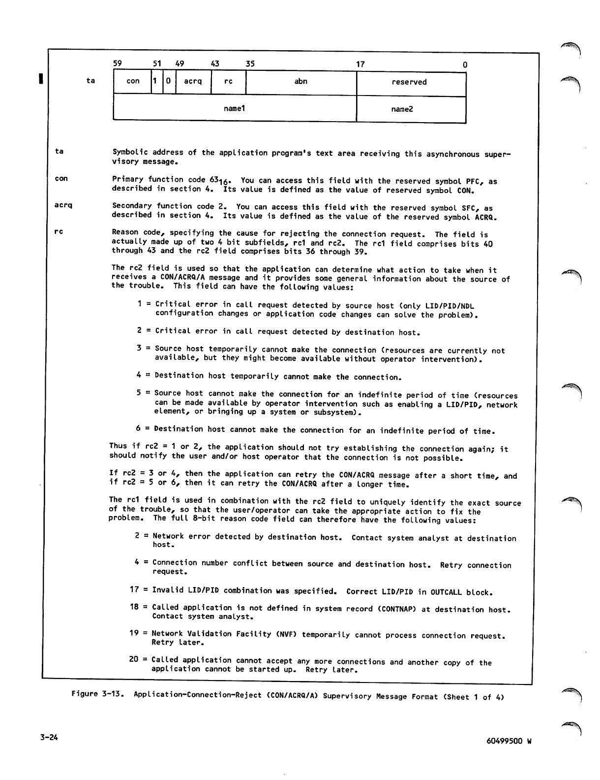
59 5 1 4 9 43 35 17
ta acrq abn reserved
namel name2
ta
acrq
Symbolic address of the application program's text area receiving this asynchronous super
visory message.
Primary function code 63<j0. You can access this field with the reserved symbol PFC, as
described in section 4. Its value is defined as the value of reserved symbol CON.
Secondary function code 2. You can access this field with the reserved symbol SFC, as
described in section 4. Its value is defined as the value of the reserved symbol ACRQ.
Reason code, specifying the cause for rejecting the connection request. The field is
actually made up of two 4 bit subfields, rd and rc2. The rc1 field comprises bits 40
through 43 and the rc2 field comprises bits 36 through 39.
The rc2 field is used so that the application can determine what action to take when it
receives a CON/ACRQ/A message and it provides some general information about the source of
the trouble. This field can have the following values:
1 = Critical error in call request detected by source host (only LID/PID/NDL
configuration changes or application code changes can solve the problem).
2 = Critical error in call request detected by destination host.
3 = Source host temporarily cannot make the connection (resources are currently not
available, but they might become available without operator intervention).
4 = Destination host temporarily cannot make the connection.
5 = Source host cannot make the connection for an indefinite period of time (resources
can be made available by operator intervention such as enabling a LID/PID, network
element, or bringing up a system or subsystem).
6 = Destination host cannot make the connection for an indefinite period of time.
Thus if rc2 = 1 or 2, the application should not try establishing the connection again; it
should notify the user and/or host operator that the connection is not possible.
If rc2 = 3 or 4, then the application can retry the CON/ACRQ message after a short time, and
if rc2 = 5 or 6, then it can retry the CON/ACRQ after a longer time.
The rd field is used in combination with the rc2 field to uniquely identify the exact source
of the trouble, so that the user/operator can take the appropriate action to fix the
problem. The full 8-bit reason code field can therefore have the following values:
2 = Network error detected by destination host. Contact system analyst at destination
host.
4 = Connection number conflict between source and destination host. Retry connection
request.
17 = Invalid LID/PID combination was specified. Correct LID/PID in OUTCALL block.
18 = Called application is not defined in system record (CONTNAP) at destination host.
Contact system analyst.
19 = Network Validation Facility (NVF) temporarily cannot process connection request.
Retry later.
20 = Called application cannot accept any more connections and another copy of the
application cannot be started up. Retry later.
/"^H
Figure 3-13. Application-Connection-Reject (CON/ACRQ/A) Supervisory Message Format (Sheet 1 of 4)
3-24 60499500 W
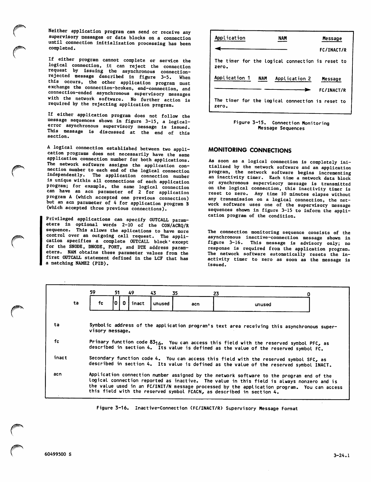
ypfey
Neither application program can send or receive any
supervisory messages or data blocks on a connection
until connection initialization processing has been
completed.
If either program cannot complete or service the
logical connection, It can reject the connection
request by issuing the asynchronous connection-
rejected message described in figure 3-5. When
this occurs, the other application program must
exchange the connection-broken, end-connection, and
connection-ended asynchronous supervisory messages
w i t h t h e n e t w o r k s o f t w a r e . N o f u r t h e r a c t i o n i s
required by the rejecting application program.
If either application program does not follow the
message sequences shown in figure 3-15, a logical-
error asynchronous supervisory message is issued.
This message is discussed at the end of this
section.
A logical connection established between two appli
cation programs does not necessarily have the same
application connection number for both applications.
Th e network s oft war e assigns t he application c on
nection number to each end of the logical connection
independently. The application connection number
is unique within all connections of each application
program; for example, the same logical connection
c a n h a v e a n a cn p a r a m e t e r o f 2 f o r ap p l i c a t i o n
program A (which accepted one previous connection)
but an acn parameter of 4 for application program B
(which accepted three previous connections).
Privileged applications can specify OUTCALL param
eters in optional word s 2 - 1 0 o f t h e C O N / A C R Q / R
sequence. This allows the aplications to have more
control over an outgoing call request. The appli
cation specifies a complete OUTCALL block' except
for the SNODE, DNODE, PORT, and DTE address param
eters. NAM obtains these parameter values from the
first OUTCALL statement defined in the LCF that has
a matching NAME2 (PID).
Application NAM Message
FC/INACT/R
The timer for the logical connection is reset to
zero.
Application 1 NAM Application 2 Message
~ ▶ FC/INACT/R
The timer for the logical connection is reset to
zero.
Figure 3-15. Connection Monitoring
Message Sequences
MONITORING CONNECTIONS
As soon as a logical connection is completely ini
tialized by the network software and an application
program, the network software begins incrementing
an inactivity timer. Each time a network data block
or synchronous supervisory message is transmitted
on the logical connection, this inactivity timer is
reset to zero. Any time 10 minutes elapse without
any transmission on a logical connection, the net
work software uses one of the supervisory message
sequences shown in figure 3-15 to inform the appli
cation program of the condition.
The connection monitoring sequence consists of the
asynchronous inactive-connection message shown in
figure 3-16. This message is advisory only; no
response is required from the application program.
The network software automatically resets the in
activity timer to zero as soon as the message is
issued.
ta
ta
fc
inact
acn
59 51 49 43 35 23
fc inact unused acn unused
Symbolic address of the application program's text area receiving this asynchronous super
visory message.
Primary function code 831o. You can access this field with the reserved symbol PFC, as
described in section 4. Its value is defined as the value of the reserved symbol FC.
Secondary function code 4. You can access this field with the reserved symbol SFC, as
described in section 4. Its value is defined as the value of the reserved symbol INACT.
Application connection number assigned by the network software to the program end of the
logical connection reported as inactive. The value in this field is always nonzero and is
the value used in an FC/INIT/N message processed by the application program. You can access
this field with the reserved symbol FCACN, as described in section 4.
Figure 3-16. Inactive-Connection (FC/INACT/R) Supervisory Message Format
60499500 S 3-24.1
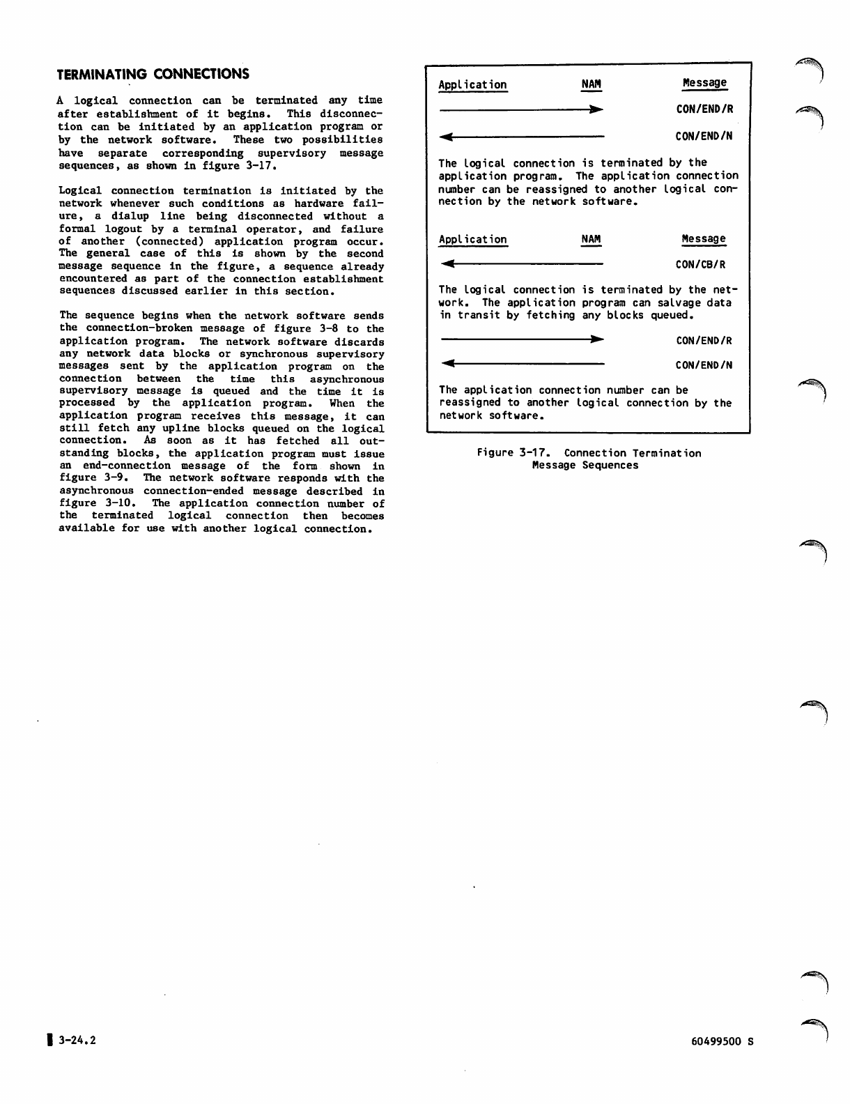
TERMINATING CONNECTIONS
A logical connection can be terminated any time
after establishment of it begins. This disconnec
tion can be initiated by an application program or
by the network software. These two possibilities
have separate corresponding supervisory message
sequences, as shown in figure 3-17.
Logical connection termination is initiated by the
network whenever such conditions as hardware fail
ure, a dialup line being disconnected without a
fo r m al lo g o ut b y a t e rmi n a l ope r a t or, and f a i l ur e
of another (connected) application program occur.
The general case of this is shown by the second
message sequence in the figure, a sequence already
encountered as part of the connection establishment
sequences discussed earlier in this section.
The sequence begins when the network software sends
the connection-broken message of figure 3-8 to the
application program. The network software discards
any network data blocks or synchronous supervisory
mes s ages s ent b y the a pplic ation p rogr a m on t he
connection between the time this asynchronous
supervisory message is queued and the time it is
processed by the application program. When the
application program receives this message, it can
still fetch any upline blocks queued on the logical
connection. As soon as it has fetched all out
standing blocks, the application program must issue
an end-connection message of the form shown in
figure 3-9. The network software responds with the
asynchronous connection-ended message described in
figure 3-10. The application connection number of
the terminated logical connection then becomes
available for use with another logical connection.
Application NAM
—▶
Message
CON/END/R
CON/END/N
The logical connection is terminated by the
application program. The application connection
number can be reassigned to another logical con
nection by the network software.
Application NAM Message
CON/CB/R
The logical connection is terminated by the net
work. The application program can salvage data
in transit by fetching any blocks queued.
CON/END/R
CON/END/N
The application connection number can be
reassigned to another logical connection by the
network software.
Figure 3-17. Connection Termination
Message Sequences
ydttSt^.
| 3-24.2 60499500 S
/Sf*^
Application-initiated termination of a logical con
nection occurs whenever the application program
processes a terminal operator's request to end con
nection, or in any other situation where the appli
cation program has finished exchanging blocks over
the logical connection. The message sequence is the
first one shown in figure 3-17. This sequence
begins when the application program issues an asyn
chronous end-connection supervisory message.
The format of the end-connection message is
described in figure 3-9. This message permits the
application program to influence connection switch
ing or disconnection processing performed for the
d e v ice a f ter i t i s d is c o nn e c ted f r o m t h e a pp l i ca
tion program. The effects of this end-connection
message vary according to the aname field contents
and whether the device is a batch or interactive
console device.
When a zero aname parameter Is used, a console
device is prompted for the name of the next program
the device should be connected to, unless the user
is allowed access only to the disconnected applica
t i on p ro g r a m . I n t h i s i n st a n c e , t h e d e v i c e ' s l o g
ical connection is processed by NVF as if an aname
value of BYE or LOGOUT was specified.
When a valid application name is used in the aname
field, a console connection is disposed of in one
of two ways. If the specified application program
is available and the login user name of the console
is allowed access to it, the console connection is
switched directly to the new application program.
This switch is performed without dialog between NVF
and a console operator. The network software per
forms the switch by sending a connection-request
supervisory message for the console to the specified
application program.
I f t h e s pe c i fie d a p pl i c ati o n pro g r am i s n o t a v a i l
able or the login user name does not permit the
terminal to access that program, the console con
nection is not switched. In this case, a console
is informed of the condition with the message
APPLICATION NOT PRESENT or USER ACCESS NOT POSSIBLE
- CONTACT NETWORK ADMIN. The terminal operator is
then prompted for another application program name,
unless the console was configured for a full auto
matic login procedure and the user name in that
procedure validates for access only to the discon
n e c t e d a p p l i c a t i o n p r o g r a m . I n t h i s I n s t a n c e , a l l
of the terminal's ended logical connections are
processed by NVF as if an aname value of BYE or
LOGOUT was specified.
When an NVF command is used in the aname field,
disconnection processing depends on the command
used and whether the device is a batch or inter
active one. The HELLO or LOGIN command causes NVF
to initiate a manual login dialog with an inter
active device. The BYE or LOGOUT command causes
NVF to disconnect a console device from the host.
When your program ends a connection with a passive
device (a batch device of device types 1 through
4), any aname value you supply is ignored. NVF
disposes of the passive device connection in the
same manner as it does the device's owning console
connection. That is:
If your program already disconnected the owning
console for the device, NVF attempts to connect
the device to the same program as the owning
console; if the owning console is disconnected
from the host, NVF disconnects the passive
device as well.
If your program has not already disconnected
the owning console for the device, NVF attempts
to reconnect the device to your program. If
your program rejects the reconnection, NVF
keeps the device connected to itself until your
program disconnects the owning console for the
device.
On dialup lines, consoles without connections to
hosts are assigned to a disconnection queue. When
all consoles on the dialup line are assigned to the
disconnection queue, a timer for the line is
sta r t e d . When the t i m e r f o r t h e l i ne e xpire s , t h e
dialup line is physically disconnected. This dis
connection causes physical disconnection of all
devices on the line, including any passive devices
still connected to an application program (the
connection is broken from the application pro
gram's viewpoint). The network software effectively
hangs up the telephone, but the devices can be
reconnected after a new dial-in procedure.
On hardwired lines, no disconnection occurs when
all interactive devices on the line are timed out.
Because the line is not disconnected in this
instance, passive devices still connected to appli
cation programs remain connected to those programs.
While a console is queued for disconnection, any
te r m i n al o pera t o r k e yboa r d e n try re m o v e s all the
devices of that terminal from the disconnection
queue and reconnects them to NVF for a new manual
login procedure. The data entered is discarded by
the network software and therefore can be anything
the operator wishes.
MANAGING CONNECTION LISTS
There are five asynchronous supervisory message
sequences used for connection list management. Each
sequence consists of one message, issued by the
application program.
Three of these sequences, as shown in figure 3-18,
control list polling and list assignment. The
other sequences, shown in figure 3-19, control the
duplexing mode used during list processing.
CONTROLLING LIST POLLING
Connection list polling control consists of enabling
or disabling the fetching of input blocks from a
single logical connection when the list that the
connection is assigned to is polled. All connec
tions are initially enabled for list processing
without application program action. Each time the
application program polls the list number that it
has associated with a specific connection, blocks
queued from that connection can be returned to the
program.
60499500 R 3-25
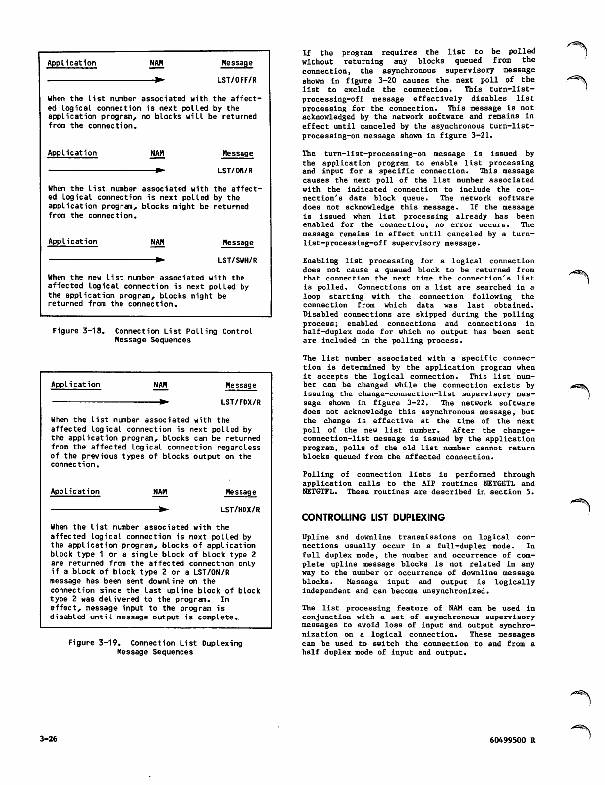
Application NAM Message
wLST/OFF/R
d with the affect-
polled by the
will be returned
When the list number
ed logical connection
application program,
from the connection.
associate
is next
no blocks
Application NAM Message
^- LST/ON/R
d with the affect-
polled by the
ght be returned
When the list number associate
ed logical connection is next
application program, blocks mi
from the connection.
AppIi c at i on NAM Message
When the new list number associated with the
affected logical connection is next polled by
the application program, blocks might be
returned from the connection.
Figure 3-18. Connection List Polling Control
Message Sequences
Application NAM
—▶
Message
LST/FDX/R
When the list number associated with the
affected logical connection is next polled by
the application program, blocks can be returned
from the affected Logical connection regardless
of the previous types of blocks output on the
connection.
Application NAM Message
LST/HDX/R
When the list number associated with the
affected logical connection is next polled by
the application program, blocks of application
block type 1 or a single block of block type 2
are returned from the affected connection only
if a block of block type 2 or a LST/ON/R
message has been sent downline on the
connection since the last upline block of block
type 2 was delivered to the program. In
effect, message input to the program is
disabled until message output is complete..
Figure 3-19. Connection List Duplexing
Message Sequences
If the program requires the list to be polled
without returning any blocks queued from the
con nect ion, the asyn chro nous supe rvis ory mess age
shown in figure 3-20 causes the next poll of the
list to exclude the connection. This turn-list-
p r o c e s s i n g - o f f m e s s a g e e f f e c t i v e l y d i s a b l e s l i s t
processing for the connection. This message is not
acknowledged by the network software and remains in
effect until canceled by the asynchronous turn-list-
process ing-on message shown in figure 3-21.
The turn-list-processing-on message is issued by
the application program to enable list processing
and input for a specific connection. This message
causes the next poll of the list number associated
with the indicated connection to include the con
nection's data block queue. The network software
does not acknowledge this message. If the message
is issued when list processing already has been
enabled for the connection, no error occurs. The
message remains in effect until canceled by a turn-
list-processing-off supervisory message.
Enabling list processing for a logical connection
does not cause a queued block to be returned from
that connection the next time the connection's list
is polled. Connections on a list are searched in a
loop starting with the connection following the
connection from which data was last obtained.
Disabled connections are skipped during the polling
process; enabled connections and connections in
half-duplex mode for which no output has been sent
are included in the polling process.
The list number associated with a specific connec
tion is determined by the application program when
it accepts the logical connection. This list num
ber can be changed while the connection exists by
issuing the change-connection-list supervisory mes
sage shown in figure 3-22. The network software
does not acknowledge this asynchronous message, but
the change is effective at the time of the next
poll of the new list number. After the change-
connection-list message is issued by the application
program, polls of the old list number cannot return
blocks queued from the affected connection.
Polling of connection lists is performed through
application calls to the AIP routines NETGETL and
NETGTFL. These routines are described in section 5.
CONTROLLING LIST DUPLEXING
Upline and downline transmissions on logical con
n e c t i o n s u s u a l l y o c c u r i n a f u l l - d u p l ex m o d e . I n
full duplex mode, the number and occurrence of com
plete upline message blocks is not related in any
way to the number or occurrence of downline message
blocks. Message input and output is logically
independent and can become unsynchronized.
The list processing feature of NAM can be used in
conjunction with a set of asynchronous supervisory
messages to avoid loss of input and output synchro
nization on a logical connection. These messages
can be used to switch the connection to and from a
half duplex mode of input and output.
3-26 60499500 R
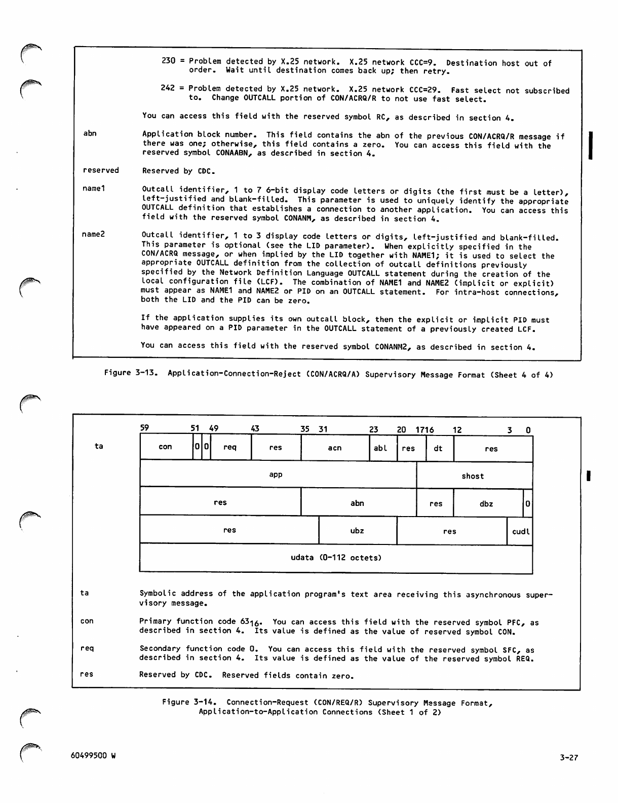
/#SS\.
abn
reserved
namel
name2
230 = Problem detected by X.25 network. X.25 network CCC=9. Destination host out of
order. Wait until destination comes back up; then retry.
242 = Problem detected by X.25 network. X.25 network CCC=29. Fast select not subscribed
to. Change OUTCALL portion of CON/ACRQ/R to not use fast select.
You can access this field with the reserved symbol RC, as described in section 4.
Application block number. This field contains the abn of the previous CON/ACRQ/R message if
there was one; otherwise, this field contains a zero. You can access this field with the
reserved symbol CONAABN, as described in section 4.
Reserved by CDC.
Outc a l l i d e n t i fier, 1 t o 7 6 - b i t d i s p lay c o de l e t ters o r d i g i ts ( t h e fi r s t m u st b e a l e tter),
left-justified and blank-filled. This parameter is used to uniquely identify the appropriate
OUTCALL definition that establishes a connection to another application. You can access this
field with the reserved symbol CONANM, as described in section 4.
Outcall identifier, 1 to 3 display code letters or digits, left-justified and blank-filled.
This parameter is optional (see the LID parameter). When explicitly specified in the
CON/ACRQ message, or when implied by the LID together with NAME1; it is used to select the
appropriate OUTCALL definition from the collection of outcall definitions previously
specified by the Network Definition Language OUTCALL statement during the creation of the
local configuration file (LCF). The combination of NAME1 and NAME2 (implicit or explicit)
must appear as NAME1 and NAME2 or PID on an OUTCALL statement. For intra-host connections,
both the LID and the PID can be zero.
If the appli catio n supplies i ts own outca ll block, th en the expli cit or impli cit PID must
have appeared on a PID parameter in the OUTCALL statement of a previously created LCF.
You can access this field with the reserved symbol C0NANM2, as described in section 4.
Figure 3-13. Application-Connection-Reject (CON/ACRQ/A) Supervisory Message Format (Sheet 4 of 4)
ta
59 51 49 43 35 31 23 20 1716 12
con req res acn abl res dt res
app shost
res abn res dbz
res ubz res cudl
udata (0-112 octets)
ta
req
Symbolic address of the application program's text area receiving this asynchronous super
visory message.
Primary function code 63-|0. You can access this field with the reserved symbol PFC, as
described in section 4. Its value is defined as the value of reserved symbol CON.
Secondary function code 0. You can access this field with the reserved symbol SFC, as
described in section 4. Its value is defined as the value of the reserved symbol REQ.
Reserved by CDC. Reserved fields contain zero.
Figure 3-14. Connection-Request (CON/REQ/R) Supervisory Message Format,
Application-to-Application Connections (Sheet 1 of 2)
/0^>, 60499500 W 3-27
abl
dt
app
shost
abn
dbz
ubz
cudl
Ap?iication con?ection number assigned to this logical connection; 1 < minacn < acn < maxacn
£ 4095, where minacn and maxacn are minimum and maximum values establTshed by The application
program in its NETON call. (See section 5.) You can access this field with the reserved
symbol CONACN, as described in section 4.
Application block limit, specifying the maximum number of data or synchronous supervisory
message blocks the program can have outstanding (unacknowledged as delivered by the network
software) on this connection at any time. This value is established when the connection is
described i n t h e l o c a l configuration fi l e . I f y o u r a p plication program i n i t i a t e d t he
connection request, this value comes from the ABL parameter of the NDL OUTCALL statement used
by your program; if another application program initiated the connection request, the initial
value comes from the ABL parameter of the NDL INCALL statement used by that program. This
value is also supplied from the abl in the CON/ACRQ if the application supplies its own
OUTCALL parameters. This field has the range 1 £ abl £7. You can access this field with
the reserved symbol CONABL, as described in section 4.
Device type of the connection. This field can have the values:
5 Application-to-application connection within the same host
6 Application-to-application connection between two hosts
You can access this field with the reserved symbol CONDT, as described in section 4.
Application name. This field contains the application name of the other application program
for intrahost application-to-application connections; otherwise, this field contains zero.
Source host identifier. This field contains the node number of the host in which the other
application program runs if this CON/REQ/R is received by the called application. The value
i s i n 6 - b i t di s p l a y c o d e c h a ra c te r s , l e f t - j us t i fi e d w i t h b l a n k fi l l . T h e c a ll i n g a p p l i c at i o n
receives a CON/REQ/R with the name2 field of the previous CON/ACRQ/R message or the name2
value of the corresponding OUTCALL parameter block.
Application block number. This field contains the abn value assigned by your application
program to the CON/ACRQ/R supervisory message if your program initiated the connection
request; otherwise, this field contains a zero. You can access this field with the reserved
symbol CONABN, as described in section 4.
Downline block size. The recommended maximum number of 8-bit character bytes in any network
data block sent on the connection. If your application program initiated the connection
request, this value comes from the DBZ parameter of the NDL OUTCALL statement used by your
program; if another application program initiated the connection request, the initial value
comes from the DBZ parameter of the NDL INCALL statement used by that program. This field
can have the values 1 £ dbz £ 2043. You can access this field with the reserved symbol
CONDBZ, as described in section 4.
Upline block size. The number of 8-bit bytes (in multiples of 100) the network will deliver
in each upline network data block on the connection. If your application program initiated
the connection request, this value comes from the UBZ parameter of the NDL OUTCALL statement
used by your program. If another application program initiated the connection request, the
initial value comes from the UBZ parameter of the NDL INCALL statement used by that program.
This field can have the values 0 £ ubz £ 20, where 0 and 1 both indicate 100-byte blocks. If
ubl is not specified, the default value of 2 is used. You can access this field with the
reserved symbol C0NUBZ, as described in section 4.
The call for the user's data length expressed in the number of octets,
zero if there is no call user data.
/<**V
^rsE^x
,^SrJ\
T h i s fi e l d i s s e t t o
udata
You can access this field with the reserved symbol C0NUDL, as described in section 4.
?uti^f,L^iLUSer da*a* Th1s 1s the caLl user data specified by the calling application in
the CON/ACRQ/R supervisory message from a NOS host; or, it is the 13th through 128th octets
of call user data an X.25 network. Allows applications to send a small amount of data to
each other without actually establishing a connection via the fast select facility on an X.25
network.
You cannot access this field with NFETCH.
Figure 3-14. Connection-Request (CON/REQ/R) Supervisory Message Format,
Application-to-Application Connections (Sheet 2 of 2)
3-28 60499500 W
^f^S^V
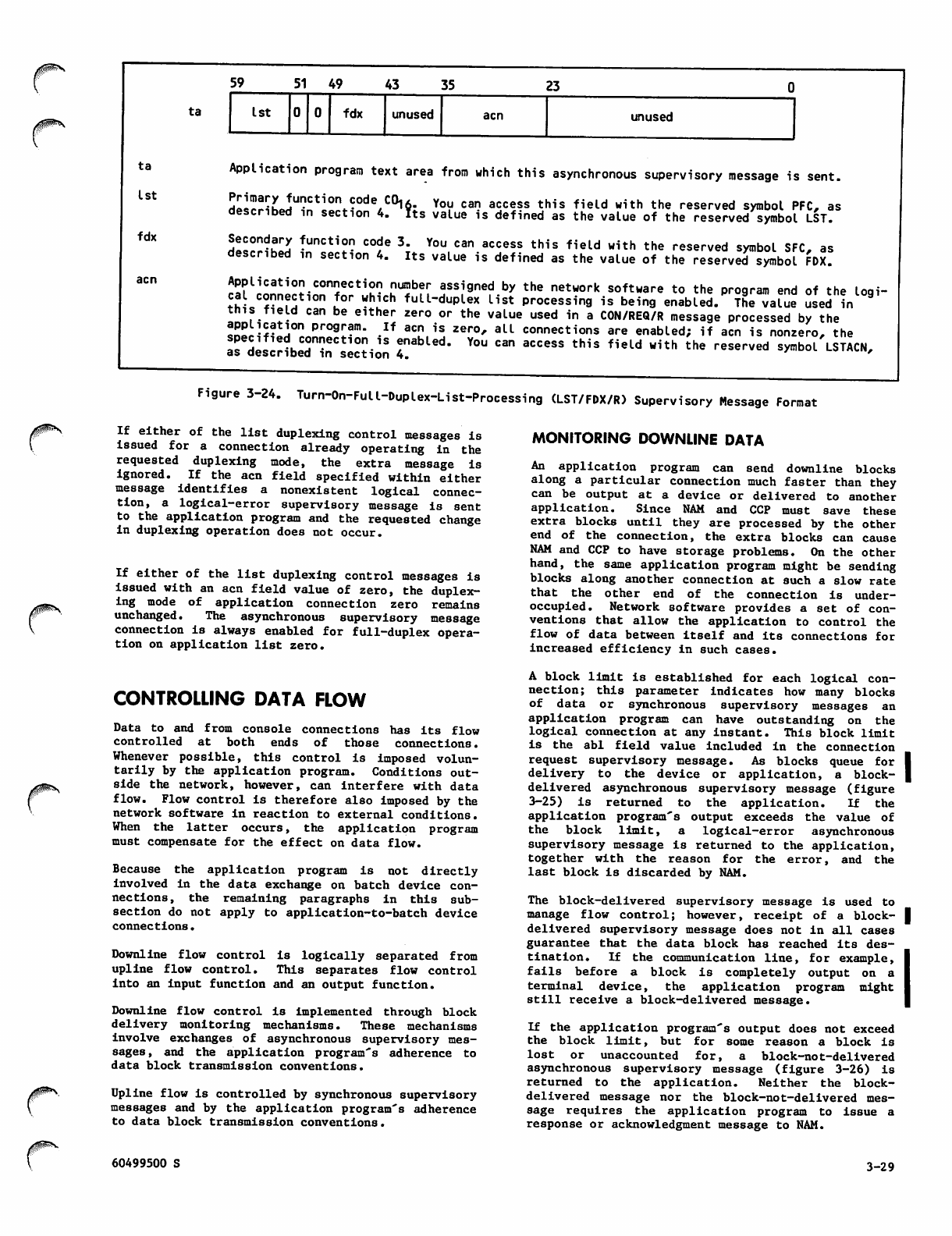
59 51 49 43 35 23
0^\ ta 1st fdx unused acn unused
ta
1st
fdx
Application program text area from which this asynchronous supervisory message is sent.
Hal!^KJU"Ct1On^ode/C01v- You can access this field with the reserved symbol PFC, as
described in section 4. ?ts value is defined as the value of the reserved symbol LST.
S!!:0nda!2 tunction code 3. You can access this field with the reserved symbol SFC, as
described m section 4. Its value is defined as the value of the reserved symbol FDX.
Application connection number assigned by the network software to the program end of the loqi-
cal connection for which full-duplex list processing is being enabled. The value Ssedin
this field can be either zero or the value used in a CON/REQ/R message processed by the
a«fi-*at2°n pr°9r?m- .If acn is zero, all connections are enabled; if acn is nonzero, the
as desrHhfr^c10?18 ?nabLed- You can access this field with the reserved symbol LSTACN,as described in section 4.
Figure 3-24. Turn-On-Full-Duplex-List-Processing (LST/FDX/R) Supervisory Message Format
If either of the list duplexing control messages is
issued for a connection already operating in the
requested duplexing mode, the extra message is
ignored. If the acn field specified within either
message identifies a nonexistent logical connec
tion, a logical-error supervisory message is sent
to the application program and the requested change
in duplexing operation does not occur.
If either of the list duplexing control messages is
issued with an acn field value of zero, the duplex
ing mode of application connection zero remains
unchanged. The asynchronous supervisory message
connection is always enabled for full-duplex opera
tion on application list zero.
CONTROLLING DATA FLOW
Data to and from console connections has its flow
controlled at both ends of those connections.
Whenever possible, this control is imposed volun
tarily by the application program. Conditions out
side the network, however, can interfere with data
flow. Flow control is therefore also imposed by the
network software in reaction to external conditions.
When the latter occurs, the application program
must compensate for the effect on data flow.
Because the application program is not directly
involved in the data exchange on batch device con
nections, the remaining paragraphs in this sub
section do not apply to application-to-batch device
connections.
Downline flow control is logically separated from
u p l i n e fl o w c o n t r o l . T h i s s e p a r a t e s fl o w c o n t r o l
into an input function and an output function.
Downline flow control Is implemented through block
delivery monitoring mechanisms. These mechanisms
involve exchanges of asynchronous supervisory mes
sages, and the application program's adherence to
data block transmission conventions.
Upline flow is controlled by synchronous supervisory
messages and by the application program's adherence
to data block transmission conventions.
MONITORING DOWNLINE DATA
An application program can send downline blocks
along a particular connection much faster than they
can be output at a de vice or delivere d to anoth er
app lic atio n. S ince NAM and CCP must save these
extra blocks until they are processed by the other
end of the connection, the extra blocks can cause
NAM and CCP to have storage problems. On the other
hand, the same application program might be sending
blocks along another connection at such a slow rate
that the other end of the connection is under-
occupied. Network software provides a set of con
ventions that allow the application to control the
flow of data betwee n itself and its connections for
increased efficiency in such cases.
A block limit is established for each logical con
nection; this parameter indicates how many blocks
of data or synchronous supervisory messages an
application program can have outstanding on the
logical connection at any instant. This block limit
is the abl field value included in the connection
request supervisory message. As blocks queue for I
delivery to the device or application, a block- |
delivered asynchronous supervisory message (figure
3-25) is returned to the application. If the
application program's output exceeds the value of
the block limit, a logical-error asynchronous
supervisory message is returned to the application,
t o g e t h e r w i t h t h e r e a s o n f o r t h e e r r o r, a n d t h e
last block is discarded by NAM.
The block-delivered supervisory message is used to
manage flow control; however, receipt of a block- |
delivered supervisory message does not in all cases
guarantee that the data block has reached its des
tination. If the communication line, for example,
fails before a block is completely output on a
terminal device, the application program might
still receive a block-delivered message.
If the application program's output does not exceed
the block limit, but for some reason a block is
lost or unaccounted for, a block-not-delivered
asyn c h ronous s u pervi s o ry mess a g e (figur e 3 -26) i s
returned to the application. Neither the block-
delivered message nor the block-not-delivered mes
sage requires the application program to issue a
response or acknowledgment message to NAM.
60499500 S 3-29
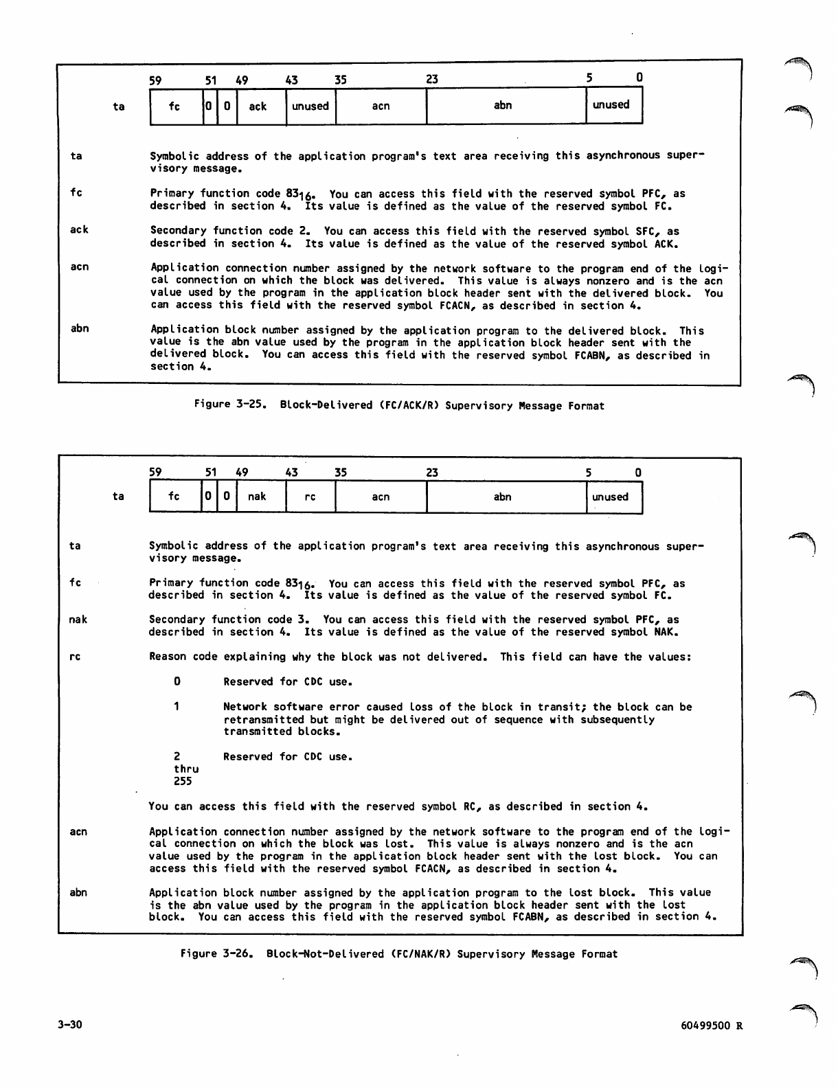
ta
fc
ack
abn
ta
59 51 49 43 35 23 5 0
fc ack unused acn abn unused
Symbolic address of the application program's text area receiving this asynchronous super
visory message.
Primary function code 83<ja. You can access this field with the reserved symbol PFC, as
described in section 4. Its value is defined as the value of the reserved symbol FC.
Secondary function code 2. You can access this field with the reserved symbol SFC, as
described in section 4. Its value is defined as the value of the reserved symbol ACK.
Application connection number assigned by the network software to the program end of the logi
cal connection on which the block was delivered. This value is always nonzero and is the acn
value used by the program in the application block header sent with the delivered block. You
can access this field with the reserved symbol FCACN, as described in section 4.
Application block number assigned by the application program to the delivered block. This
value is the abn value used by the program in the application block header sent with the
delivered block. You can access this field with the reserved symbol FCABN, as described in
section 4.
Figure 3-25. Block-Delivered (FC/ACK/R) Supervisory Message Format
ta
fc
nak
re
acn
abn
ta
59 51 49 43 35 23 5 0
fc nak re acn abn unused
Symbolic address of the application program's text area receiving this asynchronous super
visory message.
Primary function code 83-|6. You can access this field with the reserved symbol PFC, as
described in section 4. Its value is defined as the value of the reserved symbol FC.
Secondary function code 3. You can access this field with the reserved symbol PFC, as
described in section 4. Its value is defined as the value of the reserved symbol NAK.
Reason code explaining why the block was not delivered. This field can have the values:
2
thru
255
Reserved for CDC use.
Network software error caused loss of the block in transit; the block can be
retransmitted but might be delivered out of sequence with subsequently
transmitted blocks.
Reserved for CDC use.
You can access this field with the reserved symbol RC, as described in section 4.
Application connection number assigned by the network software to the program end of the logi
cal connection on which the block was lost. This value is always nonzero and is the acn
value used by the program in the application block header sent with the lost block. You can
access this field with the reserved symbol FCACN, as described in section 4.
Application block number assigned by the application program to the lost block. This value
is the abn value used by the program in the application block header sent with the lost
block. You can access this field with the reserved symbol FCABN, as described in section 4.
Figure 3-26. Block-Not-Delivered (FC/NAK/R) Supervisory Message Format
3-30 60499500 R
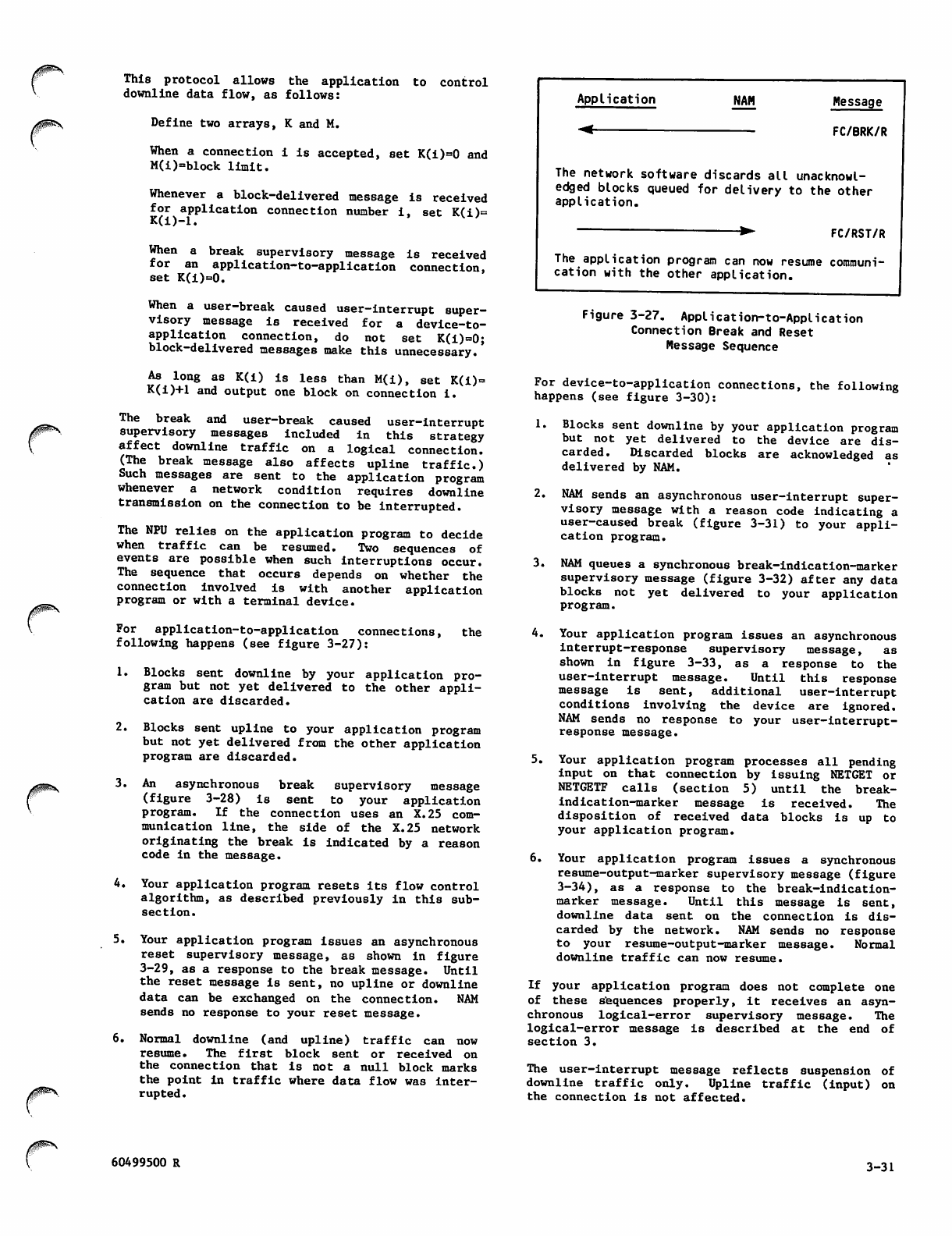
0H^\
This protocol allows the application to control
downline data flow, as follows:
Define two arrays, K and M.
When a connection i is accepted, set K(i)=0 and
M(i)=block limit.
Whenever a block-delivered message is received
for application connection number i, set K(i)=
K(i)—1.
When a break supervisory message is received
for an application-to-application connection,
set K(i)=0.
When a user-break caused user-interrupt super
visory message is received for a device-to-
a p p l i c a t i o n c o n n e c t i o n , d o n o t s e t K ( i ) = 0 ;
block-delivered messages make this unnecessary.
As long as K(i) is less than M(i), set K(i)=
K(i)+1 and output one block on connection i.
The break and user-break caused user-interrupt
supervisory messages included in this strategy
affect downline traffic on a logical connection.
( T h e b r e a k m e s s a g e a l s o a f f e c t s u p l i n e t r a f fi c . )
Such messages are sent to the application program
whenever a network condition requires downline
transmission on the connection to be interrupted.
The NPU relies on the application program to decide
when traffic can be resumed. Two sequences of
events are possible when such interruptions occur.
The sequence that occurs depends on whether the
connection involved is with another application
program or with a terminal device.
For application-to-application connections,
following happens (see figure 3-27): the
1. Blocks sent downline by your application pro
gram but not yet delivered to the other appli
cation are discarded.
2. Blocks sent upline to your application program
but not yet delivered from the other application
program are discarded.
3. An asynchronous break supervisory message
(figure 3-28) Is sent to your application
progra m. I f the conn ecti on u ses an X .25 com
mun i c a t i o n l i ne, t he s i de o f t h e X.25 n etwork
originating the break is indicated by a reason
code in the message.
4. Your application program resets its flow control
algorithm, as described previously in this sub
section.
5. Your application program issues an asynchronous
reset supervisory message, as shown in figure
3-29, as a response to the break message. Until
the reset message is sent, no upline or downline
data can be exchanged on the connection. NAM
sends no response to your reset message.
6. Normal downline (and upline) traffic can now
resume. The first block sent or received on
the connection that is not a null block marks
the point in traffic where data flow was inter
rupted.
Application
-<
NAM Message
FC/BRK/R
The network software discards all unacknowl
edged blocks queued for delivery to the other
application.
FC/RST/R
The application program can now resume communi
cation with the other application.
Figure 3-27. Application-to-Application
Connection Break and Reset
Message Sequence
For device-to-application connections, the following
happens (see figure 3-30):
1. Blocks sent downline by your application program
but not yet delivered to the device are dis
carded. Discarded blocks are acknowledged as
delivered by NAM.
2. NAM sends an asynchronous user-interrupt super
visory message with a reason code indicating a
user-caused break (figure 3-31) to your appli
cation program.
3. NAM queues a synchronous break-indication-marker
supervisory message (figure 3-32) after any data
blocks not yet delivered to your application
program.
4. Your application program issues an asynchronous
Interrupt-response supervisory message, as
shown in figure 3-33, as a response to the
user-interrupt message. Until this response
m e s s a g e i s s e n t , a d d i t i o n a l u s e r - i n t e r r u p t
conditions involving the device are ignored.
NAM sends no response to your user-interrupt-
response message.
5. Your application program processes all pending
input on that connection by issuing NETGET or
NETGETF calls (section 5) until the break-
indication-marker message is received. The
disposition of received data blocks is up to
your application program.
6. Your application program issues a synchronous
resume-output-marker supervisory message (figure
3-34), as a response to the break-indication-
marker message. Until this message is sent,
downline data sent on the connection is dis
carded by the network. NAM sends no response
to your resume-output-marker message. Normal
downline traffic can now resume.
If your application program does not complete one
of these sequences properly, it receives an asyn
chronous logical-error supervisory message. The
logical-error message is described at the end of
section 3.
The user-interrupt message reflects suspension of
downline traffic only. Upline traffic (input) on
the connection is not affected.
60499500 R 3-31
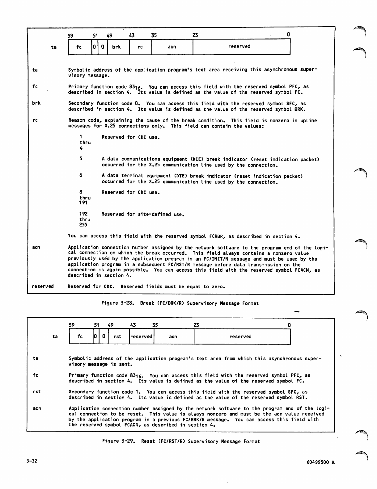
ta
fc
brk
re
ta
reserved
59 51 49 43 35 23
fc brk re acn reserved
Symbolic address of the application program's text area receiving this asynchronous super
visory message.
Primary function code 83i0. You can access this field with the reserved symbol PFC, as
described in section 4. Its value is defined as the value of the reserved symbol FC.
Secondary function code 0. You can access this field with the reserved symbol SFC, as
described in section 4. Its value is defined as the value of the reserved symbol BRK.
Reason code, explaining the cause of the break condition. This field is nonzero in upline
messages for X.25 connections only. This field can contain the values:
1
thru
4
5
6
8
thru
191
192
thru
255
Reserved for CDC use.
A data communications equipment (DCE) break indicator (reset indication packet)
occurred for the X.25 communication line used by the connection.
A data terminal equipment (DTE) break indicator (reset indication packet)
occurred for the X.25 communication line used by the connection.
Reserved for CDC use.
Reserved for site-defined use.
You can access this field with the reserved symbol FCRBR, as described in section 4.
Application connection number assigned by the network software to the program end of the logi
cal connection on which the break occurred. This field always contains a nonzero value
previously used by the application program in an FC/INIT/N message and must be used by the
application program in a subsequent FC/RST/R message before data transmission on the
connection is again possible. You can access this field with the reserved symbol FCACN, as
described in section 4.
Reserved for CDC. Reserved fields must be equal to zero.
Figure 3-28. Break (FC/BRK/R) Supervisory Message Format
ta
fc
rst
ta
59 51 49 4 3 3 5 23
fc rst reserved acn reserved
Symbolic address of the application program's text area from which this asynchronous super
visory message is sent.
Primary function code 83-|0. You can access this field with the reserved symbol PFC, as
described in section 4. Its value is defined as the value of the reserved symbol FC.
Secondary function code 1. You can access this field with the reserved symbol SFC, as
described in section 4. Its value is defined as the value of the reserved symbol RST.
Application connection number assigned by the network software to the program end of the logi
cal connection to be reset. This value is always nonzero and must be the acn value received
by the application program in a previous FC/BRK/R message. You can access this field with
the reserved symbol FCACN, as described in section 4.
Figure 3-29. Reset (FC/RST/R) Supervisory Message Format
3-32 60499500 R
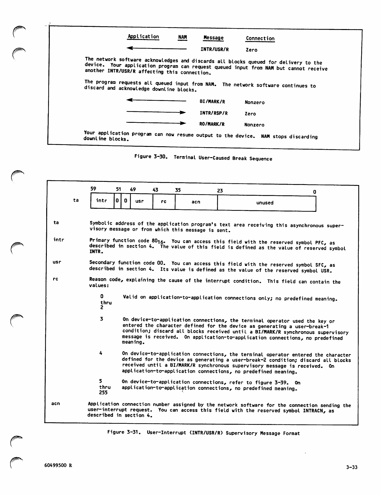
igP^N
Application
-<■
NAM Message
INTR/USR/R
Connection
Zero
dp^r!tW°vl! Softwf:e ^knowledges and discards all blocks queued for delivery to the
another" imtiiS*'-SIS• T" "" reqVeSt queued input frora NAM but cannot receiveanotner INTR/USR/R affecting this connection.
The program requests all queued input from NAM. The network software continues to
discard and acknowledge downline blocks. continues to
BI/NARK/R
INTR/RSP/R
RO/MARK/R
Nonzero
Zero
Nonzero
downlinfbloc'ks? Pr09rSa "" "°W ^^ °UtPUt t0 the device* NA" st°Ps d^carding
Figure 3-30. Terminal User-Caused Break Sequence
z^fe\
ta
int r
usr
ta
59 51 49 43 35 23
int r usr unused
Symbolic address of the application program's text area receiving this asynchronous super
visory message or from which this message is sent.
Primary function code 8016. You can access this field with the reserved symbol PFC, as
described in section 4. The value of this field is defined as the value of reserved symbol
INTR.
Secondary function code 00. You can access this field with the reserved symbol SFC, as
described in section 4. Its value is defined as the value of the reserved symbol USR.
Reason code, explaining the cause of the interrupt condition. This field can contain the
values:
0
thru
2
5
thru
255
Valid on application-to-application connections only; no predefined meaning.
On device-to-application connections, the terminal operator used the key or
entered the character defined for the device as generating a user-break-1
condition; discard all blocks received until a BI/MARK/R synchronous supervisory
message is received. On application-to-application connections, no predefined
meaning.
On device-to-application connections, the terminal operator entered the character
defined for the device as generating a user-break-2 condition; discard all blocks
received until a BI/MARK/R synchronous supervisory message is received. On
application-to-application connections, no predefined meaning.
On device-to-application connections, refer to figure 3-39. On
application-to-application connections, no predefined meaning.
Application connection number assigned by the network software for the connection sending the
user-interrupt request. You can access this field with the reserved symbol INTRACN, as
described in section 4.
Figure 3-31. User-Interrupt (INTR/USR/R) Supervisory Message Format
60499500 R 3-33
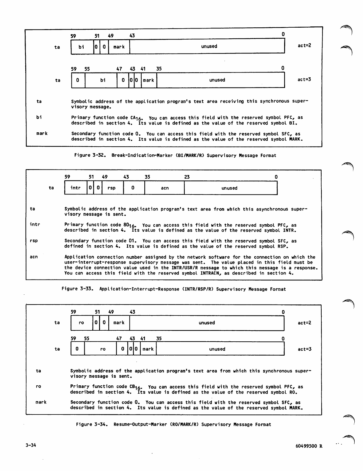
ta
bi
mark
ta
ta
5 9 5 1 4 9 4 3 0
bi mark unused act=2
5 9 5 5 4 7 4 3 4 1 3 5 0
0bi mark unused act =3
Symbolic address of the application program's text area receiving this synchronous super
visory message.
Primary function code CA<|0. You can access this field with the reserved symbol PFC, as
described in section 4. Its value is defined as the value of the reserved symbol BI.
Secondary function code 0. You can access this field with the reserved symbol SFC, as
described in section 4. Its value is defined as the value of the reserved symbol MARK.
Figure 3-32. Break-Indication-Marker (BI/MARK/R) Supervisory Message Format
ta
i n t r
rsp
ta
59 51 49 43 35 23
intr rsp acn unused
Symbolic address of the application program's text area from which this asynchronous super
visory message is sent.
Primary function code 80<jo. You can access this field with the reserved symbol PFC, as
described in section 4. Its value is defined as the value of the reserved symbol INTR.
Secondary function code 01. You can access this field with the reserved symbol SFC, as
defined in section 4. Its value is defined as the value of the reserved symbol RSP.
Application connection number assigned by the network software for the connection on which the
user-interrupt-response supervisory message was sent. The value placed in this field must be
the device connection value used in the INTR/USR/R message to which this message is a response.
You can access this field with the reserved symbol INTRACN, as described in section 4.
Figure 3-33. Application-Interrupt-Response (INTR/RSP/R) Supervisory Message Format
ta
mark
ta
ta
59 51 49 43
ro mark unused
5 9 5 5 4 7 4 3 4 1 3 5
0ro mark unused
act=2
act=3
Symbolic address of the application program's text area from which this synchronous super
visory message is sent.
Primary function code CB<|0. You can access this field with the reserved symbol PFC, as
described in section 4. Its value is defined as the value of the reserved symbol RO.
Secondary function code 0. You can access this field with the reserved symbol SFC, as
described in section 4. Its value is defined as the value of the reserved symbol MARK.
Figure 3-34. Resume-Output-Marker (RO/MARK/R) Supervisory Message Format
3-34 60499500 R
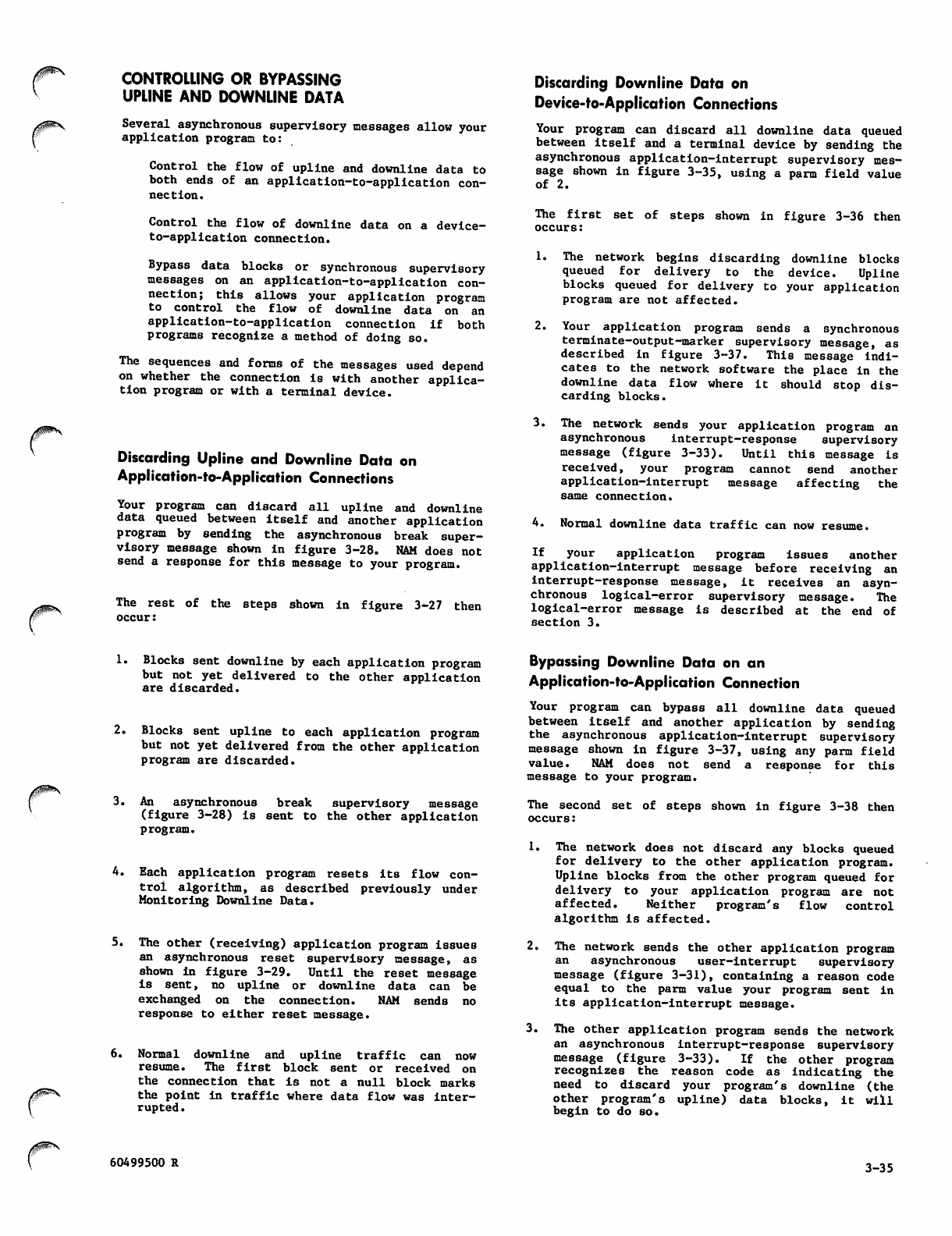
/fP^N.
CONTROLLING OR BYPASSING
UPLINE AND DOWNLINE DATA
Several asynchronous supervisory messages allow your
application program to:
Control the flow of upline and downline data to
both ends of an application-to-application con
nection.
Control the flow of downline data on a device-
to-application connection.
Bypass data blocks or synchronous supervisory
messages on an application-to-application con
nection; this allows your application program
to control the flow of downline data on an
application-to-application connection if both
programs recognize a method of doing so.
The sequences and forms of the messages used depend
on whether the connection is with another applica
tion program or with a terminal device.
Discarding Upline and Downline Data on
Application-to-Application Connections
Your program can discard all upline and downline
data queued between itself and another application
program by sending the asynchronous break super
visory message shown in figure 3-28. NAM does not
send a response for this message to your program.
The rest of the steps shown in figure 3-27 then
occur:
Discarding Downline Data on
Device-to-Application Connections
Your program can discard all downline data queued
between itself and a terminal device by sending the
asynchronous application-interrupt supervisory mes
sage shown in figure 3-35, using a parm field value
of 2.
The first set of steps shown in figure 3-36 then
occurs:
1. The network begins discarding downline blocks
queued for delivery to the device. Upline
blocks queued for delivery to your application
program are not affected.
2.
3.
Your application program sends a synchronous
terminate-output-marker supervisory message, as
described in figure 3-37. This message indi
cates to the network software the place in the
downline data flow where it should stop dis
ca rding blocks.
The network sends your application program an
a s y n c h r o n o u s i n t e r r u p t - r e s p o n s e s u p e r v i s o r y
message (figure 3-33). Until this message is
received, your program cannot send another
application-interrupt message affecting the
same connection.
4. Normal downline data traffic can now resume.
If your application program issues another
application-interrupt message before receiving an
interrupt-response message, it receives an asyn
chronous logical-error supervisory message. The
logical-error message is described at the end of
section 3.
1. Blocks sent downline by each application program
but not yet delivered to the other application
are discarded.
2. Blocks sent upline to each application program
but not yet delivered from the other application
program are discarded.
3. An asynchronous break supervisory message
(figure 3-28) is sent to the other application
program.
4. Each application program resets its flow con
trol algorithm, as described previously under
Monitoring Downline Data.
5.
6.
The other (receiving) application program issues
an asynchronous reset supervisory message, as
shown in figure 3-29. Until the reset message
is sent, no upline or downline data can be
exchanged on the connection. NAM sends no
response to either reset message.
Normal downline and upline traffic can now
r e s u m e . T h e fi r s t b l o c k s e n t o r r e c e i v e d o n
the connection that is not a null block marks
the point in traffic where data flow was inter
rupted .
Bypassing Downline Data on an
Application-to-Application Connection
Your program can bypass all downline data queued
between itself and another application by sending
the asynchronous application-interrupt supervisory
message shown in figure 3-37, using any parm field
value. NAM does not send a response for this
message to your program.
The second set of steps shown in figure 3-38 then
occurs:
1. The network does not discard any blocks queued
for delivery to the other application program.
Upline blocks from the other program queued for
delivery to your application program are not
affected. Neither program's flow control
algorithm is affected.
2. The network sends the other application program
an asynchronous user-interrupt supervisory
message (figure 3-31), containing a reason code
equal to the parm value your program sent in
its application-interrupt message.
3. The other application program sends the network
an a synch r onous i nterr u pt-re spons e superv isory
message (figure 3-33). If the other program
r e c og n i ze s t h e r e a so n c o de a s i nd i c at i n g th e
need to discard your program's downline (the
other program's upline) data blocks, it will
begin to do so.
60499500 R 3-35
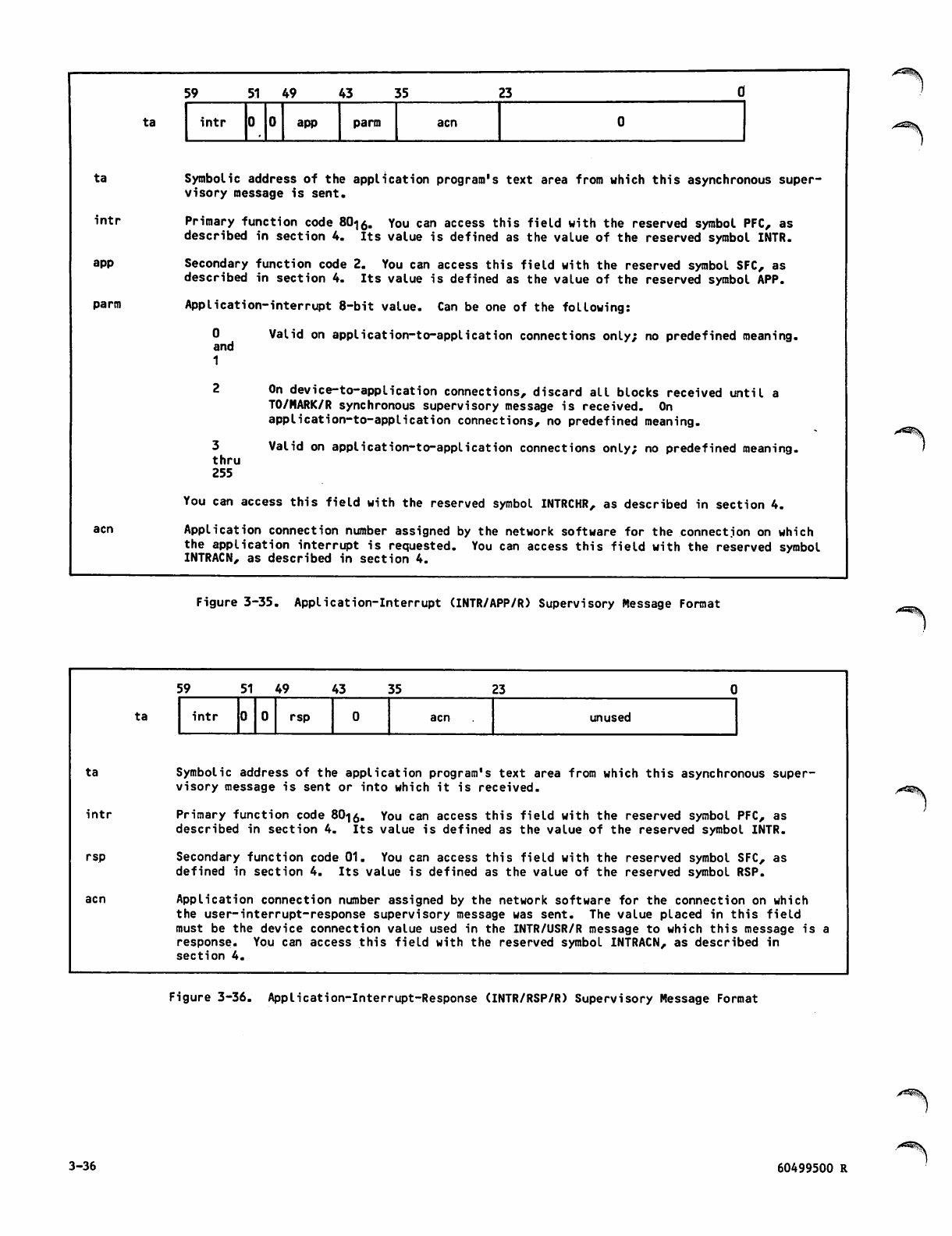
ta
i n t r
app
parm
acn
ta
59 51 49 43 55 2 3 0
i n t r app parm acn
Symbolic address of the application program's text area from which this asynchronous super
visory message is sent.
Primary function code 80<jo. You can access this field with the reserved symbol PFC, as
described in section 4. Its value is defined as the value of the reserved symbol INTR.
Secondary function code 2. You can access this field with the reserved symbol SFC, as
described in section 4. Its value is defined as the value of the reserved symbol APP.
AppIication-interrupt 8-bit value. Can be one of the following:
Valid on application-to-application connections only; no predefined meaning.0
and
1
3
thru
255
On device-to-application connections, discard all blocks received until a
TO/MARK/R synchronous supervisory message is received. On
application-to-application connections, no predefined meaning.
Valid on application-to-application connections only; no predefined meaning.
You can access this field with the reserved symbol INTRCHR, as described in section 4.
Application connection number assigned by the network software for the connection on which
the application interrupt is requested. You can access this field with the reserved symbol
INTRACN, as described in section 4.
Figure 3-35. Application-Interrupt (INTR/APP/R) Supervisory Message Format
ta
i n t r
rsp
ta
59 5 1 4 9 43 35 23
i n t r rsp acn unused
Symbolic address of the application program's text area from which this asynchronous super
visory message is sent or into which it is received.
Primary function code 80-)$. You can access this field with the reserved symbol PFC, as
described in section 4. Its value is defined as the value of the reserved symbol INTR.
Secondary function code 01. You can access this field with the reserved symbol SFC, as
defined in section 4. Its value is defined as the value of the reserved symbol RSP.
Application connection number assigned by the network software for the connection on which
the user—interrupt-response supervisory message was sent. The value placed in this field
must be the device connection value used in the INTR/USR/R message to which this message is a
response. You can access this field with the reserved symbol INTRACN, as described in
section 4.
Figure 3-36. Application-Interrupt-Response (INTR/RSP/R) Supervisory Message Format
3-36 60499500 R
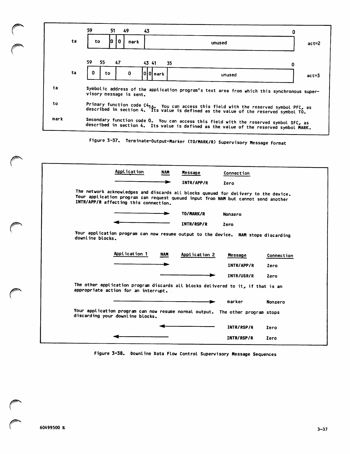
59 5 1 4 9 43
ta to mark unused act=2
ta
to
mark
ta
5 9 5 5 4 7
to
4 3 4 1 3 5
mark unused act=3
Symbolic address of the application program's text area from which this synchronous super
visory message is sent.
d^rHhJU?ntl^-°de/C41?: Yo^ can a5c!ss this fieLd with the reserved symbol PFC, as
described in section 4. Tts value is defined as the value of the reserved symbol TO.
Si.^JU !uncti0? code °- You can access this field with the reserved symbol SFC, as
described in section 4. Its value is defined as the value of the reserved symbol MARK.
Figure 3-37. Terminate-Output-Marker (TO/MARK/R) Supervisory Message Format
jtfff&K,
Application NAM Message Connection
▶ INTR/APP/R Zero
The network acknowledges and discards all blocks queued for delivery to the device.
r««/f»«^Ca!l0n pro9ram can request queued input from NAM but cannot send another
INTR/APP/R affecting this connection.
TO/MARK/R Nonzero
INTR/RSP/R Zero
Your application program can now resume output to the device. NAM stops discarding
downline blocks.
Application 1 NAM Application 2 Message Connection
INTR/APP/R Zero
INTR/USR/R Zero
The other application program discards all blocks delivered to it, if that is an
appropriate action for an interrupt.
marker Nonzero
Your application program can now resume normal output. The other program stops
discarding your downline blocks.
INTR/RSP/R Zero
INTR/RSP/R Zero
Figure 3-38. Downline Data Flow Control Supervisory Message Sequences
f 60499500 R 3-37
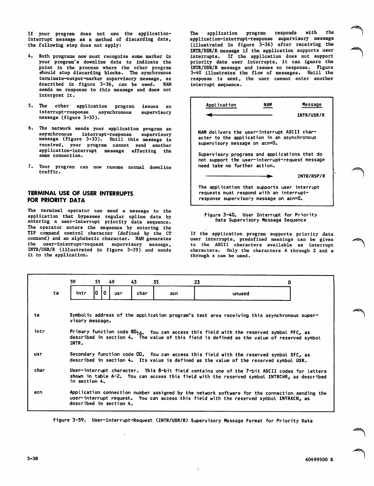
If your program does not use the application-
interrupt message as a method of discarding data,
the following step does not apply:
4. Both programs now must recognize some marker in
your program'8 downline data to indicate the
point in the process where the other program
should stop discarding blocks. The synchronous
terminate-output-marker supervisory message, as
described in figure 3-36, can be used. NAM
sends no response to this message and does not
interpret it.
5. The other application program issues an
i n t e r r u p t - r e s p o n s e a s y n c h r o n o u s s u p e r v i s o r y
message (figure 3-33).
6. The network sends your application program an
asynchronous interrupt-response supervisory
message (figure 3-33). Until this message is
received, your program cannot send another
application-interrupt message affecting the
same connection.
7. Your program can now resume normal downline
traffic.
TERMINAL USE OF USER INTERRUPTS
FOR PRIORITY DATA
The terminal operator can send a message to the
application that bypasses regular upline data by
entering a user-interrupt priority data sequence.
The ope rat or e nte rs the sequence by ente rin g the
TIP command control character (defined by the CT
command) and an alphabetic character. NAM generates
the user-interrupt-request supervisory message,
INTR/USR/R (illustrated in figure 3-39) and sends
it to the application.
The application program responds with the
application-interrupt-response supervisory message
( i l l u s t r a t e d i n fi g u r e 3 - 3 6 ) a f t e r r e c e i v i n g t h e
INTR/USR/R message if the application supports user
interrupts. If the application does not support
priority data user interrupts, it can ignore the
INTR/USR/R message and issues no response. Figure
3-40 illustrates the flow of messages. Until the
response is sent, the user cannot enter another
interrupt sequence.
Application
-<
NAM Message
INTR/USR/R
NAM delivers the user-interrupt ASCII char
acter to the application in an asynchronous
supervisory message on acn=0.
Supervisory programs and applications that do
not support the user-interrupt-request message
need take no further action.
INTR/RSP/R
The application that supports user interrupt
requests must respond with an interrupt-
response supervisory message on acn=0.
Figure 3-40. User Interrupt for Priority
Data Supervisory Message Sequence
If the application program supports priority data
user interrupts, predefined meanings can be given
to the ASCII characters available as interrupt
characters. Only the characters A through Z and a
through z can be used.
/**fi&\
ta
ta
i n t r
char
acn
59 51 49 43 35 2 3 0
i n t r usr char acn unused
Symbolic address of the application program's text area receiving this asynchronous super
visory message.
Primary function code 80-jo. You can access this field with the reserved symbol PFC, as
described in section 4. The value of this field is defined as the value of reserved symbol
INTR.
Secondary function code 00. You can access this field with the reserved symbol SFC, as
described in section 4. Its value is defined as the value of the reserved symbol USR.
User-interrupt character. This 8-bit field contains one of the 7-bit ASCII codes for letters
shown in table A-2. You can access this field with the reserved symbol INTRCHR, as described
in section 4.
Application connection number assigned by the network software for the connection sending the
user-interrupt request. You can access this field with the reserved symbol INTRACN, as
described in section 4.
Figure 3-39. User-Interrupt-Request (INTR/USR/R) Supervisory Message Format for Priority Data
3-38 60499500 R
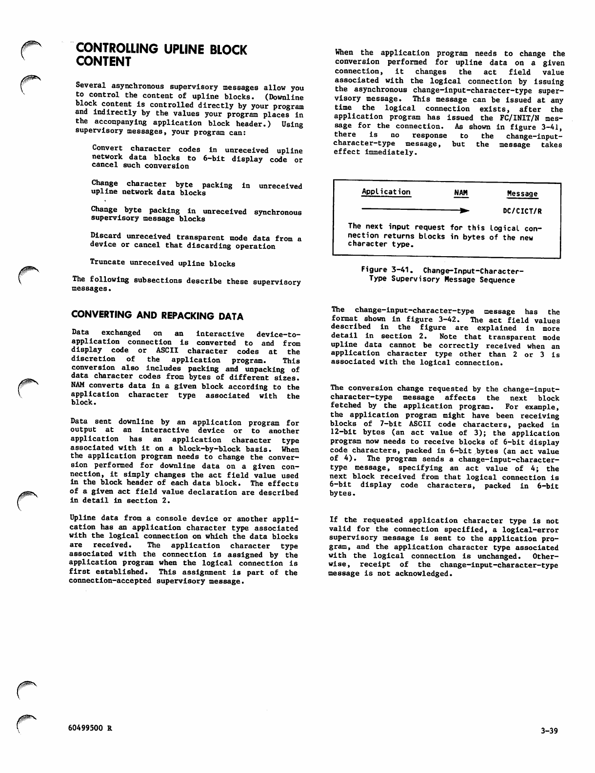
/ I p ^
CONTROLLING UPLINE BLOCK
CONTENT
Several asynchronous supervisory messages allow you
to control the content of upline blocks. (Downline
block content is controlled directly by your program
and indirectly by the values your program places in
the accompanying application block header.) Using
supervisory messages, your program can:
Convert character codes in unreceived upline
network data blocks to 6-bit display code or
cancel such conversion
Change character byte packing in unreceived
upline network data blocks
Change byte packing in unreceived synchronous
supervisory message blocks
Discard unreceived transparent mode data from a
device or cancel that discarding operation
Truncate unreceived upline blocks
The following subsections describe these supervisory
messages.
When the application program needs to change the
conversion performed for upline data on a given
connection, it changes the act field value
associated with the logical connection by issuing
the asynchronous change-input-character-type super
visory message. This message can be issued at any
time the logical connection exists, after the
application program has issued the FC/INIT/N mes
sa ge for the conne ction . As shown in figu re 3-41,
there is no response to the change-input-
character-type message, but the message takes
effect immediately.
Application NAM Message
DC/CICT/R
The next input request for this logical con
nection returns blocks in bytes of the new
character type.
Figure 3-41. Change-Input-Character-
Type Supervisory Message Sequence
CONVERTING AND REPACKING DATA
Data exchanged on an interactive device-to-
application connection is converted to and from
display code or ASCII character codes at the
discretion of the application program. This
conversion also includes packing and unpacking of
data character codes from bytes of different sizes.
NAM converts data in a given block according to the
application character type associated with the
block.
Data sent downline by an application program for
o u t p u t a t a n i n t e r a c t i v e d e v i c e o r t o a n o t h e r
application has an application character type
associated with it on a block-by-block basis. When
the application program needs to change the conver
sion performed for downline data on a given con
nection, it simply changes the act field value used
in the block header of each data block. The effects
of a given act field value declaration are described
in detail in section 2.
Upline data from a console device or another appli
cation has an application character type associated
with the logical connection on which the data blocks
are received. The application character type
associated with the connection is assigned by the
application program when the logical connection is
first established. This assignment is part of the
connection-accepted supervisory message.
The change-input-character-type message has the
format s h o w n in figure 3 - 4 2 . The a c t fi e l d v a lues
described in the figure are explained in more
detail in section 2. Note that transparent mode
upline data cannot be correctly received when an
application character type other than 2 or 3 is
associated with the logical connection.
The conversion change requested by the change-input-
character-type message affects the next block
fetched by the application program. For example,
the application program might have been receiving
blocks of 7-bit ASCII code characters, packed in
12-bit bytes (an act value of 3); the application
program now needs to receive blocks of 6-bit display
code characters, packed in 6-bit bytes (an act value
of 4). The program sends a change-input-character-
type message, specifying an act value of 4; the
next block received from that logical connection is
6-bit display code characters, packed in 6-bit
bytes.
If the requested application character type is not
valid for the connection specified, a logical-error
supervisory message is sent to the application pro
gram, and the application character type associated
with the logical connection is unchanged. Other
wise, receipt of the change-input-character-type
message is not acknowledged.
00^ 60499500 R 3-39
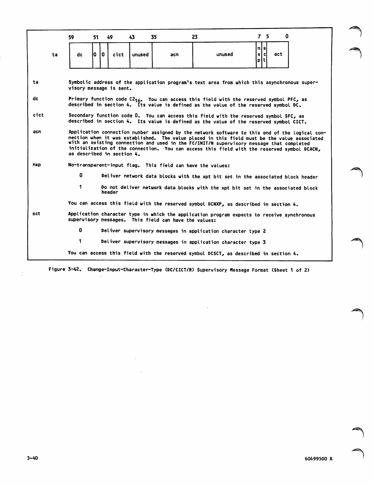
ta
dc
cict
nxp
set
ta
59 5 1 4 9 43 35 23 7 5
n s
dc cict unused acn unused act
Symbolic address of the application program's text area from which this asynchronous super
visory message is sent.
Primary function code C2<|0. You can access this field with the reserved symbol PFC, as
described in section 4. Its value is defined as the value of the reserved symbol DC.
Secondary function code 0. You can access this field with the reserved symbol SFC, as
described in section 4. Its value is defined as the value of the reserved symbol CICT.
Application connection number assigned by the network software to this end of the logical con
nection when it was established. The value placed in this field must be the value associated
with an existing connection and used in the FC/INIT/N supervisory message that completed
initialization of the connection. You can access this field with the reserved symbol DCACN,
as described in section 4.
No-transparent-input flag. This field can have the values:
0 Deliver network data blocks with the xpt bit set in the associated block header
1 Do not deliver network data blocks with the xpt bit set in the associated block
header
You can access this field with the reserved symbol DCNXP, as described in section 4.
Application character type in which the application program expects to receive synchronous
supervisory messages. This field can have the values:
0 Deliver supervisory messages in application character type 2
1 Deliver supervisory messages in application character type 3
You can access this field with the reserved symbol DCSCT, as described in section 4.
z*2^.
Figure 3-42. Change-Input-Character-Type (DC/CICT/R) Supervisory Message Format (Sheet 1 of 2)
3-40 60499500 R
/^*Z®\
act Application character type, specifying the form of character byte packing that the
application program requires for all future input data blocks from the logical connection.
The value declared replaces the value previously declared by the application program for this
connection in a CON/REQ/N or DC/CICT/R message. This field can have the values:
0
or
1
5
t h r u
11
12
thru
15
Reserved for CDC use.
8-bit characters in 8-bit bytes, packed 7.5 characters per central memory word;
if the input is not transparent mode, the ASCII chc
A*? ic iit>A/l
A-2 is used. :haracter set described in table
8-bit characters in 12-bit bytes, packed 5 characters per central memory word,
right-justified with zero fill within each byte; if the input is not transparent
mode, the ASCII character set described in table A-2 is used.
6-bit display code characters in 6-bit bytes, packed 10 characters per central
memory word; the characters used are the ASCII set of CDC characters described in
table A-1. This applies to terminal-to-application connections only.
Reserved for CDC use.
Reserved for installation use.
The act value declared applies only to input on the connection and can be changed by another
DC/CICT/R message at any time during the existence of this logical connection. You can
access this field with the reserved symbol CONACT, as described in section 4.
Figure 3-42. Change-Input-Character-Type (DC/CICT/R) Supervisory Message Format (Sheet 2 of 2)
REPACKING SYNCHRONOUS SUPERVISORY
MESSAGE BLOCKS
Synchronous supervisory message block fields are
packed in either 8-bit or 12-bit bytes, at the
discre t i o n o f t h e a p p l i c a tion p r o gram. N A M p acks
or unpacks fields in a given synchronous supervisory
message block according to the application character
type associated with the block (downline) or with
the connection (upline).
Synchronous supervisory messages sent downline by
an application program have an application character
type associated with them on a block-by-block basis.
When the application program needs to change the
packing performed for blocks on a given connection,
it simply changes the act field value used in the
block header of each synchronous supervisory mes
sage. The effects of a given act field value
declaration are described in detail in section 2.
An upline synchronous supervisory message block has
an application character type associated with the
connection on which the block is received. The
application character type associated with the
connection is assigned by the application program
as the set field value when the connection is first
established. This assignment is part of the
connection-accepted supervisory message and is
separate from the assignment made for data blocks
received on the connection.
When the application program needs to change the
packing performed for upline synchronous supervisory
messages on a given connection, it changes the set
field value associated with the connection by
issuing the asynchronous change-input-character-type
supervisory message. This message can be issued at
any time the logical connection exists, after the
application program has issued the FC/INIT/N message
for the connection. As shown in figure 3-41, there
is no response to the change-input-character-type
supervisory message, but the message takes effect
immediately.
The change-input-character-type message has the
f o r m a t s h o w n i n fi g u r e 3 - 4 2 . T h e a p p l i c a t i o n
character types selected with the set field values
are described in more detail in section 2.
The repacking change requested by the change-input-
character- type message affects the next block
fetched by the application program. For example,
the application program might have been receiving
synchronous supervisory messages with fields packed
in 12-bit bytes (using an application character
type of 3); the application program now needs to
receive synchronous supervisory message blocks with
fields stored in 8-bit bytes (using an application
character type of 2). The program sends a change-
input-character-type message, specifying an set
field value of 0; the next synchronous supervisory
message block received on that logical connection
is packed in 8-bit bytes.
60499500 R 3-41
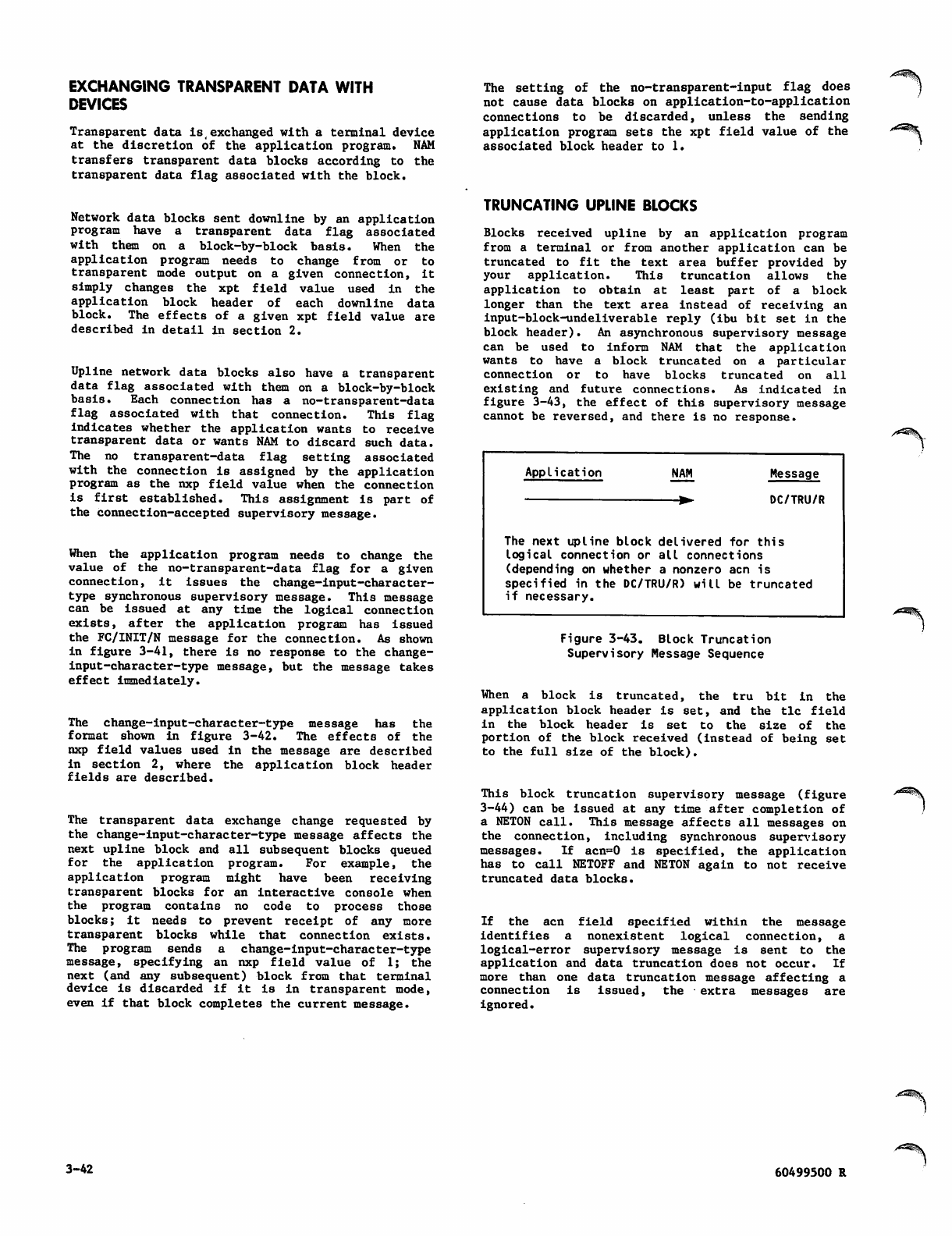
EXCHANGING TRANSPARENT DATA WITH
DEVICES
Transparent data is exchanged with a terminal device
at the discretion of the application program. NAM
transfers transparent data blocks according to the
transparent data flag associated with the block.
The setting of the no-transparent-input flag does
not cause data blocks on application-to-application
connections to be discarded, unless the sending
application program sets the xpt field value of the
associated block header to 1.
*£^$.
Network data blocks sent downline by an application
program have a transparent data flag associated
w i t h t h e m o n a b l o c k - b y - b l o c k b a s i s . W h e n t h e
application program needs to change from or to
transparent mode output on a given connection, it
s i m p l y c h a n g e s t h e x p t fi e l d v a l u e u s e d i n t h e
application block header of each downline data
block. The effects of a given xpt field value are
described in detail in section 2.
Upline network data blocks also have a transparent
data flag associated with them on a block-by-block
basis. Each connection has a no-transparent-data
fl a g a s s o c i a t e d w i t h t h a t c o n n e c t i o n . T h i s fl a g
indicates whether the application wants to receive
transparent data or wants NAM to discard such data.
The no transparent-data flag setting associated
with the connection is assigned by the application
program as the nxp field value when the connection
is first established. This assignment is part of
the connection-accepted supervisory message.
When the application program needs to change the
value of the no-transparent-data flag for a given
connection, it issues the change-input-character-
type synchronous supervisory message. This message
can be issued at any time the logical connection
exists, after the application program has issued
the FC/INIT/N message for the connection. As shown
in figure 3-41, there is no response to the change-
input-character-type message, but the message takes
effect i mmedi ately.
The change-input-character-type message has the
format shown in figure 3-42. The effects of the
nxp field values used in the message are described
in section 2, where the application block header
fields are described.
The transparent data exchange change requested by
the change-input-character-type message affects the
next upline block and all subsequent blocks queued
for the application program. For example, the
application program might have been receiving
transparent blocks for an interactive console when
the program contains no code to process those
b l o c k s ; i t ne e d s to p r e ve n t r e c ei p t o f a n y m o r e
transparent blocks while that connection exists.
The program sends a change-input-character-type
message, specifying an nxp field value of 1; the
next (and any subsequent) block from that terminal
device is discarded if it is in transparent mode,
even if that block completes the current message.
TRUNCATING UPLINE BLOCKS
Blocks received upline by an application program
from a terminal or from another application can be
truncated to fit the text area buffer provided by
your application. This truncation allows the
application to obtain at least part of a block
longer than the text area instead of receiving an
input-block-undeliverable reply (ibu bit set in the
block header). An asynchronous supervisory message
c a n be u s e d t o i n f o r m N AM t h a t t he a p p l i c a t i o n
wants to have a block truncated on a particular
connection or to have blocks truncated on all
e x i s t i n g a n d f u t u r e c o n n e c t i o n s . A s i n d i c a t e d i n
figure 3-43, the effect of this supervisory message
cannot be reversed, and there is no response.
Application NAM Message
DC/TRU/R
t h i sThe next upline block delivered for
logical connection or all connections
(depending on whether a nonzero acn is
specified in the DC/TRU/R) will be truncated
if necessary.
Figure 3-43. Block Truncation
Supervisory Message Sequence
When a block is truncated, the tru bit in the
ap p l icat i o n b lock h e a der i s s e t, an d t h e t i c fie l d
in the block header is set to the size of the
portion of the block received (instead of being set
to the full size of the block ).
This block truncation supervisory message (figure
3-44) can be issued at any time after completion of
a NETON call. This message affects all messages on
the connection, including synchronous supervisory
messages. If acn=0 is specified, the application
has to call NETOFF and NETON again to not receive
truncated data blocks.
If the acn field specified within the message
identifies a nonexistent logical connection, a
l o g i c a l - e r r o r s u p e r v i s o r y m e s s a g e i s s e n t t o t h e
application and data truncation does not occur. If
more than one data truncation message affecting a
connection is issued, the extra messages are
ignored.
.tfriWft
3-42 60499500 R
ta
dc
tru
ta
59 51 49 43 35 23
dc tr u unused acn unused
Application program text area from which this asynchronous supervisory message is sent.
Primary function code C2-J*. You can access this field with the reserved symbol PFC, as
described in section 4. Its value is defined as the value of the reserved symbol DC.
Secondary function code 0116. You can access this field with the reserved symbol SFC, as
described in section 4. Its value is defined as the value of the reserved symbol TRU.
Application connection number. If zero, all existing and future connections other than con
ne ction zero w ill have truncat ion control on. If acn is not zer o, tru ncation contro l wi ll be
on for that connection only. You can access this field with the reserved symbol DCACN, as
described in section 4.
Figure 3-44. Block Truncation (DC/TRU/R) Supervisory Message Format
/ p ^ S MANAGING DEVICE
CHARACTERISTICS
Devices serviced as interactive virtual terminals
have many characteristics that can affect the way
in which they send or output data. The network
software can use varying numbers of these charac
t e r is t i cs , d e pe n d in g o n t he t e rmi n al c l a ss o f t he
device and sometimes on the protocol used by the
device.
The following characteristics can be known and used
t h r o u g h t h e n e t w o r k s o f t w a r e w h e n s er v i c i n g a n
asynchronous device in terminal classes 1 through
8, or any device in terminal classes 28 through 31:
Character used to discard a block of output
Whether the break key should be interpreted as
a cancel input and user break 1 command (does
not apply to terminal class 4)
Backspace character used to edit a line of data
Characters used as user break 1 and user break
2 commands
Number of idle characters needed after a car
riage return or a line feed
Character used to cancel an input line
Cursor positioning needed at the end of a
physcial line or block (does not apply to
terminal class 4)
Network control character used
Delimiters of single-message transparent input
(does not apply to terminal class 4)
Delimiters of multiple-message transparent input
(does not apply to terminal class 4)
Character used at the end of a logical input
line or of an input block (does not apply to
terminal class 4)
Echoplex mode (does not apply to terminal class
4)
Whether full-ASCII or special editing mode is
in use
Whether the host availability display appears
in full form
Whether the device supports input or output flow
control characters (does not apply to terminal
class 4)
Whether the device is using paper tape, a key
board, block mode, or transparent mode during
input (does not apply to terminal class 4)
Whether the device is using a display, a
printer, or paper tape during output (paper
tape does not apply to terminal class 4)
The parity processing required during input and
output (does not apply to terminal class 4)
What the page width and page length are
Whether page waiting occurs
Whether unsolicited messages from the network
operator can be delivered
What the terminal class is
Whether the communication line is serviced in
full-duplex mode (does not apply to terminal
class 4)
What the upline blocking factor is
What the transmission block size is
60499500 R 3-43
The following characteristics can be known and used
through the network software when servicing an X.25
device in terminal classes 1 through 3 or 5 through
8:
Whether the break key should be interpreted as
a user break 1 command
Backspace character used to edit a line of data
Characters used as user break 1 and user break
2 commands
Number of idle characters needed after a car
riage return or a line feed
Character used to cancel an input line
Cursor positioning needed at the end of a
physical line or block
Network control character used
Delimiters of single-message transparent input
Delimiters of multiple-message transparent input
Character used at the end of a logical input
line or of an input block
Whether full-ASCII mode is in use
Whether the host availability display appears
in full form
Whether the device is using a display, a
printer, or paper tape during output
The parity processing required during output
What the page width and page length are
Whether page waiting occurs
Whether unsolicited messages from the network
operator can be delivered
What the terminal class is
Whether the communication line is serviced in
full-duplex mode (does not apply to terminal
class 4)
What the upline blocking factor is
What the transmission block size is
The following characteristics can be known and used
through the network software when servicing a CDC
mode 4 device in terminal classes 10 through 13 or
15:
Characters used as user break 1 and user break
2 commands
Character used to cancel an input line
Network control character used
Delimiters of single-message transparent input
Delimiters of multiple-message transparent input
Character used at the end of a logical input
line or of an input block
Whether full-ASCII editing mode is in use
Whether the host availability display appears
i n f u ll f o r m
Whether the device is using block mode or
transparent mode during input
What the page width and page length are
Whether page waiting occurs
Whether unsolicited messages from the network
operator can be delivered
What the terminal class is
What the upline blocking factor is
What the terminal transmission block size is
The following characteristics can be known and used
through the network software when servicing a HASP
device in terminal classes 9 or 14:
Characters used as user break 1 and user break
2 commands
Character used to cancel an input line
Network control character used
Character used at the end of a logical input
line
Whether the host availability display appears
i n f u ll f o r m
What the page width and page length are
Whether page waiting occurs
Whether unsolicited messages from the network
operator can be delivered
What the terminal class is
What the upline blocking factor is
What the terminal transmission block size is
The following characteristics can be known and used
by the network software when servicing a 2780 or
3780 device in terminal classes 16 or 17:
Network control character used
What the page width and page length are
Whether page waiting occurs
Whether unsolicited messages from the network
operator can be delivered
What the terminal class is
What the upline blocking factor is
What the terminal transmission block size is
3-44 60499500 R
X^^Sy
The following characteristics can be known and used
through the network software when servicing a 3270
device in terminal class 18:
Characters used as user break 1 and user break
2 commands
Character used to cancel an input line
Network control character used
Character used at the end of a logical input
line
Whether the host availability display appears
in full form
What the page width and page length are
Whether page waiting occurs
Whether unsolicited messages from the network
operator can be delivered
What the terminal class is
What the upline blocking factor is
What the terminal transmission block size is
j0$>\
60499500 S 3-44.1/3-44.2* <

/*%
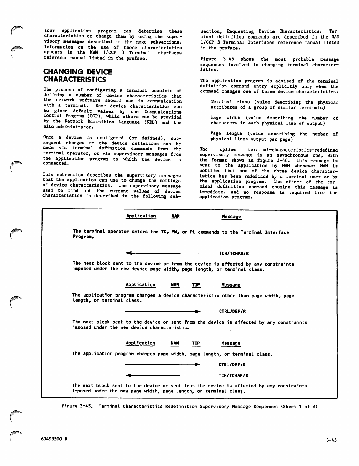
Your application program can determine these
characteristics or change them by using the super
visory messages described in the next subsections.
Information on the use of these characteristics
appears in the NAM 1/CCP 3 Terminal Interfaces
reference manual listed in the preface.
CHANGING DEVICE
CHARACTERISTICS
The process of configuring a terminal consists of
defining a number of device characteristics that
the network software should use in communication
w i th a t er m in a l . S om e d e v i c e c h a r a c t e r is t ic s c a n
be given default values by the Communications
Control Program (CCP), while others can be provided
by the Network Definition Language (NDL) and the
site administrator.
Once a device is configured (or defined), sub
sequent changes to the device definition can be
m a d e v i a t e r m i n a l d e fi n i t i o n c o m m a n d s f r o m t h e
terminal operator, or via supervisory messages from
the application program to which the device is
connected.
This subsection describes the supervisory messages
that the application can use to change the settings
of device characteristics. The supervisory message
u s e d t o fi n d o u t t h e c u r r e n t v a l u e s o f d e v i c e
characteristics is described in the following sub
s e c t i o n , R e q u e s t i n g D e v i c e C h a r a c t e r i s t i c s . Te r
minal definition commands are described in the NAM
1/CCP 3 Terminal Interfaces reference manual listed
in the preface.
Figure 3-45 shows the most probable message
sequences involved in changing terminal character
istics.
The application program is advised of the terminal
definition command entry explicitly only when the
command changes one of three device characteristics:
Terminal class (value describing the physical
attributes of a group of similar terminals)
Page width (value describing the number of
characters in each physical line of output)
Page length (value describing the number of
physical lines output per page)
The upline terminal-characteristics-redefined
supervisory message is an asynchronous one, with
the format shown in figure 3-46. This message is
sent to the application by NAM whenever NAM is
notified that one of the three device character
istics has been redefined by a terminal user or by
the application program. The effect of the ter
minal definition command causing this message is
imm e d i a t e , a n d n o r e sponse i s r e q u i r ed f r om t he
application program.
/^P^V.
Application NAM Message
The terminal operator enters the TC, PW, or PL commands to the Terminal Interface
Progran.
TCH/TCHAR/R
The next block sent to the device or from the device is affected by any constraints
imposed under the new device page width, page Length, or terminal class.
Application NAM TIP Message
The application program changes a device characteristic other than page width, page
len gth, or ter minal class .
CTRL/DEF/R
The next block sent to the device or sent from the device is affected by any constraints
imposed under the new device characteristic.
Application NAM TIP Message
The application program changes page width, page length, or terminal class.
▶ CTRL/DEF/R
TCH/TCHAR/R
The next block sent to the device or sent from the device is affected by any constraints
imposed under the new page width, page length, or terminal class.
Figure 3-45. Terminal Characteristics Redefinition Supervisory Message Sequences (Sheet 1 of 2)
60499500 R 3-45
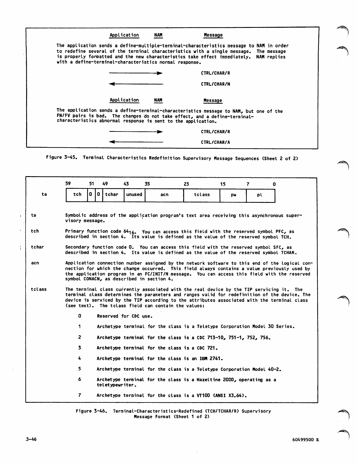
Application NAM Message
The application sends a define-multiple-terminal-characteristics message to NAM in order
to redefine several of the terminal characteristics with a single message. The message
is properly formatted and the new characteristics take effect immediately. NAM replies
with a define-terminal-characteristics normal response.
Application NAM
CTRL/CHAR/R
CTRL/CHAR/N
Message
The application sends a define-terminal-characteristics message to NAM, but one of the
FN/FV pairs is bad. The changes do not take effect, and a define-terminal-
characteristics abnormal response is sent to the application.
CTRL/CHAR/R
CTRL/CHAR/A
Figure 3-45. Terminal Characteristics Redefinition Supervisory Message Sequences (Sheet 2 of 2)
ta
ta
tch
tchar
tclass
59 51 49 43 35 23 15
tch tchar unused acn tclass pw Pi
Symbolic address of the application program's text area receiving this asynchronous super
visory message.
Primary function code 64-|0. You can access this field with the reserved symbol PFC, as
described in section 4. Its value is defined as the value of the reserved symbol TCH.
Secondary function code 0. You can access this field with the reserved symbol SFC, as
described in section 4. Its value is defined as the value of the reserved symbol TCHAR.
Application connection number assigned by the network software to this end of the logical con
nection for which the change occurred. This field always contains a value previously used by
the application program in an FC/INIT/N message. You can access this field with the reserved
symbol CONACN, as described in section 4.
The terminal class currently associated with the real device by the TIP servicing it. The
terminal class determines the parameters and ranges valid for redefinition of the device. The
device is serviced by the TIP according to the attributes associated with the terminal class
(see text). The tclass field can contain the values:
0 Reserved for CDC use.
1 Archetype terminal for the class is a Teletype Corporation Model 30 Series.
2 Archetype terminal for the class is a CDC 713-10, 751-1, 752, 756.
3 Archetype terminal for the class is a CDC 721.
4 Archetype terminal for the class is an IBM 2741.
5 Archetype terminal for the class is a Teletype Corporation Model 40-2.
6 Archetype terminal for the class is a Hazeltine 2000, operating as a
teletypewriter.
7 Archetype terminal for the class is a VT100 (ANSI X3.64).
Figure 3-46. Terminal-Characteristics-Redefined (TCH/TCHAR/R) Supervisory
Message Format (Sheet 1 of 2)
3-46 60499500 R
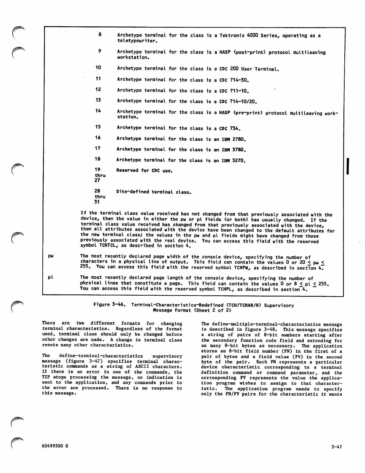
Archetype terminal for the
teletypewriter.
class is a Tektronix 4000 Series, operating as a
9Archetype terminal for the
workstation.
class is a HASP (post-print) protocol multileaving
10 Archetype terminal for the class is a CDC 200 User Terminal.
11 Archetype terminal for the class is a CDC 714-30.
12 Archetype terminal for the class is a CDC 711-10.
13 Archetype terminal for the class is a CDC 714-10/20.
14 Archetype terminal for the
station. class is a HASP (pre-print) protocol multileaving work-
/^^\
pw
pi
15
16
17
18
19
t h r u
27
28
thru
31
Archetype terminal for the class is a CDC 734.
Archetype terminal for the class is an IBM 2780.
Archetype terminal for the class is an IBM 3780.
Archetype terminal for the class is an IBM 3270.
Reserved for CDC use.
Site-defined terminal class.
If the terminal class value received has not changed from that previously associated with the
device, then the value in either the pw or pi fields (or both) has usually changed. If the
terminal class value received has changed from that previously associated with the device,
then all attributes associated with the device have been changed to the default attributes for
the new terminal class; the values in the pw and pi fields might have changed from those
previously associated with the real device. You can access this field with the reserved
symbol TCHTCL, as described in section 4.
The most recently declared page width of the console device, specifying the number of
characters in a physical line of output. This field can contain the values 0 or 20 £ pw £
255. You can access this field with the reserved symbol TCHPW, as described in section 4.
The most recently declared page length of the console device, specifying the number of
physical lines that constitute a page. This field can contain the values 0 or 8 < pi < 255.
You can access this field with the reserved symbol TCHPL, as described in section 4.
Figure 3-46. Terminal-Characteristics-Redefined (TCH/TCHAR/R) Supervisory
Message Format (Sheet 2 of 2)
T h e r e a r e t w o d i f f e r e n t f o r m a t s f o r c h a n g i n g
terminal characteristics. Regardless of the format
used, terminal class should only be changed before
other changes are made. A change in terminal class
resets many other characteristics.
The define-terminal-characteristics supervisory
message (figure 3-47) specifies terminal charac
teristic commands as a string of ASCII characters.
If there is an error in one of the commands, the
TIP stops processing the message, no indication is
sent to the application, and any commands prior to
the error are processed. There is no response to
this message.
The define-multiple-terminal-characteristic8 message
is described in figure 3-48. This message specifies
a s t r i n g o f p a i r s o f 8 - b i t n u m b e r s s t a r t i n g a f t e r
the secondary function code field and extending for
as many 8-bi t byte s as n eces sary. The appl icati on
stores an 8-bit field number (FN) in the first of a
pair of bytes and a field value (FV) in the second
byte of the pair. Each FN represents a particular
device characteristic corresponding to a terminal
definition command or command parameter, and the
corresponding FV represents the value the applica
tion program wishes to assign to that character
i s t i c . T h e a p p l i c a t i o n p r o g r a m n e e d s t o s p e c i f y
only the FN/FV pairs for the characteristic it wants
60499500 S 3-47
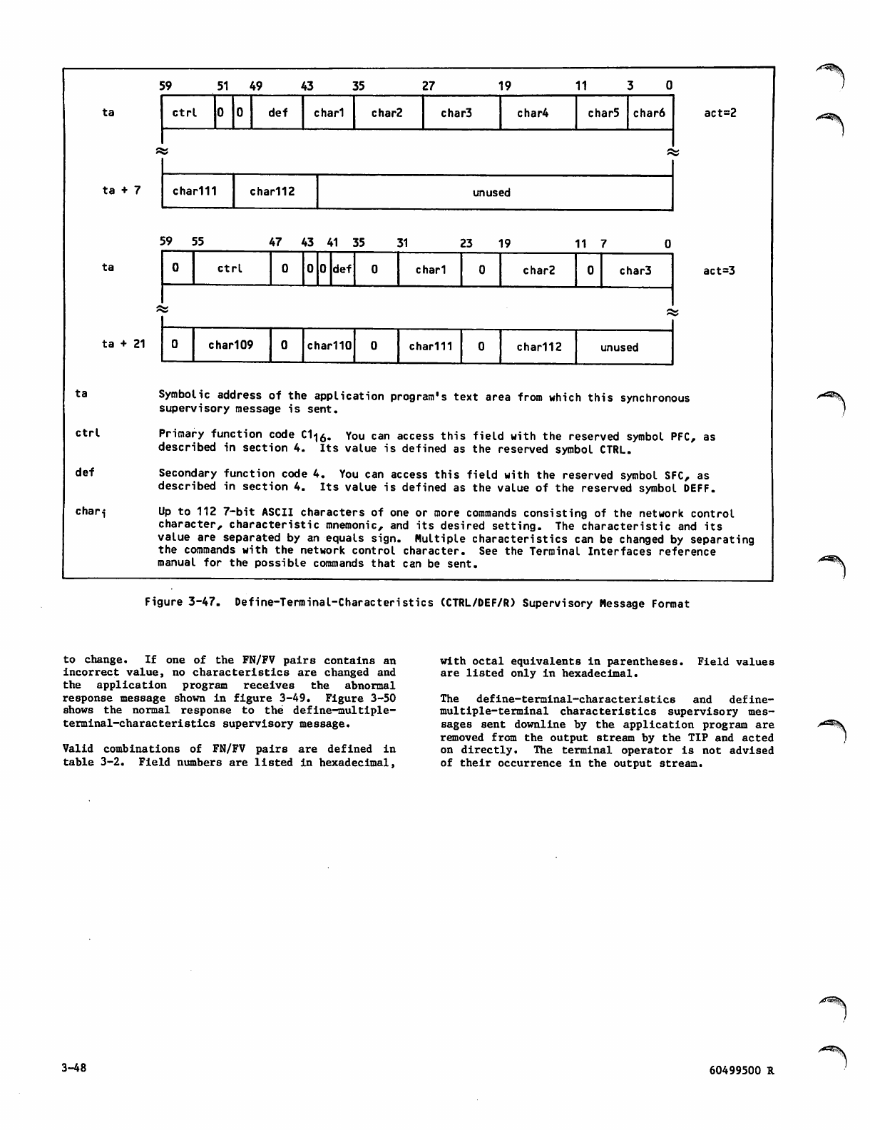
5 9 5 1 4 9 4 3 3 5 2 7 1 9 1 1 3 0
ta
ta + 7
Ctrl def chari char2 char3 char4 char5 char6 act=2
s s
char111 char112 unused
5 9 5 5 4 7 4 3 4 1 3 5 3 1 2 3 1 9 1 1 7 0
ta
ta + 21
ctrl 0 0 def c h a r i char2 char3 act=3
s s
0chari 09 char110 char111 char112 unused
t a Sy m b o l i c a d d r e ss o f t h e a p p l i c a ti on p r o g r a m ' s t e x t a r e a f r om w h i c h t h i s s y n ch r o n o u s
supervisory message is sent.
ctrl- Primary function code C1<|0. You can access this field with the reserved symbol PFC, as
described in section 4. Its value is defined as the reserved symbol CTRL.
def Secondary function code 4. You can access this field with the reserved symbol SFC, as
described in section 4. Its value is defined as the value of the reserved symbol DEFF.
chari Up to 112 7-bit ASCII characters of one or more commands consisting of the network control
ch ara cter, chara cteristi c mnemo nic , an d its desired setting. The characte ristic and its
value are separated by an equals sign. Multiple characteristics can be changed by separating
the commands with the network control character. See the Terminal Interfaces reference
manual for the possible commands that can be sent.
/ * ^ | l
Figure 3-47. Define-Terminal-Characteristies (CTRL/DEF/R) Supervisory Message Format
to change. If one of the FN/FV pairs contains an
incorrect value, no characteristics are changed and
the application program receives the abnormal
response message shown in figure 3-49. Figure 3-50
shows the normal response to the define-multiple-
terminal-characteristics supervisory message.
Valid combinations of FN/FV pairs are defined in
table 3-2. Field numbers are listed in hexadecimal,
with octal equivalents in parentheses,
are listed only in hexadecimal. Field values
T h e d e fi n e - t e r m i n a l - c h a r a c t e r i s t i c s a n d d e fi n e -
multiple-terminal characteristics supervisory mes
sages sent downline by the application program are
removed from the output stream by the TIP and acted
on directly. The terminal operator is not advised
of their occurrence in the output stream.
3-48 60499500 R
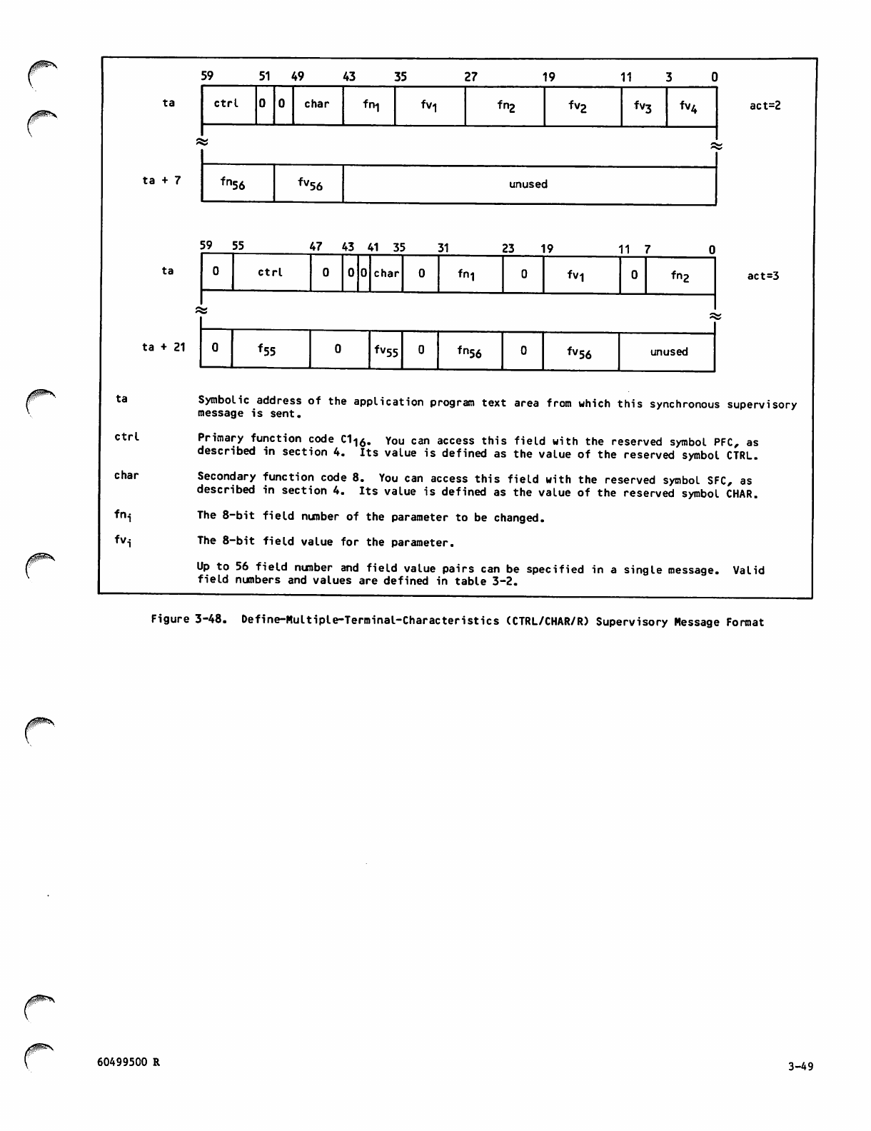
/|P?N
ta
ta + 7
ta
ta + 21
ta
ctrl
char
f v.
59 5 1 4 9 43 35 27 19 11
ctrl char fn-| fVl fn2 fvg fv3 fv4 act=2
fn
56 fv56 unused
5 9 5 5 4 7 4 3 4 1 3 5 3 1
Ctrl
2 3 1 9 11 7
char fn-| fV1 fng act=3
*55 fv55 fn56 ^56 unused
Symbolic address of the application program text area from which this synchronous supervisory
message is sent.
Primary function code C1<|0. You can access this field with the reserved symbol PFC, as
described in section 4. Its value is defined as the value of the reserved symbol CTRL.
Secondary function code 8. You can access this field with the reserved symbol SFC, as
described in section 4. Its value is defined as the value of the reserved symbol CHAR.
The 8-bit field number of the parameter to be changed.
The 8-bit field value for the parameter.
Up to 56 field number and field value pairs can be specified in a single message. Valid
field numbers and values are defined in table 3-2.
Figure 3-48. Define-Multiple-Terminal-Characteristics (CTRL/CHAR/R) Supervisory Message Format
60499500 R 3-49
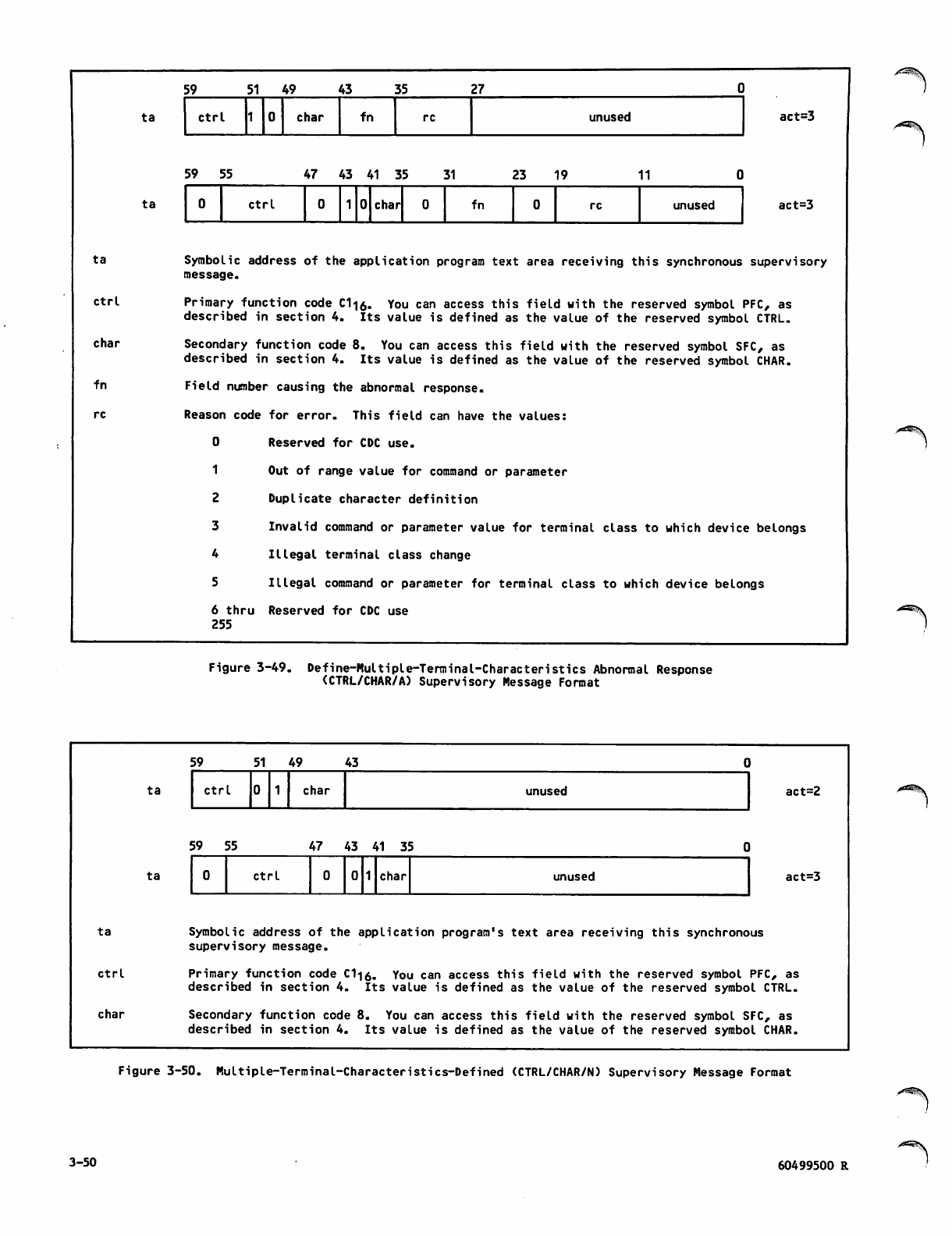
ta
ctrl
char
fn
ta
ta
59 51 49 43 35 27
ctrl char fn re unused
5 9 5 5 47 43 41 35 31 2 3 1 9 11
0ctrl char fn re unused
act=3
act=3
Symbolic address of the application program text area receiving this synchronous supervisory
message.
Primary function code C1-j0. You can access this field with the reserved symbol PFC, as
described in section 4. Its value is defined as the value of the reserved symbol CTRL.
Secondary function code 8. You can access this field with the reserved symbol SFC, as
described in section 4. Its value is defined as the value of the reserved symbol CHAR.
Field number causing the abnormal response.
Reason code for error. This field can have the values:
0 Reserved for CDC use.
1 Out of range value for command or parameter
2 Duplicate character definition
3 Invalid command or parameter value for terminal class to which device belongs
4 Illegal terminal class change
5 Illegal command or parameter for terminal class to which device belongs
6 thru Reserved for CDC use
255
Figure 3-49. Define-Multiple-Terminal-Characteristies Abnormal Response
(CTRL/CHAR/A) Supervisory Message Format
ta
ctrl
char
ta
ta
59 51 49 43
ctrl char unused
5 9 5 5 4 7 4 3 4 1 3 5 0
0Ctrl char unused
act=2
act=3
Symbolic address of the application program's text area receiving this synchronous
supervisory message.
Primary function code C1<|0. You can access this field with the reserved symbol PFC, as
described in section 4. Its value is defined as the value of the reserved symbol CTRL.
Secondary function code 8. You can access this field with the reserved symbol SFC, as
described in section 4. Its value is defined as the value of the reserved symbol CHAR.
Figure 3-50. Multiple-Terminal-Characteristics-Defined (CTRL/CHAR/N) Supervisory Message Format
3-50 60499500 R
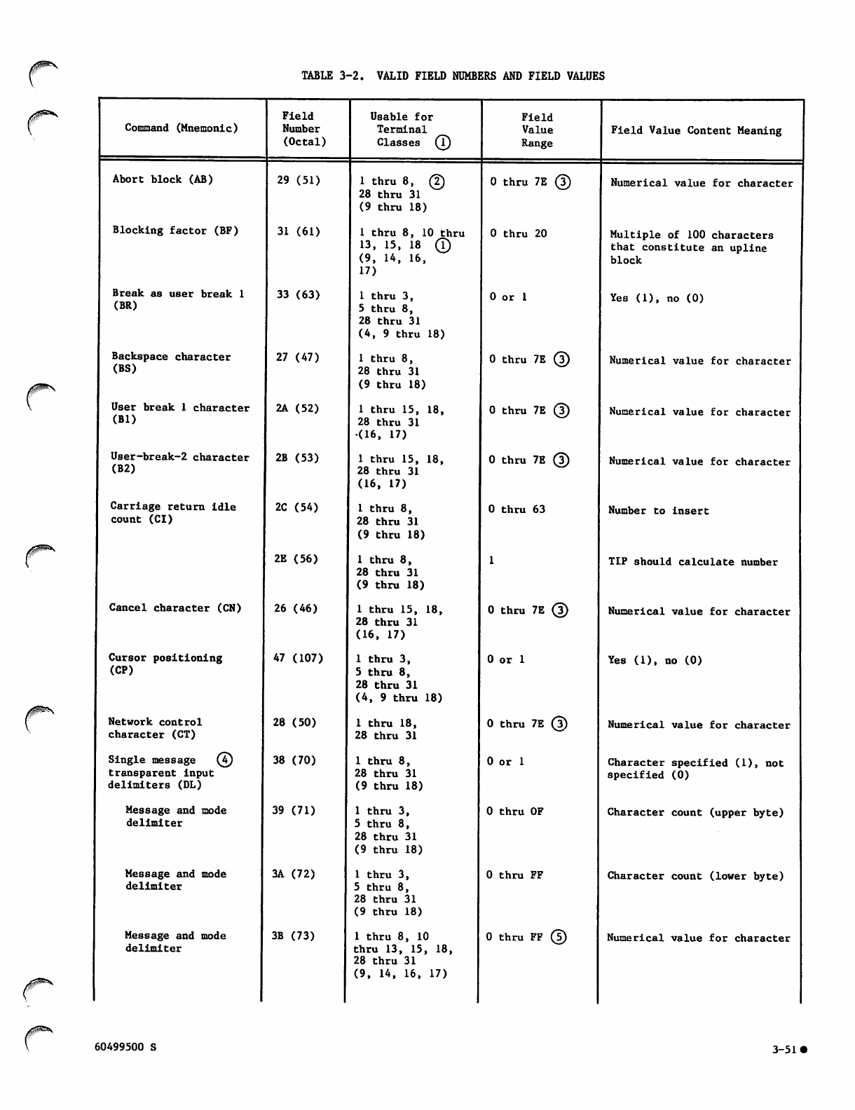
TABLE 3-2. VALID FIELD NUMBERS AND FIELD VALUES
Command (Mnemonic)
Abort block (AB)
Blocking factor (BF)
Break as user break 1
(BR)
Backspace character
(BS)
User break 1 character
(Bl)
User-break-2 character
(B2)
Carriage return idle
count (CI)
Field
Number
(Octal)
Cancel character (CN)
Cursor positioning
(CP)
Network control
character (CT)
Single message (4)
transparent input
delimiters (DL)
Message and mode
delimiter
Message and mode
delimiter
Message and mode
delimiter
29 (51)
31 (61)
33 (63)
27 (47)
2A (52)
2B (53)
2C (54)
2E (56)
26 (46)
47 (107)
28 (50)
38 (70)
39 (71)
3A (72)
3B (73)
Usable for
Terminal
Classes (T)
1 t h r u 8 , @
28 thru 31
(9 thru 18)
1 thru 8, 10 thru
13, 1 5 , 1 8 (!)
(9, 14, 16,
17)
1 thru 3,
5 thru 8,
28 thru 31
(4, 9 thru 18)
1 thru 8,
28 thru 31
(9 thru 18)
1 thru 15, 18,
28 thru 31
(16, 17)
1 thru 15, 18,
28 thru 31
(16, 17)
1 thru 8,
28 thru 31
(9 thru 18)
1 thru 8,
28 thru 31
(9 thru 18)
1 thru 15, 18,
28 thru 31
(16, 17)
1 thru 3,
5 thru 8,
28 thru 31
(4, 9 thru 18)
1 thru 18,
28 thru 31
1 thru 8,
28 thru 31
(9 thru 18)
1 thru 3,
5 thru 8,
28 thru 31
(9 thru 18)
1 thru 3,
5 thru 8,
28 thru 31
(9 thru 18)
1 thru 8, 10
thru 13, 15, 18,
28 thru 31
(9, 14, 16, 17)
Field
Value
0 thru 7E (|)
0 thru 20
0 or 1
0 thru 7E (5)
0 thru 7E (3)
0 thru 7E @
0 thru 63
0 thru 7E (3)
0 or 1
0 thru 7E (J)
0 or 1
0 thru OF
0 thru FF
0 thru FF (|)
Field Value Content Meaning
Numerical value for character
Multiple of 100 characters
that constitute an upline
block
Yes (1), no (0)
Numerical value for character
Numerical value for character
Numerical value for character
Number to insert
TIP should calculate number
Numerical value for character
Yes (1), no (0)
Numerical value for character
Character specified (1), not
specified (0)
Character count (upper byte)
Character count (lower byte)
Numerical value for character
60499500 S 3-51
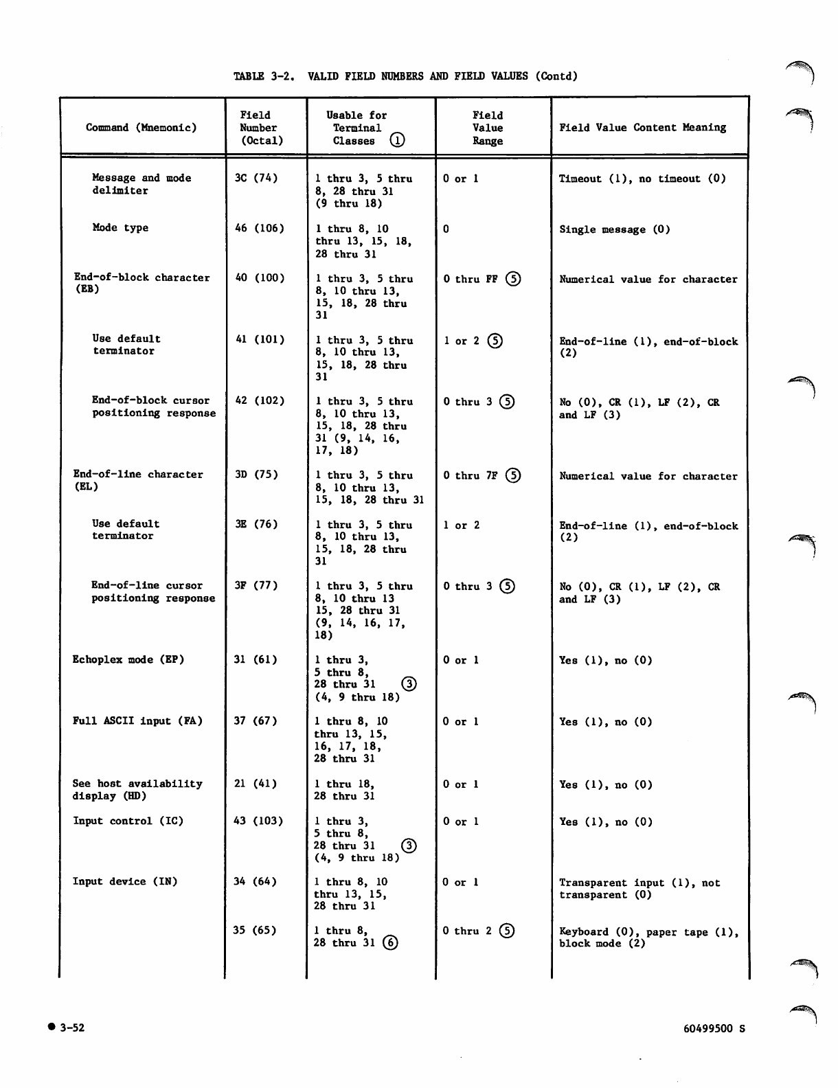
TABLE 3-2. VALID FIELD NUMBERS AND FIELD VALUES (Contd)
Command (Mnemonic)
Field
Number
(Octal)
Usable for
Terminal
Classes (l)
Field
Value
Range
Field Value Content Meaning
Message and mode
delimiter
3C (74) 1 thru 3, 5 thru
8, 28 thru 31
(9 thru 18)
0 or 1 Timeout (1), no timeout (0)
Mode type 46 (106) 1 thru 8, 10
thru 13, 15, 18,
28 thru 31
Single message (0)
End-of-block character
(EB)
40 (100) 1 thru 3, 5 thru
8, 10 thru 13,
15, 18, 28 thru
31
0 thru FF ® Numerical value for character
Use default
terminator
41 (101) 1 thru 3, 5 thru
8, 10 thru 13,
15, 18, 28 thru
31
1 or 2 © End-of-line (1), end-of-block
(2)
End-of-block cursor
positioning response
42 (102) 1 thru 3, 5 thru
8, 10 thru 13,
15, 18, 28 thru
31 (9, 14, 16,
17, 18)
0 t hru 3 © No (0), CR (1), LF (2), CR
and LF (3)
End - of-l i ne cha racte r
(EL)
3D (75) 1 thru 3, 5 thru
8, 10 thru 13,
15, 18, 28 thru 31
0 thru 7 F © Numerical value for character
Use default
terminator
3E (76) 1 thru 3, 5 thru
8, 10 thru 13,
15, 18, 28 thru
31
1 or 2 End-of-line (1), end-of-block
(2)
End-of-line cursor
positioning response
3F (77) 1 thru 3, 5 thru
8, 10 thru 13
15, 28 thru 31
(9, 14, 16, 17,
18)
0 t hru 3 © No (0), CR (1), LF (2), CR
and LF (3)
Echoplex mode (EP) 31 (61) 1 thru 3,
5 thru 8,
2 8 t h r u 3 1 ®
(4, 9 thru 18)
0 or 1 Yes (1), no (0)
Full ASCII input (FA) 37 (67) 1 thru 8, 10
thru 13, 15,
16, 17, 18,
28 thru 31
0 or 1 Yes (1), no (0)
See host availability
display (HD)
21 (41) 1 thru 18,
28 thru 31
0 or 1 Yes (1), no (0)
Input control (IC) 43 (103) 1 thru 3,
5 thru 8,
2 8 t h r u 3 1 ©
(4, 9 thru 18)
0 or 1 Yes (1), no (0)
Input device (IN) 34 (64) 1 thru 8, 10
thru 13, 15,
28 thru 31
0 or 1 Transparent input (1), not
transparent (0)
35 (65) 1 thru 8,
28 thru 31 ©
0 t h ru 2 © Keyboard (0), paper tape (1),
block mode (2)
• 3-52 60499500 S
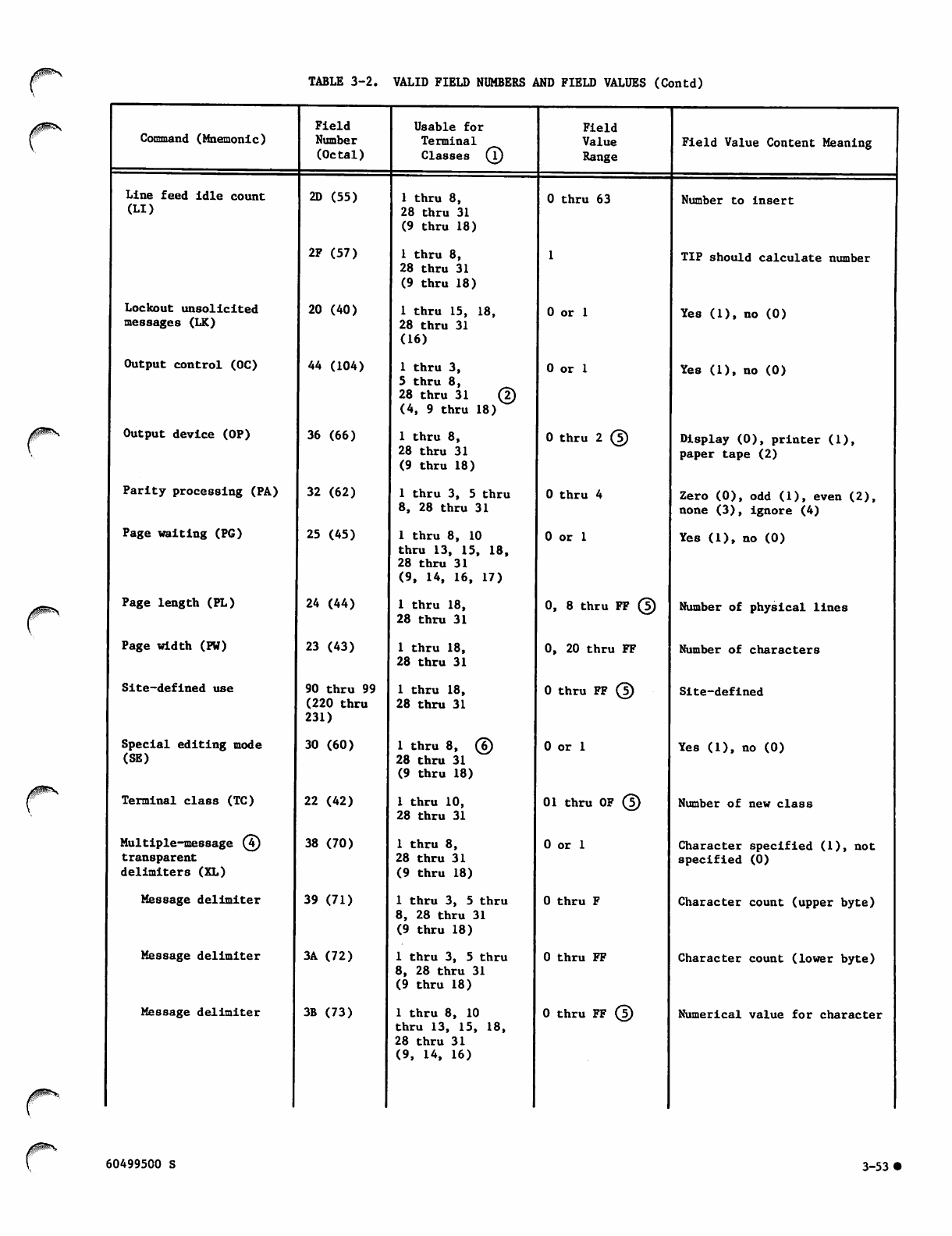
TABLE 3-2. VALID FIELD NUMBERS AND FIELD VALUES (Contd)
Command (Mnemonic)
Line feed idle count
(LI)
Lockout unsolicited
messages (LK)
Output control (OC)
Output device (OP)
Parity processing (PA)
Page waiting (PG)
Page length (PL)
Page width (PW)
Site-defined use
Special editing mode
(SE)
Terminal class (TC)
Multiple-mess a g e ©
transparent
delimiters (XL)
Message delimiter
Message delimiter
Message delimiter
Field
Number
(Octal)
2D (55)
2F (57)
20 (40)
44 (104)
36 (66)
32 (62)
25 (45)
24 (44)
23 (43)
90 thru 99
(220 thru
231)
30 (60)
22 (42)
38 (70)
39 (71)
3A (72)
3B (73)
Usable for
Terminal
Classes (T)
1 thru 8,
28 thru 31
(9 thru 18)
1 thru 8,
28 thru 31
(9 thru 18)
1 thru 15, 18,
28 thru 31
(16)
1 thru 3,
5 thru 8,
2 8 t h r u 3 1 ©
(4, 9 thru 18)
1 thru 8,
28 thru 31
(9 thru 18)
1 thru 3, 5 thru
8, 28 thru 31
1 thru 8, 10
thru 13, 15, 18,
28 thru 31
(9, 14, 16, 17)
1 thru 18,
28 thru 31
1 thru 18,
28 thru 31
1 thru 18,
28 thru 31
1 t h r u 8 , ©
28 thru 31
(9 thru 18)
1 thru 10,
28 thru 31
1 thru 8,
28 thru 31
(9 thru 18)
1 thru 3, 5 thru
8, 28 thru 31
(9 thru 18)
1 thru 3, 5 thru
8, 28 thru 31
(9 thru 18)
1 thru 8, 10
thru 13, 15, 18,
28 thru 31
(9, 14, 16)
Field
Value
Range
0 thru 63
0 or 1
0 or 1
0 t h r u 2 ©
0 thru 4
0 or 1
0, 8 thru FF ©
0, 20 thru FF
0 t hru FF ®
0 or 1
01 thru OF ©
0 or 1
0 thru F
0 thru FF
0 t h r u F F ©
Field Value Content Meaning
Number to insert
TIP should calculate number
Yes (1), no (0)
Yes (1), no (0)
Display (0), printer (1),
paper tape (2)
Zero (0), odd (1), even (2),
none (3), ignore (4)
Yes (1), no (0)
Number of physical lines
Number of characters
Site-defined
Yes (1), no (0)
Number of new class
Character specified (1), not
specified (0)
Character count (upper byte)
Character count (lower byte)
Numerical value for character
60499500 S 3-53
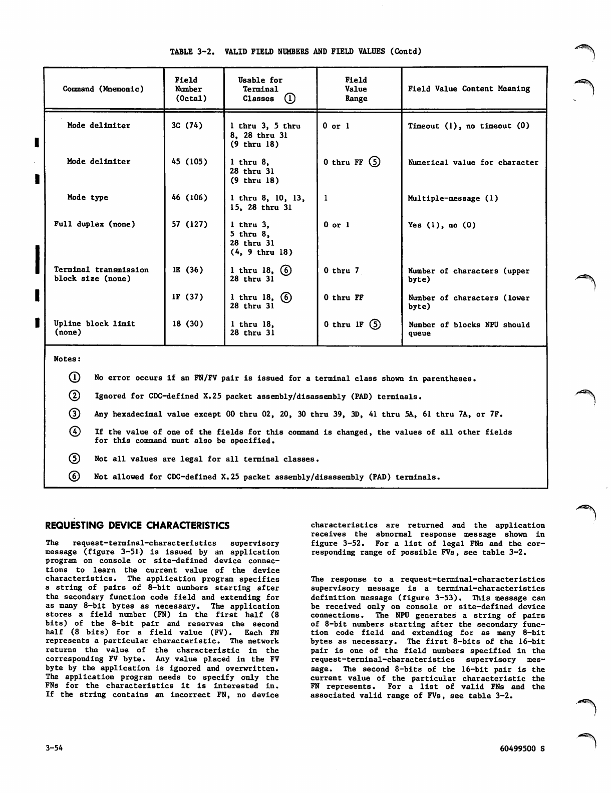
TABLE 3-2. VALID FIELD NUMBERS AND FIELD VALUES (Contd)
Command (Mnemonic)
Field
Number
(Octal)
Usable for
Terminal
Classes ©
Field
Value
Range
Field Value Content Meaning
Mode delimiter 3C (74) 1 thru 3, 5 thru
8, 28 thru 31
(9 thru 18)
0 or 1 Timeout (1), no timeout (0)
Mode delimiter 45 (105) 1 thru 8,
28 thru 31
(9 thru 18)
0 thru FF ® Numerical value for character
Mode type 46 (106) 1 thru 8, 10, 13,
15, 28 thru 31
Multiple-message (1)
Full duplex (none) 57 (127) 1 thru 3,
5 thru 8,
28 thru 31
(4, 9 thru 18)
0 or 1 Yes (1), no (0)
Terminal transmission
block size (none)
IE (36) 1 t h r u 1 8 , ©
28 thru 31
0 thru 7 Number of characters (upper
byte)
IF (37) 1 t hr u 18 , ©
28 thru 31
0 thru FF Number of characters (lower
byte)
Upline block limit
(none)
18 (30) 1 thru 18,
28 thru 31
0 t h r u I F ® Number of blocks NPU should
queue
Notes:
Q) No error occurs if an FN/FV pair is issued for a terminal class shown in parentheses.
© Ignored for CDC--defined X.25 packet assembly/disassembly (PAD) terminals.
(T) Any hexadecimal value except 00 thru 02, 20, 30 thru 39, 3D, 41 thru 5A, 61 thru 7A, or 7F.
© I f t h e v a l u e o f
for this commanc
one of the fields for this command is changed, the values of all other fields
1 must also be specified.
© Not all values are legal for all terminal classes.
© Not allowed for CDC-defined X.25 packet assembly/disassembly (PAD) terminals.
REQUESTING DEVICE CHARACTERISTICS
The request-terminal-characteristics supervisory
message (figure 3-51) is issued by an application
program on console or site-defined device connec
tions to learn the current value of the device
characteristics. The application program specifies
a s t r i n g of p a i r s o f 8 - b i t n um b e r s s ta r t i n g a f t e r
the secondary function code field and extending for
as many 8-bit bytes as necessary. The application
stores a field number (FN) in the first half (8
bits) of the 8-bit pair and reserves the second
half (8 bits) for a field value (FV). Each FN
represents a particular characteristic. The network
returns the value of the characteristic in the
corresponding FV byte. Any value placed in the FV
byte by the application Is ignored and overwritten.
The application program needs to specify only the
FNs for the characteristics it is interested in.
If the stri n g c o n t a i n s a n i n c o rrect F N , n o d e v i c e
characteristics are returned and the application
receives the abnormal response message shown in
figure 3-52. For a list of legal FNs and the cor
responding range of possible FVs, see table 3-2.
The response to a request-terminal-characteristics
supervisory message is a terminal-characteristics
definition message (figure 3-53). This message can
be received only on console or site-defined device
connections. The NPU generates a string of pairs
of 8-bit numbers starting after the secondary func
t i o n c o d e fi e l d a n d e x t e n d i n g fo r a s m a n y 8 - b i t
bytes as necessary. The first 8-bits of the 16-bit
pair is one of the field numbers specified in the
request-terminal-characteristics supervisory mes
sage. The second 8-bits of the 16-bit pair is the
c u rr e n t v al u e o f th e p a r ti c u l a r c h a r a c t er i s t i c t h e
FN represents. For a list of valid FNs and the
associated valid range of FVs, see table 3-2.
3-54 60499500 S
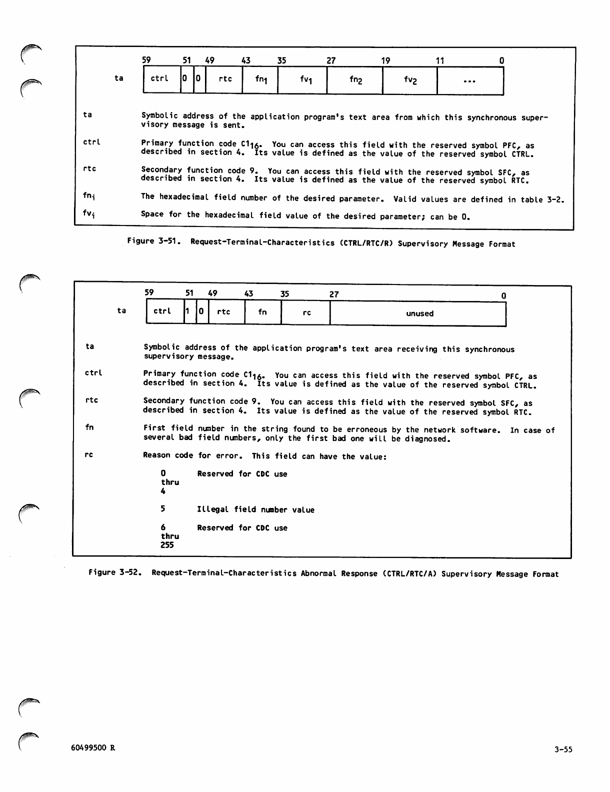
ta
ctrl
rtc
frM
fv<
ta
Ctrl
rtc
fn
59 5 1 4 9 43 35 27 19 11
ta ctrl rtc fn-j fVl fn2 fv2 • • •
Symbolic address of the application program's text area from which this synchronous super
visory message is sent.
Primary function code C1lo. You can access this field with the reserved symbol PFC, as
described in section 4. Its value is defined as the value of the reserved symbol CTRL.
Secondary function code 9. You can access this field with the reserved symbol SFC, as
described in section 4. Its value is defined as the value of the reserved symbol RTC.
The hexadecimal field number of the desired parameter. Valid values are defined in table 3-2.
Space for the hexadecimal field value of the desired parameter; can be 0.
Figure 3-51. Request-Terminal-Characteristics (CTRL/RTC/R) Supervisory Message Format
ta
59 51 49 43 35 27
Ctrl rtc fn re unused
Symbolic address of the application program's text area receiving this synchronous
supervisory message.
Primary function code C116. You can access this field with the reserved symbol PFC, as
described in section 4. Its value is defined as the value of the reserved symbol CTRL.
Secondary function code 9. You can access this field with the reserved symbol SFC, as
described in section 4. Its value is defined as the value of the reserved symbol RTC.
First field number in the string found to be erroneous by the network software. In case of
several bad field numbers, only the first bad one will be diagnosed.
Reason code for error. This field can have the value:
0 Reserved for CDC use
thru
6
thru
255
Illegal field number value
Reserved for CDC use
Figure 3-52. Request-Terminal-Characteristics Abnormal Response (CTRL/RTC/A) Supervisory Message Format
60499500 R 3-55
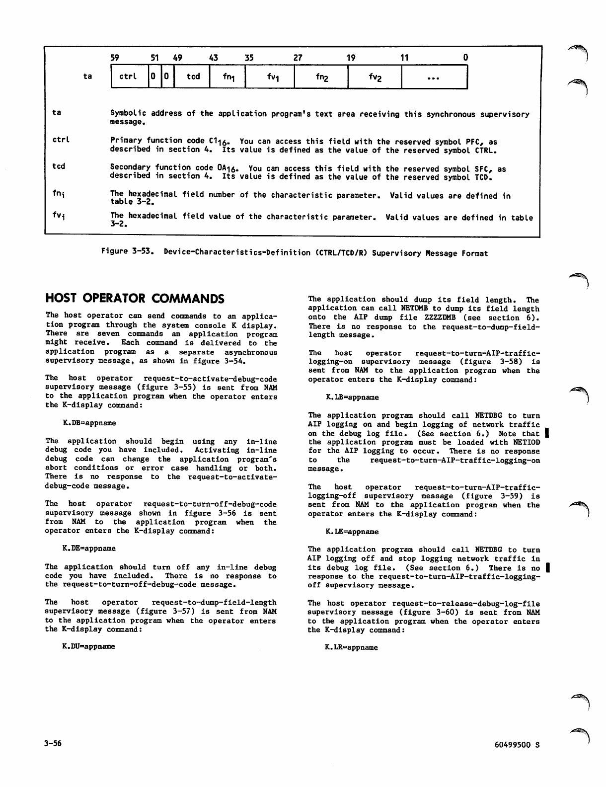
ta
ta
ctrl
ted
fni
fvi
59 51 49 43 35 27 19 1 1 0
ctrl ted fni fVl fng fvg ...
Symbolic address of the application program's text area receiving this synchronous supervisory
message.
Primary function code C1-j0. You can access this field with the reserved symbol PFC, as
described in section 4. Its value is defined as the value of the reserved symbol CTRL.
Secondary function code 0A<|o. You can access this field with the reserved symbol SFC, as
described in section 4. Its value is defined as the value of the reserved symbol TCD.
The hexadecimal field number of the characteristic parameter. Valid values are defined in
table 3-2.
The hexadecimal field value of the characteristic parameter. Valid values are defined in table
3-2.
Figure 3-53. Device-Characteristics-Definition (CTRL/TCD/R) Supervisory Message Format
HOST OPERATOR COMMANDS
The host operator can send commands to an applica
tion program through the system console K display.
There are seven commands an application program
might receive. Each command is delivered to the
application program as a separate asynchronous
supervisory message, as shown in figure 3-54.
The host operator request-to-activate-debug-code
supervisory message (figure 3-55) is sent from NAM
to the application program when the operator enters
the K-display command:
K.DB=appname
The application should begin using any in-line
debug code you have included. Activating in-line
debug code can change the application program's
abort conditions or error case handling or both.
T h e r e i s n o r es p o n s e t o t h e r e q u e s t - t o - a c t i v a te -
debug-code message.
The host operator request-to-turn-off-debug-code
supervisory message shown in figure 3-56 is sent
from NAM to the application program when the
operator enters the K-display command:
K.DE^appname
The application should turn off any in-line debug
code you have included. There is no response to
the request-to-turn-off-debug-code message.
The host operator request-to-dump-field-length
supervisory message (figure 3-57) is sent from NAM
to the application program when the operator enters
the K-display command:
K.DU=appname
The application should dump its field length. The
application can call NETDMB to dump its field length
onto the AIP dump file ZZZZDMB (see section 6).
Th ere is no re sponse to the reques t-to-dump-fi eld-
length message.
T h e h o s t o p e r a t o r r e q u e s t - t o - t u r n - A I P - t r a f fi c -
logging-on supervisory message (figure 3-58) is
sent from NAM to the application program when the
operator enters the K-display command:
K.LB=appname
The application program should call NETDBG to turn
AIP logging on and begin logging of network traffic
on the debug log file. (See section 6.) Note that |
the application program must be loaded with NETIOD
for the AIP logging to occur. There is no response
to the request-to-turn-AIP-traffic-logging-on
message.
T h e h o s t o p e r a t o r r e q u e s t - t o - t u r n - A I P - t r a f fi c -
l o g g i n g - o f f s u p e r v i s o r y m e s s a g e ( fi g u r e 3 - 5 9 ) i s
sent from NAM to the application program when the
operator enters the K-display command:
K.LE=appname
The application program should call NETDBG to turn
AI P log ging off and sto p lo gging network traffic in
its debug log file. (See section 6.) There is no |
response to the request-to-turn-AIP-traffic-logging-
off supervisory message.
The host operator request-to-release-debug-log-file
supervisory message (figure 3-60) is sent from NAM
to the application program when the operator enters
the K-display command:
K.LR=appname
3-56 60499500 S
y^^K
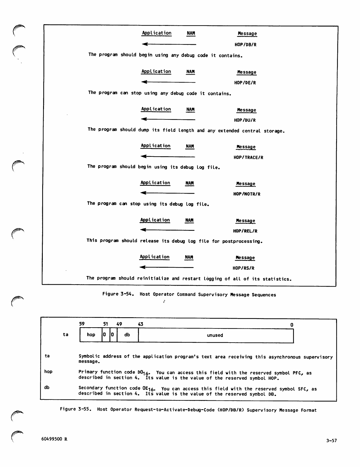
■g^N
ta
hop
db
ta
Application NAM Message
HOP/DB/R
The program should begin using any debug code it contains.
Application
-*
NAM
The program can stop using any debug code it contains.
Application NAM
Message
HOP/DE/R
Message
KOP/DU/R
The program should dump its field length and any extended central storage.
Application NAM
The program should begin using its debug log file.
Application
*<
NAN
The program can stop using its debug log file.
Application
-^
NAM
Message
HOP/TRACE/R
Message
HOP/NOTR/R
Message
KOP/REL/R
This program should release its debug log file for postprocessing.
Application
-<
NAN Message
HOP/RS/R
The program should reinitialize and restart logging of all of its statistics.
Figure 3-54. Host Operator Command Supervisory Message Sequences
59 5 1 4 9 43
hop db unused
Symbolic address of the application program's text area receiving this asynchronous supervisory
message.
Primary function code D016. You can access this field with the reserved symbol PFC, as
described in section 4. Its value is the value of the reserved symbol HOP.
Secondary function code 0E<|6. You can access this field with the reserved symbol SFC, as
described in section 4. Its value is the value of the reserved symbol DB.
Figure 3-55. Host Operator Request-to-Activate-Debug-Code (HOP/DB/R) Supervisory Message Format
60499500 R 3-57
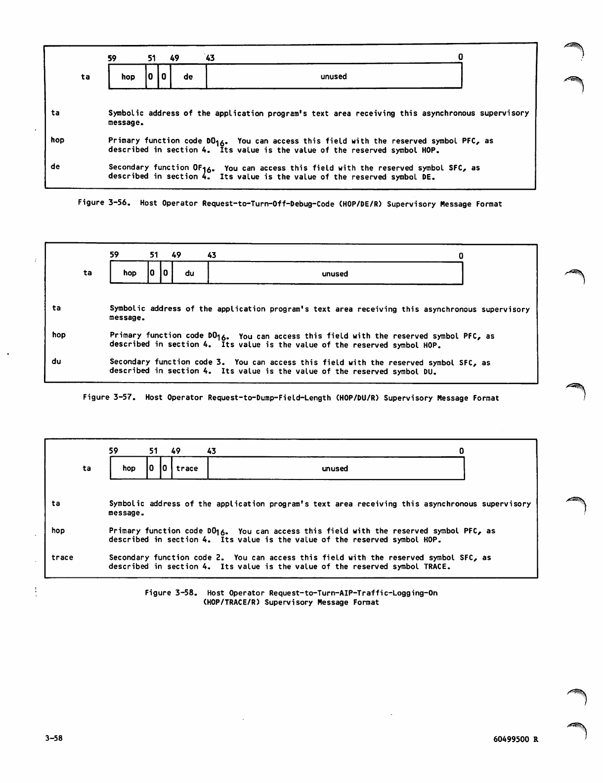
5 9 5 1 4 9 4 3 DI
ta hop de unused
ta
hop
de
Symbolic address of the application program's text area receiving this asynchronous supervisory
message.
Primary function code DO^. You can access this field with the reserved symbol PFC, as
described in section 4. Its value is the value of the reserved symbol HOP.
Secondary function 0F<|o. You can access this field with the reserved symbol SFC, as
described in section 4. Its value is the value of the reserved symbol DE.
Figure 3-56. Host Operator Request-to-Turn-Off-Debug-Code (HOP/DE/R) Supervisory Message Format
ta
hop
du
ta
59 5 1 4 9 43
hop du unused
Symbolic address of the application program's text area receiving this asynchronous supervisory
message.
Primary function code D0<|o. You can access this field with the reserved symbol PFC, as
described in section 4. Its value is the value of the reserved symbol HOP.
Secondary function code 3. You can access this field with the reserved symbol SFC, as
described in section 4. Its value is the value of the reserved symbol DU.
Figure 3-57. Host Operator Request-to-Dump-Field-Length (HOP/DU/R) Supervisory Message Format
ta
hop
trace
ta
59 5 1 4 9 43
hop trace unused
Symbolic address of the application program's text area receiving this asynchronous supervisory
message.
Primary function code DO|0. You can access this field with the reserved symbol PFC, as
described in section 4. Its value is the value of the reserved symbol HOP.
Secondary function code 2. You can access this field with the reserved symbol SFC, as
described in section 4. Its value is the value of the reserved symbol TRACE.
Figure 3-58. Host Operator Request-to-Turn-AIP-Traffic-Logging-On
(HOP/TRACE/R) Supervisory Message Format
/*^%v
3-58 60499500 R
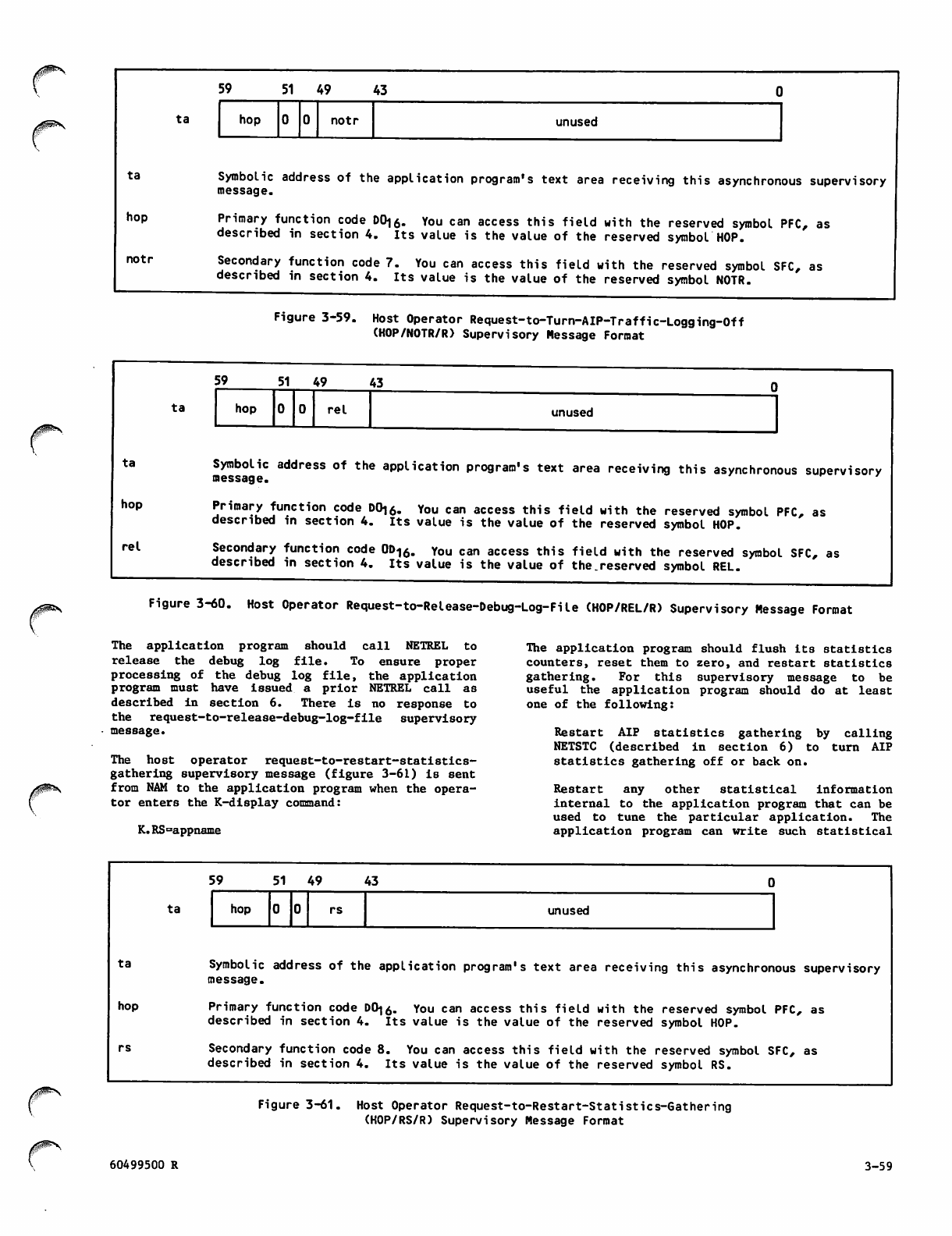
ta
hop
notr
ta
59 51 49 43
hop notr unused
Symbolic address of the application program's text area receiving this asynchronous supervisory
message.
Primary function code DO|6. You can access this field with the reserved symbol PFC, as
described in section 4. Its value is the value of the reserved symbol HOP.
Secondary function code 7. You can access this field with the reserved symbol SFC, as
described in section 4. Its value is the value of the reserved symbol NOTR.
Fi gure 3-59. Hos t Operator Request-to-Turn-AIP-Traffic-Lo gging -Off
(HOP/NOTR/R) Supervisory Message Format
ta
hop
re I
ta
59 5 1 4 9 43
hop re I unused
Symbolic address of the application program's text area receiving this asynchronous supervisory
message.
Primary function code D0i6. You can access this field with the reserved symbol PFC, as
described in section 4. Its value is the value of the reserved symbol HOP.
Secondary function code 0Dl6. You can access this field with the reserved symbol SFC, as
described in section 4. Its value is the value of the.reserved symbol REL.
Figure 3-60. Host Operator Request-to-Release-Debug-Log-File (HOP/REL/R) Supervisory Message Format
The application program should call NETREL to
release the debug log file. To ensure proper
processing of the debug log file, the application
program must have issued a prior NETREL call as
described in section 6. There is no response to
the request-to-release-debug-log-file supervisory
message.
The host operator request-to-restart-statistics-
gathering supervisory message (figure 3-61) is sent
from NAM to the application program when the opera
tor enters the K-display command:
K.RS=appname
The application program should flush its statistics
counters, reset them to zero, and restart statistics
g a t h e r i n g . F o r t h i s s u p e r v i s o r y m e s s a g e t o b e
useful the application program should do at least
one of the following:
Restart AIP statistics gathering by calling
NETSTC (described in section 6) to turn AIP
statistics gathering off or back on.
Restart any other statistical information
internal to the application program that can be
used to tune the particular application. The
application program can write such statistical
Xi^^V
ta
hop
ta
60499500 R
59 5 1 4 9 43
hop rs unused
Symbolic address of the application program's text area receiving this asynchronous supervisory
message.
Primary function code D0|o. You can access this field with the reserved symbol PFC, as
described in section 4. Its value is the value of the reserved symbol HOP.
Secondary function code 8. You can access this field with the reserved symbol SFC, as
described in section 4. Its value is the value of the reserved symbol RS.
Figure 3-61. Host Operator Request-to-Restart-Statisties-Gathering
(HOP/RS/R) Supervisory Message Format
3-59
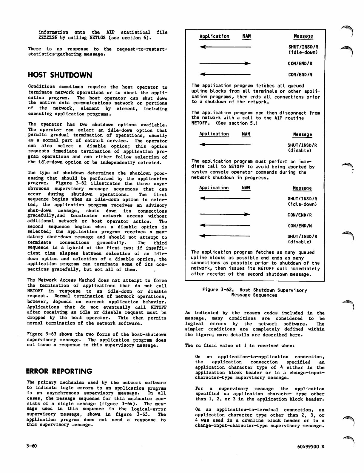
information onto the AIP statistical file
ZZZZZSN by calling NETLGS (see section 6).
There is no response to the request-to-restart-
statistics-gathering message.
HOST SHUTDOWN
Conditions sometimes require the host operator to
terminate network operations or to abort the appli
cation program. The host operator can shut down
the entire data communications network or portions
of the network, element by element, including
executing application programs.
The operator has two shutdown options available.
The operator can select an idle-down option that
permits gradual termination of operations, usually
as a normal part of network service. The operator
c a n a l s o s e l e c t a d i s a b l e o p t i o n ; t h i s o p t i o n
requests immediate termination of application pro
gram operations and can either follow selection of
the Idle-down option or be independently selected.
The type of shutdown determines the shutdown proc
essing that should be performed by the application
program. Figure 3-62 illustrates the three asyn
chronous supervisory message sequences that can
occur during shutdown operations. The first
sequence begins when an idle-down option is selec
ted; the application program receives an advisory
shut-down message, shuts down its connections
gracefully,and terminates network access without
additional network or host operator action. The
second sequence begins when a disable option is
selected; the application program receives a man
datory shut-down message and should not attempt to
terminate connections gracefully. The third
sequence is a hybrid of the first two; if insuffi
cient time elapses between selection of an idle-
down option and selection of a disable option, the
application program can terminate some of its con
nections gracefully, but not all of them.
The Network Access Method does not attempt to force
the termination of applications that do not call
NETOFF in response to an idle-down or disable
request. Normal ter min ation o f networ k operations,
however, depends on correct application behavior.
Applications that do not eventually call NETOFF
after receiving an idle or disable request must be
d r o p p e d b y t he h o s t o p e r a t o r. T h is t h e n p e r m i t s
normal termination of the network software.
Figure 3-63 shows the two forms of the host-shutdown
supervisory message. The application program does
not issue a response to this supervisory message.
ERROR REPORTING
The primary mechanism used by the network software
to indicate logic errors to an application program
is an asynchronous supervisory message. In all
cases, the message sequence for this mechanism con
sists of a single message (figure 3-64). The mes
sage used in this sequence is the logical-error
supervisory message, shown in figure 3-65. The
application program does not send a response to
this supervisory message.
Application NAM Message
-< SHUT/INSD/R
(idle-down)
▶ CON/END/R
-< CON/END/N
The application program fetches all queued
upline blocks from all terminals or other appli
cation programs, then ends all connections prior
to a shutdown of the network.
The application program can then disconnect from
the network with a call to the AIP routine
NETOFF. (See section 5.)
Application NAM Message
SHUT/INSD/R
(disable)
The application program must perform an imme
diate call to NETOFF to avoid being aborted by
system console operator commands during the
network shutdown in progress.
Application NAM Message
SHUT/INSD/R
(idle-down)
CON/END/R
CON/END/N
SHUT/INSD/R
(disable)
The application program fetches as many queued
upline blocks as possible and ends as many
connections as possible prior to shutdown of the
network, then issues its NETOFF call immediately
after receipt of the second shutdown message.
Figure 3-62. Host Shutdown Supervisory
Message Sequences
As indicated by the reason codes included in the
message, many conditions are considered to be
logical errors by the network software. The
simpler conditions are completely defined within
the figure; more details are described here.
The re field value of 1 is received when:
On an application-to-application connection,
the application connection specified an
application character type of 4 either in the
application block header or in a change-input-
character-type supervisory message.
For a supervisory message the application
s p e c ifi e d a n ap p l i c a ti o n c h a r a c t e r ty p e o t h e r
than 1, 2, or 3 in the application block header.
On an application-to-terminal connection, an
application character type other than 2, 3, or
4 was used in a downline block header or in a
change-input-character-type supervisory message.
3-60 60499500 R
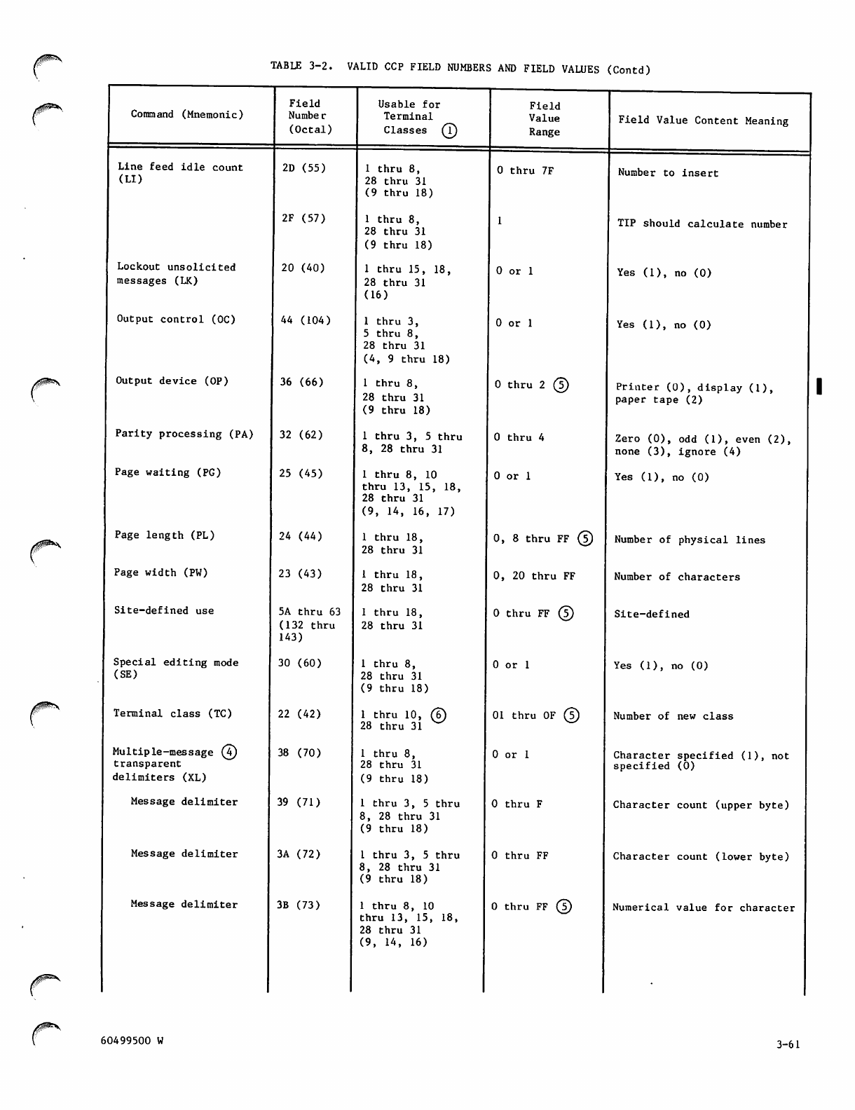
TABLE 3-2. VALID CCP FIELD NUMBERS AND FIELD VALUES (Contd)
Command (Mnemonic)
Line feed idle count
( L I )
Lockout unsolicited
messages (LK)
Output control (OC)
Output device (OP)
Parity processing (PA)
Page waiting (PG)
Page length (PL)
Page width (PW)
Site-defined use
Special editing mode
(SE)
Terminal class (TC)
Mul t iple - mess a ge ©
transparent
delimiters (XL)
Message delimiter
Message delimiter
Message delimiter
Field
Numbe r
(Octal)
2D (55)
2F (57)
20 (40)
44 (104)
36 (66)
32 (62)
25 (45)
24 (44)
23 (43)
5A thru 63
(132 thru
143)
30 (60)
22 (42)
38 (70)
39 (71)
3A (72)
3B (73)
Usable for
Terminal
Classes ®
1 thru 8,
28 thru 31
(9 thru 18)
1 thru 8,
28 thru 31
(9 thru 18)
1 thru 15, 18,
28 thru 31
(16)
1 thru 3,
5 thru 8,
28 thru 31
(4, 9 thru 18)
1 thru 8,
28 thru 31
(9 thru 18)
1 thru 3, 5 thru
8, 28 thru 31
1 thru 8, 10
thru 13, 15, 18,
28 thru 31
(9, 14, 16, 17)
1 thru 18,
28 thru 31
1 thru 18,
28 thru 31
1 thru 18,
28 thru 31
1 thru 8,
28 thru 31
(9 thru 18)
1 t h r u 10 , ©
28 thru 31
1 thru 8,
28 thru 31
(9 thru 18)
1 thru 3, 5 thru
8, 28 thru 31
(9 thru 18)
I thru 3, 5 thru
8, 28 thru 31
(9 thru 18)
1 thru 8, 10
thru 13, 15, 18,
28 thru 31
(9, 14, 16)
Field
Value
Range
0 thru 7F
0 or 1
0 or 1
0 thru 2 ©
0 thru 4
0 or 1
0, 8 thru FF ©
0, 20 thru FF
0 t hru FF ©
0 or 1
01 thru OF ©
0 or 1
0 thru F
0 thru FF
0 t hru FF ©
Field Value Content Meaning
Number to insert
TIP should calculate number
Yes (1), no (0)
Yes (1), no (0)
Printer (0), display (1),
paper tape (2)
Zero (0), odd (1), even (2),
none (3), ignore (4)
Yes (1), no (0)
Number of physical lines
Number of characters
Site-defined
Yes (1), no (0)
Number of new class
Character specified (1), not
specified (0)
Character count (upper byte)
Character count (lower byte)
Numerical value for character
60499500 W 3-61
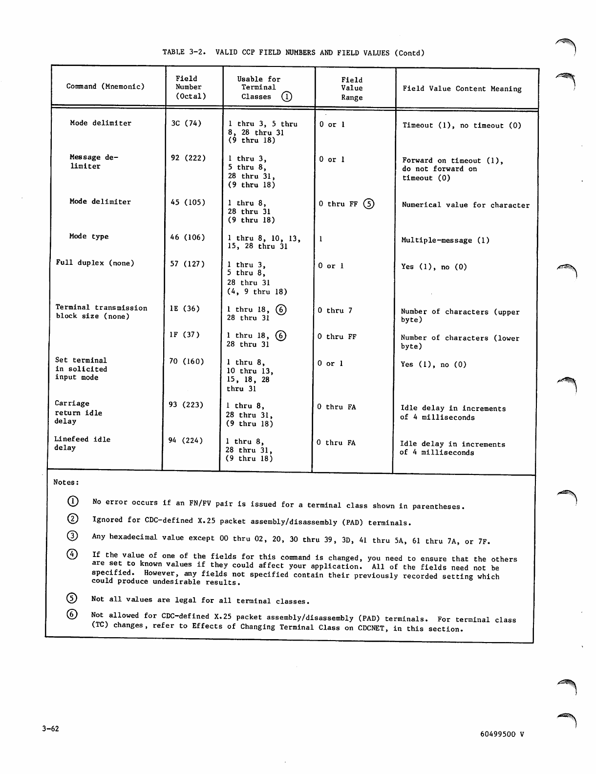
TABLE 3-2. VALID CCP FIELD NUMBERS AND FIELD VALUES (Contd)
Command (Mnemonic)
Mode delimiter
Message de
limiter
Mode delimiter
Mode type
Full duplex (none)
Terminal transmission
block size (none)
Set terminal
in solicited
input mode
Carriage
return idle
delay
Linefeed idle
delay
Notes:
®
©
®
©
©
©
Field
Number
(Octal)
3C (74)
92 (222)
45 (105)
46 (106)
57 (127)
IE (36)
IF (37)
70 (160)
93 (223)
94 (224)
Usable for
Terminal
Classes (T)
1 thru 3, 5 thru
8, 28 thru 31
(9 thru 18)
1 thru 3,
5 thru 8,
28 thru 31,
(9 thru 18)
1 thru 8,
28 thru 31
(9 thru 18)
1 thru 8, 10, 13,
15, 28 thru 31
1 thru 3,
5 thru 8,
28 thru 31
(4, 9 thru 18)
1 t h r u 18 , ©
28 thru 31
1 t h r u 18 , ©
28 thru 31
1 thru 8,
10 thru 13,
15, 18, 28
thru 31
1 thru 8,
28 thru 31,
(9 thru 18)
1 thru 8,
28 thru 31,
(9 thru 18)
Field
Value
Range
0 or 1
0 or 1
0 t hru FF ©
0 or 1
0 thru 7
0 thru FF
0 or 1
0 thru FA
0 thru FA
Field Value Content Meaning
Timeout (1), no timeout (0)
Forward on timeout (1),
do not forward on
timeout (0)
Numerical value for character
Multiple-message (1)
Yes (1), no (0)
Number of characters (upper
byte)
Number of characters (lower
byte)
Yes (1), no (0)
Idle delay in increments
of 4 milliseconds
Idle delay in increments
of 4 milliseconds
No error occurs if an FN/FV pair is issued for a terminal class shown in parentheses.
Ignored for CDC-defined X.25 packet assembly/disassembly (PAD) terminals.
Any hexadecimal value except 00 thru 02, 20, 30 thru 39, 3D, 41 thru 5A, 61 thru 7A, or 7F.
If the value of one of the fields for this command is changed, you need to ensure that the others
are set to known values if they could affect your application. All of the fields need not be
specified. However, any fields not specified contain their previously recorded setting which
could produce undesirable results.
Not all values are legal for all terminal classes.
Not allowed for CDC-defined X.25 packet assembly/disassembly (PAD) terminals. For terminal class
(TC) changes, refer to Effects of Changing Terminal Class on CDCNET, in this section.
3-62 60499500 V
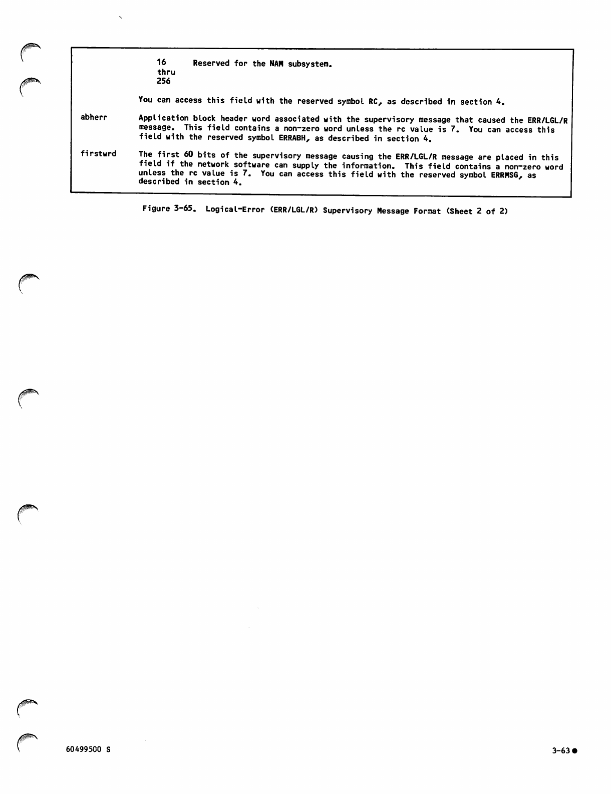
16 Reserved for the NAM subsystem.
thru
256
You can access this field with the reserved symbol RC, as described in section 4.
abherr Application block header word associated with the supervisory message that caused the ERR/L6L/R
message. This field contains a non-zero word unless the re value is 7. You can access this
field with the reserved symbol ERRABH, as described in section 4.
firstwrd The first 60 bits of the supervisory message causing the ERR/L6L/R message are placed in this
field if the network software can supply the information. This field contains a non-zero word
unless the re value is 7. You can access this field with the reserved symbol ERRMSG, as
described in section 4.
Figure 3-65. Logical-Error (ERR/LGL/R) Supervisory Message Format (Sheet 2 of 2)
60499500 S 3-63 •

USER PROGRAM INTERFACE DESCRIPTIONS 4|
/0^ .
This section describes the language interface
requirements of an application program, the inter
facing utilities available to a program, and those
aspects of network software internal interfacing
that affect program use of certain Network Access
Method (NAM) features. However, this manual does
not attempt to describe all network software inter
faces. Portions of the network software that exe
cute as application programs use supervisory mes
sages that are either not discussed in this manual
or else that are modified from the format presented
in this manual. This section treats only those
areas of interface that are properly used by an
installation-written application program.
LANGUAGE INTERFACES
Application program use of the Application Interface
Program (AIP) is essentially independent of the
language used to code the application program.
Parameter list and calling sequence requirements
are the same for COMPASS assembler language and
compiler-level languages. The residence of the AIP
r o u tin e s , th e f o rm o f t he c a l li n g s eq u e nce s , and
the utilities available to the application program
differ for COMPASS and compiler-level languages.
PARAMETER LIST AND CALLING
SEQUENCE REQUIREMENTS
The AIP statements and interfacing utilities use
FORTRAN-style calling sequences and parameter lists;
that is, a parameter list contains one 60-bit word
per parameter. The address of this parameter list
is passed to the appropriate routine in register Al.
Linkage with the statement within the application
program is performed by executing a return jump
instruction (RJ) to the entry point. To provide
compact object code, traceback information is not
generated, and the parameter list need not be fol
lowed by a word of zeros.
Because the statement parameters are passed by
address (called by reference), the NAM programmer
should be careful about substituting values when
defining the parameters. Those parameters identi
fied as return parameters should not be specified
as constants or expressions In the call statement.
Such specifications can produce unpredictable errors
in program code. This restriction is compatible
with normal FORTRAN programming practices.
Return parameters are normally defined by variable
names, array names, array element names, or similar
symbolic addresses. Since the terminology for such
entities varies according to the programming lan
guage used, this manual uses the term symbolic
address for all such possibilities. Unless other
wise stated, numeric absolute or relative addresses
are not used in call statements.
Those parameters identified as input parameters can
be defined by constants, expressions that can be
evaluated to produce constants, or symbolic
addresses (as defined above). Input parameters are
usually defined by constants or expressions; this
manual uses the term value for all such possibil
ities.
All AIP statement parameters used by a COBOL program
must be described in the Data Division as level 01
data entries, or data entries at other levels when
the entries are left-justified to word boundaries.
COBOL 5 programs that access fields within param
eters must also describe the fields in the Data
Division as COMP-4 numeric data entries to manipu
late values within the fields as 6-bit entities.
D i r ect fi e ld a c c e ss a n d A I P u s e is d i f ficu l t usi n g
COBOL; COMPASS macros or FORTRAN subroutines are
sometimes necessary to set up parameters before AIP
calls or to unpack them after AIP calls.
All direct calls from a COBOL program to AIP must
be coded as calls to FORTRAN-X subroutines. Refer
to section 5. Indirect use of AIP by a COBOL pro
gram is also possible; refer to the Queued Terminal
Record Manager description later in this section.
The AIP statement calling sequence does not permit
recursive calls.
PREDEFINED SYMBOLIC NAMES
The fields in NAM supervisory messages of appli
cation character types 1 and 2 have been assigned
symbolic names so that they can be ide n t i fi e d t o
the utilities described later in this section.
These names are display-coded Hollerith characters
and are listed and defined in table 4-1. The
capitalized symbol appears as it should be used in
calls to NFETCH or NSTORE. The symbols are arranged
alphabetically within the table.
Each symbol consists of the characters identifying
its field within a message, combined with characters
iden t ifyin g t he spe c i fic mes s age o r g roup o f mes
sages. For example:
All primary function code fields can be accessed
through the symbol PFC.
All fields in messages with the primary func
tion code mnemonic CON begin with CON; the
application list number field in such messages
is therefore CONALN.
All fi elds in the a ppli c atio n block heade r word
can be accessed through symbols beginning with
ABH.
r60499500 R 4-1
Some symbols are restricted to use in certain con
texts. For example, the FORTRAN 5 call:
IVAL=NFETCH(0,L"C0NEND")
returns the primary and secondary code value for
the corresponding fields in a CON/END/R message;
however, the FORTRAN 5 call:
CALL NSTORE(SMTA,L"CONEND",IVAL)
causes an error message indicating that the symbol
CONEND is unrecognized. The symbol is unrecognized
because its context is incorrect. The correct
FORTRAN call to store the information is:
CALL NSTORE(SMTA,L,,PFCSFC",IVAL)
o r t h e c al l :
CALL NSTORE(SMTA,L,,PFCSFC",L"CONEND")
There are no predefined names for the AIP statement
parameters described in section 5.
PREDEFINED SYMBOLIC VALUES
Some of the supervisory message fields with pre
defined symbolic names have predefined values that
can be obtained through the utilities described
later in this section. Values for such names are
given in table 4-1, where the names are listed
alphabetically.
You can obtain the value assigned to a given sym
bolic name in the released version of the network
software by using a form of the NFETCH utilities.
The NFETCH utilities comprise a macro that can be
called by a COMPASS program; and a similar subrou
tine that can be called b y a program written in a
high-level language.
Be careful in using names with predefined values;
in some instances, a name and corresponding value
have been assigned to a group of fields. Choosing
a w ron g name i n a u til ity call can fill more fields
than the programmer intends. The NAM programmer
should become familiar with all of the predefined
symbolic names before using the interfacing utili
ties.
COMPASS ASSEMBLER LANGUAGE
Application programs coded in COMPASS use AIP
statements that make macro calls. These AIP macros
reside in the system text library NETTEXT.
Packing and unpacking supervisory message blocks in
a COMPASS program is easily accomplished using the
interfacing utilities NFETCH and NSTORE. These
field access utilities also reside in the system
text library NETTEXT. An application program using
either utility must first contain calls to SST and
NETMAC.
Application Interface Program Macro
Call Formats
For those AIP statement calls with parameters, three
forms of the COMPASS macro call are possible:
[label] macro-name parameters
This is the format of the standard call,
which produces the full calling sequence.
[labell] macro-name /LIST=label2 \
lLIST=register name I
When this format is used, macro expansion
ass umes that the p rope r cal l ing para meter
block is located at the address specified
by the LIST value, loads this address into
register Al, and performs the call to the
AIP procedure.
Iabel2 macro-name parameters, LIST
When this format is used, macro expansion
produces a parameter block in place but
does not generate the call to the AIP pro
cedure; the address of the statement using
this form is the address used in the second
form.
Use t h e fi rst form w h e n making a s t r a ightforwa r d
call to the AIP procedures. Use the second form
once the parameter list has been created elsewhere
w i th t h e t h i r d f or m . T h e s e co n d a n d th i rd f o r m s
save space when procedures are used several times.
Example 1:
NETPUT IHA.ITA
This statement is a direct call to execute the
NETPUT macro with the two symbolic address param
eters shown.
Example 2:
PUT1 NETPUT IHA,ITA,LIST
This statement expands the NETPUT macro and creates
the indicated parameter list at symbolic address
PUT1 but does not execute NETPUT.
Example 3:
NETPUT LIST=PUT1
This statement actually executes the NETPUT macro
with the parameters in the list expanded at location
PUT1.
If a macro call is issued with an error, the COMPASS
assembler flags the error and provides an explana
tion during assembly of the macro. A complete
listing of the assembly error messages from AIP-
related macros is provided in appendix B.
A summary of all the macro call formats available
appears in appendix D.
4-2 60499500 R
TABLE 4-1. RESERVED SYMBOLS
Symbol
ABHABN
ABHABT
ABHACT
ABHADR
ABHBIT
ABHCAN
ABHIBU
ABHNCP
ABHNEP
ABHNFE
ABHTLC
ABHTRU
ABHWORD
ABHXPT
ACCON
ACCTRL
ACDBG
ACDC
ACERR
ACFC
ACHOP
ACIFC
60499500 W
Entity Defined by Symbol
Application block number field in application block header for all upline or
downline blocks
Application block type field in application block header for all upline or
downline blocks
Application character type field in application block header for all upline
or downline blocks
Process number address field in application block header for supervisor pro
gram upline or downline blocks (system use only). Application connection
number field in application block header for all application program upline
or downline blocks.
Parity error flag bit in application block header for upline (input) blocks.
Auto-input mode flag bit in application block header for downline (output)
blocks.
Cancel previous blocks bit in application block header for upline (input)
blocks. Punch banner (lace) card bit in application block header for down
line (output) blocks.
Input block undeliverable bit in application block header for upline (input)
blocks
No cursor positioning flag bit in application block header for downline
(output) blocks.
No echoplex flag bit in application block header for downline (output)
blocks.
No format effectors flag bit in application block header for downline (out
put) blocks
Text-length-in-character-units field in application block header for all
upline or downline blocks
Truncation occurred bit in the application block header for upline (input)
data or supervisory message blocks
Application block header word for all upline or downline blocks
Transparent mode transmission bit in application block header for all upline
or downline blocks
Application character type of CON supervisory messages, for use in applica
tion block header
Application character type of CTRL supervisory messages, for use in applica
tion block header
Application character type of DBG supervisory messages, for use in applica
tion block header
Application character type of DC supervisory messages, for use in applica
tion block header
Application character type of ERR supervisory messages, for use in applica
tion block header
Application character type of FC supervisory messages, for use in applica
tion block header
Application character type of HOP supervisory messages, for use in applica
tion block header
Application character type of IFC supervisory messages, for use in applica
tion block header
Predefined
Integer Value
None
None
None
None
None
None
None
None
None
None
None
None
None
None
1
4-3
TABLE 4-1. RESERVED SYMBOLS (Contd)
Symbol
ACINTR
ACK
ACLST
ACRQ
ACSET
ACSHUT
ACTCH
ALT
APP
BI
BTMARK
BRK
CB
CCD
CHAR
CICT
CMD
CON
CONAABL
CONABN
CONAABN
CONAAWC
CONABL
CONABN
CONABZ
CONACN
CONACR
CONACRA
Entity Defined by Symbol
Application character type of INTR supervisory messages, for use in applica
tion block header
Secondary function code field for FC/ACK/R
Application character type of LST supervisory messages, for use in applica
tion block header
Secondary function code field for CON/ACRQ messages
Application character type of SET supervisory messages, for use in applica
tion block header
Application character type of SHUT supervisory messages, for use in applica
tion block header
Application character type of TCH supervisory messages, for use in applica
tion block header
Secondary function code field in HOP/ALT/R
Secondary function code field for INTR/APP/R
Primary function code field for BI/MARK/R
Primary and secondary function code fields for BI/MARK/R, including EB and
RB fields as zero
Secondary function code field for FC/BRK/R and HOP/BRK/R
Secondary function code field for CON/CB/R
Secondary function code field for CON/CCD/R
Secondary function code field for CTRL/CHAR/R
Secondary function code field for DC/CICT/R
Secondary function code field in HOP/CMD/R
Primary function code field for connection management (CON) supervisory messages
Application block limit field in CON/ACRQ/R
Application block number field of CON/REQ/R
Application block number field of CON/ACRQ/R
User validation control word in CON/REQ/R
Application block limit field in CON/REQ/R
Application block number field of CON/ACRQ/R
Block size in connection management (CON) supervisory messages
Application connection number field in connection management (CON)
supervisory messages
Primary and secondary function code fields for CON/ACRQ/R, including EB and RB
fields as zero
Primary and secondary function code fields in CON/ACRQ/A including EB field
set to 1
Predefined
Integer Value
B
2
CA16
CAOO
0
5
0C16
816
0
1
6316
None
None
None
None
None
None
None
None
16
6302
6382
16
16
4-4 60499500 W
TABLE 4-1. RESERVED SYMBOLS (Contd)
j0m^s
Symbol
CONACT
CONADBL
CONADBZ
CONAHDS
Entity Defined by Symbol
Application input character type field in CON/REQ/N
Downline block limit field in CON/ACRQ/R
Downline block size field in CON/ACRQ/R
User validation control word in CON/REQ/R
Predefined
Integer Value
None
None
None
None
60499500 W 4-4.1/4-4.2 |

//!^*^v
0^%L
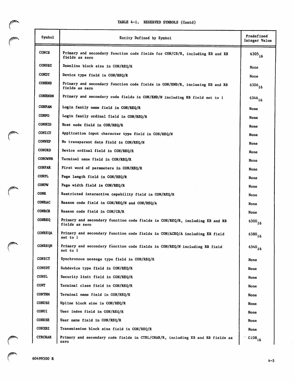
TABLE 4-1. RESERVED SYMBOLS (Contd)
Symbol
CONCB
CONDBZ
CONDT
CONEND
CONENDN
CONFAM
CONFO
CONHID
CONICT
CONNXP
CONORD
CONOWNR
CONPAR
CONPL
CONPW
CONR
CONRAC
CONRCB
CONREQ
CONREQA
CONREQN
CONSCT
CONSDT
CONSL
CONT
CONTNM
CONUBZ
CONUI
CONUSE
CONXBZ
CTRCHAR
Entity Defined by Symbol
Primary and secondary function code fields for CON/CB/R, including EB and RB
fields as zero
Downline block size in CON/REQ/R
Device type field in CON/REQ/R
Primary and secondary function code fields in CON/END/R, including EB and RB
fields as zero
Primary and secondary code fields in CON/END/N including RB field set to 1
Login family name field in CON/REQ/R
Login family ordinal field in CON/REQ/R
Host node field in CON/REQ/R
Application input character type field in CON/REQ/N
No transparent data field in CON/REQ/N
Device ordinal field in CON/REQ/R
Terminal name field in CON/REQ/R
First word of parameters in CON/REQ/R
Page length field in CON/REQ/R
Page width field in CON/REQ/R
Restricted interactive capability field in CON/REQ/R
Reason code field in CON/REQ/N and CON/REQ/A
Reason code field in CON/CB/R
Primary and secondary function code fields in CON/REQ/R, including EB and RB
fields as zero
Primary and secondary function code fields in CON/ACRQ/A including EB field
set to 1
Primary and secondary function code fields in CON/REQ/N including RB field
set to 1
Synchronous message type field in CON/REQ/R
Subdevice type field in CON/REQ/R
Security limit field in CON/REQ/R
Terminal class field in CON/REQ/R
Terminal name field in CON/REQ/R
Upline block size in CON/REQ/R
User index field in CON/REQ/R
User name field in CON/REQ/R
Transmission block size field in CON/REQ/R
Primary and secondary code fields in CTRL/CHAR/R, including EB and RB fields as
zero
Predefined
Integer Value
6305
None
None
6306
6346
None
None
None
None
None
None
None
None
None
None
None
None
None
6300
16
16
16
6380
6340
None
None
None
None
None
None
None
None
None
C108
16
16
16
16
60499500 R 4-5
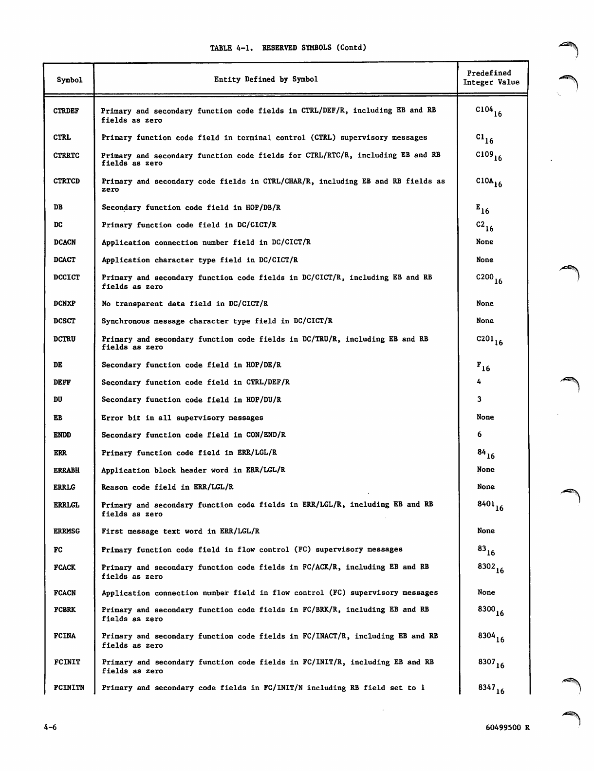
TABLE 4-1. RESERVED SYMBOLS (Contd)
Symbol Entity Defined by Symbol
Predefined
Integer Value
CTRDEF Primary and secondary function code fields in CTRL/DEF/R, including EB and RB
fields as zero C10416
CTRL Primary function code field in terminal control (CTRL) supervisory messages C116
CTRRTC Primary and secondary function code fields for CTRL/RTC/R, including EB and RB
fields as zero C10916
CTRTCD Primary and secondary code fields in CTRL/CHAR/R, including EB and RB fields as
zero C10A16
DB Secondary function code field in HOP/DB/R E16
DC Primary function code field in DC/CICT/R C216
DCACN Application connection number field in DC/CICT/R None
DCACT Application character type field in DC/CICT/R None
DCCICT Primary and secondary function code fields in DC/CICT/R, including EB and RB
fields as zero
C200,,
10
DCNXP No transparent data field in DC/CICT/R None
DCSCT Synchronous message character type field in DC/CICT/R None
DCTRU Primary and secondary function code fields in DC/TRU/R, including EB and RB
fields as zero C20116
DE Secondary function code field in HOP/DE/R F16
DEFF Secondary function code field in CTRL/DEF/R
DU Secondary function code field in HOP/DU/R
EB Error bit in all supervisory messages None
ENDD Secondary function code field in CON/END/R
ERR Primary function code field in ERR/LGL/R 8A16
ERRABH Application block header word in ERR/LGL/R None
ERRLG Reason code field in ERR/LGL/R None
ERRLGL Primary and secondary function code fields in ERR/LGL/R, including EB and RB
fields as zero 840116
ERRMSG First message text word in ERR/LGL/R None
FC Primary function code field in flow control (FC) supervisory messages 8316
FCACK Primary and secondary function code fields in FC/ACK/R, including EB and RB
fields as zero 830216
FCACN Application connection number field in flow control (FC) supervisory messages None
FCBRK Primary and secondary function code fields in FC/BRK/R, including EB and RB
fields as zero
8300.,
10
FCINA Primary and secondary function code fields in FC/INACT/R, including EB and RB
fields as zero 830416
FCINIT Primary and secondary function code fields in FC/INIT/R, including EB and RB
fields as zero 830716
FCINITN Primary and secondary code fields in FC/INIT/N including RB field set to 1 834716
4-6 60499500 R
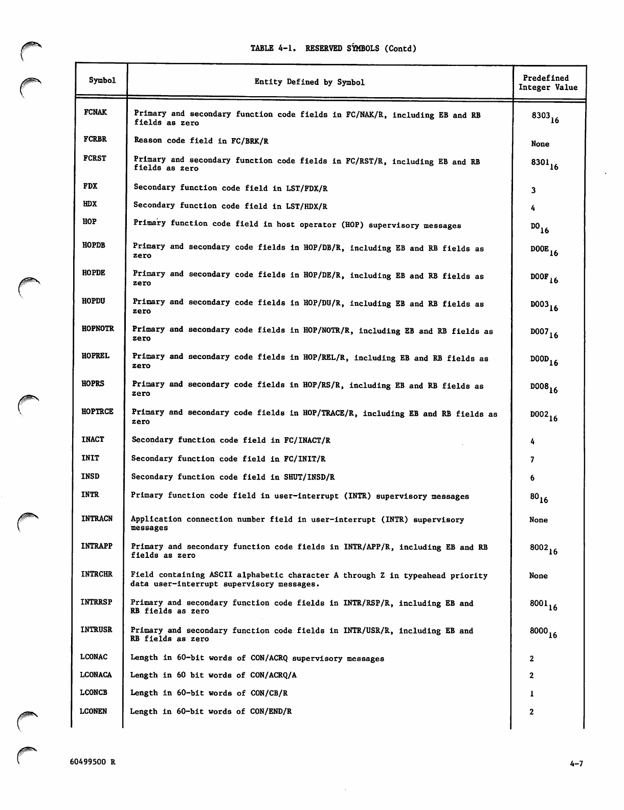
TABLE 4-1. RESERVED SYMBOLS (Contd)
Symbol
FCNAK
FCRBR
FCRST
FDX
HDX
HOP
HOPDB
HOPDE
HOPDU
HOPNOTR
HOPREL
HOPRS
HOPTRCE
INACT
INIT
INSD
INTR
INTRACN
INTRAPP
INTRCHR
INTRRSP
INTRUSR
LCONAC
LCONACA
LCONCB
LCONEN
Entity Defined by Symbol
Primary and secondary function code fields in FC/NAK/R, including EB and RB
fields as zero
Reason code field in FC/BRK/R
Primary and secondary function code fields in FC/RST/R, including EB and RB
fields as zero
Secondary function code field in LST/FDX/R
Secondary function code field in LST/HDX/R
Primary function code field in host operator (HOP) supervisory messages
Primary and secondary code fields in HOP/DB/R, including EB and RB fields as
zero
Primary and secondary code fields in HOP/DE/R, including EB and RB fields as
zero
Primary and secondary code fields in HOP/DU/R, including EB and RB fields as
zero
Primary and secondary code fields in HOP/NOTR/R, including EB and RB fields as
zero
Primary and secondary code fields in HOP/REL/R, including EB and RB fields as
zero
Primary and secondary code fields in HOP/RS/R, including EB and RB fields as
zero
Primary and secondary code fields in HOP/TRACE/R, including EB and RB fields as
zero
Secondary function code field in FC/INACT/R
Secondary function code field in FC/INIT/R
Secondary function code field in SHUT/INSD/R
Primary function code field in user-interrupt (INTR) supervisory messages
Application connection number field in user-interrupt (INTR) supervisory
messages
Primary and secondary function code fields in INTR/APP/R, including EB and RB
fields as zero
Field containing ASCII alphabetic character A through Z in typeahead priority
data user-interrupt supervisory messages.
Primary and secondary function code fields in INTR/RSP/R, including EB and
RB fields as zero
Primary and secondary function code fields in INTR/USR/R, including EB and
RB fields as zero
Length in 60-bit words of CON/ACRQ supervisory messages
Length in 60 bit words of CON/ACRQ/A
Length In 60-bit words of CON/CB/R
Length in 60-bit words of CON/END/R
Predefined
Integer Value
8303
None
8301
3
4
D016
D00E
D00F
D003
D007
D00D
D008
D002
4
7
6
8016
None
16
16
16
16
16
16
16
16
16
8002
None
8001
8000
2
2
1
2
16
16
16
60499500 R 4-7
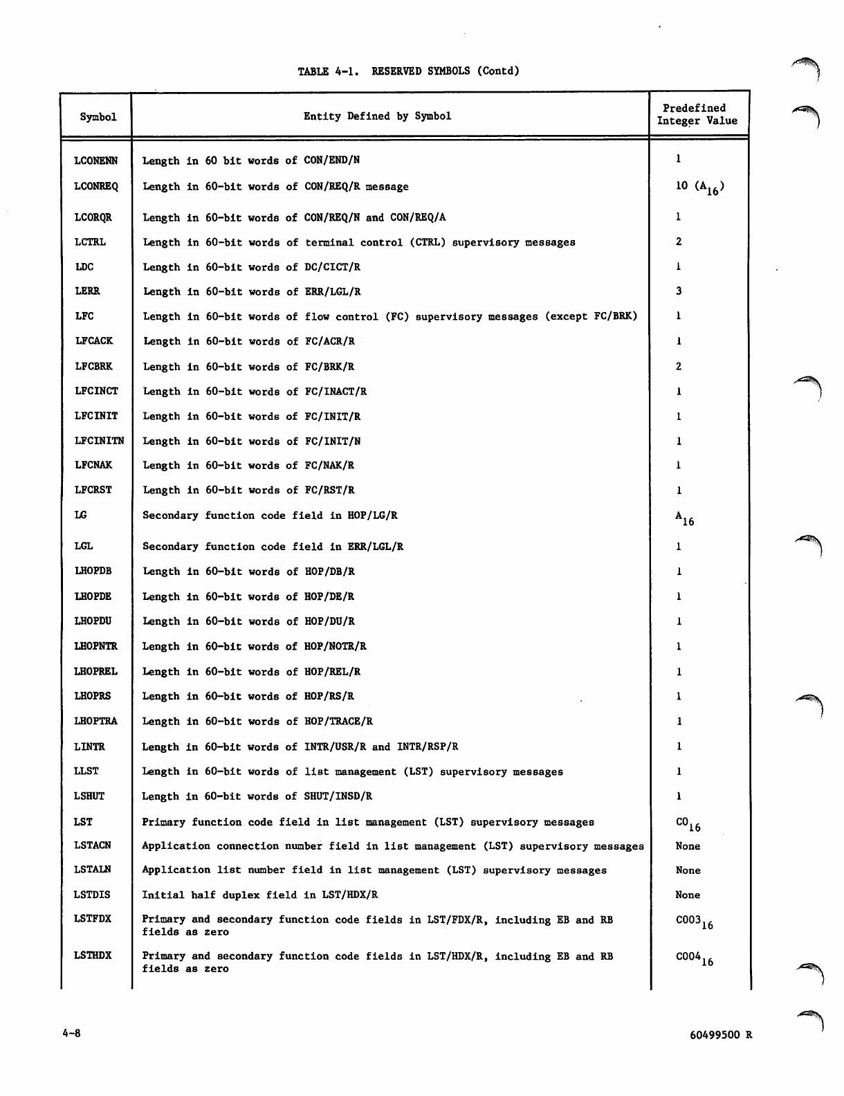
TABLE 4-1. RESERVED SYMBOLS (Contd)
Symbol Entity Defined by Symbol
Predefined
Integer Value
LCONENN Length in 60 bit words of CON/END/N
LCONREQ Length in 60-bit words of CON/REQ/R message 10 (A16)
LCORQR Length in 60-bit words of CON/REQ/N and CON/REQ/A
LCTRL Length in 60-bit words of terminal control (CTRL) supervisory messages
LDC Length in 60-bit words of DC/CICT/R
LERR Length in 60-bit words of ERR/LGL/R
LFC Length in 60-bit words of flow control (FC) supervisory messages (except FC/BRK)
LFCACK Length in 60-bit words of FC/ACR/R
LFCBRK Length in 60-bit words of FC/BRK/R
LFCINCT Length in 60-bit words of FC/INACT/R
LFCINIT Length in 60-bit words of FC/INIT/R
LFCINITN Length in 60-bit words of FC/INIT/N
LFCNAK Length in 60-bit words of FC/NAK/R
LFCRST Length in 60-bit words of FC/RST/R
LG Secondary function code field in HOP/LG/R A16
LGL Secondary function code field in ERR/LGL/R
LHOPDB Length in 60-bit words of HOP/DB/R
LHOPDE Length in 60-bit words of HOP/DE/R
LHOPDU Length in 60-bit words of HOP/DU/R
LHOPNTR Length in 60-bit words of HOP/NOTR/R
LHOPREL Length in 60-bit words of HOP/REL/R
LHOPRS Length in 60-bit words of HOP/RS/R
LHOPTRA Length in 60-bit words of HOP/TRACE/R
LINTR Length in 60-bit words of INTR/USR/R and INTR/RSP/R
LLST Length in 60-bit words of list management (LST) supervisory messages
LSHUT Length in 60-bit words of SHUT/INSD/R
LST Primary function code field in list management (LST) supervisory messages C016
LSTACN Application connection number field in list management (LST) supervisory messages None
LSTALN Application list number field in list management (LST) supervisory messages None
LSTDIS Initial half duplex field in LST/HDX/R None
LSTFDX Primary and secondary function code fields in LST/FDX/R, including EB and RB
fields as zero C00316
LSTHDX Primary and secondary function code fields in LST/HDX/R, including EB and RB
fields as zero C00416
4-8 60499500 R
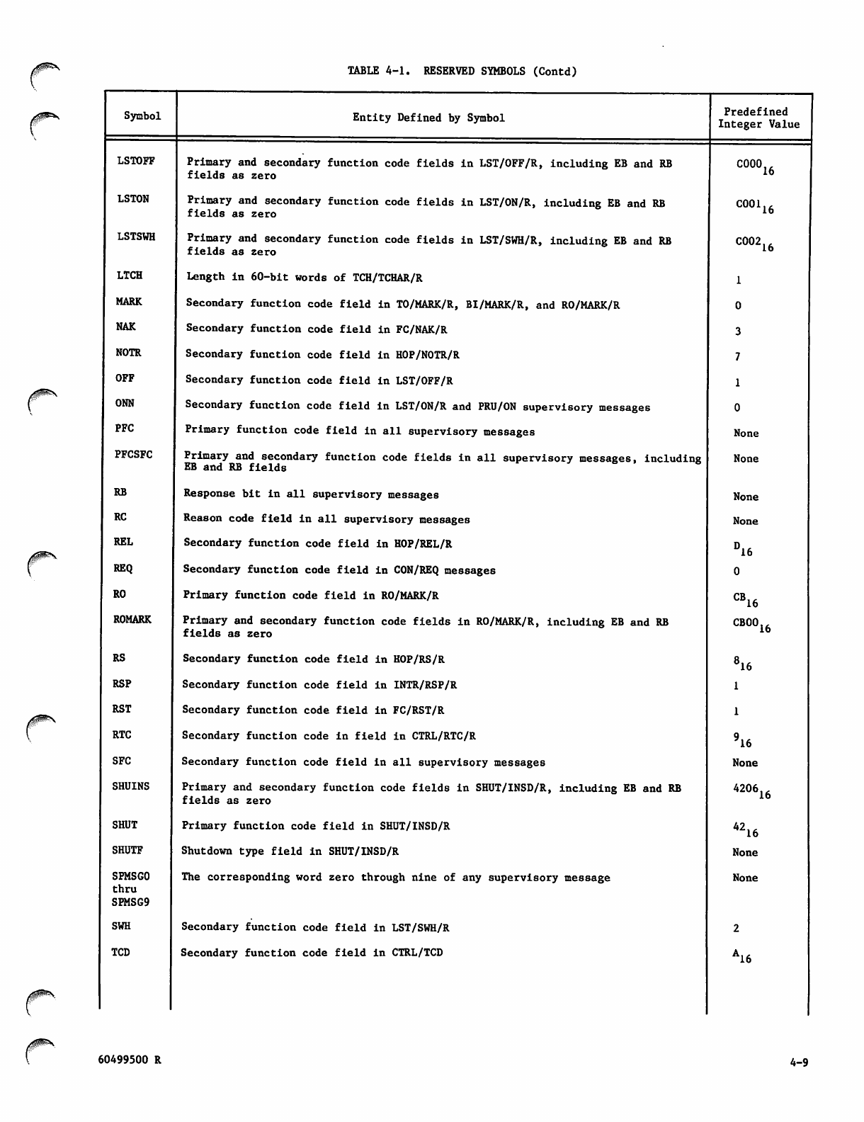
TABLE 4-1. RESERVED SYMBOLS (Contd)
Symbol
LSTOFF
LSTON
LSTSWH
LTCH
MARK
NAK
NOTR
OFF
ONN
PFC
PFCSFC
RB
RC
REL
REQ
RO
ROMARK
RS
RSP
RST
RTC
SFC
SHUINS
SHUT
SHUTF
SFMSGO
thru
SPMSG9
SWH
TCD
Entity Defined by Symbol
Primary and secondary function code fields in LST/OFF/R, including EB and RB
fields as zero
Primary and secondary function code fields in LST/ON/R, including EB and RB
fields as zero
Primary and secondary function code fields in LST/SWH/R, including EB and RB
fields as zero
Length in 60-bit words of TCH/TCHAR/R
Secondary function code field in TO/MARK/R, BI/MARK/R, and RO/MARK/R
Secondary function code field in FC/NAK/R
Secondary function code field in HOP/NOTR/R
Secondary function code field in LST/OFF/R
Secondary function code field in LST/ON/R and PRU/ON supervisory messages
Primary function code field in all supervisory messages
Primary and secondary function code fields in all supervisory messages, including
EB and RB fields
Response bit in all supervisory messages
Reason code field in all supervisory messages
Secondary function code field in HOP/REL/R
Secondary function code field in CON/REQ messages
Primary function code field in RO/MARK/R
Primary and secondary function code fields in RO/MARK/R, including EB and RB
fields as zero
Secondary function code field in HOP/RS/R
Secondary function code field in INTR/RSP/R
Secondary function code field in FC/RST/R
Secondary function code in field in CTRL/RTC/R
Secondary function code field in all supervisory messages
Primary and secondary function code fields in SHUT/INSD/R, including EB and RB
fields as zero
Primary function code field in SHUT/INSD/R
Shutdown type field in SHUT/INSD/R
The corresponding word zero through nine of any supervisory message
Secondary function code field in LST/SWH/R
Secondary function code field in CTRL/TCD
Predefined
Integer Value
C000
C001
C002
1
0
3
7
1
0
None
None
None
None
DJ
0
CB.
16
16
16
16
16
CBOO
816
1
1
916
None
4206
4216
None
None
2
A16
16
16
60499500 R 4-9
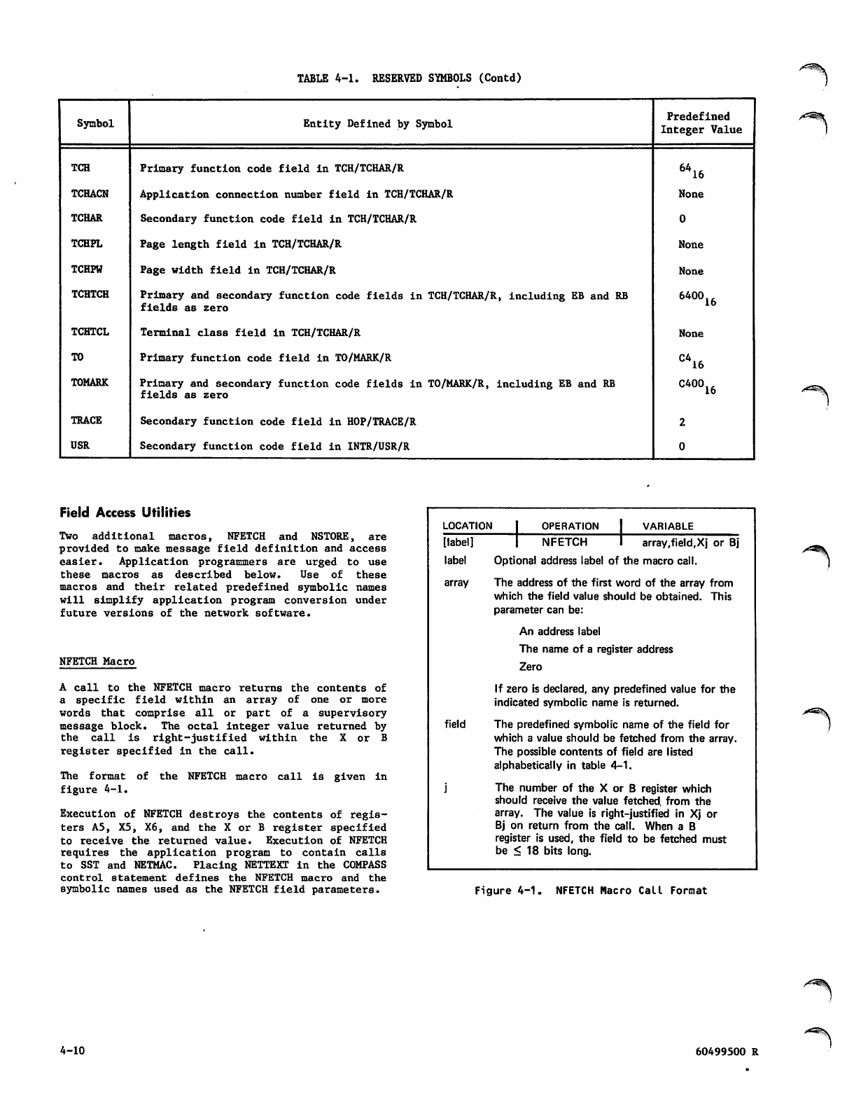
TABLE 4-1. RESERVED SYMBOLS (Contd)
Symbol Entity Defined by Symbol Predefined
Integer Value
TCH
TCHACN
TCHAR
TCHPL
TCHPW
TCHTCH
TCHTCL
TO
TOMARK
TRACE
USR
Primary function code field in TCH/TCHAR/R
Application connection number field in TCH/TCHAR/R
Secondary function code field in TCH/TCHAR/R
Page length field in TCH/TCHAR/R
Page width field in TCH/TCHAR/R
Primary and secondary function code fields in TCH/TCHAR/R, including EB and RB
fields as zero
Terminal class field in TCH/TCHAR/R
Primary function code field in TO/MARK/R
Primary and secondary function code fields in TO/MARK/R, including EB and RB
fields as zero
Secondary function code field in HOP/TRACE/R
Secondary function code field in INTR/USR/R
M16
None
0
None
None
640016
None
C416
C40016
2
0
Field Access Utilities
Two additional macros, NFETCH and NSTORE, are
provided to make message field definition and access
easier. Application programmers are urged to use
these macros as described below. Use of these
macros and their related predefined symbolic names
will simplify application program conversion under
future versions of the network software.
NFETCH Macro
A call to the NFETCH macro returns the contents of
a specific field within an array of one or more
words that comprise all or part of a supervisory
message block. The octal integer value returned by
t h e c a l l i s r i g h t - j u s t i fi e d w i t h i n t h e X o r B
register specified in the call.
The format of the NFETCH macro call is given in
figure 4-1.
Execution of NFETCH destroys the contents of regis
ters A5, X5, X6, and the X or B register specified
to receive the returned value. Execution of NFETCH
requires the application program to contain calls
to SST and NETMAC. Placing NETTEXT in the COMPASS
control statement defines the NFETCH macro and the
symbolic names used as the NFETCH field parameters.
LOCATION OPERATION VARIABLE
[ l a b e l ] | N F E T C H I a r r a y , fi e l d , X j o r B j
label Optional address label of the macro call.
array The address of the first word of the array from
which the field value should be obtained. This
parameter can be:
An address label
The name of a register address
Zero
If zero is declared, any predefined value for the
indicated symbolic name is returned.
field The predefined symbolic name of the field for
which a value should be fetched from the array.
The possible contents of field are listed
alphabetically in table 4-1.
j The number of the X or B register which
should receive the value fetched, from the
array. The value is right-justified in Xj or
Bj on return from the call. When a B
register is used, the field to be fetched must
be < 18 bits long.
S^K
Figure 4-1. NFETCH Macro Call Format
4-10 60499500 R
•^^Sv
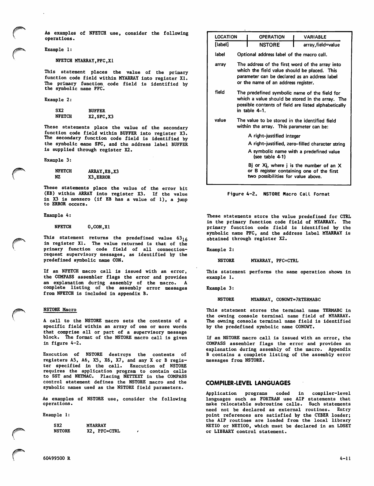
^^s As examples of NFETCH use, consider the following
operations.
Example 1:
NFETCH MYARRAY,PFC,X1
This statement places the value of the primary
function code field within MYARRAY into register XI.
The primary function code field is identified by
the symbolic name PFC.
Example 2:
SX2 BUFFER
NFETCH X2,SFC,X3
These statements place the value of the secondary
function code field within BUFFER into register X3.
The secondary function code field is identified by
the symbolic name SFC, and the address label BUFFER
is supplied through register X2.
Example 3:
NFETCH
NZ ARRAY,EB,X3
X3,ERROR
The se sta temen ts p l ace t he v alue of the e rror b it
(EB) within ARRAY into register X3. If the value
in X3 is nonzero (if EB has a value of 1), a jump
to ERROR occurs.
L O C AT I O N | O P E R AT I O N | VA R I A B L E
[label] 1 N S T O R E I a r r a y , fi e l d = v a l u e
label Optional address label of the macro call.
array The address of the first word of the array into
which the field value should be placed. This
parameter can be declared as an address label
or the name of an address register.
field The predefined symbolic name of the field for
which a value should be stored in the array. The
possible contents of field are listed alphabetically
in table 4-1.
value The value to be stored in the identified field
within the array. This parameter can be:
A right-justified integer
A right-justified, zero-filled character string
A symbolic name with a predefined value
(see table 4-1)
Bj or Xj, where j is the number of an X
or B register containing one of the first
two possibilities for value above.
Figure 4-2. NSTORE Macro Call Format
Example 4:
NFETCH 0,CON,XI
This statement returns the predefined value 63 ^g
in r e g i ste r X I . T h e v alue r e t u rne d i s t h at of t h e
primary function code field of all connection-
request supervisory messages, as identified by the
predefined symbolic name CON.
If an NFETCH macro call is issued with an error,
the COMPASS assembler flags the error and provides
an explanation during assembly of the macro. A
complete listing of the assembly error messages
from NFETCH is included in appendix B.
NSTORE Macro
A call to the NSTORE macro sets the contents of a
specific field within an array of one or more words
that comprise all or part of a supervisory message
block. The format of the NSTORE macro call is given
in figure 4-2.
Execution of NSTORE destroys the contents of
registers A5, A6, X5, X6, X7, and any X or B regis
ter specified in the call. Execution of NSTORE
requires the application program to contain calls
to SST and NETMAC. Placing NETTEXT in the COMPASS
control statement defines the NSTORE macro and the
symbolic names used as the NSTORE field parameters.
As examples of NSTORE use, consider the following
operations.
Example 1:
SX2
NSTORE
These statements store the value predefined for CTRL
in the primary function code field of MYARRAY. The
primary function code field is identified by the
symbolic name PFC, and the address label MYARRAY is
obtained through register X2.
Example 2:
NSTORE MYARRAY, PFC=CTRL
This statement performs the same operation shown in
example 1.
Example 3:
NSTORE MYARRAY, CONOWT=7RTERMABC
MYARRAY
X2, PFC=CTRL
This statement stores the terminal name TERMABC in
the owning console terminal name field of MYARRAY.
The owning console terminal name field is identified
by the predefined symbolic name CONOWT.
If an NSTORE macro call is issued with an error, the
COMPASS assembler flags the error and provides an
explanation during assembly of the macro. Appendix
B contains a complete listing of the assembly error
messages from NSTORE.
COMPILER-LEVEL LANGUAGES
Application programs coded in compiler-level
languages such as FORTRAN use AIP statements that
make relocatable subroutine calls. Such statements
need not be declared as external routines. Entry
point references are satisfied by the CYBER loader;
the AIP routin e s are l o a ded f r o m the l o cal libr a ry
NETIO or NETIOD, which must be declared in an LDSET
or LIBRARY control statement.
60499500 R 4-11
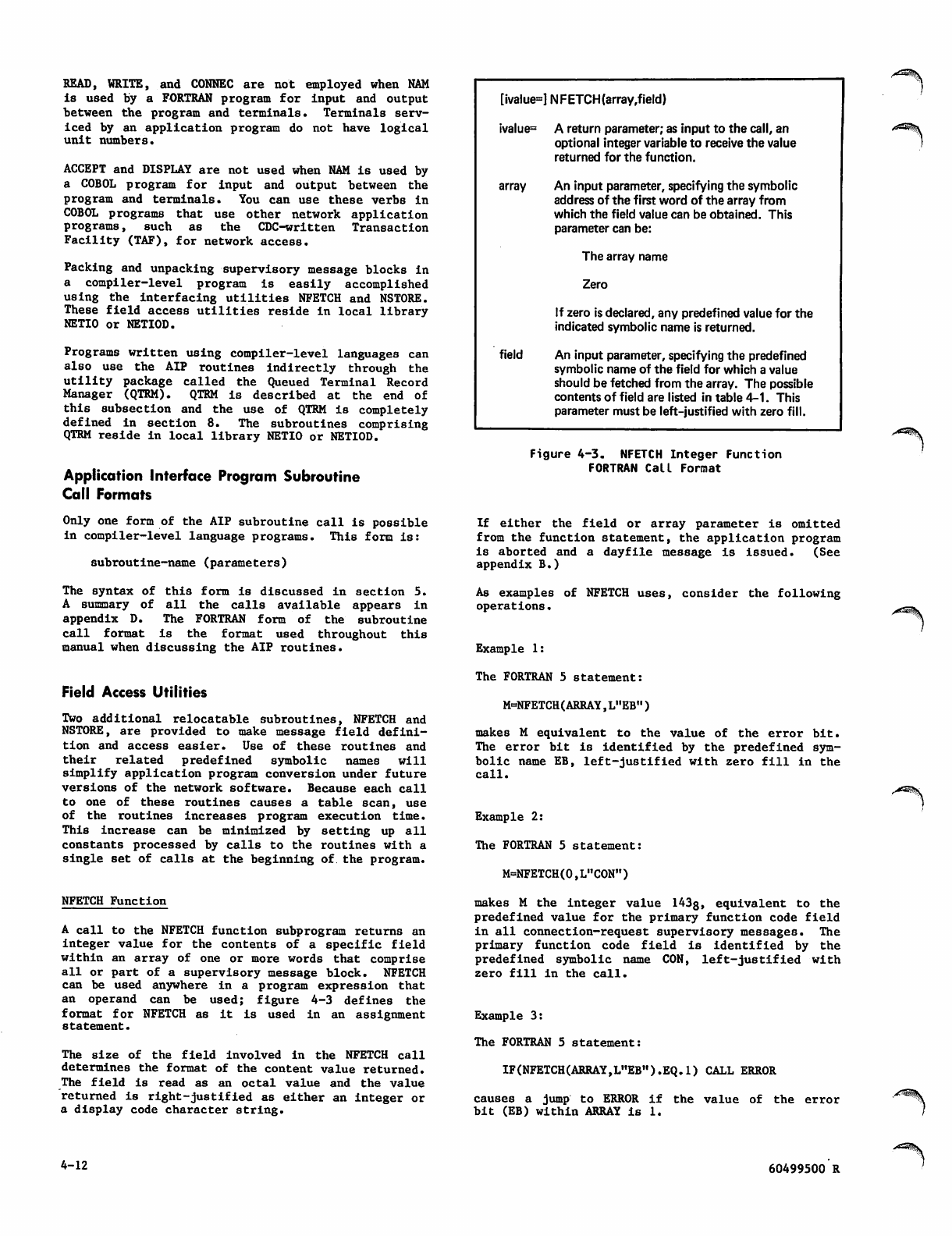
READ, WRITE, and CONNEC are not employed when NAM
is used by a FORTRAN program for input and output
between the program and terminals. Terminals serv
iced by an application program do not have logical
unit numbers.
ACCEPT and DISPLAY are not used when NAM is used by
a COBOL program for input and output between the
program and terminals. You can use these verbs in
COBOL programs that use other network application
programs, such as the CDC-written Transaction
Facility (TAF), for network access.
Packing and unpacking supervisory message blocks in
a compiler-level program is easily accomplished
using the interfacing utilities NFETCH and NSTORE.
These field access utilities reside in local library
NETIO or NETIOD.
Programs written using compiler-level languages can
a l s o u s e th e A I P r o u t i n e s in d i r e c t l y t h r o u g h t h e
utility package called the Queued Terminal Record
Manager (QTRM). QTRM is described at the end of
this subsection and the use of QTRM is completely
defined in section 8. The subroutines comprising
QTRM reside in local library NETIO or NETIOD.
Application Interface Program Subroutine
Call Formats
Only one form of the AIP subroutine call is possible
in compiler-level language programs. This form is:
subroutine-name (parameters)
The syntax of this form is discussed in section 5.
A s u m m a r y o f al l t h e c a l l s a v a i l a b l e a p p e a r s i n
appendix D. The FORTRAN form of the subroutine
call format is the format used throughout this
manual when discussing the AIP routines.
Field Access Utilities
Two additional relocatable subroutines, NFETCH and
NSTORE, are provided to make message field defini
tion and access easier. Use of these routines and
their related predefined symbolic names will
simplify application program conversion under future
versions of the network software. Because each call
to one of these routines causes a table scan, use
of the routines increases program execution time.
This increase can be minimized by setting up all
constants processed by calls to the routines with a
single set of calls at the beginning of. the program.
NFETCH Function
A call to the NFETCH function subprogram returns an
integer value for the contents of a specific field
within an array of one or more words that comprise
all or part of a supervisory message block. NFETCH
can be used anywhere in a program expression that
an operand can be used; figure 4-3 defines the
format for NFETCH as it is used in an assignment
statement.
The size of the field involved in the NFETCH call
determines the format of the content value returned.
The field is read as an octal value and the value
returned is right-justified as either an integer or
a display code character string.
[ivalue=] NFETCH(array,field)
ivalue= A return parameter; as input to the call, an
optional integer variable to receive the value
returned for the function.
array An input parameter, specifying the symbolic
address of the first word of the array from
which the field value can be obtained. This
parameter can be:
The array name
Zero
If zero is declared, any predefined value for the
indicated symbolic name is returned.
field An input parameter, specifying the predefined
symbolic name of the field for which a value
should be fetched from the array. The possible
contents of field are listed in table 4-1. This
parameter must be left-justified with zero fill.
Figure 4-3. NFETCH Integer Function
FORTRAN Call Format
If either the field or array parameter is omitted
from the function statement, the application program
is aborted and a dayfile message is issued. (See
appendix B.)
As examples of NFETCH uses, consider the following
operations.
Example 1:
The FORTRAN 5 statement:
M=NFETCH(ARRAY,L"EB")
makes M equivalent to the value of the error bit.
The error bit is identified by the predefined sym
bolic name EB, left-justified with zero fill in the
call.
Example 2:
The FORTRAN 5 statement:
M=NFETCH(0,L"CON")
makes M the integer value 143g, equivalent to the
predefined value for the primary function code field
in all connection-request supervisory messages. The
primary function code field is identified by the
p r e de fi n ed s y m bo l i c n a m e C ON , l ef t - ju s t ifie d w it h
zero fill in the call.
Example 3:
The FORTRAN 5 statement:
IF(NFETCH(ARRAY,L"EB").EQ.l) CALL ERROR
causes a jump to ERROR if the value of the error
bit (EB) within ARRAY is 1.
4-12 60499500 R
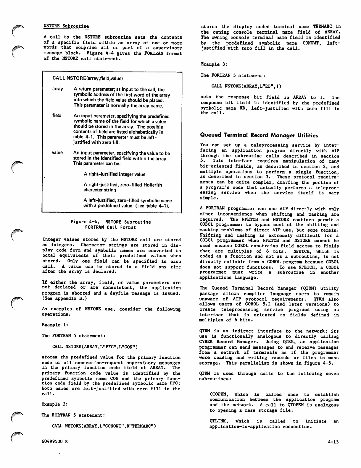
NSTORE Subroutine
A call to the NSTORE subroutine sets the contents
of a specific field within an array of one or more
words that comprise all or part of a supervisory
message block. Figure 4-4 gives the FORTRAN format
of the NSTORE call statement.
0^*s
CALL NSTORE(array,field,value)
array A return parameter; as input to the call, the
symbolic address of the first word of the array
into which the field value should be placed.
This parameter is normally the array name.
field An input parameter, specifying the predefined
symbolic name of the field for which a value
should be stored in the array. The possible
contents of field are listed alphabetically in
table 4-1. This parameter must be left-
justified with zero fill.
value An input parameter, specifying the value to be
stored in the identified field within the array.
This parameter can be:
A right-justified integer value
A right-justified, zero-filled Hollerith
character string
A left-justified, zero-filled symbolic name
with a predefined value (see table 4-1).
r
Figure 4-4. NSTORE Subroutine
FORTRAN Call Format
Integer values stored by the NSTORE call are stored
as integers. Character strings are stored in dis
play code form and symbolic names are converted to
octal equivalents of their predefined values when
stored. Only one field can be specified in each
c a l l . A v a l u e c a n b e s t o r e d i n a fi e l d a n y t i m e
after the array is declared.
If either the array, field, or value parameters are
not declared or are nonexistent, the application
program is aborted and a dayfile message is issued.
(See appendix B.)
As examples of NSTORE use, consider the following
operations.
Example 1:
The FORTRAN 5 statement:
CALL NSTORE(ARRAY,L,,PFC,,tL,,CON")
stores the predefined value for the primary function
code of all connection-request supervisory messages
in the p r i m a r y f u n c t ion code field o f ARRAY. The
primary function code value is identified by the
predefined symbolic name CON and the primary func
tion code field by the predefined symbolic name PFC;
both names are left-justified with zero fill in the
call.
Example 2:
The FORTRAN 5 statement:
CALL NSTORE(ARRAY,L"C0N0WT",R"TERMABC")
stores the display coded terminal name TERMABC in
the owning console terminal name field of ARRAY.
The owning console terminal name field is identified
by the predefined symbolic name CONOWT, left-
justified with zero fill in the call.
Example 3:
The FORTRAN 5 statement:
CALL NSTORE(ARRAY,L"RB",1)
sets the response bit field in ARRAY to 1. The
response bit field is identified by the predefined
symbolic name RB, left-justified with zero fill in
the call.
Queued Terminal Record Manager Utilities
You can set up a teleprocessing service by inter
facing an application program directly with AIP
through the subroutine calls described in section
5. This interface requires manipulation of many
bit-oriented fields, as described in section 2, and
multiple operations to perform a single function,
as described in section 3. These protocol require
ments can be quite complex, dwarfing the portion of
a program's code that actually performs a teleproc
essing service when the service itself is very
simple.
A FORTRAN programmer can use AIP directly with only
minor inconvenience when shifting and masking are
required. The NFETCH and NSTORE routines permit a
COBOL programmer to bypass most of the shifting and
masking problems of direct AIP use, but some remain.
S h i f t i n g a n d m a s k i n g i s e x t r e m e l y d i f fi c u l t f o r a
COBOL programmer when NFETCH and NSTORE cannot be
used because COBOL constrains field access to fields
that are multiples of 6 bits. NFETCH, which is
coded as a function and not as a subroutine, is not
directly callable from a COBOL program because COBOL
does not support functions. To use NFETCH, a COBOL
programmer must write a subroutine in another
applications language.
The Queued Terminal Record Manager (QTRM) utility
package allows compiler language users to remain
unaware of AIP protocol requirements. QTRM also
allows users of COBOL 5.2 (and later versions) to
create teleprocessing service programs using an
interface that is oriented to fields defined in
mu l t i p l es o f 6 b i ts.
QTRM is an indirect interface to the network; its
use is functionally analogous to directly calling
CYBER Record Manager. Using QTRM, an application
programmer can send messages to and receive messages
from a n e t work of t e r m inals as i f t h e programme r
were reading and writing records or files in mass
storage. This parallelism is shown in figure 4-5.
QTRM is used through calls to the following seven
subroutines:
QTOPEN, which is called once to establish
communication between the application program
and the network. A call to QTOPEN is analogous
to opening a mass storage file.
Q T L I N K , w h i c h i s c a l l e d t o i n i t i a t e a n
application-to-application connection.
60499500 R 4-13
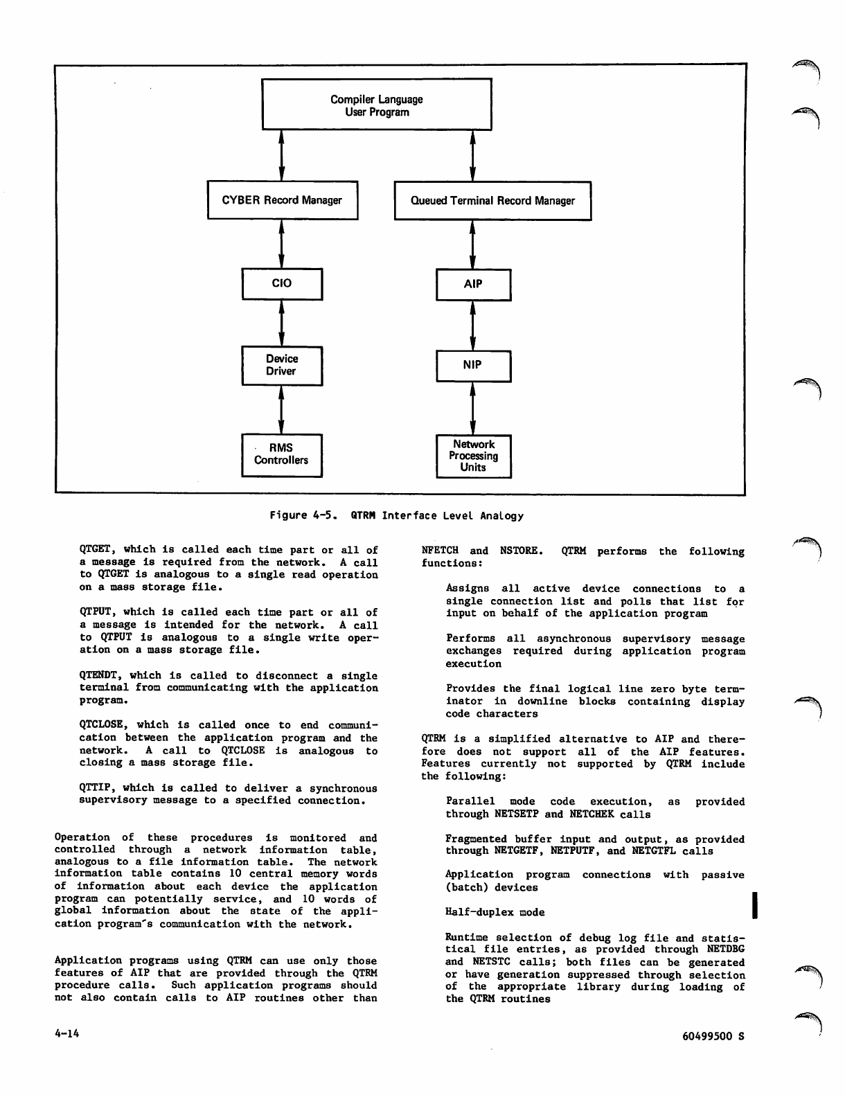
Compiler Language
User Program
CYBER Record Manager Queued Terminal Record Manager
ji
CIO AIP
ji
1
Device
Driver NIP
i
1
iii
RMS
Controllers
Network
Processing
Units
Figure 4-5. QTRM Interface Level Analogy
QTGET, which is called each time part or all of
a message is required from the network. A call
to QTGET is analogous to a single read operation
on a mass storage file.
QTPUT, which is called each time part or all of
a message i s in tende d for the n etwor k. A call
to QTPUT is analogous to a single write oper
ation on a mass storage file.
QTENDT, which is called to disconnect a single
terminal from communicating with the application
program.
QTCLOSE, which is called once to end communi
cation between the application program and the
network. A call to QTCLOSE is analogous to
closing a mass storage file.
QTTIP, which is called to deliver a synchronous
supervisory message to a specified connection.
O p e r a t i o n o f t h e s e pr o c e d u r e s i s mo n i t o r e d a n d
controlled through a network information table,
analogous to a file information table. The network
information table contains 10 central memory words
of information about each device the application
program can potentially service, and 10 words of
global information about the state of the appli
cation program's communication with the network.
Application programs using QTRM can use only those
features of AIP that are provided through the QTRM
procedure calls. Such application programs should
not also contain calls to AIP routines other than
NFETCH and NSTORE. QTRM performs the following
functions:
Assigns all active device connections to a
single connection list and polls that list for
input on behalf of the application program
Performs all asynchronous supervisory message
exchanges required during application program
execution
Provides the final logical line zero byte term
inator in downline blocks containing display
code characters
QTRM is a simplified alternative to AIP and there
fore does not support all of the AIP features.
Features currently not supported by QTRM include
the following:
Parallel mode code execution, as provided
through NETSETP and NETCHEK calls
Fragmented buffer input and output, as provided
through NETGETF, NETPUTF, and NETGTFL calls
Application program connections with passive
(batch) devices
Half-duplex mode
Runtime selection of debug log file and statis
tical file entries, as provided through NETDBG
and NETSTC calls; both files can be generated
or have generation suppressed through selection
of the appropriate library during loading of
the QTRM routines
4-14 60499500 S
j0^\
Manipulation of application connection lists,
or direct polling of any list as provided
through NETGETL and NETGTFL calls
Use of different application character types
for input on the same connection, or on differ
ent connections, or change of the application
character type used for input during the time
the program is connected to the network
Notification of inactive connections
S e l e c t i v e p o l l i n g o f i n p u t f r o m a s p e c i fi c
connection, as provided through NETGET and
NETGETF calls
Transparent mode input
Disposition of the debug log file during program
execution, as provided through the NETREL and
NETSETF calls; postprocessing disposition of
the file is required
Transmission of messages to the debug log file,
as provided through NETLOG calls
Exchange package and central memory field length
dumps, as provided through NETDMB calls
Transmission of messages to the statistical log
file, as provided through NETLGS calls
Application supplied OUTCALL parameters for
application-to-application connections sending
or receiving user data during the establishment
of application-to-application connections
Sending a break (FC/BRK) or INTR/APP message
Qualified data as described in section 2
Logical identifiers (LIO's) in the establish
ment of application-to-application connections
Section 8 contains a complete description of the
QTRM procedure calls and a sample program illus
trating QTRM use by a COBOL programmer. QTRM
procedures are not discussed elsewhere because QTRM
use precludes direct use of the AIP routines docu
mented by the remainder of this manual.
INTERNAL INTERFACES
The information in the remainder of this section is
not needed to create a Network Access Method appli
cation program. This information is provided as
background for application programmers using the
parallel mode processing feature of NAM, programmers
with a need for understanding communication among
the components of the network software, and pro
grammers needing to interpret a load map.
APPLICATION INTERFACE PROGRAM
AND NETWORK INTERFACE PROGRAM
COMMUNICATION
One copy of the Network Interface Program resides
at a control point and communicates with separate
copies of the Application Interface Program at each
control point containing an application program.
Communication between NIP and each copy of AIP
occurs through system control point calls initiated
by AIP. The mechanism for this communication is a
fixed-length buffer of status bits, pointers, and
data that is called a worklist.
Worklist Processing
When an application program requests connection
with the network, its copy of AIP establishes a
long-term connection with NIP. The long-term con
nection exists until the program requests discon
nection from the network, or until NIP is informed
of the program's failure or termination by the
op e r a t ing sy s t e m . W h ile th e l o n g-te r m c o n necti o n
exists, an additional short-term connection occurs
whenever AIP initiates a transfer of worklists be
tween itself and NIP. The short-term connection
exists until NIP issues a system control point call
to e n d it.
The requests made by an application program to AIP
are either satisfied by AIP directly or collected
into the worklist contained within the AIP portion
o f t h e a p p l i c a t i o n p r o g r a m ' s fi e l d l e n g t h . A I P
places entries in this worklist until one of the
following occurs, then initiates the short-term
connection:
NETON or NETOFF is called by the application
program. (See section 5.)
The worklist is full.
Another entry cannot be made without causing
the worklist to overflow.
The application program calls a routine (NETGET,
NETGETL, NETGETF, or NETGTFL) that obtains in
put from the network's data structures, other
than AIP queues. (See section 5.)
NETCHEK is called.
The application program issues a nonforced
NE TWAIT c all to make itself available f or roll
out or any input, and no supervisory messages
or data are queued for it. (See section 5.)
The application program issues a forced NETWAIT
call.
The application program calls NETPUTF, unless
the total message text involved in the call is
small enough to fit in the worklist.
This worklist is used to queue outgoing supervisory
or data messages, and to request a supervisory or
incoming (upline) data message. A second buffer
acts as a queue for incoming supervisory messages.
W h e n A I P i n i t i a t e s t h e s h o r t - t e r m c o n n e c t i o n , i t
checks to see whether its supervisory message buffer
is full; if not, AIP appends a request for supervi
sory message input to the end of the worklist and
passes the worklist to NIP. The period during
worklist processing is the only time when NIP can
r e a d f r o m o r w r i t e i n t o t h e fi e l d l e n g t h o f A I P,
and then only when AIP initiates the action.
NIP processes the transferred worklist until all of
the entries are satisfied, then ends the short-term
connection. Worklist processing is suspended when:
The operating system rolls out the application
program.
60499500 S 4-15
NIP causes the application program to be rolled
out in response to the request of the program.
(See NETWAIT call, section 5.)
A worklist entry cannot be processed without
obtaining additional central memory, which is
not available.
Even if there are downline messages queued, no
worklist transfer occurs in these instances:
The application program calls a routine (NETGET,
NETGETF, NETGETL, or NETGTFL) to obtain asyn
chronous supervisory messages and AIP transfers
any queued messages to the application.
The application program issues a NETWAIT call
with a flag value of 0 and there are supervisory
messages or data available for the application.
Generally, an application program does not depend
on the status of worklist processing between its
corresponding AIP copy and NIP. Most programs can
adequately function when concerned only with text
area buffers and calls to AIP. However, the Net
work Access Method does provide a mechanism that
allows an application program to monitor worklist
processing and execute code dependent on that proc
essing. This mechanism is called parallel mode
operation.
Parallel Mode Operation
When an application program issues the call that
initiates the long-term connection, it identifies a
supervisory status word that is used by AIP as a
b u f f e r f o r s e v e r a l fl a g s . A m o n g t h e s u p e r v i s o r y
status word flags are worklist processing bits used
during parallel mode operations.
When an application program is not processing in
parallel mode (the normal, default condition), its
copy of AIP initiates the short-term connection
with a system control point call specifying that
r e c a l l i s i n e f f e c t . I n t h i s c a s e , t h e p r o g r a m ' s
copy of AIP does not regain control of the central
processor until all worklist entries are processed
by NIP and the short-term connection is ended.
Because the application program cannot regain the
central processor until its copy of AIP has regained
the central processor, the program cannot perform
any processing in the interim.
Parallel mode operation is usually beneficial only
when used on a dual CPU system, because NIP ordi
narily has a higher priority than any application
program and gains control of the central processor
after a call is made to it. NIP retains control
until it completes processing of the worklist
request.
Processing in parallel mode is analagous to making
| operating system calls without recall. An applica
tion program enters parallel mode by issuing a call
to the AIP routine NETSETP. While in parallel mode,
anytime AIP initiates the short-term connection, it
does so without specifying recall. The application
program's copy of AIP reacquires control of a cen
tral processor as soon as the operating system's
scheduling algorithm permits, and AIP returns con
trol to the calling point of the application program
proper. As long as the short-term connection
exists, the application program can continue proc
essing with the sole restriction that it cannot
issue calls to any AIP routines other than NETCHEK
or NETOFF.
Calls to NETCHEK cause AIP to indicate the current
status of worklist processing using a bit in the
supervisory status word. After each NETCHEK call,
the application program must check the supervisory
status word. As soon as the bit indicating com
pletion of worklist processing is set, the program
is free to issue any AIP call. Parallel mode proc
essing is ended by a second call to the AIP routine
NETSETP.
The worklist processing completion bit serves
several purposes in parallel mode operation. Calls
to NETCHEK cause this bit to be set when processing
of the previous request to AIP has been completed,
even when that request did not cause a worklist
entry or transfer. When a call to NETCHEK results
in the completion bit being set, the application
program can:
Safely reuse any header area and text area used
in its last AIP call
Assu m e t h a t a n y w o r klist transf e r i n v o l v e d i n
the previous AIP function request resulted in
the updating of the other bits in the super
visory status word
Wh e n a c a l l t o N E TCHEK d o e s n o t r e sult in t h e
completion bit being set, the application program
should issue additional NETCHEK calls before exe
cuting any code dependent on either condition.
Calls to NETOFF end parallel mode operation by end
ing both the long-term and short-term connections
simultaneously. NIP processes a worklist containing
a N ETOFF cal l as if the worklist w ere tra nsf err ed
while the application program was not processing in
parallel mode. Calls to NETCHEK are not necessary
to test completion of a NETOFF call.
OTHER SOFTWARE COMMUNICATION
A complete compiler or assembler listing for an
application program contains symbols and entry
points not discussed in this manual. These symbols
and entry points are used internally for interfacing
between NIP, AIP, and the operating system. Table
4-2 lists the names of internal procedure calls with
an outline of the function of each routine; these
calls should not be used directly by the application
program. In general, procedure names beginning with
the three characters NP$ are reserved for use by AIP
and should not be used by application programs.
Table 4-3 lists the tables and common blocks in
volved in the processing of an application program's
AIP statements.
The Communications Supervisor, Network Supervisor,
and Network Validation Facility interface with NAM
via the AIP procedure calls described in section 5.
These interfaces use special supervisory messages
not described in section 3. These special super
visory messages cannot be used in another NAM
application program.
NAM interfaces with the network processing unit
software through the Peripheral Interface Program,
which uses an internal block protocol not described
in section 2. These blocks are compiled or inter
preted by NIP.
y^lSy
",£3%
4-16 60499500 S
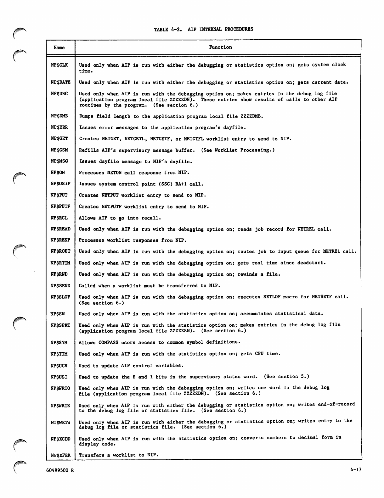
TABLE 4-2. AIP INTERNAL PROCEDURES
Name Function
NP$CLK
NP$DATE
NP$DBG
NP$DMB
NP$ERR
NP$GET
NP$GSM
NP$MSG
NP$ON
NP$OSIF
NP$PUT
NP$PUTF
NP$RCL
NP$READ
NP$RESP
NP$ROUT
NP$RTIM
NP$RWD
NP$SEND
NP$SLOF
NP$SN
NP$SPRT
NP$SYM
NP$TIM
NP$UCV
NP$USI
NP$WRTO
NP$WRTR
NT$WRTW
NP$XCDD
NP$XFER
Used only when AIP is run with either the debugging or statistics option on; gets system clock
time.
Used only when AIP is run with either the debugging or statistics option on; gets current date.
Used only when AIP is run with the debugging option on; makes entries in the debug log file
(application program local file ZZZZZDN). These entries show results of calls to other AIP
routines by the program. (See section 6.)
Dumps field length to the application program local file ZZZZDMB.
Issues error messages to the application program's dayfile.
Creates NETGET, NETGETL, NETGETF, or NETGTFL worklist entry to send to NIP.
Refills AIP's supervisory message buffer. (See Worklist Processing.)
Issues dayfile message to NIP's dayfile.
Processes NETON call response from NIP.
Issues system control point (SSC) RA+1 call.
Creates NETPUT worklist entry to send to NIP.
Creates NETPUTF worklist entry to send to NIP.
Allows AIP to go into recall.
Used only when AIP is run with the debugging option on; reads job record for NETREL call.
Processes worklist responses from NIP.
Used only when AIP is run with the debugging option on; routes job to input queue for NETREL call.
Used only when AIP is run with the debugging option on; gets real time since deadstart.
Used only when AIP is run with the debugging option on; rewinds a file.
Called when a worklist must be transferred to NIP.
Used only when AIP is run with the debugging option on; executes SETLOF macro for NETSETF call.
(See section 6.)
Used only when AIP is run with the statistics option on; accumulates statistical data.
Used only when AIP is run with the statistics option on; makes entries in the debug log file
(application program local file ZZZZZSN). (See section 6.)
Allows COMPASS users access to common symbol definitions.
Used only when AIP is run with the statistics option on; gets CPU time.
Used to update AIP control variables.
Used to update the S and I bits in the supervisory status word. (See section 5.)
Used only when AIP is run with the debugging option on; writes one word in the debug log
fil e (application pro gram lo cal file ZZZ ZZD N). (Se e section 6 .)
Used only when AIP is run with either the debugging or statistics option on; writes end-of-record
to the debug log file or statistics file. (See section 6.)
Used only when AIP is run with either the debugging or statistics option on; writes entry to the
debug log file or statistics file. (See section 6.)
Used only when AIP is run with the statistics option on; converts numbers to decimal form in
display code.
Transfers a worklist to NIP.
60499500 R 4-17
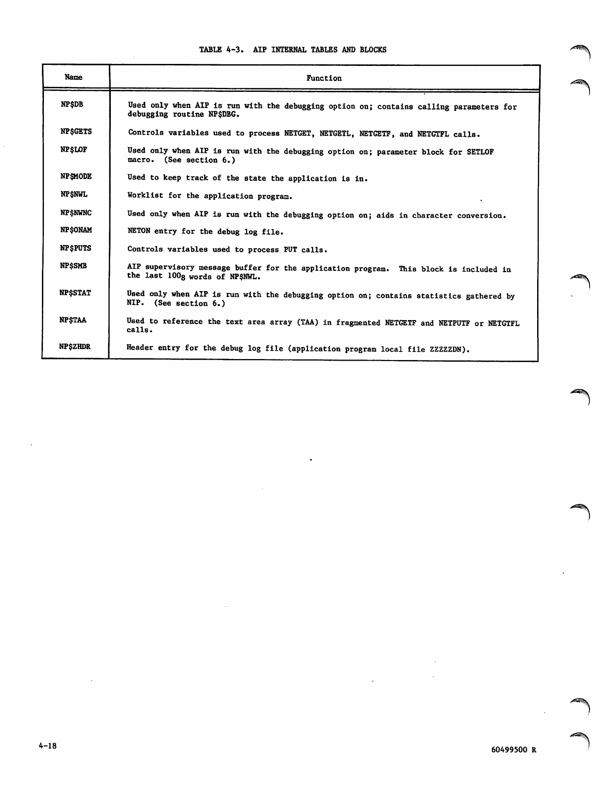
TABLE 4-3. AIP INTERNAL TABLES AND BLOCKS
Name
NP$DB
NP$GETS
NP$LOF
NP$MODE
NP$NWL
NP$NWNC
NP$ONAM
NP$PUTS
NP$SMB
NP$STAT
NP$TAA
NP$ZHDR
Function
Used only when AIP is run with the debugging option on; contains calling parameters for
debugging routine NP$DBG.
Controls variables used to process NETGET, NETGETL, NETGETF, and NETGTFL calls.
Used only when AIP Is run with the debugging option on; parameter block for SETLOF
macro. (See section 6.)
Used to keep track of the state the application is in.
Worklist for the application program.
Used only when AIP is run with the debugging option on; aids in character conversion.
NETON entry for the debug log file.
Controls variables used to process PUT calls.
AIP supervisory message buffer for the application program. This block is included in
the last 1008 words of NPSNWL.
Used only when AIP is run with the debugging option on; contains statistics gathered by
NIP. (See section 6.)
Used to reference the text area array (TAA) in fragmented NETGETF and NETPUTF or NETGTFL
c a l l s .
Header entry for the debug log file (application program local file ZZZZZDN).
4-18 60499500 R
APPLICATION INTERFACE PROGRAM CALL STATEMENTS
J0^\
This section describes the Application Interface
Program (AIP) statements used by a network appli
cation program to access the network, control
network processing, and transmit and receive the
messages described in sections 2 and 3.
SYNTAX
Application Interface Program statements are used
in COMPASS programs, or in programs written in
h i g h-l e v el l a n gu a g es s u c h as F O R T RAN . I n m os t
high-level languages, only positional parameters
can be used; AIP statements conform to this syntac
tical requirement and, therefore, do not permit the
use of keywords. The interpretation attached to a
given parameter is determined solely by its location
within the string of* parameters of each AIP state
ment. All input parameters must be supplied; there
are no defaults.
The FORTRAN positional form is used throughout this
section to present AIP statements. Coding the
statements when they are used in other languages
requires few modifications. For example, in the
form of a COMPASS macro call, a sample NETGETL
statement has the form:
[label] NETGETL aln, ha, ta, tlmax
This converts to the FORTRAN subroutine syntax,
which is:
CALL NETGETL (aln, ha, ta, tlmax)
Use of LIST a nd l abe l are discussed in s ect ion 4
where COMPASS interface requirements are given.
The FORTRAN subroutine syntax, in turn, converts to
the following COBOL syntax for the same statement:
ENTER FORTRAN-X NETGETL
USING aln, ha, ta, tlmax
The mnemonic variables identifying each parameter
are defined in the statement descriptions, along
with any coding constraints imposed on them. Commas
delimit parameters in all languages; the signifi
cance of blanks depends on the language used.
Unless otherwise specified, all values supplied for
parameters should be decimal integers.
General definitions of terms appearing in parameter
descriptions are given in the glossary. More
detailed definitions and parameter constraints that
depend on the programming language used are given
in section 4 under the heading of Language Inter
faces. Program structural considerations that
depend on command use are described in section 6
under the headings of Commands and Dependencies.
NETWORK ACCESS STATEMENTS
An application program uses two AIP statements to
begin and end access to the network's resources.
The NETON statement must be used before the program
can use any oth er AIP s tatement e xce pt N ETR EL,
NSTORE, NFETCH, NETSETF, NETCHEK, NETSETP, or
NETOFF. The NETOFF statement must be used after
all AIP f u n c tions are c o m p l e t e d to cause the AIP
portion of the application program to perform vital
housekeeping tasks; these tasks are associated with
debug log file, statistical file, and login proc
essing by the network software.
CONNECTING TO NETWORK (NETON)
The NETON statement
following functions:
( fi g u r e 5 - 1 ) p e r f o r m s t h e
Id e n t ifie s t h e a ppl i c a tio n p r o gra m t o t he ne t
work so that the Network Validation Facility
(NVF) can validate the right of the program to
access the network's resources
Causes AIP to establish communication with NIP
Identifies a word to be used for communication
from AIP to the program, outside of the super
visory message mechanism (figure 5-2)
Informs the network software of limitations on
the number of logical connections the program
can handle
Causes AIP to begin debug log file and statis
tical file compilation, if AIP contains code
permitting this (See section 6.)
An application program must successfully complete a
NETON call before it can use any AIP statement
other than NETOFF, NETCHEK, NETREL, NETSETF, or
NETSETP. If another AIP statement is used before a
NETON call is successfully completed, AIP aborts
the job and issues a message to the job's dayfile.
The incorrectly placed call has no other effect.
An application program's NETON statement is success
fully validated by the Network Validation Facility
when the program name contained in the NETON call
appears in the system common deck COMTNAP. If the
program is defined as a privileged application in
the local configuration file, it must meet the
requirements for such to be successfully validated.
(See section 6.)
If validation is not successful, the application
p r o g r a m i s a b o r t e d . I f v a l i d a t i o n i s s u c c e s s f u l ,
the program has access to the network as long as a
NETOFF statement is not issued and communication
with NIP continues.
60499500 R 5-1
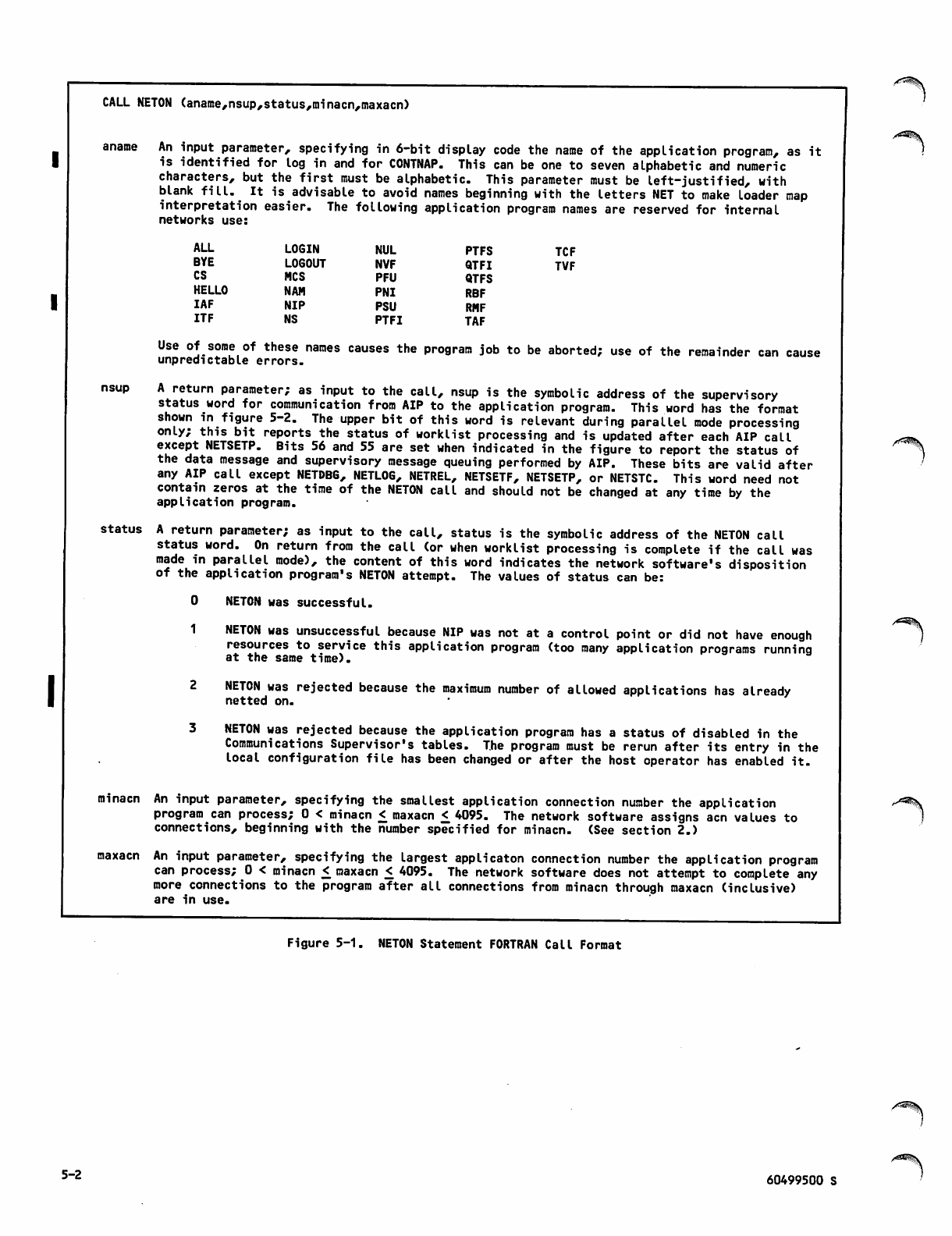
CALL NETON (aname,nsup,status,minacn,maxacn)
/^^^K
aname An input parameter, specifying in 6-bit display code the name of the application program, as it
is identified for log in and for CONTNAP. This can be one to seven alphabetic and numeric
characters, but the first must be alphabetic. This parameter must be left-justified, with
blank fill. It is advisable to avoid names beginning with the letters NET to make loader map
interpretation easier. The following application program names are reserved for internal
networks use:
ALL LOGIN NUL PTFS TCF
BYE LOGOUT NVF QTFI TVF
CS NCS PFU QTFS
HELLO NAM PNI RBF
IAF NIP PSU RMF
ITF NS PTFI TAF
nsup
status
Use of some of these names causes the program job to be aborted; use of the remainder can cause
unpredictable errors.
A return parameter; as input to the call, nsup is the symbolic address of the supervisory
status word for communication from AIP to the application program. This word has the format
shown in figure 5-2. The upper bit of this word is relevant during parallel mode processing
only; this bit reports the status of worklist processing and is updated after each AIP call
except NETSETP. Bits 56 and 55 are set when indicated in the figure to report the status of
the data message and supervisory message queuing performed by AIP. These bits are valid after
any AIP call except NETDBG, NETLOG, NETREL, NETSETF, NETSETP, or NETSTC. This word need not
contain zeros at the time of the NETON call and should not be changed at any time by the
application program.
A return parameter; as input to the call, status is the symbolic address of the NETON call
status word. On return from the call (or when worklist processing is complete if the call was
made in parallel mode), the content of this word indicates the network software's disposition
of the application program's NETON attempt. The values of status can be:
0 NETON was successful.
1 NETON was unsuccessful because NIP was not at a control point or did not have enough
resources to service this application program (too many application programs running
at the same time).
2 NETON was rejected because the maximum number of allowed applications has already
netted on.
3 NETON was rejected because the application program has a status of disabled in the
Communications Supervisor's tables. The program must be rerun after its entry in the
local configuration file has been changed or after the host operator has enabled it.
An input parameter, specifying the smallest application connection number the application
program can process; 0 < minacn < maxacn < 4095. The network software assigns acn values to
connections, beginning with the number specified for minacn. (See section 2.)
maxacn An input parameter, specifying the largest applicaton connection number the application program
can process; 0 < minacn £ maxacn < 4095. The network software does not attempt to complete any
more connections to the program after all connections from minacn through maxacn (inclusive)
are in use.
minacn
Figure 5-1. NETON Statement FORTRAN Call Format
5-2 60499500 S
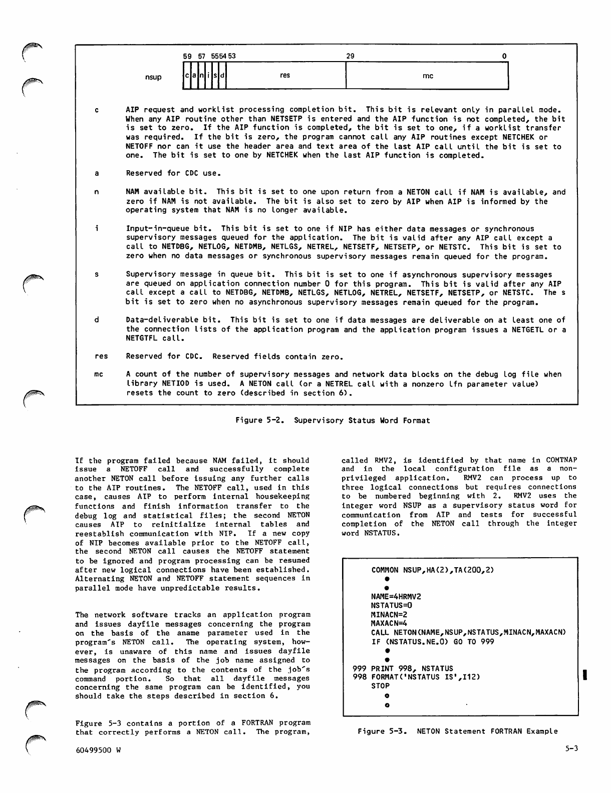
59 57 5554 53 29
c a n i s dres mc
nsup
c AIP request and worklist processing completion bit. This bit is relevant only in parallel mode.
When any AIP routine other than NETSETP is entered and the AIP function is not completed, the bit
is set to zero. If the AIP function is completed, the bit is set to one, if a worklist transfer
was required. If the bit is zero, the program cannot call any AIP routines except NETCHEK or
NETOFF nor can it use the header area and text area of the last AIP call until the bit is set to
one. The bit is set to one by NETCHEK when the last AIP function is completed.
a R e s e r v e d f o r C D C u s e .
n NAM available bit. This bit is set to one upon return from a NETON call if NAM is available, and
zero if NAM is not available. The bit is also set to zero by AIP when AIP is informed by the
operating system that NAM is no longer available.
i Input-in-queue bit. This bit is set to one if NIP has either data messages or synchronous
supervisory messages queued for the application. The bit is valid after any AIP call except a
call to NETDBG, NETLOG, NETDMB, NETLGS, NETREL, NETSETF, NETSETP, or NETSTC. This bit is set to
zero when no data messages or synchronous supervisory messages remain queued for the program.
s Supervisory message in queue bit. This bit is set to one if asynchronous supervisory messages
are queued on application connection number 0 for this program. This bit is valid after any AIP
call except a call to NETDBG, NETDMB, NETLGS, NETLOG, NETREL, NETSETF, NETSETP, or NETSTC. The s
bit is set to zero when no asynchronous supervisory messages remain queued for the program.
d Data-deliverable bit. This bit is set to one if data messages are deliverable on at least one of
the connection lists of the application program and the application program issues a NETGETL or a
NETGTFL call.
res Reserved for CDC. Reserved fields contain zero.
mc A count of the number of supervisory messages and network data blocks on the debug log file when
library NETIOD is used. A NETON call (or a NETREL call with a nonzero lfn parameter value)
resets the count to zero (described in section 6).
Figure 5-2. Supervisory Status Word Format
If the program failed because NAM failed, it should
issue a NETOFF call and successfully complete
another NETON call before issuing any further calls
to the AIP routines. The NETOFF call, used in this
case, causes AIP to perform internal housekeeping
functions and finish information transfer to the
debug log and statistical files; the second NETON
c a u s e s A I P t o r e i n i t i a l i z e i n t e r n a l t a b l e s a n d
reestablish communication with NIP. If a new copy
of NIP becomes available prior to the NETOFF call,
the second NETON call causes the NETOFF statement
to be ignored and program processing can be resumed
after new logical connections have been established.
Alternating NETON and NETOFF statement sequences in
parallel mode have unpredictable results.
The network software tracks an application program
and issues dayfile messages concerning the program
on the basis of the aname parameter used in the
program's NETON call. The operating system, how
ever, is unaware of this name and issues dayfile
messages on the basis of the job name assigned to
the program according to the contents of the job's
command portion. So that all dayfile messages
concerning the same program can be identified, you
should take the steps described in section 6.
Figure 5-3 contains a portion of a FORTRAN program
that correctly performs a NETON call. The program,
called RMV2, is identified by that name in COMTNAP
and in the local configuration file as a non-
privileged application. RMV2 can process up to
three logical connections but requires connections
to be n umbered beginni ng w ith 2. R MV2 uses the
integer word NSUP as a supervisory status word for
communication from AIP and tests for successful
completion of the NETON call through the integer
word NSTATUS.
COMMON NSUP,HA(2),TA(200,2)
•
NAME=4HRMV2
NSTATUS=0
MINACN=2
MAXACN=4
CALL NETON(NAME,NSUP,NSTATUS,MINACN,MAXACN)
IF (NSTATUS.NE.O) GO TO 999
999 PRINT 998, NSTATUS
998 FORMAT('NSTATUS IS',112)
STOP
o
o
Figure 5-3. NETON Statement FORTRAN Example
60499500 W 5-3
DISCONNECTING FROM NETWORK (NETOFF)
The NETOFF statement (figure 5-4) performs the
following functions:
Breaks AIP communication with NIP
Causes AIP to finish formatting and transferring
information for the debug log file and statis
tical file, if these files are being compiled
Clears AIP internal tables so that the program
can issue another NETON call, if necessary
NETWORK BLOCK INPUT/OUTPUT
STATEMENTS
Input and output on logical connections can be
handled through unified or fragmented buffers.
Input can be obtained from a connection either by
its individual connection number, or according to
its membership in a list of connections. AIP
statements permit an application program four
options for input or output from a specific con
nection and two options for input from a connection
o n a l is t .
CALL NETOFF
SPECIFIC CONNECTIONS
Figure 5-4. NETOFF Statement FORTRAN
Call Format
The NETOFF statement is used after all processing
of logical connection activities is finished and
the program is prepared to end connection with the
network. After the NETOFF call is completed, no
AIP statement other than NETON, NETREL, NSTORE
NFETCH, NETDMB, and NETSETF can be used. The NETOFF
call breaks any logical connection still existing
between the application program and a device or
another application and prevents the network soft
ware from attempting to establish any new connec
tion. After the NETOFF statement is processed, the
application program continues to execute under
control of the operating system.
An application program should always issue a NETOFF
call before terminating. Otherwise, the network
software informs consoles or other application
programs with which connections exist that the
program has failed; passive device connections are
disposed of by the network software as if the
program had failed. Unless a NETOFF call is com
pleted or NETREL is called, the debug log file
compiled during job execution cannot be correctly
disposed of. Unless a NETOFF call is completed,
t h e s t a t is t i c a l fi l e c o m pi l e d d u r i n g j o b e x e c u t i o n
will not exist.
The NETOFF statement can also be used in a reprieval
situation. This use is described under Connecting
to Network (NETON).
The four options for specific connection input and
output are as follows:
Fetch input to a single, unified buffer (NETGET
statement)
Fetch input to an array of buffers (NETGETF
statement)
S e n d o u t p u t f r o m a s i n g l e , u n i fi e d b u f f e r
(NETPUT statement)
Send output from an array of buffers (NETPUTF
statement)
Inputing to Single Buffer (NETGET)
You can use NETGET to obtain an asynchronous super
visory message from application connection number
0. You can also use NETGET to fetch synchronous
supervisory messages and network data blocks from
application connection numbers other than 0.
Synchronous supervisory messages and network data
blocks are never queued on logical connection 0.
Each NETGET call transfers one data or supervisory
message block from the NIP queue for the connection
specified in the call. The NETGET call places the
block header in the application program's block
header area and the network block in the application
program's text area. The NETGET statement has the
format shown in figure 5-5.
CALL NETGET(acn,ha,ta,tlmax)
ha
Sur^T.rj^^r^fi'pSr'r„ wr.:E£of the i^ — *-
Transfer one asynchronous supervisory message.
Figure 5-5. NETGET Statement FORTRAN Call Format (Sheet 1 of 2)
5-4 60499500 R
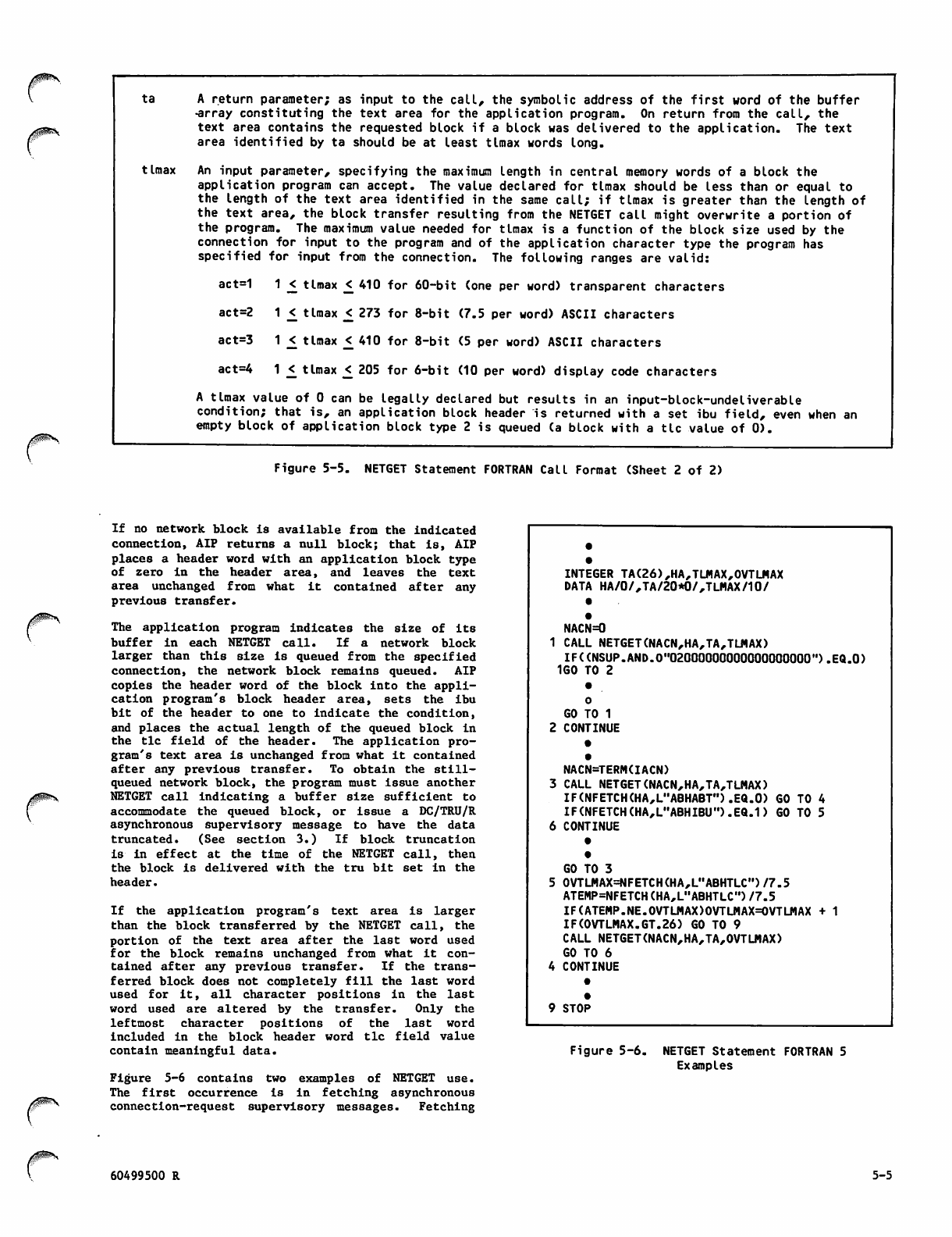
ta A return parameter; as input to the call, the symbolic address of the first word of the buffer
•array constituting the text area for the application program. On return from the call, the
text area contains the requested block if a block was delivered to the application. The text
area identified by ta should be at least tlmax words long.
tlmax An input parameter, specifying the maximum length in central memory words of a block the
application program can accept. The value declared for tlmax should be less than or equal to
the length of the text area identified in the same call; if tlmax is greater than the length of
the text area, the block transfer resulting from the NETGET call might overwrite a portion of
the program. The maximum value needed for tlmax is a function of the block size used by the
connection for input to the program and of the application character type the program has
specified for input from the connection. The following ranges are valid:
act=1 1 _< tlmax <_ 410 for 60-bit (one per word) transparent characters
act=2 1 < tlmax £ 273 for 8-bit (7.5 per word) ASCII characters
act=3 1 < tlmax <_ 410 for 8-bit (5 per word) ASCII characters
act=4 1 <_ tlmax _< 205 for 6-bit (10 per word) display code characters
A tlmax value of 0 can be legally declared but results in an input-block-undeliverable
condition; that is, an application block header is returned with a set ibu field, even when an
empty block of application block type 2 is queued (a block with a tic value of 0).
Figure 5-5. NETGET Statement FORTRAN Call Format (Sheet 2 of 2)
If no network block is available from the indicated
connection, AIP returns a null block; that is, AIP
places a header word with an application block type
of zero in the header area, and leaves the text
area unchanged from what it contained after any
previous transfer.
The application program indicates the size of its
buffer in each NETGET call. If a network block
larger than this size is queued from the specified
connection, the network block remains queued. AIP
copies the header word of the block into the appli
cation program'8 block header area, sets the ibu
bit of the header to one to indicate the condition,
and places the actual length of the queued block in
the tic field of the header. The application pro
gram's text area is unchanged from what it contained
after any previous transfer. To obtain the still-
queued network block, the program must issue another
NETGET call indicating a buffer size sufficient to
accommodate the queued block, or issue a DC/TRU/R
asynchronous supervisory message to have the data
truncated. (See section 3.) If block truncation
is in e ffect at t he t ime of t he N ETG ET cal l, then
the block is delivered with the tru bit set in the
header.
If the application program's text area is larger
than the block transferred by the NETGET call, the
portion of the text area after the last word used
for the block remains unchanged from what it con
tained after any previous transfer. If the trans
ferred block does not completely fill the last word
used for it, all character positions in the last
word used are altered by the transfer. Only the
leftmost character positions of the last word
included in the block header word tic field value
contain meaningful data.
Figure 5-6 contains two examples of NETGET use.
The first occurrence is in fetching asynchronous
con n ecti o n-re q uest super visor y mess a ges. F etchi ng
INTEGER TA(26),HA,TLMAX,0VTLMAX
DATA HA/0/,TA/20*0/,TLMAX/10/
•
1
•
NACN=0
CALL NETGET(NACN,HA,TA,TLMAX)
IF((NSUP.AND.O"02000000000000000000").EQ.O)
1G0 TO 2
•
2
0
GO TO 1
CONTINUE
•
3
6
•
NACN=TERM(IACN)
CALL NETGET(NACN,HA,TA,TLMAX)
IF(NFETCH(HA,L"ABHABT").EQ.0) GO
IF(NFETCH(HA,L"ABHIBU").EQ.1) GO
CONTINUE
•
TO 4
TO 5
5
4
•
GO TO 3
0VTLMAX=NFETCH(HA,L"ABHTLC")/7.5
ATEMP=NFETCH(HA,L"ABHTLCM)/7.5
IF(ATEMP.NE.0VTLMAX)0VTLMAX=0VTLMAX + 1
IF(0VTLMAX.GT.26) GO TO 9
CALL NETGET(NACN,HA,TA,OVTLMAX)
GO TO 6
CONTINUE
•
9•
STOP
Figure 5-6. NETGET Statement FORTRAN 5
Examples
60499500 R 5-5
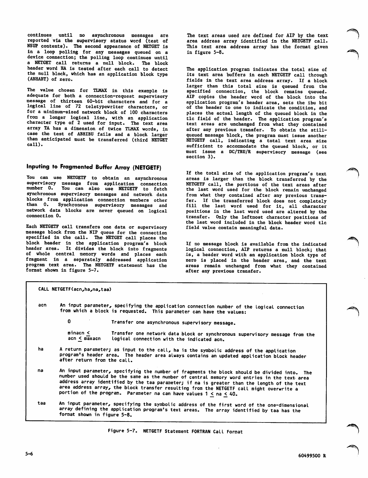
continues until no asynchronous messages are
reported via the supervisory status word (test of
NSUP contents). The second appearance of NETGET is
in a loop polling for any messa g e s q u e u e d o n a
device connection; the polling loop continues until
a NETGET call returns a null block. The block
header word HA is tested after each call to detect
the null block, which has an application block type
(ABHABT) of zero.
The value chosen for TLMAX in this example Is
adequate for both a connection-request supervisory
message of thirteen 60-bit characters and for a
logical line of 72 teletypewriter characters, or
for a minimum-sized network block of 100 characters
from a longer logical line, with an application
cha ract er t ype of 2 u sed f or i nput . T he t ext a rea
array TA has a dimension of twice TLMAX words, in
case the test of ABHIBU fails and a block larger
than anticipated must be transferred (third NETGET
call).
Inputing to Fragmented Buffer Array (NETGETF)
You can use NETGETF to obtain an asynchronous
supervisory message from application connection
n u m b e r 0. Yo u c a n a l s o u s e N E T G E T F t o fe t c h
synchronous supervisory messages and network data
blocks from application connection numbers other
than 0. Synchronous supervisory messages and
network data blocks are never queued on logical
connection 0.
Each NETGETF call transfers one data or supervisory
message block from the NIP queue for the connection
specified in the call. The NETGET call places the
block header in the application program's block
h e ad e r a r ea . I t d i vi d e s t he b l o c k i n t o f r a g m e nt s
of whole central memory words and places each
fragment in a separately addressed application
program text area. The NETGETF statement has the
format shown in figure 5-7.
The text areas used are defined for AIP by the text
area address array identified in the NETGETF call.
This text area address array has the format given
in figu r e 5 - 8 .
The application program indicates the total size of
its text area buffers in each NETGETF call through
fields in the text area address array. If a block
larger than this total size is queued from the
specified connection, the block remains queued.
AIP copies the header word of the block into the
application program's header area, sets the ibu bit
of the header to one to indicate the condition, and
places the actual length of the queued block in the
tic field of the header. The application program's
text areas are unchanged from what they contained
after any previous transfer. To obtain the still-
queued message block, the program must issue another
NETGETF call, indicating a total text area size
sufficient to accommodate the queued block, or it
mu st iss ue a DC/TR U/R supervis ory messa ge (se e
section 3).
If the t otal size of the a ppli catio n prog ram' s text
areas is larger than the block transferred by the
NETGETF call, the portions of the text areas after
the last word used for the block remain unchanged
from what they contained after any previous trans
fer. If the transferred block does not completely
fill the last word used for it, all character
positions in the last word used are altered by the
transfer. Only the leftmost character positions of
the last word included in the block header word tic
field value contain meaningful data.
If no message block is available from the indicated
logical connection, AIP returns a null block; that
is, a header word with an application block type of
zero is placed in the header area, and the text
area8 remain unchanged from what they contained
after any previous transfer.
CALL NETGETF(acn,ha,na,taa)
acn An input parameter, specifying the application connection number of the logical connection
from which a block is requested. This parameter can have the values:
0 Transfer one asynchronous supervisory message.
minacn £ Transfer one network data block or synchronous supervisory message from the
acn _< maxacn logical connection with the indicated acn.
ha
taa
A return parameter; as input to the call, ha is the symbolic address of the application
program's header area. The header area always contains an updated application block header
after r e t u rn from t h e call.
An input parameter, specifying the number of fragments the block should be divided into. The
number used should be the same as the number of central memory word entries in the text- area
address array identified by the taa parameter; if na is greater than the length of the text
area address array, the block transfer resulting from the NETGETF call might overwrite a
portion of the program. Parameter na can have values 1 < na < 40.
An input parameter, specifying the symbolic address of the first word of the one-dimensional
array defining the application program's text areas. The array identified by taa has the
format shown in figure 5-8.
s*3^
Figure 5-7. NETGETF Statement FORTRAN Call Format
5-6 60499500 R
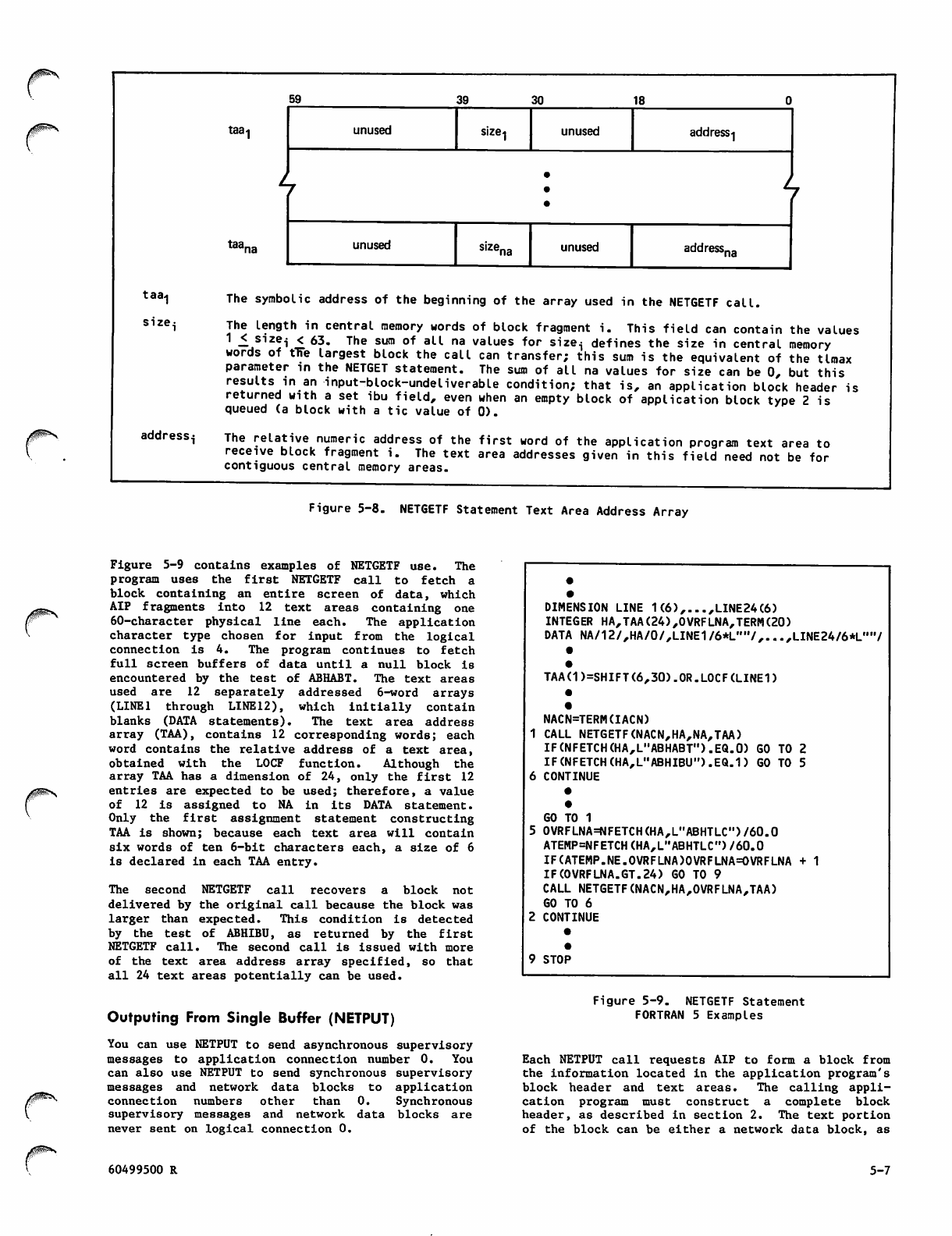
0^\
taa^
size^
address.;
taa-i
59 39 30 18
unused size-| unused address-j
•
taar unused unused address,na
The symbolic address of the beginning of the array used in the NETGETF call.
The length in central memory words of block fragment i. This field can contain the values
1 < size^ < 63. The sum of all na values for sizei defines the size in central memory
words of the largest block the call can transfer; this sum is the equivalent of the tlmax
parameter in the NETGET statement. The sum of all na values for size can be 0, but this
results in an input-block-undeliverable condition; that is, an application block header is
returned with a set ibu field, even when an empty block of application block type 2 is
queued (a block with a tic value of 0).
The relative numeric address of the first word of the application program text area to
receive block fragment i. The text area addresses given in this field need not be for
contiguous central memory areas.
Figure 5-8. NETGETF Statement Text Area Address Array
Figure 5-9 contains examples of NETGETF use. The
p r o g r a m u s e s t h e fi r s t N E T GE TF c a l l t o f e t c h a
block containing an entire screen of data, which
AIP fragments into 12 text areas containing one
60-character physical line each. The application
character type chosen for input from the logical
c o nn e ct i o n i s 4 . T h e p ro g r a m co n ti n ue s to f e tc h
full screen buffers of data until a null block is
encountered by the test of ABHABT. The text areas
used are 12 separately addressed 6-word arrays
(LINE1 through LINE12), which initially contain
blanks (DATA statements). The text area address
array (TAA), contains 12 corresponding words; each
word contains the relative address of a text area,
o b t a i n e d w i t h t h e L O C F f u n c t i o n . A l t h o u g h t h e
array TAA has a dimension of 24, only the first 12
entries are expected to be used; therefore, a value
of 12 is assigned to NA in its DATA statement.
O n l y t h e fi r s t a s s i g n m e n t s t a t e m e n t c o n s t r u c t i n g
TAA is shown; because each text area will contain
six words of ten 6-bit characters each, a size of 6
is declared in each TAA entry.
The second NETGETF call recovers a block not
delivered by the original call because the block was
l a r g e r t h a n e x p e ct e d . T h i s c o n d i t i o n i s d e t e c t e d
by the test of ABHIBU, as returned by the first
NETGETF call. The second call is issued with more
of the text area address array specified, so that
all 24 text areas potentially can be used.
DIMENSION LINE 1(6),...,LINE24(6)
INTEGER HA,TAA(24),0VRFLNA,TERM(20)
DATA NA/12/,HA/0/,LINE1/6*L",7,...,LINE24/6*L,,,7
TAA(1)=SHIFT(6,30).OR.LOCF (LINED
NACN=TERM(IACN)
1 CALL NETGETF(NACN,HA,NA,TAA)
IF (NFETCH (HA,L,,ABHABT").EQ.0) GO TO 2
IF(NFETCH(HA,L"ABHIBU").EQ.1) GO TO 5
6 CONTINUE
•
GO TO 1
0VRFLNA=NFETCH(HA,L"ABHTLC")/60.0
ATEMP=NFETCH(HA,L"ABHTLC")/60.0
IF(ATEMP.NE.OVRFLNA)OVRFLNA=OVRFLNA
IF(0VRFLNA.GT.24) GO TO 9
CALL NETGETF(NACN,HA,OVRFLNA,TAA)
GO TO 6
CONTINUE
9 STOP
+ 1
yfP?*s
Outputing From Single Buffer (NETPUT)
You can use NETPUT to send asynchronous supervisory
messages to application connection number 0. You
can also use NETPUT to send synchronous supervisory
messages and network data blocks to application
connection numbers other than 0. Synchronous
supervisory messages and network data blocks are
never sent on logical connection 0.
60499500 R
Figure 5-9. NETGETF Statement
FORTRAN 5 Examples
Each NETPUT call requests AIP to form a block from
the information located in the application program's
block header and text areas. The calling appli
cation program must construct a complete block
header, as described in section 2. The text portion
of the block can be either a network data block, as
5-7
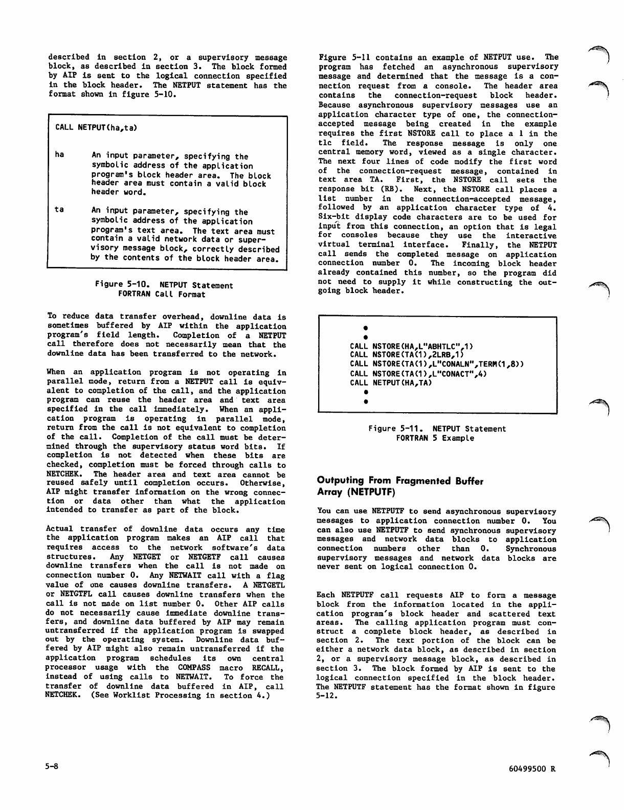
described in section 2, or a supervisory message
block, as described in section 3. The block formed
by AIP is sent to the logical connection specified
in the block header. The NETPUT statement has the
format shown in figure 5-10.
CALL NETPUT(ha,ta)
ha
ta
An input parameter, specifying the
symbolic address of the application
program's block header area. The block
header area must contain a valid block
header word.
An input parameter, specifying the
symbolic address of the application
program's text area. The text area must
contain a valid network data or super
visory message block, correctly described
by the contents of the block header area.
Figure 5-10. NETPUT Statement
FORTRAN Call Format
Figure 5-11 contains an example of NETPUT use. The
program has fetched an asynchronous supervisory
message and determined that the message is a con
nection request from a console. The header area
contains the connection-request block header.
Because asynchronous supervisory messages use an
application character type of one, the connection-
accepted message being created in the example
requires the first NSTORE call to place a 1 in the
tic field. The response message is only one
central memory word, viewed as a single character.
The next four lines of code modify the first word
of the connection-request message, contained in
text area TA. First, the NSTORE call sets the
response bit (RB). Next, the NSTORE call places a
list number in the connection-accepted message,
followed by an application character type of 4.
Six-bit display code characters are to be used for
input from this connection, an option that is legal
for consoles because they use the interactive
virtual terminal interface. Finally, the NETPUT
call sends the completed message on application
connection number 0. The incoming block header
already contained this number, so the program did
not nee d t o s u p p l y i t w h i l e c o nstructing the out
going block header.
To reduce data transfer overhead, downline data is
sometimes buffered by AIP within the application
program's field length. Completion of a NETPUT
call therefore does not necessarily mean that the
downline data has been transferred to the network.
When an application program is not operating in
parallel mode, return from a NETPUT call is equiv
alent to completion of the call, and the application
program can reuse the header area and text area
specified i n t h e c a l l i mmediately. When a n a p p l i
cation program is operating in parallel mode,
return from the call is not equivalent to completion
of the call. Completion of the call must be deter
mined through the supervisory status word bits. If
completion is not detected when these bits are
checked, completion must be forced through calls to
NETCHEK. The header area and text area cannot be
reused safely until completion occurs. Otherwise,
AIP might transfer information on the wrong connec
tion or data other than what the application
intended to transfer as part of the block.
Actual transfer of downline data occurs any time
t h e a p p l i c a t i o n p r o g r a m m a k e s a n A I P c a l l t h a t
requires access to the network software's data
structures. Any NETGET or NETGETF call causes
downline transfers when the call is not made on
connection number 0. Any NETWAIT call with a flag
value of one causes downline transfers. A NETGETL
or NETGTFL call causes downline transfers when the
call is not made on list number 0. Other AIP calls
do not necessarily cause Immediate downline trans
fers, and downline data buffered by AIP may remain
untransferred if the application program is swapped
ou t b y t h e o perati n g s y s tem. Do w n l i n e d a ta b uf
fered by AIP might also remain untransferred if the
application program schedules its own central
processor usage with the COMPASS macro RECALL,
instead of using calls to NETWAIT. To force the
transfer of downline data buffered in AIP, call
NETCHEK. (See Worklist Processing in section 4.)
CALL NSTORE(HA,L"ABHTLC",1)
CALL NSTORE(TA(1),2LRB,1)
CALL NSTORE(TA(1),L"C0NALN",TERM(1,8))
CALL NSTORE(TA(1),LMC0NACT",4)
CALL NETPUT(HA,TA)
Figure 5-11. NETPUT Statement
FORTRAN 5 Example
Outputing From Fragmented Buffer
Array (NETPUTF)
You can use NETPUTF to send asynchronous supervisory
messages to application connection number 0. You
can also use NETPUTF to send synchronous supervisory
messages and network data blocks to application
connection numbers other than 0. Synchronous
supervisory messages and network data blocks are
never sent on logical connection 0.
Each NETPUTF call requests AIP to form a message
b l o c k f r o m t h e i n f o r m a t i o n l o c a t e d I n t h e a p p l i
cation program's block header and scattered text
areas. The calling application program must con
struct a complete block header, as described in
section 2. The text portion of the block can be
either a network data block, as described in section
2, or a supervisory message block, as described in
section 3. The block formed by AIP is sent to the
logical connection specified in the block header.
The NETPUTF statement has the format shown in figure
5-12.
yli^V
5-8 60499500 R
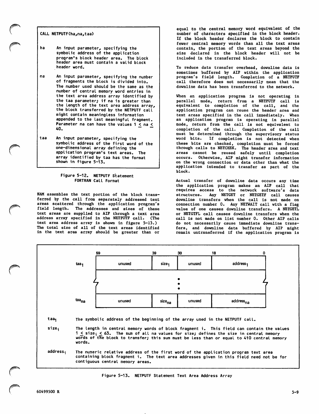
CALL NETPUTF(ha,na,taa)
ha An input parameter, specifying the
symbolic address of the application
program's block header area. The block
header area must contain a valid block
header word.
na An input parameter, specifying the number
of fragments the block is divided into.
The number used should be the same as the
number of central memory word entries in
the text area address array identified by
the taa parameter; if na is greater than
the length of the text area address array,
the block transferred by the NETPUTF call
might contain meaningless information
appended to the last meaningful fragment.
Parameter na can have the values 1 < na <
4 0 . ~ ~
taa An input parameter, specifying the
symbolic address of the first word of the
one-dimensional array defining the
application program's text areas. The
array identified by taa has the format
shown in figure 5-13.
jPs
Figure 5-12. NETPUTF Statement
FORTRAN Call Format
NAM assembles the text portion of the block trans
ferred by the call from separately addressed text
areas scattered through the application program's
field length. The addresses and sizes of these
text areas are supplied to AIP through a text area
address array spe cified in the NETPUTF call. (The
text area address array is shown in figure 5-13.)
The total size of all of the text areas identified
in th e t e x t a r e a a r ray s hould be g r e a t e r than o r
equal to the central memory word equivalent of the
number of characters specified in the block header.
If the block header declares the block to contain
fewer central memory words than all the text areas
contain, the portio n o f th e te x t a r e a s b e y o n d t h e
s i z e d e c l a r e d i n t h e b l o c k h e a d e r w i l l n o t b e
included in the transferred block.
To reduce data transfer overhead, downline data is
sometimes buffered by AIP within the application
program's field length. Completion of a NETPUTF
call therefore does not necessarily mean that the
downline data has been transferred to the network.
When an application program is not operating in
p a r a l l e l m o d e , r e t u r n f r o m a N E T P U T F c a l l i s
e q u i v a l e n t t o c o m p l e t i o n o f t h e c a l l , a n d t h e
application program can reuse the header area and
text areas specified in the call immediately. When
an application program is operating in parallel
mode, return from the call is not equivalent to
completion of the call. Completion of the call
must be determined through the supervisory status
word bits. If completion is not detected when
these bits are checked, completion must be forced
through calls to NETCHEK. The header area and text
areas cannot be reused safely until completion
o c c ur s . O th e r wi s e , A I P m i gh t t r an s f er i n fo r m at i o n
on the wrong connection or data other than what the
a p p l i c a t i o n i n t e n d e d t o t r a n s f e r a s p a r t o f t h e
block.
Actual transfer of downline data occurs any time
the application program makes an AIP call that
requires access to the network software's data
structures. Any NETGET or NETGETF call causes
downline transfers when the call is not made on
connection number 0. Any NETWAIT call with a flag
value of one causes downline transfers. A NETGETL
or NETGTFL call causes downline transfers when the
call is not made on list number 0. Other AIP calls
do not necessarily cause immediate downline trans
fers, and downline data buffered by AIP might
remain untransferred if the application program is
taa<|
size.j
address.;
5 9 3 9 3 0 1 8 0
taa^
t^na
unused size1 unused address-]
•
unused sizena unused addressna
The symbt
The lengl
1 _< size
words of
words.
The numer
containir
contiguoi
>lic address of the beginning of the array used in the NETPUTF call.
:h in central memory words of block fragment i. This field can contain
i < 63. The sum of all na values for size; defines the size in central
tTTe block to transfer; this sum must be less than or equal to 410 centr
*ic relative address of the first word of the application program text a
ig block fragment i. The text area addresses given in this field need n
js central memory areas.
the values
memory
aI memory
rea
ot be for
Figure 5-13. NETPUTF Statement Text Area Address Array
60499500 R 5-9
swapped out by the operating system. Downline data
buffered by AIP might also remain untransferred if
the application program schedules its own central
processor usage with the COMPASS macro RECALL,
instead of using calls to NETWAIT. To force the
t r a n s f e r o f d o w n l i n e d a t a b u f f e r e d i n A I P, c a l l
NETCHEK. (See Worklist Processing in section 4.)
Figure 5-14 contains an example of NETPUTF use.
T h e pr o g r a m se n d s a b l oc k c o n t ai n in g a n e n t i r e
s c r e e n o f d a t a t o a n i n t e r a c t i v e c o n s o l e . A I P
assembles the block from text areas containing one
logical (and physical) line each. The application
character type used for the block is 4. The pro
gram uses 12 text areas of separately addressed
7-word arrays (0LINE1 through 0LINE12), containing
6-bit display code characters and 12-bit zero byte
terminators (DATA statements). The text area
address array, OTAA, contains 12 corresponding
words; each word contains the relative address of a
text area, obtained with the LOCF function. Because
the array OTAA has a dimension of 12, a value of 12
Is assigned to ONA in its DATA statement. Only the
first assignment statement constructing OTAA is
shown. Because each text area contains seven words
o f t e n 6 - b i t c h a r a c t e r s e a c h , a s i z e o f 7 I s
declared in each OTAA entry.
Inputing to Single Buffer (NETGETL)
You can use NETGETL to obtain an asynchronous
supervisory message from application connection
number 0. Application connection number 0 is
always part of application list number 0. When a
N E T G E T L c a l l s p e c i f y i n g i n p u t f r o m l i s t 0 i s
issued, any asynchronous supervisory messages
queued for the program are returned before list
scanning continues to other connection numbers on
list 0. Synchronous supervisory messages and net
work data blocks on connection numbers other than
zero can also be obtained when their connection
numbers have been assigned to list 0.
Each NETGETL call causes NAM to select (on a
rotating basis) one of the logical connections from
a specified list. NAM only chooses a connection
that has network data blocks queued and that has
not been turned off by a LST/OFF/R supervisory
message. One network data block is transferred
from the NIP queue of the selected connection for
each call to NETGETL. The NETGETL call places the
block header in the application program's header
area and the block body in the application's text
area. Figure 5-15 shows the format of the NETGETL
statement.
CONNECTIONS ON LISTS
The two options for input from connections on lists
are as follows:
Fetch input to a single, unified buffer (NETGETL
statement)
Fetch input to an array of buffers (NETGTFL
statement).
Each NETGETL statement causes the connection list
to be scanned only once. Scanning begins with the
connection immediately following the connection
from which a block was previously transferred. The
first connection on the list is examined after the
last one on the list. Scanning ends when a con
nection with a queued input block is found. If no
connection has a queued input block, scanning ends
with the connection preceding the one at which
scanning started.
•
•
DIMENSION 0LINE1(7),...,0LINE12(7)
INTEGER HA,0TAA(12),0NA,TERM(20)
DATA 0NA/12/,HA/0/,0LINE1/"ABCDEFGHIJ",...,L"12345678",0/,...,
1DATA 0LINE12/"ABCDEFGHIJ",...,L,,12345678",0/
•
•
0TAA(1)=SHIFT(6,30).0R.L0CF(0LINE1)
•
•
CALL NSTORE(HA,L"ABHABT",2)
CALL NSTORE(HA,L"ABHADR",TERM(IACN)
CALL NSTORE(HA,L"ABHABN",1)
CALL NSTORE(HA,L"ABHACT",4)
CALL NSTORE(HA,L"ABHNFE",1)
CALL NSTORE(HA,L"ABHTLC",840)
CALL NETPUTF(HA,0NA,0TAA)
•
•
Figure 5-14. NETPUTF Statement FORTRAN 5 Example
5-10 60499500 R
CALL NETGETL(aln,ha,ta,tlmax)
aln
ha
ta
tlmax
An input parameter, specifying the number of the connection list to be scanned for a queued
block. This parameter can have the values:
0 Obtain all asynchronous supervisory messages queued on application connection
number 0 first, then any data or synchronous supervisory message blocks queued
on other connections on list zero.
1 £ aln £ 63 Obtain one data or synchronous supervisory message block from one connection
on the indicated list.
A return parameter; as input to the call, the symbolic address of the application program's
block header area. The header area always contains an updated application block header word
after return from the call.
A return parameter; as input to the call, the symbolic address of the first word of the buffer
array constituting the text area for the application program. On return from the call, the text
area contains the requested block if a block was available and the text area was large enough.
The text area identified by ta should be at least tlmax words long.
An input parameter, specifying the maximum length in central memory words of a block the
application program can accept. The value declared for tlmax should be less than or equal to
the length of the text area identified in the same call; if tlmax is greater than the length of
the text area, the block transfer resulting from the NETGETL call might overwrite a portion of
the program. The maximum value needed for tlmax is a function of the block size used by the
connection for input to the program and of the application character type the program has
specified for input from the connection. The following ranges are valid:
act=1 1 <^ tlmax _< 410 for 60-bit (one per word) transparent characters
act=2 1 _< tlmax j< 273 for 8-bit (7.5 per word) ASCII characters
act=3 1 _< tlmax £410 for 8-bit (5 per word) ASCII characters
act=4 1 _< tlmax £ 205 for 6-bit (10 per word) display code characters
A tlmax value of 0 can be legally declared but results in an input-block-undeliverable
condition; that is, an application block header is returned with an ibu value of 1, even when an
empty block of application block type 2 is queued (a block with a tic value of 0).
Figure 5-15. NETGETL Statement FORTRAN Call Format
If data or supervisory message blocks are not
available from any connection on the list, a null
b l o c k i s r e t u r n e d. A h e a d e r w o r d w i t h a n a p p l i
cation block type o f zer o is plac ed i n the header
area, and the text area is unchanged from its
content after the last block was obtained. Null
blocks are not returned from each connection.
The application program indicates the size of its
buffer in each NETGETL call. If a block larger
than this size is available for transfer, the block
remains queued, unless data truncation has been
requested. AIP copies the header word of the block
into the application program's block header area,
sets t h e ibu b i t of the h eader t o one t o i ndicat e
the condition, and places the actual length of the
queued block in the tic field of the header. The
appl i catio n p rogra m 's text a rea i s u nchan g e d from
what it contained after any previous transfer. To
obtain the still-queued block, the program must
issue a separate NETGET call, indicating a buffer
size sufficient to accommodate the queued block, or
it may request a truncated block using the DC/TRU/R
asynchronous supervisory message (see section 3).
The connection pointer within the list is incre
mented regardless of whether a transfer occurs, so
the same connection is not involved in a second
NETGETL call.
If the application program's text area is larger
than the block transferred by the NETGETL call, the
po r t i o n o f t h e t ext ar e a a f t er the l a s t w ord u s e d
for the block remains unchanged from what it con
tained after any previous transfer. If the trans
ferred block does not completely fill the last word
used for it, all character positions in the last
word used are altered by the transfer. Only the
leftmost character positions of the last word
included in the block header word tic field value
contain meaningful data.
Figure 5-16 contains an example of NETGETL statement
use. The program has assigned all interactive con
soles to list 0 when accepting connection with them
(code not shown). A NETGETL call is used to
periodically poll list 0 for asynchronous super
visory messages affecting new or existing connec
tions, and for interactive input affecting passive
60499500 R 5-11
INTEGER TA(26),HA,TLMAX,OVTLMAX
DATA HA/0/,TA/26*0/,TLMAX/13/
•
NALN=0
1 CALL NETGETL(NALN,HA,TA,TLMAX)
IF(NFETCH(HA,L"ABHABT").EQ.O) GO TO 5
IF(NFETCH(HA,L"ABHABT").NE.3) GO TO 4
CALL SMP(HA,TA,TLMAX)
GO TO 1
4 IF(NFETCH(HA,L"ABHIBU").EQ.D GO TO 3
2 CONTINUE
GO TO 1
3 OVTLHAX=NFETCH(HA,L"ABHTLCM)/7.5
ATEMP=NFETCH(HA,LMABHTLC")/7.5
IF(ATEMP.NE.OVTLMAX)OVTLMAX=OVTLMAX + 1
IF(OVTLHAX.GT.26) GO TO 9
NACN=NFETCH(HA,L"ABHADR")
CALL NETGET(NACN,HA,TA,OVTLMAX)
•
•
GO TO 1
5 CONTINUE
•
9 STOP
Figure 5-16. NETGETL Statement
FORTRAN 5 Example
batch connections. The TLMAX value of 13 is
adequate for both supervisory messages of appli
cation character type 1 and 72-character logical
lines or a minimum-sized network block of 100
characters in ASCII (application character type 2)
from the interactive consoles. Each time list 0 is
polled by the NETGETL call, the block header area
H A i s t e s t e d t o d e t e r m i n e t h e b l o c k t y p e . I f a
null block (ABHABT of 0) is found, polling ceases.
I f a b lo c k ty p e o f 1 o r 2 i s f o u nd , t he b l oc k I s
processed (code not shown) and polling continues.
If a supervisory message (block type of 3) is found,
a subroutine called SMP is entered to process the
supervisory message and polling of list 0 continues.
The NETGET call recovers a block not delivered by
the original call because the block was larger than
expected. This condition is detected by the test
of ABHIBU, as returned by the NETGETL call. The
NETGET call is issued with more of the text area
buffer available; OVTLMAX can be up to twice TLMAX
before the text area is completely filled.
Inputing to Fragmented Buffer
Array (NETGTFL)
You can use NETGTFL to obtain an asynchronous
supervisory message from application connection
number 0. Application connection number 0 is always
part of application list number 0. When a NETGTFL
call specifying input from list 0 is issued, any
asynchronous supervisory messages queued for the
program are returned before list scanning continues
to other connection numbers on list 0. Synchronous
supervisory messages and network data blocks on
connection numbers other than zero can be obtained
when their connection numbers have been assigned to
list 0.
Ea c h N E T GTFL c a l l c ause s N A M t o selec t ( o n a
rotating basis) one of the logical connections from
a specified list. NAM only chooses a connection
that has blocks queued and has not been turned off
by a supervisory message. One block is transferred
from the NIP queue of the selected connection for
each call to NETGTFL; the block header is placed in
the application program's header area and the body
is placed in the application's text areas. Figure
5-17 shows the format of the NETGTFL statement.
CALL NETGTFL(aln,ha,na,taa)
aln An input parameter, specifying the number of the connection list to be scanned for a queued
block. This parameter can have the values:
0 Obtain all asynchronous supervisory messages queued on application connection
number 0 first, then any data or synchronous supervisory message blocks queued
on other connections on list zero.
1 <, aln <_ 63 Obtain one data or synchronous supervisory message block from one connection
on the indicated list.
ha A return parameter; as input to the call, the symbolic address of the application program's
block header area. The header area always contains an updated application block header after
re turn f rom the call.
na An input parameter, specifying the number of fragments the block should be divided into. The
number used should be the same as the number of central memory word entries in the text area
address array identified by the taa parameter; if na is greater than the* length of the text
area address array, the block transfer resulting from the NETGTFL call might overwrite a
portion of the program. Parameter na can have the values 1 £ na < 40.
taa An input parameter, specifying the symbolic address of the first word of the one-dimensional
array defining the application program's text areas. The array identified by taa has the
format shown in figure 5-18.
Figure 5-17. NETGTFL Statement FORTRAN Call Format
5-12 60499500 R
Each NETGTFL statement causes the connection list
to be scanned only once. Scanning begins with the
connection immediately following the connection
from which a block was previously transferred. The
first connection o n t h e l i s t i s e x a m i n e d a f t e r t h e
last one on the list. Scanning ends when a con
nection with a queued input block is found. If no
connection has a queued input block, scanning ends
with the connection preceding the one at which
scanning started.
The text areas used are defined for AIP by the text
area address array identified in the NETGTFL call.
This text area address array has the format shown
in figure 5-18.
The application program indicates the total size of
its text area buffers in each NETGTFL call through
fields in the text area address array. If a block
larger than this total size is queued from the
specified connection, the block remains queued,
u n l e s s t r u n c a t i o n i s i n e f f e c t . ( S e e s e c t i o n 3 . )
AIP cop i es t h e hea d er w o rd o f the b lock i nto t he
application program's header area, sets the ibu bit
of the header to one to indicate the condition, and
places the actual length of the queued block in the
tic field of the header. The application program's
text areas are unchanged from what they contained
a f t e r a n y p r e v i o u s t r a n s f e r . To o b t a i n t h e s t i l l -
queued block, the program must issue a separate
NETGETF call, indicating a buffer size sufficient
to accommodate the queued block. The program also
can request data truncation using the DC/TRU/R
asynchronous supervisory message. (See section
3.) The connection pointer within the list is
incremented regardless of whether a transfer occurs,
so the same connection is not involved in a second
NETGTFL call.
If the total size of the application program's text
areas is larger than the block transferred by the
NE TGTFL call, the portions of the text areas aft er
the last word used for the block remain unchanged
from what they contained after any previous trans
fer. If the transferred block does not completely
fill the last word used for it, all character
positions in the last word are altered by the
transfer. Only the leftmost character positions of
the l ast w ord i n dica t ed b y the b l ock h eader word
tic field value contain meaningful data.
If data or supervisory message blocks are not
available from any connection on the list, a null
b l o c k i s r e t u r n e d. A h e a d e r w o r d w i t h a n a p p l i
cation block type o f zer o is plac ed i n the header
area, and the text areas are unchanged from their
contents after the last block was obtained. Null
(empty) blocks are not returned from each connec
tion.
Figure 5-19 contains an example of NETGTFL use.
The program previously assigned all interactive
consoles to list 0 when accepting connection with
them (code not shown). A NETGTFL call is used to
periodically poll list 0 for asynchronous super
visory messages affecting new or existing connec
t i on s , a n d fo r i n t er a ct i ve i np u t a f f e c t i n g c o n s o l e
connections. If the poll is successful (does not
return a null block) and returns an asynchronous
supervisory message block, subroutine SMP is called
to process the message. If the poll returns a
network data block header but no block (test of
A B H IB U f ai l s ), a N E TG E TF c a l l i s i ss u e d w i t h a
total text area buffer size larger than in the
original call; this NETGETF call should successfully
retrieve the queued block.
taa1
size;
address.;
59 39
taa-i unused
30 18
unused address^
b
taar unused unused address.
The symbolic address of the beginning of the array used in the NETGTFL call.
The length in central memory words of block fragment i. This field can contain the values
1 £ size.; < 63. The sum of all na values for size^ defines the size in central memory
words of fne largest block the call can transfer; this sum is the equivalent of the tlmax
parameter in the NETGETL statement. The sum of all na values for size can be 0, but this
results in an input-block-undeliverable condition; that is, an application block header is
returned with the ibu field set, even when an empty block of application block type 2 is
queued (a block with a tic value of 0).
The numeric relative address of the first word of the application program text area to
receive block fragment i. The text area addresses given in this field need not be for
contiguous central memory areas.
Figure 5-18. NETGTFL Statement Text Area Address Array
60499500 R 5-13
DIMENSION LINE1(6),...,LINE24(6)
INTEGER HA,TAA(24),OVRFLNA
DATA NA/12/,HA/0/,LINE1/6*L'"7,...,LINE24/6*L,,,7
•
•
TAA(1)=SHIFT(6,30).0R.L0CF(LINE1)
•
•
NALN=0
1 CALL NETGTFL(NALN,HA,NA,TAA)
IF(NFETCH(HA,LMABHABT").EQ.O) GO TO 5
IF(NFETCH(HA,L"ABHABT").NE.3) GO TO 4
CALL SMP(HA,NA,TAA)
GO TO 1
4 IF (NFETCH (HA,L"ABHIBU").EQ.D GO TO 3
2 CONTINUE
•
•
GO TO 1
3 OVRFLNA=NFETCH(HA,L"ABHTLC")/60.0
ATEMP=NFETCH(HA,L"ABHTLC")/60.0
IF(ATEMP.NE.OVRFLNA)OVRFLNA=OVRFLNA + 1
IF(0VRFLNA.GT.24) GO TO 9
NACN=NFETC H(HA,L"ABHADR")
CALL NETGETF(NACN,HA,OVRFLNA,TAA)
GO TO 2
5 CONTINUE
•
•
9 STOP
Figure 5-19. NETGTFL Statement
FORTRAN 5 Example
NAM fragments the block transferred by the NETGTFL
or NETGETF call into 12 (NA) or more (OVRFLNA) text
areas (LINE1 through LINE24), identified in the
24-entry text area address array (TAA). Each text
area is intended to hold one 60-character display
coded physical line from a full page of input. NAM
places each line into six consecutive central
memory words. The calculation of OVRFLNA assumes
that an application character type of 4 is used for
i n p u t , b u t t h e s i z e o f t h e L I N E 1 t e x t a r e a i s
adequate for both application character type 4
lines and the application character type 1 words
used for asynchronous supervisory messages. The
FORTRAN function LOCF stores the address of each of
the text area arrays in TAA, and the TAA entry has
a corresponding length of 6; only the first TAA
assignment statement is shown.
PROCESSING CONTROL STATEMENTS
The three processing control statements NETWAIT,
NETSETP, and NETCHEK cause or reduce processing
d e l a y s t o a l t e r t h e a p p l i c a t i o n p r o g r a m ' s e f fi
ciency. These three statements are used in
conjunction with the supervisory status word
established by the application program in its NETON
statement. NETWAIT and NETCHEK can be used by any
application program; NETSETP is used only by pro
g r a m s p e r f o r m i n g p a r a l l e l m o d e p r o c e s s i n g , a s
described in section 4.
SUSPENDING PROCESSING (NETWAIT)
The NETWAIT statement (figure 5-20) performs the
following functions:
Allows an application program to make itself a
candidate for rollout by the operating system
or otherwise suspend its processing
Allows the application program to declare a
maximum time for processing suspension
Allows the application program to delay resump
tion of processing until input is available for
i t o n a n y o f i t s l o g i c a l c o n n e c t i o n s , o r o n
connection zero
Causes the supervisory status word (NETON nsup
parameter) for the program to be updated on
return from the NETWAIT call
CALL NETWAIT(time,flag)
time
fl a g
An input parameter, 1 £ time £4095, specifying the number of seconds for which the application
program should be suspended. If a value of zero is declared, a default value of one is used;
if a value greater than 4095 is declared, a default value of 4095 is used.
An input parameter, specifying the conditions under which processing should be resumed,
parameter can have the values:
This
Return from NETWAIT call (resume processing) when input is available from any connec
tion, or when the period declared by the time parameter has elapsed. A minimum time
of 1 second is used if input is not available immediately. When a flag value of zero
is declared and input is available immediately, the value declared for the time
parameter is ignored.
Return from NETWAIT call (resume processing) when the period declared by the time
parameter has elapsed, regardless of whether input is available from any connection.
Also forces buffer output to be transmitted.
Figure 5-20. NETWAIT Statement FORTRAN Call Format
5-14 60499500 R -^
/$s**y
Calls to NETWAIT with nonzero flag values always
suspend processing when suspension is possible.
Calls to NETWAIT with zero flag values suspend
processing only when no input is available.
NETWAIT calls with a flag value of zero should only
be made after all outstanding asynchronous super
visory messages have been fetched by the program.
A NETWAIT call with a flag value of zero made while
any asynchronous supervisory message remains queued
always results in immediate return to the program,
regardless of whether any other input is available.
Such calls represent unnecessary additional proc
essing by AIP and the program and do not cause
transfer of worklists that are not completely filled
(e ffectively delayi ng output resulting from p revious
calls to NETPUT or NETPUTF).
If NETWAIT is called while the program is operating
in parallel mode, parallel mode operation is
ignored, and the program is suspended. Parallel
mode operation is reinstated when return from the
NETWAIT call occurs. You should not issue a call
to NETWAIT when i t would interr upt parallel m ode
operation, unless a call to NETCHEK first returns
an indication that all worklist processing is
completed.
You should include NETWAIT calls in an application
program that repeatedly polls the network for input
(via NETGET, NETGETL, NETGETF, or NETGTFL calls).
I f s u c h p r o g r a m s o m i t f r e q u e n t N E T WA I T c a l l s ,
severe performance degradation can result; if you
perform on-line debugging of such application
programs, you should use small time limits for the
job while it is in the debugging phase.
You should use NETWAIT calls as part of the appli
cation program's mechanisms to control queuing.
For example, the application program must be sure
before each NETPUT or NETPUTF call that the call
will not cause the logical connection's application
b l o c k l i m i t t o b e e x c e e d e d . W h e n t h e l i m i t h a s
been reached, the application program should not
output another block until it has received a block-
delivered supervisory message for a block already
sent. Because repeated polling for supervisory
message input to obtain these acknowledgments can
degrade program performance, a NETWAIT call should
follow any NETPUT or NETPUTF call that might cause
the limit to be reached. T h e t i m e v a l u e d e c l a r e d
in the NETWAIT call should be large enough to allow
a block-delivered supervisory message to be received
before another NETPUT or NETPUTF call occurs.
Similarly, an application program should never
enter parallel mode after a NETPUT call unless the
program first issues a NETWAIT call. Because AIP
does not transfer worklists partially filled by
NETPUT calls, the NETWAIT call is necessary to
force transfer of the worklist. (See Worklist
Processing in section 4.) If NETWAIT is not called,
the time between the NETSETP call and the first
NETCHEK call is not used for network processing.
Figure 5-21 contains examples of NETWAIT statement
use. The program sends a series of data message
blocks with NETPUT calls, issues a NETWAIT that
transfers the worklist and begins block trans
mission, and then checks the supervisory status
word (NSUP). If no asynchronous supervisory mes
sages are queued on return from the first NETWAIT
MSK1=0"02000000000000000000"
CALL NETPUT(HA,TA,TLMAX)
ITIME=1
IFLAG=1
CALL NETWAIT(ITIME,IFLAG)
IF(NSUP.AND.MSK1.EQ.MSK1) GO TO 1
ITIME=10
IFLAG=0
CALL NETWAIT(ITIME,IFLAG)
1 IACN=0
CALL NETGET(IACN,HA,TA,TLMAX)
CALL SMP(HA,TA,TLMAX)
•
Figure 5-21. NETWAIT Statement
FORTRAN 5 Examples
call, no block-delivered message can have been
received and the NSUP test fails. The program
issues a second NETWAIT call specifying delay until
input on any connection (including the asynchronous
supervisory message connection 0) is queued.
CONTROLLING PARALLEL MODE (NETSETP)
The NETSETP statement (figure 5-22) begins or ends
an application program's parallel mode operation.
Parallel mode operation involves worklist process
ing and is discussed in detail under both headings
in section 5. While in parallel mode, an appli
cation program cannot use any AIP statements other
than NETOFF or NETCHEK until AIP processing com
pletion has been indicated in the supervisory status
word.
CALL NETSETP(opt ion)
opt i on An input parameter, specifying whether
parallel mode operation begins or ends
after the NETSETP call. This parameter
can have the values:
=0
*0
Begin parallel mode operation.
End parallel mode operation.
(This is the default value for
application program operation.)
Figure 5-22. NETSETP Statement
FORTRAN Call Format
The supervisory status word used during parallel
mode operation is defined by the nsup parameter in
the application program's NETON statement. The bit
o f t h e s u p e r v i s o r y s t a t u s w o r d c o n c e r n e d w i t h
parallel mode processing is updated only while an
application program is operating in parallel mode.
When an application program is operating in parallel
mode, it should not alter the contents of the text
area used for a NETPUT or NETPUTF call immediately
after that call. The program can normally reuse
60499500 R 5-15
the area as soon as a call to NETWAIT, NETCET,
NETGETF, NETGETL, or NETGTFL is completed. The
text area used in a NETPUT or NETPUTF call should
n o t b e a l t e r e d u n t i l a f t e r w o r k l i s t p r o c e s s i n g i s
reported complete; nor should the NETON call status
word be tested until then.
A call to NETSETP ending parallel mode operation
should not be issued until a call to NETCHEK returns
an indication that all worklist processing is com
pleted. AIP ignores calls to NETSETP that attempt
to end parallel mode operation if the application
program is not operating in parallel mode.
Figure 5-23 contains examples of NETSETP and NETCHEK
use. The program attempts to reduce the number of
worklist transfers between AIP and NIP to increase
its efficiency. It does this while servicing a
batch device on application connection number 2 and
transmitting to a console on application connection
number 3.
The program flow shown minimizes worklist transfers
by concentrating the console output, instead of
interleaving each output line with NETGET calls
t h a t m i g h t c a u s e w o r k l i s t t r a n s f e r s b y A I P f o r
worklists not completely filled. Parallel mode
does not expedite this efficiency, but requirements
for its use are illustrated in several parts of the
code.
When the program has sent downline all of the
blocks it intends to send to the'console, it tests
for upline data or asynchronous supervisory mes
sages. If neither is found, NETWAIT rolls the
program out for 7 seconds and suspends parallel
mode processing temporarily.
When asynchronous supervisory messages are found,
the program leaves parallel mode processing with a
nonzero IOPT parameter in another NETSETP call.
The program can then fetch the messages without
needing to test NSUP for completion of the NETGET
call.
•
•
ITLMAX=410
IIACN=3
IBACN=2
I0PT=0
CALL NETSETP(IOPT)
10 DO 99, I = 1, 5, 1
CALL NSTORE(IIHA(I),L"ABHADR",IIACN)
CALL NSTORE(IIHA(I),L"ABHABN",I)
CALL NETPUT(IIHA(I), ITEXT(20*(I-1)))
88 ITEMP=NSUP.AND.SHIFT(1, 59)
IF(ITEMP.EQ.SHIFT(1, 59)) GO TO 99
CALL NETCHEK
GO TO 88
99 CONTINUE
98 ITEMP=NSUP.AND.SHIFT(1, 55)
IF(ITEMP.EQ.SHIFT(1, 55)) GO TO 3
ITEMP=NSUP.AND.SHIFT(1, 56)
IF(ITEMP.EQ.SHIFT(1, 56)) GO TO 4
ITIME=7
IFLAG=1
CALL NETWAIT(ITIME,IFLAG)
GO TO 98
3IACN=0
I0PT=1
CALL NETSETP(IOPT)
CALL NETGET(IACN, IHA, ITA, ITLMAX)
•
4•
I0PT=0
CALL NETSETP(IOPT)
CALL NETGEKIIACN, IIHAd), ITEXTd), ITLMAX)
5CALL NETCHEK
ITEMP=NSUP.AND.SHIFT(1, 59)
IF(ITEMP.NE.SHIFT(1, 59)) GO TO 5
•
6•
CALL NETCHEK
ITEMP=NSUP.AND.SHIFT(1, 59)
IFdTEMP.NE.SHIFTd, 59)) GO TO 6
•
•
GO TO 10
Figure 5-23. NETSETP and NETCHEK Statement
FORTRAN 5 Examples
When upline data is found, the program makes sure
it is in parallel mode with a zero IOPT parameter
in a NETSETP call. This call is ignored if it is
reached by a path that had already caused parallel
mode processing to begin. While in parallel mode,
the program fetches any queued input from the con
sole. NETCHEK is called and tested for completion
afte r the N E TGET call. Afte r the a t tempt t o fetc h
data from the console is completed (the input dis
posed of by code is not shown), a similar attempt
(not shown) is made to fetch data from the batch
device. When any batch data has been disposed of,
the program returns to its output loop for the
console (having presumably prepared the output
buffers first).
If a system control point job is operating in
parallel mode when it loses communication with NIP,
all further network input and ouput AIP calls are
ignored, but the program is not aborted. The
program should check the n bit in the supervisory
s t a t u s w o r d ( s e e fi g u r e 5 - 2 ) a f t e r c o m p l e t i o n o f
all network input and output calls to determine
whether or not it is still communicating with NIP.
If a system control point job is not operating in
parallel mode when it loses communication with NIP,
it is aborted when it makes the next AIP request.
The operating system aborts all nonsystem control
point jobs when NIP aborts, regardless of operating
mode.
CHECKING COMPLETION OF WORKLIST
PROCESSING (NETCHEK)
The application program uses the NETCHEK statement
(figure 5-24) to perform several functions. Each
call to NETCHEK:
Updates bit 59 of the supervisory status word
(identified by the nsup parameter used in the
NETON statement) on return from the call, when
the program is in parallel mode
Forces AIP to attempt transfer of its current
worklist to NIP if the transfer has not yet
occurred, if the program is running in either
parallel or nonparallel mode
5-16 60499500 R
CALL NETCHEK
Figure 5-24. NETCHEK Statement
FORTRAN Call Format
worklist processing operation is pending. A call
to NETSETP ending parallel mode operation should
not be issued until a call to NETCHEK returns an
indication that all worklist processing has been
completed.
ytf^»\
It is not necessary to call NETCHEK to cause work-
list transfers. Worklist transfers occur normally
after all the requirements described in section 4
under Worklist Processing have been met. A NETCHEK
call causes an attempt to transfer a worklist in
situations that do not meet these criteria. This
operation is equivalent to a NETWAIT except that
processing is not suspended.
By checking the supervisory status word after each
NETCHEK call, the application program can determine
th e m o st re c e n t s tat e o f w orkl i s t proc e s s ing a n d
determine whether additional AIP routine calls can
be issued. NETCHEK, NETOFF, and NETWAIT are the
only AIP statements that can be used while any
If NETON is called during parallel mode operation,
NETCHEK should not be called until all worklist
processing is reported complete. The NETON call
status word does not contain meaningfuL information
until processing for the worklist containing the
NETON call is complete. NETCHEK should not be
called after a NETOFF call is issued in parallel
mode. A NETOFF call ends parallel mode operation
by making worklist processing completion status
impossible.
Worklist processing is described in section 4. The
s u p e r v i s o r y s t a t u s w o r d i s d e s c r i b e d u n d e r t h e
heading Connecting to Network at the beginning of
this section. Figure 5-23 contains examples of
NETCHEK use.
60499500 R 5-17

0^%.
0*%
CHARACTERISTICS OF AN APPLICATION PROGRAM
/0^\
This section describes the structure and execution
of a Network Access Method (NAM) application pro
gram.
NOTE
You cannot execute application pro
grams as Transaction Facility tasks.
NOS SYSTEM CONTROL POINT
FACILITY
The NOS system control point facility permits the
exchange of data between programs running at dif
ferent control points. These programs are called:
System control point jobs when they are formally
defined as subsystems of the operating system
User control point jobs when they exchange data
with a system control point job
System control point jobs (subsystems) can make
privileged requests to the operating system and
execute with a very high priority. Network system
control point jobs such as the Network Interface
Program (NIP) usually reside in the operating system
library.
Application programs accessing the network execute
as system control point jobs or user control point
jobs using the system control point facility. Since
the code that implements this facility is embedded
in the Application Interface Program (AIP), it
remains transparent to the application program.
Certain aspects of system control point jobs and
user control point jobs, however, do affect appli
cation program operation.
An application program cannot execute successfully
unless the CUCP bit is set in the access word
associated with the user name of its job. If the
program attempts to access the network and the CUCP
bit is not set, the program is aborted with the
dayfile messages ILLEGAL USER ACCESS and SYSTEM
ABORT, and no error exit processing occurs. Access
word bits are set through the MODVAL utility, as
described in the NOS System Maintenance reference
manual.
Whil e c onnect i o n to t h e networ k e xists, a n etwork
application program always has a minimum system
activity count of one. If the application program
uses the control poin t man ager syst em m acr o cal l
(GETACT), the minimum system activity count appears
i n t h e S C A fi e l d o f t h e c a l l . W h e n a n e t w o r k
application program ends its connection with the
network by a NETOFF call, the system activity count
drops to zero. The GETACT macro is described in
volume 4 of the NOS reference set.
BATCH JOB STRUCTURE
A batch application program job using the Network
A c c e ss M e t ho d i s str u c tu r e d lik e a ny o t h er b a t ch
job.
A job is a sequence of commands, optionally followed
by source programs, object programs, data, or
directives. A batch job begins with the job command
and ends with an end-of-information indicator. Jobs
can consist of either physical card decks or images
of card decks.
Application program jobs can enter the system in one
of two ways:
Batc h j obs o n c ards a r e read i n throug h c ard
readers at the central site. Batch jobs of
card images are read from a load tape under the
direction of the system console operator or the
direction of another job.
Remote batch jobs on cards are read in through
card readers at remote site terminals. Remote
batch job card images are transmitted to form a
file at the host computer. All remote batch
jobs reach the host computer facilities through
the Remote Batch Facility (RBF).
Batch jobs have the same structure no matter what
their origin. Remote batch jobs differ from central
site batch jobs in that output returns to the
terminal and that remote jobs are subject to the
limitations of the physical equipment at the remote
site. The following information about job decks
applies to both card decks and card deck images.
T h e fi r s t c a r d o f t h e b a t c h j o b d e c k i s t h e j o b
command; the last card has a 6/7/8/9 multiple punch
in c o l u m n 1. Cards w i t h a 7/8/9 o r 6 / 7 /9 multiple
punch in column 1 divide the deck into a command
portion, program portion, and optional data portion.
When a job deck is created as card images from a
time-sharing terminal, the cEOR and cEOF entries
result in the logical equivalent of 7/8/9 and 6/7/9,
respectively. If the job deck is submitted from a
HASP or bisynchronous station through the Remote
Batch Facility, the /*EORnn and /*EOI cards result
in the logical equivalent of 7/8/9 and 6/7/8/9,
r e s p e ct i v e l y. H A S P o r b i s y n c h r o n o u s st a ti o n c a r d
readers and card punches support 7/8/9 cards but
not 6/7/8/9 cards; 200 User Terminal card readers
do not recognize either /*E0Rnn cards or /*E0I
car ds.
Jobs in the system waiting to begin execution are
collectively known as the input queue. Each job
enters the system with the user job name specified
by the first command in the job deck. The operating
system changes this name, based on the job command
present, to distinguish it from all others in the
system.
60499500 R 6-1
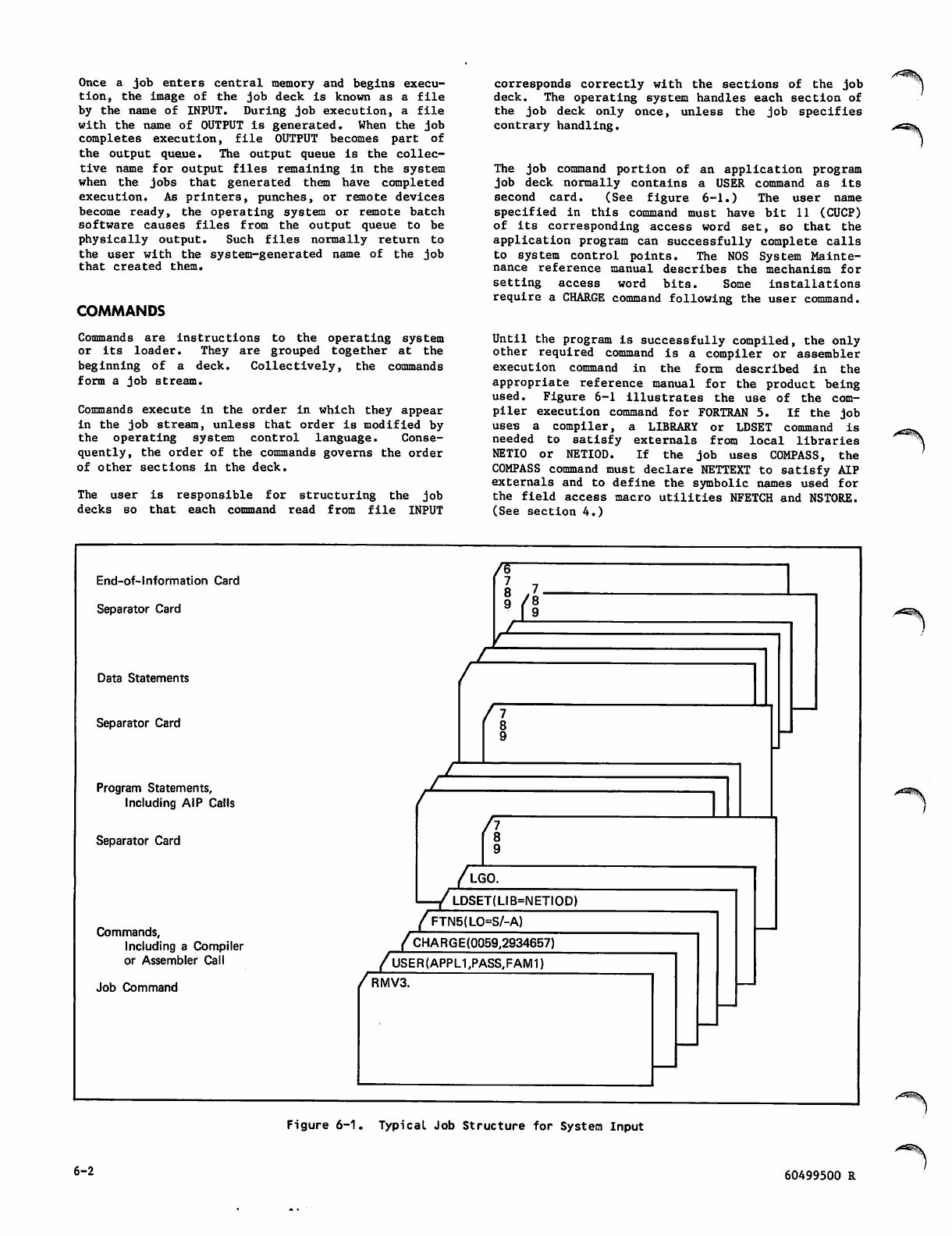
Once a job enters central memory and begins execu
tion, the image of the job deck is known as a file
by the name of INPUT. During job execution, a file
with the name of OUTPUT is generated. When the job
completes execution, file OUTPUT becomes part of
the output queue. The output queue is the collec
tive name for output files remaining in the system
when the jobs that generated them have completed
execution. As printers, punches, or remote devices
become ready, the operating system or remote batch
software causes files from the output queue to be
physically output. Such files normally return to
the user with the system-generated name of the job
that created them.
COMMANDS
Commands are instructions to the operating system
or its loader. They are grouped together at the
beginning of a deck. Collectively, the commands
form a job stream.
Commands execute in the order in which they appear
in the job stream, unless that order is modified by
the operating system control language. Conse
quently, the order of the commands governs the order
of other sections in the deck.
The user is responsible for structuring the job
decks so that each command read from file INPUT
corresponds correctly with the sections of the job
deck. The operating system handles each section of
the job deck only once, unless the job specifies
contrary handling.
The job command portion of an application program
job deck normally contains a USER command as its
second card. (See figure 6-1.) The user name
specified in this command must have bit 11 (CUCP)
of i t s corresp o n ding a c c ess word s e t, so t h a t the
application program can successfully complete calls
to system control points. The NOS System Mainte
nance reference manual describes the mechanism for
setting access word bits. Some installations
require a CHARGE command following the user command.
Until the program is successfully compiled, the only
other required command is a compiler or assembler
execution command in the form described in the
appropriate reference manual for the product being
used. Figure 6-1 illustrates the use of the com
piler execution command for FORTRAN 5. If the job
uses a compiler, a LIBRARY or LDSET command is
needed to satisfy externals from local libraries
NETIO or NETIOD. If the job uses COMPASS, the
COMPASS command must declare NETTEXT to satisfy AIP
externals and to define the symbolic names used for
the field access macro utilities NFETCH and NSTORE.
(See section 4.)
End-of-lnformation Card
Separator Card
Data Statements
Separator Card
Program Statements,
Including AIP Calls
Separator Card
Commands,
Including a Compiler
or Assembler Call
Job Command
hi
IL
n
JL
/lgo.
—/ ldset(lib=netiodT
//FTN5(L0=S/-A)
/CHARGE(0059,2934657)
/USER(APPL1,PASS,FAM17"
RMV3.
Figure 6-1. Typical Job Structure for System Input
6-2 60499500 R
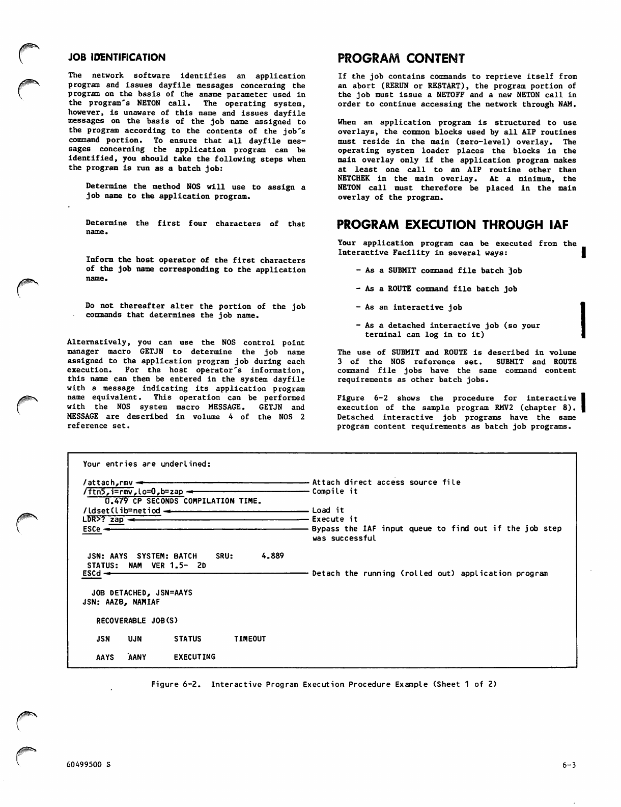
JOB IDENTIFICATION PROGRAM CONTENT
rThe network software identifies an application
program and issues dayfile messages concerning the
program on the basis of the aname parameter used in
the program's NETON call. The operating system,
however, is unaware of this name and issues dayfile
messages on the basis of the job name assigned to
the program according to the contents of the job's
command portion. To ensure that all dayfile mes
sages concerning the application program can be
identified, you should take the following steps when
the program is run as a batch job:
Determine the method NOS will use to assign a
job name to the application program.
If the job contains commands to reprieve itself from
an abort (RERUN or RESTART), the program portion of
the job must issue a NETOFF and a new NETON call in
order to continue accessing the network through NAM.
When an application program is structured to use
overlays, the common blocks used by all AIP routines
must reside in the main (zero-level) overlay. The
operating system loader places the blocks in the
main overlay only if the application program makes
at least one call to an AIP routine other than
NETCHEK i n the mai n ove rla y. At a min imu m, the
NETON call must ther efo re b e placed in the main
overlay of the program.
Determine the first four characters of that
name.
Inform the host operator of the first characters
of the job name corresponding to the application
Do not thereafter alter the portion of the job
commands that determines the job name.
Alternatively, you can use the NOS control point
manager macro GETJN to determine the job name
assigned to the application program job during each
execution. For the host operator's information,
this name can then be entered in the system dayfile
with a message indicating its application program
name equivalent. This operation can be performed
with the NOS system macro MESSAGE. GETJN and
MESSAGE are described in volume 4 of the NOS 2
reference set.
PROGRAM EXECUTION THROUGH IAF
Your application program can be executed from the
Interactive Facility in several ways: |
- As a SUBMIT command file batch job
- As a ROUTE command file batch job
- As an interactive job
- As a detached interactive job (so your
terminal can log in to it)
The use of SUBMIT and ROUTE is described in volume
3 of the NOS reference set. SUBMIT and ROUTE
command file jobs have the same command content
requirements as other batch jobs.
Figure 6-2 shows the procedure for interactive
execution of the sample program RMV2 (chapter 8).
Detached interactive job programs have the same
program content requirements as batch job programs.
Your entries are underlined:
/attach,rmv"*
/ftn5,i=rmv,lo=0,b=zap -«
0.479 CP SECONDS COMPILATION TIME.
/ldset(lib=netiod —
LDR>? zap «
ESC e -
JSN: AAYS SYSTEM: BATCH SRU:
STATUS: NAM VER 1.5- 2D
ESCd—
4.889
JOB DETACHED, JSN=AAYS
JSN: AAZB, NAMIAF
RECOVERABLE JOB(S)
J S N U J N S T A T U S
AAYS AANY EXECUTING
TIMEOUT
Attach direct access source file
Compile it
Load it
Execute it
Bypass the IAF input queue to find out if the job step
was successful
Detach the running (rolled out) application program
Figure 6-2. Interactive Program Execution Procedure Example (Sheet 1 of 2)
60499500 S 6-3
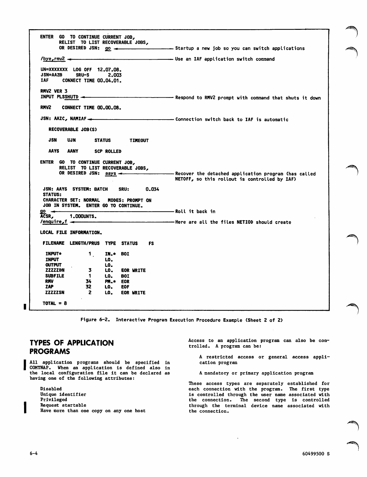
ENTER GO TO CONTINUE CURRENT JOB,
RELIST TO LIST RECOVERABLE JOBS,
OR DESIRED JSN: go, ,.
/bye,rmv2 —-
UN=XXXXXXX LOG OFF 12.07.08.
JSN=AAZB SRU-S 2.003
IAF CONNECT TIME 00.04.01.
RMV2 VER 3
INPUT PLSSHUTD —
RMV2 CONNECT TIME 00.00.08.
JSN: AAZC, NAMIAF-.
RECOVERABLE JOB(S)
JSN UJN STATUS TIMEOUT
AAYS AANY SCP ROLLED
ENTER GO TO CONTINUE CURRENT JOB,
RELIST TO LIST RECOVERABLE JOBS,
OR DESIRED JSN: aay_s —
SRU:JSN: AAYS SYSTEM: BATCH
STATUS:
CHARACTER SET: NORMAL MODES: PROMPT ON
JOB IN SYSTEM. ENTER 60 TO CONTINUE.
go -*
ACSR, 1.000UNTS.
/enquire,f —
0.034
LOCAL FILE INFORMATION.
FILENAME LENGTH/PRUS TYPE STATUS
INPUT*
INPUT
OUTPUT
ZZZZZDN
SUBFILE
RMV
ZAP
ZZZZZSN
TOTAL = 8
FS
1IN.* BOI
LO.
LO.
3LO. EOR WRITE
1LO. BOI
34 PH.* EOR
32 LO. EOF
2LO. EOR WRITE
Startup a new job so you can switch applications
Use an IAF application switch command
Respond to RMV2 prompt with command that shuts it down
Connection switch back to IAF is automatic
•Recover the detached application program (has called
NETOFF, so this rollout is controlled by IAF)
Roll it back in
Here are all the files NETIOD should create
^19$.
Figure 6-2. Interactive Program Execution Procedure Example (Sheet 2 of 2)
TYPES OF APPLICATION
PROGRAMS
All application programs should be specified in
COMTNAP. When an application is defined also in
the local configuration file it can be declared as
having one of the following attributes:
Disabled
Unique identifier
Privileged
Request startable
Have more than one copy on any one host
Access to an application program can also be con
trolled. A program can be:
A restricted access or general access appli
cation program
A mandatory or primary application program
These access types are separately established for
each connection with the program. The first type
is controlled through the user name associated with
the connection. The second type is controlled
through the terminal device name associated with
the connection.
6-4 60499500 S
DISABLED
A disabled application is configured in the network
but is not allowed to access the network until the
host operator enters an enable command to allow it
to be connected.
UNIQUE IDENTIFIER
A unique identifier application program requires
that interactive console user access to it be
restricted on the basis of the login parameters
used. Only one interactive console with a given
combination of family name and user name index can
be connected with a unique identifier application.
NVF rejects a terminal user's request to be con
nected with a unique identifier application if the
user logs in with a family name and user name index
combination used by a console that is already con
nected with the application. NVF tells the terminal
use r to try a gain late r.
As an example, the Remote Batch Facility (RBF)
routes its output files on the basis of the family
and user names used when the terminal console logs
in. So that output will not be misrouted, RBF is
normally configured as a unique identifier appli
cation program. Thus the family name and user name
index combinations of all consoles accessing the
program are guaranteed to be unique.
PRIVILEGED
Privileged application programs must have an SSJ=
entry point to access the network successfully.
They also often have the CSOJ bit set in the access
word associated with the user name for the job
executing the program code.
The CSOJ bit provides the program with system
origin type permission. Jobs with system origin
type permission can be executed by host operator
type-in. Such jobs usually reside under the
operating system user name in the operating system
permanent file catalog or are installed in the
operating system library.
Having system origin type permission does not mean
that these programs must have a system origin type
when executed; rather, a privileged application
program is capable of such execution.
Nonprivileged application programs can have any
origin type permission but do not contain an SSJ=
entry point. Origin type permission for such
programs does not affect access to the network.
The primary reason for defining an application
program as privileged is to help ensure network
security. Nonprivileged application progams cannot
run wit h the app lic ati on p rog ram nam e used fo r a
privileged application, even if the privileged
application program is not currently running.
Application programs usually become privileged when
t h e y a r e i n s t a l l e d i n t h e s y s t e m . A n i n s t a l l e d
application program is one that resides in the
operating system library. The procedure file used
to execute an installed application program must
have the CASF bit set in the access word associated
with the user name in the file. Jobs that attempt
to access installed application programs must also
have the CASF bit set in the access words associated
with their user names. This bit must be set for
access to the system library.
If a privileged application program with the CSOJ
bit set has not been installed in the system
l i b r a r y, i t c a n b e e x e c u t e d b y a h o s t o p e r a t o r
type-in that invokes its procedure file. The type-
in used has the form:
X. BEGIN(,anamep)
where the anamep parameter is the name of the
procedure file. The procedure file must be a
permanent file in the operating system permanent
file catalog (stored under the system user name and
user index). For the anamep value, you can use a
variant of either the program entry point name or
the program network application name (NETON state
ment aname parameter), and all three identifiers
should be coordinated. CDC-written application
p r o gr a m s a r e i n v o ke d t h ro u gh p r o c e d ur e fi l e s f o r
which certain naming conventions have been adopted.
These conventions appear in the NOS Installation
Handbook, described in the preface. Similar
conventions could be adopted for site-written
application programs.
An installed privileged application program with
the CSOJ bit set can be executed by a host operator
type-in of the form:
X.anament.
where the anament parameter is the name of the
program (first entry point) installed in the
library. For the anament value, you can use a
variant of the program network application name
(NETON statement aname parameter).
A privileged application program with the CSOJ bit
set that is not installed can be executed by a
system console operator type-in that invokes an
installed procedure file. This type-in has the
form:
X.anamep.
where the anamep parameter is the name of the
procedure file installed in the system library.
F o r t h e a n a m e p v a l u e y o u c a n u s e a v a r i a n t o f
e i t h e r t h e p r o g r a m e n t r y p o i n t o r t h e p r o g r a m
network application name (NETON statement aname
parameter), and all three identifiers should be
coordinated. As described previously, the naming
conventions used by CDC for CDC-written application
programs should be used as a guide for procedure
files invoking site-written application programs.
Privileged application programs with the CSOJ bit
set can be automatically started when the host's
network software is started. This process is
described in the NOS Administration reference |
manual.
You should not define an application program as
privileged or install it in the system library
until the program has been thoroughly debugged.
Programs should be run with batch, remote batch, or
detached interactive job origin during the
debugging process.
60499500 S 6-5
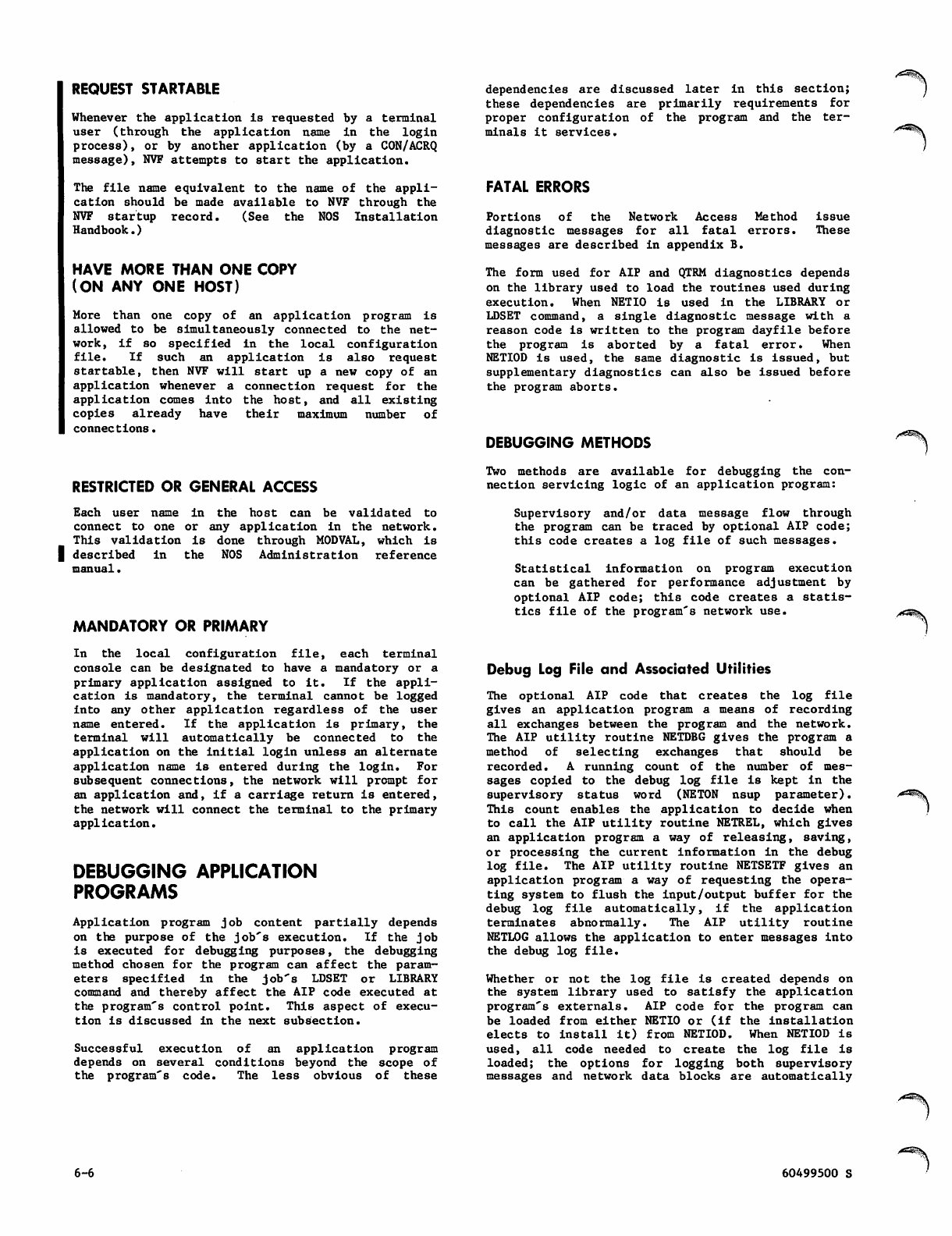
REQUEST STARTABLE
Whenever the application is requested by a terminal
u s e r ( t h r o u g h t h e a p p l i c a t i o n n a m e i n t h e l o g i n
process), or by another application (by a CON/ACRQ
message), NVF attempts to start the application.
The file name equivalent to the name of the appli
cation should be made available to NVF through the
N V F s t a r t u p r e c o r d . ( S e e t h e N O S I n s t a l l a t i o n
Handbook.)
HAVE MORE THAN ONE COPY
(ON ANY ONE HOST)
More than one copy of an application program is
allowed to be simultaneously connected to the net
work, if so specified in the local configuration
file. If such an application is also request
startable, then NVF will start up a new copy of an
application whenever a connection request for the
application comes into the host, and all existing
copies already have their maximum number of
connections.
RESTRICTED OR GENERAL ACCESS
Each user name in the host can be validated to
co nne ct to o ne or a ny applic ation in the net wor k.
Th is validation is done through MODVAL, which is
I described in the NOS Administration reference
manual.
MANDATORY OR PRIMARY
In the local configuration file, each terminal
console can be designated to have a mandatory or a
primary application assigned to it. If the appli
cation is mandatory, the terminal cannot be logged
into any other application regardless of the user
name entered. If the application is primary, the
terminal will automatically be connected to the
application on the initial login unless an alternate
application name is entered during the login. For
subsequent connections, the network will prompt for
an application and, if a carriage return is entered,
the network will connect the terminal to the primary
application.
DEBUGGING APPLICATION
PROGRAMS
Application program job content partially depends
on the purpose of the job's execution. If the job
is executed for debugging purposes, the debugging
method chosen for the program can affect the param
eters specified in the job's LDSET or LIBRARY
command and thereby affect the AIP code executed at
the program's control point. This aspect of execu
tion is discussed in the next subsection.
Successful execution of an application program
depends on several conditions beyond the scope of
the program's code. The less obvious of these
dependencies are discussed later in this section;
these dependencies are primarily requirements for
proper configuration of the program and the ter
minals it services.
FATAL ERRORS
Portions of the Network Access Method issue
diagnostic messages for all fatal errors. These
messages are described in appendix B.
The form used for AIP and QTRM diagnostics depends
on the library used to load the routines used during
execution. When NETIO is used in the LIBRARY or
LDSET command, a single diagnostic message with a
reason code is written to the program dayfile before
the program is aborted by a fatal error. When
NETIOD is used, the same diagnostic is issued, but
supplementary diagnostics can also be issued before
the program aborts.
DEBUGGING METHODS
Two methods are available for debugging the con
nection servicing logic of an application program:
Supervisory and/or data message flow through
the program can be traced by optional AIP code;
this code creates a log file of such messages.
Statistical information on program execution
can be gathered for performance adjustment by
optional AIP code; this code creates a statis
tics file of the program's network use.
Debug Log File and Associated Utilities
The optional AIP code that creates the log file
gives an application program a means of recording
all exchanges between the program and the network.
The AIP utility routine NETDBG gives the program a
method of selecting exchanges that should be
recorded. A running count of the number of mes
sages copied to the debug log file is kept in the
sup e rviso r y stat u s word ( NETO N nsup p arame t er).
This count enables the application to decide when
to call the AIP utility routine NETREL, which gives
an application program a way of releasing, saving,
or processing the current information in the debug
log file. The AIP utility routine NETSETF gives an
application program a way of requesting the opera
ting system to flush the input/output buffer for the
debug log file automatically, if the application
terminates abnormally. The AIP utility routine
NETLOG allows the application to enter messages into
the debug log file.
Whether or not the log file is created depends on
the system library used to satisfy the application
program's externals. AIP code for the program can
be loaded from either NETIO or (if the installation
elects to install it) from NETIOD. When NETIOD is
u s e d , a l l c o d e n e e d e d t o c r e a t e t h e l o g fi l e i s
loaded; the options for logging both supervisory
messages and network data blocks are automatically
6-6 60499500 S
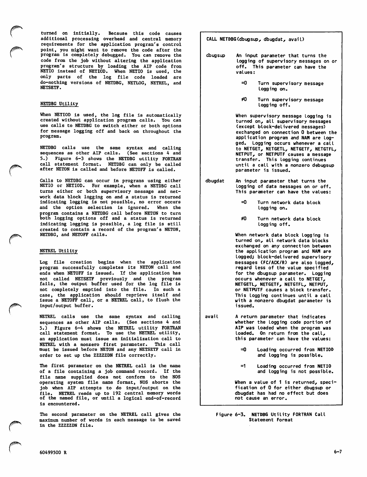
turned on initially. Because this code causes
additional processing overhead and central memory
requirements for the application program's control
point, you might want to remove the code after the
program is completely debugged. You can remove the
code f r om the j o b w ithout a l t ering t h e a pplicati o n
program's structure by loading the AIP code from
NETIO instead of NETIOD. When NETIO is used, the
o n l y p a r t s o f t h e l o g fi l e c o d e l o a d e d a r e
do-nothing versions of NETDBG, NETLOG, NETREL, and
NETSETF.
NETDBG Utility
When NETIOD is used, the log file is automatically
created without application program calls. You can
use calls to NETDBG to switch either or both options
for message logging off and back on throughout the
program.
NETDBG calls use the same syntax and calling
sequences as other AIP calls. (See sections 4 and
5.) Figure 6-3 shows the NETDBG utility FORTRAN
call statement format. NETDBG can only be called
after NETON is called and before NETOFF is called.
Calls to NETDBG can occur in programs using either
NETIO or NETIOD. For example, when a NETDBG call
turns either or both supervisory message and net
work data block logging on and a status is returned
indicating logging is not possible, no error occurs
and the option selection is ignored. When the
program contains a NETDBG call before NETON to turn
both logging options off and a status is returned
indicating logging is possible, a log file is still
created to contain a record of the program's NETON,
NETDBG, and NETOFF calls.
NETREL Utility
Log file creation begins when the application
program successfully completes its NETON call and
ends when NETOFF is issued. If the application has
n o t c a l l ed N E T S E T F p r e v io u s l y a n d t h e p r o g r a m
fails, the output buffer used for the log file is
not completely emptied into the file. In such a
case, the application should reprieve itself and
issue a NETOFF call, or a NETREL call, to flush the
input/output buffer.
NETREL calls use the same syntax and calling
sequences as other AIP calls. (See sections 4 and
5.) Figure 6-4 shows the NETREL utility FORTRAN
call statement format. To use the NETREL utility,
an application must issue an initialization call to
NETREL with a nonzero first parameter. This call
must be issued before NETON and any NETSETF call in
order to set up the ZZZZZDN file correctly.
The first parameter on the NETREL call is the name
of a file containing a job command record. If the
file name supplied does not conform to the NOS
operating system file name format, NOS aborts the
jo b w h e n AI P att e m p t s t o do i nput / o u t put on t h e
file. NETREL reads up to 192 central memory words
of the named file, or until a logical end-of-record
is encountered.
The second parameter on the NETREL call gives the
maximum number of words in each message to be saved
in the ZZZZZDN file.
CALL NETDBG(dbugsup, dbugdat, avail)
dbugsup
dbugdat
avail
An input parameter that turns the
logging of supervisory messages on or
off. This parameter can have the
values:
=0
*0
Turn supervisory message
logging on.
Turn supervisory message
logging off.
When supervisory message Logging is
turned on, all supervisory messages
(except block-delivered messages)
exchanged on connection 0 between the
application program and NAM are log
ged. Logging occurs whenever a call
to NETGET, NETGETL, NETGETF, NETGTFL,
NETPUT, or NETPUTF causes a message
transfer. This logging continues
until a call with a nonzero debugsup
parameter is issued.
An input parameter that turns the
logging of data messages on or off.
This parameter can have the values:
=0 Turn network data block
logging on.
*0 Turn network data block
Logging off.
When network data block logging is
turned on, all network data blocks
exchanged on any connection between
the application program and NAM are
logged; block-delivered supervisory
messages (FC/ACK/R) are also logged,
regard less of the value specified
for the dbugsup parameter. Logging
occurs whenever a call to NETGET,
NETGETL, NETGETF, NETGTFL, NETPUT,
or NETPUTF causes a block transfer.
This logging continues until a call
with a nonzero dbugdat parameter is
issued.
A return parameter that indicates
whether the Logging code portion of
AIP was loaded when the program was
loaded. On return from the call,
this parameter can have the values:
=0 Loading occurred from NETIOD
and logging is possible.
=1 Loading occurred from NETIO
and logging is not possible.
When a value of 1 is returned, speci
fication of 0 for either dbugsup or
dbugdat has had no effect but does
not cause an error.
Figure 6-3. NETDBG Utility FORTRAN Call
Statement Format
60499500 R 6-7
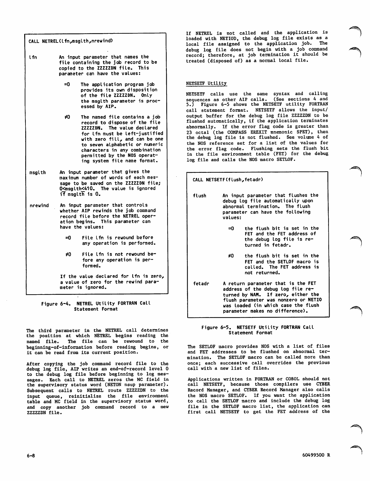
CALL NETREL(lfn,msglth,nrewind)
l f n
msglth
nrewind
An input parameter that names the
file containing the job record to be
copied to the ZZZZZDN file. This
parameter can have the values:
=0 The application program job
provides its own disposition
of the file ZZZZZDN. Only
the msglth parameter is proc
essed by AIP.
*0 The named file contains a job
record to dispose of the file
ZZZZZDN. The value declared
for lfn must be left-justified
with zero fill, and can be one
to seven alphabetic or numeric
characters in any combination
permitted by the NOS operat
ing system file name format.
An input parameter that gives the
maximum number of words of each mes
sage to be saved on the ZZZZZDN file;
0<msglth<410. The value is ignored
iT msglth" is 0.
An input parameter that controls
whether AIP rewinds the job command
record file before the NETREL oper
ation begins. This parameter can
have the values:
=0
to
File lfn is rewound before
any operation is performed.
File lfn is not rewound be
fore any operation is per
formed.
If the value declared for lfn is zero,
a value of zero for the rewind para
meter is ignored.
Figure 6-4. NETREL Utility FORTRAN Call
Statement Format
If NETREL is not called and the application is
loaded with NETIOD, the debug log file exists as a
l o c a l fi l e a s s i g n e d t o t h e a p p l i c a t i o n j o b . T h e
debug log file does not begin with a job command
record; therefore, at job termination it should be
treated (disposed of) as a normal local file.
NETSETF Utility
NETSETF calls use the same syntax and calling
sequences as other AIP calls. (See sections 4 and
5.) Figure 6-5 shows the NETSETF utility FORTRAN
call statement format. NETSETF allows the input/
output buffer for the debug log file ZZZZZDN to be
flushed automatically, if the application terminates
abnormally. If the error flag code is greater than
23 octal (the COMPASS EREXIT mnemonic SPET), then
the debug log file is not flushed. See volume 4 of
the NOS reference set for a list of the values for
the error flag code. Flushing sets the flush bit
in the file environment table (FET) for the debug
log file and calls the NOS macro SETLOF.
CALL NETSETF(flush,fetadr)
flush An input parameter that flushes the
debug log file automatically upon
abnormal termination. The flush
parameter can have the following
values:
= 0 t h e fl u s h b i t i s s e t i n t h e
FET and the FET address of
the debug log file is re
turn e d in feta d r.
* 0 t h e fl u s h b i t i s s e t i n t h e
FET and the SETLOF macro is
called. The FET address is
not returned.
f e t a d r A r e tu r n p a r a m e t e r t h a t i s t h e F ET
address of the debug log file re
turned by NAM. If zero, either the
flush parameter was nonzero or NETIO
was loaded (in which case the flush
parameter makes no difference).
The third parameter in the NETREL call determines
the position at which NETREL begins reading the
named file. The file can be rewound to the
beginning-of-information before reading begins, or
it can be read from its current position.
After copying the job command record file to the
debug log file, AIP writes an end-of-record level 0
to the debug log file before beginning to log mes
sages. Each call to NETREL zeros the MC field in
the supervisory status word (NETON nsup parameter).
Subsequent calls to NETREL route ZZZZZDN to the
input queue, reinitialize the file environment
table and MC field in the supervisory status word,
and copy another job command record to a new
ZZZZZDN file.
Figure 6-5. NETSETF Utility FORTRAN Call
Statement Format
The SETLOF macro provides NOS with a list of files
and FET addresses to be flushed on abnormal ter
mination. The SETLOF macro can be called more than
once; each successive call overrides the previous
call with a new list of files.
Applications written in FORTRAN or COBOL should not
call NETSETF, because those compilers use CYBER
Record Manager, and CYBER Record Manager also calls
the NOS macro SETLOF. If you want the application
to call the SETLOF macro and include the debug log
file in the SETLOF macro list, the application can
first call NETSETF to get the FET address of the
6-8 60499500 R
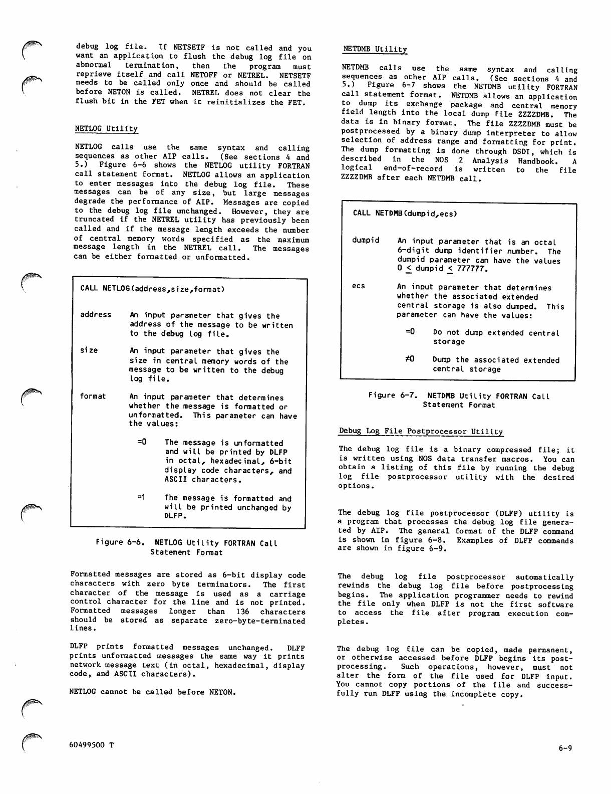
>^SS\ debu g l o g file. I f NETSET F i s not c a l led and y ou
want an application to flush the debug log file on
abnormal termination, then the program must
reprieve itself and call NETOFF or NETREL. NETSETF
needs to be called only once and should be called
before NETON is called. NETREL does not clear the
flush bit in the FET when it reinitializes the FET.
NETLOG Utility
N E T L O G c a l l s u s e t h e s a m e s y n t a x a n d c a l l i n g
sequences as other AIP calls. (See sections 4 and
5.) Figure 6-6 shows the NETLOG utility FORTRAN
call statement format. NETLOG allows an application
to enter messages into the debug log file. These
messages can be of any size, but large messages
degrade the performance of AIP. Messages are copied
to the debug log file unchanged. However, they are
truncated if the NETREL utility has previously been
called and if the message length exceeds the number
of central memory words specified as the maximum
message length in the NETREL call. The messages
can be either formatted or unformatted.
CALL NETLOG(address,size,format)
addr e ss An inpu t parame t er that g ives t he
address of the message to be written
to the debug log file.
size An input parameter that gives the
size in central memory words of the
message to be written to the debug
log file.
format An input parameter that determines
whether the message is formatted or
unformatted. This parameter can have
the values:
=0 The message is unformatted
and will be printed by DLFP
in octal, hexadecimal, 6-bit
display code characters, and
ASCII characters.
=1 The message is formatted and
will be printed unchanged by
DLFP.
NETDMB Utility
NETDMB calls use the same syntax and calling
sequences as other AIP calls. (See sections 4 and
5.) Figure 6-7 shows the NETDMB utility FORTRAN
call statement format. NETDMB allows an application
to dump its exchange package and central memory
field length into the local dump file ZZZZDMB. The
data is in binary format. The file ZZZZDMB must be
postprocessed by a binary dump interpreter to allow
selection of address range and formatting for print.
The dump formatting is done through DSDT, which is
described in the NOS 2 Analysis Handbook. A
logical end-of-record is written to the file
ZZZZDMB after each NETDMB call.
CALL NETDMB(dumpid,ecs)
dumpid An input parameter that is an octal
6-digit dump identifier number. The
dumpid parameter can have the values
0 <_ dumpid <_ 777777.
ecs An input parameter that determines
whether the associated extended
central storage is also dumped. This
parameter can have the values:
=0 Do not dump extended central
storage
*0 Dump the associated extended
central storage
Figure 6-6. NETLOG Utility FORTRAN Call
Statement Format
Figure 6-7. NETDMB Utility FORTRAN Call
Statement Format
Debug Log File Postprocessor Utility
The debug log file is a binary compressed file; it
is written using NOS data transfer macros. You can
obtain a listing of this file by running the debug
log file postprocessor utility with the desired
options.
The debug log file postprocessor (DLFP) utility is
a program that processes the debug log file genera
ted by AIP. The general format of the DLFP command
is shown in figure 6-8. Examples of DLFP commands
are shown in figure 6-9.
Formatted messages are stored as 6-bit display code
characters with zero byte terminators. The first
character of the message is used as a carriage
control character for the line and is not printed.
Formatted messages longer than 136 characters
sho u ld be s tored a s separ a te zer o -byte -term i nated
lines.
The debug log file postprocessor automatically
rewinds the debug log file before postprocessing
begins. The application programmer needs to rewind
th e fi l e o nl y w h en DL F P i s n o t th e fi r st so f t war e
to access the file after program execution com
pletes.
DLFP prints formatted messages unchanged. DLFP
prints unformatted messages the same way it prints
network message text (in octal, hexadecimal, display
code, and ASCII characters).
NETLOG cannot be called before NETON.
The debug log file can be copied, made permanent,
or otherwise accessed before DLFP begins its post
processing. Such operations, however, must not
a l t e r t h e f o r m o f t h e fi l e u s e d f o r D L F P i n p u t .
You cannot copy portions of the file and success
fully run DLFP using the incomplete copy.
60499500 T 6-9
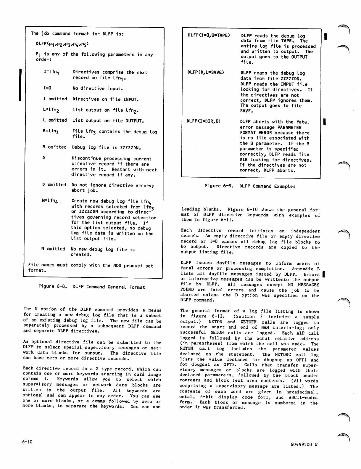
The job command format for DLFP is:
DLFP(p1,p2,p3,P4,p5)
P^ is any of the following parameters in any
order:
I=lfn<| Directives comprise the next
record on file Ifn-j.
1=0 No directive input.
I omitted Directives on file INPUT.
L=lfn2 List output on file lfn2.
L omitted List output on file OUTPUT.
B=lfn3 File lfn* contains the debug log
file.
B omitted Debug log file is ZZZZZDN.
D Discontinue processing current
directive record if there are
errors in it. Restart with next
directive record if any.
D omitted Do not ignore directive errors;
abort job.
N=lfn4 Create new debug log file lfn4
with records selected from lfn*
or ZZZZZDN according to direc
tives governing record selection
f o r t h e l i s t o u t p u t fi l e . I f
this option selected, no debug
log file data is written on the
l i s t o u t p u t fi l e .
N omitted No new debug log file is
created.
File names must comply with the NOS product set
format.
Figure 6-8. DLFP Command General Format
The N option of the DLFP command provides a means
for creating a new debug log file that is a subset
of an existing debug log file. The new file can be
separately processed by a subsequent DLFP command
and separate DLFP directives.
An optional directive file can be submitted to the
DLFP to select special supervisory messages or net
work data blocks for output. The directive file
can have zero or more directive records.
Each directive record is a Z type record, which can
contain one or more keywords starting in card image
c o l u m n 1 . K e y w o r d s a l l o w y o u t o s e l e c t w h i c h
supervisory messages or network data blocks are
written to the output file. Ml keywords are
optional and can appear in any order. You can use
one or more blanks, or a comma followed by zero or
more blanks, to separate the keywords. You can use
DLFP(I=0,B=TAPE)
DLFP(D,L=SAVE)
DLFP(I=DIR,B)
DLFP reads the debug log
data from file TAPE. The
enti r e log file i s p rocess e d
and written to output. The
output goes to the OUTPUT
file.
DLFP reads the debug log
data from file ZZZZZDN.
DLFP reads the INPUT file
looking for directives. If
the directives are not
correct, DLFP ignores them.
The output goes to file
SAVE.
DLFP aborts with the fatal
error message PARAMETER
FORMAT ERROR because there
is no file associated with
the B parameter. If the B
parameter is specified
correctly, DLFP reads file
DIR looking for directives.
If the directives are not
correct, DLFP aborts.
Figure 6-9. DLFP Command Examples
leading blanks. Figure 6-10 shows the general for
mat of DLFP directive keywords with examples of
them in figure 6-11.
Each directive record Initiates an independent
search. An empty directive file or empty directive
rec o rd or 1 =0 caus es all d ebug log fi l e block s to
be output. Directive records are copied to the
output listing file.
DLFP issues dayfile messages to inform users of
fatal errors or processing completion. Appendix B
lists all dayfile messages issued by DLFP. Errors I
or informative messages can be writtento the output
file by DLFP. AM messages except NO MESSAGES
FOUND are fatal errors and cause the job to be
aborted unless the D option was specified on the
DLFP command.
The general format of a log file listing is shown
in figure 6-12. (Section 7 includes a sample
out p u t . ) N E TO N a n d N E T O F F c a l ls a re l o gged to
record the start a nd e nd of NAM int erf aci ng; only
successful NETON calls are logged. Each AIP call
logged is followed by the octal relative address
(in parentheses) from which the call was made. The
N E T O N c a l l l o g i n c l u d e s t h e p a r a m e t e r v a l u e s
declared on the statement. The NETDBG call log
lists the value declared for dbugsup as 0PT1 and
f o r d b u g d a t a s 0 P T 2 . C a l l s t h a t t r a n s f e r s u p e r
visory messages or blocks are logged with their
declared parameters, followed by the block header
contents and block text area contents. (All words
comprising a supervisory message are listed.) The
contents of each word are given in hexadecimal,
octal, 6-bit display code form, and ASCII-coded
form. Each block or message is numbered in the
order it was transferred.
6-10 60499500 W
/ ^ S ? v
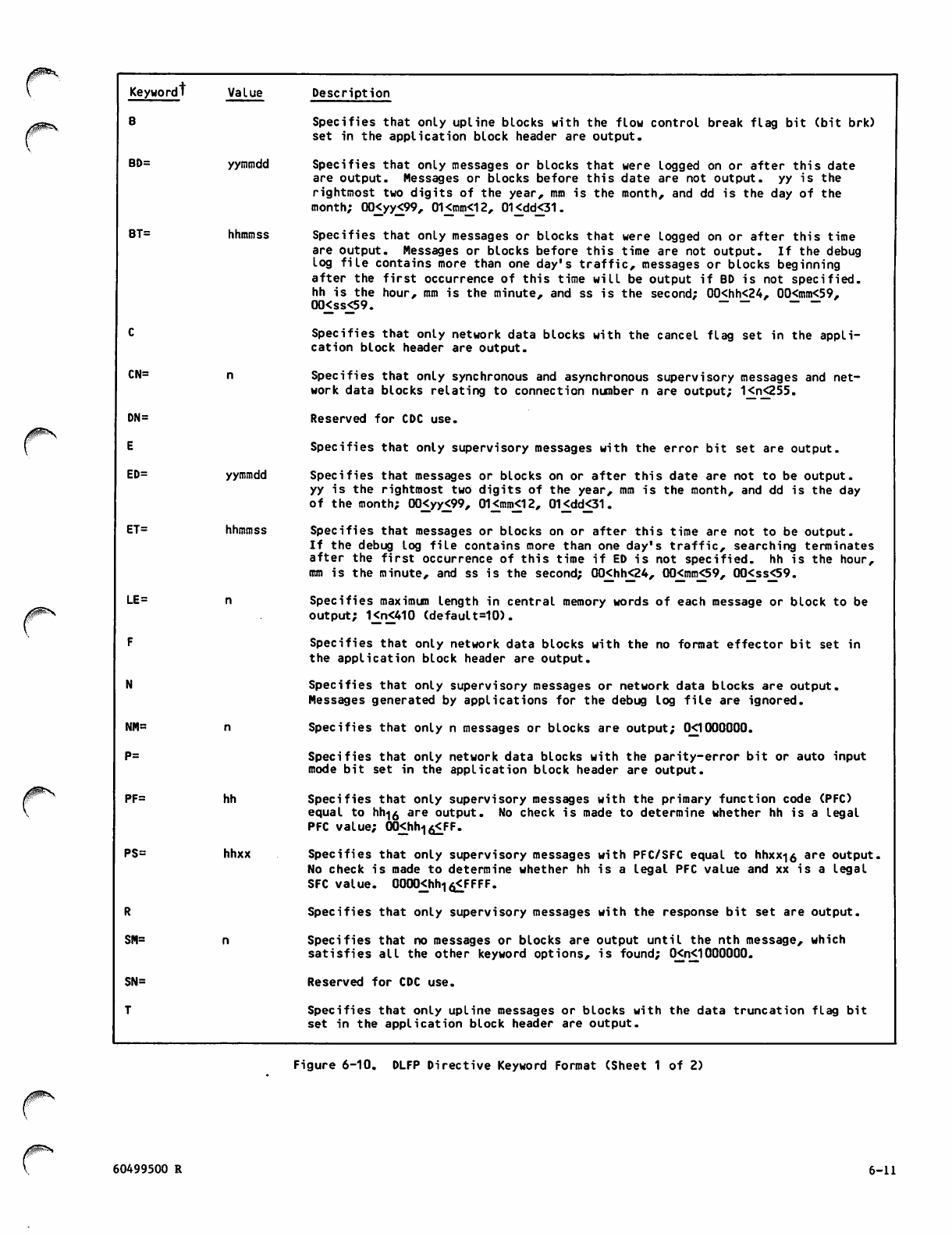
Keyword! Value Description
BSpecifies that only upline blocks with the flow control break flag bit (bit brk)
set in the application block header are output.
BD= yymmdd Specifies that only messages or blocks that were logged on or after this date
are output. Messages or blocks before this date are not output, yy is the
rightmost two digits of the year, mm is the month, and dd is the day of the
month; 00<yy<99, 01<mm<12, 01<dd<31.
BT= hhmmss Specifies that only messages or blocks that were logged on or after this time
are output. Messages or blocks before this time are not output. If the debug
log file contains more than one day's traffic, messages or blocks beginning
after the first occurrence of this time will be output if BD is not specified,
hh is the hour, mm is the minute, and ss is the second; 00<hh<24, 00<mm<59,
0 0 < s s < 5 9 . ~ ~ ~ —
CSpecifies that only network data blocks with the cancel flag set in the appli
cation block header are output.
CN= Specifies that only synchronous and asynchronous supervisory messages and net
work data blocks relating to connection number n are output; 1<n<255.
DN= Reserved for CDC use.
ESpecifies that only supervisory messages with the error bit set are output.
ED= yymmdd Specifies that messages or blocks on or after this date are not to be output,
yy is the rightmost two digits of the year, mm is the month, and dd is the day
of the month; 00<yy<99, 01<mm<12, 01<dd<31.
ET= hhmmss Specifies that messages or blocks on or after this time are not to be output.
If the debug log file contains more than one day's traffic, searching terminates
after the first occurrence of this time if ED is not specified, hh is the hour,
mm is the minute, and ss is the second; 00<hh<24, 00<mm<59, 00<ss<59.
LE= Specifies maximum length in central memory words of each message or block to be
output; 1<n<410 (default=10).
FSpecifies that only network data blocks with the no format effector bit set in
the application block header are output.
NSpecifies that only supervisory messages or network data blocks are output.
Messages generated by applications for the debug log file are ignored.
NM= Specifies that only n messages or blocks are output; 0X1000000.
P= Specifies that only network data blocks with the parity-error bit or auto input
mode bit set in the application block header are output.
PF= hh Specifies that only supervisory messages with the primary function code (PFC)
equal to hh-|0 are output. No check is made to determine whether hh is a legal
PFC value; (XKhhlo<FF.
PS= hhxx Specifies that only supervisory messages with PFC/SFC equal to hhxx<|0 are output.
No check is made to determine whether hh is a legal PFC value and xx is a legal
SFC value. 0000<_hh1o<FFFF.
RSpecifies that only supervisory messages with the response bit set are output.
SM= Specifies that no messages or blocks are output until the nth message, which
satisfies all the other keyword options, is found; 0<n<1000000.
SN= Reserved for CDC use.
TSpecifies that only upline messages or blocks with the data truncation flag bit
set in the application block header are output.
Figure 6-10. DLFP Directive Keyword Format (Sheet 1 of 2)
60499500 R 6-11
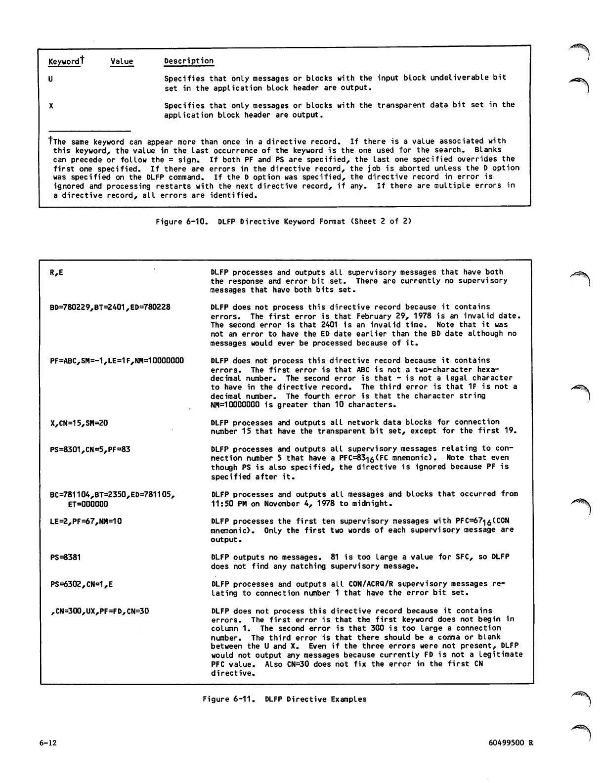
Keywordt Value
U
Description
Specifies that only messages or blocks with the input block undeliverable bit
set in the application block header are output.
Specifies that only messages or blocks with the transparent data bit set in the
application block header are output.
tThe same keyword can appear more than once in a directive record. If there is a value associated with
this keyword, the value in the last occurrence of the keyword is the one used for the search. Blanks
can precede or follow the = sign. If both PF and PS are specified, the last one specified overrides the
first one specified. If there are errors in the directive re cord, the job is aborted unless the D option
was specified on the DLFP command. If the D option was specified, the directive record in error is
ignored and processing restarts with the next directive record, if any. If there are multiple errors in
a directive record, all errors are identified.
Figure 6-10. DLFP Directive Keyword Format (Sheet 2 of 2)
R,E
BD=780229,BT=2401,ED=780228
PF=ABC,SM=-1,LE=1F,NM=10000000
X,CN=15,SM=20
PS=8301,CN=5,PF=83
BC=781104,BT=2350,ED=781105,
ET=000000
LE=2,PF=67,NM=10
PS=8381
PS=6302,CN=1,E
,CN=300,UX,PF=FD,CN=30
DLFP processes and outputs all supervisory messages that have both
the response and error bit set. There are currently no supervisory
messages that have both bits set.
DLFP does not process this directive record because it contains
errors. The first error is that February 29, 1978 is an invalid date.
The second error is that 2401 is an invalid time. Note that it was
not an error to have the ED date earlier than the BD date although no
messages would ever be processed because of it.
DLFP does not process this directive record because it contains
errors. The first error is that ABC is not a two-character hexa
decimal number. The second error is that - is not a legal character
to have in the directive record. The third error is that 1F is not a
decimal number. The fourth error is that the character string
NM=10000000 is greater than 10 characters.
DLFP processes and outputs all network data blocks for connection
number 15 that have the transparent bit set, except for the first 19.
DLFP processes and outputs all supervisory messages relating to con
nection number 5 that have a PFC=83i6(FC mnemonic). Note that even
though PS is also specified, the directive is ignored because PF is
specified after it.
DLFP processes and outputs all messages and blocks that occurred from
11:50 PM on November 4, 1978 to midnight.
DLFP processes the first ten supervisory messages with PFC=67<|6(C0N
mnemonic). Only the first two words of each supervisory message are
output.
DLFP outputs no messages. 81 is too large a value for SFC, so DLFP
does not find any matching supervisory message.
DLFP processes and outputs all CON/ACRQ/R supervisory messages re
lating to connection number 1 that have the error bit set.
DLFP does not process this directive record because it contains
errors. The first error is that the first keyword does not begin in
column 1. The second error is that 300 is too large a connection
number. The third error is that there should be a comma or blank
between the U and X. Even if the three errors were not present, DLFP
would not output any messages because currently FD is not a legitimate
PFC value. Also CN=30 does not fix the error in the first CN
directive.
Figure 6-11. DLFP Directive Examples
6-12 60499500 R
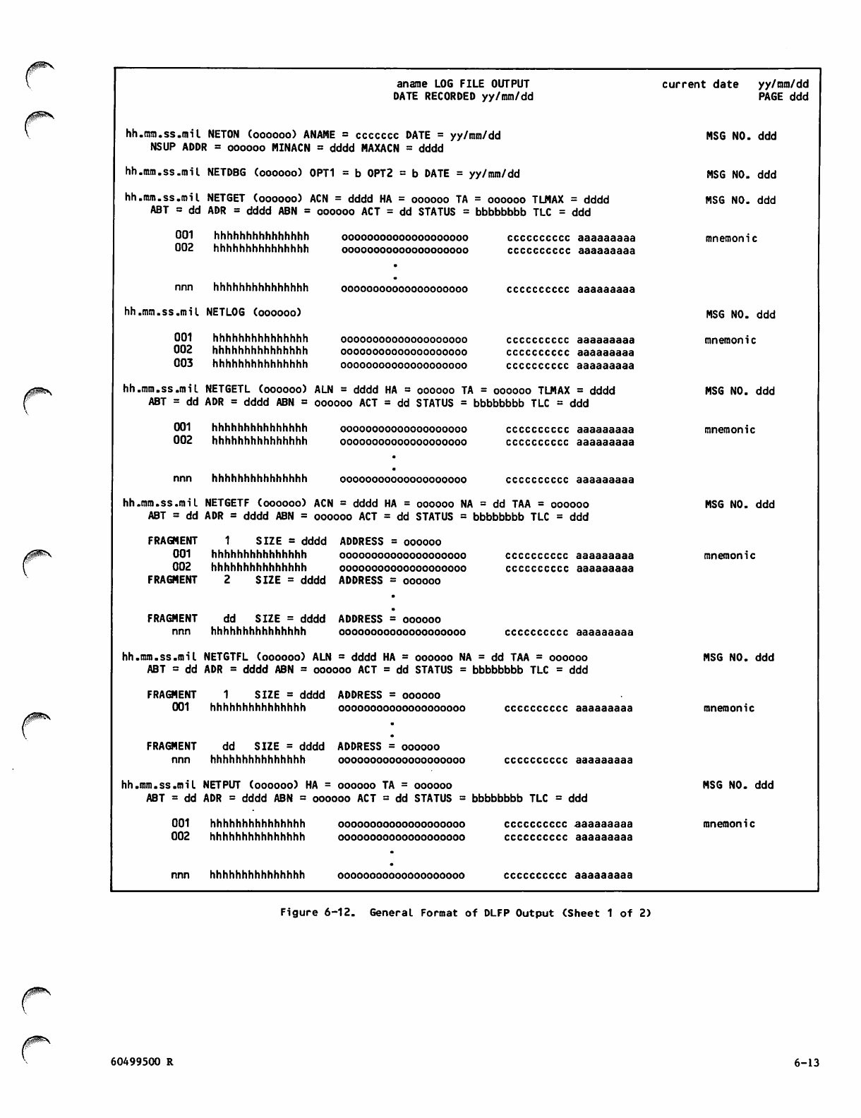
aname LOG FILE OUTPUT
DATE RECORDED yy/mm/dd
current date yy/mm/dd
PAGE ddd
hh .mm.ss.mil NETON (oooooo) ANAME = ccccccc DATE = yy/mm/dd
NSUP ADDR = oooooo MINACN = dddd MAXACN = dddd
MSG NO. ddd
hh .mm.ss.mil NETDBG (oooooo) 0PT1 = b 0PT2 = b DATE = yy/mm/dd MSG NO. ddd
hh .mm.ss.mil
ABT = dd
NETGET (oooooo) ACN = dddd HA = oooooo TA
ADR = dddd ABN = oooooo ACT = dd STATUS =
= oooooo TLMAX = dddd
bbbbbbbb TLC = ddd
MSG NO. ddd
001
002
hhhhhhhhhhhhhhh
hhhhhhhhhhhhhhh
00000000000000000000
oooooooooooooooooooo
cccccccccc aaaaaaaaa
cccccccccc aaaaaaaaa
mnemonic
nnn hhhhhhhhhhhhhhh oooooooooooooooooooo cccccccccc aaaaaaaaa
hh .mm.ss.mil NETLOG (oooooo) MSG NO. ddd
001
002
003
hhhhhhhhhhhhhhh
hhhhhhhhhhhhhhh
hhhhhhhhhhhhhhh
oooooooooooooooooooo
oooooooooooooooooooo
oooooooooooooooooooo
cccccccccc aaaaaaaaa
cccccccccc aaaaaaaaa
cccccccccc aaaaaaaaa
mnemonic
hh .mm.ss.mi I
ABT = dd
NETGETL (oooooo) ALN = dddd HA = oooooo TA
ADR = dddd ABN = oooooo ACT = dd STATUS =
= oooooo TLMAX = dddd
bbbbbbbb TLC = ddd
MSG NO. ddd
001
002
hhhhhhhhhhhhhhh
hhhhhhhhhhhhhhh
oooooooooooooooooooo
oooooooooooooooooooo
cccccccccc aaaaaaaaa
cccccccccc aaaaaaaaa
mnemonic
nnn hhhhhhhhhhhhhhh oooooooooooooooooooo cccccccccc aaaaaaaaa
hh. mm.ss.mil
ABT = dd
NETGETF (oooooo) ACN = dddd HA = oooooo NA
ADR = dddd ABN = oooooo ACT = dd STATUS =
= dd TAA = oooooo
bbbbbbbb TLC = ddd
MSG NO. ddd
FRAGMENT
001
002
FRAGMENT
1 S I Z E = d d d d
hhhhhhhhhhhhhhh
hhhhhhhhhhhhhhh
2 S I Z E = d d d d
ADDRESS = oooooo
oooooooooooooooooooo
oooooooooooooooooooo
ADDRESS = oooooo
cccccccccc aaaaaaaaa
cccccccccc aaaaaaaaa
mnemonic
FRAGMENT
nnn
dd SIZE = dddd
hhhhhhhhhhhhhhh
ADDRESS = oooooo
oooooooooooooooooooo cccccccccc aaaaaaaaa
hh. mm.ss.mil
ABT = dd
NETGTFL (oooooo) ALN = dddd HA = oooooo NA
ADR = dddd ABN = oooooo ACT = dd STATUS =
= dd TAA = oooooo
bbbbbbbb TLC = ddd
MSG NO. ddd
FRAGMENT
001
1 S I Z E = d d d d
hhhhhhhhhhhhhhh
ADDRESS = oooooo
oooooooooooooooooooo cccccccccc aaaaaaaaa mnemonic
FRAGMENT
nnn
dd SIZE = dddd
hhhhhhhhhhhhhhh
ADDRESS = oooooo
oooooooooooooooooooo cccccccccc aaaaaaaaa
hh. mm.ss.mil
ABT = dd
NETPUT (oooooo) HA = oooooo TA = oooooo
ADR = dddd ABN = oooooo ACT = dd STATUS = bbbbbbbb TLC = ddd
MSG NO. ddd
001
002
hhhhhhhhhhhhhhh
hhhhhhhhhhhhhhh
oooooooooooooooooooo
oooooooooooooooooooo
cccccccccc aaaaaaaaa
cccccccccc aaaaaaaaa
mnemonic
nnn hhhhhhhhhhhhhhh oooooooooooooooooooo cccccccccc aaaaaaaaa
Figure 6-12. General Format of DLFP Output (Sheet 1 of 2)
60499500 R 6-13
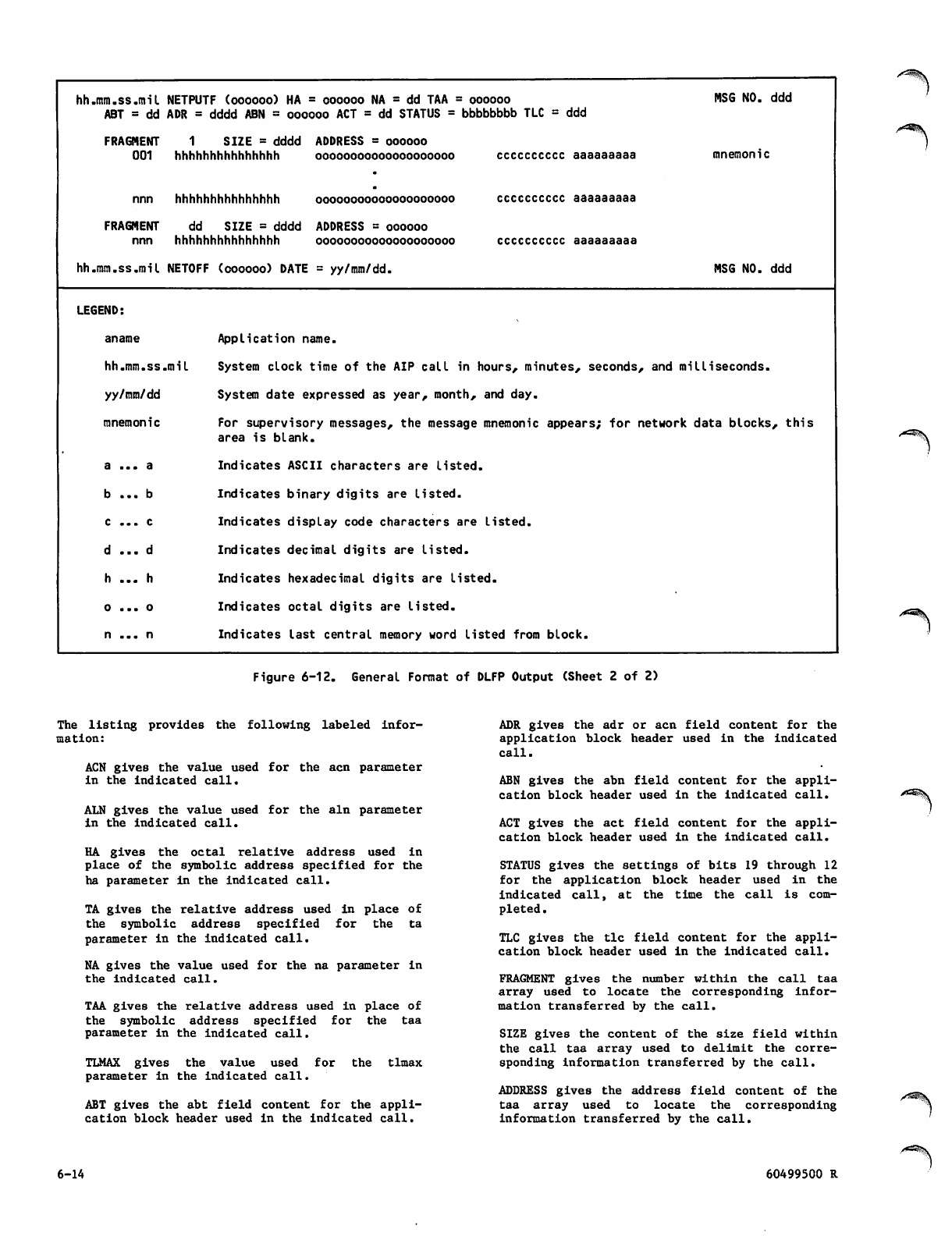
hh.mm.ss.mil NETPUTF (oooooo) HA = oooooo NA = dd TAA = oooooo
ABT = dd ADR = dddd ABN = oooooo ACT = dd STATUS = bbbbbbbb TLC = ddd
FRAGMENT 1 SIZE = dddd ADDRESS = oooooo
001 hhhhhhhhhhhhhhh oooooooooooooooooooo
nnn
FRAGMENT
nnn
hhhhhhhhhhhhhhh oooooooooooooooooooo
dd SIZE = dddd ADDRESS = oooooo
hhhhhhhhhhhhhhh oooooooooooooooooooo
cccccccccc aaaaaaaaa
cccccccccc aaaaaaaaa
cccccccccc aaaaaaaaa
MSG NO. ddd
mnemonic
hh.mm.ss.mil NETOFF (oooooo) DATE = yy/mm/dd. MSG NO. ddd
LEGEND:
aname
hh.mm.ss.mil
yy/mm/dd
mnemonic
a . . . a
b . . . b
c .. . c
d . . . d
h ... h
o . . . o
n . . . n
Application name.
System clock time of the AIP call in hours, minutes, seconds, and milliseconds.
System date expressed as year, month, and day.
For supervisory messages, the message mnemonic appears; for network data blocks, this
area is blank.
Indicates ASCII characters are listed.
Indicates binary digits are listed.
Indicates display code characters are listed.
Indicates decimal digits are listed.
Indicates hexadecimal digits are listed.
Indicates octal digits are listed.
Indicates last central memory word listed from block.
^2®$\
Figure 6-12. General Format of DLFP Output (Sheet 2 of 2)
The listing provides the following labeled infor
mation:
ACN gives the value used for the acn parameter
in the indicated call.
ALN gives the value used for the aln parameter
in the indicated call.
HA gives the octal relative address used in
place of the symbolic address specified for the
ha parameter in the indicated call.
TA gives the relative address used in place of
the symbolic address specified for the ta
parameter in the indicated call.
NA gives the value used for the na parameter in
the indicated call.
TAA gives the relative address used in place of
the symbolic address specified for the taa
parameter in the indicated call.
TLMAX gives the value used for the tlmax
parameter in the indicated call.
ABT gives the abt field content for the appli
cation block header used in the indicated call.
ADR gives the adr or acn field content for the
application block header used in the indicated
call.
ABN gives the abn field content for the appli
cation block header used in the indicated call.
ACT gives the act field content for the appli
cation block header used in the indicated call.
STATUS gives the settings of bits 19 through 12
f o r t h e a p p l i c a t io n b l o c k he a d e r u s e d i n t he
indicated call, at the time the call is com
pleted .
TLC gives the tic field content for the appli
cation block header used in the indicated call.
FRAGMENT gives the number within the call taa
array used to locate the corresponding infor
mation transferred by the call.
SIZE gives the content of the size field wi thin
the call taa array used to delimit the corre
sponding information transferred by the call.
ADDRESS gives the address field content of the
taa array used to locate the corresponding
infor mat ion transferr ed by th e call.
6-14 60499500 R
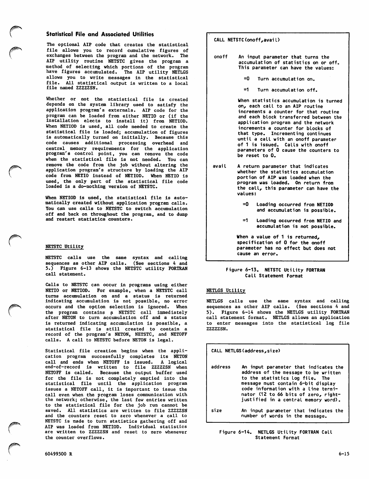
jjptaSy
Statistical File and Associated Utilities
The optional AIP code that creates the statistical
file allows you to record cumulative figures of
exchanges between the program and the network. The
AIP utility routine NETSTC gives the program a
met hod of se lect ing w hich port ions of the prog ram
have figures accumulated. The AIP utility NETLGS
allows you to write messages in the statistical
file. All statistical output is written to a local
file named ZZZZZSN.
Whether or not the statistical file is created
depends on the system library used to satisfy the
application program's externals. AIP code for the
program can be loaded from either NETIO or (if the
installation elects to install it) from NETIOD.
When NETIOD is used, all code needed to create the
statistical file is loaded; accumulation of figures
is automatically turned on initially. Because this
code causes additional processing overhead and
central memory requirements for the application
program's control point, you can remove the code
when the statistical file is not needed. You can
remove the code from the job without altering the
application program's structure by loading the AIP
code from NETIO instead of NETIOD. When NETIO is
used, the only part of the statistical file code
loaded is a do-nothing version of NETSTC.
When N ETI OD i s used, the sta tistical fi le i s auto
matically created without application program calls.
You can use calls to NETSTC to switch accumulation
off and back on throughout the program, and to dump
and restart statistics counters.
NETSTC Utility
NETSTC calls use the same syntax and calling
sequences as other AIP calls. (See sections 4 and
5.) Figure 6-13 shows the NETSTC utility FORTRAN
call statement.
Calls to NETSTC can occur in programs using either
NETIO or NETIOD. For example, when a NETSTC call
turns accumulation on and a status is returned
indicating accumulation is not possible, no error
occurs and the option selection is ignored. When
the program contains a NETSTC call immediately
after NETON to turn accumulation off and a status
Is ret u r n e d i n d i cating accum u l a t i o n i s p ossible, a
statistical file is still created to contain a
record of the program's NETON, NETSTC, and NETOFF
calls. A call to NETSTC before NETON is legal.
Statistical file creation begins when the appli
cation program successfully completes its NETON
call a n d e n d s w h e n N E T O F F i s i s s u e d. A l o gical
e n d - o f - r e c o r d i s w r i t t e n t o fi l e Z Z Z Z Z S N w h e n
NETOFF is called. Because the output buffer used
for the file is not completely emptied into the
statistical file until the application program
issues a NETOFF call, it is important to issue the
call even when the program loses communication with
the network; otherwise, the last few entries written
to the statistical file for the job run cannot be
s a v e d . A l l s t a ti s t i c s ar e w r i t t e n to fi l e Z Z Z Z Z S N
and the counters reset to zero whenever a call to
NETSTC is made to turn statistics gathering off and
AIP was loaded from NETIOD. Individual statistics
are written to ZZZZZSN and reset to zero whenever
the counter overflows.
CALL NETSTC(onoff,avail)
onoff An input parameter that turns the
accumulation of statistics on or off.
This parameter can have the values:
=0 Turn accumulation on.
=1 Turn accumulation off.
When statistics accumulation is turned
on, each call to an AIP routine
increments a counter for that routine
and each block transferred between the
application program and the network
increments a counter for blocks of
that type. Incrementing continues
until a call with an onoff parameter
of 1 is issued. Calls with onoff
parameters of 0 cause the counters to
be reset to 0.
avail A return parameter that indicates
whether the statistics accumulation
portion of AIP was loaded when the
program was loaded. On return from
the call, this parameter can have the
values:
=0 Loading occurred from NETIOD
and accumulation is possible.
=1 Loading occurred from NETIO and
accumulation is not possible.
When a value of 1 is returned,
specification of 0 for the onoff
parameter has no effect but does not
cause an error.
Figure 6-13. NETSTC Utility FORTRAN
Call Statement Format
NETLGS Utility
N E T L G S c a l l s u s e t h e s a m e s y n t a x a n d c a l l i n g
sequences as other AIP calls. (See sections 4 and
5). Figure 6-14 shows the NETLGS utility FORTRAN
call statement format. NETLGS allows an application
to enter messages into the statistical log file
ZZZZZSN.
CALL NETLGS(address,size)
address An input parameter that indicates the
address of the message to be written
t o t h e s t a t i s t i c s l o g fi l e . T h e
message must contain 6-bit display
code information with a line termi
na tor (12 to 66 bits of zero, right-
justified in a central memory word).
size An input parameter that indicates the
number of words in the message.
Figure 6-14. NETLGS Utility FORTRAN Call
Statement Format
60499500 R 6-15
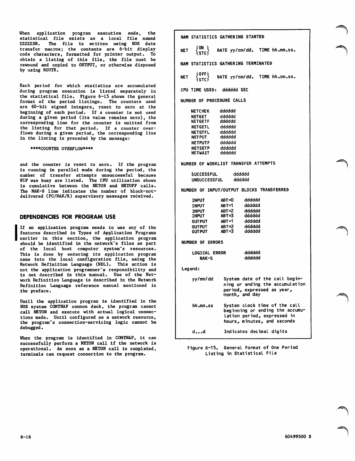
When application program execution ends, the
s t a t i s t i c a l fi l e e x i s t s a s a l o c a l fi l e n a m e d
ZZZZZSN. The file is written using NOS data
transfer macros; the contents are 6-bit display
code characters, formatted for printer output. To
o b t a i n a l i s t i n g o f t h i s fi l e , t h e fi l e m u s t b e
rewound and copied to OUTPUT, or otherwise disposed
by using ROUTE.
Ea c h p eri o d f or w h i c h s tat i s tic s a r e a ccu m u l ate d
during program execution is listed separately in
the statistical file. Figure 6-15 shows the general
f o r m a t of t h e p e ri o d l i s t i n g s . T he c o un t e r s u s e d
are 60-bit signed integers, reset to zero at the
beginning of each period. If a counter is not used
during a given period (its value remains zero), the
corresponding line for the counter is omitted from
the listing for that period. If a counter over
flows during a given period, the corresponding line
in the listing is preceded by the message:
****COUNTER OVERFLOW****
and the counter is reset to zero. If the program
is running in parallel mode during the period, the
number of transfer attempts unsuccessful because
NIP was busy are listed. The CPU utilization shown
is cumulative between the NETON and NETOFF calls.
The NAK-S line indicates the number of block-not-
delivered (FC/NAK/R) supervisory messages received.
DEPENDENCIES FOR PROGRAM USE
If an application program needs to use any of the
features described in Types of Application Programs
earlier in this section, the application program
sho uld b e iden tified i n the n etwo r k's files as par t
of the local host computer system's resources.
This is done by entering its application program
n a m e i n t o t h e l o c a l c o n fi g u r a t i o n fi l e , u s i n g t h e
Network Definition Language (NDL). This action is
not the application programmer's responsibility and
is not described in this manual. Use of the Net
work Definition Language is described in the Network
Definition Language reference manual mentioned in
the preface.
Until the application program is identified in the
NOS system COMTNAP common deck, the program cannot
call NETON and execute with actual logical connec
tions made. Until configured as a network resource,
the program's connection-servicing logic cannot be
debugged.
When the program is identified in COMTNAP, it can
successfully perform a NETON call if the network is
operational. As soon as a NETON call is completed,
terminals can request connection to the program.
NAM STATISTICS GATHERING STARTED
NET jg-Ll DATE yy/mm/dd. TIME hh.mm.ss.
NAM STATISTICS GATHERING TERMINATED
NET {cTrf DATE yy/mm/dd. TIME hh.mm.ss.
CPU TIME USED: dddddd SEC
NUMBER OF PROCEDURE CALLS
NETCHEK
NETGET
NETGETF
NETGETL
NETGTFL
NETPUT
NETPUTF
NETSETP
NETWAIT
dddddd
dddddd
dddddd
dddddd
dddddd
dddddd
dddddd
dddddd
dddddd
NUMBER OF WORKLIST TRANSFER ATTEMPTS
SUCCESSFUL
UNSUCCESSFUL
dddddd
dddddd
NUMBER OF INPUT/OUTPUT BLOCKS TRANSFERRED
INPUT
INPUT
INPUT
INPUT
OUTPUT
OUTPUT
OUTPUT
ABT=0
ABT=1
ABT=2
ABT=3
ABT=1
ABT=2
ABT =3
NUMBER OF ERRORS
LOGICAL ERROR
NAK-S
dddddd
dddddd
dddddd
dddddd
dddddd
dddddd
dddddd
dddddd
dddddd
Legend:
yy/mm/dd System date of the call begin
ning or ending the accumulation
period, expressed as year,
month, and day
hh.mm.ss System clock time of the call
beginning or ending the accumu
lation period, expressed in
hours, minutes, and seconds
d...d Indicates decimal digits
Figure 6-15. General Format of One Period
Listing in Statistical File
6-16 60499500 S
Before a terminal can complete a connection to the
program, the user name from its login procedure
must have an access word bit associated with the
a p p l i c a t i o n p r o g r a m ' s n a m e i n C O M T N A P. T h i s
association is established by using MODVAL and must
exist for all login user names. The procedure is
not described further in this manual because it is
not the application programmer's responsibility.
If the application program uses the batch device
interface, the owning console for the passive
device it is intended to service must be configured
in the local configuration file with the program
declared as the primary application for the ter
m i n a l . U n l e s s t h i s i s d o n e , t h e p a s s i v e d e v i c e s
cannot access the appl ica tion program. The appl i
cation programs released by CDC with this version
of the network sof tware only provide a me chani sm
for the switching of console device connections to
o t h e r pr o g ram s . A p a s s iv e d e vi c e c onfi g u red w i t h
the Remote Batch Facility as its primary application
program cannot be used by any other application
program.
MEMORY REQUIREMENTS
Although the size of an application program varies
with its complexity and functions, the AIP coding
added by the CYBER loader does not normally exceed
1100 words of central memory. The version of AIP
that generates the debug log file and statistics
file requires 1100 more words. Using the QTRM
utility package adds less than 700 additional words
to the program's central memory field length
requirements.
60499500 R 6-17

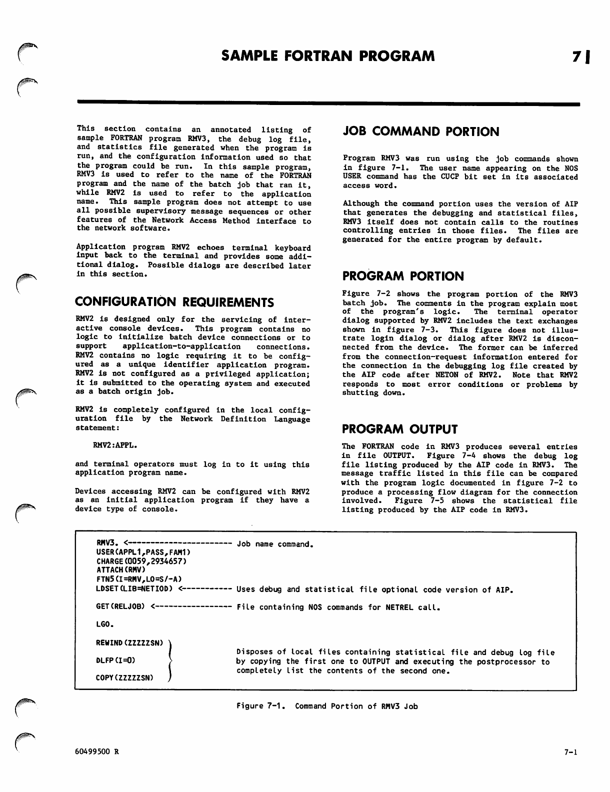
SAMPLE FORTRAN PROGRAM 7|
This section contains an annotated listing of
sample FORTRAN program RMV3, the debug log file,
and statistics file generated when the program is
run, and the configuration information used so that
the program could be run. In this sample program,
RMV3 is used to refer to the name of the FORTRAN
program and the name of the batch job that ran it,
while RMV2 is used to refer to the application
name. This sample program does not attempt to use
all possible supervisory message sequences or other
features of the Network Access Method interface to
the network software.
Application program RMV2 echoes terminal keyboard
input back to the terminal and provides some addi
tional dialog. Possible dialogs are described later
in this section.
CONFIGURATION REQUIREMENTS
RMV2 is designed only for the servicing of inter
active console devices. T h i s p r o g r a m c o n t a ins n o
logic to initialize batch device connections or to
support application-to-application connections.
RMV2 contains no logic requiring it to be config
ured as a unique identifier application program.
RMV2 is not configured as a privileged application;
it is submitted to the operating system and executed
as a batch origin job.
RMV2 is completely configured in the local config
uration file by the Network Definition Language
statement:
RMV2:APPL.
and terminal operators must log in to it using this
application program name.
Devices accessing RMV2 can be configured with RMV2
as an initial application program if they have a
device type of console.
JOB COMMAND PORTION
Program RMV3 was run using the job commands shown
in figure 7-1. The user name appearing on the NOS
USER command has the CUCP bit set in its associated
access word.
Although the command portion uses the version of AIP
that generates the debugging and statistical files,
RMV3 itself does not contain calls to the routines
controlling entries in those files. The files are
generated for the entire program by default.
PROGRAM PORTION
Figure 7-2 shows the program portion of the RMV3
batch job. The comments in the program explain most
of the program's logic. The terminal operator
dialog supported by RMV2 includes the text exchanges
shown in figure 7-3. This figure does not illus
trate login dialog or dialog after RMV2 is discon
nected from the device. The former can be inferred
from the connection-request information entered for
the connection in the debugging log file created by
the AIP code after NETON of RMV2. Note that RMV2
responds to most error conditions or problems by
shutting down.
PROGRAM OUTPUT
The FORTRAN code in RMV3 produces several entries
in file OUTPUT. Figure 7-4 shows the debug log
file listing produced by the AIP code in RMV3. The
message traffic listed in this file can be compared
with the program logic documented in figure 7-2 to
produce a processing flow diagram for the connection
involved. Figure 7-5 shows the statistical file
listing produced by the AIP code in RMV3.
RMV3. < Job name command.
USER(APPL1,PASS,FAM1)
CHARGE(0059,2934657)
ATTACH(RMV)
FTN5(I=RMV,L0=S/-A)
L D S E T ( L I B = N E T I 0 D ) < U s e s d e b u g a n d s t a t i s t i c a l fi l e o p t i o n a l c o d e v e r s i o n o f A I P.
GET(RELJOB) < File containing NOS commands for NETREL call.
LGO.
REWIND(ZZZZZSN) \
1 Disposes of local files containing statistical file and debug log file
DLFP(I=0) > by copying the first one to OUTPUT and executing the postprocessor to
\ c o m p l e t e l y l i s t t h e c o n t e n t s o f t h e s e c o n d o n e .
COPY(ZZZZZSN) /
Figure 7-1. Command Portion of RMV3 Job
60499500 R 7-1
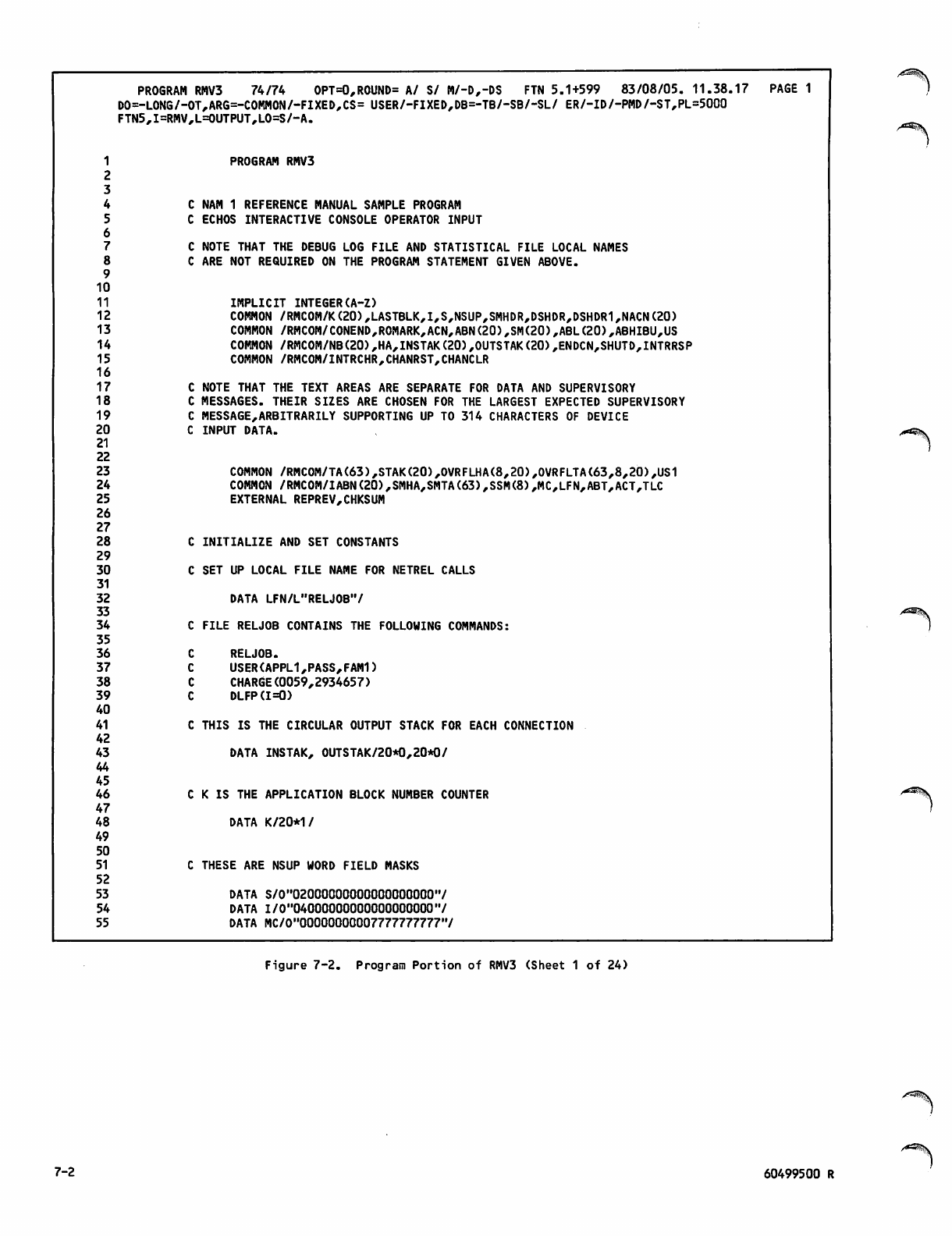
PROGRAM RMV3 74/74 OPT=0,ROUND= A/ S/ M/-D,-DS FTN 5.1+599 83/08/05. 11.38.17 PAGE 1
DO=-LONG/-OT,ARG=-COMMON/-FIXED,CS= USER/-FIXED,DB=-TB/-SB/-SL/ ER/-ID/-PMD/-ST,PL=5000
FTN5,I=RMV,L=0UTPUT,L0=S/-A.
1
2
PROGRAM RMV3
3
4CNAM 1 REFERENCE MANUAL SAMPLE PROGRAM
5
6
7
CECHOS INTERACTIVE CONSOLE OPERATOR INPUT
CNOTE THAT THE DEBUG LOG FILE AND STATISTICAL FILE LOCAL NAMES
8
9
10
ARE NOT REQUIRED ON THE PROGRAM STATEMENT GIVEN ABOVE.
11 IMPLICIT INTEGER(A-Z)
12 COMMON /RMC0M/K(20),LASTBLK,I,S,NSUP,SMHDR,DSHDR,DSHDR1,NACN(20)
13 COMMON /RMCOM/CONEND,ROMARK,ACN,ABN(20),SM(20),ABL(20),ABHIBU,US
14 COMMON /RMC0M/NB(20),HA,INSTAK(20),0UTSTAK(20),ENDCN,SHUTD,INTRRSP
15 COMMON /RMCOM/INTRCHR,CHANRST,CHANCLR
16
17 NOTE THAT THE TEXT AREAS ARE SEPARATE FOR DATA AND SUPERVISORY
18 MESSAGES. THEIR SIZES ARE CHOSEN FOR THE LARGEST EXPECTED SUPERVISORY
19 MESSAGE,ARBITRARILY SUPPORTING UP TO 314 CHARACTERS OF DEVICE
20 INPUT DATA.
2122
23 COMMON /RMCOM/TA(63),STAK(20),0VRFLHA(8,20),0VRFLTA(63,8,20),US1
24 COMMON /RMC0M/IABN(20),SMHA,SMTA(63),SSM(8),MC,LFN,ABT,ACT,TLC
25 EXTERNAL REPREV,CHKSUM
26
27
28
29
30
31
32
33
34
INITIALIZE AND SET CONSTANTS
CSET UP LOCAL FILE NAME FOR NETREL CALLS
DATA LFN/L"RELJ0B'7
CFILE RELJOB CONTAINS THE FOLLOWING COMMANDS:
35
36 RELJOB.
37 USER(APPL1,PASS,FAM1)
38 CHARGE(0059,2934657)
39 DLFP(1=0)
40
41 THIS IS THE CIRCULAR OUTPUT STACK FOR EACH CONNECTION
42
43
44
45
DATA INSTAK, 0UTSTAK/20*0,20*0/
46 K IS THE APPLICATION BLOCK NUMBER COUNTER
47
48 DATA K/20*1/
49
50
51
52
53
THESE ARE NSUP WORD FIELD MASKS
DATA S/0"02000000000000000000'7
54 DATA I/0"04000000000000000000"/
55 DATA MC/0,,00000000007777777777'7
/^Sj^
Figure 7-2. Program Portion of RMV3 (Sheet 1 of 24)
7-2 60499500 R
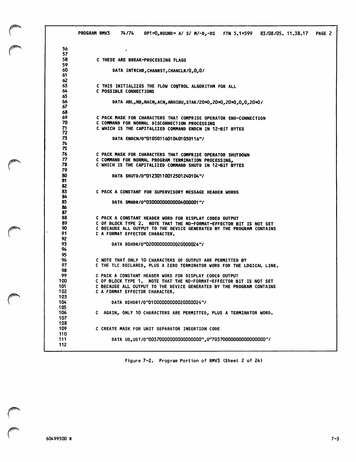
56
57
58
59
60
61
62
63
64
65
66
67
68
69
70
71
72
73
74
75
76
77
78
79
80
81
82
83
84
85
86
87
88
89
90
91
92
93
94
95
96
97
98
99
100
101
102
103
104
105
106
107
108
109
110
111
112
PROGRAM RMV3 74/74 OPT=0,ROUND= A/ S/ M/-D,-DS FTN 5.1+599 83/08/05. 11.38.17 PAGE 2
C THESE ARE BREAK-PROCESSING FLAGS
DATA INTRCHR,CHANRST,CHANCLR/0,0,0/
C THIS INITIALIZES THE FLOW CONTROL ALGORITHM FOR ALL
C POSSIBLE CONNECTIONS
DATA ABL,NB,NACN,ACN,ABHIBU,STAK/20*0,20*0,20*0,0,0,20*0/
C PACK MASK FOR CHARACTERS THAT COMPRISE OPERATOR END-CONNECTION
C COMMAND FOR NORMAL DISCONNECTION PROCESSING
C WHICH IS THE CAPITALIZED COMMAND ENDCN IN 12-BIT BYTES
DATA ENDCN/0"01050116010401030116"/
C PACK MASK FOR CHARACTERS THAT COMPRISE OPERATOR SHUTDOWN
C COMMAND FOR NORMAL PROGRAM TERMINATION PROCESSING,
C WHICH IS THE CAPITALIZED COMMAND SHUTD IN 12-BIT BYTES
DATA SHUTD/0"01230110012501240104 '7
C PACK A CONSTANT FOR SUPERVISORY MESSAGE HEADER WORDS
DATA SMHDR/0"03000000000004000001"/
C PACK A CONSTANT HEADER WORD FOR DISPLAY CODED OUTPUT
C OF BLOCK TYPE 2. NOTE THAT THE NO-FORMAT-EFFECTOR BIT IS NOT SET
C BECAUSE ALL OUTPUT TO THE DEVICE GENERATED BY THE PROGRAM CONTAINS
C A FORMAT EFFECTOR CHARACTER.
DATA DSHDR/0"0200000000Q020000024(7
C NOTE THAT ONLY 10 CHARACTERS OF OUTPUT ARE PERMITTED BY
C THE TLC DECLARED, PLUS A ZERO TERMINATOR WORD FOR THE LOGICAL LINE.
C PACK A CONSTANT HEADER WORD FOR DISPLAY CODED OUTPUT
C OF BLOCK TYPE 1. NOTE THAT THE NO-FORMAT-EFFECTOR BIT IS NOT SET
C BECAUSE ALL OUTPUT TO THE DEVICE GENERATED BY THE PROGRAM CONTAINS
C A FORMAT EFFECTOR CHARACTER.
DATA DSHDR1/0"01000000000020000024"/
C AGAIN, ONLY 10 CHARACTERS ARE PERMITTED, PLUS A TERMINATOR WORD.
C CREATE MASK FOR UNIT SEPARATOR INSERTION CODE
DATA US,US1/0"00370000000000000000",0,,70370000000000000000,7
Figure 7-2. Program Portion of RMV3 (Sheet 2 of 24)
60499500 R 7-3
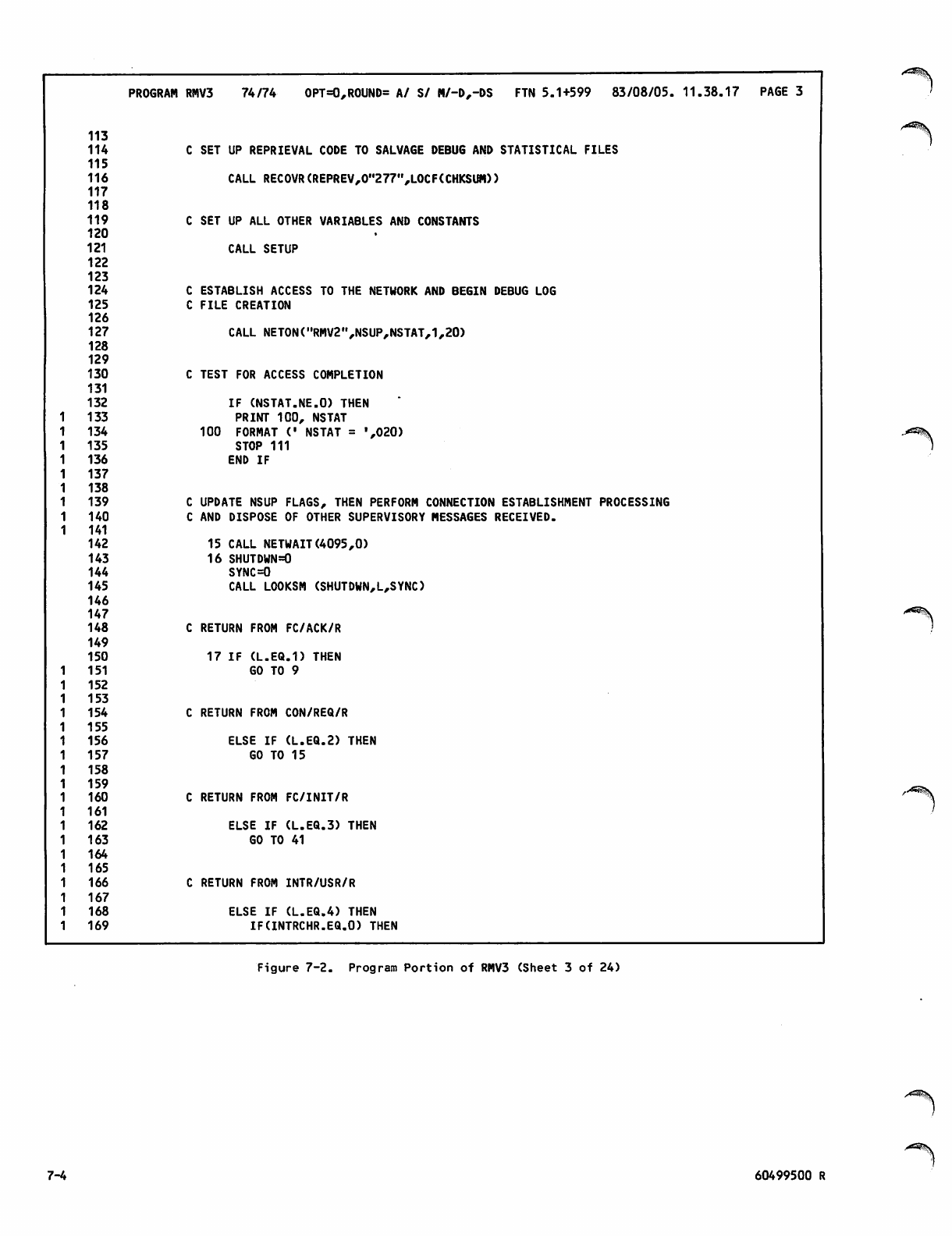
PROGRAM RMV3 74/74 OPT=0,ROUND= A/ S/ M/-D,-DS FTN 5.1+599 83/08/05. 11.38.17 PAGE 3
113
114 C SET UP REPRIEVAL CODE TO SALVAGE DEBUG AND STATISTICAL FILES
115
116 CALL RECOVR(REPREV,0"277",L0CF(CHKSUM))
117
118
119 C SET UP ALL OTHER VARIABLES AND CONSTANTS
120
121 CALL SETUP
122
123
124 C ESTABLISH ACCESS TO THE NETWORK AND BEGIN DEBUG LOG
125 C FILE CREATION
126
127 CALL NETON("RHV2",NSUP,NSTAT,1,20)
128
129
130 C TEST FOR ACCESS COMPLETION
131
132 IF (NSTAT.NE.O) THEN
1 1 3 3 PRINT 100, NSTAT
1 1 3 4 100 FORMAT (' NSTAT = ',020)
1 1 3 5 STOP 111
1 1 3 6 END IF
1 1 3 7
1 1 3 8
1 1 3 9 C UPDATE NSUP FLAGS, THEN PERFORM CONNECTION ESTABLISHMENT PROCESSING
1 1 4 0 C AND DISPOSE OF OTHER SUPERVISORY MESSAGES RECEIVED.
1 141
142 15 CALL NETWAIT(4095,0)
143 16 SHUTDWN=0
144 SYNC=0
145 CALL LOOKSM (SHUTDWN,L,SYNC)
146
147
148 C RETURN FROM FC/ACK/R
149
150 17 IF (L.EQ.1) THEN
1 1 5 1 GO TO 9
1 1 5 2
1 1 5 3
1 1 5 4 C RETURN FROM CON/REQ/R
1 1 5 5
1 1 5 6 ELSE IF (L.EQ.2) THEN
1 1 5 7 GO TO 15
1 1 5 8
1 1 5 9
1 1 6 0 C RETURN FROM FC/INIT/R
1 1 6 1
1 1 6 2 ELSE IF (L.EQ.3) THEN
1 1 6 3 GO TO 41
1 1 6 4
1 1 6 5
1 1 6 6 C RETURN FROM INTR/USR/R
1 1 6 7
1 1 6 8 ELSE IF (L.EQ.4) THEN
1 1 6 9 IF(INTRCHR.EQ.O) THEN
Figure 7-2. Program Portion of RMV3 (Sheet 3 of 24)
7-4 60499500 R
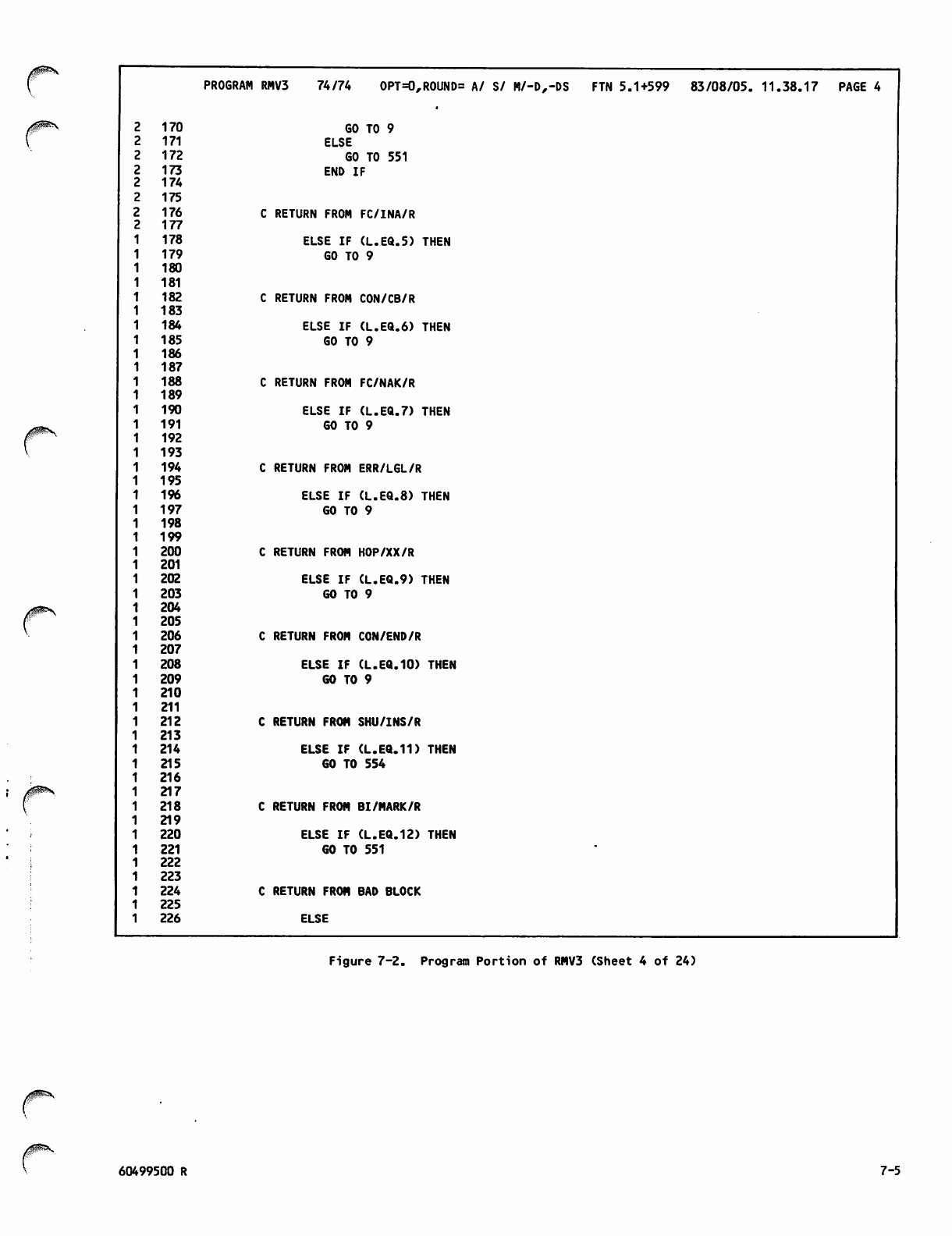
PROGRAM RMV3 74/74 OPT=0,ROUND= A/ S/ M/-D,-DS FTN 5.1+599 83/08/05. 11.38.17 PAGE 4
2170 GO TO 9
2171 ELSE
2172 GO TO 551
2173 END IF
2174
2175
2176 C RETURN FROM FC/INA/R
2177
178 ELSE IF (L.EQ.5) THEN
179 GO TO 9
180
181
182 C RETURN FROM CON/CB/R
183
184 ELSE IF (L.EQ.6) THEN
185 GO TO 9
186
187
188 C RETURN FROM FC/NAK/R
189
190 ELSE IF (L.EQ.7) THEN
191 GO TO 9
192
193
194 C RETURN FROM ERR/LGL/R
195
196 ELSE IF (L.EQ.8) THEN
197 GO TO 9
198
199
200 C RETURN FROM HOP/XX/R
201
202 ELSE IF (L.EQ.9) THEN
203 GO TO 9
204
205
206 C RETURN FROM CON/END/R
207
208 ELSE IF (L.EQ.10) THEN
209 GO TO 9
210
211
212 C RETURN FROM SHU/INS/R
213
214 ELSE IF (L.EQ.11) THEN
215 GO TO 554
216
217
218 C RETURN FROM BI/MARK/R
219
220 ELSE IF (L.EQ.12) THEN
221 GO TO 551
222
223
224 C RETURN FROM BAD BLOCK
225
226 ELSE
Figure 7-2. Program Portion of RMV3 (Sheet 4 of 24)
/ $ f P ^ *
60499500 R 7-5
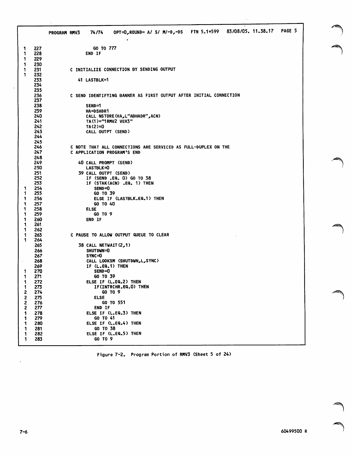
PROGRAM RMV3 74/74 OPT=0,ROUND= A/ S/ M/-D,-DS FTN 5.1+599 83/08/05. 11.38.17 PAGE 5
227 GO TO 777
228 END IF
229
230
231 INITIALIZE CONNECTION BY SENDING OUTPUT
232
233 41 LASTBLK=1
234
235
236 SEND IDENTIFYING BANNER AS FIRST OUTPUT AFTER INITIAL CONNECTION
237
238 SEND=1
239 HA=DSHDR1
240 CALL NSTORE(HA,L"ABHADR",ACN)
241 TA(1)="1RMV2 VER3"
242 TA(2)=0
243 CALL OUTPT (SEND)
244
245
246 NOTE THAT ALL CONNECTIONS ARE SERVICED AS FULL-DUPLEX ON THE
247 APPLICATION PROGRAM'S END
248
249 40 CALL PROMPT (SEND)
250 LASTBLK=0
251 39 CALL OUTPT (SEND)
252 IF (SEND .EQ. 0) GO TO 38
253 IF (STAK(ACN) .EQ. 1) THEN
254 SEND=0
255 GO TO 39
256 ELSE IF (LASTBLK.EQ.1) THEN
257 GO TO 40
258 ELSE
259 GO TO 9
260 END IF
261
262
263 PAUSE TO ALLOW OUTPUT QUEUE TO CLEAR
264
265 38 CALL NETWAIT(2,1)
266 SHUTDWN=0
267 SYNC=0
268 CALL LOOKSM (SHUTDWN,L,SYNC)
269 IF (L.EQ.1) THEN
1270 SEND=0
1271 GO TO 39
1272 ELSE IF (L.EQ.2) THEN
1273 IF(INTRCHR.EQ.O) THEN
2274 GO TO 9
2275 ELSE
2276 GO TO 551
2277
278
279
280
281
282
283
END IF
ELSE IF (L.EQ.3) THEN
GO TO 41
ELSE IF (L.EQ.4) THEN
GO TO 38
ELSE IF (L.EQ.5) THEN
GO TO 9
i^^jV
Figure 7-2. Program Portion of RMV3 (Sheet 5 of 24)
7-6 60499500 R
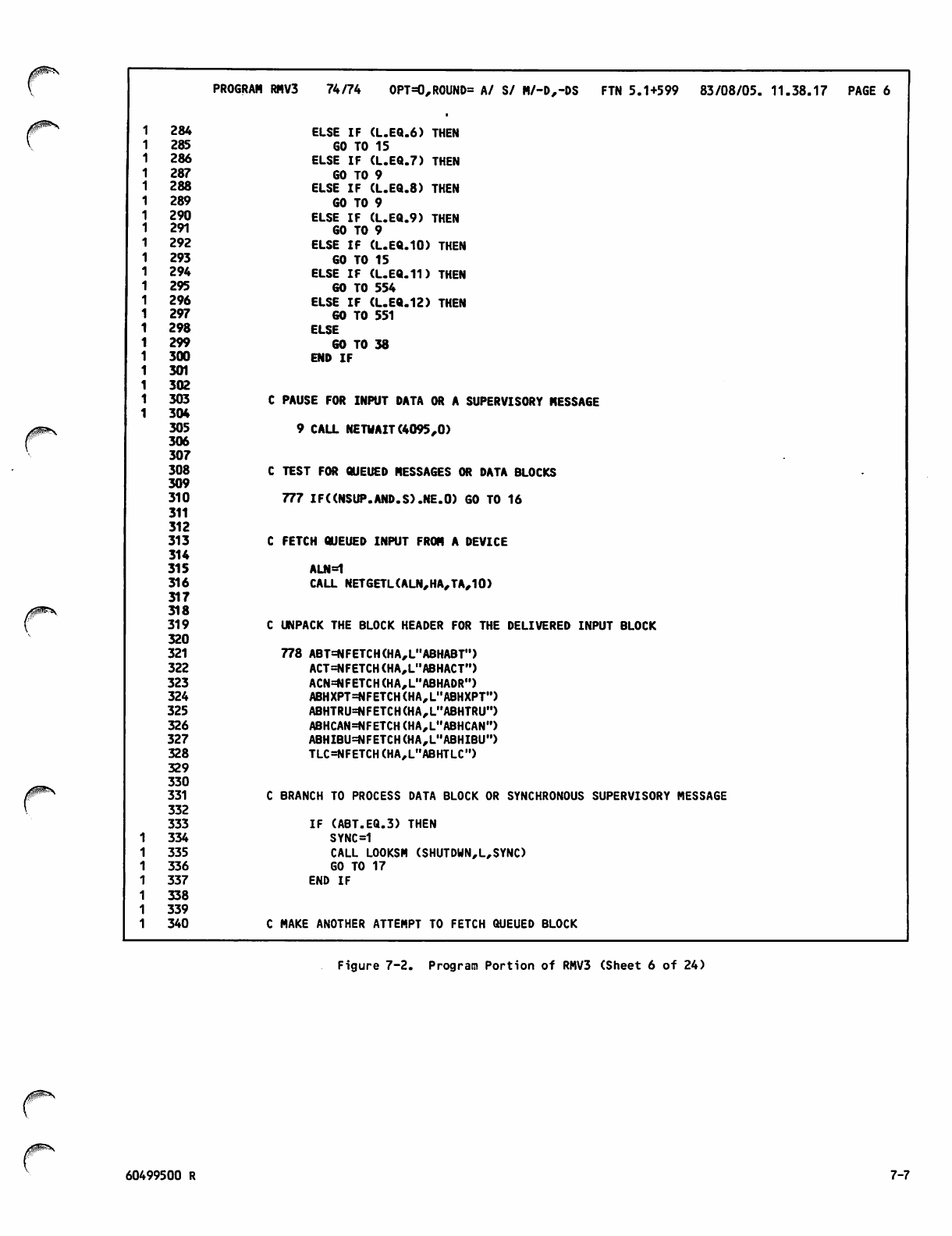
PROGRAM RMV3 74/74 OPT=0,ROUND= A/ S/ M/-D,-DS FTN 5.1+599 83/08/05. 11-3€1.17 PAGE 6
1284 ELSE IF (L.EQ.6) THEN
1285 GO TO 15
1286 ELSE IF (L.EQ.7) THEN
1287 GO TO 9
1288 ELSE IF (L.EQ.8) THEN
1289 GO TO 9
1290 ELSE IF (L.EQ.9) THEN
1291 GO TO 9
1292 ELSE IF (L.EQ.10) THEN
1293 GO TO 15
1294 ELSE IF (L.EQ.11) THEN
1295 GO TO 554
1296 ELSE IF (L.EQ.12) THEN
1297 GO TO 551
1298 ELSE
1299 GO TO 38
1300 END IF
1301
1302
1303 PAUSE FOR INPUT DATA OR A SUPERVISORY MESSAGE
1304
305
306
307
9 CALL NETWAIT(4095,0)
308 TEST FOR QUEUED MESSAGES OR DATA BLOCKS
309
310 777 IF((NSUP.AND.S).NE.O) GO TO 16
311
312
313 FETCH QUEUED INPUT FROM A DEVICE
314
315 ALN=1
316 CALL NETGETL(ALN,HA,TA,10)
317
318
319 UNPACK THE BLOCK HEADER FOR THE DELIVERED INPUT BLOCK
320
321 778 ABT=NFETCH(HA,L"ABHABT")
322 ACT=NFETCH(HA,L"ABHACT")
323 ACN=NFETCH(HA,L"ABHADR")
324 ABHXPT=NFETCH(HA,L"ABHXPT")
325 ABHTRU=NFETCH(HA,L"ABHTRU")
326 ABHCAN=NFETCH(HA,L"ABHCAN")
327 ABHIBU=NFETCH(HA,L"ABHIBU")
328 TLC=NFETCH (HA,L,,ABHTLC")
329
330
331 BRANCH TO PROCESS DATA BLOCK OR SYNCHRONOUS SUPERVISORY MESSAGE
332
333 IF (ABT.EQ.3) THEN
1334 SYNC=1
1335 CALL LOOKSM (SHUTDWN,L,SYNC)
1336 GO TO 17
1337 END IF
1338
1339
1340 MAKE ANOTHER ATTEMPT TO FETCH QUEUED BLOCK
Figure 7-2. Program Portion of RMV3 (Sheet 6 of 24)
60499500 R 7-7
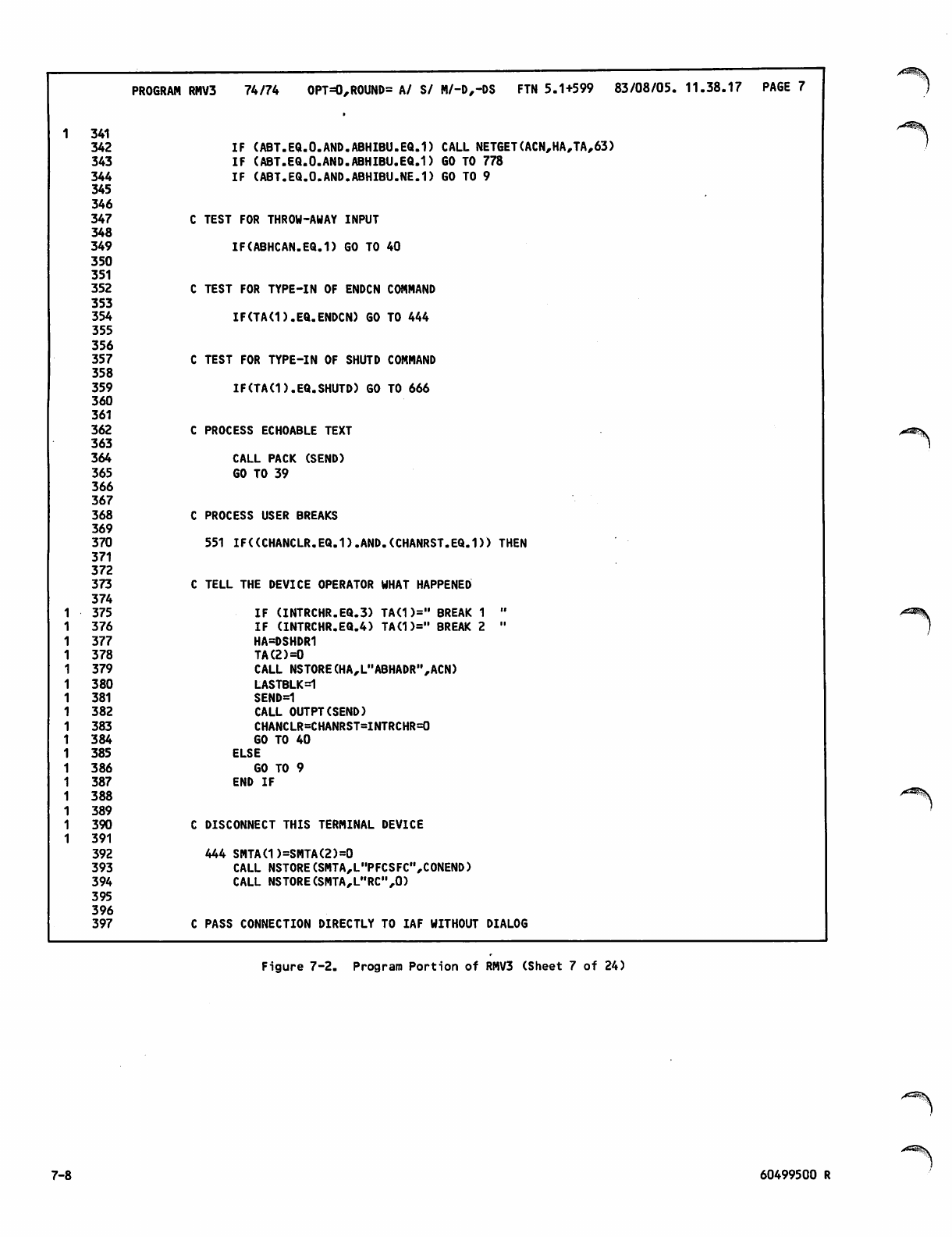
PROGRAM RMV3 74/74 OPT=0,ROUND= A/ S/ M/-D,-DS FTN 5.1+599 83/08/05. 11.38.17 PAGE 7
1 341
342 IF (ABT.EQ.0.AND.ABHIBU.EQ.1) CALL NETGET(ACN,HA,TA,63)
343 IF (ABT.EQ.0.AND.ABHIBU.EQ.1) GO TO 778
344 IF (ABT.EQ.0.AND.ABHIBU.NE.1) GO TO 9
345
346
347 TEST FOR THROW-AWAY INPUT
348
349 IF(ABHCAN.EQ.I) GO TO 40
350
351
352 TEST FOR TYPE-IN OF ENDCN COMMAND
353
354 IF(TAd).EQ.ENDCN) GO TO 444
355
356
357 TEST FOR TYPE-IN OF SHUTD COMMAND
358
359 IF(TAd).EQ.SHUTD) GO TO 666
360
361
362 PROCESS ECHOABLE TEXT
363
364 CALL PACK (SEND)
365 GO TO 39
366
367
368 PROCESS USER BREAKS
369
370 551 IF((CHANCLR.EQ.1).AND.(CHANRST.EQ.D) THEN
371
372
373 TELL THE DEVICE OPERATOR WHAT HAPPENED
374
1 3 7 5 IF (INTRCHR.EQ.3) TA(1)=" BREAK 1 "
1 3 7 6 IF (INTRCHR.EQ.4) TA(1)=" BREAK 2 "
1 3 7 7 HA=DSHDR1
1 3 7 8 TA(2)=0
1 3 7 9 CALL NSTORE(HA,L"ABHADR",ACN)
1 3 8 0 LASTBLK=1
1 381 SEND=1
1 3 8 2 CALL OUTPT(SEND)
1 3 8 3 CHANCLR=CHANRST=INTRCHR=0
1 3 8 4 GO TO 40
1 3 8 5 ELSE
1 3 8 6 GO TO 9
1 3 8 7 END IF
1 3 8 8
1 3 8 9
1 3 9 0 DISCONNECT THIS TERMINAL DEVICE
1 3 9 1
392 444 SMTA(1)=SMTA(2)=0
393 CALL NSTORE(SMTA,L"PFCSFC",CONEND)
394 CALL NSTORE(SMTA,L"RC",0)
395
396
397 PASS CONNECTION DIRECTLY TO IAF WITHOUT DIALOG
Figure 7-2. Program Portion of RMV3 (Sheet 7 of 24)
^S
7-8 60499500 R
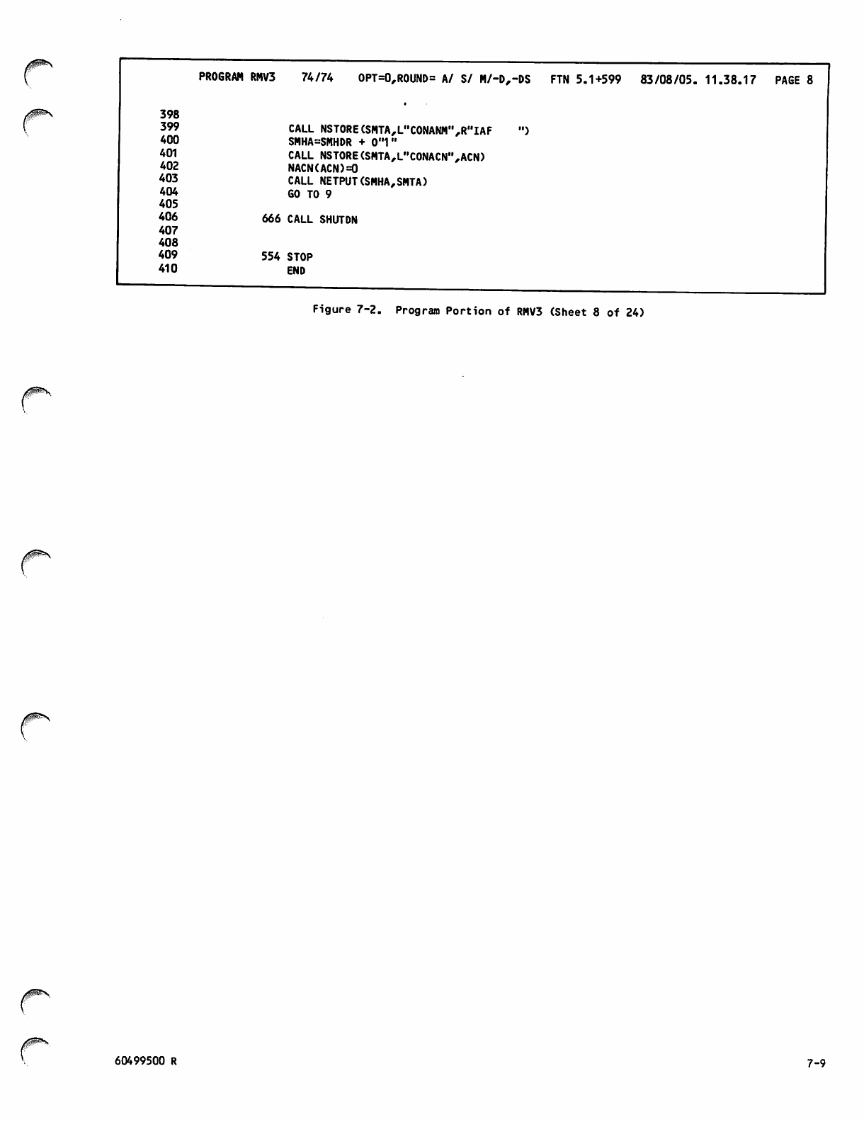
PROGRAM RMV3 74/74 OPT=0,ROUND= A/ S/ M/-D,-DS FTN 5.1+599 83/08/05. 11.38.17 PAGE 8
398
399 CALL NSTORE (SMTA,L,,CONANM",R"IAF ")
400 SMHA=SMHDR + 0**1"
401 CALL NSTORE(SMTA,LHCONACN",ACN)
402 NACN(ACN)=0
403 CALL NETPUT(SMHA,SMTA)
4 0 4 6 0 T O 9
405
406 666 CALL SHUTDN
407
408
4 0 9 5 5 4 S T O P
410 END
Figure 7-2. Program Portion of RMV3 (Sheet 8 of 24)
60499500 R 7-9
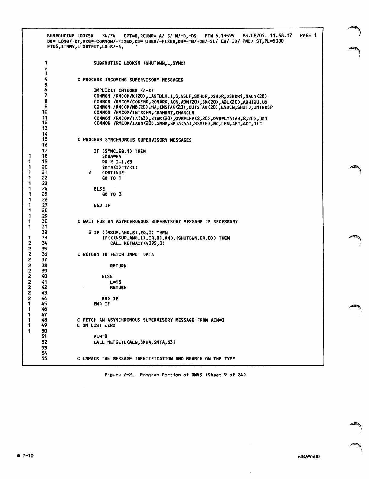
SUBROUTINE LOOKSM 74/74 OPT=0,ROUND= A/ S/ M/-D,-DS FTN 5.1+599 83/08/05. 11.38.17 PAGE 1
DO=- LONG/-OT,,ARG=-COMMON/-FIXED,CS= USER/-FIXED,DB=-TB/-SB/-SL/ ER/-ID/-PMD/-ST,PL=5000
FTN5 ,I=RMV,L=OUTPUT,LO=S/-A.
1
2
SUBROUTINE LOOKSM (SHUTDWN,L,SYNC)
3
4
5
6
CPROCESS INCOMING SUPERVISORY MESSAGES
IMPLICIT INTEGER (A-Z)
7COMMON /RMCOM/K(20),LASTBLK,I,S,NSUP,SMHDR,DSHDR,DSHDR1,NACN(20)
8COMMON /RMCOM/CONEND,ROMARK,ACN,ABN(20),SM(20),ABL(20),ABHIBU,US
9COMMON /RMCOM/NB(20),HA,INSTAK(20),OUTSTAK(20),ENDCN,SHUTD,INTRRSP
10 COMMON /RMCOM/INTRCHR,CHANRST,CHANCLR
11 COMMON /RMC0M/TA(63),STAK(20),OVRFLHA(8,20),OVRFLTA(63,8,20),US1
12 COMMON /RMCOM/IABN(20),SMHA,SMTA(63),SSM(8),MC,LFN,ABT,ACT,TLC
13
14
15 PROCESS SYNCHRONOUS SUPERVISORY MESSAGES
16
17 IF (SYNC.EQ.1) THEN
18 SMHA=HA
19 DO 2 1=1,63
20 SMTA(I)=TA(I)
21 2 CONTINUE
22 GO TO 1
23
24 ELSE
25 GO TO 3
26
27 END IF
28
29
30 WAIT FOR AN ASYNCHRONOUS SUPERVISORY MESSAGE IF NECESSARY
31
32 3 IF ((NSUP.AND.S).EQ.O) THEN
133 IF(((NSUP.AND.I).EQ.O).AND.(SHUTDWN.EQ.O)) THEN
234 CALL NETWAIT(4095,0)
235
236 RETURN TO FETCH INPUT DATA
237
238 RETURN
239
240 ELSE
241 L=13
242 RETURN
243
244
45
46
47
END IF
END IF
48 FETCH AN ASYNCHRONOUS SUPERVISORY MESSAGE FROM ACN=0
49 ON LIST ZERO
50
51 ALN=0
52 CALL NETGETL(ALN,SMHA,SMTA,63)
53
54
55 UNPACK THE MESSAGE IDENTIFICATION AND BRANCH ON THE TYPE
Figure 7-2. Program Portion of RMV3 (Sheet 9 of 24)
7-10 60499500
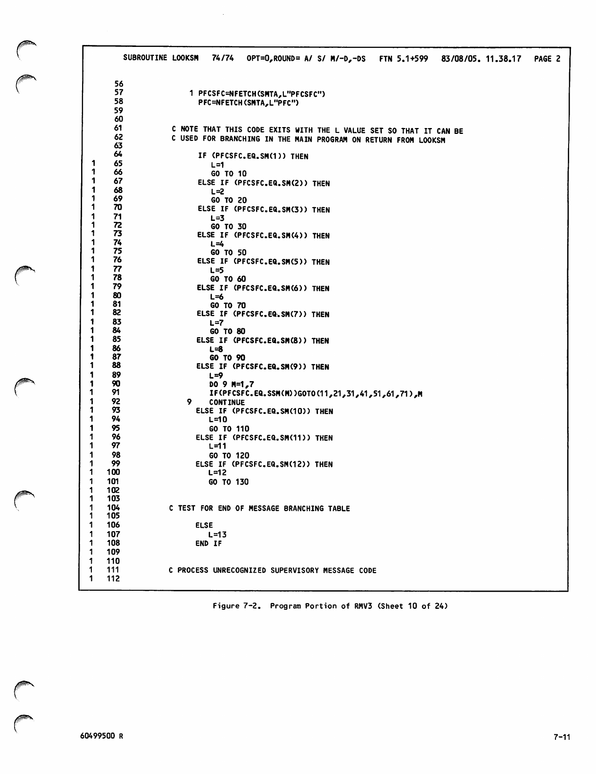
i^^N
SUBROUTINE LOOKSM 74/74 OPT=0,ROUND= A/ S/ M/-D,-DS FTN 5.1+599 83/08/05. 11.38.17 PAGE 2
56
57
58
59
60
61
62
63
64
65
66
67
68
69
70
71
72
73
74
75
76
77
78
79
80
81
82
83
84
85
86
87
88
89
90
91
92
93
94
95
96
97
98
99
100
101
102
103
104
105
106
107
108
109
110
111
112
1 PFCSFC=NFETCH(SMTA,L"PFCSFC")
PFC=NFETCH(SMTA,L"PFC")
C NOTE THAT THIS CODE EXITS WITH THE L VALUE SET SO THAT IT CAN BE
C USED FOR BRANCHING IN THE MAIN PROGRAM ON RETURN FROM LOOKSM
IF (PFCSFC.EQ.SM(D) THEN
L=1
GO TO 10
ELSE IF (PFCSFC.EQ.SM(2)) THEN
L=2
GO TO 20
ELSE IF (PFCSFC.EQ.SM(3)) THEN
L=3
GO TO 30
ELSE IF (PFCSFC.EQ.SM(4)) THEN
L=4
GO TO 50
ELSE IF (PFCSFC.EQ.SM(5)) THEN
L=5
GO TO 60
ELSE IF (PFCSFC.EQ.SM(6)) THEN
L=6
GO TO 70
ELSE IF (PFCSFC.EQ.SM(7)) THEN
L=7
GO TO 80
ELSE IF (PFCSFC.EQ.SM(8)) THEN
L=8
GO TO 90
ELSE IF (PFCSFC.EQ.SM(9)) THEN
L=9
DO 9 M=1,7
IF(PFCSFC.EQ.SSM(M))G0T0(11,21,31,41,51,61,71),M
9 CONTINUE
ELSE IF (PFCSFC.EQ.SMdO)) THEN
L=10
GO TO 110
ELSE IF (PFCSFC.EQ.SM(H)) THEN
L=11
GO TO 120
ELSE IF (PFCSFC.EQ.SM(12)) THEN
L=12
GO TO 130
C TEST FOR END OF MESSAGE BRANCHING TABLE
ELSE
L=13
END IF
C PROCESS UNRECOGNIZED SUPERVISORY MESSAGE CODE
Figure 7-2. Program Portion of RMV3 (Sheet 10 of 24)
60499500 R 7-11
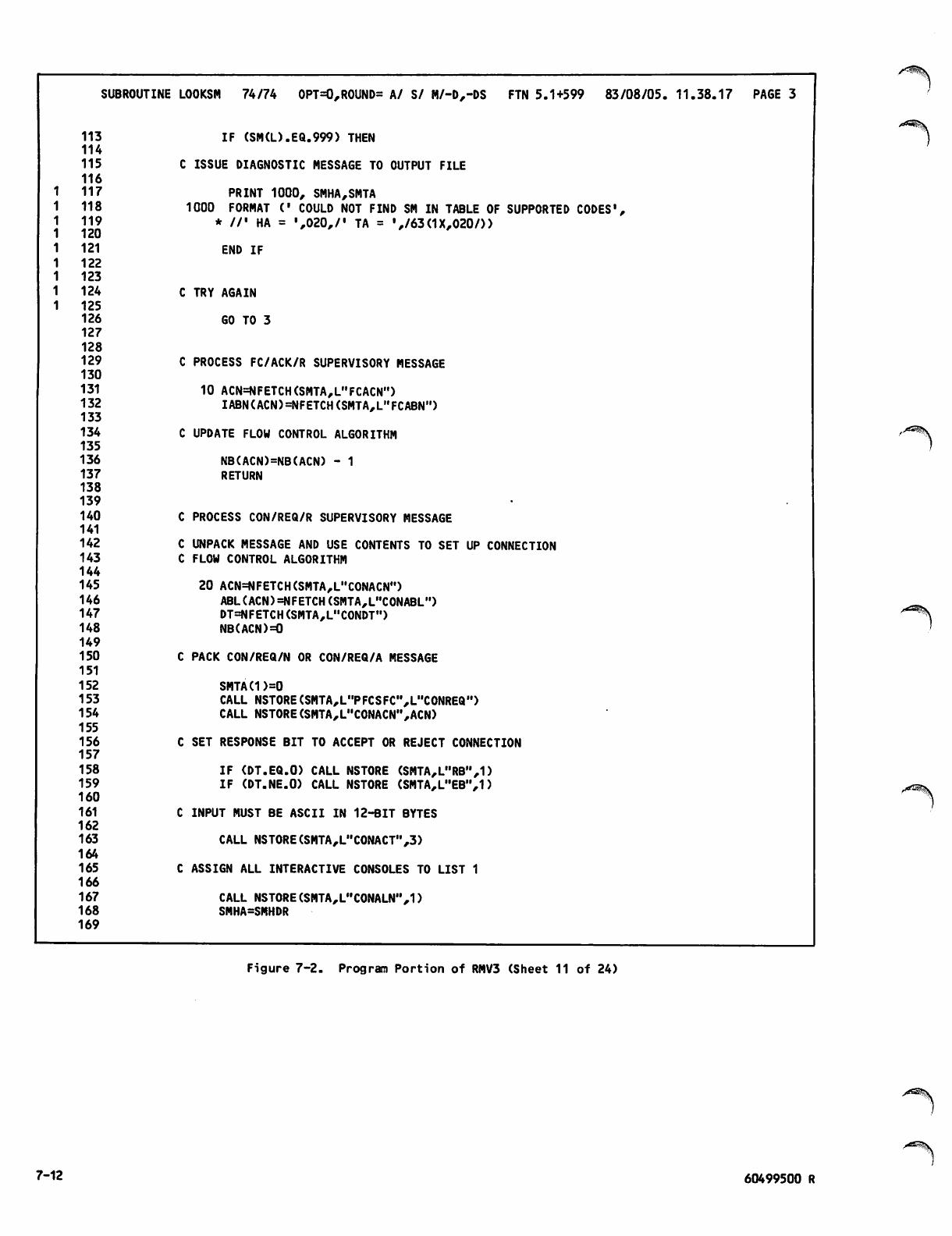
SUBROUTINE LOOKSM 74/74 OPT=0,ROUND= A/ S/ M/-D,-DS FTN 5.1+599 83/08/05. 11.38.17 PAGE 3
113 IF (SM(L).EQ.999) THEN
114
115 C ISSUE DIAGNOSTIC MESSAGE TO OUTPUT FILE
116
1 1 1 7 PRINT 1000, SMHA,SMTA
1 1 1 8 1000 FORMAT (' COULD NOT FIND SM IN TABLE OF SUPPORTED CODES1,
1 1 1 9
1 1 2 0
* //' HA = ',020,/' TA = V63(1X,020/))
1 1 2 1 END IF
1 1 2 2
1 1 2 3
1 1 2 4 C TRY AGAIN
1 1 2 5
126 GO TO 3
127
128
129 C PROCESS FC/ACK/R SUPERVISORY MESSAGE
130
131 10 ACN=NFETCH(SMTA,L"FCACN")
132 IABN(ACN)=NFETCH(SMTA,L,,FCABN")
133
134 C UPDATE FLOW CONTROL ALGORITHM
135
136 NB(ACN)=NB(ACN) - 1
137 RETURN
138
139
140 C PROCESS CON/REQ/R SUPERVISORY MESSAGE
141
142 C UNPACK MESSAGE AND USE CONTENTS TO SET UP CONNECTION
143 C FLOW CONTROL ALGORITHM
144
145 20 ACN=NFETCH(SMTA,L"CONACN")
146 ABL(ACN)=NFETCH(SMTA,L"CONABL")
147 DT=NFETCH(SMTA,L"CONDT")
148 NB(ACN)=0
149
150 C PACK CON/REQ/N OR CON/REQ/A MESSAGE
151
152 SMTA(1)=0
153 CALL NSTORE (SMTA^'PFCSFC'^U'CONREQ")
154 CALL NSTORE(SMTA,LMCONACN",ACN)
155
156 C SET RESPONSE BIT TO ACCEPT OR REJECT CONNECTION
157
158 IF (DT.EQ.O) CALL NSTORE (SMTA,L"RB",1)
159 IF (DT.NE.O) CALL NSTORE (SMTA,L"EBM,1)
160
161 C INPUT MUST BE ASCII IN 12-BIT BYTES
162
163 CALL NSTORE(SMTA,L"CONACT",3)
164
165 C ASSIGN ALL INTERACTIVE CONSOLES TO LIST 1
166
167 CALL NSTORE(SMTA,L"C0NALN",1)
168 SMHA=SMHDR
169
/*^^5k
Figure 7-2. Program Portion of RMV3 (Sheet 11 of 24)
7-12 60499500 R
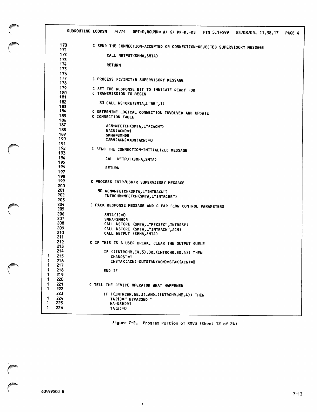
170
171
172
173
174
175
176
177
178
179
180
181
182
183
184
185
186
187
188
189
190
191
192
193
194
195
196
197
198
199
200
201
202
203
204
205
206
207
208
209
210
211
212
213
214
215
216
217
218
219
220
221
222
223
224
225
226
SUBROUTINE LOOKSM 74/74 OPT=0,ROUND= A/ S/ M/-D,-DS FTN 5.1+599 83/08/05.11.38.17 PAGE 4
C SEND THE CONNECTION-ACCEPTED OR CONNECTION-REJECTED SUPERVISORY MESSAGE
CALL NETPUT(SMHA,SMTA)
RETURN
C PROCESS FC/INIT/R SUPERVISORY MESSAGE
C SET THE RESPONSE BIT TO INDICATE READY FOR
C TRANSMISSION TO BEGIN
30 CALL NSTORE(SMTA,L"RB",1)
C DETERMINE LOGICAL CONNECTION INVOLVED AND UPDATE
C CONNECTION TABLE
ACN=NFETCH(SMTA,L"FCACN")
NACN(ACN)=1
SMHA=SMHDR
IABN(ACN)=ABN(ACN)=0
C SEND THE CONNECTION-INITIALIZED MESSAGE
CALL NETPUT(SMHA,SMTA)
RETURN
C PROCESS INTR/USR/R SUPERVISORY MESSAGE
50 ACN=NFETCH(SMTA,LnINTRACN")
INTRCHR=NFETCH(SMTA,LMINTRCHR")
C PACK RESPONSE MESSAGE AND CLEAR FLOW CONTROL PARAMETERS
SMTA(1)=0
SMHA=SMHDR
CALL NSTORE (SMTA,L"PFCSFC",INTRRSP)
CALL NSTORE (SMTA,L"INTRACN",ACN)
CALL NETPUT (SMHA,SMTA)
C IF THIS IS A USER BREAK, CLEAR THE OUTPUT QUEUE
IF (UNTRCHR.EQ.3).0R.(INTRCHR.EQ.4)) THEN
CHANRST=1
INSTAK(ACN)=OUTSTAK(ACN)=STAK(ACN)=0
END IF
C TELL THE DEVICE OPERATOR WHAT HAPPENED
IF ((INTRCHR.NE.3).AND.(INTRCHR.NE.4)) THEN
TA(1)=" BYPASSED "
HA=DSHDR1
TA(2)=0
Figure 7-2. Program Portion of RMV3 (Sheet 12 of 24)
60499500 R 7-13
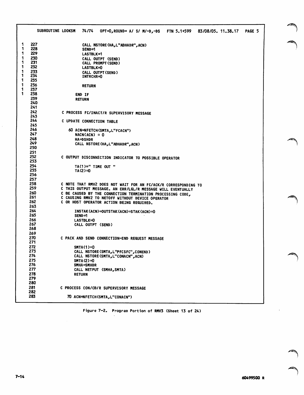
S U B R O U T I N E L O O K S M 7 4 / 7 4 O P T = 0 , R O U N D = A / S / M / - D , - D S F T N 5 . 1 + 5 9 9 8 3 / 0 8 / 0 5 . 11 . 3 8 . 1 7 PA G E 5
227
228
229
230
231
232
233
234
235
236
237
238
239
240
241
242
243
244
245
246
247
248
249
250
251
252
253
254
255
256
257
258
259
260
261
262
263
264
265
266
267
268
269
270
271
272
273
274
275
276
277
278
279
280
281
282
283
CALL NSTORE(HA,L"ABHADR",ACN)
SEND=1
LASTBLK=1
CALL OUTPT (SEND)
CALL PROMPT(SEND)
LASTBLK=0
CALL OUTPT(SEND)
INTRCHR=0
RETURN
END IF
RETURN
C PROCESS FC/INACT/R SUPERVISORY MESSAGE
C UPDATE CONNECTION TABLE
60 ACN=NFETCH(SMTA,L"FCACN")
NACN(ACN) = 0
HA=DSHDR
CALL NSTORE(HA,L"ABHADR",ACN)
C OUTPUT DISCONNECTION INDICATOR TO POSSIBLE OPERATOR
TA(1>=" TIME OUT "
TA(2)=0
C NOTE THAT RMV2 DOES NOT WAIT FOR AN FC/ACK/R CORRESPONDING TO
C THIS OUTPUT MESSAGE. AN ERR/LGL/R MESSAGE WILL EVENTUALLY
C BE CAUSED BY THE CONNECTION TERMINATION PROCESSING CODE,
C CAUSING RMV2 TO NETOFF WITHOUT DEVICE OPERATOR
C OR HOST OPERATOR ACTION BEING REQUIRED.
INSTAK(ACN)=OUTSTAK(ACN)=STAK(ACN)=0
SEND=1
LASTBLK=0
CALL OUTPT (SEND)
C PACK AND SEND CONNECTION-END REQUEST MESSAGE
SMTA(1)=0
CALL NSTORE(SMTA,L"PFCSFC",CONEND)
CALL NSTORE(SMTA,L"CONACN",ACN)
SMTA(2)=0
SMHA=SMHDR
CALL NETPUT (SMHA,SMTA)
RETURN
C PROCESS CON/CB/R SUPERVISORY MESSAGE
70 ACN=NFETCH(SMTA,LHCONACN")
Figure 7-2. Program Portion of RMV3 (Sheet 13 of 24)
7-14
^tf^^V
60499500 R
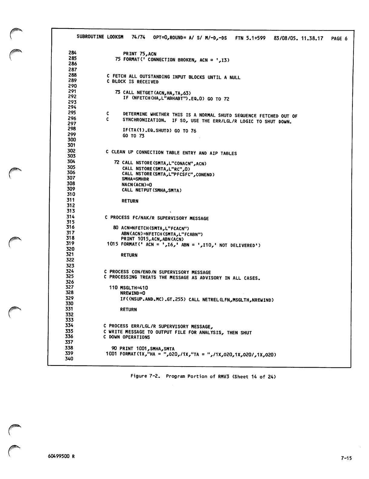
SUBROUTINE LOOKSM 74/74 OPT=0,ROUND= A/ S/ M/-D,-DS FTN 5.1+599 83/08/05. 11.38.17 PAGE 6
284
285
286
287
288
289
290
291
292
293
294
295
296
297
298
299
300
301
302
303
304
305
306
307
308
309
310
311
312
313
314
315
316
317
318
319
320
321
322
323
324
325
326
327
328
329
330
331
332
333
334
335
336
337
338
339
340
PRINT 75,ACN
75 FORMAT(' CONNECTION BROKEN, ACN = ',13)
C FETCH ALL OUTSTANDING INPUT BLOCKS UNTIL A NULL
C BLOCK IS RECEIVED
73 CALL NETGET(ACN,HA,TA,63)
IF (NFETCH(HA,L"ABHABT").EQ.O) GO TO 72
DETERMINE WHETHER THIS IS A NORMAL SHUTD SEQUENCE FETCHED OUT OF
SYNCHRONIZATION. IF SO, USE THE ERR/LGL/R LOGIC TO SHUT DOWN.
IF(TA(1).EQ.SHUTD) GO TO 76
GO TO 73
C CLEAN UP CONNECTION TABLE ENTRY AND AIP TABLES
72 CALL NSTORE(SMTA,L"CONACN",ACN)
CALL NSTORE(SMTA,L"RC",0)
CALL NSTORE(SMTA,L"PFCSFC",CONEND)
SMHA=SMHDR
NACN(ACN)=0
CALL NETPUT(SMHA,SMTA)
RETURN
C PROCESS FC/NAK/R SUPERVISORY MESSAGE
80 ACN=NFETCH(SMTA,L"FCACN")
ABN(ACN)=NFETCH(SMTA,L"FCABN")
PRINT 1015,ACN,ABN(ACN)
1015 FORMAT(' ACN = ',16,' ABN = ',110," NOT DELIVERED')
RETURN
C PROCESS CON/END/N SUPERVISORY MESSAGE
C PROCESSING TREATS THE MESSAGE AS ADVISORY IN ALL CASES.
110 MSGLTH=410
NREWIND=0
IF((NSUP.AND.MC).GT.255) CALL NETREL(LFN,MSGLTH,NREWIND)
RETURN
C PROCESS ERR/LGL/R SUPERVISORY MESSAGE,
C WRITE MESSAGE TO OUTPUT FILE FOR ANALYSIS, THEN SHUT
C DOWN OPERATIONS
90 PRINT 1001,SMHA,SMTA
1001 FORMAT (1X,"HA = ",020,/1X,"TA = ",/1X,020,1X,020/,1X,020)
Figure 7-2. Program Portion of RMV3 (Sheet 14 of 24)
z#^\
60499500 R 7-15
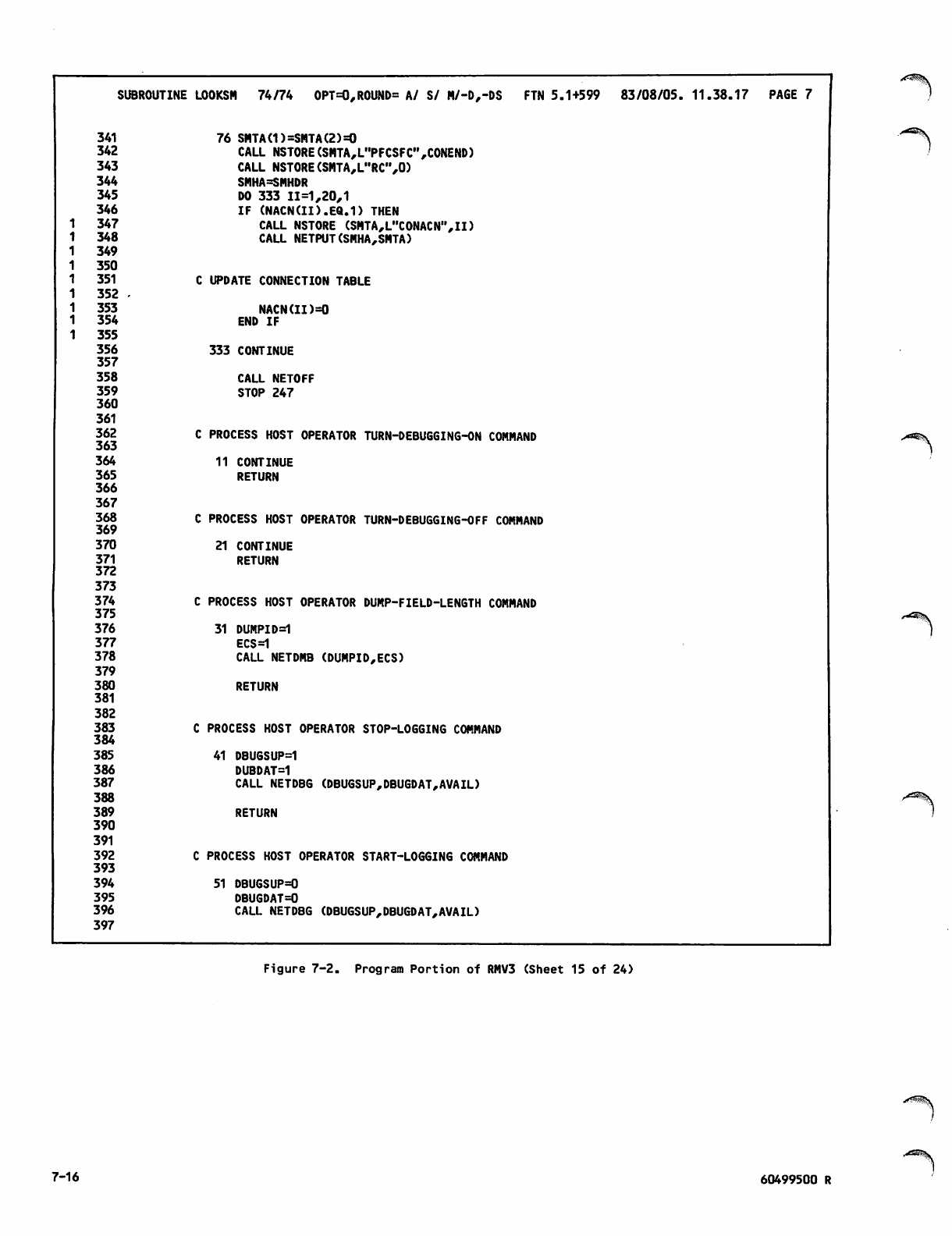
SUBROUTINE LOOKSM 74/74 OPT=0,ROUND= A/ S/ M/-D,-DS FTN 5.1+599 83/08/05. 11.38.17 PAGE 7
341 76 SMTA(1)=SMTA(2)=0
342 CALL NSTORE(SMTA,L"PFCSFC",CONEND)
343 CALL NSTORE(SMTA,L"RC",0)
344 SMHA=SMHDR
345 DO 333 11=1,20,1
346 IF (NACN(II).EQ.D THEN
1 3 4 7 CALL NSTORE (SMTA,L"CONACN",II)
1 3 4 8 CALL NETPUT(SMHA,SMTA)
1 3 4 9
1 3 5 0
1 351 UPDATE CONNECTION TABLE
1 352 -
1 3 5 3 NACN(II)=0
1 3 5 4 END IF
1 3 5 5
356 333 CONTINUE
357
358 CALL NETOFF
359 STOP 247
360
361
362
363 PROCESS HOST OPERATOR TURN-DEBUGGING-ON COMMAND
364 11 CONTINUE
365 RETURN
366
367
368
369 PROCESS HOST OPERATOR TURN-DEBUGGING-OFF COMMAND
370 21 CONTINUE
371 RETURN
372
373
374 PROCESS HOST OPERATOR DUMP-FIELD-LENGTH COMMAND
375
376 31 DUMPID=1
377 ECS=1
378 CALL NETDMB (DUMPID,ECS)
379
380 RETURN
381
382
383 PROCESS HOST OPERATOR STOP-LOGGING COMMAND
384
385 41 DBUGSUP=1
386 DUBDAT=1
387 CALL NETDBG (DBUGSUP,DBUGDAT,AVAIL)
388
389 RETURN
390
391
392 PROCESS HOST OPERATOR START-LOGGING COMMAND
393
394 51 DBUGSUP=0
395 DBUGDAT=0
396 CALL NETDBG (DBUGSUP,DBUGDAT,AVAIL)
397
Figure 7-2. Program Portion of RMV3 (Sheet 15 of 24)
7-16 60499500 R
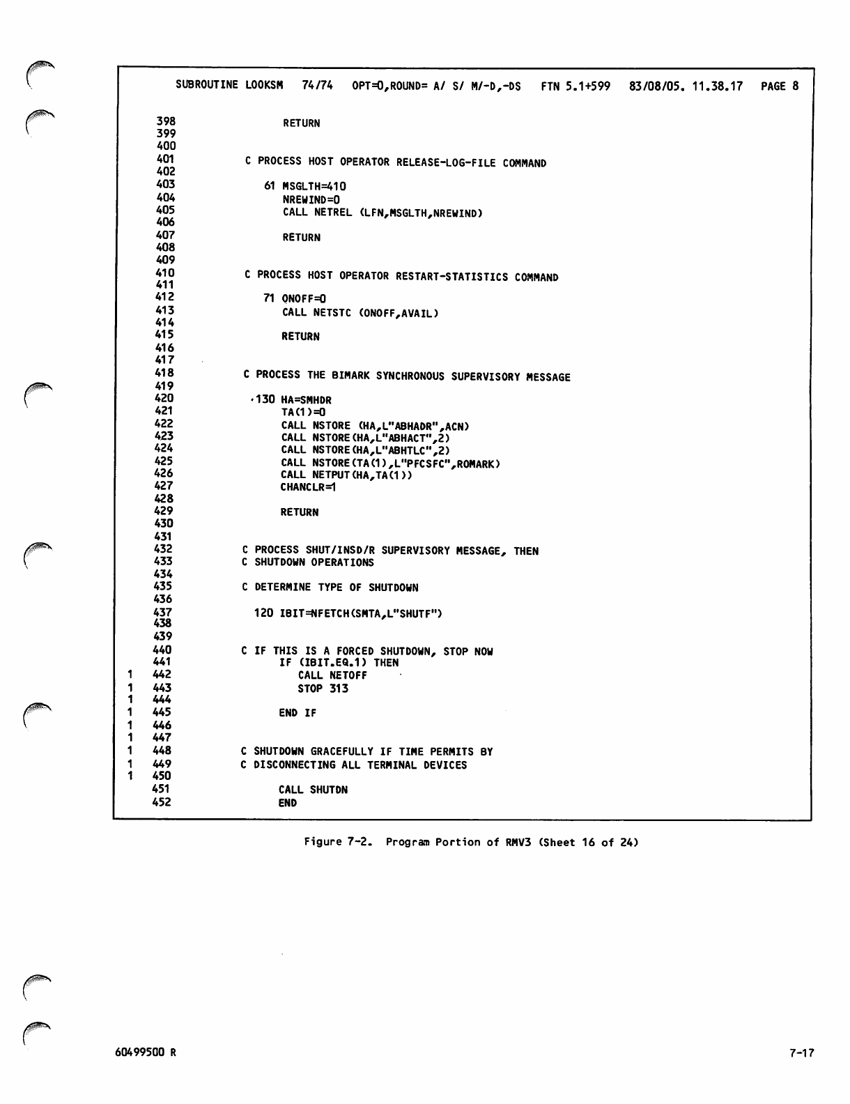
/ ^ S
r
/|P^\
SUBROUTINE LOOKSM 74/74 OPT=0,ROUND= A/ S/ M/-D,-DS FTN 5.1+599 83/08/05. 11.38.17 PAGE 8
398
399
400
401
402
403
404
405
406
407
408
409
410
411
412
413
414
415
416
417
418
419
420
421
422
423
424
425
426
427
428
429
430
431
432
433
434
435
436
437
438
439
440
441
442
443
444
445
446
447
448
449
450
451
452
RETURN
C PROCESS HOST OPERATOR RELEASE-LOG-FILE COMMAND
61 MSGLTH=410
NREWIND=0
CALL NETREL (LFN,MSGLTH,NREWIND)
RETURN
C PROCESS HOST OPERATOR RESTART-STATISTICS COMMAND
71 0N0FF=O
CALL NETSTC (ONOFF,AVAIL)
RETURN
C PROCESS THE BIMARK SYNCHRONOUS SUPERVISORY MESSAGE
•130 HA=SMHDR
TA(1)=0
CALL NSTORE (HA,L"ABHADR",ACN)
CALL NSTORE(HA,L"ABHACT",2)
CALL NSTORE(HA,L"ABHTLCM,2)
CALL NSTORE(TA(1),L"PFCSFC",R0MARK)
CALL NETPUT (HA,TA(D)
CHANCLR=1
RETURN
C PROCESS SHUT/INSD/R SUPERVISORY MESSAGE, THEN
C SHUTDOWN OPERATIONS
C DETERMINE TYPE OF SHUTDOWN
120 IBIT=NFETCH(SMTA,L"SHUTF")
C IF THIS IS A FORCED SHUTDOWN, STOP NOW
I F ( I B I T. E Q . 1 ) T H E N
CALL NETOFF
STOP 313
END IF
C SHUTDOWN GRACEFULLY IF TIME PERMITS BY
C DISCONNECTING ALL TERMINAL DEVICES
CALL SHUTDN
END
Figure 7-2. Program Portion of RMV3 (Sheet 16 of 24)
/$P^\
60499500 R 7-17
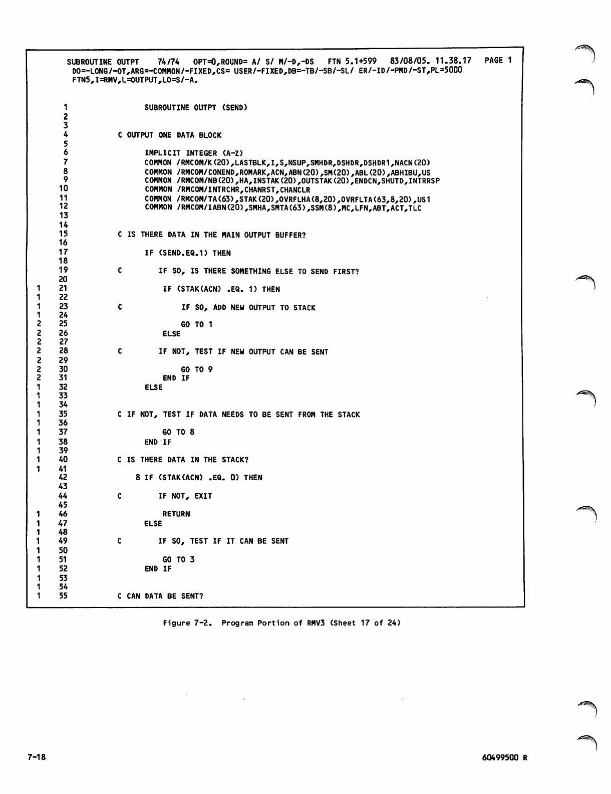
SUBROUTINE OUTPT 74/74 OPT=0,ROUND= A/ S/ M/-D,-DS FTN 5.1+599 83/08/05. 11.38.17 PAGE 1
D0=- LONG/ -01 ,ARG=-COMMON/-FIXED,CS= USER/-FIXED,DB=-TB/-SB/-SL/ ER/-ID/-PMD/-ST,PL=5000
FTN5 ,I=RMV,L=OUTPUT,LO=S/-A.
1
2
SUBROUTINE OUTPT (SEND)
3
4
5
6
COUTPUT ONE DATA BLOCK
IMPLICIT INTEGER (A-Z)
7COMMON /RMC0M/K(20),LASTBLK,I,S,NSUP,SMHDR,DSHDR,DSHDR1,NACN(20)
8COMMON /RMC0M/C0NEND,R0MARK,ACN,ABN(20),SM(20),ABL(20),ABHIBU,US
9COMMON /RMCOM/NB(20),HA,INSTAK(20),OUTSTAK(20),ENDCN,SHUTD,INTRRSP
10 COMMON /RMCOM/INTRCHR,CHANRST,CHANCLR
11 COMMON /RMCOM/TA(63),STAK(20),OVRFLHA(8,20),0VRFLTA(63,8,20),US1
12 COMMON /RMC0M/IABN(20),SMHA,SMTA(63),SSM(8),MC,LFN,ABT,ACT,TLC
13
14
15 IS THERE DATA IN THE MAIN OUTPUT BUFFER?
16
17 IF (SEND.EQ.1) THEN
18
19 IF SO, IS THERE SOMETHING ELSE TO SEND FIRST?
20
121 IF (STAK(ACN) .EQ. 1) THEN
122
123 IF SO, ADD NEW OUTPUT TO STACK
124
225 GO TO 1
226 ELSE
227
228 IF NOT, TEST IF NEW OUTPUT CAN BE SENT
229
230 GO TO 9
231
32
33
34
END IF
ELSE
35 IF NOT, TEST IF DATA NEEDS TO BE SENT FROM THE STACK
36
37 GO TO 8
38 END IF
39
40 IS THERE DATA IN THE STACK?
41
42 IF (STAK(ACN) .EQ. 0) THEN
43
44 IF NOT, EXIT
45
46 RETURN
47 ELSE
48
49 IF SO, TEST IF IT CAN BE SENT
50
51 GO TO 3
52 END IF
53
54
55 CAN DATA BE SENT?
Figure 7-2. Program Portion of RMV3 (Sheet 17 of 24)
7-18 60499500 R
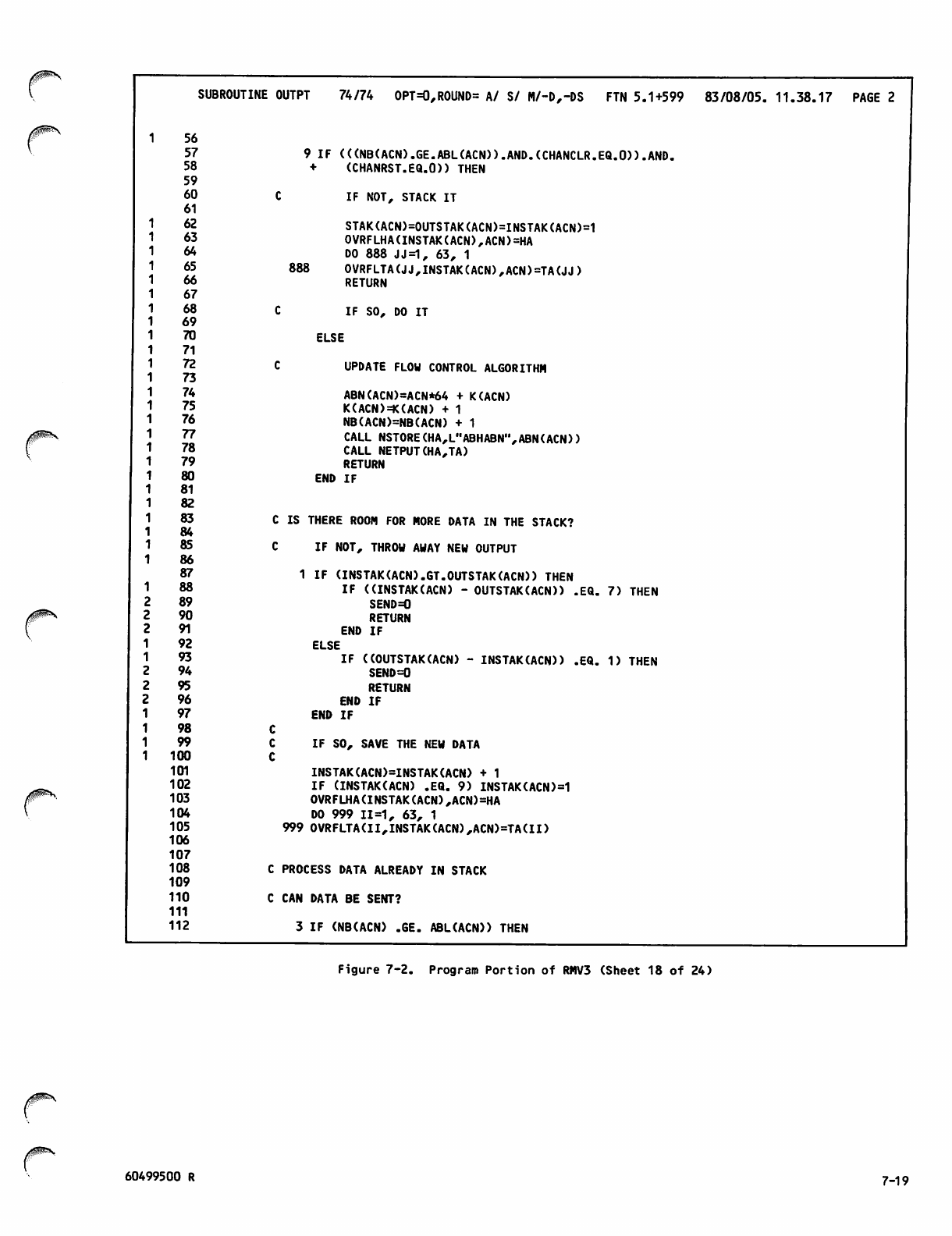
SUBROUTINE OUTPT 74/74 OPT=0,ROUND= A/ S/ M/-D,-DS FTN 5.1+599 83/08/05. 11.38.17 PAGE 2
56
57 9 IF (((NB(ACN).GE.ABL(ACN)).AND.(CHANCLR.EQ.O)).AND.
58 + (CHANRST.EQ.O)) THEN
59
6 0 C I F N O T , S T A C K I T
61
62 STAK(ACN)=0UTSTAK(ACN)=INSTAK(ACN)=1
63 OVRFLHA(INSTAK(ACN),ACN)=HA
6 4 D O 8 8 8 J J = 1 , 6 3 , 1
65 888 OVRFLTA(JJ,INSTAK(ACN),ACN)=TA(JJ)
66 RETURN
67
6 8 C I F S O , D O I T
69
70 ELSE
71
72 C UPDATE FLOW CONTROL ALGORITHM
73
74 ABN(ACN)=ACN*64 + K(ACN)
75 K(ACN)=K(ACN) + 1
76 NB(ACN)=NB(ACN) + 1
77 CALL NSTORE(HA,L"ABHABN',,ABN(ACN))
78 CALL NETPUT(HA,TA)
79 RETURN
8 0 E N D I F
81
82
83 C IS THERE ROOM FOR MORE DATA IN THE STACK?
84
8 5 C I F N O T , T H R O W A W A Y N E W O U T P U T
86
87 1 IF (INSTAK(ACN).GT.OUTSTAK(ACN)) THEN
1 88 IF ((INSTAK(ACN) - OUTSTAK(ACN)) .EQ. 7) THEN
2 89 SEND=0
2 90 RETURN
2 9 1 E N D I F
1 9 2 E L S E
1 93 IF ((OUTSTAK(ACN) - INSTAK(ACN)) .EQ. 1) THEN
2 94 SEND=0
2 95 RETURN
2 9 6 E N D I F
1 9 7 E N D I F
1 9 8 C
1 9 9 C I F S O , S A V E T H E N E W D A T A
1 1 0 0 C
101 INSTAK(ACN)=INSTAK(ACN) + 1
102 IF (INSTAK(ACN) .EQ. 9) INSTAK(ACN)=1
103 OVRFLHA(INSTAK(ACN),ACN)=HA
1 0 4 D O 9 9 9 1 1 = 1 , 6 3 , 1
105 999 OVRFLTA(II,INSTAK(ACN),ACN)=TA(II)
106
107
108 C PROCESS DATA ALREADY IN STACK
109
1 1 0 C C A N D A T A B E S E N T ?
111
112 3 IF (NB(ACN) .GE. ABL(ACN)) THEN
Figure 7-2. Program Portion of RMV3 (Sheet 18 of 24)
60499500 R 7_19

SUBROUTINE OUTPT 7 4 / 7 4 O P T = 0 , R O U N D = A / S / M / - D , - D S F T N 5 . 1 + 5 9 9 8 3 / 0 8 / 0 5 . 1 1 . 3 8 . 1 7 P A G E 3
113
114 IF NOT, EXIT
115
116 RETURN
117
118 IF SO, DO IT
119
120 ELSE
121
122
123
UPDATE FLOW CONTROL ALGORITHM
124 ABN(ACN)=ACN*64 + K(ACN)
125 K(ACN)=K(ACN) + 1
126 NB(ACN)=NB(ACN) + 1
127 CALL NSTORE(OVRFLHA(OUTSTAK(ACN),ACN),L"ABHABN",ABN(ACN))
128 CALL NETPUT(OVRFLHA(OUTSTAK(ACN),ACN),
129 OVRFLTAd ,OUTSTAK (ACN) , ACN))
130
131 TEST IF STACK HAS BEEN EMPTIED
132
133 IF (OUTSTAK(ACN).EQ.INSTAK(ACN)) THEN
2134 STAK(ACN)=0
2135
2136 IF SO, REINITIALIZE POINTERS
2137
2138 OUTSTAK(ACN)=INSTAK(ACN)=0
2139 ELSE
2140
2141 IF NOT, MOVE THE SEND BUFFER POINTER FOR NEXT PASS
2142
2143 OUTSTAK(ACN)=OUTSTAK(ACN) + 1
2144 IF (OUTSTAK(ACN) .EQ. 9) 0UTSTAK(ACN)=1
2145 RETURN
2146 END IF
1147 END IF
1148
149 RETURN
150 END
/-"^v
Figure 7-2. Program Portion of RMV3 (Sheet 19 of 24)
7-20 60499500 R
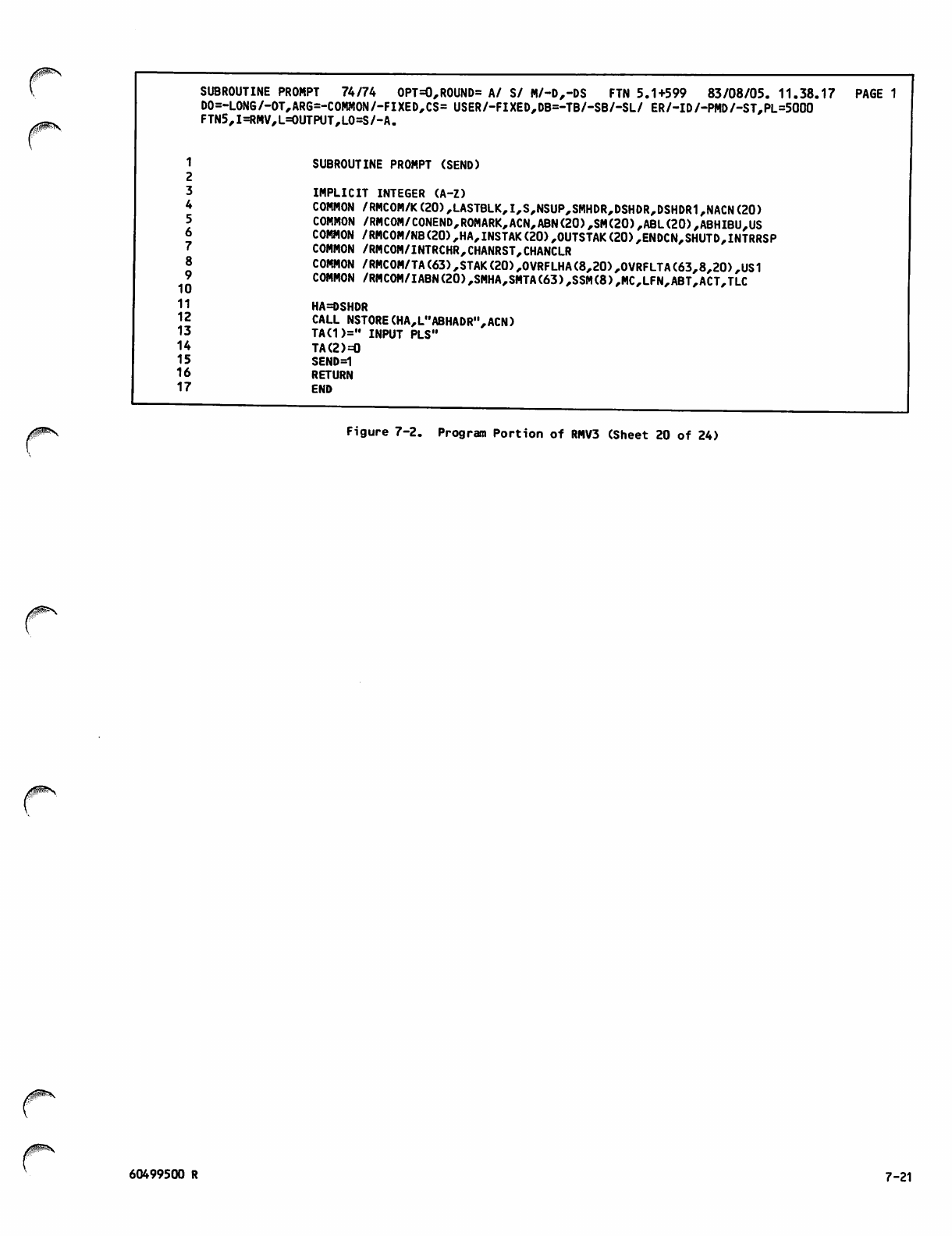
SUBROUTINE PROMPT 74/74 OPT=0,ROUND= A/ S/ M/-D,-DS FTN 5.1+599 83/08/05. 11.38.17 PAGE 1
DO=-LONG/-OT,ARG=-COMMON/-FIXED,CS= USER/-FIXED,DB=-TB/-SB/-SL/ ER/-ID/-PMD/-ST,PL=5000
FTN5,I=RMV,L=0UTPUT,L0=S/-A.
1 SUBROUTINE PROMPT (SEND)
2
3 IMPLICIT INTEGER (A-Z)
4 COMMON /RMCOM/K(20),LASTBLK,I,S,NSUP,SMHDR,DSHDR,DSHDR1,NACN(20)
5 COMMON /RMCOM/C0NEND,ROMARK,ACN,ABN(20),SM(20),ABL(20),ABHIBU,US
6 COMMON /RMC0M/NB(20),HA,INSTAK(20),OUTSTAK(20),ENDCN,SHUTD,INTRRSP
7 COMMON /RMCOM/INTRCHR,CHANRST,CHANCLR
8 COMMON /RMC0M/TA(63),STAK(20),0VRFLHA(8,20),0VRFLTA(63,8,20),US1
9 COMMON /RMC0M/IABN(20),SMHA,SMTA(63),SSM(8),MC,LFN,ABT,ACT,TLC
11 HA=DSHDR
12 CALL NSTORE(HA,L"ABHADR",ACN)
13 TA(1>=" INPUT PLS"
14 TA(2)=0
15 SEND=1
16 RETURN
1 7 E N D
Figure 7-2. Program Portion of RMV3 (Sheet 20 of 24)
60499500 R 7-21
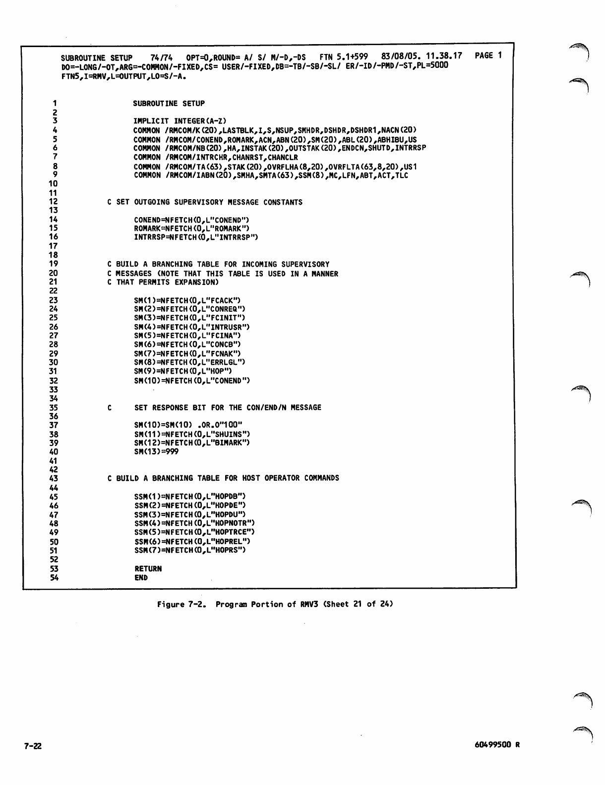
10
11
12
13
14
15
16
17
18
19
20
21
22
23
24
25
26
27
28
29
30
31
32
33
34
35
36
37
38
39
40
41
42
43
44
45
46
47
48
49
50
51
52
53
54
SUBROUTINE SETUP 74/74 OPT=0,ROUND= A/ S/ M/-D,-DS FTN 5.1+599 83/08/05. 11.38.17 PAGE 1
DO=-LONG/-OT,ARG=-COMHON/-FIXED,CS= USER/-FIXED,DB=-TB/-SB/-SL/ ER/-ID/-PMD/-ST,PL=5000
FTN5,I=RMV,L=0UTPUT,L0=S/-A.
SUBROUTINE SETUP
IMPLICIT INTEGER(A-Z)
COMMON /RMCOM/K(20),LASTBLK,I,S,NSUP,SMHDR,DSHDR,DSHDR1,NACN(20)
COMMON /RMCOM/CONEND,ROMARK,ACN,ABN(20),SM(20),ABL(20),ABHIBU,US
COMMON /RMCOM/NB(20),HA,INSTAK(20),OUTSTAK(20),ENDCN,SHUTD,INTRRSP
COMMON /RMCOM/INTRCHR,CHANRST,CHANCLR
COMMON /RMCOM/TA(63),STAK(20),OVRFLHA(8,20),OVRFLTA(63,8,20),US1
COMMON /RMC0M/IABN(20),SMHA,SMTA(63),SSM(8),MC,LFN,ABT,ACT,TLC
C SET OUTGOING SUPERVISORY MESSAGE CONSTANTS
CONEND=NFETCH(0,L"CONEND")
ROMARK=NFETCH(0,L"ROMARK")
INTRRSP=NFETCH(0,L"INTRRSP")
C BUILD A BRANCHING TABLE FOR INCOMING SUPERVISORY
C MESSAGES (NOTE THAT THIS TABLE IS USED IN A MANNER
C THAT PERMITS EXPANSION)
SMd )=NFETCH(0,L"FCACK")
SM(2)=NFETCH(0,L"C0NREQ")
SM(3)=NFETCH(0,L"FCINIT")
SM(4)=NFETCH(0,L"INTRUSR")
SM(5)=NFETCH(0,L"FCINA")
SM(6)=NFETCH(0,L"C0NCB")
SM(7)=NFETCH(0,L"FCNAK")
SM(8)=NFETCH(0,L"ERRLGL")
SM(9)=NFETCH(0,L"H0P")
SM(10)=NFETCH(0,L"CONEND")
SET RESPONSE BIT FOR THE CON/END/N MESSAGE
SM(10)=SM(10) .0R.0"100"
SM(11)=NFETCH(0,L"SHUINS")
SMd 2)=NFETCH (0,L"BIMARK")
SMd 3) =999
C BUILD A BRANCHING TABLE FOR HOST OPERATOR COMMANDS
SSMd )=NFETCH(0,L"HOPDB")
SSM(2)=NFETCH(0,L"HOPDE")
SSM(3)=NFETCH(0,L"H0PDU")
SSM(4)=NFETCH(0,L"HOPNOTR")
SSM(5)=NFETCH(0,L"H0PTRCE")
SSM(6)=NFETCH(0,L"HOPREL")
SSM(7)=NFETCH(0,L"H0PRS")
RETURN
END
Figure 7-2. Program Portion of RMV3 (Sheet 21 of 24)
/SSK
7-22 60499500 R
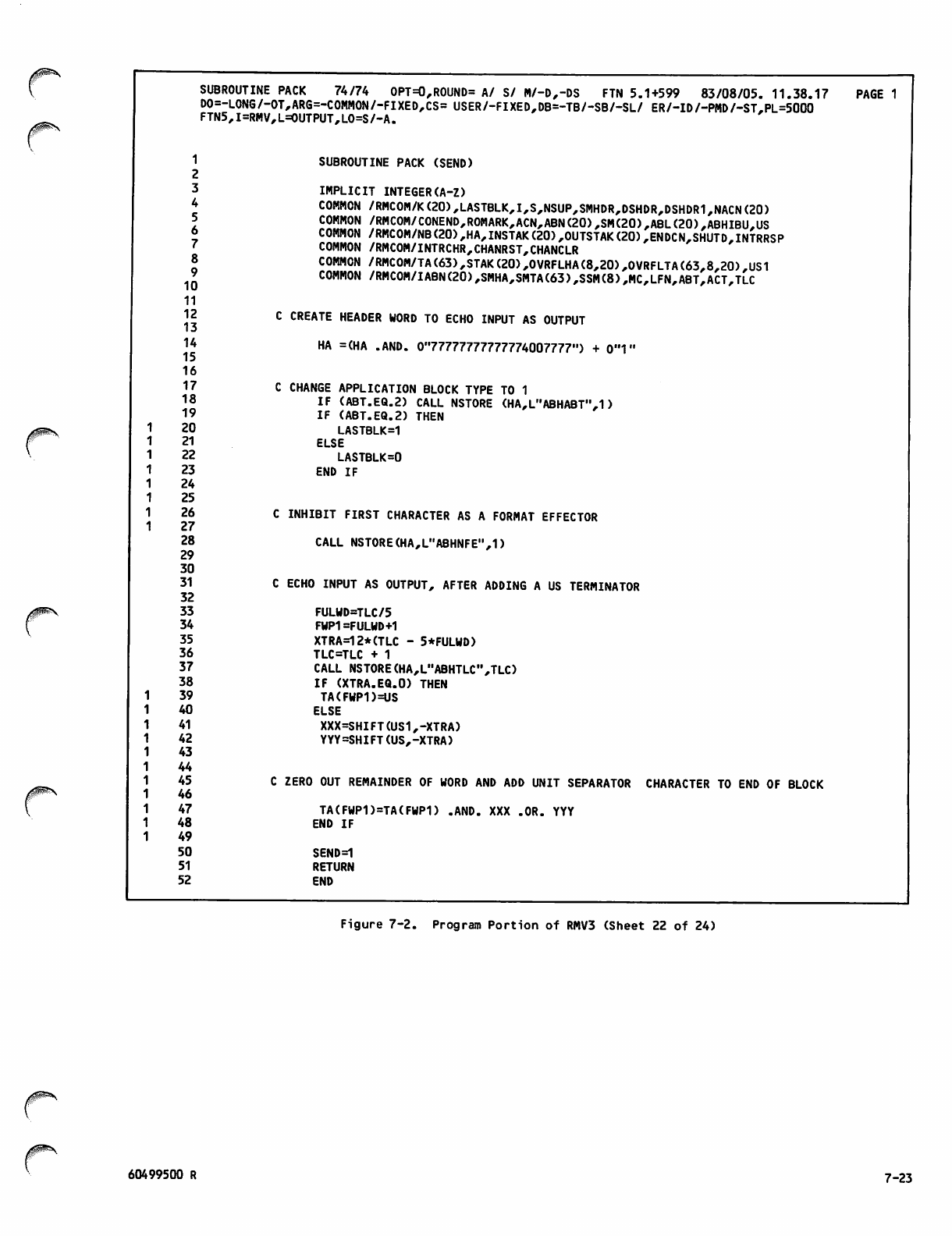
10
11
12
13
14
15
16
17
18
19
20
21
22
23
24
25
26
27
28
29
30
31
32
33
34
35
36
37
38
39
40
41
42
43
44
45
46
47
48
49
50
51
52
SUBROUTINE PACK 74/74 OPT=0,ROUND= A/ S/ M/-D,-DS FTN 5.1+599 83/08/05. 11.38.17
D0=-LONG/-OT,ARG=-COMMON/-FIXED,CS= USER/-FIXED,DB=-TB/-SB/-SL/ ER/-ID/-PMD/-ST,PL=5000
FTN5,I=RMV,L=OUTPUT,LO=S/-A.
SUBROUTINE PACK (SEND)
IMPLICIT INTEGER(A-Z)
COMMON /RMCOM/K(20),LASTBLK,I,S,NSUP,SMHDR,DSHDR,DSHDR1,NACN(20)
COMMON /RMC0M/C0NEND,R0MARK,ACN,ABN(20),SM(20),ABL(20),ABHIBU,US
COMMON /RMC0M/NB(20),HA,INSTAK(20),0UTSTAK(20),ENDCN,SHUTD,INTRRSP
COMMON /RMCOM/INTRCHR,CHANRST,CHANCLR
COMMON /RMCOM/TA(63),STAK(20),0VRFLHA(8,20),OVRFLTA(63,8,20)#US1
COMMON /RMC0M/IABN(20),SMHA,SMTA(63),SSM(8),MC,LFN,ABT,ACT,TLC
C CREATE HEADER WORD TO ECHO INPUT AS OUTPUT
HA =(HA .AND. 0"77777777777774007777") + 0"1"
C CHANGE APPLICATION BLOCK TYPE TO 1
IF (ABT.EQ.2) CALL NSTORE (HA,L"ABHABT",1)
IF (ABT.EQ.2) THEN
LASTBLK=1
ELSE
LASTBLK=0
END IF
PAGE 1
C INHIBIT FIRST CHARACTER AS A FORMAT EFFECTOR
CALL NSTORE(HA,L"ABHNFE",1)
C ECHO INPUT AS OUTPUT, AFTER ADDING A US TERMINATOR
FULWD=TLC/5
FWP1 =FULWD+1
XTRA=12*(TLC - 5*FULWD)
TLC=TLC + 1
CALL NSTORE(HA,L"ABHTLC",TLC)
IF (XTRA.EQ.O) THEN
TA(FWP1)=US
ELSE
XXX=SHIFT(US1,-XTRA)
YYY=SHIFT(US,-XTRA)
C ZERO OUT REMAINDER OF WORD AND ADD UNIT SEPARATOR CHARACTER TO END OF BLOCK
TA(FWP1)=TA(FWP1) .AND. XXX .OR. YYY
END IF
SEND=1
RETURN
END
Figure 7-2. Program Portion of RMV3 (Sheet 22 of 24)
60499500 R 7 - 2 3
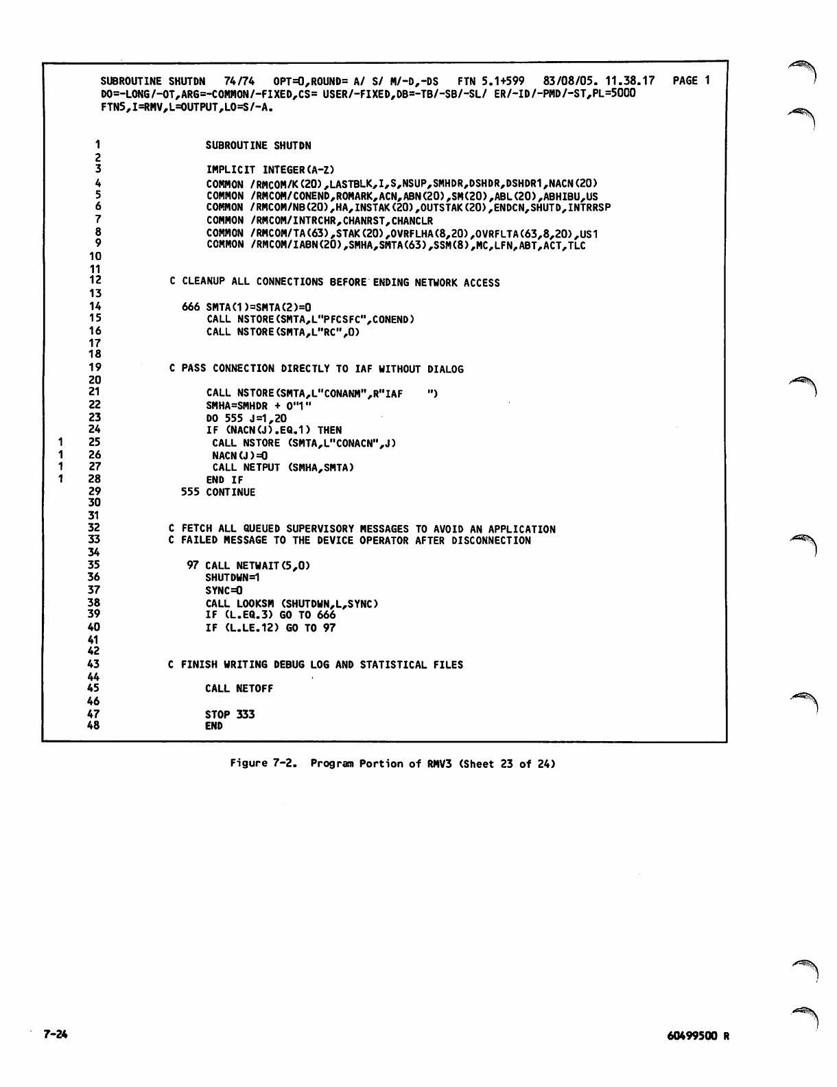
SUBROUTINE SHUTDN 74/74 OPT=0,ROUND= A/ S/ M/-D,-DS FTN 5.1+599 83/08/05. 11.38.17 PAGE 1
DO=- •LONG/-OT,ARG=-COMMON/-FIXED,CS= USER/-FIXED,DB=-TB/-SB/-SL/ ER/-ID/-PMD/-ST,PL=5000
FTN5 ,I=RMV,L=0UTPUT,L0=S/-A.
1
2
3
SUBROUTINE SHUTDN
IMPLICIT INTEGER(A-Z)
4COMMON /RMC0M/K(20),LASTBLK,I,S,NSUP,SMHDR,DSHDR,DSHDR1,NACN(20)
5COMMON /RMC0M/CONEND,R0MARK,ACN,ABN(20),SM(20),ABL(20),ABHIBU,US
6COMMON /RMC0M/NB(20),HA,INSTAK(20),OUTSTAK(20),ENDCN,SHUTD,INTRRSP
7COMMON /RMCOM/INTRCHR,CHANRST,CHANCLR
8COMMON /RMCOM/TA(63),STAK(20),OVRFLHA(8,20),OVRFLTA(63,8,20),US1
9COMMON /RMC0M/IABN(20),SMHA,SMTA(63),SSM(8),MC,LFN,ABT,ACT,TLC
10
11
12 CLEANUP ALL CONNECTIONS BEFORE ENDING NETWORK ACCESS
13
14 666 SMTA(1)=SMTA(2)=0
15 CALL NSTORE(SMTA,L"PFCSFC",CONEND)
16 CALL NSTORE(SMTA,L"RC",0)
17
18
19 PASS CONNECTION DIRECTLY TO IAF WITHOUT DIALOG
20
21 CALL NSTORE(SMTA,L"CONANM",R"IAF ")
22 SMHA=SMHDR + 0"1"
23 DO 555 J =1,20
24 IF (NACN(J).EQ.D THEN
1 2 5 CALL NSTORE (SMTA,L"CONACN",J)
1 2 6 NACN(J)=0
1 2 7 CALL NETPUT (SMHA,SMTA)
1 2 8 END IF
29 555 CONTINUE
30
31
32 FETCH ALL QUEUED SUPERVISORY MESSAGES TO AVOID AN APPLICATION
33 FAILED MESSAGE TO THE DEVICE OPERATOR AFTER DISCONNECTION
34
35 97 CALL NETWAIT(5,0)
36 SHUTDWN=1
37 SYNC=0
38 CALL LOOKSM (SHUTDWN,L,SYNC)
39 IF (L.EQ.3) GO TO 666
40
41
42
IF (L.LE.12) GO TO 97
43 FINISH WRITING DEBUG LOG AND STATISTICAL FILES
44
45 CALL NETOFF
46
47 STOP 333
48 END
Figure 7-2. Program Portion of RMV3 (Sheet 23 of 24)
<t*^\
7-24 60499500 R
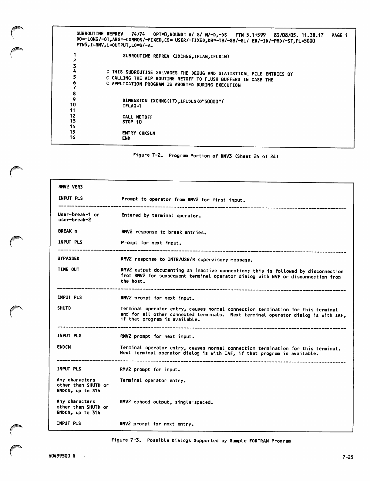
10
11
12
13
14
15
16
SUBROUTINE REPREV 74/74 OPT=0,R0UND= A/ S/ M/-D,-DS FTN 5.1+599 83/08/05. 11.38.17 PAGE 1
DO=-LONG/-OT,ARG=-COMMON/-FIXED,CS= USER/-FIXED,DB=-TB/-SB/-SL/ ER/-ID/-PMD/-ST,PL=5000
FTN5,I=RMV,L=0UTPUT,L0=S/-A.
SUBROUTINE REPREV (IXCHNG,IFLAG,IFLDLN)
C THIS SUBROUTINE SALVAGES THE DEBUG AND STATISTICAL FILE ENTRIES BY
C CALLING THE AIP ROUTINE NETOFF TO FLUSH BUFFERS IN CASE THE
C APPLICATION PROGRAM IS ABORTED DURING EXECUTION
DIMENSION IXCHNG(17),IFLDLN(0"50000")'
IFLAG=1
CALL NETOFF
STOP 10
ENTRY CHKSUM
END
Figure 7-2. Program Portion of RMV3 (Sheet 24 of 24)
r
RMV2 VER3
INPUT PLS
User-break-1 or
user-break-2
BREAK n
INPUT PLS
BYPASSED
TIME OUT
INPUT PLS
ENDCN
Prompt to operator from RMV2 for first input,
Entered by terminal operator.
RMV2 response to break entries.
Prompt for next input.
RMV2 response to INTR/USR/R supervisory message.
RMV2 output documenting an inactive connection; this is followed by disconnection
from RMV2 for subsequent terminal operator dialog with NVF or disconnection from
the host.
I N P U T P L S R M V 2 p r o m p t f o r n e x t i n p u t .
SHUTD Terminal operator entry, causes normal connection termination for this terminal
and for all other connected terminals. Next terminal operator dialog is with IAF,
if that program is available.
RMV2 prompt for next input.
Terminal operator entry, causes normal connection termination for this terminal,
Next terminal operator dialog is with IAF, if that program is available.
INPUT PLS
Any characters
other than SHUTD or
ENDCN, up to 314
Any characters
other than SHUTD or
ENDCN, up to 314
INPUT PLS
RMV2 prompt for input.
Terminal operator entry.
RMV2 echoed output, single-spaced,
RMV2 prompt for next entry.
Figure 7-3. Possible Dialogs Supported by Sample FORTRAN Program
60499500 R 7-25
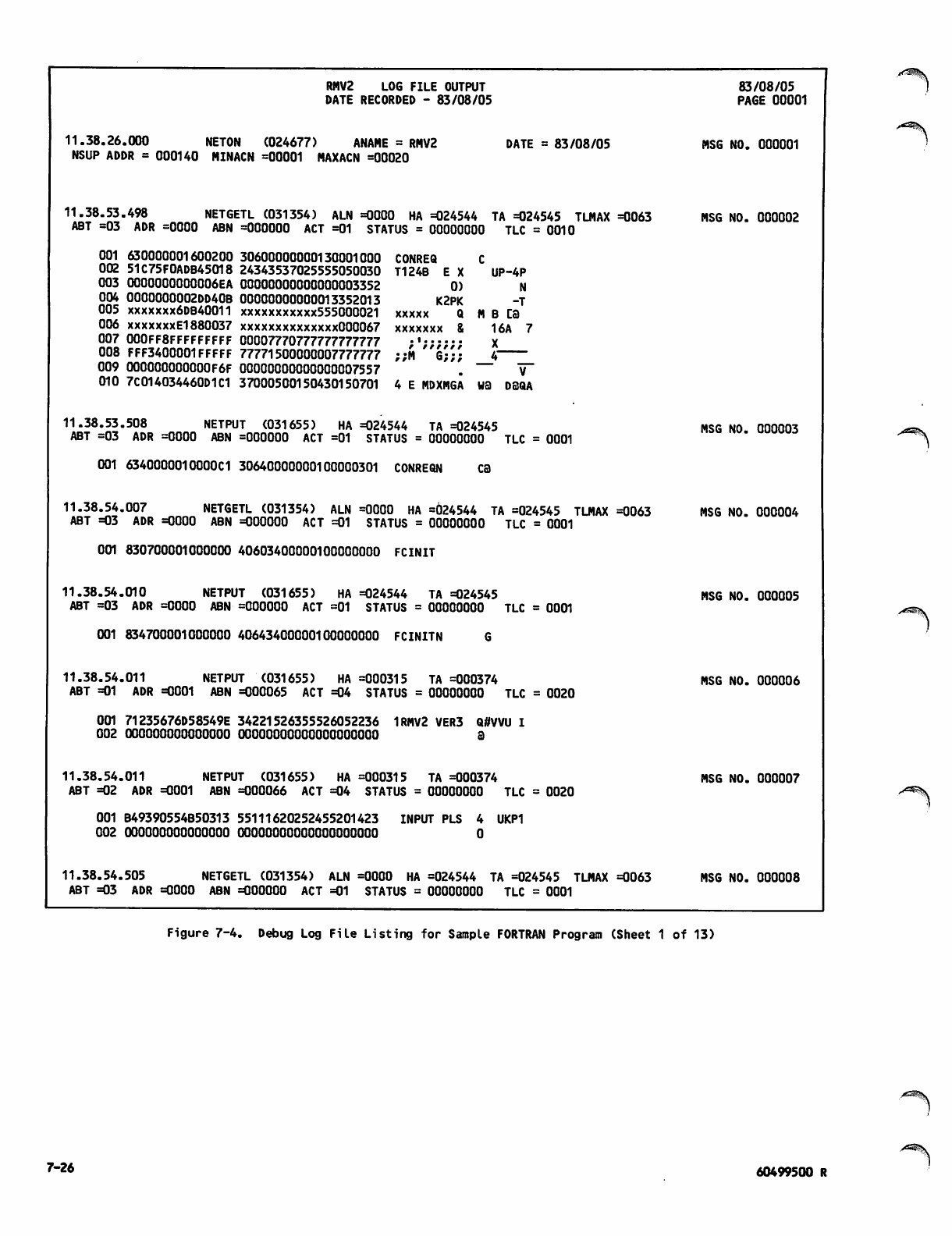
RMV2 LOG FILE OUTPUT 83/08/05
DATE RECORDED - 83/08/05 PAGE 00001
11.38.26.000 NETON (024677) ANAME = RMV2 DATE = 83/08/05 MSG NO. 000001
NSUP ADDR = 000140 MINACN =00001 MAXACN =00020
11.38.53.498 NETGETL (031354) ALN =0000 HA =024544 TA =024545 TLMAX =0063 MSG NO. 000002
ABT =03 ADR =0000 ABN =000000 ACT =01 STATUS = 00000000 TLC = 0010
001 630000001600200 30600000000130001000 CONREQ C
002 51C75F0ADB45018 24343537025555050030 T124B E X UP-4P
003 0000000000006EA 00000000000000003352 0) N
004 0000000002DD40B 00000000000013352013 K2PK -T
005 xxxxxxx6DB40011 xxxxxxxxxxx555000021 xxxxx Q M B CB
006 xxxxxxxEl880037 xxxxxxxxxxxxxx000067 xxxxxxx & 16A 7
007 000FF8FFFFFFFFF 00007770777777777777 ;,;;;;;; X
008 FFF3400001FFFFF 77771500000007777777 ;;M G;;; 4
009 OOOOOOOOOOOOF6F 00000000000000007557 . — v~
010 7C014034460D1C1 37000500150430150701 4 E MDXMGA WB DSQA
11.38.53.508 NETPUT (031655) HA =024544 TA =024545 MSG NO. 000003
ABT =03 ADR =0000 ABN =000000 ACT =01 STATUS = 00000000 TLC = 0001
001 6340000010000C1 30640000000100000301 CONREQN CB
11.38.54.007 NETGETL (031354) ALN =0000 HA =624544 TA =024545 TLMAX =0063 MSG NO. 000004
ABT =03 ADR =0000 ABN =000000 ACT =01 STATUS = 00000000 TLC = 0001
001 830700001000000 40603400000100000000 FCINIT
11.38.54.010 NETPUT (031655) HA =024544 TA =024545 MSG NO. 000005
ABT =03 ADR =0000 ABN =000000 ACT =01 STATUS = 00000000 TLC = 0001
001 834700001000000 40643400000100000000 FCINITN G
11.38.54.011 NETPUT (031655) HA =000315 TA =000374 MSG NO. 000006
ABT =01 ADR =0001 ABN =000065 ACT =04 STATUS = 00000000 TLC = 0020
001 71235676D58549E 34221526355526052236 1RMV2 VER3 Q#VVU I
002 000000000000000 OOOOOOOOOOOOOOOOOOOO S
11.38.54.011 NETPUT (031655) HA =000315 TA =000374 MSG NO. 000007
ABT =02 ADR =0001 ABN =000066 ACT =04 STATUS = 00000000 TLC = 0020
001 B49390554B50313 55111620252455201423 INPUT PLS 4 UKP1
002 000000000000000 OOOOOOOOOOOOOOOOOOOO 0
11.38.54.505 NETGETL (031354) ALN =0000 HA =024544 TA =024545 TLMAX =0063 MSG NO. 000008
ABT =03 ADR =0000 ABN =000000 ACT =01 STATUS = 00000000 TLC = 0001
Figure 7-4. Debug Log File Listing for Sample FORTRAN Program (Sheet 1 of 13)
7-26 60499500 R
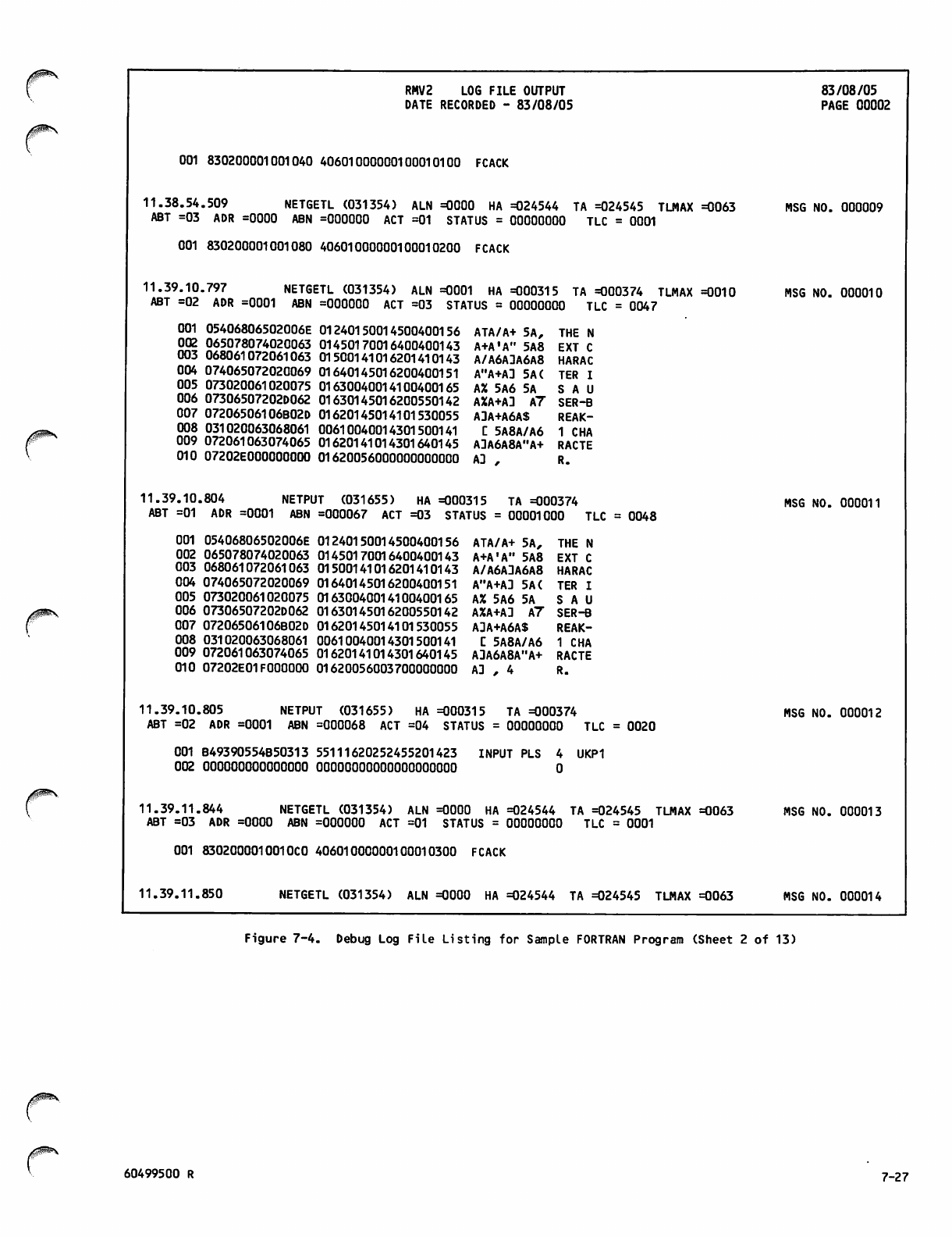
RMV2 LOG FILE OUTPUT
DATE RECORDED - 83/08/05 83/08/05
PAGE 00002
001 830200001001040 40601000000100010100 FCACK
11.38.54.509 NETGETL (031354) ALN =0000 HA =024544 TA =024545 TLMAX =0063
ABT =03 ADR =0000 ABN =000000 ACT =01 STATUS = 00000000 TLC = 0001
001 830200001001080 40601000000100010200 FCACK
11.39.10.797 NETGETL (031354) ALN =0001 HA =000315 TA =000374 TLMAX =0010
ABT =02 ADR =0001 ABN =000000 ACT =03 STATUS = 00000000 TLC = 0047
MSG NO. 000009
MSG NO. 000010
001 05406806502006E
002 065078074020063
003 068061072061063
004 074065072020069
005 073020061020075
006 07306507202D062
007 07206506106B02D
008 031020063068061
009 072061063074065
010 07202E000000000
01240150014500400156
01450170016400400143
01500141016201410143
01640145016200400151
01630040014100400165
01630145016200550142
01620145014101530055
00610040014301500141
01620141014301640145
01620056000000000000
ATA/A+ 5A, THE N
A+A'A" 5A8 EXT C
A/A6A3A6A8 HARAC
A"A+AD 5A( TER I
AX 5A6 5A S A U
AXA+AD A7 SER-B
ADA+A6AS REAK-
L" 5A8A/A6 1 CHA
ADA6A8A"A+ RACTE
AD , R.
11.39.10.804 NETPUT (031655) HA =000315 TA =000374
ABT =01 ADR =0001 ABN =000067 ACT =03 STATUS = 00001000 TLC = 0048 MSG NO. 000011
001 05406806502006E
002 065078074020063
003 068061072061063
004 074065072020069
005 073020061020075
006 07306507202D062
007 07206506106B02D
008 031020063068061
009 072061063074065
010 07202E01FOOOOOO
01240150014500400156
01450170016400400143
01500141016201410143
01640145016200400151
01630040014100400165
01630145016200550142
01620145014101530055
00610040014301500141
01620141014301640145
01620056003700000000
ATA/A+ 5A, THE N
A+A'A" 5A8 EXT C
A/A6ADA6A8 HARAC
A"A+AD 5A( TER I
AX 5A6 5A S A U
AXA+AD A7 SER-B
ADA+A6AS REAK-
C 5A8A/A6 1 CHA
AJA6A8A"A+ RACTE
AD , 4 R.
11.39.10.805 NETPUT (031655) HA =000315 TA =000374
ABT =02 ADR =0001 ABN =000068 ACT =04 STATUS = 00000000 TLC = 0020 MSG NO. 000012
001 B49390554B50313 55111620252455201423
002 000000000000000 OOOOOOOOOOOOOOOOOOOO
INPUT PLS UKP1
11.39.11.844 NETGETL (031354) ALN =0000 HA =024544 TA =024545 TLMAX =0063
ABT =03 ADR =0000 ABN =000000 ACT =01 STATUS = 00000000 TLC = 0001
001 830200001001OCO 40601000000100010300 FCACK
11.39.11.850 NETGETL (031354) ALN =0000 HA =024544 TA =024545 TLMAX =0063
MSG NO. 000013
MSG NO. 000014
Figure 7-4. Debug Log File Listing for Sample FORTRAN Program (Sheet 2 of 13)
60499500 R 7-27
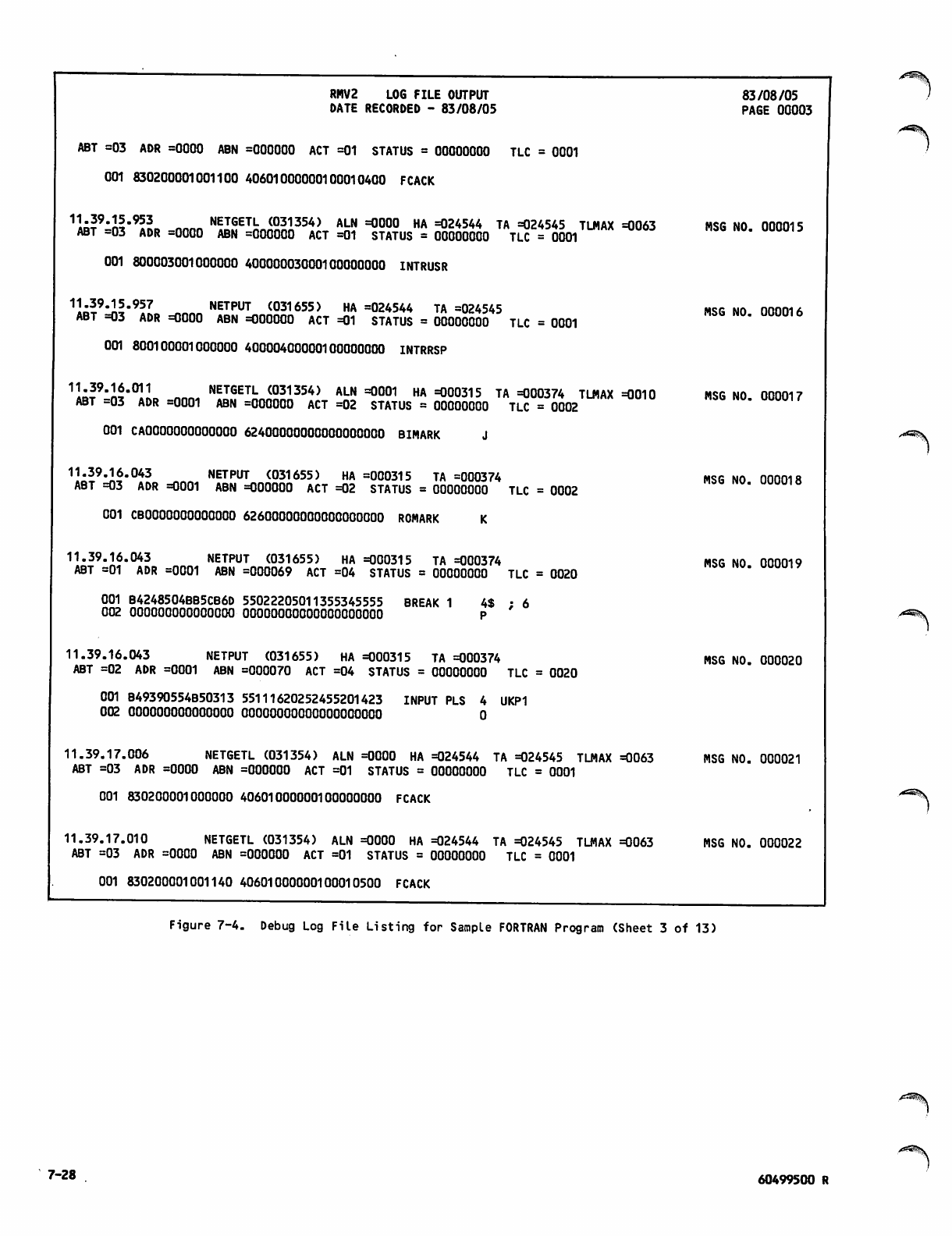
RMV2 LOG FILE OUTPUT
DATE RECORDED - 83/08/05
ABT =03 ADR =0000 ABN =000000 ACT =01 STATUS = 00000000 TLC = 0001
001 830200001001100 40601000000100010400 FCACK
1«?9"ll"955«, onno NETGET|; <031354) ALN =0000 HA =024544 TA =024545 TLMAX =0063
ABT =03 ADR =0000 ABN =000000 ACT =01 STATUS = 00000000 TLC = 0001
001 800003001000000 40000003000100000000 INTRUSR
1hl9'Jtlm95? NETPUT <031655) HA =024544 TA =024545
ABT =03 ADR =0000 ABN =000000 ACT =01 STATUS = 00000000 TLC = 0001
001 800100001000000 40000400000100000000 INTRRSP
1lo|9"lS"°IL NET6ETL (031354) ALN =0001 HA =000315 TA =000374 TLMAX =0010
ABT =03 ADR =0001 ABN =000000 ACT =02 STATUS = 00000000 TLC = 0002
001 CAOOOOOOOOOOOOO 62400000000000000000 BIMARK J
11.39.16.043 NETPUT (031655) HA =000315 TA =000374
ABT =03 ADR =0001 ABN =000000 ACT =02 STATUS = 00000000 TLC = 0002
83/08/05
PAGE 00003
001 CBOOOOOOOOOOOOO 62600000000000000000 ROMARK
11.39.16.043 NETPUT (031655) HA =000315 TA =000374
ABT =01 ADR =0001 ABN =000069 ACT =04 STATUS = 00000000 TLC = 0020
001 B4248504BB5CB6D 55022205011355345555 BREAK 1 4$ ; 6
002 000000000000000 OOOOOOOOOOOOOOOOOOOO P
11.39.16.043 NETPUT (031655) HA =000315 TA =000374
ABT =02 ADR =0001 ABN =000070 ACT =04 STATUS = 00000000 TLC = 0020
001 B49390554B50313 55111620252455201423 INPUT PLS 4 UKP1
002 000000000000000 OOOOOOOOOOOOOOOOOOOO 0
11.39.17.006 NETGETL (031354) ALN =0000 HA =024544 TA =024545 TLMAX =0063
ABT =03 ADR =0000 ABN =000000 ACT =01 STATUS = 00000000 TLC = 0001
001 830200001000000 40601000000100000000 FCACK
11.39.17.010 NETGETL (031354) ALN =0000 HA =024544 TA =024545 TLMAX =0063
ABT =03 ADR =0000 ABN =000000 ACT =01 STATUS = 00000000 TLC = 0001
001 830200001001140 40601000000100010500 FCACK
MSG NO. 000015
MSG NO. 000016
MSG NO. 000017
MSG NO. 000018
MSG NO. 000019
MSG NO. 000020
MSG NO. 000021
MSG NO. 000022
./*3S^v
Figure 7-4. Debug Log File Listing for Sample FORTRAN Program (Sheet 3 of 13)
7-28 60499500 R
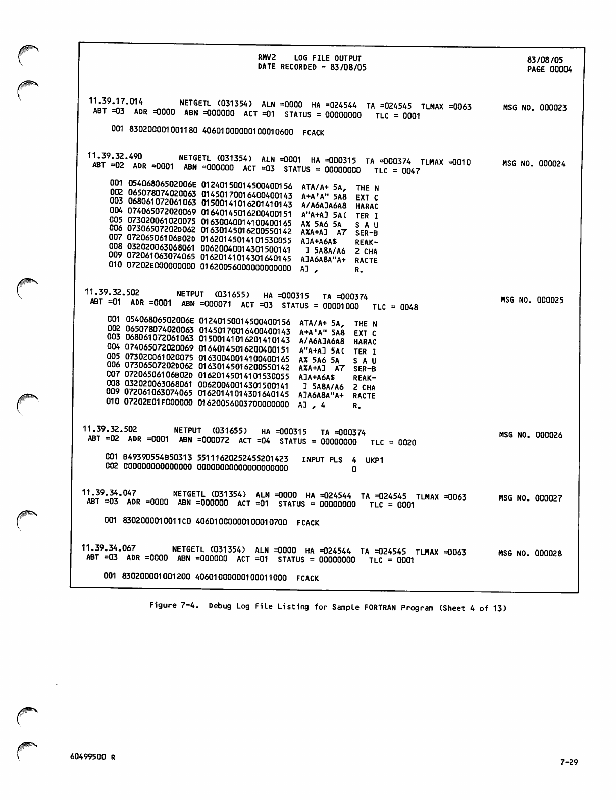
RMV2 LOG FILE OUTPUT
DATE RECORDED - 83/08/05
1M?^J"°liB ^nnn NETGETL (031354) ALN =0000 HA =024544 TA =024545 TLMAX =0063
ABT =03 ADR =0000 ABN =000000 ACT =01 STATUS = 00000000 TLC = 0001
001 830200001001180 40601000000100010600 FCACK
1l;?9*n1*49° NETGETL (031354) ALN =0001 HA =000315 TA =000374 TLMAX =0010
ABT =02 ADR =0001 ABN =000000 ACT =03 STATUS = 00000000 TLC = 0047
83/08/05
PAGE 00004
MSG NO. 000023
MSG NO. 000024
001 05406806502006E
002 065078074020063
003 068061072061063
004 074065072020069
005 073020061020075
006 07306507202D062
007 07206506106B02D
008 032020063068061
009 072061063074065
010 072O2E0OO0O0OOO
01240150014500400156
01450170016400400143
01500141016201410143
01640145016200400151
01630040014100400165
01630145016200550142
01620145014101530055
00620040014301500141
01620141014301640145
01620056000000000000
ATA/A+ 5A, THE N
A+A'A" 5A8 EXT C
A/A6ADA6A8 HARAC
A"A+AD 5A( TER I
A% 5A6 5A S A U
A%A+AD A7 SER-B
ADA+A6AS REAK-
D 5A8A/A6 2 CHA
ADA6A8A"A+ RACTE
AD , R.
11:29"«2"502 NETPUT <031655) HA =000315 TA =000374
ABT =01 ADR =0001 ABN =000071 ACT =03 STATUS = 00001000 TLC = 0048 MSG NO. 000025
001 05406806502006E
002 065078074020063
003 068061072061063
004 074065072020069
005 073020061020075
006 07306507202D062
007 07206506106B02D
008 032020063068061
009 072061063074065
010 07202E01FOOOOOO
01240150014500400156
01450170016400400143
01500141016201410143
01640145016200400151
01630040014100400165
01630145016200550142
01620145014101530055
00620040014301500141
01620141014301640145
01620056003700000000
ATA/A+ 5A,
A+A'A" 5A8
A/A6ADA6A8
A"A+AD 5A(
AX 5A6 5A
A%A+AD A7
ADA+A6AS
D 5A8A/A6
ADA6A8A"A+
AD . 4
THE N
EXT C
HARAC
TER I
S A U
SER-B
REAK-
2 CHA
RACTE
R.
11.39.32.502 NETPUT (031655) HA =000315 TA =000374
ABT =02 ADR =0001 ABN =000072 ACT =04 STATUS = 00000000 TLC = 0020 MSG NO. 000026
001 B49390554B50313 55111620252455201423
002 000000000000000 OOOOOOOOOOOOOOOOOOOO INPUT PLS UKP1
11.39.34.047 NETGETL (031354) ALN =0000 HA =024544 TA =024545 TLMAX =0063
ABT =03 ADR =0000 ABN =000000 ACT =01 STATUS = 00000000 TLC = 0001
001 8302000010011 CO 40601000000100010700 FCACK
11.39.34.067 NETGETL (031354) ALN =0000 HA =024544 TA =024545 TLMAX =0063
ABT =03 ADR =0000 ABN =000000 ACT =01 STATUS = 00000000 TLC = 0001
MSG NO. 000027
MSG NO. 000028
001 830200001001200 40601000000100011000 FCACK
Figure 7-4. Debug Log File Listing for Sample FORTRAN Program (Sheet 4 of 13)
60499500 R 7-29
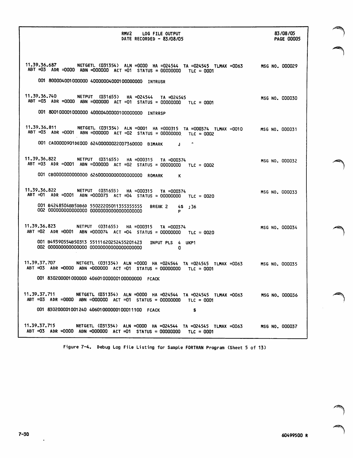
RMV2 LOG FILE OUTPUT
DATE RECORDED - 83/08/05
11.39.36.687 NETGETL (031354) ALN =0000 HA =024544 TA =024545 TLMAX =0063
ABT =03 ADR =0000 ABN =000000 ACT =01 STATUS = 00000000 TLC = 0001
001 800004001000000 40000004000100000000 INTRUSR
11.39.36.740 NETPUT (031655) HA =024544 TA =024545
ABT =03 ADR =0000 ABN =000000 ACT =01 STATUS = 00000000 TLC = 0001
001 800100001000000 40000400000100000000 INTRRSP
11.39.36.811 NETGETL (031354) ALN =0001 HA =000315 TA =000374 TLMAX =0010
ABT =03 ADR =0001 ABN =000000 ACT =02 STATUS = 00000000 TLC = 0002
001 CA00000901DEOOO 62400000022007360000 BIMARK
11.39.36.822 NETPUT (031655) HA =000315 TA =000374
ABT =03 ADR =0001 ABN =000000 ACT =02 STATUS = 00000000 TLC = 0002
001 CBOOOOOOOOOOOOO 62600000000000000000 ROMARK
11.39.36.822 NETPUT (031655) HA =000315 TA =000374
ABT =01 ADR =0001 ABN =000073 ACT =04 STATUS = 00000000 TLC = 0020
001 B4248504BB5DB6D 55022205011355355555 BREAK 2 4$ ;D6
002 000000000000000 OOOOOOOOOOOOOOOOOOOO P
11.39.36.823 NETPUT (031655) HA =000315 TA =000374
ABT =02 ADR =0001 ABN =000074 ACT =04 STATUS = 00000000 TLC = 0020
001 B49390554B50313 55111620252455201423 INPUT PLS 4 UKP1
002 000000000000000 OOOOOOOOOOOOOOOOOOOO 0
11.39.37.707 NETGETL (031354) ALN =0000 HA =024544 TA =024545 TLMAX =0063
ABT =03 ADR =0000 ABN =000000 ACT =01 STATUS = 00000000 TLC = 0001
001 830200001000000 40601000000100000000 FCACK
11.39.37.711 NETGETL (031354) ALN =0000 HA =024544 TA =024545 TLMAX =0063
ABT =03 ADR =0000 ABN =000000 ACT =01 STATUS = 00000000 TLC = 0001
001 830200001001240 40601000000100011100 FCACK $
11.39.37.715 NETGETL (031354) ALN =0000 HA =024544 TA =024545 TLMAX =0063
ABT =03 ADR =0000 ABN =000000 ACT =01 STATUS = 00000000 TLC = 0001
83/08/05
PAGE 00005
MSG NO. 000029
MSG NO. 000030
MSG NO. 000031
MSG NO. 000032
MSG NO. 000033
MSG NO. 000034
MSG NO. 000035
MSG NO. 000036
MSG NO. 000037
>**^\
Figure 7-4. Debug Log File Listing for Sample FORTRAN Program (Sheet 5 of 13)
7-30 60499500 R
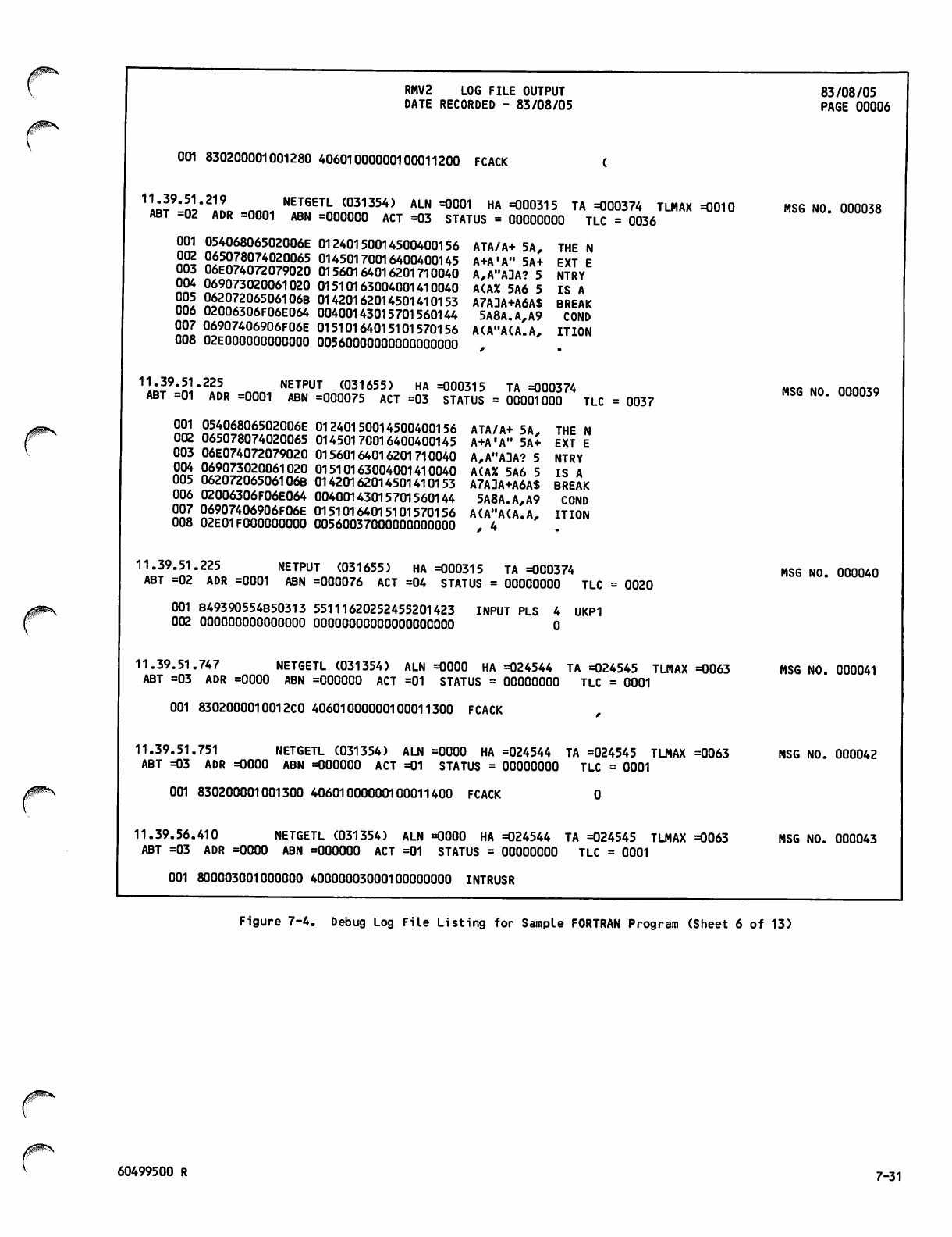
0^\ RMV2 LOG FILE OUTPUT
DATE RECORDED - 83/08/05 83/08/05
PAGE 00006
001 830200001001280 40601000000100011200 FCACK
1«?:«!"219 NETGETL (031354) ALN =0001 HA =000315 TA =000374 TLMAX =0010
ABT -02 ADR =0001 ABN =000000 ACT =03 STATUS = 00000000 TLC = 0036 MSG NO. 000038
001 05406806502006E
002 065078074020065
003 06E074072079020
004 069073020061020
005 06207206506106B
006 02006306F06E064
007 06907406906F06E
008 O2EO0OO0OOO0O0O
01240150014500400156
01450170016400400145
01560164016201710040
01510163004001410040
01420162014501410153
00400143015701560144
01510164015101570156
00560000000000000000
ATA/A+ 5A,
A+A'A" 5A+
A,A"ADA? 5
A(A% 5A6 5
A7ADA+A6AS
5A8A.A,A9
A(A"A(A.A,
THE N
EXT E
NTRY
IS A
BREAK
COND
IT ION
11»39"S'225 NETPUT ^031655) HA =000315 TA =000374
ABT =01 ADR =0001 ABN =000075 ACT =03 STATUS = 00001000 TLC = 0037 MSG NO. 000039
001 05406806502006E
002 065078074020065
003 06E074072079020
004 069073020061020
005 06207206506106B
006 02006306F06E064
007 06907406906F06E
008 02E01FOOOOOOOOO
01240150014500400156
01450170016400400145
01560164016201710040
01510163004001410040
01420162014501410153
00400143015701560144
01510164015101570156
00560037000000000000
ATA/A+ 5A, THE N
A+A'A" 5A+ EXT E
A,A"ADA? 5 NTRY
A(AX 5A6 5 IS A
A7ADA+A6AS BREAK
5A8A.A,A9 COND
A(A"A(A.A,
* 4 ITION
11.39.51.225 NETPUT (031655) HA =000315 TA =000374
ABT =02 ADR =0001 ABN =000076 ACT =04 STATUS = 00000000 TLC = 0020 MSG NO. 000040
001 B49390554B50313 55111620252455201423
002 000000000000000 OOOOOOOOOOOOOOOOOOOO INPUT PLS 4 UKP1
0
11.39.51.747 NETGETL (031354) ALN =0000 HA =024544 TA =024545 TLMAX =0063
ABT =03 ADR =0000 ABN =000000 ACT =01 STATUS = 00000000 TLC = 0001
001 8302000010012C0 40601000000100011300 FCACK ,
11.39.51.751 NETGETL (031354) ALN =0000 HA =024544 TA =024545 TLMAX =0063
ABT =03 ADR =0000 ABN =000000 ACT =01 STATUS = 00000000 TLC = 0001
001 830200001001300 40601000000100011400 FCACK 0
11.39.56.410 NETGETL (031354) ALN =0000 HA =024544 TA =024545 TLMAX =0063
ABT =03 ADR =0000 ABN =000000 ACT =01 STATUS = 00000000 TLC = 0001
001 800003001000000 40000003000100000000 INTRUSR
MSG NO. 000041
MSG NO. 000042
MSG NO. 000043
Figure 7-4. Debug Log File Listing for Sample FORTRAN Program (Sheet 6 of 13)
60499500 R 7-31
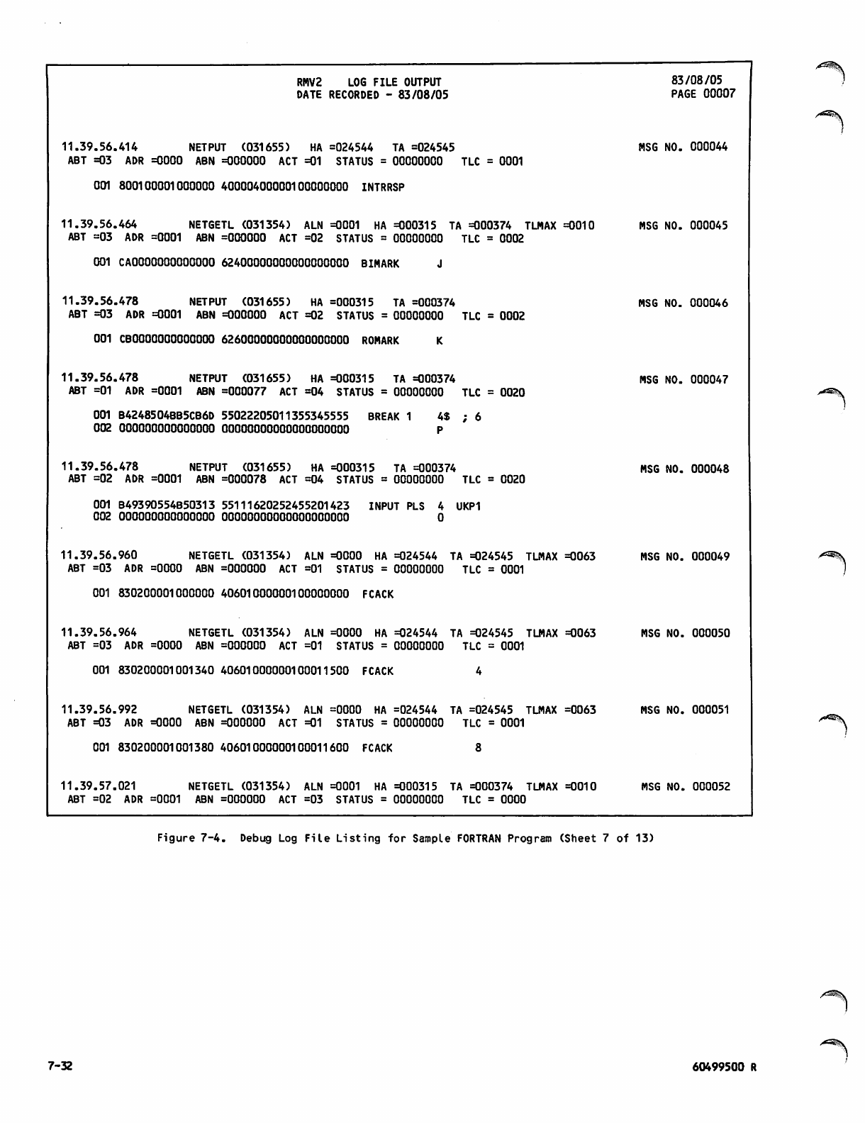
RMV2 LOG FILE OUTPUT
DATE RECORDED - 83/08/05
83/08/05
PAGE 00007
11.39.56.414 NETPUT (031655) HA =024544 TA =024545
ABT =03 ADR =0000 ABN =000000 ACT =01 STATUS = 00000000 TLC = 0001
MSG NO. 000044
001 800100001000000 40000400000100000000 INTRRSP
11.39.56.464 NETGETL (031354) ALN =0001 HA =000315 TA =000374 TLMAX
ABT =03 ADR =0001 ABN =000000 ACT =02 STATUS = 00000000 TLC = 0002 =0010 MSG NO. 000045
001 CAOOOOOOOOOOOOO 62400000000000000000 BIMARK J
11.39.56.478 NETPUT (031655) HA =000315 TA =000374
ABT =03 ADR =0001 ABN =000000 ACT =02 STATUS = 00000000 TLC = 0002 MSG NO. 000046
001 CBOOOOOOOOOOOOO 62600000000000000000 ROMARK K
11.39.56.478 NETPUT (031655) HA =000315 TA =000374
ABT =01 ADR =0001 ABN =000077 ACT =04 STATUS = 00000000 TLC = 0020 MSG NO. 000047
001 B4248504BB5CB6D 55022205011355345555 BREAK 1 4$
002 000000000000000 OOOOOOOOOOOOOOOOOOOO P ; 6
11.39.56.478 NETPUT (031655) HA =000315 TA =000374
ABT =02 ADR =0001 ABN =000078 ACT =04 STATUS = 00000000 TLC = 0020 MSG NO. 000048
001 B49390554B50313 55111620252455201423 INPUT PLS 4
002 OOOOOOOOQOOOOOO OOOOOOOOOOOOOOOOOOOO 0 JKP1
11.39.56.960 NETGETL (031354) ALN =0000 HA =024544 TA =024545 TLMAX
ABT =03 ADR =0000 ABN =000000 ACT =01 STATUS = 00000000 TLC = 0001
=0063 MSG NO. 000049
001 830200001000000 40601000000100000000 FCACK
11.39.56.964 NETGETL (031354) ALN =0000 HA =024544 TA =024545 TLMAX
ABT =03 ADR =0000 ABN =000000 ACT =01 STATUS = 00000000 TLC = 0001
=0063 MSG NO. 000050
001 830200001001340 40601000000100011500 FCACK
11.39.56.992 NETGETL (031354) ALN =0000 HA =024544 TA =024545 TLMAX
ABT =03 ADR =0000 ABN =000000 ACT =01 STATUS = 00000000 TLC = 0001
=0063 MSG NO. 000051
001 830200001001380 40601000000100011600 FCACK
11.39.57.021 NETGETL (031354) ALN =0001 HA =000315 TA =000374 TLMAX
ABT =02 ADR =0001 ABN =000000 ACT =03 STATUS = 00000000 TLC = OOOO =0010 MSG NO. 000052
Figure 7-4. Debug Log File Listing for Sample FORTRAN Program (Sheet 7 of 13)
7-32 60499500 R
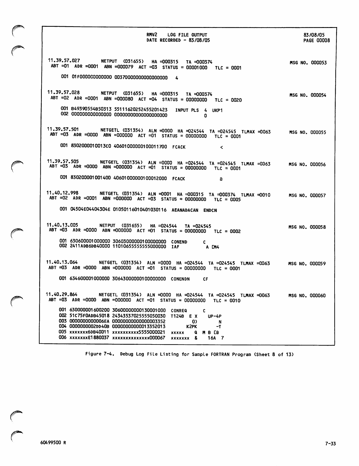
0 ^ *
RMV2 LOG FILE OUTPUT
DATE RECORDED - 83/08/05
11.39.57.027 NETPUT (031655) HA =000315 TA =000374
ABT =01 ADR =0001 ABN =000079 ACT =03 STATUS = 00001000 TLC = 0001
001 01FOOOOOOOOOOOO 00370000000000000000 4
11.39.57.028 NETPUT (031655) HA =000315 TA =000374
ABT =02 ADR =0001 ABN =000080 ACT =04 STATUS = 00000000 TLC = 0020
001 B49390554B50313 55111620252455201423 INPUT PLS 4 UKP1
002 000000000000000 OOOOOOOOOOOOOOOOOOOO 0
1«?9"S"50L nnnn NETGETL (031354) ALN =0000 HA =024544 TA =024545 TLMAX =0063
ABT =03 ADR =0000 ABN =000000 ACT =01 STATUS = 00000000 TLC = 0001
001 8302000010013C0 40601000000100011700 FCACK
1«59:S"505 NETGETL (031354) ALN =0000 HA =024544 TA =024545 TLMAX =0063
ABT =03 ADR =0000 ABN =000000 ACT =01 STATUS = 00000000 TLC =0001
001 830200001001400 40601000000100012000 FCACK
11.40.12.998 NETGETL (031354) ALN =0001 HA =000315 TA =000374 TLMAX =0010
ABT =02 ADR =0001 ABN =000000 ACT =03 STATUS = 00000000 TLC = 0005
001 04504E04404304E 01050116010401030116 AEANADACAN ENDCN
11.40.13.005 NETPUT (031655) HA =024544 TA =024545
ABT =03 ADR =0000 ABN =000000 ACT =01 STATUS = 00000000 TLC = 0002
001 630600001000000 30603000000100000000 CONEND
002 2411ADB6DB40000 11010655555555000000 IAF A L~M4
11.40.13.064 NETGETL (031354) ALN =0000 HA =024544 TA =024545 TLMAX =0063
ABT =03 ADR =0000 ABN =000000 ACT =01 STATUS = 00000000 TLC = 0001
001 634600001000000 30643000000100000000 CONENDN CF
11.40.29.864 NETGETL (031354) ALN =0000 HA =024544 TA =024545 TLMAX =0063
ABT =03 ADR =0000 ABN =000000 ACT =01 STATUS = 00000000 TLC = 0010
001 630000001600200 30600000000130001000 CONREQ C
002 51C75F0ADB45018 24343537025555050030 T124B EX UP-4P
003 0000000000006EA 00000000000000003352 0) N
004 0000000002DD40B 00000000000013352013 K2PK -T
005 xxxxxxx6DB40011 xxxxxxxxxx5555000021 xxxxx Q M B CB
006 xxxxxxxEl880037 xxxxxxxxxxxxxx000067 xxxxxxx & 16A 7
83/08/05
PAGE 00008
MSG NO. 000053
MSG NO. 000054
MSG NO. 000055
MSG NO. 000056
MSG NO. 000057
MSG NO. 000058
MSG NO. 000059
MSG NO. 000060
Figure 7-4. Debug Log File Listing for Sample FORTRAN Program (Sheet 8 of 13)
60499500 R 7-33
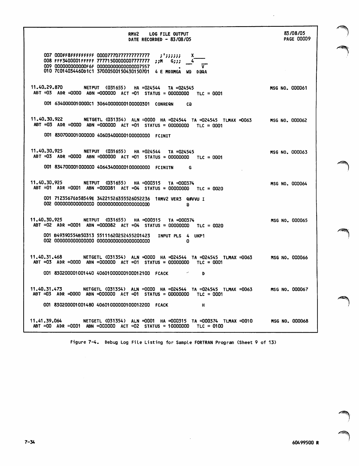
RMV2 LOG FILE OUTPUT
DATE RECORDED - 83/08/05
83/08/05
PAGE 00009
007 000FF8FFFFFFFFF 00007770777777777777 ;';;;;;; X
008 FFF3400001FFFFF 77771500000007777777 ;;M G;;; 4
009 000000000000F6F 00000000000000007557 . V
010 7C014034460D1C1 37000500150430150701 4 E MDXMGA WS) DBQA
11.40.29.870 NETPUT (031655) HA =024544 TA =024545
ABT =03 ADR =0000 ABN =000000 ACT =01 STATUS = 00000000 TLC = 0001 MSG NO. 000061
001 6340000010000C1 30640000000100000301 CONREQN C3
11.40.30.922 NETGETL (031354) ALN =0000 HA =024544 TA =024545 TLMAX
ABT =03 ADR =0000 ABN =000000 ACT =01 STATUS = 00000000 TLC = 0001 =0063 MSG NO. 000062
001 830700001000000 40603400000100000000 FCINIT
11.40.30.925 NETPUT (031655) HA =024544 TA =024545
ABT =03 ADR =0000 ABN =000000 ACT =01 STATUS = 00000000 TLC = 0001 MSG NO. 000063
001 834700001000000 40643400000100000000 FCINITN G
11.40.30.925 NETPUT (031655) HA =000315 TA =000374
ABT =01 ADR =0001 ABN =000081 ACT =04 STATUS = 00000000 TLC = 0020 MSG NO. 000064
001 71235676D58549E 34221526355526052236 1RMV2 VER3 Q#VVU I
002 000000000000000 oooooooooooooooooooo a
11.40.30.925 NETPUT (031655) HA =000315 TA =000374
ABT =02 ADR =0001 ABN =000082 ACT =04 STATUS = 00000000 TLC = 0020 MSG NO. 000065
001 B49390554B50313 55111620252455201423 INPUT PLS 4 UKP1
002 000000000000000 OOOOOOOOOOOOOOOOOOOO 0
11.40.31.468 NETGETL (031354) ALN =0000 HA =024544 TA =024545 TLMAX
ABT =03 ADR =0000 ABN =000000 ACT =01 STATUS = 00000000 TLC = 0001 =0063 MSG NO. 000066
001 830200001001440 40601000000100012100 FCACK D
11.40.31.473 NETGETL (031354) ALN =0000 HA =024544 TA =024545 TLMAX
ABT =03 ADR =0000 ABN =000000 ACT =01 STATUS = 00000000 TLC = 0001 =0063 MSG NO. 000067
001 830200001001480 40601000000100012200 FCACK H
11.41.39.064 NETGETL (031354) ALN =0001 HA =000315 TA =000374 TLMAX
ABT =00 ADR =0001 ABN =000000 ACT =02 STATUS = 10000000 TLC = 0100 =0010 MSG NO. 000068
/^Hjf-
^
^^Ifc
/*OSJJI.
Figure 7-4. Debug Log File Listing for Sample FORTRAN Program (Sheet 9 of 13)
ysS^v
7-34 60499500 R
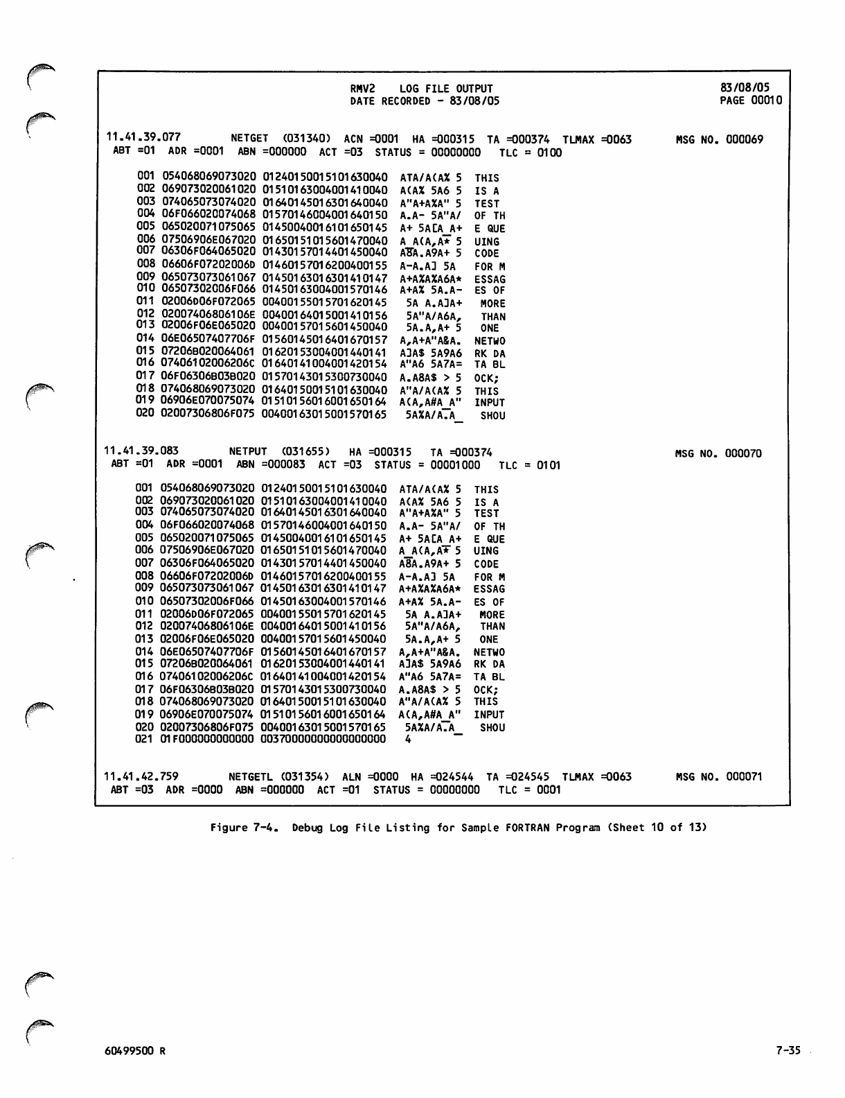
/ff*^
RMV2 LOG FILE OUTPUT
DATE RECORDED - 83/08/05
11.41.39.077 NETGET (031340) ACN =0001 HA =000315 TA =000374 TLMAX =0063
ABT =01 ADR =0001 ABN =000000 ACT =03 STATUS = 00000000 TLC =0100
83/08/05
PAGE 00010
MSG NO. 000069
001 054068069073020
002 069073020061020
003 074065073074020
004 06F066020074068
005 065020071075065
006 07506906E067020
007 06306F064065020
008 06606F07202006D
009 065073073061067
010 06507302006F066
011 02006D06F072065
012 02007406806106E
013 02006F06E065020
014 06E06507407706F
015 07206B020064061
016 07406102006206C
017 06F06306B03B020
018 074068069073020
019 06906E070075074
020 02007306806F075
01240150015101630040
01510163004001410040
01640145016301640040
01570146004001640150
01450040016101650145
01650151015601470040
01430157014401450040
01460157016200400155
01450163016301410147
01450163004001570146
00400155015701620145
00400164015001410156
00400157015601450040
01560145016401670157
01620153004001440141
01640141004001420154
01570143015300730040
01640150015101630040
01510156016001650164
00400163015001570165
ATA/A(AX 5 THIS
A(AX 5A6 5 IS A
A"A+AXA" 5 TEST
A.A- 5A"A/ OF TH
A+ 5ACA A+ E QUE
A A(A,A* 5 UING
ABA.A9A+ 5 CODE
A-A.AD 5A FOR M
A+AXAXA6A* ESSAG
A+AX 5A.A- ES OF
5A A.ADA+ MORE
5A"A/A6A, THAN
5A.A,A+ 5 ONE
A,A+A"A&A. NETWO
ADAS 5A9A6 RK DA
A"A6 5A7A= TA BL
A.A8AS > 5 OCK;
A"A/A(AX 5 THIS
A(A,A#A A" INPUT
5AXA/A.A SHOU
11.41.39.083 NETPUT (031655) HA =000315 TA =000374
ABT =01 ADR =0001 ABN =000083 ACT =03 STATUS = 00001000 TLC = 0101 MSG NO. 000070
001 054068069073020
002 069073020061020
003 074065073074020
004 06F066020074068
005 065020071075065
006 07506906E067020
007 06306F064065020
008 06606F07202006D
009 065073073061067
010 06507302006F066
011 02006D06F072065
012 02007406806106E
013 02006F06E065020
014 06E06507407706F
015 07206B020064061
016 07406102006206C
017 06F06306B03B020
018 074068069073020
019 06906E070075074
020 02007306806F075
021 01FOOOOOOOOOOOO
01240150015101630040
01510163004001410040
01640145016301640040
01570146004001640150
01450040016101650145
01650151015601470040
01430157014401450040
01460157016200400155
01450163016301410147
01450163004001570146
00400155015701620145
00400164015001410156
00400157015601450040
01560145016401670157
01620153004001440141
01640141004001420154
01570143015300730040
01640150015101630040
01510156016001650164
00400163015001570165
00370000000000000000
ATA/A(AX 5 THIS
A(AX 5A6 5 IS A
A"A+AXA" 5 TEST
A.A- 5A"A/ OF TH
A+ 5ACA A+ E QUE
A A(A,A* 5 UING
A8A.A9A+ 5 CODE
A-A.AD 5A FOR M
A+AZAXA6A* ESSAG
A+AX 5A.A- ES OF
5A A.ADA+ MORE
5A"A/A6A, THAN
5A.A,A+ 5 ONE
A,A+A"A8A. NETWO
ADAS 5A9A6 RK DA
A"A6 5A7A= TA BL
A.A8AS > 5 OCK;
A"A/A(AX 5 THIS
A(A,A#A A" INPUT
5AXA/A.A SHOU
4 ~
11.41.42.759 NETGETL (031354) ALN =0000 HA =024544 TA =024545 TLMAX =0063
ABT =03 ADR =0000 ABN =000000 ACT =01 STATUS = 00000000 TLC = 0001
MSG NO. 000071
Figure 7-4. Debug Log File Listing for Sample FORTRAN Program (Sheet 10 of 13)
60499500 R 7-35
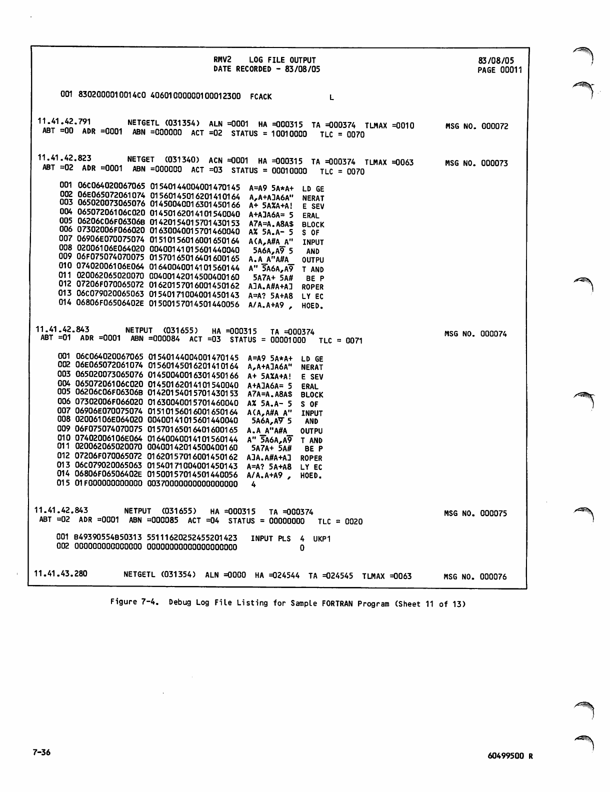
RMV2 LOG FILE OUTPUT
DATE RECORDED - 83/08/05
001 8302000010014C0 40601000000100012300 FCACK
11.41.42.791 NETGETL (031354) ALN =0001 HA =000315 TA =000374 TLMAX =0010
ABT =00 ADR =0001 ABN =000000 ACT =02 STATUS = 10010000 TLC = 0070
11.41.42.823 NETGET (031340) ACN =0001 HA =000315 TA =000374 TLMAX =0063
ABT =02 ADR =0001 ABN =000000 ACT =03 STATUS = 00010000 TLC = 0070
83/08/05
PAGE 00011
MSG NO. 000072
MSG NO. 000073
001 06C064020067065
002 06E065072061074
003 065020073065076
004 06507206106C020
005 06206C06F06306B
006 07302006F066020
007 06906E070075074
008 02006106E064020
009 06F075074070075
010 07402006106E064
011 020062065020070
012 07206F070065072
013 06C079020065063
014 06806F06506402E
01540144004001470145
01560145016201410164
01450040016301450166
01450162014101540040
01420154015701430153
01630040015701460040
01510156016001650164
00400141015601440040
01570165016401600165
01640040014101560144
00400142014500400160
01620157016001450162
01540171004001450143
01500157014501440056
A=A9 5A*A+
A,A+ADA6A"
A+ 5AXA+A!
A+ADA6A= 5
A7A=A.A8A$
AX 5A.A- 5
A(A,A#A_A"
5A6A,A9 5
A.A_A"A#A_
A" 5A6A,A9
5A7A+ 5A#
ADA.A#A+AD
A=A? 5A+A8
A/A.A+A9 .
LD GE
NERAT
E SEV
ERAL
BLOCK
S OF
INPUT
AND
OUTPU
T AND
BE P
ROPER
LY EC
HOED.
11.41.42.843 NETPUT (031655) HA =000315 TA =000374
ABT =01 ADR =0001 ABN =000084 ACT =03 STATUS = 00001000 TLC = 0071 MSG NO. 000074
001 06C064020067065
002 06E065072061074
003 065020073065076
004 06507206106C020
005 06206C06F06306B
006 07302006F066020
007 06906E070075074
008 02006106E064020
009 06F075074070075
010 07402006106E064
011 020062065020070
012 07206F070065072
013 06C079020065063
014 06806F06506402E
015 01FOOOOOOOOOOOO
01540144004001470145
01560145016201410164
01450040016301450166
01450162014101540040
01420154015701430153
01630040015701460040
01510156016001650164
00400141015601440040
01570165016401600165
01640040014101560144
00400142014500400160
01620157016001450162
01540171004001450143
01500157014501440056
003 70000000000000000
A=A9 5A*A+
A,A+ADA6A"
A+ 5AXA+A!
A+ADA6A= 5
A7A=A.A8A$
AX 5A.A- 5
A(A,A#A A"
5A6A,A7 5
A.A_A"A#A_
A" 5A6A,A9
5A7A+ 5A#
ADA.A#A+AD
A=A? 5A+A8
A/A.A+A9 ,
4
LD GE
NERAT
E SEV
ERAL
BLOCK
S OF
INPUT
AND
OUTPU
T AND
BE P
ROPER
LY EC
HOED.
11.41.42.843 NETPUT (031655) HA =000315 TA =000374
ABT =02 ADR =0001 ABN =000085 ACT =04 STATUS = 00000000 TLC = 0020 MSG NO. 000075
001 B49390554B50313 55111620252455201423
002 000000000000000 OOOOOOOOOOOOOOOOOOOO INPUT PLS 4 UKP1
0
11.41.43.280 NETGETL (031354) ALN =0000 HA =024544 TA =024545 TLMAX =0063 MSG NO. 000076
Figure 7-4. Debug Log File Listing for Sample FORTRAN Program (Sheet 11 of 13)
7-36 60499500 R

RMV2 LOG FILE OUTPUT
DATE RECORDED - 83/08/05
ABT =03 ADR =0000 ABN =000000 ACT =01 STATUS = 00000000 TLC = 0001
001 830200001001500 40601000000100012400 FCACK P
11.41.43.284 NETGETL (031354) ALN =0000 HA =024544 TA =024545 TLMAX =0063
ABT =03 ADR =0000 ABN =000000 ACT =01 STATUS = 00000000 TLC = 0001
001 830200001001540 40601000000100012500 FCACK T
1kT2lni'9!L nnn, ^IfFkJS?,!354* ALN =0001 HA =000315 TA =000374 TLMAX =0010
ABT =02 ADR =0001 ABN =000000 ACT =03 STATUS = 00000010 TLC = 0037
83/08/05
PAGE 00012
MSG NO. 000077
MSG NO. 000078
001 04E06F077020074
002 06F020074065073
003 074020074068065
004 02006906E070075
005 07402006306106E
006 06306506C06906E
007 06702006306F064
008 065040000000000
01160157016700400164
01570040016401450163
01640040016401500145
00400151015601600165
01640040014301410156
01430145015401510156
01470040014301570144
01450100000000000000
ANA.AS 5A" NOW T
A. 5A"A+AX 0 TES
A" 5A"A/A+ T THE
5A(A,A#A INPU
A" 5A8A6A7 T CAN
A8A+A=A(A, CELIN
A* 5A8A.A9 G COD
A+A E3
11.42.13.003 NETPUT (031655) HA =000315 TA =000374
ABT =02 ADR =0001 ABN =000086 ACT =04 STATUS = 00000000 TLC = 0020 MSG NO. 000079
001 B49390554B50313 55111620252455201423
002 ooooooooooooooo OOOOOOOOOOOOOOOOOOOO
INPUT PLS UKP1
11.42.14.014 NETGETL (031354) ALN =0000 HA =024544 TA =024545 TLMAX =0063
ABT =03 ADR =0000 ABN =000000 ACT =01 STATUS = 00000000 TLC = 0001
001 830200001001580 40601000000100012600 FCACK X
11.42.18.844 NETGETL (031354) ALN =0001 HA =000315 TA =000374 TLMAX =0010
ABT =02 ADR =0001 ABN =000000 ACT =03 STATUS = 00000000 TLC = 0006
001 053048055054044 01230110012501240104 ASAHAUATAD SHUTD
002 O4E0O000O00O00O 01160000000000000000 AN N
11.42.18.860 NETPUT (031655) HA =024544 TA =024545
ABT =03 ADR =0000 ABN =000000 ACT =01 STATUS = 00000000 TLC = 0002
MSG NO. 000080
MSG NO. 000081
MSG NO. 000082
001 630600001000000 30603000000100000000 CONEND
002 2411ADB6DB40000 11010655555555000000 IAF A CM4
11.42.18.927 NETGETL (031354) ALN =0000 HA =024544 TA =024545 TLMAX =0063
ABT =03 ADR =0000 ABN =000000 ACT =01 STATUS = 00000000 TLC = 0001 MSG NO. 000083
Figure 7-4. Debug Log File Listing for Sample FORTRAN Program (Sheet 12 of 13)
60499500 R 7-37
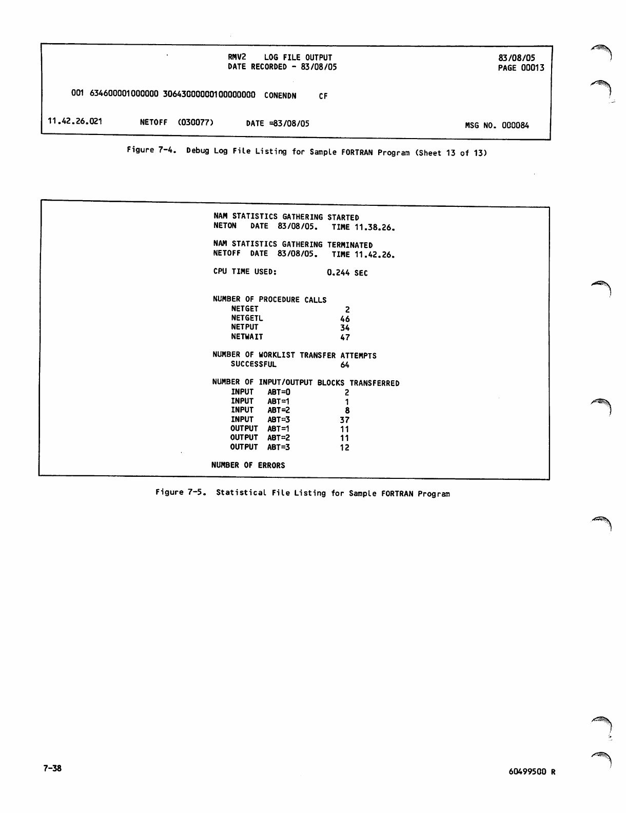
RMV2 LOG FILE OUTPUT 83/08/05
DATE RECORDED - 83/08/05 PAGE 00013
001 634600001000000 30643000000100000000 CONENDN CF
11.42.26.021 NETOFF (030077) DATE =83/08/05 MSG NO. 000084
Figure 7-4. Debug Log File Listing for Sample FORTRAN Program (Sheet 13 of 13)
NAM STATISTICS GATHERING STARTED
NETON DATE 83/08/05. TIME 11.38.26.
NAM STATISTICS GATHERING TERMINATED
NETOFF DATE 83/08/05. TIME 11.42.26.
CPU TIME USED: 0.244 SEC
NUMBER OF PROCEDURE CALLS
NETGET 2
NETGETL 46
NETPUT 34
NETWAIT 47
NUMBER OF WORKLIST TRANSFER ATTEMPTS
SUCCESSFUL 64
NUMBER OF INPUT/OUTPUT BLOCKS TRANSFERRED
INPUT ABT=0 2
INPUT ABT=1 1
INPUT ABT=2 8
INPUT ABT=3 37
OUTPUT ABT=1 11
OUTPUT ABT=2 11
O U T P U T A B T = 3 1 2
NUMBER OF ERRORS
Figure 7-5. Statistical File Listing for Sample FORTRAN Program
7-38 60499500 R
/0$?\ QUEUED TERMINAL RECORD MANAGER
The Queued Terminal Record Manager (QTRM) utility
package allows an application program to use NAM to
perform input and output to and from a device or
application in a way similar to the use of the CYBER
Record Manager to perform input and output to and
from mass storage. This section describes the
interface between QTRM and an application program.
NAM allows an application program to communicate
wit h anot her a pplic ation progr am the same as the
program does with a device. The program then has a
connection with a terminal or an application. When
the term connection is used in this section, it
refers to the general case and includes both device-
to-application connections and application-to-
application connections.
An application program interface with QTRM has two
parts:
A formal data structure, called the network
information table, is used as a communication
area.
A set of subroutines is used by the application
program to perform network actions.
NETWORK INFORMATION TABLE
An application program uses the network information
table to communicate with QTRM and with the network
software through QTRM. The application program
creates the network information table within its
o w n fi e l d l e n g t h . I f t h e p r o g r a m u s e s o v e r l a y s ,
the network information table must be created with
i n t h e m a i n ( 0 , 0 l e v e l ) o v e r l a y. T h e l e n g t h o f
the network information table varies according to
the number of connections the application program
supports.
The network information table has the format shown
in figure 8-1. This table is defined so that its
first word begins at a word boundary. In a FORTRAN
program, the table would be created as one or more
one-dimensional arrays. In a COBOL program, the
table would be created as a Data Division item
beginning with an 01 level description, preferably
in the Working Storage section.
The network information table has two consecutive
pa r t s . T h e fi r st p orti o n i s a 1 0-wo r d e n try gl o b a l
to program use of the network. The second portion
c o n s i s ts o f 10 - w o r d en t r i e s u n i q u e t o e a c h co n
nection serviced by the application program.
The global portion of the network information table
contains a few fields that only QTRM writes for the
appl i catio n p rogra m t o read . M ost o f the fi e l ds in
this portion are read or written by either QTRM or
the application program.
The connection portion of the network information
table contains fields written by QTRM that should
be used by the application program as read-only
fields. Errors can result if the application pro
gram writes in any of these fields.
The first 9 words of each 10-word entry in the
second portion of the table are maintained by QTRM
for each connection. Both QTRM and the application
program access a given 10-word entry using the
application connection number assigned by the net
work to the connection. For example, if a device
or application is assigned to connection number 3,
QTRM writes all information concerning that device
or application into the third 10-word entry in the
connection portion of the network information table.
If the application program needs some information
concerning the device or application assigned to
c o n n e c t i o n n u m b e r 5 , i t r e a d s t h e fi f t h 1 0 - w o r d
entry in the connection portion of the network
information table. The connection number assigned
to the device or application is therefore an index
ing integer that can be used to access the correct
10-word entry in the table, or other tables main
tained by the application program to contain infor
mation related to servicing the same device or
application.
The tenth word of the global portion and the tenth
word of each of the connection entries are not
accessed by QTRM. They are reserved for instal
lation use.
I
The application program determines the number of
10- w ord e ntrie s in t h e seco nd por t ion o f the net
work information table. One 10-word entry must
exist for each device or application the program is
written to service simultaneously. The application
program places the number of 10-word entries in the
first portion of the network information table so
that QTRM knows how many entries exist.
The application program does not need to provide a
10-word entry for each device or application serv
iced cumulatively during a single program execution.
The network reassigns a connection number when a
device or application disconnects from the program,
so that several devices or applications can sequen
tially use the same connection number at different
periods during a single program execution. For
example, if the program is intended to service eight
devices at the same time, it provides eight 10-word
entries. During a single execution, six different
devices might use each of those entries in succes
sion, but each device uses only the entry assigned
t o i t w h i l e i t c o m m u n i c a t e s w i t h t h e p r o g r a m .
Consequently, the program does not need 48 entries
to allow for the possibility.
/|Ste\
60499500 R 8-1
Global Entry
for QTRM
communication
net-info-table /Word
2
3
4
5
6
7
8
9
10
Word
2
3
4
5
6
7
8
59 53 47 35 29 17 11
Entry for
connection 1
Entry for
connection n
(n=num-conns)
10
'Word1
2
3
4
5
6
7
8
9
10
tsec-return-code I (6)
application-name C(7) char-
set I (6)
num-conns
1(12)
NAM-supervisor-word
reserved for CDC
reserved for CDC
max-trans-size
1(12)
current-trans-
size l{12)
abl-1
K6)
abl-n
sleep
K6)
connection-
number 1(12) code 1(6) t
next-application-name C(7)
requested-application-name C(7)
reserved for CDC
sub-system
code
return- Ah-A
int-msg
1(6)
xsleep 1(18)
destination-host C(3)
reserved for CDC
reserved for installation use
terminal-name-1/application-name-1 C(7)
family-name-1 C(7) dev-type
(6)
user-name-1 C(7)
current-abn-1
1(18) acknowledged-abn-1
1(18)
tclass-1
I (6)
state-1
I (6)
page-width-1
1(12)
page-length-1
1(12)
max-block-
size-l(12)
current-
abl-l(6)
reserved for CDC
upline-abh-1
downline-abh-1
reserved for CDC
reserved for CDC
reserved for installation use
terminal-name-n/application-name-n
family-name-n dev-type
I (6)
user-name-n
current-abn-n acknowledged-abn-n
tclass-n
state-n
page-width-n
page-length-n
max-block-
size-n
current-
abl-n
reserved for CDC
upline-abh-n
downline-abh-n
reserved for CDC
reserved for CDC
reserved for installation use
Figure 8-1. Network Information Table Format (Sheet 1 of 10)
/*^^\
Read and
write portion,
occurs only
once
Read-only
portion,
repeated once
for each
connection
/•^s.
8-2 60499500 S
net-info-table
application-name
char-set
num-conns
The symbolic address of the entire network information table, used to identify
the table in a QTOPEN call. In a COBOL program, this address is the Data Divi
sion descriptor for the level 01 data item containing level 02 or lower level
data items for all of the fields described in this figure. In a FORTRAN pro
gram, this address is the name of a one-dimensional array.
This 42-bit field contains the application name used to identify the program
to the network, and by other application programs or terminal users to access the
program. The name contained in this field can be one to seven letters or digits,
beginning with a letter, and must be left-justified within the field
and blank-filled to the right; the name must be placed in the field before
calling QTOPEN. Changing the contents of this field after calling QTOPEN has
no effect. The name placed in this field is subject to the same restraints
as the aname parameter in a call to the AIP routine NETON, as described in
section 5.
This 6-bit field contains a binary integer to identify the character code set
and byte packing convention along with the mode of data used by the program
for all input and output through QTRM.
For input, specify any integer from the following list. Either place the code
value in the char-set field before calling QTOPEN, or allow QTOPEN to place
the default value of 4 in the char-set field if the application program does
not specify a code value.
1 A 60-bit character is in 60-bit word (allowed only for connections
to other applications in the same host).
2 8-bit ASCII codes are packed with 7.5 bytes per 60-bit word (every
two words contains 15 characters) and transmitted in normalized mode.
3 8-bit ASCII codes are packed with 5 bytes per 60-bit word (each char
acter code is right-justified within a 12-bit byte and zero-filled
to the left) and transmitted in normalized mode.
4 6-bit display codes are packed with 10 bytes per 60-bit word (this
is the default value used by QTRM when no other legal value is speci
fied).
Note that the char-set value at QTOPEN applies to all input from all connec
tions. When a char-set value of 1 is used, only connections to other appli
cations should be made. Char-set values of 2 and 3 can be used for either
devices or applications.
After a call to QTOPEN is made, the char-set field is used to specify a value
that applies to output. The application program may change the contents any
time. The output is controlled by the char-set value outstanding when QTPUT
is called. No QTRM routine changes the contents after QTOPEN is completed.
In addition to the code values listed above for input, the following codes are
valid for output:
10
11
8-bit codes are packed with 7.5 bytes per 60-bit word and trans
mitted in transparent mode.
8-bit codes are packed with 5 bytes per 60-bit word and trans
mitted in transparent mode.
Use of the default value (display code) for output allows use of QTRM editing
features. Requirements on the length and contents of the transmitted data are
described in section 2.
This field contains a 12-bit integer, 1 £ num-conns < 4095, indicating how many
connections the application program can simultaneously support. Connections
are assigned numbers from 1 to num-conns; the value used for numconns should
not be greater than the number of 10-word entries provided in the network
information table. The network information table must be 10+(10 X num-conns)
central memory words in length, regardless of whether the program references
words at the end of the table. The value must be placed in this field before the
call to QTOPEN. After the call to QTOPEN, changing the contents of the field has
no e ffec t .
Figure 8-1. Network Information Table Format (Sheet 2 of 10)
60499500 S 8-3
NAM-supervi sor-word
sub return code
A-to-A
max-trans-size
Current-trans-size
This 60-bit field is used by QTRM and should be ignored by the application
program. The field contains the NETON call nsup parameter used by QTRM. (See
section 5.)
This 12-bit field contains the reason code returned in the CON/ACRQ/A supervisory
message. The field has meaning only when the return code field has the value 13.
The reason codes for the supervisory message are explained in section 3.
This 6-bit field contains an integer indicating whether the application pro
gram supports application-to-application connections. These application-to-
application connections may be initiated by this or another application. This
field can contain the following:
0 Does not support application-to-application connections.
1 Supports application-to-application connections.
The value must be placed in this field before the QTOPEN. After the call to
QTOPEN, changing the contents of the field has no effect.
This 12-bit field contains a binary integer that indicates the extent of the
application program storage area from which data for a connection is sent or
into which data is written. The value used is specified in units determined
by the code value that is the char-set value at QTOPEN for input and current
char-set value for output, as follows:
If char-set =1, one max-trans-size unit = 60 bits.
If char-set = 2 or 10, one max-trans-size unit = 8 bits.
If char-set = 3 or 11, one max-trans-size unit = 12 bits.
If char-set = 4, one max-trans-size unit = 6 bits.
The value used in this field is subject to the following restrictions:
Max-trans-size must be less than the number of units that would occupy 410
central memory words.
Max-trans-size must be less than 2043 units.
Max-trans-size must be at least 11 units longer that the value in the
current-trans-size field, if char-set = 4.
Max-trans-size must be less than or equal to the number of units that can
be contained in the text area (working-storage area) used by the program.
Max-trans-size must be set to a value that can be contained exactly in a
multiple of central memory words, otherwise QTRM restricts the size of the
text area without warning the application to make the last character posi
tion end on a word boundary.
The value must be placed in this field before any QTPUT or QTGET call, and can
be changed between calls as appropriate. This field performs a function com
parable to the tlmax parameter in direct AIP routine calls, as described in
section 5.
This 12-bit field contains a binary integer that indicates how much of the
application program text area contains data meaningful for a given QTGET or
QTPUT call. The value used is specified in units determined by the code value
that is the char-set value at QTOPEN for input and current char-set value for
output, as follows:
If char-set = 1, one current-trans-size unit = 60 bits.
If char-set = 2 or 10, one current-trans-size unit = 8 bits.
If char-set = 3 or 11, one current-trans-size unit = 12 bits.
If char-set = 4, one current-trans-size unit = 6 bits.
Figure 8-1. Network Information Table Format (Sheet 3 of 10)
8-4 60499500 S
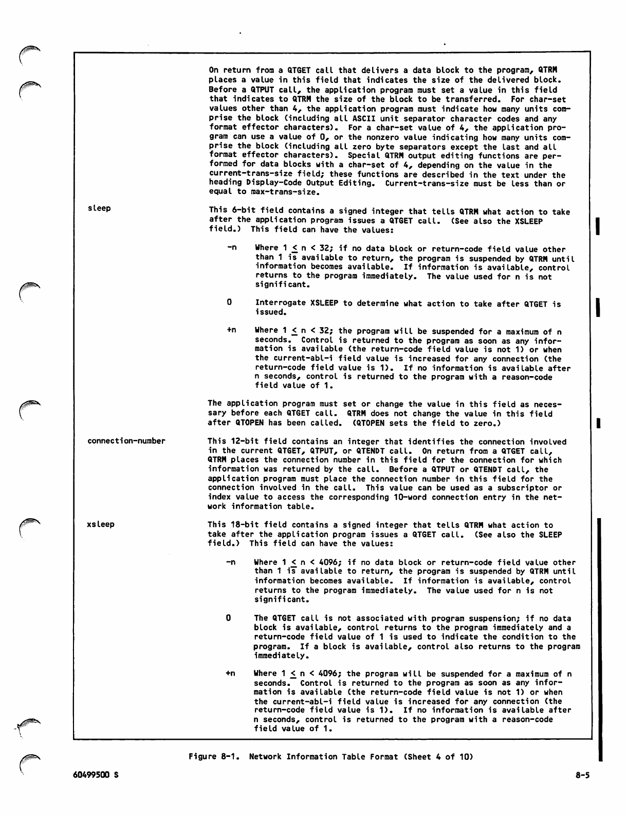
sleep
connection-number
xsleep
On return from a QTGET call that delivers a data block to the program, QTRM
places a value in this field that indicates the size of the delivered block.
Before a QTPUT call, the application program must set a value in this field
that indicates to QTRM the size of the block to be transferred. For char-set
values other than 4, the application program must indicate how many units com
prise the block (including all ASCII unit separator character codes and any
format effector characters). For a char-set value of 4, the application pro
gram can use a value of 0, or the nonzero value indicating how many units com
prise the block (including all zero byte separators except the last and all
format effector characters). Special QTRM output editing functions are per
formed for data blocks with a char-set of 4, depending on the value in the
current-trans-size field; these functions are described in the text under the
heading Display-Code Output Editing. Current-trans-size must be less than or
equal to max-trans-size.
This 6-bit field contains a signed integer that tells QTRM what action to take
after the application program issues a QTGET call. (See also the XSLEEP
field.) This field can have the values:
-n Where 1 < n < 32; if no data block or return-code field value other
than 1 is available to return, the program is suspended by QTRM until
information becomes available. If information is available, control
returns to the program immediately. The value used for n is not
significant.
0 Interrogate XSLEEP to determine what action to take after QTGET is
issued.
+n Where 1 < n < 32; the program will be suspended for a maximum of n
seconds. Control is returned to the program as soon as any infor
mation is available (the return-code field value is not 1) or when
the current-abl-i field value is increased for any connection (the
return-code field value is 1). If no information is available after
n seconds, control is returned to the program with a reason-code
field value of 1.
The application program must set or change the value in this field as neces
sary before each QTGET call. QTRM does not change the value in this field
after QTOPEN has been called. (QTOPEN sets the field to zero.)
This 12-bit field contains an integer that identifies the connection involved
in the current QTGET, QTPUT, or QTENDT call. On return from a QTGET call,
QTRM places the connection number in this field for the connection for which
information was returned by the call. Before a QTPUT or QTENDT call, the
application program must place the connection number in this field for the
connection involved in the call. This value can be used as a subscriptor or
index value to access the corresponding 10-word connection entry in the net
work information table.
This 18-bit field contains a signed integer that tells QTRM what action to
take after the application program issues a QTGET call. (See also the SLEEP
field.) This field can have the values:
-n Where 1 <_ n < 4096; if no data block or return-code field value other
than 1 is available to return, the program is suspended by QTRM until
information becomes available. If information is available, control
returns to the program immediately. The value used for n is not
significant.
0 The QTGET call is not associated with program suspension; if no data
block is available, control returns to the program immediately and a
return-code field value of 1 is used to indicate the condition to the
program. If a block is available, control also returns to the program
immediately.
+n Where 1 < n < 4096; the program will be suspended for a maximum of n
seconds. Control is returned to the program as soon as any infor
mation is available (the return-code field value is not 1) or when
the current-abl-i field value is increased for any connection (the
return-code field value is 1). If no information is available after
n seconds, control is returned to the program with a reason-code
field value of 1.
60499500 S
Figure 8-1. Network Information Table Format (Sheet 4 of 10)
8-5
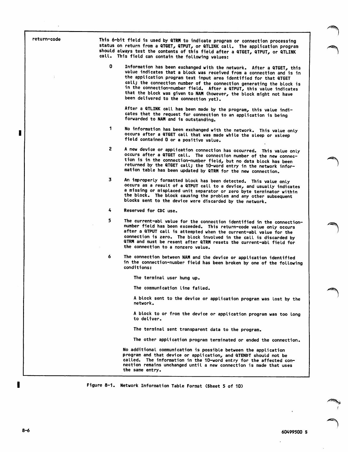
return-code This 6-bit field is used by QTRM to indicate program or connection processing
status on return from a QTGET, QTPUT, or QTLINK call. The application program
should always test the contents of this field after a QTGET, QTPUT, or QTLINK
call. This field can contain the following values:
0 Information has been exchanged with the network. After a QTGET, this
value indicates that a block was received from a connection and is in
the application program text input area identified for that QTGET
call; the connection number of the connection generating the block is
in the connection-number field. After a QTPUT, this value indicates
that the block was given to NAM (however, the block might not have
been delivered to the connection yet).
After a QTLINK call has been made by the program, this value indi
cates that the request for connection to an application is being
forwarded to NAM and is outstanding.
1 No information has been exchanged with the network. This value only
occurs after a QTGET call that was made while the sleep or xsleep
field contained 0 or a positive value.
2 A new device or application connection has occurred. This value only
occurs after a QTGET call. The connection number of the new connec
tion is in the connection-number field, but no data block has been
returned by the QTGET call; the 10-word entry in the network infor
mation table has been updated by QTRM for the new connection.
3 An improperly formatted block has been detected. This value only
occurs as a result of a QTPUT call to a device, and usually indicates
a missing or misplaced unit separator or zero byte terminator within
the block. The block causing the problem and any other subsequent
blocks sent to the device were discarded by the network.
4 Reserved for CDC use.
5 The current-abl value for the connection identified in the connection-
number field has been exceeded. This return-code value only occurs
after a QTPUT call is attempted when the current-abl value for the
connection is zero. The block involved in the call is discarded by
QTRM and must be resent after QTRM resets the current-abl field for
the connection to a nonzero value.
6 The connection between NAM and the device or application identified
in the connection-number field has been broken by one of the following
conditions:
The terminal user hung up.
The communication line failed.
A block sent to the device or application program was lost by the
network.
A block to or from the device or application program was too long
to deliver.
The terminal sent transparent data to the program.
The other application program terminated or ended the connection.
No additional communication is possible between the application
program and that device or application, and QTENDT should not be
called. The information in the 10-word entry for the affected con
nection remains unchanged until a new connection is made that uses
the same entry.
Figure 8-1. Network Information Table Format (Sheet 5 of 10)
8-6 60499500 S
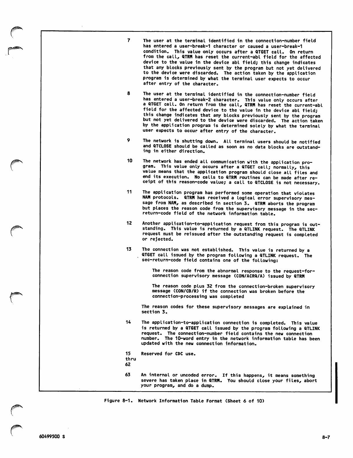
10
The user at the terminal identified in the connection-number field
has entered a user-break-1 character or caused a user-break-1
condition. This value only occurs after a QT6ET call. On return
from the call, QTRM has reset the current-abl field for the affected
device to the value in the device abl field; this change indicates
that any blocks previously sent by the program but not yet delivered
to the device were discarded. The action taken by the application
program is determined by what the terminal user expects to occur
after entry of the character.
The user at the terminal identified in the connection-number field
has entered a user-break-2 character. This value only occurs after
a QTGET call. On return from the call, QTRM has reset the current-abl
field for the affected device to the value in the device abl field;
this change indicates that any blocks previously sent by the program
but not yet delivered to the device were discarded. The action taken
by the application program is determined solely by what the terminal
user expects to occur after entry of the character.
The network is shutting down. All terminal users should be notified
and QTCLOSE should be called as soon as no data blocks are outstand
ing in either direction.
The network has ended all communication with the application pro
gram. This value only occurs after a QTGET call; normally, this
value means that the application program should close all files and
end its execution. No calls to QTRM routines can be made after re
ceipt of this reason-code value; a call to QTCLOSE is not necessary.
11 The application program has performed some operation that violates
NAM protocols. QTRM has received a logical error supervisory mes
sage from NAM, as described in section 3. QTRM aborts the program
but places the reason code from the supervisory message in the sec-
return-code field of the network information table.
12 Another application-to-application request from this program is out
standing. This value is returned by a QTLINK request. The QTLINK
request must be reissued after the outstanding request is completed
or rejected.
13 The connection was not established. This value is returned by a
QTGET call issued by the program following a QTLINK request. The
sec-return-code field contains one of the following:
The reason code from the abnormal response to the request-for-
connection supervisory message (CON/ACRQ/A) issued by QTRM
The reason code plus 32 from the connection-broken supervisory
message (CON/CB/R) if the connection was broken before the
connection-processing was completed
The reason codes for these supervisory messages are explained in
section 3.
14 The application-to-application connection is completed. This value
is returned by a QTGET call issued by the program following a QTLINK
request. The connection-number field contains the new connection
number. The 10-word entry in the network information table has been
updated with the new connection information.
15 Reserved for CDC use.
thru
62
63 An internal or uncoded error. If this happens, it means something
severe has taken place in QTRM. You should close your files, abort
your program, and do a dump.
Figure 8-1. Network Information Table Format (Sheet 6 of 10)
60499500 S 8-7
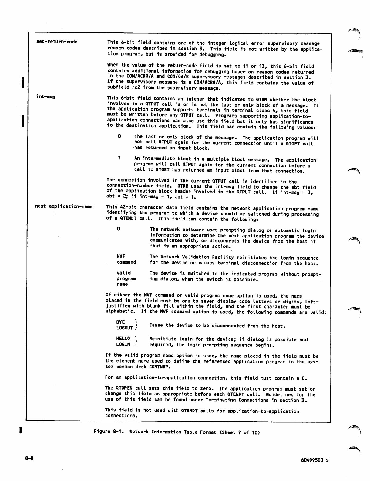
sec-return-code
i nt-msg
next-application-name
This 6-bit field contains one of the integer logical error supervisory message
reason codes described in section 3. This field is not written by the applica
tion program, but is provided for debugging.
When the value of the return-code field is set to 11 or 13, this 6-bit field
contains additional information for debugging based on reason codes returned
in the CON/ACRQ/A and CON/CB/R supervisory messages described in section 3.
If the supervisory message is a CON/ACRQ/A, this field contains the value of
subfield rc2 from the supervisory message.
This 6-bit field contains an integer that indicates to QTRM whether the block
involved in a QTPUT call is or is not the last or only block of a message. If
the application program supports terminals in terminal class 4, this field
must be written before any QTPUT call. Programs supporting application-to-
application connections can also use this field but it only has significance
to the destination application. This field can contain the following values:
0 The last or only block of the message. The application program will
not call QTPUT again for the current connection until a QTGET call
has returned an input block.
1 An intermediate block in a multiple block message. The application
program will call QTPUT again for the current connection before a
call to QTGET has returned an input block from that connection.
The connection involved in the current QTPUT call is identified in the
connection-number field. QTRM uses the int-msg field to change the abt field
of the application block header involved in the QTPUT call. If int-msg = 0,
abt = 2; if int-msg = 1, abt = 1.
This 42-bit character data field contains the network application program name
identifying the program to which a device should be switched during processing
of a QTENDT call. This field can contain the following:
0 The network software uses prompting dialog or automatic login
information to determine the next application program the device
communicates with, or disconnects the device from the host if
that is an appropriate action.
NVF
command
valid
program
name
The Network Validation Facility reinitiates the login sequence
for the device or causes terminal disconnection from the host.
The device is switched to the indicated program without prompt
ing dialog, when the switch is possible.
If either the NVF command or valid program name option is used, the name
placed in the field must be one to seven display code letters or digits, left-
justified with blank fill within the field, and the first character must be
alphabetic. If the NVF command option is used, the following commands are valid:
BYE
LOGOUT
HELLO
LOGIN
Cause the device to be disconnected from the host.
Reinitiate login for the device; if dialog is possible and
required, the login prompting sequence begins.
If the valid program name option is used, the name placed in the field must be
the element name used to define the referenced application program in the sys
tem common deck COMTNAP.
For an application-to-application connection, this field must contain a 0.
The QTOPEN call sets this field to zero. The application program must set or
change this field as appropriate before each QTENDT call. Guidelines for the
use of this field can be found under Terminating Connections in section 3.
This field is not used with QTENDT calls for application-to-application
connections.
Figure 8-1. Network Information Table Format (Sheet 7 of 10)
8-8 60499500 S
/ ^ \
requested-appIication-
name
destination-host
terminal-name-i/
appli cation-name-i
tclass-i
page-width-i
family-name-i
dev-type-i
This 42-bit character data field contains the network application program name
identifying the program to which the current application program is requesting
a connection with a QTLINK call. This is the first identifier for the
connection. This identifier can be one to seven letters or digits long and is
left-justified with blank fill within this field; the first character must be a
letter. For intra-host connections, this field contains the name of the
application program with which your program needs to establish a connection.
For inter-host connections, the name you use must match the value of the NAME1
parameter in the NDL OUTCALL statement used by your program.
This 18-bit character data field contains the second identifier for a connec
tion your program initiates with a QTLINK call. If the connection is between two
hosts, this identifier must be one to three letters or digits, left-justified
with blank fill within the field; the first character must be a letter. If the
connection is within a host, this identifier can be a binary 0. By convention,
any nonzero name is the name of the destination host in which the other
application program runs. The name you use must match the value of the NAME2
parameter in the NDL OUTCALL statement used by your program.
This 42-bit character data field contains the display code characters of the
name used to identify the device on connection i within the network. The name
is one to seven letters or digits long and is left-justified with blank fill
within this field. A terminal name used is obtained from the network
configuration file entry for the device.
For an application-to-application connection, this field contains blanks.
This 6-bit field contains the integer terminal class associated by the network
with the device on connection i. The integer used in the field is one of
those described for the tc field of the connection-request supervisory message
presented in section 3. The integer is changed during a QTGET call whenever
the terminal user has entered a TIP command to change the terminal class of
the device on connection i.
This field is not used for application-to-application connections.
This 12-bit field contains the integer page width value associated by the net
work with the device on connection i. The integer used in the field has the
significance explained in sections 2 and 3. The integer is changed during a
QTGET call whenever the terminal user has entered a TIP command to change the
page width or terminal class of the device on connection i.
This field is not used for application-to-application connections.
This 42-bit character data field contains the display code characters of the
permanent file family name associated by the network with device connection i.
The family name is one to seven letters or digits long and is left-justified with
blank fill within this field.
This field is not used for application-to-application connections.
This 6-bit field contains an integer value to identify the type of connection for
connection i. The integer used in this field is one of those described for the
dt field of the connection-request supervisory messages presented in section 3.
Typical values are:
0 This connection is a device-to-application connection for a console.
5 This connection is an application-to-application connection within the
same host.
6 This connection is an application-to-application connection between
hosts.
12 This connection is a device-to-application connection for a device
thru with a site-defined device type.
15
Figure 8-1. Network Information Table Format (Sheet 8 of 10)
60499500 S 8-9
page-length-i
user-name-i
res
max-block-size-i
abl-i
current-abn-i
acknowledged-abn-i
state-i
current-abl-i
This 12-bit field contains the integer page length value associated by the
network with the device on connection i. The integer used in the field has
the significance explained in sections 2 and 3. The integer is changed during
a QTGET call after the terminal user enters a TIP command to change the page
length or terminal class of the device on connection i.
This field is not used for application-to-application connections.
This 42-bit character data field contains the display code characters of the
NOS user name associated by the network with device connection i. The user
name is one to seven letters, digits, or asterisks long and is left-justified
with blank fill within the field.
This field is not used for application-to-application connections.
Reserved by CDC.
This 12-bit field contains the integer downline block size in character units for
the device on connection i. This block size is based on the network
configuration file information for the device or the local configuration file
information for an application-to-application connection. The block size is a
suggested value for adjusting the current-trans-size field based on efficiency
considerations for the site.
This 6-bit integer field contains the number of blocks permitted by the network
to be in transit to connection i at a given moment. This block limit is based on
the network configuration file information for the connection. The value used in
this field determines the number of QTPUT calls that can be made on connection i
before a QTGET call returns an indication that a block was delivered to the
connection. A typical value is 2 for a device-to-application connection and 7
for an application-to-application connection.
This 18-bit integer field contains the binary block number assigned by QTRM to
the block sent to connection i by the last QTPUT call involving that connec
tion. Every block sent by QTRM is assigned a number; the number assigned is
sequential within the blocks sent to a given connection, and the sequence is
restarted each time a new connection is assigned to the connection number.
This 18-bit integer field contains the binary block number assigned by QTRM to
the block last acknowledged on connection i. QTRM updates this field during
a QTGET call, when QTRM determines that a block-delivered message has been
received.
This 6-bit field contains the integer flag identifying the current processing
state of connection i. This field has the values:
0 This connection number is currently not in use.
1 This connection is currently in a transition state while a new con
nection is being established. No other information in the associated
10-word entry for this connection should be considered accurate.
2 This connection is in use and in a normal state for input or output
processing by the application program.
4 This connection is currently in a transition state while a new con
nection is being established. No other information in the associated
10-word entry for this connection should be considered accurate.
This value is used for application-to-application connections only.
This 6-bit integer field contains the number of sequential QTPUT calls that
currently can be made for connection i without waiting for acknowledgment of
delivery to the device or application. QTRM updates this field during QTGET
and QTPUT calls, and the application program should examine the field before
making a QTPUT call involving the connection. The values used in this field
range from 0 to the value contained in the abl-i field; a value of 0 indicates
that no blocks currently can be sent (the maximum number of blocks are in
transit to the connection).
Figure 8-1. Network Information Table Format (Sheet 9 of 10)
8-10 60499500 S
-^s^v
zi^v
upline-abh-i
downline-abh-i
This 60-bit field contains the binary application block header received by
QTRM with the last input data block delivered by a QTGET call for connection i.
This field has the format and contains the information described in section 2.
This 60-bit field contains the binary application block header created by QTRM
to send with the last output data block involved in a QTPUT call for connec
tion i. This field has the format and contains the information described in
section 2.
Figure 8-1. Network Information Table Format (Sheet 10 of 10)
60499500 S 8-10.1/8-10.2

/*£%
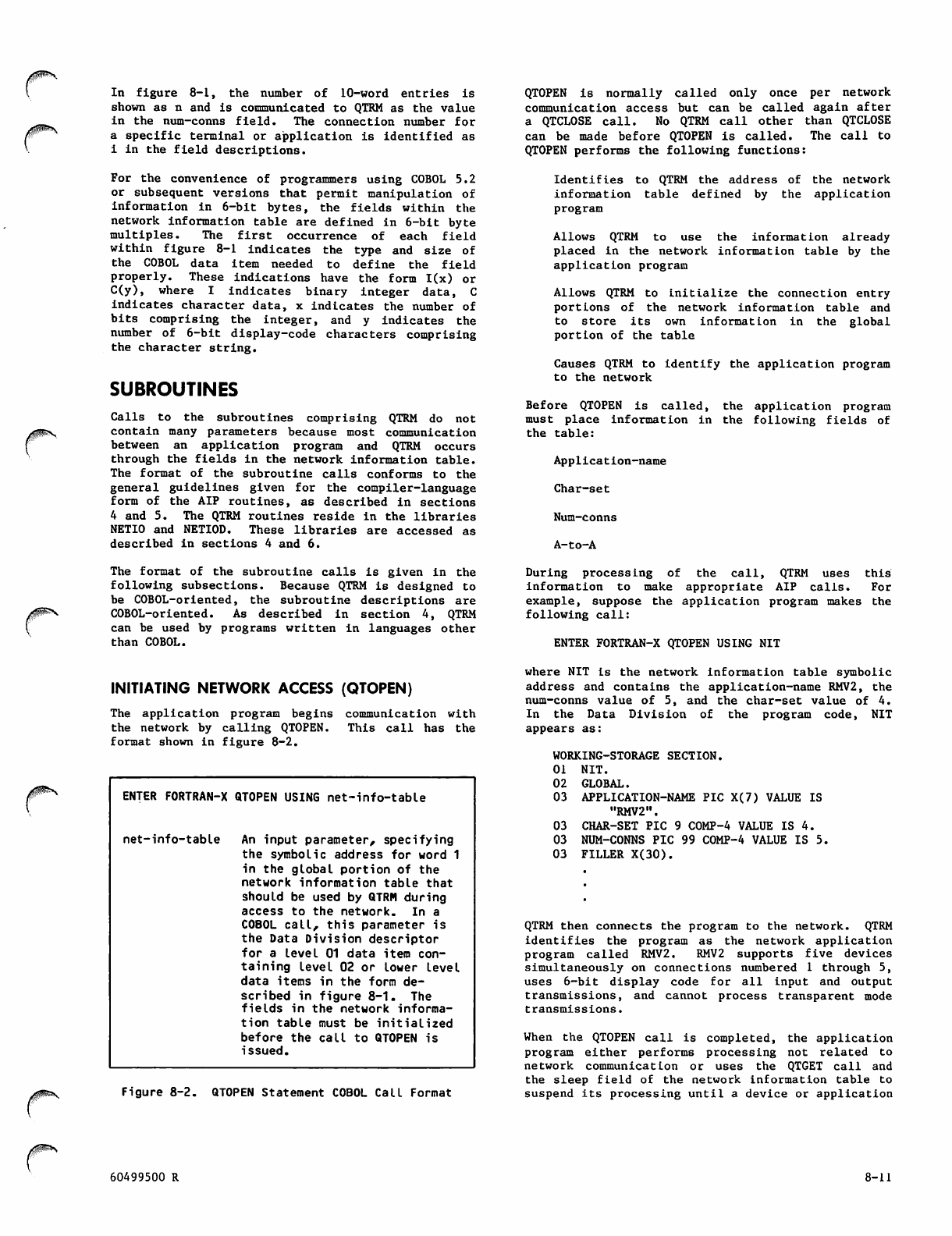
0^\
I n fi g u r e 8 - 1 , t h e n u m b e r o f 1 0 - w o r d e n t r i e s i s
shown as n and is communicated to QTRM as the value
in the num-conns field. The connection number for
a specific terminal or application is identified as
i i n t he fi e l d d e s cri p tio n s.
For the convenience of programmers using COBOL 5.2
or subsequent versions that permit manipulation of
i n f o r m a t i o n i n 6 - b i t b y t e s , t h e fi e l d s w i t h i n t h e
network information table are defined in 6-bit byte
multiples. The first occurrence of each field
within figure 8-1 indicates the type and size of
the COBOL data item needed to define the field
properly. These indications have the form I(x) or
C ( y ) , w h e r e I i n d i c a t e s b i n a r y i n t e g e r d a t a , C
indicates character data, x indicates the number of
bits comprising the integer, and y indicates the
number of 6-bit display-code characters comprising
the character string.
SUBROUTINES
Calls to the subroutines comprising QTRM do not
contain many parameters because most communication
between an application program and QTRM occurs
through the fields in the network information table.
The format of the subroutine calls conforms to the
general guidelines given for the compiler-language
form of the AIP routines, as described in sections
4 and 5. The QTRM routines reside in the libraries
NETIO and NETIOD. These libraries are accessed as
described in sections 4 and 6.
QTOPEN is normally called only once per network
communication access but can be called again after
a QTCLOSE call. No QTRM call other than QTCLOSE
can be made before QTOPEN is called. The call to
QTOPEN performs the following functions:
Identifies to QTRM the address of the network
information table defined by the application
program
Allows QTRM to use the information already
placed in the network information table by the
application program
Allows QTRM to initialize the connection entry
portions of the network information table and
t o s t o r e i t s o w n i n f o r m a t i o n i n t h e g l o b a l
portion of the table
Causes QTRM to identify the application program
to the network
Before QTOPEN is called, the application program
must place information in the following fields of
the tab le:
Application-name
Char-set
Num-conns
A-to-A
The format of the subroutine calls is given in the
following subsections. Because QTRM is designed to
be COBOL-oriented, the subroutine descriptions are
COBOL-oriented. As described in section 4, QTRM
can be used by programs written in languages other
than COBOL.
D u r i n g p r o c e s s i n g o f t h e c a l l , Q T R M u s e s t h i s
information to make appropriate AIP calls. For
example, suppose the application program makes the
following call:
ENTER FORTRAN-X QTOPEN USING NIT
INITIATING NETWORK ACCESS (QTOPEN)
J^N
The application program begins
the network by calling QTOPEN.
format shown in figure 8-2.
communication with
T h is c a l l h a s t he
ENJER FORTRAN-X QTOPEN USING net-info-table
net-info-table An input parameter, specifying
the symbolic address for word 1
in the global portion of the
network information table that
should be used by QTRM during
access to the network. In a
COBOL call, this parameter is
the Data Division descriptor
for a level 01 data item con
taining level 02 or lower level
data items in the form de
scribed in figure 8-1. The
fields in the network informa
tion table must be initialized
before the call to QTOPEN is
issued.
Figure 8-2. QTOPEN Statement COBOL Call Format
where NIT is the network information table symbolic
address and contains the application-name RMV2, the
num-conns value of 5, and the char-set value of 4.
In the Data Division of the program code, NIT
appears as:
WORKING-STORAGE SECTION.
0 1 N I T.
02 GLOBAL.
03 APPLICATION-NAME PIC X(7) VALUE IS
"RMV2".
03 CHAR-SET PIC 9 COMP-4 VALUE IS 4.
03 NUM-CONNS PIC 99 COMP-4 VALUE IS 5.
03 FILLER X(30).
QTRM then connects the program to the network. QTRM
identifies the program as the network application
program called RMV2. RMV2 supports five devices
simultaneously on connections numbered 1 through 5,
uses 6-bit display code for all input and output
transmissions, and cannot process transparent mode
transmissions.
When the QTOPEN call is completed, the application
program either performs processing not related to
network communication or uses the QTGET call and
the sleep field o f the n etwo rk i nform atio n tab le to
suspend its processing until a device or application
60499500 R 8-11
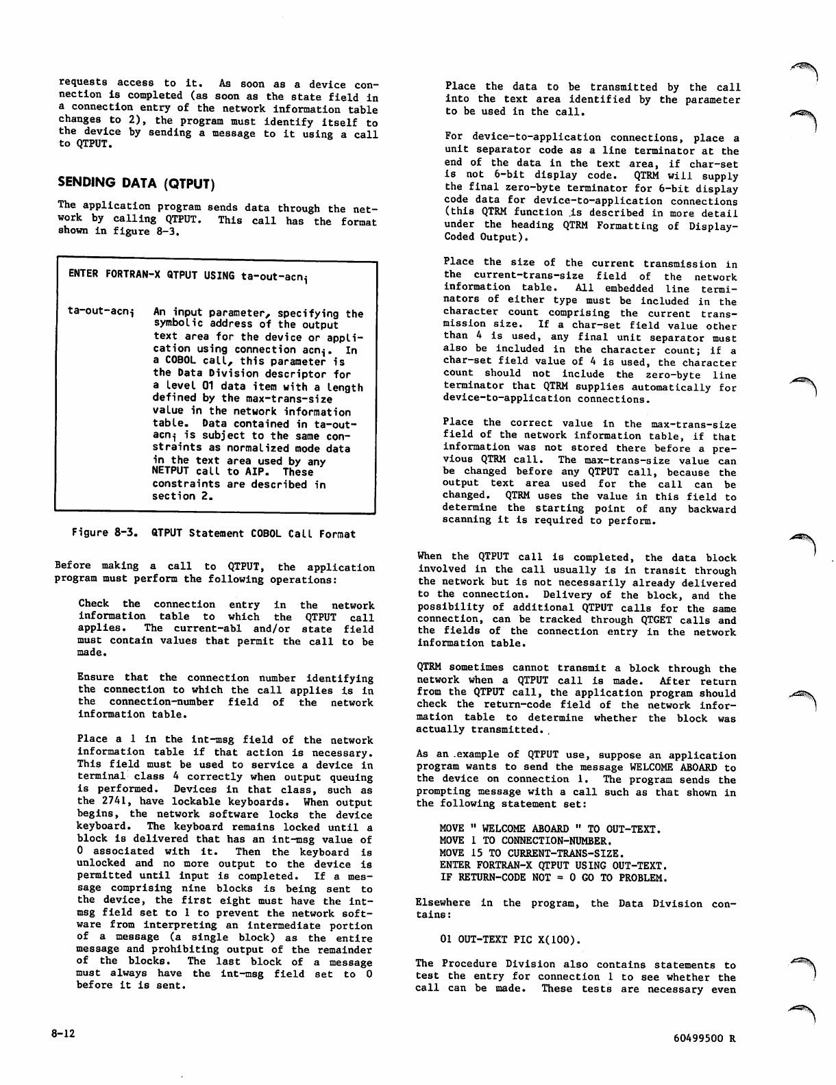
request s a c c e ss to it. As s o o n a s a device c o n
nection is completed (as soon as the state field in
a connection entry of the network information table
changes to 2), the program must identify itself to
the device by sending a message to it using a call
to QTPUT.
SENDING DATA (QTPUT)
The application program sends data through the net
work by calling QTPUT. This call has the format
shown in figure 8-3.
ENTER FORTRAN-X QTPUT USING ta-out-acni
ta-out-acni An input parameter, specifying the
symbolic address of the output
text area for the device or appli
cation using connection acn^. In
a COBOL call, this parameter is
the Data Division descriptor for
a Level 01 data item with a length
defined by the max-trans-size
value in the network information
table. Data contained in ta-out-
acn^ is subject to the same con
straints as normalized mode data
in the text area used by any
NETPUT call to AIP. These
constraints are described in
section 2.
Figure 8-3. QTPUT Statement COBOL Call Format
Before making a call to QTPUT, the application
program must perform the following operations:
C h e c k t h e c o n n e c t i o n e n t r y i n t h e n e t w o r k
i n f o r m a t i o n t a b l e t o w h i c h t h e Q T P U T c a l l
applies. The current-abl and/or state field
must contain values that permit the call to be
made.
Ensure that the connection number identifying
the connection to which the call applies is in
t h e c o n n e c t i o n - n u m b e r fi e l d o f t h e n e t w o r k
information table.
Place a 1 i n t h e i n t - m s g field of the network
information table if that action is necessary.
This field must be used to service a device in
terminal class 4 correctly when output queuing
is performed. Devices in that class, such as
the 2741, have lockable keyboards. When output
begins, the network software locks the device
keyboard. The keyboard remains locked until a
block is delivered that has an int-msg value of
0 associated with it. Then the keyboard is
unlocked and no more output to the device is
permitted until input is completed. If a mes
sage comprising nine blocks is being sent to
the device, the first eight must have the int-
msg field set to 1 to prevent the network soft
ware from interpreting an intermediate portion
of a message (a single block) as the entire
message and prohibiting output of the remainder
of the blocks. The last block of a message
m u s t a l w a y s h a v e t h e i n t - m s g fi e l d s e t t o 0
before it is sent.
8-12
Place the data to be transmitted by the call
into the text area identified by the parameter
to be used in the call.
For device-to-application connections, place a
unit separator code as a line terminator at the
en d o f t h e d ata i n t h e t ext a r e a , i f char - s e t
is not 6-bit display code. QTRM will supply
the final zero-byte terminator for 6-bit display
code data for device-to-application connections
(this QTRM function .is described in more detail
under the heading QTRM Formatting of Display-
Coded Output).
Place the size of the current transmission in
the current-trans-size field of the network
information table. All embedded line termi
nators of either type must be included in the
character c o u n t c o m p rising the c u r r e n t t r a n s
m i s s i o n si z e . I f a c h a r - s e t fi e l d v a l u e o t h e r
than 4 is used, any final unit separator must
also be included in the character count; if a
char-set field value of 4 is used, the character
count should not include the zero-byte line
terminator that QTRM supplies automatically for
device-to-application connections.
Place the correct value in the max-trans-size
field of the network information table, if that
information was not stored there before a pre
vious QTRM call. The max-trans-size value can
be changed before any QTPUT call, because the
o u t p u t t e x t a r e a u s e d f o r t h e c a l l c a n b e
changed. QTRM uses the value in this field to
determine the starting point of any backward
scanning it is required to perform.
When the QTPUT call is completed, the data block
i n v ol v e d i n th e c al l u s ua l l y i s i n t r an s i t t hr o u gh
the network but is not necessarily already delivered
to the connection. Delivery of the block, and the
possibility of additional QTPUT calls for the same
connection, can be tracked through QTGET calls and
the fields of the c o n n e c t i o n e n t r y I n t h e n e t w o r k
information table.
QTRM sometimes cannot transmit a block through the
network when a QTPUT call is made. After return
from the QTPUT call, the application program should
check the return-code field of the network infor
mation t a b l e t o d e t e r m i n e w h ether t h e b l o c k w a s
actually transmitted..
As an .example of QTPUT use, suppose an application
program wants to send the message WELCOME ABOARD to
the device on connection 1. The program sends the
prompting message with a call such as that shown in
the following statement set:
MOVE " WELCOME ABOARD " TO OUT-TEXT.
MOVE 1 TO CONNECTION-NUMBER.
MOVE 15 TO CURRENT-TRANS-SIZE.
ENTER FORTRAN-X QTPUT USING OUT-TEXT.
IF RETURN-CODE NOT = 0 GO TO PROBLEM.
Elsewhere in the program, the Data Division con
tains :
01 OUT-TEXT PIC X(100).
The Procedure Division also contains statements to
test the entry for connection 1 to see whether the
call can be made. These tests are necessary even
60499500 R
p(^i(v
,<S§\
^^ 35v
j0$g\
0K&\
25 The application program has received the reset response from the
network for the connection identified in the connection-number
field. This value occurs only after a QTGET call and only for a
connection that was in a break condition. The break condition
exists only after the application program has called QTSUP to send
a break condition to the other end of the connection. The applica
tion program can now call QTSUP to send another break condition for
this connection.
26 The application program has received a priority data message
(INTR/USR/R supervisory message with reason code other than user
break 1 or 2) on the connection identified in the connection-number
field. This value occurs only after a QTGET call and only if the
application program called QTCMD to request notification of user
interrupts. The network does not require any action or response
from the application program. QTRM sends the user acknowledgment
(INTR/RSP/N supervisory message) for the interrupt connection. The
sub-return-code field contains the reason code for the interrupt
condition.
27 The application program has received the user interrupt response
(INTR/RSP/R supervisory message) on the connection identified in
the connection-number field. This value occurs only after a QTGET
call and only if the application program called QTSUP to send a
user interrupt to the other end of the connection. The network
does not require any action or response from the application pro
gram. The application program can now call QTSUP to send another
user interrupt for this connection.
28 The application program has received the user break marker
(BI/MARK/R supervisory message) on the connection identified in
the connection-number field. This value occurs only after a QTGET
call and only if the application program previously called QTCMD to
indicate that it wanted to be informed about the user break marker.
The connection involved is always a device connection in a user
break condition (return code 7 or 8 response for this connection in
a previous QTGET call). The application program must call QTTIP to
send a RO/MARK/R synchronous supervisory message before any more
downline data will be delivered to the device. After receiving this
return code, the application program assumes that any new data it
receives on the connnection was entered after the user break.
29 The application program has received a synchronous supervisory
message other than BI/MARK/R (user break mark) on the connection
identified in the connection-number field. This value occurs only
after a QTGET call. The connection involved is always a device
connection. The synchronous supervisory message is in the
application program text input area identified for the QTGET call;
the message originates from either CCP or CDCNET. The network does
not require any action or response from the application program.
30 Reserved for CDC use.
31 The host operator has assigned the NAM K-display to this applica
tion program. This value occurs only after a QTGET call when the
application program has previously called QTCMD to inform QTRM that
it supports the NAM K-display. If the text input area is at least
one word long, QTRM stores the length of the left and right screens
in the first word of the text input area. This first word is
actually the first word of the HOP/START/R supervisory message.
The format of this message is described in section 3. If the text
input area is not large enough, the information on the size of the
left and right screens is lost.
Upon receipt of this return code, the application program should
generate a banner or other display data and call QTSUP to send the
display data to NAM.
Figure 8-1. Network Information Table Format (Sheet 12 of 24)
/^*N
60499500 W 8-13
32
33
34
The host operator has entered a K-display typein. This value
occurs only after a QTGET call when the application program has
been assigned the NAM K-display (return code 31 was received after
a QTGET call). QTRM writes the operator typein to the application
program text input area identified for that QTGET call. If the
text input area is not large enought to contain the operator typein,
QTRM truncates the typein and the last part of the typein is lost.
The current-trans-size field contains the number of characters (in
display code only) of the operator typein written to the text input
area. Until the application program sends display data back to NAM
with the input-allowed flag set (QTSUP call with parm-flagl set to
1), the host operator cannot enter any more NAM K-display typeins
for this application program.
The host operator has entered the break character. This value
occurs only after a QTGET call and the application program has been
assigned the NAM K-display (return code 31 was received after a
QTGET call). The operator is probably no Longer interested in data
from this application program and wants to enter another typein.
The application program should call QTSUP to send a HOP/DIS/R
supervisory message to NAM with the input-allowed flag set (parm-
flagl set to 1 for the QTSUP call). No K-display data is necessary
for this call (current-trans-size field is set to zero).
The host operator has entered a page character. This value occurs
only after a QTGET call when the application program has been
assigned the NAM K-display (return code 31 was received after a
QTGET call). Because the host console can display only a finite
number of lines of data, NAM scrolls the oldest data off the top of
the screen. The newest data always appears at the bottom of the
screen. If the application program sends more than one screen of
display data, only the Last part of the data remains on the screen.
This may or may not be desired by the operator. The page character
allows the operator to inform the application program whether it
should send all the display data at once or only one screen at a
time.
There are four page characters: the plus (+) character, the minus
(-) charact er, the left pare nthesis (() char acter, and the righ t
parenthesis ()) character. The plus and minus characters control
paging of the left screen. The left and right parenthesis
characters control paging of the right screen.
If the page character is the plus character, the operator is
requesting the application program to page the left screen
display data one screen at a time.
If the page character is the minus character, the operator is
requesting the application program not to page the left screen
display data.
If the page character is the left parenthesis character, the
operator is requesting the next page of the right screen
display data.
If the page character is the right parenthesis character, the
operator is requesting the previous page of the right screen
display data.
For the left screen, the convention is that all application programs
should assume that paging is off when the operator assigns the
K-display to them. The application program should never send more
than one screen full of display data to the left screen at one
time. If the application program has more than one screen to send,
it must wait for another plus page character before sending the next
screen (after a QTGET call, the application program must receive
another return code 34 with the page character set to the plus
character). This interaction between the operator and the
application program can be repeated until the application program
has no more data to display or the operator enters another command.
/"s^\
Figure 8-1. Network Information Table Format (Sheet 13 of 24)
8-14 60499500 V
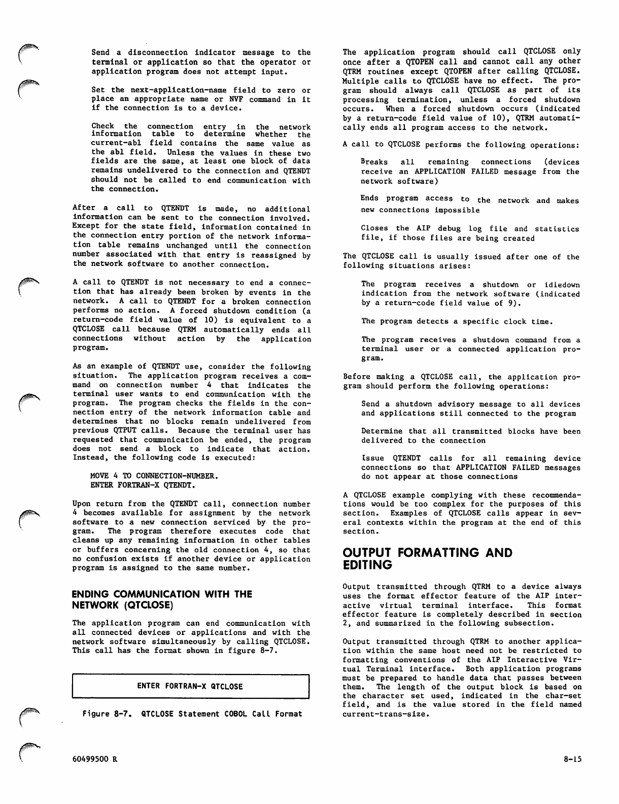
Send a disconnection indicator message to the
termin al o r applic ati on s o tha t the operato r or
application program does not attempt input.
Set the next-application-name field to zero or
place an appropriate name or NVF command in it
if the connection is to a device.
C h e c k t h e c o n n e c t i o n e n t r y i n t h e n e t w o r k
i n f o r m a t i o n t a b l e t o d e t e r m i n e w h e t h e r t h e
current-abl field contains the same value as
the abl field. Unless the values in these two
fields are the same, at least one block of data
remains undelivered to the connection and QTENDT
should not be called to end communication with
the connection.
A f t e r a c a l l t o Q T E N D T i s m a d e , n o a d d i t i o n a l
information can be sent to the connection involved.
Except for the state field, information contained in
the connection entry portion of the network informa
tion table remains unchanged until the connection
number associated with that entry is reassigned by
the network software to another connection.
A call to QTENDT is not necessary to end a connec
tion that has already been broken by events in the
network. A call to QTENDT for a broken connection
performs no action. A forced shutdown condition (a
r e t u rn - c o d e fi e l d v a l u e of 1 0 ) i s e q u i v a l e n t t o a
QTCLOSE call because QTRM automatically ends all
connections without action by the application
program.
As an example of QTENDT use, consider the following
situation. The application program receives a com
mand on connection number 4 that indicates the
terminal user wants to end communication with the
program. The program checks the fields in the con
nection entry of the network information table and
determines that no blocks remain undelivered from
previous QTPUT calls. Because the terminal user has
requested that communication be ended, the program
does not send a block to indicate that action.
Instead, the following code is executed:
MOVE 4 TO CONNECTION-NUMBER.
ENTER FORTRAN-X QTENDT.
Upon return from the QTENDT call, connection number
4 becomes available for assignment by the network
software to a new connection serviced by the pro
gram. The program therefore executes code that
cleans up any remaining information in other tables
or buffers concerning the old connection 4, so that
no confusion exists if another device or application
program is assigned to the same number.
The application program should call QTCLOSE only
once after a QTOPEN call and cannot call any other
QTRM routines except QTOPEN after calling QTCLOSE.
Multiple calls to QTCLOSE have no effect. The pro
gram should always call QTCLOSE as part of its
processing termination, unless a forced shutdown
occurs. When a forced shutdown occurs (indicated
by a return-code field value of 10), QTRM automati
cally ends all program access to the network.
A call to QTCLOSE performs the following operations:
Breaks all remaining connections (devices
receive an APPLICATION FAILED message from the
network software)
Ends program access to the network and makes
new connections impossible
C l o s e s t h e A I P d e b u g l o g fi l e a n d s t a t i s t i c s
file , if t h ose fiLes are b eing creat ed
The QTCLOSE call is usually issued after one of the
following situations arises:
The program receives a shutdown or idledown
indication from the network software (indicated
by a return-code field value of 9).
The program detects a specific clock time.
The program receives a shutdown command from a
terminal user or a connected application pro
gram.
Before making a QTCLOSE call, the application pro
gram should perform the following operations:
Send a shutdown advisory message to all devices
and applications still connected to the program
Determine that all transmitted blocks have been
delivered to the connection
Issue QTENDT calls for all remaining device
connections so that APPLICATION FAILED messages
do not appear at those connections
A QTCLOSE example complying with these recommenda
tions would be too complex for the purposes of this
section. Examples of QTCLOSE calls appear in sev
eral contexts within the program at the end of this
section.
OUTPUT FORMATTING AND
EDITING
ENDING COMMUNICATION WITH THE
NETWORK (QTCLOSE)
The application program can end communication with
all connected devices or applications and with the
network software simultaneously by calling QTCLOSE.
This call has the format shown in figure 8-7.
ENTER FORTRAN-X QTCLOSE
Figure 8-7. QTCLOSE Statement COBOL Call Format
Output transmitted through QTRM to a device always
uses the format effector feature of the AIP inter
a c t i v e v i r t u a l t e r m i n a l i n t e r f a c e . T h i s f o r m a t
effector feature is completely described in section
2, and summarized in the following subsection.
Output transmitted through QTRM to another applica
tion within the same host need not be restricted to
formatting conventions of the AIP Interactive Vir
tual Terminal interface. Both application programs
must be prepared to handle data that passes between
them . The l ength o f the o u t put b l o ck is b a s ed on
the character set used, indicated in the char-set
field, and is the value stored in the field named
current-trans-size.
60499500 R 8-15
If display-coded output is transmitted to a device
(a char-set field value of 4 is used), QTRM auto
matically performs editing functions on the contents
o f t h e t e x t a r e a u s e d . T h e s e f u n c t i o n s i n c l u d e
placement of the final line terminator (zero-byte
terminator) at the end of the output block, and
determination of the number of characters in the
block.
The current-trans-size field for blocks sent on
application-to-application connections should be
set to a value equal to the number of central memory
words in the block using the character type speci
fied in the char-set field. The contents of a block
are not edited. If the data is in display-code
(the char-set field is equal to 4) and the current-
trans-size field is equal to zero, the effective
current-trans-size is determined by scanning the
output text area.
FORMAT EFFECTORS
The network software assumes that the first char
a c t e r o f e a c h l i n e i n a b l o c k s e n t t o a d e v i c e
through QTRM begins with a format effector char
acter. The format effector character controls
placement of the line on the device output mechanism
in a manner similar to the way a carriage control
character functions in output sent to a batch line
printer. Format effector characters are discarded
by the network software, so an application program
should always format its output to prevent the first
character of data from being interpreted erroneously
as a format effector character.
DISPLAY-CODE OUTPUT EDITING
Each block sent by a QTPUT call can contain one or
many lines of data. Each line of data must end with
a line terminator byte appropriate to the value in
the char-set field of the network information table.
The terminator must follow the last character posi
tion in the line.
When an application program uses a char-set field
value of 4, it must allow 12 to 66 bits of text
a r e a b u f f e r s p a c e f o r t h e fi n a l 1 2 - b i t z e r o - b y t e
line terminator. For COBOL programs, this means
the text area used for any QTPUT call must be at
least 11 characters longer than the longest block
of data to be sent.
Generating the zero-byte terminator at the appro
p r i a t e l o c a t i o n i n t h e t e x t a r e a i s d i f fi c u l t i n a
COBOL program. QTRM therefore always generates the
l a s t s u c h b y t e r e q u i r e d b y t h e b l o c k d u r i n g i t s
processing of a QTPUT call (interim line terminators
must still be generated by the application program
bef ore the c all) .
If an output block contains only one line, QTRM can
be used as follows to perform all output formatting
required:
T h e p r o gr a m s e t s t h e c u rr e nt - tr a n s - s i z e fi e l d
of the network information table to 0.
The program blank-fills the entire output text
area to be used and then places the block to be
sent into the text area (the block must include
the format effector character). The block must
contain at least one character other than a
blank.
8-16
The program calls QTPUT. QTRM then determines
where the text area ends by examining the max-
trans-size field of the network information
table. QTRM scans backward through the output
text area, skipping over blanks until it
encounters a nonblank character. QTRM inserts
the zero-byte terminator after this character,
then calculates the number of characters in the
block and transmits it through the network.
This option eliminates unnecessary trailing blanks
from the last output line of any block and makes it
unnecessary for the application program to calculate
how many characters are being transmitted. An
alternate method permits transmission of trailing
blanks, as follows:
The program places the output block containing
a t l e a s t o n e c h a r a c t e r ( t h e f o r m a t e f f e c t o r
character) in the output text area.
The program places the number of characters
comprising the block in the current-trans-size
field of the network information table.
The program calls QTPUT. QTRM scans forward
the indicated number of character positions,
writes the final zero-byte terminator, if
n e c e s s a r y, a f t e r t h e l a s t c h a r a c t e r c o u n t e d ,
and transmits the block. QTRM adjusts the
character count indicating the block length to
compensate for the line terminator bytes it has
added.
Both options require that the last character in the
block not be a colon or consecutive colons, in
character positions 9 and 10 of a central memory
word. Two consecutive colons might be misinter
preted as a zero-byte terminator on a system using
a 64-character set.
QTRM (QTPUT) always adds a terminator for 6-bit
display code data. If the program provides its own
final line terminator for display-coded output,
QTRM does not function In the same manner as it
does for output transmissions occurring with a
char-set field value of 2 or 3. No automatic
terminator placement occurs during a QTPUT call
involving those char-set field values.
OUTPUT QUEUING USING QTRM
Application programs commonly need to transmit more
th a n o ne bl o c k in a mess a g e. If a l l o f t he co n
nections serviced by the program have large values
assigned for the abl parameter, no special program
ming is required. Most networks, however, use small
values for the abl parameter. When a program using
QTRM executes in such a network, it must use an
output queue to store blocks ready for output when
ever the network does not permit immediate output
of them.
An output queue processor using QTRM can be coded
according to the algorithm shown in figure 8-8.
This algorithm uses the sleep field parameter in
th e gl obal po rtion of t he net work i nformation tab le
and depends on use of the current-abl parameter in
the connection entry portion of the table. The
following paragraphs explain the logic used to
design the algorithm.
60499500 R
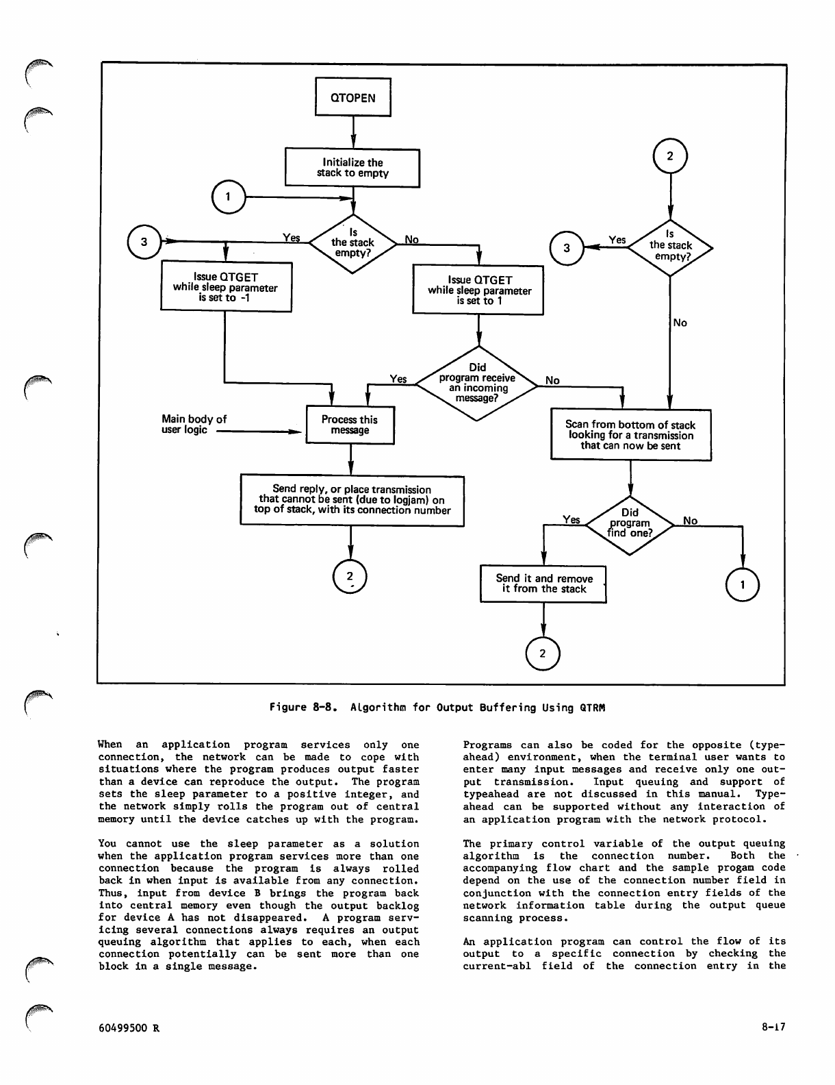
QTOPEN
O
Initialize the
stack to empty
©
Issue QTGET
while sleep parameter
is set to -1
Issue QTGET
while sleep parameter
is set to 1
G> Yes
Yes
Main body of
user logic —
Process this
message
No
Scan from bottom of stack
looking for a transmission
that can now be sent
Send reply, or place transmission
that cannot be sent (due to logjam) on
top of stack, with its connection number Yes
Send it and remove
it from the stack
Figure 8-8. Algorithm for Output Buffering Using QTRM
When an application program services only one
connection, the network can be made to cope with
situations where the program produces output faster
than a device can reproduce the output. The program
sets the sleep parameter to a positive integer, and
the network simply rolls the program out of central
memory until the device catches up with the program.
You cannot use the sleep parameter as a solution
when the application program services more than one
connection because the program is always rolled
back in when input is available from any connection.
Thus, input from device B brings the program back
into central memory even though the output backlog
for device A has not disappeared. A program serv
icing several connections always requires an output
queuing algorithm that applies to each, when each
connection potentially can be sent more than one
block in a single message.
Programs can also be coded for the opposite (type-
ahead) environment, when the terminal user wants to
enter many input messages and receive only one out
put transmission. Input queuing and support of
typeahead are not discussed in this manual. Type-
ahead can be supported without any interaction of
an application program with the network protocol.
The primary control variable of the output queuing
algorithm is the connection number. Both the
accompanying flow chart and the sample progam code
depend on the use of the connection number field in
conjunction with the connection entry fields of the
network information table during the output queue
scanning process.
An application program can control the flow of its
output to a specific connection by checking the
current-abl field of the connection entry in the
60499500 R 8-17
net work i nfor mati on tab le b efor e each QTPU T cal l
involving that connection. If the field contains a
zero, the call cannot be made without violating
network protocol; if the field does not contain a
zero, the QTPUT call can be made.
The current-abl, acknowledged-abn, and other fields
in the network information table are only updated
by QTRM during processing of a QTGET call. Tests
of these fields are not meaningful unless a QTGET
call is made before the tests. To properly control
output flow, the application program must make
periodic calls to QTGET with a positive value in the
sleep field of the network information table,
regardless of whether the program expects input
from a connection. The size of the positive value
is a tuning consideration determined by such things
as the average length of output blocks and the
speed of the device being serviced.
These QTGET calls return control to the program
after the sleep period. The program can then test
the current-abl field and make any QTPUT calls that
have become feasible. A QTPUT call is feasible
whenever the current-abl value is nonzero. If the
value is zero, another QTGET call must be made.
An application program can use two forms of output
flow control queuing. The program can actually
generate all output required as a response to one
input, then queue the output in large internal buf
fers or disk files. This queued output is then
spooled to the connection in QTPUT calls involving
one or more lines in blocks up to the max-block-size
value for the connection entry in the network
information table. The algorithm already described
is used to control the occurrence of the QTPUT
c a l l s .
Alternatively, the application program can queue
its input requests. When the flow control algorithm
described previously shows that a QTPUT call can be
made, the program can generate only enough output
f o r o n e Q T P U T c a l l . A f t e r m a k i n g t h e c a l l , a n
uncompleted input request is returned to the queue
to await additional processing the next time the
flow control algorithm permits another QTPUT call
for the connection. This approach requires a small
input queue for each connection, but does not
require large internal buffers for output storage.
The second approach minimizes field length require
ments and mass storage access requirements for the
program. Also, the program can avoid wasted output
processing when the terminal user issues a user-
b r ea k to t e r m in a t e o u t p u t a f t e r o n l y o n e o r t w o
blocks of the output have been delivered. With the
first approach, processing for the remainder of the
output has already occurred and is wasted. With
the second approach, no processing for the addi
tional output occurred and therefore the additional
processing can be bypassed.
SAMPLE PROGRAM
Figure 8-9 contains the source code listing for a
COBOL program that demonstrates use of QTRM in the
simplest form possible. Program ECH0-RMV2 is simi
lar to the FORTRAN program RMV3 shown in section
7. Both programs return to the terminal user each
block entered from the device. Both programs queue
output blocks and permit a prompting message to be
output after each returned message. Both programs
ackn o w ledge e ntry o f a user-b r eak cha r a cter w i th
dialog. Both programs shut down operation after
receiving a terminal operator command.
/*^^V
8-18 60499500 R
i^Sss\
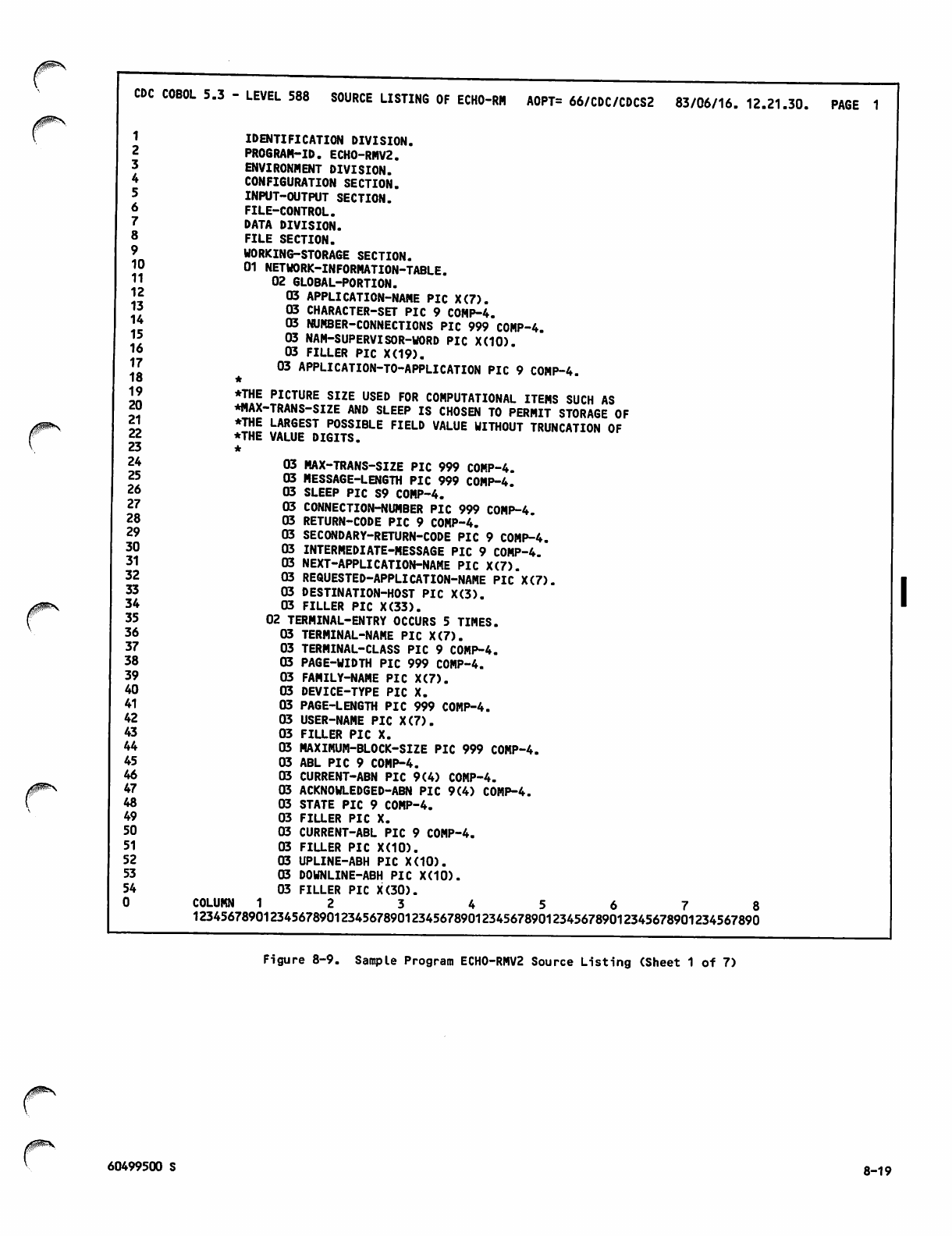
yS^N,
CDC COBOL 5.3 - LEVEL 588 SOURCE LISTING OF ECHO-RM AOPT= 66/CDC/CDCS2 83/06/16. 12.21.30. PAGE 1
1
2
3
4
5
6
7
8
9
10
11
12
13
14
15
16
17
18
19
20
21
22
23
24
25
26
27
28
29
30
31
32
33
34
35
36
37
38
39
40
41
42
43
44
45
46
47
48
49
50
51
52
53
54
0
IDENTIFICATION DIVISION.
PROGRAM-ID. ECH0-RMV2.
ENVIRONMENT DIVISION.
CONFIGURATION SECTION.
INPUT-OUTPUT SECTION.
FILE-CONTROL.
DATA DIVISION.
FILE SECTION.
WORKING-STORAGE SECTION.
01 NETWORK-INFORMATION-TABLE.
02 GLOBAL-PORTION.
03 APPLICATION-NAME PIC X(7).
03 CHARACTER-SET PIC 9 COMP-4.
03 NUMBER-CONNECTIONS PIC 999 COMP-4.
03 NAM-SUPERVISOR-WORD PIC X(10).
03 FILLER PIC X(19).
03 APPLICATION-TO-APPLICATION PIC 9 COMP-4.
•THE PICTURE SIZE USED FOR COMPUTATIONAL ITEMS SUCH AS
*MAX-TRANS-SIZE AND SLEEP IS CHOSEN TO PERMIT STORAGE OF
♦THE LARGEST POSSIBLE FIELD VALUE WITHOUT TRUNCATION OF
♦THE VALUE DIGITS. i*u«u.«nun ur
03 MAX-TRANS-SIZE PIC 999 COMP-4.
03 MESSAGE-LENGTH PIC 999 COMP-4.
03 SLEEP PIC S9 COMP-4.
03 CONNECTION-NUMBER PIC 999 COMP-4.
03 RETURN-CODE PIC 9 COMP-4.
03 SECONDARY-RETURN-CODE PIC 9 COMP-4.
03 INTERMEDIATE-MESSAGE PIC 9 COMP-4.
03 NEXT-APPLICATION-NAME PIC X(7).
03 REQUESTED-APPLICATION-NAME PIC X(7).
03 DESTINATION-HOST PIC X(3).
03 FILLER PIC X(33).
02 TERMINAL-ENTRY OCCURS 5 TIMES.
03 TERMINAL-NAME PIC X(7).
03 TERMINAL-CLASS PIC 9 COMP-4.
03 PAGE-WIDTH PIC 999 COMP-4.
FAMILY-NAME PIC X(7).
DEVICE-TYPE PIC X.
03 PAGE-LENGTH PIC 999 COMP-4.
03 USER-NAME PIC X(7).
03 FILLER PIC X.
03 MAXIMUM-BLOCK-SIZE PIC 999 COMP-4.
03 ABL PIC 9 COMP-4.
03 CURRENT-ABN PIC 9(4) COMP-4.
03 ACKNOWLEDGED-ABN PIC 9(4) COMP-4.
03 STATE PIC 9 COMP-4.
03 FILLER PIC X.
03 CURRENT-ABL PIC 9 COMP-4.
03 FILLER PIC X(10).
UPLINE-ABH PIC X(10).
03
03
03
03 DOWNLINE-ABH PIC X(10).
03 FILLER PIC X(30).
C O L U M N 1 2 3 4 5 6 7 8
12345678901234567890123456789012345678901234567890123456789012345678901234567890
Figure 8-9. Sample Program ECH0-RMV2 Source Listing (Sheet 1 of 7)
/3$!<sS*v
60499500 S 8-19
CDC COBOL 5.3 - LEVEL 588 SOURCE LISTING OF ECHO-RM AOPT= 66/CDC/CDCS2 83/06/16. 12.21.30. PAGE 2
55 01 INCOMING.
56 02 COMMAND PIC X(20).
57 02 REST-OF-DATA PIC X(80).
58 01 OUTGOING.
5 9 0 2 P R I N T - C O N T R O L P I C X .
60 02 OUT-MESSAGE PIC X(140).
61 01 FOUND-FLAG PIC 9.
62 01 QUEUE-SIZE PIC 99.
6 3 0 1 H O L D I N G - Q U E U E .
6 4 ♦
65 *THIS IS A PUSHDOWN QUEUE USED FOR STORAGE OF THOSE
66 ♦OUTPUT BLOCKS THE PROGRAM IS TEMPORARILY PREVENTED FROM SENDING
67 *10 THE TERMINAL BECAUSE OF BLOCK LIMIT OR OTHER EVENTS IN THE
6 8 ♦NETWORK.
6 9 *
70 02 QUEUE-ENTRY OCCURS 1 TO 60 TIMES DEPENDING ON QUEUE-SIZE
71 INDEXED BY INX-1 INX-2.
72 03 S-CONNECTION-NUMBER PIC 999 COMP-4.
73 03 S-MESSAGE PIC X(140).
74 03 S-INTERMEDIATE-MESSAGE PIC 9 COMP-4.
75
76
77
78 PROCEDURE DIVISION.
79
80
81 INITIALIZATION.
8 2 ♦
83 *HERE, THE NETWORK INFORMATION TABLE IS PRESET.
8 4 ♦
85 MOVE "RMV2" TO APPLICATION-NAME.
86 MOVE 4 TO CHARACTER-SET.
87 MOVE 120 TO MAX-TRANS-SIZE.
8 8 ♦
89 ♦THE FORMAT EFFECTOR CHARACTER "." CAUSES THE CURSOR TO
90 ^RETURN TO THE LEFT EDGE OF THE SCREEN OR PAGE
91 ♦FOLLOWING THE CONTENTS OF OUT-MESSAGE. THIS ACTION
92 ♦LEAVES THE CURSOR POSITIONED SO THAT THE USER CAN ENTER
93 *A LINE EQUAL TO THE FULL PAGE WIDTH OF THE TERMINAL.
9 4 ♦
95
96 MOVE "." TO PRINT-CONTROL.
9 7 M O V E S PA C E S TO O U T- M E S S A G E .
98 MOVE SPACES TO INCOMING.
99 MOVE 5 TO NUMBER-CONNECTIONS.
1 0 0 M O V E - 1 T O S L E E P .
101 MOVE 1 TO INTERMEDIATE-MESSAGE.
1 0 2 M O V E 0 T O Q U E U E - S I Z E .
103 MOVE 0 TO APPLICATION-TO-APPLICATION.
104 MOVE 0 TO FOUND-FLAG.
105 ENTER FORTRAN-X QTOPEN USING NETWORK-INFORMATION-TABLE.
106
1 0 7 ♦
108 ♦ALL TERMINALS WILL BE SWITCHED AUTOMATICALLY TO IAF
C O L U M N 1 2 3 4 5 6 7 8
12345678901234567890123456789012345678901234567890123456789012345678901234567890
Figure 8-9. Sample Program ECH0-RMV2 Source Listing (Sheet 2 of 7)
8-20 60499500 R
CDC COBOL 5.3 - LEVEL 588 SOURCE LISTING OF ECHO-RM AOPT= 66/CDC/CDCS2 83/06/16. 12.21.30, PAGE 3
109
110
111
112
113
114
115
116
117
118
119
120
121
122
123
124
125
126
127
128
129
130
131
132
133
134
135
136
137
138
139
140
141
142
143
144
145
146
147
148
149
150
151
152
153
154
155
156
157
158
159
160
161
162
♦WHEN THEY ARE DISCONNECTED FROM THIS PROGRAM.
*
MOVE "IAF" TO NEXT-APPLICATION-NAME.
MAIN-LOOP.
PERFORM RECEIVER THRU RECEIVE-EXIT.
IF STATE (CONNECTION-NUMBER) = 1
GO TO MAIN-LOOP.
IF RETURN-CODE = 2
MOVE 0 TO INTERMEDIATE-MESSAGE
PERFORM DISPLAY-BANNER THRU BANNER-EXIT
GO TO MAIN-LOOP.
IF RETURN-CODE = 4
PERFORM PUSH-DOWN-QUEUE
GO TO MAIN-LOOP.
IF RETURN-CODE = 6
PERFORM CONNECTION-BROKEN-ROUTINE THRU CB-EXIT
GO TO MAIN-LOOP.
IF RETURN-CODE = 7 OR = 8
PERFORM FLUSH-QUEUE
MOVE 0 TO INTERMEDIATE-MESSAGE
MOVE "." TO PRINT-CONTROL
MOVE "NO ACTION TAKEN. NEXT ENTRY?" TO OUT-MESSAGE
PERFORM SENDER THRU SEND-EXIT
GO TO MAIN-LOOP.
IF RETURN-CODE = 9
GO TO WRAP-UP.
*
♦TO SIMPLIFY THE PROGRAM, ONLY EXPECTED CONDITIONS ARE PROCESSED
♦BY THE PRECEDING CODE. ALL OTHER CONDITIONS CAUSE THE PROGRAM
♦TO PLACE A DIAGNOSTIC MESSAGE IN THE FILE CALLED OUTPUT (WITH
♦THE DISPLAY STATEMENT) AND SHUT DOWN. NO DIAGNOSTIC APPEARS AT
♦THE TERMINAL.
RETURN-CODE
IF RETURN-CODE NOT = 0
DISPLAY "PROGRAM BUG OR OTHER ERROR'
SECONDARY-RETURN-CODE STOP RUN.
MOVE "." TO PRINT-CONTROL.
*
♦IF A TERMINAL USER ENTERS THE WORD END, THE USER IS
♦DISCONNECTED BUT THE PROGRAM CONTINUES TO SERVICE OTHER
♦TERMINALS.
*
IF COMMAND = "END"
PERFORM END-CONNECTION THRU EC-EXIT
GO TO MAIN-LOOP.
*
♦IF A TERMINAL USER ENTERS THE WORD
♦DISCONNECTED AND THE PROGRAM SHUTS
*
IF COMMAND = "SHUTDOWN"
SHUTDOWN, THE USER IS
DOWN.
C O L U M N 1 2 3 4 5 6 7 8
12345678901234567890123456789012345678901234567890123456789012345678901234567890
Figure 8-9. Sample Program ECH0-RMV2 Source Listing (Sheet 3 of 7)
/0^K
60499500 R 8-21
CDC COBOL 5.3 - LEVEL 588 SOURCE LISTING OF ECHO-RM AOPT= 66/CDC/CDCS2 83/06/16. 12.21.30. PAGE 4
163
164
165
166
167
168
169
170
171
172
173
174
175
176
177
178
179
180
181
182
183
184
185
186
187
188
189
190
191
192
193
194
195
196
197
198
199
200
201
202
203
204
205
206
207
208
209
210
211
212
213
214
215
216
MOVE 0 TO INTERMEDIATE-MESSAGE
MOVE "." TO PRINT-CONTROL
MOVE "BYE FOREVER!" TO OUT-MESSAGE
PERFORM SENDER THRU SEND-EXIT
GO TO WRAP-UP.
♦THE FOLLOWING CODE BEGINS THE INPUT-ECHOING PORTION
♦OF THIS PROGRAM.
*
MOVE INCOMING TO OUT-MESSAGE
MOVE 1 TO INTERMEDIATE-MESSAGE
MOVE "." TO PRINT-CONTROL
PERFORM SENDER THRU SEND-EXIT
*
♦SEND PROMPT FOR NEXT LINE, WHICH ALSO ENDS PRESENT OUTPUT
♦MESSAGE TO THIS TERMINAL.
*
MOVE 0 TO INTERMEDIATE-MESSAGE
MOVE "." TO PRINT-CONTROL
MOVE "NEXT ENTRY?" TO OUT-MESSAGE
PERFORM SENDER THRU SEND-EXIT
GO TO MAIN-LOOP.
*
♦THIS ENDS THE MAIN PROGRAM PORTION OF ECH0-RMV2. THE FOLLOWING
♦PARAGRAPHS COMPRISE THE SUBROUTINES USED BY THE MAIN PROGRAM.
RECEIVER.
IF QUEUE-SIZE = 0
MOVE -1 TO SLEEP
*
♦THE NEXT LINE PREVENTS LEFTOVER CHARACTERS FROM THE END OF THE
♦LAST INPUT LINE FROM BEING INCLUDED IN THE TRANSFER OF THE
♦CURRENT (AND PRESUMABLY SHORTER) LINE.
*
MOVE SPACES TO INCOMING
ENTER FORTRAN-X QTGET USING INCOMING
GO TO RECEIVE-EXIT.
MOVE 1 TO SLEEP
MOVE SPACES TO INCOMING
ENTER FORTRAN-X QTGET USING INCOMING.
IF RETURN-CODE NOT = 1
GO TO RECEIVE-EXIT
ELSE NEXT SENTENCE.
QUEUE-OUTPUT-CODE.
MOVE 0 TO FOUND-FLAG.
PERFORM QUEUE-SCAN VARYING INX-1 FROM 1 BY 1
UNTIL FOUND-FLAG = 1 OR INX-1 EXCEEDS QUEUE-SIZE.
IF FOUND-FLAG - 0
GO TO RECEIVER
ELSE NEXT SENTENCE.
SET INX-1 DOWN BY 1.
C O L U M N 1 2 3 4 5 6 7 8
12345678901234567890123456789012345678901234567890123456789012345678901234567890
/*^?\
Figure 8-9. Sample Program ECH0-RMV2 Source Listing (Sheet 4 of 7)
^<^\
8-22 60499500 R
/SS^K
CDC COBOL 5.3 - LEVEL 588 SOURCE LISTING OF ECHO-RM AOPT= 66/CDC/CDCS2 83/06/16. 12.21.30.
PAGE 5
217
218
219
220
221
222
223
224
225
226
227
228
229
230
231
232
233
234
235
236
237
238
239
240
241
242
243
244
245
246
247
248
249
250
251
252
253
254
255
256
257
258
259
260
261
262
263
264
265
266
267
268
269
270
♦THE REMAINING CODE ATTEMPTS TO REMOVE ALL
ISS^oSISTJI0"THE 0UTPUT QUEUE' 0NE ENTRY AT A
♦TIME, REGARDLESS OF CONNECTION NUMBER. EACH SEND
♦OPERATION IS FOLLOWED BY A RETURN TO THE POINT IN
♦THE PROGRAM WHERE STATUS UPDATES ARE OBTAINED.
SS rj«I^!!EI>IATE"MESSAGE (INX"1) T0 INTERMEDIATE-MESSAGE.
MOVE S-CONNECTION-NUMBER (INX-1) TO CONNECTION-NUMBER
Move™!: «ONNEC"ON-NUMBER) = 3 GO TO RECE Se-EXu! *
MOVE "." TO PRINT-CONTROL.
MOVE S-MESSAGE (INX-1) TO OUT-MESSAGE
PERFORM QUEUE-COMPRESSION VARYING INX-2 FROM INX-1 BY 1
UNTIL INX-2 = QUEUE-SIZE.
SUBTRACT 1 FROM QUEUE-SIZE.
PERFORM SENDER THRU SEND-EXIT.
IF QUEUE-SIZE = 0
GO TO RECEIVER
ELSE GO TO QUEUE-OUTPUT-CODE.
RECEIVE-EXIT.
EXIT.
QUEUE-SCAN.
MOVE S-CONNECTION-NUMBER (INX-1) TO CONNECTION-NUMBER
IF CURRENT-ABL (CONNECTION-NUMBER) EXCEEDS 0
MOVE 1 TO FOUND-FLAG.
QUEUE-COMPRESSION.
MOVE QUEUE-ENTRY (INX-2 + 1) TO QUEUE-ENTRY (INX-2).
FLUSH-QUEUE.
SET INX-1 INX-2 TO 1.
PERFORM FLUSH-LOOP UNTIL INX-2 EXCEEDS QUEUE-SIZE.
SET INX-1 DOWN BY 1.
SET QUEUE-SIZE TO INX-1.
FLUSH-LOOP.
IF S-CONNECTION-NUMBER (INX-1) = CONNECTION-NUMBER
SET INX-2 UP BY 1
ELSE
PERFORM CONDITIONAL-QUEUE-MOVE
SET INX-1 INX-2 UP BY 1.
CONDITIONAL-QUEUE-MOVE.
IF INX-1 NOT = INX-2
MOVE QUEUE-ENTRY (INX-2) TO QUEUE-ENTRY (INX-1).
SENDER.
IF CURRENT-ABL (CONNECTION-NUMBER) = 0
PERFORM PUSH-DOWN-QUEUE GO TO SEND-EXIT.
♦THE PROGRAM HAS QTRM SCAN BACKWARDS THROUGH THE MESSAGE
♦AREA AND TRUNCATE THE MESSAGE AUTOMATICALLY. THIS PROCEDURE
C O L U M N 1 2 3 4 5 6 7 8
12345678901234567890123456789012345678901234567890123456789012345678901234567890
Figure 8-9. Sample Program ECH0-RMV2 Source Listing (Sheet 5 of 7)
60499500 R 8-23
CDC COBOL 5.3 - LEVEL 588 SOURCE LISTING OF ECHO-RM AOPT= 66/CDC/CDCS2 83/06/16.12.21.30. PAGE 6
271
272
273
274
275
276
277
278
279
280
281
282
283
284
285
286
287
288
289
290
291
292
293
294
295
296
297
298
299
300
301
302
303
304
305
306
307
308
309
310
311
312
313
314
315
316
317
318
319
320
321
322
323
324
♦IS COMPARABLE TO THE ONE USED BY CYBER RECORD MANAGER FOR
♦Z-TYPE RECORDS.
*
MOVE 0 TO MESSAGE-LENGTH.
ENTER FORTRAN-X QTPUT USING OUTGOING.
*
♦IF NAM HAS STOPPED OUTPUT ON THE CONNECTION TEMPORARILY, OR IF
♦THE BLOCK LIMIT HAS BEEN EXCEEDED (AN EVENT THAT SHOULD NOT
♦HAPPEN) FOR THE CONNECTION, THE MESSAGE IS RETURNED TO THE
♦QUEUE FOR A LATER TRY.
*
IF RETURN-CODE = 5 PERFORM PUSH-DOWN-QUEUE.
SEND-EXIT.
EXIT.
PUSH-DOWN-QUEUE.
ADD 1 TO QUEUE-SIZE.
IF QUEUE-SIZE EXCEEDS 60 DISPLAY "QUEUE OVERFLOW ABORT"
PERFORM DUMPER VARYING INX-1 FROM 1 BY 1
UNTIL INX-1 EXCEEDS 60
STOP RUN.
MOVE INTERMEDIATE-MESSAGE TO S-INTERMEDIATE-MESSAGE
(QUEUE-SIZE).
MOVE CONNECTION-NUMBER TO S-CONNECTION-NUMBER (QUEUE-SIZE),
MOVE OUT-MESSAGE TO S-MESSAGE (QUEUE-SIZE).
♦THE FOLLOWING PROMPT IS MANDATORY, BECAUSE QTRM DOES NOT
♦AUTOMATICALLY ISSUE A PROMPT TO A NEW
♦CONNECTION TO INITIALIZE THAT CONNECTION. THE FOLLOWING
♦PROMPT IS SENT BECAUSE GOOD PROGRAMMING PRACTICE
♦REQUIRES A NETWORK APPLICATION PROGRAM TO IDENTIFY ITSELF
♦TO A TERMINAL USER.
*
DISPLAY-BANNER.
MOVE "." TO PRINT-CONTROL.
MOVE "THIS IS RMV2 USING QTRM. ENTER SOMETHING." TO
OUT-MESSAGE.
PERFORM SENDER THRU SEND-EXIT.
BANNER-EXIT.
EXIT.
♦NO CALL TO QTENDT IS NECESSARY DURING THIS PROCESSING BRANCH,
♦BECAUSE QTRM AUTOMATICALLY CLEANS UP THE CONNECTION WHEN IT
♦RETURNS THE CONNECTION-BROKEN STATUS.
*
CONNECTION-BROKEN-ROUTINE.
DISPLAY "CONNECTION BROKEN - TERMINAL USER HUNG UP "
CONNECTION-NUMBER
DISPLAY " FAMILY " FAMILY-NAME (CONNECTION-NUMBER)
C O L U M N 1 2 3 4 5 6 7 8
12345678901234567890123456789012345678901234567890123456789012345678901234567890
/'*a%.
Figure 8-9. Sample Program ECH0-RMV2 Source Listing (Sheet 6 of 7)
yf^Sij^Sy
8-24 60499500 R
CDC COBOL 5.3 - LEVEL 588 SOURCE LISTING OF ECHO-RM AOPT= 66/CDC/CDCS2 83/06/16. 12.21.30. PAGE 7
325
326
327
328
329
330
331
332
333
334
335
336
337
338
339
340
341
342
343
344
345
346
347
348
349
350
351
352
353
354
355
356
357
358
359
360
361
362
363
364
365
366
367
368
ro rSJfLAY " USER " USER-NAME (CONNECTION-NUMBER).
CB—EXIT.
EXIT.
♦THE WAIT-FOR-QUIET CALLS PROVIDE A DELAY LOOP FOR THE
t™I«!r ™ !;LEAN UP ALL OUTSTANDING SUPERVISORY MESSAGE
♦TRAFFIC RELATED TO THE SHUTDOWN. WITHOUT THIS LOOP
♦SOME TERMINAL CONNECTIONS WOULD RECEIVE AN '
♦"APPLICATION FAILED" MESSAGE.
*
WRAP-UP.
PERFORM GRACEFUL-DISCONNECTS THRU GD-EXIT VARYING
CONNECTION-NUMBER
FROM 1 BY 1 UNTIL CONNECTION-NUMBER = 6.
ENTER FORTRAN-X QTCLOSE.
STOP RUN.
GRACEFUL-DISCONNECTS.
IF STATE (CONNECTION-NUMBER) = 2 PERFORM FLUSH-QUEUE
MOVE 0 TO INTERMEDIATE-MESSAGE
MOVE "." TO PRINT-CONTROL
MOVE "SHUTDOWN COMING" TO OUT-MESSAGE
PERFORM SENDER THRU SEND-EXIT
ENTER FORTRAN-X QTENDT.
GD-EXIT.
EXIT.
END-CONNECTION.
PERFORM FLUSH-QUEUE
MOVE 0 TO INTERMEDIATE-MESSAGE
MOVE "." TO PRINT-CONTROL
MOVE "GOODBYE FOR NOW.." TO OUT-MESSAGE.
PERFORM SENDER THRU SEND-EXIT.
ENTER FORTRAN-X QTENDT.
EC-EXIT.
EXIT.
DUMPER.
DISPLAY S-CONNECTION-NUMBER (INX-1)
S-MESSAGE (INX-1).
C O L U M N 1 2 3 4 5 6 7 8
12345678901234567890123456789012345678901234567890123456789012345678901234567890
Figure 8-9. Sample Program ECH0-RMV2 Source Listing (Sheet 7 of 7)
Figure 8-10 shows the commands used to execute
ECH0-RMV2. ECH0-RMV2 exists as a direct access
source code file named RMV2.
Figure 8-11 contains a complete debug log file
listing for a single execution of ECHO-RMV2. This
log file is very similar to the one shown in sec
tion 7 for program RMV3 because both programs use
essentially the same AIP routines for the same
functions and support the same kind of dialog.
Figure 8-12 contains a statistics file listing for
ECHO-RMV2.
Figure 8-13 is a console printer listing for two
sequential connections using ECHO-RMV2 during a
single execution of that program. The listing
includes program-generated messages and a console
input message that is echoed back.
ATTACH,RMV2.
COBOL5,I=RMV2.
LDSET(LIB=NETIOD)
LGO.
REWIND,ZZZZZSN.
COPY,ZZZZZSN.
DLFP(1=0)
COPY,INPUT,QTRMEXP.
REWIND,QTRMEXP.
SAVE,QTRMEXP.
Figure 8-10. ECH0-RMV2 Job Commands
60499500 R 8-25
RMV2 LOG FILE OUTPUT
DATE RECORDED - 83/06/16
12.21.41.000 NETON (004750) ANAME = RMV2
NSUP ADDR = 001507 MINACN =00001 MAXACN =00005
DATE = 83/06/16
CONREQ
T1223 E X UW-4P
GB
H'PK
xxxxx Q M B ca
xxxxxxx & 16A 7
r trt/0/
4 E MDXMFI WS D3Q
12.21.41.039 NETPUT (006634) HA =003451 TA =003501
ABT =03 ADR =0000 ABN =000000 ACT =01 STATUS = 00000000 TLC = 0001
001 C20100000000000 60400400000000000000 DCTRU B
12.22.16.257 NETGET (006312) ACN =0000 HA =003451 TA =003501 TLMAX =0063
ABT =03 ADR =0000 ABN =000000 ACT =01 STATUS = 00000000 TLC = 0011
001 630000001400200 30600000000120001000
002 51C75D7ADB45018 24343535365555050030
003 0000000000001C2 00000000000000000702
004 00000000023840B 00000000000010702013
005 xxxxxxx6DB40011 xxxxxxxxxx55550O0021
006 xxxxxxxEl880037 xxxxxxxxxxxx42Q00067
007 000FF8FFFFFFFFF 00007770777777777777
008 FFF3400001FFFFF 77771500000007777777
009 000000000000F6F 00000000000000007557
010 7C014034460D189 37000500150430150611
12.22.16.257 NETPUT (006634) HA =003451 TA =003501
ABT =03 ADR =0000 ABN =000000 ACT =01 STATUS = 00000000 TLC = 0001
001 634000001400101 30640000000120000401 CONREQN CB
12.22.16.352 NETGET (006312) ACN =0000 HA =003451 TA =003501 TLMAX =0063
ABT =03 ADR =0000 ABN =000000 ACT =01 STATUS = 00000000 TLC = 0001
001 830700001000000 40603400000100000000 FCINIT
12.22.16.352 NETPUT (006634) HA =003451 TA =003501
ABT =03 ADR =0000 ABN =000000 ACT =01 STATUS = 00000000 TLC = 0001
001 834700001000000 40643400000100000000 FCINITN G
12.22.16.353 NETPUT (006634) HA =003451 TA =001614
ABT =02 ADR =0001 ABN =000001 ACT =04 STATUS = 00000000 TLC = 0050
001 BD42094ED253B52 57241011235511235522 .THIS IS R =B NRS5
002 35676D55324E1ED 15263555252311160755 MV2 USING #VVUS$AM
003 45448DBED14E505 21242215575505162405 QTRM. ENTE ED >QNP
004 4AD4CF34550824E 22552317150524101116 R SOMETHIN T-LSEP N
005 1EF000000000000 07570000000000000000 G. P
83/06/16
PAGE 00001
MSG NO. 000001
MSG NO. 000002
MSG NO. 000003
MSG NO. 000004
MSG NO. 000005
MSG NO. 000006
MSG NO. 000007
. X f fl ^ y
Figure 8-11. Debug Log File Listing for ECH0-RMV2 (Sheet 1 of 11)
8-26
^&e$\
60499500 R
1 RMV2 LOG FILE OUTPUT
DATE RECORDED - 83/06/16
J
1AR?2:n$,7IL nnnn NETGET (006312> ACN =0000 HA =003451 TA =003501 TLMAX =0063
ABT =03 ADR =0000 ABN =000000 ACT =01 STATUS = OOOOOOnn Tir-nr.ni
001 830200001000040 40601000000100000100 FCACK "
1«?'n?*4lL nnn. UBTGEJL (006326) ALN =0001 HA =003451 TA =001602 TLMAX =0012
nn, cIS? =00°1 ABN =00000° ACT =04 STATUS = 00000000 TLC = 0047
001 50816D385614B43 24100555160530245503 THE NEXT CP M8V I
002 2014810D4152B49 10012201032405225511 HARACTM I
S™ t"°6D553152982 23550155252305224602 S A USER-B
nnt 4?504B99DB43201 22050113463555031001 REAK-2 CHA
005 4810D4152BC0000 22010324052257000000 RACTER.
83/06/16
PAGE 00002
MSG NO. 000008
MSG NO. 000009
2 H T +1
NPMU1R
$ 9 42
H T +a
1?^3'1?'412 NETPUT (0°6634) HA =003451 TA =001614
ABT =01 ADR =0001 ABN =000002 ACT =04 STATUS = 00000000 TLC = 0050 MSG NO. 000010
001 BD4205B4E15852D 57241005551605302455 .THE NEXT
002 0C80520435054AD 03100122010324052255 CHARACTER
003 253B41B554C54A6 11235501552523052246 IS A USER
S' 2!2;!412E676I)0C8 02220501134635550310 BREAK-2 CH
005 0520435054AF000 01220103240522570000 ARACTER.
=B 4AXR
PH CPT-
X;A5TEJ
B FVPH
CPT/
12.23.18.413 NETPUT (006634) HA =003451 TA =001614
ABT =02 ADR =0001 ABN =000003 ACT =04 STATUS = 00000000 TLC = 0020
SrS fJSSSSISSl? 57160530245505162422 .NEXT ENTR <AXRQNQ
002 679000000000000 31710000000000000000 Y? 8Y
12.23.18.934 NETGET (006312) ACN =0000 HA =003451 TA =003501 TLMAX =0063
ABT =03 ADR =0000 ABN =000000 ACT =01 STATUS = 00000000 TLC = 0001
001 830200001000080 40601000000100000200 FCACK
12.23.18.934 NETGET (006312) ACN =0000 HA =003451 TA =003501 TLMAX =0063
ABT =03 ADR =0000 ABN =000000 ACT =01 STATUS = 00000000 TLC = 0001
001 830200001OOOOCO 40601000000100000300 FCACK
12.23.27.818 NETGET (006312) ACN =0000 HA =003451 TA =003501 TLMAX =0063
ABT =03 ADR =0000 ABN =000000 ACT =01 STATUS = 00000000 TLC = 0001
001 800004001000000 40000004000100000000 INTRUSR
12.23.27.818 NETPUT (006634) HA =003451 TA =003501
ABT =03 ADR =0000 ABN =000000 ACT =01 STATUS = 00000000 TLC = 0001
MSG NO. 000011
MSG NO. 000012
MSG NO. 000013
MSG NO. 000014
MSG NO. 000015
Figure 8-11. Debug Log File Listing for ECH0-RMV2 (Sheet 2 of 11)
60499500 R 8-27
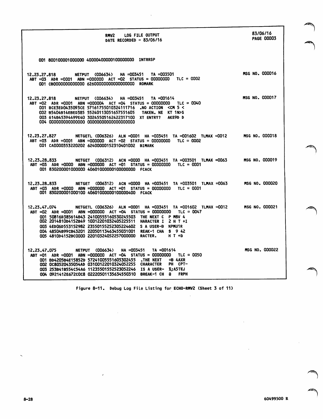
RMV2 LOG FILE OUTPUT
DATE RECORDED - 83/06/16
001 800100001000000 40000400000100000000 INTRRSP
12.23.27.818 NETPUT (006634) HA =003451 TA =003501
ABT =03 ADR =0001 ABN =000000 ACT =02 STATUS = 00000000 TLC = 0002
001 CBOOOOOOOOOOOOO 62600000000000000000 ROMARK
12.23.27.818 NETPUT (006634) HA =003451 TA =001614
ABT =02 ADR =0001 ABN =000004 ACT =04 STATUS = 00000000 TLC = 0040
001 BCE3ED0435093CE 57161755010324111716 .NO ACTION <CM 5 <
002 B5404B14EBED385 55240113051657551605 TAKEN. NE KT 1N>S
003 614B45394499E40 30245505162422317100 XT ENTRY? AKE9D D
004 000000000000000 OOOOOOOOOOOOOOOOOOOO
12.23.27.827 NETGETL (006326) ALN =0001 HA =003451 TA =001602 TLMAX =0012
ABT =03 ADR =0001 ABN =000000 ACT =02 STATUS = 00000000 TLC = 0002
001 CA0000353220202 62400000152310401002 BIMARK
12.23.28.833 NETGET (006312) ACN =0000 HA =003451 TA =003501 TLMAX =0063
ABT =03 ADR =0000 ABN =000000 ACT =01 STATUS = 00000000 TLC = 0001
001 830200001000000 40601000000100000000 FCACK
83/06/16
PAGE 00003
MSG NO. 000016
MSG NO. 000017
MSG NO. 000018
MSG NO. 000019
/■^®^y
12.23.28.833 NETGET (006312) ACN =0000 HA =003451 TA =003501 TLMAX =0063
ABT =03 ADR =0000 ABN =000000 ACT =01 STATUS = 00000000 TLC = 0001
001 830200001000100 40601000000100000400 FCACK
12.23.47.074 NETGETL (006326) ALN =0001 HA =003451 TA =001602 TLMAX =0012
MSG NO. 000020
MSG NO. 000021
ABT =02 ADR =0001 ABN -OOOOOO ACT =04 STATUS = 00000000 TLC = 0047
001 50816D385614B43 24100555160530245503 THE NEXT C P M8V 4
002 2014810D4152B49 10012201032405225511 HARACTER I 2HT+I
003 4ED06D553152982 23550155252305224602 S A USER-B NPMU1R
004 48504B99CB43201 22050113463455031001 REAK-1 CHA $ 9 42
005 4810D4152BC0000 22010324052257000000 RACTER. H T +a
12.23.47.075 NETPUT (006634) HA =003451 TA =001614
ABT =01 ADR =0001 ABN =000000 ACT =04 STATUS = 00000000 TLC = 0050
001 BD4205B4E15852D 57241005551605302455 .THE NEXT =8 4AXR
002 0C80520435054AD 03100122010324052255 CHARACTER PH CPT-
003 253B41B554C54A6 11235501552523052246 IS A USER- X;A5TEJ
004 0921412E672C0C8 02220501135634550310 BREAK-1 CH a FRPH
MSG NO. 000022
Figure 8-11. Debug Log File Listing for ECH0-RMV2 (Sheet 3 of 11)
8-28 60499500 R
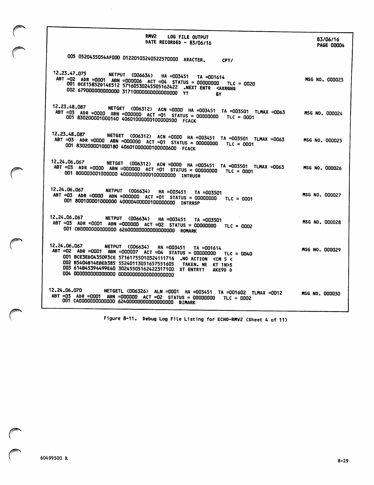
RHV2 LOG FILE OUTPUT
DATE RECORDED - 83/06/16
005 0520435054AF000 01220103240522570000 ARACTER. CPT/
n^?'^'°lL nnn« NETPUT C006634) HA =003451 TA =001614
i :iS£ ISSrl"r"« ■ -
'"is Haas "s"-^™ «■s ™™"' sss. 'vr.'Sk,'1™ -»
001 830200001000180 40601000000100000600 FCACK
1^|-°^ =0000 ,SKIafigs,ST ^ 1?A°?US- SSSSSo "t^oo,™* ^3
001 800003001000000 40000003000100000000 INTRUSR '
1?p?4'n^'°»L nnnn NETPUT <006634> HA =003451 TA =003501
ABT =03 ADR =0000 ABN =000000 ACT =01 STATUS = 00000000 ti r - nnni
001 800100001000000 40000400000100000000 INTRRSP " °1
1?:?4,!£-067 NETPUT ^006634) HA =003451 TA =003501
ABT =03 ADR =0001 ABN =000000 ACT =02 STATUS = 00000000 TLC = 0002
001 CBOOO00O00OOO00 62600000000000000000 ROMARK
1?^4'K*0?7 NETPUT <006634) HA =003451 TA =001614
ABT =02 ADR =0001 ABN =000007 ACT =04 STATUS = 00000000 TLC = 0040
001 BCE3ED0435O93CE 57161755010324111716 .NO ACTION <CM 5 <
002 B5404B14EBED385 55240113051657551605 TAKEN. NE KT 1N>S
003 614B45394499E40 30245505162422317100 XT ENTRY? AKE9D D
004 000000000000000 oooooooooooooooooooo
12.24.06.070 NETGETL (006326) ALN =0001 HA =003451 TA =001602 TLMAX =0012
ABT ™3 *ASJL«2P£L mH =000000 ACT =02 STATUS = 00000000 TLC = 0002
001 CAOOOOOOOOOOOOO 62400000000000000000 BIMARK
83/06/16
PAGE 00004
MSG NO. 000023
MSG NO. 000024
MSG NO. 000025
MSG NO. 000026
MSG NO. 000027
MSG NO. 000028
MSG NO. 000029
MSG NO. 000030
Figure 8-11. Debug Log File Listing for ECH0-RMV2 (Sheet 4 of 11)
j0^\
60499500 R 8-29
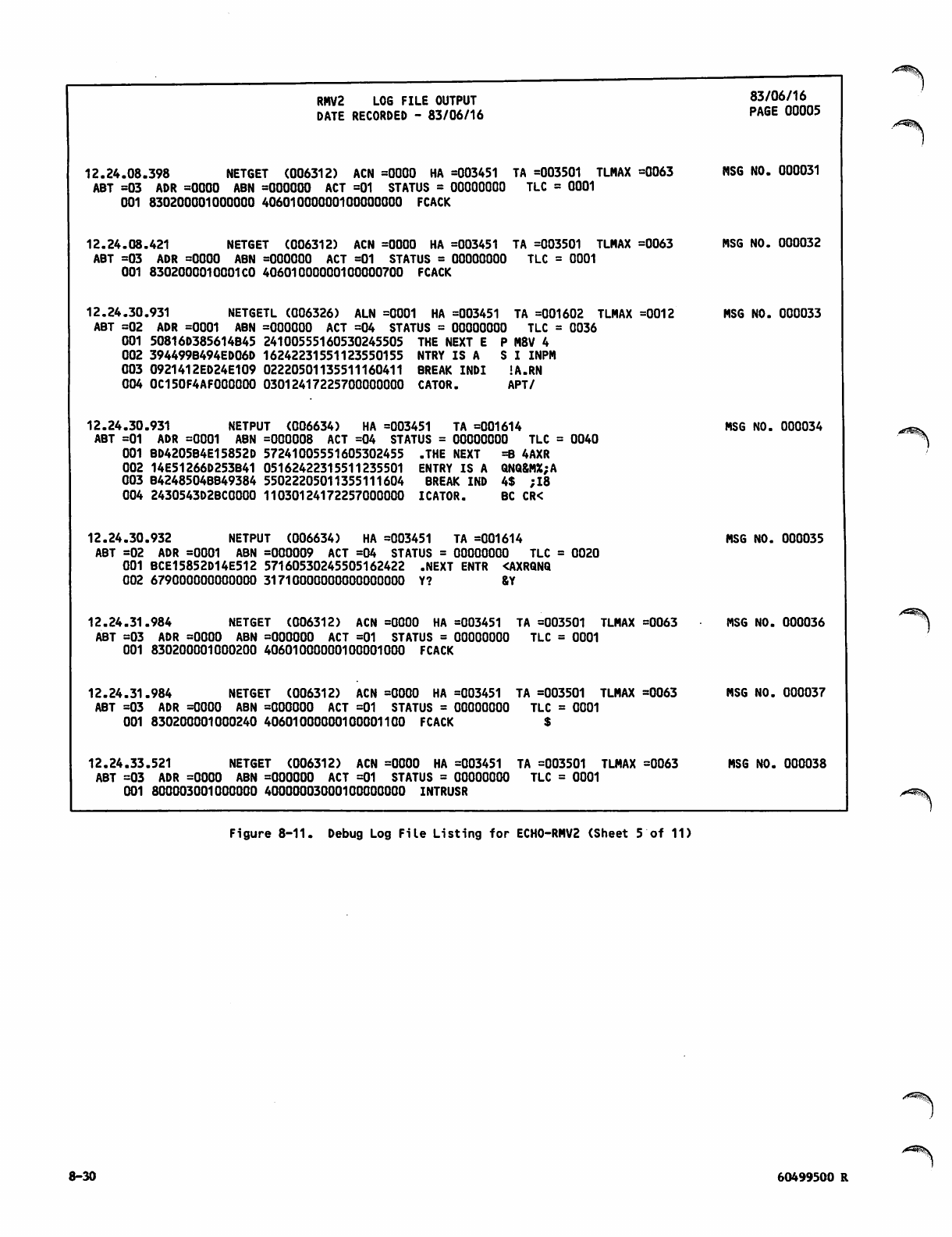
RMV2 LOG FILE OUTPUT
DATE RECORDED - 83/06/16
12.24.08.398 NETGET (006312) ACN =0000 HA =003451 TA =003501 TLMAX =0063
ABT =03 ADR =0000 ABN =000000 ACT =01 STATUS = 00000000 TLC = 0001
001 830200001000000 40601000000100000000 FCACK
12.24.08.421 NETGET (006312) ACN =0000 HA =003451 TA =003501 TLMAX =0063
ABT =03 ADR =0000 ABN =000000 ACT =01 STATUS = 00000000 TLC = 0001
001 8302000010001CO 40601000000100000700 FCACK
12.24.30.931 NETGETL (006326) ALN =0001 HA =003451 TA =001602 TLMAX =0012
ABT =02 ADR =0001 ABN =000000 ACT =04 STATUS = 00000000 TLC = 0036
001 50816D385614B45 24100555160530245505 THE NEXT E P M8V 4
002 394499B494ED06D 16242231551123550155 NTRY IS A SI INPM
003 0921412ED24E109 02220501135511160411 BREAK INDI !A.RN
004 0C15OF4AFO000O0 03012417225700000000 CATOR. APT/
12.24.30.931 NETPUT (006634) HA =003451 TA =001614
ABT =01 ADR =0001 ABN =000008 ACT =04 STATUS = 00000000 TLC = 0040
001 BD4205B4E15852D 57241005551605302455 .THE NEXT =B 4AXR
002 14E51266D253B41 05162422315511235501 ENTRY IS A QNQ&MX;A
Q03 B4248504BB49384 55022205011355111604 BREAK IND 4$ ;I8
004 2430543D2BC0000 11030124172257000000 ICATOR. BC CR<
83/06/16
PAGE 00005
MSG NO. 000031
MSG NO. 000032
MSG NO. 000033
MSG NO. 000034
12.24.30.932 NETPUT (006634) HA =003451 TA =001614
ABT =02 ADR =0001 ABN =000009 ACT =04 STATUS = 00000000 TLC = 0020
001 BCE15852D14E512 57160530245505162422 .NEXT ENTR <AXRQNQ
002 679000000000000 31710000000000000000 Y? &Y
12.24.31.984 NETGET (006312) ACN =0000 HA =003451 TA =003501 TLMAX =0063
ABT =03 ADR =0000 ABN =000000 ACT =01 STATUS = 00000000 TLC = 0001
001 830200001000200 40601000000100001000 FCACK
12.24.31.984 NETGET (006312) ACN =0000 HA =003451 TA =003501 TLMAX =0063
ABT =03 ADR =0000 ABN =000000 ACT =01 STATUS = 00000000 TLC = 0001
001 830200001000240 40601000000100001100 FCACK $
12.24.33.521 NETGET (006312) ACN =0000 HA =003451 TA =003501 TLMAX =0063
ABT =03 ADR =0000 ABN =000000 ACT =01 STATUS = 00000000 TLC = 0001
001 800003001000000 40000003000100000000 INTRUSR
MSG NO. 000035
MSG NO. 000036
MSG NO. 000037
MSG NO. 000038
/^^y
Figure 8-11. Debug Log File Listing for ECH0-RMV2 (Sheet 5 of 11)
8-30 60499500 R
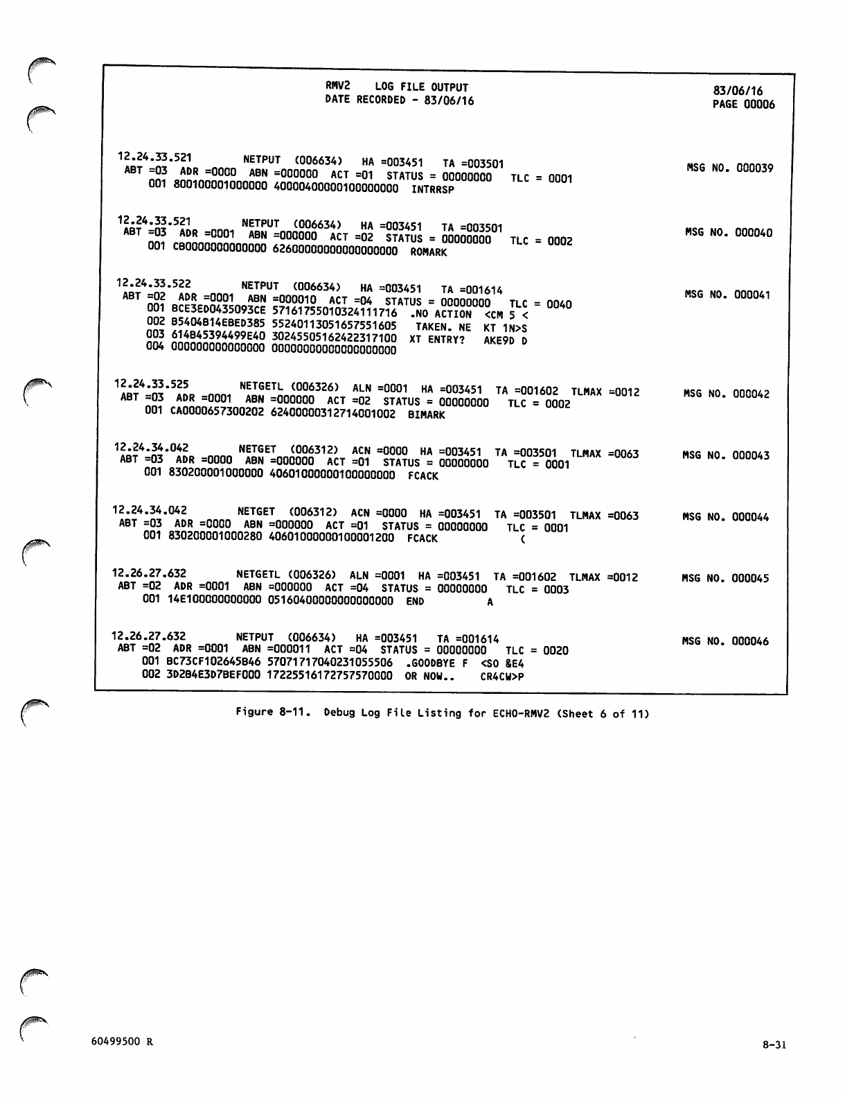
/iSS>\
/0®*\
RMV2 LOG FILE OUTPUT
DATE RECORDED - 83/06/16
IIIS 1 NETPUT (°06634) HA =003451 TA =003501
ABT =03 ADR =0000 ABN =000000 ACT =01 STATUS = 00000000 TLC = finm
001 800100001000000 40000400000100000000 INTRRSP
1?B?4:S'5!lo nnn, NETPUT (°06634) HA =003451 TA =003501
nn, T =00°1 ** =00000° ACT =02 STATUS = 00000000 TLC = 0002
001 CBOO0OOO00O00OO 62600000000000000000 ROMARK
1ART4'S*5*L nnn. NETPUT <006634> HA =003451 TA =001614
nS? oA«c^2??InrtABN =0°0010 ACT =04 STATUS = 00000000 TLC = 0040
001 BCE3ED0435093CE 57161755010324111716 .NO ACTION <CM 5 <
002 B5404B14EBED385 55240113051657551605 TAKEN. NE KT 1N>S
003 614B45394499E40 30245505162422317100 XT ENTRY' AKE9D D
004 000000000000000 OOOOOOOOOOOOOOOOOOOO
1«!4"S'5!? « NETGETL (006326) ALN =0001 HA =003451 TA =001602 TLMAX =0012
ABT =03 ADR =0001 ABN =000000 ACT =02 STATUS = 00000000 TLC =0002
001 CA0000657300202 62400000312714001002 BIMARK
^^'H'°iL nnnn NETGET (006312) AC" =0000 HA =003451 TA =003501 TLMAX =0063
ABT =03 ADR =0000 ABN =000000 ACT =01 STATUS = 00000000 TLC =0001
001 830200001000000 40601000000100000000 FCACK
12.24.34.042 NETGET (006312) ACN =0000 HA =003451 TA =003501 TLMAX =0063
ABT =03 ADR =0000 ABN =000000 ACT =01 STATUS = 00000000 TLC = 0001
001 830200001000280 40601000000100001200 FCACK (
12.26.27.632 NETGETL (006326) ALN =0001 HA =003451 TA =001602 TLMAX =0012
ABT =02 ADR =0001 ABN =000000 ACT =04 STATUS = 00000000 TLC = 0003
001 14E100000000000 05160400000000000000 END A
12.26.27.632 NETPUT (006634) HA =003451 TA =001614
ABT =02 ADR =0001 ABN =000011 ACT =04 STATUS = 00000000 TLC = 0020
001 BC73CF102645B46 57071717040231055506 .GOODBYE F <S0 &E4
002 3D2B4E3D7BEF000 17225516172757570000 OR NOW.. CR4CW>P
83/06/16
PAGE 00006
MSG NO. 000039
MSG NO. 000040
MSG NO. 000041
MSG NO. 000042
MSG NO. 000043
MSG NO. 000044
MSG NO. 000045
MSG NO. 000046
Figure 8-11. Debug Log File Listing for ECH0-RMV2 (Sheet 6 of 11)
60499500 R 8-31
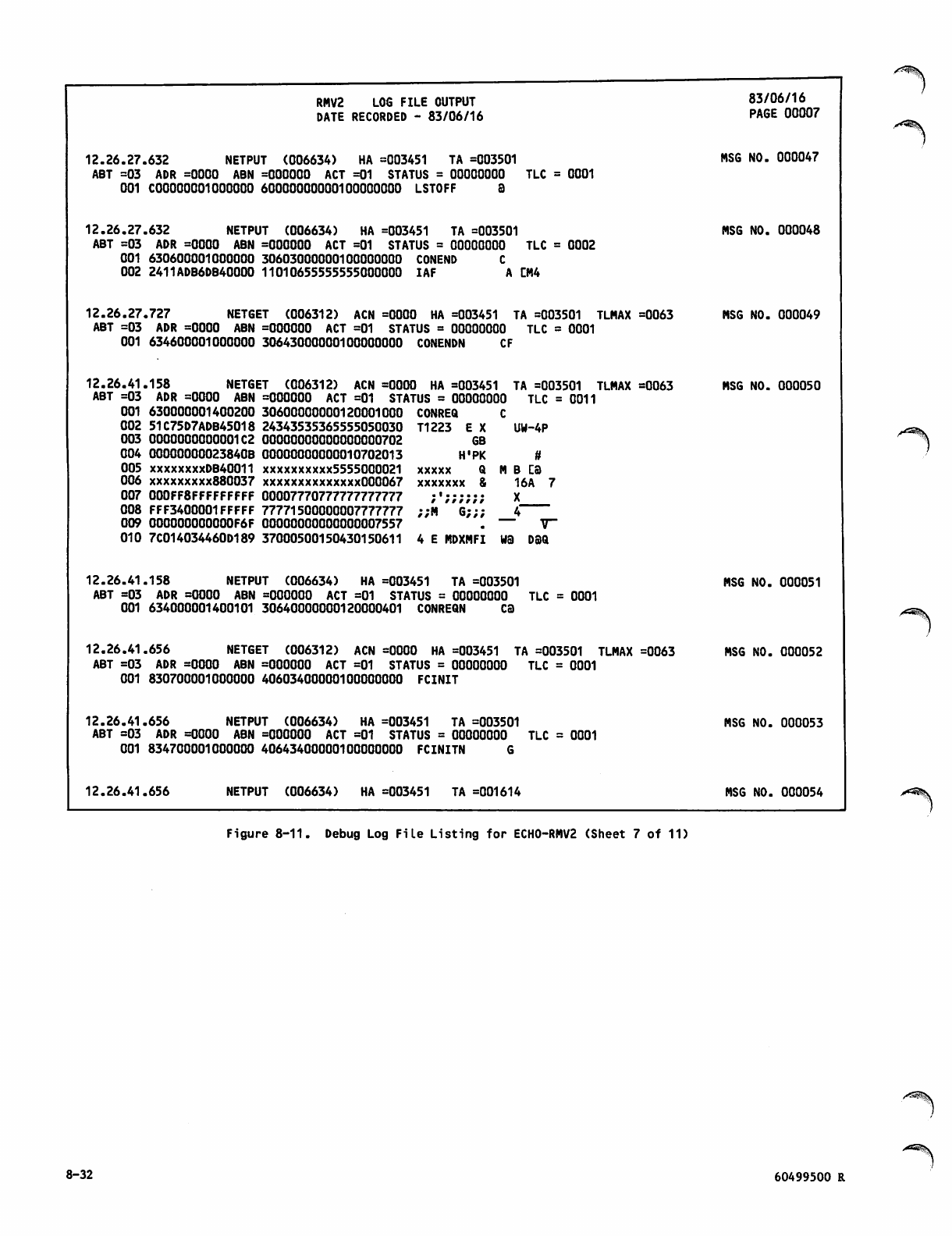
RMV2 LOG FILE OUTPUT
DATE RECORDED - 83/06/16
12.26.27.632 NETPUT (006634) HA =003451 TA =003501
ABT =03 ADR =0000 ABN =000000 ACT =01 STATUS = 00000000 TLC = 0001
001 C00000001OOOOOO 60000000000100000000 LSTOFF 3
12.26.27.632 NETPUT (006634) HA =003451 TA =003501
ABT =03 ADR =0000 ABN =000000 ACT =01 STATUS = 00000000 TLC = 0002
001 630600001000000 30603000000100000000 CONEND C
002 2411ADB6DB40000 11010655555555000000 IAF A CM4
12.26.27.727 NETGET (006312) ACN =0000 HA =003451 TA =003501 TLMAX =0063
ABT =03 ADR =0000 ABN =000000 ACT =01 STATUS = 00000000 TLC = 0001
001 634600001000000 30643000000100000000 CONENDN CF
12.26.41.158 NETGET (006312) ACN =0000
ABT =03 ADR =0000 ABN =000000 ACT =01 STAT
001 630000001400200 30600000000120001000
002 51C75D7ADB45018 24343535365555050030
003 0000000000001C2 00000000000000000702
004 00000000023840B 00000000000010702013
005 xxxxxxxxDB40011 xxxxxxxxxx5555000021
006 xxxxxxxxx880037 xxxxxxxxxxxxxx000067
007 000FF8FFFFFFFFF 00007770777777777777
008 FFF3400001FFFFF 77771500000007777777
009 000000000000F6F 00000000000000007557
010 7C014034460D189 37000500150430150611 4 E MDXMFI W3 DSQ
12.26.41.158 NETPUT (006634) HA =003451 TA =003501
ABT =03 ADR =0000 ABN =000000 ACT =01 STATUS = 00000000 TLC = 0001
001 634000001400101 30640000000120000401 CONREQN CS
12.26.41.656 NETGET (006312) ACN =0000 HA =003451 TA =003501 TLMAX =0063
ABT =03 ADR =0000 ABN =000000 ACT =01 STATUS = 00000000 TLC = 0001
001 830700001000000 40603400000100000000 FCINIT
12.26.41.656 NETPUT (006634) HA =003451 TA =003501
ABT =03 ADR =0000 ABN =000000 ACT =01 STATUS = 00000000 TLC = 0001
001 834700001000000 40643400000100000000 FCINITN G
HA =003451 TA =003501 TLMAX =0063
US = 00000000 TLC = 0011
CONREQ
T1223 E X UW-4P
GB
H'PK
xxxxx Q m b ca
xxxxxxx 8 16A 7
/ / / / r r r
;;M G;;;
83/06/16
PAGE 00007
MSG NO. 000047
MSG NO. 000048
MSG NO. 000049
MSG NO. 000050
12.26.41.656 NETPUT (006634) HA =003451 TA =001614
MSG NO. 000051
MSG NO. 000052
MSG NO. 000053
MSG NO. 000054
Figure 8-11. Debug Log File Listing for ECH0-RMV2 (Sheet 7 of 11)
8-32 60499500 R
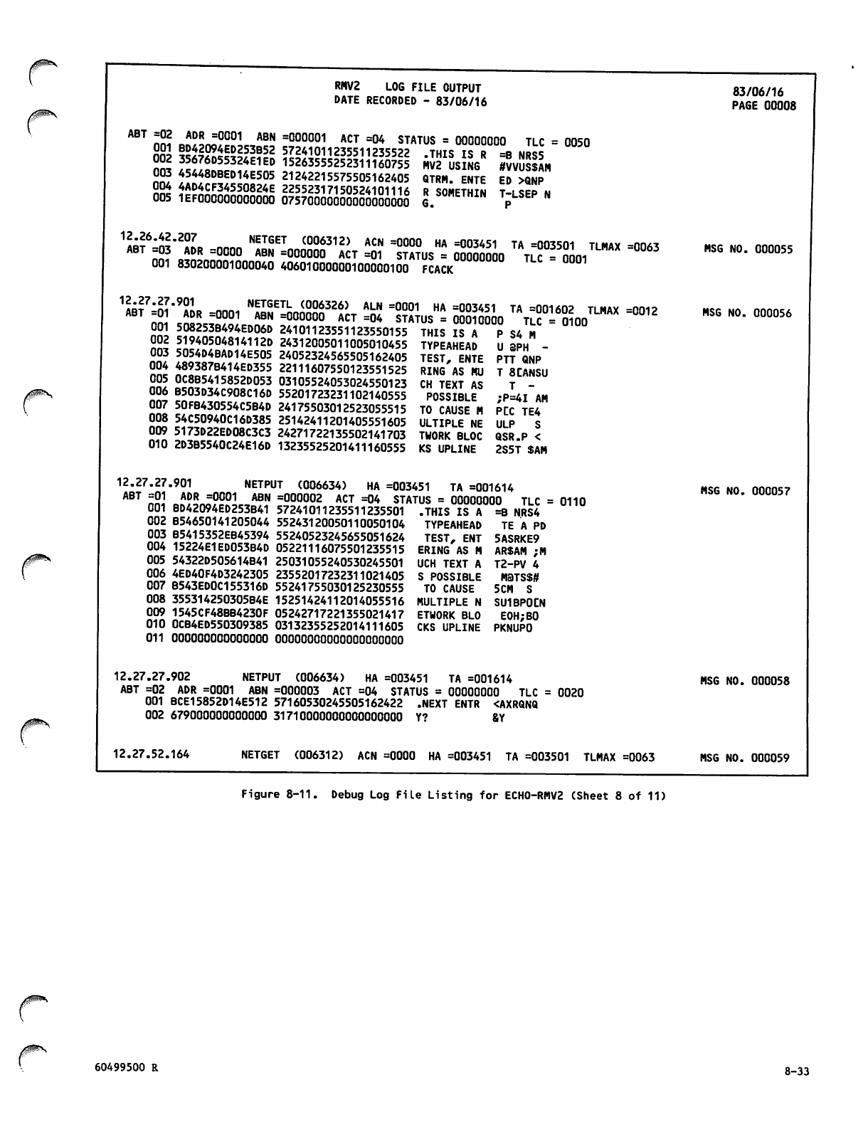
RMV2 LOG FILE OUTPUT
DATE RECORDED - 83/06/16 83/06/16
PAGE 00008
ABT =02 ADR =0001 ABN
001 BD42094ED253B52
002 35676D55324E1ED
003 45448DBED14E505
004 4AD4CF34550824E
005 1EF000000000000
=000001 ACT =04 STATUS = 00000000 TLC = 0050
57241011235511235522 .THIS IS R =B NRS5
MV2 USING WVUSSAM
QTRM. ENTE ED >QNP
R SOMETHIN T-LSEP N
G . P
15263555252311160755
21242215575505162405
22552317150524101116
07570000000000000000
1h?6'i!'2°7 NETGET <°06312) ACN =0000 HA =003451 TA =003501 TLMAX -nOA7
2? JSISSSSL ABN =00000° ACT =01 STATUS = 00000000 TLC = 0001
001 830200001000040 40601000000100000100 FCACK
12.27.27.
ABT =01
001
002
003
004
005
006
007
008
009
010
NSSETnnn22S326> ALN =0001 HA =003451 TA =001602 TLMAX =0012
ABN =000000 ACT =04 STATUS = 00010000 TLC = 0100
901
ADR =0001
c?S2SS494ED06D 24101123551123550155 THIS IS A P S4 M
0048141120 24312005011005010455 TYPEAHEAD U 3PH -
5054D4BAD14E505 24052324565505162405 TEST, ENTE PTT QNP
489387B414ED355 22111607550123551525 RING AS MU T 8CANSU
0C8B5415852D053 03105524053024550123 CH TEXT AS T -
B503D34C908C16D 55201723231102140555 POSSIBLE -P=4I AM
50F8430554C5B4D 24175503012523055515 TO CAUSE M PCC TE4
54C50940C16D385 25142411201405551605 ULTIPLE NE ULP S
5173D22ED08C3C3 24271722135502141703 TWORK BLOC QSR.P <
2D3B5540C24E16D 13235525201411160555 KS UPLINE 2S5T SAM
MSG NO. 000055
MSG NO. 000056
12.27.27
ABT =01
001
002
003
004
005
006
007
008
009
010
011
901 NETPUT (006634) HA =003451 TA =001614
ADR =0001 ABN =000002 ACT =04 STATUS = 00000000 TLC =
BD42094ED253B41 57241011235511235501 .THIS IS A
B54650141205044 55243120050110050104 TYPEAHEAD
B5415352EB45394 55240523245655051624 TEST, ENT
15224E1ED053B4D 05221116075501235515 ERING AS M
54322D505614B41 25031055240530245501 UCH TEXT A
4ED40F4D3242305 23552017232311021405 S POSSIBLE
B543ED0C155316D 55241755030125230555 TO CAUSE
355314250305B4E 15251424112014055516 MULTIPLE N
1545CF48BB4230F 05242717221355021417 ETWORK BLO
0CB4ED550309385 03132355252014111605 CKS UPLINE
000000000000000 OOOOOOOOOOOOOOOOOOOO
=8 N.RS4
TE A PD
5ASRKE9
AR$AM ;M
T2-PV 4
M3TS$#
5CM S
SU1BP0CN
EOH;BO
PKNUPO
0110 MSG NO. 000057
12.27.27.902 NETPUT (006634) HA =003451 TA =001614
ABT =02 ADR =0001 ABN =000003 ACT =04 STATUS = 00000000 TLC = 0020
001 BCE15852D14E512 57160530245505162422 .NEXT ENTR <AXRQNQ
002 679000000000000 31710000000000000000 Y? 8Y
12.27.52.164 NETGET (006312) ACN =0000 HA =003451 TA =003501 TLMAX =0063
MSG NO. 000058
MSG NO. 000059
Figure 8-11. Debug Log File Listing for ECH0-RMV2 (Sheet 8 of 11)
r
60499500 R 8-33
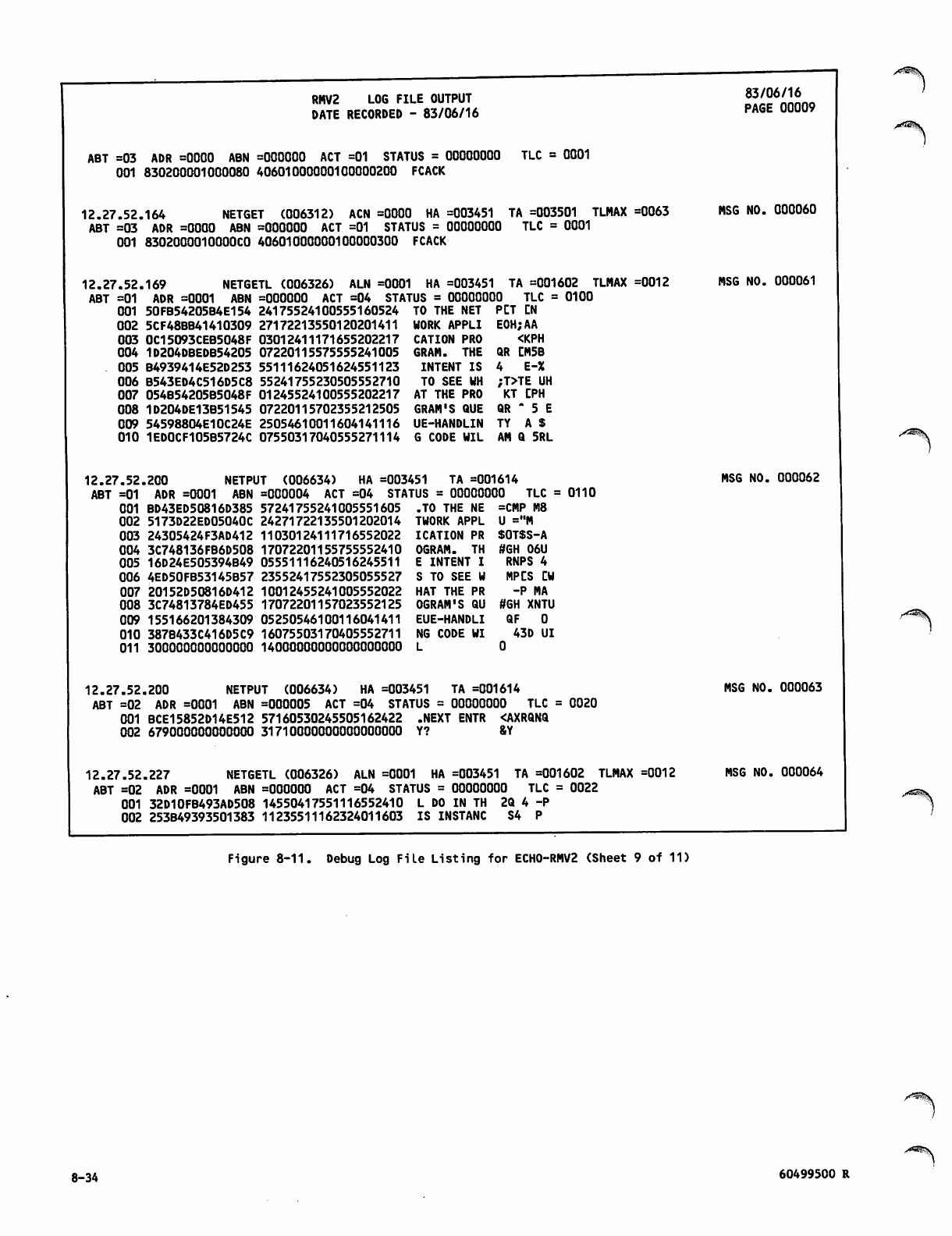
RMV2 LOG FILE OUTPUT
DATE RECORDED - 83/06/16
ABT =03 ADR =0000 ABN =000000 ACT =01 STATUS = 00000000 TLC = 0001
001 830200001000080 40601000000100000200 FCACK
12.27.52.164 NETGET (006312) ACN =0000 HA =003451 TA =003501 TLMAX =0063
ABT =03 ADR =0000 ABN =000000 ACT =01 STATUS = 00000000 TLC = 0001
001 830200001OOOOCO 40601000000100000300 FCACK
83/06/16
PAGE 00009
12.27.52.
ABT =01
001
002
003
004
005
006
007
008
009
010
12.27.52
ABT =01
001
002
003
004
005
006
007
008
009
010
011
NETGETL (006326) ALN =0001 HA =003451169
ADR =0001 ABN =000000 ACT =04 STATUS = 00000000 TLC =
50FB54205B4E154 24175524100555160524 TO THE NET PLT CN
27172213550120201411 WORK APPLI EOH;AA
03012411171655202217 CATION PRO <KPH
07220115575555241005 GRAM. THE QR CM5B
55111624051624551123 INTENT IS 4 E-%
55241755230505552710 TO SEE WH ;T>TE UH
01245524100555202217 AT THE PRO KT CPH
07220115702355212505 GRAM'S QUE QR " 5 E
25054610011604141116 UE-HANDLIN TY A $
G CODE WIL AM Q 5RL
TA =001602 TLMAX =0012
0100
MSG NO. 000060
MSG NO. 000061
5CF48BB41410309
0C15093CEB5048F
1D204DBEDB54205
B4939414E52D253
B543ED4C516D5C8
054B54205B5048F
1D204DE13B51545
54598804E10C24E
1ED0CF105B5724C 07550317040555271114
,200 NETPUT (006634) HA =003451 TA =001614
ADR =0001 ABN =000004 ACT =04 STATUS = 00000000 TLC =
BD43ED50816D385 57241755241005551605 .TO THE NE =CMP M8
24271722135501202014
11030124111716552022
17072201155755552410
05551116240516245511
23552417552305055527
10012455241005552022
17072201157023552125
155166201384309 05250546100116041411
387B433C416D5C9 16075503170405552711
300000000000000 14000000000000000000
MSG NO. 000062
0110
5173D22ED05040C
24305424F3AD412
3C748136FB6D508
16D24E505394B49
4ED50FB53145B57
20152D50816D412
3C74813784ED455
TWORK APPL U ="M
ICATION PR $OT$S-A
OGRAM. TH #GH 06U
E INTENT I RNPS 4
S TO SEE W MPCS CW
HAT THE PR -P MA
OGRAM'S QU #GH XNTU
EUE-HANDLI Q F 0
NG CODE WI 43D UI
L 0
r " * ^ ^ .
12.27.52.200 NETPUT (006634) HA =003451 TA =001614
ABT =02 ADR =0001 ABN =000005 ACT =04 STATUS = 00000000 TLC = 0020
001 BCE15852D14E512 57160530245505162422 .NEXT ENTR <AXRQNQ
002 679000000000000 31710000000000000000 Y? &Y
12.27.52.227 NETGETL (006326) ALN =0001 HA =003451 TA =001602 TLMAX =0012
ABT =02 ADR =0001 ABN =000000 ACT =04 STATUS = 00000000 TLC = 0022
001 32D10FB493AD508 14550417551116552410 L DO IN TH 2Q 4 -P
002 253B49393501383 11235511162324011603 IS INSTANC S4 P
MSG NO. 000063
MSG NO. 000064
Figure 8-11. Debug Log File Listing for ECH0-RMV2 (Sheet 9 of 11)
8-34 60499500 R
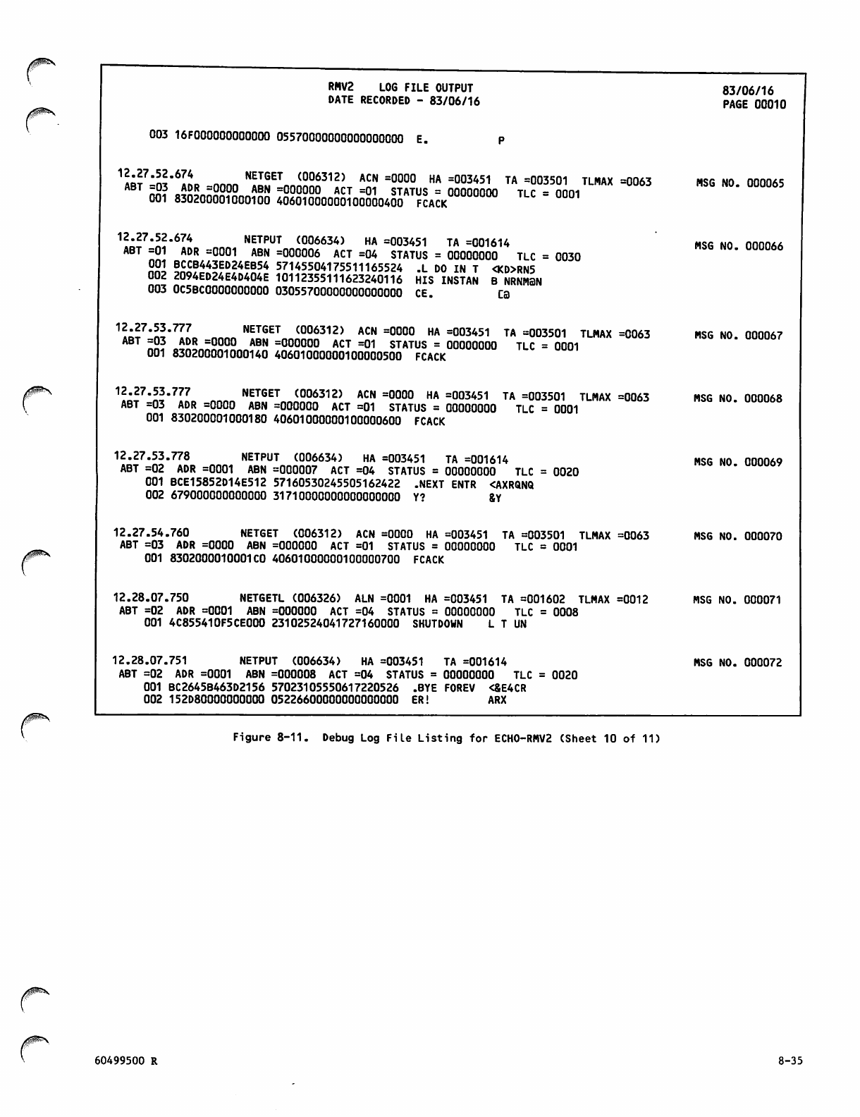
RMV2 LOG FILE OUTPUT 83/06/16
D A T E R E C O R D E D - 8 3 / 0 6 / 1 6 P A G E 0 0 0 1 0
003 16FO00000OOO0OO 05570000000000000000 E.
1AB?7-ra"6IL -nnnn "fJ^nnnn™312' ACN =000° HA =003451 TA =003501 TLMAX =0°63 MSG NO. 000065ABT -03 ADR =0000 ABN =000000 ACT =01 STATUS = OQOnnnnn ti r - nnni
001 830200001000100 40601000000100000400 FCACK "
12.27.52.674 NETPUT (006634) HA =003451 TA =001614 msg no nnnnAA
ABT =01 ADR =0001 ABN =000006 ACT =04 STATUS = 00000000 TLC = 0030
22} B"B443ED24EB54 57145504175511165524 .L DO IN T <KD>RN5
002 2094ED24E4D404E 10112355111623240116 HIS INSTAN B NRNM3N
003 0C5BC0000000000 03055700000000000000 CE. C3
^I'Jf'll'^L nnnn ""^ (006312) ACN =000° »A =003451 TA =003501 TLMAX =0063 MSG NO. 000067
ABT =03 ADR =0000 ABN =000000 ACT =01 STATUS = 00000000 TLC = 0001
001 830200001000140 40601000000100000500 FCACK
12oJ7'n!'7rL n NETGET (006312) ACN =0000 HA =003451 TA =003501 TLMAX =0063 MSG NO. 000068
ABT =03 ADR =0000 ABN =000000 ACT =01 STATUS = 00000000 TLC = 0001
001 830200001000180 40601000000100000600 FCACK
12.27.53.778 NETPUT (006634) HA =003451 TA =001614 MSG NO 000069
ABT =02 ADR =0001 ABN =000007 ACT =04 STATUS = 00000000 TLC = 0020
001 BCE15852D14E512 57160530245505162422 .NEXT ENTR <AXRQNQ
002 679000000000000 31710000000000000000 Y? 8Y
12.27.54.760 NETGET (006312) ACN =0000 HA =003451 TA =003501 TLMAX =0063 MSG NO. 000070
ABT =03 ADR =0000 ABN =000000 ACT =01 STATUS = 00000000 TLC = 0001
001 8302000010001 CO 40601000000100000700 FCACK
12.28.07.750 NETGETL (006326) ALN =0001 HA =003451 TA =001602 TLMAX =0012 MSG NO. 000071
ABT =02 ADR =0001 ABN =000000 ACT =04 STATUS = 00000000 TLC = 0008
001 4C855410F5CE000 23102524041727160000 SHUTDOWN L T UN
12.28.07.751 NETPUT (006634) HA =003451 TA =001614 MSG NO. 000072
ABT =02 ADR =0001 ABN =000008 ACT =04 STATUS = 00000000 TLC = 0020
001 BC2645B463D2156 57023105550617220526 .BYE FOREV <&E4CR
002 152D80000000000 05226600000000000000 ER! ARX
Figure 8-11. Debug Log File Listing for ECH0-RMV2 (Sheet 10 of 11)
60499500 R 8-35
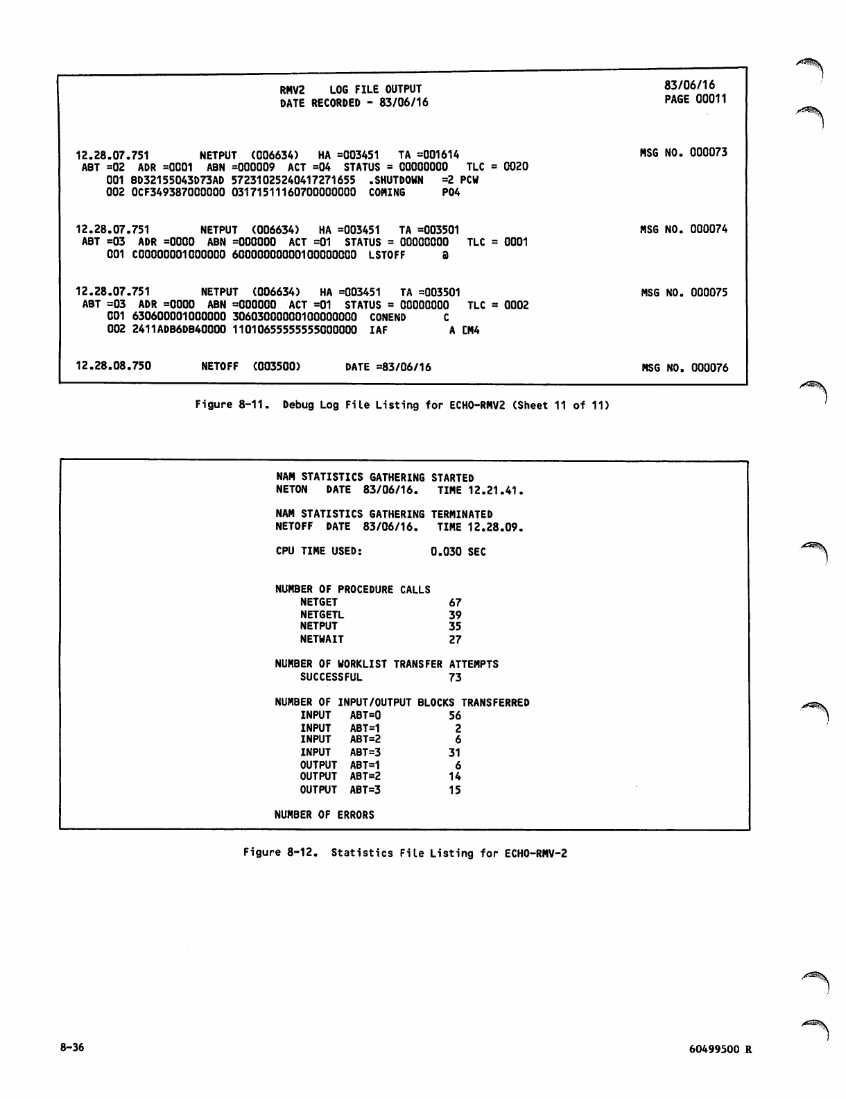
RMV2 LOG FILE OUTPUT
DATE RECORDED - 83/06/16
83/06/16
PAGE 00011
12.28.07.751 NETPUT (006634) HA =003451 TA =001614
ABT =02 ADR =0001 ABN =000009 ACT =04 STATUS = 00000000 TLC
001 BD32155043D73AD 57231025240417271655 .SHUTDOWN =2 PCW
002 0CF349387000000 03171511160700000000 COMING P04
= 0020 MSG NO. 000073
12.28.07.751 NETPUT (006634) HA =003451 TA =003501
ABT =03 ADR =0000 ABN =000000 ACT =01 STATUS = 00000000 TLC
001 C00000001OOOOOO 60000000000100000000 LSTOFF 3
= 0001 MSG NO. 000074
12.28.07.751 NETPUT (006634) HA =003451 TA =003501
ABT =03 ADR =0000 ABN =000000 ACT =01 STATUS = 00000000 TLC
001 630600001000000 30603000000100000000 CONEND C
002 2411ADB6DB40000 11010655555555000000 IAF A CM4
= 0002 MSG NO. 000075
12.28.08.750 NETOFF (003500) DATE =83/06/16 MSG NO. 000076
Figure 8-11. Debug Log File Listing for ECH0-RMV2 (Sheet 11 of 11)
NAM STATISTICS GATHERING STARTED
NETON DATE 83/06/16. TIME 12.21.41.
NAM STATISTICS GATHERING TERMINATED
NETOFF DATE 83/06/16. TIME 12.28.09.
CPU TIME USED: 0.030
NUMBER OF PROCEDURE CALLS
NETGET 67
NETGETL 39
NETPUT 35
NETWAIT 27
NUMBER OF WORKLIST TRANSFER ATTEMPTS
SUCCESSFUL 73
NUMBER OF INPUT/OUTPUT BLOCKS TRANSFERRED
INPUT ABT=0 56
INPUT ABT=1 2
INPUT ABT=2 6
INPUT ABT=3 31
OUTPUT ABT=1 6
O U T P U T A B T = 2 1 4
O U T P U T A B T = 3 1 5
NUMBER OF ERRORS
Figure 8-12. Statistics File Listing for ECHO-RMV-2
8-36 60499500 R
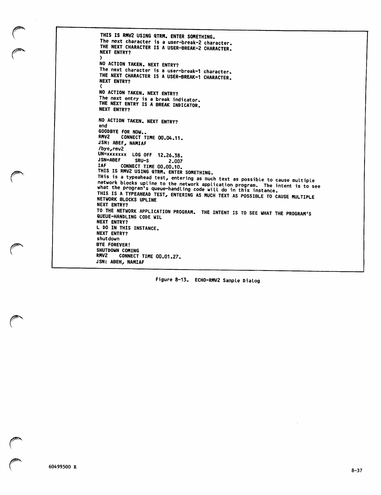
THIS IS RMV2 USING QTRM. ENTER SOMETHING.
The next character is a user-break-2 character.
THE NEXT CHARACTER IS A USER-BREAK-2 CHARACTER.
NEXT ENTRY?
)
NO ACTION TAKEN. NEXT ENTRY?
The next character is a user-break-1 character.
THE NEXT CHARACTER IS A USER-BREAK-1 CHARACTER.
NEXT ENTRY?
(
NO ACTION TAKEN. NEXT ENTRY?
The next entry is a break indicator.
THE NEXT ENTRY IS A BREAK INDICATOR.
NEXT ENTRY?
NO ACTION TAKEN. NEXT ENTRY?
end
GOODBYE FOR NOW..
RMV2 CONNECT TIME 00.04.11.
JSN: ABEF, NAMIAF
/bye,rmv2
UN=xxxxxxx LOG OFF 12.26.38.
JSN=ABEF SRU-S 2.007
IAF CONNECT TIME 00.00.10.
THIS IS RMV2 USING QTRM. ENTER SOMETHING.
I!!*S '? !,tyPeahef^ test' enteri"9 as much text as possible to cause multiple
u£?°rLbl0CkS U?Une to the netHOrk aPP^cation program. The intent is to see
rJt Ttehe.p:°9ram,s queue-handling code will do in this instance.
Network bVwkTwline"1' ENTERING AS MUC" TEXT AS P0SSIBLE t0 CAUSE multiple
NEXT ENTRY?
queue-hanKg code^Jl10" PR0GRAH* THE INTENT IS to see what the program,s
NEXT ENTRY?
L DO IN THIS INSTANCE.
NEXT ENTRY?
shutdown
BYE FOREVER!
SHUTDOWN COMING
RMV2 CONNECT TIME 00.01.27.
JSN: ABEH, NAMIAF
<^ N
Figure 8-13. ECHO-RMV2 Sample Dialog
60499500 R 8-37

CHARACTER DATA INPUT, OUTPUT, AND
CENTRAL MEMORY REPRESENTATION
/$^*\
/^N
This appendix describes the code and character sets
used by the operating system local batch device
driver programs, magnetic tape driver programs, and
n e t w o r k t e r m i n a l c o m m u n i c a t i o n p r o d u c t s . T h i s
appendix does not describe how other products
associate certain graphic or control characters
with specific binary code values for collating or
syntax processing purposes. The main text of this
manual describes such associations that are rele
vant to the reader.
CHARACTER SETS AND CODE
SETS
A character set differs from a code set. A char
acter set is a set of graphic and/or control char
acter symbols. A code set Is a numbering system
used to represent each character within a character
set . Char acte rs e xist o utsi de the comp uter s yste m
and communication network; codes are received
stored, retrieved, and transmitted within the
computer system and network.
When this manual refers to the ASCII 128-character
set or the 7-bit ASCII code set, it is referring to
the character set and code set defined as the
American National Standard Code for Information
I n t e r c h a n g e ( A S C I I , A N S I S t a n d a r d X 3 . 4 - 1 9 7 7 ) .
References in this manual to an ASCII character set
or an ASCII code set do not necessarily apply to
the 128-character, 7-bit ASCII code set.
GRAPHIC AND CONTROL
CHARACTERS
A graphic character can be displayed or printed.
Examples of graphic characters are the characters A
th rough Z, a blank , an d the digits 0 throu gh 9. A
control character is not a graphic character; a
c o n t r o l c h a r a c t e r i n i t i a t e s , m o d i fi e s , o r s t o p s a
control operation. An example of a control char
acter is the backspace character, which moves the
terminal carriage or cursor back one space. Al
tho u gh a c ontro l char a cter i s not a graph i c char
acter, some terminals use a graphic representation
for c ontrol c h aracte r s.
CODED AND BINARY
CHARACTER DATA
Character codes can be interpreted as coded char
acter data or as binary character data. Coded
character data is converted by default from one
code set representation to another as it enters or
leaves the computer system; for example, data
received from a terminal or sent to a magnetic tape
unit is converted. Binary character data is not
converted as it enters or leaves the system.
Character codes are not converted when moved within
the system; for example, data transferred to or
from mass storage is not converted.
60499500 R
The distinction between coded character data and
binary character data is important when reading or
punching cards and when reading or writing magnetic
tape. Only coded c h a r a c t e r d a t a c a n b e p r o p e r l y
re p r o d uced a s c h a racte r s o n a l ine pr i n t e r. O n ly
binary character data can properly represent
characters on a punched card when the data cannot
be stored as display code.
Th e distinction bet wee n binary character dat a and
characters represented by binary data (such as
peripheral equipment instruction codes) is also
important. Only binary noncharacter data can
properly reproduce characters on a plotter.
CHARACTER SET TABLES
The character set tables in this appendix are
designed so that the user can find the character
represented by a code (such as in a dump) or find
the code that represents a character. To find the
character represented by a code, the user looks up
the code in the column listing the appropriate code
set and then finds the character on that line in
t h e c ol u m n l is t i ng t h e a pp r o pri a t e ch a r ac t e r s et .
To find the code that represents a character, the
user looks up the character and then finds the code
on the same line in the appropriate column.
NETWORK OPERATING
SYSTEM
NOS supports the following character sets:
CDC graphic 64-character set
CDC graphic 63-character set
ASCII graphic 64-character set
ASCII graphic 63-character set
ASCII graphic 95-character set
ASCII 128-character set
Each installation must select either a 64-character
set or a 63-character set. The differences between
the codes of a 63-character set and the codes of a
64-character set are described under Character Set
Anomalies. Any reference in this appendix to a
6 4 - c h a r a c t e r s e t i m p l i e s e i t h e r a 6 3 - o r 6 4 -
character set unless otherwise stated.
NOS supports the following code sets to represent
its character sets in central memory:
6-bit display code
12-bit ASCII code
6/12-bit display code
A-l
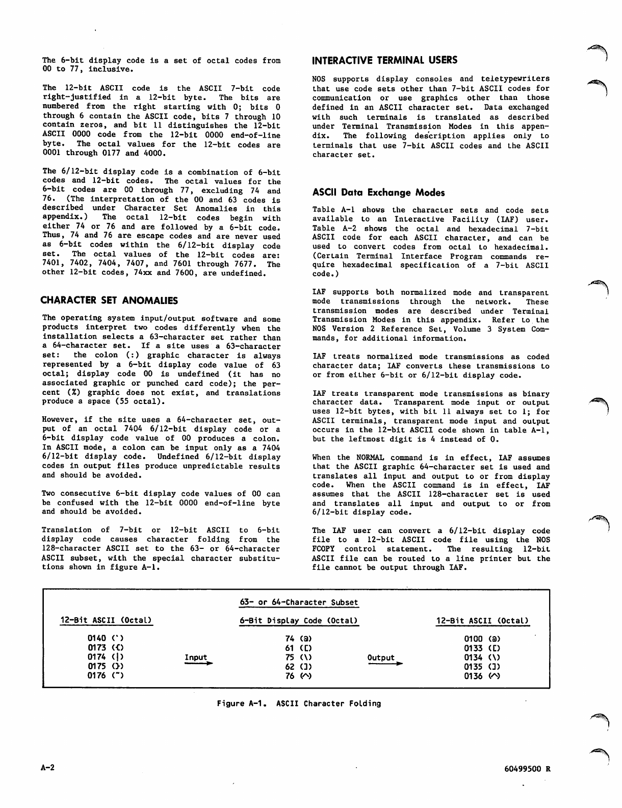
The 6-bit display code is a set of octal codes from
00 to 77, inclusive.
The 12-bit ASCII code is the ASCII 7-bit code
right-justified in a 12-bit byte. The bits are
numbered from the right starting with 0; bits 0
through 6 contain the ASCII code, bits 7 through 10
contain zeros, and bit 11 distinguishes the 12-bit
ASCII 0000 code from the 12-bit 0000 end-of-line
byte. The octal values for the 12-bit codes are
0001 through 0177 and 4000.
The 6/12-bit display code is a combination of 6-bit
codes and 12-bit codes. The octal values for the
6-bit codes are 00 through 77, excluding 74 and
76. (The Interpretation of the 00 and 63 codes is
described under Character Set Anomalies in this
appendix.) The octal 12-bit codes begin with
either 74 or 76 and are followed by a 6-bit code.
Thus, 74 and 76 are escape codes and are never used
as 6-bit codes within the 6/12-bit display code
set. The octal values of the 12-bit codes are:
7401, 7402, 7404, 7407, and 7601 through 7677. The
other 12-bit codes, 74xx and 7600, are undefined.
CHARACTER SET ANOMALIES
The operating system input/output software and some
products interpret two codes differently when the
installation selects a 63-character set rather than
a 64-character set. If a site uses a 63-character
set: the colon (:) graphic character is always
r e p r es e n t ed b y a 6 -bi t d isp l a y c od e v a lue o f 6 3
octal; display code 00 is undefined (it has no
associated graphic or punched card code); the per
cent (%) graphic does not exist, and translations
produce a space (55 octal).
However, if the site uses a 64-character set, out
put of an octal 7404 6/12-bit display code or a
6-bit display code value of 00 produces a colon.
In ASCII mode, a colon can be input only as a 7404
6/12-bit display code. Undefined 6/12-bit display
codes in output files produce unpredictable results
and should be avoided.
Two consecutive 6-bit display code values of 00 can
be confused with the 12-bit 0000 end-of-line byte
and should be avoided.
Translation of 7-bit or 12-bit ASCII to 6-bit
display code causes character folding from the
128-character ASCII set to the 63- or 64-character
ASCII subset, with the special character substitu
tions shown in figure A-l.
INTERACTIVE TERMINAL USERS
NOS supports display consoles and teletypewriters
that use code sets other than 7-bit ASCII codes for
communication or use graphics other than those
defined in an ASCII character set. Data exchanged
with such terminals is translated as described
under Terminal Transmission Modes in this appen
dix. The following description applies only to
terminals that use 7-bit ASCII codes and the ASCII
character set.
ASCII Data Exchange Modes
Table A-l shows the character sets and code sets
available to an Interactive Facility (IAF) user.
Table A-2 shows the octal and hexadecimal 7-bit
ASCII code for each ASCII character, and can be
used to convert codes from octal to hexadecimal.
(Certain Terminal Interface Program commands re
q u i r e he x a d ec i m a l s p ec i fi c at i o n o f a 7 - b i t A SC I I
code.)
IAF supports both normalized mode and transparent
mode transmissions through the network. These
transmission modes are described under Terminal
Transmission Modes in this appendix. Refer to the
NOS Version 2 Reference Set, Volume 3 System Com
mands, for additional information.
IAF treats normalized mode transmissions as coded
character data; IAF converts these transmissions to
or from either 6-bit or 6/12-bit display code.
IAF treats transparent mode transmissions as binary
character data. Transparent mode input or output
uses 12-bit bytes, with bit 11 always set to 1; for
ASCII terminals, transparent mode input and output
occurs in the 12-bit ASCII code shown in table A-l,
but the leftmost digit is 4 instead of 0.
When the NORMAL command is in effect, IAF assumes
that the ASCII graphic 64-character set is used and
translates all input and output to or from display
code. W h e n t h e A S C I I command i s i n e ffect, I A F
assumes that the ASCII 128-character set is used
a n d t r a n s l a t e s a l l i n p u t a n d o u t p u t t o o r f r o m
6/12-bit display code.
The IAF user can convert a 6/12-bit display code
fi l e t o a 1 2 - b i t A S C I I c o d e fi l e u s i n g t h e N O S
FC0PY control statement. The resulting 12-bit
ASCII file can be routed to a line printer but the
file cannot be output through IAF.
v^^\
^^S^K
63- or 64-Character Subset
12-Bit ASCII (Octal) 6-Bit Display Code (Octal) 12-Bit ASCII (Octal)
0140 (') 74 (a) 0100 (B)
0173 «> 61 (C) 0133 (C)
0174 (|) Input 75 (\) Output 0134 (\)
0175 (» 62 G) 0135 (3)
0176 (") 76 (^) 0136 (^)
Figure A-1. ASCII Character Folding
/Ka(«|K
A-2 60499500 R
Terminal Transmission Modes
Coded character data can be exchanged with a con
versational terminal in two transmission modes.
These two modes, normalized mode and transparent
mod e , c o r r e spond to t h e t y p e s o f c h a racter c o d e
editing and translation performed by the network
software during input and output operations.
The terminal operator can change the input trans
mission mode using a terminal definition command
(sometimes called a Terminal Interface Program
command). The application program providing the
t e r mi n a l f ac i l it y s er v i ce c a n cha n g e t h e I np u t or
output transmission mode.
Normalized Mode Transmissions
Normalized mode is the initial and default mode
used for both input and output transmissions. The
network software translates normalized mode data to
or from the transmission code used by the terminal
into or from the 7-bit ASCII code shown in table
A-2. (Tables A-l and A-3 through A-7 are provided
for use while coding an application program to run
under the operating system; they do not describe
character transmissions through the network.)
Translation of a specific terminal transmission
code to or from a specific 7-bit ASCII code depends
on the terminal class in which the network software
places the terminal.
The following paragraphs summarize the general case
for normalized mode data code translations. This
generalized description uses table A-2.
The reader can extend this generalized description
by using the other tables to determine character
set mapping for functions initiated from a terminal.
For example, the description under Terminal Output
Character Sets can be used to predict whether a
lowercase ASCII character stored in 6/12-bit dis
play code can appear on an EBCDIC or external BCD
terminal; if an ASCII character passes through the
network represented in 7-bit ASCII as character
mode data, it probably can be represented on an
EBCDIC terminal, but it is always transformed to an
uppercase character on a mode 4A ASCII terminal.
Table A-2 contains the ASCII 128-character set
supported by the network software. The ASCII
96-character subset in the rightmost six columns
minus the deletion character (DEL) comprises the
graphic 95-character subset; the DEL is not a
graphic character, although some terminals graphi
cally represent it. The graphic 64-character
subset comprises the middle four columns. Only the
characters in this 64-character subset have 6-bit
display code equivalents.
Terminals that support an ASCII graphic 64-character
subset actually use a subset of up to 96 charac
ters, consisting of the graphic 64-character subset
and the control characters of columns 1 and 2;
often, the DEL char act er i n col umn 7 is incl ude d.
Terminals that support an ASCII graphic 95-character
or 96-character subset actually might use all 128
characters.
The hexadecimal value of the 7-bit code for each
character in table A-2 consists of the character's
column number in the table, followed by its row
number. For example, N is in row E of column 4, so
its hexadecimal value is 4E. The octal value for
the code when it is right-justified in an 8-bit
b y t e a p p e a r s b e n e a t h t h e c h a r a c t e r g r a p h i c o r
mnemonic. The binary value of the code consists of
the bit values shown, placed in the order given by
the subscripts for the letter b; for example, N is
1001110.
Tables A-8 through A-19 show the normalized mode
translations performed for each terminal class.
The parity shown in the terminal transmission codes
i s th e p a r i t y us e d a s a d e f a u l t fo r t h e t e r m i n a l
class. The parity setting actually used by a
terminal can be identified to the network software
through a TIP command.
Ta b le s A - 8 t hr o u gh A -1 9 c o nt a i n t h e g ra p h ic a n d
control characters associated with the transmission
codes used by the terminal because of the terminal
class and code set in use. The network ASCII
graphic and control characters shown are those of
the standard ASCII character set associated with
the ASCII transmission codes of table A-2.
Terminal Output Character Subsets — Although the
network supports the ASCII 128-character set, some
terminals restrict output to a smaller character
set. This restriction is supported by replacing
the control characters in columns 0 and 1 of table
A-2 with blanks to produce the ASCII graphic
95-character subset, and replacing the characters
in columns 6 and 7 with the corresponding char
acters from columns 4 and 5, respectively, to
produce the ASCII graphic 64-character subset.
Terminal Input Character Subsets and Supersets —
Although the network supports the ASCII 128-
c h ar a ct e r s e t, s o m e t er m in a l s r es t ri c t i n pu t t o a
smaller character set or permit input of a larger
c h a r a c t e r s e t . A c h a r a c t e r i n p u t f r o m a d e v i c e
using a character set other than ASCII is converted
to an equivalent ASCII character; terminal char
acters without ASCII character equivalents are
represented by the ASCII code for a space.
Site-written terminal-servicing facility programs
can also cause input or output character replace
ment, conversion, or deletion by exchanging data
with the network in 6-bit display code.
Input Restrictions — The network software automat
ically deletes codes associated with terminal
communication protocols or terminal hardware func
tions. These codes usually represent the cancel,
backspace, linefeed, carriage return, and deletion
characters. If paper tape support is requested,
the device control 3 code also is deleted. Some of
these code deletions can be suppressed by using the
full-ASCII and special editing options (refer to
the FA and SE terminal definition parameters in the
NO S Ve r s ion 2 R e f e renc e S e t , Vo lume 3 , S y s tem
Commands).
Output Restrictions — All codes sent by an appli
cation program are transmitted to the terminal.
However, the 12-bit ASCII code 0037 (octal), the
6/12-bit display code 7677 (octal), and the 7-bit
ASCII code IF (hexadecimal) should be avoided in
character mode output. The network software inter
prets the unit separator character represented by
these codes as an end-of-line indicator. The
processing of application program-supplied unit
s e p a r a t o r s c a u s e s i n c o r r e c t f o r m a t t i n g o f o u t p u t
and can cause loss of other output characters.
60499500 R A-3
Input Parity Processing — The network software
does not preserve the parity of the terminal trans
mission code in the corresponding ASCII code. An
ASCII code received by the terminal-servicing
facility program always contains zero as its eighth
bit.
Output Parity Processing — The network software
provides the parity bit setting appropriate for the
terminal being serviced, even when the software is
tr a n sla t i n g fr o m A S C I I c ha r a c ter c o d es w i t h z ero
parity bit settings.
Transparent Mode Transmissions
Transparent mode is selected separately for input
and output transmissions.
During transparent mode input, the parity bit is
stripped from each terminal transmission code
| (unless the N or I parity option has been selected
by a terminal definition command), and the
transmission code is placed in an 8-bit byte
without translation to 7-bit ASCII code. Line
tran s m i s s i o n p r otocol chara c t e r s a r e d e leted from
mode 4 terminal input. When the 8-bit bytes arrive
in the host computer, a terminal servicing facility
program can right-justify the bytes within a 12-bit
byte.
During transparent mode output, processing similar
to that performed for input occurs. When the host
computer transmits 12-bit bytes, the leftmost 4
bits (bits 11 through 8) are discarded. The code
in each 8-bit byte received by the network software
is not translated. The parity bit appropriate for
the terminal class is altered as indicated by the
parity option In effect for the terminal. The
codes are then transmitted to the terminal in bytes
of a length appropriate for the terminal class.
Line transmission protocol characters are inserted
into mode 4 terminal output.
Line Printer Output
The printer train used on the line printer to which
a file is sent determines which batch character set
is printed. The following CDC print trains match
the batch character sets in table A-3:
Character Set
CDC graphic
64-character set
ASCII graphic
64-character set
ASCII graphic
95-character set
P r i n t
Train
596-1
596-5
596-6
Low Cost System
Print Band
530-1
530-2
The characters of the default 596-1 print train are
listed in the table A-3 column labeled CDC Graphic
(64-Character Set); the 596-5 print train charac
ters are listed in the table A-3 column labeled
ASCII Graphic (64-Character Set); and the 596-6
print train characters are listed in the table A-3
column labeled ASCII Graphic (95-Character Set).
If an unprintable character exists in a line, NOS
marks the condition by printing the number sign (it)
in the first printable column of the line. A space
replaces the unprintable character within the line.
When a transmission error occurs during the print
ing o f a l i n e, NOS m a k e s u p to five a t t e m pts to
r e p r i n t t h e l i n e . T h e C D C g r a p h i c p r i n t t r a i n
prints a concatenation symbol ( r* ) in the first
column of the repeated line following a line con
taining errors. The ASCII print trains print an
underline ( _ ) instead of the concatenation symbol.
After the fifth attempt, the setting of sense
swi t ch o n e for the b a tch i nput and o utput c ontro l
point determines further processing. NOS either
rewinds the file and returns it to the print queue,
or ignores the transmission errors.
/^"*%\
LOCAL BATCH USERS
Tab le A-3 list s the C DC g raph ic 6 4-ch arac ter set,
the ASCII graphic 64-character set, and the ASCII
graphic 95-character set available on local batch
devices. This table also lists the code sets and
card keypunch codes (026 and 029) that represent
the characters.
T h e 6 4 -c h a r a c t er s e t s u s e 6 - b i t d i s p la y co d e a s
their code set; the 95-character set uses 12-bit
ASCII code. The 95-character set is composed of
al l t h e c h a racte r s i n t h e A S C I I 1 28-ch a r a c t er s et
t h a t c a n b e p r i n t e d a t a l i n e p r i n t e r ( r e f e r t o
Line Printer Output). Only 12-bit ASCII code files
can be printed using the graphic ASCII 95-character
set. The 95-character set is represented by the
octal 12-bit ASCII codes 0040 through 0176. An
octal 12-bit ASCII code outside of the range 0040
through 0176 represents an unprintable character.
To print a 6/12-bit display code file, the user
must convert the file to 12-bit ASCII code. The
NOS FCOPY control statement is used for this con
version.
A-4
Punched Card Input and Output
A character represented by multiple punches in a
single column has its punch pattern identified by
numbers and hyphens. For example, the punches
representing an exclamation point are identified as
11-0; this notation means both rows 11 and 0 are
punched in the same column.
A multiple punch pattern that represents something
other than a character is identified by numbers and
slashes. For example, the punches representing the
end of an input file are identified as 6/7/8/9;
this notation means rows 6 through 9 are punched in
the same column.
Coded character data is exchanged with card readers
or card punches according to the translations shown
in table A-3. As indicated in the table, other
card keypunch codes are available for input of the
ASCII and CDC characters [ and ]. NOS cannot read
or punch the 95-character set as coded character
data.
Each site chooses either 026 or 029 as its default
keypunch code. NOS begins reading an input deck in
th e d e f a u lt c ode (re g a r d l ess of th e c h a r acter s e t
60499500 S
•^
NETWORK FAILURE AND RECOVERY
This section describes the types of network failure
that are possible. Each type of failure has its
own recovery techniques.
APPLICATION PROGRAMS
The present release of the network software makes
no provision for data recovery if NIP or NVF failure
occurs. The operator must reinitiate NAM. All
application programs that are not system control
point jobs are aborted. When the network process
ing unit detects a network communication failure,
it indicates the condition by displaying a message
on all connected consoles.
If the Network Access Method fails (specifically,
if NIP communication fails), the network software
dumps NAM's field length to a special file and
enters a message in the system dayfile. All
application programs that are not system control
point jobs are aborted, and a message is issued to
the dayfile of each job.
An NPU that has failed can be dumped before it is
reloaded. Whenever an NPU fails, it is auto
matically reloaded by the Network Supervisor (NS).
When the NPU is reloaded, it requests supervision
from the Communications Supervisor (CS). CS then
informs the NPU operator and the host operator that
it is now supervising the NPU.
LOGICAL LINK
Host failure, one of the causes of link failure, was
previously described. Link protocol failure leads
to regulation of data traffic until all message
traffic ceases on the link.
A logical link may recover spontaneously (regulation
level drops), or may be reinitialized by the host.
In t h e c a s e o f s p ontan e o u s r e cover y, t h e l o gical
link protocol allows a restart without loss of data.
Otherwise, all logical connections must be remade.
Trunks connecting neighboring NPUs are a special
class of links. Trunk recovery protocol is handled
by the Link Interface Package (LIP).
An aborted application program can reprieve itself
under certain conditions without being reloaded.
These conditions are described In section 6 and
appendix B. A reprieved application program must
issue a NETOFF call before it can issue a new NETON
call. A new NETON call can be successfully com
pleted as soon as a copy of the Network Access
Method is restarted. If the reprieved program
issues the NETOFF after the Network Access Method
is restarted, the NETOFF is ignored.
TRUNK
A trunk failure is detected by a failure of the
trunk protocol. All data queued for transmission
on the trunk is discarded. The failure is reported
to the host. The trunk protocol detects the trunk
recovery. The logical link protocol determines when
the trunk can again be used for data block trans
missions .
HOST
If a host f ails, the network processing u nit (NPU)
and its software must stop message processing to
tha t h o s t . H o st u navail a b i l i t y i s c o mmunic a t e d t o
the other ends of all logical links. Also, the NPU
sends an informative service message to all con
n e c t e d , c o n s o l e s ( a n d t o s o m e o t h e r t y p e s o f
devices) informing the terminal that the host is
unavailable. After recovery, all logical links are
reinitialized and new connections are made.
LINE
Lines are disconnected, and CCP tables called
terminal control blocks (TCBs) associated with the |
lines are deleted. A line failure is detected by
a b n o r m a l m o d e m s t a t u s o r b y t h e l i n e p r o t o c o l
failure. The change of status is reported by CCP
to CS in the host.
The line is constantly monitered by CCP, and if the
correct modem signals are present, CCP reactivates
the line and requests TCB configuration from CS.
NETWORK PROCESSING UNIT
If an NPU fails, it must be reloaded from the host.
Off-line diagnostic tests may be desirable during
this period to help identify the cause of failure.
Failure is detected by means of a 20-second timeout
across the coupler. The NPU is forced to generate
a load request message.
TERMINAL
Terminal status is reported and messages are dis
carded. TCBs are not released. Once terminal
failure has been detected, possible terminal
recovery is monitored by a periodic status check or
diagnostic poll made from the NPU to the terminal.
Terminal recovery status is reported to CS.
60499500 S 9-1

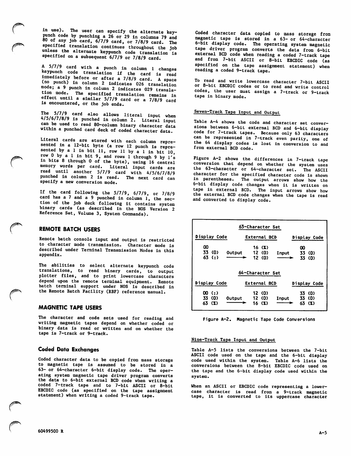
/$^\
jf^^\
in use). The user can specify the alternate key
punch code by punching a 26 or 29 in columns 79 and
80 of any job card, 6/7/9 card, or 7/8/9 card. The
specified translation continues throughout the job
unless the alternate k e y p u n c h c o d e t r a n s l a t i o n i s
specified on a subsequent 6/7/9 or 7/8/9 card.
A 5/ 7 /9 c ar d w i t h a p u n c h in c o l u mn 1 c h a n g e s
keypunch code translation if the card is read
immediately before or after a 7/8/9 card. A space
(no punch) in column 2 indicates 026 translation
mode; a 9 punch in column 2 indicates 029 transla
tion mode. The specified translation remains in
effect until a similar 5/7/9 card or a 7/8/9 card
is encountered, or the job ends.
VZ/JiVJ* Trd alS° allows literal inPut w*en
1/5/6/7/8/9 is punched in column 2. Literal input
can be used to read 80-column binary character data
within a punched card deck of coded character data.
Literal cards are stored with each column repre
sented in a 12-bit byte (a row 12 punch is repre
sented by a 1 in bit 11, row 11 by a 1 in bit 10,
row 0 by a 1 in bit 9, and rows 1 through 9 by l's
in bits 8 through 0 of the byte), using 16 central
memory words per card. Literal input cards are
read until another 5/7/9 card with 4/5/6/7/8/9
punched i n c o l umn 2 is read. The next c a r d c a n
specify a new conversion mode.
If the card following the 5/7/9, 6/7/9, or 7/8/9
card has a 7 and a 9 punched in column 1, the sec
tion of the job deck following it contains system
binary cards (as described in the NOS Version 2
Reference Set, Volume 3, System Commands).
REMOTE BATCH USERS
Remote batch console input and output is restricted
to character mode transmission. Character mode is
described under Terminal Transmission Modes in this
appendix.
T h e a b i l i t i e s t o s e l e c t a l t e r n a t e k e y p u n c h c o d e
translations, to read binary cards, to output
plotter files, and to print lowercase characters
depend upon the remote terminal equipment. Remote
batch t e rminal s upport u nder N O S is descr i b e d in
the Remote Batch Facility (RBF) reference manual.
MAGNETIC TAPE USERS
The character and code sets used for reading and
writing magnetic tapes depend on whether coded or
binary data is read or written and on whether the
tape is 7-track or 9-track.
Coded Data Exchanges
Coded character data to be copied from mass storage
to magnetic tape is assumed to be stored in a
63- or 64-character 6-bit display code. The oper
ating system magnetic tape driver program converts
the data to 6-bit external BCD code when writing a
coded 7-track tape and to 7-bit ASCII or 8-bit
EBCDIC code (as specified on the tape assignment
statement) when writing a coded 9-track tape.
Coded character data copied to mass storage from
magnetic tape is stored in a 63- or 64-character
6-bit display code. The operating system magnetic
tape driver program converts the data from 6-bit
external BCD code when reading a coded 7-track tape
a n d f r o m 7 - b i t A S C I I o r 8 - b i t E B C D I C c o d e ( a s
specified on the tape assignment statement) when
reading a coded 9-track tape.
To read and write lowercase character 7-bit ASCII
or 8-bit EBCDIC codes or to read and write control
codes, t h e u s e r m u s t assign a 7-track o r 9 - t r a c k
tape in binary mode.
Seven-Track Tape Input and Output
Table A-4 shows the code and character set conver
sions between 6-bit external BCD and 6-bit display
code for 7-track tapes. Because only 63 characters
can be r epre sen ted in 7-trac k eve n par ity, one of
the 64 display codes is lost in conversion to and
from external BCD code.
Figure A-2 shows the differences in 7-track tape
conversion that depend on whether the system uses
the 63-character or 64-character set. The ASCII
character for the specified character code is shown
in parentheses. The output arrows show how the
6-bit display code changes when it is written on
tape in external BCD. The input arrows show how
the external BCD code changes when the tape is read
and converted to display code.
Display Code
63-Character Set
External BCD
00
33 (0)
63 (: ) Output
16 (X)
12 (0)
12 (0) Input
Display Code
00
33 (0)
33 (0)
Display Code
64-Character Set
External BCD
00 (: )
33 (0)
63 (%)
Output
12 (0)
12 (0)
16 (%)
Input
Display Code
33 (0)
33 (0)
- 6 3 ( X )
Figure A-2. Magnetic Tape Code Conversions
Nine-Track Tape Input and Output
Table A-5 lists the conversions between the 7-bit
ASCII code used on the tape and the 6-bit display
c o d e u s e d w i th i n th e s ys t e m . Ta bl e A - 6 li s t s t h e
conversions between the 8-bit EBCDIC code used on
the tape and the 6-bit display code used within the
system.
When an ASCII or EBCDIC code representing a lower
case character is read from a 9-track magnetic
tape, it is converted to its uppercase character
60499500 R A-5
6-bit display code equivalent. Any EBCDIC code not
listed in table A-6 is converted to display code 55
(octal) and becomes a space. Any code between 80
(hexadecimal) and FF (hexadecimal) read from an
ASCII tape is converted to display code 00.
Binary Character Data Exchanges
Binary character data exchanged between central
memory files and magnetic tape is transferred as a
string of bytes without conversion of the byte
contents. The grouping of the bytes and the number
of bits in each byte depend on whether 7-track or
9-track tape is being used.
Seven-Track Tape Input and Output
Each binary data character code written to or read
from 7-track magnetic tape is assumed to be stored
in a 6-bit byte, such as the system uses for 63- or
64-character 6-bit display code. Seven-bit ASCII
and 8-bit EBCDIC codes can only be read from or
written to 7-track magnetic tape as binary charac
ter data if each code is stored within a 12-bit
byte as if it were two character codes.
Nine-Track Tape Input and Output
Each binary data character code exchanged between
central memory files and 9-track magnetic tape is
assumed to be stored in an 8-bit or 12-bit byte.
During such binary data transfers, the 6/12-bit
display codes and 12-bit ASCII codes shown in table
A-l, the 7-bit ASCII codes shown in table A-2, or
or the 8 -bit h exad ecim al EBC DIC code s show n in
table A-7 can be read or written. The 7-bit ASCII
codes and 8-bit EBCDIC codes can be exchanged
e i t h e r i n a n u n f o r m a t t e d f o r m o r r i g h t - j u s t i fi e d
within a zero-filled 12-bit byte of memory.
When 9-track tape is written, every pair of 12-bit
memory bytes becomes three 8-bi' •xpe bytes; when
9 - t r a c k t a p e i s r e a d , e v e r y t h i - b i t t a p e b y t e s
become a pair of 12-bit memory -oytes. Because of
the 12-bit byte pairs, codes not packed into 12-bit
bytes are exchanged in their unpacked form, while
codes packed in 12-bit bytes are exchanged in
packed form.
When an odd number of central memory words is read
or written, the lower four bits of the last 8-bit
byt e ( b i t s 0 t h rough 3 of t h e l a s t w ord) are n o t
used. For example, three central memory words are
written on tape as 22 8-bit bytes (7.5 pairs of
12-bit bytes) and the remaining four bits are
ignored.
CODE CONVERSION AIDS
Table A-7 contains the octal values of each 8-bit
EBCDIC code right-justified in a 12-bit byte with
zero fill. This 12-bit EBCDIC code can be produced
or read using the FORM and 8-Bit Subroutines
utilities.
/*8^K
A-6 60499500 R
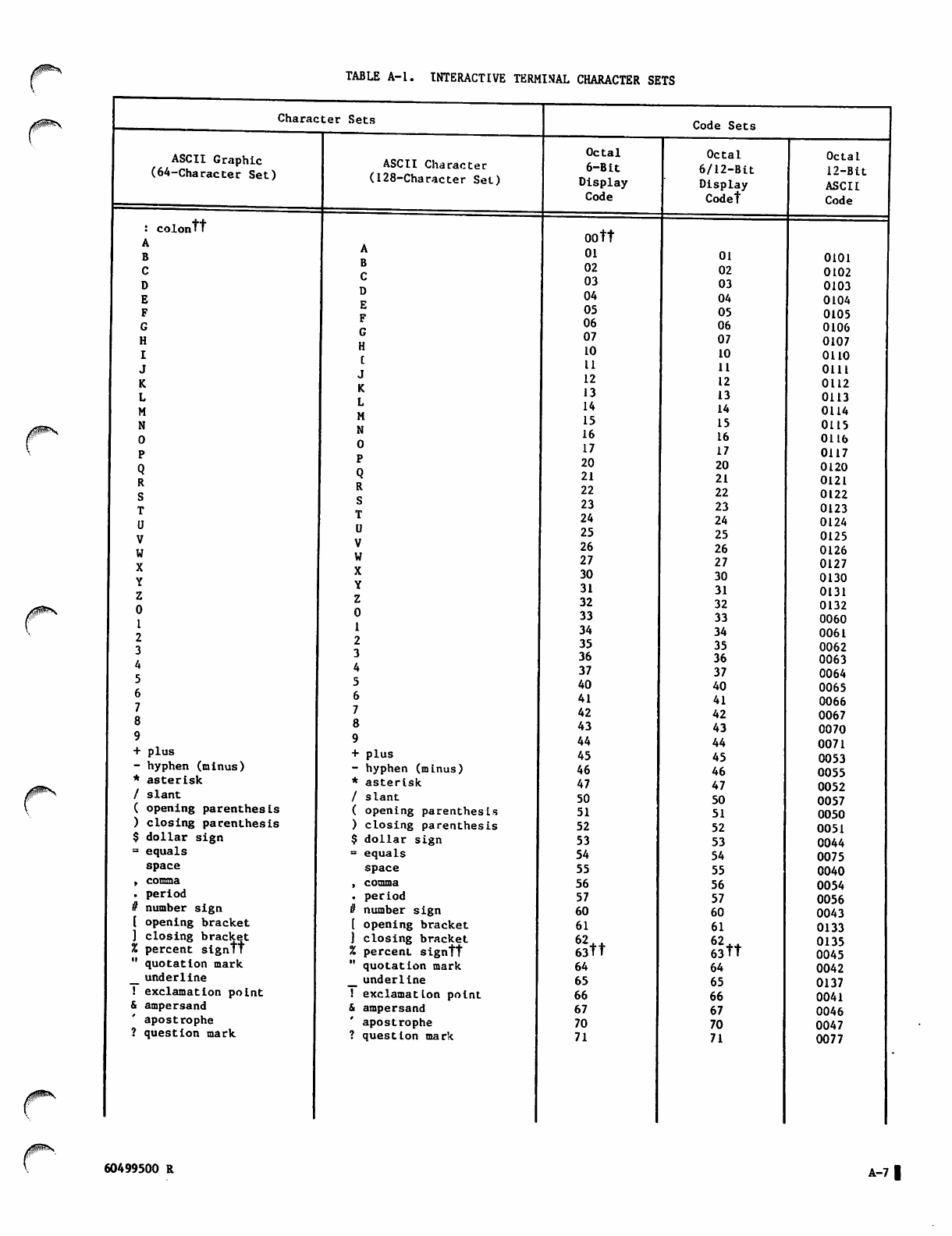
TABLE A-l. INTERACTIVE TERMINAL CHARACTER SETS
Character Sets
ASCII Graphic
(64-Character Set)
: colontt
A
B
C
D
E
F
G
H
I
J
K
L
M
N
0
P
Q
R
S
T
U
V
w
X
Y
Z
0
1
2
3
4
5
6
7
8
9
+ plus
- hyphen (minus)
* aste r i s k
/ s l an t
( opening parenthesis
) closing parenthesis
$ dollar sign
= equals
space
, comma
. period
it number sign
[ opening bracket
] closing bracket
% percent signtt
" quotation mark
_ underline
! exclamation point
& ampersand
apostrophe
? question mark
ASCII Character
(128-Character Set)
A
B
C
D
E
F
G
H
C
J
K
L
M
N
0
P
Q
R
S
T
U
V
W
X
Y
Z
0
1
2
3
4
5
6
7
8
9
+plus
hyphen (minus)
asterisk
slant
opening parenthesis
closing parenthesis
dollar sign
equals
space
comma
period
number sign
opening bracket
closing bracket
percent signtt
quotation mark
underline
exclamation point
ampersand
apostrophe
question mark
Code Sets
Octal
6 - B i t
Display
Code
00 tt
01
02
03
04
05
06
07
10
11
12
13
14
15
16
17
20
21
22
23
24
25
26
27
30
31
32
33
34
35
36
37
40
41
42
43
44
45
46
47
50
51
52
53
54
55
56
57
60
61
Stt
64
65
66
67
70
71
Octal
6/12-Bit
Display
Codet
01
02
03
04
05
06
07
10
11
12
13
14
15
16
17
20
21
22
23
24
25
26
27
30
31
32
33
34
35
36
37
40
41
42
43
44
45
46
47
50
51
52
53
54
55
56
57
60
61
62 tt
63 tt
64
65
66
67
70
71
Octal
12-Bit
ASCII
Code
0101
0102
0103
0104
0105
0106
0107
0110
0111
0112
0113
0114
0115
0116
0117
0120
0121
0122
0123
0124
0125
0126
0127
0130
0131
0132
0060
0061
0062
0063
0064
0065
0066
0067
0070
0071
0053
0055
0052
0057
0050
0051
0044
0075
0040
0054
0056
0043
0133
0135
0045
0042
0137
0041
0046
0047
0077
r60499500 R A-7 |
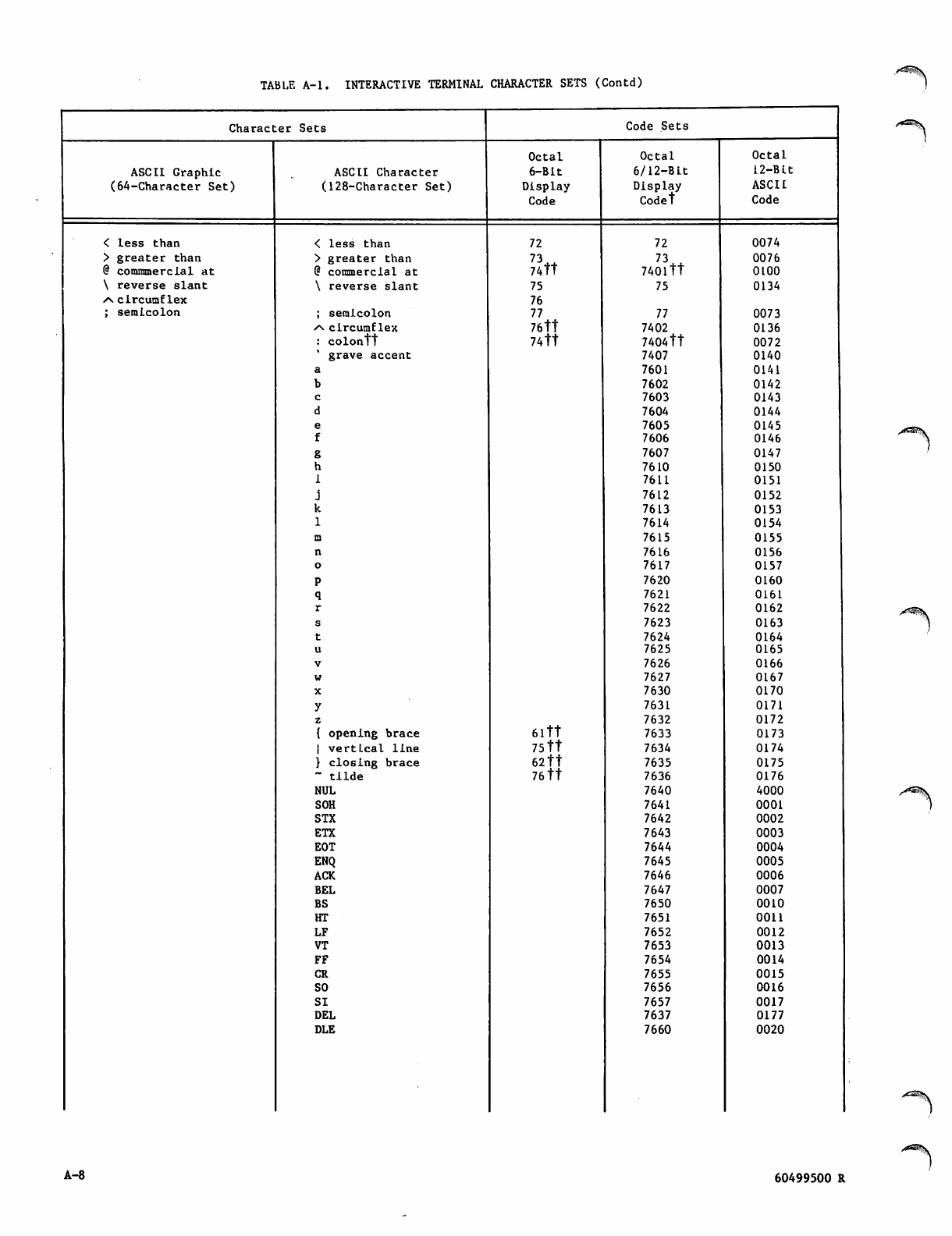
TABLE A-l. INTERACTIVE TERMINAL CHARACTER SETS (Contd)
Character Sets Code Sets
Octal Octal Octal
ASCII Graphic ASCII Character 6-Bit 6/12-Blt 12-Blt
(64-Character Set) (128-Character Set) Display Display ASCII
Code Codet Code
< less than < less than 72 72 0074
> greater than > greater than 73*+ 73*J. 0076
@ commmercial at @ commercial at 74tt 740ltt 0100
\ reverse slant \ reverse slant 75 75 0134
.a. circumflex 76
; semicolon ; semicolon 77 77 0073
/s circumflex 76tt 7402 0136
: colontt 74tt 7404tt 0072
' grave accent 7407 0140
a7601 0141
b7602 0142
c7603 0143
d7604 0144
e7605 0145
f7606 0146
g7607 0147
h7610 0150
1 7611 0151
j7612 0152
k7613 0153
17614 0154
m7615 0155
n7616 0156
o7617 0157
P7620 0160
q7621 0161
r7622 0162
s7623 0163
t7624 0164
u7625 0165
v7626 0166
w7627 0167
X7630 0170
y7631 0171
z7632 0172
{ opening brace 6 l t t 7633 0173
| vertical line 75 tt 7634 0174
} closing brace 62 tt 7635 0175
~ tilde 76 tt 7636 0176
NUL 7640 4000
SOH 7641 0001
STX 7642 0002
ETX 7643 0003
EOT 7644 0004
ENQ 7645 0005
ACK 7646 0006
BEL 7647 0007
BS 7650 0010
HT 7651 0011
LF 7652 0012
VT 7653 0013
FF 7654 0014
CR 7655 0015
SO 7656 0016
SI 7657 0017
DEL 7637 0177
DLE 7660 0020
A-8 60499500 R
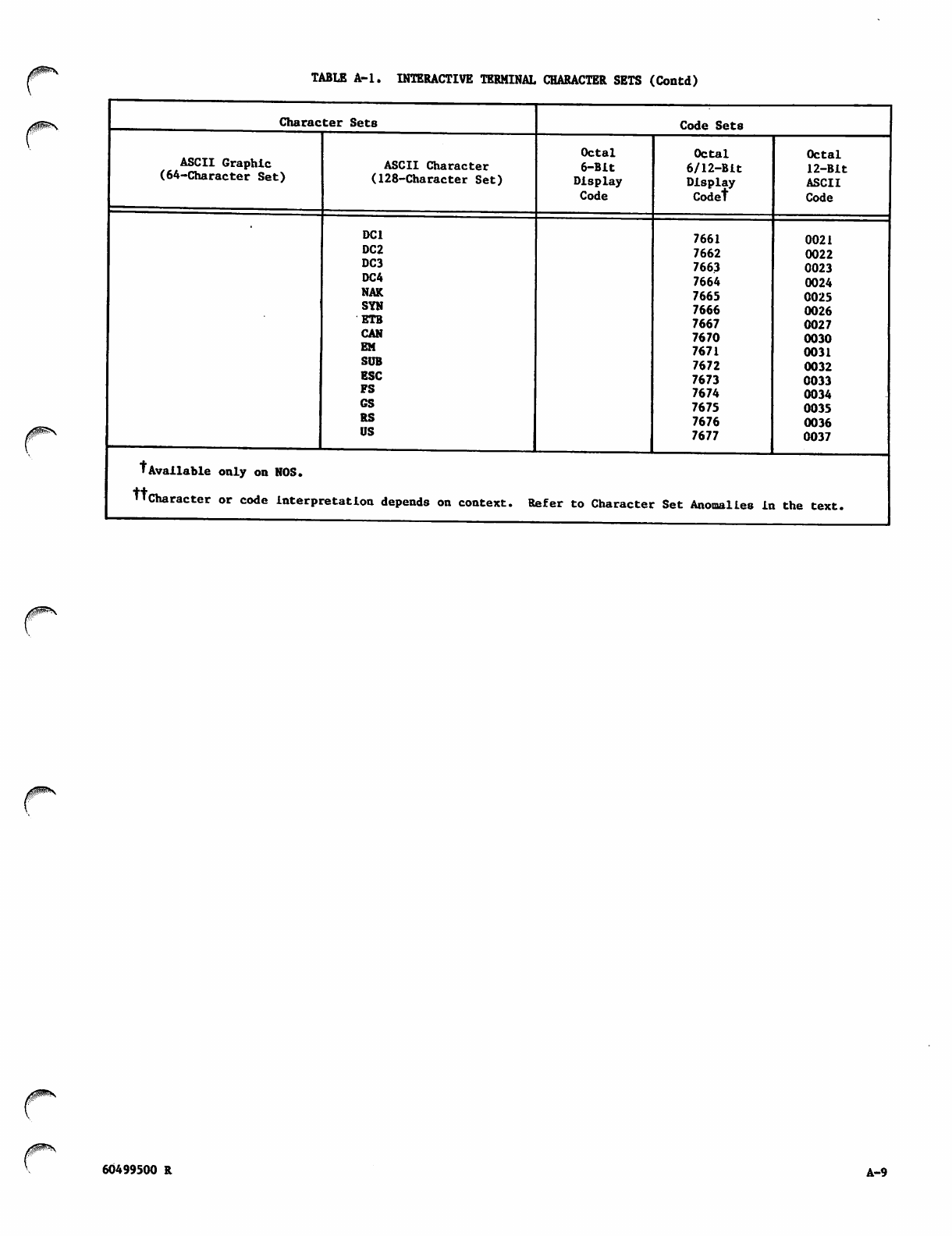
/gS^N TABLE A-l. INTERACTIVE TERMINAL CHARACTER SETS (Contd)
Character Sets
ASCII Graphic
(64-Character Set) ASCII Character
(128-Character Set)
DC1
DC2
DC3
DC4
NAK
SYN
ETB
CAN
EM
SUB
ESC
FS
GS
RS
US
Code Sets
Octal
6-Bit
Display
Code
Octal
6/12-Bit
Display
Codet
7661
7662
7663
7664
7665
7666
7667
7670
7671
7672
7673
7674
7675
7676
7677
Octal
12-Bit
ASCII
Code
0021
0022
0023
0024
0025
0026
0027
0030
0031
0032
0033
0034
0035
0036
0037
tAvailable only on NOS.
ttcharacter or code interpretation depends on context. Refer to Character Set Anomalies in the text.
60499500 R A-9
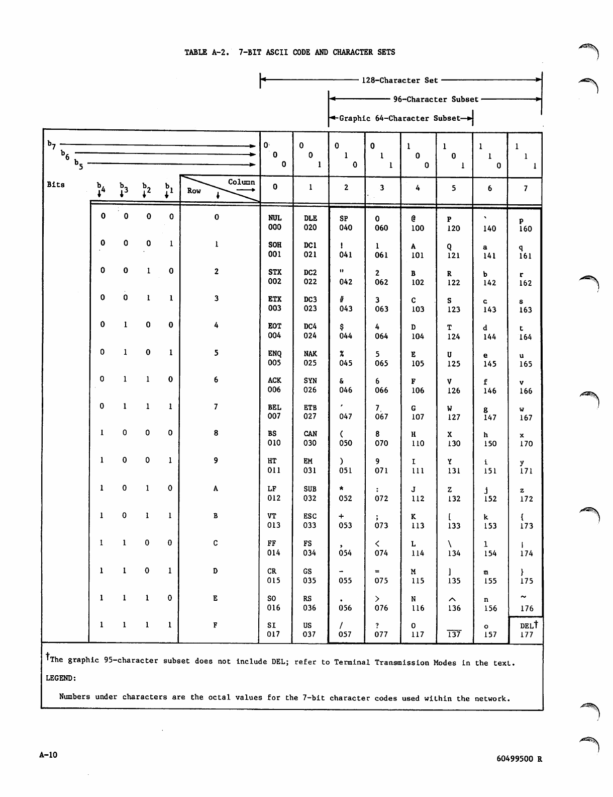
TABUS A-2. 7-BIT ASCII CODE AND CHARACTER SETS
h128-Character Set
96-Character Subset
■•-Graphic 64-Character Subset—w
K0
0
0
0
0
1
0
1
0
0
1
1
1
0
0
1
0
1
' V
6 b , -
5
b 3 b 2
B i t s ^*-^^ Column
Row i***^^-*
0 0 0 NUL
000
DLE
020
SP
040 060 100 120 140 160
00 0 SOH
001
DC1
021 041 061 101 121 141 161
00 1 STX
002
DC2
022 042 062 102 122 142 162
00 1 ETX
003
DC3
023
if
043 063 103 123 143 163
01 0 EOT
004
DC4
024 044 064 104 124 144 164
01 0 ENQ
005
NAK
025 045 065 105 125 145 165
01 1 ACK
006
SYN
026 046 066 106 126 146 166
01 1 BEL
007
ETB
027 047 067 107 127 147 167
0 0 BS
010
CAN
030 050 070 110 130 150 170
0 0 HT
011
EM
031 051 071 Ul 131 151 171
0 1 LF
012
SUB
032 052 072 112 132 152 172
0 1 VT
013
ESC
033 053 073 113 133 153 173
1 0 FF
014
FS
034 054 074 114 134 154 174
1 0 CR
015
GS
035 055 075 115 135 155 175
1 1
1 1
SO
016
SI
017
RS
036
US
037
056
/
057
076
1
077
116
O
117
136
737
156
o
157
176
DELt
177
tThe graphic 95- character subs et does not include DEL; refer to Termina1 Transra ission Modes in the texL.
LEGEND:
Numbers under characte rs at e the octal values for the 7-bit characte r codes used within the network
A-10 60499500 R
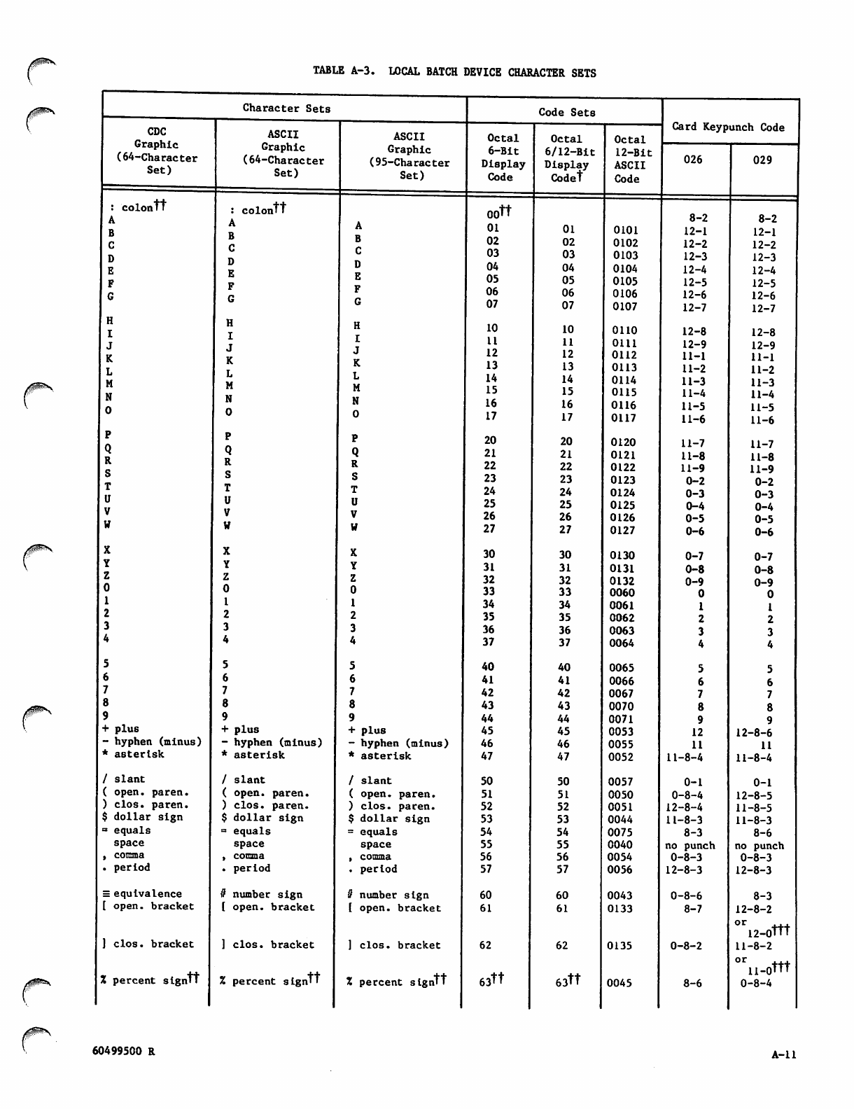
TABLE A-3. LOCAL BATCH DEVICE CHARACTER SETS
Character Sets
CDC
Graphic
(64-Character
Set)
colontt
A
B
C
D
E
F
G
H
I
J
K
L
M
N
0
P
Q
R
S
T
U
V
W
X
Y
Z
0
1
2
3
5
6
7
8
9
+ plus
- hyphen (minus)
* asterisk
/ s l an t
( open, paren.
) clos. paren.
$ dollar sign
= equals
space
, comma
. period
= equivalence
[ open, bracket
] clos. bracket
X percent signtt
ASCII
Graphic
(64-Character
Set)
: colontt
A
B
C
D
E
F
G
H
I
J
K
L
M
N
0
P
Q
R
S
T
U
V
W
X
Y
Z
0
1
2
3
4
5
6
7
6
9
+ plus
- hyphen (minus)
* asterisk
/ slant
( open, paren.
) clos. paren.
$ dollar sign
= equals
space
, comma
. period
it number sign
( open, bracket
] clos. bracket
% percent signtt
ASCII
Graphic
(95-Character
Set)
A
B
C
D
E
F
G
H
I
J
K
L
M
N
0
P
Q
R
S
T
U
V
W
X
Y
Z
0
1
2
3
4
5
6
7
8
9
+ plus
- hyphen (minus)
* asterisk
/ s l an t
( open, paren.
) clos. paren.
$ dollar sign
= equals
space
, comma
. period
9 number sign
[ open, bracket
] clos. bracket
X percent signtt
Code Sets
Octal
6-Bit
Display
Code
oott
01
02
03
04
05
06
07
10
11
12
13
14
15
16
17
20
21
22
23
24
25
26
27
30
31
32
33
34
35
36
37
40
41
42
43
44
45
46
47
50
51
52
53
54
55
56
57
60
61
62
63tt
Octal
6/12-Bit
Display
Codet
01
02
03
04
05
06
07
10
11
12
13
14
15
16
17
20
21
22
23
24
25
26
27
30
31
32
33
34
35
36
37
40
41
42
43
44
45
46
47
50
51
52
53
54
55
56
57
60
61
62
63TT
Octal
12-Bit
ASCII
Code
0101
0102
0103
0104
0105
0106
0107
0110
0111
0112
0113
0114
0115
0116
0117
0120
0121
0122
0123
0124
0125
0126
0127
0130
0131
0132
0060
0061
0062
0063
0064
0065
0066
0067
0070
0071
0053
0055
0052
0057
0050
0051
0044
0075
0040
0054
0056
0043
0133
0135
0045
Card Keypunch Code
026
8-2
12-1
12-2
12-3
12-4
12-5
12-6
12-7
12-8
12-9
11-1
11-2
11-3
11-4
11-5
11-6
11-7
11-8
11-9
0-2
0-3
0-4
0-5
0-6
0-7
0-8
0-9
0
1
2
3
4
5
6
7
8
9
12
11
11-8-4
0-1
0-8-4
12-8-4
11-8-3
8-3
no punch
0-8-3
12-8-3
0-8-6
8-7
0-8-2
029
8-6
8-2
12-1
12-2
12-3
12-4
12-5
12-6
12-7
12-8
12-9
11-1
11-2
11-3
11-4
11-5
11-6
11-7
11-8
11-9
0-2
0-3
0-4
0-5
0-6
0-7
0-8
0-9
0
1
2
3
4
5
6
7
8
9
12-8-6
11
11-8-4
0-1
12-8-5
11-8-5
11-8-3
8-6
no punch
0-8-3
12-8-3
8-3
12-8-2
°ri2-0ttt
11-8-2
"ii-ottt
0-8-4
60499500 R A-ll
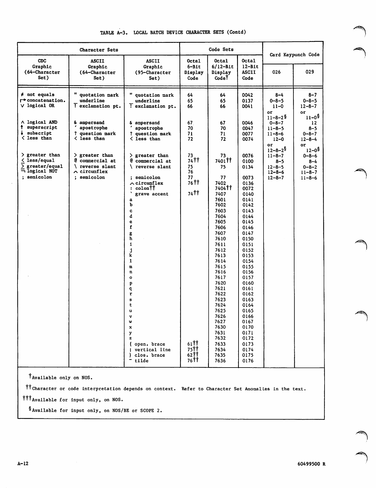
TABLE A-3. LOCAL BATCH DEVICE CHARACTER SETS (Contd)
Character Sets Code Sets
Card Keypunch Code
CDC
Graphic
ASCII
Graphic
ASCII
Graphic
Octal
6-Bit
Octal
6/12-Bit
Octal
12-Bit
(64-Character (64-Character (95-Character Display Display ASCII 026 029
Set) Set) Set) Code Codet Code
4 not equals " quotation mark " quotation mark 64 64 0042 8-4 8-7
(-♦ concatenation. _ underline _ underline 65 65 0137 0-8-5 0-8-5
V logical OR ! exclamation pt. ! exclamation pt. 66 66 0041 11-0
or
11-8-2§
12-8-7
o r 8
ll-0§
A logical AND & ampersand & ampersand 67 67 0046 0-8-7 12
t superscript ' apostrophe ' apostrophe 70 70 0047 11-8-5 8-5
x subscript ? question mark ? question mark 71 71 0077 11-8-6 0-8-7
< less than < less than < less than 72 72 0074 12-0
° r 8
12-8-28
12-8-4
or
12-0§
> greater than > greater than > greater than 73 73^ 0076 11-8-7 0-8-6
£ less/equal @ commercial at @ commercial at 74tt 740ltt 0100 8-5 8-4
> greater/equal \ r eve rse slant \ reverse slant 75 75 0134 12-8-5 0-8-2
—i logical NOT zs circumflex 76 12-8-6 11-8-7
; semicolon ; semicolon ; semicolon 77 77 0073 12-8-7 11-8-6
•s circumflex 76tt 7402 0136
: colontt 7404tt 0072
* grave accent 74tt 7407 0140
a7601 0141
b7602 0142
c7603 0143
d7604 0144
e7605 0145
f7606 0146
g7607 0147
h7610 0150
i7611 0151
j7612 0152
k7613 0153
17614 0154
m7615 0155
n7616 0156
o7617 0157
P7620 0160
q7621 0161
r7622 0162
s7623 0163
t7624 0164
u7625 0165
v7626 0166
w7627 0167
X7630 0170
y7631 0171
z7632 0172
{ open, brace 6ltt 7633 0173
| vertical lLne 75tt 7634 0174
} clos. brace 62tt
76tt
7635 0175
~ tilde 7636 0176
'Avail able o nljr on NOS.
TTcharacter or ;o d e i n t e r p r e t a t i on depends on context. Refer to CCharacter St;t Anomallles in the t:ext.
tttAvailable for input only, on NOS.
& Available for input only, on NOS/ BE or SCOPE 2.
A-12 60499500 R
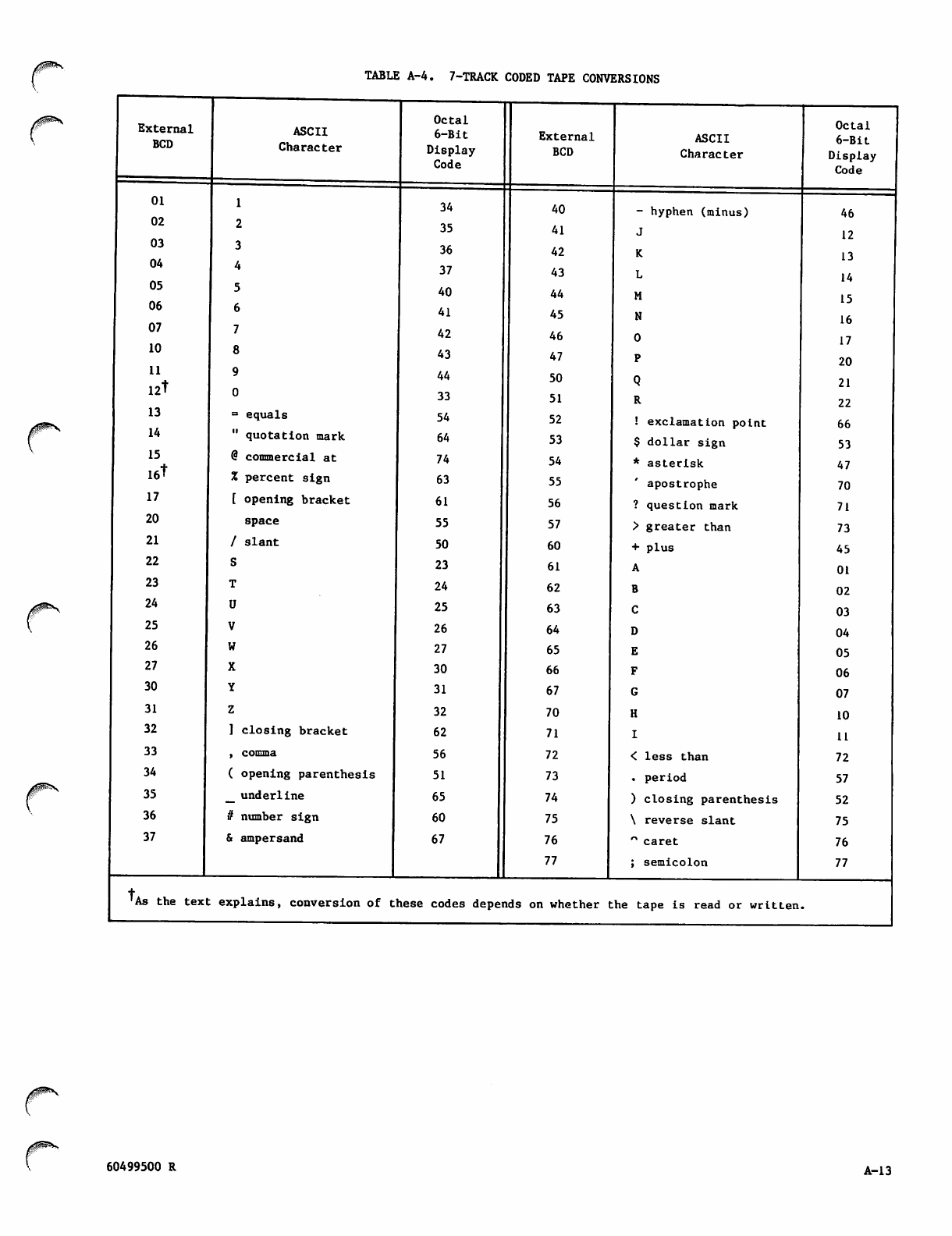
/#**•<■TABLE A-4. 7-TRACK CODED TAPE CONVERSIONS
External
BCD ASCII
Character
Octal
6-Bit
Display
Code
External
BCD
ASCII
Character
Octal
6 - B i t
Display
Code
01
02
03
04
05
06
07
10
34 40 - hyphen (minus) 46
2
3
4
5
6
7
8
35
36
37
40
41
42
43
41
42
43
44
45
46
47
12
13
14
15
16
17
20
11
12t
13 = equals
44
33
54
50
51
52 ! exclamation point
21
22
66
14 " quotation mark 64 53 $ dollar sign 53
15
16t
@ commercial at 74 54 * asterisk 47
% percent sign 63 55 apostrophe 70
17 [ opening bracket 61 56 ? question mark 71
20 space 55 57 > greater than 73
21 / slant 50 60 + plus 45
22 23 61 01
23 24 62 02
24 25 63 03
25 26 64 04
26 27 65 05
27 30 66 06
30 31 67 07
31 32 70 10
32 ] closing bracket 62 71 11
33 , comma 56 72 < less than 72
34 ( opening parenthesis 51 73 . period 57
35 _ underline 65 74 ) closing parenthesis 52
36 it number sign 60 75 \ reverse slant 75
37 & ampersand 67 76 " caret 76
"; semicolon 77
+
'As the text: explains, conversion of t lese codes depeiids on whether t.he tape is read or written
60499500 R A-l 3
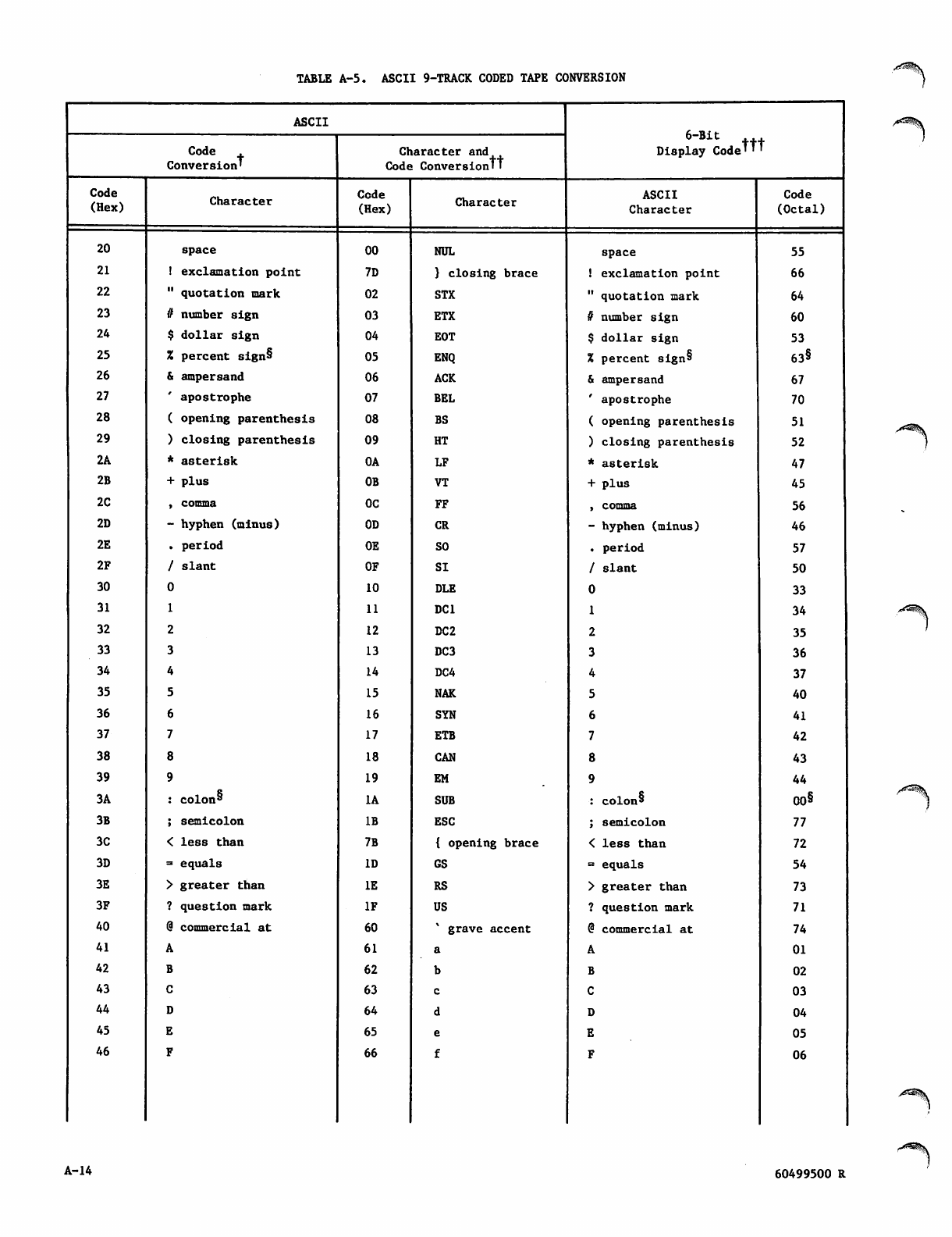
TABLE A-5. ASCII 9-TRACK CODED TAPE CONVERSION
ASCII
C o d e .
Conversion'
Character and
Code Conversiontt
Display Codettt
Code
(Hex) Character Code
(Hex) Character ASCII
Character
Code
(Octal)
20 space 00 NUL space 55
21 ! exclamation point 7D } closing brace ! exclamation point 66
22 " quotation mark 02 STX " quotation mark 64
23 it number sign 03 ETX it number sign 60
24 $ dollar sign 04 EOT $ dollar sign 53
25 X percent sign§ 05 ENQ % percent sign§ 63§
26 & ampersand 06 ACK & ampersand 67
27 ' apostrophe 07 BEL ' apostrophe 70
28 ( opening parenthesis 08 BS ( opening parenthesis 51
29 ) closing parenthesis 09 HT ) closing parenthesis 52
2A * asterisk 0A LF * asterisk 47
2B + plus 0B VT + plus 45
2C , comma OC FF , comma 56
2D - hyphen (minus) 0D CR - hyphen (minus) 46
2E . period 0E SO . period 57
2F / slant OF SI / s l a n t 50
30 10 DLE 33
31 11 DC1 34
32 12 DC2 35
33 13 DC3 36
34 14 DC4 37
35 15 NAK 40
36 16 SYN 41
37 17 ETB 42
38 18 CAN 43
39 19 EM 44
3A : colon* 1A SUB : colon^ 00§
3B ; semicolon IB ESC ; semicolon 77
3C < less than 7B { opening brace < less than 72
3D = equals ID GS = equals 54
3E > greater than IE RS > greater than 73
3F ? question mark IF US ? question mark 71
40 @ commercial at 60 grave accent @ commercial at 74
41 61 01
42 62 02
43 63 03
44 64 04
45 65 05
46 66 06
A-14 60499500 R
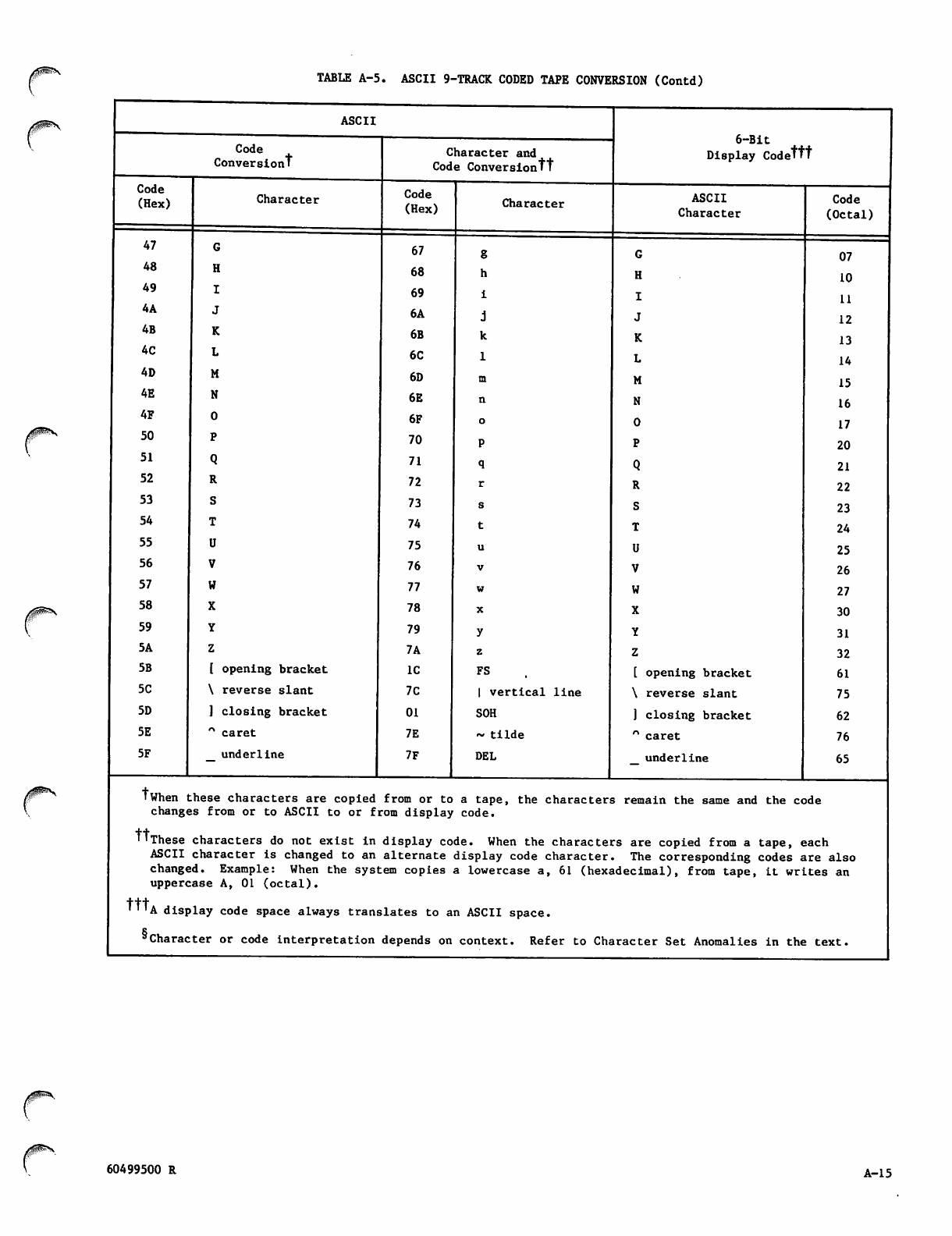
TABLE A-5. ASCII 9-TRACK CODED TAPE CONVERSION (Contd)
Code
(Hex)
47
48
49
4A
4B
4C
4D
4E
4F
50
51
52
53
54
55
56
57
58
59
5A
5B
5C
5D
5E
5F
ASCII
Code
Conversiont
Characte i
G
H
I
J
K
L
M
N
0
P
Q
R
S
T
U
V
W
X
Y
Z
[ opening bracket
\ reverse slant
] closing bracket
" caret
underline
Character and
Code Conversiontt
Code
(Hex)
67
68
69
6A
6B
6C
6D
6E
6F
70
71
72
73
74
75
76
77
78
79
7A
IC
7C
01
7E
7F
Character
w
X
y
z
FS
I vertical line
SOH
~ tilde
DEL
6 - B i t
Display Codettt
ASCII
Character
G
H
I
J
K
L
M
N
0
P
Q
R
S
T
U
V
W
X
Y
Z
[ opening bracket
\ reverse slant
] closing bracket
n caret
underline
Code
(Octal)
07
10
11
12
13
14
15
16
17
20
21
22
23
24
25
26
27
30
31
32
61
75
62
76
65
'When these characters are copied from or to a tape, the characters remain the same and the code
changes from or to ASCII to or from display code.
tt
i'These characters do not exist in display code. When the characters are copied from a tape, each
ASCII character is changed to an alternate display code character. The corresponding codes are also
changed. Example: When the system copies a lowercase a, 61 (hexadecimal), from tape, it writes an
uppercase A, 01 (octal).
tttA display code space always translates to an ASCII space.
'Character or code interpretation depends on context. Refer to Character Set Anomalies in the text.
60499500 R A-l 5
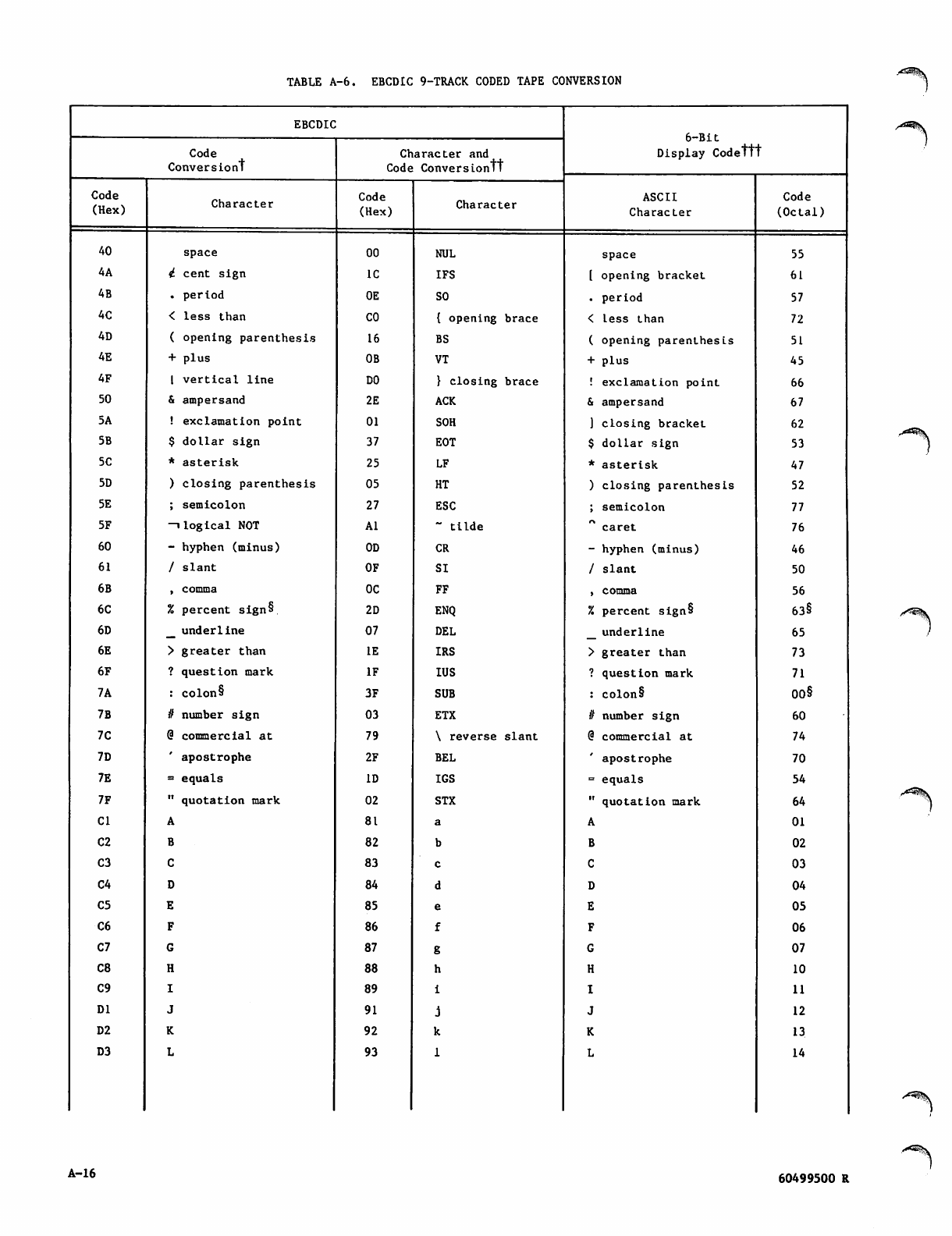
TABLE A-6. EBCDIC 9-TRACK CODED TAPE CONVERSION
EBCDIC
6-Bit
Display Codett
Code Character and
Conversiont Code Conversiontt
Code
(Hex) Character Code
(Hex) Character ASCII
Character
Code
(Octal)
40 space 00 NUL space 55
4A i cent sign IC IFS [ opening bracket 61
4B . period 0E SO . period 57
4C < less than CO { opening brace < less than 72
4D ( opening parenthesis 16 BS ( opening parenthesis 51
4E + plus 0B VT + plus 45
4F I vertical line DO } closing brace ! exclamation point 66
50 & ampersand 2E ACK & ampersand 67
5A ! exclamation point 01 SOH ] closing bracket 62
5B $ dollar sign 37 EOT $ dollar sign 53
5C * aste r i s k 25 LF * a s t e r i s k 47
5D ) closing parenthesis 05 HT ) closing parenthesis 52
5E ; semicolon 27 ESC ; semicolon 77
5F —i logical NOT Al " tilde c are t 76
60 - hyphen (minus) 0D CR - hyphen (minus) 46
61 / s l an t OF SI / s l an t 50
6B , comma OC FF , comma 56
6C % percent sign§ 2D ENQ % percent sign§ 63§
6D _ underline 07 DEL _ underline 65
6E > greater than IE IRS > greater than 73
6F ? question mark IF IUS ? question mark 71
7A : colon§ 3F SUB : colon§ 00§
7B it number sign 03 ETX it number sign 60
7C @ commercial at 79 \ reverse slant @ commercial at 74
7D ' apostrophe 2F BEL apostrophe 70
7E = equals ID IGS = equals 54
7F " quotation mark 02 STX " quotation mark 64
Cl 81 01
C2 82 02
C3 83 03
C4 84 04
C5 85 05
C6 86 06
C7 87 07
C8 88 10
C9 89 11
DI 91 12
D2 92 13
D3 93 14
A-16 60499500 R
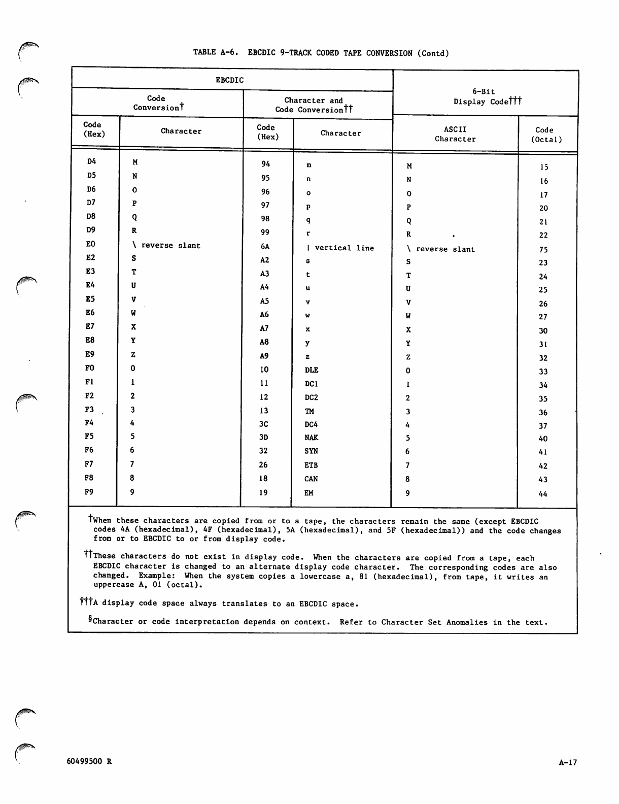
TABLE A-6. EBCDIC 9-TRACK CODED TAPE CONVERSION (Contd)
EBCDIC
D - B l t
Code
Conversiont Character and Display Codettt
Code Conversiontt
Code
(Hex) Character Code
(Hex) Character ASCII Code
Character (Octal)
D4 94 15
D5 95 16
D6 96 17
D7 97 20
D8 98 21
D9 99 22
EO \ reverse slant 6A 1 vertical line \ reverse slant 75
E2 A2 23
E3 A3 24
E4 A4 25
E5 A5 26
E6 A6 27
E7 A7 30
E8 A8 31
E9 A9 32
FO 10 DLE 33
Fl 11 DC1 34
F2 12 DC2 35
F3 13 TM 36
F4 3C DC4 37
F5 3D NAK 40
F6 32 SYN 41
F7 26 ETB 42
F8 18 CAN 43
F9 19 EM 44
twhen these characters are copied from or to a tape, the characters remain the same (except EBCDIC
codes 4A (hexadecimal), 4F (hexadecimal), 5A (hexadecimal), and 5F (hexadecimal)) and the code changes
from or to EBCDIC to or from display code.
ttThese characters do not exist in display code. When the characters are copied from a tape, each
EBCDIC character is changed to an alternate display code character. The corresponding codes are also
changed. Example: When the system copies a lowercase a, 81 (hexadecimal), from tape, it writes an
uppercase A, 01 (octal).
tttA display code space always translates to an EBCDIC space.
'Character or code interpretation depends on context. Refer to Character Set Anomalies in the text.
60499500 R A-l 7
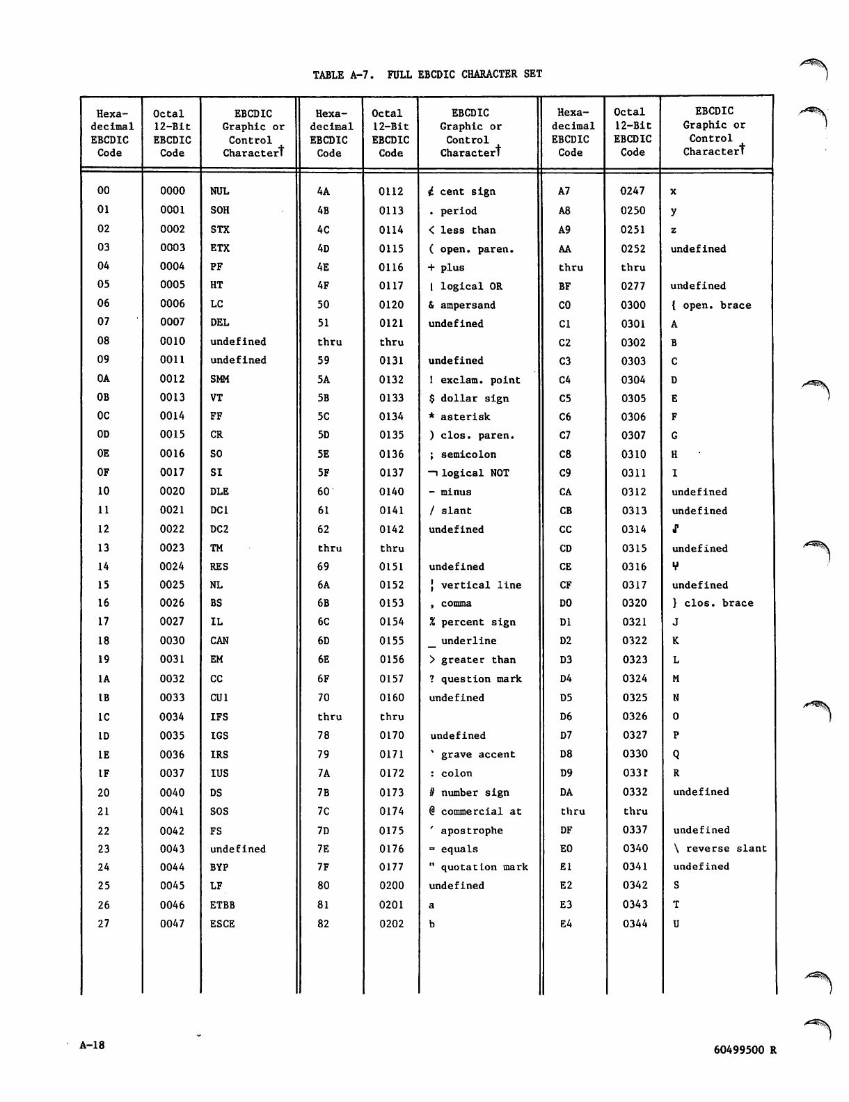
TABLE A-7. FULL EBCDIC CHARACTER SET
Hexa Octal EBCDIC Hexa Octal EBCDIC Hexa Octal EBCDIC
decimal 12-Bit Graphic or decimal 12-Bit Graphic or decimal 12-Bit Graphic or
EBCDIC EBCDIC C ontrol EBCDIC EBCDIC C o ntrol EBCDIC EBCDIC Contr o l
Charactert
Code Code Charactert Code Code Charactert Code Code
00 0000 NUL 4A 0112 i cent sign A7 0247
01 0001 SOH 4B 0113 . period A8 0250
02 0002 STX 4C 0114 < less than A9 0251
03 0003 ETX 4D 0115 ( open, paren. AA 0252 undefined
04 0004 PF 4E 0116 + plus t h r u thru
05 0005 HT 4F 0117 I logical OR BF 0277 undefined
06 0006 LC 50 0120 & ampersand CO 0300 { open, brace
07 0007 DEL 51 0121 undefined Cl 0301
08 0010 undefined thru thru C2 0302
09 0011 undefined 59 0131 undefined C3 0303
OA 0012 SMM 5A 0132 ! exclam. point C4 0304
OB 0013 VT 5B 0133 $ dollar sign C5 0305
OC 0014 FF 5C 0134 * aste r i s k C6 0306
OD 0015 CR 5D 0135 ) clos. paren. C7 0307
OE 0016 SO 5E 0136 ; semicolon C8 0310
OF 0017 SI 5F 0137 -i logical NOT C9 0311
10 0020 DLE 60 0140 - minus CA 0312 undefined
11 0021 DC1 61 0141 / s l an t CB 0313 undefined
12 0022 DC2 62 0142 undefined CC 0314
13 0023 TM thru thru CD 0315 undefined
14 0024 RES 69 0151 undefined CE 0316
15 0025 NL 6A 0152 [ v e r t i c a l l i n e CF 0317 undefined
16 0026 BS 6B 0153 , comma DO 0320 } clos. brace
17 0027 IL 6C 0154 % percent sign DI 0321
18 0030 CAN 6D 0155 underline D2 0322
19 0031 EM 6E 0156 > greater than D3 0323
1A 0032 CC 6F 0157 ? question mark D4 0324
IB 0033 CU1 70 0160 undefined D5 0325
IC 0034 IFS thru thru D6 0326
ID 0035 IGS 78 0170 undefined D7 0327
IE 0036 IRS 79 0171 * grave accent D8 0330
IF 0037 IUS 7A 0172 : colon D9 033 r
20 0040 DS 7B 0173 it number sign DA 0332 undefined
21 0041 SOS 7C 0174 @ commercial at thru thru
22 0042 FS 7D 0175 ' apostrophe DF 0337 undefined
23 0043 undefined 7E 0176 = equals E0 0340 \ reverse slant
24 0044 BYP 7F 0177 " quotation mark El 0341 undefined
25 0045 LF 80 0200 undefined E2 0342
26 0046 ETBB 81 0201 E3 0343
27 0047 ESCE 82 0202 E4 0344
A-18
'-=*^\
60499500 R
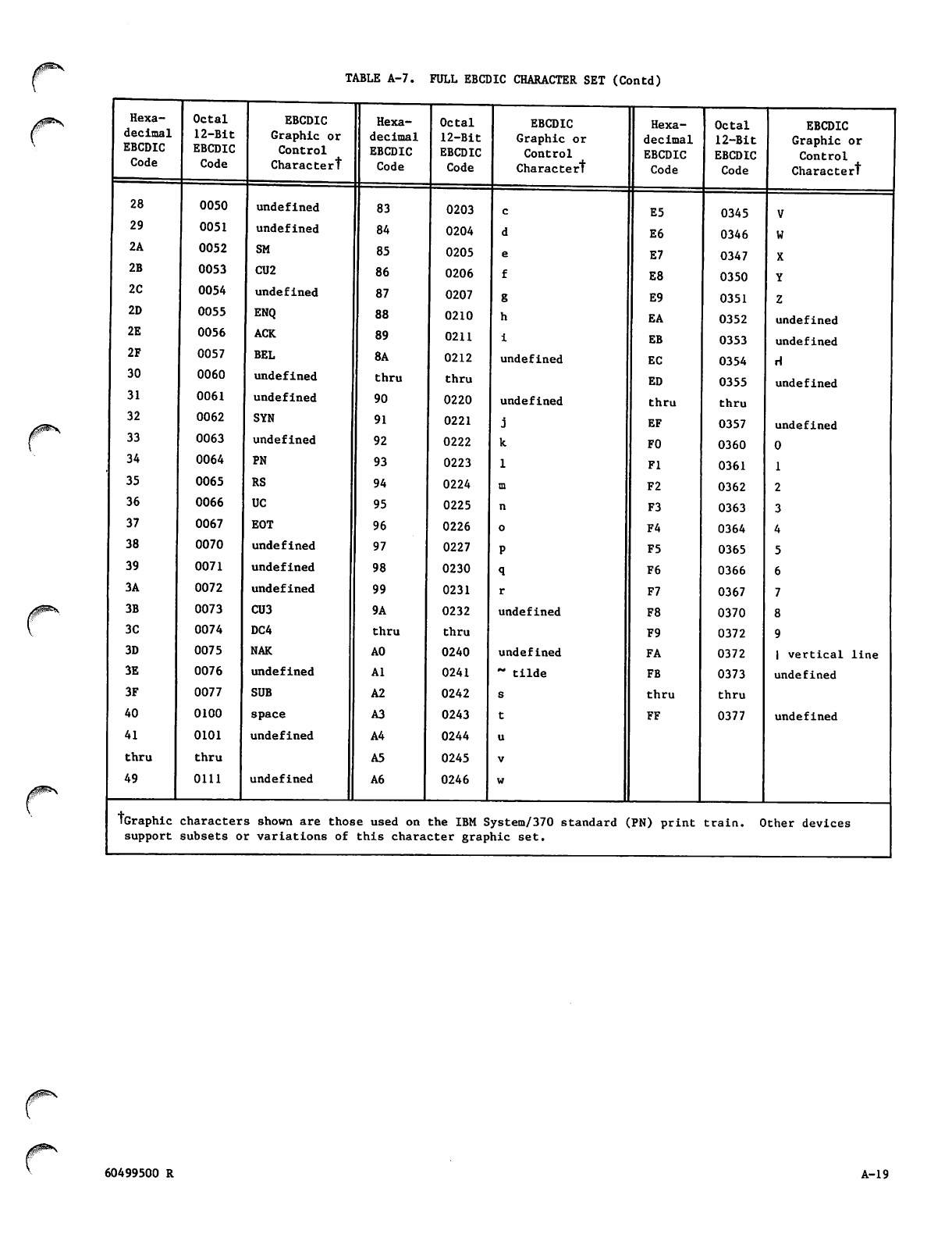
TABLE A-7. FULL EBCDIC CHARACTER SET (Contd)
Hexa
decimal
EBCDIC
Code
28
29
2A
2B
2C
2D
2E
2F
30
31
32
33
34
35
36
37
38
39
3A
3B
3C
3D
3E
3F
40
41
thru
49
Octal
12-Bit
EBCDIC
Code
0050
0051
0052
0053
0054
0055
0056
0057
0060
0061
0062
0063
0064
0065
0066
0067
0070
0071
0072
0073
0074
0075
0076
0077
0100
0101
t h r u
0111
EBCDIC
Graphic or
Control
Charactert
undefined
undefined
SM
CU2
undefined
ENQ
ACK
BEL
undefined
undefined
SYN
undefined
PN
RS
UC
EOT
undefined
undefined
undefined
CU3
DC4
NAK
undefined
SUB
space
undefined
undefined
Hexa
decimal
EBCDIC
Code
83
84
85
86
87
88
89
8A
thru
90
91
92
93
94
95
96
97
98
99
9A
t h r u
A0
Al
A2
A3
A4
A5
A6
Octal
12-Bit
EBCDIC
Code
EBCDIC
Graphic or
Control
Charactert
0203
0204
0205
0206
0207
0210
0211
0212 undefined
thru
0220 undefined
0221
0222
0223
0224
0225
0226
0227
0230
0231
0232 undefined
thru
0240 undefined
0241 ~ t i l d e
0242
0243
0244
0245
0246
Hexa
decimal
EBCDIC
Code
Octal
12-Bit
EBCDIC
Code
E5 0345
E6 0346
E7 0347
E8 0350
E9 0351
EA 0352
EB 0353
EC 0354
ED 0355
t h r u thru
EF 0357
F0 0360
Fl 0361
F2 0362
F3 0363
F4 0364
F5 0365
F6 0366
F7 0367
F8 0370
F9 0372
FA 0372
FB 0373
t h r u thru
FF 0377
EBCDIC
Graphic or
Control
Charactert
V
W
X
Y
Z
undefined
undefined
H
undefined
undefined
0
1
2
3
4
5
6
7
8
9
I v e r t i c a l l i n e
undefined
undefined
tGraphic characters shown are those used on the IBM System/370 standard (PN) print train. Other devic
support subsets or variations of this character graphic set.
J^
60499500 R A-19
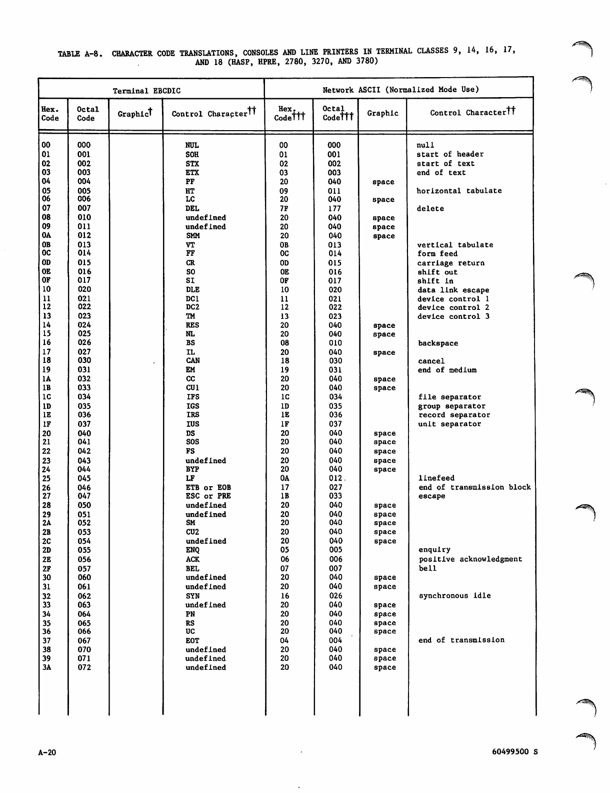
TABLE A-8. CHARACTER CODE TRANSLATIONS, CONSOLES AND LINE PRINTERS IN TERMINAL CLASSES 9, 14, 16, 17,
AND 18 (HASP, HPRE, 2780, 3270, AND 3780)
,rfS^|K
Terminal EBCDIC Network ASCII (Normalized Mode Use)
Hex.
Code
Octal
Code Graphic! Control Charapter't Hex.
Codettt
Octal
Codettt Graphic Control Charactertt
00 000 NUL 00 000 null
01 001 SOH 01 001 start of header
02 002 STX 02 002 start of text
03 003 ETX 03 003 end of text
04 004 PF 20 040 space
05 005 HT 09 on horizontal tabulate
06 006 LC 20 040 space
07 007 DEL 7F 177 delete
08 010 undefined 20 040 space
09 OU undefined 20 040 space
OA 012 SMM 20 040 space
OB 013 VT OB 013 vertical tabulate
OC 014 FF OC 014 form feed
OD 015 CR OD 015 carriage return
OE 016 SO OE 016 shift out
OF 017 SI OF 017 shift in
10 020 DLE 10 020 data link escape
11 021 DC1 11 021 device control 1
12 022 DC2 12 022 device control 2
13 023 TM 13 023 device control 3
14 024 RES 20 040 space
15 025 NL 20 040 space
16 026 BS 08 010 backspace
17 027 IL 20 040 space
18 030 CAN 18 030 cancel
19 031 EM 19 031 end of medium
1A 032 CC 20 040 space
IB 033 CU1 20 040 space
IC 034 IFS IC 034 file separator
ID 035 IGS ID 035 group separator
IE 036 IRS IE 036 record separator
IF 037 IUS IF 037 unit separator
20 040 DS 20 040 space
21 041 SOS 20 040 space
22 042 FS 20 040 space
23 043 undefined 20 040 space
24 044 BYP 20 040 space
25 045 LF OA 012. linefeed
26 046 ETB or EOB 17 027 end of transmission block
27 047 ESC or PRE IB 033 escape
28 050 undefined 20 040 space
29 051 undefined 20 040 space
2A 052 SM 20 040 space
2B 053 CU2 20 040 space
2C 054 undefined 20 040 space
2D 055 ENQ 05 005 enquiry
2E 056 ACK 06 006 positive acknowledgment
2F 057 BEL 07 007 bell
30 060 undefined 20 040 space
31 061 undefined 20 040 space
32 062 SYN 16 026 synchronous idle
33 063 undefined 20 040 space
34 064 PN 20 040 space
35 065 RS 20 040 space
36 066 UC 20 040 space
37 067 EOT 04 004 end of transmission
38 070 undefined 20 040 space
39 071 undefined 20 040 space
3A 072 undefined 20 040 space
A-20 60499500 S
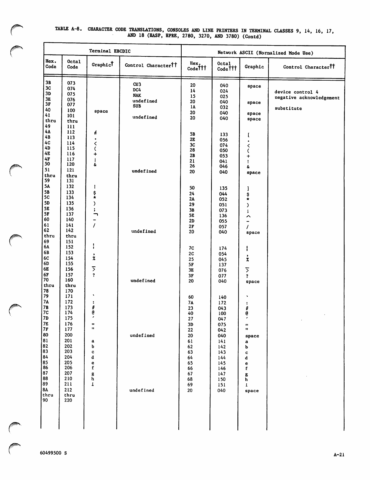
TABLE A-8. CHARACTER CODE TRANSLATIONS, CONSOLES AND LINE PRINTERS IN TERMINAL CLASSES 9, 14, 16, 17,
AND 18 (HASP, HPRE, 2780, 3270, AND 3780) (Contd)
Terminal EBCDIC Network ASCII (Normalized Mode Use)
Hex.
Code
Octal
Code Graph!ct Control Charactertt Hex.
Codettt Octal
Codettt Graphic Control Charactertt
3B
3C
3D
3E
3F
40
41
thru
073
074
075
076
077
100
101
thru
space
CU3
DC4
NAK
undefined
SUB
undefined
20
14
15
20
1A
20
20
040
024
025
040
032
040
040
space
space
space
space
device control 4
negative acknowledgement
substitute
49 111
4A
4B
112
113 5B
2E
133
056
4C 114 3C 074
4D 115 28 050
4E 116 2B 053
4F 117 21 041
50 120 26 046
51
thru
121
thru
undefined 20 040 space
59 131
5A 132 50 135
5B 133 24 044
5C 134 2A 052
5D 135 29 051
5E 136 3B 073
5F 137 -i 5E 136 S\
60 140 2D 055
61 141 2F 057
62 142 undefined 20 040 space
thru thru
69 151
6A 152 7C 174
6B 153 2C 054
6C 154 25 045
6D 155 5F 137
6E 156 3E 076
6F 157 3F 077
70 160 undefined 20 040 space
thru thru
78 170
79 171 60 140
7A 172 7A 172
7B 173 23 043
7C 174 40 100
7D 175 27 047
7E 176 3D 075
7F 177 22 042 ■I
80 200 undefined 20 040 space
81 201 61 141
82 202 62 142
83 203 63 143
84 204 64 144
85 205 65 145
86 206 66 146
87 207 67 147
88 210 68 150
89 211 69 151
8A 212 undefined 20 040 space
thru thru
90 220
60499500 S A-21
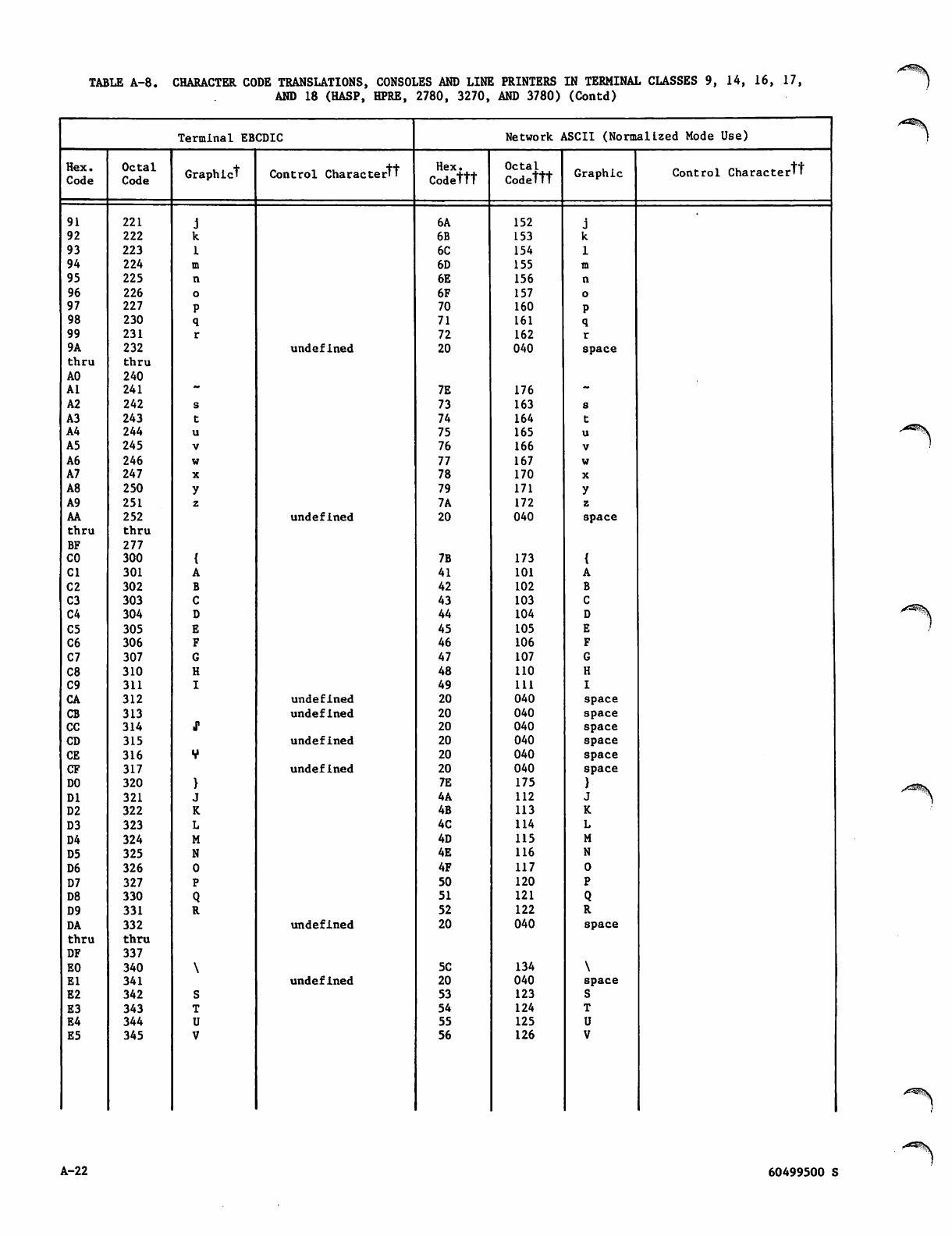
TABLE A-8. CHARACTER CODE TRANSLATIONS, CONSOLES AND LINE PRINTERS IN TERMINAL CLASSES 9, 14, 16, 17,
AND 18 (HASP, HPRE, 2780, 3270, AND 3780) (Contd)
Terminal EBCDIC Network ASCII (Normalized Mode Use)
Hex.
Code
Octal
Code Graphict Control Charactertt Hex.
Codettt
Octal
Codettt Graphic Control Charactertt
91 221 6A 152
92 222 6B 153
93 223 6C 154
94 224 6D 155
95 225 6E 156
96 226 6F 157
97 227 70 160
98 230 71 161
99 231 72 162
9A 232 undefined 20 040 space
thru thru
AO 240
Al 241 7E 176
A2 242 73 163
A3 243 74 164
A4 244 75 165
A5 245 76 166
A6 246 77 167
A7 247 78 170
A8 250 79 171
A9 251 7A 172
AA 252 undefined 20 040 space
thru thru
BF 277
CO 300 7B 173
Cl 301 41 101
C2 302 42 102
C3 303 43 103
C4 304 44 104
C5 305 45 105
C6 306 46 106
C7 307 47 107
C8 310 48 110
C9 311 49 111
CA 312 undefined 20 040 space
CB 313 undefined 20 040 space
CC 314 20 040 space
CD 315 undefined 20 040 space
CE 316 20 040 space
CF 317 undefined 20 040 space
DO 320 7E 175
DI 321 4A 112
D2 322 4B 113
D3 323 4C 114
D4 324 4D 115
D5 325 4E 116
D6 326 4F 117
D7 327 50 120
D8 330 51 121
D9 331 52 122
DA 332 undefined 20 040 space
thru thru
DF 337
EO 340 5C 134
El 341 undefined 20 040 space
E2 342 53 123
E3 343 54 124
E4 344 55 125
E5 345 56 126
A-22 60499500 S
,^s^.
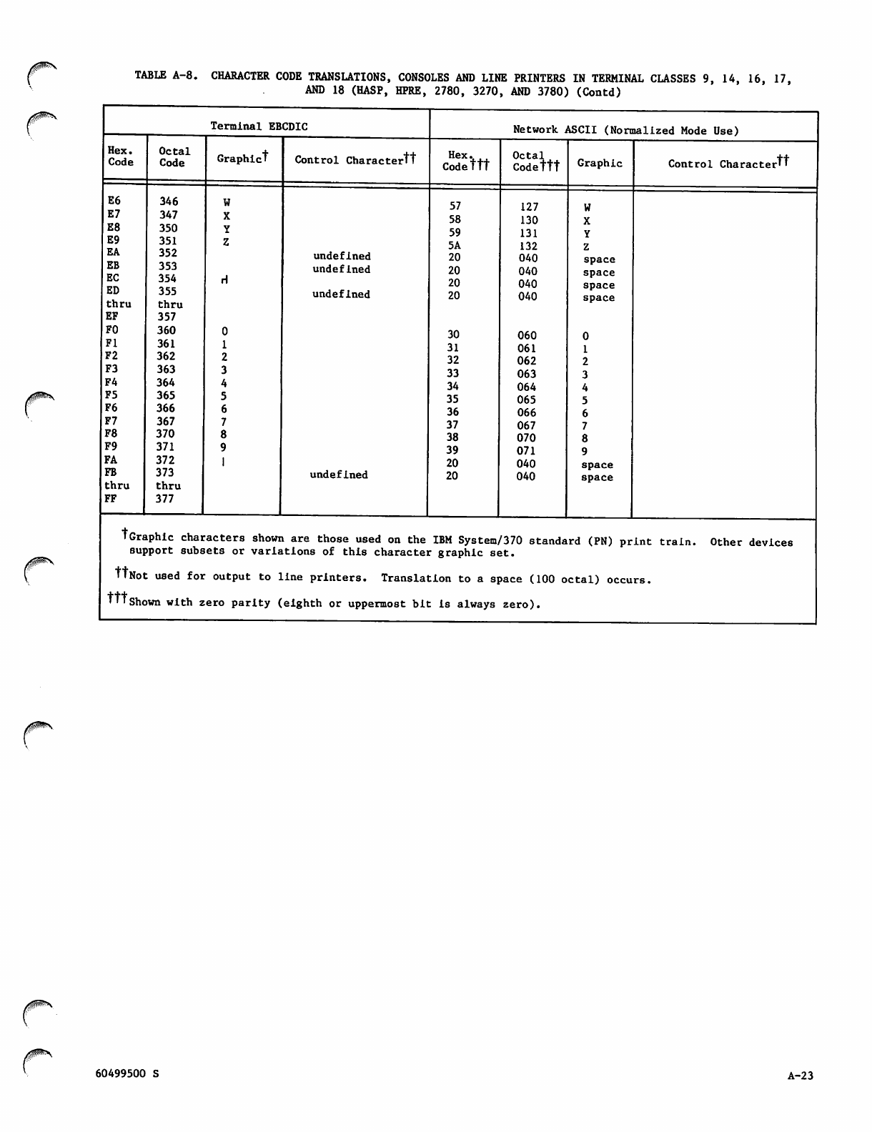
TABLE A-8. CHARACTER CODE TRANSLATIONS, CONSOLES AND LINE PRINTERS IN TERMINAL CLASSES 9, 14, 16, 17,
AND 18 (HASP, HPRE, 2780, 3270, AND 3780) (Contd)
Terminal EBCDIC Network ASCII (Normalized Mode Use)
Hex.
Code Octal
Code Graphict Control Charactertt Codettt
Octal
Codettt Graphic Control Charactertt
E6
E7
E8
E9
EA
EB
EC
ED
thru
EF
FO
Fl
F2
F3
F4
F5
F6
F7
F8
F9
FA
FB
thru
FF
346
347
350
351
352
353
354
355
thru
357
360
361
362
363
364
365
366
367
370
371
372
373
thru
377
undefined
undefined
undefined
undefined
57
58
59
5A
20
20
20
20
30
31
32
33
34
35
36
37
38
39
20
20
127
130
131
132
040
040
040
040
060
061
062
063
064
065
066
067
070
071
040
040
space
space
space
space
0
1
2
3
4
5
6
7
8
9
space
space
tGraphic characters shown are those used on the IBM System/370 standard (PN) print train. Other devices
support subsets or variations of this character graphic set.
WNot used for output to line printers. Translation to a space (100 octal) occurs.
•TTshown with zero parity (eighth or uppermost bit is always zero).
60499500 S A-2 3
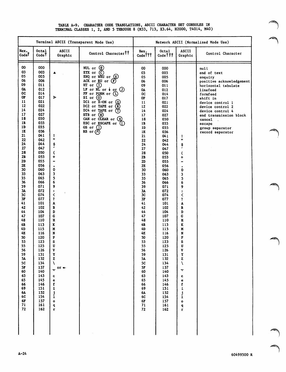
TABLE A-9. CHARACTER CODE TRANSLATIONS, ASCII CHARACTER SET CONSOLES IN
TERMINAL CLASSES 1, 2, AND 5 THROUGH 8 (M33, 713, X3.64, H2000, T4014, M40)
Terminal ASCII (Transparent Mode Use) Network ASCII (Normalized Mode Use)
Hex.
Codet
Octal
Codet
ASCII
Graphic Control Charactertt Hex.
Codettt
Octal
Codettt
ASCII
Graphic Control Character
00 000 NUL or © 00 000 null
03 003 ETX or © 03 003 end of text
05 005 ENQ or WRU or (?) 05 005 enquiry
06 006 ACK or RU or (|J 06 006 positive acknowledgement
09 Oil H T or ® 09 011 horizontal tabulate
OA 012 LF or NL or i or (j) 0A 012 linefeed
OC 014 FF or FORM or (l) OC 014 formfeed
OF 017 S I o r © OF 017 shift in
11 021 DC1 or X-ON or @ 11 021 device control 1
12 022 DC2 or TAPE or Up 12 022 device control 2
14 024 DC4 or TAPE or (T) 14 024 device control 4
17 027 ETB or (w) 17 027 end transmission block
18 030 CAN or CLEAR or (x) 18 030 cancel
IB 033 ESC or ESCAPE or (J) IB 033 escape
ID 035 GS or (T) ID 035 group separator
IE 036 RS or (A) IE 036 record separator
21 041 21 041
22 042 ii 22 042 it
24 044 24 044
27 047 27 047
28 050 28 050
2B 053 2B 053
2D 055 2D 055
2E 056 2E 056
30 060 30 060
33 063 33 063
35 065 35 065
36 066 36 066
39 071 39 071
3A 072 3A 072
3C 074 3C 074
3F 077 3F 077
41 101 41 101
42 102 42 102
44 104 44 104
47 107 47 107
48 110 48 110
4B 113 4B 113
4D 115 4D 115
4E 116 4E 116
50 120 50 120
53 123 53 123
55 125 55 125
56 126 56 126
59 131 59 131
5A 132 5A 132
5C 134 5C 134
5F 137 or «- 5F 137
60 140 60 140
63 143 63 143
65 145 65 145
66 146 66 146
69 151 69 151
6A 152 6A 152
6C 154 6C 154
6F 157 6F 157
71 161 71 161
72 162 72 162
/*^8||.
A-24 60499500 R
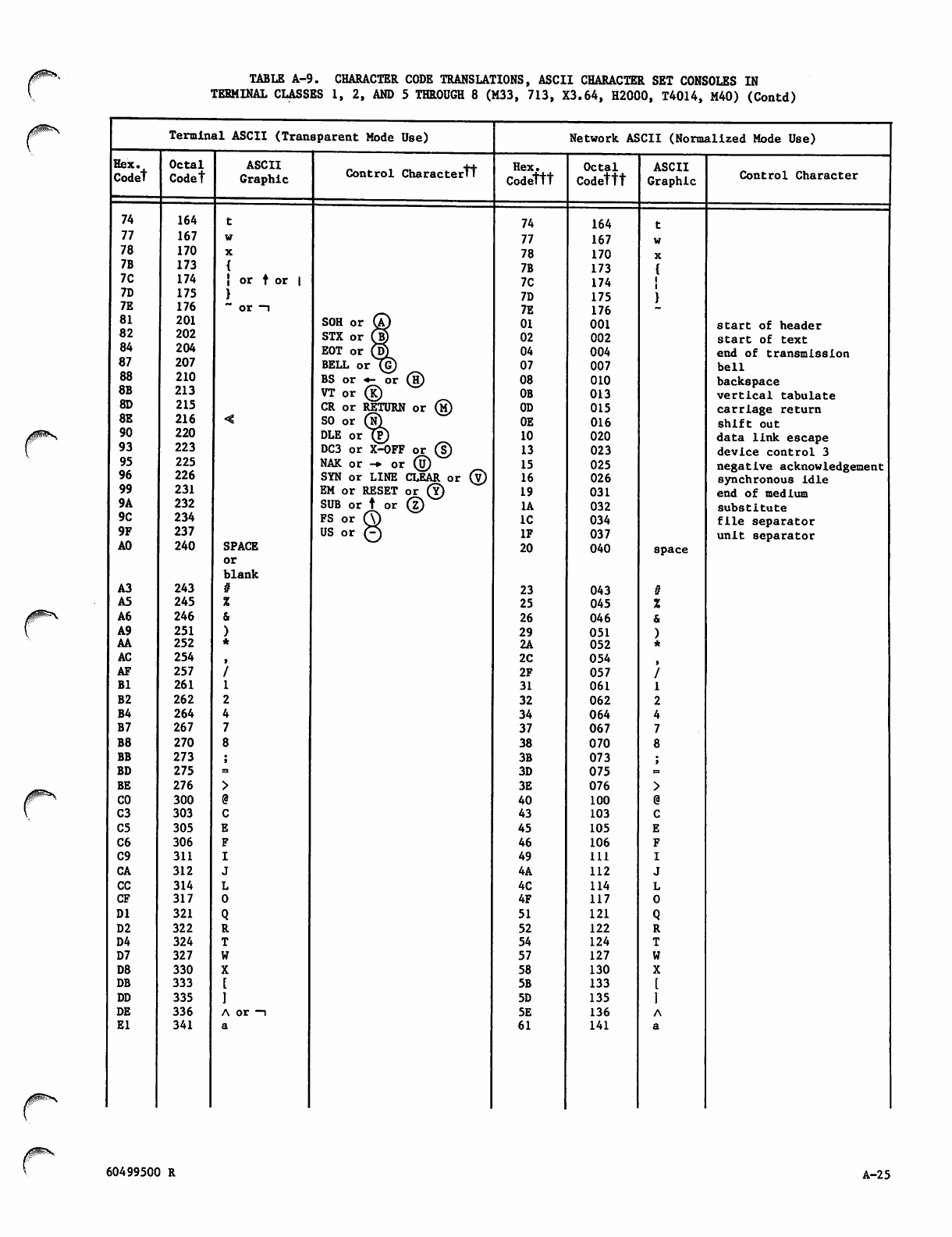
TABLE A-9. CHARACTER CODE TRANSLATIONS, ASCII CHARACTER SET CONSOLES IN
TERMINAL CLASSES 1, 2, AND 5 THROUGH 8 (M33, 713, X3.64, H2000, T4014, M40) (Contd)
Terminal ASCII (Transparent Mode Use) Network ASCII (Normalized Mode Use)
Hex. Octal ASCII Control Charactertt Hex. Octal ASCII
Codet Codet Graphic Codettt Codettt Graphic Control Character
74 164 74 164
77 167 77 167
78 170 78 170
7B 173 7B 173
7C 174 i or f or | 7C 174
7D 175 7D 175
7E 176 ~ or —i 7E 176
81 201 SOH or (A) 01 001 start of header
82 202 STX or fS) 02 002 start of text
84 204 EOT or Q}) 04 004 end of transmission
87 207 BELL or (G) 07 007 bell
88 210 BS or +- or (h) 08 010 backspace
8B 213 VT or (K) 0B 013 vertical tabulate
8D 215 CR or RETURN or (m) 0D 015 carriage return
8E 216 SO or (N) 0E 016 shift out
90 220 DLE or (P) 10 020 data link escape
93 223 DC3 or X-OFF or (?) 13 023 device control 3
95 225 NAK or -♦ or (u)
SYN or LINE CLEAR or ® 15 025 negative acknowledgement
96 226 16 026 synchronous idle
99 231 EM or RESET or (y) 19 031 end of medium
9A 232 SUB or t or (z) 1A 032 s u b s t i t u t e
9C 234 FS or (T) IC 034 file separator
9F 237 US or Q IF 037 unit separator
AO 240 SPACE
or
blank
20 040 space
A3 243 23 043
A5 245 25 045
A6 246 26 046
A9 251 29 051
AA 252 2A 052
AC 254 2C 054
AF 257 2F 057
Bl 261 31 061
B2 262 32 062
B4 264 34 064
B7 267 37 067
B8 270 38 070
BB 273 3B 073
BD 275 3D 075
BE 276 3E 076
CO 300 40 100
C3 303 43 103
C5 305 45 105
C6 306 46 106
C9 311 49 111
CA 312 4A 112
CC 314 4C 114
CF 317 4F 117
DI 321 51 121
D2 322 52 122
D4 324 54 124
D7 327 57 127
D8 330 58 130
DB 333 5B 133
DD 335 5D 135
DE 336 A or —i 5E 136
El 341 61 141
60499500 R A-25
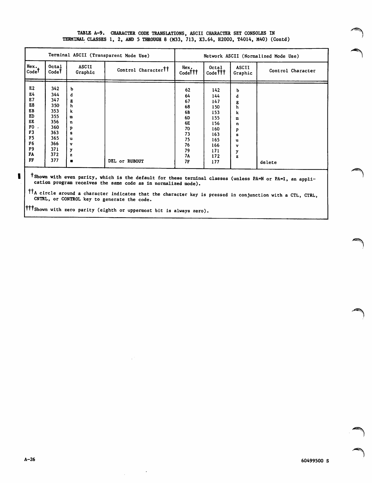
TABLE A-9. CHARACTER CODE TRANSLATIONS, ASCII CHARACTER SET CONSOLES IN
TERMINAL CLASSES 1, 2, AND 5 THROUGH 8 (M33, 713, X3.64, H2000, T4014, M40) (Contd)
Terminal ASCII (Transparent Mode Use) Network ASCII (Normalized Mode Use)
Hex.
Codet
Octal
Codet
ASCII
Graphic Control Charactertt Hex.
Codettt
Octal
Codettt
ASCII
Graphic Control Character
E2
E4
E7
E8
EB
ED
EE
FO -
F3
F5
F6
F9
FA
FF
342
344
347
350
353
355
356
360
363
365
366
371
372
377 DEL or RUBOUT
62
64
67
68
6B
6D
6E
70
73
75
76
79
7A
7F
142
144
147
150
153
155
156
160
163
165
166
171
172
177 delete
tShown with even parity, which is the default for these terminal classes (unless PA=N or PA=I, an appli
cation program receives the same code as in normalized mode).
MA circle around a character indicates that the character key is pressed in conjunction with a CTL, CTRL,
CNTRL, or CONTROL key to generate the code.
tttShown with zero parity (eighth or uppermost bit is always zero).
A-26
•*^\
60499500 S

TABLE A-10. CHARACTER CODE TRANSLATIONS, APL TYPEWRITER-PAIRING CONSOLES IN
TERMINAL. CLASSES 1, 2, AND 5 THROUGH 8 (M33, 713, X3.64, H2000, T4014, M40)
Termlna 1 ASCII (Transparent Mode Use) Network ASCII (Normalized Mode Use)
Hex
Codet
Octal
Codet
ASCII-APL
Graphic Control Charactertt Hex
Codettt
Octal
Codettt
ASCII-APL
Graphic Control Character
74 164 54 124
77 167 57 127
78 170 58 130
7B 173 7B 173
7C 174 6B 153 —\
7D 175 7D 175
7E 176 24 044
81
82
84
201 SOH or @ 01 001 start of header
202 STX or UJ) 02 002 start of text
204 EOT or ©i 04 004 end of transmission
87 207 BELL or QG) 07 007 bell
88
8B
210
213 BS or *- or (H)
VT or ® 08
0B
010
013 backspace
vertical tabulate
8D 215 CR or RETURN or (5) 0D 015 carriage return
8E 216 SO or (n) 0E 016 <^ shift out
90 220 DLE or J?) 10 020 data link escape
93
95
96
223 DC3 or X-OFF or ®
NAK or -c or ®
SYN or LINE CLEAR or ©
13 023 device control 3
225
226 15 025 negative acknowledgement
16 026 synchronous idle
99 231 EM or RESET or ® 19 031 end of medium
9A 232 SUB or t or © 1A 032 substitute
9C 234 F S or © IC 034 file separator
9F 237 US or © IF 037 unit separator
AO 240 SPACE
or
blank
20 040 space
A3 243 3C 074
A5 245 SI 3D 075
A6 246 3E 076
A9 251 26 046
AA 252 »* 22 042
AC 254 2C 054
AF 257 2F 057
Bl 261 31 061
B2 262 32 062
B4 264 34 064
B7 267 37 067
B8 270 38 070
BB 273 5B 133
BD 275 66 146
BE 276 3A 072
CO 300 5E 136
C3 303 63 143
C5 305 65 145
C6 306 5F 137
C9 311 69 151
CA 312 6A 152
CC 314 6C 154
CF 317 6F 157
DI 321 3F 077
D2 322 72 162
D4 324 74 164
D7 327 CO 77 167 CO
D8 330 => 78 170
DB 333 *- 70 160 *-
DD 335 -+ 71 161 -1*
DE 336 7C 174
El 341 41 101
60499500 R A-27
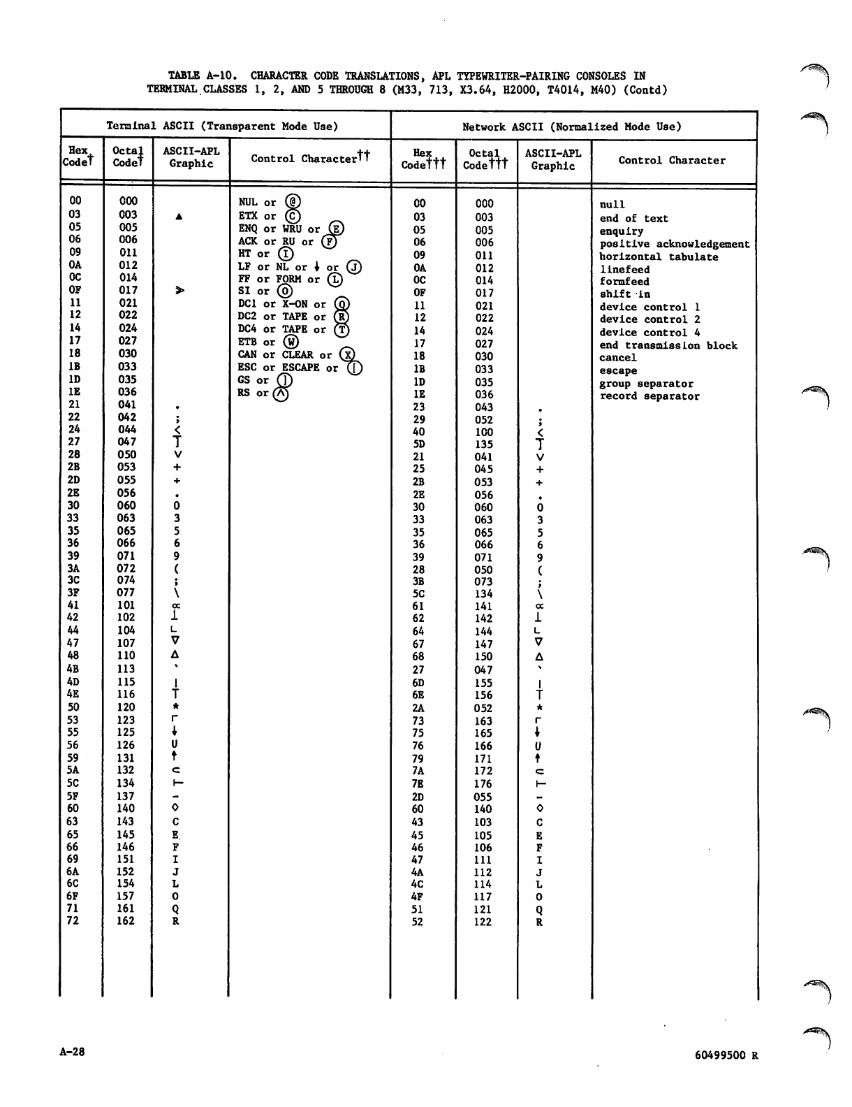
TABLE A-10. CHARACTER CODE TRANSLATIONS, APL TYPEWRITER-PAIRING CONSOLES IN
TERMINAL.CLASSES 1, 2, AND 5 THROUGH 8 (M33, 713, X3.64, H2000, T4014, M40) (Contd)
Terminal ASCII (Transparent Mode Use) Network ASCII (Normalized Mode Use)
Hex
Codet Octal
Codet
ASCII-APL
Graphic Control Charactertt Hex
Codettt Octal
Codettt ASCII-APL
Graphic Control Character
00 000 NUL or © 00 000 null
03 003 ETX or © 03 003 end of text
05 005 ENQ or WRU or (g) 05 005 enquiry
06
09 006 ACK or RU or (?)
HT or © 06 006 positive acknowledgement
Oil 09 011 horizontal tabulate
0A 012 LF or NL or 1 or ® 0A 012 linefeed
OC 014 FF or FORM or © OC 014 formfeed
OF 017 SI or © OF 017 shift in
11 021 DC1 or X-ON or © 11 021 device control 1
12 022 DC2 or TAPE or ® 12 022 device control 2
14 024 DC4 or TAPE or ® 14 024 device control 4
17 027 ETB or ® 17 027 end transmission block
18 030 CAN or CLEAR or (x) 18 030 cancel
IB 033 ESC or ESCAPE or (J) IB 033 escape
ID 035 GS or © ID 035 group separator
IE 036 RS or© IE 036 record separator
21 041 23 043
22 042 29 052
24 044 40 100
27 047 5D 135
28 050 21 041
2B 053 25 045
2D 055 2B 053
2E 056 2E 056
30 060 30 060
33 063 33 063
35 065 35 065
36 066 36 066
39 071 39 071
3A 072 28 050
3C 074 3B 073
3F 077 5C 134
41 101 ex 61 141 oc
42 102 62 142
44 104 64 144
47 107 67 147
48 110 68 150
4B 113 27 047
4D 115 6D 155
4E 116 6E 156
50 120 2A 052
53 123 73 163
55 125 75 165
56 126 76 166
59 131 79 171
5A 132 7A 172
5C 134 1— 7E 176 1—
5F 137 2D 055
60 140 60 140
63 143 43 103
65 145 E. 45 105
66 146 46 106
69 151 47 111
6A 152 4A 112
6C 154 4C 114
6F 157 4F 117
71 161 51 121
72 162 52 122
A-28 60499500 R
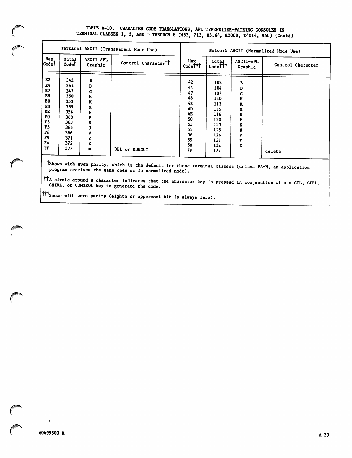
HexA
Codet
TABLE A-10. CHARACTER CODE TRANSLATIONS, APL TYPEWRITER-PAIRING CONSOLES IN
TERMINAL CLASSES 1, 2, AND 5 THROUGH 8 (M33, 713, X3.64, H2000, T4014, M40) (Contd)
Terminal ASCII (Transparent Mode Use)
Octa
Code;l
E2 342
E4 344
E7 347
E8 350
EB 353
ED 355
EE 356
FO 360
F3 363
F5 365
F6 366
F9 371
FA 372
FF 377
ASCII-APL
Graphic Control Charactertt
DEL or RUBOUT
Network ASCII (Normalized Mode Use)
Hex
Codettt
42
44
47
48
4B
4D
4E
50
53
55
56
59
5A
7F
Octal
Codettt
102
104
107
110
113
115
116
120
123
125
126
131
132
177
ASCII-APL
Graphic Control Character
delete
tshown with even parity, which is the default for these terminal classes (unless PA=N, an application
program receives the same code as in normalized mode).
^tot1016 arZnn? ^haracter in°icate8 that the character key is pressed in conjunction with a CTL, CTRL,
CNTRL, or CONTROL key to generate the code.
TTTshown with zero parity (eighth or uppermost bit is always zero).
/^**\
60499500 R A-29
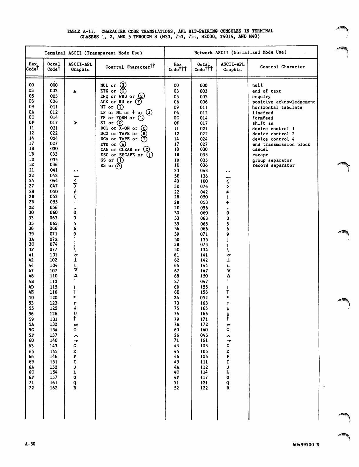
TABLE A-ll. CHARACTER CODE TRANSLATIONS, APL BIT-PAIRING CONSOLES IN TERMINAL
CLASSES 1, 2, AND 5 THROUGH 8 (M33, 753, 751, H2000, T4014, AND M40)
Terminal ASCII (Transparent Mode Use) Network ASCII (Normalized Mode Use)
Hex Octal ASCII-APL Control Charactertt Hex Octal ASCII-APL
Codet Codet Graphic Codettt Codettt Graphic Control Character
00 000 NUL or © 00 000 null
03 003 ETX or © 03 003 end of text
05 005 ENQ or WRU or (i) 05 005 enquiry
06 006 ACK or RU or (?) 06 006 positive acknowledgement
09 on H T or © 09 011 horizontal tabulate
OA 012 LF or NL or 1 or © 0A 012 linefeed
OC 014 FF or FORM or © OC 014 formfeed
OF 017 S I o r © OF 017 shift In
11 021 DC1 or X-ON or ® 11 021 device control 1
12 022 DC2 or TAPE or © 12 022 device control 2
14 024 DC4 or TAPE or © 14 024 device control 4
17 027 ETB or © 17 027 end transmission block
18 030 CAN or CLEAR or QQ 18 030 cancel
IB 033 ESC or ESCAPE ot{£) IB 033 escape
ID 035 GS o r © ID 035 group separator
IE 036 RS or(A) IE 036 record separator
21 041 .. N-^ 23 043 ..
22 042 5E 136
24 044 40 100
27 047 3E 076
28 050 1* 22 042
2B 053 28 050
2D 055 2B 053
2E 056 2E 056
30 060 30 060
33 063 33 063
35 065 35 065
36 066 36 066
39 071 39 071
3A 072 5D 135
3C 074 3B 073
3F 077 5C 134
41 101 oc 61 141 oc
42 102 62 142
44 104 64 144
47 107 67 147
48 110 68 150
4B 113 27 047
4D 115 6D 155
4E 116 6E 156
50 120 2A 052
53 123 73 163
55 125 75 165
56 126 76 166
59 131 79 171
5A 132 <= 7A 172
5C 134 60 140
5F 137 /N 26 046 /\
60 140 •* 71 161 -fr
63 143 43 103
65 145 45 105
66 146 46 106
69 151 49 Ul
6A 152 4A 112
6C 154 4C 114
6F 157 4F 117
71 161 51 121
72 162 52 122
/<r!^%
A-30 60499500 R
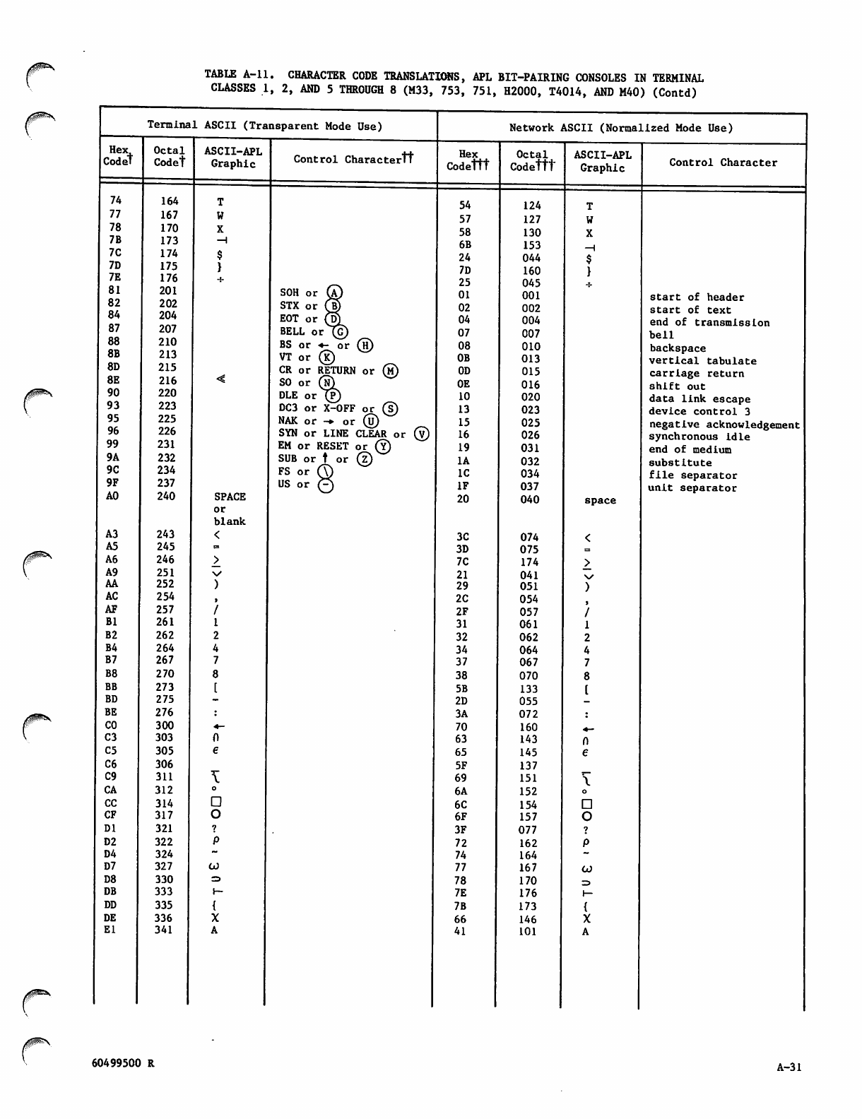
TABLE A-ll. CHARACTER CODE TRANSLATIONS, APL BIT-PAIRING CONSOLES IN TERMINAL
CLASSES 1, 2, AND 5 THROUGH 8 (M33, 753, 751, H2000, T4014, AND M40) (Contd)
Termina1 ASCII (Transparent Mode Use) Network ASCII (Normalized Mode Use)
Hex
Codet Octal
Codet
ASCII-APL
Graphic Control Charactertt Hex
Codettt
Octal
Codettt
ASCII-APL
Graphic Control Character
74 164 54 124
77 167 57 127
78 170 58 130
7B 173 —1 6B 153 —1
7C 174 24 044
7D 175 7D 160
7E 176 25 045
81
82
84
87
201 SOH or © 01 001 start of header
202
204 STX or © 02 002 start of text
EOT or ©i 04 004 end of transmission
207 BELL or (G) 07 007 bell
88
8B
8D
8E
210
213 BS or +- or ©
VT or ® 08
0B
010
013 backspace
vertical tabulate
215
216 CR or RETURN or ®
SO or ®) 0D
0E
015
016 carriage return
shift out
90 220 DLE or 1® 10 020 data link escape
93 223 DC3 or X-OFF or ® 13 023 device control 3
95
96
225
226 NAK or -*■ or ®
SYN or LINE CLEAR or ® 15 025 negative acknowledgement
16 026 synchronous idle
99 231 EM or RESET or © 19 031 end of medium
9A 232 SUB or t or © 1A 032 substitute
9C 234 FS or © IC 034 file separator
9F 237 U S o r © IF 037 unit separator
AO 240 SPACE
or
blank
20 040 space
A3 243 3C 074
A5 245 3D 075
A6 246 7C 174
A9 251 N/ 21 041 \s
AA 252 29 051
AC 254 2C 054
AF 257 2F 057
Bl 261 31 061
B2 262 32 062
B4 264 34 064
B7 267 37 067
B8 270 38 070
BB 273 5B 133
BD 275 2D 055
BE 276 3A 072
CO 300 •*- 70 160 ^_
C3 303 63 143
C5 305 65 145
C6 306 5F 137
C9 311 69 151
CA 312 6A 152
CC 314 6C 154
CF 317 6F 157
DI 321 3F 077
D2 322 72 162
D4 324 74 164
D7 327 CO 77 167 CO
D8 330 => 78 170 =>
DB 333 j- 7E 176 1—
DD 335 7B 173
DE 336 66 146
El 341 41 101
yg^\
60499500 R A-31
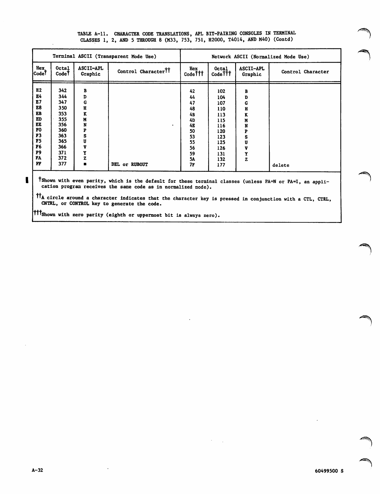
TABLE A-ll. CHARACTER CODE TRANSLATIONS, APL BIT-PAIRING CONSOLES IN TERMINAL
CLASSES 1, 2, AND 5 THROUGH 8 (M33, 753, 751, H2000, T4014, AND M40) (Contd)
Terminal ASCII (Transparent Mode Use) Network ASCII (Normalized Mode Use)
Hex
Codet
Octal
Codet
ASCII-APL
Graphic Control Charactertt Hex
Codettt
Octal
Codettt
ASCII-APL
Graphic Control Character
E2
E4
E7
E8
EB
ED
EE
FO
F3
F5
F6
F9
FA
FF
342
344
347
350
353
355
356
360
363
365
366
371
372
377 DEL or RUBOUT
42
44
47
48
4B
4D
4E
50
53
55
56
59
5A
7F
102
104
107
110
113
115
116
120
123
125
126
131
132
177 delete
tshown with even parity, which is the default for these terminal classes (unless PA=N or PA=I, an appli
cation program receives the same code as in normalized mode).
"A circle around a character indicates that the character key is pressed in conjunction with a CTL, CTRL,
CNTRL, or CONTROL key to generate the code.
TTTshown with zero parity (eighth or uppermost bit is always zero).
A-32 60499500 S
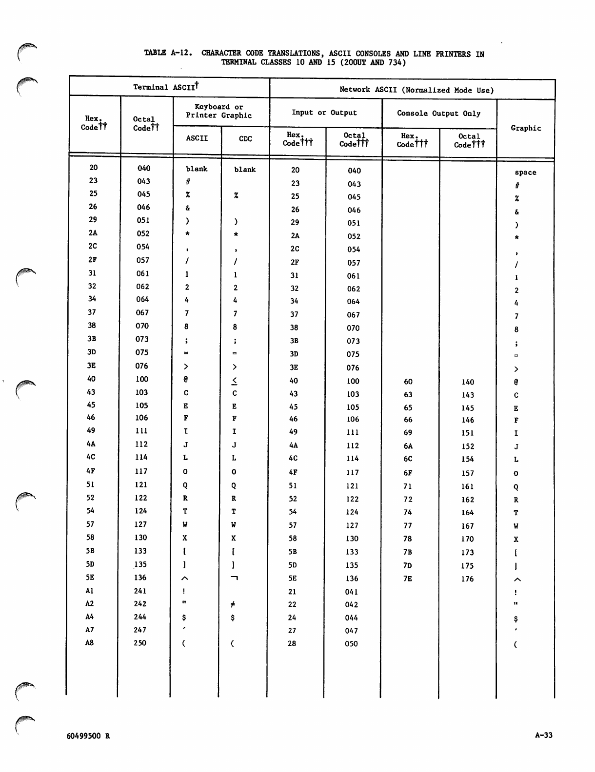
TABLE A-12. CHARACTER CODE TRANSLATIONS, ASCII CONSOLES AND LINE PRINTERS IN
TERMINAL CLASSES 10 AND 15 (200UT AND 734)
Terminal ASCIlt Network ASCII (Normalized Mode Use)
Hex.
Codett
Octal
Codett
Keyboard or
Printer Graphic Input oi Output Console Output Only
Graphic
ASCII CDC Hex.
Codettt Octal
Codettt
Hex.
Codettt
Octal
Codettt
20 040 blank blank 20 040 space
23 043 23 043
25 045 25 045
26 046 26 046
29 051 29 051
2A 052 2A 052
2C 054 2C 054
2F 057 2F 057
31 061 31 061
32 062 32 062
34 064 34 064
37 067 37 067
38 070 38 070
3B 073 3B 073
3D 075 3D 075
3E 076 3E 076
40 100 40 100 60 140
43 103 43 103 63 143
45 105 45 105 65 145
46 106 46 106 66 146
49 111 49 111 69 151
4A 112 4A 112 6A 152
4C 114 4C 114 6C 154
4F 117 4F 117 6F 157
51 121 51 121 71 161
52 122 52 122 72 162
54 124 54 124 74 164
57 127 57 127 77 167
58 130 58 130 78 170
5B 133 5B 133 7B 173
5D .135 5D 135 7D 175
5E 136 /\ —l 5E 136 7E 176 /S
Al 241 21 041
A2 242 ■ii* 22 042 ii
A4 244 24 044
A7 247 27 047
A8 250 28 050
60499500 R A-33
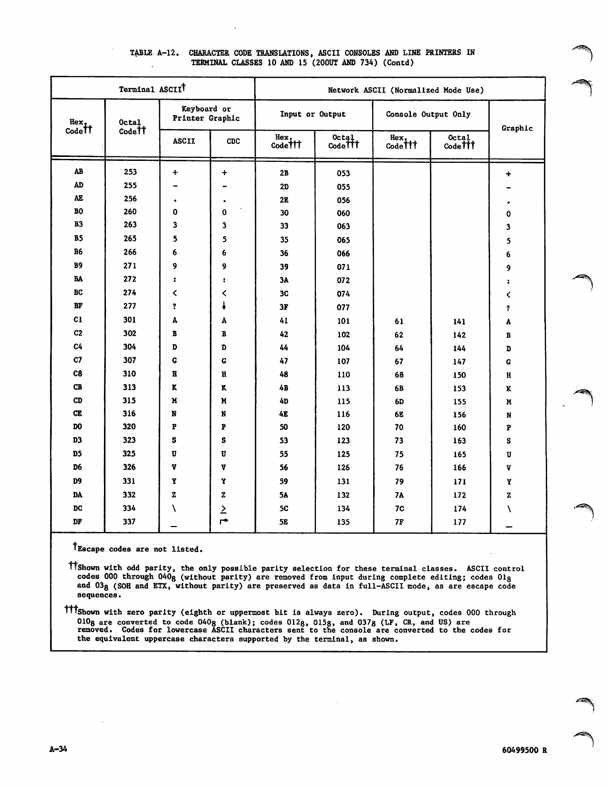
TABLE A-l2. CHARACTER CODE TRANSLATIONS, ASCII CONSOLES AND LINE PRINTERS IN
TERMINAL CLASSES 10 AND 15 (200UT AND 734) (Contd)
Terminal ASCIlt Network ASCII (Normalized Mode Use)
Hex.
Codett
Octal
Codett
Keyboard or
Printer Graphic Input or Output Console Output Only
Graphic
ASCII CDC Hex.
Codettt
Octal
Codettt Hex,
Codettt
Octal
Codettt
AB 253 2B 053
AD 255 2D 055
AE 256 2E 056
BO 260 30 060
B3 263 33 063
B5 265 35 065
B6 266 36 066
B9 271 39 071
BA 272 3A 072
BC 274 3C 074
BF 277 3F 077
Cl 301 41 101 61 141
C2 302 42 102 62 142
C4 304 44 104 64 144
C7 307 47 107 67 147
C8 310 48 110 68 150
CB 313 4B 113 6B 153
CD 315 4D 115 6D 155
CE 316 4E 116 6E 156
DO 320 50 120 70 160
D3 323 53 123 73 163
D5 325 55 125 75 165
D6 326 56 126 76 166
D9 331 59 131 79 171
DA 332 5A 132 7A 172
DC 334 5C 134 7C 174
DF 337 r* 5E 135 7F 177
■Escape codes are not listed.
Ttshown with odd parity, the only possible parity selection for these terminal classes. ASCII
codes 000 through 040g (without parity) are removed from input during complete editing; code
and 03g (SOH and ETX, without parity) are preserved as data in full-ASCII mode, as are escap
control
s 018
e code
sequences.
TTtshown with zero parity (eighth or uppermost bit Is always zero). During output, codes 000 through
010g are converted to code 040s (blank); codes 012s, 0158» and 037s (LF, CR, and US) are
removed. Codes for lowercase ASCII characters sent to the console are converted to the code s for
the equivalent uppercase characters supported by the terminal, as shown.
A-34 60499500 R
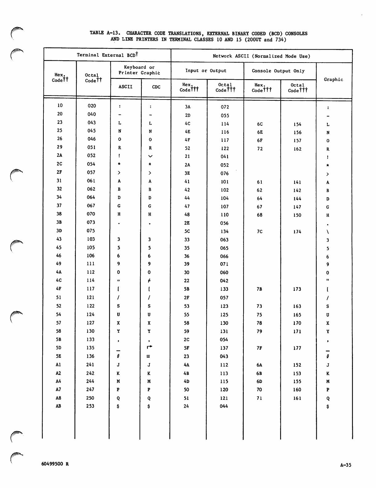
TABLE A-13. CHARACTER CODE TRANSLATIONS, EXTERNAL BINARY CODED (BCD) CONSOLES
AND LINE PRINTERS IN TERMINAL CLASSES 10 AND 15 (200UT and 734)
Terminal External BCDt Network ASCII (Normalized Mode Use)
Hex.
Codett
Octal
Codett
Keyboard or
Printer Graphic Input or Output Console Output Only
Graphic
ASCII CDC Hex.
Codettt
Octal
Codettt
Hex.
Codettt
Octal
Codettt
10 020 3A 072
20 040 2D 055
23 043 4C 114 6C 154
25 045 4E 116 6E 156
26 046 4F 117 6F 157
29 051 52 122 72 162
2A 052 21 041
2C 054 2A 052
2F 057 3E 076
31 061 41 101 61 141
32 062 42 102 62 142
34 064 44 104 64 144
37 067 47 107 67 147
38 070 48 110 68 150
3B 073 2E 056
3D 075 5C 134 7C 174
43 103 33 063
45 105 35 065
46 106 36 066
49 111 39 071
4A 112 30 060
4C 114 P" 22 042 ti
4F 117 5B 133 7B 173
51 121 2F 057
52 122 53 123 73 163
54 124 55 125 75 165
57 127 58 130 78 170
58 130 59 131 79 171
5B 133 2C 054
5D 135 r* 5F 137 7F 177
5E 136 23 043 it
Al 241 4A 112 6A 152
A2 242 4B 113 6B 153
A4 244 4D 115 6D 155
A7 247 50 120 70 160
A8 250 51 121 71 161
AB 253 24 044
60499500 R A-35
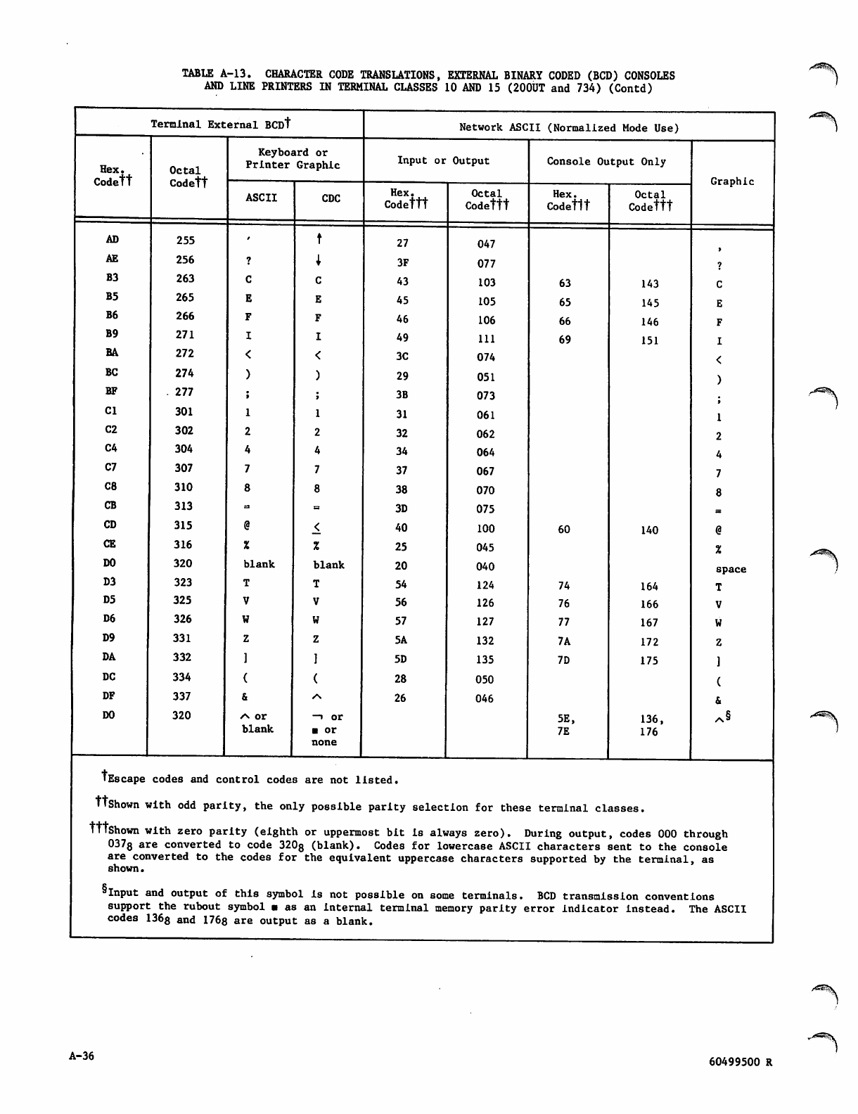
TABLE A-13. CHARACTER CODE TRANSLATIONS, EXTERNAL BINARY CODED (BCD) CONSOLES
AND LINE PRINTERS IN TERMINAL CLASSES 10 AND 15 (200UT and 734) (Contd)
Terminal External BCDt Network ASCII (Normalized Mode Use)
Hex.
Codett
Octal
Codett
Keyboard or
Printer Graphic Input or Output Console Output Only
Graphic
ASCII CDC Hex.
Codettt
Octal
Codettt
Hex.
Codettt
Octal
Codettt
AD 255 27 047
AE 256 3F 077
B3 263 43 103 63 143
B5 265 45 105 65 145
B6 266 46 106 66 146
B9 271 49 111 69 151
BA 272 3C 074
BC 274 29 051
BF . 277 3B 073
Cl 301 31 061
C2 302 32 062
C4 304 34 064
C7 307 37 067
C8 310 38 070
CB 313 23 3D 075
CD 315 40 100 60 140
CE 316 25 045
DO 320 blank blank 20 040 space
D3 323 54 124 74 164
D5 325 56 126 76 166
D6 326 57 127 77 167
D9 331 5A 132 7A 172
DA 332 5D 135 7D 175
DC 334 28 050
DF 337 •s 26 046
DO 320 /n or
blank
—i or
■ or
none
5E,
7E
136,
176
^§
TEscape codes and control codes are not listed.
TlShown with odd parity, the only possible parity selection for these terminal classes.
TttShown with zero parity (eighth or uppermost bit is always zero). During output, codes 000 through
037s are converted to code 320g (blank). Codes for lowercase ASCII characters sent to the console
are converted to the codes for the equivalent uppercase characters supported by the terminal, as
shown.
5Input and output of this symbol is not possible on some terminals. BCD transmission convent
support the rubout symbol ■ as an internal terminal memory parity error indicator instead. '
codes 1368 and 1768 are output as a blank.
ions
fhe ASCII
A-36
^^^\
60499500 R
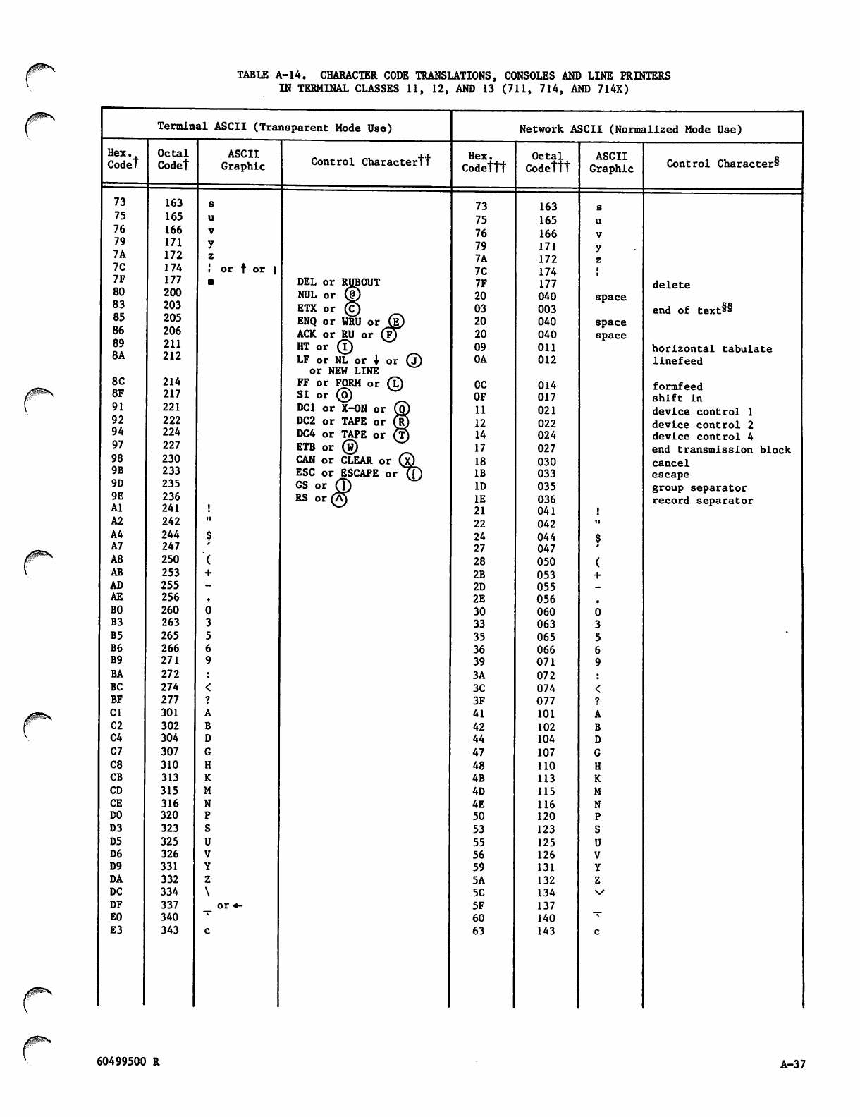
TABLE A-14. CHARACTER CODE TRANSLATIONS, CONSOLES AND LINE PRINTERS
IN TERMINAL CLASSES 11, 12, AND 13 (711, 714, AND 714X)
Hex.
Codet
73
75
76
79
7A
7C
7F
80
83
85
86
89
8A
8C
8F
91
92
94
97
98
9B
9D
9E
Al
A2
A4
A7
A8
AB
AD
AE
BO
B3
B5
B6
B9
BA
BC
BF
Cl
C2
C4
C7
C8
CB
CD
CE
DO
D3
D5
D6
D9
DA
DC
DF
EO
E3
Terminal ASCII (Transparent Mode Use)
Octal
Codet
163
165
166
171
172
174
177
200
203
205
206
211
212
214
217
221
222
224
227
230
233
235
236
241
242
244
247
250
253
255
256
260
263
265
266
271
272
274
277
301
302
304
307
310
313
315
316
320
323
325
326
331
332
334
337
340
343
ASCII
Graphic
or f or |
Control Charactertt
DEL or RUBOUT
NUL or ®
ETX or ©
ENQ or WRU or
ACK or RU or
H T o r ®
LF or NL or j
or NEW LINE
FF or FORM or
S I o r ©
DC1 or X-ON or
DC2 or TAPE or (R
DC4 or TAPE or C?
ETB or ®
CAN or CLEAR o
ESC or ESCAPE
GS or
RS or
.r ®>
orTD
Network ASCII (Normalized Mode Use)
Hex.
Codettt
73
75
76
79
7A
7C
7F
20
03
20
20
09
0A
0C
OF
11
12
14
17
18
IB
ID
IE
21
22
24
27
28
2B
2D
2E
30
33
35
36
39
3A
3C
3F
41
42
44
47
48
4B
4D
4E
50
53
55
56
59
5A
5C
5F
60
63
Octal
Codettt
163
165
166
171
172
174
177
040
003
040
040
011
012
014
017
021
022
024
027
030
033
035
036
041
042
044
047
050
053
055
056
060
063
065
066
071
072
074
077
101
102
104
107
110
113
115
116
120
123
125
126
131
132
134
137
140
143
ASCII
Graphic
space
space
space
Control Character§
delete
end of text*
horizontal tabulate
linefeed
formfeed
shift in
device control 1
device control 2
device control 4
end transmission block
cancel
escape
group separator
record separator
60499500 R A-37
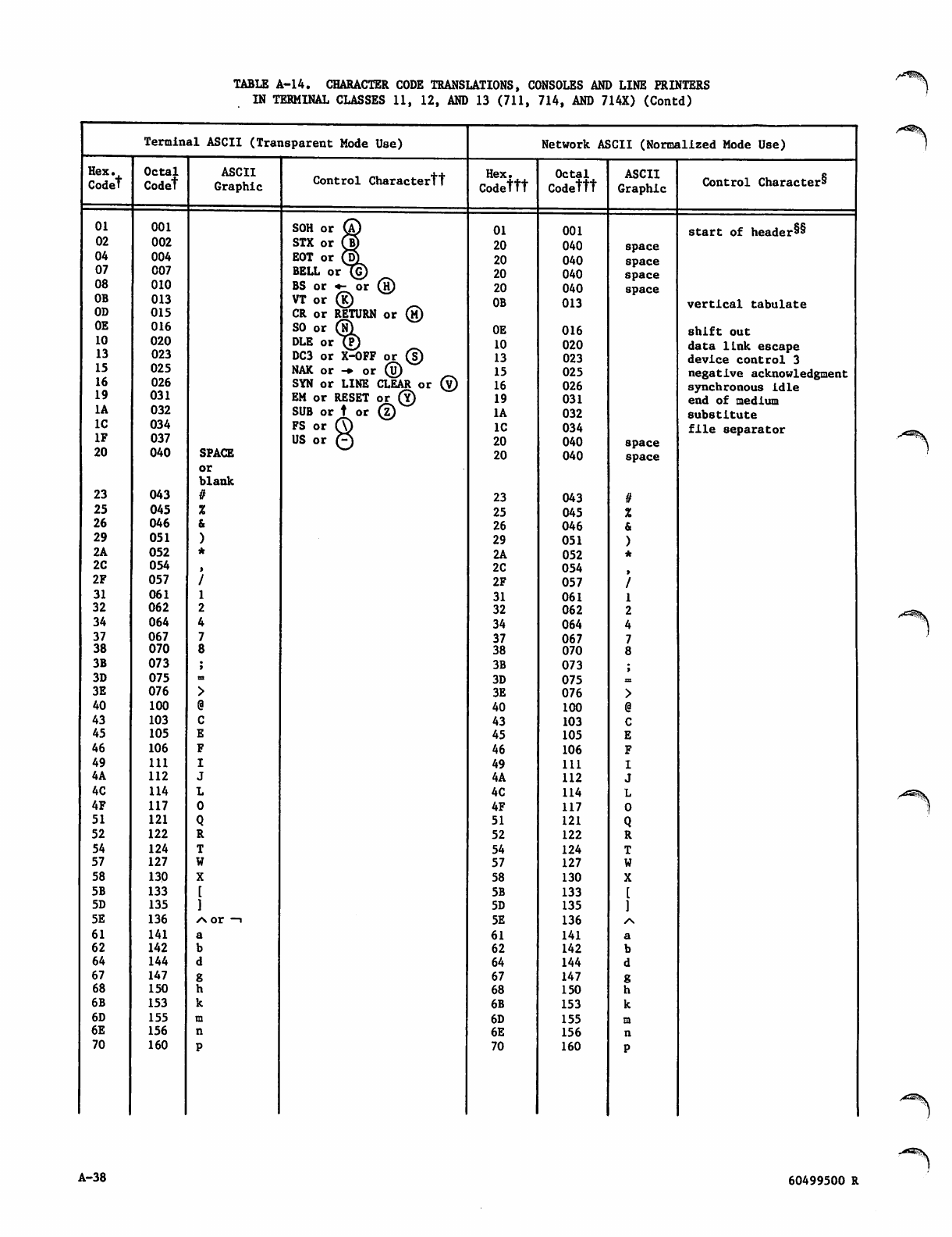
TABLE A-14. CHARACTER CODE TRANSLATIONS, CONSOLES AND LINE PRINTERS
IN TERMINAL CLASSES 11, 12, AND 13 (711, 714, AND 714X) (Contd)
Terminal ASCII (Transparent Mode Use) Network ASCII (Normalized Mode Use)
Hex.
Codet
Octal
Codet
ASCII
Graphic Control Charactertt Hex.
Codettt
Octal
Codettt
ASCII
Graphic Control Character^
01 001 SOH or ® 01 001 start of header§§
02 002 STX or pH 20 040 space
04 004 EOT or ©_ 20 040 space
07 007 BELL or (G) 20 040 space
08 010 BS or «- or ®
V T o r ®
CR or RETURN or ®
20 040 space
OB 013 0B 013 vertical tabulate
OD 015
OE 016 SO or ©> 0E 016 shift out
10 020 DLE or (® 10 020 data link escape
13 023 DC3 or X-OFF or ®
NAK or -*> or ©
SYN or LINE CLEAR or ©
13 023 device control 3
15 025 15 025 negative acknowledgment
16 026 16 026 synchronous idle
19 031 EM or RESET or ® 19 031 end of medium
1A 032 SUB or t or ® 1A 032 substitute
IC 034 F S or © IC 034 file separator
IF 037 US or © 20 040 space
20 040 SPACE
or
blank
20 040 space
23 043 23 043
25 045 25 045
26 046 26 046
29 051 29 051
2A 052 2A 052
2C 054 2C 054
2F 057 2F 057
31 061 31 061
32 062 32 062
34 064 34 064
37 067 37 067
38 070 38 070
3B 073 3B 073
3D 075 3D 075
3E 076 3E 076
40 100 40 100
43 103 43 103
45 105 45 105
46 106 46 106
49 111 49 111
4A 112 4A 112
4C 114 4C 114
4F 117 4F 117
51 121 51 121
52 122 52 122
54 124 54 124
57 127 57 127
58 130 58 130
5B 133 5B 133
5D 135 5D 135
5E 136 Aori 5E 136 /\
61 141 61 141
62 142 62 142
64 144 64 144
67 147 67 147
68 150 68 150
6B 153 6B 153
6D 155 6D 155
6E 156 6E 156
70 160 70 160
A-38
■^
60499500 R
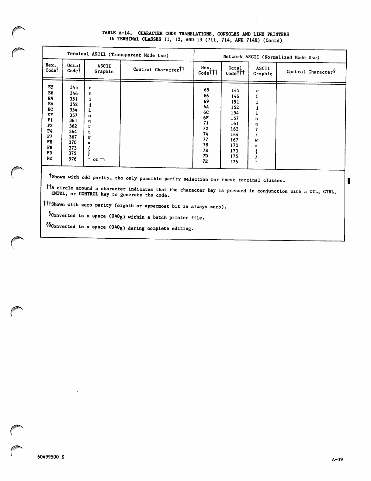
TABLE A-14. CHARACTER CODE TRANSLATIONS, CONSOLES AND LINE PRINTERS
IN TERMINAL CLASSES 11, 12, AND 13 (711, 714, AND 714X) (Contd)
Terminal ASCII (Transparent Mode Use)
Hex.
Codet
Octal
Codet
E5 345
E6 346
E9 351
EA 352
EC 354
EF 357
Fl 361
F2 362
F4 364
F7 367
F8 370
FB 373
FD 375
FE 376
ASCII
Graphic Control Charactertt
Network ASCII (Normalized Mode Use)
Hex.
Codettt
65
66
69
6A
6C
6F
71
72
74
77
78
7B
7D
7E
Octal
Codettt
145
146
151
152
154
157
161
162
164
167
170
173
175
176
ASCII
Graphic Control Character^
tShown with odd parity, the only possible parity selection for these terminal classes.
^NTiL^or^OTRO? ?3Tter lnd±Catr that the character key is pressed in conjunction with a CTL, CTRL,
ONJ7KL, or CONTROL key to generate the code.
tttShown with zero parity (eighth or uppermost bit is always zero).
Converted to a space (0408) within a batch printer file.
§§Converted to a space (0408) during compiete editing.
60499500 S A-39
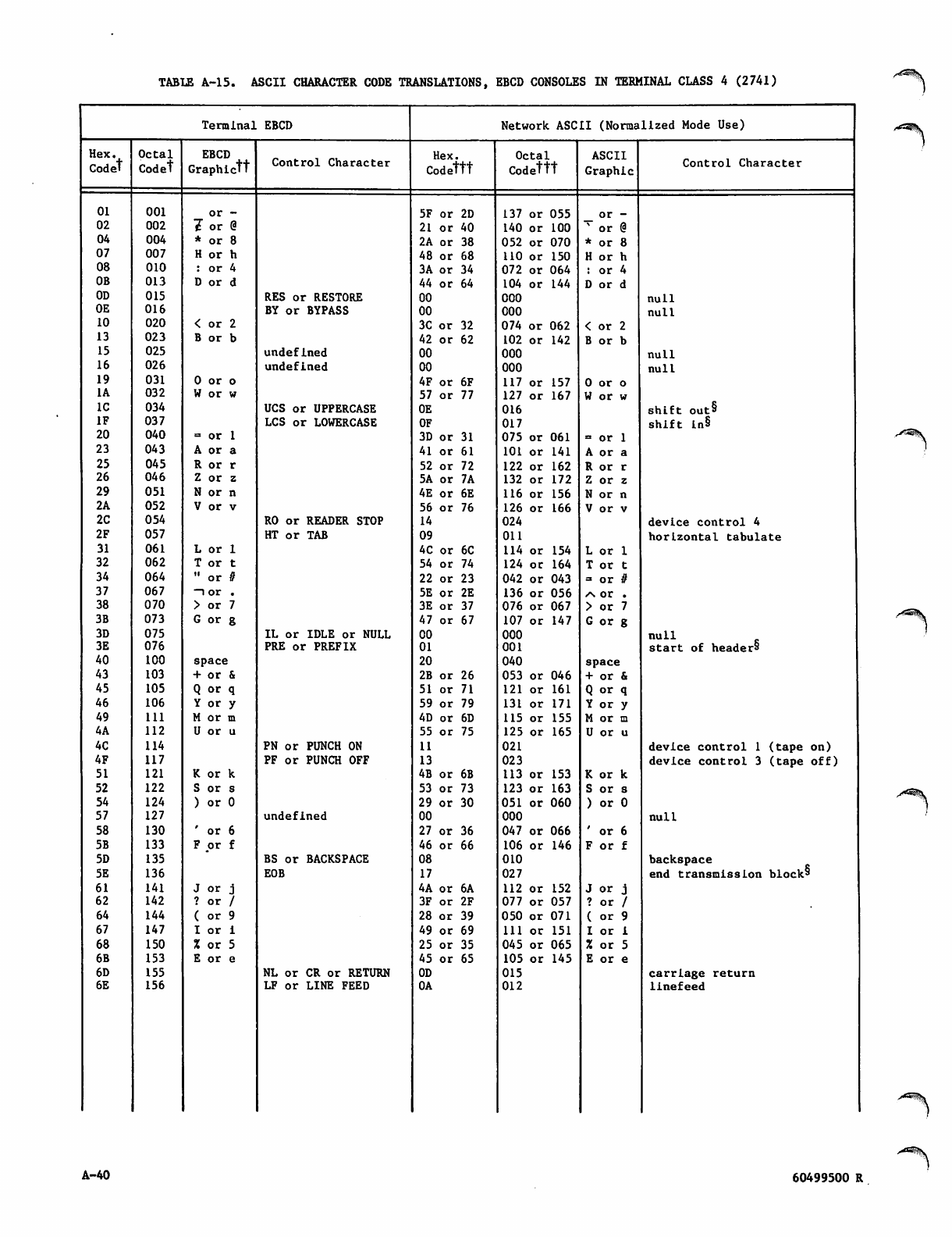
TABLE A-15. ASCII CHARACTER CODE TRANSLATIONS, EBCD CONSOLES IN TERMINAL CLASS 4 (2741) ^^^.
Terminal EBCD Network ASCII (Norma 11zed Mode Use)
Hex. Octal EBCD Hex. Octal ASCII
Codet Codet Graphictt Control Character Codettt Codettt Graphic Control Character
01 001 or - 5F or 2D 137 or 055 o r -
02 002 7 or @ 21 or 40 140 or 100 % or @
04 004 * or 8 2A or 38 052 or 070 * or 8
07 007 H or h 48 or 68 110 or 150 H or h
08 010 : or 4 3A or 34 072 or 064 : or 4
OB 013 D or d 44 or 64 104 or 144 D or d
OD 015 RES or RESTORE 00 000 null
OE 016 BY or BYPASS 00 000 null
10 020 < or 2 3C or 32 074 or 062 < or 2
13 023 B or b 42 or 62 102 or 142 B or b
15 025 undefined 00 000 null
16 026 undefined 00 000 null
19 031 0 or o 4F or 6F 117 or 157 0 or o
1A 032 W or w 57 or 77 127 or 167 W or w
IC 034 UCS or UPPERCASE 0E 016 s h i ft o u t »
IF 037 LCS or LOWERCASE OF 017 shift ln§
20 040 = or 1 3D or 31 075 or 061 = or 1
23 043 A or a 41 or 61 101 or 141 A or a
25 045 R or r 52 or 72 122 or 162 R or r
26 046 Z or z 5A or 7A 132 or 172 Z or z
29 051 N or n 4E or 6E 116 or 156 N or n
2A 052 V or v 56 or 76 126 or 166 V or v
2C 054 RO or READER STOP 14 024 device control 4
2F 057 HT or TAB 09 011 horizontal tabulate
31 061 L or 1 4C or 6C 114 or 154 L or 1
32 062 T or t 54 or 74 124 or 164 T or t
34 064 " or # 22 or 23 042 or 043 = or #
37 067 ~io r , 5E or 2E 136 or 056 /\ or .
38 070 > or 7 3E or 37 076 or 067 > or 7
3B 073 G or g 47 or 67 107 or 147 G or g
3D 075 IL or IDLE or NULL 00 000 null
3E 076 PRE or PREFIX 01 001 start of headers
40 100 space 20 040 space
43 103 + or & 2B or 26 053 or 046 + or &
45 105 Q or q 51 or 71 121 or 161 Q or q
46 106 Y or y 59 or 79 131 or 171 Y or y
49 111 M or m 4D or 6D 115 or 155 M or m
4A 112 U or u 55 or 75 125 or 165 U or u
4C 114 PN or PUNCH ON 11 021 device control 1 (tape on)
4F 117 PF or PUNCH OFF 13 023 device control 3 (tape off)
51 121 K or k 4B or 6B 113 or 153 K or k
52 122 S or s 53 or 73 123 or 163 S or s
54 124 ) or 0 29 or 30 051 or 060 ) or 0
57 127 undefined 00 000 null
58 130 ' or 6 27 or 36 047 or 066 ' or 6
5B 133 F or f 46 or 66 106 or 146 F or f
5D 135 BS or BACKSPACE 08 010 backspace
5E 136 EOB 17 027 end transmission blocks
61 141 J or j 4A or 6A 112 or 152 J or j
62 142 ? or / 3F or 2F 077 or 057 ? or /
64 144 ( or 9 28 or 39 050 or 071 ( or 9
67 147 I o r i 49 or 69 111 or 151 I o r i
68 150 % or 5 25 or 35 045 or 065 X or 5
6B 153 E or e 45 or 65 105 or 145 E or e
6D 155 NL or CR or RETURN 0D 015 carriage return
6E 156 LF or LINE FEED 0A 012 linefeed
. " ^ ^ V
S^^k
A-40 60499500 R
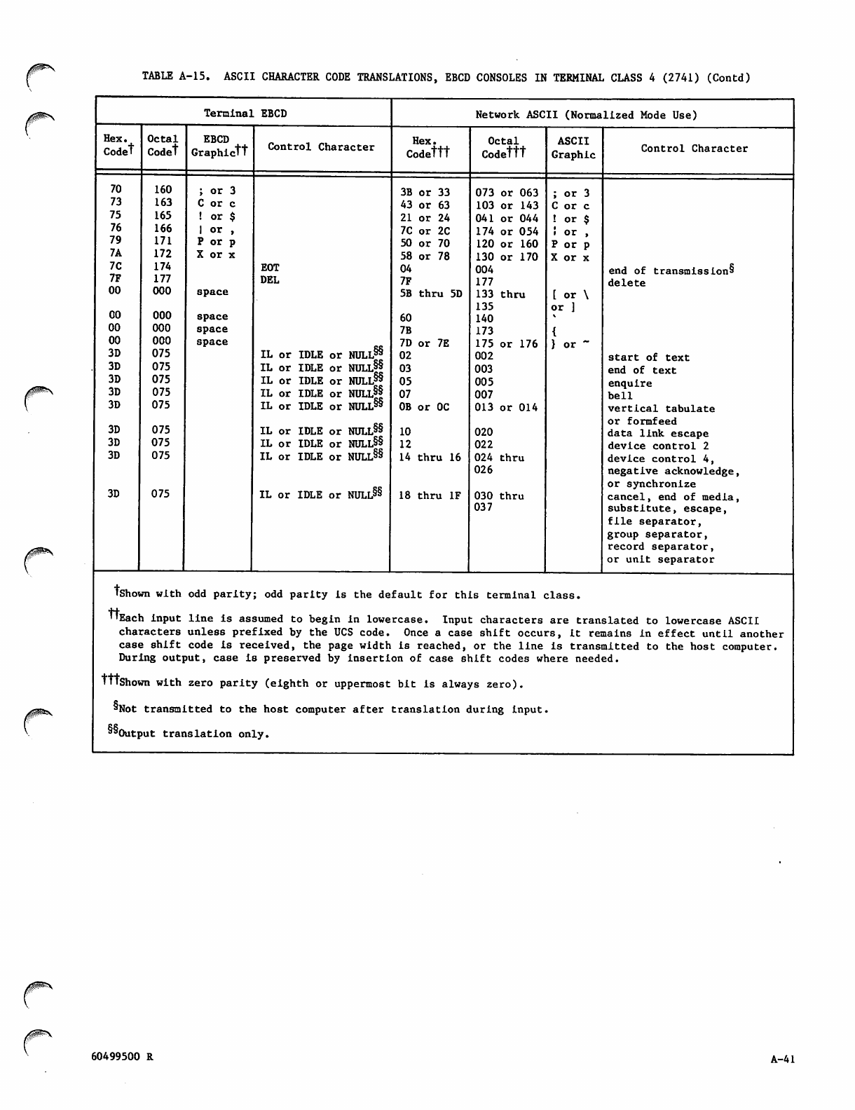
TABLE A-15. ASCII CHARACTER CODE TRANSLATIONS, EBCD CONSOLES IN TERMINAL CLASS 4 (2741) (Contd)
Terminal EBCD Network ASCII (Normalized Mode Use)
Hex. Octal EBCD Hex. Octal ASCII
Codet Codet Graphictt Control Character Codettt Codettt Graphic Control Character
70 160 ; or 3 3B or 33 073 or 063 ; or 3
73 163 C or c 43 or 63 103 or 143 C or c
75 165 ! or $ 21 or 24 041 or 044 ! or $
76 166 1 or , 7C or 2C 174 or 054 ! or ,
79 171 P or p 50 or 70 120 or 160 P or p
7A 172 X or x 58 or 78 130 or 170 X or x
7C 174 EOT 04 004 end of transmission^
7F 177 DEL 7F 177 delete
00 000 space 5B thru 5D 133 thru
135
[ or \
or ]
CO 000 space 60 140
00 000 space 7B 173
00 000 space
IL or IDLE or NULL§§
7D or 7E 175 or 176 } o r -
3D 075 02 002 start of text
3D 075 IL or IDLE or NULL§|
IL or IDLE or NULL*® 03 003 end of text
3D 075 05 005 enquire
3D 075 IL or IDLE or NULL§|
IL or IDLE or NULL§§ 07 007 bell
3D 075 0B or 0C 013 or 014 v e r t i c a l t a b u l a te
or formfeed
3D 075 IL or IDLE or NULL§§ 10 020 data link escape
3D 075 IL or IDLE or NULL§§ 12 022 device control 2
3D 075 IL or IDLE or NULL§§
IL or IDLE or NULL§§
14 thru 16 024 thru
026
device control 4,
negative acknowledge,
or synchronize
3D 075 18 thru IF 030 thru cancel, end of media,
037 substitute, escape,
file separator,
group separator,
record separator,
or unit separator
tshown with odd parity; odd parity is the default for this terminal class.
tfEach input line is assumed to begin in lowe rcase. Input characters are translated to lowercase ASCII
characters unless prefixed by the UCS code. Once a case shift occurs, it remains in effect until another
case shift code is received, the page width is reached, or the line is transmitted to the host computer.
During outj>ut, case is preserved by insert! on of case shift codes where needed.
tttshown with zero parity (eighth or uppermost bit is always zero).
§Not transmJ.tted to the host computer after translation during input.
"Outpu t t r a ris la tion only.
60499500 R A-41
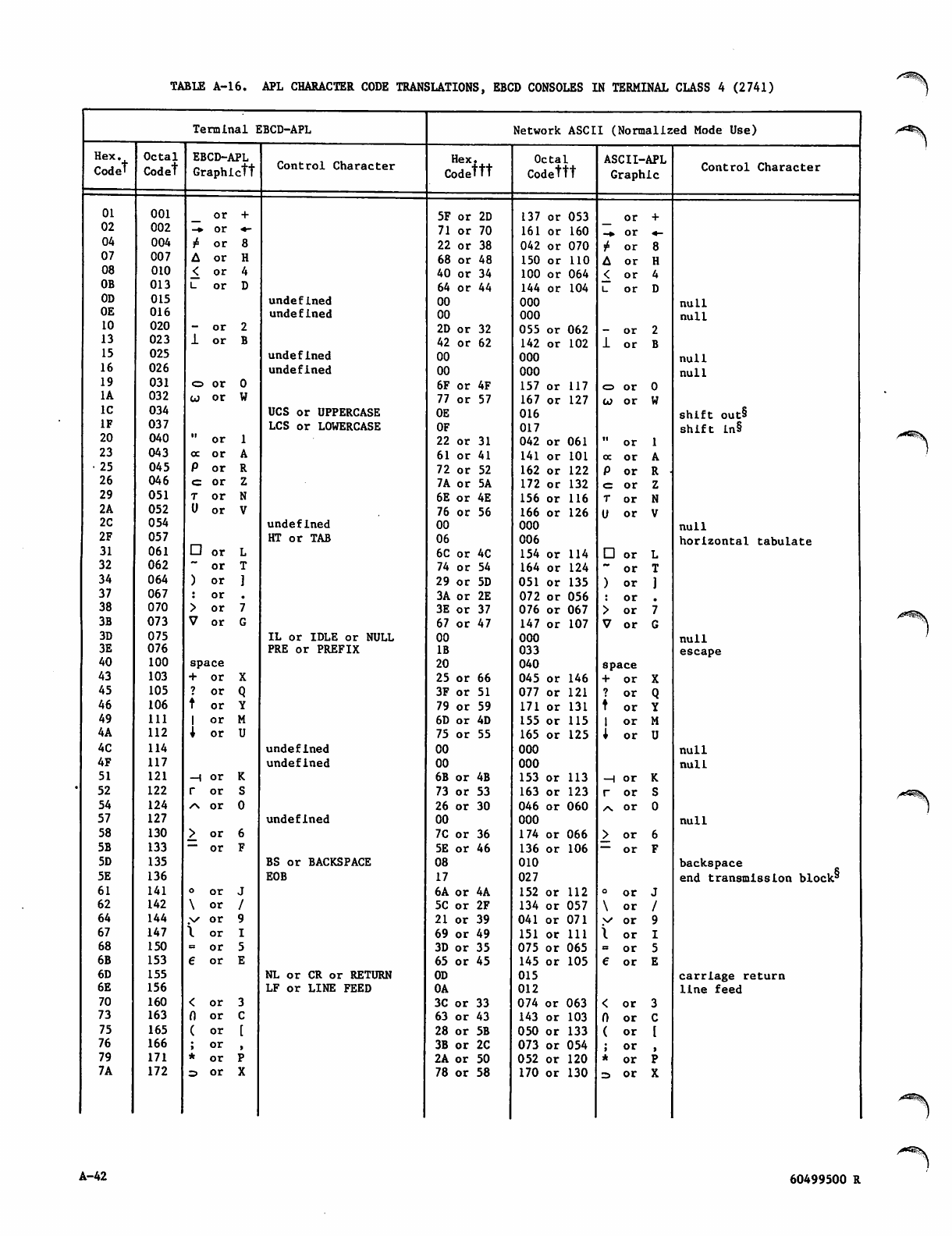
TABLE A-l6. APL CHARACTER CODE TRANSLATIONS, EBCD CONSOLES IN TERMINAL CLASS 4 (2741) /*rSS|\
Terminal EBCD-APL Network ASCII (Normalized Mode Use)
Hex. Octal EBCD-APL Hex. Octal A S fl T T - APT.
Codet Codet Graph!.ctt Control Character Codettt Codettt Graphic Control Character
01 001 _ o r 5F or 2D 137 or 053 or
02 002 -c* or *- 71 or 70 161 or 160 - * o r ■«-
04 004 i4 o r 22 or 38 042 or 070 r4 or
07 007 A o r 68 or 48 150 or 110 A o r
08 010 < o r 40 or 34 100 or 064 < o r
OB 013 L o r 64 or 44 144 or 104 u o r
OD 015 undefined 00 000 nuLl
OE 016 undefined 00 000 null
10 020 - o r 2D or 32 055 or 062 - o r
13 023 1 o r 42 or 62 142 or 102 1 o r
15 025 undefined 00 000 null
16 026 undefined 00 000 null
19 031 o o r 6F or 4F 157 or 117 <=> or
1A 032 w o r 77 or 57 167 or 127 to or
IC 034 UCS or UPPERCASE 0E 016 shift out§
IF 037 LCS or LOWERCASE OF 017 shift in§
20 040 " o r 22 or 31 042 or 061 " o r
23 043 oc or 61 or 41 141 or 101 oc or
• 25 045 P o r 72 or 52 162 or 122 P o r R •
26 046 <= or 7A or 5A 172 or 132 e= or
29 051 T o r 6E or 4E 156 or 116 T o r
2A 052 U o r 76 or 56 166 or 126 U o r
2C 054 undefined 00 000 null
2F 057 HT or TAB 06 006 horizontal tabulate
31 061 □ o r 6C or 4C 154 or 114 □ o r
32 062 ~ o r 74 or 54 164 or 124 ~ o r
34 064 ) o r 29 or 5D 051 or 135 ) o r
37 067 : o r 3A or 2E 072 or 056 : o r
38 070 > o r 3E or 37 076 or 067 > o r
3B 073 V o r 67 or 47 147 or 107 V o r
3D 075 IL or IDLE or NULL 00 000 null
3E 076 PRE or PREFIX IB 033 escape
40 100 space 20 040 space
43 103 + o r 25 or 66 045 or 146 + o r
45 105 ? o r 3F or 51 077 or 121 ? o r
46 106 t o r 79 or 59 171 or 131 t o r
49 111 1 o r 6D or 4D 155 or 115 1 o r
4A 112 1 o r 75 or 55 165 or 125 i o r
4C 114 undefined 00 000 null
4F 117 undefined 00 000 null
51 121 -H or 6B or 4B 153 or 113 —l or
52 122 r o r 73 or 53 163 or 123 r o r
54 124 / \ o r 26 or 30 046 or 060 / \ o r
57 127 undefined 00 000 null
58 130 > o r 7C or 36 174 or 066 >_ or
5B 133 """ or 5E or 46 136 or 106 — o r
5D 135 BS or BACKSPACE 08 010 backspace
end transmission block*'
5E 136 EOB 17 027
61 141 o o r 6A or 4A 152 or 112 o o r
62 142 \ o r 5C or 2F 134 or 057 \ o r
64 144 .v o r 21 or 39 041 or 071 y o r
67 147 \ o r 69 or 49 151 or 111 I o r
68 150 = o r 3D or 35 075 or 065 » o r
6B 153 € o r 65 or 45 145 or 105 € o r
6D 155 NL or CR or RETURN 0D 015 carriage return
6E 156 LF or LINE FEED 0A 012 line feed
70 160 < o r 3C or 33 074 or 063 < o r
73 163 (1 or 63 or 43 143 or 103 0 o r
75 165 ( o r 28 or 5B 050 or 133 ( o r
76 166 ; o r 3B or 2C 073 or 054 ; o r
79 171 * o r 2A or 50 052 or 120 * o r
7A 172 =i o r 78 or 58 170 or 130 z» or
A-42 60499500 R
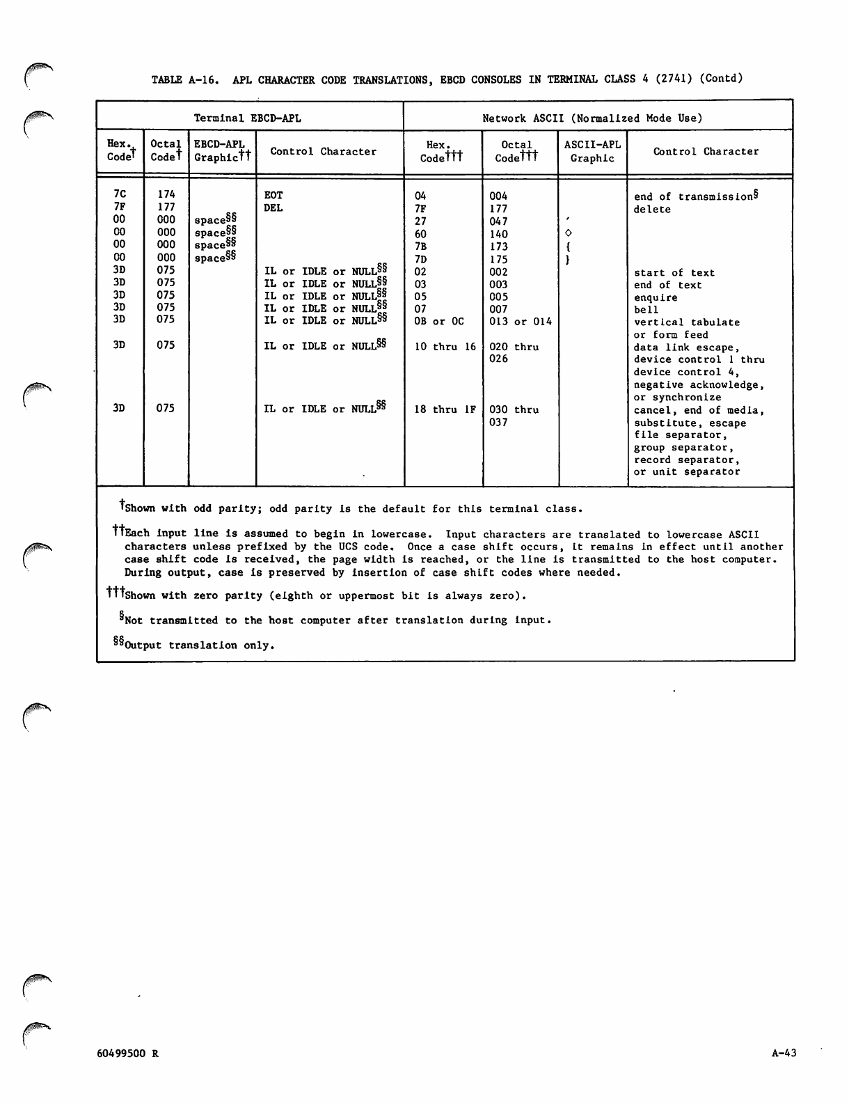
TABLE A-16. APL CHARACTER CODE TRANSLATIONS, EBCD CONSOLES IN TERMINAL CLASS 4 (2741) (Contd)
Terminal EBCD-APL Network ASCII (Normalized Mode Use)
Hex.
Codet
Octal
Codet
EBCD-APL
G r a p h i c t t Control Character Hex.
Codettt
Octal
Codettt
ASCII-APL
Graphic Control Character
7C
7F
00
00
00
00
3D
3D
3D
3D
3D
3D
3D
174
177
000
000
000
000
075
075
075
075
075
075
075
space§§
spacers
space"
spacers
EOT
DEL
IL or IDLE or NULL§§
IL or IDLE or NULL§§
IL or IDLE or NULL§|
IL or IDLE or NULl||
IL or IDLE or NULL8*
IL or IDLE or NULL§§
IL or IDLE or NULL§§
04
7F
27
60
7B
7D
02
03
05
07
0B or 0C
10 thru 16
18 thru IF
004
177
047
140
173
175
002
003
005
007
013 or 014
020 thru
026
030 thru
037
end of transmissions
delete
start of text
end of text
enquire
bell
vertical tabulate
or form feed
data link escape,
device control 1 thru
device control 4,
negative acknowledge,
or synchronize
cancel, end of media,
substitute, escape
file separator,
group separator,
record separator,
or unit separator
tshown with odd parity; odd parity is the default for this terminal class.
TlEach input line is assumed to begin in lowercase. Input characters are translated to lowercase ASCII
characters unless prefixed by the UCS code. Once a case shift occurs, it remains in effect until another
case shift code is received, the page width is reached, or the line is transmitted to the host computer.
During output, case is preserved by insertion of case shift codes where needed.
TTTshown with zero parity (eighth or uppermost bit is always zero).
"Not transmitted to the host computer after translation during input.
"'Output translation only.
60499500 R A-43
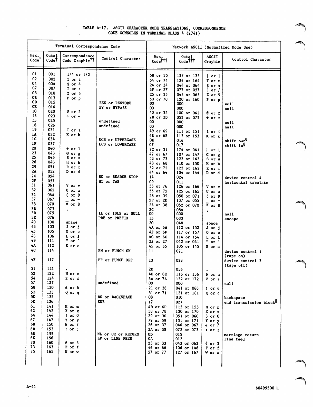
TABLE A-17. ASCII CHARACTER CODE TRANSLATIONS, CORRESPONDENCE
CODE CONSOLES IN TERMINAL CLASS 4 (2741)
Terminal Correspondence Code Network ASCII (Normalized Mode Use)
Hex.
Codet
Octal Correspondence Hex. Octal ASCII
Codet Code Graphictt Control Character Codettt Codettt Graphic Control Character
01 001 1/4 or 1/2 5B or 5D 137 or 135 [ or ]
02 002 T or t 54 or 74 124 or 164 T or t
04 004 $ or 4 24 or 34 044 or 064 $ or 4
07 007 ? or / 3F or 2F 077 or 057 ? or /
08 010 % or 5 25 or 35 045 or 065 % or 5
OB 013 P or p 50 or 70 120 or 160 P or p
OD 015 RES or RESTORE 00 000 null
OE 016 BY or BYPASS 00 000 null
10 020 @ or 2 40 or 32 100 or 062 @ or 2
13 023 + or = 2B or 3D 053 or 075 + or =
15 025 undefined 00 000 null
16 026 undefined 00 000 null
19 031 I o r i 49 or 69 111 or 151 I or i
1A 032 K or k AB or 6B 113 or 153 K or k
IC 034 UCS or UPPERCASE 0E 016 shift out§
IF 037 LCS or LOWERCASE OF 017 shift ln§
20 040 + or 1 7C or 31 174 or 061 I or 1
23 043 G or g 47 or 67 107 or 147 G or g
25 045 S or s 53 or 73 123 or 163 S or s
26 046 H or h 48 or 68 110 or 150 H or h
29 051 R or r 52 or 72 122 or 162 R or r
2A 052 D or d 44 or 64 104 or 144 D or d
2C 054 RO or READER STOP 14 024 device control 4
2F 057 HT or TAB 09 011 horizontal tabulate
31 061 V or v 56 or 76 126 or 166 V or v
32 062 U or u 55 or 75 125 or 165 U or u
34 064 ( or 9 28 or 39 050 or 071 ( or 9
37 067 _ or - 5F or 2D 137 or 055 _ or -
38 070 * or 8 2A or 38 052 or 070 * or 8
3B 073 2C 054
3D 075 IL or IDLE or NULL 00 000 null
3E 076 PRE or PREFIX IB 033 escape
40 100 space 20 040 space
43 103 J or j 4A or 6A 112 or 152 J or j
45 105 0 or o 4F or 6F 117 or 157 0 or o
46 106 L or 1 4C or 6C 114 or 154 L or 1
49 111 " or ' 22 or 27 042 or 041 " or '
4A 112 E or e 45 or 65 105 or 145 E or e
4C 114 PN or PUNCH ON 11 021 device control 1
(tape on)
4F 117 PF or PUNCH OFF 13 023 device control 3
(tape off)
51 121 2E 056
52 122 N or n 4E or 6E 116 or 156 N or n
54 124 Z or z 5A or 7A 132 or 172 Z or z
57 127 undefined 00 000 null
58 130 i or 6 21 or 36 041 or 066 ! or 6
5B 133 Q or q 51 or 71 121 or 161 Q or q
5D 135 BS or BACKSPACE 08 010 backspace
5E 136 EOB 17 027 end transmission block"
61 141 M or m 4D or 6D 115 or 155 M or m
62 142 X or x 58 or 78 130 or 170 X or x
64 144 ) or 0 29 or 30 051 or 060 ) or 0
67 147 Y or y 79 or 59 131 or 171 Y or y
68 150 & or 7 26 or 37 046 or 067 & or 7
6B 153 : or ; 3A or 3B 072 or 073 : or ;
6D 155 NL or CR or RETURN 0D 015 carriage return
6E 156 LF or LINE FEED 0A 012 line feed
70 160 # or 3 23 or 33 043 or 063 0 or 3
73 163 F of f 46 or 66 106 or 146 F or f
75 165 W or w 57 or 77 127 or 167 W or w
<^^^\
A-44 60499500 R
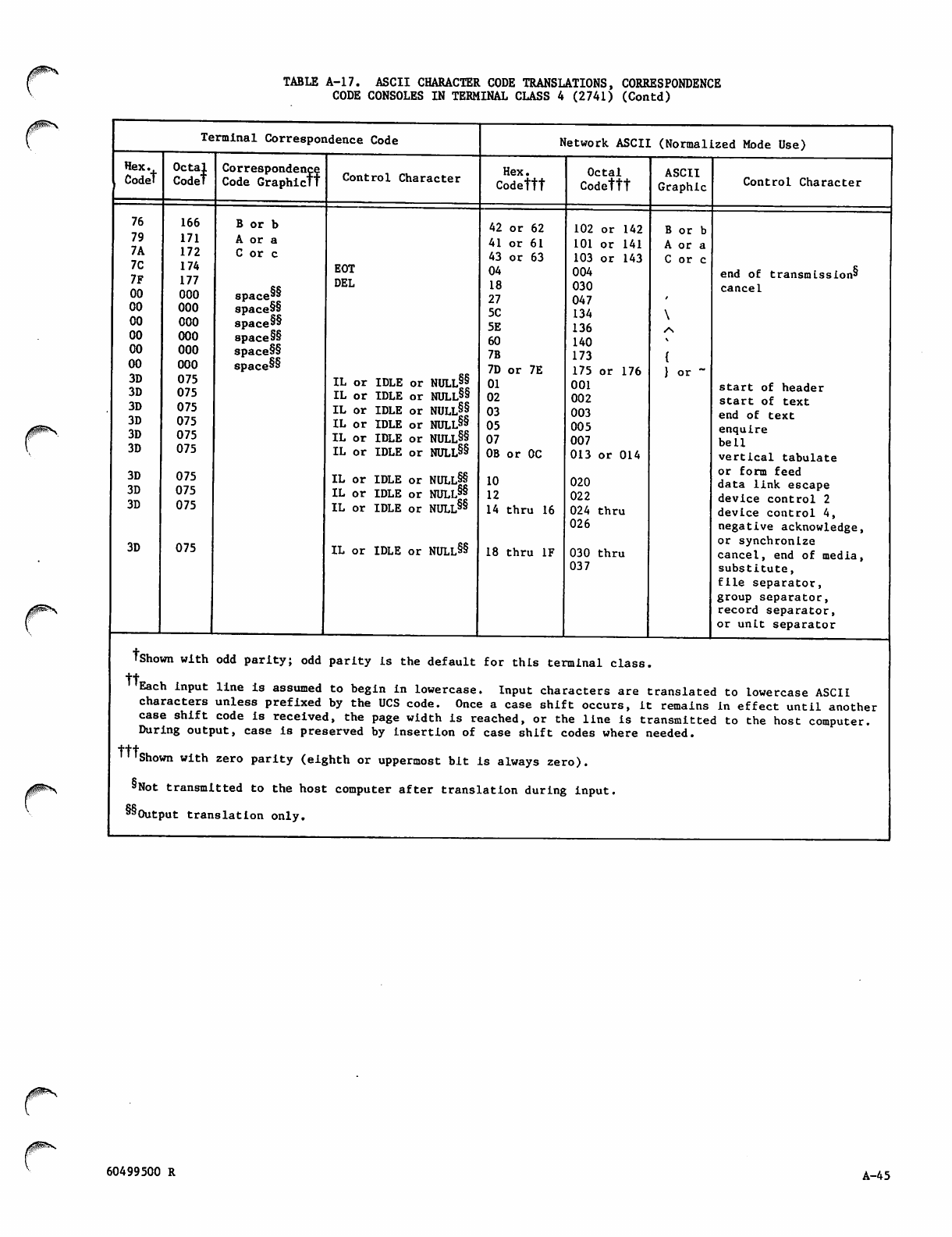
Hex.
Codet
76
79
7A
7C
7F
00
00
00
00
00
00
3D
3D
3D
3D
3D
3D
3D
3D
3D
3D
TABLE A-l7. ASCII CHARACTER CODE TRANSLATIONS, CORRESPONDENCE
CODE CONSOLES IN TERMINAL CLASS 4 (2741) (Contd)
Terminal Correspondence Code
Octal
Codet
166
171
172
174
177
000
000
000
000
000
000
075
075
075
075
075
075
075
075
075
075
Correspondence
Code Graphictt
B or b
A or a
C or c
space8"
space§§
space"
space§§
space§§
space88
Control Character
EOT
DEL
IL or IDLE or NULL§§
IL or IDLE or NULL88
IL or IDLE or NULL§§
IL or IDLE or NULL§§
IL or IDLE or NULL§§
IL or IDLE or NULL§§
IL or IDLE or NULL§§
IL or IDLE or NULL§§
IL or IDLE or NULL8^
IL or IDLE or NULL8"8"
Network ASCII (Normalized Mode Use)
Hex.
Codettt
42 or 62
41 or 61
43 or 63
04
18
27
5C
5E
60
7B
7D or 7E
01
02
03
05
07
0B or 0C
10
12
14 thru 16
18 thru IF
Octal
Codettt
143
176
102 or 142
101 or 141
103 or
004
030
047
134
136
140
173
175 or
001
002
003
005
007
013 or 014
020
022
024 thru
026
030 thru
037
ASCII
Graphic
B or b
A or a
C or c
} or
Control Character
end of transmission8
cancel
start of header
start of text
end of text
enquire
bell
vertical tabulate
or form feed
data link escape
device control 2
device control 4,
negative acknowledge,
or synchronize
cancel, end of media,
substitute,
file separator,
group separator,
record separator,
or unit separator
tshown with odd parity; odd parity is the default for this terminal class,
tt
Each input line is assumed to begin in lowercase. Input characters are translated to lowercase ASCII
characters unless prefixed by the UCS code. Once a case shift occurs, it remains in effect until another
case shift code is received, the page width is reached, or the line is transmitted to the host computer.
During output, case is preserved by insertion of case shift codes where needed.
rttShown with zero parity (eighth or uppermost bit is always zero).
8Not transmitted to the host computer after translation during input.
8Output translation only.
J^S
/sP^s
60499500 R A-45
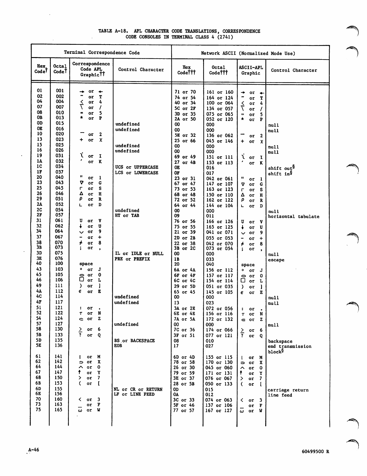
TABLE A-l8. APL CHARACTER CODE TRANSLATIONS, CORRESPONDENCE
CODE CONSOLES IN TERMINAL CLASS 4 (2741)
Hex
Codet
01
02
04
07
08
OB
OD
OE
10
13
15
16
19
1A
IC
IF
20
23
25
26
29
2A
2C
2F
31
32
34
37
38
3B
3D
3E
40
43
45
46
49
4A
4C
4F
51
52
54
57
58
5B
5D
5E
61
62
64
67
68
6B
6D
6E
70
73
75
Terminal Correspondence Code
Octal
Codet
001
002
004
007
010
013
015
016
020
023
025
026
031
032
034
037
040
043
045
046
051
052
054
057
061
062
064
067
070
073
075
076
100
103
105
106
111
112
114
117
121
122
124
127
130
133
135
136
141
142
144
147
150
153
155
156
160
163
165
Correspondence
Code APL
Graphictt
or
or
or
or
or
or
or
+ o r
U
v
or
or
or
or
or
or
or
or
or
or
or
or
space
° o r
o or
□ o r
) o r
e o r
or
or
or
or
or
or
or
or
or
or
or
\ o r I
' o r K
< o r 3
_ o r F
co or W
Control Character
undefined
undefined
undefined
undefined
UCS or UPPERCASE
LCS or LOWERCASE
undefined
HT or TAB
IL or IDLE or NULL
PRE or PREFIX
undefined
undefined
undefined
BS.or BACKSPACE
EOB
NL or CR or RETURN
LF or LINE FEED
Network ASCII (Normalized Mode Use)
Hex
Codettt
71 or 70
74 or 54
40 or 34
5C or 2F
3D or 35
2A or 50
00
00
5E or 32
25 or 66
00
00
69 or 49
27 or 4B
0E
OF
23 or 31
67 or 47
73 or 53
68 or 48
72 or 52
64 or 44
00
09
76 or 56
75 or 55
21 or 39
2D or 2B
22 or
3B or
00
IB
20
6A or 4A
6F or 4F
6C or 4C
29 or 5D
65 or 45
00
13
3A or 2E
6E or 4E
7A or 5A
00
7C or 36
3F or 51
08
17
38
2C
6D or 4D
78 or 58
26 or 30
79 or 59
3E or 37
28 or 5B
0D
0A
3C or 33
5F or 46
77 or 57
Octal
Codettt
161 or 160
164 or 124
100 or 064
134 or 057
075 or 065
052 or 120
000
000
136 or 062
045 or 146
000
000
151 or 111
153 or 113
016
017
042 or 061
147 or 107
163 or 123
150 or 110
162 or
144 or
000
OU
166 or
165 or
041 or 071
055 or 053
042 or 070
073 or 054
000
033
040
156 or 112
157 or 117
154 or 114
051 or 035
145 or 105
000
023
072 or 056
156 or 116
172 or 132
000
174 or 066
077 or
010
027
122
104
126
125
121
155 or 115
170 or 130
045 or 060
171 or 131
076 or 067
050 or 133
015
012
074 or 063
137 or 106
167 or 127
ASCII-APL
Graphic
or
or
or
or
or
or
or
or
or
or
or
or
or
or
U or
+ o r
\s or
- o r
j4 or
; o r
space
o o r
<=> or
□ o r
) o r
e o r
or
or
or
or
or
or
or
or
or
or
or
or
or
or
\ o r I
' o r K
Control Character
null
null
null
null
shift out5
shift in§
null
horizontal tabulate
null
escape
null
null
null
backspace
end transmission
block8
carriage return
line feed
A-46 60499500 R
•^■^v
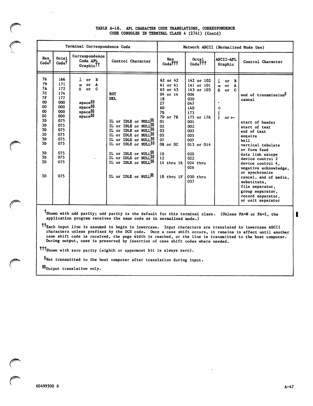
TABLE A-18. APL CHARACTER CODE TRANSLATIONS, CORRESPONDENCE
CODE CONSOLES IN TERMINAL CLASS 4 (2741) (Contd)
Terminal Correspondence Code Network ASCII (Normalized Mode Use)
Hex
Codet
Octal
Codet
Correspondence
Code APL
Graphictt
Control Character Hex
Codettt
Octal
Codettt
ASCII-APL
Graphic Control Character
76
79
7A
7C
7F
00
00
00
00
3D
3D
3D
3D
3D
3D
3D
3D
3D
3D
166
171
172
174
177
000
000
000
000
075
075
075
075
075
075
075
075
075
075
1 o r B
o c o r A
0 o r C
space§§
space§§
space§§
space§§
EOT
DEL
IL or IDLE or NULL8§
IL or IDLE or NULLff
IL or IDLE or NULL88
IL or IDLE or NULL8*8"
IL or IDLE or NULL§§
IL or IDLE or NULL§§
IL or IDLE or NULl||
IL or IDLE or NULL88
IL or IDLE or NULL§§
IL or IDLE or NULL8^
62 or 42
61 or 41
63 or 43
04 or 14
18
27
60
7B
7D or 7E
01
02
03
05
07
0B or 0C
10
12
14 thru 16
18 thru IF
142 or 102
141 or 101
143 or 103
004
030
047
140
173
175 or 176
001
002
003
005
007
013 or 014
020
022
024 thru
026
030 thru
037
1 o r B
o c o r A
0 o r C
O
{
} o r r -
end of transmission8
cancel
start of header
start of text
end of text
enquire
bell
vertical tabulate
or form feed
data link escape
device control 2
device control 4,
negative acknowledge,
or synchronize
cancel, end of media,
substitute,
file separator,
group separator,
record separator,
or unit separator
Tshown with odd parity; odd parity is the default for this terminal class. (Unless PA=N or PA=I, the
application program receives the same code as in normalized mode.)
"Each input line is assumed to begin in lowercase. Input characters are translated to lowercase ASCII
characters unless prefixed by the UCS code. Once a case shift occurs, it remains in effect until another
case shift code is received, the page width is reached, or the line is transmitted to the host computer.
During output, case is preserved by insertion of case shift codes where needed.
'TTshown with zero parity (eighth or uppermost bit is always zero).
"Not transmitted to the host computer after translation during input.
""Output translation only.
J0$^£\
60499500 S A-47
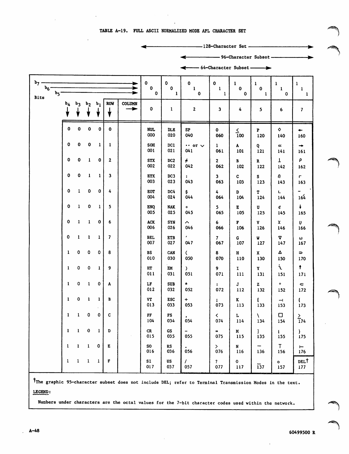
TABLE A-19. FULL ASCII NORMALIZED MODE APL CHARACTER SET
■128-Character Set
-< 96-Character Subset •
•M 64-Character Subset ▶
Bits
b4 b3 b2 bl
| | | |
OOOO
0 0 0 1
0 0 1 0
0 0 1 1
0 1 0 0
0 1 0 1
0 1 1 0
0 1 1 1
0 0 0
0 0 1
0 1 0
0 1 1
1 0 0
1 0 1
1 1 0
1 1 1
ROW
ICOLUMN
NUL
000
SOH
001
STX
002
ETX
003
EOT
004
ENQ
005
ACK
006
BEL
007
BS
010
HT
Oil
LF
012
VT
013
FF
104
CR
015
SO
016
SI
017
DLE
020
DC1
021
DC2
022
DC3
023
DC4
024
NAK
025
SYN
026
ETB
027
CAN
030
EM
031
SUB
032
ESC
033
FS
034
GS
035
RS
036
US
037
SP
040
041
042
043
$
044
045
046
047
(
050
)
051
052
+
053
054
055
056
/
057
060
1
061
2
062
3
063
4
064
5
065
6
066
7
067
8
070
9
071
072
073
<
074
075
>
076
077
100
A
101
B
102
C
103
D
104
E
105
F
106
G
107
H
110
I
111
J
112
K
113
L
114
M
115
N
116
0
117
120
Q
121
R
122
S
123
T
124
U
125
V
126
W
127
X
130
Y
131
Z
132
133
\
134
135
136
137
140
oc
141
1
142
0
143
L
144
e
145
X
146
7
147
A
150
\
151
o
152
-H
153
D
154
I
155
T
156
o
157
160
161
P
162
r
163
164
I
165
U
166
co
167
170
t
171
<=
172
{
173
>_174
}
175
r-
176
DELt
177
■The graphic 95-character subset does not include DEL; refer to Terminal Transmission Modes in the text.
LEGEND:
Numbers under characters are the octal values for the 7-bit character codes used within the network.
A-48 60499500 R
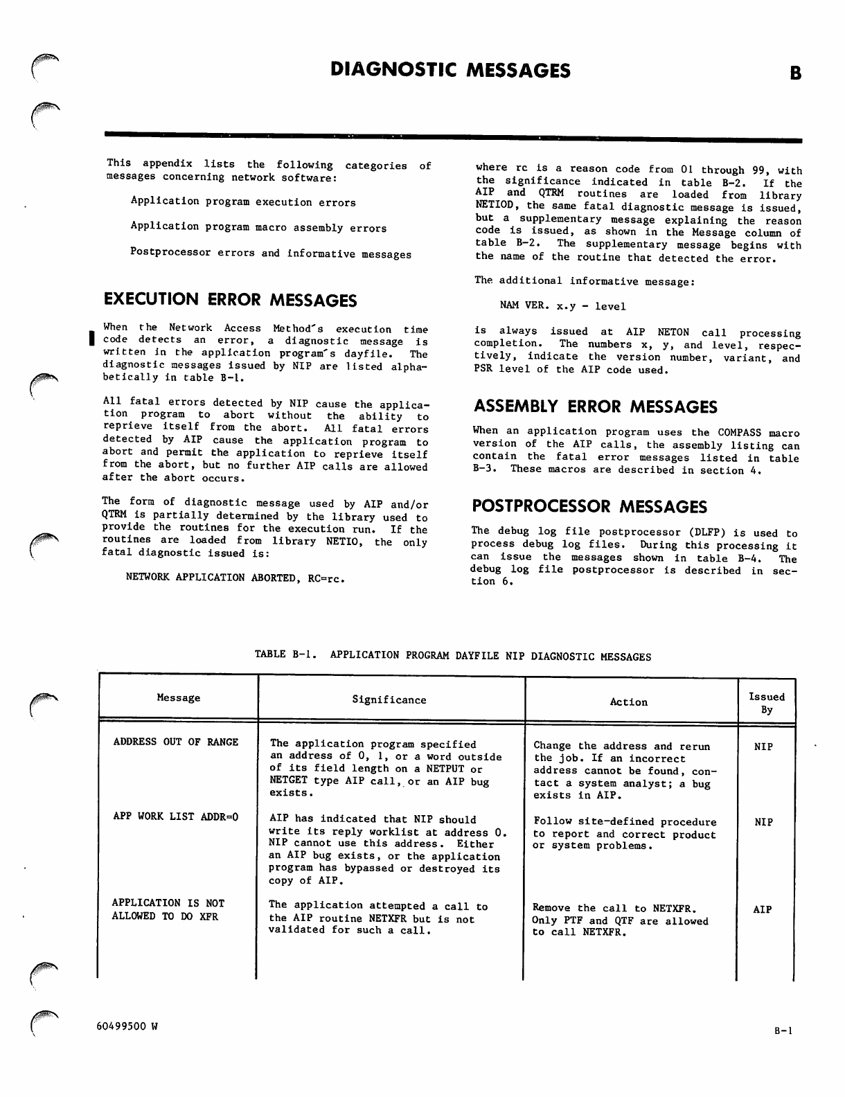
DIAGNOSTIC MESSAGES
J0^\
This appendix lists the following categories of
messages concerning network software:
Application program execution errors
Application program macro assembly errors
Postprocessor errors and informative messages
EXECUTION ERROR MESSAGES
When the Network Access Method's execution time
code detects an error, a diagnostic message is
written in the application program's dayfile. The
diagnostic messages issued by NIP are listed alpha
betically in table B-l.
All fatal errors detected by NIP cause the applica
tion program to abort without the ability to
reprieve itself from the abort. All fatal errors
detected by AIP cause the application program to
abort and permit the application to reprieve itself
from the abort, but no further AIP calls are allowed
after the abort occurs.
The form of diagnostic message used by AIP and/or
QTRM is partially determined by the library used to
pro v i d e t h e r outine s f o r t h e e xecutio n r u n . I f t h e
routines are loaded from library NETIO, the only
fatal diagnostic issued is:
NETWORK APPLICATION ABORTED, RC=rc.
where re is a reason code from 01 through 99, with
the significance indicated in table B-2. If the
AIP and QTRM routines are loaded from library
NETIOD, the same fatal diagnostic message is issued,
but a supplementary message explaining the reason
code is issued, as shown in the Message column of
table B-2. The supplementary message begins with
the name of the routine that detected the error.
The additional informative message:
NAM VER. x.y - level
is always issued at AIP NETON call processing
completion. The numbers x, y, and level, respec
tively, indicate the version number, variant, and
PSR level of the AIP code used.
ASSEMBLY ERROR MESSAGES
When an application program uses the COMPASS macro
version of the AIP calls, the assembly listing can
contain the fatal error messages listed in table
B-3. These macros are described in section 4.
POSTPROCESSOR MESSAGES
The debug log file postprocessor (DLFP) is used to
process debug log files. During this processing it
can issue the messages shown in table B-4. The
debug log file postprocessor is described in sec
tion 6.
TABLE B-l. APPLICATION PROGRAM DAYFILE NIP DIAGNOSTIC MESSAGES
Message
ADDRESS OUT OF RANGE
APP WORK LIST ADDR=0
APPLICATION IS NOT
ALLOWED TO DO XFR
Significance
The application program specified
an address of 0, 1, or a word outside
of its field length on a NETPUT or
NETGET type AIP call, or an AIP bug
exists.
AIP has indicated that NIP should
write its reply worklist at address 0.
NIP cannot use this address. Either
an AIP bug exists, or the application
program has bypassed or destroyed its
copy of AIP.
The application attempted a call to
the AIP routine NETXFR but is not
validated for such a call.
Action
Change the address and rerun
the job. If an incorrect
address cannot be found, con
tact a system analyst; a bug
exists in AIP.
Follow site-defined procedure
to report and correct product
or system problems.
Remove the call to NETXFR.
Only PTF and QTF are allowed
to call NETXFR.
Issued
By
NIP
NIP
AIP
60499500 W B-l
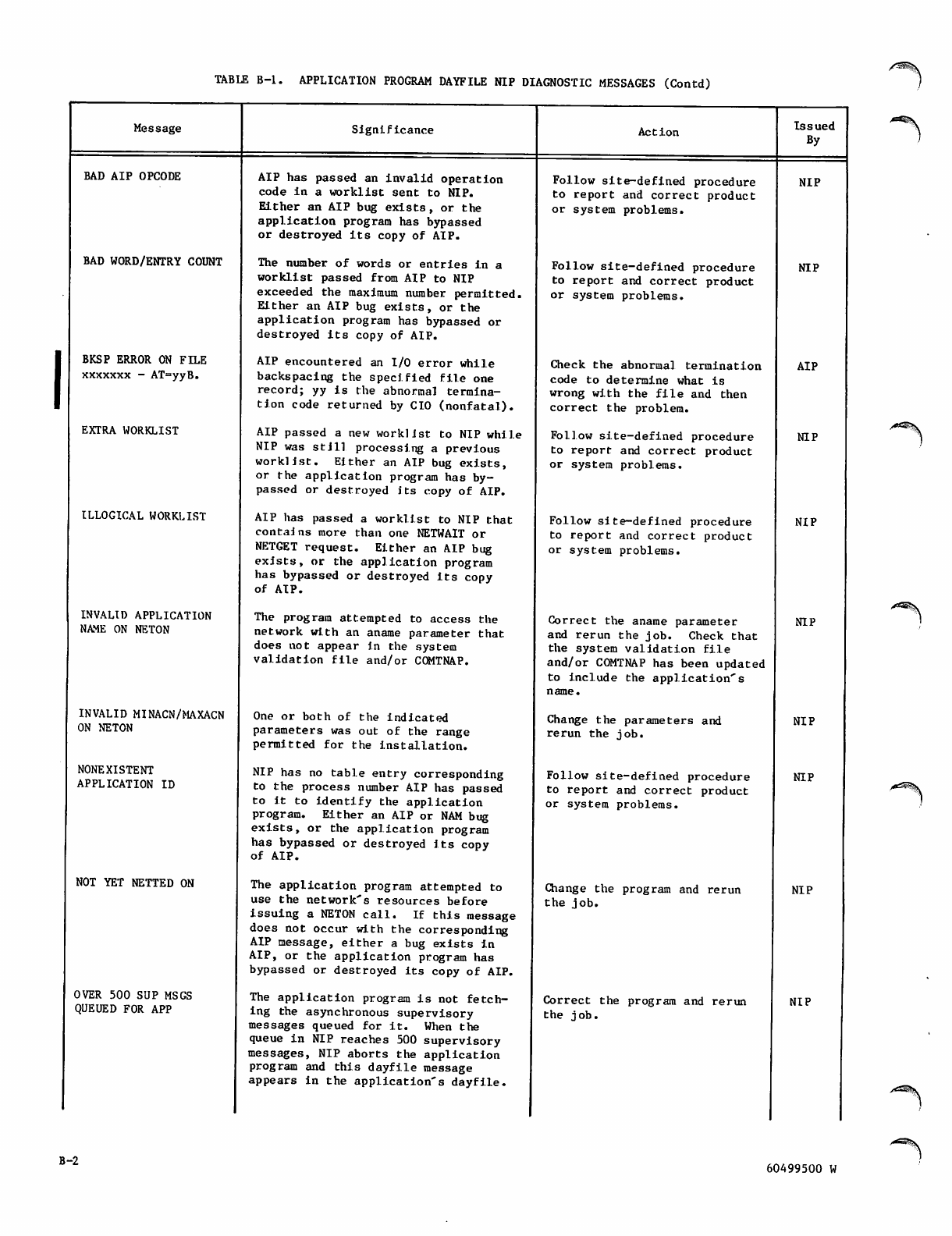
TABLE B-l. APPLICATION PROGRAM DAYFILE NIP DIAGNOSTIC MESSAGES (Contd)
Message
BAD AIP OPCODE
BAD WORD/ENTRY COUNT
BKSP ERROR ON FILE
xxxxxxx - AT=yyB.
EXTRA WORKLIST
ILLOGICAL WORKLIST
INVALID APPLICATION
NAME ON NETON
INVALID MINACN/MAXACN
ON NETON
NONEXISTENT
APPLICATION ID
NOT YET NETTED ON
OVER 500 SUP MSGS
QUEUED FOR APP
Significance
AIP has passed an invalid operation
code in a worklist sent to NIP.
Either an AIP bug exists, or the
application program has bypassed
or destroyed its copy of AIP.
The number of words or entries in a
worklist passed from AIP to NIP
exceeded the maximum number permitted.
Either an AIP bug exists, or the
application program has bypassed or
destroyed its copy of AIP.
AIP encountered an I/O error while
backspacing the specified file one
record; yy is the abnormal termina
tion code returned by CIO (nonfatal).
AIP passed a new worklist to NIP while
NIP was still processing a previous
worklist. Either an AIP bug exists,
or the application program has by
passed or destroyed its copy of AIP.
AIP has passed a worklist to NIP that
contai ns more than one NETWAIT or
NETGET request. Either an AIP bug
exists, or the application program
has bypassed or destroyed its copy
of A IP.
The program attempted to access the
network with an aname parameter that
does not appear in the system
validation file and/or COMTNAP.
One or both of the indicated
parameters was out of the range
permitted for the installation.
NIP has no table entry corresponding
to the process number AIP has passed
to i t t o i d enti f y t h e a ppli c a t i on
program. Either an AIP or NAM bug
exists, or the application program
has bypassed or destroyed its copy
of A IP.
The application program attempted to
use the network's resources before
issuing a NETON call. If this message
does not occur with the corresponding
AIP message, either a bug exists In
AIP, or the application program has
bypassed or destroyed its copy of AIP.
The application program is not fetch
ing the asynchronous supervisory
messages queued for it. When the
queue in NIP reaches 500 supervisory
messages, NIP aborts the application
program and this dayfile message
appears in the application's dayfile.
Action
Follow site-defined procedure
to report and correct product
or system problems.
Follow site-defined procedure
to report and correct product
or system problems.
Check the abnormal termination
code to determine what is
wrong with the file and then
correct the problem.
Follow site-defined procedure
to report and correct product
or system problems.
Follow site-defined procedure
to report and correct product
or system problems.
Correct the aname parameter
and rerun the job. Check that
the system validation file
and/or COMTNAP has been updated
to include the application's
name.
Change the parameters and
rerun the job.
Follow site-defined procedure
to report and correct product
or system problems.
Change the program and rerun
the job.
Correct the program and rerun
the job.
Issued
By
NIP
NIP
AIP
NIP
NIP
NIP
NIP
NIP
NIP
NIP
B-2 60499500 W
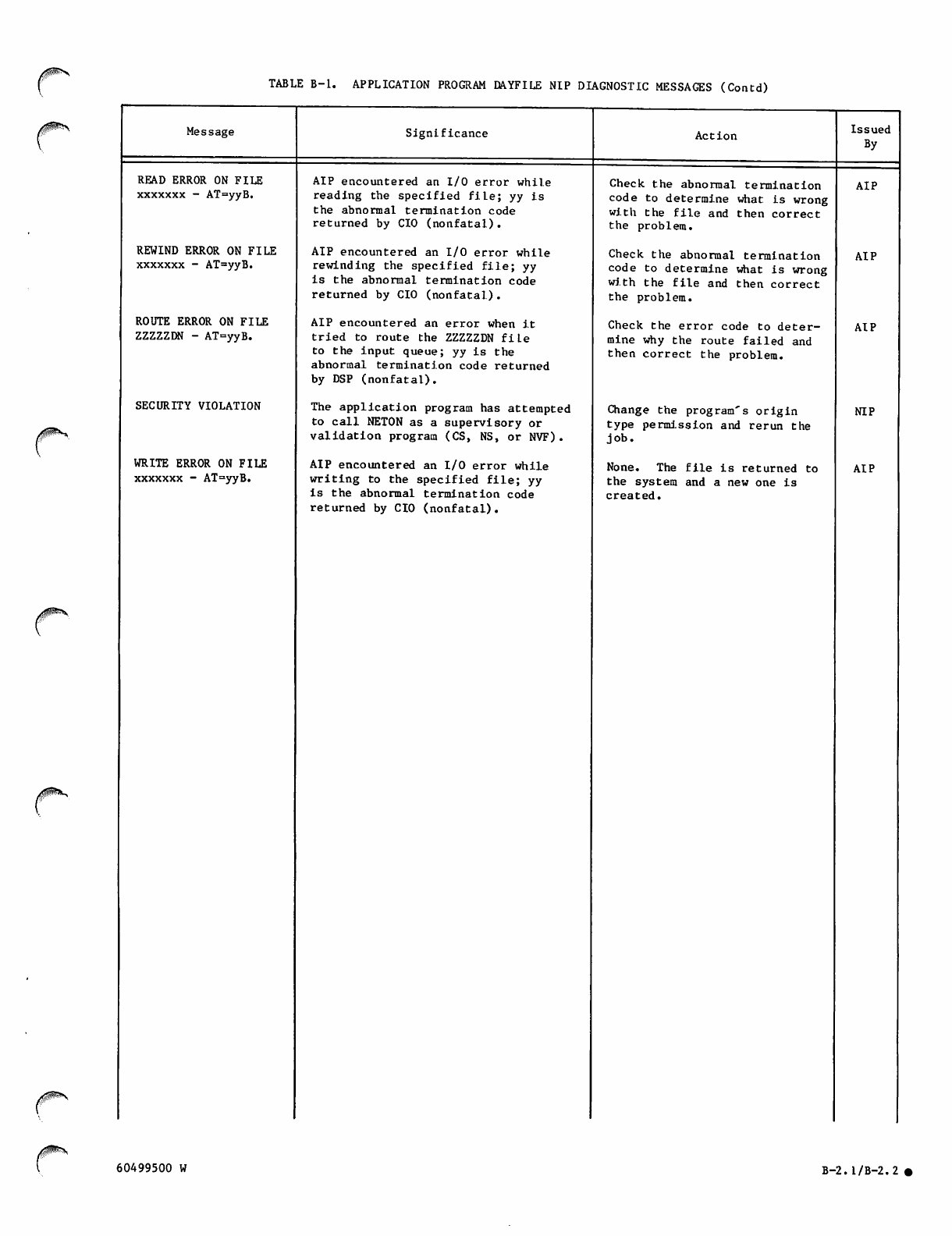
TABLE B-l. APPLICATION PROGRAM DAYFILE NIP DIAGNOSTIC MESSAGES (Contd)
/ffS^N Message
/$P^H
READ ERROR ON FILE
xxxxxxx - AT=yyB.
REWIND ERROR ON FILE
xxxxxxx - AT=yyB.
ROUTE ERROR ON FILE
ZZZZZDN - AT=yyB.
SECURITY VIOLATION
WRITE ERROR ON FILE
xxxxxxx - AT=yyB.
Significance
AIP encountered an I/O error while
reading the specified file; yy is
the abnormal termination code
returned by CIO (nonfatal).
AIP encountered an I/O error while
rewinding the specified file; yy
is the abnormal termination code
returned by CIO (nonfatal.).
AIP encountered an error when it
tried to route the ZZZZZDN file
to the input queue; yy Is the
abnormal termination code returned
by DSP (nonfatal).
The application program has attempted
to call NETON as a supervisory or
validation program (CS, NS, or NVF).
AIP encountered an I/O error while
writing to the specified file; yy
is the abnormal termination code
returned by CIO (nonfatal).
Action
Check the abnormal termination
code to determine what is wrong
with the file and then correct
the problem.
Check the abnormal termination
code to determine what is wrong
with the file and then correct
the problem.
Check the error code to deter
mine why the route failed and
then correct the problem.
Change the program's origin
type permission and rerun the
job.
None. The file is returned to
the system and a new one is
created.
Issued
By
AIP
AIP
AIP
NIP
AIP
60499500 W B-2.1/B-2.2 •

^%
^
n
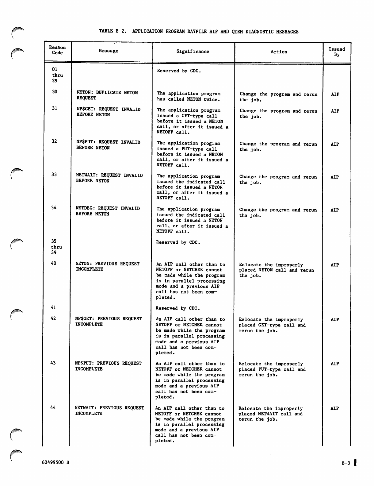
TABLE B-2. APPLICATION PROGRAM DAYFILE AIP AND QTRM DIAGNOSTIC MESSAGES
r
/0^\
Reason
Code Message Significance Action Issued
By
01
thru
29
Reserved by CDC.
30 NETON: DUPLICATE NETON
REQUEST
The application program
has called NETON twice. Change the program and rerun
the job. AIP
31 NP$GET: REQUEST INVALID
BEFORE NETON The application program
issued a GET-type call
before it issued a NETON
call, or after it issued a
NETOFF call.
Change the program and rerun
the job.
AIP
32 NP$PUT: REQUEST INVALID
BEFORE NETON The application program
issued a PUT-type call
before it issued a NETON
call, or after it issued a
NETOFF call.
Change the program and rerun
the job. AIP
33 NETWAIT: REQUEST INVALID
BEFORE NETON
The application program
issued the indicated call
before it issued a NETON
call, or after it issued a
NETOFF call.
Change the program and rerun
the job.
AIP
34 NETDBG: REQUEST INVALID
BEFORE NETON
The application program
issued the indicated call
before it issued a NETON
call, or after it issued a
NETOFF call.
Change the program and rerun
the job.
AIP
35
thru
39
Reserved by CDC.
40 NETON: PREVIOUS REQUEST
INCOMPLETE
An AIP call other than to
NETOFF or NETCHEK cannot
be made while the program
is in parallel processing
mode and a previous AIP
call has not been com
pleted .
Relocate the improperly
placed NETON call and rerun
the job.
AIP
41 Reserved by CDC.
42 NP$GET: PREVIOUS REQUEST
INCOMPLETE
An AIP call other than to
NETOFF or NETCHEK cannot
be made while the program
is in parallel processing
mode and a previous AIP
call has not been com
pleted.
Relocate the improperly
placed GET-type call and
rerun the job.
AIP
43 NP$PUT: PREVIOUS REQUEST
INCOMPLETE
An AIP call other than to
NETOFF or NETCHEK cannot
be made while the program
is in parallel processing
mode and a previous AIP
call has not been com
pleted.
Relocate the improperly
placed PUT-type call and
rerun the job.
AIP
44 NETWAIT: PREVIOUS REQUEST
INCOMPLETE
An AIP call other than to
NETOFF or NETCHEK cannot
be made while the program
is in parallel processing
mode and a previous AIP
call has not been com
pleted .
Relocate the improperly
placed NETWAIT call and
rerun the job.
AIP
60499500 S B-3 I
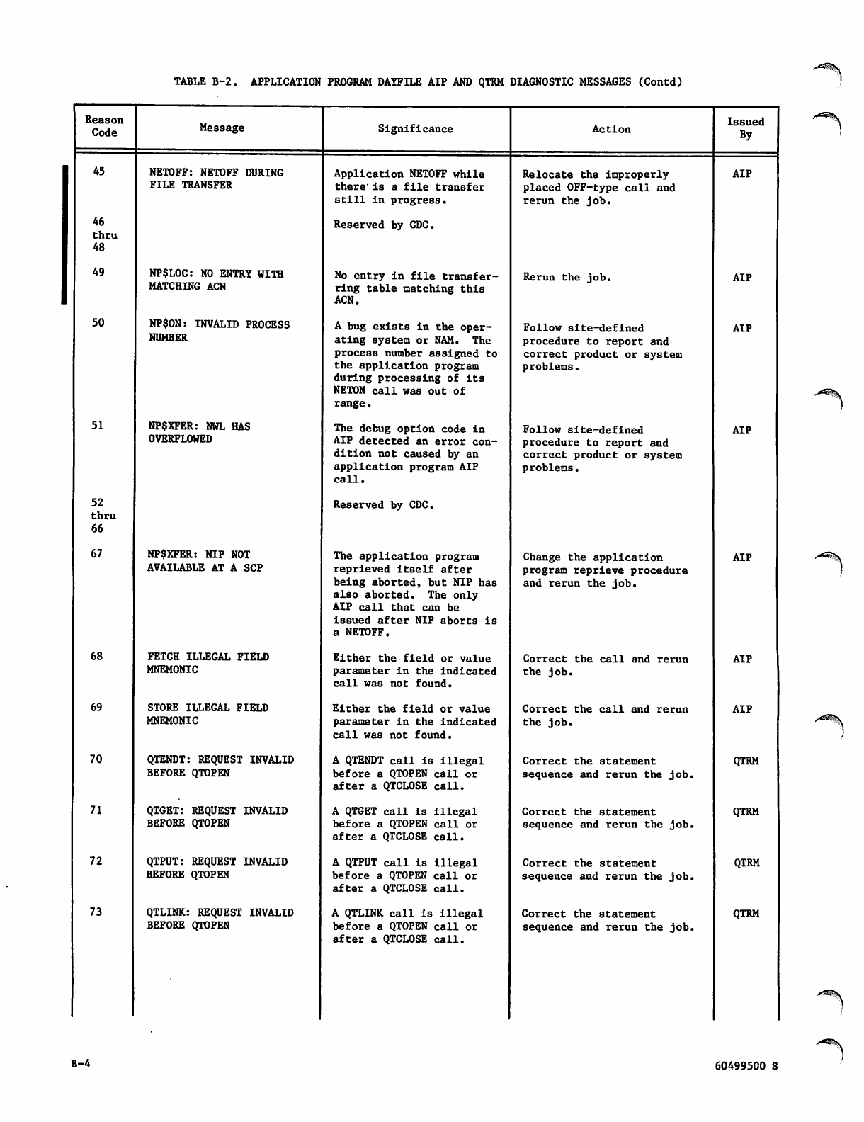
TABLE B-2. APPLICATION PROGRAM DAYFILE AIP AND QTRM DIAGNOSTIC MESSAGES (Contd)
Reason
Code Message Significance Action Issued
By
45 NETOFF: NETOFF DURING
FILE TRANSFER Application NETOFF while
there' is a file transfer
still in progress.
Relocate the improperly
placed OFF-type call and
rerun the job.
AIP
46
thru
48
Reserved by CDC.
49 NP$L0C: NO ENTRY WITH
MATCHING ACN
No ent ry in fi le transfer
ring table matching this
ACN.
Rerun the job. AIP
50 NP$ON: INVALID PROCESS
NUMBER
A bug exists in the oper
ating system or NAM. The
process number assigned to
the application program
during processing of its
NETON call was out of
range.
Follow site-defined
procedure to report and
correct product or system
problems.
AIP
51 NP$XFER: NWL HAS
OVERFLOWED
The debug option code in
AIP detected an error con
dition not caused by an
application program AIP
call.
Follow site-defined
procedure to report and
correct product or system
problems.
AIP
52
thru
66
Reserved by CDC.
67 NP$XFER: NIP NOT
AVAILABLE AT A SCP
The application program
reprieved itself after
being aborted, but NIP has
also aborted. The only
AIP call that can be
i8sued after NIP aborts is
a NETOFF.
Change the application
program reprieve procedure
and rerun the job.
AIP
68 FETCH ILLEGAL FIELD
MNEMONIC
Either the field or value
parameter in the indicated
call was not found.
Correct the call and rerun
the job.
AIP
69 STORE ILLEGAL FIELD
MNEMONIC
Either the field or value
parameter in the indicated
call was not found.
Correct the call and rerun
the job.
AIP
70 QTENDT: REQUEST INVALID
BEFORE QTOPEN
A QTENDT call is Illegal
before a QTOPEN call or
after a QTCLOSE call.
Correct the statement
sequence and rerun the job.
QTRM
71 QTGET: REQUEST INVALID
BEFORE QTOPEN
A QTGET call is illegal
before a QTOPEN call or
after a QTCLOSE call.
Correct the statement
sequence and rerun the job.
QTRM
72 QTPUT: REQUEST INVALID
BEFORE QTOPEN
A QTPUT call is illegal
before a QTOPEN call or
after a QTCLOSE call.
Correct the statement
sequence and rerun the job.
QTRM
73 QTLINK: REQUEST INVALID
BEFORE QTOPEN
A QTLINK call is illegal
before a QTOPEN call or
after a QTCLOSE call.
Correct the statement
sequence and rerun the job.
QTRM
B-4 60499500 S
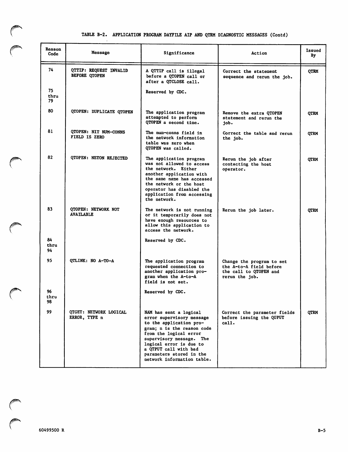
TABLE B-2. APPLICATION PROGRAM DAYFILE AIP AND QTRM DIAGNOSTIC MESSAGES (Contd)
Reason
Code Message Significance Action Issued
By
74 QTTIP: REQUEST INVALID
BEFORE QTOPEN
A QTTIP call is illegal
before a QTOPEN call or
after a QTCLOSE call.
Correct the statement
sequence and rerun the job.
QTRM
75
thru
79
Reserved by CDC.
80 QTOPEN: DUPLICATE QTOPEN The application program
attempted to perform
QTOPEN a second time.
Remove the extra QTOPEN
statement and rerun the
job.
QTRM
81 QTOPEN: NIT NUM-CONNS
FIELD IS ZERO
The num-conns field in
the network information
table was zero when
QTOPEN was called.
Correct the table and rerun
the job. QTRM
82 QTOPEN: NETON REJECTED The application program
was not allowed to access
the network. Either
another application with
the same name has accessed
the network or the host
operator has disabled the
application from accessing
the network.
Rerun the job after
contacting the host
operator.
QTRM
83 QTOPEN: NETWORK NOT
AVAILABLE
The network is not running
or it temporarily does not
have enough resources to
allow this application to
access the network.
Rerun the job later. QTRM
84
t h r u
94
Reserved by CDC.
95 QTLINK: NO A-TO-A The application program
requested connection to
another application pro
gram when the A-to-A
field is not set.
Change the program to set
the A-to-A field before
the call to QTOPEN and
rerun the job.
96
t h r u
98
Reserved by CDC.
99 QTGET: NETWORK LOGICAL
ERROR, TYPE n
NAM has sent a logical
error supervisory message
to the application pro
gram; n is the reason code
from the logical error
supervisory message. The
logical error is due to
a QTPUT call with bad
parameters stored in the
network information table.
Correct the parameter fields
before issuing the QUPUT
call.
QTRM
/S^N
60499500 R B-5
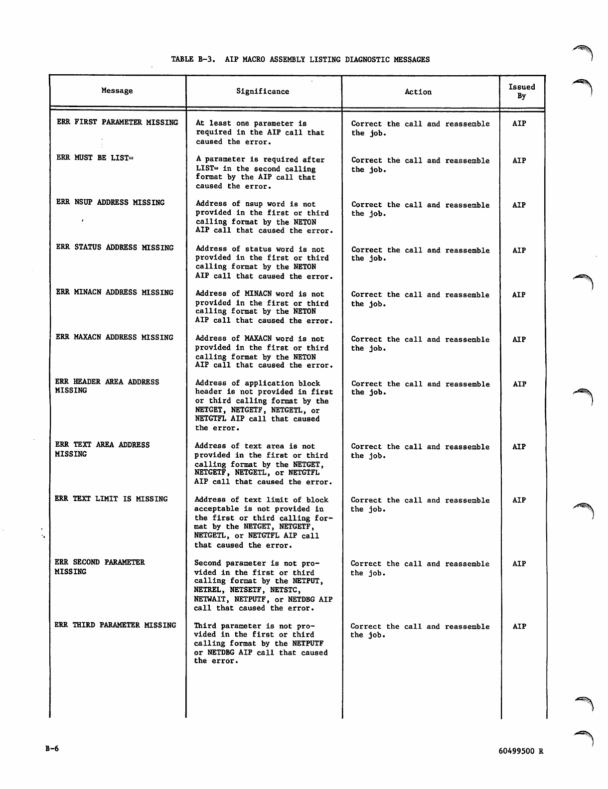
TABLE B-3. AIP MACRO ASSEMBLY LISTING DIAGNOSTIC MESSAGES
Message Significance Action Issued
By
ERR FIRST PARAMETER MISSING At least one parameter is
required in the AIP call that
caused the error.
Correct the call and reassemble
the job.
AIP
ERR MUST BE LIST= A parameter is required after
LIST= in the second calling
format by the AIP call that
caused the error.
Correct the call and reassemble
the job.
AIP
ERR NSUP ADDRESS MISSING Address of nsup word is not
provided in the first or third
calling format by the NETON
AIP call that caused the error.
Correct the call and reassemble
the job. AIP
ERR STATUS ADDRESS MISSING Address of status word is not
provided in the first or third
calling format by the NETON
AIP call that caused the error.
Correct the call and reassemble
the job. AIP
ERR MINACN ADDRESS MISSING Address of MINACN word is not
provided in the first or third
calling format by the NETON
AIP call that caused the error.
Correct the call and reassemble
the job.
AIP
ERR MAXACN ADDRESS MISSING Address of MAXACN word is not
provided in the first or third
calling format by the NETON
AIP call that caused the error.
Correct the call and reassemble
the job. AIP
ERR HEADER AREA ADDRESS
MISSING
Address of application block
header is not provided in first
or third calling format by the
NETGET, NETGETF, NETGETL, or
NETGTFL AIP call that caused
the error.
Correct the call and reassemble
the job. AIP
ERR TEXT AREA ADDRESS
MISSING
Address of text area is not
provided in the first or third
calling format by the NETGET,
NETGETF, NETGETL, or NETGTFL
AIP call that caused the error.
Correct the call and reassemble
the job.
AIP
ERR TEXT LIMIT IS MISSING Address of text limit of block
acceptable is not provided in
t h e fi r s t o r t h i r d c a l l i n g f o r
mat by the NETGET, NETGETF,
NETGETL, or NETGTFL AIP call
that caused the error.
Correct the call and reassemble
the job. AIP
ERR SECOND PARAMETER
MISSING
Second parameter is not pro
v i d ed i n t he fi r s t o r t h ir d
calling format by the NETPUT,
NETREL, NETSETF, NETSTC,
NETWAIT, NETPUTF, or NETDBG AIP
call that caused the error.
Correct the call and reassemble
the job.
AIP
ERR THIRD PARAMETER MISSING Third parameter is not pro
v i d ed i n t he fi r s t o r t h ir d
calling format by the NETPUTF
or NETDBG AIP call that caused
the error.
Correct the call and reassemble
the job.
AIP
B-6 60499500 R
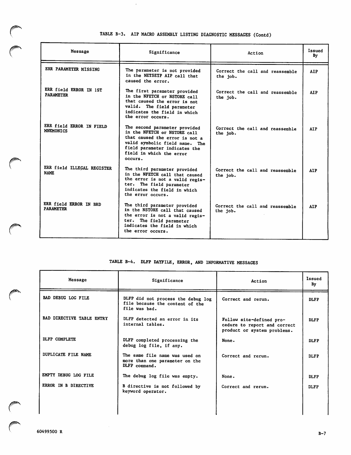
TABLE B-3. AIP MACRO ASSEMBLY LISTING DIAGNOSTIC MESSAGES (Contd)
Message
ERR PARAMETER MISSING
ERR field ERROR IN 1ST
PARAMETER
ERR field ERROR IN FIELD
MNEMONICS
ERR field ILLEGAL REGISTER
NAME
ERR field ERROR IN BRD
PARAMETER
Significance
The parameter is not provided
in the NETSETP AIP call that
caused the error.
The first parameter provided
in the NFETCH or NSTORE call
that caused the error is not
valid. The field parameter
indicates the field in which
the error occurs.
The second parameter provided
in the NFETCH or NSTORE call
that caused the error is not a
valid symbolic field name. The
field parameter indicates the
field in which the error
occurs.
The third parameter provided
in the NFETCH call that caused
the error is not a valid regis
te r. T h e fi eld p a r ame t e r
indicates the field in which
the error occurs.
The third parameter provided
in the NSTORE call that caused
the error is not a valid regis
te r. T h e fi eld p a r ame t e r
indicates the field in w hic h
the error occurs.
Action
Correct the call and reassemble
the job.
Correct the call and reassemble
the job.
Correct the call and reassemble
the job.
Correct the call and reassemble
the job.
Correct the call and reassemble
the job.
Issued
By
AIP
AIP
AIP
AIP
AIP
TABLE B-4. DLFP DAYFILE, ERROR, AND INFORMATIVE MESSAGES
/PS^
Message
BAD DEBUG LOG FILE
BAD DIRECTIVE TABLE ENTRY
DLFP COMPLETE
DUPLICATE FILE NAME
EMPTY DEBUG LOG FILE
ERROR IN B DIRECTIVE
Significance
DLFP did not process the debug log
file because the content of the
file was bad.
DLFP detected an error in its
internal tables.
DLFP completed processing the
deb u g l o g fi l e , i f a ny.
The same file name was used on
more than one parameter on the
DLFP command.
The debug log file was empty.
B directive is not followed by
keyword operator.
Action
Correct and rerun.
Follow site-defined pro
cedure to report and correct
product or system problems.
None.
Correct and rerun.
None.
Correct and rerun.
Issued
By
DLFP
DLFP
DLFP
DLFP
DLFP
DLFP
60499500 R B-7
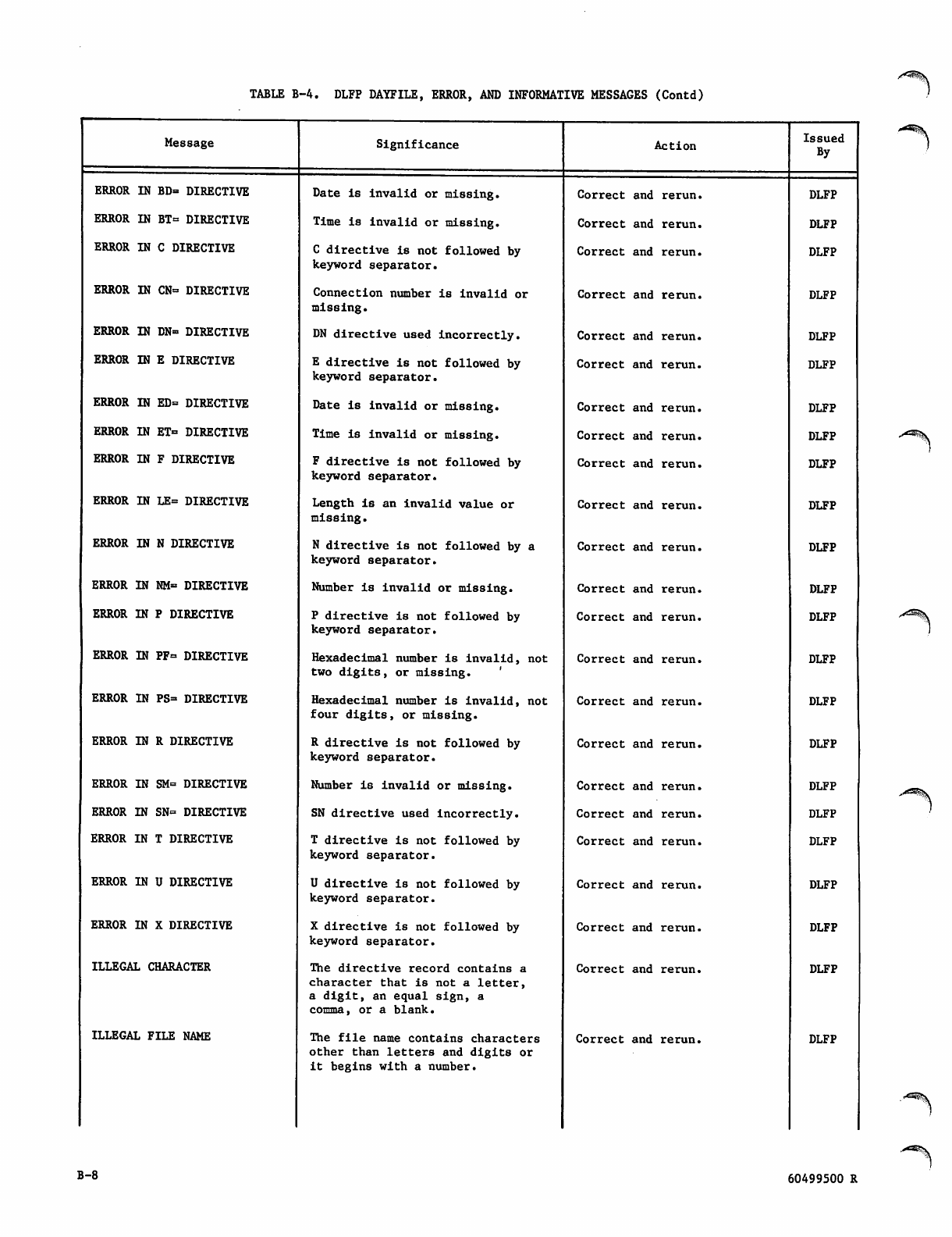
TABLE B-4. DLFP DAYFILE, ERROR, AND INFORMATIVE MESSAGES (Contd)
Message
ERROR IN BD= DIRECTIVE
ERROR IN BT= DIRECTIVE
ERROR IN C DIRECTIVE
ERROR IN CN= DIRECTIVE
ERROR IN DN= DIRECTIVE
ERROR IN E DIRECTIVE
ERROR IN ED= DIRECTIVE
ERROR IN ET= DIRECTIVE
ERROR IN F DIRECTIVE
ERROR IN LE= DIRECTIVE
ERROR IN N DIRECTIVE
ERROR IN NM= DIRECTIVE
ERROR IN P DIRECTIVE
ERROR IN PF= DIRECTIVE
ERROR IN PS= DIRECTIVE
ERROR IN R DIRECTIVE
ERROR IN SM= DIRECTIVE
ERROR IN SN= DIRECTIVE
ERROR IN T DIRECTIVE
ERROR IN U DIRECTIVE
ERROR IN X DIRECTIVE
ILLEGAL CHARACTER
ILLEGAL FILE NAME
Significance
Date is invalid or missing.
Time is invalid or missing.
C directive is not followed by
keyword separator.
Connection number is invalid or
missing.
DN directive used incorrectly.
E directive is not followed by
keyword separator.
Date is invalid or missing.
Time is invalid or missing.
F directive is not followed by
keyword separator.
Length is an invalid value or
missing.
N directive is not followed by a
keyword separator.
Number is invalid or missing.
P directive is not followed by
keyword separator.
Hexadecimal number is invalid, not
two digits, or missing. '
Hexadecimal number is invalid, not
four d i gits, o r missi n g .
R directive is not followed by
keyword separator.
Number is invalid or missing.
SN directive used incorrectly.
T directive is not followed by
keyword separator.
U directive is not followed by
keyword separator.
X directive is not followed by
keyword separator.
The directive record contains a
character that is not a letter,
a digit, an equal sign, a
comma, or a blank.
The file name contains characters
other than letters and digits or
it begins with a number.
Action
Correct and rerun.
Correct and rerun.
Correct and rerun.
Correct and rerun.
Correct and rerun.
Correct and rerun.
Correct and rerun.
Correct and rerun.
Correct and rerun.
Correct and rerun.
Correct and rerun.
Correct and rerun.
Correct and rerun.
Correct and rerun.
Correct and rerun.
Correct and rerun.
Correct and rerun.
Correct and rerun.
Correct and rerun.
Correct and rerun.
Correct and rerun.
Correct and rerun.
Correct and rerun.
Issued
By
DLFP
DLFP
DLFP
DLFP
DLFP
DLFP
DLFP
DLFP
DLFP
DLFP
DLFP
DLFP
DLFP
DLFP
DLFP
DLFP
DLFP
DLFP
DLFP
DLFP
DLFP
DLFP
DLFP
B-8 60499500 R
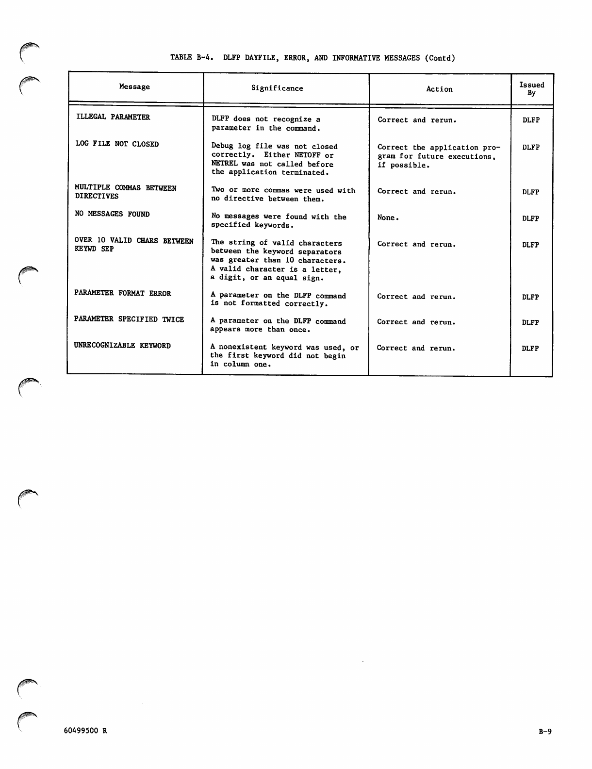
/0^\
TABLE B-4. DLFP DAYFILE, ERROR, AND INFORMATIVE MESSAGES (Contd)
Message Significance Action Issued
By
ILLEGAL PARAMETER DLFP does not recognize a
parameter in the command.
Correct and rerun. DLFP
LOG FILE NOT CLOSED Debug log file was not closed
correctly. Either NETOFF or
NETREL was not called before
the application terminated.
Correct the application pro
gram for future executions,
if possible.
DLFP
MULTIPLE COMMAS BETWEEN
DIRECTIVES Two or more commas were used with
no directive between them. Correct and rerun. DLFP
NO MESSAGES FOUND No messages were found with the
specified keywords.
None. DLFP
OVER 10 VALID CHARS BETWEEN
KEYWD SEP The string of valid characters
between the keyword separators
was greater than 10 characters.
A valid character is a letter,
a digit, or an equal sign.
Correct and rerun. DLFP
PARAMETER FORMAT ERROR A parameter on the DLFP command
is not formatted correctly. Correct and rerun. DLFP
PARAMETER SPECIFIED TWICE A parameter on the DLFP command
appears more than once.
Correct and rerun. DLFP
UNRECOGNIZABLE KEYWORD A nonexistent keyword was used, or
the first keyword did not begin
in column one.
Correct and rerun. DLFP
0!^**.
60499500 R B-9

(*%■
/fc™^
GLOSSARY
This appendix contains terms and mnemonics unique
t o t h e d e s c r i p t i o n o f t h e s o f t w a r e p r e s e n t e d i n
this manual. It also contains terms whose inter
pretation within this manual is intended to be more
co nstrained or different from that common ly mad e.
Some terms used in other manuals for the network
software are included for the reader's convenience
when reconciling terminology.
Application Name (ANAME) -
Up to seven 6-bit letters or digits (the first
must be a letter) used to identify an applica
tion program. It is used by another application
program, by a terminal operator when connection
to the application is requested, and by the host
operator to give commands.
yfwSr'K
y^P^N
Acknowledgment, Block -
A message returned to the sender confirming the
delivery of one block; referred to as BACK in
CCP documentation.
Address -
A location of data (as in the main or micro NPU
memory) or of a device (as a peripheral device
or terminal).
APL -
A scientific programming language characterized
by powerful operators and special graphic sym
bols.
Application Block Header (ABH) -
A single 60-bit word description accompanying
every block passing between an application pro
gram and NAM.
Application Block Limit (ABL) -
The number of unacknowledged blocks a logical
connection is allowed to have outstanding
(queued by the network) at any one time.
Application Block Number (ABN) -
A fi e l d i n t h e a p p l i c a t i o n b l o c k h e a d e r . A n
application-assigned number used to identify a
particular network data block.
Application Block Type (ABT) -
A field in the application block header defining
the accompanying block as either data or super
visory, null or not null, and indicating which
block is the last block of a message.
Application Character Type (ACT) -
A field in the application block header defining
the byte size and packing of text characters.
Application Connection Number (ACN) -
A number assigned by NAM to identify a particu
lar logical connection within an application
program.
Application Interface Program (AIP) -
A group of routines that reside in the applica
tion program'8 field length. These routines
buffer communication between the application
program and the network, using the system con
trol point feature of NOS.
Application List Number (ALN) -
An application-program-assigned number used to
identify a particular group of logical connec
tions belonging to the application program.
60499500 R
Application Program -
A program resident in a host computer that pro
vides an information storage, retrieval, and/or
processing service via the data communication
network and the Network Access Method. Appli
cation programs always use the system control
point feature of NOS to communicate with the
Network Access Method. In the context of net
work software, an application program is not an
interactive job, but rather a terminal servicing
facility. A terminal servicing facility pro
vides terminal users with a specific processing
capability such as remote job entry from batch
terminals, transaction processing, entry and
e x e c u t i o n o f i n t e r a c t i v e j o b s , a n d s o f o r t h .
For example, the standard CDC interactive
facility IAF makes terminal input and output
appear the same to an executing program as file
input and output; IAF is a network application
program, but the executing program using IAF is
an interactive job.
Archetype Terminal -
The specific terminal equipment possessing all
o f t h e a t t r i b u t e s u s e d a s d e f a u l t s f o r t h e
definition of one terminal class. Each terminal
class has a corresponding archetype terminal.
Asynchronous -
A transmission in whi ch each information ch ar
a c te r is i n d i vi d u a l l y s y n ch r o n i z e d b y t h e u se
of start and stop bits. The gap between each
character is not necessarily of fixed length.
Asynchronous Protocol -
The protocol used by asynchronous,
teletypewriter-like devices. For CCP, the
protocol is actually the set of protocols for
eight types of real terminals. The NPU/
terminal interface Is handled by the ASYNC TIP.
Automatic Input -
An output mode that prefixes up to 20 characters
of the output message to the input reply.
Automatic Login -
The process whereby one or more of the Network
Validation Facility login dialog parameters is
supplied to NVF from the local configuration
file. Parameters supplied through automatic
login configuration of a terminal suppress
prompting for the corresponding dialog entries
and override any entries made from the terminal.
C-l
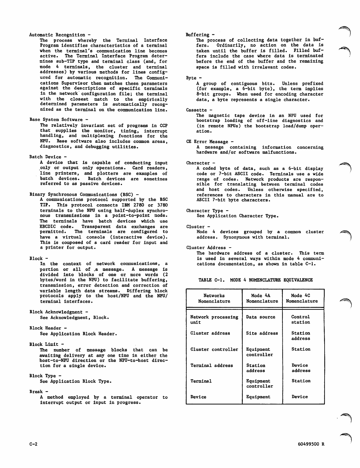
Automatic Recognition -
The process whereby the Terminal Interface
Program identifies characteristics of a terminal
when the terminal's communication line becomes
active. The Terminal Interface Program deter
mines sub-TIP type and terminal class (and, for
mode 4 terminals, the cluster and terminal
addresses) by various methods for lines config
ured for automatic recognition. The Communi
cations Supervisor then matches these parameters
against the descriptions of specific terminals
in the network configuration file; the terminal
with the closest match to the empirically
determined parameters is automatically recog
nized as the terminal on the communication line.
Base System Software -
The relatively invariant set of programs in CCP
t h a t s u p p l i e s t h e m o n i t o r , t i m i n g , i n t e r r u p t
handling, and multiplexing functions for the
NPU. Base software also includes common areas,
diagnostics, and debugging utilities.
Batch Device -
A device that is capable of conducting input
only or output only operations. Card readers,
l i n e p r i n t e r s , a n d p l o t t e r s a r e e x a m p l e s o f
batch devices* Batch devices are sometimes
referred to as passive devices.
Binary Synchronous Communications (BSC) -
A communications protocol supported by the BSC
TIP. This protocol connects IBM 2780 or 3780
terminals to the NPU using half-duplex synchro
n o u s t r a n s m i s s i o ns i n a p o i n t - t o - p o i n t m o d e .
The terminals have batch devices which use
EBCDIC code. Transparent data exchanges are
permitted. The terminals are configured to
have a virtual console (interactive device).
This is composed of a card reader for input and
a printer for output.
Block -
In the context of network communications, a
portion or all of va message. A message is
d i v i de d i n t o b l o c ks o f o n e o r m o r e w o r d s ( 2
bytes/word in the NPU) to facilitate buffering,
transmission, error detection and correction of
variable length data streams. Differing block
protocols apply to the host/NPU and the NPU/
terminal interfaces.
Block Acknowledgment -
See Acknowledgment, Block.
Block Header -
See Application Block Header.
Block Limit -
The number of message blocks that can be
awaiting delivery at any one time in either the
host-to-NPU direction or the NPU-to-host direc
tion for a single device.
Block Type -
See Application Block Type.
Break -
A method employed by a terminal operator to
interrupt output or input in progress.
Buffering -
The process of collecting data together in buf
f e r s . O r d i n a r i l y , n o a c t i o n o n t h e d a t a i s
taken until the buffer is filled. Filled buf
fers include the case where data is terminated
before the end of the buffer and the remaining
space is filled with irrelevant codes.
Byte -
A group of contiguous bits. Unless prefixed
(for example, a 6-bit byte), the term implies
8-bit groups. When used for encoding character
data, a byte represents a single character.
Cassette -
The magnetic tape device in an NPU used for
bootstrap loading of off-line diagnostics and
(in remote NPUs) the bootstrap load/dump oper
ation.
CE Error Message -
A message containing information concerning
hardware and/or software malfunctions.
Character -
A coded byte of data, such as a 6-bit display
code or 7-bit ASCII code. Terminals use a wide
range of codes. Network products are respon
sible for translating between terminal codes
and host codes. Unless otherwise specified,
references to characters in this manual are to
ASCII 7-bit byte characters.
Character Type -
See Application Character Type.
Cluster -
Mode 4 devices grouped by a common cluster
address. Synonymous with terminal.
Cluster Address -
The hardware address of a cluster. This term
is used in several ways within mode 4 communi
cations documentation, as shown in table C-l.
TABLE C-l. MODE 4 NOMENCLATURE EQUIVALENCE
Networks
Nomenclature
Mode 4A
Nomenclature
Mode 4C
Nomenclature
Network processing
unit
Data source C o ntrol
station
Cluster address Site address Station
address
Cluster controller Equipment
controller
Station
Terminal address Station
addres8
Device
address
Terminal Equipment
controller
Station
Device Equipment Device
C-2 60499500 R
0O^>\
Communication Element -
Any entity that constitutes a point of input
to, or output from, the data communication net
work. This includes terminal devices, communi
cation lines, and application programs.
Communication Line -
A complete communication circuit between a
terminal and its network processing unit.
Communication Network -
The portion of the total network comprising the
linked network processing units. The communi
cation network excludes the host computer and
terminals.
Communications Control Program (CCP) -
A portion of the network software that resides
in a 255x Series network processing unit. This
set of modules performs the tasks delegated to
the NPU in the network. This software can
include such routines as the Terminal Interface
Program.
Communications Supervisor (CS) -
A p orti o n o f the ne t w o r k s oftw a r e , w ritt e n a s
an application program; the Communications
Supervisor configures and controls the status
of NPUs and all their communication lines and
terminals.
Configuration -
See Network Configuration.
Connection -
See Logical Connection.
Connection Number (CN) -
A unique number assigned to each active device
on a logical link.
Constant Carrier -
A communication line with a transmission carrier
signal that remains on continuously; failure is
rep o rted i f the c arri e r sign al rec e ived r emain s
off for a period of time that equals or exceeds
a failure verification period.
Contention -
The state that exists in a bidirectional trans
mission line when both ends of the line try to
use the line for transmission at the same time.
All protocols contain logic to resolve the
contention situation.
Control Blocks -
(1) The types of blocks used to transmit con
t r o l ( a s o p p o s e d t o d a t a ) i n f o r m a t i o n ; ( 2 )
Blocks assigned for special configuration/
status purposes in the NPU. The major blocks
are line control blocks (LCB), logical link
control blocks (LLCB), log i c a l c h a n n e l c o n t r o l
blocks (LCCB), terminal control blocks (TCB),
queue control blocks (QCB), buffer maintenance
control blocks (BCB), multiplexer line control
blocks (MLCB), text processing control blocks
(TPCB), and diagnostics control blocks (DCB).
Controlled Carrier -
A communication line with a transmission carrier
signal that is raised and lowered with each
block transmitted; failure is reported if the
carrier signal received does not fluctuate in a
similar fashion.
Controlled Terminal -
A terminal whose input can be started and
stopped by the network software. When a ter
minal places data on a communication line only
in response to a poll, the maximum input rate
can be controlled by controlling the polling
rate. Mode 4 terminals are controlled.
Coupler -
A hardware module resident in a front-end net
work processing unit. That coupler links the
network processing unit to a host computer.
Tr a n s m i s s i o n s a c r o s s t h e c o u p l e r u s e b l o c k
protocol.
Cross -
T h e s oft w a re s u p p or t s y ste m f o r CC P. Th e s e
programs, which are run on the host, support
source code programming in PASCAL, macroassem
bler, and microassembler languages. The com
piled or assembled output of the Cross programs
are in object code format on host computer
files. The object code files are processed by
other Cross programs and host installation pro
grams into a downline load file for an NPU.
Cyclic Redundancy Check (CRC) -
A check code transmitted with blocks/frames of
data. It is used by several protocols.
Data -
Any portion of a message created by the source,
exclusive of any information used to accomplish
transmission of such a message.
Debugging -
The process of altering a program to rid it of
anomalies.
Dedicated Line -
A communication line that is permanently con
nected between a terminal and a network proc
essing unit. Contrast with Switched Line.
DEFINE -
An NDL statement that pro vides the macro-like
capability of substituting an identifier in
c o d i n g f o r a m o r e c o m p l e x e n t i t y. W h e n t h e
coding is processed, the identifier is inter
preted as if it had been replaced by the complex
entity. Also, a NOS command that creates
permanent files.
Destination -
The device or application program designated to
receive the message.
Destination Node (DN) -
The NPU node that directly interfaces to the
destination of a data block. For instance, the
DN of an upline block may be the host process
which passes the block to the application pro
gram responsible for processing the block.
Device -
A separately addressable portion or all of a
t e r m i n a l . T h i s t e r m i s u s e d i n v a r i o u s w a y s
within mode 4 communications documentation, as
shown in table C-l.
Diagnostics -
Software programs or combinations of programs
or tables which aid the troubleshooter in iso
lating problems.
60499500 R C-3
Direct Access File -
In the context of NOS permanent files, a direct
access file is a file that is accessed and
m o d i fi e d d i r e c t l y.
Downline -
The direction of output information flow, from
a host computer application program.
Dump -
In the context of CCP, the process of transfer
ring the contents of the NPU main memory,
r e g i s t e r s , a n d fi l e 1 r e g i s t e r s t o t h e h o s t .
The dump can be processed by the Network Dump
Analyzer in the host to produce a listing of
the dumped information.
Echo -
The process of displaying a keystroke on a con
sole. Echoing can be done from the TIP, from a
modem, or from the terminal itself.
Echoplex -
The process of returning received characters on
a full-duplex line. Not all terminals on full-
duplex communication lines are capable of echo
plex operation.
F i l e -
A unit of batch data. Files are transferred
between application programs and terminals by
using PRUBs on the NPU's host side and trans
mission blocks on the NPU's terminal side. A
file contains one or more records. Example: a
card reader job consists of a file containing
the card image records of all the cards in the
job deck.
Format Effectors (FE) -
Characters in an output data stream that deter
mine the appearance of data at the console. A
f o r m a t e f f e c t o r u s u a l l y t a k e s t h e f o r m o f a
single character in the output line. For
p r i n t i n g d e v i c e s , t h e c h a r a c t e r i s t r a n s l a t e d
by the output side of the TIP into a combination
o f c a r r i a g e r e t u r n s , l i n e f e e d s , o r s p a c e s .
Similarly, FEs for displays can command new
lines, screen clearing, or cursor positioning.
Frame -
A frame is a block of data sent across a high
speed link. It is composed of control bytes, a
CRC sum, and (in some cases) data bytes in sub-
block sequence. A sub-block can be a network
data block or a part of a block. The frame is
the basic communications unit used in trunk
(NPU to NPU) communications and provides high-
data density in bit-serial format over data-
grade lines, as well as data assurance.
Frames are transmitted as a sequence of bytes
through the multiplex subsystem which uses a
hardware-controlled frame on the input and out
put multiplex loops.
Free-Wheeling Terminal -
When a terminal can input at the discretion of
the terminal user and has an input rate that
cannot be controlled directly. Asynchronous
terminals are free-wheeling. Contrast with
Controlled Terminal.
Front-End NPU -
A network processing unit that directly inter
faces to one or more hosts. Synonymous with
local NPU.
Full Duplex (FDX) -
Two-way simultaneous transmission on a communi
c a t io n l in e .
Function Codes -
Codes used by the service module to designate
the type of function (command or status) being
t r a n s m i t t e d . Tw o c o d e s a r e d e fi n e d : p r i m a r y
function code (PFC) and secondary function code
(SFC). Function codes are also used between NAM
and the application programs in all supervisory
messages.
Half Duplex (HDX) -
Two-way alternating transmission on a communi
cation line. Normally a single set of data
lines carry input, output, and part of the con
trol information. Contention for use is possi
ble in HDX mode and must be resolved by the
protocol governing line transfers.
Halt Codes -
Codes generated by the NPU when it is stopped
by its software. These codes, which indicate
the cause of the stoppage, are contained in a
CCP dump.
HASP -
A protocol based on the BSC protocol; it is used
by HASP workstations. A workstation has both
interactive and batch devices. The standard
code of all HASP devices is EBCDIC; however,
transparent batch data exchanges with the host
are also permitted. The HASP TIP converts
interactive HASP data from EBCDIC transmission
blocks to ASCII IVT blocks; it converts batch
HASP data from EBCDIC transmission blocks to
display code PRU blocks.
Header -
T h e p o r t i o n o r p o r t i o n s o f a b l o c k h o l d i n g
information about the block source, destination,
and type. During network movement, a block can
acquire several headers. For example, during
movement of a block from a terminal to the host
over an X.25 network, the block acquires the
following headers: one at the terminal (also a
trailer), one for the frame, one for the packet,
and another for the host application program.
Headers are discarded by the appropriate stage
of processing, so that in this example, the host
sees only the application program block header.
Conversely, headers are generated and discarded
as needed downline, so that the terminal sees
only the terminal header (and trailer).
Header Area (HA) -
An area, usually one 60-bit word, within the
application program containing the application
block header for a NETPUT or NETPUTF call, or
the area to receive the header for a NETGET,
NETGETL, NETGETF, or NETGTFL call.
High-Speed Synchronous Line -
A data transmission line operating at or above
19200 b/s. T h e s e l i n e s a r e n o r m a l l y u s e d f o r
local LIP/remote LIP transfers and for X.25 and
HASP network transfers.
/&~"$®$>\
C-4 60499500 R
Host -
The computer that controls the network and con
tains the application programs that process
network blocks.
Host Interface Package (HIP) -
The CCP program that handles block transfers
across the host/local NPU interface. The HIP
transfers control blocks and data blocks (IVT
blocks or PRU blocks).
Host Node -
The node ID number of the NPU coupler that
directly interfaces with a host computer.
Host Operator (HOP) -
The operator who resides at the system console,
i n i t i a t e s N A M , c o n t r o l s N P U s a n d n e t w o r k -
related host elements. The HOP may do all NPU
operator functions as well as those functions
unique to the HOP despite the existance of NPU
op e r a t ors. T h ere ca n b e o n ly one H O P. C o n
trast with NPU operator.
I n i t i a l i z a t i o n -
The process of loading an NPU and optionally
dumping the NPU contents. After downline load
ing from the host, the NPU network-oriented
tables are configured by the host so that all
network processors have the same IDs for all
network terminals, lines, trunks, etc.
Input -
Information flowing upline from terminal to host
computer.
Input Parameter -
A parameter in an AIP call that provides Input
to the AIP routine. An input parameter can be
a constant, an expression, or a symbolic address
for such values. Input parameters are not
altered by the completion of AIP processing.
Interactive Device -
Any device capable of conducting both input and
output, making it capable of dialog with the
N e t w o r k Va l i da t i o n F a c i l i t y. A l s o k n o w n a s a
console device. An interactive device is serv
iced by an application program using the inter
a c t i v e v i r t u a l t e r m i n a l i n t e r f a c e . C o n t r a s t
with Passive Device.
Interactive Virtual Terminal (IVT) -
A block protocol format for interactive con
soles. CCP TIPs convert all upline interactive
b l o c k s t o t h i s f o r m a t ( e x c e p t i o n : n o t r a n s
formations are made to transparent data except
to put the data into block format). By this
method, application programs in the host need
only t o b e able t o proce s s intera c t ive d a t a in
IVT format rather than in the multiplicity of
formats that real terminals use. Downline mes
sages from the host to interactive devices are
converted from IVT to real terminal format.
IVT processing is controlled by the TIPs; the
TIPs use some common IVT modules.
Level -
For logical records, an octal number 0 through
17 in the system-supplied 48-bit marker that
terminates a short or zero-length PRU.
Line -
A connection between an NPU and a terminal, or
a group of terminals.
Li n k -
A connection between two NPUs or an NPU and a
host.
Link Interface Package (LIP) -
The CCP prog ram that handles frame transfers
across a trunk; that is, across the connection
between a local and a remote NPU. A LIP uses
CDCCP protocol and interfaces on the local NPU
side to the HIP. On the remote NPU side, the
LIP interfaces with the appropriate TIP. In
both local and remote NPUs, the LIP interfaces
with the multiplexer subsystem for transfer
across the trunk.
L i s t -
A group of logical connections with the same
application list number, which are linked
together by NAM and treated as a single entity
in NETGETL or NETGTFL calls.
List Number -
See Application List Number.
Load -
The process of moving programs downline from
the host and storing them in the NPU main and
micromemory. Loading of a remote NPU is accom
plished by the host through the use of the LIP
in the local NPU.
Local Configuration File (LCF) -
A file in th e host com pute r sys tem, contain ing
information on the logical relationships among
the service elements in the network. The file
contains a list of the application programs
available for execution in the host computer,
and the users that require automatic login to
them. This is a NOS direct access permanent
file.
Local NPU -
An NPU that is connected to the host via a
coupler. A local NPU always contains a HIP for
processing block protocol transfers across the
host/local NPU interface. Synonymous with
front-end NPU. Contrast with remote NPU.
Logical Connection -
A logical message path established between two
application programs or between a network
terminal and an application program. Until
terminated, the logical connection allows mes
sages to pass between the two entities.
Logical Line -
The basic message
See Physical Line.
unit of a console device.
Logical Link (LL) -
The portion of a logical connection defined by
h o s t n o d e a n d t e r m i n a l n o d e I D n u m b e r s . A
logical link is an error-free path across the
network over which many separate logical con
nections are multiplexed. A logical link cannot
traverse more than two NPUs.
60499500 R C-5
Logical Record -
Under NOS, a data grouping that consists of one
or more PRUs terminated by a short PRU or zero-
length PRU. Equivalent to a system-logical-
record under NOS/BE.
Loop Multiplexer (LM) -
The hardware that interfaces the CLAs (which
convert data between bit-serial digital and
bit-parallel digital character format) and the
input and output loops.
Low/Medimum-Speed Voice-Grade Line -
A line that operates at bit transmission rates
at or below 19200 b/s. These lines character
istically connect individual terminals to an
NPU or to an X.25 PAD service.
Macromemory -
The portion of 255x Series network processing
unit memory that contains code involved in data
communication, such as the Terminal Interface
Program. It is partly dedicated to programs
and common areas; the remainder is buffer area
used for data and overlay programs. Word size
is 16 data bits plus three additional bits for
parity and program protection. Memory is pack
aged in 16K and 32K word increments.
Message -
A logical unit of information, as processed by
an application program. When transmitted over
a network, a message can consist of one or more
blocks.
Micromemory -
The micro portion of the NPU memory. This con
sists of 8192 words of 64-bit length. 1024
words are Read Only Memory (ROM); the remaining
words are Random Access Memory (RAM) and are
alterable. The ROM memory contains the emulator
microprogram that allows use of assembly lan
guage.
Microprocessor -
The portion of the NPU that processes the pro
grams.
Mode 4 -
A communication line transmission protocol that
requires the polling of sources for input to
the data communication network. Control Data
defines two types of mode 4 equipment, mode 4A
and mode 4C. Mode 4A equipment is polled
through the hardware address of the console
device, regardless of how many devices interface
to the network. Mode 4C equipment is polled
through separate hardware addresses, depending
on the point each device uses to interface with
the network.
Modem -
A hardware device for converting analog levels
to digital signals and the converse. Telephone
lines interface to digital equipment via modems.
Modem is synonymous with data set.
Module -
See Program.
Monitor -
The portion of the CCP base system software
responsible for time and space allocation with
in the computer. The principal monitor program
is 0PSM0N, which executes OPS level programs by
scanning a table of programs that have pending
tasks.
Multiplex Loop Interface Adapter (MLIA) -
The hardware portion of the multiplex subsystem
that controls the multiplexing loops (input and
output) as well as the interface between the
NPU and the multiplexing subsystem.
Multiplex Subsystem -
The portion of the base NPU software that per
forms multiplexing tasks for upline and downline
data, and also demultiplexes upline data from
the CIB and places the data in line-oriented
input data buffers.
Neighbor NPUs -
Two NPUs connected to one another by means of a
trunk.
Network -
An interconnected set of network processing
units, hosts, and terminal devices.
Network Access Method (NAM) -
A software package that provides a generalized
method of using a communication network for
switching, buffering, queuing, and transmitting
data. NAM is a set of interface routines used
by a terminal servicing facility for shared
a c c e s s t o a n e t w o r k o f t e r m i n a l s a n d o t h e r
application programs, so that the facility
program does not need to support the physical
structures and protocols of a private communi
cation network.
Network Address -
The address used by block protocol to establish
routing for the message. It consists of three
p a r t s ; D N - t h e d e s t i n a t i o n n o d e , S N - t h e
source node, and CN - the connection number.
Network Configuration -
The process of setting tables and variables
throughout the network to assign lines, links,
terminals, etc., so that all elements of the
network recognize a uniform addressing scheme.
After configuration, network elements accept
all data commands directed to/through themselves
and reject all other data and commands.
Network Configuration File (NCF) -
A network definition file in the host computer,
containing information on the network elements
and permissible linkages between them. The
status of the elements described in this file
is modified by the network operator in the
course of managing the network through the
Communications Supervisor. This is a NOS direct
access permanent file.
Network Definition File -
Either of the two types of NDL program output
files that determine the configuration of the
n e t wor k . T h is c a n b e a n e t wor k c onfi g u ra t i on
file or a local configuration file.
C-6 60499500 R
JPN
Network Definition Language (NDL) -
The compiler-level language used to define the
network configuration file and local configu
r a t i o n fi l e c o n t e n t s .
Network Definition Language Processor (NDLP) -
The network software module that processes an
NDL program as an off-line batch job to create
the network definition files and other NDL pro
gram output.
Network Element -
Any configurable entity supervised or loaded by
the Network Supervisor. A network element con
sists of any entity in the total network that
is not a communication element; this term is
usually applied to the data communication net
work entities comprising the NPUs and their
linkages.
Network Logical Address -
See Network Address.
Network Processing Unit (NPU) -
The collection of hardware and software that
switches, buffers, and transmits data between
terminals and host computers.
Network Supervisor (NS) -
A portion of the network software, written as a
NAM application program. The Network Supervisor
dumps and loads the NPUs in the communication
network.
Node -
A hardware or software entity that creates,
a b s o r b s , s w i t c h e s , a n d / o r b u f f e r s m e s s a g e
blocks. NPUs and host couplers are communi
cation nodes of the network.
NPU Operator -
The network operator who resides at a terminal
and controls network elements such as NPUs,
trunks, logical links, lines, and terminals.
Co ntr ast with Ho st Operat or. Also, an operat or
using the offnet NPU console.
Off-Line Diagnostics -
Optional diagnostics for the NPU that require
the NPU to be disconnected from the network.
On-Line Diagnostics -
Optional diagnostics for the NPU that can be
executed while the NPU is connected to, and
operating a s a p a r t o f the network. I n d i v i d u a l
lines being tested must, however, be discon
nected from the network. These diagnostics are
provided if the user purchases a network main
tenance contract.
OPS Monitor -
The NPU monitor. See Monitor.
Output -
Information flowing downline from the host.
Output Buffer -
Any buffer that is used to hold a downline mes
sage from the host.
Packet -
A group of binary digits, including data and
call control signals, which is switched as a
single unit. The data, control signals, and
error-control information are arranged in a
specific format.
Packet Assembly/Disassembly Service (PAD) -
A definition of the procedures for the operation
of an asynchro nous terminal throu gh a packet-
switching network (PSN).
Assembly: The accumulation of characters from
an asynchronous device into data blocks for
transmission via a PSN. Disassembly: The
encoding of blocks for transmission to an
asynchronous terminal.
Packet-Switching Network (PSN) -
A network that provides data communication
service between various terminal and computer
systems or networks. The PSN is usually
licensed as a common carrier.
Ter min al i nterfac e to a PSN is d efined by the
packet assembly/disassembly (PAD) service. PSN
interface with a NOS network is defined by the
X.25 protocol.
PAD SubTIP -
A subTIP of the X.25 TIP that allows asynchro
n o us A S C II t e r m in a l s t o c o mm u n i ca t e o v er a
packet-switching network.
Paging (Screen) -
The process of filling a CRT display with data
and holding additional data for subsequent dis
plays. Changing the paged display is terminal
operator controlled if the page wait option is
selected.
Parity -
A type of data assurance. The most common
parity is character parity; that is, the sup
plying of one extra bit per character so that
the sum of all the bits in the character
(including the parity bit) is always an even
(even parity) or odd (odd parity) number.
Pascal -
A high level programming language used for CCP
programs. Almost all CCP programs are written
in the Pascal language.
Passive Device —
Any device incapable of conducting both input
and output and therefore incapable of dialog
with the Network Validation Facility. Batch
unit record peripherals are typical examples of
passive devices. Also known as a nonconsole
device. Contrast with Interactive Device.
Password -
A p a r a m e t e r i n t h e t e r m i n a l o p e r a t o r ' s l o g i n
procedure type-in, used for additional access
security by the Network Validation Facility.
This parameter does not appear in any super
visory messages.
60499500 R C-7
Peripheral Processor Unit (PPU) -
The hardware unit within the host computer that
performs physical input and output through the
computer'8 data channels.
Physical Line -
A string of data that is determined by the ter
minal's physical characteristics (page width or
line feed). Contrast with logical line, which
is determined by a carriage return or other
forwarding signal.
Physical Link -
A connection between two major network nodes
such as neighboring nodes. Messages can be
transmitted over active physical links.
Physical Record Unit (PRU) -
Under NOS, the amount of information trans
mitted by a single physical operation of a
specified device. The size of a PRU depends on
the device, as shown in table C-2.
A PRU that is not full of user data is called a
short PRU; a PRU that has a level terminator
but no user data is called a zero-length PRU.
TABLE C-2. PRU SIZE
Device Size in Number
of 60-Bit Words
Mass storage
Tape in SI format
with binary data
Tape in I format
Tape in other format
64
512
512
Undefined
Polling -
The process of requesting input from hardware
or software that only provides input on request.
Polling is a concept of several network proto
cols and is used to avoid input contention.
Mode 4 terminals are polled for input by the
Terminal Interface Program servicing them; an
application program polls all logical connec
tions for input, whether the logical connections
are with controlled mode 4 terminals or free
wheeling asynchronous terminals.
Po r t -
The physical connection in the NPU through which
data is transferred to/from the NPU. Each port
is numbered and supports a single line. Sub-
ports are possible but not used In the current
version of CCP.
Primary Function Code (PFC) -
See Function Codes.
Priority -
The condition when traffic through the network
i s ma i n t a i n e d p r e f e r e n t i a l l y f o r o n e o r m o r e
devices out of all devices producing network
traffic. Terminals with priority are the last
dev ices f or w hich n etwo rk tra ffic is sus pend ed
when traffic must be temporarily stopped because
the network is operating at capacity. Devices
with priority receive preferential treatment of
their input or output.
Program Initiation Control Block (PICB) -
A p r o g r a m i n i t i a t i o n c o n t r o l b l o c k c o n s i s t i n g
of a sequence of commands that control NPU load
or dump operations for a specific NPU variant.
Several PICB's may exist on the network load
file, each as a separate record with a unique
NPU variant name as its record name.
Protocol -
A set of standardized conventions that must be
used to achieve complete communication between
elements in a network. A protocol can be a set
of predefined coding sequences, such as the
control byte envelopes added to or removed from
data exchanged with a terminal; a set of data
add ress ing and divi sion m ethods, s uch as th e
block mechanism used between an application
program and the Network Access Method; or a set
of procedures used to control communication,
such as the supervisory message sequences used
between an application program and the Network
Access Method.
PRU Block (PRUB) -
Physical record unit block. A block format for
batch devices that is compatible with the host's
PRU (batch file) handling capabilities. CCP
TIPs convert all upline batch data to this
format (exception: no transformations are made
to transparent data except to put the messages
into PRUBs). By this method, application pro
g r a m s i n t h e h o s t n e e d o n l y t o b e a b l e t o
process batch data in PRU format rather than in
the multiplicity of formats that real terminals
use. Downline messages from the host to real
batch devices are converted from PRUB to real
terminal format. PRUB processing is controlled
by the TIPs with the help of the BIP.
PRU Device -
Under NOS, a mass storage device or a tape in
SI or I format, so called because records on
these devices are written in PRUs.
Public Data Network (PDN) -
A network that supports the interface described
in the CCITT protocol X.25.
Queues -
Sequences of blocks, tables, messages, etc.
Most network queues are maintained by leaving
the queued elements in place and using tables
of pointers to the next queued element. Most
queues operate on a first-in-first-out basis.
A series of worklist entries for a TIP is an
example of an NPU queue.
Random File -
In the context of the NOS operating system, a
fi l e w i t h t h e r a n d o m b i t se t in t he fi le e n v i
ronment table; individual records are accessed
by their relative PRU numbers.
'"^\
C-8 60499500 S
,>*^?\
zi^x
Record -
(1) A data unit defined for the host record
manager; (2) a data unit defined for HASP work
stations. In either case, a record contains
space for at least one character of data and
normally has a header associated with it. HASP
records can be composed of subrecords.
Regulation -
The process of making an NPU or a host progres
sively less available to accept various classes
of input data. The host has one regulation
scheme; the host and multiplex interfaces of a
local NPU have another scheme; and the multiplex
interface to a neighbor NPU has a third regula
tion scheme. Some types of terminals (for
instance, HASP workstations) may also regulate
data. Messages are classified as supervisory
or service (highest priority) priority data and
nonpriority data. Priority of data is estab
lished on a device-by-device basis through the
PRI classification in NDL.
Remote NPU -
A network processing unit linked indirectly to
a host computer through other network processing
units. Contrast with Local NPU.
Response Messages -
A subclass of supervisory or service messages
that is a response to a supervisory or service
message of the originator. Response messages
normally contain the requested information or
indicate that the requested task has been
started or performed. Error or abnormal
responses are sent when the responder cannot
deliver th e informati on or st art the task.
Return Parameter -
A parameter in an AIP call that provides as
input to the AIP routine the identification of
a location to which AIP should transfer infor
mation. This location is within the application
program's field length and outside of the AIP
portion of that field length. A return param
eter cannot be a constant or a value in itself.
Return parameters are always symbolic addresses.
The time at which transfer of information from
AIP occurs depends on whether the program is
operating in parallel mode and whether use of
the parameter is global to all AIP routines or
local to the call in which it is used.
Routing -
The process of sending data/commands through
the network to its destination (for instance, a
terminal). The network logical address (DN,
SN, CN) is the primary criterion for routing.
In the NPU, directories are used to accomplish
the routing function.
Sequential -
A file organization in which records are stored
in the order in which they are generated.
Service Channel -
The network logical connection used for service
message transmission. For this channel, the
connection number is 0. The channel is always
configured, even at load time.
Service Message (SM) -
The network method of transmitting most command
and status information to/from the NPU. Service
messages use CMD blocks in the block protocol.
Service Module (SVM) -
The set of NPU programs responsible for proc
essing service messages. SVM is a part of the
BIP.
Short PRU -
A PRU that does not contain as much user data
as the PRU can hold, and is terminated by a
system terminator with a level number. Under
NOS, a short PRU defines EOR.
Source -
T h e t e r m i n a l o r h o s t c o m p u t e r p r o g r a m t h a t
creates a message.
Source Node (SN) -
The node that interfaces directly to the source
of a network data block.
String -
A unit of information transmission. One or more
strings compose a record. A string can be com
posed of different characters or contiguous
i d e nt i c al c h a ra c t er s .
Subfunction Code (SFC) -
See Function Codes.
Subport -
One of several addresses in a port. In this
release of CCP, subport is always equal to 0.
Supervisory Message -
A message block in the host not directly
involved with the transmission of data, but
which provides information for establishing and
maintaining an environment for the communication
of data, between the application program and
NAM, and through the network to a destination
or from a source. Supervisory messages may be
transmitted to an NPU in the format of a service
message.
Switched Line -
A communication line connected with one network
processing unit but able to be connected to any
one of several terminals via a switching mecha
nism, such as a dialed telephone line.
Switching -
The pro ces s of rou ting a message o r blo ck to
the specified internal program or external
destination.
Symbolic Address -
The abstract identification of an entity serving
as a loc ation from wh ich or to w hic h inf orma
tion can be transferred. A symbolic address
can contain information, but does not constitute
i n fo r ma t i o n . A s ym b ol i c a d dr e s s i s a n i d e n t i
fi e r r e p r e s e n t e d i n c h a r a c t e r f o r m b y t h e
programmer and is equivalent to the concept of
a variable in the terminology of some program
ming languages. In FORTRAN or ALGOL programs,
typical symbolic addresses include array names,
60499500 R C-9
array element names, and variable names. In
COMPASS, a symbolic address is equivalent to a
label in a source code location field; a rela
t i v e a d d r e s s c a n n o t b e u s e d a s a s y m b o l i c
address. In COBOL, a symbolic address is
equivalent to a level 01 Data Description entry.
In SYMPL, a symbolic address is equivalent to
the name of an array or scalar item in a data
declaration.
Synchronous -
A transmission in which character synchro
nization is achieved by recognition of a prede
fined sync character that precedes the block of
data.
Terminal -
An entity, external to the data communication
network but connected to it via a communication
line, that supplies input to, and/or accepts
output from, an application program. In the
context of this manual, a terminal is each
separately addressable group of devices com
prising a physical terminal or station.
Terminal Address -
The hardware address of a mode 4 console, a
mode 4C printer or a 3780 card punch. This
term is used in various ways within mode 4 com
munications documentation, as shown in table
C-l.
Terminal Class (TC) -
An NDL parameter and supervisory message field
v a l u e d e s c r i b i n g t h e p h y s i c a l a t t r i b u te s o f a
g r o u p o f s i m i l a r t e r m i n a l s , i n t e r m s o f a n
archetype terminal for the group.
Terminal Control Block (TCB) -
A control bloc k within CCP contai nin g con figu
r a t i o n a n d s t a t u s i n f o r m a t i o n f o r a n a c t i v e
terminal. TCBs are dynamically assigned.
Terminal Definition Commands -
A group of commands that allow the operator at
the terminal or a host application program to
control some of the IVT transforms made by a
TI P.
Terminal Interface Program (TIP) -
A portion of the Communications Control Program
that provides an interface for terminals con
nected to a 255x Series network processing unit.
The TIP performs character conversion to and
from 7-bit ASCII, limited editing of the input
and output stream, parity checking, and so
forth.
Terminal Name (TNAME) -
A name of up to seven letters and digits known
to the network and used to identify a device to
the network operator.
Terminal Node -
The node number
interfaces with a
associated
terminal.
with an NPU that
Terminal Operator -
The person operating the controls of a terminal.
Contrast with User.
Terminal Servicing Facility -
See Application Program.
Test Utility Program (TUP) -
A debugging utility that supports breakpoint
debugging of CCP as well as other utility type
operations such as loading and dumping.
Text Area (TA) -
The area within the application program that
receives the message block text from a NETGET,
NETGETF, NETGTFL, or NETGETL call, or contains
the message block text for a NETPUT or NETPUTF
call.
Text Length in Characters (TLC) -
A field in the application block header spec
ifying the number of character bytes of text in
the message block.
Text Length Maximum (TLMAX) -
Maximum length in host central memory words of
the supervisory message or network data block
that the application program will accept for
processing.
Timing Services -
The subset of base system programs within CCP
which provide timeout processing and clock times
for messages, status, etc. Timing services
provide the drivers for the real-time clock.
T r a i l e r - •
Control information appended to the end of a
m e s s a g e u n i t . A t r a i l e r c o n t a i n s t h e e n d - o f -
data control signals. Trailers can be generated
by the terminal or by an intermediate device
such as a frame generator. Not all headers are
matched with trailers, although some devices
split their control information between a header
and a trailer. The trailer usually contains a
data assurance field such as a CRC-16 or a
checksum. Like headers, trailers are generated
and discarded at various stages along a data
block's path.
Transparent Mode -
A s o f t w a r e f e a t u r e p r o v i d e d b y t h e N e t w o r k
Access Method and the network processing unit
TIP. When transparent mode transmission occurs
between an application program and a terminal,
the Network Access Method does not convert data
to or from display code, and the TIP does not
edit the charact er strea m or conve rt the char
acters to or from 7-bit ASCII code. When no
parity is in effect for the terminal and trans
parent mode transmission occurs, all eight bits
of the character byte can be used to represent
c h a r a c t e r s i n 2 5 6 - c h a r a c t e r s e t s ( s u c h a s
EBCDIC).
Trunk -
The dedicated communication line connecting two
network processing units.
Trunk Protocol -
The protocol used for communicating between
neighboring NPUs. It is modified CDCCP proto
col that uses the frame as the basic communica
tions element.
C-10 60499500 R
Typeahead (Terminal) -
The ability of a terminal to enter input data
at all times. The ASYNC TIP supports typeahead;
the X.25 TIP supports typeahead if it is pro
vided by the PSN.
Upline -
The direction of input flow to a host computer
application program.
User -
That person or group of people who are the
preparers and/or recipients of messages com
municated with an application program via the
network. A user may interface with one or more
terminals, or with no terminals. Contrast with
terminal operator.
User Name -
The NOS validation file parameter entered by
the terminal operator during the Network Vali
dation Facility log-in procedure.
Virtual Channel (X.25/PAD) -
A c h a nnel define d f o r m o v i n g d a ta b e t ween a
terminal and a host. Virtual channels are
defined for the length of time that the terminal
is connected to the PSN.
Word -
The basic storage and processing element of a
computer. The NPU uses 16-bit words (main
memory) and 32-bit word (internal to the micro
processor only). All interfaces are 16-bit
word (DMA) or in character format (multiplex
loop interface). Characters are stored in main
memory two per word. Hosts (CYBER series) use
60-bit words but a 12-bit byte interface to the
NPU.
Some terminals such as a HASP workstation can
use any word size but must communicate to the
NPU in character format. Therefore, workstation
word size is transparent to the NPU.
Worklist Processor -
Within CCP, the base system programs responsible
for creating and queuing worklist entries.
Worklists -
Within CCP, packets of information containing
the pa r a m e t e r s f or a ' t a s k t o b e p e rformed.
Programs use worklists to request tasks of OPS
level programs. Worklist entries are queued to
the called program. Entries are one to six
words long, and a given program always has
entries of the same size.
X.25 Protocol -
A CCITT protocol used by the packet-switching
network. It is characterized by high-speed,
framed data transfers over links. A PSN
requires a PAD access for attaching asynchronous
terminals.
X.25 TIP -
The CCP TIP that interfaces an NPU to a packet-
switching network.
Zero-Length PRU -
A PRU that contains system information but no
user data. Under NOS, a zero-length PRU defines
EOF.
MNEMONICS
Following is a list of mnemonics used in this
manual.
ABH Application Block Header
ABL Application Block Limit
ABN Application Block Number
ABT Application Block Type
ACN Application Connection Number
ACT Application Character Type
AIP Application Interface Program
ALN Application List Number
ANAME Application Name
APL A Programming Language
ASCII American Standard Code for Info
Interchange
ASYNC Asynchronous
BCD Binary Coded Decimal
BIP Block Interface Package
BLK Message Block
BRK Break Block
BSC Binary Synchronous Communication
BT Block Type
Bl, B2 User-defined breaks
CA Cluster Address
CCITT Comite Consultif International
phonique et Telegraphique (an inter
national communications standards
organization)
CCP Communications Control Program
CDCCP CDC Communications Control Procedure
CDT Conversational Display Terminal
CE Customer Engineer
CIB Circular Input Buffer
CLA Communications Line Adapter
CMD Command Block
CR Carriage Return
C R C C y c l i c R e d u n d a n c y C h e c k
CRT Cathode Ray Tube
CS Communications Supervisor
/ggSsy
60499500 R C-ll
DBC Data Block Clarifier (for blocks/SVM) ICT
DBZ Downline Block Size INITN
DEL Delete character INITR
DLFP Debug Log File Postprocessor utility ISO
DN Destination Node IVT
DSR Data Set Ready LCF
DT Device Type LF
EBCDIC Extended Binary Coded Decimal Inter
change Code
LFG
LIP
EC Error Code LP
EOF End of File MCS
EOI End of Information MLIA
EOJ End of Job MPLINK
EOM End of Message MSG
EOR End of Record MTI
EOT End of Transmission
ETB End of Transmission Block NAK
ETX End of Text NAM
FD
FDX
Forward Data (block protocol)
Full Duplex
NCB
NCF
FE Format Effector NDA
FET File Environment Table
NDLP
FF Form Feed NIP
FN Field Number NLF
FS
FV
Forward Supervision (block protocol)
Field Value
NOP
NPU
HA Header Area
NS
HASP Houston Automatic Spooling
Protocol Program
NVF
ODD
HDLC High-level Data Link Control PA
HDX Half Duplex PAD
HIP Host Interface Package PDN
HO Host Ordinal PFC
HOP Host Operator PIP
IAF Interactive F a c i l i ty program PL
I CMD Interrupt Command PPU
ICMDR Interrupt Command Response PRU
Input Character Type
Initialization Block Acknowledgment
Initialization Block Request
International Standards Organization
Interactive Virtual Terminal
Local Configuration File
Line Feed
Load File Generator
Link Interface Package
Line printer
Message Control System
Multiplex Loop Interface Adapter
The Pascal link editor
End-of-message block
Message Type Indicators (Mode 4 pro
tocol)
Negative Acknowledgment Block
Network Access Method
Network Configuration Block
Network Configuration File
Network Dump Analyzer
Network Definition Language Processor
Network Interface Program
Network Load File
Network Operator
Network Processing Unit
Network Supervisor program
Network Validation Facility
Output Data Demand (Multiplex sub
system)
Parity
Packet Assembly/Disassembly
Public Data Network
Primary Function Code
Peripheral Interface Program
Page Length (IVT)
Peripheral Processing Unit
Physical Record Unit
,<^!\
C-12 60499500 S
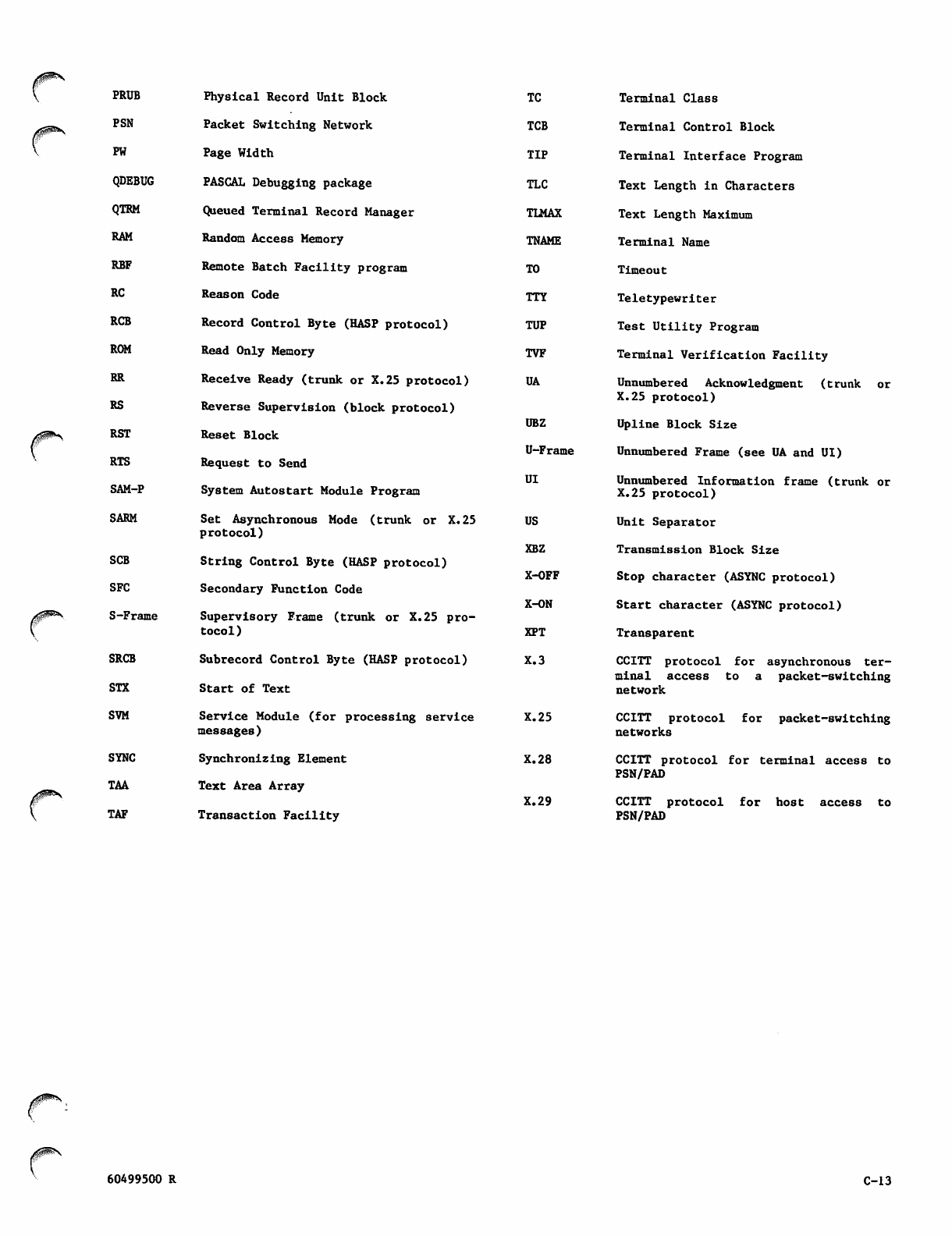
/^^
PRUB
PSN
PW
QDEBUG
QTRM
RAM
RBF
RC
RCB
ROM
RR
RS
RST
RTS
SAM-P
SARM
SCB
SFC
S-Frame
SRCB
STX
SVM
SYNC
TAA
TAF
Physical Record Unit Block
Packet Switching Network
Page Width
PASCAL Debugging package
Queued Terminal Record Manager
Random Access Memory
Remote Batch Facility program
Reason Code
Record Control Byte (HASP protocol)
Read Only Memory
Receive Ready (trunk or X.25 protocol)
Reverse Supervision (block protocol)
Reset Block
Request to Send
System Autostart Module Program
Set Asynchronous Mode (trunk or X.25
protocol)
String Control Byte (HASP protocol)
Secondary Function Code
Supervisory Frame (trunk or X.25 pro
tocol)
Subrecord Control Byte (HASP protocol)
Sta rt o f Te xt
Service Module (for processing service
messages)
Synchronizing Element
Text Area Array
Transaction Facility
TC Terminal Class
TCB Terminal Control Block
TIP Terminal Interface Program
TLC Text Length in Characters
TLMAX Text Length Maximum
T N A M E Te r m i n a l N a m e
T O T i m e o u t
TTY Teletypewriter
TUP Test Utility Program
TVF Terminal Verification Facility
UA Unnumbered Acknowledgment (trunk or
X.25 protocol)
UBZ Upline Block Size
U-Frame Unnumbered Frame (see UA and UI)
UI Unnumbered Information frame (trunk or
X.25 protocol)
US Unit Separator
X B Z T r a n s m i s s i o n B l o c k S i z e
X-OFF Stop character (ASYNC protocol)
X-ON Start character (ASYNC protocol)
XPT Transparent
X.3 CCITT protocol for asynchronous ter
minal access to a packet-switching
network
X.25 CCITT protocol for packet-switching
networks
X.28 CCITT protocol for terminal access to
PSN/PAD
X.29 CCITT protocol for host access to
PSN/PAD
yfH^'S
60499500 R C-13

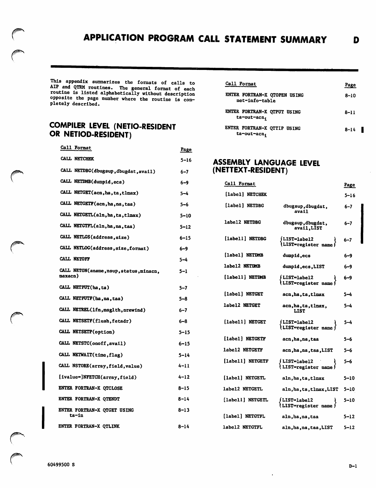
APPLICATION PROGRAM CALL STATEMENT SUMMARY
This appendix summarizes the formats of calls to
AIP and QTRM routines. The general format of each
routine is listed alphabetically without description
opposite the page number where the routine is com
pletely described.
COMPILER LEVEL (NETIO-RESIDENT
OR NETIOD-RESIDENT)
Call Format page
CALL NETCHEK 5_16
CALL NETDBG(dbugsup,dbugdat,avail) 6-7
CALL NETDMB(dumpid,ecs) 6-9
CALL NETGET(acn,ha,ta.tlmax) 5-4
CALL NETGETF(acn,ha,na,taa) 5-6
CALL NETGETL(aln,ha,ta,tlmax) 5-10
CALL NETGTFL(aln,ha,na,taa) 5-12
CALL NETLGS(address,size) 6-15
CALL NETLOG(address,size,format) 6-9
CALL NETOFF 5-4
CALL NET0N(aname,nsup,status,minacn, 5-1
maxacn)
CALL NETPUT(ha.ta) 5-7
CALL NETPUTF(ha,na,taa) 5-8
CALL NETREL(lfn,msglth,nrewind) 6-7
CALL NETSETF(flush,fetadr) 6-8
CALL NETSETP(option) 5-15
CALL NETSTC(onoff.avail) 6-15
CALL NETWAIT(time.flag) 5-14
CALL NSTORE(array,fieId,value) 4-11
[ivalue»]NFETCH(array,field) 4-12
ENTER FORTRAN-X QTCLOSE 8-15
ENTER FORTRAN-X QTENDT 8-14
E N T E R F O R T R A N - X Q T G E T U S I N G 8 - 1 3
ta-in
ENTER FORTRAN-X QTLINK 8-14
Call Format
ENTER FORTRAN-X QTOPEN USING
net-info-table
ENTER FORTRAN-X QTPUT USING
ta-out-acn^
ENTER FORTRAN-X QTTIP USING
ta-out-acn^
ASSEMBLY LANGUAGE LEVEL
(NETTEXT-RESIDENT)
Page
8-10
8-11
8-14 I
Call Format Page
[label] NETCHEK 5-16
[label] NETDBG dbugsup,dbugdat,
avail 6-7
label2 NETDBG dbugsup,dbugdat,
avail,LIST 6-7
[label1] NETDBG (LIST=label2
\LIST-register name
6-7
[label] NETDMB dumpid,ecs 6-9
label2 NETDMB dumpid,ecs,LIST 6-9
[label1] NETDMB fLIST=label2
lLIST=regi8ter name
6-9
[label] NETGET acn,ha,ta,tlmax 5-4
label2 NETGET acn,ha,ta,tlmax,
LIST
5-4
[label1] NETGET (L IST=label2
\LIST°regi8ter name
5-4
[label] NETGETF acn,ha,na,taa 5-6
label2 NETGETF acn,ha,na,taa,LISI 5-6
[label1] NETGETF /LIST=label2
\ LIST=register name
5-6
[label] NETGETL aln,ha,ta,tlmax 5-10
labe!2 NETGETL aln,ha,ta,tlmax,LIST 5-10
[label1] NETGETL
[label] NETGTFL
label2 NETGTFL
JLIST=»label2 I 5-10
(LIST=register name/
aln,ha,na,taa 5-12
aln,ha,na,taa,LIST 5-12
60499500 S D-l
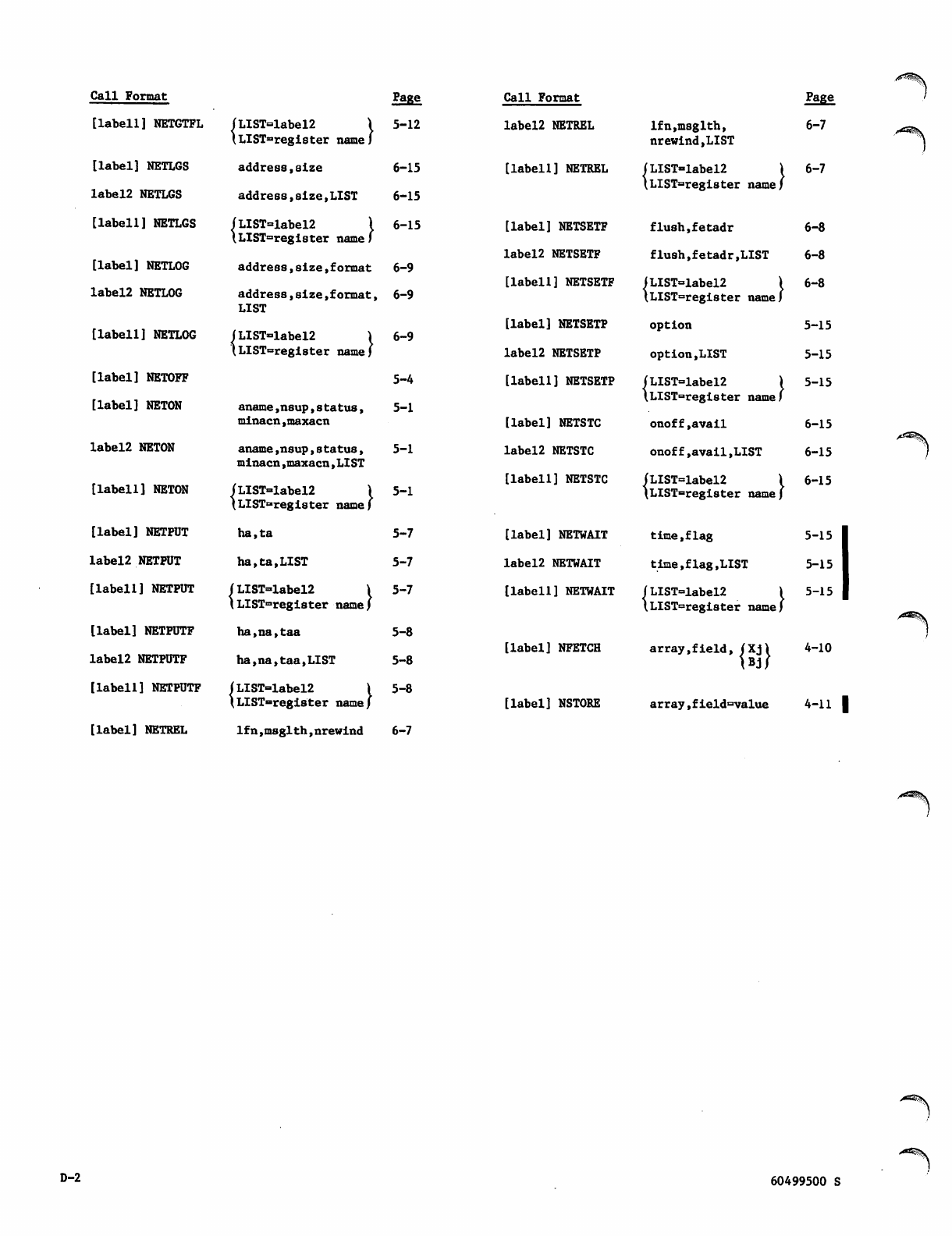
Call Format Page
[labell] NETGTFL ( L I S T = l a b e l 2 \
lLIST=regIster name J
5-12
[label] NETLGS address,size 6-15
label2 NETLGS address,size,LIST 6-15
[labell] NETLGS |LIST=label2 \
\LIST=regi8ter name)
6-15
[label] NETLOG address,size,format 6-9
label2 NETLOG address,size,format,
LIST
6-9
[labell] NETLOG ( L I S T = l a b e l 2 )
\LIST=regi8ter name)
6-9
[label] NETOFF 5-4
[label] NETON aname,nsup,s tatus, 5-1
label2 NETON
minacn,maxacn
aname,nsup,status,
minacn,maxacn,LIST
5-1
[labell] NETON ( L I S T = l a b e l 2 \
tLIST=register name)
5-1
[label] NETPUT h a , t a 5-7
label2 NETPUT h a , t a ,LIST 5-7
[labell] NETPUT ( L I S T = l a b e l 2 \
\LIST=register name)
5-7
[label] NETPUTF ha,na,taa 5-8
label2 NETPUTF ha,na,taa,LIST 5-8
[labell] NETPUTF /LIST=Iabel2 { 5-8
[label] NETREL
\LIST=register name J
lfn,msglth,nrewind 6-7
Call Format Page
label2 NETREL lfn,msglth,
nrewind,LIST
6-7
[labell] NETREL (LIST=label2 1
\LIST=register name/
6-7
[label] NETSETF flush,fetadr 6-8
label2 NETSETF flush,fetadr,LIST 6-8
[labell] NETSETF <LIST=label2 1
\LIST=regi8ter name)
6-8
[label] NETSETP option 5-15
label2 NETSETP option,LIST 5-15
[labell] NETSETP ( L I S T = l a b e l 2 )
\LIST=register name)
5-15
[label] NETSTC onoff,avail 6-15
label2 NETSTC onoff,avail,LIST 6-15
[labell] NETSTC ( L I S T = l a b e l 2 \
\LIST=register name/
6-15
[label] NETWAIT t i m e , fl a g 5-15
label2 NETWAIT time,flag,LIST 5-15
[ l a b e l l ] N E T W A I T | L I S T = l a b e l 2 \ 5 - 1 5
\LIST=register name)
[label] NFETCH array,field, (Xj\ 4-10
) B j /
[label] NSTORE array,field=value 4-11 |
D-2 60499500 S
/ - ^ \
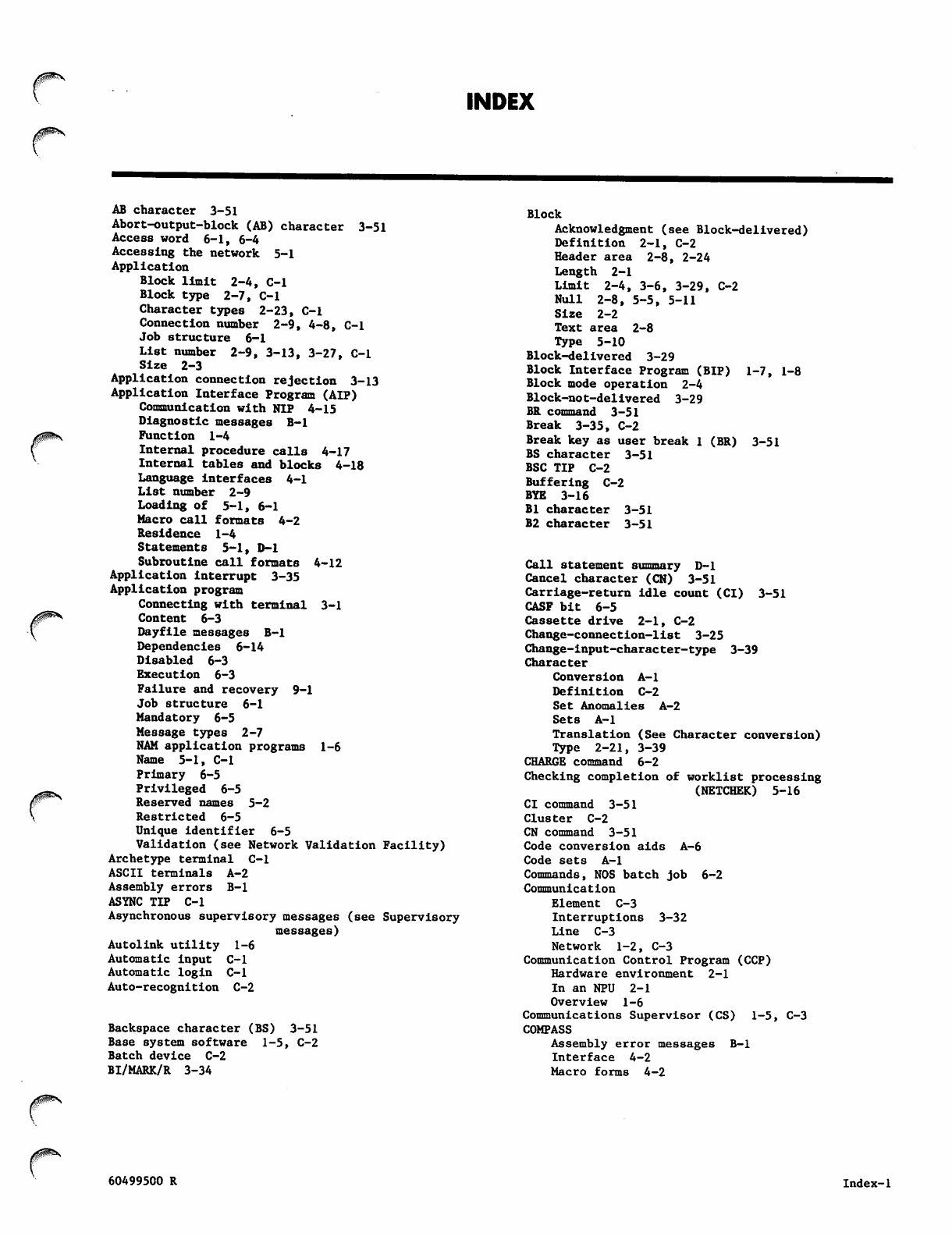
INDEX
0^\
AB character 3-51
Abort-output-block (AB) character 3-51
Access word 6-1, 6-4
Accessing the network 5-1
Application
Block limit 2-4, C-l
Block type 2-7, C-l
Character types 2-23, C-l
Connection number 2-9, 4-8, C-l
Job structure 6-1
List number 2-9, 3-13, 3-27, C-l
Size 2-3
Application connection rejection 3-13
Application Interface Program (AIP)
Communication with NIP 4-15
Diagnostic messages B-l
Function 1-4
Internal procedure calls 4-17
Internal tables and blocks 4-18
Language interfaces 4-1
List number 2-9
Loading of 5-1, 6-1
Macro call formats 4-2
Residence 1-4
Statements 5-1, D-l
Subroutine call formats 4-12
Application interrupt 3-35
Application program
Connecting with terminal 3-1
Content 6-3
Dayfile messages B-l
Dependencies 6-14
Disabled 6-3
Execution 6-3
Failure and recovery 9-1
Job structure 6-1
Mandatory 6-5
Message types 2-7
NAM application programs 1-6
Name 5-1, C-l
Primary 6-5
Privileged 6-5
Reserved names 5-2
Restricted 6-5
Unique identifier 6-5
Validation (see Network Validation Facility)
Archetype terminal C-l
ASCII terminals A-2
Assembly errors B-l
ASYNC TIP C-l
Asynchronous supervisory messages (see Supervisory
messages)
Autolink utility 1-6
Automatic input C-l
Automatic login C-l
Auto-recognition C-2
Backspace character (BS) 3-51
Base system software 1-5, C-2
Batch device C-2
BI/MARK/R 3-34
Blo c k
Acknowledgment (see Block-delivered)
Definition 2-1, C-2
Header area 2-8, 2-24
Length 2 - 1
Limit 2-4, 3-6, 3-29, C-2
Null 2-8, 5-5, 5-11
Size 2-2
Text area 2-8
Type 5-10
Block-delivered 3-29
Block Interface Program (BIP) 1-7, 1-8
Block mode operation 2-4
Block-not-delivered 3-29
BR command 3-51
Break 3-35, C-2
Break key as user break 1 (BR) 3-51
BS character 3-51
BSC TIP C-2
Buffering C-2
BYE 3-16
Bl character 3-51
B2 character 3-51
Call statement summary D-l
Cancel character (CN) 3-51
Carriage-return idle count (CI) 3-51
CASF bit 6-5
Cassette drive 2-1, C-2
Change-connection-list 3-25
Change-input-character-type 3-39
Character
Conversion A-l
Definition C-2
Set Anomalies A-2
S e t s A - l
Translation (See Character conversion)
Type 2-21, 3-39
CHARGE command 6-2
Checking completion of worklist processing
(NETCHEK) 5-16
CI command 3-51
C l u s t e r C - 2
CN command 3-51
Code conversion aids A-6
Code sets A-l
Commands, NOS batch job 6-2
Communication
Element C-3
Interruptions 3-32
Line C-3
Network 1-2, C-3
Communication Control Program (CCP)
Hardware environment 2-1
In an NPU 2-1
Overview 1-6
Communications Supervisor (CS) 1-5, C-3
COMPASS
Assembly error messages B-l
Interface 4-2
Macro forms 4-2
yfSfi^^\
60499500 R Index-1
Computer network 1-1
COMTNAP 6-14
CON/ACRQ/A 3-19, 4-4
CON/ACRQ/R 3-17, 4-4
CON/CB/R 3-15, 4-4
CON/END/N 3-16, 4-5
CON/END/R 3-16, 4-5
CON/REQ/A 3-13, 4-5
CON/REQ/N 3-12, 4-4
CON/REQ/R 3-3, 4-4
Connecting to network (NETON) 5-1
Connection
Application-to-application 3-14
Devices-to-applications 3-1
Failures 3-16
I d e n t i fi e r s 2 - 9
Lists 3-25, 5-10
Monitoring 3-18
Termination 3-24
Connection-accepted 3-12
Connection-broken 3-14, 3-25
Connection-ended 3-14, 3-25
Connection-initialized 3-14
Connection-rejected 3-13
Connection-request 4-4
Control character A-l
Controlling data flow 3-29
Controlling list duplexing 3-26
Controlling list polling 3-25
Controlling parallel mode (NETSETP) 5-15
Converting data 3-39
CP command 3-51
fcrl xili
Cross System software 1-6, C-3
CSOJ bit 6-5
ct xiii
CT command 3-51
CTRL/CHAR/A 3-50
CTRL/CHAR/N 3-50
CTRL/CHAR/R 3-49
CTRL/DEF/R 3-48, 4-6
CTRL/RTC/A 3-55
CTRL/RTC/R 3-55
CTRL/TCD/R 3-56
CUCP bit 6-1
Cursor positioning after input (CP)
CYBER channel coupler C-3
3-51
Data
Binary character A-l
Coded character A-l
Conversion 3-39
Flow control 3-29
Message protocols 2-9
Truncation 3-39
Data block 2-1
Data message content and protocols 2-10
Dayfile messages B-l
DC/CICT/R 3-40
DC/TRU/R 3-43
Debug log file processor (DLFP)
Command 6-10
Directive keywords 6-11
Messages B-l
Debug log file utilities 6-6
Debugging methods 6-6
Dedicated line C-3
Define-multiple-terminal-characteristics
Define-terminal-characteri8tic8 3-48
Delimiters for single-message transparent input
(DL ) 3 - 5 1
Delimiting and transmitting terminal input
Normalized mode 2-5
Transparent mode 2-20
Destination C-3
Device C-2, C-3
Device types 1-9
Diagnostic messages B-l
Disconnecting from network (NETOFF) 5-4
Display code A-2
Display of Host Nodes (HD) 3-52
DL command 3-51
Downline 2-1, C-4
Downline block size 2-2
Downline monitoring 3-22
EB command 3-52
Echoplex mode (EP) 3-52, C-4
EL command 3-52
End-connection 3-16
End-of-block character (EB) 2-6
End-of-file (EOF) 6-1
End-of-information (EOI) 6-1
End-of-line character (EL) 2-5
End-of-record (EOR) 6-1
EP command 3-52
ERR/LGL/R 3-62
Error reporting 3-61
Execution time errors B-l
Expand utility 1-6
FA command 3-52
Family name 3-10
Fatal errors 6-6, B-l
FC/ACK/R 3-30
FC/BRK/R 3-32
FC/INACT/R 3-24
FC/INIT/N 3-14
FC/INIT/R 3-14
FC/NAK/R 3-30
FC/RST/R 3-32
Field number (FN)
Field value (FV)
3-51, 3-52, 3-53
3-51, 3-52, 3-53
File environment table (FET) 6-8
Flow control for input devices (IC) 3-52
Flow control for output devices (0C) 3-53
Format effectors 2-14, C-4
Formatter 1-6
FORTRAN
Interface 4-11
Sample program 7-1
Frame 2-1, C-4
Full-ASCII input mode (FA) 3-52
Full duplex C-4
GETACT macro 6-1
GETJN macro 6-3
Glos s a r y C - l
Graphic character A-l
3-49
Half duplex C-4
Hardware performance analyzer (HPA)
HASP TIP 2-4, C-4
HD command 3-52
Header area content 2-24
Header word (see Header area content)
1-6
Index-2 60499500 S
/iSPSSN
Terminate-output-marker 3-37
Terminating connections 3-24
Test Utility Program (TUP) C-10
Te x t
Area 5-5, 5-8, 5-11, C-10
Length 5-5, 5-11, C-10
TO/MARK/R 3-37
Transaction Facility (TAF) 1-6
Transmission block 2-1, 2-4
Transparent
Delimiters for multiple-message transparent
input mode (XL) 2-22
Delimiters for single-message transparent input
mode (DL) 2-22, 3-52
Mode transmission 2-10, 2-19, A-3
Truncating data 3-42
Trunk C-10
Trunk failure and recovery 9-1
Turn-list-proce88ing-off 3-27
Turn-list-proce8aing-on 3-27
Turn-on-full-duplex-list-processing 3-29
Turn-on-half-duplex-list-processing 3-28
Typeahead processing 4-15, C-ll
Upline 2-1, C-ll
Upl i ne blo ck siz e 2-2
USER command 6-2
U s e r - i n t e r r u p t 3 - 3 8
User name 3-10, 6-2, C-ll
Valid field numbers and field values 3-51
V i r t u a l c h a n n e l C - l l
Worklist processing 4-15
Worklists, CCP C-ll
XL command 3-53
X.25 TIP PAD C-7
Zero-byte terminator 8-15
ZZZZZDN file 6-10
ZZZZZSN file 6-15
6-bit data 2-23
2551 Series Communications Processor 1-6
3270 Bisynchronous 1-8, 1-14
O xiii
n
60499500 S Index-5

/^
MANUAL TITLE:
/0^^.
COMMENT SHEET
Network Access Method Version 1
Host Application Programming Reference Manual
PUBLICATION NO.: 60499500
REVISION: W
This form is not intended to be used as an order blank. Control Data Corporation
welcomes your evaluation of this manual. Please indicate any errors, suggested
additions or deletions, or general comments on the back (please include page number
references).
Please reply No reply necessary
FOLD FOLD
BUSINESS REPLY MAIL
NO POSTAGE
NECESSARY
IF MAILED
IN THE
UNITED STATES
FIRST CLASS PERMIT NO. 8241 MINNEAPOLIS, MN.
POSTAGE WILL BE PAID BY ADDRESSEE
(gg) CONTROL DATA
Technology and Publications Division
Mail Stop: SVL104
P.O. Box 3492
Sunnyvale, California 94088-3492
FOLD FOLD
NO POSTAGE STAMP NECESSARY IF MAILED IN U.S.A.
FOLD ON DOTTED LINES AND TAPE
NAME:
COMPANY:
STREET ADDRESS
CITY/STATE/ZIP
TAPE TAPE

/0^\,
HELLO 3-16
HOP/DB/R 3-57
HOP/DE/R 3-58
HOP/DU/R 3-58
HOP/NOTR/R 3-59
HOP/REL/R 3-59
HOP/RS/R 3-59
HOP/TRACE/R 3-58
Host
Availability Display (HAD) 3-52
Definition C-5
Failure and recovery 9-1
Interface Program (HIP) 1-7, 1-8
Node C-5
Operator 1-5, C-5
Operator communication 3-56
Shutdown 3-60
IC command 3-52
IN command 3-52
I n f o r m a t io n i d e n t i fi c a t i o n p r o t o c o l s 2 - 7
Initialized-connection 3-5
In-line diagnostics 1-7, 1-8
INPUT 6-2
Input device and transmission mode (IN) 3-52
Input parameter C-5
In t e r acti v e d e vice C - 5
Interactive Facility (IAF) 1-4
Interactive Virtual Terminal (IVT) 2-10, 2-11, C-5
INTR/APP/R 3-36
INTR/RSP/R 3-36
INTR/USR/R 3-38
Job name 5-3, 6-3
Job structure 6-1
LDSET 4-11, 6-2
LF xiii
LI command 3-53
LIBRARY 4-11, 6-2
Line
Definition C-5
Failure and recovery 9-1
Feed idle count (LI) 3-53
Mode operation 2-4
Link editor 1-6
Link Interface Program (LIP)
List C-5
List connections 5-10
LK command 3-53
Load file generator (LFG) 1-5
Local configuration file (LCF) 1-5, 6-5, C-5
Lockout of unsolicited messages (LK) 3-53
Logical connections 1-9, 1-12, C-5
Logical-error message 3-61
Logical line C-5
Logical link
Definition C-5
Failure and recovery 9-1
Logical protocol 2-1
LOGIN 3-25
LOGOUT 3-25
LST/FDX/R 3-29
LST/HDX/R 3-28
LST/OFF/R 3-27
LST/ON/R 3-27
LST/SWH/R 3-27
1-7, 1-8, C-5
3-25
Macro assembler 1-6
Macromemory C-6
Macros 4-2
Managing connection lists
Memory requirements 6-17
MESSAGE 6-3
Message
Blocks 5-4
Definition 2-7, C-6
P r o to c ol s 3 -1
Sequences 3-1
Transmission 5-4
Types 2-7
Message control system (MCS) 1-6
Micro assembler 1-6
Micromemory C-6
Mnemonics C-l4
MODE4 TIP C-6
Monitoring connections 3-18
Monitoring downline data 3-29
Multimessage transparent mode (XL) 3-53
Multiplex loop interface adapter (MLIA) C-6
Multiplex subsystem C-6
NETCHEK
NETDBG
NETDMB
NETGET
NETGETF
NETGETL
NETGTFL
NETIO
NETIOD
NETLGS
NETLOG
NETOFF
NETON
NETPUT
NETPUTF
NETREL
NETSETF
NETSETP
NETSTC
NETTEXT
NETWAIT
6-7
5-16
1-12,
6-9
5-4
5-6
5-10
5-12
4-11, 6-2, 6-7
4-11, 6-2, 6-7
6-15
6-9
5-4
5-1
5-7
5-8
6-7
6-8
5-15
1-12, 6-15
4-2, 6-2
5-14
Network Access Method (NAM)
Block 2-1
Concepts 1-8, 2-1
Configuration file (NCF) 1-5, C-6
Control character (CT) 3-51
Definition C-6
Definition Language (NDL) 1-4, 6-16, C-7
Dump Analyzer (NDA) 1-5
Dump file 1-5
Element C-7
Failure and recovery 9-1
Functions 1-2, C-6
Information table 8-1
Operation 1-10
Network Interface Program (NIP)
Communication with AIP 4-15
Diagnostic messages B-l
Function 1-4
Networ k load file (NL F) 1 -5
Network processing unit (NPU) 1-6, C-7
Communications Control Program 1-6
Console 1-7
Failure and recovery 9-1
Network Supervisor (NS) 1-5, C-7
60499500 S Index-3
Network Validation Facility (NVF) 1-5
NFETCH 4-10, 4-12
Node (see Network processing unit)
Normalized mode transmissions 2-4, 2-10, 2-11, A-2
NPU operator C-7
NSTATUS 5-3
NSTORE 4-11, 4-13
OC command 3-53
On-line diagnostics 1-7
OP command ~3-53
OUTPUT 6-2
Output device selection (OP) 3-53
Overlays 6-3
Owning consoles 1-10
RECALL 5-8
Regulation C-9
Remote Batch Facility 1-6, 6-3
Request-application-connection 3-18
Request-terminal-characteristics 3-55
Request-to-activate-debug-code 3-57
Request-to-dump-field-length 3-58
Request-to-release-debug-log-file 3-59
Request-to-restart-statistics-gathering
Request-to-turn-AIP-tracing-off 3-59
Requ e8t-t o -turn - AIP- t racin g -on 3 -58
Request-to-turn-off-debug-code 3-58
Reserved symbols 4-1
Reserved words 5-2
Reset 3-32
Return parameter C-9
Rollout 5-8, 5-14
Routing C-8
/"^^S
3-59
PA command 3-53
Packet C-7
Packet Assembly/Disassembly Access (PAD)
Packet-Switching Network (PSN) 1-2, C-7
Page length (PL) 3-53
Page waiting (PG) C-7
Page width (PW) 3-53
Parallel mode operation 4-16, 5-15
Parameter list 4-1
Parity processing (PA) 3-53, C-7
Pascal 1-6, C-7
Passive device C-7
Peripheral Interface Program (PIP) 1-4
PG command 3-53
Phy s i c a l l i ne C -8
Physical protocol 2-1
Physical record unit (PRU)
Block C -8
Definition C-8
Device C-8
Short C-9
Zero-length C-ll
PL command 3-53
Polling C-8
Port C-8
Predefined symbolic names 4-1
Predefined symbolic values 4-2
Primary function code 2-32, 3-1
Priority C-8
Program execution processing 6-4
Protocols 2-1, 2-7, 2-10, C-8
Public data network (PDN) C-8
PW command 3-53
QTCLOSE statement 4-14, 8-15
QTENDT statement 4-14, 8-14
QTGET statement 4-14, 8-13
QTLINK statement 4-13, 8-14
QTOPEN statement 4-13, 8-11
QTPUT statement 4-14, 8-12
QTTIP statement 4-14, 8-14
Queued terminal record manager (QTRM)
Call statement summary D-l
Diagnostic messages B-l
Function 1-4, 4-13
Network information table 8-1
Output
Editing 8-15
Formatting 8-15
Queuing 8-16
Sample program 8-18
Subroutines 8-11
Utilities 4-13
Queues C-8
C-7
SE command 3-53
Secondary function code 2-32, 3-1
Service channel C-9
Service module (SVM) 1-7, 1-8, C-9
SETLOF 6-8
SHUT/INSD/R 3-61
Shutdown 3-60
Source C-9
Special editing mode (SE) 3-53
Statistical file 6-15
Supervisory message
Asynchronous 2-35
Block header content 2-36
Content 2-31
Definition C-9
Format 3-1
P r o to c ol s 3 -1
Queue 5-4, 5-6, 5-10, 5-12
Summarized 3-1
Synchronous 2-36
Switched line C-9
Symbolic address C-9
Synchronous C-10
Synchronous supervisory messages (see Supervisory
messages)
Syntax 5-1
System autostart module program (SAM-P) 1-7
System control point 6-1
TC command 3-53
TCH/TCHAR/R 3-46
Terminal access to the network 1-9
Terminal address C-10
Te r m i n a l - c h a r a c t e r i s t i c s - d e fi n i t i o n 3 - 5 6
Terminal characteristics redefined 3-46
Terminal class 1-14, C-10
Terminal control block 9-1, C-10
Terminal definition commands
Definition C-10
Range of possible values 3-51
Terminal failure and recovery 9-1
Terminal Interface Programs (TIPs) 1-8, C-10
Terminal name C-10
Terminal transmission modes A-2
Terminal Verification Facility (TVF) 1-6
Terminals
Asynchronous 1-14
Batch 1-14, 2-7
Bisynchronous 1-14
Definition C-10
HASP 1-14
Interactive 2-4
Mode 4 1-14, 2-20
V i r t u a l 1 - 9
/<^k
Index-4 60499500 R
