Networking Self Teaching Guide OSI TCPIP LANs MANs WANs Implementation Management And Maintenance
User Manual: Pdf
Open the PDF directly: View PDF ![]() .
.
Page Count: 867 [warning: Documents this large are best viewed by clicking the View PDF Link!]
- Networking Self-Teaching Guide: OSI, TCP/IP, LANs, MANs, WANs, Implementation, Management, and Maintenance
- About the Authors
- Credits
- Acknowledgments
- Contents
- Introduction
- Part I: Networking Nuts and Bolts
- Part II: The OSI Layers
- Part III: Network Design and Implementation
- Part IV: Managing and Maintaining the Network
- Appendix A: Additional Exercises
- Chapter 1 — Introduction to Networking
- Chapter 2 — LANs, WANs, and MANs
- Chapter 3 — Network Hardware and Transmission Media
- Chapter 4 — Operating Systems and Networking Software
- Chapter 5 — The TCP/IP Protocol Suite
- Chapter 6 — Ethernet Concepts
- Chapter 7 — Not to Be Forgotten
- Chapter 8 — The Upper Layers
- Chapter 9 — The Transport Layer
- Chapter 10 — The Network Layer
- Chapter 11 — The Data Link Layer
- Chapter 12 — Design Methodologies
- Chapter 13 — Implementation
- Chapter 14 — Network Security
- Chapter 15 — Network Management
- Chapter 16 — Troubleshooting
- Appendix B: Exercise Answers
- Chapter 1 Exercises
- Chapter 2 Exercises
- Chapter 3 Exercises
- Chapter 4 Exercises
- Chapter 5 Exercises
- Chapter 6 Exercises
- Chapter 7 Exercises
- Chapter 8 Exercises
- Chapter 9 Exercises
- Chapter 10 Exercises
- Chapter 11 Exercises
- Chapter 12 Exercises
- Chapter 13 Exercises
- Chapter 14 Exercises
- Chapter 15 Exercises
- Chapter 16 Exercises
- Appendix A Exercises
- Appendix C: Glossary
- Appendix D: Acronyms
- Index
Edwards ffirs.tex V3 - 03/27/2009 10:42am Page ii
Edwards ffirs.tex V3 - 03/27/2009 10:42am Page i
Networking
Self-Teaching Guide
Edwards ffirs.tex V3 - 03/27/2009 10:42am Page ii

Edwards ffirs.tex V3 - 03/27/2009 10:42am Page iii
Networking
Self-Teaching Guide
OSI, TCP/IP, LANs, MANs, WANs,
Implementation, Management,
and Maintenance
James Edwards
Richard Bramante
Wiley Publishing, Inc.
Edwards ffirs.tex V3 - 03/27/2009 10:42am Page iv
Networking Self-Teaching Guide
Published by
Wiley Publishing, Inc.
10475 Crosspoint Boulevard
Indianapolis, IN 46256
www.wiley.com
Copyright ©2009 by Wiley Publishing, Inc., Indianapolis, Indiana
Published simultaneously in Canada
ISBN: 978-0-470-40238-2
Manufactured in the United States of America
10987654321
No part of this publication may be reproduced, stored in a retrieval system or transmitted in any form or
by any means, electronic, mechanical, photocopying, recording, scanning or otherwise, except as permitted
under Sections 107 or 108 of the 1976 United States Copyright Act, without either the prior written
permission of the Publisher, or authorization through payment of the appropriate per-copy fee to the
Copyright Clearance Center, 222 Rosewood Drive, Danvers, MA 01923, (978) 750-8400, fax (978) 646-
8600. Requests to the Publisher for permission should be addressed to the Permissions Department, John
Wiley & Sons, Inc., 111 River Street, Hoboken, NJ 07030, (201) 748-6011, fax (201) 748-6008, or online at
http://www.wiley.com/go/permissions.
Limit of Liability/Disclaimer of Warranty: The publisher and the author make no representations or
warranties with respect to the accuracy or completeness of the contents of this work and specifically disclaim
all warranties, including without limitation warranties of fitness for a particular purpose. No warranty may
be created or extended by sales or promotional materials. The advice and strategies contained herein may not
be suitable for every situation. This work is sold with the understanding that the publisher is not engaged in
rendering legal, accounting, or other professional services. If professional assistance is required, the services
of a competent professional person should be sought. Neither the publisher nor the author shall be liable for
damages arising herefrom. The fact that an organization or Web site is referred to in this work as a citation
and/or a potential source of further information does not mean that the author or the publisher endorses the
information the organization or Web site may provide or recommendations it may make. Further, readers
should be aware that Internet Web sites listed in this work may have changed or disappeared between when
this work was written and when it is read.
Library of Congress Cataloging-in-Publication Data:
Edwards, James, 1962-
Networking self-teaching guide : OSI, TCP/IP, LANs, MANs, WANs, implementation, management, and
maintenance / James Edwards, Richard Bramante.
p. cm.
Includes index.
ISBN 978-0-470-40238-2 (pbk.)
1. Computer networks. 2. Computer network protocols. 3. Computer network architectures. I. Bramante,
Richard, 1944- II. Title.
TK5105.5.E28 2009
004.6’5 — dc22
2009004168
For general information on our other products and services please contact our Customer Care Department
within the United States at (877) 762-2974, outside the United States at (317) 572-3993 or fax (317) 572-4002.
Trademarks: Wiley and the Wiley logo are trademarks or registered trademarks of John Wiley & Sons, Inc.
and/or its affiliates, in the United States and other countries, and may not be used without written permission.
All other trademarks are the property of their respective owners. Wiley Publishing, Inc. is not associated with
any product or vendor mentioned in this book.
Wiley also publishes its books in a variety of electronic formats. Some content that appears in print may not
be available in electronic books.
Edwards ffirs.tex V3 - 03/27/2009 10:42am Page v
This book is dedicated to my brother, Joel, for all that he has done for so
many over the years. I sincerely hope that he will forever be able to enjoy
all of the good things that life has to offer. Whether he knows it or not, he
has always been a source of inspiration for me and his encouragement
has kept me going whenever a challenge was thrown my way. The best
brother in the world! That’s my brother, Joel.— Jim Edwards
This book is dedicated to those who have supported me, not just during
the writing of this book, but throughout my life. There have been many
and too numerous to mention, but to all who have been there for me, I
am deeply grateful. Deserving special mention are: My son, Rich; his
wife, Michelle; my three grandchildren, Vanessa, Ethan, and Olivia; my
parents; my siblings, Margaret, Mary, Josephine, Frank, and Salvatore;
and the person who believed in me, unfailingly, even through all my
blunders, my deceased wife, Barbara.
— Rich Bramante
Edwards ffirs.tex V3 - 03/27/2009 10:42am Page vi

Edwards f01.tex V2 - 03/27/2009 10:44am Page vii
About the Authors
Jim Edwards has more than 10 years of experience supporting data networks
as a Premium Support Engineer. He has authored four books pertaining to
data networking, as well as served as a technical editor.
Rich Bramante earned both a bachelor’s and master’s degree in electrical
engineering from the University of Massachusetts – Lowell. He has worked in
thetechnologyindustryformorethan40years.Forthepast11years,hehas
worked for a major telecommunications equipment manufacturer, primarily
within the VPN technology area.
vii

Edwards f02.tex V3 - 03/27/2009 3:50pm Page viii
Credits
Executive Editor
Carol Long
Development Editor
John Sleeva
Technical Editor
Don Thoreson
Production Editor
Angela Smith
Copy Editor
Lunaea Weatherstone
Editorial Manager
Mary Beth Wakefield
Production Manager
Tim Tate
Vice President and Executive
Group Publisher
Richard Swadley
Vice President and Executive
Publisher
Barry Pruett
Associate Publisher
Jim Minatel
Project Coordinator, Cover
Lynsey Stanford
Proofreader
Publication Services, Inc.
Indexer
Jack Lewis
Cover Image
©Chad Baker/Photodisc/Getty
Images
Cover Designer
Michael Trent

Edwards f03.tex V1 - 03/27/2009 11:21am Page ix
Acknowledgments
First and foremost, Jim wants to thank Rich for being such a great co-author to
work with. Rich and Jim had the opportunity to work together on a previous
bookandwemakeagreatteam.Jimisabitofapainintheneck,
1so Rich may
have other opinions on this whole team thing.
We would also like to send out a huge word of thanks for all of the
individuals involved in the development of this book. To Carol Long, thank
you for bringing the idea to us and trusting us to see it through. We really
enjoyed it as much as we all thought we would. We also want to send a word
of thanks to the development editor, John Sleeva, for keeping us in line. It
was a pleasure working with you, sir. To Angela Smith, thank you for all the
assistance you gave us during the production phase. It is always nice to work
with people who are as friendly and helpful as everyone we have had the
pleasure of working with at Wiley. Additionally, thank you to Don Thorenson
for being our technical guinea pig and to Lunaea Weatherstone for catching all
of our mistakes. Finally, to all the people who work behind the scenes, thank
you for your support of this project.
1There are times when a bit of a pain in the neck is a good thing. Rich would like to thank
Jim for his enduring good nature and understanding of the predicaments Rich finds himself
involved with from time to time. We do make a good team because we have come to understand
that although we work together each has his own methods when it comes to his work. Overall,
mutual respect and understanding have helped us endure some trials and tribulations, and at
the end of the day we can open a beer and still find a good laugh to share.
ix
Edwards f03.tex V1 - 03/27/2009 11:21am Page x

Contents
Introduction xxiii
Part I Networking Nuts and Bolts 1
Chapter 1 Introduction to Networking 3
Networking: A Brief Introduction 4
Internetworking 5
An internet 6
The Internet 6
Intranets (Give Me an ‘‘A’’, Remove My ‘‘E’’, Now Flip the
‘‘R’’ and the ‘‘A’’) 7
Extranets 7
Virtual Private Networks 8
Catenet 9
Area Networks 9
Network Relationships and Topologies 13
Network Relationship Types 13
Network Topology Types 17
Protocols 24
Transmission Control Protocol 26
User Datagram Protocol 27
Internet Protocol 27
History of Networking 28
Standards and Standards Organizations 32
American National Standards Institute 34
International Organization for Standardization 35
International Electrotechnical Commission 36
Telecommunications Industry Association 36
xi

xii Contents
Electronic Industries Alliance 37
International Telecommunication Union 37
IEEE 38
IEEE 802 Working Groups 38
IEEE 802.1 39
IEEE 802.3 41
IEEE 802.5 41
IEEE 802.11 42
Internet Society (ISOC) 43
Internet Engineering Task Force 43
An Introduction to the OSI Reference Model 45
All People Seem to Need Data Processing — A Mnemonic
Device 46
A Layered Approach 47
Layer 7 — The Application Layer 48
Layer 6 — The Presentation Layer 49
Layer 5 — The Session Layer 50
Layer 4 — The Transport Layer 50
Layer 3 — The Network Layer 51
Layer 2 — The Data Link Layer 52
Layer 1 — The Physical Layer 53
TCP/IP, Please (and Don’t Be Stingy with the IP) 53
TCP/IP Applications 55
TCP/IP Utilities 56
The TCP/IP Reference Model 57
Chapter Exercises 58
Pop Quiz Answers 60
Chapter 2 LANs, MANs, and WANs 63
Local Area Networks 64
LAN Standards 64
802.2 Logical Link Control 64
802.3 CSMA/CD Access Method and Physical Layer 66
802.5 Token Ring Access Method and Physical Layer 70
The Collision Domain Battle 73
The Most Common Wireless Standards 76
LAN Topologies 77
Token Ring Network Topologies 79
Bus Networks Topologies 83
Metropolitan Area Networks 93
Fiber Distributed Data Interface 93
AMANExample 96
Wide Area Networks 98
Whose POTS? 99

Contents xiii
Integrated Services Digital Network 100
Point-to-Point WANs 101
Frame Relay 103
Using the Internet for Your WAN 105
Chapter Exercises 107
Pop Quiz Answers 108
Chapter 3 Network Hardware and Transmission Media 109
Stuff You Just Need to Know 110
Bits,Bytes,andBinary 110
Non-human Resources 112
Volatile Memory 114
Nonvolatile Memory 115
Encapsulation 117
Data Communication Equipment and Data Terminal
Equipment 120
All Your Base Are Belong to Us 120
Computer Buses 121
IP Addressing 121
Transmission Media 123
Network Cabling 124
Twisted Pair Cable 125
Coaxial Cable 129
Fiber Optic Cable 131
Wireless Communication 133
Network Hardware 133
End-User Interface Hardware Types 134
Connecting End Users 134
Network Interfaces and Adapters 136
Network Interface Controllers 138
To Boldly Go Where Data Needs to Flow (or, How Does that
E-mail Get to Brother Joel?) 139
Concentrators 140
Hubs 141
Media Access Units 142
Repeaters 143
Bridges and Switches 143
Routers 146
Layer 3 Switches 148
Upper-Layer Switch Types 148
Remote Access 150
Servers 154
Chapter Exercises 154
Pop Quiz Answers 155

xiv Contents
Chapter 4 Operating Systems and Networking Software 157
Computer Operating System Basics 158
CPU Basics 158
Computer Basics 161
Read-Only Memory 162
Random-Access Memory 162
Mass Storage System 164
Input/Output System 166
Operating System Basics 167
Network Operating System Basics 169
Peer-to-Peer Networking 171
File Sharing on a Peer-to-Peer Network 181
Printer Sharing on a Peer-to-Peer Network 183
Other Operating Systems 185
Unix 185
Linux 188
Sun Solaris 191
Chapter Exercises 193
Pop Quiz Answers 194
Chapter 5 The TCP/IP Protocol Suite 197
The TCP/IP Layers 198
Popular TCP/IP Protocols 201
The Application Layer 202
Domain Name System 202
Simple Network Management Protocol 206
File Transfer Protocol 212
Trivial File Transfer Protocol 217
Simple Mail Transfer Protocol 220
Network File System 222
Telecommunications Network 224
Secure Shell Protocol 227
The Transport Layer 228
Transmission Control Protocol 228
User Datagram Protocol 231
The Internet Layer 232
Internet Protocol 233
Internet Group Multicast Protocol 234
Internet Control Message Protocol 234
Routing Information Protocol 235
Open Shortest Path First 237
Border Gateway Protocol 238
Internet Protocol Security 238
End of Chapter Hodgepodge 239

Contents xv
There Is Hope for Diskless Nodes 240
A Little More Information on Routing 240
Sockets and Ports Are Not the Same Thing 241
Chapter Exercises 244
Pop Quiz Answers 245
Chapter 6 Ethernet Concepts 247
The Beginning of Ethernet Technology 248
Ethernet Components 250
DCE and DTE Cabling Considerations 253
Interconnecting Like Ethernet Devices 255
Ethernet and IEEE 802.3’s Relationship to the OSI Model 263
Logical Link Control 265
Media Access Control 265
Ethernet Frame Format 267
Transmitting a Frame 270
Half-Duplex Transmission 270
Full-Duplex Transmission 274
Autonegotiation 277
Receiving a Frame 279
Traffic Optimization 280
Traffic Shaping 281
VLAN Tagging 283
Chapter Exercises 285
Pop Quiz Answers 285
Chapter 7 Not to Be Forgotten 289
Can’t Get Enough of Those LAN Technologies 290
Attached Resource Computer Network 290
StarLAN 291
Token Ring 292
Token Ring’s Modus Operandi 295
Token Ring Media 295
The Format of the Token Ring Frame 295
Fiber Distributed Data Interface 298
FDDI Does What FDDI Does 298
FDDI Node Types 301
The FDDI Frame Format 301
As If You Haven’t Had Enough of These Sweet Protocols 303
Digital Equipment Company Network 303
Xerox Network Systems 305
Internetwork Packet Exchange 306
Point-to-Point Protocol 313
PPP Encapsulation Method 313

xvi Contents
PPP Link Control Protocol 314
PPP Network Control Protocol 314
Please, Tell Us More 314
PPP Frame Format 314
X.25 315
X.25 Operations 318
Link Access Procedure, Balanced 319
Packet Layer Protocol 320
Asynchronous Transfer Mode 321
ATM Generic Cell Format 321
An Overview of ATM Operations 322
ATM Reference Model 325
Traffic Management 326
ATM Adaptation Layer Types 327
Frame Relay 328
Frame Relay Node Types 329
Virtual Circuits . . . Again? 330
Data Link Connection Identifier 330
Feckens and Beckens 330
Local Management Interface 332
Frame Relay Frame Format 332
Integrated Services Digital Network 333
Basic Rate Interface and Primary Rate Interface 333
ISDN Nodes 333
The ISDN Reference Model 334
AppleTalk 336
AppleTalk Physical and Data Link Layers 336
AppleTalk Network Layer 337
AppleTalk Upper Layers 338
Chapter Exercises 339
Pop Quiz Answers 339
Part II The OSI Layers 343
Chapter 8 The Upper Layers 345
Background 346
The TCP/IP Model 349
TCP/IP Application Layer 362
TCP/IP Transport Layer 362
TCP/IP Internet Layer 366
TCP/IP Link Layer 367
TCP/IP Link Layer Protocols 370
OSI Application Layer 372
OSI Presentation Layer 374
OSI Session Layer 374

Contents xvii
Chapter Exercises 376
Pop Quiz Answers 377
Chapter 9 The Transport Layer 379
The Terms and Conditions of Chapter 9 380
End-to-End Delivery 380
Standards 381
ISO/IEC 8072 381
ISO/IEC 8073 382
This, That, and the Other 382
Types of Transport Service 382
Data Units 383
Classes of Transport Service 383
Types of Network Service 383
Multiplexing 384
Transport Layer Operations 387
Connection-Oriented Operations 387
Setting Up the Connection 388
Maintaining the Connection 389
Terminating the Connection 389
Connectionless Operations 390
Transport Layer Protocols 393
A Few More Words about TCP 393
The TCP Header Format 395
ALittleMoreonUDP 397
The UDP Header Format 398
The Meaning of Control 399
Chapter Exercises 399
Pop Quiz Answers 400
Chapter 10 The Network Layer 403
Network Connection Types 404
Connectionless Network Services 405
Connection-Oriented Network Services 410
Domain Name Services 412
TCP/IP Network Layer Protocols 417
Internet Protocol 417
Internet Protocol Version 4 418
Internet Protocol Version 6 423
Internet Control Message Protocol 425
Ping 425
Traceroute 427
Internet Group Management Protocol 429
Internet Protocol Security 431

xviii Contents
Chapter Exercises 433
Pop Quiz Answers 433
Chapter 11 The Data Link Layer 435
Concerns of the LAN 436
It Just Is 436
Highs and Lows 437
Accessing the Medium 439
Rules of Accessing the Medium 439
From Tokens to Contention 440
Using the Token Method 441
Using the Contention Method 442
Meet the Sublayers 443
Logical Link Control 444
LLC Framing 444
Subnetwork Access Protocol 447
The MAC Sublayer 449
The MAC Address 450
Access Control for the Channel 450
The ‘‘ings’’ — Casting, Detecting, and Addressing 451
Data Link Addressing 451
The MAC Address Format 452
Unicast Addressing 453
Multicast Addressing 454
Error Detection 457
Control of the Flow 464
‘‘Knode’’ the LAN 465
Diary of a Network Bridge 466
Unicast Operation 467
Multicast Operation 469
When the Bridge Just Does Not Know 469
The Address Table 470
Chapter Exercises 472
Pop Quiz Answers 472
Part III Network Design and Implementation 475
Chapter 12 Design Methodologies 477
Your Task Is to Design a Network 478
Types of Organizational LANs 479
Other Things to Consider 480
Building the Foundation 480
Let’s Start Planning 481
Development of Scope 481

Contents xix
You Are Not Alone 483
A Hierarchical Design Model 483
Access Layer 483
Distribution Layer 485
Core Layer 486
Why Hierarchical? 489
5-4-3-2-1, Speed Is Not the Big Concern 491
Making Determinations 492
Determining Which Topology to Use 493
Bus Network Topology 493
Star Network Topology 494
Ring Network Topology 495
Determining Which Nodes to Use 496
Traditional Nodes 497
Node Evolution 501
LAN Switching Technology 505
Switch Types 506
By All Means, Be Redundant 506
I’m Loopy! 507
Link Aggregation 513
Virtual LANs 514
Determining What Other Determinations Need to Be
Determined 518
Talking to a WAN 518
Management and Security 519
Choosing Protocols 521
Proactive Thinking 522
Network Implementation 522
Chapter Exercises 523
Pop Quiz Answers 524
Chapter 13 Implementation 527
Planning 528
Totally New Network Planning Phase 529
Initial Planning 530
Finalizing the Plan 542
Network Revision Planning 544
Reworking Network Access 544
Upgrading a Network’s Core Routers 546
Upgrading the Network’s Distribution Components 547
Network Supporting Infrastructure 547
Budgeting 548
Staging 549
Rollout 550
Verification 551

xx Contents
Documentation 553
The Final Stretch 554
Chapter Exercise 556
Pop Quiz Answer 557
Part IV Managing and Maintaining the Network 559
Chapter 14 Network Security 561
Elements of Network Security 562
Network Security Policies 562
Network Access Control 566
Network Premises Access Security 566
Network Access Security and Control 568
Restricting Network Access 571
Network Data Integrity 573
Network Security Monitoring 575
Network Security Assurance 576
Network Security Methodologies 577
Authentication 578
Lightweight Directory Access Protocol 578
RADIUS 584
Certificates 585
Data Integrity 588
Point-to-Point Tunneling Protocol 591
Layer 2 Tunneling Protocol 592
Internet Protocol Security 592
Chapter Exercises 595
Pop Quiz Answers 595
Chapter 15 Network Management 597
Operation 598
Help Desk Software 600
Network Operations Staff 601
Network Monitoring 602
Administration 604
Network Management Staff Members 604
Executive Level 605
Department Heads/Managers 605
Maintenance 610
Provisioning 612
Tools 613
Simple Network Management Protocol 615
Packet-Capture Capability 618
Chapter Exercises 620
Pop Quiz Answers 620

Contents xxi
Chapter 16 Troubleshooting 621
The Little LAN that Cried Wolf 622
Feedback 623
End-User Feedback 623
Management Station Feedback 624
Hmm ... 624
What Could Possibly Go Wrong? 624
Food for Thought 625
The Proactive Approach Beats the Reactive Approach Hands
Down 627
Baseline 627
Proactive Documentation 628
There Is No Such Thing as Too Much 630
Troubleshooting Tools 631
Helpful TCP/IP Utilities 631
Ping 632
Traceroute 634
Netstat 637
Route 639
Arp 642
Ipconfig 643
More Helpful Tools 646
Even More Helpful Tools 647
A Logical Order 648
Define the Problem 649
Consider the Possibilities 649
Determine the Issue 650
Find a Possible Solution 650
Test the Possible Solution 651
Develop an Action Plan 651
Implement the Action Plan 652
Monitor the Results 652
Another Fantastic Bonus from the Authors 653
Layered Strategy 654
Common Lower-Layer Issues 656
Layer 1 656
Layer 2 657
Layer 3 658
Thoughts Pertaining to the Upper Layers 659
Troubleshooting Examples 660
Example 1: PC Can’t Connect 661
Example 2: Reading a Sniffer Trace 663
Example 3: Identifying a Broadcast Storm 665

xxii Contents
Example 4: VPN Client Can’t Connect to VPN Server 666
Example 5: Two Common LAN Issues 667
Duplex Mismatch 668
Spanning Tree 669
Chapter Exercises 671
Pop Quiz Answers 672
Appendix A Additional Exercises 675
Appendix B Exercise Answers 701
Appendix C Glossary 765
Appendix D Acronyms 793
Index 805

Edwards f04.tex V3 - 03/27/2009 11:10am Page xxiii
Introduction
The tremendous growth of local area networks (LANs) into the organizational,
corporate, and home networks in the last 20 years has shown that there is a
need for individuals with networking experience, and that need will remain
for a long time coming. The U.S. Department of Labor forecasts an increase of
58 percent in the network and system support job market by 2016. With that
growth comes opportunities for individuals with networking knowledge to
secure their future.
There are very few instances where a business is run without a network
of some sort. Retail environments maintain inventory, report income, trans-
fer personnel information, and many other functions are handled within a
LAN. LAN-to-LAN communication, secure tunneling, encryption and authen-
tication, and many other functions are now handled by specific nodes and
application programs that are part of the network.
In the beginning, most LANs were created around a shared data communi-
cation channel. Although not very reliable, these networks laid the foundation
for the LANs of today. In the late 1980s, LANs migrated from a shared medium
to more standardized and reliable media. These were twisted pair cabling and
the use of a node called a hub. End-user needs were also a driving force in
some of the advancements made in all facets of networking technology. Today,
the advancements made in areas related to networking are far superior than
what one would have dreamed possible back in the days of punch card coding
and computers that filled huge rooms.
We have written this book to serve as a self-study guide for individuals
looking to move into a networking career. Written as a basic networking guide,
the book covers networking technologies, including the hardware, software,
transmission media, and data transfer processes, along with operating systems
and systems software; LANs, WANs, and MANs; and the interactions of
network components.
xxiii

Edwards f04.tex V3 - 03/27/2009 11:10am Page xxiv
xxiv Introduction
How this Book Is Organized
The book is divided into four sections.
Part I: Networking Nuts and Bolts
The first part of the book teaches the essentials of networking. It is made up
of seven chapters. The information covered in this part is a basic overview of
many technologies used in networking today.
Chapter 1, ‘‘Introduction to Networking,’’ provides a review of basic
networking concepts, including network types, relationships, topologies,
protocols, history of networking, networking topologies, and standards
and standards organizations. This chapter is intended as a primer for
the target reader of the book. It can also be a great refresher chapter for
those of us who like to get back to the basics from time to time. This
chapter sets the framework for the rest of the book. Some important
insights are provided into the relationship between network architecture
and implementation, along with a lot of the history behind the devel-
opment of modern LAN technology and the relevant standards.
Chapter 2, ‘‘LANs, MANs, and WANs,’’ explains the details of area net-
works, including the practices, standards, and standards organizations
that operate at each level.
Chapter 3, ‘‘Network Hardware and Transmission Media,’’ takes
a glance at the hardware and cabling that make up a network.
Additionally, there is an introduction to binary numbering, IP
addressing, and Ethernet concepts that provides an introduction
to the in-depth coverage of these topics throughout this book.
Chapter 4, ‘‘Operating Systems and Networking Software,’’ covers the
programs that are involved in a given network. The chapter shows
how the operating systems interact with the components within
a node and some of the basic services that are provided because
of these interactions. Details are provided on how peer-to-peer
networking operates, and the services and standards that allow
this to happen. Finally, an overview of the more popular operating
standards that are found in networks around the world is provided.
Chapter 5, ‘‘The TCP/IP Protocol Suite,’’ explains how the suite allows
data communication to take place. No matter where a device is located,
if it has a connection to the Internet and the device supports TCP/IP, you
have a connection to the world. The chapter also covers the more popu-
lar TCP/IP protocols and what these technologies and standards do.

Edwards f04.tex V3 - 03/27/2009 11:10am Page xxv
Introduction xxv
Chapter 6, ‘‘Ethernet Concepts,’’ explains the term Ethernet and
how it is used to describe the most common network architecture
used in a majority of today’s networks. Beginning from the devel-
opment of Ethernet all the way to current Ethernet technology, you
will gain insight in the predominant LAN technology of today.
Chapter 7, ‘‘Not to Be Forgotten,’’ provides a basic overview of the
most commonly deployed standards and technologies in networking
today. From standards that are the tried and true technologies
to the up-and-coming standards, this chapter will provide you
with the understanding of the protocol and how it is used.
Part II: The OSI Layers
The second part of the book builds on the fundamentals discussed earlier to
explore advanced features and capabilities offered in many of the standards
that we discussed in the first part of the book. We provide an overview of the
individual layers of the OSI model, and explain how the layers work with one
another to communicate.
Chapter 8, ‘‘The Upper Layers,’’ covers the upper layers of the OSI
reference model: the Application layer, Presentation layer, and
Session layer. The chapter also provides information relating to the
‘‘translators’’ used so that information can flow smoothly and without
error between these layers and eventually be sent over the network
medium to another network node and the device servicing that node.
Chapter 9, ‘‘The Transport Layer,’’ explains how the Trans-
port layer interacts with the Network layer and the Session
layer. This layer is responsible for the end-to-end connection
and datagram delivery, as well as congestion control and flow
control. How connections are set up, monitored, and taken
down is discussed. Operations of connection-oriented and con-
nectionless protocols are also explained, with some further
exploration of some protocols that operate at this layer.
Chapter 10, ‘‘The Network Layer,’’ looks at the Network layer and
explains how it interfaces with the Data Link and Transport layers in
communication processes.
Chapter 11, ‘‘The Data Link Layer,’’ discusses the Data Link layer and
how it is used to allow for direct communication between network
nodes over a physical channel. Covered are topics such as one-to-one
communication as well as one-to-many. We cover concerns that are
experienced in a LAN, as well as some of the mechanisms that are in

Edwards f04.tex V3 - 03/27/2009 11:10am Page xxvi
xxvi Introduction
place to recover from problems. In addition to the operations of this
layer, we discuss the use of Layer 2 switches and bridges in a LAN.
Part III: Network Design and Implementation
The third part of the book takes the information that was covered in the first
two parts and uses it to show provide practical insight into how thought
processes work in network design.
Chapter 12, ‘‘Design Methodologies,’’ covers every facet of networking
design, from inception to rollout. More of a guide that can be followed,
the information that is provided will allow you to understand
(and possibly develop) design concepts for a given network.
Chapter 13, ‘‘Implementation,’’ expands on the information in
Chapter 12 and walks you through the process of implementing
your design. At the end of the chapter is an exercise that will
allow you to test all that you covered in this part of the book.
Part IV: Managing and Maintaining the Network
The last part of the book wraps up our journey to learning networking and
covers the important tasks of securing, managing, and troubleshooting issues
within a given network.
Chapter 14, ‘‘Network Security,’’ details the security con-
cerns that those who manage networks need to be aware of
and what you can do to assist in preventing attacks.
Chapter 15, ‘‘Network Management,’’ considers the extra functionality
that allows nodes to be configured and managed and also allows
for traffic monitoring and analysis. The chapter explains the Simple
Network Management Protocol (SNMP), along with the structure
and content of the management database. Special consideration
is given to network operations, including software, staffing and
support types, and network management and monitoring tools.
Chapter 16, ‘‘Troubleshooting’’ details the top troubleshooting strategies
for any network. The chapter covers the frequent issues that may
arise and outlines some troubleshooting strategies. It also gives an
overview of the troubleshooting process from beginning to end.
This book also includes the following four appendixes:
Appendix A, ‘‘Additional Exercises’’ contains 265 additional questions,
broken down by the chapters in which the answers can be found.

Edwards f04.tex V3 - 03/27/2009 11:10am Page xxvii
Introduction xxvii
Appendix B, ‘‘Exercise Answers’’ provides an answer to all of the
questions that were asked throughout the book. It’s up to you (or
your instructor) how these can be used. We suggest you try to answer
the questions before peeking ... they are really quite simple.
Appendix C, ‘‘Glossary’’ provides gives definitions for the
technical terms that are used throughout the book.
Appendix D, ‘‘Acronyms’’ contains a multitude of common networking
abbreviations and acronyms.
Who Should Read This Book
This book is a self-study guide that is geared toward individuals who have a
background in information technology and want to migrate into a networking
career, and individuals who are working for a certification or a degree in a
networking field of study. Some of these career fields include
Computer engineering
Network sales and marketing
Networking engineering
Networking support
Network field service engineering
Network planning
Network design
Network administration
Network security
Network operations
The reader is assumed to be at least casually familiar with computers and
information technology. It is not necessary to understand any networking
concepts, as we cover networks from very basic concepts to more advanced
protocols and standards that mandate today’s technology, as well as future
growth.
There is no attempt on our part to provide a complete, from-the-ground-up
tutorial that will make you a professional in networking. That would be a task
requiring several volumes of work. Our focus was to provide you with the
information you need to have some experience for any popular standard in
use in networking today.
The readers of this book can expect to learn everything they need to
understand the concepts of networking. We have also provided addresses of

Edwards f04.tex V3 - 03/27/2009 11:10am Page xxviii
xxviii Introduction
websites you can explore to better understand the specifics of a standard that
you have an interest in learning more about. Upon completion of this guide,
you will have a knowledge of the more popular technologies out there and in
the process you will learn about why things work and get some insight into
the reasons why things in networking are the way it is.
NOTE If you are interested, we have provided two course syllabi on our website
(www.wiley.com/compbooks). One syllabus is formatted for a quarter and the
other will fit with an 18-month course schedule.
A Few Words from the Authors
We hope that you enjoy reading this book as much as we enjoyed writing it.
We attempted to tie it all together, while providing details to some current
and up and coming practices that you will come across at some point in your
career.
ACRONYM ALERT
VMS — Virtual memory system
As you start reading the book, you will
notice that we have included a few extras
throughout each chapter. Some of these will
show up as an Acronym Alert or a Ran-
dom Bonus Definition. Here are a couple of
examples:
RANDOM BONUS DEFINITION
10BASE5 — A baseband Ethernet system
operating at 10 Mbps over thick coaxial
cable.
Don’t get confused when you
come across these. The defini-
tions and acronyms are random
and do not necessarily apply
to the subject in the particular
chapter. We did this on pur-
pose. One reason is that it helps
break the monotony that one
may experience when reading through these darn technical books. The other
reason is that it will hopefully help you to remember the terms as you progress
through the book.
Another extra that we have included are our pop quizzes, which do apply to
material that has been covered in that particular chapter. Here is an example:
POP QUIZ
Name 10 issues that you might have on the
LAN.
At the end of each chapter
are the answers to the pop
quiz questions in that particu-
lar chapter. This should serve
as a quick reference for you as
you progress through the book.
Additionally, each chapter will

Edwards f04.tex V3 - 03/27/2009 11:10am Page xxix
Introduction xxix
have questions that pertain to information contained within the chapter. The
answers to these questions are in Appendix B, but try to answer them without
looking — you have more to gain that way.
We tried to spice up this book with some jokes and remarks that will
hopefully make this enjoyable as well as informative. There are also some
secret bonuses that we won’t mention here (don’t want to ruin the surprise).
Contact the Authors
We welcome your feedback, both on the usefulness (or not) of this, the second
edition of this book, as well as any additions or corrections that should be
made in future editions. Good network-related stories, jokes, and puns are
always welcome. Please feel free to contact us:
NetworkingST@gmail.com
Edwards f04.tex V3 - 03/27/2009 11:10am Page xxx

Edwards p01.tex V3 - 03/27/2009 12:20pm Page 1
Part
I
Networking Nuts and Bolts
In This Part
Chapter 1: Introduction to Networking
Chapter 2: LANs, MANs, and WANs
Chapter 3: Network Hardware and Transmission Media
Chapter 4: Operating Systems and Networking Software
Chapter 5: The TCP/IP Protocol Suite
Chapter 6:EthernetConcepts
Chapter 7: Not To Be Forgotten
Edwards p01.tex V3 - 03/27/2009 12:20pm Page 2

Edwards c01.tex V3 - 03/27/2009 10:41am Page 3
CHAPTER
1
Introduction
to Networking
What, exactly, is the Internet? Basically it is a global network exchanging digitized
data in such a way that any computer, anywhere, that is equipped with a node
called a ‘‘modem’’ can make a noise like a duck choking on a kazoo.
— Dave Barry
Most of us would be lost without data networks.1Just a few short years ago,
when computers were first starting to make their way into the business world,
data sharing would normally have to be done by copying and then carrying
the data from one PC to the next.2Today, the data is transferred from one
user to the next in a fraction of a second. The growth that networking has
undergone is remarkable. And it doesn’t stop there. Every day there are new
standards being proposed, new innovations being developed, and updates
and changes to these being addressed.
Advances in technology are a fact of life. What needs to be considered is that
any advance that requires the movement of data from one point to the next will
need the services of a network to do so. This is why the world of networking
has grown so much (and will continue to do so). With users transferring large
amounts of data and the amount of that data growing at a exponential rate,
there seems to be no end to the opportunities networks offer.
This chapter provides an introduction to networking. The intention is to
provide you with a good foundation before we dive into the ‘‘nitty-gritty’’ of
networking. In this chapter, we cover the history of networking, the TCP/IP
and OSI reference models, standards organizations, as well as some discussions
and definitions. The approach we took with the first chapter will hopefully be
1As a matter of fact, everyone would be affected in one way or another.
2A.k.a. sneakernet.
3
Edwards c01.tex V3 - 03/27/2009 10:41am Page 4
4PartI■Networking Nuts and Bolts
an enjoyable read, as well as set the tone for the rest of this book. We tried to
make this an interesting base chapter, splitting up the boring parts as much as
possible.
So, without further ado, welcome to our introduction to networking.
1.1 Networking: A Brief Introduction
Main Entry: net·work·ing3
Function: noun
1: the exchange of information or services among individuals, groups, or
institutions; specifically: the cultivation of productive relationships
for employment or business
2: the establishment or use of a computer network
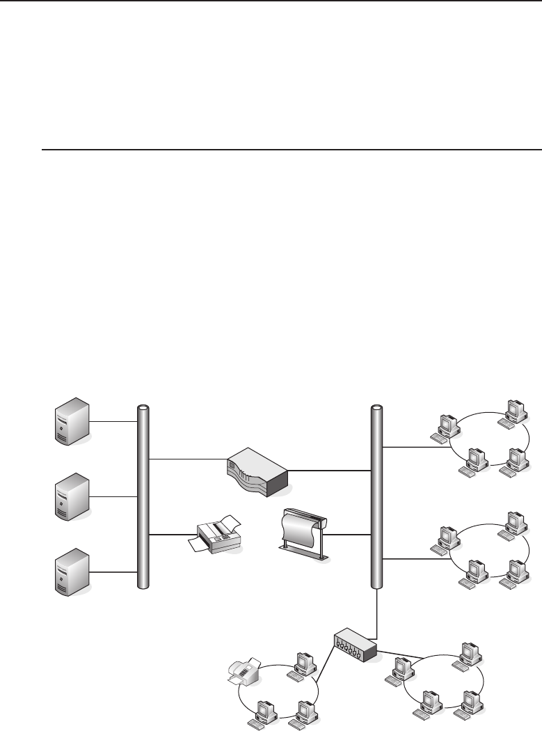
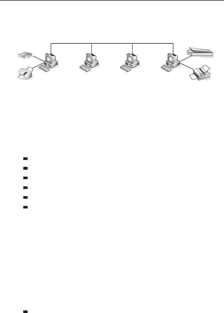
Adata network is a group of computers connected to one another by
communication paths, as well as the standards that allow communication.
A network can connect to other networks, allowing virtually worldwide
communication between two endpoints. Many networks share information
among one another, creating larger networks. Figure 1-1 is an example of a
segment of a network.
Workgroup B
Workgroup B
Workgroup B
Workgroup A
Email
FTP Server
Radius Server
Figure 1-1 A computer network sharing applications as well as hardware
3Dictionary.com Unabridged (v 1.1). Random House, Inc., accessed April 18, 2008.

Edwards c01.tex V3 - 03/27/2009 10:41am Page 5
Chapter 1 ■Introduction to Networking 5
Many things are shared on a network. Corporate business is conducted
nearly exclusively on the network. Networks allow users to share appli-
cations that are stored on servers in the network (e-mail applications,
word-processing applications, databases, and many others). They allow com-
munication between end users. Data can be shared between companies or
individuals for business or personal purposes. Many websites provide oppor-
tunities that would have not existed if networks had never been developed.
Not to mention the entire file sharing that is enabled by a network. The pos-
sibilities are endless, and you can be sure that someone is working on a new,
cutting-edge service even as you read this sentence.
ACRONYM ALERT
VPN — Virtual private networking
Typically, networks are identified by
their size. They range from small local area
networks (LANs) to larger wide area net-
works (WANs).4Many networks remain
isolated from others. They are there to
perform tasks that fit the specific needs
of the group or organization the network
supports. These networks have in place net-
working standards that support the needs of their organization, without regard
to anything outside of the network boundaries. This is due largely to the fact
that upgrading (updating) the network can be a cost that the organization has
not justified. If an organization does not need a high-speed LAN, why spend
the money to upgrade to one?
There are many other networks that have taken advantage ofthe tremendous
technology breakthroughs in the past 25 years that enable these networks to
share data securely. Vendors can connect to their clients’ LAN to exchange
business data in an instant. Internet service providers (ISPs) provide the
gateway to the Internet for their customers to share information. We discuss
many networking advancements throughout this book.
1.1.1 Internetworking
The ability to share information over dissimilar5networks is known as inter-
networking. By using a set of standards, nodes in two (or more) data networks
can share information reliably between one another. In a bridged network,6the
term does not really apply7as the data is not shared with multiple segments
and no internetworking protocol is required to transfer the data.
Internetworking was designed for the specific purpose of providing an
avenue for sharing data among different nodes on the network and among
4These are both discussed in depth in Chapter 2, ‘‘LANs, MANs, and WANs.’’
5By dissimilar, we mean networks that are running with different node types and/or standards.
6A collection of networks that are interconnected at the data link layer using network bridges.
7Although there are some people out there who insist the term does apply.

Edwards c01.tex V3 - 03/27/2009 10:41am Page 6
6PartI■Networking Nuts and Bolts
different system software and operating systems. Consider how data can be
shared by the medical profession. Lab work can be returned more quickly,
allowing for a more immediate diagnosis. Many hospitals are now allowing
x-rays and other data to be viewed over a network. Remote offices are able to
access this data in an instant, decreasing the time for a diagnosis to a level not
even dreamed of 15 years ago. The possibilities are endless.8
RANDOM BONUS DEFINITION
network application — A process or
software program that runs on a node
within a network.
Networking terminology can
be a bit tricky, but it’s really not
as confusing as it may appear
at first. Following are some of
the more common terms9used
to define networks of various
purposes.
1.1.1.1 10 An internet
An internet (lowercase i) is a group of distinct networks connected to one
another via a gateway.11 ‘‘An internet’’ is often confused with ‘‘the Internet’’
(uppercase I), but an internet is not necessarily part of the Internet.
Basically, any network that conforms to the standards defined in the TCP/IP
protocol suite (see Section 1.4) is an internet.
1.1.1.2 The Internet
‘‘A journey of a thousand sites begins with a single click.’’
— Author unknown
The Internet is what most people think of when they hear the term (upper-
and lowercases aside). The Web, WWW, the Information Super Highway, and
8As a matter of fact, there is work ongoing that may allow a surgeon to log in from home and
conduct an operation. Think how many lives can be saved because of this.
9As well as one that is outdated, but Jim just loves the word.
10Take a note of this number (not the section, the number). By the end of this book, you will
know the significance of all 1‘s.
11As with many other networking terms, a gateway can mean many things. We are referring to
a node capable of relaying user application information among networks employing different
architectures and/or protocol suites.
Following are a few other definitions for the term gateway (for those of you who are interested):
(1) An internetworking node operating at the transport layer or above.
(2) An old term for an IP router.
(3) A marketing term for anything that connects anything to anything else.

Edwards c01.tex V3 - 03/27/2009 10:41am Page 7
Chapter 1 ■Introduction to Networking 7
many other terms define the network of networks. The Internet was developed
mainly upon its predecessor, the Advanced Research Projects Agency Network
(ARPANET). In addition to the Web, it encompasses a worldwide collection of
networks, including academic institutions, government organizations, various
public networks, as well as private networks (hopefully with the appropriate
security measures in place).
SOMETHING YOU JUST HAVE TO KNOW
The Internet Protocol (IP) is the dominant standard used in networking to make
sure that information is delivered from a source to a destination. We will talk
about IP throughout this book, so it is not necessary to go into an in-depth
definition at this point. You just have to understand that IP gets the data there.
1.1.1.3 Intranets (Give Me an ‘‘A’’, Remove My ‘‘E’’,
Now Flip the ‘‘R’’ and the ‘‘A’’)
ACRONYM ALERT
LAN — Local area network
An intranet is an IP-based12 network that
is administered and controlled by a single
entity. An intranet is a controlled network,
with only users who have authorization
to be on the network granted access to it
(both remotely and physically onsite). A
corporate LAN is an example of an intranet.
Although intranets are based on (and operate like) the Internet, they are
not widely available to just anyone who needs to access them. Security is in
place (firewalls, encryption and authentication measures, etc.) that will restrict
access to only those who need the access. This allows remote users to access
work applications over the Internet, while preventing unauthorized users from
gaining access.
1.1.1.4 Extranets
An extranet is an intranet that is opened up to allow outside users(e.g., vendors,
suppliers, employees, customers) access to the intranet (or any portion thereof).
The access normally is provided by a server, which clients access over the
Internet. An extranet operates securely to ensure that only authorized users are
12See! We told you that you would need to know what IP meant.

Edwards c01.tex V3 - 03/27/2009 10:41am Page 8
8PartI■Networking Nuts and Bolts
entitled access to the intranet. An extranet may comprise any of the following
for security and privacy purposes13:
Firewall — Network hardware and/or software that captures data
passing through it and determines whether to pass or drop the data.
Firewalls are configurable, and filters can be applied to provide the
appropriate security for the LAN.
Public key certificate — An electronic document that can verify and
authorize an individual by public key cryptography. Public key cryptog-
raphy uses two keys14 (one public key and one private key) to encrypt
and then decrypt data to ensure that a message can be transported
securely.
RANDOM BONUS DEFINITION
Tunneling is a method of securing access to
an intranet. Another popular form is
through a web server, where registered
users can be authenticated after logging in
through a web browser login page.
Authentication encryp-
tion (AE) — A system that
is able to protect both the
secrecy and the integrity
of data communication.
Virtual private network
(VPN) — A network that
is created when one net-
work connects to another
by a secure tunnel.
1.1.1.5 Virtual Private Networks
A virtual private network (VPN) is an extranet that securely connects separate
networks to one another, as well as individuals to networks. VPNs updated15
the use of dedicated lines that could only be used by one entity at a time. VPN
technology is a much more proficient and cost-effective solution than the use
of dedicated lines.
VPN technology uses a public network (normally the Internet) to connect
users and networks to one another in what are known as tunnels.Dataintegrity
is ensured by the use of security measures as well as tunneling protocols that
set the rules for the tunnel.
VPN tunneling protocols include:
Generic Routing Encapsulation (GRE)
IP Security (IPSec)
13It’s important to note that the technologies listed are not exclusive to extranets, but they are
important technologies within extranets.
14Akey is information used to determine an algorithm’s output.
15Although many organizations now use VPNs (or some other extranet type) for remote access,
some networks still utilize the dedicated lines (both owned and leased) when network access is
required.

Edwards c01.tex V3 - 03/27/2009 10:41am Page 9
Chapter 1 ■Introduction to Networking 9
Layer 2 Tunneling Protocol (L2TP)
Point-to-Point Tunneling Protocol (PPTP)
RANDOM BONUS DEFINITION
network node — Any device that partic-
ipates in data communication within a
network.
Tunneling protocols ensure
that the data is encrypted on the
sending end of the tunnel and
is decrypted appropriately at
the receiving end of the tunnel.
In addition to the data encryp-
tion, security is established to
ensure that endpoint addresses
are encrypted as well.
1.1.1.6 Catenet
The term catenet stands for ‘‘catenated network.’’ A catenet is simply a group
of networks that are connected to one another via a gateway. It is an obsolete
term that was replaced by some more up-to-date terms (i.e., internet) that we
discuss in the pages that follow.
AND NOW, A MOMENT OF THOUGHT
Maybe someone will propose a standard to replace the word internet
(lowercase i)withcatenet and save us all that darn confusion. I mean, it really
would make sense, right? However, should this ever happen, I would bet $20
that it wouldn’t be long before ‘‘the Internet’’ became ‘‘the Catenet’’ and then
we would be right back where we were before.
What it boils down to is that it would be nice to see the term catenet return.
It’s kind of catchy.
1.1.1.7 Area Networks
Chapter 2, ‘‘LANs, MANs, and WANs,’’ discusses area networks in depth.
However, for those who may not have heard these terms, it is appropriate to
have a brief introduction to area networks in this first chapter.
An area network is simply a network that spans a specific geographic area and
serves a specific purpose. Any time you communicate over a network (wired
or wireless), you are using an area network (or even various area networks
and network types). In a nutshell, a LAN, a WAN, and a MAN are basically all
the same. The differences are the geographical area that each covers, as well
as some of the communication protocols that are in use.

Edwards c01.tex V3 - 03/27/2009 10:41am Page 10
10 Part I ■Networking Nuts and Bolts
POP QUIZ
What is a public key certificate?
The main three area networks
you will probably hear about
are the local area network, the
metropolitan area network, and
the wide area network. There
are a few other area network
terms in use at the time of this writing, but they are not referred to as often as
the aforementioned. These less common area networks are the personal area
network (PAN), the campus area network (CAN), and the global area network
(GAN).16
1.1.1.7.1 Campus Area Networks
A network that spans a limited geographic area specific to academics is
considered a campus area network (CAN). A CAN is nothing more than a
MAN that connects university buildings and provides services for the staff of
the university and its students.
Some CANs provide additional services such as classroom updates, labs,
e-mail, and other necessary services for the students via iPod, cell phone, and
other wireless technologies. You may or may not ever have to be involved
in a CAN, but at least now you can share your CAN knowledge should the
opportunity present itself.17
1.1.1.7.2 Global Area Networks
A global area network (GAN) is any network that connects two or more WANS
and covers an unlimited geographical area. The entire network connected
together would be considered a GAN. GANs are becoming increasingly
popular as so many companies are opening offices and operating business on
a global scale.
1.1.1.7.3 Local Area Network
A local area network (LAN) is a data network that covers a small geographical
area, typically ranging from just a few PCs to an area about the size of an
office building or a group of buildings. Unlike WANs, LANs don’t require a
leased line to operate. LANs also maintain higher data rates than do some of
the larger area networks, due mainly to the smaller area of coverage.
Nodes that are members of a LAN communicate with other LAN nodes by
sharing some form of channel (e.g., a wireless access point, twisted cable, fiber
optic cable). PC users on a LAN often use a shared server to access and work
with certain applications used by the organization.
16In the near future, you might see this one used a lot more. The use of the word global has
increased over the past few years, so it stands to reason that a GAN is right around the corner.
17Or you can just sit on your CAN, er, knowledge and keep it to yourself.

Edwards c01.tex V3 - 03/27/2009 10:41am Page 11
Chapter 1 ■Introduction to Networking 11
The three major LAN technologies in use today are Token Ring (discussed
in Chapter 7, ‘‘Not to Be Forgotten’’), Ethernet18 (discussed in Chapter 6, ‘‘Eth-
ernet Concepts’’), and Fiber Distributed Data Interface (FDDI), also discussed
in Chapter 7.
1.1.1.7.4 Metropolitan Area Networks
A metropolitan area network (MAN) is a network that physically covers an
area larger than a LAN and smaller than a WAN. The network is normally
maintained by a single operating entity, such as government offices, healthcare
systems, and any other type of large organization or corporation.
MANs allow communication over a large geographical area, utilizing pro-
tocols such as ATM, FDDI, Fast Ethernet, or Gigabit Ethernet.19 This is a
better solution than communication between LANs over a WAN, which relies
on routing to decipher and allow communication of different protocol types
between various area networks. Communication over a WAN is also slower
and more expensive than what is offered by a MAN. MANs also provide
control of the transmission of data from endpoint to endpoint, whereas the
WAN solution requires that you rely on the service provider for a portion of
the data flow control.
1.1.1.7.5 Personal Area Networks
A personal area network (PAN) is a network that is established for an
individual user within a range of around 30 feet — for instance, a person has
a PDA or cell phone and connects to a PC or other node for the purposes of
exchanging data. This is done wirelessly, although wired PANs are feasible
in this day and age. A pure wireless PAN is termed a WPAN, although most
PANs would likely be made predominately of wireless devices. Although
a PAN or WPAN might be considered a LAN or WLAN, the defined area
outlined by the terms certainly does help in isolating network segments.
Some examples of devices that might make up part of a PAN include:
iPhone
Personal digital assistants (PDAs)
Cellular phones
18Ethernet is by far the most popular and widely used LAN technology. As a matter of fact, many
LANs are now migrating to Ethernet when they begin replacing legacy nodes in their LANs.
Chapter 6, Ethernet Concepts, is dedicated to this technology.
19Although many MANs still utilize a lot of these various protocols (e.g., FDDI, ATM),
Ethernet-based MANs are rapidly becoming the preferred standard. Most new MANs are
Ethernet-based, and many MANs are migrating to the Ethernet-based solution as their MAN
standard.
Edwards c01.tex V3 - 03/27/2009 10:41am Page 12
12 Part I ■Networking Nuts and Bolts
Video gaming systems
Pagers
Personal computers or laptops
Printers
Most portable peripherals
1.1.1.7.6 Wide Area Networks
A wide area network (WAN) is a network that covers a large geographical
area.20 Most people think of a WAN as a public shared network, which is partly
the case, but a lot of privately owned as well as leased WANs are currently in
existence.21 A WAN links other area networks to one another, providing a way
to transmit data to and from users in other places. If you think about it, the
WAN is the king of the area networks (although this might not hold true for
much longer, as the GAN is quickly gaining speed to become the big daddy of
them all).
WANs use networking protocols (e.g., TCP/IP) to deliver data from end-
point to endpoint. A WAN also ensures that addressing of endpoints is
maintained so it knows where data needs to go to reach its intended desti-
nation. Some communication protocols that are used on WANs to handle the
transmission of data include:
Asynchronous Transfer Mode (ATM)
Frame relay
Packet over SONET (POS)22
X.2523
1.1.1.7.7 Wireless Local Area Networks
A wireless local area network (WLAN) is an LAN without wires. WLANs use
modulation technologies that are based on radio wave technology to allow
communication with other wireless nodes within a limited geographical area.
Many businesses now offer WLANs for use by their customers (many at
no charge). Additionally, many cities in the United States are implementing
WLANS throughout their city to allow free access to users within the wireless
area.
20You can consider a network a WAN if the network boundaries exceed the size of a large
metropolitan area. But hey, one man’s MAN is another man’s WAN.
21These will not be going away. As a matter of fact, no one knows what the future holds. The
possibilities seem endless.
22Here is another fun acronym to consider. Instead of Packet over SONET (POS), why not SONET
under Packet (SUP)? Then when you greet your fellow networking professionals you could say,
‘‘Hey! What’s SUP?’’
23X.25 is an oldie but goodie. It has long been replaced by other protocols. Still, it was one of the
earliest WAN protocols and it deserved a mention.

Edwards c01.tex V3 - 03/27/2009 10:41am Page 13
Chapter 1 ■Introduction to Networking 13
1.1.2 Network Relationships and Topologies24
RANDOM BONUS DEFINITION
packet — The encapsulated data that is
transmitted and received at the Network
layer (see Section 1.4.2.5).
Network relationships refer to
the communication that takes
place between two nodes over
a network. When a relationship
is formed, the nodes are able
to utilize resources between one
another in order to share data.
There are two network relation-
ship types that define the foun-
dation of any network. A peer-to-peer network relationship is where both nodes
treat each others as equals, whereas a client/server network relationship is one
in which one node (the server) handles storing and sharing information and
the other node (the client) accesses the stored data.
The manner is which nodes in a network connect to a communication line in
order to exchange data is an example of a physical topology. Another topology
type would be a logical topology, which defines the way data is passed from
endpoint to endpoint throughout the network. The logical topology does not
give any regard to the way the nodes are physically laid out. Its concern is to
getthedatawhereitissupposedtogo.
1.1.2.1 Network Relationship Types
ACRONYM ALERT
TCP — Transmission Control Protocol
The main difference between the two net-
work relationship types are whether you
want to have every user share resources
with each other or have a central node that
handles all the processing while serving the
needs of the clients. This means that pretty
much everything else is the same between
the relationships. They both use the same protocols and physical connections
to the network. Which one is appropriate for an organization depends on the
needs, wants, and demands of the users of the network (cost factors, data
speed concerns, etc.).
1.1.2.1.1 Client/Server Network Relationship
In a client/server25 network relationship, one node acts as a server and the
other nodes are clients that utilize the resources of the server to access an
24Relationships and Topologies (RAT). Now, that acronym has a certain ring to it. Or maybe we
should have written this heading to read Network Relationships or Topologies (ROT).Theformer
has a better ring, in our opinion, so RAT it is!
25A client/server network relationship is different from a client/server database system. In both
cases, the server provides the data requested by a client, but in a database system, the client node
has to use its own resources to format and view the data retrieved.
Edwards c01.tex V3 - 03/27/2009 10:41am Page 14
14 Part I ■Networking Nuts and Bolts
application or service. In a client/server network relationship, the server
stores data (e.g., e-mail applications, encryption and authorization services,
printers, VPN network access, and many more) that is used by the users of
the organizational LAN. Most servers are Unix based, or a derivative of Unix,
such as Linux or SunOS, all of which are discussed in depth in Chapter 4,
‘‘Operating Systems and Networking Software.’’ The users interface with the
network through a PC or Mac (or whatever device is necessary at that time26).
The PCs will have an application that contains the information necessary to
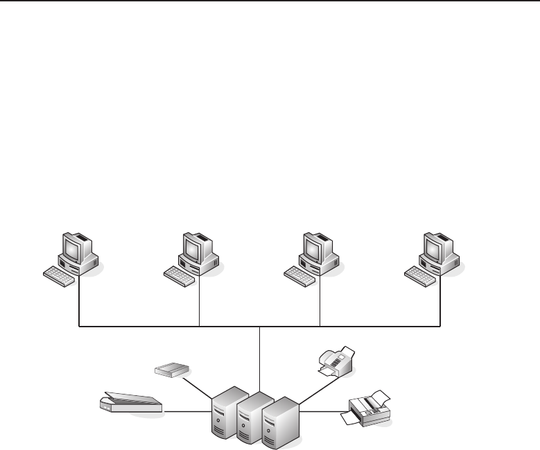
connect to and share data with the server. Figure 1-2 shows an example of the
client/server relationship.
PC–A PC–B
Server Farm
Scanner (all)
Printer (all)
Modem (all)
Fax Machine (all)
Documents (A only)
Documents (B only)
Documents (D only)
Warehouse database (shared)
Production Software (shared)
Accounting (D only)
Payroll (C only)
Invoices (C only)
Employee records (C only)
PC–C PC–D
Figure 1-2 A client/server network relationship
No clients share resources with any other client in the client/server network
relationship. They are simply users of the resources that are made available by
26For the remainder of the book, when a reference is made to a network user, it is assumed that
the user is a PC end user. Otherwise, we will specify the type of user that is being referenced.
Don’t worry, Mac fans. Chapter 4, ‘‘Operating Systems and Networking Software’’ talks about
the Mac OS.

Edwards c01.tex V3 - 03/27/2009 10:41am Page 15
Chapter 1 ■Introduction to Networking 15
the server. The servers maintain and provide shared resources to a specified
number27 of clients.
Advantages of a client/server network relationship include:
It is a secure way to share data over a network. Because all the
accessed resources are on the server, the server is able to control
and maintain the security of sessions. Also, instead of multiple
nodes in various locations, the server is a single entity and can be
secured away from unauthorized visitors.
Because most servers have more built-in redundancy than a single
user’s PC, the servers are very reliable in doing their job. Normally,
there are backup drives (or other servers) that can be failed over28
to if there is a problem with the primary drive or server.
It is easier to back up data that is on the server than to do so with
many nodes. Most organizations perform backups at night when
the server is not as busy. Having only one node to back up makes it a
very simple, time-saving process.
Servers are fast because they have to serve multiple end users at the
same time. The performance standards set for a server are far higher than
the standards for a PC.
Of course, it’s not all peaches and cream inclient/server land. Disadvantages
of a client/server network relationship include:
POP QUIZ
Encapsulated data that is transmitted
and received at the Network layer is
called a .
Administrators of the
server have to be trained
and experienced. There
is a lot to know, and the
potential for failure is very
high without a trained
professional (therefore,
be prepared to pay).
Servers require more physical resources in order to do the job.
This makes the price to operate a bit higher than in a peer-to-peer
environment.
1.1.2.1.2 Peer-to-Peer Network Relationship
A peer-to-peer network relationship is exactly that: all the users are peers
(equals) and they share resources that are necessary to be shared. Each
27The total number would depend on the capabilities of both the server hardware and the
software that it is running on the node.
28In a redundant configuration, a failover occurs when the primary has a failure and the
backup has to take over as the primary. A failover is transparent to the end users.
Edwards c01.tex V3 - 03/27/2009 10:41am Page 16
16 Part I ■Networking Nuts and Bolts
computer is required to determine what is to be shared and then ensures that
resources are made available to the nodes that need to access the resources.
Figure 1-3 shows an example of how this works.
PC–A
Modem (shared)
Fax Machine (shared)
Documents (private)
Warehouse database (shared)
Production Software (shared)
Documents (private)
Payroll (private)
Invoices (private)
Employee records (private)
Scanner (shared)
Printer (shared)
Documents (private)
Accounting (private)
PC–B PC–C PC–D
Figure 1-3 A peer-to-peer network relationship
Note that in the example, PC-C does not have any shared resources, but
it may have a need to use some of the shared resources in the peer-to-peer
network. Therefore, PC-C will be a part of the peer-to-peer topology as a user
of the other resources made available by the other peers.
Some examples of shared resources include:
Printers
Modems
Scanners
Data files
Applications
Storage devices
A peer can share any of these in any combination that makes the best use
of resources to meet the needs of the users in the network. One computer
can provide access to the office printer and scanner, while another computer
can have the modem connected to it. By sharing resources, you save the
expense of having to have one of everything for every computer in
the organization. Security for the shared resources is the responsibility of the
peer that controls them. Each node will implement and maintain security
policies for the resources and ultimately ensures that only those that have a
need can use the resources. Each peer in a peer-to-peer network is responsible
for knowing how to reach another peer, what resources are shared where, and
what security policies are in place.
Advantages of a peer-to-peer network relationship include:
It is cheaper to implement and maintain. You don’t have to buy mul-
tiple peripherals for each computer. You also don’t have the cost of

Edwards c01.tex V3 - 03/27/2009 10:41am Page 17
Chapter 1 ■Introduction to Networking 17
purchasing and maintaining a server. Because each peer uses its own
resources, there is no stress on only one node to do all the serving.
A peer-to-peer network does not require a special operating
system. A peer-to-peer network can be built on operating systems that
are currently running on most PCs.
There are more redundancy options available in a peer-to-peer
network. Because multiple clients are sharing resources, it is a
good idea to design a way to have a process failover to a backup
peer should the master peer have a failure.
A peer-to-peer network is easier to maintain than a client/server
network, and the job of keeping up with the network can be assigned to
multiple people.29
Disadvantages of a peer-to-peer network relationship include:
If a lot of people are trying to use a shared resource, computer perfor-
mance may be adversely affected.
Because multiple peers are performing different tasks, it is harder
to back up data in a peer-to-peer network.
Security is not as good as in a client/server network. Because each peer
is responsible for maintaining security for the resources it controls, the
potential exists that an end user may accidentally or maliciously change
the security parameters, causing a security lapse on that particular node.
Also, each node is physically available to multiple people (possibly
even people who work in the same building but whom you don’t
know). In a client/server environment, the administrator maintains
security and the server is physically set apart from the clients.
1.1.2.2 Network Topology Types
Anetworktopology is basically the way all the nodes in the network are
connected. There are five primary topologies (bus, mesh, ring, star, and tree)
that are installed in various networks. When designing a network, knowing
which topology to use is determined by several factors:
Is speed a concern?
How reliable does the network need to be?
How much money are you willing to spend to set it up?
How much are you willing to spend to maintain the network?
29And where exactly does the buck stop?
Edwards c01.tex V3 - 03/27/2009 10:41am Page 18
18 Part I ■Networking Nuts and Bolts
Data is carried in the network by a detailed cabling scheme. How the
network performs depends on whether the cabling is set up correctly.30 Miss a
port here or there and you can really cause a network some problems. If there is
a cable that is longer than specifications, you are going to have other problems.
Once you complete this section, you will come to realize that networking is
more than just ‘‘plugging it in.’’
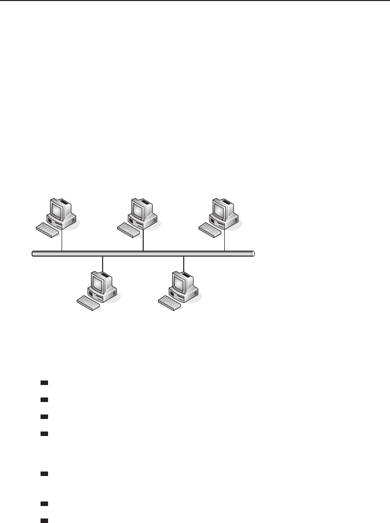
1.1.2.2.1 Bus Topology
The bus topology is probably the easiest one to understand and to implement.
It is simply a topology in which all the nodes are connected to a single shared
cable (called a bus). The cable is terminated at each end to prevent an open
loop condition. Figure 1-4 shows an example of a bus topology.
Figure 1-4 A bus topology
As with any of the topology types, the bus topology has benefits as well as
drawbacks. The advantages of a bus topology include:
It’s easy to install and maintain.
Adding new nodes is rather simple.
Less cabling is required than with some of the other topology types.
It’s inexpensive to implement.
The disadvantages include:
If the cable breaks at any point, network access is lost to all nodes on the
segment.
It can be expensive to maintain over a period of time.
Data communication is slower than with some of the other topologies.
30When designing a network, the placement of the cabling is the first thing that you need to
consider and then you expand from that. Of course, wireless networking is an option, but you
still begin planning the wireless network by determining where the access points should be.
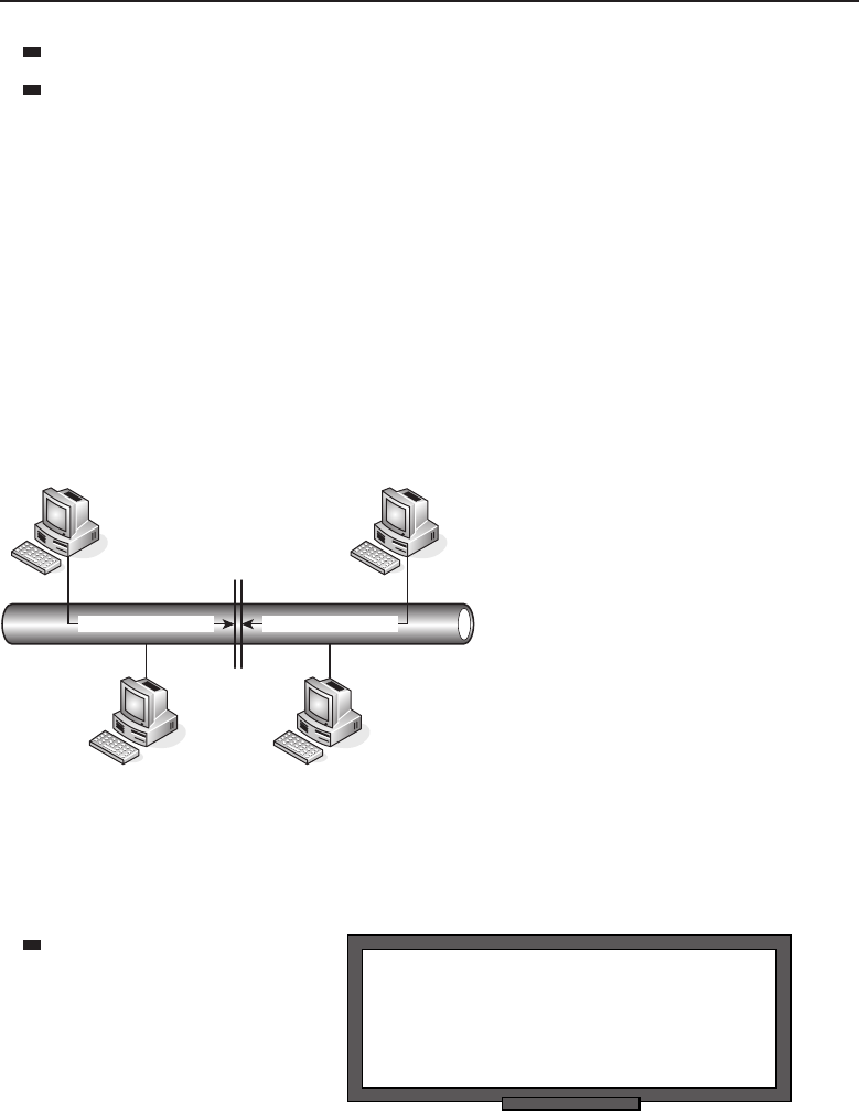
Edwards c01.tex V3 - 03/27/2009 10:41am Page 19
Chapter 1 ■Introduction to Networking 19
The network segment traffic flow is affected each time a node is added.
There is a limit to the number of nodes that can be added to the segment.
When a node that is connected to a shared bus needs to pass data on to
the network, it has to have a mechanism for detecting whether other nodes
are transmitting data at the same time. It must do this to prevent a collision
on the bus (see Figure 1-5) or have a set of rules to follow when a collision
occurs. In the example, you see that node C is trying to send data to node D.
At the same time, node A is sending data to node E. Because there is no way to
determine whether the other node was passing data, a collision occurs on the
bus. This is not the worst part — because there was no mechanism within the
bus topology to detect collisions, both of the sending nodes assume that the
data reached the intended recipients and they relax, thinking they successfully
sent the data.
Node A
Node D
Collision
Data Destined for Node D
Node E
Node C
Data Destined for Node E
Figure 1-5 The dreaded collision
Collision avoidance can be handled in the following ways in a bus topology:
RANDOM BONUS DEFINITION
physical port — A physical interface that
resides on a network node. Not to be
confused with a TCP/UDP port.
Carrier Sense Multiple
Access with Collision
Detection (CSMA/CD)
protocol31 —Thisisa
method of determin-
ing if another node is
sending data by lis-
tening on the bus first. If it senses that the channel is being used by
another node, the node will delay transmitting its data until the chan-
nel is available. CSMA is used to avoid collisions, while CD will detect
31Protocols are discussed in Section 1.1.3.
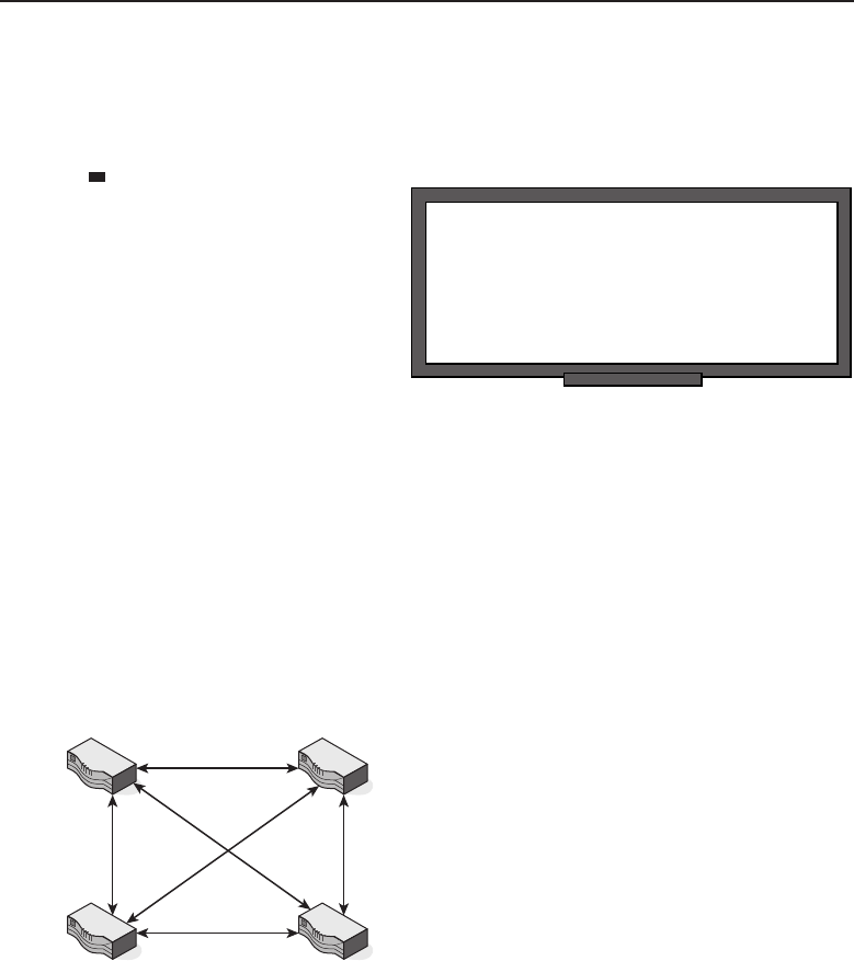
Edwards c01.tex V3 - 03/27/2009 10:41am Page 20
20 Part I ■Networking Nuts and Bolts
when a collision occurs and will stop transmitting data. Once a set
period of time has lapsed, the sending node will send the data again.
Take note that if CSMA is used without the CD, each sending node
will send the entire datagram,32 even when a collision occurs.
RANDOM BONUS DEFINITION
TCP/IP port — A number in the data
packet header that maps to a process
running on a node. Not to be confused with
a physical port.
A bus master —Abus
master is an application
running on one of the
nodes within the seg-
ment or a separate node
known as an input/output
(I/O) controller.The
bus master is the mas-
ter node and all other
nodes are referred to as slave nodes. The master controls the trans-
mission of data to and from all nodes within the bus topology.
1.1.2.2.2 Mesh Topology
There are two types of mesh topologies that can be used. A full mesh topology
(Figure 1-6) is a configuration where all the nodes within the network segment
are connected to one another. A partial mesh topology (Figure 1-7) is where
some nodes are connected to all the others, and some only connect to the ones
they need to communicate with.
Figure 1-6 A full mesh topology
As with almost any topology, there are some advantages and some disad-
vantages to the mesh topology. One advantage of the mesh topology is that
you have a lot of redundancy. If one node is down, the others are virtually
unaffected. There is always a route around broken or blocked paths.
32Adatagram is a self-contained entity of data that is transmitted from one endpoint to another
within a network. Layer 3 packets and Layer 2 frames are two examples of datagrams. As a
matter of fact, many network professionals use the three terms interchangeably.
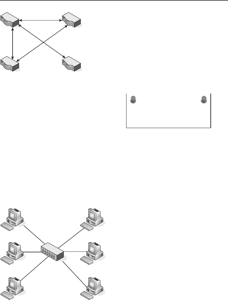
Edwards c01.tex V3 - 03/27/2009 10:41am Page 21
Chapter 1 ■Introduction to Networking 21
Figure 1-7 A partial mesh topology
ACRONYM ALERT
FTP — File Transfer Protocol
One major disadvantage of the mesh
topology is that it is expensive to imple-
ment. Also, as the network grows, so does
the complexity of the mesh topology. In
Figure 1-6, there are four nodes within
the mesh topology. Imagine what a night-
mare it would be to maintain a mesh that
included 100 nodes.
1.1.2.2.3 Star Topology
The star network is one of the more popular network types used by organiza-
tional LANs. In the star topology, all nodes in the network connect to a central
node that handles the passing of datagrams between the nodes. Figure 1-8
shows an example of the star topology.
Figure 1-8 A star topology
The central node receives a datagram and then broadcasts the data to all the
nodes it connects to. The connecting nodes can communicate with each other
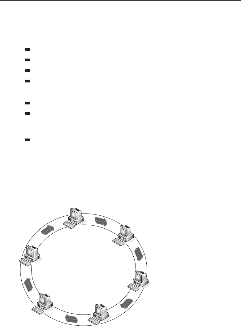
Edwards c01.tex V3 - 03/27/2009 10:41am Page 22
22 Part I ■Networking Nuts and Bolts
by sending data to and receiving data from the central node. Should one of the
connecting nodes go offline, the central hub will discontinue communication
to the one node only and the other connecting nodes will continue to operate.
The advantages of a star topology include:
It allows for direct communication between two nodes.
It’s simple to implement and maintain
It helps to narrow down problematic network segments.
It’s easy to troubleshoot and allows for quick recovery.33
The disadvantages include:
If the central node fails, all the other nodes are affected.
If there is an increase in network traffic, the central node may become
‘‘sluggish,’’ affecting the performance of some, if not all, of the connect-
ing nodes.
Scalability within the network is limited to the capabilities of the central
node.
1.1.2.2.4 Ring Topology
The ring topology can be a bit confusing, as the term ring defines the logical
topology rather than the physical topology. As shown in Figure 1-9, the
ring passes data logically from station to station until the data reaches its
destination.
Figure 1-9 A ring (logical) topology
33When the problematic link is discovered, all you have to do is pull out the cable to pre-
vent the issue from propagating to the rest of the nodes within the star.
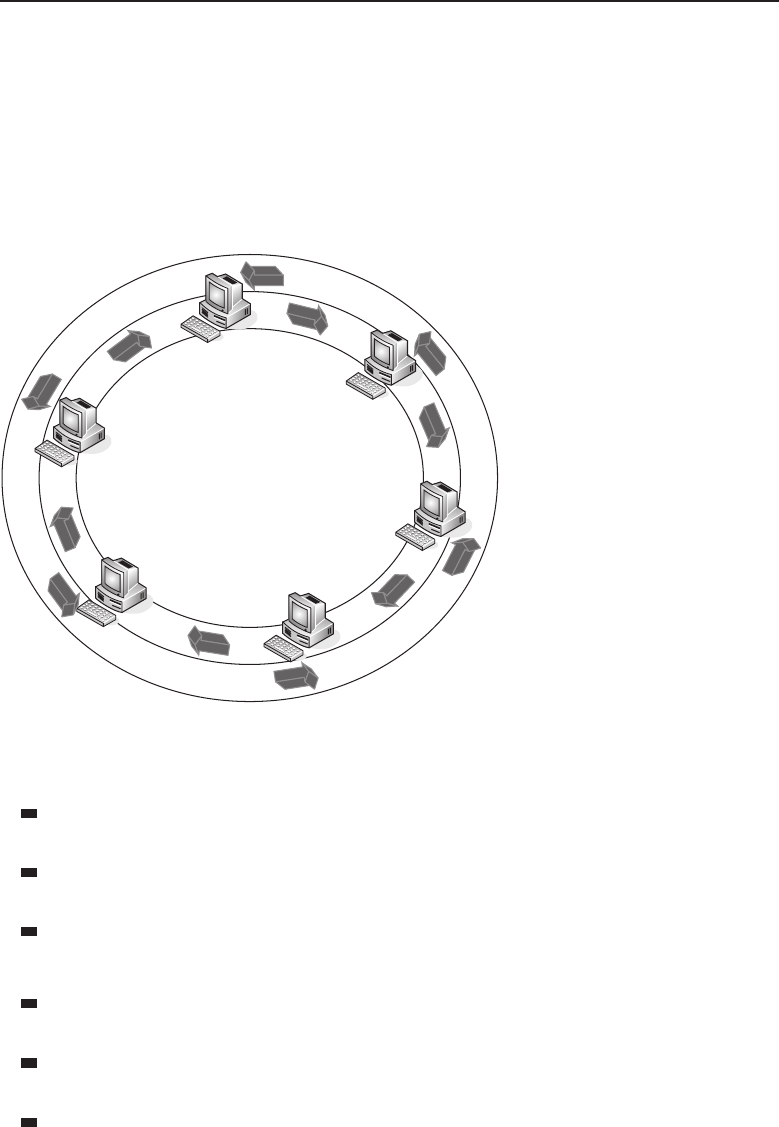
Edwards c01.tex V3 - 03/27/2009 10:41am Page 23
Chapter 1 ■Introduction to Networking 23
Each node handles each datagram that is passed, verifying whether the
datagram is destined for it and, if not, passing it along to the next node. In
the ring topology, there is a single path from one node to the next. Should
there be a break along the way, all nodes on the ring will no longer be able to
communicate on the network. To overcome this, many ring topology networks
employ a dual ring, with data passing in the opposite direction on a redundant
ring (see Figure 1-10).
Figure 1-10 A dual-ring topology
Advantages of a ring topology include:
There’s no need to have a mechanism to ensure collision-free datagram
passing.
It can expand to cover a greater number of nodes than some of the other
topology types.
It’s fairly simple to maintain.
Disadvantages of a ring topology include:
A failure with one node on the ring may cause an outage to all connected
nodes.
Any maintenance (e.g., adding a node, making a change to a node,
removing a node) would affect all the nodes that connect to the ring.
Some of the hardware required to implement a ring is more
expensive than Ethernet network cards and nodes.
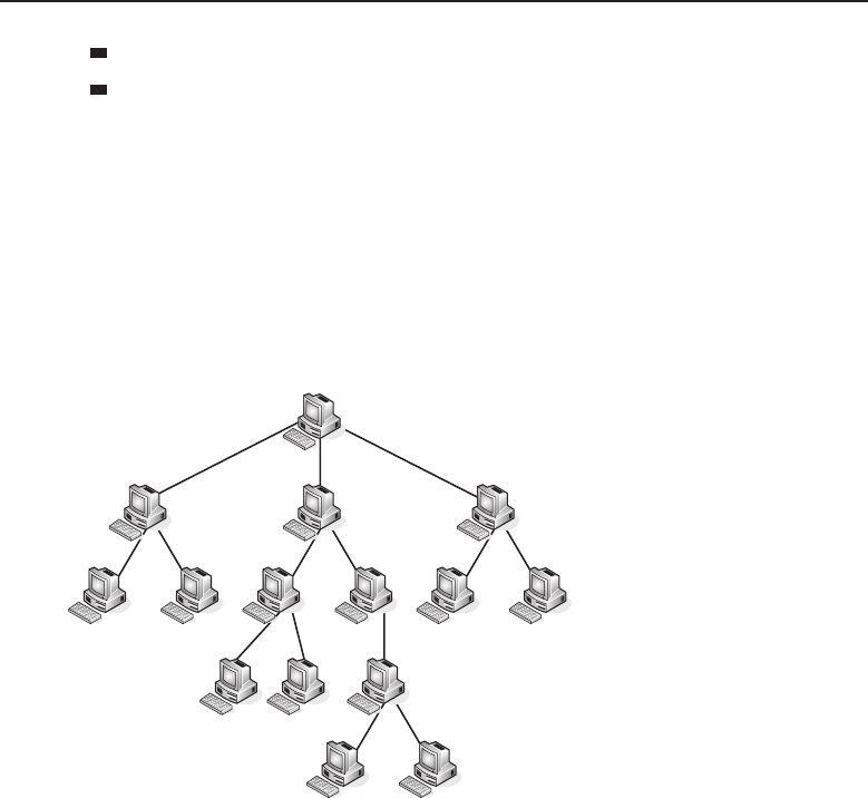
Edwards c01.tex V3 - 03/27/2009 10:41am Page 24
24 Part I ■Networking Nuts and Bolts
Under normal traffic load, a ring is much slower than other topologies.
There are not many of this type of network, as most networks are migrat-
ing to Ethernet.
1.1.2.2.5 Hierarchical Topology (a.k.a. Tree Topology)
A hierarchical34 topology is very similar to a star topology. Like the star
topology, the hierarchical topology has a central node that connects multiple
nodes to one another. However, in the hierarchical topology, each node could
potentially act as a central node to a group of other nodes. Figure 1-11 shows
the physical layout of a hierarchical topology.
Figure 1-11 A hierarchical topology
Notice how a hierarchical topology is similar to an organizational structure.
The mainframe computer would be the single node at the top of the chart, and
then the lower levels would be other minicomputers and PCs. The hierarchical
topology is quite effective in smaller areas, where a central mainframe can
connect to different minicomputers, and the minicomputers can provide a
central connection for the PCs in the departments they serve.
1.1.3 Protocols
Simply put, a protocol is a standard (or set of standards) that governs the rules
for setting up a data connection, communicating between endpoints once the
connection is set, and transferring data between those endpoints. There are
34Jim used to have a colleague who could never get the pronunciation right for the word
‘‘hierarchical.’’ He would pronounce the word ‘‘harr-arrr-cul-cul.’’ No matter how hard he tried,
he never could get the word down. It was pretty funny.

Edwards c01.tex V3 - 03/27/2009 10:41am Page 25
Chapter 1 ■Introduction to Networking 25
POP QUIZ
What is the difference between a physical
port and a TCP port?
protocols set for both hardware
and software, and sometimes for
the combination of the two.
Network protocols vary in
purpose and complexity. They
are usually used to detect the
physical properties of both the
sending and the target nodes, as well as whether the target node is available.
Once the connection endpoints are determined, a protocol will handle the
initial communication35 between the endpoints as well as the rules for the
connection. The protocol will identify how each end will know where a data
stream starts and stops, what format it will be sent and received in, and what
to do with the data if there are any problems with the transfer.
The Internet would not be what it is if it were not for the protocols, especially
the Internet Protocol (IP) and the Transmission Control Protocol (TCP), used
in combination with each other and referred to as TCP/IP or the TCP/IP
protocol suite.
TCP/IP and many other protocols are discussed throughout this book, but
here is a short list of a few of the more common protocols:
File Transfer Protocol (FTP) — FTP is used to transfer large
amounts of data from one node to another. The FTP protocol
uses an FTP server to serve files to an FTP client.
Hypertext Transfer Protocol (HTTP) — HTTP is a communica-
tions protocol that allows for data transmissions within data
networks as well as the World Wide Web (WWW). HTTP uses
a server (e.g., a website) to serve the clients (end users) data the clients
have requested via a web browser.
Hypertext Transfer Protocol over Secure Socket Layer (HTTPS) —
HTTPS is an enhancement to HTTP that allows secure sessions over SSL.
These sessions provide adequate security for private transactions on the
WWW.
Internet Message Access Protocol version 4 (IMAP4) —IMAP4isapro-
tocol that allows a client to connect to and retrieve e-mail from an e-mail
server.
Internet Protocol (IP) — IP is a standard that allows for the
transfer of data between nodes that are connected on a network.
Each node within an IP network has a unique address that
identifies it for the purpose of locating and sharing data between
nodes. The latest version of IP that has been released is IPv6.
35The initial conversation between the two endpoints is commonly referred to as a handshake.

Edwards c01.tex V3 - 03/27/2009 10:41am Page 26
26 Part I ■Networking Nuts and Bolts
Post Office Protocol version 3 (POP3) — POP3 is a protocol that
allows an e-mail client to connect to an e-mail server and retrieve mail
that is destined for that client.
Simple Mail Transfer Protocol (SMTP) — SMTP is a protocol that
allows a network user to send and receive e-mail.
Simple Network Management Protocol (SNMP) — SNMP is a protocol
that allows for the sharing of management data on a network. SNMP
allows network administrators the ability to quickly access network
nodes to monitor performance, troubleshoot, baseline, and ensure that
the network is capable of addressing the needs of the organization.
Transmission Control Protocol (TCP) — TCP is a protocol that connects
end users with one another and ensures the integrity of the exchanged
data.
Trivial File Transfer Protocol (TFTP) — TFTP is a protocol that is a sim-
pler form of FTP.
User Datagram Protocol (UDP) — UDP is a protocol that connects
end users to one another and transfers datagrams, but does not ensure
the integrity of the datagrams.
1.1.3.1 Transmission Control Protocol
The Transmission Control Protocol (TCP) ensures that data is transmitted
from endpoint to endpoint in a reliable manner. TCP operates at the Transport
layer of the OSI reference model (more on this in Section 1.4). TCP is normally
associated with the TCP/IP protocol suite; however, it is its own entity. It is
a protocol that can adapt to a variety of data delivery standards, providing
reliable data delivery.
TCP is the reliable36 transport protocol that controls the flow of data
between hosts. TCP divides messages into smaller segments and ensures the
data arrives error-free and is presented by the target node in the correct order.
TCP manages the flow of data and makes adjustments to the size and the
speed in which the data is transported. TCP is used by most of today’s more
popular networking services and applications, including the World Wide Web
(WWW), e-mail, and Secure Shell (SSH).
36The key word here is ‘‘reliable.’’ This does not imply that TCP can provide the quickest delivery
available. TCP is designed to offer reliable and accurate delivery, but it does not guarantee timely
delivery and is not used when speed is needed to transmit data. The Real-time Transport Protocol
(RTP) is normally used in these instances.

Edwards c01.tex V3 - 03/27/2009 10:41am Page 27
Chapter 1 ■Introduction to Networking 27
TCP is a connection-oriented protocol. This means that there is a connection
between two endpoints before any data is sent. A connection-oriented protocol
also ensures that once the data arrives at a destination, it is put back together
in the proper order. A connection-oriented protocol cannot promise that data
won’t get dropped, but if it is received, it will be sequenced appropriately.
1.1.3.2 User Datagram Protocol
The User Datagram Protocol (UDP) provides a method for transmitting data-
grams between endpoints, but no guarantee of the delivery is made. This
means that a datagram may be duplicated, can go missing, and may not
arrive in the order in which it was sent. This also means that UDP is a faster
transmission standard than TCP.
UDP is preferred in situations where you need data to be transmitted
quickly. There is simply more processing power to get the data to the desti-
nation because there is no error checking. UDP supports broadcasting37 and
multicasting,38 so messages can get to destinations within a network segment
as well as to everyone within the network.
UDP is a connectionless protocol, which means there is no guarantee that
the intended destination is available. There is no checking the communication
line prior to transmitting data, it is just transmitted.
1.1.3.3 Internet Protocol
POP QUIZ
Because IP does not establish a connection
before sending data to an endpoint, it would
be considered a protocol.
The Internet Protocol (IP) is the
protocol that defines how data is
transmitted between two nodes.
Datagrams are forwarded to a
destination endpoint based on
the IP address that is assigned
to the endpoint. When data is
transmitted, the data is encap-
sulated into datagrams and multiple datagrams may be required to transmit
a single message. Each datagram is treated as its own entity without regard
to any of the other datagrams that make up the message. Each datagram can
choose whatever path it wishes to take to reach a destination. That is IP’s job:
to get the datagram to the destination by the quickest route possible.39
37Sending data to everyone connected to the network segment.
38Sending data to a select group of nodes.
39It is TCP’s job to put them back together again.

Edwards c01.tex V3 - 03/27/2009 10:41am Page 28
28 Part I ■Networking Nuts and Bolts
1.2 History of Networking
On April 3, 1860, the Pony Express officially opened for business. Covering
250 miles in each 24-hour period, the riders would travel at full gallop from
one Pony Express station to the next. At each stop, they would change horses,
exchange mail, and head on to the next stop. After 100 miles or so, the
rider would be relieved by a fresh rider to continue the journey. What an
accomplishment this was. Only 15 years prior to that, it would take six months
to get a message from the east coast to the west coast. The Pony Express could
do it in about 11 days. The Pony Express dissolved in October 1861, when the
first transcontinental telegraph was transmitted.
Now look where we are today. In milliseconds, we can send a letter from
Hong Kong to New York, or talk over the Internet with a loved one on the
other side of the planet. We can get trip directions, listen to a radio station
anywhere in the world, work, and play games — all at the same time. It is
amazing how far communication has come.
It might surprise you to know that the concept of connecting nodes to one
another was developed as a way for research organizations and educational
institutions to share resources. There was one significant event that occurred
that opened the doors for a lot of various research, some of which eventually
introduced the network concept. What exactly was this event? It was the race
to space.
The Soviet Union launched the Sputnik satellite on October 4, 1957. This
alarmed many American citizens and was an embarrassment to many people
in the United States because of a few failed attempts prior to that date. The
launch of the Sputnik satellite is said to have ushered in the Space Age, but
that is not all it changed. It changed the attitude of those who were involved in
the United States space program, as well as the attitude of U.S. citizens. After
Sputnik launched, funds began flooding to research agencies and institutions.
The National Defense Education Act was signed to promote studies in math,
science, and foreign languages. One of the agencies formed was the Advanced
Research Projects Agency (ARPA) in 1958.
ARPA was formed as an agency that would be tasked by the United States
Department of Defense (DoD) to research and develop projects. ARPA was
not required to focus on only projects of military concern, and it was quickly
determined that a focus on computers would be a worthwhile investment. In
1962, ARPA chose Dr. J.C.R. Licklider to lead the computer research effort.
WHAT’S IN A WORD?
If you think that the whole catenet/internet/Internet terming conventions seem
a little confusing, you haven’t seen anything yet. Check this out:
(continued)

Edwards c01.tex V3 - 03/27/2009 10:41am Page 29
Chapter 1 ■Introduction to Networking 29
WHAT’S IN A WORD? (continued)
The Advanced Research Projects Agency (ARPA) was formed in 1958. In 1972,
ARPA was replaced by the Defense Advanced Research Projects Agency
(DARPA). DARPA did the same job that ARPA did, but DARPA was established
as a separate defense agency (still under the Secretary of Defense).
In 1993, DARPA became ARPA and was put back as it was when it was first
formed. In 1996, the name was officially changed to DARPA again.
Licklider realized even before his appointment the potential of connecting
nodes to one another to share resources. He had developed what he called
agalactic network concept, and he was able to convince other researchers
(including those who took over when he left) how important his concept
was. He outlined his plan to accomplish this concept and the very first large
network research team was formed. This team, known as the ARPA community,
was a group of universities across the United States. It is important to note
that Licklider left his position before his concepts became a reality, but his
successors moved ahead in their development.
POP QUIZ
What is the difference between a WAN and
aLAN?
ARPA formed a subgroup
called the Information Process-
ing Techniques Office (IPTO)
to focus on research pertain-
ing to anything related to com-
puting. It was funding from
ARPA/IPTO that assisted in
the ARPA community of edu-
cational and scientific institutions to investigate time and resource sharing
possibilities.
Many people today still feel that the Internet was developed to provide a
fallback mechanism in the event of a nuclear attack. This is probably due to the
fact that there was so much funding poured into development after the launch
of the Sputnik satellite. The official reason that was given for the concept of
networking nodes together was simply to share files and resources among
investigative agencies and groups.
In 1968, ARPA allowed contractors to bid on the plan they had been working
on, and BBN Technologies was brought in. In 1969, ARPANET was born. The
original ARPANET was a network with several small computers referred
to as interface message processors (IMPs), which were nodes that performed
packet-switching and were used to connect to each other by modems and to
users on host computers.40 The IMPs were configured with 24 Kb41 of memory,
40Don’t think of these hosts as PCs. These hosts were huge computers, sometimes occupying a
whole floor of a building.
41Kb =kilobits

Edwards c01.tex V3 - 03/27/2009 10:41am Page 30
30 Part I ■Networking Nuts and Bolts
supported up to four host computers, and were able to connect to a maximum
of six other IMPs. The IMPs communicated with one another over leased
communication lines. The original ARPANET was made up of four IMPs that
were established at the following locations:
Stanford Research Institute
University of California, Los Angeles
University of California, Santa Barbara
University of Utah
ACRONYM ALERT
DoS — Denial of service
BBN Technologies developed the first
communications protocol, known as the
BBN Report 1822, which later became known
as the 1822 protocol. The 1822 protocol sim-
ply specified the manner in which a host
communicated with the IMP. The 1822 pro-
tocol predated the OSI reference model (see
Section 1.4) and did not really follow the layering process we use today.42
The 1822 protocol was eventually replaced by the Network Control Protocol
(NCP), which incorporated a transport function. The NCP remained the main
communication protocol until 1983, when it was replaced by the TCP/IP pro-
tocol suite. The TCP/IP protocol suite was more resilient than the NCP, and
its introduction was the birth of communication networks as we have known
them to date.
Eventually, ARPA got out of the networking business to focus on research
in other areas. The Defense Department retained the military portion of
the ARPANET and named it the MILNET. The remainder of ARPANET
remained with research and educational organizations, and BBN Technologies
continued to maintain these networks. Because of the split of ARPANET,
many of the resources available to the institutions and organizations were
severed in the interest of security required by the MILNET. In response to this,
the National Science Foundation funded the development of the Computer
Science Network (CSNET), which provided access toshared resources for these
groups. Eventually, the network grew and was transformed into the National
Science Foundation Network (NSFNET), which was developed originally to
allow researchers access to five supercomputers at the following locations:
Cornell University
Pittsburgh Supercomputing Center
42It can be said that the 1822 protocol used the physical, data link, and network layers as the
host system packaged data and sent it to the address of the IMP (directly connected). The IMP,
in turn, routed the data to the destination IMP, which sent it to the destination host.

Edwards c01.tex V3 - 03/27/2009 10:41am Page 31
Chapter 1 ■Introduction to Networking 31
Princeton University
University of Illinois
University of California, San Diego
The NSFNET used the TCP/IP protocol suite as a communications protocol
and was completely compatible with the ARPANET. In the early 1990s, more
and more organizations started accessing what was now called the Internet,
but permissions had to be obtained from the NSFNET to use many of the
services that were offered. The main supercomputer centers maintained and
monitored the Internet’s growth.
Today networks are defined by the way they get information from point to
point. The nodes used and the standards deployed are integral parts of any
network, defining the very basis for that network’s existence. Networks are
commonplace and growing on a global level. Only the future can tell what
new advances will be made for this global communication vehicle.
INTERNET TIMELINE TRIVIA
1957: The Advanced Research Projects Agency (AARPA) is formed.
1961: The Massachusetts Institute of Technology (MIT) began researching
data-sharing potential. There are fewer than 9,500 computers in the world.
1966: ARPANET is under development, packet-switching technology is
launched.
1969: ARPANET is launched.
1971: The number of nodes on the ARPANET is 15.
1973: London and Norway join ARPANET. Global communications are
launched.
1974: TCP is launched. Data communication speeds increase and the reliability
of data transmission improves.
1975: The first ARPANET mailing list is launched. TCP tests are run successfully
from the U.S. mainland to Hawaii as well as to the U.K., via satellite links.
1976: Unix is developed.
1978: TCP and IP split into two separate protocols.
1982: TCP/IP becomes the standard used by the Department of Defense
for data communication within the U.S. military’s network.
1984: The number of nodes on the Internet is over 1,000. Domain Name Ser-
vice is launched.
(continued)

Edwards c01.tex V3 - 03/27/2009 10:41am Page 32
32 Part I ■Networking Nuts and Bolts
INTERNET TIMELINE TRIVIA (continued)
1987: The number of nodes on the Internet is over 10,000.
1988: The Internet experiences its first Internet worm.
1989: The number of nodes on the Internet is over 100,000.
1990: ARPANET is disbanded. The first commercial Internet service provider
(ISP) is launched.
1991: The first Internet connection is made (at 9600 baud). The World Wide
Web is launched.
1992: The number of nodes on the Internet is over 1,000,000.
1994: The WWW becomes the most popular service on the Internet.
Some radio stations start broadcasting over the Internet.
1995: Internet streaming technology is introduced.
1996: Web browser software vendors begin a ‘‘browser war.’’
1997: Over 70,000 mailing lists are now registered.
1998: The 2,000,000th domain name is registered.
2000: The first major denial-of-service (DoS) attack is launched. Most major
websites are affected.
2002: Blogs become cool.
2003: Flash mobs are born. Flash mobs are groups of people who gather
online and plan a meeting in a public place. Once they assemble, they
perform a predetermined action, ranging from pillow fights to zombie
walks. The participants leave as soon as the meeting is over. (Wikipedia has
a good article about flash mobs: www.wikipedia.org/wiki/Flash mob.)
2005: The Microsoft Network (MSN) reports that there are over 200 million
active Hotmail accounts.
2006: Joost is launched, allowing for the sharing of TV shows and video using
peer-to-peer technology.
2008: Online search engine Technorati reported that they are
now tracking and indexing over 112 million online blogs.
1.3 Standards and Standards Organizations
As we have discussed already, the standards that are put in place to ensure
that data communication can be shared between nodes on a network are
an essential part of the network. Without a standard way of doing things,

Edwards c01.tex V3 - 03/27/2009 10:41am Page 33
Chapter 1 ■Introduction to Networking 33
networks would not be able to operate nearly as efficient as they do today.43
So it is fair to say that based on what we have discussed so far, we can all be
in agreement that standards are required in order for data communication to
be shared on a network. Standards serve the following purposes:
Set up and maintain rules to be followed in the network
Define how network hardware interfaces operate
Maintain all communication protocols that are in use in a network
Offer the ability of utilizing the hardware and software available from
multiple vendors and ensure that these are interoperable with like
resources from other vendors
Standards begin when an individual or organization has an idea. A proposal
is put forth and a committee reviews it to determine if the proposal has any
merit. If the proposal is accepted, the idea will be transferred to a development
committee, which will outline the scope of the proposed standard and submit a
draft to a committee that will vote on whether the standard is to be approved.
If the standard is passed for approval, the final draft is written and then
published as a new standard.
There are three main types of networking-related standards. It important
that you understand the differences, as it is virtually a guarantee that you will
need to know this at some point.
De facto standards — A de facto standard is a standard that began
as a proprietary standard and then grew to a standard that is used
by pretty much everyone. As a matter of fact, it is widely assumed
that many proprietary standards are developed with the hopes
that they will become de facto standards.44 A de facto standard is
similar to an open standard in that it is universally used by multiple
vendors, but it is never approved as a formal open standard.
Proprietary standards — A proprietary standard is a standard that is
developed and owned by a specific vendor. When PCs first started com-
ing out, most vendors tried to avoid admitting the importance of a coop-
erative standard that could be used between different vendors. The
technology was starting to boom, and corporate confidentiality was a
huge concern, so it was important to keep their standards to themselves.
As a matter of fact, it really made sense that having control of a standard
43That is assuming that they would work at all without standards.
44Why would they do this? To become the industry leader for whatever the standard covers.
Think about it this way. If you want to purchase a computer that supports the widget stan-
dard, you might have more faith in the company that introduced and has supported the stan-
dard for years, as opposed to purchasing a PC from ‘‘Mom and Pop’s PC shop,’’ which only
recently started supporting the widget standard.

Edwards c01.tex V3 - 03/27/2009 10:41am Page 34
34 Part I ■Networking Nuts and Bolts
as it would be beneficial to the future of the company. To take this even
further, companies saw no real value in supporting the proprietary stan-
dard of the competition (why have to pay them for the rights to use the
standard?), so instead they developed something close to what the com-
petition had, and then encouraged the consumer to move to what they
had to offer, as they did ‘‘xyz’’45 more than the competitor. Proprietary
standards still exist, but they are not as common as they once were.
ACRONYM ALERT
IEEE — Institute of Electrical and Electronics
Engineers
Open standards —Anopenstandard
is a standard that is used by almost
everyone. Most vendors involved in
networking resources now realize
that they can be just as competitive
while developing cooperative stan-
dards that are agreed upon by other
vendors. This quickly became evident as consumer demand grew. Con-
sumers wanted to be able to choose from multiple vendors, and expected
the nodes to communicate well with one another. There are some com-
panies that still prefer to work with mostly proprietary standards, but
there is a larger customer base for devices that use open standards.
This section discusses some of the standards organizations and what purpose
each one serves. These organizations develop formal standards for the area
of networking they are applicable to. Most standards committees operate as
nonprofit organizations and are made up of researchers, educators, specific
vendors, and industry professionals. In turn, vendors model the development
of their products based on the agreed standard.
1.3.1 American National Standards Institute
POP QUIZ
The three types of standards are
,
,and .
The American National Stan-
dards Institute (ANSI) is the
organization responsible for
ensuring that guidelines are
established for every type of
business you can imagine. From
construction standards to agri-
cultural standards, ANSI is
responsible for outlining and
accrediting these standards. The mission of ANSI is to ensure that standards
are defined and followed in order to protect and ensure global competitiveness
45This could be anything from a true advance over the competitor to a ‘‘prettier’’ package.

Edwards c01.tex V3 - 03/27/2009 10:41am Page 35
Chapter 1 ■Introduction to Networking 35
for American business and ultimately improve life standards for the American
consumer.
ANSI is the organization that represents the United States in working with
the global community on issues relating to two important global standards
organizations. These are:
International Organization for Standardization (ISO)
International Electrotechnical Commission (IEC)
It is important to note that ANSI is not the developer of standards; rather, it
oversees the development of standards by accrediting the standards once they
have been set up and proposed by what are known as Standards Development
Organizations (SDOs). It is the responsibility of the SDOs to develop and
maintain standards that represent the users for their group.46
Examples of some of the SDOs that have had standards accredited by
ANSI47:
RANDOM BONUS DEFINITION
working group — A group formed by
interested members of an organization. The
working group can have open meetings, as
well as communication through Internet
forums and mailing lists. The working
group works on issues relating to standards
and standards development.
American Dental Asso-
ciation (ADA)
North American Die Cast-
ing Association (NADCA)
Standards Australia (SAI)
Institute of Electrical
and Electronics Engi-
neers (IEEE)
Chinese Standards (SPC)
1.3.2 International Organization for Standardization
Founded in 1947, the International Organization for Standardization (ISO)48
is an organization that is tasked with standardizing international standards
for various interests. Based in Switzerland, the ISO is made up of members
46By ‘‘group,’’ we mean the individuals outside of the SDO for whom the developing standards
will apply.
47This list is provided as an example of the broad range of communities that are ANSI accredited.
That being said, some of these have nothing to do with networking. If you are interested in
further reading, you can go to the ANSI website (www.ansi.org), or there is a search engine
you can use to locate standards and SDOs (www.nssn.org).
48You might wonder why the acronym is not IOS for the International Organization for
Standardization. Being an international organization, the acronym would be different depending
on which country you were in (English would be IOS, but the French acronym would be OIN,
which stands for Organisation Internationale de Normalisation). The forming members of the
organization agreed upon ISO, which came from the Greek word isos, meaning ‘‘equal.’’ This
provided a globally standard acronym for the organization.

Edwards c01.tex V3 - 03/27/2009 10:41am Page 36
36 Part I ■Networking Nuts and Bolts
from 157 nations. In addition to the development of international standards,
the ISO also is responsible for publishing an assortment of technical reports,
specifications, and guides. Following is a list of some of the available ISO
standards:
ISO/IEC 9541 –Information Technology — Font information inter-
change
ISO 9000 — Quality management system in production environments
ISO 9141 — Network interconnection of computers in a vehicle
ISO 15930 — Portable Document Format (PDF)
The preceding is only a short example of the many standards maintained
by the ISO. For further reading, visit the ISO website at www.iso.org.
1.3.3 International Electrotechnical Commission
The International Electrotechnical Commission (IEC) is responsible for stan-
dards that relate to electrotechnology (electronics and related technology). The
strict standards developed by the IEC are used by its members as references
when standardizing electrotechnical resources and contracts. Products that are
manufactured to these standards can be used regardless of where in the world
you live. The IEC is credited for promoting trade and technical efficiency on
a global scale. This ensures that the end user can operate the IEC-supported
device without having to understand the complexities that may be involved
in the technology itself.
In addition to international standards, the IEC also produces various pub-
lications that outline specifications and guidelines for areas that may not be
considered standards. Many of these publications are revisions to existing
standards or draft standards that are under review.
1.3.4 Telecommunications Industry Association
The Telecommunications Industry Association (TIA) develops standards that
apply to telecommunications technologies. TIA has over 70 formulation
RANDOM BONUS DEFINITION
birds of a feather (BoF) — A BoF is an
informal discussion group that consists of
members who share a common interest or
concern.
groups, each of which manages
different subcommittees com-
posed of industry profession-
als, manufacturers, service pro-
viders, and even government
representatives.
These subcommittees and for-
mulation groups devise and de-
velop standards that are submitted to ANSI for accreditation. TIA committees

Edwards c01.tex V3 - 03/27/2009 10:41am Page 37
Chapter 1 ■Introduction to Networking 37
write and maintain standards and specifications for the telecommunications
industry. TIA also participates within various international telecommuni-
cations groups representing the interests of the United States on a global
forum.
1.3.5 Electronic Industries Alliance
The Electronic Industries Alliance (EIA) is an association made up of technical
and electronic manufacturers from the United States that cooperatively work
with each other to ensure that the development and competitiveness of these
companies are represented on a global scale. The issues the EIA addresses are
of interest to the common good of these companies as a whole, ensuring that
the companies are able to achieve the success they deserve. The EIA focuses
on the following areas:
Cyber security
The environment
Information technology reform
Telecommunications reform
Global competitiveness
Global trade and market access
1.3.6 International Telecommunication Union
Dedicated to bringing worldwide communication to everyone, the Inter-
national Telecommunication Union (ITU) is an organization that works to
facilitate telecommunications and data network development and continued
growth on a global scale. The ITU is striving to enable individuals everywhere
to have access to benefits that are available with the information community
and the global economy.
ACRONYM ALERT
RIP — Routing Information Protocol
In 2007, the ITU launched the Global
Cybersecurity Agenda (GCA), envisioning
the future assurance of cybersecurity as
well as cyber peace throughout the Inter-
net. Another goal of the ITU is to strengthen
communications to assist in disaster recov-
ery and prevention efforts in major coun-
tries as well as developing countries that lack resources and economies to
support the Information Age.

Edwards c01.tex V3 - 03/27/2009 10:41am Page 38
38 Part I ■Networking Nuts and Bolts
1.3.7 IEEE
Originally, IEEE was the acronym for the Institute of Electrical and Electronics
Engineers. Over time, the scope and mission of the IEEE grew into other related
fields, and now the name of the organization is simply IEEE (that’s I-triple-E).
The IEEE develops49 global standards applicable to information technology,
telecommunications, power generation, and other related services. The IEEE
has developed and maintains more than 900 standards that are active and in
use. Additionally, more than 400 draft standards are in development.
The IEEE membership is made up of scientists, engineers, and other leaders
in the fields of computer science, electronics, engineering, and related pro-
fessions. Membership in the IEEE provides access to the latest developments
in technology, assists in career development, provides access to technical
information, and many other benefits.
In additional to the standards that are developed and maintained by the
IEEE, the organization publishes almost a third of the world’s technical
literature for the fields of computer science, electrical engineering, and elec-
tronics. They also maintain an online digital library, sponsor conferences, offer
educational and special-purpose grants, and bestow recognition awards.
One of the largest family of standards maintained by the IEEE is IEEE 802.
The IEEE 802 organization is made up of 22 working groups (see Section 1.3.7.1)
that work to develop standards applicable to LAN, MAN, and some WAN
technologies. This section introduces some of the IEEE LAN standards. For
more information about the IEEE, go to their website, www.ieee.org.
1.3.7.1 IEEE 802 Working Groups
Aworking group is a team of professionals who are brought together to work
on new research activities. Usually these are formed when an individual or a
group presents a suggestion for a resolution to a current standard or on the
behalf of a new technology that is being mainstreamed. Working groups are
often referred to as a task force, task group, study group, advisory group, and
many others. Following is a list of IEEE 802 working groups and their current
status:
Active groups
802.1 Higher Layer LAN Protocols Working Group
802.3 Ethernet Working Group
802.11 Wireless LAN Working Group
49As a matter of fact, at the time of this writing, IEEE touted that they were the leading developer
of international standards.

Edwards c01.tex V3 - 03/27/2009 10:41am Page 39
Chapter 1 ■Introduction to Networking 39
802.15 Wireless Personal Area Network (WPAN) Working Group
802.16 Broadband Wireless Access Working Group
802.17 Resilient Packet Ring Working Group
802.18 Radio Regulatory Technical Advisory Group
802.19 Coexistence Technical Advisory Group
802.20 Mobile Broadband Wireless Access (MBWA) Working Group
802.21 Media Independent Handoff Working Group
802.22 Wireless Regional Area Networks
Inactive groups50
802.2 Logical Link Control Working Group
802.5 Token Ring Working Group
Disbanded groups
802.4 Token Bus Working Group
802.6 Metropolitan Area Network Working Group
802.7 Broadband TAG
802.8 Fiber Optic TAG
802.9 Integrated Services LAN Working Group
802.10 Security Working Group
802.12 Demand Priority Working Group
802.14 Cable Modem Working Group
QOS/FC Executive Committee Study Group
The remainder of this section lists some of the standards that have been
developed by the IEEE working groups that deal with subject matter common
in most LANs and MANs.51 These working groups are IEEE 802.1, IEEE 802.3,
IEEE 802.5, and IEEE 802.11.
1.3.7.2 IEEE 802.1
IEEE 802.1 is responsible for the development of numerous standards, as well as
providing recommendations for the following areas: 802 LAN architecture, 802
50‘‘Inactive’’ does not mean the technology is not out there; it just means there are no updates
being worked on at this time.
51These are also the main working groups within the IEEE 802 family that sets standards for the
material covered in this book.

Edwards c01.tex V3 - 03/27/2009 10:41am Page 40
40 Part I ■Networking Nuts and Bolts
MAN architecture, 802 WAN architecture, 802 overall network management,
protocol layers above the MAC and LLC sublayers (see Section 1.4), and 802
Security. Following is a list of IEEE 802.1 standards:
IEEE 802.1AB — This standard defines how to use the Link Layer
Discovery Protocol (LLDP) as well as identifying node access points for
network and device management.
IEEE 802.1AD — This standard sets the rules used by service providers
to use bridges, so they can basically provide the equivalent of a separate
catenet to their customers.
IEEE 802.1AE — This standard defines the MAC security guidelines for
the purpose of data security.
IEEE 802.1B — This standard defines the rules for remote management
of IEEE 802 LANs.52
IEEE 802.1D — Of all the 802.1 standards, this is the one that is the
most well known. It is also the most used standard and outlines the
rules followed by LAN bridges and switches.
IEEE 802.1E — This standard outlines the rules for using multicast to
reliably transfer large amounts of data to multiple network nodes.
IEEE 802.1F53 — This standard outlines some common definitions used
for system management information common through the series of IEEE
802 standards.
IEEE 802.1G — This standard outlines the rules that allow bridges in
LANs to communication using WAN technology.
IEEE 802.1H — This is more of a recommendation than a standard.
It provides a way for end stations and bridges in an Ethernet LAN
to communicate with end stations and bridges in other LANs that use a
non-native encapsulation type.
IEEE 802.1Q — This standard outlines the requirements and rules for
nodes operating in an virtual LAN (VLAN). Like the 802.1D standard,
this is one of the more widely used and implemented 802.1 standards.
IEEE 802.1X — This standard outlines the rules that allow a way of
authenticating devices attached to a LAN port at the Data Link layer (see
Section 1.4).
52The Simple Network Management Protocol (SNMP) is the de facto standard, used by pretty
much everyone. Because of this, the IEEE 802.1B standard is not used very often.
53SNMP has pretty much taken over. 802.1F has joined 802.1B on the not used often list.

Edwards c01.tex V3 - 03/27/2009 10:41am Page 41
Chapter 1 ■Introduction to Networking 41
1.3.7.3 IEEE 802.3
IEEE 802.3 is the standard for Ethernet-based LANs. It defines the rules for
the Media Access Control (MAC) sublayer and the Physical sublayer of the
Data Link layer (Layer 2 of the OSI reference model, which is discussed in
Section 1.4) in an Ethernet LAN. IEEE 802.3 is one document maintained by
the IEEE 802.3 working group — the IEEE 802.3 standard. Supplements to the
standards are identified by letter designations at the end (for instance, 802.3a,
802.3c, etc.). The following is a list of some of the supplements that have been
part of the 802.3 standard:
IEEE 802.3a — Thin coaxial cable, 10BASE2
IEEE 802.3c — Specifications for repeaters
IEEE 802.3d — Fiber optic inter-repeater link
IEEE 802.3i — UTP cable, 10BASE-T
IEEE 802.3j — Fiber optic LAN, 10BASE-F
IEEE 802.3u — Fast Ethernet, 100BASE-T
IEEE 802.3x — Full duplex operation and flow control
IEEE 802.3z — Gigabit Ethernet over optical fiber
IEEE 802.3ab — Gigabit Ethernet over UTP cable, 1000BASE-T
IEEE 802.3ac — Frame extensions for VLAN-tagging
IEEE 802.3ad — Link aggregation
IEEE 802.3ae — 10 Gbit/s Ethernet over fiber
IEEE 802.3af — Power over Ethernet
IEEE 802.3ah — Ethernet in the First Mile
IEEE 802.3ak — Ethernet over Twinaxial
IEEE 802.3an — 10GBASE-T
IEEE 802.3ap — Backplane Ethernet
IEEE 802.3aq — 10GBASE-LRM
IEEE 802.3as —Frameexpansion
1.3.7.4 IEEE 802.5
IEEE 802.5 is the standard for Token Ring–based LANs. I t defines the rules
for the Media Access Control (MAC) sublayer and the physical sublayer of
the Data Link layer (Layer 2 of the OSI reference model, which is discussed

Edwards c01.tex V3 - 03/27/2009 10:41am Page 42
42 Part I ■Networking Nuts and Bolts
in Section 1.4) in an Token Ring LAN. IEEE 802.5 is one document that was
maintained by the IEEE 802.5 working group (now inactive) — the IEEE 802.5
standard. Supplements to the standards are identified by letter designations
at the end (for instance, 802.5c, 802.5j, etc.). The following is a list of some of
the supplements that have been part of the 802.5 standard:
IEEE 802.5c — Dual-ring redundant configuration
IEEE 802.5j —Opticalfibermedia
IEEE 802.5r — Dedicated Token Ring/full duplex operation
IEEE 802.5t — 100 Mb/s High Speed Token Ring
IEEE 802.5v — Gigabit Token Ring
1.3.7.5 IEEE 802.11
IEEE 802.11 is the standard for wireless LAN technology. All the supplements
to 802.11 follow the basic protocol, with the difference being the frequency,
speed, and distance supported. The original 802.11 standard supported an
operating frequency of 2.4 Ghz.54 The maximum supported data rate is 2
Mbit/s, with an indoor range of 20 meters and an outdoor range of 100
meters.55
IEEE 802.11a — The 802.11a standard supports an operating frequency
of 5 GHz. The maximum data rate for 802.11a is 54 Mbit/s and the aver-
age data rate is approximately 23 Mbit/s. 802.11a reaches a maximum
indoor range of 35 meters and an outdoor range of 120 meters.
IEEE 802.11b — The 802.11b standard supports an operating frequency
of 2.4 GHz. The maximum data rate for 802.11b is 11 Mbit/s. 802.11b
reaches a maximum indoor range of 38 meters and an outdoor range of
140 meters.
IEEE 802.11g — The 802.11g standard supports an operating frequency
of 2.4 GHz. The maximum data rate for 802.11g is 54 Mbit/s. 802.11g
reaches a maximum indoor range of 38 meters and an outdoor range of
140 meters.
IEEE 802.11n — The 802.11n standard supports an operating frequency
of 2.4GHz and 5 GHz. The maximum data rate for 802.11n is 248 Mbit/s.
802.11n reaches a maximum indoor range of 70 meters and an outdoor
range of 250 meters.
54In this section, operating frequencies are listed in accordance with the industrial, scientific, and
medical (ISM) radio bands.
55Any guesses on why the outdoor range is higher? Two words: NO WALLS.

Edwards c01.tex V3 - 03/27/2009 10:41am Page 43
Chapter 1 ■Introduction to Networking 43
IEEE 802.11y — The 802.11y standard supports an oper-
ating frequency of 3.7 GHz. The maximum data rate for
802.11y is 54 Mbit/s. 802.11y reaches a maximum indoor
range of 50 meters and an outdoor range of 5000 meters.
1.3.8 Internet Society (ISOC)
The Internet Society (ISOC) was formed in 1992 as an organization dedicated
to structuring the development process of Internet standards. ISOC maintains
a global focus, striving to ensure that the ongoing development and growth of
the Internet provides benefits to users all over the world.
ISOC has more than 27,000 members split into groups and chapters through-
out the world. The main offices are in Washington, D.C., and Geneva,
Switzerland. ISOC has several organizations that assist in its purpose, includ-
ing the Internet Architecture Board (IAB), the Internet Research Task Force
(IRTF), and others. There are three main goals that ISOC works to achieve.
They support the Internet Engineering Task Force (IETF) in standards devel-
opment. They also work with organizations, institutions, and other groups
to form public policy to promote global equality for all global users of the
Internet. Finally, ISOC is dedicated to technical education by providing train-
ing, educational grants for experts in the field in developing countries, and
conferences pertaining to issues that affect the Internet.
More information can be found on the ISOC website: www.isoc.org.
1.3.9 Internet Engineering Task Force
RANDOM BONUS DEFINITION
IP address — An address assigned to
network nodes in order to transmit data at
the Network layer.
The Internet Engineering Task
Force (IETF) develops and main-
tains the standards pertaining
to the TCP/IP protocol suite.
Membership is open to any-
one, and the committees are
composed solely of volunteers
(although sometimes employ-
ers and sponsors may fund
research). The IETF is a task force within ISOC.
The IETF has both working groups and birds of a feather (BoF) discussion
groups. Regardless of the group type, each has a charter that explains the goals
of the group. Decisions are determined by an open consensus, rather than a
vote. Once a BoF or working group completes its goals, the group dissolves56
56Some working groups have it written into their charter that the working group can continue to
take on new tasks that pertain to the working group.

Edwards c01.tex V3 - 03/27/2009 10:41am Page 44
44 Part I ■Networking Nuts and Bolts
and the members usually go on to other tasks. Following are some important
terms that pertain to the standards process within the IETF:
Internet Architecture Board (IAB) — The IAB is a committee within the
IETF. It is responsible for defining and managing the rules for the Inter-
net’s architecture. As an IETF committee, the IAB provides oversight
and direction to the IETF and is an advisory group for the ISOC.
Internet Assigned Numbers Authority (IANA) —TheIANAis
responsible for three very important Internet technical functions.
The first function is the assignment of protocol name and number
registers for many Internet protocols. The second function is main-
taining the top-level domain names (a.k.a. the DNS root), the .int
domain, the .ARPA domain, as well as maintaining the Internation-
alized Domain Name (IDN) registry. The third service provided
by the IANA is the coordination of IP addresses and Autonomous
System (AS) numbering used for routing data on the Internet.
Internet Engineering Steering Group (IESG) — The IESG manages
the activities of the IETF and is also responsible for reviewing and moni-
toring Internet standards development and, ultimately, the approval of
the standards.
Internet-Drafts — Internet-Drafts are documents that are being worked
on by the IETF or one of its working groups, BoFs, members, etc.
Internet-Drafts are not approved standards and should not be treated
as such. An Internet-Draft must have some revision or edit every six
months, or it must be either removed or transformed into an approved
standard. An Internet-Draft is also referred to as a draft standard (DS).
Request for Comments (RFCs) —RFCsaredocumentsthatprovide
new technology information, updates to standards, better ways of doing
things, R and D, and other miscellaneous information57 dealing with net-
work technologies. The IETF reviews RFCs and takes up some of ideas
and proposals in the RFCs as an Internet standard. Some people con-
fuse RFCs with Internet standards, but they are not the same thing. If
the IETF decides to adopt an RFC for consideration to be a standard,
it starts the RFC on a standards track. Initially, the RFC will be a pro-
posed standard (PS). If the RFC makes it past the approval process, it
then becomes a draft standard (DS). Finally, if the RFC gets approval
through the draft process, it becomes an Internet standard (STD).
57You can even find some funny RFCs, such as RFC 1438, ‘‘Internet Engineering Task Force
Statements Of Boredom (SOBs), or RFC 1097, ‘‘TELNET Subliminal-Message Option.’’ There are
quite a few out there; see how many you can find. Read a couple and then write to Jim or Rich
and tell them which one is your favorite. Or better yet, write your own and submit it. See if it
gets published.

Edwards c01.tex V3 - 03/27/2009 10:41am Page 45
Chapter 1 ■Introduction to Networking 45
Interested in reading more? You can get more information about the IETF
on the IETF website (www.ietf.org).
1.4 An Introduction to the OSI Reference Model
In 1977, ANSI began work on what eventually became known as the OSI refer-
ence model.58 A working group was formed, and the proposal was submitted
to the ISO to begin working on a networking suite to develop a layer model
for network architecture in an attempt to standardize. ISO and the Interna-
tional Telecommunication Union –Telecommunication Standardization Sector
(ITU-T) participated in a joint effort to standardize networking. The joint effort
became known as the Open Systems Interconnection (OSI). OSI was an effort
to establish some commonality among communication protocols. Through the
efforts of the OSI, the OSI protocol suite and the OSI reference model were
born.
RANDOM BONUS DEFINITION
MAC address — The physical (hardware or
adaptor) address that identifies a network
node
Since its inception, the OSI
reference model has been the
modelthatmostnetworking
professionals first learn about.59
It still remains an excellent mo-
del to learn networking archi-
tecture from. It’s important to
note that the reference model is
only a guide and not the rules
for networking. It serves as a tool for vendors to follow if they want their
product to be available for use in multivendor environments. It is important
to note that many of the protocols on the market today are modeled after the
TCP/IP reference model (see Section 1.6), and may not fit into any particular
layer of the OSI reference model.
The OSI reference model is a standard reference model for data commu-
nication between network nodes. From a user’s perspective, it is used as a
reference to define and understand a network. From a vendor’s perspective, it
is used when developing a product that you expect to be able to operate with
products from other vendors.
The OSI reference model divides data communication into seven layers, as
shown in Figure 1-12. The lower three layers are used to pass data between
58The OSI reference model is also known as the OSI Basic Reference Model, the seven-layer
model, and the OSI model. For the purposes of standardization, we will refer to this as the
OSI reference model throughout this book. This does not infer that the other names are not
appropriate, only that it is preferred by the authors.
59The OSI reference model has been largely superseded by publications that have been developed
since it first came out.

Edwards c01.tex V3 - 03/27/2009 10:41am Page 46
46 Part I ■Networking Nuts and Bolts
network nodes, whereas the upper four layers are used when user data is
passed between end users.
Layer 7 Application
Layer 6 Presentation
Layer 5 Session
Layer 4 Transport
Layer 3 Network
Layer 2 Data Link
Layer 1 Physical
Figure 1-12 The OSI reference model
1.4.1 All People Seem to Need Data Processing—
A Mnemonic Device
You might think that this is silly, but no self-respecting self-teaching guide
would hold back from sharing information that might be of a benefit to the
reader. You need to know the layers of the reference model and what each
layer does. It will not only make you sound like you know what you’re doing,
it will also help you understand what others are talking about. It is also about
an 80 percent certainty that you are going to be asked to name the layers, so
here is a quick tip on how you can remember them. Simply take the first letter
of each name in the model, in order, and replace it with a word that fits into a
sentence. For instance:
Application–Presentation–Session–Transport–Network–
Data link–Physical
becomes
All–People–Seem–To–Need–Data–Processing
You can also do this in reverse order:
Physical–Data link–Network–Transport–Session–Presentation–
Application
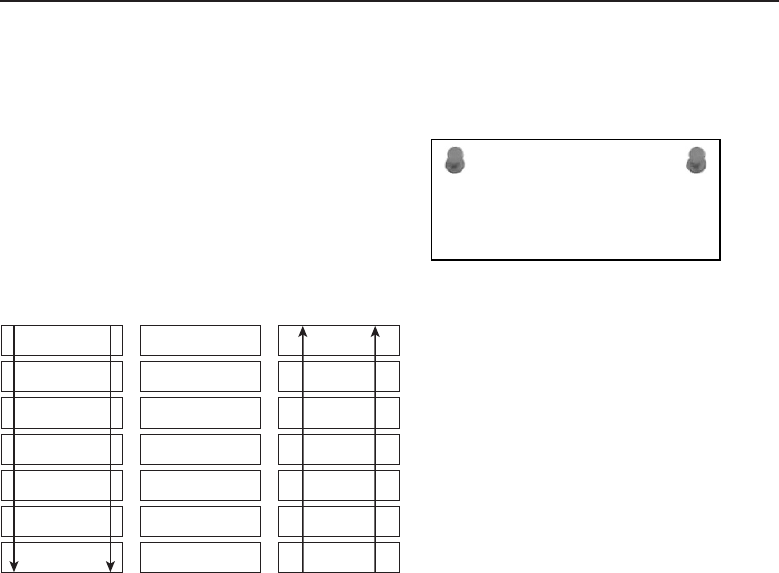
Edwards c01.tex V3 - 03/27/2009 10:41am Page 47
Chapter 1 ■Introduction to Networking 47
becomes
Please–Do–Not–Throw–Sausage–Pizza–Away60
ACRONYM ALERT
OSPF — Open Shortest Path First
Figure 1-13 has an example of these two
mnemonic devices, set next to the layers
in the OSI model. Many other mnemonic
devices have been made up for the pur-
poses of memorizing the layers, and you’re
certainly welcome to create your own. Hey,
if it works, don’t knock it!
All
People
Seem
To
Need
Data
Processing
Away
Pizza
Sausage
Throw
Not
Do
Please
Application
Presentation
Session
Transport
Network
Data Link
Physical
Figure 1-13 Using a mnemonic device as a memory aid
1.4.2 A Layered Approach
The OSI reference model is a systematic approach to outlining the services
of protocols that define network architecture. Each layer within the model
works with the layers above and/or below them to serve a data transmission
purpose. In most networks, the theory of the OSI model may not represent the
entire network, and that is why it is a reference model, not a required set of
rules.
The OSI reference model breaks down the services within a network into
seven layers. Each layer represents protocols that perform a certain purpose
or method for allowing data communication within the network. Data is
transmitted from a user on the network to another user. It is an application
that begins and ends the network connection process. As shown in Figure 1-14,
60Jim actually once interviewed an individual who when asked to name the layers of the OSI
model actually said, ‘‘Please do not throw sausage pizza away’’ out loud to remember the layer
names. His intention wasn’t to say it out loud, but he did. He also ended up getting the job.
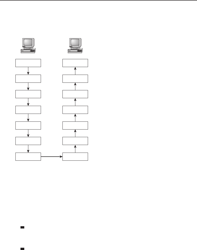
Edwards c01.tex V3 - 03/27/2009 10:41am Page 48
48 Part I ■Networking Nuts and Bolts
data flows from Layer 7 to Layer 1, is transmitted to the destination, where
it travels up the layers to the end user. So what exactly is going on in these
layers? Let’s talk about that for a while.
Application
Presentation
Session
Transport
Network
Data Link
Physical
Application
Presentation
Session
Transport
Network
Data Link
Physical
Computer Computer
Figure 1-14 A complete, end-to-end network connection
1.4.2.1 Layer 7 — The Application Layer
The name application might confuse you at first. The Application layer contains
the operating systems that enable application programs to interface with the
network. This layer serves application processes that the network uses, but not
the applications that interface with the user. Let’s look at a couple of examples.
Example 1: Sending an e-mail — The Application layer defines
the protocols used in an e-mail transmission, but not the interface
that the end user has to initiate in order to send the e-mail.
Example 2: Initiating an FTP session — The Application layer defines
the protocol used for a file transfer, but the end user has to initiate
an interface with an FTP application to perform the file transfer.
Keep in mind that the OSI reference model is for the architecture of networks
and network nodes. Therefore, the Presentation layer does not define end users
and the interfaces they have with a PC (and the applications running on the

Edwards c01.tex V3 - 03/27/2009 10:41am Page 49
Chapter 1 ■Introduction to Networking 49
PC). Not only does the Application layer serve the applications process, it also
sends service requests to the Presentation layer. Examples of some common,
and a few uncommon, Application layer protocols and services include:
Association Control Service Element (ACSE)
Common Management Information Protocol (CMIP)
Common Management Information Service (CMIS)
CMIP over TCP/IP (CMOT)
Dynamic Host Configuration Protocol (DHCP)
File Transfer Access and Management (FTAM)
File Transfer Protocol (FTP)
Hypertext Transfer Protocol (HTTP)
Internet Relay Chat (IRC)
Network File System (NFS)
Post Office Protocol 3 (POP3)
Remote Operation Service Element (ROSE)
Reliable Transfer Service Element (RTSE)
Simple Mail Transfer Protocol (SMTP)
Simple Network Management Protocol (SNMP)
Telecommunications Network (Telnet)
VirtualTerminalProtocol(VSP)
X.400 –Message Handling Service Protocols
X.500 –Directory Access Service Protocol (DAP)
1.4.2.2 Layer 6 — The Presentation Layer
The Presentation layer responds to service requests from the Application layer,
and sends service requests to the Session layer. The Presentation layer also is
responsible for accepting data from the lower layers and then presenting the
data to the Application layer, and, ultimately, to the destination. The following
functions operate at the Presentation layer:
Encryption services
Decryption services
Data compression services
Data decompression services
Translation services

Edwards c01.tex V3 - 03/27/2009 10:41am Page 50
50 Part I ■Networking Nuts and Bolts
The Presentation layer takes care of translating data from lower layers so the
data is understood at the Application layer. This saves the Application layer
the headache of having to translate the data itself. The translation also occurs
at the Presentation layer when data is being passed down the stack from the
Application layer. Note that the Presentation layer is not always needed61 and
that the Application layer may actually work with the Session layer and keep
the Presentation layer out of the loop. Here are some examples of the data
formats that are defined at the Presentation layer:
American Standard Code for Information Interchange (ASCII)
Binary
Extended Binary Coded Decimal Interchange Code (EBCDIC)
Joint Photographic Experts Group (JPEG)
Musical Instrument Digital Interface (MIDI)
1.4.2.3 Layer 5 — The Session Layer
The Session layer is responsible for setting up communication between nodes.
The Session layer responds to service requests from the Presentation layer62 as
well as sending service requests to the Transport layer. The Session layer may
also provide access control services, authentication, data synchronization, and
other services.
The Session layer establishes a communication session, manages the session,
and then terminates the session between endpoints. The Session layer is able to
gather data streams that are coming from multiple originators and can ensure
that the data is synchronized correctly for the destination.63
Here are some examples of the data formats defined at the Session layer:
Network Basic Input/Output System (NetBIOS)
Network File System (NFS)
Secure Shell (SSH)
Structured Query Language (SQL)
1.4.2.4 Layer 4 — The Transport Layer
The Transport layer takes care of getting data from endpoint to endpoint. As
long as there is an open communications path, the Transport layer can do its
job. The Transport layer receives requests from the Session layer and sends
61This is due to the fact that encryption/decryption and compression/decompression are not
always used.
62As mentioned previously, the session layer can also respond to the application layer if the
presentation layer is not necessary for a session.
63Imagine how much fun we would all have if the destination had to just figure it out on its own.

Edwards c01.tex V3 - 03/27/2009 10:41am Page 51
Chapter 1 ■Introduction to Networking 51
requests on to the Network layer. The Transport layer ensures end-to-end
delivery of data, allowing communication to occur between various endpoint
nodes within a network.
The Transport layer utilizes various standards to ensure that data arrives in
the right order and that its integrity is maintained. To do this, several functions
occur at the Transport layer, including:
Ensuring that a connection is established
Disassembling and then reassembling large data streams
Flow control
Error recovery
Data sequencing
The Transport layer is similar to a delivery service, such as the U.S. Postal
Service, UPS, or Fed-Ex. They sort, separate, and distribute packages, and have
different priorities and classifications. Without caring what is in the package,
they get the package where it is supposed to go.64
Some examples of Transport layer protocols include:
AppleTalk Transaction Protocol (ATP)
Transmission Control Protocol (TCP)
User Datagram Protocol (UDP)
Sequenced Packet Exchange (SPX)
1.4.2.5 Layer 3 — The Network Layer
The Network layer is responsible for exchanging data between nodes across
several data paths. The Network layer uses nodes called routers to route
packets from endpoint to endpoint. The Network layer allows the packet to
pass through various network topologies, choosing from multiple paths until
it reaches its destination.
The Network layer is able to transfer variable amounts of data between
endpoints over one or more networks. The Network layer breaks data into
smaller packets and then reassembles the data once it arrives at its destination.
The Network layer is also responsible for identifying when an error in data
transmission occurs.
IP is the most well-known and widely used Network layer protocol. Remem-
ber, IP is connectionless and is not required to regulate and ensure reliable
data delivery. It does, however, identify errors in transmission, ensuring that
bad packets are dropped. Also, it is IP that fragments data into packets that
the next node on the network can support.
64Hopefully in the condition it is expected to arrive in.

Edwards c01.tex V3 - 03/27/2009 10:41am Page 52
52 Part I ■Networking Nuts and Bolts
Some examples of Network layer protocols include:
Internet Protocol (IP)
Internetwork Packet Exchange protocol (IPX)
Routing Information Protocol (RIP)
Internet Control Message Protocol (ICMP)
Address Resolution Protocol (ARP)
Reverse Address Resolution Protocol (RARP)
Open Shortest Path First (OSPF)
Internet Group Management Protocol (IGMP)
1.4.2.6 Layer 2 — The Data Link Layer
For the most part, LAN communication is handled at the Data Link layer and
the Physical layer. At the Data Link layer, network nodes known as switches
or bridges pass frames between nodes in the LAN. Data communication at the
Data Link layer can be between two nodes (point-to-point) or between a single
endpoint node to many endpoint nodes (point-to-multipoint).
RANDOM BONUS DEFINITION
multiplexing — The act of combining
multiple data streams into a single signal
and then transmitting the data over a
shared medium. Also known as muxing.
The Data Link layer ensures
data delivery between nodes,
using the physical addresses
of the nodes. It is important
that considerations are made
for the physical topology of the
network segment for the data
link traffic. The Data Link layer
provides for data flow control,
which is used to prevent a node
from receiving more data than it can handle at any particular time. The Data
Link layer also provides for error notification to the upper layers when a data
transmission error occurs.
Some examples of Data Link layer protocols include:
High-level Data Link Control (HDLC)
Serial Line Internet Protocol (SLIP)
Point-to-Point Protocol (PPP)
The IEEE divides the Data Link layer into two sublayers: the Logical Link
Control (LLC) sublayer and the Media Access Control (MAC) sublayer. The
LLC sublayer is referred to as the upper sublayer of the Data Link layer, whereas
the MAC sublayer is the lower sublayer. The LLC sublayer multiplexes and

Edwards c01.tex V3 - 03/27/2009 10:41am Page 53
Chapter 1 ■Introduction to Networking 53
demultiplexes data transmitted over the MAC sublayer. The IEEE standard
that encompasses the LLC sublayer is IEEE 802.2. The MAC sublayer acts as an
interface between the LLC sublayer and the Physical layer. The MAC sublayer
makes it possible for network nodes to communication within a multipoint
network (such as a LAN or a MAN), by providing address and access control
services.
1.4.2.7 Layer 1 — The Physical Layer
The Physical layer serves the Data Link layer. The Physical layer provides a
way for the data to be transmitted in a network. Data is converted into a signal
which is passed to an endpoint over a physical connection. The Physical layer
is responsible for the procedures, mechanics, and the electricity required for
operating.
Examples of network nodes that are Physical layer nodes include network
adaptors (NIC cards), network hubs, and modems.
1.5 TCP/IP, Please (and Don’t Be Stingy
with the IP)
TCP/IP is the main protocol used by the Internet and most other network
types. If you are a node that connects directly to the Internet, then you will use
the TCP/IP protocol to communicate with other nodes. Earlier you learned
that TCP and IP are two separate protocols that work with one another.
TCP handles breaking down data into small packages, known as packets,and
then puts the data back together when the data arrives at its destination. IP
knows how to get the data there. In this section, we introduce TCP/IP. In
Chapter 2, ‘‘The TCP/IP Protocol Suite,’’ we will discuss it more in depth.
This introduction is required, however, because you will need to have a basic
understanding for some of the material covered in Chapters 2 through 4.
POP QUIZ
What is ARPANET? (Note: If you don’t
know the answer to this one, go back and
reread Section 1.2. The next paragraph is
where that information starts to come in
handy.)
A network is simply nodes
that are connected to one
another to pass data. For data
to arrive intact and at the right
destination, you must have the
protocols that can make sure this
happens. This combination of
protocols is the TCP/IP proto-
col suite. TCP/IP was brought
about to standardize communi-
cations protocols, as there were
a lot of proprietary protocols when networking was in its infancy.

Edwards c01.tex V3 - 03/27/2009 10:41am Page 54
54 Part I ■Networking Nuts and Bolts
POP QUIZ
Name the four IMPs that made up the
original ARPANET.
If you are reading this, that
means you remember what
ARPANET was. This is impor-
tant, because you probably
remember when those super-
computers from different geo-
graphical areas first talked to
each other. Well, the ARPANET protocols that made that happen are what is
now known as TCP/IP. The name TCP/IP somewhat implies that these two
protocols are what makes TCP/IP what it is. Actually, TCP/IP is a collection of
several protocols that work with one another to accomplish data transmission.
TCP/IP has its own reference model (see Section 1.5.3) that basically follows
the OSI reference model. The protocols that make up TCP/IP use the TCP/IP
reference model to map out where they are to function.
Over the years, other protocols have been used to provide upper-layer
functionality to transmit data. There are still a few of these out there, but most
people support and utilize the TCP/IP protocol. Why use TCP/IP? The answer
is simple: because everyone uses TCP/IP. Besides the fact that everyone uses
it in some fashion or another, there are several other reasons why TCP/IP has
grown into the ‘‘method of choice.’’ Some of these are:
Routing —TCP/IPwasdesignedtoroutedatafromnodetonodeof
networks of variable sizes and complexities. TCP/IP is not worried
about the status of nodes in the network; it is concerned about the
networks that it should know about. Various protocols within the
TCP/IP protocol suite manage data flow between networks.
Addressing — And guess what is built into TCP/IP? That’s right, IP.
IP provides a way for a node to identify other nodes within a network
and deliver data to any endpoint node it has been made aware of.
Name resolution — TCP/IP provides a way to map an IP address
(10.10.10.10) to an actual name (networkz.org). Can you imagine
how tough it would be to remember the IP addresses of all the
websites you needed to know about? Name resolution really helps.
Doesn’t discount the lower layers —AlthoughTCP/IPoperates
at the upper layers (Layer 3 and above), it does have the ability to
operate at the lower levels as well. This means that for most LANs and
WLANs, and some MANs and WANs, TCP/IP is able to work with
multiple networks of these types and connect them to each other.
Open standards — TCP/IP was mainstreamed to enable different
nodes to communicate with one another. The open standards that
TCP/IP contains are available to anyone. These standards are
determined through the RFC process discussed in Section 1.3.9.

Edwards c01.tex V3 - 03/27/2009 10:41am Page 55
Chapter 1 ■Introduction to Networking 55
Talking endpoint to endpoint —TCP/IPprovidesawayfor
one endpoint to speak directly with another endpoint, regardless
of any nodes that are in between. It is as if the endpoints were
directly connected to one another, even when they are not phys-
ically connected to the same local network. Thanks to TCP/IP,
both the originating and the destination nodes can exchange
connection acknowledgements directly with one another.
Application support — TCP/IP provides protocols that provide a com-
monality among end user applications. Often when an application that
utilizes TCP/IP is developed, many of the functions required for the
application are already common with any node supporting TCP/IP.
There are some basic Network layer services provided by any network.
All user applications that utilize TCP/IP rely on these standard services to
assist in data transport. The first of these standards is that TCP/IP supports
connectionless datagram delivery. The TCP/IP network is able to route data
from node to node based on the address of the source and destination nodes,
but is not concerned about the order in which the data is sent. Having
connectionless datagram delivery gives TCP/IP the flexibility to support a
wide range of hardware through the network. The other basic service that is
used by TCP/IP applications is a reliable transport service. Endpoints establish
a connection prior to exchanging data. This allows a temporary connection
to appear, from a user’s perspective, as a direct connection. The connection
remains while the endpoints exchange data (regardless of the amount of data
that is transported).
1.5.1 TCP/IP Applications
End users are able to navigate networks by using applications based on the
TCP/IP protocol suite. They are able to do so without having any under-
standing of exactly what it takes to get information shared with destination
nodes. The only details the average user needs to know is how the actual
interface works. Users rely on the software and technology to get the data to
an endpoint.
Numerous TCP/IP-based applications are in deployment within networks
worldwide. The following list contains some of the more popular applications
that are widely used today:
Electronic mail (e-mail)
File transfer
IP address allocation
Remote login
Web browser

Edwards c01.tex V3 - 03/27/2009 10:41am Page 56
56 Part I ■Networking Nuts and Bolts
1.5.2 TCP/IP Utilities
In addition to application support, TCP/IP also provides some helpful utilities
that are available in any node that supports TCP/IP. These utilities provide a
variety of information that can be used to help maintain the network. These
utilities will be discussed in detail throughout the book. It is important to
be aware of these, and no good networking introduction would be complete
without a summary of the utilities and the purpose they serve. There are three
main categories of TCP/IP utilities:
Diagnostic utilities — These utilities assist in troubleshooting issues
within the network.
General purpose utilities — These utilities are used to connect
to other TCP/IP nodes to perform a specific action, to exchange
data, or to allow remote management and related services.
Services utilities — These utilities are software applications
that are offered by a TCP/IP-based server to TCP/IP clients.
Table 1-1 contains a list of some commonly used TCP/IP utilities.
Table 1-1 TCP/IP utilities
DIAGNOSTIC UTILITIES GENERAL PURPOSE SERVICES
UTILITIES UTILITIES
Address Resolution Protocol
(ARP)
File Transfer Protocol
(FTP)
TCP/IP print server
IPConfig Line Printer Daemon
(LPD)
Web server
Line Printer Daemon (LPD) Remote Copy Protocol
(RCP)
File Transfer Protocol
server
netstat Remote Shell (RSH) E-mail server
nslookup Telnet
ping Trivial File Transfer
Protocol (TFTP)
route
tracert (Windows)
Traceroute (other operating
systems, such as Linux, Unix,
and others)
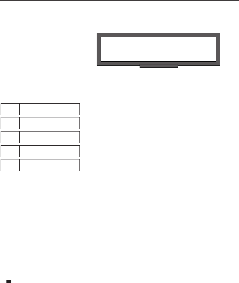
Edwards c01.tex V3 - 03/27/2009 10:41am Page 57
Chapter 1 ■Introduction to Networking 57
1.5.3 The TCP/IP Reference Model
POP QUIZ
What is the Post Office Protocol?
The TCP/IP reference model,
the specification established by
DARPA65 to set the rules for
ARPANET (and now maintain-
ed by the IETF), was developed
long before the OSI reference
model. Rather than the seven-layer OSI reference model, the TCP/IP reference
model has only five66 layers, as shown in Figure 1-15.
Layer 5 Application
Layer 4 Transport
Layer 3 Network
Layer 2 Data Link
Layer 1 Physical
Figure 1-15 The TCP/IP reference model
An important thing to note is that the TCP/IP reference model, although
represented in layers, does not really operate in a layered manner as the OSI
reference model does. There is not a lot of agreement where the layers really
fall, though you will often hear about the upper and lower layers in the TCP/IP
reference model. The main point is that regardless of whether you follow the
OSI reference model or the TCP/IP reference model, the functionality of the
network is, for the most part, the same.
As mentioned previously, Chapter 2 discusses the TCP/IP reference model
in depth. For the purposes of this introductory chapter, it is important to have
only an introduction to the model. The TCP/IP reference model layers are:
Application layer (Layer 5) — The Application layer in the
TCP/IP reference model assumes most of the functions per-
formed by the Session and Presentation layers of the OSI reference
model. All upper-layer protocols are handled at this layer.
65At least we think it was DARPA ... or was it ARPA? Okay, enough funning around — it was
DARPA at the time.
66A lot of people don’t consider the physical layer to be part of the TCP/IP reference model. For
the purposes of this book, we have decided to include the physical layer. We don’t want you to
be confused in the future when someone mentions the four-layer TCP/IP model.

Edwards c01.tex V3 - 03/27/2009 10:41am Page 58
58 Part I ■Networking Nuts and Bolts
Transport layer (Layer 4) — The Transport layer functions the same
in both reference models. The two major protocols that operate
at this layer are TCP and UDP. TCP is a connection-oriented pro-
tocol and therefore provides reliable delivery. UDP, on the other
hand, is connectionless and provides unreliable data delivery.
Network layer or Internet layer (Layer 3) —Thislayerperformsthe
same functions as Layer 3 of the OSI reference model. The network layer
is responsible for routing a packet from a source to a destination. It can
do this within a LAN as well as over multiple LANs, MANs, and WANs.
Data Link layer (Layer 2) — This layer is often combined with
the Physical layer and is referred to as the host to Network layer.
The TCP/IP reference model largely ignores these lower layers.
All it cares about it that there is a connection to pass data on.
Physical layer (Layer 1) — This layer is often combined with the Data
Link layer and is largely ignored as well, although it does provide the
connections to get data passed to a destination. Make no mistake, how-
ever: If the Physical layer isn’t working, you will miss it real quick. It’s
like that old saying, ‘‘You don’t know what you’ve got until it’s gone.’’
1.6 Chapter Exercises
1. The network used exclusively by the University of Texas is an example
of a area network.
2. What are the names of the layers in the OSI reference model?
Layer 7
Layer 6
Layer 5
Layer 4
Layer 3
Layer 2
Layer 1
3. List at least five applications and/or utilities that use TCP/IP.

Edwards c01.tex V3 - 03/27/2009 10:41am Page 59
Chapter 1 ■Introduction to Networking 59
4. What are the two types of network relationships?
5. Explain the difference between a client/server network relationship
and a client/server database system.
6. What is the 1822 protocol?
7. What are the three types of standards? Do a search on the Internet
to see if you can find at least one of each standard type.
8. The 802.11n standard supports an operating frequency of
and . The maximum data rate for
802.11n is . 802.11n reaches a maximum indoor
range of 7 and an outdoor range of 250 meters.
9. T or F: The application layer of the OSI model concerns itself
with the application/user interface on a PC.
10. In this chapter, we listed seven reasons why TCP/IP has grown
to be the method of choice. What are these seven reasons?

Edwards c01.tex V3 - 03/27/2009 10:41am Page 60
60 Part I ■Networking Nuts and Bolts
1.7 Pop Quiz Answers
1. What is a public key certificate?
Public key certificates are electronic documents that can verify and
authorize an individual by public key cryptography. In public key
cryptography, two keys (one public key and one private key) are used
to encrypt and then decrypt data to ensure that a message can be trans-
ported securely.
2. Encapsulated data that is transmitted and received at the network layer
is called a packet.
3. What is the difference between a physical port and a TCP port?
Aphysical port is an interface that resides on a network node. A TCP/IP
port is a number that is in the data packet header that maps to a process
running on a node.
4. Because IP does not establish a connection before sending data to
an endpoint, it would be considered a connectionless protocol.
5. What is the difference between a WAN and a LAN?
The main difference between a LAN and a WAN is the size of
the geographical area that is covered. A LAN covers a small
geographical area whereas a WAN covers a large geographical area.
6. The three types of standards are called a de facto standard, a proprietary
standard, and an open standard.
7. What is ARPANET?
ARPANET stands for the Advanced Research Projects Agency Network
and was the first packet-switching network ever. The Internet was devel-
oped from the ARPANET.
8. Name the four IMPs that made up the original ARPANET.
Stanford Research Institute
University of California, Los Angeles

Edwards c01.tex V3 - 03/27/2009 10:41am Page 61
Chapter 1 ■Introduction to Networking 61
University of California, Santa Barbara
University of Utah
9. What is the Post Office Protocol?
Post Office Protocol (POP) is a protocol that allows an e-mail client to
connect to an e-mail server and retrieve mail that is destined for that
client.
Edwards c01.tex V3 - 03/27/2009 10:41am Page 62

Edwards c02.tex V3 - 03/27/2009 11:58am Page 63
CHAPTER
2
LANs, MANs, and WANs
This is my LAN; that is your LAN; we are joined at the MAN, but I am also connected
toaWAN... from sea to shining sea.
— The authors
Digital data communications has changed rapidly and continues to evolve due
to the demand of many types of ‘‘data consumers.’’ High-speed data commu-
nications is no longer the preferred network of only large companies; everyday
consumers use these networks for various forms of communication — voice,
text, video, and teleconferencing. The past decade has seen a convergence of a
wide range of services utilizing the public network simply referred to as the
Internet.
The term Internet covers a wide range of network devices and services offered
by a wide range of companies commonly referred to as the telecommunications
industry. This chapter discusses local area networks (LANs), metropolitan
area networks (MANs), and wide area networks (WANs). The topics will
be discussed in this order, but it is not meant to imply that this was the
evolutionary process in networking technology. In reality, it is perhaps more
like WANs, LANs, and then MANs. However, there have been areas of overlap
where the evolution of all three occurred simultaneously.
The quote above is trying to give a sense of the relationship between LAN,
MAN, and WAN. Some LAN networks are a personal thing, like my LAN
at home. It is mine, all mine, and not to be shared with others.1Strategically
speaking, a LAN is owned by a person or small group, but it is fairly local
1Rich gets a little over-possessive at times. He is a giving soul and does go out of his way to share
with others, but his LAN is his LAN.
63

Edwards c02.tex V3 - 03/27/2009 11:58am Page 64
64 Part I ■Networking Nuts and Bolts
geographically no matter how many network nodes it may have. MANs may
comprise many LAN networks spread about a geographical region whereas
WANs can be global. However, the purpose of the MAN or WAN is so that
users on LANs, no matter where they may be located geographically, can
communicate with each other in the sharing of data and network resources.
2.1 Local Area Networks
A LAN may consist of computers, printers, storage devices, and other shared
devices or services available to a group of users within a ‘‘local’’ geographical
ACRONYM ALERT
PAN — Personal area network
area. These devices are interconnected
either via copper wire, optical wire (fiber),
or wireless media. Information passing over
the LAN is controlled by a set of network
protocols that allows for the orderly sharing
of data between applications and devices,
even though these may come from many
different companies and manufacturers.
2.1.1 LAN Standards
As discussed in Chapter 1, the IEEE recognized that standards had to be
developed in order for LAN devices from differing manufacturers to be able
to communicate with one another. The IEEE 802 Overview and Architecture
standard heading described how these devices are to be interconnected on
both LANs and MANs.
For the purposes of this chapter, the standards that will be primarily
discussed as far as LAN networks go are:
802.2 Logical Link Control
802.3 CSMA/CD Access Method and Physical Layer Specifications
802.5 Token Ring Access Method and Physical Layer Specifications
2.1.1.1 802.2 Logical Link Control
The lower two layers of the Open Systems Interconnection (OSI) reference
model, Data Link and Physical, are addressed within the IEEE 802.2 stan-
dard. It further divides the Data Link layer into two sublayers, Logical Link
Control (LLC) and Media Access Control (MAC). This allows for ease in
mapping between different LAN Physical layers throughout the 802 family of
LAN/MAN standards.
Edwards c02.tex V3 - 03/27/2009 11:58am Page 65
Chapter 2 ■LANs, MANs, and WANs 65
RANDOM BONUS DEFINITION
hop count — A measure of the number of
routers that a packet has passed through.
The 802.2 implementation
uses a strategy of having the
LLC sublayer as a common
interface between the upper lay-
ers and the Physical layer no
matter what type of media is
being used in the construction
of the LAN. Figure 2-1 shows the LLC structure.
Destination Service Access
Point
DSAP
8 bits
Source Service Access
Point
SSAP
8 bits
Control
8 to 16 bits
Data
Variable Length
Figure 2-1 The IEEE 802.2 LLC structure
Destination service access point — The type of service that is
to receive the packet based on assigned SAP numbers, which
are independent from the type of network being used.
Source service access point — The type of service sending the packet
based on assigned SAP numbers, which are independent from the net-
work type being used.
Control — Used for flow control and contains the send and receive
sequence numbers ensuring packets are being received in the proper
sequence.
Data — A variable length field containing the information being carried
within the packet.
The Media Access Control sublayer provides addressing and channel con-
trol. The MAC address, considered the physical address of the device, is a
unique value that allows multiple devices to share the same LAN no matter
what the physical medium being used for its implementation. Examples of
shared medium networks are those utilizing bus, ring, or wireless topologies.
Figure 2-2 illustrates the format of the 48-bit MAC address.
As illustrated, the address is split into two sections. The most significant
three octets make up the portion of the address that is referred to as the
organizationally unique identifier (OUI). These identify the organization that
issued the identifier. The NIC specific portion of the address assigned and
the serialization of the assigned numbers are under the control of the organi-
zation that owns the assigned OUI. With 24 bits of address, an organization
can assign 16,777,216 unique addresses to devices they have manufactured.
Assigned OUI addresses are maintained by the IEEE and can be found at
http://standards.ieee.org/regauth/oui/oui.txt.
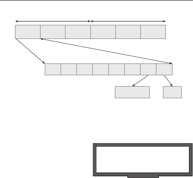
Edwards c02.tex V3 - 03/27/2009 11:58am Page 66
66 Part I ■Networking Nuts and Bolts
Octet 1 Octet 2 Octet 3 Octet 4 Octet 5 Octet 6
Bit 1 Bit 2 Bit 3 Bit 4 Bit 5 Bit 6 Bit 7 Bit 8
0: OUI unique address
1: locally assigned address
0: unicast
1: multicast
Organizationally Unique Identifier
(OUI)
Network Interface Controller
(NIC) specific
Figure 2-2 The IEEE 802 MAC address format
Bit B8 determines if the packet is either a unicast addressed packet, meaning
it is directed to a single network node address, or broadcast, which is directed
to all network nodes within a subnet.
POP QUIZ
What are the two sublayers of the Data Link
layer?
MAC addresses are usually
written with either hyphens
or colons separating the hexa-
decimal numbers representing
each of the octets. A MAC
address annotated with the
use of hyphens would look
like 00-04-54-AA-B1-C2. If using
colons, it would be presented as 00:04:54:AA:B1:C2.
There is provision for network administrators to locally assign MAC
addresses to network interface controllers. If the NIC has been manufactured
to allow modification of the factory-assigned MAC address, the administrator
can set the bit to indicate that the MAC address has been locally assigned.
The NIC portion of the address can be a number for the interface that is of
administrator’s choosing. Locally assigned addresses do not contain values
representative of assigned OUI values. An example of a typical locally assigned
MAC address would be:
02-00-00-01-00--F4
2.1.1.2 802.3 CSMA/CD Access Method and Physical Layer
The IEEE 802.3 standard contains a group of standards that addresses the
unique characteristics of the network Physical layer being used on the network.
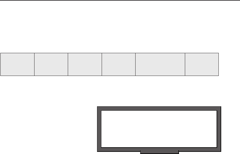
Edwards c02.tex V3 - 03/27/2009 11:58am Page 67
Chapter 2 ■LANs, MANs, and WANs 67
These standards were evolutionary and were issued as new types of media
with differing characteristics were developed.
This standard defined the MAC structure for CSMA/CD,2as shown in
Figure 2-3.
Start Frame
Delimiter
Destination
Address
Source
Address Length 802.2 LLC Structure Frame Check
Sequence
Figure 2-3 The CSMA/CD MAC structure
RANDOM BONUS DEFINITION
multicast address — A method of
identifying a set of one or more stations as
the destination for transmitted data.
When first introduced, IEEE
802.3 dealt with the use of
data networking on a bus
type network architecture using
thick coax cable. This coax
cablecarriedthedesignationof
10BASE5 and was more com-
monly referred to as thicknet.
This type of cabling was rigid
and difficult to work with. It required a transceiver that would tap3the cable
to form a node on the network. A cable constructed with a 15-pin D style
connector was needed to connect the transceiver to the device residing on a
node of the network.
To circumvent the difficulties with 10BASE5 cabling, a new standard was
developed, IEEE 802.3a, which still is bus network architecture but utilized
thin coax, commonly referred to as thinnet.4The cable used was referred to
as 10BASE2, with RG-58 coax cable being the popular choice. RG-58 cable
being thinner offered more flexibility over the RG-8 cable that was used in a
10BASE5 network. The network was formed by using lengths of RG-58 cable
terminated with a BNC connector on each end. A BNC T connector formed the
network node at the back of each workstation. The network was terminated
on each end with a 50 ohm terminator. Figure 2-4 illustrates a simple 10BASE2
network with three workstations connected to the network using a BNC T
connector to connect to the network interface card.
2Carrier Sense Multiple Access with Collision Detection is necessary in a bus architecture where
any workstation may transmit randomly at any given time. The bus segment these workstations
reside on is sometimes referred to as a collision domain.
3This type of tap was also referred to as a vampire tap since it had a pointed probe that pierced
the protective layer of the cable insulation to strike the ‘‘vein’’ at its core, which was the center
copper conductor. The bits would be allowed to flow like the life’s blood of the network was
being sucked out. OK, getting a little too dramatic with the class B horror movie genre references.
4Thinnet was also referred to as cheapernet since the cost factor was a mere fraction of the cost
of 10BASE5 cabling, being more readily available at many electrical supply houses. There really
is something to that supply and demand theory that I learned in my economics classes.
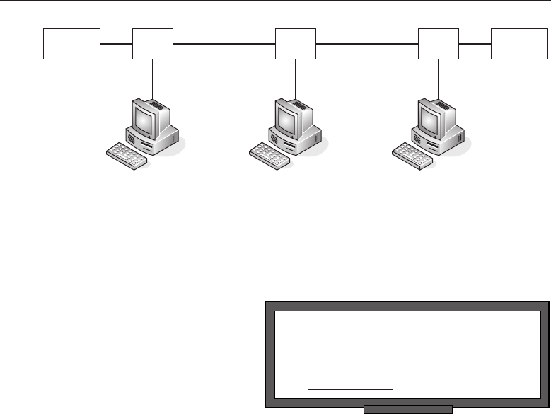
Edwards c02.tex V3 - 03/27/2009 11:58am Page 68
68 Part I ■Networking Nuts and Bolts
50 ohm
terminator
50 ohm
terminator
T
Conn
T
Conn
T
Conn
ACB
Figure 2-4 A simple 10BASE2 network
The BNC T connector on workstation B has a coax cable connected to it going
to workstation A and another going to workstation C. Workstations A and C,
POP QUIZ
MAC addresses are represented with
hexadecimal numbers, separated by a colon
or a .
having only one cable con-
nected to their BNC T con-
nector and being at each end
of the network, require that
theopenconnectiononeach
BNC T connector be terminated
with a 50 ohm BNC terminator.
Although this is an improve-
ment over 10BASE5 cabling, the
one drawback is that workstations not on the end of the network required two
cables to be terminated at the workstation’s BNC T connector.
Bus-based network architectures have inherent problems with cabling
that don’t exist in star-based networks. The development of IEEE 802.3i
(a bus network that allows for wiring to have the appearance that it is
physically a star-based topology while maintaining the CSMA/CD bus
network architecture) provided for network cabling that uses unshielded
twisted pair (UTP) and is commonly referred to as 10BASE-T. This allows
for the use of Category 5 cable, which contained four twisted pairs con-
tained within an unshielded jacket. Each end of the cable is terminated with
an RJ-45 plug for short lengths of cable. Larger installations may termi-
nate at wall jacks for workstation areas and to a patch panel at a central
location. Since these appear to be spokes out to the workstations, the cen-
tral location would require a device to concentrate these network nodes
on a CSMA/CD network. The devices that accomplish this are appropri-
ately called hubs. Figure 2-5 shows a hub and workstations in a CSMA/CD
network.
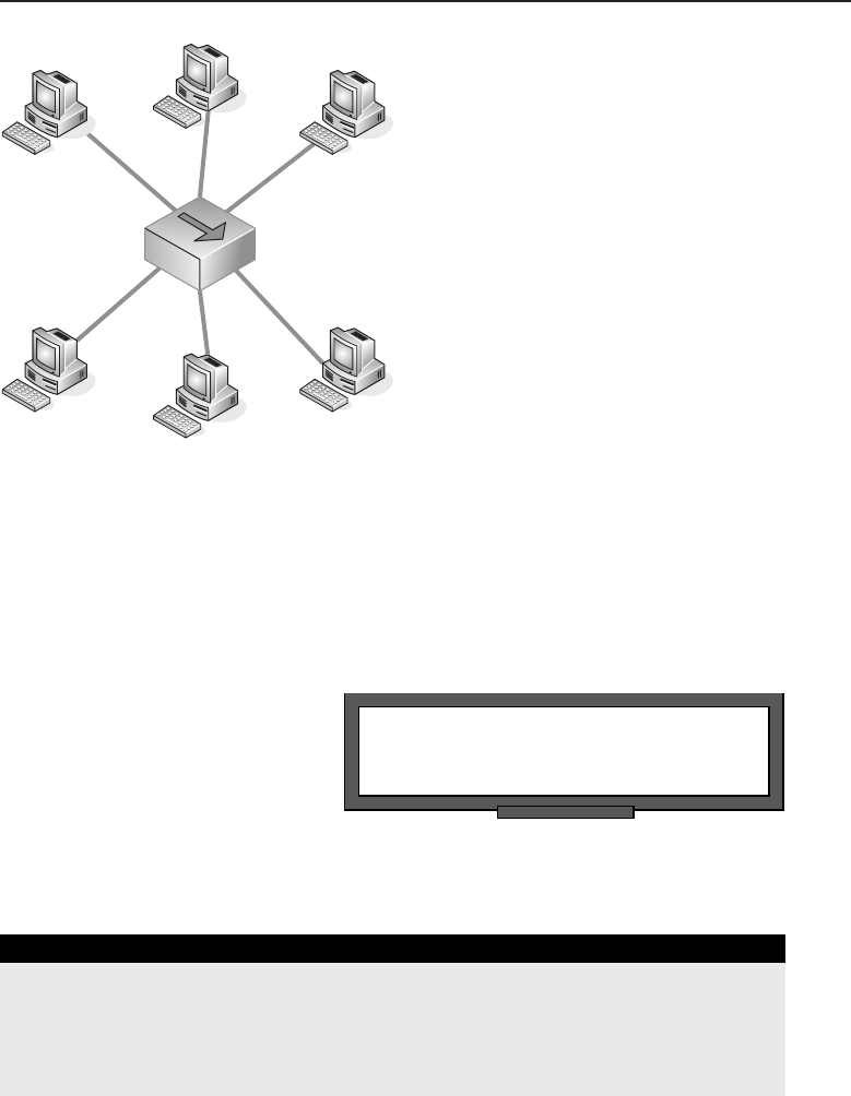
Edwards c02.tex V3 - 03/27/2009 11:58am Page 69
Chapter 2 ■LANs, MANs, and WANs 69
Hub
Figure 2-5 A CSMA/CD network using UTP cabling and a hub
Each workstation can be located at varying lengths from the hub. The
maximum length of cable between a workstation and a hub is 100 meters.5
This topology allows for the easy reconfiguration of the workstation. If a
workstation is removed, there are no special considerations as there are with
a 10BASE2 network topology.
RANDOM BONUS DEFINITION
nibble — A 4-bit unit of data (half of a byte).
The maximum transmission
speed of the IEEE 802.3 net-
works discussed in this section
is 10 Mbps. Subsequent stan-
dards have been added to the
IEEE 802.3 standard that pro-
vide for 100 Mbps Fast Ether-
net and 1Gbits/s over twisted
pair wire.
A QUICK REMEDIAL LESSON
Mega represents a million of something. In decimal number notation, it is
1,000,000. This number can be represented in shorthand notation as 1M.
(continued)
5Meters are a metric measurement of distance. A quick calculation would be there are roughly 3
feet to the meter. Therefore, 100 meters is about 300 feet. But to be more precise, it’s 328.08 feet.

Edwards c02.tex V3 - 03/27/2009 11:58am Page 70
70 Part I ■Networking Nuts and Bolts
A QUICK REMEDIAL LESSON (continued)
Giga represents a billion of something. In decimal number notation, it is
1,000,000,000. This number can be represented in shorthand notation as 1G.
Now, we have millions and billions of bits, but what exactly is a bit, you ask?
It is a single binary number represented by a 1 or a 0. Even if the value is 0, it
still requires a signal on the wire, so this is one place where exactly zero does
truly represent something.
Ten million bits per second (10Mbps) is 10 million binary numbers having a
value of either 0 or 1 being sent over some medium in a one-second interval.
With giga rapidly becoming the new standard in Ethernet transmission speed,
which is the equivalent of a billion bits per second (bps) hitting the wire, data
that is normally referenced in bytes containing 8 bits of data would equate to
125 MBps (125,000,00 bytes per second) as the maximum number of bytes that
can be sent within a second. Note that lowercase ‘‘b’’ signifies bits and that
uppercase ‘‘B’’ signifies bytes in the notation used to reference these
quantities. Make sure you keep your bits and bytes straight because you can be
off by a factor of 8 in your calculations — usually not a problem when you
overestimate but you can really feel some heat if you underestimate a
network’s throughput capability.
2.1.1.3 802.5 Token Ring Access Method and Physical Layer
The IEEE 802.5 standard defines a Token Ring protocol that is much different
from that of a CSMA/CD protocol. With CSMA/CD, multiple workstations
can transmit onto the wire at the same time, potentially causing collisions.
When a collision occurs, they remedy the situation by backing off and retrans-
mitting. With Token Ring, only one workstation is permitted to transmit onto
the wire, that being the workstation currently in possession of the token.
POP QUIZ
What is the maximum length of a cable
between a workstation and a hub?
Transmission onto the wire
is sequential in a fixed pat-
tern. After a workstation pos-
sessing the token has completed
its transmission onto the wire,
it passes the token to the next
workstation. This is an advan-
tage over CSMA/CD when the
network has fewer workstations. As the number of workstations increases, the
advantage is lost and the chattier CSMA/CD finally wins out.
When Token Ring was first introduced by IBM, it possessed a speed of
4 Mbps, thus not offering any advantage over CSMA/CD networks. With the
introduction of 16 Mbps Token Ring, it was a toss-up between it and CSMA/CD

Edwards c02.tex V3 - 03/27/2009 11:58am Page 71
Chapter 2 ■LANs, MANs, and WANs 71
networks far as performance when the total number of workstations is lower.
Figure 2-6 illustrates the IEEE 802.5 frame structure.
Starting Frame
Delimiter
Access
Control
Frame
Control
Destination
Address
Source
Address
802.2 LLC
Structure
Route
Information
Frame Check
Sequence
Ending
Delimiter
Frame
Status
Figure 2-6 The IEEE 802.5 Token Ring frame structure
There are two minor differences between the IBM and IEEE 802.5 standards
for Token Ring:
The number of nodes on a ring is up to 260 nodes per IBM specification,
and the IEEE 802.5 standard limits it to a maximum of 250 nodes.
IBM allows up to 8 fields for route designation when source routing is
employed, whereas the IEEE 802.5 standard allows for a maximum of 14
fields.
The frame format for IBM/IEEE 802.5 is as follows:
The Starting Frame Delimiter and Ending Delimiter fields are
each a single byte with deliberate breaches in certain positions
of the Manchester Code6so that the start or end of a frame can
never be recognized from any other portion of data on the wire.
Access Control is a single-byte field serving to signal control
and maintenance functions. The fourth bit position in this field
is the token bit. If it is set to 1, this frame is a token and only
consists of the Starting Frame Delimiter, Access Control, and
Ending Delimiter. A token frame is only 3 bytes long.
Frame Control is a single-byte field that indicates if the frame is control
information or data.
The Destination Address field contains either 2 or 6 bytes of addressing
information, depending on whether the frame is addressed to a single
node or a group of nodes.
The Source Address field contains either 2 or 6 bytes of addressing
information that indicates the address of the sending node.
The Route Information field is present only when source routing
has been enabled. It defines routing control, a route descriptor,
and type of routing information contained within the packet.
6The Manchester Code is Phase Encoding used within telecommunications where each data bit
has a minimum of one voltage transition within a fixed time slot, making it self clocking since
the clocking signal can be extracted directly from the encoded data stream.
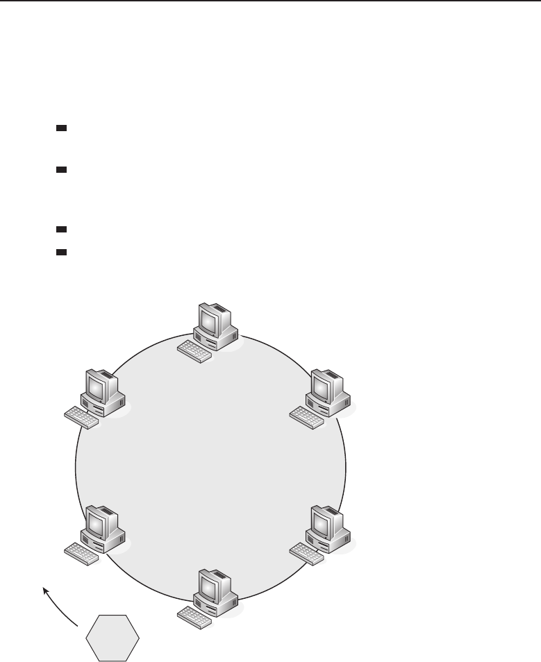
Edwards c02.tex V3 - 03/27/2009 11:58am Page 72
72 Part I ■Networking Nuts and Bolts
With source routing enabled there is a minimum of two fields
that will be present. The 2-byte route designator field defines
a ring number and the bridge number that the frame is to pass
through. The last route designator will contain the ring number
of the receiving node and a bridge number that is set to zero.
802.2 LLC Information Structure is a variable-length field that, surprise,
contains 802.2 LLC information.
Frame Check Sequence is a 4-byte field containing the checksum
information verifying the integrity of the frame starting from
the Frame Control field through the 802.2 LLC/Data field.
Ending Delimiter is an 8-bit field that indicates the end of the frame.
Frame Status is a 1-byte field indicating that the intended recipient has
received the frame.
Token
Figure 2-7 The token-passing sequence
Figure 2-7 is a logical visualization of a Token Ring network. The token is
a frame type that is transmitted sequentially around the ring network. When
a workstation needs to transmit on the ring, it keeps the token and modifies
it with address and data information, and then transmits it onto the ring. The
receiving station the data frame was intended for accepts the frame and sets a

Edwards c02.tex V3 - 03/27/2009 11:58am Page 73
Chapter 2 ■LANs, MANs, and WANs 73
flag in the frame to acknowledge proper receipt of the frame. The receiving sta-
tion then retransmits the frame with the flag set back onto the ring network. On
receipt of the frame with the flag set, the transmitting workstation transmits a
new token frame onto the ring network and forwards it, allowing any of the fol-
lowing sequential workstations an opportunity to transmit onto the network.
In a Token Ring network, one of the workstations becomes the active ring
monitor. Any workstation can be an active monitor, but only one workstation
at a time. It is the role of the active monitor to detect data frames that have
traveled around the ring more than once. Once a frame that traveled around
the ring more than once is detected, the active monitor will remove the frame
from the network and discard it. If the active monitor determines that a token
frame is missing from the ring network, it purges the ring network of any
frames and then transmits a new token onto the ring network. The active
monitor workstation is responsible for the timing and clocking on the ring
network. All workstations on the ring network use the timing from the active
monitor to ensure that the same timing is being used to receive and send data.
A workstation becomes an active monitor by an election process when
the absence of a ring monitor is detected. Upon detection of this message, a
workstation transmits a claim token onto the ring network. Any subsequent
workstation with a higher address that wishes to participate as the active
monitor initiates a new claim token and transmits it onto the ring network.
Through this election process the workstation with the highest address and
participating in the claim token process is elected as the active monitor.
Although Token Ring is a logical ring, its topology appears as a star-based
network. This is accomplished by cabling and connectors designed by IBM.
The cabling consists of IBM type 1 shielded twisted pair (STP) cable and a
unique connector design which is bulky, giving it a distinct space disadvantage
compared to other cable connectors. To complete the ring, these connectors
are plugged into a media access unit (MAU), as illustrated in Figure 2-8.
The cable is constructed with a receive pair and a transmit pair. When the
Token Ring connector is inserted into the MAU,7the receive pair is connected to
the transmit pair of the preceding workstation. The transmit pair is connected
to the receive pair of the following workstation, and the MAU completes
the ring. Multiple MAU units can be combined to form a larger single ring
network, as needed.
2.1.1.4 The Collision Domain Battle
Both IEEE 802.3 and Ethernet are CSMA/CD network standards; however,
the two are not fully compatible with each other. Although both 802.3 and
7MAU (media access unit) allows multiple units connected in a star topology to form a logical
Token Ring. These devices are sometimes referred to as a ‘‘ring in a box.’’
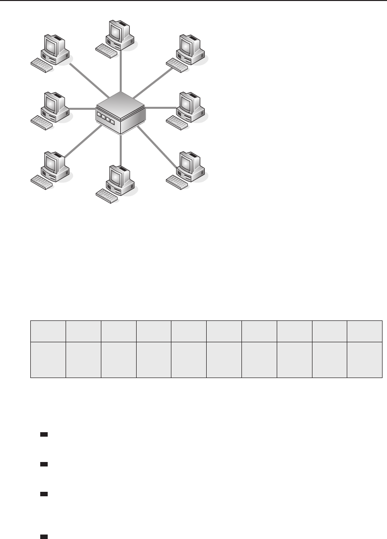
Edwards c02.tex V3 - 03/27/2009 11:58am Page 74
74 Part I ■Networking Nuts and Bolts
MAU
Figure 2-8 A Token Ring network using MAUs
Ethernet devices can coexist within the same LAN network, there are important
differences. The major difference between IEEE 802.3 and Ethernet is the frame
format. For them to coexist in the same LAN, the network software must be
able to differentiate between the different frame types.
Figure 2-9 illustrates the IEEE 802.3 frame.
7 Bytes 1 Byte 6 Bytes 6 Bytes 2 Bytes 1 Byte 1 Byte 1 or 2
Bytes
Variable
Length 4 Bytes
Preamble Start Frame
Delimiter
Destination
Address
Source
Address Length
Destination
Service
Access
Point
Source
Service
Access
Point
Control
Information
(Data and
Padding)
Frame
Check
Sequence
Figure 2-9 The 802.3 frame structure
The IEEE 802.3 frame contains the following fields:
Preamble — A 7-byte binary pattern used to establish frame synchro-
nization.
Start Frame Delimiter — A single byte used to denote the start of a
frame.
Destination Address — The address the frame is being sent to. Al-
though the standard allows this field to be anywhere between 2 to 6
bytes in length, the implementation in common use consists of 6 bytes.
Source Address — This field contains the address of the device sending
the frame. The standard allows this to be anywhere between 2 to 6 bytes
in length, but most implementations use 6 bytes in defining this field.

Edwards c02.tex V3 - 03/27/2009 11:58am Page 75
Chapter 2 ■LANs, MANs, and WANs 75
Length — A 2-byte field used to denote the size of the IEEE 802.2 struc-
ture, including header and data.
Destination Service Access Point — A 1-byte field that indicates which
network protocol the receiving device should use in interpreting the
frame.
Source Service Access Point — A 1-byte field indicating which net-
work protocol was used to create the frame. Normally this field con-
tains the same information as the Destination Service Access Point.
Control — This field may be either 2 or 6 bytes long, where
the length of the field is indicated by the first 2 bits of the field.
It is used for indicating various commands such as exchange
identification, test, connect, disconnect or frame rejection.
An information field containing data and any number of required
padding bytes.
Data — A variable length field that contains the actual
information that is being transmitted within the frame.
Pad Bytes — An optional field that contains no information
but is added to ensure that the frame meets the minimum length
requirement.
Frame Check Sequence — A 4-byte field that contains the checksum of
the fields starting with the Destination Address through the Data field.
Figure 2-10 illustrates the Ethernet frame.
7 Bytes 1 Byte 6 Bytes 6 Bytes 2 Bytes Variable Length 4 Bytes
Preamble Start Frame
Delimiter
Destination
Address
Source
Address Type Information
(Data and Padding)
Frame Check
Sequence
Figure 2-10 The Ethernet frame
The Ethernet Frame contains the following fields:
Preamble — A 7-byte binary pattern used to establish frame synchro-
nization.
Start Frame Delimiter — A single byte used to denote the start of a
frame.
Destination Address — The address the frame is being sent to.
Although the standard allows this field to be anywhere between 2 to 6
bytes in length, the implementation in common use consists of 6 bytes.

Edwards c02.tex V3 - 03/27/2009 11:58am Page 76
76 Part I ■Networking Nuts and Bolts
Source Address — This field contains the address of the device sending
the frame. The standard allows this to be anywhere between 2 to 6 bytes
in length, but most implementations use 6 bytes in defining this field.
Type — This is a 2-byte field that indicates the network protocol or
the protocol service contained within the frame.
Information — This is a variable length field that contains the
actual data being carried by the frame and any number of
bytes of padding to ensure the minimum frame size.
Frame Check Sequence — A 4-byte field that contains the checksum of
the fields starting with the Destination Address through the Data field.
The key difference between the IEEE 802.3 frame and the Ethernet frame is
Ethernet’s Type field. The IEEE 802.3 frame uses the IEEE 802.2 Source Service
Access Point and Destination Service Access Point fields to indicate which
network the frame is coming from and which network it is going to.
A list of registered Ethernet types can be found at http://standards.ieee
.org/regauth/ethertype/eth.txt.
2.1.1.5 The Most Common Wireless Standards
As covered in Chapter 1, the IEEE 802.11 is a group of standards defining
the operation of network communications using radio frequencies. These
ACRONYM ALERT
STE — Spanning tree explorer
standards are loosely interchanged with
the term Wi-Fi, but do have some dif-
ferences with the standards of the Wi-Fi
Alliance. With the proliferation of wireless
network products into the marketplace, the
Wi-Fi Alliance is in the process of certify-
ing these products before amendments to
the 802.11 are completed. Today’s wireless
products are being sold under the following
standards:
802.11 — This is the legacy base standard for wireless networking
802.11a — This standard’s advantage is the use of the less crowded
5 GHz band, but its chief disadvantage is that its signals are more
easily absorbed and dampen the signal quality as the signal travels
through solid objects along its path.
802.11b — Introduced in 1999, this standard uses the 2.4 GHz broadcast
band providing a typical data rate of 4.5 Mbps with a maximum data
rate of 11 Mbps. Its major disadvantage is that it can receive interference
from other devices that also share the 2.4 GHz frequency band such as
microwaves, cordless telephones, and a wide variety of Bluetooth

Edwards c02.tex V3 - 03/27/2009 11:58am Page 77
Chapter 2 ■LANs, MANs, and WANs 77
devices. The substantial increase of data rate throughput and the
reduction of product cost have led to the rapid acceptance of this
standard as the definitive standard for wireless LAN networks.
802.11g — Consumer demand for higher data rate products led to
the introduction of products that supported the older IEEE 802.11a
and b standards as well as this standard, which made these products
capable of supporting all three standards within a single device.
However, an 802.11g standard wireless LAN network can reduce
the overall speed of the network if one device participating in the
wireless network is only capable of supporting the IEEE 802.11b
standard. As with 802.11b, this standard also falls prey to the same
interference from other devices sharing the same frequency band.
802.11-2007 — This is a standard that was released to be all-inclusive
of the amendments to 802.11 since its introduction. To date this is the
most conclusive standard document that defines wireless LAN network
operation.
802.11n — With a proposed release date of 2009, this is an amendment
that will add additional features to the 802.11 standard and will include
multiple input/multiple output (MIMO) technology. MIMO will
use multiple antennas for both transmission and receiving, which
would offer significant increases in range and data rate throughput
without the need for increased bandwidth of transmission power.
Although it is still in draft, many vendors are beginning to sell
products labeled under the 802.11n standard. To avoid any interop-
erability problems between differing vendors, it is recommended to
purchase routers and access points from the same manufacturer.
The standards listed above are not all-inclusive of the IEEE 802.11 standard.
They are the most commonly known and discussed standards when there is
a discussion on wireless LAN networks. Additional information can be found
at the IEEE 802.11 group’s website at http://ieee802.org/11/.
2.1.2 LAN Topologies
Chapter 1 presented a variety of network topologies. In this chapter, we will
attempt to provide further information concerning the implementation and
use of these topologies in the creation of a LAN.
Figure 2-11 illustrates a very basic network map. The purpose is to demon-
strate that even a simple network can and probably will use a variety of media,
protocols, and network devices. The media shown on this network topology
is a combination of wired systems, which include both ring and bus network
topologies, along with a network segment that is connected using wireless
network technology. Users are connected to the network either hard-wired to
a bus or ring LAN segment or through a wireless LAN access point.
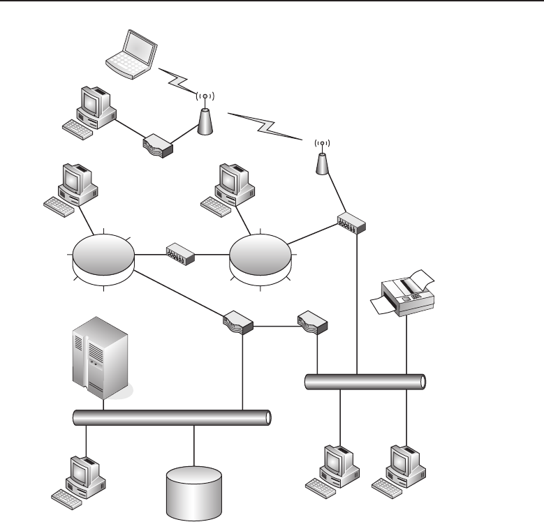
Edwards c02.tex V3 - 03/27/2009 11:58am Page 78
78 Part I ■Networking Nuts and Bolts
Figure 2-11 A sample LAN’s topological map
The network allows for the access of users to network resources such as
mainframe computers, network storage devices, network printers, and other
shared resources connected to the network. The LAN segment illustrated
in this figure has no access to the outside world via the Internet and is
self-contained. Most of today’s LAN networks ultimately do connect to the
Internet and will be discussed further in the ‘‘Metropolitan Area Networks’’
and ‘‘Wide Area Networks’’ sections of this chapter. So the focus of this section
is solely on the LAN. This is the section that deals with ‘‘this is my LAN and
that is your LAN’’ area of networking.
A LAN can contain a single network segment of any media type, or it may be
a collection of two or more of the network media currently in use today. So, if a
LAN is a combination of different media types, how do they interconnect? This
is where devices called gateways, bridges, and routers come into play. They
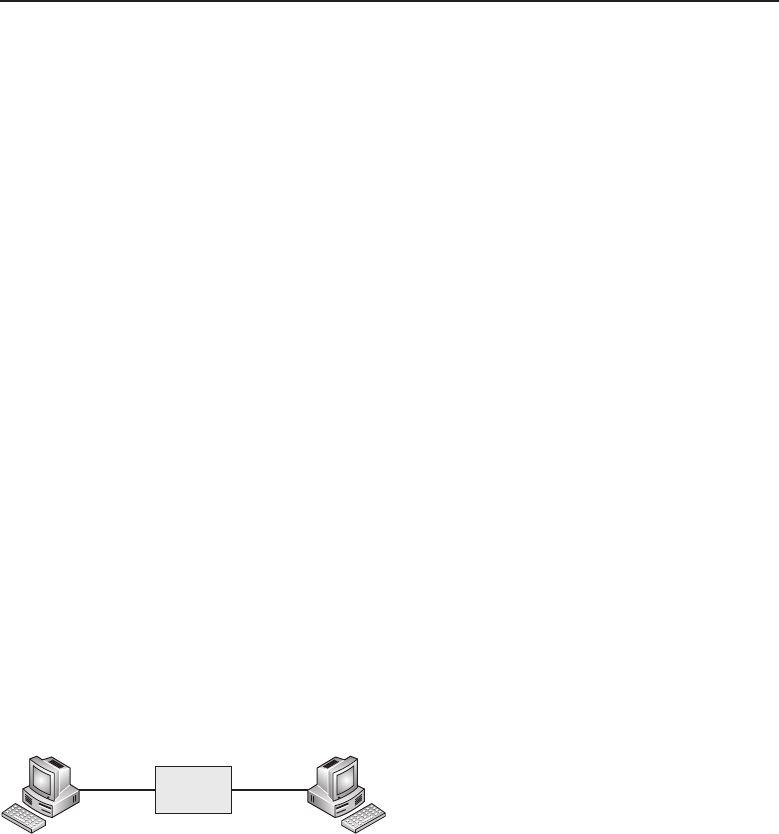
Edwards c02.tex V3 - 03/27/2009 11:58am Page 79
Chapter 2 ■LANs, MANs, and WANs 79
are depicted in Figure 2-11 as boxes between LAN segments. How you plan to
implement your network and the networking address schemes that are to be
used will determine whichtype of these devices would need tobe used for these
network nodes. These devices will be covered in depth in Chapter 3, ‘‘Network
Hardware and Transmission Media.’’ For the purpose of this chapter, it will be
generally accepted that these devices do allow for communications between
LAN segments with different media and network protocols.
2.1.2.1 Token Ring Network Topologies
Wired Token Ring networks are still around, but the number of new instal-
lations is declining as more new network installations opt toward wired bus
network implementations. The need to discuss the wired Token Ring network
architecture is due to the fact that there are a number of these networks still
deployed in the field today even though they are considered legacy8networks.
The original design of a Token Ring network was literally a ring where each
node of the network was daisy-chained to the next node until the network
came back around to the first node in the ring. There was a ring-in (RI) port
and a ring-out (RO) port, with the RO of one station connecting to the RI of the
next upstream station on the ring. This would continue until all the network
nodes had been connected. The major disadvantage of this network design
was that the disruption or disconnection of any one node on the ring brought
the whole network down. Newer Token Ring networks were designed using
hubs or media access units (MAUs), which allowed for ease in cabling while
maintaining the logical ring of the Token Ring network architecture. Figure 2-
12 illustrates the construction of a Token Ring network with two nodes with
the use of a two-port MAU.
MAU
Figure 2-12 A simple Token Ring network
Obviously, a network of this construction has a limited use. To overcome
this limitation, an eight-port MAU was designed with the ability to extend the
Token Ring by daisy-chaining multiple eight-port MAU units together using
the RI and RO ports on the eight-port MAU. Figure 2-13 illustrates this more
complex Token Ring network.
8A legacy network is one that is installed and operational although its technology has been super-
seded by other network technologies. Networks in large organizations are mostly evolutionary.
It is not uncommon to find some networks still operational although they are no longer sold and
supported by the original manufacturer. A lot of companies work on the ‘‘if it ain’t broke, don’t
fix it’’ mentality when it comes to their internal LAN networks.
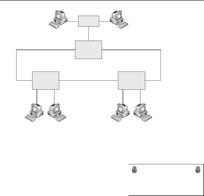
Edwards c02.tex V3 - 03/27/2009 11:58am Page 80
80 Part I ■Networking Nuts and Bolts
8 Port MAU 8 Port MAU
8 Port MAU
2 Port Hub
RIRO
RORI RORI
Figure 2-13 A typical Token Ring network
Up to a maximum of 33 MAU units can be interconnected to form the ring
network. The distance between MAU units is determined by the cable used to
ACRONYM ALERT
UDP — User Datagram Protocol
interconnect them. With the use of Type
1 cable, MAU units can be placed up to
a maximum of 100 meters apart. If greater
distances are needed, a repeater is required.
Repeaters used for copper wire network
segments can increase this distance up to
740 meters. If even greater distances are
required, the network segment can be further extended up to four kilometers
with the use of a fiber optic repeater and fiber optic cable.
Workstations and hubs connected to the MAU by cable are referred to as
lobes. Normally a lobe connects a workstation to a MAU, but if multiple
workstations in the same area need to be connected to the ring network, this is
accomplished with the use of a lobe access unit (LAU). A LAU unit splits the
lobe into two or more lobes. A LAU can be placed at the end of a cable to allow
for the connection of multiple workstations in that area. Although LAU units
soundasiftheyarethesameasMAUunits, there is a major difference. Unlike
a MAU, a LAU cannot be used to create a standalone ring. So LAU units are
basically used as hubs.
Although the difference between LAU and MAU units has become obscured
because some manufacturers market products called LAU units, in reality they
are functionally MAU units. However, the primary use of both MAU and

Edwards c02.tex V3 - 03/27/2009 11:58am Page 81
Chapter 2 ■LANs, MANs, and WANs 81
LAU units is in maintaining the functioning of the ring network as devices are
disconnected from the network.
A MAU or LAU allows a lobe on the ring to be opened for the insertion
of a new workstation, and it closes the ring when a workstation is removed
from the network. This allows for flexibility of network construction and any
necessary network reconfiguration without the problem of interruption of ring
network function.
2.1.2.1.1 Token Ring Cabling
The physical layout of a Token Ring network depends not only on the
placement of MAU, LAU, and hub units, but also on the cabling being used in
its construction. It has been previously mentioned that the cable construction
can be either STP or UTP cable.
2.1.2.1.1.1 Shielded Twisted Pair Cable STP Token Ring cable, also known
as IBM Type 1 cable, is constructed with twisted pair wires that are shielded.
The use of this cable allows for Token Ring lobe connections to be a maximum
of 100 meters apart. STP cables are terminated with either DB9 connectors or
patch connectors. Generally, patch connectors are used to connect to MAU
units, whereas DB9 male connectors are used to connect to workstations or
LAU units. DB9 female connectors are used to daisy-chain one LAU unit to
another.
The signals carried by the cable are transmit and receive. Two shielded
pairs are needed for these differential9signals. Table 2-1 lists the DB9 pin
assignments.
Table 2-1 DB9 Pin Assignments
SIGNAL PIN
Receive +1
Receive −6
Transmit +9
Transmit −5
2.1.2.1.1.2 Unshielded Twisted Pair Cable UTP Token Ring cable, also
known as IBM Type 3 cable, is constructed with unshielded twisted pair wire
similar to telephone cable. These cables are terminated with RJ-45 modular
9Differential Manchester encoding is used for the transmission and reception of data in the use
of either STP or UTP Token Ring cabling. The balanced signals for both the send and receive data
signals allow for data integrity and greater noise immunity.

Edwards c02.tex V3 - 03/27/2009 11:58am Page 82
82 Part I ■Networking Nuts and Bolts
plugs. This style of Token Ring cabling is dependent on the operating environ-
ment the network segment is in and the speed of the LAN itself. This cabling
is used to form lobe segments that do not exceed 45 meters. Typically these
cables10 are constructed using 10BASE-T UTP cable terminated on each end
with RJ-45 plugs. The RJ-45 pin assignments are listed in Table 2-2.
Table 2-2 RJ-45 Pin Assignments
SIGNAL PIN WIRE COLOR
Receive +4 White with orange stripe
Receive −5 Orange with white stripe
Transmit +6 White with blue stripe
Transmit −3 Blue with white stripe
2.1.2.1.1.3 Other Variations of Token Ring Cabling For special environments
or applications, IBM also uses cabling that consists of Type 2, Type 5, Type 6,
Type 8, and Type 9 cables.
Type 2 — Consists of two STPs as can be found in Type 1
cable and four UTPs as can be found in Type 3 cable.
Type 5 — Consists of multimode fiber optic cable used to extend
the Token Ring network and to interconnect optical repeaters.
Type 6 — Consists of two STPs. It is considered a low cost, short
distance cable with a maximum length of 45 meters and is often used for
MAU-to-MAU connection.
Type 8 — Consists of two parallel pairs. The wires in this cable are
untwisted and have a maximum length of 50 meters. The primary
purpose of this wire is in installations requiring the cable to run under
carpeting.
Type 9 — A lower cost alternative to Type 1 cable with a maximum
length of 65 meters. It consists of two pairs of STPs.
2.1.2.1.2 High-Speed Token Ring
There have been efforts made to push the speed of Token Ring networks
beyond the standard 16 Mbps. High-speed Token Ring has not been fully
deployed with the decline in newer Token Ring installations. However, it is
10Although these cables appear to be similar to those used for Ethernet 10BASE-T patch cables,
they are not the same. Ethernet 10BASE-T cables are constructed to use pins 1 and 2, and 3 and
6, for their twisted pair combinations.
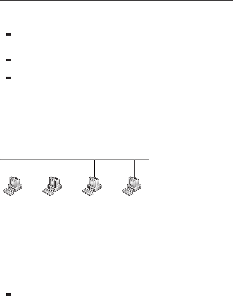
Edwards c02.tex V3 - 03/27/2009 11:58am Page 83
Chapter 2 ■LANs, MANs, and WANs 83
worth mentioning since there is a high likelihood of it being encountered in
the remaining legacy Token Ring networks.
32 Mbps Token Ring — Both IBM and other vendors of Token Ring
components and devices attempted to push Token Ring operation to a
higher speed.
Token Ring switches — These are in the form of switching bridges
capable of speeding up how messages travel between network rings.
Fiber distributed data interface (FDDI) — Although closely
related to Token Ring, it is not officially considered as part of the
Token Ring family. They both use a token-passing protocol.
2.1.2.2 Bus Networks Topologies
Bus networks initially were designed as a physical bus allowing devices to be
connected to nodes along the bus. Figure 2-14 shows a typical bus network.
Bus network
Figure 2-14 A typical bus network
In this illustration, workstations are connected to the bus with the use
of transceivers. With 10BASE5 cabling being used to form the bus network,
external transceivers were typically used to connect a workstation to the
network. In later bus implementations using 10BASE2 cabling in the form of
RG-58 coax cable to form the bus network, the transceiver was integrated into
the network adapter card that was installed within the workstation.
The transceiver not only converted the digital data generated by the work-
station into the appropriate data signals, it performed other functions useful
to both 802.3 and Ethernet LAN networks.
Collision detection — Provided by circuitry designed to detect
collisions on the bus network. If a collision is detected, the transceiver
notifies the transmitting function that a collision has occurred and
then broadcasts a jamming signal on the network to notify other
systems connected to the bus network. The LAN is then allowed
to settle before the resumption of transmissions on to the bus.

Edwards c02.tex V3 - 03/27/2009 11:58am Page 84
84 Part I ■Networking Nuts and Bolts
Heartbeat — Generation of a short signal to inform the main
adapter that the transmission is successful and collision free.
Although specified in the 802.3 standard and the Ethernet
standard, it is rarely used because many adapters confuse this
signal with the signal that signifies a collision has occurred.
Jabber — The function that allows the transceiver to cease trans-
mission if the frame being transmitted exceeds the specified
limit of 1518 bytes. This helps prevent a malfunctioning system
or adapter from flooding the LAN with inappropriate data.
Monitor — This function monitors LAN traffic by prohibit-
ing transmit functions while receive and collision functions
are enabled. It does not generate any traffic onto the LAN.
A bus network created using 10BASE5 or thick coax cable can have a
maximum overall segment length of 500 meters. Each node on the segment is
created with the use of a transceiver. Nodes on a thick coax cable are to be
spaced no closer than 2.5 meters with a maximum number of 100 nodes per
segment. The impedance for thick coax is 50 ohms. With the use of repeaters,
the overall length of the combined segments is not to exceed 2,500 meters.
RANDOM BONUS DEFINITION
twisted pair — A communications medium
consisting of two copper conductors twisted
together.
Generally, bus networks that
are formed by using 10BASE2
cabling use adapters that have
the transceiver function built in.
The network is formed using
a BNC coax T connector con-
nected to the workstation’s BNC
coax connector. Workstations
are then daisy-chained together
using lengths of coax cable terminated at both ends with coax plugs. These
interconnecting cables should not be less than 0.5 meters in length with a
maximum of 30 nodes and a total length of 185 meters per network segment.
The BNC T connector on each end of the network segment requires a 50 ohm
terminator to be attached to the open end of the T connector to maintain
the cable impedance. This is essential to maintain signal integrity and the
dampening of any signal reflections on the cable. With the use of repeaters,
the overall length of the combined segments is not to exceed 925 meters.
The maximum frame size for both IEEE 802.3 and Ethernet frames is 1518
bytes. 802.3 provides for a maximum data segment size of 1460 bytes while
Ethernet allows for a maximum data size of 1500 bytes. The original speed for
Ethernet was 10 Mbps.
There are two other implementations of logical bus networks: the star
topology and the tree topology.
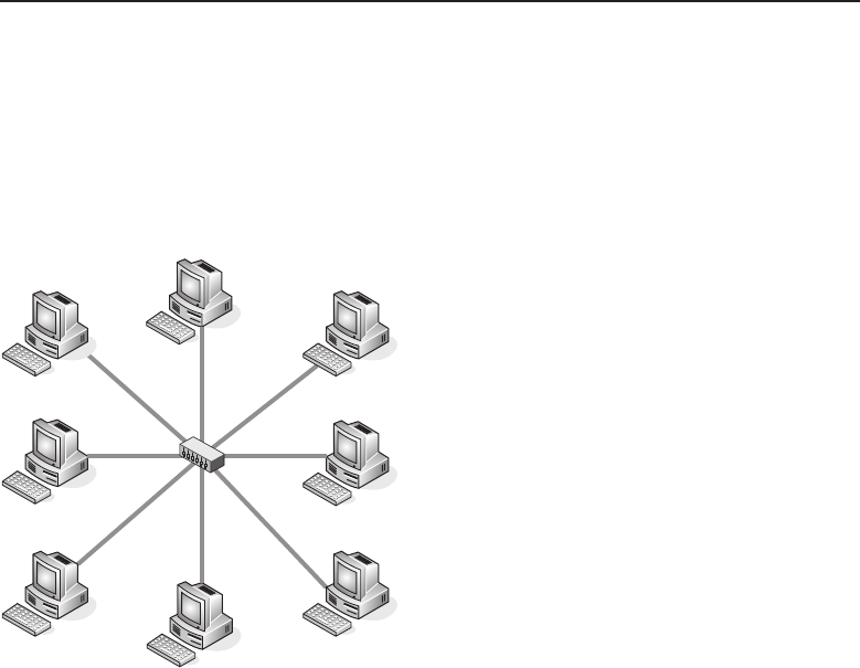
Edwards c02.tex V3 - 03/27/2009 11:58am Page 85
Chapter 2 ■LANs, MANs, and WANs 85
2.1.2.2.1 Star Network Topology
A star topology is implemented with the use of hubs and UTP cables terminated
with RJ-45 plugs. Hubs maintain the logic of the bus network while the UTP
cables radiate out in a star pattern. Figure 2-15 illustrates a star network formed
with the use of a single hub and UTP cables that are no longer than 100 meters
in length.
Figure 2-15 Astarnetwork
The simplicity of this type of network is the ease in which devices may be
added or removed from the network. The only limiting factor for this type of
network with a single hub is the number of ports contained on the hub. This
type of network is only useful for a small self-contained work group with no
requirement of connecting to other network segments located elsewhere.
2.1.2.2.2 Tree Network Topologies
Tree network topologies consist of network segments connected by hubs
and other devices in various combinations to create the network. Network
segments can either be geographically close or remote. Many networks fall into
the tree network architecture. This is especially true for very large networks
with many nodes. Figure 2-16 illustrates a simple logical diagram showing a
series of user nodes.
This could be considered a top level drawing where the later drawings show
more detail of how the segments are to be connected and the media that make
up the network segments. Figure 2-17 illustrates what one of the network
segments might look like. It is a combination of devices using both wired and
wireless media to connect nodes within that network segment.
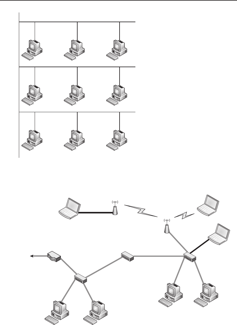
Edwards c02.tex V3 - 03/27/2009 11:58am Page 86
86 Part I ■Networking Nuts and Bolts
Tree network
Figure 2-16 A logical drawing of tree network topology
Main Network
Segment Router
Hub
Hub
Bridge
Wireless Router Wireless Access
point
Figure 2-17 A tree topology network segment

Edwards c02.tex V3 - 03/27/2009 11:58am Page 87
Chapter 2 ■LANs, MANs, and WANs 87
Laptop users with wireless enabled laptops can communicate directly from
their laptop to a wireless access point to gain access to the network. Laptops
that are not wireless enabled can be directly connected to the wired network
segment using the network interface card, which is internal to the laptop.
Another option, if needed, is to connect the laptop to a wireless router that is
able to communicate to the wireless access point to gain access to the network.
Workstations on the network segment are connected to the network with the
use of a hub. Separate local network segments are connected with the use of a
bridge. This whole network segment is connected to other network segments
with the use of a router.
2.1.2.2.3 Devices that Make Up a Network
True bus networks11 can still be found, but they are considered legacy networks
by today’s standards. Most newly deployed networks, although they are bus
networks, logically make use of devices to maintain the bus while nodes are
placed in either a star or tree network topology or, in many cases, a combination
of both. The majority of cabling used is 10BASE-T UTP cable connected to the
bus network devices with the use of RJ-45 plugs.
The following devices may be found in a variety of network topologies:
Hubs — Considered to be passive network devices.12 Passive hubs allow
the connection of multiple nodes to the network. They can be stand-
alone or daisy-chained to other hubs to form a larger network segment.
Repeaters — Used to extend network segments beyond the recom-
mended distance over wire cabling by performing signal regeneration to
ensure that data integrity is maintained over the long network segment.
Bridges — Used to divide a network into smaller segments to reduce
the number of network devices contending on the network segment for
network access. The bridge only passes network traffic that is specifi-
cally intended for the other network segment that it is connected to.
Ethernet switches — These are more predominately used today in
LAN networks to perform the role of bridges in dividing a network
into smaller segments to reduce network contention between network
devices. A single Ethernet switch is capable of having multiple
network segments contained within it. This is accomplished by
programmable ports, which may be dedicated to virtual LAN (VLAN)
11The term true bus network refers to networks that are physically constructed as a bus. They
consist of either thick or thin coax cable. These networks use 10BASE5 and 10BASE2 cabling to
form the network segment.
12Passive network devices such as hubs are designed to maintain the electrical characteristics
of a bus network while physically giving the appearance that they are interconnected in
either a star or tree network topology.

Edwards c02.tex V3 - 03/27/2009 11:58am Page 88
88 Part I ■Networking Nuts and Bolts
segments on that device. They usually contain multiple ports and
are similar in appearance to hubs but differ in that hubs are not
able to reduce network contention on the network segment they
are being used on. Some Ethernet switches provide the ability to
gang multiple devices together to form a larger network segment.
Routers — Used to connect multiple network segments but differ
vastly from bridge devices. Bridges operate solely on the information
contained within the 802.3 data frame and are not effected by the
routing protocols being run over the network. Routers operate
at the network protocol level and forward network traffic based
upon the network protocol information contained within the data
frame being forwarded from one network segment to another.
Network interface cards (NIC) — A term used predominately to refer
to the cards contained within devices connected to the network. How-
ever, the devices that fall under this category are wide and diverse,
from cards meant to fit into a PC slot to other devices intended to con-
nect via a USB port. Some NIC devices fit into a PCMCIA card slot on
a laptop and allow it to gain network access via a wireless link. They
all serve the same purpose: to allow a device to connect to a LAN.
The devices briefly described in this section are covered in further depth in
Chapter 3.
2.1.2.2.4 Bus Network Cabling
This section discusses the following bus wire types: 10BASE5 coax (thicknet),
10BASE2 (thinnet), and 10BASE-T (UTP). The predominant wiring used in
today’s network is 10BASE-T, which is commonly referred to as Ethernet
cabling. The characteristics and limitations of each cable type will be discussed
in this section.
2.1.2.2.4.1 10BASE5 Thicknet This cable type was the initial introduction
to CSMA/CD bus network topology. The network segment is formed using
this thick coax cable, which has a maximum segment length of 500 meters.
Being thick and heavy, the cable is difficult to handle when routing the cable
throughout a building. A network node is formed with the use of what is
commonly referred to as a vampire tap. This device pierces the jacket of the
coax cable to make contact to the center conductor of the coax cable and
provide the signal to the network node with the use of a transceiver. The
physical construction of the transceiver appears the same for both Ethernet
and IEEE 802.3, both using a DB15 connector style. However, where they
differ is in the circuit assignment for each pin. Table 2-3 shows the DB15 pin
assignments for both Ethernet and IEEE 802.3.

Edwards c02.tex V3 - 03/27/2009 11:58am Page 89
Chapter 2 ■LANs, MANs, and WANs 89
Table 2-3 DB15 Pin Assignments
PIN ETHERNET IEEE 802.3
1 Ground Ground control in
2 Collision detected +Control in A
3Transmit+Data out A
4 Ground Data in
5 Receive +Data in A
6 Voltage Common
7 Control Out A
8 Ground Control out
9 Collision detected −Control in B
10 Transmit −Data out B
11 Ground Data out
12 Receive −Data in B
13 Power
14 Power ground
15 Control Out B
The Ethernet transceiver specifies the pinout for three signals, transmit,
receive, and collision detect, whereas the IEEE 802.3 standard provides for an
added signal of control out (which is not used). Although the pin assignments
are such that a cable manufactured for either standard would work with the
other standard’s transceiver, it is not recommended due to differences used in
signal grounding.
Vampire taps may not be located any closer together than 2.5 meters with
a maximum of 100 taps per network segment. Network segments can be
combined with the use of repeaters to increase the overall combined network
length to 2,500 meters. The characteristic impedance of 10BASE5 cable is
50 ohms.
2.1.2.2.4.2 10BASE2 Thinnet 10BASE2 networks are constructed mostly with
the use of RG-58 coax cable, which has a characteristic impedance of 50 ohms.
This cabling is more desirable for use in network segments due to its lower
cost and greater flexibility than that of 10BASE5 cable. Network nodes are
easily formed with lower cost BNC T connectors, whereas 10BASE5 cabling
requires a more expensive vampire tap transceiver. However, 10BASE5 cable

Edwards c02.tex V3 - 03/27/2009 11:58am Page 90
90 Part I ■Networking Nuts and Bolts
is capable of far greater network segment length than 10BASE2, which makes
it more suitable for a network backbone. The 10BASE2 network, with its lower
cost and ease of reconfiguration if needed, is more suited for a work group
environment clustered in a smaller geographical area. To properly terminate a
10BASE2 network to maintain the characteristic 50 ohm impedance across the
network and reduce signal reflections on the wire, the last BNC T connector
on each end of the network segment must have a 50 ohm BNC terminating
plug connected to the open tap on that BNC T connector.
The overall segment length for a 10BASE2 cabled network is 185 meters
with a maximum of 30 network nodes per segment. The minimum distance
between network nodes is 0.5 meter. The overall network length that can be
achieved with the use of repeaters for 10BASE2 is 925 meters.
2.1.2.2.4.3 10BASE-T UTP Cabling These days, 10BASE-T cable and Ethernet
UTP cable are simply synonymously called Ethernet cable. Although logically
it is considered as bus topology cable, it is point-to-point between a network
node device and a device that completes the logical bus. Cable construction is
similar to telephone cable, which makes it easily routable through a building.
Similar to telephone cable in larger installation sites, patch panels are used to
terminate cables from differing locations throughout the facility.
Ethernet cables of various lengths terminated with RJ-45 plugs on both ends
are usually referred to as patch cables or straight-through cables.Thesecablesare
used to connect a network node device to a network device that completes the
logical bus. Table 2-4 shows the pinout for an RJ-45 plug on an Ethernet cable.
Table 2-4 RJ-45 Pin Assignments
PIN SIGNAL
1Transmit+
2Transmit−
3 Receive +
4
5
6 Receive −
7
8
It can be seen that a patch cable or straight-through cable carries the same
signal from one end to the other on the same pin if both RJ-45 jacks are wired
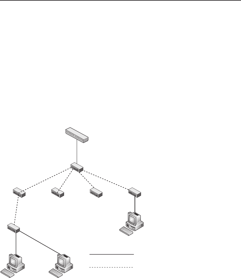
Edwards c02.tex V3 - 03/27/2009 11:58am Page 91
Chapter 2 ■LANs, MANs, and WANs 91
exactly alike. However, there is another cable that appears physically identical
but is wired differently, called a crossover cable. These cables do literally just
that — they cross over the transmit signals to the receive signals. The purpose
of these cables is to connect two network devices whose connectors are wired
exactly the same. A simple example of this would be two computers connected
by a crossover cable to use the network cable to transfer files between them.
Many of today’s network devices such as hubs and switches use auto-
sensing, auto-switching ports to sense the cable and dynamically configure
the port to ensure that the transmit signal from another network device is
connected to its receive signal input. This was not always the case, so in order
to expand a network segment, crossover cables were necessary to daisy-chain
multiple hubs together. Figure 2-18 illustrates how hubs can be daisy-chained
to form a larger network segment.
Hub
Second Tier
Hub
Third Tier
Hub
First Tier
Patch Panel
Patch Cable
Crossover Cable
Figure 2-18 Daisy-chaining for an expanded network segment
In Figure 2-18, a local geographical area is serviced by a series of hubs to
allow network devices in that location to gain access to the network. The feed
for this network is from a patch panel over a patch cable to the first tier hub
device. This device with the use of crossover cables is attached to a number of
second tier hubs. In this illustration, one of the second tier hubs is connected
using a crossover cable to a third tier hub, which services some computers
attached to the network. This appears at first to be an unlimited geometric

Edwards c02.tex V3 - 03/27/2009 11:58am Page 92
92 Part I ■Networking Nuts and Bolts
progression, but in reality it is a bus network, so network devices do contend
for network bandwidth. It can be readily seen that all devices on this network
segment that send traffic to other network segments need to have it pass over
the single cable between the patch panel and the first tier hub device. This is
often referred to as a single point of access.13
Hub manufacturers saw the inconvenience of having two cable types and
began to design and sell hubs with a mechanical switch on one of the ports
so that a patch cable could be used between hubs in place of a crossover
cable. More recent Ethernet port designs have led to the development of a port
device using electronic auto-sensing, auto-switching to configure the port to
match transmit and receive signals no matter if a patch or crossover cable is
connected to the port.
Any segment of the network shown in Figure 2-18 may not have a cable
linking two network devices that exceeds 100 meters. The overall combined
length of the entire segment with the use of hubs and repeaters may not exceed
2,500 meters. For smaller local networks, these lengths are more than adequate.
For much larger installations, special considerations will be required to ensure
data integrity on the network.
2.1.2.2.4.4 So What about Speed and Duplex? The initial speed standard
for CSMA/CD bus networks over UTP cable was 10 Mbps. Since the initial
RANDOM BONUS DEFINITION
ping — A utility program used to test for
network connectivity by using the echo
request and echo response mechanisms of
ICMP.
introduction, devices that can
pass network traffic at 100 Mbps
(100BASE-TX) are now fairly
common. Many of today’s in-
stallations make use of giga-
bit speeds (1000BASE-T), which
sometimes is referred to as gig-E.
These advances in technology
have allowed for the attainment
of greater network speeds with-
out the need for changing the current wiring infrastructure. Devices capable
of any of the speeds listed are able to do so over existing Category 5 cabling.
Duplex is either half-duplex or full-duplex. The difference between the two
is that full-duplex devices are capable of transmitting and receiving at the
same time, whereas half-duplex devices are either in transmit or receive mode
but never both simultaneously.
Since UTP cabling is connected in a point-to-point fashion, the ports con-
nected to each end of the cable must be able to transmit and receive at the same
speed. On some devices, these are only manually configurable. Some devices
13Single point of access is also a single point of network failure. Depending on the number
of devices in a local area or how critical network availability is to those users, some thought
should be given to network segmentation and redundancy. There will be further discussions and
examples of this throughout this book.

Edwards c02.tex V3 - 03/27/2009 11:58am Page 93
Chapter 2 ■LANs, MANs, and WANs 93
are able to negotiate speed and duplex with their peer port to set the speed
and duplex to be used over the link.14 This mode of operation is referred to as
auto-negotiation.
Careful attention must be paid to the speed and duplex of an interface.
If there is a mismatch between the devices, network performance will be
degraded and full network speed cannot be realized. This is a small detail that’s
often overlooked but has major implications in overall network performance.
2.2 Metropolitan Area Networks
The term metropolitan area network is a bit nebulous and embraces a variety of
differing network scenarios. The common denominator in all these networks is
that they cover areas that are much larger than a conventional LAN is capable
of, as discussed in Chapter 1.
The technological development of fiber optic network devices has facilitated
the growth of both private and public MAN networks. Fiber optics allowed the
network to stretch to over several kilometers, which made extended networks
more feasible. Fiber distributed data interface (FDDI) is used for the backbone
that interconnects distant portions of the MAN. So what exactly is an FDDI?
2.2.1 Fiber Distributed Data Interface
Fiber optic cabling presents several advantages over conventional copper
wiring. It is lighter in weight than copper, weighing in at roughly 10 percent
ofacoppercableofthesamelength.Itiscapableofdrivingdatasignals
much further with less loss and is immune to crosstalk and noise caused by
electromagnetic interference (EMI). Fiber optic cable, being electrically inert,
aids in the elimination of ground loops between sending and receiving nodes.
Since fiber optic cable does not emit any radio frequency interference
(RFI) when data is transmitted on the cable, it cannot be snooped using
radio frequency detectors as copper wire can. The only way data can be
eavesdropped on is by actually breaking the cable and placing a receiver in
the line. Since this action would not go undetected, fiber optic cabling offers
greater security over copper.
All this stuff about fiber optic cable is great, but how is it used in a network,
you ask? Well, knowing you read the section on Token Ring LAN segments,
the authors feel we do not have to review the concept of token passing. If
we are wrong, you should go back and read the Token Ring section about
how a token is passed about a ring. Although the token-passing concept is
14Link is a reference to a cable connecting (linking) two network devices’ ports. Many interface
connectors on network devices have an LED indicator to indicate the presence of link. Link on
an interface indicates that the transmit and receive signals are properly connected and the two
devices are capable of communicating over the cable (link).
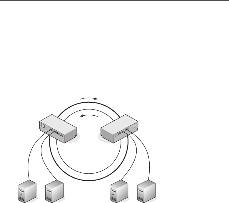
Edwards c02.tex V3 - 03/27/2009 11:58am Page 94
94 Part I ■Networking Nuts and Bolts
similar, FDDI is not the same as the IEEE 802.5 Token Ring standard. FDDI
was standardized under ANSI standard X3T9.
From the previous paragraph, you are already aware that FDDI is imple-
mented using token passing over a ring topology consisting of fiber optic
cable. Construction of the network consists of dual rings, a primary ring and
a secondary ring. Both rings are capable of passing data, but usually the
counter-rotating secondary ring, which can carry data in the opposite direc-
tion, is reserved to be used as a backup in case of ring failure. Figure 2-19
shows a logical representation of an FDDI network.
Secondary
Ring
Primary Ring
FDDI
Bridge
FDDI
Bridge
Figure 2-19 An FDDI network
Although this network is shown logically as a ring, it is physically deployed
in a star topology similar to that of wired Token Ring networks. FDDI
bridge/concentrators complete the logical ring while also providing the optical
to electrical signal conversion to allow data to be transferred from an optical
network segment to a wired network segment and in the reverse direction.
To facilitate the star physical topology, fiber optic cable is dual strand cable.
There is one fiber optic strand carrying intelligent light information to the
FDDI bridge concentrator while the other strand allows for the transmission of
data from that FDDI concentrator to the next. These fiber optic network cables
are sometime called light pipes.15
15Don’t confuse fiber optic data cables with those fiber strands you see at the mall emitting all
those wild colors. Although similar in terms of light being transmitted through an optical fiber, the
quality and construction are far different. After all, it is for the purpose of sending intelligent data.

Edwards c02.tex V3 - 03/27/2009 11:58am Page 95
Chapter 2 ■LANs, MANs, and WANs 95
FDDI networks are capable of transmitting data at 100 Mbps for a maximum
ring circumference of 100 kilometers. If both the primary and secondary rings
are used, an effective data rate of 200 Mbps can be achieved. This is what
makes FDDI the preferred choice for backbones on large LAN networks and
for deploying a MAN over a wide geographical area.
To pass data from either an Ethernet or Token Ring LAN segment
requires a bridge to transform electrical signals into intelligent light impulses.
These bridges fall into two categories, encapsulating bridges and translating
bridges. Encapsulating bridges encapsulate Ethernet frames into FDDI frames,
and translating bridges translate the received frame source and destination
MAC addresses into FDDI addresses. The maximum FDDI frame size is
4500 bytes.
A dual ring FDDI network can connect up to a maximum of 500 stations.
Since FDDI requires a repeater every 2 kilometers, it is unsuitable for a WAN
network deployment. FDDI lends itself easily within existing metropolitan
infrastructures where cabling is routed in hostile environments under streets
and overhead lines. It is impervious to EMI, so no special shielding is required
other than having the fiber jacketed to withstand the environment it is to
be placed in. Since fiber cable depends on a continuous, undistorted fiber to
transmit data without degradation, care must be taken to maintain a min-
imum bending radius for the type of fiber cable being used, to prevent a
possible crimp in the fiber. A distortion of the fiber can cause light reflec-
tions that could render the total cable length unusable for the transmission
of data.
Fault tolerance is built into the dual ring FDDI network. When an interrup-
tion on the primary ring is detected, beaconing is used to determine where
the break occurred. Beaconing is also used to monitor the health of the ring
network token-passing process. Each station on the ring is responsible for
checking the token-passing status of the ring. If a fault is detected by a station,
it transmits a beacon onto the ring. The upstream station receives the beacon
and begins to transmit its own beacon. The downstream station ceases bea-
coning after receiving a beacon from its upstream station. The process keeps
moving to the next upstream station around the ring untilthe beaconing station
does not detect a beacon from its upstream station. The fault has been isolated
between the beaconing station and its upstream station. The secondary ring
can then be placed into service by allowing for data traffic flow in the opposite
direction. When the beaconing station detects its own beacon being received
on the primary ring, it is notified that the fault has been isolated and repaired.
Upon receipt of its own beacon, the station shuts off beaconing and returns to
normal service.

Edwards c02.tex V3 - 03/27/2009 11:58am Page 96
96 Part I ■Networking Nuts and Bolts
2.2.2 A MAN Example
Anytown, USA, considers itself a happening place. Not wanting to miss out
on being part of the ‘‘connected’’ age, the city fathers have launched a plan
to provide computer services to all city departments. In order for the local
citizenry to see their tax dollars at work, they decided as part of the overall
project they would provide Internet access to the general populace. The greater
Anytown metropolitan area spans several miles, with some buildings as far as
five miles away from city hall.
The mayor called in the heads of Anytown’s IS department, told them of his
great vision, and asked how they would go about implementing his great plan.
The IS department managers went away scratching their heads and wondered
how they were to pull this one off. The general thought within the group
was that, since the mayor’s vision was pie in the sky, they would draw up a
proposal that would be doable while still maintaining their control over the
administration of Anytown’s information services.
After several weeks of thrashing about among the IS department’s staff,
the plan was devised and drawn up. The big night arrived, and the chief of
Anytown’s IS department wore his Sunday best for the presentation of the
devised plan to the mayor and the city counselors.
When the slide was placed on the overhead projector, the mayor and
counselors saw what is shown in Figure 2-20.
The IS chief’s explanation went as follows. The main departments within
Anytown’s government already had LAN technology deployed within the
areas they were responsible for. General communication and the passing of
data between departments was being done via e-mail. By implementing a
citywide FDDI network, each department’s LAN would be able to send data
directly from station to station over the newly connected LAN networks.
He went on to explain that servers located on each individual LAN would
be centrally located within the IS department at city hall. Each department
location would be connected directly to city hall via high-speed fiber optic
cable, shown as dashed lines on the MAN network diagram.
He went on to further explain that each department currently was respon-
sible for its own Internet access. With the proposed high-speed fiber optic
POP QUIZ
IEEE 802.5 limits the number of nodes on a
ring to nodes.
network, this could be con-
solidated under the control of
the city hall IS staff. A single
high-speed network connection
would give Internet access to
not only all city departments
but also the general public. It
was stated that there would be
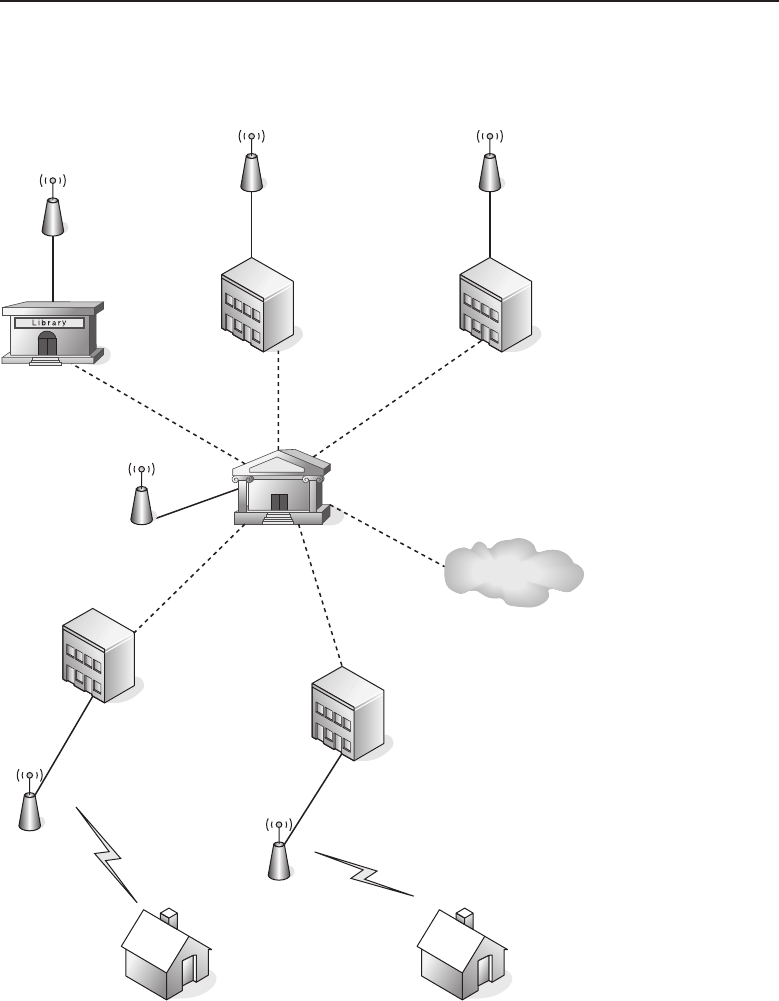
Edwards c02.tex V3 - 03/27/2009 11:58am Page 97
Chapter 2 ■LANs, MANs, and WANs 97
security precautions put in place to prevent unauthorized access to servers
maintained by the city.
City Hall
School Department School
Internet Service Provider
(ISP)
Library
Fire
Department
Police
Department
Figure 2-20 Anytown’s MAN
The local telephone company would be contracted to run the dedicated fiber
optic cable from city hall to the remote buildings over their current cableways
and overhead lines. The general public would have access over wireless links

Edwards c02.tex V3 - 03/27/2009 11:58am Page 98
98 Part I ■Networking Nuts and Bolts
to access points located throughout the city to ensure that all of Anytown’s
citizenry would have equal access to the Internet service provided by the city.
For those without personal computers or unable to connect to the citywide
wireless network, public access computers would be located at schools and
libraries.
With his presentation completed, the IS chief asked if there were any
questions. The mayor seemed pensive at first and then asked, ‘‘Can you
explain why there is only wireless Internet for the public?’’ The IS chief said,
‘‘Yes, sir, I can.’’ He went on to explain that the infrastructure cost to bring a
wired Internet alternative to all of the city inhabitants would drive costs for
the project beyond reach of the city’s budget. Also, some of the expenses for
the FDDI network could be recouped over time from consolidation of common
services utilized by each city department. Providing a citywide wired public
network would be cost-prohibitive. The IS chief went on to explain that
there were already a few Internet providers servicing the Anytown greater
metropolitan area, and those citizens desiring a wired Internet access were
more likely to already be subscribed to their service or would do so in the
future.
The mayor thanked the IS chief for his presentation. The counselors all voted
their approval, and the mayor began drawing up his new campaign speech on
how he was instrumental in getting Anytown connected.
This example of how a MAN might come about is largely tongue-in-cheek.
However, it does demonstrate that the basic definition of a MAN is a network
that covers a wide geographical area that can be either a city or include the
greater metropolitan area of a city. The feasibility of MAN networks would
not be possible without the availability of high-speed networks such as Metro
Ethernet or FDDI optical networks.
The chief piece of information that the student should take from this section
is the awareness that a high-speed data link is required when connecting LAN
networks located some distance apart. When users and services on both ends
of the link are contending for use of the link, the speed at which the link is
able to pass traffic will be the determining factor of the performance of the
interconnected LAN networks over that link. A safe rule of thumb is the more
bandwidth the better. It gives better performance and allows for future growth
and expansion of the connected LAN networks.
2.3 Wide Area Networks
As discussed in Chapter 1, the main use of a WAN is to provide a high-speed
data network between two geographically distant networks. This chapter will
discuss a few WAN telecommunications services most used in the makeup of
aWANnetwork.

Edwards c02.tex V3 - 03/27/2009 11:58am Page 99
Chapter 2 ■LANs, MANs, and WANs 99
ACRONYM ALERT
QoS — Quality of service
WAN networks are constructed from a
wide range of service levels that can be
obtained from the telephone companies.
These can range from slow, low-grade ana-
log circuits to high-speed digital signal ser-
vices. The most widely used and available
WAN standards are POTS, ISDN, and frame
relay.
2.3.1 Whose POTS?
POTS stands for plain old telephone service. It refers to the use of voice-grade
telephone lines to form a point-to-point data connection. Because these
voice lines can be found in many places around the world, it is possi-
ble to create a WAN connection between two LAN networks that are far
apart. Figure 2-21 illustrates a dialup modem16 connection between two
offices.
This figure shows two LAN networks, one located in Boston and the other
in Santa Fe. This is a manual WAN connection operation. Each modem can be
set to auto-answer so that when another modem dials in, it will answer the call
and allow the connection to be completed. This is a very rudimentary WAN
network. It works and is still the only available WAN-type connection that can
be made from some very rural areas of the country.
The speed of the WAN connection is determined by the type of modem
and the signal quality of the telephone line it is connected to. Customary
speeds that can be attained are between 28.8 and 57.6Kbps. There are devices
in the marketplace that automate the dialing process. These are considered
to be dial-on-demand routers. These devices reside on the LAN and will
automatically dial a preprogrammed number when they detect that the data
received from the network is destined for a LAN at the other end of the dialup
WAN connection.
With a clear line and the use of compression, some modem-based devices
are capable of throughput of 115 Kbps. As other access technologies have
rolled out, such as DSL and Internet access over cable and fiber to the home,
modem use has fallen off. These newer technologies can provide higher speed
access to the Internet, but they are unable to provide a point-to-point WAN
connection, which some organizations require. Later in this section we will
discuss how these technologies can be used to provide a virtual point-to-point
WAN connection.
16Modem takes its name from modulate/demodulate. It is a device able to both modulate and
demodulate a digital signal into an analog signal that can be sent across standard voice-grade
telephone lines.
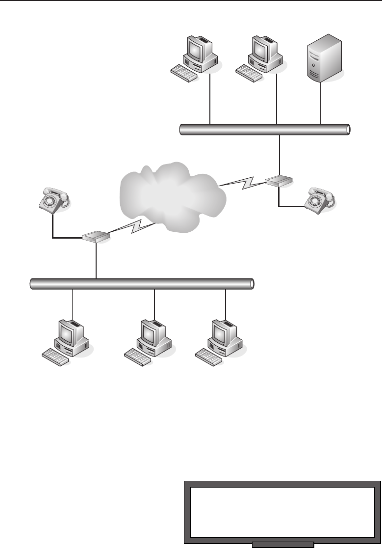
Edwards c02.tex V3 - 03/27/2009 11:58am Page 100
100 Part I ■Networking Nuts and Bolts
POTS
Network
Boston
Santa Fe
Figure 2-21 A POTS WAN connection
2.3.2 Integrated Services Digital Network
Integrated services digital network (ISDN) is a set of standards to provide
voice, data, and video transmission over a digital telephone network. It is
POP QUIZ
What is the major difference between
Ethernet and IEEE 802.3?
similar to a POTS line and
modem in that it is able to
use existing premises wiring to
make a called connection to
another ISDN subscriber. How-
ever, it can only call another
ISDN subscriber, whereas a
POTS setup can call any number

Edwards c02.tex V3 - 03/27/2009 11:58am Page 101
Chapter 2 ■LANs, MANs, and WANs 101
that has an analog telephone connection to it. By integrating analog and digital
signal transmissions using a digital network, ISDN is capable of delivering
an improved data rate over typical modem connections. Unlike POTS, ISDN
service is mostly concentrated in major metropolitan areas.
Taking advantage of LAN-to-LAN connectivity with ISDN providing the
link can best be accomplished with the use of ISDN routers. They are typically
configured for on-demand dialing. When there is data to be sent from one
LAN to a remote LAN, the router will dial the remote ISDN router. When
the remote ISDN router answers the call, data can be sent across the link.
Since most ISDN service usage is typically billed by the number of calls and
total minutes connected, ISDN routers may utilize an idle timer. This timer
determines when there is no traffic being passed across the link. When the idle
time interval has been reached, the call is terminated. These timers need to be
set properly to eliminate excessive dialing and increased telephone charges. It
is recommended that you understand how your local ISDN provider bills for
this service. It could be by connected minutes, number of calls, or a combination
of both. The only advantage that ISDN has over leased lines is that for low
usage data connections it is cheaper than paying for a point-to-point leased
line connection. ISDN is at a cost disadvantage in situations where the line is
up for great periods of time. In those circumstances, it is best to look into using
a leased line.
The two most commonly found ISDN services are:
Basic rate — Provides two B channels of 64 Kbps and a single D channel
of 16 Kbps.
Primary rate — Provides 23 B channels of 64 Kbps and a single D
channel of 64 Kbps for U.S.- and Japan-based subscribers. Subscribers
in Europe and Australia are provided with 30 B channels.
An advantage that ISDN has over other WAN connection types when
connecting to sites located in other countries is the service levels have been
standardized by the International Telegraph and Telephone Consultative
Committee (CCITT), so subscribers with ISDN service around the globe are
able to interconnect to form a WAN network.
2.3.3 Point-to-Point WANs
In reality, all the WAN connections we spoke of in the two previous sections
are also point-to-point WAN connections even though they require a manual
or automated dial from a modem-based router. For the most part, when people
refer to a point-to-point connection in the telecommunications arena, the first
thought that comes to mind is directly connected point-to-point leased line
connections. Figure 2-22 illustrates an organization with three major offices
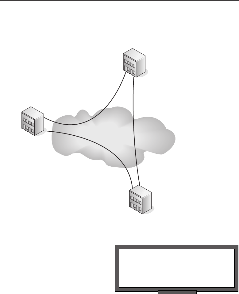
Edwards c02.tex V3 - 03/27/2009 11:58am Page 102
102 Part I ■Networking Nuts and Bolts
located in New York, Los Angeles, and Miami. The amount of data traffic
between these locations warrants dedicated point-to-point WAN connections.
The lines in use are considered to be of the T class variety.
Los Angeles
New York
Miami
Telephone
Network
Los
Figure 2-22 A point-to-point WAN network
RANDOM BONUS DEFINITION
preamble — A frame field used to allow a
receiver to properly synchronize its clock
before decoding incoming data.
Organizations do not only use
these lines for data transmis-
sion. The lines can also be used
for telephone, teleconferencing,
and other forms of communi-
cations. The most common ser-
vices used for these T class
connections are T1, fractional
T1, and T3. T1 can provide
1.544 Mbps of speed while T3
can deliver 44.736 Mbps.
A full T1 line provides 24 channels, each with 64Kbps of bandwidth. When
an organization leases a dedicated full T1 line, they are responsible for the
T1 multiplexer equipment located at each endpoint. They can then dedicate
the channels in any manner they choose. An example of this would be 6

Edwards c02.tex V3 - 03/27/2009 11:58am Page 103
Chapter 2 ■LANs, MANs, and WANs 103
channels dedicated to telephone service, 2 channels for teleconferencing, and
the remaining 16 channels dedicated to moving data between locations. For
organizations with demands for more bandwidth, the option would be to
move up to T3 service. These services are point-to-point through the telephone
network, but the service level is guaranteed by the telecommunications com-
pany. The lease cost is determined by the required bandwidth and distance
between locations.
Organizations that require guaranteed throughput between organizations
but do not need the speed of a full T1 can purchase a number of channels
split out from an existing trunk circuit. This does provide a cost advantage,
but it has its downside — the organization does not have control over where
that circuit is routed. Cost is determined by the number of channels required
and the distance between the locations. As the number of channels begins to
increase, the cost advantage of fractional T1 is lost.
2.3.4 Frame Relay
So far, we have talked about WAN circuits being directly connected endpoint
to endpoint, although traveling through a switched telephone network. Those
connections were dedicated to creating a full-time fixed bandwidth connection.
Frame relay17 is designed for data traffic that tends to move in bursts. This is
accomplished by using packet switching in a switched cloud provided by the
telecommunications companies.
POP QUIZ
What are the two most common ISDN
services?
Because frame relay lends
itself to burst-oriented traffic,
it is not suitable for real-time
applications such as telephones
or teleconferencing. As informa-
tion is moved in packets, the
service is provided as a commit-
ted information rate (CIR). It is
listed as a bandwidth number, but that does not necessarily mean you have
continuous access at that bandwidth.
The level of service is measured for frame relay using a formula that includes
committed burst size (CBS) over an interval of time. The basic formula is as
follows:
Time =Committed Burst Size (CBS) / Committed Information Rate (CIR)
17Frame relay is based on X.25 packet-switching technology, which was developed to move data
signals that were primarily analog, such as voice conversations. X.25 works in Layers 1, 2, and 3
of the OSI model. Frame relay only uses Layers 1 and 2, giving it greater speed that is about a
factor of 20 over X.25. This is accomplished by dropping packets that are found to be in error and
relying on the endpoints to process packet-drop detection and request retransmission of packets.
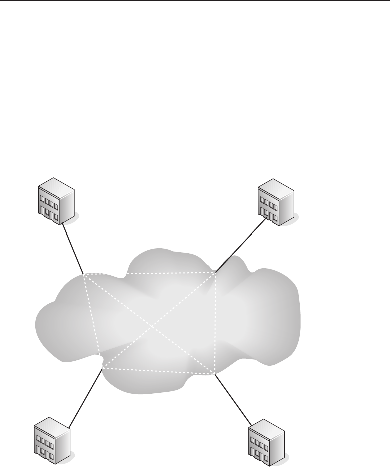
Edwards c02.tex V3 - 03/27/2009 11:58am Page 104
104 Part I ■Networking Nuts and Bolts
To illustrate this further, a customer has chosen a service that provides a
CIR of 64 Kbps and a CBS of 256 Kbps. At first glance, it appears that traffic
can burst up to 256 Kbps, but that is not the case. If CBS is divided by CIR, the
resulting value is four seconds. This means the circuit needs to be capable of
moving 256 Kbps in any four-second interval. This is far different from what
most people think burst rate means. So the CIR and CBS need to be carefully
looked at when subscribing to a frame relay service. If the network burst rate
begins to exceed the CBS, network congestion will occur and data traffic will
be affected. When selecting a frame relay service, it is best to have a good
knowledge of the networks to be interconnected over frame relay. Figure 2-23
illustrates how a frame relay network may be implemented.
Seattle Boston
Frame Relay
Switched Network
T1 Link
Los Angeles
New York
T1 Link
T1 Link
T1 Link
Figure 2-23 A frame relay network
This figure shows an organization with offices in Boston, New York, Seattle,
and Los Angeles. Each has a T1 connection to the frame relay switched
network. In this figure, each office is connected to every other office within
the frame relay switched network using a private virtual circuit (PVC), which
is illustrated by the dashed lines between each of the nodes connected to
the switched network. This does have an advantage over pure point-to-point

Edwards c02.tex V3 - 03/27/2009 11:58am Page 105
Chapter 2 ■LANs, MANs, and WANs 105
WAN implementations, but it is best suited for burst type traffic and not traffic
requiring a continuous guaranteed rate.
2.3.5 Using the Internet for Your WAN
The Internet is a network mesh that covers most of the globe. So it is possible
to connect remote LAN networks over the Internet. However, the Internet is
really a best-attempt-possible service. It is not guaranteed far as performance
and is open to the public, which makes security a major concern. The chief
advantage of using the Internet over other subscriber services is cost. Other
than local Internet access fees, there are no other charges involved such as
can be found when using a dedicated long line solution. Unlike dedicated
point-to-point services, it is inconsequential how these devices connect to the
Internet. The type of connection to the Internet is not a factor in the creation
of the virtual point-to-point connection. Factors that can affect performance
include the speed of the connection and its reliability where connectivity is
concerned. Although electrons move at the speed of light, intelligent electrical
signals are also subject to latency problems the greater the distance is between
two endpoints of a network.
The solution of using virtual private networks (VPN)18 is only viable in
scenarios that require a remote office to connect to a central office. It is not
intended to replace dedicated high-speed point-to-point network connections.
Data integrity and security are maintained and ensured using encryption
and encapsulation of the data packets that are transmitted over the Internet.
Authentication is used to confirm that an endpoint device or user is fully
authorized to send and receive data from the VPN connection. Figure 2-24
illustrates how VPN connections may be used as a substitute for a dedicated
WAN network connection.
POP QUIZ
True or false: Virtual private networking is
networking that does not require any
hardware at all.
A remote office in Boston is
connected to the corporate office
in New York using the Inter-
net to form its VPN tunnel. This
is a peer-to-peer tunnel where
each endpoint knows the other
and is part of the security as
the peers are known to each
other. Authentication security is
increased with the use of preshared keys (PSK), and other authentication
methods such as certificates and tokens may also be added. Once the VPN
18For further information on how to use VPN tunnels, check out Nortel Guide to VPN Routing for
Security and VoIP, by James Edwards, Richard Bramante, and Al Martin (Wiley Publishing, Inc.,
2006).
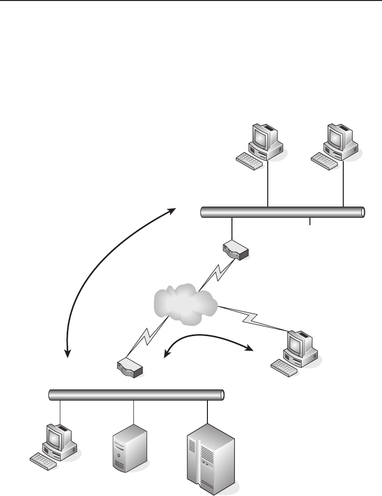
Edwards c02.tex V3 - 03/27/2009 11:58am Page 106
106 Part I ■Networking Nuts and Bolts
tunnel is formed, traffic destined for either LAN is passed through the tunnel
as if it were a dedicated link. The end-user workstations only need to be
concerned with the address of the device on the other LAN. The VPN routers
are the only devices that need to be aware of the endpoint address of its peer
VPN routers. So for this purpose, the peer-to-peer tunnel functions as if a
dedicated point-to-point link is in place between the two LAN networks.
Boston
VPN Router
Remote Client
St. Louis
New York
Client
Tunnel
Central LAN
Peer to Peer
VPN Tunnel
VPN Router
Remote LAN
Figure 2-24 A VPN as a WAN
VPN routers are also able to accommodate end-user tunnel connections.
For this example in Figure 2-24, a user in St. Louis is able to connect to
the central office in New York to gain access to the network and use the

Edwards c02.tex V3 - 03/27/2009 11:58am Page 107
Chapter 2 ■LANs, MANs, and WANs 107
services on that network. Since remote users can contact the central office
from almost anywhere, their endpoint addresses would not be previously
known. However, users are required to be authenticated in the same manner
as a peer-to-peer tunnel, which may include multiple forms of authentication
processes. Once authorized, a user is able to access the services they are
authorized to use. Many installations require additional authentication to
access internal servers. Access to the network does not necessarily mean access
to all devices. VPN routers are capable of applying security policies on both
peer-to-peer and end-user client tunnel connections.
The protocols used for VPN tunneling are Point-to-Point Tunneling Protocol
(PPTP), Layer 2 Tunneling Protocol (L2TP), and IPSec (IP Security).
2.4 Chapter Exercises
1. The term modem is short for .
2. A is a network where network devices are located within
close proximity to each other.
3. CSMA/CD is an acronym for and is associated
with a network using a network topology.
4. Which network topology allows for orderly network access for the sta-
tions connected to that network?
5. What two standards define a CSMA/CD network?
6. Name three media types that can be used to connect devices located on a
LAN?
7. The major characteristic of 10BASE-T cable is:
8. A personal computer (PC) requires a to be connected to a
local area network (LAN).
9. FDDI is an acronym for ,whichisoftenused
to construct citywide networks called .
10. POTS is an acronym for .

Edwards c02.tex V3 - 03/27/2009 11:58am Page 108
108 Part I ■Networking Nuts and Bolts
11. A dialup service that connects to a digital network is .
12. What technology can be used to create a point-to-point network connec-
tion over the Internet?
2.5 Pop Quiz Answers
1. What are the 2 sublayers of the Data Link layer?
Logical Link Control (LLC) and Media Access Control (MAC)
2. MAC addresses are represented with hexadecimal numbers, separated
by a colon or a hyphen.
3. What is the maximum length of a cable between a workstation and a
hub?
100 meters
4. IEEE 802.5 limits the number of nodes on a ring to 250 nodes.
5. What is the major difference between Ethernet and IEEE 802.3?
Frame format
6. What are the two most common ISDN services?
Primary rate and basic rate
7. True or false: Virtual private networking is networking that does not
require any hardware at all.
False

Edwards c03.tex V2 - 03/27/2009 7:38pm Page 109
CHAPTER
3
Network Hardware and
Transmission Media
Men have become the tools of their tools.
— Henry David Thoreau
Most Internet users don’t understand the hardware and media used to give
them the freedom they enjoy on the WWW. There are a lot of different types
of nodes that serve specific purposes, as well as different transmission media
types that connect network nodes together. The average Internet user is mainly
concerned that they are able to send that important e-mail and have it get
there, or that they are able to download the new episode of Survivor.Forthe
average user, the Internet simply is there, and that is fine for them.
The same holds true in today’s workplace. Almost every business uses a
network in some form and in some capacity. Even if a worker does not interface
with a computer, they are probably working off a printout that was generated
electronically and often from a database that connects to ... you got it — a
network. As long as they have what they need to perform the functions they
need to do, they don’t care what it takes to get the data passed from one point
to the next.
The fact that you are reading this book means you have a reason for learning
how data is transmitted. That means you need to know the information in
this chapter intimately.1In later chapters, when we refer to a router, you
need to recognize that name and know what it does.2This chapter provides
an explanation for most of the network hardware that is in use in networks
today. Network traffic and traffic patterns, as well as the cables (or lack of)
used to pass the traffic, are also discussed. After reading this chapter, when
1This in no way implies that you don’t need to know the rest of the information in this book.
2Besides that, if we kept saying ‘‘node’’ through this whole book, we would all get pretty bored
and probably a little confused. Maybe that is why they got rid of the term ‘‘network’’ — people
simple got bored and confused.
109

Edwards c03.tex V2 - 03/27/2009 7:38pm Page 110
110 Part I ■Networking Nuts and Bolts
someone asks you to explain what ‘‘10 half or 100 full’’ means, you will be able
to explain what they mean, define the difference between the two, and list a
few pros and cons of each.
3.1 Stuff You Just Need to Know
ACRONYM ALERT
SNMPv3 — Simple Network Management Protocol
version 3
There are a few things you need to have
a basic understanding of before we jump
into this chapter. First, you need to know
what bits and bytes are. Even if you know
what bits and bytes are, take a quick skim
through this section. We also provide an
overview of network addressing, encapsu-
lation types, and other technologies we will
be discussing throughout this chapter. If everything seems familiar to you,
please feel free to skip to Section 3.2. If further discussion is required for any
of the information in this section, it will be introduced when appropriate.3If
you decide to skip to Section 3.2 and later get to a point in this chapter where
you are not sure about something, check back to see if it was explained in this
section.
3.1.1 Bits, Bytes, and Binary
A binary number is a system of numbering used in data communications.
Sometimes referred to as the base-2 number system, the binary numeral system
represents numeric values by a 0 or a 1. The numeral system that we are
all most familiar with is the base-10 number system, often referred to as the
decimal numeral system. The decimal numeral system represents numeric values
bya0,1,2,3,4,5,6,7,8,or9.Table3-1showsacomparisonofthedecimal
and binary systems.
You can see that the decimal representation of the number ten is 10, whereas
the binary representation is 1010. In the binary system, the numbers are
counted just like they are in the decimal system. Numeric symbols count
incrementally one at a time and when the highest symbol is reached (a 1 in
binary, a 9 in decimal), the number resets to 0 and carries one to the left.
For example, if you count from zero through ten in decimal, it looks like
this:0,1,2,3,4,5,6,7,8,9,10.Whenthehighestsymbol(9)isreached,the
number carries over a 1 symbol to the left and then resets the first symbol to 0.
If you count zero through ten in binary, it looks like this: 0, 1, 10, 11, 100, 101,
110, 111, 1000, 1001, 1010. In binary, when the highest symbol (1) is reached, it
carries a number to the left and resets, just like in decimal.
3In fact, this is information you are probably familiar with. We won’t dwell too much on this
section; that way we can have more room to talk about the beefier hardware that moves data in
any given network.

Edwards c03.tex V2 - 03/27/2009 7:38pm Page 111
Chapter 3 ■Network Hardware and Transmission Media 111
Table 3-2 shows some examples of converting decimal numbers to binary.
Table 3-1 Decimal Numbers and Their Binary Number Equivalents
DECIMAL BINARY
0 0000
1 0001
2 0010
3 0011
4 0100
5 0101
6 0110
7 0111
8 1000
9 1001
10 1010
Table 3-2 Decimal/Binary Conversions
DECIMAL 1286432168421
BINARY 0 0 0 0 0011
Starting from the right of the table, you can reference the decimal symbols with the
binary symbol. The decimal number 3 is equal to (2+1). The binary symbols that
correspond with the decimal symbols being referenced are then set to 1 and all others
are set to 0.
DECIMAL 1286432168421
BINARY 1 0 0 0 1001
Starting from the right of the table, you can reference the decimal symbols with the
binary symbol. The decimal number 137 is equal to (128+8+1). The binary symbols
that correspond with the decimal symbols being referenced are then set to 1 and all
others are set to 0.

Edwards c03.tex V2 - 03/27/2009 7:38pm Page 112
112 Part I ■Networking Nuts and Bolts
The symbols that are used in the binary system are known as binary digits,
or bits. The single digit in the binary number is 1 bit (which is a 1 or a 0).
For example, binary number 0100 is 4 bits long. The bit is the basic unit of
information in data communication. It is much like a toggle switch with only
two settings, on (1) or off (0). In data communications, the bit is set based on
electrical levels. A 1 is set if voltage is received, and a 0 is set if there is no
voltage.
There are other terms you will come across that you need to understand
when referencing a group of bits. Eight bits are equal to 1 byte, 1,024 bits are
equal to 1 kilobit (Kbit or Kb), 125,000 bytes are equal to 1 megabit (Mb), and
so on (see Table 3-3).
Table 3-3 Grouping of Bits
SI NAME BINARY VALUE IN BITS BINARY NAME (IEC)
Kilobit (Kbit) 210 Kibibit (Kbit)
Megabit (Mbit) 220 Mebibit (Mibit)
Gigabit (Gbit) 230 Gibibit (Bibit)
Terabit (Tbit) 240 Tebibit (Tibit)
Petabit (Pbit) 250 Pebibit (Pibit)
Exabit (Ebit) 260 Exbibit (Ebit)
Zettabit (Zbit) 270 Zebibit (Zibit)
YottaBit (Ybit) 280 Yobibit (Yibit)
We have already determined that 8 bits are referred to as 1 byte. To continue,
1,024 bytes is equal to 1 kilobyte (KB or kB), 1,048,576 bytes is equal to 1 megabyte
(MB or Mbyte), and so on (see Table 3-4).
3.1.2 Non-human Resources
There is a vast array of resources in use in a network. Anything that is
used within the network to provide data to the end users (e.g., applications,
operating systems, servers, memory, storage devices, etc.) is considered a
network resource. All the hardware and media discussed throughout this

Edwards c03.tex V2 - 03/27/2009 7:38pm Page 113
Chapter 3 ■Network Hardware and Transmission Media 113
chapter are network resources. In this section, we refer to the processing and
storage resources used by the nodes in a network.
Table 3-4 Grouping of Bytes
SI NAME BINARY VALUE IN BYTES BINARY NAME (IEC)
Kilobyte (KB, kB) 210 Kibibyte (KiB)
Mebibyte (Mbyte) 220 Mebibyte (MiB)
Gigabyte (Gbyte) 230 Gibibyte (GiB)
Terabyte (Tbyte) 240 Tebibyte (TiB)
Petabyte (Pbyte) 250 Pebibyte (PiB)
Exabyte (Ebyte) 260 Exbibyte (EiB)
Zettabyte (Zbyte) 270 Zebibyte (ZiB)
Yottabyte (Ybyte) 280 Yobibyte (YiB)
Network resources can be classified as volatile or nonvolatile.
vol·a·tile4
adjective
1: readily vaporizable at a relatively low temperature
2: flying or having the power to fly
3: a: lighthearted
b: easily aroused <volatile suspicions>
c: tending to erupt into violence
4: a: unable to hold the attention fixed because of an inherent lightness
or fickleness of disposition
b: characterized by or subject to rapid or unexpected change
5: difficult to capture or hold permanently
non·vol·a·tile5
1: not volatile:
a: not vaporizing readily
b: of a computer memory : retaining data when power is shut off
4volatile. (2008). In Merriam-Webster Online Dictionary. Retrieved May 14, 2008, from
www.merriam-webster.com/dictionary/volatile
5nonvolatile. (2008). In Merriam-Webster Online Dictionary. Retrieved May 14, 2008, from
www.merriam-webster.com/dictionary/nonvolatile

Edwards c03.tex V2 - 03/27/2009 7:38pm Page 114
114 Part I ■Networking Nuts and Bolts
3.1.2.1 Volatile Memory
POP QUIZ
The decimal number 211 is equal to what
binary number?
Data storage is performed by a
storage device or memory that
is set aside for the storage of
data for a nonpermanent period
of time. In other words, a device
receives and reviews data, pro-
cesses it, and then moves on to
the next data process. It uses
volatile memory or storage in order to perform this action. Once the data is
no longer needed, it can be removed and new data can take its place. When
power is removed, volatile memory does not retain its data.
3.1.2.1.1 Random Access Memory
RANDOM BONUS DEFINITION
data storage density — The quantity of data
that can be stored within a data storage
medium.
Random access memory (RAM)6
is the most well known form
of memory in the data environ-
ments. It is called random access
memory because it is memory
that is available for data storage
and access, regardless of the order
in which it is stored. Information
stored in RAM is accessible until
it is cleared out or the device it is being used on is shut down.
Computers store OS and system data in RAM when the computer boots
up. The remaining space that is not used by the system software is utilized as
programs are accessed and used on the computer. Data access is quicker with
data that is stored in RAM than any of the other storage devices a computer
may use.
3.1.2.1.2 Dynamic Random Access Memory
Dynamic random access memory (DRAM) is the type of RAM that is used as
the main memory by most PCs. DRAM has to have a little jolt of electricity
every couple of milliseconds in order to operate. DRAM uses a transistor and
a capacitor for each storage cell it contains. Each received bit is stored in a cell.
As the capacitor loses its charge, an electronic charge refreshes the capacitor.
6A lot of companies are working on a nonvolatile form of RAM. This will speed up the boot-up
and shutdown times of a device, and will save energy as well. As more and more companies
are releasing ‘‘green’’-friendly devices, this technology may debut soon (maybe even before this
book is released).

Edwards c03.tex V2 - 03/27/2009 7:38pm Page 115
Chapter 3 ■Network Hardware and Transmission Media 115
DRAM is considered high density because it is able to store more data
than other memory types. This is because each storage cell only requires one
capacitor and transistor. Examples of DRAM modules include:
Dual inline memory module (DIMM) — Designed for use in
personal computers, miscellaneous workstations, and servers.
Single inline memory module (SIMM) — Used in personal computers
prior to the late 1990s.
Single inline pin package (SIPP) — Used in older computers that had the
Intel 80286 processor.
Synchronous dynamic random access memory (SDRAM) — DRAM
with a serial interface, which allows the memory to accept
new instructions while it is still processing previous instruc-
tions. Used in computers, workstations, and servers.
3.1.2.1.3 Static Random Access Memory
POP QUIZ
The binary number 01011100 is equal to
what decimal number?
Static random access memory
(SRAM) uses electronic circuitry
to store bits in memory. SRAM
does not need to be charged,
as there are no capacitors being
used to store the bits. SRAM
cells maintain one of two states,
either a 0 or a 1. SRAM is most
commonly used as the cache memory for most microprocessors, storing up to
several MBs of data. Device system registers will also often use SRAM as the
mode of memory.
3.1.2.2 Nonvolatile Memory
Memory that can retain data even when it is not receiving power is known as
nonvolatile memory. Nonvolatile memory is used as a secondary storage device.
This is where data that needs to be stored for long periods of time is located,
such as configuration files, OS software, and systems software. For the most
part, nonvolatile memory is slower in moving data than volatile memory. This
is the main reason that nonvolatile memory is used for storage.
3.1.2.2.1 Magnetic Storage Media
You might use magnetic storage a lot more than you are aware of. Not only are
computer hard disk drives and backup tape drives (and a few other storage

Edwards c03.tex V2 - 03/27/2009 7:38pm Page 116
116 Part I ■Networking Nuts and Bolts
devices) magnetized data storage devices, magnetic storage is used in the
audio and video world as well. As a matter of fact, the strip on the back of
your debit and credit cards is magnetic storage for identification data that
communicates with the card reader used when you purchase something.7
Data stored on electronic media can be removed and the space that it was
occupying can be reused for other data. Data is written onto the medium with
electrical impulses that set a bit to either positive or negative polarity. When
data is accessed, the polarity of the bit is read, and the setting of the bit (1 or 0)
is determined.
3.1.2.2.2 Read-Only Memory
Memory used to store information that is not intended to be modified is known
as read-only memory (ROM). ROM is often referred to as firmware,whichis
the software required for hardware-specific operations. ROM chips can retain
this data even without electricity applied to the device. There are arrays of
different ROM chip types; among these are:
Read-only memory (ROM) — Memory that is configured
and set by the manufacturer. It contains device systems soft-
ware necessary for the proper operation of the device.
Programmable read-only memory (PROM) — A memory chip
that can be written to only once. This will allow someone other
than the manufacturer to write data onto the PROM. Just like
ROM, the data is there forever. A device known as a PROM
programmer (PROM burner) is used to write the data onto the
chip.
ACRONYM ALERT
PCMCIA — Personal Computer Memory Card
International Association
Erasable programmable read-only
memory (EPROM) — A memory
chip that can store data that may
need to be overwritten at some point.
The data on the EPROM is erased
by UV light and can then be repro-
grammed with a PROM burner.
Electrically erasable programmable read-only memory (EEP-
ROM)8— A memory chip that can store data that may need to
be overwritten at some point. The data on the EEPROM is erased
by an electrical charge and can then be reprogrammed with a PROM
burner.
7You can now ‘‘pay at the pump,’’ thanks to magnetic storage.
8Say that five times real fast!

Edwards c03.tex V2 - 03/27/2009 7:38pm Page 117
Chapter 3 ■Network Hardware and Transmission Media 117
3.1.2.2.3 Flash Memory
Flash memory is a form of EEPROM that is used by a device for specific
storage purposes. Digital cameras, video gaming systems, laptops, many
network devices, and PCs all use flash memory. Examples of flash memory
are:
Memory cards for cell phones
Memory cards for digital cameras
Memory cards for video game systems
PCMCIA9type 1 memory cards (3.3 mm thick)
PCMCIA type 2 memory cards (5.0 mm thick)
PCMCIA type 3 memory cards (10.5 mm thick)
Personal computer system BIOS chip
POP QUIZ
What is the binary name for the binary
value of 250?
PC BIOS memory chips are
the most commonly used fixed
type of flash memory. The
other types of flash memory
are removable and can hold a
lot of data. When feasible, flash
memory is preferred over hard
disk drive memory because it is
faster, smaller, lighter, and does not have any moving parts. On the downside,
flash memory is more expensive when comparing the cost of an equal amount
of storage space on a hard drive.
3.1.3 Encapsulation
Encapsulation is the act of including data from an upper-layer protocol within
a structure in order to transmit the data. As we discussed in Chapter 1, most
applications use either TCP or UDP. If data is transmitted from the Application
layer, the data that needs to be transmitted is passed to the Transport layer.
Let’s say that TCP is the protocol that is used. TCP adds a TCP header to the
datagram and then the datagram is passed to the Network layer where it is
encapsulated into an IP packet. The packet is then passed to the Data Link
layer where it is encapsulated into a frame (Ethernet, Token ring, etc.) and
then transmitted over the physical media to a destination. Figure 3-1 shows an
example of this.
9Many people still refer to this type of memory card as a PCMCIA card.Thisisactuallyno
longer the appropriate term. PCMCIA memory cards are now simply called PC cards.
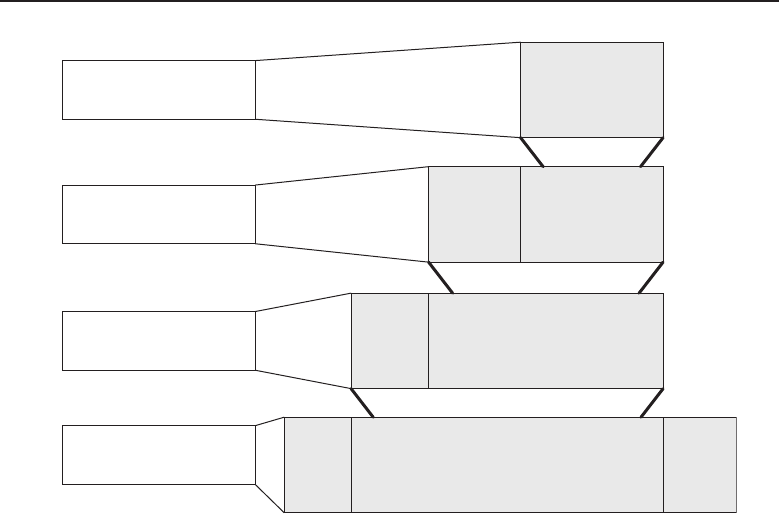
Edwards c03.tex V2 - 03/27/2009 7:38pm Page 118
118 Part I ■Networking Nuts and Bolts
Application
Transport
Network
Data Link
Data
TCP Data
IP Data
Frame Data
Frame
Header
Frame
Footer
IP
Header
TCP
Header
Figure 3-1 Encapsulation
Information passed from layer to layer is called service data units (SDUs)
or protocol data units (PDUs). The difference between an SDU and a PDU is
that the PDU specifies the data that is to be transmitted to the peer layer at the
receiving end. The SDU can be considered the PDU payload. Recall from the
paragraph above, data is transmitted from Layer 7 to Layer 4, from Layer 4 to
Layer 3, and so on. The data that is put together to be passed from Layer 7 to
Layer 4 is the PDU. The SDU is what it becomes when it is encapsulated into
the PDU of the lower layer. Figure 3-2 shows an example of what PDU is used
at each layer in the OSI reference model.
Each layer within the OSI reference model creates a PDU for any data that
needs to be transmitted to the next lower level. In addition to the data in the
PDU, each layer assigns a header to the PDU as well. Refer now to Figure 3-3.
Data is being transmitted from Layer 7 to Layer 1, across a medium to the
Physical layer on the opposite end, and then up each layer until it reaches
Layer 7. Notice that each layer appears to communicate directly to the layer on
the opposite end. When each layer passes data to the layer below it, the data
(including the higher layer header) becomes an SDU. When the layer attaches
its header to the SDU, it becomes the PDU that is transmitted to the next lower
layer.
Edwards c03.tex V2 - 03/27/2009 7:38pm Page 119
Chapter 3 ■Network Hardware and Transmission Media 119
Layer PDU
Application Data
Presentation Data
Session Data
Transport Segment
Network Packet
Data Link Frame
Physical Bit
Figure 3-2 PDUs used at each layer in the OSI reference model
Application
Presentation
Session
Transport
Network
Data Link
Physical
Application
Presentation
Session
Transport
Network
Data Link
Physical
Data
Data
Data
Data
Data
Data
Layer 7
Header
Layer 7
Header
Layer 7
Header
Layer 7
Header
Layer 7
Header
Layer 7
Header
Layer 7
Header
Layer 7
Header
Layer 7
Header
Layer 7
Header
Layer 7
Header
Layer 7
Header
Layer 2
Footer
Layer 6
Header
Layer 6
Header
Layer 6
Header
Layer 6
Header
Layer 6
Header
Layer 5
Header
Layer 5
Header
Layer 5
Header
Layer 5
Header
Layer 4
Header
Layer 4
Header
Layer 4
Header
Layer 3
Header
Layer 3
Header
Layer 2
Header
00101110010110001101111011011001110101
Figure 3-3 Layer-by-layer encapsulation

Edwards c03.tex V2 - 03/27/2009 7:38pm Page 120
120 Part I ■Networking Nuts and Bolts
3.1.4 Data Communication Equipment
and Data Terminal Equipment
RANDOM BONUS DEFINITION
straight-through cable — A twisted pair
cable that is wired for normal DTE to DCE
communications.
crossover cable — A twisted pair cable that
is reverse-wired for DCE-to-DCE or
DTE-to-DTE communications.
Data communication predom-
inately takes place between
nodes that are known as either
data communication equip-
ment (DCE)10 or data terminal
equipment (DTE). In order for
communication to take place
between nodes, one end of the
connection must be a DCE and
the other a DTE. If you have to
connect a DCE to a DCE or a
DTE to a DTE, a null modem11 or a crossover cable12 must be used. The plug
connector of a hub (see Section 3.3.4) or a modem would be an example of a
DCE, whereas the plug connector on an NIC card (see Section 3.3.2.2) would
be an example of a DTE.
In data communications, synchronization between nodes is known as clock-
ing. The DCE is responsible for providing the clock signal while the DTE is
responsible for synchronizing its clock based on the signal received. The DCE
uses what is called internal clocking, setting the clocking without any outside
influence. The DTE uses external clocking, which requires a signal in order to
set and synchronize its clocking.
3.1.5 All Your Base Are Belong to Us13
We don’t want to jump into Ethernet signaling at this point (Chapter 6,
‘‘Ethernet Concepts,’’ will cover this in depth). We do want to introduce some
terms that you will come across in this chapter (10BASE-T, 100BASE-TX, etc.),
so you will understand what they mean.
Baseband simply refers to the way data is transported onthe wire. A baseband
signal is data that transported as digital data on an unmultiplexed channel
over the transmission medium. The BASE in the term 10BASE-T stands for
broadband. The number preceding BASE is the speed (for instance, 10BASE
means that the transmission medium can support Ethernet transmission at a
10DCEs are also often called data carrier equipment.
11Serial cables that crosslink the transmit and receive wires. Also can be an adapter that is used
to cross the signals.
12Normally a crossover cable is an Ethernet cable that is reverse-wired on each end. This will put
all output signals on one end of the cable to be the input signals on the other, and vice versa.
This is appropriate for other technologies, but is most common in Ethernet.
13If you are an Internet gamer, you are probably familiar with this slogan. This broken English
translation appeared in a European release of the Japanese video game Zero Wing.

Edwards c03.tex V2 - 03/27/2009 7:38pm Page 121
Chapter 3 ■Network Hardware and Transmission Media 121
speed of 10 Mbps over baseband). All symbols following BASE identify either
a distance of transmission or a medium type (5 for 500 meters, T for twisted
pair, F for fiber optic).
3.1.6 Computer Buses14
ACRONYM ALERT
PCI — Peripheral component interconnect
Computers can be modified and any hard-
ware that is added to the computer is known
as a peripheral. New peripherals come with
software, known as a driver,thatisloaded
on your PC and provides the instructions
the computer will use to learn what it
needs to communicate and coexist with the
peripheral. Within the computer, there is a system that can logically connect
multiple peripherals within the same set of wires. This system is known as
the computer bus. Computer buses are also used to connect computer internal
components (more on this in a minute15).
A computer bus can operate as both a parallel bus and a serial bus. What’s the
difference? Glad you asked. Parallel buses transmit several bits of data at the
same time, in parallel on the bus, whereas serial buses transmit data one bit at
a time, sequentially to the destination. The main types of computer buses are
an internal bus and an external bus. The internal bus is the bus that is contained
within the computer and connects internal components to the shared bus; an
external bus is a bus that connects peripherals to the motherboard.
3.1.7 IP Addressing
Nodes in a TCP/IP network are assigned a numeric value, known as an IP
address. We will be discussing IP addressing throughout this book, so this is
a short overview. The IP address usually is unique and provides a network
identify for the node. Although there are new versions of IP that are growing
in popularity, currently16 IP version four (IPv4) is still what the majority of
networks are using.
An IPv4 address is a 32-bit number that is divided into four fields, called
octets, separated by dots. Each octet represents 8 bits of the total 32-bit number.
This is known as dotted decimal notation. An example of dotted decimal
14Not to be confused with a commuter bus.
15Disclaimer: This actually may take more or less than a minute. It depends on how fast you can
read and how many breaks you take.
16IPv4 is popular at the time of this writing, although this may change in the near future, as a lot
of new vendor implementations are using IPv6.

Edwards c03.tex V2 - 03/27/2009 7:38pm Page 122
122 Part I ■Networking Nuts and Bolts
notation would be the IP address 192.168.1.1.17 The meaning of the octet that is
represented by each number depends upon what network class the IP address
belongs to. The entire IP address is separated into two parts: the network part
and the host part. Figure 3-4 shows an example of the difference in network
classes.
Class A
Network bits Host bits
10 42 64 114
Class B
Network bits Host bits
142 23 107 14
Class C
Network bits Host bits
192 168 11 122
Figure 3-4 IP address network classes
The four18 network classes are as follows:
Class A — Class A addresses are identified by a number from 1
to 126 in the first octet. In Class A addresses, the first octet identi-
fies the network and the remaining three octets identify the host.
These addresses are normally assigned to larger networks.
Class B — Class B addresses are identified by a number from 128
to 191 in the first octet. In Class B addresses, the first two octets
identify the network and the last two identify the host. These
addresses are normally assigned to medium-sized networks.
Class C — Class C addresses are identified by a number from 192
to 223 in the first octet. In Class C addresses, the first three octets
17IP addresses are identified in decimal (dotted decimal notation, to be specific). If converted to
binary, this number is 11000000.10101000.00000001.00000001 (note that there are 8 bits in each
field).
18There is also a Class E network class, but it is not an approved standard and is experimental.

Edwards c03.tex V2 - 03/27/2009 7:38pm Page 123
Chapter 3 ■Network Hardware and Transmission Media 123
identify the network while the last octet identifies the host. These
addresses are normally assigned to small to medium-sized networks
Class D — Class D addresses are a little different than the other classes.
Class D addresses are used for multicasting. These addresses always
begin with the first 4 bits being 1110 and the remaining 28 bits iden-
tifying the network in which the multicast message is to be sent.
DID YOU JUST NOTICE THAT?
If you were paying attention during the previous discussion of IP network
classes, you may have noticed that the number 127 is skipped in the transition
from Class A (first octet containing 1–126) to Class B (first octet containing
128–191). This is because the number 127 in the first octet represents a special
type of IP address called a loopback address. Used mainly for troubleshooting,
the loopback IP simply loops datagrams back to the sender.
Some other special IP addresses include:
◆0.0.0.0 — Default network (where packets go when the router doesn’t know
where a host is)
◆1.1.1.1 — Broadcast to all on a specified network
3.2 Transmission Media
POP QUIZ
Define RAM.
Transmission media refers to the
modes and materials by which
the data is transferred in a
network. Network cables, light
waves, and so on are all con-
sidered transmission media. (If
you are referring to more than
one medium, it is called media.19) Transmission media provide a way for data
to be passed from one endpoint to another. The medium does not guaran-
tee delivery nor is it concerned with what information is contained in the
datagram; it simply provides the path for the data.
In the United States, there are two forms of transmission media in data
communications. The first type, bounded or guided, is a communication line
(or any other type of solid medium) that transports waves from one endpoint
to another. The second type, unguided or wireless, is where data is passed
wirelessly from one access point (antenna) to another.
19Another one of those terms that is often misused but always understood.

Edwards c03.tex V2 - 03/27/2009 7:38pm Page 124
124 Part I ■Networking Nuts and Bolts
3.2.1 Network Cabling
Wireless communication as a transmission medium is becoming more and
more popular, but network cabling is still the backbone of any network. There
are many different types of cabling, each serving a specific purpose to meet the
needs of the network. Often you will find different types of cabling running
side by side between nodes in the network. It’s important to understand
the cabling types that are in use on any network you configure and how to
maintain them. The major cable types are:
Twisted pair
Coaxial
Fiber optic
The type of cabling that is used depends on the network. Data traffic
requirements, the size of the network, the topology of the network, the
protocols in use, the nodes in place, cost considerations, and many other
things need to be taken into account when designing and/or maintaining a
network. In this section, we will discuss the more popular cable types and how
they work.
TIPS FOR INSTALLING AND REPLACING CABLES
Whenever you need to replace cables, or are tasked with designing and
implementing a cable run, there are a few hints you should be aware of that
will save you headaches in the future.
1. Use cable ties to keep cables grouped together. Do not use tape, staples,
glue, rubber bands, etc. The cable ties are easy to work with and easy to
remove when you need to.
2. Make sure to label the cables on each end of the link. It can be very time
consuming to try to track down a problem if the cables are not labeled.
Tape, glue, and even rubber bands work well for this task. Staples or tacks
do not.
3. Keep the cable off the floor. If you do not have a choice, then
make sure you cover the cable with a cable protector.
4. Stay away from anything that may cause electrical interference.
5. Cut your cables too long on purpose — leave some excess (on both ends) to
work with in the future.
6. Make a detailed drawing of the cables that are installed in
the building. The drawing needs to be easy to understand
when tracking cable routes and endpoint connections.
(continued)

Edwards c03.tex V2 - 03/27/2009 7:38pm Page 125
Chapter 3 ■Network Hardware and Transmission Media 125
TIPS FOR INSTALLING AND REPLACING CABLES (continued)
7. Implement a ‘‘hands-off’’ policy for end users. Make sure you
know who is touching the cables and interfaces attaching
end-user nodes to the network. This is especially important
in coaxial runs. One glitch and all the users go down.
3.2.1.1 Twisted Pair Cable
Twisted pair cabling consists of two or more pairs of conductors that are
twisted together within the cable. The conductors are wrapped in plastic
and then all of the pairs are wrapped within the cable, making them less
susceptible to outside electrical interference. Twisted pair cables are used
primarily in areas with short to medium distances between nodes. Twisted
pair is less expensive than coaxial cable or fiber cable, and is often used as a
consideration in network design.
There are four pairs of twisted wires in a network Ethernet cable. These
are color coded in blue, brown, green, and orange. Each twisted pair has one
solid and one striped wire. Here is a list of the wires that are within a normal
twisted pair cable:
Blue
Blue/white
Brown
POP QUIZ
Define encapsulation.
Brown/white
Green
Green/white
Orange
Orange/white
There are two main types of twisted pair cabling in use in LANs. Unshielded
twisted pair (UTP) is the most popular copper cable type. Shielded twisted
pair (STP) is the other type. Ethernet and Token Ring both use twisted pair
cabling.
Unshielded twisted pair — UTP cabling is the type of copper
cabling that is used the most in networks today. UTP cables con-
sist of two or more pairs of conductors that are grouped within
an outer sleeve. Figure 3-5 shows an example of a UTP cable.

Edwards c03.tex V2 - 03/27/2009 7:38pm Page 126
126 Part I ■Networking Nuts and Bolts
Figure 3-5 UTP cable
UTP cable is often referred to as Ethernet cable,becauseEth-
ernet is the predominate technology that uses UTP cable.
UTP cabling is cheap, but does not offer protection from elec-
trical interference. Additionally, bandwidth is limited with
UTP in comparison with some of the other cable types.
Shielded twisted pair — STP cabling is a type of copper cabling that
is used in networks where fast data rates are required. STP cables
consist of two or more pairs of conductors that are grouped together
and then an additional metal shield wraps around the twisted pairs,
forming an additional barrier to help protect the cabling. Finally, all
of the cables are grouped together and a final outer sleeve is placed
over the wiring. Figure 3-6 shows an example of an STP cable.
Figure 3-6 STP cable
STP cables are also referred to as Ethernet cables. STP cables provide
additional protection to the internal copper, thus data rates are
increased and more reliable. The conductors that are grouped together
can be shielded as individual pairs (in other words, each pair will
have its own shield), or all pairs can be shielded as a group.
The ANSI/TIA/EIA-568-B standard, Commercial Building Telecommunica-
tions Standard, is the standard that defines the requirements for installing and

Edwards c03.tex V2 - 03/27/2009 7:38pm Page 127
Chapter 3 ■Network Hardware and Transmission Media 127
maintaining cabling systems, component, and data transmissions in commer-
cial buildings. In the standard, the categories (Cat) of twisted pair cabling are
outlined. As of the release of the ANSI/TIA/EIA-568-B standard, the only
categories that are recognized by the standards are Cat 5e and above.20 Table
3-5 lists all the categories, but you need only to know they exist. You should
focus on Cat 5e and above, as this is the direction the data world is heading.
Table 3-5 ANSI/TIA/EIA-568-B Standard Categories
CATEGORY ANSI/TIA/EIA- USED FOR PERFORMANCE
568-B STATUS
Cat 1 Unrecognized ISDN, ISDN basic rate
interface (BRI), doorbell
wiring, POTS voice
communication
Less than or equal to 1
Mbps
Cat 2 Unrecognized Token Ring 4 Mbps
Cat 3 Unrecognized 10BASE-T Ethernet 16 MHz
Cat 4 Unrecognized Token Ring 20 Mbps
Cat 5 Unrecognized 100BASE-T Ethernet Less than or equal to
100 MHz
Cat 5e Recognized 100BASE-T and 1000BASE-T
Ethernet
Less than or equal to
100 MHz
Cat 6 Recognized Backward compatible to Cat
3, Cat 5, and Cat 5e cabling;
10BASE-T, 100BASE-TX, and
1000BASE-T Ethernet
Less than or equal to
250 MHz
Cat 6a Recognized 10GBASE-T Ethernet Less than or equal to
500 MHz
Cat 6e Recognized 10GBASE-T Ethernet Less than or equal to
625 MHz
Twisted pair cables can be hard-wired to endpoints or attached to a regis-
tered jack (RJ) connector. The most common connector is often referred to as
an RJ45 connector. The RJ45 connector resembles the connector for land-based
telephones, only larger. If you have plugged your PC into a network, then you
plugged in an RJ45 (see Figure 3-7).
20This does not mean that other categories are no longer in use. They probably are and will be
in networks that never change (which are rare). It simply means there are no plans to advance
the category (and you can bet there are not a lot of vendors out there that will continue to build
based on Cat 5 and below technology).

Edwards c03.tex V2 - 03/27/2009 7:38pm Page 128
128 Part I ■Networking Nuts and Bolts
Figure 3-7 An 8P8C plug (RJ45)
STUFF YOU JUST HAVE TO KNOW
Let’s take a moment to talk a little about registered jacks. A registered jack (the
RJ in RJ45) is simply a standardized network interface. The pattern of the
wiring, as well as the construction of the jack itself, is based on the standard
for which the jack was developed. Although we have written mostly about the
RJ45 in this chapter, this does not imply that the RJ45 is the only type of
interface you will come across. So we have provided the following handy-dandy
reference list for your information.
◆RJ11 — Used for telephone wires. If you pick up a phone (land line, of
course) and look at the wire that plugs into the phone, you are most likely
looking at an RJ11 connector.
◆RJ14 — Same as above, but for two lines instead of one.
◆RJ25 — For three lines.
◆RJ61 — For four lines.
◆RJ48 — Tor T1 and ISDN lines.
◆RJ49 — Tor ISDN BRI lines.
◆RJ61 — For twisted pair cables.
ACRONYM ALERT
HDLC — High-Level Data Link Control
The term RJ45 refers to what is normally
attached to any 8 Position 8 Contact (8P8C)
jacks and plugs, but the true RJ45 standard
defines the mechanics of the interface as
well as a wiring scheme that does not match
the ANSI/TIA/EIA-568-B standard. There
are two parts to the 8P8C: the plug and the
jack. The plug is what was referred to in

Edwards c03.tex V2 - 03/27/2009 7:38pm Page 129
Chapter 3 ■Network Hardware and Transmission Media 129
Figure 3-7 and is often called the male connector or male plug.Thejack is the
interface that the plug goes into and is called the female connector or female jack.
There are eight pins, numbered 1 through 8 in an RJ45 connector. Sometimes
these are labeled on the plug. If they are not labeled, you can identify the pin
numbers by holding the connector in your hand with connector pins facing
upward and outward. The pin that is closest to you will be pin number 1 and
then they are sequentially numbered through pin number 8. (See Figure 3-8.)
Pin 1-
Pin 8-
Figure 3-8 RJ45 pin numbering
ANSI/TIA/EIA-568-B defines the pin to twisted pair definitions for pin
assignments when connecting the twisted pair to the 8P8C connector. The
definition of the pin/pair assignment21 is named T568A and T568B.22 The
standard to use depends on the 8-pin cabling system that is in use. T568A
and T568B define the order in which twisted pairs should be attached to the
8P8C adapter. Table 3-6 shows an example of the cable pin-outs for a T568A
straight-through cable.
The difference between the T568B pin-out definitions and the T568A pin-out
definitions is that the green pair and the orange pair are reversed. Table 3-7
shows the pin-outs for T568B.
3.2.1.2 Coaxial Cable
Coaxial cabling is not as popular as twisted pair cabling, but there still are some
networks that use it.23 Figure 3-9 shows an example of a coaxial cable. Within
the cable, there is either a single inner conductor or group of conductors that
are twisted together to form one. The conductor is then wrapped in a plastic
sleeve, which is wrapped in a metallic conducting shield. Finally, these are
all wrapped in an insulating sleeve. There may be a slight variation between
cablevendors,butthefunctionsofthecoaxialcableremainthesame.
21The pin/pair assignment is often referred to as the cable pin-outs.
22T568B is not to be confused with the standard ANSI/TIA/EIA-568-B.
23Most of these were networks that were built in the late 1980s and early 1990s. Most new
deployments use twisted pair.

Edwards c03.tex V2 - 03/27/2009 7:38pm Page 130
130 Part I ■Networking Nuts and Bolts
Table 3-6 T568A Straight-Through Pin-Outs
8P8C PIN WIRE COLOR 10BASE-T 1000BASE-T
NUMBER 100BASE-T SIGNALING SIGNALING
1 Green/white Transmit+Bidirectional data
A+(BI DA+)
2 Green Transmit– Bidirectional data
A– (BI DA–)
3 Orange/white Receive+Bidirectional data
B+(BI DB+)
4 Blue Not used Bidirectional data
C+(BI DC+)
5 Blue/white Not used Bidirectional data
C– (BI DC–)
6 Orange Receive– Bidirectional data
B– (BI DB–)
7 Brown/white Not used Bidirectional data
D+(BI DD+)
8 Brown Not used Bidirectional data
D– (BI DD–)
Table 3-7 T568B Straight-Through Pin-Outs
8P8C PIN WIRE COLOR 10BASE-T 100BASE-T
NUMBER 10BASE-T SIGNALING SIGNALING
1 Orange/white Transmit+(BI DA+)
2 Orange Transmit– (BI DA–)
3 Green/white Receive+(BI DB+)
4 Blue Not used (BI DC+)
5 Blue/white Not used (BI DC–)
6 Green Receive– (BI DB–)
7Brown/whiteNotused (BIDD+)
8BrownNotused (BIDD–)

Edwards c03.tex V2 - 03/27/2009 7:38pm Page 131
Chapter 3 ■Network Hardware and Transmission Media 131
Figure 3-9 An example of coaxial cable
The inner conductor and the conducting shield work on the same axis
and work together to pass data — hence the name co (cooperative) and axial
(running on the same axis). Data is transmitted in the space between the inner
conductor and the outer conducting shield. Coaxial cables are best suited for
high-frequency or broadband signaling.
The connectors that are used to connect coaxial cable runs are known as
bayonet Neill-Concelman (BNC) connectors. There are two main types of coaxial
cabling, thin coaxial and thick coaxial, often referred to as thinnet and thicknet.
When used for Ethernet, they are called thin Ethernet (10BASE2) and thick
Ethernet (10BASE5).
Thin coaxial cabling, known as RG-58, is used for connections that use a low
power signal. In Ethernet, the maximum distance that data can be transmitted
is 185 meters. A node must be placed within that distance, or data corruption
and deletion may occur. Thick coaxial cabling, known as RG-8,isusedfor
connections that require a higher power signal. The maximum travel distance
between nodes using thick coaxial cables is 500 meters.
3.2.1.3 Fiber Optic Cable
When used in data networking, fiber optic cables are groups of thin strands
of glass or transparent plastic that is able to carry data for long distances. The
fibers are grouped together to form the core of the cable. The core is wrapped
in a cladding, which is denser glass material that reflects light back to the core.
Surrounding the cladding is a buffer. Finally, there is an outer wrap called a
jacket that helps protect the core from damage. Fiber optic cable has helped
make a lot of the advances in networking over the last few years. The use of
fiber cables provides for an increase in the distance data can travel between
nodes, as well as speeds that are, well, as fast as light.24 Optical signaling is not
hampered by electronic interference, so data loss is not seen as often as with
twisted pair or coaxial.
Fiber optic cabling works by sending reflections of light from one endpoint
to another. The light travels between the core and the cladding and back again.
The cladding reflects the light back to the core, much like a mirror does if you
shine a light into it. This is known as total internal reflection (see Figure 3-10).
24Light signals can be transmitted at speeds of up to 40 Gbps.
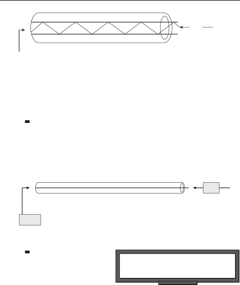
Edwards c03.tex V2 - 03/27/2009 7:38pm Page 132
132 Part I ■Networking Nuts and Bolts
Core
Cladding
Light
Figure 3-10 Total internal reflection in a fiber optic cable
Fiber optic cables are advantageous as a transmission medium for fast data
exchange over long distances. Fiber optic cabling can also save space in a
LAN as it requires less space than copper cables. There are two main types, or
modes, of fiber optic cabling used for data communications: single-mode fiber
(SMF) and multi-mode fiber (MMF).
Single-mode fiber optical cabling — SMF cables are thinner
than MMF cables. This is because SMF cables are designed to
carry a single beam of light. Because there are not multiple
beams involved, the SMF cable is more reliable and supports a
much higher bandwidth and longer distances than MMF cables.
The bulk cost of SMF cabling is much less expensive than MMF
cabling. Figure 3-11 shows an example of an SMF cable.
Core
Cladding
Light
Figure 3-11 Single-mode signaling
POP QUIZ
What is IEEE Standard 802.11?
Multi-mode fiber optical
cabling — MMF cabling
is made for shorter dis-
tances. Unlike SMF, there
are multiple beams of
light, so the distance and
speed are less. Granted, supporting data rates of up to 10 Gbps for
distances as far as 300 meters is nothing to sneeze at. Because of the
additional modes, MMF cabling is able to carry much more data at
any given time. Figure 3-12 shows an example of MMF cabling.

Edwards c03.tex V2 - 03/27/2009 7:38pm Page 133
Chapter 3 ■Network Hardware and Transmission Media 133
Cladding
Multiple Modes
Core
Light
Figure 3-12 Multi-mode signaling
3.2.2 Wireless Communication
Wireless communication has really grown in the past few years. Many busi-
nesses, universities, and even some cities have now implemented wireless
access for anyone to use. There is nothing like being able to sit in a bookstore
or a coffee shop and being able to connect to the Internet and all that it offers.
Signals in wireless communication are sent via antennas, microwave stations,
satellite, or infrared light.
Wireless communication enables data to be transferred through the air via a
communication signal. Communication is normally handled by infrared light
or high-frequency radio waves. Infrared communication normally takes place
between nodes. The wireless signal between a PDA and a PC is an example
of nodes that use an infrared signal. Data communications, radio, and cellular
phones are all examples of nodes that use radio waves for data communication.
Section 3.3.3.9.3 covers the hardware that makes wireless communication as a
transmission medium a reality.
3.3 Network Hardware
A lot of different types of network hardware work together25 to issue, pass,
respond, receive, and otherwise transmit data in a network. Network hardware
performs the operations necessary to receive and forward data that it is
responsible for. Not all network hardware is created equal. Keep in mind,
however, the hardware is built to support the available standards that the
particular node should be able to support. Most of the hardware in networks
is nothing more than a big paperweight without the software loaded on the
device to teach it what to do and sometimes how to do it. To take this a bit
further, the hardware and software are useless without someone to configure
25There are also times when the network hardware does not work well together, but we will save
that discussion until Chapter 16, ‘‘Troubleshooting.’’

Edwards c03.tex V2 - 03/27/2009 7:38pm Page 134
134 Part I ■Networking Nuts and Bolts
it. Until computers are able to think for themselves, it is always going to take
human intervention to get a node to operate correctly in a LAN.
The following sections list network hardware common in networks today.
Not all the devices listed are in place in every network. They are available to
anyone who needs the device in order to support implemented or planned
standards within a network.
3.3.1 End-User Interface Hardware Types
A network exists to servethe needs of the end users. The network administrator
(head honcho, big daddy, C-3PO, or whatever else the person is called) plans
very carefully to ensure that the right equipment is purchased and brought
into the network. The hardware has to be able to support data traffic needs as
well as the necessary standards and protocols. Look at it this way: it wouldn’t
do you any good to buy a cell phone from one vendor and then order the
cell phone plan from another vendor. Most likely, the cell phone would never
work.26
The end users interface with some specific hardware devices that they need
to do their job. In Figure 3-13, you can see an example of some of the many
hardware devices that an end user may actually interface with. At the very
least, an Internet user will have a PC or laptop and an adapter of some sort
that will allow the PC to connect to a network. In many office environments,
multiple users will share the services of a printer, fax machine, or copy
machine. The network is what allows them to do this. For the purposes of this
chapter, we will not discuss the end-user direct access hardware. It would be
information that you are most likely familiar with.
3.3.2 Connecting End Users
RANDOM BONUS DEFINITION
wireless fidelity (Wi-Fi) — A term that
describes certain types of 802.11 WLANs.
Although there are many dif-
ferent user interface types out
there, we are going to focus on
the PC or laptop as the user
interface type for the remainder
of this book. If we enter into dis-
cussions of other user network
interfaces, we will define these
as they come up.
26Jim heard on the news the other day that a cell phone vendor out there claims its service will
work with any other vendor’s plan. Looks like maybe we can all get along.
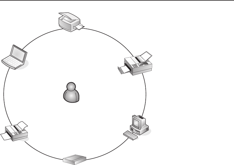
Edwards c03.tex V2 - 03/27/2009 7:38pm Page 135
Chapter 3 ■Network Hardware and Transmission Media 135
PC
Laptop
Printer
Modem
Fax Machine
Copy Machine
Figure 3-13 End-user hardware types
The user interface is the device, software application, software program,
or other tool the user uses to complete a network transmission. The network
interface is the physical interface that allows the network node to connect to
the network.
It’s important to note the distinction between a network interface and a
user interface. Take a look at Figure 3-14. Really, you couldn’t tell a user to
go interface with a router and send an e-mail to 192.168.2.2. Now look at
Figure 3-15. The opposite holds true, as well: you can’t tell a router to send an
e-mail to your brother Joel in Abilene.
End users interface with cell phones, telephones, PDAs, PCs, e-mail pro-
grams, word processing programs, and a variety of other software and
hardware tools. They may go as far as installing a network adapter so
they can connect to the network, but the adapter really is not a user interface;
it’s a way for a PC (or other node) to pass and receive data to and from a
network.
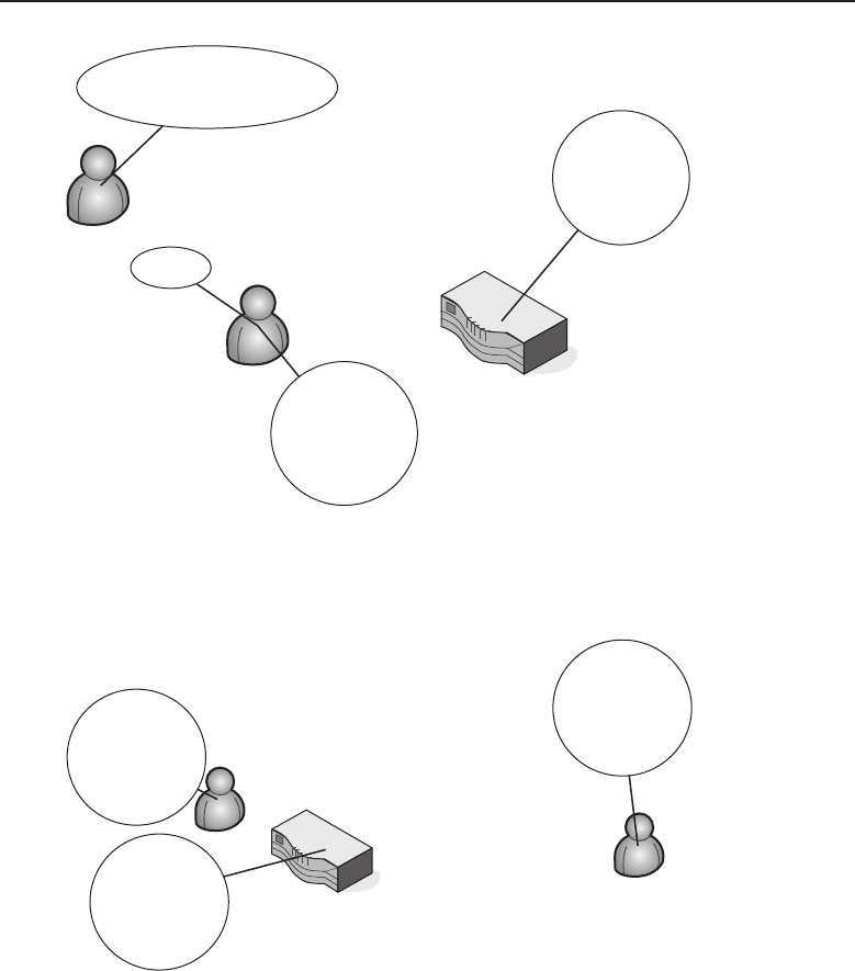
Edwards c03.tex V2 - 03/27/2009 7:38pm Page 136
136 Part I ■Networking Nuts and Bolts
“Hey Joel – tell the router to send
an email to 192.168.2.2”
OK
“Hey router – send
an email to
192.168.2.2
Silly user, I only
speak in
datagrams!
Figure 3-14 A user trying to interface with a router
“Hey router – send
an email to my
brother, Joel”
I told you that I
only speak in
datagrams!
I wonder why my
brother hasn’t
written??
Joel
Chirp Chirp Chirp
Chirp Chirp Chirp
Chirp Chirp Chirp
Figure 3-15 A router trying to send an email to a user
3.3.2.1 Network Interfaces and Adapters
Like many other things in networking, the terms interface and adapter
can have various meanings (and sometimes they mean the same thing).

Edwards c03.tex V2 - 03/27/2009 7:38pm Page 137
Chapter 3 ■Network Hardware and Transmission Media 137
RANDOM BONUS DEFINITION
Worldwide Interoperability for Microwave
Access (WiMAX [IEEE 802.16]) — A task
force responsible for the IEEE 802.16
standards for broadband wireless access
(BWA) networks
We already discussed user inter-
faces and the types that are asso-
ciated in that group. We are now
going to discuss network inter-
faces and network adapters.
Before we do that, take a look at
how Merriam-Webster defines
an interface and an adapter.
in·ter·face27
noun
1: a surface forming a common boundary of two bodies, spaces, or phases
(an oil-water interface)
2 a: the place at which independent and often unrelated systems meet and
act on or communicate with each other (the man-machine interface)
b: the means by which interaction or communication is achieved at an
interface transitive verb
1: to connect by means of an interface (interface a machine with a
computer)
2: to serve as an interface for
adapt·or28
also adap·ter
noun
1: one that adapts
2 a: a device for connecting two parts (as of different diameters) of an
apparatus
b: an attachment for adapting apparatus for uses not originally intended
A network interface is any device or method that serves as an access point
to a data path among various network nodes within a network. A network
interface is also the point that connects users with a network that is outside
the boundaries of their LAN. Network interfaces provide a way for a node to
speak to other nodes, regardless of the standards that are in place along the
data path.
There is more to a network interface than simply installing it and then
plugging in a cable. The network interface is also able to convert data from
proprietary or noncommon standards to one that is shared, thus allowing
nodes to communicate with another one even if they don’t have the same
protocols implemented. A network interface connects end-user devices to a
network. The network interface controller (NIC) that is in a standard desktop
computer is a type of network interface. The point at the boundary of a LAN,
27Merriam-Webster Online Dictionary. Retrieved May 9, 2008, from www.merriam-webster.
com/dictionary/interface.
28Merriam-Webster Online Dictionary. Retrieved May 9, 2008, from www.merriam-webster.
com/dictionary/interface.

Edwards c03.tex V2 - 03/27/2009 7:38pm Page 138
138 Part I ■Networking Nuts and Bolts
which connects the LAN to an outside network, is another type of network
interface. In Layer 3 environments, interface is often the term used to describe
a network connection and really isn’t considered hardware.
Network adapter is usually the term given to the hardware interface to the
network. Previously we said that an NIC card is a network interface that a
computer uses. An NIC card is also referred to as a network adapter.29 The NIC
card adapts to the computer, allowing it to have an interface to the network.
Confused yet? Wait — there’s more. There is also what is known as a virtual
network adapter, which is an application that assists a computer to connect to
the Internet without a physical adapter. This is usually done over WiFi or
WiMAX.
We really shouldn’t dwell on this much longer. With practice, you will
learn how to adapt to your fellow networking gurus and can interface with one
another while talking about how great this book is and how much you enjoyed
reading it.30 You will get a better feel for adapters and interfaces throughout
the remainder of this book. It’s not as difficult as it may seem, we promise.
3.3.2.2 Network Interface Controllers
The network interface controller (NIC)31 is a hardware card that allows a PC to
participate in passing and receiving data on a network. An NIC is commonly
referred to as an NIC card,LAN card,LAN adapter,network card,network adapter,
Ethernet adapter, and a few other names. Often the name may be a reference
to technology the NIC is supporting (i.e., an Ethernet card). All are entirely
acceptable and, regardless of what term you use, generally understood by
whoever is participating in the discussion.32 Figure 3-16 shows an example of
an NIC card.
NIC cards operate at Layers 1 and 2 of the OSI reference model. Because
NIC is a physical connecting device, providing a user with network access, it is
a Layer 1 device. However, because it uses a system for addressing nodes, it is
also a Layer 2 device. NIC cards33 have a 48-bit serial number assigned to them,
which is the MAC address. NIC cards normally take one of two forms; they
can be an expansion card that has to be physically inserted into the bus on the
PC motherboard or they can be integrated into the motherboard. You may also
have interfaces that have a difference connector type, such as a USB interface.
29A good portion of the time if someone says ‘‘network adapter,’’ they are talking about an NIC
card. Or the adapter at the end of a cable (serial adapter, Ethernet adapter, etc.).
30It seemed like a good time for a shameless plug.
31Some people assume that NIC stands for network interface card. This is not correct, although
the term NIC card is accepted by most. If NIC were network interface card, then an NIC card
would be a network interface card card.
32If you are ever unsure, just ask someone.
33Okay. We said that it was a funny term, but it’s one we are comfortable with. It is less awkward
to ask someone, ‘‘Who do you buy the NIC card from?’’ than ‘‘Where did you get that NIC?’’
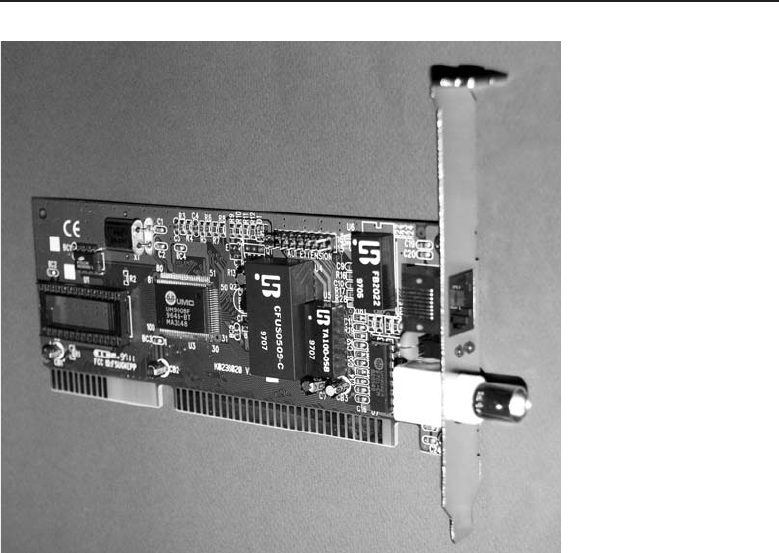
Edwards c03.tex V2 - 03/27/2009 7:38pm Page 139
Chapter 3 ■Network Hardware and Transmission Media 139
Figure 3-16 An NIC card
3.3.3 To Boldly Go Where Data Needs to Flow
(or, How Does that E-mail Get to Brother Joel?)
We have our cables, computers, NIC cards, buses, and all the things we need
to get our bits to hit the NIC card and travel across our UTP to a destination
on the other side of the LAN. As you can see in Figure 3-17, our bits just
are not going to go very far. The application sends the data to our NIC card,
who forwards it on to the medium, who just cannot figure out where the bits
should go.
We all know that the example in the preceding paragraph is simplistic, but
if you think about it, that is about all we have covered so far. Well, folks,
it’s time now for us to talk about the nodes in the network. Some of these
nodes you may not ever come across in real life, and others you will become
very familiar with. There are a lot of different nodes in a network, and often
equipment from many different vendors of node types is implemented within
thesamenetwork.
34 When designing a network, it is important to put the
right node in place to perform the right job. You really don’t need a router
34Don’t put all of your eggs in one basket.
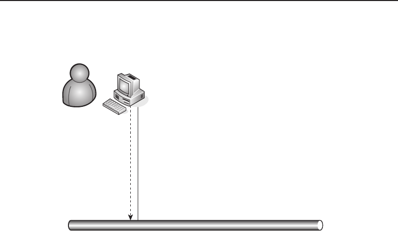
Edwards c03.tex V2 - 03/27/2009 7:38pm Page 140
140 Part I ■Networking Nuts and Bolts
in a bridged network, nor would you try to use a repeater to connect to your
Internet service provider (ISP).
101010
001101
011100
110011
001100
111110
001010
100110
011001
010110
011110
0
0
0
0
0
0
00
0
0
0
0
0??1
1
1
1
1
1
1
1
1
1
1??010??1011??01?1000??1101??011001??110101?011??0
1
1
Figure 3-17 Sending data to the pseudo-net
This section does not provide an in-depth discussion of the standards
involved with and the modus operandi of any individual node. Most of these
will be covered in upcoming chapters. This section is more ofan introduction to
networking hardware. Where does the data go when it leaves your computer?
What other nodes might you be using and not even realize it? These are the
types of questions you will be able to answer when you are done with this
section. The next time you hear someone say, ‘‘Hey, what’s all the hubbub?’’
you may be able to come up with a witty quip in response.
3.3.3.1 Concentrators
Anetworkconcentrator isanodethatisabletomultiplexsignalsandthen
transmit them over a single transmission medium. Most concentrators support
multiple asynchronous35 channels and one high-speed synchronous channel.
The term concentrator is often used generically when referring to some nodes
35In data communication, an asynchronous process is one that does not require a clocking
mechanism in order to work. A synchronous process does require clocking — in other words, it
has to be synchronized in order to work.
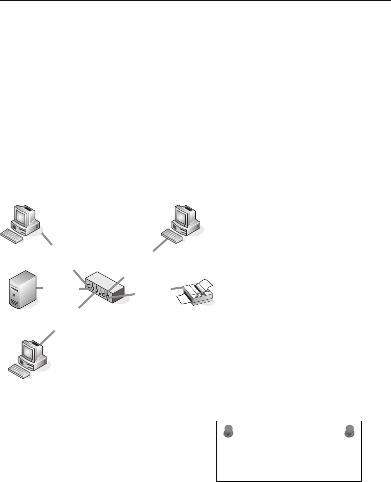
Edwards c03.tex V2 - 03/27/2009 7:38pm Page 141
Chapter 3 ■Network Hardware and Transmission Media 141
knownashubs(seenextsection).A concentrator usually provides point of
presence (POP) access for remote users, as well as performing other functions.36
3.3.3.2 Hubs
Hubs are commonly used to connect devices within network segments37 to
one another. Figure 3-18 shows an example of a typical hub deployment in a
network segment. Notice in the figure, the hub actually supports data rates of
both 10 Mbps and 100 Mbps. There are a lot of different types of hubs, with
varying numbers of hosts supported. Some support multiple data rates while
some only support a single data rate. The hub that is appropriate for your
environment should be chosen based on the needs of the network and the end
users.
10/100 Mbps Hub
10 Mbps
100 Mbps
10 Mbps
100 Mbps
100 Mbps
Figure 3-18 Hub deployment
ACRONYM ALERT
FPGA — Field-programmable gate array
When data is received by a hub, the hub
forwards the received data to all the nodes
that connect to it. All ports see datagrams
received on any other ports within the hub.
Hubs are considered shared media,asthere
are multiple hosts sharing a common trans-
mission medium. If a hub is made aware of a collision (data that collides
when two or more hosts try to pass data at the same time), it will signal
the other ports to stop transmitting until the collision is resolved. Hubs also
36Some concentrators are also able to perform high-layer functions, such as routing.
37Segments are areas of a LAN that are contained within a boundary with the boundary
termination node being a router, switch, or a bridge.
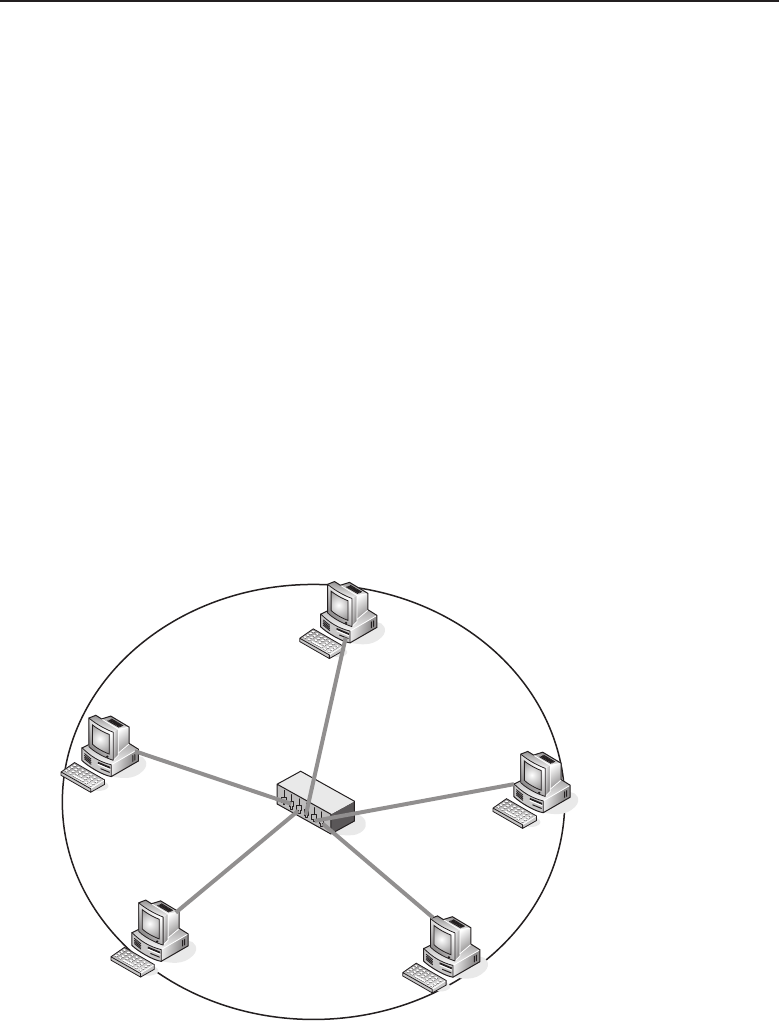
Edwards c03.tex V2 - 03/27/2009 7:38pm Page 142
142 Part I ■Networking Nuts and Bolts
typically determine if one of the ports is having problems (excessive collisions,
corrupted data, etc.). If so, the hub can react and shut the port off from the rest
of the shared media. Hubs are considered Layer 1 nodes.
Hubs have largely been replaced in recent years, due to the popularity and
cost reduction of network switches, though they are still in use for many
home and small business networks. Additionally, hubs can be used to copy
datagrams that are sent to or received by a specific node and have that
information forwarded to one or more network monitoring connections.
3.3.3.3 Media Access Units
Media access units (MAUs), also referred to as multi-station access units,38
function similarly to hubs, but for Token Ring networks. Data flows through
the MAU in a logical ring topology, although the physical topology is a star
topology configuration. The MAU can recognize any hosts that are inactive
and disable the port the host is on so as not to disrupt the operation of the
logical ring. MAUs are considered Layer 1 nodes.
Take a look at Figure 3-19. You see that all hosts are physically connected
to the MAU in a star topology, while communication between the hosts is still
performed as if the hosts were physically connected in a ring.
MAU
Figure 3-19 An MAU — physical star, logical ring
38There are two acronyms that are common when referring to the multi-service access unit, MAU
and MSAU.
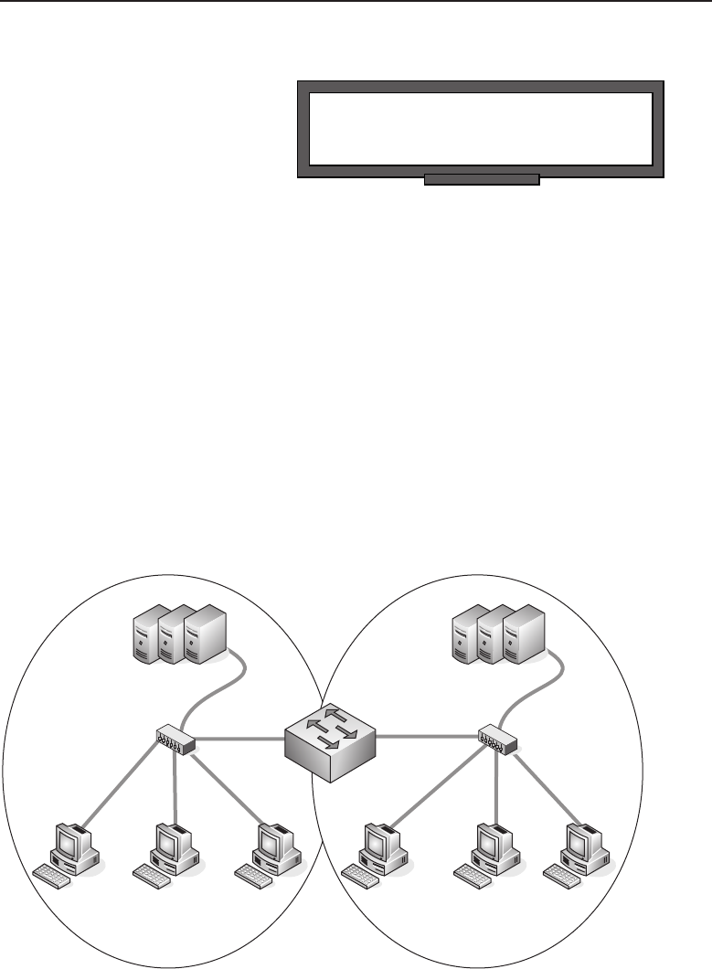
Edwards c03.tex V2 - 03/27/2009 7:38pm Page 143
Chapter 3 ■Network Hardware and Transmission Media 143
3.3.3.4 Repeaters
POP QUIZ
What does MAU stand for?
Repeaters are used to give data
the extra push it needs to reach
an endpoint. Transmission media
has distance limitations before
the signal experiences degrada-
tion, known as attenuation or sig-
nal loss. When the distance limit has been reached, instead of placing another
switch,hub,orrouterinthepath,arepeaterisused.
The role of the repeater is simple: it accepts data and then retransmits it to
the other side. Copper and fiber optic cabling are both supported by repeaters
geared for the cabling type. Additionally, there are repeaters available for
networks that use wireless as a transmission medium.
3.3.3.5 Bridges and Switches
Functionally, bridges and switches are pretty much interchangeable. Both are
Layer 2 devices that support and perform the same basic function of joining
network segments within the LAN (see Figure 3-20). Bridges traditionally were
very small (some had only two port interfaces). When sold on the market, some
bridges fetched a very expensive price, especially if they could support data
rates that matched the rates supported by the transmission media in place.
Server Farm
Switch
Users
Segment A Segment B
Users
Server Farm
Figure 3-20 An example of a switch bridging two LAN segments to one another

Edwards c03.tex V2 - 03/27/2009 7:38pm Page 144
144 Part I ■Networking Nuts and Bolts
In the late 1980s and the early 1990s, the demand started growing for faster
systems and faster networks. LANs were expanding to the point where ashared
media network was no longer able to handle the demand. Advancements in
technology paved the way for system resource (processor and memory)
advancements, which allowed vendors to build nodes with more flexibility in
the number of ports than traditional bridges could support, all at the speed
supported by the connected transmission medium. These nodes were termed
switches, but their functions remained the same as what a bridge did — the
switch just was able to do more of it. The term switch is more of a marketing
term, used to separate the legacy nodes from the new and improved version.39
For the most part, a bridge is a switch and a switch is a bridge and both do
more than a hub.
AN UNRELATED MOMENT OF PAUSE
Too bad they didn’t think of these:
◆AMIGA — A Merely Insignificant Game Addiction
◆BASIC — Bill’s Attempt to Seize Industry Control
◆CD-ROM — Consumer Device, Rendered Obsolete in Months
◆COBOL — Completely Obsolete Business-Oriented Language
◆DOS — Defective Operating System
◆ISDN — It Still Does Nothing
◆LISP — Lots of Infuriating and Silly Parentheses
◆MIPS — Meaningless Indication of Processor Speed
◆PCMCIA — People Can’t Memorize Computer Industry Acronyms
◆PENTIUM — Produces Erroneous Numbers Through Incorrect Understanding
of Mathematics
◆SCSI — System Can’t See It
◆WWW — World Wide Wait
Switches have almost completely replaced hubs in today’s networks. The
prices of switches and hubs are fairly close when taking into account the
number of supported hosts. Some reasons why switches are preferred over
hubs are that switches are configurable, support more hosts within a single
node, and perform faster and more reliably than a hub.
39The sales and marketing folks continue to do this today. In Sections 3.3.3.7 and 3.3.3.8, we will
discuss upper-layer switching (Layer 3 switching, web switching, application switching, etc.),
which is nothing like traditional switching, but it sounds good and it sells.
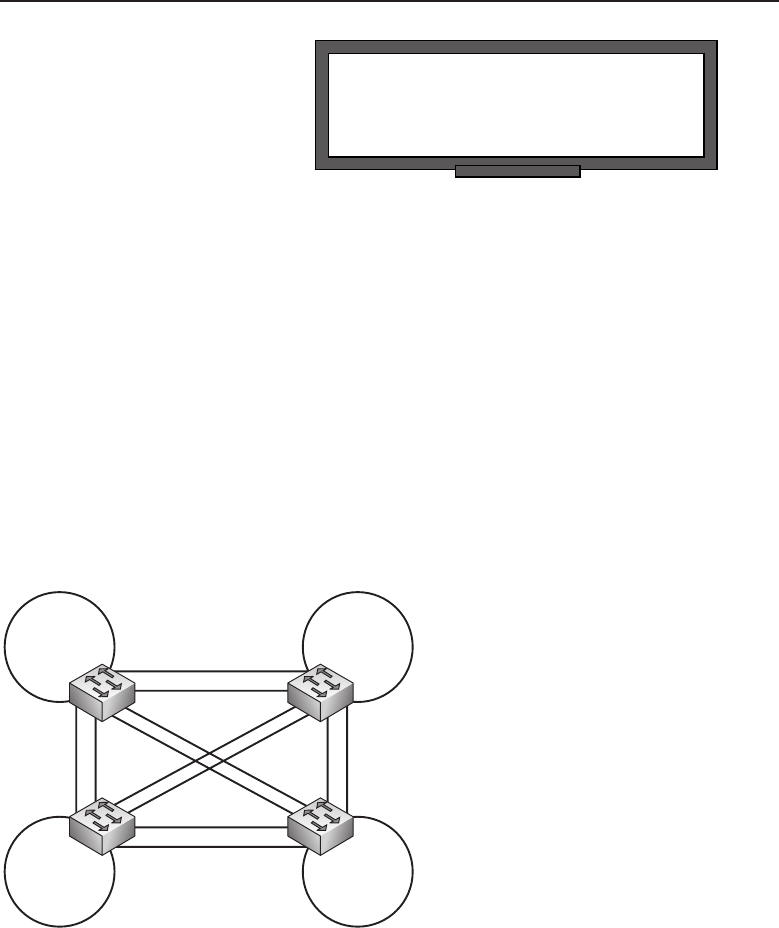
Edwards c03.tex V2 - 03/27/2009 7:38pm Page 145
Chapter 3 ■Network Hardware and Transmission Media 145
RANDOM BONUS DEFINITION
buffer — A block of memory used to store
data temporarily.
Switches are deployed in var-
ious locations in a network.
Switches are able to determine
the best path to a network seg-
ment through the use of the
Spanning Tree Protocol (STP).
STP allows a network to be
designed to include redundant links, which ensures that data gets to its
destination if the primary link fails. STP also ensures that there are no loops in
the network, which might be introduced with the addition of the redundant
links. Spanning Tree has had many improvements made in the past few years.
We will discuss the Spanning Tree Protocol further in Chapter 11, ‘‘The Data
Link Layer.’’
Switches are also capable of being configured with multiple virtual LANs
(VLANs), which allow nodes to communicate as if they were all connected
within the same LAN segment, regardless of where the nodes physically
reside. In a VLAN environment, broadcast messages are only sent to the
interfaces that are members of the VLAN, leaving the remainder of the switch
the opportunity to serve other areas. Figure 3-21 shows an example of the
logical topology of a fully meshed switched network.
VLAN 101
VLAN 105VLAN 109
VLAN 108
VLAN 1
VLAN 1
VLAN 1 VLAN 1
Figure 3-21 LAN switch deployment
Take note of all the available links and let’s take a moment to discuss what
problems may occur if there were no way to control the flow of data. Keep in
mind that switches forward data in the direction of the node that knows where
the MAC address of the destination is. In the example, if a host in VLAN 108
needs to get data to a host in VLAN 105, and there is nothing configured on
the switch to assist in forwarding decisions, which path would the data take?
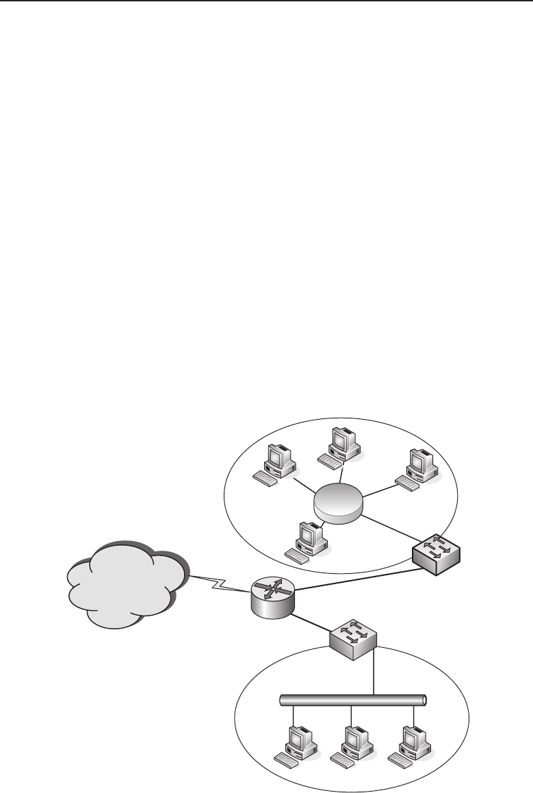
Edwards c03.tex V2 - 03/27/2009 7:38pm Page 146
146 Part I ■Networking Nuts and Bolts
Each switch would flood the data out all other switches and would continue
to do so at an alarming rate. Keep in mind that there are other nodes in other
VLANs doing the same thing. A basic example, but enough for you to see
that there are problems. That is what makes switches special — all the tools
available today to address these issues and many more that may arise. We will
discuss switching in more detail in Chapter 11.
3.3.3.6 Routers
Routers make it possible for our e-mails to make it to their destination. They
make the decisions that are necessary to get data from one user to another. It
would be virtually impossible to meet the demands of users today without a
router in the mix, helping make decisions on how to get data from point A to
point B.
Routers are advanced network nodes that connect networks of different
types. Routers are intelligent enough to know how to get data from a Token
Ring subnet to an Ethernet subnet, without data corruption of any kind. Routers
support many protocols and standards that allow much more flexibility in
their deployment. A router can be placed in the network to join two or more
LANs together, two or more WANs, a LAN to an ISP, and so on. Figure 3-22
shows a router joining two networks to one another and joining both of them
to the Internet.
The Internet
Token
Ring
Catenet
Router
Switch
Switch
Ethernet
Catenet
Figure 3-22 An example of a router deployment

Edwards c03.tex V2 - 03/27/2009 7:38pm Page 147
Chapter 3 ■Network Hardware and Transmission Media 147
POP QUIZ
At which layer of the OSI model does a
switch operate?
Routers operate at Layer 3 of
the OSI reference model and use
IP addresses for data delivery.
Routers also are able to com-
municate with other routers and
share path information, so when
a packet is received, it can be
sent toward its destination over the best path possible. Routers run algorithms
to assist in determining the best path, and they share information with one
another, so every router can be on the same page. Routers ensure that data
gets to where it is supposed to go.
Routers maintain routing tables that help determine where the best path
is to a destination. The routing table includes information that shows what
subnets the router has learned and the path to the next node (next hop) that
leads to the destination IP address. The routing table is able to place a metric
or cost to a destination to assist in routing decisions. The entries in the routing
table can be configured (static) or learned via a routing protocol such as RIP
or OSPF. Following is an example of a routing table:
Active Routes:
Network Destination Netmask Gateway Interface Metric
0.0.0.0 0.0.0.0 192.168.1.1 192.168.1.104 1
127.0.0.0 255.0.0.0 127.0.0.1 127.0.0.1 1
192.168.1.0 255.255.255.0 192.168.1.104 192.168.1.104 1
192.168.1.104 255.255.255.255 127.0.0.1 127.0.0.1 1
192.168.1.255 255.255.255.255 192.168.1.104 192.168.1.104 1
224.0.0.0 224.0.0.0 192.168.1.104 192.168.1.104 1
255.255.255.255 255.255.255.255 192.168.1.104 192.168.1.104 1
Default Gateway: 192.168.1.1
In the example, you can see that the routing table has information on the
destination addresses that it is aware of, the subnet mask that is assigned
to the destination IP address, the gateway (next hop to destination), the
interface through which the data needs to go in order to reach the gateway,
and the metric assigned to the destination. The metric is the number of
hops to a destination. If there is only one route, the metric is ignored. If
there are multiple routes to a destination, the one with the lowest metric
is used.
Routers can be as simple as a router in a home office to as complex as an
Internet backbone router. Routers support multiple protocols and interfaces,
which allows them to be operated and translate data coming from multiple
network types. Routers are discussed in greater detail in Chapter 10, ‘‘The
Network Layer.’’

Edwards c03.tex V2 - 03/27/2009 7:38pm Page 148
148 Part I ■Networking Nuts and Bolts
3.3.3.7 Layer 3 Switches
RANDOM BONUS DEFINITION
bit — A unit of data that is either a 0 or a 1.
Section 3.3.3.5 discussed tradi-
tional Layer 2 switches and the
functions they perform. Layer 3
switches can operate at Layer 2,
as well as function like a router.
Layer 3 switches can be config-
ured to make routing decisions to send data to a destination. Routers use
software to perform logic decisions for operation and use a microprocessor
to perform packet switching. Layer 3 switches have replaced the need for
software logic decisions and some hardware that routers rely on with inte-
grated circuitry to perform these tasks. The circuitry that is used is known as
application-specific integrated circuits (ASICs).
Layer 3 switches combine the wire speed technologies used by Layer 2
switches and the tools necessary to route packets as a router. Layer 3 switches
make routing decisions based on the same routing table information as a
traditional router does. As far as the hardware design, a Layer 3 switch and a
router look a lot alike in many cases. Both are configurable and the higher end
ones have slots where different types of modules can be inserted, increasing
the protocols that are supported by the node.
Layer 3 switches are predominately developed for larger corporate LANs.
The Internet still utilizes routers in the core to get data to a destination. Most
Layer 3 switches are not able to support the WAN interfaces required for
routing Internet data. Layer 3 switches are often referred to as routing switches
or Ethernet routing switches.
Layer 3 switches also have the ability to control the flow of data by
implementing what is known as class of service (CoS), which provides for
packet queuing into classes of service to ensure that data with a higher priority
is attended to before data with a lower priority.
3.3.3.8 Upper-Layer Switch Types
There are nodes that perform functions at Layer 4 and above of the OSI
reference model. The term switch is more of a marketing term, as these nodes
are nothing like traditional Layer 2 switches. Some of the terms that are
assigned to switches that fall in the upper-layer category include:
Multilayer switches
Server load balancer switches
Web switches
Layer 7 switches
Application switches
Layer 3 switches
Layer 4 switches
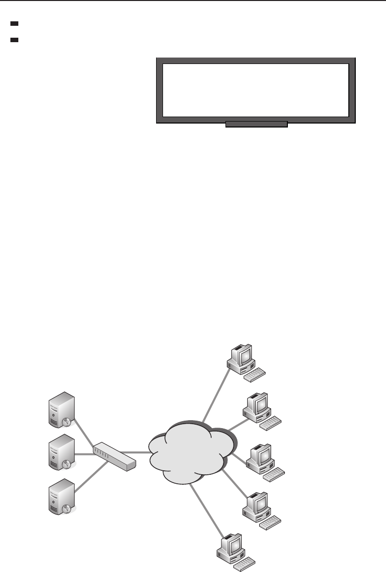
Edwards c03.tex V2 - 03/27/2009 7:38pm Page 149
Chapter 3 ■Network Hardware and Transmission Media 149
Layer 4–7 switches
Content switches
POP QUIZ
At which layer of the OSI model does a
router operate?
The previous section dis-
cussed the Layer 3 switch. The
Layer 3 switch is able to route
data much like a router at wire
speed, as well as function as tra-
ditional Layer 2 switches. Layer
3 switches are also sometimes
referred to as multilayer switches.
A Layer 4 switch operates at the Transport layer and expands the functions
that are performed by Layer 2 and Layer 3 switches. Layer 4 switches prioritize
data based on applications that are in use. A Layer 4 switch provides for CoS
to be deployed throughout the LAN (not just within the switch). An example
of providing priority for applications would be in a LAN where e-mail traffic
takes precedence over Telnet traffic. These parameters can be configured so if
there are some users who need Telnet more than e-mail, it can be configured
to allow for this. Layer 4 switches are also referred to as multilayer switches.
Server load balancers (SLBs) distribute traffic destined for a server. They
share the load for requests between multiple servers, without the end user even
being aware that there is any node between them and the server. Figure 3-23
shows an example of a switch performing load balancing for HTTP requested
to a website.
Load
Balancer
Web Server A
Web Server B
Web Server C
Internet
Figure 3-23 Deployment of a server load balancer

Edwards c03.tex V2 - 03/27/2009 7:38pm Page 150
150 Part I ■Networking Nuts and Bolts
Load balancers also spoof the IP address of the server, which helps secure
the servers from attack. Load balancers divide requests destined for the server
among all the servers that are attached to the load balancer. If a load balancing
solution is not in place, all traffic hits the same server, which could potentially
cause latency and rejecting of requests to the server.
Some of the upper-layer switches are also able to cache data for speedy
access. These functions are known as data acceleration. Some also support
cryptographic protocols — for instance, Secure Sockets Layer (SSL) and Trans-
port Layer Security (TLS). Load balancing, data acceleration, cryptographic
protocols, and many more things.40 Who could ask for anything more?41
3.3.3.9 Remote Access
Network nodes that are used to provide remote users the capability of accessing
a computer or network from a remote location are known as remote access nodes.
Many corporate LANs utilize VPN technology to allow users into the LAN
from any location, as long as they have access to the Internet. Some users may
not have access to the Internet, and in those cases, they can use a modem to
connect to the remote location.
RANDOM BONUS DEFINITION
modulation — The process of manipulating
a waveform to create a signal that sends a
message. In data communications,
modulation is performed by a node that
converts a digital signal to an analog signal,
in order to be communicated over a phone
line.
Home users also have
modems that allow them to con-
nect to the service provider.
Once connected, the users can
digitally travel to almost any-
where in the world. They can
also use VPN client software
to connect to the VPN server
(or rather, to the node that is
running the server software).
Remote access technology, like
many other networking technologies, has grown by leaps and bounds in the
last decade. Remote access (with the necessary applications) allows people to
telecommute and work from remote locations as often as necessary.42 Addi-
tionally, remote access gives small offices the capability to connect to the
corporate LAN to conduct business. This is a much cheaper option than what
was provided in the 1980s to early 1990s.
40That’s what Layer 4–7 switches are made of.
41We assure you: someone is always asking for more.
42Or as long as the boss will allow them to do so.
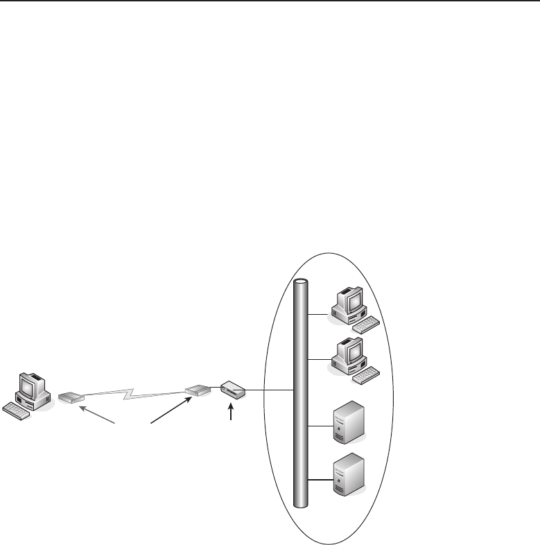
Edwards c03.tex V2 - 03/27/2009 7:38pm Page 151
Chapter 3 ■Network Hardware and Transmission Media 151
Remote access gives clients, vendors, and partners the capability to connect
to the corporate LAN. The system administrator controls who gets to go where
once they are on the LAN. In this section, we discuss the hardware nodes that
provide an avenue for these technologies to exist.
3.3.3.9.1 Modems
The term modem is derived from its two main functions. A modem modulates
and demodulates. This means that a modem converts digital data to an analog
signal and then converts it back again when the data reaches the modem that
is connected to the destination node. Figure 3-24 is an example of remote users
accessing a corporate network segment via a modem.
ModemsHome user Switch
Figure 3-24 Modem remote access
Data that is sent and received by a modem is measured in bits per second
(bps) or by its baud rate.Bpsisameasureoftheamountofdata(numberof
bits) that can be sent in one second. Baud rate is determined by the type of
modulation used and represents the number of times that a signal is changed
inonesecond.Thebaudrateandthebpsratearenotthesamenumber.
Modems that connect a user’s PC to a phone line are called dialup modems.
Dialup modems are not the only modem type that is available. Internet access
is now available to most people in the United States and other parts of the
world at very high data rate speeds. There are different types of modems

Edwards c03.tex V2 - 03/27/2009 7:38pm Page 152
152 Part I ■Networking Nuts and Bolts
available to the average user as well as businesses and other organizational
types. Here is a list of a few of these:
Cable modem
Asymmetric digital subscriber line (ADSL) modem
Digital subscriber line (DSL)
Microwave modem
Optical modem
Wi-Fi modem
The type of modem to use really depends on the needs of the user(s). A
person who plays video games online would be much happier with a cable
or DSL modem over the traditional dialup modem. Someone who goes online
to send and receive e-mail once a week can probably survive with a dialup
modem.43
3.3.3.9.2 VPNs
VPN technology provides a way for a remote user or branch office to connect
virtually to a remote LAN over the Internet. A VPN supporting node has three
main functions:
Provide remote access for individual users
Provide remote access for a branch office or other LAN
Ensure that only authorized individuals are able to access the LAN
POP QUIZ
What is the common name for a
modulator/demodulator?
There are many different
types of nodes that support VPN
technology. Some are called
VPN routers,VPN switches,
extranet routers,andextranet
switches. As long as the node in
question’s predominate jobs are
remote access, authentication, and encryption, the node is VPN-compatible.
VPN hardware supports enhanced security, load-balancing methodologies,
and the capability to support an increased number of clients that can be
connected at the same time, based on the processing power of the node.
43But good luck with opening some of those attachments.
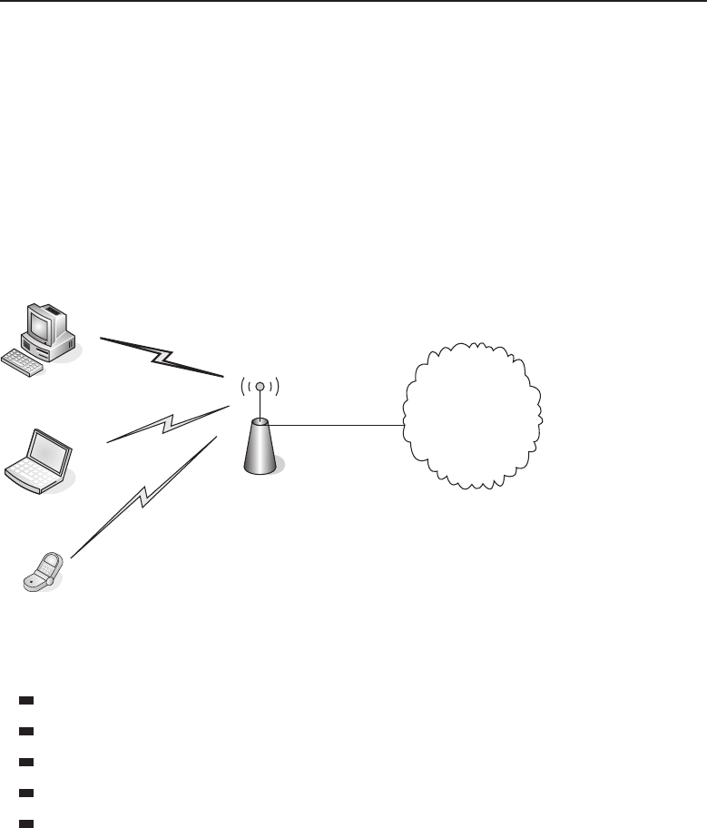
Edwards c03.tex V2 - 03/27/2009 7:38pm Page 153
Chapter 3 ■Network Hardware and Transmission Media 153
3.3.3.9.3 Wireless
Wireless remote access is a growing technology. Many business and companies
are providing access to the Internet and/or the LAN for their customers and
employees. There are two main nodes that are needed for wireless remote
access. You need to have an end user with a wireless NIC (WNIC) and an
access point for them to connect to. The end user is known as the wireless
client. Access points are the boundary nodes for the network. A wireless
client would be any node that is used to connect to the network without a
solid communication path. Figure 3-25 shows an example of wireless remote
access.
Corporate LAN
Figure 3-25 Wireless remote access
Some examples of these client node types would be:
Cellular phones
IP phones
Laptops
Workstations
Computers
Notice that a wireless client does not have to be a portable device. It can be
a stationary device as well, as long as it has an interface that supports wireless
technology. There are many access point nodes; some are integrated into other
network node types. Within networks that are completely wireless there are
wireless bridges, switches, routers, and so on, just as there would be in any
wired LAN.

Edwards c03.tex V2 - 03/27/2009 7:38pm Page 154
154 Part I ■Networking Nuts and Bolts
3.3.3.10 Servers
Network servers are nodes that manage the resources available to the users of
the network. There are many different types of servers, normally named for
the function they perform. A few examples include:
Print servers — Manage traffic destined to a network printer.
File servers — Store files for network users.
Network servers — Manage the traffic on the network.
FTP servers — Manage file transfer.
Mail servers — Manage e-mail traffic.
Fax servers — Manage incoming and outgoing fax messages.
List servers — Manage mailing lists.
Proxy servers — A node that resides between a client and a server,
whose purpose is to manage requests destined to the server. Proxy
servers allow for shared connections and free the server up so the per-
formance of the server from a end-user perspective is greatly improved.
RANDOM BONUS DEFINITION
AppleTalk — A protocol suite developed by
Apple Computer.
Network servers are nodes
that are dedicated to the tech-
nology they are configured to
support. These nodes have noth-
ing else to worry about but that
specific function. Some servers
can have multiple applications
running and therefore have the
resources necessary to support each of those. Even if the node is running
multiple applications, the application itself is the server and is still referenced
by the function it is set to do.
3.4 Chapter Exercises
1. Explain what ‘‘10 half or 100 full?’’44 means to you, what the differ-
ence is between 10 half and 100 full, and list pros and cons of each.
2. List three types of interfaces and three types of adapters.
3. Why is an NIC card considered both an interface and an adapter?
44We told you that someone would ask this someday.

Edwards c03.tex V2 - 03/27/2009 7:38pm Page 155
Chapter 3 ■Network Hardware and Transmission Media 155
4. List three examples of flash memory.
5. List the PDU for each of the OSI layers:
Layer PDU
Application
Presentation
Session
Transport
Network
Data Link
Physical
6. What is the difference between volatile and nonvolatile memory?
7. What is the difference between STP and UTP cabling?
8. Explain when you would want to use MMF cables instead of SMF cables.
Next, explain in what instances SMF cabling would be preferred over
MMF cabling.
9. Define modulation.
10. What is the main difference between a Layer 3 switch and a router?
3.5 Pop Quiz Answers
1. The decimal number 211 is equal to what binary number?
11010011
2. The binary number 01011100 is equal to what decimal number?
92
3. What is the binary name for the binary value of 250?
Pebibit (Pibit)
4. Define RAM.
Volatile memory that is available for data storage and access,
regardless of the order in which it was received.
5. Define encapsulation.
Encapsulation is the act of including data from an upper-layer
protocol within a structure in order to transmit the data.

Edwards c03.tex V2 - 03/27/2009 7:38pm Page 156
156 Part I ■Networking Nuts and Bolts
6. What is IEEE Standard 802.11?
IEEE 802.11 is the standard that is maintained by the IEEE outlining
WLAN communications. Sometimes, IEEE802.11 is also referred to as
Wi-Fi, although traditional Wi-Fi standards are not included in IEEE
802.11.
7. What does MAU stand for?
Media access unit
8. At which layer of the OSI model does a switch operate?
Layer 2
9. At which layer of the OSI model does a router operate?
Layer 3
10. What is the common name for a modulator/demodulator?
Modem

Edwards c04.tex V3 - 03/27/2009 11:04am Page 157
CHAPTER
4
Operating Systems and
Networking Software
Part of the inhumanity of the computer is that, once it is competently programmed
and working smoothly, it is completely honest.
— Isaac Asimov
This quote by Isaac Asimov points out the basic difference between human
intelligence and that which is attributed to computers. True computers can
be designed and built to calculate, retain, and retrieve vast amounts of data
in microseconds and display it in graphics and color beyond what human
language is able to relate.1However, computers are programmed devices that
are only able to operate on a set of rules designed by humans.
True, there are programs that attempt to give computers a form of artificial
intelligence, but being only machines that work within a defined rule set,
they can only respond in a completely honest manner. On the other hand,
humans are capable of lying at any time and often do. We will not get into
the philosophical or psychological reasons for why humans have a tendency
toward lying. Whatever their reason may be, humans can be whimsical,
whereas when a computer acts in that manner, it usually gets its guts torn out.
So, now aren’t you happy you are not a computer?
The essential piece of software each computer requires is an operating
system. Without it, a computer would just sit and not do a meaningful piece
of work, just like some humans we know. It is the basic process that operates
on human requests and responds accordingly, if programmed to act in that
manner. The network drivers embedded in the operating system communicate
with the portions of a computer that interact with the network. The operating
system assists other application programs to communicate with a server that
1Try to tell the average human to produce a fancy graph on the fly!
157

Edwards c04.tex V3 - 03/27/2009 11:04am Page 158
158 Part I ■Networking Nuts and Bolts
is located remotely and can only be reached over the network. There are other
programs involved in the network arena, but the purpose of this chapter is to
cover the basic computer operating system and how it interacts with network
components. There will also be discussion on network operating systems
(NOS) and their place in the network.
4.1 Computer Operating System Basics
ACRONYM ALERT
ARE — All routes explorer
To understand computer operating sys-
tems and their place in the universe, it
is essential to first discuss some computer
design basics. Everyone by now has heard
the acronym CPU (central processing unit).
Some may say it means the computer itself,
such as a personal computer, without any
peripherals attached to it. In days gone by,
a CPU could have taken up some serious floor space, filling a large room
or many rooms with racks of equipment. Today, a desktop computer has
roughly a footprint of one square foot. This represents a significant difference
in floor space, but today’s CPU also has major advantages in speed, storage,
processing power, and energy consumption. Even though modern computers
are far more capable than their early predecessors, they still operate pretty
similarly when it comes to handling data.
4.1.1 CPU Basics
TheCPUistheheartofanycomputer.Data and instructions flow into it so
the data can be manipulated and acted upon in a controlled manner. Data and
instructions are stored within the memory system of the computer. Figure 4-1
shows a block diagram of a basic CPU.
The memory storage area can be constructed of various storage devices
ranging from semiconductor to magnetic media. For this section, all you need
to know is this is where the instructions of a program and the data that
program is to operate on reside. The memory interface contains circuitry that
provides addressing information to the memory storage devices so that data
may be retrieved. Once the data is received, it is passed to circuits that decode
the retrieved data to determine if it is an instruction or data that needs to be
operated on. If the latter, the appropriate input registers are loaded with the
data. If it is determined that the retrieved data is an instruction, the arithmetic
logic unit (ALU) is given the instruction. Depending on the instruction the
ALU receives, it performs an operation on the data contained in the input
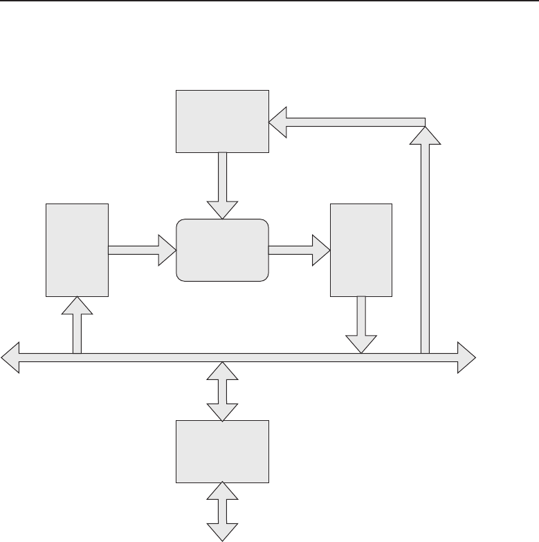
Edwards c04.tex V3 - 03/27/2009 11:04am Page 159
Chapter 4 ■Operating Systems and Networking Software 159
registers and places the result of that operation in the output registers so that
data can be moved back to the memory system for storage.
Instruction
Fetch/Decode
Memory
Interface
Memory Storage
Data Path
Input
Registers
Output
Registers
Arithmetic
Logic Unit
Figure 4-1 A block diagram of a basic CPU
The ALU is the device that performs mathematical operations on the data it is
presented with. These are not only the basic functions of addition, subtraction,
multiplication, and division, but also Boolean logic2such as or,and,and
their negated logical functions. The ALU is solely responsible for actual
mathematical manipulation of the data it is presented with. The remainder
of the CPU functional blocks is solely for the purpose of retrieving data and
seeing that it is returned to the memory system properly so it can be easily
accessed if needed.
2A system of logical operations. The term Boolean comes from the name of the inventor of Boolean
algebra, George Boole.

Edwards c04.tex V3 - 03/27/2009 11:04am Page 160
160 Part I ■Networking Nuts and Bolts
QUICK REVIEW
The Boolean algebra or function is usually indicated by a +sign between
variables, such as A+B=C. A variable is usually true when its value is equal to 1
and false when its value is equal to 0. An or function result is true if any of the
variables making up the function is true. A negated or function is usually
referred to as a nor function and its value is false if any of the variables making
up the function is true.
The Boolean algebra and function is indicated with a ‘‘·’’ sign between
variables, such as A·B=C. An and function result is only true if all of the
variables making up the function are true. A negated and function is usually
referred to as a nand function and its value is only false if all the variables
making up the function are true.
The following table shows two variables and the resultants of the or,nor,
and,andnand functions.
A B OR NOR AND NAND
00 0 1 0 1
01 1 0 0 1
10 1 0 0 1
11 1 0 1 0
POP QUIZ
What function does an arithmetic logic unit
provide?
This discussion is a simplifica-
tion of what a CPU is. However,
what once took racks of equip-
ment is now contained on a
single microprocessor chip. Cur-
rent microprocessors are magni-
tudes more powerful than those
early computers and use much
more sophisticated designs that take advantage of bigger data paths, larger
addressing capabilities, caching, look-ahead memory fetch,3parallel and mul-
tiple processor technologies — to name a few.
The next section discusses the overall computer architecture and how the
CPU interacts with those other computer subsystems.
3A memory fetch grabs the immediate contents of a memory location. Look ahead memory
fetch is intuitively retrieving data from memory using the idea that memory fetching is mostly
sequential and to save time memory contents would be retrieved in blocks of sequential memory
addresses.
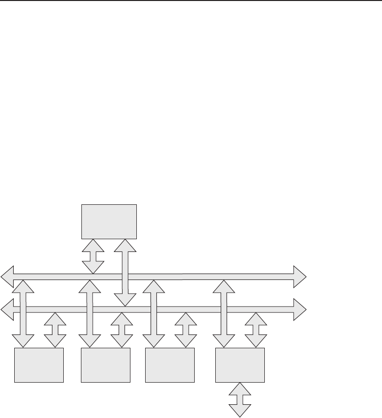
Edwards c04.tex V3 - 03/27/2009 11:04am Page 161
Chapter 4 ■Operating Systems and Networking Software 161
4.1.2 Computer Basics
A computer is a collection of subsystems under the control of the operating
system, which is the driving intelligence behind the electrical circuits it runs
over. Without an operating system, a computer is just a pile of chips, boards,
wires, and circuits that would not do any useful thing. But, then again, an
operating system is just a collection of ones and zeroes, which is just a bunch
of useless information without a computer to execute those commands and
instructions. So computers and their operating systems need each other to
make a complete package.
In this section, we will be discussing a generic computer system. Most
computers have the subsystems being discussed or at least some compatible
variation of those subsystems. Figure 4-2 illustrates a block diagram of a basic
computer system.
Read Only
Memory
ROM
Central
Processing Unit
CPU
Address Bus
Data Bus
Read Access
Memory
RAM
Mass Storage
System
Input/Output
System
User Interface
&
Peripheral
Devices
Figure 4-2 A block diagram of a basic computer
We already discussed the CPU portion of a computer. You know that it
executes instructions and operates on data, but where is that data obtained?
In Figure 4-2, the memory system is distributed across the ROM (read-only
memory), RAM (random-access memory), and mass storage System. Why
the need for different memory systems? Each has its own purpose within a
computer system.

Edwards c04.tex V3 - 03/27/2009 11:04am Page 162
162 Part I ■Networking Nuts and Bolts
4.1.2.1 Read-Only Memory
ACRONYM ALERT
CRC — Cyclic redundancy check
When power is first applied4to a computer,
commands must be inputted into the CPU
to initialize the computer system. A CPU is
designed to output an initial address to the
address bus to retrieve the first instructions
from the ROM. The ROM is a fixed stor-
age subsystem that has the initial boot-up
instructions to initialize the system. Most boot-up programs perform both an
initialization of the computer and a check of the subsystems to ensure they are
functional. The ROM may consist of semiconductor devices that contain bits
of the data making up the instructions to be executed that are not alterable by
the user. However, current personal computer systems do allow for updates
to the ROM software program for bug fixes or feature enhancements. ROM
devices in this category are usually called electrically alterable read-only memory
devices.5
POP QUIZ
Would it be advisable to cycle power to the
computer while a ROM upgrade is in
process?
This means the device can
be written to if necessary using
special sequences under control
of the operating system. The
boot-up code is critical for com-
puter initialization. If this code
becomes corrupted for any rea-
son, the computer may not be
usable and may require profes-
sional maintenance to restore it back to operation. For this reason, many
computers flash warning messages and precautions when the ROM is being
accessed under user control. ROMs can be upgraded safely, but do not attempt
an upgrade without fully understanding the upgrade process. Typically, once
the process has been initiated, it cannot be interrupted until it has completed
and the computer has rebooted. If you ever have any questions about upgrad-
ing ROM, consult your computer documentation and, if necessary, contact the
support staff of the computer’s manufacturer.
4.1.2.2 Random-Access Memory
Random-access memory (RAM) consists of semiconductor devices that are used
for temporary storage of program instructions and data. The usual design is
4Technically, you have power within the PC as soon as the battery is plugged in — in other
words, when you press the ‘‘on’’ button on the node.
5The actual devices used in today’s computers are called EEPROM (electrically erasable pro-
grammable read-only memory).

Edwards c04.tex V3 - 03/27/2009 11:04am Page 163
Chapter 4 ■Operating Systems and Networking Software 163
an array of these devices residing in the address space of the CPU. As their
name implies, they can be accessed randomly no matter what address the
information to be retrieved is residing at. This also means the CPU under
program control may write data to locations within its address space and
store the information for later retrieval. RAM space is usually controlled by
the operating system, which designates locations for fixed buffer space for
functions under its control and for use by the application programs that
may be running at the time. Modern operating systems are capable of running
multiple processes at the same time. Each of these processes require operational
memory space, so it is critical that memory management be handled properly
andasefficientlyaspossible.
All programs running under the control of the operating system must be
well behaved and adhere to the memory space allocation given. When a
program violates its memory space allotment, it may overwrite locations being
used by other applications or the operating system. If a rogue application
overwrites memory used by the operating system for control of the computer,
there is a strong likelihood that machine control will be lost and the user will
no longer be able to operate the computer under normal conditions. It is in
these times that a computer may need to be rebooted to restore operation.
The amount of memory space a computer may contain is determined by how
large an address a CPU is able to generate. In the early microprocessor-based
PCs, the number of bits of address was only 16, which would allow for
a maximum of 65,536 discrete memory addresses. You can determine the
address space of a device by taking the number 2 and raising it to the power
of the number of address bits that are generated by the CPU. For example:
RANDOM BONUS DEFINITION
active monitor — A node in a Token Ring
LAN that is responsible for handling many
boundary conditions and housekeeping
functions, including generation of a
common clock, elastic buffering, and
removal of circulating high-priority tokens.
216=65,536 for 16
address bits
220=1,048,576 for 20
address bits
224=16, 777,216 for 24
address bits
232=4,294,967,296 for
32 address bits
Earlier PCs were mostly character-based computers. Programs were smaller
and not as memory-intensive as the visually oriented operating systems of
today. As processor capabilities expanded with increased processing speeds
and greater addressing ability, software became more sophisticated by taking
advantage of these increased capabilities. In the early days, there was a
constant battle between hardware designers and their software counterparts.
The standing joke used to be that software is like a gas; it will occupy the space

Edwards c04.tex V3 - 03/27/2009 11:04am Page 164
164 Part I ■Networking Nuts and Bolts
that is provided. This is still pretty much true, but to the software developers’
credit, they have done some totally marvelous things with the space they filled.
POP QUIZ
True or false: The information contained
within RAM is saved when the computer is
powered off.
The real battle lines were
drawn on the lines of cost.
Hardware had fixed costs and
increased rapidly as memory
needed to be expanded. Those
lines have been obliterated
somewhat by the advances in
chip design, with increased den-
sities and lower power con-
sumption of newer processor and memory chips. Costs dropped dramatically
and the capabilities of PCs expanded exponentially. This leads to the con-
clusion that there is a direct correlation between memory size and computer
performance. A general rule of thumb is to buy as much memory as you
can afford. However, it is really application-dependant. Applications such as
gaming software require much more memory and processor speed, whereas
someone who just wants to type a few reports can get by on a relatively smaller
amount of memory and decreased processor speed. The marketplace puts PCs
on the cutting edge of technology as consumers become more sophisticated.
It can only keep pushing the demands on memory and processors to increase
their abilities, and this is the driving force for today’s technology.
4.1.2.3 Mass Storage System
The mass storage system is comprised of a collection of multiple devices
storing programs and information either in magnetic or optical media formats.
The very earliest PCs used floppy disks to write and retrieve information in
a somewhat nonvolatile manner when the computer was powered off. The
‘‘somewhat nonvolatile’’ comment is for anyone who had to suffer through
the loss of information due to a flaw in the magnetic media or the electronics
of the device controlling this media. If it can be easily written, it can be easily
removed or erased.
ACRONYM ALERT
BOOTP — Bootstrap Protocol
Just as memory chips underwent im-
provement, so did magnetic media devices.
Floppy disks went from single-sided to
double-sided and higher densities. The
last floppy disks were high-density 3.5-inch
plastic-encased disks that were more re-
liable than their predecessors but still could
suffer similar data losses. The highest
density obtained with floppy disks was 1.44 MB, which is a lot for a
typewritten document but far from having the capacity to store some of

Edwards c04.tex V3 - 03/27/2009 11:04am Page 165
Chapter 4 ■Operating Systems and Networking Software 165
today’s programs. Programmers had to develop schemes to distribute their
software using multiple floppy disks. A user had to sit by the computer
during the installation of such a program and wait for the message to load the
next disk. The process was tedious and time-consuming.
The development of optical storage devices, such as CD-ROM, increased
storage capacities in a movable media format from just over 1 MB to the
vicinity of 700 MB. This was a boon to both software developers and computer
users. DVD devices, with their higher capacity for data storage, increased what
CD-ROM could store by a factor of 10 — or roughly the ability to store 7 GB of
information. Current day computers are shipped with optical drives that can
read and write both CD-ROM and DVD media formats. Optical media now has
read-write capability, but the process is slower than that of magnetic media.
However, as a removable media storage system, it has many advantages over
its magnetic predecessors. Even though optical disks are more robust as far
as data retention, they still can be rendered unusable by physical damage. A
severe scratch can make an optical disk unreadable.
POP QUIZ
When a computer is first powered on, the
first device it is most likely to read its initial
set of instructions from is the
.
Nonremovable disk storage
systems are referred to as hard
disks. They are ‘‘hard’’ because
the magnetic media was orig-
inally sprayed on the sur-
face of rigid aluminum disks,
which were mounted within an
enclosed airtight container to
eliminate data corruption due
to dust and other contaminants.
Magnetic media was bonded to a soft pliable Mylar surface, thus the name
‘‘floppy disk.’’ The advantages of hard disks are their ability to store vast
amounts of information and its fast retrieval times. Initially, hard drives
were commercially available only to users of large mainframe computers,
but as development progressed on these devices, the pricing was such that
it was commercially feasible to sell them to the PC market. The first PCs
shipped with a whopping hard disk storage capacity of 5 MB. Many of today’s
graphics-intensive programs would not be able to load onto the drive, let alone
the operating system or any other user data. It is not uncommon today to see
laptops with 200 GB hard drives and desktops with 500 GB6storage capacities.
Hard drives are usually mounted within a computer’s case, but many drives
are sold as external drives communicating between the drive and computer
over the USB port.
6This really is an amazing amount of data storage. Can you imagine what increases will be made
within the next decade?

Edwards c04.tex V3 - 03/27/2009 11:04am Page 166
166 Part I ■Networking Nuts and Bolts
4.1.2.4 Input/Output System
A computer is not very useful if information cannot be entered into it or
retrieved from it. The input/output system is a collection of circuits that allow
for information to be entered by the user via a keyboard, pointing device,
scanner, etc. It also provides a method for information to be displayed to the
user. This can be in the form of video screens, teletype, printers, plotters, etc.
These are the most common methods of input and output from a computer
system. There are many specialized input/output devices for data entry and
retrieval not mentioned in this section, but the idea is always the same: move
information into the computer and retrieve it from the computer after it has
operated on it.
RANDOM BONUS DEFINITION
bit stuffing — A technique that provides a
unique frame delimiter pattern yet
maintains payload data transparency by
inserting an extra 0 bit after every
occurrence of five 1 bits in the payload data
stream.
Because input/output de-
vices interacting with other
physical devices and humans
may experience timing differ-
ences with the CPU, there needs
to be a way of storing the infor-
mation and notifying the CPU
when the data is present. Gener-
ally two schemes were devised
to accomplish this. One is where
the input/output devices are
mapped to dedicated memory addresses and the CPU polls these locations
to see if there is information that needs to be acted on. This is referred to as
memory-mapped I/O. The other scheme is interrupt-driven I/O, where a device
writes information into a dedicated register at a fixed port location and sets an
interrupt requesting service from the CPU.
In a memory-mapped I/O system, the CPU determines which location it
should poll under operating system control. In an interrupt-driven I/O system,
the CPU responds to interrupts (and there may be many, depending on the
number of I/O ports to be serviced). Interrupts adhere to a fixed interrupt
priority scheme, which is hierarchal. The CPU can be processing an interrupt
request and be preempted by a higher priority interrupt request.
Regardless of which I/O scheme is used in a computer, the operating
system must be able to deal with input/output data requests. It must be able
to determine when a device is acting unresponsive and either notify the user
or take other action as determined by the program. Generally the operating
system is responsible for data movement between the various systems within
the computer. However, a user may be running an application, such as a word
processor, which is running over the operating system. When a user depresses
a key on the keyboard, the operating system reads the key and presents that

Edwards c04.tex V3 - 03/27/2009 11:04am Page 167
Chapter 4 ■Operating Systems and Networking Software 167
information to the word processor program, which may request that it also be
displayed on the video screen.
POP QUIZ
Nameadevicethatyoumightfind
connected to a serial port.
On PCs, input/output con-
nections are in the form of ports
dedicated to either serial or
parallel data communications.
Serial communications refers to
the information being passed
one bit for each time inter-
val, which is determined by the
speed of the port. Generally serial devices are slow data rate devices such
as keyboards, modems, pointing devices, scanners, etc. However, with the
development of Universal Serial Bus (USB), high-speed serial ports, devices
such as hard disk drives and printers can be used due to the increased data
rates on these ports. Parallel ports on older PCs were mostly relegated as
printer ports. Parallel data communications means that data is sent a whole byte
at a time for each cycle of the port. USB has become today’s de facto standard
for peripheral ports.
4.1.3 Operating System Basics
Operating systems in one form or another have been around since the inception
of the first computer. Of course, the first computers were of the mainframe
variety with character-oriented terminals.7Users entered commands and data
in the form of alphanumeric characters that could be found on any typewriter.
Data retrieved from the computer could be displayed on the terminal screen
for small queries, or, for larger reports, outputted to a printer.
ACRONYM ALERT
DMA — Direct memory access
The most basic form of an operating sys-
tem is a file manager. It is able to create new
files on the storage medium being used. It is
also able to catalog the files for easy retrieval
and has some sort of indexing ability simi-
lar to that of a filing cabinet. Computers and
their operating systems were first designed
to adopt systems that were similar to the
business practices of those days. The earlier computers were a high-speed
filing system able to store, index, and retrieve data faster than a filing clerk.
Operating systems underwent some dramatic revisions with the introduc-
tion of the PC. Initially, these operating systems were similar to those found
7The first terminals were alpha-character-oriented. They were merely an electronic form of a
typewriter. Graphic terminals that could display some sort of graphic (usually at low resolution
by today’s standards) were a later innovation in terminal design. Terminals connected to the
computer via serial cable.

Edwards c04.tex V3 - 03/27/2009 11:04am Page 168
168 Part I ■Networking Nuts and Bolts
on the larger computers. They too were character-oriented. The major early
PCs initially ran on proprietary operating systems such as Apple’s DOS (Disk
Operating System) and Tandy Radio Shack’s TRS-DOS (usually phonetically
pronounced tris-dos). The first cross-platform PC operating system to gain
popularity was Digital Research’s CP/M (Control Program for Microcom-
puters), originally designed to run on Intel 8080/8085 microprocessor-based
computers. It migrated to the Zilog Z80 which was capable of executing the
Intel 8080-based instruction set and was a mainstay of the Z80-based PCs for
anumberofyears.
The major limitation of CP/M was that it was designed for 8-bit microproces-
sors and was only capable of addressing 64 KB of memory. As microprocessors
moved up in capability, CP/M began to lose ground to other operating sys-
tems, mainly Microsoft’s MS-DOS. Digital Research did finally release a 16-bit
version as CP/M86, but it was not able to compete against the IBM/Microsoft
juggernaut.
Initially, MS-DOS was locked up by IBM and was sold with the IBM PC
as IBM DOS. Other PC manufacturers were on the outside looking in and
attempted to adopt CP/M86, but the popularity of the IBM PC running
MS-DOS left them far behind on the number of PCs being sold. The off-brand
manufacturers eventually developed clone PCs that were able to run MS-DOS,
thus boosting their PC sales. The developer of CP/M and CP/M86, Digital
Research, also developed a clone to MS-DOS called DR-DOS to compete with
Microsoft. The number of PCs now running MS-DOS caused IBM to lose their
competitive edge and to eventually give up on the PC market.
Although CP/M was a cross-platform operating system, the hardware it was
running over could have major differences. As a result, a CP/M program on one
computer could not run on another computer from a different manufacturer.
The portability of CP/M was the core operating system (sometimes referred
to as the kernel). The CP/M kernel provided a common interface for user input
and application programs that would run over different computer platforms.
The computer manufacturers had their own software designer teams that
would write the software code needed to allow the kernel to communicate
with other hardware systems of the computer system. These pieces of code
were referred to as hardware drivers.8Each subsystem in a computer system
could have its own driver if needed. An example of this is the mass storage
subsystem. The kernel would call for a file and the driver would cause the
floppy drive to seek the track and sector where the beginning of the file
was located. The point is, although there was commonality as far as user
interfaces and the applications able to run on CP/M, they could have been
8Hardware drivers are synonymous with device drivers. It is the code that is designed to allow
the kernel of the operating system to properly communicate with the device/hardware no matter
how different in design they may be. The device driver acts as a translator to allow for the correct
operation of the device/hardware.

Edwards c04.tex V3 - 03/27/2009 11:04am Page 169
Chapter 4 ■Operating Systems and Networking Software 169
operating on computers whose hardware had substantial differences from one
manufacturer to the next.
RANDOM BONUS DEFINITION
byte — A unit of data that is equal to 8 bits.
Soon after the IBM PC was
introduced and its hardware
specifications were published,
clone PCs began to enter the
marketplace. Since IBM opened
its architecture, it was not able
to legally protect its design, and
the PC marketplace ballooned overnight with clones from a number of hard-
ware manufacturers. This phenomenon led to a PC base that not only was
able to have the same operating system but also had hardware commonality,
which was a boon to the peripheral manufacturers.
POP QUIZ
What is the acronym for a user interface that
uses a point-and-click method of executing
computer commands?
With the consolidation of
today’s PC marketplace, there
are really only two variations
of PCs. Today’s PC users are
either in the Apple Mac domain
or the PC domain (PCs from
various manufacturers able to
run the various iterations of
Microsoft DOS). Today, Apple
manufactures and markets laptops and desktop PCs based on its Macin-
tosh family of computers. Macs were the first PCs that took advantage of a
point-and-click–based operating system.9
Today’s PC world is divided between the Mac operating system and
Microsoft Windows operating system. Both are GUI (graphical user interface)
based and use a graphical display screen and some sort of pointing device.
However, even with the whiz-bang colorful interfaces, the operating system
is basically performing the same functions as its predecessors. The only
difference is that instead of parsing text instructions, the user input interpreter
uses positional information, and if a mouse is used, a right, left, or double-click
will cause the operating system to act on the object that is being pointed at on
the video graphical display screen.
4.2 Network Operating System Basics
As the need grew for PCs to interconnect and share data and common
resources, the opportunity arose for the design and marketing of network
9If this had caught on before Windows came out, it might have been a much different world
today.
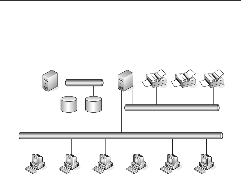
Edwards c04.tex V3 - 03/27/2009 11:04am Page 170
170 Part I ■Networking Nuts and Bolts
operating systems. The most common design of network operating systems
was the client/server implementation. PCs were clustered for individual users
(clients) to share files on the file server or print data files on printers under the
control of a print server. Figure 4-3 illustrates an example of network running
a network operating system (NOS).
File Server Print Server
User Client PC stations
Database Database
Figure 4-3 A computer network under the control of a network operating system
Actually, ‘‘network operating system’’ is a bit of a misnomer in that the NOS
really runs on computers that are servers placed in the network. Figure 4-3
shows a single10 file server and a single11 print server. In reality, on large
networks there could be multiple servers in use. Also, for a small office,
the functionalities of both the file server and print server can be combined
in a single server. Being a client/server application, the responsibility for
authentication of clients with the authority to connect to the server depends on
the server to verify that clients have the necessary valid security credentials.
In larger networks with many clients, that function can be placed in entirely
separate servers solely responsible for granting network access as well as the
permission levels a user will have while logged into the network.
There are networks where the software that is being run on a local PC is
actually an application located on the server. An example of this is a word
processor program that has a fixed number of network licenses. The theory is
that not all users would use the program simultaneously, so a company could
save some costs by sharing applications over the network. Once all the licenses
10Just because they are single does not mean they are available.
11See footnote 7.

Edwards c04.tex V3 - 03/27/2009 11:04am Page 171
Chapter 4 ■Operating Systems and Networking Software 171
are occupied, subsequent users would need to wait until another user logged
out of the program, thus releasing the license. Users could be prevented from
loading a program from a server if the network or the server is being heavily
worked. Once the program is downloaded to the local PC, there is no further
network interaction required until the application is released by the user. This
interaction was called the file services portion of the NOS.
ACRONYM ALERT
FIFO — First in, first out.
Print services were also an important
piece of NOS. Printer requests would be
queued to the print server servicing that
portion of the network. A print server could
have one or many printers under its con-
trol. As print job requests arrived at the
print server, it would determine the printer
the print job was to be outputted to. The
print server queued the print jobs on a first-come, first-served basis. Print jobs
were stored on the print server and parceled out to the printer as fast as the
printer was able to take the data. Today’s network-ready printers are basically
their own print server with the intelligence and storage capacity required to
queue print jobs from a large user base.
There were many networking operating systems, but the most popular
were Novell NetWare and Microsoft Networking. Novell utilized an IPX/SPX
protocol stack to provide communications over its network. Both Novell
and Microsoft have since migrated to supporting the TCP/IP protocol suite
over their networks. TCP/IP is not a NOS; it is a protocol that controls
communications between peers. A client/server application can be run over a
network that uses TCP/IP protocol for communicating over the network, but
the actual client/server application is independent on the protocol itself.
The majority of today’s networks are TCP/IP-based networks that have
a wide range of applications running over them. A workstation may have
multiple sessions to various servers on the network simultaneously. Most
people use e-mail and may be logged into a corporate mail server while
running other applications to other servers over the same network. The need
for a network server running a NOS is not required when running the TCP/IP
protocol over a network.
4.2.1 Peer-to-Peer Networking
When discussing network operating systems, the context of the discussion
is usually based around client/server networks. To perform peer-to-peer
networking, where one computer can share data and resources with another
computer, requires some sort of application program. The earlier versions of
peer-to-peer networking were crude and cumbersome to configure and use.
However, as Microsoft evolved its Windows operating system, they added

Edwards c04.tex V3 - 03/27/2009 11:04am Page 172
172 Part I ■Networking Nuts and Bolts
peer-to-peer as well as workgroup network capabilities. Windows was the first
GUI-based operating system that was able to support this type of networking.
Windows users are able to share drive space and locally attached printers
with other users on the same network using what is commonly referred to as
Windows networking. Windows networking depends on the host names of each
computer to be different if they reside within the same network. This was first
accomplished with NetBIOS API (application programming interface) running
on each Windows computer on the network. In today’s networks, NetBIOS is
usually run over the TCP/IP protocol. In this scenario, each computer has both
a unique computer name and an IP address. The services NetBIOS provides
are related to the Session layer of the OSI model.
On smaller networks, the computer broadcasts the name of the computer that
it wants to establish a session with. On large networks, broadcasts can become
intrusive and affect network throughput speeds. Large Windows networks
will utilize a WINS (Windows Internet Name Service) server for computer
name resolution. It maps computer host names to network addresses, thus
eliminating multiple broadcasts on the network. WINS can be thought of as
the name service for NetBIOS networks and is similar to a DNS (Domain Name
Service) server in operation on a TCP/IP network.
Figure 4-4 shows a small peer-to-peer Windows-based network.
Computer C Computer D
Computer B
Computer A
Hub/Switch
Shared Printer
Figure 4-4 A small, Windows-based peer-to-peer network
In this figure, the PCs are labeled Computer A, B, C, and D. However, they
may be named in any manner a user or network administrator chooses. It is

Edwards c04.tex V3 - 03/27/2009 11:04am Page 173
Chapter 4 ■Operating Systems and Networking Software 173
a good idea to select meaningful names such as joes pc, jims pc, and so on,
to give a frame of reference for the PC. In larger companies, the computers
may be named by department and function. Naming is purely arbitrary, but
knowing what each PC is named can be helpful, especially when trying to
troubleshoot network issues.
RANDOM BONUS DEFINITION
cheapernet — Another name for 10BASE2.
Within this network, Net-
BIOS provides computer name
registration and resolution, a
connection-oriented communi-
cation session service, and a con-
nectionless communication for
datagram distribution service.
Before a computer can either start a session or distribute datagrams on
the network, it must use the NetBIOS name service to register its name. Net-
BIOS utilizes UDP port 137 for the name service. The NetBIOS name service
functions are to add a name or group name, delete a name or group name, or
find a name on the network.
Since in today’s networks NetBIOS is run over TCP/IP, NBT (NetBIOS over
TCP/IP) utilizes TCP port 139 for the session service. The session mode of
NBT allows two computers to establish a connection to pass communications
between them. The NetBIOS primitives12 associated with the session service
are as follows:
Call — Opens a session to a remote computer using its NetBIOS name.
Listen — Listens for session requests using NetBIOS name.
Hang Up — Ends a session that had been previously established.
Send — Sends a packet to the computer that a session has been estab-
lished with.
Send No ACK — Similar to Send but does not require a
returned acknowledgement that the packet was received.
Receive — Waits for the arrival of a packet from a computer a session
has been established with.
The datagram distribution service is a connectionless service where messages
are sent without regard to error detection or remediation. It is incumbent upon
the application using this service to provide the necessary data error detection
and recovery when needed. UDP port 138 is used by NBT for this datagram
distribution service.
12This list is almost the same responses that one can expect from the family teenager. However,
for a NetBIOS session these are the root terms used to describe a particular sequence within the
session.

Edwards c04.tex V3 - 03/27/2009 11:04am Page 174
174 Part I ■Networking Nuts and Bolts
The primitives used for datagram distribution by NetBIOS are as follows:
Send Datagram — Sends a datagram to a remote computer using its
NetBIOS name.
Send Broadcast Datagram — Sends a datagram to all the
NetBIOS names that are registered on the network.
Receive Datagram — Waits for the arrival of a packet from a Send Data-
gram process.
Receive Broadcast Datagram — Waits for the arrival of
a packet from a Send Broadcast Datagram process.
Fortunately, setting up a small Windows-based local network is easy to do.
The previous discussion in this section gives you an appreciation of what is
going on under that colorful GUI screen. The unfortunate part is that Windows,
with all its various generations, had added twists and bends to the methods
used to configure networking on a PC using the Windows operating system
for its OS. It is the author’s recommendation to review the documentation for
your particular version of Windows before attempting to configure your PC
for networking. The configuration overview as well as the screenshots in the
remainder of this section are based on Windows XP.
Most of the PCs purchased within the last couple of years come pretty much
network-ready. Many desktops come with an Ethernet NIC card13 installed,
and many laptops not only have a hard-wired NIC for Ethernet connectivity
but also have some sort of wireless connection interface. However, if you
have an older PC that you would like to add to your network and it does
not have a NIC installed, you have choices available to you to make your PC
network-ready. Desktop computer models may either use an internal card, if
there is an interface card slot available, or some sort of external solution. There
are network interfaces available that will plug into the USB port. If you are
not all that computer savvy, I recommend taking down as much information
you have about your PC and visiting your local computer store. The sales
clerk or computer support staff should be able to assist you in purchasing the
appropriate solution to make your computer network-capable.
Older laptops can be easily made network-ready with the addition of a
network PCMCIA card. The usual choice is either a card that supports a
hard-wired Ethernet solution or a WLAN PCMCIA card, which enables you
to connect to your local network wirelessly. The choice is solely dependent
upon the current installed network. If this is an initial setup, I strongly suggest
investigating a wireless solution. The beauty of a laptop is its mobility, and to
have it tethered by an Ethernet cable may not be the ultimate network solution.
13Keep in mind, NIC =network interface controller.
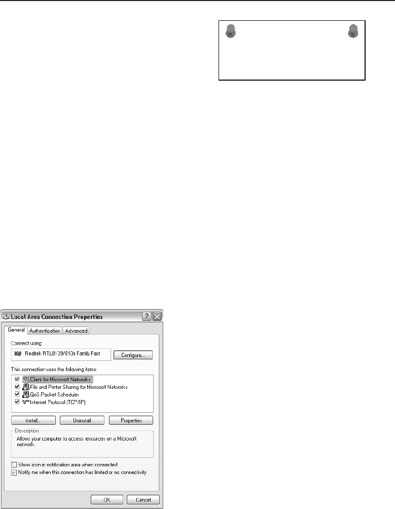
Edwards c04.tex V3 - 03/27/2009 11:04am Page 175
Chapter 4 ■Operating Systems and Networking Software 175
ACRONYM ALERT
IP — Internet Protocol
NICs require driversto be able to interop-
erate with the operating system. Windows
has moved to the plug-and-play philos-
ophy where the Windows operating sys-
tem detects when new hardware has been
installed. In most cases, with interface cards
from larger manufacturers there is a high probability that Windows will have
and load the appropriate driver. If your card is one that Windows is unable
to auto-detect, the Windows wizard may request that you load a driver disk
to complete the installation of the card. In most cases, there is usually a disk
in the box with the card or documentation that will point you to a website or
FTP server where the appropriate driver14 can be downloaded.15 You can use
that downloaded file to complete the installation of the card.
With your wired Ethernet Interface installed, you can navigate to your local
area connections properties. On Windows XP, click Start Control Panel. On
the Control Panel screen, select Network Connections for the classic view, or
if using category view, select Network and Internet Connections. Select the
Local Area Connection that is associated with the NIC card you have installed.
With the icon for the interface selected, right-click and scroll to Properties. A
window should appear labeled Local Area Connection Properties, similar to
Figure 4-5.
Figure 4-5 Windows XP Local Area Connection Properties
14Not to be confused with diver, one who deliberately jumps headfirst into water.
15Assuming that you have another computer that has network capability and is able to reach the
Internet to get the file to download.

Edwards c04.tex V3 - 03/27/2009 11:04am Page 176
176 Part I ■Networking Nuts and Bolts
RANDOM BONUS DEFINITION
flooding — The process of sending a frame
to all of a switch’s ports, with the exception
of the port the frame came in on.
On this PC, Client for
Microsoft Networks is already
installed and enabled. If it
is not yet installed on your
PC, select the Install button
and a new window will open
labeled Select Network Compo-
nent Type. Select the Client component and click on the Add button. The Select
Network Client window will open. Select Client for Microsoft Networks and
click OK. If you want to share parts of your file system or locally attached
printers, you must enable File and Print Sharing. In the Local Area Connection
Properties window, click the Install button. When the Select Network Com-
ponent type window appears, select Service and click on the Add button. The
Select Network Service window will appear. Select File and Printer Sharing for
Microsoft Networks, and then click OK. You now have Microsoft Networking
enabled with file and printer services enabled. We will revisit both file and
printer sharing in a bit. For now, it’s on to how we get TCP/IP on this puppy.
If you do not see Internet Protocol (TCP/IP) in the Local Area Connection
Properties window, the protocol must be added. Click on the Install button
in the Local Area Connection Properties window. When the Select Network
Component window appears, select Protocol and click on the Add button. On
the Select Network Protocol window, select Internet Protocol (TCP/IP) and
click OK. The protocol has now been installed but must be configured.
ACRONYM ALERT
MIB — Management information base
Before getting into the configuration of
TCP/IP on this Windows PC, a brief
description is in order of the difference
between a statically assigned IP address
and an IP address that has been assigned
by a server acting as a DHCP server. This
topic will be covered and mentioned in
other chapters, and by the time this book
is finished there will be no question that you will know the differences and
how they come to be assigned. First, a statically assigned IP address is pretty
obvious. It is an IP address that is assigned to the PC by a user or administrator
and is the same IP address the computer will have assigned to it each time the
PC is booted up.16 The only things that have to be known prior to assigning the
static IP address is that the IP address is unique and not assigned to another
computer on the same network segment, that the address to be assigned fits
into the addressing scheme being used on that network segment, and, lastly,
that the subnet mask assigned with the IP address is compatible with the IP
16Whatitisnot is an address that is applied via a static charge.

Edwards c04.tex V3 - 03/27/2009 11:04am Page 177
Chapter 4 ■Operating Systems and Networking Software 177
address and is the subnet mask assigned to that network segment. Static IP
address assignment is not difficult in a small network, but it can become rather
unwieldy in a large network. And if a network redesign is required with a
change in IP address assignment for that network, it can become a support
nightmare in very short order. If it can be avoided on the network you are
setting up, it is recommended to do so and use a DHCP server for IP address
assignment.
So, how does one come up with a DHCP server for their network? Of
course, you could have an actual server running a DHCP service, but for
a small network, such as that shown in Figure 4-5, it would be a waste of
resources. There are many newer network devices that do run a DHCP service
if configured to do so. Most routers, both wired and wireless, are capable of
running a DHCP service. If the hub/switch shown in Figure 4-5 were replaced
by a mini-router like those used for cable/DSL Internet access, you could have
a DHCP service running on that network. The beauty of having a local DHCP
server is that if there is ever a need to change a network’s addressing scheme,
default gateway, or the DNS servers being used, there is just a single point
that requires configuration change. So there is a major support advantage of
running a DHCP service on your network. It is easy to see the advantages
of having such a service on large networks with many PCs. One reason to
consider DHCP even for a small network is if there are laptops being used. The
advantage of using a laptop for a PC is its portability and its mobility of moving
from one network to another. Although it is doable, having to configure your
TCP/IP setting each time you move from one network to another can grow
old very quickly.
To set the IP properties of the installed NIC, click on Start Settings
Control Panel. On the Control Panel, select Network Connections. Right-click
on the Local Area Connection you are going to configure IP addressing on,
and then select Properties. Select Internet Protocol (TCP/IP) and click on
the Properties button. The window where properties can be configured will
appear and look similar to that shown in Figure 4-6.
Notice that this interface is configured for obtaining an address dynami-
cally from a DHCP server somewhere on the existing network. To do this,
only the two radio buttons to automatically select these addresses need be
selected. However, if you select to statically assign the IP address, each
of the grayed fields needs to filled in with the appropriate information.
RANDOM BONUS DEFINITION
host — Any node in an IP network.
IP address — A unique
IP address that is not cur-
rently used on the network
segment where the com-
puter is to be connected
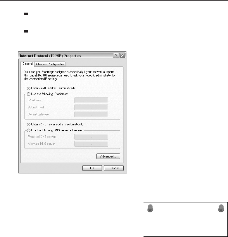
Edwards c04.tex V3 - 03/27/2009 11:04am Page 178
178 Part I ■Networking Nuts and Bolts
Subnet mask — The subnet address assigned to the network segment
that the computer is to connected to.
Default gateway17 — The IP address of the node that acts as the default
gateway for the network segment the computer is connected to.
Figure 4-6 Windows XP Internet Protocol (TCP/IP) Properties screen
ACRONYM ALERT
ns — Nanoseconds.
The DNS (Domain Name Service) server
is required if the computer is going to
attempt to connect to remote computers
by using a domain name.18 In Figures 4-3
and 4-4 the networks are self-contained and
it is assumed that someone is keeping track
of IP addresses that have been assigned. In
those situations, there is no need for a DNS server to reach the other PCs
on the network. Each user will need a list of what those IP addresses are
for all computers and other network resources, such as printers. However, in
17A quick definition of a default gateway is that it is the IP address of a node that is used when a
computer needs to start a session with a computer that is not resident on the same network.
18A domain name server is a computer residing on the Internet providing requested services.
For example, a web server may have a name like www.mywebsite.com. Since the IP protocol is
dependent upon finding an address using numerical addresses, someone needs to resolve the
name to a numeric address. This is the role of a DNS server and it gets its information from the
authoritative service on the Internet where the name has been registered.
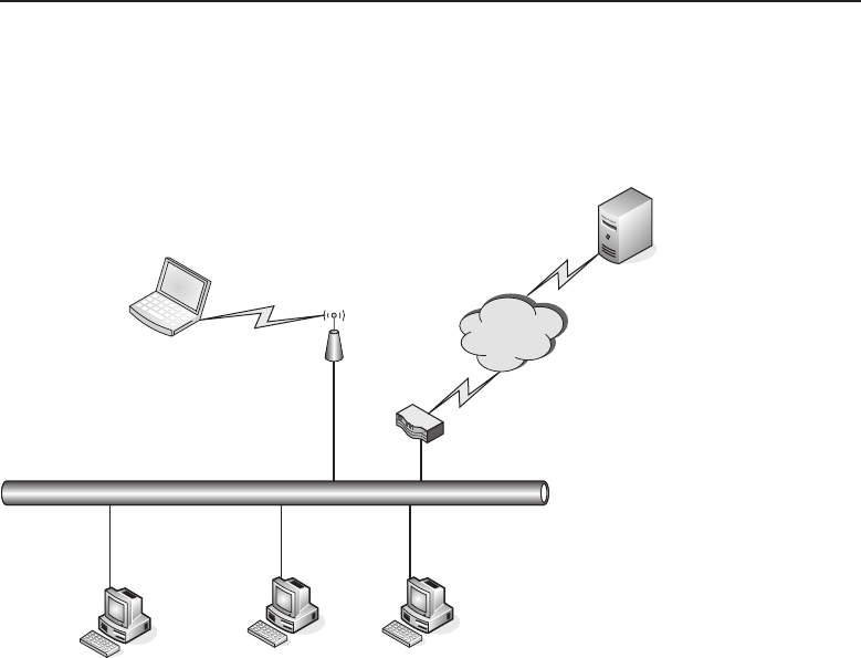
Edwards c04.tex V3 - 03/27/2009 11:04am Page 179
Chapter 4 ■Operating Systems and Networking Software 179
this current interconnected world the need for DNS is paramount. Figure 4-7
shows a small local network connected to the Internet using a router with a
high-speed connection.
User Computer Workstations
Wireless
Enabled Laptop
Wireless
Access Point Internet
www.mywebsite.com
Router
Ethernet Network Segment
Figure 4-7 A small local network connected to the Internet
Usually when a user or company signs up with an Internet service provider
(ISP), they are provided information such as the public IP address that is to be
used on the router and its default gateway’s IP address. The ISP also provides
local DNS service located within the ISP’s network, which can be pointed to
for DNS name resolution. In a statically assigned IP scheme, these addresses
would need to be entered in the appropriate fields of the Internet Protocols
(TCP/IP) Properties window to enable the computer to query the provided
DNS servers for name resolution when needed. This will need to be done for
every computer on the network if they are to be able to connect to computers
by IP host name. Most ISPs provide two DNS server addresses. Normally
these would be called a primary DNS address and a secondary DNS address.The
primary DNS address is entered in the Preferred DNS server box, whereas the
secondary DNS address is entered in the Alternate DNS server box. The PC
is now configured to communicate with other PCs on the local network and
other computers that may be found on the Internet.

Edwards c04.tex V3 - 03/27/2009 11:04am Page 180
180 Part I ■Networking Nuts and Bolts
QUICK TIP
There are a couple of quick tests you may want to perform to verify the
operation of the NIC card and the connectivity to the local network and the
Internet.
1. Click on the Start button in the lower-left portion of your Windows screen.
2. Select Run.
3. In the Run window, enter cmd and click OK. A DOS window will open where
DOS commands can be entered.
4. Type the command ping 127.0.0.1. You should receive back four messages
stating ‘‘reply from 127.0.0.1.’’ This indicates that your NIC card is
working properly with Ethernet and TCP/IP. If you receive ‘‘Request
timed out’’ messages, your card has not been properly configured.
5. To verify your network connectivity, attempt to ping the local
default gateway19 for your network. If you get ‘‘Request timed
out’’ messages, verify your physical connection to the LAN.
6. If you get good responses back from the local default gateway,
you may want to also check your connection to the Internet.
7. Ping the IP address of the router’s default gateway. If you get
good responses, you are able to reach the Internet. If you receive
‘‘Request timed out messages’’ and you own the whole net-
work, you will need to troubleshoot further. If you are on a
company network, contact your network administrator.
8. DNS name resolution can be quickly checked if the Internet connectivity
test passed successfully. Ping an Internet connected computer by its host
name. For example, ping www.mywebsite.com. Receiving ‘‘Request timed
out’’ messages may not be an indication of a problem with DNS. Some sites
drop ping requests in order to combat denial-of-service attacks of their
site. What you would want to see is that the name has been resolved to
a numeric IP address. If so, then DNS appears to be working properly and
you should be able to connect to the site using your web browser.
9. If DNS resolution does not appear to be working, verify the address
you had entered on the Internet Protocol (TCP/IP) Properties. If there
are no typos, you may want to attempt to ping the IP address of
the DNS server. If there are no replies, you may want to attempt to
ping the secondary DNS IP address. If you get a reply there, you may
want to place the secondary DNS IP address in the preferred DNS
server address field and test again, pinging by Internet host name. If
problem persists, contact your ISP or your network administrator.
19This is the IP address inserted in the Internet Protocol (TCP/IP) Properties for the Default
Gateway field. A default gateway is normally the IP address of a router located on your network
that has access to the Internet.
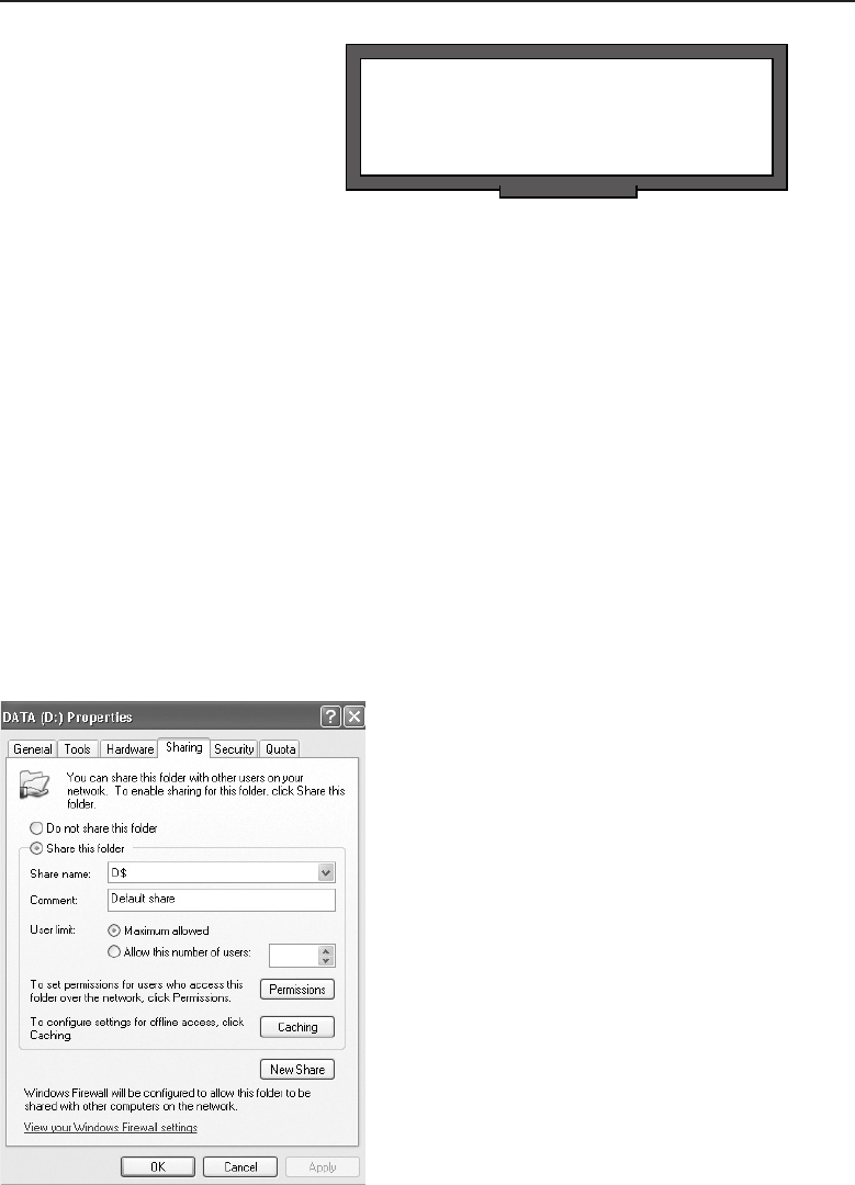
Edwards c04.tex V3 - 03/27/2009 11:04am Page 181
Chapter 4 ■Operating Systems and Networking Software 181
POP QUIZ
Name two network operating systems that
are prominent in today’s networking world.
This section configures a
Windows-based PC not only for
use on a Microsoft network but
also for any TCP/IP-based net-
work, which includes the Inter-
net as we know it today. There
will be changes coming such as
IPv6,20 but the basics will remain the basics. What is learned here is scalable to
any new nuances that may be coming into the world of networking.
4.2.1.1 File Sharing on a Peer-to-Peer Network
When we configured the NIC card on the PC to permit file sharing, we did
not expound on how this is accomplished in a Microsoft Windows world.
The strategy is to first determine what is needed to be shared between users.
Whole drives, including hard drives, floppy drives, CD-ROM drives, and
DVD drives, can be shared. However, any portion of the file system can be
shared down to the lowest subdirectory within a directory structure. So this
allows for drive, directory, and subdirectory file sharing, all of which can be
accomplished over the local network.
From My Computer, right-click on the drive that you are willing to share.
From the drop-down menu, select Sharing and Security. A new window will
open showing the properties for the drive (see Figure 4-8).
Figure 4-8 Windows XP drive properties
20We will cover this in Chapter 10, ”The Network Layer.”

Edwards c04.tex V3 - 03/27/2009 11:04am Page 182
182 Part I ■Networking Nuts and Bolts
Notice the message about the security risk that is involved in sharing a
whole hard drive. You can proceed if you wish or you can back off to the
directory you want to share. Multiple directories can be shared on a hard
drive.
QUICK TIP
Proper planning can simplify sharing of directories over the network. Create a
single folder that you want to share. Under that folder you can create other
folders (subdirectories) that will be shared with the parent folder. The whole
directory tree under the shared folder will be shared when you allow sharing
on this folder.
One instance where it makes sense to share an entire drive is where
removable media is concerned. Floppy drives, CD drives, and DVD drives
can be both read and written to, as needed. The floppy drive is nowhere to be
found on today’s newer laptops, so if you need to generate a floppy disk with
information from your laptop, share the drive on the desktop to accomplish
that task. Granted, it may not be as fast as a directly connected floppy drive,
butitcangetyoubyinapinch.
RANDOM BONUS DEFINITION
router — A network node that operates at
the Network layer.
Enabling file sharing is only
half of the task. You may want to
create user accounts on the PC.
This can be accomplished under
the User Accounts section of the
Control Panel. For other com-
puters to use the shared folder,
they will need to map a network
drive. This can be done from My Computer by selecting the Tools drop-down
menu and then Map Network Drive. This window is illustrated in Figure 4-9.
POP QUIZ
What can be shared using Windows file
sharing?
The format shown on this
window is \\server,which
wouldbetheNetBIOScomputer
name of the computer where
the shared directory is located.
An example would be \\joe pc.
However, with TCP/IP enabled
on the network connection, this
also may be an IP address of the computer where the shared directory is
located. The command format would be similar but with the IP address of the
computer is placed where the computer name had been. An example would
be \\192.168.5.154.The\share is the name assigned to the shared entity,
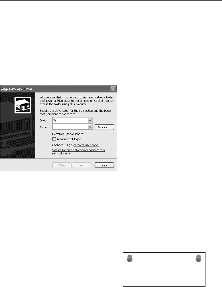
Edwards c04.tex V3 - 03/27/2009 11:04am Page 183
Chapter 4 ■Operating Systems and Networking Software 183
whether it is a drive or directory on the hard drive. The naming is fairly
arbitrary and the owner of the computer can use any name he or she pleases.
However, the owner must play nice and give the name to the user who would
be sharing the data contained in that directory. Without the proper shared
name, the share cannot be established. If a guest account or user account has
been created for that user, they will be prompted for the account prior to
gaining access to the shared data. However, for file sharing to work properly,
the computer with the shared directory must be powered on and connected to
the network before its shared resources can be accessed.
Figure 4-9 Windows XP Map Network Drive screen
4.2.1.2 Printer Sharing on a Peer-to-Peer Network
In today’s networking world there are network-ready printers that act as their
own print server. They can obtain a network IP address, be given a name, and
will allow themselves to be mapped to from other computers connected to the
network. This section does not deal with those printers but with the printers
that are locally connected to computer on the network.
ACRONYM ALERT
RAM — Random-Access Memory
These printers may be locally connected
to a network PC with a parallel port, serial
port, or USB port.21 To share a locally con-
nected printer, select Printers and Faxes
from the Control Panel. Select the printer
to be shared by pointing to it and clicking
the right-mouse button. In the drop-down
menu, select Sharing. A new window simi-
lar to the window in Figure 4-10 will appear on the screen.
21Extra credit: What is the benefit and the disadvantage for each of the port types? (This is a
question that you will have to research — unless you already know).

Edwards c04.tex V3 - 03/27/2009 11:04am Page 184
184 Part I ■Networking Nuts and Bolts
Figure 4-10 Windows XP Printer Sharing screen
Select the radio button to share this printer and enter a share name in the box
provided. Windows will attempt to enter a name that is being used locally, but
this can be changed as needed. For this example, it a high-speed laser printer
connected to Flo the secretary’s computer, and other users in the department
would like access to that print resource, so a share name may be something
like flo printer. Other computer users on the network can then go to Control
Panel and select Printers and Faxes and then Add a Printer. They may either
browse the network for Flo’s printer or enter the name directly, as discussed in
the file sharing section. For the sake of this example, the name may appear as
\\flo pc\flo printer,whereflo pc is the server name of the computer and
flo printer is the share name for the laser printer sitting by her computer. If
needed, the IP address assigned to Flo’s computer can be used in place of a
server name.
QUICK TIP
The use of IP addresses in place of server names is indicative of static IP
address assignment. If the network is designed to use dynamic IP address
assignment, this could cause problems for users on the network since a
computer’s assigned IP address could theoretically change each time it is
booted up.

Edwards c04.tex V3 - 03/27/2009 11:04am Page 185
Chapter 4 ■Operating Systems and Networking Software 185
POP QUIZ
Which printers connected to a
network-connected computer can be shared
with other users on the network?
Remember that a shared re-
source in a peer-to-peer network
environment assumes that the
resource is available on the net-
work. The computer providing
the source must be powered on
and connected to the network
for the resource to be shared.
4.3 Other Operating Systems
So far in this chapter, we have concentrated on the client aspect of networks
and the Internet. However, many computers on the Internet and within
the corporate environment are large computers running a wide range of
applications. Although there are many similar applications that can run on a
PC and offer the same type of service, they may not be equally able to handle
many users at the same time. Large computers were initially designed and
used to service multiuser environments, whereas the small computer or PC
was initially designed with the single user in mind. As a result, the operating
systems that control these large machines are much more robust when it comes
to handling a large number of simultaneous users.
This section will concentrate on the network aspects of these operating
systems and how they are used within boththe corporate network environment
and the Internet.
4.3.1 Unix
Unix was first developed by AT&T Bell Labs as a multiuser operating system. It
was initially designed to handle many users connected simultaneously and all
sitting in front of character-based terminals. These terminals were connected
to terminal concentrators that were able to aggregate a number of users for
ease of communications with the computer the Unix operating system was
running on. TCP/IP had not been implemented and the Internet was in its
earliest planning stages.
Since its inception, Unix, because of its kernel design was able to be ported
to a number of different computer platforms from a variety of computer
manufacturers. Later, the operating system program was emulated and offered
by other software vendors and computer manufacturers. The discussion
in this section will cover the basics to get a Unix-based computer onto a

Edwards c04.tex V3 - 03/27/2009 11:04am Page 186
186 Part I ■Networking Nuts and Bolts
TCP/IP network. Since these are usually specialized computers from many
manufacturers, it would be difficult to get into specifics for all the variations
and iterations, so consider this a familiarization with the requirements to make
a Unix-based computer network-able.
RANDOM BONUS DEFINITION
trap — A message that originates from a
network management client to a network
management server to notify the server of a
notable event.
Unix is a flat file operating
system, which basically means
that most of the configuration
files are in readable text. Config-
uration is accomplished using
one of the resident text proces-
sor programs that are part of
the utilities that come with the
operating system. The appropri-
ate files can be edited as needed to configure the TCP/IP settings on the
computer. Usually, systems of this vintage have system administrators who
maintain and update the /etc/hosts22 file. The information that needs to be
modified includes the following:
The host name
The IP address assigned to the interface
The subnet mask being used for the network segment the computer
resides on
The IP address of the DNS server that is going to be used
Thedefaultgatewaythatisresidingonthesamenetworksegmentasthe
computer
The version of Unix you are working with will determine which files and
syntax of commands will need to be used. Luckily, most iterations of Unix
have resident help in the form of the man pages. These pages are an online
manual and the common syntax is man <command>,where<command>is the
command you need help with. You will be informed if the command does
not exist. When in doubt, issue the man command and you will get a complete
description of the command along with the various switches that are used by
the command.
Newer versions of Unix come with configuration utility programs that assist
with the network settings and configuration. Edits of the related network files
are automated for ease of use, but essentially it performs the same edits that
an administrator can do with a text editor.
22The Unix /etc directory contains configuration files for devices connected to the computer.
The hosts file aids in host name to IP address resolution. For further information on the Unix
directory structure, including the full contents of the /etc directory, consult the operating
manual supplied with your Unix system.

Edwards c04.tex V3 - 03/27/2009 11:04am Page 187
Chapter 4 ■Operating Systems and Networking Software 187
The following are a few useful commands for troubleshooting network
issues on a Unix computer:
arp — Displays a table that shows the IP address to physical
MAC address relation for nodes on the same subnet with the
Unix computer. This is useful when there are connectivity issues
between the Unix computer and that host. If there is an arp entry
for the problem node, there is a possible Physical layer issue.
arp -a
ping — An important troubleshooting command that helps to determine
that the TCP/IP stack is configured properly on the Unix computer, that
the network interface is configured properly, that the default gateway
is reachable, and that domain name services are configured properly.
ping 127.0.0.1
If no response is received, you need to verify that TCP/IP services
have been loaded and are running on the Unix computer.
ping <address of default gateway>
If no response is received, verify that TCP/IP has been bound to the
NIC. Check that the operating system has been configured properly as
far as the NIC’s hardware address and the proper interrupt request num-
ber. If the operating system is configured properly, check for a Physical
layer issue.
ping <address on another subnet>
ACRONYM ALERT
SMTP — Simple Mail Transport Protocol
This verifies that the subnet mask has
been properly set in the TCP/IP con-
figuration and that the request is sent
to the default gateway correctly. If
no response it received, check set-
tings to verify that the default gateway is set correctly in the TCP/IP
parameters after you were successful in pinging the default gateway.
ping <Internet hostname>23
This will verify that the DNS service is correctly configured on the
TCP/IP stack. If no response is received, attempt to ping the configured
DNS server using its IP address. If no reply is received, there may
be a connectivity issue. Repeat the ping test to the default gateway.
If that passes, verify the settings in the TCP/IP configuration.
23Internet host name is the fully qualified domain name (FQDN) of the host server you are
attempting to reach. An example of a FQDN for a host name would be www.google.com.

Edwards c04.tex V3 - 03/27/2009 11:04am Page 188
188 Part I ■Networking Nuts and Bolts
netstat — A network status command that will display status
and information on the network interfaces24 configured on the Unix
computer.
Thefollowingaresomeswitchesthatcanbeusedwiththenetstat
command:
-a — Displays information on all interfaces.
-i — Displays configuration information.
-n — Displays IP addresses.
-r — Displays routing table information.
ifconfig — Used to display information on the interfaces that are found
on the Unix computer. These interfaces can be Ethernet or other types of
interfaces.
route — Used to add static routes to the Unix computer’s routing table.
POP QUIZ
Which command can be used to verify the
TCP/IP stack has been properly configured
on a Unix computer?
traceroute —Ause-
ful tool to show the
nodes an echo request25
needstopassthrough
to reach its intended
target. The target
address may be either
a numeric address or an alphanumeric Internet host name.
traceroute <address>
4.3.2 Linux
Linux26 has many similarities and commonalities to Unix. However, it was
designed more for the desktop environment even though it will run on larger
computers. The number of Linux variations is too many to mention, and each
has its own piece of window dressing when it comes to configuration. Similar
to Unix, Linux can be configured with a text editor, if necessary.
The variables that are configured are part of a script that is loaded each time a
Linux computer is booted. Therefore, changes in network configuration would
require a reboot so that these scripts can be executed with the new variables
24Network interfaces on a computer can be of the LAN variety (NICs) or interfaces for WANs,
such as a WAN card for a T1 line.
25Echo request is part of the ICMP protocol primarily utilized by the ping command. The ICMP
components of a ping command are echo request (the ping to a target IP address) and echo
reply (a successful response from that target). traceroute uses these components to verify
the path by receiving and logging the network nodes that the echo request passed through on
its way to the target IP address.
26One of the Unix-like operating systems.

Edwards c04.tex V3 - 03/27/2009 11:04am Page 189
Chapter 4 ■Operating Systems and Networking Software 189
in place. The Linux distribution being used will determine the name of the
script. In some distributions, the script responsible for initializing the kernel
for networking may have the name rc.inet1, whereas the script that starts
the networking services may be named rc.inet2. Again, the distribution
and vintage of Linux being used may cause these file names to be totally
different. You should consult the documentation for your Linux version prior
to configuring or making network changes on the Linux computer.
The networking information for the kernel runtime can be accessed and
displayed through the /proc file system. The /proc file system is usually
mounted when the computer is first booted. If it is not mounted, there will be
a message stating that procfs is not supported by the kernel. If this is the case,
the kernel will need to be recompiled with procfs support enabled.
Most Linux distributions come with a set of binaries27 containing all the
applications and utilities needed for networking support. These applications
and utilities may change from time to time with updates to the kernel and the
networking utilities. These updates and applications need to be recompiled in
order to be used as part of the Linux operating system.
The following are a few of the basic networking configuration and monitor-
ing commands:
hostname — Sets the name of the computer entered in the /etc/hosts
file.
hostname <name of the computer>
ifconfig — Allows the interface to be available to the kernel
networking layer. This command is normally a portion of the
network initialization script that is executed at system boot-up.
ifconfig <interface><assigned IP address>
The first interface required to be activated is the loopback interface.28
The following ifconfig command configures this interface:
ifconfig l0 127.0.0.1
27Binary files are programs that have already been compiled for the system the program is
to be executed on. Since Linux can run over many various platforms, application programs
need to be compiled on the computer to execute properly. To save users time, many Linux OS
providers have already compiled these programs for the platform they are and are considered
to be included binaries with the operating system. An example of different platforms would be
those that are built around the Intel family of microprocessors versus those computers that have
been designed and built using the Motorola 68000 microprocessor family.
28The loopback interface on a computer is a logical network interface which will allow for testing
of applications requiring network connectivity. Using this adapter permits the testing of those
applications even though the computer is not connected to a network. An example of this would
be a computer that is running as a web server testing itself by launching a web browser and
navigating to the loopback IP address of 127.0.0.1. The web browser will bring up the server’s
own home page. A less sophisticated use is in checking the IP stack of the computer by pinging
the IP address 127.0.0.1. If no response is returned, there is a problem with the IP stack of that
computer.

Edwards c04.tex V3 - 03/27/2009 11:04am Page 190
190 Part I ■Networking Nuts and Bolts
RANDOM BONUS DEFINITION
wire speed — The maximum frame and
data rate that is supported on a given
interface.
The following entry in
the host table is inserted
upon execution of this
command:
localhost 127.0.0.1
Configuration of an
Ethernet interface is accomplished using the following command:
ifconfig eth0 <interface address>netmask <interface subnet mask>
Status of an Ethernet interface can be obtained by executing the following
command:
ifconfig eth0
route — Used to add or delete routes from the kernel’s routing table.
route [add |del] [-net |-host] target [if]
add — Adds a route.
del — Removes a route.
-net — Specifies it is a network route.
-host — Specifies a host address.
target — Specifies the address of either the network or host.
if — Specifies the network interface the route should be directed to
(optional).
To add a default gateway, execute the following command:
route add default gw <address of gateway node>
netstat — As in Unix, a useful command to verify the operation and
status of the Linux network components.
netstat [-nr, -i, -ta]
-nr — Displays the kernel’s route table with IP addresses displayed in
dotted numerical notation.
-i — Displays interface statistics for currently configured network
interfaces.
-ta — Displays a list of both active and passive TCP sockets. This
command option can also be modified to also show UDP (-u), RAW
(-w), and Unix sockets (-x).
arp — Displays the kernel’s ARP table.
arp -a

Edwards c04.tex V3 - 03/27/2009 11:04am Page 191
Chapter 4 ■Operating Systems and Networking Software 191
POP QUIZ
True or false: The name Linux is a
derivative of the words Unix lite.
Linux is a very robust and
feature-rich operating system
that is under constant devel-
opment and improvement. The
commands in this section are
just a beginning when it comes
to Linux. Much more investigation is required, and the information that is
available from a wide range of sources is beyond the scope of this section and
book.
4.3.3 Sun Solaris
Sun Microsystems initially developed the Solaris operating system for their
Sun SPARC workstations. It has been ported to X86 Intel-based computers
and is distributed and supported by Sun Microsystems. Like Linux, it has
similarities and commonalities with the Unix operating system. The latest
release of Sun’s operating system is Solaris 10.
Although Solaris-based workstations are capable of operating in a stan-
dalone (not networked) environment, the operating system provides strong
networking tools to allow it to be interconnected not only to the local LAN but
the Internet.
Solaris does provide a number of installation programs that will configure
the built-in installations.
Enabling a network interface on a Solaris computer requires the following
actions:
1. Install device drivers.
2. Reboot to reconfigure the system.
3. Assign an IP address on the interface.
4. Create a hosts file entry to map the IP address to the host name.
5. Configure the interface to pass traffic.
The IP address is assigned to an interface when the IP address is entered
into the hostname file located in the /etc directory. As with Unix and Linux,
this can be accomplished with the use of a text editor.
An interface is configured to allow IP traffic with the use of the ifconfig
command. The command can also be issued to verify the operation of an
interface and to monitor its health. Issuing the ifconfig -a command displays
all active interfaces on the computer. Incorrect configuration of an interface
will result in an error message being returned stating ‘‘no such interface.’’ To
enable an interface, issue the following command:
/usr/bin/ifconfig eri0 up
Edwards c04.tex V3 - 03/27/2009 11:04am Page 192
192 Part I ■Networking Nuts and Bolts
To verify connectivity over TCP/IP with other hosts on the network, issue
the following command, which will display the kernel’s ARP table:
arp -a
The flags that can be returned in the ARP table are as follows:
P— Indicates a published address
S— Indicates a static address
U— Indicates an unresolved address
M— Indicates a mapped address for multicast
ACRONYM ALERT
SRT — Source route/transparent bridge
Solaris allows for manual tuning of pro-
tocol transmission parameters for increased
performance. This can be accomplished
with the use of the ndd command. Using
ndd parameter options for TCP, UDP, IP,
and ARP will display a list of parameter
values related to that particular protocol.
An example of this would be the issuing of
the command ndd /dev/tcp \?to display a list of all the parameters that are
currently related to TCP.
Like Unix and Linux, Solaris uses the netstat command to display network
statistics and to verify the operational status of network interfaces.
netstat is capable of displaying the following statistics:
Data collection by protocol type
Statistics grouped by node address, which may be IPv4, IPv6, or
Unix-based
Data related to DHCP
Multicast grouped interface data
Details of the routing table
Data associated to STREAMS29
State and status of all IP interfaces
State of all active logical and physical interfaces, routes, and sockets
netstat can display protocol statistics for packets of the following types:
TCP, UDP, RAWIP, IPv4, IPv6, ICMPv4, ICMPv6, and IGMP. Each of these
29STREAMS is a flexible programming model used for Unix communications services. It allows
for the definition of standard interfaces for character input and output both within the kernel
and between the kernel and the rest of the Unix system. It is a collection of system calls, kernel
resources, and kernel routines.

Edwards c04.tex V3 - 03/27/2009 11:04am Page 193
Chapter 4 ■Operating Systems and Networking Software 193
packet types has specific parameters associated with it. Generally they display
the total number of packets in and out and those that are in error. When
monitored, these counters can be used to point out possible problem areas.
Issuing a netstat -m command will display the system calls, standard
libraries, and kernel associated with writing network applications that use the
STREAMS package. Additional details on this function can be obtained by
reading the man page for the streamio command.
POP QUIZ
List some of the Solaris network commands
that are similar to those found in Unix and
Linux.
Sun Solaris version 10 can be
obtained free of charge from the
download section of the Sun
Microsystems web page. A ver-
sion with documentation can be
ordered directly from Sun for a
nominal charge. If you are inter-
ested in learning more about the
configuration and maintenance of a Sun system, the X86 version can be loaded
on any i86 Intel microprocessor-based computer.
4.4 Chapter Exercises
1. If you have a network-capable PC, try using a few of the network utili-
ties discussed in this chapter.
2. Open a DOS window by running cmd from Start, Run. Enter the
command ipconfig andnotewhatisdisplayed.
3. Issue the command ipconfig /all and note what is displayed.
4. If your network allows your PC to access the Internet, execute this com-
mand tracert <insert your favorite website URL>and hit the Return
key. Note the results. You may want to repeat this with other Internet
addresses.
5. To display information about all the interfaces on a Unix computer,
which command would need to be issued?
6. What is used on the Internet to find the numeric address of a computer
host that resides on the Internet?
7. True or false: Floppy disks are the fastest form of magnetic media.
8. True or false: AT&T is the sole provider for the Unix operating system.
9. Can you name at least one Linux distribution?
10. If a microprocessor designer wanted to allow his newest chip design
to access a greater amount of memory space, what might he do to accom-
plish this?

Edwards c04.tex V3 - 03/27/2009 11:04am Page 194
194 Part I ■Networking Nuts and Bolts
4.5 Pop Quiz Answers
1. What function does an arithmetic logic unit (ALU) provide?
The ALU performs mathematical operations on the data it is presented
with.
2. Would it be advisable to cycle power to the computer while a ROM
upgrade is in process?
No.
3. True or false: The information contained within RAM is saved when the
computer is powered off.
False.
4. When a computer is first powered on, the first device it is most
likely to read its initial instructions from is the ROM.
5. Name a device that you may find connected to a serial port.
Generally serial devices are slow data rate devices such as keyboards,
modems, pointing devices, scanners, etc. However, with the develop-
ment of Universal Serial Bus (USB) high-speed serial ports, devices such
as hard disk drives and printers can be used due to the increased data
rates on these ports.
6. What is the acronym for a user interface that uses a point-and-click
method of executing computer commands?
Graphical user interface (GUI)
7. Name two network operating systems that are prominent in today’s net-
working world.
Novell Netware
Microsoft Windows networking
8. What can be shared using Windows file sharing?
Drives
Directories
Subdirectories
9. Which printers connected to a network-connected computer can be
shared with other users on the network?
All of the ones designated for sharing.
10. Which command can be used to verify the TCP/IP stack has been
properly configured on a Unix computer?
ping 127.0.0.1

Edwards c04.tex V3 - 03/27/2009 11:04am Page 195
Chapter 4 ■Operating Systems and Networking Software 195
11. True or false: The name Linux is a derivative of the words Unix lite.
False — The correct answer is Unix-like.
12. List some of the Solaris network commands that are similar to those
found in Unix and Linux.
netstat
ping
traceroute
Edwards c04.tex V3 - 03/27/2009 11:04am Page 196

Edwards c05.tex V3 - 03/27/2009 11:05am Page 197
CHAPTER
5
The TCP/IP
Protocol Suite
I dwell in Possibility.
Emily Dickinson
TCP/IP is the name that refers to the group of protocols that it encompasses.
This group of protocols is known as the TCP/IP protocol suite. It’s called TCP/IP
because of the two main protocols that are part of the group: TCP and IP. The
TCP/IP protocol suite is also known as the Internet protocol suite,asTCP/IPis
pretty much the backbone of the Internet (and the majority of all networks out
there).
There are many good books that cover the TCP/IP protocol suite. Some
of these are multivolume, so that might give you an idea of the amount of
information that is covered in the standard. TCP/IP can be considered the
most widely used standard of the Internet, much as Ethernet is the dominant
LAN standard. In addition to multiple standards, TCP/IP also includes any
applications, tools, and transmission media used in the network to pass
datagrams. As a matter of fact, RFC 1180, ‘‘A TCP/IP Tutorial,’’ states that the
term internet technology is more appropriate than TCP/IP when defining the
purpose of the standard.
As we discussed in Chapter 1, ‘‘Introduction to Networking,’’ the processes
and standards contained in the TCP/IP protocol suite are mapped to one of
four layers.1These layers are based on the four-layer model of DARPA. Every
layer within the TCP/IP reference model is cross-referenced to the seven-layer
OSI reference model.
The TCP/IP protocol suite allows data communication to take place. No
matter what the node is, who it was made by, which operating system software
1Or five layers, depending on what school of thought one follows.
197

Edwards c05.tex V3 - 03/27/2009 11:05am Page 198
198 Part I ■Networking Nuts and Bolts
is running, and where the node is located, TCP/IP makes it work. TCP/IP has
kept up with the tremendous growth that the Internet (as well as networks in
general) has experienced. The possibilities seem endless and may very well
be. The quote we selected for this chapter really is appropriate for the TCP/IP
protocol suite because anyone involved with any facet of the TCP/IP protocol
suite should always dwell in the possibilities.
This chapter covers the more well-known protocols and functions that make
up TCP/IP. What do these technologies and standards do? What layer of the
TCP/IP reference model does each fall into and why? What are the differences
among IPv4, IPv6, and IPng? These are just a few questions that will be
answered in the pages to come.
5.1 The TCP/IP Layers
Developers of networking protocols adhere to a layered approach. Each layer is
responsible for a different portion of the data communication that is occurring
at any time. There are many protocols that are part of the TCP/IP protocol
suite. Each protocol functions within a layer of the TCP/IP model, depending
on its function. Figure 5-1 shows an example of the TCP/IP model, how it
corresponds to the OSI model, and some of the more well-known protocols
that are served at each layer.
OSI TCP/IP
Application
TCP/IP Protocol Suite
Telnet
SMTP
NFS
FTP
SNMP
DNS
DNS
TFTP
DHCP
TCP UDP
IP RIP IGMP ICMP OSPF
ATM Ethernet HDLC PPP
FDDIToken RingFrame Relay
Transport
Internet
Network
Interface
Application
Presentation
Session
Transport
Network
Data Link
Physical
Figure 5-1 TCP/IP reference model layering
The layers in the TCP/IP reference model roughly correspond to one or
more layers of the OSI reference model. Protocols of the upper layers can focus
on the layer they are a member of, without concerning themselves with the
functions performed by the lower levels. This is huge during the development

Edwards c05.tex V3 - 03/27/2009 11:05am Page 199
Chapter 5 ■The TCP/IP Protocol Suite 199
of the protocol, as it enables developers to focus on the development at each
layer, rather than worrying about an all-encompassing standard. The layers of
the TCP/IP reference model and their responsibilities are as follows:
Network Interface layer — The Network Interface layer corresponds
to the Physical and Data Link layers of the OSI reference model. This
layer is also often referred to as the Link layer or the Data Link layer.
The Network Interface layer is responsible for the device drivers and
hardware interfaces that connect a node to the transmission media.
RANDOM BONUS DEFINITION
uplink port — Any switch port that is
designed to connect to a backbone switch or
network.
Internet layer —The
Internet layer corresponds
to the Network layer of
the OSI reference model.
This layer is also known
as the Network layer.The
Internet layer is responsi-
ble for the delivery of packets through a network. All routing protocols
(RIP, OSPF, IP, etc.) are members of this layer. Nodes that perform func-
tions at this layer are responsible for receiving a datagram, determining
where to send it to,2and then forwarding it toward the destination.
When a node receives a datagram that is destined for the node, this
layer is responsible for determining the forwarding method for infor-
mation in the packet. Finally, this layer contains protocols that will
send and receive error messages and control messages as required.
Transport layer — The Transport layer corresponds to the Transport
layer of the OSI reference model. Two primary protocols operate at this
layer: Transmission Control Protocol (TCP), and the User Datagram
Protocol (UDP). This layer serves the Application layer and is respon-
sible for data flow between two or more nodes within a network.
Application layer — The Application layer corresponds to the
Application, Presentation, and Session layers of the OSI reference
model. Users initiate a process that will use an application to access
network services. Applications work with protocols at the Transport
layer in order to pass data in the form needed by the transport protocol
chosen. On the receiving end, the data is received by the lower layers
and passed up to the application for processing for the destination
end user. This layer concerns itself with the details of the application
and its process, and not so much about the movement of data. This
is what separates this upper layer from the lower three layers.
2Based on the IP address that is assigned to the destination network or node.
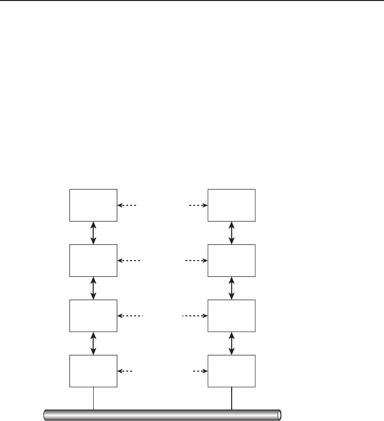
Edwards c05.tex V3 - 03/27/2009 11:05am Page 200
200 Part I ■Networking Nuts and Bolts
The design of the TCP/IP model was based on the original Department of
Defense network model. The act of layering network protocols is known as
protocol layering. Protocol layering ensures that data sent by one layer on the
source side is the same data received at that layer on the destination side. This
layered principle allows focus to remain on the functions of protocols at the
layer and ensure that the data matches on each end.
Most applications will use the client/server method of communication. One
of the host nodes will act as the server, and the other as a client. Each layer
will use a protocol or a group of protocols to transfer readable data from the
source layer to the peer layer on the destination side.
Figure 5-2 shows an example of which protocols would be involved to
transfer an e-mail message from a source to a destination.
SMTP
Application
Layer
Transport
Layer
Internet
Layer
Network
Interface
Layer
SMTP
TCP TCP
IP IP
Ethernet
(driver)
Ethernet
(driver)
Ethernet
SMTP Protocol
TCP Protocol
IP Protocol
Ethernet Protocol
Figure 5-2 TCP/IP layering in action
As you can see, a user on one side of a communication session initiates
an e-mail to be sent to the user on the destination side of the session. The
Application layer protocol that is used in this process is the Simple Mail Transfer
Protocol (SMTP). SMTP will use TCP as the Transport layer protocol, IP as the
Internet layer protocol, and then use the Ethernet interfaces at the Network
Interface layer to send the data to the media for transport to the other end.
This works exactly the same way when there are multiple networks in the mix
(see Figure 5-3).
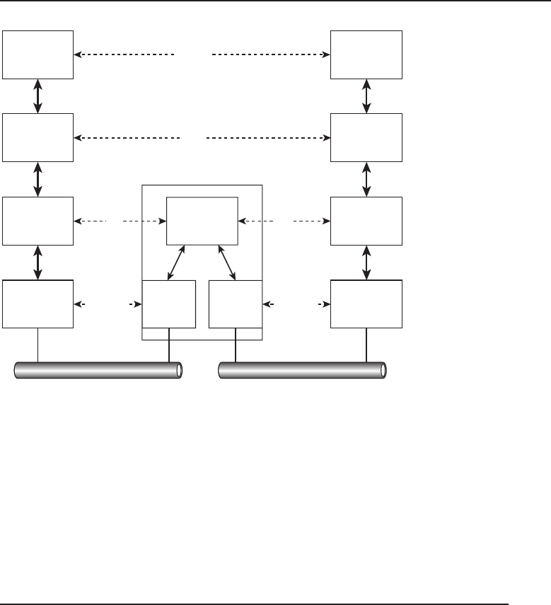
Edwards c05.tex V3 - 03/27/2009 11:05am Page 201
Chapter 5 ■The TCP/IP Protocol Suite 201
SMTP SMTP
TCP TCP
IP IP
Ethernet
(driver)
Ethernet
(driver)
Ethernet
(driver)
Ethernet
(driver)
SMTP
TCP
IP
Router
Ethernet
Protocol
Ethernet Ethernet
Ethernet
Protocol
IP IP
Figure 5-3 TCP/IP layering in multiple networks
In this example, a router is connecting two different networks.3Notice
that the layers on each end, even though they are not local, are still able to
recognize information from their respective peers, as though they are on the
same segment. There you have it. That is how the layered model works. The
next section discusses many of the protocols that make up the TCP/IP protocol
suite.
5.2 Popular TCP/IP Protocols
Now that you know the principles of protocol layering and how it relates to the
TCP/IP protocol suite, it’s time to discuss the various protocols that operate
at each layer. There are many more protocols that are part of the TCP/IP
protocol suite. This section covers some of the more widely known (and used)
protocols in use in many networks today.
3That’s the really nice thing about a router. It does not care what type of network it connects to.
It can be Token Ring, Ethernet, or many others. The layers don’t realize any of this as long as
they can talk to their peer.

Edwards c05.tex V3 - 03/27/2009 11:05am Page 202
202 Part I ■Networking Nuts and Bolts
5.2.1 The Application Layer
A lot of applications are supported by nodes that run TCP/IP. Many of these
are commonly included with the operating system software running on the
node. If they are not built into an operating system, these applications can
readily be found on the Internet, often free of charge. The Application layer
is not concerned with the movement of data from one point to another on a
network. Its only concern is the details of the application to ensure that what
goes out is what is interpreted on the other end. The following protocols are
discussed in this section:
Domain Name System
Simple Network Management Protocol
File Transfer Protocol
Trivial File Transfer Protocol
Simple Mail Transfer Protocol
Network File System
Telecommunications Network Protocol
Secure Shell
5.2.1.1 Domain Name System
A domain name is simply the name assigned to a node on a network. It
is also the name that is assigned as a host name for a given URL on the
Internet. For example, if you want to go to the Cable News Network (CNN)
website, you would open a web browser application (for example, Firefox,
Internet Explorer, etc.) and initiate an HTTP session for the domain name that
is assigned to CNN:4
http://www.cnn.com
ACRONYM ALERT
AFP — AppleTalk Filing Protocol
In the example, cnn.com is the domain
name that you want to reach because you
know that is the domain name for the CNN
website. So, why is DNS important? Well,
instead of a direct answer to that question,
let’s answer it this way: What is the IP
address for the CNN website? If you know
4This example was probably too simple, so don’t get fooled into thinking that any website you
want to go to will have a domain name that matches the site. It depends whether that domain
name is owned by someone else and, if it is, whether the owner is willing to sell the domain
name. During the initial Internet boom, a lot of people had the foresight to buy popular domain
names and later sold them for a lot of money.

Edwards c05.tex V3 - 03/27/2009 11:05am Page 203
Chapter 5 ■The TCP/IP Protocol Suite 203
that one, you really are doing well, but most likely you do not know the CNN
website’s IP address. If you have access to a computer that supports TCP/IP,
you can find out what the address is. Open up a command-line session and
initiate a ping to the domain name, and you will be able to see the IP address
assigned to the domain name. Here is a ping that was run to the cnn.com
domain name and the IP address that was returned:
C:\>ping cnn.com
Pinging cnn.com [64.236.16.20] with 32 bytes of data:
Reply from 64.236.16.20: bytes=32 time=88ms TTL=51
Reply from 64.236.16.20: bytes=32 time=88ms TTL=51
Reply from 64.236.16.20: bytes=32 time=87ms TTL=51
Reply from 64.236.16.20: bytes=32 time=87ms TTL=51
Ping statistics for 64.236.16.20:
Packets: Sent =4, Received =4, Lost =0 (0% loss),
Approximate round trip times in milli-seconds:
Minimum =87ms, Maximum =88ms, Average =87ms
As you can see in the example, the IP address assigned to the CNN website
is 64.236.16.20. Once you know the IP address, you can put that number where
you would normally enter the URL in your web browser, and it should bring
up the site.
The need for DNS is simple. Humans speak in words, whereas computers
speak in numbers. Bits and bytes are all the computers understand. This is
why a node has to be assigned a number.5Sure, humans can learn numbers
and use them as well, but it would probably take a lot of conditioning to
remember all the numbers in IP addresses that are assigned to nodes in
networks worldwide.6
RANDOM BONUS DEFINITION
store-and-forward — A mode of switch
operation where frames are completely
received before they are forwarded onto
any of the output ports of the device.
DNS is a database that maps
host names to IP addresses. The
database is referred to as a dis-
tributed database,asDNSinfor-
mation is distributed among
several servers. Each server will
maintain the DNS information
that is assigned the server to
serve to clients within its own
network. DNS uses the client/server model, and the protocol itself provides
the facility for the servers to share this information with authorized clients.
5Remember back when we couldn’t send an e-mail to Brother Joel?
6Are you kidding? Jim has a hard enough time just remembering how old he is.
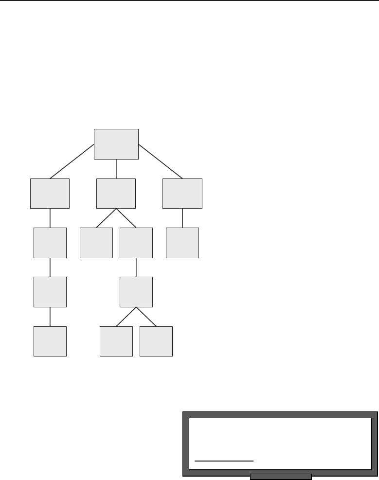
Edwards c05.tex V3 - 03/27/2009 11:05am Page 204
204 Part I ■Networking Nuts and Bolts
DNS names are organized hierarchically,7with an unnamed root at the
top, then what are known as top-level domain (TLD) names next, followed by
second-level domain, and, finally, one or more subdomains. The names assigned
to nodes in the DNS hierarchical tree are often referred to as labels.This
organized hierarchy is known as the DNS namespace.TheDNSnamespacesets
the rules for how the labels are organized in the domain name. Figure 5-4
shows an example of the DNS namespace.
Root
Top Level
Domain
Second
Level
Domain
Second
Level
Domain
Second
Level
Domain
Second
Level
Domain
Sub-
domain
Sub-
domain
Sub-
domain
Sub-
domain
Sub-
domain
Top Level
Domain
Top Level
Domain
Figure 5-4 DNS namespace hierarchy
POP QUIZ
The Internet layer is also known as the
layer.
The DNS namespace hierar-
chy requires a different adminis-
trator on each level. This ensures
that the administration of a
particular branch in the DNS
tree does not become too cum-
bersome. At each level of the
namespace, there is an admin-
istrative authority that provides updates to the database. The delegation of
authority should ensure that no level of the namespace becomes too hard to
manage.
7There is that word again.

Edwards c05.tex V3 - 03/27/2009 11:05am Page 205
Chapter 5 ■The TCP/IP Protocol Suite 205
Authorities at each level must ensure the DNS server is updated as required.
Whenever there is a new node added into the network, the authority adds
this to the database. Any removed nodes are required to be updated as well.
Not keeping up with these can cause real headaches to end users as well
as additional traffic on the network. DNS servers are normally installed in
a redundant fashion. Updates are made to the primary server and then are
synchronized with the secondary server.8This ensures there is not a complete
failure of DNS services should the primary server fail.
So, let’s see this in action, shall we? We are going to assume there is a
company that sells widgets and has decided to use DNS resolution so that end
users don’t have to remember all of the IP addresses they have to access. DNS
name syntax for this company could be:
widgets.co
ACRONYM ALERT
μs — Microseconds
In this example, co is the top-level
domain name, and widgets is the second-
level domain name. Notice that in between
widgets and co is a period (.), which is
called a dot.TheDNSnamewidgets.co
wouldbepronouncedwidjits-dot-see-oh.Pay
attention to the dot that separates the levels
within the domain name structure. In any name, the dot separates the levels.
YoucanquicklyidentifytheTLDwhenyourunoutofdots.
Now, let’s assume there is an additional subdomain level, and an authority
has been assigned to assign names to nodes within the particular department
(Payroll, Production, Planning, and Sales) nodes. The namespace would be
updated to reflect this (see Figure 5-5), and the name syntax for each could be9
as follows:
payroll.widgets.co
production.widgets.co
planning.widgets.co
sales.widgets.co
The Internet Assigned Numbers Authority (IANA) is responsible for main-
taining the DNS root zone and is the authority for domain names, IP addresses,
and other parameters as well as appointing the authorities that sponsor them.
8The synchronization is handled by the secondary server. The secondary server will query the
primary periodically to see if there are any updates and, if so, will perform the update to its
record.
9The authority for the level can assign almost anything that he wants. Normally the name would
reflect some identification that reflects the users it serves. The name must be 63 characters or less;
other than that, the sky is the limit.
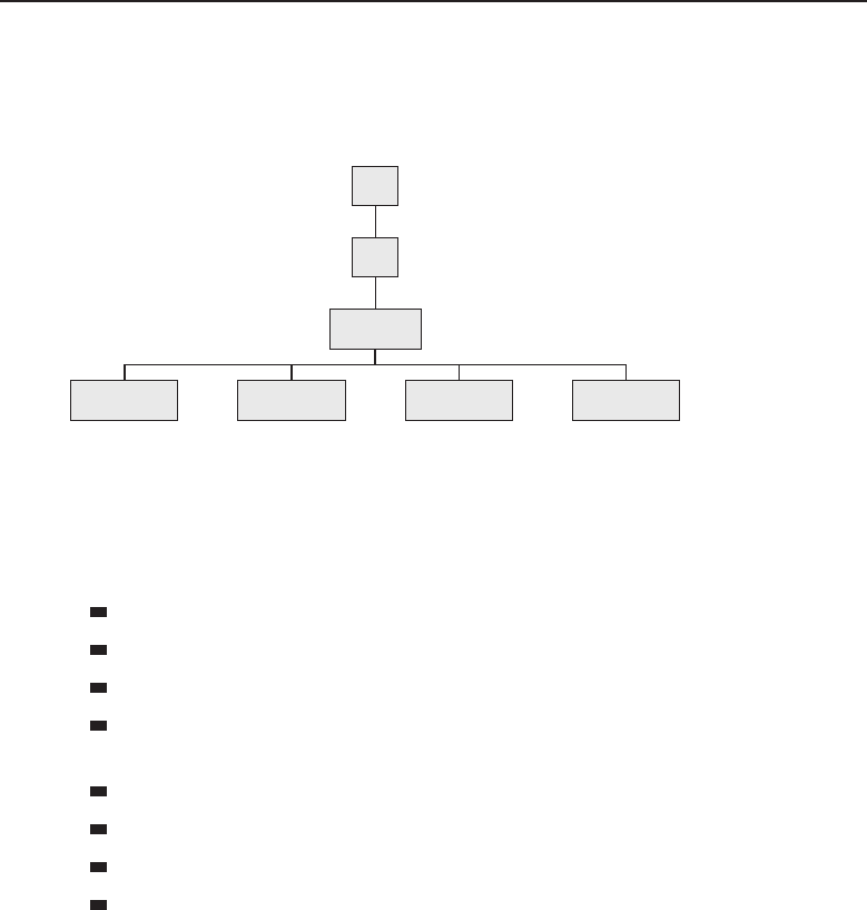
Edwards c05.tex V3 - 03/27/2009 11:05am Page 206
206 Part I ■Networking Nuts and Bolts
Sometimes the top-level domain names are specific for a particular group
or organization. For instance, the top-level domain name for the country of
France is .fr.10
Root
.co
.widgets
.production.payroll .planning .sales
Figure 5-5 An example of the hierarchical tree structure for the widgets.co domain
Sometimes the top-level domain is not really assigned to a particular purpose
and therefore is generic in nature. These types of domain names are called
generic top-level domains (gTLD). Some of the more well-known gTLDs are
.biz — restricted for use by businesses
.com — intended for use by commercial organizations
.edu — postsecondary educational institutions
.gov — restricted for use by the United States federal, state, and local
governments.
.jobs — for sites related to employment
.mil — the United States Military
.net — miscellaneous11
.org — miscellaneous organizations
5.2.1.2 Simple Network Management Protocol
Today’s networks are no longer the shared media environments they once
were. As you learned in Chapter 3, ‘‘Network Hardware and Transmission
Media,’’ a lot of different nodes are deployed in the networks of today. More
often than not, there is traffic sharing between nodes and multiple protocols
that regulate the flow of data in the network. All this growth requires a way to
keep track of what is going on within the network.
10Which is basically the country code.
11This domain was originally intended for large network infrastructure support centers.

Edwards c05.tex V3 - 03/27/2009 11:05am Page 207
Chapter 5 ■The TCP/IP Protocol Suite 207
RANDOM BONUS DEFINITION
protocol — A set of algorithms,
communication formats, and processes used
in the process of data transmission in a
network.
Determining traffic patterns
to ensure that the network keeps
up with end-user demands is
not an option; it is a necessity if
the network is to live to its full
potential. Having the ability to
monitor the network12 for any
problems that may occur and
getting notification when a problem has arisen is just as (if not more so)
important.
Once again, the technology opened up for the development of a protocol
that would do these things. That protocol is the Simple Network Management
Protocol (SNMP). SNMP is a protocol that runs between an SNMP manager and
an SNMP client, also known as an SNMP managed system, for the purpose of
sharing management information pertaining to the managed system. Software
that runs on the managed system used to communicate system information
with the SNMP manager is known as the SNMP agent. The information that is
shared is determined by the information (known as managed objects)setinthe
management information base (MIB).13
Communication between an SNMP manager and an SNMP agent is handled
in two directions. The SNMP manager can query the SNMP agent for system
information, or the SNMP agent can report information to the SNMP manager.
There are five Protocol Data Unit (PDU) types that are exchanged between an
SNMP manager and an SNMP agent.14 These are the GetRequest, GetNextRe-
quest, SetRequest, GetResponse, and Trap. The GetRequest, GetNextRequest,
and SetRequest are all PDUs that are sent from the SNMP manager to the
SNMP agent. The GetResponse and Trap are sent from the SNMP agent to the
SNMP manager (see Figure 5-6).
We discuss these in more detail in Sections 5.2.1.2.1 and 5.2.1.2.3.
5.2.1.2.1 SNMP Managers
The SNMP manager is a workstation that is running SNMP manager software.
In some environments, the SNMP manager function is shared by more than
one manager, so the resources of one device are not completely consumed
trying to monitor the nodes in its charge. System failover is another reason
why you may want to have multiple managers in your network.
12In a proactive manner.
13You will often hear people refer to the management information base as ‘‘the MIBs.’’
14An easy way to remember who is responsible to send what message type is to remember that
the requests are sent by the SNMP manager to the SNMP agent, requesting information. That
leaves only the SNMP response, which are the responses by the SNMP agent to requests that
were sent by the SNMP manager, and a trap, which is notification of a problem.
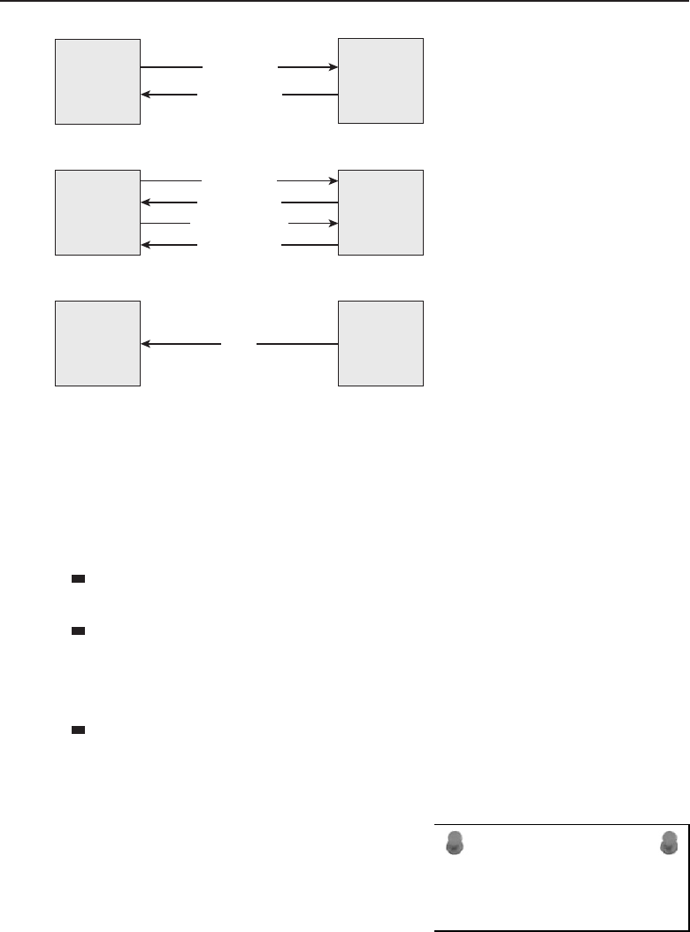
Edwards c05.tex V3 - 03/27/2009 11:05am Page 208
208 Part I ■Networking Nuts and Bolts
SNMP
manager
SNMP
agent
SNMP
manager
SNMP
agent
SNMP
manager
SNMP
agent
GetRequest
GetRequest
GetNextRequest
GetResponse
GetResponse
GetResponse
Trap
Figure 5-6 An example of SNMP’s five PDUs in action
SNMP managers normally output audible alarms and also color-coded
reporting in real time. SNMP managers enable you set the protocols and nodes
that you want to keep an eye on.
Information that is sent from the SNMP manager to the SNMP agents can
be one of three message types:
GetRequest — This message type is a request by the SNMP manager for
information pertaining to a variable within a particular managed object.
GetNextRequest — This message type is used to retrieve information
that is contained in subsequent requests for information pertaining to a
managed object. This helps speed up the retrieval process as the SNMP
manager does not have to send a GetRequest for each variable needed.
SetRequest — This message type is used by the SNMP manager
to make a change to a variable within a managed object.
5.2.1.2.2 SNMP Managed Devices
ACRONYM ALERT
UTP — Unshielded twisted pair
An SNMP managed device is any network
node that has SNMP agent software run-
ning on it for the purposes of network
management.
5.2.1.2.3 SNMP Agents
The SNMP agent is the software that runs on the SNMP managed device. This
software is what allows the managed device to release system information

Edwards c05.tex V3 - 03/27/2009 11:05am Page 209
Chapter 5 ■The TCP/IP Protocol Suite 209
to the SNMP manager. The information to be monitored is set by the SNMP
manager and is known as the managed objects. Some of the information that
can be gathered is port failure, traffic patterns, network unreachable, protocol
failures, and many other things.
Information that is sent from the SNMP agent to the SNMP manager can be
one of two message types:
GetResponse — This message type is a response to the requests that
are sent by the SNMP manager. This can be anything from a value of
a variable for a managed object to an error response (for example, if
there is no value or if the SNMP agent does not recognize the managed
object that the SNMP manager is requesting information about).
Trap — This message type is used by the SNMP agent to report a
change of state for a managed object, as well as reporting errors. Some
examples of errors that may be reported by the SNMP agent include
Link up — The link is up and operational.
Link down — The link is down.
Cold start — To start a node from the beginning (i.e., a reboot).
Warm start — To resume from where a process had left off.
OSPF neighbor state changes — In IP routing, the process of learning
OSPF topology changes.
Authentication failures — Data that is received that cannot be authen-
ticated or verified.
Hardware failures — The issue is caused by a problem with hard-
ware.
Traffic bursts — The transfer of large amounts of data, without inter-
ruption, to a destination node.
5.2.1.2.4 Management Information Base
A management information base (MIB) is a database that contains manageable
objects and variables of these objects pertaining to a network node, for
the purpose of node management within a network. SNMP itself is not
able to define details for the information it retrieves; that is what a MIB is
there for.
The reason to keep MIBs and SNMP as separate standards is simple. This
allows the management station to monitor multiple nodes, many with a
different set of MIBs specific to the node. A MIB is configurable and can be
updated. If a node is upgraded to support new and/or approved standards,
the MIBs can be updated on the manager to match what is available on the
agent.
Edwards c05.tex V3 - 03/27/2009 11:05am Page 210
210 Part I ■Networking Nuts and Bolts
RANDOM BONUS DEFINITION
half duplex — A communication mode
where a device can either transmit or
receive data across a communications
channel, but not at the same time.
The formal language used
by SNMP is Abstract Syntax
Notation 1 (ASN.1, pronounced
A-S-N-dot-one). ASN.1 specifies
how information can be mapped
so it can be readable by humans
and data nodes as well. The pur-
pose of this encoding of data is
to assign names and variables contained within a MIB to a standard so they can
be precisely read and recorded by administrators as well as SNMP supported
nodes. A subset of ASN.1 is the Structure Management Information (SMI)
standards, which define the relationship of MIB objects.
The MIB structure is similar to the structure that is used by DNS. It is a
hierarchical tree structure with an unnamed root at the top of the tree and
then levels of object identifiers (OID). An OID is a series of sequential integers
separated by dots. The OID defines the path to the sought object. Figure 5-7
shows an example of the OID for the MIB variables.
Root
iso (1)iso
iso.org
iso.org.dod
iso.org.dod.internet
iso.org.dod.internet.mgmt
iso.org.dod.internet.mgmt.mib
1
1.3
1.3.6
1.3.6.1
1.3.6.1.2
1.3.6.1.2.1
org (3)
dod
(6)
internet
(1)
mgmt
(2)
Mib
(1)
Figure 5-7 The OID structure for SNMP MIB variables

Edwards c05.tex V3 - 03/27/2009 11:05am Page 211
Chapter 5 ■The TCP/IP Protocol Suite 211
In Figure 5-7, you can see the OID string on the right side of the tree and
the corresponding names for each level. All MIB variables will start with
1.3.6.1.2.1, which is assigned the named value of iso.org.dod.internet.
mgmt.mib.
5.2.1.2.5 SNMP version 2
The Simple Network Management Protocol version 2 (SNMPv2) introduced
improvements and additions to some of the areas in the original SNMP
standard. These improvements include
Improved security
SNMP-manager-to-SNMP-manager communication
Improved performance
Confidential sessions
Additional protocol support
Improvements in the way Trap PDUs are handled
ACRONYM ALERT
TAG — Technical action group
SNMPv2 also introduced two new types
of PDUs. The first one is called GetBulk-
Request, which improved on the GetNext-
Request PDU by giving the SNMP manager
the ability to retrieve all of that consecutive
data in one request instead of one request in
between responses. In other words, every-
thing is handled in one request and return
response. The second PDU type that was introduced by SNMPv2 is Inform,
which allows an SNMP manager to receive and reply to traps sent to and from
another SNMP manager.
SNMP and SNMPv2 are not completely compatible. They use different
message formats as well as handle protocols differently. There are some
optional configuration strategies that will help these versions coexist within
the same network. One of these optional strategies is called a bilingual network
management system, where an SNMP manager will determine what version an
agent is using and then will speak with that agent in the version the agent
understands. The other strategy is through the use of a proxy agent,wherean
SNMPv2 agent can act as a middleman and translate communications between
an SNMPv2 manager and an SNMP agent.
5.2.1.2.6 SNMP version 3
The Simple Network Management Protocol version 3 (SNMPv3) is considered
the official standard and is the one that will be developed upon if there are
any updates or enhancements needed at some point in the future.

Edwards c05.tex V3 - 03/27/2009 11:05am Page 212
212 Part I ■Networking Nuts and Bolts
SNMPv3 introduces some very important support for securing the access
to nodes in the network and also offers remote node configuration support.
SNMPv3 ensures message integrity, authentication, and encryption to assist in
preventing unwanted individuals from accessing important information from
traffic between the managers and the agents.
5.2.1.3 File Transfer Protocol
The File Transfer Protocol (FTP) provides the ability for users to access an
FTP server and transfer files to and from the server. FTP is used by network
nodes as well as end users for file transfer of large amounts of data.15 FTP
is a really easy protocol to use. It provides an interactive interface for end
users, authenticates and provides access controls based on the authorizations
that have been given to the users, and enables the system administrator to
determine the format of the stored data.
The only thing that is required for file access with the FTP protocol is a node
that is running FTP server software, and the users must have some sort of a
client software application running on their workstations.16 The server needs
to know the user credential information. The user needs know their user ID
and password, as well as the name or IP address of the FTP server.
Nodes that participate in an FTP session can be in the same building or
across the world from one another. To connect to the FTP server, all you have
to do is issue an ftp command. The following example opens an FTP session
between a workstation and the widgetsinc.com FTP server. Once connected,
the FTP server will print any messages that are configured on the server and
then will request the login credentials.
% ftp widgetsinc.co
Connected to widgetsinc.co
220-FTP server ready
230- Have a great day!
230-
230-Access to this network and the information on it are the lawful
230-property of widgets.co and its employees. If you
230-are not an authorized user then you are not authorized
230-on this server.
230-User (widgetsinc.co:(none)):
Previously we said that FTP provides an interactive interface for end users,
provides user access control, and that the format of the data stored can be
of various types. Now, let’s take a look at some of these functions. For the
examples in the following sections, we used a Microsoft Windows PC via
15Sure, you can e-mail files too, but try to e-mail a 100 MB file.
16If the node is TCP/IP compliant, the utility should already be available.

Edwards c05.tex V3 - 03/27/2009 11:05am Page 213
Chapter 5 ■The TCP/IP Protocol Suite 213
RANDOM BONUS DEFINITION
full duplex — A communication mode
where a device has the ability to
simultaneously transmit and receive data
across a communications channel.
the cmd.exe17 window for
all command-line operations.
Additionally, there is a freeware
FTP server application (Cere-
bus FTP server) that is available
for download and supported by
most Windows-based PCs. This
application can be downloaded
at www.cerberusftp.com. We recommend that you use this application if you
are interested in replicating some of the examples.
End users can use an FTP client application to access a node that is running
the FTP server software for the purpose of either placing files on the server (with
the put command), or getting files from the server (with the get command).
The directories on an FTP server can also be manipulated by the end
user, provided the user had the appropriate credentials when they log in.
We will talk more about user access in the next section; for now, all you
need to know is that you can perform the following functions with FTP:
ACRONYM ALERT
SA — Source address
Retrieve files
Store files
Create directories
Remove directories
Rename directories
View hidden files and directories
Issue miscellaneous commands to navigate the directory tree
As with any command-line structure you may come across, FTP utilizes
several commands to perform tasks while in an FTP session. The command
structure can vary from operating system to operating system, but the function
of the command remains the same. Table 5-1 lists some of the more common
FTP commands.
Keeping track of whether you are here or there is important when you
are in an FTP session. Keep in mind that you will be working with files and
directories on two nodes. If you are getting a file, you are pulling it off of the
remote node and filing it away on your local node. Likewise, if you are putting
a file, you are getting a copy of the file on your local node and saving it on the
remote node.18
17cmd.exe is a command-line interpreter for most Windows-based systems that are in use today.
It is the command that allows a user to communicate with the OS.
18This sounds straightforward, and it really is. It does get confusing at times when you have
been working on an issue for a while and sleep deprivation sets in.

Edwards c05.tex V3 - 03/27/2009 11:05am Page 214
214 Part I ■Networking Nuts and Bolts
Table 5-1 Common FTP Commands
COMMAND FUNCTION
ascii Sets the file transfer mode to ASCII.
binary Sets the file transfer mode to binary.
cd Changes to another directory.
close Terminates a connection.
delete Removes a file.
get Places a copy of a file on the remote node into a specified
directory on the local node.
hash Used to monitor the file transfer process. For every 1028
bytes received, a # will be placed on the screen.
help Lists available FTP commands.
?Gets information about commands.
ls Lists the names of the files in the current directory.
mget Used to copy more than one file from the remote node to
the local node.
mkdir Makes a new directory.
mput Used to copy more than one file from the local node to the
remote node.
put Used to copy a file from the local node to the remote node.
pwd Determine the directory path to the current directory.
quit Terminates the FTP session.
rename Renames a file or directory.
rmdir Removes a directory and any subdirectories, if applicable.
Now it’s time for a special treat. The following walks through the process of
putting a file from the local node onto the remote node.
1. Once you have the name or IP address of the remote node (the
FTP server), open up a session with the server, using an FTP client
(in our case, we are using the command line). You should see
some confirmation that you have connected, then the banner (if
there is one) is printed, and you will be prompted to log in.
C:\>ftp 192.168.1.104
Connected to 192.168.1.104.

Edwards c05.tex V3 - 03/27/2009 11:05am Page 215
Chapter 5 ■The TCP/IP Protocol Suite 215
220-Access to this network and the information on it are the
220-lawful property of widgets.co and its employees. If you are
220-not an employee or an authorized user, then you are not
220-authorized to be on this server.
220
User (192.168.1.104:(none)):
2. Log in using the credentials that have been provided to you. Some
users may have more rights on the server than other users. Most FTP
server administrators also allow for anonymous logins. Anonymous
logins are beneficial if you have customers, vendors, and partners
you may want to share files with, but not give them full access,
only access to the directories they have a need to connect to. Once
you have logged in and provided the password, you will receive
confirmation that you have been authorized on the server.
User (192.168.1.104:(none)): jedwards
331 User jedwards, password please
Password:
230 Password Ok, User logged in
3. Use the ls command to see what directories and files the cur-
rent directory possesses. In the following example, note
that there are two directories: ftproot and widgets.
ftp>ls
200 Port command received
150 Opening data connection
ftproot
widgets
226 Transfer complete
ACRONYM ALERT
LLC — Logical Link Control
4. If you determine that you want
to change to the widgets direc-
tory, use the cd command.
ftp>cd widgets
250 Change directory ok
5. Use the ls command to see if there are any subdirectories;
note the customers directory. Assume that you want change
to that directory (with the cd command) and prepare to
copy a file from our workstation to the remote node.19
ftp>ls
200 Port command received
150 Opening data connection
ftproot
19If you know the path name for the destination directory, you can change to that directory
by listing the path (cd widgets/customers).

Edwards c05.tex V3 - 03/27/2009 11:05am Page 216
216 Part I ■Networking Nuts and Bolts
ftp>cd customers
250 Change directory ok
6. To verify your current directory, you can issue the pwd command.
ftp>pwd
257 "/widgets/customers" is the current directory
7. You can set the transfer mode to ASCII.20
ftp>ascii
200 Type ASCII
8. You can set the transfer mode to binary.
ftp>binary
200 Type Binary
POP QUIZ
What is the function of the FTP command
ascii?
9. Now put the file in the
directory on the remote
node. In this example,
you will transfer two
files: transfer.doc and
transfer2.doc.
ftp>put c:\transfer.doc
200 Port command received
150 Opening data connection
226 Transfer complete
ftp: 24064 bytes sent in 0.01Seconds 2406.40Kbytes/sec.
ftp>put transfer2.doc
200 Port command received
150 Opening data connection
226 Transfer complete
ftp: 24064 bytes sent in 0.00Seconds 24064000.00Kbytes/sec.
10. Since you transferred multiple files, you can also do this with the mput
command. Take note that there is a confirmation required between files.
ftp>mput c:\trans*.*
mput c:\transfer.doc?
200 Port command received
150 Opening data connection
226 Transfer complete
ftp: 24064 bytes sent in 0.01Seconds 2406.40Kbytes/sec.
mput c:\transfer2.doc?
200 Port command received
150 Opening data connection
226 Transfer complete
ftp: 24064 bytes sent in 0.01Seconds 2406.40Kbytes/sec.
20ASCII is the default mode.

Edwards c05.tex V3 - 03/27/2009 11:05am Page 217
Chapter 5 ■The TCP/IP Protocol Suite 217
11. Finally, log out of the session with the quit command. This will
close the session and display any messages, if configured.
ftp>quit
221 Have a great day
TIME FOR SOMETHING NICE TO KNOW
The ?command and the help command do not require an FTP session to be
established in order to run. If you type the command ftp, you initiate the FTP
client. Once you have the FTP prompt, you can issue the help or ?command to
see a list of FTP commands. You can also connect to the remote node using the
open <destination name or IP address>command. Here is an example
of both these commands, and the output:
C:\>ftp
ftp>?
Commands may be abbreviated. Commands are:
! delete literal prompt send
? debug ls put status
append dir mdelete pwd trace
ascii disconnect mdir quit type
bell get mget quote user
binary glob mkdir recv verbose
bye hash mls remotehelp
cd help mput rename
close lcd open rmdir
ftp>open 192.168.1.104
Connected to 192.168.1.104.
5.2.1.4 Trivial File Transfer Protocol
Why waste time with a protocol that is so trivial?21
RANDOM BONUS DEFINITION
Session layer — Layer 5 of the seven-layer
OSI model, responsible for process-to-
process communication.
The Trivial File Transfer Pro-
tocol (TFTP)22 is another popu-
lar file transfer program. Since
the protocol uses UDP (see
Section 5.2.2.2), there is less chat-
ter than with the FTP protocol,
which uses TCP (see Section
5.2.2.1). TFTP is mainly used
21Okay,it’salamejoke,butwecouldnotresist.
22Note that not all nodes support TFTP. If a network is performing file transfer in a controlled
environment, it is likely that TFTP is not used at all.

Edwards c05.tex V3 - 03/27/2009 11:05am Page 218
218 Part I ■Networking Nuts and Bolts
with the Bootstrap Protocol (see Section 5.3.4) to transfer node configura-
tion files for nodes that do not have hard disk storage.23 TFTP is also utilized
to transfer files to and from network nodes for the purpose of troubleshooting,
configuring, upgrading, and so on.
TFTP is a simple protocol that is small enough to be stored in a node’s
ROM. It requires a TFTP client and a TFTP server in order to function. Since
UDP is a connectionless protocol, the TFTP server allocates different ports in
order to support multiple TFTP clients at any given time. Security parameters
are limited with the TFTP protocol. A system administrator can provide user
access to only certain directories, but there is a potential for a security problem
in the network if the TFTP sessions are not monitored and maintained.
TFTP does not have all the functions that are available with FTP. To
understand why, keep in mind that TFTP is a simple file transfer protocol
designed to transfer boot-up files for diskless nodes. You won’t be able to
browse directories, make directory changes, list files or directories, and you
will be limited to the files you have been assigned.
TFTP commands are very similar to the FTP commands (keeping in mind
that there are fewer options with TFTP). Table 5-2 contains a list of the most
often used commands.
Table 5-2 Common TFTP Commands
COMMAND FUNCTION
connect Sets the remote node and/or ports for file transfer.
get Places a copy of a file on the remote node onto a specified
directory on the local node.
hash Displays hash marks (#) to monitor file transfer progress.
mode ascii Sets the file transfer mode to ASCII.
mode binary Sets the file transfer mode to binary.
put Copies a file from the local node to the remote node.
quit Terminates the TFTP session.
rate Displays the transfer rate information.
status Displays relevant information about the transfer.
TFTP is connectionless. This means that a connection is not established
prior to the transfer of data. When a user issues the tftp <hostname or ip
23Also known as diskless nodes or diskless systems.

Edwards c05.tex V3 - 03/27/2009 11:05am Page 219
Chapter 5 ■The TCP/IP Protocol Suite 219
address>command or the connect command, the client does not actually
make a connection; rather, it buffers the information to use when it initiates
the file transfer process. Following are a few TFTP command examples from a
cmd.exe window:
1. To view the commands that are available in the cmd.exe com-
mand line for TFTP, you simply initiate the tftp command.
C:\>tftp
Transfers files to and from a remote computer running the TFTP service.
TFTP [-i] host [GET |PUT] source [destination]
-i Specifies binary image transfer mode (also called
octet). In binary image mode the file is moved
literally, byte by byte. Use this mode when
transferring binary files.
host Specifies the local or remote host.
GET Transfers the file destination on the remote host
to the file source on the local host.
PUT Transfers the file source on the local host to
the file destination on the remote host.
source Specifies the file to transfer.
destination Specifies where to transfer the file.
2. To retrieve a file from the remote node and save a copy on the local
node, use the get command.
C:\>tftp 192.168.1.104 get /widgets/Users/dns.doc
Transfer successful: 20480 bytes in 1 second, 20480 bytes/s
3. Finally, to place a copy of a file that is stored on a local node onto the
remote node, use the put command.
C:\>tftp 192.168.1.104 put c:\dns.doc /widgets/Users/dns2.doc
Transfer successful: 6 bytes in 1 second, 6 bytes/s
It’s as simple as that. Note that you have to know the full path for the
file that you want to get and place on the remote node. This is because the
TFTP protocol does not support directory path browsing. This makes it a
little less simple than FTP, but if used mainly for transfer of files for diskless
systems and system modification, it should easily serve the purpose of most
networks.

Edwards c05.tex V3 - 03/27/2009 11:05am Page 220
220 Part I ■Networking Nuts and Bolts
5.2.1.5 Simple Mail Transfer Protocol
The Simple Mail Transfer Protocol (SMTP) is a protocol used for the transfers
of electronic mail (e-mail) between network nodes. SMTP sets the format
of e-mail from the client running on one node to a server running on
another.
SMTP is not involved with the way an end user interfaces with an e-mail
application or stores e-mail messages, when to check for new messages,
or when to send messages, nor is it involved in determining what e-mail
messages to accept or not accept on the destination node. SMTP is con-
cerned only with how the e-mail messages are transferred across the shared
medium.
SMTP works with the Post Office Protocol version 3 (POP3) and/or the
Internet Message Access Protocol (IMAP), which enables e-mail messages to
be stored (queued) on a server. The client periodically queries the server to
check for and retrieve new messages. Without POP3 or IMAP, some messages
might have a hard time reaching a destination due to the limited ability to
queue data on the receiving node. In summary, POP3 and IMAP receive
e-mail messages, and SMTP sends them. Many SMTP server applications
includePOP3supportinthesamepackage.
Communication in SMTP is initiated by the client. The server will respond
to a client query with a response code and an explanation. The server will
also respond to other servers with response codes. Response codes can be
used when troubleshooting e-mail transfer problems. Table 5-3 lists the server
response codes and their meanings.
The client also has a set of messages that it will send to the server. There
are a total of five messages used by a client to send an e-mail message.
These are
RANDOM BONUS DEFINITION
collision — When simultaneous
transmission is attempted by two or more
nodes on a shared Ethernet LAN
HELO —Usedbythe
client to identify itself
to the server
MAIL — Identifies the end
user sending the message
RCPT —Identifiesthe
end user the message
is being sent to
DATA — Identifies the contents of the message
QUIT — Terminates the session

Edwards c05.tex V3 - 03/27/2009 11:05am Page 221
Chapter 5 ■The TCP/IP Protocol Suite 221
Table 5-3 SMTP Server Response Codes
SERVER RESPONSE CODE EXPLANATION
220 Ready to receive mail from the client
221 Server is closing the session
250 Message sent from the server to the client
informing the client that a requested action has
been completed
251 Message sent from one server to another that it
is forwarding mail for a user whom the server
does not recognize
354 Message sent to a remote server in response to
a query from that remote server about whether
itcansendmail
421 Server is unavailable
450 Message sent by the server to inform the client
that a message could not be sent because the
destination mailbox was not available
451 Message sent by the server when there is an
error in processing a request; when this occurs,
the request is terminated
452 Server has run out of storage space and cannot
accept the message
500 Syntax error with a command
501 Syntax error with a function of a command
502 Server is not configured to support the request
503 Requests from the client are out of sequence
and cannot be understood
550 Message cannot be delivered to the remote
server or mailbox; if local, the mailbox is not
available
551 The mailbox is not local, and the server cannot
forward the message due to configuration
constraints
552 User has run out of storage
553 SMTP address format is not correct
554 Request failed — no specification as to why

Edwards c05.tex V3 - 03/27/2009 11:05am Page 222
222 Part I ■Networking Nuts and Bolts
Following is a cleartext example of an SMTP session. We will assume that the
client has already set up a connection request and is waiting for the response
from the server (which is the response code 220 in the first line of the following
example). The lines that begin with S: are messages from the server, and the
lines that begin with a C: are messages from the client.
S: 220 smtp.widgets.com SMTP Service ready
C: HELO smtp.example.org
S: 250 Hello smtp.example.org, I am glad to meet you
C: MAIL FROM:<slick@example.org>
S: 250 Ok
C: RCPT TO:<blah@widgets.com>
S: 250 Ok
C: RCPT TO:<halb@widgets.com>
S: 550 That is not a valid user
C: DATA
S: 354 Input mail. End data with <CR><LF>.<CR><LF>
C: From: "Slick Johnson" <slick@example.org>
C: To: Blah Blah Blah <blah@widgets.com>
C: Date: Thurs, 15 Jun 2008 08:02:11 -0500
C: Subject: Example
C:
C: Hey Blah!
C: I need 20,000 widgets. Please send ASAP.
C: Sincerely,
C: Slick
C: <CR><LF>.<CR><LF>
S: 250 Ok
C: QUIT
S: 221 Bye
Notice how the five messages are organized in the SMTP transfer. Also, note
that one of the intended recipients is not a valid user.
5.2.1.6 Network File System
Developed originally by Sun Microsystems, the Network File System (NFS)
protocol allows end users access to files that are stored remotely as if the files
were local to the end user’s workstation. The original version of NFS used UDP
as a transport protocol; however, with the release of NFS version 3 (NFSv3) in
1995, the protocol included transport via TCP. This made it more feasible to
use NFS over a WAN, thus increasing the options available for networks that
had implemented and utilized NFS.

Edwards c05.tex V3 - 03/27/2009 11:05am Page 223
Chapter 5 ■The TCP/IP Protocol Suite 223
Like all the Application layer protocols discussed so far, NFS is a client/
server application. Using NFS, end users are able to view, store, update, and
manage files on a remote server. All that is required is that the originating
node has an NFS client application running and the remote node has an NFS
server application running.
ACRONYM ALERT
CPU — Central processing unit
Files that are shared on the server node
are mounted,or setas accessible,for the users
in the network. Access is controlled based
on the permissions or privileges that have
been set for an individual user. Permissions
are set based on what directories the user
is authorized to access. Privileges can be
read/write (user can modify the file) or read-only (user can view the file but
cannot modify the file).
An NFS server must have some background applications running, known as
daemons,24 in order for the client to be able to connect to and utilize the services
that are provided through the NFS protocol. Following are the daemons that
need to run on the NFS server:
nfsd — This is the NFS daemon, which receives and processes requests
from the NFS client(s).
mountd — This is the NFS mount daemon, which receives requests from
nfsd and processes them.
rpcbind — This is a daemon that provides a way for the
NFS clients to see what ports the NFS server is using.
MORE UNIX DAEMONS
Here is a handy-dandy reference list of common Unix daemons and their
functions.
◆dcpd — The DHCP daemon, which allows for the dynamic configuration
of TCP/IP data for nodes running the appropriate client application.
◆fingerd — The finger daemon, which provides finger protocol access to the
server.
◆ftpd — The FTP daemon, which supports and services FTP requests from a
node running the client application.
◆httpd — The HTTP daemon, which provides web server support.
(continued)
24When you look at a node’s file system, you can usually tell which processes are daemons. Most
of these are identified with a ‘‘d’’ at the end of the name of the process. For instance, the http
daemon is labeled httpd.

Edwards c05.tex V3 - 03/27/2009 11:05am Page 224
224 Part I ■Networking Nuts and Bolts
MORE UNIX DAEMONS (continued)
◆lpd — The line printer daemon, which manages the spooling of print jobs.
◆nfsd — The NFS daemon, which receives and processes requests from the
NFS client(s).
◆ntpd — The NTP daemon, which manages node clock synchronization.
◆rpcbind — The RPC daemon, which takes care of remote call procedure con-
versions.
◆sshd — The SSH daemon, which monitors for SSH request from an SSH
client.
◆sendmail — The SMTP daemon, which handles e-mail transport.
◆syslogd — The system logging daemon, which logs system processes and
system log messages.
◆syncd — The synchronization daemon, which synchronizes file systems with
system memory.
RANDOM BONUS DEFINITION
hub — A central interconnection device
used in a star-wired topology
NFS is more commonly used
with nodes that are running
aUnix-like25 operating system;
however, there are many other
operating systems that can use
and implement NFS in an envi-
ronment where it is feasible to
do so.
Users working in an NFS environment are able to access their home
directories that are stored on the NFS server from any workstation that has
access to the server. This is a huge benefit, especially for users who may migrate
from workstation to workstation. Another benefit of NFS implementation is
workstation resource sharing (not having to fit every workstation with the
entire same storage medium and software requirements).
5.2.1.7 Telecommunications Network
The Telecommunications Network (Telnet) protocol gives a user the ability to
access and manage a remote node. Almost all nodes that are running TCP/IP
will support the Telnet protocol. The Telnet client initiates a session with a
node that is running the Telnet server application.
25Unix-like is a term that is used to identify an operating system that is similar to the original
Unix operating system.

Edwards c05.tex V3 - 03/27/2009 11:05am Page 225
Chapter 5 ■The TCP/IP Protocol Suite 225
POP QUIZ
What does an SMTP server response code
421 mean?
The server runs telnetd,
which listens for a Telnet client
request. Telnet is used mostly
for system administration, man-
agement, and troubleshooting,
but can also be used to check the
status of other server types in
the network.
To initiate a Telnet session, issue the following command:
telnet <ip address or dns name>
If you are successful, you will either be prompted with a login prompt or you
will be at the user interface for the node. It depends on the settings of the remote
node. Optionally, you can initiate a Telnet session in a Windows environment
by issuing the telnet command. This will bring you to the Microsoft Telnet
prompt, where you can view a list of commands. You can also initiate your
session with the open <ip address or dns name>command. Following is
the Windows Telnet client interface:
C:\>telnet
Microsoft (R) Windows 2000 (TM) Version 5.00 (Build 2195)
Welcome to Microsoft Telnet Client
Telnet Client Build 5.00.99206.1
Escape Character is ‘CTRL+]’
Microsoft Telnet>?
Commands may be abbreviated. Supported commands are:
close close current connection
display display operating parameters
open connect to a site
quit exit telnet
set set options (type ‘set ?’ for a list)
status print status information
unset unset options (type ‘unset ?’ for a list)
?/help print help information
5.2.1.7.1 Network Virtual Terminal
Because there are so many different operating systems, it’s important that
a client and server can participate in a Telnet session regardless of which
operating system they are running. This is done through the use of a virtual
node known as a network virtual terminal (NVT). The NVT basically provides a

Edwards c05.tex V3 - 03/27/2009 11:05am Page 226
226 Part I ■Networking Nuts and Bolts
way for the client to provide a mapping to the interface the end user is using,
and the server will map to a terminal type that it supports. Data in the NVT
environment is input to a keyboard and then output to a printer. Figure 5-8 is an
example of an NVT.
Telnet Client
NVT
Telnet Server
Printer
Printer Keyboard
Keyboard
Figure 5-8 An NVT example
5.2.1.7.2 Options and Option Negotiation
If a Telnet client supports it, the client and server have the ability to negotiate
the use of features known as options for the session. Options can be negotiated
before a Telnet session is set up or at any time during the session. The following
four control characters are used for option negotiation:
POP QUIZ
What does the acronym NFS stand for?
WILL —Usedwhen
the sender wants to
enable an option
WONT —Usedwhen
the sender wants to dis-
able an option
DO — Used when the sender wants the receiver to enable an option
DON’T — Used when the sender wants the receiver to disable an option
Table 5-4 lists some Telnet option codes.26
Option negotiation can be initiated by the server and the client. Some options
are specifically for a client (that is, the server doesn’t have a need to request),
and some are for the server.
5.2.1.7.3 Modes of Operation
Telnet servers and clients comply with one of three modes of operation:
Half-duplex mode (the default) means that communication takes
place in half-duplex. This in and of itself is why this mode is for
the most part never used. Most nodes now support full-duplex,
which means that communication cannot be handled in half-duplex
26Currently there are more than 50 option codes.

Edwards c05.tex V3 - 03/27/2009 11:05am Page 227
Chapter 5 ■The TCP/IP Protocol Suite 227
mode. In this mode, echoing is performed by the client, and
the client will not transmit new data until the line that was sent
previously is complete and has been received by the remote node.
Table 5-4 Option Codes
OPTION CODE OPTION EXPLANATION
0 Binary Assumes that transmission is binary
1 Echo Repeats information received
3 Suppress go ahead Suppresses go ahead signaling
5 Status Lists the Telnet status
6 Timing mark Sets the timing mark
24 Terminal type Sets the terminal type
31 Window size Sets the window size
32 Terminal speed Sets the terminal speed
33 Remote flow control Sets the remote flow control
34 Line mode Sets to line mode
Character mode is a mode where only O-N-E C-H-A-R-A-C-T-E-R at a
time is transmitted. The server will provide an acknowledgment when it
receives each character and the echoing is performed by the server. The
client, in turn, will send an acknowledgment to the server as well.
Line mode is the mode where full-duplex transmission occurs
with data being transmitted a line at a time. In line mode, text that
is entered by the user is echoed locally and only full lines of data
are transmitted to the server. This greatly reduces the number of
packets that are required to be transmitted across the network.
5.2.1.8 Secure Shell Protocol
The Secure Shell (SSH) Protocol provides a very important function that Telnet
lacks: the ability to protect the integrity of the data being transmitted by
supporting encrypted connections between network nodes.
SSH utilizes public key cryptography, which provides cryptographic keys to
authenticate remote nodes and users. In public key cryptography, two keys
are involved in the encryption/decryption process: the public key, which can
be shared by multiple remote nodes, and a private key,whichisasecretused
to decrypt a corresponding public key.

Edwards c05.tex V3 - 03/27/2009 11:05am Page 228
228 Part I ■Networking Nuts and Bolts
POP QUIZ
What is the purpose of Telnet option
code 32?
Nodes that support SSH have
both a public and a private key
assigned to them. The private
key is protected by a password,
which is entered by the user. The
private key corresponds with
the public key, which matches
the public key on the remote end. The remote node has a private key as well
that will decrypt the information sent to a readable form for the remote user.
SSH is used primarily as an encrypted form of Telnet. With SSH, you can
log in and be authenticated so the session is less vulnerable to attack than is
the Telnet session. SSH also provides other functions, which makes it a very
appeasable application to support in a network.
SSH servers listen for requests coming from an SSH client. The SSH daemon
runs on the server node. There are many SSH variations in today’s networks.
The most popular ones are OpenSSH and Putty.27 The most recent version of
the SSH protocol itself is SSH version 2 (SSH-2), which has been submitted as
a proposed Internet standard.
5.2.2 The Transport Layer
The next layer of the TCP/IP reference model is the Transport layer. It is the
layer that accepts requests from the Application layer, and it sends requests
to the Network layer. Transport protocols operate at the Transport layer. The
two most popular of these protocols are the User Datagram Protocol (UDP)
and the Transmission Control Protocol (TCP) at the Transport layer, both of
which we introduce in this section. Chapter 9, ‘‘The Transport Layer,’’ will
discuss these in more depth.
5.2.2.1 Transmission Control Protocol
RANDOM BONUS DEFINITION
Media Access Control — The entity or
algorithm used to arbitrate for access to a
shared communications channel.
We bet you are thinking to your-
self that you must have heard
about this protocol before. Well,
you have heard of it. At the very
least you have heard it men-
tioned in this book, and it’s a
good possibility that you have
heard of it if you have ever
configured your computer to be
27These and many others are open source applications, which can be downloaded from many
different websites. An Internet search will point you to where you can download these.
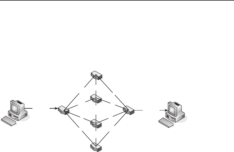
Edwards c05.tex V3 - 03/27/2009 11:05am Page 229
Chapter 5 ■The TCP/IP Protocol Suite 229
connected to a network. You may not have known what it does, but you have
heard of it.
TCP is used to transport data. It ensures that data is placed in sequence (the
order that it was sent in), that data arrives at its destination (or will force a
retransmission if it didn’t), and it helps cut down on over-traffic in the network.
To give you an idea of why TCP is important, take a look at Figure 5-9.
H
o H
i o
!
m
H
oTi
H!
om
i
T
???
?
?
?
?
Hi Tom! i!T oHm
Figure 5-9 An example that proves why TCP is very helpful
In the figure, you can see that a node wants to send the message ‘‘Hi
Tom!’’ to a remote node.28 There are many different paths that data can take
to get from the originating node to the remote node. Assuming that we are
sending one character at a time, each character will take whatever path the
routers tell it to take. Because the originating and the destination nodes do not
know which path the data is taking, the destination node will have no way to
put the data back together when it receives it, and therefore will most likely
receive a jumbled mess. Note that the destination node receives all the data,
but the message received is ‘‘i!T oHm,’’ which is nothing like the originating
message.29
TCP is a connection-oriented protocol, which means that a TCP session
must be established between a TCP server and a TCP client before any data
transmission occurs. Most professionals use the analogy of a telephone when
explaining the meaning of connection-oriented. When you make a phone call,
you wait until someone answers the other end before you say hello, hey, how’s
it going, or anything else that you called to say.30 This is exactly how TCP
works. An originating node will contact a destination node to make sure they
28For this example, it really does not matter what application is being used to send the message.
All that is important is that you understand that the information is coming from the Application
layer and is being sent to the Network layer.
29Can you imagine what Brother Joel might think about this message?
30Some phrases can be uttered that we can’t mention in this book.

Edwards c05.tex V3 - 03/27/2009 11:05am Page 230
230 Part I ■Networking Nuts and Bolts
are available to get the message. Once confirmation is received that it is okay
to send data, the transmission begins.
TCP is also considered a reliable protocol because there are functions built
into TCP that provide for various checks and balances to ensure the integrity
of the data being transmitted. Some of the reliability functions are
TCP is able to break down data that is received from the Application
layer into segments.
TCP places an acknowledgment timer on sent segments. When
the timer expires, if the originating node does not receive
confirmation from the remote node that the segment was
received, the originating node will resend the segment.
TCP maintains a checksum (within the TCP header and within the
actual data payload) that is set on each end of the connection. The
checksum is used to ensure that data arrives exactly as it was sent.
If the receiving node notices that the checksum does not match
(invalid checksum), the receiving node will throw the segment
away. In throwing the segment away, the receiver does not receive
the segment. This means that the receiving node does not send an
acknowledgment, which causes the originator to send it again.
TCP datagrams are not sent in order. They traverse the network
over the best path possible (based on calculations made by nodes,
which we discuss in several places throughout this book). TCP
supports the ability for the receiving node to put all of the datagrams
back into the correct order, once they have been received.
TCP can recognize duplicate datagrams and can discard them when
received.
POP QUIZ
What does the acronym SSH stand for?
TCP supports what
is known as flow
control. Flow con-
trol is a way for each
node to know how
much buffer space
they have available to receive data. This way no node will over-
whelm the other node with more data than it can handle.
Examples of applications31 that use TCP would be
FTP
Telnet
31Notice that some protocols use both TCP and UDP (DNS, for instance).

Edwards c05.tex V3 - 03/27/2009 11:05am Page 231
Chapter 5 ■The TCP/IP Protocol Suite 231
SMTP
DNS
POP3
HTTP
DNS
IMAP
5.2.2.2 User Datagram Protocol
Here is a bonus question for you. The User Datagram Protocol (UDP) is part
of the Transport layer and is used to do what to data?
That’s right! Just like TCP is used to transport data between nodes, UDP is
also used to transport data within a network. That is about the only thing (at
least functionally) that the two have in common. UDP does not guarantee that
data is going to be delivered to a destination. Basically, UDP throws the data
toward the destination and then moves on to its next task. This makes UDP a
connectionless protocol.
RANDOM BONUS DEFINITION
operating system — The application
software responsible for the proper
operation of a given node.
UDP is usually used to
send short bursts of datagrams
between nodes where reliabil-
ity is not a big concern. UDP
can get data to a destination
quicker, as it avoids all of the
overhead required when all the
checks and balances are occur-
ring within TCP. Also, because
UDP is connectionless, it can support broadcasting (sending messages to all
nodes within a broadcast domain) and multicasting (sending messages to all
nodes that are subscribed to the network).
UDP provides an optional checksum that can be assigned to the UDP header
as well as the data payload. This ensures that if any data that is sent over
UDP requires a header and data payload checksum, the destination is able to
do so. If any error checking is required, it will normally be performed by the
application, not via UDP.
Most voice and video applications transmit over UDP. If you have ever
watched a video online that cut out or got choppy at times, this is because
data was not being received. Recovery from these choppy moments can go
unnoticed for the most part. If TCP were used in these instances, there would
be delays that last much longer when packet loss is requiring retransmission
of the data. Keep in mind that speed is the consideration when going with
UDP, not reliability.32
32You can always reload that video if you want to watch it again.

Edwards c05.tex V3 - 03/27/2009 11:05am Page 232
232 Part I ■Networking Nuts and Bolts
Examples of protocols that use UDP include
DNS
BOOTP/DHCP
TFTP
SNMP
RIP
NFS
UDP accepts data (the payload) from the Application layer. It then adds
a UDP header and passes the header and the payload to the Internet layer,
where it is encapsulated into an IP packet and is passed on to the Network
Interface layer and over the transmission medium to the destination, where
it makes its way up to the Application layer on the destination end of the
connection.
5.2.3 The Internet Layer
POP QUIZ
Name the two popular transport protocols
that we discussed in this chapter.
The final layer that we will be
discussing in this chapter is the
Internet layer. Although we will
discuss this layer in detail in
Chapter 10, we wanted to pro-
vide a quick overview of some
Internet layer protocols.
This layer is responsible for ensuring that there is a path to a destination.
It receives information from the Transport layer and ensures transmission to
the destination node. Some examples of protocols that operate at this layer
include
Internet Protocol (IP)
Internet Group Multicast Protocol (IGMP)
Internet Control Message Protocol (ICMP)
Address Resolution Protocol (ARP)
Routing Information Protocol (RIP)
Open Shortest Path First (OSPF)
Border Gateway Protocol (BGP)
Internet Protocol Security (IPSec)
Although all layers of the TCP/IP reference model are important in their
own right, the Internet layer is probably the most important one. It provides

Edwards c05.tex V3 - 03/27/2009 11:05am Page 233
Chapter 5 ■The TCP/IP Protocol Suite 233
the ability to route data to a destination based on an IP address. It manages
the IP addressing structure for a network, and it also defines the datagrams
that are transported to a remote node.
5.2.3.1 Internet Protocol
The Internet Protocol (IP) is the most important protocol that exists within
the Internet layer. IP receives data from one of the Transport layer protocols,
packages it into a datagram, and then transports it to and from a given set
of nodes. IP is a connectionless protocol, which means it does not establish a
line of communication prior to transmitting.33 IP is also responsible for the IP
addressing for network nodes.
ACRONYM ALERT
FCS — Frame Check Sequence
The network node that is responsible for
getting data between different networks
is a router. The router is responsible for
receiving a datagram known as a packet and
pointing the packet in the direction it needs
to go, based on the IP address the packet is
looking for. IP addresses are learned by the
router based on information from another router or information that it has
discovered as it was passing packets to and fro. The information received for
the purpose of routing packets is determined, calculated, and provided for
by a routing protocol. IP addresses can also be configured and set statically
(hard coded), but this is a tedious task to maintain. The dynamic option is a
preferred method.34
Since IP is connectionless, the upper layers are responsible for any error
checking. The most IP will do is drop a packet and then send a message to the
source IP address telling them that the packet didn’t make it to where it was
supposed to go. There are many protocols that work with IP and are placed
into an IP packet for transmission. Some of these include
TCP
UDP
ICMP
POP QUIZ
Which layer of the TCP/IP reference model
is probably the most important one?
There are a few versions of IP
in use today. IP version 4 (IPv4)
is the most commonly used ver-
sion, but a proposed standard,
IP version 6 (IPv6), is in use and
33Here is more of that repetition that we mentioned in the front matter of this book.
34You will find that there are times when static routes make the most sense. They can also help
you get a route back up when you are troubleshooting an issue. Static routes can be your friend.

Edwards c05.tex V3 - 03/27/2009 11:05am Page 234
234 Part I ■Networking Nuts and Bolts
is intended to eventually be the successor to IPv4. The main difference between
IPv4 and IPv6 is the addressing. IPv6 allows for more addressing flexibility,
as there is room for a larger address space. Both versions will probably be
around for a long time, and there are ways to ensure that they can coexist, but
eventually you will probably see a migration to IPv6.
Have you ever heard of IP Next Generation (IPng)? IPng is nothing more than
the unofficial name for IPv6. The name was coined early and replaced when
the proposed standard was submitted.
5.2.3.2 Internet Group Multicast Protocol
The Internet Group Multicast Protocol (IGMP) is a protocol that provides
support for IP multicasting. IGMP provides a way for messages to be sent
to multiple nodes. Nodes are grouped into multicast groups, so when a
multicast message is destined for a group, only that group will receive the
message.
IGMP messages are transmitted in an IP datagram. Multicast routers (that
is, routers that can support multicasting) use IGMP messages to keep track
of what groups are connected to what interfaces on the router. When the
operating system of the originating node initiates a program process that
requires IGMP support, the node will send a report out of an interface in
which the process joins the group. Processes can join groups over multiple
interfaces. When there are no other processes running in a group, the node
will no longer report the group.
IGMP queries are sent out by a multicast router periodically to see if anyone
has a process that might belong to a multicast group. This query is sent out
of every router interface. When a remote node receives an IGMP query, it will
respond with one report for each group that it recognizes as having a running
process.
There may be many remote nodes running processes that are tied to a
multicast group. Each node is responsible for reporting process and group
information. The times that these reports are sent are staggered so there are
not too many nodes responding at the same time. For a router to acknowledge
a multicast group, there must be at least one node that is a member of the
group.
5.2.3.3 Internet Control Message Protocol
The Internet Control Message Protocol (ICMP) is responsible for reporting
conditions that need attention. When something goes wrong with IP, TCP, or
UDP transmission, ICMP is there to let you know about it. Like ICMP, TCP,
and UDP, ICMP messages are transmitted within an IP datagram.

Edwards c05.tex V3 - 03/27/2009 11:05am Page 235
Chapter 5 ■The TCP/IP Protocol Suite 235
Two versions of ICMP are in use today: ICMP version 4 (ICMPv4)35 and
ICMP version 6 (ICMPv6). ICMPv4 was developed to work with IPv4, so with
the release of IPv6 updates were required and ICMPv6 was born.36
The functions of each version are basically the same. ICMPvwhatever is there
to pass messages. Following are the main reporting functions performed by
ICMP:
Error reporting
Testing and troubleshooting
Informational reporting
IP and ICMP work very well together. As a matter of fact, you can consider
ICMP the ‘‘right-hand man’’ of IP. While IP is busy packing up data and
routing that data to a destination, ICMP is taking care of all the busywork.
ICMP passes messages that help ensure IP can perform its job well.
Many consider ICMP one of the simplest protocols there is. If you think
about it, this is true. ICMP doesn’t have to give a lot of thought or calculation
to do its job. All it has to do is pass messages.
5.2.3.4 Routing Information Protocol
POP QUIZ
What is the difference between IPng and
IPv6?
The Routing Information Proto-
col (RIP) is a dynamic routing
protocol that is used in many
networks. It is a distance-vector
protocol, which means that each
router will advertise the desti-
nations it is aware of and the
distance to each destination to
neighboring routers.
Many different implementations of RIP were in place when the protocol
became an Internet standard. Although there were a few differences between
RIP implementations in different networks, the differences didn’t cause many
interoperability issues in production. A second version of RIP (RIPv2, or RIP2)
was introduced and offered a few improvements over the original version
of RIP. The most notable of these improvements was the support of variable
length subnet masking (VLSM)37 and support for authentication.
35ICMPv4 wasn’t always called that. It was called simply ICMP since its inception. The v4 was
added later to separate it from ICMPv6.
36ICMPng in and of itself is a pretty cool acronym. Not too many adopted the term, but at least
one of the authors of this book would have adopted it (yes, we are talking about that author who
thinks catenet is a cool term).
37VLSM increases the efficiency of the utilizationofIPaddressesinagivennetworkbyallowing
different subnet masks to be used for each subnet. This will be discussed in Chapter 10, ‘‘The
Internet Layer.’’
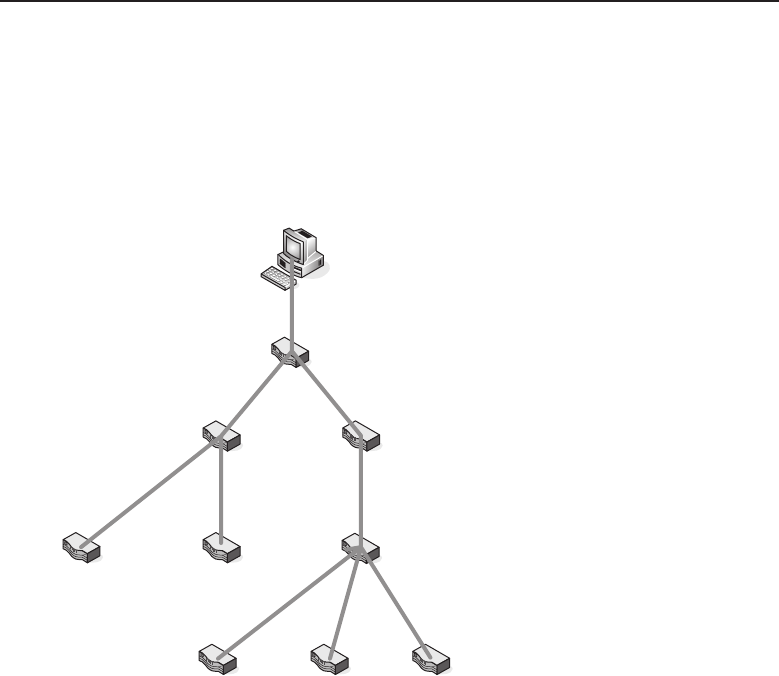
Edwards c05.tex V3 - 03/27/2009 11:05am Page 236
236 Part I ■Networking Nuts and Bolts
RIP determines distances to a destination based on what is known as a hop
count, which is the number of devices a packet must pass through on the way
to a destination. The hop count increases each time a packet reaches a node
along the path to its destination. The link taken by the packet from one node
to another node is the actual hop. Figure 5-10 shows an example of hops38 in a
network.
Hop
Hop
Hop
Hop
Hop
Hop
Hop
Hop
Figure 5-10 Hops in a RIP-routed environment
Now, let’s quickly review the operation of RIP. When a router first boots
up, one of the first things it will do (once connectivity is established) is
send a packet out of each interface requesting routing tables from each
of the neighboring routers. In turn, each router will send the routing table to
the router that requested it. As the router receives the routing table from
the neighboring routers, it will send a response telling the neighbors it has
received the requested routing table. The neighbors will respond with any
updates they may have since they last sent the routing table. If there are no
updates, the neighbors will validate that they know of the originating router.
Once the preliminary routing table updates are performed, the routing table
of each router will be broadcast to all other neighbor routers. This update occurs
every 30 seconds. Updates known as triggered updates will occur whenever
38This is not to be confused with the flower hops, which is a key ingredient in beer. There is a
shortage of hops at the time of this writing, which makes the hobby of home brewing a bit more
expensive than in years past.

Edwards c05.tex V3 - 03/27/2009 11:05am Page 237
Chapter 5 ■The TCP/IP Protocol Suite 237
there is a change with the hop count to a destination. When triggered updates
occur, only the information that has changed is sent.
5.2.3.5 Open Shortest Path First
The Open Shortest Path First (OSPF) protocol is a dynamic routing protocol
that uses the link state between nodes to determine routing paths for packets.
The link state is simply the state of the link to the next router (the neighbor).
Routers in an OSPF environment do not check the distance from one point to
another in a network. Instead, the routers monitor the state of a link to each of
its neighbor routers (the router next door). The link states are logged into the
link state database (LSDB), which is then shared with all the neighbors. LSDB
information that is received is used to build the routing table for the router
and then the information is shared with its neighbors.
Although an OSPF system can be a single autonomous system, most often
OSPF routers are assigned as members of OSPF areas. Each area is identified by
a 32-bit identifier, much like an IP address. Routers in the OSPF environment
are also assigned tasks they need to perform to ensure that the routing domain
runs smoothly. Following are a few important terms you will need to know:
Backbone area — The core of the entire OSPF network. The identifier
that is assigned to the backbone area is 0.0.0.0. All areas are connected to
the backbone area.
Stub area — An autonomous system that only receives LSDB
updates from routers within the same area. The stub area
only receives external routes through the default route.
Not so stubby area (NSSA) — A stub area that contains no external
routes. The NSSA can retrieve external updates and send them to the
backbone.
Internal router — Any router that only shares information with routers
in the same area.
Backbone router — Any router that participates in the backbone area.
Most backbone routers are ABRs as they share information between
areas. There may be some routers in the backbone that are not ABRs,
but these are still backbone routers as they are in the backbone area.
Area border router (ABR) — Any router that is a member of more than
one area.
Autonomous system boundary router (ASBR) —Anyrouterthat
shares link state with a router in another area is called an ASBR.
Note that any router within the area can be an ASBR; this includes
area border routers, backbone routers, and internal routers.

Edwards c05.tex V3 - 03/27/2009 11:05am Page 238
238 Part I ■Networking Nuts and Bolts
Designated router (DR) — Any router that handles advertisements
on multi-access networks. The DR is elected by a process among
other routers. It is responsible for being the representative for the
multi-access network to the rest of the network. It is also in place to
ensure that data is not flooded due to the multi-access environment.
Backup designated router (BDR) — Any router that takes
over the responsibilities of the DR if the DR should fail.
5.2.3.6 Border Gateway Protocol
The Border Gateway Protocol (BGP) provides for IP data communication
between routers that are in different autonomous systems (AS). BGP routers
share information with one another, providing paths that can be used to reach
an AS. To prevent routing loops, BGP routers make a determination of the best
path and any possible loops are pruned from the decision tree.
AnAScanbeclassifiedmuchasareasareinOSPF,including
Multihomed AS — An AS that connects to more than one other
AS. A multihomed AS does not participate in transit traffic.
Stub AS — An AS that connects to only one other AS. A stub AS does
not participate in transit traffic.
Transit AS — An AS that connects to more than one other
AS. A transit AS participates in local and transit traffic.
Data traffic within an AS is either transit traffic (just passing through) or local
traffic (traffic that starts or ends39 within the AS).
Like RIP, BGP is a distance-vector protocol. However, instead of counting
hops to a destination, BGP counts the number of autonomous systems it
takes to get to a destination. BGP also supports policy-based routing. In other
words, policy specifications are set by the system administrator and are used
to allow BGP to determine the best route to a destination, ensuring all policies
are strictly enforced. This means that even though there may be a quicker
path to take to a destination, policies may prevent a datagram from going on
that path.
BGP sends what are known as keepalive messages to its neighbors to ensure
that the neighbors are reachable. If they are not reachable, BGP will recognize
this as a link failure.
5.2.3.7 Internet Protocol Security
Internet Protocol Security (IPSec) is a suite of protocols that allow for security
and encryption for IP datagrams. IPSec is designed to provide endpoint to
39The alpha and omega of BGP traffic types.

Edwards c05.tex V3 - 03/27/2009 11:05am Page 239
Chapter 5 ■The TCP/IP Protocol Suite 239
endpoint datagram security (transport mode) for nodes that do not support secu-
rity protocols.40 IPSec is also used in VPN environments (tunnel mode), which
allows the gateway to the network to provide security and authentication
services for the users and networks the node supports.
IPSec provides several types of security for networks and the users of the
networks. One of the biggest functions that came from IPSec is the ability
to encrypt datagrams so that only the destination can read and understand
them.41 IPSec also provides checks of datgrams to ensure that they have not
been tampered with in transit. Finally, IPSec provides for the authentication
of users, to ensure that anyone that should not have access doesn’t.
AN UNRELATED MOMENT OF PAUSE
Three friends were out driving one day. One was a network sales engineer, one
was a network hardware engineer, and one was a network software engineer.
All of the sudden the right rear tire blew out, and the car rolled to a stop. Since
the car was full of problem solvers, the three friends jumped out of the car to
survey the situation.
The network sales engineer proclaimed, ‘‘The car just won’t do anymore; it is
time to buy a new one!’’
The network hardware engineer gave it some thought and then said, ‘‘We
need to try swapping the left tires with the right tires. If that does not fix it,
then we need to swap the front tires with the rear tires. If we are still having
problems at that point, we will have to replace the tires.’’
The network software engineer then piped in, ‘‘You guys are just wasting
time. We need to get back in the car and drive some more to see if the problem
will just work itself out.’’
5.3 End of Chapter Hodgepodge
We hope that you now have a better understanding of the TCP/IP reference
model, some of the protocols that operate in each layer, and how each layer
interfaces with each of the other layers. As you continue through the pages of
this book, we will be revisiting a lot of these protocols and discussing some of
the details that make each one tick.
In this section, we will discuss some of the other processes that operate in
a TCP/IP environment. Like many of the other functions and specifications
that we have discussed in this chapter, we will be revisiting some of these in
upcoming chapters.
40These nodes may support security, but not at the level that a network needs the node to.
41Remember when we were talking about key exchange?

Edwards c05.tex V3 - 03/27/2009 11:05am Page 240
240 Part I ■Networking Nuts and Bolts
5.3.1 There Is Hope for Diskless Nodes
The Bootstrap Protocol (BOOTP) manages IP parameters on a given network.
It assigns IP addresses for a pool of users. Not only that, it also provides for
operating system initiation for remote diskless nodes.
BOOTP is a network protocol that uses UDP for transport. When a node
is booting up, there is a bootstrap process that initiates the execution of the
node’s operating system. If a node is running a BOOTP client, the node will
send a request to a BOOTP server for assignment of an IP address, along with
any other startup assistance that the client node requires (and the BOOTP
server supports). BOOTP is normally integrated into the node’s motherboard
or NIC card.
The Dynamic Host Configuration Protocol (DHCP) evolved from BOOTP.
Several enhancements were provided with DHCP, although BOOTP is simpler
to implement and maintain. A single DHCP server can provide IP addresses,
subnet masks, gateway information, and more. When a node connects to the
network, the DHCP client will broadcast a request for information from the
DHCP server. The server will then send the requested information so the node
can connect and operate in the network.
BOOTP and DHCP are called communication management protocols.Theycan
work separately or together (together is the most often implemented). DHCP
can serve the requests that come from a BOOTP client.
5.3.2 A Little More Information on Routing
Just when you thought we had finished with our discussion about routers,
here we are back on the subject.42 Following are a few terms that we wanted
to quickly touch on. Why not? We have to discuss them somewhere.
Routing protocol — The protocol that performs functions that allow
the routing of packets between routers. RIP, OSPF, and BGP are
examples of routing protocols. Sometimes confused with a routed proto-
col, which is not the same thing.
Routed protocol — A protocol that participates in transmitting data
between nodes within a network. Telnet, SNMP, and IP are all examples
of a routed protocol. Routed protocols are sometimes incorrectly termed
routing protocols.
Gateway — The entry point for an entity. A computer that provides
access to a network area is a gateway. A network that provides
access to another network is a gateway. Many applications have
gateways that allow information sharing. The node that connects
the LAN to the Internet (or any other network type) is a gateway.
42We are far from finished with our discussion on routers.

Edwards c05.tex V3 - 03/27/2009 11:05am Page 241
Chapter 5 ■The TCP/IP Protocol Suite 241
Interior Gateway Protocol (IGP) — A routing protocol that operates
within an AS. RIP and OSPF are IGPs.
Exterior Gateway Protocol (EGP) — BGP is often called an EGP,
although the EGP protocol was the predecessor to BGP for IP
routing between autonomous systems.
Static routing — IP routing information that is manually configured on a
node by a system administrator.
POP QUIZ
What are the two IGPs that we discussed in
this chapter?
Dynamic routing —IP
routing information that
is learned by the node
through a routing pro-
tocol, such as RIP.
This concludes our discussion of routers for this chapter.
5.3.3 Sockets and Ports Are Not the Same Thing
A couple of important terms that often get confused are socket43 and port.Note
that we are referring to TCP and/or UDP ports, not to the physical interface
of the node. A TCP or UDP port is a number assigned to the datagram header
that is mapped to a particular process or application on a given node. A socket
is the end-point of data communication flow on a network.
TCP and UDP ports are basically an extension of addressing used by
TCP/IP to ensure that data communication is tied to the correct running
process. Each packet header that is transported over TCP or UDP has a source
and destination port logged in it. The port number can range from 0 to 65535.
Port numbers are divided into three sections. These are well-known ports (0
through 1023), registered ports (1024 through 49151), and dynamic and/or
private ports (49152 through 65535).
TCP/UDP WELL-KNOWN PORT NUMBERS
Following is an example list of many popular well-known TCP and UDP port
numbers. TCP well-known port numbers are identified by an assignment of 0
through 1023. This list is only an example to provide the port numbers for
many of the protocols we have covered, along with a few that are just darn
interesting.
(continued)
43Sockets are also often called TCP or UDP sockets (depending on the transport protocol), Internet
sockets, or network sockets.

Edwards c05.tex V3 - 03/27/2009 11:05am Page 242
242 Part I ■Networking Nuts and Bolts
TCP/UDP WELL-KNOWN PORT NUMBERS (continued)
For a complete and current list, go to www.iana.org/assignments/
port-numbers.
Port Number Description Applicable Protocol
0 Reserved TCP and UDP
1 TCP port service multiplexer TCP and UDP
5 Remote job entry TCP and UDP
7Echo TCPandUDP
20 FTP – data TCP
21 FTP – control TCP
22 SSH TCP and UDP
23 Telnet TCP and UDP
25 SMTP TCP and UDP
53 DNS TCP and UDP
67 BOOTP/DHCP – server TCP and UDP
68 BOOTP/DHCP - client TCP and UDP
69 TFTP TCP and UDP
80 HTTP TCP and UDP
101 NIC host name server TCP and UDP
107 Remote Telnet service TCP and UDP
109 POP2 TCP and UDP
110 POP3 TCP and UDP
115 SFTP TCP and UDP
118 SQL TCP and UDP
123 NTP TCP and UDP
135 DCE endpoint TCP and UDP
143 IMAP TCP and UDP
161 SNMP TCP and UDP
162 SNMP trap TCP and UDP
166 Sirius TCP and UDP
179 BGP TCP and UDP
213 IPX TCP and UDP
220 IMAPv3 TCP and UDP
(continued)

Edwards c05.tex V3 - 03/27/2009 11:05am Page 243
Chapter 5 ■The TCP/IP Protocol Suite 243
TCP/UDP WELL-KNOWN PORT NUMBERS (continued)
Port Number Description Applicable Protocol
389 LDAP TCP and UDP
401 UPS TCP and UDP
500 ISAKMP UDP
513 Login TCP
513 Who UDP
515 Lpd TCP
520 RIP UDP
546 DHCPv6 client TCP and UDP
547 DHCPv6 server TCP and UDP
647 DHCP failover TCP
666 Doom (video game) UDP
989 FTP data over TLS/SSL TCP and UDP
990 FTP control over TLS/SSL TCP and UDP
992 Telnet over TLS/SSL TCP and UDP
1023 Reserved TCP and UDP
ACRONYM ALERT
CRC — Cyclic redundancy check
Any application that provides a common
and well-known service (SMTP, FTP, Tel-
net, etc.) will monitor for incoming requests
on the well-known ports. Firewalls can
be configured to allow or deny specific
ports, thus enhancing network security. If
arequestcomesinwithaportthatisnot
defined, the server will assign a port number for the duration of the application
process.
ThesocketisthecombinationofanIPaddressornodenameandaport
number. The syntax of a socket would be
<ip address>:<port number>
An example of this would be the Telnet protocol, which uses port number
23 (for both TCP and UDP). If the host that is running the Telnet server has
an IP of 10.10.10.10, the Telnet client would send a request to that IP for port
number 23. The syntax would look like this:
10.10.10.10:23

Edwards c05.tex V3 - 03/27/2009 11:05am Page 244
244 Part I ■Networking Nuts and Bolts
Any given port can have a single passive socket, which monitors for
incoming requests, but can serve multiple active sockets, each serving a
request from a different client.
5.4 Chapter Exercises
1. What are the four layers of the TCP/IP reference model?
2. Name four Application layer protocols that we discussed in this chapter.
3. Explain the structure of the DNS hierarchy.
4. What are the five PDU types that are used by SNMP?
5. What is the purpose of FTP?
6. Why does TFTP not perform many of the functions that FTP does?
7. What is a daemon?
8. What are the four control characters used by Telnet for option negotia-
tion and their meanings?
9. TCP is a -oriented protocol, whereas UDP is a
protocol

Edwards c05.tex V3 - 03/27/2009 11:05am Page 245
Chapter 5 ■The TCP/IP Protocol Suite 245
10. What are the three main reporting functions that we said are performed
by ICMP?
5.5 Pop Quiz Answers
1. The Internet layer is also known as the Network layer.
2. What is the function of the FTP command ascii?
Sets the file transfer mode to ASCII.
3. What does an SMTP server response code 421 mean?
Server is unavailable.
4. What does the acronym NFS stand for?
Network File System
5. What is the purpose of Telnet option code 32?
Used to set the terminal speed.
6. What does the acronym SSH stand for?
Secure Shell
7. Name the two popular transport protocols that we discussed in this
chapter.
TCP and UDP
8. Which layer of the TCP/IP reference model is probably the most impor-
tant one?
The Internet layer
9. What is the difference between IPng and IPv6?
None. Other than the names, they are the same protocol.
10. What are the two IGPs that we discussed in this chapter?
RIP and OSPF
Edwards c05.tex V3 - 03/27/2009 11:05am Page 246

Edwards c06.tex V3 - 03/27/2009 11:07am Page 247
CHAPTER
6
Ethernet Concepts
The system of nature, of which man is a part, tends to be self-balancing,
self-adjusting, self-cleansing. Not so with technology.
— E.F. Schumacher
The term Ethernet is a catchall word used to describe the most common
network architecture used in a majority of today’s networks worldwide. If you
were to say to someone, ‘‘Describe an Ethernet cable,’’ 99 out of 100 would
probably respond that it consists of unshielded twisted pair (UTP) cable that
is terminated on each end with RJ45 plugs. That is mostly true in today’s
network, but Ethernet technology has evolved from its early coaxial cable days
to what it is today.
All Ethernet networks, no matter the type of cable that is in use, are Carrier
Sense Multiple Access with Collision Detection (CSMA/CD) networks that
adhere to the standards described in IEEE 802.3. This is true for either coaxial
or UTP cable Ethernet networks. Let’s review how Ethernet came about and
how it evolved to its current emanation of Ethernet cable technology.
NOTE The term Ethernet is derived from two words: ether and net.Etherisa
medium that can be made from pretty much anything. This is evident in today’s
network environment, where network signals can be carried over wire, fiber (fiber
optic), or air (wireless). The word net may be short for network, but one of the
authors likes the idea of visualizing a fishing net, where each node is tied to
adjoining nodes, and there are multiple paths from one to the other.
247

Edwards c06.tex V3 - 03/27/2009 11:07am Page 248
248 Part I ■Networking Nuts and Bolts
6.1 The Beginning of Ethernet Technology
From 1973 to 1975, Ethernet had its start at the Xerox Palo Alto Research Center
(PARC). Xerox filed a patent application in 1975 with the U.S. Patent Office
for a Multipoint Data Communication System with Collision Detection. Patent
4,063,220 described how multiple data processing stations distributed along
a branched cable segment would be able to communicate with each other. It
included descriptions of the cable the devices needed to send and receive data
on that cable. It also included a packet description outlining both source and
destination addresses along with data and error fields.
In the experimental implementation of Ethernet, data rates were 3 Mbps,
and the source and destination address fields were only provided 8 bits for
addressing, which limited the number of devices that could be addressed
on the network. There were 16 bits allocated for the packet type, which
would be used to define a packet type that would be used within a particular
protocol.
NOTE Mbps means ‘‘megabits per second,’’ where mega is the value of a
million. So 100 Mbps is 100 million bits per second. Remember that a bit is a
single binary digit of either zero or one. Even if only one stream of zeros was being
generated, there are still 100 million of them in a second. It may represent a whole
lot of nothing, but in the network world they truly have value.
One of the original inventors on the Xerox patent, Robert Metcalfe, left
Xerox in 1979 to form 3Com to promote LAN development and the use of PCs
as nodes on the Ethernet network. He was instrumental in convincing Digital
Equipment Corporation (DEC), Intel, and Xerox to work together to promote
Ethernet as a LAN standard. This standard came to be known as the DIX
standard, after the companies (DEC, Intel, Xerox) who came together to create
the standard.
The DIX or Ethernet II standard describes a frame format that provides
48 bits each for destination and source addresses, along with 16 bits for the
packet type. The standard also set the data rate at 10 Mbps. Figure 6-1 illustrates
aDIX/EthernetIIframe.
Destination MAC
Address
(6 bytes)
Source MAC
Address
(6 bytes)
Ethernet
Type
(2 bytes)
Data
Payload
(46 to 1500 bytes)
CRC
Checksum
(4 bytes)
Figure 6-1 ADIX/EthernetIIframe
The Destination and Source Address fields are 6 bytes in length and are
usually presented as a group of 12 hexadecimal numbers. These addresses are

Edwards c06.tex V3 - 03/27/2009 11:07am Page 249
Chapter 6 ■Ethernet Concepts 249
called the Media Access Control (MAC) addresses and are a unique Ethernet hard-
ware address assigned to a network interface card (NIC). The DIX/Ethernet II
standard has been superseded by IEEE 802.3.
NOTE Hexadecimal number system is an easy way of illustrating 4 binary bits,
which can have values from 0 to 15. The values 0 through 9 are presented as their
actual value, while the units 10 through 15 are represented by the alpha characters
A through F, respectively. The 16 (the root hexadeca means 16) values that can be
contained in a hexadecimal number are 0, 1, 2, 3, 4, 5, 6, 7, 8, 9, A, B, C, D, E
and F.
Although Ethernet was originally designed to allow computers to com-
municate with each other over a coaxial cable as the broadcast transmission
medium, twisted pair Ethernet cable systems have been under development
since as early as the mid-1980s. The first network topology using UTP cable
was StarLAN, and it was introduced with a data rate of 1 Mbps. However,
StarLAN would eventually evolve into what became known as 10BASE-T,
which is the predominant UTP cable in use today.
Since the publication of IEEE 802.3 in 1985, there have been several amend-
ments that provide for increased Ethernet rates. Table 6-1 lists the data rates
thatcanbefoundinusetoday.
Table 6-1 Ethernet Types and Speeds
ETHERNET TYPE SPEED
10BASE-T 10 Mbps
Fast 100 Mbps
Gigabit 1000 Mbps
POP QUIZ
What was the first type of cable used to
form an Ethernet network?
Ethernet has emerged as
the de facto network standard
worldwide. It has withstood
challenges from other network-
ing protocols over time, and as
a result, large numbers of prod-
ucts from a wide range of man-
ufacturers are readily available
and are able to successfully interconnect based on this standard. Due to the
economies of scale, networking products have decreased in price while perfor-
mance has increased. Ethernet allows for flexibility in network implementation
that is easy to maintain and manage. The installed base for Ethernet networks
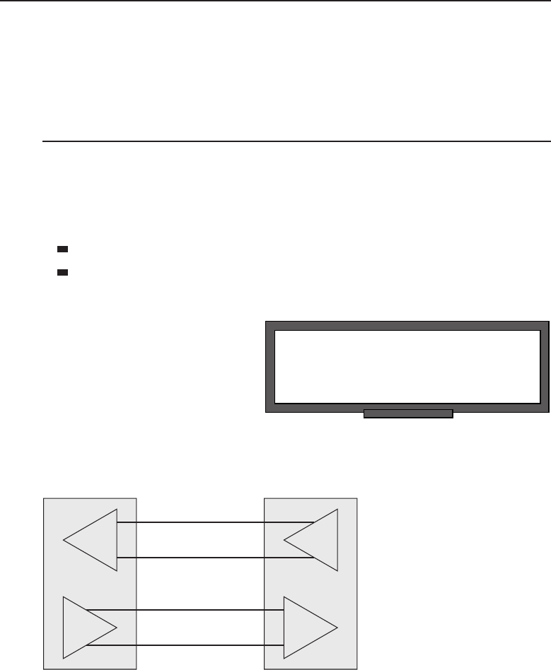
Edwards c06.tex V3 - 03/27/2009 11:07am Page 250
250 Part I ■Networking Nuts and Bolts
is huge, guaranteeing that Ethernet will be around for some time to come.
There will always be improvements inserted into existing networks, but they
will not cause a total dumping of the current Ethernet network.
6.2 Ethernet Components
We discussed how UTP cable evolved from UTP telephone wire used to create
the StarLAN networks. It would stand to reason that some of the concepts
would be carried over from the Telco influence in setting Ethernet standards.
Ethernet components using UTP cabling fall into two categories:
Data terminal equipment (DTE)
Data communications equipment (DCE)
RANDOM BONUS DEFINITION
bridge port — A network interface on a
bridge.
This nomenclature is part of
the long-standing serial commu-
nications standard EIA RS-232.
Much like that standard, the
Ethernet standard uses this
framework as the basis in devel-
oping standards for the elec-
trical signal characteristics for
Ethernet cabling and signals. Figure 6-2 illustrates a DCE and DTE device
connected with UTP cable.
Transmit +
Transmit +
Receive +
Receive +
Transmit –
Transmit –
Receive –
Receive –
DCE
UTP Cable
DTE
Figure 6-2 Interconnection of DCE and DTE Ethernet devices
This figure represents the conceptual interconnection of two Ethernet devices
using UTP Ethernet cable. You will notice that the cable appears to be straight
across, although physically the +and −wires are twisted together within the
jacket of the cable. This type of Ethernet cable is often referred to as a patch

Edwards c06.tex V3 - 03/27/2009 11:07am Page 251
Chapter 6 ■Ethernet Concepts 251
cable or a straight-through cable because there is no crossover from receive to
transmit circuits.
NOTE Twisted pair wire does have a purpose. The pair of wires are twisted
together in a uniform manner with a fixed number of twists per foot. Why should
the cable be twisted in the first place? To look pretty? To keep the wires from
drifting apart? Okay, the answer is: to combat the effects of electromagnetic
interference (EMI). Electrical waves are all about us, now more so than ever with
the plethora of cell phones and other mobile devices. When these waves intersect
wire, they can induce minute fluctuations in voltage. No big deal, right? Just a little
static on the line. Wrong! These signals could cause erroneous data to be read, so
signal integrity is an absolute necessity. (How would you like it if your ATM card
was swallowed before you could get your money out?) Now, do not go adding
extra twists to your Ethernet cable thinking this is going to increase your immunity.
In reality, you will alter the electrical characteristics of the wire and cause
reflections within the cable, which is bad as EMI. Leave the cables alone and go
pop some bubble wrap if you need to keep those idle hands busy.
So, we have DCE and DTE Ethernet devices, but which is which? A good
way to remember this is by recalling the early days of RS-232. The term data
terminal equipment often referred to teletypewriters, whereas data communication
equipment most often referred to modems. When PCs were introduced, the
majority of telecommunications was accomplished via a modem. (Yes, we
recall those days — the 300 baud handset devices where you squeezed your
phone’s handset into the foam cuffs so it could receive the actual audio signals
through the telephone.)
NOTE Ahandset refers to a standard telephone like we had back in the olden
days. The telephone wire was connected to the base, and the handset portion had
a spiraled wire, which always managed to get so twisted that you found you could
not talk on the phone unless your head was about a foot off the table where the
base rested. The base contained the actual dialing mechanism, which allowed you
to dial the number you wished to connect to. Yes, ‘‘dial’’ — where do you think the
word originated? Surely, not from punching those minute buttons on the latest
whiz-bang cell phone, which has given us a new set of human ailments such as
‘‘texting thumb.’’
RANDOM BONUS DEFINITION
bandwidth — The data-carrying capacity of
a device or communications channel.
As telephone technology
evolved from mechanical dialing
mechanisms to touch-tone dial-
ing, modems also implemented
those technologies. Even today’s
modems — whether external or
internal modems embedded in a laptop, PCMCIA modem card, or PCI

Edwards c06.tex V3 - 03/27/2009 11:07am Page 252
252 Part I ■Networking Nuts and Bolts
modem card in a desktop computer — all support both dial and touch-tone
dialing methodologies in their designs.
NOTE What is meant by mechanical dialing? The old rotary phones had a dial
with numbers and letters assigned around a dial mechanism shaped like a wheel
with finger holes assigned the numbers 1 through 9 and 0 for either the number
zero or Operator if that number was dialed first and by itself. A number was dialed
by placing one’s index finger in the hole with the corresponding number that was
desired and then in a circular motion moving the dial to the stationery finger-stop
and releasing the dial to allow it to step back. As it stepped back, it sent a pulse on
the wire to the home office, where stepping relays would increment to set up the
circuit corresponding to that number. Switching theory was developed and used by
the telephone companies in order to eliminate human operators who would
actually make the circuit connection for the caller. The number selected would
determine the number of pulses, which stepped the home office stepping relay to
that number. You can just imagine how many relays were required to set up those
switching offices. Today’s modems use a relay to pulse line the number of times
required for the number to be dialed, and that is what is meant by the pulse
setting on the modem.
Touch-tone dialing was devised by the telephone companies to accomplish pretty
much the same thing as pulse dialing. However, it uses a more modern technique
of using distinct audio tones for each discrete number. If you ever listened to a
modem dial with tone dialing, you know it sounds like automatons in sci-fi
movies.
POP QUIZ
An Ethernet network device that forwards
data on the network would be considered
what type of Ethernet device?
PCs pretty much replaced
teletypewriters as the device
to use for telecommunications.
They were supplied with RS-232
serial ports. With a terminal
emulation program, these PCs
became the modern-day tele-
typewriter. We said that tele-
typewriters were DTE devices,
so the PC with an Ethernet NIC is an Ethernet DTE device. Modems are
DCE devices, and since they pass data along the network, devices like Eth-
ernet hubs, routers, and switches are also considered to be DCE Ethernet
devices.
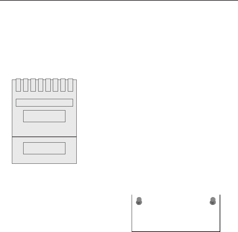
Edwards c06.tex V3 - 03/27/2009 11:07am Page 253
Chapter 6 ■Ethernet Concepts 253
6.2.1 DCE and DTE Cabling Considerations
We mentioned that a straight-through cable was one where the wire from pin
1 would be connected to pin 1 on the other connector. Let’s discuss the RJ-45
modular plug that is used on any UTP Ethernet cable. Figure 6-3 represents
how an RJ-45 plug would look if you held the plug with its gold contacts facing
you. Pin 1 of the plug will be on your left, with pin numbers incrementing
until pin 8 on your right is reached. The pin numbering is sequential.1
Pin 8Pin 1
Figure 6-3 An RJ-45 modular plug
ACRONYM ALERT
AFP — AppleTalk Filing Protocol
UTP Ethernet cable consists of four
twisted pairs,2for a total of eight wires
contained within an unshielded jacket. The
wires are colored with four solid colored
wires, each of which is twisted together
with its mate, which is mostly white with a
colored stripe that matches the color of its
solid colored mate. How and to what pin these wires connect to on the RJ-45
plug adhere to old telephone company standards and are contained within
the TIA/EIA-568-A and TIA/EIA-568-B standards. Table 6-2 lists the wiring
scheme for T568A wiring, and Table 6-3 lists the wiring scheme for T568B
wiring.
1Sequential is derived from the word sequence, which means one after the other. For those in the
reading audience who find it difficult to grasp this concept, we shall be more precise in the pin
numbering definition. Starting on the left with pin 1, the pin numbers increment in sequence:
2, 3, 4, 5, 6, 7, and pin 8, which is the last pin on the right. Now, if you tell us you can’t count,
then we have a major problem here, and you need additional help, which is beyond the scope of
this book.
2Pair refers to the number two. So a twisted pair of wire would consist of two discrete wires
which have been twisted together for ... what? Noise immunity, good answer.

Edwards c06.tex V3 - 03/27/2009 11:07am Page 254
254 Part I ■Networking Nuts and Bolts
Table 6-2 T568A Wiring Pin-out
PIN PAIR WIRE COLOR ETHERNET SIGNAL
1 3 Tip White/green Transmit +
2 3 Ring Green Transmit –
3 2 Tip White/orange Receive +
4 1 Ring Blue
51 TipWhite/blue
6 2 Ring Orange Receive –
74 TipWhite/brown
8 4 Ring Brown
Table 6-3 T568B Wiring Pin-out
PIN PAIR WIRE COLOR ETHERNET SIGNAL
1 2 Tip White/orange Transmit +
2 2 Ring Orange Transmit –
3 3 Tip White/green Receive +
4 1 Ring Blue
51 TipWhite/blue
6 3 Ring Green Receive –
74 TipWhite/brown
8 4 Ring Brown
A straight-through cable can be wired with either the T568A or T568B wiring
scheme as long as both ends of the cable are wired exactly the same using the
same wiring pin-out.
RANDOM BONUS DEFINITION
Application layer — The highest layer of the
seven-layer OSI model.
A crossover Ethernet cable
must have one plug wired
with the T568A wiring scheme
and the other plug wired follow-
ing the T568B wiring pin-out.
The purpose of a crossover cable
is to interconnect to like devices,
regardless of whether they are

Edwards c06.tex V3 - 03/27/2009 11:07am Page 255
Chapter 6 ■Ethernet Concepts 255
DCE or DTE devices. The crossover is to have the transmit signals from one
device terminate on the receive signals of the other device so they can pass
data between them. A quick analogy is connecting two microphones together;
the two parties could scream into them but neither could hear the other. Now,
ifwetakeonemicrophoneandcrossedovertoaspeakeranddidthesame
for the other microphone, then parties would be able communicate without
aproblem.
3ThesamegoesforEthernetdevices—justbecausethereissome
sort of Ethernet UTP cable strung between them does not mean they are
‘‘supposed’’ to communicate.
So, when you are having problems getting two Ethernet devices to commu-
nicate, the first place to look is at the Physical layer (such as the cable being
used).
HELPFUL HINT
Since for the most part Ethernet cables use RJ-45 jacks, which are mostly clear
plastic, it is fairly easy to determine if a Ethernet UTP cable is either a
straight-through or crossover cable. Take the two connectors on the ends of the
cable and hold them against each other with both plugs oriented in the same
direction. Scan the colors of each. They should look exactly alike on a
straight-through cable. If it is a crossover cable, you will notice that the colored
wires on pins 1 and 2 of one plug have moved to pins 3 and 6 of the other, with
the reverse also being true.
If for any reason the cables do match as described in this note, there is a
likelihood it is a cable used for another purpose or it is supposed to be an
Ethernet UTP cable but has been manufactured incorrectly.
Do yourself a favor: if you find cables in your box of goodies that appear
different from what has been described in this note, discard them in the
nearest wastebasket. Many countless hours have been wasted fighting
problems with bad cables, not only by people in general but by network
administrators who should know better.
For the frugally minded who cannot bear to toss anything away, our
recommendation is to cut the ends off the cables so you will not be tempted to
use them in your network. You may want to use them to tie up all those
newspapers that have been collecting in the corner and bring them to a
recycling drop-off in your community.
6.2.1.1 Interconnecting Like Ethernet Devices
We have already discussed that Ethernet devices fall into two categories, DCE
or DTE type devices. It has also been stated that interconnecting to like Ethernet
3We fully acknowledge that his simple-minded analogy has very little likelihood of succeeding
in the real world because there is a whole lot of electronics that needs to be added for it to actually
work. The purpose of any analogy is to demonstrate in the simplest terms how something works.
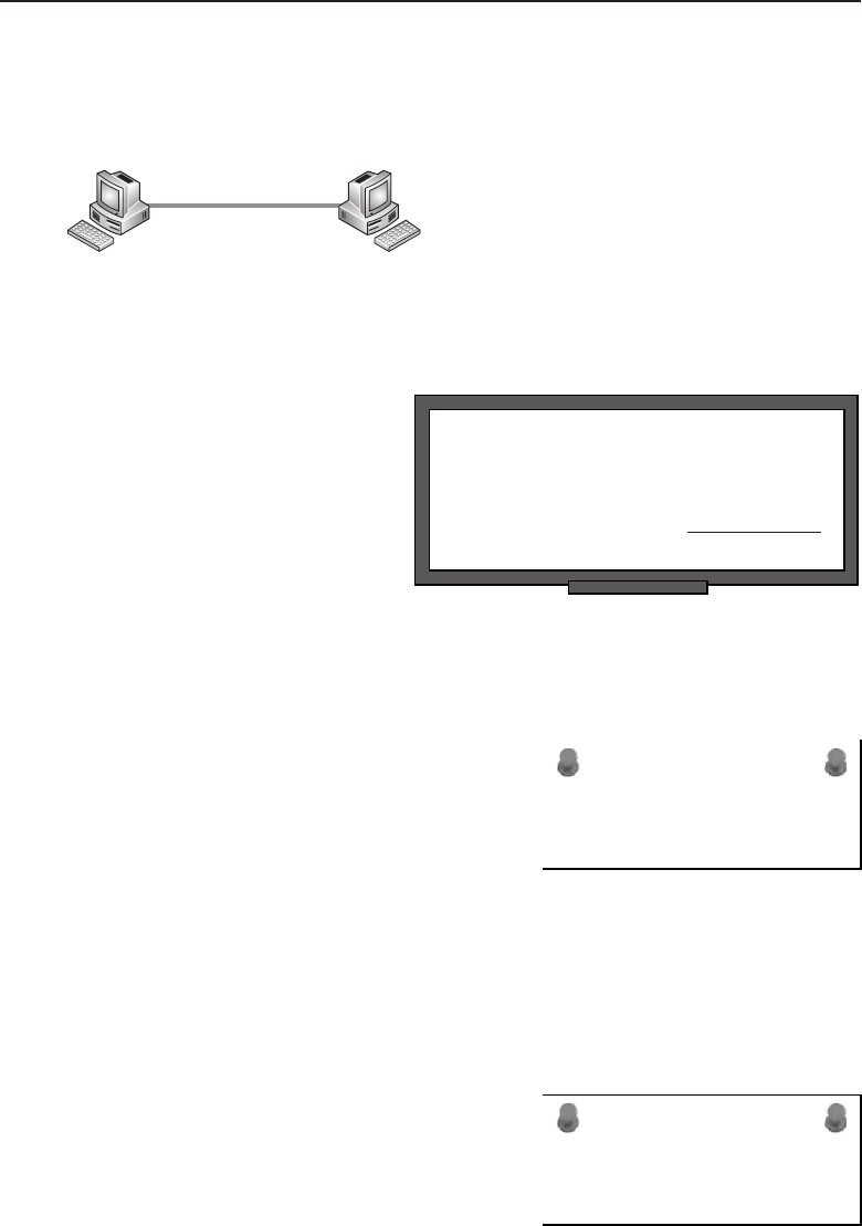
Edwards c06.tex V3 - 03/27/2009 11:07am Page 256
256 Part I ■Networking Nuts and Bolts
devices requires the use of a crossover cable. For example, two PCs with NIC
cards can be directly interconnected with a crossover cable, as illustrated in
Figure 6-4.
Ethernet UTP
Crossover Cable
PC A PC B
Figure 6-4 Two PCs interconnected via Ethernet
POP QUIZ
If a cable is wired such that one plug is a
T568A and the other is a T568B, it would
commonly be referred to as
cable.
In this simple figure, the two
computers are able to commu-
nicate with each other over the
crossover cable. There must be
some sort of networking proto-
col running on the PCs, such as
TCP/IP, and some sort of appli-
cation that will allow the sharing
of data or devices (whichmay be
locally connected to either or both of them). Some operating systems, such as
Microsoft Windows and Apple Macintosh, are ‘‘network-able’’ and include
tools and utilities to facilitate data and device sharing over the network.
ACRONYM ALERT
BER — Bit error rate
The last example showed two Ether-
net DTE devices interconnected, but how
about DCE devices? We already mentioned
that DCE devices are in the form of hubs,
switches, and routers, so we know we
are dealing with that kind of device. Why
would anyone want to connect those types
of devices? To illustrate this, we will con-
sider a few simple examples.
The first example is a case where we have a stack of dumb,4eight-port,
passive hubs and there is a small office with 15 workers who need to be
interconnected to a local server to share the resources available on that server.
Figure 6-5 illustrates one method of how these passive eight-port hubs may be
used to accomplish this.
ACRONYM ALERT
TTL — Time to live
Thethreehubsareplacedabouttheoffice
for the ease of cabling between each other
and the workstations connected to them.
Since these hubs have eight ports, with one
4Dumb means exactly that: dumb. There is no internal intelligence contained within the unit.
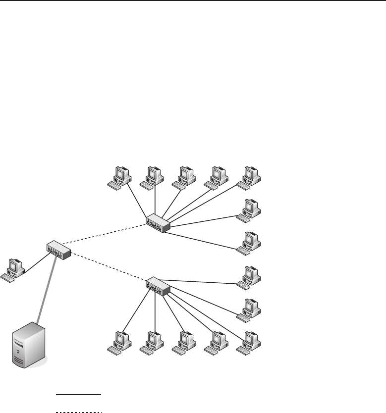
Edwards c06.tex V3 - 03/27/2009 11:07am Page 257
Chapter 6 ■Ethernet Concepts 257
port dedicated for linking to the other hub, this leaves seven available ports for
workstation connections. As you can see in Figure 6-5, two of the hubs have
seven workstations each connected to them. That leaves one workstation and
the server to be connected to the LAN. The hub that is used to connect these
devices and the other two hubs has only used four of the eight available ports,
so if needed there are four ports remaining for future expansion. You can see
from the cabling legend that the workstations and the server are connected to
the LAN with a patch or straight-through Ethernet UTP cable. The hubs are
connected to each other using crossover cables since we are interconnecting
like DCE Ethernet devices.
Server
with Shared Resources
Straight Through Ethernet UTP Cable
Crossover Ethernet UTP Cable
Figure 6-5 A LAN created with passive hubs
This scenario is not uncommon, and a few of you who may be familiar with
cabling hubs today may be scratching your head. We remember the day when
this was standard operating procedure for interconnecting passive hubs, so go
with us on this one. Yes, there have been improvements in hub technology.
One was actually adding what was called an uplink port, where a DTE port
was added to the device to facilitate it being connected to another hub, with a
patch cable eliminating the need to find a crossover cable, in case you forgot
to purchase one when you purchased the hub. Another improvement is an
uplink port with a switch dedicated to it that switches its receive and transmit

Edwards c06.tex V3 - 03/27/2009 11:07am Page 258
258 Part I ■Networking Nuts and Bolts
circuits to match the cable and the port it was connected to at the other end.
The most recent innovation in hub and switch design is that all ports on the
hub are now auto-sensing and auto-switching.
NOTE Auto-sensing is accomplished by electronic circuits that determine if the
incoming wires to a signal pair of pins are connected to a transmitter or a receiver.
Once the ‘‘sense’’ of the wire is determined, this information is passed to the
circuits responsible for auto-switching.
Auto-switching is circuitry added to a port to configure the port to which pins
receive and transmit circuits should be connected to. If one set of pins is
determined to be a receive pair, then the other set of pins must be the transmit
pair. Receive and transmit are mutually exclusive in that one set of pins must be
the receive circuit and the other must be the transmit circuit. If both sets of pins
are the same, either receive or transmit, the device is defective.
HELPFUL HINT
Most Ethernet devices with RJ-45 jacks to accommodate Ethernet UTP cables
have LED5lights showing the link status. If there is no link indication, the first
place to check is the cable. Both devices connected with the same cable should
indicate link while connected. If you pull one end of the cable and the other
device’s link light is still illuminated, you may not be connected to the correct
device. In large LAN implementations, many times a cable is pulled to ensure
that it loses link so one knows the port assignment is correct on both ends of
the cable.
We can see that look on your face. You are thinking that if devices can do
auto-sensing and auto-switching, why do you have to learn the differences
in cable types? The answer is, you may be correct if you are only doing new
implementations and using stock cables you buy already assembled.However,
there is a large installed base of legacy systems that have dedicated ports wired
as either a DTE or DCE, so cable knowledge is essential.
ACRONYM ALERT
HTTP — Hypertext Transfer Protocol
Let’s continue with another example.
Remember, it still is not yet an auto-
sensing/auto-switching world. Figure 6-6
shows a part of a larger installation at a
corporate office. There are many user work-
stations, but for sake of illustration there
5LED is the acronym for light emitting diode. It is actually a semiconductor device that will
illuminate when a current is passed through it. Some are single colored while others are able to
change color depending on how the device is electrically driven.
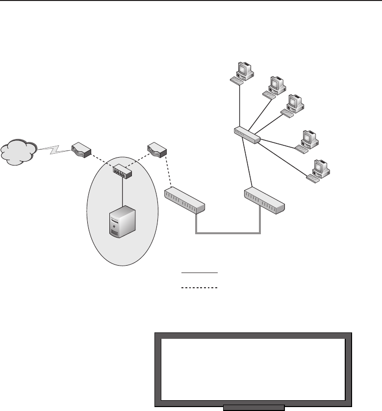
Edwards c06.tex V3 - 03/27/2009 11:07am Page 259
Chapter 6 ■Ethernet Concepts 259
are only a few in the figure drawing. This figure may represent a floor or
department location within a building.
Internet
Router Router Hub
Patch Panel Patch Panel
User
Workstations
Premise Wiring
DMZ
Hub
Server
Straight Through Ethernet UTP Cable
Crossover Ethernet UTP Cable
Figure 6-6 A larger LAN implementation
RANDOM BONUS DEFINITION
multimode fiber — An optical fiber that
allows signals to propagate in multiple
transmission modes simultaneously.
There are three DCE devices
in this drawing, two routers
and a hub that are interconnec-
ted using crossover cables. Off
the hub there is a server con-
nected with a patch cable/
straight-through Ethernet UTP
cable. The placement of the hub and server is considered a DMZ (demilita-
rized zone). The purpose of a DMZ is to regulate access to the networks it is
connected to. In this scenario, there is a network of corporate user workstations
that have access to a corporate server and the Internet. The routers within the
DMZ have been programmed with policies that allow approved users from
the Internet to have access to the corporate server but not to pass to any other
networks connected to the DMZ. These routers and other equipment may be
located in a data center on another floor from the users who need access to the
server and the Internet. This is where premise6wiring comes in.
6Premise is the term used to represent a given locale like a home or building. Thus, premise
wiring is the wiring contained within the building.

Edwards c06.tex V3 - 03/27/2009 11:07am Page 260
260 Part I ■Networking Nuts and Bolts
Cable needs to be run from the data center to the floor where the user
workstations are located. This is done by running Ethernet-grade7cable,
which is terminated on patch panels8located in the data center and the wiring
closet on the floor where the user workstations are located.
HELPFUL HINT
We have seen wiring closets that are neat and orderly, and others with wire
strung everywhere and piled on the floor like a large bowl of my mother’s
spaghetti and meatballs. (For more information on my mother’s secret recipe,
read the note on it.)
If you are a network administrator and want to do yourself a favor, please try
to keep your wiring closets orderly and well labeled. You do not want to be
called at all hours of the night or on vacation or even on your weekends off,
and that will be the case each time someone is troubleshooting a problem and
has no clue as to which cables go where. Do it right up front and you can truly
have peace of mind. If not, your ears will be burning each time someone curses
you for making their job harder.
The patch panels are wired with Category 5e or Category 6 cable from panel
to panel as straight-through cables. There is no crossover taking place within
the long-run cables. If a crossover is needed, it will be taken care of from
the patch panel to the device using an Ethernet UTP crossover cable. This is
illustrated in Figure 6-6 with the router that is connected to the patch panel.
Notice on the other patch panel that although the switch is a DCE Ethernet
device, it is connected with a patch cable. This is because it connects to the router
at the other end, whichis connected to the patch panel with a crossover cable, so
that only a single crossover is required. Double crossover9cables will basically
negate the crossover function, and the device link lights will not illuminate.
7Ethernet using UTP cable was initially designed on the idea of using existing premise wiring that
was in place for telephone communications. With improvements in speed on Ethernet circuits,
a higher quality cable was necessary to support these new requirements. Today’s new cable
installations should be using Category 5e or Category 6 cable, especially if Gigabit Ethernet is to
be used.
8Patch panels are an old holdover from the telephone company days. However, remember the
basis of Ethernet over UTP was to use existing premise wiring, which was telephone UTP cable.
It stood to reason if those cables are attached to patch panels, then patch panels would become
part of the Ethernet UTP connectivity equation.
9Double crossover is like a double negative: two negatives make a positive, so you don’t have
the crossover. It may come in handy sometime when you find yourself up to the armpits in
crossover cables but are unable to find that one badly needed patch cable. Now, how would you
connect them?

Edwards c06.tex V3 - 03/27/2009 11:07am Page 261
Chapter 6 ■Ethernet Concepts 261
POP QUIZ
You are interconnecting two Ethernet
devices, but neither device is showing a link
light on the assigned port. List in order of
likelihood where the problem might be.
The server and all the user
workstations are DTE devices
connecting to other DTE
devices, so the cables used are
straight-through (patch) Ether-
net UTP cables. With the right
routing protocols and security
policies in place, users at the
user workstations are able to access the local corporate server as well as
the Internet, while the corporate LAN is protected from unauthorized users
from the Internet.
AN UNRELATED MOMENT OF PAUSE — MAMA BRAMANTE’S SECRET
SPAGHETTI AND MEATBALLS RECIPE
The thought of all of the cables in a wiring closet made Rich think of his
mother’s spaghetti and meatballs. Rich decided to share the recipe with you all:
Well, the recipe is not under lock and key like you see in some of those
commercials on TV, and no, the dog doesn’t know it either. The reason it is so
secret is that my mother had the knack of making it without measuring
ingredients other than with her watchful eye. I always said she could cook for
five or fifty and it would always be the same, and it was. There is nothing like a
mother’s cooking, eh?
So, I am going to give you a list of ingredients, and you can mix up a batch.
You may surprise yourself and it could be almost as good as my mom’s. My
mother always started the sauce before the meatballs. (For you Italian readers
out there, ‘‘sauce’’ is ‘‘gravy.’’)
◆Sauce Steps:
1. Using a large pot, pour a liberal amount of olive oil to a
depth of about a quarter of an inch and heat to a tem-
perature that would fry whatever you place in it.
2. Slice up (slice, not dice) a medium-sized onion. Add the onion to
the oil and brown to a dark crisp. Remove the onion from the oil and set
aside.
3. Take some garlic cloves and slice them so you have these tiny garlic
slabs. Add them to the oil and just brown (do not cook as long as the
onions).
4. Once the garlic is brown, add two cans of peeled Roma tomatoes
into the olive oil/garlic mix. Be careful that the oil does not splatter
back.
(continued)

Edwards c06.tex V3 - 03/27/2009 11:07am Page 262
262 Part I ■Networking Nuts and Bolts
AN UNRELATED MOMENT OF PAUSE — MAMA BRAMANTE’S SECRET
SPAGHETTI AND MEATBALLS RECIPE (continued)
5. Stir in one can of tomato paste and the fried onions. Stir for
consistency and let simmer while making the meatballs.
◆Meatball Steps:
1. Put about a pound or pound and a half of fresh ground beef into a large
mixing bowl.
2. Grate in an amount of bread crumbs that is about a third
of the hamburger volume. (Stale Italian bread allowed
to thoroughly dry to a rock was used to make the bread
crumbs. Not much was wasted when feeding six kids.)
3. Finely dice two garlic cloves and add to the mix.
4. Finely chop two or three sprigs of fresh parsley and add to the mix.
5. Grate in some fresh Parmesan or Romano cheese — about half a cup or
slightly more.
6. Add salt (not too much, as the cheese is salty) and some ground black
pepper.
7. Createacavityinthemixandaddthreewholeeggsintothemix.
8. Mix all the ingredients thoroughly so that the whole batch is consistent
throughout.
9. In a large skillet, preheat olive oil to fry the meatballs
in. Scoop up enough of the beef mixture to make a golf
ball size meatball. Roll the meatball in the palm of your
hand (wash your hands before and after this process) to
form a firm ball that can withstand frying without falling
apart.
10. Fry the meatballs to a deep brown crust on all sides before dropping
them into the sauce.
◆Spaghetti Steps:
1. Once everything is simmering in the large sauce pot, it is time to boil
the water for the spaghetti.
2. Add a half teaspoon of salt to the spaghetti water and bring to a rapid
boil.
3. Add a pound of spaghetti (smaller amount for a smaller gathering) to
the water and stir in.
4. Keep an eye on the pot since rapidly boiling spaghetti
has a tendency to foam up and overflow the pot.
(continued)

Edwards c06.tex V3 - 03/27/2009 11:07am Page 263
Chapter 6 ■Ethernet Concepts 263
AN UNRELATED MOMENT OF PAUSE — MAMA BRAMANTE’S SECRET
SPAGHETTI AND MEATBALLS RECIPE (continued)
5. Once the spaghetti is cooked and is soft but firm to the bite (al dente),
strain it in a colander.10 Make sure the spaghetti is well drained.
◆Serving Steps:
1. Dump the colander of spaghetti into a large serving bowl.
2. Add some of the sauce (no meatballs) to the spaghetti and mix thor-
oughly to where the spaghetti has sauce on it but not is swimming in
the sauce. I know there is a fine line to this, so add sauce slowly.
3. Once you are satisfied the spaghetti has sufficient sauce on it, fish
out two meatballs for each diner and place in the bowl on top of the
spaghetti.
4. Serve with freshly grated cheese on the side, a little vino, good com-
pany, and conversation.
Congratulations! You have just served up Mama Bramante’s favorite dish to
la famiglia.
6.3 Ethernet and IEEE 802.3’s Relationship
to the OSI Model
There is a close similarity between the ISO OSI model and IEEE 802.3 model,
with the difference being at the Data Link layer of the OSI model, as illustrated
in Figure 6-7.
ACRONYM ALERT
MAN — Metropolitan area network
The Physical layer is the same in both
models and is dependent upon the media11
being used. This layer deals with parame-
ters such as cable pin-out, signal electrical
characteristics, modulation encoding of the
data being modulated on carrier signals,
and data synchronization.12 Once it has
been determined that the receive buffer has received a complete frame, the
Data Link layer is signaled and the frame is passed up to that layer.
10For those of you who are uninformed about cooking utensils, a colander looks kind of like a
leaky bucket or a hemispherical pot shot full of buckshot holes. Not useful for holding water, but
it sure comes in handy when draining spaghetti.
11Media is in reference to the method of delivery of the data. Obviously in a wired network it
depends on the type of cable and the NIC cards being used. However, other methods of delivery
such as wireless and optical can be used. So media for the most part is how the data moves
between data points.
12Data synchronization refers to the capability to detect the start of a data frame from a stream
of data bits and the fact that the binary pattern is a complete frame.
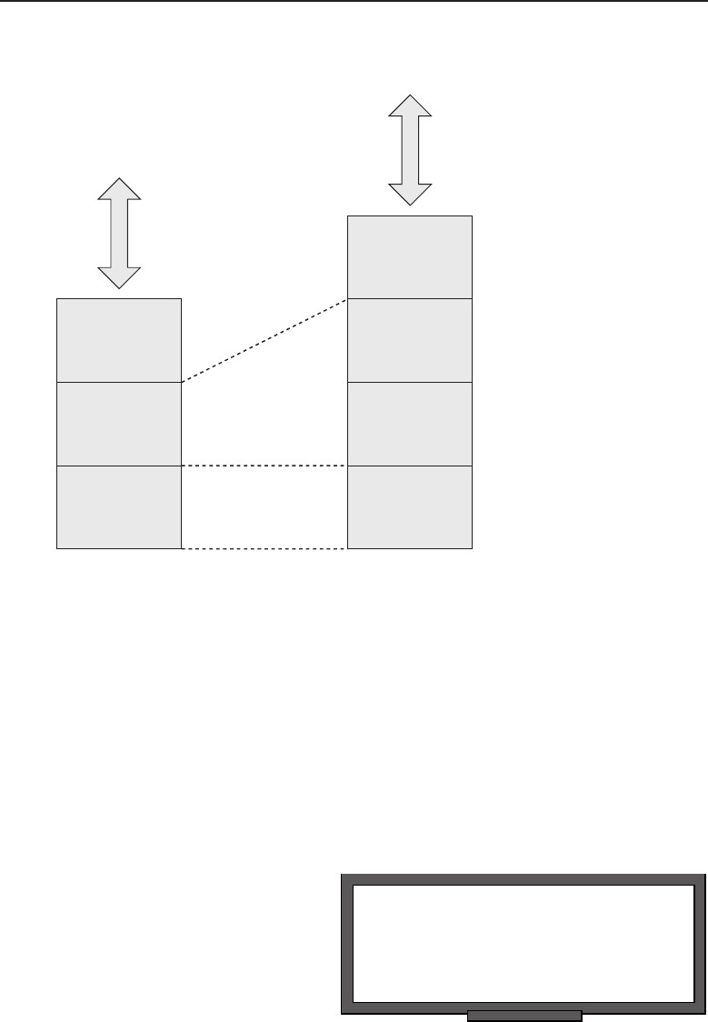
Edwards c06.tex V3 - 03/27/2009 11:07am Page 264
264 Part I ■Networking Nuts and Bolts
Network
Data Link
Physical
Logical Link
Control
Network
Media Access
Control
Physical
OSI
Reference Model
Upper Layers
IEEE 802.3
Reference Model
Upper Layers
Figure 6-7 OSI’s relationship to IEEE 802.3
In the OSI reference model, the Data Link layer accepts service requests
from the Network layer and sends service to the Physical layer. It is the
layer responsible for data transfer between adjacent network nodes and has
the capability to detect and correct errors that may occur on the Physical
layer. Although the Data Link layer is responsible for data transfer over the
Physical link, many data link protocols do not provide acknowledgments of a
successful receipt and acceptance of a frame. Some data link protocols do not
even provide for a checksum to detect errors in transmission. In these cases,
frames received depend on higher-level protocols for frame flow control,
acknowledgments, retransmission, and error checking.
POP QUIZ
Into which two sublayers of the IEEE 802
reference model is the OSI reference model
Data Link layer divided?
The IEEE 802.3 reference
model divides the OSI model’s
Data Link layer into two sub-
layers, the Logical Link Control
sublayer and the Media Access
Control sublayer. The Logical
Link Control sublayer resides in
the upper layer of the OSI Data

Edwards c06.tex V3 - 03/27/2009 11:07am Page 265
Chapter 6 ■Ethernet Concepts 265
Link layer, whereas the Media Access Control sublayer is in the lower portion
and provides the interface to the Physical layer.
6.3.1 Logical Link Control
The IEEE 802 standard for the Logical Link Control resides in the upper portion
of the OSI reference model’s Data Link layer and provides the same functions
no matter what media is being used. The Physical layer can be Ethernet, Token
Ring, or wireless LAN, of which the Logical Link Control sublayer is primarily
concerned with providing flow control, error control, and what multiplexing
protocols are being used over the Media Access Control sublayer.
POP QUIZ
With which functions is the Logical Link
Control sublayer mainly concerned?
Logical Link Control flow
control manages the data trans-
mission rate between two net-
work nodes to prevent one node
sending faster than the speed of
the receiving node. If one node
is receiving data from multiple
network nodes, it may not be able to receive as quickly as the sending
node would like to transmit. Flow control depends on feedback from the
receiving node to the sending node signaling possible congestion and its
inability to receive data at higher speeds. In an Ethernet network, a receiving
node that is unable to keep up with a sending node will transmit a PAUSE
frame to halt transmission for a given period of time. The PAUSE frame
for flow control can be used only on network segments that are running at
full-duplex.13
6.3.2 Media Access Control
The Media Access Control sublayer provides the interface betweenthe Physical
layer and the Logical Link Control sublayer. The Media Access Control
sublayer is responsible for data encapsulation and frame assembly for sending
frames, and de-encapsulation and error checking of received frames. It also
provides addressing and a channel access control mechanism, which allows
multiple nodes on a local area network to communicate.
The Media Access Control address, or the physical address of the node
device, is commonly referred to as the MAC address. It is an industry stan-
dardized unique address assigned to each network adapter at the time of
manufacture. Although highly unlikely, there is a possibility of duplicate
13We previously defined full duplex as the capability to send and receive simultaneously. It is
logical that if a half-duplex node is currently receiving, it is unable to transmit until all the data
is received. This makes a PAUSE frame unusable in half-duplex network segment.

Edwards c06.tex V3 - 03/27/2009 11:07am Page 266
266 Part I ■Networking Nuts and Bolts
MAC addresses on a network segment due to the capability to overwrite a
manufacturer’s previously assigned MAC addresses.
HELPFUL HINT
Although I have seen only one case of a duplicate MAC address on a LAN
segment, I know it is possible. Depending on the network size, it can be a real
nightmare. (Unfortunately, for the case I worked, it was a large network.)
For whatever reason, the site in the case I worked decided that they would
assign their own MAC addresses for every device in their network. Although
they had full control and well-documented logging of MAC addresses, it took a
while to find the offending node.
Ultimately, knowing the MAC address of the device that was being adversely
affected was helpful. Using a process of elimination that allowed for a digit
being entered into a MAC address incorrectly aided in locating the culprit. If the
site had not properly documented their MAC addresses and where they were
assigned, the other option would have been to assign a new MAC address
(which they preferred not doing) to the device that had not been previously
assigned.
I am sure they had good reasons to use their own MAC address scheme, and
they attempted to document it well, which is a major plus. However, it is best
to leave well alone and use the already assigned MAC address to identify the
device on the LAN segment.
Because Ethernet is a CSMA/CD (Carrier Sense Multiple Access with
Collision Detection) network protocol, not only are all the network nodes on
a network segment required to have unique physical hardware addresses,
but there must be a provision for the control of the multiple access of more
than one node at a time. The Media Access Control sublayer provides channel
access control to allow multiple access.14
When multiple network nodes are connected to the same physical media,
there is a high likelihood of collisions occurring. The multiple access protocol
is used to detect and avoid packet collisions where multiple nodes contend
for access to the same physical media. Ethernet and IEEE 802.3 are the most
common standards used for CSMA/CD networks.
CSMA/CD utilizes a carrier-sensing scheme. If a transmitting node detects
another signal on the media while it is transmitting a frame, it ceases transmittal
of that frame and immediately transmits a jam signal onto the media. All nodes
on the network are aware a collision on the media has taken place and will
14Multiple access allows more than one data stream to share the same Physical layer media.
Examples of shared media networks are bus topology networks, ring topology networks, wireless
networks, and Ethernet point-to-point links running at half duplex.

Edwards c06.tex V3 - 03/27/2009 11:07am Page 267
Chapter 6 ■Ethernet Concepts 267
back off and not transmit for a period of time, which is calculated using a
back-off delay algorithm. After the back-off delay has elapsed, the node will
attempt to retransmit the frame, giving it a higher probability of success.
POP QUIZ
When a collision occurs on the media, what
does the transmitting network node do?
The methods used for colli-
sion detection depend on the
media being used. On a wired
Ethernet bus, it is accomplished
by comparing the transmit-
ted data with the data being
received off the wire. If it is
determined that they differ, the transmitting station on that node recognizes
that another node is transmitting at the same time and a collision has occurred.
All transmitting nodes then cease transmission and use the calculated back-off
interval before attempting to transmit again. The back-off algorithm is a calcu-
lation that randomizes the back-off interval for each transmitting node so that
the probability of another collision is very low.
HELPFUL HINT
CSMA/CD is required in a half-duplex network environment. Although the
protocol works well if all network node devices remain well behaved, a single
‘‘chattering’’ network node can cause all data flow on a network segment to
cease. Of course, this is a malfunction, but it is within the realm of possibility. A
quick sniffer trace15 of that network segment should out the culprit pretty
quickly.
With the movement to higher-speed full-duplex Ethernet devices, the need
for CSMA/CD is diminishing, although it must be maintained for legacy network
segments and devices.
6.4 Ethernet Frame Format
Figure 6-8 illustrates the basic Ethernet frame format.
Preamble
Start of
Frame
Delimiter
Destination
Address
Source
Address
Frame
Length/
Type
Data
Frame
Check
Sequence
Figure 6-8 The basic Ethernet frame format
15Sniffer trace is a technical colloquialism referring to a packet capture. There are dedicated
pieces of equipment to capture and display packets or you can load packet-capture software on
a laptop. The sniffer trace will permit you to see the traffic that is on a network segment.

Edwards c06.tex V3 - 03/27/2009 11:07am Page 268
268 Part I ■Networking Nuts and Bolts
ACRONYM ALERT
OUI — Organizationally unique identifier
The basic frame format illustrated in
Figure 6-8 is required for all MAC imple-
mentations of the IEEE 802.3 standard.
Some additional optional formats also are
used to widen the basic capability of the
protocol. Following is a list of the basic
frame fields:
Preamble — A 7-byte field consisting of alternating 1s and 0s
to alert a receiving station that a frame is being received. It is
a method used to aid synchronization between the Physical
layer receiving circuits and the incoming data stream.
Start of Frame Delimiter — A 1-byte field consisting of a field of
alternating 1s and 0s ending with two consecutive 1 bits to signal that
the next bit is the leftmost bit in the leftmost byte of the destination
address.
Destination Address — A 6-byte field that contains the address of the
node that is to receive the frame. The leftmost bit in this field indicates
if the frame is destined for a individual node address (0) or a group
address (1). The second from the leftmost bit is an indicator if the address
is a globally assigned address16 (0) or a locally administered address17
(1). The remaining 46 bits of this field contain the address value of the
unique node address, a group of network nodes, or all nodes on the
network.
Source Address — A 6-byte field that contains the hardware address
of the transmitting node, which is always a unique individual
address where the leftmost bit of the field is always set to 0.
Frame Length/Type — A 2-byte field that indicates either the number
of bytes contained within the Data field of the frame or an alternate
frame format type. If the Frame Length/Type has a value of 1500 or less,
this value indicates the number of bytes contained within the frame’s
Data field. If the field value is 1536 or greater, it is used to indicate the
16A globally assigned address is the address assigned to the network interface at time of man-
ufacture. These addresses are assigned in blocks to manufacturers and can be used to distin-
guish which device is from which manufacturer by the hardware address used on that net-
work segment. This can be a valuable troubleshooting tool where large network installations
are concerned.
17A locally administered address is a MAC address that has been locally assigned by a net-
work administrator. It overrides the default MAC address assigned to the network interface
by the manufacturer. Without extreme care, there is a distinct possibility that duplicate
addresses could appear on the local network. Duplicate addresses are a big no-no in the
networking world. So, if you need to do this, be very careful or you could be in a lot of hot
water.

Edwards c06.tex V3 - 03/27/2009 11:07am Page 269
Chapter 6 ■Ethernet Concepts 269
alternate frame type that is being used for either a received or trans-
mitted frame. Table 6-4 lists a handful of the common frame types.
Table 6-4 A Few Common Frame Types
FRAME TYPE PROTOCOL
0x0800 Internet Protocol Version 4 (IPv4)
0x0806 Address Resolution Protocol (ARP)
0x8035 Reverse Address Resolution Protocol (RARP)
0x809b AppleTalk
0x80f3 AppleTalk Address Resolution Protocol (AARP)
0x8100 IEEE 802.1Q Tagged Frame
0x8137 Novell IPX
0x86dd Internet Protocol Version 6 (IPv6)
RANDOM BONUS DEFINITION
network management — The process of
configuring, monitoring, controlling, and
administering a network’s operation.
Data —Thisfieldcon-
tains the data that is
being sent within the
frame. It can be any num-
ber of bytes of informa-
tion up to and equaling
the maximum number
of 1500 bytes that is allowed for this field. However, if the number
of bytes is less than 46, a number of bytes must be added to pad the
field to reach its minimum length of 46 bytes. The minimum frame
size, per the IEEE 802.3 standard, which does not include the pream-
ble, is 64 bytes. Frames of less than 64 bytes are discarded as frames
from collisions, faulty NICs, or software-caused under-runs.
POP QUIZ
What is the maximum number of bytes that
can be contained in the Data field of an
Ethernet frame?
Frame Check
Sequence —A4-byte
field that contains a 32-bit
CRC (cyclical redun-
dancy check) checksum
value, which is calcu-
lated and inserted by
the sending network node and used by the receiving network node to
validate the received frame. Both the sending and receiving nodes calcu-
late the CRC value by using the data contained within the Destination
Address, Source Address, Frame Length/Type, and Data fields.

Edwards c06.tex V3 - 03/27/2009 11:07am Page 270
270 Part I ■Networking Nuts and Bolts
6.4.1 Transmitting a Frame
When a frame request is received by the Media Access Control sublayer from
the Logical Link Control sublayer, it is accompanied by the data to be sent
and the destination address where the data is to be delivered. The Media
Access Control sublayer starts the transmission process by loading the data
and address information into the frame buffer. The preamble of alternating
ones and zeros, along with the start of frame delimiter, are inserted into their
appropriate fields. Destination address and source address information is then
added to the fields to which it is assigned. The data bytes received from the
Logical Link Control sublayer are counted, and the number of bytes to be
contained within the Data field is added to the Frame Length/Type field. The
data from the Logical Link Control sublayer is inserted into the Data field,
and, if the total number of data bytes is less than 46, a number of pad bytes
are added until the number of data bytes is equal to 46. A CRC calculation
is performed on the data contained within the Destination Address, Source
Address, Frame Length/Type, and Data fields, and then appended to the end
of the Data field.
POP QUIZ
What does the Frame Check Sequence field
of an Ethernet frame contain?
Oncethewholeframeis
assembled and ready for trans-
mission, the Media Access Con-
trol sublayer’s next operation
depends on whether it is oper-
ating in half-duplex mode or
full-duplex mode. If it is oper-
ating in half-duplex mode, it cannot transmit and receive simultaneously.
Since IEEE 802.3 requires that all Ethernet Media Access Control sublayers
support half-duplex, if the Media Access Control sublayer is operating in that
mode, it is unable to transmit until any incoming frame is completely received.
In full-duplex mode, this is not an issue, and the frame can be transmitted
immediately.
6.4.1.1 Half-Duplex Transmission
With the development of the CSMA/CD protocol, multiple network nodes are
able to share a common media without the need for a centrally located bus
arbiter, tokens, or dedicated transmission time slots to determine when they
would be allowed to transmit on the media.
NOTE Time division multiplexing (TDM) is a form of digital multiplexing where
two or more bit streams are transmitted on a common communications medium.
Although it appears as if they are simultaneous, they are actually sharing the time
domain. The time domain is divided into a number of fixed time slots. Each data

Edwards c06.tex V3 - 03/27/2009 11:07am Page 271
Chapter 6 ■Ethernet Concepts 271
stream is dedicated to a fixed time slot or channel. Although the same media is
being shared, it is not the most efficient use of the media if all or some of the
channels are not transmitting. If no data is being streamed on a channel for a
particular time slot, it is still using up part of the bandwidth dedicated to it and
cannot be used by other channels.
Each portion of the CSMA/CD protocol can be summarized as follows:
Carrier Sense — All network nodes continuously listen on the net-
work media to determine if there are gaps in frame transmission on the
media.
Multiple Access — All network nodes are able to transmit
anytime they determine that the network media is quiet.
Collision Detection — When two network nodes transmit at the same
time, the data streams from both nodes will interfere and a collision
occurs. The network nodes involved must be capable of detecting
that a collision has occurred while they were attempting to transmit
a frame. Upon detecting that the collision has occurred, both nodes
cease transmission of the frame and wait a period of time deter-
mined by the back-off algorithm before again attempting to transmit the
frame.
POP QUIZ
What is the name of the transmission mode
that allows either transmitting or receiving
at different time intervals but never within
thesametimeinterval?
Although bit signals are prop-
agated on a shared network
medium at the same rate, the
amount of time it takes to trans-
mit a whole frame is inversely
proportional to the speed the
interface is capable of transmit-
ting it. This means that the time
it takes to actually transmit a frame onto the network medium is less. By
analyzing this, you can see that a worst-case scenario would be if two network
ACRONYM ALERT
RTMP — Routing Table Maintenance Protocol
nodes were at two extreme ends of the
network media. Electrical signals travel at
the same rate, but the amount of time to
put a whole frame on the media is much
less at higher interface speeds. In order to
detect that a collision has taken place, time
is needed to travel to the far end of the
network segment and back. To allow collision detection to occur within the
transmission window of a sending network node, limitations were established
for cable lengths and minimum frame length as higher interface speeds were
developed. Table 6-5 lists these limitations.

Edwards c06.tex V3 - 03/27/2009 11:07am Page 272
272 Part I ■Networking Nuts and Bolts
Table 6-5 Half-Duplex Operational Limitations
PARAMETERS 10 MBPS 100 MBPS 1000 MBPS
Minimum frame size 64 bytes 64 bytes 520 bytes
Maximum collision
diameter18 UTP cable
100 meters 100 meters 100 meters
Maximum collision diameter
with Repeaters
2500 meters 205 meters 200 meters
Maximum number of
repeaters in network path
521
6.4.1.1.1 Gigabit Ethernet Considerations
Although the Gigabit Ethernet frame is similar to the standard Ethernet frame,
it is slightly different in minimum frame length. As you can see in Table 6-5, the
minimum frame size expanded from 64 bytes to 520 bytes for a 1000BASE-T
frame. The Gigabit Ethernet19 frame is illustrated in Figure 6-9.
Preamble
Start of
Frame
Delimiter
Destination
Address
Source
Address
Frame
Length/
Type
Data
Frame
Check
Sequence
Gigabit Carrier
Extension
Figure 6-9 The Gigabit Ethernet frame
ACRONYM ALERT
SRB — Source routing bridging
In order to maintain the same collision
domain diameter, the developers opted to
increase the minimum frame length to 520
bytes. The longer frame was obtained by
adding an extension to the frame after the
Frame Check Sequence field. The Carrier
Extension field is automatically removed by the receiving network node. The
added frame length makes it possible for a frame collision to be detected
because of the added time it takes to transmit a minimum-sized gigabit frame
18Maximum collision diameter refers to the network media length from one transmitting network
node to a receiving network node. Worst case is that each node is at the extreme end of a network
segment. In wired network media, this equates to cable length and is linear, whereas in a wireless
environment, it truly can represent a circle, where the diameter is the maximum distance from
transmitter to receiver.
19Gigabit per second capability is the capability to pass a billion bits per second on an interface.
Remember, a bit is either a single binary 0 or a 1. Whatever the bit value is, there is a lot of stuff
coming at you all at once.

Edwards c06.tex V3 - 03/27/2009 11:07am Page 273
Chapter 6 ■Ethernet Concepts 273
onto the network media. The time is close to that of a 64-byte minimum-sized
frame being transmitted on the network medium by a 10/100 half-duplex NIC.
The standard for CSMA/CD Gigabit Ethernet added frame bursting,the
capability of a Gigabit Ethernet NIC’s Media Access Control sublayer to
transmit a burst of frames without releasing the access to the network media.
This is possible since the time needed to place a minimum-sized frame on the
network media is much less than the total propagation delay round-trip time
of the frame traveling over the network media.
Bursting is accomplished by allowing the transmission of a burst of frames
within a time interval slightly greater than that needed for transmitting five
maximum-sized frames. The media is kept occupied for the transmitting node
by inserting frame carrier extension bits between the frames in the burst.
Figure 6-10 illustrates a burst frame sequence.
POP QUIZ
What name is applied to the transmission
mode that allows multiple frames to be sent
without the need to release the network
media between frames?
In Figure 6-10 you will notice
that the first frame may have a
carrier extension added to it if
it does not meet with the min-
imum frame size of 520 bytes.
Between frames or the frame
gap periods, the network media
is kept busy with a continu-
ous carrier by inserting carrier
extension bits. For subsequent frames within a frame burst that do not meet
the minimum frame size, a Frame Carrier Extension field is not needed since
the frame gaps are being filled with extension bits while in the frame burst
transmission mode. Frames will continue to be sent in burst mode until the
burst frame limit has been reached. If there is a frame in the process of trans-
mission when the burst frame limit has been reached, the frame is allowed to
complete its transmission before the transmitting node releases the network
media. Burst frame mode is only supported in Gigabit Ethernet.
Burst Carrier Duration
Frame plus
Extension
Frame
Gap
Frame
Gap
Frame Frame
Figure 6-10 The Gigabit Ethernet burst frame sequence

Edwards c06.tex V3 - 03/27/2009 11:07am Page 274
274 Part I ■Networking Nuts and Bolts
HELPFUL HINT
Since frame burst mode is not supported in 10Mbps or 100 Mbps Ethernet, it is
not a good idea to add these types of network devices to a network segment
that is running at gigabit speeds. If you need to mix these devices on the same
network segment, you should not use burst mode on that network segment.
6.4.1.2 Full-Duplex Transmission
Full-duplex transmission is the capability of a network node to transmit
and receive simultaneously. It is a simpler method of communications than
half-duplex since the need for collision detection is eliminated. However, it
can only be attained in UTP networks or fiber optic networks, where transmit
and receive circuits remain separated. The capability to send and receive at
the same time effectually doubles the bandwidth of the network link between
network nodes.
The first cabling used for Ethernet networks was coaxial. Because this wired
medium was being used for both transmission and reception, the CSMA/CD
protocol was developed to permit a sending and receiving network node to
communicate over the same cable. Moving from the coaxial wire network
media to the UTP cable media, the half-duplicity of the coaxial cable was
maintained with the use of hubs that simulated the coaxial cable. So the need
to maintain the CSMA/CD protocol was carried forward from the coaxial
wire network environment to the UTP cable environment using a half-duplex
mode of communications.
Full-duplex is a point-to-point method of communication, where the trans-
mit circuit of one network node is directly connected to the receive circuit of
another node, and vice versa. This is fine in a network where two network
devices are connected directly to each other, but this is far from the capa-
bility to connect many network nodes together over a LAN. If hubs force
network nodes into using half-duplex communications, how does one build
a multinode network where the devices communicate using a full-duplex
communications method?
With the advent of Layer 2 network switches, full-duplex communications
are possible on a multinode network. There is a difference between a ‘‘dumb’’20
hub and an ‘‘intelligent’’ switch. Hubs are actually considered part of the
Physical layer because they are not decision-making devices. They basically
provide the interconnectivity on the physical level for network nodes.
20Hubs are sometimes called dumb or passive since they do not have any intrinsic intelligence
to make a decision on how two nodes are to connect. They are always connected in half-duplex
mode.

Edwards c06.tex V3 - 03/27/2009 11:07am Page 275
Chapter 6 ■Ethernet Concepts 275
HELPFUL HINT
Do not confuse terms such as switching hub or intelligent hub with true Layer 2
network switches. What is often being referred to in those terms for a hub is
the capability to sense the pins for transmit and receive signals and configure
the hub accordingly to accommodate the cable connecting the network node to
the hub. Once the hub is configured, it still supports half-duplex
communications. To run full-duplex on your local network segment, make sure
the device you have selected is a true Layer 2 network switch. Layer 2 switches
are more expensive than hubs, so there is a cost consideration.
The name Layer 2 switch means exactly what it implies: it is a network
device that operates within the first two layers of the OSI reference model.
Of course, Layer 1 is the Physical layer, which implies that the construction
of the ports of an Ethernet Layer 2 switch is designed with sockets that will
accommodate UTP cables terminated with RJ-45 plugs. This physical attribute
is no different from that of an Ethernet hub’s; they look almost alike but operate
very differently. As the name implies, the Layer 2 portion is the Data Link
layer of the OSI model, and that is the major difference between a hub and a
switch. Hubs do not know or care about the hardware addresses of the devices
that are connected to them. In a hub-interconnected network, the endpoint
network nodes are responsible for knowing and deciphering the messages on
the network media to determine if a frame is addressed to them. The Layer
2 switch uses this very information to electronically interconnect the ports
that are connected to it using hardware source and destination addresses. The
Layer 2 switch is not concerned with any other aspect of the frame other than
being able to direct it to a port that corresponds to the hardware address of
the device connected to it. In setting up this connection, the switch is able
to maintain the network nodes connected to it to be able to communicate in
full-duplex mode.
POP QUIZ
What does the term full-duplex mean?
In full-duplex mode, a frame
can be transmitted as soon as
it is assembled. However, there
is a requirement that the gap
between successive transmitted
frames be long enough for frame
synchronization. Each transmitted frame that is transmitted must still adhere
to Ethernet framing standards.
6.4.1.2.1 Full-Duplex Flow Control
In the half-duplex mode of operation, a network node does not transmit unless
the network medium is silent. It then transmits and while doing so attempts

Edwards c06.tex V3 - 03/27/2009 11:07am Page 276
276 Part I ■Networking Nuts and Bolts
to detect any network collisions that may have occurred within its transmit
interval. Since in full-duplex mode the transmit circuit is separate from the
receive circuit, there is no need for collision detection. But how will a trans-
mitting network node know when there is a need for a delay in transmission?
A method of signaling between MediaAccess Control sublayers was devised
to allow a receiving network to signal a transmitting network node that there
is network congestion and to cease frame transmission for a period of time.
This is referred to as flow control. To cause the cessation of frame transmission
from a transmitting network node, the receiving network sends a PAUSE
frame with a set delay time for the transmitting network node to wait before
transmitting the next frame.
If congestion is relieved after a PAUSE frame with a set interval is sent,
the receiving network node may transmit another PAUSE frame with the
time-to-wait value set to zero. Upon receiving this PAUSE frame, the trans-
mitting network node may begin transmission once again.
PAUSE frames are Media Access Control sublayer frames that have the
Frame Length/Type field set to 0x0001 hexadecimal. The destination MAC
address that is contained within thetransmittedPAUSEframeissetto
ACRONYM ALERT
UI — User interface
01-80-C2-00-00-01. This reserved multi-
cast21 address is a signal to the receiving
switch that the frame is a PAUSE frame
for a particular port and will not forward
the frame to the other ports that are on the
switch. A network node receiving a PAUSE
frame will not pass the frame beyond the
Media Access Control sublayer.
POP QUIZ
What is flow control used for?
The time-to-wait interval
within a PAUSE frame is con-
tained within a 2-byte unsigned
integer with a value between
zero and all bits of the 2 bytes
set to ones.22 Each unit of delay
is equivalent to 512 bit times. In a 10Mbps network, the bit time is equivalent
to 0.0000001 seconds or a tenth of a microsecond. You can imagine how small
these times are by factors of 10 in 100 Mbps and Gigabit Ethernet networks. In
21Multicast is the capability to transmit a frame to all network nodes on the network. Upon
seeing that the address is set for a multicast broadcast, a node on the network will receive the
frame since it was intended to be received by all network nodes on the network.
22Two bytes or 16 bits of ones are represented by 1111111111111111 binary, FFFF hexadecimal, or
65,535 decimal. These are all equivalents. However, there will be times in networking or digital
circuits where the bit position carries a different connotation than simply a value. Usually these
values are represented by a binary bit stream and are more an indication of position or time than
just a value.

Edwards c06.tex V3 - 03/27/2009 11:07am Page 277
Chapter 6 ■Ethernet Concepts 277
a 10 Mbps network, the minimum delay would be 51.2 microseconds, which
is quicker than you can blink an eye. So you can see that for major congestion,
the wait to send delay will have a greater value than the minimum of one.
HELPFUL HINT
Full-duplex and flow control are available for all network speeds of 10 Mbps,
100 Mbps and 1 Gbps. However, on any one particular link between a network
node device and a switch, the transmission speed, duplex mode, and flow
control all need to match. This is on a link-per-link basis. so it is possible that
there can be links of various speeds, duplex, and flow control on differing ports
within the same switch. Unless you are certain you know the configuration on a
switch, it is not a good idea to swap ports blindly unless you are certain the
ports are set identically. If switch ports are set to autonegotiate, they should be
able to self-configure and settle on the method of communication to be used
over the network link.
6.4.1.3 Autonegotiation
Autonegotiation is the capability of a NIC to negotiate the communication
parameters that are to be used between it and the port it’s connected to.
The negotiation between peers only happens on a direct link between the
two network nodes. The two devices can have different capabilities but will
negotiate upon the duplex and the highest transmission speed the two network
interfaces are capable of. Devices of 10 Mbps, 100 Mbps and gigabit speed can
be matched on the same network link if needed.
The maximum speed that can be attained on any one network link would
be the maximum speed of the slowest network interface. An example of this
would be if a 10 Mbs interface set to half-duplex is plugged into a switch port
that is set to autonegotiate. Assuming that the switch has the capability to
perform at 100 Mbs at full-duplex, it would negotiate the port settings down
to 10 Mbs at half-duplex, which is below its rated capability. This allows for
flexibility within the network environment where the switch has been placed,
but is not really beneficial for network performance. Autonegotiation has its
place and at times can be very beneficial, so that network administrators do
not have to configure each port every time they want to swap a port.
RANDOM BONUS DEFINITION
Physical layer — The lowest layer of the
seven-layer OSI model.
Another example would be if
one end of a network link has
a 100 Mbps network interface
and the other end has a gigabit
interface connected to it. If both
interfaces were set to autonego-
tiate, they would ideally settle

Edwards c06.tex V3 - 03/27/2009 11:07am Page 278
278 Part I ■Networking Nuts and Bolts
upon 100 Mbps at full duplex. However, this is assuming that the two network
node devices play nice and can settle on that speed and duplex. Depending on
manufacturer and the network interface being used, a link may need to be set
permanently to a speed and duplex due to the inability of the two devices to
negotiate a speed and duplex that works for both of them.
There may be instances where both interfaces do negotiate a speed but for
some reason one interface settles upon half-duplex while the other settles upon
full-duplex. On the surface everything may appear to be working as planned.
However, performance over the link may be affected and communications
seem slow. Mismatch in duplex is not uncommon and at times goes unnoticed
until major network degradation is noted.
It is possible when two network node ports are interconnected that it
appears that one network interface may have failed. The two devices will
not bring up the link. There are a couple of ways to attack this problem.
One is to hard-set both ends to a speed and duplex that you know they are
capable of and see if you can send data across the link. The other method
is to have a third network node device that you know is reliable connect to
each to see if the link will come up with either device connected. This test
is not conclusive, but if both devices can link with the known device, the
culprit may be that autonegotiation between the two network interfaces is not
working.
POP QUIZ
What is autonegotiation?
There is a possibility that two
network node interfaces may
appear to autonegotiate prop-
erly and can operate for an
extended period of time without
any problems. Then it is noticed
that some network performance
problems have arisen. Traffic over a particular link seems to degrade, comes
back, and then degrades again. This can be an indication that the autonego-
tiation between the two network node interfaces may be flapping.23 If these
network ports are set to autonegotiate, it would be best to manually configure
them for the highest common speed and duplex and then monitor the link to
see if performance picks up. If not, it can be an indication of bad cabling or
possibly one network node interface may be having problems.
23Flapping (or flopping or flipping) generally describes an unstable network interface link. This
is perhaps an offshoot of the old digital design days when flip-flops were used to maintain
a particular state. Flip-flopping has wiggled its way into our society to mean something that
is either indecisive or changes state whimsically. A good example of this would be today’s
politicians.

Edwards c06.tex V3 - 03/27/2009 11:07am Page 279
Chapter 6 ■Ethernet Concepts 279
HELPFUL HINT
Some devices indicate link status and/or speed, but few indicate whether the
link is running half- or full-duplex. You may want to become familiar with the
network devices being used in that network segment. This will allow you to use
monitoring tools to determine if speed and duplex for the link are set properly
for the two network node interfaces that are connected on the link. Many
network node devices do provide software tools for monitoring and measuring
performance of the ports on the device. These software tools are usually a part
of the software suite that came with the network device and can be used not
only for configuration but also for troubleshooting.
6.4.2 Receiving a Frame
The receiving of a frame is the same no matter what type of network interface is
in use. The electrical signals are received from the network media and loaded
into a frame receive buffer. The major difference is between half-duplex net-
work interfaces and full-duplex interfaces. A network interface that is strictly
a half-duplex interface can use the same frame buffer for both transmitting
and receiving a frame. However, full-duplex interfaces need to be capable of
both transmitting and receiving at the same time, so a receive frame buffer is
needed as well as a transmit frame buffer.
When a frame is received by a network interface, it is loaded into the receive
frame buffer and the destination address is compared to see if it matches
the unique MAC address of the network interface or network group address
or if the frame is a broadcast frame. If there is an address match, the frame
length is checked along with the Frame Check Sequence field. The Frame
Check Sequence field is checked against the checksum, which was calculated
as the frame was received from the Physical layer. If this matches, the Frame
Length/Type field is checked to determine the frame type of the frame that
was received so it can be properly be parsed and passed to the appropriate
upper layer.
POP QUIZ
When a frame is received, what is the first
criteria that is checked?
Once the frame has been
unloaded from the receive
buffer and passed up the ISO
reference model to the upper
layers, the network interface is
then ready to receive another
frame from the Physical layer. If
a frame does not pass the proper framing criteria, it is discarded and the
interface is readied to receive the next network frame.
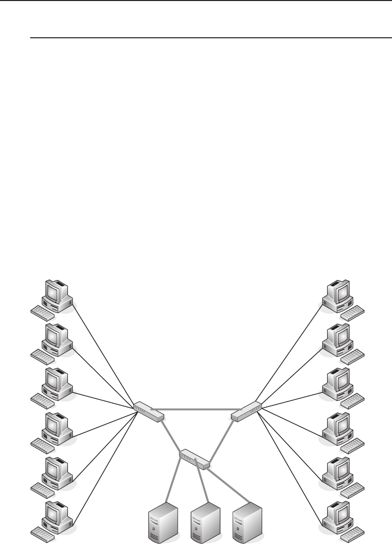
Edwards c06.tex V3 - 03/27/2009 11:07am Page 280
280 Part I ■Networking Nuts and Bolts
6.5 Traffic Optimization
What exactly is traffic optimization? It connotes a lot of various things, but
the gist of the term is overall improvement in network performance. In the
earlier sections of this chapter, we discussed speed and duplex and how they
can affect the performance on a particular network link. We can see that there
are advantages of having certain network paths being faster than others. Links
going between devices that aggregate numerous network nodes need to be
faster and more reliable than those of a single workstation to a hub or network
switch. Figure 6-11 illustrates a network consisting of many user network
nodes interconnected with high-speed switches that have high-speed gigabit
interfaces between them.
The high-speed switches in this figure are to aggregate the multiple work-
stations and allow them to stream network data unimpeded by congestion
caused if the data links between the switches were of the same speed as those
between the workstation and the switches. In this example, the workstations
are connected to the switches using a 100 Mbps full-duplex link. The switches
are interconnected with high-speed gigabit full-duplex links and provide a
redundant path if needed.
High Speed Ethernet Link
User Workstations User Workstations
Server Farm
Figure 6-11 A network segment with high-speed links
Edwards c06.tex V3 - 03/27/2009 11:07am Page 281
Chapter 6 ■Ethernet Concepts 281
ACRONYM ALERT
SNAP — Sub-network Access Protocol
The redundant24 path shown in this
figure allows for any of the high-speed links
to go down and still have workstations
on both network switches to which they
are connected be able to access the server
farm. These servers can provide various ser-
vices such as e-mail, mass data storage, and
client/server applications The servers are interconnected over a high-speed
data link with a gigabit NIC to eliminate congestion on any one server. This
increases the likelihood that there would be less congestion on these data links
but does not totally eliminate the possibility that congestion could occur.
POP QUIZ
What is the first step you should perform
before implementing a network?
When administering large
network installations it is impor-
tant to understand the traffic
patterns that are present on
the network. Network efficiency
can be increased where needed.
The idea is to balance the need
versus what it will cost since there can be areas of overkill where the investment
in network resources is underutilized and thus is not a wise decision. Careful
planning can greatly aid in determining where more network resources are
required and limit the amount of waste of underutilized network segments.
Know the business environment in which the network you are administering
is installed. A carefully thought-out network is easier to install, maintain, and
troubleshoot and runs efficiently with higher reliability.
6.5.1 Traffic Shaping
In the previous section, we discussed planning where high-speed links would
be required. This approach is best-effort, and there is no differentiation of
the type of traffic or if it is more important traffic than that of another
transmitting network node. With real-time applications such as Voice over IP
and videoconferencing, there is a need to give priority to these frames so they
can be delivered in a timely fashion.
What if there was a way to tag a frame so it would be given a priority over
another frame that need not be delivered as quickly? If frames are marked,
they can be queued so the frames with priority will be forwarded on to the
next segment. A simplified diagram illustrates this in Figure 6-12.
24Redundant path or redundancy in a network is the capability to provide multiple paths to
various network resources to add fault tolerance. If one or more high-speed links go down, the
network will either be unaffected or, at worst, be partially affected. It may not be able to have all
of the network resources available to all of network users, but there will be areas of unimpeded
network operation.
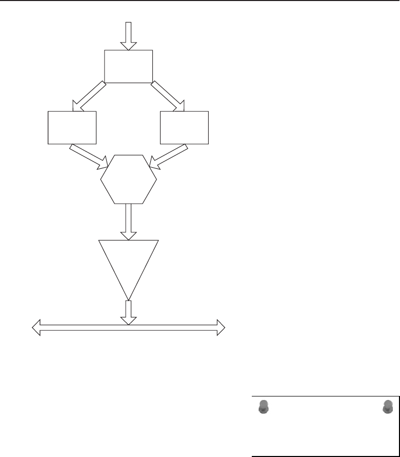
Edwards c06.tex V3 - 03/27/2009 11:07am Page 282
282 Part I ■Networking Nuts and Bolts
Frame
Sorter
Frames IN
Tagged
Frames
Untagged
Frames
Frame
Decision
Logic
Frame
Buffer
Frames OUT
Network Data Stream
Figure 6-12 Frame prioritization
ACRONYM ALERT
PDU — Protocol data unit
Frames are tagged to identify them as
frames that should be transmitted over the
network with priority. As frames enter into
a network node that is to transmit tagged
frames with priority, they are checked for
a priority tag. A queuing system is used to
keep both tagged and untagged frames in
the same order as they are received. When the network node device is ready
to transmit the next frame, a check is made by frame decision logic to see
if there are any tagged frames to be sent with priority. If there are tagged
frames, they will continue to be transmitted until there are no remaining
tagged frames that need to be transmitted. When the tagged frames bin
is empty, untagged frames will be transmitted until the next tagged frame
arrives in the tagged frame bin. All frames are sent in the order they are
received, with the tagged frames being transmitted before any untagged
frames.

Edwards c06.tex V3 - 03/27/2009 11:07am Page 283
Chapter 6 ■Ethernet Concepts 283
POP QUIZ
How is a frame given priority?
We have discussed the Layer
2 switch, but tagging requires
a higher level than that. Routers
are capable of operating at Layer
3 and can make decisions on
tagged packets. However, there
is a more recent development in the switching area — the Layer 3 switch (some-
times called the routing switch). Routing switches perform many of the same
functions as routers, except they operate much faster. Conventional routers
depend on software for the routing protocols and decision making. Routing
switches implement the routing decision process in hardware, allowing higher
throughput of frames. These network devices may be faster than routers as
far as forwarding frames, but they are not as flexible or as programmable as a
conventional router.
6.5.1.1 VLAN Tagging
VLAN25 tagging was standardized in IEEE 802.1Q. The standard allows for
4 bytes used for tagging purposes to be inserted between the Source MAC
Address and the Frame Length/Type fields. Any modification of a frame will
destroy the Frame Check Sequence checksum, so after the frame is assembled
with the 802.1Q tagging the checksum is recalculated and placed in the Frame
Check Sequence field. Figure 6-13 illustrates the 802.1Q VLAN header.
Tag Protocol Identifier
(TPID)
Priority Code
Point
(PCP)
Canonical Format
Indicator
(CFI)
VLAN Identifier
(VID)
16 Bits 3 Bits 1 Bit 12 Bits
Figure 6-13 The IEEE 802.1Q VLAN header
TPID — The Tag Protocol Identifier is a 16-bit field containing the
hexadecimal value of 0x8100 as an indicator that the frame is an 802.1Q
tagged frame.
PCP — The Priority Code Point is a 3-bit field26 that contains
a value from 0 to 7 and is used to indicate the priority level of
the frame. Zero is the lowest priority and 7 is the highest.
25VLAN is an acronym for virtual local area network. Normally, a LAN is localized within a
network segment. However, in a switched network environment, the member network nodes of
a VLAN do not need to be located within the same local vicinity. They are identified as a group
belonging to a particular VLAN.
26The maximum value of 3 binary bits is 7: 111(binary) =7 (decimal). The binary value posi-
tions are 4+2+1, which equals 7. This little exercise is for those readers who may find them-
selves ‘‘base-2 challenged.’’

Edwards c06.tex V3 - 03/27/2009 11:07am Page 284
284 Part I ■Networking Nuts and Bolts
RANDOM BONUS DEFINITION
1BASE5 — A baseband Ethernet system
operating at 1 Mbps over one pair of UTP
cable. Also known as StarLAN.
CFI — The Canonical
Format Indicator is a
1-bit field when set to
the value 0 to indicate
that the MAC address
is in canonical format,
which is always set
to 0 for Ethernet switches. If a frame is received with the CFI set to
the value 1, it should not be bridged to an untagged port.
VID — The VLAN Identifier is a 12-bit field that specifies
which VLAN the incoming frame belongs to. If this field
is set to the value of 0, it indicates that the frame does not
belong to a VLAN and that it is only a priority tag.
POP QUIZ
What does the acronym VLAN stand for?
The advantage of having net-
work node devices that are part
of a VLAN group equipped
with VLAN tagging is primar-
ily the capability to tag outgo-
ing frames with a priority. This
means that frames that require
timely delivery are expedited over the network before less critical or best deliv-
ery frames. Another advantage is that network node devices can be grouped
and are allowed to communicate across multiple LAN networks as if they were
all on a single LAN network. The destination address is filtered by the switches
and bridges in the network path and only forwards the frames to the ports
that service the VLAN the frame belongs to. Because of the configurability
of these switches, network management is made simpler, allowing for easy
addition, removal, movement, or other configuration changes required on a
VLAN port.
HELPFUL HINT
Layer 3 (or routing) switches seem so easy to manage and configure. We will
again caution about the need for documenting your network well, unless you
prefer to go through a multitude of switch configurations, port by port. It is
even more imperative because of configurations where ports can be moved and
juggled without physically going out and moving a cable on a port. Switch
networking issues can be daunting on a large network, so there is no substitute
for good network documentation.
(continued)

Edwards c06.tex V3 - 03/27/2009 11:07am Page 285
Chapter 6 ■Ethernet Concepts 285
HELPFUL HINT (continued)
If you need to call for support on a problem, remember that the support
engineer does not have a crystal ball27 to look into your network. He is going to
rely on your ability to know your network and know it well. Support engineers
do not like playing guessing games. It is a waste of their time and will add to
your frustration level as your boss blows his hot breath on the back of
your neck.
Want to be a good network administrator? Document, document, document!
6.6 Chapter Exercises
1. What does the acronym CSMA/CD stand for?
2. What form of communications eliminates the need for collision detec-
tion?
3. When you choose not to configure an Ethernet port for speed and duplex
mode, what are you relying on?
4. What is needed when setting up VLAN networking?
5. What is a source address? What is a destination address?
6. What is the maximum number of bytes the Data field can contain in
an Ethernet frame? What is the minimum number of data bytes?
6.7 Pop Quiz Answers
1. What was the first type of cable used to form an Ethernet network?
Coaxial cable
2. An Ethernet network device that forwards data on the network
would be considered what type of Ethernet device?
DCE (data communications equipment)
27A crystal ball is a device a network administrator hopes the support engineer at the other
end of the hotline has when he frantically calls for support. Alas, he does not possess one,
so drop to your knees and start praying. Or you can take the easy way out and start docu-
menting your network from initial installation through configuration changes, additions, and
anything that modifies the network.

Edwards c06.tex V3 - 03/27/2009 11:07am Page 286
286 Part I ■Networking Nuts and Bolts
3. If a cable is wired such that one plug is a T568A and the other is a
T568B, it would commonly be referred to as cable.
Crossover
4. You are interconnecting two Ethernet devices, but neither
device is showing a link light on the assigned port. List
in order of likelihood where the problem might be.
Cable type
Defective cable
Bad network interface
5. Into which two sublayers of the IEEE 802 reference model
is the OSI reference model Data Link layer divided?
LLC (Logical Link Control)
MAC (Media Access Control)
6. With which functions is the Logical Link Control sublayer mainly con-
cerned?
Flow control
Error control
Multiplexing protocols
7. When a collision occurs on the media, what does the transmitting net-
work node do?
Stops transmitting
8. What is the maximum number of bytes that can be contained in the Data
field of an Ethernet frame?
1500 bytes
9. What does the Frame Check Sequence field of an Ethernet frame con-
tain?
CRC calculation using the bytes of the Destination Address,
Source Address, Frame Length/Type, and Data fields.
10. What is the name of the transmission mode that allows either transmit-
ting or receiving at different time intervals but never within the same
time interval?
Half-duplex
11. What name is applied to the transmission mode that allows multiple
frames to be sent without the need to release the network media between
frames?
Burst mode

Edwards c06.tex V3 - 03/27/2009 11:07am Page 287
Chapter 6 ■Ethernet Concepts 287
12. What does the term full-duplex mean?
The capability to transmit and receive at the same time.
13. What is flow control used for?
To stop a transmitting node from sending when congestion is detected.
14. What is autonegotiation?
The capability of two network node peers to negotiate the
speed and duplex used on the link they are connected to.
15. When a frame is received, what is the first criteria that is checked?
Destination address
16. What is the first step you should perform before implementing a net-
work?
Carefully plan out the network.
17. How is a frame given priority?
Tagging
18. What does the acronym VLAN stand for?
Virtual local area network
Edwards c06.tex V3 - 03/27/2009 11:07am Page 288

Edwards c07.tex V3 - 03/27/2009 11:19am Page 289
CHAPTER
7
Not to Be Forgotten
If you would not be forgotten as soon as you are dead and rotten, either write
things worth reading or do things worth the writing.
— Benjamin Franklin
We are now at the end of the ‘‘Networking Nuts and Bolts’’ part of this
book. So far we have discussed most of the predominate standards that are
implemented in the majority of networks. We have discussed the popular
LAN and WAN standards that you will most likely be involved with should
you continue in your quest of network knowledge. What you have seen in
this section of the book is only a portion of the technologies that are available
and/or implemented in many networks.
This chapter is going to provide an overview of some of the other standards
and processes that are available and, for the most part, in use (if only in a
small percentage of networks). The way we see it, it just wouldn’t be a good
networking book if these weren’t at least mentioned.1Some of the technologies
in the following pages are of a dying breed, whereas others are just starting
to grow. Whatever their status, these are standards that have been replaced
by other standards, enhanced by revisions to the original standard, developed
to support proprietary hardware and/or software products, or developed to
support a new technology.
When a standard is placed on the road to becoming obsolete,2it is normally
due to technology advancements that the standard cannot support. This does
not mean you cannot use the standard, but it does mean there will be no further
advancements to the standard and, for the most part, what you see is what
1Although there are many good networking books out there that deal with even a single protocol.
2The process of retiring a standard is known as placing it into an ‘‘end-of-life’’ status.
289

Edwards c07.tex V3 - 03/27/2009 11:19am Page 290
290 Part I ■Networking Nuts and Bolts
you get (WYSIWYG).3Some of the standards we will discuss are proprietary
butareoftenimplementedasthestandardofchoice,andsomearenewer
technologies that are just experiencing ‘‘startup growth’’ and will probably
prove themselves to be a major part of networks in the next decade.
Attheendofthechapter,wehaveprovidedanintroductiontothestructure
of a datagram — what it is, how it works, and why it is important. This is to
ensure that we keep that network knowledge flowing.
7.1 Can’t Get Enough of Those LAN Technologies
RANDOM BONUS DEFINITION
100BASE-T — The term used to describe
baseband Ethernet transmission of 100
Mbps.
Inthelastchapter,wediscussed
Ethernet, which is the most pop-
ular of LAN protocols in use
today. Because of the advance-
ments and cost savings offered
by Ethernet, many other proto-
cols have been retired (or are not
as commonly used as Ethernet).
In this section, we discuss a few LAN protocols that were once on the cutting
edge, and may still be out there serving in some capacity.
7.1.1 Attached Resource Computer Network
In Chapter 1, we defined a LAN as a data network that covers a small
geographical area. This normally ranges from an area with just a few PCs
to an area about the size of an office building or a group of buildings.
Attached Resource Computer Network (ARCnet) is a protocol that was once
very popular in LANs, and has even found a purpose in today’s Ethernet
world. ARCnet is now used as an embedded standard to serve networks
that control automation services, transportation, robotics, gaming, and other
similar network types.
Developed by the Datapoint Corporation in the late 1970s, ARCnet was
designed to use token-passing bus technology over coaxial cabling. The physi-
cal topology of ARCnet is a star/bus topology (see Figure 7-1). ARCnet touted
speeds of up to 2.5 Mbps4and distances of up to four miles. ARCnet is con-
sidered the first truly commercially available LAN. Due to the low cost of the
infrastructure and the simplicity in implementation and maintenance, ARCnet
was very popular when it first arrived.
3Pronounced ‘‘wizzy-wig.’’
4A later version of ARCnet was released in the early 1990s and was called ARCnet plus. It could
operate at speeds of up to 20 Mbps. By the time ARCnet plus had come out, however, Ethernet
was quickly becoming the standard of choice.
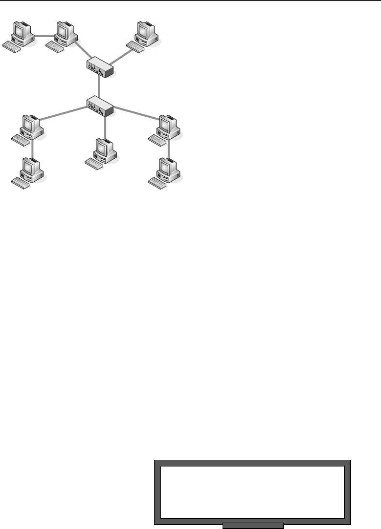
Edwards c07.tex V3 - 03/27/2009 11:19am Page 291
Chapter 7 ■Not to Be Forgotten 291
Figure 7-1 An example of an ARCnet topology
ARCnet doesn’t have all the bells and whistles that are offered in networks
today. It is a very simple technology that is easy to implement and run. A big
drawback with ARCnet is that when an interface is brought into the network,
the address of the interface has to be set by whoever is installing it. Most of
the time, the address is set by jumpers or switches on the resource interface
module (RIM)5itself.
ARCnet was designed to give Datapoint nodes the capability to share
resources over the token bus, thus increasing the overall power of the attached
nodes. Datapoint had originally intended to keep what became known as
ARCnet fully proprietary because if the public bought their gear, they could
tout resource sharing as a selling point.
Datapoint had some problems with the design of the RIM chip, so they even-
tually contracted with Standard Microsystems Corporation (SMSC). SMSC
successfully built the chip specifically for Datapoint, and in the final negoti-
ations got the approval to sell a version of the chip to other vendors — and
ARCnet was born.
7.1.2 StarLAN
POP QUIZ
What was the name of the company that
developed ARCnet?
StarLAN technology is, for the
most part, the predecessor to
what we all know as Ethernet.
Often referred to as 1BASE5 and
developed in the early 1980s by
AT&T, StarLAN provided a way
5The RIM is basically the ARCnet-supported NIC card.
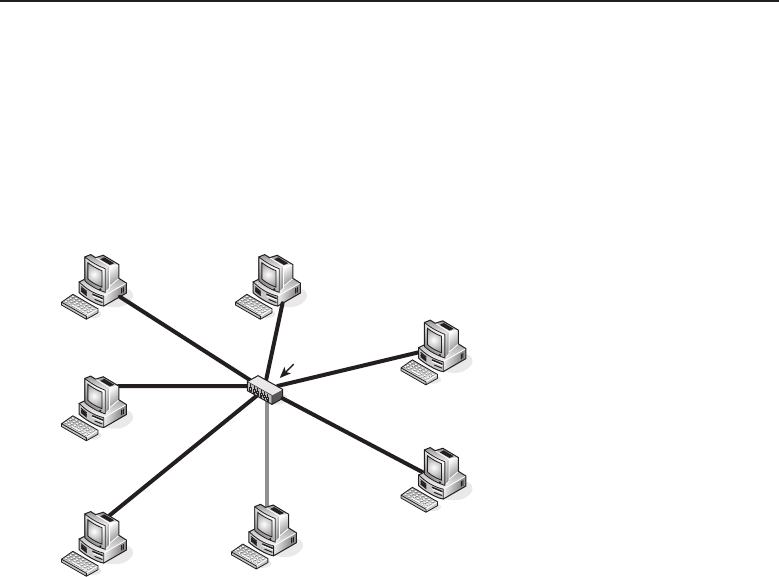
Edwards c07.tex V3 - 03/27/2009 11:19am Page 292
292 Part I ■Networking Nuts and Bolts
for nodes to communicate with one another over a telephone line. StarLAN
operated at 1 Mbps and eventually supported speeds of 10 Mbps.61BASE5
actually came out after coaxial cabling came out supporting 10 Mbps. This is
part of the reason that StarLAN never really got deployed in most LANs. Once
10BASE-T came out, the only time StarLAN was used was when someone
needed a low cost infrastructure and speed was not a concern. Figure 7-2
shows an example of the StarLAN topology.
StarLAN
Hub
All links operate
at 1 Mbps
Figure 7-2 The StarLAN topology
StarLAN networks used UTP as a transmission medium and typically
connected nodes to one another through at least one hub. StarLAN was able to
also connect to multiple nodes without a hub by daisy-chaining them one by
one upon the shared medium. The maximum number of nodes in a daisy-chain
configuration was 10. Figure 7-3 shows an example of daisy-chaining.
7.1.3 Token Ring
Token Ring network technology was developed by IBM in the late 1970s.
IBM submitted the proposed standard to the IEEE LAN standards committee,
which adopted the proposal and used the standard as the basis for the IEEE
802.5 standard. Token Ring topologies are a star physical topology and a ring
logical topology, as shown in Figure 7-4.
6By this time, however, 10BASE-T was out, which rendered this advancement moot.
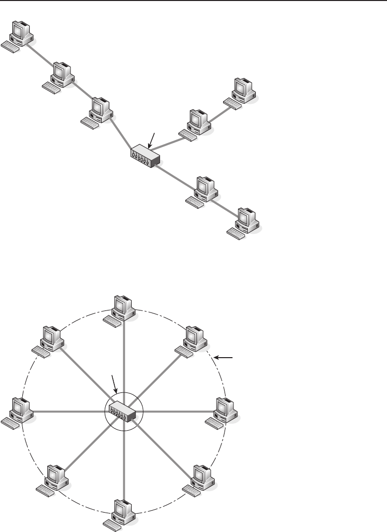
Edwards c07.tex V3 - 03/27/2009 11:19am Page 293
Chapter 7 ■Not to Be Forgotten 293
StarLAN
Hub
Figure 7-3 Including a daisy chain in a StarLAN configuration
Physical
Topology
Logical
Topology
Figure 7-4 A Token Ring topology
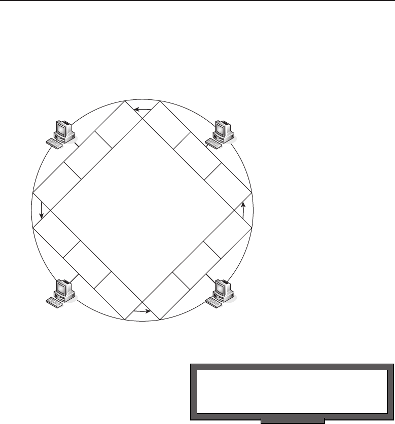
Edwards c07.tex V3 - 03/27/2009 11:19am Page 294
294 Part I ■Networking Nuts and Bolts
Token Ring networks pass a signal, known as a token, from one node to the
next. The node that you receive the token from is the upstream neighbor.The
node that you pass the token to is the downstream neighbor. Each node receives
the token, takes action, and then passes the token to the downstream neighbor
(see Figure 7-5).
Send Action Receive
Send Action Receive
Send Action Receive
Send Action Receive
Figure 7-5 Token Ring operations
POP QUIZ
What technology is also known as 1BASE5?
The actions that are taken
are determined by whether the
node has control of the token.
If a node controls the token,
it transmits the token onto the
ring to the downstream neigh-
bor, which receives the token
and then passes it on the ring to its downstream neighbor. The data is captured
by each node, and once the token has made it back to the originating node,
that node will remove it from the ring, thus freeing the ring up for the next
token to be passed.
The original Token Ring supported speeds of 4 Mbps and later came to
support 16 Mbps. It didn’t take long for networks to upgrade to support the
higher speed, especially as the demands on the LAN grew. There is an 802.5
approved standard for Token Ring, allowing up to 100 Mbps speeds, but this
never really became popular.7
7Anyone care to guess why?

Edwards c07.tex V3 - 03/27/2009 11:19am Page 295
Chapter 7 ■Not to Be Forgotten 295
7.1.3.1 Token Ring’s Modus Operandi
In a Token Ring environment, only one node can transmit data from itself at
a time. The originating node is given the token in order to pass it on to the
network. The node sets the Token bit from a 0 to a 1, which transforms the
Token into a datagram known as a frame. The data is passed from node to
node around the ring. Each node inspects the frame and forwards it to the
downstream neighbor.
ACRONYM ALERT
TTL — Time to live
Once a node inspects the data frame and
recognizes its own address as a destination
address, the node retains a copy of the data
and sends the data on to the next node in
line. The data continues around the ring,
inspected by all nodes, and then returns to
the originating node, which retrieves the
frame from the token and sends a new token8on to the next node. Once the
token arrives at a node that wants to send data, the process begins again.
7.1.3.2 Token Ring Media
Token Ring originally operated on STP cabling but converted to UTP cabling
in the 1990s. This was greatly appreciated by the networking community, as it
offered a cheaper and less bulky medium.
MMF9cabling was supported officially in 1998 when an approved amend-
ment was written into IEEE 802.5, although in actuality a lot of networks were
using it already. Token Ring 100 Mbps operation is conducted on the exact
twisted pair specification that is used for 100Mbps Ethernet.
7.1.3.3 The Format of the Token Ring Frame
Token Ring uses one of three frame types. Token frames have the token bit set
to 0 and have no data. Token data frames10 have the data payload contained
within the frame (the token bit is set to 1). The abort frame carries no data and
is used to stop its own transmission of data, or used to clear up data that is on
the line.
The fields contained within the token frame are fairly simple to understand,
as shown in Figure 7-6.
8Sending a ‘‘new’’ token simply means that the token bit is set back to 0, indicating an available
token.
9Quick refresher: In Section 3.2.1.3 we discussed the two types of optical fiber, multi-mode fiber
(MMF) and single-mode fiber (SMF).
10Also known as a token command frame.
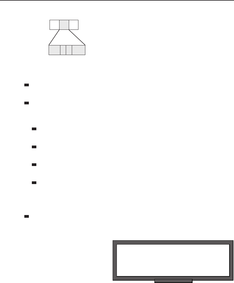
Edwards c07.tex V3 - 03/27/2009 11:19am Page 296
296 Part I ■Networking Nuts and Bolts
SD AC ED
1
Number of Bytes 11
PRI 0 M RES
Figure 7-6 An empty Token frame
SD (start of frame delimiter) — This field lets the receiving node know
when the frame begins.11
AC (access control) — There are four subfields in the access control
field, all used to transmit information to the access control process within
Token Ring.
PRI (priority bits) — The priority bits show the priority level of the
frame.
0(token bit) — This bit differentiates the frame type. In Figure 7-6,
the token bit is set to 0, identifying it as a token frame.
M(monitor bit) — The monitor bit is used by a node that is known
as an active monitor node. This bit is used to detect various errors.
RES (reservation bits) — The reservation bits are used by a node to
announce that it has data to send and needs to use the token as soon
as it is available. Reservations are based on the priority level that has
been set.
ED (end of frame delimiter) — This field lets the receiving node know
when the frame ends.12
POP QUIZ
What is the signal called that is passed in
Token Ring from one node to the next?
Thetokendataframeformat
is pretty much an extension of
the token frame format. The first
two fields are identical, but the
third field is moved to the end
of the frame (where it belongs).
Several fields are in between
that contain the data and the
information that a node will need to send and receive frames on the Token
Ring.
11There has to be something identifying the beginning of the frame.
12When you have to be clued in when the frame starts, there has to be some way to let you know
that the frame is complete.

Edwards c07.tex V3 - 03/27/2009 11:19am Page 297
Chapter 7 ■Not to Be Forgotten 297
Figure 7-7 shows the fields contained within the token data frame.
SD FSEDAC FC Data FCS
Destination
Address
Source
Address
1
Number of Bytes 11116 6 4
PRI 1 M RES
Figure 7-7 Token frame with data attached
SD (start of frame delimiter) — This field lets the receiving node know
when the frame begins.
AC (access control) — There are four subfields in the access control
field, all used to transmit information to the access control process within
Token Ring.
PRI (priority bits) — The priority bits show the priority level of the
frame.
1(token bit) — This bit differentiates the frame type. In
Figure 7-7, the token bit is set to 1, identifying it as a token data frame.
M(monitor bit) — The monitor bit is used by a node that is known
as an active monitor node. This bit is used to detect various errors.
RES (reservation bits) — The reservation bits are used by
a node to announce that it has data to send and needs
to use the Token as soon as it is available. Reservations
are based on the priority level that has been set.
FC (frame control) — The frame control field is used to separate
network management data frames from user data frames.
Destination Address — This field contains the 6-byte network address
ofthenodetheframeisdestinedfor.
Source Address — This field contains the 6-byte network address of the
node the frame originated from.
Data — This field contains the data from the upper layer protocol that
is being transmitted. There is a certain limit on the amount of data that
can be included in the frame. At 4 Mbps, the limit is 4,528 bytes. At 16
Mbps, the limit is 18,173 bytes. At 100 Mbps, the limit is 18,173 bytes.
FCS (frame check sequence) — This field is a checksum algorithm that
checksums the frame from the FC field to the end of the Data field.

Edwards c07.tex V3 - 03/27/2009 11:19am Page 298
298 Part I ■Networking Nuts and Bolts
ED (end of frame delimiter) — This field lets the receiving node know
when the frame ends.
RANDOM BONUS DEFINITION
trunk — A name defining a bundle of links,
also known as aggregate links.
FS (frame status) — This
field is used by the
originating node to
detect whether there
were any errors during
transmission. This
includes: if the destination
node copied the data; if there were any errors encountered; and even
if the destination node recognized itself as the destination node.
7.1.4 Fiber Distributed Data Interface
The Fiber Distributed Data Interface (FDDI) is a LAN13 and/or MAN technology.
FDDI14 was the first such technology that could operate at 100 Mbps. FDDI is
an ISO standard and is fully compatible with the IEEE 802 standards.
Although FDDI could function as a LAN technology, it is cheaper and
easier to use 100 Mbps Ethernet. When FDDI was developed, it was intended
to provide higher speeds in LANs than the quickest rate that was available
at the time: 16 Mbps Token Ring or Ethernet. FDDI is sometimes used to
connect server farms and multiprocessors to the network. Most often you will
find FDDI deployed within the backbone of the network, providing quick
connectivity between other networks.
7.1.4.1 FDDI Does What FDDI Does
POP QUIZ
What information is contained in the
Destination Address field in a Token Ring
frame?
FDDI was designed to oper-
ate over shared fiber media.
The fiber connected nodes in a
ring similar to the IEEE 802.5
Token Ring standard configura-
tion. The difference is that FDDI
uses a dual-ring topology over
asharedfibermedium.
15 Data
traffic on a FDDI ring flows in a counter-rotating manner. This means that data
on one of the rings goes in one direction while the other ring carries traffic in
the opposite direction. The ring that actively carries data is the primary ring
13Most networks use FDDI at the MAN levels.
14Pronounced ‘‘fiddy.’’
15There is a newer standard for FDDI that allows the use of twisted pair cabling instead of fiber.
This is called the Copper Distributed Data Interface (CDDI), discussed in Section 7.1.4.1.2.

Edwards c07.tex V3 - 03/27/2009 11:19am Page 299
Chapter 7 ■Not to Be Forgotten 299
and the other is the secondary ring, which remains in an inactive status until
needed. Figure 7-8 shows an example of the FDDI topology.
Primary ring
Secondary ring
FDDI concentrator
FDDI concentrator
FDDI concentrator
Primary ring
Primary ring
Figure 7-8 FDDI topology
Notice that unlike Token Ring, which connects to a central MAU, there are
concentrators16 that connect nodes to the FDDI topology. We will discuss the
different concentrator types in Section 7.1.4.2. Other nodes that can be used
within a FDDI ring are servers, routers, switches, and so on. As long as the
node is able to support FDDI, it can be used for its intended purpose on the
FDDI ring.
The FDDI protocol supports optical fiber (FDDI) as well as copper cables
(CDDI)17 as a shared medium. The operations provide the FDDI functions,
with the difference being the medium type used. Both have advantages and
disadvantages, which we will discuss in the next two sections.
7.1.4.1.1 Fiber Distributed Data Interface
FDDI is the FDDI protocol over fiber optic cabling. Both MMF and SMF optical
fiber medium types are supported in a FDDI environment.
16Refer to Section 3.3.3.1 if you do not remember what purpose the concentrator serves in a
network.
17The official name is twisted pair physical medium dependent (TP-PMD); however, CDDI seems
to be gaining in popularity. CDDI is a Cisco term, while TP-PMD is the ISO term. It seemed to
us that it is easier to refer to this as CDDI for the purposes of this book, but you may need to
know both acronyms when working in a professional environment (you don’t want to get caught
saying, ‘‘Huh?’’ when someone asks you if your TP-PMD is running). As has occurred many
times in the history of networking, terms come and go. What is important is that you understand
what they are referring to.
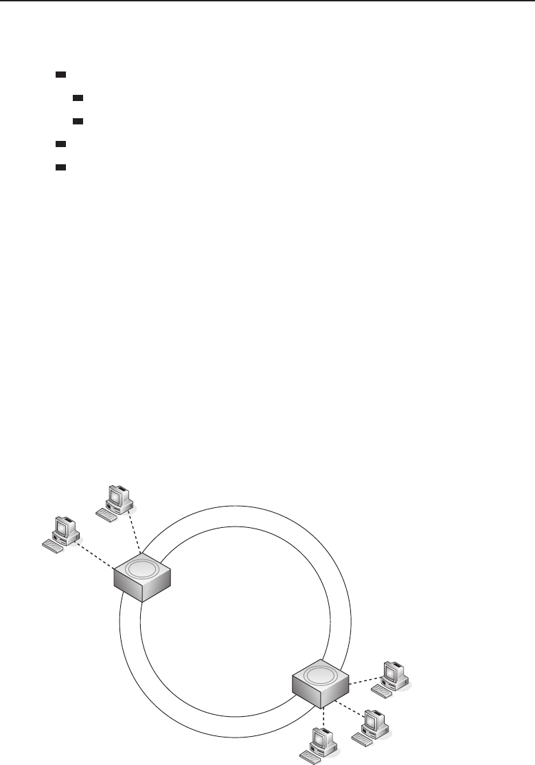
Edwards c07.tex V3 - 03/27/2009 11:19am Page 300
300 Part I ■Networking Nuts and Bolts
There are advantages in using optical fiber as the primary transmission
medium:
Performance
Greater distances
Faster transmission speed
Reliability
Data security
Each advantage is due to the actual medium itself. Optical fiber uses light
instead of electricity to carry data. This prevents the leaking of electrical
signals, thus improving performance and the reliability of the transmission
of data. This also increases security as there is no way to tap into the fiber
optic cable. This ensures that, for the most part, only the individuals that are
intended to see the data will see the data.
7.1.4.1.2 Copper Distributed Data Interface
Copper Distributed Data Interface (CDDI) is the FDDI protocol over twisted pair
media instead of fiber. CDDI is officially known as twisted pair physical medium
dependent (TP-PMD) and is also known as twisted pair distributed data interface
(TP-DDI). CDTP-PMDDIusesbothSTPandUTPcabletypes.
The main advantage with copper is that it is cheaper and easier to install
and maintain than fiber. Because copper cannot transmit the distances that
fiber can, it is often used to connect nodes to the concentrator in the FDDI
environment. Figure 7-9 shows an example of this.
Fiber Optic
Fiber Optic
Twisted pair
Twisted pair
Figure 7-9 FDDI and CDDI together

Edwards c07.tex V3 - 03/27/2009 11:19am Page 301
Chapter 7 ■Not to Be Forgotten 301
7.1.4.2 FDDI Node Types
One of the really neat things about FDDI is there are options for how you can
configure it. Will you use fiber or copper? How many nodes and concentrators
should be supported? What types of concentrators should you use? FDDI
offers a lot of choices for you.
The four main node types in the FDDI environment are:
Single attachment station (SAS) — Connects to the FDDI ring
through a single connector. The connector has an input port
and an output port. Data is received on the input port and is
sent to the downstream neighbor via the output port. The SAS
connects to a concentrator and then to the primary ring only.
Single attached concentrator (SAC) — Like the SAS, the SAC concen-
trator connects to only the primary ring. The connection is made through
another concentrator.
POP QUIZ
What does the acronym FDDI stand for?
Dual attachment station
(DAS) — Connects to
the FDDI ring through
two connectors (each
with an input and
an output port). Can
connect directly to the ring or through a concentrator.
Dual attached concentrator (DAC) — A concentrator that connects to
both rings.
7.1.4.3 The FDDI Frame Format
The FDDI frame format is very similar to the format of a Token Ring frame.
FDDI uses either token frames or token data frames. Figure 7-10 shows an
example of a token frame.
SD FC
≥2
Number of Bytes 11
ED
1
Preamble
Figure 7-10 An empty token frame
Preamble — Provides a vehicle to ensure the receiving node is synchro-
nized to receive the frame.
SD (start of frame delimiter) — This field lets the receiving node know
when the frame begins.

Edwards c07.tex V3 - 03/27/2009 11:19am Page 302
302 Part I ■Networking Nuts and Bolts
FC (frame control) — This field is used to separate network management
data frames from user data frames.
ED (end of frame delimiter) — This field lets the receiving node know
when the frame ends.
The token data frame format is pretty much an extension of the token frame
format. The first two fields are identical, but the third field is moved to the
end of the frame (where it belongs). There are several fields in between that
contain the data and the information a node needs to send and receive frames
on the Token Ring.
Figure 7-11 shows the fields contained within the token data frame.
SD FSEDFC Data FCS
Destination
Address
Source
Address
≥2
Number of Bytes 11116 6 4
Preamble
Figure 7-11 A token frame with data attached
Preamble — Provides a vehicle to ensure the receiving node is synchro-
nized to receive the frame.
SD (start of frame delimiter) — This field lets the receiving node know
when the frame begins.
FC (frame control) — This field is used to separate network management
data frames from user data frames.
Destination Address — This field contains the 6-byte network address
ofthenodetheframeisdestinedfor.
Source Address — This field contains the 6-byte network address of the
node the frame originated from.
Data — This field contains the data from the upper layer protocol that
is being transmitted. There is a certain limit on the amount of data that
can be included in the frame. At 4 Mbps, the limit is 4,528 bytes. At 16
Mbps, the limit is 18,173 bytes. At 100 Mbps, the limit is 18,173 bytes.
FCS (frame check sequence) —This field is a checksum algorithm that
checksums the frame from the FC field to the end of the Data field.
POP QUIZ
What are the four main node types in the
FDDI environment?
ED (end of frame
delimiter) — This field lets
the receiving node know
when the frame ends.

Edwards c07.tex V3 - 03/27/2009 11:19am Page 303
Chapter 7 ■Not to Be Forgotten 303
FS (frame status field) — This field is used by the originating
node to detect whether there were any errors during trans-
mission. This includes: if the destination node copied the
data; if there were any errors encountered; and even if the
destination node recognized itself as the destination node.
7.2 As If You Haven’t Had Enough
of These Sweet Protocols
It was tough to decide what to include in this section. There are a lot of
protocols and other services that you will need to know. For one thing, you
will probably come across some, if not all, of them at some point. Additionally,
many of the protocols were built upon some networking original protocols,
so understanding their function and structure is helpful in understanding the
more advanced protocols that have come out in recent years.
The information in this section should really help you start piecing out
how things are connected in today’s networks. It should also help you better
understand the next two parts of this book (especially when you will be tasked
to design your own network).
This section is fairly long, but it simply made sense to put it all in here. After
reading through this chapter, if you like what we did, you can thank author
Jim. If you don’t like it, it was author Rich’s idea.
7.2.1 Digital Equipment Company Network
The Digital Equipment Company (Digital)18 developed and released the first
version of the Digital Equipment Company Network (DECnet) protocol in the
mid-1970s. For years, Digital had been developing a series of minicomputers
that were known as the programmed data processor (PDP)19 series. DECnet was
developed to allow two PDP series 11 (PDP-11) nodes to connect to one another
over a point-to-point link and share resources.
18Many people in the industry refer to the Digital Equipment Company as ‘‘DEC’’ (pronounced
‘‘deck’’), but the official ‘‘short name’’ is Digital.
19Digital decided to use the term programmed data processor (PDP) instead of what it truly
was — a computer. This is because computers were known to be complicated and very expensive.
To thwart the negative press the computer had developed, the term PDP was used and sold to a
market that could not afford a computer.

Edwards c07.tex V3 - 03/27/2009 11:19am Page 304
304 Part I ■Networking Nuts and Bolts
AN UNRELATED MOMENT OF PAUSE
A reporter was given an opportunity to do an exclusive interview with a
network engineer who had been sent to the International Space Station to
upgrade the network.
Reporter: ‘‘So, how do you feel now that you have been there for 3 days?’’
Engineer: ‘‘Lady, how would you feel if you were stuck in space, floating
inside a grouping of about 120,000 parts all bought from the lowest bidder?’’
DECnet is not in and of itself a complete single standard; it’s a suite of
protocols. As with most protocols that continue to have an end-user demand,
DECnet has undergone several updates to the original protocols. Following is
a brief overview of the DECnet phases:
DECnet phase I — Allowed two PDP-11 series to communicate with one
another.
DECnet phase II — Increased support to networks of up to
32 nodes. The nodes did not have to be identical, but were
requested to be able to interoperate with each other. Commu-
nication between nodes was done via a point-to-point link.
File sharing was an important upgrade during this phase.
DECnet phase III — Increased support to networks of up to 255
nodes. Communication was handled via point-to-point link, as
well as multidrop links. Support was added to allow DECnet
networks to communicate with networks of other types. Routing
and network management were also supported at this phase.
DECnet phase IV — Increased support of networks of up to 63
areas, supporting up to 1023 nodes each. Phase IV included Ethernet
support as well as some hierarchical routing standards. Also, a client
was developed for Microsoft DOS and some Windows platforms
that allowed workstation support of the DECnet protocol.
ACRONYM ALERT
SONET — Synchronous Optical Network
DECnet phase V —IOSstandards
were rolled into this phase, mov-
ing the protocol from a proprietary
standard to an open standard. The
name phase V was later changed to
DECnet/OSI, identifying the com-
patibility with other OSI standards. Eventually, some TCP/IP proto-
cols were added and the name was changed to DECnet-Plus.
DECnet phase IV introduced a layered network architecture that is similar
to the architecture outlined in the OSI reference model. The DECnet layered

Edwards c07.tex V3 - 03/27/2009 11:19am Page 305
Chapter 7 ■Not to Be Forgotten 305
model is known as the digital network architecture (DNA).IntheDNAmodel,
each layer serves the layers above it and requests services from the layer
beneath it. The structure and purpose of the DNA model are much like the
OSI model, each layer being responsible for a function to support the protocol.
Each layer is mostly based on the proprietary protocol, so some of the upper
layers share functions within individual substandards.
The DNA changed as well when DECnet phase V came about, due to the
multiple open standard support that was now part of the protocol. Most of the
upper layers support both the proprietary and the open standards that became
part of the protocol suite.
Note that you don’t have to know all the proprietary standards in the
protocol suite; know only that it operates in a hierarchical manner.
7.2.2 Xerox Network Systems
Xerox Network Systems (XNS), developed by the Xerox Corporation20 in the
late 1970s and early 1980s, was a suite of protocols that supported a variety
of functions. Although it was never a true competitor to TCP/IP, XNS was
adopted by many vendors to run within their LANs.21
XNS also utilized a reference model that roughly matched the OSI reference
model. There were a total of five levels22 in the XNS reference model:
Level 0 — Roughly corresponded with the OSI Layers 1 and 2.
Level 1 — Roughly corresponded with the OSI Layer 3.
Level 2 — Roughly corresponded to the OSI Layers 3 and 4.
Level 3 — Roughly corresponded to the OSI Layers 7 and 7.
Level 4+— Roughly corresponded to the OSI Layer 7.
XNS used a routing protocol called the Internet Datagram Protocol (IDP),
which was responsible for datagram delivery within a network as well as an
addressing scheme for the routing of said datagrams. Because the format of
the IDP packet differed23 from some other routing protocols, we wanted to
break down the packet for you in Figure 7-12 so you can see the fields that are
contained in the packet.
22
Number of Bytes 11 4 6 6224
CS DSN SSNL T
C
P
T
Destination
Network #
Source
Network #
Destination
Host # Source Host # Data
Figure 7-12 The IDP packet format
20That was pretty obvious, wasn’t it?
21XNS was modified for several of these companies to suit the needs of their particular network.
22Not layers.
23For one thing, the IDP network address contains the following: a 4-byte network number, a
6-byte host address, and a 2-byte socket field.

Edwards c07.tex V3 - 03/27/2009 11:19am Page 306
306 Part I ■Networking Nuts and Bolts
CS (checksum) — Used to determine the integrity of the packet upon
receipt by the destination.
L(length) — Identifies the length of the packet.
TC (transport control) — This field actually contains two subfields. The
first subfield identifies the current hop count for the packet. The other
subfield identifies the maximum time the packet can live on the network.
PT (packet type) — Identifies the format of the packet.
Destination Network # (destination network number) — The 4-byte
destination network identifier.
Destination Host # (destination host number) — The 6-byte destination
host identifier.
DSN (destination socket number) — The 2-byte destination socket
identifier.
Source Network # (source network number) — The 4-byte source net-
work number.
Source Host # (source host number) — The 6-byte source host identifier.
POP QUIZ
What are DECnet’s five phases?
SSN (source socket
number) — The 2-byte
source socket identifier.
Data (data) — The
payload!
7.2.3 Internetwork Packet Exchange
The Internetwork Packet Exchange (IPX) protocol is normally found within
networks with nodes running the Novell NetWare operating system. Novell
NetWare was built to support the protocols that were a part of the XNS
protocol suite. IPX is a datagram protocol used to route packets within a
network. It is connectionless-oriented protocol (IP, for example) and therefore
does not have to ensure a connection before it puts the packet onto the transport
medium.
IPX uses a distance-vector protocol (RIP, for example), making routing
decisions based on hop counts. IPX RIP works similarly to RIP, but instead of
using a hop count for distance determination it uses what is known as a tick.A
tick is simply a measure of time (1/18th of a second) delay that is expected for
a particular distance on the medium. If there are two routes to the destination
and the ticks are the same on each path, the route with the lowest hop count
is the one that will be chosen.

Edwards c07.tex V3 - 03/27/2009 11:19am Page 307
Chapter 7 ■Not to Be Forgotten 307
IPX uses an IPX address for host/node identification. There are two parts
to the IPX address. The first part of the IPX address is the network number:
the remaining part is known as the node number. The network number is 4
bytes long (that’s a total of 32 bits for those of you who are counting).24 The
node number is 6 bytes long (48 bits), which happens to match the length of
the MAC address of the NIC. Why does it match? Because the MAC (IEEE
802) address is the number that is used for the node number part of the IPX
address. Figure 7-13 is an example of the IPX address.
Network–4 bytes Node–6 bytes
Figure 7-13 The IPX address
RANDOM BONUS DEFINITION
workgroup switch — A switch used within
a single department or workgroup.
Because the node has its own
MAC address, the only require-
ment you need to have an IPX
address assigned to the node is
to plug it into an interface to the
network. The node will send out
a broadcast letting the network know it has joined the network. The appro-
priate router will then assign the network number to the node. The node now
has identification and can send and receive IPX datagrams. IPX is simple to
implement — it is basically plug and play.
By now you have to be asking if there is anything complicated about IPX. The
answer is no, but there is something you need to know about the IPX datagram
format: there is not just a single datagram format. Why? Originally, IPX frame
formats served well on the early Ethernet networks within a single network.
But as networks grew and as LANs began communicating with one another,
other standards were introduced and existing standards were improved, and
IPX could not support communication with nodes outside of their known
network number–which is why four Ethernet frame formats are used.25
Novell proprietary frame format — This is the original frame
format that was used. It is often referred to as 802.3 raw
(minus the LLC [802.2]). Figure 7-14 is an example of this.
662 4
Number of Bytes
LNH IPX PacketDA SA CRC
Figure 7-14 The 802.3 raw frame format
24If you are counting, or even thought of counting, then you get extra credit! Great job!
25The router is responsible for translating and reformatting different formats so the destination
can understand the information within the frame.

Edwards c07.tex V3 - 03/27/2009 11:19am Page 308
308 Part I ■Networking Nuts and Bolts
DA (destination address) — The 6-byte destination MAC address.
SA (Source address) — The 6-byte source MAC address.
LNH (length) — This field identifies the amount of data contained in
the data payload field.
IPX Packet — This is the IPX datagram portion of the frame.
The following subfields are part of the IPX packet:
CS (checksum) — This field is normally not used. If it is used,
then it is not compatible with the Novell proprietary format.
PL (packet length) — The length of the IPX packet.
TC (transport control) — The hop count (this is an incrementing field).
PT (packet type) — Identifies the format of the data in the payload
portion of the packet.
DNN (destination network number) — The 4-byte destination net-
work identifier.
DHN (destination host number) — The 6-byte destination host
identifier.
DSN (destination socket number) — The 2-byte destination socket
identifier.
SNN (source network number) — The 4-byte source network number.
SHN (source host number) — The 6-byte source host identifier.
SSN (source socket number) — The 2-byte source socket identifier.
Data —The payload!
CRC (cyclic redundancy check) — This is a 4-byte value
that is part of the frame check sequence (FCS), used to
determine if a frame is intact at the receiving end.
POP QUIZ
Which operating system uses IPX?
802.3 frame format —This
is the same format used
by Ethernet, followed
by the IPX data pay-
load. Figure 7-15 is an
example of this.
662 4
Number of Bytes
8137 IPX PacketDA SA CRC
Figure 7-15 The 802.3 frame format
DA (destination address) — The 6-byte destination MAC address.
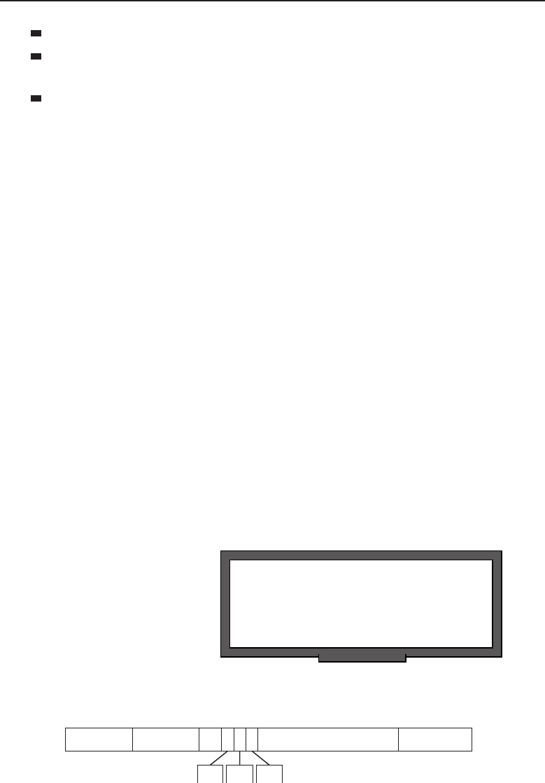
Edwards c07.tex V3 - 03/27/2009 11:19am Page 309
Chapter 7 ■Not to Be Forgotten 309
SA (source address) — The 6-byte source MAC address.
LNH (length) — This field identifies the amount of data contained in
the data payload field.
IPX Packet — This is the IPX datagram portion of the frame.
The following subfields are part of the IPX packet:
CS (checksum) — This field is normally not used. If it is used,
then it is not compatible with the Novell proprietary format.
PL (packet length) — The length of the IPX packet.
TC (transport control) — The hop count (this is an incrementing field).
PT (packet type) — Identifies the format of the data in the payload
portion of the packet.
DNN (destination network number) — The 4-byte destination net-
work identifier.
DHN (destination host number) — The 6-byte destination host identi-
fier.
DSN (destination socket number) — The 2-byte destination socket
identifier.
SNN (source network number) — The 4-byte source network number.
SHN (source host number) — The 6-byte source host identifier.
SSN (source socket number) — The 2-byte source socket identifier.
Data (data) — The payload!
CRC (cyclic redundancy check) — This is a 4-byte value
that is part of the frame check sequence (FCS), used to
determine if a frame is intact at the receiving end.
RANDOM BONUS DEFINITION
access priority — The priority used to
determine access privileges on a shared
LAN segment.
802.3 with 802.2 frame for-
mat — The header of this
format is the same format
used by IEEE 802.3, then
comes the LLC header,
and finally the IPX data
payload. Figure 7-16 is
an example of this.
662111 4
Number of Bytes
LNH IPX PacketDA SA CRC
SSAP CTRLDSAP
Figure 7-16 The 802.3 with 802.2 frame format

Edwards c07.tex V3 - 03/27/2009 11:19am Page 310
310 Part I ■Networking Nuts and Bolts
DA (destination address) — The 6-byte destination MAC address.
SA (source address) — The 6-byte source MAC address.
LNH (length) — This field identifies the amount of data contained in
the data payload field.
DSAP (destination service access point) — This field identifies which
service access points26 the LLC information should be delivered to.
SSAP (source service access point) — This field identifies
the service access point the data originated from.
CTRL (control) — This field contains information used by the
LLC on the receiving node that identifies the LLC frame type.
IPX Packet — This is the IPX datagram portion of the frame.
The following subfields are part of the IPX packet:
CS (checksum) — This field is normally not used. If it is used,
then it is not compatible with the Novell proprietary format.
PL (packet length) — The length of the IPX packet.
TC (transport control) — The hop count (this is an incrementing field).
PT (packet type) — Identifies the format of the data in the payload
portion of the packet.
DNN (destination network number) — The 4-byte destination net-
work identifier.
DHN (destination host number) — The 6-byte destination host identi-
fier.
DSN (destination socket number) — The 2-byte destination socket
identifier.
SNN (source network number) — The 4-byte source network number.
SHN (source host number) — The 6-byte source host identifier.
SSN (source socket number) — The 2-byte source socket identifier.
Data (data) — The payload!
CRC (cyclic redundancy check) — This is a 4-byte value
that is part of the frame check sequence (FCS), used to
determine if a frame is intact at the receiving end.
Sub-network Access Protocol (SNAP) frame format —Usesthe
IEEE 802.3 standard header, LLC header, SNAP header, and
finally the IPX data payload. Figure 7-17 is an example of this.
26Aservice access point (SAP) is a label that is assigned to endpoints in a network.
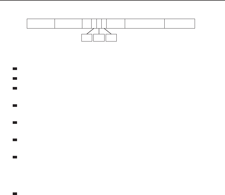
Edwards c07.tex V3 - 03/27/2009 11:19am Page 311
Chapter 7 ■Not to Be Forgotten 311
6621115 4
Number of Bytes
LNH IPX PacketDA SA SNAP-H CRC
SSAP CTRLDSAP
Figure 7-17 The SNAP frame format
DA (destination address) — The 6-byte destination MAC address.
SA (source address) — The 6-byte source MAC address.
LNH (length) — This field identifies the amount of data contained in
the data payload field.
DSAP (destination service access point) — This field identifies which
service access points that the LLC information should be delivered to.
SSAP (source service access point) — This field identifies
the service access point that the data originated from.
CTRL (control) — This field contains information used by the
LLC on the receiving node that identifies the LLC frame type.
SNAP-H (Sub-network Access Protocol27 header) — There are two
subfields contained within this):
VC (vendor code) — This identifies the vendor code of the source.
ET (ether type) — This identifies the version of Ethernet being used.
IPX Packet — This is the IPX datagram portion of the frame.
The following subfields are part of the IPX packet:
CS (checksum) — This field is normally not used. If it is used,
then it is not compatible with the Novell proprietary format.
PL (packet length) — The length of the IPX packet.
TC (transport control) — The hop count (this is an incrementing field).
PT (packet type) — Identifies the format of the data in the payload
portion of the packet.
DNN (destination network number) — The 4-byte destination net-
work identifier.
DHN (destination host number) — The 6-byte destination host
identifier.
DSN (destination socket number) — The 2-byte destination socket
identifier.
27SNAP is an extension of LLC.
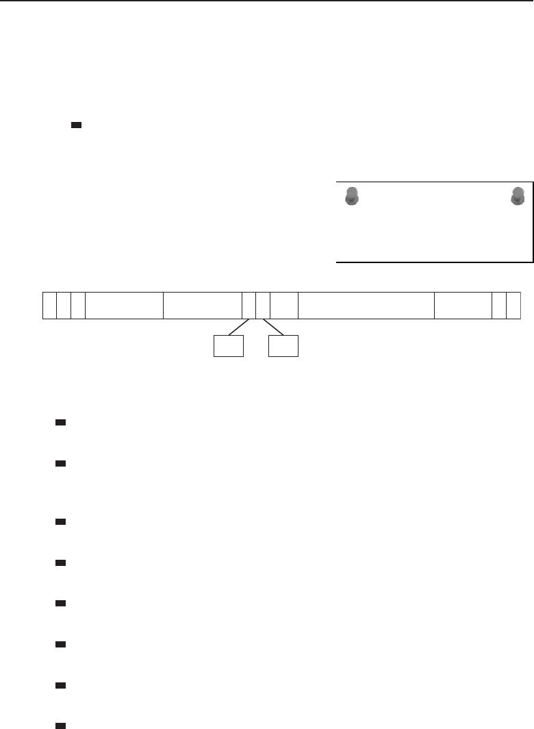
Edwards c07.tex V3 - 03/27/2009 11:19am Page 312
312 Part I ■Networking Nuts and Bolts
SNN (source network number) — The 4-byte source network number.
SHN (source host number) — The 6-byte source host identifier.
SSN (source socket number) — The 2-byte source socket identifier.
Data (data) — The payload!
CRC (cyclic redundancy check field) — This is a 4-byte
value that is part of the frame check sequence (FCS), used
to determine if a frame is intact at the receiving end.
ACRONYM ALERT
ARB — All routes broadcast
All of you Token Ring fans, don’t fret. IPX
also can be encapsulated and transmitted on
a Token Ring network. Figure 7-18 shows
the format of the Token Ring frame.
1116 6112 411
RIF and DataDA SA CTRL FCS E
D
F
S
SSAPDSAP
S
D
A
C
F
C
Figure 7-18 The IPX Token Ring frame format
SD (start of frame delimiter) — This field lets the receiving node know
when the frame begins.
AC (access control) — There are four subfields in the access control
field, all used to transmit information to the access control process within
Token Ring.
FC (frame control) — This field is used to separate network management
data frames from user data frames.
DA (destination address) — This field contains the 6-byte network
address of the node the frame is destined for.
SA (source address) — This field contains the 6-byte network address
of the node the frame originated from.
DSAP (destination service access point) — This field identifies which
service access points28 the LLC information should be delivered to.
SSAP (source service access point) — This field identifies
the service access point that the data originated from.
CTRL (control) — This field contains information that is used by
the LLC on the receiving node that identifies the LLC frame type.
28Aservice access point (SAP) is a label assigned to endpoints in a network.

Edwards c07.tex V3 - 03/27/2009 11:19am Page 313
Chapter 7 ■Not to Be Forgotten 313
RIF (routing information) — This field assists in ensuring
the Token Ring frame is sent in the correct direction.
Data —The payload!
FCS (frame check sequence) — This field is a checksum algorithm that
checksums the frame from the FC field to the end of the Data field.
ED (end of frame delimiter) — This field lets the receiving node know
when the frame ends.
POP QUIZ
True or false: IPX is not supported on a
Token Ring network.
FS (frame status) — This
field is used by the
originating node
to detect whether
there were any
errors during trans-
mission. This includes if the destination node copied the data,
if there were any errors encountered, and even if the destina-
tion node recognized itself as the destination node.
7.2.4 Point-to-Point Protocol
The Point-to-Point Protocol (PPP) is really not a protocol at all; rather, it is a
suite of protocols that work to allow IP data exchange over PPP links. Prior
to the release of PPP, the standard that was being used for IP serial link
transmission was the Serial Link Internet Protocol (SLIP). SLIP did a decent job
of transmitting the IP data, but it wasn’t reliable, wasn’t secure, and really
wasn’t able to support the performance demands of end users. Additionally,
SLIP was used in LANs where the cabling wasn’t long at all — SLIP just
couldn’t support communication over longer distances. PPP was developed
to address these issues, as well as support serial communication for many
network layer protocols, not just IP.
To support the multiple protocol datagrams, PPP uses the following three
main components:
PPP encapsulation method
PPP Link Control Protocol (LCP)
PPP Network Control Protocol (NCP)
7.2.4.1 PPP Encapsulation Method
PPP specifies a frame format that is to be used to encapsulate higher layer data.
The format is based on the format used for the High-level Data Link Control
(HDLC) protocol. HDLC is a synchronous Data Link layer protocol developed
bytheISOandusedasareferenceforthePPPstandard.

Edwards c07.tex V3 - 03/27/2009 11:19am Page 314
314 Part I ■Networking Nuts and Bolts
7.2.4.2 PPP Link Control Protocol
LCP is the foundation protocol of the PPP protocol suite. It is the big kahuna in
PPPland, supervising all the other protocols to ensure that they are performing
the actions they are responsible for. LCP controls the PPP links. The processes
involved in setting up and negotiating the rules for a link, managing the activity
on the link, and closing the link when the data transmission is complete are all
functions overseen by LCP.
7.2.4.3 PPP Network Control Protocol
ACRONYM ALERT
RFC — Request for Comments
NCP is the control protocol that ensures the
correct Layer 3 protocol is being used. NCP
establishes which network layer protocol
is required and then it sets the parameters
needed to ensure that data can be recog-
nized and understood at the endpoint. PPP supports multiple NCPs running
on the same link, regardless of the type or which of the Layer 3 protocols is
being supported.
7.2.4.4 Please, Tell Us More
PPP has to set up a PPP link in order to communicate to the destination. The
first node will test the link by sending an LCP frame. Once LCP has set up
the link and all of the session parameters have been negotiated between the
endpoints, NCP frames are then sent to set up and configure the parameters
for the particular NCP type to be used. Once all these steps have occurred,
packets can be sent. The link remains established until it is no longer needed
or something external29 causes link failure.
7.2.4.5 PPP Frame Format
We previously mentioned that PPP was designed based on the HDLC protocol.
The frame format is the same for PPP and HDLC; however, PPP does not use
all the fields. Therefore, some fields are set to a standard number for PPP.30
Figure 7-19 depicts the PPP frame format.
Flag — The PPP Flag field is always set to binary 01111110. This
field indicates the start point and end point of the frame.
29In other words, PPP didn’t do it.
30Why reinvent the wheel?

Edwards c07.tex V3 - 03/27/2009 11:19am Page 315
Chapter 7 ■Not to Be Forgotten 315
BA (broadcast address) — This field is set to binary 11111111.
CTRL (control) — This field is used by HDLC and is used for cer-
tain control parameters. The PPP control field is always set to binary
00000011.
Protocol — This field identifies the protocol type for the information
contained in the data payload.
Data —The payload!
FCS (frame check sequence) — This field is a checksum algorithm that
checksums the frame from the FC field to the end of the Data field.
POP QUIZ
What serial transmission standard was used
before PPP came out?
Flag — The PPP Flag field
is always set to binary
01111110. This field indi-
cates the start point and
end point of the frame.
111 2 Up to 4 1
Data FCS Flag
Protocol
Flag CTRL
BA
Figure 7-19 The PPP frame format
7.2.5 X.25
X.25 is a Network layer protocol standard that is maintained by the Interna-
tional Telecommunication Union – Telecommunication standardization sector
(ITU-T). Used within packet-switched networks, X.25’s purpose in networking
is to provide the rules on how connections between nodes are set up and main-
tained. X.25 protocols31 allow communication between different networks,
regardless of what equipment and protocols they are running. Communica-
tion between the networks is actually handled through an intermediary (more
on this in a little bit) at the Network layer. X.25 is a reliable connection-oriented
standard of protocols.
X.25 uses the following three main types of nodes (see Figure 7-20):
Data terminal equipment (DTE) — Nodes that communicate on
the X.25 network (these are the computers and nodes that connect
the user to a network). Think of the DTE as the user nodes.
31Did you notice the s? Yep — it’s a suite of protocols, not really a single protocol.
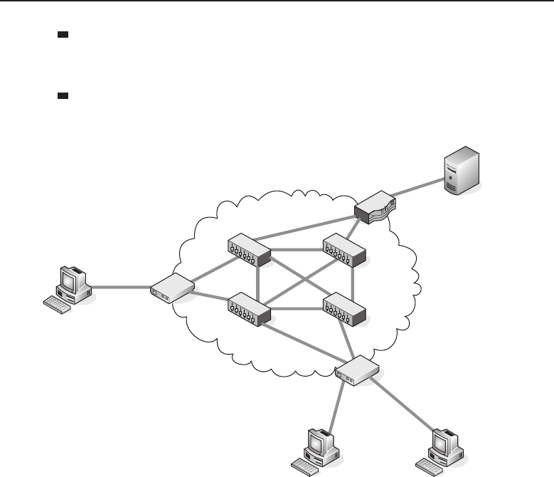
Edwards c07.tex V3 - 03/27/2009 11:19am Page 316
316 Part I ■Networking Nuts and Bolts
Data circuit-terminating equipment (DCE)32 — A network access
point (normally a modem or packet switch that is the interface
to the cloud).33 Think of the DCE as the network nodes.
Date switching exchange (DSE)34 — The nodes that are in the cloud.
These nodes are responsible for passing data from DTE to DTE.
DTE
DTE DTE
DCE
DCE
DSE
DSE
DSE
DSE
DCE
DTE
Figure 7-20 Deployments of the X.25 node types
In X.25 data transmission operations, every DTE must have an association
with a DCE. Don’t confuse DTE and DCE as being single standalone network
nodes. DTE and DCE are actually the functions performed. As a matter of fact,
a single node can provide multiple functions (for instance, a node can be both
a DCE and a DSE.
DCEs and DSEs are the nodes that route the packets through the cloud to
a destination. Each and every packet that is transmitted may take a different
32Also known as data communications equipment and data carrier equipment.
33Cloud is a term that defines the WAN infrastructure. Normally networks connect using a
communication protocol (such as X.25). There is usually a switch that is the interface to the
cloud. Once a packet hits the cloud, the provider is responsible for routing data to a desti-
nation. What goes on in the cloud stays with the cloud — meaning the endpoint networks
don’t necessarily care how the provider is getting the data there, just as long as it gets there.
34Also known as packet switching exchange (PSE).
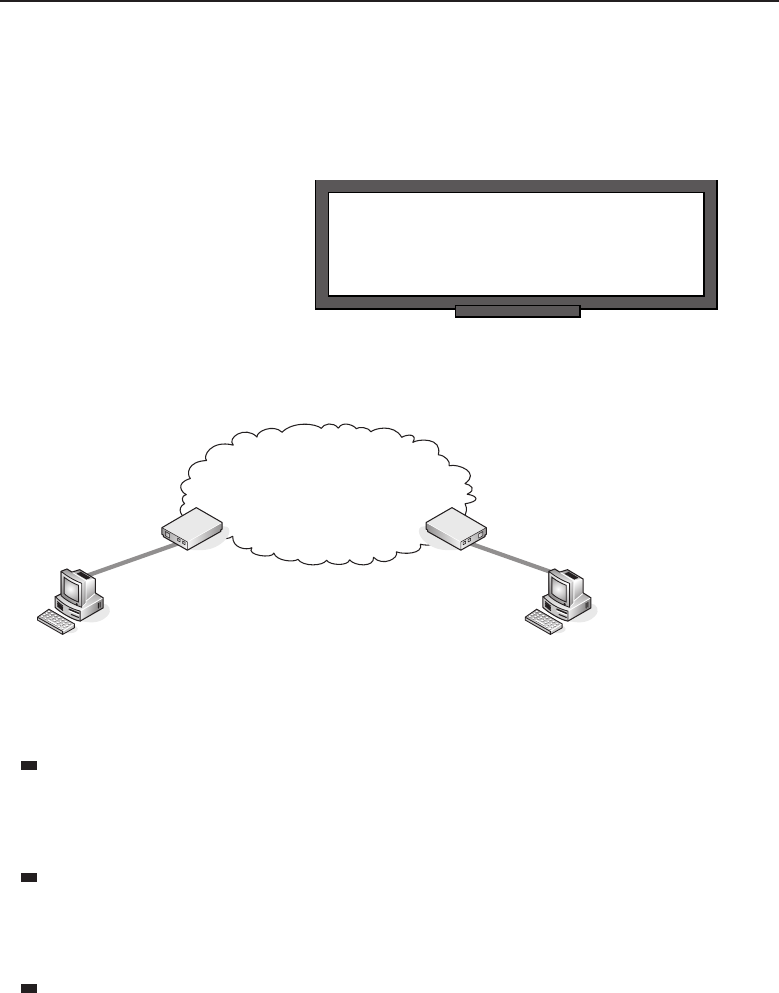
Edwards c07.tex V3 - 03/27/2009 11:19am Page 317
Chapter 7 ■Not to Be Forgotten 317
path to get to the destination DCE and ultimately the destination DTE. Usually,
the DTE connects to the DCE over some type of network, but two nodes can
be connected directly. When there is a direct connection between nodes, then
one of the nodes has to perform the functions of a DCE.
RANDOM BONUS DEFINITION
broadcast address — The well-known
multicast address defining all nodes.
The DTE is responsible for
serving multiple sessions over
a single connection to the DCE.
Each and every session first
needs to be connected to the
DCE. Once the connections are
established, the transmission of
data can occur. Figure 7-21 is a
basic diagram that depicts the session setup and processes.
DCE 1
DTE 1
DCE 2
DTE 2
Figure 7-21 A basic X.25 network
A session can be established in one of three ways (refer to Figure 7-21):
The DTE can send a message to the DCE, letting the DCE
know it has data to transmit. For instance, DTE 1 contacts
DCE 1 and lets the DCE know it has data to transmit to
DTE 2. This is known as a switched virtual circuit (SVC).
A DCE can receive a message from another DCE, letting the
DCE know that a DTE is requesting to send data to another DTE.
For instance, DCE1 informs DCE 2 that DTE 1 wishes to pass data to
DTE 2.
The session can be left up at all times. In this scenario, as far as
the DTEs are concerned, they can just pass the data to the desti-
nation DTE whenever they have data to send. No session setup
is required. This is known as a permanent virtual circuit (PVC).

Edwards c07.tex V3 - 03/27/2009 11:19am Page 318
318 Part I ■Networking Nuts and Bolts
THE X.25 PAD
Some DTEs (for instance, dumb terminals) are not complex enough to
understand full X.25 functionality. Therefore, they need a little assistance in
communicating with the DCE. X.25 also supports a node type that performs just
this function (helping the little guy out).
The packet assembler/disassembler (PAD) is a node between the DCE and
the DTE that is used to assemble packets, disassemble packets, and buffer data
until the DTE is ready to receive.
X.25 was developed and used before the OSI reference model was developed.
To understand the protocol X.25, all you have to know is that (with only a
few exceptions) operations can be mapped to the functions of the lower three
levels (Physical, Data Link, and Network) of the OSI reference model. The
three levels of the X.25 suite are as follows:
1. Physical level — This level corresponds to the OSI Physical layer.
This includes defining all of the electrical and mechanical functions that
are used by the physical medium. Some X.25 protocols operating at this
level include:
V.35
X.21bis
RS232
2. Link level — This level corresponds to the OSI model’s Data Link
layer. Functions that are performed at this level are the framing
of packets, numbering packets, receipt acknowledgment, flow
control, error detection, and recovery, etc. The X.25 protocol that
operates at this level is Link Access Procedure, Balanced (LAPB).
RANDOM BONUS DEFINITION
routing — The passing of data among
various networks.
3. Packet level —Atthis
level, data is exchanged
between X.25 nodes. The
protocol that is used at
this level is the Packet
Layer Protocol (PLP).
7.2.5.1 X.25 Operations
When an X.25 session is established, the session is assigned a virtual circuit
number that is known to only the DTE and its associated DCE. The virtual
circuit number is what is used to route the packets to the destination. The
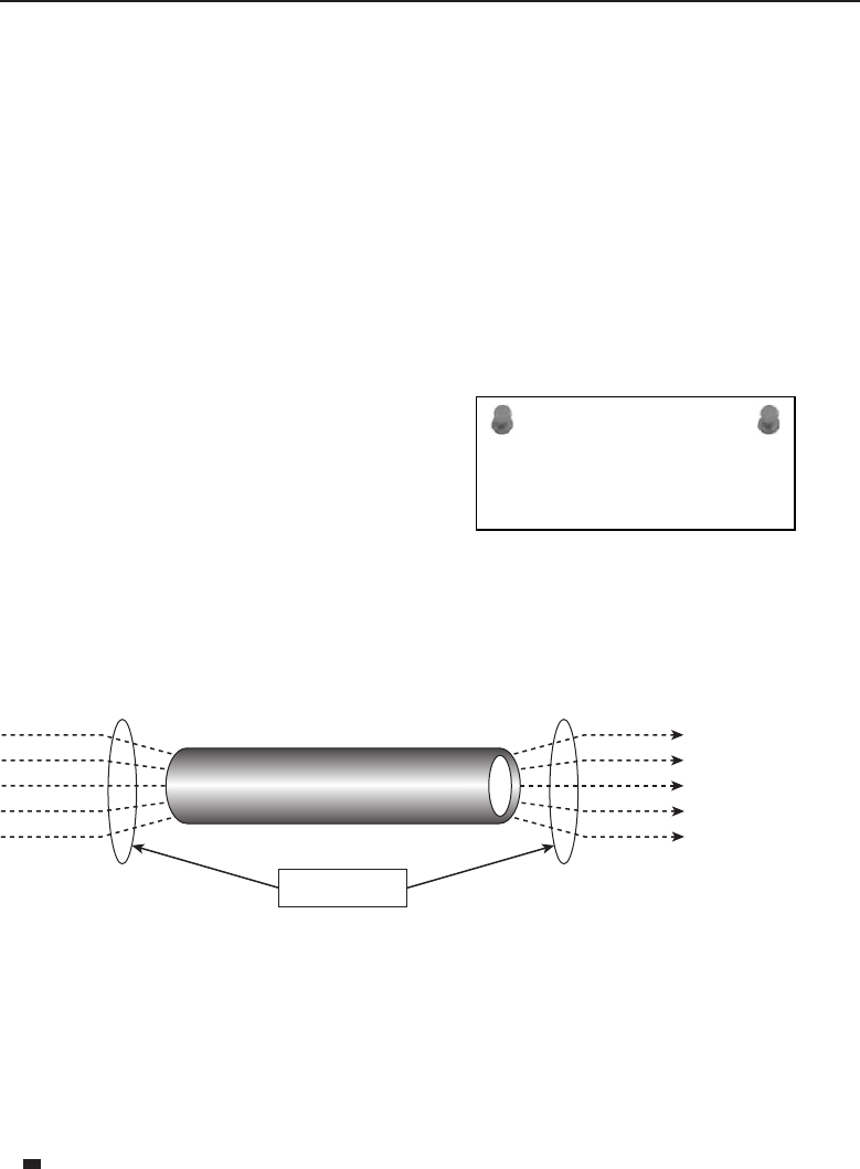
Edwards c07.tex V3 - 03/27/2009 11:19am Page 319
Chapter 7 ■Not to Be Forgotten 319
virtual circuit number is normally a shorted number, so the route lookup
processisshorted(fewerbitsandbytestolookat).
The virtual circuit is nothing more than a path to a destination. A virtual
circuit number reinforces the existence of a reliable path from one DTE to
another DTE. As mentioned previously, there are two types of virtual circuits:
switched virtual circuits (SVC) and permanent virtual circuits (PVC).TheSVCis
a circuit that is established as needed between DTEs. Each time a DTE needs
to send data, the SVC will have to be set up before communication occurs and
closed when the session terminates. The other type of virtual circuit, the PVC,
is set up only once. It is used between DTEs that have a constant need to send
data to other DTEs.
ACRONYM ALERT
ATP — AppleTalk Transaction Protocol
Additionally, X.25 supports what is
known as multiplexing, which means that
it can carry multiple sessions over a single
physical line. Each session would maintain
its own virtual circuit, which will identify
the destination DTE. Multiplexing is used
when a single DTE has several processes
that need to communicate with multiple
destinations. Once data arrives at the destination, it is demultiplexed and sent
to the appropriate DCE to be passed to the endpoint DTE. Figure 7-22 shows
an example of how this works.
Physical circuit
Multiplexing De-Multiplexing
Virtual circuits
Figure 7-22 A multiplexing example
7.2.5.2 Link Access Procedure, Balanced
The Link Access Procedure, Balanced (LAPB) istheX.25DataLinklayerproto-
col that ensures reliable, error-free packet framing and data communication
management. LAPB employs the use of three message frame types:
Information frame type — Frames of this type are known as I-frames.
I-frames are used to pass upper layer data and some control data.
I-frames perform packet sequencing, flow control, and error detection
and recovery.

Edwards c07.tex V3 - 03/27/2009 11:19am Page 320
320 Part I ■Networking Nuts and Bolts
Supervisory frame type — Frames of this type are known as S-frames.
S-frames are used to pass control data, such as transmission requests,
status reporting, I-frame receipt acknowledgements, and termination
requests.
Unnumbered frame type — Frames of this type are known as U-frames.
U-frames are used to pass control data, such as session setup, error
reporting, and session termination.
LAPB frames include a header, the PLP data that is being passed to the other
end, and a frame trailer. Figure 7-23 shows the format of the LAPB frame.
11121
Data FCS FlagFlag Ctrl
AD
Number of Bytes
Figure 7-23 The LAPB frame format
Flag — The LAPB Flag field indicates the start point and end point of the
frame.
AD (address) — This field identifies whether the frame is carrying a
response or a command.
CTRL (control) — This field details which frame type (I-frame, S-frame,
or U-frame) is being used, the frame sequence number, and the frame
function.
Data — The payload! In LAPD, this is the PLP packet.
FCS (frame check sequence) — This field is a checksum algorithm
that checksums the frame from the FC field to the end of the Data
field. This is where error checking and data integrity are monitored.
Flag — The LAPB flag field indicates the start point and end point of the
frame.
7.2.5.3 Packet Layer Protocol
The Packet Layer Protocol (PLP) is the X.25 Network layer protocol that is used
to direct the flow of packets between two DTE nodes over a virtual circuit.
PLP can run in conjunction with other protocol standards (for instance, ISDN
interfaces on a WAN or LLC within a LAN). There are five defined modes of
operation for the PLP:
Initial session setup mode — Used to set up an SVC or PVC between
DTE nodes.

Edwards c07.tex V3 - 03/27/2009 11:19am Page 321
Chapter 7 ■Not to Be Forgotten 321
Data transfer mode — Used to transfer data between DTEs.
Idle mode — Used by SVCs to keep a session active when no data is
being transmitted at the time.
Session termination mode — Used to terminate a session and to clear
the SVC.
ACRONYM ALERT
ISP — Internet service provider
Re-initialization mode —Used
to synchronize data transmis-
sion between a DTE and its
associated DCE.
7.2.6 Asynchronous Transfer Mode
Asynchronous Transfer Mode (ATM) is a standard maintained by the ITU-U. Its
function is to pass fixed-size datagrams known as cells over an ATM network.
ATM is a connection-oriented standard, which means the connection is up
between nodes before data can be transmitted.35 Unlike pure packet-switched
networks (IP, Ethernet, X.25, etc.), where the frames are of variable lengths,
ATM provides cell-relay (transmission of data that is encapsulated into a fixed
length cell) services on a packet-switched network.
ATM uses nodes that are called ATM switches36 for the transfer of cells within
a network. An ATM switch is not a switch in the Layer 2 meaning of the term.
It is actually more like a router in functionality.
7.2.6.1 ATM Generic Cell Format
ATM cells are a fixed 53 bytes in size (see Figure 7-24). The first portion of
the cell is the header information and is 5 bytes long. The remaining 48 bytes
are for the data payload. ATM cells are perfect for passing large amounts of
data (streaming video, for example). The fixed length cells do not require the
delays that can occur in synchronous data transmission because the variable
length packets can cause long upload and download times. Asynchronous
transmission, on the other hand, is a steady stream of cells.
Header Data payload
548
Number of Bytes
Figure 7-24 The ATM cell format
35Repetition – repetition - repetition.
36Oftennodesaretaggedwiththewordswitch by the marketing folks out there. It’s a buzzword
that is often used to impress the customer base.
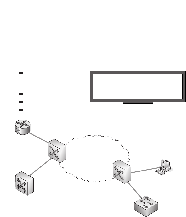
Edwards c07.tex V3 - 03/27/2009 11:19am Page 322
322 Part I ■Networking Nuts and Bolts
7.2.6.2 An Overview of ATM Operations
ATM is efficient and reliable. It offers transmission delay (there is no time
lapse waiting for your turn), guaranteed to serve constant streams of data and
patient enough to wait until data is ready to be passed.
ATM networks contain nodes that are called ATM switches, as well as
endpoint nodes that support ATM. ATM switches are responsible for pass-
ing data traffic to destination ATM switches and/or ATM endpoint nodes.
Endpoint nodes are responsible for interfacing other network types to the
ATM network. Examples of endpoint nodes include (see Figure 7-25):
POP QUIZ
Which protocol operates at the packet level
of the X.25 model?
ATM channel service
unit/data service unit
(CSU/DSU)
LAN router
LAN switch
LAN workstation
ATM
switch
ATM
switch
LAN switch
Router
CSU/DSU
Figure 7-25 An ATM network
7.2.6.2.1 ATM: Virtual Paths, Circuits, and Channels
Closely emulating the virtual circuit concept that is used in X.25, ATM uses
what are known as virtual path identifiers (VPI) and virtual circuit identifiers
(VCI)37 for the routing of cells in an ATM environment. The VPI/VCI pairing
37Also known as a virtual channel identifier. A channel is basically the same thing as a circuit.

Edwards c07.tex V3 - 03/27/2009 11:19am Page 323
Chapter 7 ■Not to Be Forgotten 323
is found in the ATM header and is used to map sessions that are active at
any given time. The VPI is used by ATM switches to keep track of the paths
to a destination. The backbone switches do not care about the VCI; it’s the
interfacing nodes (nodes that are outside of the backbone) which include that
in path definition. When a switch includes the VCI in its switching decisions,
it considers the VPI/VCI pair as a single number.
Different types of VPIs and VCIs are used in an ATM network:
Virtual circuit types
Permanent virtual circuit (PVC) — This is a static virtual circuit.
Soft permanent virtual circuit (SPVC) — This is a dynamic PVC.
Switched virtual circuit (SVC) — This is an ‘‘as needed’’38 virtual
circuit.
Virtual path types
Permanent virtual path (PVP) — This is a static virtual path.
Soft permanent virtual path (SPVP) — This is a dynamic PVP.
RANDOM BONUS DEFINITION
end of frame delimiter — Used to indicate
the end of the Data Link encapsulation.
The VPI and VCI sessions are
identified in the header of the
ATM cell. THE VPI is a 12-bit
identifier39 and the VCI is a
16-bit identifier. Virtual circuits
must be set up before any data
transmission can occur. A vir-
tual path is a group of virtual channels, which are bundled together and
transmitted across the ATM network over a shared virtual path. Even though
there may be multiple virtual circuits between ATM switches, the VPI and VCI
pairing is used only by the endpoint nodes that are involved in the session
(see Figure 7-26). Notice how this ATM multiplexing is very similar to the
multiplexing processes in X.25.
7.2.6.2.2 ATM: Link Interface Types
There are two primary types of link interfaces used in an ATM environment.
The network-network interface (NNI) and the user-network interface (UNI).The
UNI is the link that connects ATM endpoint nodes to an ATM switch. The
NNI is the connection between ATM switches through the cloud.
38This could also be ‘‘on demand.’’
39Four bits of this can be used for generic flow control (GFC), when the communication is taking
place between an endpoint node and an ATM switch.
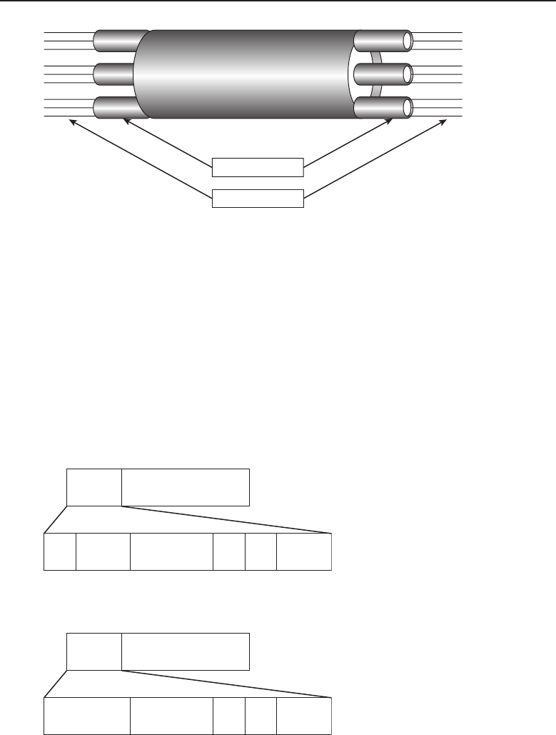
Edwards c07.tex V3 - 03/27/2009 11:19am Page 324
324 Part I ■Networking Nuts and Bolts
Physical medium
Virtual circuits
Virtual paths
Figure 7-26 ATM multiplexing
Both interface types can be broken up into public UNIs and NNIs or private
UNIs and NNIs. Private interface types are used to connect nodes within an
ATM topology that is specific to their organization. The public interface types
are used to connect nodes on a public network (available to everyone).
7.2.6.2.3 ATM Cell Header Format
The format of the cell header that is used in the ATM cell is determined by
the interface type being used. The UNI header (see Figure 7-27) is used for
communication between an endpoint node and an ATM switch, while the NNI
header (see Figure 7-28) is used for communication between ATM switches.
Header Data payload
GFC VPI VCI PT CLP HEC
Figure 7-27 The UNI header format
Header Data payload
VPI VCI PT CLP HEC
Figure 7-28 The NNI header format

Edwards c07.tex V3 - 03/27/2009 11:19am Page 325
Chapter 7 ■Not to Be Forgotten 325
UNI header
GFC (generic flow control; 4 bits) — Used to assist in identifying the
nodes that are part of a shared ATM interface.
VPI (virtual path identifier; 8 bits) — Used to identify the VPI portion
of the VCI.
VCI (virtual circuit identifier; 16 bits) — The circuit number used
to associate the session’s virtual circuit.
PT (payload type; 3 bits) — Identifies the data type in the data pay-
load portion of the ATM cell.
CLP (cell loss priority; 1 bit) — Often referred to as the discard
bit, set by the sending node for cells that can be discarded if link
congestion occurs. Also can be sent by nodes if there is a connection
that is exceeding the bandwidth allotment for its session.
HEC (header error control; 8 bits) — The checksum algorithm used for
the information contained within the header only for error detection
and control.
NNI header
VPI (virtual path identifier; 12 bits) — Used to identify the VPI por-
tion of the VCI.
VCI (virtual circuit identifier; 16 bits) — The circuit number
that is used to associate the session’s virtual circuit.
PT (payload type; 3 bits) — Identifies the data type in the data pay-
load portion of the ATM cell.
CLP (cell loss priority; 1 bit) — Often referred to as the discard
bit, set by the sending node for cells that can be discarded if link
congestion occurs. Also can be sent by nodes if there is a connection
that is exceeding the bandwidth allotment for its session.
HEC (header error control; 8 bits) — The checksum algorithm used for
the information contained within the header only for error detection
and control.
7.2.6.3 ATM Reference Model
ACRONYM ALERT
DRAM — Dynamic Random Access Memory
ATM is a protocol suite whose functions are
described by a reference model. The ATM
reference model uses layers that correspond
to the Physical layer and a portion of the
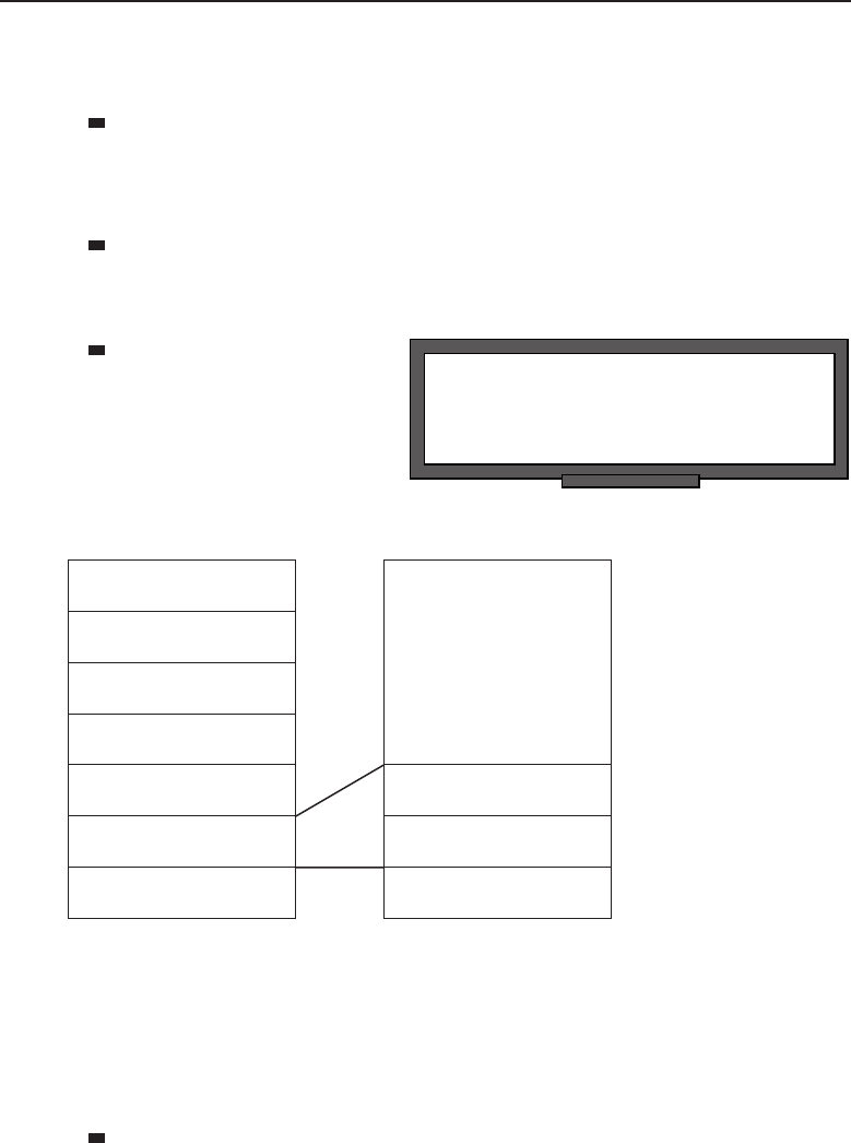
Edwards c07.tex V3 - 03/27/2009 11:19am Page 326
326 Part I ■Networking Nuts and Bolts
Data Link layer of the OSI reference model. The layers that are part of the
ATM reference model are as follows (see Figure 7-29):
ATM adaptation layer (AAL) — Comparable to the functions of
the OSI reference model’s Data Link layer. This layer is respon-
sible for sorting higher layer data from the ATM processes. This
layer combines its services with the service of the ATM layer.
ATM layer — Comparable to the functions of the OSI reference model’s
Data Link layer. This layer handles the relay of cells through the ATM
environment. This layer is also responsible for cell multiplexing.
POP QUIZ
What are the three virtual circuit types used
in ATM?
Physical
layer — Responsible
for transmission of
data on the medium.
Application layer
Presentation layer
Session layer
Transport layer
OSI Reference model
Network layer
Data Link layer
Physical layer
Higher layers
ATM Reference model
ATM adaptation
layer (AAL)
ATM layer
Physical layer
Figure 7-29 A comparison of the OSI and ATM reference models
7.2.6.4 Traffic Management
Several classes of service are defined for user data that is passed within an
ATM network. These are as follows:
Constant bit rate (CBR) — Data is passed constantly. The
bandwidth required to pass the data is always available.

Edwards c07.tex V3 - 03/27/2009 11:19am Page 327
Chapter 7 ■Not to Be Forgotten 327
Variable bit rate (VBR) — Data is passed often. The bandwidth
required to pass the data is available, but there are limits on the amount
of data that can be passed. The following two types of VBR are used:
Variable bit rate real-time (VBR-rt) — This is used to pass real-time
application data.
Variable bit rate non-real-time (VBR-nrt) —Thisisusedto
temporarily store data in a queue when there is not enough available
bandwidth to pass all of the data. It is used with applications that send
data, but is not real-time.
Available bit rate (ABR) — Data is passed when bandwidth is
available. ABR supports congestion feedback so the sending node
will know when there is too much congestion to pass data.
Unspecified bit rate (UBR) — Data is passed if there is bandwidth
available, and is dropped if there isn’t any available bandwidth. There
are no guarantees about delivery.
7.2.6.5 ATM Adaptation Layer Types
The AAL provides interface types that support the service class type that it is
assigned to. The type of AAL to be used is determined by the sending node
and the type announced when the initial call setup is sent. The AAL types are:
AAL1 — Supports CBR transmissions.
AAL2 — Supports VBR transmissions.
AAL3/4 — Supports both connectionless and connection-oriented data
transmission. This AAL type is used to transmit switched multimegabit
data services (SMDS)40 packets.
RANDOM BONUS DEFINITION
network layer — Layer 3 of the OSI
reference model.
AAL5 — Supports both
connectionless and
connection-oriented data
transmission. This AAL
type is used to transmit
non-SMDS packets.
40SMDS is a connectionless telco service that supports various protocols and functions needed
to transmit data over a high-performance packet-switched network. This protocol is outside of
the scope of this book, so this footnote should provide all the information that you will need — a
basic definition pertaining to the service.

Edwards c07.tex V3 - 03/27/2009 11:19am Page 328
328 Part I ■Networking Nuts and Bolts
AN UNRELATED MOMENT OF PAUSE
By now, we felt that you might be in need of a study break. To make your break
a bit more enjoyable, here is a great peanut butter cookie recipe. Make a
couple of batches to enjoy while you continue on with this book. If you are
hyper-motivated, you can reread the section on X.25 while the cookies bake.
That section is a good lead-in to the next section, ‘‘Frame Relay.’’
Ingredients:
■1 cup firmly packed brown sugar
■1/2 cup peanut butter
■1/2 cup softened butter
■1 tsp vanilla
■1egg
■1 cup sugar
■1 1/2 cups flour
■1/2 tsp baking powder
■1/2 tsp baking soda
■1/2 tsp salt
Preparation steps:
1. Preheat oven to 375◦F.
2. Combine brown sugar, butter, and peanut butter in a large bowl. Beat on
medium speed until well mixed.
3. Add egg and vanilla; continue beating until well mixed.
4. Reduce speed to low.
5. Add flour, baking powder, baking soda, and salt. Beat until well mixed.
6. Shape dough into 1-inch balls; roll in sugar.
7. Place the balls 2 inches apart onto ungreased cookie sheets;
flatten balls in a crisscross pattern with fork dipped in sugar.
8. Bake for 8 to 10 minutes or until edges are lightly browned.
Bon app´
etit!
7.2.7 Frame Relay
Frame relay is a WAN protocol that operates as a packet-switched network.
Like other packet-switched network protocols, frame relay uses the following:
Multiplexing
Variable length datagrams
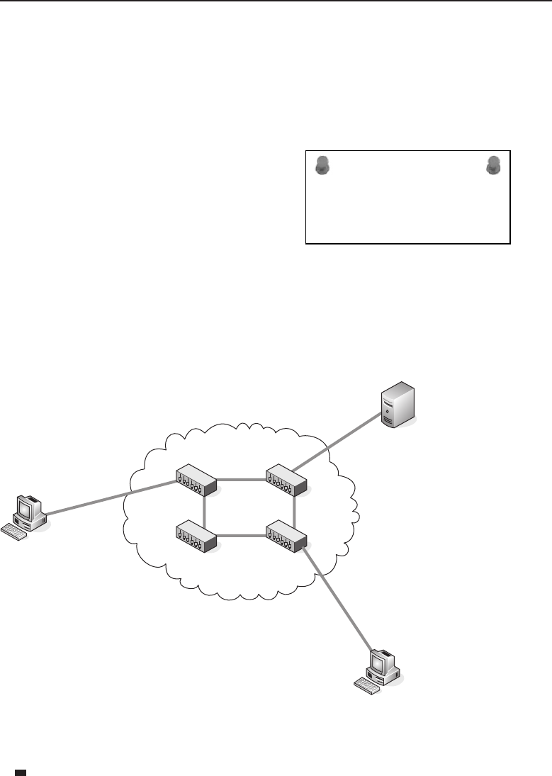
Edwards c07.tex V3 - 03/27/2009 11:19am Page 329
Chapter 7 ■Not to Be Forgotten 329
Frame relay is very similar to X.25, and is often considered the upgraded
version of X.25. Because frame relay uses various WAN interface types (such
as ISDN) to handle Layer 3 functions, and because communication media has
improved, frame relay does not have to do the error checking and recovery
that X.25 did. Because there is less chatter, frame relay is able to provide
quicker and more reliable data transmission, which pretty much renders X.25
obsolete.
ACRONYM ALERT
CSMA/CD — Carrier Sense, Multiple Access with
Collision Detection
Frame relay services operate at the Physi-
cal and Data Link layersof the OSI reference
model. Originally designed to operate over
ISDN interfaces, it now supports transmis-
sion over broadband ISDN and ATM.
7.2.7.1 Frame Relay Node Types
If you reread the section on X.25 while your cookies were baking, you will
probably remember the X.25 node types are DTE, DCE, or DSE. In frame
relay, you cut out the DSE and have the two node types that are used (see
Figure 7-30):
DTE
DTE
DCE
DCE
DCE
DCE
DTE
Figure 7-30 DCE and DTE relationship in a frame relay environment
DTE — Nodes that communicate on the frame relay network
(these are the computers and endpoint nodes that connect the
user to a network). Think of the DTE as the user nodes.

Edwards c07.tex V3 - 03/27/2009 11:19am Page 330
330 Part I ■Networking Nuts and Bolts
DCE — These are the devices that are within the cloud that trans-
ports the data over a WAN. Because the DCEs in frame relay are
able to handle the clocking and packet-switching services, there
is no need for an intermediary device, like the DSE in X.25
7.2.7.2 Virtual Circuits . . . Again?
Frame relay provides a connection-oriented service at the Data Link layer.
Before data can be transmitted, the connection has to be up. The connection is
associated with a unique data link connection identifier (see the next section).
It is the DLCI that defines the virtual circuit between DTEs. Frame relay
supports the multiplexing of virtual circuits to be established over a physical
circuit. The frame relay virtual circuit types are:
SVC — A temporary connection
PVC — A permanent connection
7.2.7.3 Data Link Connection Identifier
The identifier used to define a circuit is known as the data link connection
identifier (DLCI). The DLCI is a value that is normally defined and assigned
by the telco provider. The DLCIs are only important to the DTEs. The DCEs
normally employ various methods and routes from circuit to circuit. In other
POP QUIZ
Frame relay is very similar to .
words, the DLCI is what allows
thedatatobepassedtotheend-
point nodes outside of the cloud.
TheDCEsmakedecisionsbased
on whatever technologies are in
use by the telco. Because frame
relay is a multiplexing WAN
protocol, there can be multiple logical circuits passing data through the
cloud over a single physical circuit.
7.2.7.4 Feckens and Beckens41
As much as we all may hate to admit it, network congestion occurs more often
than we would like it to. It’s just a fact of life in a network. Fortunately, there
are a lot of checks and balances in most networks that help to prevent errors
and to detect and recover from them when they do occur.
Within the frame relay cloud (the provider’s portion of the frame relay envi-
ronment), there can be thousands upon thousands of transmissions passing
41These are another pair of fun acronyms similar to catenet (although these are still in use).

Edwards c07.tex V3 - 03/27/2009 11:19am Page 331
Chapter 7 ■Not to Be Forgotten 331
through from multiple organizational LANs. All of this data is passing through
the same equipment to make its way through the cloud and to a destination.
Because of all the end-user data passing through the nodes, congestion does
occur.
Frame relay has a couple of functions that help detect congestion and notify
the DTEs that congestion is occurring. Additionally, the frame relay header
provides an address field that reserves 1 bit for the FECN and one for the
BECN. These functions are:
Forward explicit congestion notification (FECN)42 bit — Within the
address field of the frame relay frame header.
Backward explicit congestion notification (BECN)43 bit — Within the
address field of the frame relay frame header.
In addition to the FECN bit and the BECN bit, there is also a bit that is
used to indicate if the data is important or not. This field is known as the
discard eligibility (DE) bit. If the DE bit is ‘‘set,’’ the DTE is notifying the DCEs
that the frame is low priority and can be discarded if congestion is occurring.
This gives the DCEs the capability to prioritize, dropping the data with less
importance and only discarding the important data as a last option. The DTEs
will retransmit the higher priority data if it gets notification from the DCEs
that congestion is occurring.
ACRONYM ALERT
FC — Frame control
There are two additional bits in the frame
relay frame header that can be set to notify a
target node that there is congestion. BECNs
are sent to the sending DCEs that there is
congestion and FECNs are sent to the target
DCEs that there is congestion. Normally,
the sending DCE will assume that there are
problems if it receives so many BECNs in
a certain time period (the number is set by the provider and the subscribing
network). It will then cut down on the amount of data it is transmitting44 or
will stop transmitting altogether. When the DTE stops seeing the BECNs, it
will return to the way it normally performs.
42Pronounced ‘‘fecken.’’
43Pronounced ‘‘becken.’’
44Normally, a frame relay provider will promise a minimum transmission rate for a virtual
circuit. This is known as the committed information rate (CIR). Often, the provider will allow
you to exceed the CIR and will try to pass the data on a best-effort basis. Should your edge router
start seeing the BECNs repeatedly outside of the standards you have configured, the CIR should
be checked and may need to be adjusted. It could be that multiple frames are being received by
a router that has a lower CIR and cannot handle the level of traffic at the time (especially if all of
the sending routers are exceeding the CIR).

Edwards c07.tex V3 - 03/27/2009 11:19am Page 332
332 Part I ■Networking Nuts and Bolts
7.2.7.5 Local Management Interface
For the first few years that frame relay was in use, it didn’t really have any
standards that ensured that the link was up between DTEs and DCEs. Several
companies that were leaders in the networking and telecommunication fields
banded together to come up with a signaling standard that would work with
frame relay to assist in ensuring the link between a DTE and its associated
DCE would remain up. What developed was an enhancement known as the
local management interface (LMI).
LMI is used to provide link status updates pertaining to PVCs between
a DTE and the local DCE. One of the functions performed by LMI is status
inquiries that are sent out periodically (normally 10 seconds) to test if a link is
up. If the inquiry does not receive a reply, it assumes the link is down. These
inquiries are known as keepalives. LMI also sends out updates pertaining to the
status of all the links in frame relay network, provides information about PVC
changes, and ensures that IP multicast is functioning.
7.2.7.6 Frame Relay Frame Format
The standard frame relay frame format is also known as the LMI version of
the frame relay frame. Figure 7-31 shows the fields contained within the frame
relay frame.
12 21
Data FCS FlagFlag AD
Number of Bytes
Figure 7-31 Frame Relay frame format
Flag — The frame relay Flag field indicates the start point and end point
of the frame.
AD (address) — Included in this field is information pertaining to
the DLCI. There are also 3 bits that are included in this field that are for
the FECN, BECN, and the DE bit.
Data —The payload!
FCS (frame check sequence) — This field is a checksum algorithm
that checksums the frame from the FC field to the end of the Data
field. This is where error checking and data integrity are monitored.
Flag — The frame relay Flag field indicates the start point and end point
of the frame.

Edwards c07.tex V3 - 03/27/2009 11:19am Page 333
Chapter 7 ■Not to Be Forgotten 333
7.2.8 Integrated Services Digital Network
Integrated Services Digital Network (ISDN) is a data transport service that can
be used over regular existing telephone lines. The ISDN service enables the
telephone line to be digitized, allowing multiple data types to be passed over
existing telephone lines. Additionally, ISDN can be used with digital telephone
lines.
ISDN is a baseband transmission standard, used to operate over normal
copper lines. Broadband ISDN (B-ISDN) was designed to be faster and more
reliable than ISDN. B-ISDN operates over fiber optics. As fiber optics are being
rolled into more and more residences and businesses, many ISDN users are
using the broadband service.
ISDN provides two types of channels to be used for communication in the
ISDN environment, the B channel and the D channel. The B channel is used
to carry user data, whereas the D channel is used for signaling between the
end user and the ISDN network. The B channel operates at 64 kbps, and the
D channel operates between 16 and 64 kbps, depending on the interface rate
standard that is being used.
7.2.8.1 Basic Rate Interface and Primary Rate Interface
The following two services are used in ISDN to determine bandwidth avail-
ability between a source and a destination:
Basic rate interface (BRI)
Primary rate interface (PRI)
RANDOM BONUS DEFINITION
modem — A node used to pass data
communication over an analog
communications channel.
The BRI service uses two B
channels and one D channel.45
Each B channel operates at 16
kbps. The BRI D channel oper-
ates at 16 kbps as well. The PRI
service uses 23 B channels46 and
one D channel.47 Each B channel
operates at 16 kbps, whereas the PRI D channel operates at 64 kbps.
7.2.8.2 ISDN Nodes
Several node types are used in an ISDN environment. Terminals are a node
type that can be either an ISDN terminal type, known as a terminal equipment
45This is referred to as 2B+D.
46PRI in the United States and in Japan includes 23 B channels. Other parts of the world include
30 B channels.
47This is referred to as 23B+D.
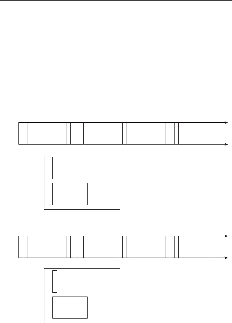
Edwards c07.tex V3 - 03/27/2009 11:19am Page 334
334 Part I ■Networking Nuts and Bolts
type 1 (TE1), or a non-ISDN terminal, known as a terminal equipment type 2
(TE2). The next type of node is called a terminal adaptor (TA),whichisused
to interface a TE2 with the ISDN network. The next type of node is called
anetwork termination device type 1 (NT1) and network termination device type 2
(NT2) (or a combination of both). Most ISDN networks will use the NT1.
7.2.8.3 The ISDN Reference Model
ISDN standards span the first three layers of the OSI reference model. At
the Physical layer, two different types of frames are used. Which one is used
depends on whether the data is flowing from the user node (the terminal) to
the ISDN network (TE frame) or from the network to the terminal (NT frame).
Figure 7-32 shows the format of the TE frame, and Figure 7-33 shows the
format of the NT frame.
FFLFEEEASSDDDB1 B2
= 1 bit
= 1 byte
B1 B2
Figure 7-32 TheTEframeformat
FFLLLLLLLLDDDB1 B2
= 1 bit
= 1 byte
B1 B2
Figure 7-33 The NT frame format

Edwards c07.tex V3 - 03/27/2009 11:19am Page 335
Chapter 7 ■Not to Be Forgotten 335
F— Framing bit, marks the beginning of the frame for synchronization.
L— Load balancing bit. These are used to balance the frames signaling.
B1 — B1 channel byte. This is B channel data.
E— Echo bit. Echoes D channel data when line congestion is occurring.
D— D channel bit. This is D channel data.
A— Activation bit. Used to activate nodes.
B2 — B2 channel byte. This is B channel data.
S—Spare bit.
F— Framing bit. When used, marks the beginning of the frame for syn-
chronization.
L— Load balancing bit. These are used when needed to balance the
frames signaling.
B1 — B1 channel byte. This is B channel data.
D— D channel bit. This is D channel data.
B2 — B2 channel byte. This is B channel data.
S—Spare bit.
The Layer 2 protocol used by ISDN is called the link access procedure
D channel (LAPD), which functions like LAPB does for the X.25 protocol.
Figure 7-34 shows the LAPD frame format.
Number of Bytes
Flag
11 112
AD Ctrl Data FCS Flag
Figure 7-34 The LAPD frame format
Flag — The LAPD Flag field indicates the start point and end point of the
frame.
AD (address) — This field identifies whether the frame is carrying a
response or a command.
CTRL (control) — This field details which frame type (I-frame, S-frame,
or U-frame) is being used, the frame sequence number, and the frame
function.
Data — The payload! In LAPD, this is the PLP packet.
FCS (frame check sequence) — This field is a checksum algorithm
that checksums the frame from the FC field to the end of the Data
field. This is where error checking and data integrity are monitored.

Edwards c07.tex V3 - 03/27/2009 11:19am Page 336
336 Part I ■Networking Nuts and Bolts
Flag — The LAPD Flag field indicates the start point and end point of the
frame.
POP QUIZ
What are the four endpoint node types used
in ATM?
Finally, two Layer 3 proto-
cols are used by ISDN: ITU-T
and ITU-T I.451. These pro-
tocols take care of operations
at Layer 3, including setting
up sessions, establishing and
maintaining connections, gath-
ering information pertaining to
remote nodes, and other functions.
7.2.9 AppleTalk
AppleTalk is a protocol suite developed by the Apple Computer company to
be integrated with Macintosh computers to allow users to share resources on
anetwork.
AppleTalk came into existence in the 1980s and was one of the first to imple-
ment the client/server network architecture. AppleTalk is a plug-and-play
service that doesn’t require any intervention on the end user’s part to connect
to a network. The first version of AppleTalk, known as AppleTalk Phase 1,was
developed mainly for use in a local network segment. It was able to support
a maximum of 135 client nodes and 135 server nodes. AppleTalk Phase 2 was
developed to support routing outside of the local segment and could support
a total of 253 nodes, regardless of whether they were clients or servers.
ACRONYM ALERT
CIST — Common and internal spanning tree
The services provided and/or supported
by AppleTalk span all the layers in the
OSI reference model. Figure 7-35 compares
the OSI reference model and the AppleTalk
protocols that correspond to each layer.
7.2.9.1 AppleTalk Physical and Data Link Layers
AppleTalk depends on the same media access protocols to exchange network-
ing data. Each implementation has to work with the AppleTalk suite. At the
Physical layer, AppleTalk data can be passed over fiber, twisted pair, and
coaxial cabling. AppleTalk interacts with each implementation of a media
access protocol to allow AppleTalk data to be exchanged. Following are some
of the protocols used at this layer:
EtherTalk — Used on Ethernet networks. The protocol that
communicates between the network layer and the Physical
layer is known as the EtherTalk Link Access Protocol (ELAP).

Edwards c07.tex V3 - 03/27/2009 11:19am Page 337
Chapter 7 ■Not to Be Forgotten 337
TokenTalk — Used on Token Ring networks. The protocol that
communicates between the Network layer and the Physical
layer is known as the TokenTalk Link Access Protocol (TLAP).
FDDITalk — Used on FDDI networks. The protocol that com-
municates between the Network layer and the Physical layer
is known as the FDDITalk Link Access Protocol (FLAP).
LocalTalk — This is the AppleTalk proprietary standard that
is included with all Macintosh computers. This standard is
supported on Macintosh nodes only. The protocol that com-
municates between the Network layer and the Physical layer
is known as the LocalTalk Link Access Protocol (LLAP).
OSI Reference
Model AppleTalk Model
AppleTalk Filing Protocol
AppleTalk Session Protocol
AppleTalk Echo Protocol
Datagram Delivery Protocol
EtherTalk Link Access
Protocol
Ethernet LocalTalk
LocalTalk Link Access
Protocol
Routing Table
Maintenance Protocol
AppleTalk Datastream
Protocol
TokenTalk
Link Access Protocol
Token Ring
Printer Access Protocol
Name Binding Protocol
Application
Presentation
Session
Transport
Network
Data Link
Physical
Figure 7-35 The layers of the AppleTalk model
7.2.9.2 AppleTalk Network Layer
The Datagram Delivery Protocol (DDP) is the protocol used by AppleTalk at
the Network layer. The purpose of DDP in an AppleTalk infrastructure is to
provide end-to-end datagram delivery. DDP uses sockets to identify a logical
process on a node and as part of the address that is used in order to exchange
datagrams. All the upper layers use sockets as well.

Edwards c07.tex V3 - 03/27/2009 11:19am Page 338
338 Part I ■Networking Nuts and Bolts
All AppleTalk data is formatted to be exchanged in DDP packets over
an AppleTalk network. DDP has two different packet types. The short DDP
packet type is not used much anymore. It was developed when AppleTalk
was limited to segments only. The extended DDP packet type is what is most
commonly used.48
RANDOM BONUS DEFINITION
Layer 3 switch — A router.
Another protocol used at this
layer is the AppleTalk Address
Resolution Protocol (AARP).Just
like the Address Resolution Pro-
tocol (ARP) for TCP/IP, AARP
maps network addresses to their
associated data link addresses.
7.2.9.3 AppleTalk Upper Layers
AppleTalk uses several upper layer protocols that were built off of the DDP
protocol and therefore use DDP as the protocol of choice when information is
being passed down to the lower layers for transport across the network.
Transport layer protocols are used for flow control, circuit management, and
error checking, detection, and recovery. The AppleTalk protocols included at
this layer are:
AppleTalk Echo Protocol (AEP) — The service provided by this
protocol is an echo request or an echo reply.
AppleTalk Transaction Protocol (ATP) — Used to pass transmissions
between two sockets.
Name Binding Protocol (NBP) — Maintains and manages the use of
host names and socket addresses for nodes within the network.
Routing Table Maintenance Protocol (RTMP) — Used to maintain and
manage routing information.
Session layer protocols manage communication sessions between Presenta-
tion layer processes. The protocols operating at this layer are:
AppleTalk DataStream Protocol (ADSP) — A connection-oriented
protocol that provides a data channel for the host nodes.
AppleTalk Session Protocol (ASP) — Maintains and manages higher
level sessions.
Printer Access Protocol (PAP) — Maintains and manages virtual
connections to printers, print servers, and other server types.
48The extended DDP packet is the one most commonly used in new implementations. There is
really no good reason to use the short DDP packet, as you need to plan for growth and that
packet type limits where your data can be transmitted.

Edwards c07.tex V3 - 03/27/2009 11:19am Page 339
Chapter 7 ■Not to Be Forgotten 339
Zone Information Protocol (ZIP) — Manages network numbers and
AppleTalk zone names.
RANDOM BONUS DEFINITION
internetwork — A group of networks
connected to one another through a router.
The final two layers, the
Application and Presentation
layers, use the services of the
AppleTalk Filing Protocol (AFP)49.
The Presentation layer provides
services that are applied to data
at the Application layer. Addi-
tionally, the Application layer interacts with Macintosh applications (which
the OSI Application layer does not).
7.3 Chapter Exercises
1. Trueorfalse:TheonlytypeofnodethatisusedonaFDDIringisaFDDI
concentrator.
2. What are the three levels of operation within the X.25 protocol suite?
3. In X.25, are used to pass control data, such
as: transmission requests, status reporting,
receipt acknowledgements, and termination requests.
4. What are the three main components used by PPP?
5. What is the difference between a DTE and a DCE in an X.25 network?
6. What are the Session layer protocols that are used in the AppleTalk
protocol suite?
7. What does the acronym ISDN stand for?
8. What is the frame relay local management interface (LMI) used for?
9. What is a constant bit rate (CBR)?
10. is the foundation protocol of the PPP protocol suite.
7.4 Pop Quiz Answers
1. What was the name of the company that developed ARCnet?
The Datapoint Corporation developed ARCnet in the late 1970s.
49AFP is a file sharing protocol.

Edwards c07.tex V3 - 03/27/2009 11:19am Page 340
340 Part I ■Networking Nuts and Bolts
2. What technology is also known as 1BASE5?
StarLAN
3. What is the signal called that is passed in Token Ring from one node to
the next?
Atoken
4. What information is contained in the Destination Address field in a
Token Ring frame?
The Destination Address field contains the 6-byte network address of the
node that the frame is destined for.
5. What does the acronym FDDI stand for?
Fiber Distributed Data Interface
6. What are the four main node types in the FDDI environment?
Single attached station
Single attached concentrator
Dual attached station
Dual attached concentrator
7. What are DECnet’s five phases?
DECnet phase I
DECnet phase II
DECnet phase III
DECnet phase IV
DECnet phase V
8. Which operating system uses IPX?
Novell NetWare
9. True or false: IPX is not supported on a Token Ring network.
False
10. What serial transmission standard was used before PPP came out?
Serial Link Internet Protocol (SLIP)
11. Which protocol operates at the packet level of the X.25 model?
Packet Layer Protocol (PLP)
12. What are the three virtual circuit types used in ATM?
Permanent virtual circuit (PVC) — This is a static virtual circuit.
Soft permanent virtual circuit (SPVC) — This is a dynamic PVC.

Edwards c07.tex V3 - 03/27/2009 11:19am Page 341
Chapter 7 ■Not to Be Forgotten 341
Switched virtual circuit (SVC) — This is an ‘‘as needed’’50 virtual
circuit.
13. Frame relay is very similar to .
X.25
14. What are the four endpoint node types used in ATM?
ATM customer service unit/digital service unit (CSU/DSU)
LAN router
LAN switch
LAN workstation
50This could also be ‘‘on demand.’’
Edwards c07.tex V3 - 03/27/2009 11:19am Page 342

Edwards p02.tex V3 - 03/27/2009 12:41pm Page 343
Part
II
The OSI Layers
In This Part
Chapter 8: The Upper Layers
Chapter 9: The Transport Layer
Chapter 10:TheNetworkLayer
Chapter 11: The Data Link Layer
Edwards p02.tex V3 - 03/27/2009 12:41pm Page 344

Edwards c08.tex V3 - 03/27/2009 11:22am Page 345
CHAPTER
8
The Upper Layers
Protocol is everything.
Francois Giuliani1
The above quote is truly succinct, a real economy of words. This quote is
not only true at the United Nations but also is easily applied to the network-
ing environment. When you think of the mix of various equipment, wiring,
networking operating systems, computer operating systems, programs run-
ning on servers as multiuser platforms, programs running on local computer
workstations (which includes pretty much anything a person can hang off a
network segment), the ability to communicate is essential. The United Nations
uses translators to ensure that all the representatives from the many varied
nations can understand the procedures. A network protocol also acts as a
translator between the many subcomponents that we lump together under the
word ‘‘network.’’
We would hate to think what a General Assembly meeting of the United
Nations would look and sound like without the translators they employ. There
is only one word that comes to mind: chaos. How would you ever be able to
get anything done? The same goes for networks, except things move much
faster than the world’s fastest talker can utter even a single word. So protocol
is truly everything in the networking world.
1Francois Giuliani worked at the United Nations for 25 years. At the time of his departure in
March 1996, he was the director of the Media Division of the Department of Public Information
(DPI).
345

Edwards c08.tex V3 - 03/27/2009 11:22am Page 346
346 Part II ■The OSI Layers
RANDOM BONUS DEFINITION
hardware address — Synonymous with MAC
address, physical address, and unicast
address.
This chapter investigates the
upper layers of the OSI reference
model: the Application layer,
the Presentation layer, and the
Session layer. We will iden-
tify the ‘‘translators’’ being used
so that information can flow
smoothly and without error between these layers and eventually be sent
over the network media to another network node and the device servicing
that node. This is a top-down approach where users attempt to interact with
the device they are using to communicate with another device and/or users
somewhere over the net.2
8.1 Background
Software programs use the upper layers of the OSI reference model to send and
receive data over a network. Normally such programs are called applications
and although they may interface with the Application layer of the OSI reference
model, it does not necessarily need to be the case. In this chapter, ‘‘application
program’’ and ‘‘Application layer’’ are not synonymous and refer to different
aspects of computer usage.
A computer user purchases an application program and loads it on to his
or her computer’s hard drive. Basically, programs can be divided into two
broad categories: locally run application programs and client/server-based
application programs. As the name implies, a locally run application program
executes program instructions and all data is maintained within the local com-
puter, so there is never a need to utilize a network connection. A client/server
application implies that a client computer and a server need to communicate if
the application program is to run successfully. A client/server application in
most cases requires a degree of interconnectivity for the application program
to communicate with its counterpart server-based program. As this book is
concerned with networking, the only application programs that have rele-
vance are application programs that follow the client/server model. Figure 8-1
illustrates a client/server application program scenario.
As you can see in the figure, a client computer communicates over the net-
work with a server. Although they are working in conjunction within a certain
application program, they run within their own realms. The server listens on
the network,awaitingrequests from client computers. Whenthe server receives
a request from a client, it fulfills it. The communication between a particular
client computer and the server is considered a session. Servers only respond to
2The ‘‘net’’ is in reference to any and all segments of a network, which can include in part or in
whole any of the following: local network segment, the local LAN, intranet, or the Internet.
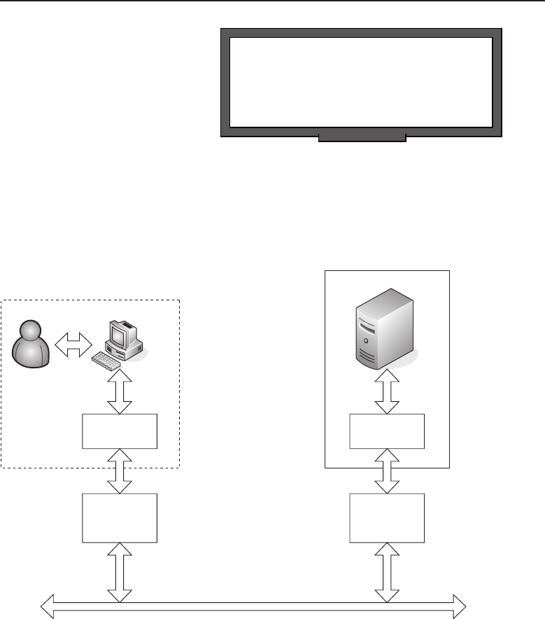
Edwards c08.tex V3 - 03/27/2009 11:22am Page 347
Chapter 8 ■The Upper Layers 347
POP QUIZ
True or false: The Application layer is
where all the application programs you
load on your PC are stored.
session requests in this environ-
ment; they do not initiate the
start of session. Once a data
transfer to or from the server is
complete, it may request to ter-
minate the session. Depending
on the server application being
run on the server, the server may
be capable of maintaining a number of simultaneous sessions with multiple
client computers. Server applications that can maintain multiple sessions are
usually referred to as multiuser applications.
Client
Application
Program
Client Realm
Network Physical Layer
Server Realm
Network
Protocol
Stack
Server
Application
Program
Network
Protocol
Stack
Figure 8-1 A client/server application
The client realm involves not only the client computer and application
program, but a user as well. The user initiates requests to the client computer
via an input device (usually a keyboard, mouse, or both). The application
responds back to the user in graphic images or text displayed on a screen or
tone signals played back through the computer’s audio system.The application
program requires user input in the form of commands and data in order for
it to interact with the server application it is working in conjunction with in a
particular client/server application.

Edwards c08.tex V3 - 03/27/2009 11:22am Page 348
348 Part II ■The OSI Layers
ACRONYM ALERT
AARP — AppleTalk Address Resolution Protocol
Although client/server applications
work in conjunction with each other, they
are autonomous until a session is estab-
lished between a particular client applica-
tion workstation and the application server.
The server application, in most cases, is con-
stantly running on a server that is rarely shut down. For instance, a mail server
is always available to receive messages from client workstations, process them,
and direct them to another mail server where the recipient of that message has
an account. Received messages from other mail servers destined for users on a
particular mail server are stored on the server until the mail server is queried
by a user to see if there are any messages.
Mail servers or other application servers may also have to perform user
authentication to ensure security and user privacy. An example of this would
be when users launch a particular application on their client workstation, such
as a mail reader. They may be first presented with a dialog message box to enter
their user ID and password. Unbeknownst to the users, when they launched
the client application it went out over the network and requested to establish
a session with the server. The server at that point returned a response that
security is required and requested that a user ID and password be provided
for the connection to be established and maintained over the length of the
session. Users at the client workstation enter their user ID and password,
and if it matches the authentication parameters that the mail server is using
for authentication, a mail session is opened between the client workstation
and the mail server. The simple process of just logging on to a mail server
requires interaction of the application program and the network stack3to
ensure that messages are properly transmitted over the network between the
client workstation and the server within a predetermined protocol.
POP QUIZ
The predominant networking protocol run
over Ethernet networks is .
Since TCP/IP (Transmission
Control Protocol/Internet Pro-
tocol) is the predominant net-
work protocol in use within
today’s networking world, the
remainder of this chapter will
refer to the network stack in
terms of how it relates to the TCP/IP protocol suite. Most, if not all, of
today’s computer operating systems provide a network stack that is compat-
ible and easily interacts with applications that use TCP/IP to communicate
over a network.
3Usually in reference to the OSI model, ‘‘network stack’’ or simply the ‘‘stack’’ refers to layers
within the OSI reference model that, in most cases, have been embedded within the particular
operating system running on the computer in use.
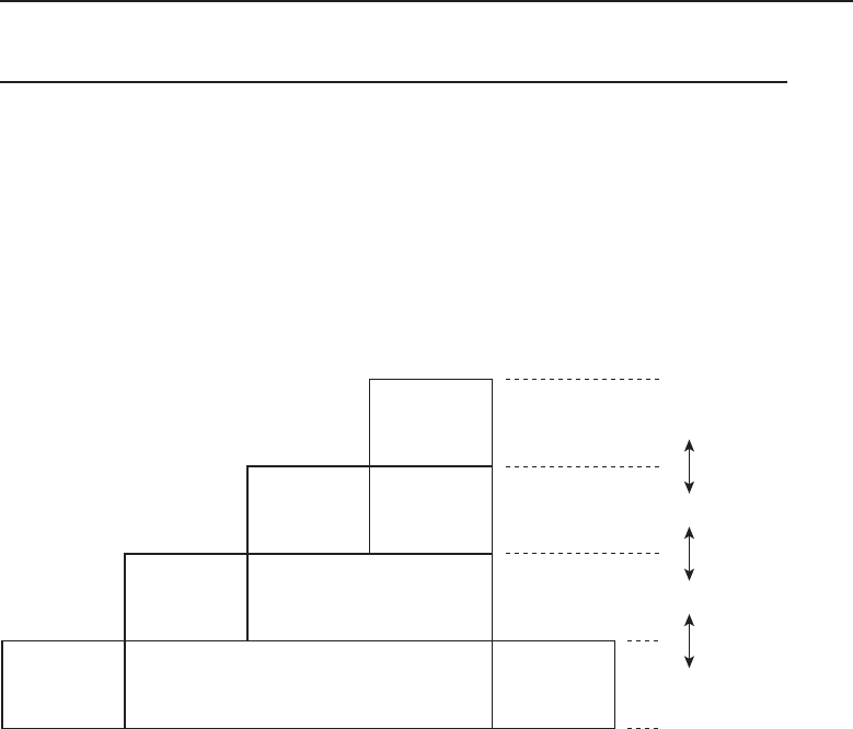
Edwards c08.tex V3 - 03/27/2009 11:22am Page 349
Chapter 8 ■The Upper Layers 349
8.2 The TCP/IP Model
The TCP/IP model consists of four layers: an Application layer, a Transport
layer, an Internet layer, and a Link layer. To accommodate a wide range of
application programs that need to communicate over a network structure,
encapsulation is performed between the layers to allow data to be moved
independently of the application that produced the data. Figure 8-2 illustrates
a conceptual view of the TCP/IP network stack.
Data
UDP Header UDP Data
IP DataIP Header
Frame Header Frame Data Frame Footer
Layer
Application
Transport
Internet
Link
Figure 8-2 The TCP/IP network stack/model
The top level Application layer is the data portion of the network stack.
It contains the upper level protocols that allow application programs to
encapsulate data so that it can be passed down to the Transport layer.
Since the OSI model Presentation layer and Session layer are combined with
the OSI model Application layer to make up the TCP/IP network stack’s
Application layer, any protocols needed within the OSI model for these
layers are accomplished via the use of libraries4within the TCP/IP model’s
Application layer.
The TCP/IP model Transport layer maps directly to the Layer 4 Transport
layer of the OSI model, and the TCP/IP model Internet layer is usually mapped
directly to the OSI model’s Network layer. However, the TCP/IP model’s Link
layer covers both the OSI model’s Physical layer and Data Link layer.
Application layer data is passed to the Transport layer, where a UDP header
is applied and is framed with the data, as shown in Figure 8-3.
4Libraries are collections of protocol routines for various protocol functions.
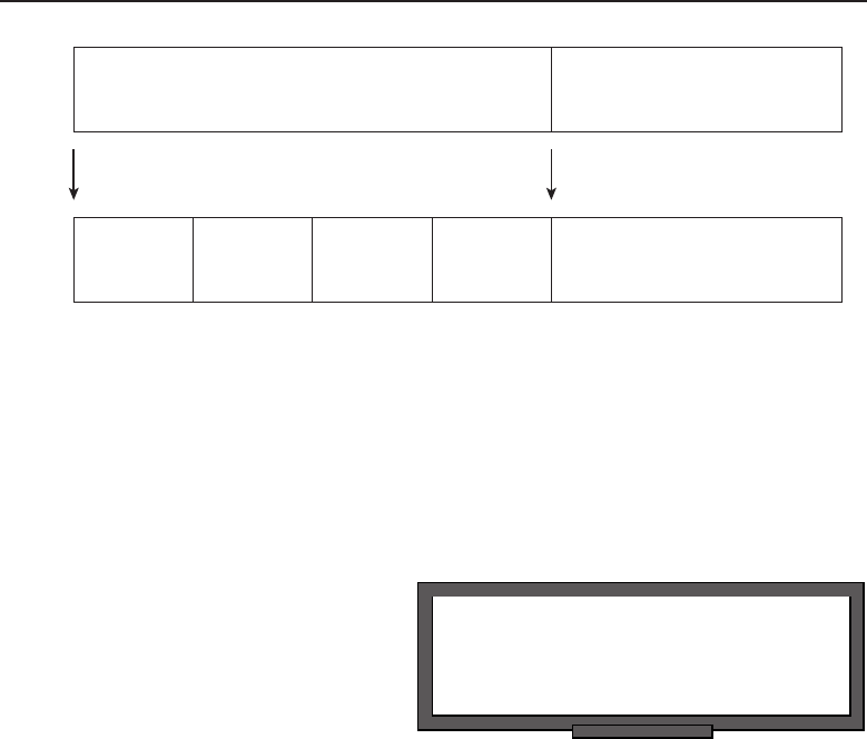
Edwards c08.tex V3 - 03/27/2009 11:22am Page 350
350 Part II ■The OSI Layers
UDP Header UDP Data
Data
UDP Packet
Checksum
(2 bytes)
UDP Packet
Length
(2 bytes)
Destination Port
(2 bytes)
Source Port
(2 bytes)
Figure 8-3 AUDPpacket
As you can see, there is no address information other than the ports that
that are being accessed. Since there is a lack of addressing and control, UDP
is referred to as a connectionless protocol.5With 2 bytes allocated for both
the source and destination port addresses, this accommodates up to 65,536
port numbers. However, the lower 1,024 port address values are reserved for
defined services and are considered to be the well-known port values.6
POP QUIZ
True or false: UDP is a connection-based
protocol.
The UDP Packet Length field
is 2 bytes in length and contains
the number of bytes of the whole
packet, including header and
data. The UDP Packet Check-
sumfieldisalso2bytesin
length and is the checksum of
the whole packet, including header and data. Unlike TCP, the Checksum field
is optional, which brings into question its use for packet transport over the
network. The choice between using UDP and TCP depends on the transport
mode selected by the application program developers. A deciding factor may
be speed, since UDP does not require further encapsulation and the overall
packet size is smaller than TCP by 12 bytes. On a single packet basis, this
seems like a small price to pay; however, in applications where large amounts
of data are transferred over the network, there can be noticeable performance
differences. A software developer may choose not to use UDP where reliability
of the transfer is required. UDP has no means of guaranteeing packet delivery.
To guarantee delivery requires further encapsulation and the packet is then
passed to the Internet layer of the TCP/IP network stack.
5A connectionless protocol means that packets are streamed onto the network without any
relation to one another. There is no means to connect packets that may have been fragmented or
to determine if packets have been received out of order.
6Well-known port addresses are reserved; however, the range above 1024 also has some
predetermined services using a high-numbered port. An example would be radius server
authentication using port 1812.

Edwards c08.tex V3 - 03/27/2009 11:22am Page 351
Chapter 8 ■The Upper Layers 351
At the Internet layer, the UDP packet is encapsulated as data within the IP
packet. Figure 8-4 illustrates the applied IP header.
Bit
0
0-3
Version
4-7
Header
Length Type of Service Total Length
Fragment Offset
Header Checksum
Source Address
Destination Address
Options
Data
8-15 16-18 19-31
Flags
Time to Live Protocol
Identification32
64
96
128
160
160
or
192
+
Figure 8-4 The IP packet header
You can see that additional information is added to the packet that can affect
its delivery over the network. The bit order of the packet delivery begins with
bit position 0. Streaming from left to right across the header, the first field
encountered is the Version field. Since this packet complies with IP version 4
(IPv4), the value contained in this field is 4.7
The next field is the Header Length of the IP header. The value contained
in this field is the number of 32-bit words that are contained in the header.
This value also indicates the bit position of where the Data field begins. The
minimum value for this field is 5. So, in a header containing five 32-bit words,
the start of data will begin at bit position 160 (5 ×32 bits =160 bits). The
beginning of the Data field will be pushed back an additional 32 bits if the
Options field is present.
The Type of Service field was allocated to provide control over the packet’s
delivery priority. In the past, this field was not utilized; in recent days,
7Because this is a 4-bit binary field, the value in binary 4-bit notation would appear as 0100.

Edwards c08.tex V3 - 03/27/2009 11:22am Page 352
352 Part II ■The OSI Layers
RANDOM BONUS DEFINITION
flow control — A function that prevents a
sender of traffic from sending faster than
the receiver is capable of receiving.
it has evolved into a Differen-
tiated Services field (DiffServ).
DiffServ provides a method
of classifying network traffic
for manageability and provides
quality of service (QoS) guaran-
tees across an IP network. This
ability is essential for delivering time-sensitive packets for applications that
require real-time performance. An example of a real-time application in wide
use today is Voice over IP (VoIP).
The Total Length field contains the value in the number of bytes of the
total length of the IP packet datagram, which also includes the header. The
minimum value this field can contain is 20, which is the minimum number of
bytes in an IP header without any data. Since this is a 16-bit field, the maximum
amount of bytes in the datagram is restricted to a theoretical limit of 65,536
bytes. However, most networks do not permit the transfer of super-sized
packets without fragmentation. The customary size restriction for TCP/IP on
an Ethernet network is 1500 bytes. Larger packets would needto be fragmented
and delivered reliably so they can be reconstructed on the receiving network
node.
The next three fields, Identification, Flags, and Fragment Offset, are all used
when fragmentation of a packet is required. A packet that is too large is broken
into fragments, which are placed within a collection of packets to transfer the
information within the original unfragmented packet. The Identification field
is used to uniquely identify all IP packets that are fragments of a packet that
needed to be fragmented before being placed on the network. The Flags field
consists of 3 bits. The value of each field may either be a 0 or a 1, where 0
indicates ‘‘no flag’’ being present and 1 indicates ‘‘flag bit set.’’ In order of
precedence, the most significant bit is reserved and always must be set to
1. The next bit is the do-not-fragment bit. When set, this bit signals that the
packet is not to be fragmented. This can lead to packets being dropped if they
exceed the overall packet size permitted by a receiving node. The only reason
for use of the do-not-fragment flag is that the network node sending the packet
knows that the network node that is to receive the packet does not have the
capability to reassemble fragmented packets and sets the flag so upstream
routers will not fragment the packet. The next flag bit is the more-frames bit,
which indicates that more fragment packets are to follow this particular packet.
The last packet containing a packet fragment segment will have this bit set to
0 to indicate that no other fragments are to follow this fragment. This bit is
always set to 0 for all packets that don’t contain fragmented packet segments.8
8If a packet does not contain fragmented packet segments, it is a packet unto itself and is
considered an unfragmented packet. Whether to fragment a packet is determined by the amount
of data that is be transmitted, since the header is for the most part of fixed length.

Edwards c08.tex V3 - 03/27/2009 11:22am Page 353
Chapter 8 ■The Upper Layers 353
The Fragmentation Offset field contains the number of 8-byte blocks that the
fragment data is offset from where it was located in the original unfragmented
packet. The field is 13 bits long, so the maximum number of offset is 65,528.9
Since the maximum packet size is fixed at 65,536, the values of the offset, plus
the 20 bytes required for the IP header, is greater than the maximum size of a
packet. Thirteen bytes are more than adequate for this field.
The Time to Live field is an 8-bit field that indicates how many seconds
a packet can live on the Internet. With that many bits, it would equate to
255 seconds as a maximum or four and a quarter minutes. Imagine waiting
more than four minutes per packet to see if they had arrived. Needless to
say, the reason for the TTL timer is to prevent lost packets from traversing
the Internet into infinity if they cannot find a home or until they end up
being dropped somewhere along the way. These days this field is not used to
display the amount of seconds but is a hop count.10 As a packet travels across
the Internet, each network forwarding device it passes through decrements
the TTL field by one before forwarding the packet along to the next network
hop. The packet will continue to travel until the packet with a TTL set to zero
arrives at the input of a network forwarding device. When a packet with TTL
equal to zero is received by a network forwarding device, it will simply not
forward the packet and it is dropped.11 When a packet is dropped, an ICMP
(Internet Control Message Protocol) error is sent to the sender alerting it that
the packet has been dropped. The typical message is that the TTL has been
exceeded, which means the destination was not found. ICMP utilities include
ping and traceroute and use error messages to allow a sender to know if a
target address is reachable over the Internet.
ACRONYM ALERT
ATM — Asynchronous Transfer Mode
TheProtocolfieldisan8-bitfieldused
to indicate the protocol of the data portion
of the IP packet. These are pre-assigned
values maintained by the Internet Assigned
Numbers Authority (IANA). Some of the
most common protocols found in IP headers
are a value of 1 for ICMP messages, a value
of 6 for TCP messages, and a value of 17 for UDP messages.
The Header Checksum field is a 16-bit field that contains the checksum of
the header portion of the IP packet. The data portion carries the checksum
of the protocol that is contained within it. When the packet is received, the
checksum is calculated and compared to the value contained within the field. If
9This values is derived by (213 –1) ×8 bytes per block, or 65,528 bytes.
10Hop count is a method of counting the hops a packet traverses. As a packet is passed through a
network forwarding device (e.g., a router), it is considered as a single hop.
11What is meant by ‘‘dropped’’? Simply that the packet is ignored and not forwarded or analyzed
any further. It just ends up in the sky, where all lost packets go. However, network administrators
always like to know why a packet is dropped.

Edwards c08.tex V3 - 03/27/2009 11:22am Page 354
354 Part II ■The OSI Layers
there is a checksum mismatch, the packet is dropped. Since the header includes
the Time to Live field, which is decremented each time the packet crosses a
network hop, the header checksum will need to change if it is to remain valid
at the next receiving network node. Because of known decrementing of the
TTL field and the possibility that a network forwarding device may fragment
the packet before passing it to the next network hop, each network forwarding
device must insert the new valid checksum value in order to not create a
checksum mismatch at the next receiving network node.
The Source Address field contains 32 bits of address information. The
address is represented as four octets. Normally, IP addresses are annotated in
what is called dot-decimal notation,suchas:
192.168.16.1
Converting each octet into binary is represented as follows:
11000000.10101000.00010000.00000001
Binary address information in the Source Address field is represented as
follows:
11000000101010000001000000000001
There are times when the source address of a packet is not the address of
the sending network node. Various packet-forwarding network devices can
perform a NAT function. Figure 8-5 illustrates a user workstation behind a
router that is providing a NAT function.
Source Address
192.168.1.28
Destination Address
38.214.37.10
Source Address
74.123.17.33
Destination Address
38.214.37.10
Source Address
74.123.17.33
Destination Address
38.214.37.10
192.168.1.28
192.168.1.1
NAT
Router
Web
Server
74.123.17.33
38.214.37.10
Network Address
192.168.1.0
Internet
Figure 8-5 A private network behind a NAT router

Edwards c08.tex V3 - 03/27/2009 11:22am Page 355
Chapter 8 ■The Upper Layers 355
In the figure, there is a private network12 with a network address of
192.168.1.0, and on that network is a router with NAT capability of taking
packets from a device on the 192.168.1.0 network and routing them out to
the Internet. A user workstation at 192.168.1.28 wants to access a web page
from a web server over the Internet at 38.214.37.10. Since the NAT router is
the default gateway for the 192.168.1.0 network, all traffic that is not destined
for the local LAN is sent to it. The user workstation in its TCP/IP settings
has the default gateway address of 192.168.1.1, which is the NAT router’s
local network interface. The user workstation sends a request packet with a
destination address of 38.214.37.10 with its own address of 192.168.1.28 in the
Source Address field. Since the destination address is not on the local LAN, it
is sent to the default gateway at 192.168.1.1.
The NAT router accepts the packet from the workstation at 192.168.1.28 and
determines that it is destined to another network device over the Internet. The
router replaces the user workstation’s IP address with its own public interface13
address in the Source Address field of the packet. After the address is replaced,
it computes a new checksum for the header and inserts it into the checksum
field before sending the packet out its public interface at 74.123.17.33.
RANDOM BONUS DEFINITION
Fast Ethernet — 100 Mbps Ethernet.
The packet is routed over
the Internet and arrives at the
web server residing at the pub-
lic IP address of 38.214.37.10.
The server determines that the
request is destined for its
address and notes that the source address is 74.123.17.33. The web server
has no knowledge of the user workstation IP address of 192.168.1.28. The web
server prepares a response using the public IP address of the NAT router as
the destination address.
When the response packet arrives at the NAT router from the web server,
it uses its NAT translation table to send the packet to the requesting work-
station. It accomplishes this by modifying the destination address to the
workstation address of 192.168.1.28 and computing a new checksum for the
IP header before sending the packet out its private address interface onto
the local LAN. For all intents and purposes, the user workstation believes it
is interacting directly with the web server. NAT has some advantages and
disadvantages, but for most small local networks it works well and offers
12Certain network addresses spaces have been determined by the Internet community to remain
private. What this really means is that network forwarding devices on the Internet are not to
forward any packet with a destination address that falls into the following ranges: 192.168.X.X,
172.16.X.X, and 10.X.X.X, where X denotes any number between 0 and 255.
13There are two sides to every router that interfaces a private local LAN network and the Internet.
Normally, the interface that is accessible over the Internet is referred to as the public interface or
public interface address.

Edwards c08.tex V3 - 03/27/2009 11:22am Page 356
356 Part II ■The OSI Layers
POP QUIZ
Describewhathappenstoapacketwhenit
is passed through a NAT-enabled router.
protection against unsolicited
network traffic ever making it
through the NAT router to
the local private network. If
a packet’s parameters do not
match the translation table’s
known sessions, the packet is not processed and is dropped.
The Destination Address field is pretty much self-explanatory. It is a 32-bit
(4-byte) field containing the address information in the same format as the
Source Address field. There is no difference in how the destination address is
presented. In most circumstances the destination address is not messed with
as the source address is with NAT. However, there are instances where the
destination address may be translated and that is in special cases involving
some sort of NAT router or a firewall. Actually, most routers used for the NAT
function on outbound network traffic also have some capability to perform
a port forwarding NAT. Notice that the web server in Figure 8-5 is directly
connected to the Internet. That is certainly a possibility but is rarely found in
today’s networking environment because of possible attacks on the server via
the Internet. Figure 8-6 illustrates a network that offers services available on
the Internet but is protected and hidden from users.
Internet
Firewall
Other Network
Services
Web Server
FTP Server
VPN Router
DMZ Network Private Network
Figure 8-6 Port forwarding NAT
As you can see,the network located behind the firewall is shielded to prevent
users on the Internet from accessing these services directly. A firewall may be

Edwards c08.tex V3 - 03/27/2009 11:22am Page 357
Chapter 8 ■The Upper Layers 357
a network device that is designed as a firewall for the inspection of packets
as they are received, or it may be a router running a firewall application on it
that provides the packet inspection. In any case, the firewall function requires
packet inspection and a determination by the policies put in place by the
network administrators of what to do with the received packet. If a packet is
received and does not match any of the existing policies, it is dropped.
The network behind the firewall may be a private network, but in this
example it is shown as a DMZ14 network. Connected to this network are
services that the Internet community is permitted to reach. In this example,
we have a web server, an FTP server, and a VPN router. Obviously, the web
server is where web pages can be accessed and is generally used only for
queries to obtain information. The FTP server may be only for file downloads
but if allowed may also be a place where users can upload files. An example
where users from the Internet community at large can upload files to an FTP
server is a website that allows user posting on the site or a photo lab site that
prints users’ digital JPEG files on photographic paper.
In the figure, there is a VPN15 router between the DMZ network and the
private network. This device may be used as a remote access device for
users who are remotely located but have permission to use the network
service located on the private network. Usually VPN routers require user
authentication, which can be performed locally on the VPN router, although
it may depend on other authentication servers. For more information on this
topic, see Chapter 14, ‘‘Network Security.’’
Back to our lovely red-brick firewall. We said that the firewall is responsible
for inspecting the packets and using the policies installed by the network
administrators to make a determination on what to do with the packet.
To ensure that traffic is routed to the proper services, there must be port
forwarding policies in place on the firewall. There are two ways this may be
accomplished: either by changing the destination address and forwarding the
packet on to the DMZ network, or, if the DMZ network addresses are routable
Internet addresses, the packet may be inspected to ensure that only certain
traffic is permitted to pass through the firewall. If the DMZ network uses
addresses that are classified as nonroutable addresses, the only way traffic
can be directed to the servers providing the requested services is by changing
the packet’s destination address. In this example, the web and FTP services
14DMZ is the acronym for demilitarized zone. In networking parlance, it refers to a network that
may have some access by the public at large. The private network is protected by some sort
of authentication process to only allow users with the proper credentials to reach the private
network.
15VPN is the acronym for virtual private network. Usually the acronym is applied to the device,
but in reality it is not the network in itself. It provides access to the network using security
authentication and encryption processes to ensure that the private network is accessed only by
those authorized to use its services.

Edwards c08.tex V3 - 03/27/2009 11:22am Page 358
358 Part II ■The OSI Layers
only receive traffic for those particular services. Although these services are
shown as separate computers, many services can be supplied by a single server
running multiple protocols. In this example, packets directed to port 80 for
web services would be directed to the web server, while packets using ports
20 and 21 would be directed to the FTP server. Lastly, VPN requests would
be directed to the VPN router, and there are a few VPN protocols that may be
used, so for now we will just say any VPN service requests will be directed to it.
The next field in the IP header is the Options field. As the name connotes,
this is an optional field that follows the Destination Address field but is not
used often. The last field in IP packet is the Data field, which is not part of the
IP header so it is not used in the computation of the header checksum. The
contents of the Data field are specified within the protocol header and can be
any one of the IP protocols. Some of the most common protocols used in an IP
packet are ICMP, TCP, UDP, and OSPF. OSPF (Open Shortest Path First) is a
routing protocol used to route IP packets over the network.
The last layer of the TCP/IP Model is the Link layer. This is a combination
of physical hardware and software to frame the IP packet to transport it over
whatever network medium is being used. So frame information depends on
the type of network connectivity that is being used. In the case of Ethernet, the
IP packet is encapsulated within the Ethernet frame. Figure 8-7 shows Ethernet
encapsulationofanIPpacket.
Destination
MAC Address
Source
MAC Address
Ethernet
IP Payload Type IP Payload CRC Checksum
Frame Header Frame Footer
Figure 8-7 Ethernet encapsulation of an IP packet
The Ethernet frame header contains both the MAC (Media Access Control)
destination and source addresses, each containing 12 bytes of addressing
information. These addresses are unique and are directly associated with the
physical network device. The last field in the Ethernet frame header is the
Ethernet IP payload type. This is a 2-byte field and indicates the type of IP
payload being transmitted by the Ethernet frame. Two of the most common
IP payload types are 0x0800 for an IPv4 datagram and 0x080616 indicating that
the frame is an ARP17 (Address Resolution Protocol).
16The numeric representation with an ‘‘x’’ contained within it signifies that the number is a
hexadecimal number. Each unit position is 4 binary bits in width. Thus, four hexadecimal
numbers would contain 16 binary bits, or 2 bytes. If you still have difficulty grasping the concept
ofhexadecimalinrelationtobinarynumbers, it is time for a review of number systems.
17ARP is a mechanism for a transmitting network node to determine which network node is
associated with a particular IP address. The network node assigned that IP address responds
with its MAC address.
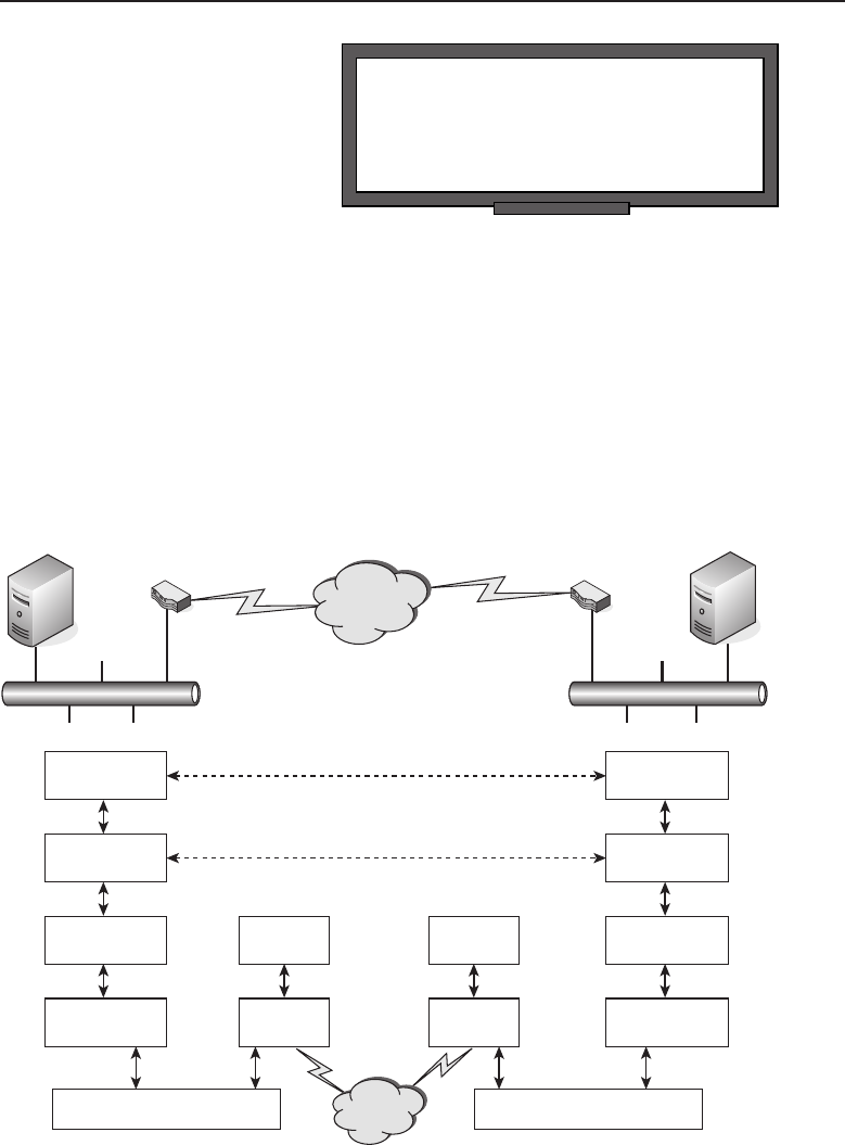
Edwards c08.tex V3 - 03/27/2009 11:22am Page 359
Chapter 8 ■The Upper Layers 359
POP QUIZ
At which layer of the TCP/IP model can the
physical component of a network node be
found?
The Ethernet frame footer
contains the CRC checksum for
the entire Ethernet frame. It con-
tains 4 bytes of checksum data,
which is used to validate that
the frame was received correctly
by the network node it was for-
warded to. So, if the minimum size of an IP packet is 46 bytes, the minimum
size if an Ethernet frame is 64 bytes, with the addition of the 18 bytes
of Ethernet header and footer. The maximum size of an IP packet is 1500
bytes, which makes the maximum Ethernet frame allowed onto an Ethernet
to be 1518 bytes in total. For large data payloads, fragmentation must be
used.
We have worked our way down the TCP/IP model and now it is time to
put the frame on the wire. Figure 8-8 conceptually illustrates the relationship
between actual network elements and the TCP/IP network stack.
Computer Computer
Router
LAN A LAN B
Peer to Peer Application
Communications
Router
Internet
Internet
Application
Transport
Internet
Link Link
Local Area Network Local Area Network
Application
Transport
InternetInternet
Link
Internet
Link
Figure 8-8 The relationship between network elements and the TCP/IP network stack

Edwards c08.tex V3 - 03/27/2009 11:22am Page 360
360 Part II ■The OSI Layers
Two LANs, LAN A and LAN B, have computers that want to communicate
with each other using an application program that supports their capability to
establish a session and communicate effectively. This is shown as a computer
and router connected to each LAN. Each router is connected to the Internet,
shown as a cloud since there is an unknown amount of network devices that
may be in the path between the router on LAN A and the router on LAN B.
The assumption is that if a frame18 is constructed properly, it can travel across
many networks and through many devices in its path to reliably arrive at its
predetermined destination.
The application program running on both computers may be aware of
the other’s network parameters, such as address and type of service, but
it does not concern itself with the actual delivery of the data between the
two peer computers running the application program. The only concern of
the application program running within the TCP/IP’s Application layer is
preparing the data so it can present it to the Transport layer in anticipation
of having the data delivered to the computer residing on the other LAN. So
a peer-to-peer application session between two computers over the Internet
appears as if they communicate with each other only using the Application
layer and the Transport layer of TCP/IP model.
If application programs only concern themselves with getting the data
properly packaged for the Transport layer, who does the rest of the actual
delivery of the information? As illustrated in Figure 8-8, the lower two layers
of the TCP/IP model are the Internet layer and the Link layer, which are
directly responsible for reliably transporting the packet of information over
the Internet. Since routing devices only need to be aware of addressing
information, they only need to use the two lower layers of the model to effect
the proper transmission of the information on its journey over the Internet.
They are not concerned with data content since routing decisions are made on
address and type of service.
ACRONYM ALERT
DOS — Disk operation system
The Internet and Link layers are normally
part of the operating system and the hard-
ware that is installed on the computer. If
we assume an Ethernet-based LAN, then
the computer would require an NIC that
is capable of providing an Ethernet con-
nection to the LAN. This is what would be Layer 1 or the Physical layer
of the OSI reference model. However, it is a portion of the TCP/IP model
18Frame and packet are terms that are used interchangeably and are pretty much synonymous.
Another term that may be tossed about from time to time is datagram. All these terms refer to
some sort of encapsulation that includes the data to be transferred along with addressing and
type of service being requested. It is how data can traverse the Internet from one computer to
another.

Edwards c08.tex V3 - 03/27/2009 11:22am Page 361
Chapter 8 ■The Upper Layers 361
Link layer. In order for the operating system to communicate properly with
the NIC, device drivers are required that allow the software operating sys-
tem to configure and control the physical components of the NIC. In a
Microsoft Windows environment, this may be transparent to the user due
to the capability of the operating system to recognize various pieces of com-
puter hardware and automatically load the appropriate driver to communicate
with the installed device. This portion of the TCP/IP model Link layer that
includes device drivers maps to the Data Link layer of the OSI reference
model.
Once an NIC is installed in a computer and the device drivers are loaded
so that the operating system is able to communicate with the device on a
physical level,19 a network operating protocol needs to be bound to the card
for it to communicate over the network with another network-connected
device. In the case of TCP/IP, this is the address applied to the com-
puter network interface along with its default gateway20 and the location
of at least one DNS server. Most operating systems allow these parame-
ters to be set manually, or the computer requesting the values can apply
them automatically from a DHCP server that is servicing that network seg-
ment.
POP QUIZ
What determines the type of framing that is
to be used on a particular network segment?
Note that the routers illus-
trated in Figure 8-8 have their
Link layers connected to both
the LAN and the Internet. In
reality these would be two dif-
ferent interfaces and also of dif-
fering types of network connec-
tivity. More than likely the router will have an Ethernet interface allowing it
to be interconnected to an Ethernet-based LAN. The interface to the Internet
is dependent upon the type of service the router is connected to. It may be a
point-to-point T1 interface, a FDDI interface, or some other form of high-speed
service to the Internet. So a router’s Link layer may consist of differing network
hardware, device drivers, and Internet layer parameters to effectively transmit
a data packet from the LAN to the Internet.
19Physical level kind of implies actual hardware but includes software that allows the hardware
registers be written to for data and control. It is the device driver that makes the translation from
hardware-specific elements to the standardized routines within the operating system controlling
network-based communications.
20Default gateway has been mentioned more than once in this chapter. In a simple network, as
illustrated in Figure 8-3, the address applied to the router on the LAN side would be considered
to be a default gateway address. Basically, any packet with a destination address that is not
located on the local LAN segment is forwarded to the address that is programmed into the
default gateway address parameter field.

Edwards c08.tex V3 - 03/27/2009 11:22am Page 362
362 Part II ■The OSI Layers
8.2.1 TCP/IP Application Layer
RANDOM BONUS DEFINITION
AppleTalk — A protocol suite developed by
Apple Computer.
The Application layer of the
TCP/IP model contains the
upper level protocols of the
TCP/IP protocol suite, such as
FTP (File Transport Protocol)
and SMTP (Simple Mail Trans-
fer Protocol). Data is encapsu-
lated and passed to the Transport Control Protocol for actual transmission
on the network. The Application layer is dependent upon the lower layers
to provide an effective and reliable means of network communications. The
Application layer may be aware of the IP addresses and port numbers that
are being used by the Transport layer, but it is that layer’s responsibility to
encapsulate this information as it is passed to the Internet layer below it. Some
of the more common Application layer protocols are listed in Table 8-1.
8.2.2 TCP/IP Transport Layer
RANDOM BONUS DEFINITION
endpoint node — A node that interfaces
with the user and the user’s communication
within a LAN.
The two predominant protocols
found in the TCP/IP Transport
layer are UDP (User Datagram
Protocol) and TCP (Transmis-
sion Control Protocol). The main
difference between these proto-
cols is that UDP does not guar-
antee delivery, and packets can
arrive at the receiving network
node out of order or duplicated, or not arrive at all. UDP is considered an unre-
liable delivery protocol whereas TCP is considered a reliable delivery protocol.
TCP has the capability to detect missing, duplicated, and out of order packets
and possesses mechanisms to request a packet be retransmitted if necessary.
UDP relies on the use of ports for application-to-application communications.
Since the port number is a 16-bit field in the UDP datagram, it can be anything
between 0 and 65,535 or (216 –1).21
Port numbers may range from 0 to 65,535, but for the most part the first 1024
(0 to 1023 decimal or 0x03FF hexadecimal) are considered to be the well-known
ports. The ports from 1024 to 49,151 (0x0400 to 0xBFFF) are registered ports
21Why would the max port number would be 216 –1? True, the number 2 raised to the 16th power
is equal to 65,536, so that is the maximum number of combinations that can be found when using
16 binary bits. However, one of those combinations is zero, so the −1 from the maximum value
for the zero value and you end up the highest numeric value that can be attained with 16 binary
bits is 65,535.

Edwards c08.tex V3 - 03/27/2009 11:22am Page 363
Chapter 8 ■The Upper Layers 363
with the Internet Corporation for Assigned Names and Numbers (ICANN).
Ports 49,152 to 65,535 (0xC000 to 0xFFFF) are considered to be temporary ports
that clients can use when they communicate with servers.
Table 8-1 Common Application Layer Protocols
PROTOCOL PORT(S) DESCRIPTION
DHCP 67 and 68 Dynamic Host Configuration Protocol provides the means for
network clients to obtain an IP address, default gateway IP
address, and Domain Name System server addresses.
DNS 53 Domain Name System server requests are used to convert a
host name to an IP address so it may be found on the Internet.
FTP 20 and 21 File Transfer Protocol is used to transfer files between an FTP
client workstation and an FTP server. Port 20 is for data and
port 21 is used for control signaling between server and client.
HTTP 80 Hypertext Transfer Protocol is used to transfer hypertext
information over the Internet. The most familiar application
use for hypertext information retrieval is a web browser.
IRC 19422 Internet Relay Chat is used for group communications over the
Internet. Groups are referred to as channels and can also
provide direct client-to-client chats and file transfers.
POP3 110 Post Office Protocol version 3 is used to retrieve mail from a
mail server by a mail reader application program.
SMTP 25 Simple Mail Transport Protocol is used to send and receive
mail messages between mail servers over the Internet.
SNMP 161 Simple Network Management Protocol is used to manage and
monitor network devices over the local network and Internet.
Telnet 23 Telecommunications Network protocol is used over local
networks and the Internet to establish terminal sessions
between a client computer and a server.
NTP 123 Network Time Protocol is used to synchronize time on a
network by synchronizing network devices to a time standard
found on the local network or over the Internet,
BGP 179 Border Gateway Protocol is the main routing protocol of the
Internet. It is responsible for maintaining a table of IP networks
and makes routing decisions on path networking policies and
rules.
RIP 520 Routing Information Protocol is routing protocol run on local
network segments to advertise route gateway addresses within
the local network.
22IRC runs on the de facto standard port of 6667 and other nearby ports in the range of 6665 to
6669.

Edwards c08.tex V3 - 03/27/2009 11:22am Page 364
364 Part II ■The OSI Layers
HELPFUL HINT
As you’ll recall from the discussion on Network Address Translation (NAT,) a
device that has NAT capability keeps a translation table. The device uses its
own public interface address as the source address, while maintaining a
cross-reference to the actual address of the requesting workstation. A
technique known as port mapping maps the hidden source address to an
unused port number. A workstation that requests a page from a web server
must access the server using port 80 for the server to respond to the request.
When the server receives the request, its only concern is the destination port,
which must be port 80. So, what the source port number is makes no difference
when servicing the request. The server simply sends the packet back to the
requesting IP address, even though it is of a NAT-enabled router and not the
actual workstation making the request. When the packet arrives at the
NAT-enabled router, it examines the packet and finds that the destination port
address correlates to a workstation on its private LAN in its NAT translation
table. It modifies the packet with a new destination IP and port address,
recalculates a new checksum, and then transmits it on to the private LAN.
Therefore, knowing those temporary port addresses are available can come in
handy when you’re using NAT.
Port 0 is normally reserved, but its use is allowed as a valid source port
in transmissions where the transmitting network node does not require a
response from the receiving network node, which would be true in a case
of a streaming application. Some common UDP network applications that
are considered streaming applications are video teleconferencing, gaming,
telephone using voice over IP (VoIP), and Trivial File Transfer Protocol
(TFTP). Domain Name Services (DNS), an essential component of the Internet
for the resolution of IP addresses to domain names, also utilizes UDP for its
transmissions.
Whereas UDP is connectionless, TCP is considered a connection-oriented
protocol. This means that an end-to-end communication is required with
the use of handshaking between client and server. Once the connection is
established between the client and server, data can flow across that connection.
Servers provide a multitude of services, including web, FTP, and Telnet.
TCP utilizes a three-way handshake in establishing a connection. The server
first must bind to a particular service and be available to all connections.
This listening on a port is considered to be a passive open. Establishing
a connection requires an active open on the server port. To do this the
client sends a SYN (synchronization) packet with a random packet sequence
number to the server. In response the client’s SYN the server replies with a
SYN-ACK (acknowledgment) with the initial sequence number received from
the client but incremented by one for the next sequence number it is expecting

Edwards c08.tex V3 - 03/27/2009 11:22am Page 365
Chapter 8 ■The Upper Layers 365
to receive. Also in the packet is the server’s initial sequence number. The
client then replies back to the server an ACK that contains its initial sequence
number incremented by one along with the server’s acknowledgment number,
which is the server’s sequence number incremented by one. After a successful
SYN, SYN-ACK, ACK sequence between client and server, a connection23 is
established.
With the use of sequence numbers, it is very easy to determine packet order,
duplicate packets, or missing packets. This provides TCP with the capability
to provide error-free transmission. Applications requiring a high degree of
reliability work best when they use TCP to set up communications over the
network between a client and a server running that application program.
HELPFUL HINT
This section noted that certain applications utilize UDP for their transmission of
data. An example of this is VoIP. However, telephone conversations are
somewhat forgiving for lost audio packets. Voice quality can degrade rapidly
when packet loss begins to increase. Depending on bandwidth usage on
networks and with the addition of quality of service (QoS) for some traffic, UDP
traffic may be affected because of its best-effort delivery method. With VoIP,
this is manifested in choppy voice quality and dead air, which some users find
intolerable. One way around this issue is further encapsulation, although it
does add a degree of overhead to each packet. Some users opt for sending
their VoIP data through a tunneling protocol, which is delivered using TCP/IP.
POP QUIZ
Which TCP/IP model Transport layer
protocol is connection based?
To terminate a TCP connec-
tion, the protocol uses a FIN,
ACK sequence. When a network
node desires to terminate the
connectionit sends a FIN packet,
and the receiving network node
sends an ACK in acknowledg-
ment of receiving the FIN packet. This is considered a half open connection.
The network node that has terminated its connection can no longer use the
connection for data transmission, but the network node that has not sent its
FIN packet can remain open and transmitting data. This sequence of FIN,
ACK, FIN, ACK from both nodes is termed a four-way handshake sequence.
Perhaps the most commonly used connection termination sequence is one
network node sends a FIN packet and the other network node responds with
a FIN-ACK combining the two handshakes into one. The network node that
23Connection is sometimes synonymous with the word session, as in client server session. These
words are sometimes used interchangeably to represent the SYN, SYN-ACK, ACK sequence.

Edwards c08.tex V3 - 03/27/2009 11:22am Page 366
366 Part II ■The OSI Layers
initiated the termination sequence just responds with an ACK. This type of
termination sequence is considered a three-way handshake.
There is a possibility that both network nodes may send a FIN packet
simultaneously and also will send their ACK packets at the same time.
Since this sequence is done in parallel it is considered a two-termination
sequence.
8.2.3 TCP/IP Internet Layer
Some of the common services found at the Internet layer of the TCP/IP model
are IP (Internet Protocol), ICMP (Internet Control Message Protocol), and
IPSec (Internet Protocol Security). The primary protocol of the Internet layer
suite of protocols is IP. Its main purpose is the delivery of packets between
network nodes based solely on source and destination addresses since it is
a connectionless protocol. Data from the upper layers is encapsulated within
the IP datagram for delivery. IP is a best-effort delivery method and has
no provision for out of order, duplicate, or missing packets. IP does not
guarantee that the data payload has not been corrupted since the checksum
it carries is only for the header, ensuring that it is error free. However,
this does allow for quick discarding of packets whose headers have been
corrupted.
POP QUIZ
True or false: The TCP/IP model Internet
layer IP protocol is a connectionless
protocol.
IP is responsible for fragmen-
tation into multiple packets if
the data load it receives from the
upper layers is too large to send
within a single packet. When
fragmentation is involved, the
IP layer uses flags and offset
to aid in the determination of
packet sequence and their order. However, IP depends on the upper layers to
ensure that the end-to-end integrity of the connection is maintained.
RANDOM BONUS DEFINITION
bottleneck — A point in a data
communications path or computer
processing flow that limits overall
throughput or performance.
ICMP is another integral pro-
tocol of the Internet layer. Its
chief responsibility is to send a
message to the operating system
of a computer when a network
error has been detected. These
messages usually report that a
requested service is not avail-
able or the other host could not
be reached. Normally ICMP is a
single-ended protocol since it not used to transmit messages between network
nodes. However, there are some exceptions and the most common of these are

Edwards c08.tex V3 - 03/27/2009 11:22am Page 367
Chapter 8 ■The Upper Layers 367
the ping and traceroute24 commands. These two tools require a reply from a
receiving network node. If no reply is received, an error message is displayed.
POP QUIZ
What two ICMP applications can be used to
verify the presence of an IP address on the
Internet or local network?
The ping utility is used to
determine if a target network
node is available over the net-
work. If it replies, the assump-
tion25 is that the path is good
between two network nodes.
The traceroute utility returns
replies from each hop that it
crosses to reach a particular targeted network node. Usually, it will try to
reach a target in a given number of hops. The customary maximum hop count
is 30 hops. It is a good indication if the packet is traveling in the right direction
or not.
8.2.4 TCP/IP Link Layer
We already mentioned that the TCP/IP model’s Link layer maps to the OSI
model’s Data Link layer and Physical layer. The Physical layer components
are the tangible pieces of hardware required to connect a computer to the
network. It consists of the cabling, connectors, and NIC, which in most cases
is installed in the computer. The hardware pieces are the lowest level of the
TCP/IP model and make up the first level of the OSI model.
Normally we do not think of hardware in terms of protocols. However,
there are standards and specifications that hardware from different manufac-
turers must meet to be considered compliant with a standard. An example
of this would be the electrical characteristics of cabling used for networking.
There are also mechanical considerations such as size and form factor. The
interconnection world is large, and manufacturers from all over the globe
produce various components that all need to interconnect with products
from other networking products manufacturers. So the protocol of the Phys-
ical layer is the standards and specifications that define various networking
components.
However, we know that the demarcation line between the Physical layer
and the Data Link layer of the OSI model is at the Link layer of the TCP/IP
model. It is the Network Interface Card.
24 traceroute is found mostly in Unix-based systems. In the Microsoft Windows world, the
command is tracert.ThisisanaccommodationtoitspredecessorMS-DOS,sincecommands
and filenames could not be longer than eight characters.
25The word ‘‘assumption’’ is used here since the fact that a reply is received does not guarantee
that the host you desire to reach is actually the host that is replying. There is always a
possibility of a duplicate address on a network. You will read more about this in Chapter 16,
‘‘Troubleshooting.’’

Edwards c08.tex V3 - 03/27/2009 11:22am Page 368
368 Part II ■The OSI Layers
ACRONYM ALERT
ICMP — Internet Control Message Protocol
An NIC card is a piece of hardware with
electrical capabilities of sending intelligent
electrical signals to another NIC card on the
same network. The intelligence is contained
within the bits and order that it places over
the network medium, which in a lot of
cases is wire based but may also be either fiber or air, in the case of wireless
networking. The NIC contains registers and buffer space where the data
and network control signals from the computer operating system are written
to while sending packets to or reading packets from the network medium.
Figure 8-9 shows a block diagram of a generic NIC.
The diagram in Figure 8-9 is a representation of the basics of any type of NIC
card. It is drawn to indicate that the card is capable of full-duplex operation
because it contains both send and receive paths that are independent from one
another, which would allow for simultaneous receive and transmit capability.
To send a frame, the computer operating system needs to communicate with
the card. Since these cards are functionally the same, the method used to
communicate with a network interface is fixed by the operating system’s
developer. It is up to the card manufacturer to either manufacture the card so
it can be installed in a computer using generic N driver software or provide a
tailored driver that would perform this function. Hardware interface software
drivers26 are the link between operating system and the actual network
hardware.
Reviewing the block diagram, the computer bus interface component has
to adhere to the architecture of the bus structure used within the computer.
There have been many bus structures used since the spawning of PCs. In the
earlier days, many were proprietary designs. As the industry evolved so did
bus standards. One of the earlier standards was S-100, and cards of this type
can be found in computer museums and in the cellars of computer aficionados.
With IBM’s development of the IBM-PC, the bus standard that was rapidly
adopted was ISA (Industry Standard Architecture). As computer capabilities
began to expand so too did the bus architecture. The next evolution of the
bus was the Extended ISA card or, simply, EISA card. Today’s bus standard
is PCI (Peripheral Component Interconnect). So a network card or any sort of
peripheral card needs the capability to be inserted into the internal bus of the
computer it is being installed in.
26Device driver is the common name for software that performs the hardware interface to the
operating system. It is a piece of software code that allows the addressing and control of a
hardware card installed in a computer.
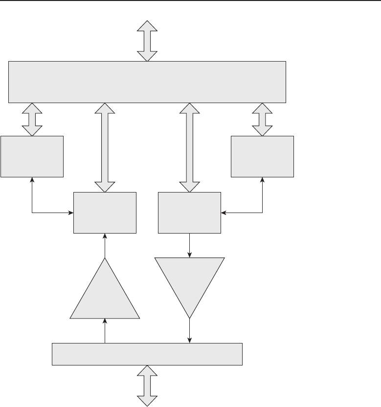
Edwards c08.tex V3 - 03/27/2009 11:22am Page 369
Chapter 8 ■The Upper Layers 369
Input Frame
Control
Input Frame
Buffer
Receive
Electrical
Interface
Transmit
Electrical
Interface
Output Frame
Buffer
Output Frame
Control
Computer Bus Interface
Network Interface Connector
To Network Bus
To Computer Bus
Figure 8-9 A block diagram of a generic NIC
With the network card installed in the computer chassis and the appropriate
device driver installed into the computer so that the operating system knows
how to communicate with the NIC, the next step is to bind a network protocol
to the card so data can be moved to and from the network. Depending on
the operating system, differing methods can be used; consult your computer
documentation. When all of that is completed, data can be sent and received
from the network transparent to the workstation’s user.

Edwards c08.tex V3 - 03/27/2009 11:22am Page 370
370 Part II ■The OSI Layers
RANDOM BONUS DEFINITION
collision domain — A set of nodes
connecting to a shared medium among
which a collision can occur. Stations on the
same shared LAN are in the same collision
domain.
Outgoing packets from an
application program flow down
the network stack with each
layer encapsulated within the
proper protocol. Once the frame
that is to be transmitted is
assembled and loaded into the
output frame buffer, the output
frame control prevents any fur-
ther packets from being written into the output buffer until the frame has
been completely sent. When the output frame buffer is cleared, the output
frame control (through the device driver associated with this card) alerts the
operating system that the card is ready to transmit another frame. On the
receive side, the card monitors the network medium. When it has received a
frame and it is completely in the input frame buffer and passes the checksum
validation, the operating system is alerted (again via the device driver for the
card) that a frame is ready to be passed up the network stack. As the packet
passes through each layer, it is verified and checked as it is de-encapsulated.
The input frame control is alerted that the frame is read and that another frame
can be received.
POP QUIZ
List what is required for a network card to
have full-duplex capability.
The last component to be dis-
cussed from the block diagram
of the NIC is the connector.
Many people are already famil-
iar with the UTP RJ-45 connec-
tors and plugs that are fairly
commonplace on PCs, hubs,
switches, and routers. However, depending on the medium being used, the
connector will be different and adhere to the standards governing the usage
of that type of medium.
8.2.4.1 TCP/IP Link Layer Protocols
The three common protocols residing at the Link layer of the TCP/IP model
are ARP (Address Resolution Protocol), RARP (Reverse Address Resolution
Protocol), and OSPF (Open Shortest Path First). ARP and RARP are the
complement of each other in resolving network addresses. ARP is used to find
what hardware MAC address is associated with a particular IP address. It
accomplishes this by sending out an ARP request packet as a broadcast to all
nodes on its local network segment. The packet contains the IP address that
the transmitting network node is seeking. The receiving nodes on the network
that do not have the IP address being requested simply ignore the packet. The
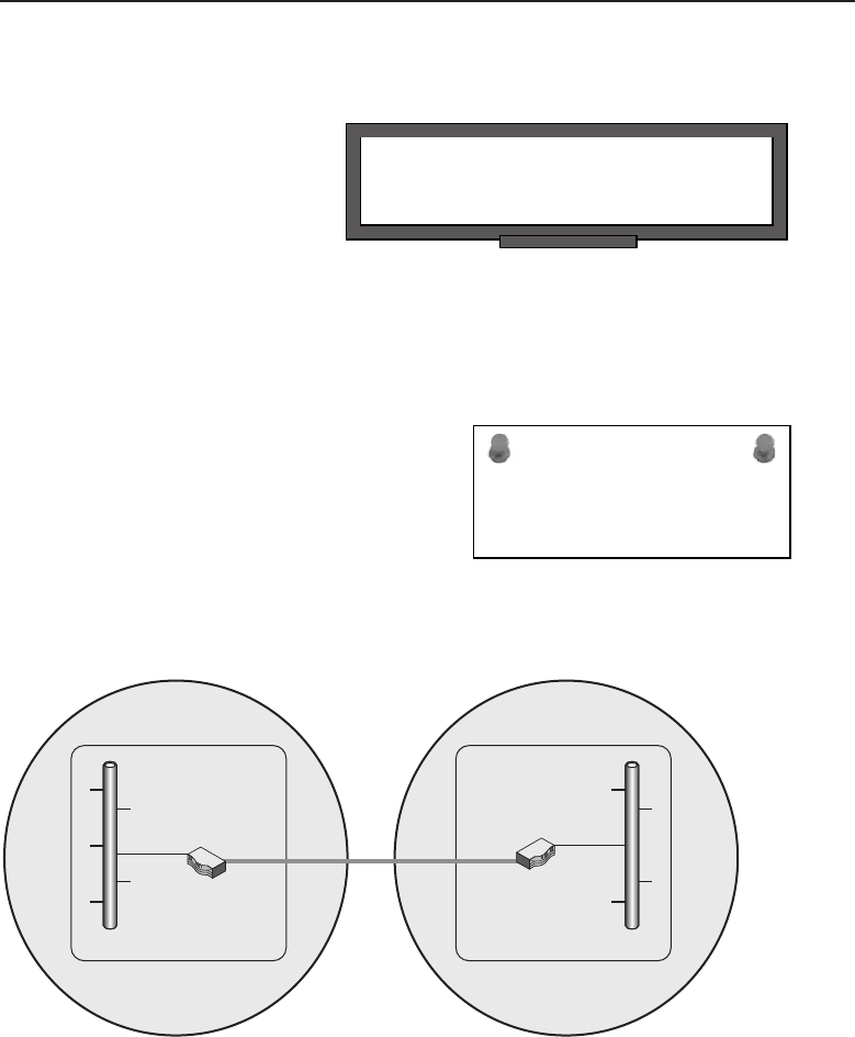
Edwards c08.tex V3 - 03/27/2009 11:22am Page 371
Chapter 8 ■The Upper Layers 371
network node that does have that IP address bound to its network interface
responds with its MAC hardware address.
POP QUIZ
What is ARP used for?
RARP is a protocol that
attempts to determine its IP
address by broadcasting on the
local network segment with
its MAC address. It expects a
receiving network node to have
an entry in its ARP cache that matches that MAC address with an IP address to
transmit back a packet containing the IP address. With DHCP now in wide use,
RARP has fallen into disuse. However, DHCP is a TCP/IP model Application
layer protocol and does not reside at the Link layer.
ACRONYM ALERT
RSTP — Rapid Spanning Tree Protocol
OSPF is a dynamic routing protocol used
to move packets from network segment to
network segment. Two network segments
with a router in each that have a path
between them can build and interchange
route information. Figure 8-10 illustrates a
network utilizing OSPF to pass network
routing information.
Area 0
LAN A LAN B
Area 1
Figure 8-10 OSPF passing network routing information
Notice there are two areas: Area 0 and Area 1. An area is a collection of
network segments with routers and other network forwarding devices. For the
sake of simplicity, these are shown as two large circles. Within each area there
is a router to route traffic from that area to another area. Routers that border a
network and pass routing information to another router within another area

Edwards c08.tex V3 - 03/27/2009 11:22am Page 372
372 Part II ■The OSI Layers
POP QUIZ
What is OSPF?
are called area border routers
(ABRs). You will recall in the
earlier discussion of routers in
this chapter we said they resided
within the lower level of the
TCP/IP model. The OSPF information passed between routers is used to
update their routing information tables. The two routers only communicate
OSPF information between them and do not pass that information into the
network they control. So if a workstation on LAN A wanted to pass data to
a server or another workstation on LAN B, it would send the packet to its
default gateway. The packet will ultimately end up at the ABR for Area 0 and
finding that the targeted address when compared to its learned routes in its
routing table is destined for network node in Area 1, forwards the adjacent
ABR for Area 1. The information that is used is the Link State Database
(LSDB)routingdatathatispassedbetweentheArea0andArea1ABR
router.
HELPFUL HINT
The OSPF example used is very simplistic. Large networks have multiple areas
where one ABR may be interconnected to many other ABR routers. The key to
OSPF is to know that the updates exchanged between routers can be found
within the router’s LSDB. Since this is a dynamic routing protocol, routes may
pop up or age out as network nodes are inserted or removed from the
network.
8.3 OSI Application Layer
The OSI Application layer resides at Layer 7 at the top of the OSI model.
It was mentioned that the TCP/IP Application model directly links to this
layer. So the protocols listed in the discussion of the TCP/IP model Appli-
cation layer are also contained within this layer of the OSI model. This
is the layer that is directly responsible for interfacing with the applica-
tion program a user is using on the computer. The most common use of
a computer with Internet access is e-mail. The e-mail protocols residing at
this layer are POP (Post Office Protocol), POP3 (Post Office Protocol ver-
sion 3), and SMTP (Simple Mail Transfer Protocol). POP and POP3 are
mail client–based in the form of user e-mail reader programs. SMTP is

Edwards c08.tex V3 - 03/27/2009 11:22am Page 373
Chapter 8 ■The Upper Layers 373
e-mail server–based and is used to transfer mail from one mail server to
another, so this layer is keenly aware of its communication peers. Mail clients
know where their mail server is, and mail servers can establish a connec-
tion for the transfer of mail between them. Using the example of e-mail
at the Application layer, the information the layer is concerned with is the
identity of the sender and the identity of the recipient of that message
and what application is available to assist in preparing the message to be
sent. All e-mail users are pretty familiar with the address format used, e.g.,
john.doe@his company.com.
ACRONYM ALERT
MTU — Maximum transmission unit
There are two parts to the recipient
address: the user name ‘‘john.doe’’ and
the domain name ‘‘his company.com’’. The
e-mail is formatted with sender address,
recipient address, and message and passed
on to the local mail server servicing that
sender. The mail server is concerned with both the domain name portion
of the recipient’s address and the recipient’s name. The recipient’s name is
used to identify the local mailbox for that user on the server. The applica-
tion on the mail server is designed to use SMTP to send and receive mail
from other mail servers. Most mail servers run a local post office where local
users communicate locally over the local network using either POP or POP3
to retrieve mail from the local mail server. To send mail, users direct their
outgoing messages to the SMTP service running on the mail server. Mail
clients run POP at the Application layer to read mail and use SMTP to send
mail. A mail server also runs two protocols at that layer, SMTP and POP
and/or POP3. These protocols rely on the layers below them to actually get
the message delivered and alert them when there is a message to pass up from
the network.
The Application layer is concerned with any syntax restraints such as the
‘‘@’’ sign in an e-mail message being required as a delimiter between recipient
address and domain address. It is also the layer where security is applied for
user identification and privacy. If quality of service is being applied to network
communications, this is the layer concerned with determining the priority of
apacketbyitsQoS
27 tagging.
NOTE Although there are many devices that are capable of QOS tagging of
packets, there is no support for it over the Internet. The Internet is still a
best-effort network.
27QoS is the acronym for quality of service. We mentioned that the DiffServ field or the Type of
Service field of the IP header is used for tagging packets to allow them to be transmitted along
the network with a priority determined by how they are tagged.

Edwards c08.tex V3 - 03/27/2009 11:22am Page 374
374 Part II ■The OSI Layers
POP QUIZ
True or false: The maximum number of
protocols the TCP/IP Application layer can
have at any one time is two.
This chapter covers only a
handful of the most familiar
Layer 7 protocols. Many more
protocols are available, consid-
ering that the combination for
port numbers is 65,536. Even
with some protocols using more
than one port, there is still a lot of them. You can obtain information on
many protocols by reading their RFCs. RFCs are available over the Internet at
www.ietf.org/rfc.html.
8.4 OSI Presentation Layer
The middle layer of the OSI model upper layers is the Presentation layer,
which occupies Layer 6 of that model. It has been mentioned that within the
TCP/IP model, this OSI layer resides within its top Application layer. In the
OSI model, it takes service requests from the Application layer and then issues
requests to the Session layer below.
POP QUIZ
True or false: The OSI model Presentation
layer maps directly to the Transport layer of
the TCP/IP model.
Although we said that this
layer resides within the TCP/IP
model Application layer, its
components are more likely to
be found within the computer’s
operating system. Within this
layer, incoming and outgoing
data can be translated from one
data format to another. This layer also offers the capability for data encryption
and compression as well as decrypting and uncompressing data received.
8.5 OSI Session Layer
ACRONYM ALERT
SNMP — Simple Network Management Protocol
The lowest layer of the upper layers of the
OSI model is Layer 5, the Session layer.
Like the OSI model’s Application and Pre-
sentation layers, it too can be found within
the Application layer of the TCP/IP model.
True to its name, it is the layer that is respon-
sible for opening, managing, and closing a
session between applications. It also provides the capability of restoring a
session. It is the layer where authentication and permissions are granted.

Edwards c08.tex V3 - 03/27/2009 11:22am Page 375
Chapter 8 ■The Upper Layers 375
The Session layer is where TCP SYN handshake sequences are provided
for. Although the Session layer is responsible for checkpointing and recovery
within the OSI model, it is seldom used by protocols of the Internet Protocol
suite. Some of the protocols found within the Session layer are
L2F (Layer 2 Forwarding Protocol) — Used to provide virtual private
networks (VPN) over the Internet.
L2TP (Layer 2 Tunneling Protocol) — Used to provide virtual private
networks (VPN) over the Internet.
NetBIOS (Network Basic Input/Output System) — In today’s networks
is usually run over TCP/IP on the local network. It is a naming
convention used to identify hosts on a Windows-based network.
Although it is run over TCP/IP, its host name is not to be confused with
the host domain name a computer may be given to resolve its name to
an IP address. Those host names are registered with a DNS server and
are not associated at all with a computer’s NetBIOS host name, which
on larger networks is resolved by a WINS (Windows Internet Name
Service) server. In small networks where WINS may not be available,
WINS name resolution can be accomplished by editing the LMHOSTS
file on the computer to correlate the NetBIOS name to an IP address.
PAP (Password Authentication Protocol) — A simple authentica-
tion protocol to allow users access to network services. A major
drawback to PAP is that passwords are passed in cleartext and
can be easily captured. Since PAP is not secure, network admin-
istrators have been making use of CHAP (Challenge Handshake
Authentication Protocol), which uses a hashing function to secure
the password. MS-CHAP is Microsoft’s implementation of CHAP.
RANDOM BONUS DEFINITION
catenet — A collection of networks
connected together at the Data Link layer
level.
PPTP (Point-to-Point
Tunneling
Protocol) — Provides
a means of creating a
VPN over the Inter-
net. PPTP uses a stan-
dard PPP (Point-to-Point
Protocol) session to its peer endpoint using the Generic Routing
Encapsulation (GRE) protocol. A second session is then opened
using TCP port 1723 to initiate and control the GTE session. Due
to the need to have two simultaneous sessions opened, PPTP is
not easily passed through a firewall. PPTP has lost favor and is
being replaced by the L2TP and IPSec tunneling protocols.
SSH (Secure Shell) — Allows for the secure exchange of data between
two network nodes. It was designed as a replacement for Telnet and

Edwards c08.tex V3 - 03/27/2009 11:22am Page 376
376 Part II ■The OSI Layers
other insecure protocols that were used for remote access over the
Internet. These shells sent communications in cleartext, and passwords
were easily compromised. SSH makes use of public key cryptography
for authentication of the remote computer and allows the remote
computer to also authenticate the user establishing the session.
POP QUIZ
At which layer of the TCP/IP model is the
OSI Session layer found?
The Session layer provides
for either half-duplex or full-
duplex operation, synchroniza-
tion points in the message
stream, and error checking.
LAST BUT NOT LEAST
As mentioned previously, you are encouraged to review the RFC documentation
for any further information on protocols. Be aware, however, that any RFC is
subject to variations in interpretation, and one implementation of a protocol
may not be identical to another. A network administrator or member of the
support staff must always be aware of this when integrating network pieces
from different manufacturers. When there are interoperability issues,
performance degradation issues, or functional issues, you may have to draw on
the RFC to find which way to point the finger.
8.6 Chapter Exercises
1. List in order from highest to lowest the upper layers of the OSI model,
also indicating their layer number.
2. An application that runs on a user’s workstation and communicates
over a network with an appropriate application that is running
on a server is considered to be what type of application?
3. Which protocol is considered to be a connection-based protocol?
4. What functionality can be used to disguise addresses from
a private address space to be seen on the Internet?
5. List the three private address spaces that may be used and
areconsideredtobenotroutableovertheInternet.
6. Name an Application layer protocol that may be used to perform file
transfers over the network.
7. What is the protocol that resolves IP addresses to hardware addresses?

Edwards c08.tex V3 - 03/27/2009 11:22am Page 377
Chapter 8 ■The Upper Layers 377
8.7 Pop Quiz Answers
1. True or false: The Application layer is where all the application pro-
grams you load on your PC are stored.
False
2. The predominant networking protocol run over Ethernet networks is
TCP/IP
3. True or false: UDP is a connection-based protocol.
False
4. Describe what happens to a packet when it is passed through a
NAT-enabled router.
A technique known as port mapping maps the hidden source address to
an unused port number. A workstation that requests a page from a web
server must access the server using port 80 for the server to respond
to the request. When the server receives the request, its only concern
is the destination port, which must be port 80. So what the source
port number is makes no difference when servicing the request. The
server simply sends the packet back to the requesting IP address, even
though it is of a NAT-enabled router and not the actual workstation
making the request. When the packet arrives at the NAT-enabled
router, it examines the packet and finds that the destination port
address correlates to a workstation on its private LAN in its NAT
translation table. It modifies the packet with a new destination IP
and port address, recalculates a new checksum, and then transmits
it on to the private LAN. Therefore, knowing those temporary port
addresses are available can come in handy when you’re using NAT.
5. At which layer of the TCP/IP model can the physical component of a
network node be found?
Layer 1
6. What determines the type of framing that is to be used on a particular
network segment?
The media being used for that network segment.
7. Which TCP/IP model Transport layer protocol is connection based?
TCP
8. True or false: The TCP/IP model Internet layer IP protocol is a connec-
tionless protocol.
True

Edwards c08.tex V3 - 03/27/2009 11:22am Page 378
378 Part II ■The OSI Layers
9. What two ICMP applications can be used to verify the pres-
ence of an IP address on the Internet or local network?
ping and/or traceroute
10. List what is required for a network card to have full-duplex capability.
input frame control
input frame buffer
receive circuit
output frame control
output frame buffer
transmit circuit
11. What is ARP used for?
Address resolution
12. What is OSPF?
A routing protocol
13. True or false: The maximum number of protocols the TCP/IP
Application layer can have at any one time is two.
False
14. True or false: The OSI model Presentation layer maps directly to the
Transport layer of the TCP/IP model.
True
15. At which layer of the TCP/IP model is the OSI Session layer found?
Layer 5

Edwards c09.tex V3 - 03/27/2009 11:23am Page 379
CHAPTER
9
The Transport Layer
Transport of the mails, transport of the human voice, transport of flickering
pictures — in this century as in others our highest accomplishments still have the
single aim of bringing men together.
— Antoine de Saint-Exup´
ery
The last chapter talked about the upper layers of the OSI reference model.
You learned the specific purpose of each layer and how the layers interact
with each other. This chapter covers the Transport layer, Layer 4 of the OSI
reference model.
The Transport layer is the highest layer of the lower layers of the OSI
reference model. The Transport layer sits on top of the Network layer and
below the Session layer. This layer is responsible for the end-to-end connection
and datagram delivery, as well as congestion control and flow control. The
two main protocols that operate at this layer are UDP and TCP, which were
discussed in Chapter 5.
The purpose of the Transport layer is to set up connections, maintain connec-
tions, shut down connections, and perform error checking.1The protocols that
operate at this layer are considered either connection-oriented (i.e., TCP) or
connectionless (i.e., UDP). Remember that connection-oriented means that the
connection must be set up before data can be transmitted, and connectionless
means that data can flow without the connection being established first.
1Error checking and other transport reliability attributes can be handled at this layer, if they are
not already performed at the lower layers.
379

Edwards c09.tex V3 - 03/27/2009 11:23am Page 380
380 Part II ■The OSI Layers
RANDOM BONUS DEFINITION
1000BASE-SX — A baseband Ethernet
system operating at 1000 Mbps over two
multimode optical fibers using shortwave
laser optics.
So far this book has explained
what the Transport layer is and
the services and protocols it pro-
vides. This chapter takes a little
deeper look into some of the
functions that operate at this
layer.
9.1 The Terms and Conditions of Chapter 9
RANDOM BONUS DEFINITION
root port — In the Spanning Tree Protocol,
the port through which a designated bridge
forwards traffic in the direction of the root
bridge.
Much like many other chapters
in this book, there are some
terms you need to have an
understanding of, but not nec-
essarily in-depth knowledge.
Therefore, we start this chapter
off with a few basic Transport
layer functions and terms relat-
ing to these.
9.1.1 End-to-End Delivery
The Transport layer provides logical communication between upper layer
processes2running on different nodes on a network (see Figure 9-1).
POP QUIZ
True or false: UDP is an example of a
connectionless protocol.
Notice in the figure that the
lower layer processes are trans-
parent to the Transport layer.
The sending node takes the
upper layer data and breaks it
into smaller segments that are
then passed to the lower layers
to be encapsulated and trans-
ported to a receiving node. The receiving node will cache the data, put the
segments back into the message, and pass it to the upper layers to be delivered
to the Application layer.
2Notice this says processes and not nodes. The Network layer provides the logical connection
between nodes.
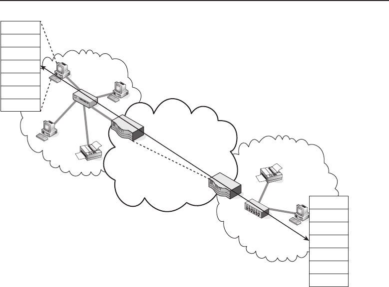
Edwards c09.tex V3 - 03/27/2009 11:23am Page 381
Chapter 9 ■The Transport Layer 381
Application
Presentation
Session
Transport
Network
Data Link
Physical
Application
Presentation
Session
Transport
Network
Data Link
Physical
Figure 9-1 Logical Transport layer communications
9.1.2 Standards
Before getting too much further into this chapter, there are a couple of stan-
dards that need to be mentioned that deal with the services and operations of
functions at the Transport layer. The first of these is the ISO/IEC 8072 stan-
dard (Information technology – Open Systems Interconnection – Transport
service definition), and the other is the ISO/IEC 8073 standard (Information
technology – Open Systems Interconnection – Protocol for providing the
connection-mode transport service).
Following is a quick summary of these two standards. The remainder of the
chapter covers the information that is defined in the standards.
9.1.2.1 ISO/IEC 8072
The ISO/IEC 8072 standard defines the recommended services provided by
the OSI Transport layer while working with the Network layer to serve the
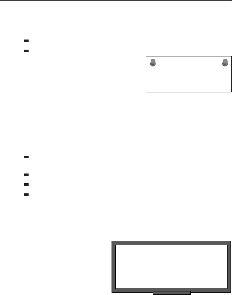
Edwards c09.tex V3 - 03/27/2009 11:23am Page 382
382 Part II ■The OSI Layers
needs of protocols used at the Session layer. These are only recommendations
or guidelines, and strict adherence is not upheld.3Defined in this standard are
recommendations for the implementation for the following functions:
Connection-oriented mode services
Connectionless-mode services
ACRONYM ALERT
BGP — Border Gateway Protocol
The main thing to remember about this
standard is that it defines the way the Trans-
port layer interoperates with the other OSI
layers it works with.
9.1.2.2 ISO/IEC 8073
The ISO/IEC 8073 standard sets the recommendations to be followed by nodes
(entities) within a network that are utilizing the services of the OSI Transport
layer. This standard is also available to future node deployments within an
open systems environment. Defined in this standard are recommendations for
the following functions:
The recommendation and scope for classes of procedures that should
be taken into account by the nodes when transporting data
How peer nodes exchange data
How the nodes exchange information with the transport service
The manner in which the nodes exchange information with a service
provider
9.1.3 This, That, and the Other
RANDOM BONUS DEFINITION
aggregated link — A set of two or more
physical links that appear to higher layer
entities as though they were a single, higher
capacity link.
This section takes a look at a few
other ‘‘items of interest’’ regard-
ing the Transport layer.
9.1.3.1 Types of Transport
Service
This is an easy one.4There
are two types of transport ser-
vice: connection-oriented and
connectionless.
3Keep in mind that all of the functions at each of the layers in the reference model are only
recommendations and guidelines that can be followed for conformity sake.
4Atleastwehopeitis.

Edwards c09.tex V3 - 03/27/2009 11:23am Page 383
Chapter 9 ■The Transport Layer 383
9.1.3.2 Data Units
The following two data units operate at the Transport layer:
Transport protocol data unit (TPDU)
Transport service data unit (TSDU)
POP QUIZ
TCP is a connection-
protocol.
So, what is the difference
between the two types of data
units? The TSDU is the data that
is transmitted to the various lay-
ers on both ends of a connection.
The TPDU is the data that is sent
from a protocol on one end to the
peer protocol at the other end.
9.1.3.3 Classes of Transport Service
ACRONYM ALERT
IETF — Internet Engineering Task Force
The Transport layer defines the functions of
service performed by it within five differ-
ence classes of transport service, as shown
in Table 9-1.
Table 9-1 Classes of Transport Service
CLASS NAME CLASS FUNCTION
Class 0 Simple class
Class 1 Basic error recovery class
Class 2 Multiplexing class
Class 3 Error recovery and multiplexing class
Class 4 Error detection and recovery class
9.1.3.4 Types of Network Service
The Transport layer takes into consideration the current error rate status of
the connection being used. There are three types of network service used to
classify the connection status. The data units are classified into one of the three
types based on signal quality:
Type A — A network connection with an acceptable residual
error rate as well as an acceptable rate of signal failures.
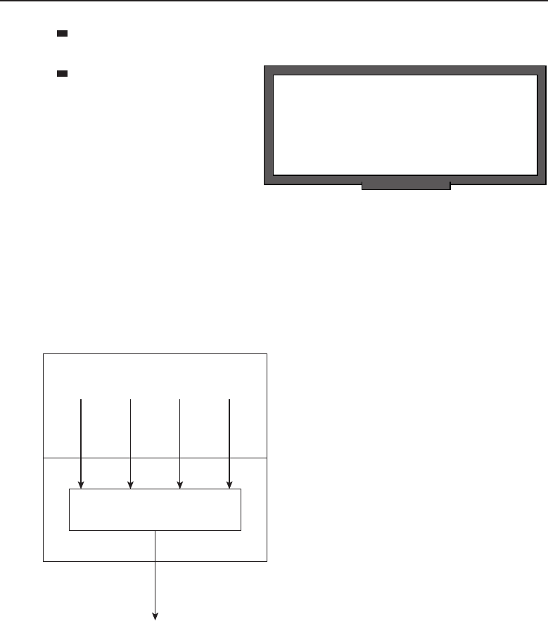
Edwards c09.tex V3 - 03/27/2009 11:23am Page 384
384 Part II ■The OSI Layers
Type B — A network connection with acceptable residual
error rate but an unacceptable rate of signal failures.
RANDOM BONUS DEFINITION
promiscuous mode — A mode of operation
of a network interface in which it receives
(or attempts to receive) all traffic, regardless
of the destination address.
Type C —Anetwork
connection with an unac-
ceptable residual error
rate for the user of the
transport service.
9.1.3.5 Multiplexing
Multiplexing is the act of grouping several signals into a shared single signal.
Multiplexing at the Transport layer is performed between the Transport layer
and its adjoining layers. Multiple upper layer users can be multiplexed to share
the services of a single Transport layer protocol. The signals are separated by
what are known as transport service access points (TSAP). An example of this is
shown in Figure 9-2.
Upper
Layers
Transport Layer Protocol Transport
Layer
Figure 9-2 An example of multiplexing
Network service multiplexing is also supported at the Transport layer.
Multiplexing can occur in both an upward (multiple Transport layer signals
to a single network signal) and a downward (multiple network signals to a
single transport signal) fashion.
The use of upward multiplexing (see Figure 9-3) is a cost-saving measure
that allows multiple Transport layer signals to share a single network signal
(a signal purchased from the network provider).
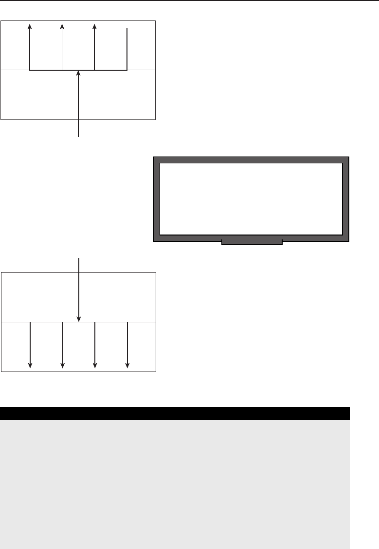
Edwards c09.tex V3 - 03/27/2009 11:23am Page 385
Chapter 9 ■The Transport Layer 385
Network
Layer
Transport
Layer
Figure 9-3 Upward multiplexing
RANDOM BONUS DEFINITION
best-effort service — A service provided by
an entity where frames or packets are
delivered with high probability but with no
absolute guarantee.
Downward multiplexing (see
Figure 9-4) is useful when band-
width and throughput of data
are priorities.
Network
Layer
Transport
Layer
Figure 9-4 Downward multiplexing
AN UNRELATED MOMENT OF PAUSE: WEB ACRONYMS
It isn’t just the networking world that uses acronyms. Millions of users are
typing away with acronyms that a few years ago didn’t exist. A lot of kids out
there have added their own, such as POS (parent over shoulder). Jim has
already prepared to start running a sniffer if he sees one of his kids using that
one — having to warn a pal that the parent is looking in deserves a quick
look-see.
Enough rambling. Here is a list of some common web acronyms that you may
come across at some point.
(continued)

Edwards c09.tex V3 - 03/27/2009 11:23am Page 386
386 Part II ■The OSI Layers
AN UNRELATED MOMENT OF PAUSE: WEB ACRONYMS (continued)
2L8 Too late
AFK Away from keyboard
AFN [That’s] all for now
AISB As I said before
B4 Before
B4N Bye for now
BAK Back at keyboard
BBL Be back later
BCNU Be seeing you
BRB Be right back
BTW By the way
CU See you
CYA See ya
DL Download
EZ Easy
F2F Face to face
FWIW For what it’s worth
G2G Gotta go
GMTA Great minds think alike
HAND Have a nice day
IC I see
IDK I don’t know
IK I know
IKWUM I know what you mean
IMAO In my arrogant opinion
IMHO In my humble opinion
IMO In my opinion
IYKWIM If you know what I mean
IYO In your opinion
IYSWIM If you see what I mean
JK Just kidding
(continued)

Edwards c09.tex V3 - 03/27/2009 11:23am Page 387
Chapter 9 ■The Transport Layer 387
AN UNRELATED MOMENT OF PAUSE: WEB ACRONYMS (continued)
KISS Keep it simple, stupid
LOL Laughing out loud
ME2 Me too
NP No problem
ROTFL Rolling on the floor laughing
TC Take care
9.2 Transport Layer Operations
POP QUIZ
Which standard defines the way the
Transport layer interoperates with the other
OSI layers it works with?
ThepurposeoftheTransport
layer is to provide end-to-end
delivery of data from one appli-
cation to another. The Trans-
port layer can deliver data in
a reliable or an unreliable fash-
ion. Data flow can be regulated
and each end can communi-
cate lost datagram data with the other end. Protocols can operate in a
connection-oriented manner as well as a connectionless manner. In the
connection-oriented approach, a logical connection between nodes must be
established before any data is transmitted. The connectionless approach does
not require connection establishment; data is sent as it is received.
ACRONYM ALERT
ROM — Read-only memory
In this section, we take a deeper look
into the operations for both the connection-
oriented as well as the connectionless
protocols that are available within the
Transport layer.
9.2.1 Connection-Oriented Operations
Connection-oriented protocols require that a logical connection between two
nodes is established before any data can be sent. To dothis, rules are established
that lay out how a connection is set up, maintained, and terminated.
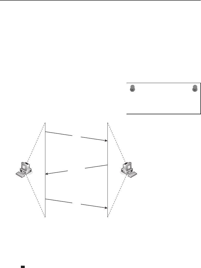
Edwards c09.tex V3 - 03/27/2009 11:23am Page 388
388 Part II ■The OSI Layers
9.2.1.1 Setting Up the Connection
If a node needs to pass data in a connection-oriented environment, a series
of messages is passed between the node and the destination node it wants to
send the data to. The series of messages is known as the three-way handshake,
and it works like this:
1. The originating node will send a request known as a SYN5to the destina-
tion node.
2. The destination node will let the originating node know that it has
received the SYN request by sending back a SYN-ACK6message.
ACRONYM ALERT
MSTI — Multiple spanning tree instance
3. The originating node will respond
to the SYN-ACK by sending
back an ACK message.
Figure 9-5 shows an example of this.
SYN
SYN-ACK
ACK
Step 1
Step 3
Step 2
Figure 9-5 An example of a three-way handshake
Don’t be fooled into believing this is all that’s going on in the connection
setup phase. A number of variables are being negotiated during this phase.
User node quality of service is matched to any available services that are
provided by the Network layer. Some of the services negotiated include
Which network services best match requirements set by the user for the
connection
5SYN stands for synchronize.
6ACK stands for acknowledgment.
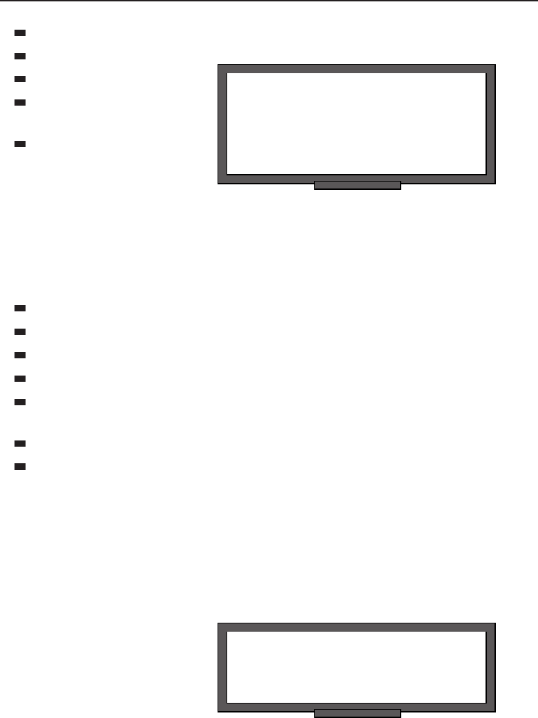
Edwards c09.tex V3 - 03/27/2009 11:23am Page 389
Chapter 9 ■The Transport Layer 389
Whether multiplexing can (or should) be used
RANDOM BONUS DEFINITION
optical fiber — A communications medium
capable of carrying and directing light
signals. Normally extruded or drawn from
transparent glass or plastic material.
Datagram size
Address mapping
Ability to separate mul-
tiple connections
Inactivity timer infor-
mation
9.2.1.2 Maintaining the Connection
Maintaining the connection is nothing more than ensuring the connection
remains stable during the transfer of data between the endpoint nodes. The
following activities occur during this phase:
Segmentation of data
Reassembly of data
Splitting data over multiple connections
Flow control
Setting the identification parameters for a particular connection between
endpoint nodes
Attending to prioritized datagrams
TSDU delimiting
9.2.1.3 Terminating the Connection
Just like with the connection setup phase, there has to be a way to terminate
the connection when the endpoint nodes are finished exchanging data. This
phase operates much like the connection establishment phase.
RANDOM BONUS DEFINITION
collision detection — The act of detecting
when packets collide during transmission.
Any node that has an active
connection can initiate a con-
nection termination by sending
out a FIN7packet (or by set-
ting a flag in a datagram). The
other node can continue receiv-
ing data until it sends out a
FIN-ACK, acknowledging the
request to terminate the session.
7FIN stands for finished.

Edwards c09.tex V3 - 03/27/2009 11:23am Page 390
390 Part II ■The OSI Layers
9.2.2 Connectionless Operations
Connectionless protocols do not require a connection; a transmitting device
simply sends data as soon as it has data that is ready to be sent. Protocols that
operate in a connectionless manner have a space available in the datagram
to identify the source and destination addresses for the endpoint nodes.
Connectionless protocols do need an available route to the destination in order
to work. This means there must be some type of medium, a data link protocol,
and a networking protocol to transmit the data. Other than these, there really
is no other requirement.
ACRONYM ALERT
SNA — Systems network architecture
Protocols that use the connectionless
method of transport will often provide error
checking and recovery methods, which are
lacking in the connectionless environment.
Some of these include:
POP QUIZ
How many types of transport service are
there?
Hop count verification
Verification of the
reassembly of frag-
mented data
Datagram priority infor-
mation and verification
Datagram size verification
TIME FOR SOMETHING NICE TO KNOW
Following are some helpful MS-DOS commands that are available with most
Windows OS platforms.
◆To determine whether a remote node is reachable and its connection qual-
ity, use the ping command.
C:\>ping
Usage: ping [-t] [-a] [-n count] [-l size] [-f] [-i TTL] [-v TOS]
[-r count] [-s count] [[-j host-list] |
[-k host-list]]
[-w timeout] destination-list
Options:
-t Ping the specified host until stopped.
To see statistics and continue - type
Control-Break;
To stop - type Control-C.
-a Resolve addresses to hostnames.
-n count Number of echo requests to send.
-l size Send buffer size.
(continued)

Edwards c09.tex V3 - 03/27/2009 11:23am Page 391
Chapter 9 ■The Transport Layer 391
TIME FOR SOMETHING NICE TO KNOW (continued)
-f Set Don’t Fragment flag in packet.
-i TTL Time To Live.
-v TOS Type Of Service.
-r count Record route for count hops.
-s count Timestamp for count hops.
-j host-list Loose source route along host-list.
-k host-list Strict source route along host-list.
-w timeout Timeout in milliseconds to wait for each reply.
◆To follow the path that is taken by a datagram to a remote node, use the
tracert8command.
C:\>tracert
Usage: tracert [-d] [-h maximum hops] [-j host-list] [-w timeout]
target name
Options:
-d Do not resolve addresses to
hostnames.
-h maximum hops Maximum number of hops to search for
target.
-j host-list Loose source route along host-list.
-w timeout Wait timeout milliseconds for each
reply.
◆To view and manage the local routing table, use the route command.
C:\>route
ROUTE [-f] [-p] [command [destination]
[MASK netmask] [gateway] [METRIC metric]
[IF interface]
-f Clears the routing tables of all gateway
entries. If this is used in conjunction with
one of the commands, the tables are cleared
prior to running the command.
-p When used with the ADD command, makes a route
persistent across
boots of the system. By default, routes are
not preserved
when the system is restarted. Ignored for all
other commands,
which always affect the appropriate
persistent routes. This option is not
supported in Windows 95.
command One of these:
PRINT Prints a route
(continued )
8Tracert stands for trace route.

Edwards c09.tex V3 - 03/27/2009 11:23am Page 392
392 Part II ■The OSI Layers
TIME FOR SOMETHING NICE TO KNOW (continued)
ADD Adds a route
DELETE Deletes a route
CHANGE Modifies an existing route
destination Specifies the host.
MASK Specifies that the next parameter is the
‘netmask’ value.
netmask Specifies a subnet mask value for this route
entry.
If not specified, it defaults to
255.255.255.255.
gateway Specifies gateway.
interface the interface number for the specified route.
METRIC specifies the metric, ie. cost for the
destination.
◆To view and manage the ARP table, use the arp command.
C:\>arp
Displays and modifies the IP-to-Physical address translation
tables used by address resolution protocol (ARP).
ARP -s inet addr eth addr [if addr]
ARP -d inet addr [if addr]
ARP -a [inet addr] [-N if addr]
-a Displays current ARP entries by
interrogating the current
protocol data. If inet addr is specified,
the IP and Physical
addresses for only the specified computer
are displayed. If more than one network
interface uses ARP, entries for each ARP
table are displayed.
-g Same as -a.
inet addr Specifies an internet address.
-N if addr Displays the ARP entries for the network
interface specified by if addr.
-d Deletes the host specified by inet addr.
inet addr may be wildcarded with * to delete
all hosts.
-s Adds the host and associates the Internet
address inet addr with the Physical address
eth addr. The Physical address is
given as 6 hexadecimal bytes separated by
hyphens. The entry is permanent.
eth addr Specifies a physical address.
if addr If present, this specifies the Internet
address of the interface whose address
translation table should be modified.
If not present, the first applicable
interface will be used.

Edwards c09.tex V3 - 03/27/2009 11:23am Page 393
Chapter 9 ■The Transport Layer 393
9.3 Transport Layer Protocols
Chapter 5 provided some information on the TCP and UDP Transport layer
protocols. Although these are the most popular and most commonly used, the
following Transport layer protocols are also in use in some networks today:
AppleTalk Transaction Protocol (ATP)
Datagram Congestion Control Protocol (DCCP)
NetBIOS Extended User Interface (NetBEUI)
Real-time Transport Protocol (RTP)
ACRONYM ALERT
PPP — Point-to-Point Protocol
These are mentioned only to provide you
with the names of a few more Transport
layer protocols that you may come across.
For the purposes of this book, TCP and
UDP are the Transport layer protocols that
we will stick with.
9.3.1 A Few More Words about TCP
TCP is a connection-oriented protocol. An originating node will contact a desti-
nation node to make sure it is available to get the message. Once confirmation
is received that it is okay to send data, the transmission begins. TCP is also
considered a reliable protocol because it has functions built into it that provide
for various checks and balances to ensure the integrity of the data being
transmitted.
RANDOM BONUS DEFINITION
jumbo frame — A frame longer than the
maximum frame length allowed by a
standard.
TCP is able to break data
down into segments so that
smaller chunks of data are
lost if there are problems with
the transmission. TCP supports
acknowledgments for received
datagrams, and timers are set
for the receipt of an acknowl-
edgment to ensure that data is
received on the destination end. TCP utilizes a checksum to monitor data
receipt integrity. TCP also supports datagram reassembly, ensuring that it is
put back into the same order it was sent. Finally, TCP supports both conges-
tion control and flow control, allowing a sending node to monitor bandwidth
availability as well as whether the receiving node can receive any more data.
TCP uses sequence numbers between nodes to ensure that reliable commu-
nication is taking place. Receiving nodes use sequence numbers to put the data
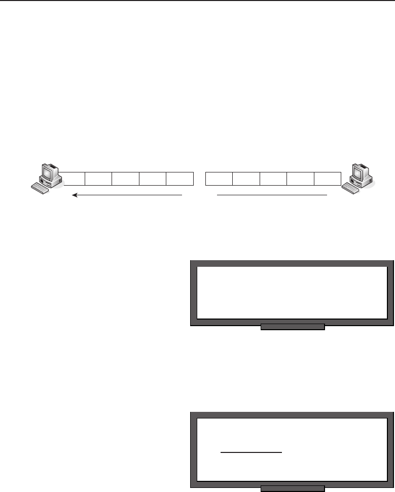
Edwards c09.tex V3 - 03/27/2009 11:23am Page 394
394 Part II ■The OSI Layers
back in order when it is received. Sequence numbers are also used to identify
problems (lost packets, duplicate packets, etc.) that may occur with a specific
packet that had been transmitted. Each end of the connection maintains its own
sequence numbers, so data transmission can operate in a full-duplex manner.
TCP is known as a byte-oriented sequencing protocol because every byte9that is
being transmitted is assigned a sequence number. The TCP packet is assigned
the sequence number of the first byte of the packet. The following packet
will get assigned the sequence number of its first byte, and so on. Figure 9-6
provides an example of sequencing.
67891012345
Data Flow
Figure 9-6 TCP sequencing
RANDOM BONUS DEFINITION
D-compliant — A bridge or switch that
complies with IEEE 802.1D.
In the figure, you can see that
data is flowing from one node
to another. The receiving node
recognizes that it is receiving a
packet with a sequence num-
ber of 1. As the node receives
the packet, the number of bytes
in the packet is counted. This
will tell the node what packet
sequence number is expected next. As you can see, there were 5 bytes10 in the
first packet, so the next packet should start with a sequence number of 6. And
that, my friend, is TCP byte sequencing.
POP QUIZ
The is the data that is
transmitted to the various layers on both
ends of a connection.
TCP also uses acknowledg-
ment numbers that work hand
in hand with the sequence num-
bers. Acknowledgment num-
bers are simply the sequence
numbers in reverse. They are
the reply from the destina-
tion node that sequence num-
ber such-and-such has been
received. Figure 9-7 provides an example of how this works.
9As opposed to some protocols that assign a sequence number to a whole datagram.
10Five-byte TCP segments? Now, that’s funny. This number was picked at random for use in the
example. TCP segments normally have 512 bytes.
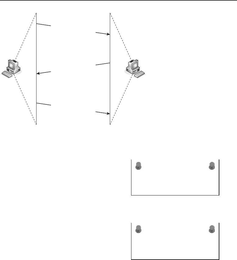
Edwards c09.tex V3 - 03/27/2009 11:23am Page 395
Chapter 9 ■The Transport Layer 395
Sequence #1, ACK #71
Sequence #71, ACK #6
Sequence #6, ACK #76
Node A Node B
Figure 9-7 Sequencing and acknowledgement
ACRONYM ALERT
VLAN — Virtual local area network
The figure represents communication
between a pair of nodes. The originat-
ing node sends a packet that is assigned
sequence number 1 (because the first byte
sequence number is 1) and then sends an
acknowledgment of a received datagram.
The acknowledgment number is actually
the sequence number that the node is
ACRONYM ALERT
SRAM — Static random-access memory
expecting next. In the figure, Node A sends
a packet to Node B. The packet has a
sequence number of 1, and an acknowledg-
ment number of 71. This means that Node
A is telling Node B that it has received
a packet and the next one it is expecting
is sequence number 71. Node B sends a
packet with sequence number 71 and the
acknowledgment that packet sequence number 1 was received and the node
is ready to receive sequence number 6. Node A then sends the next packet and
acknowledges receipt of a previous packet. This process continues until data
transmission is no longer required.
9.3.2 The TCP Header Format
The TCP header and the upper layer data are joined to form a TCP segment.The
TCP header is where the sequencing number and acknowledgment number

Edwards c09.tex V3 - 03/27/2009 11:23am Page 396
396 Part II ■The OSI Layers
are maintained, as well as many other factors needed for proper data delivery.
Figure 9-8 shows the format of the TCP header.
Source Port
Checksum
Options (if used)–Variable Length
Urgent Pointer
Window
Padding
Data
Offset Rsvd U A P R S F
Destination Port
Sequence Number
Acknowledgment Number
Figure 9-8 The format of the TCP header
Source Port — A 16-bit number that identifies the application that sent
the TCP segment.
Destination Port — A 16-bit number that identifies the application the
TCP segment is destined for.
Sequence Number — A 32-bit number that identifies the first data byte
in the segment.
Acknowledgment Number — A 32-bit number that iden-
tifies the next data byte the node expects to receive.
Offset — A field that identifies the length of the TCP header.
Rsvd — An unused field reserved for potential future use.
U/A/P/R/S/F — This field grouping contains the control fields:
U— Urgent. If this field is set, the destination (receiving)
node knows there is urgent data waiting to be sent.
A— Acknowledgment. This is set when the packet has an acknowl-
edgment for a received datagram.
P— Push. When this field is set, the receiver needs to deliver
the segment to the receiving application ASAP.11
11As soon as possible.

Edwards c09.tex V3 - 03/27/2009 11:23am Page 397
Chapter 9 ■The Transport Layer 397
R— Reset. When this is set, it tells the receiving node
that the originator is terminating the connection.
S— Synchronize. This field is set at startup when setting sequence
numbers.
F— Finished. There will be no more data coming.
Window — A 16-bit number used by TCP for flow control. It
indicates the number of available buffers the sending node has.
Checksum — A 16-bit number used for error detection.
Urgent Pointer — This is a 16-bit field. When the Urgent bit
is set, there will be a number that points to the sequence num-
ber of the data that follows urgent data. This identifies to the
destination node that the last byte of urgent data was received.
Options — TCP support options that can be set for the data.
This is a variable length field, depending on the option data.
POP QUIZ
How many different classes of transport
service are there?
Padding — Padding fills
the remainder of the 32-bit
field. This is necessary due
to the optional and vari-
able length Options field.
Data — The application
data: the payload!
9.3.3 A Little More on UDP
RANDOM BONUS DEFINITION
E1 — A T-carrier technology commonly
used in Europe, capable of multiplexing 32
DS-0 (64 Kbps) channels for a total
data-carrying capacity of 2.048 Mbps.
UDP is a connectionless proto-
col. It does not guarantee that
data is going to be delivered
to a destination. UDP simply
transmits data when it has data
that is ready to be transmitted.
Remember that UDP is usu-
ally used to send short bursts
of datagrams between nodes
where reliability is not a big concern. UDP can get data to a destination
quicker, as it avoids the overhead required by all the checks and balances in
TCP. Also, because UDP is connectionless, it can support broadcasting (sending
messages to all nodes within a broadcast domain) and multicasting (sending
messages to all nodes that are subscribed to the catenet).
UDP accepts data (the payload) from the Application layer. It adds a UDP
header and passes the header and the payload to the Internet layer. There

Edwards c09.tex V3 - 03/27/2009 11:23am Page 398
398 Part II ■The OSI Layers
it is encapsulated into an IP packet and passed on to the Network Interface
layer, then is passed over the transmission medium to the destination, where
it makes its way up to the Application layer on the destination end of the
connection.
POP QUIZ
True or false: FIN stands for finished.
UDP segments can be lost
along the way. They can also
be received out of sequence.
This is why UDP is known as a
best-effort protocol.UDPisbene-
ficial when you need to transmit
a lot of data. There is no delay
with UDP, as there is no need to set up a connection prior to the distribution
of the data. If an application needs a method of recovering from errors, the
application will handle this task itself. UDP also uses a checksum, which is a
method for detecting transmission errors.
9.3.4 The UDP Header Format
The UDP header and the upper layer data are joined to form a UDP segment.
The UDP header is simpler than the TCP header due to the overhead required
for the connection-orientation used by TCP. Figure 9-9 shows the format of the
UDP header.
Source Port Destination Port
ChecksumMessage Length
Data
Figure 9-9 The format of the UDP header
Source Port — A 16-bit number that identifies the application that sent
the UDP segment.
Destination Port — A 16-bit number that identifies the application the
UDP segment is destined for.
Message Length — A field that identifies the length of the UDP header.

Edwards c09.tex V3 - 03/27/2009 11:23am Page 399
Chapter 9 ■The Transport Layer 399
POP QUIZ
True or false: The AppleTalk Translucent
Protocol is a transport layer protocol.
Checksum — A 16-bit
number used for error
detection.
Data — The application
data: the payload!
9.4 The Meaning of Control
In a connection-oriented environment, control of data transmission is impor-
tant to ensure data delivery. Congestion control and flow control are two
mechanisms used. Congestion control is used to avoid congestion on a link
by avoiding the oversubscription of the rate that is supported by the link and
reducing the rate of datagram transmission when congestion is on the link.
POP QUIZ
What is a TCP source port?
Flow control is a mechanism
that an originating node uses to
ensure that a destination node
can handle the amount of data
being transferred.
9.5 Chapter Exercises
1. What are the two ISO/IEC standards that define recommendations for
the transport layer?
2. What are the two types of transport service?
3. From the following list, fill in the class function in the table below.
Multiplexing class
Error detection and recovery class
Simple class
Error recovery and multiplexing class

Edwards c09.tex V3 - 03/27/2009 11:23am Page 400
400 Part II ■The OSI Layers
Basic error recovery class
Class Name Class Function
Class 0
Class 1
Class 2
Class 3
Class 4
4. Match the type with the correct description:
Type Network connections that maintain an unacceptable
rate of residual errors
Type Network connections that maintain both
an acceptable rate of signaled errors and residual errors
Type Network connections that maintain an acceptable
rate of residual errors and an unacceptable rate of signaled errors
5. Define upward multiplexing.
6. Define downward multiplexing.
7. Explain how a three-way handshake works.
8. List four Transport layer protocols.
9.6 Pop Quiz Answers
1. True or false: UDP is an example of a connectionless protocol.
True
2. TCP is a connection-oriented protocol.
3. Which standard defines the way the Transport layer interoperates with
the other OSI layers it works with?
ISO/IEC 8072

Edwards c09.tex V3 - 03/27/2009 11:23am Page 401
Chapter 9 ■The Transport Layer 401
4. How many types of transport service are there?
Two
5. The TSDU is the data that is transmitted to the various layers on both
ends of a connection.
6. How many different classes of transport service are there?
Five
7. True or false: FIN stands for finished.
True
8. True or false: The AppleTalk Translucent Protocol is a Transport layer
protocol.
False. It is the AppleTalk Transaction Protocol. (Gotcha!)
9. What is a TCP source port?
The TCP source port is part of the TCP header. It is the 16-bit
number that identifies the application that sent the TCP segment.
Edwards c09.tex V3 - 03/27/2009 11:23am Page 402

Edwards c10.tex V3 - 03/27/2009 11:24am Page 403
CHAPTER
10
The Network Layer
It’s not what you know but who you know that makes the difference.
— Anonymous
There is not much difference between human networking and computer net-
working. You can be the most gifted human or the highest powered computer,
but lacking the ability to share those resources, you can do nothing as far as
the progression of humankind is concerned. The power of information is in its
capacity to be shared. Since the evolution of wireless networking, information
can be shared not only globally but beyond this world into outer space.1
The number of connected computers on the World Wide Web is staggering.
Two computers are able to share information between them without concern
about how that information is to navigate over the Internet. This is the ‘‘who
you know that makes the difference’’ portion of what networking is about.
Networking is about being able to route information to a particular computer
and receive requested information from that computer without a need to know
the path it travels over the Internet.
Think of the Internet as a giant matrix with routing devices at every crossing
point to aid in the movement of a packet of information along the cables
connecting to the next crossing point. The route a packet of information
travels can be different each time another packet of information is sent. The
routing device’s responsibility is to make sure that the packet will arrive at the
destination it is intended for.
1Amateur Radio on the International Space Station (ARISS) has been experimenting with packet
mail from amateur radio operators from around the world to the International Space Station.
Although this is not conventional wireless networking, it may be a precursor of things to come
when there is a manned base on the moon.
403

Edwards c10.tex V3 - 03/27/2009 11:24am Page 404
404 Part II ■The OSI Layers
A computer is concerned only with its locally connected default gateway. A
default gateway is where network traffic is sent when a computer wants to send
information to a computer that it knows does not reside on its local network.
Every computer and network-connected device has a default gateway set
within their network configuration parameters. When information comes in
via the Internet, it is accepted by the default gateway and routed on to the
local network, directed toward the computer the received data is intended for.
Routing or network traffic forwarding devices need not know every other
device that is connected to the Internet. They just need to have a good working
relationship with their immediate peers. It is dependent upon networking
through these other peer routing devices to know other devices that they also
have a working relationship with. It is essential that networks know the right
entities to network to.
RANDOM BONUS DEFINITION
mirror port — A switch port configured to
reflect the traffic appearing on another of
the switch’s ports.
The Network layer occupies
Layer 3 of the OSI model. It
receives network requests from
the Transport layer and, in
turn, issues network requests
to the Data Link layer. It is
the layer that is responsible for
end-to-end information trans-
fer. The delivery of information is within a datagram,alsoknownasa
frame or packet. The Network layer loosely maps to the Internet layer of
the TCP/IP model, but the Internet layer deals only with the Internet Protocol
(IP), whereas the OSI Network layer encompasses a broader range of both
connection-oriented and connectionless network services.
10.1 Network Connection Types
What does a connection-oriented service versus a connectionless network
service really mean? All network-enabled devices2are connected to a network,
right? So they must be connected, right? Well, in the physical sense that
is true. However, as far as a network service is concerned, it does make a
difference how information is delivered between network nodes. The easy
way to differentiate between the two types of network services is that a
connected-oriented network service is one where the endpoint network nodes
know who a session was established with, whereas in a connectionless network
service, the two network nodes do not need to establish a direct connection in
order to share information
2A ‘‘network-enabled’’ device is simply any computer or packet-forwarding device with the right
network interface for the network medium connecting the device, along with the appropriate
network software.
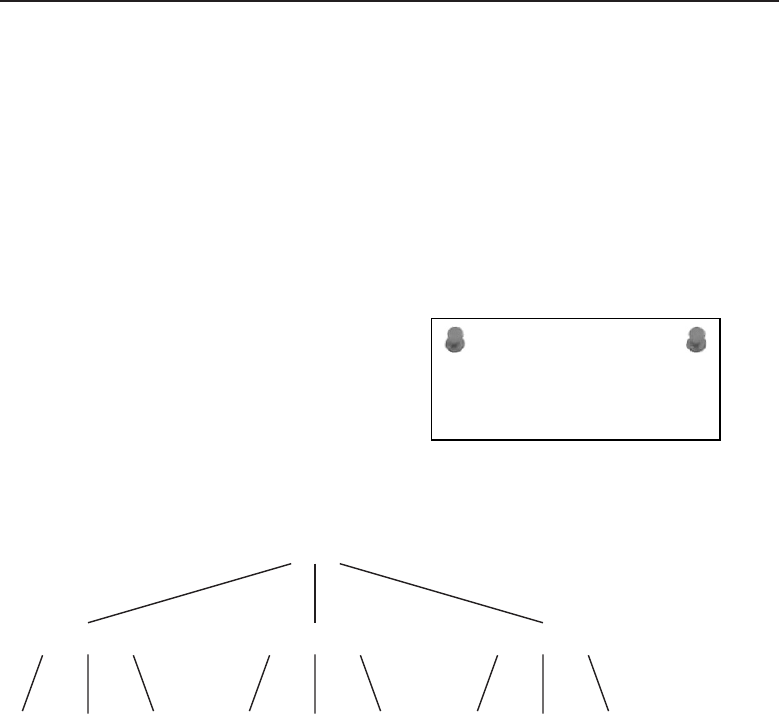
Edwards c10.tex V3 - 03/27/2009 11:24am Page 405
Chapter 10 ■The Network Layer 405
10.1.1 Connectionless Network Services
How can two network nodes exchange information if they do not have a
connection established between them? This is where connectionless network
services come into play. A great example of a connectionless network service is
e-mail. E-mail is addressed to a particular user residing in a particular domain.
It has no relation to a particular computer or geographical location.
The following is an example of a typical e-mail address:
john.doe@hishome.com
ACRONYM ALERT
XNS — Xerox Network System
The recipient of this e-mail is john.doe
who resides in the network domain of
hishome.com. This brings in the concept
once again of domain names and their
relationship to network services. There is
a hierarchy to network addressing, and
the domain name is the highest level.
Figure 10-1 illustrates the network addressing hierarchy.
Domain
Sub Domain 2
User 2 User 3User 1
Sub Domain 1
User 2 User 3User 1
Sub Domain 3
User 2 User 3User 1
Figure 10-1 The network addressing hierarchy
As shown in Figure 10-1, the top level of addressing is the domain.3Adomain
can contain subdomains that have a varying number of users assigned. For
example, the Widget Company has various departments with varying groups
of users assigned to those departments. Figure 10-2 could be a method the
Widget Company uses to set up their domain.
The Widget Company is a family-owned business founded in the mid-1800s.
It prides itself on being wholly American owned and its operations being
located only within the geographic boundaries of the United States. Although
their products are shipped globally, they support sales and customer service
from within the good old USA. Even though they face fierce price cutting from
3Domains are named by the organization that wants to create a domain for its network
infrastructure. Domain names are usually classified with either a company name or some other
meaningful words or acronyms for the easy identification of domain ownership.
Edwards c10.tex V3 - 03/27/2009 11:24am Page 406
406 Part II ■The OSI Layers
manufacturers that off-shored their operations, the Widget family of products
have maintained their competitive edge due to superior product reliability
and what is considered to be best-in-class customer service.
.widget.com
.marketing
.sales
.manufacturing
Users
Users
Users
UsersSub DomainDomain
Figure 10-2 The Widget Company’s domain hierarchy
The Widget Company wants to create three subdomains for its marketing,
sales, and manufacturing departments. These departments have control of
various servers that service the users of each department. These users may
be either internal or external users over the Internet. The Widget Company
domain does not require that all the entities of the domain be located within
a single building, city, state, or country. Components that are not only for the
overall domain but also for the subdomains may be located in geographically
distant locations.4However, the network nodes that are part of the domain
can still be reached using domain names without the need for absolute address
locations. Figure 10-3 illustrates what the overall network topology of Widget
Company might look like on a top level network map.
RANDOM BONUS DEFINITION
link aggregation — The process of
combining multiple physical links into a
single logical link for use by higher layer
link clients.
The top level drawing of
the Widget Company network
shows locations that are solely
contained within the United
States in various distantly loca-
ted sites. The various sites
are interconnected using the
4Geographically distant locations can be in the building next door, down the street, in the next
town, in the next state, or in the next country. If they are not on the same local network, they
are considered to be distant and require special handling to ensure information is transmitted
reliably.
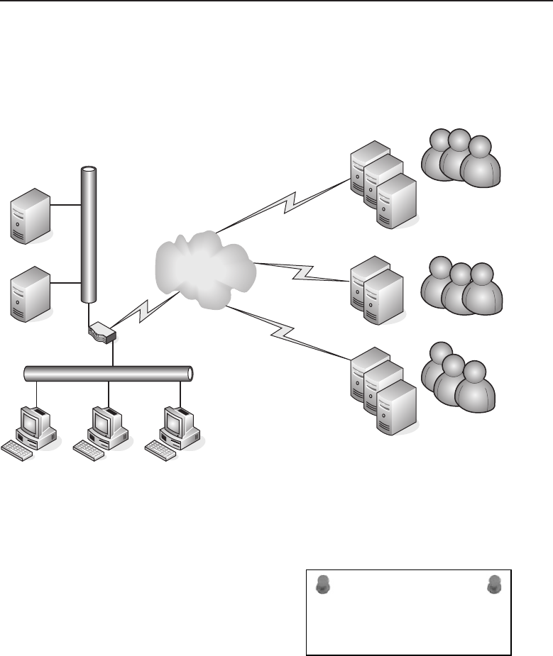
Edwards c10.tex V3 - 03/27/2009 11:24am Page 407
Chapter 10 ■The Network Layer 407
Internet as a transportation medium for the domain’s network infrastruc-
ture. Because these sites are connected over the Internet, they utilize IP for the
transmission from site to site.
Corporate Headquarters
Milwaukee
Manufacturing
Canton, Ohio
Marketing
New York City
Sales
Chicago
WEB
MAIL
Corporate Users Network
Figure 10-3 The Widget Company’s top level network diagram
ACRONYM ALERT
Telnet — Teletype Network
It was already mentioned that the
TCP/IP model’s Internet layer is a subset
of the OSI model’s Network layer. There
will be places in this chapter where we
discusstheaspectsofTCP/IPwhereit
is relevant within the OSI Network layer.
The domain aspect can be used for either
connection-oriented or connectionless network services. However, the world
of TCP/IP uses IP to move information along the world’s information
highway. To bridge between domain names and IP protocol addresses
requires domain name resolution, commonly referred to as DNS (Domain
Name System). Further discussion of DNS can be found in Section 10.1.3.

Edwards c10.tex V3 - 03/27/2009 11:24am Page 408
408 Part II ■The OSI Layers
As you can see in Figure 10-3, the corporate offices located in Milwaukee have
multiple networks, various computer systems, and a number of servers. This
diagram is simplistic in its presentation for a large corporate network, which is
far more complex. However, the base principles of network interoperability5
are fairly similar due to the scalability6of networking technologies. The figure
shows two servers: a mail server and a web server. The remote offices also
have servers located at their sites that are able to pass information from other
servers and users located either locally or over the Internet. Using domain
names to reach various servers has the following format:
Host name.domain name.sub domain name.domain name suffix7
The mail server named mail located at the corporate office would have a
domain name that appears as follows:
mail.widget.com
If the marketing group located in New York City also has a mail server that
gathers its mail from the corporate mail server, its name could be:
mail.marketing.widget.com
Mail shared between users is connectionless8because the computer sending
the mail does not need a connection directly to the mail server the recipient
of the e-mail is connected to. There are differences in e-mail, and perhaps
there is some confusion due to the type of e-mail service being used. A local
mail program on a computer is capable of creating a mail program entirely
independent from any other computer. When it is ready to send the e-mail
message, it does so by forwarding the mail to a Simple Mail Transport Protocol
(SMTP) server where the user has an account. The message is forwarded by
the SMTP server without any further action by the user to aid in the delivery
of the message.
5‘‘Interoperability’’ is just a fancy name for network node devices to play nice with all the other
network node devices connected on the same network.
6‘‘Scalability’’ simply means that networks can start small and grow larger as needed. However,
larger networks usually require higher capacity network devices able to handle the amount of
information that is to traverse the network within a fixed period of time.
7Domain names as illustrated in this example do not have spaces within the name. So, using
the above example as a domain name would actually appear as hostname.domainname
.subdomainname.domainnamesuffix.
8A computer connected to its local mail server uses the POP or POP3 protocol to receive mail and
SMTP to send mail. These protocols are connection-based because the PC has a direct session
with its local mail server. However, mail user to mail user is connectionless because a user-to-user
PC session is not needed to send or read mail.

Edwards c10.tex V3 - 03/27/2009 11:24am Page 409
Chapter 10 ■The Network Layer 409
RANDOM BONUS DEFINITION
learning state — A transition state in the
Spanning Tree Protocol state machine where
a bridge port is learning address-to-port
mappings to build its filtering database
before entering the forwarding state.
If a user is using web-based
mail, the session established by
the browser to create the e-mail
is a connection-oriented net-
work service. In using web mail,
the user establishes a connection
to the server serving his or her
account to create and forward
the message. However, the type
of service is still connectionless since the user is not required to provide any fur-
ther action to ensure delivery of the e-mail message. This illustrates that even
connectionless processes may require some elements of a connection-oriented
network service.
SMTP mail servers deliver e-mail to the SMTP mail server servicing a particu-
lar domain. Although a user name is attached as part of the message, the SMTP
server does not deliverthe message to the user. A user must have an account on
a mail server in order for the mail to be delivered to that user’s post office box.
In the case of incorrect spelling of a user name or if a user never had an e-mail
account or their account had been deleted, the SMTP server would return the
original message with an error header9stating the cause for the message not
being delivered. The most common reason for return is ‘‘user unknown.
E-mail for a user is held on the mail server for a period of time established
by the administrator of that server. There are various parameters on most
mail servers that allow for a mailbox’s size, usually in megabytes, length of
time a message is held, and the maximum allowable size of a message. An
error message may be returned to an e-mail sender if the recipient is not in
compliance with any of the preset parameters. Depending on the mail service
provided by the mail server, mail may be read while remaining on a mail
server or it may have to be downloaded using the Post Office Protocol (POP
or POP3) to the local workstation for reading and any other required action.10
POP QUIZ
Mail is what type of network service?
To summarize, a connection-
less network service has the
capability to prepare informa-
tion for transmittal to another
network node without the cre-
ation of a real-time connection
to that network node in order
to complete the transfer of the
information being sent.
9In computerese, the header is simply the top of the message. In other words, you do not need
to read the whole message to see why it was bounced back.
10The required action is usually reading the message and either filing it or discarding it.
Unfortunately, just like your postal mailbox, your e-mail mailbox also gets a lot of junk mail.
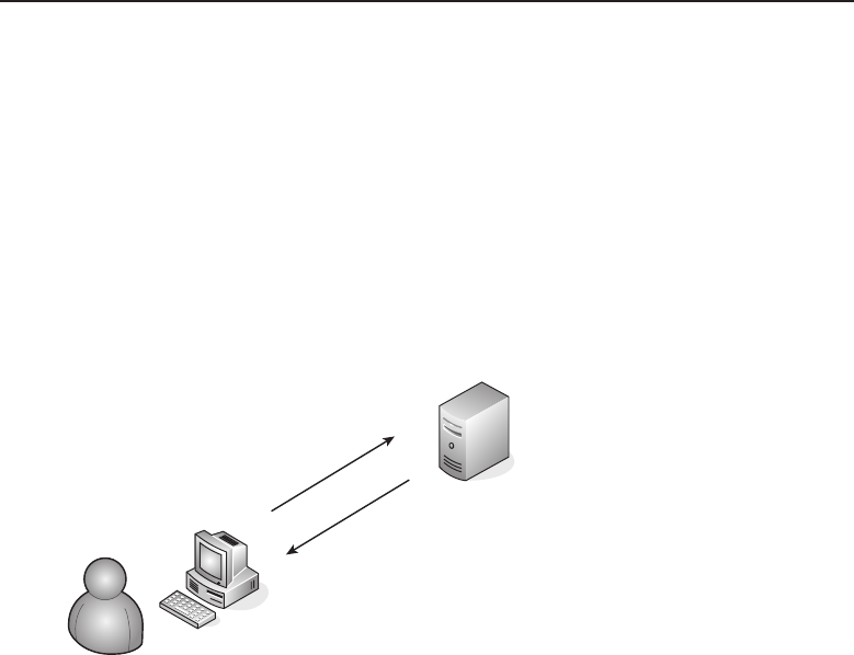
Edwards c10.tex V3 - 03/27/2009 11:24am Page 410
410 Part II ■The OSI Layers
10.1.2 Connection-Oriented Network Services
A connection-oriented network service is exactly what the name implies.
A network connection11 is established between two computers to trans-
fer information from one computer to the other over the Internet. Many
client/server application programs are connection-oriented network services.
A good example of this would be the interaction between an FTP client and
an FTP server.12 Figure 10-4 illustrates a user residing on a local network at IP
address 192.168.2.13 requesting information from a local FTP server whose IP
address is 192.168.2.5.
192.168.2.13
FTP Client
FTP Server
192.168.2.5
Figure 10-4 An FTP client/server connection-oriented network server
The following portion of the FTP server log illustrates the interaction of the
client with the FTP server:
Oct 11 20:28:35 Cerberus FTP Server started
Oct 11 20:28:35 Local Host: Rbramant-2
Oct 11 20:28:35 Local Interface 0 located at 192.168.2.5
Oct 11 20:28:35 Listening on Port 21
Oct 11 20:34:39 1 Incoming connection request on interface
192.168.2.5
Oct 11 20:34:39 1 Connection request accepted from 192.168.2.13
Oct 11 20:34:52 1 USER anonymous
Oct 11 20:34:52 1 331 User anonymous, password please
Oct 11 20:34:57 1 PASS ***********
11Although networks use electrical connections for signal transmission, a network connection
is when two endpoint network node devices know each other and establish a session that is
connected.
12Many places within the text server and client are shown and discussed as totally separate
network entities. In reality, a computer can be both a server and a client simultaneously for
network services.
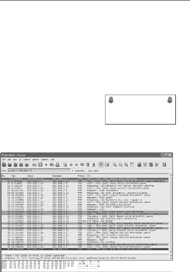
Edwards c10.tex V3 - 03/27/2009 11:24am Page 411
Chapter 10 ■The Network Layer 411
Oct 11 20:34:57 1 230 Password Ok, User logged in
Oct 11 20:34:57 1 Anonymous user ‘‘anonymous’’ logged in with
password ‘‘guest’’
Oct 11 20:35:00 1 PORT 192,168,2,13,19,137
Oct 11 20:35:00 1 200 Port command received
Oct 11 20:35:00 1 LIST
Oct 11 20:35:00 1 150 Opening data connection
Oct 11 20:35:00 1 226 Transfer complete
Oct 11 20:35:08 1 QUIT
Oct 11 20:35:08 1 Connection terminated.
You can see that the client initiated the connection to the server. The server
forced the client to supply a user ID and a password. The client responded
with a user ID and password combination, and is authenticated and allowed
to maintain the session with the FTP server.
ACRONYM ALERT
STP — Spanning Tree Protocol
The FTP client user requested a direc-
tory listing from the FTP server. After the
listing was received, the user quit the ses-
sion and thus caused the termination of
the connection between the client and the
server.
A packet capture of this session was performed at the FTP server, as
illustrated in Figure 10-5.
Figure 10-5 A packet capture of an FTP session

Edwards c10.tex V3 - 03/27/2009 11:24am Page 412
412 Part II ■The OSI Layers
The FTP session uses the TCP/IP protocol to establish the session and
complete the transfer of information from the FTP server to the FTP client.
Packet number 7 shows the client requesting a session with the FTP server.
Packet 10 is the FTP server acknowledging the session request. Packets 12
through 21 are the packets showing the interaction between the FTP client
and FTP server to authenticate the FTP client and establish the FTP session.
Packets 22 through 36 are the directory listing request and the transfer of the
directory contents information to the FTP client. Packets 37 through 44 are the
packets showing that the FTP client is terminating the FTP session and thus
terminating the network connection.
POP QUIZ
Name the ports used by an FTP client to
request an FTP session with an FTP server.
Which port is used for data transmission?
An FTP13 session does involve
layers above the Network layer,
but FTP helps illustrate the con-
cept of a connection-oriented
network service. The two com-
puters establish a connection
session and transfer informa-
tion between them. The Net-
work layer is responsible only for the end-to-end connections and is not
involved with the hop-to-hop14 transfer of the packets over the network.
WANT TO TRY SOMETHING?
You are encouraged to reproduce the FTP session as illustrated in this section.
It requires two computers and software that can be obtained by a free
download from the Internet. The FTP session was accomplished by using FTP
server software from www.cerberusftp.com and using the ftp command from
the command prompt of a Windows XP PC. You can obtain packet capture
software for free from www.wireshark.org. The computers can either be on
the same network segment or on different segments with network routing
devices between the network segments.
10.1.3 Domain Name Services
Many of you are probably familiar with the term URL (uniform resource
locator). A typical URL would appear as follows:
http://www.mydomainname.com
13The FTP protocol uses two ports for control and data transfer. Control is dedicated to port 21,
and port 20 is dedicated to data transfer. An FTP server would listen on port 21 for FTP requests,
and the FTP session is negotiated and controlled using this port.
14A network hop is any network node a data packet needs to be forwarded through on its journey
to the requested destination.

Edwards c10.tex V3 - 03/27/2009 11:24am Page 413
Chapter 10 ■The Network Layer 413
The http indicates this is a request for port 80 on a computer with the
host name www located in the domain mydomain.com.IntheTCP/IPworld,
computer addresses take the following form:
XXX.XXX.XXX.XXX
where XXX can be a numeric decimal value between 0 and 255. We are
preconditioned to think of URLs as being as follows:
prefix.domainname.suffix
We are accustomed to seeing .com, .org, .gov, .edu, or .net being used as
a suffix, although many others are in use. Also, a country code may be used
as the suffix to denote where the domain and host computer are found. So
how does one get from a text-based URL name to an IP address? Someone
has to take care of it, like the telephone company has with the use of area
codes, exchange numbers, and the last four unique digits to reach a particular
telephone. So in the case of finding an IP address for a particular computer
by its host name, who would have the super-sized host name book that lists
every computer connected to the Internet?
RANDOM BONUS DEFINITION
jam — In Ethernet, the process of sending
an additional 32 data bits following the
detection of a collision to ensure that all
parties to the collision properly recognize
the event as such.
Telephones are basically
static devices. They are wired
into a particular telephone
switch with a fixed number.
Computers can be moved or
exchanged with other comput-
ers, and occasionally IP addre-
sses associated with a particular
URL can also be changed. So,
host-name-to-IP addresses can
be pretty dynamic, and a dynamic system is required to maintain the capa-
bility to perform host name resolution. There needs to be some form of
registration to enable this to occur. There are many companies that sell domain
name registration for a fee. But what does that really mean?
As with IP addresses, domain names also need to be unique. Domain names
must be registered to ensure that they are not duplicated on the Internet. The
Internet Assigned Numbers Authority (IANA) is an organization created to
establish standard naming for what is called the top level domain (TLD), or
root zone. The suffix portion of a URL is the root zone. It is used to parse
a host name URL to establish which root zone the host name is a member
of. The Internet Network Information Center (InterNIC) is maintained by
the Internet Corporation for Assigned Names and Numbers (ICANN) and is
responsible for the registration of domain names through registered domain
name hosting companies.
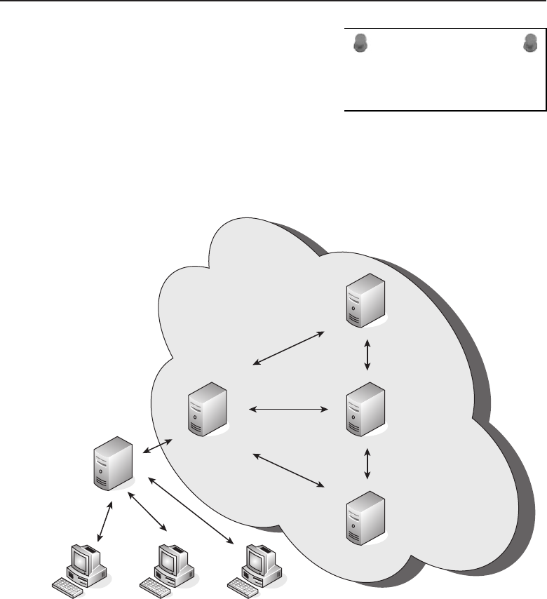
Edwards c10.tex V3 - 03/27/2009 11:24am Page 414
414 Part II ■The OSI Layers
ACRONYM ALERT
SD — Start delimiter
When a domain name is registered, it is
associated with an IP address and is main-
tained on a DNS server. Each DNS server
needs to know what the designated author-
itative name server is in order to receive
DNS updates. Although the service is fairly
dynamic, caching15 is used to save time querying the root name servers each
time a request is made for a particular host name. Figure 10-6 illustrates a
typical DNS server scenario.
Local DNS Server
ISP DNS Server
Local Computers
Authoritative
DNS
Servers
Figure 10-6 A typical DNS server scenario
DNS is part of the TCP/IP protocol suite. The computers on the local
network have configured the IP address of the local DNS server into their
15Caching is the process of saving information for a predetermined amount of time. In DNS,
caching can save time for address resolution. However, to ensure that a name resolution stays
‘‘fresh,’’ there is usually an expiration time associated with the entry. Old entries are aged out
automatically. When a DNS request is made, if it is not in the cache, name resolution needs to
be performed. Although under normal circumstances it is completed fairly rapidly, it does take
more time than just pulling it up from the local cache storage.

Edwards c10.tex V3 - 03/27/2009 11:24am Page 415
Chapter 10 ■The Network Layer 415
TCP/IP configuration settings. You can verify these settings by issuing an
ipconfig /all command at the command window of a Windows-based PC.
The response would be similar to the following:
Ethernet adapter Local Area Connection:
Connection-specific DNS Suffix . :
Description . . . . . . . . . . . : Broadcom NetXtreme
Gigabit Ethernet
Physical Address. . . . . . . . . : 00-17-08-30-6A-01
DHCP Enabled. . . . . . . . . . . : Yes
Autoconfiguration Enabled . . . . : Yes
IP Address. . . . . . . . . . . . : 192.168.2.5
Subnet Mask . . . . . . . . . . . : 255.255.255.0
Default Gateway . . . . . . . . . : 192.168.2.1
DHCP Server . . . . . . . . . . . : 192.168.2.4
DNS Servers . . . . . . . . . . . : 192.168.2.1
Lease Obtained. . . . . . . . . . : Sunday, October 12, 2008
8:08:02 AM
Lease Expires . . . . . . . . . . : Monday, October 13, 2008
8:08:02 AM
In this example, there is only one DNS server, and it is the same as the
device that is acting as the default gateway. In this particular setup, the router
is capable of running a DNS service, and its DNS servers are the upstream
servers at the ISP, as shown in Figure 10-6.
Using the example of a browser attempting to reach a particular URL, if the
computer does not have the resolved host name stored in its local DNS cache,
it will request it from its assigned DNS server. Figure 10-7 shows a packet
capture of a DNS request from a local PC to its local DNS server.
The user is calling the URL www.imagesbybramante.com and, not having the
host name cached, it places the request to its local DNS server. If the local
DNS server does not have the host name cached, it makes a DNS request to its
upstream server and would eventually work its way back to a root authoritative
server until the name is resolved. If the name cannot be resolved, an error
message is returned. When the name is resolved, it is passed back through the
servers until it reaches the computer that made the original request. Figure 10-8
shows a successful host name lookup for the query used in this example.
POP QUIZ
Name some top-level domain names.
This has been a top-level dis-
cussion of DNS to give you a
basic understanding of name
resolution in regard to IP.
You are encouraged to explore
literature dedicated solely to
DNS concepts for additional,
in-depth information.
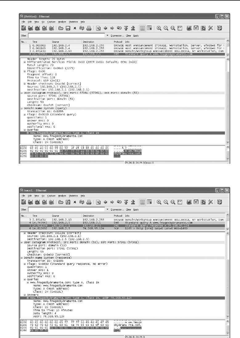
Edwards c10.tex V3 - 03/27/2009 11:24am Page 416
416 Part II ■The OSI Layers
Figure 10-7 A packet capture of a DNS request
Figure 10-8 A packet capture of a DNS response

Edwards c10.tex V3 - 03/27/2009 11:24am Page 417
Chapter 10 ■The Network Layer 417
SOMETHING TO TRY
We suggested earlier that you download a freeware version of Wireshark. It is a
useful tool not only for troubleshooting but to give added insight to what is
occurring on your computer in terms of network communications. It can be
loaded on either a desktop or laptop with your other Windows-based
applications. It may be launched prior to opening any application and allowed
to capture the packets of that application. This will help build familiarity with
the Wireshark application itself and aid in increasing your understanding of
TCP/IP and the protocols supported within the TCP/IP protocol suite.
10.2 TCP/IP Network Layer Protocols
RANDOM BONUS DEFINITION
filtering — The process of inspecting frames
received on an input port of a switch and
deciding whether to discard or forward
them.
The Network layer of the OSI
model provides for both connec-
tionless network services and
connection-oriented services. It
encompasses the protocols of
the TCP/IP model’s Internet
layer. However, the OSI model’s
Network layer is broader in
scope than TCP/IP’s Internet
layer, and at times, it includes other TCP/IP protocols from its Link layer. Due
to this difference, the two layers should not be considered mirror images of
each other, although they do have some protocols in common.
10.2.1 Internet Protocol
The Internet Protocol (IP) is primarily a method of moving packets of
data across networks comprising various media, seamlessly delivering these
packets solely based on the destination address. This is accomplished by
encapsulating data from the upper layers into packets16 in preparation for
delivery over the network. IP is a connectionless protocol since packets can be
transmitted without the establishment of a circuit to the destination network
node. Because IP is a best-effort delivery service, it makes no guarantee that
a packet will be delivered. Therefore, data can become corrupted, packets can
16The word ‘‘packet’’ is synonymous with ‘‘datagram’’ or ‘‘frame.’’ These three words are used
interchangeably and refer to the structure containing all the pertinent information for the proper
construct so that the data can be reliably transmitted and that it can be properly unencapsulated
when received at the intended network node.

Edwards c10.tex V3 - 03/27/2009 11:24am Page 418
418 Part II ■The OSI Layers
arrive out of order, duplicate packets can be received, and packets can be lost
or discarded.
The mainstay for many years has been Internet Protocol version 4 (IPv4),
but due to its limitation of addressing, Internet Protocol version 6 (IPv6)
is currently being deployed worldwide. To work around the limited address
space of IPv4, the development of Network Address Translation (NAT) helped
delay the need to deploy IPv6 any sooner.
10.2.1.1 Internet Protocol Version 4
Because IPv4 utilizes 4 bytes to express an address, it has only 32 bits that can
be used for its address. This allows for a maximum combination of addresses
that can be supported of 232, or 4,294,967,296 unique addresses. Since some of
the addresses are within reserved address space, the total space is not available
as public Internet addresses. IPv4 addresses are mostly expressed in what is
referred to as dot-decimal notation, for example:
192.168.15.85
Each dotted section is representative of the decimal value of the byte. So it
would look as follows in binary:
11000000.10101000.00001111.01010101
There is a multitude of variations to express IP addresses, but the dot-decimal
notation is the most widely used.
REMEDIAL EXERCISE
For those of you who are not proficient in manipulating numbers between
various number systems, try to convert the above dotted binary number to a
hexadecimal-dotted notation. Hint: The bits of a byte are equally divided to
create two hexadecimal numbers for each dotted binary section. A hexadecimal
number is usually represented by 0x<hex valued number>. If you want the
answer, wait until you give it an honest try, and then look at the footnote
below.17
POP QUIZ
What is a maximum transmission unit?
If the upper layers present
the TCP/IP Internet layer with
data that is too large to transmit
within a single packet, the
data will be fragmented and
transmitted over the network in
17xC0.0xA0.0x0F.0x55, or in not-dotted notation, 0xC0A00F55

Edwards c10.tex V3 - 03/27/2009 11:24am Page 419
Chapter 10 ■The Network Layer 419
multiple packets. IP performs the fragmentation since it is host dependent, not
machine dependent. The maximum transmission unit (MTU) is the number
of bytes of data that a particular network medium is capable of handling. It is
determined by the largest packet the medium is capable of handling, minus any
number of bytes required as a header to transmit the packet over the medium.
In the case of Ethernet, which has a maximum packet size of 1500 bytes, the
MTU is the maximum packet size minus the number of bytes required for
the header. Ethernet normally requires 20 bytes for a header, which provides
for an MTU of 1480 bytes. The data is fragmented into the number of packets
needed, with each packet tagged indicating it contains a fragment. The
receiving network nodes unencapsulate the received fragmented packets and
reassemble the data before passing it up to the layer above it.
10.2.1.1.1 Network Address Translation
It was mentioned that Network Address Translation (NAT) was developed
to provide a method of using addresses designated as private address space
behind a network device, such as a router, that is able to perform the translation
from a nonroutable IP address to a publicly known IP address. Table 10-1 shows
the reserved addresses for private networking.18
Table 10-1 Private Networking Reserved Addresses
ADDRESS RANGE CIDR NETWORK CLASS ADDRESSES
10.0.0.0 to
10.255.255.255
10.0.0.0/8 Single Class A 16,777,216
172.16.0.0 to
172.31.255.255
172.16.0.0/12 16 Contiguous
Class B
1,048,576
192.168.0.0 to
192.168.255.255
192.168.0.0/16 Single Class B 65,536
USEFUL NOTE
Generally speaking, the first address of a subnet range ending in 0 is used to
designate the network address, and the last address ending in 255 is used to
designate the broadcast address of the subnet. It depends on the subnet mask
being used whether 0 or 255 is assigned to a host. For example, if the whole
(continued)
18Although these address ranges are shown to be contiguous, they may be subdivided (subnetted)
into smaller subnet ranges within a private network space. Often, these private network classes
can be found using class C 24-bit subnet masks of 255.255.255.0 to form smaller network ranges.

Edwards c10.tex V3 - 03/27/2009 11:24am Page 420
420 Part II ■The OSI Layers
USEFUL NOTE (continued)
class A subnet of 10.0.0.0 with a subnet mask of 255.0.0.0 is used for a network,
then 10.0.0.0 would be the network address and 10.255.255.255 would be the
broadcast address for that subnet. This would permit 10.0.1.0, 10.0.1.255,
10.0.2.0, 10.0.2.255, etc., to be used for host addresses. It is important to know
the subnet mask that is assigned to a particular IP address range.
USEFUL NOTE #2
The CIDR is the number that indicates the number of mask bits being assigned
to a subnet. So, /8 would have a subnet mask of 255.0.0.0, /12 would have a
subnet mask of 255.240.0.0, and /16 would have a subnet mask of 255.255.0.0.
Have you guessed what the CIDR represents yet? The CIDR indicates the
number of bits for the subnet mask starting at the highest significant position
and working its way down to the least significant position.19
USEFUL NOTE #3
When you see /32 or a subnet mask of 255.255.255.255, it is called a host
route. This means there is only one network node connected to that address;
there is no network, just one device — and that is it. Host routes are used more
frequently than you would think, but be aware of this when someone talks of a
‘‘slash 32’’ or ‘‘32-bit route.’’
ACRONYM ALERT
PHY — Physical layer interface
Figure 10-9 illustrates three separate
networks all performing NAT on the
192.168.0.0/16 network address space.
You will notice that the IP addresses
assigned to the public interface20 are addre-
sses that are assigned by an ISP (Internet
service provider). These addresses can be either statically or dynamically
assigned IP addresses. The type of installation usually dictates how IP address
assignment is handled. DSL (digital subscriber line), PPPoE (Point-to-Point
Protocol over Ethernet), and dialup network circuits are usually configured
to have a dynamically assigned IP address. Dynamically assigned addresses
19Okay, for the readers who fell asleep during math class: The higher the power of the number,
the more significance it has. In our number system, the number to the left of another number
has a higher power, thus more significance. The leftmost number is always the most significant
number.
20A public interface is one that has a publicly routable IP address assigned to it. Private IP
addresses cannot be routed over the Internet.
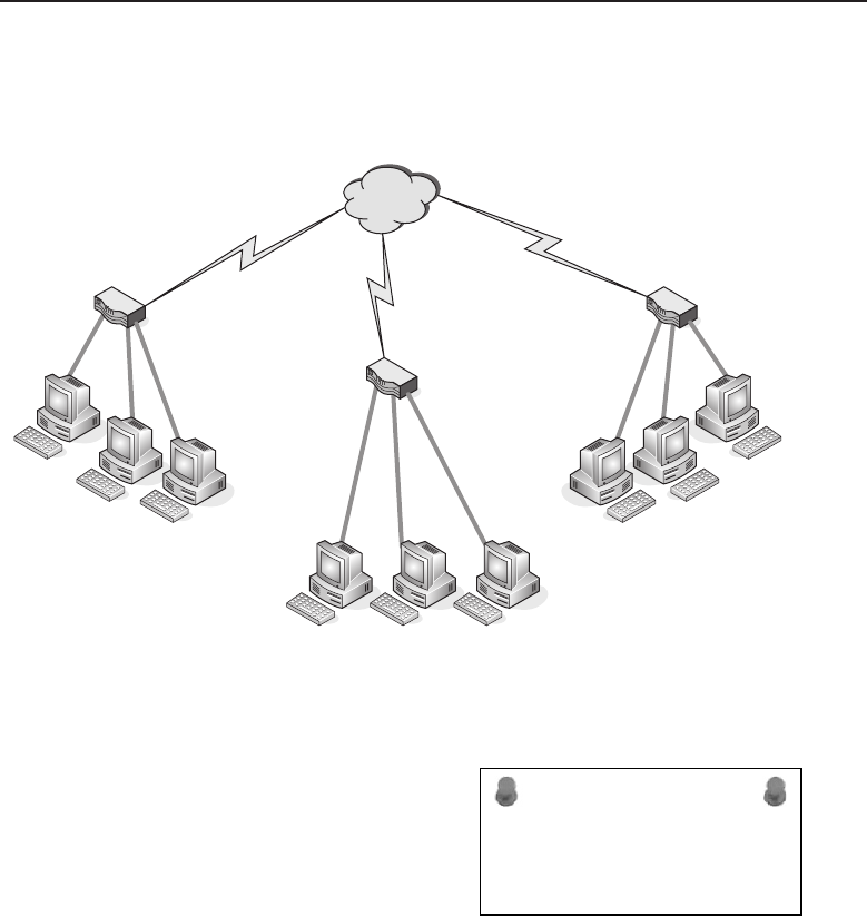
Edwards c10.tex V3 - 03/27/2009 11:24am Page 421
Chapter 10 ■The Network Layer 421
change each time a connection is made. However, the ISP can usually assign a
static IP address, if requested to do so.
Internet
72.34.21.168
192.168.0.0/16
Network
192.168.0.0/16
Network
192.168.0.0/16
Network
168.34.78.99
69.54.112.145
Figure 10-9 A NAT example
ACRONYM ALERT
CSMA/CA — Carrier Sense, Multiple Access with
Collision Avoidance
Notice that the private IP addresses for all
three are in the 192.168.0.0/16 network and
that the NAT-enabled router will translate
those addresses to its public IP address.
The receiving node over the Internet will
see the public IP address in the packet’s
source address. The sending NAT-enabled
router keeps a translation table in order to recall which sending workstation
on its private IP address space has initiated the session. When the receiving
node sends a reply back to the NAT-enabled router, it removes its address
from the destination address field of the packet, replaces the IP address from
its translation table of the workstation that started the session, and passes the
packet into the private network.
Since workstations are on a private IP address space, they are not reachable
from the Internet unless a policy to allow this is embedded within the
NAT-enabled router. Such policies are called port forwarding policies. Usually
servers offering web services, e-mail services, or FTP services are located
on private networks behind a NAT-enabled router. Figure 10-10 illustrates
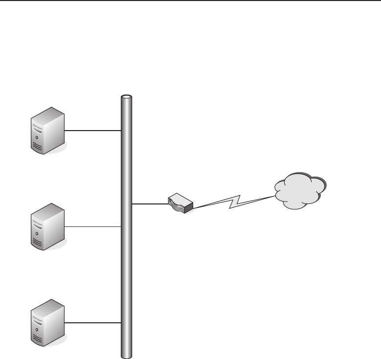
Edwards c10.tex V3 - 03/27/2009 11:24am Page 422
422 Part II ■The OSI Layers
services being offered to users over the Internet while being located behind a
NAT-enabled router on a private IP address space.
192.168.0.0/16
Private IP Address
192.168.0.1
FTP Server
Web Server
NAT Enabled Router
Internet
Mail Server
Offering both
SMTP & POP
Mail Services
192.168.0.2
192.168.0.3
Figure 10-10 Servers behind a NAT-enabled router
Table 10-2 is representative of a NAT port forwarding table a NAT-enabled
router would have to accept service requests on its public IP address interface.
When a packet arrives at the public interface with the destination address
set to its public IP address and a port service request that matches a port
address in the NAT port forwarding table, the packet is modified and passed
on to the network, directed toward the server that supplies that service. An
example of this is a web page request that arrives at the public IP address of
the NAT-enabled server. The NAT-enabled router sees the requested port is
port 80, so it replaces its address in the destination field with the IP address of
the web server that is at 192.168.0.2, recalculates the checksum for the packet,
and passes it on to the private network.

Edwards c10.tex V3 - 03/27/2009 11:24am Page 423
Chapter 10 ■The Network Layer 423
Table 10-2 NAT Port Forwarding Table
SERVICE PORT SERVER ADDRESS
SMTP Mail 25 192.168.0.3
POP Mail 109 192.168.0.3
POP3 Mail 110 192.168.0.3
FTP Control 21 192.168.0.1
FTP Data 20 192.168.0.1
HTTP 80 192.168.0.2
POP QUIZ
What is the type of address translation that
is used to keep track of sessions initiated by
a computer on a private network to a
service on the Internet?
NAT does offer some firewall
protection since the addresses
used on the private IP address
are not routed over the Internet.
Unsolicited connection requests
are dropped by the NAT-
enabled router since there is
no entry in its NAT translation
table. However, when port for-
warding policies are enabled within the NAT-enabled router, there is an
possibility that one of the servers may be hacked and compromised. A pru-
dent measure would be to have a DMZ (demilitarized zone) by using a router
that has multiple private IP address interfaces. Place the servers on one inter-
face isolated by different network addresses and policies. This will prevent the
servers from initiating connections into the private network where other users
and devices are protected behind the NAT-enabled router.
Due to the development of NAT-enabled devices and the capability to use
private network IP address space, the stress of coming up with a new standard
to replace IPv4 was lessened. This has allowed the life span of IPv4 to be
extended and a gradual transition made to the newer IP address standard
IPv6. Although current devices are IPv6-capable, they are still able to be
installed and used within the IPv4 environment.
10.2.1.2 Internet Protocol Version 6
The real thrust of moving to IPv6 is the larger address space that it provides,
with 128 bits dedicated to address space. The number is so large that it
exceeds the national debt, which is pretty hard to do these days. Our scientific
calculator claims it is 3.4028 e38, give or take a few addresses. It is so great
that each person alive on the face of the earth can have multiple devices using

Edwards c10.tex V3 - 03/27/2009 11:24am Page 424
424 Part II ■The OSI Layers
IP addresses and there would still be addresses left over. Although these
numbers are staggering, the real intent of IPv6 is to increase the efficiency
of network management and routing. There is a high probability that only a
small percentage of the address space will actually be used.
Figure 10-11 illustrates the IPv6 header, which is 40 bytes in total length.
Version Traffic Class
Payload Length
Source Address
Destination Address
Next Header Hop Limit
Flow Label
0
0
32
BIT
64
192
320
4 8 12 16 20 24 28 32
Figure 10-11 The IPv6 header
RANDOM BONUS DEFINITION
encapsulating bridge — A bridge that
encapsulates LAN frames.
Thefirst4bitsaretheVersion
field for IPv6. The next 8 bits
are the Traffic Class field, which
adds in the control options. The
next 20 bits are the Flow Label
field, allocated for QoS (quality
of service). The Payload Length
field indicates the packet length
in bytes. When this field is set to 0, the packet contains a jumbo-sized payload.
The Next Header field indicates which encapsulated protocol follows. These
protocol values are compatible with the IPv4 protocol field values. The Hop
Limit field replaces the TTL (time to live) field of IPv4. Both the Source
Address and Destination Address fields contain 128 bits of address data.
The standard sized payload can be 65,536 bytes, and if the option is set, the
payload can be jumbo-sized.21 All data fragmentation is controlled by the
sending network node since routers will never fragment a packet. However,
IPv6 sending network nodes are expected to use a technique known as path
21Techno-geeks like to use jargon and you may hear a variety of words used to describe an entity.
A ‘‘jumbo-sized’’ payload merely refers to a payload that is very large.

Edwards c10.tex V3 - 03/27/2009 11:24am Page 425
Chapter 10 ■The Network Layer 425
MTU discovery (PMTUD) to determine the MTU that can be used to send
packets over the network.
The address notation used in IPv6 is quite different from that of IPv4. IPv6
addresses consist of eight groups of four hexadecimal numbers, where each
field is separated by a colon. For example:
113A:00AB:8900:0000:0000:7EA3:0034:3347
POP QUIZ
What is the difference between how IPv4
IP addresses are denoted and how IPv6 IP
addresses are denoted?
A shorthand notation would
be to reduce the fields con-
taining zeros to just a pair of
colons (::). IPv6 address nota-
tion has a variety of rules that
allow for various methods of
displaying the same address. As
IPv6 begins to be deployed more
widely, there is sure to be a particular notation format that will become the
more widely used and accepted format.
10.2.2 Internet Control Message Protocol
Internet Control Message Protocol (ICMP) is an essential part of the TCP/IP
protocol suite. It provides a means of messaging when a sent datagram is
unable to be received by the intended network node. The ping and traceroute
networking tools are also part of this protocol. ICMP error messages are
generated in response to detected errors in the IP datagram, routing, or
diagnostics. The ICMP protocol suite is part of IPv4, but there is an equivalent
to ICMP that is a protocol within IPv6, referred to as ICMPv6. For the most
part, computer users are unaware of network problems until a network error
message is triggered by ICMP. When a user suspects that a network problem
may exist, he or she can use the ping and traceroute22 commands to aid in
troubleshooting the problem.
10.2.2.1 Ping
The ping command within the Microsoft Windows operating system has the
following syntax:
Microsoft Windows XP [Version 5.1.2600]
(C) Copyright 1985-2001 Microsoft Corp.
22traceroute is the normal command for many various operating systems. However, in
the Microsoft Windows-based world, the actual command for traceroute is truncated to
tracert.

Edwards c10.tex V3 - 03/27/2009 11:24am Page 426
426 Part II ■The OSI Layers
C:\>ping
Usage: ping [-t] [-a] [-n count] [-l size] [-f] [-i TTL] [-v TOS]
[-r count] [-s count] [[-j host-list] |[-k host-list]]
[-w timeout] target name
Options:
-t Ping the specified host until stopped.
To see statistics and continue - type Control-Break;
To stop - type Control-C.
-a Resolve addresses to hostnames.
-n count Number of echo requests to send.
-l size Send buffer size.
-f Set Don’t Fragment flag in packet.
-i TTL Time To Live.
-v TOS Type Of Service.
-r count Record route for count hops.
-s count Timestamp for count hops.
-j host-list Loose source route along host-list.
-k host-list Strict source route along host-list.
-w timeout Timeout in milliseconds to wait for each reply.
ACRONYM ALERT
NIC — Network interface card or network interface
controller
The most common use of ping is to verify
that a particular network is available over
the network. In the following example, a
computer has issued a ping command for
its default gateway.
C:\>ping 192.168.2.1
Pinging 192.168.2.1 with 32 bytes of data:
Reply from 192.168.2.1: bytes=32 time<1ms TTL=64
Reply from 192.168.2.1: bytes=32 time<1ms TTL=64
Reply from 192.168.2.1: bytes=32 time<1ms TTL=64
Reply from 192.168.2.1: bytes=32 time<1ms TTL=64
Ping statistics for 192.168.2.1:
Packets: Sent =4, Received =4, Lost =0 (0% loss),
Approximate round trip times in milli-seconds:
Minimum =0ms, Maximum =0ms, Average =0ms
POP QUIZ
What option would be used to modify the
size of a ping packet?
There are many ways to use
the ping command for trou-
bleshooting various network
issues. Chapter 16, ‘‘Trou-
bleshooting,’’ will go into
greater detail about how this

Edwards c10.tex V3 - 03/27/2009 11:24am Page 427
Chapter 10 ■The Network Layer 427
tool can be used as an aid in determining what is causing certain network
issues.
10.2.2.2 Traceroute
The traceroute command is used to trace the path from the sending network
node to the receiving network node on a hop-to-hop basis. It reports back on
each hop as it is traversed over the network on the path to the destination
network node. The following is the syntax for the traceroute command for
the Microsoft Windows operating system:
C:\>tracert
Usage: tracert [-d] [-h maximum hops] [-j host-list] [-w timeout]
target name
Options:
-d Do not resolve addresses to hostnames.
-h maximum hops Maximum number of hops to search for
target.
-j host-list Loose source route along host-list.
-w timeout Wait timeout milliseconds for each reply.
RANDOM BONUS DEFINITION
common and internal spanning tree — A
collection of the internal spanning trees in a
multiple spanning tree region, combined
with the common spanning tree that
connects MST regions to form a single
spanning tree that ensures all LANs in the
bridge network are fully connected and
loop-free.
The options are self-
explanatory. The -d option is
often used to save the time
that is required to resolve IP
addresses to host namesfor each
hop along the path. The follow-
ing is an example of a successful
completion of a traceroute
command:
C:\>tracert www.richardbramante.com
Tracing route to www.richardbramante.com [68.180.151.74]
over a maximum of 30 hops:
1<1ms <1ms <1 ms 192.168.2.1
2<1ms <1ms <1 ms 192.168.0.1
3 4ms 4ms 4ms L100.VFTTP-12.BSTNMA.verizon-
gni.net [72.74.235.1]
4 3ms 4ms 4ms P4-1.LCR-04.BSTNMA.verizon-
gni.net [130.81.60.226]
5 26ms 27ms 27ms so-7-0-0-0.ASH-PEER-

Edwards c10.tex V3 - 03/27/2009 11:24am Page 428
428 Part II ■The OSI Layers
RTR2.verizon-gni.net
[130.81.17.179]
6 28 ms 27 ms 27 ms 130.81.14.98
7 65 ms 64 ms 64 ms so-2-0-0.pat2.dax.yahoo.com
[216.115.96.21]
8 91 ms 92 ms 92 ms as1.pat2.pao.yahoo.com
[216.115.101.130]
9 92 ms 92 ms 92 ms ae1-p151.msr2.sp1.yahoo.com
[216.115.107.79]
10 100 ms 92 ms 92 ms ge-1-41.bas-b2.sp1.yahoo.com
[209.131.32.33]
11 92 ms 94 ms 92 ms www.richardbramante.com
[68.180.151.74]
Trace complete.
If a target node does not allow ICMP, a traceroute wouldnotendnormally
and would appear as follows:
C:\>tracert www.wiley.com
Tracing route to www.wiley.com [208.215.179.146]
over a maximum of 30 hops:
1<1ms <1ms <1 ms 192.168.2.1
2<1ms <1ms <1 ms 192.168.0.1
3 3 ms 4ms 4ms L100.VFTTP-12.BSTNMA.verizon-
gni.net [72.74.235.1]
4 5 ms 4ms 4ms P4-1.LCR-04.BSTNMA.verizon-
gni.net [130.81.60.226]
5 4 ms 4 ms 4 ms 130.81.29.170
6 8 ms 7ms 7ms 0.so-1-0-0.XL2.BOS4.ALTER.NET
[152.63.16.141]
7 15ms 14ms 14ms 0.so-7-0-0.XL4.NYC4.ALTER.NET
[152.63.17.97]
8 13ms 14ms 14ms 0.ge-5-1-0.BR3.NYC4.ALTER.NET
[152.63.3.118]
9 16 ms 17 ms 17 ms 192.205.34.49
10 18 ms 17 ms 17 ms tbr1.n54ny.ip.att.net
[12.122.105.14]
11 16 ms 17 ms 17 ms gar3.nw2nj.ip.att.net
[12.122.105.49]
12 18 ms 17 ms 19 ms 12.88.61.178
13 * * * Request timed out.
14 * * * Request timed out.
15 * * * Request timed out.
16 ˆC

Edwards c10.tex V3 - 03/27/2009 11:24am Page 429
Chapter 10 ■The Network Layer 429
RANDOM BONUS DEFINITION
10BASE-T — A baseband Ethernet system
operating at 10 Mbps over two pairs of
Category 3 UTP cable.
The traceroute command
was truncated with the Ctrl+C
key combination to shorten the
number of hops, as the com-
mand would have continued
with ‘‘Request timed out’’ for
the default number of 30 hops.
For further testing, the ping command was then issued with the following
results:
C:\>ping www.wiley.com
Pinging www.wiley.com [208.215.179.146] with 32 bytes of data:
Request timed out.
Request timed out.
Request timed out.
Request timed out.
Ping statistics for 208.215.179.146:
Packets: Sent =4, Received =0, Lost =4 (100% loss),
So, it first appears that the target network node is not available, but we
know that is not true since our browser displays the following image for that
network node address, as shown in Figure 10-12.
POP QUIZ
What is the default maximum hop count for
the traceroute command?
Although the ping and
traceroute commands are very
useful tools, they are not 100 per-
cent accurate in predicting what
is going on in the network. From
the above indications it appears
that the Wiley website is drop-
ping ICMP packets.
10.2.3 Internet Group Management Protocol
Internet Group Management Protocol (IGMP) is a protocol for handling
multicast group memberships, which are required in situations with streaming
video or multiplayer games. The protocol is used by the client computer to
establish a connection to a local multicast23 router. With the use of local and
23Multicast is when you have many users connected to a single service simultaneously. It is
analogous to the broadcast of a radio or TV program.
Edwards c10.tex V3 - 03/27/2009 11:24am Page 430
430 Part II ■The OSI Layers
multicast routers, these streaming applications are able to provide service to
many multicast clients simultaneously.
Figure 10-12 The Web page for www.wiley.com
IGMP-enabled routers check on the users within the group to determine if
they have an active session. As long as there is an active group member, the
router will continue to forward the multicast to that subnet. If all members are
inactive, the packets are simply dropped.24
ACRONYM ALERT
DSAP — Destination service access point
A computer running an IGMP-based
application issues an IGMP report packet
to join a group. When the router serving
that group determines it has one member
of the group, it would forward multicast
packets to that subnet. Member computers
need not inform the IGMP-enabled router
when they leave the group. The IGMP-enabled router will perform member
queries at fixed intervals to determine if there are any connected IGMP mem-
bers. If there are, it continues to forward multicast packets to that subnet. The
24‘‘Dropped’’ is a techno-geek word for a packet not being forwarded. The router just discards
the packet to work on the next packet that it receives.
Edwards c10.tex V3 - 03/27/2009 11:24am Page 431
Chapter 10 ■The Network Layer 431
reason for this behavior by the IGMP router is to prevent flooding subnets
with multicast packets when there are no connected users from that subnet.
10.2.4 Internet Protocol Security
RANDOM BONUS DEFINITION
bittime—Thelengthoftimerequiredto
transmit 1 bit of information.
Internet Protocol Security
(IPSec) uses authentication and
encryption to establish a secure
connection between endpoint
network nodes. The terms VPN
and tunneling25 are used along
with IPSec; however, IPSec is
the means that permits the use of these capabilities. Tunnels between endpoint
VPN devices normally are point-to-point and use a preshared key (PSK) as
part of the authentication process. Once authenticated, the endpoints are able
to pass traffic between them that is encapsulated using strong encryption26
to prevent data from being compromised. Figure 10-13 illustrates the use of
IPSec endpoint devices as well as IPSec client workstations establishing VPN
network connections over the Internet.
ACRONYM ALERT
GARP — Generic Attribute Registration Protocol
In Figure 10-13, Network A and Net-
work B are connected to VPN-enabled
routers. These routers use IPSec to estab-
lish a peer-to-peer tunnel to allow data
to flow between the private internal net-
work of Network A and Network B.
Peer-to-peer networks know each other’s
statically assigned IP address, and that is part of the security mechanism.
The major component of safe data transfer is the use of preshared keys with
strong encryption. Depending on the policies established on the VPN routers,
users from one network can connect to resources on the remote network the
VPN tunnel was established with. Another aspect for consideration when
conceptualizing a VPN is determining the permissions that will be allowed
for network users. Some users might need access to services on the Internet,
whereas users might not require this as part of their jobs. VPN routers act as
firewalls and are policy-intensive devices. The normal default state for these
25Tunneling is the term used to describe a virtual protected conduit between two endpoint
network nodes. There is no way to actually ‘‘build’’ a real tunnel. The idea is that with strong
encryption the packet is undecipherable; thus, it is as if the data stream is traveling within a
protected tunnel, unseen to the rest of the Internet. In reality, packets can be snooped, but hacking
the real information out of the packet is next to impossible.
26Encryption depends on key length. There are two predominant key lengths used within the
Data Encryption Standard (DES): 56-bit, referred to as simply DES or single DES, and 128-bit,
referred to as triple DES or 3DES.
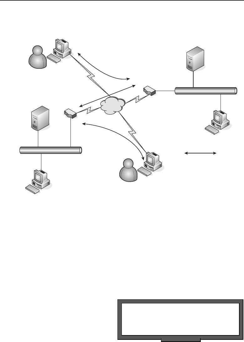
Edwards c10.tex V3 - 03/27/2009 11:24am Page 432
432 Part II ■The OSI Layers
devices is to allow only tunnel traffic to pass through from one VPN tunnel
endpoint to another.
Indicates VPN
Tunnel Connection
Using IPsec
Network B
Network A
User A
User B
Figure 10-13 VPN networking using IPSec
Remote users using only a computer connected to an Internet access point
require a client to be loaded on their PC to establish a VPN tunnel between the
computer and a remote VPN router. Once a tunnel session is established, users
can launch other applications, which will utilize the connection to gain access
to the resources located on the private network protected by the VPN router.
The VPN router is capable of setting user policies, either by user or group of
users, to limit access to only some of the network’s resources. It is also capable
of denying remote users the capability to access the private network and then
access the remote private network through the established peer-to-peer tunnel.
POP QUIZ
Name two components that help make
VPNs safe and secure.
The use of IPSec to create
VPNs using the Internet elimi-
nates the need for direct
point-to-point telecommunica-
tions between remote network
nodes. This is a large cost sav-
ings over using directly con-
nected dedicated lines between
remote office locations. However, careful planning and thought needs to go

Edwards c10.tex V3 - 03/27/2009 11:24am Page 433
Chapter 10 ■The Network Layer 433
into the design of the network, and policies may have to be developed to
secure the network from a security breach or the compromise of information
as it travels over the Internet.
10.3 Chapter Exercises
1. Name the type of network service being used for each of the following:
HTTP
FTP
Mail
Telnet
2. A client/server application is considered to be what type of network ser-
vice?
3. What is a TLD and can you name a few?
4. How is the MTU size determined?
5. What does NAT accomplish?
6. Name two network tools that can troubleshoot a network problem?
10.4 Pop Quiz Answers
1. Mail is what type of network service?
Connectionless
2. Name the ports used by an FTP client to request an FTP session
with an FTP server. Which port is used for data transmission?
Ports 20 and 21. Port 20 is used for data.
3. Name some top level domain names.
.com, .gov, .edu, .net
4. What is a maximum transmission unit?
The maximum payload size that can be transmitted without the use of
fragmentation.

Edwards c10.tex V3 - 03/27/2009 11:24am Page 434
434 Part II ■The OSI Layers
5. What is the type of address translation that is used to keep track of
sessions initiated by a computer on a private network to a service on the
Internet?
Port mapping
6. What is the difference between how IPv4 IP addresses are denoted and
how IPv6 IP addresses are denoted?
Dot-decimal notation versus hexadecimal numbers separated by colons.
7. What option would be used to modify the size of a ping packet?
The -l option
8. What is the default maximum hop count for the traceroute command?
30 hops
9. Name two components that help make VPNs safe and secure.
Authentication and encryption

Edwards c11.tex V3 - 03/27/2009 3:33pm Page 435
CHAPTER
11
The Data Link Layer
Power consists in one’s capacity to link his will with the purpose of others, to lead
by reason and a gift of cooperation.
— Woodrow Wilson
The Data Link layer is Layer 2 of the OSI reference model. This layer allows for
direct communication between nodes over the physical channel provided at the
lower layer. The communication can be point-to-point (one-to-one communica-
tion between two nodes) or point-to-multipoint (one-to-many communication,
from one node to many nodes), depending on the nature and configuration of
the network.
LAN technology exists primarily at the Data Link and Physical layers of the
architecture. The functions performed by a network bridge or switch occur
mainly at the Data Link layer. Network switches are able to tremendously
enhance the capabilities provided by the Data Link layer. This is true to the
point where you have to be careful that the implementation of the features
doesn’t affect the operations of some protocols within the upper layers.
The generic operation performed at the Data Link layer is the movement
of data between nodes within a network over a physical connection. Once
the Data Link layer has ensured that a connection is set up, the layer divides
data into frames and transmits them to other nodes within a network. The
receiving node sends acknowledgments and ensures that the data is received
by keeping track of bit patterns in the received frames.
435

Edwards c11.tex V3 - 03/27/2009 3:33pm Page 436
436 Part II ■The OSI Layers
RANDOM BONUS DEFINITION
Layer 2 switch — Synonymous with bridge.
In this chapter, we discuss the
Data Link layer. We cover con-
cerns that are experienced in a
LAN, as well as some of the
mechanisms that are in place to
recover from problems. In addi-
tion to the operations of this layer, we will discuss the use of switches and
bridges in a LAN.
11.1 Concerns of the LAN
Most typical network users do not care about all the protocols and mechanisms
that are in use to get their data; they just care that they get it. Because you
are not the typical network user, however, you should care how this data gets
there. Networks of all sizes produce conditions that are less than optimal, so
actions have to be taken to address these needs. If there were no way to control
the flow of data, the networking world would be a mess. If you worked in
an organization that only used several thousand 10/100 Mbps Ethernet hubs,
you would find that the end users would be less than satisfied (especially if
you consider the types of data that are flowing in a normal LAN).
POP QUIZ
The Data Link layer is what layer of the OSI
reference model?
What should you concern
yourself with in relation to oper-
ations at the Data Link layer
within a network? This question
is the reason this section is in
the book. There are a lot of con-
siderations to be aware of if you
want to have an understanding
of good old Layer 2.
In general, the Data Link layer must provide mechanisms for framing,
addressing, and detecting errors in data that is being sent to and fro over
the physical link. The framing mechanisms provide a way for the frames
to be delimited. Node addressing identifies the source and destination for
communication on the LAN. Error detection ensures that only good data is
received at the destination and then delivered to the upper layers. In some
cases, the Data Link layer discards any errors it discovers, or it may employ a
recovery mechanism — it all depends on which action it was designed to do.
11.1.1 It Just Is
It’s really hard to compare one LAN to another. There really isn’t anything
typical about any LAN. There are similarities in both design and functionality,
but each LAN is unique. This LAN is your LAN, if you will. The concerns

Edwards c11.tex V3 - 03/27/2009 3:33pm Page 437
Chapter 11 ■The Data Link Layer 437
of the LAN are fairly typical. There are commonalities that exist in any
LAN.1ThepurposeandtheexpectedoutcomearethesameinanyLAN.
The purpose of the LAN is to provide the avenue needed for communication
of data. The expected outcome is for the LAN to live up to its configured
expectations.
No matter what you do, there are some things about a LAN that are a fact.2
These have remained (and probably always will remain) a constant throughout
the lifetime of LANs.
A LAN consists of multiple nodes that are attached to a single shared
medium.
There are geographical distance limitations.
Every LAN will have a ceiling on the number of nodes that it supports.
A LAN cannot survive without error detection, correction, and recovery.
A LAN needs to support broadcasting and multicasting.
ACRONYM ALERT
DA — Destination address
Like nodes are peers to one another.
A LAN is administered locally
and is not subject to the same
rules that are maintained by net-
works outside of the LAN.
These are only a few of the things that most LANs have in common. This is
an important list for this chapter because these are what the Data Link layer is
all about.
11.1.2 Highs and Lows
Another concern for any LAN is to ensure that the highs and lows are met.
What do we mean by this? The LAN is there to provide the best possible
methods to deliver data over a shared link. This means that the LAN should
meet the following expectations:
Highs — This is the portion of data communication that you want more
of.
High throughput3— The data throughput is simply the rate of
error-free delivery of messages within a network. This includes data
1Believe it or not, there are some network administrators who still do not understand that point.
2An important thing to remember is that there is technology coming out all the time that not only
pushes the limits of the facts of the LAN, but also gives reason for upgrades.
3There are other terms that mean the same thing, but some of those have multiple definitions. For
instance, when we were determining exactly which term to use, we had originally considered
using the term ‘‘data rate.’’ Although this would have been perfectly appropriate, it may have
been a bit confusing. Data rate is a term that is used to define signaling rate, bit rate, transfer rate,
etc. Throughout, we determined, is more specific in this case.

Edwards c11.tex V3 - 03/27/2009 3:33pm Page 438
438 Part II ■The OSI Layers
that is transmitted over a physical or wireless channel, switched
through a node, or passed through the portals on both sides of the
link. The expectation of the LAN is that the data throughput stays at
a level as close as possible to the maximum allowable throughput.
This is determined by the configuration and design of the network.
High total bandwidth4— Bandwidth is the available capac-
ity of the physical or wireless channel, and network nodes
provide for the delivery of data messages in the LAN.
Lows — Things that you know will happen, but you don’t want to
happen.
Low delays — No delays is optimal, but unlikely. There will be
peaks and there will be lulls. You can take action to try to stagger
network chores (for instance, you can transfer large amounts of
data at night so that it does not affect the times when users are all at
work). Delays will occur, but the goal is to have as few as possible.
POP QUIZ
Multiple nodes attached to a single shared
medium can define what?
Low error rate —The
number of errors in
the network needs to
stay as low as pos-
sible. You can take
actions to detect
and recover from errors, but you want to be as proactive as pos-
sible to prevent them from occurring in the first place.
AN UNRELATED MOMENT OF PAUSE: FUN TECHNICAL TRIVIA!
1. The Macintosh computer was launched by Apple Computer in 1984, with
an ad that played during the Super Bowl. (The Raiders beat the Redskins,
38 to 9.)
2. How many approximate lines of code did the following Microsoft OS origi-
nal releases have?
■Windows 3.1 had over 3 million lines of code.
(continued)
4Consider bandwidth as the amount available, and throughput as the actual amount of suc-
cessful data messages that are transmitted. The throughput normally does not match the band-
width, as there is other chatter that consumes some of the capacity of the communication chan-
nel (Hellos, Acks, etc.). For instance, if the link is a 10 GB Ethernet link, the bandwidth is going
to be 10,000 Mbps. The throughput would be the rate of successful messages sent over the link.
Of course, this is based on the performance of the network and is variable.

Edwards c11.tex V3 - 03/27/2009 3:33pm Page 439
Chapter 11 ■The Data Link Layer 439
AN UNRELATED MOMENT OF PAUSE: FUN TECHNICAL TRIVIA! (continued)
■Windows 95 had over 15 million lines of code.
■Windows 98 had over 18 million lines of code.
■Windows 2000 had over 35 million lines of code.
3. The computer mouse was invented in 1963 by Dr. Douglas C. Engelbart.
4. The term ‘‘computer’’ was first used to describe a mechanical calculating
device in 1897.
5. We all know that 8 bits is called a byte, but did you know that 4 bits is called
a nibble?
6. The type of keyboard that we are all familiar with is known as the QWERTY
keyboard. This name is derived from the first six letters on the top line.
7. Netscape was the most popular Internet browser until Microsoft released
Internet Explorer 4.
11.2 Accessing the Medium
POP QUIZ
Define throughput.
We all know that the LAN is
made up of nodes connected
to one another over a shared
medium. We also know that
it is called ‘‘shared medium’’
because everyone shares it for
transmitting data. It’s important
to cover a few of the rules that
must be upheld in a LAN as far as actually connecting to the network.
Sure, we have discussed some of this before, but now is a good time for a
refresher!
11.2.1 Rules of Accessing the Medium
The previous section talked about some of the facts of a typical5LAN. When
dealing with the shared medium, there are some facts as well.
Within a shared medium, only one node can successfully transmit data
at any given time.
5Typical is used loosely.
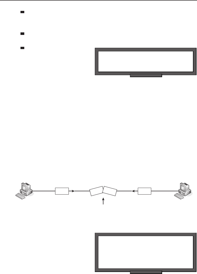
Edwards c11.tex V3 - 03/27/2009 3:33pm Page 440
440 Part II ■The OSI Layers
Bandwidth is allocated to support the nodes that are sharing the medium
so that each node gets a fair amount of bandwidth, with little to none left
over.6
The shared medium should support as much throughput as it is
intended to handle.
RANDOM BONUS DEFINITION
Gigabit Ethernet — 1000 Mbps Ethernet.
The network adminis-
trator should ensure that
delays are kept to a min-
imum for data that is
transported over a shared
medium. A reasonable
amount of waste, overhead, and delay should be taken into account
when setting up and maintaining the network, and network monitor-
ing will help you ensure that you meet the goals that you set.
11.2.2 From Tokens to Contention
So, how exactly do you go about ensuring the bandwidth is distributed fairly
to the nodes using the shared medium? There are two methods that can be
used in a LAN: tokens and contention. When using the token method, a token
is passed from node to node. The nodes then pass data among one another in a
round-robin fashion. When the contention method is used, the nodes transmit
data when they want to. Therefore, it is entirely possible that two stations send
data at the same time, causing a collision) to occur (see Figure 11-1).
Collision
Figure 11-1 A collision
POP QUIZ
Name two methods of ensuring bandwidth
is distributed fairly to the nodes that share
connectivity within a LAN.
A collision causes datagrams
to be dropped, but it doesn’t
necessarily mean that the data
can’t be recovered in some way.
There are mechanisms that can
6When allocating bandwidth, it is important to use as much as possible. Some will be used
by other processes, so a small amount of waste is possible.
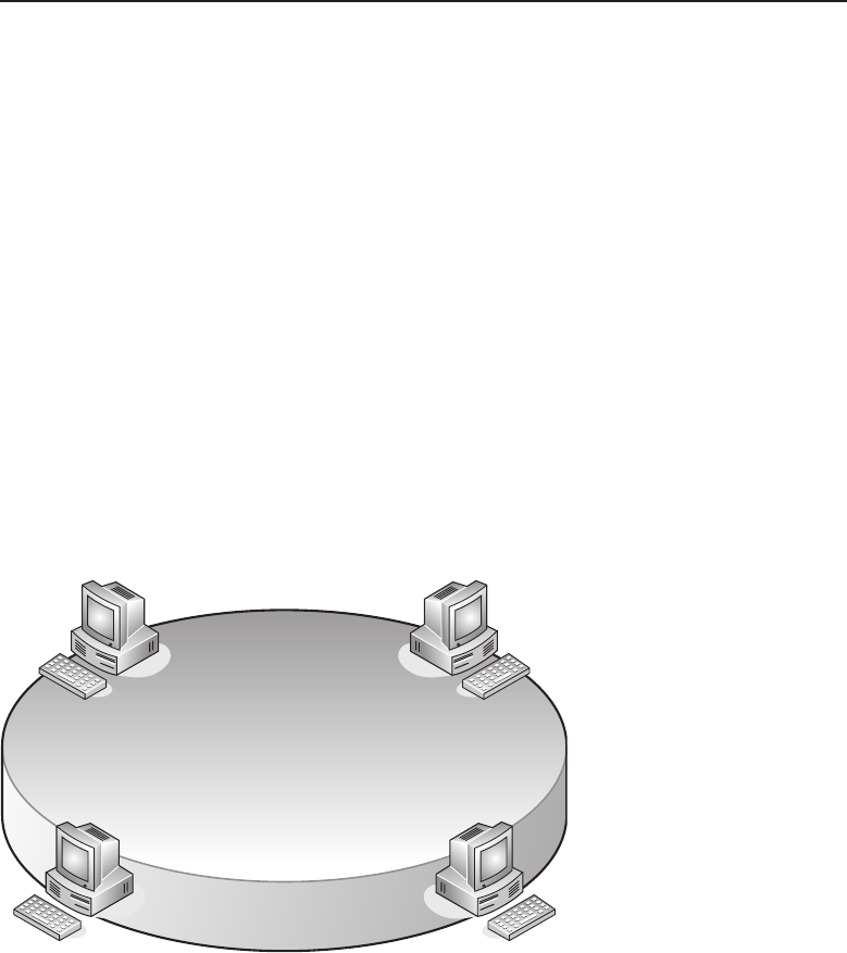
Edwards c11.tex V3 - 03/27/2009 3:33pm Page 441
Chapter 11 ■The Data Link Layer 441
be configured to recover from data loss and even prevent conditions that may
cause it. Even so, there is a potential for data loss, so you can consider the token
method a guarantee, whereas the contention method is more of a probability.
11.2.2.1 Using the Token Method
In Chapter 1 you learned that the token-passing topology consists of a single
frame, known as a token, that is passed from one station to the next. When a
node wants to pass data, it must wait until it receives an empty token. The
node can then add its data to the token and pass it along the way. IEEE 802.5
is the official standard for Token Ring, which is the most common LAN token
method in use.
A Token Ring topology can be set up physically in either a token ring
(Figure 11-2) or a token bus (Figure 11-3) configuration. There is no logical
difference between the two methods, as both operate in a token-passing
manner.
Figure 11-2 A token ring
In a token bus configuration, there is a central node called a media access
unit (MAU) or a multistation access unit (MSAU). This device is similar to
an Ethernet hub, but it has a computer chip that provides the logical ring
that the end nodes are concerned with. The benefit of the token bus is that
when a node goes down, the ring can be adjusted so that the other nodes will
continue to operate on the network. In a physical ring, if a node goes down,
the communication for all nodes goes down as well.
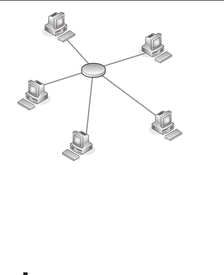
Edwards c11.tex V3 - 03/27/2009 3:33pm Page 442
442 Part II ■The OSI Layers
Figure 11-3 A token bus
11.2.2.2 Using the Contention Method
Nodes that use the contention method transmit their data at any time. The
first node to get data on the line gets served first. When two nodes transmit at
the same time, a collision occurs and the data will be resent. If the network is
experiencing a high rate of data at any particular time, there will most likely be
a lot of collisions, which will continue until bandwidth availability is restored.
Fortunately, some enterprising individuals came up with a way to sense
when there is data being transmitted, thus reducing the number of collisions
that can occur. Following are the protocols that are used to ensure that data
flow in a contention method environment passes as smoothly as possible:
Carrier Sense Multiple Access (CSMA) — Allows multiple nodes to
be attached to a shared network. Prior to transmission, the nodes lis-
ten to see if the shared channel is busy and will transmit when they
sense that the channel is not busy. ‘‘Carrier sense’’ simply means that
a node is listening to see if it can detect an unused channel. If the node
senses that there is a busy channel, it will defer transmission of its data
until the channel is idle. ‘‘Multiple access’’ defines the fact that there
are multiple nodes accessing the shared medium to transmit data.

Edwards c11.tex V3 - 03/27/2009 3:33pm Page 443
Chapter 11 ■The Data Link Layer 443
Carrier Sense Multiple Access with Collision Avoidance
(CSMA/CA) — This is an enhanced version of the CSMA proto-
col in that it adds collision avoidance as a function. In this type
of network, collisions are avoided because the station will not
transmit data when it senses the channel is busy. The node will
listen to the channel for a defined amount of time, and when the
node is ready to send data, it will send a jam signal,7which lets all
the other nodes know that the node is ready to transmit data.
Carrier Sense Multiple Access with Collision Detection
(CSMA/CD) — This is an enhanced version of the CSMA proto-
col in that it adds collision detection as a function. This function
allows the transmitting node to monitor the channel for other
transmissions. If while transmitting a frame, the node detects
a signal coming from another node, it will terminate the trans-
mission, send out a jam signal, and then try to send the frame
again.8There are different ways for collisions to be detected,
depending on the shared medium that is being used. The most
popular and most often used CSMA/CD protocol is Ethernet.
11.3 Meet the Sublayers
ACRONYM ALERT
DEC — Digital Equipment Corporation
In order to handle service requests from
the network, the Data Link layer is broken
into two sublayers: the Logical Link Con-
trol (LLC) sublayer and the Media Access
Control (MAC) sublayer (see Figure 11-4).
Data Link
LLC
MAC
Figure 11-4 The Data Link layer’s sublayers
LLC is the upper sublayer and is responsible for flow control, error control,
and multiplexing and demultiplexing data transmitted over the MAC sublayer.
The LLC sublayer is the sublayer that serves the higher layer client. LLC does
7A jam signal in CSMA/CD is a message to all other nodes that a collision has occurred
and that they should stop transmitting.
8A random time interval is set that will determine when a station will try to transmit a frame
again.

Edwards c11.tex V3 - 03/27/2009 3:33pm Page 444
444 Part II ■The OSI Layers
not have to worry about the design and functions of the LAN, which allows
it to buffer these functions so that the higher layer protocols need not worry
about the details but can focus on the tasks at hand.
The MAC sublayer is responsible for framing formats and determining
which frame is going to be the next to access the shared medium.
11.3.1 Logical Link Control
LLC is a protocol developed by the IEEE 802.2 working group and provides
three different types of service:
LLC Type 1 (LLC-1) — Used for connectionless services.
LLC Type 2 (LLC-2) — Used for connection-oriented services.
LLC Type 3 (LLC-3) — Used for acknowledgments in conjunction with
connectionless services.
POP QUIZ
The most popular and most often used
CSMA/CD protocol is .
LLC-1 is used for connection-
less services. It is a best-effort
delivery, providing none of the
bells and whistles (for instance,
flow control). LLC-1 provides
multiplexing services to the
upper layers. LLC-29is used
for connection-oriented ser-
vices. Because it serves the connection-oriented operations, it does support the
bells and whistles (for example, flow control, error control and recovery, call
setup, call management, and call termination). LLC-3, which is seldom used,
acknowledges frame delivery in a connectionless environment.10
11.3.1.1 LLC Framing
LAN source and destination addresses are determined by the MAC sublayer
and will be in the MAC header portion of the frame. The LLC PDU11 contains
the following fields:
Destination Service Access Point (DSAP) —Thisisusedto
identify the LLC that is supposed to receive the PDU.
9Note that nodes that support LLC-2 must also support LLC-1. This is because LLC-2 connections
are established from an LLC-1 connectionless session.
10LLC-3 is used over LLC-1. This provides you with a bit of reliability without having the
overhead of LLC-2. In most LANs you will usually only see LLC-1 and LLC-2. This is because
many upper-layer protocols provide for recovery and don’t need more than best-effort delivery.
11In case you forgot, PDU stands for protocol data unit. The PDU is the entity that all information
is transferred in within a network.
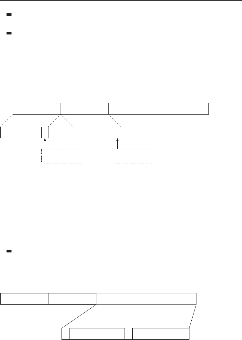
Edwards c11.tex V3 - 03/27/2009 3:33pm Page 445
Chapter 11 ■The Data Link Layer 445
Source Service Access Point (SSAP) — This is used to identify the LLC
that is supposed to send the PDU.
Control — The Control field provides sequencing data, command infor-
mation, and responses to requests. Note that any or all of these can be
used in any combination.
Figure 11-5 shows the format of the LLC header. The LLC header is either 3
bytes or 4 bytes in length, depending on the version of LLC service type that
you are using. The DSAP and SSAP are always 8 bytes in length each, which
leaves the control field as the variable length field in the PDU.
Destination
address Source Address
I
G1 bit
7 bits
8 bits 8 bits 8 or 16 bits
7 bits
1 bit
C
R
DSAP SSAP CONTROL
Individual DSAP = 0
Group DSAP = 1
Command = 0
Response = 1
Figure 11-5 An LLC PDU (LLC header)
The DSAP field and the SSAP field are pretty straightforward. The DSAP
field is an 8-bit (or 1-byte) field that contains 7 bits for the destination address
portion of the field; the additional bit identifies whether it is destined for an
individual or group DSAP. The SSAP field is an 8-bit (or 1-byte) field that
contains 7 bits for the source address portion of the field; the additional bit
identifies whether it is a request or a response to a request.
The Control field is a variable length, depending on what type of LLC you
are using, and the type of the frame. The three frame formats you will see are:
Informational frame (I-frame) — Used with LLC-2 only. This type uses
a 2-byte (16-bit) field. Its purpose is tosendnumberedinformationtrans-
fer in LLC-2. Figure 11-6 shows an example of the format of the I-frame
format.
8 bits 8 bits 8 or 16 bits
DSAP SSAP
SSN RSN
CONTROL
P
F
0
Figure 11-6 The format of the I-frame
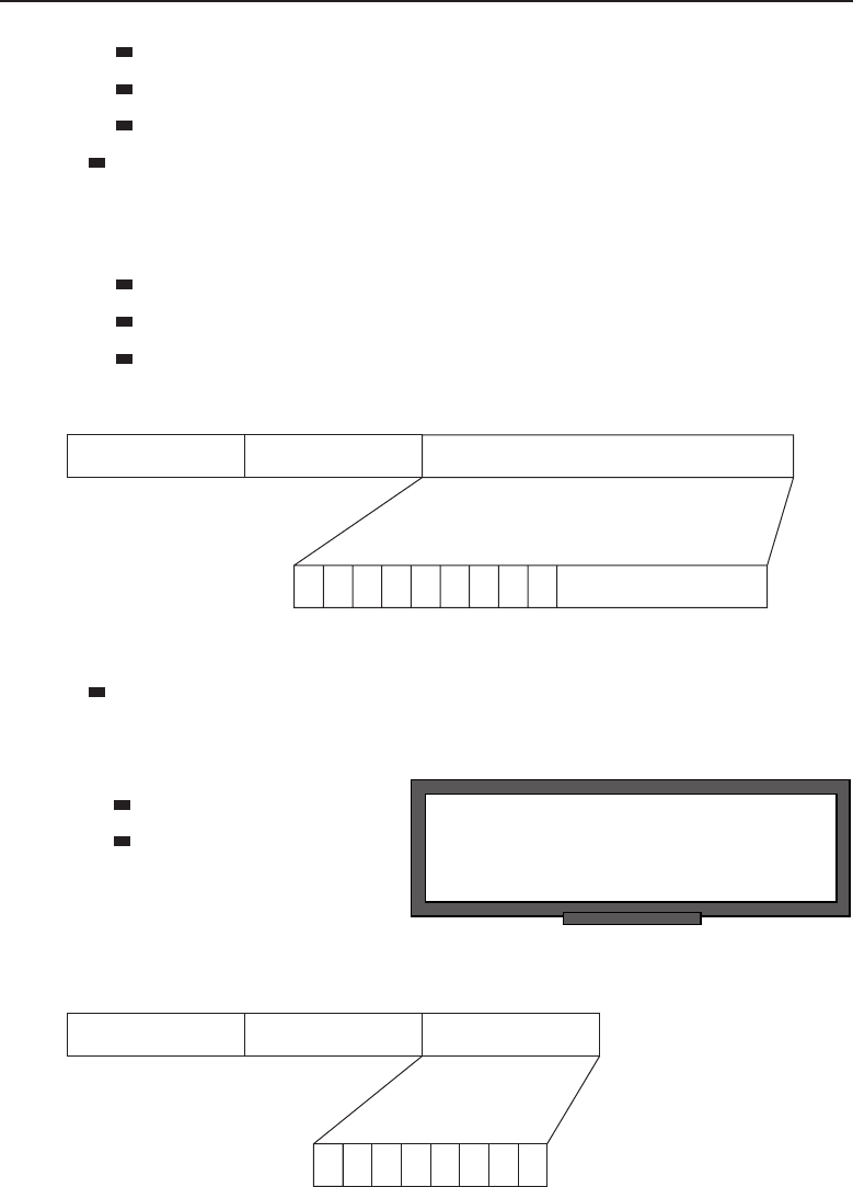
Edwards c11.tex V3 - 03/27/2009 3:33pm Page 446
446 Part II ■The OSI Layers
SSN — Sender sequence number
RSN — Receiver sequence number
PF — Poll on command frames or Final on response frames
Supervisory frame (S-frame) — Used with LLC-2 only. This type uses
a 2-byte (16-bit) field. It is responsible for handling acknowledgments,
retransmitting requests, and terminating requests of the I-frames in
LLC-2. Figure 11-7 is an example of the format of the I-frame format.
S — Supervisory function bits
PF — Poll on command frames or Final on response frames
RSN — Receiver sequence number
8 bits 8 bits 16 bits
DSAP SSAP
RSN
P
F
10SS0000
CONTROL
Figure 11-7 The format of the S-frame
Unnumbered frame (U-frame) — Can be used with all LLC types. This
type uses a 1-byte (8-bit) field. It is responsible for unsequenced data
transfer and may handle some control functions as well (see Figure 11-8).
RANDOM BONUS DEFINITION
frame — The Data Link layer encapsulation
of transmitted or received information.
M—Modifierbits
PF — Poll on com-
mand frames or Final
on response frames
8 bits 8 bits 8 bits
DSAP SSAP
M
CONTROL
MM
P
F
MM11
Figure 11-8 The format of the U-frame
Edwards c11.tex V3 - 03/27/2009 3:33pm Page 447
Chapter 11 ■The Data Link Layer 447
11.3.1.2 Subnetwork Access Protocol
POP QUIZ
What does DSAP stand for?
The Subnetwork12 Access Proto-
col (SNAP) is used in conjunc-
tion with LLC-1 for the purpose
of upward multiplexing to more
upper-layer protocols than what
is available with the standard
LLC 8-bit SAP fields. When SNAP is not in use, the LLC DSAP’s 8-bit field
provides support of multiplexing to a maximum of 256 clients. Because the
DSAP field reserves half its space for group SAPs, you actually can only
multiplex to 128 clients.
As far as the PDU goes, the SNAP header is placed directly behind the LLC
header in the PDU. If SNAP encapsulation is being used, the DSAP and SSAP
fields will be set to 0xAA, which indicates that SNAP is being used and that
there is a SNAP header in the PDU. See Figure 11-9 for an example of SNAP
encapsulation.
8 bits 8 bits 8 bits 24 bits 16 bits
DSAP SSAP CONTROL SNAP OUI SNAP PID
LLC Header SNAP Header
Figure 11-9 SNAP encapsulation
The fields in the SNAP header are as follows:
SNAP OUI — This is a 24-bit field that contains the organizationally
unique identifier (OUI). The OUI identifies the organization that the PID
is assigned to.
ACRONYM ALERT
EIA — Electronic Industries Association
SNAP PID — This is a 16-bit field that
contains the protocol identifier (PID),
which identifies the upper-layer pro-
tocol that the PDU is destined for.
Here’s the clincher: SNAP encapsulation allows you13 to have up to 65,536
upper-layer protocol identifiers.14
12It’s important to note that the term ‘‘subnetwork,’’ in the SNAP sense, does not have anything
to do with a subnetwork in a TCP/IP sense. This is one of those acronyms that may have actually
come before the term. It’s nothing more than a way to make SNAP have that fancy ring that we
‘‘catenet’’ lovers like.
13In saying you, we are referencing the applicable organization.
14This simply blows the 256 (if you are lucky) identifiers out of the water.

Edwards c11.tex V3 - 03/27/2009 3:33pm Page 448
448 Part II ■The OSI Layers
A LITTLE MORE ABOUT THE OUI
The OUI is a 24-bit number that can be purchased from the IEEE. The number is
unique to an organization (vendor, company, etc.) and serves several purposes.
Many protocols reference the OUI (SNAP, for instance). Some even append a
few bits to increase the functionality of the OUI. There are a lot of other terms
that are used for the OUI. It is also known as a MAC address (more on this in
the following section), vendor ID, NIC address, and many more.
Here is a list of a few OUIs that are assigned today. Note that these are
globally assigned, which is why they are unique for that particular organization.
Also note that often the same company can be assigned multiple OUIs,
regardless of the location they are registered to (as in the case of Nortel
Networks).
00-00-C0 (hex) Western Digital Corporation
0000C0 (base 16) Western Digital Corporation
8105 Irvine Center Drive
Irvine, CA 92718
United States
00-0C-41 (hex) Cisco-Linksys
000C41 (base 16) Cisco-Linksys
121 Theory Drive
Irvine, CA 92612
United States
00-0D-54 (hex) 3Com Ltd.
000D54 (base 16) 3Com Ltd.
Peoplebuilding 2
Peoplebuilding Estate
Maylands Avenue
Hemel Hempstead
Hertfordshire HP2 4NW
United Kingdom
00-0D-56 (hex) Dell PCBA Test
000D56 (base 16) Dell PCBA Test
One Dell Way
RR5 MS-8545
(continued)

Edwards c11.tex V3 - 03/27/2009 3:33pm Page 449
Chapter 11 ■The Data Link Layer 449
A LITTLE MORE ABOUT THE OUI (continued)
Round Rock, TX 78682
United States
00-0E-40 (hex) Nortel Networks
000E40 (base 16) Nortel Networks
8200 Dixie Road
Suite 100
Brampton, Ontario L6T 5P6
Canada
00-1F-9A (hex) Nortel Networks
001F9A (base 16) Nortel Networks
2221 Lakeside Boulevard
Richardson, TX 75082-4399
United States
00-23-0D (hex) Nortel Networks
00230D (base 16) Nortel Networks
2221 Lakeside Boulevard
Richardson, TX 75082-4399
United States
This list is an example and is only a short list compared to all the OUIs that
are registered. If you want to see a complete list, you can view it on the IEEE
website (http://standards.ieee.org).
11.3.2 The MAC Sublayer
The MAC sublayer is responsible for interfacing between the LLC sublayer
and Layer 1, the Physical layer. The MAC sublayer provides access control
as well as addressing for the PDU. This sublayer is what makes multipoint
communication with a LAN/WAN a reality. This sublayer is also able to
operate as a full-duplex logical channel in a LAN. This logical channel supports
unicast (point-to-point) services, multicast services (point-to-multipoint), and
broadcast (point-to-multipoint) services. All these services are discussed in
Section 11.4.

Edwards c11.tex V3 - 03/27/2009 3:33pm Page 450
450 Part II ■The OSI Layers
POP QUIZ
What does SNAP stand for?
The MAC sublayer uses a
MAC address,15 the address
assigned to the node’s network
adaptor (commonly, a NIC).
For channel access, the MAC
sublayer employs some control
functions that allow multiple nodes to use the same physical medium. We
discuss both the MAC address and the channel access control functions next.
11.3.2.1 The MAC Address
The IEEE 802 MAC address is a 48-bit address that is used to identify the
network adaptor for a particular node or interface in the network. The MAC
address was originally designed as a permanent address that is unique to the
adaptor it is assigned to. Most hardware today allows a MAC address manip-
ulation method known as MAC spoofing. That tidbit of trivia is informational,
but we won’t be going into the details, as it is beyond the scope of this book.
The format of the IEEE 802 MAC address is set up to make it as easy as
possible to understand. It consists of six groups of two hexadecimal digits.
The groups are separated by either a colon (:) or a hyphen (-). Following is an
example of each method:
01:00:23:00:bf:00
01-00-23-00-bf-00
In these examples, the OUI would be 01:00:23, with the remainder being the
NIC-specific identifier. Combined, they make up the MAC address.
RANDOM BONUS DEFINITION
error control — A procedure used to
recover from detected errors.
MAC addresses can be ad-
ministered both universally and
locally. When the address is
administered universally, the
MAC address is assigned to the
interface by the device’s man-
ufacturer. Locally administered
addresses are manipulated by a network administrator for purposes that serve
the needs of the LAN.
11.3.2.2 Access Control for the Channel
The MAC sublayer is responsible for ensuring that multiple nodes are able to
connect to and share the same physical medium. The groups of protocols that
operate and perform this function are known as multiple access protocols (MAP).
15The MAC address is also referred to as a physical address.

Edwards c11.tex V3 - 03/27/2009 3:33pm Page 451
Chapter 11 ■The Data Link Layer 451
These protocols detect and avoid collisions in contention environments and
ensure that there are enough resources to set up a logical connection when
needed. Remember, earlier in this chapter we said that the most popular
contention method used is Ethernet.
11.4 The ‘‘ings’’ — Casting, Detecting,
and Addressing
LAN traffic flow is a fairly simple process. There are a lot of standards and
configuration options in a LAN that provide a lot of freedom to configure and
maintain in an attempt to reach the maximum highs and minimum lows that
we discussed in Section 11.1.2. None of this would really mean anything if we
didn’t have a way of getting the data from the upper layers and making sure it
reaches the appropriate process on the other end of the link. Well, we do have
a way to do all of this in one very helpful and handy layer — Layer 2!
It is important to keep in mind that some of the ‘‘ing’’ operations occur at
other layers of the OSI reference model (upward/downward multiplexing,
data link multicasting vs. IP multicasting, etc.). Unless otherwise stated, this
section pertains only to the processes at the Data Link layer.
This section covers MAC addressing and end-to-end delivery of data to a
single node as well as multiple nodes.
11.4.1 Data Link Addressing
Main Entry: ad.dress16
Function: noun, verb, -dresses or –drest, -dress.ing.
1. a direction as to the intended recipient, written on or attached
to a piece of mail.
2. the place or the name of the place where a person, organization, or
the like is located or may be reached: What is your address when you’re
in Des Moines?
3. to direct (data) to a specified location in an electronic computer.
ACRONYM ALERT
IC — Integrated circuit
Directing data is what addressing is all
about. At the Data Link layer, this is done
by pointing PDUs to the destination MAC
address for delivery of a frame within a
LAN. The MAC address is the number that
is assigned by the manufacturer of a NIC
or a network interface. In Figure 11-10, you
16Dictionary.com Unabridged (v 1.1). Random House, Inc. April 18, 2008.
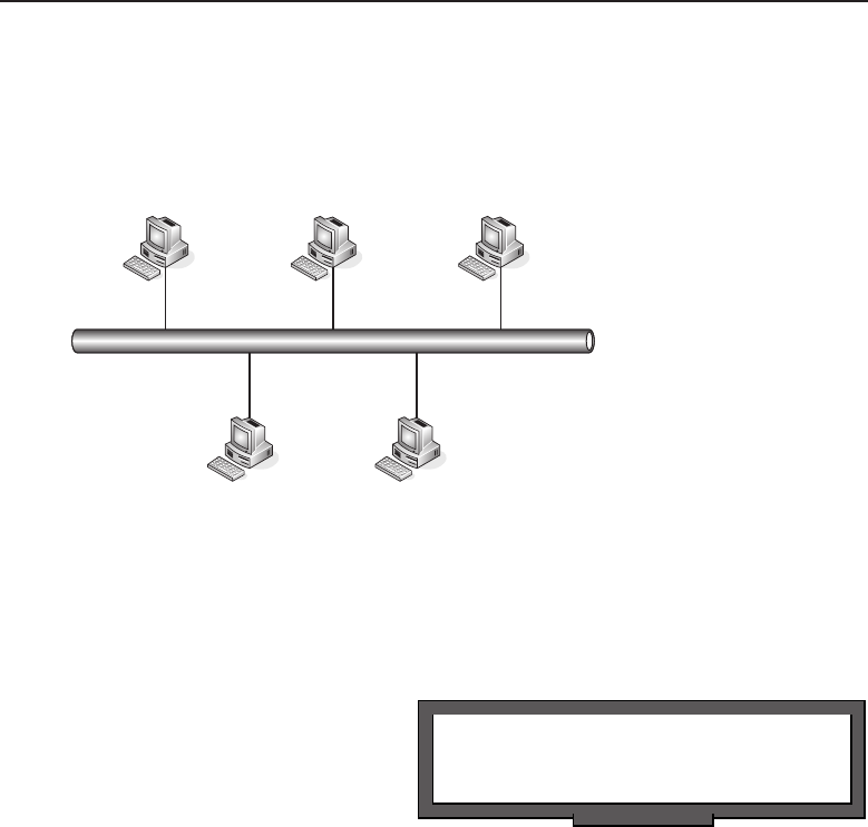
Edwards c11.tex V3 - 03/27/2009 3:33pm Page 452
452 Part II ■The OSI Layers
can see a group of individuals sharing a physical medium. If Bob needs to
send anything to Larry, he simply enters the MAC address (01:bb:04:af:00:1f)
that is assigned to the NIC card on Larry’s PC in the frame and sends it toward
Larry’s PC.
01:bb:04:af:00:1f
LarrySue
Bob George Lilly
Figure 11-10 Data Link layer frame delivery
That sounds simple, doesn’t it? But what we haven’t really discussed is how
Bob’s PC learned the MAC address of Larry’s PC. We also need to cover how
Larry’s PC knows how to get back in touch with Bob’s.
POP QUIZ
What does SSAP stand for?
It wasn’t until the early 1980s’
PC boom that there was really
a need to formulate address-
ing that could be learned in
a dynamic fashion and could
support several hundred nodes.
Prior to the PC boom, there were
not more than a few nodes in a
network, and addressing was locally assigned and administered. In a network
of only a few nodes, it was easy to maintain networks in this manner. Now,
however, with hundreds of nodes communicating with hundreds of networks
with hundreds of nodes, there is a real need to have a way to bridge traffic
that is easy to administer.
For now, and way into the future, LANs will continue to evolve and expand
geographically as well as in technical achievements that are, and will probably
remain, a constant.
11.4.1.1 The MAC Address Format
The MAC header of a frame contains the destination and source MAC
addresses for the interfaces involved in the communication stream.
Figure 11-11 shows the 48 bits that make up the MAC address.
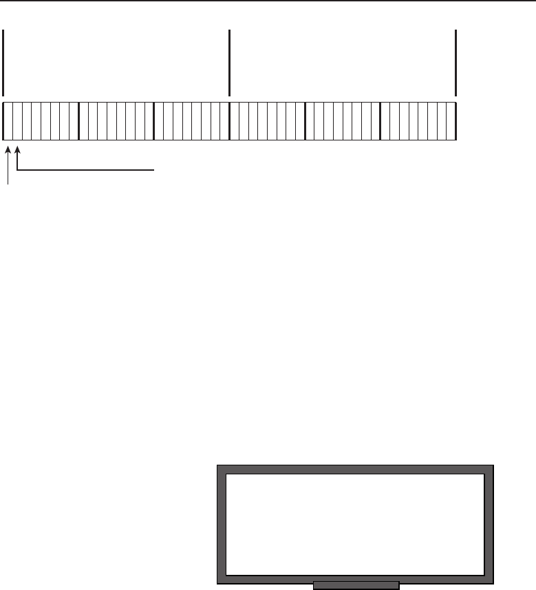
Edwards c11.tex V3 - 03/27/2009 3:33pm Page 453
Chapter 11 ■The Data Link Layer 453
Globally/Locally
administered bit
(G/L bit)
Individual/Group bit
(I/G bit)
OUI
I
G
G
L
Organizationally
assigned
identifyer
Figure 11-11 The MAC address format
Regardless of whether it is the source or destination address, the format is
the same for all but the first bit. When referring to the destination address
field, the first bit (the I/G bit) identifies whether the destination target is an
individual (unicast) or a group (multicast). The source address field only uses
the first bit when using Token Ring or FDDI. When used, it identifies if there
is any source routing data in the frame.
Thesecondbitinthesourceanddestination address field indicates whether
the address is globally or locally unique. This bit is called the G/L bit and it
identifies whether the organizational assigned identifier17 is globally unique
(G/L bit set to 0) or locally unique (G/L bit set to 1). If it is a locally unique
identifier, then the address is unique only to the LAN.
RANDOM BONUS DEFINITION
edge switch — A switch that is
implemented at the boundary of a
VLAN-unaware segment and a
VLAN-aware segment of a LAN.
In any given LAN, there can
be a mix of both globally and
locally unique addresses. The
nodes within that LAN do not
have to worry about whether an
identifier matches theirs that is
in another LAN. This is because
LAN-to-LAN communication is
handled at the Network layer
and the IP addressing scheme negates this concern. Nodes within a LAN
cannot directly communicate at the Data Link layer with nodes in other LANs.
Therefore, it is possible to have a duplicate locally assigned MAC, but they
will not be aware of one another.
11.4.1.2 Unicast Addressing
Aunicast address is simply the address of a particular node’s interface within
the LAN. The unicast address is the MAC address that is assigned to a device
17The last 24 bits of the MAC address.
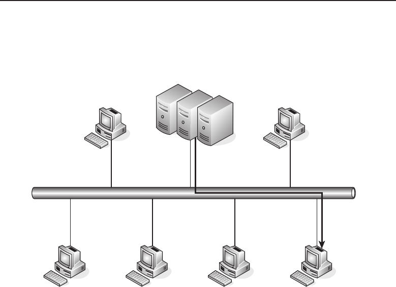
Edwards c11.tex V3 - 03/27/2009 3:33pm Page 454
454 Part II ■The OSI Layers
or an interface within the LAN. Unicasting is the act of sending a frame from
one source node to a single destination node. Figure 11-12 shows an example
of unicasting.
00:01:af:21:ab:11
00:01:af:21:ab:00
Figure 11-12 Unicasting
The figure shows the server farm sending data to a single node on the LAN.
The unicast address ofthe source is 00:01:af:21:ab:11, which is the MAC address
oftheinterfaceonthesourcesideofthetransmission.Thedestinationunicast
address is the MAC address of the interface used by the destination node — in
this case, 00:01:af:21:ab:00. All transmitted frames during the session will use
the same destination and source unicast addresses.
11.4.1.3 Multicast Addressing
Multicasting18 is the act of sending a message to multiple nodes. Multicasting
can be handled at the Layer 3 level (IP multicasting) or at Layer 2 (Ethernet
multicasting). This section will focus on Layer 2 multicasting; the Layer 3
multicasting was discussed in Chapter 10.
18A type of multicast that you might come across in a LAN is the broadcast, which is destined
for everyone in the network. Often called the ‘‘all F’s’’ MAC address, the broadcast address is
always ff:ff:ff:ff:ff:ff. Table 11.2 shows how this address maps to various protocols over Ethernet.
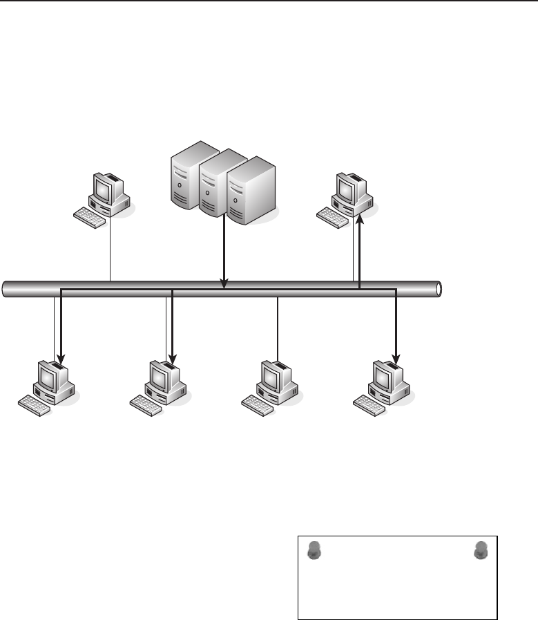
Edwards c11.tex V3 - 03/27/2009 3:33pm Page 455
Chapter 11 ■The Data Link Layer 455
Nodes that participate in a multicast group will be related in some logical
fashion.19 Multicast addresses are group addresses of nodes within a shared
internetwork. Multicasting provides the ability for multiple nodes to receive
data sent from a single transmission. Figure 11-13 shows an example of
multicasting.
00:01:af:21:ab:11
Figure 11-13 Multicasting
Notice that in the figure not all nodes are receiving the transmission that
is being sourced from the server farm. This is because not all of the nodes
are in the same multicast group. Also notice that the source address for the
originator will be a unicast address.20
ACRONYM ALERT
LACP — Link Aggregation Control Protocol
When a node decides to join a multicast
group, it needs to determine if a received
frame is a unicast or a multicast frame. NIC
cards are configured to recognize when a
frame is unicast and when it is not. How is
this done? Remember the I/G bit that we
discussed in Section 11.4.1.2? This is the bit that identifies if the frame is a
unicast (I/G bit set to 0) or multicast (I/G bit set to 1).
19The multicast will be sent only to those stations that share the function that requires them to
receive the message. The stations that are not applicable won’t be bothered.
20This is because there is only one source node involved.

Edwards c11.tex V3 - 03/27/2009 3:33pm Page 456
456 Part II ■The OSI Layers
Table 11-1 shows some well-known multicast MAC addresses that are used
by Ethernet.
Table 11-1 Ethernet Multicast MAC Addresses
ADDRESS TYPE FUNCTION
01:80:C2:00:00:00 Length field Spanning tree BPDU
09:00:07:FF:FF:FF Length field AppleTalk Multicast
09:00:07:00:00:FC Length field AppleTalk Zone Multicast
09:00:2B:00:00:03 8038 DEC LanBridge Hello packet
09:00:2B:00:00:0F 6004 DEC LAT
09:00:2B:00:00:00 8038 DEC LanBridge copy packet
09:00:2B:00:00:01 8038 DEC LanBridge Hello packet
09:00:4EL00:00:02 8137 Novell IPX
AB:00:04:04:00:00 6003 DECnet Phase IV router Hello packets
AB:00:00:03:00:00 6003 DECnet Phase IV end node Hello packets
CF:00:00:00:00:00 0900 Ethernet configuration test
POP QUIZ
Aaddress is simply the
address of a particular node’s interface
within the LAN.
Broadcasting is really noth-
ing more than multicasting to
everyone in the LAN. Table 11-2
shows some of the various types
and functions performed in the
broadcast message.
Table 11-2 Ethernet Broadcast MAC Addresses
ADDRESS TYPE FUNCTION
FF:FF:FF:FF:FF:FF 0600 XNS hello packets
FF:FF:FF:FF:FF:FF 0800 IP
FF:FF:FF:FF:FF:FF 0806 ARP
FF:FF:FF:FF:FF:FF 8035 Reverse ARP
FF:FF:FF:FF:FF:FF 809B Ethertalk

Edwards c11.tex V3 - 03/27/2009 3:33pm Page 457
Chapter 11 ■The Data Link Layer 457
11.4.2 Error Detection
Frames are either fixed-length PDUs (ATM uses a fixed-length PDU) or
bit-oriented, which is more common and is what we discuss in this book.
Regardless of the frame type, errors can occur in the LAN, and frames can
disappear, duplicate, and even become corrupted on their way to a destination.
An error in a length-type frame can cause the frame to terminate and skew
the beginning of a new frame. Likewise, a bit can be set incorrectly in a
bit-oriented type frame, which can cause duplication and even deletion of the
frame. Errors can be caused by numerous reasons, environmental as well as
traffic-related. Electrical interference can cause noise on the physical medium,
which can corrupt the bits in the frame. Other causes of transmission errors
include:
Signal distortion
Synchronization issues
Crosstalk
ACRONYM ALERT
TB — Transparent bridge
Errors will occur and there are accept-
able error rates that are figured into any
LAN design. Excessive errors are not good.
Depending on the protocols in use, errors
can cause transmission delays, and if not
handled correctly, the problem can propa-
gate itself, causing sluggishness and possi-
ble outages in the LAN. This is why you need a way to detect and possibly
correct errors at the Data Link layer level (as well as some protocols within
other layers).
There are two methods of error detection used at Layer 2, parity check and
cyclic redundancy check (CRC):
Parity check — The simplest of the error-checking methods. This
method adds a bit to a string of bits to ensure that the total number of
1s in the string is equal to an even or an odd number. For example:
POP QUIZ
What is the Ethernet standard broadcast
MAC address?
Odd parity — 01010101
+1 parity bit =
010101011. Notice
that the total num-
berof1sisan
odd number. An
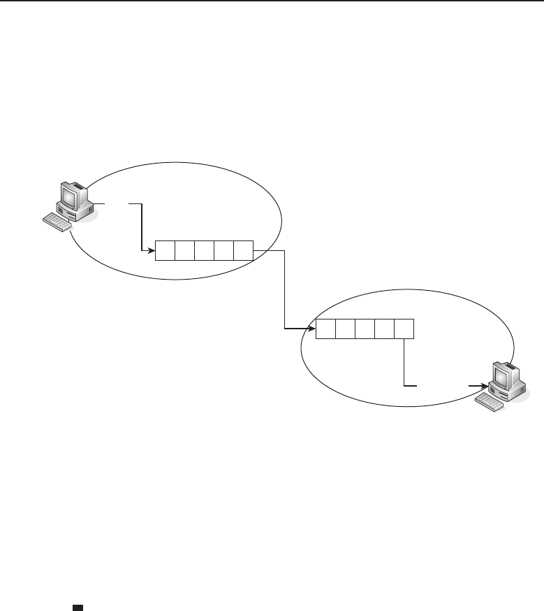
Edwards c11.tex V3 - 03/27/2009 3:33pm Page 458
458 Part II ■The OSI Layers
odd parity bit is always set to 1 if the total number of 1s in the
string (before the parity bit is considered) is an even number.
By adding 1 to the even number, it ensures that the number is
odd, which matches the type of parity in use in this case.
Figure 11-14 shows an example of data transmission using odd parity.
0011
0+0+1+1+1
Node A
Node B
00111
00111
Figure 11-14 Odd parity
In Figure 11-14, node A wants to send the data stream 0011
to node B. Node A computes the value of the data stream
(0+0+1+1)21 and because odd parity checking is being used,
node A turns the parity bit on to 1 before it transmits the data.
Node B then receives the data and computes the overall
value (0+0+1+1+1), which is an odd value. Odd Parity
is in use, so node B reports a good frame received.
Even parity — 01010100 +1 parity bit =010101001. Notice
that the total number of 1s is an even number. An even par-
ity bit is always set to 1 if the total number of 1s in the string
(before the parity bit is considered) is an odd number. By
adding 1 to the odd number, it ensures that the number is
even, which matches the type of parity in use in this case.
Figure 11-15 shows an example of data transmission using even
parity.
21When does 1 +1=1? When dealing with binary, when you are either on (1) or off (1).
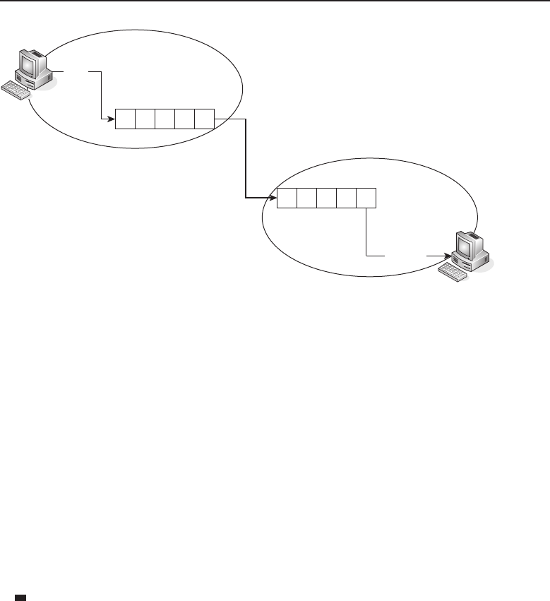
Edwards c11.tex V3 - 03/27/2009 3:33pm Page 459
Chapter 11 ■The Data Link Layer 459
0011
0+0+1+1
Node A
Node B
00110
00110
Figure 11-15 Even parity
In Figure 11-15, node A wants to send the data stream 0011
to node B. Node A computes the value of the data stream
(0+0+1+1) and because even parity checking is being used, node
A does not turn on the parity bit before it transmits the data.
Node B then receives the data and computes the overall
value (0+0+1+1+0), which is an even value. Even parity
is in use, so node B reports a good frame received.
Finally, let’s take a look at the parity check when an error has
occurred. Figure 11-16 shows an example of a data stream that is
being sent using even parity. Notice that an error occurs before
the stream reached the destination. When node B receives the
data, it counts the number of 1s and notices that there is an
odd number, therefore realizing that an error has occurred.
Cyclic redundancy check (CRC) — Also known as the frame check
sequence (FCS). The CRC is a function used to detect common errors
that may occur during data transmission. CRC is a much more complex
method of error checking than the parity check method, but it isn’t nec-
essarily complicated.
The way the CRC method works is that the node that is transmitting the
frame adds a value, known as a checksum, to the message that is being
transmitted, The receiver uses the CRC method to calculate the check-
sum on its end and compares it with the checksum that was added by
the transmitting node to determine if there was any corruption along
the way. Figure 11-17 shows an example of a simple checksum.
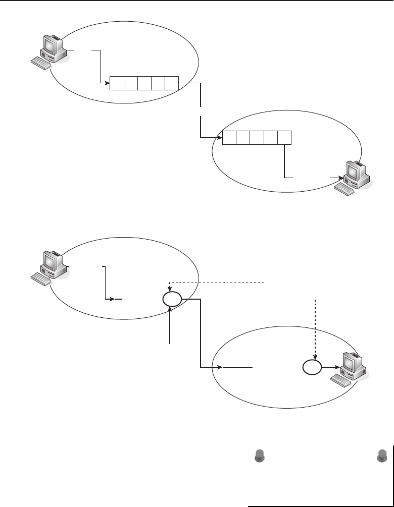
Edwards c11.tex V3 - 03/27/2009 3:33pm Page 460
460 Part II ■The OSI Layers
0011
0+0+1+1+1
Node A
Node B
00110
00111
—***Error***—
Figure 11-16 A parity error
61 120 4
Node A
Node B
61 + 120 + 4 = 185
61 120 4 185
Checksum matches on
both ends
Checksum
Figure 11-17 A simple checksum
ACRONYM ALERT
POP — Point of presence or Post Office Protocol
For simplicity sake, this example uses
decimal notation. Each decimal num-
ber represents a byte of data in a mes-
sage. This means that there are 256
possibilities in each byte. The check-
sum algorithm in use simply adds
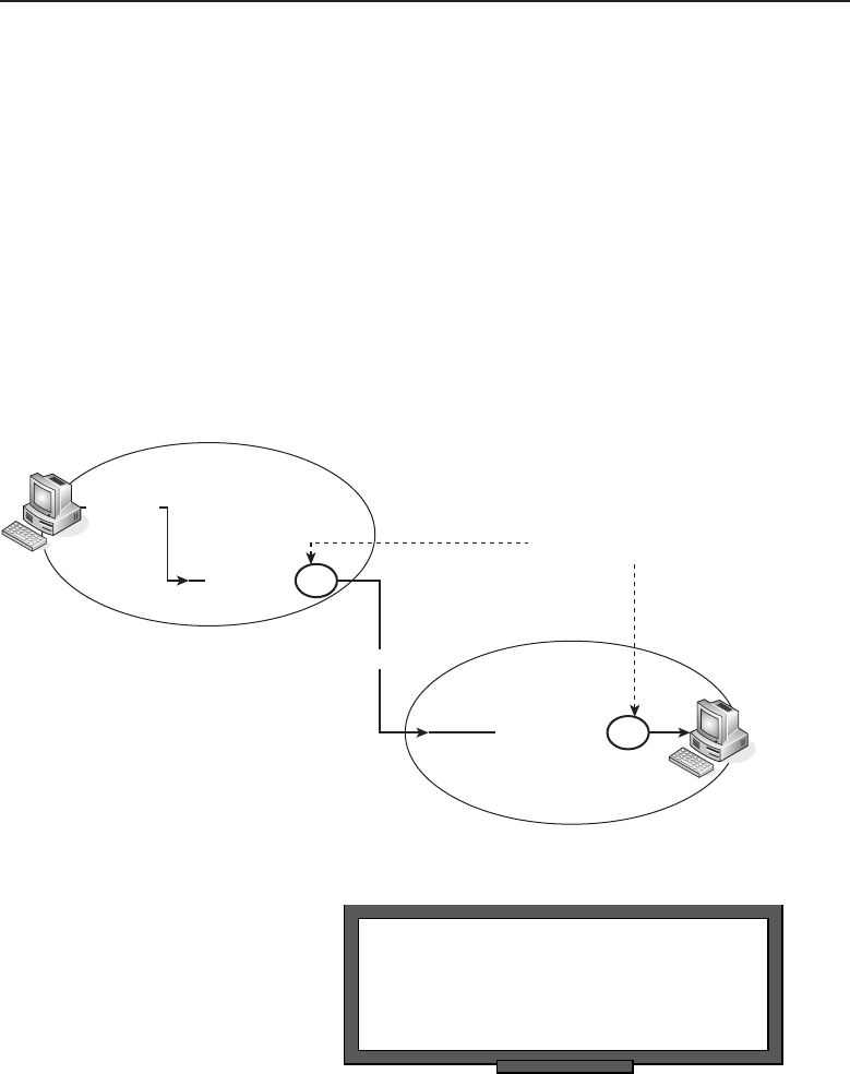
Edwards c11.tex V3 - 03/27/2009 3:33pm Page 461
Chapter 11 ■The Data Link Layer 461
the value of all the bytes and uses the combined value as the checksum.
In Figure 11-17, node A is sending the message 61----120----4.
Node A adds the total number of bytes and appends the check-
sum to the message (61 +120 +4=the checksum of 185).
Node B receives the message and adds the value of the bytes
in the message (61 +120 +4). By adding the total numerical
value, node B determines that the checksum should be 185.
Once node B determines the value that it thinks it should be,
it compares its checksum with the checksum of node A. If
there is a match, it knows the message was received intact.
Next, let’s take a look at how the simple checksum works when
an error occurs. Figure 11-18 shows such an example.
61 120 4
Node A
Node B
61 + 120 + 1 = 182
61 120 4 185
Checksum error
—Error—
Figure 11-18 Checksum failure
RANDOM BONUS DEFINITION
access domain — The collection of nodes
that share a network segment among which
MAC arbitration can occur.
In this example, node A
is sending the message
61----120----4.Node
A adds the total number
of bytes and appends the
checksum to the message
(61 +120 +4=the check-
sum of 185). Notice that somewhere between node A and node B, there is
an error that causes the last digit of the message to change from a 4 to a 1.

Edwards c11.tex V3 - 03/27/2009 3:33pm Page 462
462 Part II ■The OSI Layers
Node B receives the message and adds the value of the bytes in the
message (61 +120 +1). By adding the total numerical value, node B
determines that the checksum should be 182. Once node B determines
the value that it thinks it should be, it compares its checksum with
the checksum of node A. In this example, node B recognizes that the
message was corrupted (185 does not equal 182), so an error occurs.
The simple checksum used in the example above would not be
that reliable. There are too many possibilities of errors occurring
with the checksum still intact at the opposite end. For instance:
61 +120 +4=185
51 +130 +4=185
60 +120 +5=185
POP QUIZ
What is the simplest of all error-checking
methods?
CRC computes the check-
sum by using an algo-
rithm that is basically
long division for binary.
Additionally, the CRC
uses the first 16 bits in
the calculation, creat-
ing 65,536 possibilities. (The chances of an erroneous calculation is far
less than with the simple example above.) Taking it a step further, the
remainder (not the quotient) is what is used as the checksum.
Let’s assume that an originator wants to send the first 2 bytes of data
used in the example above (61 and 120). Also assume that the CRC
divider will be a constant 1-byte divider whose value would equal the
decimal number 7. So, now we want to convert these numbers to binary:
61 =00111101
120 =01111000
7=00000111
Take a look at Figure 11-19, which shows that node A is sending a mes-
sage to node B.
The message is binary 00111101 01111000. The CRC constant divisor
is set to binary 00000111. You want to take the message and divide
it by the divider. The remainder is your checksum value.22
22Calculated out (we cheated and used a scientific calculator), the remainder in this case would
be binary 00000110 and that is what will be used as the checksum value.
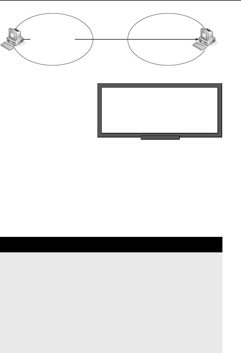
Edwards c11.tex V3 - 03/27/2009 3:33pm Page 463
Chapter 11 ■The Data Link Layer 463
Node A Node B
00111101 01111000
Figure 11-19 The CRC function
RANDOM BONUS DEFINITION
disabled state — A state used in the
Spanning Tree Protocol that identifies a
bridge port that has been set to not receive
or transmit any frames.
CRC algorithms more
commonly use a method
that closely resembles
polynomial arithmetic.
Instead of a simple divisor,
message value, quotient,
and remainder, as you
saw in the last example,
these integers are actually seen as polynomials with a binary coeffi-
cient. There are many ways to take this even further but are beyond the
scope of this book. Really, we could fill pages with the different algo-
rithms that can be used. Therefore, we bring this section to a close. What
you really need to understand is that the CRC uses a checksum that
can be complex and is used to validate data integrity in a LAN.
Now, all this may sound complicated, but it is fairly simple. To show how
simple it is, we want you to take a moment away from the book and relax. Just
clear your thoughts and take a break from all of this technical mumbo jumbo
and relax. And what better way of relaxing than eating a pizza?
AN UNRELATED MOMENT OF PAUSE —
DENISE’S PESTO CHICKEN PIZZA
If you are a fan of interesting foods, you are bound to love this pizza recipe. It
is a super-easy meal to make and well worth the time it takes to make it. Just
be careful if you have an allergy to nuts, as pesto contains pine nuts and you
may have a reaction.
Note: Delivery is also an option, but they won’t have this recipe.
Ingredients:
■Refrigerated pizza dough
■Pesto sauce
■Cooked chicken, cubed or shredded
(continued)

Edwards c11.tex V3 - 03/27/2009 3:33pm Page 464
464 Part II ■The OSI Layers
AN UNRELATED MOMENT OF PAUSE —
DENISE’S PESTO CHICKEN PIZZA (continued)
■Fresh mozzarella (that doesn’t mean shredded!)
■Sun-dried tomatoes in oil (rinsed)
■Rosemary
■Olive oil
Directions:
1. Preheat oven to 425◦.
2. Roll out the pizza dough, brush on olive oil, and sprinkle with rosemary.
3. Bake for about 5 minutes.
4. Remove the pizza and spread on the pesto, chicken, and sun-dried
tomatoes. Top with mozzarella.
5. Bake 10 to 15 minutes, or until the cheese is melted.
11.4.3 Control of the Flow
Flow control is used to prevent the sender of data from sending more data
than the receiver can handle. Without flow control, the sender would not be
aware that the receiver can’t accept any more data and would continue to send
the data, only to have to send it again once they are aware there is a problem.
There are different methods of flow control that can be used. Sometimes
it is medium dependant, but there are options that work with higher-layer
protocols. The receiving node does not necessarily have to provide feedback
when it can or cannot accept more data. Ethernet uses what are known as
PAUSE frames for flow control.
A PAUSE frame is a message sent by a receiver to the sender, letting the
sender know that the receiving node can no longer receive data and that the
transmission needs to be paused for a specified period of time. The PAUSE
function only works within full-duplex environments.23
The PAUSE function has a reserved multicast MAC address of
01-80-C2-00-00-01. This is a MAC address that was set up by the IEEE and is
used for the MAC PAUSE frame function.
23Because this is the most common standard in today’s networks, we decided to focus on the
PAUSE function in our discussion of flow control. Understand that, from a data link perspective,
flow control is a function that prevents a sender from overloading a receiver.

Edwards c11.tex V3 - 03/27/2009 3:33pm Page 465
Chapter 11 ■The Data Link Layer 465
11.5 ‘‘Knode’’ the LAN
We assume that you are all thinking, ‘‘What in the heck is knode?’’ A knode
is fictional, simply a term that we created as a combination of ‘‘know’’ and
‘‘node.’’ This may be a bit silly, but it is also good food for thought. Knowing
your LAN is every bit as important as having the nodes you need to do what
you want in the LAN.
In Chapter 3, ‘‘Network Hardware and Transmission Media,’’ we introduced
bridges and switches, two types of hardware that operate at the Data Link
layer. We are going to finish this chapter by talking about bridge/switch
deployment within the LANs. Although only an overview, this section
should be a great lead-in to Part III of the book, which deals with network
design and implementation. If you are interested in getting a good reference
book, Jim’s last book,24 The All-New Switch Book: The Complete Guide to LAN
Switching Technology, is a comprehensive reference to everything network
switching.
So what is different between a bridge and a Layer 2 switch? The answer to
this question may surprise you. There is no functional difference between a
bridge and a switch. That’s right! None! Nada! Zero! Zip! Switch is nothing
more than a marketing term that came out in the 1990s. The change was
brought about due to the ever-growing LANs. Original bridges could not
offer wire speed transmission rates on more than two ports within the bridge.
Bridges that could handle the higher rates were still not that reliable and
carried a very high price tag.
RANDOM BONUS DEFINITION
chassis switch — A switch that is designed
in a modular fashion. This type of switch
consists of a chassis and multiple plug-in
modules.
This all changed when the
application-specific integrated
circuit (ASIC)25 was developed.
Along with improvements in
system memory and higher pro-
cessor speeds, the ASIC allowed
the bridge to be developed,
supporting a lot of ports that
were capable of concurrent wire
speed transmissions. The best part was that the cost was less than tradi-
tional bridges with the same number of ports per area, but not transmission
speeds.
24This is more than just a shameless plug – it’s a really good book.
25Pronounced ‘‘a sick.’’

Edwards c11.tex V3 - 03/27/2009 3:33pm Page 466
466 Part II ■The OSI Layers
These new devices were introduced to the world and the salespeople of the
world decided to call them ‘‘switches,’’ and that was where the switch was
born.26 For simplicity sake, we will use the term ‘‘bridge’’ for the remainder of
this section. Feel free to substitute the word ‘‘switch’’ if you are so inclined.
Two methods27 of address-to-port mapping are used:
Source route bridging — This type of bridging is used in a
source-routed internetwork. The path to a destination is deter-
mined by the end nodes, not by the bridge itself. An example of
an environment that uses source route bridging is Token Ring.
ACRONYM ALERT
RISC — Reduced instruction-set computer
Transparent bridging —Thisis
the type of bridging that is used
in Ethernet (and others).28 In a
transparent bridging environment,
the bridge makes the path deter-
minations and the end nodes are
not aware of decisions that are being made. They simply throw the
data to the bridge and leave the decision making up to it.
Let’s take a moment to look at a bridge in a network segment and how the
bridge learns and gets the data to and from a set of endpoint nodes. Don’t be
disappointed if there is not enough meat and potatoes in this section; we will
discuss node implementation in further depth in the upcoming parts of this
book. As a matter of fact, network design and implementation are up next.
11.5.1 Diary of a Network Bridge
A bridge is a device that operates much like a repeater or a hub, but it makes
data forwarding decisions that bridges traffic from one network segment to
another. A network segment is simply a group of nodes that are connected to
one another via a shared medium (see Figure 11-20).
The only limitations to the number of network segments the bridge can
connect would be the number of ports the bridge physically has. In order
for a bridge to operate correctly, each node that connects to a segment that
is connected to the bridge must have a globally unique MAC address.29 The
bridge will have at least one interface that connects to the network segment
26The term ‘‘switch’’ is often used when a new product is marketed. Some examples of a node
that is called a switch but is nothing like a bridge include Layer 3 switching, routing switch, and
application switch.
27You may need to run the two types together if you are running a mixed environment. This is
supported (thank goodness).
28This is also the type that we will focus on (in keeping in line with our focus on Ethernet).
29You wouldn’t want to introduce confusion when you have the same locally assigned MAC
address in a node in two different network segments.
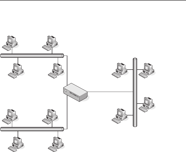
Edwards c11.tex V3 - 03/27/2009 3:33pm Page 467
Chapter 11 ■The Data Link Layer 467
that it knows about, and it will build a table that maps the globally assigned
MAC addresses to the port or interface that the bridge has determined the
MAC can be reached through.
Network
Bridge
Figure 11-20 A bridge connecting three network segments
The bridge operates in promiscuous mode, which means it will take each frame
that it receives (regardless of the destination MAC address). The switch then
will use information in the frame to make a decision on which segment a MAC
address belongs to. In Ethernet, the source and destination MAC address is the
information the bridge uses. Figure 11-21 shows an example of two network
segments that are able to communicate via an Ethernet bridge. Notice that the
bridge has learned the MAC address of each of the nodes and has logged it in
the MAC address table, along with the port that it knows it has to go through
to reach the MAC.
11.5.1.1 Unicast Operation
Earlier in this chapter, we said that unicasting is the act of sending a frame
from one source node to a single destination node. Now let’s take a deeper
look into what happens in multicast operations. The bridge receives frames
on any active interface. The bridge then reviews the frame, looking at the
destination and the source MAC addresses. It checks the MAC table to see
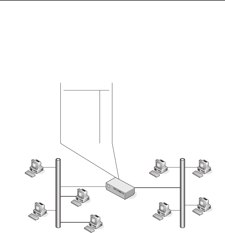
Edwards c11.tex V3 - 03/27/2009 3:33pm Page 468
468 Part II ■The OSI Layers
if it knows the destination and forwards the frame to the destination.30 The
bridge follows the rules of the network protocols that are in use (for instance,
the rules of CSMA/CD, flow control, congestion control, waiting for the
token, etc.). Another thing that a bridge does when forwarding the frame is
to use the source node’s MAC address as the outbound interface address,
instead of its own. This keeps the bridge transparent to the end nodes and
reduces the computations necessary when receiving and retransmitting a
frame. Figure 11-22 shows an example of frame forwarding.
08:00:58:6C:00:09
08:00:58:6C:00:C2
08:00:58:6C:00:1B
08:00:58:6C:00:C5
08:00:58:6C:00:41
08:00:58:6C:00:1B 1
08:00:58:6C:00:C5 1
08:00:58:6C:00:09 1
08:00:58:6C:00:C2 1
08:00:58:6C:00:41 2
08:00:58:6C:00:95 2
08:00:58:6C:00:AB 2
08:00:58:6C:00:01 2
08:00:58:6C:00:AB
08:00:58:6C:00:95
08:00:58:6C:00:02
Network
Bridge
Node address Port
Figure 11-21 The operation of a bridge — mapping the addresses to the interface they
belong on
You can see that the source node contains a MAC address of 08:00:58:
6C:00:09, and it is sending a frame to MAC address 08:00:58:6C:00:AB.
The bridge receives the frame, noting that the destination MAC address
is 08:00:58:6C:00:AB. Looking at the address table, the bridge knows that MAC
address is reachable via port 3, and the bridge forwards the frame on, leaving
itself transparent by identifying itself with the source MAC of the destination.
30When the bridge sees a source MAC address that it does not currently have in its address table,
it will add the information at that point.
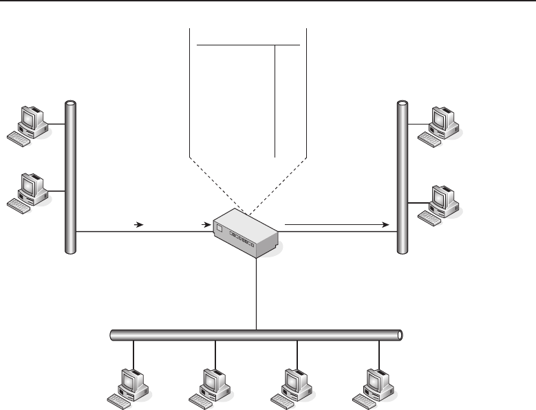
Edwards c11.tex V3 - 03/27/2009 3:33pm Page 469
Chapter 11 ■The Data Link Layer 469
Network
Bridge
08:00:58:6C:00:41
08:00:58:6C:00:C2 08:00:58:6C:00:C5 08:00:58:6C:00:95 08:00:58:6C:00:02
08:00:58:6C:00:AB
08:00:58:6C:00:09
08:00:58:6C:00:1B
08:00:58:6C:00:1B 1
08:00:58:6C:00:C5 2
08:00:58:6C:00:09 1
08:00:58:6C:00:C2 2
08:00:58:6C:00:41 3
08:00:58:6C:00:95 2
08:00:58:6C:00:AB 3
08:00:58:6C:00:01 2
Node address Port
08:00:58:6C:00:09 08:00:58:6C:00:AB
Figure 11-22 Unicast frame forwarding
11.5.1.2 Multicast Operation
When a bridge receives a frame that is destined for a multicast address,
the bridge forwards the frame to all the ports except the port on which it
is received.31 In Figure 11-23, the source node that has a MAC address of
08:00:58:6C:00:09 sends a frame to all members of the multicast group. The
bridge recognizes that this is a multicast frame and forwards it out to all ports
except the port that it received the frame on (in this case, port 1).
11.5.1.3 When the Bridge Just Does Not Know
Sometimes a bridge receives a frame that is destined for a node it does not
know about. The bridge is limited in what it can do in these cases. It can
31This is known as flooding. A couple of things that can be done to cut down on the amount of
ports that are flooded to are multicast pruning and virtual LANs (VLANS). These allow the ports
in the switch to be separated into groups so that not all are affected when a frame is flooded. This
ensures that the multicast traffic only goes out the ports that are part of that multicast group.
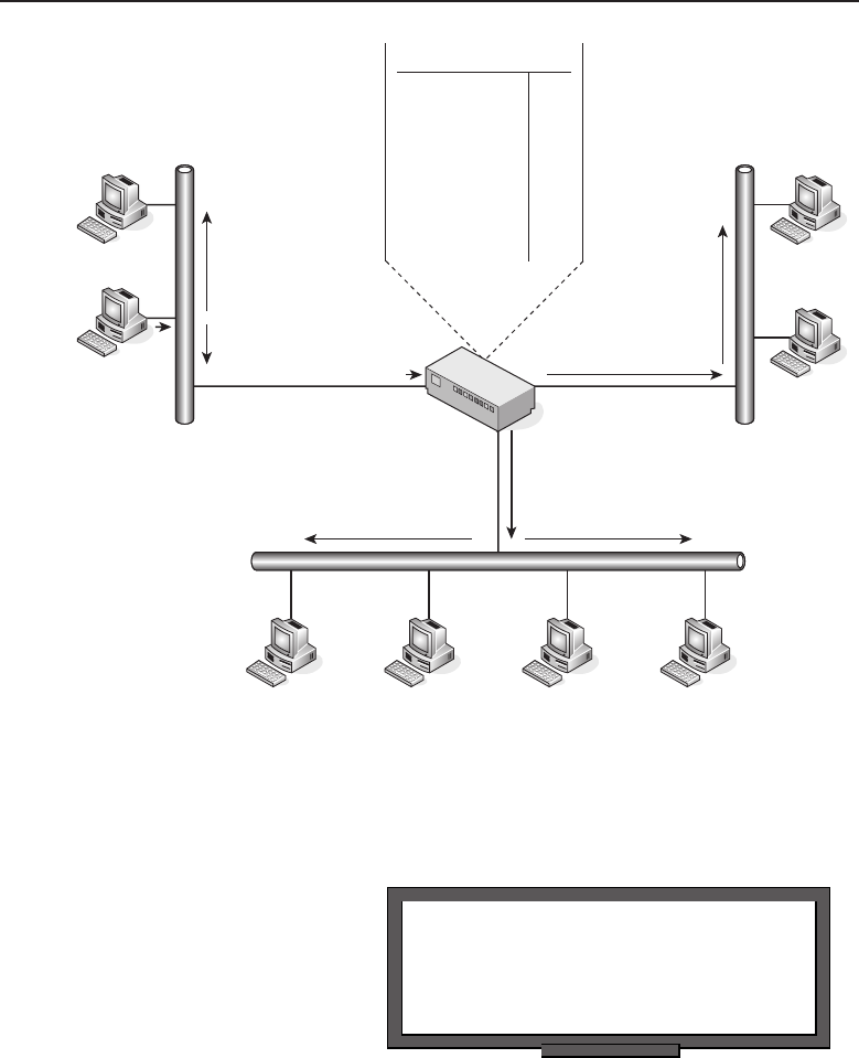
Edwards c11.tex V3 - 03/27/2009 3:33pm Page 470
470 Part II ■The OSI Layers
08:00:58:6C:00:09 08:00:58:6C:00:44
08:00:58:6C:00:41
08:00:58:6C:00:C2 08:00:58:6C:00:C5 08:00:58:6C:00:95 08:00:58:6C:00:02
08:00:58:6C:00:AB
08:00:58:6C:00:09
08:00:58:6C:00:1B
08:00:58:6C:00:1B 1
08:00:58:6C:00:C5 2
08:00:58:6C:00:09 1
08:00:58:6C:00:C2 2
08:00:58:6C:00:41 3
08:00:58:6C:00:95 2
08:00:58:6C:00:AB 3
08:00:58:6C:00:01 2
Node address Port
Figure 11-23 Multicast frame forwarding
forward the frame to all ports (except the one it received the frame on), or it
can discard the frame.
RANDOM BONUS DEFINITION
ARP cache — A data structure that provides
the current mapping of 32-bit IP addresses
to 48-bit MAC addresses.
Figure 11-24 shows node
08:00:58:6C:00:09 sending a
frame to node 08:00:58:6C:
00:44. The bridge can’t find
that MAC address in its table,
so it floods the frame out
and eventually the frame will
arrive at the node via port 3.
11.5.2 The Address Table
The bridge would be nothing more than a bulkier rendition of a network hub
if it were not for its ability to direct traffic to a proper port for data delivery.
The address table is the backbone for the proper operation of a bridge. The
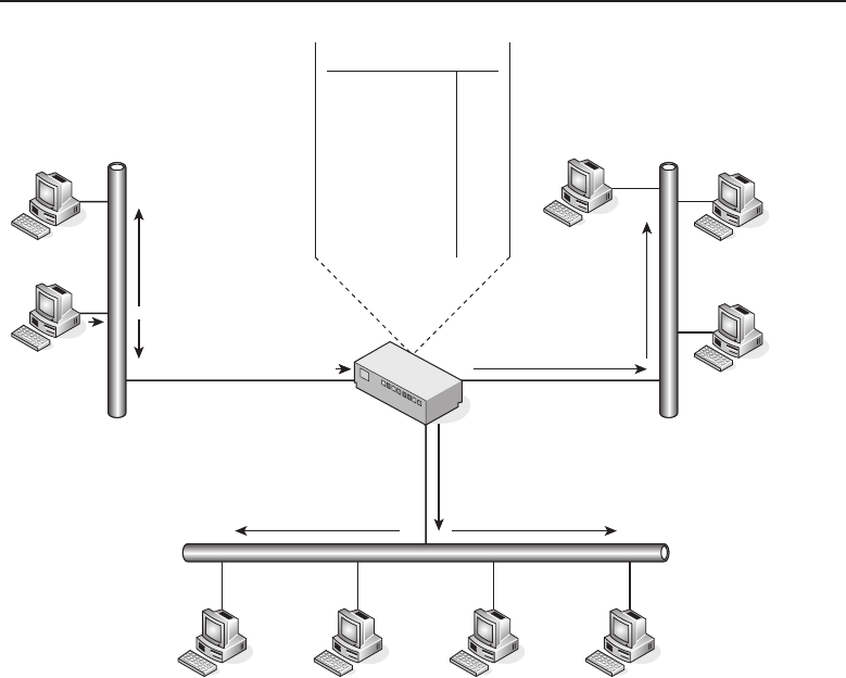
Edwards c11.tex V3 - 03/27/2009 3:33pm Page 471
Chapter 11 ■The Data Link Layer 471
08:00:58:6C:00:41
08:00:58:6C:00:44
08:00:58:6C:00:C2 08:00:58:6C:00:C5 08:00:58:6C:00:95 08:00:58:6C:00:02
08:00:58:6C:00:AB
08:00:58:6C:00:09
08:00:58:6C:00:1B
08:00:58:6C:00:1B 1
08:00:58:6C:00:C5 2
08:00:58:6C:00:09 1
08:00:58:6C:00:C2 2
08:00:58:6C:00:41 3
08:00:58:6C:00:95 2
08:00:58:6C:00:AB 3
08:00:58:6C:00:01 2
Node address Port
08:00:58:6C:00:09 08:00:58:6C:00:44
Figure 11-24 Unknown destination frame forwarding
address table is built based on the source address of received frames. As we
discussed previously, one of the functions of the bridge is to forward and
flood frames based on the information in the address table. Another important
function is to see if a source address contained in the frame is in the address
table, and if not, to add it. If it is, then the port mapping is updated so that
the latest destination information is synchronized. Eventually, the bridge will
know about every bridge32 that connects to a shared segment that it interfaces
with.
Another important process that needs to occur pertaining to the address
table is that the address entries must expire after a period of time. Imagine
how big an address table would become if entries were never removed.
Additionally, the performance of the bridge could suffer, as the list could
become cumbersome to review if too large. When the bridge receives a frame,
it checks the address table to see if the source MAC is present. If it is, it flags
32And have updated and accurate forwarding information.

Edwards c11.tex V3 - 03/27/2009 3:33pm Page 472
472 Part II ■The OSI Layers
the address so that it realizes that the MAC is still active and the information
needs to be retained until the address finally does expire.
11.6 Chapter Exercises
1. How is a jam signal used in a CSMA/CD environment?
2. How is a jam signal used in a CSMA/CA environment?
3. An unnumbered frame type is used with which type of LLC?
4. Find the MAC address of your PC’s NIC card. Once you have
found it, take the OUI and look it up on the IEEE website. What
is the information that is listed for that particular OUI?
5. What are the three fields in an LLC PDU, and what do they do?
6. How many bits are in an IEEE 802 MAC address?
7. What are the two error-checking methods used at the Data Link layer?
8. What does full-duplex Ethernet use for flow control?
9. What is the functional difference between a bridge and a Layer 2 switch?
11.7 Pop Quiz Answers
1. The Data Link layer is what layer of the OSI reference model?
Layer 2
2. Multiple nodes attached to a single shared medium can define what?
ALAN
3. Define throughput.
Throughput is the average rate of successful messages transmitted over
a channel.
4. Name two methods of ensuring bandwidth is distributed
fairly to the nodes that share connectivity within a LAN.
Token
Contention
5. The most popular and most often used CSMA/CD protocol is Ethernet.
6. What does DSAP stand for?
Destination Service Access Point

Edwards c11.tex V3 - 03/27/2009 3:33pm Page 473
Chapter 11 ■The Data Link Layer 473
7. What does SNAP stand for?
Subnetwork Access Protocol
8. What does SSAP stand for?
Source Service Access Point
9. A unicast address is simply the address of a particular node’s interface
within the LAN.
10. What is the Ethernet standard broadcast MAC address?
FF:FF:FF:FF:FF:FF
11. What is the simplest of all error-checking methods?
Parity check
Edwards c11.tex V3 - 03/27/2009 3:33pm Page 474

Edwards p03.tex V3 - 03/27/2009 2:58pm Page 475
Part
III
Network Design and
Implementation
In This Part
Chapter 12: Design Methodologies
Chapter 13: Implementation
Edwards p03.tex V3 - 03/27/2009 2:58pm Page 476

Edwards c12.tex V3 - 03/27/2009 11:27am Page 477
CHAPTER
12
Design Methodologies
Take a method and try it. If it fails, admit it frankly, and try another. But by all
means, try something.
— Franklin D. Roosevelt
Planning and designing a network can be a daunting task. In the early days of
data networking, a network consisted of a handful of nodes. Any addressing
schemes were normally manually assigned and maintained. This required
human intervention any time a node was moved, removed, or changed in any
way. This manual intervention was not that bad, however, due to the fact that
there were not that many numbers to keep track of.
In today’s LANs, this manual addressing would not work. Networks are
changing, technology is changing, and LANs have grown to a size that was
not foreseeable 20 years ago. In addition, other concerns exist that were not
there 20 years ago, including security, the highs and lows1of the LAN, and
many others.
LANs can be a simple as a handful of nodes in a remote office to as complex
as thousands of nodes in a fully meshed routing environment supporting
applications that require as much of the highs and lows as can be squeezed
out of the LAN any time the application want to do so. LANs are responsible
for supporting multiple protocols running over multiple nodes and multiple
media types. Many of these node and media types are from different vendors,
all of which can potentially be running some proprietary features that may or
may not play nice with the nodes, media, and even protocols that are running
the LAN.
1These were discussed in Chapter 11 — high throughput, high total bandwidth, and low error
rates and delays.
477

Edwards c12.tex V3 - 03/27/2009 11:27am Page 478
478 Part III ■Network Design and Implementation
Sounds challenging, doesn’t it?2And we haven’t even gotten to plans for
future growth. What is the organization’s five-year plan? Are you installing
gearthatcanbeupgraded?Howdoyouknowhowmuchgeartoplanfor
without getting more than you need? These are just some of the questions you
will need to ask yourself if you are going to design a network.
Planning and designing a data network is complex enough from a LAN
perspective, and that is the focus of this chapter. For comparison purposes, we
may discuss commonalities between the LAN and networks of smaller and
larger size. Proper planning and design of the network can be trial and error
at times. Sometimes things just don’t do what you want them to.3But don’t
get discouraged. When you encounter problems with a design in the network,
follow President Roosevelt’s advice.
12.1 Your Task Is to Design a Network
By no means will you be a professional network designer after reading this
chapter, but that isn’t our intention. As with most of the topics in this book,
we are trying to teach you the fundamentals. It’s important to understand the
difference between a network that was planned and designed carefully and
one that was thrown together haphazardly, no matter what you end up doing
in a networking career.
Careful planning is essential to ensure that your network will support your
organization’s needs. So what do you want to consider when you are designing
anetwork?
What are the needs of the business or organization?
What should be considered in order to meet current and future needs?
What are the cost considerations (short and long term)?4
ACRONYM ALERT
NFS — Network File System
These are all important questions to con-
sider. You might want to design the most
ultra-fantastic network with all the bells
and the whistles, but the budget may not
cover it. You might also want to build in
some features to make life simpler for you,
but that may be beyond the scope of the business model or plan.
2If you like challenge, you would love a job in data networking.
3No matter what the salesperson told you.
4This would include costs factored in for network maintenance.

Edwards c12.tex V3 - 03/27/2009 11:27am Page 479
Chapter 12 ■Design Methodologies 479
12.1.1 Types of Organizational LANs
Following are examples of some of the various network LAN types that are in
use. While reading through this list, consider the impact that might occur if
these LANs were improperly designed.
Hospital LANs — Life-critical data is delivered to various
departments via the computer. Emergency logging is automated.
Lives could be in danger if there are any network delays.5
Banking and financial corporate LANs — Can you imagine how
much money can be lost during the middle of the trading day on Wall
Street6if the network has delays? What about the delays that could occur
in the online trading world? Not to mention all the remote automatic
teller machines.
Manufacturer LANs — Production lines in all sorts of different
manufacturing environments run with the use of robotics and
automation. If there is a data hiccup, thousands of dollars can be lost.
Retail LANs — Retail stores often have a LAN running within them,
taking care of inventory and sales along the way. Periodically, the store
will connect to the corporate LAN to exchange the data collected. Today,
some retail sites run a remote connection into the LAN and are able to
provide real-time updates. Imagine the impact if the store is not able
to ring sales or communicate as needed with the corporate LAN.
POP QUIZ
Name five businesses or organizations that
are not listed above. What do you think the
biggest concern would be pertaining to each
organizational LAN type?
Government
LANs —Considerthe
amount of security
that has to be deployed
for government
LANs. Authen-
tication methods
and authoriza-
tion are of the utmost importance. Consider what might occur
if a hacker gains access to a government LAN.7
5Getting off topic a bit, here is an interesting tidbit of information. There are hopes that one
day a doctor can connect to the hospital from home and perform an operation over a video
feed with the use of robotics. Won’t that be amazing if it ever happens?
6Although based on the days that Wall Street had beginning in late September 2008,
maybe the network should fail every time that stocks start to tumble. No network ... no
trading ... problem solved.
7And for any other LAN — security is very important.
Edwards c12.tex V3 - 03/27/2009 11:27am Page 480
480 Part III ■Network Design and Implementation
And this is just a small list. Name a business type, and there will be some
form of network for it. The network itself may not be optimized,8but it will
most likely be there. What the design of the network for these organizations
looks like all depends on the needs of that organization.
12.1.2 Other Things to Consider
Now that we have an idea of the needs of the business, we still have some
work to do. The next thing is to ensure that you have a fair balance between
what is available to be considered in the network environment (needs vs.
wants) and whether the projected business needs limit what technically is
available. You don’t want to provide more than is needed for the LAN,
but you also don’t want unreasonable demands driving design decisions.9
Another important concern for network planners is to not be too cutting edge.
You don’t want to deploy a brand new switch, new feature, or new code until
it has had time to be field tested.10 Most products undergo a serious amount
of testing, but environments are different and new products often introduce
new problems that can take time to iron out.
There are also several external factors:
Consideration needs to be given to WAN interfacing, as well as
interfacings with LANs that are within of your realm of control.
Make sure you know about any government regulations and are in com-
pliance with them.
ACRONYM ALERT
LSAP — Link service access point
What are your competitors
using/doing? What network type
wouldyouliketohave,andwhohas
done it right? What did they do?
What is the potential technologi-
cal growth, and will your proposed
design be prepared to support it?
12.1.3 Building the Foundation
Now that you have an idea of the things that need to be considered, you can
move on to the planning stage. Before you do so, however, we are going to let
you in on a secret. If you have been paying attention to what we have written
thus far in the book, guess what? Without knowing it, you already have some
of the fundamentals that are necessary to design a network.
8This can be for several reasons. The network may be outdated, poorly designed, or simply not
maintained properly. If you try modeling yourself based on a similar network type, make sure
you model your LAN after one that has been operating a while and proved itself successful.
9Just because someone wants something to work a certain way does not mean that it can be done.
10Keep in mind that you may be able to make some kind of deal if you are willing to test any or
all of these.

Edwards c12.tex V3 - 03/27/2009 11:27am Page 481
Chapter 12 ■Design Methodologies 481
You have an understanding of networking concepts.
You have an understanding of the needs of the organization.
You have an understanding of the hardware types that operate in a LAN.
You have an understanding of LAN protocols.
You know the different types of network topologies that are used in
today’s LANs.
RANDOM BONUS DEFINITION
aggregator — The entity that performs the
operations required to make multiple
physical links function as an aggregated
link.
You know about LAN
protocols and MAC and
IP addressing.
You know the seven OSI
layers and what func-
tions at each layer.
You know how to make
spaghetti and meatballs!
Give yourself a pat on the back. You are ready to start planning the network.
12.2 Let’s Start Planning
We just realized that there has not been anything really technical about this
chapter so far.11 You will be surprised at how much nontechnical thought is
put into the initial planning stages. Don’t worry — there is plenty of technical
thought left in the upcoming pages.12
We already have established that you have been tasked with planning and
designing a network. More than likely, you will be given a team to work with
to get this project going.13 The first task you will want to attack is to develop
an action plan and project scope.
12.2.1 Development of Scope
Main Entry: scope (skop)14
Function: noun
1. The range of one’s perceptions, thoughts, or actions.
2. Breadth or opportunity to function.
3. The area covered by a given activity or subject.
11Then again, when is cooking up some of Mama Bramante’s spaghetti a technical task?
12Jim is thinking that a nontechnical book might be fun to write, perhaps The Networker’s Guide
to Homebrewing Beer.
13At the very least you should insist on access to someone who knows something when and if
you have any questions along the way.
14The American Heritage®Dictionary of the English Language, Fourth Edition. Houghton Mif-
flin Company, 2004.

Edwards c12.tex V3 - 03/27/2009 11:27am Page 482
482 Part III ■Network Design and Implementation
Developing a project scope is important in the early phases of network
design. This is where you gather the information you will need in order to
proceed with the project. One of the big considerations is the nature of the
organization (the type of network). Do the users only communicate with other
users on the network, or is there a need for access to networks outside of your
own LAN? Do users need remote access? Do any vendors or customers need
access? What applications need to be supported by the network? Finally, it is
good to know the budget that is available for the project and the time frame
for completion.
RANDOM BONUS DEFINITION
aging time — This is used in a spanning tree
environment — the amount of time a node
can be inactive before a dynamic filtering
database will remove the node’s entry.
The next thing that needs to
be addressed is to determine
whether the wants and needs
are even doable. Is there enough
money available to meet the
requests? Can the project be
completed in the proposed time
frame? Will the project’s com-
pletion keep up with technolog-
ical growth?
Now that the scope has been discussed, and it was determined to probably
work, the scope has to be refined even more. The specific services that are to
be placed in the LAN need to be determined. Information such as:
Will the network support voice communications?
Will the network support data communications?
Will the network support e-commerce?
Will the network support video streaming?
After identifying the services, you must determine what the potential traffic
flow will be in such a network. What will be required in the future? Some of
these can be answered if you are fortunate enough to have a network you can
model yours after. Also, if you have a way to test (or get a vendor to help you
out), you can possibly get some traffic analysis data that will give you a good
idea of what to look for and expect. But the real test is when you go live. The
secret is making sure you have enough, but not too much.
Data traffic patterns are subject to variations and fluctuations. Sometimes
this is due to a certain time of day or a particular day of the week. Even the
weather can affect data flow. Usually the trends point to an event (Friday
night backups, Monday morning end node boot-up, etc.), and you just won’t
know about all of them until you get the network up and running. In the next
chapter, we will be discussing ways to baseline.

Edwards c12.tex V3 - 03/27/2009 11:27am Page 483
Chapter 12 ■Design Methodologies 483
12.2.2 You Are Not Alone
POP QUIZ
Define scope.
The great thing about all this is
that you are not alone. You can
send your scope out to some of
the many networking vendors
and ask them what they have
that will help you do what you
want to do. This will get you a lot of information and maybe even some deals
along the way. The request for information (RFI) is a standard process used
in business to obtain just this type of information from vendors. Once you
find what you like, the request for proposal (RFP) is used to seek the best
deal.
12.3 A Hierarchical Design Model
Thereisthatwordagain—hierarchical. The hierarchical design model is the
most commonly used model in most high-speed LANs today. This model
allows for easy expansion. It also makes network management and trou-
bleshooting easier. By breaking nodes in the LAN into three functions, the
nodes are able to focus on specific tasks instead of each of them working to
perform all tasks. Figure 12-1 shows an example of what we are talking about.
The hierarchical model has the following three different layers, with nodes
within each layer performing a specific function:
Access layer
Distribution layer
Core layer
Keep in mind that a model is a recommendation or a guideline more than
it is a rule. Sometimes a single node can take care of all the layers itself,
sometimes it can’t. It’s always easier to follow a model, and this one is tried
and true.
12.3.1 Access Layer
The access layer is the lowest layer. This is the layer that interfaces with the
endpoint nodes. Types of nodes that are found at this layer are wireless access
points, hubs, repeaters, bridges, Layer 3 switches, and routers. The access
layer is what enables end users to connect to the network. This layer is also
responsible for determining when nodes are not allowed access to certain
portions of the network.
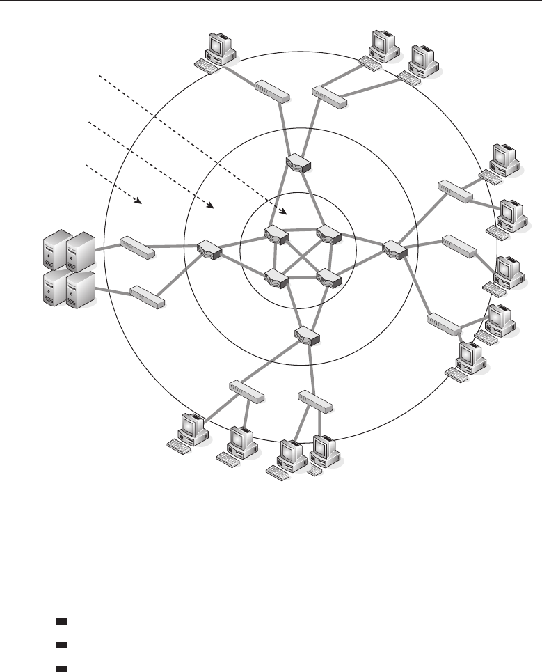
Edwards c12.tex V3 - 03/27/2009 11:27am Page 484
484 Part III ■Network Design and Implementation
The Core
Layer
The
Distribution
Layer
The Access
Layer
Figure 12-1 A hierarchical approach to LAN design
The access layer can also be the gateway to the LAN for remote users (see
Figure 12-2). For this to occur, some form of WAN technology must be used.
Examples of WAN technologies that can be used to connect remote sites to
the corporate LAN include:
Frame Relay
ISDN
Leased lines
The access layer can simply be thought of as the endpoint node access to the
LAN. It manages the data between the endpoint nodes and the distribution
layer. Switched bandwidth and MAC filtering are functions performed at this
layer.
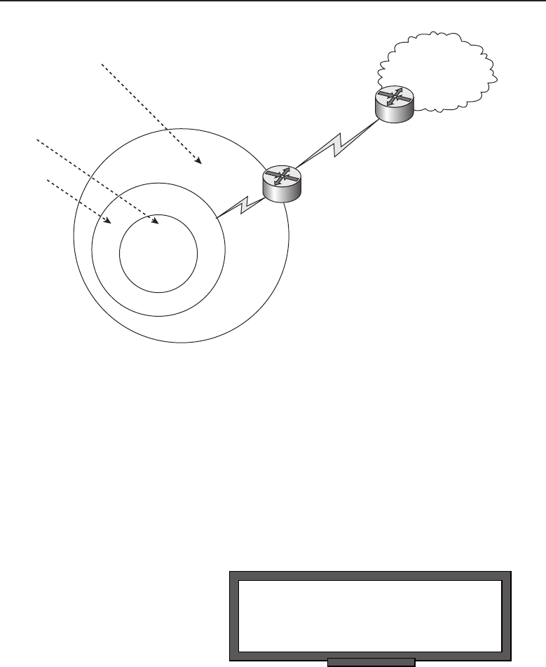
Edwards c12.tex V3 - 03/27/2009 11:27am Page 485
Chapter 12 ■Design Methodologies 485
The
Access
Layer Remote Office
The Core
Layer
The
Distribution
Layer
Figure 12-2 Remote relations to the access layer
12.3.2 Distribution Layer
The distribution layer is the middleman between the access layer and the
core layer. Data received from the access layer is sent to the core layer to be
routed to the destination. Broadcast domains are separated at this layer with
the implementation of virtual LANs (VLANs). Security is also a function that
is implemented at this layer.
POP QUIZ
Name three WAN technologies that are
used to connect to remote sites.
Network access can be im-
plemented at this layer when
policy-based connectivity is re-
quired. High-performance Layer
3 switches are implemented at
this layer. Guarantees that are
required at this layer are high per-
formance, high reliability, high
availability, and redundancy.
Policy-based connectivity between the other layers is what you get from the
distribution layer. Figure 12-3 provides an example of a method of connecting
the three layers together.
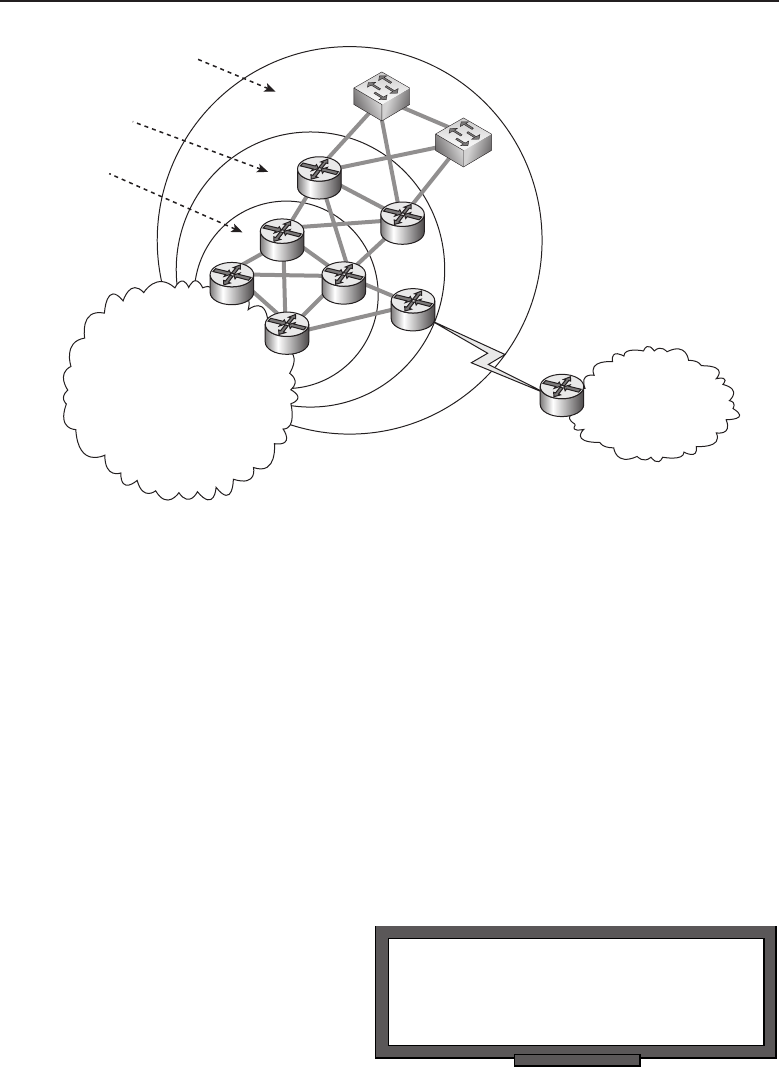
Edwards c12.tex V3 - 03/27/2009 11:27am Page 486
486 Part III ■Network Design and Implementation
Remote Office
The Access Layer
The Distribution Layer
The Core Layer
Variable network–typically a
WAN, MAN, or LAN (or a
combination of)
Figure 12-3 Connecting the three layers
Notice that the distribution layer has nodes that aggregate with other nodes
in the access and code layers. Additionally, there is a remote connection that
is coming from a remote office and accessing the network via the distribution
layer.
12.3.3 Core Layer
This is the big daddy layer of this model. The core layer is the backbone
of the LAN and often provides connectivity to WANs as well as to Internet
services. The core routers15 are highly available and support redundancy in the
connections with the distribution layer nodes. These nodes need to be hefty,
as they process data flowing throughout the whole LAN. They have to do that
reliably and quickly.
POP QUIZ
What are the layers of the hierarchical
design model?
Refer to Figure 12-4 and
answer this question: If the
drawing represents the physi-
cal layout of a network, is this
an example of a hierarchical
design?
15When we say routers, we are referring to any node that can provide network layer services. So,
aroutermaybearouter,aLayer3switch,etc.
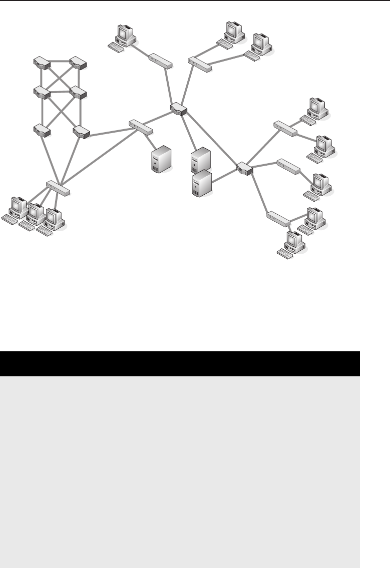
Edwards c12.tex V3 - 03/27/2009 11:27am Page 487
Chapter 12 ■Design Methodologies 487
Figure 12-4 An example of a LAN physical layout
The answer to that question is maybe. We do not know the logical layout of
the network, so it is entirely possible that this figure represents a hierarchical
design. Hierarchical in a logical manner, that is; the physical layout is pretty
much a moot concern at this point.
AN UNRELATED MOMENT OF PAUSE —
BARBECUE CHICKEN NACHOS
We know how easy it can be to get wrapped up in the reading of this book and
time can get away from you. Before you know it, you don’t have time to make
dinner and the last pizza delivery ran 30 minutes ago. This is a super-easy
recipe and a really excellent quick fix when you need to fill the void left from
skipping dinner.
The layers of the nacho model are as follows:
◆The Determination layer
◆The Preparation layer
◆The Application layer
◆The Thermal layer
◆The Devour layer
(continued)

Edwards c12.tex V3 - 03/27/2009 11:27am Page 488
488 Part III ■Network Design and Implementation
AN UNRELATED MOMENT OF PAUSE —
BARBECUE CHICKEN NACHOS (continued)
The Determination Layer
This is the first layer, in which you decide on the toppings that you want on
your nachos. Thanks to this handy reference model, you are not confined to the
recipe listed here. Anything goes well on nachos, so if you like it, try it out. For
this recipe, we have determined that we will be using the following ingredients:
◆Cheese — Use whatever kind you like (cheddar and/or Monterey jack is
good).
◆Tortilla chips — Any kind will do. We normally use restaurant-style tortilla
chips, which make good nacho chips.
◆Chicken — Chicken breast is the best.
◆BBQ sauce — At least one bottle of your favorite kind. The ones
with the squirt top works well for presentation purposes.
◆Bacon — One package.
The Preparation Layer
This layer is where you prepare everything that needs to be prepared. Here are
the preparation steps:
1. In a bowl, place enough cheese to cover the amount of nachos you
plan on eating. You can shred it yourself or buy it preshredded.
2. The chicken can be boiled and then shredded, or sliced and cooked
in a pan; the choice is up to you. Don’t add a lot of seasoning to the
chicken as it cooks, as you will be gaining flavor in your nachos.
3. Fry the bacon and then cut it into small pieces.
The Application Layer
This is where is you put everything together. Apply all your toppings to your
nachos in any way you want — it’s hard to mess up nachos. This is what we did;
it came out yummy and had a nice presentation.
Use a microwave-safe plate or platter. Put a generous handful of tortilla chips
(make sure to cover the plate completely). Now put a layer of cheese and about
half of your bacon. Make sure to cover the chips completely with the cheese.
Now put on another layer of chips. Next, put the chicken, enough cheese to
(continued)

Edwards c12.tex V3 - 03/27/2009 11:27am Page 489
Chapter 12 ■Design Methodologies 489
AN UNRELATED MOMENT OF PAUSE —
BARBECUE CHICKEN NACHOS (continued)
cover the chips, and the rest of bacon. Make sure that you get some cheese on
the chicken, but it does not have to bury the chicken. Finally, squirt the BBQ
sauce over the whole thing — be creative. The nachos should be in a heap on
the plate, but not flowing off of the plate.
The Thermal Layer
Stick all this in the microwave and cook it for about 30 seconds, then pause for
about 5 seconds and then another 30 seconds. Keep your eye on it — when the
cheese is melted, they are done.
The Devour Layer
Eat the nachos.
12.3.4 Why Hierarchical?
Some of you probably wondering, ‘‘Why hierarchical?’’ Well, we have been
putting a lot of effort into presenting you with a slew of networking information
while making the book as enjoyable to read as possible. So when the recipe
was written, we thought it might be funny to present it in a hierarchical model.
It worked too. Wait — you were not thinking about the recipe at all, were you?
What you are really wondering is what the benefits are of a hierarchical model.
Here are just a few:
Design replication — Once you have a working model, you can
simply change the addressing schemes and design the next network
expansion based on the way the original design was configured.
Expandability — As the network grows, it is very simple to introduce
additional nodes into the topology. Future growth planning is a breeze.
Redundancy — Redundancy from the access layer to the core layer is
very important in high-speed LANs. When a node fails, you have to
have another node picking up the pieces until the node comes back on
line.
Better performance — Nodes that operate in the hierarchical model are
able to maintain close to wire speed transmissions to all of the nodes it
supports.

Edwards c12.tex V3 - 03/27/2009 11:27am Page 490
490 Part III ■Network Design and Implementation
Security — Access control security is provided at the access layer. The
distribution layer can support advanced security that meets the security
needs of the LAN.
ACRONYM ALERT
NetBEUI — NetBIOS Extended User Interface
Easy to manage and
maintain — Because of the scalabil-
ity of the hierarchical design model,
the network is easy to manage and
maintain. A layered approach to
troubleshooting helps you find the source of a network connectivity
issue. Additional nodes can be installed fairly simply, and configura-
tions can be built from existing configurations, saving you time and
money.16 Over time, the hierarchical model will pay for itself in money
saved due to the ease of maintaining and managing the LAN.
And there you have the hierarchical design model in a nutshell. Now let’s
take a look at a design model that is used in planning Ethernet segments. The
next section covers the 5-4-3-2-1 design reference model.17 It is a nice model to
follow when you are planning a network, as it pulls together many tasks that
are needed for basic design principles.
THINGS YOU JUST HAVE TO KNOW
Before we move ahead, here are a couple of terms you need to know.
◆Collision domain — A group of nodes, sharing a communication channel,
that are all in a group where a collision can occur. These nodes are
connected to the same shared medium and are part of the same collision
domain. These nodes are not concerned with other collision domains, as
they do not have to negotiate for a communication channel bandwidth
with them. Collision domains are normally separated by a bridge.
◆Broadcast domain — A group of nodes that are all within
the same broadcast area. The broadcast domain comprises
multiple collision domains. Broadcast domains are normally
separated by a node that functions at Layer 3 or higher.
◆Propagation delay — The amount of time it takes to transmit a
set number of bytes from endpoint to endpoint in a LAN.
◆Network segment — A physically related grouping of nodes. Similar
in function to a subnet, which is a logical grouping of nodes.
◆Repeater — A Layer 1 node that connects network segments.
16When it works in one segment, it should work in another.
17This is also known as the 5-4-3 rule. Either term is fine, as long as you understand the overall
concept.

Edwards c12.tex V3 - 03/27/2009 11:27am Page 491
Chapter 12 ■Design Methodologies 491
12.4 5-4-3-2-1, Speed Is Not the Big Concern
The rule used for designing a collision domain is known as the 5-4-3-2-1 rule.
This is more of a reference model than it is a rule, providing guidance as to
the number of repeaters and network segments that can be on a shared access
Ethernet backbone.18 The 5-4-3-2-1 rule says that between two communication
nodes in a shared environment, the following are the maximums that are
allowed:
5— This is the total number of segments allowed.
4— This is the number of repeaters used to join the segments together.
3— This is the maximum number of segments that have nodes that are
active.
2— This is the maximum number of segments that are not active.
1— This is the number of collision domains.
RANDOM BONUS DEFINITION
backbone — A network used primarily to
interconnect other networks.
The 5-4-3-2-1 rule is used in
networks that use a tree topol-
ogy (a combination of a bus and
a star topology). The tree topol-
ogy used groups (segments) that
attach to a linear backbone.
Figure 12-5 shows an example of this rule.
POP QUIZ
What is the purpose of a network’s access
layer?
In a tree topology environ-
ment, there can be a maximum
of five segments between two
communication nodes. Addi-
tionally, data can pass through
a maximum of four repeaters.
Finally, there can be a maximum
of three segments that are popu-
lated with active nodes. In Figure 12-5, you can see that there are five segments,
four repeaters, and no more than three active segments between the source
and destination endpoint nodes.
By placing these limits on the collision domain, you are essentially ensuring
that the propagation delay is decreased (fewer nodes to pass through). This
greatly improves the reliability in the collision domain.
18Note that this rule only is beneficial in a shared access domain. Switched backbones should
consider other methods (most commonly, the hierarchical).
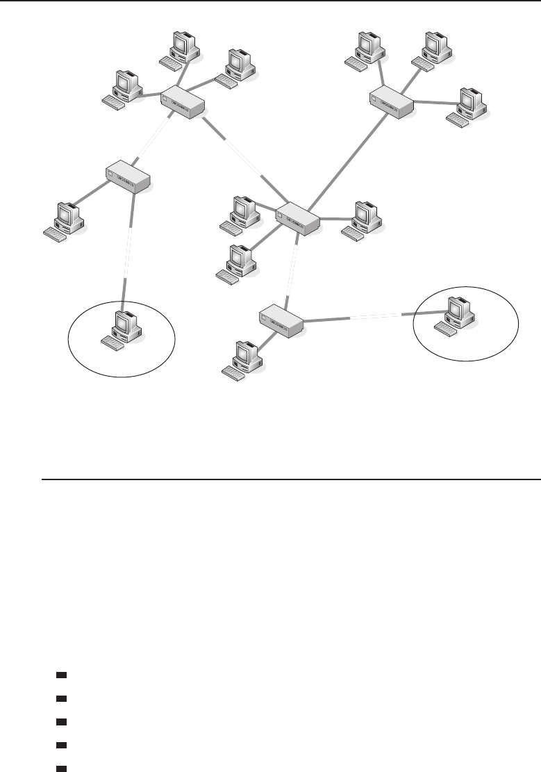
Edwards c12.tex V3 - 03/27/2009 11:27am Page 492
492 Part III ■Network Design and Implementation
Repeater 1
Source Destination
Repeater 2
Repeater 3
Repeater 4
Segment 2
Segment 5
Segment 4
Segment 1
Segment 3
Figure 12-5 The 5-4-3-2-1 rule in action
12.5 Making Determinations
Now that all the preliminary mumbo-jumbo has been taken care of, it’s time
for you to determine what you will need out of your network. Some things
will be contingent on others (for instance, if authentication is going to be used,
what will you need to support it?). This is exactly why you will want to review
and adjust your plan as you go along.
You have determined the needs and wants of the users of the network.
Now you start making determinations on what should be put into the network
to support those needs. Be sure to consider potential future growth in your
determinations. Some decisions you will make include:
Which topology are you going to be using?
Will you be using Ethernet or Token ring?
How many ports will be needed at each level?
What is the target transmission speed(s)?
Which node types are you planning on deploying?
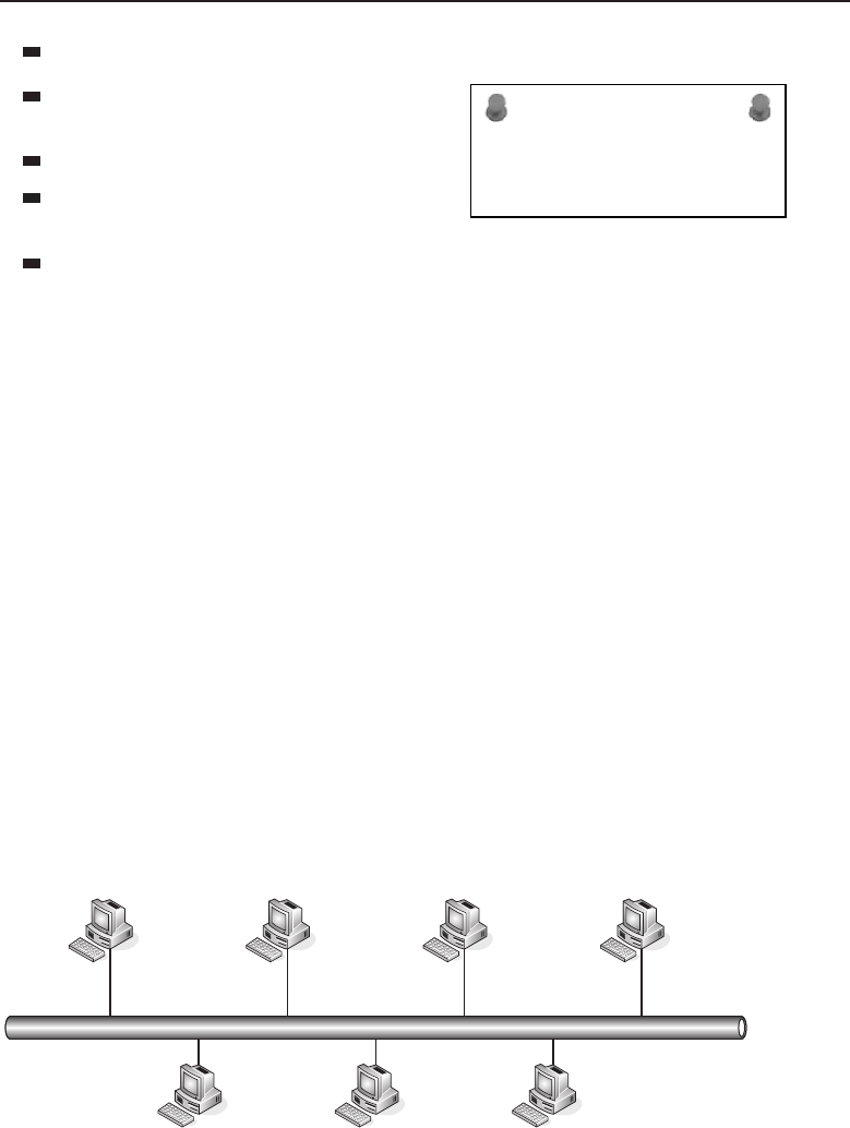
Edwards c12.tex V3 - 03/27/2009 11:27am Page 493
Chapter 12 ■Design Methodologies 493
Which end-user applications will be used?
ACRONYM ALERT
DDP — Datagram Delivery Protocol
Which protocols will need to
be supported?
Will remote access be required?
Which types of WAN protocol
options will be used (if required)?
What are the security concerns?
In the next few sections, we will discuss some things you should consider
when making these determinations.
12.5.1 Determining Which Topology to Use
Deciding on the network topology really depends on the requirements at each
level of the network. More than likely you will be using Ethernet (the most
popular shared network protocol), so your biggest decision will be the speed
and the actual physical layout of the building in which the network is being
installed.
Chapter 1 introduced the topology types in most LANs. The three most
popular topology types are the bus, the star, and the ring. Let’s take a moment
to review these.
12.5.1.1 Bus Network Topology
The bus topology is the most often used topology in LANs. In this topology,
the nodes connect to a common shared communication channel, referred to
as a bus. Figure 12-6 shows an example of a network with a bus network
topology.
Figure 12-6 The bus topology
So what makes the bus topology the most often implemented?

Edwards c12.tex V3 - 03/27/2009 11:27am Page 494
494 Part III ■Network Design and Implementation
Advantages:
It’s easy to install.
It’s easy to extend.
It’s less expensive to implement than other topologies.
Disadvantages:
There is a limitation to the distance a cable can go without a repeater.
There is a limit to the number of nodes that can be supported.
The LAN can experience sluggishness in performance when there are
heavy traffic loads.
Security risks exist because all stations can hear what the others are
saying on the shared channel.
RANDOM BONUS DEFINITION
blocking state — A stable state in the
Spanning Tree Protocol in which a bridge
port will receive BPDUs but will neither
receive nor transmit data frames.
The cost and ease of use are
the biggest reasons for consid-
ering the bus network. How-
ever, if there are concerns about
speed, performance, reliability,
or number of supported nodes,
another design might need to be
considered.
12.5.1.2 Star Network Topology
The star topology can be divided into two categories. It can be a logical
star topology or a physical star topology. Figure 12-7 shows an example
of a physical star topology where a central bridge or a hub controls the
communications to and from attached nodes.
The advantages of a star topology include:
It offers better performance.
It’s easy to troubleshoot.
It offers high scalability of the network through the central node.
The disadvantages of a star topology include:
There is too much dependency on the central node.
It can be complex to manage.
Wiring can become cumbersome.
If neither the bus nor the star topology fit your specific needs, you might
want to consider implementing a ring topology.
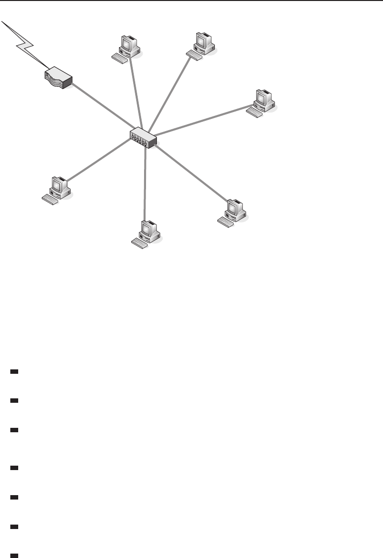
Edwards c12.tex V3 - 03/27/2009 11:27am Page 495
Chapter 12 ■Design Methodologies 495
Hub
Router
Figure 12-7 The star topology
12.5.1.3 Ring Network Topology
The ring topology is used for Token Ring and FDDI LANs. In the ring topology,
a frame is passed from node to node until it reaches its destination. Figure 12-8
shows an example of a network with a ring network topology.
The advantages of a ring topology include:
There is no need to have a mechanism to ensure collision-free datagram
passing.
It can be expanded to cover a greater number of nodes than some of the
other topology types.
It’s fairly simple to maintain.
The disadvantages of a ring topology include:
A failure with one node on the ring can cause an outage to all connected
nodes.
Any maintenance (e.g., adding a node, making a change to a node,
removing a node) affects all the nodes that connect to the ring.
Some of the hardware required to implement a ring is more
expensive than Ethernet network cards and nodes.
Under normal traffic load, a ring is much slower than other topologies.
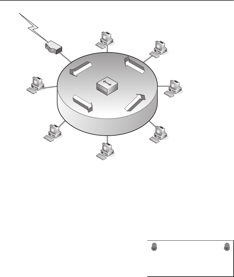
Edwards c12.tex V3 - 03/27/2009 11:27am Page 496
496 Part III ■Network Design and Implementation
MAU
Router
Figure 12-8 The ring topology
Another determination is which nodes to deploy and where to deploy them.
The following section discusses some things to consider.
12.5.2 Determining Which Nodes to Use
ACRONYM ALERT
CST — Common spanning tree
Traditionally, packet-switched LANs have
comprised four main network nodes: con-
centrators, repeaters, bridges, and routers.
For the most part, these traditional nodes
are still used and make up various levels
of the network. Repeaters and bridges are
used heavily in user workgroups, server
farms, and in the access layer of hierarchical networks.
The list of nodes has really grown in the past 20 years. The traditional nodes
are still in use, but so many other nodes have been introduced in that time. In
addition to the traditional nodes, many networks use Layer 3 switches, Layer
4–7 switches, VPN remote access solutions, etc.
Chapter 3 discussed each of these node types extensively, but here is a quick
overview, along with some examples of node deployment.
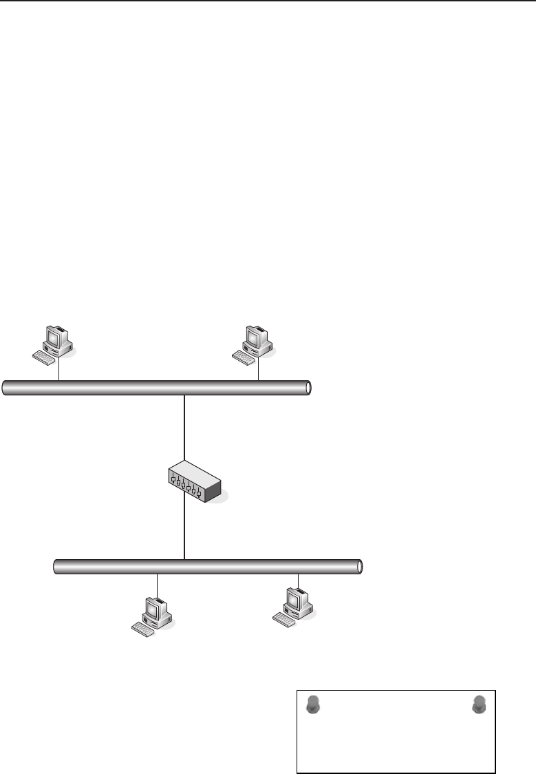
Edwards c12.tex V3 - 03/27/2009 11:27am Page 497
Chapter 12 ■Design Methodologies 497
12.5.2.1 Traditional Nodes
Thefirsttypesofnodeswewanttocoverarewhatwewillcallthetraditional
nodes. These node types are the most often deployed and are found in many
home networks. In traditional node networks, each node serves a distinct and
specific function. Repeaters and hubs pass data without using any logic at all.
Bridges (also known as Layer 2 switches) connect like networks to one another
and are able to make correct forwarding decisions. Routers are able to connect
different network types to one another and can also make correct forwarding
decisions.
Get it? Got it! Good!
12.5.2.1.1 Repeaters
The repeater is a node that simply passes information on. It is used to extend
the segment when medium-distance limitations have been reached. Figure 12-9
shows an example of a repeater separating two parts of a network.
Repeater
Figure 12-9 A repeater
ACRONYM ALERT
ADSP — AppleTalk Data Stream Protocol
A repeater amplifies a signal, but that is
not its only task. A repeater also filters out
any distorted data it has received, and it
will not pass that data along. Technically,
you can say that the function of the repeater
is to amplify good data.
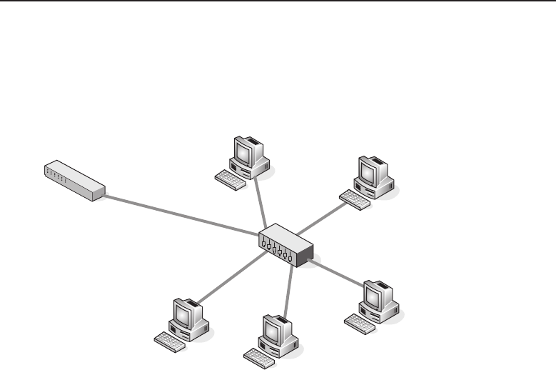
Edwards c12.tex V3 - 03/27/2009 11:27am Page 498
498 Part III ■Network Design and Implementation
12.5.2.1.2 Concentrators
The concentrator used within a LAN is either a hub or an MAU that allows the
combination of data transmissions for a group of nodes. Figure 12-10 shows
an example of a hub deployed in a LAN.
Bridge
Hub
Figure 12-10 A hub
A hub is used to connect segments in a LAN. Hubs have multiple ports, and
when data is received on a port, the hub will send the datagram to all of the
other ports, so all segments will see all datagrams that are passed through the
hub.
An MAU is a type of concentrator that is used to connect nodes within
a Token Ring environment. The MAU connects the nodes in a physical star
configuration, but the logical operations are Token Ring. The MAU allows the
Token Ring to continue operating when a node on the ring breaks. This is
much better than the alternative, where a node breaks on a physical ring and
the whole ring goes down.
12.5.2.1.3 Bridges
The bridge is a LAN node that operates at Layer 2 of the OSI reference model.
The bridge is used to connect different networks to one another. Data received
from one network can be forwarded through the bridge to get the data to the
correct destination. Figure 12-11 shows an example of bridge deployment.
Bridges are smart enough to know how to send datagrams to a specific port
so that not all areas of the network have to receive the data as well. This frees
up the other segments to pass data separately, without having to analyze all
the datagrams. When a bridge gets the datagram, it passes the data based on
the MAC address of the destination node.
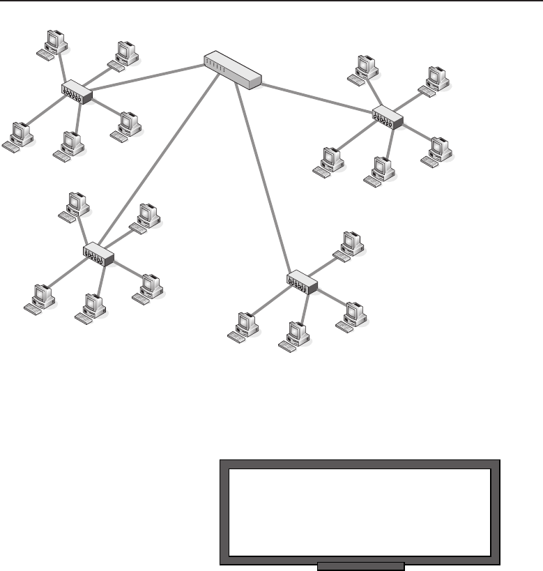
Edwards c12.tex V3 - 03/27/2009 11:27am Page 499
Chapter 12 ■Design Methodologies 499
Bridge
Hub
Hub
Hub
Hub
Figure 12-11 Abridge
12.5.2.1.4 Routers
RANDOM BONUS DEFINITION
coaxial cable — A communications medium
used in 10BASE5 and 10BASE2 Ethernet
systems.
The final node in the traditional
node family is the router. Oper-
ating at Layer 3, the router is
the backbone of most LANs.
Routers use IP addresses to
route datagrams in a network.
Routers support multiple proto-
cols of different types and are
able to separate networks of different types because of this. Figure 12-12 is an
example of the placement of a router in a LAN.
Routers are still in use in LANs today, but Layer 3 switches are becom-
ing increasingly more popular. The reason for this is simple. The advanced
switches are able to function as a router at a much higher speed due to
application-specific integrated circuit (ASIC) technology. Additionally, switch-
ing hardware is cheaper to replace than traditional router hardware.
Routers are still used as boundaries between the LAN and the Internet.19
Figure 12-13 shows an example of this. Routers are also often used for remote
connectivity for remote offices.
19Or other networks that are not controlled by the organization.
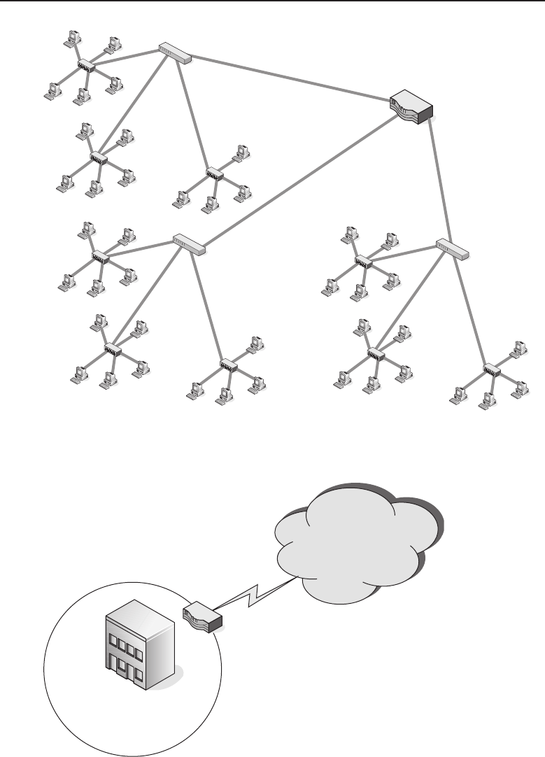
Edwards c12.tex V3 - 03/27/2009 11:27am Page 500
500 Part III ■Network Design and Implementation
Bridge
Hub
Hub
Hub
Bridge
Hub
Hub
Hub
Bridge
Hub
Hub
Hub
Router
Figure 12-12 A router
Organizational LAN
Router
The Internet
Figure 12-13 Routers connecting a LAN to the Internet

Edwards c12.tex V3 - 03/27/2009 11:27am Page 501
Chapter 12 ■Design Methodologies 501
Routers are used to route data between different networks. Routers control
the flow of data in and out of the LAN, often working with a firewall solution
to limit and/or control data coming into the LAN, as well as data going out
from the LAN to the Internet.
12.5.2.2 Node Evolution
Main Entry:ev·o·lu·tion20
Function: noun.
1. A gradual process in which something changes into a different and
usually more complex or better form.
2. The process of developing.
3. A movement that is part of a set of ordered movements.
4. Mathematics: The extraction of a root of a quantity.
Networking never stops growing. As a new product is being introduced,
there is another product just around the corner that will replace it. Software
upgrades and new program implementations also see the same changes and
growth. No longer is a modem the standard for accessing the LAN. No
longer do we have to rely on filtering and VLAN techniques to authorize and
authenticate. There are a lot of nodes out there that do the trick, and a lot of
nodes out there that just plain do it better than traditional nodes.
RANDOM BONUS DEFINITION
congestion — The state where the offered
network load approaches or exceeds the
locally available resources designed to
handle that load
We already have discussed
how the term Layer 2 switch
replaced the term bridge, but it is
really just a marketing term. As
a matter of fact, it was so well
received21 that almost anything
networking is a switch now. In
this section, we talk about some
other switches that are in a lot
of LANs. In addition to the switches, we discuss a bit about VPN and wireless
nodes.
12.5.2.2.1 Layer 3 Switches
Layer 3 switches perform the same task as routers and are deployed in
high-speed LANs as well as in WANs. The Layer 3 switch is preferred over a
router because routing decisions are hardware-based and thus are able to be
performed much faster than traditional routers. Layer 3 switches are also able
20The American Heritage®Dictionary of the English Language, Fourth Edition. Houghton Mif-
flin Company, 2004.
21Well received by the customers or the salespeople. We are not really sure which, but we all
know how those sales guys are.
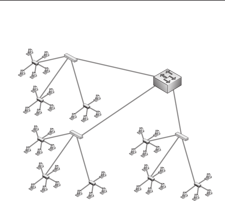
Edwards c12.tex V3 - 03/27/2009 11:27am Page 502
502 Part III ■Network Design and Implementation
to perform as Layer 2 switches, giving the best of both worlds. They give you
the control of data flow that is offered in a routed network and the speed that
is offered in a switched environment. Figure 12-14 shows an example of Layer
3 switch deployment.
Hub
Hub
Hub
Hub
Hub
Hub
Hub
Hub
Hub
Layer 2 switch
Layer 2 switch
Layer 2 switch
Layer 3 switch
Figure 12-14 A Layer 3 switch deployment
Traditional routers do a great job, but the logic decisions they make are
software-based and therefore are a slower process than what is offered by
the Layer 3 switches. Layer 3 switches can support the same protocols that
are supported by a traditional router and generally cost less than traditional
switches.
So what is the hardware feature on the Layer 3 switch? It is the ASIC that
makes the Layer 3 switch. A Layer 3 switch can have from one ASIC per
chassis up to one ASIC per port.22
12.5.2.2.2 Layer 4–7 Switching
Layer 4–7 switching is not traditional Layer 2 switching. Many vendors now
market nodes that are able to perform Layer 4–7 functions. It’s important to
note that even though a node may be labeled a Layer 4–7 switch, multiple
22This depends on how badly the vendor wants to make sure that you can get wire speed
throughput through the device.

Edwards c12.tex V3 - 03/27/2009 11:27am Page 503
Chapter 12 ■Design Methodologies 503
vendors use the definition loosely, so it may not really be exactly the same
between vendors. Some terms you might come across to describe Layer 4–7
switching include:
Web switch
Application switch
Content switch
VPN switch
Generally, Layer 4 switches are used to assist in balancing data destined
for servers within a network. Layer 4 switches operate at the TCP/UDP level
and will make decisions about where to send traffic based on information
that is stored at the Transport layer. Not all Layer 4 switches actually do
transfers based on that information. Web load balancers are often termed
Layer 4 switches, as they are able to forward Layer 2 switches based on the
MAC address, but are also able to send some MAC address data to multiple
physical ports within the load-balancing switch. Some load balancers are able
to monitor load on the server ports and can switch requests that are received
to the data port that connects to the server with the lightest load.
As we have said, some of these nodes can function at up to Layer 7 of the OSI
model. These are used to load-balance traffic among groups of servers. These
servers can provide applications such as HTTP, HTTPS, and many others that
use TCP/IP to transport traffic via a specified port.
Layer 4–7 switches use Network Address Translation (NAT), often at wire
speed, to provide an avenue to allow multiple clients access to multiple host
servers without having to know the exact physical server that is handling the
request from the individual client. Some Layer 4–7 switches are also able to
provide SSL encryption and decryption services so that the servers don’t have
to, as well as being able to manage digital certificates.
ACRONYM ALERT
MAC — Media Access Control
Layer 4–7 switches provide an excellent
service — the almost instant, endless, and
secure flow of data to end users. This is cer-
tainly an improvement for many users who
are beginning to expect instant gratification
when connecting to a website. The Layer
4–7 switch may not be for everyone, but it
does come in handy when a network needs to have it.
12.5.2.2.3 Virtual Private Networks
VPN solutions have changed the way that organizations connect to remote
sites. Traditionally, site-to-site connectivity was done over leased lines (such
asISDN,dial-up,etc.).AstheInternetgrew,andtechnologygrew,sodid
the way that we connect to remote offices. VPN technology allows remote
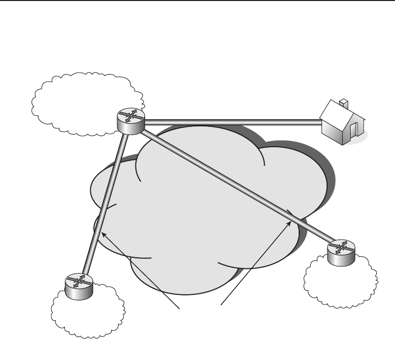
Edwards c12.tex V3 - 03/27/2009 11:27am Page 504
504 Part III ■Network Design and Implementation
connectivity over a secure tunnel to the organizational LAN, so it will appear
as if the remote user or office is actually geographically located within the
LAN. Figure 12-15 provides an example of three uses of the VPN solution.
The Internet
Branch Office Tunnel
Customer LAN
Organizational LAN
User Tunnel
Home Office
Remote Office
Figure 12-15 Typical VPN deployments
In the figure, you can see that there are three different tunnels going into the
corporate LAN. One of these tunnels is a remote user connecting from home
through a user tunnel.23 The other two tunnels connect remote LANs and are
known as branch office tunnels. One of the branch office tunnels goes to a
remote office for workers in the VPN’s organization.24 The other branch office
tunnel is used by customers to connect to the corporate network.25
12.5.2.2.4 Wireless Networks
The last topic we will talk about in this node evolution section is wireless
networks. Wireless seems to be where networking is really growing. Almost
everyone has at least one cell phone, but it does not stop there. You have
Bluetooth, infrared, wireless PC connections, etc., almost everywhere you go.
We can’t tell you the last time we were out and about when there wasn’t
23This type of VPN is also known as a remote access VPN.
24This type of VPN is also known as an intranet VPN.
25This type of VPN is also known as an extranet VPN.
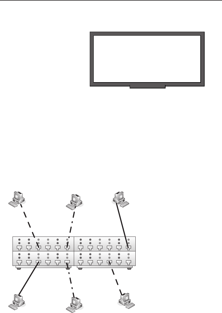
Edwards c12.tex V3 - 03/27/2009 11:27am Page 505
Chapter 12 ■Design Methodologies 505
at least one person using some form of wireless device. Thanks to wireless
networks, this is all possible.
RANDOM BONUS DEFINITION
dedicated bandwidth — A configuration in
which the communications channel
attached to a network interface is dedicated
for use by a single station and does not have
to be shared.
IEEE 802.11 is the stan-
dard that outlines wireless LAN
standards. Another standard,
called wireless IP, allows mobile
devices to remain connected,
even when they move into an
wireless area that has a differ-
ent IP scheme than the user has.
Basically, this standard allows
roaming without losing connectivity.
Security is a big concern in wireless networks, so encryption and authoriza-
tion options need to be considered.
12.5.3 LAN Switching Technology
Layer 2 switches changed what we can do in a network. These LAN switches
broke up the transitional shared network and converted it into a switched
network. This greatly improved the performance of the LAN as a whole.
Figure 12-16 shows an example of a small switched network consisting of the
switch (of course) and six end users. If this were a shared network connected
by a central hub, all the nodes would have to read all the data transmitted,
and the end-user nodes would have to negotiate in order to transmit.
Steve Tuyett
Walter
Zung Derrick
Mike
Figure 12-16 A switched network

Edwards c12.tex V3 - 03/27/2009 11:27am Page 506
506 Part III ■Network Design and Implementation
As you can see, there are a total of six end users. Each user is exchanging
data with one other node, but each node is communicating with only one node
at a time. Notice that there are three simultaneous active connections (Mike to
Tuyett, Zung to Steve, and Derrick to Walter) in the example. Try to do that in
a shared network!
12.5.3.1 Switch Types
The way that a switch handles the data it receives depends on whether the
switch is a cut-through type or a store and forward type.
Cut through — In cut-through operations, the switch reads the
header of the datagram as it is received on a port. Once the switch
determines the port that reaches the destination, the datagram
is sent to the port and on to its destination. There is no storing
of data in a cut-through environment. There are also no options
for error checking or control because the cut-through switch only
reads the header for an address and sends the datagram on.
Store and forward — In store and forward operations, the
switch stores the data and does error checking on the datagram
before it sends the datagram off toward its destination port.
Although this makes the transfer of datagrams slower than
with a cut-through switch, the data is delivered reliably.
12.5.3.2 By All Means, Be Redundant
A well-designed network will be built with plenty of redundancy throughout.
The last thing a network administrator needs is a single point of failure anywhere
in the network. A single point of failure is a location within the network that
does not have a backup link of some sort. In other words, if the link fails, the
network that is relying on that link will not be able to reach some or all of the
LAN. Figure 12-17 shows an example of a single switch that is used to connect
LAN 1 to LAN 2.
ACRONYM ALERT
BPDU — Bridge protocol data unit
Consider what would happen in this
example if the switch failed, or if one of the
links between a LAN and the switch failed.
If there were a failure, LAN-to-LAN com-
munication would not happen. Depending
on the problem, it could be several hours
before service is restored, and in most busi-
nesses, there is a financial impact that could be detrimental.
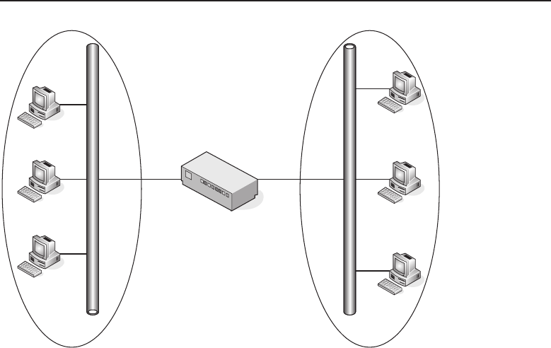
Edwards c12.tex V3 - 03/27/2009 11:27am Page 507
Chapter 12 ■Design Methodologies 507
LAN switch
LAN 1 LAN 2
Figure 12-17 A switched network without redundancy
This is why you absolutely want to place redundancy throughout the
network. Always have some sort of backup so there is a network convergence
to a separate parallel link between endpoints (an example would be the
LAN-to-LAN connection in the example we used above). Not only does this
improve the reliability of data delivery, but a redundant network in a network
diagram also really adds something to the overall picture. Figure 12-18 is an
example of a network with redundancy.
So, the problem is resolved, right? Well, technically, yes, the problem
of LAN-to-LAN communication being lost when a link goes down is now
resolved. But like many solutions in the data world,26 in resolving one issue,
a new issue was introduced. The new issue is a loop, and we discuss it in the
next section.
12.5.3.3 I’m Loopy!
We have established that there is a requirement for redundancy if we want
our LAN to be reliable. However, in introducing that reliability by adding a
second link, we have now created an environment where a loop may occur
(see Figure 12-19). We’ll now take a different look at the switched network.
26This includes both public solutions and proprietary solutions.
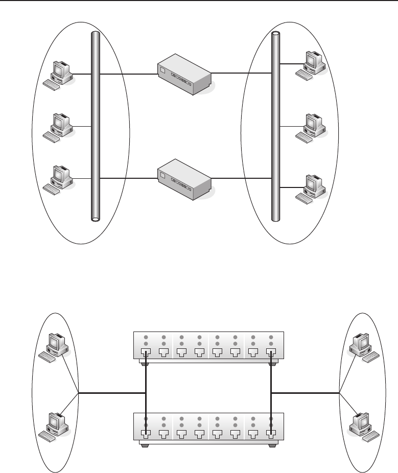
Edwards c12.tex V3 - 03/27/2009 11:27am Page 508
508 Part III ■Network Design and Implementation
LAN 1 LAN 2
LAN switch A
LAN switch B
Figure 12-18 A switched network with redundancy
L1-1
Port 1
Port 1
Port 8
Port 8
Layer 2 Switch B
Layer 2 Switch A
L1-2
LAN 1
L2-1
L2-2
LAN 2
Figure 12-19 A switched network that is vulnerable to a Layer 2 loop

Edwards c12.tex V3 - 03/27/2009 11:27am Page 509
Chapter 12 ■Design Methodologies 509
Assume that both switches are aware of all the endpoints. If node L1-1
sends data to node L2-2, that data will be received on port 1 on both switches
and will exit out of port 8 on both switches. The data will be sent to the
appropriate node, but that node will get two copies of every datagram it
receives. Duplication of effort is never desirable27 and is a big no-no in a LAN.
So, if the redundant solution caused that kind of problem with the unicast
traffic, what will happen with multicast traffic?28 Believe it or not, this is a
much bigger problem.
RANDOM BONUS DEFINITION
error detection — A procedure used to
detect whether received information
contains errors.
Let’s assume that node L1-2
sends out a frame to a multi-
cast address. The frame will
be directed to port 1 on both
switches. Once received, the
frame will be forwarded to port
8onbothswitches.Thisiswhere
it gets fun. We learned that our
LAN switch will receive all data received and will forward the multicasts to
all other ports except the one it was received on. This means that both switches
will receive the frame on port 8 and will forward it to port 1 on both switches.
Port 1 will receive the frame, forward it to port 8, and so on. This multicast
frame continues in that same loop indefinitely.
Pretty bad, isn’t it? Now assume something is plugged into every interface
on the switch we used in the example, and that every one of them has
multiple loops going on. It does not take long for this condition to saturate the
bandwidth and overwhelm the resources of the switches involved.
12.5.3.3.1 Darn that Redundancy Anyway
Now that we have determined that a loop is created when a redundant switch
is added to the network, we can let you in on a little secret. Redundant switches
are not the only thing that might cause a loop within your switched LAN.
Here are a few other things that may be the root cause of a loop on the LAN:
A configuration error within the LAN
Introducing a duplicate route
Introducing an additional node into the LAN
LANs can actually become quite complex (if they were not complex from the
outset). The more complex a LAN becomes, the more it can create confusion,
27Remember, your job in designing the network is to ensure performance and reliability. Imagine
the extra processing that will occur by not only all of the nodes in the domain, but also the
upper-layer tasks that are used.
28See if you can answer this yourself before continuing on.

Edwards c12.tex V3 - 03/27/2009 11:27am Page 510
510 Part III ■Network Design and Implementation
especially if there is incomplete, inaccurate, or missing network documen-
tation. Poor documentation and lack of preparation are leading causes of
configuration errors that can lead to a loop in the LAN and can cause dis-
ruption in traffic flow, as well as bring portions of the network completely
down.
Lack of experience and training is also a problem in many LANs. Sometimes
a configuration mistake is made by someone who is not really sure what they
are doing.29 Incorrect provisioning can cause duplicate routes, and duplicate
routes can cause loops.
12.5.3.3.2 Loop Resolution
ACRONYM ALERT
DECnet — Digital Equipment Corporation Network
The good news is that there are ways to
resolve loops in the LAN and even to
prevent them. You can prevent a loop by
not making the LAN vulnerable to a loop.
In other words, don’t do anything that can
cause a loop. Although this is the optimal
choice, it really isn’t practical in today’s LANs.30 The second option is to
implement vendor-specific design solutions that manage and eliminate loops.
The problem with this choice is that vendor-specific means vendor-specific.31
The final option is to implement a protocol designed to control loops in LANs.
The Spanning Tree Protocol (STP) is just that protocol!
12.5.3.3.3 Spanning Tree
The Spanning Tree Protocol (STP) is based32 on a protocol that was devel-
oped by Digital Equipment Corporation (DEC). Many of DEC’s bridges were
equipped with their version of the protocol, eradicating loops in the DEC
environment. As bridge technology grew, the IEEE eventually set up a task
force to develop a public version of this protocol, and STP was born. STP is
covered in IEEE 802.1D.
29When this happens, you can only hope the individual can either fix the issue quickly or be
honest about what they did when you are trying to find the solution. Rich and Jim both have
network support backgrounds and they can tell stories of troubleshooting issues that would have
been resolved a lot faster had the mistake been pointed out early on.
30However, it is an open question for some networks where the reliability of data is not the
biggest concern. For instance, a mom and pop shop might have a LAN, but really would not
suffer if the LAN went down, so the price of redundancy is not worth it.
31Although many vendors have proprietary protocols that can interact with another vendor’s
proprietary protocol, that does not mean they are 100 percent functional in a mixed environment.
By implementing a vendor-specific solution, you are effectively tying yourself to that vendor for
a while (or will have to wait until the protocol becomes an open standard).
32‘‘Based’’ is the operative word. While the protocols share many similarities, they are not fully
interoperable. Therefore, if you are using DEC’s version of the protocol, you cannot use the
public version in the same network.
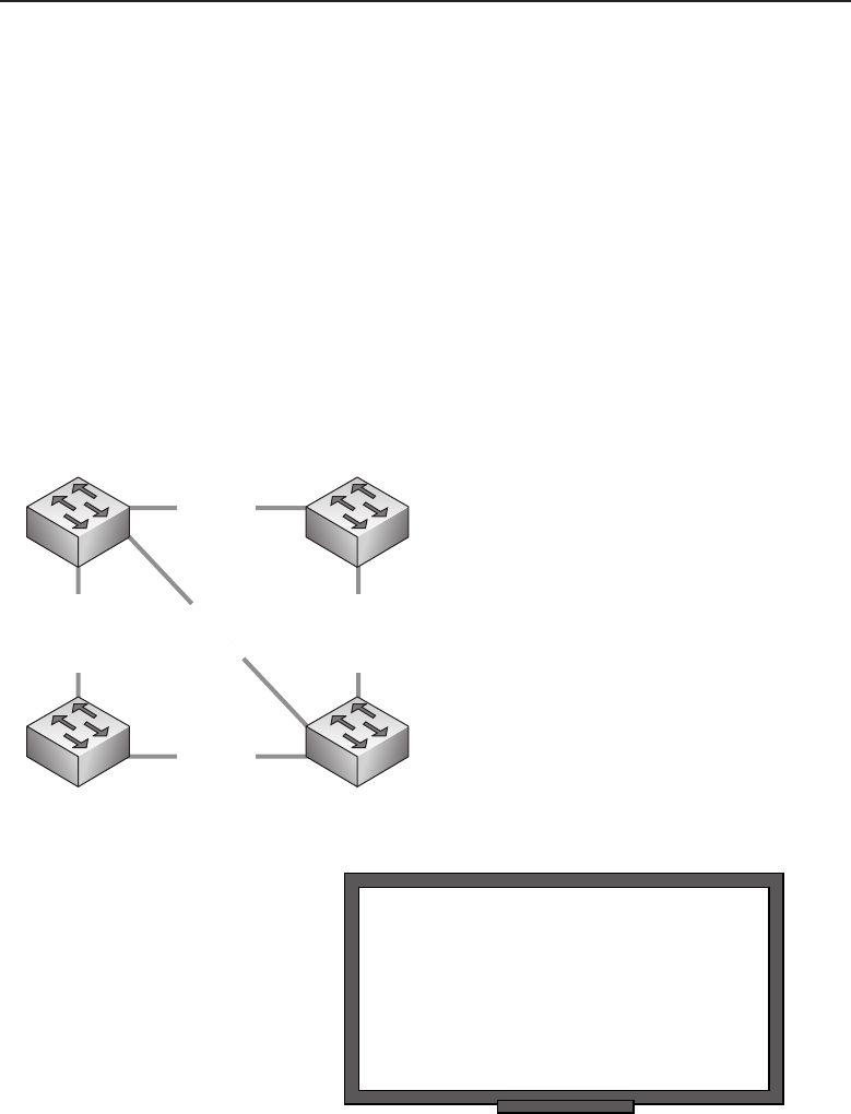
Edwards c12.tex V3 - 03/27/2009 11:27am Page 511
Chapter 12 ■Design Methodologies 511
Spanning tree33 uses an algorithm, known as the spanning tree algorithm,to
make calculations that are used to prevent the dreaded loop. It does this by
determining where there are multiple paths to a segment, and then making a
calculation that will determine the best bridge to use. Once it determines the
best bridge, it will elect that bridge as the root bridge. All other bridges in the
group will be assigned the title of designated bridge when they are participating
in forwarding data that the root is sending to a destination. In other words, the
designated bridge is the one that is responsible for sending data over the best
path. Any bridge that is not the root bridge can be a designated bridge.34 At
the designated-bridge level, there are different port types: the designated port,
the root port, and the inactive port. The inactive port can be either a disabled
port (a port that is not used) or a port that has been set into a blocking status.
Figure 12-20 shows an example of a network containing physical loops
(segmentsA,C,EandsegmentsB,E,D).
SN-1 SN-2
SN-3 SN-4
Segment D
Segment A
Segment C
Segment B
Segment E
Figure 12-20 A physically looped network
RANDOM BONUS DEFINITION
globally administered address — A node or
interface identifier whose uniqueness is
ensured through the use of an assigned
organizationally unique identifier (OUI),
typically by the manufacturer of the device
or interface.
Spanning tree will determine
which bridge in the group will
be elected to function as the root
bridge. The root bridge is always
the logical center of the net-
work. The way the root bridge
is elected is a process that relies
on a data message known as a
bridge protocol data unit (BPDU).
33A lot of times instead of calling the protocol STP, network professionals just say ‘‘spanning
tree.’’ We like spanning tree; it flows better.
34We should note that as time goes on and changes happen on the network (adding nodes,
removing nodes, etc.), each bridge has the potential of being elected as the root bridge at some
point in time.

Edwards c12.tex V3 - 03/27/2009 11:27am Page 512
512 Part III ■Network Design and Implementation
TheBPDUsaresentbyallthebridgesthatwanttoparticipate
35 in the spanning
tree. One of the fields in the BPDU contains the bridge identifier of the sending
bridge. Once all BPDUs have been compared, the one with the lowest value
will be elected the root bridge. Once the root bridge is selected, designated
bridges are used to forward data. The main rule the designated bridge needs
to follow is that only one bridge can forward data from the root bridge to the
destination nodes. This rule ensures that no loops can occur because only one
designated bridge is sending data from the root.
BPDUs are sent by spanning tree nodes to a well-known multicast address.
This ensures that everyone in the group will receive the data. Spanning tree
will decide which designated bridge it will use to forward a frame and will
also decide which designated port to use to forward the data away from the
root. Another field that is found in the BPDU is the root path cost. The root
path cost is a configurable value that is used to set a priority on a preferred
link. The port that is identified as having the lowest path cost will become
the designated port and is the port that will be used to forward the frame to
its destination. Once the spanning tree has determined the designated port, it
will prevent traffic from flowing on other links to that destination by putting
the ports on the other links into a blocking state.
12.5.3.3.4 Spanning Tree Port States
Every port on a bridge that is participating in spanning tree will have one of
five possible port states assigned to it. A port state is exactly what it sounds like:
it identifies the current state of the port. Each port state is important as it will
identify the function the port is performing. These port states are as follows:
Disabled — A port in a disabled state is simply that, disabled. There
are many reasons why a port may be disabled. It may be a Physical
layer problem, a communication problem, may not be used, etc.
Blocking — A port in a blocking state is an active port that
is not being used. Any port that is not a designated port or a
root port is going to be in a blocking state. A block port listens
for BPDUs to determine if it should become active, but does
not participate in frame passing when it is in this state.
Listening — A port in a listening state is not forwarding frames,
but is listening to, and sometimes sending, BPDUs.
Learning — A port in a learning state is learning paths to des-
tinations and preparing to forward the frame. This state is used
on a port that has not built an address table.36 Alearningport
35By participate, we mean that the node will use the BPDU to find out about other nodes as well
as to receive information that will be used to calculate the spanning tree.
36Normally this is due to the port coming up.
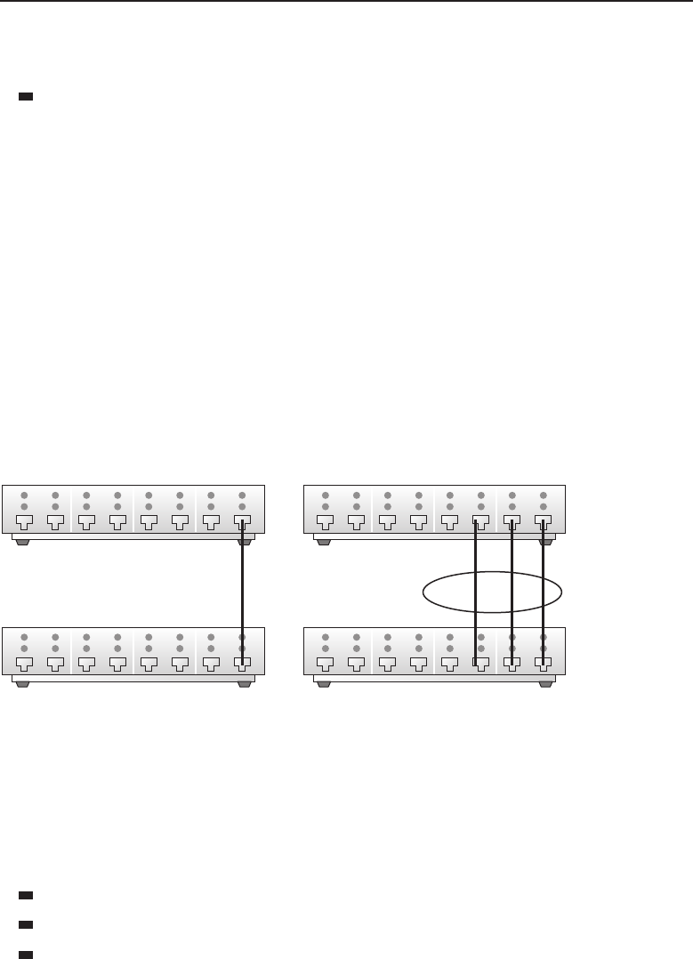
Edwards c12.tex V3 - 03/27/2009 11:27am Page 513
Chapter 12 ■Design Methodologies 513
will wait a period of time before it starts forwarding frames.37
This gives it an opportunity to gather path information.
Forwarding — This is the port state for the active port that is forwarding
frames.
12.5.3.4 Link Aggregation
Main Entry: ag·gre·ga·tion (ag-ri-gey-shun)
Function: noun.
1. Several things grouped together or considered as a whole.
2. The act of gathering something together.
As networks grow and the end application becomes more complex, there is a
real need to increase the capacity of a given link. Link aggregation is a method
of increasing the capacity of a channel by allowing multiple physical links to
act together as a whole. The parallel links make the endpoint nodes think there
is a better performing single channel. Figure 12-21 shows an example of two
networks; one is using aggregation and one isn’t.
1 Gb/s
Single Link
1 Gb/s x 3
Aggregated Link
Figure 12-21 The benefits of link aggregation
The standard that covers link aggregation is IEEE 802.1ad, the Link Aggrega-
tion Control Protocol (LACP). Most high-speed LANs can support larger data
rates, so it makes sense to use link aggregation. In smaller, lower-speed LANs,
aggregation may not make sense due to the restrictions of the environment.38
The benefits of link aggregation include:
Increased link capacity
High link availability
Often can be done with existing hardware
37This is known as ‘‘forwarding delay.’’
38Why would you want to aggregate to double your capacity if the network cannot support it?

Edwards c12.tex V3 - 03/27/2009 11:27am Page 514
514 Part III ■Network Design and Implementation
A few disadvantages of link aggregation include:
POP QUIZ
What is forwarding delay?
Requires additional inter-
faces on each end39
Higher potential of con-
figuration errors
May require device
driver updates to ensure compatibility with link aggregation
LACP was introduced in 1999 as a standardized way to aggregate multiple
gigabit links in a high-speed LAN. As many LANs already supported some
proprietary form of aggregation — for instance, Multi-Link Trunking (MLT)
for Nortel and Inter-Switch Link (ISL) trunking for Cisco — for lower-speed
networks, it was already well known that these were proprietary and did
not work with other vendors’ equipment. LACP resolved this for the giga-
bit world, and things have been growing ever since. Link aggregation has
been supported from switch-to-switch, router/server-to-router/server, and
switch-to-router/server since it came out, but now many NICs support LACP,
allowing aggregation to the end-user level. Although it isn’t used everywhere
and a lot of LANs still use proprietary standards, we predict that it won’t be
long for this to be the standard of choice. Of course, at the time of this writing,
there are a few proprietary solutions that are under standards review, so who
knows what tomorrow will bring?
12.5.3.5 Virtual LANs
Early on in this book, we determined that a LAN is a data network that serves
a small geographical area. Most of us think of a group of nodes connected to
one another as forming a LAN (in other words, a broadcast domain). Larger
organizations have an organizational LAN that is made up of several broadcast
domains, the extent of the LAN being the area it covers or a distance-limiting
factor. With the LAN, the limits remain for as long as the node exists in the
LAN. What we mean by this is that within a LAN, the logical topology is
limited to the physical topology as well. Figure 12-22 shows an example of
this. You can only adjust those limits by having additional nodes to collect the
broadcast domains that may be located within the same area. In addition, a
router is required to ensure that broadcast domains are separated, reducing
the effectiveness of the router.
39You may have to buy more equipment, either now or in the future. Not only may you have
to purchase more gear now to support this, this also means that you could be consuming
empty slots on existing nodes. Although this is great for now, you may have to buy more in
the future.
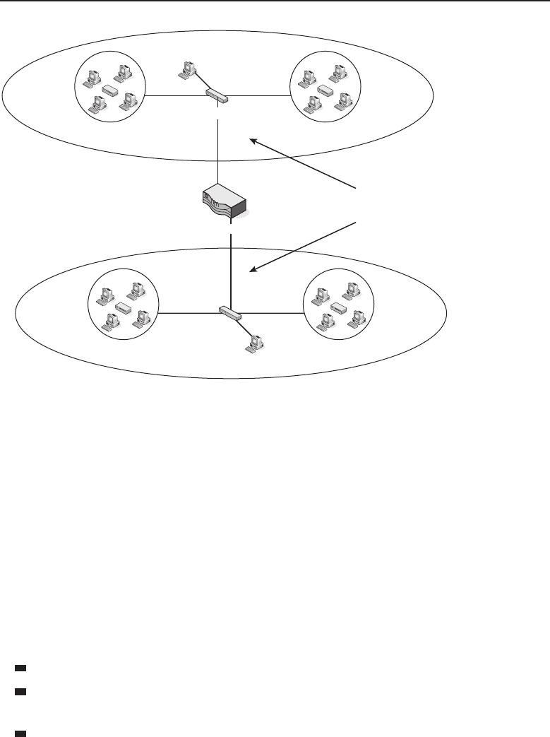
Edwards c12.tex V3 - 03/27/2009 11:27am Page 515
Chapter 12 ■Design Methodologies 515
Collision
Domain
Collision
Domain
Collision
Domain
Collision
Domain
Router
Broadcast
Domains
Switch
Switch
Figure 12-22 A traditional LAN
The virtual LAN (VLAN) was developed to give a LAN bridge the
capability to separate these broadcast domains. This not only frees up the
router to perform other important functions, but it also allows the network
administrator to be flexible in domain configurations. Nodes no longer have
to be in the same physical area to participate in a particular broadcast domain.
Figure 12-23 shows an example of this. Notice that in each of the VLANs,
there are members of each VLAN on each switch. This is a rough example,
but the intention is to show that members of VLANs no longer have to be
physically together to be in the same broadcast domain.
12.5.3.5.1 Benefits of VLANs
There are a lot of benefits to having VLANs configured in your LAN. Some of
these include:
Better performance. Only VLAN members receive multicasts.
Members of a group no longer have to physically be located close to the
group.
Administration is easier. Changes to any work area can be done with
simple configuration change.
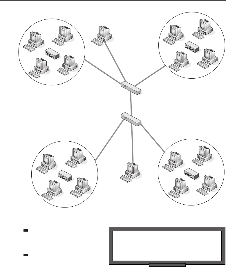
Edwards c12.tex V3 - 03/27/2009 11:27am Page 516
516 Part III ■Network Design and Implementation
VLAN 3
VLAN 1
VLAN 1
VLAN 2
Switch
Switch
VLAN 2 VLAN 3
Figure 12-23 AVLAN
RANDOM BONUS DEFINITION
individual port — A switch port that cannot
form an aggregated link with any other port.
Increased security. Only
nodes within a VLAN
have access to data.
No need for a router in
order to separate the
broadcast domain.
12.5.3.5.2 VLAN-Awareness
A node that participates in a VLAN, whether it is a user node or a LAN
switch, is known as a VLAN-aware node/switch. This simply means that the
node is aware of the VLAN rules and is participating in such an environment.
VLAN-awareness is the capability to understand that there is an underlying
function that allows the mapping of frames to the correct and appropriate

Edwards c12.tex V3 - 03/27/2009 11:27am Page 517
Chapter 12 ■Design Methodologies 517
destination(s). VLAN-aware switches make forwarding decisions based on
the destination address as well as the VLAN to which the frame belongs.
12.5.3.5.3 Tag! You’re It!
To determine which VLAN a particular frame is a member of, the VLAN
environment uses either implicit tagging or explicit tagging. When the switch
receives a frame, it will ‘‘tag’’40 the frame with the VLAN identifier where the
data came from. This process is known as explicit tagging (commonly referred
to as VLAN tagging,orsimplytagging). The other type, implicit tagging,isa
method of mapping an untagged frame to its associated VLAN by inspecting
the contents of the frame.
Information that is contained within the explicit tag can be based on MAC
address, port, and any other combination of information, but will always
contain the VLAN identifier. VLAN tags can be set by a VLAN-aware node,
or they can be assigned to a frame when received on a VLAN-aware switch.
When a VLAN-aware switch receives an untagged frame, it applies the VLAN
mapping rules and forwards the frame with the tagged bit set.
The implicitly tagged frame is a frame that has no tagging at all. Forwarding
decisions are made based on the source address, protocol type, network
identifiers, etc.41
AN UNRELATED MOMENT OF PAUSE — WHAT IS IN THE WORD ‘‘TAG’’?
In the preceding section, we discussed an implicit tag and an explicit tag. But
what other uses are there for the word ‘‘tag’’? One of the first things that I
thought of was the kids’ game tag, as in ‘‘Tag! You’re it!’’ It wasn’t so much me
wanting to relive my childhood, but with five kids under my belt, I have spent
many weekends playing tag in the backyard.
The next thought when I think of the word ‘‘tag’’ is my two boys, who outgrew
tag long ago. Both of them went through a phase where they were constantly
squirting Tag body spray on themselves. I thank goodness that the stampede of
women you see on the commercials never came charging at the house.
You can call a small label a tag, although I think that ‘‘label’’ is perfectly fine.
Tagging a wall means adding your personal graffiti, which some consider art (I
have seen some impressive tagging). Your car has a couple of tags on it: a VIN
tag, tax tag, license tag, and so on and so forth. There are tags in computer
programming, tags on the shelves in the grocery store — as a matter of fact, I
don’t know that we could get through life without tags. Seriously, try getting
through life without seeing that gas is at $4.00 a gallon. Okay, that’s a tag we
could all do without.
40A tag is a field inserted into a frame that provides an explicit indication of the VLAN association
for that frame.
41And any such combination that is predetermined.

Edwards c12.tex V3 - 03/27/2009 11:27am Page 518
518 Part III ■Network Design and Implementation
12.5.3.5.4 VLAN Types
Membership to a particular VLAN is based on the following criteria:
Port-based VLANs — Port-based VLANs are determined by the ports
that are members of a particular VLAN. This is a Layer 1 decision, as
no Layer 2 or 3 data is used to make the membership determination.
MAC-based VLANs — MAC-based VLANs are determined by
the MAC address of the nodes that are members of the VLAN.
Protocol-based VLANs — Protocol-based VLANs members are deter-
mined based on the protocol type in the header of the Layer 2 frame.
POP QUIZ
What is implicit tagging?
IP subnet–based
VLANs —IP
subnet-based VLAN mem-
bers are determined by the
subnet address contained
in the Layer 3 header. This
does not mean that a Layer 3 VLAN can route. It cannot. This means
there is a Layer 3 subnet address used for the VLAN membership rules.
12.5.4 Determining What Other Determinations
Need to Be Determined
This section discusses a few things you should consider in designing a net-
work. Some of the items are good practice talking points and the rest are
provided as a vehicle for thought. Some of the determinations are based on
decisions particular for your environment. Will you be using SNMP manage-
ment? Is there a need for secure remote access? How much documentation
is appropriate for your network? These are only a few questions that will be
answered in this section.
If there is anything missing from this section that you feel is important,
blame Rich!42
12.5.4.1 Talking to a WAN
With any luck, your LAN won’t require a connection to a WAN. Individual
dialup sessions can be handled by the users on the network, if they require
remote connectivity. This is ideal because the number of security issues that
you could potentially have is reduced.43 If this type of LAN works for you, go
for it — it will be a gem to maintain in the long run.
42Just kidding! Jim can’t help but give Rich a hard time.
43If you are not connected to a WAN, then a hacker has no way in, unless he is already in. The
majority of security incidents in corporate LANs can be attributed more to physical (human)
carelessness (some examples are losing laptops, leaving areas unsecure, not securing passwords,
etc.) than to maliciousness.

Edwards c12.tex V3 - 03/27/2009 11:27am Page 519
Chapter 12 ■Design Methodologies 519
The reality is that most of us are going to be working within LANs that do
require WAN connectivity, and because of this, there are decisions to be made
as to what protocols you want for your LAN-to-WAN connectivity. Examples
of options available include:
Integrated Services Digital Network (ISDN)
Leased lines
Synchronous Optical Network (SONET)
Frame relay
Asynchronous Transfer Mode (ATM)
Packet over SONET (POS)
Point-to-Point Protocol (PPP)
High-level Data Link Control (HDLC)
X.25
POP QUIZ
What are the four types of VLANs?
The protocols and standards
used can be determined by you
and the service provider. The
anticipated bandwidth require-
ments, type of traffic, costs, and
many other items can be (and
should be) considered in the
decision making. Regardless of the main protocol you choose, it is always
a good and effective idea to have a backup plan. For instance, you can use
frame relay as a primary method of connecting and have ISDN as a backup.
This way, if the frame relay service fails, you can continue to have connectivity.
Connectivity doesn’t always stop when you meet the WAN. Often there
is a reason for remote offices to connect to the LAN. We have discussed the
VPN solution,44 ISDN, and other services that are in use today. But there are
times when you do not need continuous remote access. For instance, a retail
store may connect one or two times a day to transmit inventory, sales figures,
employee data, etc. In cases like this, a simple dialup connection or satellite
link is often used. You and only you can determine what you need.
12.5.4.2 Management and Security
Don’t kid yourself. Network security and network management are big busi-
ness. We will be discussing these topics in later chapters of this book (network
security in Chapter 14 and network management in Chapter 15). For the
purposes of this chapter, it is important to know a little about both of these as
you are determining what other determinations need to be determined.
44The next best thing to being there!

Edwards c12.tex V3 - 03/27/2009 11:27am Page 520
520 Part III ■Network Design and Implementation
12.5.4.2.1 Network Security
ACRONYM ALERT
FDDI — Fiber Distributed Data Interface
Thereisalottobesaidabouttakinga
strong, proactive approach to network secu-
rity in today’s networks. There is a real need
to protect the network from not only indi-
viduals who are out for a challenge, but
also to someone who wants to steal or harm
data in the network. The malicious offender is probably a deeper concern,
but either type of security breach can cause harm to the network and to the
organization’s operation and effectiveness.
Networksecurityisimportantregardless of whether you are connected to
a public network. Without security, your network is vulnerable to an outside
(and sometimes even an inside) attack.
Security precautions need to be taken to protect the data that is being
transmitted in the network. Here is a list of things to consider:
Antivirus software is a must for every PC in the network. There are
too many viruses and worms that can affect not only that end user’s
node, but also the entire network. These attacks can be introduced
to the network through e-mail, web surfing, and even through a
software application loaded from a disk to the end user’s nodes.
A firewall is important, as it will help prevent unauthorized
access to the network. Some services that are offered by fire-
walls are spoofing, encryption and decryption, authentication,
filtering, and proxy services. Not all firewalls will offer all of
these, so you will need to determine what suits your needs.
Maintain a strong network authentication procedure. Change
passwords often, and control the individuals who can access them.
Do not discount the importance of physical security. Only authorized
individuals should have physical access to network equipment.
End users need to understand the importance of not leaving
their PCs open and available when they are not at their desks.
Passwords need to be protected. Laptops and other mobile gear
need to be secure, and users must understand the importance
of keeping a good eye on the laptop and the data it contains.
Utilize network management to keep track of operations within the LAN
(more on this in the next section).
Again, we discuss network security further in Chapter 14.

Edwards c12.tex V3 - 03/27/2009 11:27am Page 521
Chapter 12 ■Design Methodologies 521
12.5.4.2.2 Network Management
Network management is the process of configuring, monitoring, and main-
taining the operations of the entire network. There are two types of network
management nodes within a network:
Network management agent — An entity (typically a combina-
tion of software and hardware) within a node that is responsible
for gathering network management information and reporting it to a
network management station as appropriate.
Network management station — A node that communicates with net-
work management agents throughout a network. Typically it comprises
a workstation operated by a network administrator, equipped with
network management and other relevant applications software.
Security of the network is actually a network management function, but it is
such a deep subject that it is often separated from other network management
functions. Network management also includes maintaining the reliability of
the network as well as keeping track of network overall performance.
We discuss network management in Chapter 15.
12.5.4.3 Choosing Protocols
POP QUIZ
What is a network management station?
You have determined what the
network will look like and you
have also determined the nodes
youplanto‘‘rollout.’’Someof
the protocols you will be using
in your LAN are determined by
the types of nodes you have decided on.45 Some of the major protocols (for
instance, RIP vs. OSPF) will be easy to select, just based on the design and
the needs of the network. On the other hand, some of the protocols that you
will want to implement may be proprietary and not interact well with other
protocols. Investigate, test, and then make the determination on what you will
implement.
In some cases, the de facto standard may not be the optimum choice, and
you may want to implement a protocol based on its current availability. In
other words, how widely is it deployed? As we discussed early in this chapter,
another rule of thumb is to model your design after another network. Often,
you will be able to implement the same protocols.
Complex protocols may have a lot of bells and whistles, but may also be well
out of scope for your network. There is a principle in professional communities
45You would not implement TCP/IP on a Macintosh network.

Edwards c12.tex V3 - 03/27/2009 11:27am Page 522
522 Part III ■Network Design and Implementation
known as KISS — Keep It Simple, Stupid.46 Pick your protocols based on need,
but follow the KISS principle at all times.
12.5.4.4 Proactive Thinking
Throughout the design process, it is important to remain as proactive as
possible. Not only do you want to try to figure out traffic patterns and future
needs in your design decisions, it is also good to keep in mind that no
matter how the network is designed, there will be at least one person at some
point who will have a real need to understand the network and whether the
performance expectations are being met. Here are a few tips:
Use the KISS principle as often as possible in everything that you
plan for the network. Design the network to be easy to configure,
easy to maintain, easy to troubleshoot, easy to replicate, etc.
Always develop an action plan. Have a logical sequence of steps
that you take during the design process and on through imple-
mentation (see next chapter). Always have a back-out plan,
too. Make sure to leave yourself a way to get things back to
where they were working before you tried that last thing.
Always document everything. Keep a record of IP addressing,
node name, protocols running on each slot/port in the LAN, and
anything else that you come across that might be important. In some
cases, when you can’t document, make sure you share. Do not keep
node administrative passwords to yourself. Share them with at
least one person. The more the network is on paper,47 the better.
Following very close to the documentation category, the network
diagram is a useful tool to have and keep current. When trouble-
shooting is necessary, it can save a lot of time if you can point out
something that is documented, rather than doing it on the fly.
12.6 Network Implementation
Okay, folks, you have the design of the network determined, you have
purchased the equipment, and you have had a test running for several
weeks now. Vendors are flying in tomorrow, because it’s implementation day!
Network implementation is the next stop on the way to the end of this book.
We don’t know about you, but we can taste that beer already.48
46Although Keep It Simple, Silly, is a bit nicer.
47Actually, this will probably be digital, but you get the drift.
48That is the beer that we will be drinking when we type the last letter of the book. If you choose
to have a beer when you read that last letter, Rich and Jim are hoping that it will be in celebration
of a book you enjoyed and not a beer drunk in sadness for the time you wasted. If your opinion
is the latter, we hope that those yummy recipes will save us.
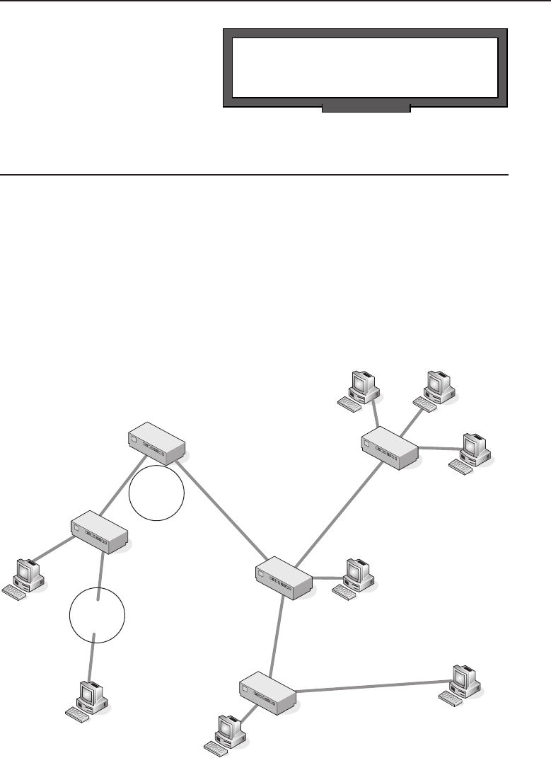
Edwards c12.tex V3 - 03/27/2009 11:27am Page 523
Chapter 12 ■Design Methodologies 523
POP QUIZ
What is the KISS principle?
In lucky Chapter 13, we will
take all the information that you
learned in this chapter and put
it to use in several different
scenarios.
12.7 Chapter Exercises
1. What are the three layers of the hierarchical design model?
2. In this chapter, we listed six benefits of the hierarchical model. List these.
3. This question is actually broken down into questions about
the 5-4-3 rule. Refer to Figure 12-24 for these questions.
(a) Does this network comply with the 5-4-3 rule?
(b) Identify what A and B represent in the diagram.
A
B
Figure 12-24 An example of the 5-4-3 rule
4. How many possible spanning tree states are there and what are they?

Edwards c12.tex V3 - 03/27/2009 11:27am Page 524
524 Part III ■Network Design and Implementation
5. In this chapter, we discussed that a spanning tree port can be in
a learning state. Why do you think that this is required instead
of the port becoming active and just forwarding the frame?
6. A port in a state is one that is paths
to destinations and is preparing to forward the frame.
7. What is the purpose of the distribution layer of the hierarchical network?
8. True or false: When the switch receives a frame, it will ‘‘tag’’
the frame with the VLAN identifier from where the data
came from. This process is known as implicit tagging.
9. What are the VLAN types we discussed in this chapter?
10. Take a look at Figure 12-25 and then identify the appropriate layer of the
hierarchical design model.
The letter A in the example represents the layer.
The letter B in the example represents the layer.
The letter C in the example represents the layer.
A
B
C
Figure 12-25 The hierarchical model
12.8 Pop Quiz Answers
1. Name five businesses or organizations that are not listed above. What
do you think the biggest concern would be pertaining to each organiza-
tional LAN type?
This answer is intended to provoke thought, so there are no right or
wrong answers.

Edwards c12.tex V3 - 03/27/2009 11:27am Page 525
Chapter 12 ■Design Methodologies 525
2. Define scope.
The range of one’s perceptions, thoughts, or actions
Breadth or opportunity to function
The area covered by a given activity or subject
3. Name three WAN technologies that are used to connect to remote sites.
In the chapter, we mentioned frame relay, leased lines, and
ISDN. Any protocol or implementation standards used to
connect to the remote site are good answers as well.
4. What are the layers of the hierarchical design model?
Distribution layer
Core layer
Access layer
5. What is the purpose of a network’s access layer?
This is the layer that interfaces with the endpoint nodes. Types of
nodes that are found at this layer are wireless access points, hubs,
repeaters, bridges, Layer 3 switches, and routers. The access layer is
what allows end users to connect to the network. This layer is also
responsible for determining when nodes are not allowed access to cer-
tain portions of the network.
6. What is implicit tagging?
Implicit tagging is a method of mapping an untagged frame to its asso-
ciated VLAN through the inspection of data contained in the frame.
7. What are the four types of VLANs?
Port-based VLANs
Protocol-based VLANs
MAC-based VLANs
IP subnet–based VLANs
8. What is a network management station?
A network management station is a node that communicates with net-
work management agents throughout a network. Typically it comprises
a workstation operated by a network administrator, equipped with
network management and other relevant applications software.
9. What is the KISS principle?
Keep It Simple, Stupid
Edwards c12.tex V3 - 03/27/2009 11:27am Page 526

Edwards c13.tex V3 - 03/27/2009 11:37am Page 527
CHAPTER
13
Implementation
First, have a definite, clear, practical idea — a goal, an objective. Second, have the
necessary means to achieve your ends — wisdom, money, materials, and methods.
Third, adjust all your means to that end.
—Aristotle
Aristotle lived many centuries before the age of computer networking, but
his wisdom rings true when it comes to implementing any new network
infrastructure. For the most part, organizations have used an evolutionary
approach to growing their networks, adding capability when it was needed.
As a result, many of today’s networks are poorly laid out and maintained,
often with little or no documentation.
ACRONYM ALERT
WAN — Wide area network
Many executives like to think of their
networks as they do any other utility, such
as electrical power, telephone service, etc.
There is no mistake about it: corporate
networks are part of the ingrained infras-
tructure in running any type of business.
However, unlike these other utilities, which have large organizations behind
them in their support, the network infrastructure is the sole responsibility of
the organization that owns it. Unfortunately, they tend to look at it as an over-
head function, and when budget cuts are required, it is always the overhead
areas that get chopped first. That is all well and good as long as things keep
humming along without interruption. But there comes a day when something
decides to burp. If there is network equipment stored in accessible closets, you
may have the following scenario occur. The janitor thinks he should clean out
the back of a closet that has collected a lot of junk along with some portions of
the company’s network infrastructure. He inadvertently kicks out some cables
527

Edwards c13.tex V3 - 03/27/2009 11:37am Page 528
528 Part III ■Network Design and Implementation
and plugs them back where he thought they were connected. All of a sudden
no one is getting e-mail and the CEO is on the horn trying to find out what
is going on. I know this sounds comical and perhaps a bit far-fetched, but we
can assure you that it does happen and it can get downright ugly before things
are running again.
13.1 Planning
Planning is where you place Aristotle’s first line into action: ‘‘have a definite,
clear, practical idea — a goal, an objective.’’ Good network planning begins
with a top-down approach. Today’s complex networks evolved from very
basic networks and were patched together as more networking capability
was needed. This was far from a top-down design. We have seen network
installations that would have made Rube Goldberg1cringe at the thought
of adding his name to its design. Many of these networks became this way
primarily by a ‘‘if it ain’t broke, don’t fix it’’2mentality.
RANDOM BONUS DEFINITION
100BASE-TX — A baseband Ethernet
system operating at 100 Mbps over two
pairs of STP or Category 5 UTP cable.
Figure 13-1 illustrates a net-
work planner in the initial plan-
ning phase to implement the
design approach he decided on
using the information provided
in Chapter 12 on design method-
ologies. There is a natural divid-
ing line as far as planning goes;
one side involves a current network infrastructure and the other side a total
new design. If this is a totally new design, the planning task only involves
how to implement the new network design. If there is a preexisting network,
however, several considerations need to be reviewed prior to implementing
the new network design. Because the totally new network implementation
requires only a subset of a network design that would be required for an older
network infrastructure, it will be covered first.
The initial planning phase should consider not only the current network
requirements, but also what may be needed in the future, both near-term and
long-term. Think of where the growth areas will be and see how that growth
can be easily accommodated while growing the network infrastructure in
an orderly manner. Remember, you should plan ahead for network growth,
rather than cobbling together networking capability as required.
1Reuben Garret Lucius Goldberg, born July 4, 1883, died December 7, 1970. American cartoonist
noted for his cartoons of involved and complex machines, most of them just accomplishing a
mundane task in a convoluted manner.
2An expression popularized by President Jimmy Carter’s advisor Bert Lance.
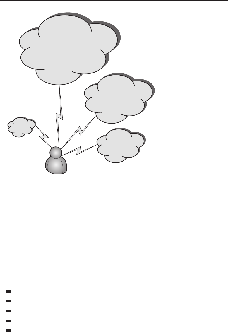
Edwards c13.tex V3 - 03/27/2009 11:37am Page 529
Chapter 13 ■Implementation 529
Network Planner
Current Network
Current Requirement
Near Term
Need
Long Term
Need
Figure 13-1 The initial planning phase
13.1.1 Totally New Network Planning Phase
As the old saying says, the best-laid plans of mice and men often go awry. The
idea is to eliminate as many problems as possible by beginning with a well
thought out plan. If you have the opportunity to do a total network design from
scratch, there are many variables to consider. The key is to size the network and
the network segments so you can meet peak bandwidth requirements without
overbuying. Some items involve a recurring cost, whereas others are one-time
purchases. Part of the planning entails making appropriate cost estimations.
A good place to start is to list both recurring and fixed cost items.
Recurring costs:
Access fees
Support contracts (usually billed annually)
In-house support staff
Energy needs
Routine maintenance

Edwards c13.tex V3 - 03/27/2009 11:37am Page 530
530 Part III ■Network Design and Implementation
One-time costs:
Hardware
Cabling
Initial installation fees
ACRONYM ALERT
TIA — Telecommunications Industries Association
Access fees are the monthly service
charges from the telecommunications com-
pany for providing access to their network.
Theruleofthumbisthatthemoreband-
width required, the higher the cost. Some
factors that may help determine which
service to use for access are the services offered and the number of telecom-
munications companies that are located within the area for your new planned
network. If there are multiple telecommunications companies within the area,
you should request quotes for the types of services they offer. There may be
a one-time installation or hookup fee associated with the service plan you are
considering.
13.1.1.1 Initial Planning
The design approach should be completed using a top-down method-
ology — that is, start with the big picture. However, each phase should
entail a document that details what is needed at that level.
We will begin the initial planning phase using a hypothetical3example of
the Widget Company, which wants to expand their operations west of the
Mississippi River. The corporate planners have researched various areas and
determined that Denver best suits their needs for their first expansion out of
their Midwest region. The first-level network plan may look something like
that illustrated in Figure 13-2.
13.1.1.1.1 Office Interconnection Planning
RANDOM BONUS DEFINITION
application flow — A stream of frames or
packets among communicating processes
within a set of end nodes.
The plan is for a high-speed
network between the new West
Region office in Denver and the
corporate office in Chicago. This
is to be a point-to-point connec-
tion to provide for the sharing of
services located at the corporate
offices. The plan entails using a
3What is being discussed is scalable to any size organization. The required numbers depend on
the size of the facility and the number of network users located at this facility.
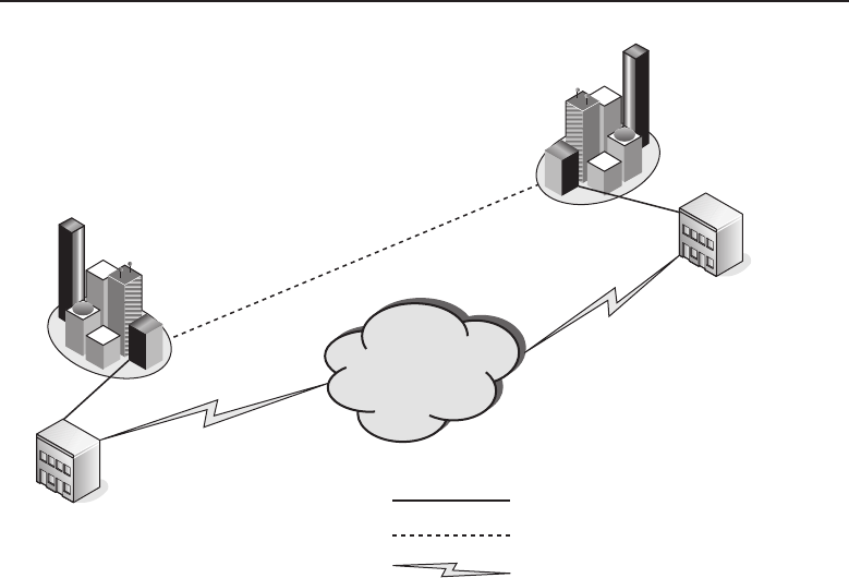
Edwards c13.tex V3 - 03/27/2009 11:37am Page 531
Chapter 13 ■Implementation 531
Denver
New
West Region Office
Internet
Local Point to Point Link
Long Line Point to Point Link
Local Internet Access
Corporate Office
Chicago
Figure 13-2 The top-level plan for Denver’s expansion
carrier to provide those services over its national optical network. However,
the plan is to allow the users at the Denver office to also have Internet access
locally with a local provider. This Internet access can be used as a redundant
path to the corporate office in Chicago, if the need ever arises with a failure
in the high-speed optical network. After determining how the offices are to be
interconnected, the planning does not end there. Bids will need to be solicited
from the optical carriers for services offered and the rate schedule for those
services. Also, bids will need to be obtained from local ISPs in the Denver
area.
While that bid process is ongoing, other plans can be worked on. You should
continue planning both the access to the network from the outside world and
the network distribution inside the building. In the Widget Company example,
it is determined that a combination server and network services area would also
house the access and backbone network distribution equipment. Figure 13-3
illustrates the layout of the combined server and network operations area.
13.1.1.1.2 Network Operations Area
Many companies these days lump computer operations, network operations,
and all other telecommunications under the IT (information technology)
umbrella. If the company is large enough and the amount of equipment
and services offered warrant it, the department could have a number of
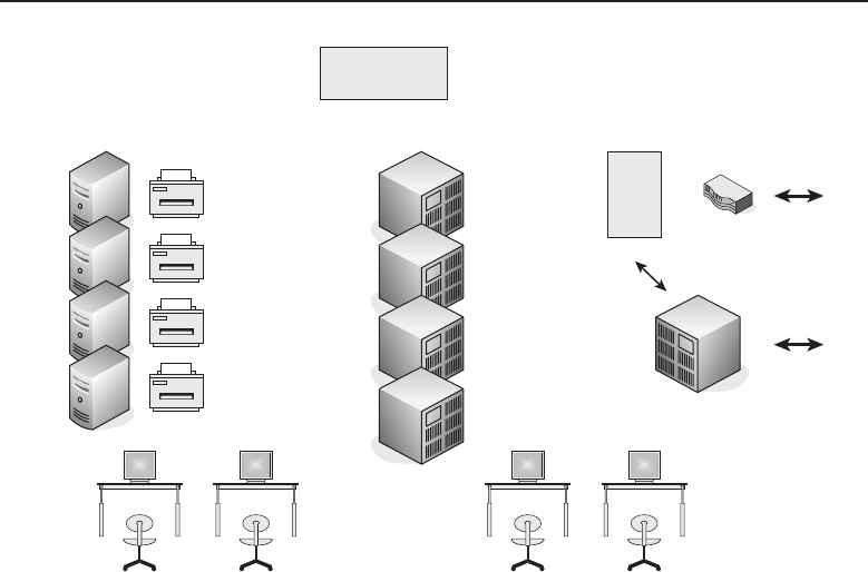
Edwards c13.tex V3 - 03/27/2009 11:37am Page 532
532 Part III ■Network Design and Implementation
Server
Cluster
Computer Support
Personnel
Network Operations
Personnel
Network Core &
Distribution
Network Access
External Public Networks
Network Access
Distribution
Environmental Control
Equipment
Telephone
Public Network Access
Figure 13-3 The combined server and network operations area
staff to maintain the equipment and support the workforce located at that
facility. Sizing and scaling of the support model is proportional; there is no
one-size-fits-all approach for each separate installation. Some companies with
a corporate office and regional office use a model where much of the IT
support is run out of the corporate office, with a smaller staff located at the
remote offices performing the hands-on work. Chapter 15 discusses methods
of remote network management.
Figure 13-3 shows a single central support area. It is not uncommon to locate
core services for IT to save money by not needing more support staff located
in different areas of the facility. Once an IT department is set up, the amount
of staff required to maintain the on-site equipment and field support calls
from the local users for services provided by IT is much lower in the initial
implementation phase. If major upgrades to the local network are required, a
company can opt to hire contractors or send staff from other locations to assist
in the upgrade. Another option is to hire a company to handle the upgrade
and pay for the labor that is required directly to that network contractor. Many
factors will determine which method would be best, but the overall cost and
size are typically the driving forces of the upgrade project. Small upgrades

Edwards c13.tex V3 - 03/27/2009 11:37am Page 533
Chapter 13 ■Implementation 533
or addition of added network capacity are usually handled by the on-site IT
employees.
NOTE On-site IT employee numbers have dwindled due to companies
‘‘off-shoring’’ their support functions. It is a situation that appears monetarily
lucrative to those that run the budgets of companies but can be a nightmare at
times. Being locally based employees for our entire careers may have jaded us, but
it is our opinion that this is a poor way to provide IT services support. It has been
our experience that the best run network infrastructures are maintained locally by
staff who knew their networks well. It can be difficult for an IT support person on a
support call to envision what is going on with a network half a world away. Add to
it idiom-based language differences and the frustration level rises to the point of
exasperation. The key is knowing what you are paying for when you decide how
your IT department is to be staffed.
13.1.1.1.3 Environmental Requirements
ACRONYM ALERT
SPX — Sequenced Packet eXchange
There are other considerations to take into
account while designing a central area for
the computer and network operations for
the IT department. One consideration is
flooring. There are pros and cons for having
afalse
4floor. It can facilitate environmental
control of the area by using the space under
the false floor as the return duct for the HVAC5system, and it can be where
the power and network cabling can be placed. The major disadvantage is
that adding additional cabling at a later date can be difficult since the tiles
would need to be lifted to route the cable. A false or raised floor can be
more aesthetically appealing than overhead cabling, but it lends itself to an
installation that is fairly static. You do not want to use that type of flooring if
you anticipate a dynamic work area with many additions and reconfigurations.
It is much easier to use overhead cable racks to distribute the network cabling
and power buses for the power drops that may be required. These are easily
reconfigurable and facilitate changes much more rapidly than routing cables
under a floor.
4A false floor is a raised floor made up of individual panels that are normally two-foot squares.
They are laid in over a framework that looks like a giant matrix before the tiles are laid in.
Usually, the facility is wired under the flooring before the tiles are placed down.
5HVAC stands for heating, ventilation, and air conditioning. When there is a high concentration
of computer-related equipment is a fixed area, there is a volume of heat that needs to be dealt
with. Most facilities install HVAC systems to control the environment not only for temperature
but humidity levels, too. High humidity can cause corrosion, and the last thing you want is
something growing on your network connections. Contact corrosion can cause problems that are
nasty to diagnose and find.

Edwards c13.tex V3 - 03/27/2009 11:37am Page 534
534 Part III ■Network Design and Implementation
RANDOM BONUS DEFINITION
backoff — The mechanism used in the
Ethernet MAC (CSMA/CD) to reschedule a
transmission in the event of a collision.
The environmental control
system is usually installed and
maintained by an HVAC con-
tractor. However, the sizing of
the system requires input from
the network planners as to the
number of BTUs6of heat gener-
ated within the area. This will include all the equipment within the area as
well as the number of human bodies7that will be in the area. The HVAC
contractor can use that information to right size8the equipment needed, with
afudgefactor
9to compensate for minor growth.
13.1.1.1.4 Network Access Requirements
You may have noticed in Figure 13-3 that the public telephone network access
and the network access are in the area dedicated for IT services. It has been
decided that this site will use VoIP (Voice over IP) and the telephone sets will
be IP-enabled phones. The voice communications will run over the network
throughout the facility. So the convergence of the voice and data networks
will occur in the IT area. Part of the traffic shaping10 plan may entail that
voice communications between the Denver facility and the Chicago corporate
office will go directly from the local phone switch as IP data over the directly
connected fiber link.
NOTE The term ‘‘convergence’’ is tossed about heavily in the network world. The
simple fact of the matter is, it’s becoming an IP world. Any form of data that can
be digitized can be transmitted over the network within data packets. However,
real-time applications such as voice and video require committed bandwidth rates
to guarantee a satisfactory level of service. Humans do not take too well to choppy
voice reception or flickering video displays. When planning these services, care
must be taken to guarantee the required bandwidth to eliminate these types of
issues. Traffic profiling and shaping are essential parts of the planning phase.
6BTU is the acronym for British Thermal Unit. It is the amount of heat required to heat a pound
of water from 60 to 61 degrees while it is sitting at a constant pressure of one atmosphere.
7We are talking of live human bodies here. Live bodies generate heat and expel moisture as they
breathe. Dead human bodies neither breathe nor generate heat so they need not be counted, but
we would not want them around too long either. So although many employers like to work their
employees to death, they prefer you to do your dying on your own time.
8‘‘Right size’’ has come to mean many things these days. It usually refers to getting the size
right for a particular need. However, it has been hijacked by corporate management as a term to
replace ‘‘layoff.’’
9‘‘Fudge factor’’ is a term used to suggest that a number has been tampered with. Here it is used
to mean that additional capacity for HVAC equipment is ‘‘upped’’ to compensate for possible
future growth.
10Traffic shaping is the ability to direct network traffic over segments of a network, depending
on bandwidth availability and other policies enforced on the network by the IT staff.
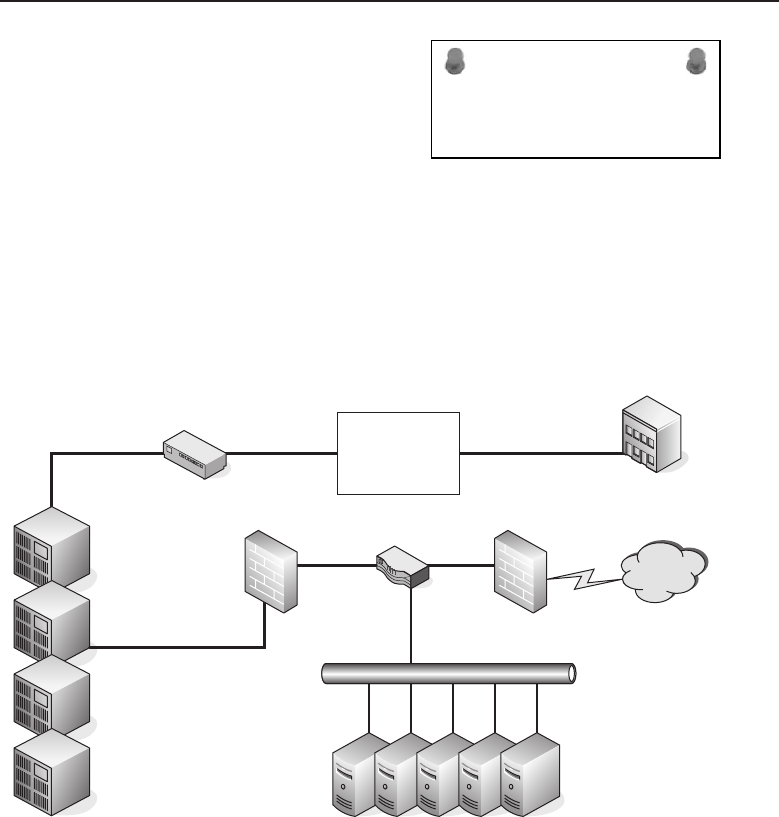
Edwards c13.tex V3 - 03/27/2009 11:37am Page 535
Chapter 13 ■Implementation 535
ACRONYM ALERT
RMON — Remote monitor
Part of the planning phase is determin-
ing levels of access to the network. If it is
decided that there will be services avail-
able from the Internet, strong consideration
needs to go into designing firewalls and
DMZ11 zones. You may want to segment
your network to easily facilitate these DMZ areas. There may be other fire-
walls that police the traffic flow to and from the network at large. Whenever
a network ties into the Internet, there should be a firewall between it and
the first router on the Internet. This is to prevent unwanted and unsolicited
traffic12 from finding its way into the local network. A preliminary plan may
be similar to that illustrated in Figure 13-4.
National
Fiber Optic
Carrier
Fiber Link Router
Corporate Office
Chicago
Internet
DMZ RouterFirewall Firewall
Server Cluster
Internal Network
Distribution
Figure 13-4 A preliminary DMZ plan
11DMZ is the acronym for demilitarized zone. It has been adopted by the networking world to
mean an area that is not directly connected to any other network segment. It is policed by firewall
devices with access policies to prevent a security breach of the network. More on this subject can
be found in Chapter 14, ‘‘Network Security.’’
12Unsolicited network traffic refers to network traffic originated elsewhere over the Internet
that has not been asked for. It may be a possible hack attempt. This type of traffic is generally
discarded and not allowed into the network. However, if the location is providing services such
as web or FTP to the outside world, the unsolicited network traffic must be allowed through to
those services. That is the reason they need to be located within the DMZ.
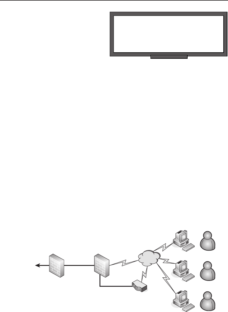
Edwards c13.tex V3 - 03/27/2009 11:37am Page 536
536 Part III ■Network Design and Implementation
RANDOM BONUS DEFINITION
bridge — A networking node that relays
frames among its ports based upon Data
Link layer information.
As mentioned previously, the
Chicago corporate office is con-
nected to the Denver office via
a fiber link by a service pro-
vided by a national fiber carrier.
There is no need for a firewall
because the two connected net-
works have been secured at both ends of the link. However, since there is
another, unsecured path to the Internet, there is a need for a DMZ between the
private network and the Internet. You will notice that the DMZ is portioned
off with firewalls on both sides that allow for traffic policies to police the traffic
flow into and through the DMZ. Policies should be in place to allow users out
on the Internet to access services being served by the server cluster in the DMZ.
The additional firewall before traffic reaches the internal private network is in
place to prevent the possibility of one of the servers being compromised from
the Internet and then used for a possible breach of the internal private net-
work. Traffic pattern flow will only allow traffic from the Internet to reach the
server cluster and prevent it from accessing the internal private network. Any
unsolicited traffic that is originated before the firewall guarding the internal
private network will be dropped and not permitted to pass beyond the firewall
into the internal private network. Policies have been placed on both firewalls
to allow users on the internal private network to access both the server cluster
and the Internet since they are originating the network connection.
13.1.1.1.5 Remote User Access
If remote company users need to access the resources on the internal private
network, you should consider using a VPN router to allow access through the
firewalls. Figure 13-5 shows a typical topology.
DMZ
Internet
VPN Access
Gateway Router
Remote
VPN Users
Internal
Private
Network
Figure 13-5 A VPN gateway for remote access

Edwards c13.tex V3 - 03/27/2009 11:37am Page 537
Chapter 13 ■Implementation 537
ACRONYM ALERT
RARP — Reverse Address Resolution Protocol
TheVPNremoteusershaveaVPNclient
on their PCs that is configured to access the
company’s VPN access gateway router to
permit these users access to the private net-
work and the services that are available to
them, as determined by the policies placed
on their user IDs. Companies can restrict the services available to these remote
users on an individual basis or group basis. Users are authenticated when they
access the VPN access gateway router. Chapter 14 discusses authentication
and encryption of VPN connections in greater detail. If users are unable to
be authenticated due to invalid credentials, they are not able to gain access
to the internal private network. Once users are authenticated, their client is
assigned an IP address that is routable through the DMZ firewalls into the
internal private network. All policies regarding remote user VPN access must
be in place to permit traffic from these users to reach the private network.
Now that we have covered the access to the corporate offices and Internet
access for the company-based users, as well as remote users able to log in to
the facility in Denver, we are ready to discuss the network distribution within
the Denver facility. The Denver facility is a new, four-story building. Users
have jacks at their desks to accommodate computer access as well jacks for
IP-enabled telephones. To ensure worker productivity, provisions are to be
made to let them keep working through minor network failures. The idea is to
have redundancy for both the IP phone and the computer network access. Each
desk position throughout the facility is to have four Ethernet jack outlet boxes
next to it. Figure 13-6 illustrates the Ethernet jack outlet, with two network
designations assigned to each pair of jacks.
A1
A2
B1
B2
Figure 13-6 The Ethernet jack outlet
13.1.1.1.6 Network Distribution
There are two designations for the networks to be used: A and B. The jacks
for each network are labeled 1 and 2. Both the A and B networks are ‘‘live’’ at

Edwards c13.tex V3 - 03/27/2009 11:37am Page 538
538 Part III ■Network Design and Implementation
RANDOM BONUS DEFINITION
browser — An application program that
provides a graphical user interface to
Internet.
all times and can be used for
load balancing within the net-
work. In the event of a net-
work failure, they can provide a
means of network redundancy.
This will allow users on the
failed network to switch to the
remaining operational network if needed. The plan is to have users connect
one device (such as their PC) to the A network and the other device (such as an
IP-enabled telephone) to the B network. This is just an example of a possible
scheme to allow for redundancy and network traffic management. There are
a variety of methods to accomplish this and the considerations are primarily
cost-based. There is a fine line between true redundancy and overkill. Once
it is determined how each desk position on each floor is to be wired, we can
consider how the distribution is to be made from the network operations area
to the wiring closets on each floor. Each wiring closet is to have two switches
that are capable of dividing the local network on a particular floor of the
building into separate virtual LANs (VLANs) One switch will be assigned
to the A network, and the other will be assigned to the B network. This is
illustrated in Figure 13-7.
13.1.1.1.7 Network Backbone Distribution
The distribution of the network backbone from the network operations area to
each floor is accomplished using a fiber-optic link to provide a high-speed path
for the network traffic coming from each floor. Although the fiber-optic link is
illustrated as being daisy-chained from a switch on one floor to another switch
on another floor, this does not necessarily have to be the case. The switches
more than likely do have that capability and daisy-chaining would certainly
reduce the number of fiber optic runs in the wiring closets, but a break in any
link can potentially affect more than one floor. Another consideration would
be to run direct links from each switch in each of the wiring closets to the
switched backbone13 in the network operations area. The wiring to each floor is
Category 5 Ethernet cabling. Usually the cabling runs back to the wiring closet,
where it is terminated on a patch panel. This permits easy reconfiguration of
network jacks to the network node terminating devices in the wiring closet.
Figure 13-8 illustrates the distribution of the Ethernet cabling out from the
wiring closet to the devices connected to each network node on the floor.
13Backbone refers to the distribution of the network out from the core. However, in the day of
the multiswitch switched network core, it is difficult to see a ‘‘backbone’’ structure per se. The
term today refers to the central distribution out from the core, so a network could have a bunch
of backbones.
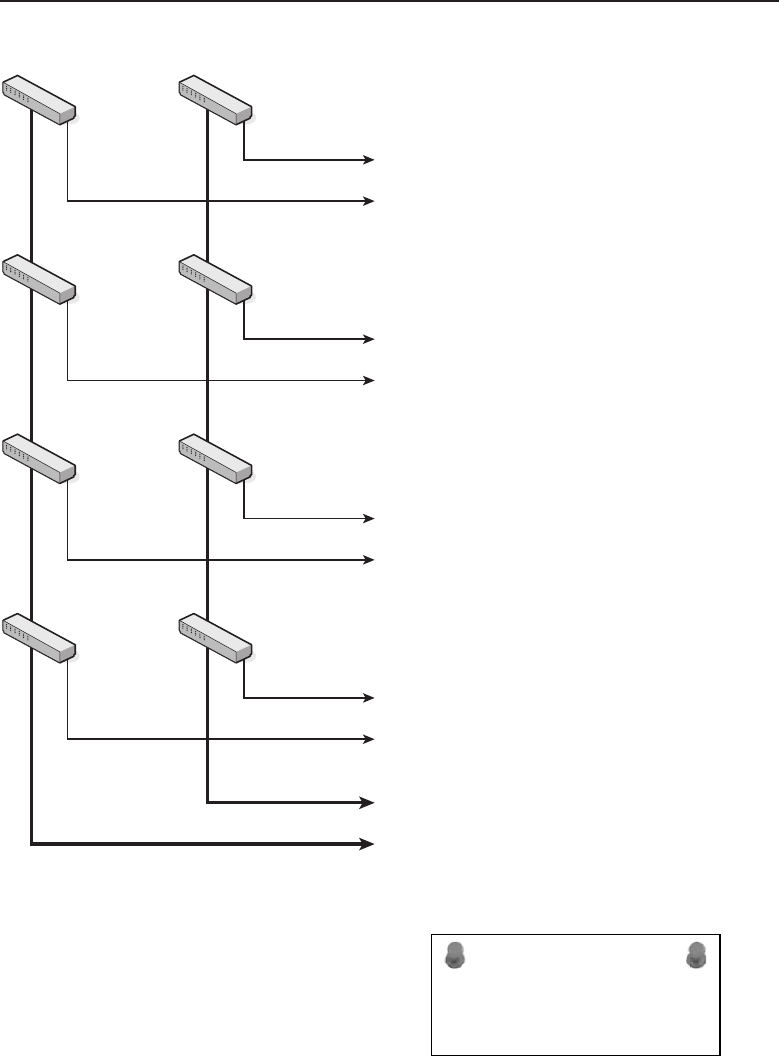
Edwards c13.tex V3 - 03/27/2009 11:37am Page 539
Chapter 13 ■Implementation 539
Floor 4
Floor 3
Floor 2
Floor 1
AB
Network Operations
Fiber Optic
Link
Figure 13-7 The network distribution on separate floors
ACRONYM ALERT
NOS — Network operating system
After being terminated to the patch panel,
the network nodes on the floor are con-
nected using patch cables between the RJ-45
Ethernet jacks on the patch panel and the
appropriate RJ-45 network jack on one of
the network switches located in the wiring
closet. Since this is a new installation, it is expected that the wiring closet
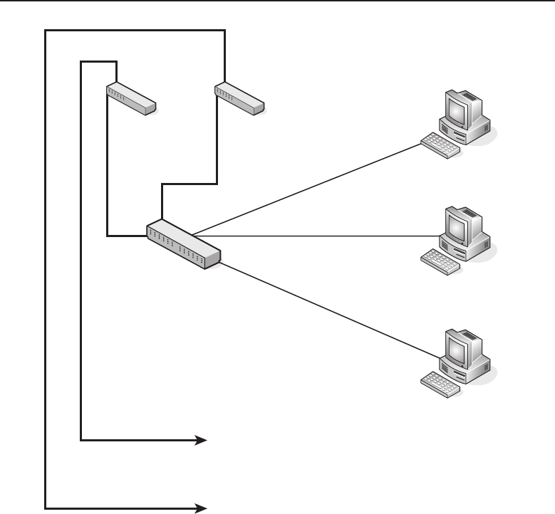
Edwards c13.tex V3 - 03/27/2009 11:37am Page 540
540 Part III ■Network Design and Implementation
Wiring Closet
Switches
Ethernet
Patch Panel
Fiber Optic Link
Network Core
Network devices connected
via Ethernet cabling
Figure 13-8 Wiring closet network distribution
will be orderly and cables secured and off the floor.14 Ethernet cables can be
bundled and tie-wrapped15 if needed.
13.1.1.1.8 Wireless Access
So far all the networking that has been discussed is of the wired variety.
However, having some wireless network access may be desirable for transient
users who may visit the facility and want to use their wireless-enabled laptops.
14We have seen wiring closet floors with network cable just strewn all over the place and draped
onto the floor. The only way to work on anything was to actually walk on the cables. We
highly recommend against this type of wiring system. The chances of intermittent and broken
connections are tremendous.
15Tie wraps are those plastic straps that are ratcheted when pulled tight. They come in various
grades, from very small to fairly thick, and various lengths. They are found in many cabling
areas and can be easily cut to reconfigure a cable.
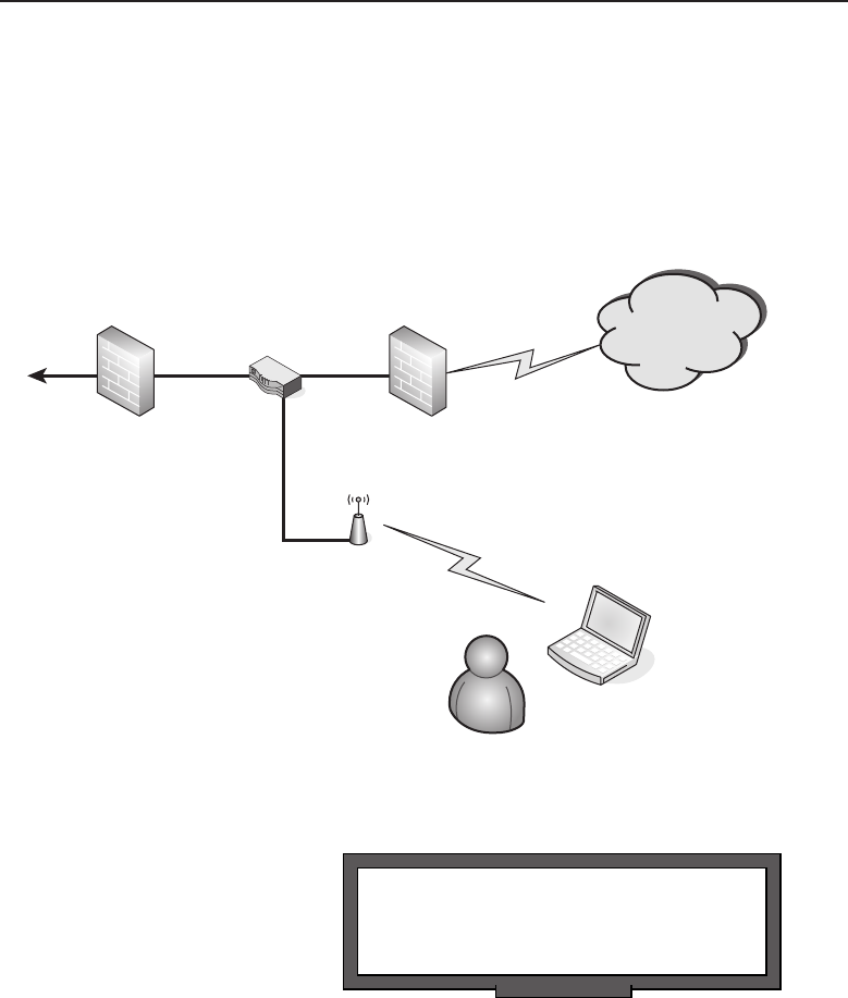
Edwards c13.tex V3 - 03/27/2009 11:37am Page 541
Chapter 13 ■Implementation 541
The wireless network is capable of being isolated from the wired network and
it may not be desirable to have these users plug into the main network. This
will minimize the possibility of a virus-infected laptop spreading a harmful
virus to the main network. For this installation, you may want to consider
a visitors’ area, but only allow visiting users access to the Internet, not to
other internal network resources. This can be accomplished as illustrated in
Figure 13-9.
DMZ Router
Internal
Private Network
Internet
Wireless Access
Visitor
Figure 13-9 Wireless network access
RANDOM BONUS DEFINITION
collision fragment — The portion of an
Ethernet frame that results from a collision.
In this figure, the access point
from the visitors’ area is routed
directly to the router located in
the DMZ area. Internet access is
allowed as a courtesy to visitors
to the Denver facility. The rea-
son for the wireless access point
being wired into the DMZ and not somewhere on the private network is that
it could constitute a breach of the private network’s security. With the policies
on both firewalls, users in the visitors’ area are allowed Internet access but
are prevented from penetrating the firewall from the DMZ into the private
network. Employees from the corporate office visiting the Denver facility will
be allowed to connect their laptops to the network from a secured area. Many
companies provide ‘‘drop in’’ offices for such visiting employees so that can
have access to resources on the private network.

Edwards c13.tex V3 - 03/27/2009 11:37am Page 542
542 Part III ■Network Design and Implementation
We have now performed the initial planning of the network’s design. You
have an idea of the overall scope of the project. The project continuously gets
refined and developed until the final plan is completed. Each phase through
the planning stage must be well documented, and revision control is essential
to minimize confusion as the implementation is being rolled out.
13.1.1.2 Finalizing the Plan
The initial planning documentation describes the equipment used and where
it should be placed within the facility. Once that has been determined, it is
time to lay out the network in regard to addressing and segmentation. We
will lay out the VLANs and other subnet segments to be used in various areas
of the facility. This is the most critical part of the documentation since it will
have major impact on the network’s operation and performance.
This example uses the network space 192.168.X.X to define the network.
The initial plan of the network layout used IP addressing to specify various
segments of the network. An addressing scheme has been devised that uses
the third octet of the IP address space to indicate a particular routing switch
on any particular floor. Table 13-1 illustrates the IP addressing scheme that is
to be used in this network.
Table 13-1 IP Addressing Scheme
FLOOR SWITCH A SWITCH B
1 192.168.10.X 192.168.11.X
2 192.168.20.X 192.168.21.X
3 192.168.30.X 192.168.31.X
4 192.168.40.X 192.168.41.X
The tens column indicates the floor, 0 indicates the A switch, and 1 indicates
the B switch. This is just an example of how with private IP address space
addressing you can parse your network where an IP address can be used as
an immediate indicator where traffic may be originating from. Can you think
of any advantage of doing something like this?
ACRONYM ALERT
MIS — Management information system
The first thing that should come to mind
is the ability to quickly find a problem just
by the IP address of the traffic that is being
generated. If there is congestion in the net-
work and a flood of packets are coming
from a particular network segment, it can
be quickly determined by the IP address’s third octet. Knowing where the

Edwards c13.tex V3 - 03/27/2009 11:37am Page 543
Chapter 13 ■Implementation 543
IP traffic is being originated will aid in rapidly isolating broadcast storms or
denial-of-service (DoS) attacks. So careful planning and layout can not only
aid with performance, it can also help to troubleshoot network problems.
The final plan should include:
Complete network diagrams, including IP addresses
Equipment lists, including their location
Descriptions of each type of network equipment
Troubleshooting guides for each type of network equipment
Lists containing support information for each manufacturer of the net-
work equipment
A collection location for all warranty statements for all new equipment
deployed
A collection location for all support contracts from the original
equipment or other third-party support organizations
A collection location for all equipment manuals for the network equip-
ment
Wiring diagrams for each panel deployed about the network
A collection location for the information dealing with Internet service
providers and other telecommunications providers, including data and
voice
A collection location for all license keys that may be required for any of
the equipment in the network
Maintenance/trouble log16 (used for ongoing support)
A collection location of all contact information for all staff responsible for
the maintenance of the network
The network described in this chapter would have a large amount of
documentation associated with it. It may be worthwhile to set aside a portion
of the network operations area as a library to collect the hard copy17 documents
as well as files where other information can be kept. The list of finalized
documentation is fairly complete, but is not to be construed as everything
that needs to be maintained as part of the documentation. Some equipment
may come with physical keys, and these too should be collected in an area
16A maintenance/trouble log can have various forms. It can be a notebook where trouble
events are written or it can be a computerized form. A wide variety of software is available for
trouble tracking as part of the IT process.
17Hard copy refers to documentation in printed form. Many manufacturers are opting for
documentation on CD due to the cost of print media. Whatever form the documentation for the
equipment is in, it should be properly stored and filed. An index indicating the documentation
that is available and its location is extremely helpful.

Edwards c13.tex V3 - 03/27/2009 11:37am Page 544
544 Part III ■Network Design and Implementation
where documents are safeguarded, cataloged, and under distribution control,
noting where each key is used and what equipment it is used with. The
documentation and keys (both software-based and physical) should be kept
and cataloged where all network support staff can easily find them.
13.1.2 Network Revision Planning
It was said earlier that planning a network upgrade to an existing network is
similar to planning the implementation of a complete brand new network. The
major difference is keeping portions of the network running and trouble-free
while making changes in order to not affect the operation of the company’s
business. Usually this is accomplished by building a network segment in
parallel and verifying its operation prior to making the cutover to the new
network segment. Typically, cutovers are planned during off hours. However,
if a company is a 24/7 operation, a maintenance window needs to be scheduled
for the cutover.
RANDOM BONUS DEFINITION
connection-oriented — A communications
model in which stations establish a
connection before transmitting data
The following sections review
just a few of the possible types
of network upgrades or ex-
pansions that are typically18
performed. We will primarily
discuss access changes, internal
network upgrades, and expan-
sions.
13.1.2.1 Reworking Network Access
ACRONYM ALERT
FS — Frame status
What is involved in a change in network
access? Primarily, it is the type of pipe19
coming from the outside. However, when
there is a transition in service, there is also
a change in the access equipment to accom-
modate that type of service. This discussion
uses as an example a small company that currently has Internet services com-
ing in on an ISDN service from the local telecommunications company. The
company wants to upgrade to accommodate the increase in Internet traffic
required to keep the business growing. Just as you would do in the case of
a new installation, they will poll their local telecommunications providers to
find a service that fits both their needs and their budget. After a thorough
18One could argue that there is no typical network upgrade or expansion and we would have
to concur. Many variables are involved, so no two upgrades will be exactly alike. However, the
planning will be similar.
19A pipe is the type of service that is being provided. It could be DSL, cable, T1, fiber optic, etc. It
is the carrier that brings the Internet and other telecommunications services to your doorstep.
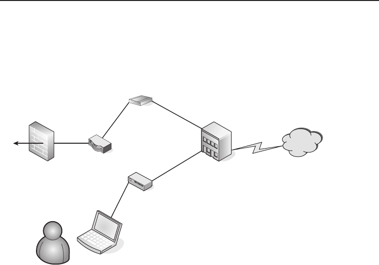
Edwards c13.tex V3 - 03/27/2009 11:37am Page 545
Chapter 13 ■Implementation 545
investigation, the company’s IT department settles on a fiber service from
the same telecommunications provider they have their ISDN service with.
Figure 13-10 illustrates the setup in preparation for the cutover from an ISDN
service to a fiber optic service from the same telecommunications provider.
Internet
IT Test Engineer
Fiber Optic
Interface
Telecommunications
Provider
ISDN Modem
Network Access
Router
Private
Internal
Network
Figure 13-10 Reworking network access
Plans are made to have the telecommunications company bring the fiber
cable to the premises of the company while leaving the ISDN service in
place. Usually the new service installation includes cabling and the fiber optic
interface to convert the fiber signal to Ethernet-compatible signals. Figure 13-10
illustrates that the telecommunications provider has performed its portion of
the upgrade of the service. However, instead of cutting over the service on the
same day it is delivered and set up, the IT staff wants to first test the reliability
of the service provided by the telecommunications provider.
The IT test engineer has connected a crossover cable between his laptop
and the Ethernet interface on the fiber optic interface unit. From his laptop, he
is able to run a series of tests to verify the operation of the link. He can run
burst tests20 to verify the data throughput of the circuit. Once the IT staff is
satisfied that the new access circuit is functioning as expected, they schedule a
maintenance window for the circuit cutover. For the scenario of just changing
over the service, the cutover is very fast because it only entails removing
the Ethernet cable from the network access router to the ISDN modem and
connecting it to the fiber optic interface unit.
20Burst testing is a method of testing the overall throughput of a network link. It generally refers
to the ability to generate enough network traffic to stress the link to its maximum bandwidth
capability.

Edwards c13.tex V3 - 03/27/2009 11:37am Page 546
546 Part III ■Network Design and Implementation
Consider a scenario where the company wants to have a redundant access
service to the telecommunications provider in case there is a failure of the fiber
optic access link. The plan is to keep the ISDN service as a dial-on-demand
service. The ISDN service will only attempt to connect to the telecommunica-
tions provider’s network if it receives traffic on its Ethernet interface. In this
type of upgrade, the network access router may have to be either upgraded
for an additional Ethernet interface or replaced with a new router. If the router
is being replaced, it could be connected to the fiber optic interface and the
IT test engineer could run his tests through the router and out over the fiber
optic link. The IT engineer can test the routing through the new network by
placing a network device on the interface that is to be used to connect the
ISDN modem. With the routing policy set as having the preferred route set to
the link with the fiber optic interface, a test can be made to see if the secondary
route to the ISDN modem takes over routing traffic when the link to the fiber
optic interface is disconnected. A secondary test would be to see if the routing
will revert back to the primary link with the fiber optic interface when the link
has been restored to operation.
RANDOM BONUS DEFINITION
cut-through — A mode of switch operation
where frames can be forwarded before they
are fully received.
After the operation of the
equipment and the new fiber
optic link have been tested, a
maintenance window should be
scheduled for the cutover to the
new link and network access
router configuration.
13.1.2.2 Upgrading a Network’s Core Routers
Changing over the central core routers of a network is a major undertaking. It
requires careful planning and implementation that are as thorough as if these
were the initial core routers for the network. The criticality of the situation is
that you are taking down a working network for an upgrade.
Planning should include designing the new core, documenting the new
installation, obtaining the equipment, installing the equipment and bringing
it up as a standalone core routing network, and testing it fully to ensure
operation before cutting over from the old routing core to the upgraded one.
The timetable for this type of upgrade depends on the complexity of the
routing core. The size of the core and the number of network nodes involved
will determine the amount of time required for the cutover.
Many times when there is a major change in the core routing network, a
company may decide to upgrade the entire network behind it. It may involve
not only network node devices but all new cabling as well. Many older
installations were wired with older Category 3 cabling. With a major upgrade,
the decision may be to upgrade the whole network, including wiring and
Ethernet jacks.

Edwards c13.tex V3 - 03/27/2009 11:37am Page 547
Chapter 13 ■Implementation 547
13.1.2.3 Upgrading the Network’s Distribution Components
ACRONYM ALERT
IPX — Internetwork Packet eXchange
The network distribution system can
include older cabling, Ethernet jacks, and
network node devices, such as Ethernet
switches and hubs. Usually the upgrade
of the network distribution components is
not a major impact on the current network
operations, as a new network distribution fabric21 can be installed in parallel.
This is same process that can be used for an expansion of the network
distribution system.
New cabling can be distributed into the areas where the network is either
to be expanded or upgraded. With the cabling in place, the Ethernet jacks can
be wired in place. Once all the cables are punched down22 on the patch panel,
each run can be tested using Ethernet cable testing tools. With new switches23
in place in the wiring closet, the patch cables can be placed between them
and the patch panel. New cabling, either wire or fiber optic, can be used to
terminate each switch back to the network operations area. It, too, will need
to be routed over the cable ways between the wiring closet and the network
backbone or routing core.
If this process is an upgrade and not a network expansion, it can be done in
parallel and users’ Ethernet jacks can be moved over to the new network if the
IP addressing scheme allows it. To have two parallel networks running and
move users from one network to another requires proper routing, as duplicate
network addresses would cause routing issues. Planning and documenting
the IP addressing scheme is essential to avoid those types of issues.
13.2 Network Supporting Infrastructure
RANDOM BONUS DEFINITION
StarLAN — A name for nodes using
1BASE5 Ethernet.
Infrastructure refers to the struc-
tural components within a facil-
ity in support of the network
architecture. Modern buildings
make provision for cable ways24
between floors and from one
21The term ‘‘fabric’’ usually refers to the threads of the network that are woven to allow network
nodes to be connected into the network. It is at times synonymous with the idea of a woven web,
especially when full redundancy is employed.
22The term ‘‘punched down’’ refers to the tool used to push the individual wires of the Ethernet
cable.
23Many times upgrades include new equipment. New switches can replace hubs or older,
less-capable switches. For this example, we are using new switches that have been placed in the
wiring closet of the area undergoing the network upgrade.
24Cablewaysisagenerictermusedtoindicatestructural devices connected to the walls, floors,
and ceiling of a facility to accommodate the orderly distribution of cabling. The amount of
cabling that will be supported by a particular cable way will determine its structural strength.

Edwards c13.tex V3 - 03/27/2009 11:37am Page 548
548 Part III ■Network Design and Implementation
end of a building to another. Cable ways can be seen passing through walls
and can be found above false ceilings. Wiring closets are in areas where there
are cable ducts to allow the routing of cabling between floors. A wiring closet
may have an overhead cable way that looks like a ladder. Cables are routed
over the cable way and can be dropped down between the rungs to various
areas in the wiring closet.
The network operations area is also part of the facility’s infrastructure.
Adequate space needs to be set aside for the area, as outlined in the initial
planning phase. Another consideration for the network operations area within
a facility is security on the physical level. Access to the network operations
area should be limited to IT staff to prevent inadvertent disruption of network
operation by people who are not responsible for keeping the network opera-
tional. This limited access should be not only in the networks operation area
but throughout the facility, including the wiring closets and other areas used
in support of the network, These areas should be secured behind locked doors.
Infrastructure planning is a process that needs to be done in cooperation
between the IT staff and the facility’s management team. It is not only about
floor space but also includes utilities such as electrical and the HVAC support
staff. Network planning and implementation requires the cooperation of many
departments along with the IT department.
13.3 Budgeting
Budgeting is an important part of the implementation phase. The company
must have the financial resources to pay for a new computer network or an
upgrade to an existing network. The initial planning phase perhaps does not
need to have the financial numbers up front when the initial plan is kicked off.
The initial plan takes a directive on what is needed and starts from there. The
IT staff can plan the network and list out the equipment required to complete
the task. From that they can get cost estimates to feed into the accounting
numbers to see if it is possible to fund the project. The idea is to have as
precise as a number as possible so that the budgeting is fairly accurate to
prevent coming in grossly over budget. Coming under budget is never an
issue; however, coming in over budget could cost someone his or her job.
ACRONYM ALERT
DRP — DECnet Routing Protocol
If the project is large and the burden on
the budget is excessive, then in cooperation
with financial personnel a new budget can
be devised to perform the new network
implementation in phases. This will spread
the load over several budget periods until
the full implementation can be completed.
This is related more for upgrades, because a company would not undertake the
design of a new facility and not budget for completion of the facility. The project

Edwards c13.tex V3 - 03/27/2009 11:37am Page 549
Chapter 13 ■Implementation 549
would not be started for a new facility if the company only had the resources
to build only the shell of a building. Companies plan new facilities to allow
employees to move in and be productive immediately after project completion
However, upgrading older networks in existing facilities can be done on
a piecemeal basis. This will allow for budgeting of the upgrade over several
accounting periods, thus easing the financial burden. It would take the follow-
ing considerations, in order: required infrastructure upgrades, improvement
of network access to the outside world, core routing on the backbone, and
lastly, the network distribution to the devices that are to be connected to
the network throughout the facility. Without an allocated budget a network
project is unfunded and possibly would only remain in the planning stage.
13.4 Staging
Staging is the period of time between the final planning phase and when the
project begins to get under way. The vendor bidding has been completed
during the planning stages and the purchase orders begin to flow out to obtain
the needed equipment, infrastructure upgrades, and other contracted network
services.
If upgrades are required for infrastructure improvements, they must be
completed before the project can move along. Having a set timetable and
attempting to stick to it allows for each phase of the overall project to meld
into the next phase. If one phase falls behind, the timing for the whole
project can be jeopardized. Some portions of the project can be worked in
parallel, but infrastructure improvement is not one of them (unless there are
separate areas requiring infrastructure improvement, which would allow
one area to be completed while another area is being upgraded). If an
area requiring infrastructure improvement has not been completed, no other
network upgrade activity can take place in that area until the infrastructure
improvement has been completed.
Most companies do not maintain construction crews for infrastructure
upgrades. These types of improvements are usually completed by subcon-
tractors working under the direction of the company’s facility management
personnel. Electrical wiring, data cabling, and improvements to HVAC in
most cases will be bid out to subcontractors. Contractors winning the bids
will need to be under signed contract and have their progress monitored to
ensure satisfactory completion of the project.
RANDOM BONUS DEFINITION
sniffer — Also known as a protocol
analyzer.
While the improvement of
the network’s infrastructure is
ongoing, equipment that has
been ordered will begin to
trickle in. It is best to unpack
each box and verify that the

Edwards c13.tex V3 - 03/27/2009 11:37am Page 550
550 Part III ■Network Design and Implementation
piece of equipment is exactly what has been ordered and is fully functional.
This may require powering the unit and testing it in some manner. The type
of device will dictate the type of testing that can be completed without it being
placed within a network. At the least, the unit should be able to link to another
network device. In many instances it is not likely that full functionality of
the device can be tested as part of a bench test. However, bench testing will
help eliminate DOA25 devices or devices that suffer an infant mortality.26 If
the piece of equipment is unable to be placed within its location, then it can
be reboxed and placed in storage until the location is clear for its installation.
Pre-testing the equipment will minimize the number of surprises you will
encounter. Once the network equipment has been received and the infrastruc-
ture improvements have been completed, it is time to move on to the next
implementation stage: rolling out the network upgrade.
13.5 Rollout
Rollouts are usually synonymous with network upgrades or expansions. They
do not apply to a completely new network in a brand new facility. Although
some of the stages are similar, no special considerations are required to work
around other company personnel with the possibility of causing network
outages, as there is with a network upgrade. With an upgrade of a network in
an older facility, where there are company personnel who can be affected, some
extra planning is required. Such planning should be performed in conjunction
with those who would to be affected to minimize the loss of productivity due
to the network upgrade. Much of the network upgrade can happen in the
background and in areas where other personnel are unaffected. However, in
the areas where personnel are affected, it is best to work out a maintenance
window to complete the work. If a work area has daily down time after a shift,
this work can be completed in the after-hours time periods.
ACRONYM ALERT
CoS — Class of service
If a whole network is to be upgraded,
the network access and core routing areas,
along with wiring closet and network
distribution equipment, can be upgraded
without interfering directly with company
personnel. Of course, cutovers of certain
network components can and will affect the whole facility, or at least large
portions of the network, but do not require the direct interaction with other
company personnel. For those types of cutovers, a maintenance window
25DOA is dead on arrival. Usually this means the unit did not power on when pulled from the
box or perhaps it failed its own self-diagnostic.
26Infant mortality is a morbid term and one we prefer not to use. However, it is prevalent in the
industry, used to describe a failure of a device shortly after it has been received and powered on.

Edwards c13.tex V3 - 03/27/2009 11:37am Page 551
Chapter 13 ■Implementation 551
should be scheduled to be as nonintrusive as possible. Proper notification
should be sent out to the whole facility or to those personnel who are to be
affected and who will be left without some or all network resources during
that period of time.
There are times when a rollout may not go smoothly and either has to
delayed and rescheduled or if started, may need to be rolled back due to some
impasse that was reached during the maintenance window. Therefore, not
only is a careful initial plan required for the rollout but also a contingency
plan with a ‘‘what-if’’27 clause to deal with all possible combination of events
that could occur while the rollout is going on. Plan for the worst-case scenario
and you will be covered. Remember, there are always alligators in the swamp,
so be prepared to drain the swamp before proceeding and the alligators will
have no place to hide.
13.6 Verification
Whatever can go wrong, will go wrong.
— Murphy’s Law28
Verification is a kind of nebulous state throughout any network implementa-
tion. It is the work done to eliminate as much of Murphy’s Law as possible
throughout the whole project. As carefully designed as a plan may be, there
is always a chance something can go wrong. However, with the proper
preparation, these events can be neutralized and dealt with quickly and
efficiently.
The verification process should start at the earliest stages of the project.
In the early planning stages, you should verify the concepts that are to
be implemented into the network design. You should also verify any new
products as far as suitability for use within the design. Many times vendors
of networking equipment and systems will provide loaners so that their
customers can verify a network concept. Part of the evaluation may be a ‘‘bake
off’’ between vendors to verify which manufacturer’s device or system offers
better performance and maintainability.29
27A ‘‘what-if’’ is a decision tree element in a flow chart. A rollout plan can be flowcharted to help
you see the possibilities that can occur while the rollout phase is ongoing.
28Sometimes attributed to Capt. Edward A. Murphy, Jr., an engineer working on the Air Force
MX981 project in 1949 who was testing how much deceleration a human can withstand in a
crash.
29Maintainability is the state of being able to maintain a piece of equipment while it is installed
within the network. Things that may be considered include whether the user interface is easy to
use and intuitive or if there are things like air filters that need to be replaced at a certain interval.
Other considerations include whether the device has built-in redundancy.

Edwards c13.tex V3 - 03/27/2009 11:37am Page 552
552 Part III ■Network Design and Implementation
RANDOM BONUS DEFINITION
protocol analyzer — Also known as a
sniffer, it can perform packet captures,
allowing the datagram to be analyzed. Some
of the information that can be seen with this
device are source and destination addresses,
encapsulation, protocol, and data payload,
as well if whether it is a whole packet or a
fragment of a larger packet.
Verification should be per-
formed on every aspect that
contributes to the overall suc-
cess of the project. Have the
improvements to the infra-
structure been completed and
done satisfactorily? Usually this
is accomplished with a visual
inspection and walkthrough
with the contractors who per-
formed the work.
In the budgeting phase, after a dollar amount has been approved, there is
verification that prices quoted in the planning phases are still valid and that
billing for received materials and services is correct and within the set budget.
Remember, under budget is good and over budget is bad. If price breaks have
been given due to a discount for quantity or a new pricing structure from a
vendor, then you are good to go. However, if a situation arises when the cost
of the project is going to increase, it is best to put on the brakes and verify why
there is a cost increase. You may need to get the financial powers-that-be to
buy into the cost increase before proceeding any further with the project.
ACRONYM ALERT
CAM — Content-addressable memory
With the design and budget verified, it
is time for the materials and services for
which purchase orders have been issued to
begin to flow in. We already took care of
the infrastructure, so the primary concern is
that the correct equipment is being received,
and if installation services also have been contracted, such as power and data
cabling, that the work is being performed on time and as expected. Equipment
should be logged in as it is received with the recording of dates, time,
model, and serial numbers. Many manufacturers provide warranties for their
equipment, but it is up to the customer to provide such information to receive
warranty service from them.
During the rollout, there needs to be continued verification of where equip-
ment is to be placed and interconnected with the remainder of the network.
It is critical that network addresses are programmed correctly and that the
equipment is placed in a subnet address it was planned to be placed in. Once
the equipment is in place, performance checks should be made to verify the
equipment’s operation within the network. Normally verification to the end
Ethernet jack in any network segment has been verified by the contractors who
performed the data cabling. However, verification for end-user performance
is normally performed by the IT staff, either in a proactive manner with a new
network rollout or in a passive manner.

Edwards c13.tex V3 - 03/27/2009 11:37am Page 553
Chapter 13 ■Implementation 553
NOTE A ‘‘proactive manner’’ is one where the IT staff actually asks the end user
if everything is working satisfactorily. This can include testing the end user
applications that require network interaction.
A ‘‘passive manner’’ is one in which the IT staff performs the rollout of the network
project and then sits back and waits for end-user complaints to find the problem
areas of the rollout. If there is insufficient staff to perform a full proactive
verification of the network, it behooves the IT staff to be selective with whom they
verify network operation in a more proactive manner.
RANDOM BONUS DEFINITION
root bridge — The STP bridge with the
numerically lowest bridge identifier.
There is constant verification
of the documentation every time
it is used or reviewed for any
reason. If there is something that
does not appear correct, mark
the document and verify if it is
correct and how it was intended
during the planning phase. It is not unusual for there to be minor changes
that need to be recorded as the network project implementation is being per-
formed. There may be changes in network addressing, configuration changes
performed on equipment, and equipment being replaced. Replacement of
pieces of equipment that have not failed is rare; however, there may be times
when the equipment does not have a capability that is now required within
the network. There needs to be a constant update of any changes within the
documentation as the project is going on in order to capture the true state of
the network in the event that it varies in any manner from the blueprint that
was laid out in the planning phases.
13.7 Documentation
ACRONYM ALERT
ASIC — Application-specific integrated circuit
There is nothing more exasperating to any
support person than when someone calls
seeking help with their network issue but
knows squat about it. Okay, perhaps we are
being a little harsh here, and you may have
inherited a bag of doo-doo from the person
who had previously held the position you currently hold, but that excuse still
sounds pretty lame to the support person on the other end of the support call.
The support person is more than willing to work with you, but please provide
them with something they can go on. Just because you have a support contract
with the vendor does not mean they know everything about how the device is
situated in your network.

Edwards c13.tex V3 - 03/27/2009 11:37am Page 554
554 Part III ■Network Design and Implementation
There are no excuses whatsoever for inadequate documentation if you were
present for the implementation of the network project. Unless the network is
very static and did not change, the documentation collected and assembled
during the various phases of the network implementation should be complete
and include all information necessary to support and maintain the network.
This would include any network security passwords used on any of the
network equipment requiring administrators to supply passwords to obtain
control over their operation. Configuration information for each piece of
equipment should be saved in both electronic and hard copy form so they
can be reviewed if and when it is necessary. Every piece of information that
describes your network’s layout and operation should be collected and kept for
safekeeping in an orderly manner so it can be easily retrieved when it is needed.
POP QUIZ
What are the five major phases of a
network’s implementation?
If you are a newly appointed
network administrator, your
first course of action when tak-
ing over the control network
operation is to review the docu-
mentation for the network and a
physical inventory of all devices
within the network. This is a
long and tedious task, but it is best to perform it while not under the gun
when the network is burning down. Systematically collecting and cataloging
the network you have been placed in charge of will give you a good under-
standing of your network and the tools to support and maintain it. If no layout
plan is available for the network as it currently stands, attempt to draw one
up, including the addressing schemes used. There is no substitute for good
and thorough documentation.
13.8 The Final Stretch
Avoid any action with an unacceptable outcome.
— George E. Nichols, Northrop Project Manager
RANDOM BONUS DEFINITION
single-mode fiber — An optical fiber that
allows signals in only one transmission
mode.
The preceding quote is so true.
Proper implementation of a
network requires care in plan-
ning through each phase of the
project. This means not only
planning for the obvious but the
unexpected as well. If all runs to
plan, there is no need for contingency plans. However, when stuff hits the fan

Edwards c13.tex V3 - 03/27/2009 11:37am Page 555
Chapter 13 ■Implementation 555
ACRONYM ALERT
AC — Access control
the absence of contingency plans does make
for a very unacceptable outcome. Short-
sightedness and attempting to take all the
shortcuts possible are actions that will ulti-
mately result in an unacceptable outcome.
With thoughtful and careful planning, a
major network implementation can be completed for both the targeted perfor-
mance and cost within the time period allocated for the project. Think of it as
making a fine stew. Plan out the ingredients, have all the ingredients on hand
and ready to go, stage the different cooking phases, and let it all simmer. When
you are done, you have an outcome that is rewarding and very satisfying.
AN UNRELATED MOMENT OF PAUSE —
MOTHER TURBYNE’S STEW
The thought of stew has me hankering to cook up a pot of some fine stew. It is
called Mother Turbyne’s Stew because the recipe was obtained from my former
cube mate, Jamie Turbyne. We shared some fine cuisine over the years from all
the fast food eateries available to us while working the second shift. The recipe
made its travels among the staff and everyone seems to like it. You can digress
from the recipe as presented here to suit your taste. It is also great to freeze up
single-sized portions that microwave well to make for a good and wholesome
meal on those late nights at work.
Ingredients:
◆2 bottles of Guinness beer
◆1 to 1 1/2 pounds of stew meat (beef)
◆1 medium sized onion
◆1 pound baby carrots
◆1 pound frozen peas
◆2 cloves of garlic
◆2 tablespoons of butter
◆Salt and pepper to taste
◆Water to bring the stew to a consistency that suits your palate
Preparation:
1. Peel and dice the onion.
2. Add the butter to a four-quart pot and melt over medium heat.
3. Add the diced onions. Cook until they appear translucent. (Do not brown
them.)
(continued)

Edwards c13.tex V3 - 03/27/2009 11:37am Page 556
556 Part III ■Network Design and Implementation
AN UNRELATED MOMENT OF PAUSE —
MOTHER TURBYNE’S STEW (continued)
4. When the onions are translucent, add the stew meat and brown thoroughly.
5. When meat has been browned, pour in the two bottles of Guinness
beer and let the meat and onion simmer in the beer for at least a
half hour to make the meat tender. While it is simmering, keep an
eye on the pot to make sure it is not rapidly boiling, causing the
pan to dry out. Add water if needed to keep the meat covered while
it is simmering. Stir from time to time to ensure even cooking.
6. Add the two cloves of garlic sliced into slivers and continue simmering the
mixture.
7. When you feel the meat is sufficiently tender, add the package of
baby carrots. Continue to simmer the mixture until carrots soften.
8. When carrots have become tender, add the package of frozen peas. The
peas can be kept frozen and added to the mixture while frozen. Allow the
stew to simmer for about another half hour. You do not want the peas to
get mushy.
9. When cooking has been completed, remove from heat and serve with some
hearty bread and butter. You have just served up a wonderful meal of
Mother Turbyne’s Stew.
13.9 Chapter Exercise
This exercise can be done as a class project or as a sole contributor project. If is
to be part of a class project, the class should be divided into teams consisting
of a project manager and a number of associates. It is the duty of the project
manager to divide the planning tasks and the implementation phases between
the associates.
The project consists of providing network services to a new facility built
next door to an adjacent older building that is to be razed for a parking garage
after the move to the new building has been completed. This facility will
house approximately 500 employees after the move. Business at this facility is
expected to grow by 50 percent in the next year, requiring the workforce to be
expanded by 20 percent. The long-term goal of the company is for the facility
to house 1,000 employees.
30Other brands of beer have been used successfully. Although there is a distinct difference in
taste when going to lighter beers, you are encouraged to experiment on your own. However, this
is only if you are of legal drinking age for your area. If not, just add beef broth.

Edwards c13.tex V3 - 03/27/2009 11:37am Page 557
Chapter 13 ■Implementation 557
Design a network implementation that will accomplish the immediate and
future needs of the company for communication, including both data and
other services, such as voice and video conferencing.
Draw out initial plans and some detailed plans showing network segmenta-
tion for security and traffic patterns. Detailed drawings may include network
addresses and the division of the network using subnets and routing between
areas. The entire local network is in the private network space, so pick a
designated private IP address space and work from there.
RANDOM BONUS DEFINITION
Q-compliant — A network node that
complies with IEEE 802.1Q.
If this book is being used in
an instructor-led course, the in-
structor can provide additional
information for the require-
ments he or she is looking for. It
is up to the instructor to select
the level of detail that is required
to submit the project on completion. In a class environment, if time is avail-
able, the teams can present their project to the class with their reason for the
implementation path they selected.
13.10 Pop Quiz Answer
What are the five major phases of a network’s implementation?
1. Planning
2. Budgeting
3. Staging
4. Rollout
5. Verification
Edwards c13.tex V3 - 03/27/2009 11:37am Page 558

Edwards p04.tex V3 - 03/27/2009 11:48am Page 559
Part
IV
Managing and Maintaining
the Network
In This Part
Chapter 14: Network Security
Chapter 15: Network Management
Chapter 16: Troubleshooting
Edwards p04.tex V3 - 03/27/2009 11:48am Page 560

Edwards c14.tex V3 - 03/27/2009 11:38am Page 561
CHAPTER
14
Network Security
Uncertainty is the only certainty there is, and knowing how to live with insecurity is
the only real security.
— John Allen Paulos
We’ve all heard the sensational stories of large databases being hacked and
people’s medical records, charge cards, banking account information, and other
sensitive data being compromised and released for anyone with an interest
in using that information for some unethical purpose. However, there are
breaches of network security that happen daily and may not make the news
outlets for all to hear. These are those little quiet events that happen to
individuals, listed under the heading of ‘‘identity theft.’’ With the Internet,
large amounts of data can be collected on any person. The insidious thing about
it is there is no warning that you are being tracked or spied upon. There is no
way for the individual under scrutiny to know that someone has an interest in
who they are and any other information about them that can be garnered from
searches on the Internet. With such information, an unscrupulous person can
set up a parallel identity and begin assuming that unsuspecting person’s life.
The stories that eventually come to light in a case of identity theft are when
the victims of such a crime have had their lives totally ruined.
Network threats are real and constant. It is unfortunate that so many
individuals seek to prey on innocent and trusting people, but it falls upon
those entrusted with that information to safeguard it as if it were their own
personal data. This chapter explores the various aspects of network security
and what it entails.
561

Edwards c14.tex V3 - 03/27/2009 11:38am Page 562
562 Part IV ■Managing and Maintaining the Network
14.1 Elements of Network Security
RANDOM BONUS DEFINITION
SANS (SysAdmin, Audit, Network,
Security) — SANS Institute is a research
and educational organization dedicated to
training and sharing information with
security professionals around the globe.
You cannot become complacent
that your network is secure.
It takes diligence to ensure that
the information entrusted to the
network, either stored on mass
mediaorasitisbeingtransmit-
ted over the network, is pro-
tected from any compromise.
Network security has become
a field unto itself, with profes-
sional organizations dedicated to maintaining data integrity and security
within the computer network environment. These organizations help develop
and set standards for the main elements of network security — policies, access
control, data integrity, monitoring, and assurance.
14.1.1 Network Security Policies
‘‘Policy’’ is a pretty broad term in the networking environment. For larger
organizations, it is imperative that these policies be written out and maintained
in a network usage and security handbook, which all those requiring network
access to the organization’s network should be aware of. The organization’s
size, structure, and type of information handled will determine how rigorous
and how vigorously applied these network policies are. Policies are usually
tailored to fit the needs and functions of the organization for network resource
usage.
Consider a simple example of possible network policies using a small family
model of Dad, Mom, #1 Son, and #2 Son. #1 Son is a college student who is
home only for weekends. His computer is a laptop that was purchased when
he entered college. #2 Son is a high school student and needs to be monitored
for computer usage, since he tends to let his homework slide. Mom and Dad
also want to make sure that their sons are not visiting questionable Internet
sites. Mom has a laptop to maintain her social organization’s information since
being elected its president. Dad is a businessman who has both a home office
computer and a laptop. The home network consists of both wireless and wired
Ethernet connections to a router connected to the Internet. Figure 14-1 shows
a topological diagram of the family’s network.
At a family meeting, policies were developed to control network access,
monitor content, and ensure data integrity. It was unanimously agreed that
each computer will have virus protection software loaded, virus definition
files will be maintained on a timely basis, and each computer will be scanned
for viruses on a regular basis.
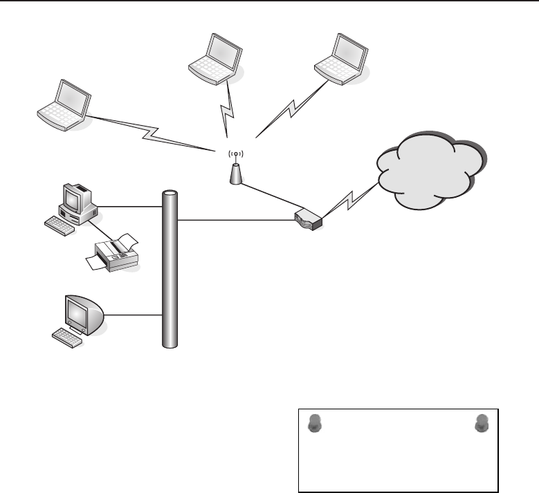
Edwards c14.tex V3 - 03/27/2009 11:38am Page 563
Chapter 14 ■Network Security 563
Hard-Wired
Ethernet Cabling Internet Router
Internet
Wireless
Access Point
Mom #1Son
Dad
Home Office
Computer
Family Room
Computer
Figure 14-1 A family’s network
ACRONYM ALERT
SRF — Specifically routed frame
Computer access for Dad, Mom, and #1
Son is totally unrestricted. #2 Son has been
relegated to using the family room com-
puter, which only has access granted to
connect to the Internet from 8 am to 9 pm.
At all other times, it can connect to the local
network and use the local resources of the network, such as the shared printer
connected to the desktop computer located in Dad’s home office. In addition to
an Administrator profile, each laptop has a user profile that allows the owner
to log on and use the computer either locally or on the home network. The
desktop computer in Dad’s home office has user profiles for Administrator,
Dad, and Mom, with no guest account. The desktop computer in the family
room has a user profile for Administrator, Dad, Mom, #1 Son, #2 Son, Local
User, and Guest. Dad delegated himself as the network Administrator for all
of the household computers.
Basically, overall network control and security was set during the family
meeting. Dad had already taken care of some of the more obvious sites he
preferred that the boys not visit, but also notified them he would be monitoring
their access. #2 Son’s Internet connectivity would be controlled and monitored
by Mom. She will keep an eye on #2 Son to make sure he does his homework
prior to any recreational Internet usage. The family room desktop’s Internet
access is accomplished by allowing access for that computer’s IP address

Edwards c14.tex V3 - 03/27/2009 11:38am Page 564
564 Part IV ■Managing and Maintaining the Network
within the time between 8 am and 9 pm. #2 Son’s computer access is controlled
by changing his password every day. He is granted a new password on
completion of his homework. The Guest user profile password is kept secret
by Mom and Dad and will be given to a guest only as necessary. The Local
User password is known by all the members of the family, but it only allows
use of the local network for access to shared resources on the network, such as
the printer. The Local User profile has no Internet access rights.
ACRONYM ALERT
SRF — Source routed frame
ThereasonfortheAdministratoruser
profile on each computer is to permit a cen-
tralized entity to control every computer’s
configuration and access privileges to the
network. The centralized network entity
can enforce network policies on each com-
puter and user. In this example, Dad is the single entity. In a larger organization,
however, there may be a single department given that responsibility, withmore
than one staff member tasked to perform the enforcement of the organization’s
network usage and access policies. The larger the organization, the greater the
need to formalize and document every policy to avoid confusion and to have
uniformity across the organization’s network infrastructure.
In larger corporate networks, network policies can be enforced by ‘‘push-
ing’’1policies down to the computers as they log on to the network. Computers
in a corporate environment are usually standardized with as few variations as
possible to aid in the supportability of the company’s user computer base. It
is easier to cookie cutter2computer systems than to tailor each one individu-
ally. Usually there is an initial software suite of corporate applications that is
installed by the IT staff. Depending on the organization and how they enforce
their computer and network usage policies, the users of these computers may
not be allowed to load additional software without prior authorization. Orga-
nizations frown on the loading of rogue3software, so if employees require
additional software applications beyond the organization’s standard software
suite, they must seek prior approval.
In our family example, network access is controlled by the computer’s user
password. All members of the family except #2 Son have control over their
own passwords. The homework is #2 Son’s token to gain network access for
Internet usage. If he needs local access to write reports or print homework,
1There is no real pushing involved. Network administrators like to use terms that give a sense
of direction and control. The idea of pushing is having an application run on a computer that
is automatically spawned each time a user logs on to a network. The application connects with
a policy server, which sends the updated policies to the computer. In reality, this is two-way
communication, so ‘‘pushing’’ is merely a euphuism for the ability to enforce policies remotely
on a computer.
2Cookie cutter is a term used by computer and network administrators to illustrate that it is much
easier to replicate the same thing over and over again.
3The term rogue software refers to unauthorized software.

Edwards c14.tex V3 - 03/27/2009 11:38am Page 565
Chapter 14 ■Network Security 565
he can do so by logging on to the shared computer in the family room under
the Local User ID and its password. If #2 Son attempts unauthorized Internet
access, he will not be granted Internet access for a week.
ACRONYM ALERT
SAP — Service access point and Service
Advertisement Protocol
Dad is both the network and computer
administrator for the family and has the
ability to program the Internet router to
block certain objectionable sites. He had
already added objectionable sites to the
block access list within the router and has
the ability to monitor the sites that are being
visited. Periodically, Dad logs on to the router and peruses the accessed site
log, looking for URL names that may be for sites with objectionable content.
This logging provides Dad a means of monitoring access to the network as
well as the address of the computer that is making the connection. From this
information Dad can determine if any of the household members are violating
the computer and network usage policies.
POP QUIZ
Think about your own personal computer
network. Do you have any policies in place?
Evaluate your current network and find
where you think you may need to set up
some sort of policy. Think about your place
of employment. Do they have a computer
network, and if so, do they have policies for
its usage? If they have policies, are they
adequate in your estimation? Do you see a
need for additional policies? If so, list them
and why you think these policies are
needed.
Because all the laptops use
wireless NIC cards for network
connectivity, Dad has added
aWEP
4key to the wireless
router and on the wireless NIC
card configuration for each lap-
top computer. This is basically
a software configuration that
identifies a user’s laptop to the
wireless component of the Inter-
net router by the use of a
shared key. The WEP key, Inter-
net router password, and the
Administrator passwords are
only known to Dad. The only
time he would relinquish a pass-
word to Mom is when there is a network issue and he is not available to perform
the task requiring the password. On Dad’s return, he will change the pass-
word in order to maintain a restriction to the network’s resources by using
a password revision control. If there is a need to document passwords, this
must be safeguarded under lock and key to prevent inadvertent compromise
of the network resources protected by these passwords.
4WEP is an acronym for Wired Equivalent Privacy. This is used by the wireless components
within the network for authentication using a shared key. It is used to prevent unintended use
of the network.

Edwards c14.tex V3 - 03/27/2009 11:38am Page 566
566 Part IV ■Managing and Maintaining the Network
RANDOM BONUS DEFINITION
antivirus (AV) software — A computer
application that scans computer systems to
detect and eliminate computer viruses.
This simple example illus-
trates what network security
policies entail. They contain
every aspect of a network’s
configuration and maintenance.
They also control user access
and usage, as well as the con-
tent users are allowed to access. Companies with a large number of users may
have a generic user policy that covers the more general terms of computer
use and network access. However, there may be further policies that depend
on locale, right to know, job function, and other variables designated by the
company.
14.1.2 Network Access Control
RANDOM BONUS DEFINITION
unified threat management (UTM) — A
device operating on Layers 2 through 7 that
is capable of providing firewall protection
as well as filtering content.
Network access control is
another wide area of concern.
The first thought that most peo-
ple would come up with when
asked ‘‘What is network access
control?’’ is that it’s the use of
passwords. But it goes beyond
that. When we discuss control-
ling network access, we are also
concerned with the ability of anyone who is unauthorized to have access
to any network elements — and this includes physical as well as intellectual
information — to alter a network’s operation or performance. This means
restricting access to where network components may be vulnerable to tamper-
ing. It means the security of a facility in its entirety, including the portions of
the premises that contain the network components.
14.1.2.1 Network Premises Access Security
There are various ways of securing an organization’s premises. They depend
on the scope and need of the network to be protected. If a network operation
center occupies an entire building, the entire building must be secured to
prevent either unintentional or a direct intended act to compromise the
network. Since most network breaches are performed by an insider, access
to network elements should only be permitted on an as-needed basis. For the
most part, restricted access means closed and locked doors, with only those
who need access given the right of passage into that network strategic area.
All areas of the network require protection. This is especially true where
networking equipment is placed in areas that are mostly unmanned, such

Edwards c14.tex V3 - 03/27/2009 11:38am Page 567
Chapter 14 ■Network Security 567
as wiring closets and central network distribution points. It is very easy for
someone to sit in a wiring closet with a network analyzer and capture traffic
from a particular user and lift passwords and other sensitive information. For
this reason alone, these areas should be kept under lock and key.
Using actual locks and keys can be cumbersome, but if that is the only
means, then it needs to be accomplished until another alternative method
to secure the area is realized. If it is feasible, areas should be secured with
a combination badge reader and lock release mechanism. This allows for
the greatest flexibility while having a means of logging who has entered a
restricted area, as well as the time and date they entered. This information can
be used if there is ever an investigation of a network event in that particular
area. If your organization is unable to have these types of logging and locking
devices and the restricted area is under simple lock and key, there needs to be
a person in charge of giving out a key while logging in a ledger who borrowed
the key, the date and time periods the key was on loan, along with the reason
why access was granted.
Network operations should be in an area with restricted access at all times.
The only people allowed in that area unescorted are the staff members tasked
with the network operation. A badge key system is ideal for securing the area
as well as logging who was present at any particular time of the day if the
need for that information is ever required. If the network operations area is
not a 24/7 facility, the area needs to be secured and monitored during off-shift
hours. Monitoring can usually be accomplished as part of the overall security
guard activity that goes on after hours.
Most of the security measures are to keep employees not working in the
network operations area from tampering with network resources. The intent
can be innocent or malicious, but it does not matter which — damage to net-
work elements can have an impact on the ability of a company to do business.
It is better to err on the side of being overly cautious or perhaps a bit paranoid.
POP QUIZ
While you are at work or at school where
there is a network infrastructure, note how
their areas are controlled as far as control of
access. Do you notice any deficiencies? Do
you see areas for improvement? Would you
change how the network premises access
security is performed?
Network access premises
security is not strictly a func-
tion of the IT/network oper-
ations staff. It partly falls
under the facility’s manage-
ment and maintenance, since
they are in charge of the build-
ing, and the security depart-
ment, which monitors company
assets. The IT/network opera-
tions staff may oversee the over-
all network security, but safe-
guarding the network and all its elements requires cooperation and assistance
from these other departments.

Edwards c14.tex V3 - 03/27/2009 11:38am Page 568
568 Part IV ■Managing and Maintaining the Network
Although this section is primarily concerned with the physical aspects
of the network premises, there needs to be attention on the information
maintained within the network operations area. Computer networks can
be easily compromised if someone is allowed into sensitive network areas.
However, information about the network could point someone with malicious
intent toward the areas they are interested in and assist them in targeting
those areas. Network diagrams with network addressing should be kept
securely and under document control to prevent copies from being taken to
plan an attack on the network. Any shared passwords should also be kept
under lock and key. A locked file cabinet goes a long way toward preventing
easy access to the network.
14.1.2.2 Network Access Security and Control
In the earlier example of the family network, network access was primarily
controlled by knowing the password to gain access using a user profile.
For home and small offices, this type of network authentication may suffice.
However, in large networks with a wide range of network services and
resources, there is a need to restrict some users to only portions of the
network that are required by their function. There is the possibility of multiple
authentication services within the same organization. There may be servers
within the network that do not rely on network authentication and request a
user ID and password from users when they try to gain access to that server.
Figure 14-2 illustrates a small network with an authentication server.
When network users turn on their computers, they are presented with a
login dialog window. This login process is twofold. It identifies a user as
a particular user with a set user profile for that computer. It also authorizes
a user to use the network authentication server for use of the network and
the resources connected to it. The services available to the user, after being
authenticated that he or she possesses the proper credentials for this network,
are print services5and access to the Internet.
All network users in the organization have access to e-mail. The e-mail
server requires them to log in to their account with a user ID and password.
Some users as part of their job function within the organization have access
to the application database server, which also requires a user ID/password
combination. Keeping separate accounts with separate passwords for each
service that requires a login is cumbersome at best. However, there are
5Print service is a general term to express the use of print servers to output print jobs to a bank of
network-enabled printers. A print server is a combination queuing/spooling device that stores
(buffers) a print job and directs it to a printer designated by the user. Generally, print jobs are
serviced in a FIFO (first in, first out) manner. The print server notifies the user on the progress of
the print job, displaying error messages if there are any problems with the selected printer.
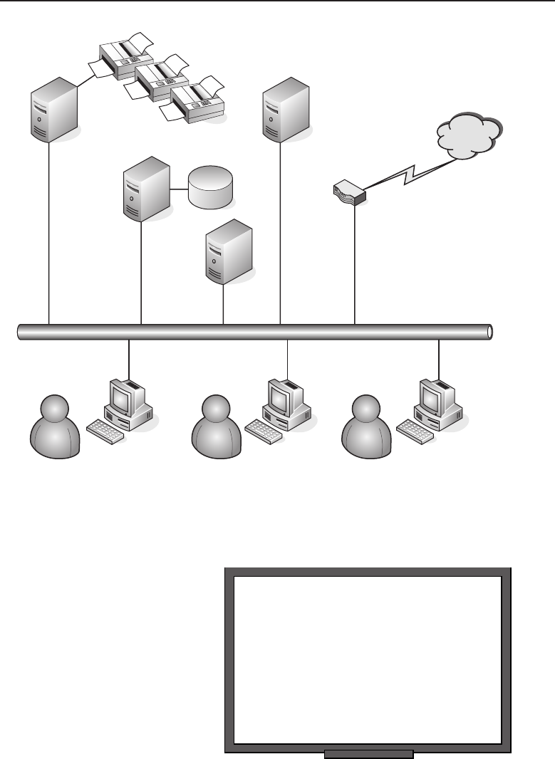
Edwards c14.tex V3 - 03/27/2009 11:38am Page 569
Chapter 14 ■Network Security 569
Print Server
Mail Server
Internet Access
Router
Internet
Network Users
Network
Authentication
Server
Application
Database
Server
Figure 14-2 A small network with an authentication server
RANDOM BONUS DEFINITION
network access server (NAS) — A gateway
device that protects access to a protected
network resource. An additional definition
of NAS is network attached storage,
network-enabled mass storage devices (e.g.,
hard disks) either singularly or in arrays,
that provide increased data reliability
through redundancy.
network authentication services
that synchronize user pass-
words with each service they are
permitted to use on the network.
If access privileges need to be
tailored for each separate user, it
would become a logistical night-
mare to maintain for a network
administrator. So a hierarchical
approach is used to determine
the privileges a user is allowed.
Figure 14-3 illustrates a possible
hierarchical map.
In this figure, users assigned to particular tasks within the organization are
placed in groups, with those groups having set privileges for access to certain
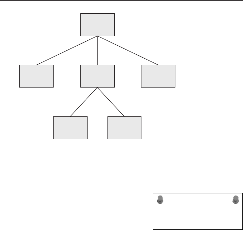
Edwards c14.tex V3 - 03/27/2009 11:38am Page 570
570 Part IV ■Managing and Maintaining the Network
Organization
Accounting
Accounts
Payable/
Receivable
Payroll
ShippingSales
Figure 14-3 A hierarchical authentication schema
network resources. Under the organization umbrella, all users have access to
e-mail and print services over the network. However, differentiation between
users begins at the group level, where tasks differ for each user.
ACRONYM ALERT
RSVP — Resource reSerVation Protocol
In this example, the group level has been
divided into Sales, Accounting, and Ship-
ping, each with separate functions and par-
ticular informational needs, although they
all work in the same organization. The Sales
group needs to be able to enter sales and
track the progress of orders. The Accounting group is responsible for checking
customer credit to permit the continuation of the order process and approve
orders to be shipped. The Shipping department processes orders, and when
shipped, notes that the orders are completed so that Accounting can process
the billing. Although all these groups interact on a particular transaction,
they each have separate functions. These functions may be broken out into
a particular group of permissions a user has to perform that particular func-
tion. The functional separation provides checks and balances throughout the
transaction cycle for a particular transaction. It provides accountability for
each department and does not allow any one particular user the capability to
force a transaction through without assistance from other users in a different
department.
In this example of the group hierarchical schema, there are two subgroups
within the Accounting group: Payroll and Accounts Payable/Receivable. The
reason for this is that payroll is a very important function within any particular

Edwards c14.tex V3 - 03/27/2009 11:38am Page 571
Chapter 14 ■Network Security 571
organization, and the data handled by that group is confidential and requires
more security than other functions within the Accounting department.
RANDOM BONUS DEFINITION
hacker — A person who has evaded
network security with the intention of
modifying computer software, hardware
configuration, and other security measures
to either damage their effective operation or
compromise them to the point where data
theft can be accomplished without the
offenders being detected.
It is evident from this
example that using the hierar-
chical approach of groups and
users not only organizes users
by job function, but also aids
in network security by permit-
ting only the services required
for each user by their group
association. If network permis-
sions need to be changed, they
can be performed at the appro-
priate group level to enforce
that change on all users who
are members of that particular group. Further details of network authentication
methods will be discussed later in this chapter.
14.1.2.3 Restricting Network Access
Restricting network access for unauthorized users can go a long way toward
preventing both theft of services and malicious intent. Malicious intent can fall
under a number of different categories. The basic elements include hacking
into a network with the intent of making it unusable, altering data to one’s
advantage, or stealing information to get a competitive edge over an organi-
zation. The threat of a network attack is not just from outside but often from
within. It is not within the scope of this book to go into the psychological
implications or fathom the reasons why a member of an organization would
use the network to commit crimes against the organization, but it does happen
and not all that infrequently.
Recalling the use of a hierarchical schema to give permissions on a network,
a network can be segmented to isolate critical areas and prevent access by those
who are unauthorized to use those services. This goes beyond authentication
and actually will restrict network access based on network address and type
of service being requested. An example of this is illustrated in Figure 14-4.
ACRONYM ALERT
OSI — Open Systems Interconnection
In this example, the organization has an
intranet web server to allow all members
of the organization to view information
about the organization and the products it
offers. To prevent unauthorized changes to
this important content, it has been decided
to isolate the administration of this server on a network segment of its own.
Even though a user ID and password are required to log on to the server
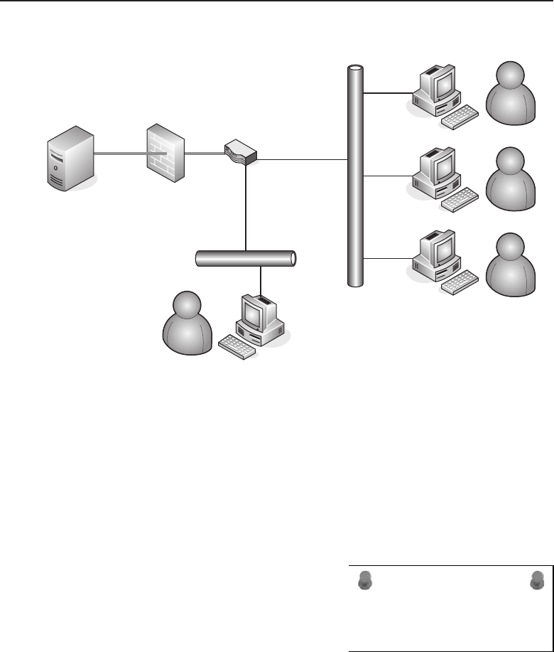
Edwards c14.tex V3 - 03/27/2009 11:38am Page 572
572 Part IV ■Managing and Maintaining the Network
192.168.1.0
Network
Router
Internal
Firewall
192.168.99.0
Network
Intranet
Web Administrator
Organization’s
General User Base
Intranet
Web Server
Figure 14-4 Restricting internal network access
for administration purposes, it was thought that extra measures were needed
if ever the user ID and password information got into the hands of an
unauthorized user. Although it is not illustrated in this figure, the web server
is in a secured location where only authorized personnel are allowed. If an
unauthorized user is able to gain access to the server room and knows the user
IDandpasswordfortheserver,heorshewouldbeabletoaccessthe
administration applications on the web server and alter their contents.
ACRONYM ALERT
VPID — VLAN protocol identifier
A firewall is placed in the path from the
intranet web server to analyze the network
traffic that is being directed toward it. All
users are permitted HTTP port 80 access
through the firewall. As long as the traf-
fic is intended for port 80, it will not be
restricted. However, if the traffic is requesting a different service from that
which is allowed, then those network packets will be discarded6by the firewall
and never forwarded on to the intranet web server. Notice that the network
segments are different for the web administrator and the rest of the organiza-
tion’s user base. For the web server administrator, a policy has been added in
6‘‘Discarded’’ is more appropriate than ‘‘dropped’’ when referring to data packets that are not
forwarded on by a network-forwarding device. ‘‘Dropped’’ implies an action, when none is
really taken.

Edwards c14.tex V3 - 03/27/2009 11:38am Page 573
Chapter 14 ■Network Security 573
the firewall to permit any traffic from that safeguarded network to be passed
through to the web server. The operative word here is ‘‘safeguarded,’’ which
implies the web administrator is able to secure not only his or her user ID
and password for the web server, but also to prevent unauthorized access to
his or her network connection by locking the office when he or she leaves for
the day. This prevents access even if his or her user ID and password have
been compromised. All precautions are required when it comes to restricting
unauthorized network use.
14.1.3 Network Data Integrity
Throughout this book, emphasis has been placed on the ability to pass data
over the network without error. So what is network data integrity? It is
the guarantee that data sent to an intended network node arrives without
alternation. The other part is that if the data being sent is of a sensitive nature,
it needs to be safeguarded and not ‘‘eavesdropped’’ upon as it traverses over
the network.
One method, as previously mentioned, is to secure the premises and not
allow unauthorized personnel into areas where the network could be easily
snooped. The other method is to safeguard data with encryption. Encryption
encodes the data being transmitted over the network in such a manner that
only the two endpoints of the network connection are able to decrypt the
data. This was initially performed by sharing a known key7between the two
endpoints, which was used to encrypt the data that was sent and decrypt the
received data to make it readable. Figure 14-5 illustrates an example of sharing
a key between two endpoint network nodes.
Rob and Jack want to share sensitive information over the network. The
network can include the Internet and any other portions of network, whether
public or private. To accomplish this, they decide to encrypt the data before
sending it over the network. They settle on an application that allows them to
use a shared key between them. This is secure only if they are the only two
people who know what the key contains. However, they should not send the
key over the same network link. If Rob and Jack are unable to meet privately
and the key needs to be carried over a public network, they need to be cautious
not to give the people who may be snooping their communications the key
along with the encrypted document. It would be better for them to mail the
key through the post office than to e-mail it. Or they could simply call each
other to pass along the key. The only caveat is that with the convergence of
voice and data on the organization’s network, if the phone service is one and
the same as the data network, then there is no security for Rob calling Jack
7A shared key is a string of ASCII characters used to encrypt and decrypt data. The key must be
known by the entities on both ends of the network connection.
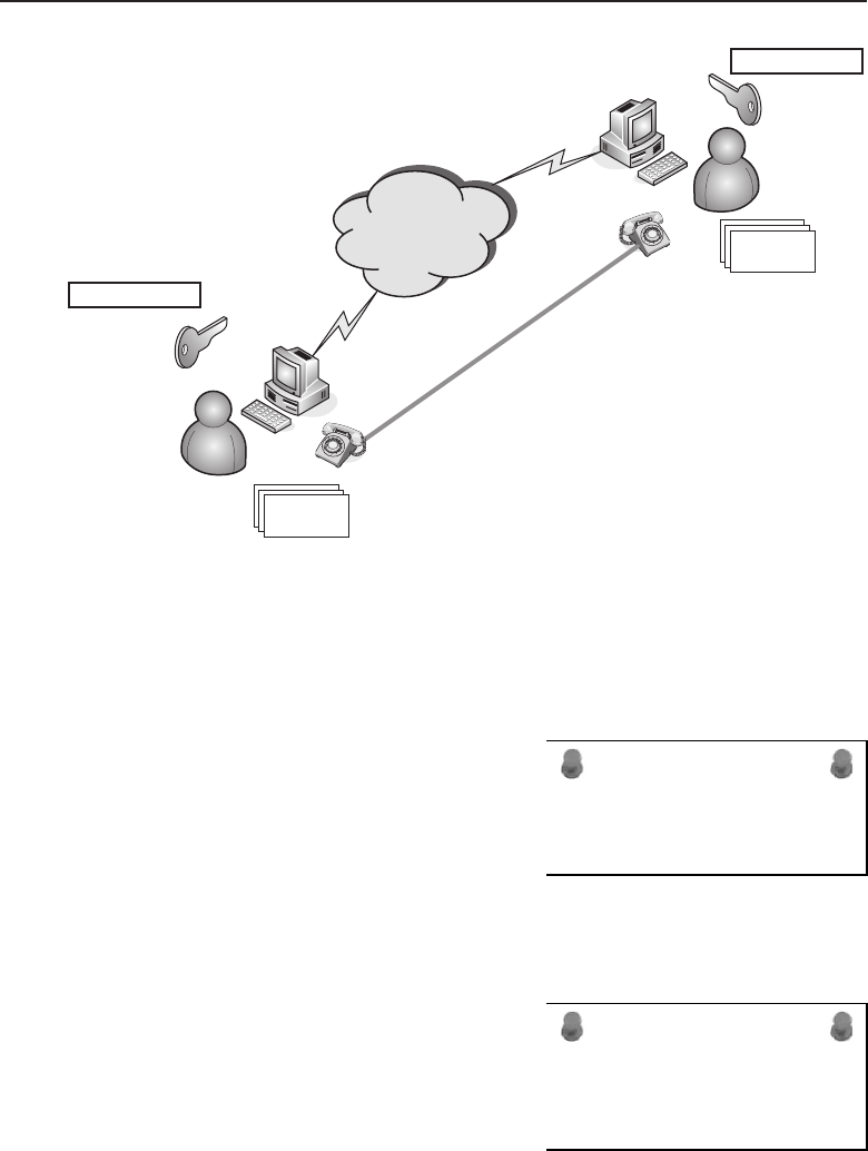
Edwards c14.tex V3 - 03/27/2009 11:38am Page 574
574 Part IV ■Managing and Maintaining the Network
Sensitive Data
Sensitive Data
Rob
AX192Bc99aF23
AX192Bc99aF23
Shared Key
Shared Key
Jack
Figure 14-5 Endpoint-to-endpoint encryption using a shared key
over that link to pass along the key. Or Rob and Jack could meet at a bar and
pass the key on the back of a cocktail napkin, like a 1940s spy movie.
ACRONYM ALERT
MSTP — Multiple Spanning Tree Protocol
The advent of VPN technology has
removed some of the melodramatic antics
about passing a shared key. A VPN can
create a virtual data tunnel over a net-
work between endpoints that are secured
with encryption while data is being passed
between them. The primary reason VPN technology evolved was to use
the Internet as a point-to-point carrier for two remote locations. Figure 14-6
illustrates the connection of two networks over a network cloud.
ACRONYM ALERT
SNMPv2 — Simple Network Management Protocol
version 2
In this example, the network cloud can be
an internal network, the Internet, or a com-
bination of both, depending on where the
VPN routers are placed in the network.
The VPN routers establish an encrypted
tunnel between them with the use of a pre-
shared key and a private key that is known only to the endpoint it belongs to.
When the tunnel is established between the two VPN routers, the keys are used
to encrypt the data entering the tunnel and decrypt the data as it exits the tunnel.
The data is safe between the two VPN routers because of the heavy encryption,
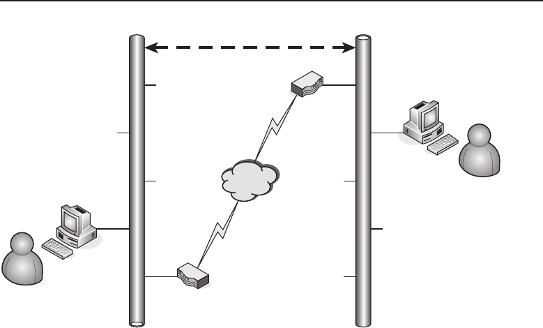
Edwards c14.tex V3 - 03/27/2009 11:38am Page 575
Chapter 14 ■Network Security 575
VPN Router
VPN Router
Larry
Frank
Network A Network B
VPN Tunnel
Figure 14-6 A VPN tunnel connecting two networks
but there is still vulnerability once the data has been decrypted and is traveling
over the private network.
14.1.4 Network Security Monitoring
Depending on the size of the network, constantly monitoring every node can
be overwhelming. However, continuous checking is possible with random
checks of certain key areas. The first red flag that should go up is if any of the
server logs shows a larger than normal amount of authentication failures. This
could be a good clue that someone is attempting to hack into the network. Rest
assured that if authorized users forget their password, they will not wait too
long before calling the network operations help desk.
Most network administrators generally permit only a single login per user.
If a user who has only a single login account tells the help desk that the
network authentication server is saying they already have an active session,
it is recommended to investigate the reason why before ever increasing a
user’s account to allow them to have more than one simultaneous active user
session. There is a possibility that their user ID and password may have been
compromised and another unauthorized user is using their account to gain
access to the network.
Administrators should review login data on all servers. They should review
the logins to the network authentication server to look for any unusual
logins — for instance, if a daytime user is seen to be logging into the network
late at night when they have never done so in the past. This can indicate the

Edwards c14.tex V3 - 03/27/2009 11:38am Page 576
576 Part IV ■Managing and Maintaining the Network
possibility that a user ID and password have been compromised and that
an unauthorized user is gaining access to the network using that account.
Unusual activity even by an authorized user may indicate they are attempting
to use the network for covert activity.
Calls to the network operations center can also be an indicator that the
network is under attack. Of course, there is a possibility that an actual
hardware failure may have caused the issue. However, those are usually
total outages of portions of the network. Calls such as slow performance or
sluggish response from some application servers need to be investigated not
as a possible hardware issue but as possible unauthorized network usage.
It could be a deliberate act by an individual, or it could be inadvertent and
caused by a user receiving a virus on their computer. In any case, a network
analyzer should monitor the network traffic on the affected network segments.
ACRONYM ALERT
NetBIOS — Network Basic Input/Output System
Look for what appears to be heavy net-
work traffic flow and determine if it is from
asinglesourceorthewholesegment.Itis
possible that a virus has infected multiple
computers on a particular segment. There
is a possibility that there is a hardware
cause, such as a chattering8NIC. You may need to take a divide-and-conquer
approach, where you isolate the offending network segment until you can
isolate the source of the issue. Sudden changes in performance without any
configuration changes on a network could be an indicator of component
failure, but usually the issue is not hardware-related. Never ignore users’
complaints about network slowness unless you already know the cause. If
not, the matter needs to be investigated as quickly as possible to avoid a more
catastrophic network event.
14.1.5 Network Security Assurance
A large network needs to be monitored closely on a daily basis. However,
assurance is more than investigating issues when they occur. Assurance is a
recurring, proactive activity that is accomplished at fixed intervals. The size
of the organization’s network will determine how often a review of the entire
network needs to be done. In the case of multiple installations in various
locales, a network security audit can be completed on a rotating basis between
the different network areas.
Assuring the network from a security perspective requires full documen-
tation as the network currently exists. The documentation should include
8Chattering is a term used to express that a network card is broadcasting when it should not
be. It is constantly beaconing and causing unnecessary traffic flow on the network segment it is
connected to.

Edwards c14.tex V3 - 03/27/2009 11:38am Page 577
Chapter 14 ■Network Security 577
network diagrams with network address schemes and the physical locations
of the equipment and cabling being used. Any deviation from what has been
documented as part of the network needs to be investigated. As noted earlier,
many if not most network security breaches are caused by personnel employed
by the company.
A network assurance security audit should entail the following:
A list of equipment located in the network segment under audit.
A network topology diagram showing the network addressing scheme.
A password list for network servers in the segment.
Ensure that all user IDs are active.
Ensure that unauthorized users are not on the list.
Verify that staff members who have left the company are not on the
list.
Server access logs.
Look for suspicious and repetitive logins.
Examine what appear to be frequent or out of the ordinary login
times.
Look for repeated login denials. Are there user IDs that suggest
an unauthorized person is trying various user ID combinations?
Are these coming from a particular network address?
Traffic patterns on the network segment under audit.
Look for what appears to be unusual traffic flow. Is this traffic legiti-
mate? If so, it may indicate the need to redesign portions of the net-
work segment.
14.2 Network Security Methodologies
POP QUIZ
How often should a network administrator
think about their network’s security? Give a
reason for your selection.
There are various methods for
ensuring authorized users are
permitted access to only those
resources they need to perform
their function within the orga-
nization. This section reviews
some of the most widely used
authorization methods for net-
work access. The primary authentication methods discussed are Lightweight
Directory Access Protocol (LDAP), Remote Authentication Dial-In User Service
(RADIUS), and certificates.

Edwards c14.tex V3 - 03/27/2009 11:38am Page 578
578 Part IV ■Managing and Maintaining the Network
RANDOM BONUS DEFINITION
managed security service provider
(MSSP) — An ISP that provides additional
network security management, which may
include virus scanning, intrusion detection,
and firewall capabilities.
Network protection requires
more than just access control;
it also includes data integrity.
Data traveling to the trusted por-
tions of the network, whether
from internal or external sources,
can be protected using encryp-
tion.9The use of data encryp-
tion provides the capability for
secured tunneling for the creation of virtual private networks (VPNs). The
tunnel is created between network nodes that can encode and decode the data
that is passed between them.
14.2.1 Authentication
The process of network authentication can be as simple as a user ID10 and
password. However, even with that, users can be restricted by their group
association to certain locations or resources within the network. It is the
responsibility of the client to properly identify itself to the authentication
servers on the network.
14.2.1.1 Lightweight Directory Access Protocol
The use of LDAP emerged from the X.500 directory service. It has gained in
popularity as a means of authenticating users for a wide range of network
services. It is the model being used for directory services on the Internet. X.500
is the International Standards Organization (ISO) and International Telecom-
munications Union (ITU) standard that defines how global directories are to
be structured. LDAP is used by many suppliers of software for their directory
services strategy and has widespread acceptability among the network user
base. The standard uses a hierarchical directory structure that is parsed on
different levels of categorized information. The customary information used
for these categories are elements such as country, state, city, and other locale
information.
LDAP uses an Internet identity schema that defines common attributes to
define the objects contained within it. Many levels of an LDAP can be defined,
and authenticating users depends on the granularity required by the net-
work site.
9Encryption is using cryptographic means of using ‘‘crypto’’ keys to encode the data so it is not
easily readable by anyone that does not have possession of the key.
10User ID (identification) is synonymous with username or the prompt that is displayed on some
systems as ‘‘username.’’

Edwards c14.tex V3 - 03/27/2009 11:38am Page 579
Chapter 14 ■Network Security 579
The most common used elements in LDAP are:
Users
Groups
Filters
Services
ACRONYM ALERT
LAT — Local area transport
An LDAP directory service is based on
a collection of attributes used to define a
distinguished name (DN). The intended use
of a DN is to define an entry without any
ambiguity so that each entry is unique. The
entry is defined by a series of attributes,
which are commonly mnemonic strings, such as cn for common name, mail
for an e-mail address, etc.
Being a hierarchical, tree-like structure, an LDAP directory’s entries are
arranged to reflect boundaries that are categorized by geographical, political,
or organizational descriptions. An example of this tree-like structure would be
starting at the top with the largest entity as country followed by each subgroup
(e.g., country/state/organization/department/user).
LDAP uses a special attribute called objectclass to control the required
attributes to define an LDAP entry. The objectclass defines the schema rules
used for interrogating, maintaining, and updating the LDAP. The primary
function of an LDAP server is to respond to service requests for an inquiry
by searching the contents of its directory. Since for the most part LDAP
data is stored in cleartext,11 an LDAP server requires the client requesting
service to authenticate itself prior to responding to the request for information.
Usually the authentication scheme used between an LDAP client and an LDAP
server is Password Authentication Protocol (PAP) or Challenge Handshake
Authentication Protocol (CHAP). PAP is a point-to-point protocol that uses
a simple username and password sent over the network in cleartext for the
authentication of an LDAP client requesting LDAP services from the LDAP
server. To increase security between an LDAP client and an LDAP server,
CHAP can be used. CHAP is also a point-to-point protocol that uses a
three-way handshake to validate the identity of the remote client. Both client
and server use a hashing algorithm using a shared secret to ensure the validity
of the connection. CHAP has security advantages that are more desirable than
what PAP offers. However, both client and server must be capable of using
that protocol.
Figure 14-7 illustrates a model used between an LDAP client and server.
11Cleartext is text that is clearly readableand is not encrypted. These files can be usually examined
with any text editor.
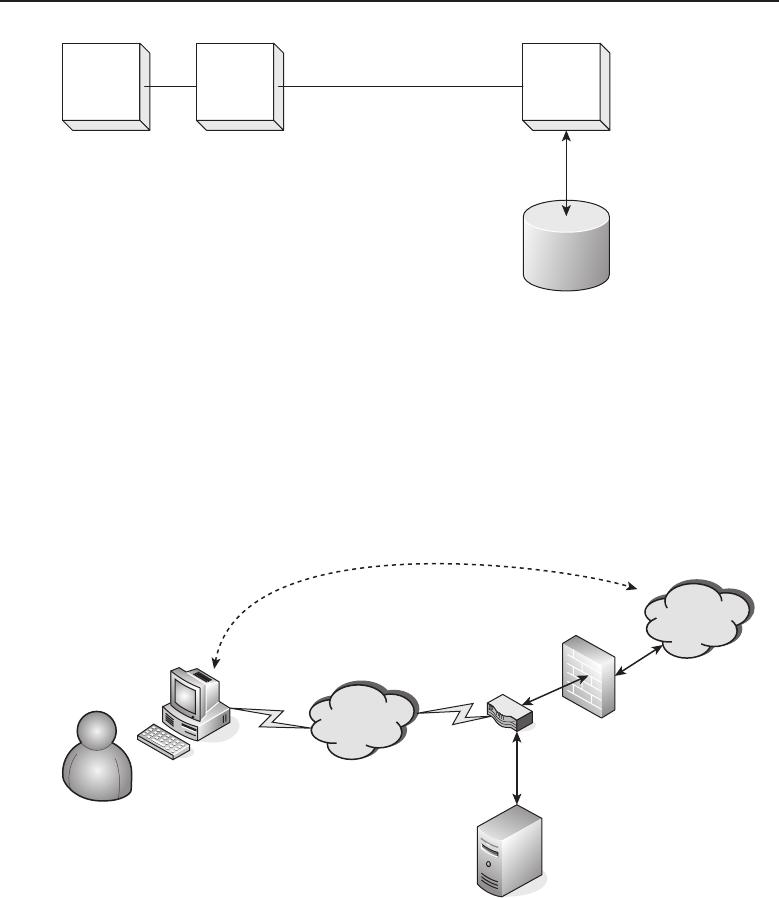
Edwards c14.tex V3 - 03/27/2009 11:38am Page 580
580 Part IV ■Managing and Maintaining the Network
Client LDAP API LDAP
Server
TCP/IP Data Link
Directory
Figure 14-7 An LDAP model
The client can be any device that needs to authenticate users to permit the
use of services over a network. The client loads an LDAP application program
interface (API) allowing it to open a TCP/IP socket with the LDAP server.
Once the server authenticates the client, it permits it to access its directory. A
real-world scenario may be similar to what is illustrated in Figure 14-8.
Client Computer
Internet Access
Gateway
Server Running
LDAP Services
User
Organization’s
Network Cloud
Authenticated
Connection
Figure 14-8 User authentication using LDAP
In this figure, a user is attempting to gain access to the organizational
network of which he is a member. When the user became a member of the orga-
nization, the IT staff responsible for maintaining the LDAP server entered the
information regarding this particular user. The information can contain some
or all of the following, depending on the schema that is in use: username, full
name, department, e-mail address, and filters used to determine access privi-
leges. The user initiates a connection to the device acting as the access gateway.
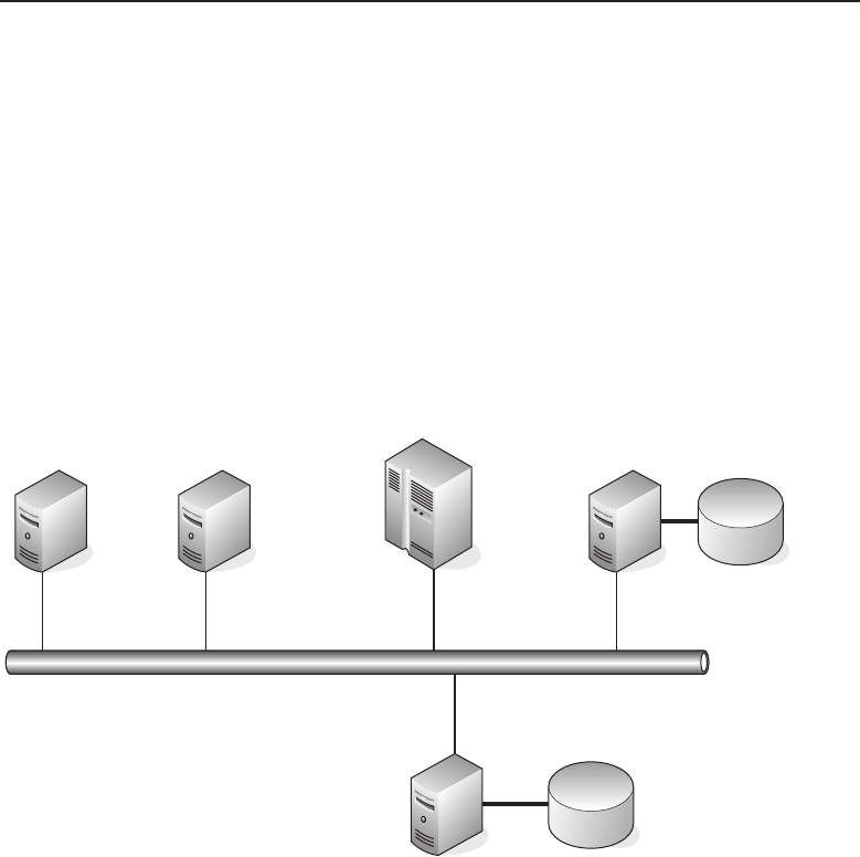
Edwards c14.tex V3 - 03/27/2009 11:38am Page 581
Chapter 14 ■Network Security 581
Upon receipt of the initial contact, the user is required to enter his or her cre-
dentials for access. The access gateway device acting as an LDAP client sends
the request to the LDAP server it is connected to over the local network. If
the access credentials match the database, a response is returned granting
access as well as the level of rights that this user is to have on the network.
On establishment of the authenticated connection, the remote user is virtually
on the organization’s network. This illustration is just showing LDAP being
used for remote access, but in reality it also can be used for internal services
on the network. Multiple servers can have the capability to use the common
LDAP database for authentication to the particular services they offer on the
network, as shown in Figure 14-9.
Accounting
Server
Organization’s Network
LDAP
Server
LDAP
Directory
Mail
Server
Mainframe
Server Database
Server
Figure 14-9 An LDAP server servicing multiple clients
As illustrated, there are a number of servers on the network, each of which
requires authentication of a user in order to use the services provided by
that server. Many servers offer some sort of authentication scheme, but if
each server had its own user database, administrators of those servers would
be busy ensuring that a particular user has rights to use that server and the
level of permissions they are to have on that server. The commonality of
having a single LDAP server performing the authentication function service
for the network does alleviate the headache of maintaining so many servers.
However, the caveat is that with a single LDAP server, there is a single point
of failure if that server should go down. Depending on the number of users a
site may have, it may be prudent to have an alternative authentication method.
One scheme would be to have redundant LDAP servers that synchronize their

Edwards c14.tex V3 - 03/27/2009 11:38am Page 582
582 Part IV ■Managing and Maintaining the Network
databases to ensure that user credentials on both LDAP servers are current.
If the primary LDAP server were to go down or become unavailable for
any reason, the devices requiring LDAP services would switch to the backup
LDAP server.
ACRONYM ALERT
GVRP — GARP VLAN Registration Protocol
On a smaller network or perhaps due to
cost restraints, a redundant LDAP server is
not possible. A possible workaround can be
accomplished using the internal authenti-
cation services of the servers themselves to
act as a backup to the LDAP server. This
does require additional work on the part of the server administrators, but if
needed it can be used if the external LDAP server experiences a failure. The
configuration that would be used is to program the servers to first search the
external LDAP for authentication requests and if no response is received from
that LDAP server to then search the internal authentication database. Using
this method takes more effort to maintain, but it would allow the network
users to still gain authorized access to the network.
Figure 14-10 illustrates the flow between the LDAP request and the infor-
mation returned.
As illustrated, the LDAP client opens a connection over TCP/IP to the LDAP
server. After the client is identified and authorized by the LDAP server, the
client is bound to the LDAP server and submits an LDAP query. The server
continues to return data to the client until the client’s query has been satisfied.
Upon completion of the query, the LDAP client unbinds from the LDAP server
and the TCP/IP connection is closed, indicating the completion of the LDAP
transaction.
The following are the basic responses an LDAP client can receive:
Authenticated
Denied
Timeout
RANDOM BONUS DEFINITION
firewall — A function using hardware,
software, or a combination of the two to
detect and prevent unauthorized access to a
network.
When a user is authenticated,
the LDAP server returns infor-
mation about the user, such as
group membership, to the client
that is requesting the informa-
tion. Another valid response
is that the user is not in the
LDAP directory. In the event
that a client receives no re-
sponse, a timeout condition is reached and the LDAP client has two options
available: to seek another means of authentication or to deny the user access. A
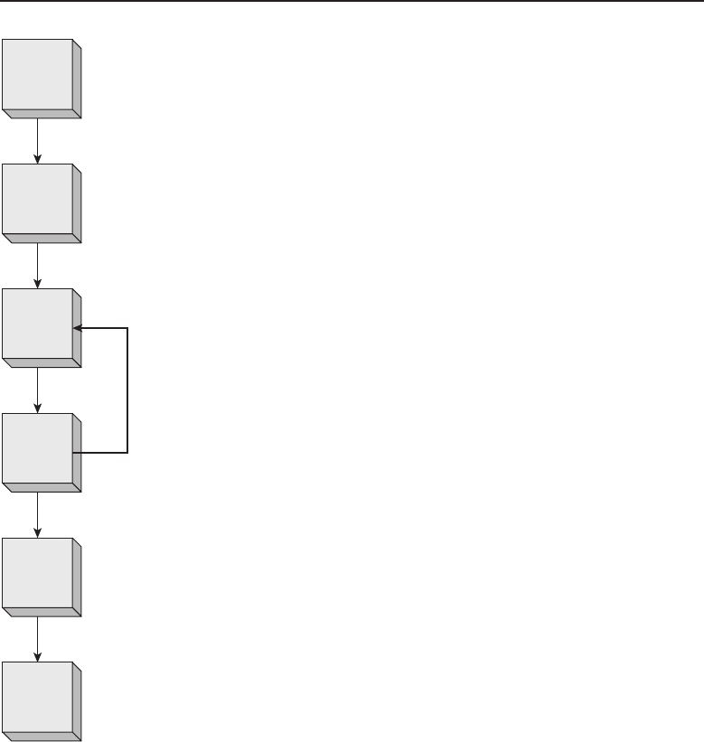
Edwards c14.tex V3 - 03/27/2009 11:38am Page 583
Chapter 14 ■Network Security 583
Open
Connection
Bind
Send
Request
Data
Returned
Unbind
Close
Connection
Figure 14-10 The flow of an LDAP request
timeout condition can be reached for many reasons, such as network conges-
tion, a busy server, or simply that the LDAP service on the server has been shut
down. This is the primary reason for having multiple authentication servers
available. Some larger organizations go as far as having redundant sites that
are interconnected but located geographically distant from each other. Redun-
dancy schemes depend on the size of an organization, but no matter how
small the organization, an administrator needs to consider the alternatives
in order to have high availability of the network and its resources for the
user base.

Edwards c14.tex V3 - 03/27/2009 11:38am Page 584
584 Part IV ■Managing and Maintaining the Network
14.2.1.2 RADIUS
Like LDAP, RADIUS performs user authentication but also has an accounting
component (a RADIUS accounting server) associated with it. Initially, RADIUS
authentication and accounting was used by telecommunications companies to
authorize subscribers to the network services being offered and as a means
of tracking usage for billing purposes.12 However, RADIUS is not just used
by older ‘‘legacy’’ network systems. It has found wide usage in the industry
primarily for authentication purposes, although there are organizations that
sell information on their online databases based on the amount of time a
user remains connected to their service. These organizations use both the
authentication and accounting components of a RADIUS server. Interestingly,
RADIUS servers or their derivative will remain in use by telecommunications
companies for a while to come. They are being used in the cell phone industry
to authenticate your calls as well as to keep track of your minutes.
As with an external LDAP server, a RADIUS server provides a centralized
user administration service. A RADIUS server can provide authentication
services for multiple network devices. These network devices have a RADIUS
client embedded within them that can be configured to establish a secure
connection with a RADIUS server. The client and server use a shared secret to
hash the user password that is being passed from the client to the server. This
protects the identity of the user; however, the connection between the client
and server is not as secure. The initial connection between the RADIUS
client and server is established using either PAP or CHAP, which is less secure
since the password being passed between client and server is in cleartext.
When a RADIUS client passes a user’s authentication credentials to the
RADIUS server, the server will respond with one of the following responses:
Access Reject — The user is denied access to all network
resources. Reasons may be invalid credentials, no account
on the server, or an account that has been deactivated.
Access Challenge — The user needs to provide additional information.
Information requested may be a secondary password, PIN, or token.
Access Accept — The user is granted access.
Once a user is granted access, the RADIUS server returns attributes that
have been determined by the information in the user’s record contained in the
RADIUS server’s database.
12In today’s high-bandwidth, constantly connected network world, billing is primarily a monthly
flat fee charge dependent upon the type of service that is being subscribed to. But some of us long
in the tooth and gray haired guys remember the days of dialup services on 300 baud modems,
which were painfully slow and billed by usage. The service type was billed in an increment of
hours, such as 25 hours per month, with additional charges for each minute over, which could get
pretty expensive. So, yes, the ability to tie accounting to network access was extremely important
for those whose revenue was dependent upon it.

Edwards c14.tex V3 - 03/27/2009 11:38am Page 585
Chapter 14 ■Network Security 585
The user attributes that can be returned are as follows:
Assigned user IP address — A statically assigned address may be given
to a particular user.13
Assigned IP address pool for the user — A dynamically assigned
address from the address pool this user is assigned to.
Maximum connection time — For connections that are limited
by the amount of time they can remain connected.14
Service level — These may be in the form of permissions or restrictions
on the user’s ability to use particular resources on the network.
RANDOM BONUS DEFINITION
disaster recovery (DR) — A plan to
maintain or restore network services after a
catastrophic event.
RADIUS authentication and
accounting not only has wide-
spread use among legacy sys-
tems, but it can also be found
in many installations requiring
centralized administration for
authentication and accounting
purposes. This makes RADIUS
the current de facto standard for authentication systems.
14.2.1.3 Certificates
Digitally signed certificates came into use as a security method of ensuring
that the two parties on either end of a connection are who they claim to be.
This is to prevent unauthorized (spoofing) users from gaining access to
a server pretending to be someone else. This is especially important with
the establishment of e-commerce over the Internet. The process binds a user’s
identity to a publicly encrypted signed key that has been verified and validated
by a trusted third-party called a certification authority (CA). The CA registers
the certificate, ensuring that the certificate and the relationship between it
and the individual user are accurate. Figure 14-11 illustrates the relationship
between a user, server, and CA.
13Particular care is required to avoid duplication when statically assigning user IP addresses.
Duplicate addresses on a network can wreak havoc and can be difficult to diagnose unless you
get lucky and guess that there may be two different devices responding to requests on a par-
ticular IP address. Document well when using statically assigned IP addresses.
14Many broadband connections don’t use a maximum connection time attribute. How-
ever, for services offered by a server, there may be a limited amount of resources, and
the number of connections being serviced is a determining factor of the quality of ser-
vice the server is able to provide. In these instances, this attribute can be used to force
log off users that are hanging on the services for long periods of time. The length of time
is purely dependent upon the installation site and its operating mode. Many installa-
tions allow a maximum of a 24-hour period before a user is given a forced log off.
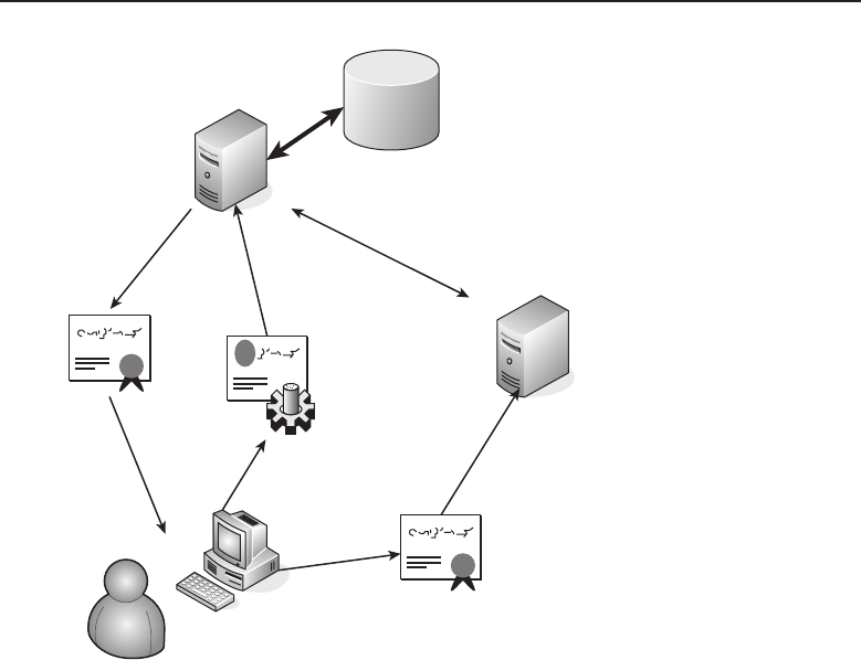
Edwards c14.tex V3 - 03/27/2009 11:38am Page 586
586 Part IV ■Managing and Maintaining the Network
Certificate
Storage
Certification Authority
(CA)
Authorized User
Server Providing
Services to Authorized
Users
Figure 14-11 The certificate relationship
A user is required to have a signed certificate to gain access to a server over
the Internet. The user provides credentials to a CA, which confirms the user’s
identity and provides the user with a signed certificate. The user then presents
the certificate to the server they want to gain access to. Because the certificate is
from a trusted CA, the server permits access to the user. The server providing
the service can confirm the validity of the certificate by communicating directly
with the CA.
The CA is responsible not just for signing certificates to validate a user’s
identity, but also for administering the certificates it issues. The CA needs to
provide storage for issued certificates to provide maintenance of the certifi-
cate’s validity. If for any reason a certificate has been invalidated, the server
must also maintain a certificate revocation list (CRL). The CRL is used to pre-
vent users with invalid credentials from gaining access to a server. Certificates
are usually issued with an expiration date, and this too can be a reason for a
certificate to be placed on the CRL. Certificate time periods are usually for
a number of years, which is set by the certificate issuer.
Certificates are heavily used in web-based applications. Most web browsers
can use HTTPS (Hypertext Transfer Protocol Secure). This uses the Secure
Socket Layer (SSL), which resides between the HTTP layer and the TCP

Edwards c14.tex V3 - 03/27/2009 11:38am Page 587
Chapter 14 ■Network Security 587
layer. The user/client creates a secure socket connection to a website/server,
taking advantage of public and private key encryption with the use of a
digital certificate. SSL has been recently superseded by TLS (Transport Layer
Security). TLS 1.2 is defined by RFC 5246, ‘‘The Transport Layer Security (TLS)
Protocol Version 1.2.’’
TLS is a client/server-based protocol that establishes a stateful connec-
tion using a handshake procedure. The handshake is used to negotiate and
establish the network security that is used between the client and the server.
This handshake interaction is initiated when a client requests a connection
to a TLS-enabled server. The client informs the server which ciphers and
hash functions it supports. The server then selects the strongest cipher and
hash function it supports, and sends a response to the client. In its response,
the server returns a digital certificate that verifies its identity, which usually
contains its server name, the name of the trusted CA, and its public encryp-
tion key.
POP QUIZ
Open your browser and examine the
certificates in its certificate store. Open a
certificate and examine its contents. Note in
particular creation and expiration dates.
Note the intended uses for this certificate.
Does the certificate store contain all the
certificates you expected or many more?
Can you think of a reason why that is?
Note that each browser program may have
different ways of displaying the certificate
store. An example of this is Apple’s Safari
browser, where you select Edit Pref-
erences Advanced, and then click the
Change Settings button for Proxies. Click
the Content tab and then in the Certificates
section, click the Certificates button to view
the certificate store. There are a number of
tabs to select the various types of cer-
tificates.
Upon receipt of the server’s
digital certificate, the client con-
tacts the trusted CA to verify the
certificate’s validity before pro-
ceeding any further. If the client
is satisfied with the server’s cer-
tificate’s authenticity, it gener-
ates a random number, which it
encrypts with the server’s public
key, and forwards the encrypted
value to the server. The server is
the only entity that can decrypt
this encrypted number from the
client using its private key. The
random number is used by both
client and server to develop keys
to encrypt and decrypt the data
that is passed between them.
With the completion of the
handshake, the secure connec-
tion is established and the gen-
erated keys are used to encrypt and decrypt the data being passed, until the
connection is terminated.
If for any reason any part of the handshake process fails, the connection will
not be created. The client must attempt to initiate a new handshake sequence
when making further attempts to create a secure connection to that particular
server.
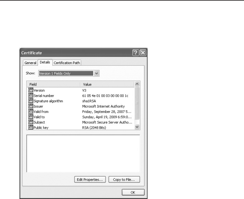
Edwards c14.tex V3 - 03/27/2009 11:38am Page 588
588 Part IV ■Managing and Maintaining the Network
All browsers have a certificate store associated with them. Usually this can
be found under the options for a browser application. An example screen is
illustrated in Figure 14-12.
Figure 14-12 A browser’s certificate store
14.2.2 Data Integrity
The Internet has provided many positive things. It has spawned whole new
businesses with what is called e-commerce. It has allowed people to take
communications to new levels. But the flip side is that the hyper-connected
world, where information about anything and anyone can be found, has
brought out those who have found illicit uses for that information to prey
upon unsuspecting users.
The previous section discussed SSL and TLS using certificates to provide
proof of identification for authentication. They can also provide an encrypted
connection to pass data safely between a user (client) and a server that are
directly connected to each other. But what about a remote user who requires
services located on the company’s intranet? SSL/TLS are client/server-based,
which means a connection is established between a user and a particular
server. If a user requires many different services on a network, they need
to establish a secured connection with each server providing that service.
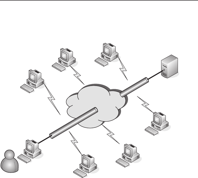
Edwards c14.tex V3 - 03/27/2009 11:38am Page 589
Chapter 14 ■Network Security 589
Tunneling protocols have been developed to allow remote users to work
as though they were directly connected to a local network. A conceptual
illustration is shown in Figure 14-13.
Hackers
Eavesdroppers
Figure 14-13 The tunneling concept
As shown in this figure, a connection between a user and a particular network
or server can be under attack not only over the Internet but locally as well.
However, if a connection can be tunneled through that hostile environment,
the conversation is protected from eavesdroppers or hackers trying to steal
a user’s identity for later use in an attack on that network or server. With
the development of tunneling protocols such as PPTP, L2TP, and IPSec, the
concept of the VPN was spawned.
The basic concept of a VPN is that the local network is secure. Earlier in
this chapter, we discussed local network security and why it is needed. If the
premise is that the endpoint networks are secure, the only way to ensure total
network security is to secure the link between the locally secured networks.
Tunneling protocols allow organizations with separate, geographically distant
networks to connect these local private networks using the Internet as the
conduit. Figure 14-14 illustrates this concept.
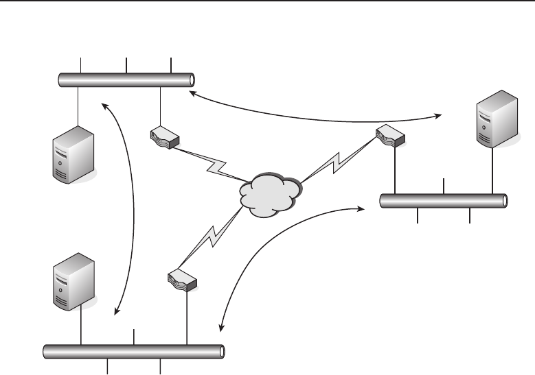
Edwards c14.tex V3 - 03/27/2009 11:38am Page 590
590 Part IV ■Managing and Maintaining the Network
192.168.1.X
Network
192.168.3.X
Network
192.168.2.X
Network
2.2.2.2
1.1.1.1
3.3.3.3
A
B
C
Figure 14-14 The use of the Internet for VPN
This figure shows three private networks: 192.168.1.X, 192.168.2.X, and
192.168.3.X. These are 24-bit mask networks.15 Each network is connected to
the Internet with a VPN-enabled router. The routers require two separate
tunnels for each of the two locations they are to be connected to. Although the
routers have only one physical connection to the Internet, they are capable
of having multiple virtual tunnel connections, as needed. The VPN-enabled
router knows the networks that it’s connected to, including both the physical
connections and the virtual connections.
In this illustration, assume that these routers have only two interfaces:
one on the public network (Internet) and the other on the private network
(192.168.X.X). Network A’s router knows its private network is 192.168.1.0,
15This is for those who either did not read the earlier chapters or may need a refresher. A subnet
mask is made up of four octets having the values of 255, 252, 248, 240, 224, 192, 128, and 0.
We will leave it as an exercise for the reader to figure out how we came up with just those
numbers and nothing else in between. A 24-bit mask has the first three octets filled, so it would
be 255.255.255.0 in decimal dot notation. If 0 is the network address and 255 is the broadcast
address for the network, then a 24-bit mask network can have 254 distinct addresses from 1 to
254. If more addresses are needed, it is time to either do some creative subnetting or add routers
with additional subnets. Both work and have their respective advantages and disadvantages. If
you do not know the differences, it is time for a review of the earlier chapters.

Edwards c14.tex V3 - 03/27/2009 11:38am Page 591
Chapter 14 ■Network Security 591
so any packets it receives for this network would be passed into the network
and directed to the device that responds to the ARP16 for that particular IP
address. For addresses located on either the 192.168.2.0 or 192.168.3.0 network,
the VPN-enabled router knows it must use one of its virtual tunnel routes.
In order to route network traffic over the Internet, actual addresses that are
routable over the network need to be used. This illustration is using private IP
space addresses, which are not routed, so how does a packet with a destination
that is in the private IP address space get routed? This is where encapsulation
comes in. The source and destination addresses are the actual physical public
addresses of the VPN-enabled routers. So, if a network node on network A
wants to send network traffic to network C, the packet is encapsulated within
the tunneling protocol and the destination address is set to 3.3.3.3 with a source
address of 1.1.1.1. Although these are not the actual addresses of the physical
devices that are sending and receiving the data, the VPN-enabled router on
the sending node knows that it must encapsulate these addresses, and the
receiving VPN-enabled router knows that it must de-encapsulate the packet
to ensure its delivery over the private network the router is connected to.
RANDOM BONUS DEFINITION
ISDN (integrated services digital
network) — A telecommunications
standard used for the transmission of voice,
data, and video using digital
telecommunications over ordinary
telephone lines.
Using encapsulation com-
bined with strong encryption
can safeguard and maintain
data integrity even while pass-
ing the traffic through a hos-
tile environment. If packets
are intercepted, the information
they contain will not be easily
decrypted and thus will not be
compromised. Tunneling does
not necessarily travel over the
Internet, although that is where it is used most frequently. VPN tunnels can
be used within an organization’s intranet, as well.
14.2.2.1 Point-to-Point Tunneling Protocol
The Point-to-Point Tunneling Protocol (PPTP) does not provide safeguarding
of data or perform encryption upon the data it carries. If encryption is required,
PPTP depends on the protocol of the data that is being tunneled. PPTP is a
peer-to-peer PPP session with generic routing encapsulation (GRE). For the
GRE session to be initiated and maintained, a second session is required on
TCP port 1723. Due to the need for a second session, PPTP is difficult to pass
through a firewall since it uses two separate sessions for tunnel creation.
16Once again, if you are having a problem with this you better go back for a review. Like, what
is Address Resolution Protocol? We ain’t telling — you tell us.

Edwards c14.tex V3 - 03/27/2009 11:38am Page 592
592 Part IV ■Managing and Maintaining the Network
The popularity of PPTP, even with its issues with security and its inability
to be passed through firewalls, is due to the fact that it was the first tunneling
protocol supported in Microsoft’s Dialup Networking, initially released with
Microsoft’s Windows 95 operating system. Authentication to initiate a PPTP
tunnel is performed using MS-CHAP or EAP-TLS,17 which require the use
of client certificates. Using a weak password with MS-CHAP is a security
risk due to the possibility of the password becoming compromised. EAP-TLS
adds further security but requires that clients provide a certificate. Microsoft
supports both client and server EAP-TLS implementations in its Windows
operating system. The progression path from PPTP VPN tunneling is usually
to L2TP or IPSec.
14.2.2.2 Layer 2 Tunneling Protocol
Similar to PPTP, L2TP does not encrypt the data carried within the packet,
but depends on the protocol being carried within it to provide encryption and
maintain data confidentiality. Although L2TP behaves as a Data Link layer
protocol (Layer 2 of the OSI model), it is in reality a Session layer protocol
(Layer 5) using UDP port 1701. The entire L2TP packet, including header and
data, is transmitted within a UDP datagram.
Because L2TP lacks the capability to maintain confidentiality, it is often
deployed with an implementation using IPSec, referred to as L2TP/IPSec.
L2TP/IPSec negotiates with the IPSec Security Association (ISA) through
Internet Key Exchange (IKE). This is accomplished over UDP port 500 using
preshared keys, public keys, or certificates for both endpoints of the tunnel.
Because L2TP is encapsulated, there is no need to open port 1701 on any
firewalls that may be in the path between the endpoints creating the tunnel.
The L2TP packet is totally encrypted within the IPSec packet and allows for
the secure transport from endpoint to endpoint. In this implementation, IPSec
provides for a secure channel within which L2TP can tunnel safely.
14.2.2.3 Internet Protocol Security
IPSec is really a suite of protocols for securing Internet communications,
utilizing authentication and encryption within each packet of the data stream
between two network nodes. Each endpoint of an IPSec connection negotiates
the type of authentication to be used at the start of a session and the form
of encryption to be used while the session is maintained. IPSec resides at the
Internet layer of the TCP/IP model, which is comparable to the OSI Layer 3
Network layer. Upper level applications above these layers can be protected
easily within IPSec, since there is no special design consideration required for
its use.
17EAP-TLS is Extensible Authentication Protocol–Transport Layer Security
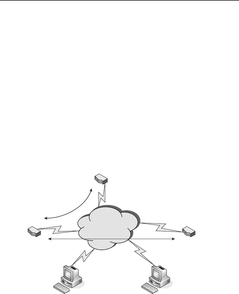
Edwards c14.tex V3 - 03/27/2009 11:38am Page 593
Chapter 14 ■Network Security 593
IPSec has been embedded into network edge devices such as VPN-enabled
routers. Two of these devices can be configured to establish a secure tunnel
between them, passing traffic from one protected private network to another.
A tunnel of this type is normally referred to as a peer-to-peer tunnel since
each endpoint of the tunnel is aware of the other endpoint’s IP address. In
instances where one endpoint is unable to have a static endpoint address,
there is a method for tunnel establishment that is referred to as aggressive
mode tunneling. This is similar to a client connection but allows for the passing
of traffic for network addresses that have been defined within the tunnel
definition of its security association (SA). At least one endpoint must have a
static public address. It is not possible for both ends to be unknown since the
IP address is used to provide part of the security for tunnel establishment. The
dynamically assigned IP address endpoint knows the peer it is connecting
to. The statically assigned IP address endpoint depends on authentication
schemes to verify the identity of the aggressive mode peer requesting the
connection. Because the dynamically assigned IP address endpoint is not
known to the statically assigned IP address endpoint, the tunnel-initiation
request has to be started from the dynamically assigned IP address endpoint.
Figure 14-15 illustrates an IPSec deployment over multiple sites.
Central Static
Public IP Address
IPsec Client IPsec Client
Dynamic
Public IP Address
Remote Static
IP Address
Figure 14-15 IPSec deployment
This figure shows that there is a central site with a statically assigned public
endpoint IP address and two other sites to which it has VPN connectivity.
One endpoint also has a statically assigned public IP address, and the other
endpoint is connected to a service that only allows it to have a dynamically

Edwards c14.tex V3 - 03/27/2009 11:38am Page 594
594 Part IV ■Managing and Maintaining the Network
assigned public IP address. These two endpoints know each other and can
reach each other because of the statically assigned public IP addresses. Since
this is a peer-to-peer connection, either endpoint can initiate a tunnel when
there is a need to pass traffic between the two locations. In essence, the tunnel is
an on-demand connection. If there is no traffic passing between the endpoints,
and if the tunnel idles for a period of time, it can be torn down by a configurable
idle timeout setting. Because either end may bring up the tunnel on demand,
there is no need for a keepalive18 to maintain the tunnel in a secure operational
state.
The behavior of the aggressive mode tunnel is different from a main mode,
peer-to-peer tunnel19 since the tunnel can be reestablished only from the
dynamically assigned public IP address endpoint, sometimes referred to as
the remote endpoint. If there is an idle timeout and the tunnel is dropped due to
inactivity, the central site’s statically assigned public IP address endpoint will
not be able to bring up the tunnel. If the central site needs to get to portions of
the remote network when there is no one at the remote site, a keepalive can
be used to allow the tunnel to remain up even when no real traffic is being
passed over the tunnel.
Remote users can be located anywhere there is an Internet connection
available to connect to any VPN-enabled router on which they have an
account. In Figure 14-15, if either IPSec client user has an account on both of
the statically assigned public IP address–enabled routers, they can connect
to that site with a secure IPSec tunnel. However, there are sometimes special
conditions that need to be met if the client is connected on a private network
that is using network address translation (NAT) to hide its private IP address
space from the Internet. For these conditions, the VPN-enabled router would
need to be able to handle ‘‘NAT traversal’’ (NAT-T).20 There are different
schemes for how this is handled and VPN-enabled routers are different in how
they handle these scenarios. However, it is something to become familiar with
if you do not want to be awakened at 3 am when the CEO who traveled to
Hong Kong is unable to get his e-mail from his hotel room.
18Keepalive is a mechanism that prevents a tunnel from being shut down due to traffic inactivity
between the tunnel endpoints. If a tunnel is idle, there is no certainty that it remains secure.
Keepalive traffic maintains the tunnel in an active state and both endpoints are secure in that
each is connected to its secured peer.
19A peer-to peer tunnel is one where both endpoints have equal capability to initiate and establish
a tunnel with its remote endpoint. Both endpoints are aware of the other’s IP address.
20NAT traversal is when an IPSec client tunnel is created from a private IP address that is not
routable over the Internet. How NAT is performed by the router local to the client PC determines
how the VPN router that the client is attempting to connect with handles the encapsulation of
the returned encrypted packets. There is no set standard on how NAT traversal is accomplished
between client and VPN router; it varies from manufacturer to manufacturer.

Edwards c14.tex V3 - 03/27/2009 11:38am Page 595
Chapter 14 ■Network Security 595
POP QUIZ
Think of a network that you are aware of
and how a VPN solution may be beneficial
to the organization. How would you
implement the VPN design? What tunneling
protocol would you select and why?
IPSec tunneling is flexible
and fits many VPN schemes.
It supports a wide variety
of authentication methods and
has strong encryption capabil-
ity. Previously, IPSec used a
56-bit data encryption standard
(DES). Now triple DES (3DES) is
fairly common. There are IPSec
clients for many platforms and operating systems, from desktops to laptops
to handheld devices. IPSec has been widely deployed and will be with us for
some time into the future.
14.3 Chapter Exercises
1. How would you best protect network elements that are located
in a remote area away from the network operations center?
2. Name a service that can provide not only user authentication
but determine the amount of time a user has been logged in.
3. What is a digital signature associated with?
4. Which tunneling protocol was first supported with Microsoft’s Win-
dows 95 operating system?
14.4 Pop Quiz Answers
There are no hard-and-fast answers to these questions. You should use them
as an exercise to attune your mind to what it takes to secure a network.
Edwards c14.tex V3 - 03/27/2009 11:38am Page 596

Edwards c15.tex V3 - 03/27/2009 11:47am Page 597
CHAPTER
15
Network Management
I believe in having each device secured and monitoring each device,
rather than just monitoring holistically on the network,
and then responding in short enough time for damage control.
— Kevin Mitnick1
Network management is a very broad term. It is not a single aspect unto
itself but encompasses the entire network operations arena, from the mundane
to the cutting edge of network technological advances. It is all-inclusive,
from ordering pencils for the network operations staff to buying the latest
and greatest piece of networking hardware. In other words, it deals with
everything required for the daily operation of the network. It includes the
ability to ensure that the network runs smoothly and that the base of network
users is content. Remember, there is a direct correlation between the number
of calls into the network operations help desk and how well the network is
designed, deployed, and maintained. In a perfectly managed network, the
help desk telephones simply collect dust. Of course, this is more fantasy than
reality, but the idea is to keep the call volume down as much as possible.
The opening quote for this chapter highlights that size of the network
does have a bearing on its management. A small office may have a single
person who manages everything about the network, so perhaps he or she
can have an opportunity to use a holistic approach to network management.
However, very large corporate networks have a whole hierarchy of staff,
possibly including even a vice president of IT who oversees the entire network
operations. The number of network node devices also affects how many
1Kevin Mitnick is the author of the book The Art of Deception, a convicted computer cracker, and
currently a computer security consultant.
597

Edwards c15.tex V3 - 03/27/2009 11:47am Page 598
598 Part IV ■Managing and Maintaining the Network
POP QUIZ
Think about a network you are familiar
with. It may be any network — home, work,
school, organization, etc. How would you
rate their user to support staff ratio? Give
reasons why.
support staff are required to
maintain the network. Large
corporations with networks
spread over geographically dis-
tant locales may require staffing
that appears redundant at
times. However, such staffing is
required because of the sheer
size of the networks and the
need to mobilize support staff in the shortest amount of time possible. This
comes with a cost, so there needs to be a balance between what is ideal
and what is practical. Contingency planning can aid in developing required
response times and in turn set staffing levels. A totally holistic approach
for a very large network is not practical, but cost is always a factor. Each
organization has to place a value on its network. Value has to be seen, not
implied, and the network staff needs to be aware that many times they are
viewed as overhead. A well-managed network can save a company money
by minimizing lost productivity; it can also be a driving force in increasing
revenues due to speed and availability of resources to increase productivity.
Network management is not just a mere casual consideration, it’s essential, as
it may very well be the foundation on which the modern organization is built.
15.1 Operation
A network operation is the day-to-day operation of network resources. In most
instances, the components that make up the network fabric2are powered on
24 hours a day, every day of the year, and hopefully are running error-free.
Depending on the type of organization, the network it supports will determine
whether support staff positions must also be manned on a 24/7 schedule. In an
environment where network users (employees) only work a portion of the day,
there may not be a need to maintain support staff throughout the 24/7 time
period. In these instances, scheduling for support staff should encompass those
hours when network users are present. Support staff should be scheduled to
arrive before the start of the business day to ensure the network is functional
before the network user base starts their workday. Staff members are required
to handle end-user calls and respond to these calls if further assistance is
required. The main activity of the day-to-day network operation is manning
the help desk. Figure 15-1 illustrates a possible network operations help desk
implementation.
2Network fabric refers to cabling and network node devices that forward network traffic, such as
routers, switches, and hubs. It does not include endpoints such as PCs and servers not involved in
network operation. Servers that provide a network service, such as DNS servers, DHCP servers,
print servers, etc., are considered to be part of the overall network fabric.
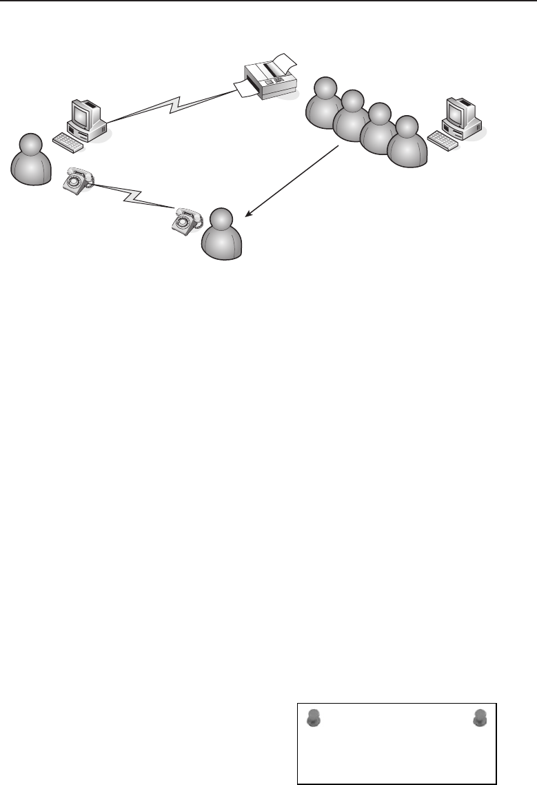
Edwards c15.tex V3 - 03/27/2009 11:47am Page 599
Chapter 15 ■Network Management 599
Work Order
Printout
Help Desk
Support Staff
End User
with Network Problem
Network Support
Personnel
Figure 15-1 A network operations help desk implementation
A successful help desk implementation requires that someone is available
to answer the telephone. In small operations, where there is only one person
running the whole department, there is still a need to answer the call, no
matter where that person may be located. There are a couple of ways this
can be done. The first is to have the help desk telephone number be a mobile
telephone that is carried at all times. An alternative would be to have a fixed
land-line telephone in the network operations area which is the help desk
number but is forwarded to a mobile telephone if the phone is not picked
up in a certain number of rings. We can already sense the question arising
about why bother to have a land-line telephone at all if there is still a mobile
telephone in the mix? The answer is that every organization, no matter how
small, has aspirations of growing, and with it the network would also need
to grow. It would be possible to have the person who is currently heading
up the network area eventually add another staff person, even if only on a
part-time basis. Then one person can remain in the network operations area
while the other is reachable when he or she is out and about in the facility
by calling the mobile telephone number. Another possible scenario is that the
daytime person is tied to the mobile telephone on a 24-hour basis, with other
staff added to maintain and monitor the network during overnight hours. The
daytime person should be reachable on an on-call basis.
ACRONYM ALERT
VAR — Value-added reseller
Larger organizations may have one or
more people whose prime responsibility is
to answer the help desk telephone calls.
This may be a network support person or
an operator able to open a service-request
ticket for the networking trained staff.

Edwards c15.tex V3 - 03/27/2009 11:47am Page 600
600 Part IV ■Managing and Maintaining the Network
In a very large, fast-paced networking organization, the person answering
the help desk telephone has the responsibility to triage the call to find out
the problem’s severity, how the user is affected, the expected response time,
and how many other workers in the same area may have been affected. Once
all the pertinent information is collected, along with the necessary contact
information, a trouble ticket is generated and dispatched to the appropriate
network support group for further action.
15.1.1 Help Desk Software
When a call is received, there needs to be some sort of record. Even for a
small, low-cost operation, there needs to be at least a spiral-bound notebook
designated as the call log. The minimum information includes the date, time,
caller, nature of the issue, and whether the issue has been resolved. A step
up from the notebook is a spreadsheet that records the same information and
perhaps a few more columns for other pertinent information.
ACRONYM ALERT
MIB — Management Information Base
The collection of this data is not only
used in determining open and closed issues
but as a collection of the network’s oper-
ational history. Recurring issues need to
be analyzed to find the root cause and to
determine the actions that can be taken to
eliminate them. Of course, some software is always better than others. Each
has its advantages and disadvantages as far as how it fits into a particular
network operations environment. If there is already a help desk or network
operations program in use, this may be a situation of living with what you’ve
got. This is especially true if the program has been in use for a long time and
is serviceable in that network environment. However, if you are employed in
a network environment that has not committed to any particular help desk or
network operations program, you can investigate some to integrate into your
network support area.
All help desk programs can open a trouble ticket and follow that ticket
through to its resolution. The difference in many is in the database area and
their capability to search on issues or generate reports to indicate trends or
problem areas. Some programs are fairly inexpensive and a good start. How-
ever, it is best to investigate the capability for moving stored network-related
information in the event there is a need to migrate to a more sophisticated
program in the future. You want to be able to migrate the data to the new
software system to provide continuity in the network operations area. Avoid
programs that use a compressed, proprietary format and do not provide tools
to export the data in a readable and sortable format.

Edwards c15.tex V3 - 03/27/2009 11:47am Page 601
Chapter 15 ■Network Management 601
Some programs are single-user applications that are loaded on a local
PC. This is fine in a one-person department where future growth may not
exist. Attempt to find a program that would easily migrate to a multiuser
environment. Client/server applications have client and server components;
however, they may require a per-seat license for each user using the client
application. Normally, these types of licenses are based on simultaneous
connections, so you may not need a license for every staff member who needs
access to the program. Make sure there is a firm understanding of the license
terms prior to committing to the purchase of the program.
POP QUIZ
List the minimum information that is
needed to generate a trouble ticket or work
order for network support.
The last consideration is the
program’suserinterface.Isit
fairly intuitive, requiring little
to no training? The idea is to
have a help desk program that
increases the productivity of the
network support staff, not tie
them down with the business
of just running the help desk
program. If a program requires leafing through thick manuals for explanation
of various functions, it is perhaps best to look in another direction.
15.1.2 Network Operations Staff
In a small, one-person network operations shop, the person needs to wear
many hats. Perhaps the person is fairly knowledgeable about all facets of the
network environment, but if the network is sophisticated, certain components
may need to be supported via support contracts with either the original
equipment manufacturer or some other third party with expertise in that
particular piece of hardware or software. In larger installations, there may be
an entire staff dedicated to different network aspects.
The tasks performed by help desk personnel may be more of a clerical
function in a large, high call volume network environment. It would be the
responsibility of these staff members to capture as much relevant information
as possible and then pass the ticket to a network specialist. In some environ-
ments, the call volume may be such that the person answering the telephone
at the help desk is expected to perform some minor troubleshooting prior to
handing off the ticket for further work by a network specialist. In a shop with
a handful of network support staff, the person taking the support call may be
expected to manage the issue until it is resolved. There will be times when all
the staff is working on issues and no one is available to answer the phone.
Calls should be routed to an answering service that relays the messages as
soon as a staff member returns to the network operations area.

Edwards c15.tex V3 - 03/27/2009 11:47am Page 602
602 Part IV ■Managing and Maintaining the Network
In large organizations that need to have dedicated expertise in certain areas,
the staff can be divided as follows:
PC support — Staff members dedicated to desktop applications and
hardware issues related to the computer and the network node it is
directly connected to.
Server support — Staff members dedicated to various server-based
applications, such as e-mail, authentication servers, domain servers, etc.
A server administrator may be dedicated to a single server application.
Network support — Staff members dedicated to the network fabric con-
sisting of network forwarding devices, such as routers, switches, hubs,
and related cabling.
Telecommunications support — This function may be broken out
into a voice group and a data group. However, with the convergence
of voice and data networks, this function can overlap into the net-
work, server, and PC support areas with the use of IP voice-based
devices and applications. Data telecommunications staff mostly
work with the high-speed network data carriers and the devices
locally located to provide a network path to the outside world.
User base support — Staff members dedicated to training users,
creating user manuals, and creating and maintaining user
accounts, including passwords and network access privileges.
This is a granular description of possible support functions for those orga-
nizations that have the ability to divide these functions into separate areas.
There are many instances where these functions may overlap or where one
support person from one group can help in supplying support to a different
group.
15.1.3 Network Monitoring
ACRONYM ALERT
WATS — Wide area telecommunications service
Monitoring network performance for larger
networks is an automated process. There
are monitoring stations that monitor not
only the health of network devices but
also can track traffic patterns through the
network. In these types of network environ-
ments, network support personnel is dedicated to evaluating the information
that is displayed and determining if there is a need for some sort of service on
the network. This kind of monitoring is interactive and is normally used in a
24/7 network operations environment to ensure that the network is function-
ing at optimum performance throughout the day. The networks where this

Edwards c15.tex V3 - 03/27/2009 11:47am Page 603
Chapter 15 ■Network Management 603
type of monitoring can be found are those that deal with thousands of devices
spread not only around a single site but perhaps several sites whose networks
are being monitored from a central location.
ACRONYM ALERT
TAPI — Telephony application programming
interface
This type of network monitoring may be
too costly for a smaller network installa-
tion. However, monitoring can be done on
a less grand scale using Simple Network
Management Protocol (SNMP). There are
low-cost SNMP programs that can be set
up on a workstation where the network devices can be polled. These programs
poll the devices and query the management information base (MIB).3An MIB
is a database containing the network objects that provide information on the
major elements of the device and its interfaces. The program can simply query
and display the retrieved information or in more feature-rich programs, retain
the information captured over a fixed interval and display it in a historical
graph. So the feature-to-cost ratio would be a deciding factor when selecting a
program using SNMP to monitor your network.
POP QUIZ
Name the two major types of user interfaces
used today in the computer and network
areas.
Even without SNMP, many
devices retain information that
can be used to monitor their
health. This information can be
read using a console connec-
tion4or Telnet to a management
address on the device to retrieve
the information. These methods utilize the command-line interface (CLI)5of
the device to retrieve the requested information. Whereas SNMP for the most
part has many standardized MIBs, CLIs can vary from manufacturer to man-
ufacturer, as well as from device to device from the same manufacturer, so
there is no standard query. Keeping CLI reference manuals for all the different
devices within the network is essential.
Monitoring is a preemptive activity. It is used to provide early warning
of network problem areas. It most definitely is capable of reporting network
3MIB is a collection of object identifiers (OID) to collect information regarding the operation of
a network device. There are standard MIB OID values, which every network device supports,
and then there are the proprietary MIB OID values, which are designed to query components
of a nonstandard device. The MIB database is loaded on an SMNP workstation so it can use the
appropriate OID to retrieve the desired information from the network device.
4Console connection usually refers to an RS232 serial connection that allows the establishment
of a terminal session. This connection can be used to issue commands for either configuring the
device or retrieving the requested information. These commands may be of a proprietary nature,
depending upon the device. In these cases, the manufacturer’s operational manual should be
consulted.
5Command-line interface (CLI) refers to a line-by-line command set that is a proprietary set of
commands designed by the manufacturer to allow the device to be configured or respond to
information queries relating to its configuration or operation.

Edwards c15.tex V3 - 03/27/2009 11:47am Page 604
604 Part IV ■Managing and Maintaining the Network
outages as well as network device failures, but its real value is pointing out
areas of the network that may need modification to handle increased demand
or traffic patterns that can be rerouted for a more even distribution of network
bandwidth.
15.2 Administration
ACRONYM ALERT
SOCKS — SOCKet secure server
The main thrust of network administra-
tion is evaluating and allocating network
resources and other administrative needs
in support of the organization’s network.
What are the resources? First, it is people —
understanding the staffing needs required
to maintain a network, scheduling staff members efficiently to carry out the
mission of ensuring network maintainability and availability with a minimal
amount of downtime. Second, it is relationships with vendors and suppliers,
not only for material goods but as resources for their knowledge expertise of
the products they market. Third, it is the creation of processes and policies for
the smooth operation of the network management group.
15.2.1 Network Management Staff Members
The main topic of discussion in this section is for those network management
organizations that have been tasked with the care of a large organization’s
network. There are natural divisions of labor as far as expertise, with a support
hierarchy to coordinate activities to ensure a high level of service to their user
base with minimal impact on those users whose productivity is directly related
to the availability of network resources.
For smaller network operations with only a handful of staff in support of net-
work resources, this section may seem like overkill. However, networks tend
to grow as organizations grow, so this information may be usable as a roadmap
to aid in planning that growth. Figure 15-2 illustrates an organizational chart
for a hypothetical large network management organization.
ACRONYM ALERT
SMS — System management server
In very large companies, it is recognized
that the network management organization
is an integral part of the organization and
that it requires an executive-level employee
with the title of VP or director to lead
the network management organization. The
smaller the company, the fewer staff are required. It may be run by a
higher-level manager acting as the focal point for the whole department.
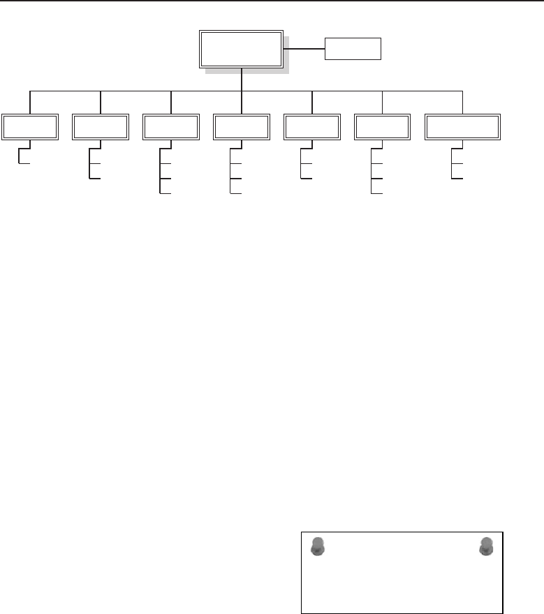
Edwards c15.tex V3 - 03/27/2009 11:47am Page 605
Chapter 15 ■Network Management 605
VP
Network Management
Application
Server Support
Domain
E-mail
Cabling
Network
Support
Routing
Firewall
Security
Passwords
Audits
Voice
Telecommunications
Data
Helpdesk
PC Support
Application
Configuration
Real Estate
Infrastructure
Structural
Inventory
Logistics
Administrative
Assistant
Figure 15-2 A network management organizational chart
15.2.1.1 Executive Level
Only a very large organization would have a vice president of network
management. The reason for it would be the number of staff positions that
are reporting to this position. If a network management organization has
a multilevel hierarchy, such as division or group managers with a support
structure under them, someone needs to drive the coordination between
the various groups. There also may be large purchases for major expansion
or upgrades that require contract negotiations. On that level, an executive
position is warranted.
This position or office may require additional staff, such as an administrative
assistant to coordinate and schedule events. Attached to the position may
be an accounting function and a contracts function for managing budgets,
accounting for expenditures, and negotiating contracts for equipment and
services. The executive position would be able to authorize those expenditures
and contracts, and to set staffing levels.
ACRONYM ALERT
RAS — Remote access server
This position is the focal point for all
things related to network resources. It is
the position that oversees all activities and
is responsible for preparing reports to the
other members of the executive office. The
position requires a skilled management per-
son more than a technocrat. However, he or she must be knowledgeable
enough to understand some of the aspects involved with the overall network
infrastructure. More technical management is left to the department heads and
managers. They are the ones who oversee the day-to-day activity within their
respective departments.
15.2.1.2 Department Heads/Managers
Department head (or manager) positions should be filled by people who are
technically competent in the area they have been placed in charge of. They

Edwards c15.tex V3 - 03/27/2009 11:47am Page 606
606 Part IV ■Managing and Maintaining the Network
ACRONYM ALERT
PSN — Packet-switching network
should have good managerial skills as well
as people skills. In a smaller organization,
this may be a hands-on position where
the department head/manager/supervisor
performs some network-related responsi-
bilities as well as oversees the overall
operation of the department. The differing functional areas are broken out
for easier identification of their roles and activity level within the organization.
In a smaller organization, a department head may wear many hats and cover
more than one functional area at the same time.
15.2.1.2.1 Telecommunications Department
This department may have both voice and data responsibilities. It coordinates
communication activities not only with internal users, but potentially with
remote users as well. The type of telephone service that is in use, POTS6or
VoIP, will determine how much separation there actually is between the voice
and data groups.
The telecommunications department is responsible for interfacing with
the long line companies that connect the organization to the outside world.
The department also monitors the bandwidth needs of the organization
and negotiates contracts and rates with telecommunications providers. Final
approval of contracts occurs at the executive level, but the details of the
services and support that are to be provided is usually worked out by those
that are intimately involved in the daily operations of the telecommunications
department.
ACRONYM ALERT
PSTN — Public switched telephone network
On the voice side, there is usually a tele-
phone switch that needs to be administered
and maintained. The telecommunications
department is responsible for the entire cir-
cuit, from the switch to the handset of the
user base, including assigning telephone
numbers to employees and generating reports about telephone usage and
billing.
15.2.1.2.2 Security Department
The security department conducts a broad range of activities that deal with
all aspects of network security. It deals with the physical and the abstract. On
the physical side, it is tasked with locking down the network to prevent any
malicious intent. It is responsible for monitoring the network’s security with
6POTS (plain old telephone service) is the standard convention of analog signals traveling over
old low-grade telephone wires. These may be found in older installations where the convergence
of the voice and data networks has not yet taken place.

Edwards c15.tex V3 - 03/27/2009 11:47am Page 607
Chapter 15 ■Network Management 607
periodic security audits. The department also looks for any vulnerabilities that
may exist but have not yet been exploited.
Members of the security department are responsible for developing policies
for network usage and for enforcing those policies with monitoring. They are
also are in charge of the various firewalls in the network. The group is incontrol
of the traffic that enters and leaves the network. This is accomplished by placing
the appropriate policies on the firewall devices to restrict undesirable traffic
and permit traffic that is necessary for the performance of the organization’s
business.
ACRONYM ALERT
PGP — Pretty Good Privacy
User authentication, including the
servers involved, is under the auspices of
the group, although parts of this respon-
sibility may be shared with other groups.
Ultimately, however, this group is the high-
est authority on user password control. The
group administers the policies that set user permission levels on the net-
work and monitors network usage to ensure it falls within the organization’s
policies.
15.2.1.2.3 Network Support Group
The network support group is responsible for the distribution of network
services over the network fabric. This includes the cabling, wireless access,
or whatever network media is being used and the devices placed within
the network to facilitate network traffic flow. The group interacts with other
network groups to help resolve network-related issues, varying from the
network access in the telecommunications group to the PC support group
bringing the network to the desktop computer.
ACRONYM ALERT
NMM — Network management module
The group is in control of the bandwidth
distribution across the network, as well as
routing policies that control the flow of
network traffic. They are responsible for
configuring and maintaining all the devices
that perform the distribution and routing
functions, as well as media that is used. Some large network installations do
enough cabling to justify having staff whose sole function is to distribute cable
throughout the facility. Smaller organizations subcontract out the cabling
function on an as-needed basis. Usually, small runs not requiring a major
effort can be carried out directly by the network support staff members. Every
network administrator at one time or another has strung a fair amount of
CAT 5 cabling.

Edwards c15.tex V3 - 03/27/2009 11:47am Page 608
608 Part IV ■Managing and Maintaining the Network
15.2.1.2.4 Server Support Team
As its name implies, the server support team is responsible for maintaining all
servers. These may be specific application servers, such as e-mail, print services,
database, etc. The goal is for the servers to function with a minimal amount of
downtime. Members of the server support team perform preventive measures,
such as running daily backups on all servers that are being strategically used
in the conducting of the organization’s business.
ACRONYM ALERT
NOC — Network operations center
Access to the servers is normally re-
stricted, even to other members of the net-
work operations group. The reason for this
is that the information an organization has
and controls is an integral component of
its business. The server support group may
work closely with the security group, but it has a major say in any decisions
involving the operation of the servers.
POP QUIZ
Name three kinds of servers a server
support team may support.
If there are network domain
servers under the control of the
server support group, the group
needs to interface with the secu-
rity, PC support, and network
support groups to ensure that
users are assigned within the
proper domain, subdomains,
and groups, and that users can reach all the resources their particular mem-
bership allows. The server support group coordinates with the security group
to add or remove users as they move into and out of the organization.
15.2.1.2.5 PC Support
The network operations help desk is often the first place a network user calls
when experiencing a computer issue, whether network-related or not. For this
reason, it may fall within the realm of the PC support staff. In reality, it can
be a number manned by a call coordinator function without any particular
network technology knowledge other than to determine if the issue is related
to software, hardware, or network access. The call can then be directed to a
staff member within that particular group for further diagnosis and remedy.
If the help desk is to resolve problems, it needs to be manned by technically
competent staff members and requires additional staff, as the possibility of
receiving multiple calls simultaneously is a constant reality. It is a balance that
needs to be attained and perhaps it can be met with staff members with duties
other than help desk–related tasks who can jump in and assist during peak
call periods. There is no hard and fast rule of how many user seats per help
desk member is ideal. It is not a one-size-fits-all situation.

Edwards c15.tex V3 - 03/27/2009 11:47am Page 609
Chapter 15 ■Network Management 609
It benefits the PC support group to have an educated user base, so there
may be training personnel assigned to the group whose responsibility is to
prepare user-based documentation to facilitate the users in the use of network
resources and perhaps other applications. Depending on the organization and
the applications used to run the business, there may be multiple application
specialists who not only conduct training but who can also troubleshoot issues
related to specific applications.
Needless to say, PC support is involved in computer hardware as much it is
with application programs. Larger organizations use ‘‘corporate builds.’’ These
are the base programs that needto be loaded on each computer within the orga-
nization. Since a large organization has many users with computers, the ideal
situation would be to develop a standard that is a combination of hardware
and software given to each user. There are application programs that allow
the creation of an image file that contains the base operating system and any
other standard applications given to each user, including antivirus, e-mail, and
productivity programs such as word-processing, spreadsheet, and database
applications. Use of the image file allows for the rapid deployment of standard
production PCs. Users requiring additional programs to carry out their func-
tions within the organization would have them loaded on an as-needed basis.
ACRONYM ALERT
JVM — Java Virtual Machine
In the area of computer hardware, some
organizations depend on support directly
from the computer manufacturer. Some go
as far as leasing computers from vendors so
that they do not own them outright. Usually
at the end of the lease, the equipment is
returned and the computer is replaced with a more current version. The
organization often specifies the software suite image or develops an image
and supplies it to the vendor to load on the computers before they are shipped
to the organization.
Members of the PC support group are directly involved in negotiating the
technical details of all major computer purchases, but large contracts require
final approval at the executive level.
15.2.1.2.6 Infrastructure Group
Users often think of the network as a massive cloud that information flows
over. However, the cloud is more solid than its usual representation. In reality,
network infrastructure does occupy real estate space. It occupies space not
only in closets and offices but also in many different areas throughout the
facility it serves. The network operations group may not have real estate staff
members as part of its staff. However, there is a need for this function within
the group. The staff member performing this function works with facility
administrators and real estate management to ensure that the network has the
required space and is secured properly.

Edwards c15.tex V3 - 03/27/2009 11:47am Page 610
610 Part IV ■Managing and Maintaining the Network
Planning is required anytime there is a network expansion or change that
requires the involvement of other areas of the facility not under the direct
control of the network operations group. Network operation staff members
need to interface with the people who determine real estate usage. The network
staff should map out the space requirements and any other special needs, such
as cableway access to support cabling needed within the area.
ACRONYM ALERT
IIS — Internet Information Server
An infrastructure group as part of the
network operations group may only be
a reality within very large organizations.
However, it is a necessity, and if it’s not a
group of its own, then one of the functional
department heads should assume the role.
In all likelihood, it will fall within the network support group.
15.2.1.2.7 Logistics Group
The logistics group is responsible for overseeing all the devices deployed in
the network, as well as any spare equipment. It is the department responsible
for logging the new stock as well as the units that have been returned to
the manufacturer for repair (RMA).7Various accounting processes are used
to keep track of all major components. It is easier if a bar coding process is
in place. When a new component is received, its description, serial number,
barcode, and date are entered into an inventory database. The date is essential
if there is ever a question of warranty. If a company is large enough, it makes
sense to have a single department control the flow of materials into and
out of the network’s facility. If an organization is not large enough, or the
volume of goods entering and leaving the network’s facility is low, a separate
department to handle this activity or function may not be required.
ACRONYM ALERT
DDNS — Dynamic Domain Name System
Control of inventory is essential. The PC
support group should maintain its own
inventory of computer-related materials,
as should the server support and network
support groups. If the volume is high, a
centralized service that performs this func-
tion for those groups may be warranted. If planned correctly, there can be a
savings involved, as well as the elimination of redundant activity.
15.3 Maintenance
Maintenance is a network operations–wide activity. Each area should carry
out its prescribed plan of what is considered maintenance. However, the
primary activities are as discussed below.
7RMA (returned materials authorization) is a process used by all manufacturers for the return of
materials, whether in warranty or not, for repair or replacement of the failed component.

Edwards c15.tex V3 - 03/27/2009 11:47am Page 611
Chapter 15 ■Network Management 611
Preventive measures — This activity can be as simple as performing
household-type activities such as making sure that ventilation vents
on equipment are free and clear. If there are filters involved, they
should be changed at the manufacturer’s recommended interval.
An occasional survey of all equipment within the network should
be taken to ensure that no obstructions block vents or fan intakes.
General housekeeping should be performed to eliminate any clutter
that may have gathered around equipment. The serviceability of
electronic equipment is directly proportional to how well it is kept
to its normal operational range. If devices become stressed due
to excessive heat, they will eventually fail. Good housekeeping
practices can boost the reliability of the network while eliminating
unnecessary costs.
A major preventive measure that often is forgotten is the saving
of configuration files related to a piece of equipment. This needs
to be done on the initial configuration and any time the unit has
been reconfigured. Having the ability to reload a configuration if
it is ever lost can save many hours of trying to reconstruct all the
configuration information and applied policies by hand. Unfortunately,
there are cases when there are no configurations to be had, either
in electronic storage or on paper. These are the times the network
needs to be reinvented — a most painful task that could cause
the loss of network resources not only for hours but for days.
Corrective measures — For the most part, corrective measures
deal with a direct failure in the network’s operation. They involve
troubleshooting, locating the cause of the problem, and eliminating
the problem with a correction of some type. It could be as simple as
finding a lose connector or as complicated as replacing a major network
component. It may also involve finding a workaround to allow net-
work users to continue working, thus eliminating lost productivity
due to a network failure. If a workaround can be found, a maintenance
window can be arranged for the full repair of the network issue.
Some network problems occur when a device has lost its configuration.
There are many reasons why this happens, such as power surge, etc.
However, the impact of the downtime can be reduced with the avail-
ability of a configuration backup file. The file can be used to restore the
configuration, and in case of an equipment failure the configuration
can be quickly moved to a spare unit restoring network operation.
Corrective measures need not wait for a network problem to occur. It
can entail other activities such as taking care of cabling that is exposed
in a manner that it may become damaged. It may require a mainte-
nance window to allow for the corrective measure to be taken.

Edwards c15.tex V3 - 03/27/2009 11:47am Page 612
612 Part IV ■Managing and Maintaining the Network
Revision-control measures — Most equipment in the network area
has firmware or software programs embedded within it. Like all
software, there are revisions that occur due to bug fixes or added
features. Manufacturers release updates to software from time to time,
but may or may not issue bulletins. It is up to the user base that is
utilizing that equipment within their network to keep abreast of any
changes that may have taken place. Many times the software is free, and
some companies sell maintenance agreements for continued software
support after the warranty period has been exceeded. It is best to keep
an ongoing relationship with your equipment vendor to ensure that
you are made aware of any bug fixes or new features that have been
added to the software. Bug fixes are necessary patches, whereas added
features are more of a selective choice. If a feature is not needed and
your software is running fine in its current configuration, you may
be able to save the effort required to upgrade your network device.
15.4 Provisioning
POP QUIZ
Performing nightly backups on all network
serversiscalledwhattypeofmeasure?
Many people believe that pro-
visioning happens only once, at
the initial installation of the net-
work. However, networks tend
to change and grow. As a result,
they may require some repro-
visioning within their life cycle.
This may be adding more bandwidth in certain network segments to facilitate
an increase of network traffic, or segmenting networks to isolate elements in
order to increase security or improve performance. It could be reprovisioning
of a switch to add more VLAN circuits to isolate certain network resources. A
VLAN may have experienced network performance issues and upon investi-
gation the network support staff might determine that breaking up the VLAN
into multiple segments would increase performance without the need for any
additional hardware or bandwidth.
Provisioning of network resources mainly falls upon the network support
group. They are in control of the network fabric over which the network
flows. However, it is the responsibility of all the network operations groups to
identify areas where provisioning may be needed.
Both the initial provisioning and the reprovisioning need to be documented.
If there are configuration changes made on a unit, it needs to be backed up and
the old configuration file archived. A rule to remember is to never discard the
previous running configuration file after making some configuration changes.
If in doubt whether a backup of the current running configuration file exists,
play it safe and perform a backup before installing any changes on a network
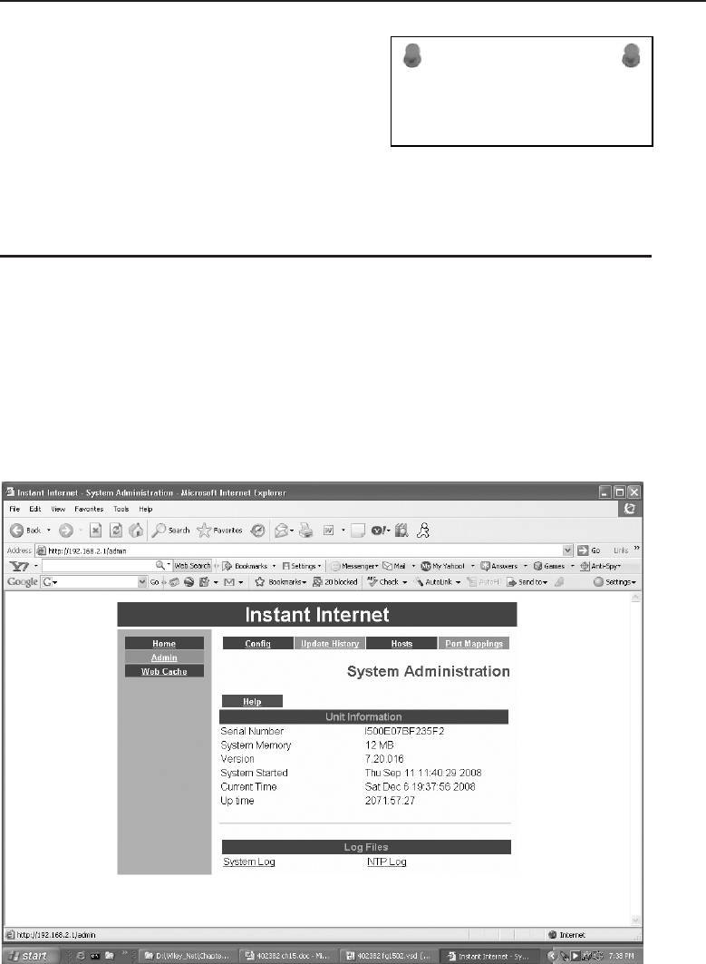
Edwards c15.tex V3 - 03/27/2009 11:47am Page 613
Chapter 15 ■Network Management 613
ACRONYM ALERT
PKCS — Public Key Cryptography Standard
device. This will allow for a quick reversal
if the new changes do not work or cause
other issues. Even if it appears that the new
changes are working as planned, it does
no harm to archive the previous running
configuration file. However, make sure the
file name is duly marked that it was the previous running configuration.
15.5 Tools
The tools that can be used in the network operations area are many and varied,
ranging from generic programs designed to monitor a wide range of network
devices to small utility programs that diagnose a specific issue. They may be
proprietary and provided by the manufacturer of a device to configure and
maintain that device. Some of these tools are graphical (GUI) or others use a
command-line interface (CLI). GUIs can be either proprietary or web-based,
requiring a web browser for configuration and reporting. Figure 15-3 illustrates
a web-based configuration/monitoring tool for a network device.
Figure 15-3 A web-based configuration/monitoring tool
The same device also has a proprietary configuration tool, which is also
graphical in nature. This user interface is illustrated in Figure 15-4.
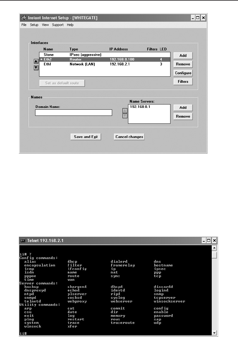
Edwards c15.tex V3 - 03/27/2009 11:47am Page 614
614 Part IV ■Managing and Maintaining the Network
Figure 15-4 A proprietary configuration/monitoring tool
For this particular piece of equipment, the proprietary tool is easier to use
than the web-based tool. The implementation depends on how the manufac-
turer envisions the tool is to be used.
Most equipment manufacturers provide a CLI to configure, provision, and
monitor their device. Access to this interface is usually through a console
terminal connection or a Telnet session using a TCP/IP connection to one of
the Ethernet ports on the device. Figure 15-5 illustrates a typical Telnet session.
Figure 15-5 A typical Telnet session

Edwards c15.tex V3 - 03/27/2009 11:47am Page 615
Chapter 15 ■Network Management 615
ACRONYM ALERT
SAM — Security accounts manager
Utilities that come with network devices
are handy to have and usually a lot easier
to use while configuring units, but as far
as monitoring one device at a time on a
network, they can be formidable at best.
SNMP was devised to allow the monitoring
of many network devices from many different manufacturers, but it can be
used to make configuration changes on the devices as well.
15.5.1 Simple Network Management Protocol
Most of today’s network devices are considered to be ‘‘managed’’ de-
vices. Many devices can be managed thanks to the development of SNMP.
Devices such as computers, servers, IP telephones, printers, hubs, bridges,
routers, wireless access points, remote access devices, and many more all
have an imbedded SNMP agent that allows them to be considered ‘‘network
managed.’’ The SNMP agent is software that answers queries from a network
management station (NMS). Each device has a standard MIB and if needed,
additional proprietary MIB entries. An MIB is a collection of managed vari-
ables within the device that is identified by its object identifier (OID). There are
objects for many elements in a device. Each element has its own unique OID.
The OID is used to retrieve information on the object or to set an object variable
to configure the unit. Figure 15-6 illustrates a network-managed device with
an embedded SNMP agent.
A network support staff person is monitoring the network. In normal polling
fashion, the device’s operational information can be retrieved on an ongoing
basis to monitor the overall performance of the network. Network-managed
devices can have SNMP traps set for various alert conditions. If a trap setting
is reached, the device waits to be polled but sends a trap message to the
network management station notifying it of the alert condition on the device.
Figure 15-7 illustrates the output from an MIB polling program.
In this figure, the interfaces on the unit are listed with their attributes, which
include IP address with subnet mask, MAC address, MTU size, speed, and
a description. Notice that all ports are reported, even an AUX console port
(a serial RS232 port). Its administrative state is up, but its operational state is
down, as there is no connection to that console port. All the Ethernet ports are
showing up and operational.
Additional operational information can be obtained from the device, such
as the routing table displayed in Figure 15-8.
This figure shows the internal routing table of the device. These are direct
routes, which means they were programmed into the device. If a routing proto-
col were involved, such as RIP or OSPF, those routes obtained from the protocol
running on the device would be indicated in the protocol (proto) column.
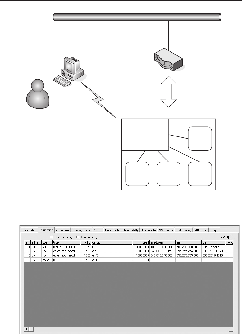
Edwards c15.tex V3 - 03/27/2009 11:47am Page 616
616 Part IV ■Managing and Maintaining the Network
SNMP
Agent OID
OIDOIDOID
Network Support
Staff
Network
Management
Station Network Managed
Device
SNMP
Embedded Agent
Figure 15-6 A network-managed device with an embedded SNMP agent
Figure 15-7 The output from an MIB polling program
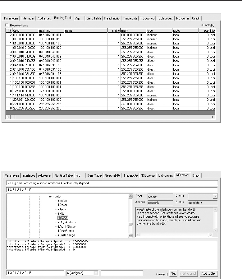
Edwards c15.tex V3 - 03/27/2009 11:47am Page 617
Chapter 15 ■Network Management 617
Figure 15-8 MIB program displaying the routing table
An MIB walkthrough can illustrate the OID associated with a particular
object. In Figure 15-9, the OID for interface speed has been selected.
Figure 15-9 MIB program displaying interface speed
Notice that the speed of all four interfaces is shown. This differs from
Figure 15-7, which showed all the information relating to each interface. To
build that table, all the OID entities for each column would need to be gathered
for display. However, an OID is unique, and the displayed OID is the interface
speed. Notice that the OID description and MIB number are displayed and it
is a read-only MIB, so a setting to another value is not allowed.

Edwards c15.tex V3 - 03/27/2009 11:47am Page 618
618 Part IV ■Managing and Maintaining the Network
POP QUIZ
How is a network device element uniquely
categorized within its MIB?
SNMP uses a community set-
ting to group a number of
devices to be monitored within
the community. The default
community setting is ‘‘public,’’
although this can be changed.
The network management station is able to poll all devices in the community
it is monitoring. SNMP traps will be sent to the MNS server that is a member
of the community the device is a member of.
ACRONYM ALERT
NCC — Network control center
A variety of SNMP programs are avail-
able, each with varying levels of capability.
Standard MIB variables can be read by
many different SNMP programs, but the
software that reads and sets them may be
far different in capability. This is an area a
network administrator really needs to comparison shop to get the functions
that are desired and the best price-to-performance ratio. Some programs are
more glitzy than others, showing all sorts of graphs and histograms. Although
they may be attractive, you may be paying extra for information overload.
Determine what is valuable for your network and develop a checklist to see
which SNMP program has the desired features at the best price.
15.5.2 Packet-Capture Capability
There are times it is difficult to determine what is going on when a network is
having traffic problems. Often the only way to do this is to analyze the packets
that are entering and leaving a particular network device. Packet-capture
devices and programs can return some statistical information when you are
investigating traffic patterns or performance issues on a network segment. With
the availability of open source packet-capture software, there is no reason not
to have this ability, even for a network operations center with a small budget.
Even if you are uncomfortable reading through a packet capture to see if
you can find a problem, it is useful if you can use the packet capture under
the direction of your third-party support organization. Figure 15-10 illustrates
ascreenofapacket-captureprogram.
ACRONYM ALERT
PDU — Protocol data unit
Summary information can be retrieved,
and individual packets can be selected,
opened, and analyzed. The summary can
give you an idea of the performance level
of the network segment the packet-capture
station is attached to. A packet-capture pro-
gram can be a low-cost traffic analyzer that measures network traffic load on a
particular segment. Statistical information can also be displayed in graphical
form, as shown in Figure 15-11.
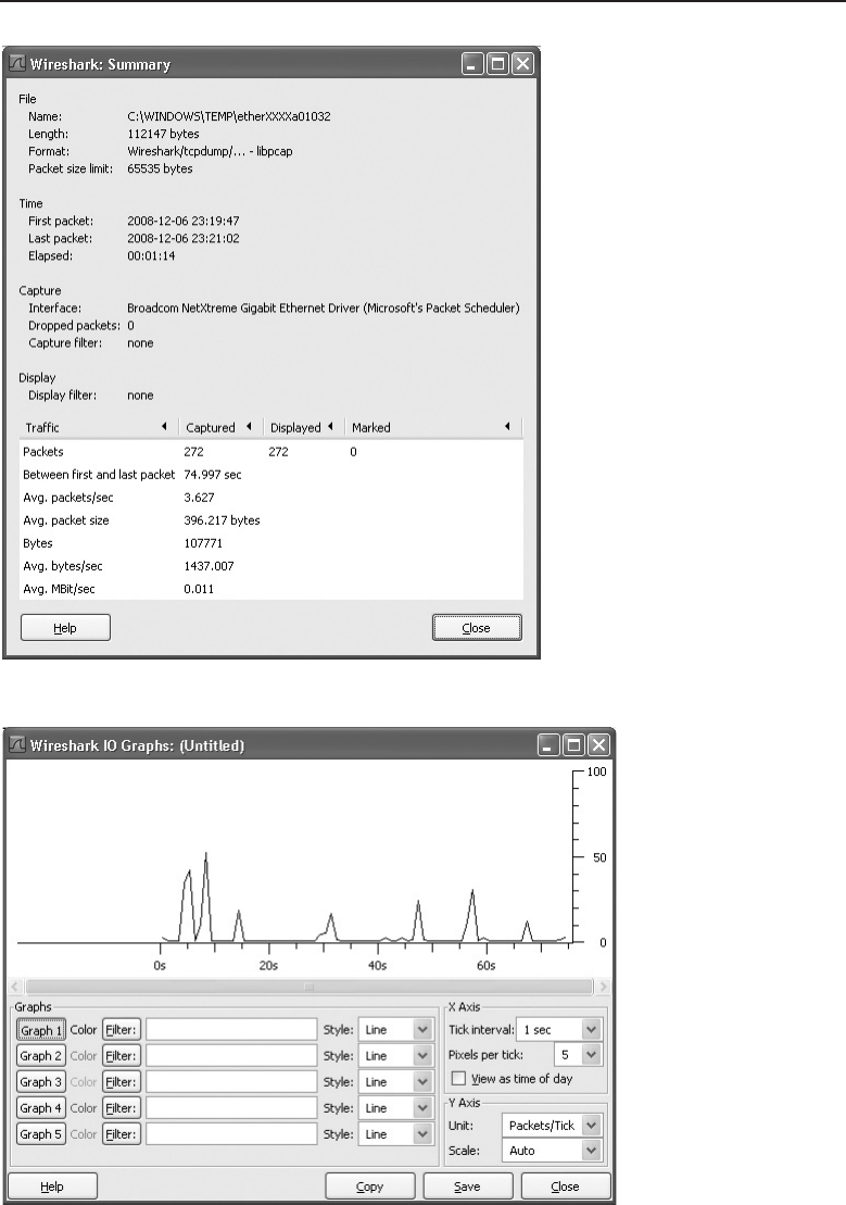
Edwards c15.tex V3 - 03/27/2009 11:47am Page 619
Chapter 15 ■Network Management 619
Figure 15-10 A packet-capture program’s display
Figure 15-11 A packet-capture program’s graphical display

Edwards c15.tex V3 - 03/27/2009 11:47am Page 620
620 Part IV ■Managing and Maintaining the Network
15.6 Chapter Exercises
1. Which protocol can be used to monitor devices on a network?
2. Where would an SNMP agent be found?
3. What would cause an alert to be displayed on an NMS workstation?
4. How would packets on a network be captured and inspected?
15.7 Pop Quiz Answers
1. Think about a network you are familiar with. It may be any net-
work home, work, school, organization, etc. How would you
rate their user to support staff ratio? Give reasons why.
A ratio of 1,000 network users to one support staff member may be
considered poor, whereas a 10-to-1 ratio would be considered overkill.
At home, it is one to one, because it is your network and you are
both the user and support staff. There is no set textbook answer or a
one-size-fits-all answer. Staffing levels are set by the dynamics of the
organization and how quickly network issues must be resolved.
2. List the minimum information that is needed to generate
a trouble ticket or work order for network support.
Date, time, contact, problem description, severity
3. Name the two major types of user interfaces used today in the computer
and network areas.
GUI (graphical user interface) and CLI (command-line interface)
4. Name three kinds of servers a server support team may support.
E-mail, print services, database
5. Performing nightly backups on all network servers is called what type of
measure?
Preventive
6. How is a network device element uniquely categorized within its MIB?
OID (object identifier)

Edwards c16.tex V3 - 03/27/2009 11:49am Page 621
CHAPTER
16
Troubleshooting
Difficulties exist to be surmounted.
— Ralph Waldo Emerson
We complete this book with a topic that we all hope we never need to worry
about, but all need to know. It is nearly impossible to run a LAN full time
with nothing ever going wrong. Even the most carefully designed networks
experience ‘‘issues.’’ As a matter of fact, when designing your network, you
decided on your acceptable level of risk for such issues. Now that your network
is operational, it’s your actions, both proactive and reactive, that are going to
get you out of trouble quickly when problems occur within the LAN.
No two LANs are alike. Even if they are alike in design, operationally they
are their own entities. There is no one fix-all for any particular issue within the
LAN. The complexities of today’s networks (high-speed data transfer, complex
end-user application, etc.)1complicate the troubleshooting process even more.
This is why we find ourselves (us writing and you reading) with this chapter.
It’s not a troubleshooting bible, but it is a guide that you can use to help you
get a feel for 1) what is out there, and 2) a little of what you can expect. We
hope it gives you the upper hand when you first approach troubleshooting
and serves as a useful reference for you in the future.
The quote used for this section, ‘‘Difficulties exist to be surmounted,’’
seemed like a perfect thing to remember when taking on the challenge of an
issue that has reared its ugly head. The more that we thought about the quote,
1According to the NASA Mars Rover update on http://marsrovers.nasa.gov,theMars
Rover, Opportunity, completed a 7.5 mile journey on the planet Mars that occurred in late
September 2008. Think about this. Somewhere in the world (and outside of the world), there
was data flowing from here to there that told Opportunity exactly where to go and how to get
feedback to NASA when it was done.
621

Edwards c16.tex V3 - 03/27/2009 11:49am Page 622
622 Part IV ■Managing and Maintaining the Network
the more we realized that this really is one of those ideas you should live by.
Trouble and difficulty are two of life’s guarantees. It is up to us whether we let
them overtake the situation. In the network world, we do not have the option
of letting the trouble overtake our LAN. That said, let’s start surmounting!
16.1 The Little LAN that Cried Wolf
Troubleshooting a LAN can be a seriously tough job to accomplish. Many
variables come into play. A specific issue may appear to be one thing and turn
out to be something totally different. Sometimes a troubleshooting session can
lead to a resolution in a few moments, and other times it may take hours.2If
the issue is reasonably containable, you can often provide a quick fix without
causing too much of an impact for any given set of issues. It’s the times when
you cannot get a fix in a reasonable amount of time that can cause you to
wonder why the heck you even bothered reading this book.3
It is never a good thing when a catastrophic event impairs network func-
tionality. Sometimes you may luck out and it will be an issue you have seen
or heard of before. Other times, you will end up on a conference call with a
team of managers, vendors, and other support staff trying to resolve a LAN
problem.
With any luck, you made sure to insist that a robust network management
station be installed when you were designing the network. Network man-
agement is big business and is well worth the time, money, and effort that
are put into deploying one in a LAN. Network management and proactive
troubleshooting are optional methods for keeping your LAN up and running.
If, for whatever reason, you are unable to do either or both of these, you will
eventually come to regret it.
End-user feedback is another way to find out if there are issues in the
network. End users can provide invaluable help when you want to isolate
an issue and then verify whether a fix worked.4Whichever method you use
to police your LAN (everything at your disposal, we hope), make sure to
establish a specific process to respond to events. You don’t want a bunch
of unprepared individuals running off to fix an issue with no strategy in
mind. If this is the case, a hundred bucks says that you will have more than
2Sometimes it can take weeks and possibly even months to reach a full resolution for an issue.
These problems are often related to poor design, vendor interoperability issues, or bugs in the
code. If you can prove it is an issue with a vendor, you will be able to get them to bend over
backwards to get you back up and running. Often there will already be a backup plan, but if not,
a temporary resolution will suffice until a permanent solution is developed.
3Especially the part that Jim wrote! (Rich just got Jim back for those comments he’s been throwing
around throughout this book.)
4Although you have to fully trust that the end user is giving accurate data.
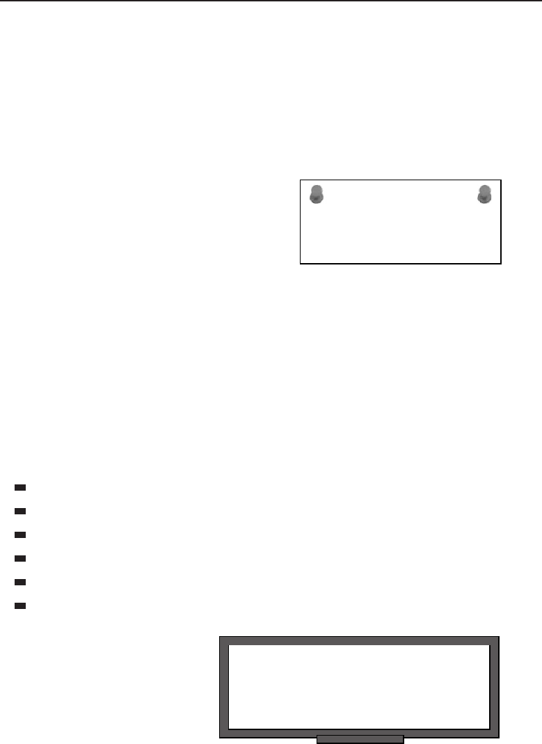
Edwards c16.tex V3 - 03/27/2009 11:49am Page 623
Chapter 16 ■Troubleshooting 623
one individual working on the same issue and possibly heading in opposite
directions strategy-wise.5
Before we move on in this chapter, let’s look at some reasons why a network
may begin experiencing problems and at some common feedback you might
get when such LAN issues arise.
16.1.1 Feedback
ACRONYM ALERT
VMS — Virtual memory system
When a problem occurs within your LAN
(and remember, it’s not if ,butwhen), you
need a notification procedure that alerts you
as quickly as possible. After all, you want
to narrow down and fix the issue before
too many users, services, or applications
are affected. As we have mentioned, you may have a network management
station that alerts you during these times, but user feedback is also a great way
of identifying a problem.
16.1.1.1 End-User Feedback
Often, the issue may be reported from a single individual, and with any luck,
will turn out to be something particular to that one person. That person called
in, reported what was occurring, and quickly you have them back up and
running. Now it is time for some coffee. Have a great day! Issues that may be
reported by an end user include the following:
Unable to print to a network printer
Unable to send or receive e-mail
Unable to access a specific application server
Unable to be authenticated
Things on the computer seem a lot slower than usual
Unable to get on the network
RANDOM BONUS DEFINITION
10BASE5 — A baseband Ethernet system
operating at 10 Mbps over thick coaxial
cable.
End users are not only use-
ful in notifying you of an issue,
they are also helpful in describ-
ing what is going on as you
attempt to resolve an issue. End
users can be walked through dif-
ferent tools that are running on
5Try to get a couple of bull-headed engineers off their train of thought. Before you know it, they
are both making changes and are making matters worse.

Edwards c16.tex V3 - 03/27/2009 11:49am Page 624
624 Part IV ■Managing and Maintaining the Network
their workstation, and you might be surprised how much these tools will
tell you.
16.1.1.2 Management Station Feedback
As we discussed in Chapter 15, the network management station is a good
way of being alerted to issues in the LAN. When an issue occurs that could
potentially affect normal data flow, the network management station gives an
alert. The alert can be visual (a red node identifier within a GUI) or audio (a
‘‘ding’’ or ‘‘beep’’). It can also be an alert that sends a message to a phone
number, pager, or even an e-mail account (or set of accounts).
The management station can also provide statistical reports. You can review
them for anything that seems abnormal. In other words, if you notice a
particular port reporting an excessive number of errors, you may want to
investigate to determine whether this indicates a problem in the LAN.
16.1.1.3 Hmm ...
It may seem that we are making a big to-do about nothing. We have network
management. We designed the network, we know it better than the paper
route we had in the seventh grade. Therefore, nothing can happen that we
can’t overcome in mere moments. Seriously, no sweat. We are done! Or are we?
16.1.2 What Could Possibly Go Wrong?
You know for certain that you took every precaution in the design of your
network. It should be reliable and fast ... very fast. As a matter of fact, you
made sure to put in a top-of-the-line network management station with all
the bells and whistles. So what could possibly go wrong? The answer to that
question is, almost anything. And that is what is so challenging to the network
professional. Exactly why is the network having issues? Following is a list of
possible issues that you might come across when troubleshooting a problem
in your LAN:6
Damaged cables
Dirty fiber
Excessive signal attenuation
Insufficient bandwidth
6We are going to let you in on a little secret that those who don’t read footnotes may never find
out. Pay attention to the items on the list because at the end of the chapter, there is a question
that tells you to match each item with the OSI layer it applies to.

Edwards c16.tex V3 - 03/27/2009 11:49am Page 625
Chapter 16 ■Troubleshooting 625
Denial-of-service (DoS) attack
Electrical interference
Wireless interference
Damaged nodes
Damaged interface
Dirty interface
Configuration error
ACRONYM ALERT
SSAP — Source service access point
Authentication issues
Excessive utilization
Excessive errors
VLAN configuration error
Class-of-service issue
Quality-of-service issue
16.1.3 Food for Thought
So far we have reviewed examples of some of the symptoms that you might
come across when monitoring and managing the LAN. Without getting too
deep into the task of troubleshooting, let’s take a look at some of the instant
questions that might come to mind when first learning of a network issue.
If you are notified that something is irregular in the LAN, you should ask
the following questions:
How many users are affected?
Is only one user experiencing the problem or several?
Is the problem an expected one? If so, do you have an action plan?
Have you seen the issue before?
What is the impact to the LAN? In other words, what nodes are affected?
How many domains are affected?
Understanding the problem is paramount to effective network troubleshoot-
ing (as discussed in depth later in this chapter). Without a good understanding
of the problem, you may find yourself chasing the wrong trails instead of
working toward resolution.7
7Although troubleshooting sometimes is a game of cat and mouse.

Edwards c16.tex V3 - 03/27/2009 11:49am Page 626
626 Part IV ■Managing and Maintaining the Network
‘‘OH NO! I BURNED THE DINNER!’’
We have provided you with some excellent recipes to enjoy at some point, but
now it is time to take a more serious approach to future dinner plans, so you
can proactively be prepared when you happen to burn the dinner. Sure, you
may laugh at this thought, and we know that burning the dinner is not
something you plan on doing anytime in the near future, but there is a real
concern here, and we will tell you why. The concern is that by this point in the
book, you are so engrossed in reading that time is flying by. Because of this, it
is possible that you may be reading this most excellent book and might, in fact,
burn your dinner.
We (Rich and Jim) feel that it is important that we give you some helpful tips
on things you can do to be prepared for such quick meal emergencies. By all
means, feel free to add any of your own favorites to this (or even to your
own) list.
Jim’s List of Proactive Staples:
Frozen veggies Bouillon Refried beans
Cheddar cheese Frozen pizza Ground beef
Canned veggies Peanut butter Jelly
Crackers Ramen Eggs
Tortillas Salsa
Rich’s List of Proactive Staples:
Peanut butter Popcorn Refried beans
Crackers Provolone cheese Salted peanuts
Dried figs Cranraisins Cheerios
Oatmeal Toast Macaroni and cheese
Franks and beans
You might also want to consider eating a few leftovers. For a quick and easy
meal, throw every leftover in a pot with some water and bouillon and make a
nice refrigerator stew. Ramen with some lunch meat or tuna, an egg, and some
American cheese makes a really yummy meal. If you can handle the taste and
smell of kimchi (a Korean pickled cabbage), you can add that to the ramen, too.
Now, if your meal is for a date, break down and take the person out to
dinner. Whatever you do, don’t call your mom as a backup for the date. (We are
sure she would be more than happy to come over and help, though. Probably
with your baby pictures in tow.)

Edwards c16.tex V3 - 03/27/2009 11:49am Page 627
Chapter 16 ■Troubleshooting 627
16.2 The Proactive Approach Beats
the Reactive Approach Hands Down
POP QUIZ
feedback is a great way to
benotifiedofanissueontheLAN.
It is amazing how many net-
work administrators still take
an extremely loose approach to
network management. Not that
weareheretojudgeanyone,
but it really doesn’t make sense
in most LANs to take a loose
approach. In at least one8of the authors’ opinions, proactively troubleshooting
your network is one of the most important things you can do to decrease the
timeittakestoreacharesolutionwhenanissueoccursontheLAN.
16.2.1 Baseline
To know that something is wrong, you have to know what right is (in this
scenario, with regard to your LAN). In other words, what is normal? The
baseline of the network is defined by the normal behavior of the network.
Traffic patterns and protocol behaviors are only a couple of items that can be
baselined and used as a comparison when something just does not look right.
Here are a few things that you can use to baseline your network:
Traffic analyzer — The traffic analyzer (also known as a network
analyzer, packet analyzer, packet sniffer, or just sniffer) is an appli-
cation or a specialized node used to capture data transmitted on
the network. Each packet is captured and can be manipulated and
sorted by RFC, protocol, statistics, or whatever specifications are
set by the user. The data can be organized and set to graphs or
any other form supported by the analyzer and set by the user.
Statistical graphing with the management station — SNMP manage-
ment stations can usually record statistical data and output the data
in reports and graphs. Maintaining such information can prove use-
ful in determining abnormal conditions within the internetwork.
Determine thresholds that need to be maintained —Knowyour
LAN. Test and analyze traffic patterns, traffic capacity limits, overall
throughput operation, routing path costs, Physical layer well-being,
8And I know that the other author would agree with this, even if he doesn’t say so.

Edwards c16.tex V3 - 03/27/2009 11:49am Page 628
628 Part IV ■Managing and Maintaining the Network
etc. Keep the results on hand for reference when an issue occurs.
Not only can this assist in alerting you of abnormal operations,
it can offer proof of the abnormal operations should you need to
bring in a vendor for assistance. Understand peak traffic periods,
protocol usage statistics, and average throughput. Normal traf-
fic patterns are important in understanding problems that occur
in the network and resolving them quickly and effectively.9
RANDOM BONUS DEFINITION
campus switch — A switch used within a
campus backbone.
By having a baseline to com-
pare with, when the end user
tells you that things are slower
than usual, you will be able to
compare the baseline data with
real-time data to see if, in fact,
the issue resides in the LAN.
Baselining is an excellent way of
reducing the time it takes to find the culprit when there is an issue on the LAN.
Keeping a record of captured baseline data is a very important practice to make
a habit. You will find that this is helpful not only in reaching a resolution, but
also in proving that something is wrong when you start calling vendors for
support. Often, you need to have the proof to show to help the vendor help
you. In addition, sometimes the vendor won’t be able to find an issue if there
is no proof the issue exists. By having the baseline data, you have the proof.
16.2.2 Proactive Documentation
Keeping documentation that outlines the physical and logical topology is
essential for proactive troubleshooting of the LAN. Even more essential
is making sure that this documentation stays current and updated at all
times. For instance, it does absolutely no good to maintain network diagrams
that do not keep up with the changes that are ever present in the LAN. By
documentation, we don’t mean you must keep a paper copy of everything you
retain; rather, we are suggesting the storage of critical information in either
electronic (soft copy) or paper (hard copy) form.
We are offering an overview of some recommended documentation to
maintain and have readily available. Like many things in networking, you can
look at this information as a reference model. If you don’t want to retain any
of the information in this section, don’t. Feel free to add to this list anything
that you feel you need to add. A good saying to live by is, ‘‘There is no such
thing as too much documentation.’’
9This is not meant to infer that you will never reach a resolution without this information. This
just makes the job of troubleshooting easier.

Edwards c16.tex V3 - 03/27/2009 11:49am Page 629
Chapter 16 ■Troubleshooting 629
Make sure that your baseline documentation is saved and is regularly
updated. Make it a habit to change the baseline documentation as changes
are introduced into the network. In addition to the baseline documentation,
keep good records that pertain to the physical and logical topologies of the
network.10 Keep in mind that even the most impressive network monitoring
system is not going to do you any good if you cannot locate a problem node.
At the very least, keep a record of the following:
A logical topology diagram
A physical topology diagram
A spreadsheet or other listing of where user nodes reside
Documentation that relates to the DMZ
Documentation that contains information pertaining to nodes outside of
the DMZ
Documentation that outlines the location and node interconnectivity for:
Network firewalls
Network management stations
Mainframe servers
Remote access servers
Routers
Switches
Layer 4–7 nodes
Wiring closets
VLANs
VPNs
Information pertaining to the LAN to WAN connectivity
Information pertaining to campus-to-campus connectivity
Documentation listing:
Network layer addressing
Major node names
LAN identification
Node serial number
Node makes and model names/numbers
10The topology documentation is especially important for the portions of the network that are
related to major host nodes, server nodes, interconnecting nodes, and individual segments within
the network.

Edwards c16.tex V3 - 03/27/2009 11:49am Page 630
630 Part IV ■Managing and Maintaining the Network
Software and hardware version numbers
Licensing information
Circuit identification for WAN connections
Geographical information for nodes listed above, including address and
contact name and number
Node access login information
Backup copies of:
Node configurations
System logs
System software
Name and number for support with the ISP
Name and number for support for the vendors of nodes and application
in use within the LAN
POP QUIZ
Name 10 issues that you might have on the
LAN.
Again, these are all simply
recommendations. It is entirely
up to you what you choose
to keep track of. At the very
least, keep a record of address-
ing schemes.11 It’s nice to have
if you need a reference point to
start troubleshooting from.
16.2.3 There Is No Such Thing as Too Much
Establishing a baseline for your network is not the only thing you can do to
simplify the task of troubleshooting. You can take a few other proactive steps
to help keep the LAN running and get it back to running when you have
an issue:
Shared knowledge — It’s always good to share what you know. Have
discussions with others when you are not sure, and freely offer up any
helpful information you may have with anyone who might have a need
to know.
Proper tools — Make sure that you and your staff have access to the
correct tools. Examples include backup laptops, serial cables, baseline
documentation, etc. The staff can only be as effective as their tools allow
them to be.
11Although having just the addressing schemes is really inadequate for today’s high-speed LANs

Edwards c16.tex V3 - 03/27/2009 11:49am Page 631
Chapter 16 ■Troubleshooting 631
Knowledge requirements — Make sure there is no single point of
failure in the network. Make sure that any and all tasks are performed
by at least two individuals. This way if someone is on vacation there
will be at least one person in the know. Also, make sure that you
allow only trained personnel to work on an issue. If this is not an
option,makesuretheyhaveaccesstosomeonewhoisexperienced.
12
Spares — If it was within your budget when you designed the
network, you purchased (we hope) and have network spares on
hand. These prevent shipping delays when there is a hardware
problem. Be careful when you use network spares; make sure not
to do a hardware swap if the issue really isn’t the hardware.13
ACRONYM ALERT
PID — Protocol identifier
Your network is only as effective as
you are. If you follow all these proactive
recommendations, you can help alleviate
some of the pain you might experience
when troubleshooting without some of this
information.14
16.3 Troubleshooting Tools
When there is a problem on the network, it is important to have access to some
important tools that can assist your troubleshooting. Most network nodes have
event logs that assist in diagnosing issues with a specific node. In addition,
you can refer to MAC address tables in Layer 2 nodes, IP routing tables in
Layer 3 nodes, ARP caches, command-line statistics, etc. Because there are
many different types of nodes, and the commands to gather such data
are vendor-specific, it is nearly impossible to introduce many of these in
this book. These are things you will learn and that will be specific to the
vendor your organization uses. Fortunately, there are some tools and utilities
that are available for you to use, whether built in, downloadable, or otherwise
available for purchase.
16.3.1 Helpful TCP/IP Utilities
If you are using a TCP/IP-compatible node, it will most likely include many
of the utilities that we discuss in this section. Examples used in this section are
12Your vendor should have a support staff and/or documentation available. Check with your
vendor for details.
13Sometimes a hardware swap may appear to fix a problem, but in reality the swap ‘‘bounced’’
the issue, and it may clear up or return depending on what the problem really is.
14Not to mention the potential cost to the organization when an issue occurs.

Edwards c16.tex V3 - 03/27/2009 11:49am Page 632
632 Part IV ■Managing and Maintaining the Network
from a Windows-based PC,15 so be aware that if you are trying to use them on
a non-Windows node, the command may differ from what you see here. The
result will still be the same, however.
These helpful utilities provide you with commands to determine whether
the node that you are issuing the command from is able to reach a destination,
verify the correct path is being taken to a destination, verify name-to-address
mapping is correct, verify that MAC-to-IP address mapping is correct, and
issue tests to other upper-layer protocols.
16.3.1.1 Ping
Ping is an acronym for packet Internet groper.Theping utility enables you to
test whether a destination node is reachable. The ping command is most often
issued at the beginning of (and several times during) a troubleshooting session.
The ping is an ICMP echo request/reply that determines whether a node is
reachable and outputs the round-trip time for the process to complete, any
packet-loss percentages, and a statistical summary for a given remote node.
The ping command is simple to use. Open your command-line window and
issue the command ping, followed by a DNS name or an IP address. Following
is an example of a successful ping to the DNS name yahoo.com:
C:\>ping yahoo.com
Pinging yahoo.com [206.190.60.37] with 32 bytes of data:
Reply from 206.190.60.37: bytes=32 time=23ms TTL=50
Reply from 206.190.60.37: bytes=32 time=21ms TTL=50
Reply from 206.190.60.37: bytes=32 time=22ms TTL=50
Reply from 206.190.60.37: bytes=32 time=22ms TTL=50
Ping statistics for 206.190.60.37:
Packets: Sent =4, Received =4, Lost =0 (0% loss),
Approximate round trip times in milli-seconds:
Minimum =21ms, Maximum =23ms, Average =22ms
RANDOM BONUS DEFINITION
collapsed backbone — A method of
interconnecting networks by using a switch
or router as a central relay device.
Notice that, by default,
the ping command will send
four ICMP requests and will
expect four replies. At the end
of the session, the statistics
are outputted,16 showing the
average success rate, round-trip
15Chances are, this is what you will be using in a networking environment.
16Also known as printed,orprinted on the screen.

Edwards c16.tex V3 - 03/27/2009 11:49am Page 633
Chapter 16 ■Troubleshooting 633
times, etc. So what happens if we issue a command to a node that ping is
unable to reach? Following is such an example:
C:\>ping testshow.com
Pinging testshow.com [207.215.79.16] with 32 bytes of data:
Request timed out.
Request timed out.
Request timed out.
Request timed out.
Ping statistics for 207.215.79.16:
Packets: Sent =4, Received =0, Lost =4 (100% loss),
Approximate round trip times in milli-seconds:
Minimum =0ms, Maximum =0ms, Average =0ms
As you can see, we were not able to get even one reply back from the destina-
tion node. The responses (request timed out) mean that the reply timer expired
before a reply was received. If you receive a request timed out response, you
cannot automatically assume that something is wrong with the remote node.
The problem could be anywhere between your PC and the destination node.
ACRONYM ALERT
MSB — Most significant bit; most significant byte
Request timed out is a message that indi-
cates that there is no route to the remote
node. One of the first things you can do
is issue a ping to the interface of your PC
(127.0.0.1) to see whether you get a reply. If
you do receive a reply, you know that TCP
is running and is working on your PC. The
next thing you want to do is ping the next hop router, or your default gateway.
Continue pinging until your ping fails; doing so will indicate where the issue
is occurring.17
You have several options available in most ping utilities. These can assist
you in different stages of your troubleshooting session. The options available
on a Windows-based PC include the following:
Options:
-t Ping the specified host until stopped.
To see statistics and continue - type Control-Break;
To stop - type Control-C.
-a Resolve addresses to hostnames.
-n count Number of echo requests to send.
-l size Send buffer size.
-f Set Don’t Fragment flag in packet.
-i TTL Time To Live.
17Another option is to use the traceroute utility, which we discuss in Section 16.3.1.2.

Edwards c16.tex V3 - 03/27/2009 11:49am Page 634
634 Part IV ■Managing and Maintaining the Network
-v TOS Type Of Service.
-r count Record route for count hops.
-s count Timestamp for count hops.
-j host-list Loose source route along host-list.
-k host-list Strict source route along host-list.
-w timeout Timeout in milliseconds to wait for each reply.
As you can see, several options are available to help you narrow down a
problem in the LAN. An example of what you can do with the command is
to issue a permanent ping to a remote destination. You do this by issuing the
ping command, the identification ID, followed by –t. For example, you want
to issue a constant ping to the IP address of 10.10.10.1:
C:\>ping 10.10.10.1 -t
POP QUIZ
Proactive troubleshooting or reactive
troubleshooting — which is better?
You can use a constant ping
when working on an issue
between two endpoints within
your network, to see if the node
comesupandstaysup.Also,
some VPN tunnel connections
require a constant ping through
the tunnel, or the connection between the remote site and the corporate site
will be dropped and the tunnel will be brought down.
16.3.1.2 Traceroute
The traceroute utility (tracert in Windows) enables you to viewthe sequence
of hops that a packet takes to a destination. Each and every router that the
packet passes through is listed in the output of the command. This output will
continue until the destination is reached, or when the replies are no longer
being sent. Following is an example of the tracert command from a PC to the
yahoo.com domain:
C:\>tracert yahoo.com
Tracing route to yahoo.com [206.190.60.37]
over a maximum of 30 hops:
11ms<10 ms <10 ms 192.168.1.1
2 7 ms 7 ms 6 ms c-3-0-ubr01.boston.cast.net
[43.16.12.1]
3 9 ms 8 ms 7 ms ge-1-37-ur01.boston.cast.net
[43.16.12.193]
4 6 ms 7 ms 6 ms po-20-ur02.boston.cast.net
[43.16.12.158]
5 7 ms 7 ms 7 ms po-24-ur01.boston.cast.net
[43.16.12.161]

Edwards c16.tex V3 - 03/27/2009 11:49am Page 635
Chapter 16 ■Troubleshooting 635
6 9 ms 9 ms 8 ms po-21-ar01.needham.cast.net
[43.16.12.157]
7 14 ms 13 ms 13 ms te-3-2-ar01.hartford.cast.net
[43.16.12.62]
8 15 ms 15 ms 15 ms cr01.newyork.ny.ibone.cast.net
[43.16.12.61]
9 16 ms 18 ms 15 ms TenGigabitEthernetNYC1.gblx.net
[43.16.12.217]
10 16 ms 15 ms 15 ms te2-4nyc1.gblx.net [43.16.12.237]
11 24 ms 17 ms 18 ms NewYork1.Level3.net [44.69.14.13]
12 26 ms 20 ms 32 ms Washington1.Level3.net [44.69.12.3]
13 29 ms 21 ms 31 ms Washington1.Level3.net [44.69.14.1]]
14 27 ms 22 ms 20 ms 4.79.228.2
15 23 ms 21 ms 23 ms ae2-p140.msr1.re1.yahoo.com
[216.115.108.57]
16 22 ms 21 ms 21 ms ge-9-3.bas-a2.re4.yahoo.com
[216.39.49.7]
17 24 ms 21 ms 22 ms w2.rc.vip.re4.yahoo.com
[206.190.60.37]
Trace complete.
From the responses received, you can see the amount of time it takes for
each particular router to respond. If you notice delays, investigate to determine
whether the segment that the delay appears in is having issues. Now, let’s
issue the tracert command to the IP address 207.215.79.16. Notice that this is
thesameaddressweusedinourfailedpingabove.Youshouldbeabletosee
this tracert fail at some point during the session:
C:\>tracert 207.215.79.16
Tracing route to www.testshow.com [207.215.79.16]
over a maximum of 30 hops:
11ms<10 ms <10 ms 192.168.1.1
2 7 ms 7 ms 6 ms c-3-0-ubr01.boston.cast.net
[43.16.12.1]
3 9 ms 8 ms 7 ms ge-1-37-ur01.boston.cast.net
[43.16.12.193]
4 6 ms 7 ms 6 ms po-20-ur02.boston.cast.net
[43.16.12.158]
5 7 ms 7 ms 7 ms po-24-ur01.boston.cast.net
[43.16.12.161]
6 9 ms 9 ms 8 ms po-21-ar01.needham.cast.net
[43.16.12.157]
7 14 ms 13 ms 13 ms te-3-2-ar01.hartford.cast.net
[43.16.12.62]
8 15 ms 15 ms 15 ms cr01.newyork.ny.ibone.cast.net
[43.16.12.61]

Edwards c16.tex V3 - 03/27/2009 11:49am Page 636
636 Part IV ■Managing and Maintaining the Network
9 16 ms 18 ms 15 ms TenGigabitEthernetNYC1.gblx.net
[43.16.12.217]
10 16 ms 15 ms 15 ms te2-4nyc1.gblx.net [43.16.12.237]
11 24 ms 17 ms 18 ms NewYork1.Level3.net [44.69.14.13]
12 26 ms 20 ms 32 ms Washington1.Level3.net [44.69.12.3]
13 29 ms 21 ms 31 ms Washington1.Level3.net [44.69.14.1]]
14 16 ms 16 ms 15 ms ex1-tg2-0.eqnwnj.sbcglobal.net
[151.164.89.249]
15 * * * Request timed out.
16 * * * Request timed out.
17 * * * Request timed out.
RANDOM BONUS DEFINITION
mirror port — A port configured on a Layer
2 switch used to copy the traffic appearing
on another port on the same switch.
As you can see in this
example, the last hop that
we were able to reach is
151.164.89.249. If you were trou-
bleshooting, you would focus on
that router to start with to see
why it is not able to reach the
destination. It is possible that it
can reach the next destination, but the next hop may be filtering ICMP traffic,
in which case you would not be able to push the ICMP packet through the
node that is blocking that type of traffic.
Here is a test for you. You are doing a tracert and you notice the following:
C:\>tracert 207.215.79.16
Tracing route to www.testshow.com [207.215.79.16]
over a maximum of 30 hops:
11ms<10 ms <10 ms 192.168.1.1
2 7 ms 7 ms 6 ms c-3-0-ubr01.boston.cast.net
[43.16.12.1]
3 9 ms 8 ms 7 ms ge-1-37-ur01.boston.cast.net
[43.16.12.193]
4 * * * Request timed out.
5 7 ms 7 ms 7 ms po-24-ur01.boston.cast.net
[43.16.12.161]
Notice that the fourth hop timed out, but the fifth hop didn’t. Why do you
think this happened?18
As with the ping command, you have several options available in
most traceroute utilities. These can assist you in different stages of your
18The answer will be provided at the end of Section 16.3.1.2.

Edwards c16.tex V3 - 03/27/2009 11:49am Page 637
Chapter 16 ■Troubleshooting 637
troubleshooting session. The options available on a Windows-based PC
include the following:
Options:
-d Do not resolve addresses to hostnames.
-h maximum hops Maximum number of hops to search for target.
-j host-list Loose source route along host-list.
-w timeout Wait timeout milliseconds for each reply.
Okay, now getting back to the question at hand: Why did the fourth hop
time out, but the fifth hop didn’t? This happened because the preferred next
hop was not available, so an alternative route was taken.19
16.3.1.3 Netstat
By default, the netstat utility displays both incoming and outgoing net-
work connections. These commands prove useful in troubleshooting issues
on the network, and when gathering traffic statistics to measure network
performance. Following is an example of the netstat command:
C:\>netstat
Active Connections
Proto Local Foreign State
Address Address
TCP PC:1693 PC:1694 ESTABLISHED
TCP PC:1694 PC:1693 ESTABLISHED
TCP PC:1663 es.com:http ESTABLISHED
TCP PC:1671 bs1.ads.vip.ac4.yahoo.com:http TIME WAIT
TCP PC:1674 jkhiuyg.com:http ESTABLISHED
TCP PC:1675 a96-17-73-9.deploy.com:http ESTABLISHED
TCP PC:1678 a96-17-72-144.depl.com:http ESTABLISHED
TCP PC:1680 bs1.ads.vip.ac4.yahoo.com:http TIME WAIT
TCP PC:1683 209.62.185.43:http ESTABLISHED
TCP PC:1685 bs1.ads.vip.ac4.yahoo.com:http TIME WAIT
TCP PC:1687 bs1.ads.vip.ac4.yahoo.com:http TIME WAIT
TCP PC:1690 a96-17-73-27.depogies.com:http ESTABLISHED
TCP PC:1695 a96-17-73-35.deplo.com:http ESTABLISHED
TCP PC:1707 bs1b1.ads.vip.re2.yahoo.com:http TIME WAIT
TCP PC:1728 8.12.222.126:http ESTABLISHED
TCP PC:1729 8.12.222.126:http ESTABLISHED
TCP PC:1735 8.12.222.126:http CLOSE WAIT
TCP PC:1737 8.12.222.126:http CLOSE WAIT
19Thanks to our friend Mr. Redundancy.
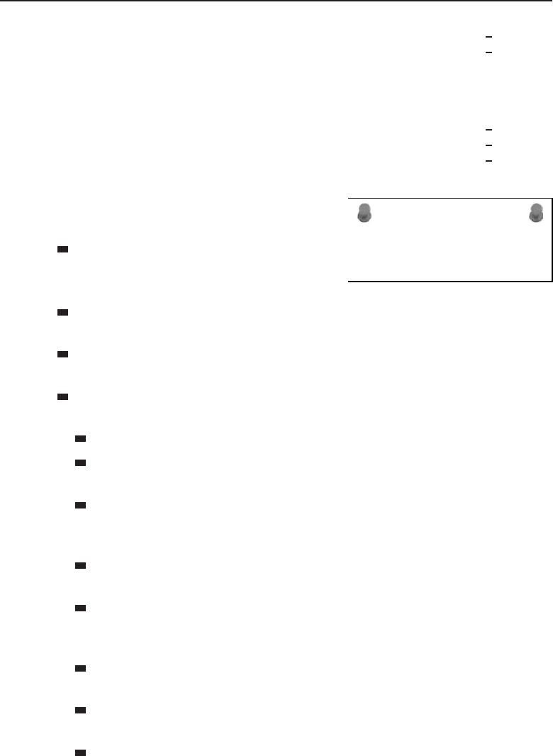
Edwards c16.tex V3 - 03/27/2009 11:49am Page 638
638 Part IV ■Managing and Maintaining the Network
TCP PC:1738 64.236.29.103:http CLOSE WAIT
TCP PC:1739 64.236.29.103:http CLOSE WAIT
TCP PC:1743 209.62.185.43:http ESTABLISHED
TCP PC:1746 208.215.179.180:http ESTABLISHED
TCP PC:1749 od-in-f166.google.com:http ESTABLISHED
TCP PC:1751 66.235.142.3:http ESTABLISHED
TCP PC:1752 157.166.226.31:http CLOSE WAIT
TCP PC:1754 157.166.224.32:http CLOSE WAIT
TCP PC:1756 157.166.226.30:http CLOSE WAIT
ACRONYM ALERT
DDR — Double-data rate
Take a moment to review the data that
you can capture with the default netstat
command:
Protocol — The first field provided is
the Protocol field, which identifies
whether the connection is TCP or UDP.
Local Address — This is the name of the local node20 and the port
number that is being used.
Foreign Address — This is the name of the remote node and the port
number that the socket is connected to.
State — This field identifies the TCP connection state. Following are the
possible TCP states:
LISTEN — Indicates that the node is waiting for a connection request.
SYN-SENT — Indicates that a connection request has been sent and
TCP is waiting for a matching connection request.
SYN-RECEIVED — Indicates that TCP is waiting for a confirming
connection request acknowledgment after having both sent and
received a connection request.
ESTABLISHED — Indicates that the TCP connection is open. This
is the normal state for the data transfer phase of the connection.
FIN-WAIT-1 — Indicates that TCP is waiting for a connection-
termination request from the remote TCP. It can also serve as
an acknowledgment of a connection termination request.
FIN-WAIT-2 — Indicates that TCP is waiting for a connection
termination request from the remote TCP.
CLOSE-WAIT — Indicates that TCP is waiting for a connection-
termination request from the local user.
CLOSING — Indicates that TCP is waiting for a connection-
termination request acknowledgment from the remote TCP.
20The local node is always the node that you are close to.

Edwards c16.tex V3 - 03/27/2009 11:49am Page 639
Chapter 16 ■Troubleshooting 639
LAST-ACK —Indicates
that TCP is waiting for
an acknowledgment of a
connection-termination
request previously sent
to the remote TCP.
TIME-WAIT — Indicates that TCP is waiting for enough time to
pass to be sure that the remote TCP received the acknowledgment of
its connection-termination request.
RANDOM BONUS DEFINITION
copy port — Synonymous with mirror port.
dummy text
As with the other utilities discussed so far, you have several options
available in most netstat utilities. These can assist you in different stages of
your troubleshooting session. The options available on a Windows-based PC
include the following:
Options:
-a Displays all connections and listening ports.
-e Displays Ethernet statistics. This may be combined
with the -s option.
-n Displays addresses and port numbers in numerical
form.
-p proto Shows connections for the protocol specified by
proto; proto may be TCP or UDP. If used with the -s
option to display per-protocol statistics, proto may
be TCP, UDP, or IP.
-r Displays the routing table.
-s Displays per-protocol statistics. By default,
statistics are shown for TCP, UDP and IP; the -p
option may be used to specify a subset of the
default.
interval Redisplays selected statistics, pausing interval
seconds between each display. Press CTRL+C to stop
redisplaying statistics. If omitted, netstat will
print the current configuration information once.
POP QUIZ
What are two types of topology diagrams
that come in handy when troubleshooting
an issue within your LAN?
You can gather so much sta-
tistical information from the
netstat command. Try the com-
mand a few times on your PC to
get an idea about what you can
obtain with this helpful utility.
16.3.1.4 Route
You can use the route utility to view and manipulate the routing table of a
Windows-based node. Note that any Layer 3 node will have this capability.

Edwards c16.tex V3 - 03/27/2009 11:49am Page 640
640 Part IV ■Managing and Maintaining the Network
Following is an example of the route print command, which can be used to
display the routing table of a PC:
C:\>route print
========================================================
Interface List
0x1 ........................... MS TCP Loopback interface
0x1000003 ...00 10 b5 65 4d 1a ...... NDIS 5.0 driver
========================================================
========================================================
Active Routes:
Network Netmask Gateway Interface Metric
Destination
0.0.0.0 0.0.0.0 192.168.1.1 192.168.1.104 1
127.0.0.0 255.0.0.0 127.0.0.1 127.0.0.1 1
192.168.1.104 255.255.255.255 127.0.0.1 127.0.0.1 1
192.168.1.255 255.255.255.255 192.168.1.104 192.168.1.104 1
255.255.255.255 255.255.255.255 192.168.1.104 192.168.1.104 1
Default Gateway: 192.168.1.1
========================================================
Persistent Routes:
None
In the routing table, you can see the destination IP addresses, the subnet
mask, the gateway, the local interface, and the number of hops to the gateway.
Following are the optional flags and commands that can be used with the
route command for advanced display and configuration options:
Options:
-f Clears the routing tables of all gateway entries. If
this is used in conjunction with one of the commands,
the tables are cleared prior to running the command.
-p When used with the ADD command, makes a route
persistent across boots of the system. By default,
routes are not preserved when the system is
restarted. Ignored for all other commands, which
always affect the appropriate persistent routes. This
option is not supported in Windows 95.
command One of these:
PRINT Prints a route
ADD Adds a route
DELETE Deletes a route
CHANGE Modifies an existing route

Edwards c16.tex V3 - 03/27/2009 11:49am Page 641
Chapter 16 ■Troubleshooting 641
destination Specifies the host.
MASK Specifies that the next parameter is the ‘netmask’
value.
netmask Specifies a subnet mask value for this route entry.
If not specified, it defaults to 255.255.255.255.
gateway Specifies gateway.
interface The interface number for the specified route.
METRIC Specifies the metric, ie. cost for the destination.
ACRONYM ALERT
CLNP — Connectionless Network Protocol
Let’s assume that during troubleshooting
you discover that you need to add a default
static route to your routing table to reach
a remote node. The network you want to
reach is the 10.10.10.0 subnet. You know
that you have a route to that subnet from
the gateway node (192.168.1.1), so you want to set up the static route to the
10.10.10.0 network and the 192.168.1.1 as the default gateway. The syntax is
C:\>route add <IP address>mask <mask><gateway IP address>
So using the addressing that we discussed previously, the following is the
input needed to add the static route:
C:\>route add 10.10.10.0 mask 255.255.255.0 192.168.1.1
To verify that the route was added, check the routing table:
C:\>route print
========================================================
Interface List
0x1 ........................... MS TCP Loopback interface
0x1000003 ...00 10 b5 65 4d 1a ...... NDIS 5.0 driver
========================================================
========================================================
Active Routes:
Network Netmask Gateway Interface Metric
Destination
0.0.0.0 0.0.0.0 192.168.1.1 192.168.1.104 1
10.10.10.0 255.255.255.0 192.168.1.1 192.168.1.104 1
127.0.0.0 255.0.0.0 127.0.0.1 127.0.0.1 1
192.168.1.104 255.255.255.255 127.0.0.1 127.0.0.1 1
192.168.1.255 255.255.255.255 192.168.1.104 192.168.1.104 1
255.255.255.255 255.255.255.255 192.168.1.104 192.168.1.104 1
Default Gateway: 192.168.1.1
========================================================
Persistent Routes:
None

Edwards c16.tex V3 - 03/27/2009 11:49am Page 642
642 Part IV ■Managing and Maintaining the Network
RANDOM BONUS DEFINITION
monitored port — A port on a switch that is
being mirrored.
As you can see, there is now a
route to the 10.10.10.0 network.
If you were to reboot your PC
at this point, the static route will
be removed and will have to be
re-added. If you want to ensure
that the static route remains until it is manually removed, you need to add
the -p flag:
C:\>route add 10.10.10.0 mask 255.255.255.0 192.168.1.1 -p
16.3.1.5 Arp
The arp utility enables you to view and manipulate the ARP table of a
Windows-based node. Note that any Layer 3 node will have this capability.
Following is an example of the arp –a (to view) command, which can be used
to display a PC’s routing table:
C:\>arp -a
Interface: 19.108.1.14 on Interface 0x1000003
Internet Address Physical Address Type
19.108.1.1 00-f8-f8-ea-08-bc dynamic
19.108.1.102 00-19-ea-f8-36-95 dynamic
We want to force our node to learn the route to an IP that is not listed in the
ARP table, so we ping the remote node’s IP address:
C:\>ping 19.108.1.106
Pinging 19.108.1.106 with 32 bytes of data:
Reply from 19.108.1.106: bytes=32 time=23ms TTL=50
Reply from 19.108.1.106: bytes=32 time=23ms TTL=50
Reply from 19.108.1.106: bytes=32 time=23ms TTL=50
Reply from 19.108.1.106: bytes=32 time=23ms TTL=50
Ping statistics for 206.190.60.37:
Packets: Sent =4, Received =4, Lost =0 (0% loss),
Next, we will view the ARP table again:
C:\>arp -a
Interface: 19.108.1.14 on Interface 0x1000003
Internet Address Physical Address Type
19.108.1.1 00-f8-f8-ea-08-bc dynamic
19.108.1.102 00-19-ea-f8-36-95 dynamic
19.108.1.106 00-95-6f-af-84-6d dynamic

Edwards c16.tex V3 - 03/27/2009 11:49am Page 643
Chapter 16 ■Troubleshooting 643
The options available on a Windows-based PC include the following:
Options:
-a Displays current ARP entries by interrogating the
current protocol data. If inet addr is specified,
the IP and Physical addresses for only the specified
computer are displayed. If more than one network
interface uses ARP, entries for each ARP table are
displayed.
-g Same as -a.
inet addr Specifies an internet address.
-N if addr Displays the ARP entries for the network interface
specified by if addr.
-d Deletes the host specified by inet addr. inet addr
may be wildcarded with * to delete all hosts.
-s Adds the host and associates the Internet address
inet addr with the Physical address eth addr. The
Physical address is given as 6 hexadecimal bytes
separated by hyphens. The entry is permanent.
eth addr Specifies a physical address.
if addr If present, this specifies the Internet address of
the interface whose address translation table should
be modified. If not present, the first applicable
interface will be used.
16.3.1.6 Ipconfig
ACRONYM ALERT
ASCII — American Standard Code for Information
Interchange
The ipconfig utility provides the TCP/IP
configuration for the PC and enables you
to refresh many of the TCP/IP components
(such as DNS). ipconfig is the Windows
version of this tool, although many operat-
ing systems have a similar utility. Examples
of this include the ifconfig command that is used by Unix and some versions
of Macintosh operating systems. Following is an example of the ipconfig
command:
C:\>ipconfig
Windows 2000 IP Configuration
Ethernet adapter Local Area Connection:
Connection-specific DNS Suffix . : hs.comcast.net.
IP Address. . . . . . . . . . . . : 192.168.1.1
Subnet Mask . . . . . . . . . . . : 255.255.255.0
Default Gateway . . . . . . . . . : 192.168.1.100

Edwards c16.tex V3 - 03/27/2009 11:49am Page 644
644 Part IV ■Managing and Maintaining the Network
As you can see in the above example, the ipconfig command pro-
vides you with the DNS name pertaining to the ISP connection, node IP
address, subnet mask, and the default gateway IP address. A lot of help-
ful options are available with this command. To view the options, use the
/? option:
C:\>ipconfig /?
Windows 2000 IP Configuration
Ethernet adapter Local Area Connection:
USAGE:
ipconfig [/? |/all |/release [adapter] |/renew [adapter]
|/flushdns |/registerdns
|/showclassid adapter
|/setclassid adapter [classidtoset] ]
adapter Full name or pattern with ‘*’ and ‘?’ to ‘match’,
* matches any character, ? matches one character.
Options
/? Display this help message.
/all Display full configuration information.
/release Release the IP address for the specified
adapter.
/renew Renew the IP address for the specified adapter.
/flushdns Purges the DNS Resolver cache.
/registerdns Refreshes all DHCP leases and re-registers DNS
names
/displaydns Display the contents of the DNS Resolver Cache.
/showclassid Displays all the dhcp class IDs allowed for
adapter.
/setclassid Modifies the dhcp class id.
The default is to display only the IP address, subnet mask and
default gateway for each adapter bound to TCP/IP.
For Release and Renew, if no adapter name is specified, then the IP
address leases for all adapters bound to TCP/IP will be released or
renewed.
For SetClassID, if no class id is specified, then the classid is
removed.
Examples:
>ipconfig ... Show information.
>ipconfig /all ... Show detailed information
>ipconfig /renew ... renew all adapaters
>ipconfig /renew EL* ... renew adapters named EL....
>ipconfig /release *ELINK?21* ... release all matching adapters

Edwards c16.tex V3 - 03/27/2009 11:49am Page 645
Chapter 16 ■Troubleshooting 645
POP QUIZ
Name a proactive step you can take to help
keep the network running.
Many tools are available
to help you test and trou-
bleshoot issues in your net-
work.21 When troubleshooting
end-user issues, these tools
allow you to relearn IP address-
ing, DNS information, and
DHCP information.
At the beginning of this section, we told you that the ipconfig utility will
provide you with the TCP/IP settings. To see a detailed list of these settings,
just enter the /all option:
C:\>ipconfig /all
Windows 2000 IP Configuration
Host Name . . . . . . . . . . . . : Widget Net.
Primary DNS Suffix . . . . . . . :
Node Type . . . . . . . . . . . . : Broadcast
IP Routing Enabled. . . . . . . . : No
WINS Proxy Enabled. . . . . . . . : No
DNS Suffix Search List......:hsd1.nh.comcast.net.
Ethernet adapter Local Area Connection:
Connection-specific DNS Suffix . : hs.comcast.net.
Description . . . . . . . . . . . : blahblahblah-based
Ethernet Adapter
Physical Address. . . . . . . . . : 1A-10-B5-4D-01-56
DHCP Enabled. . . . . . . . . . . : Yes
Autoconfiguration Enabled . . . . : Yes
IP Address. . . . . . . . . . . . : 192.168.1.1
Subnet Mask . . . . . . . . . . . : 255.255.255.0
Default Gateway . . . . . . . . . : 192.168.1.100
DHCP Server . . . . . . . . . . . : 192.168.1.100
DNS Servers . . . . . . . . . . . : 67.87.71.26
67.87.71.22
67.87.73.16
Lease Obtained . . . . . . . . . : Sunday, October 19,
2008 4:00:00 PM
Lease Expires . . . . . . . . . . : Monday, October 20,
2008 4:00:00 PM
A lot of information is output when you use the ipconfig /all command.
It is a useful command to view and resolve network connection issues.
21As well as connection issues with your PC.

Edwards c16.tex V3 - 03/27/2009 11:49am Page 646
646 Part IV ■Managing and Maintaining the Network
RANDOM BONUS DEFINITION
LAN segmentation — The practice of
dividing a single LAN into a set of multiple
LANs.
This concludes the discus-
sion of TCP/IP utilities in this
chapter. We highly recommend
that you try as many of these as
you can to build a good under-
standing of how these tools can
help you in the future. The next
section travels outside of our TCP/IP world and discusses more specialized
equipment and processes that assist in network troubleshooting, diagnosis,
and resolution.
16.3.2 More Helpful Tools
The TCP/IP utilities that we discussed in the previous section are great tools
when troubleshooting Layer 2 and above issues. But what happens when a
cable breaks? There are several tools that are handy in troubleshooting Physical
layer issues. Following is a list of some of these tools:
Volt-ohm meter — This device is used to measure voltage, current,
and resistance.22 It is used to test electrical continuity through the
physical medium. Volt-ohm meters are often called multimeters,
which is entirely appropriate. There are two main types of multimeters,
analog and digital. Digital multimeters are popular because they
are accurate, durable, and may provide additional functionality not
supported by an analog multimeter.
The volt-ohm meter provides basic troubleshooting assistance, but can
be helpful in determining whether you have an issue at the Physical
layer. As you will find in Section 16.5, you will often start your trouble-
shooting sessions by looking for Physical layer issues. Having the
capability to test the Physical layer at a moment’s notice can save valu-
able time in the long run.
Cable tester — Network cable testers are used to check the integrity of
the cabling in the LAN. Cable testers are made for all types of network
cabling (STP, UTP, coaxial, and optical fiber), and some cable testers
can even choose the type of cabling that will be tested. There are differ-
ent types of testers out there, and they vary in functionality. Normally,
at a minimum, they enable you to test for crosstalk, attenuation, and
noise. More advanced testers can test to ensure that the shield used in
STP is not damaged, can display MAC address information, and can
capture information pertaining to data rates, errors, and collisions.
22Some volt-ohm meters provide additional functionality to broaden their testing ability.

Edwards c16.tex V3 - 03/27/2009 11:49am Page 647
Chapter 16 ■Troubleshooting 647
Breakout box — This is a device used to troubleshoot issues over a
serial port. The breakout box is placed between two nodes (for instance,
between a router and a CSU). The breakout box monitors the signals
and uses LEDs to display information pertaining to the signals.
BitErrorRateTest(BERT)tester— This device is used to generate
a test pattern that the tester and a remote node can use to test the
line for errors. Both the tester and the remote side can be set to
the same pattern so that the integrity of the test is maintained.
ACRONYM ALERT
FLR — Frame loss rate
It’s not absolutely necessary for you
to have any of these tools, but consider-
ing the affordability of many of these, it
sure makes sense to have them around.
You might never use them,23 but they can
prove extremely helpful when you are trou-
bleshooting.
16.3.3 Even More Helpful Tools
These are helpful tools that you will find yourself referring to often when
troubleshooting, monitoring, and baselining your network. Of course, some
of these tools are optional, and some may not be available on every system or
network (for instance, some older LAN bridges did not have the capability of
generating an event log). If you do have them available, however, by all means
use them:
Event logs — Most network nodes have an event log24 that reports
major changes to the status of any particular function of the node.
Event logs can be helpful in troubleshooting an issue. In addition, the
event log can be set to report catastrophic events. Often, the node will
provide a dump of information that can be analyzed by the vendor.
Network analyzer — The network analyzer is used to capture packets
that are being transmitted on the LAN. The analyzer will log the data it
receives and can analyze the data based on a specified RFC or standard.
Network analyzers (sniffers) can be software based or can be a node
running the analyzer software. Sniffers can be configured to cap-
ture all the traffic to and from a specified segment, or can be set to
capture specific data only (for instance, only ICMP traffic). Sniffers are
23Scratch that — we all know that if you buy one, you will use it, even if you are just fiddling
around.
24Many upper-layer nodes provide additional logs, such as security log, radius log, authentica-
tion log, hardware log, etc. While these are beyond the scope of this book, they should be
reviewed when an applicable issue is occurring.

Edwards c16.tex V3 - 03/27/2009 11:49am Page 648
648 Part IV ■Managing and Maintaining the Network
helpful any time you are having an issue with a portion of the
network sending or receiving data. They provide a line-by-line analysis
of the packets that were captured.
Sniffers are also helpful in troubleshooting protocol specific issues
that may be occurring within the LAN. Intrusion attempts by
an unwelcome remote party can be detected with the sniffer.
Documentation captures — When troubleshooting, make sure you
keep a copy of everything you do. If you are running commands
on the command line, do them through a terminal emulator,
such as Windows HyperTerminal. At the very least, capture the
following (from all applicable nodes) before you do anything else:
Node configurations
Event logs (and any other available logs)
Status of the interfaces of the node
Memory-usage statistics
Any vendor-recommended documentation
Screenshots that may provide insight to the issue
As you are troubleshooting,
capture anything you
believe may be important.
Any details that may help
lead to resolution are
recommended. In addition,
if you have a good idea of what the issue is and can capture proof,
do so. Document any error messages you encounter. If at some point
you need to contact a vendor or another technical support person, you
will have a lot of documentation that they can start working with. It
is much easier to bring someone up to speed if you have the visual
evidence and the troubleshooting performed thus far (and the results).
POP QUIZ
What does tracert do?
dummy text
16.4 A Logical Order
There are various strategies for troubleshooting issues in a LAN. The strategy
discussed in this section provides a systematic approach to troubleshooting.
There are variations to this troubleshooting model, but they are all geared to
work toward the ultimate goal of resolving network issues in a timely manner.
Following is an example of a logical model that you can follow to troubleshoot
network issues:
1. Define the problem.
2. Consider the possibilities.

Edwards c16.tex V3 - 03/27/2009 11:49am Page 649
Chapter 16 ■Troubleshooting 649
3. Determine the issue.
4. Find a possible solution.
5. Test the possible solution.
6. Develop an action plan.
7. Implement the action plan.
8. Monitor the results.
16.4.1 Define the Problem
Before you do anything, you need a good understanding of what the problem
is. Sometimes this is a simple step to take, sometimes it isn’t. Without fully
understanding problem, you will find yourself going around in circles instead
of progressing toward resolution.
Narrow down where the problem exists. How many users are affected?
What is the overall impact? How many VLANs are down? What range of IPs
cannot be reached? These are just a few questions that you should ask when
gathering information. It’s your opportunity to play detective and investigate.
Most organizations have large, high-speed networks that are the core for the
daily operations of the business. You need to isolate the problem not only to
help you define what it is, but also to keep it from spreading to other segments
of the network.
RANDOM BONUS DEFINITION
learning process — The process whereby a
bridge builds its filtering database by
gleaning address-to-port mappings from
received frames.
Don’t always believe every-
thing you hear. This is not to say
that people are lying. A person
may make an assumption and
provide you more of an opinion
than an explanation. You don’t
have to discount everything you
hear. Instead, investigate the
issue to confirm whether you
can see what users are seeing (or saying that they are seeing). Don’t take
everything you hear to heart, and make sure you keep control over everything
that is going on, especially when troubleshooting in a group setting.25
16.4.2 Consider the Possibilities
Once you have clearly defined the problem as much as you possibly can, the
next step is to start looking at all the things that could be contributing to it.
This is when you want to get out all of that baseline information you have
25This assumes you are the most experienced. If you are not, then have the most experienced
person take control of the troubleshooting session, but make sure you keep one person in charge
of all the operations. Otherwise, you may find yourself in a position where several members are
making changes and not communicating with one another.

Edwards c16.tex V3 - 03/27/2009 11:49am Page 650
650 Part IV ■Managing and Maintaining the Network
been keeping updated and start comparing the baseline data with the current
status of the portion of the network you are troubleshooting. What can you
determine from this data that is not normal operation? Narrow this down as
much as you can.
It’s a good possibility that you will never be troubleshooting an issue
alone. Complex issues will sometimes require conference calls, and many
other technical and nontechnical people will probably join, all hoping to work
toward a resolution. Share the known. Share as much as you can. Remember
that the more people who have all the facts, the better. When information is
withheld (perhaps because someone doesn’t want to admit a mistake) is when
troubleshooting gets harder.
Once you have determined all the possibilities that may be causing your
problem, start narrowing down the list of possibilities by going through them.
Take a hard look at each one and see if you can prove whether each is working
as intended. If so, you can cross that item off the list. If not, keep it on the list
for further evaluation.
16.4.3 Determine the Issue
Now it’s time to narrow down your list and go through the remaining items to
see whether they can still seriously be considered as culprits of the problem.
Continue to gather as much data as you can. Keep a running copy of your
command-line sessions. Pull the system logs, get traces, etc. Any data that can
be relevant to the issue, grab it. Document, document, document!
Analyze the data. Start with the Physical layer and then move on up the
OSI reference model (more on this in Section 16.5). Once you have ruled out
the physical medium, continue layer by layer until you determine where the
problem lies. Rule out problems with the cables and the interface cards. Next,
ensure that data is flowing across the cables. If it is, you will step up to Layer
3: Is information getting passed via the proper route?
ACRONYM ALERT
ED — End delimiter
The OSI reference model is a great model
to follow when troubleshooting. Although
some protocols were built without regard
to the model, for the most part it is,
and probably will forever be, the model
to follow.
16.4.4 Find a Possible Solution
By this point, you should have a good idea of the issue. Once you have
determined what the issue is, try to develop a solution. Make sure to consider
all possibilities. Sometimes a problem may be a symptom of another issue.
Sometimes more than one solution may be possible. In such cases, decide

Edwards c16.tex V3 - 03/27/2009 11:49am Page 651
Chapter 16 ■Troubleshooting 651
which is less intrusive and try that one first. Keep a list of other possibilities so
you can continue looking into the issue should one proposed solution fail to
resolve the issue.
16.4.5 Test the Possible Solution
Once you believe you have a possible solution, try to test it in a lab environment
before trying it out in your network. If you don’t have a lab to try it out in, you
will have to do it on the network. Only in dire circumstances should you work
on the network during peak periods.26 Trytoscheduledowntimesoyoucan
try a solution without affecting too many users.
If you were smart enough to have proposed funds and lucky enough to have
received them, you may have enough equipment for a lab. If you do, try to
replicate and then test an issue in the lab before rolling the proposed solution
out on the network.27 Doing so provides an opportunity to test the solution,
to ensure that the solution works, without negatively affecting the production
network.
If you do not have the capability to test the solution, find out if one of
the vendors can. If a theorized solution does not resolve the issue in a lab
environment, you can work on another solution without any impact to the
current network status. Of course, if the network is down and you need to
get it back up, you may not have the opportunity to test before putting the
testing into action. However, because the network is down, you will have an
opportunity to try anything that will get it back up.
16.4.6 Develop an Action Plan
An action plan is one of the most helpful tools you can have available to
you when you are implementing a proposed solution to a network problem.28
Granted, sometimes you might not have the time to build an action plan,
but even a verbal action plan is better than making changes without a plan
in mind. Action plans should be written in an easy-to-understand manner
so that anyone who might be joining the troubleshooting session will have a
good idea of what is expected. In addition, the action plan is a great way to
coordinate efforts.
The type and amount of data that you include in your action plan depends
on what exactly you are working on. The action plan can be as simple as
instructions for logging into a node, or as complex as who is involved, where
26Sometimes you won’t have a choice.
27The network during troubleshooting sessions is often referred to as the production network.
This is to distinguish it from a lab environment or from any question that is not affecting the
network.
28An action plan is helpful any time you are making a change on the network.

Edwards c16.tex V3 - 03/27/2009 11:49am Page 652
652 Part IV ■Managing and Maintaining the Network
they are involved, steps to be taken, recovery plans, etc. Once an action plan
is drawn up, make sure that you have others review it for completeness and
sensibility. It wouldn’t hurt to have the vendor involved confirm the plan
and offer recommendations. Finally, run through the action plan in the lab (if
you have one) to see if your action plan resolves the issue.
RANDOM BONUS DEFINITION
local area network — A network that covers
a small geographical area.
Again, having an action plan
is not a requirement, nor will
youalwaysbeabletohaveone.
In the long run, though, you will
find that the action plan sure
makes things smoother.
16.4.7 Implement the Action Plan
It is now time to roll out the action plan. Set up the conference call, notify
the appropriate user groups, and implement the action plan. The action plan
should be an easy-to-follow document that lays out, in chronological order, the
step-by-step troubleshooting procedure, so the implementation phase should
run smoothly.
Make sure you have a backup plan so that if anything does go wrong during
the change window you have a way to get the network back to where it was
before you started the change.
16.4.8 Monitor the Results
Once you have implemented the action plan, it is time to monitor the results.
Utilize all tools that you have for the baseline and monitoring so you can
gather and compare statistics to ensure the desired effect has been obtained.
Make sure you allow ample time for all the standards and processes running
on the node to make the appropriate decisions before panicking that something
isn’t working. For example, routing updates take time, so you need to allow
the appropriate amount of time before you start worrying about something
being wrong.
POP QUIZ
What does the command ipconfig /all
provide for you?
Test to confirm that the
problem you are working on
is resolved. Also, check other
statistics to ensure that no new
issues have arisen (in case a
change has fixed one problem
but introduced another one).
Also be aware that sometimes a fix doesn’t work in the production envi-
ronment, and the troubleshooting process will have to begin again.
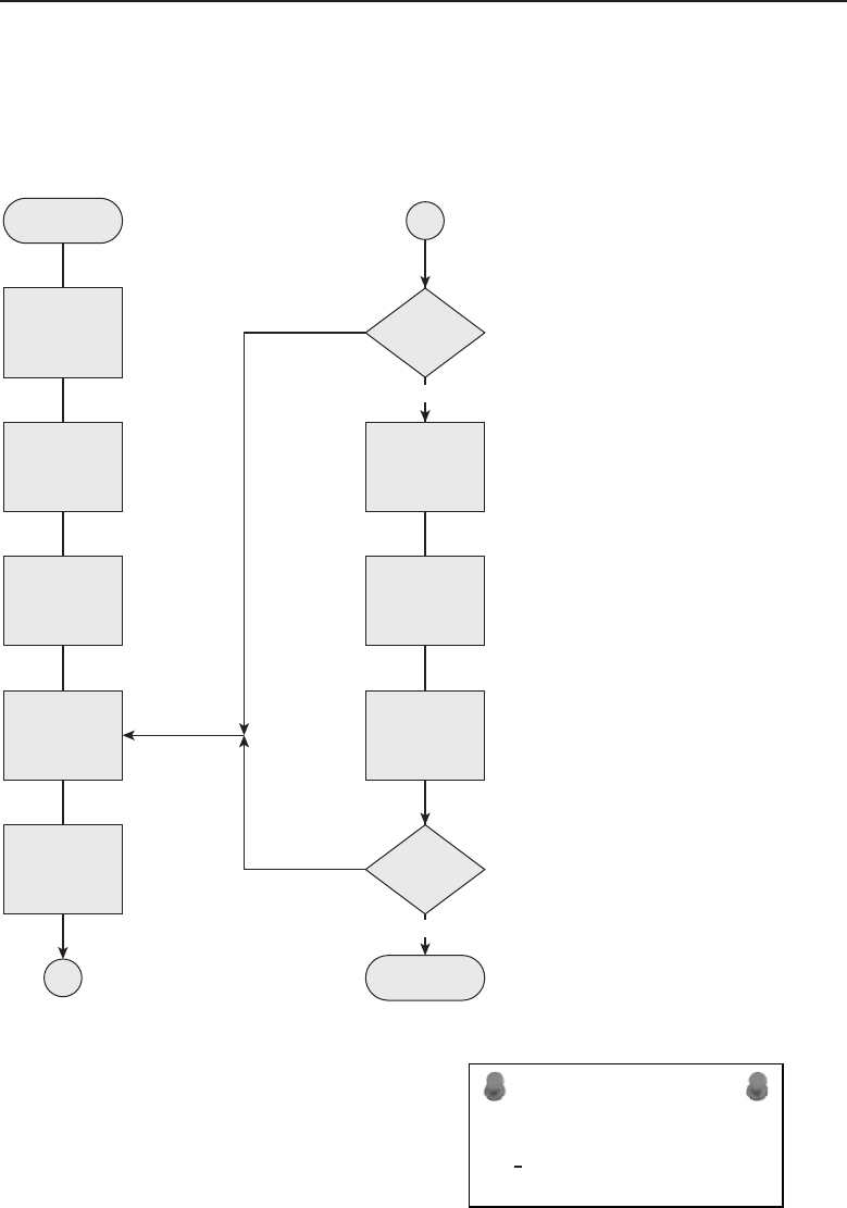
Edwards c16.tex V3 - 03/27/2009 11:49am Page 653
Chapter 16 ■Troubleshooting 653
16.4.9 Another Fantastic Bonus from the Authors
That’s right. Because you might need to have a reference at some point in your
networking career,29 we have included a handy-dandy flowchart to follow
(see Figure 16-1).
Define the
problem
Consider the
possibilities
Determine the
issue
Find a
possible
solution
Test the
solution
Start
A
Did test
work?
Develop an
action plan
Implement the
action plan
Monitor the
results
Is issue
resolved?
Stop
A
No
No
Yes
Yes
Figure 16-1 The bonus, handy-dandy logical troubleshooting reference flowchart
ACRONYM ALERT
MAC PDU — Media Access Control Protocol Data
Unit
Continuing on, in the next section we
show you how to exploit the OSI reference
model when troubleshooting.
29We also realized that we had gone too far into the chapter without a picture for you.

Edwards c16.tex V3 - 03/27/2009 11:49am Page 654
654 Part IV ■Managing and Maintaining the Network
TROUBLESHOOTING TIPS
Keep in mind the following tips and follow them to the best of your ability.
These tips will help keep the troubleshooting focus headed in a positive
direction:
1. Troubleshoot methodically. Make sure that you stay focused on the
task at hand and try not to get sidetracked while you are working on
issue resolution. It is easy sometimes to get sidetracked when reviewing
and troubleshooting the network. Make sure that you test each step
completely before moving to the next step. In other words, test the Layer
1 possibilities fully before moving to Layer 2. It doesn’t make sense to
make sure that a cable is plugged into every interface but the last hop.
Be sure that everything along the way is checked and confirmed.
2. Document! Document! Document!
3. Approach every possibility with an open mind. Don’t discount anything just
because you have never heard of it before. Review all tests, and retest if you
need convincing, but do not ignore or discount any possibility. Also, don’t
ever assume. Just because you see a symptom that seems like one you have
seen before, you can’t be sure it is the same until you confirm that fact.
4. Make sure you research error messages fully.
5. Remember that there can always be human error. Also, humans are not
always aware of, or honest about, something they might have done.
6. Whenever possible, test and replicate an issue.
7. Keep anyone who might be affected by the trouble aware that the
issue is being worked on. Provide a timeline when possible.
16.5 Layered Strategy
An effective method of troubleshooting is to follow the OSI reference model
(see Figure 16-2). Each layer in the OSI reference model communicates with
its peer on the remote node (represented by the dotted line in the figure).
Each layer passes data down to the next layer30 for processing, and each layer
provides services to the next-higher layer.
It’s important that you understand the functions of each layer31 and some
typical issues that you will see within each layer. As you are trying to diagnose
the cause of an issue, you should follow the OSI reference model. In this
30The exception to this is the Physical layer because that layer doesn’t have a lower layer to pass
data to.
31And by now you should.
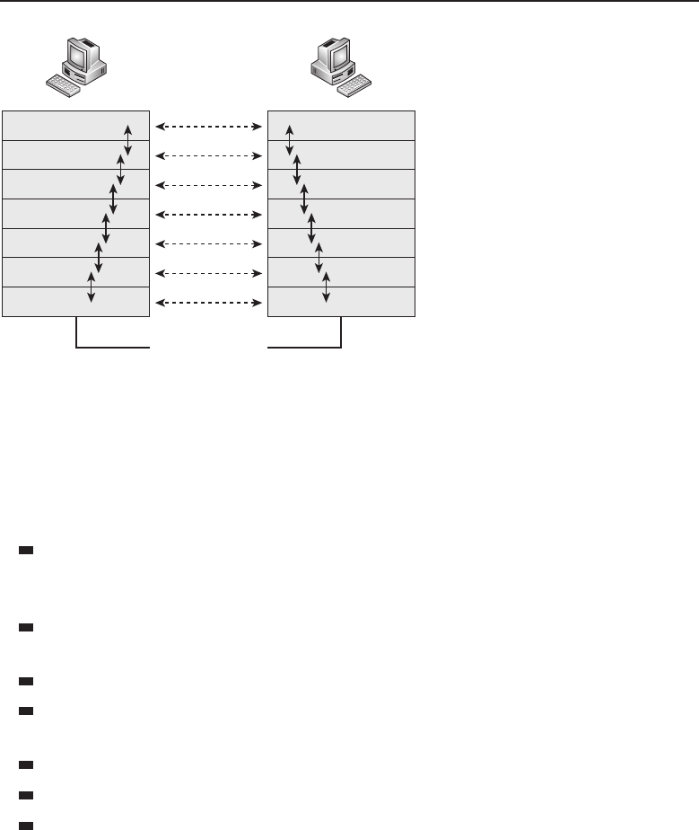
Edwards c16.tex V3 - 03/27/2009 11:49am Page 655
Chapter 16 ■Troubleshooting 655
Node A
Application
Presentation
Session
Transport
Network
Data Link
Physical
Application
Presentation
Session
Transport
Network
Data Link
Physical
Node B
Physical Medium
Figure 16-2 The OSI reference model
chapter, we discuss starting at the Physical layer and working your way up,32
although it really doesn’t matter which direction you head. As a matter of fact,
you can start at the layer that you suspect is causing the issue and can continue
from there. Here is a quick refresher on the roles of the OSI layers:
Application layer — Provides services used by applications (the transfer
of files and messages, authentication, name lookups, etc.) within the
network.
Presentation layer — Ensures that information received by one host can
be read by that host.
Session layer — Sets up, manages, and ends application sessions.
Transport layer — Ensures the transmission of data from one endpoint
to another.
Network layer — Provides a path from endpoint to endpoint.
Data Link layer — Provides a way to transport data over a physical link.
Physical layer — Determines the specifications for the operations of the
physical links between network devices.
If working from the bottom up, the first layer you check is the Physical
layer. Check the cables and the node interfaces to confirm that everything is
working correctly. Once you have ruled out the cables and interfaces, check for
media access and data encapsulation configurations to ensure that everything
32This is because the book is geared toward networking newcomers, and following the OSI
reference model from the bottom up makes it easier for a newcomer to work toward a resolution.

Edwards c16.tex V3 - 03/27/2009 11:49am Page 656
656 Part IV ■Managing and Maintaining the Network
is working at the Data Link layer. After the integrity of Layer 2 has been
confirmed, check for Network layer issues. Are you having routing problems
or problems with addressing in the network? Finally, move on to the upper
layers where you verify if the problem is related to memory or buffer issues,
authentication, encryption, data compression, etc., all dependent on the layer
you are troubleshooting.
As we have stated before, not all standards and protocols follow strict
adherence to the OSI reference model. This fact does not change the basic
troubleshooting strategy of using the OSI reference model. Regardless of the
network issue, the OSI reference model is a good overall base model to follow
while troubleshooting.
16.5.1 Common Lower-Layer Issues
RANDOM BONUS DEFINITION
network — A set of nodes that connect to
one another over a shared communication
link.
Sometimes issues can occur
at more than one layer. (For
example, you can have a config-
urationissueinboththeData
Link and the Network layer.)
Other issues can occur at only
one layer of the OSI model (for
example, a dirty fiber cable). At
the upper layers, many of the processes can overlap layers, which can make
the job of troubleshooting a challenge.
In this section, we discuss common issues that relate to the lower three
layers of the OSI reference model.
16.5.1.1 Layer 1
Often a network communication error can be caused by something as simple
as a cable not being plugged in. This is why we recommend that one of the
first things you do is to check the items that function at the Physical layer.
Make sure that your cable is plugged in and that there are no errors (for
instance, CRC errors, input/output errors, buffer failures, excessive collisions)
accumulating on the interface. Most of these errors can be detected with some
simple commands that are run within the command-line interface of a given
network node. In addition, most network nodes have LEDs that indicate the
status of a given interface. Check with the vendor for the definitions of
the LEDs for any particular node.
Common Layer 1 issues that can occur in a network include the following:
Damaged cables
Dirty fiber

Edwards c16.tex V3 - 03/27/2009 11:49am Page 657
Chapter 16 ■Troubleshooting 657
Excessive signal attenuation
Insufficient bandwidth
Electrical interference
Wireless interference
Damaged interface
Dirty interface
You can find yourself chasing the wrong issue if the Physical layer functions
are not checked and verified operational. Just think about it. It makes no sense
trying to figure out why you are not able to route to a specific subnet if the
problem is as simple as a cable that someone has kicked out.
16.5.1.2 Layer 2
In a given LAN, there are plenty of Layer 2 nodes. Configured correctly, their
operation should be transparent to end users, meeting and often exceeding
expectations as they perform the function of getting frames from point to
point. When a connection issue is occurring and the Physical layer has been
ruled out, take a look at the processes operating at Layer 2 to see whether the
issue originates or resides at this layer.
So, what will you want to look at? One thing to note is whether you are
having an issue with a particular VLAN or are seeing a loop in the network.
Then you need to focus on what is occurring at Layer 2 before continuing with
your troubleshooting.
Common issues that occur at Layer 2 include the following:
Configuration error
Denial-of-service (DoS) attack
VLAN configuration error
Class-of-service issue
Excessive utilization
Excessive errors
VLAN issue
Spanning tree issue
MAC address table issue
Hardware compression issue
Software compression issue
VRRP issue

Edwards c16.tex V3 - 03/27/2009 11:49am Page 658
658 Part IV ■Managing and Maintaining the Network
ACRONYM ALERT
PAgP — Port Aggregation Protocol
In networks where data is transported at
both Layer 2 and Layer 3, it is important to
ensure that the Layer 2 services are opera-
tional before assuming that a routing issue
is due to a Layer 3 issue. Make sure that
all Layer 2 functions are verified for any IP
connectivity issue.
16.5.1.3 Layer 3
You have determined that the issue does not reside at Layer 1 and Layer 2, so
now you want to focus on Layer 3. The simplest way to tell if Layer 3 routing
is working is to issue a ping to a remote portion of the LAN. If you are having
problems communicating with a particular node or subnet, issue the ping to
an IP address of the affected area to see what the results are.
Most routers will provide a command-line interface in which you can issue
commands to view the status of your IP interfaces. These show commands
will be valuable in reporting the current status of particular interfaces and
will assist in narrowing down the source of an issue. Compare the interface
information with the information on the remote side of the connection to make
sure they match. For the IP interface to be up and operational, the following
holds true:
The interfaces must be on the same IP network.
The interfaces must have the same IP subnet masking scheme.
Filters should be checked to make sure that no rules are configured for
the interface. If there are rules, they need to be checked to ensure they are
correct.
Make sure that the interface configuration parameters are correct.
If all these items are checked and verified, the issue may reside in other
layers, processes, or external to the node. Following are other potential issues
that may be occurring at this layer that could be the cause of an IP issue in the
network:
ARP issue
IP addressing issue
Configuration error
Authentication issue
VLAN configuration error
Keep in mind that for one LAN to communicate with another, there has
to be a route to the destination. The route to the destination is either static

Edwards c16.tex V3 - 03/27/2009 11:49am Page 659
Chapter 16 ■Troubleshooting 659
or dynamic, depending on the environment in which the router is placed. A
helpful tool in troubleshooting is the configuration of a static route. Because
of this manual configuration capability, network connectivity can often be
restored with a static route, at least until the dynamic routing issue is resolved.
POP QUIZ
What are the eight logical steps that we
provided in this chapter that you can use to
troubleshoot an issue on the LAN?
Layer 3 nodes (or nodes that
provide Layer 3 services) have
TCP/IP utilities that enable
users to view the routing table,
purge the routing table, etc. The
routing table, ARP table, and the
many show commands offered
by the nodes are helpful in trou-
bleshooting Layer 3 issues.
16.5.2 Thoughts Pertaining to the Upper Layers
If you are able to successfully ping between nodes in different LANs, it is safe
to assume that the connectivity issue is not a problem with Layers 1 through
3. If you can get a ping across, but some other things are not working, the
problem is in the upper layers. Following are some of the things that you can
look at in each layer:
Layer 4 — At this layer, focus on whether TCP or UDP is operating
as intended. Take a sniffer trace and determine whether acknowl-
edgments are being sent in response to requests. Also, check whether
fragmentation is working as intended. Finally, check to see if any
filters or QoS parameters may be affecting the flow of data.
Layer 5 — Things to look for at this layer include whether the Session
layer protocols are receiving errors while trying to communicate. A snif-
fer trace can be used to determine if the protocols are behaving correctly.
Layer 6 — Encryption, formatting, and compression of data occur in
this layer. Is data being encrypted/decrypted appropriately? Are encry-
ption configuration settings correct? Are the correct data formats in
use?33 Another concern at this layer is whether a VPN tunnel is operating
as it is configured to do.
Layer 7 — Are applications working correctly? Sometimes a version
of a standard may support new features, and older clients may no
longer interoperate with the new versions. Also, end users may still try
to connect to a server with the incorrect client, and, of course, the user
will not be able to connect.34
33In other words, is the end user viewing the data in the same format as it was sent? Make
sure that the end user is using the correct program to view the data.
34You just cannot Telnet to a destination when the destination requires SSH.

Edwards c16.tex V3 - 03/27/2009 11:49am Page 660
660 Part IV ■Managing and Maintaining the Network
RANDOM BONUS DEFINITION
overprovisioning — A technique of
providing more capacity than is actually
needed for a given application.
As you can probably see,
there is a method to this mad-
ness. Some issues require a bit
of thought and investigation,
whereas others can become sec-
ond nature. Following the OSI
reference model may or may not
be for you, but it is a tried and true method ... and methods really do help.
AN UNRELATED MOMENT OF PAUSE
Jim once worked with another engineer who received a phone call from a
customer one day. The customer was insistent on getting a field engineer out to
his site because the network was having a service-affecting issue. When the
engineer arrived, the customer announced that the issue was no longer
happening. The field engineer offered to take a look to ensure that the problem
was resolved, but the customer kept turning him down.
After a few moments of discussion, the customer reached up on a shelf and
produced a router that was no longer serviced by our company. The customer
handed the router to the engineer and said, ‘‘Well, since you are here, you can
help us configure this router.’’ Although we were never able to prove it, we
suspect that the customer told a little story to get an engineer on site and then
to bully him into configuring the router. If that was the motive, it worked.
After a few years, this customer upgraded their entire LAN. New equipment,
with all the latest and greatest (at the time) bells and whistles. With the
upgrades, our company recommended that the customer begin training their
support engineers on the new gear that would now be supported. The customer
didn’t think that this training was all that important, so they decided that the
engineers would be trained on the job, rather than in a structured training
process.
To make matters worse, multiple nontechnical managers took over the
implementation phase. The implementation of the network wasn’t the
smoothest that ever occurred. The problem that ended up happening was that
many of the engineers would make changes that would cause an issue, and no
one would admit that they had made the change. The fear of being fired in the
high-stress environment was very real, so many would not say a thing.
The moral of the story is to listen to others, but make sure you have proof.
16.6 Troubleshooting Examples
There is no way that we could list every possible scenario that you might
come across when troubleshooting within your LAN. There are so many
different vendors, standards, and configuration possibilities that the task of

Edwards c16.tex V3 - 03/27/2009 11:49am Page 661
Chapter 16 ■Troubleshooting 661
troubleshooting this week will be far different from what it was five years ago or
five years from now. We could go into deep discussion about troubleshooting
IPX and you might not ever come across a network running that protocol.
ACRONYM ALERT
RT — Routing type
We do think it might be helpful if we
run through a few possible situations you
might come across in your LAN, and some
recommended steps you can take to reach
a resolution. We recommend that you fol-
low the command examples we have listed
throughout this section.
16.6.1 Example 1: PC Can’t Connect
A user on your LAN is not able to connect to the network. The computer
comes up, but the user reports that no network connection can be obtained.
This is considered a critical issue from the user’s standpoint, because she
cannot access servers that run applications she needs to do her job.
So far, you know that there is at least one user who is unable to connect
to the network. Ask the user if others are affected; if not, you can assume the
issue is local to the one user.
Have the user verify that there are LEDs on the network adapter. If there
are, have her describe them. Are they blinking or solid? What color are they?
Generally, a solid green light means an interface is up and there is a medium
(wireless/physical medium)present. A blinking green light normally indicates
that there are datagrams being passed through the interface. Any other color
or activity indicates abnormal behavior. If the LEDs are not working correctly,
have the user ensure that the network cable is properly connected.
If you have checked the interface and the connection and they appear to be
intact, but there is still no activity, you can assume that the cable is bad, that the
card is bad or is not configured correctly, or that the interface is not receiving a
signal from the network for some other reason. Check the network card. Make
sure it is inserted into the node correctly and is snug. Check the configuration
of the interface and the card and confirm that they are configured correctly
and that they match the next hop’s interface settings.
Issue a ping to the interface itself. The well-known IP address for a local
host interface is always 127.0.0.1. For example:
C:\>ping 127.0.0.1
Pinging 127.0.0.1 with 32 bytes of data:
Reply from 127.0.0.1: bytes=32 time<10ms TTL=128
Reply from 127.0.0.1: bytes=32 time<10ms TTL=128
Reply from 127.0.0.1: bytes=32 time<10ms TTL=128
Reply from 127.0.0.1: bytes=32 time<10ms TTL=128

Edwards c16.tex V3 - 03/27/2009 11:49am Page 662
662 Part IV ■Managing and Maintaining the Network
Ping statistics for 127.0.0.1:
Packets: Sent =4, Received =4, Lost =0 (0% loss),
Approximate round trip times in milli-seconds:
Minimum =0ms, Maximum =0ms, Average =0ms
POP QUIZ
What are three common issues you can
have at the Physical layer?
The results tell you that your
interface is up and your NIC is
working as it should. If there
had not been four successful
replies in the ping test, you
could assume that either the
NIC is not inserted correctly or
that the NIC is failing. Next,
check the user’s PC to make sure that the correct protocols are set up
and are running and that no firewall policies are preventing network
connectivity.
If there is nothing local to the user’s PC that is preventing her from con-
necting to the network, it is time to migrate to the broadcast domain to see
if issues at that level are causing the problem. Broadcast domain issues can
be tricky to diagnose. Thank goodness that VLANs help keep the size of
the domain down. Your network topology diagram will be needed when
you are having an issue within a VLAN. The topology diagram ensures
that you are looking at all possibilities within the VLAN. Otherwise, you
will have to rely on memory and will have to explain the topology (possi-
bly multiple times) to others who are assisting in the troubleshooting. Always
remember that the logical topology is tougher to troubleshoot than the physical
topology.
When an issue arises within the VLAN, the first step is to check all the
members in the VLAN to see if there is one in particular that exhibits abnormal
behavior. Begin troubleshooting bridges that are in the middle and then move
outward. Following logical steps, try to pinpoint the issue:
1. Is there any maintenance going on?
2. Have there been any recent changes that may have created the issue?
3. Verify the configurations of the bridges.
4. Check statistics. Review logs and traces. Utilize show and
debug commands that are available and are applicable.
5. Is this a new configuration? Make sure that all necessary configuration
parameters are set correctly.
6. Are the VLANs configured correctly? Make sure that all VLAN rules
were followed. Have there been any changes made? Did someone
delete a VLAN, or are there other issues going on?

Edwards c16.tex V3 - 03/27/2009 11:49am Page 663
Chapter 16 ■Troubleshooting 663
7. Are tagging rules applied
correctly?
8. Is a routing issue preven-
ting devices within the
VLAN from communicating
with other devices?
RANDOM BONUS DEFINITION
port number — A locally assigned,
bridge-unique number that identifies each
port on the bridge.
Regardless of the variables that apply to your LAN, this section gave you
a good baseline strategy to work from when finding the cause of a user
connection issue in any given LAN. However, there may be other steps that
come into play, depending on the installed protocols, so make sure that you
cover anything that may be applicable to your LAN.
16.6.2 Example 2: Reading a Sniffer Trace
Having the ability to read a sniffer trace is a must in any networking career.
It is one of the most effective ways to prove an issue exists and what might
be happening with a particular process you are analyzing. We use Wireshark
version 1.0.4 for the examples in this section. If you have not done so already,
we recommend that you download the latest stable version and follow along.
(You need to learn how to use a packet analyzer at some point. If for some
reason you don’t want to use Wireshark, there are a lot of other free options.
Wireshark is available at www.wireshark.org/download.html.)35
Once you have Wireshark (or some other traffic analyzer) installed on your
PC,openitandstartacapture.
36 Capture packets on the interface that you
are using on your PC. The PC that was used in capturing the examples is a
Microsoft Windows platform. The interface that is used on this PC is a NDIS
5.0 NIC (Network Driver Interface Specification, version 5.0), which is the
interface architecture included in many Microsoft Windows packages. Make
sure the traffic analyzer is set to capture and display the packets in real time
so you can watch the packets as they are hitting the interface.
Once the traffic analyzer is running and capturing packets on the interface,
we issue a ping command to Rich’s website (richardbramante.com):
C:\>ping richardbramante.com
Pinging richardbramante.com [68.180.151.74] with 32 bytes of data:
Reply from 68.180.151.74: bytes=32 time=100ms TTL=49
35While you are at it, download the users guide for the software version that you will be using.
The users guide is very informative and will explain the features and how to use them.
36Because all the basic functions of Wireshark are beyond the scope of this book, we are not going
into the details of how to start the capture. The users guide will help you through this. If you are
generally quick to learn menu navigation, the process is fairly straightforward.
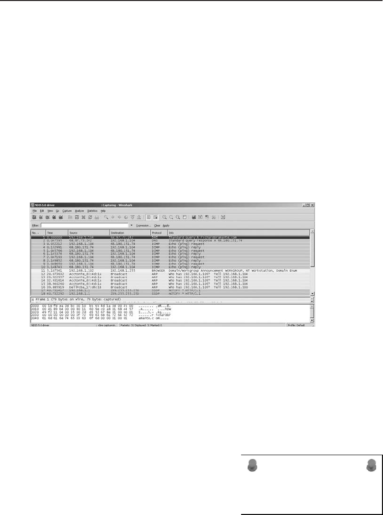
Edwards c16.tex V3 - 03/27/2009 11:49am Page 664
664 Part IV ■Managing and Maintaining the Network
Reply from 68.180.151.74: bytes=32 time=99ms TTL=49
Reply from 68.180.151.74: bytes=32 time=102ms TTL=49
Reply from 68.180.151.74: bytes=32 time=100ms TTL=49
Ping statistics for 68.180.151.74:
Packets: Sent =4, Received =4, Lost =0 (0% loss),
Approximate round trip times in milli-seconds:
Minimum =99ms, Maximum =102ms, Average =100ms
Now take a look at the example in Figure 16-3. This is a picture of the trace
that we captured when issuing the above command. As you can see in the
figure, there is a DNS query for richardbramante.com. A DNS response was
sent back with the IP address associated with the domain name richardbra-
mante.com. Once the IP address is located, you can see the four successful
ICMP echo requests and the corresponding replies to each of this.
Figure 16-3 Viewing the sniffer trace
Wireshark (and most other analyzers) provides three views to the user.
In this description, we used the term window, which means a section of
the application. You are sure to see what we mean as we go along. The top
window of the application shows the list of packets that have beencaptured, the
middle window provides a tree of information for a selected packet, and the
bottom window lists the byte information for the packet. Take a look at
Figure 16-4 for an example of these windows.
ACRONYM ALERT
SMDS — Switched multimegabit data service
In the example, we highlighted the fourth
packet in the trace that we took. This
was an ICMP reply packet from source
node 68.180.151.74 to the destination node
192.168.1.104. Click on the packet in the
upper area of the application to display a
tree listing of the details for the fields of the packet. If you can remember
the frame format of an ICMP reply, that’ll help because this is the data that
is provided in each of those fields. The bottom area is the byte information
breakdown.
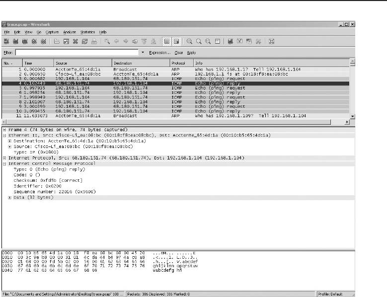
Edwards c16.tex V3 - 03/27/2009 11:49am Page 665
Chapter 16 ■Troubleshooting 665
Figure 16-4 Viewing the sniffer trace details
Now that you have had an opportunity to see how a trace is taken and
how to break down the information in the packet when you are analyz-
ing/troubleshooting your LAN. Now, we highly recommend that you start
another new trace (save your old one for future reference), and this time start
multiple processes. Send an e-mail, open an HTTP session, do an FTP, and ping
a remote destination (why not richardbramante.com?). While these processes
are running, watch the packets processing through the traffic analyzer. This
is a great way to better understand the processes of many of the applications
used by the users of the LAN.
Another thing you can do is download example traces, which are available
in many locations online. These are a good way to learn how to recognize some
issues that you may come across. To locate these, just do an Internet search for
‘‘packet capture example.’’
16.6.3 Example 3: Identifying a Broadcast Storm
Network broadcasts and multicasts are a necessary operation for any LAN.
If you have baselined your network, you should have a good idea of what
is a normal amount of broadcasts or multicasts for your LAN. Therefore,

Edwards c16.tex V3 - 03/27/2009 11:49am Page 666
666 Part IV ■Managing and Maintaining the Network
you should notice when you are having more broadcasts than usual. (This
condition could be catastrophic if not treated.)
If you are working on a LAN that is starting to run slower than normal,37 it
is a good possibility that you are experiencing a broadcast or multicast storm.
Other symptoms of a storm include
Network operations are timing out.
Users are not able to connect to the network.
Users are not able to log on.
Application access is slow or is not available.
The network is down.
A network could be experiencing a broadcast storm for several reasons.
Hardware may have failed, there may be a configuration error on an interface
or a node, spanning tree may have failed, a new application may be causing
the issue, a virus or a worm may be attacking the LAN, and many others.
Broadcast storms can be identified in a sniffer trace and via network
management systems. Finding the originator can be tricky at times. If the
storm is propagating and is affecting multiple areas, you might need to have
some coffee and donuts on hand; it’s going to be a long night. Once you find
the offending interface, you can disable it, and that should calm the storm. A
rogue node on the network can be removed after it is located. A worm can be
filtered and eventually eradicated with software upgrades and installations.
The list goes on and on.
RANDOM BONUS DEFINITION
presentation layer — The sixth layer of the
seven-layer OSI model
In the case of disabling an
interface, you need to track
down where the node is located.
You can do so with information
contained in the trace that you
have taken. Some network man-
agement applications will also
do the tracking for you. Once
you have located the offending interface, disable it. You can do that through
the command line or you can pull out the cable. This can always be reversed,
once you are able to clear whatever is causing or contributing to the storm.
16.6.4 Example 4: VPN Client
Can’t Connect to VPN Server
A VPN client reports that they are unable to connect to the VPN server. They
have repeatedly tried to connect and have also tried to reboot their PC, but
37Jim likes the term sluggish.

Edwards c16.tex V3 - 03/27/2009 11:49am Page 667
Chapter 16 ■Troubleshooting 667
they are not able to connect. The first thing the user needs to check is whether
the VPN client is giving him an error message. If there is one, often it can be
looked up at the vendor’s website to see what the issue might be.38 Finally,
have the user make sure he has an active connection to the Internet. Has
he rebooted his router/modem? Once you have verified that everything is
operating correctly on the client side, whether there have been any changes on
that end? These changes can be PC modifications, change of service provider,
connection setting error, etc. Client issues can be tricky, because the user of
the client software often has the capability to manipulate files on the PC. By
making changes to their configuration, a conflict may arise that causes issues.
Everything on the client side has been checked and verified that the settings
are correct and everything is operating as it should. If the client application
allows for local logging, ask the user to set this up so he can log a connection
attempt on his end. Also, the VPN server log should be checked for messages
pertaining to the user that are on the VPN client side.
Client connection issues can range from a configuration error to a failed
authentication attempt. Most of the time, an error will be displayed and should
identify the problem that is occurring. If there is no error, check the logs. If you
can run a sniffer trace on the client side (and possibly even the public interface
of the VPN server), you may be able to see more indications of what the issue
may be.
POP QUIZ
What are some Network layer issues that
you may come across in a LAN?
If all else fails, the VPN
client software may have to be
reloaded on the user’s PC. This
would have to be accomplished
by following the rules of the
LAN.39
16.6.5 Example 5: Two Common LAN Issues
In Section 16.6.1, we introduced a single user’s connectivity issue from the
application that was running on the user’s PC to the VLAN and routing
domain that the user belonged to. VLAN issues in a bridged LAN are not the
only common issue you might come across. Duplex mismatching and spanning
tree loops are issues that you will come across at some point in your networking
career.
In this section, we provide some information on these two issues and some
ways to diagnose and resolve the issue. If you have access to a lab, you can
38Often the error is self-explanatory. For instance, invalid password means that the password is
not right.
39Hopefully an automatic process or a script has been developed so the installation process is
automatic and as transparent to the end user as possible.

Edwards c16.tex V3 - 03/27/2009 11:49am Page 668
668 Part IV ■Managing and Maintaining the Network
easily replicate these issues and take some traces to view the processes and
learn how to recognize them.
16.6.5.1 Duplex Mismatch
One of the most common issues that arise in an Ethernet LAN is a mismatch in
duplex settings. If you have one end set to full-duplex while the other end is set
to half-duplex, you will see latency when passing data on that link. It’s always
a good rule of thumb to run autonegotiation on your switch ports that connect to
end users. Regardless of what PC they may be using and how it is configured,
the switch will be able to recognize and mirror the settings of the other end.
When autonegotiation was first introduced as a standard, there were a lot
of issues with it working with some bridges that were already installed in
networks at the time. Because of this, many network administrators hard-set
the duplex settings on nodes in the internetwork. When possible, the settings
should be set to 100 MB/full-duplex to ensure maximum performance from
the link.
Symptoms that you may see that indicate a duplex mismatch include the
following:
FCS/CRC errors
Runt datagrams
Late collisions
The hard-coding of the duplex settings requires that the opposite end is
set to the same duplex and speed settings. Although simple in concept, if
the network grows, maintaining these settings at both ends might prove a
real headache. In addition, if a device is set to autonegotiation, it will not
communicate with any device that is not set to autonegotiate. It will recognize
the speed of the link, but not the duplex settings.
ACRONYM ALERT
TC — Topology change
Because the packets can be sent when
you have a duplex mismatch, you cannot
rely on a ping test to determine whether a
problem exists. When you have a duplex
mismatch, data can still be passed over the
link, but will have failures when data is
being forwarded from both ends of the link.
Remember, in TCP many datagrams will
send an acknowledgment to the sender, causing traffic to be sent in both
directions on the link. The full-duplex side will receive the acknowledgment
datagrams, but the half-duplex side will not and will recognize the link as
having a series of collisions. This will cause most of the datagrams that were
sent by the host on the full-duplex side to be lost. Another symptom you will

Edwards c16.tex V3 - 03/27/2009 11:49am Page 669
Chapter 16 ■Troubleshooting 669
see when there is a duplex mismatch is that the transfer of data is slower than
expected when passing large amounts of data (in either direction).
The simplest way to check for duplex mismatches is to look at the configu-
ration settings on both ends of the link.
16.6.5.2 Spanning Tree
A failure in spanning tree usually creates a loop within the area that the
spanning tree group covers. The loop is often called a spanning tree loop,
although this really does not make sense because spanning tree is there to
prevent, not to cause loops. Therefore we should all start referring to it as a lack
of spanning tree loop. So what does this loop mean? It means there is probably
a port within the spanning tree that is forwarding traffic when it shouldn’t be.
Remember that a port can change from blocking to forwarding when it does
not receive a better advertised BPDU from the designated bridge and therefore
elects itself as the designated bridge.
Another problem that might be occurring is a duplex mismatch. If there
is a duplex mismatch within the spanning tree area, the resulting collisions
on the half-duplex side can cause BPDUs to not reach the other bridges
and will therefore trigger a loop in your spanning tree. In addition, if the
physical medium is reporting errors, this will cause packet corruption, which
could cause excessive BPDU loss. Finally, a bridge could get overloaded
and run out of resources, preventing it from sending out BPDUs, although
this is not as common. Usually, forming and sending the BPDUs is not too
resource intensive and will receive a priority over processes that consume
resources.
RANDOM BONUS DEFINITION
Rapid Spanning Tree Protocol (RSTP) — An
enhancement to the original Spanning Tree
Protocol; provides for a faster convergence
when there is a change in the topology of
the spanning tree group.
If you experience a loop
in your bridged network, you
will most likely discover this
through system statistics, with
a sniffer trace, or because every-
one is reporting issues. If you
have effectively baselined your
network, the network topology
diagrams can prove very helpful
when troubleshooting the loop.
In addition, it helps to know
where the root bridge is located in relation to the diagram, and which
ports should be blocking, which ones are redundant links, and which are not
utilized on the spanning tree. As mentioned previously in this chapter, this
information will help you when you are reviewing the traces and the statistics
while trying to trace down the problem. This will also assist anyone who may
not be familiar with your network.

Edwards c16.tex V3 - 03/27/2009 11:49am Page 670
670 Part IV ■Managing and Maintaining the Network
To get out of the loop as soon as possible, disable redundant links (beginning
where you suspect most of the looped traffic is occurring). Although this can
be time consuming, it will tell you where your problem lies. To disable the
link, you can administratively do so or just pull the link and see if the loop
dissipates. If the loop does not dissipate, you can put that link back in and
move to the next one.
You also want to rely on your system event logs, system statistics, and
any traces that you have captured. Some switches also allow options to
verbosely log specific events, so you can capture more specific information
in your event logs. Another thing to keep in mind when troubleshooting
issues in multivendor environments is that some proprietary standards may
cause problems with data passing between different vendor bridges. If your
environment is such, check with the vendor for any compatibility issues that
may exist.
WASN’T THIS BOOK A SNAP?
We know (well, are pretty sure) that you have enjoyed this book, but not as
much as you are going to enjoy these cookies if you make them. We
recommend that you bake up a couple of batches to munch on while you go
over the 200+bonus questions that follow in the appendixes. This recipe
makes about 48 cookies. It was added to this chapter mainly because Jim and
Rich have a diet competition going on, and Jim is trying to tempt Rich into
baking and eating these cookies. It’s also a bonus for you, the reader. Thank
you for reading this book. We hope it really was a snap!
Ingredients:
◆1 cup brown sugar, packed
◆1/4 cup molasses
◆3/4 cup vegetable oil
◆1egg
◆2 cups flour
◆2 tsp. baking soda
◆1/4 tsp. salt
◆1/2 tsp. ground cloves
◆1 tsp. ground ginger
◆1 tsp. ground cinnamon
◆1/3 cup sugar (for decoration)
(continued)

Edwards c16.tex V3 - 03/27/2009 11:49am Page 671
Chapter 16 ■Troubleshooting 671
WASN’T THIS BOOK A SNAP? (continued)
Preparation steps:
1. Preheat oven to 375 degrees.
2. In a large bowl, mix the brown sugar, oil, molasses, and egg.
3. In a separate bowl, combine the flour, baking soda, salt, cloves,
cinnamon, and ginger; stir into the molasses mixture.
4. Roll the dough into 1-1/4 inch balls.
5. Roll each ball in the white sugar and place them on an ungreased
cookie sheet, 2 inches apart. Do not press the cookies down.
6. Bake for 8 to 10 minutes in the preheated oven. The cookie is done when
the center becomes firm.
7. Cool the cookies on wire racks.
16.7 Chapter Exercises
1. For each item in the following list, identify the layer of the OSI refer-
ence model that item applies to:
Damaged cables
Dirty fiber
Excessive signal attenuation
Insufficient bandwidth
Denial-of-service (DoS) attack
Electrical interference
Wireless interference
Damaged interface
Dirty interface
Configuration errors
Authentication issues
Excessive utilization
Excessive errors
VLAN configuration errors
Class-of-service issues

Edwards c16.tex V3 - 03/27/2009 11:49am Page 672
672 Part IV ■Managing and Maintaining the Network
2. In the following example, explain why there is a missing hop.
C:\>tracert 207.215.79.16
Tracing route to www.testshow.com [207.215.79.16]
over a maximum of 30 hops:
11ms<10 ms <10 ms 192.168.1.1
2 7 ms 7 ms 6 ms c-3-0-ubr01.boston.cast.net
[43.16.12.1]
3 9 ms 8 ms 7 ms ge-1-37-ur01.boston.cast.net
[43.16.12.193]
4 * * * Request timed out.
5 7 ms 7 ms 7 ms po-24-ur01.boston.cast.net
[43.16.12.161]
3. True or false: The UDP connection state is one of the fields displayed
with the netstat utility.
4. Network testers are devices used to check the integrity of
LAN cabling.
5. List three options that can be used with the arp command in Windows,
and what each one does.
6. The network analyzer is also known as a .
7. What are three ways you can baseline your network? Describe each
method.
8. What command in a Windows environment enables you to retrieve
detailed information about the current TCP/IP settings of your PC?
9. From your PC, open a traffic analyzer and point it to the inter-
face of your PC. Issue a constant ping to richardbramante.com
(ping richardbramante.com –t). Next, disable your network
connection. What do you notice in your trace?
10. This chapter listed eight quick checks that you can do when
you are having issues within a VLAN. What are they?
16.8 Pop Quiz Answers
1. User feedback is a great way to be notified of an issue on the LAN.
2. Name 10 issues that you might have on the LAN.
Damaged cables
Dirty fiber
Excessive signal attenuation
Insufficient bandwidth

Edwards c16.tex V3 - 03/27/2009 11:49am Page 673
Chapter 16 ■Troubleshooting 673
Denial-of-service (DoS) attack
Electrical interference
Wireless interference
Damaged nodes.
Damaged interface
Dirty interface
Configuration error
Authentication issues
Excessive utilization
Excessive errors
VLAN configuration error
Class-of-service issue
Quality-of-service issue
3. Proactive troubleshooting or reactive troubleshooting — which
is better?
The proactive approach beats the reactive approach hands down!
4. What are two types of topology diagrams that come in handy
when troubleshooting an issue within your LAN?
Logical diagram and physical diagram
5. Name a proactive step you can take to help keep the network running.
Shared knowledge — It’s always good to share what you know.
Have discussions with others when you are not sure, and freely offer
any helpful information you may have with anyone who might have
a need to know.
Proper tools — Make sure that you and your staff have access to
the correct tools. Examples include backup laptops, serial cables,
baseline documentation, etc. The staff can only be as effective as their
tools allow them to be.
Knowledge requirements — Make sure there is no single point of
failure in the network. Make sure that any and all tasks are per-
formed by at least two individuals. This way if someone is on vaca-
tion there will be at least one person in the know. Also, make sure
that you allow only trained personnel to work on an issue. If this is
not an option, make sure they have access to someone who is
experienced.
Spares — If it was within your budget when you designed the
network, you purchased (we hope) and have network spares on

Edwards c16.tex V3 - 03/27/2009 11:49am Page 674
674 Part IV ■Managing and Maintaining the Network
hand. These prevent shipping delays when there is a hardware
problem. Be careful when you do use network spares; make sure
not to do a hardware swap if the issue really isn’t the hardware.
6. What does tracert do?
Provides you with a visual view of the sequence of hops that a packet
takes to a destination
7. What does the command ipconfig /all provide for you?
A detailed listing of the TCP/IP settings on your PC
8. What are the eight logical steps that we provided in this chapter
that you can use to troubleshoot an issue on the LAN?
1. Define the problem.
2. Consider the possibilities.
3. Determine the issue.
4. Find a possible solution.
5. Test the possible solution.
6. Develop an action plan.
7. Implement the action plan.
8. Monitor the results.
9. What are three common issues you can have at the Physical layer?
Damaged cables
Dirty fiber
Excessive signal attenuation
Insufficient bandwidth
Electrical interference
Wireless interference
Damaged interface
Dirty interface
10. What are some Network layer issues that you may come across in
aLAN?
ARP issues
IP addressing issues
Configuration errors
Authentication issues
VLAN configuration errors

Edwards bapp01.tex V3 - 03/27/2009 11:51am Page 675
APPENDIX
A
Additional Exercises
Chapter 1 — Introduction to Networking
1. What is an Internet service provider? (Section 1.1)
2. An internet is often confused with the ,butaninternet
is not necessarily part of the .(Section1.1)
3. What is an extranet? (Section 1.1)
4. In a client/server network relationship, the stores data
that is used by the users of the organizational LAN. (Section 1.1)
5. List three examples of a shared network resource. (Section 1.1)
6. What is a network protocol? (Section 1.1)
7. What is the name of the ARPA subgroup that was set up to focus on
research pertaining to anything that related to computing? (Section 1.2)
8. What are the four locations that made up the original ARPANET?
(Section 1.2)
9. The Nations Science Foundation Network (NSFNET) was developed
originally to allow researchers access to five supercomputers.
Where were these supercomputers located? (Section 1.2)
675

Edwards bapp01.tex V3 - 03/27/2009 11:51am Page 676
676 Appendix A ■Additional Exercises
10. A standard is a standard that is developed and owned by
a specific vendor. (Section 1.3)
11. What is a de facto standard? (Section 1.3)
12. ANSI is the organization that represents the United States
in working with the global community on discussions
relating to two important global standards organizations.
Name these standards organizations. (Section 1.3)
13. A is a team of IEEE professionals brought
together to work on new research activities. (Section 1.3)
14. IEEE 802.3 identifies which IEEE working group? (Section 1.3)
15. IEEE 802.11 is the standard for
(Section 1.3)
16. What functions are performed at the presentation layer? (Section 1.4)
17. Network File System (NFS) is a data format that is used at the
layer. (Section 1.4)
18. Open Shortest Path First (OSPF) is an example of a layer
protocol. (Section 1.4)
19. Point-to-Point Protocol (PPP) is an example of a -
layer protocol. (Section 1.4)
20. What are the reasons why we said that TCP/IP has grown into the
‘‘method of choice’’? Explain each of the reasons you list. (Section 1.5)
21. Using the terms listed under the table, place them in the appropriate
spaces. (Section 1.5)
Diagnostic General Purpose Services
Utilities Utilities Utilities
ipconfig
File Transfer Protocol (FTP)

Edwards bapp01.tex V3 - 03/27/2009 11:51am Page 677
Appendix A ■Additional Exercises 677
Address Resolution Protocol (ARP)
Remote Copy Protocol (RCP)
TCP/IP print server
Web server
Line Printer Daemon (LPD)
tracert
Remote Shell (RSH)
e-mail server
nslookup
Line Printer Daemon (LPD)
Trivial File Transfer Protocol (TFTP)
ping
File Transfer Protocol server
Telnet
netstat
route
DNS
Chapter 2 — LANs, WANs, and MANs
22. A LAN may consist of computers, printers, storage devices, and other
shared devices or services available to a group of users within a
geographical area. (Section 2.1)
23. What does the term sneakernet refer to? (Section 2.1)
24. What are the three main IEEE standards that are primarily
associated with traditional LANs? (Section 2.1)
25. The Media Access Control sublayer provides and
control. (Section 2.1)
26. What was the name of the company that introduced Token Ring tech-
nology? When was it introduced, and what was the operating speed?
(Section 2.1)
27. What are the two notable differences between the IBM and IEEE
802.5 specifications for Token Ring? (Section 2.1)
28. True or false: Both IEEE 802.3 and Ethernet are CSMA/CD network
standards that are fully compatible with each other. (Section 2.1)

Edwards bapp01.tex V3 - 03/27/2009 11:51am Page 678
678 Appendix A ■Additional Exercises
29. Fill out the missing information in the following two tables.
(Section 2.1)
DB9 Pin Assignment
Signal Pin
1
Receive –
Transmit +
5
RJ-45 Pin Assignment
Signal Pin Wire Color
White with orange stripe
Receive – 5
Transmit +White with blue stripe
3
30. IBM Token Ring used cabling of different types to be used in different
environments. Connect the appropriate type with its description below.
(Section 2.1)
Type 2
Type 5
Type 6
Type 8
Type 9
A. This type consists of two parallel pairs. The wires in this cable are
untwisted and have a maximum length of 50 meters. The primary
purposeofthiswireistobeusedininstallationsrequiringthecable
to run under carpeting
B. This type consists of multimode fiber optic cable used to extend the
token ring network and used to interconnect optical repeaters.
C. This type consists of two shielded twisted pairs. It is considered
a low cost short distance cable with a maximum length of 45
meters and is often used for MAU-to-MAU interconnection.
D. This type is a lower cost alternative to Type 1 cable with a maxi-
mum length of 65 meters. It consists of two pairs of shielded twisted
pairs.

Edwards bapp01.tex V3 - 03/27/2009 11:51am Page 679
Appendix A ■Additional Exercises 679
E. This type consists of two shielded twisted pairs as can be found
in Type 1 cable and four unshielded twisted pairs as can be found in
Type 3 cable.
31. Although this protocol is closely related to Token Ring, it is not offi-
cially considered as part of the Token Ring family. Name this protocol.
(Section 2.1)
32. Define the following bus network terms (Section 2.1):
Collision detection
Heartbeat
Jabber
Monitor
33. A star topology is implemented with the use of and
UTP cables terminated with plugs. (Section 2.1)
34. Fill in the blanks in the following table (Section 2.1)
Pin Ethernet IEEE 802.3
1
2
3
4
5
6
7
8
9
10
11
12
13
14
15
35. What are the two types of duplex? What are the differences?
(Section 2.1)

Edwards bapp01.tex V3 - 03/27/2009 11:51am Page 680
680 Appendix A ■Additional Exercises
36. Fault is built into the dual-ring FDDI network.
(Section 2.2)
37. What is POTS? What is it used for? (Section 2.3)
38. What type of a node is required in order for two LANs to be
able to communicate using the ISDN protocol? (Section 2.3)
39. Explain the two most commonly used ISDN services. (Section 2.3)
40. A full T1 line provides channels each with
Kbps of bandwidth. (Section 2.3)
Chapter 3 — Network Hardware
and Transmission Media
41. Fill in the blanks in the following table. Explain how you converted
each one. (Section 3.1)
decimal binary
0
1
2
3
4
5
6
7
8
9
10
42. What is RAM? (Section 3.1)
43. The type of RAM that is used by most PCs today is called
.(Section 3.1)
44. Define the following: (Section 3.1)
Read-only memory (ROM)
Programmable read-only memory (PROM)

Edwards bapp01.tex V3 - 03/27/2009 11:51am Page 681
Appendix A ■Additional Exercises 681
Erasable programmable read-only memory (EPROM)
Electrically erasable programmable read-only memory (EEPROM)
45. What is the difference between a PDU and an SDU? (Section 3.1)
46. In order for communication to take place between nodes, one end of
the connection must be a and the other a .
(Section 3.1)
47. What are the four IP address network classes? Explain each one.
(Section 3.1)
48. The main types of network cables are , ,
.(Section 3.2)
49. What are the four primary colors of cabling used in twisted pair?
50. True or false: Twisted pair cabling is used in Ethernet and Token Ring
networks. (Section 3.2)
51. What are the types of twisted pair cabling? What are the differences in
the types? (Section 3.2)
52. What are the two types of fiber optic cabling? Explain each. (Section 3.2)
53. The is a hardware card that allows a PC to participate
in passing and receiving data on a network. (Section 3.3)
54. A network isanodethatisabletomultiplexsignalsand
then transmit them over a single transmission medium. (Section 3.3)
55. WhatisthenameforthenodetypethatissimilartoanEthernet
hub, but is used in Token Ring networks? (Section 3.3)
56. What is the name of the Layer 2 device that supports and performs
the same basic function of joining network segments within the LAN?
(Section 3.3)
57. What is the name of the node that operates at Layer 3 of the OSI refer-
ence model? (Section 3.3)
58. A is a node that allows the wire speed technologies that
areusedbyLayer2andthetoolsthatareneededtoroutepacketsat
Layer 3. (Section 3.3)
59. Layer switches have the ability to control the flow of data
by implementing what is known as ,whichprovidesfor
packet queuing into classes of service to ensure that data with a higher
priority is attended to before data with a lower priority. (Section 3.3)
60. Name at least three types of network servers that are used in a LAN.
(Section 3.3)

Edwards bapp01.tex V3 - 03/27/2009 11:51am Page 682
682 Appendix A ■Additional Exercises
Chapter 4 — Operating Systems
and Networking Software
61. The portion of a computer that receives data and instructions and
manipulates and acts on the received data in a controlled manner is
known as what? (Section 4.1)
62. True or false: Data can never be stored on magnetic media
because the magnet will erase all data. (Section 4.1)
63. The address space of a node can be determined by taking the
number 2 and raising it to the power of the number of address
bits that are generated by the CPU. That being said, calculate
the following (the first one is done for you: (Section 4.1)
16 address bits =216 (65,536)
20 address bits =
24 address bits =
32 address bits =
64. Hard drives are usually mounted within a computer’s case but today
with USB ports many drives are sold as drives communi-
cating between the drive and computer over the USB port. (Section 4.1)
65. On personal computers input/output connections are in the form of
ports dedicated to either or data communi-
cations. (Section 4.1)
66. What is the most basic form of an operating system? (Section 4.1)
67. In the world today, there are two main GUI-based operating systems
that are in use by most people. What are they? (Section 4.1)
68. As the need for PC connectivity rose, the most common design of net-
work operating systems was the -implemen-
tation. (Section 4.2)
69. True or false: One of the early network operating systems,
Microsoft Networking, utilized an IPX/SPX protocol stack to
provide communications over its network. (Section 4.2)
70. True or false: The problem with TCP/IP networks is that a
workstation can only have a single session running at a
time with any server on the network. (Section 4.2)
71. What is peer-to-peer networking? (Section 4.2)
72. True or false: To perform peer-to-peer networking, some
sort of application program is required. (Section 4.2)

Edwards bapp01.tex V3 - 03/27/2009 11:51am Page 683
Appendix A ■Additional Exercises 683
73. List the NetBIOS primitives that are associated with the ses-
sion service and what each of them does. (Section 4.2)
74. For each of the following statements, give the corresponding operating
system name. (Section 4.3)
A. The operating system that was first developed by AT&T
Bell Labs as a multiuser operating system.
B. This operating system was designed more for the desktop environ-
ment even though it will run on larger computers.
C. Newer versions of this operating system come with configuration
utility programs that assist with the network settings and configura-
tion.
D. This operating system has many similarities and commonalities to
Unix.
E. Can be configured with a text editor.
F. This operating system was initially designed to handle
many users connected simultaneously and all sitting in
front of a character-based terminal.
G. Sun initially developed this operating system for their Sun SPARC
workstations.
H. This operating system is a flat file operating system; most of
the configuration files are in readable text.
I. This operating system provides strong networking tools to allow
it to be interconnected not only to the local LAN but the Internet.
Chapter 5 — The TCP/IP Protocol Suite
75. Developers of networking protocols adhere to a approach.
(Section 5.1)
76. Name the layers of the TCP/IP reference model and list
what the responsibility is of each layer. (Section 5.1)
77. What is the name of the protocol that allows for e-mail commu-
nications and at which layer does it operate? (Section 5.1)
78. True or false: Secure Shell is an application layer protocol. (Section 5.2)
79. names are names that are assigned to URLs on the Inter-
net. (Section 5.2)

Edwards bapp01.tex V3 - 03/27/2009 11:51am Page 684
684 Appendix A ■Additional Exercises
80. Make sure that you have a connection to the Internet, then use the
ping command to find the IP address for the following domains. Write
down your results. (Section 5.2)
www.cnn.com
www.yahoo.com
www.wiley.com
www.google.com
www.richardbramante.com
81. What does the acronym gTLD stand for? (Section 5.2)
82. What type of organization or business would use the following TLDs?
(Section 5.2)
.biz
.com
.edu
.gov
.jobs
.mil
.net
.org
83. What is the name of the protocol that runs between nodes for the pur-
pose of sharing management information pertaining to the managed
system? (Section 5.2)
84. What are the three message types that can be sent from the
SNMP manager to the SNMP agents? (Section 5.2)
85. A is a database that contains manageable objects and
variables of these objects pertaining to a network node, for the
purpose of node management within a network. (Section 5.2)
86. The formal language used by SNMP is (Section 5.2)
87. What is an object identifier (OID)? (Section 5.2)
88. Name some of the improvements that were introduced by SNMPv2.
(Section 5.2)
89. Which version of the SNMP protocol is considered the official one?
(Section 5.2)
90. What is the name of the protocol that provides the capability for
users to access an FTP server and transfer files to and from the server?
(Section 5.2)

Edwards bapp01.tex V3 - 03/27/2009 11:51am Page 685
Appendix A ■Additional Exercises 685
91. Fill out the correct FTP command in the following table. (Section 5.2)
Command Function
Sets the file transfer mode to ASCII.
Sets the file transfer mode to binary.
Changes to another directory.
Terminates a connection.
Removes a file.
Places a copy of a file on the remote node onto a specified
directory on the local node.
Used to monitor the file transfer process. For every 1028
bytes received, a # will be placed on the screen.
Gets a list of available FTP commands.
Gets information about commands.
Lists the names of the files in the current directory.
Used to copy more than one file from the remote node to
the local node.
Makes a new directory.
Used to copy more than one file from the local node to the
remote node.
Used to copy a file from the local node to the remote node.
Used to determine the directory path to the current
directory.
Terminates the FTP session.
Renames a file or directory.
Removes a directory and any subdirectories, if applicable.
92. True or false: There is no difference between the TFTP and FTP proto-
cols. They have different names because they were developed by differ-
ent companies, but they are exactly the same in function. (Section 5.2)
93. Using the SMTP protocol, an SMTP client has a total of five message
types that are sent to an SMTP server. Following is a list of these
message types. Define the purpose of each one. (Section 5.2)
HELO
MAIL
RCPT

Edwards bapp01.tex V3 - 03/27/2009 11:51am Page 686
686 Appendix A ■Additional Exercises
DATA
QUIT
94. Developed originally by Sun Microsystems, this protocol allows end
users access to files that are stored remotely as if the files were local
to the end users workstation. What is the name of this protocol?
(Section 5.2)
95. What are the three modes of operation used by Telnet clients and
servers? (Section 5.2)
96. SSH utilizes which is used to
provide cryptographic keys to authenticate remote nodes and users.
(Section 5.2)
97. What are the two most popular Transport layer protocols? (Section 5.2)
98. Name at least three Application layer protocols that use TCP.
(Section 5.2)
99. Name at least three Application layer protocols that use UDP.
(Section 5.2)
100. Name at least five Internet layer protocols. (Section 5.2)
101. What is the name of the protocol that allows for operating system
access for diskless nodes? (Section 5.3)
102. Define the following. (Section 5.3)
Routing protocol
Routed protocol
Gateway
Interior Gateway Protocol (IGP)
Exterior Gateway Protocol (EGP)
Static routing
Dynamic routing
Chapter 6 — Ethernet Concepts
103. What is the speed of the following Ethernet types? (Section 6.1)
10BASE-T
Fast Ethernet
Gigabyte Ethernet
104. Ethernet nodes using UTP cabling fall into one of two component
types. What are those? (Section 6.1)

Edwards bapp01.tex V3 - 03/27/2009 11:51am Page 687
Appendix A ■Additional Exercises 687
105. What is a straight-through cable? (Section 6.2)
106. True or false: A straight-through cable can be wired with either the
T568A or T568B wiring scheme as long as both ends of the cable are
wired exactly the same using the same wiring pin-out. (Section 6.2)
107. A Ethernet cable must have one plug wired with the
T568A wiring scheme and the other plug wired following the T568B
wiring pin-out. (Section 6.2)
108. What is the major difference between the OSI reference model and the
IEEE 802.3 model? (Section 6.3)
109. What is a frame check sequence? (Section 6.4)
110. Define the following. (Section 6.4)
Carrier sense
Multiple access
Collision detection
111. Fill in the missing information in the following table. (Section 6.4)
Half-Duplex Operational Limitations
Parameters 10 Mbps 100 Mbps 1000 Mbps
Minimum frame size
Maximum collision diameter
with UTP cable
100 meters
Maximum collision diameter
with repeaters
2500 meters 205 meters 200 meters
Maximum number of
repeaters in network path
112. What is frame bursting, and when was it introduced? (Section 6.4)
113. transmission is the capability of a net-
work node to transmit and receive simultaneously. (Section 6.4)
114. are nodes that are actually considered part of the
Physical layer since they are not decision-making devices. They basi-
cally provide the interconnectivity on the physical level for network
nodes. (Section 6.4)
115. is the capability of a network interface to negotiate the
communication parameters to be used between it and the port it is
connected to. (Section 6.4)

Edwards bapp01.tex V3 - 03/27/2009 11:51am Page 688
688 Appendix A ■Additional Exercises
116. True or false: Network administrators don’t have to worry
about traffic patterns on the network. (Section 6.5)
117. What does the acronym VLAN stand for? (Section 6.5)
Chapter 7 — Not to Be Forgotten
118. What is the name of the LAN protocol that was once popular in
the majority of active LANs and is now used as an embedded
standard to serve networks that control technologies such as
automation services, transportation, robotics, gaming, and other
similar network types? (Section 7.1)
119. technology is, for the most part, the predeces-
sor to what we all know as Ethernet. (Section 7.1)
120. What is the name of the corporation that developed Token Ring
technology? (Section 7.1)
121. True or false: Unshielded twisted pair (UTP) cables became
the preferred medium used by Token Ring technologies. This
is because it was less bulky than shielded twisted pair (STP)
cables and was also less expensive than STP. (Section 7.1)
122. What is the name of the first technology that could operate at 100
Mbps? (Section 7.1)
123. What advantages are there in using optical fiber as the primary
transmission medium within a network? (Section 7.1)
124. is the FDDI protocol over twisted-pair medium instead
of fiber. (Section 7.1)
125. Define the following FDDI node types. (Section 7.1)
Single attachment station (SAS)
Single attached concentrator (SAC)
Dual attachment station (DAS)
Dual attached concentrator (DAC)
126. The Digital Equipment Company (Digital) developed and released the
first version of the protocol in the mid-1970s. (Section 7.2)
127. What are the levels of the XNS model and what layer does each
level correspond to on the OSI layered model? (Section 7.2)
128. The protocol is one that is normally found within net-
works that have nodes that are running the Novell NetWare operating
system. (Section 7.2)

Edwards bapp01.tex V3 - 03/27/2009 11:51am Page 689
Appendix A ■Additional Exercises 689
129. In order to support multiple protocol datagrams, there are three main
components that are used by PPP. What are they? (Section 7.2)
130. The Link Access Procedure, Balanced (LAPB) is the
link level protocol that ensures reliable, error-free packet
framing and data communication management. (Section 7.2)
131. Match the ATM adaptation layer type to its appropriate function.
(Section 7.2)
AAL1
AAL2
AAL3
AAL4
AAL5
A. This AAL type supports both connectionless and connection-
oriented data transmission. This AAL type is used to transmit
non-SMDS packets.
B. This AAL type supports VBR transmissions.
C. This AAL type supports CBR transmissions.
D. This AAL type supports both connectionless and connection-
oriented data transmission. This AAL type is used to transmit
switched multimegabit data services (SMDS) packets.
132. AppleTalk is a protocol suite that was developed by the Apple
computer company. AppleTalk was developed specifically
to be integrated with new computers to
allow for resource sharing on a network. (Section 7.2)
133. There are two services used in ISDN to determine bandwidth avail-
ability for an end network. These are and .
(Section 7.2)
Chapter 8 — The Upper Layers
134. The upper layers of the OSI reference model are utilized by
to send and receive data over a network.
(Section 8.1)
135. True or false: One of the great things about mail servers is
that they do not have to perform any authentication, as such
authentication is only performed by a RADIUS server. (Section 8.1)

Edwards bapp01.tex V3 - 03/27/2009 11:51am Page 690
690 Appendix A ■Additional Exercises
136. The field is an 8-bit field that indicates how many
seconds a packet can live on the Internet. (Section 8.2)
137. DMZ is the acronym for what? (Section 8.2)
138. FTP and SMTP are upper-layer protocols that reside within which
layer of the TCP/IP model? (Section 8.2)
139. The following table contains some common Application layer
protocols. Complete the missing parts of the table. (Section 8.2)
Mnemonic PORT(s) Description
DHCP Dynamic Host Configuration Protocol provides the
means for network clients to obtain an IP address,
default gateway IP address and Domain Name System
server addresses.
FTP
HTTP 80
Simple Network Management Protocol is used to
manage and monitor network devices over the local
network and Internet.
Telnet
140. True or false: Port numbers range from 0 to 65,535, but for the
most part the first 1024 (0 to 1023 decimal or 0x03FF hexadecimal)
are considered to be the well-known ports. (Section 8.2)
141. Explain traceroute.(Section8.2)
142. is a dynamic routing protocol used to move packets
from network segment to network segment. (Section 8.2)
143. True or false: Port 0 is normally reserved, but its use is allowed as a
valid source port in transmissions where the transmitting network
node does not require a response from the receiving network node.
(Section 8.2)
Chapter 9 — The Transport Layer
144. What is the standard that defines the recommended services
that are provided by the OSI Transport layer while working with
the Network layer to serve the needs of protocols that are used
at the Session layer? (Section 9.1)

Edwards bapp01.tex V3 - 03/27/2009 11:51am Page 691
Appendix A ■Additional Exercises 691
145. What is the standard that sets the recommendations to be fol-
lowed by nodes (entities) within a network that are utilizing
the services of the OSI Transport layer? (Section 9.1)
146. There are two types of transport service. What are they? (Section 9.1)
147. What are the two data units that operate at the Transport layer?
(Section 9.1)
148. Match the correct transport service class with its class function.
(Section 9.1)
Class 0
Class 1
Class 2
Class 3
Class 4
A. Error recovery and multiplexing class
B. Multiplexing class
C. Simple class
D. Error detection and recovery class
E. Basic error recovery class
149. The purpose of the Transport layer is to provide end-to-end
delivery of data from one to another. (Section 9.2)
150. Explain how a three-way handshake works. (Section 9.2)
151. True or false: The term connectionless can be misleading as connec-
tionless protocols require a connection before they can transmit data.
(Section 9.2)
152. TCP is a protocol, whereas UDP is a proto-
col. (Section 9.3)
153. In a connection-oriented environment, control
and control are two mechanisms that are used to
maintain control over the transmission of data. (Section 9.4)
Chapter 10 — The Network Layer
154. SMTP mail servers will deliver e-mail to the
server servicing a particular domain. (Section 10.1)
155. http://www.mydomainname.com is an example of a .
(Section 10.1)

Edwards bapp01.tex V3 - 03/27/2009 11:51am Page 692
692 Appendix A ■Additional Exercises
156. True or false: Unlike IP addresses, domain names do not have to be
unique. (Section 10.1)
157. What protocol is primarily a method of moving packets of data across
networks consisting of various mediums, seamlessly delivering
these packets solely based on destination address? (Section 10.2)
158. What version of IP allows for 4,294,967,296 unique addresses?
(Section 10.2)
159. What would the binary number look like for the IP address
192.168.15.85? (Section 10.2)
160. The real thrust of moving to is the larger address space
that it provides with 128 bits dedicated to address space. (Section 10.2)
161. What is the name of the protocol that provides a means of messaging
when a sent datagram is not able to be received by a destination node?
(Section 10.2)
162. The command is used to trace the path from the sending
network node to the receiving network node on a network hop-to-hop
basis. (Section 10.2)
163. What is the name of the protocol that makes use of authentication
and encryption to establish a secure connection between end point
network nodes? (Section 10.2)
Chapter 11 — The Data Link Layer
164. In this chapter, we discussed certain expectations that each
LAN should meet. We called them the highs and the lows.
What are each of these? Define them. (Section 11.1)
165. A collision causes datagrams to be , but it doesn’t
necessarily mean that the data can’t be recovered in some way.
(Section 11.2)
166. In a token bus configuration, there is a central node called a
or a . This device is similar to an Eth-
ernet hub, but it has a computer chip that provides the logical
ring that the end nodes are concerned with. (Section 11.2)
167. Define the following. (Section 11.2)
Carrier Sense Multiple Access (CSMA)
Carrier Sense Multiple Access with Collision Avoidance
(CSMA/CA)
Carrier Sense Multiple Access with Collision Detection
(CSMA/CD)

Edwards bapp01.tex V3 - 03/27/2009 11:51am Page 693
Appendix A ■Additional Exercises 693
168. A in CSMA/CD is a message to all other
nodes that a collision has occurred and that they should stop transmit-
ting. (Section 11.2)
169. Match the LLC type with the correct answer. (Section 11.3)
LLC Type 1 (LLC-1)
LLC Type 2 (LLC-2)
LLC Type 3 (LLC-3)
A. This LLC type is used for connectionless services.
B. This LLC type is used for connection-oriented services.
C. This LLC type is used for acknowledgments in conjunction with
connectionless services.
170. Define the following. (Section 11.3)
Destination service access point (DSAP)
Source service access point (SSAP)
Control
171. The is a protocol that is used in conjunction
with LLC-1 for the purpose of upward multiplexing to
more upper layer protocols than what is available with
the standard LLC 8 bit SAP fields. (Section 11.3)
172. True or false: The LLC sublayer is responsible for interfacing
between the MAC sublayer and the Physical layer. (Section 11.3)
173. The IEEE 802 address is a 48-bit address
that is used to identify the network adaptor for a partic-
ular node or interface in the network. (Section 11.3)
174. What is the name for the portion of a frame that contains the
source and destination MAC addresses for interfaces that
are involved in a communication stream? (Section 11.4)
175. True or false: Multicasting is the act of sending a message to multiple
nodes. (Section 11.4)
176. What is the function of the following well-known MAC addresses?
(Section 11.4)
01:80:C2:00:00:00
09:00:4E:00:00:02
CF:00:00:00:00:00
09:00:2B:00:00:0F
177. Frames are either or
PDUs (Section 11.4)

Edwards bapp01.tex V3 - 03/27/2009 11:51am Page 694
694 Appendix A ■Additional Exercises
178. is a function that is used to detect common errors
that may occur during data transmission. (Section 11.4)
179. Ethernet uses what are known as frames for
flow control within Ethernet LANs. (Section 11.4)
180. Explain the following. (Section 11.5)
Source route bridging
Transparent bridging
181. True or false: A bridge is a device that operates much like a repeater
or a hub, but it makes data forwarding decisions that bridge
traffic from one network segment to another. (Section 11.5)
182. True or false: When a bridge receives a frame that is destined for
a multicast address, the bridge will forward the frame to all of the
ports, including the port on which it is received. (Section 11.5)
Chapter 12 — Design Methodologies
183. Which of the following is not a type of organizational LAN?
(Section 12.1)
Hospital LANs
Banking and financial corporate LANs
Manufacturing LANs
Retail LANs
The Internet
184. What are examples of external considerations that need to
be made when designing a network? (Section 12.1)
185. Developing a project is important in the early phases of
network design. (Section 12.2)
186. The design models are the most commonly
used in most high-speed LANs today. (Section 12.3)
187. In a hierarchical design model, there are three layers. What are they?
(Section 12.3)
188. What are three WAN protocols that can be used to connect a LAN to
remote sites? (Section 12.3)
189. The layer is the middleman between the access layer and
the core. (Section 12.3)

Edwards bapp01.tex V3 - 03/27/2009 11:51am Page 695
Appendix A ■Additional Exercises 695
190. The layer is the backbone of the LAN and often provides
connectivity to WANs as well as Internet services. (Section 12.3)
191. Explain some of the benefits of using a hierarchical model.
(Section 12.3)
192. Specify the maximum allowed in each level of the 5-4-3-2-1 design
model. (Section 12.4)
is the number of segments allowed in total.
is the number of repeaters used to join the segments
together.
is the maximum number of segments in total that
have nodes that are active.
is the maximum number of segments in total that are
not active.
is the number of collision domains.
193. The topology is the most often used topology in LANs.
(Section 12.5)
194. What are the advantages to the bus topology? (Section 12.5)
195. What are the disadvantages to the bus topology? (Section 12.5)
196. What are the advantages to the star topology? (Section 12.5)
197. What are the disadvantages of a star topology? (Section 12.5)
198. What are the advantages of a ring topology? (Section 12.5)
199. What are the disadvantages of a ring topology? (Section 12.5)
200. The topology is used for Token Ring and FDDI LANs.
(Section 12.5)
201. The used within a LAN is either a hub or an MAU that
allows the combination of data transmissions for a group of nodes.
(Section 12.5)
202. The ,or ,isaLANnodethatoperates
at Layer 2 of the OSI reference model. (Section 12.5)
203. What is the name of the traditional network node that operates
at Layer 3 of the OSI reference model? (Section 12.5)
204. Why is a Layer 3 switch preferred over a traditional router in
high-speed LANS? (Section 12.5)
205. List five terms that are used to define a switch that oper-
ates at Layers 4-7 of the OSI model. (Section 12.5)

Edwards bapp01.tex V3 - 03/27/2009 11:51am Page 696
696 Appendix A ■Additional Exercises
206. Explain what each type of switch does. (Section 12.5)
Cut-through
Store and forward
207. Which of the following is a false statement? (Section 12.5)
A configuration error within the LAN.
Introduction of a duplicate route.
A loop only occurs when there is no redundancy built into the net-
work.
Introducing an additional node into the LAN.
208. What is the name of the public standard protocol that was
developed to control loops in a catenet? (Section 12.5)
209. What are the possible port states used by STP? (Section 12.5)
210. The standard that covers link aggregation is ,the
Link Aggregation Control Protocol (LACP). (Section 12.5)
211. What are some benefits of link aggregation? (Section 12.5)
212. What are some disadvantages of link aggregation? (Section 12.5)
213. What are some benefits of creating VLANS within your LAN?
(Section 12.5)
214. What are the four types of VLANS? (Section 12.5)
215. What are the two types of network management nodes and
what function does each type perform? (Section 12.5)
Chapter 13 — Implementation
216. True or false: Good network planning begins with a top-down
approach. (Section 13.1)
217. There is a natural dividing line as far as planning goes; one involves
anetwork infrastructure and the other a totally new
design. (Section 13.1)
218. In the chapter, we discussed some fixed costs that you should con-
sider when planning the network. What are these? (Section 13.1)
219. In the chapter, we discussed some recurring costs that you should
consider when planning the network. What are these? (Section 13.1)
220. Which is the best answer to the following statement? (Section 13.1)
Many companies these days lump under the IT (informa-
tion technology) umbrella.

Edwards bapp01.tex V3 - 03/27/2009 11:51am Page 697
Appendix A ■Additional Exercises 697
A. Computer operations and network operations.
B. Telecommunication services
C. Computer operations, network operations, and all other telecom-
munications
D. All data communication services
221. What is a false floor? (Section 13.1)
222. What is a DMZ? (Section 13.1)
223. The VPN remote users have a VPN on their PCs which
is configured to access the company’s VPN access gateway router.
(Section 13.1)
224. True or false: The distribution from the network operations
area to each floor is accomplished by using redundant
STP cabling to provide a high-speed path for the net-
work traffic coming from each floor. (Section 13.1)
225. List the items that should be included in the final documentation of a
network. (Section 13.1)
226. refers to the structural components within a
facility in support of the network architecture. (Section 13.2)
Chapter 14 — Network Security
227. What does WEP stand for? (Section 14.1)
228. In a networking environment, what is the area that should be
restricted and controlled access at all times? (Section 14.1)
229. True or false: The security practices used in a home LAN
are sufficient for all large corporate LANs. (Section 14.1)
230. A is placed in the path in front of the Intranet web
server to analyze the network traffic that is being directed towards it.
(Section 14.1)
231. True or false: Depending upon the size of the network, con-
stantly monitoring every node of a network can be overwhelming.
(Section 14.1)
232. True or false: It is bad practice to document the network from a secu-
rity perspective. (Section 14.1)
233. Name three methods of authentication. (Section 14.2)
234. True or false: The process of network authentication can be simple
as a user ID and password. (Section 14.2)

Edwards bapp01.tex V3 - 03/27/2009 11:51am Page 698
698 Appendix A ■Additional Exercises
235. What are the four most commonly used elements in an LDAP?
(Section 14.2)
236. When a RADIUS client passes a user’s authentication credentials
to the RADIUS server, the server will respond with one of three
responses. What are these responses and what does each mean?
(Section 14.2)
237. The use of came into use as a security method
used to ensure the entities on opposite ends of a communi-
cation channel are who they claim to be. (Section 14.2)
238. is a suite of protocols used for securing Internet commu-
nications. (Section 14.2)
Chapter 15 — Network Management
239. True or false: To have a successful help desk implementation, there
is a need for someone to pick up the telephone. (Section 15.1)
240. In a large organization, there are usually groups of dedicated indi-
viduals who support certain aspects of the network. What are they?
(Section 15.1)
241. True or false: Monitoring network performance for larger
networks is a manual, time-consuming process. (Section 15.1)
242. In any organization, the security group would have a broad
range of activities that deal with all aspects of network
(Section 15.2)
243. The support group is responsible for the distri-
bution of network services over the network. (Section 15.2)
244. What is the logistics group responsible for? (Section 15.2)
245. What are three activities that are considered network maintenance?
(Section 15.3)
246. The SNMP is software that communicates with a net-
work management station (NMS) to answer queries from the station.
(Section 15.5)
247. Each element has its own unique ,whichpro-
vides information on the object or is an object that will take
a variable setting to configure the unit. (Section 15.5)
248. True or false: Packet capture nodes and programs can return
some statistical information if you are investigating

Edwards bapp01.tex V3 - 03/27/2009 11:51am Page 699
Appendix A ■Additional Exercises 699
traffic patterns or performance issues on a network segment.
(Section 15.5)
249. SNMP uses a setting to group a number of devices
to be monitored within the . (Section 15.5)
Chapter 16 — Troubleshooting
250. Name at least five of the common LAN issues that we mentioned in
the chapter. (Section 16.1)
251. When you are notified of a network issue, what are some of the
first questions you should start considering? (Section 16.1)
252. The approach beats the approach.
(Section 16.2)
253. Which of the following is a good proactive step you can take
to help keep the network from going down and to recover
quickly when it does? (Section 16.2)
Shared knowledge
Proper tools
Ensure the proper individuals are trained appropriately
Hardware spares
All of the above
254. The ping is an ICMP echo request/reply that determines
whether a node is ,the time for
the process to complete, any percentages, and a
statistical for a given remote node. (Section 16.3)
255. True or false: By default, the ping command will send four
ICMP requests and will expect four replies. (Section 16.3)
256. The utility by default displays both incoming
and outgoing network connections. (Section 16.3)
257. Network cable testers are devices that are used to check the
integrity of the in the LAN. (Section 16.3)
258. Name a few things that you should investigate when trou-
bleshooting a node that is having problems. (Section 16.3)
259. What are the steps in the logical, eight-step troubleshooting
model that we discussed in the chapter? (Section 16.4)

Edwards bapp01.tex V3 - 03/27/2009 11:51am Page 700
700 Appendix A ■Additional Exercises
260. As redundant as it may seem, what are the layers of the OSI refer-
ence model, and what is performed at each layer? (Section 16.4)
261. What are some common Layer 1 issues that can occur in a network?
(Section 16.5)
262. What are some things that you should look for in each of the following
layers? (Section 16.5)
Layer 4
Layer 5
Layer 6
Layer 7
263. What are three of the symptoms that indicate a duplex mismatch?
(Section 16.7)
264. A failure in spanning tree usually creates a within
the area that the spanning tree group covers. (Section 16.7)
265. What are three common ways to find out you have a loop within the
LAN? (Section 16.7)

Edwards bapp02.tex V3 - 03/27/2009 11:52am Page 701
APPENDIX
B
Exercise Answers
Chapter 1 Exercises
1. The network used exclusively by the University of Texas is an example
of a campus area network (CAN). Note that LAN and MAN are also
appropriate responses.
2. What are the names of the layers in the OSI reference model?
Layer 7 — Application
Layer 6 — Presentation
Layer 5 — Session
Layer 4 — Transport
Layer 3 — Network
Layer 2 — Data Link
Layer 1 — Physical
3. List at least five applications and/or utilities that use TCP/IP.
Telnet
FTP
701

Edwards bapp02.tex V3 - 03/27/2009 11:52am Page 702
702 Appendix B ■Exercise Answers
SMTP
POP
SNMP
4. What are the two types of network relationships?
Connectionless
Connection-oriented
5. Explain the difference between a client/server network relationship
and a client/server database system.
In both cases, the server provides the data requested by a client, but in a
database system, the client node has to use its own resources to format
and view the data retrieved.
6. What is the 1822 protocol?
Specifies the method to connect a host computer to an ARPANET
router.
7. What are the three types of standards? Do a search on the Internet
to see if you can find at least one of each standard type.
Proprietary
Open
De facto
8. The 802.11n standard supports an operating frequency of 2.4 GHz and
5GHz. The maximum data rate for 802.11n is 600 Mbps. 802.11n reaches
a maximum indoor range of 70 meters and an outdoor range of 250
meters.
9. True or false: The Application layer of the OSI model concerns
itself with the application/user interface on a PC.
True
10. In this chapter, we listed seven reasons why TCP/IP has grown to be
the ‘‘method of choice.’’ What are these seven reasons?
Routing
Addressing
Name resolution
Operates on many types of networks
Connection-oriented

Edwards bapp02.tex V3 - 03/27/2009 11:52am Page 703
Appendix B ■Exercise Answers 703
Open standards
Application support
Chapter 2 Exercises
1. Modem is short for modulator/demodulator.
2. A LAN (local area network) is a network where network devices are
located within close proximity to each other.
3. CSMA/CD is an acronym for Carrier Sense Multiple Access with Collision
Detection and is associated with a network using a bus network
topology.
4. Which network topology allows for orderly network access for the sta-
tions connected to that network?
Token Ring
5. What two standards define a CSMA/CD network?
IEEE 802.3
Ethernet
6. Name three media types that can be used to interconnect devices
located on a LAN.
Wire
Fiber optic
Wireless
7. What is the major characteristic of 10BASE-T cable?
Unshielded twisted pair (UTP)
8. A personal computer (PC) requires a network interface card (NIC)
to be connected to a local area network (LAN).
9. FDDI is an acronym for Fiber Distributed Data Interface,whichisoften
used to construct citywide networks called metropolitan area networks
(MANs).
10. POTS is an acronym for plain old telephone system.
11. A dialup service that connects to a digital network is integrated services
digital network (ISDN).

Edwards bapp02.tex V3 - 03/27/2009 11:52am Page 704
704 Appendix B ■Exercise Answers
12. What technology can be used to create a point-to-point network con-
nection over the Internet?
VPN (virtual private network)
Chapter 3 Exercises
1. Explain what ‘‘10 half or 100 full?’’ means to you, what the difference
between 10 half and 100 full is, and list pros and cons of each.
10 half is 10Mbps at half-duplex. It is slower and prone to
collisions.
100 full is 100Mbps at full-duplex. It is faster and not prone to
collisions
2. List three types of interfaces and three types of adaptors.
Interfaces:
The network interface controller (NIC).
The point at the boundary of a LAN, which connects the LAN
to an outside network, is another type of network interface.
In Layer 3 environments, interface is often the term used to describe
a network connection and really isn’t considered hardware.
Adaptors:
The network interface controller (NIC)
Virtual adaptor
Physical adaptor
3. Why is an NIC card considered both an interface and an adaptor?
The NIC card adapts to the computer, allowing it to have an interface to
the network.
4. List three examples of flash memory:
Memory cards for cell phones
Memory cards for digital cameras
Memory cards for video game systems
PCMCIA type 1 memory cards
PCMCIA type 2 memory cards
PCMCIA type 3 memory cards
Personal computer system BIOS chip

Edwards bapp02.tex V3 - 03/27/2009 11:52am Page 705
Appendix B ■Exercise Answers 705
5. List the PDU for each of the OSI layers.
Layer PDU
Application Data
Presentation Data
Session Data
Transport Segment
Network Packet
Data Link Frame
Physical Bit
6. What is the difference between volatile and nonvolatile memory?
Volatile memory content is erased when power is removed.
Nonvolatile memory retains its contents whether power is on or off.
7. What is the difference between STP and UTP cabling?
STP has a shield around the twisted pairs, whereas UTP has no shield.
8. Explain when you would want to use MMF cables instead of SMF
cables. Next, explain in what instances SMF cabling would be preferred
over MMF cabling.
SMF cables are thinner than MMF cables. This is because SMF cables
are designed to carry a single beam of light. Because there are not
multiple beams involved, the SMF cable is more reliable and supports
greater distances and a bandwidth much higher than MMF cables.
The bulk cost of SMF cabling is much less expensive than the MMF
cabling. MMF cabling is made for shorter distances. Unlike SMF,
there are multiple beams of light, so the distance and speed is less.
Granted, supporting data rates of up to 10 Gbps for distances as far as
300 meters is nothing to sneeze at. Because of the additional modes,
MMF cabling is able to carry much more data at any given time.
9. Define modulation.
The process of manipulating a waveform to create a signal that sends
a message that needs to be communicated. In data communications,
modulation is performed by a node that converts a digital signal to
an analog signal, in order to be communicated over a phone line.
10. What does a router use to determine the best path to a destination?
Routing table

Edwards bapp02.tex V3 - 03/27/2009 11:52am Page 706
706 Appendix B ■Exercise Answers
Chapter 4 Exercises
1. If you have a network-capable PC, try using a few of the network utili-
ties discussed in this chapter.
2. Open a DOS window by running cmd from Start ➪Run and
enter the command ipconfig and note what is displayed.
3. Issue the command ipconfig /all and note what is displayed.
4. If your network allows your PC to access the Internet, execute this com-
mand tracert <insert your favorite website URL>andhittheReturn
key. Note the results. You may want to repeat this to other Internet
addresses.
5. To display information about all the interfaces on a Unix computer,
which command would need to be issued?
netstat
6. What is used on the Internet to find the numeric address of a computer
host that resides on the Internet?
DNS server
7. True or false: Floppy disks are the fastest form of magnetic media.
False
8. True or false: AT&T is the sole provider for the Unix operating system.
False
9. Can you name at least one Linux distribution?
Red Hat, SUSE, Ubuntu
10. If a microprocessor designer wanted to allow his newest chip design to
access a greater amount of memory space, what might he do to accom-
plish this?
Increase the number of address bits available
Chapter 5 Exercises
1. What are the four layers of the TCP/IP reference model?
Network interface layer
Internet layer
Transport layer
Application layer

Edwards bapp02.tex V3 - 03/27/2009 11:52am Page 707
Appendix B ■Exercise Answers 707
2. Name four Application layer protocols that we discussed in this
chapter.
DNS (Domain Name System)
SNMP (Simple Network Management Protocol)
FTP (File Transfer Protocol)
TFTP (Trivial File Transfer Protocol)
SMTP (Simple Mail Transfer Protocol)
NFS (Network File System)
TNP (Telecommunications Network Protocol)
SSH (Secure Shell)
3. Explain the structure of the DNS hierarchy.
DNS names are organized hierarchically, with an unnamed root at the
top, then what are known as top-level domain (TLD) names next, fol-
lowed by second-level domain, and, finally, one or more subdomains.
4. What are the five PDU types that are used by SNMP?
GetRequest
GetNextRequest
SetRequest
GetResponse
Trap
5. What is the purpose of FTP?
The File Transfer Protocol (FTP) allows users to access an
FTP server and transfer files to and from the server.
6. Why does TFTP not perform many of the functions that FTP does?
TFTP is a simple file transfer protocol designed to transfer boot-up files
for diskless nodes.
7. What is a daemon?
A daemon is an application or a process that is running on a server for
the purpose of providing client and server access and communication.
8. What are the four control characters used by Telnet for option negotia-
tion and their meanings?
WILL — Used when the sender wants to enable an option
WONT — Used when the sender wants to disable an option
DO — Used when the sender wants the receiver to enable an option

Edwards bapp02.tex V3 - 03/27/2009 11:52am Page 708
708 Appendix B ■Exercise Answers
DON’T — Used when the sender wants the receiver to disable an
option
9. TCP is a connection-oriented protocol, whereas UDP is a connectionless
protocol
10. What are the three main reporting functions that we said are performed
by ICMP?
Error reporting
Testing and troubleshooting
Informational reporting
Chapter 6 Exercises
1. What does the acronym CSMA/CD mean?
Carrier Sense Multiple Access with Collision Detection.
2. What form of communications eliminates the need for collision
detection?
Full-duplex
3. When you choose not to configure an Ethernet port’s speed and duplex
mode what are you relying on?
Autonegotiation
4. What is needed when setting up VLAN networking?
The ability to tag frames
5. What is a source address? What is a destination address?
A source address is the address of the network node that is transmit-
ting the frame. A destination address is the address of the network node
that the frame is intended for.
6. What is the maximum number of bytes the Data field can contain in
an Ethernet frame? What is the minimum number of data bytes?
The maximum number of bytes in the Data field is 1500. The minimum
number is 46 bytes.
Chapter 7 Exercises
1. True or false: The only type of node that is used on a FDDI ring is a
FDDI concentrator.
False

Edwards bapp02.tex V3 - 03/27/2009 11:52am Page 709
Appendix B ■Exercise Answers 709
2. The three levels of operation within the X.25 protocol suite are:
Physical level
Link level
Packet level
3. In X.25, S-frames are used to pass control data, such as transmission
requests, status reporting, I-frame receipt acknowledgements, and
termination requests.
4. What are the three main components used by PPP?
The PPP encapsulation method.
The PPP link control protocol (LCP)
The PPP network control protocol (NCP)
5. What is the difference between a DTE and a DCE in an X.25 network?
The DTE are the user nodes (endpoint nodes), while the DCE is the
entry to the cloud (network nodes).
6. What are the Session layer protocols that are used in the AppleTalk
protocol suite?
AppleTalk DataStream Protocol (ADSP) — A connection-oriented
protocol that provides a data channel for the host nodes.
AppleTalk Session Protocol (ASP) — ASP maintains and manages
higher level sessions.
Printer Access Protocol (PAP) — Maintains and manages virtual
connections to printers, print servers, and other server types.
Zone Information Protocol (ZIP) — Used to manage network num-
bers and AppleTalk zone names.
7. What does the acronym ISDN stand for?
Integrated services digital network
8. What is the frame relay local management interface (LMI) used for?
LMI is used to provide link status updates pertaining to PVCs
between a DTE and the local DCE. One of the functions performed
by LMI is status inquiries that are sent out periodically (normally 10
seconds) to test to see if a link is up. If the inquiry does not receive
a reply, it assumes the link is down. These inquiries are known as
keepalives. LMI will also send out updates pertaining to the status
of all the links in a frame relay network, provide information about
PVC changes, and ensure that IP multicast is functioning.

Edwards bapp02.tex V3 - 03/27/2009 11:52am Page 710
710 Appendix B ■Exercise Answers
9. What is a constant bit rate (CBR)?
A constant bit rate means that the bandwidth required to pass the data
is always available.
10. The Link Control Protocol (LCP) is the foundation protocol of the PPP
protocol suite.
Chapter 8 Exercises
1. List in order from highest to lowest the upper layers of the OSI model,
also indicating their layer number.
Application Layer — Layer 7
Presentation Layer — Layer 6
Session Layer — Layer 5
2. An application that runs on a user’s workstation and communicates over
a network with an appropriate application that is running on a server is
considered to be what type of application?
Client/server
3. Which protocol is considered to be a connection-based protocol?
TCP (Transmission Control Protocol)
4. What functionality can be used to disguise addresses from a private
address space to be seen on the Internet?
NAT (Network Address Translation)
5. List the three private address spaces that may be used and are consid-
ered to be not routable over the Internet.
10.X.X.X
172.16.X.X
192.168.X.X
6. Name an Application layer protocol that can be used to perform file
transfers over the network.
FTP (File Transfer Protocol)
7. What is the protocol that resolves IP addresses to hardware addresses?
ARP (Address Resolution Protocol)

Edwards bapp02.tex V3 - 03/27/2009 11:52am Page 711
Appendix B ■Exercise Answers 711
Chapter 9 Exercises
1. What are the two ISO/IRC standards that define recommendations for
the transport layer?
ISO/IEC 8072 and ISO/IEC 8073
2. What are the two types of transport service?
Connectionless
Connection-oriented
3. From the following list, fill in the class function in the following table.
Multiplexing class
Error detection and recovery class
Simple class
Error recovery and multiplexing class
Basic error recovery class
Class Name Class Function
Class 0 Simple class
Class 1 Basic error recovery class
Class 2 Multiplexing class
Class 3 Error recovery and multiplexing class
Class 4 Error detection and recovery class
4. Match the type with the correct description:
Type C — Network connections that maintain an unacceptable rate of
residual errors
Type A — Network connections that maintain both an acceptable rate
of signaled errors and residual errors
Type B — Network connections that maintain an acceptable rate
of residual errors and an unacceptable rate of signaled errors
5. Define upward multiplexing.
Multiple Transport layer signals to a single network signal
6. Define downward multiplexing.
Multiple network signals to a single transport signal

Edwards bapp02.tex V3 - 03/27/2009 11:52am Page 712
712 Appendix B ■Exercise Answers
7. Explain how a three-way handshake works.
1. The originating node will send a request known as a SYN to the desti-
nation node.
2. The destination node will let the originating node know that it has
received the SYN request by sending back a SYN-ACK message.
3. The originating node will respond to the SYN-ACK by sending back
an ACK message.
8. List four Transport layer protocols.
ATP (AppleTalk Transaction Protocol)
DCCP (Datagram Congestion Control Protocol)
NetBEUI
RTP (Realtime Transport Protocol)
TCP (Transmission Control Protocol)
UDP (User Datagram Protocol)
Chapter 10 Exercises
1. Name the type of network service being used for each of the following:
HTTP — Connection-oriented
FTP — Connection-oriented
Mail — Connectionless
Telnet — Connection-oriented
2. A client/server application is considered to be what type of network
service?
Connection-oriented
3. What is a TLD and can you name a few?
TLD is a top-level domain and is usually the suffix of a URL such as
.com, .gov, .edu, or .net.
4. How is the MTU size determined?
MTU is determined by taking the maximum packet size allowed to cross
the network medium being used and subtracting the size of the frame’s
header and the remainder is the maximum payload size or MTU.

Edwards bapp02.tex V3 - 03/27/2009 11:52am Page 713
Appendix B ■Exercise Answers 713
5. What does NAT accomplish?
NAT enables the use of non-routable addresses to be used on a pri-
vate network that can be used to translate out network requests to the
Internet using a public IP address that the requestor’s source address
has been translated to.
6. Name two network tools that can be used to troubleshoot a network
problem.
ping and traceroute
Chapter 11 Exercises
1. How is a jam signal used in a CSMA/CD environment?
A jam signal in CSMA/CD is a message to all other nodes that a collision
has occurred and they should stop transmitting.
2. How is a jam signal used in a CSMA/CA environment?
A jam signal lets all the other nodes know that the node is ready to
transmit data.
3. An unnumbered frame type is used with which type of LLC?
LLC-1, LLC-2, and LLC-3
4. Find the MAC address of your PC’s NIC card. Once you have found it,
take the OUI and look it up on the IEEE website. What is the informa-
tion that is listed for that particular OUI?
User-dependent results
5. What are the three fields in an LLC PDU, and what do they do?
Destination Service Access Point (DSAP) — This is used to identify
the LLC that is supposed to receive the PDU.
Source Service Access Point (SSAP) — This is used to identify the
LLC that is supposed to send the PDU.
Control — The control field provides sequencing data, command
information, and responses to requests. Note that any or all of
these can be used in any combination.
6. How many bits are in an IEEE 802 MAC address?
There are 48 bits in an IEEE 802 MAC address.

Edwards bapp02.tex V3 - 03/27/2009 11:52am Page 714
714 Appendix B ■Exercise Answers
7. What are the two error checking methods used at the Data Link layer?
Parity checking
CRC
8. What does full-duplex Ethernet use for flow control?
PAUSE frames or the PAUSE function.
9. What is the functional difference between a bridge and a Layer 2 switch?
There is no functional difference between a bridge and a switch. That’s
right! None! Nada! Zero! Zip! Switch is nothing more than a marketing
term that came out in the 1990s.
Chapter 12 Exercises
1. What are the three layers of the hierarchical design model?
The access layer
The distribution layer
Thecorelayer
2. In this chapter, we listed six benefits of the hierarchical model. List
these.
Easy design replication
Easy expandability of the network
Provides redundancy
Increased network performance
Better security
Easy to manage and maintain
3. This question is actually broken down into questions about the 5-4-3
rule. Refer to Figure A-1 for these questions.
a. Does this network comply with the 5-4-3 rule?
Yes
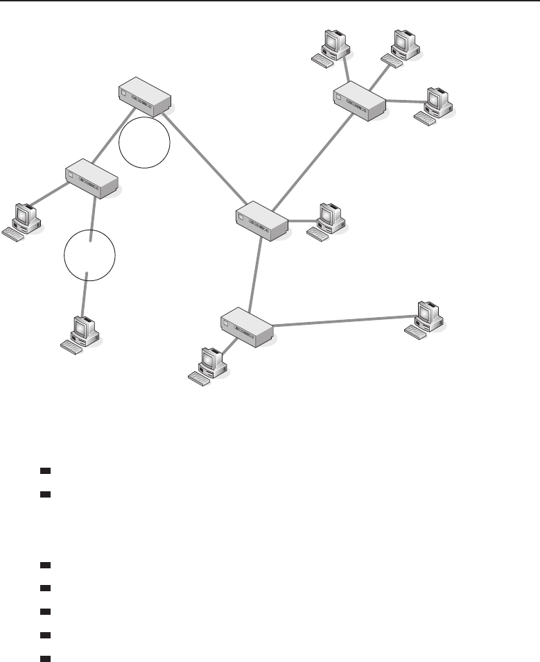
Edwards bapp02.tex V3 - 03/27/2009 11:52am Page 715
Appendix B ■Exercise Answers 715
A
B
Figure A-1
b. Identify what A and B represent in the diagram.
A=Segment
B=Repeater
4. How many possible spanning tree states are there and what are they?
There are five spanning tree port states:
Disabled
Blocking
Listening
Learning
Forwarding

Edwards bapp02.tex V3 - 03/27/2009 11:52am Page 716
716 Appendix B ■Exercise Answers
5. In this chapter, we discussed that a spanning tree port can be in a
learning state. Why do you think that this is required instead of the
port becoming active and just forwarding the frame?
Having a port wait before forwarding data will prevent the alterna-
tive that is offered by the switched default behavior, which is to flood
the frame for destinations that the port does not know about.
6. A port in a learning state is one that is learning paths to destinations
and is preparing to forward the frame.
7. What is the purpose of the distribution layer of the hierarchical
network?
The distribution layer is the middleman between the access layer and
the core. Data received from the access layer is sent to the core to be
routed to the destination. Broadcast domains are separated at this layer
with the implementation of virtual LANs (VLANs). Security is also a
function that is implemented at this layer.
8. True or false: When the switch receives a frame, it will ‘‘tag’’ the
frame with the VLAN identifier from where the data came from.
This process is known as implicit tagging.
False
9. What are the VLAN types we discussed in this chapter?
Port-based VLANs
MAC-based VLANs
Protocol-based VLANs
IP subnet-based VLANs
10. Take a look at Figure A-2 and then identify the appropriate layer of the
hierarchical design model.
A
B
C
Figure A-2

Edwards bapp02.tex V3 - 03/27/2009 11:52am Page 717
Appendix B ■Exercise Answers 717
The letter Ain the example represents the access layer.
The letter Bin the example represents the distribution layer.
The letter Cin the example represents the core layer.
Chapter 13 Exercises
The exercise in the chapter has no right or wrong answers. The important
part is that you understand design planning concepts. If Rich and Jim get
motivated enough, we will roll out a website with some more exercises. If not,
there are many steps that you can take to create your own exercises.
Within Appendix A, there are some more direct questions pertaining to the
chapter.
Chapter 14 Exercises
1. How would you best protect network elements that are located in a
remote area away from the network operations center?
Secure the area and keep it under lock and key.
2. Name a service that can provide not only user authentication but
determine the amount of time a user has been logged in.
RADIUS
3. What is a digital signature associated with?
Certificates
4. Which tunneling protocol was first supported with Microsoft’s Win-
dows 95 operating system?
PPTP
Chapter 15 Exercises
1. Which protocol can be used to monitor devices on a network?
SNMP — Simple Network Management Protocol
2. Where would an SNMP agent be found?
Embedded within a network-connected device
3. What would cause an alert to be displayed on an NMS workstation?
A network-connected device that is being monitored to set an SNMP
trap.

Edwards bapp02.tex V3 - 03/27/2009 11:52am Page 718
718 Appendix B ■Exercise Answers
4. How would packets on a network be captured and inspected?
With packet-capturing software loaded on a computer or a packet sniffer
device.
Chapter 16 Exercises
1. For each item on the following list, identify the layer of the OSI refer-
ence model that item applies to.
Damaged cables — Layer 1
Dirty fiber — Layer 1
Excessive signal attenuation — Layer 1
Insufficient bandwidth — Layer 1
Denial-of-service (DoS) attack — Layer 2
Electrical interference — Layer 1
Wireless interference — Layer 1
Damaged interface — Layer 1
Dirty interface — Layer 1
Configuration error — Layer 2, Layer 3
Authentication issues — Layer 3
Excessive utilization — Layer 2
Excessive errors — Layer 2
VLAN configuration error — Layer 2, Layer 3
Class of Service issue — Layer 2
2. In the following example, explain why there is a missing hop.
C:\>tracert 207.215.79.16
Tracing route to www.testshow.com [207.215.79.16]
over a maximum of 30 hops:
11ms<10 ms <10 ms 192.168.1.1
2 7 ms 7 ms 6 ms c-3-0-ubr01.boston.cast.net [43.16.12.1]
3 9 ms 8 ms 7 ms ge-1-37-ur01.boston.cast.net [43.16.12.193]
4 * * * Request timed out.
5 7 ms 7 ms 7 ms po-24-ur01.boston.cast.net [43.16.12.161]
In the example, there is a missing hop because the router 43.16.12.193
was unable to reach the preferred next hop and took an alternate path.

Edwards bapp02.tex V3 - 03/27/2009 11:52am Page 719
Appendix B ■Exercise Answers 719
3. True or false: The UDP connection state is one of the fields displayed
with the netstat utility.
False. UDP is connectionless, so there is no such thing as a connec-
tion state. TCP is the connection state that is displayed with the netstat
command.
4. Network cable testers are devices that are used to check the integrity of
the cabling in the LAN.
5. List three options that can be used with the arp command in windows,
and what each one does.
-a — Displays current ARP entries by interrogating the current pro-
tocol data. If inet addr is specified, the IP and physical addresses for
only the specified computer are displayed. If more than one network
interface uses ARP, entries for each ARP table are displayed.
-g —Same as -a.
inet addr — Specifies an Internet address.
-N if addr — Displays the ARP entries for the network interface
specified by if addr.
-d — Deletes the host specified by inet addr.inet addr may be
wildcarded with * to delete all hosts.
-s — Adds the host and associates the Internet address inet addr
with the physical address eth addr. The physical address is given as
6 hexadecimal bytes separated by hyphens. The entry is permanent.
eth addr — Specifies a physical address.
if addr — If present, this specifies the Internet address of the
interface whose address translation table should be modified. If
not present, the first applicable interface will be used.
6. The network analyzer is also known as a sniffer.
7. What are three ways you can baseline your network? Explain details for
each of these.
Traffic analyzer — The traffic analyzer (also known as a network
analyzer, packet analyzer, packet sniffer, or just sniffer) can be an
application or a specialized node that is used to capture data being
transmitted on the network. Each packet is captured and can be
manipulated and sorted by RFC, protocol, statistics, or whatever
specifications are set by the user. The data can be organized and
set to graphs or any other form supported by the analyzer and
set by the user.

Edwards bapp02.tex V3 - 03/27/2009 11:52am Page 720
720 Appendix B ■Exercise Answers
Statistical graphing with the management station —SNMP
management stations usually have the ability to record statistical
data and record the data in reports and graphs. Maintaining such
information can be useful in determining abnormal conditions
within the catenet.
Determine thresholds that need to be maintained —Knowyour
LAN. Test and analyze traffic patterns, traffic capacity limits, overall
throughput operation, routing path costs, Physical layer well-being,
etc. Keep the results on hand for reference when an issue occurs.
Not only can this assist in alerting you to abnormal operations, it can
offer proof of the abnormal operations should you need to bring in
a vendor for assistance in troubleshooting an issue. Understanding
peak traffic periods, protocol usage statistics, average throughput,
and normal traffic patterns is important in understanding problems
that occur in the network and resolving them quickly and effectively.
8. What command can be used in a Windows environment that will pro-
vide you with detailed information about the current TCP/IP settings
of your PC?
ipconfig /all
9. From your PC, open up a traffic analyzer and point it to the interface
of your PC. Issue a constant ping to www.richardbramante.com
(ping www.richardbramante.com –t). Next, disable your
network connection. What do you notice in your trace?
This exercise is mainly for the reader to get a better feel for data col-
lection and process recognition. The main thing we are looking for in
the answer to this question is the ARP processes that start when the
connection is down, and then the route-learning processes that occur
until the connection is recovered.
10. This chapter listed eight quick checks that you can do when you are
having issues within a VLAN. What are they?
Is there any maintenance going on at the time?
Have there been any recent changes that may have created the issue?
Verify the configurations of the bridges.
Check statistics. Review logs and traces. Utilize show and
debug commands that are available and are applicable.
Is this a new configuration? Make sure that all necessary configu-
ration parameters are set correctly.

Edwards bapp02.tex V3 - 03/27/2009 11:52am Page 721
Appendix B ■Exercise Answers 721
Are the VLANs configured correctly? Make sure that all VLAN rules
were followed. Have there been any changes made? Did someone
delete a VLAN?
Are tagging rules applied correctly?
Is there a routing issue that is preventing devices within
the VLAN from communicating with other devices?
Appendix A Exercises
1. What is an Internet service provider (ISP)?
Internet service providers (ISPs) provide the gateway to the
Internet for their customers and information is shared.
2. An internet is often confused with the Internet, but an internet is not
necessarily part of the Internet.
3. What is an extranet?
An extranet is an intranet that is opened up to allow outside users
4. In a client/server network relationship, the server stores data
that is used by the users of the organizational LAN.
5. List three examples of a shared network resource.
Printers
Modem
Scanner
Data files
Applications
Storage
6. What is a network protocol?
A protocol is a standard (or set of standards) that governs the
rules to follow for setting up a data connection, communication
between endpoints once the connection is set, and transferring data
between those endpoints.
7. What is the name of the ARPA subgroup that was set up to focus
on research pertaining to anything that related to computing?
The Information Processing Techniques Office (IPTO)
8. What are the four locations that made up the original ARPANET?
Stanford Research Institute

Edwards bapp02.tex V3 - 03/27/2009 11:52am Page 722
722 Appendix B ■Exercise Answers
University of California, Los Angeles
University of California, Santa Barbara
University of Utah
9. The National Science Foundation Network (NSFNET) was developed
originally to allow researchers access to five supercomputers. Where
were these supercomputers located?
Cornell University
Pittsburgh Supercomputing Center
Princeton University
University of Illinois
University of California, San Diego
10. A proprietary standard is a standard that is developed and owned by a
specific vendor.
11. What is a de facto standard?
A de facto standard is a standard that began as a proprietary standard
and then grew to a standard that is used by pretty much everyone.
12. ANSI is the organization that represents the United States in working
with the global community on discussions relating to two important
global standards organizations. Name these standards organizations.
International Organization for Standardization (ISO)
International Electrotechnical Commission (IEC)
13. A working group is a team of IEEE professionals brought together to
work on new research activities.
14. IEEE 802.3 identifies which IEEE working group?
Ethernet Working Group
15. IEEE 802.11 is the standard for wireless LAN technology.
16. What functions are performed at the Presentation layer?
Encryption services
Decryption services
Data compression services
Data decompression services
Translation services
17. Network File System (NFS) is a data format that is used at the Session
layer.

Edwards bapp02.tex V3 - 03/27/2009 11:52am Page 723
Appendix B ■Exercise Answers 723
18. Open Shortest Path First (OSPF) is an example of a Network layer
protocol.
19. Point-to-Point Protocol (PPP) is an example of a Data Link layer
protocol.
20. What are the reasons why we said that TCP/IP has grown into
the ‘‘method of choice’’? Explain each of the reasons you list.
Routing — TCP/IP was designed to route data from node to node
of networks of variable sizes and complexities. TCP/IP is not
worried about the status of nodes in the network, it is concerned
about the networks that it should know about. Various protocols
that are within the TCP/IP protocol suite manage data flow
between networks.
Addressing — And guess what is built into TCP/IP? That’s
right, IP. IP provides a way for a node to identify other nodes
within a network and deliver data to any endpoint node that it
has been made aware of.
Name resolution — TCP/IP provides name resolution as
a way to map an IP address (10.10.10.10) to an actual name
(networkz.org). Can you imagine how tough it would
be to remember the IP addresses of all of the websites
that you needed to know about? Name resolution really
helps.
Doesn’t discount the lower layers —AlthoughTCP/IPoperates
at the upper layers (Layer 3 and above), it does have the ability
to operate at the lower levels as well. This means that for most
LANs and WLANs, and some MANs and WANs, TCP/IP is
able to work with multiple networks of these types and connect
them to each other with TCP/IP.
Open standards — TCP/IP was mainstreamed to give different
nodes the capability to communicate with one another. The open
standards that TCP/IP contains are available to anyone. These stan-
dards are determined through the RFC process that we discuss in
Section 1.3.9.
Talking endpoint to endpoint — TCP/IP provides a way for one
endpoint to speak directly with another endpoint, regardless of any
nodes that are in between. It is as if the endpoints were directly con-
nected to one another, even when they are not physically connected
to a common network. Thanks to TCP/IP, both the originating
and the destination nodes can exchange connection acknowledge-
ments directly with one another.

Edwards bapp02.tex V3 - 03/27/2009 11:52am Page 724
724 Appendix B ■Exercise Answers
Application support — TCP/IP provides protocols that provide a
commonality among end user applications. Often when an appli-
cation that utilizes TCP/IP is developed, many of the functions
required for the application are already common with any node
supporting TCP/IP.
21. Using the terms listed under the table, place them in the appropriate
spaces.
Diagnostic Utilities General Purpose Utilities Services Utilities
Address Resolution
Protocol (ARP)
File Transfer Protocol
(FTP)
TCP/IP print
server
ipconfig Line Printer Daemon
(LPD)
Web server
Line Printer Daemon
(LPD)
Remote Copy Protocol
(RCP)
File Transfer
Protocol Server
netstat Remote Shell (RSH) E-mail server
nslookup Telnet Domain name
server
ping Trivial File Transfer
Protocol (TFTP)
route
tracert
22. A LAN may consist of computers, printers, storage devices, and
other shared devices or services available to a group of users within
a(any term that defines a local or a limited distance is a correct answer)
geographical area.
23. What does the term sneakernet refer to?
The term sneakernet refers to the days when data was copied on a
floppy disk and then transported by an individual to the des-
tination PC.
24. What are the three main IEEE standards that are primarily associated
with traditional LANs?
IEEE 802.2 Logical Link Control
IEEE 802.3 CSMA/CD Access Method and Physical Layer
Specifications
IEEE 802.5 Token Ring Access Method and Physical Layer
Specifications

Edwards bapp02.tex V3 - 03/27/2009 11:52am Page 725
Appendix B ■Exercise Answers 725
25. The Media Access Control sublayer provides addressing and channel
control.
26. What was the name of the company that introduced Token Ring
technology? When it was introduced, what was the operating
speed?
When Token Ring was first introduced by IBM it possessed a speed of
4 Mbps, thus not offering any advantage over CSMA/CD networks.
27. What are the two notable differences between the IBM and IEEE 802.5
specifications for Token Ring?
The number of nodes on a ring is up to 260 nodes per IBM specifi-
cation, and the IEEE 802.5 standard limits it to a maximum of 250
nodes.
Source routing IBM allows up to 8 fields for route designation
when source routing is employed, while the IEEE 802.5 standard
allows for a maximum of 14 fields.
28. True or false: Both IEEE 802.3 and Ethernet are CSMA/CD network
standards that are fully compatible with each other.
False — Although both are network standards, the two are not fully
compatible with each other.
29. Fill in the missing information in the following two tables.
DB9 Pin Assignment
Signal Pin
Receive +1
Receive – 6
Transmit +9
Transmit – 5
RJ-45 Pin Assignment
Signal Pin Wire Color
Receive +4 White with orange stripe
Receive – 5 Orange with white stripe
Transmit +6 White with blue stripe
Transmit – 3 Blue with white stripe

Edwards bapp02.tex V3 - 03/27/2009 11:52am Page 726
726 Appendix B ■Exercise Answers
30. IBM Token Ring used cabling of different types to be used in different
environments. Connect the appropriate type with its description
below.
A. This type consists of two parallel pairs. The wires in this cable
are untwisted and have a maximum length of 50 meters. The pri-
marypurposeofthiswireistobeusedininstallationsrequiring
the cable to run under carpeting.
B. This type consists of multimode fiber optic cable used to extend
the token ring network and used to interconnect optical repeaters.
C. This type consists of two shielded twisted pairs. It is considered
a low cost short distance cable with a maximum length of 45
meters and is often used for MAU-to-MAU interconnection.
D. This type is a lower cost alternative to Type 1 cable with a
maximum length of 65 meters. It consists of two pairs of shielded
twisted pairs.
E. This type consists of two shielded twisted pairs as can be found
in Type 1 cable and four unshielded twisted pairs as can be found
in Type 3 cable.
Type 2 — E
Type 5 — B
Type 6 — C
Type 8 — A
Type 9 — D
31. Although this protocol is closely related to Token Ring, it is not offi-
cially considered part of the Token Ring family. Name this protocol.
Fiber Distributed Data Interface (FDDI)
32. Define the following bus network terms:
Collision detection — Provided by circuitry designed to detect
collisions on the bus network. If a collision is detected, the
transceiver notifies the transmitting function that a collision has
occurred and then it broadcasts a jamming signal on the network
to notify other systems connected to the bus network that a
collision has occurred. The LAN is then allowed to settle before the
resumption of transmissions on to the bus.
Heartbeat — Generation of a short signal to inform the main
adapter that the transmission was successful and collision
free. Although it is specified in the 802.3 standard and the

Edwards bapp02.tex V3 - 03/27/2009 11:52am Page 727
Appendix B ■Exercise Answers 727
Ethernet standard, it is rarely used as many adapters confuse this
signal with the signal that signifies a collision has occurred.
Jabber — The function that allows the transceiver to cease
transmission if the frame being transmitted exceeds the specified
limit of 1518 bytes. This helps prevent a malfunctioning system or
adapter from flooding the LAN with inappropriate data.
Monitor — This function monitors LAN traffic by prohibiting
transmit functions while receive and collision functions are
enabled. It does not generate any traffic onto the LAN.
33. A star topology is implemented with the use of hubs and UTP cables
terminated with RJ-45 plugs.
34. Fill in the blanks in the following table:
Pin Ethernet IEEE 802.3
1 Ground Ground Control In
2 Collision Detected +Control In A
3Transmit+Data Out A
4Ground DataIn
5 Receive +Data In A
6 Voltage Common
7 Control Out A
8 Ground Control Out
9 Collision Detected – Control In B
10 Transmit – Data Out B
11 Ground Data Out
12 Receive – Data In B
13 Power
14 Power Ground
15 Control Out B
35. What are the two types of duplex? What are the differences?
Duplex is either half duplex or full duplex. The difference between
the two is that full-duplex devices are capable of both transmitting
and receiving at the same time, whereas half-duplex devices are
either in transmit or receive mode but never both simultaneously.
36. Fault tolerance is built into the dual-ring FDDI network.

Edwards bapp02.tex V3 - 03/27/2009 11:52am Page 728
728 Appendix B ■Exercise Answers
37. What is POTS? What is it used for?
POTS stands for plain old telephone service. It refers to the use of
voice-grade telephone lines to form a point-to-point data connection.
38. What type of a node is required in order for two LANs to be able to
communicate using the ISDN protocol?
LAN-to-LAN connectivity with ISDN can best be accomplished with
the use of ISDN routers.
39. Explain the two most commonly used ISDN services.
Basic rate — Provides two B channels of 64 Kbps and a single D
channel of 16Kbps.
Primary rate — Provides 23 B channels of 64 Kbps and a single
D channel of 64 Kbps for U.S.- and Japan-based subscribers. Sub-
scribers in Europe and Australia are provided with 30 B channels.
40. A full T1 line provides 24 channels each with 64Kbps of bandwidth.
41. Fill in the blanks in the following table:
decimal binary
0 0000
1 0001
2 0010
3 0011
4 0100
5 0101
6 0110
7 0111
8 1000
9 1001
10 1010
42. What is RAM?
Random access memory (RAM) is memory that is available for data
storage and access, regardless of the order in which it is stored.
Information stored in RAM is accessible until it is cleared out or the
device it is being used on is shut down.
43. The type of RAM that is used by most PCs today is called dynamic ran-
dom access memory (DRAM).

Edwards bapp02.tex V3 - 03/27/2009 11:52am Page 729
Appendix B ■Exercise Answers 729
44. Define the following:
Read-only memory (ROM) — Memory that is configured and set
by the manufacturer. It contains device systems software that is
necessary for the proper operation of the device.
Programmable read-only memory (PROM) — A memory chip that
can be written to only once. This will allow someone other than the
manufacturer to write data onto the PROM. Just like ROM, the data
is there forever. In order to write the data onto the memory chip, a
device known as a PROM programmer (PROM burner) is used.
Erasable programmable read-only memory (EPROM) — A mem-
ory chip that can be written to and store data that may need to be
overwritten at some point. The data on the EPROM is erased by
UV light and then can be reprogrammed with a PROM burner.
Electrically erasable programmable read-only memory
(EEPROM) — A memory chip that can be written to and store data
that may need to be overwritten at some point. The data on the
EEPROM is erased by an electrical charge and then can be
reprogrammed with a PROM burner.
45. What is the difference between a PDU and an SDU?
The PDU specifies the data that is to be transmitted to the peer layer
at the receiving end. The SDU can be considered the PDU payload.
46. In order for communication to take place between nodes, one
end of the connection must be a DCE and the other a DTE.
47. What are the four IP address network classes? Explain each one.
Class A — Class A addresses are identified by a number from 1
to 126 in the first octet. In Class A addresses, the first octet identi-
fies the network and the remaining three octets identify the host.
These addresses are normally assigned to larger networks.
Class B — Class B addresses are identified by a number from 128
to 191 in the first octet. In Class B addresses, the first two octets
identify the network and the last two identify the host. These
addresses are normally assigned to medium size networks.
Class C — Class C addresses are identified by a number from 192
to 223 in the first octet. In Class C addresses, the first three octets
identify the network while the last octet identifies the host. These
addresses are normally assigned to small to medium size networks.
Class D — Class D addresses are a little different from the other
Classes. Class D addresses are used for multicasting. These
addresses always begin with the first 4 bits being 1110 and the

Edwards bapp02.tex V3 - 03/27/2009 11:52am Page 730
730 Appendix B ■Exercise Answers
remaining 29 bits identifying the catenet in which the multicast
message is to be sent.
48. The main types of network cables are twisted pair,fiber optic,and
coaxial.
49. What are the four primary colors of cabling used in twisted pair?
Blue
Brown
Green
Orange
50. True or false: Twisted pair cabling is used in Ethernet and Token Ring
networks.
True
51. What are the types of twisted pair cabling? What are the differences in
the types?
UTP (unshielded twisted pair) — UTP cabling is the type of
copper cabling that is used the most in networks today. UTP
cables consist of two or more pairs of conductors that are grouped
within an outer sleeve. UTP cable is often referred to as Ethernet
cable, because Ethernet is the predominant technology that uses
UTP cable. UTP cabling is cheap, but does not offer protection
from electrical interference. Additionally, bandwidth is limited
with UTP in comparison with some of the other cable types.
STP (shielded twisted pair) — STP cabling is a type of copper
cabling that is used in networks where fast data rates are required.
STP cables consist of two or more pairs of conductors that are
grouped together and then an additional metal shield wraps
around the twisted pairs, forming an additional barrier to help
protect the cabling. Finally, all of the cables are grouped together
and a final outer sleeve is placed over the wiring. STP cables are
also referred to as Ethernet cables. STP cables provide additional
protection to the internal copper, thus data rates are increased
and more reliable. The conductors that are grouped together can
be shielded as individual pairs (in other words, each pair will
have its own shield), or all pairs can be shielded as a group.
52. What are the two types of fiber optic cabling? Explain each.
Single-mode fiber optical cabling — SMF cables are thinner
than MMF cables. This is because SMF cables are designed to
carry a single beam of light. Because there are not multiple beams
involved, the SMF cable is more reliable and supports greater

Edwards bapp02.tex V3 - 03/27/2009 11:52am Page 731
Appendix B ■Exercise Answers 731
distances and a much higher bandwidth than MMF cables. The
bulk cost of SMF cabling is much less expensive than MMF cabling.
Multi-mode fiber optical cabling — MMF cabling is made for
shorter distances. Unlike SMF, there are multiple beams of light, so
the distance and speed are less. Granted, supporting data rates of
up to 10 Gbps for distances as far as 300 meters is nothing to sneeze
at. Because of the additional modes, MMF cabling is able to carry
much more data at any given time.
53. The network interface controller (NIC) is a hardware card that allows
a PC to participate in passing and receiving data on a network.
54. A network concentrator is a node that is able to multiplex signals
and then transmit them over a single transmission medium.
55. What is the name for the node type that is similar to a Ethernet hub,
but is used in Token Ring networks?
Media access unit (MAU)
56. What is the name of the Layer 2 device that supports and performs the
same basic function of joining network segments within the LAN?
Layer 2 switch or a bridge
57. What is the name of the node that operates at Layer 3 of the OSI
reference model?
Router
58. A Layer 3 switch is a node that allows the wire speed technologies that
are used by Layer 2 and the tools that are needed to route packets at
Layer 3.
59. Layer 3 switches have the ability to control the flow of data by
implementing what is known as class of service (COS),whichprovides
for packet queuing into classes of service to ensure that data with
a higher priority is attended to before data with a lower priority.
60. Name at least three types of network servers that are used in a LAN.
Print server
File server
Network server
FTP server
Mail server
Fax server
List server
Proxy server

Edwards bapp02.tex V3 - 03/27/2009 11:52am Page 732
732 Appendix B ■Exercise Answers
61. The portion of a computer that receives data and instructions and
manipulates and acts on the received data in a controlled manner is
known as what?
The central processing unit (CPU)
62. True or false: Data can never be stored on magnetic media because the
magnet will erase all data.
False — The memory storage area can be constructed of various stor-
age nodes anywhere from semiconductor to magnetic media.
63. The address space of a node can be determined by taking the number
2 and raising it to the power of the number of address bits that are
generated by the CPU. That being said, calculate the following (the
first one is done for you):
16 address bits =216(65,536)
20 address bits =220(1,048,576)
24 address bits =224(16, 777,216)
32 address bits =232(4,294,967,296)
64. Hard drives are usually mounted within a computer’s case, but
today, with USB ports, many drives are sold as external drives
communicating between the drive and computer over the USB port.
65. On personal computers, input/output connections are in the form of
ports dedicated to either serial or parallel data communications.
66. What is the most basic form of an operating system?
Afilemanager
67. In the world today, there are two main GUI-based operating
systems that are in use by most people. What are they?
Microsoft Windows
Mac OS X
68. As the need for PC connectivity rose, the most common design of
network operating systems was the client/server implementation
69. True or false: One of the early network operating systems, Microsoft
Networking, utilized an IPX/SPX protocol stack to provide
communications over its network.
False — Novell utilized an IPX/SPX protocol stack to provide commu-
nications over its network.
70. True or false: The problem with TCP/IP networks is that a worksta-
tion can only have a single session running at a time with any server
on the network.

Edwards bapp02.tex V3 - 03/27/2009 11:52am Page 733
Appendix B ■Exercise Answers 733
False — The majority of today’s networks are TCP/IP-based
networks that have a wide range of various applications running
over them. A workstation may have multiple sessions to various
servers on the network simultaneously.
71. What is peer-to-peer networking?
Peer-to-peer networking is where one computer can share data and
resources with another computer.
72. True or false: To perform peer-to-peer networking, some sort of appli-
cation program is required.
True
73. List the NetBIOS primitives that are associated with the session
service and what each of them does.
Call — Opens a session to a remote computer using its NetBIOS
name
Listen — Listens for session requests using NetBIOS name
Hang Up — Ends a session that had been previously established
Send — Sends a packet to the computer that a session had been
established with
Send No ACK — Similar to Send but does not require a returned
acknowledgement that the packet was received
Receive — Waits for the arrival of a packet from a computer a
session has been established with
74. For each of the following statements, give the correspond-
ing operating system name. The first one has been completed as an
example.
A. The operating system that was first developed by AT&T Bell Labs
as a multiuser operating system.
Unix
B. This operating system was designed more for the desktop
environment even though it will run on larger computers.
Linux
C. Newer versions of this operating system come with configura-
tion utility programs that assist with the network settings and
configuration.
Unix
D. This operating system has many similarities and commonalities to
Unix.

Edwards bapp02.tex V3 - 03/27/2009 11:52am Page 734
734 Appendix B ■Exercise Answers
Linux and Sun Solaris
E. Can be configured with a text editor.
Linux and Unix
F. This operating system was initially designed to handle many users
connected simultaneously and all sitting in front of a character-
based terminal.
Unix
G. Sun initially developed this operating system for their Sun SPARC
workstations.
Sun Solaris
H. This operating system is a flat file operating system; most of the
configuration files are in readable text.
Unix
I. This operating system provides strong networking tools to allow it
to be interconnected not only to the local LAN but the Internet.
Sun Solaris
75. Developers of networking protocols adhere to a layered approach.
76. Name the layers of the TCP/IP reference model and list what the
responsibility is of each layer.
Network interface layer — The network interface layer corre-
sponds to the Physical and Data Link layers of the OSI reference
model. This layer is also often referred to as the link layer or
the data link layer. The network interface layer is responsible
for the device drivers and hardware interfaces that connect a
node to the transmission medium.
Internet layer — The Internet layer corresponds to the Network
layer of the OSI reference model. This layer is also known as the
network layer. The Internet layer is responsible for the delivery of
packets through a network. All routing protocols (RIP, OSPF, IP,
etc.) are members of this layer. Nodes that perform functions at this
layer are responsible for receiving a datagram, determining where
to send it, and then forwarding it toward the destination. When a
node receives a datagram that is destined for the node, this layer is
responsible for determining the forwarding method for information
that is in the packet. Finally, this layer contains protocols that send
and receive error messages and control messages as required.
Transport layer — The transport layer corresponds to the
Transport layer of the OSI reference model. There are two primary

Edwards bapp02.tex V3 - 03/27/2009 11:52am Page 735
Appendix B ■Exercise Answers 735
protocols that operate at this layer. These are the Transmission
Control Protocol (TCP) and the User Datagram Protocol (UDP).
This layer serves the application layer and is responsible for
data flow between two or more nodes within a network.
Application layer — The application layer corresponds to the
Application, Presentation, and Session layers of the OSI reference
model. Users initiate a process that will use an application to access
network services. Applications work with protocols at the transport
layer in order to pass data in the form needed by the transport pro-
tocol chosen. On the receiving end, the data is received by the lower
layers and passed up to the application for processing for the des-
tination end user. This layer concerns itself with the details of the
application and its process and not so much about the movement of
data. This is what separates this upper layer from the lower three.
77. What is the name of the protocol that allows for e-mail commu-
nications and at which layer does it operate?
The name of the protocol is the Simple Mail Transfer Protocol (SMTP)
and it is an Application layer protocol.
78. True or false: Secure Shell is an Application layer protocol.
True
79. Domain names are names that are assigned to URLs on the Internet.
80. Make sure that you have a connection to the Internet, then use the
ping command to find the IP address for the following domains.
Write down your results.
www.cnn.com
www.yahoo.com
www.wiley.com
www.google.com
www.richardbramante.com
Because IP addresses can change, the blanks have been left
blank. The important thing is that you were able to get an IP
address using the ping command.
81. What does the acronym gTLD stand for?
Generic top-level domain
82. What type of organization or business would use the following
gTLDs?
.biz — Restricted for use by businesses

Edwards bapp02.tex V3 - 03/27/2009 11:52am Page 736
736 Appendix B ■Exercise Answers
.com — Intended for use by commercial organizations
.edu — Post-secondary educational institutions
.gov — Restricted for use by the United States federal, state, and
local governments.
.jobs — Sites related to employment
.mil — The United States military
.net — Miscellaneous
.org — Miscellaneous organizations
83. What is the name of the protocol that runs between nodes for the pur-
pose of sharing management information pertaining to the managed
system?
The Simple Network Management Protocol (SNMP) is a protocol
that runs between an SNMP manager and an SNMP client, also
known as an SNMP managed system, for the purpose of sharing
management information pertaining to the managed system.
84. What are the three message types that can be sent from the SNMP
manager to the SNMP agents?
GetRequest
GetNextRequest
SetRequest
85. A management information base (MIB) is a database that contains man-
ageable objects and variables of these objects pertaining to a network
node, for the purpose of node management within a network.
86. The formal language used by SNMP is Abstract Syntax Notation 1
(ASN.1).
87. What is an object identifier (OID)?
An OID is a series of sequential integers that are separated
by dots. The OID defines the path to the sought object.
88. Name some of the improvements that were introduced by SNMPv2.
Security
SNMP manager to SNMP manager communication
Improved performance
Confidential sessions
Additional protocol support
Improvements in the way trap PDUs are handled

Edwards bapp02.tex V3 - 03/27/2009 11:52am Page 737
Appendix B ■Exercise Answers 737
89. Which version of the SNMP protocol is considered the official one?
The Simple Network Management Protocol version 3 (SNMPv3)
is considered the official standard and is the one that will be
developed upon if there are any updates or enhancements needed
at some point in the future.
90. What is the name of the protocol that provides the capability for users
to access an FTP server and transfer files to and from the server?
FTP (File Transfer Protocol)
91. Fill in the correct FTP command in the following table.
Command Function
ascii Sets the file transfer mode to ASCII.
binary Sets the file transfer mode to binary.
cd Changes to another directory.
close Terminates a connection.
delete Removes a file.
get Places a copy of a file on the remote node onto a
specified directory on the local node.
hash Used to monitor the file transfer process. For every
1028 bytes received, a # will be placed on the screen.
help Gets a list of available FTP commands.
? Gets information about commands.
ls Lists the names of the files in the current directory.
mget Used to copy more than one file from the remote node
to the local node.
mkdir Makes a new directory.
mput Used to copy more than one file from the local node to
the remote node.
put Used to copy a file from the local node to the remote
node.
pwd Used to determine the directory path to the current
directory.
quit Terminates the FTP session.
rename Renames a file or directory.
rmdir Removes a directory and any subdirectories, if
applicable.

Edwards bapp02.tex V3 - 03/27/2009 11:52am Page 738
738 Appendix B ■Exercise Answers
92. True or false: There is no difference in between the TFTP and FTP pro-
tocols. They have different names because they were developed by
different companies, but they are exactly the same in function.
False — TFTP uses UDP while FTP uses TCP. TFTP uses UDP because
it is less chatty than the FTP protocol. TFTP does not have all of
the functions that are available with FTP. This is because TFTP is a
simple file transfer protocol designed to transfer boot-up files for
diskless nodes. With TFTP, users are not able to browse directories,
make directory changes, list files or directories, and are limited
in terms of the files they can access.
93. Using the SMTP protocol, an SMTP client has a total of five message
types that are sent to an SMTP server. Following is a list of these mes-
sage types. Define the purpose of each one.
HELO — Used by the client to identify itself to the server
MAIL — Identifies the end user that is sending the message
RCPT — Identifies the end user that the message is being sent to
DATA — The contents of the message
QUIT — Terminates the session
94. Developed originally by Sun Microsystems, this protocol allows end
users access to files that are stored remotely as if the files were local
to the end user’s workstation. What is the name of this protocol?
NFS (Network File System)
95. What are the three modes of operation used by Telnet clients and
servers?
Half-duplex mode
Character mode
Line mode
96. SSH utilizes public key cryptography,whichisusedtopro-
vide cryptographic keys to authenticate remote nodes and
users.
97. What are the two most popular Transport layer protocols?
UDP (User Datagram Protocol)
TCP (Transmission Control Protocol)
98. Name at least three Application layer protocols that use TCP.
FTP
Telnet

Edwards bapp02.tex V3 - 03/27/2009 11:52am Page 739
Appendix B ■Exercise Answers 739
SMTP
DNS
POP3
HTTP
DNS
IMAP
99. Name at least three Application layer protocols that use UDP.
DNS
BOOTP/DHCP
TFTP
SNMP
RIP
NFS
100. Name at least five Internet layer protocols.
IP
IGMP
ICMP
ARP
RIP
OSPF
BGP
IPSec
101. What is the name of the protocol that allows for operating system
access for diskless nodes?
BOOTP (Bootstrap Protocol)
102. Define the following:
Routing protocol — Refers to the protocols that perform func-
tions that allow the routing of packets between routers. RIP, OSPF,
BGP, etc., are examples of routing protocols. This is sometimes
confused with a routed protocol, which is not the same thing.
Routed protocol — Refers to protocols that participate in transmit-
ting data between nodes within a network. Telnet, SNMP, IP, etc.,
are all examples of a routed protocol. Routed protocols are some-
times incorrectly termed routing protocols.

Edwards bapp02.tex V3 - 03/27/2009 11:52am Page 740
740 Appendix B ■Exercise Answers
Gateway — Refers to the entry point for an entity. A computer that
provides access to a network area is a gateway. A network that
provides access to a network is a gateway. Many applications
have gateways that allow information sharing. The node that
connects the LAN to the Internet (or any other network type) is a
gateway.
Interior gateway protocol (IGP) — A routing protocol that oper-
ates within an AS. RIP and OSPF are IGPs.
Exterior gateway protocol (EGP) — BGP is often called an EGP,
although the EGP protocol was the predecessor to BGP for IP rout-
ing between AS’s.
Static routing — Refers to IP routing information that is manually
configured on a node by a system administrator.
Dynamic routing — Refers to IP routing information that is learned
by the node through a routing protocol, such as RIP.
103. What is the speed of the following Ethernet types?
10BASE-T — 10 Mbps
Fast Ethernet — 100 Mbps
Gig Ethernet — 1000 Mbps
104. Ethernet nodes using UTP cabling fall into one of two component
types. What are those?
DTE (data terminal equipment)
DCE (data communications equipment)
105. What is a straight-through cable?
A straight-through cable is a cable where the wire will run to the
same number on each end of the cable (i.e., pin 1 on one end would
be connected to pin 1 on the other end).
106. True or false: A straight-through cable can be wired with either the
T568A or T568B wiring scheme as long as both ends of the cable
are wired exactly the same using the same wiring pin-out.
True
107. A crossover Ethernet cable must have one plug wired with the T568A
wiring scheme and the other plug wired following the T568B wiring
pin-out.
108. What is the major difference between the OSI reference model and the
IEEE 802.3 model?

Edwards bapp02.tex V3 - 03/27/2009 11:52am Page 741
Appendix B ■Exercise Answers 741
There is a close similarity between the ISO OSI model and IEEE 802.3
model with the difference being at the Data Link layer of the OSI
model
109. What is a frame check sequence?
A frame check sequence is a 4-byte field that contains a 32-bit CRC
checksum (cyclical redundancy check) value, which is calculated and
inserted by the sending network node and is used by the receiving
network node to validate the received frame. Both the sending
and receiving nodes calculate the CRC value by using the data
contained within the Destination Address, Source Address, Frame
Length/Type, and Data fields.
110. Define the following:
Carrier sense — All network nodes continuously listen on the net-
work media to determine if there are gaps in frame transmission on
the media.
Multiple access — All network nodes are able to transmit any time
they determine that the network media is quiet.
Collision detection — When two network nodes transmit at the
same time, the data streams from both nodes interfere and a colli-
sion occurs. The network nodes involved must be capable of
detecting that a collision has occurred while they were attempt-
ing to transmit a frame. Upon detecting that a collision occurred
at the time they were transmitting a frame, both nodes will cease
transmission of the frame and back off. They will wait a period of
time determined by the back-off algorithm before again attempting
to transmit the frame.
111. Fill in the missing information in the following table:
Half-Duplex Operational Limitations
Parameters 10 Mbps 100 Mbps 1000 Mbps
Minimum frame size 64 64 520
Maximum collision diameter
with UTP cable
100 meters 100 meters 100 meters
Maximum collision diameter
with repeaters
2500 meters 205 meters 200 meters
Maximum number of
repeaters in network path
521

Edwards bapp02.tex V3 - 03/27/2009 11:52am Page 742
742 Appendix B ■Exercise Answers
112. What is frame bursting, and when was it introduced?
The standard for CSMA/CD Ethernet for Gigabit Ethernet added the
capability for frame bursting. Frame bursting is the capability of a
Gigabit Ethernet network interface’s Media Access Control to transmit
a burst of frames without releasing the access to the network media.
113. Full-duplex transmission is the capability of a network node to transmit
and receive simultaneously.
114. Hubs are nodes that are actually considered part of the Physical layer
since they are not decision making devices. They basically provide
the interconnectivity on the physical level for network nodes.
115. Autonegotiation is the capability of a network interface to negotiate the
communication parameters to be used between it and the port it is
connected to.
116. True or false: Network administrators don’t have to worry about traf-
fic patterns on the network.
False — When administering large network installations it is impor-
tant to understand the traffic patterns present on the network.
117. What does the acronym VLAN stand for?
Virtual local area network
118. What is the name of the LAN protocol that was once popular in the
majority of active LANs and is now used as an embedded standard to
serve networks that control technologies such as automation services,
transportation, robotics, gaming, and other similar network types?
Attached Resource Computer Network (ARCnet)
119. StarLAN technology is, for the most part, the predecessor to what we
all know as Ethernet.
120. What is the name of the corporation that developed Token Ring
technology?
Token Ring network technology was developed by IBM in the late
1970s.
121. True or false: Unshielded twisted pair (UTP) cables became the pre-
ferred medium used by Token Ring technologies. This is because it
was less bulky than shielded twisted pair (STP) cables and was also
less expensive than STP.
True — Token Ring originally operated on STP cabling, but converted
to UTP cabling in the 1990s. This was greatly appreciated by the net-
working community as it offered a cheaper and less bulky medium.

Edwards bapp02.tex V3 - 03/27/2009 11:52am Page 743
Appendix B ■Exercise Answers 743
122. What is the name of the first technology that could operate at 100
Mbps?
Fiber Distributed Data Interface (FDDI)
123. What advantages are there in using optical fiber as the primary
transmission medium within a network?
Performance
Greater distances
Faster transmission speed
Reliability
Data security
124. Copper Distributed Data Interface (CDDI) is the FDDI protocol over
twisted pair medium instead of fiber.
125. Define the following FDDI node types:
Single attachment station (SAS) — Connects to the FDDI ring
through a single connector. The connector has an input port and
an output port. Data is received on the input port and is sent to the
downstream neighbor via the output port. The SAS connects to a
concentrator and then to the primary ring only.
Single attached concentrator (SAC) — Like the SAS, the SAC
concentrator connects to only the primary ring. The connection
is made through another concentrator.
Dual attachment station (DAS) — Connects to the FDDI ring
through two connectors (each with an input and an output port).
Can connect directly to the ring or through a concentrator.
Dual attached concentrator (DAC) — A concentrator that connects
to both rings.
126. The Digital Equipment Company (Digital) developed and released
the first version of the Digital Equipment Company Network (DECnet)
protocol in the mid-1970s.
127. What are the levels of the XNS model and what layer does
each level correspond to on the OSI layered model?
Level 0 — Roughly corresponds to the OSI Layers 1 and 2.
Level 1 — Roughly corresponds to the OSI Layer 3.
Level 2 — Roughly corresponds to the OSI Layers 3 and 4.
Level 3 — Roughly corresponds to the OSI Layers 6 and 7.
Level 4+— Roughly corresponds to the OSI Layer 7.

Edwards bapp02.tex V3 - 03/27/2009 11:52am Page 744
744 Appendix B ■Exercise Answers
128. The Internetwork Packet Exchange (IPX) protocol is one that is
normally found within networks that have nodes that are running
the Novell NetWare operating system.
129. In order to support multiple protocol datagrams, there are three
main components that are used by PPP. What are they?
PPP encapsulation method
PPP Link Control Protocol (LCP)
PPP Network Control Protocol (NCP)
130. The Link Access Procedure, Balanced (LAPB) is the X.25 link-level
protocol that ensures reliable, error-free packet framing and data
communication management.
131. Match the ATM adaptation layer type to its appropriate function.
A. This AAL type supports both connectionless and connection-
oriented data transmission. This AAL type is used to transmit
non-SMDS packets.
B. This AAL type supports VBR transmissions.
C. This AAL type supports CBR transmissions.
D. This AAL type supports both connectionless and connection-
oriented data transmission. This AAL type is used to transmit
switched multimegabit data services (SMDS) packets.
AAL1 — C
AAL2 — B
AAL3 — D
AAL4 — D
AAL5 — A
132. AppleTalk is a protocol suite that was developed by the Apple
computer company. AppleTalk was developed specifically to be
integrated with new Macintosh computers to allow for resource
sharing on a network.
133. There are two services used in ISDN to determine bandwidth
availability for an end network. These are basic rate interface (BRI)
and primary rate interface (PRI).
134. The upper layers of the OSI reference model are utilized by
software programs to send and receive data over a network.
135. True or false: One of the great things about mail servers is that they
do not have to perform any authentication, as such authentication
is only performed by a RADIUS server.

Edwards bapp02.tex V3 - 03/27/2009 11:52am Page 745
Appendix B ■Exercise Answers 745
False — Mail servers may have to perform user authentication to
ensure security and user privacy. The determination on whether the
mail server will perform such actions is made by the network
administrators.
136. The time-to-live field is an 8-bit field that indicates how many seconds a
packet can live on the Internet.
137. DMZ is the acronym for what?
Demilitarized zone
138. FTP and SMTP are upper-layer protocols that reside within which
layer of the TCP/IP model?
The Application layer of the TCP/IP model contains the upper-level
protocols of the TCP/IP protocol suite such as FTP (File Transport
Protocol) and SMTP (Simple Mail Transfer Protocol).
139. The following table contains some common Application layer
protocols. Complete the missing parts of the table.
Mnemonic Port(s) Description
DHCP 67 and 68 Dynamic Host Configuration Protocol
provides the means for network clients to
obtain an IP address, default gateway IP
address, and Domain Name System server
addresses.
FTP 20 and 21 File Transfer Protocol is used to transfer
files between an FTP client workstation and
an FTP server. Port 20 is for data and port
21 is used for control signaling between
server and client.
HTTP 80 Hypertext Transfer Protocol is used to
transfer Hypertext information over the
Internet. The most familiar application use
for hypertext information retrieval is a web
browser.
SNMP 161 Simple Network Management Protocol is
used to manage and monitor network
devices over the local network and Internet.
Telnet 23 Telecommunications Network Protocol is
used over the local network and Internet to
establish terminal sessions between a client
computer and a server.

Edwards bapp02.tex V3 - 03/27/2009 11:52am Page 746
746 Appendix B ■Exercise Answers
140. True or false: Port numbers range from 0 to 65,535, but for the most
part the first 1024 (0 to 1023 decimal or 0x03FF hexadecimal) are
considered to be the well-known ports.
True
141. Explain traceroute.
traceroute returns replies from each hop that it crosses to reach a par-
ticular targeted network node. Usually, it will try to reach a target in a
given number of hops. The customary maximum hop count is 30 hops.
It is a good indication if the packet is traveling in the right direction.
142. OSPF is a dynamic routing protocol used to move packets from net-
work segment to network segment.
143. True or false: Port 0 is normally reserved, but its use is allowed as a
valid source port in transmissions where the transmitting network
node does not require a response from the receiving network node.
True
144. What is the standard that defines the recommended services provided
by the OSI Transport layer while working with the Network layer to
serve the needs of protocols that are used at the Session layer?
ISO/IEC 8072
145. What is the standard that sets the recommendations to be
followed by nodes (entities) within a network that are
utilizing the services of the OSI Transport layer?
ISO/IEC 8073
146. There are two types of transport service. What are they?
Connection-oriented and connectionless
147. What are the two data units that operate at the Transport layer?
Transport protocol data unit (TPDU)
Transport service data unit (TSDU)
148. Match the correct transport service class with its class function.
A. Error recovery and multiplexing class
B. Multiplexing class
C. Simple class
D. Error detection and recovery class
E. Basic error recovery class
Class 0 — C
Class 1 — E

Edwards bapp02.tex V3 - 03/27/2009 11:52am Page 747
Appendix B ■Exercise Answers 747
Class 2 — B
Class 3 — A
Class 4 — D
149. The purpose of the Transport layer is to provide end-to-end delivery
of data from one application to another.
150. Explain how a three-way handshake works.
Step 1 — The originating node will send a request known as a SYN
to the destination node.
Step 2 — The destination node will let the originating node know
that it has received the SYN request by sending back a SYN-ACK
message.
Step 3 — The originating node will respond to the SYN-ACK by
sending back an ACK message.
151. True or false: The term connectionless can be misleading as connection-
less protocols require a connection before they can transmit data.
False — Connectionless protocols do not require a connection; a trans-
mitting device simply sends data as soon as it has data that is ready to
be sent.
152. TCP is a connection-oriented protocol, whereas UDP is a connectionless
protocol.
153. In a connection-oriented environment, congestion control and flow
control are two mechanisms that are used to maintain control over
the transmission of data.
154. SMTP mail servers will deliver e-mail to the SMTP mail server servic-
ing a particular domain.
155. http://www.mydomainname.com is an example of a URL.
156. True or false: Unlike IP addresses, domain names do not have to be
unique.
False — As with IP addresses, domain names also need to be unique.
157. What protocol is primarily a method of moving packets of data across
networks consisting of various mediums, seamlessly delivering these
packets solely based on destination address?
IP (Internet Protocol)
158. What version of IP allows for 4,294,967,296 unique addresses?
IPv4

Edwards bapp02.tex V3 - 03/27/2009 11:52am Page 748
748 Appendix B ■Exercise Answers
159. What would the binary number look like for the IP address
192.168.15.85?
11000000.10101000.00001111.01010101
160. The real thrust of moving to IPv6 is the larger address space that it
provides, with 128 bits dedicated to address space.
161. What is the name of the protocol that provides a means of messaging
when a sent datagram is not able to be received by a destination node?
Internet Control Message Protocol, an essential part of the TCP/IP
Internet protocol suite.
162. The traceroute command is used to trace the path from the sending
network node to the receiving network node on a network hop-to-hop
basis.
163. What is the name of the protocol that makes use of authentication and
encryption to establish a secure connection between endpoint network
nodes?
Internet Protocol Security (IPSec)
164. In this chapter, we discussed certain expectations that each LAN
should meet. We called them the highs and the lows. What are these?
Define them.
High throughput — The data throughput is simply the rate of
error-free delivery for messages within a network.
High total bandwidth — Bandwidth is the available capacity of the
physical or wireless channel and network nodes provided for the
delivery of data messages in the LAN.
Low delays — No delays is optimal, but unlikely. Delays will
occur, but the goal is to have as few as possible.
Low error rate — The amount of errors that you see in the network
needs to stay as low as possible.
165. A collision causes datagrams to be dropped, but it doesn’t necessarily
mean that the data can’t be recovered in some way.
166. In a token bus configuration, there is a central node called a MAU or a
MSAU. This device is similar to an Ethernet hub, but it has a computer
chip that provides the logical ring that the end nodes are concerned
with.
167. Define the following:
Carrier Sense Multiple Access (CSMA) — Allows multiple nodes
to be attached to a shared network. Prior to transmission, the
nodes listen to see if the shared channel is busy and transmit when

Edwards bapp02.tex V3 - 03/27/2009 11:52am Page 749
Appendix B ■Exercise Answers 749
they sense that the channel is not busy. ‘‘Carrier sense’’ simply
means that a node is listening to see if it can detect an unused
channel. If the node senses that there is a busy channel, it will defer
transmission of its data until the channel is idle. ‘‘Multiple access’’
defines the fact that there are multiple nodes accessing the shared
medium to transmit data.
Carrier Sense Multiple Access with Collision Avoidance
(CSMA/CA) — This is an enhanced version of the CSMA protocol
in that it adds collision avoidance as a function. In this type of
network, collisions are avoided because the station will not
transmit data when it senses the channel is busy. The node listens
to the channel for a defined amount of time and when the node
is ready to send data, it sends a jam signal, which lets all of the
other nodes know that the node is ready to transmit data.
Carrier Sense Multiple Access with Collision Detection
(CSMA/CD) — This is an enhanced version of the CSMA protocol
in that it adds collision detection as a function. The collision detec-
tion function allows the transmitting node to be able to monitor
the channel for other transmissions. If while transmitting a frame
the node detects a signal coming from another node, it terminates
the transmission, sends out a signal known as a jam signal, and
then tries to send the frame again. There are different ways for
collisions to be detected, depending on the shared media that is
being used. The most popular and most often used CSMA/CD
protocol is Ethernet.
168. A jam signal in CSMA/CD is a message to all other nodes that a
collision has occurred and that they should stop transmitting.
169. Match the LLC type with the correct answer.
A. This LLC type is used for connectionless services.
B. This LLC type is used for connection-oriented services.
C. This LLC type is used for acknowledgments in conjunction with
connectionless services.
LLC Type 1 (LLC-1) — A
LLC Type 2 (LLC-2) — B
LLC Type 3 (LLC-3) — C
170. Define the following:
Destination service access point (DSAP) — This is used to identify
the LLC that is supposed to receive the PDU.

Edwards bapp02.tex V3 - 03/27/2009 11:52am Page 750
750 Appendix B ■Exercise Answers
Source service access point (SSAP) — This is used to identify the
LLC that is supposed to send the PDU.
Control — The control field provides sequencing data, command
information, and responses to requests. Note that any or all of these
can be used in any combination.
171. The Subnetwork Access Protocol (SNAP) is a protocol that is used in
conjunction with LLC-1 for the purpose of upward multiplexing to
more upper-layer protocols than what is available with the standard
LLC 8-bit SAP fields.
172. True or false: The LLC sublayer is responsible for interfacing between
the MAC sublayer and the Physical layer.
False — The MAC sublayer is responsible for interfacing between the
LLC sublayer and Layer 1, the Physical layer.
173. The IEEE 802 MAC address is a 48-bit address that is used to identify
the network adaptor for a particular node or interface in the network.
174. What is the name for the portion of a frame that contains the source
and destination MAC addresses for interfaces that are involved in a
communication stream?
The MAC header
175. True or false: Multicasting is the act of sending a message to multiple
nodes.
True
176. What is the function of the following well-known MAC addresses?
01:80:C2:00:00:00 — Spanning tree BPDU
09:00:4E:00:00:02 — Novell IPX
CF:00:00:00:00:00 — Ethernet configuration test
09:00:2B:00:00:0F — DEC LAT
177. Frames are either fixed-length or bit-oriented PDUs
178. CRC is a function that is used to detect common errors that may occur
during data transmission.
179. Ethernet uses what are known as PAUSE frames for flow control
within Ethernet LANs.
180. Explain the following:
Source route bridging —Thistypeofbridgingisusedina
source-routed catenet. In a source-routed catenet, the path to a
destination is determined by the end nodes and not the bridge

Edwards bapp02.tex V3 - 03/27/2009 11:52am Page 751
Appendix B ■Exercise Answers 751
itself. An example of an environment that uses source route
bridging is Token Ring.
Transparent bridging — This is the type of bridging that is used
in Ethernet (and others). In a transparent bridging environment,
the bridge makes the path determinations and the end nodes are
not aware of decisions that are being made. They simply throw
the data to the bridge and leave the decision making up to it.
181. True or false: A bridge is a device that operates much like a repeater
or a hub, but it makes data forwarding decisions that bridge traffic
from one network segment to another.
True
182. True or false: When a bridge receives a frame that is destined for a
multicast address, the bridge will forward the frame to all of the ports,
including the port on which it is received.
False — When a bridge receives a frame that is destined for a multicast
address,thebridgewillforwardtheframetoalloftheportsexcept the
port on which it is received.
183. Which of the following is not a type of organizational LAN?
The Internet
184. What are examples of external considerations that need to be made
when designing a network?
Consideration needs to be given to WAN interfacing, as well as
interfacings with LANs that are within your realm of control.
Make sure you know about any government regulations and that
you are in compliance with them.
What are your competitors using/doing? What network type
would you like to have and who out there did it right? What did
they do?
What potential technological growth is out there, and will
your proposed design be prepared to support it?
185. Developing a project scope is important in the early phases of network
design.
186. The hierarchical design models are the most commonly used in most
high-speed LANs today.
187. In a hierarchical design model, there are three layers. What are they?
The access layer
The distribution layer
The core layer

Edwards bapp02.tex V3 - 03/27/2009 11:52am Page 752
752 Appendix B ■Exercise Answers
188. What are three WAN protocols that can be used to connect a LAN to
remote sites?
Frame relay
ISDN
Leased lines
189. The distribution layer is the middleman between the access layer and
the core.
190. The core layer is the backbone of the LAN and often provides
connectivity to WANs as well as Internet services.
191. Explain some of the benefits of using a hierarchical model.
Design replication — Once you have a working model, you can
simply change the addressing schemes and design the next network
expansion based on the way the original design was configured.
Expandability — As the network grows, it is very simple to intro-
duce additional nodes into the topology. Future growth planning is
a breeze.
Redundancy — Redundancy from the access layer to the core layer
is very important in high speed LANs. When a node fails, you
have to have another node picking up the pieces until the node
comes back on line.
Better performance — Nodes that operate in the hierarchical model
are able to maintain close to wire speed transmissions to all of the
nodes they support.
Security — Access control security is provided at the access layer.
The distribution layer can support advanced security that meets the
security needs of the LAN
Easy to manage and maintain — Because of the scalability of the
hierarchical design model, the network is easy to manage and
maintain. A layered approach to troubleshooting helps in finding
the source or a network connectivity issue. Additional nodes can
be installed fairly simply, and configurations can be built from
existing configurations, thus saving time and money. Over time,
the hierarchical model will pay for itself in money saved due to
the ease of maintaining and managing the LAN.
192. Explain the maximum allowed in each level of the 5-4-3-2-1 design
model.
5 — This is the number of segments allowed in total.

Edwards bapp02.tex V3 - 03/27/2009 11:52am Page 753
Appendix B ■Exercise Answers 753
4 — This is the number of repeaters used to join the segments
together.
3 — This is the maximum number of segments in total that have
nodes that are active.
2 — This is the maximum number of segments in total that are not
active.
1 — This is the number of collision domains.
193. The bus topology is the most often used topology in LANs.
194. What are the advantages to the bus topology?
Easy to install
Easy to extend
Less expensive to implement
195. What are the disadvantages to the bus topology?
There is a limitation to the distance a cable can go without a
repeater.
There is a limit to the number of nodes that can be supported.
It can experience sluggishness in performance when there are
heavy traffic loads.
Security risks exist because all stations can hear what the others are
saying on the shared channel.
196. What are the advantages to the star topology?
Better performance
Easy to troubleshoot
High scalability of the network through the central node
197. What are the disadvantages of a star topology?
Too much dependency on the central node
May be complex to manage
Wiring may become cumbersome
198. What are the advantages of a ring topology?
No need to have a mechanism to ensure collision-free datagram
passing
Can expand to cover a greater number of nodes than some of the
other topology types
Fairly simple to maintain

Edwards bapp02.tex V3 - 03/27/2009 11:52am Page 754
754 Appendix B ■Exercise Answers
199. What are the disadvantages of a ring topology?
A failure with one node on the ring may cause an outage to all con-
nected nodes.
Any maintenance (e.g., adding a node, making a change to a node,
removing a node) would affect all of the nodes that connect to
the ring.
Some of the hardware required to implement a ring is more
expensive than Ethernet network cards and nodes.
Under normal traffic load, a ring is much slower than other
topologies.
200. The ring topology is used for Token Ring and FDDI LANs.
201. The concentrator used within a LAN is either a hub or an MAU that
allows the combination of data transmissions for a group of nodes.
202. The bridge,orLayer 2 switch,isaLANnodethatoperatesatLayer2of
the OSI reference model.
203. What is the name of the traditional network node that operates at
Layer 3 of the OSI reference model?
Arouter
204. Why is a Layer 3 switch preferred over a traditional router in
high-speed LANs?
The Layer 3 switch is preferred over a router because routing deci-
sions are hardware based and thus are much faster than those done by
traditional routers.
205. List five terms that are used to define a switch that operates at Layer
4-7 of the OSI model.
Layer 4-7 switch
Web switch
Application switch
Content switch
VPN switch
206. Explain what each type of switch does.
Cut-through — In cut-through operations, the switch reads the
header of the datagram as it is received on a port. Once the switch
determines the port that reaches the destination, the datagram is
sent to the port and on to its destination. There is no storing of data
in a cut-through environment. There are also no options for error

Edwards bapp02.tex V3 - 03/27/2009 11:52am Page 755
Appendix B ■Exercise Answers 755
checking or control because the cut-through switch only reads
the header for an address and sends the datagram on.
Store and forward — In store and forward operations, the switch
stores the data and does error checking on the datagram before it
sends the datagram off toward its destination port. Although this
will make the transfer of datagrams slower than with a cut-through
switch, the data is delivered reliably.
207. Which of the following is a false statement?
C. A loop only occurs when there is no redundancy built into the net-
work.
208. What is the name of the public standard protocol that was developed
to control loops in a catenet?
Spanning Tree Protocol (STP)
209. What are the possible port states used by STP?
Disabled
Blocking
Listening
Learning
Forwarding
210. The standard that covers link aggregation is IEEE 802.1ad, the Link
Aggregation Control Protocol (LACP).
211. What are some benefits of link aggregation?
Increase link capacity
High link availability
Often can be done with existing hardware
212. What are some disadvantages of link aggregation?
Requires additional interfaces on each end
Higher potential of configuration errors
May require device driver updates to ensure compatibility with link
aggregation
213. What are some benefits of creating VLANs within your LAN?
Better performance. Only VLAN members receive multicasts.
Members of a group no longer have to physically be located close to
the group.

Edwards bapp02.tex V3 - 03/27/2009 11:52am Page 756
756 Appendix B ■Exercise Answers
Administration is easier. Changes to any work area can be done
with simple configuration change.
Increased security. Only nodes within a VLAN will have access to
data.
No need for a router in order to separate the broadcast domain.
214. What are the four types of VLANs?
Port-based VLANs
MAC-based VLANs
Protocol-based VLANs
IP subnet–based VLANs
215. What are the two types of network management nodes and what func-
tion does each type perform?
Network management agent — An entity (typically a combination
of software and hardware) within a node that is responsible for
gathering network management information and reporting it to
a network management station as appropriate.
Network management station — A node that communicates with
network management agents throughout a network. Typically it
comprises a workstation operated by a network administrator,
equipped with network management and other relevant
applications software.
216. True or false: Good network planning begins with a top-down
approach.
True
217. There is a natural dividing line as far as planning goes; one involves
acurrent network infrastructure and the other a totally new design.
218. In Chapter 13, we discussed some fixed costs that you should con-
sider when planning the network. What are these?
Hardware
Cabling
Any initial installation fees
219. In Chapter 13, we discussed some recurring costs that you should con-
sider when planning the network. What are these?
Access fees (monthly telecommunications charges)
Support contracts (usually billed out annually)
In-house support staff

Edwards bapp02.tex V3 - 03/27/2009 11:52am Page 757
Appendix B ■Exercise Answers 757
Energy needs
Routine maintenance
220. Which is the best answer to the following statement?
Many companies these days lump under the IT (Infor-
mation Technology) umbrella.
C. Computer operations, network operations, and all other
telecommunications.
221. What is a false floor?
A false floor is a raised floor made up of individual panels that are
normally two-foot squares (two feet on each side). They are installed
over a framework that looks like a giant matrix before the tiles are
laid in. Usually, the facility is wired under the flooring before the
tiles are placed down.
222. What is a DMZ?
DMZ is the acronym for demilitarized zone. It has been adopted by
the networking world to mean an area not directly connected to any
other network segment.
223. VPN remote users have a VPN client on their PCs which is
configured to access the company’s VPN access gateway router.
224. True or false: The distribution from the network operations area to
each floor is accomplished by using redundant STP cabling to provide
a high-speed path for the network traffic coming from each floor.
False — The distribution from the network operations area to each
floor is accomplished using a high-speed fiber optic link to provide a
high-speed path for the network traffic coming from each floor.
225. List the items that should be included in the final documentation of a
network.
Complete network diagrams with IP addressing
Equipment lists with location
Description of each type of network equipment used in the network
Troubleshooting guides for each type of network equipment being
used in the network
List containing support information for each manufacturer of the
network equipment used within the network
A collection location for all warranty statements for all new equip-
ment deployed within the network
A collection location for all support contracts from the original
equipment or other third-party support organizations

Edwards bapp02.tex V3 - 03/27/2009 11:52am Page 758
758 Appendix B ■Exercise Answers
A collection location of all equipment manuals for the network
equipment deployed in the network
Wiring diagrams for each panel deployed about the network
A collection location for the information dealing with Internet ser-
vice providers and other telecommunications providers, including
data and voice
A collection location for all license keys that may be required for
any of the equipment in the network
Maintenance/trouble log (used for ongoing support)
A collection location of all contact information for all staff
responsible for the maintenance of the network
226. Infrastructure refers to the structural components within a facility
in support of the network architecture.
227. What does WEP stand for?
WEP is an acronym for wired equivalent privacy. This is used by the
wireless components within the network for authentication using a
shared key. It is only used to prevent unintended use of the network
from those users not permitted to access the network’s resources.
228. In a networking environment, what is the area that should be
restricted and controlled access at all times?
The network operations area
229. True or false: The security practices used in a home LAN are sufficient
for all large corporate LANs.
False — In large networks with a wide range of network services and
resources, there is a need to restrict some users to only portions of
the network that are required by their function within the organiza-
tion. There is the possibility of multiple authentication services within
the same organization. There may be servers within the network that
may not rely on network authentication and request a user ID and
password from users when they try to gain access to that server.
230. A firewall is placed in the path in front of the Intranet web server to
analyze the network traffic that is being directed toward it.
231. True or false: Depending upon the size of the network, constantly
monitoring every node of a network can be overwhelming.
True
232. True or false: It is bad practice to document the network from a secu-
rity perspective.

Edwards bapp02.tex V3 - 03/27/2009 11:52am Page 759
Appendix B ■Exercise Answers 759
False — To ensure the network from a security perspective requires
full documentation as the network currently exists. The documen-
tation should include network diagrams with network address
schemes being used and the physical locations of the equipment
and cabling being used to make up the network.
233. Name three methods of authentication.
Lightweight Directory Access Protocol (LDAP)
Remote Authentication Dial In User Service (RADIUS)
Certificates
234. True or false: The process of network authentication can be simple as a
user ID and password.
True
235. What are the four most commonly used elements in an LDAP?
Users
Groups
Filters
Services
236. When a RADIUS client passes a user’s authentication credentials
to the RADIUS server, the server will respond with one of three
responses. What are these responses and what does each mean?
Access Reject — User is denied all access to network resources.
Access Challenge — User needs to provide additional information.
Access Accept — User is granted access.
237. The use of digitally signed certificates came into use as a security method
used to ensure the entities on opposite ends of a communication chan-
nel are who they claim to be.
238. IPSec is a suite of protocols used for securing Internet communi-
cations.
239. True or false: To have a successful help desk implementation, there is
a need for someone to pick up the telephone.
True
240. In a large organization, there are usually groups of dedicated individ-
uals who support certain aspects of the network. What are they?
PC support
Server support
Network support

Edwards bapp02.tex V3 - 03/27/2009 11:52am Page 760
760 Appendix B ■Exercise Answers
Telecommunications support
User base support
241. True or false: Monitoring network performance for larger networks is
a manual, time-consuming process.
False — Monitoring network performance for larger networks is an
automated process.
242. In any organization, the security group would have a broad range
of activities that deal with all aspects of network security.
243. The network support group is responsible for the distribution of net-
work services over the network.
244. What is the logistics group responsible for?
Logistics involves overseeing the inventory on hand as spares and
accounting for all devices deployed in the network. It is the depart-
ment responsible for logging of the new incoming stock as well as
the units that have been returned to the manufacturer for repair.
245. What are three activities that are considered network maintenance?
Revision control measures
Corrective measures
Preventive measures
246. The SNMP agent is software that communicates with a network
management station (NMS) to answer queries from the station.
247. Each element has its own unique OID, which provides information
on the object or is an object that will take a variable setting to configure
the unit.
248. True or false: Packet capture nodes and programs can return some
statistical information if you are investigating traffic patterns or
performance issues on a network segment.
True
249. SNMP uses a community setting to group a number of devices to be
monitored within the community.
250. Name at least five of the common LAN issues that we mentioned in
Chapter 16.
Damaged cables
Dirty fiber
Excessive signal attenuation
Insufficient bandwidth

Edwards bapp02.tex V3 - 03/27/2009 11:52am Page 761
Appendix B ■Exercise Answers 761
Denial-of-service (DoS) attack
Electrical interference
Wireless interference
Damaged nodes
Damaged interface
Dirty interface
Configuration error
Authentication issues
Excessive utilization
Excessive errors
VLAN configuration error
Class-of-service issue
Quality-of-service issue
251. When you are notified of a network issue, what are some
of the first questions you should start considering?
How many users are affected?
Is there only one user having the issue, or are there several
individuals?
Is the problem an expected one? If so, do you have an action plan?
Have you seen the issue before?
What is the impact to the LAN? In other words, what nodes are
affected?
How many domains are affected?
252. The proactive approach beats the reactive approach.
253. Which of the following is a good proactive step you can take to help
keep the network from going down and to recover quickly when it
does?
Shared knowledge
Proper tools
Ensure the proper individuals are trained appropriately
Hardware spares
All of the above
254. The ping is an ICMP echo request/reply that determines whether a
node is reachable,theround-trip time for the process to complete, any

Edwards bapp02.tex V3 - 03/27/2009 11:52am Page 762
762 Appendix B ■Exercise Answers
packet loss percentages, and a statistical summary for a given remote
node.
255. True or false: By default, the ping command will send four ICMP
requests and will expect four replies.
True
256. The netstat utility by default displays both incoming and outgoing
network connections.
257. Network cable testers are devices that are used to check the integrity
of the cabling in the LAN.
258. Name a few things that you should investigate when
troubleshooting a node that is having problems.
Node configuration(s)
Event logs (as well as any other logs that may be available)
Check the status of the interfaces of the node
Check the memory usage statistics
Capture any vendor recommended documentation
Screen shots that may provide insight about the problem
259. What are the steps in the logical, eight-step troubleshooting model
that we discussed in Chapter 16?
Define the problem.
Consider the possibilities.
Determine the issue.
Find a possible solution.
Test the possible solution.
Develop an action plan.
Implement the action plan.
Monitor the results.
260. As redundant as it may seem, what are the layers of the OSI
reference model, and what is performed at each layer?
Application layer — Provides services used by applications (the
transfer of files and messages, authentication, name lookups, etc.)
within the network.
Presentation layer — Ensures that information received by one host
can be read by that host.
Session layer — Sets up, manages, and ends application sessions.

Edwards bapp02.tex V3 - 03/27/2009 11:52am Page 763
Appendix B ■Exercise Answers 763
Transport layer — Ensures the transmission of data from one end-
point to another.
Network layer — Provides a path from endpoint to endpoint.
Data Link layer — Provides for a way to transport data over a
physical link.
Physical layer — Determines the specifications for the operations of
the physical links between network devices.
261. What are some common Layer 1 issues that can occur in a network?
Damaged cables
Dirty fiber
Excessive signal attenuation
Insufficient bandwidth
Electrical interference
Wireless interference
Damaged interface
Dirty interface
Configuration error
Denial-of-service (DoS) attack
VLAN configuration error
Class-of-service issue
Excessive utilization
Excessive errors
VLAN issue
Spanning tree issue
MAC address table issue
Hardware compression issue
Software compression issue
VRRP issue
262. What are some things that you should look for in each of the following
layers?
Layer 4 — At this layer, you want to focus on whether TCP or UDP
is operating as intended. Take a sniffer trace and see if there are
acknowledgements being sent in response to requests. Also, you
will want to check if fragmentation is working as intended. Finally,

Edwards bapp02.tex V3 - 03/27/2009 11:52am Page 764
764 Appendix B ■Exercise Answers
check if there are any filters or QOS parameters that may be affect-
ing the flow of data.
Layer 5 — Things to look for at this layer are whether the session
layer protocols are receiving errors while trying to communicate.
A sniffer trace can be viewed to determine if the protocols are
behaving correctly.
Layer 6 — At this layer, the encryption, formatting, and compres-
sion of data occurs. Is data being encrypted and/or decrypted
appropriately? Are encryption configuration settings correct? Are
the correct data formats in use? Another concern at this layer is
whether a VPN tunnel is operating as it is configured to do.
Layer 7 — Concerns at the final layer are whether applications are
working correctly. Sometimes a version of a standard may sup-
port new features, and older clients may no longer interoperate
with the new versions. Also, end users may still try to connect to a
server with the incorrect client and this, of course, will cause the
user not to connect.
263. What are three of the symptoms that indicate a duplex mismatch?
FCS/CRC errors
Runt datagrams
Late collisions
264. A failure in spanning tree usually creates a loop within the area that the
spanning tree group covers.
265. What are three common ways to find out you have a loop within the
LAN?
System statistics
Sniffer trace
Because everyone is reporting issues

Edwards bapp03.tex V3 - 03/27/2009 11:53am Page 765
APPENDIX
C
Glossary
1BASE5 A baseband Ethernet system operating at 1 Mbps over one pair of
UTP cable.
10BASE-T A baseband Ethernet system operating at 10 Mbps over two
pairs of Category 3 UTP cable.
100BASE-T Baseband Ethernet transmission of 100 Mbps.
100BASE-TX A baseband Ethernet system operating at 100 Mbps over two
pairs of STP or Category 5 UTP cable.
1000BASE-SX A baseband Ethernet system operating at 1000 Mbps over
two multimode optical fibers using shortwave laser optics.
access domain A set of nodes among which MAC arbitration can occur.
access point A node that is configured to transmit and receive radio signals
in a wireless LAN (WLAN).
access priority The priority used to determine access privileges on a shared
LAN segment relative to other nodes that have frames queued.
765

Edwards bapp03.tex V3 - 03/27/2009 11:53am Page 766
766 Appendix C ■Glossary
active monitor A node in a Token Ring LAN that is responsible for
handling many boundary conditions and housekeeping functions.
adapter The interface between a node and the network.
address A unique identifier of a node or network interface.
ad hoc A method of allowing wireless nodes to communicate directly with
one another.
aggregated link A set of two or more physical links that appear to
higher-layer entities as if they were a single higher-capacity link.
aggregator The entity that performs the operations required to make
multiple physical links function as an aggregated link.
Address Resolution Protocol (ARP) A protocol that maps the IP address to
the MAC address of a node or an interface.
aging process A process used in a spanning tree environment that removes
dynamic entries from the filtering database when the associated nodes
have been inactive for a specified time.
aging time A process used in a spanning tree environment that specifies the
time after which a dynamic filtering database entry will be removed if its
associated node has been continuously inactive.
AppleTalk A protocol suite developed by Apple Computer, used in
Macintosh computers and other compatible nodes.
application A process or program running on a node.
application flow A stream of frames or packets among communicating
processes within a set of end nodes.
Application layer The highest layer of the seven-layer OSI model.
application service provider (ASP) An online business that delivers and
manages software over the Internet.
application-based VLAN A VLAN where the association of a frame to a
VLAN is determined by application-specific information.

Edwards bapp03.tex V3 - 03/27/2009 11:53am Page 767
Appendix C ■Glossary 767
ARP cache A data structure that provides the current mapping of IP
addresses to MAC addresses.
asymmetric digital subscriber line (ADSL) The most common form of DSL
used in home networks. It is popular in home networks because it offers
higher bandwidth for download.
Asynchronous Transfer Mode (ATM) A networking standard that
supports high-speed communications for both data and voice transmission.
autonegotiation A technique used in Ethernet environments that operate
over point-to-point links, where the node at each end of the link can learn
the capabilities of the node at the other end and automatically configure
itself to match the other end.
autosense A process that allows an interface that supports both traditional
and fast Ethernet speeds the capability to automatically sense the medium
that is being used.
backbone A network used primarily to interconnect other networks.
backoff The mechanism used in the Ethernet MAC (CSMA/CD) to
reschedule a transmission in the event of a collision.
backpressure A technique used to stop a node from sending frames by
using the half-duplex MAC mechanisms afforded by the underlying LAN.
bandwidth The data-carrying capacity of a node or communications
channel, usually expressed in bits per second.
baud An analog signaling unit of measure.
best-effort service A data delivery service where frames or packets are
delivered to a destination with an understanding that delivery of the data
is probable but is not guaranteed.
bit An atomic unit of data representing either a 0 or a 1.
bit stuffing A technique that provides a unique frame delimiter pattern yet
maintains payload data transparency by inserting an extra 0 bit after every
occurrence of five 1 bits in the payload data stream.
bit time The length of time required to transmit 1 bit of information; equal
to the reciprocal of the data rate.

Edwards bapp03.tex V3 - 03/27/2009 11:53am Page 768
768 Appendix C ■Glossary
blocking In connectionless networks, a characteristic of a switch, switch
fabric, or network interface implying that it is not capable of handling
traffic at the maximum frame and/or data arrival rate without having to
discard traffic (in the worst case) due to a lack of internal resources.
blocking state A stable state in the Spanning Tree Protocol in which a bridge
port will receive BPDUs but will neither receive nor transmit data frames.
bottleneck A point in a data communications path or computer processing
flow that limits overall throughput or performance.
bridge An internetworking node that relays frames among its ports based
upon Data Link layer information.
bridge port A network interface on a bridge.
bridge priority An administratively controlled value that is catenated with
the bridge’s MAC address to create a bridge identifier.
bridge transit delay The delay between the receipt of a frame on one port
and the forwarding of that frame onto another port of a bridge.
bridged LAN A collection of networks (typically LANs) interconnected at
the Data Link layer using bridges.
broadband A technique of data transmission that carries multiple data
channels over a shared wire.
broadcast address A well-known multicast address signifying the set of all
nodes.
brouter A node combining the functions of a bridge and a router.
browser An application program providing a graphical user interface to
Internet or intranet services.
buffer A block of memory used to temporarily store data while it is being
processed.
burst mode A modification to the flow control algorithm originally used in
the NetWare (IPX) protocol suite. In burst mode, a node may continue to
transmit information even if there are multiple outstanding packets
awaiting acknowledgment.

Edwards bapp03.tex V3 - 03/27/2009 11:53am Page 769
Appendix C ■Glossary 769
byte An 8-bit unit of data.
call-back unit A node that calls a user at a pre-programmed telephone
number when a connection is requested to prevent unauthorized access
from unknown locations.
campus switch A switch used within a campus backbone. Campus switches
are generally high-performance nodes that aggregate traffic streams from
multiple buildings and departments within a site.
canonical format Synonymous with little-endian format.
carrier sense In Ethernet, the act of determining whether the shared
communications channel is currently in use by another node.
catenet A collection of networks connected together at the Data Link layer.
Also known as a bridged LAN.
chassis switch A switch implemented in a modular fashion, with a base
chassis and a set of plug-in blades chosen for a particular application
environment.
cheapernet A slang term for thin-wire coaxial Ethernet (10BASE2).
classification engine The module within a switch that is responsible for
examining incoming frames and classifying them as to VLAN association,
priority, and so on.
client (1) Application software (typically resident in an end-user work
node) designed to operate through cooperation and communication with a
companion server application (typically resident in a dedicated
multitasking computer system). (2) An architectural entity using the
services of a lower-layer service provider (for example, a Transport layer
entity may be a client of a Network layer service provider).
cluster A group of nodes that are integrated together to serve a common
purpose.
coaxial cable A communications medium built as a pair of concentric
cylindrical conductors.
collapsed backbone A method of interconnecting networks by using a
switch or router as a central relay node.

Edwards bapp03.tex V3 - 03/27/2009 11:53am Page 770
770 Appendix C ■Glossary
collector The module within a link aggregator responsible for gathering
frames received from multiple, underlying physical links.
collision A simultaneous transmission attempt by two or more nodes on a
shared Ethernet LAN.
collision detection The act of detecting a collision.
collision domain The set of nodes among which a collision can occur.
Nodes on the same shared LAN are in the same collision domain; nodes in
separate collision domains do not contend for use of a common
communications channel.
collision fragment The portion of an Ethernet frame that results from a
collision. On a properly configured and operating LAN, collision fragments
are always shorter than the minimum length of a valid frame.
common and internal spanning tree (CIST) A collection of the internal
spanning trees in a multiple spanning tree region, combined with the
common spanning tree that connects MST regions to form a single
spanning tree that ensures all LANs in the bridge network are fully
connected and loop-free.
common spanning tree (CST) A single spanning tree that interconnects
multiple MST regions.
communications channel The medium and Physical layer nodes that
convey signals among communicating nodes.
communications medium The physical medium used to propagate signals
across a communications channel (for example, optical fiber, coaxial cable,
twisted pair cable).
configuration message In the Spanning Tree Protocol, a BPDU that carries
the information needed to compute and maintain the spanning tree.
congestion The state where the offered network load approaches or exceeds
the locally available resources designed to handle that load (for example,
link capacity or memory buffers).
connectionless A communications model in which nodes can exchange data
without first establishing a connection. In connectionless communications,
each frame or packet is handled independently of all others.

Edwards bapp03.tex V3 - 03/27/2009 11:53am Page 771
Appendix C ■Glossary 771
connection-oriented A communications model in which nodes establish a
connection before proceeding with data exchange and in which the data
constitutes a flow that persists over time.
consultant A person who borrows your watch, then charges you for the
time of day.
conversation As used in link aggregation, a set of traffic among which
ordering must be maintained.
copy port Synonymous with mirror port.
core switch A VLAN-aware switch that connects exclusively to other
VLAN-aware nodes.
crossbar A common name for a crosspoint matrix switch fabric.
crossover cable An Ethernet cable that is used to connect nodes of like
types to one another for data communication.
crosspoint matrix A switch fabric designed to provide simultaneous
transient connections between any input port and any available output
port.
cut-through A mode of switch operation where frames can be forwarded
before they are fully received.
datagram A frame or a packet, depending on the encapsulation used.
Data Link layer The second layer of the seven-layer OSI model, responsible
for frame delivery across a single link.
data storage density The quantity of data that can be stored within a data
storage medium.
D-compliant A bridge or switch that complies with IEEE 802.1D.
decapsulation The process of removing protocol headers and trailers to
extract higher-layer protocol information carried in the data payload.
decibel The standard unit of measurement used for wireless radio signaling.
decoder The entity within the Physical layer responsible for converting
signals received from a communications channel into binary data.

Edwards bapp03.tex V3 - 03/27/2009 11:53am Page 772
772 Appendix C ■Glossary
dedicated bandwidth A configuration in which the communications
channel attached to a network interface is dedicated for use by a single
node and does not have to be shared.
default port A switch port configured to be the target destination port for
traffic received on other ports and for which the lookup process fails.
default priority The priority assigned to a received frame when none of the
administratively configured policy rules apply to it.
deferral The mechanism by which a half-duplex Ethernet node withholds
its own transmissions when another node is currently using the shared
communications channel.
demilitarized zone (DMZ) Used to help secure LANs from outside attacks.
denial of service Normally used to refer to a malicious attack on a LAN in
an attempt to render a node or group of nodes unusable.
departmental switch Synonymous with workgroup switch.
designated bridge In the Spanning Tree Protocol, the bridge responsible for
forwarding traffic from the direction of the root bridge onto a given link.
designated port In the Spanning Tree Protocol, a port through which a
designated bridge forwards traffic onto a given link in the direction away
from the root bridge.
desktop switch A switch used to connect directly to end user nodes.
driver The software used to provide an abstraction of the hardware details
of a network or peripheral node interface.
dialup A method of network connectivity that is done between a PC and a
network over a standard telephone line.
digital subscriber line An Internet service that provides home users and
small businesses a cost effective ability to access the Internet over normal
phone lines at high speeds.
disabled state A stable state in the Spanning Tree Protocol state machine in
which a bridge port will not receive or transmit any frames.

Edwards bapp03.tex V3 - 03/27/2009 11:53am Page 773
Appendix C ■Glossary 773
disaster recovery (DR) A plan to maintain or restore network services after
the occurrence of a catastrophic event.
distributed backbone A shared-bandwidth network used to interconnect
other networks, where the backbone communications medium (rather than
a central relay node) is used to attach to the lower level networks.
distribution function The algorithm used by a distributor to assign
conversations to particular physical links within an aggregation.
distributor The module within a link aggregator responsible for assigning
frames submitted by higher-layer clients to the individual underlying
physical links.
Domain Name System (DNS) Used to map host names with IP addresses.
download The act of receiving and storing data from a remote node to a
local node.
Dynamic Domain Name System (DDNS) A system of mapping IP
addresses to host names. DDNS works with dynamic IP addresses.
Dynamic Host Configuration Protocol (DHCP) A network protocol that is
used to assign an IP address to nodes when they join the network.
E1 A T-carrier technology commonly used in Europe, capable of
multiplexing 32 DS-0 (64 Kbps) channels for a total data-carrying capacity
of 2.048 Mbps.
edge switch A switch located at the boundary between a VLAN-unaware
domain and a VLAN-aware domain of a catenet.
egress filter A qualification function implemented in an output port of a
VLAN-aware switch.
egress rule Theruleusedtodeterminewhetheraframeistransmittedin
tagged or untagged format on the output port of a switch. If a frame
belonging to a given VLAN is sent tagged, every node that is a member of
that VLAN and directly connected to that port must be tag-aware.
encapsulating bridge A bridge that encapsulates LAN frames for
transmission across a backbone.

Edwards bapp03.tex V3 - 03/27/2009 11:53am Page 774
774 Appendix C ■Glossary
encapsulation The process of taking data provided by a higher-layer entity
as the payload for a lower-layer entity and applying a header and trailer as
appropriate for the protocol in question.
encoder The entity within the Physical layer responsible for converting
binary data into signals appropriate for transmission across the
communications channel.
end-of-frame delimiter A symbol or set of symbols used to indicate the end
of the Data Link (or MAC) encapsulation.
end-of-stream delimiter A symbol or set of symbols used to indicate the
end of the Physical layer encapsulation.
enterprise network The set of LAN, MAN, and/or WAN networks and
internetworking nodes comprising the communications infrastructure for a
geographically distributed organization.
enterprise switch Aswitchusedwithinanenterprisebackbone.
error control A procedure used to recover from detected errors.
error detection A procedure used to detect whether received information
contains errors.
error rate The ratio of bits (or frames) received in error to the total number
of bits (or frames) received.
Ethernet The popular name for a family of LAN technologies standardized
by IEEE 802.3.
explorer frame In source routing, a frame used either to perform route
discovery or to propagate multicast traffic. There are two types of explorer
frames: spanning tree explorers and all routes explorers.
extranet A network that allows access from users that are outside of the
controlled LAN.
Fast Ethernet An Ethernet system operating at 100 Mbps.
fast path The code thread that is traversed most often and that is usually
highly optimized for performance.

Edwards bapp03.tex V3 - 03/27/2009 11:53am Page 775
Appendix C ■Glossary 775
fiber optic cable A network cable designed for high-speed data transfer
over long distances. The fiber optic cable consists of multiple glass fibers
that are wrapped in an insulated case. Signals within a fiber optic cable are
carried over pulses of light.
filtering The process of inspecting frames received on an input port of a
switch and deciding whether to discard or forward them.
filtering database A data structure within a bridge that provides the
mapping from destination address to bridge port (in a D-compliant bridge),
or from the combination of destination address and VLAN to bridge port
(in a Q-compliant bridge).
firewall Software and/or hardware used specifically to protect a computer
or network from being accessed by unauthorized users.
firmware Software that is embedded in a node.
flooding The action of forwarding a frame on to all ports of a switch except
the port on which it arrived.
flow control A mechanism that prevents a sender of traffic from sending
faster than the receiver is capable of receiving.
forwarding The process of taking a frame received on an input port of a
switch and transmitting it on one or more output ports.
forwarding delay A parameter of the Spanning Tree Protocol that defines
the delay imposed between transitions from one state to another.
forwarding state A stable state in the Spanning Tree Protocol in which a
bridge port will transmit frames received from other ports as determined
by the bridge forwarding algorithm.
fragmentation A technique whereby a packet is subdivided into smaller
packets so that they can be sent through a network with a smaller
maximum transmission unit.
frame The Data Link layer encapsulation of transmitted or received
information.
frame check sequence A block check code used to detect errors in a frame.

Edwards bapp03.tex V3 - 03/27/2009 11:53am Page 776
776 Appendix C ■Glossary
frame relay ALayer2protocolthatisusedtotransferdataoveraWAN.
full duplex A mode of communication whereby a node can simultaneously
transmit and receive data across a communications channel.
gateway (1) A node capable of relaying user application information among
networks employing different architectures and/or protocol suites. (2) An
internetworking node operating at the Transport layer or above. (3) An old
term for an IP router. (4) A marketing name for anything that connects
anything to anything else.
Gigabit Ethernet An Ethernet system operating at 1000 Mbps.
gigabits per second (Gbps) One billion bits per second.
gigahertz (GHz) The radio signal transmission frequency of one billion
cycles per second.
globally administered address A node or interface identifier whose
uniqueness is ensured through the use of an assigned organizationally
unique identifier (OUI), typically by the manufacturer of the node or
interface.
group address Synonymous with multicast address.
guru Richard Bramante.
hacker A person who has evaded network security with the intention of
modifying computer software, hardware configuration, and other security
measures to either damage their effective operation or compromise them to
the point where data theft can be accomplished without them being
detected.
half duplex A mode of communication in which a node can either transmit
or receive data across a communications channel.
hardware address Synonymous with MAC address,physical address,and
unicast address.
hash function An algorithm that distributes items evenly into one of a
number of possible buckets in a hash table.
header A protocol-specific field or fields that precede the encapsulated
higher-layer data payload.

Edwards bapp03.tex V3 - 03/27/2009 11:53am Page 777
Appendix C ■Glossary 777
hello time In the Spanning Tree Protocol, the interval between
configuration messages as generated by the root bridge.
high-water mark An indicator that the number of entries or bytes in a
queue has risen above a predetermined level.
hop A unit of measurement used to describe the path between a source and
a destination.
hop count A measure of the number of routers through which a packet has
passed.
host In an IP network, a synonym for end node.
hub (1) A central interconnection node as used in a star-wired topology. (2)
A repeater.
implicit tag A method of mapping an untagged frame to its associated
VLAN by inspection of the frame’s contents.
individual port A switch port that cannot form an aggregated link with any
other port.
ingress filter A qualification function implemented in an input port of a
VLAN-aware switch.
ingress rule A rule used to classify a frame as to its VLAN association.
integrated services digital network (ISDN) A technology that supports the
transmission of both data and voice over an existing phone line.
interframe gap The spacing between time-sequential frames.
internal spanning tree The spanning tree that has been calculated to run
within an MST region.
Internet A well-known set of networks interconnected by routers using the
Internet Protocol (IP).
internet A set of networks interconnected at the Network layer by routers.
Internet Protocol (IP) The internetwork protocol used in the Internet,
specified in RFC 791.

Edwards bapp03.tex V3 - 03/27/2009 11:53am Page 778
778 Appendix C ■Glossary
Internet service provider (ISP) The entity that provides Internet access to
homes and businesses.
internetwork A set of networks interconnected at the Network layer by
routers.
internetwork protocol The protocol used to move frames from originating
source nodes to their ultimate target destinations.
internetworking node A node used to relay frames or packets among a set
of networks (for example, a bridge or router).
IP address An address assigned to network nodes in order to transmit data
at the Network layer.
IPSec A protocol that implements security in an IP network.
isoEthernet A variant of Ethernet developed by National Semiconductor
Corp. (and standardized in IEEE 802.9a) that provides an isochronous
communication channel in addition to a 10 Mbps Ethernet LAN.
jabber control A method used to prevent a node from transmitting
continuously and thereby disrupting a shared communications channel.
jam In Ethernet, the process of sending an additional 32 data bits following
the detection of a collision to ensure that all parties to the collision properly
recognize the event as such.
jumbo frame A frame longer than the maximum frame length allowed by a
standard.
kilobit (kb) The equivalent of 1000 bits.
kilobits per second (Kbps) One thousand bits per second.
kilobyte (KB) 1024 bytes.
LAN segmentation The practice of dividing a single LAN into a set of
multiple LANs interconnected by bridges.
LAN switch A switch that interconnects local area networks.
Layer 2 switch Synonymous with bridge.

Edwards bapp03.tex V3 - 03/27/2009 11:53am Page 779
Appendix C ■Glossary 779
Layer 3 switch Synonymous with router.
Layer 4 switch A router that can make routing policy decisions based on
Transport layer information (for example, TCP port identifiers)
encapsulated within packets.
leaky VLAN A VLAN that may, under certain boundary conditions, carry
frames that do not belong to that VLAN.
learning process The process whereby a bridge builds its filtering database
by gleaning address-to-port mappings from received frames.
learning state A transition state in the Spanning Tree Protocol state
machine where a bridge port is learning address-to-port mappings to build
its filtering database before entering the forwarding state.
Lightweight Directory Access Protocol (LDAP) A protocol that allows the
development and management of directories, or databases, that contain
information about nodes, personnel, and other aspects of the network.
line driver An electronic or optical node used to convey line signals onto a
physical communications medium.
line receiver An electronic or optical node used to extract line signals from
a physical communications medium.
link aggregation A process to increase both the capacity and availability of
a communications channel.
link cost A metric assigned to a link, used to compute the spanning tree.
listening state A transition state in the Spanning Tree Protocol state
machine in which a bridge port is listening for BPDUs transmitted by other
bridge ports to determine whether it should proceed to the learning state.
load balancing The practice of allocating traffic across multiple nodes,
interfaces, or communications links to evenly distribute offered load and
obtain maximum benefit from the available resources.
local area network (LAN) A network with a relatively small geographical
extent.

Edwards bapp03.tex V3 - 03/27/2009 11:53am Page 780
780 Appendix C ■Glossary
locally administered address A node or interface identifier whose
uniqueness is established by a network administrator rather than by the
manufacturer of the node or interface.
LocalTalk An Apple Computer–proprietary LAN technology employing
CSMA/CA access control at a data rate of 230 Kbps.
low-water mark An indicator that the number of entries or bytes in a queue
has dropped below a predetermined level.
MAC address A bit string that uniquely identifies one or more nodes or
interfaces as the source or destination of transmitted frames. IEEE 802
MAC addresses are 48 bits in length and may be either unicast (source or
destination) or multicast (destination only).
MAC address–based VLAN A catenet where the association of a frame to a
VLAN is determined by the source MAC address in the frame.
MAC algorithm The set of procedures used by the nodes on a LAN to
arbitrate for access to the shared communications channel (for example,
CSMA/CD, token passing).
managed object An atomic element of an SNMP MIB with a precisely
defined syntax and meaning, representing a characteristic of a managed
node.
managed security service provider (MSSP) An ISP that provides additional
network security management, which may include virus scanning,
intrusion detection, and firewall capabilities.
maximum transmission unit (MTU) The maximum size of a unit of data.
Media Access Control (MAC) The entity or algorithm used to arbitrate for
access to a shared communications channel.
megabit (Mb) One million bits.
megabits per second (Mbps) One million bits per second.
megabyte (MB) 1024 kilobytes.
megahertz (MHz) One million cycles per second.

Edwards bapp03.tex V3 - 03/27/2009 11:53am Page 781
Appendix C ■Glossary 781
microsegmentation A network configuration model in which each
individual node connects to a dedicated port on a switch.
mirror port A switch port configured to reflect the traffic appearing on
another one of the switch’s ports.
modem A node used to convert digital data to, or from, analog signals for
transmission across an analog communications channel.
modulation The process of manipulating a waveform to create a signal that
sends a message that needs to be communicated. In data communications,
modulation is performed by a node that converts a digital signal to an
analog signal, in order to be communicated over a phone line.
monitored port A port on a switch whose traffic is replicated to a mirror
port for the purpose of external traffic monitoring.
MTU discovery A process whereby a node can determine the largest frame
or packet that can be transferred across a catenet or internetwork without
requiring fragmentation.
multicast address A method of identifying a set of one or more nodes as the
destination for transmitted data.
multicast pruning A technique whereby traffic is propagated only on those
links necessary to deliver it to the nodes listening to a particular multicast
address.
multihoming Configuration of multiple network interfaces on a single
computer.
multimode fiber An optical fiber that allows signals to propagate in
multiple transmission modes simultaneously, ultimately limiting both its
bandwidth and maximum extent.
multiple spanning tree bridge A bridge that supports the common
spanning tree and at least one multiple spanning tree instance.
multiple spanning tree configuration table A table that maps all VLANs to
a common spanning tree or to a multiple spanning tree instance.
multiple spanning tree instance A spanning tree within a multiple
spanning tree region.

Edwards bapp03.tex V3 - 03/27/2009 11:53am Page 782
782 Appendix C ■Glossary
Multiple Spanning Tree Protocol (MSTP) The Multiple Spanning Tree
Protocol allows for a separate spanning tree for each VLAN group while
also blocking redundant links.
multiple spanning tree region LANs and multiple spanning tree bridges
that connect to each other by ports on the multiple spanning tree
bridges. Each LAN must designate a common internal spanning tree bridge
that must also be a multiple spanning tree bridge. Each connected port
must either be a designated port on one of the LANs or a nondesignated
port on a multiple spanning tree bridge that connects to one of the LANs.
multiplexing The act of combining multiple data streams into a single
signal and then transmitting the data over a shared medium.
NetWare A network operating system and related software components
developed by Novell.
network A set of nodes and communication links that allow computers to
intercommunicate.
network access server (NAS) A gateway device protecting access to a
protected network resource
Network Address Translation (NAT) A networking protocol that allows
the separation of public and private addresses within a LAN.
network administrator (1) A person responsible for managing the
day-to-day operations of a network. (2) The person blamed for all
computing problems, whether they are related to the network or not.
network architecture A model of the operation and behavior of nodes
attached to a network, typically as a series of layered protocol entities.
Network Basic Input/Output System (NetBIOS) A protocol that provides
computer services on a network.
network interface A subsystem that provides the means for a computer or
internetworking node to attach to a communications link.
network interface card (NIC) A network adapter that provides a hardware
interface between an end node and the network.

Edwards bapp03.tex V3 - 03/27/2009 11:53am Page 783
Appendix C ■Glossary 783
Network layer The third layer of the seven-layer OSI model, responsible for
routing packets across an internetwork.
network management The process of configuring, monitoring, controlling,
and administering network operation.
network management agent An entity (typically a combination of software
and hardware) within a node that is responsible for gathering network
management information and reporting it to a network management node
as appropriate.
Network Time Protocol (NTP) A protocol that is used to synchronize
system clocks of nodes in a LAN.
nibble A 4-bit unit of data (half of a byte).
node Any device that connects to a LAN.
nonblocking In connectionless networks, a characteristic of a switch, switch
fabric, or network interface implying that it is capable of handling traffic at
the maximum frame and data arrival rates without ever having to discard
traffic due to a lack of internal resources.
null modem cable A cable that allows serial port to serial port
communication.
one-armed router A router (typically connected to a VLAN-aware switch)
that forwards traffic among multiple logical networks through a single
physical interface.
operating system The software responsible for managing the underlying
hardware in a computer.
optical fiber A network cable designed for high-speed data transfer over
long distances. The fiber optic cable consists of multiple glass fibers that are
wrapped in an insulated case. Signals within a fiber optic cable are carried
over pulses of light.
overprovisioning A technique of providing more capacity than is actually
needed for a given application.
packet The Network layer encapsulation of transmitted or received
information.

Edwards bapp03.tex V3 - 03/27/2009 11:53am Page 784
784 Appendix C ■Glossary
patch cable An Ethernet cable that is used to link nodes that are close to one
another. Patch cables are normally made using a stranded sheath, which
makes it more pliable and less likely to be broken when transporting them
from location to location.
path cost The sum of the link costs between a given bridge port and the root
bridge, used to compute the spanning tree.
pause time The parameter of an Ethernet flow control message that
indicates the length of time for which a node should cease data
transmission.
Physical layer The lowest layer of the seven-layer OSI model, responsible
for transmission and reception of signals across the communications
medium.
ping A utility program used to test for network connectivity by using the
Echo Request and Echo Response mechanisms of ICMP.
port A network interface on a bridge, switch, or node.
port identifier A value assigned to a port that uniquely identifies it within a
switch. The Spanning Tree and Link Aggregation Control Protocols both
use port identifiers.
port mirroring A process whereby one switch port (the mirror port) is
configured to reflect the traffic appearing on another one of the switch’s
ports (the monitored port).
port number A locally assigned, bridge-unique number identifying each
port on the bridge.
port priority An administratively controlled value that is catenated with a
port number to create a port identifier.
port-based VLAN A catenet where the association of a frame to a VLAN is
determined by the switch port on which the frame arrived.
preamble A frame field used to allow a receiver to properly synchronize its
clock before decoding incoming data.
Presentation layer The sixth layer of the seven-layer OSI model, responsible
for converting information between a local format and a common network
format.

Edwards bapp03.tex V3 - 03/27/2009 11:53am Page 785
Appendix C ■Glossary 785
priority The principle whereby preferential treatment is given to certain
network nodes, applications, or traffic over others.
priority regeneration AtechniqueusedinaVLAN-awareswitchtomap
locally significant, natively signaled user priority levels into globally
significant values.
priority tag A tag adhering to the syntax of IEEE 802.1Q, but used solely to
indicate frame priority as opposed to a VLAN association.
promiscuous mode A mode of operation of a network interface in which it
receives all traffic regardless of destination address.
protocol A set of behavioral algorithms, message formats, and message
semantics used to support communications between entities across a
network.
protocol analyzer A network management tool that is used to parse and
decode frames for the purpose of monitoring and/or isolating faults in a
network.
protocol stack A set of layered protocol entities that implement a given
network architecture.
protocol-based VLAN A catenet in which the association of a frame with a
VLAN is determined by the Network layer protocol encapsulated by the
frame.
Q-compliant A bridge or switch that complies with IEEE 802.1Q.
quality of service (QoS) A collection of networking techniques that are
used to provide data delivery guarantees with predictable results.
Rapid Spanning Tree Protocol (RSTP) An enhancement to the original
Spanning Tree Protocol; provides for a faster convergence when there is a
change in the topology of the spanning tree group.
reassembly The process of reconstructing a packet from its fragments.
relay entity The architectural abstraction within an internetworking node
that transfers data among the ports of the node.
remote bridge A bridge that has at least one port connected to a WAN link
to allow a catenet to span geographically dispersed LANs.

Edwards bapp03.tex V3 - 03/27/2009 11:53am Page 786
786 Appendix C ■Glossary
repeater A node used to interconnect LAN segments at the Physical layer.
ring number A locally assigned, catenet-unique value identifying each ring
in a source-routed catenet.
RMON probe A node capable of passively monitoring network traffic,
gathering statistics related to that traffic, and reporting it to a network
management node using SNMP.
root bridge In the Spanning Tree Protocol, the bridge in the catenet with the
numerically lowest value for its bridge identifier.
root port In the Spanning Tree Protocol, the port through which a
designated bridge forwards traffic in the direction of the root bridge.
route descriptor A catenation of a ring number and a bridge number within
the routing information field of a source-routed frame.
route discovery The process of determining the available route(s) between a
pair of nodes in a source-routed catenet.
router An intermediate node operating as a Network layer relay node.
routing The process of relaying packets between networks.
segment A subset of a larger network.
serial cable A cable that connects to a serial port and allows for bi-direction
data flow between a node and a PC or an external modem.
serial port A port that connects to a serial cable and allows for bi-direction
data flow between a node and a PC or an external modem.
server (1) Application software designed to operate with a companion client
application. 2) An architectural entity providing services to a higher-layer
client.
Session layer The fifth layer of the seven-layer OSI model, responsible for
process-to-process communication.
shared bandwidth A characteristic of a communications channel in which
the available capacity is shared among all the attached nodes.

Edwards bapp03.tex V3 - 03/27/2009 11:53am Page 787
Appendix C ■Glossary 787
shared bus A type of switch fabric that uses a common communications
channel as the mechanism for frame exchange among the switch ports.
shared media A physical communications medium that supports the
connection of multiple nodes, each of which may transmit and/or receive
information across the common communications channel.
shared memory A type of switch fabric that uses a common memory pool
as the mechanism for frame exchange among the switch ports.
singlemode fiber An optical fiber that allows signals to propagate in only
one transmission mode.
sink The ultimate destination of a frame or packet on a network. A sink
absorbs and removes the frame or packet from the network, as opposed to
relaying or forwarding it to another link.
sniffer A network analyzer.
source The original sender of a frame or packet on a network. A source
generates new frames that may be forwarded by internetworking nodes,
and which are absorbed by the ultimate destination.
source pruning A technique used within multicast pruning in which the
source of a multicast stream is turned off if it is known that there are no
nodes currently listening to the stream.
source routing A method of bridging where the path through the catenet is
determined by the communicating end nodes rather than the bridges, and
frames carry explicit routing information. Used exclusively in Token Ring
and some FDDI LANs.
source routing bridge A bridge used in a source-routed catenet.
spanning forest A set of multiple spanning trees in a single catenet. Traffic
for any given VLAN propagates over a single spanning tree in the forest.
spanning tree A loop-free topology used to ensure that frames are neither
replicated nor resequenced when bridged among nodes in a catenet.
Spanning Tree Protocol (STP) A protocol used by bridges to determine,
establish, and maintain a loop-free topology that includes every reachable
link in a catenet.

Edwards bapp03.tex V3 - 03/27/2009 11:53am Page 788
788 Appendix C ■Glossary
stackable switch A switch equipped with a means of connection to other
similar switches such that the set of interconnected switches can be
configured and managed as if it were a single switch.
standing request A method of switch fabric arbitration where an input port
requests the use of a specified output port and is notified at a later time
when that request can be granted.
start-of-frame delimiter (SFD) A symbol or set of symbols used to indicate
the beginning of the Data Link (or MAC) encapsulation.
start-of-stream delimiter (SSD) A symbol or set of symbols used to indicate
the beginning of the Physical layer encapsulation.
store-and-forward A mode of switch operation where frames are
completely received before they are forwarded on to any of the output
ports of the node.
straight-through cable A twisted pair cable that is wired for normal
DTE-to-DCE communications.
stream The Physical layer encapsulation of transmitted or received
information.
strict priority A method of priority scheduling where higher priority traffic
is always processed before lower priority traffic.
subnet mask A 32-bit field that, when logically with an IP address,
produces the network portion of that address. The bits of a subnet mask are
set to 1 for those bits that correspond to the network portion of the
associated IP address and to 0 otherwise.
subnet-based VLAN A catenet where the association of a frame to a VLAN
is determined by the network portion of the IP source address contained
within the frame.
switch Synonymous with internetworking node.
switch fabric The mechanism used to transfer frames from the input ports
of a switch to its output ports.
switch mirroring A process whereby one switch port is configured to reflect
the traffic appearing on all other ports of the switch.

Edwards bapp03.tex V3 - 03/27/2009 11:53am Page 789
Appendix C ■Glossary 789
switched LAN A LAN characterized by the use of a switching hub rather
than a repeater hub as the central node.
switching hub A switch used as a central interconnection node in a
star-wired topology.
symbol An encoded bit or group of bits. A symbol is the atomic unit of data
at the Physical layer of the OSI model.
T1 A T-carrier technology capable of multiplexing 24 DS-0 (64 kbps)
channels, for a total data-carrying capacity of 1.536 Mbps.
tag-aware domain A region of a virtual bridged network in which all nodes
are tag-aware.
tag-awareness A property of a node that supports and can use VLAN tags.
tagged frame A frame that includes a VLAN tag.
task force A subcommittee within an IEEE 802 working group that is
responsible for the development of a particular standard or standards.
throughput A measure of the rate of data transfer between communicating
nodes, typically in bits per second.
time-to-live (TTL) A field within an IP packet used for lifetime control.
Routers decrement the TTL field; packets can be discarded if the value ever
reaches 0.
token A mechanism used to administer access control among nodes on a
token bus or Token Ring LAN. Under normal conditions, only the node in
possession of the token may transmit frames.
token bus A LAN whose MAC algorithm uses token passing among nodes
on a logical bus topology.
token domain The access domain of a LAN using a token-passing MAC (for
example, token bus or Token Ring). See also access domain.
token reservation A mechanism that allows nodes to arbitrate for the future
use of a token at a given priority level.

Edwards bapp03.tex V3 - 03/27/2009 11:53am Page 790
790 Appendix C ■Glossary
Token Ring A LAN whose MAC algorithm uses token passing among
nodes on a logical ring topology.
token-passing A method of arbitrating access to a shared LAN where
control is passed among the attached nodes through the use of a token.
topology The physical or logical layout of a network.
topology change An event that evokes recomputation of the spanning tree
in a catenet.
trailer A protocol-specific field or fields that follow the encapsulated
higher-layer data payload.
translational bridge A transparent bridge that interconnects LANs that use
different frame formats.
transparent bridging A method of bridging in which the path through the
catenet is determined by the bridges themselves and nodes can
communicate without any knowledge of the presence or action of those
bridges.
Transport layer The fourth layer of the seven-layer OSI model, which
typically provides reliable end-to-end message delivery across the
underlying potentially unreliable network.
trap An unsolicited message sent from a network management agent to a
network management node, usually to signal a significant event.
trunk A common name for an aggregated link.
tunnel A node used to encapsulate one protocol within another, often at the
same layer of their respective architectures.
twisted pair A communications medium consisting of two helically
intertwined copper conductors.
type encapsulation The Ethernet frame format in which the Length/Type
field identifies the protocol type of the encapsulated data rather than its
length.
unified threat management A device that operates on Layers 2 through 7
and is capable of providing firewall along with the ability of performing
content filtering.

Edwards bapp03.tex V3 - 03/27/2009 11:53am Page 791
Appendix C ■Glossary 791
unmanaged switch A switch that does not support any remote network
management capability.
untagged frame A frame that does not include a VLAN tag.
uplink port A switch port designed to connect to a backbone switch or
network. An uplink port often supports a higher data rate than the
attachment ports of the switch.
upload The act of sending data from a local node to a remote node.
user priority The priority associated with the application submitting a
frame. User priority is carried end-to-end across a catenet.
virtual bridged network A catenet that comprises one or more
VLAN-aware nodes, allowing the definition, creation, and maintenance of
virtual LANs.
virtual LAN (VLAN) A subset of the nodes, applications, and/or links
within a catenet, as defined by their logical relationship rather than their
physical connectivity.
VLAN association rule An algorithm used to map a frame to the VLAN to
which it belongs.
VLAN tag A field inserted into a frame that provides an explicit indication
of the VLAN association for that frame.
VLAN-awareness A property of a node that supports and can use VLAN
capabilities within a catenet.
wide area network (WAN) A network with far-reaching geographical
extent. Typically, the links comprising WANs are owned by, and leased
from, common carriers, which imposes a recurring cost as a function of
distance and/or data rate.
wire speed The maximum frame and data arrival rate possible on a given
network interface. Wire speed on a 100 Mbps Ethernet implies rates of 100
million bits per second and 148,809.5 frames per second.
wireless fidelity (WiFi) A term that describes certain types of 802.11
WLANs.

Edwards bapp03.tex V3 - 03/27/2009 11:53am Page 792
792 Appendix C ■Glossary
wiring closet A room used to house and interconnect network and/or
telecommunications equipment. Hubs, switches, and routers are typically
installed in wiring closets.
workgroup switch A switch used within a single department or workgroup.
working group A group formed by interested members of an organization.
The working group can have open meetings, as well as communication
through Internet forums and mailing lists. The working group works on
issues relating to standards and standards development.
Worldwide Interoperability for Microwave Access (WiMAX [IEEE 802.16])
A task force responsible for the IEEE 802.16 standards for broadband
wireless access networks.
X.25 A suite of protocols, used in packet-switched networks, that
encompasses Layers 1 through 3 of the OSI reference model
zone A set of logically related nodes within an AppleTalk internetwork.
Nodes in the same zone can communicate as a single workgroup regardless
of whether they are on the same or different networks. An AppleTalk zone
constitutes a Network layer VLAN.

Edwards bapp04.tex V3 - 03/27/2009 11:54am Page 793
APPENDIX
D
Acronyms
AAL1: ATM adaptation layer 1
AAL2: ATM adaptation layer 2
AAL5: ATM adaptation layer 5
AARP: AppleTalk Address Resolution Protocol
ABR: Available bit rate
AC: Access control
AC: Alternating current
ACK: Acknowledgment
ADSL: Asymmetric digital subscriber line
ADSP: AppleTalk Data Stream Protocol
AFP: AppleTalk Filing Protocol
AIM: AOL Instant Messenger
ALG: Application layer gateway
AN: Access network
ANSI: American National Standards Institute
AP: Access point
API : Application program interface
793

Edwards bapp04.tex V3 - 03/27/2009 11:54am Page 794
794 Appendix D ■Acronyms
APIPA: Automatic private IP address
ARB: All routes broadcast
ARCnet: Attached Resource Computer network
ARE: All routes explorer
ARP: Address Resolution Protocol
ASCII: American Standard Code for Information Interchange
ASIC: Application-specific integrated circuit
ASN.1: Abstract Syntax Notation 1
ASP: AppleTalk Session Protocol
ATC: ATM transfer capability
ATM: Asynchronous Transfer Mode
ATM MPE: ATM Transfer Capability
ATP: AppleTalk Transaction Protocol
AURP: AppleTalk Update-based Routing Protocol
BER: Bit error rate
BERT: Bit error rate test
BGP: Border Gateway Protocol
BGP4: BGP version 4
BOOTP: Bootstrap Protocol
BPDU: Bridge protocol data unit
bps: Bits per second
Bps: Bytes per second
BRI: Basic rate interface
CAM: Content-addressable memory
CAT5: Category 5 cable
CATV: Community antenna television
CBR: Constant bit rate
CCITT: International Consultative Committee for Telephone and Telegraph
CCD: Clear channel data
CDDI: Copper distributed data interface
CFI: Canonical format indicator
CIDR: Classless interdomain routing
CIST: Common and internal spanning tree

Edwards bapp04.tex V3 - 03/27/2009 11:54am Page 795
Appendix D ■Acronyms 795
CLNP: Connectionless Network Protocol
CMIP: Common Management Interface Protocol
CMT: Connection management
CMTS: Cable modem termination system
COAX: Coaxial cable
CODEC: Coder/decoder
CoS: Class of service
CPU: Central processing unit
CRC: Cyclic redundancy check
CSMA/CA: Carrier Sense Multiple Access with Collision Avoidance
CSMA/CD: Carrier Sense Multiple Access with Collision Detection
CST: Common spanning tree
CTD: Cell transfer delay
DA: Destination address
dB: Decibel
DBR: Deterministic bit rate
DC: Direct current
DDNS: Dynamic Domain Name System
DDP: Datagram Delivery Protocol
DDR: Double-data rate
DEC: Digital Equipment Corporation
DECnet: Digital Equipment Corporation Network Architecture
DEUNA: Digital Ethernet UNIBUS Network Adapter
DHCP: Dynamic Host Configuration Protocol
DiffServ: Differentiated services
DIX: Digital–Intel–Xerox
DMA: Direct memory access
DMS: Digital multiplex switch
DMZ: Demilitarized zone
DNS: Domain Name System
DOS: Disk Operation System
DoS: Denial of service
DPM: Downtime performance measure

Edwards bapp04.tex V3 - 03/27/2009 11:54am Page 796
796 Appendix D ■Acronyms
DPNSS: Digital private network signaling system
DPT: Dynamic packet trunking
DQDB: Distributed queue dual bus
DRAM: Dynamic random access memory
DRP: DECnet Routing Protocol
DSAP: Destination service access point
DSCP: DiffServe code point
DSL: Digital subscriber line
DSP: Digital signal processing
DSLAM: Digital subscriber line access multiplexer
DSPVC: Dynamic soft permanent virtual circuit
DSVD: Digital simultaneous voice and data
DTMF: Dual-tone multi-frequency
DTR: Data terminal ready
DTR: Dedicated Token Ring
DWDM: Dense wavelength division multiplexing
E-RIF: Embedded routing information field
ECC: Error-correcting code
ECL: Emitter-coupled logic
ECMP: Equal cost multipath
ECS: Encryption control signal
ED: End delimiter
EEPROM: Electrically erasable programmable read-only memory
EIA: Electronic Industries Association
EMI: Electromagnetic interference
FC: Frame control
FCS: Frame check sequence
FDDI: Fiber distributed data interface
FE: Fast Ethernet
FIFO: First in/first out
FIRE: Flexible intelligent routing engine
FLR: Frame loss rate
FOIRL: Fiber-optic inter-repeater link

Edwards bapp04.tex V3 - 03/27/2009 11:54am Page 797
Appendix D ■Acronyms 797
FPGA: Field-programmable gate array
FR: Frame relay
FS: Frame status
FTP: File Transfer Protocol
GARP: Generic Attribute Registration Protocol
Gbps: Gigabits per second
GE: Gigabit Ethernet
GHz: Gigahertz
GigE: Gigabit Ethernet
GMRP: GARP Multicast Registration Protocol
GQOS: Guaranteed quality of service
GVRP: GARP VLAN Registration Protocol
GW: Gateway
HDLC: High-level data link control
HDSL: High (bit-rate) digital subscriber line
HILI: High-level interface
HTTP: Hypertext Transfer Protocol
Hz: Hertz
IAD: Integrated access device
IANA: Internet Assigned Number Authority
IBM: International Business Machines
IC: Integrated circuit
ICMP: Internet Control Message Protocol
IEEE: Institute of Electrical and Electronics Engineers
IETF: Internet Engineering Task Force
IFG: Interframe gap
I/O: Input/output
IP: Internet Protocol
IPX: Internetwork Packet eXchange
ISDN: Integrated Services Digital Network
ISIS: Intermediate system to intermediate system
ISO: International Organization for Standardization
ISP: Internet service provider

Edwards bapp04.tex V3 - 03/27/2009 11:54am Page 798
798 Appendix D ■Acronyms
IST: Internal spanning tree
ITU: International Telecommunications Union
IVL: Independent VLAN learning
Kbps: Kilobits per second
LACP: Link Aggregation Control Protocol
LAN: Local area network
LAT: Local area transport
LDAP: Lightweight Directory Access Protocol
LDP: Label Distribution Protocol
LE: Local exchange
LED: Light-emitting diode
LEN: Line equipment number
LER: Label edge router
LF: Largest frame
LFI: Link fragmentation and interleaving
LFSR: Linear feedback shift register
LLC: Logical link control
LLQ: Low latency queuing
LRU: Least recently used
LSAP: Link service access point
LSB: Least significant bit
LSB: Least significant byte
LVDS: Low-voltage differential signaling
MAC: Media Access Control
MAC PDU: Media Access Control protocol data unit
MAN: Metropolitan area network
MAP: Manufacturing automation protocol
Mbps: Megabits per second
MDA: Media dependent adapter
MDM: Multiservice data manager
MF: Multifrequency
MG: Media gateway
MGCP: Media Gateway Control Protocol

Edwards bapp04.tex V3 - 03/27/2009 11:54am Page 799
Appendix D ■Acronyms 799
MIB: Management information base
MIPPS: Micro integrated project planning system
MIS: Management information system
MLT: Multilink trunk
MM: Multiple mode
MOP: Maintenance-Oriented Protocol
MP: Media proxy
MP: Multipoint procession
MPEG: Motion Picture Experts Group
MPLS: Multi-protocol label switching
ms: Milliseconds
MST: Multiple spanning tree
MSTI: Multiple spanning tree instance
MSTP: Multiple Spanning Tree Protocol
MTBF: Mean time between failures
MTP: Message Transfer Protocol
MTU: Maximum transmission unit
NAT: Network Address Translation
NBP: Name Binding Protocol
NCC: Network control center
NCFI: Non-canonical format indicator
NCP: NetWareCoreProtocol
NCS: Network call signaling
NE: Network element
NetBEUI: NetBIOS Extended User Interface
NetBIOS: Network Basic Input/Output System
NFS: Network File System
NGRB: Networking Guru Rich Bramante
NIC: Network interface controller
NMI: Network management interface
NOC: Network operations center
NOS: Network operating system
NSAP: Network service access point

Edwards bapp04.tex V3 - 03/27/2009 11:54am Page 800
800 Appendix D ■Acronyms
ns: Nanoseconds
NTP: Network Time Protocol
OC-3: Optical carrier level 3
OC-12: Optical carrier level 12
OC-48: Optical carrier level 48
OC-192: Optical carrier level 192
opcode: Operation code
OS: Operating system
OSI: Open Systems Interconnect
OSPF: Open shortest path first
OUI: Organizationally unique identifier
PAgP: Port Aggregation Protocol
PAN: Personal area network
PAR: Positive acknowledgment and retransmission
PAR: Project authorization request
PATRICIA: Practical Algorithm to Retrieve Information Coded in
Alphanumeric
PBN: Packet-based network
PC: Personal computer
PCB: Printed circuit board
PCI: Peripheral component interconnect
PCM: Pulse code modulation
PCR: Peak cell rate
PDU: Protocol data unit
PHB: Per-hop behavior
PHY: Physical layer interface
PID: Protocol identifier
PL PDU: Physical layer protocol data unit
PNNI: Private network to network interface
POP: Point of presence
POP: Post Office Protocol
POS: Packet over SONET
PPP: Point-to-Point Protocol

Edwards bapp04.tex V3 - 03/27/2009 11:54am Page 801
Appendix D ■Acronyms 801
PRI: Primary rate interface
ps: Picoseconds
PSTN: Public switched telephone network
PVC: Permanent virtual circuit
PVID: Port VLAN identifier
QoS: Quality of service
RAM: Random access memory
RARP: Reverse Address Resolution Protocol
RAS: Remote access server
RBGoN: Rich Bramante, Guru of Networking
RDRAM: Rambus Dynamic Random Access Memory
RED: Random early discard
RED: Random early detect
RFC: Request for Comments
RII: Routing information indicator
RIP: Routing Information Protocol
RISC: Reduced instruction-set computer
RMON: Remote monitor
ROM: Read-only memory
RPSU: Redundant power supply unit
RSTP: Rapid Spanning Tree Protocol
RSVP: Resource Reservation Protocol
RT: Routing type
RTCP: Real-Time Control Protocol
RTP: Real-Time Transport Protocol
RTTP: Real-Time Transport Protocol
RTMP: Routing Table Maintenance Protocol
SA: Source address
SAP: Service access point
SAP: Service Advertisement Protocol
SD: Start delimiter
SDH: Synchronous digital hierarchy
SDU: Service data unit

Edwards bapp04.tex V3 - 03/27/2009 11:54am Page 802
802 Appendix D ■Acronyms
SFD: Start-of-frame delimiter
SG: Signaling gateway
SGMP: Simple Gateway Management Protocol
SGRAM: Synchronous graphic random access memory
SIP: Session Initiation Protocol
SM: Single mode
SMDS: Switched multimegabit data service
SMT: Station management
SMTP: Simple Mail Transport Protocol
SNA: Systems network architecture
SNAP: Sub-Network Access Protocol
SNMP: Simple Network Management Protocol
SNMPv2: Simple Network Management Protocol version 2
SNMPv3: Simple Network Management Protocol version 3
SOHO: Small office/home office
SONET: Synchronous Optical Network
SPF: Single point of failure
SPVC: Soft permanent virtual circuit
SPX: Sequenced Packet eXchange
SR-TB: Source routing-to-transparent bridge
SRAM: Static random access memory
SRB: Source routing bridge
SRF: Specifically routed frame
SRF: Source routed frame
SRT: Source route/transparent bridge
SSAP: Source service access point
SSE: Silicon switching engine
SSRAM: Synchronous static random access memory
STE: Spanning tree explorer
STP: Spanning Tree Protocol
STUN: Simple traversal of UDP over NAT
SVC: Switched virtual circuit
SVL: Shared VLAN learning

Edwards bapp04.tex V3 - 03/27/2009 11:54am Page 803
Appendix D ■Acronyms 803
SVoIP: Switched Voice over IP
TAG: Technical Action Group
TB: Transparent bridge
Tbps: Terabits per second
TC: Topology change
TCI: Tag control information
TCP: Transmission Control Protocol
TDM: Time division multiplexing
Telnet: Telecommunication network
TFTP: Trivial FTP
TIA: Telecommunications Industries Association
TLV: Type-length-value
TOS: Type of service
TP-4: Transport Protocol Class 4
TP-PMD: Twisted-pair physical medium dependent sublayer
TREN: Token Ring encapsulation
TSAP: Transport layer service access point
TTL: Time to live
TXI: Transmit immediate
UDP: User Datagram Protocol
UI: User interface
UNI: User to network interface
UPS: Uninterruptible power supply
UTP: Unshielded twisted pair
UUI: User-to-user interface
VAX: Virtual address extensions
VBR: Variable bit rate
VC: Virtual channel
VLAN: Virtual local area network
VMS: Virtual memory system
VoATM: Voice over ATM
VoIP: Voice over IP
VoP: Voice over Packet

Edwards bapp04.tex V3 - 03/27/2009 11:54am Page 804
804 Appendix D ■Acronyms
VPID: VLAN protocol identifier
VPN: Virtual private network
VRRP: Virtual Router Redundancy Protocol
WAN: Wide area network
WDM: Wavelength-division multiplexer
WFQ: Weighted fair queuing
WG: Working group
XIJI: Extended LAN interface interconnect
XNS: Xerox Network System
XTP: Express Transport Protocol
ZIP: Zone Information Protocol

Edwards bindex.tex V2 - 03/27/2009 11:32am Page 805
Index
Numbers
1BASE5, 284, 291–292
5–4–3–2–1rule,491–492, 523
10BASE2 Thinnet, 89–90, 131
10BASE5 Thicknet, 88–89, 131, 623
10BASE-T, 90–92, 120, 429
100BASE-T, 290
100BASE-TX, 528
802 working groups of IEEE (Institute of
Electrical and Electronics Engineers)
802.1, 39–40
802.11, 42–43
802.3. See 802.3 of IEEE (Institute of
Electrical and Electronics Engineers)
802.5, 41–42
generally, 38–39
802.3 of IEEE (Institute of Electrical and
Electronics Engineers)
defined, 41
frame format of, 308–309
for Logical Link Control, 265
Media Access Control and, 265–267
OSI model and, 263–265
1000BASE-SX, 380
A
AAL (ATM Adaptation Layer) types, 327
AARP (AppleTalk Address Resolution
Protocol), 348
ABR (available bit rate), 327
ABRs (area border routers), 237, 371
Abstract Syntax Notation 1 (ASN.1), 210
AC (access control). See access control (AC)
access
Carrier Sense Multiple Access for,
442
domains, 461
Media Access Control for. See MAC
(Media Access Control)
media access units in. See MAUs (media
access units)
to memory, 114–115, 167
to messages, 25
to premises, 566–568
priorities, 309
requirements for, 534–536
reworking, 544–546
to shared mediums, 439–443
access control (AC)
defined, 555
for premises, 566–568
restricting access, 571–573
for security, 568–571
Access layer, 483–485
acronyms, 385–387
action plans, 651–652
active monitors, 163
Address Resolution Protocol (ARP). See
ARP (Address Resolution Protocol)
address tables, 470–472
addressing
Address Resolution Protocol for. See
ARP (Address Resolution Protocol)
broadcast, 317
in Data Link layer, 451–452
805

Edwards bindex.tex V2 - 03/27/2009 11:32am Page 806
806 Index ■A
active monitors (continued)
destination addresses in, 268, 437
documentation of schemes for,
630
global, 268, 511
hierarchies and, 405
Internet Protocol for. See IP (Internet
Protocol) addressing
locally administered, 268
Network Address Translation for. See
NAT (Network Address
Translation)
private, 419–423
public, 419–422
source addresses in, 213, 268
TCP/IP and, 54
administration, 604–610
department heads in, 605–606
executive levels of, 605
generally, 604
infrastructure groups in, 609–610
logistics groups in, 610
network support groups in, 607
PC support in, 608–609
security departments in, 606–607
server support teams in, 608
staff for, 604–605
telecommunications departments in, 606
Advanced Research Projects Agency
(ARPA), 28–30
Advanced Research Projects Agency
Network (ARPANET), 7, 29–31
AE (authentication encryption), 8
AFP (AppleTalk Filing Protocol), 202,
253
agents, 208–209, 521
aggregate links, 298, 382
aggregators, 481
aggressive mode tunneling, 593
aging time, 482
”all people seem to need data processing”,
46–47
The All-New Switch Book: The Complete
Guide to LAN Switching Technology, 465
ALUs (arithmetic logic units), 158–160
Amateur Radio on the International Space
Station (ARISS), 403
American National Standards Institute
(ANSI), 34–35
American Standard Code for Information
Interchange (ASCII), 643
analyzers, 552, 647–648
ANSI (American National Standards
Institute),34–35
ANSI/TIA/EIA-568-B standard, 126–129
antivirus software, 520, 566
AppleTalk
Data Link layer in, 336–337
defined, 362
introduction to, 336
Network Layer in, 337–338
Physical layer in, 336–337
servers and, 154
upper layers in, 338–339
AppleTalk Address Resolution Protocol
(AARP), 348
AppleTalk Filing Protocol (AFP), 202, 253
AppleTalk Transaction Protocol (ATP),
319
application flow, 530
Application layer in OSI reference model.
See also Application layer in TCP/IP
defined, 254, 655
introduction to, 46–49, 199
as OSI layer, 372–373
in upper layers, 362
Application layer in TCP/IP, 202–228. See
also Application layer in OSI reference
model
Domain Name System in, 202–206
File Transfer Protocol and, 212–217
introduction to, 57, 202
Network File System in, 222–224
network virtual terminals in, 225–226
Secure Shell Protocol in, 227–228
Simple Mail Transfer Protocol in,
220–222
Simple Network Management Protocol
in, 206–212
Telecommunications Network in,
224–227
Trivial File Transfer Protocol in, 217–219
application-specific integrated circuits
(ASICs), 148, 553
ARE (all routes explorer), 158
area border routers (ABRs), 237, 371
areanetworks,9–13
ARISS (Amateur Radio on the
International Space Station), 403
Aristotle, 527, 528
arithmetic logic units (ALUs), 158–160
ARP (Address Resolution Protocol)
caches, 470
in TCP/IP Link layer, 370–371
utility. See arp utility

Edwards bindex.tex V2 - 03/27/2009 11:32am Page 807
Index ■A–B 807
arp utility
in Linux, 190
in Sun Solaris, 192
for troubleshooting, 642–643
in Unix, 187
ARPA (Advanced Research Projects
Agency), 28–30
ARPANET (Advanced Research Projects
Agency Network), 7, 29–31
The Art of Deception, 597
AS (autonomous systems), 238
ASBRs (autonomous system boundary
routers), 237
ASCII (American Standard Code for
Information Interchange), 643
ASICs (application-specific integrated
circuits), 148, 553
Asimov, Isaac, 157
ASN.1 (Abstract Syntax Notation 1), 210
assurance, 576–577
asynchronous processes, 140
Asynchronous Transfer Mode (ATM),
321–327
AAL (ATM Adaptation Layer) types, 327
cell format, generic, 321
cell header format in, 324–325
defined, 12, 353
introduction to, 321
link interface types in, 323–324
operations of, 322
reference model of, 325–326
traffic management in, 326–327
virtual paths, circuits, and channels in,
322–323
ATM (Asynchronous Transfer Mode). See
Asynchronous Transfer Mode (ATM)
ATP (AppleTalk Transaction Protocol), 319
attenuation, 143
authentication
certificates for, 585–588
generally, 578
Lightweight Directory Access Protocol
for, 578–583
procedures for, 520
RADIUS for, 584–585
authentication encryption (AE), 8
autonegotiation, 277–279
autonomous system boundary routers
(ASBRs), 237
autonomous systems (AS), 238
auto-sensing, 258
auto-switching, 258
available bit rate (ABR), 327
B
backbone areas, 237
backbone distribution, 538–540
backbone routers, 237
backbones, defined, 491
backoffs, 534
backup designated routers (BDRs), 238
backward explicit congestion notification
(BECN), 331
bake offs, 551
bandwidth, 251, 438–441
banking LANs, 479
barbecue chicken nachos model, 487–489
Barry, Dave, 3
base-2 number system, 110
baseband, 120–121
baselines, 627–628
basic rate interfaces (BRIs), 333
baud rates, 151
bayonet Neil-Concelman (BNC)
connectors, 131
BDRs (backup designated routers), 238
beckens, 330–331
BECN (backward explicit congestion
notification), 331
BER (bit error rate), 256
best-effort protocols, 398
best-effort service, 385
BGP (Border Gateway Protocol), 238, 380
bilingual network management systems,
211
binary systems, 110–111
birds of a feather (BoF), 36
bit error rate (BER), 256
Bit Error Rate Test (BERT) tester, 647
bit stuffing, 166
bit time, 431
bits, 112, 148
bits per second (bps), 151
blocking port states, 494, 511–512
blogs, 32
BNC (bayonet Neil-Concelman)
connectors, 131
BNN Technologies, 30
BoF (birds of a feather), 36
Boole, George, 160
Boolean algebra, 159–160
BOOTP (Bootstrap Protocol), 164, 240
Bootstrap Protocol (BOOTP), 164, 240
Border Gateway Protocol (BGP), 238, 380
bottlenecks, 366
bounded transmission media, 123

Edwards bindex.tex V2 - 03/27/2009 11:32am Page 808
808 Index ■B–C
BPDUs (bridge protocol data units). See
bridge protocol data units (BPDUs)
bps (bits per second), 151
Bramanta, Mama, 261–263
breakout boxes, 647
bridge ports, 250
bridge protocol data units (BPDUs)
in design methodologies, 506, 511–512
in spanning tree example, 669
bridges
in bus networks, 87
in Data Link layer, 466–470
defined, 536
deploying, 465–466
in design methodologies, 498–499
switches and, 143–146
BRIs (basic rate interfaces), 333
British Thermal Unit (BTU), 534
broadcast address, 317
broadcast domains, 490
broadcast storms, 665–666
broadcasting
defined, 231
Media Access Control addresses, 456
User Datagram Protocol in, 397
browsers, defined, 538
BTU (British Thermal Unit), 534
budgeting, 548–549
buffers, 145
burst frame mode, 273–274
burst testing, 545
bus masters, 20
bus networks
cabling for, 88
design methodologies for, 493–494
for local area networks, 83–84
topology of, 18–20
byte-oriented sequencing protocol, 394
bytes, 112–113, 169
C
cables
installing and repairing, 124–125
testing, 646
in Token Ring networks, 81–82, 295
types of, 123–124
caching, 414
CAM (content-addressable memory), 552
campus area networks (CANs), 10
campus switches, 627
CANs (campus area networks), 10
captures. See packet captures
Carrier Sense Multiple Access with
Collision Detection (CSMA/CD). See
CSMA/CD (Carrier Sense Multiple
Access with Collision Detection)
catenets, 9, 375
CBR (constant bit rate), 326, 327
CBS (committed burst sizes),
103–104
cell formats, 321, 324–325
cell phones, 11
cell-relay, 321
central processing unit (CPU), 161–169
Cerebrus FTP servers, 213, 412
certificate revocation list (CRL), 586
certificates, 585–588
Challenge Handshake Authentication
Protocol (CHAP), 579
CHAP (Challenge Handshake
Authentication Protocol), 579
character operation mode, 227
chassis switches, 465
chattering, 576
cheapernet, 173
checksum, 353–354, 460–462
CIR (committed information rate), 103–104
CIST (common and internal spanning
tree), 336, 427
cladding, 131
class of service (CoS), 148, 550
classes, 122–123, 383
cleartext, 579
client/server applications, 347–348
client/server relationships, 13–15
CLIs (command-line interfaces), 603,
613–615
CLNP (Connectionless Network Protocol),
641
clocking, 120
clouds, 316
cmd.exe, 213
CNN (Cable News Network), 202–203
coaxial cables, 124, 129–131, 499
collapsed backbones, 632
Collision Detection in CSMA/CD protocol,
271
collision domains
battles of, 73–76
defined, 490
in design methodologies, 491–492
in Link layer, 370
in local area networks, 515
in Physical layer, 67
collision fragments, 541

Edwards bindex.tex V2 - 03/27/2009 11:32am Page 809
Index ■C–D 809
collisions
in bus topologies, 19
in Data Link layer, 440–443
defined, 220
detecting, 83, 389
command-line interfaces (CLIs), 603
Commercial Building Telecommunications
Standard, 126–129
committed burst size (CBS), 103–104
committed information rate (CIR), 103–104
common and internal spanning tree
(CIST), 336, 427
communication management protocols,
240
computer basics, 161–169
generally, 161
input/output system in, 166–167
mass storage system in, 164–165
operating systems and, 167–169
random-access memory in, 162–164
read-only memory in, 162
computer buses
hardware for, 121
in TCP/IP Link layer, 369
as transmission media, 121
Computer Science Network (CSN), 30
concentrators, 140–141, 498
congestion, 330–331, 502
connecting end users, 134–136, 138–139
Connectionless Network Protocol (CLNP),
641
connectionless operations
in Network layer, 404–409
protocols for, 350
in Transport layer, 390
User Datagram Protocol for, 379, 382, 397
connection-oriented operations
defined, 544
in Network layer, 410–412
Transmission Control Protocol for, 379,
382, 393
in Transport layer, 387–389
constant bit rate (CBR), 326, 327
content-addressable memory (CAM), 552
contention method, 440–443
Control field in Logical Link Control, 445
control of flow. See flow control
Control Program for Microcomputers
(CP/M), 168
convergence, 534
copy ports, 639
Core layer, 486–487
core of cables, 131
core routers, 546
corrective measures, 611
CoS (class of service), 148, 550
CP/M (Control Program for
Microcomputers), 168
CPUs (central processing units)
defined, 158, 223
input/output systems and, 166–167
in mass storage systems, 164–165
in operating systems, 158–161, 167–169
in random-access memory, 162–164
in read-only memory, 162
CRC (cyclic redundancy check), 162,
459–463
CRL (certificate revocation list), 586
cross-over cables, 120, 255–260
crosstalk, 457
CSMA (Carrier Sense Multiple Access), 442
CSMA/CA (Carrier Sense Multiple Access
with Collision Avoidance), 443
CSMA/CD (Carrier Sense Multiple Access
with Collision Detection)
in bus topologies, 19–20
in Data Link layer, 443
defined, 329, 421
in Ethernet networks, 247, 266–267, 271
in Physical layer, 66–70
CSN (Computer Science Network), 30
CST (common spanning tree), 498
cut-through switch operations, 506, 546
cyclic redundancy check (CRC), 162,
459–463
D
DA (destination address), 268, 437
DAC (dual attachment concentrator), 301
daemons, 223–224
daisy-chaining, 91
DAS (dual attachment station), 301
DATA, 220
data acceleration, 149
data circuit-terminating equipment (DCE),
316–317
data communication equipment (DCE)
for circuit termination, 316–317
in Ethernet networks, 253–255
in Frame Relay, 329–331
interconnecting, 256–260
introduction to, 251–252
as transmission media, 120
in X.25, 319
Data frame fields, 269

Edwards bindex.tex V2 - 03/27/2009 11:32am Page 810
810 Index ■D
data integrity in network security,
573–591
assurance of, 576–577
generally, 573–575, 588–591
Internet Protocol Security for, 592–595
Layer 2 Tunneling Protocol for, 592
monitoring, 575–576
Point-to-Point Tunneling Protocol for,
591–592
data link connection identifier (DLCI),
330
Data Link layer in OSI reference model,
435–473. See also Data Link layer in
TCP/IP
accessing shared mediums in, 439–443
address tables in, 470–472
addressing in, 451–456
answers to pop quizzes on, 472–473
bridges in, 465–470
contention method in, 440
defined, 655
error detection in, 457–463
exercises for, 472
flow control in, 464
introduction to, 435–436
local area networks and, 436–438
Logical Link Control and, 444–447
Media Access Control in, 449–453
multicast operation in, 469
multicasting in, 454–456
organizationally unique identifiers in,
448–449
Physical layer in, 41
sublayers generally, 443–444
Sub-network Access Protocol in, 447
switch deployment in, 465–466
token method in, 440–442
troubleshooting, 656, 657–658
unicasting in, 453–454, 469
Data Link layer in TCP/IP. See also Data
Link layer in OSI reference model
AppleTalk and, 336–337
Ethernet networks and, 263–265
introduction to, 58
data networks, 4
data storage density, 114
data switching exchange (DSE), 316–317
data synchronization, 263
data terminal equipment (DTE)
cabling in Ethernet networks, 253–255
in Frame Relay, 329–331
interconnecting, 256–261
introduction to, 251–252
as transmission media, 120
in X.25, 315–317, 319
data units, 383
Datagram Delivery Protocol (DDP),
337–338, 493
datagrams
in bus topologies, 20
defined, 404
delivery protocol, 337–338, 493
distribution of, 173–174
Datapoint Corporation, 290
DB9 pin assignments, 81
DB15 pin assignments, 89
DCE (data communication equipment). See
data communication equipment (DCE)
D-compliant, 394
DDNS (Dynamic Domain Name System),
610
DDP (Datagram Delivery Protocol),
337–338, 493
DDR (double-data rate), 638
DE (discard eligibility) field, 331
de facto standards, 33
DEC (Digital Equipment Corporation),
248, 443
decimal number system, 110–111
DECnet (Digital Equipment Corporation
Network), 303–305, 510
DECnet Routing Protocol (DRP), 548
dedicated bandwidth, 505
default gateways, 178, 404
demilitarized zones (DMZs). See DMZs
(demilitarized zones)
denial of service (DoS), 30, 32
Denise’s pesto chicken pizza, 463–464
department heads, 605–606
design methodologies
Access layer in, 483–485
answers to pop quizzes on, 524–525
bridges in, 498–499
bus network topology in, 493–494
collision domains in, 491–492
concentrators in, 498
Core layer in, 486–487
determinations for, 492–493
Distribution layer in, 485–486
exercises for, 523–524
foundation of, 480
hierarchical models generally, 483,
489–490
implementation in, 522–523
introduction to, 477–478
LAN switching technology in, 505–506

Edwards bindex.tex V2 - 03/27/2009 11:32am Page 811
Index ■D 811
Layer 3 switches, 501–502
Layer 4–7 switching, 502–503
link aggregation in, 513–514
loops in, 507–512
node evolution in, 501–505
node selection in, 496–501
organizational LAN types for, 479–480
planning stages of, 478–480
proactive thinking in, 522
protocol selection in, 521–522
redundancy in, 506–510
repeaters in, 497
requests for information and proposal,
483
ring topology in, 495–496
routers in, 499–501
scope of, 481–482
Spanning Tree port states in, 512–513
Spanning Tree Protocol in, 510–512
star topology in, 494–495
switch types in, 506
topology selection generally, 493
traditional nodes, 497
virtual LANs in, 514–518
virtual private networks in, 503–504
wide area networks and, 518–521
wireless networks in, 504–505
designated bridges, 511
designated routers (DRs), 238
destination address (DA), 268, 437
destination service access points (DSAPs),
65, 430
device drivers, 368
DHCP (Dynamic Host Configuration)
Protocol, 240
diagnostic utilities, 55
Dickinson, Emily, 197
Digital Equipment Corporation (DEC), 248
Digital Equipment Corporation Network
(DECnet), 303–305
digital network architecture (DNA), 305
Digital Research, 168
DIMM (dual inline memory module), 115
direct memory access (DMA), 167
disabled port states, 463, 512
disaster recovery (DR), 585
discard eligibility (DE) fields, 331
discarded network packets, 572
disk operating system (DOS), 360
diskless nodes, 240
distributed databases, 203
distribution, 537–538, 547
Distribution layer, 485–486
DIX standard, 248–249
DLCI (data link connection identifier),
330
DMA (direct memory access), 167
DMZs (demilitarized zones)
in Ethernet networks, 259
preliminary plans for, 535–537, 541
in Upper layers in TCP/IP, 357
DNA (digital network architecture), 305
DNS (Domain Name System)
in Application layer, 202–206
namespaces in, 204–206
in Network layer, 412–417
in peer-to-peer networks, 172, 177–179
DO,226
documentation
capturing, 648
in implementation, 553–554
for troubleshooting, 628–630
Domain Name System (DNS). See DNS
(Domain Name System)
domain names, 405–406
DONT, 226
DoS (denial of service), 30, 32
DOS (disk operating system), 360
dot-decimal notation, 354, 418
dotted decimal notations, 121–122
double-data rate (DDR), 638
downstream neighbors, 294
downward multiplexing, 385
DR (disaster recovery), 585
DRAM (Dynamic Random Access
Memory), 114–115, 325. See also RAM
(random-access memory)
drivers, 121
DRP (DECnet Routing Protocol), 548
DRs (designated routers), 238
DSAPs (destination service access points),
430, 444
DSE (data switching exchange), 316–317
DTE (data terminal equipment). See data
terminal equipment (DTE)
dual attachment concentrator (DAC), 301
dual attachment station (DAS), 301
dual inline memory module (DIMM), 115
dumb hubs, 274
duplex for local area networks, 92–93
duplex mismatches, 668–669
Dynamic Domain Name System (DDNS),
610
Dynamic Host Configuration (DHCP)
Protocol, 240

Edwards bindex.tex V2 - 03/27/2009 11:32am Page 812
812 Index ■D–F
Dynamic Random Access Memory
(DRAM), 114–115, 325
dynamic routing, 241
E
E1, defined, 397
EAP-TLS (Extensible Authentication
Protocol-Transport Layer Security),
592
ED (end delimiter), 650
edge switches, 453
EEPROM (electrically erasable
programmable read-only memory),
116
EGP (Exterior Gateway Protocol), 241
EIA (Electronic Industries Alliance), 37,
447
ELAP (EtherTalk Link Access Protocol),
336
electrically alterable read-only memory
devices, 162
electrically erasable programmable
read-only memory (EEPROM), 116
electromagnetic interference (EMI), 93, 251
Electronic Industries Alliance (EIA), 37,
447
e-mail, 405–409
Emerson, Ralph Waldo, 621
EMI (electromagnetic interference), 93, 251
encapsulation
bridges in, 424
hardware, 117–119
of IP packets, 358
end delimiter (ED), 650
end-of-life technologies, 289. See also
secondary network standards
endpoint nodes, 362
endpoints in TCP/IP, 55
endpoint-to-endpoint encryption, 573–574
end-to-end delivery, 380–381
end-user feedback, 623–624
end-user interface types, 134
environmental requirements, 533–534
EPROM (erasable programmable
read-only memory), 116
erasable programmable read-only memory
(EPROM), 116
errors
control of, 450
in Data Link layer, 457–463
detecting, 509
in Transport layer, 379
Ethernet
answers to pop quizzes on on, 285–287
beginnings of, 248–250
busnetworksand,87–88
cabling in, 88, 253–255
components of, 250–252
exercises for, 285
frame format of. See Ethernet frame
format
interconnecting like devices, 255–263
introduction to, 11, 247
Logical Link Control in, 265
Media Access Control in, 265–267
OSI model and, 263–265
for remote user access, 537
switches. See Layer 3 switches
traffic optimization in, 280–281
traffic shaping in, 281–283
VLAN tagging in, 283–285
Ethernet frame format
autonegotiation in, 277–279
flow control in, 275–277
full-duplex transmission in, 274–279
gigabit Ethernet in, 272–274
half-duplex transmission in, 270–274
overview of, 267–269
receiving frames, 279
transmitting frames generally, 270
Ethernet-based LANs, 41
EtherTalk Link Access Protocol (ELAP),
336
even parity, 458–459
event logs, 647
executive levels, 605
expandibility of networks, 489
explicit tagging, 517
Extensible Authentication
Protocol-Transport Layer Security
(EAP-TLS), 592
Exterior Gateway Protocol (EGP), 241
external buses, 121
external clocks, 120
extranet routers, 152
extranet VPNs (virtual private networks),
504
extranets, 7–8
F
fabric of networks, 547, 598
false floors, 533
Fast Ethernet, 355. See also Ethernet
FCS (Frame Check Sequence), 233

Edwards bindex.tex V2 - 03/27/2009 11:32am Page 813
Index ■F–G 813
FDDI (Fiber Distributed Data Interface),
298–303
over fiber optic cabling, 299–300
Copper Distributed Data Interface and,
300
defined, 520
frame format of, 301–303
functions of, 298–299
introduction to, 298
in metropolitan area networks, 93–95
node types in, 301
FDDITalk Link Access Protocol (FLAP),
337
feckens, 330–331
FECN (forward explicit congestion
notification) bit, 331
feedback, 623–624
female connectors, 129
Fiber Distributed Data Interface (FDDI).
See FDDI (Fiber Distributed Data
Interface)
fiber optic cables, 124, 131–133
field-programmable gate array (FPGA),
141
FIFO (first in, first out), 171
file services, 171
File Transfer Protocol (FTP). See FTP (File
Transfer Protocol)
file-sharing, 181–183
filtering, 417
FIN (finished) packets, 365–366, 389
finalizing implementation plans, 542–544
financial corporate LANs, 479
firewalls
defined, 8, 582
in design methodologies, 520
in Upper layers in TCP/IP, 356–357
first in, first out (FIFO), 171
FLAP (FDDITalk Link Access Protocol),
337
flapping, 278
flash memory, 117
flash mobs, 32
flooding, 176, 469
floppy disks, 165
flow control
in Data Link layer, 464
defined, 352
in Ethernet, 275–277
in Logical Link Control, 65
in Transport layer, 399
FLR (frame loss rate), 646
forward explicit congestion notification
(FECN) bit, 331
forwarding port states, 513
forwarding protocols, 375
FPGA (field-programmable gate array),
141
FQDN (fully qualified domain name), 187
fragmentation, 352–353
frame bursting, 273
Frame Check Sequence (FCS), 233, 269
frame formats in Ethernet. See Ethernet
frame format
Frame Length/Type, 268
frame loss rate (FLR), 647
Frame Relay, 328–332
congestion and, 330–331
data link connection identifier in, 330
defined, 12
frame format of, 332
introduction to, 328–329
local management interfaces in, 332
node types in, 329
virtual circuits and, 330
in wide area networks, 103–105
frame status (FS), 544
frames, defined, 361, 404, 446
framing in Logical Link Control (LLC),
444–446
Franklin, Benjamin, 289
FS (frame status), 544
FTP (File Transfer Protocol)
in Application layer, 212–217
in connection-oriented network services,
410–412
introduction to, 21, 25
Trivial, 26, 217–219
full-duplex communication mode, 213,
274–279
fully qualified domain name (FQDN), 187
G
galactic network, 29
GANs (global area networks), 10
GARP (Generic Attribute Registration
Protocol), 431
GARP VLAN Registration Protocol
(GVRP), 582
Gateway protocol, 240
gateways, 6, 147, 178
Generic Attribute Registration Protocol
(GARP), 431

Edwards bindex.tex V2 - 03/27/2009 11:32am Page 814
814 Index ■G–H
generic flow control (GFC), 323
generic top-level domains (gTLD), 206
GetBulkRequest, 211
GetNextRequest, 208
GetNextRequest PDU, 211
GetRequest, 208, 209
Gigabit Ethernet, 272–274, 440–441
gig-E, 91
Giuliani, Franc¸ois, 345
global area networks (GANs), 10
globally administered addresses, 511
globally assigned addresses, 268
globally unique G/L bit, 453–454
Goldberg, Rube, 528
government local area networks (LANs),
479
graphical user interfaces (GUIs), 169
gTLD (generic top-level domains), 206
guided transmission media, 123
GUIs (graphical user interfaces), 169
GVRP (GARP VLAN Registration
Protocol), 582
H
hackers, 571
half-duplex communication mode, 210,
226–227
half-duplex transmission of Ethernet
frames, 271–279
autonegotiation in, 277–279
flow control in, 275–277
generally, 270–272
gigabit Ethernet considerations in,
272–274
operational limitations of, 271–272
transmitting generally, 274–279
handsets, 251
handshakes, 25
hard disks, 165
hardware, 109–123. See also transmission
media
addresses, 346
answers to pop quizzes on, 155–156
baseband and, 120–121
binary systems and, 110–111
bits and, 112
bridges and switches, 143–146
bytes and, 112–113
computer buses, 121
concentrators, 140–141
for connecting end users, 134–136,
138–139
data communication equipment, 120
data terminal equipment, 120
drivers, 168
for dynamic random access memory,
114–115
encapsulation and, 117–119
end-user interface types of, 134
exercises about, 154–155
for flash memory, 117
hubs, 141–142
introduction to, 109–110, 133–134
IP addressing and, 121–123
Layer 3 switches, 148
magnetic storage media, 115–116
Media Access Units, 142
modems, 151–152
network adapters, 136–138
network interface controllers, 138–139
network interfaces, 136–138
for nonvolatile memory, 115–117
in processing and storage generally,
112–113
for random access memory, 114
for read-only memory, 116
for remote access, 150–151
repeaters, 143
routers, 146–147
servers, 154
for static random access memory, 115
transmitting data with, 139–140
upper-layer switch types, 148–149
in virtual private networks, 152
for volatile memory, 114–115
wireless remote access with, 153
HDLC (High-Level Data Link Connect),
128, 313–314
heartbeats, 84
heating, ventilation, and air conditioning
(HVAC), 533–534
HELO, 220
help desks, 598–601
hexadecimal number system, 249
hierarchical topologies, 24, 489–490, 524
high speed Ethernet links, 280
high speed Token Ring networks, 82–83
high throughput, 437–438
high total bandwidth, 438
High-Level Data Link Connect (HDLC),
128, 313–314
highs of data communication, 437
history of networking, 28
hop counts, 65, 353
hospital LANs, 479

Edwards bindex.tex V2 - 03/27/2009 11:32am Page 815
Index ■H–I 815
hostname, 189
hosts, defined, 177
HTTP (Hypertext Transfer Protocol), 25,
258
HTTPS (Hypertext Transfer Protocol over
Secure Sockets Layer), 25
hubs
bridges and, 498–500
in bus networks, 87
as concentrators, 498
defined, 224
in Ethernet networks, 256–257
in full-duplex transmission, 274–275
hardware, 141–142
Layer 3 switches and, 502
in local area networks, 68–69
in StarLAN, 292–293
HVAC (heating, ventilation, and air
conditioning), 533–534
Hypertext Transfer Protocol (HTTP), 25,
258
Hypertext Transfer Protocol over Secure
Sockets Layer (HTTPS), 25
I
IAB (Internet Architecture Board), 44
IANA (Internet Assigned Numbers
Authority), 44, 205, 412
IBM MS-DOS, 168
IBM Type 1 cables, 81
IBM/IEEE (Institute of Electrical and
Electronics Engineers) 802.5, 71–72
IC (integrated circuit), 451
ICANN (Internet Corporation for
Assigned Names and Numbers), 413
ICMP (Internet Control Message Protocol)
defined, 368
in Internet layer, 234–235, 366–367
ping command in, 425–427
traceroute command in, 427–429
IDP (Internet Datagram Protocol), 305–306
IEC (International Electrotechnical
Commission), 36
IEEE (Institute of Electrical and Electronics
Engineers)
802 working groups generally, 38–39,
450
802.1, 39–40
802.11, 42–43
802.3. See 802.3 of IEEE (Institute of
Electrical and Electronics Engineers)
802.5, 41–42
defined, 34
Logical Link Control and, 265
Media Access Control and, 265–267
OSI model and, 263–265
IESG (Internet Engineering Steering
Group), 44
IETF (Internet Engineering Task Force),
43–45, 383
ifconfig, 188, 189
I-frames (informational frames), 319,
445–446
IGMP (Internet Group Multicast Protocol),
234
IGP (Interior Gateway Protocol), 241
IIS (Internet Information Server), 610
IMAP4 (Internet Message Access Protocol,
version 4), 25
implementation, 527–557
answers to pop quizzes on, 557
budgeting for, 548–549
core routers, upgrading, 546
distribution components, upgrading, 547
documentation in, 553–554
environmental requirements for,
533–534
exercises for, 556–557
finalizing, 542–544, 554
infrastructure for, 547–548
introduction to, 527–528
network access in, 534–536, 544–546
network backbone distribution in,
538–540
of network designs, 522–523
network distribution in, 537–538
new network planning generally,
529–530
office interconnection planning, 530–531
operations areas in, 531–533
planning stages generally, 528–529,
542–544
remote user access in, 536–537
revision planning generally, 544
rollout of, 550–551
staging in, 549–550
verification in, 551–553
wireless access in, 540–542
implicit tagging, 517
IMPs (interface message processors), 29–30
individual ports, 516
Industry Standard Architecture (ISA), 368
Information frame type, 319

Edwards bindex.tex V2 - 03/27/2009 11:32am Page 816
816 Index ■I
Information Processing Techniques Office
(IPTO), 29
informational frames (I-frames), 319,
445–446
infrastructure, 547–548, 609–610
input/output (I/O) system, 20, 166–167
Institute of Electrical and Electronics
Engineers (IEEE). See IEEE (Institute of
Electrical and Electronics Engineers)
integrated circuit (IC), 451
Integrated Services Digital Network
(ISDN). See ISDN (Integrated Services
Digital Network)
intelligent hubs, 275
interconnecting like devices, 255–263
interconnections of offices, 530–531
interface message processors (IMPs),
29–30
Interior Gateway Protocol (IGP), 241
internal buses, 121
internal clocks, 120
internal routers, 237
International Electrotechnical Commission
(IEC), 36
International Organization for
Standardization (ISO), 35–36
International Telecommunication Union
(ITU), 37
Internet, history of, 6–7,31–32
Internet Architecture Board (IAB), 44
Internet Assigned Numbers Authority
(IANA), 44, 205, 413
Internet Control Message Protocol (ICMP),
234–235, 425–429
Internet Corporation for Assigned Names
and Numbers (ICANN), 413
Internet Datagram Protocol (IDP),
305–306
Internet Engineering Steering Group
(IESG), 44
Internet Engineering Task Force (IETF),
43–45, 383
Internet Group Management Protocol
(IGMP), 429–431
Internet Group Multicast Protocol (IGMP),
234
Internet Information Server (IIS), 610
Internet layer in TCP/IP
Bootstrap Protocol and, 240
Border Gateway Protocol and, 238
Internet Control Message Protocol and,
234–235
Internet Group Multicast Protocol and,
234
Internet Protocol and, 233–234
Internet Protocol Security in, 238–239
introduction to, 58, 199, 232–233
Open Shortest Path First in, 237–238
overview of, 232–239
Routing Information Protocol in,
235–237
as upper layer, 366–367
Internet Message Access Protocol, version
4 (IMAP4), 25
Internet Network Information Center
(InterNIC), 413
Internet Protocol (IP). See IP (Internet
Protocol)
Internet Protocol (IP) addressing. See IP
(Internet Protocol) addressing
Internet Protocol Security (IPSec). See IPSec
(Internet Protocol Security)
Internet Service Providers (ISPs), 179, 321
Internet Society (ISOC), 43
Internet-Drafts, 44
Internetwork Packet Exchange (IPX),
306–313, 547
internetworking, 5–6, 339
InterNIC (Internet Network Information
Center), 413
interoperability, 408
interrupt-driven I/O (input/output), 166
intranet VPNs (virtual private networks),
504
intranets, 7
introduction to networking
”all people seem to need data
processing”, 46–47
American National Standards Institute
(ANSI), 34–35
answers to pop quizzes on, 60–61
Application layer, 48–49
bus topology, 18–20
campus area networks (CANs), 10
catenets, 9
client/server relationships, 13–15
Data Link layer in, 52–53
Electronic Industries Alliance, 37
exercises for, 58–60
extranets, 7–8
global area networks (GANs), 10
hierarchical topology in, 24
history of networking, 28
Institute of Electrical and Electronics
Engineers, 38–43

Edwards bindex.tex V2 - 03/27/2009 11:32am Page 817
Index ■I–J 817
International Electrotechnical
Commission (IEC), 36
International Organization for
Standardization (ISO), 35–36
International Telecommunication Union,
37
Internet and, 6–7
Internet Engineering Task Force,
43–45
Internet Protocol (IP) in, 27
Internet Society, 43
internetworking, 5–6
intranets, 7
layered approach of, 47–53
local area networks (LANs), 7, 10–11
mesh topology in, 20–21
metropolitan area networks (MANs), 11
Networklayer in, 51–52
OSI reference model generally, 45–46
overview of, 3–5
peer-to-peer relationships, 15–17
personal area networks (PANs),
11–12
Physical layer in, 52–53
Presentation layer in, 49–50
protocols in, 24–27
relationships of networks, 13–17
ring topology in, 22–24
Session layer in, 50
standards in, 32–34
star topology in, 21–22
TCP/IP,53–58
Telecommunications Industry
Association (TIA), 36–37
topologies, 13, 17–24
Transmission Control Protocol (TCP) in,
26–27
Transport layer in, 50–51
User Datagram Protocol (UDP), 27
virtual private networks (VPNs), 8–9
wide area networks (WANs), 12
wireless local area networks (WLANs),
12
I/O (input/output), 166
IO (input/output) controllers, 20
IP (Internet Protocol)
addressing in. See IP (Internet Protocol)
addressing
defined, 7, 175
Internet layer and, 233–234, 366–367
introduction to, 27
IPv4, 418–423
IPv6, 423–425
Network Address Translation in,
419–423
Network layer and, 417–418
packets, 351–358
subnet-based VLANs, 518
IP (Internet Protocol) addressing
dynamic vs. static, 184
hardware for, 121–123
introduction to, 43
in peer-to-peer networks, 175–177
schemes for, 541
transmission media for, 121–123
IP Next Generation (IPng), 234
ipconfig, 643–646
iPhones, 11
IPSec (Internet Protocol Security)
in Internet layer, 238–239, 366–367
in Network layer, 431–433
for security, 592–595
IPTO (Information Processing Techniques
Office), 29
IPv4 (Internet Protocol, version 4), 418–423
IPv6 (Internet Protocol, version 6), 423–425
IPX (Internetwork Packet Exchange),
306–313, 547
ISA (Industry Standard Architecture), 368
ISDN (Integrated Services Digital
Network), 333–336
basic rate interfaces in, 333
nodes in, 333–334
primary rate interfaces in, 333
reference model of, 334–336
in security, 591
in wide area networks, 100–101
ISO (International Organization for
Standardization), 35–36
ISOC (Internet Society), 43
ISO/IEC 8072, 381–382
ISO/IEC 8073, 382
ISP (Internet Service Providers), 179, 321
IT services support, 532–533
ITU (International Telecommunication
Union), 37
J
jabbers, 84
jacket of cables, 131
jam signals, 413, 443
Java Virtual Machine (JVM), 609
Joost, 32
jumbo frames, 393
JVM (Java Virtual Machine), 609

Edwards bindex.tex V2 - 03/27/2009 11:32am Page 818
818 Index ■K–L
K
Keep It Simple, Stupid (KISS) principle, 522
keepalive messages, 238, 332, 594
kernels, 168
keyboards, 226
keys, defined, 8
kilobytes (KB), 112
KISS (Keep It Simple, Stupid) principle, 522
knowledge requirements, 631
L
L2TP (Layer 2 Tunneling Protocol), 592
labels in Domain Name Service, 204–205
lack of spanning tree loops, 669
LACP (Link Aggregate Control Protocol),
455, 513–514
Lance, Bert, 528
LANs (local area networks), 63–93
10BASE2 Thinnet, 89–90
10BASE5 Thicknet and, 88–89
10BASE-T UTP cabling, 90–92
answers to pop quizzes on, 108
bus topologies for, 83–84, 88
collision domain battles in, 73–76
CSMA/CDin,66–70
Data Link layer in, 436–438
defined, 652
devicesin, 87–88
duplex for, 92–93
Ethernet and. See Ethernet
exercises for, 107–108
introduction to, 7, 10–11, 63–64
Logical Link Control in, 64–66
segmentation of, 646
speed in, 92–93
standards for, generally, 64
star network topologies for, 85
switching technology in, 505–506
Token Ring access method in, 70–73
topologies for, generally, 77–79
tree network topologies for, 85–87
troubleshooting, 622–623, 667–668
wireless standards for, 76–77
LAPD (link access procedure D) channel,
335–336
LAT (local area transport), 579
LAUs (lobe access units), 80–81
Layer 1. See Physical layer
Layer 2. See Data Link layer in OSI
reference model
Layer 2 switches, 274–275, 436
Layer 2 Tunneling Protocol (L2TP), 592
Layer 3. See Network layer in OSI reference
model
Layer 3 switches
defined, 338
design methodologies, 501–502
hardware, 148
overview of, 283–285
layer-by-layer encapsulation, 118–119
layered approach to networking, 47–53,
654–656
Layers 4–7, 502–503, 659. See also upper
layers
learning port states, 512
learning process, 649
LED (light emitting diode) lights, 258
libraries, 349
Licklider, Dr. J.C.R., 28–29
light pipes, 94
Lightweight Directory Access Protocol
(LDAP), 578–583
line operation mode, 227
link access procedure D (LAPD) channel,
335–336
Link Aggregate Control Protocol (LACP),
455, 513–514
link aggregation, 406, 513–514
link interface types, 323–324
Link layer, 367–372
Link level in X.25, 318
link state databases (LSDBs), 237
link states, 237
Linux, 188–191
listening port states, 512
LLAP (Local Talk Link Access Protocol),
337
LLC (Logical Link Control). See Logical
Link Control (LLC)
LMIs (local management interfacesI), 332
lobe access units (LAUs), 80–81
local area networks (LANs). See LANs
(local area networks)
local area transport (LAT), 579
local data traffic, 238
local management interfaces (LMIs), 332
Local Talk Link Access Protocol (LLAP),
337
locally administered addresses, 268
locally unique G/L bit, 453–454
Logical Link Control (LLC)
in Data Link layer, 444–447
defined, 215
in Ethernet, 265
for IEEE 802.3, 265

Edwards bindex.tex V2 - 03/27/2009 11:32am Page 819
Index ■L–M 819
introduction to, 52–53
in local area networks, 64–66
logical model for troubleshooting,
648–649, 653
logistics groups, 610
loopback interfaces, 189
loops, 507–512
low delays, 438
low error rates, 438
lower-layer troubleshooting issues,
656–659
lows of data communication, 438
LSAPs (link service access points), 480
LSDBs (link state databases), 237
M
MAC (Media Access Control)
addresses, 45, 452–453
bridges and, 467–468
in Data Link layer, 449–453
defined, 231, 503
in Ethernet, 249, 265–267
Logical Link Control and, 64–66
as sublayer, 52–53
virtual local area networks and, 518
Mac operating system, 169
MAC PDU (Media Access Control
Protocol Data Unit), 653
magnetic storage media, 115–116
MAIL, 220
maintainability, 551, 610–612
male connectors, 129
man pages, 186
managed devices, 208
managed security service provider (MSSP),
578
management, 597–620
of administration generally, 604
agents for, 521
answers to pop quizzes on, 620
of department heads generally, 605–606
at executive levels, 605
exercises in, 620
help desk software for, 600–601
of infrastructure groups, 609–610
introduction to, 597–598
of logistics groups, 610
of maintenance, 610–612
of management staff generally, 604–605
monitoring in, 602–604
in network design, 490
of network support groups, 607
of operations generally, 598–600
of operations staff, 601–602
packet-capture capability for, 618–619
of PC support, 608–609
of provisioning, 612–613
of security departments, 606–607
of server support teams, 608
Simple Network Management Protocol
for, 207–208, 615–618
of telecommunications departments, 606
tools for, generally, 613–615
of wide area networks, 519, 521
management information base (MIB)
monitoring with, 603
for operations management, 599–600
in peer-to-peer networks, 176
in Simple Network Management
Protocol, 615–618
in TCP/IP, 209–211
management information system (MIS),
542
management staff, 604–605
management station feedback, 624
MANs (metropolitan area networks),
93–98
answers to pop quizzes on, 108
defined, 263
example of, 96–98
exercises for, 107–108
fiber distributed data interfaces (FDDI)
in, 93–95
introduction to, 11, 63, 93
manufacturer LANs (local area networks),
479
Mars Rover, 621
mass storage systems, 164–165
MAUs (media access units)
as concentrators, 498
in hardware, 142
in local area networks, 73–74
in Token Ring topologies, 79–81,
441–442
maximum collision diameter, 272
maximum transmission units (MTUs), 419
mbps (megabits per second), 248
mechanical dialing, 252
Media Access Control (MAC). See MAC
(Media Access Control)
Media Access Control Protocol Data Unit
(MAC PDU), 653
media access units (MAUs). See MAUs
(media access units)
megabits per second (mbps), 248

Edwards bindex.tex V2 - 03/27/2009 11:32am Page 820
820 Index ■M–N
megabytes (MB), 112
memory
content-addressable, 552
direct access, 167
dynamic random access, 325
flash, 117
hardware for, 114–116
programmable read-only, 116
random access. See RAM (random-access
memory)
read-only. See ROM (read-only memory)
static random access, 395
virtual system for, 623
memory fetch, 160
memory-mapped I/O (input/output), 166
mesh topology, 20–21
Metcalfe, Robert, 248
metropolitan area networks (MANs). See
MANs (metropolitan area networks)
MIB (management information base). See
management information base (MIB)
Microsoft
MS-DOS, 168
Network, 32, 171–176
Windows operating system, 169
Microsoft Network (MSN), 32,
171–176
MILNET, 30
mirror ports, 404, 636
MIS (management information system),
542
Mitnick, Kevin, 597
MMFs (multi-mode fibers), 132–133
mnemonic device, 46–47
modems
in Ethernet networks, 251–252
as hardware, 151–152
in wide area networks, 99
modulation, 150
monitoring
in management, 602–604
ports, 642
of security, 575–576
troubleshooting results, 652
monitors, 84
mounted, 223
mounted files, 223
MSAUs (multi-station access units),
441–442
MSB (most significant bit, byte), 633
MS-DOS, 168, 390–392
MSN (Microsoft Network), 32, 171–176
MSSP (managed security service provider),
578
MSTI (Multiple Spanning Tree instance),
388
MSTP (Multiple Spanning Tree Protocol),
574
MTUs (maximum transmission units),
372–373, 419
multicast addressing, 67, 454–456
multicasting
in Data Link layer, 469
defined, 231
in Ethernet, 276
Internet Group Multicast Protocol for,
234
in Network layer, 429–430
User Datagram Protocol for, 397
multihoned AS (autonomous systems), 238
multimode fibers, 259
multi-mode fibers (MMFs), 132–133
Multiple Access in CSMA/CD protocol,
271
multiple access protocols (MAP) in MAC,
450–451
multiple spanning tree instance (MSTI),
388
Multiple Spanning Tree Protocol (MSTP),
574
multiplexing, 319, 384–385
multi-station access units (MSAUs),
441–442
multiuser applications, 347
Murphy’s Law, 551
N
name resolution, 54
namespaces, 204–206. See also DNS
(Domain Name System)
NAS (network attached storage; network
access server), 569
NAT (Network Address Translation)
in Network layer, 419–423
port mapping and, 364
traversal, 594
in upper layers, 354–356
NAT traversal (NAT-T), 594
National Science Foundation Network
(NSFNET), 30–31
NAT-T (NAT traversal), 594
NCCs (network control centers), 618
NetBEUI (NetBIOS Extended User
Interface), 490

Edwards bindex.tex V2 - 03/27/2009 11:32am Page 821
Index ■N 821
NetBIOS (Network Basic Input/Output
System)
defined, 576
overview of, 172–174
Session layer and, 375
netstat
in Linux, 188
in Sun Solaris, 192–193
for troubleshooting, 637–639
network access, 534–536, 544–546. See also
access
network access server (NAS), 569
network adapters, 136–138
Network Address Translation (NAT). See
NAT (Network Address Translation)
network analyzers, 647–648
network applications, 6
network attached storage (NAS), 569
network backbone distribution, 538–540
Network Basic Input/Output System
(NetBIOS). See NetBIOS (Network
Basic Input/Output System)
network classes, 122–123
network control centers (NCCs), 618
network distribution, 537–538
network fabric, 598
Network File System (NFS), 222–224
network interface controllers (NICs). See
NICs (network interface controllers)
Network Interface layer, 199
network interfaces, 136–138
Network layer in OSI reference model. See
also Network layer in TCP/IP
answers to pop quizzes on, 433–434
in AppleTalk, 337–338
connectionless services in, 404–409
connection-oriented services in, 410–412
defined, 655
Domain Name System in, 412–417
exercises for, 433
Internet Control Message Protocol in,
425–429
Internet Group Management Protocol in,
429–431
Internet Protocol in, generally, 417–418
Internet Protocol Security in, 431–433
introduction to, 51–52, 403–404
IPv4, 418–423
IPv6, 423–425
Network Address Translation in,
419–423
ping command in, 425–427
switches in. See Layer 3 switches
traceroute command in, 427–429
troubleshooting, 656, 658–659
Network layer in TCP/IP
Domain Name System in, 417. See also
Network layer in OSI reference
model
introduction to, 58
overview of, 199
network layers, defined, 327. See also
specific layers
network management, defined, 269. See
also management
network management module (NMM), 607
network management station (NMS), 615
network nodes, 9
network numbers, 307
network operating systems (NOS),
defined, 158. See also operating systems
network operations areas, 531–533
network operations center (NOC), 608
network relationships, 13–17
network security. See security
network segments, 490
network support groups, 607
network termination (NT) device types,
334
network virtual terminals (NVTs), 225–226
networking, introduction to. See
introduction to networking
networking software. See software for
networking
network-network interfaces (NNIs),
323–325
new networks, planning of, 529–530
NFS (Network File System), 222–224, 478
nfsd, 223
nibbles, 69
Nichols, George E., 554
NICs (network interface controllers)
in bus networks, 88
defined, 426
hardware and, 138–139
in peer-to-peer networks, 174–180
in standard desktop computers, 137
in TCP/IP Link layer, 368–370
NMM (network management module), 607
NMS (network management station), 615
NNIs (network-network interfaces),
323–325
NOC (network operations center), 608
node numbers, 307
nodes
evolution of, 501–505

Edwards bindex.tex V2 - 03/27/2009 11:32am Page 822
822 Index ■N–O
nodes (continued)
in Integrated Services Digital Network,
333–334
selecting, 496–501
types of, 329
nonvolatile memory
for hardware, 115–117
transmission media for, 115–117
nonvolatile network resources, 113
NOS (network operating systems), 158,
539. See also operating systems
not so stubby areas (NSSAs), 237
Novell Netware, 171, 306–307
ns (nanoseconds), 178
NSFNET (National Science Foundation
Network),30–31
NSSAs (not so stubby areas), 237
NVTs (network virtual terminals), 225–226
O
object identifiers (OIDs)
in management information base, 603
in Simple Network Management
Protocol, 615–617
in TCP/IP, 210–211
obsolescence of technologies, 289. See also
secondary network standards
odd parity, 457–458
office interconnection planning, 530–531
OIDs (object identifiers). See object
identifiers (OIDs)
Open Shortest Path First (OSPF), 237–238,
370–372
open standards, 34, 54
Open Systems Interconnection (OSI)
reference model. See OSI (Open
Systems Interconnection) reference
model
operating systems, 157–196
answers to pop quizzes on, 194–195
basics of, 167–169
computer basics in, 161–169
CPU basics in, 158–161
defined, 231
exercises for, 193
file-sharing in, 181–183
input/output system in, 166–167
introduction to, 157–158
Linux, 188–191
mass storage system in, 164–165
for networks generally, 169–171
for peer-to-peer networking. See
operating systems for peer-to-peer
networking
printer sharing, 183–185
random-access memory in, 162–164
read-only memory in, 162
Sun Solaris, 191–193
Unix, 185–188
operating systems for peer-to-peer
networking
addressing in, 176–181
file-sharing in, 181–183
printer sharing in, 183–185
TCP/IP, 171–176
operations areas, 531–533
operations management
generally, 598–600
help desk software in, 600–601
monitoring in, 602–604
of staff, 601–602
operations staff, 601–602
Opportunity, 621
optical fiber, 389
organizational local area networks (LANs),
479–480
organizationally unique identifier (OUI),
65–66
OSI (Open Systems Interconnection)
reference model, 45–53
”all people seem to need data
processing” and, 46–47
Application layer in, 48–49, 372–373
Data Link layer in. See Data Link layer in
OSI reference model
Ethernet and, 263–265
introduction to, 45–46
layered approach of, 47–53
Networklayer in, 51–52
Physical layer in, 52–53
Presentation layer in, 49–50, 374
security in, 571
Session layer in, 50, 374–376
Transport layer in, 50–51
troubleshooting, 655–656
OSPF (Open Shortest Path First), 237–238,
370–372
OUIs (organizationally unique identifiers)
in Data Link layer, 448–449
defined, 268
in Logical Link Control, 65–66
registered, 448–449
in Sub-network Access Protocol, 447
overprovisioning, 660

Edwards bindex.tex V2 - 03/27/2009 11:32am Page 823
Index ■P 823
P
packet assembler/disassembler (PAD),
318
packet captures. See also packets
managing, 618–619
in Network layer, 415–416
troubleshooting, 663–665
packet Internet groper (ping). See ping
(packet Internet groper) utility
Packet level in X.25, 318
packet over SONET (POS), 12
packets
in Application layer, 361
capturing. See packet captures
in Internet Protocol, 417
introduction to, 12–13
in Network layer, 404
packet-switching networks (PSNs ),
606
PAD (packet assembler/disassembler),
318
pagers, 12
PAgP (Port Aggregation Protocol), 658
Palo Alto Research Center (PARC), 248
PANs (personal area networks), 11–12, 64
PAP (Password Authentication Protocol),
375, 579
parallel buses, 121
parallel data communications, 167
PARC (Palo Alto Research Center), 248
parity check, 457–460
passive hubs, 274
Password Authentication Protocol (PAP),
375, 579
patents, 247
path cables, 250–251
path MTU discovery (PMTUD), 425
Paulos, John Allen, 561
PAUSE function, 276, 464
PCI (peripheral component interconnect),
121, 368
PCMIA (Personal Computer Memory Card
International Association), 116
PCs (personal computers)
as end users, 14
history of, 168–169
in peer-to-peer relationships, 16
on personal area networks, 12
support for, 602, 608–609
troubleshooting connections of, 661–663
PDAs (personal digital assistants), 11
PDP (programmed data processor) series,
303
PDUs (protocol data units)
encapsulation and, 118
in Ethernet, 282
in packet captures, 618
peanut butter cookies, 328
peer-to-peer networking, operating
systems for. See operating systems for
peer-to-peer networking
peer-to-peer relationships, 15–17, 359–361
peer-to-peer tunnels, 593
performance, 489
peripheral component interconnect (PCI),
121
peripherals, 12
permanent virtual circuits (PVCs), 317–319
personal area networks (PANs), 11–12
Personal Computer Memory Card
International Association (PCMIA),
116
personal computers (PCs). See PCs
(personal computers)
personal digital assistants (PDAs), 11
PGP (pretty good privacy), 607
PHY (Physical layer interface), 420
physical access, 520
physical addresses, 450
Physical layer in OSI reference model
in AppleTalk, 336–337
CSMA/CD access method and, 66–70
defined, 277, 655
introduction to, 52–53
troubleshooting, 646, 655–657
Physical layer in TCP/IP, 58
Physical level in X.25, 318
physical ports, 19
PIDs (protocol identifiers), 447, 631
pin numbering, 129–130
ping (packet Internet groper) utility
introduction to, 91, 187
in Link layer, 367
in Network layer, 425–427
for troubleshooting, 632–634
pipes, 544
pizza, 463–464
PKCS (Public Key Cryptography
Standard), 613
plain old telephone service (POTS),
99–100, 606
planning network designs, 478–480
planning network implementation
access requirements in, 534–536
backbone distribution in, 538–540
distribution in, 537–538

Edwards bindex.tex V2 - 03/27/2009 11:32am Page 824
824 Index ■P
planning network implementation
(continued)
environmental requirements in,
533–534
finalizing, 542–544
generally, 528–529
of new networks, 529–530
office interconnections in, 530–531
operations areas in, 531–533
user access in, 536–537
wireless access in, 540–542
point of presence (POP), 141
Point-to-Point Protocol (PPP)
encapsulation method in, 313
link control protocol in, 314
network control protocol in, 314
overview of, 313–315
in Transport layer, 393
Point-to-Point Tunneling Protocol (PPTP),
375, 591–592
point-to-point wide area networks
(WANs), 101–103
POP (point of presence), 141
POP3 (Post Office Protocol version 3), 26,
372–373
Port Aggregation Protocol (PAgP),
658
port forwarding, 421–423
port mapping, 364
port numbers, 362–363, 663
port-based VLANs, 518
ports vs. sockets, 241–243
POS (packet over SONET), 12
Post Office Protocol version 3 (POP3), 26,
372–373
POTS (plain old telephone service),
99–100, 606
PPP (Point-to-Point Protocol). See
Point-to-Point Protocol (PPP)
PPTP (Point-to-Point Tunneling Protocol),
375
Preamble frame fields, 268
preambles, 102
premises access security, 566–568
Presentation layer
defined, 655
introduction to, 49–50
as OSI layer, 374
troubleshooting, 666
preshared keys (PSKs), 431
pretty good privacy (PGP), 607
preventive measures, 611
primary DNS addresses, 179
primary rate interface (PRI),
333
print services, 171, 568–569
printers
in network virtual terminals, 226
on personal area networks, 12
sharing, 183–185
PRIs (primary rate interfaces), 333
private addresses, 419–423
private keys, 227–228
private virtual circuits (PVCs),
104–107
proactive design thinking, 522, 553
proactive staples, 626
proactive troubleshooting, 627
programmable read-only memory
(PROM), 116
programmed data processor (PDP) series,
303
PROM (programmable read-only
memory), 116
promiscuous mode, 384, 467
propagation delays, 490
proprietary standards, 33–34
protocol data units (PDUs). See PDUs
(protocol data units)
protocol identifiers (PIDs), 447, 631
protocol-based VLANs, 518
protocols. See also specific protocols
analyzing, 552
defined, 207
layering, 200
overview of, 24–27
selecting, 521–522
in Transport layer, 393–399
provisioning, 612–613
PSKs (preshared keys), 431
PSNs (packet-switching networks), 606
PSTNs (public switched telephone
networks), 606
public addresses, 419–422
public interfaces, 355
public key certificates, 8
public key cryptography, 227–228
Public Key Cryptography Standard
(PKCS), 613
public switched telephone network
(PSTNs), 606
punched down, 547
PVCs (permanent virtual circuits),
317–319
PVCs (private virtual circuits), 104–107

Edwards bindex.tex V2 - 03/27/2009 11:32am Page 825
Index ■Q–R 825
Q
Q-compliant, 557
QoS (quality of service) tagging,
372–373
QUIT, 220
R
radio frequency interference (RFI), 93
RADIUS, 584–585
RAM (random-access memory)
defined, 184
hardware for, 114
operating systems and, 161–164
random-access memory (RAM). See RAM
(random-access memory)
Rapid Spanning Tree Protocol (RSTP), 371
RARP (Reverse Address Resolution
Protocol), 370–371, 537
RAS (remote access server), 605
RCPT, 220
reading sniffer traces, 663–665
read-onlymemory(ROM).See ROM
(read-only memory)
receiving frames, 279
reduced instruction-set computer (RISC),
466
redundancy
in client/server relationships, 15
in design methodologies, 506–510
between layers, 489
in peer-to-peer relationships, 17
redundant paths, 281
reference models
of Asynchronous Transfer Mode,
325–326
of Integrated Services Digital Network,
334–336
of Open Systems Interconnection. See
OSI (Open Systems Interconnection)
reference model
registered jack (RJ) connectors, 127–129
relationships of networks, 13–17
remote access
hardware for, 150–151
for users, 536–537
virtual private networks, 504
remote access server (RAS), 605
remote endpoints, 594
remote monitor (RMON), 535
repeaters
in bus networks, 87
defined, 490
in design methodologies, 497
as hardware, 143
replication of network models, 489
Request for Comments (RFC)
Internet Protocol and, 44
Point-to-Point Protocol and, 314
in Session layer, 376
request timed out responses, 633
requests for information and proposal, 483
resource interface module (RIM), 291
Resource reSerVation Protocol (RSVP), 570
restricting access, 571–573
retail local area networks (LANs), 479
returned materials authorization (RMA),
610
Reverse Address Resolution Protocol
(RARP), 370–371, 537
revision planning, 544–547
core routers, upgrading, 546
distribution components, upgrading, 547
finalizing plans for, 542–544
generally, 544
network access, reworking, 544–546
revision-control measures, 612
RFC (Request for Comments). See Request
for Comments (RFC)
RFI (radio frequency interference), 93
RG-58, 131
RI (ring-in) ports, 79
RIM (resource interface module), 291
ring topology, 22–24, 495–496. See also
Token Ring networks
ring-in (RI) ports, 79
RIP (Routing Information Protocol), 37,
235–237
RISC (reduced instruction-set computer),
466
RJ (registered jack) connectors, 127–129
RJ-45 jacks
in Ethernet networks, 253
link indicators on, 258
straight-through vs. crossover cables
and, 255
RJ-45 pin assignments, 82, 90
RMA (returned materials authorization),
610
RMON (remote monitor), 535
rogue software, 564
rollouts, 550–551
ROM (read-only memory)
defined, 387
hardware for, 116
in operating systems, 161–162

Edwards bindex.tex V2 - 03/27/2009 11:32am Page 826
826 Index ■R–S
Roosevelt, Franklin D., 477, 478
root bridges, 553
root ports, 380
root zones, 205
route, 188, 639–642
routers
in bus networks, 88
defined, 182
in design methodologies, 499–501
as hardware, 146–147
routing
defined, 318
protocols for, 240
switches, 283–285
via TCP/IP, 54
Routing Information Protocol (RIP), 37,
235–237
Routing Table Maintenance Protocol
(RTMP), 271
routing type (RT), 661
rpcbind, 223
RSTP (Rapid Spanning Tree Protocol), 371,
669
RSVP (Resource reSerVation Protocol), 570
RT (routing type), 661
RTMP (Routing Table Maintenance
Protocol), 271
S
SA (security association), 593
SA (source address), 213
SAC (single attachment concentrator), 301
Saint Exup´
ery, Antoine de, 379
SAMs (security accounts managers), 615
SANS (SysAdmin, Audit, Network,
Security), 562
SAP (Service Advertisement Protocol), 565
SAPs (service access points), 310–313, 565
SAS (single attachment station), 301
scalability, 408
Schumacher, E.F., 247
scope of designs, 481–482
SDRAM (synchronous dynamic random
access memory), 115
SDs (start delimiters), 414
secondary Domain Name System (DNS)
addresses, 179
secondary network standards, 289–341
answers to pop quizzes on, 339–341
AppleTalk, 336–339
Asynchronous Transfer Mode, 321–327
Attached Resource Computer Network,
290–291
Digital Equipment Corporation
Network, 303–305
exercises for, 339
Fiber Distributed Data Interface, 298–303
Frame Relay, 328–332
Integrated Services Digital Network,
333–336
Internetwork Packet Exchange, 306–313
introduction to, 289–341
Point-to-Point Protocol, 313–315
StarLAN, 291–293
Token Ring, 292–298
X.25, 315–321
Xerox Network Systems, 305–306
second-level domains, 204–205
Secure Shell (SSH) Protocol, 227–228,
375–376
Secure Sockets Layer (SSL), 149
security, 561–595
access control for, 566, 568–571
answers to pop quizzes on, 595
assurance of, 576–577
authentication for, 578
certificates in, 585–588
in client/server relationships, 15
data integrity in, 573–575, 588–591
departments, 606–607
elements of, generally, 562
exercises in, 595
Internet Protocol Security for, 592–595
introduction to, 561
Layer 2 Tunneling Protocol for, 592
Lightweight Directory Access Protocol
for, 578–583
methodologies for, generally, 577
monitoring of, 575–576
in network design, 490
in peer-to-peer relationships, 17
Point-to-Point Tunneling Protocol for,
591–592
policies for, 562–566
premises access in, 566–568
RADIUS for, 584–585
restricting access for, 571–573
of wide area networks, 519–520
security accounts managers (SAMs), 615
security association (SA), 593
Sequenced Packet Exchange (SPX), 533
sequencing, 393–395
sequential numbering, 253
serial buses, 121

Edwards bindex.tex V2 - 03/27/2009 11:32am Page 827
Index ■S 827
serial communications, 167
Serial Link Internet Protocol (SLIP), 313
servers
as hardware, 154
support for, 602, 608
service access points (SAPs), 310–313, 565
Service Advertisement Protocol (SAP), 565
service load balancers (SLBs), 149–150
services utilities, 55
Session layer in OSI reference model
defined, 655
introduction to, 50
overview of, 374–376
Session layer in TCP/IP, 217
sessions, defined, 346–347
SetRequest, 208
S-frames (supervisory frames), 320, 446
shared keys, 573–574
shared knowledge, 630
shared media, 141
shielded twisted pair (STP) cables, 81,
125–129
signal distortion, 457
signal loss, 143
SIMM (single inline memory module), 115
simple checksum, 460–462
Simple Mail Transfer Protocol (SMTP)
in Application layer, 220–222, 372–373
in connectionless network services,
408–409
defined, 187
introduction to, 26
in TCP/IP, 200–201
Simple Network Management Protocol
(SNMP)
agents in, 208–209
in Application layer, 206–212
defined, 374
introduction to, 26, 206–207
managed devices in, 208
managed information base in, 209–211
for management, 615–618
in management stations, 627
managers in, 207–208
version 2, 211, 574
version 3, 110, 211–212
single attachment concentrator (SAC), 301
single attachment station (SAS), 301
single inline memory module (SIMM), 115
single inline pin package (SIPP), 115
single point of failure, 506
single-mode fibers (SMFs), 132
SIPPs (single inline pin packages), 115
SLBs (service load balancers), 149–150
SLIP (Serial Link Internet Protocol), 313
SMDS (switched multimegabit service),
327, 663–664
SMFs (single-mode fibers), 132
SMI (Structure Management Information),
210
SMS (system management server), 604
SMSC (Standard Microsystems
Corporation), 291
SMTP (Simple Mail Transfer Protocol). See
Simple Mail Transfer Protocol (SMTP)
SNA (systems network architecture), 390
SNAP (Sub-network Access Protocol)
in Data Link layer, 447
in Ethernet, 281
as network standard, 310–313
snap cookies, 670–671
sneakernet, 3
sniffer traces, 267
sniffers
network analyzers and, 647–648
in network implementation, 549
in troubleshooting, 627
SNMP (Simple Network Management
Protocol). See Simple Network
Management Protocol (SNMP)
sockets vs. ports, 241–243
SOCKS (SOCKet secure server), 604
software for networking, 157–196
answers to pop quizzes on, 194–195
basics of, 167–169
computer basics in, 161–167
CPU basics in, 158–161
exercises for, 193
file-sharing in, 181–183
input/output system in, 166–167
introduction to, 157–158
Linux, 188–191
mass storage system in, 164–165
for networks generally, 169–171
for peer-to-peer networking. See
software for peer-to-peer
networking
printer sharing, 183–185
random-access memory in, 162–164
read-only memory in, 162
Sun Solaris, 191–193
Unix, 185–188
software for peer-to-peer networking
file-sharing in, 181–183
generally, 171–181
printer sharing in, 183–185

Edwards bindex.tex V2 - 03/27/2009 11:32am Page 828
828 Index ■S
SONET (Synchronous Optical Network),
304
Source Address frame fields, 268
source address (SA), 213
source routed frames (SRFs), 564
source route/transparent bridge (SRT),
192
source routing bridging (SRB), 272,
466
Source Service Access Points (SSAPs), 65,
625
spaghetti and meatballs, 261–263
spanning tree explorer (STE), 76
Spanning Tree Protocol (STP)
in connection-oriented network services,
411
in design methodologies, 510–512
port states in, 512–513
troubleshooting, 669–670
in virtual local area networks, 145
spares, 631
specifically routed frames (SRFs),
563
speed, 92–93, 491–492
spoofing, 585
Sputnik, 28
SPX (Sequenced Packet Exchange),
533
SRAM (static random access memory), 115,
395
SRB (source routing bridging), 272
SRFs (source routed frames), 564
SRFs (specifically routed frames), 563
SRT (source route/transparent bridge),
192
SSAPs (Source Service Access Points), 445,
625
SSH (Secure Shell) Protocol, 227–228,
375–376
SSL (Secure Sockets Layer), 149
stacks, 348
staging, 549–550
Standard Microsystems Corporation
(SMSC), 291
standards
introduction to, 32–34
for local area networks. See standards for
local area networks (LANs)
organizations. See standards
organizations
secondary. See secondary network
standards
for Transport layer, 381
standards for local area networks (LANs)
collision domain battle in, 73–76
CSMA/CD, 66–70
Logical Link Control, 64–66
Token Ring access method and,
70–73
wireless standards for, 76–77
standards organizations, 34–45
American National Standards Institute,
34–35
Electronic Industries Alliance, 37
Institute of Electrical and Electronics
Engineers, 38–43
International Electrotechnical
Commission, 36
International Organization for
Standardization, 35–36
International Telecommunication Union,
37
Internet Engineering Task Force,
43–45
Internet Society, 43
Telecommunications Industry
Association, 36–37
staples, 626
star network topology
in design methodologies, 494–495
introduction to, 21–22
for local area networks, 85
StarLAN, 547
start delimiters (SDs), 414
Start of Frame Delimiter frame fields,
268
static random access memory (SRAM)
defined, 395
for hardware, 115
transmission media for, 115
Static routing, 241
stations for network management, 521
statistical graphing, 627
STE (spanning tree explorer), 76
stew, 555–556
store-and-forward switch operations, 203,
506
STP (Spanning Tree Protocol). See
Spanning Tree Protocol (STP)
STPs (shielded twisted pair) cables, 81,
125–129
straight-through cables
in Ethernet, 250–251
in Ethernet networks,
253–261
as transmission media, 120

Edwards bindex.tex V2 - 03/27/2009 11:32am Page 829
Index ■S–T 829
STREAMS, 192–193
Structure Management Information (SMI),
210
stub areas, 237
stub AS (autonomous systems),
238
sublayers, 443–444
subnet masks, 178
subnets, 419–420
Sub-network Access Protocol (SNAP). See
SNAP (Sub-network Access Protocol)
Sun Microsystems, 191, 222
Sun Solaris, 191–193
supervisory frames (S-frames), 320,
446
support for applications, 55
support for network operations, 602
SVCs (switched virtual circuits),
317–319
switched multimegabit service (SMDS),
664
switched virtual circuits (SVCs), 317–319
switches
in Asynchronous Transfer Mode, 321
defined, 466
in design methodologies, 506
SYN (synchronization) packets,
364–365
synchronization issues, 457
synchronizing clocks, 120
synchronous dynamic random access
memory (SDRAM), 115
Synchronous Optical Network (SONET),
304
synchronous processes, 140
SysAdmin, Audit, Network, Security
(SANS), 562
system management server (SMS),
604
systems network architecture (SNA),
390
T
T568 wiring pin-outs, 253–254
tagging, 282–283, 517
TAPIs (telephony application
programming interfaces), 603
TBs (transparent bridges), 457
TC (topology change), 668
TCP (Transmission Control Protocol). See
also TCP/IP (Transmission Control
Protocol/Internet Protocol)
as connection-oriented, 379
encapsulation in, 117
header format, 395–397
introduction to, 13, 26–27
Transport layer in, 228–231, 393–395
TCP/IP (Transmission Control
Protocol/Internet Protocol), 197–245
addressing in, 121
answers to pop quizzes on, 245
Application layer in, 202, 362
Bootstrap Protocol and, 240
Border Gateway Protocol and, 238
Domain Name System in, 202–206
endpoints in, 55
exercises in, 244
File Transfer Protocol and, 212–217
Internet Control Message Protocol and,
234–235
Internet Group Multicast Protocol and,
234
Internet layer in, 232–239, 366–367
Internet Protocol and, 233–234
Internet Protocol Security and,
238–239
introduction to, 30–31, 53–58,
197–198
layers in, 198–201
Link layer in, 367–372
management information base in,
209–211
Network File System in, 222–224
Network layer in, 417
network virtual terminals in, 225–226
networks, 171–176
Open Shortest Path First and, 237–238
popular protocols in, 201
port, 20
reference model, 57–58
Routing Information Protocol and,
235–237
routing protocols, 240–241
Secure Shell Protocol in, 227–228
Simple Mail Transfer Protocol in,
220–222
Simple Network Management Protocol
and, 207–212
sockets vs. ports, 241–243
Telecommunications Network and,
224–227
Transport layer in, 228–232,
362–366
Trivial File Transfer Protocol and,
217–219

Edwards bindex.tex V2 - 03/27/2009 11:32am Page 830
830 Index ■T
TCP/IP (Transmission Control
Protocol/Internet Protocol) (continued)
troubleshooting. See TCP/IP
troubleshooting utilities
upper layers in. See upper layers in
TCP/IP
utilities, 56
TCP/IP troubleshooting utilities
arp, 642–643
generally, 631–632
ipconfig, 643–646
netstat, 637–639
ping, 632–634
route, 639–642
traceroute, 634–637
TDM (time division multiplexing),
270–271
Technorati, 32
telecommunications departments, 602,
606
Telecommunications Industry Association
(TIA), 36–37
Telecommunications Network (Telnet)
Application layer in, 224–227
for configuring/monitoring,
614–615
connectionless services in, 406
modes of operation in, 226–227
network virtual terminals in,
225–226
options and option negotiation in,
226
telephones, 251
telephony application programming
interfaces (TAPIs), 603
Telnet (Telecommunications Network). See
Telecommunications Network (Telnet)
terminal equipment (TE) types, 334
testing troubleshooting solutions, 651
TFTP (Trivial File Transfer Protocol), 26,
217–219
thicknet (thick coaxial cable), 67, 131
thinnet (thin coaxial cables), 67, 131
Thoreau, Henry David, 109
three-way handshakes, 388
threshold maintenance, 627–628
TIA (Telecommunications Industry
Association), 36–37, 530
ticks, 306
time division multiplexing (TDM), 270
Time to Live field, 353
time to live (TTL), 256, 295
TLAP (TokenTalk Link Access Protocol),
337
TLS (Transport Layer Security), 149, 587
token method, 440–442
Token Ring networks, 79–83
access method in, 70–73
cabling in, 81–82
frame format of, 295–298
high speed, 82–83
Internetwork Packet Exchange and,
310–313
media for, 295
modus operandi of, 295
standardsfor, 41–42
technology for, 292–294
topology of, 441–442
TokenTalk Link Access Protocol (TLAP),
337
top-level domain (TLD) names, 204–206,
413
topologies, 17–24
bus,18–20
documentation of, 629
hierarchical, 24
for local area networks, 77–79
mesh, 20–21
ring, 22–24
selecting, 493
star, 21–22
topology change (TC), 668
total internal reflection, 131–132
touch-tone dialing, 252
TPDU (Transport protocol data unit), 383
TP-PMD (twisted pair physical medium
dependant), 299–300
traceroute
introduction to, 188
in Link layer, 367
in Network layer, 427–429
troubleshooting with, 634–637
traditional nodes, 497
traffic
analyzing, 627
managing, 326–327
optimization, 280–281
shaping, 281–283
transit AS (autonomous systems), 238
Transmission Control Protocol (TCP). See
TCP (Transmission Control Protocol)
Transmission Control Protocol/Internet
Protocol (TCP/IP). See TCP/IP
(Transmission Control
Protocol/Internet Protocol)

Edwards bindex.tex V2 - 03/27/2009 11:32am Page 831
Index ■T 831
transmission media. See also hardware
baseband and, 120–121
cabling generally, 124–125
coaxial cables, 129–131
computer buses, 121
data communication equipment, 120
data terminal equipment, 120
for dynamic random access memory,
114–115
encapsulation and, 117–119
fiber optic cables, 131–133
for flash memory, 117
introduction to, 109–110, 123
IP addressing and, 121–123
magnetic storage media, 115–116
for nonvolatile memory, 115–117
for read-only memory, 116
for static random access memory,
115
twisted pair cables, 125–129
for wireless communications, 133
transmitting Ethernet frames
autonegotiation in, 277–279
flow control, 275–277
frame format in, 270
full-duplex transmission, 274–279
generally, 270
in gigabit Ethernet, 272–274
half-duplex transmission,
270–274
transparent bridges (TBs), 457, 466
Transport layer in OSI reference model. See
also Transport layer in TCP/IP
answers to pop quizzes on, 400–401
classes of transport service in, 383
connectionless operations of, 390
connection-oriented operations of,
387–389
data units in, 383
defined, 655
end-to-end delivery by, 380–381
exercises for, 399–400
flow control in, 399
introduction to, 50–51, 379–380
ISO/IEC 8072, 381–382
ISO/IEC 8073, 382
multiplexing with, 384–385
operations of, 387–390
protocols of, 393–399
standards for, 381
terms and conditions in, 380–387
types of service by, 382–387
User Datagram Protocol and, 397–399
Transport layer in TCP/IP
header format, 395–397
introduction to, 58, 199, 228
overview of, 228–232
Transmission Control Protocol and,
228–231, 393–395
in upper layers, 362–366
User Datagram Protocol and, 231–232
Transport Layer Security (TLS), 149, 587
transport protocol data units (TPDUs), 383
transport service access points (TSAPs),
384
transport service data units (TSDUs), 383
transport vs. tunnel mode, 239
Trap, 209
traps, 186
tree topologies, 24, 85–87
triggered updates, 236
trivia, 438–439
Trivial File Transfer Protocol (TFTP), 26,
217–219
troubleshooting, 621–674
action plans in, 651–652
answers to pop quizzes on, 672–674
arp for, 642–643
baselines for, 627–628
Bit Error Rate Test for, 647
breakout boxes for, 647
broadcast storm identification example,
665–666
cable testers for, 646
contributing factors in, 649–650
documentation for, 628–630, 648
duplex mismatch example, 668–669
end-user feedback in, 623–624
event logs for, 647
examples generally, 660–661
exercises for, 671–672
feedback in, 623–624
flowchart of, 653
introduction to, 621–622
ipconfig for, 643–646
knowledge requirements for, 631
LAN issues examples, 667–668
Layer 2, 657–658
Layer 3, 658–659
layered strategy for, generally, 654–656
local area networks generally, 622–623
logical model for, 648–649, 653
lower-layer issues in, 656–659
management station feedback in, 624
monitoring results in, 652
netstat for, 637–639

Edwards bindex.tex V2 - 03/27/2009 11:32am Page 832
832 Index ■T–U
troubleshooting (continued)
network analyzer for, 647–648
PC connections example, 661–663
Physical layer in, 656–657
ping for, 632–634
proactive approach to, 627
problem definition in, 649
problems addressed by, 624–625
reading sniffer traces example, 663–665
route for, 639–642
shared knowledge in, 630
solution options in, 650–651
spanning tree example, 669–670
spares in, 631
TCP/IP utilities for, generally, 631–632
testing solutions in, 651
tips for, 654
tools for, generally, 630–631, 646, 647
traceroute for, 634–637
upper layers in, 659–660
volt-ohm meter for, 646
VPN client/server connection example,
666–667
trunks, 298
TSAPs (transport service access points),
384
TSDUs (Transport service data units), 383
TTL (time to live), 256, 295
tunnel vs. transport mode, 239
tunneling
introduction to, 8–9
IPSec and, 431–432
for network security, 589
protocols, 375
Turbyne, Mother, 555–556
twisted pair cables
cross-over cables as, 120
in Ethernet networks, 255
introduction to, 84
purpose of, 251
shielded. See shielded twisted pair (STP)
cables
as transmission media, 124–129
unshielded. See unshielded twisted pair
(UTP) cables
twisted pair physical medium dependant
(TP-PMD), 299–300
U
UBR (unspecified bit rate), 327
UDP (User Datagram Protocol)
as connectionless service, 379
encapsulation in, 117
header format in, 398–399
introduction to, 26–27
TCP/IP and, 365
in Token Ring topologies, 80
in Transport layer, 231–232, 397–398
U-frames (unnumbered frames), 320, 446
UIs (user interfaces), 276
unguided transmission media, 123
unicasting, 453–454, 467–469
unified threat management (UTM), 566
UNIs (user-network interfaces), 323–325
United Nations, 345
Unix, 185–188, 223–224
unlink ports, 199
Unnumbered frames (U-frames), 320, 446
unshielded twisted pair (UTP) cables
defined, 208
in Token Ring networks, 81–82
as transmission media, 125–129
unspecified bit rate (UBR), 327
uplink ports, 257–258
upper layers in OSI reference model,
345–378. See also upper layers in
TCP/IP
answers to pop quizzes on, 377–378
in AppleTalk, 338–339
Application layer, 372–373
background of, 346–348
exercises for, 376
introduction to, 345–346
Presentation layer, 374
Session layer, 374–376
troubleshooting, 656
in troubleshooting, 659–660
upper layers in TCP/IP. See also upper
layers in OSI reference model
Application layer, 362
checksums in, 353–354, 359
DMZ networks in, 357
FIN packets in, 365–366
firewalls in, 356–357
fragmentation in, 352–353
generally, 349–361
Internet layer, 366–367
IP packets in, 351–352
Link layer generally, 367–370
Link layer protocols, 370–372
NAT functions in, 354–356, 364
network stack/model of, 349–361
peer-to-peer relationships in, 359–361
port numbers, 362–363
SYN packets in, 364–365

Edwards bindex.tex V2 - 03/27/2009 11:32am Page 833
Index ■U–W 833
Time to Live field of, 353
Transport layer, 362–366
UDP packets in, 349–351
upper-layer switch types, 148–149
upstream neighbors, 294
upward multiplexing, 385
URLs, 412
U.S. Department of Defense, 28–31
user access, 536–537
user bases, 602
User Diagram Protocol (UDP). See UDP
(User Datagram Protocol)
user IDs, 578
user-network interfaces (UNIs), 323–325
UTM (unified threat management), 566
UTP (unshielded twisted pair) cables. See
unshielded twisted pair (UTP) cables
V
value-added resellers (VARs), 599
vampire taps, 67, 88–89
variable bit rate (VBR), 327
VARs (value-added resellers), 599
VBR (variable bit rate), 327
VCIs (virtual circuit identifiers), 322–324
verification, 551–553
video games, 12
virtual channels, 322–323
virtual circuit identifiers (VCIs), 322–324
virtual circuits, 322–323, 330
virtual local area networks (VLANs)
awareness of, 516–517
benefits of, 515–516
defined, 395
in design methodologies, 514–518
Spanning Tree Protocol in, 145–146
tagging in, 283–285, 517
types of, 518
virtual memory system (VMS), 623
virtual path identifiers (VPIs), 322–324
virtual paths, 322–323
virtual private networks (VPNs)
in design methodologies, 503–504
hardware for, 152
introduction to, 8–9
IPSec and, 431–432
for remote user access, 536–537
security and, 589–591
troubleshooting, 666–667
tunnels of, 574–575
in upper layers, 357–358
VLAN protocol identifier (VPID), 572
VLAN-aware node/switch, 516–517
VLANs (virtual LANs). See virtual local
area networks (VLANs)
VMS (virtual memory system), 623
Voice over IP (VoIP), 534
VoIP (Voice over IP), 534
volatile memory, 114–115
volatile network resources, 113
volt-ohm meter, 646
VPID (VLAN protocol identifier), 572
VPIs (virtual path identifiers), 322–324
VPNs (virtual private networks). See
virtual private networks (VPNs)
W
WANs (wide area networks)
answers to pop quizzes on, 108
defined, 527
in design methodologies, 518–521
exercises for, 107–108
frame relay in, 103–105
Integrated Services Digital Network in,
100–101
Internet use for, 105–107
introduction to, 12, 98–99
point-to-point, 101–103
POTS in, 99–100
WATs (wide area telecommunications
service), 602
Web acronyms, 385–387
well-known ports, 241, 350
WEP (Wired Equivalent Privacy) keys,
565
wide area networks (WANs). See WANs
(wide area networks)
wide area telecommunications service
(WATs), 602
Wi-Fi (wireless fidelity), 134
WILL, 226
Wilson, Woodrow, 435
WiMAX (Worldwide Interoperability for
Microwave Access), 136
Windows Internet Name Service (WINS),
172
Windows operating system, 169, 174–178
Windows XP operating system
drive properties, 181
Internet Protocol in, 178
local area connections properties in, 175
Map Network Drive in, 183
Printer Sharing in, 184

Edwards bindex.tex V2 - 03/27/2009 11:32am Page 834
834 Index ■W–Z
WINS (Windows Internet Name Service),
172
wire speed, 190
Wired Equivalent Privacy (WEP) keys, 565
wireless communications
access in, 540–542
designing networks for, 504–505
remote access in, 153
transmission media for, 123, 133
wireless fidelity (Wi-Fi), 134
wireless local area networks (WLANs)
introduction to, 12
standards for, 42–43, 76–77
Wireshark, 412, 417, 663–664
WLANs (wireless LANs). See wireless local
area networks (WLANs)
WONT, 226
workgroup switches, 307
Worldwide Interoperability for Microwave
Access (WiMAX), 136
X
X.25 protocol, 315–321
introduction to, 12, 315–318
and Link Access Procedure, Balanced,
319–320
operations of, 318–319
Packet Layer Protocol and, 320–321
Xerox, 248
Xerox Network Systems (XNS), 305–306,
405
Z
Zero Wing, 121

NETWORKING
SELF-TEACHING GUIDE
OSI, TCP/IP, LANs,
MANs, WANs,
Implementation,
Management,
and Maintenance James Edwards
Richard Bramante
Select, design, and implement a network
If you want to make the move into a networking career, this is the resource for you. It
covers the technologies you need to know, including the hardware, software, data transfer
processes, and more. is guide fi rst takes you through the essentials of networking and
progresses through the advanced features and capabilities available in many of the standards.
You’ll then delve into network design as well as the important tasks of securing, managing,
and troubleshooting issues within a given network.
James Edwards has over 10 years of experience as a Premium
Support Network Engineer. He also served as a technical
editor and expert in networking technologies.
Rich Bramante has been a network engineer for 10 years
as well as a technical lead. He was also a technical writer
for functional specifi cations and testing procedures.
• Manage all the components
within a node
• Take advantage of the Ethernet,
today’s most prominent LAN
technology
• Utilize the most commonly deployed
standards and technologies in
networking
• Ensure that information fl ows
smoothly and without error
between the upper layers
• Allow for direct communication
between network nodes over a
physical channel
• Apply and develop design concepts
for a given network
• Prevent network attacks and perform
traffi c monitoring and analysis
• Troubleshoot any network problem
using proven strategies
Cover Image: © Chad Baker/Photodisc/Getty Images
Networking / General
$60.00 US
$72.00 CAN
Visit our Web site at www.wiley.com/compbooks
NETWORKING
SELF-TEACHING GUIDE
Edwards
Bramante
