Nexus 1450 Meter QS Guide V.1.02 Quickstart E171703
User Manual: Pdf Nexus-1450-Meter-Quickstart-Guide E171703
Open the PDF directly: View PDF ![]() .
.
Page Count: 4

Doc# E171703 V.1.02 QS - 1
Nexus® 1450 Meter Quickstart
Electro Industries/GaugeTech
The Leader In Power Monitoring and Smart Grid Solutions
Electro Industries/GaugeTech
The Leader In Power Monitoring and Smart Grid Solutions
Mounting Brackets (MBIO)
Male RS485
Side Port
Female RS485
Side Port
I/O Port
(Size and Pin
Configuration Vary)
Reset Button
LEDs
Nexus® 1450 Meter Quickstart Guide
Mechanical Installation:
Mount the Nexus® 1450 Meter against any firm, flat surface. Use a #10 screw in each of the four slots on the
flange to ensure that the unit is installed securely. For safety reasons, mount the meter in an enclosed and pro-
tected environment, such as in a switchgear cabinet. Install a switch or circuit breaker nearby; label it clearly
as the meter’s disconnecting mechanism.
Installing an External Display:
The LED Display Model # P40N+ (shown above on the right) mounts using a standard ANSI C39.1 drill plan.
Secure the four mounting studs to the back of the panel with the supplied nuts. Insert one end of the supplied
RS485 cable into one of the meter’s RS485 ports set to Modbus RTU, Slave, Address 1, and Baud Rate of 9600.
Insert the other end of the cable into the back of the P40N+ display.
NOTE: RS485 communication is viable for up to 4000 feet (1220 meters). If your cable length exceeds 200 feet
you must use a remote power supply, such as the PSIO.
Installing Input Output (I/O) Modules:
1. Secure the mounting brackets to the I/O module using the supplied screws (#440
pan-head screws).
2. Secure the brackets to a flat surface using a #8 screw with a lock washer.
• Six feet of RS485 cable harness is supplied. Using the cable, connect the I/O
module’s male RS485 side port to the meter’s Port 4.
• If multiple I/O modules are connected together, secure a mounting bracket to
both ends of the group. (See figure below.) Connect multiple I/O modules by
connecting the male RS485 port on one module to the female RS485 port on
the next module.
See Chapter 10 of the meter’s User Manual for more information.
;LQ
FP
LQ FP
;LQ
FP
LQ
FP
LQ
FP
;LQ
FP
7+52*+6/27)256&5(:
Connect from one of the meter’s
RS485 ports to the RS485 connection
on the back of this display
!
DANGER
On
L(+)
Power Supply
PSIO
Max Power: 12 VA
Input Voltage: 12-60V DC
www.electroind.com
Output Voltage: 12V DC
ElectroIndustries/GaugeTech
90-240V AC/DC
N(-)
Power In
RESET
COM
INPUT 1
INPUT 2
INPUT 3
INPUT 4
0-1mA
Analog Input
Module
INPUT 5
INPUT 6
INPUT 7
INPUT 8
RESET
COM
INPUT 1
INPUT 2
INPUT 3
INPUT 4
0-1mA
Analog Input
Module
INPUT 5
INPUT 6
INPUT 7
INPUT 8
RESET
COM
OUT 1
OUT 2
OUT 3
OUT 4
TX
RX
CT
0-1mA
Analog Output
Module
RX
RX
CT
CT
TX
TX
Doc# E171703 V.1.02 QS - 2
Nexus® 1450 Meter Quickstart
Electro Industries/GaugeTech
The Leader In Power Monitoring and Smart Grid Solutions
Electro Industries/GaugeTech
The Leader In Power Monitoring and Smart Grid Solutions
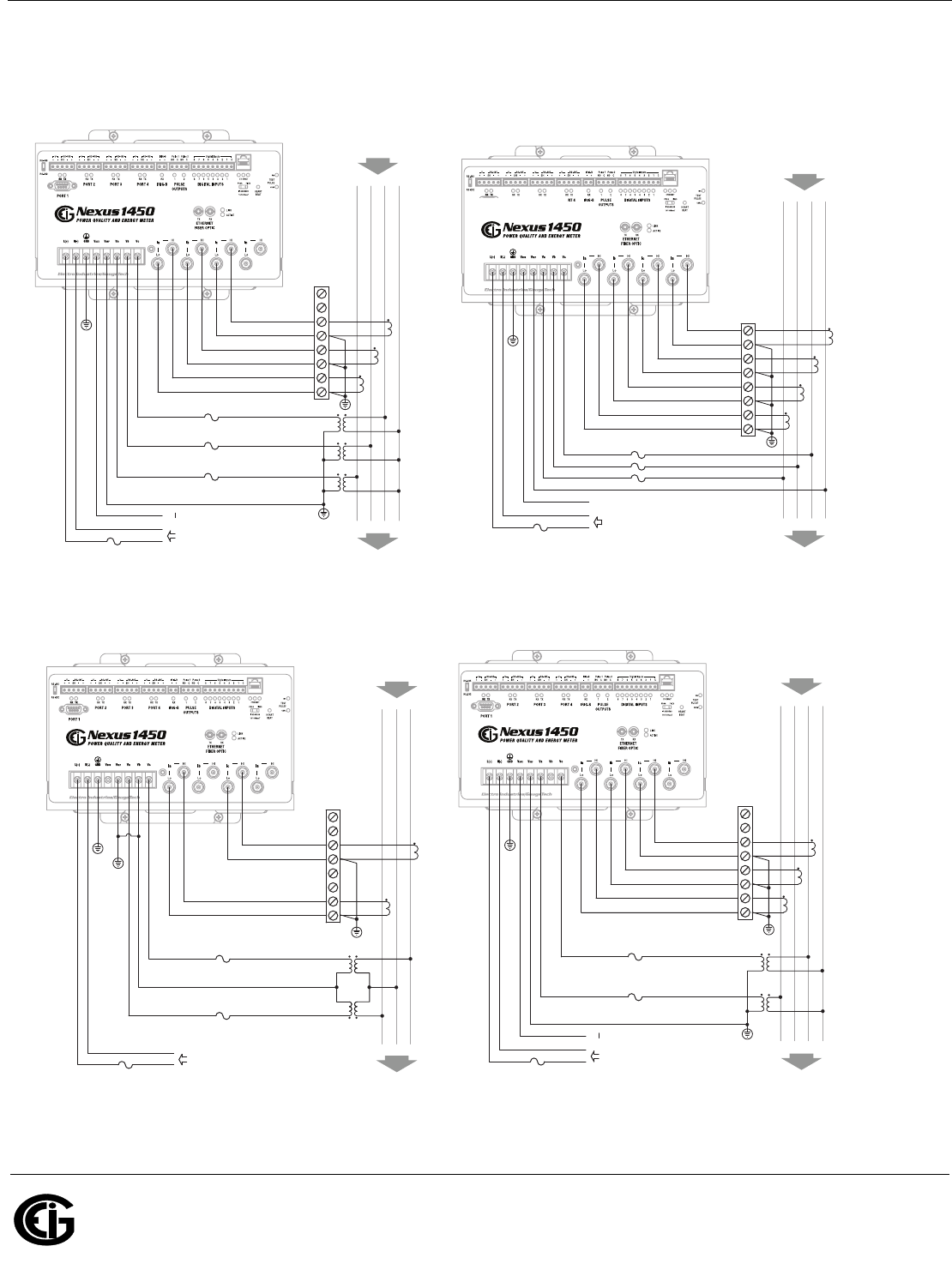
Wiring Diagrams:
Please refer to the Nexus® 1450 Meter User Manual for additional wiring diagrams and information.
A
A
C
C
LOAD
BN
BN
LINE
Ia
Ib
Ic
In
N -
Vref
Vb
Vc
L +
Vaux
Va
AUXILIARY VOLTAGE
POWER SUPPLY
(DEPENDENT ON EQUIPPED SUPPLY OPTION)
FUSES
LO
LO
LO
LO
HI
HI
HI
HI
TEST BLOCK
SHORTING SWITCH OR
CTs
EARTH GROUND
EARTH GROUND
FUSE
A
A
C
C
LOAD
BN
BN
LINE
Ia
Ib
Ic
N -
Vref
Vb
Vc
L +
Vaux
Va
AUXILIARY VOLTAGE
POWER SUPPLY
(DEPENDENT ON EQUIPPED SUPPLY OPTION)
FUSES
LO
LO
LO
HI
HI
HI
TEST BLOCK
SHORTING SWITCH OR
CTs
PTs
EARTH GROUND
EARTH
GROUND
FUSE
EARTH GROUND
4 Wire 3 Element with 3 PTs and 3 CTs 4 Wire 3 Element Direct Voltage with 4 CTs
B
LOAD
AC
A B C
LINE
Ia
Ic
N -
Vb
Vc
L +
Va
POWER SUPPLY
(DEPENDENT ON EQUIPPED SUPPLY OPTION)
FUSES
LO
LO
HI
HI
TEST BLOCK
SHORTING SWITCH OR
CTs
PTs
EARTH GROUND
EARTH GROUND
EARTH GROUND
FUSE
A
A
C
C
LOAD
BN
BN
LINE
Ia
Ib
Ic
N -
Vref
Vc
L +
Vaux
Va
AUXILIARY VOLTAGE
POWER SUPPLY
(DEPENDENT ON EQUIPPED SUPPLY OPTION)
FUSES
LO
LO
LO
HI
HI
HI
TEST BLOCK
SHORTING SWITCH OR
CTs
PTs
EARTH GROUND
EARTH GROUND
FUSE
EARTH GROUND
3 Wire 2 Element Open Delta with 2 PTs and 2 CTs 3 Phase 4 Wire 2.5 Elements with 2 PTS and 3 CTs
Doc# E171703 V.1.02 QS - 3
Nexus® 1450 Meter Quickstart
Electro Industries/GaugeTech
The Leader In Power Monitoring and Smart Grid Solutions
Electro Industries/GaugeTech
The Leader In Power Monitoring and Smart Grid Solutions
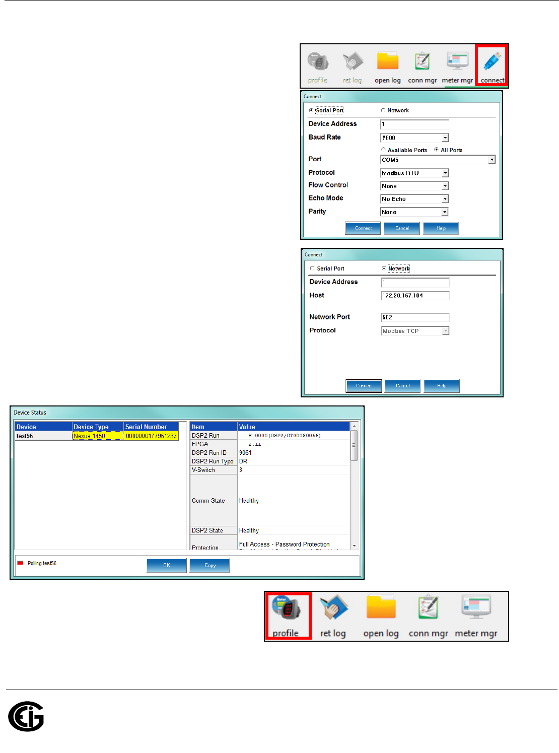
Programming the Meter through Communicator EXTTM 4.0 Software
1. From the Communicator EXTTM software’s Main screen, click
the Connect icon in the Icon Bar.
• If you are connecting through a serial port (ports 1-4), use
a cable to communicate from the meter to your PC and click
the Serial Port radio button.
a. Enter device address.
b. Select baud rate (default for both RS485 and RS232
ports is 9600), communication port you are using, pro-
tocol (default for RS485 is Modbus RTU and for RS232 is
Modbus ASCII), and parity (for RS485 - the default is
None). You can leave the other fields as they are.
c. Click Connnect.
• If you are connecting through an Ethernet port, click the
Network radio button.
a. Enter device address.
b. Enter the meter’s IP address
c. Enter the Network port (the default is 502).
d. Network protocol is Modbus TCP.
e. Click Connect.
2. The Device Status screen opens, displaying information
about the meter.
3. Click OK to close the Device Status screen, and then
click the Profile icon in the Icon Bar.
4. The meter’s Device Profile screen opens, giving you
access to the programmable settings for the meter.
Doc# E171703 V.1.02 QS - 4
Nexus® 1450 Meter Quickstart
Electro Industries/GaugeTech
The Leader In Power Monitoring and Smart Grid Solutions
Electro Industries/GaugeTech
The Leader In Power Monitoring and Smart Grid Solutions
Program CT, PT Ratios:
1. From the Device Profile screen, double-click
General Settings>CT, PT Ratios and System
Hookup>one of the items in the list.
a. Enter CT Ratios Primary (1-65535). The
Secondary is display only.
b. Enter PT Ratios Primary (1-99999999)
and Secondary (1-65535) voltage.
Example CT Setting:
200/5 Amps: set the Primary current value
as 200.00.
Example PT Settings:
14400/120 Volts: set the Primary voltage
value as 14400.00; set the Secondary volt-
age as 120.00.
c. Select the Hookup (e.g., Wye).
d. Operational Frequency Range is display
only.
e. Click OK.
Program Communications Setting:
1. From the Device Profile screen, double-
click General Settings>Communi-
cations>one of the listed ports.
2. The settings shown here for the four
serial ports (ports 1-4), the Main Net-
work card (port 5), and the Fiber Optic
Network card (port 6) are the default
settings.
You can change the settings, if neces-
sary for your system.
a. For the serial ports, the settings are
Address, Baud Rate, Data Bits,
Parity, Stop Bits, Tx Delay, Protocol,
and Mode.
b. For the Network card ports, the set-
tings are IP Address, Subnet Mask,
and Default Gateway.
c. The Advanced Settings button lets
you set up additional features for
the Network cards. See the Com-
municator EXTTM 4.0 and
MeterManager EXT Software User
Manual for instructions on these
settings.
d. Click OK.
IMPORTANT! When you have made changes to the meter’s Device Profile, click Update Device at the bottom
of the Device Profile screen, to send the new settings to the meter.
NOTE: For additional meter operation and programming information, refer to the Nexus® 1450 Meter Installa-
tion and Operation Manual and the Communicator EXTTM 4.0 and MeterManager EXT Software User Manual on
the Nexus® Series CD. You can also view the software manual by clicking the Help button on a settings screen,
or by selecting Help>Contents from the top of the Communicator EXTTM software’s Main screen.
