ManualsLib Makes It Easy To Find Manuals Online! Operating Instructions Ind226x
User Manual: Pdf
Open the PDF directly: View PDF ![]() .
.
Page Count: 46
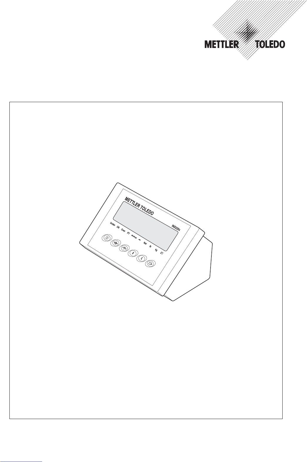

Dependable Performance of Your
IND226x Scale Terminal
Register your new terminal:
We invite you to register your new scale equipment at
www.mt.com/productregistration to allow us to contact you about en-
hancements, updates and important notifications concerning your product.
Get to know your weighing equipment:
Production engineers, maintenance personnel and operators should
familiarize themselves with the user and technical documentation
shipped with your new terminal. If you cannot locate this information,
please contact your local authorized service provider to request a copy.
Contact METTLER TOLEDO for service:
The value of a measurement is proportional to its accuracy – an out
of specification scale can diminish quality, reduce profits and increase
liability. Timely service from METTLER TOLEDO will ensure accuracy and
optimize uptime and equipment life.
1
2
3
Installation, Configuration, Integration and Training
Our service representatives are factory-trained, weighing equip-
ment experts. We make certain that your weighing equipment is
ready for production in a cost effective and timely fashion and
that personnel are trained for success.
Initial Calibration Documentation
The installation environment and application requirements are
unique for every industrial scale so performance must be tested
and certified. Our calibration services and certificates document
accuracy to ensure production quality and provide a quality
system record of performance.
Periodic Calibration Maintenance
A Calibration Service Agreement provides on-going confidence in
your weighing process and documentation of compliance with
requirements. We offer a variety of service plans that are
scheduled to meet your needs and designed to fit your budget.
Whenever you call us, our service representatives will be there
at the right time, with the right parts, the right tools and the right
skills to meet your needs.
Essential Services
Downloaded from www.Manualslib.com manuals search engine

Extending the Capability
of Your IND226x
The IND226x is a weighing terminal for
the use in hazardous areas. There are a
variety of peripherals that can be added
to the terminal to enhance your process.
METTER TOLEDO authorized sales and
service representatives will assist you in
selecting, installing, configuring, con-
necting and maintaining your IND226x
with the following hardware and software
solutions:
Configurable Weighing Functions:
• Over/Under mode (checking or
classifying)
• CalFREE calibration without test
weights
• Configurable Sleep / Standby mode
• Remote display function
Communications:
• Interface IND: serial data interface for
communicating with PC systems or
peripheral devices in the non-
hazardous zone via the interface con-
verter ACM200
• Interface Remote: serial data interface
for operating the IND226x as a sec-
ondary display
Discrete I/O:
•
One active input for clear, tare, zero or
print function
Parts and Accessories:
•
Floor stand
•
Pillar support
•
Wall bracket
Additional Services to Ensure
Compliance, Equipment Life
and Uptime
METTLER TOLEDO can deliver services
that help to ensure your compliance with
regulatory and quality requirements and
to maximize equipment life and uptime.
These services include:
Regulatory Compliance Services:
•
Equipment Qualification (IQ, OQ,
PQ)
•
Recommendations and help with
SOPs
• Periodic test procedures and refer-
ence weights
Calibration and Certification Services:
• ISO9001 and ISO17025 compliant
certification
• Measurement uncertainty and mini-
mum weight determination
Maintenance and Repair:
• Comprehensive service agreements
• On-site maintenance and repair
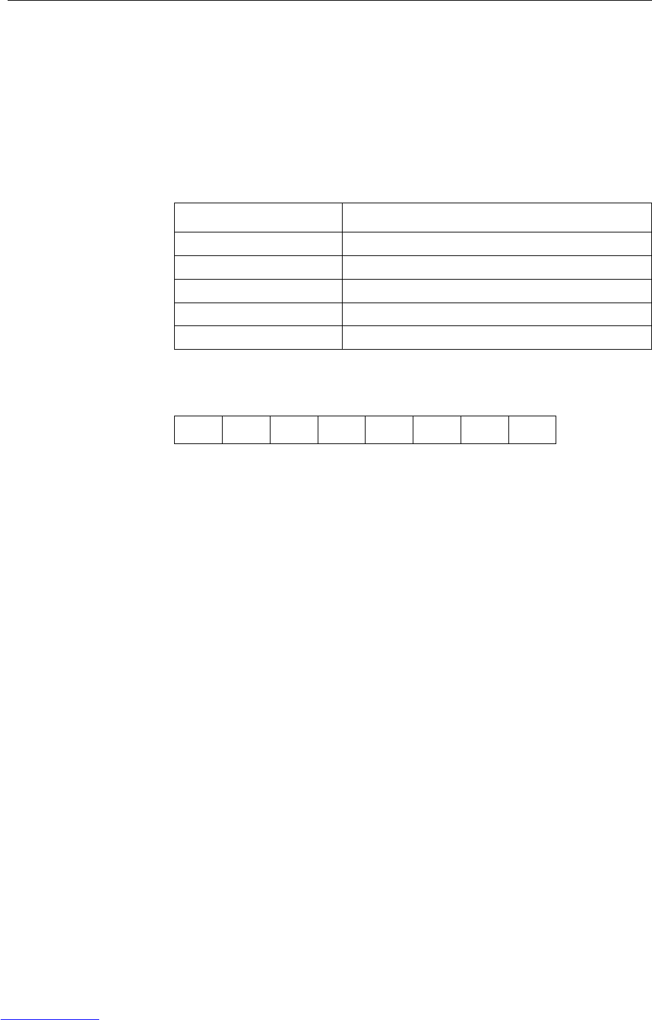
Product Model Number1:
Product Serial Number:
Authorized Service Provider2:
Service Telephone Number:
1) Product model and serial number can be obtained from product data plate
2) Visit www.mt.com/contact to find the name and number of an authorized service provider
Essential Services IND226x
Subject to technical changes
© 11/2007 Mettler-Toledo AG
www.mt.com/serviceXXL
Downloaded from www.Manualslib.com manuals search engine

Contents
Operating instructions 72203952A 11/07 3
IND226x
Contents
Page
1 Safety instructions ....................................................................... 5
2 Introduction................................................................................. 6
2.1 System overview........................................................................... 6
2.2 Commissioning ............................................................................ 8
2.3 Description .................................................................................. 9
3 Basic functions ............................................................................ 11
3.1 Switching on and off ..................................................................... 11
3.2 Zeroing........................................................................................ 11
3.3 Simple weighing ........................................................................... 11
3.4 Weighing with tare ........................................................................ 12
3.5 Printing/transferring data ............................................................... 12
3.6 Information on storage battery operation.......................................... 13
3.7 Cleaning ...................................................................................... 13
4 Applications ................................................................................ 14
4.1 Displaying weight values with a higher resolution (x10) ................... 14
4.2 Switching weight unit .................................................................... 14
4.3 Checkweighing ............................................................................. 15
4.4 Classifying ................................................................................... 16
5 Operator menu ............................................................................ 18
5.1 Entering the operator menu ............................................................ 18
5.2 Operating the menu ...................................................................... 18
5.3 F2 – F key menu .......................................................................... 19
5.4 F3 – terminal menu ...................................................................... 22
5.5 F4 – communication menu ............................................................ 22
5.6 F6 – ending menu ........................................................................ 24
6 Supervisor menu ......................................................................... 25
6.1 Entering Supervisor menu .............................................................. 25
6.2 Operating the Supervisor menu....................................................... 25
6.3 Block F1 – Scale .......................................................................... 26
6.4 Block F5 – Maintenance ................................................................ 31
7 Interface commands .................................................................... 33
7.1 SICS interface commands .............................................................. 33
7.2 Toledo Continuous Mode ............................................................... 34
8 Error messages ........................................................................... 36
Downloaded from www.Manualslib.com manuals search engine

inhalt
4Operating instructions 72203952A 11/07
IND226x
9 Technical data and accessories .................................................... 37
9.1 Technical data ............................................................................. 37
9.2 Technical data for ACM200 ........................................................... 39
9.3 Accessories ................................................................................. 40
10 Appendix .................................................................................... 41
10.1 Disposal...................................................................................... 41
10.2 Declarations of conformity ............................................................. 42
Downloaded from www.Manualslib.com manuals search engine

Safety instructions
Operating instructions 72203952A 11/07 5
IND226x
1 Safety instructions
The IND226x weighing terminal is approved for operation in Zone 1 and 21
hazardous areas. The interface converter ACM200 may only be installed and
operated in the safe area.
If the IND226x weighing terminal is used in hazardous areas, special care must be
taken. The code of practice is oriented to the "Safe Distribution" concept drawn up by
METTLER TOLEDO.
Competence ▲The weighing system may only be installed, maintained and repaired by
authorised METTLER TOLEDO service personnel.
Ex approval ▲No modifications may be made to the terminal and no repair work may be
performed on the modules. Any weighing platform or system modules that are
used must comply with the specifications contained in the installation
instructions. Non-compliant equipment jeopardises the intrinsic safety of the
system, cancels the "Ex" approval and renders any warranty or product liability
claims null and void.
▲The safety of the weighing system is only guaranteed when the weighing system
is operated, installed and maintained in accordance with the respective instructions.
▲Also comply with the following:
– the instructions for the system modules,
– the regulations and standards in the respective country,
– the statutory requirement for electrical equipment installed in hazardous areas
in the respective country,
– all instructions related to safety issued by the owner.
▲The explosion-protected weighing system must be checked to ensure compliance
with the requirements for safety before being put into service for the first time,
following any service work and every 3 years, at least.
Operation ▲Prevent the build-up of static electricity. Always wear suitable working clothes
when operating or performing service work in a hazardous area.
▲Do not use protective coverings for the devices.
▲Protect the keyboard membrane against ultraviolet radiation.
▲Avoid damage to the system components.
Downloaded from www.Manualslib.com manuals search engine

Introduction
6Operating instructions 72203952A 11/07
IND226x
2 Introduction
2.1 System overview
A weighing system with the IND226x weighing terminal can be operated either with
one of the following power supply units or an external storage battery:
APS500 Power supply unit in a hazardous area,
US version, 120 VAC, 50/60 Hz
APS501 Power supply unit in a hazardous area,
EU version, 240 VAC, 50/60 Hz
PSUx/120 V Power supply unit in a hazardous area,
US version, 120 VAC, 50/60 Hz
PSUx/230 V Power supply unit in a hazardous area,
EU version, 230 VAC, 50 Hz
External Battery Pack External storage battery for a hazardous area,
charging only in a safe area and using a charger specified
and approved by METTLER TOLEDO
Either an analog weighing platform or the system solution Analog Ex1 can be
connected to the weighing IND226x terminal.
The following components are necessary for connection of peripheral devices:
Interface IND Active intrinsically safe data interface,
installed in IND226x (Master)
Interface Remote Passive intrinsically safe data interface, for remote control
of an IND226x (IND226x as a second display),
installed in IND226x (second display)
ACM200 Interface converter for the safe area,
for example, for connection of a PC in the safe area
Wide range power supply unit 100 – 240 V AC, 50/60 Hz
Downloaded from www.Manualslib.com manuals search engine

Introduction
Operating instructions 72203952A 11/07 7
IND226x
2.1.1 Configuration with interface converter ACM200 in the safe area
Dashed-line components are alternatives.
2.1.2 Configuration with remote controlled IND226x (second display)
Dashed-line components are alternatives.
IND226x
APS50. Ex-i
max. 15 m
PSUx Ex-i
max. 50 m
Battery
Pack
Ex-i
max. 3 m
Analog weighing
platform
Wc
System
solution
Analog Ex1
Wc
Wc
Wc
Ex-i
max. 20 m
Ex-i
max. 20 m
Hazardous area Safe area
ACM200
Ex-i
max. 300 m
Interface
IND
RS232
IND226x
(Master)
Analog
Wheiging platform
Ex-i
max. 20 m
Interface
IND
IND226x
(Second display)
APS50.
Ex-i
max. 15 m
Interface
Remote
Ex-i max. 300 m
Battery
Pack
Ex-i
max. 3 m
PSUx Ex-i
max. 50 m
Wz
System solution
Analog Ex1
Wz
Wz
Wz
Ex-i
max. 20 m
APS50.
Ex-i
max. 15 m
Battery
Pack
Ex-i
max. 3 m
PSUx Ex-i
max. 50 m
Hazardous area Safe area
Downloaded from www.Manualslib.com manuals search engine

Introduction
8Operating instructions 72203952A 11/07
IND226x
2.2 Commissioning
2.2.1 Guide for installers and terminal diagram
The installation of an explosion-protected weighing system with the IND226x
weighing terminal may only be carried out in accordance with the guide for installers
ME-72203958 and control drawing ME-72203677.
2.2.2 Information on certified weighing systems
In the case of certified weighing systems, the weighing platform connection at the
weighing terminal must be sealed with a wire seal or a verification mark. In addition,
a label with the information on "Max", "Min" and "e" has to be placed within the
range of vision of the weight display.
Verification mark
Wire seal
Downloaded from www.Manualslib.com manuals search engine
Introduction
Operating instructions 72203952A 11/07 9
IND226x
2.3 Description
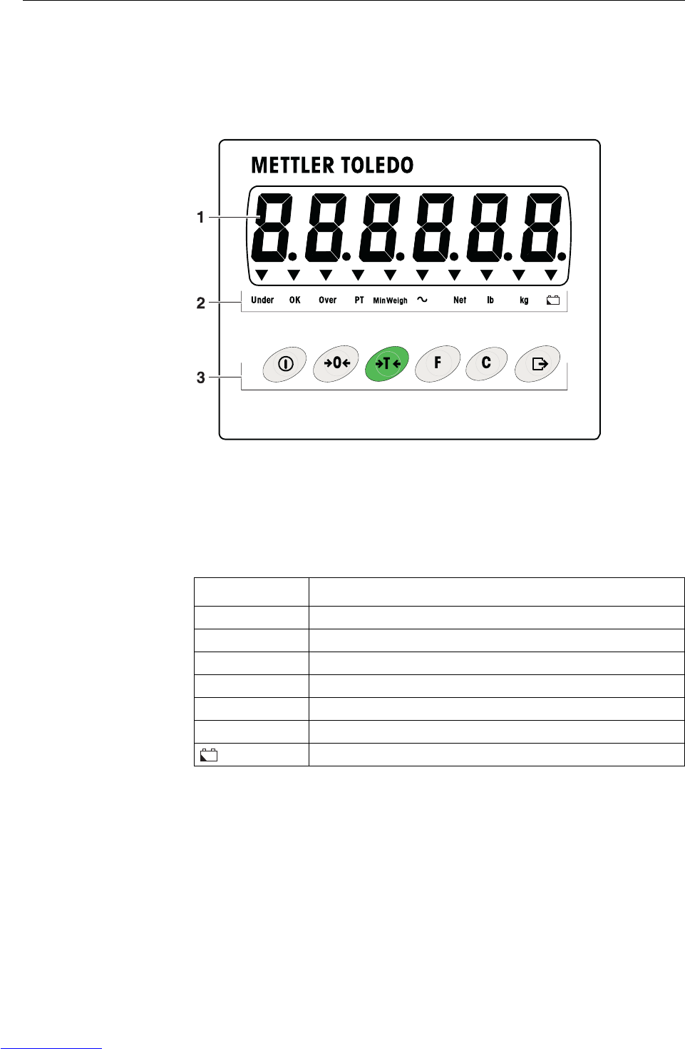
2.3.1 Overview
16-digit weight display
2Status indicators
3Keypad
2.3.2 Status indicators
IND226x
+–
LED Meaning
Under / OK / Over Indicators for check weighing
PT Indicator for tare specification
MinWeigh Indicator for MinWeigh function
~Movement indicator
Net The displayed weight value is a net weight value
lb / kg Weight unit currently selected
Storage battery state
+–
Downloaded from www.Manualslib.com manuals search engine
Introduction
10 Operating instructions 72203952A 11/07
IND226x
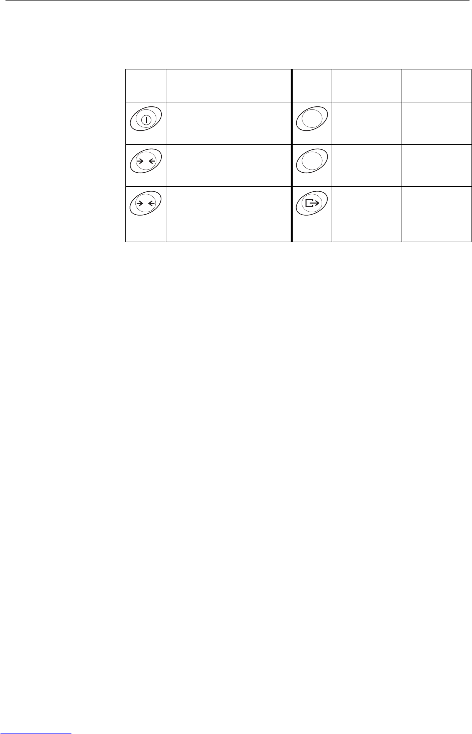
2.3.3 Keys
Key Operating
mode Menu Key Operating
mode Menu
Switching
power on/off;
abort
– Function key Back to the next
higher menu
item
Zeroing Scrolling
back
Clear key Back to the
previous menu
item
Tare Scrolling
forward
Transfer key
Long key-
press: Calling
up menu
Activating
menu item;
accepting
selected setting
F
0C
T
Downloaded from www.Manualslib.com manuals search engine

Basic functions
Operating instructions 72203952A 11/07 11
IND226x
3 Basic functions
3.1 Switching on and off
Switching on
➜Press .
The display lights up and then shows the software number.
When the weight display appears, the weighing terminal is ready for operation.
Switching off
➜Press and hold until –OFF– is displayed.
3.2 Zeroing
Zeroing corrects the influence of slight soiling on the load plate.
Setting to zero manually
1. Unload weighing platform.
2. Press .
The zero display appears.
Automatic zeroing
In case of non-certified weighing platforms, the automatic zero point correction can
be deactivated in the supervisor menu (F1.4.1).
In standard operation, the zero point of the weighing platform is automatically cor-
rected when the weighing platform is unloaded.
3.3 Simple weighing
1. Place weighing sample on the weighing platform.
2. Wait until the motion indicator goes out.
3. Read weighing result.
Downloaded from www.Manualslib.com manuals search engine

Basic functions
12 Operating instructions 72203952A 11/07
IND226x
3.4 Weighing with tare
Taring
➜Place the empty container on the weighing platform and press .
The zero display and the Net indicator appear.
Clearing the tare
➜Press .
The Net indicator goes out, the gross weight appears in the display.
• If automatic clearing of the tare weight is set in the supervisor menu
(F1.5.2=On), the tare weight is cleared automatically as soon as the weighing
platform is unloaded to zero.
• If tare interlock is set in the supervisor menu (F1.5.3=On), the tare weight can
only be cleared when the weighing platform is unloaded to zero.
Automatic taring
This function must be activated in the supervisor menu (F1.5.1=On).
➜Place the empty container on the weighing platform.
The weight applied on the weighing platform is automatically saved as the tare
weight.
The zero display and the Net indicator appear.
3.5 Printing/transferring data
Condition
The weighing terminal is connected via the optional Interface IND to the interface
converter ACM200 in the safe area.
➜Press .
The display contents are printed out or transferred to a computer.
Note
The display contents will not be printed or transferred if the scale is in motion.
T
C
Downloaded from www.Manualslib.com manuals search engine
Basic functions
Operating instructions 72203952A 11/07 13
IND226x
3.6 Information on storage battery operation
EXPLOSION HAZARD!
➜Always charge the Battery Pack in a safe area!
➜Only use chargers approved by METTLER TOLEDO!
The indicator indicates the storage battery state.
▼ above continuous red Storage battery charged approx. 10%
Residual operating life approx. 3–5 h
▼ above slow flashing, red Storage battery charged approx. 5%
Residual operating life approx. 1 h
▼ above rapid flashing, red Storage battery charged less than 5%
Storage battery must be charged immediately
The (residual) operating life during storage battery operation depends on the
operating mode.
The following operating life applies for a fully charged new storage battery:
Sleep mode min. 70 h
Normal weight display min. 60 h
Normal weight display and interface operation min. 50 h
Note
Depending on the age and the charging state of the storage battery, the operating life
may vary downwards.
3.7 Cleaning
EXPLOSION HAZARD!
➜Before cleaning ensure that the weighing terminal is closed properly. The four clip
fasteners at the corners must have engaged fully.
Further notes on cleaning
• Use a damp cloth.
• Do not use any acids, alkalis or strong solvents.
• Do not clean the weighing terminal using high-pressure or high-temperature water.
• Follow all the relevant instructions regarding cleaning intervals and permissible
cleaning agents.
+–
+–
+–
+–
Downloaded from www.Manualslib.com manuals search engine
Applications
14 Operating instructions 72203952A 11/07
IND226x
4 Applications
Depending on the setting of F2.1 parameter in the operator menu, different applica-
tions can be activated using the key.
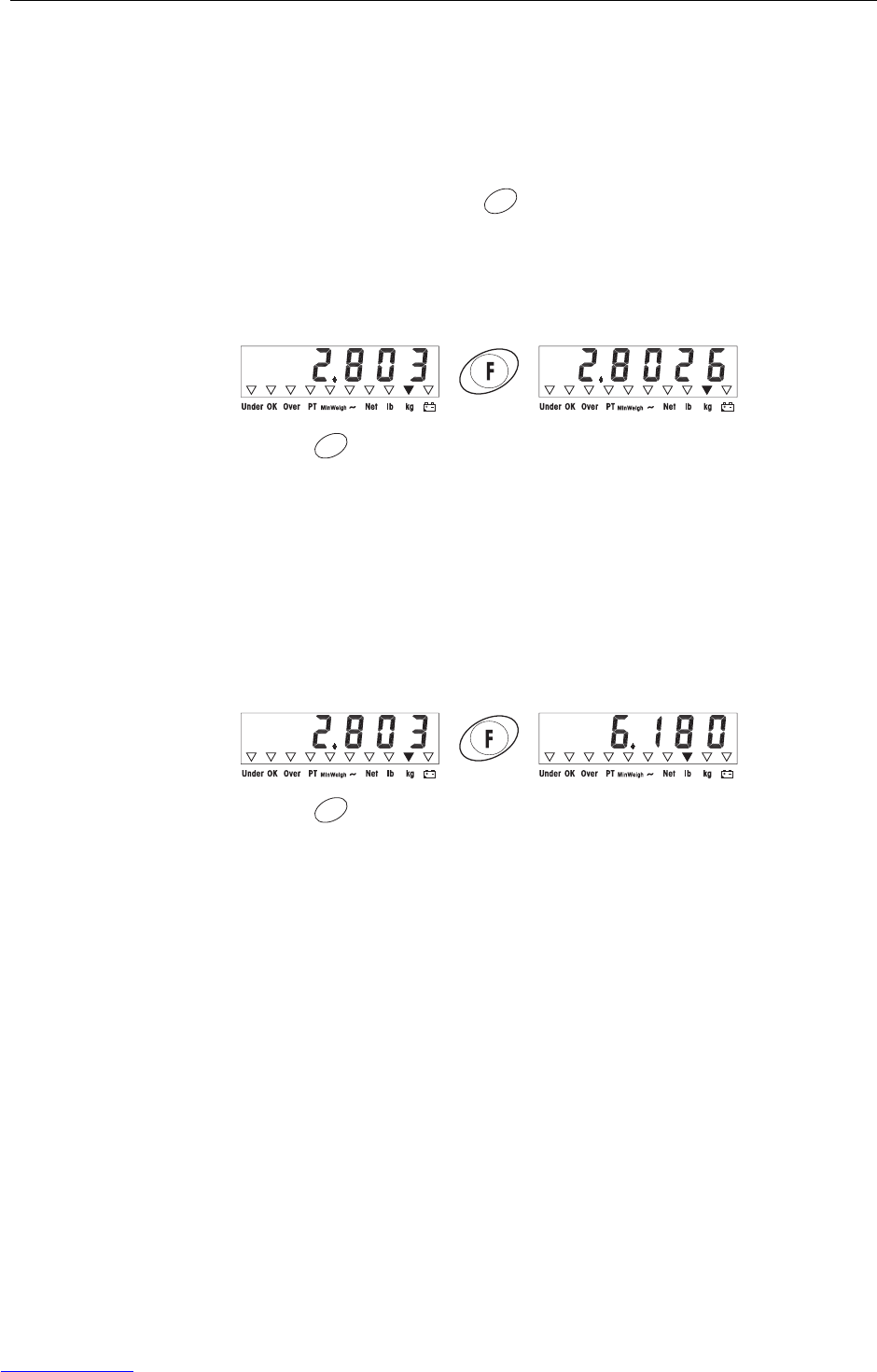
4.1 Displaying weight values with a higher resolution (x10)
For this purpose F2.1=MULt must be set in the operator menu (factory setting).
➜Press .
The weight value is displayed with a higher resolution (x10) for about 10 sec-
onds.
Note
The weight value in higher resolution (x10) cannot be printed.
4.2 Switching weight unit
For this purpose, F2.1=Unit must be set in the operator menu.
➜Press .
The weight value is displayed in the second weight unit.
Note
The displayed weight unit remains until it is switched again.
F
F
F
Downloaded from www.Manualslib.com manuals search engine
Applications
Operating instructions 72203952A 11/07 15
IND226x
4.3 Checkweighing
For this purpose, F2.1=OVEr and F2.2.1=CHECh (factory setting) must be set
in the operator menu. In the factory setting, the check weighing function is working
with upper and lower tolerances of 10 d. With parameters F2.2.3 and F2.2.4, these
tolerances can be customized.
Setting target weight
1. Press to activate the check weighing function.
2. Press and hold until tArGEt and the 3 indicators Under, OK and Over
appear.
If F2.2.2=WEIGHt (factory setting) is set in the operator menu, the weight
display appears.
3. Put the target weight on the weighing platform and save with .
The OK indicator lights.
If F2.2.2=MAnUAL is set in the operator menu, the weight display with blink-
ing last digit appears.
4. Enter target weight using the , and keys and confirm with
(see page 18).
5. Save entered weight value as target weight using the key.
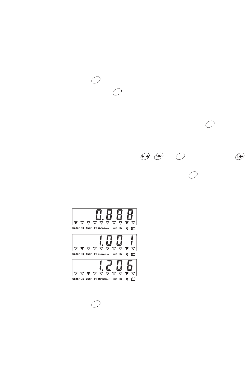
Check weighing
Example: Target weight = 1.000 kg
Switching between checkweighing and normal weighing
➜Press to switch between checkweighing and normal weighing.
• Weight is less than the target weight and
below the lower tolerance value.
The Under indicator lights.
• Weight is within the tolerance values.
The OK indicator lights.
• Weight is more than the target weight and
above the upper tolerance value.
The Over indicator lights.
F
F
F
T
F
F
F
Downloaded from www.Manualslib.com manuals search engine

Applications
16 Operating instructions 72203952A 11/07
IND226x
4.4 Classifying
For this purpose, F2.1=OVEr and F2.2.1=CLASS must be set in the operator
menu.
In the factory setting, the classifying function is working with upper and lower toler-
ances of 10 d, 20 d, 30 d. With parameters F2.2.3 and F2.2.4, these tolerances
can be customized.
Setting target weight
1. Press to activate the classifying function.
2. Press and hold until tArGEt and the 3 indicators Under, OK and Over
appear.
If F2.2.2=WEIGHt (factory setting) is set in the operator menu, the weight
display appears.
3. Put the target weight on the weighing platform and save with .
The OK indicator lights.
If F2.2.2=MAnUAL is set in the operator menu, the weight display with blink-
ing last digit appears.
4. Enter target weight using the , and keys and confirm with
(see page 18).
5. Save entered weight value as target weight using the key.
F
F
F
T
F
F
Downloaded from www.Manualslib.com manuals search engine
Applications
Operating instructions 72203952A 11/07 17
IND226x
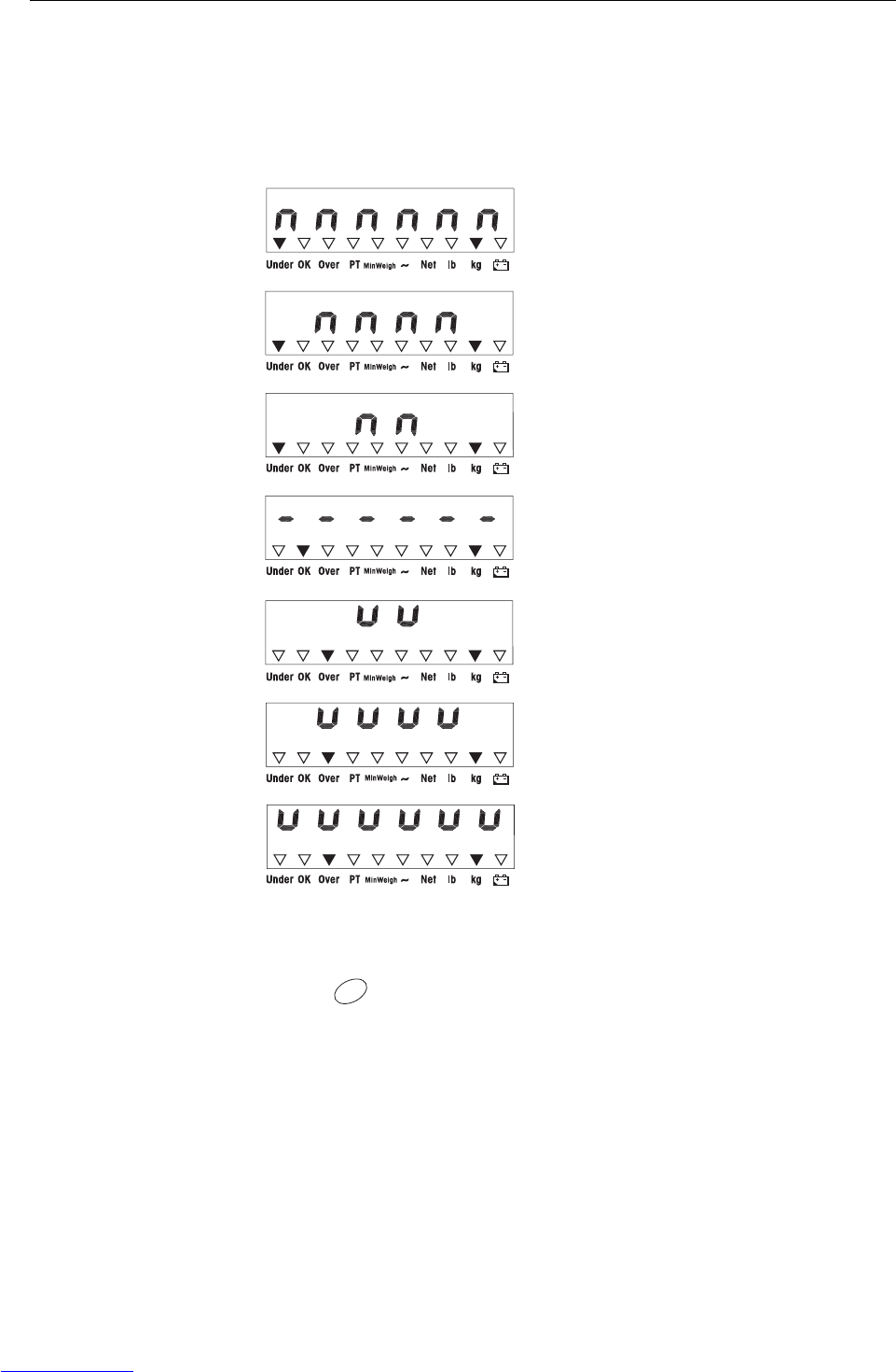
Classifying
Example:
Target weight = 1,000 kg, tol. 1 = 100 kg, tol. 2 = 200 kg, tol. 3 = 300 kg
Switching between classifying and normal weighing
➜Press to switch between classifying and normal weighing.
• Weight is less than the target weight and
below tolerance 3, e.g. below 700 kg.
The Under indicator lights.
• Weight is less than the target weight and
below tolerance 2,
e.g. between 700 kg and 800 kg.
The Under indicator lights.
• Weight is less than the target weight and
below tolerance 1,
e.g. between 800 kg and 900 kg.
The Under indicator lights.
• Weight is within tolerance 1,
e.g. between 900 kg and 1,100 kg.
The OK indicator lights.
• Weight is more than the target weight and
above upper tolerance 1,
e.g. between 1,100 kg and 1,200 kg.
The Over indicator lights.
• Weight is more than the target weight and
above upper tolerance 2,
e.g. between 1,200 kg and 1,300 kg.
The Over indicator lights.
• Weight is more than the target weight and
above upper tolerance 3,
e.g. above 1,300 kg.
The Over indicator lights.
F
Downloaded from www.Manualslib.com manuals search engine
Operator menu
18 Operating instructions 72203952A 11/07
IND226x
5 Operator menu
The operator menu consists of the following blocks:
F2 – F key menu settings
F3 – Terminal menu settings
F4 – Communication menu settings
F6 – Exit menu
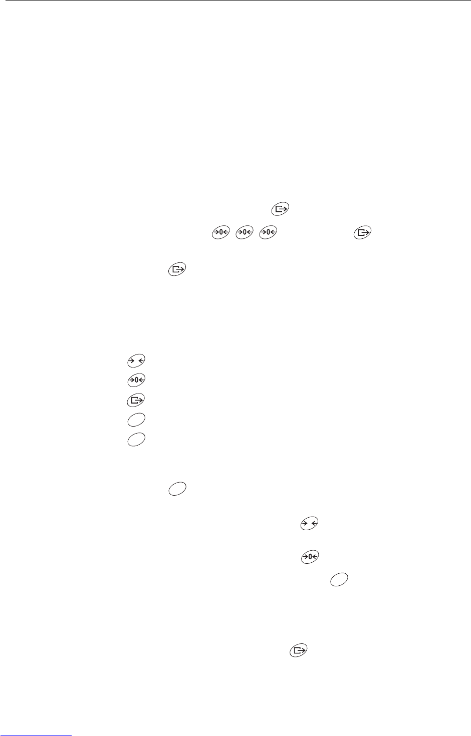
5.1 Entering the operator menu
➜In gross mode, press and hold until MAStEr appears.
➜Enter pass word and confirm with .
SEtUP appears.
➜Press .
F2 appears.
5.2 Operating the menu
Keys and their function in the menu
Selecting next parameter.
Back to the previous parameter.
Confirming selection.
Back to the previous menu item.
Back to the next higher menu item.
Numeric entry
1. Press for editing the displayed value.
The (last) digit will blink.
2. Increase the displayed digit using the key.
– or –
Decrease the displayed digit using the key.
3. When entering multi-digit numbers, use the key to move the cursor one
place to the left.
4. Change the digit as described in step 2.
5. Repeat steps 3 and 4 if necessary.
6. When all digits are entered, use the key to confirm the entry.
T
C
F
F
T
F
Downloaded from www.Manualslib.com manuals search engine

Operator menu
Operating instructions 72203952A 11/07 19
IND226x
Note
With , you can clear the entry.
5.3 F2 – F key menu
Factory settings are printed with bold characters.
F2.1 – Function of the F key
3 different functions can be assigned to the F key:
MUL10 When pressing the F key, the weight value is displayed in 10 times hig-
her resolution
Unit When pressing the F key, the weight unit switches between kg and lb
Note: lb is not possible in compulsory-certification mode.
OVEr Plus/Minus weighing
Additional settings, see F2.2
F2.2 – Plus/Minus weighing
These parameters only appear if F2.1=OVEr is set.
F2.2.1 – Operating mode
CHECh Check weighing
CLASS Classifiying
F2.2.2 – Setting the target weight
WEIGHt By weighing in an actual sample weight
MAnUAL By numeric entry
F2.2.3 – Upper tolerances
After selecting the parameter, the currently set tolerance value is displayed.
If F2.2.1 = Chech is set:
Upper tolerance = target value + displayed tolerance value
If F2.2.1 = CLASS is set:
Internally the terminal calculates 3 tolerances.
Upper tolerance 1 = target value + displayed tolerance value
Upper tolerance 2 = target value + 2 x displayed tolerance value
Upper tolerance 3 = target value + 3 x displayed tolerance value
1. If necessary, use the key to activate editing.
2. Change tolerance value using the , and keys.
Factory setting upper tolerance value = 10 d
Possible settings 0 ... full load
C
F
T
F
Downloaded from www.Manualslib.com manuals search engine

Operator menu
20 Operating instructions 72203952A 11/07
IND226x
F2.2.4 – Lower tolerances
After selecting the parameter, the currently set tolerance value is displayed.
If F2.2.1 = Chech is set:
Lower tolerance = target value – displayed tolerance value
If F2.2.1 = CLASS is set:
Internally the terminal calculates 3 tolerances.
Lower tolerance 1 = target value – displayed tolerance value
Lower tolerance 2 = target value – 2 x displayed tolerance value
Lower tolerance 3 = target value – 3 x displayed tolerance value
1. Use the key to activate editing if necessary.
2. Change tolerance using the , and keys.
Factory setting lower tolerance value = 10 d
Possible settings 0 ... full load
F2.4 – Remote Display (IND226x as secondary display)
The Interface Remote has to be installed in the secondary display in order to use this
function.
The following commands can be carried out optionally by the master or the
secondary display: Set to Zero, Tare, and Delete.
The cabling of the system components is described in the terminal diagram
ME-72203677 of the IND226x installation instructions.
OFF Remote function of the secondary display de-activated
ON Remote function activated. The secondary display displays the weight
value of the master terminal.
F2.5 – Active input
Please refer to the IND226x guide for installers and the terminal diagram ME-
72203677 for information on selecting and connecting external switches or
pushbuttons to the active input.
The active input can have one of the following functions assigned to it:
None Active input de-activated
Clear Delete key
Print Transfer key
Tare Tare key
Zero Zero-adjustment key
F2.6 – MinWeigh
When the MinWeigh function is activated, the MinWeigh indicator lights up when the
weight lies below the minimum weighing-in quantity.
F2.6.1 – Activation of the MinWeigh function
OFF MinWeigh function de-activated
ON MinWeigh function activated
F
T
F
Downloaded from www.Manualslib.com manuals search engine

Operator menu
Operating instructions 72203952A 11/07 21
IND226x
F2.6.2 – Input mode
The minimum weighing-in quantity can be entered directly or be calculated directly
by the terminal from the following variables:
U0Measurement uncertainty when the load approaches 0
T Required tolerance as a %
F Safety factor
dirEct Enter minimum weighing-in quantity via keyboard
CoMPon The minimum weighing-in quantity is calculated by the terminal
F2.6.3 – Direct entry of the minimum weighing-in quantity
This parameter is only displayed if F2.6.2 = dirEct has been selected.
➜Enter the minimum weighing-in quantity by using the keys , and .
F2.6.4 – Entry of the measurement uncertainty U0
This parameter is only displayed if F2.6.2 = CoMPon has been selected.
➜Enter the measurement uncertainty by using the keys , and .
F2.6.5 – Entry of the tolerance T
This parameter is only displayed if F2.6.2 = CoMPon has been selected.
➜Enter the tolerance as a % by using the keys , and .
Factory setting 0.1%
Possible values 0.1 ... 99.9%
F2.6.6 – Entry of the safety factor F
This parameter is only displayed if F2.6.2 = CoMPon has been selected.
➜Enter the safety factor by using the keys , and .
Factory setting 1
Possible values 1 ... 10
F2.10 – Reset F key settings
Reset all parameters F2.x(.x) to factory setting.
T
F
T
F
T
F
T
F
Downloaded from www.Manualslib.com manuals search engine

Operator menu
22 Operating instructions 72203952A 11/07
IND226x
5.4 F3 – terminal menu
Factory settings are printed with bold characters.
F3.1 – Display settings
F3.1.1 – Sleep mode
The weighing terminal switches to sleep mode when during the set time no action on
the weighing terminal or no change in weight occurred.
Factory setting 60 (seconds)
Function disabled 0
Possible settings 10 ... 999 (seconds)
F3.2 – Auto power off
The weighing terminal is switched off if during the set time no action was on the
weighing terminal or on the weighing platform.
Factory setting 5 (minutes)
Function disabled 0
Possible settings 0.5 ... 60 (minutes)
F3.10 – Reset terminal settings
Reset all parameters F3.x(.x) to factory setting.
5.5 F4 – communication menu
The Interface IND data interface has to be installed in the IND226x in order to use this
function. In addition an interface converter ACM200 is required for communication
with PCs or printers in the safe area.
Factory settings are printed in bold characters.
F4.1 – Connections
Print When pressing , the current display is printed.
APrint Stable weight values are printed automatically
Additional settings: F4.2.5 and F4.2.6
SICS Communication via the METTLER TOLEDO Standard Interface Command
Set (MT-SICS)
Contin Toledo Continuous Mode – for continuous transfer of weight data and
status information, for example to a PC or a secondary display.
F4.2 – Format
F4.2.1 – Line format
MULti Multi line
SinGLE Single line
Downloaded from www.Manualslib.com manuals search engine

Operator menu
Operating instructions 72203952A 11/07 23
IND226x
F4.2.2 – Print format
StAndr Standard (current display)
OVEr over / good / under
Count Piece number
F4.2.3 – Print language
EnG English
CHn Chinese
F4.2.4 – Add line feed
Factory setting 3 (lines)
Possible settings 0 ... 9 (lines)
F4.2.5 – Auto print threshold
This menu item is only available if F4.1=APrint is set.
A stable weight value which is higher than the set value is printed automatically.
Factory setting 10 (d)
Possible settings 0 ... max. load
F4.2.6 – Auto print reset threshold
This menu item is only available if F4.1=APrint is set.
The scale must be unloaded below the set value before a new weight value can be
printed automatically.
Factory setting 10 (d)
Possible settings 0 ... max. load
F4.3 – Parameters
F4.3.1 – Baudrate
1200
2400
4800
9600
19200
F4.3.2 – Data bits / parity
7-odd 7 bits, parity odd
7-even 7 bits, parity even
8-nonE 8 bits, no parity
8-odd 8 bits, parity odd
8-even 8 Bits, parity even
F4.3.3 – Xon/Xoff
On Xon/Xoff enabled
OFF Xon/Xoff disabled
Downloaded from www.Manualslib.com manuals search engine
Operator menu
24 Operating instructions 72203952A 11/07
IND226x
F4.3.4 – Checksum
On Checksum enabled
OFF Checksum disabled
F4.10 – Reset communication settings
Reset all parameters F4.x(.x) to factory setting.
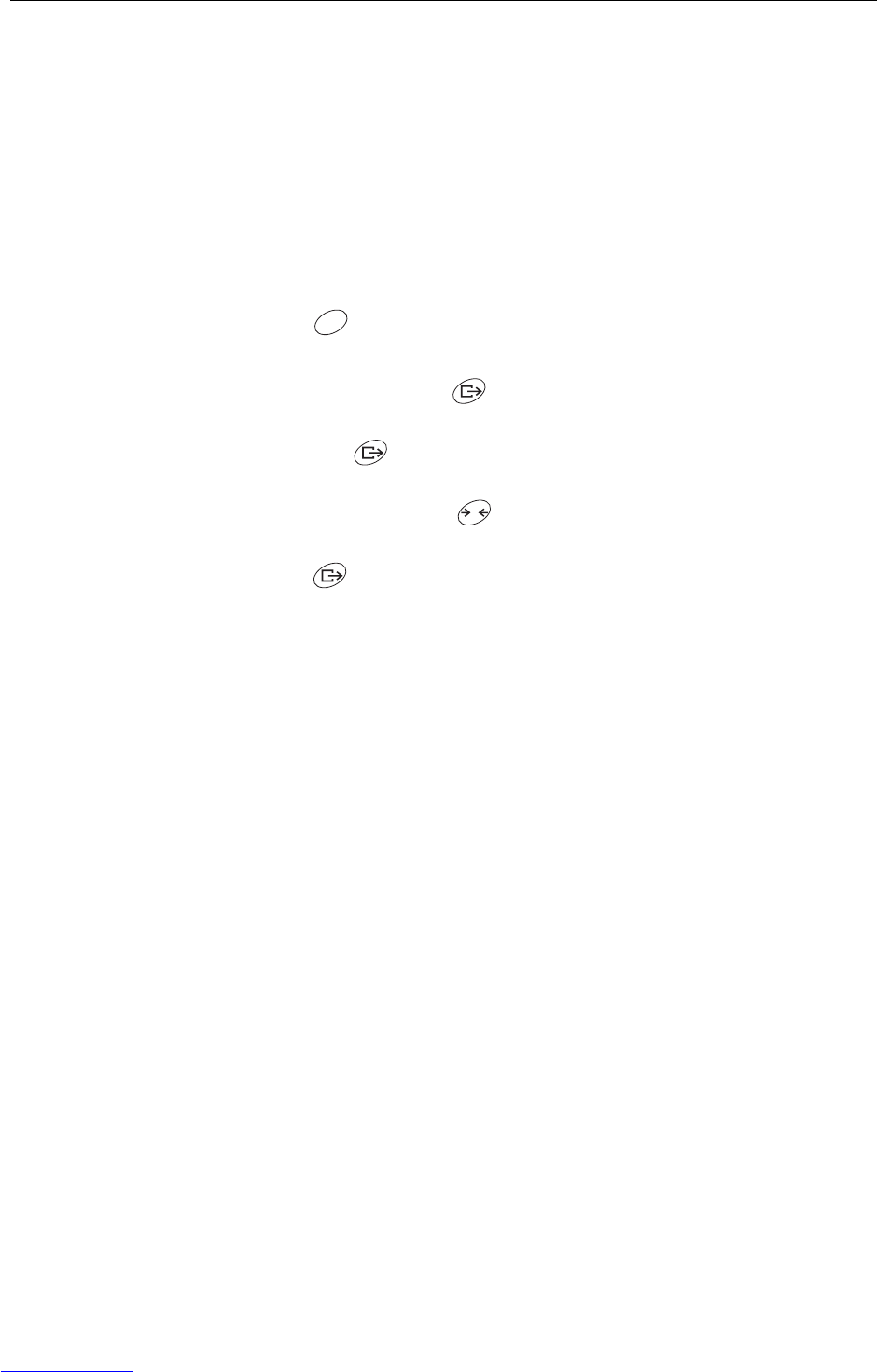
5.6 F6 – ending menu
1. Press .
F6 appears.
2. To save changes: Press .
SAVE appears.
Then press again.
– or –
To reject changes: Press .
AbOrt appears.
Press .
C
T
Downloaded from www.Manualslib.com manuals search engine
Supervisor menu
Operating instructions 72203952A 11/07 25
IND226x
6 Supervisor menu
In addition to the blocks of the user menu, the following blocks can be accessed in
the Technician menu:
F1 – Scale settings
F5 – Terminal settings
F6 – Exit menu
6.1 Entering Supervisor menu
1. In gross mode, press and hold until MAStEr appears in the display.
1. Enter password and confirm with .
SEtUP appears in the display.
1. Press .
F1 appears in the display. All parameters can be modified.
Information for certified weighing systems (OIML or NTEP)
The parameters F1, F5.1 und F5.4 are disabled at certified weighing systems.
Proceed as follows in order to change these parameters:
1. Switch off weighing terminal and open.
2. Use a jumper to close the W&M solder bridge on the mainboard.
3. Close the cover and switch on the weighing terminal.
SEtUp is displayed. All the parameters can be modified.
4. Save the modified configuration (F6).
CALOFF appears in the display.
5. Switch off weighing terminal and open.
6. Open the W&M solder bridge by removing the jumper.
7. Close the cover and seal the weighing terminal.
6.2 Operating the Supervisor menu
Operating the Supervisor menu is the same as in the Operator menu, see page 18.
T T
Downloaded from www.Manualslib.com manuals search engine

Supervisor menu
26 Operating instructions 72203952A 11/07
IND226x
6.3 Block F1 – Scale
Factory settings are printed in bold letters.
F1.1 – Approval
no no approval
OIML approval according to OIML
ntEP approval according to NTEP
otHEr for other approvals
F1.2.1 – Weight units
1weight unit: kg
2weight unit: lb 1 lb ≈ 0.454 kg
F1.2.3 – Capacity
Possible capacities and the factory settings depend on the weighing platform con-
nected.
➜If necessary, modify the displayed value.
Factory setting 3 kg
F1.2.4 – Resolution
Possible resolutions and the factory settings depend on the weighing platform con-
nected.
1. If necessary, modify the displayed value.
Factory setting 0.001 kg
F1.3.1 – Geo value
Adaptation of the weighing platform to the geographical location, see table in the
annex.
Possible settings 0 ... 31
Factory setting 16
F1.3.2 – Linearization during adjustment
LinOFF Linearization disabled
LinOn Linearization enabled (3 point linearization)
Downloaded from www.Manualslib.com manuals search engine

Supervisor menu
Operating instructions 72203952A 11/07 27
IND226x
F1.3.3 – Adjustment
The steps with grey background only appear if parameter F1.3.2=LinOn is set.
Display Key Description
E SCL Unload weighing platform
Confirm empty weighing platform
10 CAL
...
0 CAL
The weighing terminal counts down from 10 to 0.
The zero point is determined
Add Ld Load half of the maximum load
Confirm half load
000000 Enter weight value for half maximum load
Enter weight value
003000 Weight value for half of the maximum load
entered
Confirm weight value
10 CAL
...
0 CAL
The weighing terminal counts down from 10 to 0.
Half maximum load is adjusted
FULL Ld Load maximum load
Confirm maximum load
000000 Enter weight value of maximum load
Enter weight value
006000 Weight value for maximum load entered
Confirm weight value
10 CAL
...
0 CAL
The weighing terminal counts down from 10 to 0.
Maximum load is adjusted
donE Adjustment finished. This message is displayed
for about 2 seconds
F1.4 Next block in the supervisor menu
T
F
T
F
Downloaded from www.Manualslib.com manuals search engine

Supervisor menu
28 Operating instructions 72203952A 11/07
IND226x
F1.3.4 – CalFREE
The CalFREE procedure can be used at tank and silo scales. It is used to precalibrate
the weighing system without calibration weights.
CalFREE offers simple and rapid calibration when the use of calibration weights is not
possible or when the readability > 0.2% of the weighing capacity. The CalFREE
procedure calibrates only the internal A/D converter of the IND226x. Mechanical
influences and vibrations are not compensated.
In order to achieve the best results we recommend interconnecting the individual
weighing cells via a junction PCB without rotary potentiometers.
F1.3.4.1 – Entering the total weighing cell capacity
The total weighing cell capacity Emax is the total of the individual capacities.
➜Determine the total weighing cell capacity Emax and use the , and
keys to enter it.
Example 4 weighing modules with 500 kg each result in a total weighing cell capacity Emax =
2000 kg.
F1.3.4.2 – Selecting the weight unit of the weighing cell capacity
1kg
2lb
F1.3.4.3 – Entering the mean value of the output signals
➜Determine the mean value up to 3 decimal places and use the , and
keys to enter it.
Permissible values: 0 to 3 mV/V
Example Weighing module 1 output signal S1 = 1.990 mV/V
Weighing module 2 output signal S2 = 2.002 mV/V
Weighing module 3 output signal S3 = 1.998 mV/V
Weighing module 4 output signal S4 = 1.995 mV/V
Mean value from S1 ... S4 S = 1.996 mV/V
F1.3.4.4 – Entering the preload range of the weighing system
➜Enter the preload range by using the keys , and .
T
F
T
F
T
F
Downloaded from www.Manualslib.com manuals search engine

Supervisor menu
Operating instructions 72203952A 11/07 29
IND226x
F1.3.4.5 – Starting the CalFREE procedure
F1.4.1 – Automatic zero setting
OFF Automatic zero setting disabled
0.5 d Automatic zero setting within +/–0.5 d
1 d Automatic zero setting within +/–1.0 d
3 d Automatic zero setting within +/–3 d
F1.4.2 – Power up zero
OFF Power up zero disabled
2 Power up zero within +/–2 %
10 Power up zero within +/–10 %
20 Power up zero within +/–20 %
F1.4.3 – Pushbutton zero
OFF Pushbutton zero disabled
2Pushbutton zero with +/–2 % zero setting range
10 Pushbutton zero with +/–10 % zero setting range
20 Pushbutton zero with +/–20 % zero setting range
F1.5.1 – Automatic taring
On Automatic taring enabled
OFF Automatic taring disabled
F1.5.2 – Auto clear tare
On Clearing tare automatically enabled
OFF Clearing tare automatically disabled
F1.5.3 – Tare Interlock
On The weighing platform must be unloaded to zero before the tare weight
can be cleared.
OFF Function disabled
Display Key Description
E SCL Unload weighing platform
Confirm empty weighing platform
10 CAL
...
0 CAL
The weighing terminal counts downwards from
10 to 0
The internal A/D converter is calibrated
F1.3 CalFREE procedure terminated, return to F1.3
Downloaded from www.Manualslib.com manuals search engine

Supervisor menu
30 Operating instructions 72203952A 11/07
IND226x
F1.5.4 – Auto tare threshold
This menu item is only available if F1.5.1=On is set.
The weighing platform must be loaded to the set value before the weight value is
automatically tared.
Factory setting 10 d
Possible settings 0 ... maximum load
F1.5.5 – Auto clear tare threshold
This menu item is only available if F1.5.1=On is set.
The weighing platform must be unloaded below the set value before a new weight
value can be tared automatically.
If F1.5.2=On is set, the weighing platform must be unloaded to the set value
before the tare value is cleared automatically.
Factory setting 10 d
Possible settings 0 ... maximum load
F1.5.6 – Restart
If the Restart function is activated, the last zero point and the tare value are stored.
The terminal operates with the stored zero point and tare value after it has been
switched off and on or after a power interruption.
OFF Restart function de-activated
On Restart function activated
F1.6.1 – Digital filter
The digital filter stabilizes the weight display when the load is moving or vibrating.
Lo Low filter
MEd Medium filter
HIGH High filter
F1.6.2 – Motion detection
0.5 d Motion detection within +/–0.5 d
1 d Motion detection within +/–1 d
3 d Motion detection within +/–3 d
F1.10 – Resetting parameters 1.x(.x) to factory setting
Only parameter settings are reset, the adjustment is saved.
Downloaded from www.Manualslib.com manuals search engine

Supervisor menu
Operating instructions 72203952A 11/07 31
IND226x
6.4 Block F5 – Maintenance
Factory settings are printed in bold letters.
F5.1 – Display of calibration values
In this menu the following calibration values can be called up:
F5.1.1 – Show zero-counts
F5.1.2 – Show half load weight value
F5.1.3 – Show half load counts
F5.1.4 – Show full load weight value
F5.1.5 – Show full load weight counts
F5.2– Keypad test
The terminal shows PrESS.
➜Press .
➜Press to exit keypad test.
F5.3 – Display test
All display segments light up.
F5.4 – Internal resolution of the display
The current weight value is displayed in "RawCounts".
F5.5 – COM1 test
To this purpose the terminal has to be connected to a computer via the interface
converter ACM200 In addition the Interface IND data interface has to be installed in
the IND226x.
F5.6 – Testing the digital input
The digital input is tested.
F5.7 – Print setup
Output all the parameters via the data interface.
T
F
C
Downloaded from www.Manualslib.com manuals search engine

Supervisor menu
32 Operating instructions 72203952A 11/07
IND226x
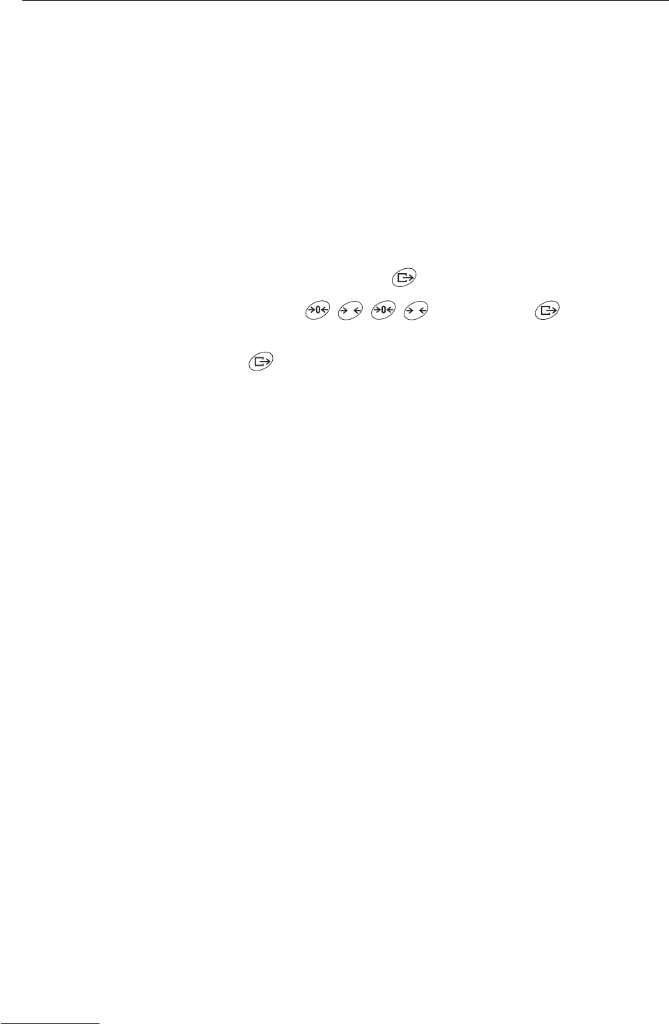
F5.8 – Entering the serial number
The 10-digit serial number of the weighing terminal has to be entered in 2 blocks in
the reverse order.
1. Activate F5.8.
H – is displayed in the display.
2. Enter the first 5 digits of the serial number in the reverse order
(Digit 5, ... Digit 1).
3. Press .
L – is displayed in the display.
4. Enter the last 5 digits of the serial number in the reverse order
(Digit 10, ... Digit 6).
F5.10 – General reset
Reset all parameters of groups F1 to F4 to factory settings.
T
Downloaded from www.Manualslib.com manuals search engine
Interface commands
Operating instructions 72203952A 11/07 33
IND226x
7 Interface commands
7.1 SICS interface commands
The weighing terminal supports the MT-SICS (METTLER TOLEDO Standard Interface
Command Set) command set. With SICS commands, it is possible to configure,
query and operate the terminal from a PC. SICS commands are divided up into vari-
ous levels.
For further information about the MT-SICS command set, see MT-SICS Manual (Order
No. 00 705 184) or contact the METTLER TOLEDO Customer Service.
Command Meaning
LEVEL 0 @Reset the scale
I0 Inquiry of all available SICS commands
I1 Inquiry of SICS level und SICS version
I2 Inquiry of scale data
I3 Inquiry of scale software version
I4 Inquiry of serial number
SSend stable weight value
SI Send weight value immediately
SIR Send weight value immediately and repeatedly
ZZero the scale
ZI Zero immediately
LEVEL 1 TTare
TAC Clear tare
TI Tare immediately
Downloaded from www.Manualslib.com manuals search engine
Interface commands
34 Operating instructions 72203952A 11/07
IND226x
7.2 Toledo Continuous Mode
The weighing terminal supports the Toledo Continuous Mode for continuous transfer
of weight data and status information, for example to a PC or a secondary display.
At a baud rate of 2400 bauds and higher, a data string is transferred approximately
9 times per second. The transfer rate is slower if the baud rate is lower.
7.2.1 Toledo Continuous commands
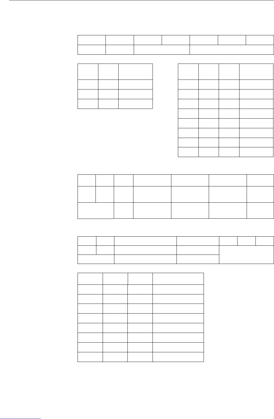
7.2.2 Toledo Continuous output format
Weight values are always transmitted in the following format:
STX ASCII characters 02 hex/2 deci, character for "start of text"
SB... For status bytes, see below
DF1 Data field with 6 digits for the weight value (gross or net),
transmitted without a decimal point and unit,
leading zeroes replaced by blank spaces
DF2 Data field with 6 digits for the tare weight;
transmitted without a decimal point and unit,
leading zeroes replaced by blank spaces
CR Carriage return (ASCII character 0D hex/13 deci)
CHK Checksum (2-part complement of binary sum of 7 lower bits of all
previously transmitted characters, including STX and CR),
transmitted only if activated in the menu
Command Meaning
PPrint out the current result
T Tare the scale
Z Zero the display
C Clear the current value
USwitching the weight unit
STX SB1 SB2 SB3 DF1 DF2 CR CHK
Downloaded from www.Manualslib.com manuals search engine
Interface commands
Operating instructions 72203952A 11/07 35
IND226x
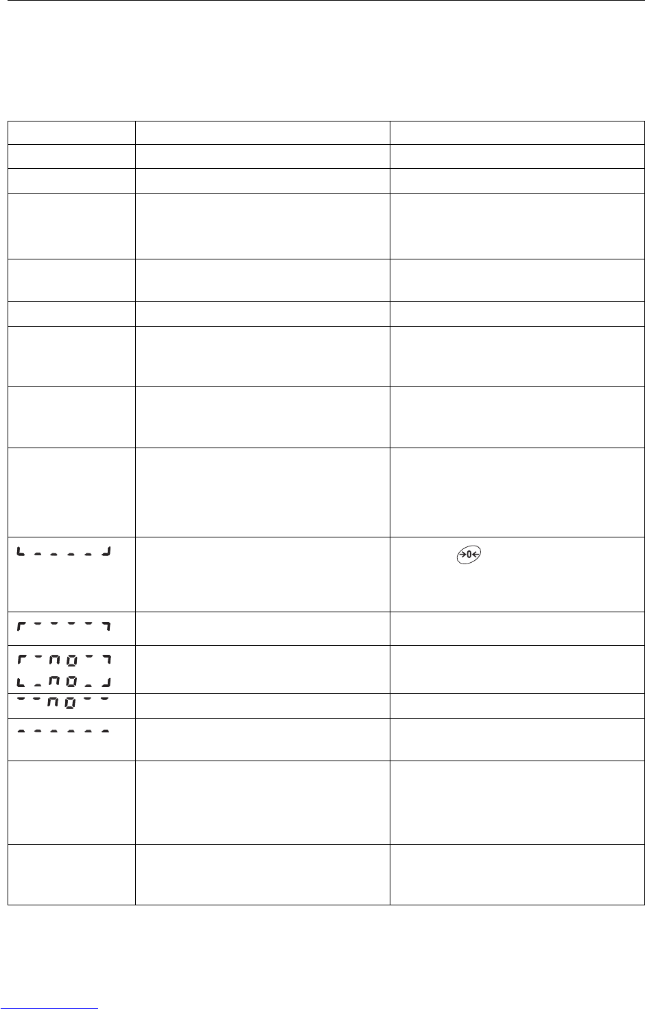
Status byte SB1
Status byte SB2
Status byte SB3
Bit 6 Bit 5 Bit 4 Bit 3 Bit 2 Bit 1 Bit 0
0 1 Rounding / Increment Decimal position
Bit 4 Bit 3 Rounding/
Increment
Bit 2 Bit 1 Bit 0 Decimal
position
0 1 x1 000XXXX00
1 0 x2 001XXXXX0
1 1 x5 010XXXXXX
011XXXXX.X
100XXXX.XX
101XXX.XXX
110XX.XXXX
111X.XXXXX
Bit 6 Bit 5 Bit 4 Bit 3 Bit 2 Bit 1 Bit 0
1 1 0 lb 0 Stabiliza-
tion
0Normal
status
0 Positive
sign
0 Gross
value
1 kg 1 Movement 1 Underload/
overload
1 Negative
sign
1Net
value
Bit 6 Bit 5 Bit 4 Bit 3 Bit 2 Bit 1 Bit 0
0 1 0 Normal status 0 Normal status Weight unit
1 High resolution (x 10) 1 Print request
Bit 2 Bit 1 Bit 0 Weight unit
000kg / lb (SB2 Bit 4)
001g
010t
011oz
100ozt
101dwt
110ton
111free unit
Downloaded from www.Manualslib.com manuals search engine
Error messages
36 Operating instructions 72203952A 11/07
IND226x
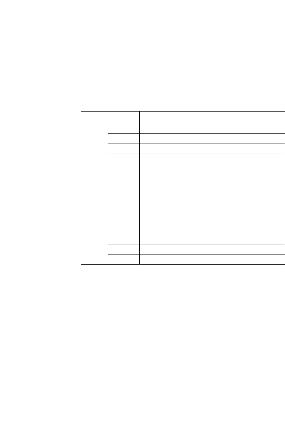
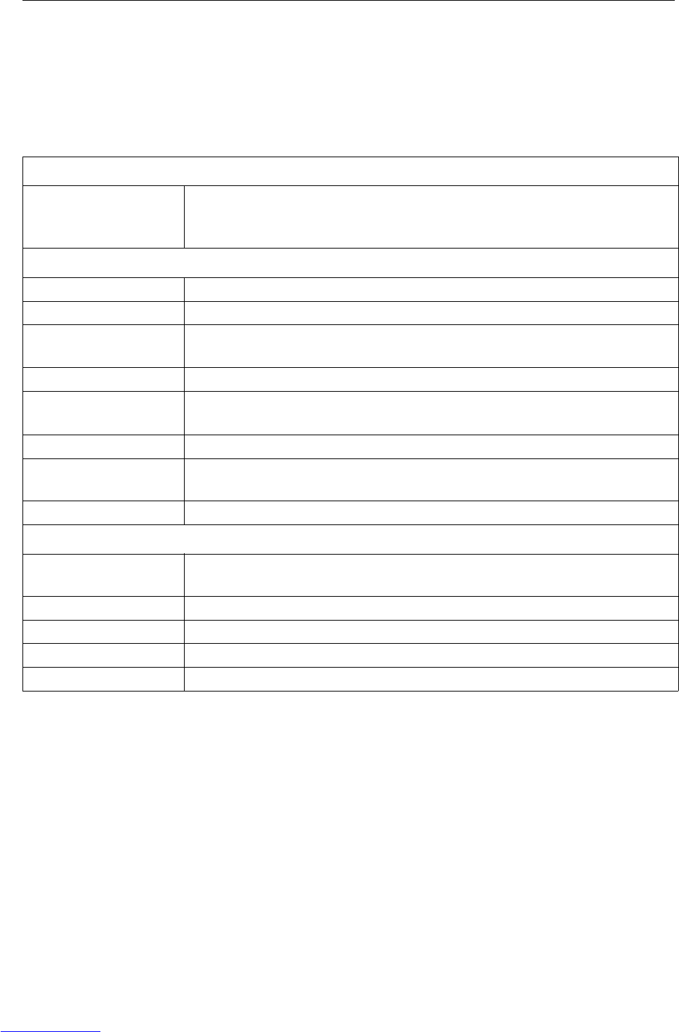
8 Error messages
Error code Error Remedy
Err 3 • EEPROM error ➜Turn the weighing terminal off and on
Err 6 • EEPROM read/write error ➜Call METTLER TOLEDO Service
Err 32 • Impermissible values entered in Block
F1
➜Repeat the entry with correct values
➜If the message is displayed again,
inform the METTLER TOLEDO Service
Err 35 • Weighing platform in motion when cali-
brating
➜Ensure that the weighing platform is
stable
Err 70 • Keypad error ➜Call METTLER TOLEDO Service
EEE • In case of certified weighing platforms:
Zero setting range exceeded during
switching on
➜Unload weighing platform
–EEE • In case of certified weighing platforms:
Zero setting range below limit during
switching on
➜Place the load plate on (correctly)
no DTA • Secondary display does not receive any
valid data
➜Check the communication settings
➜Check data cable connections
➜If the message is displayed again,
inform the METTLER TOLEDO Service
•Underload ➜Press
➜If the message reappears, call
METTLER TOLEDO Service
• Overload ➜Decrease load
• Zero setting outside zero setting range ➜Unload weighing platform
• Cannot perform the key function ➜Go back to gross mode
• Cannot perform the key function, scale is
in motion
➜Ensure that the weighing platform is
stable
Weighing terminal
switches off
automatically
• Automatic switching-off activated
• Battery level too low
➜Unload the weighing platform and, if
appropriate, configure Display Timeout
and Power Off differently
➜Charge the Battery Pack
Weighing terminal
remains dark after
being switched on
• No or incorrect voltage supply ➜Check supply unit connection
➜Call the METTLER TOLEDO Service
Downloaded from www.Manualslib.com manuals search engine
Technical data and accessories
Operating instructions 72203952A 11/07 37
IND226x
9 Technical data and accessories
9.1 Technical data
Explosion protection IND226x, Interface IND, Interface Remote
Ignition protection type ATEX II 2G Ex ib IIC T4
II 2D Ex tD A21 T60 °C
CFMUS IS Class I, II, III, Div. 1, Group A, B, C, D, E, F, G / T4 Ta 40 °C
Metrological data
Input signal range 0 to 3 mV/V
Supply voltage 5 V
Weighing platform
impedance
87.5 ... 1050 Ω
Smallest perm. certif. incr. 0.80 μV/e
Fraction of the error limit
(Pi)
0.5
Number of weighing cells max. 4
Max. number of certifiable
increment values
≤ 6000 e
Scale configuration Single range (SR)
Maximum cable length
Weighing platform –
IND226x
max. 20 m
APS50. – IND226x max. 15 m
PSUx – IND226x max. 50 m
Battery Pack – IND226x max. 3 m
ACM200 – IND226x max. 300 m
Downloaded from www.Manualslib.com manuals search engine
Technical data and accessories
38 Operating instructions 72203952A 11/07
IND226x
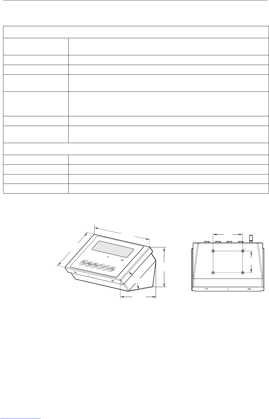
Dimensions
General technical data
Display Weight value: 7-segment display, 6 digits, 30 mm high
Status indication: 10 indicators
Housing stainless steel
Protection type IP66
Power supply APS500/501 power supply unit
alternatively via external Battery Pack or PSUx
Data interface 1 serial intrinsically safe data interface:
Interface IND for communication with peripheral devices in the safe area
Alternatively: Interface Remote for operating the IND226x as a secondary display
Digital inputs 1 digital input
Weight
(incl. packaging)
2.5 kg
Ambient conditions
Operating temperature –10 ... +40 °C
Storage temperature –20 ... +60 °C
Relative humidity 10 ... 85 %, non-condensing
Operating altitude up to 2000 m above sea level, indoors
90
66
132
148
150
220
38°
M5
Under OK Over PT Net lb kg
MinWeigh
Dimensions in mm
Downloaded from www.Manualslib.com manuals search engine
Technical data and accessories
Operating instructions 72203952A 11/07 39
IND226x
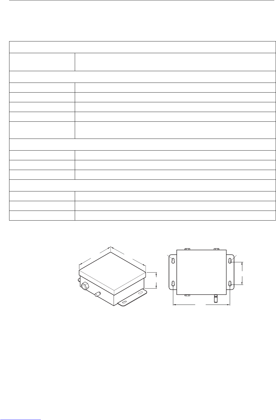
9.2 Technical data for ACM200
Dimensions
Explosion protection
Ignition protection type EN II (2) GD [Ex ib] IIC
CFMUS AIS Class I, II, III; Division 1; Group A, B, C, D, E, F, G
General technical data
Housing Stainless steel
Protection type IP66
Power supply Wide range power supply unit 100 ... 240 VAC 50/60 Hz
Data interface RS232
Weight
(incl. packaging)
3,4 kg
Ambient conditions
Operating temperature –10 ... +40 °C
Storage temperature –20 ... +60 °C
Relative humidity 10 ... 85 %, non-condensing
Connection cables
Cable to IND226x 10 m, premounted at the factory, intrinsically safe, with M16x1.5 screwing
Cable to peripheral devices 10 m, premounted at factory, RS232 Sub-D connector (female)
Power connection cable 2.4 m, with earthing-pin plug
81
R5
200
175
160
69.5
R3.5
Dimensions in mm
Downloaded from www.Manualslib.com manuals search engine
Technical data and accessories
40 Operating instructions 72203952A 11/07
IND226x
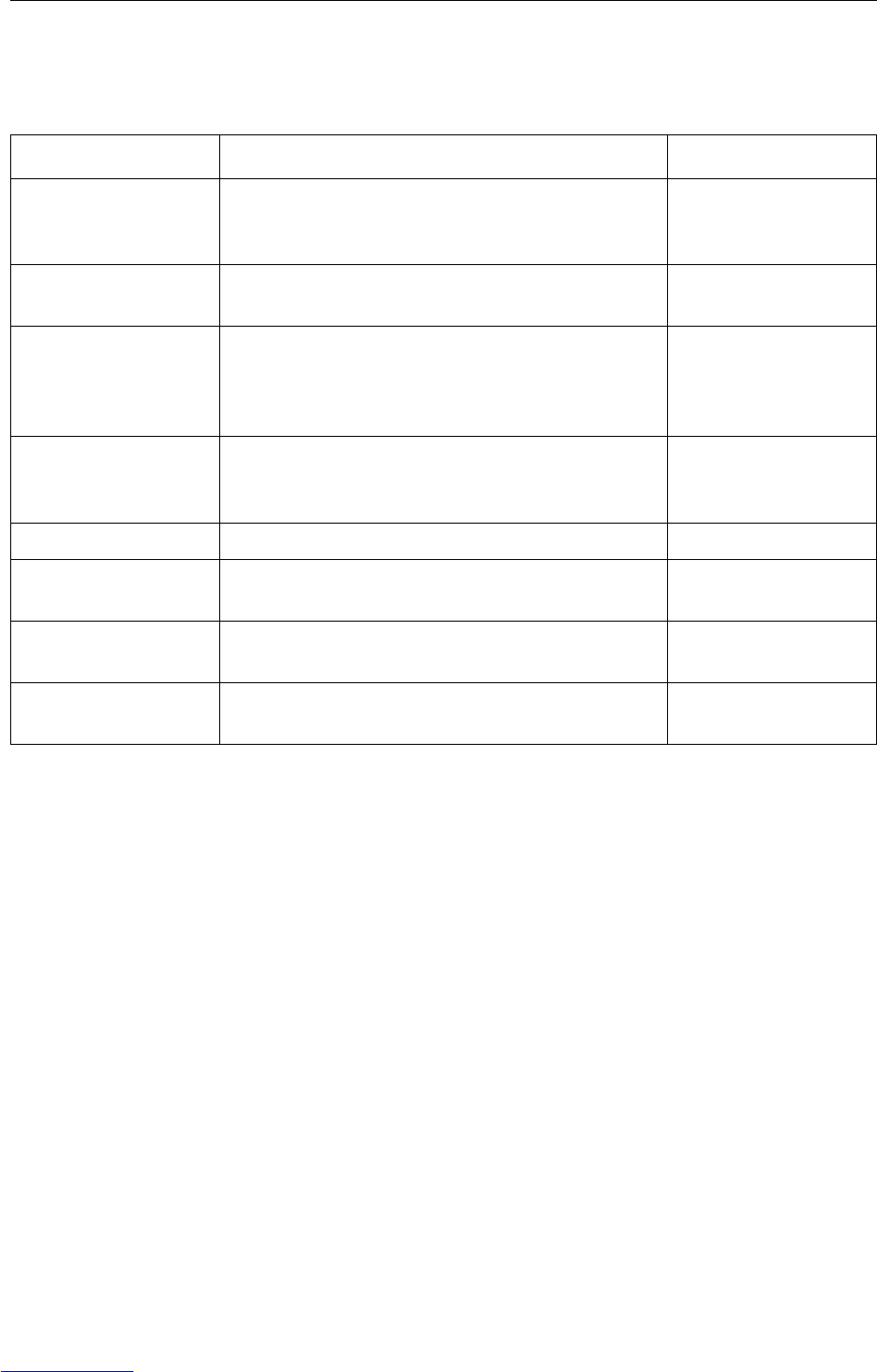
9.3 Accessories
Accessories Description Order number
Interface IND Serial data interface (active) for installation in the
IND226x, communication with peripheral devices in the
safe area
22 018 019
Interface Remote Serial data interface (passive) for installation in the
IND226x, remote function of the IND226x
22 018 020
Scale stand for
PBA430x
For mounting the weighing terminal to the weighing
platform, stainless
Height 330 mm
Height 660 mm
22 010 334
22 010 335
Floor stand For free installation of the weighing terminal
including mounting material for screwing to the floor,
stainless, rustproof
00 504 132
Stand base For movable installation of the floor stand, rustproof 00 503 701
Wall bracket For mounting the weighing terminal to the wall,
including mounting screws, rustproof
00 504 130
Bench stand S For fastening the weighing terminal to
PBA430x, 600 x 800 mm, rustproof
00 504 128
ID retainer For mounting the weighing terminal to the shaft of the
pallet scale PTA459x
22 012 196
Downloaded from www.Manualslib.com manuals search engine

Appendix
Operating instructions 72203952A 11/07 41
IND226x
10 Appendix
10.1 Disposal
In conformance with the European Directive 2002/96/EC on Waste Electrical and
Electronic Equipment (WEEE), this device may not be disposed of in domestic waste.
This also applies to countries outside the EU as per their specific regulations.
➜Please dispose of this product in accordance with local regulations at the collect-
ing point specified for electrical and electronic equipment.
If you have any questions, please contact the responsible authority or the distributor
from which you purchased this device.
Should this device be passed on to other parties (for private or professional use), the
content of this regulation must also be related.
Thank you for your contribution to environmental protection.
Downloaded from www.Manualslib.com manuals search engine
Appendix
42 Operating instructions 72203952A 11/07
IND226x
10.2Declarations of conformity
Mettler-Toledo (ChangZhou) Scale System Ltd.
Legal Metrology
EC-Declaration of Conformity
EC-Konformitätserklärung
EC-Déclaration de conformité
EC-Declaración de Conformidad
EC-Conformiteitsverklaring
EC-Dichiarazione di conformità
________________________________________________________________________________________________________
We, Wir, Nous, Nosotros, Noi
Mettler-Toledo (ChangZhou) Scale System Ltd.
No.111, West Tai Hu Road, XinBei District, ChangZhou, JiangSu, 213125, P.R.China
declare under our sole responsibility that the product,
erklären, in alleiniger Verantwortung, daß dieses Produkt,
déclarons sous notre seule responsabilité que le produit,
declaramos, bajo nuestra sola responsabilidad, que el producto,
verklaren onder onze verantwoordelijkheid, dat het product,
dichiariamo sotto nostra unica responsabilitá, che il prodotto,
Model/Type:IND226x weighing Terminal (EC test certificate:TC6862)
To which this declaration relates , is in conformity with the following standard(s) or other normative document(s),
auf das sich diese Erklärung bezieht, mitder/den folgenden Norm(en) oder Richtlinie(n) übereinstimmt.
Auquel se réfère cette déclaration est conforme à la (aux) norme(s) ou au(x) document(s) normatif(s).
Al que se refiere esta declaración es conforme a la(s) norma(s) u otro(s) documento(s) normativo(s).
Waarnaar deze verklaring verwijst, aan de volende norm(en) of richtlijn(en) beantwoordt.
A cui si riferisce questa dichiarazione è conforme alla/e sequente/i norma/e o documento/i normativo/i.
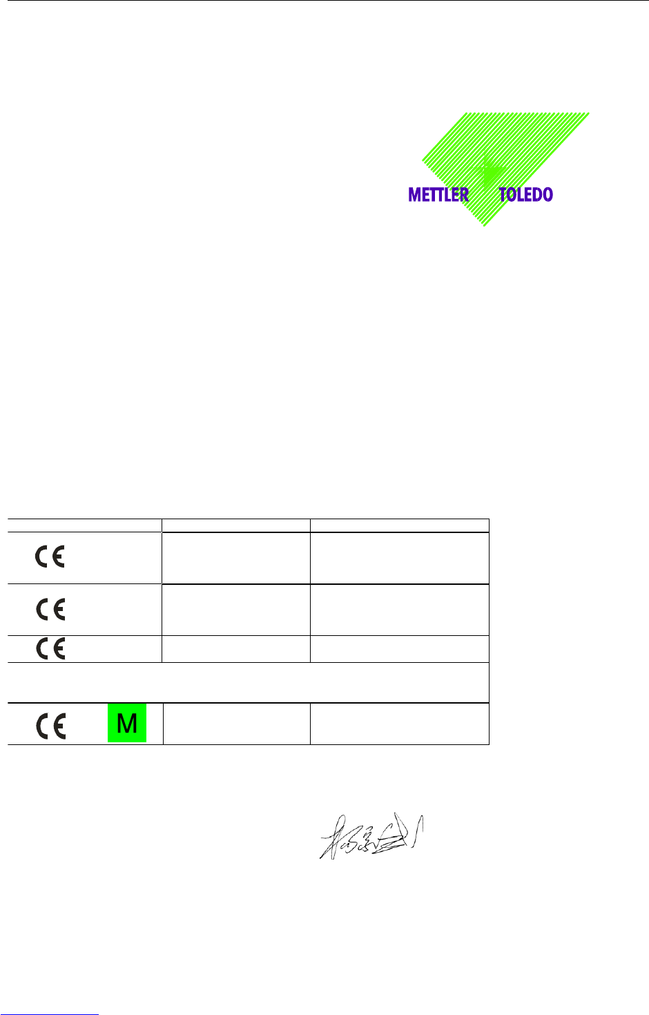
EC marking EC Directive Applicable Standards
0344 94/9/EC Directive
EN60079-0:2004
EN60079-11:2006
EN61241-0
EN61241-1
89/336/EEC
EMC Directive
EN61000-6-1
EN61000-6-3
EN61000-4-3(10V/m)
EN61000-4-6(10V/m)
2002/95/EC
RoHS Directive N/A
For non-automatic weighing instrument used in an Article 1,2.(a) application ,additional
metrological marking according to Annex IV of Council Directive 90/384/EEC must be
attached to the instrument
0103
90/384/EEC
Non-automatic weighing
instruments directive
EN45501*
* Only valid for weighing terminal in connection with approved load cells.
* ATEX certificate: BVS 07 ATEX 015, EXAM 0158, 44809 Bochum, Germany
No.111, West TaiHu Road, XinBei District , ChangZhou, JiangSu.213125,PRC, July 18, 2007,Mettler-Toledo (ChangZhou) Scale &
System Ltd.
Yang JiaWu
Quality Assurance Manager
year
Downloaded from www.Manualslib.com manuals search engine

Appendix
Operating instructions 72203952A 11/07 43
IND226x
Mettler-Toledo (ChangZhou) Scale System Ltd.
EC-Declaration of Conformity
EC-Konformitätserklärung
EC-Déclaration de conformité
EC-Declaración de Conformidad
EC-Conformiteitsverklaring
EC-Dichiarazione di conformità
________________________________________________________________________________________________________
We, Wir, Nous, Nosotros, Wij, Noi
Mettler-Toledo (ChangZhou) Scale System Ltd.
No.111, West Tai Hu Road, XinBei District, ChangZhou, JiangSu, 213125, P.R.China
declare under our sole responsibility that the product,
erklären, in alleiniger Verantwortung, daß dieses Produkt,
déclarons sous notre seule responsabilité que le produit,
declaramos, bajo nuestra sola responsabilidad, que el producto,
verklaren onder onze verantwoordelijkheid, dat het product,
dichiariamo sotto nostra unica responsabilitá, che il prodotto,
Model/Type: ACM200 Communication module
To which this declaration relates , is in conformity with the following standard(s) or other normative document(s),
auf das sich diese Erklärung bezieht, mitder/den folgenden Norm(en) oder Richtlinie(n) übereinstimmt.
Auquel se réfère cette déclaration est conforme à la (aux) norme(s) ou au(x) document(s) normatif(s).
Al que se refiere esta declaración es conforme a la(s) norma(s) u otro(s) documento(s) normativo(s).
Waarnaar deze verklaring verwijst, aan de volende norm(en) of richtlijn(en) beantwoordt.
A cui si riferisce questa dichiarazione è conforme alla/e sequente/i norma/e o documento/i normativo/i.
EC Directive Applicable Standards
94/9/EC Directive EN60079-0:2006
EN60079-11:2007 **
2006/95/EC
Low Voltage Directive
EN61010-1˖2001
2004/108/EC
EMC Directive
EN61000-6-1
EN61000-6-3
EN61000-4-3(10V/m)
EN61000-4-6(10V/m)
2002/95/EC
RoHS Directive N/A
* * ATEX certificate: BVS 07 ATEX E 149, EXAM 0158, 44809 Bochum, Germany
No.111, West TaiHu Road, XinBei District , ChangZhou, JiangSu. 213125,PRC, Nov 7, 2007,Mettler-Toledo (ChangZhou) Scale &
System Ltd.
Yang JiaWu
Quality Assurance Manager
Downloaded from www.Manualslib.com manuals search engine

Congratulations on choosing the quality and precision of METTLER TOLEDO. Proper
use according to these instructions and regular calibration and maintenance by our
factory-trained service team ensure dependable and accurate operation, protecting
your investment. Contact us about a ServiceXXL agreement tailored to your needs and
budget.
We invite you to register your product at www.mt.com/productregistration so we can
contact you about enhancements, updates and important notifications concerning
your product.
*72203952A*
72203952A
Subject to technical changes © Mettler-Toledo (Changzhou) Measurement Technology Ltd. 11/07 72203952A
Mettler-Toledo (Changzhou) Measurement Technology Ltd.
10 Kunlun Road, Changzhou Xinbei District, Jiangsu Province, P.R. China 213125
Tel. 0086-519-664-2040
Fax 0086-519-664-1991
Internet http://www.mt.com
Downloaded from www.Manualslib.com manuals search engine
