Oripa User Manual
User Manual: Pdf
Open the PDF directly: View PDF ![]() .
.
Page Count: 7
ORIPA – Origami Pattern Editorv0.34
User’s Manual
1.
Overview
ORIPA is a drawing software dedicated to designing crease patterns of origami. The
unique feature of ORIPA is calculation of the folded shape from the pattern.
The first version of ORIPA was released in 2005.
1.1.
Main Screen
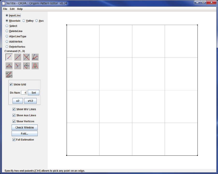
When first initialized, ORIPA’s window must look like the image below:
Figure 1. ORIPA main screen.
The square showed on the white panel represents the crease pattern.
-
Black
lines represent the edges of the paper or cuts;
-
Red
lines represent mountain folds;
-
Blue
lines represent valley folds;
-
Grey
lines represent auxiliary lines;
-
Green
lines represent selected lines;
By default, it is also displayed a grid of grey lines that aren’t part of the crease
pattern and are used to aid the input of lines.
The menu by the left side of the crease pattern displays input options, display
options and the Check Window and Fold buttons.
A tip is always displayed by the lower left corner of the window.
2.
Line input
To input a line, first check the “Input Line” option on the left menu and select one of
the three line types below. The types of the lines can be changed afterwards (using the “Alter
Line Type” option of the left menu). There are nine ways of creating new lines. To select the
input mode click in one of the 9 buttons under the “Command (1…9)” label.
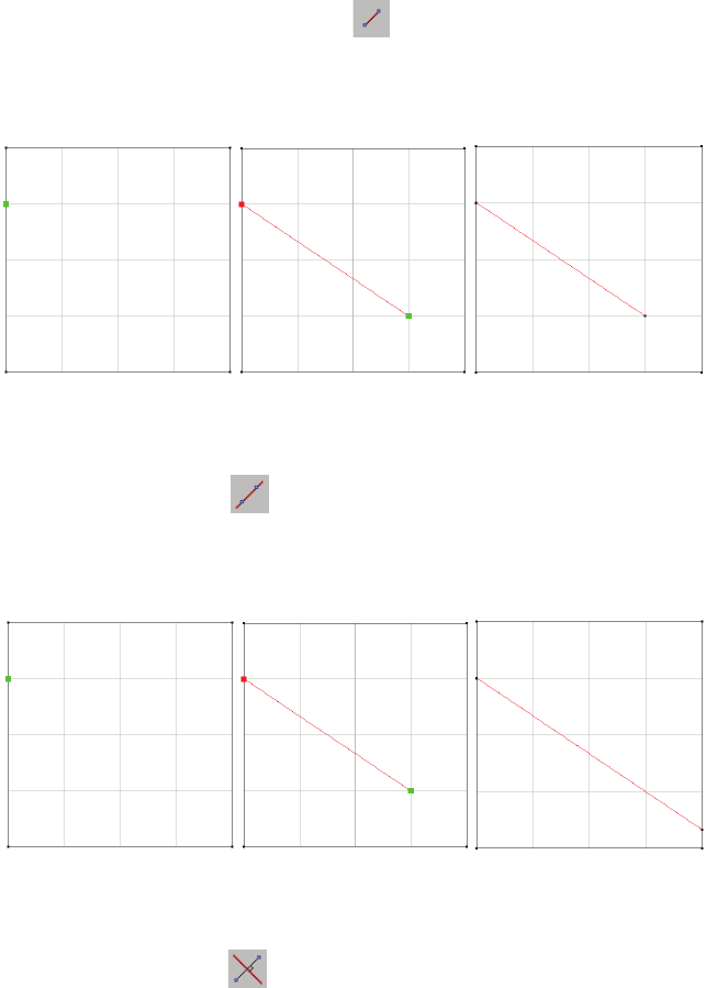
2.1 Line segment
To input a line segment while the icon is selected, specify two end points.
Holding Ctrl will allow the selection of any point on an existing line. The result will be a line
segment connecting the selected points.
Figure 2. Example of line segment input
2.2 Line
To input a line while the icon is selected, specify two points. Holding Crtl will
allow the selection of any point on an existing line. The result will be a line that connects two
points of the edge of the paper and contains the selected points.
Figure 3. Example of line input
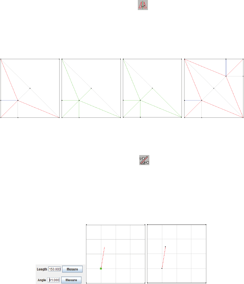
2.3 Perpendicular bisector
To input a line while the icon is selected, specify two points. The result will be
the perpendicular bisector of the segment delimited by the selected points. This line will
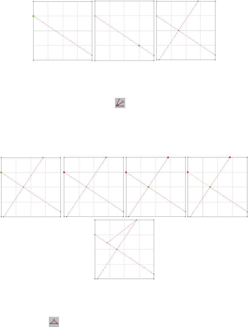
connect two point of the edge of the paper.
Figure 4. Example of perpendicular bisector input.
2.4 Angle bisector
To input a line segment while the icon is selected, first specify three points that
delimit the angle to be bisected (the second point will be the vertex of the angle). Then, choose
a line to delimit where should the new segment stop. The result will be the angle bisector of
the specified angle, starting on the angle vertex and ending on the selected line.
Figure 5. Example of angle bisector input.
2.5 Triangle incenter
When the icon is selected, specify three points. ORIPA will add three segments
to the CP, each of them beginning on one of the selected vertices and ending on the incenter of
the triangle delimited by those vertices.
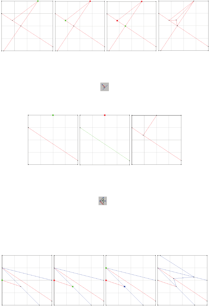
Figure 6. Example of input using triangle incenter
2.6 Perpendicular line segment
To input a line segment while the icon is selected, specify a point and a line.
The result will be a line segment connecting the selected point with its orthogonal projection
on the selected line.
Figure 7. Example of perpendicular line segment input.
2.7Symmetric line
To input a line segment while the icon is selected, specify three points. ORIPA
will create a line symmetric to the line that passes through the first and second selected
points. The axis of symmetry is the line passing through the second and third selected points.
The new line will begin on the second selected point and go until it intersects another existing
line of the crease pattern. Holding Ctrl will automatically apply the same function to
propagate the new fold until it reaches an edge of the paper.
Figure 8. Example of symmetric line input.
2.8 Mirror copy
To perform mirror copy, select the icon and pick target line segments by
clicking on them. A selected segment will change its color to green even if the mouse cursor
isn’t above it. To complete the copy, hold Ctrl and click on a segment with the desired position
for the axis. To select segments with a mouse drag movement, see section use the “Select”
option in the left menu.
Figure 9. Example of mirror copy.
2.9 Input by value
To input a segment by value, select the icon and specify the length and angle (in
degrees) using the text fields that will appear below the input mode icons. Move the mouse
cursor next to a vertex and a preview of the new segment will appear. To complete the input,
click on the vertex. Alternatively, you can click on the “Measure” button to get the values of
an existing segment. To measure the length of a segment, after clicking on “Measure”, specify
two end points. To measure an angle, after clicking on “Measure”, specify three points.
Figure 10. Example of input by value.
3.
Line copy
By using the “Edit” menu in the main screen, you can access three types of copying
lines (“Copy and Paste”, “Array Copy” and “Circle Copy”). For all of them, select the target
lines first using the “Select” functionality of the left menu.
4.
Display options
The grid in ORIPA is used to aid the line input by creating virtual vertices on the
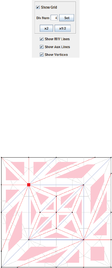
crease pattern. By unselecting the check box “Show Gird” the grid won’t be displayed. You can
also specify the number of divisions for the grid, in the text field “DivNum”, or click on the “x2”
and “x1/2” buttons. The number of divisions will always be a natural number greater than 1.
The appearance of the mountain/valley creases, auxiliary lines and vertices can be
changed by clicking on the respective check box.
Figure 11. Part of the left menu showing display options.
5.
Folded crease pattern
For ORIPA to compute the folded form of the crease pattern, each vertex of the CP
must obey the local rules of flat foldability (for more on that, check: T. Hull,
On the
mathematics of flat origamis
. Congressus Numerantium, 100 (1994), pp. 215–224. ) To check
if the crease pattern is locally flat foldable, click on the “Check Window” button. Figure 12
shows an example of this window. The problematic vertices are marked with a red square.
Figure 12. Example of a check window.
Clicking on the “Fold” button will open 2 windows (if there is no problem with the
CP): one entitled “Expected Folded Origami” and other entitled “Folded Origami” (if the “Full
Estimation ” check box is not selected, only the first one will appear). The “Expected Folded
Origami” will show an X-ray of the folded model.
You can export .dxf and .obj files using the “File” menu, and, by selecting “Show
Cross-Line” in the “Display” menu, a red line will be displayed on this window representing a
cut in the origami. The corresponding lines will also be displayed on the CP in purple. You
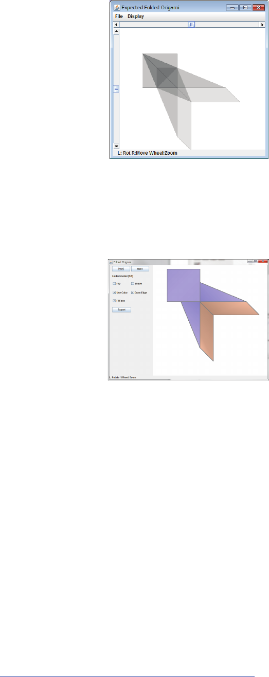
can control the position of the red line with the scroll bars on top and left parts of the window.
Figure 13. Example of “Expected Folded Origami” window
The “Folded Origami” window displays the full estimation of the folded form (with
layer order). Depending on the crease pattern, multiple answers for layer ordering can be
found. In that case, you can navigate between these answers using the “Prev” and “Next”
buttons.
Figure 14. Example of “Folded Origami” window
6.
Panning, Zooming and Rotating.
The crease pattern main screen, the “Folded Origami” and the “Expected Folded
Origami” screens can be panned and zoomed. To pan the content of the window, click using
the right button of the mouse and drag it to the desired position. To zoom in, use the scroll
wheel of the mouse upwards. To zoom out, scroll downwards. The main screen also supports
zooming by holding Ctrl while dragging the mouse with the left click.
Additionally, the “Folded Origami” and the “Expected Folded Origami” screens
support rotation. To rotate the image clockwise, use the mouse drag to the right while
clicking on the left button. To rotate counterclockwise, drag to the left.
For more information on the ORIPA algorithm see:
http://mitani.cs.tsukuba.ac.jp/dl/eg2008_mitani.pdf
