Lexicon PCM90 User Guide Revision 0 Rev0 Original
Lexicon PCM90 PCM90 User Guide Revision 0 pcm90_user_guide_rev0_original Lexicon - PCM90 - PCM90 User Guide Revision 0
User Manual: Pdf Lexicon PCM90 PCM90 User Guide Revision 0 Lexicon - PCM90 - PCM90 User Guide Revision 0
Open the PDF directly: View PDF ![]() .
.
Page Count: 129 [warning: Documents this large are best viewed by clicking the View PDF Link!]

User Guide
Digital
Reverberator
PCM 90
Lexicon Part # 070-10399
Copyright 1995
All Rights Reserved.
Unpacking and Inspection
Notice
This equipment generates and uses radio frequency energy and if not installed and used properly, that is, in strict accordance with the
manufacturer's instructions, may cause interference to radio and television reception. It has been type tested and found to comply with the
limits for a Class B computing device in accordance with the specifications in Subpart J of Part 15 of FCC Rules, which are designated to provide
reasonable protection against such interference in a residential installation. However, there is no guarantee that interference will not occur
in a particular installation. If this equipment does cause interference to radio or television reception, which can be determined by turning the
equipment OFF and ON, the user is encouraged to try to correct the interference by one or more of the following measures:
Reorient the receiving antenna
Relocate the computer with respect to the receiver
Move the computer away from the receiver
Plug the computer into a different outlet so that the computer and receiver are on different branch circuits.
If necessary, the user should consult the dealer or an experienced radio/television technician for additional suggestions. The user may find
the following booklet prepared by the Federal Communications Commission helpful:
"How to identify and Resolve Radio/TV Interference Problems."
This booklet is available from the U.S. Government Printing Office, Washington, DC 20402, Stock No. 004-000-00345-4.
Le présent appareil numérique n'émet pas de bruits radioélectriques dépassant les limites applicables aux appareils numériques de la class
B prescrites dans le Règlement sur le brouillage radioélectrique édicté par le ministère des Communications du Canada.
After unpacking the PCM 90, save all packing materials in case you ever need to ship the unit. Thoroughly inspect
the PCM 90 and packing materials for signs of damage. Report any shipment damage to the carrier at once; report
equipment malfunction to your dealer.
CAUTION
RISK OF ELECTRIC SHOCK
DO NOT OPEN
This triangle, which appears on your
component, alerts you to the pres-
ence of uninsulated, dangerous volt-
age inside the enclosure... voltage
that may be sufficient to constitute a
risk of shock.
This triangle, which appears on your
component, alerts you to important
operating and maintenance instruc-
tions in this accompanying litera-
ture.
Save these instructions for later use.
Follow all instructions and warnings marked on the unit.
Always use with the correct line voltage. Refer to the manufacturer's operating instructions for power requirements. Be advised that different
operating voltages may require the use of a different line cord and/or attachment plug.
Do not install the unit in an unventilated rack, or directly above heat producing equipment such as power amplifiers. Observe the maximum
ambient operating temperature listed in the product specification.
Slots and openings on the case are provided for ventilation; to ensure reliable operation and prevent it from overheating, these openings must
not be blocked or covered. Never push objects of any kind through any of the ventilation slots. Never spill a liquid of any kind on the unit.
This product is equipped with a 3-wire grounding type plug. This is a safety feature and should not be defeated.
Never attach audio power amplifier outputs directly to any of the unit's connectors.
To prevent shock or fire hazard, do not expose the unit to rain or moisture, or operate it where it will be exposed to water.
Do not attempt to operate the unit if it has been dropped, damaged, exposed to liquids, or if it exhibits a distinct change in performance indicating
the need for service.
This unit should only be opened by qualified service personnel. Removing covers will expose you to hazardous voltages.
Precautions

User Guide
Digital
Reverberator
PCM 90
Dansk
Vigtig information om sikkerhed
Gem denne vejledning til senere brug.
Følg alle anvisninger og advarsler på apparatet.
Apparatet skal altid tilsluttes den korrekte spænding. Der henvises til
brugsanvisningen, der indeholder specifikationer for strømforsyning. Der
gøres opmærksom på, at ved varierende driftsspændinger kan det blive
nødvendigt at bruge andre lednings- og/eller stiktyper.
Apparatet må ikke monteres i et kabinet uden ventilation eller lige over
andet udstyr, der udvikler varme, f.eks. forstærkere. Den maksimale
omgivelsestemperatur ved drift, der står opført i specifikationerne, skal
overholdes.
Der er ventilationsåbninger i kabinettet. For at sikre apparatets drift og
hindre overophedning må disse åbninger ikke blokeres eller tildækkes. Stik
aldrig noget ind igennem ventilationsåbningerne, og pas på aldrig at spilde
nogen form for væske på apparatet.
Dette apparat er forsynet med et stik med jordforbindelse. Denne
sikkerhedsforanstaltning må aldrig omgås.
Udgangsstik fra audioforstærkere må aldrig sættes direkte i apparatet.
Apparatet må ikke udsættes for regn eller fugt og må ikke bruges i
nærheden af vand for at undgå risiko for elektrisk stød og brand.
Apparatet må aldrig bruges, hvis det er blevet stødt, beskadiget eller vådt,
eller hvis ændringer i ydelsen tyder på, at det trænger til eftersyn.
Dette apparat må kun åbnes af fagfolk. Hvis dækslet tages af, udsættes
man for livsfarlig højspænding.
Denne mærkat på komponenten advarer om vigtig drifts- og
vedligeholdsinformation i den tilhørende litteratur.
Denne mærkat på komponenten advarer om uisoleret, farlig spænding
i apparatet ... høj nok til at give elektrisk stød.
Suomi
Tärkeitä turvallisuusohjeita
Säilytä nämä ohjeet tulevaa käyttöä varten.
Seuraa kaikkia yksikköön merkittyjä ohjeita ja varoituksia.
Käytä aina oikeaa verkkojännitettä. Tehovaatimukset selviävät valmistajan
käyttöohjeista. Huomaa, että eri käyttöjännitteet saattavat vaatia
toisenlaisen verkkojohdon ja/tai -pistokkeen käytön.
Älä asenna yksikköä telineeseen jossa ei ole tuuletusta, tai välittömästi
lämpöä tuottavien laitteiden, esim. tehovahvistimien, yläpuolelle. Ympäristön
lämpötila käytössä ei saa ylittää tuotespesifikaation maksimilämpötilaa.
Kotelo on varustettu tuuletusreiillä ja -aukoilla. Luotettavan toiminnan
varmistamiseksi ja ylilämpenemisen välttämiseksi näitä aukkoja ei saa
sulkea tai peittää. Mitään esineitä ei saa työntää tuuletusaukkoihin. Mitään
nesteitä ei saa kaataa yksikköön.
Tuote on varustettu 3-johtimisella maadoitetulla verkkopistokkeella. Tämä
on turvallisuustoiminne eikä sitä saa poistaa.
Älä kytke audiotehovahvistimen lähtöjä suoraan mihinkään yksikön
liittimeen.
Sähköiskun ja palovaaran välttämiseksi yksikkö ei saa olla sateessa tai
kosteassa, eikä sitä saa käyttää märässä ympäristössä.
Älä käytä yksikköä jos se on pudonnut, vaurioitunut, kostunut, tai jos sen
suorituskyky on huomattavasti muuttunut, mikä vaatii huoltoa.
Yksikön saa avata vain laitteeseen perehtynyt huoltohenkilö. Kansien
poisto altistaa sinut vaarallisille jännitteille.
Tämä kolmio, joka esiintyy komponentissasi, kertoo sinulle, että
tässä tuotedokumentoinnissa esiintyy tärkeitä käyttö- ja ylläpito-
ohjeita.
Tämä kolmio, joka esiintyy komponentissasi, varoittaa sinua
eristämättömän vaarallisen jännitteen esiintymisestä yksikön sisällä.
Tämä jännite saattaa olla riittävän korkea aiheuttamaan
sähköiskuvaaran.
Norsk
Viktig informasjon om sikkerhet
Ta vare på denne veiledningen for senere bruk.
Følg alle anvisningene og advarslene som er angitt på apparatet.
Apparatet skal alltid anvendes med korrekt spenning. Produktbeskrivelsen
inneholder spesifikasjoner for strømkrav. Vær oppmerksom på at det ved
ulike driftsspenninger kan være nødvendig å bruke en annen ledning- og/
eller støpseltype.
Apparatet skal ikke monteres i skap uten ventilasjon, eller direkte over
varmeproduserende utstyr, som for eksempel kraftforsterkere. Den
maksimale romtemperaturen som står oppgitt i produktbeskrivelsen, skal
overholdes.
Apparatet er utstyrt med ventilasjonsåpninger. For at apparatet skal være
pålitelig i bruk og ikke overopphetes, må disse åpningene ikke blokkeres
eller tildekkes. Stikk aldri noe inn i ventilasjonsåpningene, og pass på at det
aldri søles noen form for væske på apparatet.
Dette apparatet er utstyrt med et jordet støpsel. Dette er en
sikkerhetsforanstaltning som ikke må forandres.
Utgangsplugger fra audioforsterkere skal aldri koples direkte til apparatet.
Unngå brannfare og elektrisk støt ved å sørge for at apparatet ikke utsettes
for regn eller fuktighet og ikke anvendes i nærheten av vann.
Apparatet skal ikke brukes hvis det har blitt utsatt for støt, er skadet eller blitt
vått, eller hvis endringer i ytelsen tyder på at det trenger service.
Dette apparatet skal kun åpnes av fagfolk. Hvis dekselet fjernes, utsettes
man for livsfarlig høyspenning.
Komponenten er merket med denne trekanten, som er en advarsel
om at det finnes uisolert, farlig spenning inne i kabinettet ... høy nok
til å utgjøre en fare for elektrisk støt.
Komponenten er merket med denne trekanten, som betyr at den
tilhørende litteraturen inneholder viktige opplysninger om drift og
vedlikehold.
Svenska
Viktiga säkerhetsföreskrifter
Spara dessa föreskrifter för framtida bruk.
Följ alla anvisningar och varningar som anges på enheten.
Använd alltid rätt nätspänning. Se tillverkarens bruksanvisningar för infor-
mation om effektkrav. Märkväl, att andra matningsspänningar eventuellt
kräver att en annan typs nätsladd och/eller kontakt används.
Installera inte enheten i ett oventilerat stativ, eller direkt ovanför utrustningar
som avger värme, t ex effektförstärkare. Se till att omgivningens temperatur
vid drift inte överskrider det angivna värdet i produktspecifikationen.
Behållaren är försedd med hål och öppningar för ventilering. För att
garantera tillförlitlig funktion och förhindra överhettning får dessa öppningar
inte blockeras eller täckas. Inga föremål får skuffas in genom ventilationshålen.
Inga vätskor får spillas på enheten.
Produkten är försedd med en jordad 3-trådskontakt. Detta är en
säkerhetsfunktion som inte får tas ur bruk.
Anslut aldrig audioeffektförstärkarutgångar direkt till någon av enhetens
kontakter.
För att undvika elstöt eller brandfara får enheten inte utsättas för regn eller
fukt, eller användas på ställen där den blir våt.
Använd inte enheten om den har fallit i golvet, skadats, blivit våt, eller om
dess prestanda förändrats märkbart, vilket kräver service.
Enheten får öppnas endast av behörig servicepersonal. Farliga spänningar
blir tillgängliga när locken tas bort.
Denna triangel, som visas på din komponent, anger att viktiga
bruksanvisningar och serviceanvisningar ingår i dokumentationen i
fråga.
Denna triangel, som visas på din komponent, varnar dig om en
oisolerad farlig spänning inne i enheten. Denna spänning är eventuellt
så hög att fara för elstöt föreligger.
Dieses Dreieck auf Ihrem Apparat bedeutet daß wichtige Betriebs-
und Wartungsanweisungen in der mitgelieferten Dokumentation zu
finden sind.
Dieses Dreieck auf Ihrem Apparat warnt Sie vor nicht-isolierter,
gefährlicher Spannung im Gehäuse ... stark genug um eine
Berührungsgefahr darzustellen.
Deutsch
Wichtige Sicherheitsanweisungen
Heben Sie sich diese Sicherheitsanweisungen auch für später auf.
Befolgen Sie alle auf der Vorrichtung stehenden Anweisungen und Warnungen.
Immer nur mit der richtigen Spannung verwenden! Die Gebrauchsanweisungen
des Herstellers informieren Sie über die elektrischen Anforderungen.
Vergessen Sie nicht daß bei verschiedenen Betriebsspannungen ggf. auch
verschiedene Leitungskabel und/oder Verbindungsstecker zu verwenden
sind.
Stellen Sie die Vorrichtung nicht in ein unbelüftetes Gestell oder unmittelbar
über wärmeerzeugende Geräte wie z.B. Tonverstärker. Halten Sie die in den
Produktspezifikationen angegebene maximale Umgebungstemperatur bei
Betrieb ein.
Schlitze und Öffnungen im Gehäuse dienen der Belüfung; um verläßlichen
Betrieb sicherzustellen und Überheizen zu vermeiden dürfen diese Öffnungen
nich verstopft oder abgedeckt werden. Stecken Sie nie irgend einen
Gegenstand durch die Belüftungsschlitze. Vergießen Sie keine Flüssigkeiten
auf den Apparat.
Dieses Produkt is mit einem 3-drahtigen Erdungsstecker ausgerüstet. Diese
Sicherheitsmaßnahme darf nicht unwirksam gemacht werden.
Schließen Sie nie Tonverstärker unmittelbar an einen Anschluß des Apparates
an.
Um elektrischen Schlag oder Feuer zu vermeiden, setzen Sie den Apparat
weder Regen noch Feuchtigkeit aus und betreiben Sie ihn nicht dort wo
Wasser eindringen könnte.
Versuchen Sie nicht den Apparat zu betreiben falls er fallen gelassen,
beschädigt, oder Flüssigkeiten ausgesetzt wurde, oder falls sich seine
Arbeitsweise derart ändert daß daraus ein Bedarf nach Raparatur zu schließen
ist.
Dieser Apparat sollte nur von qualifizierten Fachleuten geöffnet werden. Das
Abnehmen von Abdeckungen setzt Sie gefährlichen Spannungen aus.
Español
Instrucciones importantes de seguridad
Guarde esta instrucciones para uso posterior.
Utilice siempre el voltaje correcto. Diríjase a las instrucciones de operación
del fabricante para obtener las especificaciones de potencia. Esté al tanto
de que voltajes de operación distintos requieren el uso de cables y/o
enchufes distintos.
No instale esta unidad en un estante sin ventilación, ni tampoco directamente
encima de equipos que generen calor tales como amplificadores de potencia.
Fíjese en las temperaturas ambientales máximas de operación que se
mencionan en las especificaciones del producto.
Las aperturas y ranuras del chasis sirven para proveer la ventilación
necesaria para operar la unidad con seguridad y para prevenir
sobrecalentamiento, y por lo tanto no pueden ser obstruidas o cubiertas. No
introduzca objetos de ningún tipo a través de las ranuras de ventilación, y
nunca deje caer ningún líquido sobre la unidad.
Este producto está equipado con un enchufe de 3 clavijas con conexión a
tierra. Éste es un elemento de seguridad que no debe ser eliminado.
Nunca conecte ningún tipo de salida de amplificadores de sonido directamente
a los conectores de la unidad.
Para prevenir descargas eléctricas o incendios, mantenga la unidad alejada
de la lluvia, humedad o cualquier lugar en el que pueda entrar en contacto
con agua.
No trate de hacer funcionar la unidad si se ha caído, está dañada, ha entrado
en contacto con líquidos, o si nota cualquier cambio brusco en su
funcionamiento que indique la necesidad de hacerle un servicio de
mantenimiento.
Esta unidad deberá ser abierta únicamente por personal calificado. Si usted
quita las coberturas se expondrá a voltajes peligrosos.
Este triángulo que aparece en su componente lo alerta sobre las
instrucciones de operación y mantenimiento importantes que están
en los materiales de lectura que se incluyen.
Este triángulo que aparece en su componente le advierte sobre la
existencia dentro del chasis de voltajes peligrosos sin aislantes ...
voltajes que son lo suficientemente grandes como para causar
electrocución.
Français
Instructions de Sûreté Importantes
Gardez ces instructions pour réference future.
Observez toutes les instructions et tous les avertissements marqués sur
l’appareil.
Branchez uniquements sur un réseau de tension indiquée. Consultez le
manuel d’instruction du fabriquant pour les spécifications de courant.
N’oubliez pas que différentes tensions peuvent nécessiter l’utilisation de
cables et/ou de fiches de connexion différents.
N’installez pas l’appareil en un compartiment non-aéré ou directement au-
dessus d’équipements générateurs de chaleur, tels qu’amplificateurs de
courants, etc. Ne dépassez pas la température ambiante maximale de
fonctionnement indiquée dans les spécifications du produit.
Des fentes et ouvertures sont prévues dans le boîtier pour l’aération; Pour
assurer le bon fonctionnement et pour prévenir l’échauffement, ces ouvertures
ne doivent pas être couvertes ou bloquées. N’insérez pas d’objets dans les
fentes d’aération. Empêchez tout liquide de se répandre sur l’appareil.
Ce produit est muni d’une fiche à trois fils pour la mise à terre. Ceci est une
mesure de sécurité et ne doit pas être contrariée.
Ne connectez jamais d’amplificateurs audio directement aux connecteurs
de l’appareil.
Pour empêcher les chocs électriques et le danger d’incendie, évitez d’exposer
l’appareil à la pluie ou à l’humidité, et ne le mettez pas en marche en un
endroit où il serait exposé aux éclaboussures d’eau.
N’essayez pas de faire fonctionner l’appareil s’il est tombé à terre, a été
endommangé, exposé à un liquide, ou si vous observez des différences
nettes dans son fonctionnement, indiquant la nécessité de réparations.
Cet appareil ne doit être ouvert que par un personnel de service qualifié. En
enlevant les couvercles vous vous exposez à des tensions électriques
dangereuses.
Ce triangle sur sur votre appareil vous invite de suivre d’importantes
instructions d’utilisation et d’entretien dans la documentation livrée
avec le produit.
Ce triangle, sur votre appareil vous avertit de la présence de tension
dangereuse, non-isolée à l’intérieur du boîtier...une tension suffisante
pour représenter un danger d’électrocution.
Italiano
Importanti norme di sicurezza
Conservare le presenti norme per l’utilizzo futuro.
Osservare tutte le istruzioni e le avvertenze apposte sull’unità.
Utilizzare esclusivamente con la tensione di rete corretta. Consultare le
istruzioni operative fornite dal fabbricante per i dati riguardanti la tensione e
l’assorbimento di corrente. Potrebbe essere necessario l’uso di cavi di rete
e/o di spine diverse a seconda della tensione utilizzata.
Non installare l’unità in uno scaffale privo di ventilazione oppure direttamente
sopra una fonte di calore, come, ad esempio, un amplificatore. Non superare
la temperatura ambientale massima di funzionamento riportata nei dati
tecnici del prodotto.
Le fessure e le altre aperture nella scatola servono alla ventilazione. Per un
funzionamento affidabile, e per evitare un eventuale surriscaldamento,
queste aperture non vanno ostruite o coperte in nessun modo. Evitare in tutti
i casi di inserire oggetti di qualsiasi genere attraverso le fessure di ventilazione.
Non versare mai del liquido di nessun tipo sull’unità.
Questo prodotto viene fornito con una spina a 3 fili con massa. Tale
dispositivo di sicurezza non va eliminato.
Evitare sempre di collegare le uscite dell’amplificatore audio direttamente ai
connettori dell’unità.
Per prevenire il pericolo di folgorazione e di incendio non esporre l’unità alla
pioggia o ad un’umidità eccessiva; evitare di adoperare l’unità dove potrebbe
entrare in contatto con acqua.
Evitare di adoperare l’unità se la stessa è stata urtata violentemente, se ha
subito un danno, se è stata esposta ad un liquido o in caso di un evidente
cambiamento delle prestazioni che indichi la necessità di un intervento di
assistenza tecnica.
Ogni intervento sull’unità va eseguito esclusivamente da personale qualificato.
La rimozione della copertura comporta l’esposizione al pericolo di
folgorazione.
Il presente triangolo impresso sul componente avverte l’utente della
presenza nella documentazione allegata di importanti istruzioni relative
al funzionamento ed alla manutenzione.
Il presente triangolo impresso sul componente avverte della presenza
di tensioni pericolose non isolate all’interno della copertura... tali
tensioni rappresentano un pericolo di folgorazione

Contents
Introduction
1. Product Overview
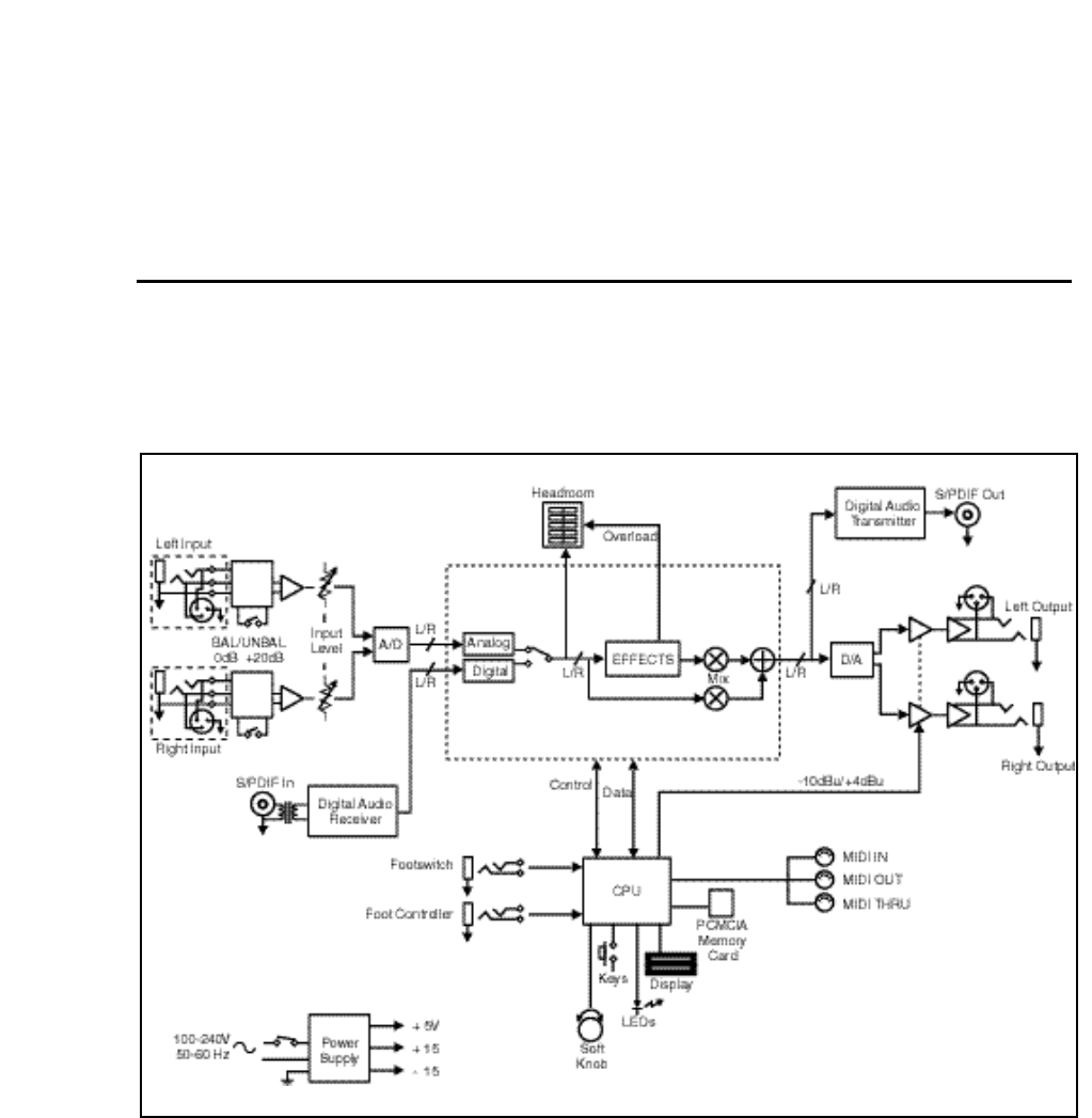
Block Diagram .................................................................................... 1-1
Front Panel Overview ......................................................................... 1-2
Rear Panel Overview .......................................................................... 1-3
Installation Notes ................................................................................ 1-4
Mounting ...................................................................................... 1-4
Power Requirements .................................................................... 1-4
Audio Connections ....................................................................... 1-4
Control Connections ..................................................................... 1-4
Setting Audio Levels .................................................................... 1-5
Headroom Display • Overload • Setting Input Levels
Setting Analog Output Level
Configurations .............................................................................. 1-7
Memory Cards .............................................................................. 1-8
2. Basic Operation
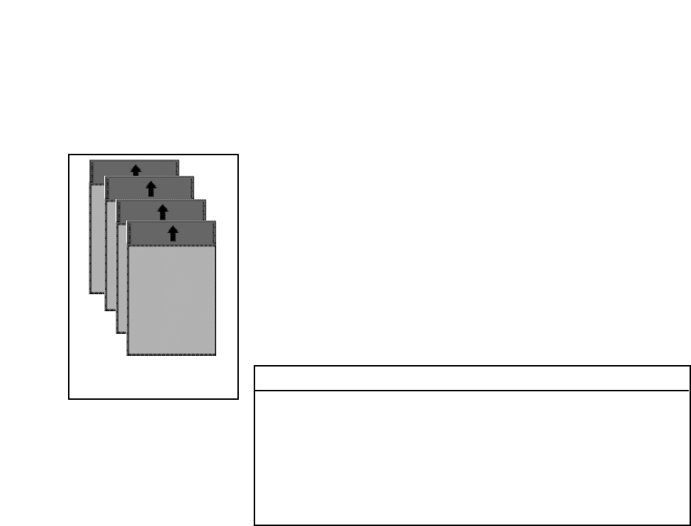
Modes of Operation ............................................................................ 2-1
Navigating a Matrix ...................................................................... 2-2
Info ............................................................................................... 2-3
History of Effects Loaded ............................................................. 2-3
Control Mode ...................................................................................... 2-4
Program and Register Banks............................................................ 2-17
Tempo Mode .................................................................................... 2-20
Editing an Effect................................................................................ 2-23
The Soft Knob ............................................................................ 2-23
The Soft Row ............................................................................. 2-24
Compare .................................................................................... 2-25
Bypass ....................................................................................... 2-25
Store operations ......................................................................... 2-26
Turning Memory Protection On • Storing an Effect
Renaming the Effect • Selecting a Bank and Register
Location
The Full Edit Matrix .................................................................... 2-28
Creating a Soft Row
Patching ..................................................................................... 2-31
About Sources • The Patch Row • Assigning a Source
Patch Sources • Assigning a Destination • Assigning
Values • Jump
Patching Examples .................................................................... 2-35
Creating a patch with default values • Adjusting the
modulation source parameters • Changing the default
destination values • Adding an additional pivot point to
the patch • Multiple Patches with the Same Destination
Mod Row Patches
The Custom Row ....................................................................... 2-42
Setting Range Limits for ADJUST and the Custom
Controls • Labeling ADJUST, the Custom Controls and Their
Ranges • Assigning KeyWords to an Effect

Contents, cont'd. 3. The Algorithms and their Parameters
About the Algorithms .......................................................................... 3-1
Random Hall ................................................................................ 3-2
Ambience ..................................................................................... 3-4
Rich Plate ..................................................................................... 3-5
Concert Hall ................................................................................. 3-6
Chamber/Room ............................................................................ 3-7
The Parameters .................................................................................. 3-8
Compress ..................................................................................... 3-8
Controls ........................................................................................ 3-9
Custom ....................................................................................... 3-10
Delay .......................................................................................... 3-12
Design ........................................................................................ 3-12
Echo ........................................................................................... 3-14
Expand ....................................................................................... 3-14
Modulation .................................................................................. 3-15
Patches ...................................................................................... 3-20
Reflect ........................................................................................ 3-21
Spatial EQ .................................................................................. 3-21
Time ........................................................................................... 3-22
4. The Presets
Program Bank 0 Halls ......................................................................... 4-2
Orchestral (0.0-0.9) ...................................................................... 4-2
Vocal (1.0-1.9) .............................................................................. 4-3
Live Sound (2.0-2.9) ..................................................................... 4-4
Instrument (3.0-3.9) ...................................................................... 4-5
Custom (4.0-4.9) .......................................................................... 4-6
Program Bank 1 Rooms ..................................................................... 4-7
Instrument (0.0-0.9) ...................................................................... 4-7
Vocal (1.0-1.9) .............................................................................. 4-8
Live Sound (2.0-2.9) ..................................................................... 4-9
Drums&Perc (3.0-3.9) ................................................................ 4-10
Custom (4.0-4.9) ........................................................................ 4-11
Program Bank 2 Plates ..................................................................... 4-12
Instrument (0.0-0.9) .................................................................... 4-12
Vocal (1.0-1.9) ............................................................................ 4-13
Live Sound (2.0-2.9) ................................................................... 4-14
Drums&Perc (3.0-3.9) ................................................................ 4-15
Custom (4.0-4.9) ........................................................................ 4-16
Program Bank 3 Post........................................................................ 4-17
Indoor Small (0.0-0.9) ................................................................ 4-17
Indoor Large (1.0-1.9) ................................................................ 4-18
Outdoor (2.0-2.9) ........................................................................ 4-19
Spatial (3.0-3.9) .......................................................................... 4-19
Custom (4.0-4.9) ........................................................................ 4-21
Program Bank 4 Splits ...................................................................... 4-22
Mono (0.0-0.9) ............................................................................ 4-22
Stereo (1.0-1.9) .......................................................................... 4-23
Live Sound (2.0-2.9) ................................................................... 4-24
Instrument (3.0-3.9) .................................................................... 4-25
Custom (4.0-4.9) ........................................................................ 4-26

5. MIDI Operation
Selecting a MIDI Channel ................................................................... 5-1
Accessing Programs and Registers .................................................... 5-1
Controlling PCM 90 Tempo Rate with MIDI Clock .............................. 5-2
MIDI Tempo Control ..................................................................... 5-2
Using the PCM 90 as a MIDI Clock Source ................................. 5-2
Slaving two or more PCM 90s ...................................................... 5-3
Controller Quirks ................................................................................. 5-4
The ADJUST Knob, Custom Controls, Foot Pedal, Foot Sw 1
and Foot Sw 2 as MIDI controllers ............................................... 5-4
Controlling the Soft Knob with MIDI ............................................. 5-5
Controlling the Soft Knob with a Foot Pedal ................................. 5-5
Program Change Messages ............................................................... 5-6
Automation ......................................................................................... 5-7
SysEx Automation • Controller Automation • Reset All
Controllers • MIDI Clock and Clock Commands • Dynamic
MIDI®
Bulk Data Dumps ................................................................................ 5-8
MIDI Implementation Chart ................................................................. 5-9
6. Troubleshooting
Low Voltage ........................................................................................ 6-1
Overheating ........................................................................................ 6-1
Common MIDI Problems .................................................................... 6-1
Operational Problems ......................................................................... 6-2
Power On Behavior............................................................................. 6-3
Restoring Factory Default Settings ..................................................... 6-3
Reinitialization .................................................................................... 6-4
7. Specifications
Contents, cont'd.

Thank you for your purchase of the PCM 90 Digital Reverberator. The PCM 90
gives you Lexicon's renowned high-end reverb effects with a powerful new
interface that provides easy access to superbly crafted presets as well as a
wealth of programming capabilities for the sound designer.
The PCM 90 contains a built-in library of 250 reverb effects that simulate realistic
halls, rooms and plates, and let you create completely natural, or other-worldly
spaces. The presets are organized into 5 Banks of 50, and are functionally
grouped for different applications. Be sure to experiment with all 250 presets to
get a feel for the full range of PCM 90 capabilities.
Introduction
The Presets
Bank P4 Splits
0.0-0.9 Mono
1.0-1.9 Stereo
2.0-2.9 Live Sound
3.0-3.9 Instrument
4.0-4.9 Custom
Bank P3 Post
0.0-0.9 Indoor Small
1.0-1.9 Indoor Large
2.0-2.9 Outdoor
3.0-3.9 Spatial
4.0-4.9 Custom
Bank P2 Plates
0.0-0.9 Instrument
1.0-1.9 Vocal
2.0-2.9 Live Sound
3.0-3.9 Drums&Perc
4.0-4.9 Custom
Bank P1 Rooms
0.0-0.9 Instrument
1.0-1.9 Vocal
2.0-2.9 Live Sound
3.0-3.9 Drums&Perc
4.0-4.9 Custom
Bank P0 Halls
0.0-0.9 Orchestral
1.0-1.9 Vocal
2.0-2.9 Live Sound
3.0-3.9 Instrument
4.0-4.9 Custom
A program sorting function allows you to tag programs with KeyWords and
display only programs which have been tagged. (Press Program Banks or
Register Banks repeatedly to step through all available banks and then to the
KeyWord display.) The default KeyWord selection, A to Z, allows you to view all
of the presets in alphabetical order. Others allow you to view, for example, only
Acoustic or Spatial effects. Each preset has already been assigned from 1 to
4 KeyWords — you can easily change these assignments in Edit mode. The
selection of the KeyWord you want to use for sorting is accessed in Control
mode.
Each preset has one or more of its parameters patched to the front panel
ADJUST knob, giving you instant control over the primary aspect of the effect —
without going into Edit mode.
As many as four additional Custom Controls can be created for any effect,
allowing you to tailor presets for specific applications. We've created some
interesting Custom Controls in the presets, and assigned them descriptive
names. You can change both the parameter assignments and the names in Edit
mode.
The PCM 90 uses 5 stereo algorithms to create different types of reverb effects.
Each algorithm includes an uncompromised stereo reverb effect with selected
"tools" for ambience, post-processing, compression/expansion, as well as
modulation and patching parameters which are common to each algorithm.
Program Sorting
Soft Control
The Algorithms

Tempo Control The PCM 90 gives you a unique set of tempo controls.Tempos can be tapped
in with the front panel Tap button (or an assigned controller) or “dialed-in”, in
BPM (beats per minute) on the display. The PCM 90 also lets you generate MIDI
clock from your tempo, as well as receive MIDI tempo from an external
sequencer or drum machine. In the PCM 90, tempo can control LFO speeds and
Time Switch controls, as well as all delay parameters, ensuring that all of your
modulations are in tempo with your music. You can even set independent
rhythmic values for different parameters within a single program.
Tempo can be set and displayed in either rhythmic value or time values. Many
presets have delay times assigned to Tap tempo. Try loading some of these and
pressing Tap twice in rhythm to change tempo.
An enormous range of editing control is provided for each algorithm, with
parameters organized in an edit matrix. In addition to providing this powerful
sound design capability, the PCM 90 also allows you to customize these controls
for your day-to-day editing needs, or to use a subset of controls specially
designed for each preset.
The PCM 90 has two levels of Edit Mode control called Go mode and Pro mode.
In Go mode, the most useful parameters within an effect are grouped for instant
access via the front panel Edit button. Parameters can even be grouped for
control by a single master control. These master parameters, called Custom
Controls, can be labeled with names that describe their function. Each preset
has a specially selected set of Go mode parameters which let you make value
changes to the effect without losing the character of the sound. Pro mode gives
you access to the full parameter editing matrix for the algorithm of any loaded
effect when you press Edit. In this mode, you can access a complete set of
Modulation and Patching parameters, create your own ADJUST knob patch,
create Custom Controls, and assign your own Go mode parameters.
A unique Patching and Modulation system provides unprecedented control over
your effects, with a versatile set of internal modulators: two LFOs, AR Envelope,
Envelope Follower, Latch and Time Switches, MIDI Delay and Sample and Hold.
These allow you to create modulation sweeps which move in time with music,
or animated effects. You can create as many as 10 patches per effect, each with
as many as 8 pivot points. You can patch multiple parameters to a single
controller, or patch multiple sources to a single destination.
For all of its programming power and flexibility, you’ll find the PCM 90 simple to
use. The large, 2-line fluorescent display is easy to see from any angle whether
the surroundings are bright or dark. Separate SELECT and ADJUST knobs
make program loading and editing quick and easy. We’ve even designed in a
special Info mode — press and hold any button to find out what its function is,
or to get status information such as the name of the running effect, current tempo
rate, etc.
To get the most out of the PCM 90, we suggest that you invest the time to explore
this manual. We think you’ll agree that the time spent investigating will reward
you with enjoyment of its full capabilities.
Editing
User Interface
1-1
Product Overview
1
Product Overview
Block Diagram
Lexicon
1-2
PCM 90 User Guide
Up/Down
Press to move up and
down through program
and register banks, or
a parameter matrix.
Program Banks
Enables selection of
factory presets. Press
repeatedly to cycle
selection of 5 internal
preset banks and a
KeyWord sorted dis-
play. Press and hold
to display the name
and algorithm of the
current program.
Load/✱
In Program or Regis-
ter mode, loads the
selected program. In
Edit mode, scrolls
through any multi-field
parameter.
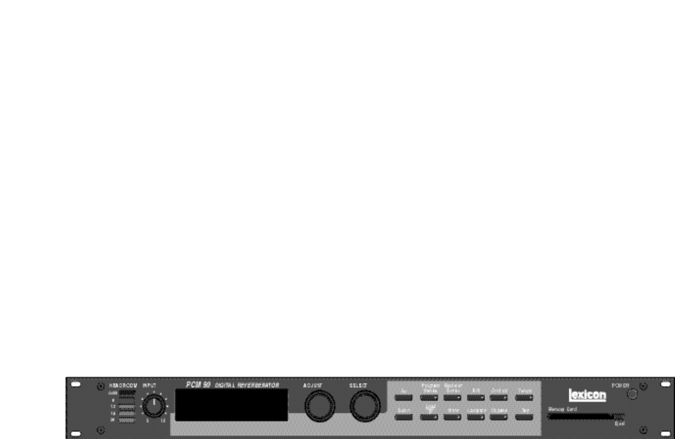
Front Panel Overview
HEADROOM
5-position indicator for
analog and digital sig-
nal levels and over-
load conditions.
INPUT
Adjusts analog input
level.
POWER
On/Off.
Memory Card
Slot for optional preset
ROM or register RAM
cards. Press Eject
button to remove card.
Register Banks
Enables selection of
user memory. If a RAM
card is loaded into the
Memory Card slot,
each press of this but-
ton selects a new reg-
ister bank. Press and
hold to display the
name and algorithm of
the current program.
Store
Initiates register store
function.
Edit
Enables parameter
selection for editing of
values.
Compare
Active in Program,
Register, and Edit
modes. Press to com-
pare the active version
of the current effect
with the most recently
stored version.
Control
Enables selection of
system and global pa-
rameters.
Bypass
Bypasses or mutes
audio, depending on
the setting of each
program's bypass pa-
rameter.
Tempo
Press to display tempo
rate and to initiate
tempo functions. LED
flashes in time with
current tempo rate.
Tap
Sets tempo. Press
twice in rhythm to es-
tablish tempo rate.
Press once to reset
LFO.
ADJUST
In Edit mode, changes
values of parameters
chosen with SELECT.
With Program Banks
or Register Banks se-
lected, behaves as a
soft knob for patched
parameters.
SELECT
Scrolls through pre-
sets, registers or pa-
rameters. With Pro-
gram Bank or Register
Bank selected, scrolls
through the 50 pro-
grams in the selected
bank, then begins
scrolling through the
programs in the next
bank. With Edit se-
lected, scrolls through
matrix parameters.
Display
Two rows of 20 alpha-
numeric characters
display effect names
and ID numbers, and
parameter names and
values.
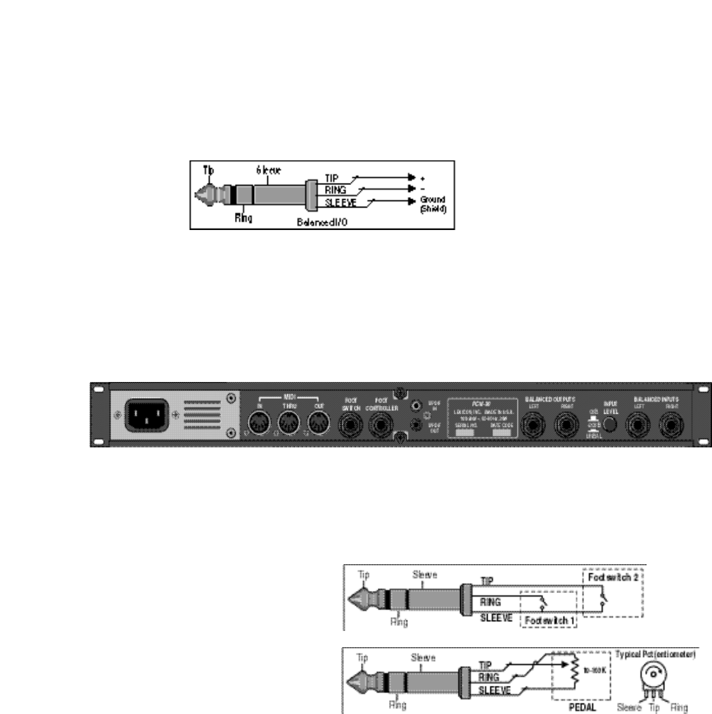
1-3
Product Overview
AC Power
Standard 3-pin IEC
power connector. 100-
240V, 50-60Hz auto-
matic switching to cor-
rect voltage range.
MIDI
IN
Receives MIDI infor-
mation from other
MIDI equipment such
as master keyboard
controllers, MIDI foot
controllers, sequen-
cers and synthesizers.
THRU
Passes received MIDI
data without change.
OUT
Transmits MIDI data to
other equipment.
Footswitch
1/4" Tip/Ring/Sleeve
phone jack for two in-
dependent momen-
tary footswitches
S/PDIF In/Out
S/PDIF format digital
connectors conform to
CP-340 Type II and
IEC-958 consumer
standards.
Input Level
2-position (In/Out)
switch for matching in-
put gain to the source
being used. In position
adds 20dB of input
gain (unbalanced) to
the input stages. Out
position provides 0dB
of gain (balanced).
Balanced Inputs
Combined 3 pole XLR
and 1/4" jacks, elec-
tronically balanced.
Input impedance is
50kΩ unbalanced,
and 100kΩ balanced.
Inputs accept input
levels from -22dBu to
+20dBu.
Foot Controller
1/4" Tip/Ring/Sleeve
phone jack provided
for footpedal with
10kΩ to 100Ω imped-
ance.
Rear Panel Overview
Balanced Outputs
Output impedance is
125Ω, each side, bal-
anced, and levels up to
+18dBu maximum full
scale. 1/4" phone con-
nectors and XLRs pro-
vided.

Lexicon
1-4
PCM 90 User Guide
Installation Notes
Mounting
The PCM 90 is equipped with a 3-pin IEC power connector and detachable cord.
The PCM 90 will operate with power sources from 100 to 240 volts AC, 50-60Hz.
Power switching to actual line voltage is automatic.
Power Requirements
Audio Connections Analog Audio
For best performance, maintain balanced connections, and use high-quality,
low-capacitance, twisted-shielded pair cable.
When connecting to single-ended, unbalanced devices, connect the low side to
signal ground at the unbalanced piece of equipment. Output level does not
change when connected to an unbalanced input.
Mono Applications
Use a Y-connector inserted at the analog inputs and outputs to have the signal
summed to mono.
NOTE
Be careful to keep input and output to all channels wired consistently. Out-of-
phase wiring can produce audible effects.
Digital Audio
S/PDIF (CP-340 Type II) Consumer Digital Audio I/O. 75Ω coaxial cable suited
for digital audio or video signals is required. Audio grade cable is not suitable.
Dual Footswitch/Foot Controller
One 1/4 inch T/R/S phone jack is provided for 2 momentary footswitches.
Another 1/4 inch T/R/S phone jack is provided for a footpedal (minimum 100Ω
to maximum 10kΩ impedance). Normally open or normally closed momentary
switches are suitable. At power on, the PCM 90 assumes the switch is off. Use
shielded, twisted-pair cable with shield connected to sleeve. See diagram on
previous page.
MIDI
5-pin DIN connectors are provided for MIDI IN, THRU and OUT. Use standard
5-pin DIN MIDI cable assemblies, available from your local dealer.
The PCM 90 uses one EIA-standard rack space, and can be mounted on any
level surface or in a standard 19 inch (483 mm) rack. If the PCM 90 is mounted
in a rack or road case, support the rear of the chassis to prevent possible
damage from mechanical shock and vibration.
The maximum ambient operating temperature is 104°F (40°C). Provide ade-
quate ventilation if the PCM 90 is mounted in a closed rack with heat-producing
equipment such as power amplifiers.
Control Connections
1-5
Product Overview
The PCM 90, with both analog and digital input and output connections, requires
some attention to proper setting of signal level.
Analog inputs are first gain-conditioned by the rear panel input gain switch, and
then by the front panel INPUT knob. Proper setting of both the switch and knob
are important for best performance of the A/D converter.
Analog and digital sources are selected in Control mode (0.0 Audio Input
Source). The selections are: Digital, Analog 48kHz and Analog 44.1kHz.
Proper setting of Input level on the PCM 90 is dependent on:
• Proper signal level into the analog front end to avoid signals causing overload
at the DSP input (rear panel Input Level button),
• Proper adjustment of the signal level into the analog-to-digital converter to
optimize noise and avoid overload (front panel INPUT knob),
• Proper setting of signal level into the digital signal processor to optimize noise
(InLvl parameter in each algorithm).
Headroom Display
The headroom display provides both headroom and overload information from
a variety of measurement points. The meters display analog or digital input data,
depending on the selected Audio Input Source (Control mode 0.0).
The chart below illustrates the adjustment range that will set input levels for both
balanced and unbalanced operation.When a choice can be made, it is best to
operate at the higher amplitude end of the recommended range to optimize
noise performance.
Setting Audio Levels
Unbalanced Balanced
overload: >+20dBu > 0dBu
acceptable: +20dBu to -2dBu 0dBu to -22dBu
too low (noisy): <-2dBu <-22dBu
Overload
The 0db (overload) indicators will light under the following conditions:
• A/D overload
• overload at any point in effects processing
• input level within 1dB of maximum
For example, level buildup from certain reverberation modes can result in
overload, even when the input A/D or digital receiver data stream is not at full
scale. Such conditions are most often caused by a combination of extreme
parameter settings. Adjusting parameter/level settings can eliminate these
overload conditions.

Lexicon
1-6
PCM 90 User Guide
Setting Input Levels
1. Press Control.
2. Press Up or Down until the leftmost digit in the lower lefthand corner of the
display is 0.
3. Turn SELECT to 0.0 Audio Input Source.
4. Turn ADJUST to select Analog: 48kHz or Analog: 44.1kHz.
5. Adjust the front panel INPUT knob so that program material level peaks
cause the headroom display to reach the top of the column without lighting
the overload indicators. An occasional large signal peak causing momentary
flashing of the overload indicator is acceptable in most instances, but should
be validated by listening to the actual result.
6. Turn ADJUST to select Dig:. The display will show any valid digital format
which is properly connected to the PCM 90 rear panel digital input.
Setting Analog Output Level
While still in Control mode, turn SELECT to 0.3 Output Level. The Output Level
parameter has two range positions. The appropriate position depends on the
level handling capability of the device connected to the analog outputs. Devices
capable of handling outputs with peak levels of 18dBu require setting Output
Level to the +4dBu setting. Devices which cannot handle peak levels greater
than +4dBu require the -10dBu setting.
1-7
Product Overview
Effects Send (R)
Effects Send (L)
Channel
Input or
Effects
Return (L)
Channel Input or
Effects Return (R)
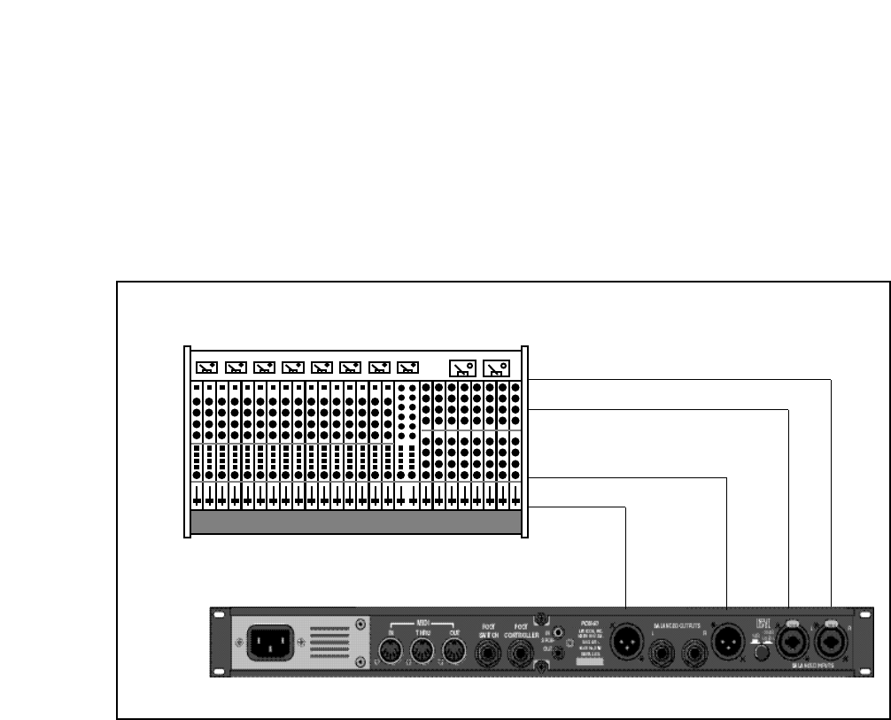
Configurations
Connection to a
mixing console's
effects sends
If you will be using a PCM 90 as your primary effects unit, and your system
includes a console with one or more auxiliary (effects) sends, connect the PCM
90 as shown above. In most applications, it is preferable to connect the PCM
90 outputs to two of the console's input channel strips, panned full left and right,
rather than to the effects returns. This allows the greatest flexibility in routing and
equalization.
In this configuration the console controls are used to set the amount of effect
heard—the PCM 90's MIX control should be set for 100% wet. To assign a global
MIX setting:
1. Press Control.
2. Press Up or Down until 1.x is displayed in the lower left of the display and
System is displayed on the upper line.
3. Turn SELECT until System Mix Mode is displayed on the upper line. 1.1 will
be displayed in the lower left.
4. Turn ADJUST until the lower line reads:
1.1 ✱ Global
5. Press Load /✱ to show the current global setting of MIX; use ADJUST to set
it to 100% wet.
Lexicon
1-8
PCM 90 User Guide
You can use Memory cards to store as many as 1000 PCM 90 registers (20
banks of 50 — on a 1 Meg card). Registers stored on a properly formatted card
will be recognized whenever the card is inserted, and can be accessed via the
front panel Register Banks button, exactly as internal registers.
Memory cards can also be used to store "setups" (your system configuration,
as set in Control mode). As many as 5 PCM 90 setups can be stored on a card,
allowing you to transport not only your effects, but complete PCM 90 environ-
ments to another PCM 90. Cards also provide storage for additional program
maps and effect chains.
See Control Mode Store and Load functions for details on saving setups on a
card and reloading them.
Memory cards must be of the following type:
PCMCIA SRAM Memory Card — 68 pin, Type I
Usable densities: 64 kByte
128 kByte
256 kByte
1 MByte (Cards larger than 1MByte can be used,
but the PCM 90 will only make use of 1MByte.)
Access Time: 250 nsec or faster
Conforms to PCMCIA 2.0/JEDIA 4.1. Can use either 8-bit or 8/16-bit bus configuration.
Attribute memory can be present, but is not used.
Memory cards can be used to store
PCM 90 registers, or setups.
Memory Cards
2-1
Basic Operation
2
Basic Operation
The PCM 90 provides a wide range of control over an extraordinary set of reverb
effects. All of the controls are easily accessed from the front panel and are
described in detail in this section.
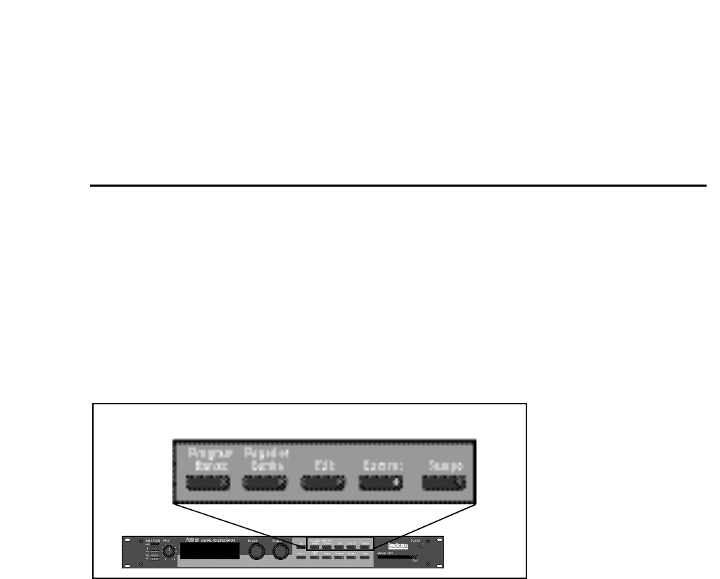
The PCM 90 has five basic modes of operation, each of which is selected by
pressing a front panel button (Program Banks, Register Banks, Edit, Control
and Tempo). Each of these first four mode buttons has an LED which lights when
the mode is active. The Tempo LED (unless you elect to have this function turned
off) flashes the current tempo. When Tempo mode is active, no other mode
LEDs will be lighted.
Modes of Operation
The PCM 90 is always operating in one of these modes.
Here, the lighted LED indicates that Control mode is active.
The five mode buttons give you the first level of access to all of the functions and
parameters in the PCM 90.
• Press Program Banks repeatedly to access five banks of 50 factory presets
and a KeyWord mode where programs can be viewed according to type. The
PCM 90's KeyWord function is activated in Control mode.
• Press Register Banks repeatedly to access two banks of 50 memory
locations, called registers, where you can store your customized effects.
Memory cards can be used for storage of additional banks of registers. When
a formatted memory card containing stored registers is inserted, pressing
Register Banks repeatedly will cycle through both the internal and the card
banks. Registers can be sorted and viewed according to type when the PCM
90's KeyWord function is activated in Control mode.
• Press Edit to access all of the available parameters for the currently running
effect.
• Press Control to select system parameters, MIDI, card formatting, etc.
• Press Tempo to set tempo-related values that affect the delay time and LFO
rate parameters of the currently-running effect.
Lexicon
2-2
PCM 90 User Guide
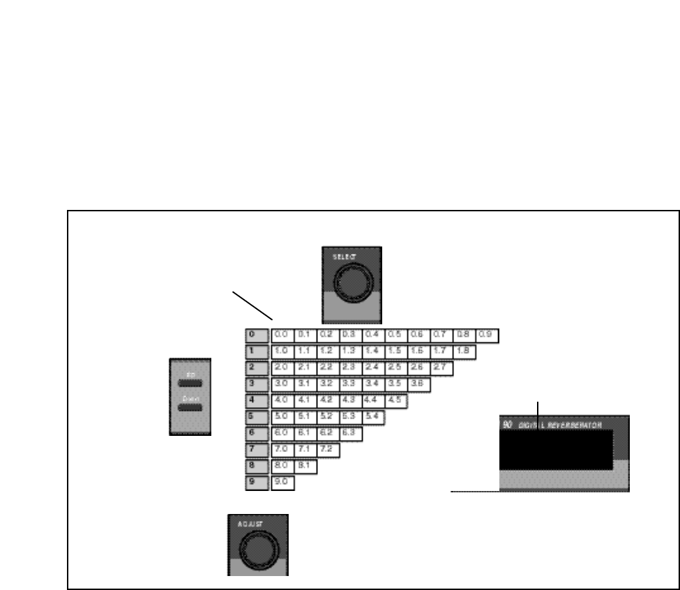
All of the controls available in a mode are arranged in a matrix of up to 10 columns
(numbered 0-9) and 10 rows (each numbered .0-.9). This arrangment allows any
one of as many as 100 parameters to be selected simply by using the SELECT
knob and the Up and Down buttons to select a position in the matrix.
Navigating a Matrix
→
←
↑
↓
Simultaneously pressing
Up and Down will always
return you to 0.0
The SELECT knob moves you
horizontally across the matrix.
In the Program and Register Banks, the ADJUST knob acts
as a soft knob for adjustment of one or more patched effect
parameters. In the other modes, ADJUST scrolls through the
range of available settings for the control you have selected.
The Up and Down
buttons move you
vertically through
the rows of the
matrix.
XXXXXXX ✱XXXXXXXXXX
3.6 XXXXXXXXXXXXXXXXX
Your current location in the matrix is shown
in the lower lefthand corner of the display.
An asterisk in the display indicates that
Load /✱ is active and, depending on the
mode, will load effects or display
additional parameters when pressed.
Go or Pro The PCM 90 offers a choice between two levels of Edit mode parameter access.
We call these Go mode and Pro mode.
Go mode makes use of an extra row in the edit mode matrix called the Soft Row,
where you can assign as many as 10 effect parameters or Custom Controls for
easy access. Selecting Go mode (Control mode 1.0) limits the action of the Edit
button to displaying only the Soft Row parameters assigned to the current effect.
Each preset has a set of Soft Row assignments which we've selected for you (as
well as an assignment for the ADJUST knob and Custom Controls). When
shipped, the PCM 90 will power up in Go mode with the first preset (P0 0.0)
loaded. Press Edit to display the Soft Row of parameters. Press Up or Down
to access a Pro mode selection display.
Pro mode gives you access to the full parameter matrix, including the Soft Row.
Use this mode when you want to do in-depth effects editing or patching, or when
you want to customize Soft Row assignments.
Go mode and Pro mode selection is made in Control mode at matrix location 1.0.
2-3
Basic Operation
Info
The PCM 90 offers an extensive set of informative display messages which can
be activated from the front panel.
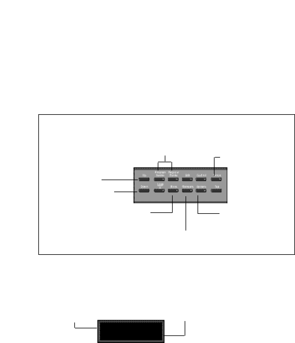
The front panel switches perform various functions when pressed. Most of these
functions are activated on release of the button. If you want to know more about
the function of a particular button (without actually executing any action) press
and hold the button down. While you are holding down the button, an explanatory
message will appear on the display. The activation of an Info message overrides
the normal function of the button, so that no action is taken on release.
Displays the current function
assigned to the Up button and
the ADJUST knob.
Displays the current function
assigned to the Down button
and the SELECT knob.
Displays the type of system
bypass currently selected,
and the current status (on
or off).
Displays action needed to
perform a store operation or
Memory Protect message when
store function is disabled.
Inactive until an effect has been
altered, then displays "Press to
hear stored effect"
Info messages are displayed when a button is pressed and
held down. Generally, Info messages inform you of the
function of a button, or provide current status information.
Displays the current tempo and
the clock source (MIDI or
Internal).
Displays the currently loaded effect name,bank, and matrix
location. In Program Banks or Register Banks mode,
simultaneously press and release both buttons to display
the last ten effects loaded.
The PCM 90 allows you to review the last ten effects loaded. This is useful when
you want to return to an effect you were using earlier, but can't remember its
name or location. This History view is accessed from Program Banks or Register
Banks mode by simultaneously pressing and releasing both the Program
Banks and the Register Banks buttons. The following display will appear:
History of Effects Loaded
History: 1 back
XX X.X ✱XXXXXXXXXX
The top line of the display
shows the position in the review
list of the displayed effect.
The bottom line shows the
bank and matrix location and
the name of the effect.
The label 1 back in the example, means that the effect shown on the bottom line
was running just before the current effect. Turning SELECT to the right will scroll
you through the stored list of effects, all the way to 10 back. Press Load/✱ to load
any of the displayed programs. Press any key to exit.
Note that loading programs from the review display does not update the
historical record, nor does loading from MIDI, Chain or Map. Only program loads
from Programs Banks or Register Banks mode are recorded.
Lexicon
2-4
PCM 90 User Guide
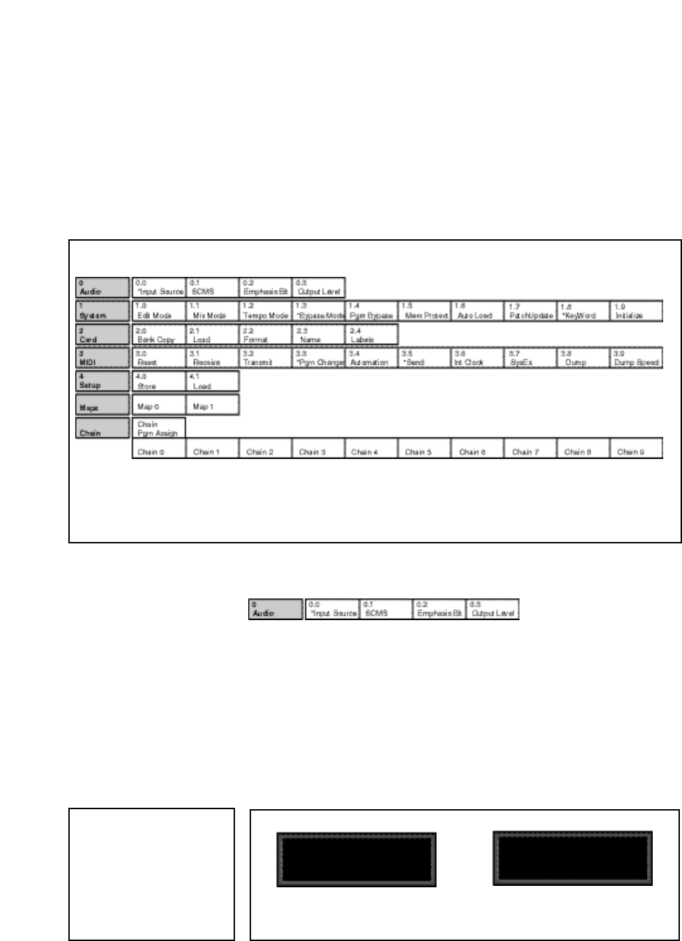
Control Mode Selections of various system states and conditions are made in Control Mode.
Press Control to enter this mode. The Control button LED will light to indicate
that the mode is active. Note that Control Mode functions are not available when
the Compare function is active.
The Control Mode matrix is shown below, followed by descriptions of each
available selection.
0.0 Dig: Prf 44.1kHz
Audio ✱Input Source
0.0 Dig: Cns 48kHz
Audio ✱Input Source
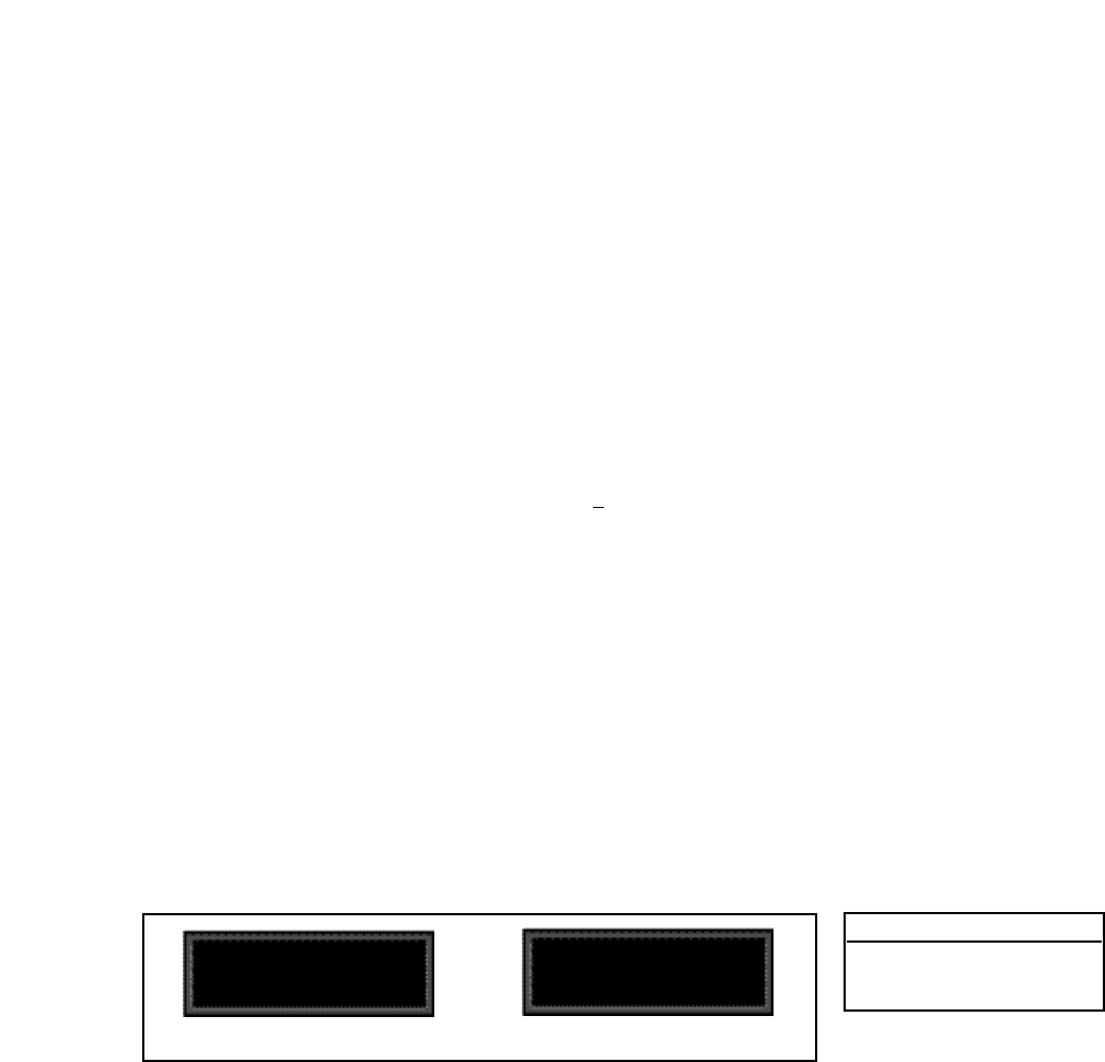
Row 0
Audio
0.0 Input Source
The PCM 90 can use its own internal clock as a timing reference, or it can
reference an external clock source from the rear panel S/PDIF jack. Use
ADJUST to select Dig, Analog: 48kHz or Analog: 44.1kHz. When either analog
rate is selected, the digital input is disabled. To process audio from the digital
input, you must select Dig.
When Dig is selected, and the PCM 90 detects valid digital audio, the rate of the
external word clock will be displayed with a label indicating the digital audio
format type: Prf (Professional) or Cns (Consumer, also called S/PDIF).
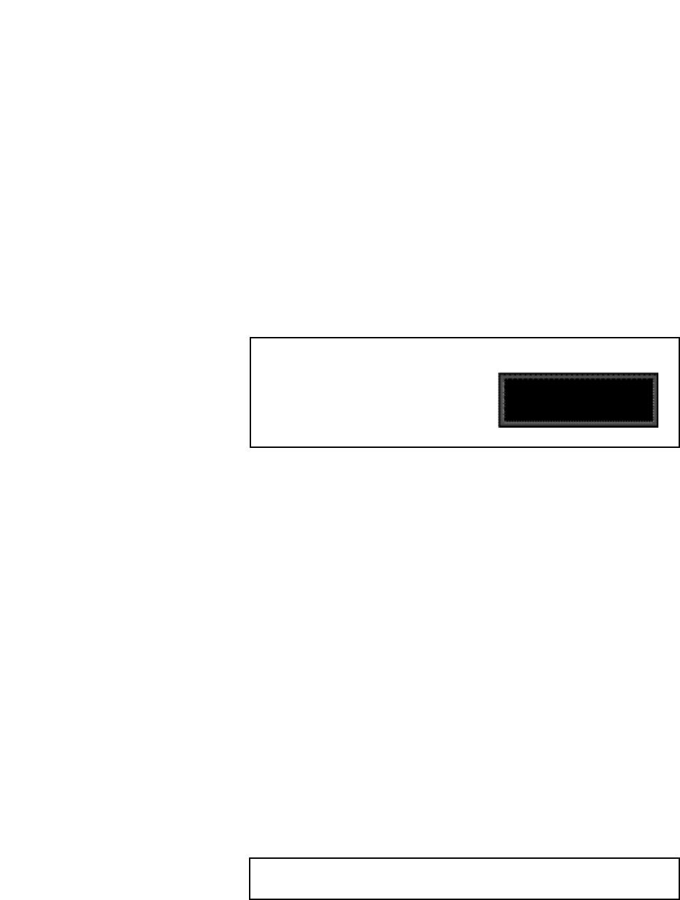
Simultaneously press Up
and Down to return to 0.0.
An asterisk (✱) accompanying a parameter name indicates that there are subparameters available
at that matrix location. The Load /✱ LED will light whenever an asterisk appears in the display. Press
Load /✱ to step to the next subparameter. From any point in the matrix, press Up or Down together
with Load /✱ to backstep to the previous parameter.
Note: Although the PCM 90 will
detect AES professional format
signals, it is designed to be used
with S/PDIF input. If your digital
input is not S/PDIF, please be
alert for locking problems and
other potential errors, and be
prepared to take the necessary
steps to provide the correct for-
mat input signal.
When the PCM 90 is receiving valid digital audio, selecting Input Source
will display the audio format and the rate of the incoming signal.
2-5
Basic Operation
When digital clock is selected, any loss of lock detected in the incoming digital
audio, or reception of non-audio data will cause the digital input to be muted. An
error message will be displayed if this occurs. The PCM 90 will repeatedly try to
establish lock. If a valid signal is detected, the PCM 90 will unmute and resume
passing audio. The PCM 90 will always generate a valid wordclock at its digital
output, even if no clock is detected at the input. The frequency of the generated
wordclock will match the most recent operating sample rate.
The following types of errors are detected when the PCM 90 is set to Dig:
No Lock: The PCM 90, at some point, lost lock to the incoming digital
audio signal. Digital audio input is muted.
Out of Range: The sampling rate of the incoming audio signal is outside of
acceptable tolerance limits of +4%. Digital audio input is
muted.
Non Audio: Indicates transmission of non-audio data, such as from a CD
ROM. Digital audio input is muted.
CRC: The error is reported, but incoming audio is accepted.
Dig In Status
Pressing Load/✱ from Input Source will display the current digital input status.
This status display is continuously updated, acting as a real-time monitor of the
PCM 90 digital input. This display is active even when the PCM 90 is set to
Internal clock. Note that in the case of an AES Pro format signal, "Emphasis"
means either CCITT or 50/15µs emphasis.
If valid digital audio is detected, the display will show the external clock rate and
format information, along with the status of the Emphasis bit(s) in the incoming
audio signal. If the PCM 90 has lost lock, the display message will indicate "No
Lock" and parenthetically show the internal clock rate now in use.
Error Log
The following errors are continuously logged and are available for review by
pressing Load/✱ from the Dig In Status display and using ADJUST to scroll
through the error list.
Validity: A Validity error indicates that the Validity bit was set in a frame
of incoming data and that the data attached to it may be
corrupted. This bit may also be sent when the transmitting device
is paused.
Confidence: The PCM 90 is detecting excessive jitter or noise on the digital
audio line. No data has been corrupted, but corrective action
should be taken.
SlipSample: Indicates that a single sample is misaligned with the window
defined by the Input Source. This may occur when an external
master changes sample rate, or when it is just powering up, but
should not occur in normal operation. (This type of error is
reported for reference only, as the PCM 90 does not accept
digital data when using its own internal clock.)
Upon loss of lock, or reception of non-
audio data, the PCM 90 will mute the
digital input and display the following
messages when Input Source or Dig
In Status is selected:
Input Source Dig In Status
Not Locked No Lock (Int 44.1)
Out of Range No Lock (Int 44.1)
Non Audio: 44.1 Non Audio: 44.1
Audio ✱Dig In Status
0.0 Prf 44.1 Emp:Yes
Audio ✱Dig In Status
0.0 NoLock (Int:44.1)
When the PCM 90 loses lock, it will mute the digital input.
Lexicon
2-6
PCM 90 User Guide
CRC: Indicates a Cyclic Redundancy Check error in the incoming data.
Parity, Biphase: Indicate that at least one bit (and therefore at least one audio
sample) was corrupted.
Parity, Biphase, and Confidence errors are most often caused by
inappropriate cabling. Be sure to use 75Ω video-grade cable,
kept as short as possible — standard audio cable will not work
reliably.
Each error is reported by name, with the number of occurrences of that particular
type of error. The display might show, for example "CRC: 4752". As many as
9999 instances of each error can be shown. If the number of actual errors
exceeds 9999, the display will indicate ">9999". A special symbol (■) before the
error type indicates the most recently received error.
Press Load/✱ from the Dig In Status display and use ADJUST to scroll through the Error
Log.
Audio ✱Error Log
0.0 ■ CRC >9999
A typical Error Log display showing that the last
error received was a CRC error (■ CRC) and
that there have been more than (>) 9999 in-
stances of CRC errors since Word Clock was
last set to Ext.
To clear the Error Log, reselect Dig from the Control Mode Input Source
display. This will cause the PCM 90 to attempt to lock to the current external
source and will reset the Error Log. The log is also cleared on power up, and
whenever it relocks (Auto Lock On).
0.1 SCMS
Digital audio signals, in order to comply with copyright standards, are encoded
with control information which can limit the ability to copy audio data. This control
information is generally known as SCMS (Serial Copy Management System).
Under this system, you can choose to have the audio material processed by the
PCM 90 encoded to allow one of three levels of copy restriction. To make your
selection, use ADJUST to select No Copy, One Copy, or Multi Copy.
0.2 Emphasis Bit
The Emphasis control allows you to explicitly set the emphasis "flag" in the digital
audio, or to pass along the incoming signal without changing its emphasis
coding. (The PCM 90 does not perform any emphasis or de-emphasis as part
of its signal processing.) The choices available with ADJUST are: Yes, No, and
Pass Thru.
0.3 Output Level
This control allows you to select the maximum output level at the PCM 90's
analog outputs. Use ADJUST to select +4 dBu, or –10 dBu.
Exercise care when switching this control, as a 14dB level change
instantly occurs when going from -10dBu to +4dBu.
2-7
Basic Operation
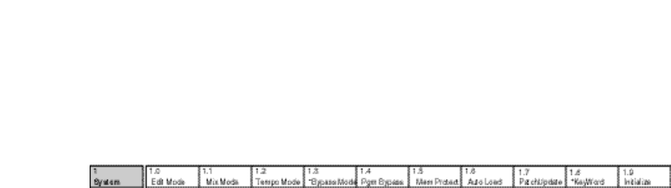
1.0 Edit Mode
The PCM 90 has been designed with a "plug and play" feature called Go mode.
In this mode, the most useful parameters of each effect are grouped together in
a single row which is available whenever you press Edit.
Each PCM 90 preset has a set of Go mode parameters which we've selected for
you. When shipped, the PCM 90 will power up in Go mode, with the first preset
(P0 0.0) loaded. Press Edit to display the first available parameter in the Soft
Row.
If you want access to the full parameter matrix for any effect, including the Soft
Row parameters, use ADJUST to select Pro mode. Now, when Edit is pressed,
you can select any parameter for adjustment, and customize any effect with your
own Soft Row assignments. For more information about the Soft Row, see
Editing an Effect later in this chapter.
1.1 Mix Mode
Each PCM 90 effect has its own Mix parameter, with the Mix setting stored as
an integral part of the effect. Mix Mode allows you to override these individual
Mix settings and set a global Mix value for all effects. This is useful when using
a mixing console's controls to set the amount of wet signal in a mix. In such a
case, you can use this control to set all PCM 90 effects to 100% wet.
When shipped, the PCM 90 has the Mix Mode set to Pgm. This setting
determines that effects will be loaded with their stored Mix settings, and allows
the individual Mix controls in the edit matrix of each effect to be adjusted from
0-100% Wet. To set a global Mix value, use ADJUST to select Global, press
Load/✱ to display the current value, and use ADJUST to assign any value from
0-100% Wet.
1.2 Tempo Mode
The PCM 90 gives you an exciting new approach to working with delay times and
modulation parameters. Now you can set these parameters in beats, allowing
you to control your effects in a completely musical way. Each PCM 90 effect has
its own Tempo parameters, with tempo settings stored as an integral part of the
effect. These include: Tempo Rate, Tempo Beat, Tempo Source (internal or
MIDI), Tap Duration, and Tap Average. The Global setting here allows you to
override individual Tempo Rate settings with a global value which can then be
changed on the fly.
When shipped, the PCM 90 has the Tempo Mode set to Pgm, with each effect
driven by its own stored tempo rate. To change to a global Tempo Rate, use
ADJUST to select Global, press Load/✱ to display the current tempo in BPM
(beats per minute), then use ADJUST to assign a global tempo value of 40-
400BPM.
Row 1
System

Lexicon
2-8
PCM 90 User Guide
Whether Tempo Mode is set to Global or Pgm, you can set a new tempo rate
by pressing the front panel Tap button twice. Alternatively, you can choose to
have tempo set automatically from incoming MIDI clock. The rate you tap, or the
MIDI tempo, will be displayed here.
For more information about working with the tempo parameters, see Tempo
Mode later in this chapter.
1.3 Bypass Mode/Bypass Src
This control alows you to determine the behavior of the PCM 90 when the front
panel Bypass button is pressed. You can also assign an external controller to
perform identically to the front panel button. When the Bypass button is pressed,
the LED will light, and a message indicating bypass type will be displayed.
Pressing Bypass again will turn bypass off.
The choices available via ADJUST are:
AllMute: Mutes both the input and the output signal, giving com-
plete silence.
InputMute: Mutes the input to the PCM 90, allowing the tail of the
effect to ring out. (This is the default setting.)
OutputMute: Mutes the output. Audio signals are still being fed to the
PCM 90, so processed audio returns immediately when
Bypass is turned off.
Bypass: Completely bypasses the PCM 90, passing unproc-
essed audio directly through to the outputs.
To assign an external controller to perform the selected bypass function, press
Load/✱ to display Bypass Src. Use ADJUST to select a footswitch or any MIDI
controller (or Off). Once a source is selected, it will perform the same function
assigned to the front panel Bypass button.
1.4 Pgm Bypass
This control allows you to determine the behavior of the PCM 90 when a new
effect is loaded. The choices available are: AllMute or Bypass.
1.5 Mem Protect
The PCM 90 provides a memory protection feature to prevent accidental
overwriting of your stored effects. When this control is set to On, pressing the
front panel Store button will cause an error message to be displayed. The PCM
90 is shipped with the Memory Protection function turned Off.
1.6 Auto Load
This control allows you to choose whether PCM 90 effects will be loaded
immediately when selected with SELECT and the Up and Down buttons (On),
or whether they will require a press of the Load/✱ button (Off).

2-9
Basic Operation
1.7 Patch Update
When a controller is patched to an effect parameter, this control determines
when the controller will take control of the parameter. If Immediate is selected,
stored parameter values will jump to the current controller position when the
effect is loaded. If Delayed is selected, the stored parameter value will remain
in effect until the controller is moved. See Patching later in this chapter.
1.8 KeyWord
For convenient effect sorting, the PCM 90 allows you to assign KeyWords (as
many as four) to each effect. The KeyWord function here allows you to display
effects according to type, or to turn this function off. Turn ADJUST to select an
effect type from the list shown in the sidebar. Press Load/✱ and use ADJUST
to turn the KeyWord function On or Off.
When shipped, the PCM 90 has the KeyWord function turned On, with A to Z
selected. This allows you to view all of the effects in the Program or Register
banks alphabetically. To access this display, press Program Banks or Register
Banks repeatedly to step through all of the available banks. The KeyWord
display will appear after the last bank. Press Control to jump to Control mode,
where you can use ADJUST to select a different KeyWord for sorting. Press
Program Banks or Register Banks to return to the KeyWord display —
resorted according to your new selection.
Most KeyWords (except for User 1-4 which are reserved for your use) have been
assigned to several presets. KeyWords are assigned to effects in Edit mode.
(See Editing an Effect.)
1.9 Initialize
Selecting this control arms the PCM 90 to revert to its factory settings.
This will erase all registers and setups,
and return the PCM 90 to its default states.
If you press Store, the display will ask "Are you sure?" (Press STORE). If you
don't want to reinitialize your unit, press any button to cancel the operation. If you
press Store in response to this message, the display will flash "Restoring
original factory settings" and your unit will be reinitialized.
PCM 90 KeyWords
Mastering
Medium
MIDI
Mono
Natural
Orchestral
Outdoor
Plate
RandomHall
Room
Short
Slap FX
Small
Spatial
Special FX
Splits
Stereo
Surround
Tempo
Unnatural
Vocal
User 1
User 2
User 3
User 4
A to Z
Acoustic
Ambience
Ballad
Bright
Broadcast
Cascade
Chamber
Classical
Cncrt Hall
Custom
Dark
Dialog
Drums/Perc
Dynamic
Echo
Film-ADR
Gated
Guitar
Indoor
Instrument
Keyboard
Large
Live PA
Long
Lexicon
2-10
PCM 90 User Guide
Select and copy
effect banks
Card Bank Copy
2.0 Src: ✱P0 Dst: R0
Card Bank Copy
2.0 Src: P0 Dst: ✱R0
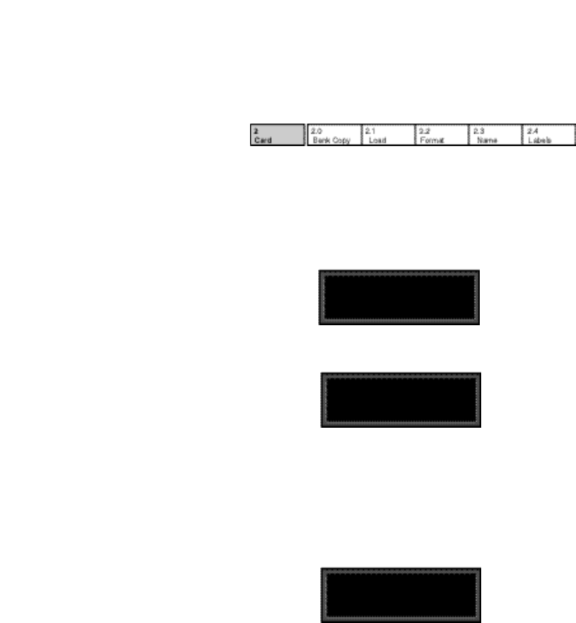
Row 2
Card
2.0 Bank Copy
This control allows you to copy banks of effects from one location to another.
Banks can be copied internally, or to and from PCMCIA Memory Cards. Try, for
example, copying Preset Bank 0 into internal Register Bank R0.
1. Press Store. The following display will appear briefly.
Now, use ADJUST to select the destination of your copy. Selecting a
register bank here will cause its contents to be erased and overwritten
with the bank you have selected as the source when Store is pressed.
4. Press Store to copy the selected source (in this case Preset Bank 0) into
internal Register Bank R0. The display will ask "Are you sure?" (Press
STORE). Press any button to cancel. Press Store to complete the store
operation.
2.1 Load
This control is provided for future enhancement. It will allow you to load audio
software from a Memory Card simply by inserting the new card and responding
to the display prompts.
The asterisk indicates that Src is available for adjustment. ADJUST will
scroll through all available banks, including internal preset and register
banks, as well as any banks on inserted cards. Internal banks are labeled
"P0...P4" and "R0, R1". Card registers will be labeled "C0, C1, C2" etc.
2. Press Load/✱ to move the asterisk to Dst.
The display will then change to show:
2-11
Basic Operation
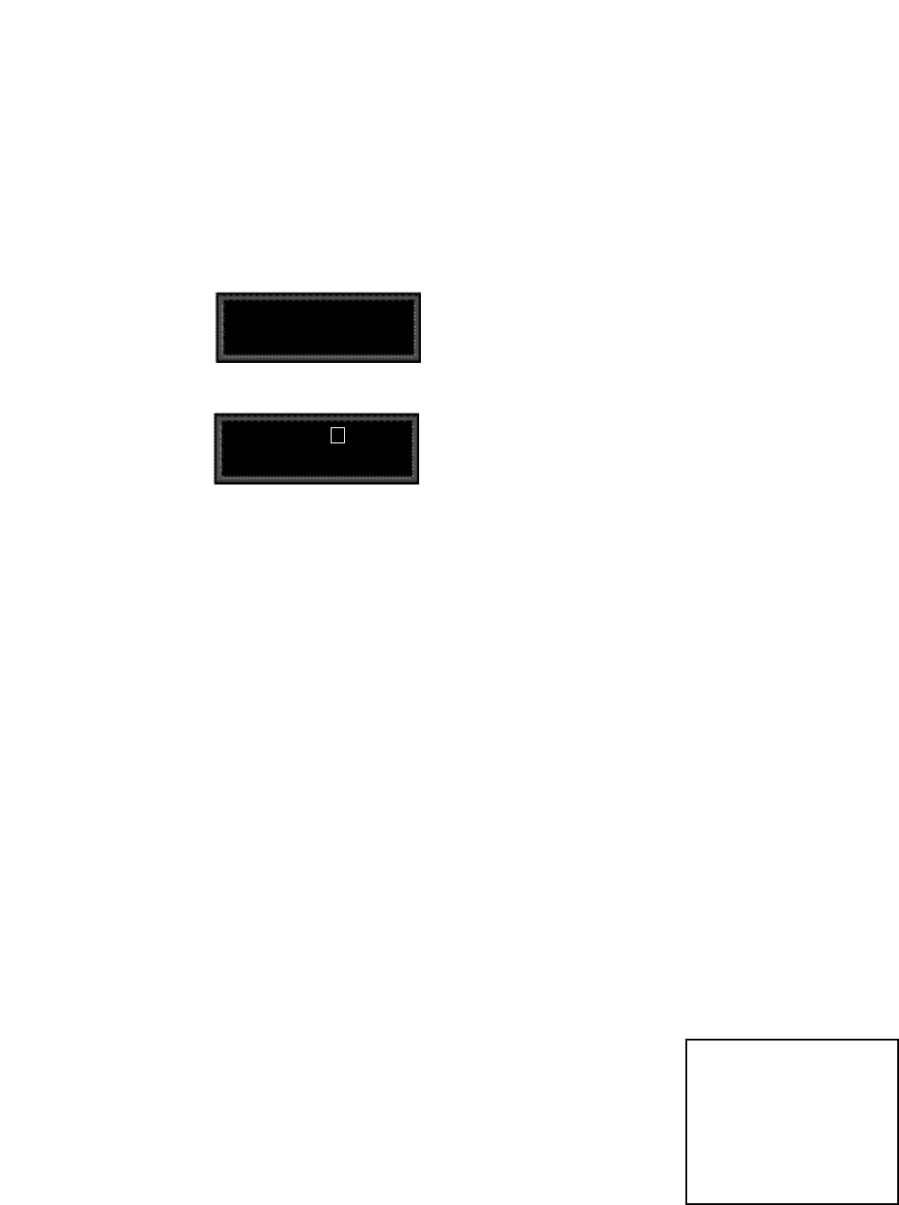
2.2 Format
This control allows you to format a Memory Card for PCM 90 use. (Make sure
the Write Protect switch on the card is set to Off.) Insert an unformatted card (or
one you don't mind erasing), then press Store. The display will ask "Are you
sure?" (Press STORE). Press Store. The following display will appear briefly.
The display will then change as shown below.
A blinking cursor indicates that a particular character is available for changing.
Use ADJUST to select the character you want in that position. Turn SELECT to
move the cursor to another character. Press Store to execute. The display will
ask "Are you sure?" (Press STORE). Press Store again to complete the
operation. Press any front panel button to cancel.
2.3 Name
This control allows you to rename a formatted card. Insert a formatted card and
press Store. The card name will be displayed with the blinking cursor as shown
above. Use ADJUST to select a new character at the location marked by the
cursor. Turn SELECT to move the cursor to another position. Press Store twice
to execute.
2.4 Labels
This control allows you to rename Register bank and row labels. Any changes
made here are executed immediately. To rename bank and row labels, press
Store and use ADJUST to display any bank. Press Load/✱ to access the naming
function for the selected bank, then use ADJUST and SELECT to enter a new
bank name.
Press Load/✱ to display the first row in the selected bank. Use ADJUST to select
any other row within the bank. Press Load/✱ to access the naming function for
any displayed row, then use ADJUST and SELECT to enter a new bank name.
Pressing Load/✱ from the row label naming display will jump you back to bank
selection.
Format and name
memory card
Name: New Card
(press STORE)
This display allows you to assign a name (of 10 characters or less) to the card.
PCM 90 Character Set
! “ # $ % & ‘ ( ) * + , - . / 0 1 2 3 4 5
6 7 8 9 : ; < = > ? @ A B C D E F G
H I J K L M N O P Q R S T U V W
X Y Z [ ¥ ] ^ _ ‘ a b c d e f g h i j k l
m n o p q r s t u v w x y z { : } ~ ❚
(space)
The @ and the $ symbols are used to
represent Custom Control values.
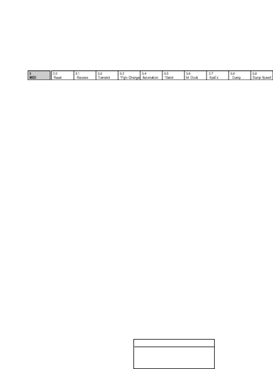
Lexicon
2-12
PCM 90 User Guide
Row 3
MIDI
3.0 Reset
This control resets all patched parameters to their previously stored values.
When this control is activated, a MIDI "Reset All Controllers" message is also
transmitted on the current channel by the PCM 90.
3.1 Receive
Turn ADJUST to select OFF, 1-16, or OMNI for receipt of MIDI messages.
3.2 Transmit
Turn ADJUST to select OFF, or 1-16 for transmission of MIDI messages.
3.3 Pgm Change
This control specifies the PCM 90's response to incoming MIDI Program Change
messages. There are four selections available via ADJUST: On, Off, Map and
Chain.
Pgm+ and Pgm –, are available as subparameters in each location. Pgm+ will
load the next higher effect in the current bank, map , or chain. Pgm – will load
the next lower effect. You can select the following sources to activate Pgm+ and
Pgm –:
Off
Footswitch 1
Footswitch 2
•
•
•
MIDI Controller #119
On
Program Change messages 0-49 correspond to PCM 90 Effects 0.0-4.9 in the
current bank. Program Change messages 50—127 are ignored. The current
bank can be changed with MIDI Continuous Controller 32 and Bank Select
Messages as follows:
0–4: Program Banks 0–4
5-6: Internal Register Banks 0-1
7-11: reserved for ROM Card Banks
12-20: Memory Card Banks. The number of banks available on a given
card will vary with its size, as follows:
Card Size # Banks
64 1
256 5
512 10
1 Meg 20
Off
All Program Change and Bank select messages are ignored.

2-13
Basic Operation
Map
Program Change 0-127 can be mapped to any PCM 90 effect in any internal or
card bank. Two 128 element maps are stored internally, additional maps may be
stored on RAM cards. Once you have selected Map, press Load/✱ to display:
Turn ADJUST to select the desired Program Chain. When set to MIDI, Program
Chains will be loaded by MIDI Program Change messages according to the
settings of Chain Pgm Assign in Row 6.
To load a specific Program Chain, without sending the PCM 90 a MIDI Program
Change message, use ADJUST to display the desired chain number.
MIDI Pgm Change
3.3 ✱MapSelect 0
Turn ADJUST to select the desired Program Change Map.
Chain
Any Program Change number can be selected to load any one of ten customized
effect “chains". Additional chains can be stored on RAM cards. Once a chain is
loaded, effects in the chain are accessed by the controller patched to Pgm + and
Pgm – (program increment and program decrement). Once you have selected
Chain, press Load/✱ to display:
MIDI Pgm Change
3.3 ✱Chain MIDI
MIDI Pgm Change
3.3 ✱Chain 3
3.4 Automation
This control is provided to allow one PCM 90 to act as a master for any number
of slaved PCM 90s. Select On to have values resulting from front panel
operations sent out as SysEx messages. Press Load/✱ to select the ID (0-126
or All) of the target PCM 90(s).
3.5 Send (Foot Pedal, Foot Sw 1, Foot Sw 2, ADJUST, Custom 1-4)
If Transmit is set to On these controls can transmit MIDI controller messages.
Press Load/✱ to cycle through the controller selections. Use ADJUST to select
the MIDI Controller message to transmit. Receipt of MIDI Controller messages
will affect the PCM 90 in the same manner as if the internal controls were
adjusted.
3.6 Int Clock
You can choose to have the PCM 90 transmit MIDI Clock at the current tempo
rate by setting this control to On and Tempo mode Source (0.2) to Internal. If
this control is set to Off, MIDI Clock will not be transmitted.

Lexicon
2-14
PCM 90 User Guide
3.7 SysEx
This control is provided for communication with one or more additional PCM 90s
or computer editor software. On (the default setting) allows SysEx messages
to be received by the PCM 90. Press Load/✱ to select device ID (0-126 ).
3.8 Dump
Press Store to configure the PCM 90 to execute MIDI dumps of single effects,
banks, maps, chains, or setups.
3.9 Dump Speed
Turn ADJUST to select dump speeds of Slow, Medium or Fast to achieve
compatibility with the connected MIDI device.
2-15
Basic Operation
Row 4
Setup
4.0 Store
Control mode Audio, System, and MIDI parameter settings, along with two
settings from the Tempo matrix, comprise a "Setup." Five setups can be stored
and named in the unit, or on a Memory Card, allowing you to transport not only
your effects, but complete PCM 90 environments to another PCM 90. Press
Store to initiate the Setup Store function.
When the PCM 90 is shipped (or when you reinitialize the unit) default values are
assigned to these parameters. The following table shows the Setup parameters
along with the factory default setting of each parameter.
4.1 Load
This control allows you to load any of five stored setups, restore the factory
default setup shown above, or load a setup from a Memory Card. Press Load/
✱ to cycle through the selections. (Memory Card selections will only appear
when an appropriate card is inserted.)
Control Mode
Matrix Location System Parameter Default Setting
Audio 0.0 Input Source Analog: 48kHz
0.1 SCMS Multi Copy
0.2 Emphasis Bit Pass Thru
0.3 Output Level +4dBu
System 1.0 Edit Mode Go
1.1 Mix Mode Pgm
Global Mix Value 100% Wet
1.2 Tempo Mode Pgm
Global Tempo Value 120 BPM
1.3 Bypass Mode InputMute
Bypass Src Off
1.4 Pgm Bypass AllMute
1.5 Mem Protect Off
1.6 Auto Load Off
1.7 Patch Update Delayed
1.8 KeyWord On (A to Z)
MIDI 3.1 Receive OMNI
3.2 Transmit 1
3.3 Pgm Change On
Pgm+ Off
Pgm– Off
Map select 0
Chain MIDI
3.4 Automation Off
3.5 Footpedal None
Sw 1 None
Sw 2 None
ADJUST None
Custom 1-4 None
3.6 Int Clock Transmit Off
3.7 SysEx Receive On
Device ID 0
3.8 MIDI Dump Current Program
3.9 Dump Speed Slow
Tempo Mode
Matrix Location System Parameter Default Setting
Tempo 0.2 Source Internal
Tap 1.3 Display On
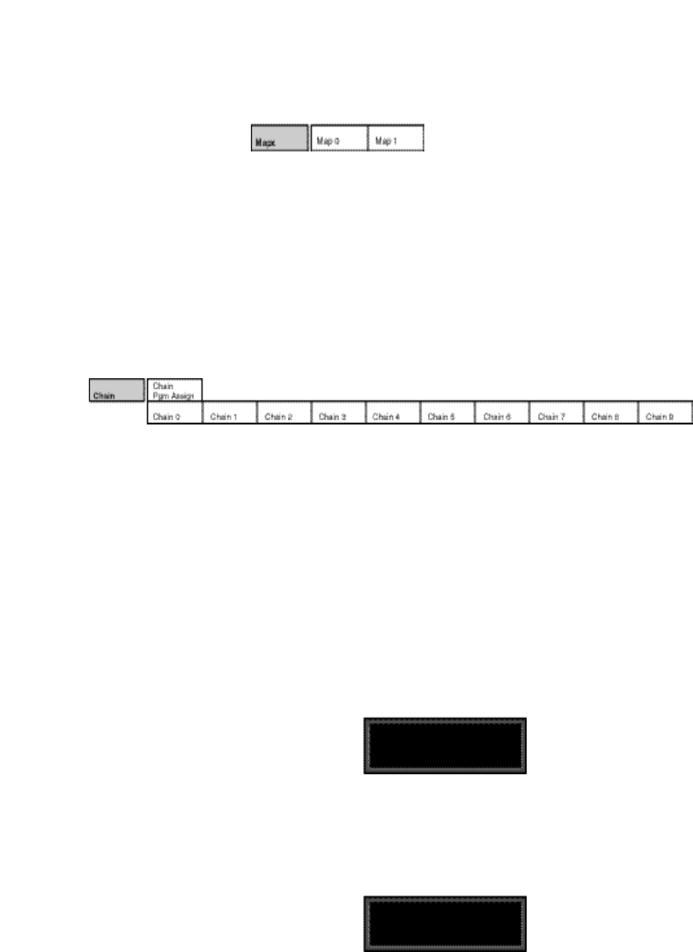
Lexicon
2-16
PCM 90 User Guide
Row 5
Mapx
Row 6
Chain
The PCM 90 has 10 internal program chains, numbered 0-9. (Ten additional
chains are available if a memory card is inserted.) Each chain is made up of 10
"links" (numbered 0-9). You can assign any program or register to any link in the
chain.
A chain can be loaded with a MIDI Program Change message, or by selecting
its number directly at Control mode 3.3. Once a chain is loaded, the source
assigned to Pgm+ and Pgm– will load the next higher or lower program in the
chain.
Pgm Assign
When Control mode 3.3 is set to Chain, received MIDI Program Change
messages will be mapped according to the selections made here. Two assign-
ments are available: MIDI Program Change # (0-127) and Chain # (0-9). When
the PCM 90 is shipped, all program numbers are mapped to Chain #0. To change
assignments, set Pgm#, with ADJUST, press Load/✱ to move the ✱ to Chain#
and set it with ADJUST. (You cannot assign more than one chain/MIDI #.)
Chain Pgm Assign
Pgm# : ✱ 3 Chain# : 3
Chain 0-9
Use SELECT to choose a chain. Once a chain is selected, any PCM 90 program
or register can be assigned to any link in the chain. Press Load/✱ to move the
✱ from Link# to the Bank ID, to the program number. Depending on the field
marked with the ✱ , ADJUST will select link numbers 0-9, Banks (Pn or Rn), or
the desired program within the displayed bank.
Chain 3 Deep Blue
Link# : ✱ 0 P0 0.0
Map 0 and Map 1
When Control mode 3.3 is set to Map, received MIDI Program Change
messages will be mapped according to the selections made here. The selec-
tions available are: MIDI Program Change # (0-127), Bank # (PCM 90 preset,
register, or card bank) and Pgm # (PCM 90 effect number 0-49). When shipped,
the PCM 90 has the two internal maps configured to access all presets and
registers:
Map 0 Map 1
MIDI 0 = P0 0.0 MIDI 0 = P2 2.8
MIDI 127 = P2 2.7 MIDI 121 = P4 4.9
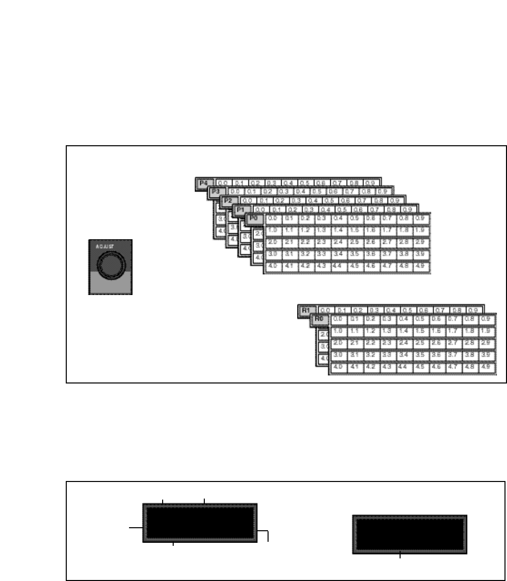
2-17
Basic Operation
The PCM 90 has 5 Program Banks, each with
50 factory-designed programs
Two Register Banks provide 100 memory locations
for storing your own effects.
The PCM 90 has 250 factory-designed programs, organized into five Program
Banks of 50 each, and 100 memory locations, called registers, for storing your
customized effects. Two Register Banks are available in the PCM 90 itself.
Additional Register Banks can be stored on PCMCIA cards.
Program and
Register Banks
Selecting Effects
The procedure for loading effects is the same, whether you are choosing from
banks of factory presets, or from your own banks of registers. When first turned
on, the PCM 90 will load whatever effect was running when it was last turned off.
When shipped from the factory, the first effect in the first Program Bank (P0 0.0
Deep Blue) is loaded. The Bank ID (P0, P1, P2, P3, P4 ), matrix location,
program name, and bank and row labels are all displayed.
All PCM 90 programs have one or more parameters
patched to the ADJUST knob.
In Program Banks or Register Banks mode, turn
ADJUST to change the sound of the currently
running effect. While ADJUST is turned, the patch
name and value are displayed. Custom Controls
allow you to create additional group parameter
controls.
P0 0.0 Deep Blue
Halls: Orchestral
Matrix Location Program Name
Program Bank ID
Bank label Row label
Turn SELECT to display another effect.
P0 0.1 ✱Large Hall
Halls: Orchestral
An asterisk in the display indicates that
the displayed effect is not loaded.
Press Program Banks repeatedly to cycle through the program banks. Simul-
taneously press Program Banks along with either Up or Down to backstep.
SELECT will scroll sequentially through all of the effects in one bank and then
begin scrolling through the next bank. Press Program Banks to reselect the last
displayed effect in another bank. Press Load/✱ to load any displayed effect.
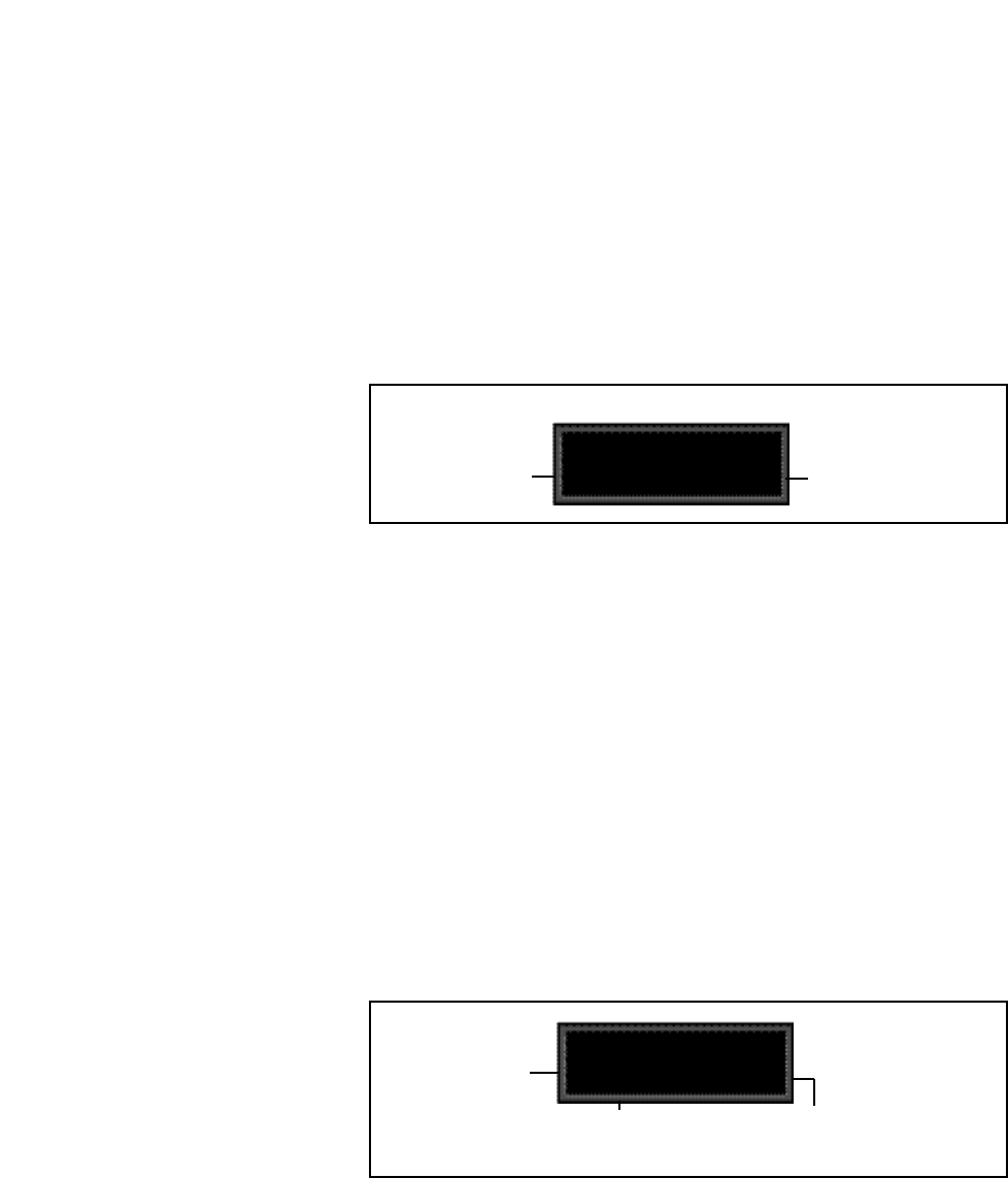
Lexicon
2-18
PCM 90 User Guide
In the Program and Register Banks, ADJUST is a Soft Knob. Each of the factory-
designed programs has one or more parameters patched to this knob, providing
a quick way to make useful changes to the effect.
Turning ADJUST will display the patch name and the current value, as well as
any name assigned to the current value. Continue turning ADJUST to alter the
patched parameter's value. You can create your own ADJUST knob parameter
assignments for your registers. (See Editing, later in this chapter.)
Turn ADJUST to briefly display the Soft Knob assignment
Decay 30
ADJUST is patched to
Current Soft Knob parameter
setting. Turn ADJUST to al-
ter this value.
Note that scrolling through the effects in the Program or Register banks will not
load the effects, but will merely display them (unless you have specifically turned
on the Auto Load function in Control Mode). Displayed effect names will be
preceded by an ✱ indicating that they can be loaded by pressing Load/✱. (The
Load / ✱ LED will light to indicate that the load function is available.) To find out
at any time what the currently running effect is, press and hold Program Banks
or Register Banks. An Info message will be displayed providing the name of the
currently running effect, as well as the algorithm from which it is derived.
To select an effect stored in a register, press Register Banks. If you have
registers stored on a memory card, and have the card inserted, pressing
Register Banks repeatedly will cycle through all of your stored bank selections.
Simultaneously press Register Banks along with either Up or Down to
backstep. Turn SELECT to scroll through all of the effects in the bank. As in
Program Banks mode, an asterisk in front of the effect name indicates that the
displayed effect is not loaded. Press Register Banks to reselect the last
displayed effect in another bank. Unused registers are indicated by the message
"available" on the display. Press Load/✱ to load the displayed effect.
R0 0.0 ✱ available
User Effects
Matrix Location The name you assign to a stored effect will
appear here. "available" indicates that no
effect has been stored at this location.
Register Bank ID
The PCM 90's internal
register banks are
labeled R0 and R1;
register banks created
on memory cards will be
labeled C0, C1, C2, etc.
The organization of programs in the five program banks and descriptions of the
250 preset programs are given in Chapter 3.
Soft Knob name

2-19
Basic Operation
Bank and Row Labels
Each bank and row in the Program and Register Banks has a descriptive name
to help you locate different types of effects. For instance, if you want to process
dialog to sound as though it's in a shower stall, the Rooms bank is a good place
to start. Bank and row labels appear on the top line of the display in Program and
Register modes.
Banks and rows that you create yourself can be renamed at Control 2.4.
To make finding the effects you want even easier, the PCM 90 has an effect
sorting function called KeyWord which lets you display only a selected type of
effect. When the KeyWord function is activated (at Control 1.8), pressing
Program Banks or Register Banks one push beyond the available banks will
access a list of effects sorted by one of the KeyWords shown in the sidebar.
SELECT will scroll you through the effects in that category. When shipped, the
PCM 90 has the KeyWord function turned on, with A to Z selected. This displays
all of the effects in alphabetical order. Each preset has at least one KeyWord
assignment.
The KeyWord categories cover a wide variety of effect types. To select a
different KeyWord for sorting, go to Control 1.8. (If you are in the KeyWord
section of the Program Banks or Register Banks mode, pressing Control will
jump you directly to this location.) Turn ADJUST to select any KeyWord from the
list. Now, when you return to Program Banks or Register Banks mode, the
display of programs will be limited to those which have been tagged with that
particular KeyWord.
KeyWords are assigned to effects in Edit mode. As many as four KeyWords can
be assigned to a single effect to allow sorting into more than one group. An effect
might, for example, be assigned the KeyWords: Acoustic, Ballad, Guitar and
Small. The effect would then be displayed when any of these KeyWords was
selected.
To turn the KeyWord function off, go to Control 1.8 System *KeyWord. Press
Load/✱ and use ADJUST to select On or Off.
Sorting Effects
PCM 90 KeyWords
Mastering
Medium
MIDI
Mono
Natural
Orchestral
Outdoor
Plate
RandomHall
Room
Short
Slap FX
Small
Spatial
Special FX
Splits
Stereo
Surround
Tempo
Unnatural
Vocal
User 1
User 2
User 3
User 4
A to Z
Acoustic
Ambience
Ballad
Bright
Broadcast
Cascade
Chamber
Classical
Cncrt Hall
Custom
Dark
Dialog
Drums/Perc
Dynamic
Echo
Film-ADR
Gated
Guitar
Indoor
Instrument
Keyboard
Large
Live PA
Long
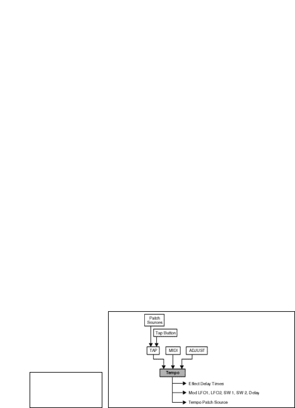
Lexicon
2-20
PCM 90 User Guide
The PCM 90 gives you unique control over tempo. In the PCM 90, tempo is not
just a matter of setting echo rates. Any delay parameter and any time-based
modulator (LFO1, LFO2, Sw 1, Sw 2 and Mod: Delay) can be individually
assigned to an absolute time value, or assigned to a tempo value.
For example, a delay time can be set to a specific number of milliseconds, and
you will always get a delay of that number of milliseconds, regardless of tempo
changes. Alternatively, a delay time can be set to a specific ratio of echoes to
beats. Now, if you create a rhythmic echo pattern, delay times will be linked to
tempo. When you change tempo, the delay time will change to maintain the
same rhythm at the new tempo.
With the LFOs, time-based switches, and Mod: Delay, the rate of change can be
an absolute value (such as once per second), or it can be linked to tempo (for
example, once every four beats). Almost any delay parameter, or time-based
modulator, can be set to its own individual rhythm, allowing you to set up an effect
which will change in a rhythmically interesting way — evolving over time, for
example, as opposed to being a mere series of repetitions. Once delays and
time-based modulators are assigned, tempo rate can be easily changed in a
variety of useful ways.
Tempo Rate can be set internally or via MIDI. If Tempo Source is set to Internal,
you can dial in any tempo from 40-400 BPM at location 0.0 in the Tempo mode
matrix. Alternatively, you can press the front panel Tap button twice in rhythm
to establish the rate you want, or you can have the value of a patch source act
as a tap trigger. (See Patching.) The tap function, whether performed by the front
panel Tap button, or by an assigned controller, is always active, allowing you to
change tempo on the fly from any mode. You can also choose to have your
tempo transmitted as a MIDI Clock signal to control the tempo of connected MIDI
devices (Control mode 3.6). If Source is set to MIDI Clock, PCM 90 tempo will
sync to incoming MIDI Clock. Whether tempo is set internally or via MIDI, the
LED in the Tempo button will flash at the current rate. (You can disable the
Tempo LED flashing under Tempo mode 1.3.) Press and hold the Tempo button
at any time to display the current Tempo Rate and Source.
Each effect in the PCM 90 has its own tempo rate setting which is stored with the
effect. You can override these individual tempo rates with a global tempo rate
at Control Mode 1.2. Tempo is also available as an independent patch source
which can control any effect parameter. (See Patching later in this chapter.)
Tempo Mode
When Compare is on, Tap
will not alter the tempo, but
will still reset the LFOs. See
Chapter 3 Modulation.
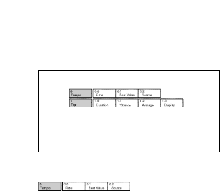
2-21
Basic Operation
The Tempo Mode Matrix
Row 0
Tempo
0.0 Rate
This is the current tempo (in Beats Per Minute). When 0.2 is set to Internal,
turning ADJUST allows you to select a different rate (40-400 BPM). The Tempo
LED will flash at the new rate. Note that fractional tempos can be tapped in, but
are not available via ADJUST. The display will always show the nearest whole
number value.
0.1 BeatValue
Tempo is expressed in BPM. This control allows you to specify the value of the
beat. Eighth, dotted-eighth, quarter, dotted-quarter, half, dotted-half, and whole-
note values are available. If, for example, the rate is 120 BPM, and you select
eighth-note here, the tempo will be 120 eighth-notes per minute. If you select
quarter-note here, the tempo will be 120 quarter-notes per minute. (The factory
default is quarter-note.)
0.2 Source
You can choose to have tempo determined by the PCM 90 Tap and Rate
controls (Internal), or by MIDI Clock. When MIDI Clock is selected as the tempo
source, Tap acts as a reset, setting the downbeat of the LFO and the time-based
switches.
Press Tempo to access the following tempo parameters:
Simultaneously press Up
and Down to return to 0.0.
An asterisk (✱) accompanying a parameter name indicates that there are
subparameters available at that matrix location. The Load /✱ LED will light whenever
an asterisk appears in the display. Press Load /✱ to step to the next subparameter.
From any point in the matrix, press Up or Down together with Load /✱ to backstep to
the previous parameter.

Lexicon
2-22
PCM 90 User Guide
1.0 Tap Duration
This control determines how many beats will occur in a tap interval. The default
setting (1 beat) is probably adequate for most applications. With the default
setting of 1 beat, if the tempo is set to 120 bpm, and the beat value is set to
quarter-note, each TAP = 1 quarter-note = 1 beat. Available values are: 1/8,
1/7, 1/6, 1/5, 1/4, 1/3, 1/2, 1-8 beats
1.1 Tap Source and Tap Level
Press Load/✱ to toggle between these two controls.
Tap Source allows you to assign the Tap function to any of the PCM 90’s
Internal, MIDI, or MIDI controllers as listed under Patching.
Tap Level allows you to set the level at which the Tap function is triggered.
1.2 Average
This control allows you to average the last 2-8 taps. Higher numbers mean that
the response to incoming taps will be more gradual. (The tempo is updated on
every tap, but with a value which is the average of the last 2-8 taps.) Higher
average values are more useful if you're trying to lock into a pre-recorded track.
1.3 Display
This control allows you to disable the flashing of the Tempo LED. Turn ADJUST
to select Off. The Tempo LED will turn off.
Row 1
Tap
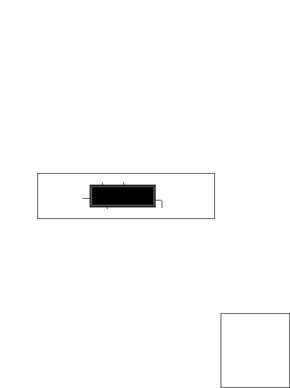
2-23
Basic Operation
With 5 algorithms and 250 preset effects, the PCM 90 gives you a lot to play with
right out of the box. An enormous range of editing control is provided for each
algorithm, with parameters organized into a simple edit matrix. In addition to
providing this powerful sound design capability, the PCM 90 is also designed to
allow you to customize these controls for your day-to-day editing needs, or to
simply use a subset of controls specially designed for each preset.
This section will describe three basic levels of editing, from the simplest "plug
and play" method, through the full edit matrix.
Every preset in the PCM 90 has one or more of its available parameters patched
to the front panel ADJUST knob. This Soft Knob provides the first level of editing
control. Once you have loaded a preset, simply turn ADJUST to alter the effect.
When shipped, the PCM 90 will power up with the first preset (P0 0.0 Deep
Blue) loaded. The following display will appear:
Editing an Effect
Controlling the Soft Knob with a
Foot Pedal
If you have a foot pedal connected to
the PCM 90 rear panel Foot Control-
ler jack, you can use it to control the
soft knob patch. (Note that no MIDI
connections are required to do this.)
To assign a foot pedal control over
the soft knob patches, set both Con-
trol mode 3.5 ADJUST and Control
mode 3.5 Foot Pedal to the same
MIDI Controller. See Chapter 5 MIDI
Operation.
The Soft Knob
P0 0.0 Deep Blue
Halls: Orchestral
Matrix Location
Program Bank ID
Program Name
Bank Row
Turn ADJUST. The display will change to show the name assigned to the
ADJUST patch, and the current value of the patch. Continue turning ADJUST to
change the value of the patch along its entire range. The range of ADJUST knob
control can be limited in the Custom row of the edit matrix, making it possible,
for example, to have a range of only 0...1, in order to have the ADJUST knob
behave as an Off/On control. Many of the presets have range limits to make them
more convenient to use, and some have text assigned to range values for even
greater clarity. In some of the presets, the changes effected by ADJUST will be
as simple as altering the wet/dry mix. In others, turning ADJUST will affect
multiple parameters over the complete control range of 0-127.
Details on how to create your own ADJUST knob patches are given at the end
of this chapter under Patching.
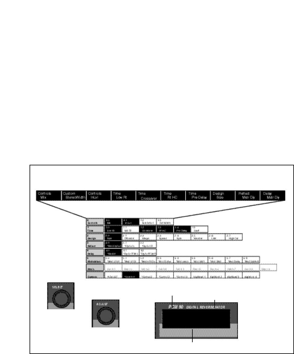
Lexicon
2-24
PCM 90 User Guide
Beyond simple ADJUST knob editing, the PCM 90 offers two levels of editing
control, called Go mode and Pro mode. Go mode is designed to be a basic
"plug and play" mode, with easy access to a specific set of preset parameters.
For each of the 250 presets, we have designed a Soft Row containing those
parameters which allow you to make value changes to the effect without losing
the character of the sound.
When shipped, the PCM 90 will power up in Go mode with the first preset (P0
0.0 Deep Blue) loaded. Press Edit to display the Soft Row of parameters which
have been designed for this preset. In this example, 10 soft row parameters have
been assigned. The name of each Soft Row parameter is displayed, along with
a reference to its row in the Edit matrix.
Turn SELECT to scroll all of the available parameters in the Soft Row. Turn
ADJUST to change the value of any displayed parameter along its entire range.
The Soft Row
Each preset has a Soft Row of parameters which have been
specifically selected to provide everything you need to play with the
effect. This example shows the Soft Row for P0 0.0 Deep Blue.
An asterisk in front of a displayed parameter
indicates additional parameters are available when
you press Load/✱.
→
←
Turn SELECT to move
horizontally across the
Soft Row.
Use ADJUST to change the
value of a displayed parameter.
38.3 M
Design Size
The Soft Row display shows:
an Edit matrix row label...
... and the current parameter value.
Each effect has four available Custom Controls which can be patched to one or
more parameters and assigned to the Soft Row. Like the ADJUST knob, Custom
Controls can be individually named and can have customized range limits to
make them more useful. In the presets, Custom Controls are assigned to the Soft
Row in sequence after Mix, so that their positions in the Soft Row will always
relate to their Control number. This is a convention you may want to follow in
creating your own Soft Rows.
... the name of the parameter...
Soft Row parameters are
derived from the full Edit
matrix (with the exception
of the Patch row). In the
presets, they are
arranged according to
their numerical order in
the matrix after Mix and
any Custom Controls.
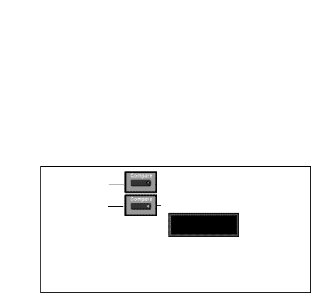
2-25
Basic Operation
If you press Compare while the light
is on, a message will be displayed ...
stored effect active
Compare is on
...and you will hear the original (stored)
version of the effect. You can display the
parameter values of the stored effect with
SELECT and Up and Down.
As soon as you alter an effect,
the Compare light will go on.
The Compare light is off until
you make changes to an effect.
The Compare light will flash until you press
Compare again to reload the edited version of
the effect. While Compare is on, you cannot
select another effect.
Bypass
The front panel Bypass button is always active, and will turn on the type of
bypass (AllMute, InputMute, OutputMute, or Bypass) selected in Control
Mode 1.3.
When you press Bypass, the button LED will light and a message will be
displayed to inform you that bypass is on. The display message will also indicate
the type of bypass which is in effect. Press Bypass again to turn both the LED
and the bypass condition off. A brief display message will inform you that bypass
is off.
Press and hold Bypass to display the current state and type of bypass.
Compare
Whenever you edit a PCM 90 effect from the front panel, the LED in the
Compare button will light. This lets you know that the effect has been altered
since the last store operation, and that the edit compare function is active.
Whenever this light is on, you can press Compare to hear the original version
of the effect. A message will be displayed to inform you that the stored version
of the effect is being loaded. Although this message is only displayed briefly, the
Compare LED will flash to let you know the effect you are hearing is the stored
version. While Compare is on, you can use the SELECT knob and the Up and
Down buttons to view parameter values in the stored effect.
Press Compare again to reload your edited version. Another message will be
displayed, and the Compare LED will stop flashing and remain lit until you store
your edited version, or select and load another effect.
Note: Altering parameter values with patched sources other than ADJUST or
Custom Controls will not light the LED.
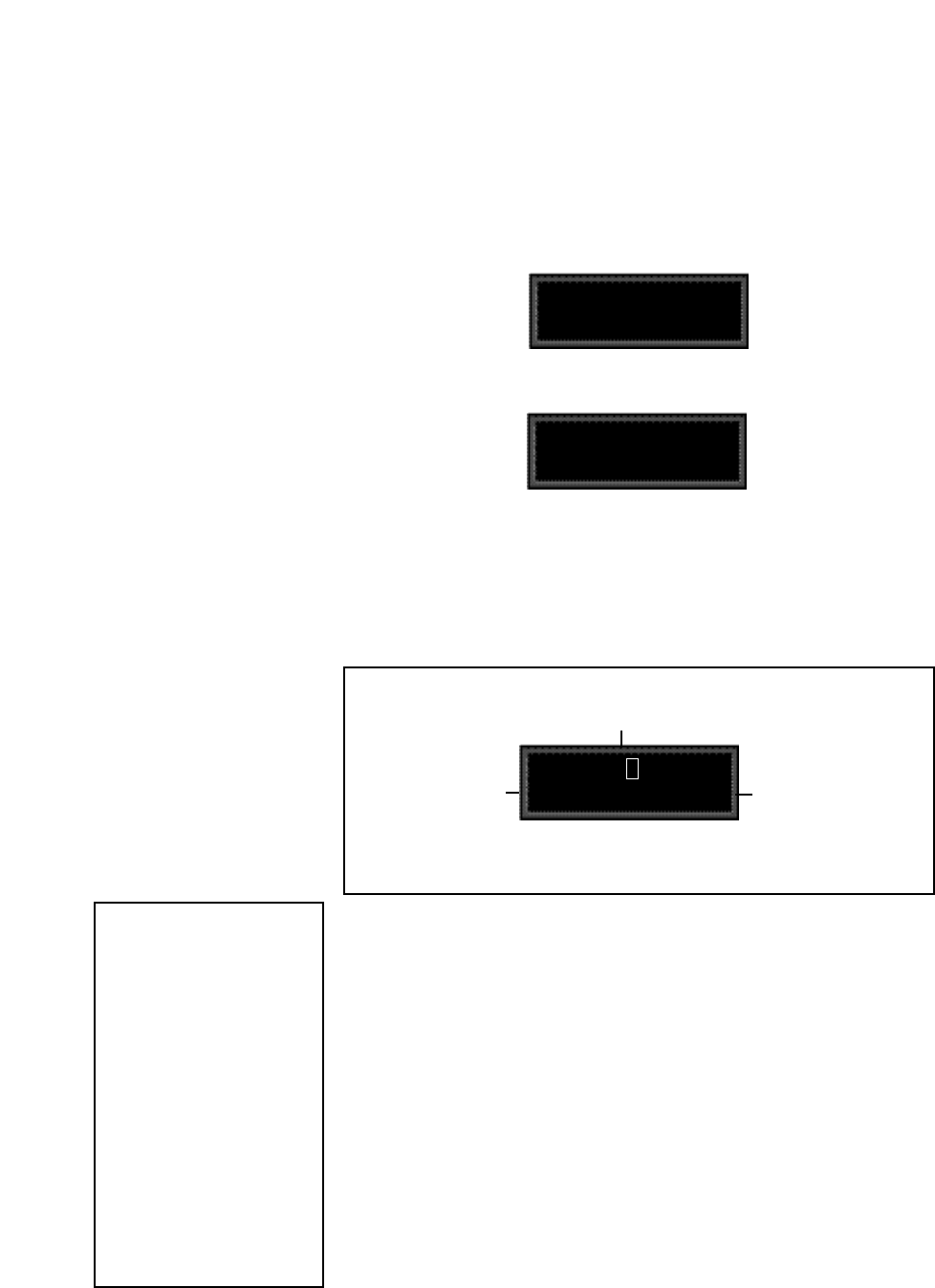
Lexicon
2-26
PCM 90 User Guide
R0 0.0 available
Name: ✱Deep Blue
An asterisk (✱) is positioned in front of the display
label which is available for changing — in this
case, the name of the effect.
"available" means that
this location is empty. If
an effect is stored at this
location, its name will
appear here.
The default Bank and
register location will
appear here.
Press Load/✱ to move the cursor from the name, to the
register bank, and again to select the register location
within the selected bank.
Store Operations
How the PCM 90 selects a
default Bank and Register
If a register is loaded when Store is
pressed, the default location will be
the same as the loaded effect. If a
preset is loaded when Store is
pressed, the default location is de-
termined as follows:
The PCM 90 always uses the last-
stored register location as a starting
point. Its default choice is the next
"available" register within that bank.
If there are no available registers at
a higher location number within the
same bank, the default location will
be that of the last stored register.
If the last stored register is on a RAM
card, and the RAM card is not in-
serted, the PCM 90 will search for
available registers starting at 0.0 in
the Internal Register Bank R0.
Turning Memory Protection On
The PCM 90 is shipped with its Memory Protection option off. To turn Memory
Protection on, press Control and use Up and Down and SELECT to display
matrix location 1.5. The display should read:
1.5 Off
System Mem Protect
Turn ADJUST to select On. With Mem Protect on, when you press the front panel
Store button, the following message will be displayed:
Mem Protect is on
Store not active
The PCM 90 will then jump to the Mem Protect display (Control 1.5) where you
can use ADJUST to turn Mem Protect off.
Storing an Effect
With Memory Protection disabled, pressing Store will cause a message like the
following one to be displayed:
If you press Store again, the display will ask "Are you sure?" (Press STORE).
Pressing Store will cause the currently running effect to be saved, as is, in the
location shown in the lower lefthand corner of the display. A brief message will
inform you that the effect is being stored, then the PCM 90 will revert to the mode
it was in before Store was pressed, with the newly-stored effect loaded.
When you store an effect, the following things are saved:
• Values of all Edit matrix parameters. This includes the initial values for any patch
destinations when Patch Update (Control mode 1.7) is set to Delayed.
• Soft Row parameter assignments.
• Value of ADJUST when the effect was stored.
• Last parameter selected when the effect was stored.
• Tempo Rate and BeatValue.
• Tap Duration and Average.
• All names, labels and values for ADJUST and Custom Controls.
• Effect name.
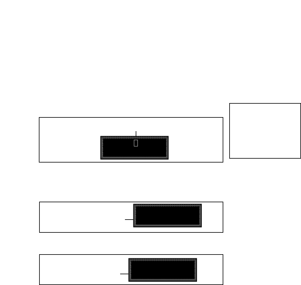
2-27
Basic Operation
PCM 90 Character Set
! “ # $ % & ‘ ( ) * + , - . / 0 1 2 3 4 5
6 7 8 9 : ; < = > ? @ A B C D E F G
H I J K L M N O P Q R S T U V W
X Y Z [ ¥ ] ^ _ ‘ a b c d e f g h i j k l
m n o p q r s t u v w x y z { : } ~ ❚
(space)
The @ and the $ symbols are used to
represent Custom Control values.
Renaming the Effect
Renaming an effect is straightforward. With the asterisk and the cursor posi-
tioned as shown, turn ADJUST to select a new character. Press Up or Down to
select a new type of character (upper case, lower case, numeric, symbolic, or
blank). Simultaneously press Up and Down to clear all characters from the
cursor to the end of the line. Turn SELECT to reposition the cursor over another
character, and use ADJUST to change it. Continue in this manner until you have
finished entering the new name. A maximum of 12 characters (including spaces)
may be used.
R0 0.0 available
Name: ✱Deep Blue
Use ADJUST to select a new character. Turn
SELECT to move the cursor to another position.
Selecting a Bank and Register Location
Press Load/✱ to move the asterisk to the Register Bank ID.
✱R0 0.0 available
Name: Deep Blue
When the asterisk is positioned in front of
the Bank ID, ADJUST or SELECT will scroll
through the available register banks.
Press Load/✱ again to move the asterisk to the register matrix location.
R0 ✱ 0.0 available
Name: Deep Blue
When the asterisk is positioned in
front of the register matrix location,
ADJUST or SELECT will scroll
through the available registers.
Once you have made all the changes you want to an effect, and have selected
a register location, press Store. If you press Store, the display will ask "Are you
sure?" (Press STORE). If you don't want to save the effect as shown, press any
button to cancel the operation. Press Store to complete the operation.
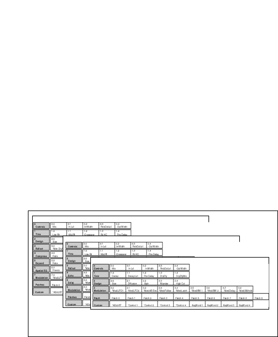
Lexicon
2-28
PCM 90 User Guide
Concert Hall
Rich Plate
Ambience
Similar parameters can be found in similar positions in
every effect matrix. Once you are familiar with one edit
matrix, you will find it easy to anticipate where to find
controls in another matrix.
Detailed information about each individual edit matrix, as well as parameter and
effect descriptions are given in Chapter 3.
The Full Edit Matrix Setting Edit Mode to Pro (Control Mode 1.0) gives you access to the full
parameter matrix of the algorithm for any loaded effect whenever you press the
front panel Edit button.
To select any parameter for adjustment, use SELECT to move horizontally
across the matrix and the Up and Down buttons to move vertically. An asterisk
(✱) appearing before a displayed parameter indicates that more than one
parameter is available at that location. Press Load/ ✱ to display these additional
parameters.
Each of the five PCM 90 algorithms has a unique matrix, but many parameters
are common to all effects, and their placement within the matrix is consistent.
For example, all parameters within a given row of any matrix are related. This
type of grouping is immediately apparent from the name of the row. For example
the "Time" row in any matrix will contain all of the available duration controls for
the effect's reverberator.
As far as possible, rows with similar controls will always appear in the same
position in the matrix and, within each row, parameters will generally appear in
the same position. For example, the first row (0) in every algorithm is "Controls".
The Mix parameter, which is available in all effects, is always located in position
0 in this row. Similarly, the last three rows of every matrix are "Modulation,"
Patches" and "Custom". This makes it very easy to find your way around the
large number of available parameters, and to anticipate where to find the
controls you are looking for when you switch between effects.
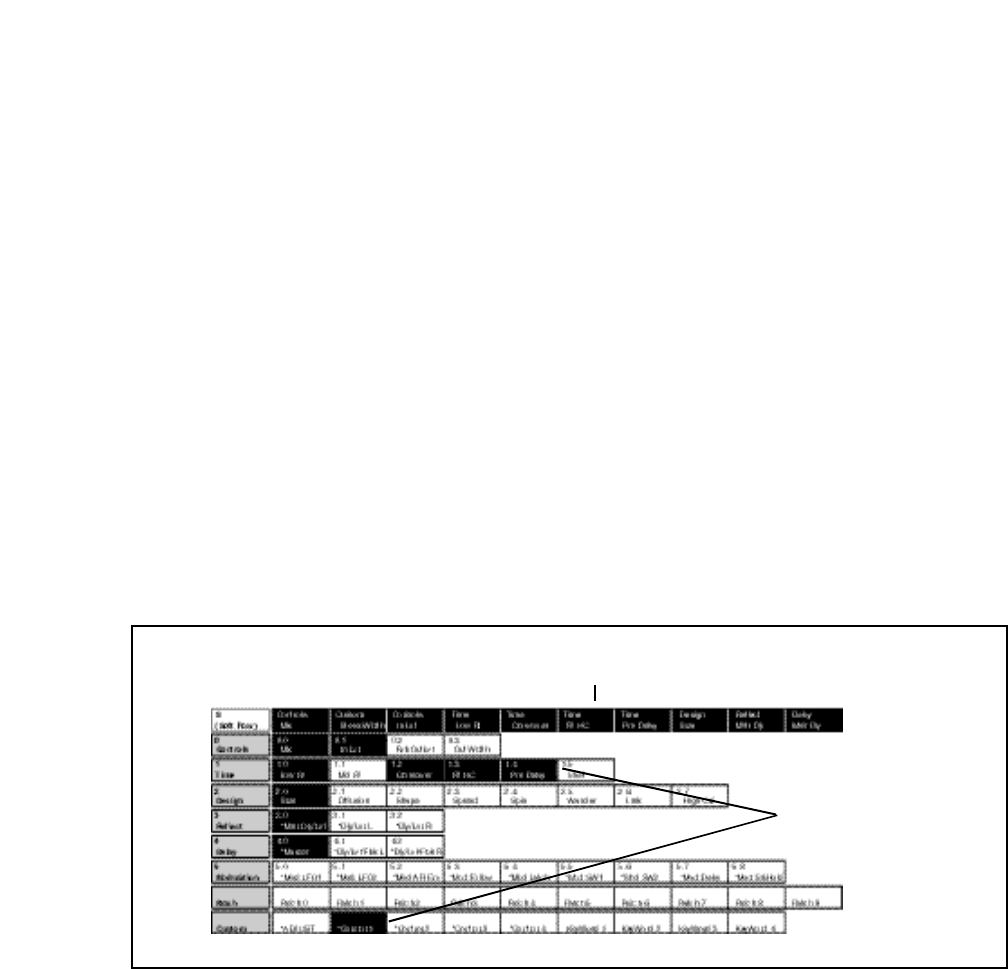
2-29
Basic Operation
Creating a Soft Row
In Pro mode you still have complete access to the Soft Row, which appears
above row 0 of the full edit matrix. The parameters assigned here are duplicates
of selected parameters in the matrix and can be adjusted from Row S (Soft Row),
or from their matrix location.
The following example shows the edit matrix for the preset, P 0.0 Deep Blue
(Random Hall algorithm). As you can see, parameters from locations throughout
the matrix have been assigned to this Soft Row. In this preset (and in every
preset) we have designed the Soft Row by assigning the Mix control first,
followed by any Custom Controls, then the parameters in numerical order.
Parameters from the Controls row are assigned in order to the first locations,
followed by assignments from the Time row, and so on. As Soft Row parameters
are also labeled with the name of the row from which they were taken, this makes
it relatively easy to find the source parameter for any Soft Row assignment.
In the presets, the convention of assigning Custom Controls 1-4 to Soft Row
positions 1-4 allows you to identify the original control by its corresponding
number, even when a name has been assigned to it.
The Soft Row assigned to an effect appears
above Row 0 in the full Edit matrix.
We have highlighted those
parameters in the Edit matrix
which have been assigned to the
Soft Row of P 0.0 Deep Blue,
for example: Pre Delay, and
Control 1 (named StereoWidth
in the Soft Row).

Lexicon
2-30
PCM 90 User Guide
When you release the Edit button, the display will change to the Soft Row
Assignment display shown below. The Edit button LED will begin flashing
and will continue to flash as long as you are in Soft Row Assign.
Here we show the first Soft Row parameter in our example — the actual Soft
Row parameter selected will correspond to whichever one was displayed
when you pressed and held Edit.
3. Turn ADJUST to scroll through all of the available parameters in the Edit
matrix row by row, in numerical order. The entry "available" can be selected
(at the fully counterclockwise position of ADJUST) to indicate that no
assignment has been made at that position. Custom Controls are available
for assignment at the end of the parameter list.
4. Turn SELECT to display another Soft Row position (0-9) for assignment. For
each position, you can choose any effect parameter, including one(s) you
have already assigned to a Soft Row position.
5. When you have arranged the Soft Row assignments as you want them,
press Edit to exit Soft Row Assign and return to your last position in the Edit
matrix. Pressing Up or Down once will also cause you to exit Soft Row
Assign. Another push of either of these buttons will move you vertically
through the Edit matrix.
When you return to Go mode, you will see the parameters in the order you
assigned them — the spaces from any unassigned row positions will not appear.
Controls Mix
Soft Row param : 0
Modifying the Soft Row, or creating a completely new Soft Row for an effect is
easy:
1. From the full Edit matrix, press Up until you get to the Soft Row, indicated by
an S in the lower left corner of the display.
2. With any Soft Row parameter displayed, press and hold down the Edit
button. The following display will appear briefly.
assign . . .
Entering Soft Row
2-31
Basic Operation
Int LFO1
Patch 0 ✱Src
SELECT will move you across
the Patch row (0-9).
The Source type is indicated here.
(Int, MIDI or 001-119 to indicate a
MIDI Controller.)
The name of the current Source assignment is
shown here. (The default Source assignment is
Int...Off.)
The asterisk (✱) indicates that Sources will be selected when
you turn ADJUST. Press Load /✱ to change the selection to
Dst. Press Load /✱ again to bring up the Values display where
you can select Src Value and Dst Value.
Pressing the Load /✱ button will change the display to allow you to sequentially
select: Src, Dst, Src Value and Dst Value. Press Up or Down together with
Load /✱ to backstep to the previous parameter.
Patching
Patching is the ability to assign a control (Source) to any PCM 90 parameter
(Destination). This allows you to alter the value of the parameter by manipulating
the control Source. For example, you can select the front panel ADJUST knob
as a Source and an effect's Mix parameter as a Destination. This simple patch
will allow you to dynamically alter the mix of the effect whenever you turn
ADJUST. You can create as many as 10 patches, each with as many as 8 pairs
of pivot points. You can patch multiple parameters to a single controller, or patch
multiple Sources to a single Destination.
About Sources
All Sources are the same in the sense that each generates an output value in the
range of 0-127. The output value is used to increase or decrease the setting of
a Destination parameter. Sources differ in the manner in which they generate an
output. Some generate values continuously (they’re always “on”); some gener-
ate output based on the position of a particular external MIDI controller, or an
external footpedal, or footswitch. Some Sources generate output based on
aspects of physical performance such as how loud, how fast, or how hard you
play. The PCM 90 allows you to choose from a selection of Sources as shown
for each Destination. A list of the available Sources is shown on the following
page.
The Patch Row
Each PCM 90 effect has an identical Patch row in its Edit matrix where you can
make as many as 10 patches.
To make a patch, use SELECT and the Down button to move down through the
Edit matrix to the Patch row. A display such as the following will appear.
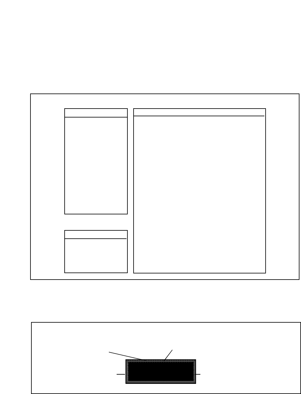
Lexicon
2-32
PCM 90 User Guide
Assigning a Source
Three types of sources are available: Internal, MIDI and MIDI Controller. These
types are indicated in the Source list by the labels: Int, MIDI, or a number (001-
119). Turn ADJUST to scroll through the entire list of available sources.
Internal MIDI Controller Numbers
070 Sound Var
071 Timbre
072 Release
073 Attack
074 Bright
075 Sound 6
076 Sound 7
077 Sound 8
078 Sound 9
079 Sound 10
080 General 5
081 General 6
082 General 7
083 General 8
084 Porta Ctl
085 Ctl 85
... ...
090 Ctl 90
091 FX1 Depth
092 FX2 Depth
093 FX3 Depth
094 FX4 Depth
095 FX5 Depth
096 Data Inc
097 Data Dec
098 NRPN LSB
099 NRPN MSB
100 RPN LSB
101 RPN MSB
102 Ctl 102
... ...
119 Ctl 119
000 Ignored
001 Mod Wheel
002 Breath
003 Ctl 3
004 Foot Ctl
005 PortaTime
006 Data Entry
007 Volume
008 Balance
009 Ctl 9
010 Pan
011 Xpression
012 Effect 1
013 Effect 2
014 Ctl 14
015 Ctl 15
016 General 1
017 General 2
018 General 3
019 General 4
020 Ctl 20
... ...
031 Ctl 31
(PCM 90 interprets 032 as Bank Select)
033 Ctl 33
... ...
063 Ctl 63
064 Sustain
065 Porta On
066 Sostenuto
067 SoftPedal
068 Legato
069 Hold 2
PCM 90 Patch Sources
Latch
Sw 1
Sw 2
Sw 1 & 2
Delay
S&Hold
Mono Lvl
Left Lvl
Right Lvl
FootPedal
Foot Sw 1
Foot Sw 2
ADJUST
Custom 1
Custom 2
Custom 3
Custom 4
Tempo
On
Off
LFO1
Sine1
Cosine1
Square1
Sawtooth1
Pulse1
Triangle1
Random1
LFO2
Sine2
Cosine2
Square2
Sawtooth2
Pulse2
Triangle2
Random2
Env L
Env R
Env L+R
AR Env
MIDI
P Bend
A Touch
Velocity
Last Note
Low Note
High Note
Clk Cmnds
Assigning a Destination
Once you have selected a Source, press Load /✱ and the display will change
to allow you to assign a Destination (Dst).
Reflect Lvl L
Patch 0 ✱Dst
SELECT will move you across
the Patch row (0-9).
The name of the current Destination assign-
ment is shown here. (✱✱✱Unassigned✱✱✱
will appear across the bottom display line if no
assignment is selected.)
The Edit matrix row label for the
currently assigned parameter is
shown here.
The asterisk (✱) indicates that Destinations will be se-
lected when you turn ADJUST. Press Load /✱ to bring up
the Values display where you can assign Src Value and
Dst Value. Press Load /✱ again to return to Source
selection, etc.
Turn ADJUST to scroll through all of the parameters in the Edit matrix of the
currently loaded effect, including the Modulation parameters.
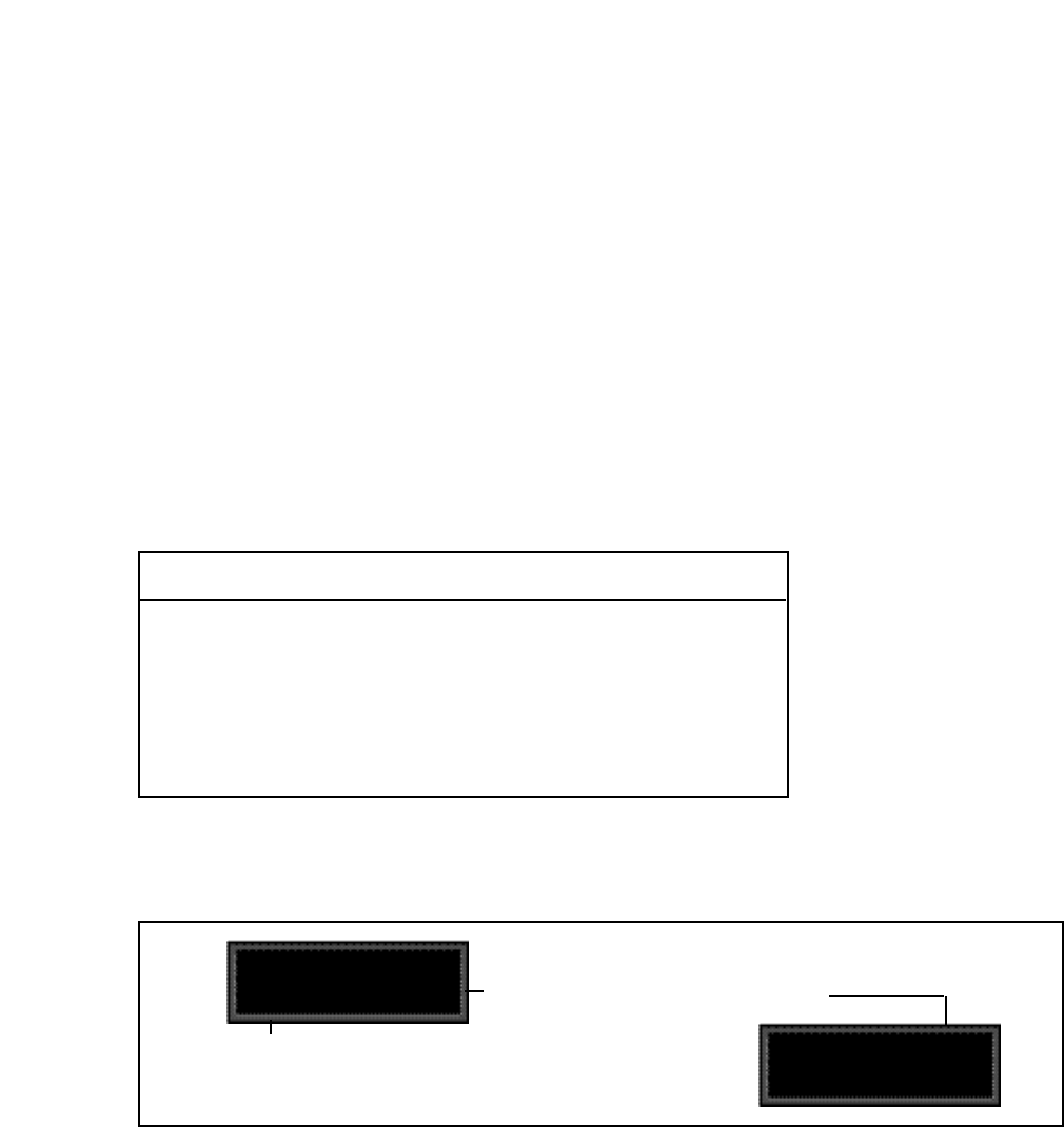
2-33
Basic Operation
Once you have assigned a parameter as a Destination, the controller you have
assigned “owns” that parameter. Adjustments made to this parameter from the
Edit matrix, will only affect the initial value of the parameter when the program
is loaded.
The behavior of the parameter on program load is determined by the setting of
the Patch Update parameter in Control mode (1.7). This parameter can be set
to Immediate or Delayed.
When Immediate is selected, the initial value of the parameter value will
correspond to the controller position.
When Delayed is selected, the stored value of the parameter will continue to be
in effect until the controller is moved. (It is, therefore, a good idea to set a sensible
value to the parameter in the Edit matrix.)
Assigning Values
Once you have assigned a Destination, press Load /✱ to get to the Values
display.
✱000: Off
Patch 0 Values
Src values are shown here. The asterisk (✱) indicates
that this field is available for control with the ADJUST
knob (and that additional parameters are available by
pressing Load /✱).
The current Dst value is displayed here. When you press
Load /✱ again, the asterisk will move to indicate that this value
is available to be changed by turning ADJUST.
000: ✱Off
Patch 0 Values
This display allows you to assign Destination values to specific Source values.
These assignments are made in pairs, each with a value for the Source and a
value for the Destination. For example, the default is two pairs mapped as
follows:
minimum Src value (0) = minimum Dst value
maximum Src value (127) = maximum Dst value
This establishes a linear relationship between the parameter and the controller.
Inverse control is accomplished easily by reversing these settings. As many as
eight pairs of Destination/Source values, or pivot points, can be assigned here,
providing an exciting new level of dynamic control.
Mod Row parameters that can be assigned as Patch Destinations
LFO1 Rate, Shape, P Width, Depth
LFO2 Rate, Shape, P Width, Depth
AR ENV Attack, Release, Mode
Env L Release
Env R Release
Sw 1 Rate, P Width, Mode
Sw 2 Rate, P Width, Mode
Delay Delay Time

Lexicon
2-34
PCM 90 User Guide
Jump
When creating patches, there are situations in which you will want to leave the
Patch row to adjust parameters. To make this convenient, a Jump command is
available. Jumping is dependent on the current Patch display, and is activated
simply by pressing Edit while a certain display is active. This will jump you out
of the Patch row and to the location where you can make the necessary
adjustments. Pressing Edit again will jump you back to the Patch Row. (Note
that using any front panel controls other than those required to adjust the
parameter to which you have jumped, will disable the jump. This is not
catastrophic, but it will require you to return by using Up and Down and
SELECT.) The following Jumps are available:
From the Patch row Src display:
• With ADJUST or Custom 1-4 selected as the Source, press Edit to jump to
the Controls row, where you can specify range limits. Press Edit again to
return to the Patch row.
• With any modulation parameter selected as a Source, press Edit to jump
to the Modulation row position of the Source. For example, if the Patch
source LFO is displayed, press Edit to jump to Modulation row position 0
(LFO) where you can edit any LFO parameter value. Press Edit again to
return to the Patch row.
From the Patch row Dst selection display:
• Press Edit to jump to the Edit controls for the parameter you have selected
as the Destination. You will have complete access to all parameter controls,
including any subparameters at that location. Press Edit again to return to
the Patch row.
From the Patch row Values display:
• Press Edit to jump to the next Src or Dst value. Default values are
0...minimum, 127...maximum.
The following examples illustrate how to create a patch, use the patch jump
features, modify the default patch values and add an additional pivot point to
the example patch values.
Creating a patch with default values
Load program P0 0.0 Deep Blue. Press Edit to enter Edit mode, then press
Up to move to the Patch Row. Press Load/✱ until the display looks like this:
Int ADJUST
Patch 0 ✱ Src
Patching Examples
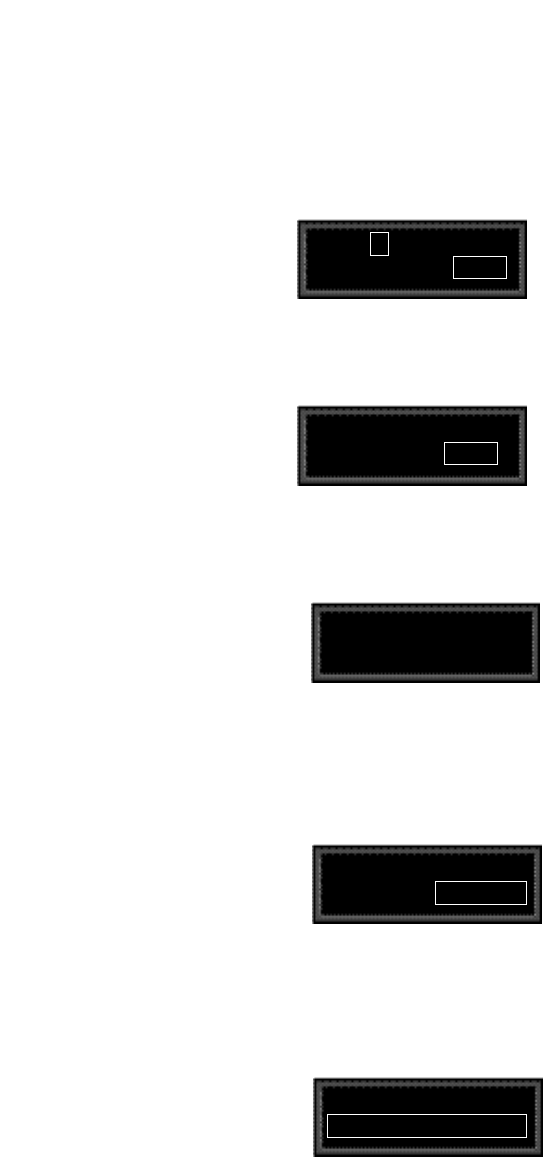
2-35
Basic Operation
Turn SELECT to select Patch 2 (which is set to Off).
Int Off
Patch 2 ✱ Src
Turning ADJUST will scroll through the entire list of available patch Sources.
Turn ADJUST counterclockwise until LFO1 is displayed in the lower right.
Int LFO1
Patch 2 ✱ Src
Patch 2 ✱ Dst
✱✱✱ Unassigned ✱✱✱
The ADJUST knob will now scroll through all of the available parameters of Deep
Blue. The lower line of the display will show the edit matrix row label on the left,
and the parameters in that row on the right.
Turn ADJUST clockwise until High Cut (in the effect's Design row) is displayed
in the lower right corner of the display.
Patch 2 ✱ Dst
Design High Cut
The High Cut parameter is now assigned as the patch Destination.
Now, press Load/✱ to bring up the Values display. This will show the default
Destination value setting (0.1kHz). This is the value assigned to High Cut when
LFO1 is at its minimum value (000).
Patch 2 Values
✱ 000 0.1kHz
LFO1 is now assigned as a patch Source.
Press Load/✱ to bring up patch Destinations for selection. The display should
show that Destination is unassigned.
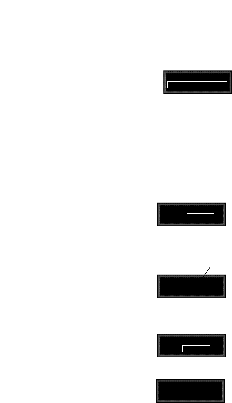
Lexicon
2-36
PCM 90 User Guide
Turn ADJUST one click counterclockwise to display the default Destination
value (FLAT) assigned to High Cut when LFO1 is at its maximum value (127).
Int LFO1
Patch 2 ✱ Src
Mod : LFO1 ✱ Rate
5.0 0.00 Hz
The display now shows position 5.0 in the Edit matrix Mod Row.
Turn ADJUST to change the rate of LFO1 to 0.30Hz.
Press Edit to jump directly to the LFO1 parameters in the Mod row.
The asterisk (✱) indicates that LFO1 Rate will be altered when
you turn ADJUST. Press Load /✱ to change the selection to
the other LFO1 parameters ( Shape, P Width and Depth).
Mod : LFO1 ✱ Rate
5.0 0.30 Hz
Now, press Edit to jump back to your previous position in the Patch row.
Int LFO1
Patch 2 ✱ Src
Patch 2 Values
✱ 127 FLAT
That’s all there is to setting up a default patch— select a Source and Destination,
and the minimum and maximum patch values are set automatically.
Of course, you will often want to modify the patch further, either by adjusting the
modulation source parameters, changing the default values or adding additional
pivot points. In the following sections, we’ll continue using this patch to
demonstrate examples of these modifications. When we’re done, the new patch
will add dynamic spatialization to the Deep Blue program.
Adjusting the modulation source parameters
Continuing the previous example, we’ll adjust the rate of LFO1 by jumping to it
from the Patch row.
Press Load/✱ repeatedly to return to the Patch 2 Source selection display.
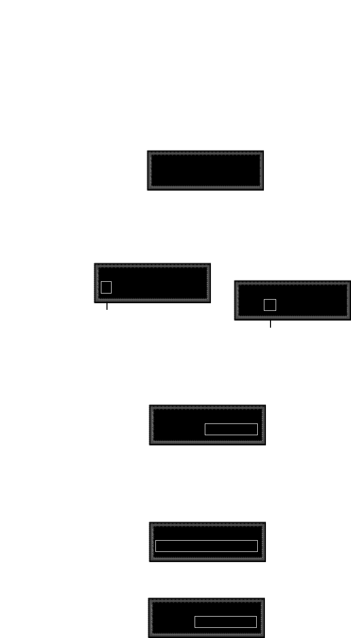
2-37
Basic Operation
Changing the default destination values
Let’s modify the patch further by adjusting the Destination values to a more
useful range.
Press Load/✱ repeatedly until the Patch 2 Values screen is displayed.
Notice that the ✱ is to the left of the Source value. This indicates that the Source
value is selected and its value will be changed when you turn ADJUST.
Press Load/✱ once to move the ✱ to the right of the Source value. When the
✱ is in this position, ADJUST will change the Destination value.
Patch 2 Values
000 : ✱–360 MONO
Patch 2 Values
✱ 000 –360 MONO
Press Load /✱ to move the asterisk to this position,
where it indicates that Destination values will be
altered when you turn ADJUST.
The asterisk (✱) indicates that the Source value
will be altered when you turn ADJUST.
Patch 2 Values
000 : ✱+0 MONO
Next, we’ll want to adjust the Destination value when LFO1 is at its maximum
value. One way to do this is to press Load/✱ three times to cycle the ✱ to the
display of the Source value, and continue on from there — but we’ve provided
a short cut! Press Edit to jump to the next assigned value ( in our example, the
maximum value for LFO1).
Patch 2 Values
127 : ✱+360 MONO
Now our example has been modified so that LFO1 sweeps the Out Width Value
from 0 to 90. This creates a dynamic alteration of the effect’s spatial character-
istics. Its stereo image changes smoothly from mono to stereo, to surround, and
back again.
Note that the ✱ remains in the same position, so you can just turn ADJUST to
set the new Destination value. Set the value to +90.
Patch 2 Values
127 : ✱+90 L-R, R-L
With the Destination value selected, turn ADJUST clockwise to set the value to
+0.
Patch 2 Values
✱ 000 –360 MONO
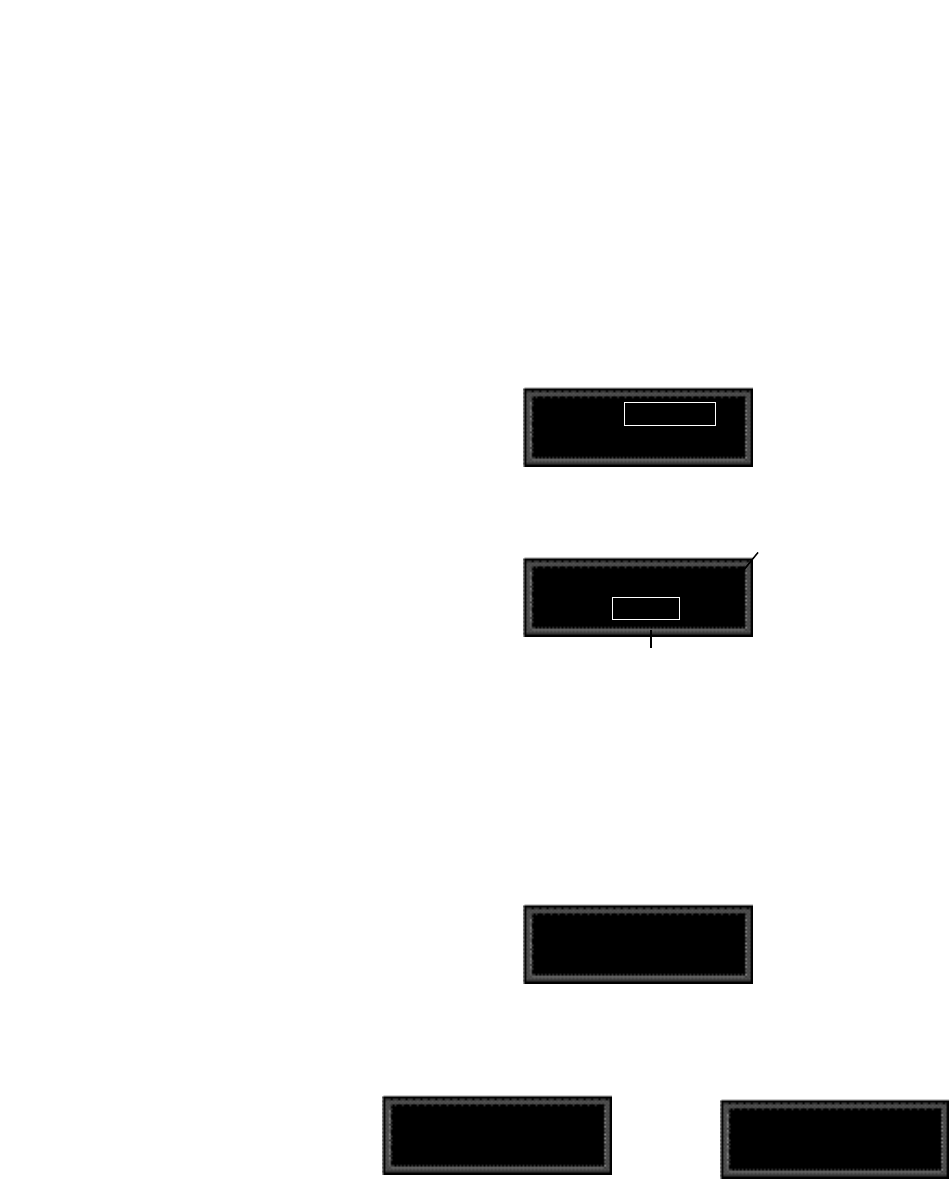
Lexicon
2-38
PCM 90 User Guide
Adding an additional pivot point to the patch
So far, our example uses only two pairs of patch values. The Destination
parameter moves linearly between the value assigned at 000 and the value
asssigned at 127.
You can watch this change by displaying the Destination parameter. Here’s how
to jump directly to it from the patch:
Press Load/✱ repeatedly to return to the Patch 2 Destination selection display.
Press Edit to jump directly to the Out Width parameter in the Controls Row.
Controls Out Width ■
0.3 +0...90 MONO
Patch Destination Indicator
The Out Width value will be changing
from 0 to 90 and back again.
Controls Out Width
Patch 2 ✱ Dst
The display will change to show position 0.3 in the Controls Row. Note that the
value is changing continuously from 0 to 90 and back again. Notice also the small
square in the upper right corner of the display. This patch destination indicator
appears whenever a parameter has been assigned as a patch Destination in the
effect being edited.
Now let’s return to the Patch row to add a pivot point to the effect.
Press Edit to jump back to the Patch row.
Controls Out Width
Patch 2 ✱ Dst
Press Load/✱ to bring up the Values display. The last value edited will be
displayed, so you will see either the minimum or maximum value.
Patch 2 Values
127 : ✱+90 L-R, R-L
Patch 2 Values
✱ 000 +0 MONO OR
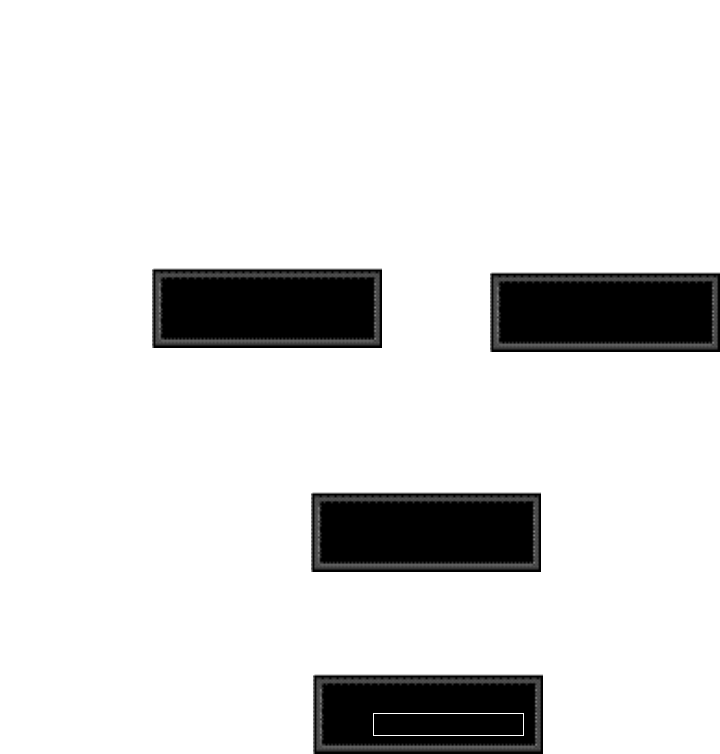
2-39
Basic Operation
By adding this pivot point, we have put a “kink” in the patch. The value of the
Destination parameter no longer moves in a straight line between 0 and 90.
Instead it moves from 0 to –45, and then from –45 to 90. This will produce a very
different sounding spatial change from the original patch. You can see the
difference by pressing Load/✱ twice to display the patch Destination, then
pressing Edit to jump back to the Destination parameter to watch its value
change.
If the ✱ is not at the left of the Source value, press Load/✱ three times to move
it there. (You can take a short cut instead — simultaneously press Down and
Load/✱ to back-step.)
Patch 2 Values
✱127 : +90 L-R, R-L
Patch 2 Values
✱ 000 +0 MONO OR
Turn ADJUST to display 64. This will be the Source value of our new pivot point.
The string of dots in the destination value portion of the display indicate that there
is no Destination value assigned when the source value is 64.
Patch 2 Values
✱ 064 : . . . . . . . . . . . . . .
Press Load/✱ to move the ✱ to the right of the Source value, and turn ADJUST
clockwise to set the Destination value for this point to –45.
Patch 2 Values
064 : ✱-45 R, L

Lexicon
2-40
PCM 90 User Guide
Multiple Patches with the Same Destination
If you create two or more patches with the same Destination, the Destination
value will be the sum of all of the patches assigned to it.
For example, if Footpedal and ADJUST are both assigned to Mix, the Mix value
will be the sum of the patch Destination values for those two patches. When
creating multiple patches to the same Destination, you should set the individual
Destinations to values which, when added together, are less than or equal to the
maximum value for the parameter. Footpedal and ADJUST, for example, could
each have a maximum value of 50%, or they could be assigned values of 25%
and 75%, 60% and 40%, etc.
When the sum of multiple patched parameter Destination values is greater than
the maximum value of the parameter, the parameter value will remain at
maximum until the sum of the patches falls below it.
Mod Row Patches
AR ENV, Latch, Sw 1, Sw 2 , Delay and S&Hold are each activated by
assigning a threshold source to T Src that is used to turn them on and off. This
assignment is a subparameter in the Mod row — not in the Patch row.

2-41
Basic Operation
The Custom Row
PCM 90 Character Set
! “ # $ % & ‘ ( ) * + , - . / 0 1 2 3 4 5
6 7 8 9 : ; < = > ? @ A B C D E F G
H I J K L M N O P Q R S T U V W
X Y Z [ ¥ ] ^ _ ‘ a b c d e f g h i j k l
m n o p q r s t u v w x y z { : } ~ ❚
(space)
The @ and the $ symbols are used to
represent Custom Control values.
The Custom row of the full edit matrix allows you to customize an effect by adding
defining ranges, as well as adding meaningful names and labels to the ADJUST
knob and the Custom Controls. It also provides controls for assigning KeyWords
to effects for sorting purposes.
Setting Range Limits for ADJUST and the Custom Controls
The first five positions in the Custom row: ADJUST and Control 1-4 allow
customization of the ADJUST knob and any Custom Controls you want to place
in the Soft Row. The controls for each of these behave identically.
The first set of controls allows you to set range limits. Press Load/✱ and turn
SELECT to display Low Limit, High Limit and MidPoint. Use ADJUST to
select values from 0-127.
Low Limit is the minimum value that the control will output. In most cases this
will be 0 (or 127 for inverted control). If ADJUST or the Custom Control is also
mapped to a MIDI controller, incoming MIDI values below this minimum value
will be treated as equivalent to the Low Limit.
High Limit is the maximum value that the control will output. This can be set to
any value above the Low Limit and effectively establishes the total range of the
controller. If ADJUST or the Custom Control is also mapped to a MIDI controller,
MIDI values above this maximum value will be treated as equivalent to the High
Limit.
In many cases, where the control is to have full range (0-127) or where it is to
behave as an off/on switch (0-1) these two values (Low and High) are the only
ones which have to be specified. In other cases, the control can be enhanced
by adding more than just these simple range limits.
MidPoint allows you to establish a fixed reference point between the Low and
High Limits you have selected. The MidPoint has no effect on the range you have
established, but does determine the number of positions within the controller's
range which can be labeled with text.
Labeling ADJUST, the Custom Controls and their ranges
Press and hold down the Edit button to access a submode which allows you to
name the control, as well as any points you have assigned. While you are holding
down Edit, the message: Entering Custom label assign ... will be displayed,
followed by the current name of the control with a cursor positioned over the first
character of the name. Use ADJUST to select a new character. Press Up or
Down to select a new type of character (upper case, lower case, numeric,
symbolic, or blank). Simultaneously press Up and Down to clear all characters
from the cursor to the end of the line. Turn SELECT to move the cursor to a new
position. Continue in this manner until you have finished entering the new name.
A maximum of 20 characters (including spaces) may be used.
Press Load/✱ repeatedly to cycle through the remaining choices: LowLabel,
HighLabel, MidLabel, LowRange and HighRange. Names are entered using
ADJUST and SELECT in exactly the same manner.

Lexicon
2-42
PCM 90 User Guide
LowLabel: The name you assign will appear on the bottom line of the display
when the control reaches the value you have set as the Low limit.
HighLabel: The name you assign will appear on the bottom line of the display
when the control reaches the value you have set as the High Limit.
MidLabel: The name you assign will appear on the bottom line of the display
when the control reaches the value you have set as the MidPoint. (This naming
display is not available if you have not assigned a MidPoint within the range
established by the Low and High Limits.)
LowRange: The name you assign here will be displayed whenever the control-
ler is between the MidPoint and the Low Limit.
HighRange: The name you assign here will be displayed whenever the
controller is between the MidPoint and the High Limit.
You can display numerical values anywhere along the bottom line of the display
by entering the characters @ or $ where you want values to appear. As many
as three digits can be displayed, representing absolute distance from the Low
Limit (@@@), or relative distance from the selected MidPoint ($$$). If the
MidPoint is at or below the Low Limit, this range will be equivalent to the entire
range of the controller. The default status of the label displays includes @@@
already entered at the beginning of the entry line. Check out the presets in the
Custom row of any bank for examples of Custom Controls.
Assigning KeyWords to an Effect
The last four positions of the Custom row allow as many as four KeyWords to be
assigned to the current effect. At each position (KeyWord 1-4), use ADJUST to
select a representative KeyWord from the list shown in the sidebar — or "none".
Effect sorting by KeyWord is accomplished in Control mode at location1.8. To
view the sorted list, repeatedly press either Program Banks or Register Banks
through all of the available banks, then to the KeyWord display. In Control mode,
A to Z is available as a viewing selection. All effects are internally tagged to allow
this option of alphabetical sorting.
Medium
MIDI
Mono
Natural
Orchestral
Outdoor
Plate
RandomHall
Room
Short
Slap FX
Small
Spatial
Special FX
Splits
Stereo
Surround
Tempo
Unnatural
Vocal
User 1
User 2
User 3
User 4
Acoustic
Ambience
Ballad
Bright
Broadcast
Cascade
Chamber
Classical
Cncrt Hall
Custom
Dark
Dialog
Drums/Perc
Dynamic
Echo
Film-ADR
Gated
Guitar
Indoor
Instrument
Keyboard
Large
Live PA
Long
Mastering
Assignable KeyWords
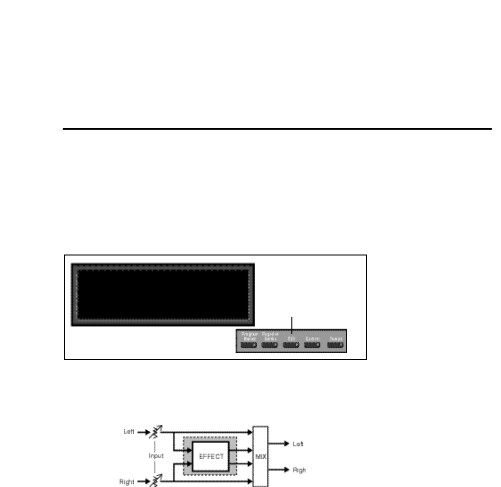
3-1
The Algorithms and Their Parameters
3
The Algorithms and
Their Parameters
The PCM 90 uses five algorithms to create different types of reverberation
effects. Each of these algorithms and its associated parameters are described
in detail in this section.
When you select any effect, the bank and row label will appear on the upper
display line. The matrix location and the effect name will appear on the lower line.
Press and hold Program Banks or Register Banks to display the algorithm
from which the currently loaded effect is derived. Press Edit to display the last
edited parameter in that algorithm's parameter matrix.
The five algorithms share a common set of controls and parameters built around
one of the five stereo reverb effects.
Input levels and hardwired pans determine the signal flow to left and right pairs
of delay voices, and also to the reverb effect. Some delay voices have
individually adjustable level, delay, and feedback controls, as well as master
voice controls. A High Cut parameter provides high end rolloffl. InWidth and
OutWidth controls allow the creation of spatial effects.
In this chapter, diagrams and descriptions of each algorithm are presented first,
along with pictures of each edit matrix. The diagrams are followed by a glossary
of parameter descriptions, organized alphabetically by matrix row name. Within
each matrix row, parameters are organized as far as possible in the sequence
in which they appear in the row.
Halls: Orchestral
Press Edit to access the
parameter matrix.
P0 0.0 Deep Blue
The five PCM 90 algorithms, Random Hall, Ambience, Rich Plate, Concert Hall
and Chamber/Room, share the same general structure, shown below. The
shaded area of the diagram is detailed in the individual effect descriptions that
follow.
About the Algorithms

Lexicon
3-2
PCM 90 User Guide
Random Hall The Random Hall algorithm gives recorded music a sense of being performed
in a real acoustic location. The Size, Spread and Shape controls allow adjust-
ment of the buildup and decay of the initial part of the reverberation envelope.
Shape controls the shape of the envelope, while Spread and Size set the time
over which this shape is active.
Size acts as a master control for the apparent size of the space being created.
Both Spread and Reverb Time vary linearly with the setting of Size. Thus
maximum reverb time and spread require high settings of Size. To find an
appropriate reverb sound, start with a preset with a similar sound to what you
want to end up with, turn ADJUST to see what effect it has, then investigate the
parameters, starting with Size. Until you are familiar with the PCM 90, we
recommend that you edit any patch driving a parameter rather than editing the
parameter directly.
Once a size has been selected, Spread and Shape are used to adjust the shape
and duration of the initial reverb envelope, which together provide the major
sonic impression of room size.
When Shape is at minimum, the reverberation envelope builds up very quickly
to a maximum amplitude, and then dies away quickly at a smooth rate. This
envelope is characteristic of small reverberation chambers and reverberation
plates. There are few (if any) size cues in this envelope, so it is ineffective in
creating ambience. With this Shape setting, Spread has no effect. The density
is set by the Size control, and the rate of decay is set by the reverb time controls.
As Shape is raised to about 1/8 of its range, the initial sharp attack of the
reverberation is reduced, and reverberation builds more slowly. The envelope
then sustains briefly before it begins to die away at the rate set by Mid Rt. Spread
has little or no effect on this shape. When Shape is at 1/4 of its range, buildup
is even slower and the sustain is longer. Now Spread affects the length of both
the buildup and the sustain. As a rough estimate, the sustain will be approximate-
ly the time value indicated by the Spread display (in milliseconds).
As Shape is raised further, the buildup and sustain remain similar, but now a
secondary sustain appears in the envelope, at a lower level than the first. This
secondary plateau simulates a very diffused reflection off the back wall of a hall,
and is effective in creating a sense of size and space. This reflection becomes
stronger and stronger, reaching an optimal loudness when Shape is at about 1/
2 of its range.
The highest Shape settings are typically used for effects. Near the top of the
scale the back wall reflection becomes stronger than the earlier part of the
envelope, resulting in an inverse sound.
Note that none of these shape effects are audible unless Mid Rt is set short
enough. Generally, this control should be set to a value of about 1.2 seconds for
small rooms, and up to 2.4 seconds or so for halls. Size should also be set to a
value appropriate to the desired hall size (note, however, that small sizes color
the reverberation).15 meters makes a very small room, and 38 meters is useful
for a large hall.
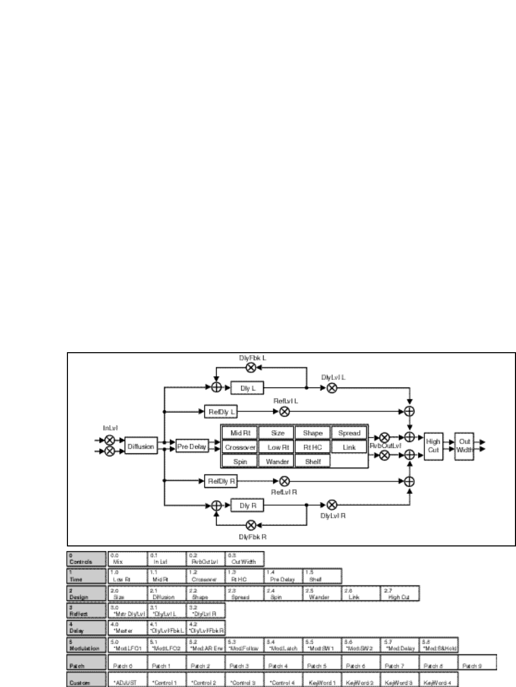
3-3
The Algorithms and Their Parameters
Random Hall incorporates random delay elements which have several effects.
First, there is a reduction of long-lived modes in the reverberant decay, which
makes the decay less metallic and reduces the apparent reverb time. The
random elements also improve the steady-state timbre of the program.
The speed at which the delay elements move is controlled by Spin. Values of
Spin which are higher than about 40% can cause audible pitch wobble in very
critical material (such as classical guitar or piano) and can also cause noise on
pure tones. This noise is not audible in speech, however, and, for mixed music
or speech, values up to 50% will give an improved sound. Wander is typically set
to about 10ms at larger settings of Size. Smaller values of Wander should be
used when smaller Sizes are used.
This algorithm also offers the option of adding early reflections which have been
made into diffused clusters of pre-echoes. The density of the cluster is set by the
Diffusion control. We recommend that these pre-echoes be used with caution,
unless you are trying to match the sound of the reverberation to a particular
location where such reflections are strong.
An output width control affects the stereo image of the signal leaving the reverb
effect. OutWidth can add width to a signal, or move a reverb into a surround
channel. Either control can be used statically or dynamically, but in certain
positions may be mono-incompatible.
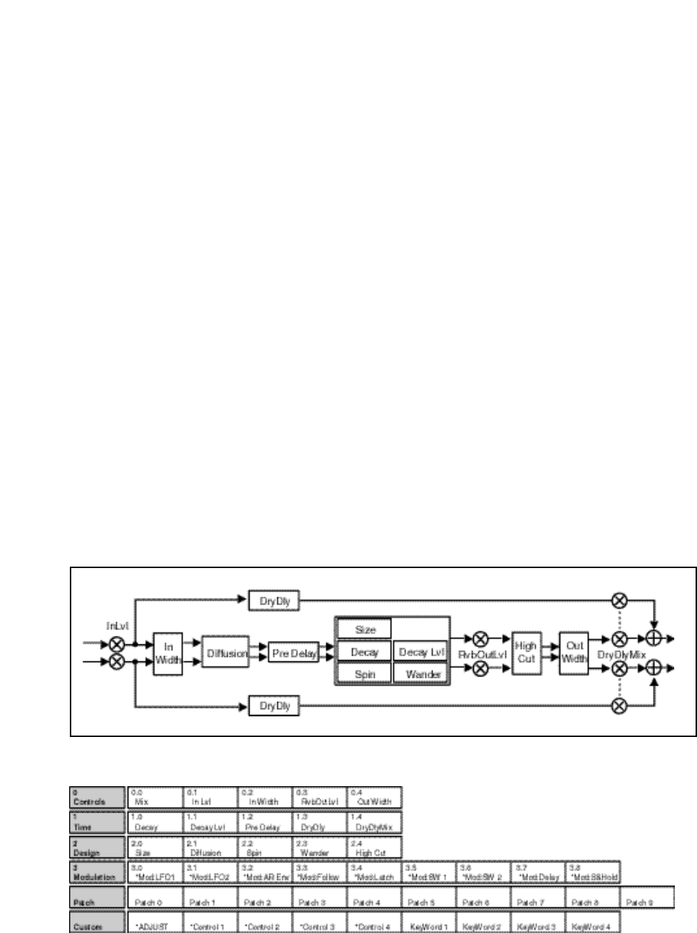
Lexicon
3-4
PCM 90 User Guide
Ambience While Random Hall effects are designed to add a cushion of reverberance to
recorded music, while leaving the clarity of the direct sound unaffected,
Ambience is intended to become a part of the direct sound — to give it both better
blend and a definite position in space. Ambience gives warmth, spaciousness
and depth to a performance without coloring the direct sound at all.
This algorithm generates primarily the strong reflections which appear in the first
few hundred milliseconds of the reverberation process. These early reflections
constitute the primary audible effect, giving you the impression of a hall
surrounding you while the music is playing. To avoid any coloration from these
strong reflections, the time delays and amplitudes are random functions.
Ambience is very useful for adding a room sound to recorded music or speech.
It is particularly easy to match a studio recording of dialog to a typical room
environment. In music recording, it allows you to realistically add distance to a
close-miked signal. If an ensemble has been recorded with close-mikes and pan
pots, Ambience can provide the missing blend and depth. The apparent position
of the instruments is preserved in the reverb while the apparent distance is
increased. This algorithm is also useful in matching a closely miked accent
microphone to the overall ambience of a recording. This allows a soloist to be
increased in level without changing the apparent distance. Ambience can be
used in a recording situation any time a close-miked sound is undesireable.
To use the algorithm with a console, it is best to use a stereo send to the PCM
90, carefully matching the panning of the various close-miked sources to their
positions in the mix. Leave the Mix control at 100%. The apparent distance of
each source can be controlled by the level of its feed.
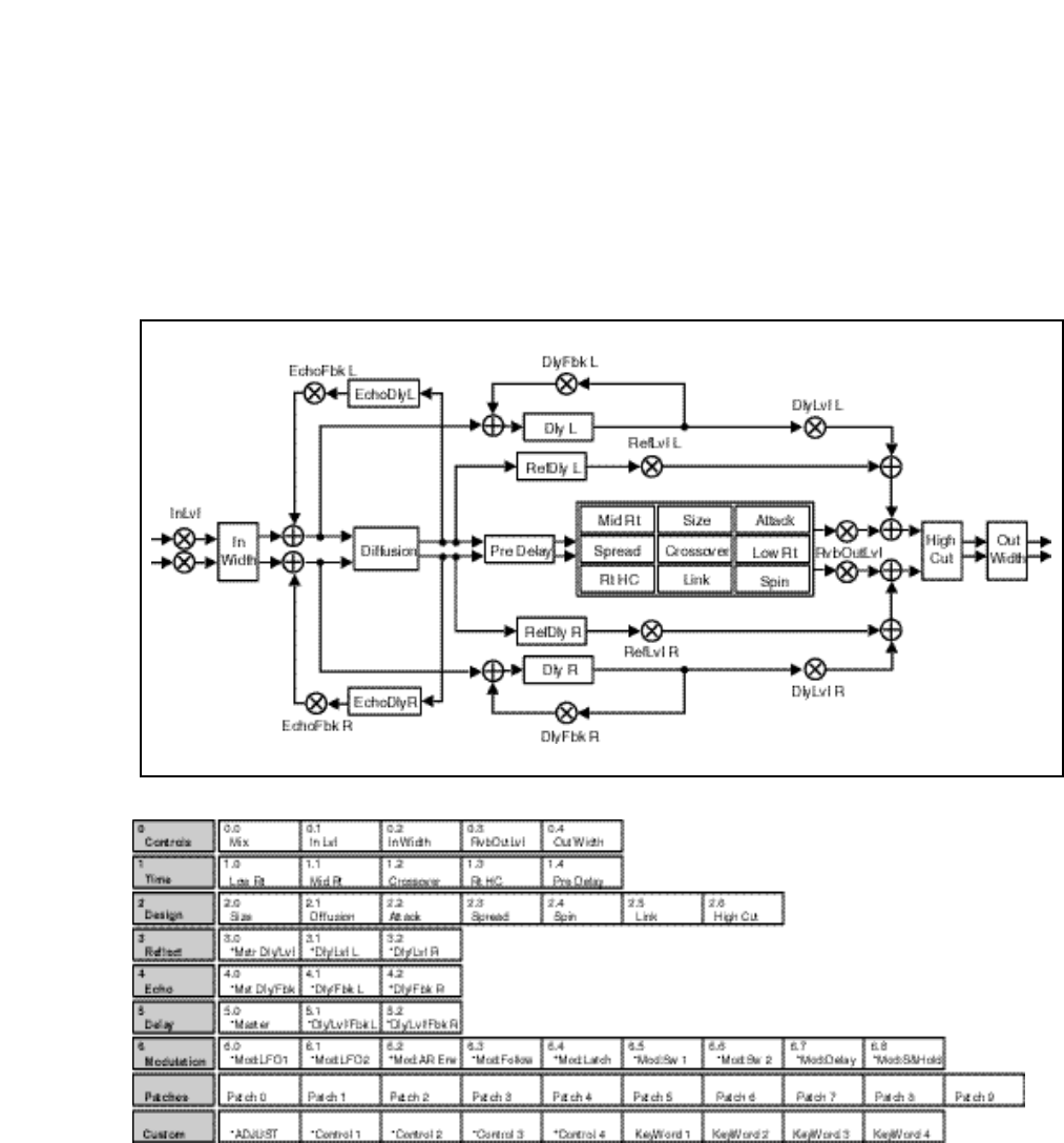
3-5
The Algorithms and Their Parameters
Rich Plate
The Rich Plate algorithm mimics the sound of metal plates. It has a dense,
smooth, colored sound that makes it a good choice for enhancing any type of
percussion. Larger sizes and longer reverb times are particularly effective on
vocals and brass, but this algorithm can be optimized for use on virtually any
source.
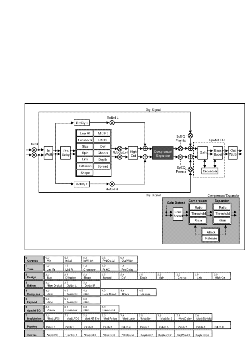
Lexicon
3-6
PCM 90 User Guide
This algorithm emulates a real concert hall. The reverberation is very clean, and
designed to remain behind the direct sound — adding ambience, but leaving the
source unchanged. This effect has a relatively low initial echo density which
builds up gradually over time.
This algorithm also features a post-reverb compressor which can be used to
shape the reverb tail in unusual ways. Spatial EQ controls, following the
compressor, can be used to widen or narrow low-frequency stereo separation.
A dry signal path allows you to process material with or without reverberation.
This is useful in live recordings.
Concert Hall
Note that the compressor and expander
controls are computed simultaneously.
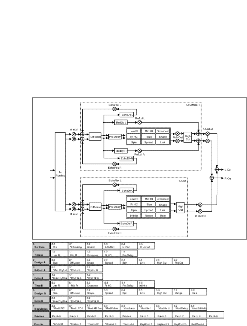
3-7
The Algorithms and Their Parameters
Chamber/Room
This algorithm provides two independent reverbs which can be used in mono in/
stereo out, or stereo in/stereo out configuration. Chamber provides an even,
relatively dimensionless reverberation, with little change in color as the sound
decays. Its unobtrusive character makes it useful on a wide range of program
material. Room produces an excellent simulation of a very small room which is
useful for dialog and voiceover applications, but which may be too colored for
some sustained musical tones. Increasing the Size/Shape/Spread parameters
produces an excellent reverb and an Infinite control allows you to freeze a signal
for as long as you like. The outputs of the two reverbs are summed into a single
stereo output.

Lexicon
3-8
PCM 90 User Guide
The Parameters PCM 90 parameters are organized into labeled rows within each edit matrix.
Although there are similarities among all matrixes, such as having a row of
Controls first, and Modulation, Patching and Custom Control rows last, some of
the parameters within each row, and some entire rows are unique to specific
algorithms.
This section contains descriptions for all PCM 90 parameters, organized
alphabetically by row label as follows:
Compress
Controls
Custom
Delay
Design
Echo
Expand
Modulation
Patches
Spatial EQ
Reflect
Time
Individual parameter descriptions within each row are presented, as far as
possible, in the order in which they appear from left to right in the edit matrix.
Row 4 of the Concert Hall algorithm contains compression controls for a built-
in compressor/expander. Remember that, in some ways, a digital compressor
is the opposite of an analog compressor. An analog compressor reduces gain
when the incoming signal is above a certain threshold; a digital compressor
increases gain when the signal is below the threshold. The end result — lower
dynamic range— is the same, but it's easy to become confused if you are familiar
only with analog equipment.
Ratio
Ratio controls the slope of the gain curve or the ratio of input level versus output
level.
Threshold
Threshold sets the level below which gain is increased. This should normally be
set fairly high (-10dB or more).
Gain
Gain adjusts the gain of low level signals (below the compression threshold).
LookAhead
LookAhead sets the predelay of the audio before the digital VCA. If the source
material has many strong transients, proper adjustment of this parameter can
reduce the possibility of clipping.
Attack
Attack adjusts the attack time constant, determining how quickly the compres-
sor responds to increasing input level. This should normally be set quite low to
allow the compressor to react to sharp transients.
Compress

3-9
The Algorithms and Their Parameters
Release
Release allows adjustment of the release time constant, determining how
quickly the compresor responds to decreasing input level. This should normally
be set long. Short release times may cause an effect similar to "pumping" in an
analog compressor.
Row 0 of every algorithm contains parameters that provide overall control of
both the reverb and voice effects.
Mix
Mix controls the ratio of dry and wet signal present at the PCM 90 outputs. When
the PCM 90 is patched into a console or an instrument amplifier through an
auxiliary or effects loop, this control should always be set to 100% wet. (Control
Mode 1.1 allows you to select a global Mix setting.)
In Lvl
InLvl controls the level of the unprocessed (dry) signal into the effect. The range
of this parameter in the Chamber/Room algorithm is +5.0dB, to –7.2dB, to Off.
In all other algorithms the range is from +6dB, to -73dB, to Off. Individual controls
for the A and B effects in the Chamber/Room algorithm are labeled A InLvl and
B InLvl.
RvbOutLvl
RvbOutLvl controls the output level of the reverberator before it is mixed with the
dry signal and any reflections or delays. The range is from Full (0dB) to -24dB,
to Off. Individual controls for the A and B effects in the Chamber/Room algorithm
are labeled A OutLvl and B OutLvl.
Out Width
Out Width controls the width of the entire processed signal. This can be thought
of as an extension of typical mono to stereo imaging controls. The range of this
parameter is -360 to +360, in single digit increments. Values of -360, 0, or +360
cause the effect's audio output to be mono. Values of -315 and +45 cause the
output to be normal left/right stereo. Values of -45 and +315 cause "swapped",
or right/left stereo.
Value Display Label Description
360 MONO Phase Normal Mono
315 R, L Phase Normal R/L stereo
270 R–L, L–R R–L, L–R surround*
225 STEREO INV Phase Inverted L/R Stereo
180 MONO INV Phase Inverted Mono
135 R, L INV Phase Inverted R/L Stereo
90 L–R, R–L L–R, R–L surround
45 STEREO Phase Normal L/R stereo
0 MONO Phase Normal Mono
-45 R,L Phase Normal R/L Stereo
-90 R–L, L–R Phase Inverted R–L, L–R surround*
-135 STEREO INV Phase Inverted L/R Stereo
-180 MONO INV Phase Inverted Mono
-225 R, L INV Phase Inverted R/L Stereo
-270 L–R, R–L L–R, R–L surround
-315 STEREO Phase Normal L/R Stereo
-360 MONO Phase Normal Mono
* Disappears in mono
Controls

Lexicon
3-10
PCM 90 User Guide
Controls cont'd.
PCM 90 Character Set
! “ # $ % & ‘ ( ) * + , - . / 0 1 2 3 4 5
6 7 8 9 : ; < = > ? @ A B C D E F G
H I J K L M N O P Q R S T U V W
X Y Z [ ¥ ] ^ _ ‘ a b c d e f g h i j k l
m n o p q r s t u v w x y z { : } ~ ❚
(space)
The @ and the $ symbols are used to
represent Custom Control values.
The large and duplicated range of the Out Width parameter allows smooth
glides from any Left/Right Mix, Phase, Mono/Stereo image point to any other. Of
particular interest are: 0 MONO, 45 STEREO, and 90 L–R, R–L (surround
channel). This parameter can be changed in real-time for fascinating spatial
effects.
In Width
In Width provides a width control for the input signal before it is fed to the
reverberator. Careful use of this control can provide fascinating results. For
example, a setting of 45 will provide a normal stereo reverberation effect, while
a setting of 90 will exclude any mono (center) signal from the reverberator.
Modulation of this control can result in the illusion of various parts of the input
moving forward and backward in the reverberant field.
InRouting
Available in the Chamber/Room algorithm, InRouting controls the routing of the
input signal to the reverberators. MonoSplit routes the left input to the Chamber
and the right input to the Room, RevMonoSplit routes the right input to the
Chamber and the left input to the Room, Stereo Split routes both inputs to both
the Chamber and the Room. In each case the outputs from the two reverberators
are summed and sent to the stereo output of the PCM 90.
The last row of each algorithm edit matrix allows customization and labeling of
ADJUST, and four custom controls. It also allows the assignment of KeyWords
for effect sorting.
ADJUST, Control 1, Control 2, Control 3, Control 4
These controls allow names and ranges to be specified for ADJUST and for four
other Custom Controls. Press Load/✱ to display: Low Limit, High Limit and
MidPoint for the displayed control. Turn ADJUST to select values from 0-127.
Low Limit: This is the lowest value that the controller will output (or
accept, if connected to MIDI).
High Limit: This is the maximum value that the controller will output.
MidPoint:This allows you to set a fixed point within the range you have
established between the high and low limits.
Pressing and holding Edit accesses a submode which allows you to name the
control, as well as any points you have assigned. Pressing Load/✱ will cycle
through the following choices. From any of the displays, use ADJUST to select
a character for the space marked by the flashing cursor. Use SELECT to move
the cursor to another position.
Name: The name you assign here will appear on the top line of the
display whenever the control is adjusted.
LowLabel: The name you assign will appear on the bottom line of the
display when the control reaches the value you have set as the Low
Limit.
Custom

3-11
The Algorithms and Their Parameters
HighLabel: The name you assign will appear on the bottom line of the
display when the control reaches the value you have set as the High
Limit.
MidLabel: The name you assign will appear on the bottom line of the
display when the control reaches the value you have set as the MidPoint
(not available if you have not assigned a MidPoint within the established
range.)
LowRange: The name you assign here will be displayed whenever the
controller is between the Midpoint and the Low Limit.
HighRange: The name you assign here will be displayed whenever the
controller is between the Midpoint and the High Limit.
You can display numerical values anywhere along the bottom line of the
display by entering the characters @ or $ where you want these values
to appear. As many as 3 digits can be displayed, representing absolute
distance from the the Low Point (@@@) or relative distance from the
selected Midpoint ($$$). If the Midpoint is at or below the Low Limit, this
range will be equivalent to the entire range of the controller. The default
status of the naming displays is to have @@@ already entered at the
beginning of the entry line.
For additional information on Custom Controls, see Chapter 2: Basic Operation.
KeyWord 1-4
The last four controls in the Custom row allow assignment of as many as four
KeyWords to the effect. Each of the controls behaves identically — simply turn
ADJUST to select a KeyWord from the list shown in the sidebar. All effects are
tagged internally for alphabetical (A to Z) sorting, but this is shown in the list for
completeness. For specialized sorting, four User KeyWords are provided at the
end of the list.
PCM 90 KeyWords
Mastering
Medium
MIDI
Mono
Natural
Orchestral
Outdoor
Plate
RandomHall
Room
Short
Slap FX
Small
Spatial
Special FX
Splits
Stereo
Surround
Tempo
Unnatural
Vocal
User 1
User 2
User 3
User 4
A to Z
Acoustic
Ambience
Ballad
Bright
Broadcast
Cascade
Chamber
Classical
Cncrt Hall
Custom
Dark
Dialog
Drums/Perc
Dynamic
Echo
Film-ADR
Gated
Guitar
Indoor
Instrument
Keyboard
Large
Live PA
Long

Lexicon
3-12
PCM 90 User Guide
In each the Random Hall and Rich Plate algorithms, a Delay row contains
parameters for delay, feedback and level settings of each voice. Press Load/✱
to cycle through selections.
Mstr Dly, Dly L, Dly R
These controls provide delay voices to the left and right channels. The delays
are routed to the output (through the Lvl controls) and also through a feedback
path. The master delay control allows you to simultaneously change the delay
times of both voices. The available range is from 0-200%. This provides a simple
way to expand or close in the voice delay times. If a voice's delay time is set to
500ms, changing the setting of Mstr Dly to 200% will change the delay time to
1.000sec. Setting this parameter to 0% is an easy way to set both delays to 0
from a single control.
When display of values in BPM has been selected, these are set as fractions of
a beat. The smallest fraction is 1/24th beat. Delay times can also be tempo
modulated.
Mstr Lvl, Lvl L, Lvl R
These controls modify the levels of the delay voices (Dly L and R) as they are
routed to the output. The range of the left and right controls is from Full (0dB),
to -85dB, to Off. Mstr Lvl provides grouped control from 0-100%. With low or
moderate settings, small changes in Mstr Lvl may not have any effect.
Mstr Fbk L, Fbk R
These controls modify the levels of the delay feedback path. The range of the
left and right controls is from -100% to +100% in 1% increments. Mstr Fbk
provides grouped control from 0-100%. With low or moderate settings, small
changes in Mstr Fbk may not have any effect.
The Design row, available in every algorithm, contains parameters that affect the
structural aspects of the reverb effect. In the Chamber/Room algorithm, indi-
vidual Design rows are available for Effect A and B.
Size
Size sets the rate of build-up of diffusion after the initial period (which is
controlled by Diffusion). The Size control changes a reverb sound from very
large to very small. Generally, you should set this control to approximate the size
of the acoustic space you are trying to create, before adjusting anything else.
The size in meters is roughly equal to the longest dimension of the space. Audio
is temporarily muted when Size is changed.
Diffusion
A Diffusion control is provided in all algorithms. It controls the degree to which
initial echo density increases over time. High settings of Diffusion result in initial
build-up of echo density, and low settings cause low initial build-up. Echo density
is also affected by Size; smaller spaces will sound denser. To enhance
percussion, use high settings of Diffusion. For clearer and more natural vocals,
mixes, and piano music, use low or moderate settings of Diffusion. Note that, at
some extreme input levels, high settings of Diffusion may trigger the overload
indicators on the headroom display.
Delay
You can set and display delay val-
ues in units of time, or with tempo
values. Press Up and Tempo simul-
taneously to toggle between these
two options. When time units are
selected, delay times are set and
displayed in milliseconds or seconds
(from 0ms to the maximum available
delay for that parameter). When
tempo values are selected, delay
values are set and displayed as a
ratio of echoes to beats (from 24:1 to
1:24). This will automatically syn-
chronize the delay to the current
tempo (MIDI, Internal, or TAP — see
Tempo Mode in Chapter 2.) For ex-
ample, a delay setting of 1:2 (1 echo
for every 2 beats) will produce half-
note delay rhythms synchronized to
the current tempo.
Design

3-13
The Algorithms and Their Parameters
Attack
Attack is provided in the Plate algorithm to set the sharpness of the initial
response to an input signal. High settings cause an explosive sound, while low
settings cause the sound to build up more slowly with time. Attack only affects
the level of sound within the first 50 milliseconds.
Shape, Spread
In Random Hall, Concert Hall and Chamber/Room, Shape and Spread work
together to control the overall ambience of the reverberation. Shape determines
the contour of the reverberation envelope. With Shape all the way down,
reverberation builds explosively, and decays quickly. As Shape is advanced,
reverberation builds up more slowly and sustains for the time set by Spread. With
Shape in the middle, the build-up and sustain of the reverberation envelope
emulates a large concert hall (assuming that Spread is at least halfway up, and
that Size is 30 meters or larger). Low Spread settings result in a rapid onset of
reverberation at the beginning of the envelope, with little or no sustain. Higher
settings spread out both the buildup and sustain.
Def
In the Concert Hall algorithm, Definition affects the echo density buildup rate
during the latter part of the decay period. When set to Off, the rate is determined
by the program material. Raising Definition through its range (1-99%) causes the
sound to become choppier — the decrease in echo density creates increasingly
distinct, repetitive echo trails.
Depth
In the Concert Hall algorithm, Depth sets the output amplitude envelope,
changing the listener's perspective from the front to the rear of the hall.
Spin
Spin affects the movement of the reverberation tail. The object of Spin is to
continuously alter the timbre of the reverberant sound. This makes the result
more natural, without making the position of instruments unstable. Spin should
typically be set to values between 10% and 50%. Higher values may make the
timbre of piano or guitar unstable.
Chorus
In the Concert Hall algorithm, Chorus randomizes delay times and introduces
modulation to make reverberation sound less metallic. Increasing Chorus
increases the rate of modulation. Because Chorusing can cause pitch variation,
this parameter should be set with care when using sources with very little pitch
wobble (such as guitar or piano). A good practice is to increase the setting until
pitch wobble becomes noticeable, then lower it slightly.
Link
This control is available in all algorithms except Ambience. When Link is set to
On, the reverb time (Mid Rt) and Spread scale linearly as the Size control is
varied. For some special effects, Mid Rt, Spread and Size can be unlinked.
High Cut
High Cut sets the high frequency cutoff of a low-pass filter. This parameter
affects both channels.

Lexicon
3-14
PCM 90 User Guide
Range and Rate
Range and Rate controls in the Room algorithm in Chamber/Room can be used
to reduce coloration for small room sizes or to reduce the sense of periodicity
when the Infinite control is on. These controls allow you to set the range of a
moving delay and the speed at which it moves. High settings of either control
may be unsuitable for sustained tones, like piano.
Wander
Wander sets the distance (in time) that early reflections will move. For best
results with larger sizes, this control should be set to about 10ms.
Mstr Dly, Dly L, Dly R
In Rich Plate and Chamber/Room, Dly L and Dly R provide echoes to the left and
right channels. Unlike Delay and Reflect, which are isolated left and right delays,
left and right echoes are blended in the diffusor. The echoes are routed both to
the outputs and through a feedback path. Mstr Dly provides a simple grouped
control that modifies the left and right values from 0-200%.
Mstr Fbk, Fbk L, Fbk R
Fbk L and Fbk R modify the levels of the echo feedback path. The range is from
-100% to 0 to +100%. Mstr Fbk has a range of 0-100%. With low or moderate
settings, small changes of Mstr Fbk may not have an effect.
Row 5 of the Concert Hall algorithm contains expansion controls for a built-in
compressor/expander. (See also Compress at the beginning of this section.)
Ratio
Ratio controls the slope of the expander circuit.
Threshold
Threshold sets the threshold below which gain is reduced.
Gain
Gain sets the amount of negative gain.
Design cont'd.
Echo
Expand
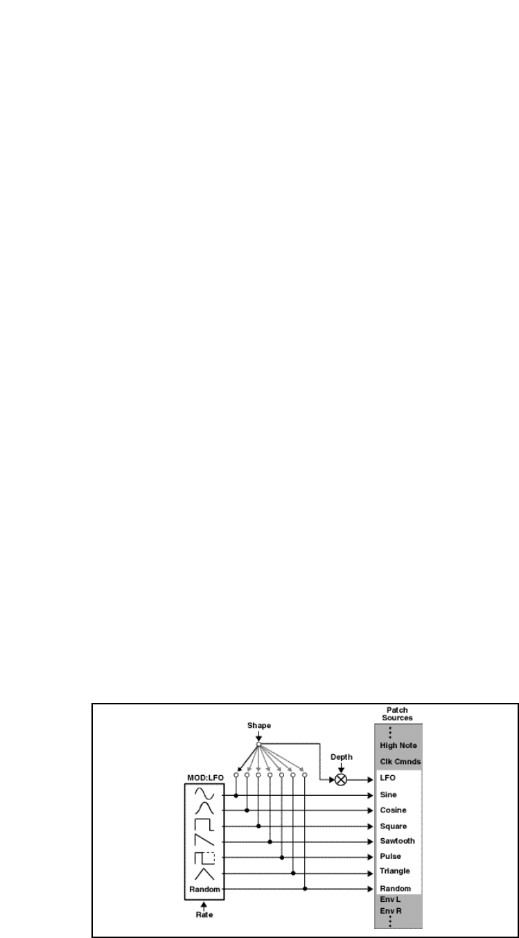
3-15
The Algorithms and Their Parameters
The Modulation row, which is the same for every algorithm, contains the
parameters for the PCM 90's internal modulation sources. Use the Patch row to
assign these modulators to any PCM 90 effect parameter.
Mod: LFO1 and Mod:LFO2
Four parameters are available: Shape, P Width, Depth, and Rate.
Shape allows you to select the wave shape which will be used when "LFO" is
selected as a patch Source. The choices are:
Sine
Cosine
Square
Sawtooth
Pulse
Triangle
Random (outputs a new value on each cycle of the LFO)
P Width determines the proportion of each pulse wave cycle for which the LFO
is on (1-99%). For example, setting P Width to 50% means that the LFO is on
for half of its cycle. The effect of this control will only be heard if you are using
the Pulse shape.
Depth scales the output of the LFO from 0 to 100%. This control affects the
output of the LFO only. It has no effect on the outputs of the individual
waveforms.
Rate sets the speed (0-10Hz) at which the LFO cycles. It can be set in time
values (such as 1.5Hz) or in tempo values (such as 3:2 cycles per beat).
Simultaneously pressing Up and Tempo will toggle these two display options.
Note: The PCM 90 allows six LFO shapes (sine, cosine, sawtooth, triangle,
square and pulse) or a random shape to be selected as patch sources, as well
as the LFO itself. All of these are generated by a single LFO, and are controlled
by the single Rate control. When "LFO1" is selected, for example, as a patch
source, the output will be the Shape selected here. The amplitude of the LFO
output is controlled by Depth. Both Shape and Depth are available as patch
destinations and can be controlled externally. Shape, Pulse Width, Depth, and
Rate are all available as patch destination parameters, and can be controlled
externally. See Patching in Chapter 2.
Shape, Rate and Depth can be controlled by a patch.
Modulation

Lexicon
3-16
PCM 90 User Guide
Mod: AR Env
This envelope generator's output, when turned on, will go from 0 to127. How
quickly it goes from 0 to 127 is determined by the setting of Attack (0-10
seconds). Once the envelope generator has reached 127, it remains there as
long as it is turned on. When it is turned off, it goes from 127 to 0, at the rate
determined by Release (0 to 10 seconds).
T Src allows you to select a Source to turn the envelope generator on and off.
T Lvl allows you to select a specific threshold value which the T Src must reach
to turn the envelope generator on.
The Mode parameter allows you to determine the behavior of the envelope
controller in relation to the threshold value. Four settings are available: Off, One
Shot, Retrigger and Repeat.
Off This control turns the AR envelope off (and frees up proces-
sor time). To optimize PCM 90 real-time response, set AR
Env to Off when it is not being used.
One Shot Once T Lvl is reached, the envelope will go through its
entire attack cycle. Once the attack cycle is completed, if
Source value is below T Lvl, the envelope will immediately
fall at the specified Release rate. The envelope will go
through its entire release cycle, even if the source subse-
quently rises above T Lvl. If the Source value is at or above
T Lvl, the envelope will remain at 127 until the T Src falls.
Retrigger As long as the level is at or above T Lvl, the envelope will
go through its attack cycle. If the level falls below T Lvl
before attack is completed, the envelope immediately be-
gins to release.Likewise, if the T Lvl is crossed again before
the release is completed, the attack cycle will begin again.
Repeat As long as the threshold source remains at or above T Lvl,
the envelope cycles from attack to release. If A=R, the
output of the envelope is a triangle wave.
Mod: Follow
This control provides three input signal envelope followers. Press Load/✱ to
select Env L, Env R or Env L+R. The only available parameter is Release which
is set in milliseconds. This control allows you to specify the release rate (0-10
seconds) when the input level drops.
Modulation cont'd.
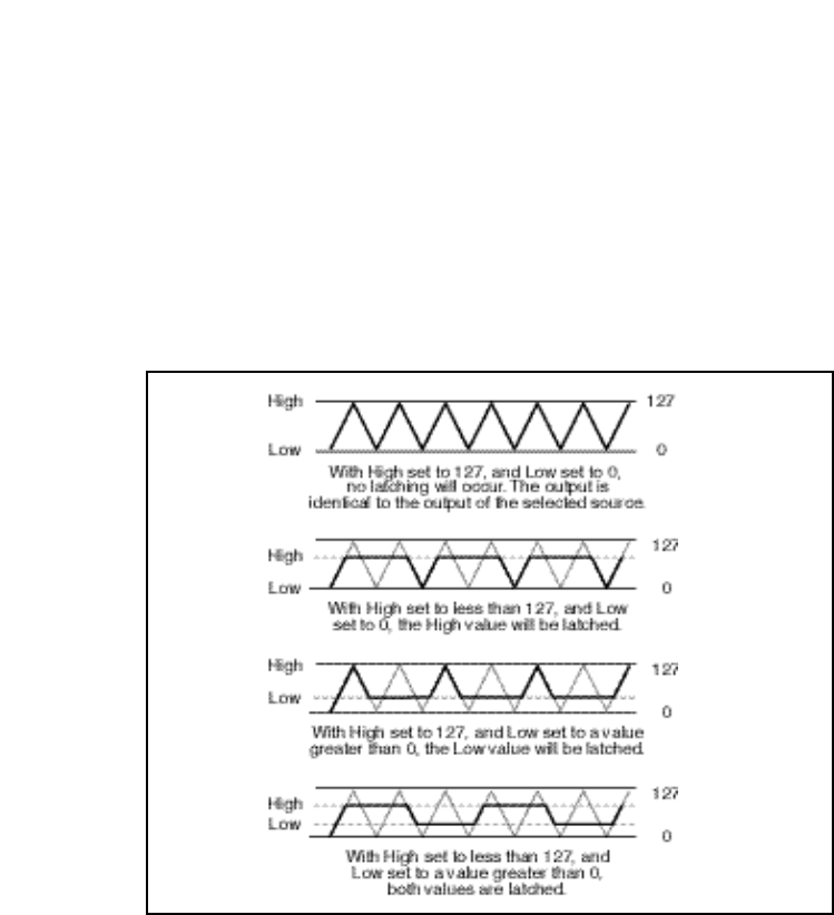
3-17
The Algorithms and Their Parameters
Mod: Latch
The latch is a very flexible modulation source. It can be used to do such things
as derive a switch from a continuous “return to zero” source (like MIDI After
Touch). It can turn a momentary (on/off) footswitch into a latching footswitch
(push on/ push off), and it can divide the switching rates of sources in half or
thirds.
Modulation cont'd.
The latch has three parameters: Src, High and Low. Any patch source can be
the Src (See Source listing under Patching.) High and Low are threshold
values. The latch works as follows:
There is no output from the latch until the Src value falls within the range defined
by the settings of High and Low. While the source value is between these
thresholds, the output of the latch is the same value as the source. When the
source value reaches or passes either threshold, the output of the latch holds at
the limit value until the source value passes through the threshold twice. The
latch can be set to hold at either the low threshold, the high threshold, or both.
Setting Low to 0 disables latching at the low threshold. Setting High to 127
disables latching at the high threshold.
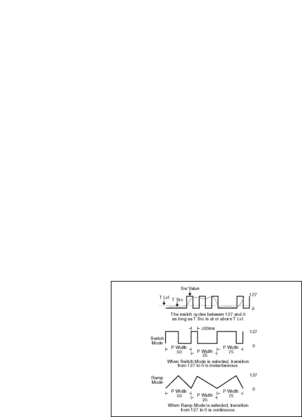
Lexicon
3-18
PCM 90 User Guide
Mod: Sw 1 and Mod: Sw 2
These are identical time switches. Each has five parameters: Rate, P Width,
Mode, T Lvl and T Src.
Rate sets the speed (0-10Hz) at which the switch cycles. It can
be set in time values (such as 1.5 Hz) or tempo values
(such as 3:2 Cycles per Beat). Simultaneously pressing
Up and Tempo will toggle these display options.
P Width determines the proportion of each switch cycle during
which the switch is on. For example, setting P Width to
50% means that the switch is on for one-half of a cycle.
Mode determines the “shape” of the switch output. Three set-
tings are available: Off, Switch, and Ramp. Off turns the
switch off (and frees up processor time). To optimize real
time response, set switch to Off when it is not being used.
When Switch is selected, the transition from on to off is
instantaneous, i.e. the switch output resembles a pulse
wave. When Ramp is selected, the transition from on to off
is continuous, i.e. the switch output resembles a triangle or
sawtooth wave.
T Lvl sets the threshold value at which the switch will begin to
cycle.
T Src selects a patch source to drive the switch. The output of the
switch is 0 as long as T Src is set to a value below T Lvl.
Once the source value reaches or passes T Lvl, the switch
will begin to cycle between on (127) and off (0) at the speed
set by Rate.
Note that both Rate and P Width are available as patch
Destinations, allowing them to be dynamically controlled
by other patch sources. Switches are reset to the begin-
ning of their cycles whenever Tap is pressed.
Modulation cont'd.
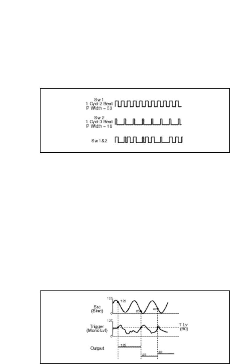
3-19
The Algorithms and Their Parameters
Modulation cont'd.A special, composite output of these switches, called Sw 1&2 is available as a
patch source. The value of Sw 1&2 alternates between the output of Sw 1 and
the output of Sw 2. The alternation occurs on the transition from on to off. Note
that both Sw 1 and Sw 2 must be active for the alternation to occur.
Mod: Delay
This control allows a copy of the output of any other patch source to be delayed.
The delay time can be set as an absolute amount of time (0-5 seconds) or it can
be related to tempo. The delayed value specified here can then be selected as
a patch source.
Mod: S&Hold
The Sample & Hold control allows you to select an input source, a trigger for
sampling the source, and a trigger threshold. Anything on the Patch Source list
(shown on the following page) can be selected as an input source (Src). The
trigger (Trigger) can be any other Patch Source. Each time the trigger rises
above the threshold specified for T Lvl, the PCM 90 snaps a sample of the
source and holds its value until the trigger once again exceeds the threshold. In
example shown below, a sine wave is the source and Mono Lvl is the trigger. The
threshold has been set at 90. Each time Mono Lvl rises above 90, the sine wave
is sampled and held.
Lexicon
3-20
PCM 90 User Guide
Internal MIDI Controller Numbers
070 Sound Var
071 Timbre
072 Release
073 Attack
074 Bright
075 Sound 6
076 Sound 7
077 Sound 8
078 Sound 9
079 Sound 10
080 General 5
081 General 6
082 General 7
083 General 8
084 Porta Ctl
085 Ctl 85
... ...
090 Ctl 90
091 FX1 Depth
092 FX2 Depth
093 FX3 Depth
094 FX4 Depth
095 FX5 Depth
096 Data Inc
097 Data Dec
098 NRPN LSB
099 NRPN MSB
100 RPN LSB
101 RPN MSB
102 Ctl 102
... ...
119 Ctl 119
000 Ignored
001 Mod Wheel
002 Breath
003 Ctl 3
004 Foot Ctl
005 PortaTime
006 Data Entry
007 Volume
008 Balance
009 Ctl 9
010 Pan
011 Xpression
012 Effect 1
013 Effect 2
014 Ctl 14
015 Ctl 15
016 General 1
017 General 2
018 General 3
019 General 4
020 Ctl 20
... ...
031 Ctl 31
(PCM 90 interprets 032 as Bank Select)
033 Ctl 33
... ...
063 Ctl 63
064 Sustain
065 Porta On
066 Sostenuto
067 SoftPedal
068 Legato
069 Hold 2
PCM 90 Patch Sources
Latch
Sw 1
Sw 2
Sw 1 & 2
Delay
S&Hold
Mono Lvl
Left Lvl
Right Lvl
FootPedal
Foot Sw 1
Foot Sw 2
ADJUST
Custom 1
Custom 2
Custom 3
Custom 4
Tempo
On
Off
LFO1
Sine1
Cosine1
Square1
Sawtooth1
Pulse1
Triangle1
Random1
LFO2
Sine2
Cosine2
Square2
Sawtooth2
Pulse2
Triangle2
Random2
Env L
Env R
Env L+R
AR Env
MIDI
P Bend
A Touch
Velocity
Last Note
Low Note
High Note
Clk Cmnds
Following the Modulation row in each algorithm's edit matrix is the Patch row.
This row provides parameters for creating as many as ten patches in each effect.
Each row position (Patch 0-9) has three controls available: Src, Dst, and
Values. Press Load/✱ to cycle among these selections.
Src
Use ADJUST to select any of the sources listed.
Dst
Use ADJUST to select any effect parameter except those on the Patch row.
Values
Use ADJUST to assign Destination values to specific Source values. These
assignments are made in pairs, each with a value for the Source and a value for
the Destination. For example, the default is two pairs mapped as follows:
minimum Source value (0) = minimum Destination value
maximum Source value (127) = maximum Destination value
This gives you a linear relationship between the parameter and the controller.
Inverse control is accomplished easily by reversing these settings. As many as
eight pairs of Destination/ Source values can be assigned here, providing an
exciting new level of dynamic control.
See Chapter 2 for a complete description of the Patching System.
Patches

3-21
The Algorithms and Their Parameters
Mstr Dly, Dly L, Dly R
Dly L and Dly R provide pre-echoes to the left and right channels. Mstr Dly
provides a simple grouped control that modifies the left and right values from 0-
200%.
Mstr Lvl, Lvl L, Lvl R
In Random Hall, Concert Hall and Rich Plate, Lvl L and Lvl R modify the levels
of the reflections (Dly L and R). The range of each is from Full (0dB) to -85dB,
to Off. Mstr Lvl has a range of 0-100%.
Spatial EQ, when used to enhance the spaciousness of stereo material,
increases low frequency differences between left and right channels. An effect
called "negative cross-feed" is created by subtracting a copy of low frequency
on the left from the right channel, and vice-versa. This effect can be dramatic
when used judiciously on live stereo recordings.
Spatial EQ can also be used to reduce low frequency differences and steer the
bass into mono. This might be used in mastering LPs to keep the stylus in the
groove, in TV mixing, or in any situation in which the low frequency load should
be shared by both speakers. Spatial EQ used in this manner is said to have
"positive cross-feed".
In the PCM 90,Spatial EQ is placed in the signal path where it can process the
dry signal, the reverberation, or both.
Premix
In Concert Hall, Spatial EQ is placed in the signal path after the reverberator. An
additional dry signal is also provided so that the dry input can be sent to the
Spatial EQ. In this case, we recommend setting the value of Mix in the Controls
row to 100% so that Premix controls the wet/dry mix.
Crossover
Crossover sets the frequency below which the Spatial EQ effect takes place.
Setting this frequency too high may result in unusual imaging.
Gain
Gain sets the amount of crossfeed between channels. The signal first goes
through a 6 dB/octave low-pass filter whose frequency is set with Crossover.
When Gain is set positive (above 0) the crossfeed has a negative sign. This
increases the sense of spaciousness. When Gain is set negative (below 0), the
crossfeed has a positive sign. This reduces the sense of spaciousness. When
the control is set to either maximum or minimum, the gain in the crossfeed circuit
is unity. At maximum, low frequency mono signals are completely removed. This
represents an extreme setting which should seldom be needed in practice.
Raising Gain may reduce the bass level. This effect can be compensated for by
raising the overall bass level with BassBoost. Since both controls use the same
Crossover setting, this compensation will be quite accurate as long as Gain is
set to less than 3 dB boost. With Gain at its lowest setting, low frequency signals
are competely mono. This may increase the bass level, which can then be cut
by lowering the BassBoost control.
Reflect
Spatial EQ

Lexicon
3-22
PCM 90 User Guide
BassBoost
A positive value for Gain may reduce low frequencies in program material.
Conversely, a negative value for Gain may increase low frequencies. BassBoost
allows compensation for this effect by boosting or cutting frequencies below
Crossover. The amount of boost or cut required is highly dependent on the
material being processed. Start by setting this control to the same value as the
Gain control, and then adjust it as necessary.
The Time row, available in every algorithm, contains parameters that affect the
time-based aspects of the reverb effect.
Mid Rt and Low Rt
Mid Rt sets the reverb time for mid-frequency signals. Because low frequency
reverb time (Low Rt) is a multiplier of Mid Rt, Mid Rt acts as a master control for
the reverb time.
Low Rt sets the reverb time for low-frequency signals, as a multiplier of the Mid
Rt parameter. For example, if Low Rt is set to 2X, and Mid Rt is set to two
seconds, the low frequency reverb time will be four seconds. For a natural-
sounding hall ambience, we recommend values of 1.5X or less.
Crossover
Crossover sets the frequency at which the transition from Mid Rt to Low Rt takes
place. This control should be set at least two octaves higher than the low
frequency you want to boost. For example, to boost a signal at 100Hz, set
Crossover to 400Hz. (This setting works well for classical music.) Crossover
works best around 400Hz for boosting low frequencies, and around 1.5 kHz for
cutting low frequencies.
Rt HC
Rt HC sets the frequency above which a 6dB/octave low-pass filter attenuates
the reverberated signal. It does not attenuate the reflections. High frequencies
are often rolled off with this parameter, resulting in more natural-sounding
reverberation. Setting a low frequency for this parameter can actually shorten
the reverb time, as it damps the audio as it recirculates.
Pre Delay
Pre Delay adjusts an additional time delay between the input of signal and the
onset of reverberation. The maximum range is 1000ms. This control is not
intended to mimic the time delays in natural spaces. In real rooms, the build-up
of reverberation is gradual, and the initial time gap is usually relatively short.
Natural spaces are best emulated by adjusting Spread for the desired effective
predelay. This parameter is available for tempo control in all algorithms except
Ambience.
Time

3-23
The Algorithms and Their Parameters
Shelf
In Random Hall, Shelf modifies the lowpass characteristic of Rt HC, turning it into
a shelving filter. Shelf sets the gain of an output patch which is mixed with the
output of Rt HC to form the main reverberant output. Both the pre-echoes and
the reverberation are affected. For example, if Shelf is set to -6dB, frequencies
below approximately Rt HC/2 will be boosted by 3.5dB. Above approximately Rt
HC/2, the response will be flat.
Shelf provides a method for making the spectral content of the reverberation
match the ideal spectrum for musical acoustics in rooms. For this application, Rt
HC should be set between 700 and 1.5kHz, with Shelf set between -12 and -6dB.
Decay
In Ambience, Decay controls the length of the ambience "tail".
Decay Lvl
In Ambience, Decay Lvl controls the level of the ambience "tail". When Decay
Lvl is off, ambience consists entirely of the early reflection signal.
Dry Dly
Dry Dly is used to add fine control to Ambience. An additional dry path is created
"inside" the ambience effect. When necessary, this path can be delayed slightly
to match an ambience.
DryDlyMix
In Ambience, DryDlyMix is used to control the relative levels of the internal dry
path and the ambience effect itself. A value of 100% indicates a completely dry
path. This is identical to the normal external dry path, except that it is delayed
by DryDly. If this control is used to vary the wet/dry mix, it is recommended that
the value of Mix on the Controls row be set to 100%.
Infinite
In the Room algorithm, this control is provided to turn the Infinite effect On or Off.

Lexicon
3-24
PCM 90 User Guide

4-1
The Presets
The PCM 90 has 250 factory-designed presets which are organized into five
banks of 50 each (labeled P0, P1, P2, P3 and P4). Each bank is organized in
a matrix of 5 rows of 10. Press the front panel Program Banks button to display
the first bank. Press it again to switch to another bank. Simultaneously press
Program Banks and either the Up or Down button to backstep through the
banks. The display will show the bank label and the matrix location, the preset
name, and the algorithm from which the effect is derived.
Turn SELECT to scroll through all of the presets in a bank in numerical order. Use
Up or Down to jump forward or backward by 10. Press Load/✱ to load any
displayed preset.
In the Program Banks mode (as in the Register Banks mode), ADJUST is a soft
knob. Each preset has one or more parameters patched to this knob, providing
a quick way to make useful changes to the effect.When you turn ADJUST, the
display will show the name assigned to ADJUST, as well as the patch value.
Continue turning ADJUST to alter the patch value along its available range.
Many of the presets also have Custom Controls assigned to provide easy access
to even more parameters. Look for these in the Soft row.
The program banks are organized as follows:
4
The Presets
Bank P4 Splits
0.0-0.9 Mono
1.0-1.9 Stereo
2.0-2.9 Live Sound
3.0-3.9 Instrument
4.0-4.9 Custom
Bank P3 Post
0.0-0.9 Indoor Small
1.0-1.9 Indoor Large
2.0-2.9 Outdoor
3.0-3.9 Spatial
4.0-4.9 Custom
Bank P2 Plates
0.0-0.9 Instrument
1.0-1.9 Vocal
2.0-2.9 Live Sound
3.0-3.9 Drums&Perc
4.0-4.9 Custom
Bank P1 Rooms
0.0-0.9 Instrument
1.0-1.9 Vocal
2.0-2.9 Live Sound
3.0-3.9 Drums&Perc
4.0-4.9 Custom
Bank P0 Halls
0.0-0.9 Orchestral
1.0-1.9 Vocal
2.0-2.9 Live Sound
3.0-3.9 Instrument
4.0-4.9 Custom
Each preset is described in this section with a header which indicates the matrix
location, the program name, the name assigned to the ADJUST knob, as well
as any KeyWords assigned for sorting. This header is followed by a brief
description of the effect and a list of any Custom Controls assigned.

4-2
PCM 90 User Guide Lexicon
Program Bank P0
Halls Orchestral
0.0 Deep Blue ADJUST: Decay
Keywords: Large, Tempo, RandomHall
This is an all-purpose hall with moderate size and delay time. The reflection delays are
set at 36 and 34 ms, but the master level is off. Set to desired level for initial reflections.
The master delays are set to beat 3 against 2, but their levels are also off. Set the master
delay level to hear the delays. You can also set the tempo of these delays with Tap.
Custom 1 allows control of the source from stereo to a narrow setting just a bit wider than
mono.
0.1 Large Hall ADJUST: Decay
Keywords: Large, Long, RandomHall
A classic reverb preset. The hall size is large, with a gentle bloom in the reverberation
envelope. The first set of pre-echoes are set to 14 and 20 ms, but are turned off in the
preset. Use ADJUST to add some initial reflections.
0.2 Medium Hall ADJUST: Decay
Keywords: Medium, Indoor, RandomHall, Orchestral
A natural sounding hall, with moderate decay time. Similar to Large Hall, but a smaller
room with proportionately shorter decay time.
0.3 Small Hall ADJUST: Predelay
Keywords: Small, RandomHall, Orchestral, Short
A natural sounding environment with bright initial reverb that decays quickly. Turn
ADJUST up for a small early reflection or down for a more diffused decay.
Presets 0.4-0.6 are similar in texture to the first 3 presets in this row, with added reflections
from a stage. In each, ADJUST is designed to allow you to change the size of the stage.
0.4 L Hall+Stage ADJUST: Stage Size
Keywords: Large, RandomHall, Long, Orchestral
0.5 M Hall+Stage ADJUST: Stage Size
Keywords: Medium, RandomHall, Orchestral, Indoor
0.6 S Hall+Stage ADJUST: Stage Size
Keywords: Small, Short, RandomHall, Orchestral
0.7 Gothic Hall ADJUST: Decay
Keywords: Large, Long, RandomHall, Orchestral
A large, spacious and filtered medium-bright reverb, as in a space made of stone. Smaller
room sizes add density to the sound.
0.8 Concert Hall ADJUST: Decay
Keywords: Large, Instrument, Cncrt Hall, Orchestral
A large,smooth, dark and lush concert hall. Very dense with reflections added to reinforce
the sound. Classic Lexicon!
0.9 Small Church ADJUST: Decay
Keywords: Small, Film-ADR, RandomHall, Orchestral
A smaller version of Large Church with no reflections and much shorter decay time.

4-3
The Presets
P0 Halls cont'd.
Vocal
1.0 Choir Hall ADJUST: Decay
Keywords: Large, Short, RandomHall, Vocal
A medium sized space with lots of reflections. Fairly dark timbre and a bit of predelay
make it more suitable for a group of voices rather than a soloist.
1.1 Vocal Hall ADJUST: Liveness
Keywords: Medium, Natural, RandomHall, Vocal
This medium-sized hall has a short, clear reverb decay that doesn’t get in the way of the
source. Great for vocals or any other instrument with a very defined pitch, such as piano.
ADJUST varies the room’s tonal characteristics.
1.2 Vocal Hall2 ADJUST: Liveness
Keywords: Short, Natural, RandomHall, Vocal
This is a fairly large hall with a generous reverb decay. A flat high cut keeps the tail from
muddying the source. ADJUST varies the room’s tonal characteristics.
1.3 VocalConcert ADJUST: Seating
Keywords: Short, Large, Concert Hall, Vocal
An enormous slightly reflective room. When ADJUST is low, the source is clear and close.
Increasing ADJUST creates a longer decay and makes the source more diffuse and the
higher frequencies roll off. This creates the illusion of moving the listener’s vantage point
further back, away from the stage.
1.4 Rise’n Hall ADJUST: Decay
Keywords: Vocal, Medium, RandomHall, Long
A strange hall with a long early reflection rise and a short decay, creating an echo verb
effect on leads.
1.5 Good Ol’Verb ADJUST: Attitude
Keywords: Large, Natural, RandomHall, Vocal
A quick solution when you’re looking for a well rounded reverb. ADJUST is patched to
stereo width, predelay, and the reverb’s high cut parameter, giving you extensive control
over the sound of the effect.
1.6 Deep Verb ADJUST: Decay
Keywords: Large, Short, RandomHall, Vocal
A large, washy, chorused space.
1.7 Vocal Magic ADJUST: Decay
Keywords: Cncrt Hall, Vocal, Large, Long
A lovely reverb with a short decay that is perfect as a vocal reverb.
1.8 Wide Vox ADJUST: Width Arc
Keywords: Medium, Unnatural, RandomHall, Vocal
This preset doubles the source with close delays and widens the stereo signal. ADJUST
controls width, the delay feedbacks, Shelf, and Mid reverb time to alter the apparent width
of the source on the sound stage.
1.9 Slap Hall ADJUST: Decay
Keywords: Cncrt Hall, Vocal, Dark, Slap FX
Provides a dense reverb with a soft initial double tap of the source, before darkening and
decaying.

4-4
PCM 90 User Guide Lexicon
P0 Halls cont'd. Live Sound
2.0 Live Arena ADJUST: Seating
Keywords: RandomHall, Live PA, Large, Long
A very large hall with moderate reverb decay time. ADJUST allows you control the
apparent distance from the sound source. Best suited for non-percussive sources.
2.1 Real Hall ADJUST: Decay
Keywords: Cncrt Hall, Live PA, Dark, Medium
A small, relatively bright sounding hall, good for all program material.
2.2 Great Hall ADJUST: Decay
Keywords: Cncrt Hall, Live PA, Long, Bright
A great hall reverb that works well with all program material.
2.3 Brick Wallz ADJUST: Decay
Keywords: RandomHall, Live PA, Unnatural, Dark,
A wide and abrupt sounding, gated effect.
2.4 Cannon Gate ADJUST: Decay
Keywords: Ambience, Live PA, Gated, Short
This medium-sized room has a sharp, medium long decay. Great on percussive and lead
sounds.
2.5 Spatial Hall ADJUST: Decay
Keywords: Cncrt Hall, Live PA, Spatial, Surround,
A strange hall with an LFO controlling spatial EQ. The reverb tail moves in and out of the
stereo field.
2.6 Nonlin Wrhse ADJUST: Decay Level
Keywords: Ambience, Live PA, Gated, Unnatural
A large nonlinear reverb that sounds like a gated warehouse.
2.7 Sizzle Hall ADJUST: Decay
Keywords: RandomHall, Live PA, Medium, Bright
A bright, close hall with medium short decay with a very live reverb quality.
2.8 Bright Hall ADJUST: Tail Brightness
Keywords: Medium, Bright, RandomHall, Live PA
A light reverb with a great deal of high end activity. A short decay time keeps the reverb
tail from muddying the effect. This hall was designed to provide a lush, bright reverb ideal
for cutting through the darkness in live settings.
2.9 Utility Hall ADJUST: Decay
Keywords: RandomHall, Live PA, Dark, Medium
A truly useful large hall with very little high frequency content. Adds spaciousness to all
sounds without getting in the way.

4-5
The Presets
P0 Halls cont'd.
Instrument
3.0 Horns Hall ADJUST: Timbre
Keywords: Cncrt Hall, Instrument, Natural, Acoustic
A very large space, ideal for horns. ADJUST optimizes the timbre of the horn for a bright,
or warm sound.
3.1 Snare Gate ADJUST: Release & Threshold
Keywords: Cncrt Hall, Instrument, Gated, Drums/Perc
A very tight, gated hall reverb. Roomy and dense when open but slams shut abruptly.
Perfect for snare drums and other percussive instruments.
3.2 Guitar Cave ADJUST: Decay
Keywords: Instrument, RandomHall, Guitar, Dark
Long predelay with recirculating echoes. The main delay taps give it a lot of left and right
bouncing activity. Great solo preset.
3.3 Drum Cave ADJUST: Decay
Keywords: Drums/Perc, Small, RandomHall, Instrument
A medium sized cave with short decay time. Use ADJUST to vary reverb decay time to
suit the tempo of the music.
3.4 Saxy Hangar ADJUST: Out Width
Keywords: Ambience, Instrument, Long, Acoustic
A large hall that sounds like an airplane hangar designed for a spacious sax solo.
3.5 Gated Hall ADJUST: Room Size
Keywords: Instrument, Large, RandomHall, Gated
If it were possible to have a gated hall, it would sound like this.
3.6 For The Toms ADJUST: Room Type
Keywords: Ambience, Instrument, Short, Drums/Perc
A large, dense room reverb for toms and other percussives.
3.7 Synth Hall ADJUST: Decay
Keywords: Cncrt Hall, Instrument, Keyboard, Long
A chorused hall with long decay time for all synth type pads and washes. Also good on
strings. Pitched sound sources may seem to sway from center pitch. This can be made
more or less dramatic dependent upon the chorus value.
3.8 ShortReverse ADJUST: Shape
Keywords: Cncrt Hall, Instrument, Special FX, Unnatural
A short reverse reverb with a quick build up and short decay. Good for leads and
percussives.
3.9 GtrBalladBPM ADJUST: High Cut
Keywords: Instrument, RandomHall, Tempo, Ballad
This medium-sized room blends a 2-second reverb decay with delay taps that beat
according to the tempo you Tap in.

4-6
PCM 90 User Guide Lexicon
P0 Halls cont'd. Custom
4.0 Tidal Hall ADJUST: LFO1 Rate
Keywords: Cncrt Hall, Custom, Dynamic, Unnatural
A strange hall with an LFO controlling the high cut of the reverb as well as the output width,
creating an “in and out” kind of washing action on the verb.
Custom 1: Wash Density
Custom 2: Liveness
Custom 3: Reverb Density
Custom 4: Yank the Inputs
4.1 Dream Hall ADJUST: LFO1 & LFO2 Rates
Keywords: RandomHall, Custom, Bright, Slap FX
A bright, crystalline hall with potent but subtle delay taps that pan randomly from left to
right, then fade. ADJUST controls the pan rate.
Custom 1: Dream Taps
Custom 2: Reverb Density
Custom 3: Shape & Spread
4.2 PumpVerb ADJUST: Decay
Keywords: Cncrt Hall, Custom, Large, Long
A strange, semi-gated reverb with pumping from the compressor, which is following the
input signal. Sounds cool on drums and percussives.
Custom 1: Expander Gate
Custom 2: Reverb Density
Custom 3: Spatial Bass EQ
Custom 4: Liveness
4.3 PanHallBPM ADJUST: Tap Rate
Keywords: RandomHall, Custom, Spatial, Tempo
This unique hall patches LFO1 to OutWidth, creating a subtle sweeping sensation. The
sweep rate is dependent upon either tempo set through Tap or ADJUST.
Custom 1: Spiral Depth
Custom 2: Reverb Density
Custom 3: Liveness
Custom 4: Brightness
4.4 Utility Verb ADJUST: Out Width
Keywords: Unnatural, Gated, Concert Hall, Custom
A general, all purpose reverb with medium parameter settings.
Custom 1: Effect Gate Release
Custom 2: Liveness
Custom 3: Width/EQ
Custom 4: Wah-Wah Speed
4.5 Museum Hall ADJUST: Reflective Material
Keywords: Cncrt Hall, Custom, Indoor, Bright
A large reverberant hall like a large room in a museum. ADJUST selects the physical
characteristics of the walls.
Custom 1: Source Proximity
Custom 2: Width EQ
Custom 3: Reverb Tail
Custom 4: Room Size

4-7
The Presets
P0 Halls cont'd.
4.6 Nonlinear#1 ADJUST: Room Size
Keywords: Ambience, Custom, Gated, Short,
A dense, medium long, nonlinear gated verb. Good for all sorts of program material,
especially percussive sounds.
Custom 1: Tail Environment
Custom 2: High Cut
Custom 3: Decay
Custom 4: Decay Level
4.7 Tap BrickBPM ADJUST: Tap Rate
Keywords: RandomHall, Custom, Tempo, Spatial
This preset has a very reflective sound, as if the source is pounding against a hard brick
wall. The LFO opens up the Mid RT and controls OutWidth in cycles that are tempo
dependent. Use Tap or ADJUST to control the rate.
Custom 1: Liveness
Custom 2: Size
Custom 3: Tap Depth
Custom 4: Outwidth Tap Sweep
4.8 Gen. Concert ADJUST: not patched
KeyWords: Cncrt Hall
A generic concert hall. Use this as a starting place to make your own concert hall effects.
4.9 Gen. RHall ADJUST: not patched
KeyWords: RandomHall
A generic hall with random reflections. Use this as a starting place to make your own
random hall effects.
Instrument
0.0 Large Room ADJUST: Decay
Keywords: Large, Room, Instrument, RandomHall
A perfectly smooth listening room with high diffusion. Very natural sounding on any sound
source.
0.1 Medium Room ADJUST: Decay
Keywords: Medium, Room, Instrument, RandomHall
A smaller version of the Large Room preset.
0.2 Small Room ADJUST: Decay
Keywords: Small, Room, Instrument, RandomHall
Use ADJUST to quickly change the reverb decay time on this typically tight sounding
room. Like its two larger counterparts, Small Room is smooth and natural sounding.
0.3 Guitar Room ADJUST: High Cut
Keywords: Guitar, Room, Instrument, Ambience
A tight and punchy ambience effect, combining the smallest of sizes and reverb times.
Use the ADJUST knob to roll off the higher frequencies.
0.4 Organ Room ADJUST: Low Rt
Keywords: Keyboard, Room, Splits, Instrument
This Chamber/Room effect is ideally suited for organ and other keyboards with its
medium size, natural reverb, and a bit of predelay.
Program Bank P1
Rooms

4-8
PCM 90 User Guide Lexicon
P1 Rooms cont'd. 0.5 LargeChamber ADJUST: Decay
Keywords: Large, Chamber, RandomHall, Instrument
A smooth, large reverberant space using Shape and Spread to add some definition.
0.6 SmallChamber ADJUST: Decay
Keywords: Small, Chamber, RandomHall, Instrument
Just like its bigger predecessor, but with a tighter Mid Rt and a smaller size.
0.7 SpinningRoom ADJUST: Speed
Keywords: Room, Instrument, Spatial, Ambience
A nice Ambience reverb with a circular sweep of Out Width. Great as a special effect or
for adding some movement to your mix. ADJUST controls the rate of the circular sweep.
0.8 Wide Chamber ADJUST: Decay
Keywords: Chamber, Orchestral, Instrument, RandomHall
A big and wide sounding space with a preset medium Mid Rt. A dark, somber reverb.
0.9 Tiled Room ADJUST: Rt HC
Keywords: Room, Bright, Instrument, Cncrt Hall
Just what you’d expect — an incredibly sibilant and bright reverberant space. Use
ADJUST to soften the brightness of this short reverb.
Vocal
1.0 Brite Vocal ADJUST: High Cut
Keywords: Bright, Room, Vocal, Ambience
This effect is ideal for vocalists using a bit of predelay to separate the bright reverb from
the source for definition and clarity. ADJUST controls brightness.
1.1 Vocal Space ADJUST: Size
Keywords: Room, Vocal, Small, RandomHall
A short Mid RT and small Size — an ideal space for vocals due to the use of Shape and
Spread.
1.2 Vocal Amb ADJUST: Diffusion
Keywords: Dark, Natural, Vocal , Ambience
Short and soft. A very realistic small room.
1.3 VerySmallAmb ADJUST: Width
Keywords: Small, Vocal, Ambience, Ballad
Just like Vocal Amb, but smaller and tighter. ADJUST provides mono to stereo OutWidth
control.
1.4 S VocalSpace ADJUST: High Cut
Keywords: Vocal, Ambience, Small, Ballad
A small, smooth space, well-suited for vocals. A Decay Level of -8dB keeps the reverb
from becoming overpowering.
1.5 L VocalSpace ADJUST: High Cut
Keywords: Large, Vocal, Ambience, Ballad
A bigger version of S VocalSpace.
1.6 S Vocal Amb ADJUST: Diffusion
Keywords: Small, Vocal, Ambience, Custom
Use Custom 1 to choose the right studio for your vocalist.
Custom 1: Choose the Studio

4-9
The Presets
P1 Rooms cont'd.
1.7 L Vocal Amb ADJUST: Diffusion
Keywords: Large, Vocal, Ambience, Custom
A more spacious version of S Vocal Amb. Already set to Studio “A”. Customize your
vocals with ADJUST and the three studio settings on Custom 1.
Custom 1:Choose the Studio
1.8 AmbientSus ADJUST: Size
Keywords: Ambience, Natural, Vocal
A bit of dry delay makes this a sweet selection for your vocal tracks. You’ll find the
subtleties of this preset will perfectly suit instruments as well.
1.9 Vocal Booth ADJUST: Walls/Size
Keywords: Vocal, Cncrt Hall, Small, Dialog
The most confining of isolation booths. ADJUST lets you select wall materials and booth
size.
Live Sound
2.0 LargeSpace ADJUST: Decay
Keywords: RandomHall, Live PA, Large, Bright
Designed for live sound reinforcement in all situations.
2.1 Med. Space ADJUST: Decay
Keywords: RandomHall, Live PA, Medium, Instrument
For a more intimate and small setting, choose this preset with its smooth reverb and softer
timbre.
2.2 Delay Space ADJUST: Decay
Keywords: RandomHall, Live PA, Small, Tempo
Attitude for live drums, guitar, or vocals with a less dominating reverb, punchier sound,
and lots of delay. Tap in delay time, or dial in the BPM of the song.
2.3 BigBoom Room ADJUST: Blend
Keywords: Split Rvb, Live PA, Custom, Large
This preset is saturated with bottom-heavy, dense reverb. Configure the input as stereo
or mono to get your sound sources to this dense room. Use ADJUST to blend between
rooms and to adjust distance from the sound source.
Custom 1: Bass Boost
2.4 Tight Space ADJUST: Proximity
Keywords: Ambience, Live PA, Gated, Drums/Perc
An effect to give your live drums that extra push. Vibrancy and attitude with a gated feel.
Use ADJUST to add space and reverb, or to bring the effect up to the front with less reverb.
2.5 Reflect Room ADJUST: Arena Size
Keywords: Concert Hall, Live PA, Large, Unnatural
Super-saturated, atmospheric quality. Great for creating a dreamy landscape for the solo
instrument or vocalist.
2.6 RockRoom ADJUST: Liveness
Keywords: RandomHall, Live PA, Small, Drums/Perc
A great preset for live drum sound. Extremely bright with no RT HC.
2.7 Real Room ADJUST: Size
Keywords: Ambience, Live PA, Natural, Acoustic
A bit more natural reverb for a live setting. Smooth and subtle, perfect for anything you
throw at it.

4-10
PCM 90 User Guide Lexicon
P1 Rooms cont'd. 2.8 Spatial Bass ADJUST: High Cut
Keywords: Cncrt Hall, Live PA, Short, Spatial
A Spatial EQ bass boost enhances the lower frequencies of your sound source and
combines it with a bright reverb on top.
2.9 Great Room ADJUST: Liveness
Keywords: Cncrt Hall, Live PA, Instrument, Acoustic
The same warm, smooth reverb as Real Room, with more decay time and an overall
warmer timbre.
Drums&Perc
3.0 Drum Room ADJUST: Size
Keywords: Ambience, Drums/Perc, Instrument, Short
With the whole kit in mind, the staple for this dark drum preset is its dense, saturated
reverb.
3.1 Snare Trash ADJUST: Rt HC
Keywords: Cncrt Hall, Drums/Perc, Instrument, Medium
The large room size, short Mid Rt, and cut of the Spatial EQ bass boost all play a
significant role in the search for the perfect snare reverb.
3.2 MetallicRoom ADJUST: Decay Lvl
Keywords: Ambience, Drums/Perc, Instrument, Small
The resonant quality of this drum preset comes from its very small Size and Mid Rt
settings. You’ll find this preset works best on individual drums rather than the whole kit.
3.3 Slap Place ADJUST: Pre Delay
Keywords: Ambience, Drums/Perc, Instrument, Medium
A dark and wet reverb. Medium room size and long reverb tail make this a good choice
for a big drum sound. For a bit of space before your reverb kicks in, dial in the Pre Delay
you want with ADJUST.
3.4 PercussPlace ADJUST: Decay Lvl
Keywords: Ambience, Drums/Perc, Instrument, Medium
Congas, bongos, bells, and whistles are all at home with this preset. A full and resonant
reverb accentuates the transients as well as the pitch material in percussive instruments.
3.5 PercussRoom ADJUST: Decay Lvl
Keywords: Ambience, Drums/Perc, Instrument, Short
Similar to PercussPlace with slightly smaller Mid Rt and Size settings for a more intimate
effect.
3.6 Room 4 Drums ADJUST: Decay Lvl
Keywords: Ambience, Drums/Perc, Instrument, Short
All you could ever want for drums — punch, attitude, and a tight, beefy reverb. Crank it
up!
3.7 Sloppy Place ADJUST: Sloppiness
Keywords: Ambience, Drums, Dark, Unnatural
An unnatural room reverb that will enhance any drum track.
3.8 WideSlapDrum ADJUST: Spatial Enhance
Keywords: Cncrt Hall, Drums, Slap FX, Spatial
Perfect as a special drum effect. ADJUST takes you from narrow and dry to wide and slap
happy.

4-11
The Presets
P1 Rooms cont'd.
3.9 InverseDrums ADJUST: Spread
Keywords: RandomHall, Drums, Special FX, Unnatural
A backwards effect. Great as a special effect for one drum, or the whole kit. ADJUST lets
you smooth out or tighten up the time it takes to get that perfect backwards sound.
Custom
4.0 PCM 60 Room ADJUST: Reverb Time
Keywords: Plate, Large, Custom, Natural
Let this preset take you back to the good old days of 1984 when life was simple, and so
were the reverbs. Use ADJUST to choose the color and reverb time that was your favorite,
then use the Customs 1 and 2 to set Size and exercise that wonderful feeling of power
with the Bass/Treble Contour control. Customs 3 & 4 offer effects you thought not possible
in 1984 — backwards effects and adjustable echoes.
Custom 1: Size
Custom 2: Contour
Custom 3: Inverse Effects
Custom 4: Echoes
4.1 InverseRoom2 ADJUST: Width
Keywords: RandomHall, Drums/Perc, Unnatural, Custom
Lots of options via ADJUST and the Customs to create a great backwards effect.
Custom 1: High Cut
Custom 2: Reflections
Custom 3: Liveness
Custom 4: Input Pulse
4.2 BeeBeeSlapz ADJUST: Feedback
Keywords: Cncrt Hall, Slap FX, Unnatural, Custom
Perfect for creating dreamy soundscapes, and atmospheric moods dripping with reverb.
ADJUST takes you from dry delay taps to complete reverb abandon, Custom Controls set
the atmosphere.
Custom 1: Comp/Ratio Thrshld
Custom 2: Spatial EQ
Custom 3: Moving Reflections
4.3 Storeroom ADJUST: Amount of Boxes
Keywords: Cncrt Hall, Dark, Indoor, Custom
A storeroom where ADJUST lets you customize how empty or full it is, and hear how it
affects the sound. Customs let you further define the space.
Custom 1: BassBoost
Custom 2: Delay Taps
Custom 3: Width
4.4 Split Rooms ADJUST: Reverb Balance
Keywords: Split Rvb, Special FX, Dynamic, Custom
A Chamber/Room where both the small room and the big, bright chamber are patched
with the AR Envelope to Mono InLvl. Below a certain point, only the Room reverb is heard.
When the threshold is crossed, the Room drops out and the Chamber reverb kicks in.
ADJUST lets you blend or separate the two rooms.
Custom 1: In Routing
Custom 2: Inverse HighPass
Custom 3: Reverb Density

4-12
PCM 90 User Guide Lexicon
P1 Rooms cont'd. 4.5 Spatial Room ADJUST: Spatial Movement
Keywords: Ambience, Spatial, Unnatural, Custom
Similar to SpinningRoom, but with a different parameters, and more Custom Controls.
Custom 1: LFO Shape
Custom 2: HighPass
Custom 3: Gliding Chorus
Custom 4: Verb Proximity
4.6 Hole Room ADJUST: Decay
Keywords: Cncrt Hall, Special FX, Custom, Unnatural
A dense ConcertHall reverb. Customize your decay time with ADJUST, Bass Boost with
Custom 1, Liveness with Custom 2, throw in some backwards effects with Custom 3, and
control the Wet/Dry mix with Custom 4.
Custom 1: BassBoost
Custom 2: Liveness
Custom 3: Inverse Effects
Custom 4: Dry/Wet Mix
4.7 Storage Tank ADJUST: Fullness/Size
Keywords: Ambience, Dark, Indoor, Custom
A storage tank with a metallic sound and bright, resonant reverb. Change the Fullness
and the Size of the tank with ADJUST, and the density of the Ambience with Custom 1.
The AR Envelope is patched to OutWidth and triggered by the Mono InLvl. When the
threshold is crossed, the effect changes from Mono to Stereo.
Custom 1: Amb Density
Custom 2: TriggerRelease Width
4.8 StrangePlace ADJUST: Chorus
Keywords: Cncrt Hall, Spatial, Custom, Unnatural
A super-tight ConcertHall effect with lots of spatial enhancement.
Custom 1: Psychorus
Custom 2: Comp Ratio/Thrshld
Custom 3: Expand ratio/Thrshld
Custom 4: High Cut
4.9 Gen. Ambi ADJUST: None
Keywords: Ambience
A generic ambience effect. Use this as a starting place to make your own ambience
effects.
Instrument
0.0 Just Plate ADJUST: Liveness
Keywords: Plate, Instrument, Large
A basic plate, good for any kind of sound source.
0.1 Rich Plate ADJUST: Decay
Keywords: Plate, Instrument
An old standard, bright and diffuse.
0.2 Gold Plate: ADJUST: Size & Decay
Keywords: Plate, Instrument
A classic plate with a long decay and medium high end response.
0.3 Plate4Brass ADJUST: Rt HC
Keywords: Plate, Instrument
A good plate for brass sounds.
Program Bank P2
Plates

4-13
The Presets
P2 Plates cont'd.
0.4 Rock Plate ADJUST: Out Width
Keywords: Plate, Instrument, Large
A big boomy dark plate with a moderate reverb tail great for high frequency sound sources
where you do not want to add more high end.
0.5 Eko Plate ADJUST: Mstr Delay
Keywords: Plate, Instrument, Echo, Guitar
A sweet combination of recirculating pre-echoes and bright sounding reverb, great for
guitar and keys.
0.6 A.Gtr Plate ADJUST: Dly Lvls
Keywords: Plate, Instrument, Guitar
A really smooth plate with a slow reverb build that great for acoustic guitar. ADJUST
allows you to mix in delay.
0.7 SynthLdBPM ADJUST: Delay Lvl
Keywords: Plate, Keyboard, Echo, Tempo
A medium bright plate with tempo delays optimized for use with synth patches. Tap allows
you to tap in the tempo of the delays.
0.8 Floyd Wash ADJUST: In Width:OutWidth
Keywords: Plate, Instrument, Echo, Guitar
A big plate reverb with long predelay and repeating echo delays adds a spacey wash to
slow program material. Great for guitar and synth sounds. ADJUST controls a custom In
Width/Out Width parameter that changes the spatial feel.
0.9 GtrPlateBPM ADJUST: Dry Dly
Keywords: Plate, Guitar, Echo, Tempo
A moderate size dark plate reverb optimized for guitar with tempo driven delays to fatten
up the sound. Tap in the tempo of the delays.
Vocal
1.0 Vocal Plate ADJUST: Decay
Keywords: Plate, Vocal, Short
A short plate with low diffusion great for a solo vocal track.
1.1 Vocal Plate2 ADJUST: Liveness
Keywords: Plate, Vocal, Large
A large plate with a moderate decay time, great for backing vocals.
1.2 SmVoxPlate ADJUST: Decay
Keywords: Plate, Vocal, Small
A small bright plate that’s good for vocals.
1.3 VoclEkoPlate ADJUST: PreDelay
Keywords: Plate, Vocal, Echo
A large dark plate with just the right amount of delay to enhance vocal tracks.
1.4 Choir Plate ADJUST: Choir Size & Type
Keywords: Plate, Vocal, Large
A large silky plate with a long decay time, great for background vocals. ADJUST controls
the choir from big and breathy to small and short.
1.5 Multi Vox ADJUST: Size & Decay
Keywords: Plate, Vocal, Short
A small short plate great for gang vocals. ADJUST simutaneously controls Size and
Decay from small and short, small and long, medium and short, medium and long, and
large and long.

4-14
PCM 90 User Guide Lexicon
P2 Plates cont'd. 1.6 Bright Vox ADJUST: Darkknob
Keywords: Plate, Vocal, Bright
A large bright plate with a long decay time, great for various vocals. ADJUST controls the
high and low frequency response of the plate.
1.7 VoclEcho BPM ADJUST: Dry Signal Pan
Keywords: Plate, Vocal, Echo, Tempo
A silky smooth plate with moderate decay time and recirculating delays, great for all
vocals.
1.8 VocalTapBPM ADJUST: Reverb Level
Keywords: Plate, Vocal, Echo, Tempo
Similar to VocalEchoBPM with different delay taps.
1.9 VocalTapBPM2 ADJUST: Size
Keywords: Plate, Vocal, Echo, Tempo
Similar to VocalEcho BPM with a more linear straight BPM delay. ADJUST lets you
choose from five room sizes.
Live Sound
2.0 Live Plate ADJUST: Decay
Keywords: Plate,Live PA, Bright
A crisp clean basic plate with medium decay time and low bass response optimized for
live PA applications.
2.1 Clean Plate ADJUST: Diffusion
Keywords: Plate, Live PA, Bright
A clean plate with ADJUST control of diffusion.
2.2 Live Gate ADJUST: Gate or Inverse
Keywords: Plate, Live PA, Gated, Special FX
Change from a tight gate or crisp inverse sounds on the fly. ADJUST controls the choice
from Gate to Inverse.
2.3 Bright Plate ADJUST: Liveness
Keywords: Plate, Live PA, Bright
A small bright plate with short decay time. Great for enhancing an instrument without
overpowering it.
2.4 Hot Plate ADJUST: Plate Temperature
Keywords: Plate, Live PA, Bright
A medium sizzling plate optimized for live sound mixing, good for all material. ADJUST
allows you to modify the high frequency of the plate.
2.5 Ever Plate ADJUST: Decay
Keywords: Plate, Large, Dynamic
Mono Level is patched to Attack and Spread making this an ever-changing plate.
2.6 Warm Plate ADJUST: Decay
Keywords: Plate, Live PA, Dark
A slightly warmer plate for those situations where you don’t want as much edge. Try on
a solo acoustic guitar performance.
2.7 Live Drums ADJUST: High Cut
Keywords: Plate, Live PA, Drums/Perc, Bright
A medium plate with short reverb time great for a full kit! ADJUST gives you a high cut
filter with five EQ choices.

4-15
The Presets
P2 Plates cont'd.
2.8 Great Plate ADJUST: Decay
Keywords: Plate, Live PA, Instrument
A basic plate that will work well with most any sound source. Not too dark and not too
bright!
2.9 PlateDlyBPM ADJUST: Reverb Lvl
Keywords: Plate, Live PA, Echo, Tempo
This preset can be a plate reverb, a tap tempo delay or both!
Drums&Perc.
3.0 Big Drums ADJUST: Size
Keywords: Plate, Live PA, Drums/Perc
A medium size plate with high diffusion and moderate decay time.
3.1 Drum Plate ADJUST: Decay
Keywords: Plate, Live PA, Drums/Perc, Dark
A large dark plate with high diffusion and a long decay time. This is the ultimate drum plate!
3.2 Fat Drums ADJUST: Reverb Attack
Keywords: Plate, Drums/Perc
A moderate sized deep sounding plate with a high attack time. ADJUST controls a
combination of predelay, reflections and Rt HC.
3.3 Cool Plate ADJUST: Liveness
Keywords: Plate, Drums/Perc, Short, Dark
A short dull plate good for percussion.
3.4 Tight Plate ADJUST: Decay
Keywords: Plate, Drums/Perc, Small
Small and tight with moderate diffusion. Use this to add punch to any percussion track.
3.5 Short Plate ADJUST: Decay
Keywords: Plate, Drums/Perc, Short
A short plate reverb with a fairly short decay time and good high end, great for a full kit.
3.6 Dark Plate ADJUST: Diffusion
Keywords: Plate, Drums/Perc, Dark, Long
A classic! Dark and smooth with a long decay time. This fattens any percussion track.
3.7 Plate Gate ADJUST: Pre Delay
Keywords: Plate, Drums/Perc, Gated
A gate with the tonal qualities of a plate. The ultimate drum gate!
3.8 Plate Gate 2 ADJUST: Size
Keywords: Plate, Drums, Gated
A heavy dense and short nonlinear reverb designed to emulate a plate. ADJUST gives
you five different size settings to choose from.
3.9 Bongo Plate ADJUST: Diffusion
Keywords: Ambience, Drums/Perc, Bright
Give bongo and native drums thickness with this preset. ADJUST allows you to smooth
out the sound.

4-16
PCM 90 User Guide Lexicon
P2 Plates cont'd. Custom
4.0 Plate 90 ADJUST: Attitude
Keywords: Plate, Dark, Instrument, Custom
A general purpose, dark plate. ADJUST gives you attitude which ranges from soft and
short to harsh and dry. Custom Controls allow you to control the Reverb Density and
delay levels. Play with all three of these controls to make your own plate
Custom 1: Reverb Density
Custom 2: Delay Lvls
4.1 WhatTheHeck?: ADJUST: LFO2
Keywords: Plate, Spatial, Tempo, Custom
Need we say more? A tap tempo-controlled LFO 1 modulates the High Cut parameter.
ADJUST controls the speed of LFO 2 which modulates the OutWidth parameter.
Custom 1: Dly Lvls
Custom 2: Reverb Density
4.2 GtrDlyPlate: ADJUST: Delay Separation
Keywords: Plate, Guitar, Echo, Custom
A basic guitar delay with some plate reverb mixed in. ADJUST lets you choose 100ms,
150ms, 250ms, 500ms, and 1 second delays. Custom 1 allow you to control the Width,
from mono to stereo.
Custom 1: Width
4.3 Patterns BPM: ADJUST: LFO Rate
Keywords: Plate, Spatial, Tempo, Custom
A tempo-driven spatial effect that moves delays around the room. ADJUST controls the
LFO rate which is patched to Out Width. Slow it down or speed it up for more dramatic
spatial effects Works great with any sound source!
Custom 1: Dly Lvls
4.4 MultPlateDly: ADJUST: Tap Delay Speed
Keywords: Plate, Echo, Instrument, Custom
A multi-purpose plate delay. ADJUST control the tap speed of the echo delays. Custom
Control 1 simultaneously controls InWidth and OutWidth for some unique spatial effects.
Custom 2 controls the delay levels for the reflections and the dry delays. Custom 3
controls the reverb liveness.
Custom 1: In Width:Out Width
Custom 2: Dly Lvls
Custom 3: Liveness
4.5 MonoOrStereo: ADJUST: Mono or Stereo
Keywords: Plate, Instrument, Custom
A general plate that can be run in mono, stereo or 3 choices in between.
Custom 1: Liveness
4.6 TapDelayBPM: ADJUST: Eko Feedback Decay
Keywords: Plate, Echo, Tempo
An all purpose tap tempo delay with a small amount of plate reverb.
Custom 1: Dly & Ref Lvls
4.7 Spatial Plate: ADJUST: LFO 1 & 2
Keywords: Plate, Spatial, Custom
A spatial plate reverb with LFO 1 & 2 each independently controlling InWidth and
OutWidth scaled inversely. ADJUST gives you three choices for LFO speed.
Custom 1: Reverb Density

4-17
The Presets
P2 Plates cont'd.
4.8 PanEkoBPM: ADJUST: Panning Speed
Keywords: Plate, Echo, Tempo, Custom
LFOs modulate dry reflections levels to give you a panning effect. Use Tap to tap in the
desired delay time. ADJUST controls the panning speed while Custom 1 controls InWidth
and OutWidth — these parameters are inversely scaled to produce some interesting
spatial effects.
Custom 1: In Width:Out Width
4.9 Gen. Plate: ADJUST: Not Patched
Keywords: Plate
A generic plate preset. Use this as a starting point to make your own plate presets.
Indoor Small
0.0 Cabin Fever ADJUST: Decay
Keywords: Cncrt Hall, Indoor, Small.
Sounds like you’ve been snowed in too long! Basically a dead space — muffled and not
much width. ADJUST provides some variation in the response of this small space.
0.1 Echo/Kitchen ADJUST: Blend
Keywords: Splits, Indoor, Small
A split program providing a syncopated echo delay, and a reverb like the inside of a small
kitchen. ADJUST controls the blend of the two effects
0.2 HardwoodRoom ADJUST: Size
Keywords: Ambience, Indoor, Small, Room
Designed to sound like a room with a hardwood floor. Select room size with ADJUST.
0.3 MeetingRoom ADJUST: Decay
Keywords: Ambience, Indoor, Small, Room.
Hotel-like meeting room. Predelay is set to 46ms, so the wet mix sounds like the
microphone is at the back of the room.
0.4 Locker Room ADJUST: Decay
Keywords: Ambience, Indoor, Small, Room
The ambience of a locker room.
0.5 Living Room ADJUST: Size
Keywords: Ambience, Indoor, Small, Room
A softer room with a short Rt and some of the stereo width removed.
0.6 Bedroom ADJUST: Size
Keywords: Cncrt Hall, Indoor, Small, Room
A small bedroom with furniture and heavy curtains. Good on lots of instruments and
drums.
0.7 Dual Closets ADJUST: Blend
Keywords: Split Rvb, Indoor, Small
A split effect providing an empty closet, and a full closet. ADJUST controls the blend
between the two.
0.8 Phone Booth ADJUST: Size
Keywords: Ambience, Indoor, Small.
How much sound can you squeeze into a phone booth? Adds a bit of space to all sounds.
Custom Control 1 links pre delay, dry delay, and dry delay mix to easily change the
characteristics of the booth.
Custom 1: Delay Mix 0 - 100
Program Bank P3
Post

4-18
PCM 90 User Guide Lexicon
0.9 Coffin ADJUST: Mix
Keywords: Ambience, Indoor, Small.
Simulate a tight small space with this ambience preset. ADJUST controls dry delay mix
to brighten or deaden the sound for an open or closed casket.
Indoor Large
1.0 MetalChamber ADJUST: Decay
Keywords: RandomHall, Indoor, Large, Room
Short, boomy, and bright. Like the inside of an anechoic chamber without the absorption
cones.
1.1 Stairwell ADJUST: Number Of Floors
Keywords: Cncrt Hall, Indoor, Large
Short decay of a single room, to large reflections lost in the high-rise. ADJUST lets you
select from 20 floors.
1.2 Make-A-Space ADJUST: Decay
Keywords: RandomHall, Indoor, Large, Custom
ADJUST and Liveness controls let you quickly design your own space.
Custom 1: Liveness 0 - 127
1.3 Dly/Hallway ADJUST: Blend
Keywords: Splits, Indoor, Large, Echo
A split program with a short ping-pong delay, and a medium-long hallway reverb.
ADJUST.
1.4 LectureHalls ADJUST: Blend
Keywords: Splits, Indoor, Large
A split program with an “empty” hall and a “full” hall.
1.5 Dance Hall ADJUST: Decay
Keywords: RandomHall, Indoor, Large
Preset at 1.4 seconds of reverb time for a medium bright hall, or use ADJUST to
customize.
1.6 Ballrooms ADJUST: Blend
Keywords: Splits, Indoor, Large, Room
A split program providing two different shaped ballrooms: a rectangular-shaped room
with strong reflections and a fan-shaped room with a smooth decay.
1.7 Empty Club ADJUST: Decay
Keywords: RandomHall, Indoor, Large, Empty
Typical Monday night at the club. Reflections and delays simulate the emptiness.
1.8 NYC Clubs ADJUST: Blend
Keywords: Splits, Indoor, Large
A split program with the acoustics of two famous New York City nighclubs.
1.9 Sports Verbs ADJUST: Blend
Keywords: Splits, Indoor, Large
A split reverb with the inside of a locker room, and a large empty arena.
P3 Post cont'd.

4-19
The Presets
P3 Post cont'd.
Outdoor
2.0 Inside-Out ADJUST: Decay
Keywords: Cncrt Hall, Outdoor, Spatial, Special FX
A strange hall reverb where the input envelope controls the output width of the reverb. At
high levels the signal goes mono. As it decays, the sound fills out the stereo field.
2.1 Outdoor PA ADJUST: Mix
Keywords: Ambience, Outdoor, Echo
Open space, not much reflection. Takes advantage of maximum DryDly time with no Pre
Delay to provide a simple outdoor echo. Use ADJUST to mix in the right amount of dry
delay level.
2.2 Outdoor PA 2 ADJUST: Decay/DecayLvl
Keywords: Ambience, Outdoor
Similar to Outdoor PA. ADJUST provides five different settings.
2.3 Two Autos ADJUST: Blend
Keywords: Splits, Outdoor
A split program giving you the inside of a VW van and the inside of a VW bug. Use ADJUST
to control the blend between the two.
2.4 NYC Tunnels ADJUST: Blend
Keywords: Splits, Outdoor, Large, Long
A split reverb simulating two of NYC’s automobile tunnels: the Lincoln and the Holland.
2.5 Indoors/Out ADJUST: Blend
Keywords: Splits, Outdoor, Indoor
A split program with a medium chamber and an outdoor response.
2.6 Echo Beach ADJUST: Mstr Delays
Keywords: Splits, Outdoor, Echo, Custom
Echo, echo, echo. Use Custom Control 1 to select between the two echoes.
Custom 1: Echo Chamber/Room
2.7 Block Party ADJUST: Pre Delay
Keywords: Cncrt Hall, Outdoor, Custom
The music reflects off of the brick buildings and paved surfaces, down alley ways and up
to the rooftops throughout the neighborhood.
Custom 1: Liveness
2.8 Stadium ADJUST: Decay
Keywords: RandomHall, Outdoor, Custom
Designed to simulate a large sports stadium.
Custom 1: Liveness
2.9 Dull/Bright ADJUST: Blend
Keywords: Splits, Bright, Dark
A split reverb with a dull backstage sound, and a large open space.

4-20
PCM 90 User Guide Lexicon
P3 Post cont'd. Spatial
3.0 Wobble Room ADJUST: Delay Lvl
Keywords: RandomHall, Spatial, Room, Custom
An LFO drives OutWidth to make the room wobble. A Custom Control allows you to set
the LFO rate.
Custom 1: Rate
3.1 Spatializer ADJUST: Out Width
Keywords: Cncrt Hall, Spatial, Special FX, Custom
Compress and Expand ratios are cranked. A Custom Control allows you to vary liveness
from dull to bright. Compression and expansion parameters are available in the Soft row.
Custom 1: Liveness
3.2 Mic Location ADJUST: Delay Mix
Keywords: Ambience, Spatial
Use bipolar ADJUST to add Predelay or Dry Delay effects; center position is dry close mic.
Mono drops out at either extreme.
3.3 Voices? ADJUST: More Voices
Keywords: RandomHall, Spatial, Dialog, Custom
Get lost in the crowd. ADJUST sets the delays to produce multiple voices.
3.4 Voices? 2 ADJUST: More Voices
Keywords: RandomHall, Spatial, Dialog, Custom
Similar to Voices? with OutWidth controlled by an LFO for a maddening spatial effect.
ADJUST sets the delays. Custom Control 1 sets the rate, decreasing depth as rate is
increased to maintain smooth transistions.
Custom 1: Rate
3.5 Voices? BPM ADJUST: More Voices
Keywords: RandomHall, Spatial, Custom, Tempo
Tempo drives individual left/right delays while ADJUST sets delay masters. As in Voices?
2, OutWidth is modulated by an LFO, with rate set by Custom Control 1.
Custom 1: Rate
3.6 MovingDelays ADJUST: High Cut
Keywords: Plate, Spatial, Special FX
An LFO modulates OutWidth to produce wildly moving echoes with left and right delays
50 ms apart.
3.7 Window ADJUST: Window
Keywords: Plate, Spatial, Special FX
The sound source is on the opposite side of windows that can be opened or closed with
ADJUST.
3.8 Wall Slap ADJUST: Decay Lvl
Keywords: Ambience, Spatial, Custom
Use ADJUST to determine the wall texture. Custom Control 1 links predelay, dry delay,
and the dry delay mix; fullly clockwise is dry, anything less introduces ambience.
Custom 1: Delay Mix
3.9 BombayClub ADJUST: Location
Keywords: Ambience, Spatial, Indoor, Custom
ADJUST varies Decay, Out Width, and High Cut, to simulate different locations within the
club. Custom Control 1 links predelay, dry delay, and the dry delay mix; fullly clockwise
is dry, anything less introduces ambience.
Custom 1: Delay Mix

4-21
The Presets
Custom
4.0 X Variable ADJUST: Decay
Keywords: Cncrt Hall, Indoor, Custom
Custom Controls are the solution to this variable equation. Custom 1 links Rt HC,
Crossover, and Shape to vary liveness from dull to bright. Custom 2 links Reflect Mstr Dly
and Size to setup different reflections; 0 is all pre delay with no reflections. Predelay is
located in the Soft row for convenience.
Custom 1: Liveness
Custom 2: Reflections
4.1 Y Variable ADJUST: Decay
Keywords: RandomHall, Large, Indoor, Custom
Random Hall version of X Variable. Here, Custom 2 varies reflections, 0 is all Delay with
no reflections. Delay parameters are located in the Soft row for convenience.
Custom 1: Liveness
Custom 2: Reflections
4.2 Sound Check ADJUST: Decay
Keywords: Cncrt Hall, Indoor, Large, Custom
Imagine an empty hall, club, or arena from the perspective of the stage. ADJUST lets you
choose the venue.
Custom 1: Liveness 0 - 127
Custom 2: Reflections 0 - 50
4.3 Sound Stage ADJUST: Decay
Keywords: Ambience, Live PA, Indoor, Custom
For variations in ambience, try using Custom Control 1 to change Pre Delay/Dry Delay
mix.Custom 1: Delay Mix
4.4 BPM Looper ADJUST: Response
Keywords: Plate, Custom, MIDI, Tempo
Tempo drives a mod row time switch which ramps delay feedback for interesting looping
effects. ADJUST varies delay/decay response. Great for wild drum machine rhythms with
Tempo Source set to MIDI.
Custom 1: Attitude
4.5 Reverse Taps ADJUST: Decay
Keywords: Cncrt Hall, Custom, Special FX, Tempo
ADJUST provides five choices of Mid Rt from 0.292 sec to 32.49 sec. Tempo sets Reflect
Dly L/R to vary the reverse effect.
Custom 1: Liveness
Custom 2: Reflections
4.6 Air Pressure ADJUST: Compress/Expand
Keywords: Cncrt Hall, Broadcast, Dialog, Custom
Use either compression or expansion with the bipolar functionality of ADJUST. Custom
1 allows you to add some reverb if desired.
Custom 1: Reflections 0 - 50
4.7 The Tomb ADJUST: Decay
Keywords: RandomHall, Large, Dark, Custom
Places source material within a very reflective tomb. ADJUST moves the source deeper
into this scary space. Use the Custom Controls for additional variations in darkness.
Custom 1: Liveness
Custom 2: Reflections
P3 Post cont'd.

4-22
PCM 90 User Guide Lexicon
4.8 Mythology ADJUST: Decay
Keywords: RandomHall, Dialog, Unnatural, Custom
Size and delay are inversely proportionate to Custom 3; long delay with minimal size at
0, large size with half the delay at 50. Great for supernatural dialog, or Indian film music
vocals.
Custom 1: Liveness
Custom 2: Rate
Custom 3: ReverseReflect
4.9 Mr. Vader ADJUST: Special Effect Type
Keywords: Plate, Dialog, Special FX, Custom
Use ADJUST to select Buzzing or Modulated special effects for out-of-this-world voice
or techno-pop.
Custom 1: Attitude
Custom 2: Rate
Mono
This row consists of dual independent mono input machines with a combined stereo
output. This row (and portions of other rows) may be utilized fully when each input is
connected to a dedicated effect send on a console, giving the PCM 90 a dual machine
operation.
0.0 Chamber/Room ADJUST: Chamber/Room
KeyWords: Splits, Chamber, Room, Mono
A fine example of the dual functionality and quality of the Chamber/Room algorithm. Set
up as two independent reverberators, ADJUST allows you to monitor the Chamber, the
Room or both.
0.1 Two Chambers ADJUST: Wood/Brick
KeyWords: Chamber, Drums, Splits, Mono
The Brick Chamber has a live reflective sound while the Wood Chamber is designed to
be dark and more dense.
0.2 Hall/Room ADJUST: Hall/Room
KeyWords: Splits, Large, Small, Mono
The Chamber reverb is configured to sound like a large hall, and the Room reverb
maintains its smaller size and depth.
0.3 Mono Halls ADJUST: Left Hall, Right Hall
KeyWords: Splits, Large, Mono
This dual purpose program splits the left and right inputs to each reverberator, both of
which are tailored to emulate halls.
0.4 LgKick/Snare ADJUST: Kick/Snare
KeyWords: Large, Drums/Perc, Splits, Mono
This Program is meant to be dedicated to the kick drum and snare drum. ADJUST allows
you to monitor a single input while Input Configuration in the Soft row allows you to switch
the effect for each instrument.
0.5 Keys Room ADJUST: Clavinet/Organ
KeyWords: Splits, Chamber, Keyboard, Mono
Two Rooms designed specifically for use with Clavinet and Organ. ADJUST lets you
swap the input into each Room.
P3 Post cont'd.
Program Bank P4
Splits

4-23
The Presets
0.6 Two Guitars ADJUST: Gtr1/Gtr2
KeyWords: Splits, Acoustic, Guitar, Mono
Designed with a duo in mind, the Acoustic guitar space is fairly small and ambient, while
the Electric guitar is in a large wash with a bit of echo.
0.7 Fusion BD/SN ADJUST: Kick/Snare
KeyWords: Splits, Drums, Small, Mono
Ideal for adding live Room ambience to the kick drum and snare drum. This program is
very useful when set up with a console for two independent auxiliary sends; the Soft row
has a parameter for swapping the inputs.
0.8 Dual Drums ADJUST: Chamber/Room
KeyWords: Splits, Drums/Perc, Mono
Similar to Fustion BD/SN, thispreset is made up of two great drum rooms.
0.9 SmKick/Snare ADJUST: Kick/Snare
KeyWords: Splits, Drums/Perc, Small, Mono
A smaller version of LgKick/Snare dedicated to snare and bass drums.
Stereo
This row utilizes the stereo input configuration of the Chamber/Room algorithm resulting
in two stereo-in, stereo-out effects.
1.0 Vocal Verbs ADJUST: Lead/Backing
KeyWords: Vocal, Echo, Splits, Stereo
A reverb designed for background vocals, and one designed for lead vocals.
1.1 Studio Rooms ADJUST: StudioA/Studio B
KeyWords: Room, Chamber, Splits, Stereo
Provides two different sounding studio rooms. Good for all program material.
1.2 Hard Rooms ADJUST: Smooth/Ragged
KeyWords: Room, Short, Splits, Stereo
A ragged, bright small, hard room, and a smooth, medium large room.
1.3 Random Rooms ADJUST: Rarely /Very Often
KeyWords: Special FX, Drums, Splits, Stereo
A large room is triggered in place of the small, constantly running Chamber. ADJUST
controls the speed of LFO1’s Random waveform output, which in turn, is used to trigger
the AR Envelope providing a smooth transition from the small Chamber to the lrage
Room.
1.4 Hall/Basemnt ADJUST: Hall/Bsmnt
KeyWords: Room, Chamber, Splits, Stereo
A nice hall reverb, and a basement-like room.
1.5 Breath ADJUST: Pre Delay
KeyWords: Splits, Large, Stereo
A dual reverb program with very large Size and Pre Delay.
1.6 Cathedrals ADJUST: St. Peters/St. Johns
KeyWords: Large, Splits Stereo
The inside of two cathedrals.
1.7 Castle Chmbr ADJUST: Rt HC
KeyWords: Bright, Splits, Stereo
An all-purpose Chamber with Reverb Time High Cut patched to ADJUST.
P4 Splits cont'd.

4-24
PCM 90 User Guide Lexicon
1.8 Warm Dual ADJUST: Chamber/Room
KeyWords: Dark, Room, Splits, Stereo
A Chamber and a Room edited to have very low high frequency content.
1.9 Rvb+DryDelay ADJUST: Stereo Delay Level
KeyWords: Splits, Echo, Vocal
When the stereo reverb effect decays to silence, a slightly panned dry-signal delay is
heard. This effect is Tempo based — the delays and reverb tail scale with BPM.
Live Sound
Designed for Live Sound applications, all delay programs have their delays based on Tap
Tempo. Programs 2.7 - 2.9 are dual mono input machines with a combined stereo output.
2.0 Dlys/HallsBPM ADJUST: Delays/Reverb
KeyWords: Echo, Tempo, Splits, Live PA
A split program witha basic hall, and dual Tap-Tempo delays.
2.1 Split Elvis ADJUST: Slap-back echo
KeyWords: Special FX, Echo, Splits, Live PA
Two slap-back echo effects:a large slap echo, and a small slap with Room ambience.
2.2 Room In Room ADJUST: Big/Small Room
KeyWords: Room, Splits, Live PA, Stereo
A split reverb with a small room and a large pre-delayed room. Combined, they provide
a “small room in a large room” effect. Separately, they are useful as standalone rooms.
2.3 Bloom Verbs ADJUST: Short/Long
KeyWords: Drums/Perc, Stereo, Splits, Live PA
A long, “Blooming” reverb that rises and decays, and a short Bloom verb. Good on all
types of sounds.
2.4 DualEcho BPM ADJUST: Echo 1/Echo 2
KeyWords: Echo, Splits, Live PA, Stereo
A split effect with two different echo patterns, creating a syncopated echo/delay. ADJUST
controls the blend between the two effects.
2.5 Chords/Leads ADJUST: Chords, Leads
KeyWords: Splits, Guitar, Live PA, Stereo
A large hall with Tap Tempo based Reflections for added delay and a small room for chord
comping. The AR Envelope generator makes the crossfade between the two effects.
2.6 Two Delays ADJUST: Delay 1/Delay 2
KeyWords: Echo, Stereo, Splits, Live PA
A split program with two different delay types: a syncopated multi delay, and a modulated
resonant delay with LFO2 controlling Master Delay and Master Feedback.
2.7 Gloss & BPM ADJUST: Gloss
KeyWords: Echo, Mono, Splits, Live PA
The left input feeds a Tap Tempo based stereo delay while the right channel comprises
a large glossy reverb designed to add shine to the mix. Controls in the Soft row allow you
to change the input assignments and adjust the amount of recirculation within the echoes.
2.8 BPMVox/Drums ADJUST: Vocal Decay Time
KeyWords: Splits, Live PA, Splits, Mono
The left input feeds a large vocal reverb combined with a Tap Tempo based diffused echo.
The right channel feeds a medium sized drum rrom with the bass response rolled off
around 270 Hz.
P4 Splits cont'd.

4-25
The Presets
2.9 DualDelayBPM ADJUST: Ganged Delay Hi Cut
KeyWords: Splits, Echo, Live PA, Tempo
Tap Tempo based dual delays. These can be inserted in a console as two independent
mono delays.
Instrument
The Programs in this bank have been created for specific instrument applications.
Programs 3.5 - 3.9 are independent mono input machines with a combined stereo output.
3.0 Symphonic ADJUST: Decay
KeyWords: Splits, Classical, Large, Instrument
This program uses the Chamber portion of the Chamber/Room algorithm to emulate a
large dark hall. This orchestral setting is good for large vocal choirs, strings, and dark
brass instruments.
3.1 Bass Mics ADJUST: Blend
KeyWords: Guitar, Instrument, Splits, Stereo
This split program provides two mic’d bass amps: one close mic’d and one a bit farther
away.
3.2 Dyna Room ADJUST: Large Room Decay
KeyWords: Instrument, Short, Long, Splits
Similar to Random Rooms, but with input level used to kick in the large Room.
3.3 TwoDrumRooms ADJUST: Blend
KeyWords: Drums, Room, Splits, Instrument
A large, bright room with strong early reflections and a far mic, combined with a medium
large room with smoother response and a close mic.
3.4 Full Kit ADJUST: Size
KeyWords: Splits, Chamber, Drums/Perc, Instrument
A multi-purpose Chamber most suitable for adding life to a full drum kit.
3.5 Perc/Synth ADJUST: Blend
KeyWords: Drums/Perc, Keyboard, Splits, Instrument
A room reverb for percussion, and a reverb for synth washes.
3.6 Rhodes/Brass ADJUST: Rhodes/Brass
KeyWords: Keyboard, Splits, Instrument
This program is intended for keyboard instruments. The Brass reverb is highly reflective
to accentuate keyboard samples. The Room reverb is tailored for the classic Fender
Rhodes.
3.7 Organ/Piano ADJUST: Organ/Piano
KeyWords: Acoustic, Keyboard, Splits, Instrument
A room for organ sounds, and a hall for pianos.
3.8 Brass/String ADJUST: String/Brass
KeyWords: Keyboard, Instrument, Splits, Mono
A reverb suited for bright brass instruments, and one designed for strings.
3.9 Guitar Verbs ADJUST: Gtr1/Gtr2
KeyWords: Instrument, Guitar, Splits, Mono
A dual reverb for electric and acoustic guitars.
P4 Splits cont'd.

4-26
PCM 90 User Guide Lexicon
Custom
4.0 Thunder&Ice ADJUST: Effects Blend
KeyWords: Splits Special FX, Spatial, Custom
Two completely opposite reverbs at your disposal. Use ADJUST to blend or separate the
short, bright Room and the big and thunderous Chamber. For a backwards effect, go to
Custom 1. To change the In Routing configuration, use Custom 2. Custom Controls 3 and
4 are dynamic effects:a switch ramping the Mix from Wet to Dry, with the controller
accessing the speed of the ramp, and an LFO patched to the High Cut of the Room (Ice)
setting — you can control the rate of oscillation.
Custom 1: Inverse Effects
Custom 2: In Routing
Custom 3: Wet to Dry Ramp
Custom 4: Im-Pulse Ice
4.1 Ring Verb ADJUST: Verb to Mod
KeyWords: Splits, Special FX, Spatial, Custom
This Chamber/Hall preset lets you have a long, bright reverb and an ultra-metallic ring
mod. ADJUST lets you blend or separate these two effects. Custom 1 tunes the frequency
of the ring mod. Custom 2 lets you change the In Routing status. Enhance your stereo
sound with Custom 3, or use Custom 4 to turn up some delay and then Tap in the delay
time or dial in the BPM.
Custom 1: Mod Tuner
Custom 2: In Routing
Custom 3: Stereo Enhancer
Custom 4: TapReflect Level
4.2 Dark & Brite ADJUST: Reverb Blend
KeyWords: Splits, Special FX, Spatial, Custom
A dark, dense reverb and a bright, thin reverb. Use ADJUST to balance the two. Use the
Inverse EQ effect on Custom 1 to cut the highs on the Room while boosting them on the
Chamber. Custom 2 lets you change the effect from forwards to backwards, while Custom
3 adds a bit of Predelay to the signal. Custom 4 gives you a bit more EQ enhancement.
Custom 1: Inverse EQ
Custom 2: Inverse Effects
Custom 3: Pre Delay
Custom 4: Briteness Enhancer
4.3 Dark & Gated ADJUST: Toggle Gate FX
KeyWords: Splits, Special FX, Custom, Gated
A dynamic effect with input level affecting the Shape setting of the Room, and triggering
the Infinite switch on the Chamber reverb. When Infinite triggers, then releases, a gate
effect is produced. Use ADJUST to change the Mode of the AR envelope. Use Custom
1 to change the release time of the gate. Custom 2 changes the balance of the Chamber/
Room levels, Custom 3 changes their Sizes. Input level also controls a Master Delay line
that is active at lower levels, then cuts out and the gate kicks in at higher levels. Use
Custom 4 to change the level of this delay.
Custom 1: Gate/Shape Release
Custom 2: Effects Blend
Custom 3: Switch the Sizes
Custom 4: Master Delay Level
4.4 Pipe Reverb ADJUST: PipeSize
KeyWords: Splits, Special FX, Bright, Custom
With all the characteristics of a pipe in mind, this small drain to enormous tunnel reverb
is great as a special effect for television or film. Use ADJUST to choose pipe size, or just
use Custom 1 to control the basic Size settings. For more control over the EQ, use Custom
2 to change the high frequencies.
Custom 1: Size
Custom 2: High Cut
P4 Splits cont'd.

4-27
The Presets
4.5 Weird Places ADJUST: Eko Box/Oil Drum
KeyWords: Echo, Special FX, Splits, Custom
A split program with a short “Box” reverb with repeating echo delays, and a reverb like the
inside of an Oil drum.
Custom 1: Stereo Delay
Custom 2: Oil Drum Timbre
Custom 3: Oil Drum Texture
4.6 Two Rooms ADJUST: Little Thin/Dark Room
KeyWords: Slap FX, Guitar, Splits, Custom
Two very distinct rooms allows for quick switching between different effects.
Custom 1: Dual Decay
Custom 2: Dual Liveness
4.7 TapDly&Hall ADJUST: Tap Delay/Hall
KeyWords: Echo, Bright, Splits, Custom
This Program places a Tap-Tempo based delay on the left input with a hall reverb on the
righ input. The Soft row has Custom Controls created for swapping the inputs and
adjusting the amount of feedback present in the delays.
Custom 1: Input Assignment
Custom 2: Tap Delay Master
4.8 E-NoseDelays ADJUST: Nose 1/Nose 2
KeyWords: Echo, Dynamic, Splits, Custom
Two very strange delays. One with a highly resonant short delay with Random LFO1
modulating delay time, the other with long modulated delays modulated by LFO2.
4.9 Gen. Split ADJUST: not patched
KeyWords: Splits, Custom
A generic Chamber/Room preset. Use this as a starting point to create your own split
reverb effects.
P4 Splits cont'd.

4-28
PCM 90 User Guide Lexicon
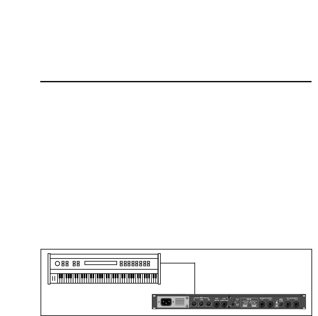
5-1
MIDI Operation
5
MIDI Operation
All PCM 90 parameters, programs and registers can be accessed by MIDI. All
MIDI applications require the PCM 90 to be connected with one or more MIDI
devices with standard MIDI cables via the rear panel MIDI jacks.
MIDI controls, such as Transmit and Receive Channel selection are available in
Control mode Row 3 MIDI. All of these controls are described in Chapter 2.
Several are repeated here for your convenience.
Before using the PCM 90 with other MIDI devices, all devices must be set to the
same MIDI channel. To set the PCM 90 to receive MIDI:
1. Set the controller you will be using (keyboard, sequencer, other PCM 90,
etc.) to transmit on any MIDI channel (1-16).
2. On the PCM 90, press Control. Use Select and Up or Down to locate
matrix position 3.1 Receive.
3. Turn ADJUST to select OFF, 1-16, or OMNI for receipt of MIDI messages.
Selecting a
MIDI Channel
MIDI Out
MIDI In
Some extremely useful effects can be created by controlling PCM 90 parameters
remotely in real time. Almost all of the controllers found on a MIDI keyboard or
MIDI foot controller (pitch benders, mod wheels, sliders, switches, breath
controllers, foot pedals and footswitches) can be used to adjust PCM 90
parameters. We refer to this real time remote control capability as Dynamic
MIDI®
Sending a MIDI Program Change message (0-49) from the controller will load
the corresponding PCM 90 program from the current bank. If any MIDI sources
are active as global or general purpose patches, moving the appropriate control
on the controller will cause the patched destination parameter to change. (See
Patching.) If you want to use Dynamic MIDI, but don’t want the PCM 90 to load
new registers when you change programs on your controller, set your controller
so that it doesn’t transmit Program Change messages, or set PCM 90 MIDI
Program Change to Off at Control mode matrix location 3.3.
Accessing Programs
and Registers

5-2
PCM 90 User Guide Lexicon
MIDI Out
MIDI In
PCM 90 Control 3.6 Int Clock set to Transmit On
Tempo 0.2 Source set to Internal
Tempo 0.0 Rate set with ADJUST or Tap
Controlling PCM 90
Tempo Rate
with MIDI Clock
Using the PCM 90 as a
MIDI Clock Source
MIDI Tempo Control
MIDI Out (MIDI Clock)
MIDI In
PCM 90 Tempo 0.2 Source set to MIDI
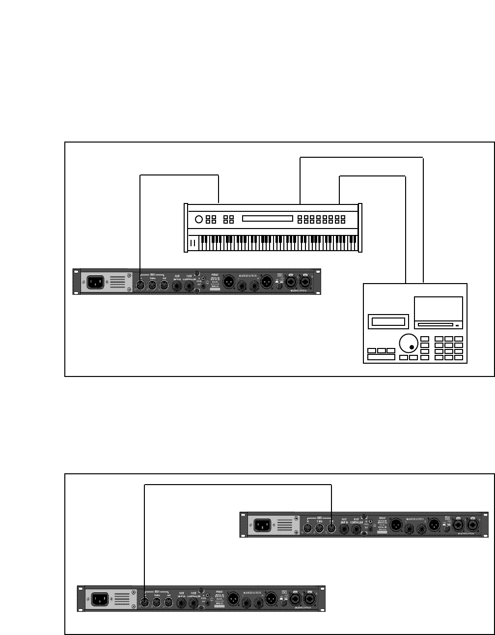
5-3
MIDI Operation
MIDI In MIDI Out
MIDI In
MIDI Thru
MIDI In MIDI Out
(MIDI Clock)
PCM 90 Tempo 0.2 Source set to MIDI
The configuration below shows the MIDI connections for controlling the PCM 90
simultaneously with MIDI Clocks from a sequencer, and messages from another
MIDI controller. Note that the controller is set to "local control off" and the
sequencer is set to "echo input".
Two PCM 90s can be slaved together by connecting a cable from the MIDI OUT
jack of the master to the MIDI IN jack of the slave. Additional PCM 90s can be
slaved to the master by connecting a cable from the MIDI THRU port of one slave
unit to the MIDI IN port of the next unit. All of the PCM 90s must be set to the same
MIDI channel and Device ID.
Slaving two or more
PCM 90s
MIDI Out
MIDI In
Control 3.4 Automation set to On
Target ID set to All or same # as Slave device ID #
Control 3.7 MIDI SysEx set to Receive On

5-4
PCM 90 User Guide Lexicon
Some synthesizers and controllers cannot send the full range of MIDI program
change messages (1-128). Others may appear to be able to send only 32, but
actually have a bank mode that does let you send all 128 program change
messages. Also, be aware that some MIDI devices use a program numbering
system that uses 0-127 instead of 1-128. If in doubt, see the manual for your
controller. For reference, in the PCM 90, Program Change 0 will load the effect
at 0.0 in the current bank. Program Change 1 will load the effect at 0.1, etc.
You can choose to have the PCM 90 send MIDI Controller messages whenever
you turn ADJUST (the soft knob in Program Banks or Register Banks modes),
when you modify a Custom Control, or use them to activate analog controllers
connected to the rear panel Footswitch or Foot Controller jacks. This makes it
possible to record real-time control of PCM 90 effects with a MIDI sequencer —
A simple but quite powerful way to automate effects.
To send MIDI data from these controllers, first set Control mode 3.2 (Transmit)
to the desired MIDI Channel. (The default is Channel 1.)
Controller quirks
When a PCM 90 controller is assigned to a MIDI Controller, the PCM 90 will
respond to incoming controller messages as though its own controller were
moved. In other words, if FootSw1 is assigned to Sustain, the PCM 90 will
respond to incoming Sustain messages as though Foot Sw 1 had been
activated.
Once a transmit channel has been set, go to Control mode 3.5 to assign MIDI
Controllers. Press Load/✱ to display the available controllers: Foot Pedal, Foot
Sw 1, Foot Sw 2, ADJUST, or Custom 1-4. Turn ADJUST to assign the MIDI
Controller data to be sent when the displayed controller is activated. (The default
assignment is None.).
The ADJUST Knob,
Custom Controls,
Foot Pedal, Foot Sw 1
and Foot Sw 2 as
MIDI Controllers
MIDI Transmit
3.2 1
MIDI ✱ Foot Sw 1
3.5 Send Sustain

5-5
MIDI Operation
Each PCM 90 preset has a unique soft knob patch that allows you to control the
effect directly from Program or Register Banks mode with the ADJUST knob.
You can also control the soft knob patch remotely from MIDI, or from the Foot
Pedal.
To control the soft knob with MIDI, set Control mode 3.1 (Receive) to the desired
MIDI Channel. Set Control mode 3.5 (ADJUST) to the desired MIDI Controller
such as Mod Wheel.
Controlling the Soft
Knob with MIDI
MIDI ✱ADJUST
3.5 Send Mod Wheel
Now, the Mod Wheel on the MIDI instrument will control the soft knob patch of
the running effect.
Note: In Program Banks mode, the ADJUST display will not appear when the
controller is moved. In this case, ADJUST is still independent of the controller.
If you have a foot pedal connected to the PCM 90 rear panel Foot Controller jack,
you can use it to control the soft knob patch. (Note that no MIDI connections are
required to do this.)
Set both Control mode 3.5 ADJUST and Control mode 3.5 Foot Pedal to the
same MIDI Controller.
Controlling the Soft
Knob with a Foot Pedal
MIDI ✱ADJUST
3.5 Send Ctl 3
MIDI ✱Foot Pedal
3.5 Send Ctl 3
Now, the foot pedal will control the soft knob patch of the running effect. Keep
in mind that, if Patch Update (System 1.7) is set to Immediate, the current value
of the controller will be sent to ADJUST when the program is loaded. For
example, if your footpedal is at 0, ADJUST will be set to 0 on program load.
Note: Footswitches are transmitted with an On value of 127, and an Off value of
0.

5-6
PCM 90 User Guide Lexicon
Reception of MIDI Program Change and Bank Select messages can be
selectively enabled/disabled from Control Mode parameter 3.3, MIDI Pgm
Change. The manner in which the PCM 90 interprets these messages is
determined by the value of this parameter as follows:
Pgm Change: Off
All Program Change and Bank select messages are treated as "unavailable".
Pgm+ and Pgm– will load the next higher or lower program in the current bank,
then wrap to the adjacent bank.
Pgm Change : On
Program Change messages 0-49 correspond to PCM 90 Effects 0.0 -4.9 in the
current bank. Program Change messages 50—127 are ignored. Pgm+ and
Pgm– will load the next higher or lower program in the current bank, then wrap
to the adjacent bank.
The current bank can be changed with MIDI Continuous Controller 32 and Bank
Select Messages as follows:
0-4: Program Banks 0-4
5-6: Internal Register Banks R0 and R1
7-11: reserved for ROM Card Banks
12-...: Memory Card Banks
The number of banks available on a given card will vary with card
size as follows:
Card Size # Banks
64k 1
256k 5
512k 10
1 Meg 20
Pgm Change: Map
Program Change 0-127 can be mapped to any PCM 90 Effect in any internal or
card bank. Two 128 element maps are stored internally, additional maps may be
stored on RAM cards.
Map 0 Map 1
MIDI 0 = P0 0.0 MIDI 0 = P2 2.8
MIDI 127 = P2 2.7 MIDI 127 = R 4.9
Pgm+ and Pgm– will load the next higher or lower program in the map.
Pgm Change: Chain
Any Program Change number can be selected to load any one of ten customized
effect “chains.” Once a chain is loaded, effects in the chain are accessed by the
controller patched to Pgm + and Pgm – (program increment and program
decrement).
Note: The PCM 90 requires a brief amount of time to change programs.
Additional Program Change messages received during this time out may be lost.
Program Change
Messages

5-7
MIDI Operation
Automation
SysEx Automation
The PCM 90 will transmit SysEx automation messages when Control Mode
parameter 3.4, MIDI Automation is set to On. Almost all changes made by front
panel operations are transmitted as PCM 90 SysEx messages. This is intended
primarily for use in configurations where it is desirable for one or more PCM 90s
to be slaved to a single PCM 90 acting as a master. The current mode (Program
Banks, Register Banks, Edit, Control or Tempo) of the slave does not follow the
master, but the actual parameter values do. (SysEx automation can also be
stored on a sequencer and replayed in real-time. As a general rule, automating
more than two or three SysEx program changes at once is not recommended.)
The PCM 90 can receive SysEx messages when Control mode 3.7 MIDI SysEx
is set to Receive On. Note that when using SysEx automation, the device of the
receiving PCM 90 must match the Target ID of the transmitting PCM 90, or the
transmitting device must use the All Devices ID.
The Target ID setting can be adjusted from Control 3.4 MIDI Automation. It is
selected by pressing Load/✱ after setting Automation to On. The default setting
for the Target ID is All.
The Device ID setting can be adjusted from Control mode 3.7 MIDI SysEx. It is
selected by pressing Load/✱ after setting SysEx to Receive On. The default
setting for the Device ID is 0.
Controller Automation
For applications where it is desirable to "automate" changes made to PCM 90
effects with its own controls (ADJUST, Custom 1-4, Foot Pedal, Footswitch 1 or
Footswitch 2), we recommend assigning the controllers to MIDI destinations and
recording the changes with a MIDI sequencer (see Control Mode parameter 3.5,
MIDI Destinations).
Reset All Controllers
The PCM 90 recognizes the “Reset All Controllers” message. When received,
all patched parameters are reset to their stored values. Patched parameters may
also be reset from the PCM 90 front panel —Control Mode parameter 3.0 (the
message will be transmitted from the PCM 90 as well).
MIDI Clock and Clock Commands
The PCM 90 recognizes MIDI clock messages when Tempo Mode parameter
0.2, Tempo Source is set to MIDI. Any Delay or Mod row parameter set to display
tempo values will be synchronized to the tempo of the incoming MIDI clock.
MIDI Clock and Clock Commands are also available as Dynamic MIDI patch
sources. The value of MIDI Clock when used as a patch source is a linear scaling
of 0 to 127 (0 = 40 BPM and 127 = 400 BPM). The value of Clock Commands
when used as a Dynamic MIDI patch source is 127 for START and CONTINUE
and 0 for STOP.

5-8
PCM 90 User Guide Lexicon
Dynamic MIDI
The following MIDI messages are available as Dynamic MIDI patch sources:
MIDI Controllers 1-31 and 33-119
Pitch Bend
After Touch (Polyphonic and Channel combined)
Velocity (Note On)
Last Note
Low Note
High Note
Tempo (40–400BPM is converted to controller range 0-127)
Clock Commands
These MIDI messages are also available as threshold sources for several
Modulation parameters: AR Env, Latch, Sw 1 and Sw 2, and S&Hold. They may
also be used as a tap source for controlling Tempo.
MIDI Implementation Details, including System Exclusive documentation, are
available to assist experienced programmers in developing software for use
with the PCM 90. These can be obtained directly from Lexicon.
Request: PCM 90 MIDI Implementation Details.
Bulk Data Dumps Control mode 3.8 (MIDI Dump) allows selection of the following types of bulk
data to be dumped directly from the PCM 90 to another PCM 90, or to editor/
librarian software.
Displayed Name Description
CurrentPgm Currently running effect
Bank R0-R1 Internal Register Banks
Bank C0-CJ Card Banks (card must be inserted)
Map 0, 1 Internal Program Change Maps
Map 2-3 Card Program Change Maps (card must be inserted)
Chain 0-9 Internal Program Chains
Chain 10-19 Card Program Chains (card must be inserted)
Int Chains All Internal Program Chains
Ext Chains All Card Program Chains (card must be inserted)
Setup C Current Setup
Setup 0-4 Internal Setups
Setup 5-9 Card Setups
Use ADJUST to select the bulk data type. Press Store to transmit the data .

5-9
MIDI Operation
MIDI Implementation Chart
Mode 1: OMNI ON, POLY Mode 2: OMNI ON, MONO O : Yes OX: Selectable
Mode 3: OMNI OFF, POLY Mode 4: OMNI OFF, MONO X : No
Lexicon PCM 90
Digital Reverberator
Function Transmitted Recognized Remarks
Basic Default 1 1
Channel Changed 1-16 1-16
Mode Default X Mode 1, 3
Messages X X
Altered X
Note X 0-127 Last Note, Low Note,
Number High Note used as
controllers
Velocity Note ON X O 9n v = 1-127 used as controller
Note OFF
After Keys X X
Touch Channel X O
Pitch Bend X O
Control 1-119 OX OX ADJUST, FootPedal,
Change Footswitch 1, and 2, and
Custom 1-4 can be
assigned controllers
1-119 for MIDI transmit;
32 reserved for bank select
Program X 0-127 See Implementation
Change True # Details
System Lexicon OX OX product ID=6
Exclusive Real-time X X
non Real-time X OX device ID
System :Song Pos X X
Common :Song Sel X X
:Tune X X
System :Clock OX OX
Real Time :Commands X OX* START, STOP and CON-
TINUE are patchable as
a switch: START/CON-
TINUE=127; STOP=0
Aux :Local ON/OFF X X
Messages :All Notes OFF X O
:Active Sense X X
:Reset All Controllers OX OX
Notes

5-10
PCM 90 User Guide Lexicon

6-1
Troubleshooting
6
Troubleshooting
This chapter is intended primarily to help you recognize some common error
states which can be corrected from the PCM 90 front panel, or by simple means
such as cable replacement. Any error states which are not covered here should
be referred to your local dealer for service by a qualified technician.
In a low-voltage, or "brown-out" condition, the PCM 90 will freeze in its current
state. None of the controls will have any effect. When power returns to a normal
level, the unit will reset itself as though it had just been powered on. If the unit
does not reset itself, turn the power OFF, then ON to resume normal operation.
Temperature extremes may cause the PCM 90 to exhibit unpredictable behav-
ior. If the unit has been subjected to temperatures below 32°F (0°C) or above
95°F (35°C), it should be turned off and allowed to return to normal temperature
before use. The unit may be damaged by exposure to temperatures below -22°F
(-30°C) or above 167°F (75°C), or by exposure to humidity in excess of 95%. If
a unit exposed to such conditions fails to operate after it returns to a normal
operating temperature, contact your local service representative.
The PCM 90 doesn't respond to MIDI Program Changes.
Check Receive control at Control mode 3.1 and make sure it is set to On. Check
the MIDI Channel selected as well as the MIDI Channel of the transmitting
device. Make sure that Pgm Change at Control mode 3.3 is set to On. Also
check MIDI In/Out connections between the units.
MIDI Program Change numbers are off by 1.
The PCM 90 transmits and recognizes ProgramChange messages 0-127. MIDI
devices which transmit 1-128 rather than 0-127, will be off by 1. Simply adjust
by 1 when working with such devices.
The PCM 90 doesn't respond to SysEx commands.
Check the SysEx setting (and the Device ID selection) at Control mode 3.7.
The PCM 90 does not transmit SysEx Automation commands.
Check the Automation setting (and the target device ID selection) at Control
mode 3.4.
Low Voltage
Overheating
Common MIDI
Problems

6-2
Lexicon
PCM 90 User Guide
Operational Problems The PCM 90 will not lock onto an incoming digital signal.
Check the cables that you are using. DO NOT USE ANALOG AUDIO CABLE TO
CONNECT DIGITAL AUDIO.
Also check to make sure that your input signal complies with S/PDIF format
standards. The PCM 90 will recognize AES professional format signals from an
appropriate connector, but will not necessarily read and transmit encoded
information accurately.
No Digital Audio Output
Check the Bypass state for any mute settings.
No Effects Output
Check the setting of Mix Mode at Control mode 1.1. Also verify that any
controllers patched to Input Level, or Mix are not turned off.
The PCM 90 performs a series of self tests each time it is powered on, then
displays the PCM 90 copyright notice. This should be followed by the display and
loading of the last loaded effect. If this sequence does not occur, contact Lexicon
Customer Service.
Power On Behavior

6-3
Troubleshooting
You can restore the PCM 90 to its default state without erasing registers by
restoring the factory default setup:
1. Press Control.
2. Use the Up and Down buttons to locate Row 4 Setup.
3. Turn SELECT to 4.1 Load.
4. Turn ADJUST counterclockwise to select "Factory Settings".
5. Press Load/✱. The PCM 90 will display the message "Setup restored".
The following table shows the parameters which comprise a setup, along with
the factory default setting of each parameter.
Control Mode
Matrix Location System Parameter Default Setting
Audio 0.0 Input Source Analog: 48kHz
0.1 SCMS Multi Copy
0.2 Emphasis Bit Pass Thru
0.3 Output Level +4dBu
System 1.0 Edit Mode Go
1.1 Mix Mode Pgm
Global Mix Value 100% Wet
1.2 Tempo Mode Pgm
Global Tempo Value 120 BPM
1.3 Bypass Mode InputMute
Bypass Src Off
1.4 Pgm Bypass AllMute
1.5 Mem Protect Off
1.6 Auto Load Off
1.7 Patch Update Delayed
1.8 KeyWord On (A to Z)
MIDI 3.1 Receive OMNI
3.2 Transmit 1
3.3 Pgm Change On
Pgm+ Off
Pgm– Off
Map select 0
Chain MIDI
3.4 Automation Off
3.5 Footpedal None
Sw 1 None
Sw 2 None
ADJUST None
Custom 1-4 None
3.6 Int Clock Transmit Off
3.7 SysEx Receive On
Device ID 0
3.8 MIDI Dump Current Program
3.9 Dump Speed Slow
Tempo Mode
Matrix Location System Parameter Default Setting
Tempo 0.2 Source Internal
Tap 1.3 Display On
Restoring Factory
Default Settings

6-4
Lexicon
PCM 90 User Guide
Reinitialization Reinitializing will erase all registers and setups
The following procedure will return the PCM 90 to the state it was in when
shipped from the factory. This includes erasing all registers and setups, as well
as restoring all of the default settings:
1. Press Control.
2. Use the Up and Down buttons to locate Row 1 System.
3. Turn SELECT to 1.9 Initialize.
4. Press Store. The PCM 90 will display the message "Are you sure? (Press
STORE)".
If you don't want to reinitialize your unit, press any button except Store to
return to matrix position 1.9.
If you press Store in response to this message, the display will flash
"Restoring original factory settings" and your unit will be reinitialized.

7-1
Specifications
7
PCM 90
Specifications
Audio Input Connectors: Combined 3 pole XLR and 1/4 inch T/R/S phone jacks (2)
Impedance: 0 dB/BAL switch position: 100kΩ, balanced
-20 dB/UNBAL switch position: 50kΩ, unbalanced
Levels: 0 dB/BAL switch position: -2 dBu min for full scale, +20 dBu max
-20 dB/UNBAL switch position: -22 dBu min for full scale, 0 dBu max
CMRR: 0 dB/BAL switch position: 40 dB minimum, 10 Hz to 20 kHz
Audio Output Connectors: 1/4 inch T/R/S phone jacks (2); balanced XLRs, pin 2 "high" (2)
Impedance: 125Ω, each side, balanced
Levels: +18 dBm max, full scale (+4 dBu setting) balanced, unbalanced
+4 dBm max, full scale (-10 dBu setting)
Protection: Relays provided for output muting during power on/off
A/D Performance Frequency
Response: 10 Hz to 20 kHz, ±0.5 dB
Crosstalk: -65 dB max, 10 Hz to 20 kHz
S/N Ratio: 100 dB min, 20 kHz bandwidth
THD: 0.004% max, 10 Hz to 20 kHz
Dynamic
Range: 100 dB min, 20 kHz bandwidth
Delay: 24 samples (0.54 msec for 44.1 kHz, 0.50 msec for 48 kHz)
D/A Performance Frequency
Response: 10 Hz to 20 kHz, ±0.5 dB
Crosstalk: -80 dB max, 10 Hz to 20 kHz
S/N Ratio: 100 dB min, 20 kHz bandwidth
THD: 0.006% max, 10 Hz to 20 kHz
Dynamic
Range: 92 dB min (96 dB typ), 20 kHz bandwidth
Delay: 50 samples (1.13 msec for 44.1 kHz, 1.04 msec for 48 kHz)
A/A Performance Frequency
Response: 10 Hz to 20 kHz, ±0.5 dB
Crosstalk: -55 dB max, 10 Hz to 20 kHz
S/N Ratio: 90 dB min, 20 kHz bandwidth
THD: 0.008% max, 10 Hz to 20 kHz
Dynamic
Range: 90 dB min, 20 kHz bandwidth

7-2
Lexicon
PCM 90 User Guide
Digital Audio Interface Connectors: Coaxial, RCA type
Format: conforms to S/PDIF CP-340 Type II and IEC-958 consumer standards
Sample Rates: 44.1 kHz, 48 kHz
Internal Audio Data Paths Conversion: 18 bits
DSP: 18 to 24 bits
Audio Memory Configuration Base memory: Two 256k x 18 DRAMs
External Memory Card Connector: Accepts PCMCIA Type I cards, 68 pins
Standards: Conforms to PCMCIA 2.0 / JEIDA 4.0
Card Format: Supports up to 1MB SRAM (attribute memory not required)
Control Interface MIDI: 5-pin DIN connectors provided for MIDI IN, THRU, & OUT
Footswitch: 1/4 inch T/R/S phone jack provided for
2 independent momentary footswitches
System detects normal-open, or normal-closed on power up
Foot controller: 1/4 inch T/R/S phone jack provided for footpedal
(100Ω minimum, 10kΩ maximum impedance)
General Dimensions: 19.0"W x 1.75"H x 12.0"D (483 x 45 x 305 mm)
19 inch rack mount standard, 1U high
Weight: Net: 6.4 lbs (2.9 kg)
Shipping: 9.5 lbs (4.3 kg)
Power
Requirements: 100-240 VAC, 50-60 Hz, 35 W, 3-pin IEC power connector
RFI/ESD: Conforms to FCC Class B,
EN55022 Class B (CE), IEC 801-2, IEC 801-3
Environment: Operating temperature: 32˚ to 104˚F (0˚ to 40˚C)
Storage temperature: -22˚ to 167˚F (-30˚ to 70˚C)
Humidity: maximum 95% without condensation
Unless otherwise noted, all audio specifications assume rear-panel switch set to BAL, input level control
is set for unity gain (0dB), and analog I/O connections wired for balanced configuration.
Specifications subject to change without notice.

Lexicon Part # 070-10399
