IL 1070116 Spectra User Guide Passive Polaris
User Manual: Pdf
Open the PDF directly: View PDF ![]() .
.
Page Count: 126 [warning: Documents this large are best viewed by clicking the View PDF Link!]
- Read Me First!
- 1 Polaris Spectra System Overview
- 2 Setting Up the Polaris Spectra System
- 3 Tutorial: Learning to Use the Polaris Spectra System
- 4 How the Polaris Spectra System Works
- 4.1 Communicating with the Polaris Spectra System
- 4.2 Information Returned by the Polaris Spectra System
- 4.3 Global Coordinate System and Measurement Volume
- 4.4 Marker Detection and Tool Tracking
- 4.5 Sampling Rate
- 4.6 Polaris Spectra System Tools
- 4.7 Tool Definition File
- 4.8 Tool Tracking Parameters
- 4.9 Tool Tip Offset
- 4.10 Reference Tools
- 4.11 Stray Marker Reporting
- 4.12 Phantom Markers
- 4.13 Passive Sphere Markers
- 4.14 Active Markers
- 4.15 System Spectral Response
- 4.16 Data Transmission Rate
- 5 Additional System Features
- 6 Error Flags and Codes
- 7 Maintenance
- 8 Setting the Infrared Light Sensitivity
- 9 Calibration and Firmware
- 10 Approvals
- 11 Classifications
- 12 Technical Specifications
- 13 Electromagnetic Compatibility
- 14 Troubleshooting
- 15 Return Procedure and Warranty
- 16 Declaration of Conformity
- 17 Abbreviations and Acronyms
- 18 Equipment Symbols
- 19 Glossary
- Appendix A Polaris Spectra Calibration Performance and Methodology
Passive Polaris Spectra User Guide
Revision 7
September 2012
IMPORTANT
Please read this entire document
before attempting to operate
the Polaris Spectra System

Copyright 2006 - 2012 Northern Digital Inc. All Rights Reserved.
p Printed in Canada.
Revision Status
Revision Number Date Description
1 September 2006 Initial release
2 June 2007 Updated descriptions of LED behaviour and Position
Sensor mounting options.
3 July 2007 Clarification of Host USB Converter operating
temperature parameters.
4 March 2008 Removed Bluetooth information. Updated optional
positioning laser information. Included Mac OS X user
instructions.
5 March 2011 Minor updates
Revised FTDI driver information
Added Windows 7 information
6 April 2012 Revised software installation instructions for Linux
Revised serial number and laser safety label graphics
7 September 2012 Update Power Supply specifications, standards and
Declaration of Conformity to comply with IEC 60601-1
3rd Edition
Part Number: IL-1070116

Passive Polaris Spectra User Guide - Revision 7
Published by:
Northern Digital Inc.
103 Randall Dr.
Waterloo, Ontario, Canada N2V 1C5
Telephone: + (519) 884-5142
Toll Free: + (877) 634-6340
Global: + (800) 634 634 00
Facsimile: + (519) 884-5184
Website: www.ndigital.com
Copyright 2006 - 2012 Northern Digital Inc.
All rights reserved. No part of this document may be reproduced, transcribed, transmitted, distributed, modi-
fied, merged or translated into any language in any form by any means - graphic, electronic, or mechanical,
including but not limited to photocopying, recording, taping or information storage and retrieval systems - with-
out the prior written consent of Northern Digital Inc. Certain copying of the software included herein is unlawful.
Refer to your software license agreement for information respecting permitted copying.
DISCLAIMER OF WARRANTIES AND LIMITATION OF LIABILITIES
Northern Digital Inc. has taken due care in preparing this document and the programs and data on the elec-
tronic media accompanying this document including research, development, and testing.
This document describes the state of Northern Digital Inc.’s knowledge respecting the subject matter herein at
the time of its publication, and may not reflect its state of knowledge at all times in the future. Northern Digital
Inc. has carefully reviewed this document for technical accuracy. If errors are suspected, the user should con-
sult with Northern Digital Inc. prior to proceeding. Northern Digital Inc. makes no expressed or implied warranty
of any kind with regard to this document or the programs and data on the electronic media accompanying this
document.
Northern Digital Inc. makes no representation, condition or warranty to the user or any other party with respect
to the adequacy of this document or accompanying media for any particular purpose or with respect to its ade-
quacy to produce a particular result. The user’s right to recover damages caused by fault or negligence on the
part of Northern Digital Inc. shall be limited to the amount paid by the user to Northern Digital Inc. for the provi-
sion of this document. In no event shall Northern Digital Inc. be liable for special, collateral, incidental, direct,
indirect or consequential damages, losses, costs, charges, claims, demands, or claim for lost profits, data, fees
or expenses of any nature or kind.
Product names listed are trademarks of their respective manufacturers. Company names listed are trademarks
or trade names of their respective companies.

Passive Polaris Spectra User Guide - Revision 7

Table of Contents
Passive Polaris Spectra User Guide - Revision 7 i
Table of Contents
Read Me First! . . . . . . . . . . . . . . . . . . . . . . . . . . . . . . . . . . . . . . . . . . . . . . . . . . . . . . . . . . . . . . . . . . . . . . . ix
Warnings . . . . . . . . . . . . . . . . . . . . . . . . . . . . . . . . . . . . . . . . . . . . . . . . . . . . . . . . . . . . . .ix
Cautions . . . . . . . . . . . . . . . . . . . . . . . . . . . . . . . . . . . . . . . . . . . . . . . . . . . . . . . . . . . . . . .xi
Disclaimers . . . . . . . . . . . . . . . . . . . . . . . . . . . . . . . . . . . . . . . . . . . . . . . . . . . . . . . . . . . xii
Contact Information . . . . . . . . . . . . . . . . . . . . . . . . . . . . . . . . . . . . . . . . . . . . . . . . . . . . .xiii
Updates . . . . . . . . . . . . . . . . . . . . . . . . . . . . . . . . . . . . . . . . . . . . . . . . . . . . . . . . . . . . . .xiii
1 Polaris Spectra System Overview . . . . . . . . . . . . . . . . . . . . . . . . . . . . . . . . . . . . . . . . . . . . . . . . . . . . . . 1
1.1 Introduction . . . . . . . . . . . . . . . . . . . . . . . . . . . . . . . . . . . . . . . . . . . . . . . . . . . . . . . . . 1
1.2 Host Computer Requirements . . . . . . . . . . . . . . . . . . . . . . . . . . . . . . . . . . . . . . . . . . . 2
1.3 Position Sensor . . . . . . . . . . . . . . . . . . . . . . . . . . . . . . . . . . . . . . . . . . . . . . . . . . . . . . 3
1.4 Host USB Converter . . . . . . . . . . . . . . . . . . . . . . . . . . . . . . . . . . . . . . . . . . . . . . . . . . 8
1.5 Power Adapter . . . . . . . . . . . . . . . . . . . . . . . . . . . . . . . . . . . . . . . . . . . . . . . . . . . . . . . 9
1.6 Cables . . . . . . . . . . . . . . . . . . . . . . . . . . . . . . . . . . . . . . . . . . . . . . . . . . . . . . . . . . . . 10
1.7 Tools . . . . . . . . . . . . . . . . . . . . . . . . . . . . . . . . . . . . . . . . . . . . . . . . . . . . . . . . . . . . . 11
1.8 Software. . . . . . . . . . . . . . . . . . . . . . . . . . . . . . . . . . . . . . . . . . . . . . . . . . . . . . . . . . . 13
2 Setting Up the Polaris Spectra System . . . . . . . . . . . . . . . . . . . . . . . . . . . . . . . . . . . . . . . . . . . . . . . . . 14
2.1 Unpacking the Polaris Spectra System . . . . . . . . . . . . . . . . . . . . . . . . . . . . . . . . . . . 14
2.2 Operating Environment Requirements . . . . . . . . . . . . . . . . . . . . . . . . . . . . . . . . . . . 14
2.3 Mounting the System Units . . . . . . . . . . . . . . . . . . . . . . . . . . . . . . . . . . . . . . . . . . . . 16
2.4 Connecting the Hardware . . . . . . . . . . . . . . . . . . . . . . . . . . . . . . . . . . . . . . . . . . . . . 19
2.5 Installing the Software (Windows) . . . . . . . . . . . . . . . . . . . . . . . . . . . . . . . . . . . . . . 20
2.6 Installing the Software (Linux) . . . . . . . . . . . . . . . . . . . . . . . . . . . . . . . . . . . . . . . . . 23
2.7 Installing the Software (Mac) . . . . . . . . . . . . . . . . . . . . . . . . . . . . . . . . . . . . . . . . . . 25
3 Tutorial: Learning to Use the Polaris Spectra System. . . . . . . . . . . . . . . . . . . . . . . . . . . . . . . . . . . . .31
3.1 Getting Started: Tracking Tools . . . . . . . . . . . . . . . . . . . . . . . . . . . . . . . . . . . . . . . . 31
3.2 Triggering Information and Error Flags . . . . . . . . . . . . . . . . . . . . . . . . . . . . . . . . . . 32
3.3 Setting a Tool as Reference. . . . . . . . . . . . . . . . . . . . . . . . . . . . . . . . . . . . . . . . . . . . 34
3.4 Determining the Tool Tip Offset. . . . . . . . . . . . . . . . . . . . . . . . . . . . . . . . . . . . . . . . 35

Table of Contents
ii Passive Polaris Spectra User Guide - Revision 7
4 How the Polaris Spectra System Works . . . . . . . . . . . . . . . . . . . . . . . . . . . . . . . . . . . . . . . . . . . . . . . . 37
4.1 Communicating with the Polaris Spectra System . . . . . . . . . . . . . . . . . . . . . . . . . . . 37
4.2 Information Returned by the Polaris Spectra System . . . . . . . . . . . . . . . . . . . . . . . . 38
4.3 Global Coordinate System and Measurement Volume . . . . . . . . . . . . . . . . . . . . . . . 39
4.4 Marker Detection and Tool Tracking. . . . . . . . . . . . . . . . . . . . . . . . . . . . . . . . . . . . . 42
4.5 Sampling Rate . . . . . . . . . . . . . . . . . . . . . . . . . . . . . . . . . . . . . . . . . . . . . . . . . . . . . . 43
4.6 Polaris Spectra System Tools. . . . . . . . . . . . . . . . . . . . . . . . . . . . . . . . . . . . . . . . . . . 44
4.7 Tool Definition File . . . . . . . . . . . . . . . . . . . . . . . . . . . . . . . . . . . . . . . . . . . . . . . . . . 47
4.8 Tool Tracking Parameters . . . . . . . . . . . . . . . . . . . . . . . . . . . . . . . . . . . . . . . . . . . . . 47
4.9 Tool Tip Offset. . . . . . . . . . . . . . . . . . . . . . . . . . . . . . . . . . . . . . . . . . . . . . . . . . . . . . 51
4.10 Reference Tools . . . . . . . . . . . . . . . . . . . . . . . . . . . . . . . . . . . . . . . . . . . . . . . . . . . . 52
4.11 Stray Marker Reporting . . . . . . . . . . . . . . . . . . . . . . . . . . . . . . . . . . . . . . . . . . . . . . 53
4.12 Phantom Markers . . . . . . . . . . . . . . . . . . . . . . . . . . . . . . . . . . . . . . . . . . . . . . . . . . . 54
4.13 Passive Sphere Markers . . . . . . . . . . . . . . . . . . . . . . . . . . . . . . . . . . . . . . . . . . . . . . 54
4.14 Active Markers. . . . . . . . . . . . . . . . . . . . . . . . . . . . . . . . . . . . . . . . . . . . . . . . . . . . . 55
4.15 System Spectral Response . . . . . . . . . . . . . . . . . . . . . . . . . . . . . . . . . . . . . . . . . . . . 55
4.16 Data Transmission Rate . . . . . . . . . . . . . . . . . . . . . . . . . . . . . . . . . . . . . . . . . . . . . . 56
5 Additional System Features. . . . . . . . . . . . . . . . . . . . . . . . . . . . . . . . . . . . . . . . . . . . . . . . . . . . . . . . . . 57
5.1 Bump Sensor . . . . . . . . . . . . . . . . . . . . . . . . . . . . . . . . . . . . . . . . . . . . . . . . . . . . . . . 57
5.2 Positioning Laser . . . . . . . . . . . . . . . . . . . . . . . . . . . . . . . . . . . . . . . . . . . . . . . . . . . . 58
5.3 Keyed Features. . . . . . . . . . . . . . . . . . . . . . . . . . . . . . . . . . . . . . . . . . . . . . . . . . . . . . 59
6 Error Flags and Codes . . . . . . . . . . . . . . . . . . . . . . . . . . . . . . . . . . . . . . . . . . . . . . . . . . . . . . . . . . . . . . 62
6.1 Missing and Disabled Transformations . . . . . . . . . . . . . . . . . . . . . . . . . . . . . . . . . . . 62
6.2 Tracking Errors and Flags . . . . . . . . . . . . . . . . . . . . . . . . . . . . . . . . . . . . . . . . . . . . . 63
7 Maintenance . . . . . . . . . . . . . . . . . . . . . . . . . . . . . . . . . . . . . . . . . . . . . . . . . . . . . . . . . . . . . . . . . . . . . . 66
7.1 Cleaning the Position Sensor . . . . . . . . . . . . . . . . . . . . . . . . . . . . . . . . . . . . . . . . . . . 66
7.2 Disposal of Equipment. . . . . . . . . . . . . . . . . . . . . . . . . . . . . . . . . . . . . . . . . . . . . . . . 67
8 Setting the Infrared Light Sensitivity. . . . . . . . . . . . . . . . . . . . . . . . . . . . . . . . . . . . . . . . . . . . . . . . . . . 68
8.1 Infrared Light Sensitivity Levels . . . . . . . . . . . . . . . . . . . . . . . . . . . . . . . . . . . . . . . . 68
8.2 Changing the Sensitivity Level . . . . . . . . . . . . . . . . . . . . . . . . . . . . . . . . . . . . . . . . . 69

Table of Contents
Passive Polaris Spectra User Guide - Revision 7 iii
9 Calibration and Firmware . . . . . . . . . . . . . . . . . . . . . . . . . . . . . . . . . . . . . . . . . . . . . . . . . . . . . . . . . . . . 71
9.1 Checking the Calibration of the Polaris Spectra System. . . . . . . . . . . . . . . . . . . . . . 71
9.2 Updating the Firmware . . . . . . . . . . . . . . . . . . . . . . . . . . . . . . . . . . . . . . . . . . . . . . . 72
10 Approvals . . . . . . . . . . . . . . . . . . . . . . . . . . . . . . . . . . . . . . . . . . . . . . . . . . . . . . . . . . . . . . . . . . . . . . . . 73
10.1 Electrical Safety and Electromagnetic Compatibility . . . . . . . . . . . . . . . . . . . . . . . 73
10.2 Optical Radiation Safety . . . . . . . . . . . . . . . . . . . . . . . . . . . . . . . . . . . . . . . . . . . . . 73
11 Classifications . . . . . . . . . . . . . . . . . . . . . . . . . . . . . . . . . . . . . . . . . . . . . . . . . . . . . . . . . . . . . . . . . . . . 74
12 Technical Specifications. . . . . . . . . . . . . . . . . . . . . . . . . . . . . . . . . . . . . . . . . . . . . . . . . . . . . . . . . . . . 75
12.1 Operating Environmental Conditions . . . . . . . . . . . . . . . . . . . . . . . . . . . . . . . . . . . 75
12.2 Transportation and Storage Environmental Conditions . . . . . . . . . . . . . . . . . . . . . 75
12.3 Technical Specifications . . . . . . . . . . . . . . . . . . . . . . . . . . . . . . . . . . . . . . . . . . . . . 76
13 Electromagnetic Compatibility . . . . . . . . . . . . . . . . . . . . . . . . . . . . . . . . . . . . . . . . . . . . . . . . . . . . . . . 78
13.1 Cables and Accessories . . . . . . . . . . . . . . . . . . . . . . . . . . . . . . . . . . . . . . . . . . . . . . 78
13.2 Guidance and Manufacturer's Declaration: Electromagnetic Emissions. . . . . . . . . 79
13.3 Guidance and Manufacturer’s Declaration: Electromagnetic Immunity. . . . . . . . . 79
13.4 Recommended Separation Distances . . . . . . . . . . . . . . . . . . . . . . . . . . . . . . . . . . . 82
13.5 Radio Frequency Emissions . . . . . . . . . . . . . . . . . . . . . . . . . . . . . . . . . . . . . . . . . . 83
14 Troubleshooting. . . . . . . . . . . . . . . . . . . . . . . . . . . . . . . . . . . . . . . . . . . . . . . . . . . . . . . . . . . . . . . . . . . 84
14.1 Introduction . . . . . . . . . . . . . . . . . . . . . . . . . . . . . . . . . . . . . . . . . . . . . . . . . . . . . . . 84
14.2 LEDs . . . . . . . . . . . . . . . . . . . . . . . . . . . . . . . . . . . . . . . . . . . . . . . . . . . . . . . . . . . . 85
14.3 Audio Codes . . . . . . . . . . . . . . . . . . . . . . . . . . . . . . . . . . . . . . . . . . . . . . . . . . . . . . 88
14.4 Common Problems . . . . . . . . . . . . . . . . . . . . . . . . . . . . . . . . . . . . . . . . . . . . . . . . . 88
15 Return Procedure and Warranty. . . . . . . . . . . . . . . . . . . . . . . . . . . . . . . . . . . . . . . . . . . . . . . . . . . . . . 91
15.1 Return Procedure . . . . . . . . . . . . . . . . . . . . . . . . . . . . . . . . . . . . . . . . . . . . . . . . . . . 91
15.2 Warranty . . . . . . . . . . . . . . . . . . . . . . . . . . . . . . . . . . . . . . . . . . . . . . . . . . . . . . . . . 91

Table of Contents
iv Passive Polaris Spectra User Guide - Revision 7
16 Declaration of Conformity . . . . . . . . . . . . . . . . . . . . . . . . . . . . . . . . . . . . . . . . . . . . . . . . . . . . . . . . . . 93
17 Abbreviations and Acronyms . . . . . . . . . . . . . . . . . . . . . . . . . . . . . . . . . . . . . . . . . . . . . . . . . . . . . . . 95
18 Equipment Symbols . . . . . . . . . . . . . . . . . . . . . . . . . . . . . . . . . . . . . . . . . . . . . . . . . . . . . . . . . . . . . . . 96
19 Glossary. . . . . . . . . . . . . . . . . . . . . . . . . . . . . . . . . . . . . . . . . . . . . . . . . . . . . . . . . . . . . . . . . . . . . . . . . 97
Appendix A Polaris Spectra Calibration Performance and Methodology . . . . . . . . . . . . . . . . . . . . . 100
A.1 Polaris Spectra Performance . . . . . . . . . . . . . . . . . . . . . . . . . . . . . . . . . . . . . . . . . 100
A.2 Calibration Method . . . . . . . . . . . . . . . . . . . . . . . . . . . . . . . . . . . . . . . . . . . . . . . . 100

List of Figures
Passive Polaris Spectra User Guide - Revision 7 v
List of Figures
Figure 1-1 Polaris Spectra Measurement Volume . . . . . . . . . . . . . . . . . . . . . . . . . . . . . . . . . . . . . 1
Figure 1-2 Polaris Spectra System Setup . . . . . . . . . . . . . . . . . . . . . . . . . . . . . . . . . . . . . . . . . . . .2
Figure 1-3 Position Sensor (with Laser Option) Front View. . . . . . . . . . . . . . . . . . . . . . . . . . . . . 3
Figure 1-4 Position Sensor (without Laser Option) Front View . . . . . . . . . . . . . . . . . . . . . . . . . . 4
Figure 1-5 Position Sensor Rear View. . . . . . . . . . . . . . . . . . . . . . . . . . . . . . . . . . . . . . . . . . . . . .5
Figure 1-6 Position Sensor Connector Layout. . . . . . . . . . . . . . . . . . . . . . . . . . . . . . . . . . . . . . . . 6
Figure 1-7 Position Sensor Laser Label. . . . . . . . . . . . . . . . . . . . . . . . . . . . . . . . . . . . . . . . . . . . .7
Figure 1-8 Position Sensor Serial Number Label . . . . . . . . . . . . . . . . . . . . . . . . . . . . . . . . . . . . . 7
Figure 1-9 Host USB Converter. . . . . . . . . . . . . . . . . . . . . . . . . . . . . . . . . . . . . . . . . . . . . . . . . . . 8
Figure 1-10 Host USB Converter Serial Number Label . . . . . . . . . . . . . . . . . . . . . . . . . . . . . . . . 9
Figure 1-11 Passive Tool . . . . . . . . . . . . . . . . . . . . . . . . . . . . . . . . . . . . . . . . . . . . . . . . . . . . . . . 11
Figure 2-1 Position Sensor Mounting Details . . . . . . . . . . . . . . . . . . . . . . . . . . . . . . . . . . . . . . . 17
Figure 2-2 Position Sensor Mounting Bracket. . . . . . . . . . . . . . . . . . . . . . . . . . . . . . . . . . . . . . . 17
Figure 2-3 Host USB Converter Mounting Details . . . . . . . . . . . . . . . . . . . . . . . . . . . . . . . . . . . 18
Figure 2-4 Host USB Converter Connecting the Cables . . . . . . . . . . . . . . . . . . . . . . . . . . . . . . . 20
Figure 3-1 Tutorial: NDI ToolBox Tool Tracking Window . . . . . . . . . . . . . . . . . . . . . . . . . . . . 32
Figure 3-2 Tutorial: “Partially Out of Volume” Flag. . . . . . . . . . . . . . . . . . . . . . . . . . . . . . . . . . 33
Figure 3-3 Tutorial: Detected Markers Indicator . . . . . . . . . . . . . . . . . . . . . . . . . . . . . . . . . . . . . 33
Figure 3-4 Tutorial: “Too Few Markers” Flag. . . . . . . . . . . . . . . . . . . . . . . . . . . . . . . . . . . . . . . 33
Figure 3-5 Tutorial: “Exceeded Max Marker Angle” Indicator. . . . . . . . . . . . . . . . . . . . . . . . . . 34
Figure 3-6 Tutorial: Selecting a Reference Tool . . . . . . . . . . . . . . . . . . . . . . . . . . . . . . . . . . . . . 34
Figure 3-7 Tutorial: Selecting a Tool to Pivot . . . . . . . . . . . . . . . . . . . . . . . . . . . . . . . . . . . . . . . 35
Figure 3-8 Tutorial: Pivoting Technique . . . . . . . . . . . . . . . . . . . . . . . . . . . . . . . . . . . . . . . . . . . 36
Figure 3-9 NDI ToolBox Software: Pivot Result Dialog. . . . . . . . . . . . . . . . . . . . . . . . . . . . . . . 36

List of Figures
vi Passive Polaris Spectra User Guide - Revision 7
Figure 4-1 Global Coordinate System . . . . . . . . . . . . . . . . . . . . . . . . . . . . . . . . . . . . . . . . . . . . . 39
Figure 4-2 Pyramid Volume. . . . . . . . . . . . . . . . . . . . . . . . . . . . . . . . . . . . . . . . . . . . . . . . . . . . . 40
Figure 4-3 Extended Pyramid Volume . . . . . . . . . . . . . . . . . . . . . . . . . . . . . . . . . . . . . . . . . . . . 41
Figure 4-4 Determining a Marker Position . . . . . . . . . . . . . . . . . . . . . . . . . . . . . . . . . . . . . . . . . 42
Figure 4-5 Markers Normal . . . . . . . . . . . . . . . . . . . . . . . . . . . . . . . . . . . . . . . . . . . . . . . . . . . . . 48
Figure 4-6 Actual Range of Use. . . . . . . . . . . . . . . . . . . . . . . . . . . . . . . . . . . . . . . . . . . . . . . . . . 48
Figure 4-7 Flowchart of Tool Tracking Parameters. . . . . . . . . . . . . . . . . . . . . . . . . . . . . . . . . . . 50
Figure 4-8 Sample Calibrator. . . . . . . . . . . . . . . . . . . . . . . . . . . . . . . . . . . . . . . . . . . . . . . . . . . . 52
Figure 4-9 Phantom Markers . . . . . . . . . . . . . . . . . . . . . . . . . . . . . . . . . . . . . . . . . . . . . . . . . . . . 54
Figure 4-10 Filter Spectral Response. . . . . . . . . . . . . . . . . . . . . . . . . . . . . . . . . . . . . . . . . . . . . .56
Figure 5-1 Position Sensor Laser Label. . . . . . . . . . . . . . . . . . . . . . . . . . . . . . . . . . . . . . . . . . . . 59
Figure 8-1 Infrared Light Sensitivity Levels . . . . . . . . . . . . . . . . . . . . . . . . . . . . . . . . . . . . . . . . 69
Figure 14-1 Host USB Converter: Error LED Fault Chart . . . . . . . . . . . . . . . . . . . . . . . . . . . . . 87
Figure 16-1 EC Declaration of Conformity - Page 1 . . . . . . . . . . . . . . . . . . . . . . . . . . . . . . . . . . 93
Figure 16-2 EC Declaration of Conformity - Page 2 . . . . . . . . . . . . . . . . . . . . . . . . . . . . . . . . . . 94

List of Tables
Passive Polaris Spectra User Guide - Revision 7 vii
List of Tables
Table 1-1 Position Sensor Indicator LEDs Summary . . . . . . . . . . . . . . . . . . . . . . . . . . . . . . . . . . 4
Table 1-2 Position Sensor Connector - Signals. . . . . . . . . . . . . . . . . . . . . . . . . . . . . . . . . . . . . . . 6
Table 4-1 Maximum Tool Sampling Rate - Passive Polaris Spectra . . . . . . . . . . . . . . . . . . . . . 44
Table 4-2 Actual Range of Use . . . . . . . . . . . . . . . . . . . . . . . . . . . . . . . . . . . . . . . . . . . . . . . . . . 48
Table 11-1 Classifications . . . . . . . . . . . . . . . . . . . . . . . . . . . . . . . . . . . . . . . . . . . . . . . . . . . . . . 74
Table 12-1 Operating Environmental Conditions . . . . . . . . . . . . . . . . . . . . . . . . . . . . . . . . . . . 75
Table 12-2 Transportation and Storage Environmental Conditions . . . . . . . . . . . . . . . . . . . . . . 76
Table 12-3 Position Sensor Technical Specifications . . . . . . . . . . . . . . . . . . . . . . . . . . . . . . . . . 76
Table 12-4 Host USB Converter Technical Specifications . . . . . . . . . . . . . . . . . . . . . . . . . . . . . 76
Table 12-5 Power Adapter Technical Specifications
(Part number APS49ES-24021/Hitron HES49ES-24021
applicable to IEC 60601-1 2nd Edition only). . . . . . . . . . . . . . . . . . . . . . . . . . . . . . . . 77
Table 12-6 Power Adapter Technical Specifications
(Part Number APS49EMG-24021-7/Hitron HEMG49-S240210-7
applicable to IEC 60601-1 2nd and 3rd Editions) . . . . . . . . . . . . . . . . . . . . . . . . . . . . 77
Table 13-1 Cables and Accessories that Maintain Emissions and Immunity Compliance . . . . . 78
Table 13-2 Manufacturer’s Declaration for Electromagnetic Emissions . . . . . . . . . . . . . . . . . . 79
Table 13-3 Electromagnetic Immunity . . . . . . . . . . . . . . . . . . . . . . . . . . . . . . . . . . . . . . . . . . . . 79
Table 13-4 Electromagnetic Immunity—Not Life Supporting . . . . . . . . . . . . . . . . . . . . . . . . . . 81
Table 13-5 Recommended Separation Distances between Portable and
Mobile RF Communications Equipment and the
Passive Polaris Spectra System . . . . . . . . . . . . . . . . . . . . . . . . . . . . . . . . . . . . . . . . . . 82
Table 14-1 Power, Status, and Error LEDs Summary. . . . . . . . . . . . . . . . . . . . . . . . . . . . . . . . . 85
Table 14-2 Audio Codes . . . . . . . . . . . . . . . . . . . . . . . . . . . . . . . . . . . . . . . . . . . . . . . . . . . . . . . 88

List of Tables
viii Passive Polaris Spectra User Guide - Revision 7

Passive Polaris Spectra User Guide - Revision 7 ix
Read Me First!
This guide provides detailed information about using the Polaris Spectra® Optical Tracking System.
Read this section before continuing with the rest of the guide.
Warnings
In all NDI documentation, warnings are marked by this symbol. Follow the information in the accompanying
paragraph to avoid personal injury.
1. Do not use the Polaris Spectra System in the presence of flammable materials such as
anaesthetics, solvents, cleaning agents, and endogenous gases. Flammable materials may ignite,
causing personal injury or death.
2. Do not transport or store the Position Sensor outside the recommended storage temperature
range, as this may cause the system to go out of calibration. Reliance on data provided by an out
of calibration Position Sensor may lead to inaccurate conclusions and may cause personal
injury. A calibration procedure must be performed before using the Position Sensor after it has
been transported or stored outside the recommended storage temperature range.
3. Do not protect or shield either the Position Sensor or tools with methods not approved by NDI.
Non-approved methods will interrupt the optical path and degrade the performance of the
system. Reliance on data provided by a Position Sensor without an uninterrupted optical path
may lead to inaccurate conclusions. If your application involves personal safety, inaccurate
conclusions may result in personal injury.
4. The Polaris Spectra System requires special precautions regarding EMC. It must be installed
and put into service in accordance with the EMC information detailed in “Electromagnetic
Compatibility” on page 78. Failure to do so may result in personal injury.
5. Radio frequency communications equipment, including portable and mobile devices, may affect
the Polaris Spectra System and result in personal injury.
6. Do not use the passive Polaris Spectra System either adjacent to, or stacked with, other
equipment. Check that the Polaris Spectra System is operating normally if it is used either
adjacent to, or stacked with, other equipment. Failure to do so may result in personal injury.
7. Do not use cables or accessories other than those listed in this guide. The use of other cables or
accessories may result in increased emissions and/or decreased immunity of the Polaris Spectra
System and may result in personal injury.
8. Do not incorporate non-NDI components with the Polaris Spectra System. The accuracy of
results produced by applications that incorporate non-NDI components with the Polaris Spectra
System is unknown. If your application involves personal safety, reliance on these results may
result in personal injury.
9. All user maintenance must be done by appropriately trained personnel. Individual components
of the Polaris Spectra System contain no user-serviceable parts. Maintenance by untrained
personnel may present an electric shock hazard.
Warning!

x Passive Polaris Spectra User Guide - Revision 7
10. Do not attempt to bypass the grounding prong on the power cord by using a three-prong to two-
prong adapter. The system must be properly grounded to ensure safe operation. Failure to do so
presents an electric shock hazard.
11. Do not immerse any part of the Polaris Spectra System or allow fluid to enter the equipment. If
fluids enter any part of the system they may damage it and present a risk of personal injury.
12. Do not sterilize the Polaris Spectra Position Sensor as this may cause irreversible damage to its
components. Reliance on data provided by a damaged Position Sensor may lead to inaccurate
conclusions. If your application involves personal safety, these inaccurate conclusions may
result in personal injury.
13. Do not use the Position Sensor without inspecting it for cleanliness and damage both before and
during a procedure. Reliance on data provided by an unclean or damaged Position Sensor may
lead to inaccurate conclusions. If your application involves personal safety, inaccurate
conclusions may result in personal injury.
14. Do not use the Polaris Spectra System for absolute measurements; the system is designed for
relative measurements only. Treating measurements as absolute may result in an incorrect
interpretation of results. If your application involves personal safety, these incorrect
interpretations may result in personal injury.
15. Do not rely on unqualified 3D results for stray markers. There are no built-in checks to
determine if the 3D results for stray markers represent real markers, phantom markers or IR
interference, so the host application must identify and qualify the reported 3D results for stray
markers. Reliance on unqualified 3D data may lead to inaccurate conclusions. If your
application involves personal safety, inaccurate conclusions may result in personal injury.
16. When using reply option 0x0800 with the BX or TX command, you must take appropriate
action to detect the following events: the tool or marker is out of volume, the bump sensor has
been tripped, or the system is outside of the optimal operating temperature range. You must
determine whether these events are detrimental to your application. If one or more of the events
listed occurs, reply option 0800 enables the system to return data that may lead to inaccurate
conclusions and may cause personal injury. See the “Polaris Application Program Interface
Guide” for details.
17. Do not use a wireless tool whose design does not conform to the Polaris Spectra System's
unique geometry constraints. When a Polaris Spectra System attempts to track more than one
wireless tool in the measurement volume, these unique geometry constraints ensure that they are
distinguishable from each other. Reliance on data produced by two indistinguishable tools can
lead to inaccurate conclusions. If your application involves personal safety, these inaccurate
conclusions may result in personal injury.
18. Do not use a tool with a tip without first verifying the tip offset. Any application that uses a tool
with a tip must provide a means to determine the location of the tip. Reliance on data produced
by a tool with an inaccurate tip offset may lead to inaccurate conclusions. If your application
involves personal safety, these inaccurate conclusions may result in personal injury.
19. Do not use markers without inspecting them for cleanliness and damage both before and during
a procedure. Reliance on data produced by unclean or damaged markers may lead to inaccurate
conclusions. If your application involves personal safety, inaccurate conclusions may result in
personal injury.

Passive Polaris Spectra User Guide - Revision 7 xi
20. Do not obstruct the normal flow of air around the Position Sensor (for example, draping or
bagging the Position Sensor). Doing so will affect the Position Sensor's operational
environment, possibly beyond its recommended thresholds. Reliance on data provided by a
Position Sensor that is outside of recommended thresholds may lead to inaccurate conclusions.
If your application involves personal safety, inaccurate conclusions may result in personal
injury.
21. Do not use the Polaris Spectra Position Sensor in an MRI environment without first determining
the performance, including accuracy, of the Position Sensor in an MRI environment. NDI has
not fully validated the Polaris Spectra Position Sensor in an MRI environment. It is unknown
whether reliance on data provided by a Position Sensor in an MRI environment may lead to
inaccurate conclusions. If your application involves personal safety, reliance on inaccurate
conclusions may result in personal injury.
22. Do not look directly into the laser-emitting aperture. The Class 2 laser module on the Position
Sensor emits radiation that is visible and may be harmful to the human eye. Direct viewing of
the laser diode emission at close range may cause eye damage.
23. Take precautions to ensure that people with restricted movement or reflexes (for example,
patients undergoing medical procedures) do not look directly into the laser-emitting aperture.
Patients undergoing medical procedures may be restricted in the availability of adverse-effects
reflexes (turning away eyes and/or head, closing eyes) due to pharmaceutical influences and/or
mechanical restraints. The Class 2 laser module on the Position Sensor emits radiation that is
visible and may be harmful to the human eye. Direct viewing of the laser diode emission at close
range may cause eye damage.
24. Use of laser controls or adjustments or performance of laser-related procedures other than those
specified herein may result in hazardous radiation exposure.
25. Do not connect the Polaris Spectra System to a host computer that is not IEC 60950 and/or
IEC 60601 approved. If you connect the system to a non-approved host computer you may
increase leakage currents beyond safe limits and cause personal injury.
Cautions
Caution! In all NDI documentation, cautions are marked with the word “Caution!”. Follow the information in the
accompanying paragraph to avoid damage to equipment.
1. To ship the Polaris Spectra System, repack it in the original containers with all protective
packaging. The provided packaging is designed to prevent damage to the equipment.
2. Always place the Position Sensor on a rigid support system. If not supported, the Position
Sensor may fall, which may affect the calibration and damage the Position Sensor.
3. Use only 70% isopropanol and a lens cleaning solution formulated for multi-coated lenses (for
example, AR66) to clean the Position Sensor. Other fluids may cause damage to the illuminator
filters. Do not use any paper products for cleaning. Paper products may cause scratches on the
illuminator filters.

xii Passive Polaris Spectra User Guide - Revision 7
4. Do not handle the passive sphere markers with bare hands as this will leave residue from skin
that affects the marker's reflectivity. Take care not to drop or scuff the markers, as this also
affects the reflectivity of the markers.
5. Do not push or pull connectors in constricted areas.
6. Do not put heavy objects on cable connectors
7. Do not leave cable connectors where they can be damaged, particularly on the floor, where they
can easily be stepped on
8. Pull connections apart by gripping the connector. Do not pull them apart by tugging on the cable
as this can damage the connecting cable. Never force a connection or a disconnection.
Disclaimers
1. Read the entire “Polaris Spectra User Guide” before attempting to operate the Polaris Spectra
System.
2. This device complies with Part 15 of the FCC Rules. Operation is subject to the following two
conditions:
a) this device may not cause harmful interference, and
b) this device must accept any interference received, including interference that may cause
undesired operation.
See “Radio Frequency Emissions” on page 83 for further information.
3. The user must determine the suitability of the Polaris Spectra System for their own application.
4. The Underwriters Laboratories Inc. (UL) recognition of the Polaris Spectra System includes the
Polaris Spectra Position Sensor, Host USB Converter and the power adapter as follows:
IEC 60601-1 2nd Edition only - APS APS49ES-24021/Hitron HES49ES-24021 power adapter.
IEC 60601-1 2nd Edition and 3rd Edition - APS APS49EMG-24021-7/Hitron HEMG49-
S240210-7 power adapter.
This investigation does not include the use of any other power adapter or source with the Polaris
Spectra System. Any such configuration will require further investigation. If the Polaris Spectra
System is used in a medical application, the final end-use configuration must be independently
investigated to the IEC 60601 family of standards and all applicable national differences.
5. The ambient operating temperature range for the Polaris Spectra System is dependent upon the
physical location of the Host USB Converter. If the Host USB Converter is located within the
patient vicinity where it may be touched by the patient, the operating ambient temperature range
is +10°C to +30°C. If the Host USB Converter is located outside this patient vicinity, the
operating ambient temperature range permitted for the system is +10°C to +40°C. The power
adapter must be located outside the patient vicinity under all operating conditions. It is the
responsibility of the system integrator and/or the end-user to ensure that the system is
appropriately configured for the operating conditions.

Passive Polaris Spectra User Guide - Revision 7 xiii
6. This equipment has been investigated with regard to safety from electrical shock and fire
hazard. The inspection authority has not investigated other physiological effects.
7. The Polaris Spectra Position Sensor requires a thermal stabilization period in order to provide
reliable measurements. When the Position Sensor is powered on, the power light will flash to
indicate that the system is warming up. When the light stops flashing, the system is ready for use
as defined by the NDI Accuracy Assessment Kit (AAK) protocol.
8. Northern Digital Inc. has not investigated the implications of incorporating the Polaris Spectra
Position Sensor with an automatic position device, or any other automated closed loop systems.
Using the Polaris Spectra System in such an application is solely the responsibility of the user.
9. The Polaris Spectra System emits IR light that may interfere with IR-controlled devices, such as
operating room tables. It is recommended that you test the Polaris Spectra System if you intend
to use it in an environment where other IR-controlled devices are in use.
Contact Information
If you have any questions regarding the content of this guide or the operation of this product, please
contact us:
Updates
NDI is committed to continuous improvements in the quality and versatility of its software and
hardware. To obtain the best results with your NDI system, check the NDI Support Site regularly for
update information: http://support.ndigital.com
Email: APsupport@ndigital.com
Website: www.ndigital.com
Unit 301, 3/F Core Building 1
No. 1 Science Park East Avenue,
Hong Kong Science Park,
Shatin, New Territories,
Hong Kong
Phone: + (852) 2802 2205
Fax: + (852) 2802 0060
Güttinger Str. 37
78315 Radolfzell
Germany
Phone: +49 7732 8234-0
Global: + 800 634 634 00
Fax: +49 7732 8234-199
Email: support@ndieurope.com
Website: www.ndieurope.com
103 Randall Drive
Waterloo, ON, Canada N2V 1C5
Phone: + 1 (519) 884-5142
Toll Free: + 1 (877) 634-6340
Global: + (800) 634-634-00
Fax: + 1 (519) 884-5184
Email: support@ndigital.com
Website: www.ndigital.com

xiv Passive Polaris Spectra User Guide - Revision 7
Polaris Spectra System Overview
Passive Polaris Spectra User Guide - Revision 7 1
1 Polaris Spectra System Overview
1.1 Introduction
The Polaris Spectra System is an optical measurement system that measures the 3D positions of
either active or passive markers affixed to application-specific tools. Using this information, the
Polaris Spectra System is able to determine the position and orientation of tools within a specific
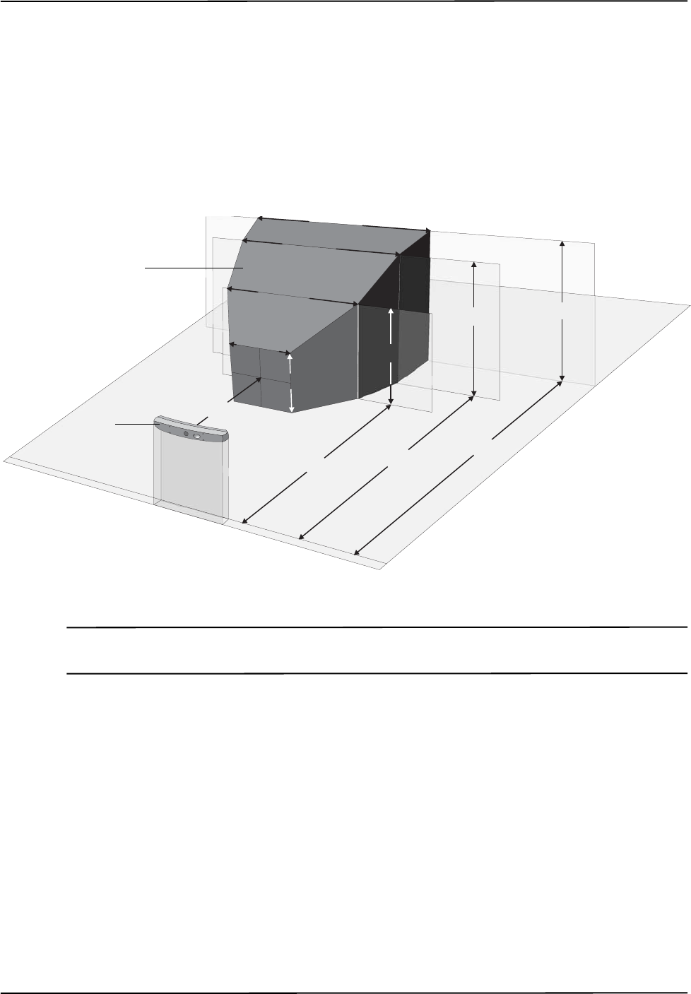
measurement volume. A 3D representation of the measurement volume is shown in Figure 1-1.
Figure 1-1 Polaris Spectra Measurement Volume
Note The back section of the measurement volume, 2400 mm to 3000 mm from the Position Sensor, is only available in
the optional extended pyramid volume.
The system has applications in a range of industries, including:
• medical
•dental
• research
The Polaris Spectra System consists of a Position Sensor, a Host USB Converter, a power adapter,
and cables, as shown in Figure 1-2.
1856 mm
1566 mm
1144 mm
480 mm
950 mm
448 mm
796 mm
1312 mm 1470 mm
1532 mm 2400 mm 3000 mm
Measurement Volume
Position Sensor

Polaris Spectra System Overview
2 Passive Polaris Spectra User Guide - Revision 7
Figure 1-2 Polaris Spectra System Setup
The individual components of the system are described on the following pages:
•“Position Sensor” on page 3
•“Host USB Converter” on page 8
•“Power Adapter” on page 9
•“Cables” on page 10
•“Tools” on page 11
•“Software” on page 13
1.2 Host Computer Requirements
A host computer is also required to operate the system. The host computer must be approved to
IEC 60950 or IEC 60601 standard and meet the following minimum specifications:
• Intel or Power PC G5 Processor
• 512Mb random access memory (RAM)
• 100 Mb free disc space
• Operating system options:
- Windows XP (32 bit)
- Windows Vista (32 bit and 64 bit)
- Windows 7 (64 bit)
- Linux Kernel 2.6.35 (see “Installing the Software (Linux)” on page 23.)
Position Sensor
Position Sensor Cable
Host USB Converter
Power Adapter Cable
Power Adapter
USB Cable
To Computer
Power Cord
To Mains Power
Polaris Spectra System Overview
Passive Polaris Spectra User Guide - Revision 7 3
- Mac OS X (the system was tested and verified on version 10.5.8, but may work on
earlier and later versions.)
• Screen resolution 1024 x 768 (1280 x 1024 recommended)
1.3 Position Sensor
The Position Sensor is the main component of the Polaris Spectra System. An overview of its
operation is as follows:
1. The Position Sensor emits infrared (IR) light from its illuminators, similar to the flash on a
conventional camera.
2. The IR light floods the surrounding area and reflects back to the Position Sensor off passive
sphere markers (on passive tools) or triggers markers to activate and emit IR light (on active
wireless tools).
3. The Position Sensor then measures the positions of the markers, and calculates the
transformations (the positions and orientations) of the tools to which the markers are attached.
4. The Position Sensor transmits the transformation data, along with status information, to the host
computer for collection, display, or further manipulation.
Note For a more detailed description of how the Position Sensor detects markers, see “Marker Detection and Tool
Tracking” on page 42.
When connected to a Host USB Converter, the Position Sensor can track two types of tools: passive
tools and active wireless tools. For more information on tools, see “Polaris Spectra System Tools”
on page 44.
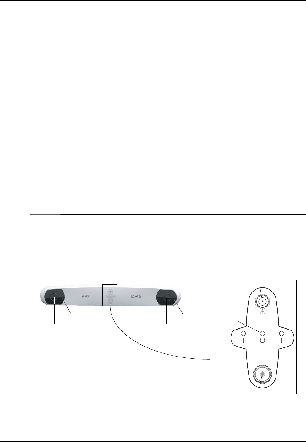
Front View
Figure 1-3 Position Sensor (with Laser Option) Front View
L
A
S
E
R
A
P
E
R
T
U
R
E
Sensor
Illuminator Indicator
LEDs (3)
Laser Activation Button
Laser Aperture
Sensor
Illuminator
Polaris Spectra System Overview
4 Passive Polaris Spectra User Guide - Revision 7
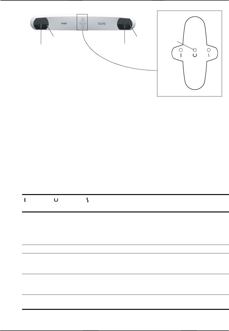
Figure 1-4 Position Sensor (without Laser Option) Front View
The front of the Position Sensor incorporates the following components:
Illuminators Two arrays of infrared light-emitting diodes (IREDs) that provide IR light for the
passive sphere markers (on passive tools) and an activation trigger for active markers (on active
wireless tools).
Sensors Two sensors that each comprise a lens and a charge coupled device (CCD). The sensors
collect IR light that is reflected from passive sphere markers (on passive tools) or emitted from
active markers (on active wireless tools).
Indicator LEDs The power, status, and error LEDs on the front of the Position Sensor combine as
described in Table 1-1 to indicate the status of the Position Sensor:
Table 1-1 Position Sensor Indicator LEDs Summary
Power LED
(Green) Status LED
(Green) Error LED
(Amber) Position Sensor Status
Flashing (Any state) (Any state) The Position Sensor is warming up. The power LED
will stop flashing and light steady green when Position
Sensor is ready for use, as defined by the NDI
Accuracy Assessment Kit (AAK) protocol. For
information on the AAK, contact NDI.
Solid Solid Off The Position Sensor is ready for use; no faults
Solid Solid Flashing Minor recoverable fault; can easily be corrected by a
novice user (for example, bump sensor has detected a
bump). Does not prevent system operation.
Solid or off Solid Solid Major recoverable fault (for example, firmware update
required). The system will not operate until the fault is
corrected.
Solid Off Solid Non-recoverable fault. Return the Position Sensor to
NDI for service.
Sensor
Illuminator Indicator
LEDs (3)
Sensor
Illuminator
Polaris Spectra System Overview
Passive Polaris Spectra User Guide - Revision 7 5
Note If your Polaris Spectra System uses combined firmware revision 002, see the technical bulletin “Polaris Spectra
Position Sensor LED Behaviour with Combined Firmware Revision 002,” available on the NDI support site at
http://support.ndigital.com.
You may be able to diagnose the error using the configure utility of NDI ToolBox, or using the API
command GET to read the Info.Status.Alerts user parameter. (See the “Polaris Application Pro-
gram Interface Guide” for details.)
A minor recoverable fault can usually be quickly corrected by a novice user. A major recoverable
fault usually requires more expertise (for example, performing a firmware update). A non-
recoverable fault requires that the Position Sensor be returned to NDI for servicing.
Laser Aperture (Optional) The positioning laser beam is emitted from this aperture.
Do not look directly into the laser-emitting aperture. The Class 2 laser module on the Position Sensor emits
radiation that is visible and may be harmful to the human eye. Direct viewing of the laser diode emission at close
range may cause eye damage.
Take precautions to ensure that people with restricted movement or reflexes (for example, patients undergoing
medical procedures) do not look directly into the laser-emitting aperture. Patients undergoing medical
procedures may be restricted in the availability of adverse-effects reflexes (turning away eyes and/or head,
closing eyes) due to pharmaceutical influences and/or mechanical restraints. The Class 2 laser module on the
Position Sensor emits radiation that is visible and may be harmful to the human eye. Direct viewing of the laser
diode emission at close range may cause eye damage.
Laser Activation Button (Optional) Press this button to activate the positioning laser. The laser will
remain on only while the button is pressed.
Use of laser controls or adjustments or performance of laser-related procedures other than those specified
herein may result in hazardous radiation exposure.
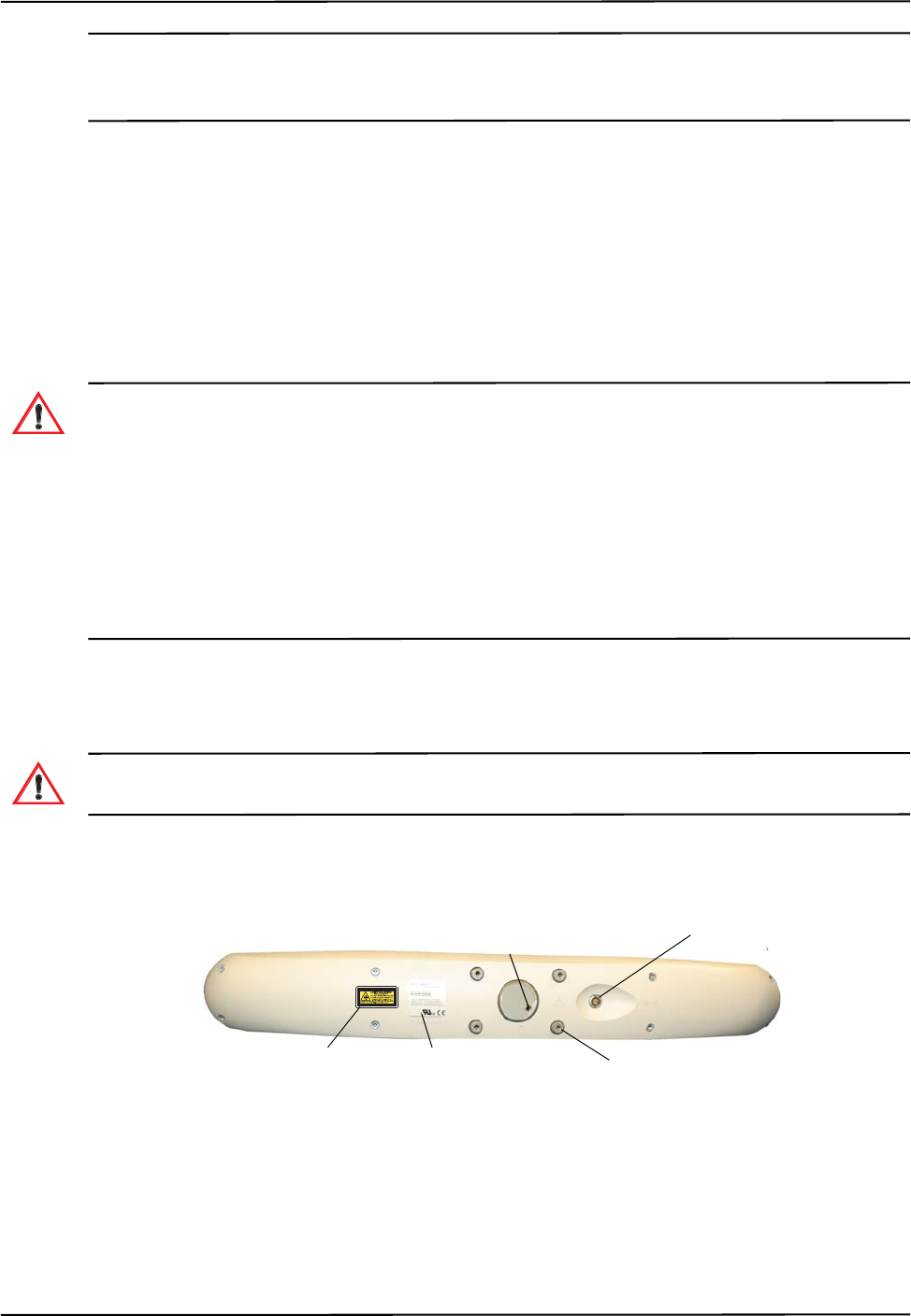
Rear View
Figure 1-5 Position Sensor Rear View
The rear of the Position Sensor incorporates the following components:
Mount Four M4 x 0.7 mm pitch x 8.5 mm deep threaded holes (See Figure 2-1 on page 17 for
mounting details.)
Warning!
Warning!
Mounting
point (4)
Connector
Laser Label Serial Number
Label
Laser Activation
Switch Connector

Polaris Spectra System Overview
6 Passive Polaris Spectra User Guide - Revision 7
Connector (LEMO) A 14-pin connector that provides power to the Position Sensor and allows
communications to and from the Position Sensor. The LEMO connector is located on the back of
Position Sensor. The connector details, internal to the Position Sensor, are shown in Figure 1-6 and
Table 1-2.
If you make a custom cable, use LEMO part number FGA.1B.314.CYCD62Z or equivalent LEMO
connector to mate to the connector on the Position Sensor.
Cable shield ground connection must be maintained to the shell of the LEMO connector.
Any unused contacts can be left floating.
Note It is good practice to disconnect mains power before connecting or disconnecting cables. Failure to do so may
cause damage to the equipment.
Figure 1-6 Position Sensor Connector Layout
Table 1-2 Position Sensor Connector - Signals
Pin Signal
1Power
2Power
3Rx +
4Rx-
5Ground
6Ground
7Ground
8Tx +
9Tx -
10 Power
11 RTS +
12 RTS -
13 CTS +
14 CTS -
Pin 1 (viewed from the
front of connector)

Polaris Spectra System Overview
Passive Polaris Spectra User Guide - Revision 7 7
Laser Label The laser label is located on the back of the Position Sensor and shows the
classification, output, wavelength, standards, and a warning.
Figure 1-7 Position Sensor Laser Label
Serial Number Label The serial number label is located on the back of the Position Sensor and shows
the item ID, model, serial number, and manufacture date of the Position Sensor.
Figure 1-8 Position Sensor Serial Number Label
Audio Codes
In addition to the indicator LEDs, the Position Sensor emits audio tones to alert the user to events.
The codes are interpreted as follows:
• Two beeps are emitted on reset or when power is applied to the Position Sensor. (This
feature can be disabled in NDI ToolBox software, or by setting the value of the user
parameter Param.System Beeper to 0.)
• If the host computer does not send a command to the system within a given time, the
Position Sensor will emit two quick beeps every three seconds. This feature is an
application watchdog; the timeout value is the value of the user parameter Param.Watch
Dog Timer. By default this feature is disabled; to enable it, set the value of the user
parameter Param.Watch Dog Timer to an non-zero value.
• The API command BEEP can be used to cause the Position Sensor to emit beeps.
Note The user parameters store values for different aspects of the Polaris Spectra System. To set the value of a user
parameter, use the API command SET. To retrieve a user parameter value, use the API command GET. For details
on user parameters and API commands, see the “Polaris Application Program Interface Guide.”

Polaris Spectra System Overview
8 Passive Polaris Spectra User Guide - Revision 7
Bump Sensor
The Position Sensor contains an internal bump sensor that detects when the Position Sensor has
suffered an impact that may affect its calibration. For more information on the bump sensor, see
“Bump Sensor” on page 57.
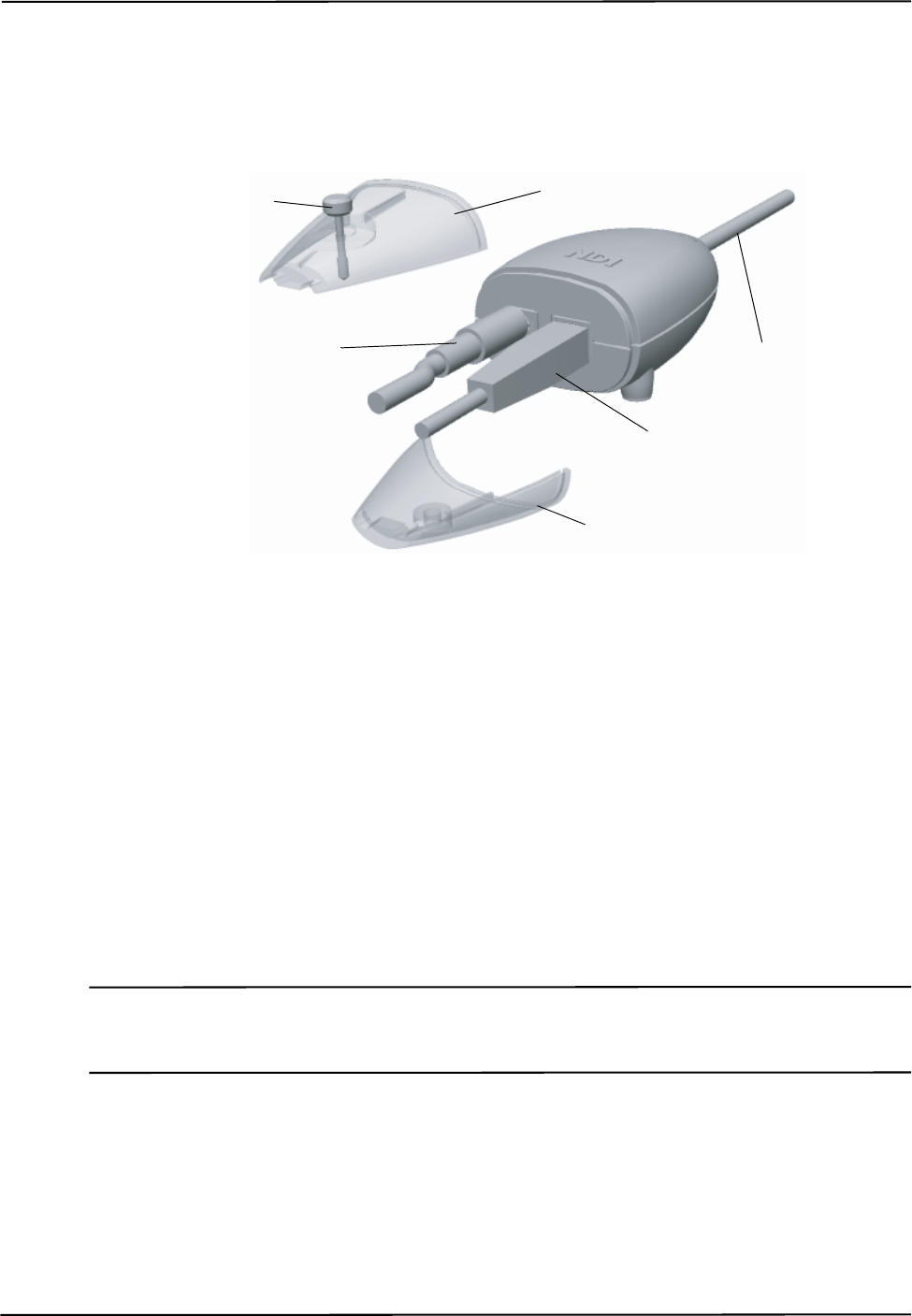
1.4 Host USB Converter
The Host USB Converter provides the interface between the Position Sensor, the power adapter,
and the host computer:
• The attached Position Sensor cable connects the Host USB Converter to the Position Sensor.
• The power adapter and USB cable plug into the Host USB Converter.
• Modem status bits are provided (see “Serial Port Emulation” on page 9).
Figure 1-9 Host USB Converter
The Host USB Converter incorporates the following components:
Cable Covers: Two covers (top and bottom) that are secured together by means of a thumbscrew.
The covers retain the USB and power adapter cables in place.
Position Sensor Cable: Provides connection for data and power between the Position Sensor and
Host USB Converter. This cable is permanently connected to the Host USB Converter and is
available in various lengths to a maximum of 30 m, depending on the configuration of your system.
Power Indicator: Lights green when power is being supplied to the Host USB Converter.
Error Indicator: Lights amber when the Host USB Converter has detected a fault. (Also flashes
briefly when the Host USB Converter is first powered on.)
Indicator LED
(Error) Indicator LED
(Power)
Position Sensor Cable
Power Connector
Mounting Feet x 3
USB Connector
Cable Covers
(top and bottom)
Thumbscrew

Polaris Spectra System Overview
Passive Polaris Spectra User Guide - Revision 7 9
Mounting Feet: Three feet that incorporate an internal thread (M6 x 1 mm pitch x 4 mm depth) to
allow the Host USB Converter to be attached to an external structure (for example, a cart). For free-
standing use, rubber inserts are located in the mounting feet.
Serial Number Label The serial number label is located on the bottom of the Host USB Converter
and shows the item ID, model, serial number, and manufacture date of the Host USB Converter.
Figure 1-10 Host USB Converter Serial Number Label
Serial Port Emulation
Modem Status Bits The Host USB Converter emulates a standard PC serial port, such that the host
application may communicate with the Polaris Spectra System as if it was a standard RS-232 device.
A feature of this is that the following modem status bits are used as follows:
• The Data Set Ready (DSR) will be set when the Host USB Converter senses that a Position
Sensor is connected (power must also be connected to the Host USB converter).
• The Ring Indicator (RI) will be set when a fault condition is showing on the Host USB
Converter error indicator.
Communication Rate If your operating system cannot set the serial port rate directly to 1.2 Mbaud,
an aliased 19 200 baud rate is provided to enable you to run at the higher speed. Do not set the
Polaris Spectra System to 19 200 baud; if the system is set to 19 200 baud, it will be unable to
communicate with the host computer, because setting the host application to 19 200 baud will result
in the aliased rate of 1.2 Mbaud. (The baud rate of the Polaris Spectra System can be set using the
API command COMM. See the “Polaris Application Program Interface Guide” for details.)
1.5 Power Adapter
The system is powered by an NDI supplied power adapter. The model of the power adapter is
dependent on which Edition of the IEC 60601-1 standard your system is compliant with as follows:
• Advanced Power Systems, part number APS49ES-24021/Hitron, part number HES49ES-
24021 - applicable to IEC 60601-1 2nd Edition only.
• Advanced Power Systems, part number APS49EMG-24021-7/Hitron, part number
HEMG49-S240210-7 - applicable to IEC 60601-1 2nd Edition and 3rd Edition.
The power adapter connects to the mains supply and provides DC power to the Position Sensor via
the Host USB Converter.
Alternatively, power may be supplied by a customer provided power adapter that meets the
following criteria:

Polaris Spectra System Overview
10 Passive Polaris Spectra User Guide - Revision 7
• medical grade, double insulated (required if end use will be in a medical environment)
• 24 V DC, 1.2 A output (40 W typical)
• Switchcraft part number 760 plug (or equivalent)
Note The Underwriters Laboratories Inc. (UL) recognition of the Polaris Spectra System includes the Polaris Spectra
Position Sensor, Host USB Converter and the power adapter as follows:
IEC 60601-1 2nd Edition only - APS APS49ES-24021/Hitron HES49ES-24021 power adapter.
IEC 60601-1 2nd Edition and 3rd Edition - APS APS49EMG-24021-7/Hitron HEMG49-S240210-7 power adapter.
This investigation does not include the use of any other power adapter or source with the Polaris Spectra
System. Any such configuration will require further investigation. If the Polaris Spectra System is used in a
medical application, the final end-use configuration must be independently investigated to the IEC 60601 family
of standards and all applicable national differences.
Note If a non-NDI supplied power adapter is used, it should be chosen to suit the particular use and the resulting
system configuration must be verified for electrical safety by an approved test laboratory. For further information
contact NDI.
1.6 Cables
NDI supplies the following cables for use with the Polaris Spectra System:
Position Sensor Cable: Provides connection for data and power between the Position Sensor and
Host USB Converter. This cable is permanently connected to the Host USB Converter and is
available in various lengths to a maximum of 30 m (approximately 100 feet), depending on the
configuration of your system.
The cable used by NDI for the Host USB Converter and the Position Sensor cable has the following
characteristics:
• The cable has redundant power and ground lines (three of each) to reduce power loss. A
conductor specification of 28 AWG is used for each of these six lines.
• The cable houses four twisted pairs of differential signal lines. A conductor specification of
32 AWG is used for each of these eight lines. These lines are kept as small as possible to
reduce cable size.
• To minimise noise interference, the cable is shrouded in a braided shield with 80% to 90%
coverage.
NDI has tested communications along a cable with the above specifications up to a length of 30 m
(approximately 100 feet).
NDI has also successfully tested a lower cost, but less robust cable. It is available as NDI part
number 2600608 (3M™ part number 3600B/14). The details of this cable are as follows:
• 3M Round, Shielded/Jacketed, Discrete Wire Cable, 28 AWG Stranded, PVC/PVC,
3600B/14
• Meets external wiring requirements of National Electrical Code, Article 725 (CL2)
Polaris Spectra System Overview
Passive Polaris Spectra User Guide - Revision 7 11
• 28 AWG stranded wire provides flexibility
• Twisted pairs reduce crosstalk for balanced drive applications
• Dual shielding with aluminium film foil and copper braid provides excellent EMI/ESD
protection
• Wires are colour coded for easy identification
• 35 db average shielding effectiveness
• RoHS compliant
USB Cable: Provides connection for data between the host computer and Host USB Converter. This
cable is a USB, A-B male, double shielded, 5 m cable.
Power Adapter Output Cable: Provides connection for power to the Host USB Converter. This cable
is permanently connected to the power adapter and has a plug-in jack connector to connect to the
Host USB Converter.
Power Adapter Power Cable: Connects the power adapter to the mains supply. This cable is a
medical grade AC line cord.
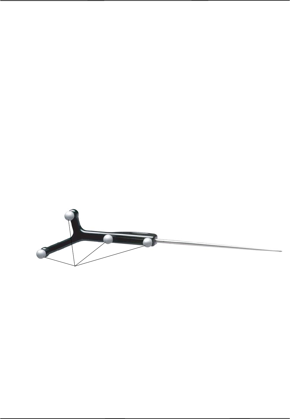
1.7 Tools
A tool is a rigid structure on which three or more markers are fixed so that there is no relative
movement between them. An example of a tool is shown in Figure 1-11.
Figure 1-11 Passive Tool
The passive Polaris Spectra System can track passive tools and active wireless tools. The Position
Sensor tracks tools based on the geometry of the markers on the tools. The Position Sensor requires
a tool definition file for each tool. A tool definition file describes a tool to the Position Sensor
(including the tool’s marker geometry).
Passive Tools
Passive tools incorporate NDI passive sphere markers. The passive sphere markers have a retro-
reflective coating that reflects IR light back to its source, instead of scattering it. As such, the IR
light from the Position Sensor illuminators reflects off the markers directly back to the sensors. The
Polaris Spectra System can track the positions and orientations of tools, and can also report the
positions of individual passive spheres.
Passive Sphere Markers

Polaris Spectra System Overview
12 Passive Polaris Spectra User Guide - Revision 7
Passive sphere markers must be attached to the tool using NDI mounting posts, which are
manufactured to firmly hold NDI spheres.
An example of a passive tool is shown in Figure 1-11. The example shows a probe that incorporates
four passive sphere markers. For more information on passive tools and passive sphere markers, see
“Passive Tools” on page 44.
Active Wireless Tools
Active wireless tools incorporate active markers, which emit IR light. The tools also house an IR
receiver. An active wireless tool draws power from a battery, or from the equipment to which it is
attached.
The Position Sensor pulses the illuminators in a way that is recognizable by the IR receiver in the
active wireless tool. The active wireless tool detects the IR pulse; the markers then emit IR, which is
detected by the Position Sensor.
For more information on active wireless tools and active markers, see “Active Wireless Tools” on
page 45.
Tool Definition Files
Each tool has a tool definition file (formatted as .rom) to describe it to the system. A tool definition
file must be loaded into the system before the system can track the associated tool. The information
stored in the tool definition file includes the geometry of the tool’s markers, the tool’s manufacturing
data, tool face definitions (for a multi-faced tool), and the parameters and settings described in “Tool
Tracking Parameters” on page 47. Without this information, the system cannot accurately interpret
the data it collects.
Note For more information on tool definition files, see “Tool Definition File” on page 47. Polaris Spectra System tools
are described in more detail in “Polaris Spectra System Tools” on page 44. For information on tool design and
construction, refer to the “Polaris Tool Design Guide.”
Number of Tools
Up to 15 compatible wireless tool definition files can be loaded simultaneously, ready for tracking.
The system can simultaneously track up to six passive tools and one active wireless tool, within the
following constraint: a maximum of 32 passive and 32 active markers, including stray markers, can
simultaneously be in view of the Position Sensor. Additional markers in view may affect the speed
of the system and its ability to return transformations.
Note The field of view of the Position Sensor is described on page 40. Stray markers are described on page 53.

Polaris Spectra System Overview
Passive Polaris Spectra User Guide - Revision 7 13
1.8 Software
The following software is included on the Polaris Spectra CD. You can also download the software
from the NDI Support Site at http://support.ndigital.com.
NDI Combined API Sample A sample program written for Windows, and the source code for the
program. This program provides an example of how to write programs to operate the Polaris Spectra
System.
NDI ToolBox A suite of utilities for diagnostics, maintenance, testing, and development support for
the Polaris Spectra System. NDI ToolBox also includes command line functionality, to allow you to
embed an NDI ToolBox application (such as upgrading firmware) into your application software.
See the NDI ToolBox help for details.
Note NDI 6D Architect application software, which is used to characterize tools and create tool definition files, is
located on the CD that accompanies the developer kit.

Setting Up the Polaris Spectra System
14 Passive Polaris Spectra User Guide - Revision 7
2 Setting Up the Polaris Spectra System
This chapter provides instructions and information required to set up the Polaris Spectra System for
use. This chapter contains the following sections:
•“Unpacking the Polaris Spectra System” on page 14
•“Operating Environment Requirements” on page 14
•“Mounting the System Units” on page 16
•“Connecting the Hardware” on page 19
•“Installing the Software (Windows)” on page 20
•“Installing the Software (Linux)” on page 23
•“Installing the Software (Mac)” on page 25
2.1 Unpacking the Polaris Spectra System
The Polaris Spectra System is shipped with a Position Sensor, a Host USB Converter, a power
adapter, cables, the Polaris Spectra CD, and documentation.
When unpacking the Polaris Spectra System, be sure to handle all system components with care.
Keep the packaging in good condition; you will need to use it if the system ever needs to be returned
to NDI for repair.
Note See “Return Procedure” on page 91 for instructions on returning your system to NDI.
2.2 Operating Environment Requirements
Warnings
Read the following warnings before using the Polaris Spectra System, to avoid the risk of personal
injury.
1. Do not use the Polaris Spectra System in the presence of flammable materials such as
anaesthetics, solvents, cleaning agents, and endogenous gases. Flammable materials may
ignite, causing personal injury or death.
2. Do not protect or shield either the Position Sensor or tools with methods not approved by
NDI. Non-approved methods will interrupt the optical path and degrade the performance
of the system. Reliance on data provided by a Position Sensor without an uninterrupted
optical path may lead to inaccurate conclusions. If your application involves personal
safety, inaccurate conclusions may result in personal injury.
3. The Polaris Spectra System requires special precautions regarding EMC. It must be
installed and put into service in accordance with the EMC information detailed in
“Electromagnetic Compatibility” on page 78. Failure to do so may result in personal
injury.
Warning!

Setting Up the Polaris Spectra System
Passive Polaris Spectra User Guide - Revision 7 15
4. Do not use the passive Polaris Spectra System either adjacent to, or stacked with, other
equipment. Check that the Polaris Spectra System is operating normally if it is used either
adjacent to, or stacked with, other equipment. Failure to do so may result in personal
injury.
5. Radio frequency communications equipment, including portable and mobile devices, may
affect the Polaris Spectra System and result in personal injury.
6. Do not immerse any part of the Polaris Spectra System or allow fluid to enter the
equipment. If fluids enter any part of the system they may damage it and present a risk of
personal injury.
7. Do not obstruct the normal flow of air around the Position Sensor (for example, by
draping or bagging the Position Sensor). Doing so will affect the Position Sensor's
operational environment, possibly beyond its recommended thresholds. Reliance on data
provided by a Position Sensor that is outside of recommended thresholds may lead to
inaccurate conclusions. If your application involves personal safety, inaccurate conclusions
may result in personal injury.
8. Do not use the Polaris Spectra Position Sensor in an MRI environment without first
determining the performance, including accuracy, of the Position Sensor in an MRI
environment. NDI has not fully validated the Polaris Spectra Position Sensor in an MRI
environment. It is unknown whether reliance on data provided by a Position Sensor in an
MRI environment may lead to inaccurate conclusions. If your application involves
personal safety, reliance on inaccurate conclusions may result in personal injury.
In order for the Polaris Spectra System to operate correctly, the system must be set up in an
environment that meets the following criteria:
• There must be a clear line of sight between the Position Sensor and the tools to be tracked.
The tools must be inside the characterized measurement volume. Refer to Figure 4-2 on
page 40 or Figure 4-3 on page 41 for the dimensions of the characterized measurement
volume.
• The ambient operating temperature range for the Polaris Spectra System is dependent upon
the physical location of the Host USB Converter. If the Host USB Converter is located
within the patient vicinity where it may be touched by the patient, the operating ambient
temperature range is +10°C to +30°C. If the Host USB Converter is located outside this
patient vicinity, the operating ambient temperature range permitted for the system is +10°C
to +40°C. The power adapter must be located outside the patient vicinity under all operating
conditions. It is the responsibility of the system integrator and/or the end-user to ensure that
the system is appropriately configured for the operating conditions.
• Make sure that sources of background IR light in the 800 nm to 1100 nm range (e.g.
sunlight, some operating room lights) are minimized. The Position Sensor is sensitive to IR
light. Since the Position Sensor functions by detecting IR light reflected from, or emitted by,
markers, other sources of IR light can interfere with the Polaris Spectra System.
• Make sure that there are no large reflective surfaces within the field of view (described on
page 40). For example, the gantry for a magnetic resonance imaging (MRI) machine has a
large reflective surface. It can be draped with non-reflective material to eliminate
reflections.

Setting Up the Polaris Spectra System
16 Passive Polaris Spectra User Guide - Revision 7
• Make sure that the tools do not have flat reflective surfaces. Certain tool shapes and surfaces
can cause reflections that may interfere with the Polaris Spectra System. For more
information, see the “Polaris Tool Design Guide.”
• Before using the system, make sure the power LED on the Position Sensor has stopped
flashing. The power LED will flash while the Position Sensor warms up; once the LED is
steady, the system is ready for use as defined by the NDI Accuracy Assessment Kit (AAK)
protocol. For information on the AAK, contact NDI.
• The environmental conditions must be as listed in Figure 12-1 on page 75.
• If the system is to be used in an MRI environment, contact NDI for information on response
of the system.
2.3 Mounting the System Units
Caution! Always place the Position Sensor on a rigid support system. If not supported, the Position Sensor may fall, which
may affect the calibration and damage the Position Sensor.
Note Before you design a custom enclosure or any attachments (other than mounting) for the Position Sensor, contact
NDI for assistance.
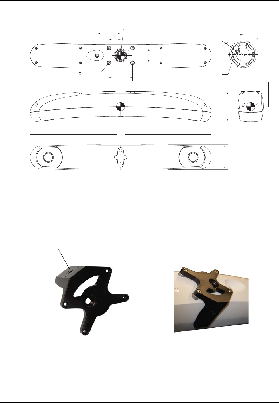
Position Sensor
The Position Sensor is mounted via four M4 x 0.7 mm pitch x 8.5 mm deep threaded holes.
Figure 2-1 shows the Position Sensor dimensions and mounting arrangement.
Setting Up the Polaris Spectra System
Passive Polaris Spectra User Guide - Revision 7 17
Figure 2-1 Position Sensor Mounting Details
An optional Position Sensor mounting bracket (Figure 2-2) is available. The bracket provides a
mounting option to a standard 1/4” tripod mount. Contact NDI for details.
Figure 2-2 Position Sensor Mounting Bracket
40
80 See Detail A
Thread m4x0.7x 8.5 4x 80 ± 0.5
25 50 ± 0.5
External laser trigger jack
57.5° 22.9 P.D.
Detail A
52.04
Centre of gravity
104
84
613
All dimensions in mm
1/4” thread tripod
mount point
Mounting Bracket fitted
to Position Sensor
Mounting Bracket
Setting Up the Polaris Spectra System
18 Passive Polaris Spectra User Guide - Revision 7
External Laser Trigger Switch
The external laser trigger can be used to connect a switch to trigger the laser. This port is a four-
conductor, 3.5-mm audio jack. Only the first two conductors are used, as follows:
If you intend to design and integrate an external laser activation switch, there are certain
considerations you should take into account to provide the maximum protection against electrostatic
discharge (ESD):
• Design the handle and select a switch that will minimise the possibility of energy flowing
into the laser switch circuits in the Position Sensor.
• Electrically isolate the body of the switch from the handle, and provide a good grounding
path from the handle to earth ground. This will direct the ESD energy to flow through the
handle and to ground, instead of passing through the laser switch wiring into the Position
Sensor.
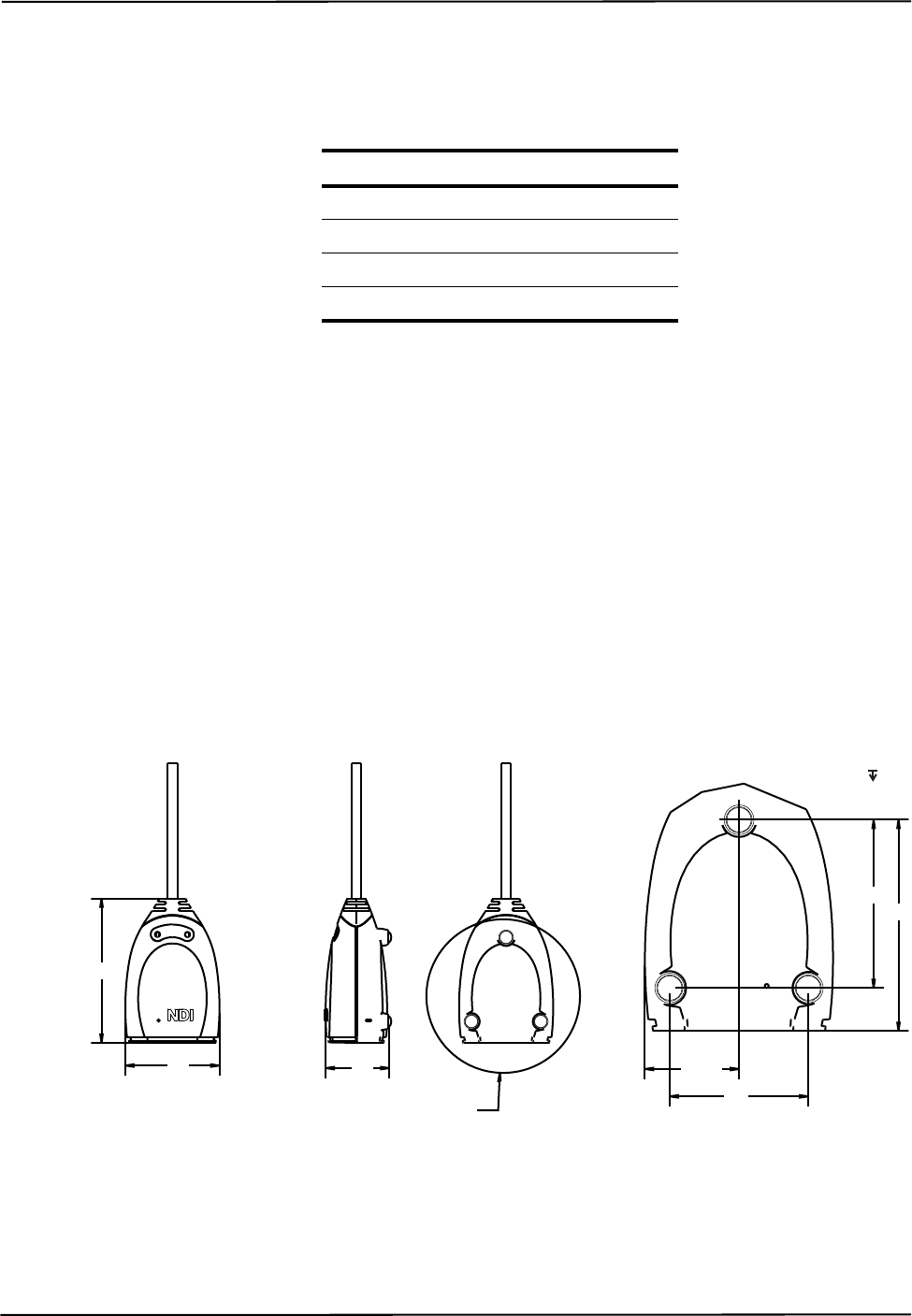
Host USB Converter
The Host USB Converter can be free-standing or may be mounted via M6 x 1 mm pitch x 3 mm
deep threaded holes located in the three mounting feet. Figure 2-3 shows the Host USB Converter
dimensions and mounting arrangement.
Figure 2-3 Host USB Converter Mounting Details
Conductor Signal
1 Laser switch contact input
2 Laser switch contact input
3 Not used
4 Not used
57 40
See Detail A
28.53
42
Detail A
51 64
M6x1x3
3Places
88
All dimensions in mm

Setting Up the Polaris Spectra System
Passive Polaris Spectra User Guide - Revision 7 19
2.4 Connecting the Hardware
Warnings
Read the following warnings before using the Polaris Spectra System, to avoid the risk of personal
injury.
1. Do not use cables or accessories other than those listed in this guide. The use of other
cables or accessories may result in increased emissions and/or decreased immunity of the
Polaris Spectra System and may result in personal injury.
2. Do not incorporate non-NDI components with the Polaris Spectra System. The accuracy of
results produced by applications that incorporate non-NDI components with the Polaris
Spectra System is unknown. If your application involves personal safety, reliance on these
results may result in personal injury.
3. Do not attempt to bypass the grounding prong on the power cord by using a three-prong to
two-prong adapter. The system must be properly grounded to ensure safe operation.
Failure to do so presents an electric shock hazard.
4. Do not use the Position Sensor without inspecting it for cleanliness and damage both
before and during a procedure. Reliance on data provided by an unclean or damaged
Position Sensor may lead to inaccurate conclusions. If your application involves personal
safety, inaccurate conclusions may result in personal injury.
5. Do not connect the Polaris Spectra System to a host computer that is not IEC 60950 and/or
IEC 60601 approved. If you connect the system to a non-approved host computer you may
increase leakage currents beyond safe limits and cause personal injury.
Read the following cautions before you connect the Polaris System components.
Caution! Do not push or pull connectors in constricted areas.
Do not put heavy objects on cable connectors.
Do not leave cable connectors where they can be damaged, particularly on the floor, where they can easily be
stepped on.
Pull connections apart by gripping the connector. Do not pull them apart by tugging on the cable as this can
damage the connecting cable. Never force a connection or a disconnection.
Note It is good practice to disconnect the mains power before connecting or disconnecting cables.
1. Connect the Position Sensor cable (attached to the Host USB Converter) to the connector
located on the back of the Position Sensor. Align the red marking on the Position Sensor
connector with the red marking on the cable connector (the double keys of the connectors
should be aligned).
Make sure the Position Sensor cable is securely connected to the Position Sensor. A loose
connection may result in partial functionality or unpredictable system behaviour.
Warning!
Setting Up the Polaris Spectra System
20 Passive Polaris Spectra User Guide - Revision 7
2. Connect the USB cable B plug and power adapter cable to the Host USB Converter, as shown in
Figure 2-4.
3. Locate the top and bottom cable covers in place on the Host USB Converter. Secure the covers
with the thumbscrew, as shown in Figure 2-4.
Figure 2-4 Host USB Converter Connecting the Cables
4. Plug the USB cable A plug into the host computer.
5. Make sure all the cables are connected firmly, and placed where they will not be stressed,
stepped on, or bent.
6. Plug the power cable into the power adapter.
7. Plug the power cable into the power mains and turn on the mains.
The Polaris Spectra System will begin a diagnostic evaluation. During this evaluation, the LEDs on
the Position Sensor will flash. When the diagnostic evaluation is complete, the Position Sensor will
emit two beeps and the power LED on the Position Sensor will light.
The Position Sensor requires a warm-up time every time it is powered on. The power LED will flash
while the Position Sensor warms up; once the LED is steady, the system is ready for use as defined
by the NDI Accuracy Assessment Kit (AAK) protocol. For information on the AAK, contact NDI.
Note The Position Sensor initially communicates to the host computer at 9600 baud. If you are using the NDI ToolBox
application it will increase the baud rate as high as possible. If you are using your own application, the baud rate
can be set using the API command COMM. Refer to the “Polaris Application Program Interface Guide” for details.
2.5 Installing the Software (Windows)
The NDI software is located on the Polaris Spectra CD. You can also download the software from
the NDI Support Site at http://support.ndigital.com.
Top Cable Cover
Bottom Cable Cover
Power Adapter
Cable
USB Cable
Position Sensor
Cable
Thumbscrew

Setting Up the Polaris Spectra System
Passive Polaris Spectra User Guide - Revision 7 21
Note NDI 6D Architect application software, which is used to characterize tools and create tool definition files, is
located on the CD that accompanies the developer kit.
NDI Combined API Sample
To install NDI Combined API Sample, copy the contents of the “CombinedAPISample” folder from
the Polaris Spectra CD onto the host computer.
NDI ToolBox
To install NDI ToolBox, follow the on-screen instructions from the auto-run window that appears
when you insert the Polaris Spectra CD into the drive. Alternatively, on the Polaris Spectra CD,
browse to Windows\ToolBox\ directory and double-click install.exe.
Once you start the installation from the install page, a wizard appears. Follow the on-screen
instructions to complete the process. The default installation location is
C:\Program Files\Northern Digital Inc\ToolBox.
The installation of NDI ToolBox also includes downloading the drivers for the Host USB Converter.
Note The NDI ToolBox installation includes a Java virtual machine (VM) for Windows and Linux systems. The Java VM
included in the NDI ToolBox installation is fully compatible with NDI ToolBox. Other versions of Java VM may
cause NDI ToolBox to exhibit unusual or unpredictable behaviour.
Host USB Drivers
The Windows driver model consists of two parts; low-level USB and high-level virtual serial port. It
appears as a Windows serial port, COMx (where x is enumerated) and emulates a standard PC serial
port such that the Host USB Converter may be communicated with as a standard RS-232 device.
When you first connect the NDI Host USB Converter to the host computer, you will need to install
drivers for the Host USB Converter. There are two sets of drivers for the Host USB Converter:
• the first set of drivers enables the Host USB converter to work with the host computer
• the second set of drivers sets up the USB port where the Host USB Converter is connected
to emulate a serial port
Driver Location
If you have already installed NDI ToolBox, the USB drivers were installed as part of that
installation. By default, the drivers are located at C:\Program Files\Northern Digital Inc\ToolBox\
USB Driver. (See “NDI ToolBox” on page 21.)
The drivers are also located on the Polaris Spectra CD in the USB Driver folder.

Setting Up the Polaris Spectra System
22 Passive Polaris Spectra User Guide - Revision 7
Windows XP and Vista
Install the USB drivers for Windows XP and Vista as follows:
1. When you first connect the Host USB Converter to the host computer, the Found New
Hardware wizard will begin automatically.
2. When prompted, select the option that allows you to specify the drivers’ location.
3. Browse to the folder containing the drivers, either on the host computer or on the Polaris Spectra
CD. Windows will automatically select the correct drivers from the folder.
4. Click Next and Finish as required to complete the installation.
Note After you have selected the folder containing the USB drivers, a warning may appear, indicating that the drivers
have not passed Windows Logo testing. Click “Continue Anyway”.
5. Once the first set of drivers is installed, the Found New Hardware Wizard will launch a
second time. Follow steps 2 to 4 above to install the second set of drivers.
6. The system will now appear to be connected through a virtual COM port.
Host USB Converters are interchangeable on the same USB port, without having to re-install drivers
or losing the COM port previously established.
Windows 7
Install the USBdrivers for Windows 7 as follows:
Note When you first connect the Host USB Converter to the host computer, an error message may appear over the task
bar. Ignore the message and complete the following steps to install the USB drivers
1. From the Windows menu, select Control Panel.
2. In the top right hand corner of the Control Panel window, select View by: Small Icons.
3. From the Control panel, select Device Manager.
4. Under Other Devices, right click NDI Host USB Converter.
5. Select Update Driver Software..., then select Browse my computer for driver software.
6. Select Program Files (x86)\Northern Digital Inc\ToolBox\USB Driver. Select Next.
7. In the Windows security dialog, select Install this driver software anyway option. The first set
of drivers will install.
8. After the first set of drivers are installed, browse to Other Devices and right click USB Serial
Port.
9. Select Update Driver Software..., then select Browse my computer for driver software.
10. Select Program Files (x86)\Northern Digital Inc\ToolBox\USB Driver. Select Next.

Setting Up the Polaris Spectra System
Passive Polaris Spectra User Guide - Revision 7 23
11. In the Windows security dialog, select Install this driver software anyway option. The second
set of drivers will install.
Driver installation is complete and the system will now appear to be connected through a virtual
COM port.
Host USB converters are interchangeable on the same USB port, without having to re-install drivers
or losing the COM port previously established.
Reassigning the Windows COM Number
After the Host USB Converter drivers have been installed, you can reassign the Windows COM
number if desired, as follows:
1. Launch Device Manager.
2. Navigate to Ports (COM & LPT).
3. Right-click on the Host USB Converter.
4. Select the Properties pop-up menu.
5. Select the Port Settings tab.
6. Click on the Advanced Settings button.
7. From the dialog box that is displayed, select the Com Port Number drop-down field.
8. Reassign the COM port as necessary.
9. Select OK to save the changes.
Windows will remember this mapping even if the Host USB Converter is unplugged from the USB
port. When the Host USB Converter is reconnected to the host computer, the COM port mapping
will be re-established (if it is plugged into the same USB port).
2.6 Installing the Software (Linux)
The NDI software is located on the Polaris Spectra CD. You can also download the software from
the NDI Support Site at http://support.ndigital.com.
Note NDI 6D Architect application software, which is used to characterize tools and create tool definition files, is
located on the CD that accompanies the developer kit. NDI 6D Architect is written to run on a Windows operating
system.
NDI Combined API Sample
To install NDI Combined API Sample, copy the contents of the “CombinedAPISample” folder from
the Polaris Spectra CD onto the host computer.
Note The NDI Combined API Sample contains an application and source code. The application is written to run on a
Windows operating system; however, you can still view the source code on a Linux system.

Setting Up the Polaris Spectra System
24 Passive Polaris Spectra User Guide - Revision 7
NDI ToolBox
Install NDI ToolBox as follows:
1. On the Polaris Spectra CD, browse to Linux/ToolBox/install.bin.
2. Follow the on-screen instructions to complete the process. The default installation location is
<user_account>/ToolBox.
3. Installing NDI ToolBox also downloads the kernel patch file to apply to drivers for the Host
USB Converter. The default download location is <user_account>/ToolBox/usb-patch.
Note The NDI ToolBox download includes a Java virtual machine (VM) for Windows and Linux systems. The Java VM
included in the NDI ToolBox download is fully compatible with NDI ToolBox. Other versions of Java VM may
cause NDI ToolBox to exhibit unusual or unpredictable behaviour.
Host USB Drivers
On Linux kernel versions 2.6 and later USB serial devices appear as driver files "/dev/ttyUSBx"
(where x is the port number). These drivers emulate a standard tty serial port and allow applications
to communicate through the USB device as if it were an RS-232 or RS-422 port.
For Linux kernel versions 2.6.8 through 2.6.30 NDI has supplied a patch to allow the kernel to
recognize and configure the NDI Host USB Converter. (The patch files are located in the
<ToolBox_install_dir>/usb-patch/ directory after ToolBox has been installed.) Kernel versions
2.6.32 and later automatically recognize the NDI devices and no patching is required; but you must
execute step 7 below.
Note These instructions and the supplied patches have been tested with specific kernel versions. If you are using a
different kernel version, the patch file may not work.
Note Only apply the patch appropriate to your kernel version. Do not apply the patch more than once. Patches are
available for 2.6.8, 2.6.20, 2.6.23 and 2.6.28. (Version 2.6.28 will also work on version 2.6.30.) Kernel versions
2.6.33 and 2.6.34 do not work with Polaris Spectra device drivers.
The patch modifies the files ftdi_sio.c and ftdi_sio.h in the directory /usr/src/linux-2.6.x/drivers/usb/
serial. The modifications are:
1. ftdi_sio.h - added the define for the USB product ID for the Polaris Spectra SCU and NDI Host
USB Converter.
2. ftdi_sio.c - alias baud rate 19.2Kbs to 1.2Mbs and set default USB latency to 1ms.
Apply the patch to an unmodified kernel as follows:
1. Log on as root user.
Note Steps 2 to 5 are not required if you are using Linux kernel 2.6.32 or higher.
2. Open a command shell and cd to the kernel source directory, usually /usr/src/linux.

Setting Up the Polaris Spectra System
Passive Polaris Spectra User Guide - Revision 7 25
3. Create backups of the files ./drivers/usb/serial/ftdi_sio.c and ./drivers/usb/serial/ftdi_sio.h.
4. patch -p1 < ftdi-usb-patch-kernel-2.6.x.patch.
5. If the driver is a kernel-loadable module, apply the patch as follows:
a) make modules
b) make modules_install
c) Restart the computer.
If the driver is not a kernel-loadable module, rebuild the kernel following the instructions
specific to the kernel. If you are unfamiliar with kernel rebuilding, refer to the instructions
usually located in the source directory or at http://www.kernel.org/.
6. The Host USB Converter when connected will appear as “/dev/ttyUSBx”, where x is the port
number.
7. If you plan to access the Polaris Spectra from a non-root user account, you will need to add the
user account to the “lock” group. It may also be necessary to add the user account to the
following groups:
•uucp
• tty
• dialout
This can be done only as root user with the command “usermod –G <group> <account name>”.
(You will need to logout and login for the changes to take effect.)
These drivers can be used for both the Host USB Converter and SCU (a component of the hybrid
Polaris Spectra System). SCUs and Host USB Converters are interchangeable on the same USB
port, without having to re-install drivers or losing the device file enumeration previously
established, as long as all serial converters (NDI or other FTDI-based converters) are plugged in and
enumerated in the same order.
2.7 Installing the Software (Mac)
The NDI software is located on the Polaris Spectra CD. You can also download the software from
the NDI Support Site at http://support.ndigital.com.
Note NDI 6D Architect application software, which is used to characterize tools and create tool definition files, is
located on the CD that accompanies the developer kit. NDI 6D Architect is written to run on a Windows operating
system.
System Requirements
The system requirements for the Mac OS X as follows:
Hardware
• A Power PC or Intel based Mac (NDI ToolBox and the USB driver are Universal Binaries).

Setting Up the Polaris Spectra System
26 Passive Polaris Spectra User Guide - Revision 7
• 512 MB minimum installed memory
• 15 MB free hard drive space
Mac OS X Version
• Mac OS X 10.5.8 The system was tested and verified on version 10.5.8, but may work with
earlier and later versions. (To determine which version of Mac OS X you have, select
Apple>About This Mac.)
Java Version
• Minimum: Java 2 Platform Standard Edition 5.0 (J2SE 5.0 build 1.5.0_xx). (If you have an
older version of Java you will need to download an update from the Apple website.)
To determine which version of Java you have, launch the Terminal application and at the command
prompt, enter:
java -version.
Account Permissions
To manage NDI software on a Mac platform you will need administrator account privileges.
Installing and Running NDI ToolBox
Install NDI ToolBox as follows:
1. On the Polaris Spectra CD, locate, and open, the MacOSX folder.
2. In the MacOSX folder, locate and open the ToolBox sub-folder
3. In the ToolBox folder, locate and double-click on the install.dmg file. Double click on NDI
Installer and enter your administrator password.
4. Follow the on-screen instructions to complete the NDI ToolBox installation
To run NDI ToolBox you can connect to the system using either:
• /dev/cu.usbserial-xxxxxxxx
or
• /dev/tty.usbserial-xxxxxxxx
The USB driver creates two possible Virtual COM Ports (VCP) connection methods to each NDI
device. This is for backwards compatibility with access via BSD UNIX-style device methods. The
tty methods were traditionally meant to be used for call-in connections and the cu methods for call-
out connections. NDI ToolBox will work correctly when either of the connections is chosen.
Each NDI ToolBox Utility (Configure, Tool Tracker, Image Capture, Terminal Window, Console)
runs in its own window. To switch between them, select the keystroke combination: Command-
Accent (`).

Setting Up the Polaris Spectra System
Passive Polaris Spectra User Guide - Revision 7 27
Host USB Driver
Install the host USB driver as follows:
1. On the Polaris Spectra CD, locate, and open, the MacOSX folder.
2. In the MacOSX folder, locate and open the USB Driver sub-folder.
3. Double-click on FTDIUSBSerialDriver (NDI).pkg. (This file is also placed in the ToolBox
installation folder, during ToolBox installation.)
Follow the on-screen instructions to complete the installation procedure.
Note The driver supplied with NDI ToolBox is necessary for the creation of a VCP software interface to a NDI device
with a USB interface. The driver is a Mac OS X kernel extension provided by FTDI and configured by NDI to
support NDI devices.
Activating the VCP for a NDI Device
Activate the VCP for an NDI device as follows:
1. Restart the Mac host computer. (If you have been following the previous installation procedures,
the computer will have already restarted.)
2. Connect the NDI device to one of the Mac host computer USB ports.
3. From the Apple menu, select System Preferences..., then select the Network preferences icon.
Select OK on the resulting dialog box.
4. If necessary, “unlock” the lock icon (located in the lower left of the dialog box) and enter your
password.
5. From the Show drop-down menu, select Network Port Configurations. The newly created
VCP for the NDI device will be shown at the top of the list.
6. Click the check box next to usbserialxxxxxxxx and click the Apply Now button. This will
activate the VCP. Quit the System Preference application.
Note A unique VCP will be assigned to each USB port to which NDI devices have been connected irrespective of which
NDI device you connected. This means that, if in the future, you connect the NDI device to a different USB port on
your Mac you will have to go through this activation procedure again if an NDI device has never been connected
to that port.
To verify that the NDI device is recognized by the VCP driver, launch the System Profiler
application (normally found in the Utilities sub-folder within the Applications folder). Expand the
Hardware tree in the left-hand Contents pane and click on the USB branch. The USB device tree
will appear in the right-hand pane. The NDI device should appear under the applicable USB Bus
branch.

Setting Up the Polaris Spectra System
28 Passive Polaris Spectra User Guide - Revision 7
Uninstalling Software
NDI ToolBox
Uninstall NDI ToolBox as follows:
Navigate to Applications>NDI ToolBox and double click on the uninstall application and follow
the on-screen instructions. (The uninstall application is normally located in the NDI ToolBox folder
in the Uninstall sub-folder.) All related NDI ToolBox files and aliases to NDI ToolBox utilities will
be removed from your system.
Host USB Driver
Remove the host USB driver as follows:
1. Launch the Terminal application (normally found in the Applications folder in the Utilities sub-
folder) At the command prompt, enter the following commands:
cd /System/Library/Extensions
sudo rm -r FTDIUSBSerialDriver.kext
cd /Library/Receipts
sudo rm -r “FTDIUSBSerialDriver (NDI).pkg”
2. To remove the deactivated VCPs (usbserial-xxxxxxxx) from the system:
a) Unplug any NDI devices from the USB ports.
b) Select Apple>System Preferences...> Network.
c) From the Show drop down menu, select the Network Port Configurations. The menu will
display a deactivated port as greyed out. Select the port and click Delete. Confirm the
deletion to remove the port.
Additional Information
The following sections provide additional Mac OS X specific information.
Modified FTDI USB to Serial Driver
If you have other devices (such as a USB to serial port converter) that also use a FTDI VCP driver
then installing the driver that is included on the Polaris Spectra CD may:
1. Result in a change to the version of the driver previously installed
and/or
2. Possibly disable access to your other devices.
The NDI configured version of the driver is based on v2.2.7 of the original FTDI VCP driver. If your
device is not recognized by this version of the driver, access to your device will be disabled. Please
contact NDI for assistance.

Setting Up the Polaris Spectra System
Passive Polaris Spectra User Guide - Revision 7 29
Additional Installation Files
During NDI ToolBox installation additional support files are placed outside the selected destination
folder. The following files are placed in the /Library/Java/Extensions folder:
• jai_imageio.jar
•jh.jar
• libpivot.jnilib
• librxtxSerial.jnilib
• RXTXcomm.jar
Lock Files and Groups
NDI ToolBox uses lock files to manage requests to access the VCP connections to NDI devices.
These lock files are kept in the folder /var/lock (hidden from the Finder but accessible via the
Terminal application). Access to this folder is available to members of the uucp group. The user
account that ran the NDI ToolBox installer was added as a member of the uucp group and the /var/
lock folder was created at that time.
If an alternate user account (different from the one that was used to install NDI ToolBox) runs the
NDI ToolBox utilities, then make this account a member of the uucp group as follows:
Note The following procedure is only applicable to Mac OS 10.4.X. For information on Mac OS 10.5 and above, please
contact NDI for details.
1. Launch the NetInfo Manager application (normally found in the Applications folder in the
Utilities sub-folder).
2. Use the hierarchical navigator to select groups>uucp.
3. Click the lock icon and authenticate (using a userid with administrator privileges).
4. Select the users property in the bottom panel.
5. Select the Directory>New Value menu. Enter the userid of the user account you wish to enter.
6. Click the lock icon and confirm that you wish the modification to become permanent.
7. Quit the NetInfo Manager application. This will allow the alternate user account to run the
ToolBox utilities.
Note Uninstalling NDI ToolBox does not remove the lock file folder or membership to the uucp group.

Setting Up the Polaris Spectra System
30 Passive Polaris Spectra User Guide - Revision 7
NDI ToolBox Preferences
When you exit NDI ToolBox, the state of each utility (window sizes, VCP last connected to, etc.) are
saved to the user's home folder. These preference files are hidden from viewing in the Finder. They
have names of the form .[*]Properties and can be viewed using the Terminal application. Launch
the Terminal application (normally found in the Applications>Utilities sub-folder) and enter the
following commands:
cd ~
ls -la
Moving NDI ToolBox Files
The NDI ToolBox utility applications (configure, track, capture) all have to reside in a single folder
(default is NDI ToolBox). Within this directory is a Java file named toolbox.jar. It contains
supporting code for the utilities and as such has to be located with the utilities. NDI recommends
that you do not manually move the folder from where NDI ToolBox has been installed, otherwise
the uninstall application will not operate correctly. If you wish to move where NDI ToolBox is
installed you should first uninstall it and then re-install.

Tutorial: Learning to Use the Polaris Spectra System
Passive Polaris Spectra User Guide - Revision 7 31
3 Tutorial: Learning to Use the Polaris Spectra System
This chapter is intended as a tutorial to demonstrate the basic functionality of the Polaris Spectra
System using NDI ToolBox. For more detailed information on NDI ToolBox, refer to the NDI
ToolBox online help. The tutorial is designed for first time users of the system to:
• set up the system to track tools,
• observe error and information flags while tracking tools,
• track using a reference tool, and
• pivot a tool to determine the tool tip offset.
3.1 Getting Started: Tracking Tools
This section describes how to set the system up to track tools.
To Set Up the System
1. Install NDI ToolBox, as described in “Installing the Software (Windows)” on page 20,
“Installing the Software (Linux)” on page 23 or “Installing the Software (Mac)” on page 25.
2. Set up and connect the hardware, as described in “Connecting the Hardware” on page 19.
3. Install the drivers for the Host USB Converter, as described in “Host USB Drivers” on page 21
(Windows), “Host USB Drivers” on page 24 (Linux) or “Host USB Driver” on page 27 (Mac).
4. Open NDI ToolBox.
5. If NDI ToolBox does not automatically connect to the system, select File > Connect to >
(COMx) (Windows) or File > Connect to > (/dev/ttyUSBx) (Linux). If you are using a Mac,
refer to “Installing and Running NDI ToolBox” on page 26.
To Track Tools
1. If the tool tracking utility is not open, click to open it.
2. Click to load the tool definition files for the tools you want to track.
3. In the dialog that appears, browse to the desired tool definition file(s). Hold down Ctrl and click
to select more than one file.
4. Click Open.
Once a tool definition file has been loaded, the Polaris Spectra System will automatically
attempt to track the tool.
5. Move the tool throughout the characterized measurement volume, making sure the markers on
the tool face the Position Sensor.
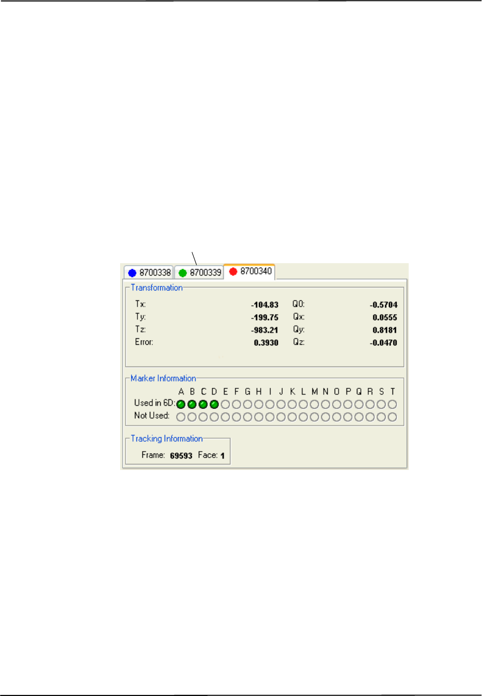
Tutorial: Learning to Use the Polaris Spectra System
32 Passive Polaris Spectra User Guide - Revision 7
As you move the tool, the symbol representing the tool in the graphical representation will move
to reflect the tool’s position.
3.2 Triggering Information and Error Flags
This section describes how to trigger some of the most common flags. Errors, warnings, and marker
information for each tool are displayed in the bottom right section of the tool tracking utility.
To View Information and Error Flags
1. Set up the system to track tools, as described in “Getting Started: Tracking Tools” on page 31.
2. For each loaded tool definition file, there is a tab in the bottom right section of the tool tracking
utility. Select a tab to display tracking information for a particular tool.
Figure 3-1 Tutorial: NDI ToolBox Tool Tracking Window
“Partially Out of Volume” and “Out of Volume” flags:
Move the tool to the edge of the characterized measurement volume.
As you move the tool to the edge of the volume (some markers are in the volume and some out),
NDI ToolBox will display the message “Partially Out of Volume.” Once all the markers are outside
of the volume, NDI ToolBox will display the message “Out of Volume.”
Select a tab to display
tracking information for
a particular tool

Tutorial: Learning to Use the Polaris Spectra System
Passive Polaris Spectra User Guide - Revision 7 33
Figure 3-2 Tutorial: “Partially Out of Volume” Flag
“Too Few Markers” flag:
1. Position the tool inside the characterized measurement volume, with the markers facing the
Position Sensor.
2. Cover one or more markers, without touching them.
The Position Sensor will no longer be able to detect the covered markers.
Figure 3-3 Tutorial: Detected Markers Indicator
If the Position Sensor cannot detect the minimum number of markers, NDI ToolBox will display
the message “Too Few Markers” and will not report a transformation.
Figure 3-4 Tutorial: “Too Few Markers” Flag
“Exceeded Maximum Marker Angle” flag:
1. Position the tool inside the characterized measurement volume, with the markers facing the
Position Sensor.
2. Turn the tool gradually until the markers are no longer facing the Position Sensor.
Once a marker has exceeded the maximum marker angle, NDI ToolBox will display a blue
indicator in the Not Used section of the marker information.
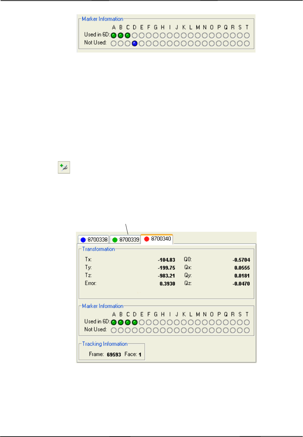
Tutorial: Learning to Use the Polaris Spectra System
34 Passive Polaris Spectra User Guide - Revision 7
Figure 3-5 Tutorial: “Exceeded Max Marker Angle” Indicator
3.3 Setting a Tool as Reference
This section describes how to set a tool as reference. When you set a tool as reference, all the other
tools will be tracked with respect to the reference tool. For more information on reference tools, see
“Reference Tools” on page 52.
To Set a Tool as Reference
1. Set up the system to track tools, as described in “Getting Started: Tracking Tools” on page 31.
2. Click to load tool definition files for at least two tools.
3. For each loaded tool definition file, there is a tab in the bottom right section of the tool tracking
utility. Select the tab corresponding to the tool you want to set as reference.
Figure 3-6 Tutorial: Selecting a Reference Tool
4. Right-click on the tool tab, then select Global Reference.
The reference tool will appear as a square in the graphical display. The other tools will be
displayed inside a square that is the colour of the reference tool. The positions and orientations
of other tools will now be reported in the local coordinate system of the reference tool.
Select the tab for the
tool you want to set
as reference.
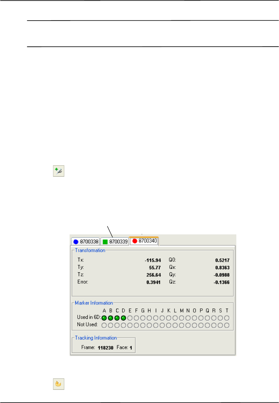
Tutorial: Learning to Use the Polaris Spectra System
Passive Polaris Spectra User Guide - Revision 7 35
Note The Polaris Spectra System still calculates the tool transformations in the coordinate system of the Position
Sensor. The NDI ToolBox software then calculates and reports the tool transformations with respect to the
reference tool.
3.4 Determining the Tool Tip Offset
This section describes how to determine the tool tip offset of a probe or pointer tool by pivoting.
Once NDI ToolBox has calculated the tool tip offset, it can report the position of the tip of the tool,
instead of the position of the origin of the tool. See “Tool Tip Offset” on page 51 for more details.
To Set Up the System to Pivot
You will need a divot in which to rest the tool tip while you pivot the tool. The size and shape of the
divot must match the tool tip, to ensure that the tip does not move. For example, a probe with a
1-mm ball tip requires a hemispherical divot with a 1-mm diameter in which to pivot.
1. Set up the system to track tools, as described in “Getting Started: Tracking Tools” on page 31.
2. Click to load a tool definition file for the probe or pointer tool.
3. For each loaded tool definition file, there is a tab in the bottom right section of the tool tracking
utility. Select the tab corresponding to the tool you want to pivot.
Figure 3-7 Tutorial: Selecting a Tool to Pivot
4. Click to open the Pivot dialog.
Select the tab
corresponding to the
tool you want to pivot.
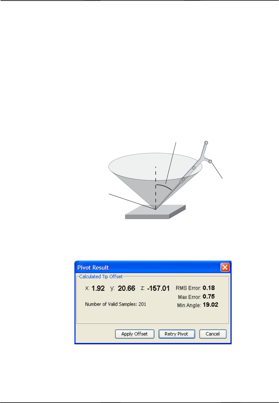
Tutorial: Learning to Use the Polaris Spectra System
36 Passive Polaris Spectra User Guide - Revision 7
5. Select a start delay of about 5 seconds and a duration of about 20 seconds.
To Pivot the Tool
1. Place the tool tip in the divot.
2. Ensure that the tool is within the characterized measurement volume, and will remain within the
volume throughout the pivoting procedure.
3. Click Start Collection in the Pivot tool dialog.
4. Pivot the tool in a cone shape, at an angle of 30º to 60º from the vertical.
a) Keep the tool tip stationary, and ensure that there is a line of sight between the markers on
the tool and the Position Sensor throughout the pivoting procedure.
b) Pivot the tool slowly until the specified pivot duration time has elapsed.
Figure 3-8 Tutorial: Pivoting Technique
When the pivot is complete, the Pivot Result dialog appears. Click Apply Offset to report the
position of the tip of the tool.
Figure 3-9 NDI ToolBox Software: Pivot Result Dialog
Markers are facing the
Position Sensor.
30º to 60º
Divot size and shape match
tool tip size and shape.

How the Polaris Spectra System Works
Passive Polaris Spectra User Guide - Revision 7 37
4 How the Polaris Spectra System Works
This chapter provides details on how the Polaris Spectra System works. The information can help
increase your technical understanding of the system, but is not absolutely necessary in order to use
the system. To learn how to use the system, refer to “Tutorial: Learning to Use the Polaris Spectra
System” on page 31.
This chapter contains the following information:
•“Communicating with the Polaris Spectra System” on page 37
•“Information Returned by the Polaris Spectra System” on page 38
•“Global Coordinate System and Measurement Volume” on page 39
•“Marker Detection and Tool Tracking” on page 42
•“Sampling Rate” on page 43
•“Polaris Spectra System Tools” on page 44
•“Tool Definition File” on page 47
•“Tool Tracking Parameters” on page 47
•“Tool Tip Offset” on page 51
•“Reference Tools” on page 52
•“Stray Marker Reporting” on page 53
•“Phantom Markers” on page 54
•“Passive Sphere Markers” on page 54
•“Active Markers” on page 55
•“System Spectral Response” on page 55
•“Data Transmission Rate” on page 56
4.1 Communicating with the Polaris Spectra System
The Polaris Spectra System is controlled using an application program interface (API). The API is a
set of commands and parameters that allow you to configure and request information from the
system.
Values for different aspects of the Polaris Spectra System are stored in user parameters. Some user
parameters store values for the full system configuration (for example, the combined firmware
revision); others store values pertaining to a particular hardware device in the system (for example,
the illuminator rate on the Position Sensor). Some user parameters are read-only parameters that
store useful information about the system; some user parameter values can be changed, to allow you
to configure the system. You can read and change user parameter values using API commands.
NDI Combined API Sample and NDI ToolBox both allow you to view the communications stream
of API commands and responses between the application and the Polaris Spectra System.

How the Polaris Spectra System Works
38 Passive Polaris Spectra User Guide - Revision 7
For details on API commands and user parameters, see the “Polaris Application Program Interface
Guide.”
4.2 Information Returned by the Polaris Spectra System
Do not use the Polaris Spectra System for absolute measurements; the system is designed for relative
measurements only. Treating measurements as absolute may result in an incorrect interpretation of results. If
your application involves personal safety, these incorrect interpretations may result in personal injury.
When the Polaris Spectra System is tracking tools, it returns information about those tools to the
host computer. By default, the system returns:
•the position of each tool’s origin, given in mm, in the coordinate system of the Position
Sensor (see “Global Coordinate System” on page 39).
Note Transformations with respect to a reference tool (described on page 52), and transformations for a probe with a
tool tip offset (described on page 51) are calculated using application software such as NDI ToolBox.
•the orientation of each tool, given in quaternion format. The quaternion values are rounded
off, so the returned values may not be normalized.
•an error value for each tool transformation. This RMS value, given in mm, is the result of
the least squares minimization between the marker geometry in the tool definition file and
the tool’s measured marker positions.
•the status of each tool, indicating whether the tool is out of volume, partially out of
volume, or missing. It also indicates whether the port handle corresponding to each tool is
enabled and initialized. For more information on port handles, see the “Polaris Application
Program Interface Guide.”
•the frame number for each tool transformation. The frame number is incremented by 1 at a
constant rate of 60 Hz. The frame counter starts as soon as the system is powered on, and
can be reset using API commands (see the “Polaris Application Program Interface Guide”
for details). The frame number returned with a transformation corresponds to the frame in
which the data used to calculate that transformation was collected.
•the system status, which includes some of the system errors described in “Tracking Errors
and Flags” on page 63.
If requested, the system can also return:
• tracking errors and flags (described in “Tracking Errors and Flags” on page 63). (Some
tracking errors and flags are returned by default.)
• marker status information, such as whether a particular marker was used to calculate a tool
transformation.
• positions of stray passive markers.
• transformations for tools that are outside of the characterized measurement volume.
Warning!
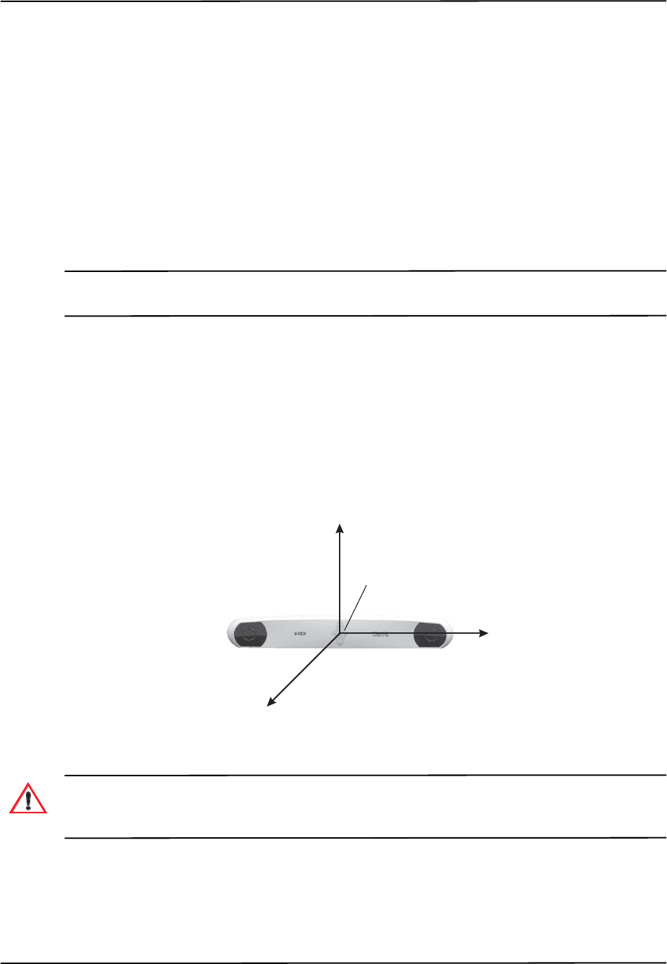
How the Polaris Spectra System Works
Passive Polaris Spectra User Guide - Revision 7 39
• transformations for tools when the system has detected one of the following error
conditions:
• the bump sensor has been triggered,
• the system is outside of operating temperature range,
• the bump sensor battery power is low,
• the temperature sensors are outside of functional range, or
• the input voltage is out of range.
The tool tracking utility of NDI ToolBox displays most of this returned information (except for the
port handle information).
Note For information on the API commands used to request tracking information from the Polaris Spectra System, see
the BX or TX command in the “Polaris Application Program Interface Guide.”
4.3 Global Coordinate System and Measurement Volume
Global Coordinate System
The Polaris Spectra Position Sensor uses a coordinate system with an origin located at the Position
Sensor and axes aligned as shown in Figure 4-1. This global coordinate system is defined during
manufacturing and cannot be changed.
Figure 4-1 Global Coordinate System
Do not use the Polaris Spectra System for absolute measurements; the system is designed for relative
measurements only. Treating measurements as absolute may result in an incorrect interpretation of results. If
your application involves personal safety, these incorrect interpretations may result in personal injury.
The Polaris Spectra System will report the transformations of tools in the global coordinate system.
However, if you are using a reference tool, software can calculate and report transformations in the
local coordinate system of the reference tool. For more information on reference tools, see
“Reference Tools” on page 52.
-x
-
y
-z
Origin
Warning!
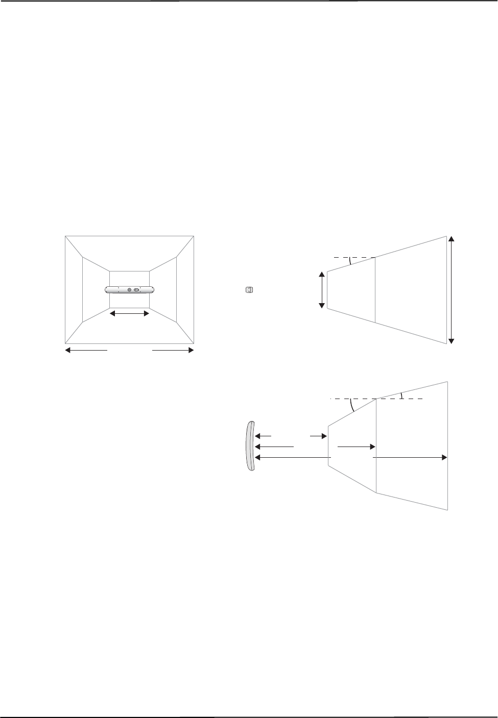
How the Polaris Spectra System Works
40 Passive Polaris Spectra User Guide - Revision 7
Field of View and Characterized Measurement Volume
The field of view is the total volume in which the Polaris Spectra System can detect a marker,
regardless of accuracy.
The characterized measurement volume is a subset of the field of view. It is the volume where
data was collected and used to characterize the Polaris Spectra System Position Sensor. There are
two characterized measurement volumes available for the Polaris Spectra System: the pyramid
volume, illustrated in Figure 4-2, and the extended pyramid volume, illustrated in Figure 4-3.
Within the pyramid volume, the Polaris Spectra System volumetric accuracy is 0.25 mm RMS.
Within the extended pyramid volume, the Polaris Spectra System volumetric accuracy is
0.30 mm RMS. The accuracy of measurements reported outside the Polaris Spectra characterized
measurement volume is unknown. The Position Sensor’s performance is determined using the
calibration methodology described in Appendix A on page 100.
Figure 4-2 Pyramid Volume
1312 mm
2400 mm
1566 mm
448 mm
Side View
16.58º
Top View
1532 mm
950 mm
29.66º 13.66º
Front View
480 mm
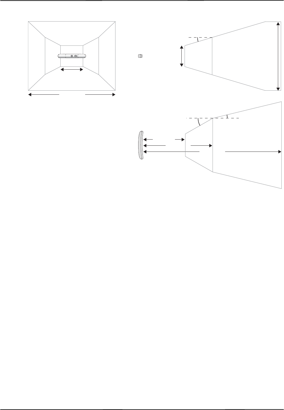
How the Polaris Spectra System Works
Passive Polaris Spectra User Guide - Revision 7 41
Figure 4-3 Extended Pyramid Volume
Out of Volume and Partially Out of Volume Flags
A tool is flagged as out of volume if all of its markers are outside of the characterized measurement
volume, but the system can still detect the tool.
The Polaris Spectra System is specifically designed to NOT report measurements for tools or
markers that are out of volume. By default, the Polaris Spectra System reports that these tools are
missing. You can request measurements for these tools by using reply option 0x0800 with the BX or
TX command. You enable this additional functionality at your own discretion. See the “Polaris
Application Program Interface Guide” for details.
A tool is flagged as partially out of volume if:
• fewer than the minimum number of markers (a parameter in the tool definition file) are
inside the characterized measurement volume, and
• at least one marker on the tool is inside the characterized measurement volume
For example, consider a five-marker tool, with three markers inside the characterized measurement
volume and two markers outside the volume. If the minimum number of markers is set to 3, the tool
is considered to be inside the volume. If the minimum number of markers is set to 4 or 5, the tool
will be flagged as partially out of volume. (The minimum number of markers parameter specifies
the minimum number of markers that the system must use in the calculation of a tool transformation.
See page 49 for details.)
1470 mm
3000 mm
1856 mm
448 mm
Side View
16.58º
Top View
1532 mm
950 mm
29.66º 13.66º
Front View
480 mm

How the Polaris Spectra System Works
42 Passive Polaris Spectra User Guide - Revision 7
4.4 Marker Detection and Tool Tracking
Detecting Markers
The Position Sensor detects active and passive markers using different methods. Active markers are
triggered by a 20 Hz “chirp” signal emitted by the Position Sensor illuminators, which causes the
active markers to emit IR for the integration time. (The chirp signal is only a trigger.)
To detect passive markers, the Position Sensor’s illuminators flood the surrounding area with IR for
the whole integration time by flashing at a default rate of 20 Hz (similar to the flash on a camera).
The passive sphere markers have a retro-reflective coating that reflects the IR directly back to the
Position Sensor instead of scattering it.
For both active and passive markers, the Position Sensor collects IR for a period of time called the
integration time. This acts like an electronic shutter. The system makes automatic adjustments to
the integration time so that the intensity of the brightest IR detected is set to a maximum value, and
the intensity of all other IR detected falls below this value. This process is called dynamic range
control.
The system distinguishes between potential marker data and background IR using a value called the
trigger level. The trigger level is the minimum IR intensity considered to be valid marker data.
Background IR that falls below the trigger level is rejected by the Position Sensor. The trigger level
generally increases with integration time; see “Setting the Infrared Light Sensitivity” on page 68 for
more details.
Acquiring and Tracking Tools
When the Polaris Spectra System first begins tracking a tool, or whenever a tool goes missing, it
must “acquire” the tool. (For information on why a tool goes missing, see “Missing and Disabled
Transformations” on page 62.) To acquire tools, the Polaris Spectra System first measures the
positions of all the visible markers.
IR light hits the Charge Coupled Devices (CCDs) in the Position Sensor. If the system is unable to
detect individual IR sources, or has detected more IR sources than it can process, it will report an
error (see “Tracking Errors and Flags” on page 63). Otherwise, the system will calculate the position
of the IR sources.
To determine the position of an IR source, the Position Sensor calculates a line between the source
of IR and each sensor (displayed as dotted lines in Figure 4-4). Where the lines cross each other, the
Polaris Spectra System calculates the line separation. (The distance between the lines.) In a
theoretical case the lines will intersect exactly, but in the modelled “real world” case they will be
apart. If the line separation at this point is less than a predefined limit, the Polaris Spectra System
considers the point to be a possible marker position. Otherwise, the point is discarded.
Figure 4-4 Determining a Marker Position
Marker

How the Polaris Spectra System Works
Passive Polaris Spectra User Guide - Revision 7 43
Once the system has measured the positions of all the markers, it calculates the segment length (the
distance between two markers) for each pair of markers, and the angle between each segment. It
compares this data with the marker geometry data in each tool definition file (described on page 47),
to determine which markers belong to which tool. The unique geometry requirements, described in
the “Polaris Tool Design Guide,” allow the Polaris Spectra System to distinguish between tools.
Any markers that are not part of a tool are considered stray markers (this may include phantom
markers). See “Stray Marker Reporting” on page 53 and “Phantom Markers” on page 54 for more
details.
The Polaris Spectra System has “acquired” a tool once it has matched the minimum number of
markers (a parameter in the tool definition file) for the tool and can calculate a transformation for
the tool. Once a tool has been acquired, the Position Sensor tracks it using a predictive algorithm.
Three-Marker Lock-On
If the “three-marker lock-on” option is enabled in the tool definition file, the Polaris Spectra System
will acquire and track the tool as long as it can detect at least three markers. The system will not
report the transformations unless the minimum number of markers is used to calculate the
transformation.
For example, consider a four-marker tool with the “three-marker lock-on” option enabled. If the
system can only detect three of the markers on the tool, it will continue to track that tool but will
only report transformations if the minimum number of markers is set to 3. If the minimum number
of markers is set to 4, the system will continue to track the tool in the background, but will report the
tool as MISSING. Selecting three-marker lock-on in this case will result in the tool transformations
being reported sooner, once the minimum number of markers becomes visible, because the system
does not have to spend time re-acquiring the tool.
Note For more details on the “three-marker lock-on” option, see the “Polaris Tool Design Guide.”
4.5 Sampling Rate
The sampling rate is the rate at which the system reports transformations for all the tools. The
number and classification of tools being tracked affects the sampling rate.
The maximum internal sampling rate of the passive Polaris Spectra System is 60 Hz. The sampling
rate is decreased as more frames are needed to track all the tools. The number and classification of
tools have the following effects on the number of frames needed:
• All passive tools are tracked in the same frame. You can select an illuminator rate of 60 Hz,
30 Hz, or 20 Hz if you are tracking only passive tools.
• All active wireless tools are tracked in the same frame. The circuitry in NDI’s active
wireless tool development kit is limited to 20 Hz. If the system is tracking NDI’s active
wireless tools, it is limited to a maximum rate of 20 Hz, regardless of whether passive tools
are being tracked. Faster tracking rates may be achieved with alternative tool designs.

How the Polaris Spectra System Works
44 Passive Polaris Spectra User Guide - Revision 7
Table 4-1 summarizes the sampling rate for different combinations of tools.
4.6 Polaris Spectra System Tools
A tool is a rigid structure on which three or more markers are fixed so that there is no relative
movement between them. Polaris Spectra tools can be either passive or active wireless. See “Passive
Tools” on page 44 and “Active Wireless Tools” on page 45 for further information.
Up to 15 compatible tool definition files can be loaded simultaneously, ready for tracking. The
system can simultaneously track up to six passive tools and one active wireless tool within the
following constraint: a maximum of 32 passive and 32 active markers, including stray markers, can
simultaneously be in view of the Position Sensor, regardless of whether or not they are being
tracked. Additional markers in view may affect the speed of the system and its ability to return
transformations.
The Position Sensor tracks tools based on marker geometry, which is specified in the tool definition
file for each tool. A tool definition file must be loaded before the Polaris Spectra System can track
its associated tool. For more information on tool definition files, see “Tool Definition File” on
page 47.
Tools are available from NDI for use with the Polaris Spectra System. Contact NDI for more details.
Passive Tools
Passive tools are wireless, and incorporate NDI passive sphere markers. The passive sphere markers
have a retro-reflective coating that reflects IR light back to its source, instead of scattering it. To
track passive tools, the Position Sensor flashes IR from its illuminators, similar to the flash on a
camera. The IR floods the surrounding area and reflects off the passive markers back to the Position
Sensor, where it is detected by the sensors.
The Polaris Spectra System can report the positions of passive markers individually, and calculate
the position and orientation of tools that incorporate them. The measured position is the centre of the
marker. When a passive sphere marker is attached to an NDI mounting post, the centre of the sphere
is located at the top of the mounting post.
The Position Sensor recognizes passive tools solely by marker geometry. The marker geometry is
specified in the tool definition file, which must be loaded into the system before the tool can be
tracked. See “Tool Definition File” on page 47 for details.
Table 4-1 Maximum Tool Sampling Rate - Passive Polaris Spectra
Tools Being Tracked Maximum Sampling Rate (Hz)
Passive tools only 60, 30, or 20 (user-selectable)
Active wireless tools only 20 - using NDI tools.
(Faster tracking rates may be achieved with
alternative tool designs.)
Passive and active wireless tools 20 - using NDI tools.
(Faster tracking rates may be achieved with
alternative tool designs.)
How the Polaris Spectra System Works
Passive Polaris Spectra User Guide - Revision 7 45
Do not use a wireless tool whose design does not conform to the Polaris Spectra System's unique geometry
constraints. When a Polaris Spectra System attempts to track more than one wireless tool in the measurement
volume, these unique geometry constraints ensure that they are distinguishable from each other. Reliance on
data produced by two indistinguishable tools can lead to inaccurate conclusions. If your application involves
personal safety, these inaccurate conclusions increase the possibility of personal injury.
The passive markers can only be sterilized one time. NDI does not recommend that a passive marker
be used if it has been sterilized more than once, as multiple cycles of sterilization may adversely
affect the marker's performance. Testing has shown that there is no significant degradation in the
performance of these markers after one cycle of ETO, STERRAD 100S, or STERIS SYSTEM 1
sterilization. The passive markers cannot be autoclaved. Pre-sterilized passive sphere markers are
also available; contact NDI for details.
Do not use markers without inspecting them for cleanliness and damage both before and during a procedure.
Reliance on data produced by unclean or damaged markers may lead to inaccurate conclusions. If your
application involves personal safety, inaccurate conclusions increase the possibility of personal injury.
Caution! Do not handle the passive sphere markers with bare hands as this will leave residue from skin that affects the
marker's reflectivity. Take care not to drop or scuff the markers, as this also affects the reflectivity of the markers.
For detailed information on passive sphere markers, see the “Polaris Tool Design Guide.”
Active Wireless Tools
Active wireless tools are not connected to the system, and incorporate active markers. Active
wireless tools are powered by battery or by the equipment to which they are attached. To track active
wireless tools, the Position Sensor pulses the illuminators in a way that is recognizable by an IR
receiver in the active wireless tool. The active wireless tool detects the IR pulse; the markers then
emit IR, which is detected by the Position Sensor.
The Position Sensor recognizes active wireless tools solely by marker geometry. The marker
geometry is specified in the tool definition file, which must be loaded into the system before the tool
can be tracked. See “Tool Definition File” on page 47 for details.
Do not use a wireless tool whose design does not conform to the Polaris Spectra System's unique geometry
constraints. When a Polaris Spectra System attempts to track more than one wireless tool in the measurement
volume, these unique geometry constraints ensure that they are distinguishable from each other. Reliance on
data produced by two indistinguishable tools can lead to inaccurate conclusions. If your application involves
personal safety, these inaccurate conclusions increase the possibility of personal injury.
Active markers are physically smaller than passive sphere markers. They consist of an infrared
light-emitting diode (IRED) mounted on a ceramic base. The ceramic base allows the markers to be
sterilized by auto-claving.
Warning!
Warning!
Warning!

How the Polaris Spectra System Works
46 Passive Polaris Spectra User Guide - Revision 7
Do not use markers without inspecting them for cleanliness and damage both before and during a procedure.
Reliance on data produced by unclean or damaged markers may lead to inaccurate conclusions. If your
application involves personal safety, inaccurate conclusions increase the possibility of personal injury.
Tool Characteristics
Tools used with the Polaris Spectra System have the following characteristics:
• A 5DOF (five degrees of freedom) tool has between three and six markers. All the markers
on a 5DOF tool are collinear. The Polaris Spectra System will report the 3D position and 2D
orientation of a 5DOF tool.
• A 6DOF (six degrees of freedom) tool has between three and six markers that are not
collinear. The Polaris Spectra System will report the 3D position and 3D orientation of a
6DOF tool.
• The geometry of each tool must follow the unique geometry constraints. Tools must have
different marker geometries from one another, so the Position Sensor can distinguish
between them. A marker geometry that is the mirror image of another tool’s marker
geometry is not considered unique. For more details on unique geometry constraints and
marker geometry, see the “Polaris Tool Design Guide”.
• A multi-faced tool (which is also 6DOF) can have up to six faces, totalling a maximum of
20 markers. Each face on a tool is treated as a separate rigid body which complies with the
following constraints:
• It has a maximum of six markers
• It complies with the unique geometry constraints
• It has a different marker geometry from the other faces on the tool.
• Each tool has its own local coordinate system This is defined during the tool
characterization process, and is often dependent on the tool’s intended use.
Multi-Faced Tool Tracking
When the Polaris Spectra System is tracking a multi-faced tool, it tracks only one face at a time. The
face being tracked is returned with reply option 0x0002 of the BX and TX commands, and is
reported in NDI ToolBox (see the online help in NDI ToolBox for more details).
Each face is assigned a face normal in the tool definition file (described on page 47). The face
normal is a vector pointing in the same direction as the tool face, to let the Polaris Spectra System
know the direction each tool face is facing. The system will track the face most directly oriented to
the Position Sensor (i.e. the face with the smallest angle between the face normal and the sensors in
the Position Sensor). If the minimum number of markers are not visible on the face most directly
oriented to the Position Sensor, the system will attempt to track another face.
The system has a hysteresis of 2° when determining whether to switch faces. The system will
determine the angle between the sensors and each face of the tool. If the face with the smallest angle
is 2° smaller than the current face’s angle, the system will switch to the new face.
Warning!

How the Polaris Spectra System Works
Passive Polaris Spectra User Guide - Revision 7 47
4.7 Tool Definition File
A tool definition file (formatted as .rom) describes a tool to the Position Sensor. The information
stored in the tool definition file includes the geometry of the tool's markers, the tool’s manufacturing
data, information on marker and face normals, face definitions, and the parameters used to track
tools. For more information on the parameters used to track tools, see Tool Tracking Parameters
below.
A tool definition file must be loaded into the system (by the host computer) before the Polaris
Spectra System can track its associated tool. If the Polaris Spectra System is measuring the positions
of stray markers (described in “Stray Marker Reporting” on page 53), at least one tool definition file
must be loaded in order for the Position Sensor illuminators to emit IR light.
Tool definition files can be created in NDI 6D Architect. The procedure used to create a tool
definition file is called tool characterization. For more information on tool characterization, see the
“Polaris Tool Design Guide” and the “NDI 6D Architect User Guide”.
4.8 Tool Tracking Parameters
The tool tracking parameters (described below) are the maximum 3D error, the maximum marker
angle, the minimum number of markers, and the minimum spread. They are specified in the tool
definition file (described on page 47). The flow chart on page 50 describes how the Polaris Spectra
System uses the tool tracking parameters to determine which markers to use to calculate a tool
transformation, and when to return a transformation.
For information on how to change the tool tracking parameters and what values to use, see the
“Polaris Tool Design Guide” and the “NDI 6D Architect User Guide.”
Maximum 3D Error
The maximum 3D error parameter specifies the maximum allowable 3D error for each marker on
the tool. The 3D error is the difference between the measured and expected location of a marker on a
tool. The expected location of a marker on a tool is specified in the tool definition file (described on
page 47).
If the 3D error for a particular marker is greater than the specified maximum 3D error value, the
system will not use data from that marker to determine the tool transformation.
Maximum Marker Angle
The maximum marker angle parameter specifies the maximum allowable angle between a marker
and each sensor on the Position Sensor. The default maximum marker angle for passive sphere
markers is 90º and for active markers it is 60°. Each marker has an associated normal vector, which
is defined in the tool definition file. A marker normal is a vector of length 1, and points in the same
direction as the marker, as illustrated in Figure 4-5.
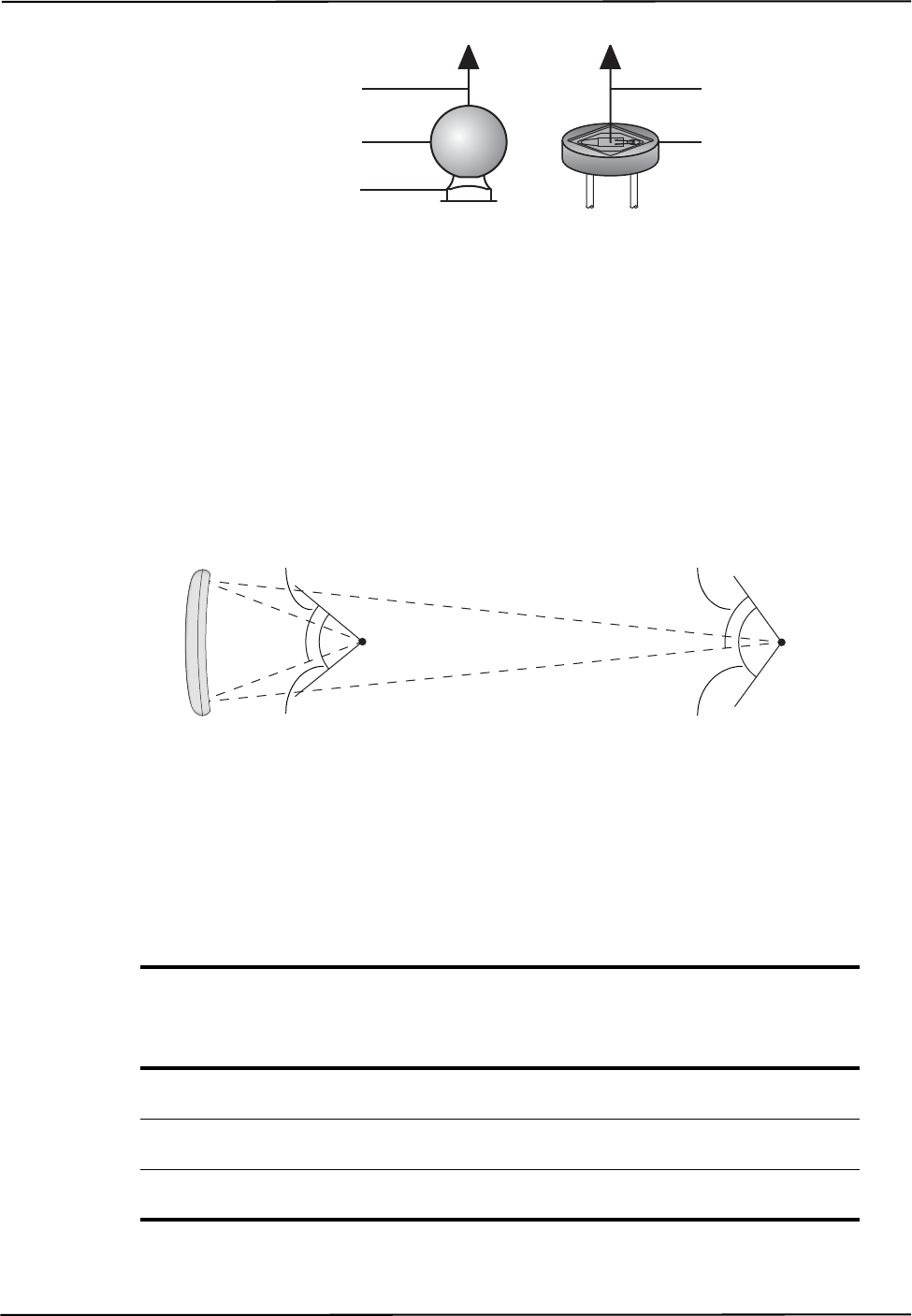
How the Polaris Spectra System Works
48 Passive Polaris Spectra User Guide - Revision 7
Figure 4-5 Markers Normal
The Polaris Spectra System uses the marker normal to determine which direction the marker is
facing. The system measures the angle between the marker normal and each sensor, in both the
Position Sensor’s xy- and yz-planes. (The Position Sensor’s coordinate system is described in
“Global Coordinate System” on page 39.) If the angle between the marker normal and either sensor
is greater than the specified maximum marker angle value, the system will not use the data from that
marker to determine the tool transformation.
The actual range of use of a marker depends on the marker’s location in the characterized
measurement volume. The closer a marker is to the Position Sensor, the smaller its range of use.
This is illustrated in Figure 4-6 for a maximum marker angle value of 60º.
Figure 4-6 Actual Range of Use
Table 4-2 lists some examples of the actual range of use of a marker at different places in the
characterized measurement volume. The calculations use the default maximum marker angle values
of ±90º for passive sphere markers and ±60° for active markers.
Table 4-2 Actual Range of Use
Distance From Position Sensor (along z-axis) Actual Range of Use
Passive Marker Active Marker
950 mm (front of volume) 150.5º 90.51º
2400 mm (back of pyramid volume) 168.1º 108.1º
3000 mm (back of extended pyramid volume) 170.5º 110.5º
Marker Normal
Active Marker
Marker Normal
Passive Sphere Marker
NDI Mounting Post
Maximum marker
angle (60º)
Maximum marker
angle (60º)
Actual range
of use (108.1º)
Actual range
of use (90.51º)

How the Polaris Spectra System Works
Passive Polaris Spectra User Guide - Revision 7 49
Minimum Number of Markers
The minimum number of markers parameter specifies the minimum number of markers that the
Position Sensor must use in the calculation of a tool transformation. If the system cannot calculate a
transformation using the minimum number of markers, it will report the tool as MISSING.
For example, consider a four-marker tool that has three markers inside the characterized
measurement volume, and one marker outside of the characterized measurement volume. If the
minimum number of markers parameter is set to 3, the Polaris Spectra System will report
transformations for the tool (as long as the other tool tracking parameters are satisfied). If the
minimum number of markers parameter is set to 4, the Polaris Spectra System will report the tool as
MISSING.
Note You can tell the Polaris Spectra System to report the positions of tools that have fewer than the minimum number
of markers inside the characterized measurement volume by using reply option 0x0800 with the TX or BX
command. This may reduce the accuracy of the transformations. See the “Polaris Application Program Interface
Guide” for details.
Minimum Spread
The minimum spread parameters specify the minimum size 3D box that must contain all the
markers used in the calculation of a tool transformation. The length, width, and height of this box
must be greater than the specified Minimum Spread 1, Minimum Spread 2 and Minimum Spread 3
parameters, respectively, or else the system will not return a transformation. This setting is optional.
For further information on the minimum spread parameters, see the “Polaris Tool Design Guide”.
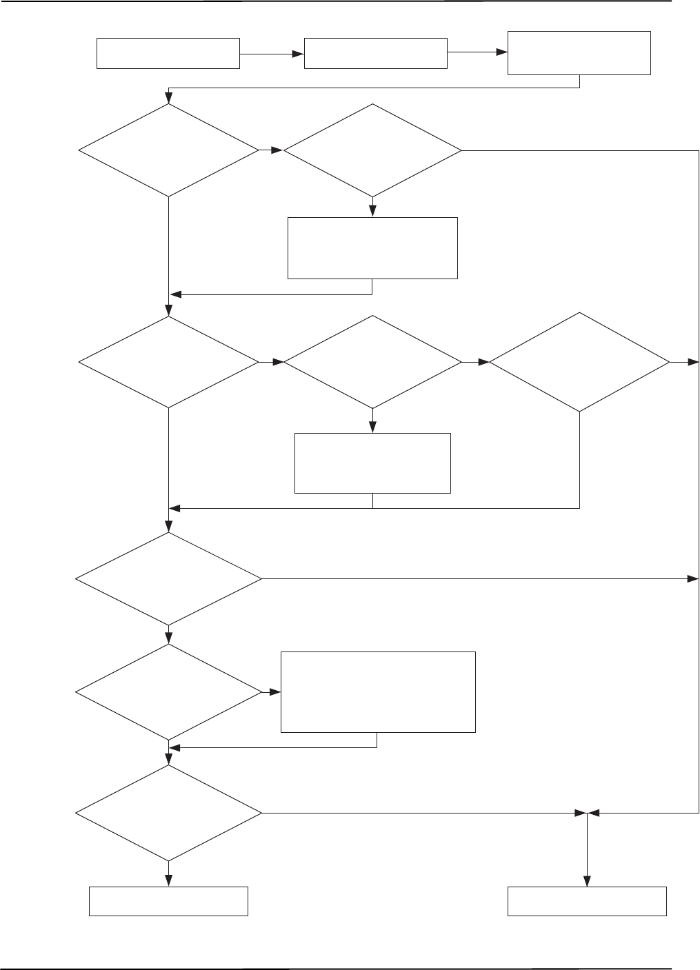
How the Polaris Spectra System Works
50 Passive Polaris Spectra User Guide - Revision 7
Figure 4-7 Flowchart of Tool Tracking Parameters
yes
no
yes
yes
yes
yes
yes
no no
yes
no
no
no
yes
no
Return MISSING &
status and error information
Return tool tranformation &
status and error information
Are
the spread
parameters satisfied?
Ignore markers that are greater than
the max. 3D error
&
calculate tool transformation using at
least the min. number of markers
Are
all markers
within the max. 3D
error?
Were the
min. number of
markers used to calculate a
transformation?
Ignore the out-of-volume
markers & calculate tool
transformation using
at least 3 markers
Is reply
option 0x0800 used
with BX or TX
command?
Can the
system calculate a tool
transformation without the out-
of-volume markers?
Are
all markers
inside the characterized
measurement volume?
Ignore markers that are outside
of the max. marker angle &
calculate tool transformation
using at least 3 markers
Can the
system calculate a
transformation without the
off-angle markers
?
Are
all markers
within the max.
marker angle?
Calculate tool
transformation using at
least 3 markers
Measure positions of
markers
Flash illuminators on
Position Sensor
no

How the Polaris Spectra System Works
Passive Polaris Spectra User Guide - Revision 7 51
4.9 Tool Tip Offset
Do not use a tool with a tip without first performing a pivot procedure to verify the tip offset. Reliance on data
produced by a tool with an inaccurate tip offset may lead to inaccurate conclusions. If your application involves
personal safety, these inaccurate conclusions increase the possibility of personal injury.
The origin of a tool is defined as part of the tool’s local coordinate system in the tool definition file.
When the Position Sensor tracks a tool, it reports the transformations of the origin of the tool.
In certain circumstances, it is useful to track a point on the tool other than the tool’s origin. In
particular, it is useful to track the location of the tip of a probe. It is possible to define the tool’s
origin at the tip of the probe; however, if the tool is later bent, the origin will no longer be located at
the tip.
NDI recommends determining the tool tip offset of the tool, prior to each use. The tool tip offset is
the vector between the tip of the tool and the origin of the tool. Application software can apply the
tool transformations reported by the Polaris Spectra System to the tool tip offset, in order to
determine the location of the tool tip.
Note The Polaris Spectra System always tracks the origin of the tool. It is the application software, not the Polaris
Spectra System, that calculates the location of the tool tip.
Determining the tool tip offset prior to each use ensures that the location of the tool tip is known as
accurately as possible.The tool tip offset can be determined either by using a calibrator, or by
performing a pivoting procedure.
Using a Calibrator
A calibrator is a rigid body that incorporates three or more markers and a clamping mechanism. The
clamping mechanism allows another tool (usually a probe) to be clamped into place. An example of
a calibrator is illustrated in Figure 4-8. To use a calibrator to determine the tool tip offset of a probe,
clamp the probe in place on the calibrator. The origin of the calibrator is defined at the point where
the tool tip will rest. The Polaris Spectra System can then measure the positions of the probe’s origin
and the calibrator’s origin. The application software compares these measurements to determine the
tool tip offset of the probe.
Warning!
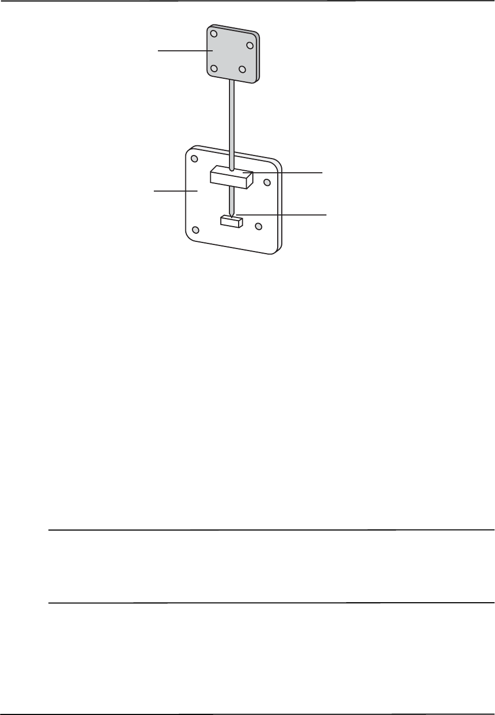
How the Polaris Spectra System Works
52 Passive Polaris Spectra User Guide - Revision 7
Figure 4-8 Sample Calibrator
Pivoting
You can also determine the tool tip offset using a process called pivoting, using either NDI ToolBox
or NDI 6D Architect software. During the pivoting procedure, the Polaris Spectra System will
measure the positions of the markers while you pivot the tool. The software collects this data, and
uses it to determine the tool tip offset. Instructions on how to pivot a tool are detailed in
“Determining the Tool Tip Offset” on page 35. In addition the procedure is also detailed in the “NDI
6D Architect User Guide” and online help, and in the NDI ToolBox online help.
4.10 Reference Tools
A reference tool is a tool whose local coordinate system is used as the global coordinate system in
which other tools are tracked. The Polaris Spectra System tracks all the tools, including the
reference tool, and reports the transformations in the coordinate system of the Position Sensor
(described on page 39). Software (such as NDI ToolBox) then calculates and reports the positions
and orientations of all other tools with respect to the position and orientation of the reference tool.
Note Use a reference tool to ensure minimal drift in the measurements produced; specifically, drift caused by time,
settling and/or temperature.
It is the application software, not the Polaris Spectra System, that calculates the tool transformations with
respect to the reference tool.
For example, in neurosurgery the reference tool can be attached to the patient’s head. Then a
registration procedure is performed that defines the reference tool’s position relative to the patient’s
head. From then on, if either the patient’s head or the Position Sensor shifts, the measurements are
not affected since they are reported with respect to the patient’s head (the reference tool) and not
with respect to the Position Sensor.
Probe
Calibrator
Clamp Probe in Place
Place Tool Tip at Origin
of Calibrator

How the Polaris Spectra System Works
Passive Polaris Spectra User Guide - Revision 7 53
If the Polaris Spectra cannot track the reference tool (for example, if the reference tool is occluded),
then the software will not be able to calculate the transformations of other tools with respect to the
reference tool.
4.11 Stray Marker Reporting
A stray marker is a marker that is not part of a rigid body or tool. For example, by placing stray
markers on a patient’s chest, the markers may be used to gate/track the patient’s breathing in order to
time radiation therapy.
When you request stray marker data from the Polaris Spectra System, the Polaris Spectra System
will report tool transformations, as well as 3D data (position only, no orientation information) and
out-of-volume information for up to 50 markers that are not used in tool transformations (including
phantom markers, described on page 54). It is then necessary to eliminate phantom markers within
the application software, and verify that the stray markers are within the characterized measurement
volume.
It is important to be aware of the potential hazards associated with using the stray marker reporting
functionality. The hazards are as follows:
• An external IR source, for example, an IR transmitter or incandescent light, may be reported
as a stray marker.
• No marker identification is possible from frame to frame. It is therefore the user’s
responsibility to devise a method to keep track of which 3D position belongs to which
marker.
• A stray marker does not have a marker normal, so there is no way to know if the marker
orientation is exceeding a particular angle.
• There are no built-in checks to determine if the 3D result is a real marker or a phantom
marker, generated by other IR sources or markers in view of the Position Sensor. The system
tries to reject markers by the use of the line separation qualifier, but if several markers are in
a line parallel to the horizontal plane of the Position Sensor, phantom markers may still be
generated that are within the line separation qualifier. (Phantom markers are explained on
page 54.)
• Partial occlusion of markers cannot be detected or compensated for by the Position Sensor.
The user may be able to detect the apparent shift if the marker position can be constrained in
the application software. For example, the marker position has to be constrained along a
vector and its position relative to another marker is supposed to be fixed within some
tolerance.
Do not rely on unqualified 3D results for stray markers. There are no built-in checks to determine if the 3D results
for stray markers represent real markers, phantom markers or IR interference, so the host application must
identify and qualify the reported 3D results for stray markers. Reliance on unqualified 3D data may lead to
inaccurate conclusions. If your application involves personal safety, inaccurate conclusions may result in
personal injury.
To request stray marker data, use the 0x1000 reply option with the API command BX or TX. This
reply option returns out-of-volume information along with the 3D data. See the “Polaris Application
Program Interface Guide” for details.
Warning!

How the Polaris Spectra System Works
54 Passive Polaris Spectra User Guide - Revision 7
In order for the Position Sensor to measure stray passive markers, a tool definition file must be
loaded, and the associated port handle must be initialized and enabled, even if no tools are being
tracked. The Position Sensor illuminators emit IR light only when a tool definition file is loaded.
4.12 Phantom Markers
Phantom markers are the result of the calculation that the Polaris Spectra System uses to determine
the position of a source of IR. They appear and are reported as markers but they do not actually
exist.
To determine the position of a source of IR, the Position Sensor calculates a line between the source
of IR and each sensor (displayed as dotted lines in Figure 4-9). Where the lines cross each other, the
Polaris Spectra System calculates the line separation (the distance between the lines). If the line
separation at this point is within a predefined limit, the Polaris Spectra System considers the point to
be a possible marker position.
Phantom markers are reported when the imaginary lines calculated from the sensors intersect in
more than one place with a line separation within a predefined limit. This generally occurs when two
or more markers are in the same plane as the sensors. For example, in the case of two coplanar
markers, there will be four mathematical solutions, as illustrated in Figure 4-9. Two are the actual
marker locations and two are the phantom marker locations. In the example shown, one phantom
marker is closer to the Position Sensor than the actual markers and the other phantom marker will be
farther away from the Position Sensor than the actual markers, but this is not the only possible
scenario.
The number of phantom markers increases with the number of coplanar markers. When there are n
coplanar markers, there will be up to n • (n - 1) phantom markers.
Figure 4-9 Phantom Markers
When you request stray marker data from the Polaris Spectra System, the system will report data for
both phantom markers and stray markers. The system cannot distinguish which solutions are
phantom markers; it is necessary to eliminate the reported phantom markers using application
software.
If you do not request stray marker data from the Polaris Spectra System, the system will not return
any phantom marker data.
4.13 Passive Sphere Markers
NDI passive sphere markers have a retro-reflective coating that reflects IR light back to its source
instead of scattering it. The IR light from the Position Sensor illuminators reflects off the passive
markers directly back to the sensors.
Phantom Markers
Real Markers

How the Polaris Spectra System Works
Passive Polaris Spectra User Guide - Revision 7 55
The Polaris Spectra System can report the positions of passive markers individually, and calculate
the position and orientation of tools that incorporate them. The measured position is the centre of the
marker. When a passive sphere marker is attached to an NDI mounting post, the centre of the sphere
is located at the top of the mounting post.
The passive markers can only be sterilized one time. NDI does not recommend that a passive marker
be used if it has been sterilized more than once, as multiple cycles of sterilization may adversely
affect the marker's performance. Testing has shown that there is no significant degradation in the
performance of these markers after one cycle of ETO, STERRAD 100S, or STERIS SYSTEM 1
sterilization. The passive markers cannot be autoclaved. Pre-sterilized passive sphere markers are
also available; contact NDI for details.
Do not use markers without inspecting them for cleanliness and damage both before and during a procedure.
Reliance on data produced by unclean or damaged markers may lead to inaccurate conclusions. If your
application involves personal safety, inaccurate conclusions increase the possibility of personal injury.
Caution! Do not handle the passive sphere markers with bare hands as this will leave residue from skin that affects the
marker's reflectivity. Take care not to drop or scuff the markers, as this also affects the reflectivity of the markers.
4.14 Active Markers
Note The active wireless tool tracking feature is an option that you must order at time of purchase.
Active markers are physically smaller than passive sphere markers. They consist of an Infrared
Light Emitting Diode (IRED) mounted on a ceramic base. The Position Sensor codes (“chirps”) the
IR pulses emitted from its illuminators. These coded IR pulses are received by the IR receiver on the
tool which then activates the IREDs. The Position Sensor receives the IR emitted by the IREDs and
processes it in the same manner as passive markers.
Active markers are mounted in active wireless tools. The ceramic base allows them to be sterilised
by auto-claving as required. The power for active wireless tools is supplied by battery. For detailed
information on active markers and active wireless tools, refer to the “Polaris Tool Design Guide”.
4.15 System Spectral Response
The lenses on the Position Sensor filter out visible light, allowing only certain amounts of light at
specific frequencies to pass through to the CCDs. The CCDs are sensitive only to light below certain
frequencies. The result is a selective wavelength sensitivity from 800 nm to 1100 nm.
Environmental light in this range can affect the performance of the Polaris Spectra System. The
more intense the environmental light in this range, the higher the probability that it will interfere
with the system.
Note It is important to reduce environmental IR, to prevent interference with the system. Some operating room lights
may emit IR.
Warning!

How the Polaris Spectra System Works
56 Passive Polaris Spectra User Guide - Revision 7
The amount of light at various frequencies that passes through the lenses to the CCDs, and is then
detected by the CCDs, is illustrated in Figure 4-10.
Figure 4-10 Filter Spectral Response
4.16 Data Transmission Rate
The Polaris Spectra System can achieve an internal tool transformation update rate of up to 60 Hz.
The host computer update rate (the rate at which the host computer receives data) is dependent on
the following factors:
Baud Rate The baud rate specifies how fast data is transferred from the system to the host computer.
At lower baud rates, the host computer may not receive tool transformations at 60 Hz.
API command reply length The more data the system must return with every transformation, the
slower the host update rate. The amount of data returned with each transformation increases as you
track more tools and select more options.
Application speed The host transmission rate can vary according to how often the application asks
for data, and how often the graphical user interface (in particular, graphics) need to be updated.
800 nm 880 nm 1100 nm
90 %
Light Wavelength
Amount of Light
Amount of Light
Passing Through
Lenses to CCDs
Amount of Light
Detected by CCDs

Additional System Features
Passive Polaris Spectra User Guide - Revision 7 57
5 Additional System Features
This chapter provides details about additional features of the Polaris Spectra System. This chapter
contains the following information:
•“Bump Sensor” on page 57
•“Positioning Laser” on page 58
•“Keyed Features” on page 59
5.1 Bump Sensor
The Position Sensor contains an internal bump sensor that detects when the Position Sensor has
suffered an impact. Although each instance is different, it is NDI’s expectation that a representative
trigger threshold is equivalent to a 255 mm to 380 mm drop onto a vinyl tiled concrete surface.
When a bump is detected:
• The error LED on the Position Sensor flashes, indicating that a non-critical error has been
detected. The flashing will persist until the bump is cleared.
• The “bump detected” bit in the Info.Status.Alerts user parameter is set. This bit will persist
until the bump is cleared.
• The “bump detected” bit in the Info.Status.New Alerts user parameter is set. This bit will
be cleared as soon as the user parameter is read. (When the bit is set in Info.Status.New
Alerts, the “diagnostic pending” bit in the TX and BX responses will also be set to indicate
a new alert.)
•The Info.Status.Bump Detected and Param.Bump Detector.Bumped user parameters are
set to “1”. These user parameter values persist until the bump is cleared.
• The API commands TX and BX will not report transformations unless reply option 0x0800
is used. This behaviour persists until the bump is cleared. Because a bump can affect the
calibration of the Position Sensor, the system is designed not to report transformations if it
has detected a bump.
Note See the “Polaris Application Program Interface Guide” for details on user parameters and API commands.
If a bump has been detected, NDI recommends that you perform an accuracy assessment procedure
with the NDI Accuracy Assessment Kit (AAK), to ensure that the Position Sensor is still calibrated.
For information on the accuracy assessment procedure and AAK, contact NDI or visit the support
site at http://support.ndigital.com.
A Position Sensor whose bump sensor has been triggered may no longer be covered under warranty,
as the impact required to trigger the bump sensor is greater than that expected to occur through
proper use and handling of the Position Sensor.

Additional System Features
58 Passive Polaris Spectra User Guide - Revision 7
Clearing the Bump Sensor
You can clear a bump using the following methods:
• Use the configure utility of NDI ToolBox. See the NDI ToolBox help for more details.
• Use the API command SET to set the value of the user parameter Param.Bump
Detector.Clear to “1”. This clears all bumps detected up to this point. The system will
automatically reset this user parameter to “0”. See the “Polaris Application Program
Interface Guide” for details.
Bump Sensor Battery
The bump sensor is functional whether the Polaris Spectra System is powered on or off. When the
system is powered on, the bump sensor circuit draws its power, through the system, from the mains
supply. When the system is not powered on, the bump sensor derives its power from an internal
battery that has an operational life of approximately 10 years. If the bump sensor battery in your
system needs to be replaced, contact NDI.
5.2 Positioning Laser
The positioning laser is an optional component of the system. It is located in the Position Sensor,
and indicates the centre of the characterized measurement volume. This feature allows you to
properly position the Position Sensor, or position objects in the measurement volume. The laser
beam is emitted from an aperture on the front of the Position Sensor, and is directed along the z-axis
of the Position Sensor’s global coordinate system (described on page 39).
Laser Use
Do not look directly into the laser-emitting aperture. The Class 2 laser module on the Position Sensor emits
radiation that is visible and may be harmful to the human eye. Direct viewing of the laser diode emission at close
range may cause eye damage.
Take precautions to ensure that people with restricted movement or reflexes (for example, patients undergoing
medical procedures) do not look directly into the laser-emitting aperture. Patients undergoing medical
procedures may be restricted in the availability of adverse-effects reflexes (turning away eyes and/or head,
closing eyes) due to pharmaceutical influences and/or mechanical restraints. The Class 2 laser module on the
Position Sensor emits radiation that is visible and may be harmful to the human eye. Direct viewing of the laser
diode emission at close range may cause eye damage.
Use of laser controls or adjustments or performance of laser-related procedures other than those specified
herein may result in hazardous radiation exposure.
You can activate the laser using the following methods:
• Press the laser activation button on the front of the Position Sensor. The laser will remain on
only while the button is pressed.
Warning!

Additional System Features
Passive Polaris Spectra User Guide - Revision 7 59
• Use the API command SET to set the value of the user parameter
Param.Laser.Laser Status. A value of 1 turns the laser on; a value of 0 turns the laser off.
The laser will automatically turn off after 60 s.
• You can connect a switch to the external laser trigger connector. See “Mounting the System
Units” on page 16 for details.
Note For more information on user parameters and API commands, see the “Polaris Application Program Interface
Guide.”
Laser Battery
The laser can be activated whether the Polaris Spectra System is powered on or off. When the
system is powered on, the laser draws its power, through the system, from the mains supply. When
the system is not powered on, the laser derives its power from an internal battery. If the laser battery
in your system needs to be replaced, contact NDI.
Laser Specifications and Standards
The positioning laser is a Class 2 laser, with a wavelength of 635 nm and a maximum output of
1 mW. The Polaris Spectra System containing a positioning laser conforms to the following
standards:
• ANSI Z136.1 (2007)
• IEC 60825-1 (2007)
• FDA/CDRH 21 CFR 1040.10 and 1040.11 except for deviations pursuant to Laser Notice
No. 50, dated June 24, 2007
The label shown in Figure 5-1 is located on the back of the Position Sensor, and lists the laser
specifications and safety information.
Figure 5-1 Position Sensor Laser Label
Note If the Polaris Spectra System is incorporated into another product, the laser safety information must be included
in the product manual.
5.3 Keyed Features
In addition to the base configuration, certain options are available from NDI as keyed features for
the Polaris Spectra System. Currently available keyed features are:

Additional System Features
60 Passive Polaris Spectra User Guide - Revision 7
• Multi Firmware: allows the system to be simultaneously programmed with more than one
combined firmware revision.
• Password Protect: provides security against changes to the system configuration.
• Positioning Laser: indicates the centre of the characterized measurement volume.
For information on the latest keyed features and how to purchase them, contact NDI.
Installing a Keyed Feature
To install a keyed feature, use the configure utility of NDI ToolBox. For information on using NDI
ToolBox, see the NDI ToolBox online help.
Disabling and Enabling Keyed Features
Disabling a feature makes that feature unavailable. Enabling a feature makes the feature available. A
feature is enabled upon installation. You can disable or enable features using the configure utility of
NDI ToolBox, or using API commands. For details on API commands, see the “Polaris Application
Program Interface Guide.”
Available Features
Multi Firmware Feature
The multi firmware feature allows the system to house more than one combined firmware revision.
When the multi firmware feature is enabled, you can specify which combined firmware revision the
system will use on its next reset or power up.
You can install new combined firmware revisions using NDI ToolBox. You can specify which
combined firmware revision the system will use in NDI ToolBox or using API commands. For
details on API commands, see the “Polaris Application Program Interface Guide.”
Password Protect Feature
The password protect feature provides security against changes to the system configuration. When
the password feature is enabled, you must enter the correct password before you can:
• save user parameter values,
• update the firmware, or
• install, disable, or enable a keyed feature.
If the correct password is not entered, user parameter values can be changed but not saved (they will
return to their previous values upon system reset or initialization).
To enter the password, use NDI ToolBox or use the API command SET to set the value of the user
parameter Config.Password to the correct password. If the system is subsequently reset or
initialized, you will have to re-enter the password before you can make changes to the system
configuration. For details on API commands, see the “Polaris Application Program Interface
Guide.”
The password is obtained from NDI.

Additional System Features
Passive Polaris Spectra User Guide - Revision 7 61
Position Laser Feature
The positioning laser is located in the Position Sensor, and indicates the centre of the characterized
measurement volume. This feature allows you to properly position the Position Sensor, or position
objects in the measurement volume. Unlike the other keyed features, the positioning laser cannot be
purchased after you obtain the system; it must be installed when the system is manufactured. For full
details on the positioning laser, see “Positioning Laser” on page 58.

Error Flags and Codes
62 Passive Polaris Spectra User Guide - Revision 7
6 Error Flags and Codes
This chapter explains the error flags and codes that the Polaris Spectra System may return. This
chapter contains the following information:
•“Missing and Disabled Transformations” on page 62
•“Tracking Errors and Flags” on page 63
6.1 Missing and Disabled Transformations
Normally, the Polaris Spectra System reports a position, orientation, and error value for every
transformation. If the system cannot return a transformation, it will report the tool as MISSING or
DISABLED.
Missing Transformations
The system reports a tool as MISSING if it cannot calculate a transformation for the tool. The
system may be unable to calculate a transformation if:
• The system cannot detect the minimum number of markers.
• Fewer than the minimum number of markers are inside the characterized measurement
volume. By default, the Polaris Spectra System only reports the transformation of markers
and tools inside the characterized measurement volume. You can tell the Polaris Spectra
System to report the positions of markers outside the characterized measurement volume,
using reply option 0x0800 with the TX or BX command. See the “Polaris Application
Program Interface Guide” for details. See “Tool Tracking Parameters” on page 47 for a
description of this parameter.
• Fewer than the minimum number of markers are within the maximum marker angle or the
maximum 3D error.
• The spread parameters are not satisfied.
• There is a system error (described on page 63).
By default, the system will report a tool as MISSING (even when it has calculated a transformation
for the tool) if one of the following conditions is present:
• Fewer than the minimum number of markers are inside the measurement volume.
• The bump sensor has been triggered.
• The system is outside of the operating temperature range.
• The bump sensor battery power is low, the temperature sensors are out of functional range,
or the input voltage is out of range.
The Polaris Spectra System is specifically designed to NOT report measurements in these
conditions. You can request measurements in these conditions by using reply option 0x0800 with the
BX or TX command. You enable this additional functionality at your own discretion.

Error Flags and Codes
Passive Polaris Spectra User Guide - Revision 7 63
When using reply option 0x0800 with the BX or TX command, you must take appropriate action to detect the
following events: the tool or marker is out of volume, the bump sensor has been tripped, or the system is outside
of the optimal operating temperature range. You must determine whether these events are detrimental to your
application. If one or more of the events listed occurs, reply option 0800 enables the system to return data that
may lead to inaccurate conclusions and may cause personal injury. See the “Polaris Application Program
Interface Guide” for details.
Disabled Transformations
The system reports a tool as DISABLED if the port handle corresponding to the tool was not
enabled, has been disabled, or is unoccupied. A port handle is unoccupied if it has been allocated,
but you have not yet associated a tool definition file with that port handle. See the “Polaris
Application Program Interface Guide” for more details on port handles.
6.2 Tracking Errors and Flags
Many of the following errors and flags are displayed in NDI ToolBox. They are all returned with the
TX and BX commands (using reply options 0x0001 and 0x0002).
System Status Flags
System Communication Synchronization Error Indicates communication problems between internal
sub-components of the system.
Diagnostic Pending Indicates a change in any of the alerts flags. The flag persists until the
Info.Status.New Alerts user parameter is read. Reading the new alerts user parameter automatically
clears the flag.
Temperature Indicates that the system is out of specified operating temperature range or not yet
warmed up. By default transformation data is not returned when this flag is set. The flag will
automatically be cleared as soon as the system is within in the specified operating temperature
range.
Port Status Flags
Out of Volume The out of volume flag is set for a marker or tool that is completely outside of the
characterized measurement volume, but can still be detected by the system. The flag is set regardless
of whether the reply option 0x0800 for the TX or BX command is used. (Reply option 0x0800
enables the reporting of the positions of tools and markers that are outside of the characterized
measurement volume. See the “Polaris Application Program Interface Guide” for details.)
Partially Out of Volume The partially out of volume flag is set for a tool if fewer than the minimum
number of markers are inside the characterized measurement volume, and at least one marker on the
tool is inside the characterized measurement volume. See “Tool Tracking Parameters” on page 47
for a description of the minimum number of markers parameter.
Algorithm Limitations Indicates that during parts of the algorithm used for 2D/3D/6D calculations, a
limitation has been detected (for example, the buffer is full). This does not mean that an error
occurred or that the tools will not track properly.
Warning!

Error Flags and Codes
64 Passive Polaris Spectra User Guide - Revision 7
• If the flag is transient, i.e. it comes on for only a few frames during the beginning of
tracking or during a disruption of the scene (blocking/unblocking a tool), no actions need to
be taken.
• If the flag persists and the tool does not track, changing the scene (removing tools and/or
markers) or simply re-arranging the scene should resolve the problem.
IR Interference Indicates that one of the sensors has detected an object that is bright enough to be
considered a marker but is too large. (For example, this flag can be triggered by two passive sphere
markers being close together.) This may not affect tracking, in which case it can be ignored. If one or
more tools do not track and the flag persists, the scene should be examined for the root cause of the
interference (for example, using the image capture utility in NDI ToolBox).
Processing Exception Indicates that an exception has been detected in the firmware. Transformation
data will be invalid as long as the flag persists. The system may self-recover from this condition,
depending on the scene. The flag typically comes on when the system is overloaded. Remove some
tools and/or markers from the scene to prevent this flag from being triggered.
Fell Behind While Processing Indicates that the system cannot keep up with processing the data.
This flag is triggered when the system is overloaded. Remove some tools and/or markers from the
scene to prevent this flag from being triggered.
Data Buffer Limitations The system’s internal data buffers cannot hold all incoming data. This flag
comes on when the scene is overloaded or, in rare cases, if the scene is arranged in an unfavourable
way (many markers lined up in a horizontal line).
Re-arranging the scene or removing tools/markers will remove this flag.
Note This flag is different from “Algorithm limitations,” as “Data buffer limitations” means that real raw data is lost. In
the case of the “Algorithm limitations” flag, the system has all raw data, but does not have enough buffer to
process it. Both flags are very scene-dependent and are independent of each other, however both flags are
typically only triggered in heavily loaded scenes.
Tool Information Flags
Bad Transformation Fit Indicates that although enough markers are visible, the tool transformation
could not be calculated due to fit constraints.
Not Enough Acceptable Markers for Transformation The system does not have enough “good”
markers (inside the characterized measurement volume, within the tool tracking parameter values
defined in the tool definition file) to calculate a transformation for this tool.
IR Interference This flag is a combination of the “IR interference” and “Data buffer limitation” flags
in the port status flags. It is kept for backward compatibility with Polaris. NDI recommends that
instead you use the port status flags.
Fell Behind While Processing This is a copy of the flag “Fell behind while processing” in the port
status flags. It is kept for backward compatibility with Polaris. NDI recommends that instead you
use the port status flag.
Processing Exception This is a copy of the flag “Processing exception” in the port status flags. It is
kept for backward compatibility with Polaris. NDI recommends that instead you use the port status
flag.

Error Flags and Codes
Passive Polaris Spectra User Guide - Revision 7 65
Marker Information
The marker information returned with option 0x0002 of the TX and BX commands are 4-bit
numbers that indicate if and how a marker was used in the tool transformation or, if it was not used,
it provides an indication of why it was rejected for the tool transformation. For a detailed
explanation of the marker information see the “Polaris Application Program Interface Guide” (TX
and BX commands).
Note If option 0x0008 (3D position of markers on tools) is used, NDI recommends that you use the 3D information only
in combination with the marker information reported in option 0x0002. Option 0x0008 will report all markers
associated with a tool, regardless of individual marker status. The marker information can provide further
indication about the “quality” of the reported 3D position.

Maintenance
66 Passive Polaris Spectra User Guide - Revision 7
7 Maintenance
User maintenance of the Polaris Spectra System is limited to the following procedures:
• Cleaning the Position Sensor
• Disposal of equipment
The Position Sensor is the only system unit that requires special cleaning consideration. The power
adapter and Host USB Converter can be cleaned by following standard procedures.
Note Do not open any component of the Polaris Spectra System. Doing so will void the warranty.
Maintenance Warnings
Before doing any maintenance on the Polaris Spectra System, read the following warnings:
1. All user maintenance must be done by appropriately trained personnel. Individual
components of the Polaris Spectra System contain no user-serviceable parts. Maintenance
by untrained personnel may present an electric shock hazard.
2. Do not use the Position Sensor without inspecting it for cleanliness and damage both
before and during a procedure. Reliance on data provided by an unclean or damaged
Position Sensor may lead to inaccurate conclusions. If your application involves personal
safety, inaccurate conclusions increase the possibility of personal injury.
3. Do not immerse any part of the Polaris Spectra System or allow fluid to enter the
equipment. If fluids enter any part of the system they may damage it and present a risk of
personal injury.
4. Do not sterilize the Polaris Spectra Position Sensor as this may cause irreversible damage
to its components. Reliance on data provided by a damaged Position Sensor may lead to
inaccurate conclusions. If your application involves personal safety, these inaccurate
conclusions may result in personal injury.
7.1 Cleaning the Position Sensor
Regularly inspect the Position Sensor for cleanliness. The Position Sensor, particularly the
illuminator filters and lenses, should be cleaned only when necessary. The frequency of cleaning
must be determined by the user. This may include “in-use” cleaning.
Caution! Use only 70% isopropanol and a lens cleaning solution formulated for multi-coated lenses (for example, AR66) to
clean the Position Sensor. Other fluids may cause damage to the illuminator filters. Do not use any paper
products for cleaning. Paper products may cause scratches on the illuminator filters.
To clean the Position Sensor, follow the procedure detailed below:
1. Remove dust from each illuminator filter and lens, using a photographic lens duster (brush).
Gently wipe the surface in one direction only, by pulling the brush across the surface.
Warning!

Maintenance
Passive Polaris Spectra User Guide - Revision 7 67
2. Gently wipe the illuminator filters and lenses with disinfectant wipes containing 70%
isopropanol. Continue cleaning the remainder of the Position Sensor, taking care not to wipe
debris from the Position Sensor case onto the illuminator filters or lenses. Avoid prolonged
contact between the wipes and the Position Sensor.
3. Clean the illuminator filters and lenses, using a commercial lens cleaning solution formulated
for multi-coated lenses (for example, AR66) and a clean knitted microfibre optical cleaning
cloth (for example, Hitecloth). Avoid prolonged contact between the lens cleaner and the
illuminator filters and lenses.
7.2 Disposal of Equipment
To ensure environmentally responsible disposal after the equipment is decommissioned, please
contact NDI. See “Contact Information” on page xiii.

Setting the Infrared Light Sensitivity
68 Passive Polaris Spectra User Guide - Revision 7
8 Setting the Infrared Light Sensitivity
8.1 Infrared Light Sensitivity Levels
The IR light sensitivity level determines how sensitive the Polaris Spectra System is to IR light.
Background IR Light
Background IR light is IR light that is not reflected (passive) or emitted (active) from a marker, but
is detected by the Polaris Spectra Position Sensor. Background IR light can be direct (light bulbs,
sunlight) or indirect (reflections off shiny surfaces or draping). In particular, IR light in the 800 nm
to 1100 nm range can interfere with the Polaris Spectra System’s ability to track tools. For example,
some types of operating room lights emit IR light that is detected as background IR.
The IR light sensitivity level controls the Polaris Spectra System’s ability to tolerate background IR
light.
Trigger Level and Integration Time
The integration time is the time in which the Polaris Spectra Position Sensor collects IR light.
The trigger level is the minimum IR light intensity considered to be valid marker data. The Polaris
Spectra System uses the trigger level to distinguish between marker data and background IR light.
IR light that falls below the trigger level is rejected by the Position Sensor. The trigger level
increases with the integration time. In general, as the sensitivity level increases, so does the trigger
level.
During operation, the Polaris Spectra System makes adjustments to the integration time so that the
intensity of the brightest IR light detected is set to a maximum value, and the intensity of all other IR
light detected falls below this value. Changing the sensitivity level does not change this maximum
value. Thus, when the sensitivity level changes, the integration time does not change but the trigger
level does.
The relationship between trigger level and integration time for each sensitivity level is illustrated in
Figure 8-1.
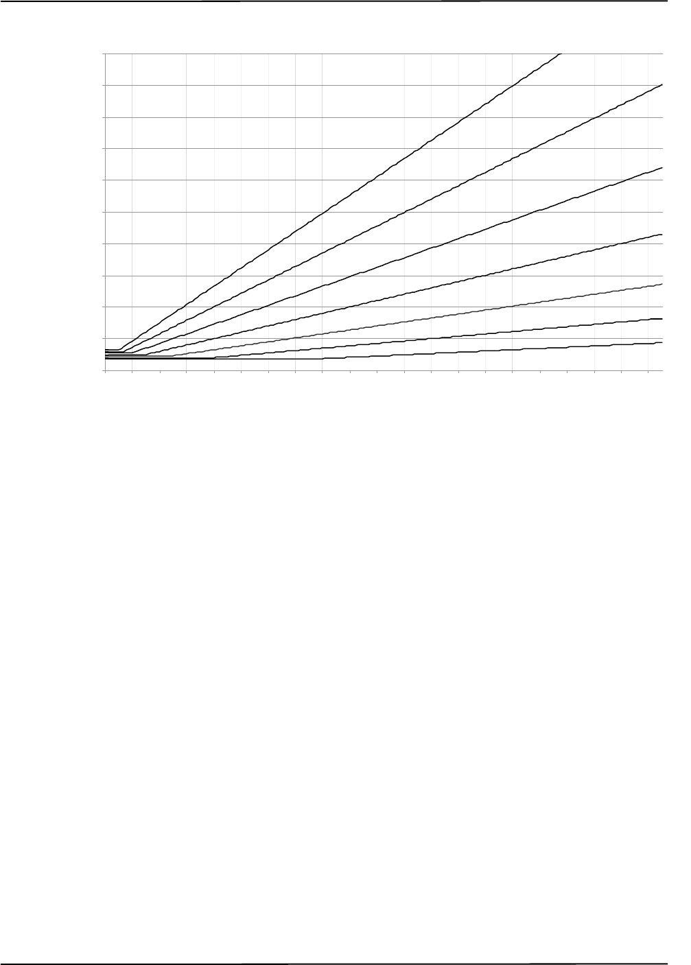
Setting the Infrared Light Sensitivity
Passive Polaris Spectra User Guide - Revision 7 69
Figure 8-1 Infrared Light Sensitivity Levels
Sensitivity Levels
There are seven sensitivity levels; with each increasing level number, the ability of the system to
tolerate background IR light increases. Increasing the sensitivity level makes the system
performance more robust in the presence of background IR light; however, it increases the chance
that a tool cannot be tracked properly because it may have a marker that is not bright enough. Low
marker brightness can be caused by, for example, the surface of a marker becoming partially
occluded by fluids or other materials, thus reducing the reflectivity of the marker.
Level 4 is the default sensitivity level for the Polaris Spectra System and should work well in most
situations.
8.2 Changing the Sensitivity Level
Checking for Background IR Light
If a tool is tracking intermittently or not tracking at all, check the IR interference flag in the port
status and in the tool information returned with the BX or TX command. If the IR interference flag
is intermittently or constantly on for any of the tools, there may be background IR present.
Alternatively, you can check for the “Interference” flag in the tool tracking utility of NDI ToolBox,
or use the image capture utility in NDI ToolBox to capture images of the IR detected by the system.
0
10
20
30
40
50
60
70
80
90
10 0
0 100 200 300 400 500 600 700 800 900 1000 1100 1200 1300 1400 1500 1600 1700 1800 1900 2000
Trigger Level (% of maximum)
Integration Time (µs)
2
1
3
4
5
6
7
1 - 7 represent
sensitivity levels

Setting the Infrared Light Sensitivity
70 Passive Polaris Spectra User Guide - Revision 7
Choosing a Sensitivity Level
Choose a sensitivity level of 5, 6 or 7 if:
• the “IR Interference” flag in the Port Status flags is on persistently
AND
• tools don't track
AND
• re-arranging the scene doesn't help.
Choose a sensitivity level of 3, 2 or 1 if:
• a tool doesn't track
AND
• all markers are clearly in view AND clean
AND
• no other error flags are giving any indication for why the tool is not tracking
(NDI experience shows that there should not be any reason for going to a level lower than 4.)
Note Changing the sensitivity level may reduce tracking problems only when the tools are in a different physical
location from the background IR. The sensitivity level cannot reduce tracking problems when the tools are
embedded in background IR.
Use the default sensitivity level 4 unless the system is experiencing interference from background
IR light. If the system is experiencing such interference, check the environment for causes (for
example, reflections). If it is not possible to eliminate the source of the background IR light, then
start with a low sensitivity level and increase the level until the tools track reliably.
The system may actually be tracking a tool even when the tool’s IR interference flag is on. You
should still increase the sensitivity level, since the behaviour of the system in this case is dependent
on the setup. (For example, moving the tool to another part of the measurement volume may prevent
it from being tracked properly.)
Changing the Sensitivity Level
You can change the IR sensitivity using the following methods:
• Use the configure utility of NDI ToolBox to select a sensitivity level, and to program a
sensitivity level as the default setting in the Position Sensor memory.
• Use the API command SET to change the value of the user parameter
Param.Tracking.Sensitivity. The changed value will persist until the system is reset or
initialized. To save the changed value (program it as the default setting in the Position
Sensor memory), use the API command SAVE. See the “Polaris Application Program
Interface Guide” for details.

Calibration and Firmware
Passive Polaris Spectra User Guide - Revision 7 71
9 Calibration and Firmware
9.1 Checking the Calibration of the Polaris Spectra System
The Position Sensor is calibrated at NDI, using the methodology described in Appendix A. Over
time, it is possible for the Position Sensor to lose calibration. A periodic calibration check should be
performed on the Position Sensor. The frequency of the calibration check depends on the specific
application and environment in which the Position Sensor is used.
If the Position Sensor begins to lose calibration, it may lose the ability to track some tools before
others. This is due to the various constraints used by the Polaris Spectra System, which make certain
tool designs more sensitive to loss of calibration than others. For example, consider a tool that has
several similar segment lengths or similar angles between segments, or has segment lengths similar
to those of another tool. An out-of-calibration Position Sensor may not be able to determine which
markers belong to which tool, because the segment lengths will be measured less accurately. In this
case, the system will report the tools as missing. (See “Marker Detection and Tool Tracking” on
page 42 and the “Polaris Tool Design Guide” for details on segment lengths and angles.)
NDI’s Accuracy Assessment Kit can be used as an aid in determining whether a Position Sensor is
performing acceptably for the user’s application. For all calibration procedures, return the Position
Sensor to NDI. This practice ensures that all calibrations are conducted in accordance with
procedures established specifically for the Polaris Spectra Position Sensor. See “Return Procedure”
on page 91 for instructions on returning equipment to NDI.
Line Separation and Calibration
The Position Sensor line separation (described on page 42) can sometimes be an indication that a
Position Sensor is out of calibration, but is not necessarily the best indicator and cannot always
detect calibration loss. For example, suppose one of the sensors was to shift towards the centre of the
Position Sensor while maintaining its horizontal alignment. In this case, the Position Sensor would
be out of calibration without any change in line separation, and the reported position of the tool
would be shifted.
If the Position Sensor is measuring high line separation values, it may be an indication of loss of
calibration. Line separation alone should not, however, be used as a test for calibration loss.
Bump Sensor
The Position Sensor contains an internal bump sensor that detects when the Position Sensor has
suffered an impact. Although each instance is different, it is NDI’s expectation that a representative
trigger threshold is equivalent to a 255 mm to 380 mm drop onto a vinyl tiled concrete surface.
If a bump has been detected, NDI recommends that you perform an accuracy assessment procedure
with the NDI Accuracy Assessment Kit (AAK), to ensure that the Position Sensor is still calibrated.
For information on the accuracy assessment procedure and AAK, contact NDI or visit the support
site at http://support.ndigital.com.
For full details on the bump sensor, see “Bump Sensor” on page 57.

Calibration and Firmware
72 Passive Polaris Spectra User Guide - Revision 7
9.2 Updating the Firmware
The Polaris Spectra System’s firmware is stored in EEPROM flash memory devices in the Position
Sensor. The latest firmware can be downloaded from the NDI Support Site at
http://support.ndigital.com.
The Position Sensor incorporates a safe boot loader that will perform verification of the control
firmware prior to loading and executing it. The safe boot loader has been included to provide a
fallback if a future control firmware upgrade fails. A communication fault or power fault could
cause a field firmware upgrade to fail. In these cases, the Position Sensor will still be able to start up
by running the safe boot loader. This will provide minimal support, to allow you to retry the control
firmware upgrade.
Updating Firmware
Update the Polaris Spectra System’s firmware using the configure utility in NDI ToolBox. NDI
ToolBox also includes command line functionality, to allow you to embed an NDI ToolBox
application (such as upgrading firmware) into your application software. See the ToolBox help for
details.
Multi Firmware Feature
The multi firmware feature is a keyed feature available for purchase from NDI. This feature allows
the system to be simultaneously programmed with more than one combined firmware revision.
When the multi firmware feature is enabled, you can specify which combined firmware revision the
system will use on its next reset or power up.
You can install new combined firmware revisions using NDI ToolBox.
The NDI ToolBox help explains how to use NDI ToolBox to select which combined firmware
revision the system will use. The “Polaris Application Program Interface Guide” explains how to
select a combined firmware revision using API commands.

Approvals
Passive Polaris Spectra User Guide - Revision 7 73
10 Approvals
10.1 Electrical Safety and Electromagnetic Compatibility
The Polaris Spectra System (consisting of a Position Sensor (model P7), power adapter, and Host
USB Converter), are listed in the “Declaration of Conformity” on page 93.
10.2 Optical Radiation Safety
Position Sensor Illuminators
The Polaris System Position Sensor illuminators emit invisible LED radiation with a pulsed duration
of up to 2.2 ms and 4.4% duty cycle resulting in a maximum average measured power of 127 W.
The Position Sensor has been assessed against the standards listed in the “Declaration of
Conformity” on page 93 and found not to pose a potential hazard to the eye under any foreseeable
viewing condition.
Note The Polaris Spectra System emits IR light that may interfere with IR-controlled devices, such as operating room
tables. It is recommended that you test the Polaris Spectra System if you intend to use it in an environment where
other IR-controlled devices are in use.
Positioning Laser
The positioning laser is a Class 2 laser, with a wavelength of 635 nm and a maximum output of
1 mW. The Polaris Spectra System containing a positioning laser conforms to the following
standards:
• ANSI Z136.1 (2007)
• IEC 60825-1 (2007)
• FDA/CDRH 21 CFR 1040.10 and 1040.11 except for deviations pursuant to Laser Notice
No. 50, dated June 24, 2007
Note For information on laser operation, see “Positioning Laser” on page 58.

Classifications
74 Passive Polaris Spectra User Guide - Revision 7
11 Classifications
Table 11-1 Classifications
Classification Description
Electric shock protection Class I - no applied parts
Degree of protection from electric shock Not classified
Degree of protection against ingress of
solids and liquids
Ordinary equipment
Flammable atmosphere Not suitable for use in the presence of a flammable
anaesthetic mixture with air, oxygen or nitrous oxide
Mode of operation Continuous when supplied by mains
Method of sterilization or disinfection Not suitable for sterilization
Laser classification Class 2
IRED illuminators risk group Exempt

Technical Specifications
Passive Polaris Spectra User Guide - Revision 7 75
12 Technical Specifications
12.1 Operating Environmental Conditions
The Polaris Spectra System (Position Sensor, Host USB Converter, power adapter, and cables) has
been tested to function in the conditions listed in Table 12-1.
The ambient operating temperature range for the Polaris Spectra System is dependent upon the physical location
of the Host USB Converter. If the Host USB Converter is located within the patient vicinity where it may be
touched by the patient, the operating ambient temperature range is +10°C to +30°C. If the Host USB Converter is
located outside this patient vicinity, the operating ambient temperature range permitted for the system is +10°C
to +40°C. The power adapter must be located outside the patient vicinity under all operating conditions. It is the
responsibility of the system integrator and/or the end-user to ensure that the system is appropriately configured
for the operating conditions.
The Position Sensor requires a warm-up time every time it is powered on. The warm-up time is
typically two minutes; if the Position Sensor is stored at low temperatures, the warm-up time may be
longer. The power LED will flash while the Position Sensor warms up; once the LED is steady, the
system is ready for use as defined by the NDI Accuracy Assessment Kit (AAK) protocol. For
information on the AAK, contact NDI.
12.2 Transportation and Storage Environmental Conditions
The Polaris Spectra System (Position Sensor, Host USB Converter, power adapter, and cables) has
been tested to be stored and transported in the conditions listed in Table 12-2.
Do not transport or store the Position Sensor outside the recommended storage temperature range, as this may
cause the system to go out of calibration. Reliance on data provided by an out-of-calibration Position Sensor may
lead to inaccurate conclusions and may cause personal injury. A calibration procedure must be performed before
using the Position Sensor after it has been transported or stored outside the recommended storage temperature
range.
Table 12-1 Operating Environmental Conditions
Environmental Condition Value
Atmospheric Pressure 70 kPa to 106 kPa
Relative Humidity 30% to 75%
Temperature +10oC to +30oC (see warning below)
Warning!
Warning!

Technical Specifications
76 Passive Polaris Spectra User Guide - Revision 7
Caution! To ship the Polaris Spectra System, repack it in the original containers with all the supplied protective packaging.
The provided packaging is designed to prevent damage to the equipment.
12.3 Technical Specifications
Table 12-2 Transportation and Storage Environmental Conditions
Specification Value
Atmospheric Pressure 50 kPa to 106 kPa
Relative Humidity 10% to 90% non-condensing
Temperature -10oC to +50oC
Table 12-3 Position Sensor Technical Specifications
Specification Value
Dimensions 613 mm x 104 mm x 86 mm
Weight 1.9 kg
Mounting via four M4 x 0.7 mm pitch x 8.5 mm deep threaded
holes, rear mount
Maximum Update Rate 60 Hz
Input Voltage 18-32 VDC
Power Consumption 13.5 W
Table 12-4 Host USB Converter Technical Specifications
Specification Value
Dimensions 88 mm x 57 mm x 39 mm
Weight 0.35 kg
Mounting Free standing or secured via three M6 x 1mm pitch x 3
mm deep threaded holes, located in the mounting feet
Host Interface USB (1.1 and 2.0 compatible)
Input Voltage 24 VDC
Output Voltage 26 VDC
Power Consumption <2 W

Technical Specifications
Passive Polaris Spectra User Guide - Revision 7 77
Table 12-5 Power Adapter Technical Specifications
(Part number APS49ES-24021/Hitron HES49ES-24021
applicable to IEC 60601-1 2nd Edition only)
Specification Value
Dimensions 125.00 mm x 61.78 mm x 32.00 mm
Weight 0.37 kg
Mounting Free standing
Input Voltage 100 VAC to 240 VAC
Input Frequency 60/50 Hz
Input Power 1.0 A
Power Output 24 VDC @ 2.1 A
Table 12-6 Power Adapter Technical Specifications
(Part Number APS49EMG-24021-7/Hitron HEMG49-S240210-7
applicable to IEC 60601-1 2nd and 3rd Editions)
Specification Value
Dimensions 125.00 mm x 61.78 mm x 32.50 mm
Weight 0.37 kg
Mounting Free standing
Input Voltage 100 VAC to 240 VAC
Input Frequency 60/50 Hz
Input Power 1.20 to 0.63 A
Power Output 24 VDC @ 2.1 A

Electromagnetic Compatibility
78 Passive Polaris Spectra User Guide - Revision 7
13 Electromagnetic Compatibility
The Polaris Spectra System requires special precautions regarding EMC. It must be installed and put into service
in accordance with the EMC information, detailed in this chapter. Failure to do so may result in personal injury.
Radio frequency communications equipment, including portable and mobile devices, may affect the Polaris
Spectra System and result in personal injury.
Do not use the passive Polaris Spectra System either adjacent to, or stacked with, other equipment. Check that
the Polaris Spectra System is operating normally if it is used either adjacent to, or stacked with, other equipment.
Failure to do so may result in personal injury.
This chapter contains the following information about the electromagnetic compatibility of the
system:
•“Cables and Accessories” on page 78
•“Guidance and Manufacturer's Declaration: Electromagnetic Emissions” on page 79
•“Guidance and Manufacturer’s Declaration: Electromagnetic Immunity” on page 79
•“Recommended Separation Distances” on page 82
•“Radio Frequency Emissions” on page 83
13.1 Cables and Accessories
The following table lists the cables and accessories that may be used with the Polaris Spectra System
while still maintaining compliance to the emissions and immunity requirements of IEC 60601-1-
2:2007.
Use of cables or accessories other than those listed in the following table may result in increased emissions and/
or decreased immunity of the Polaris Spectra System and may result in personal injury.
Warning!
Warning!
Table 13-1 Cables and Accessories that Maintain Emissions and Immunity Compliance
Name NDI P/N Type Shield Notes
Cable AC Line Cord,
Medical Grade
7500010 North American No Mains to Power
Adapter, for 120 VAC
testing
Cable AC Line Cord 7500012 France/Belgium/
Germany
No Mains to Power
Adapter, for 230 VAC
testing
USB cable 2600596 USB, A-B male,
double shielded, 5 m
Yes Computer to Host USB
Converter

Electromagnetic Compatibility
Passive Polaris Spectra User Guide - Revision 7 79
13.2 Guidance and Manufacturer's Declaration: Electromagnetic Emissions
The passive Polaris Spectra System is intended for use in the electromagnetic environment specified
below. The customer or the user of the passive Polaris Spectra System should assure that it is used in
such an environment.
13.3 Guidance and Manufacturer’s Declaration: Electromagnetic Immunity
The passive Polaris Spectra System is intended for use in the electromagnetic environment specified
below. The customer or the user of the passive Polaris Spectra System should assure that it is used in
such an environment.
Power Adapter 8001088 Switch Mode, 100-
240 VAC input, 24
VDC, 2.1 A output
N/A Applicable to
IEC 60601-1 2nd
Edition only
Power Adapter 8001260 Switch Mode, 100-
240 VAC input, 24
VDC, 2.1 A output
N/A Applicable to
IEC 60601-1 2nd and
3rd Editions
Table 13-1 Cables and Accessories that Maintain Emissions and Immunity Compliance
Name NDI P/N Type Shield Notes
Table 13-2 Manufacturer’s Declaration for Electromagnetic Emissions
Emissions Test Compliance Electromagnetic Environment Guidance
RF emissions
CISPR11
Group 1 The passive Polaris Spectra System uses RF energy only for
its internal function. Therefore, its RF emissions are very
low and are not likely to cause any interference in nearby
electronic equipment.
RF emissions
CISPR11
Class B
The passive Polaris Spectra System is suitable for use in all
establishments, including domestic establishments and those
directly connected to the public low-voltage power supply
network that supplies buildings used for domestic purposes.
Harmonic emissions
IEC61000 3-2
Class A
Voltage fluctuations/
flicker emissions
IEC61000-3-3
Complies
Table 13-3 Electromagnetic Immunity
Immunity Test IEC 60601 Test
Level Compliance Level Electromagnetic Environment -
Guidance
Electrostatic
discharge (ESD)
IEC 61000-4-2
±6 kV contact
±8 kV air
±6 kV contact
±8 kV air
Floors should be wood, concrete or
ceramic tile. If floors are covered
with synthetic material, the relative
humidity should be at least 30%.

Electromagnetic Compatibility
80 Passive Polaris Spectra User Guide - Revision 7
Note UT is the a.c. mains voltage prior to application of the test level.
Electrical fast
transient/burst
IEC 61000-4-4
±2 kV for power
supply lines.
±1 kV for input/
output lines
±2 kV for power
supply lines.
±1 kV for input/
output lines
Mains power quality should be that
of a typical commercial or hospital
environment.
Surge
IEC 61000-4-5
±1 kV line(s) to
line(s)
±1 kV
differential mode Mains power quality should be that
of a typical commercial or hospital
environment.
±2 kV line(s) to
earth
±2 kV common
mode
Voltage dips, short
interruptions and
voltage variations
on power supply
input lines
IEC 61000-4-11
<5% UT
(>95% dip in UT)
for 0.5 cycles
<5% UT
(>95% dip in UT)
for 0.5 cycles
Mains power quality should be that
of a typical commercial or hospital
environment. If the user of the
passive Polaris Spectra System
requires continued operation during
power mains interruptions, it is
recommended that the passive Polaris
Spectra System be powered from an
uninterruptible power supply or a
battery.
40% UT
(60% dip in UT)
for 5 cycles
40% UT
(60% dip in UT)
for 5 cycles
70% UT
(30% dip in UT)
for 25 cycles
70% UT
(30% dip in UT)
for 25 cycles
<5% UT
(>95% dip in UT)
for 5 s
<5% UT
(>95% dip in UT)
for 5 s
Power frequency
(50/60Hz) magnetic
field IEC 61000-4-8
3 A/m 3 A/m Power frequency magnetic fields
should be at levels characteristic of a
typical location in a typical
commercial or hospital environment.
Table 13-3 Electromagnetic Immunity (Continued)
Immunity Test IEC 60601 Test
Level Compliance Level Electromagnetic Environment -
Guidance
Electromagnetic Compatibility
Passive Polaris Spectra User Guide - Revision 7 81
Note At 80 MHz and 800 MHz, the higher frequency range applies.
These guidelines may not apply to all situations. Electromagnetic propagation is affected by absorption and
reflection from structures, objects, and people.
a - Field strengths from fixed transmitters, such as base stations for radio (cellular/cordless)
telephones and land mobile radios, amateur radio, AM and FM radio broadcast and TV broadcast,
cannot be predicted theoretically with accuracy. To assess the electromagnetic environment due to
fixed RF transmitters, an electromagnetic site survey should be considered. If the measured field
strength in the location where the passive Polaris Spectra System is used exceeds the applicable RF
compliance level above, observe the passive Polaris Spectra System to verify normal operation. If
Table 13-4 Electromagnetic Immunity—Not Life Supporting
Immunity Test IEC 60601
Test Level Compliance
Level Electromagnetic Environment - Guidance
Conducted RF
IEC 61000-4-6
3 Vrms
150 kHz to
80 MHz
3 V Portable and mobile RF communications equipment
should be used no closer to any part of the Polaris
Spectra System, including cables, than the
recommended separation distance calculated from the
equation applicable to the frequency of the transmitter.
Recommended separation distance:
d = 1,2√P
See Table 13-5 on page 82.
Radiated RF
IEC 61000-4-3
3 V/m
80 MHz to
2,5 GHz
3 V/m d = 1,2√P 80 MHz to 800 MHz
d = 2,3√P 800 MHz to 2,5 GHz
See Table 13-5 on page 82.
Where 'P' is the maximum output power rating of the
transmitter in watts (W) according to the transmitter
manufacturer and 'd' is the recommended separation
distance in metres.
Field strengths from fixed RF transmitters, as
determined by an electromagnetic site surveya, should
be less than the compliance level in each frequency
rangeb. Interference may occur in the vicinity of
equipment marked with the following symbol:

Electromagnetic Compatibility
82 Passive Polaris Spectra User Guide - Revision 7
abnormal performance is observed, additional measures may be necessary, such as re-orienting or
relocating the passive Polaris Spectra System.
b - Over the frequency range of 150 kHz to 80 MHz, field strengths should be less than 3 V/m.
13.4 Recommended Separation Distances
The passive Polaris Spectra System is intended for use in an electromagnetic environment in which
radiated RF disturbances are controlled. The customer or the user of the passive Polaris Spectra
System can help prevent electromagnetic interference by maintaining a minimum distance between
portable and mobile RF communications equipment (transmitters) and the passive Polaris Spectra
System, as recommended below, according to the maximum output power of the communications
equipment.
For transmitters rated at a maximum output power not listed above, the recommended separation
distance (d) in metres (m) can be estimated using the equation applicable to the frequency of the
transmitter, where P is the maximum output power rating of the transmitter in watts (W) according
to the transmitter manufacturer.
Note At 80 MHz and 800 MHz, the higher frequency range applies.
These guidelines may not apply to all situations. Electromagnetic propagation is affected by absorption and
reflection from structures, objects, and people.
Table 13-5 Recommended Separation Distances between Portable and
Mobile RF Communications Equipment and the
Passive Polaris Spectra System
Rated maximum output power
of transmitter (watts)
Separation distance according to frequency of transmitter (metres)
150 kHz to 80 MHz
d = 1,2√P
80 MHz to 800 MHz
d = 1,2√P
800 MHz to 2.5 GHz
d = 2,3√P
0,01 0,12 0,12 0,23
0,1 0,38 0,38 0,73
1 1,2 1,2 2,3
10 3,8 3,8 7,3
100 12 12 23

Electromagnetic Compatibility
Passive Polaris Spectra User Guide - Revision 7 83
13.5 Radio Frequency Emissions
FCC
This device complies with Part 15 of the FCC rules. Operation is subject to the following two
conditions:
1. This device may not cause harmful interference and,
2. This device must accept any interference received, including interference that may cause
undesired operation.
Note This equipment has been tested and found to comply with the limits for a Class B digital device, pursuant to Part
15 of the FCC Rules. These limits are designed to provide reasonable protection against harmful interference in a
residential installation. This equipment generates, uses and can radiate radio frequency energy and, if not
installed and used in accordance with the instructions, may cause harmful interference to radio communications.
However, there is no guarantee that interference will not occur in a particular installation. If this equipment does
cause harmful interference to radio or television reception, which can be determined by turning the equipment off
and on, the user is encouraged to try to correct the interference by one or more of the following measures:
— Reorient or relocate the receiving antenna.
— Increase the separation between the equipment and receiver.
— Connect the equipment into an outlet on a circuit different from that to which the receiver is connected.
— Consult the dealer or an experienced radio/TV technician for help.
Changes or modifications not expressly approved by Northern Digital Inc. could void the user’s authority to
operate the equipment.
CE Mark
CE Mark: This is a Class B product. In a domestic environment, this product may cause radio
interference, in which case the user may be required to take adequate measures.
Industry Canada
Industry Canada Compliance Statement: This ISM device complies with Canadian ICES-001.
Avis de Conformité à la réglementation d’Industrie Canada: Cet appareil ISM est conforme à la
norme NMB-001 du Canada.

Troubleshooting
84 Passive Polaris Spectra User Guide - Revision 7
14 Troubleshooting
14.1 Introduction
This section provides possible solutions to common problems and answers some frequently asked
questions. For further information regularly check the NDI Support Site at:
http://support.ndigital.com.
If you cannot find the answer to your question here or on the support site, contact NDI at the address
shown at the front of this guide.
The majority of problems that may occur with the Polaris Spectra System can be grouped into one of
the following categories:
• A system hardware failure (for example, a faulty Position Sensor or cable)
• A tool error (for example, dirty markers)
• Environmental conditions (for example, incidental IR light)
• User error (for example, obscuring the optical path)
Most faults are be indicated by system LEDs or audio codes, as detailed in “LEDs” on page 85 and
“Audio Codes” on page 88. You can diagnose the fault by using the GET command to read the
Info.Status.Alerts user parameters, or by observing the error message in the configure utility of
NDI ToolBox. For details on the Info.Status.Alerts user parameters, see the “Polaris Application
Program Interface Guide.”

Troubleshooting
Passive Polaris Spectra User Guide - Revision 7 85
14.2 LEDs
Position Sensor
The power, status, and error LEDs on the Position Sensor combine to indicate the status of the
component. These LEDs behave as described in Table 14-1:
Table 14-1 Power, Status, and Error LEDs Summary
Power
(Green) Status
(Green) Error
(Amber) Meaning and Action Required
Flashing (Any
state)
(Any
state)
The power LED will stop flashing and light steady green when
system is ready for use as defined by the NDI Accuracy
Assessment Kit (AAK) protocol. For information on the AAK,
contact NDI.
Solid Solid Off The Position Sensor is ready for use; no faults
Solid Solid Flashing Minor recoverable fault that can easily be corrected by a novice
user.
NDI ToolBox response: The fault is indicated in the configure
utility of NDI ToolBox.
API response: The “diagnostic pending” bit is set in the BX or
TX response. To determine what the fault is, read the alerts
parameters as described in the “Polaris Application Program
Interface Guide.”
Solid
or off
Solid Solid Major recoverable fault. This type of fault requires more expertise
to correct than a minor recoverable fault.
NDI ToolBox response: The fault is indicated in the configure
utility of NDI ToolBox.
API response: One of the following responses occurs:
• The “diagnostic pending” bit is set in the BX or TX
response. To determine what the fault is, read the alerts
parameters as described in the “Polaris Application
Program Interface Guide.”
• An error is returned. The error code indicates the nature
of the error. Error codes are listed in the “Polaris
Application Program Interface Guide.”

Troubleshooting
86 Passive Polaris Spectra User Guide - Revision 7
Note If your Polaris Spectra System uses combined firmware revision 002, see the technical bulletin “Polaris Spectra
Position Sensor LED Behaviour with Combined Firmware Revision 002,” available on the NDI support site at
http://support.ndigital.com.
Host USB Converter
•Power :
Lights green when power is being supplied to the Host USB Converter.
•Error :
Lights amber when the Host USB Converter has detected a fault.
Solid Off Solid Non-recoverable fault. Return the Position Sensor to NDI for
service.
NDI ToolBox response: The fault is indicated in the configure
utility of NDI ToolBox.
API response: One of the following responses occurs:
• The “diagnostic pending” bit is set in the BX or TX response.
To determine what the fault is, read the alerts parameters as
described in the “Polaris Application Program Interface
Guide.”
• An error is returned. The error code indicates the nature of the
error. Error codes are listed in the “Polaris Application
Program Interface Guide.”
Off Off Off Voltage is out of range.
Check/replace the Position Sensor, Host USB Converter, or
cables.
Table 14-1 Power, Status, and Error LEDs Summary (Continued)
Power
(Green) Status
(Green) Error
(Amber) Meaning and Action Required

Troubleshooting
Passive Polaris Spectra User Guide - Revision 7 87
If the Host USB Converter Error LED is lit, follow the flow chart below to help diagnose the fault.
Figure 14-1 Host USB Converter: Error LED Fault Chart
Host USB Converter
Error LED is lit
Turn system mains power
off for 10 seconds, then
turn back on
Does
Error
LED go
off?
Fault Cleared
Disconnect Position
Sensor
Does
Error
LED go
off?
Replace Position
Sensor
Check/Replace:
1. Power Adapter
2. Host USB Converter
Yes
No
Yes
No

Troubleshooting
88 Passive Polaris Spectra User Guide - Revision 7
14.3 Audio Codes
The Position Sensor emits audio tones that provide an audible indication of system status, as listed
in Table 14-2.
14.4 Common Problems
The following paragraphs lists specific problems and possible solutions.
The tool is inside the measurement volume, but the software reports that the tool is
partially out of volume
This may mean that fewer than the minimum number of markers (a parameter in the tool
definition file) are inside the characterized measurement volume, but at least one marker on the tool
is outside the characterized measurement volume.
For example, consider a four-marker tool, whose minimum number of markers parameter is set to 4.
If three of the tool’s markers are inside the characterized measurement volume, and the other marker
is outside the characterized measurement volume, the Polaris Spectra System will continue to track
the tool, but the accuracy is unknown, and the tool will be reported as partially out of volume.
The system doesn’t track tools at the back of the characterized measurement volume
If the system will track at the front of the measurement volume but not at the back, the Position
Sensor may be damaged, or calculating high line separation values. For more details on line
separation, see “Marker Detection and Tool Tracking” on page 42. You can check the line separation
values using the 3D command. See the “Polaris Application Program Interface Guide” for details.
Other IR-based devices are not working properly
Using the Polaris Spectra System in the same room as other IR-based devices may cause these other
devices to malfunction. The Position Sensor’s illuminators flood the surrounding area with IR light,
which could saturate other IR receiving devices, preventing them from properly receiving other IR
signals.
Table 14-2 Audio Codes
Indication Meaning Action
Two beeps emitted Normal indication when power is initially
applied to the system or the system is reset.
No action required.
Two beeps emitted
every three seconds
The host computer has not sent a command
to the system within the amount of time
specified by the user parameter
Param.Watch Dog Timer.
By default this feature is disabled; to
enable it, set the value of the user
parameter Param.Watch Dog Timer to an
non-zero value.
Check the host computer
application to make sure it is
functioning as desired.

Troubleshooting
Passive Polaris Spectra User Guide - Revision 7 89
It may be possible to synchronize other devices with the Polaris Spectra System, so that IR signals
from the other devices are not being emitted at the same time as the illuminators emit IR. Contact
NDI Technical Support for details or visit the support site at http://support.ndigital.com.
The Polaris Spectra System is tracking some tools, but not others
As the Position Sensor begins to lose calibration, it may lose the ability to track some tools before
others. This is due to the various algorithm constraints used by the Polaris Spectra System, which
make certain tool designs more sensitive to loss of calibration than others. Consider, for example, a
tool that has several similar segment lengths or similar angles between segments, or has segment
lengths similar to those of another tool. The out-of-calibration Position Sensor may not be able to
determine which markers belong to which tool, and so will report the tools as missing. (See “Marker
Detection and Tool Tracking” on page 42 and the “Polaris Tool Design Guide” for details on
segment lengths and angles.)
See “Checking the Calibration of the Polaris Spectra System” on page 71 for more details about
calibration.
Reflections and other IR sources
Reflections and other IR sources may cause markers to become “lost” in the background IR light.
These reflections and sources should be eliminated or minimized as much as possible. Reflections
occur when IR light from the illuminators is reflected off surfaces such as:
• surgical drapes: ensure the drapes are placed such the reflections are minimized
• reflective surfaces: minimize reflective surfaces in the environment
• tools: design and manufacture tools in non-reflective materials. Refer to the “Polaris Tool
Design Guide” for further information.
Other sources of IR light, such as operating room lights, should be considered when positioning the
system in order to minimize interference from such devices.
What happens if the markers are partially blocked from the view of the Position
Sensor?
The Polaris Spectra System requires a clear line of sight to the markers. Anything that interferes
with the line of sight can reduce the measurement accuracy. The magnitude of the errors that are
caused by partial occlusion of the markers depends on the number of markers, the geometry of the
tool, and the severity of the occlusion. Errors caused by partial occlusion can have exactly the same
magnitude for active and passive tools. However, there is more opportunity to partially occlude the
passive markers because they are larger than active markers.When designing a new tool, it is
important to consider the effect of partial occlusion on its accuracy. See the “Polaris Tool Design
Guide” for further information on tool design.
Why is the tool reported as missing?
A tool may be reported as missing if:
• it has been rotated so that too few markers are visible to the Position Sensor

Troubleshooting
90 Passive Polaris Spectra User Guide - Revision 7
• the tool is no longer in the field of view
• the tool is damaged (for instance, it is bent)
• the condition of the makers has deteriorated (for instance, the markers are scuffed or
occluded with foreign matter).
The Position Sensor seems too warm
The Position Sensor will be warm to the touch during normal use. If the temperature goes out of
range, the temperature bit in the system status section of the BX/TX response will be set. An error
message will be shown in NDI ToolBox application software.
The Virtual Serial Port cannot be opened
If you cannot open the virtual serial port, check the system connections, the Host USB Converter
and the host computer USB port.
The Polaris Spectra System does not have full functionality, or is behaving
intermittently
Check the connection between the Position Sensor cable and the Position Sensor. A loose
connection may result in partial functionality or unpredictable system behaviour.

Return Procedure and Warranty
Passive Polaris Spectra User Guide - Revision 7 91
15 Return Procedure and Warranty
15.1 Return Procedure
In the event that you need to return equipment to NDI for repairs, you will need to fill out a Return
Materials Authorization (RMA) request form at the NDI Support Site at http://support.ndigital.com.
NDI will contact you with RMA information and shipping instructions. Any materials you are
returning to NDI should be shipped in their original packaging.
You are responsible for the shipping costs of returning equipment to NDI, whether or not the
equipment is covered under warranty. When the equipment is received at NDI, it will be inspected to
determine whether the required repair is covered under warranty. NDI can provide you with a quote
of repair costs either before or after repairs have been made. If the equipment is covered under
warranty, NDI will pay the return shipping costs. If the equipment is not covered under warranty,
you are required to pay the return shipping costs.
15.2 Warranty
Unless otherwise agreed to in writing by NDI, the warranty is as follows, and applies only to the
original purchaser.
Note This warranty is also posted on the NDI Support Site at http://support.ndigital.com.
Note This warranty is void if you open the case of any system component.
Hardware
NDI warrants to the Buyer that NDI’s hardware product(s) will be free from defects in material and
workmanship only for a period twelve (12) months from the date such product(s) is/are shipped
from NDI to the Buyer.
This warranty does not apply to product(s) normally consumed in Buyer’s operations or which have
a normal life inherently shorter than the above-stated warranty period. Without limiting the
generality of the foregoing, the following products shall have the following warranty periods:
product or components thereof which are re-chargeable batteries . . . 90 days from shipment
infrared emitting diode (IRED) markers or product(s) which contain
IRED markers (other than illuminators on Position Sensors) . . . . . . . 90 days from shipment
single use, disposable reflective (passive-type) markers . . . . . . . . . . . prior to first use but no more
than 90 days from shipment

Return Procedure and Warranty
92 Passive Polaris Spectra User Guide - Revision 7
Software
NDI’s software product(s) is/are licensed and provided “as is, where is” without warranty of any
kind. NDI makes no warranties, express or implied, that the functions contained in the software
product(s) will meet the Buyer’s requirements or that the operation of the programs contained
therein will be error free.
General Provisions Applicable to Warranty
NDI’s obligations under this warranty shall be limited to repairing or replacing (at NDI’s option) the
product(s), EXW (Incoterms 2000) NDI’s plant (Waterloo, Ontario, Canada). Any original parts
removed and/or replaced during any repair process shall become the property of NDI. This warranty
shall apply only to the original Buyer [being that person or legal entity which has contracted directly
with NDI for the supply of the product(s)]. Repair work shall be warranted on the same terms as
stated herein except such warranty shall be for a period of sixty (60) days or for the remainder of the
unexpired warranty period, whichever is longer. In respect of any product(s) supplied hereunder
which are manufactured by others, NDI gives no warranty whatsoever, and the warranty given by
such manufacturers, if any, shall apply.
The obligations of NDI set forth in this warranty are conditional upon proper transportation,
shipping, handling, storage, installation, use, maintenance and compliance with any applicable
recommendations of NDI. Without limiting the generality of the foregoing, this warranty shall not
apply to defects or damage resulting from: fire; misuse; abuse; accident; neglect; improper
installation; improper care and/or maintenance; lack of care and/or maintenance; customer supplied
software interfacing; modification or repair which is not authorized by NDI; power fluctuations;
operation of hardware product(s) outside of environmental specifications; improper site preparation
and maintenance; permitting any substance whatsoever to contaminate or otherwise interfere with
optics; and any other cause beyond the control of NDI. The obligations set forth in this warranty are
further conditional upon the Buyer promptly notifying NDI of any defect and, if required, promptly
making the product(s) available for correction. NDI shall be given reasonable opportunity to
investigate all claims and no product(s) shall be returned to NDI without NDI first providing the
Buyer with a return material authorization number and shipping instructions. All product(s) returned
to NDI shall be packaged in the containers originally used by NDI to ship the product(s) to the
Buyer.
NDI, for itself, its agents, contractors, employees, providers, and for any parent or subsidiary of
NDI, expressly disclaims all warranties, express or implied, including, without limitation, of
merchantability or fitness for a particular purpose.
The foregoing warranty is the entire warranty of NDI. NDI neither assumes nor authorizes any
person, purporting to act on its behalf, to modify or to change this warranty, or any other warranty or
liability concerning the product(s).


Declaration of Conformity
94 Passive Polaris Spectra User Guide - Revision 7
Figure 16-2 EC Declaration of Conformity - Page 2

Abbreviations and Acronyms
Passive Polaris Spectra User Guide - Revision 7 95
17 Abbreviations and Acronyms
Acronym or Abbreviation Definition
5DOF 5 Degrees Of Freedom
6DOF 6 Degrees Of Freedom
AAK Accuracy Assessment Kit
API Application Program Interface
CAPI Combined Application Program Interface
CCD Charge Coupled Device
CD Compact Disk
CRC Cyclic Redundancy Check
DSR Data Set Ready
EEPROM Electrically Erasable Programmable Read Only Memory
EMC Electromagnetic Compatibility
EMI Electromagnetic Immunity
ESD Electrostatic Discharge
FCC Federal Communications Commission
IC Industry Canada
IR Infrared Light
IRED Infrared Light-Emitting Diode
LED Light-Emitting Diode
MRI Magnetic Resonance Imaging
NDI Northern Digital Inc.
RAM Random Access Memory
RF Radio Frequency
RI Ring Indicator
RMA Return Materials Authorization
RMS Root Mean Square
UL Underwriters Laboratories Inc.
USB Universal Serial Bus
VCP Virtual COM Port
VM Virtual Machine
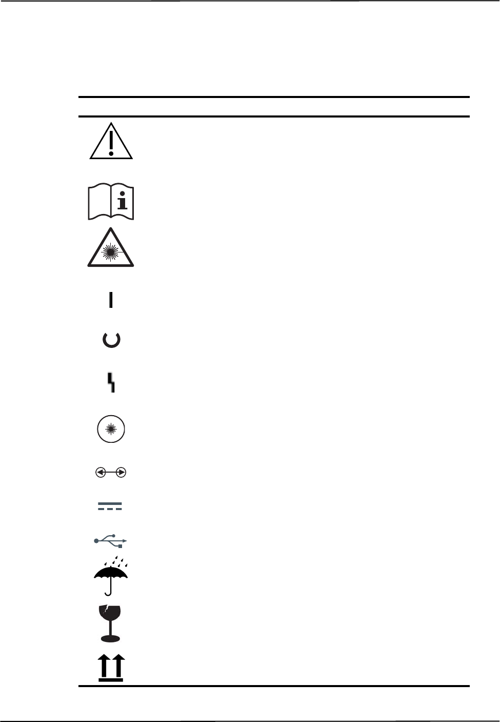
Equipment Symbols
96 Passive Polaris Spectra User Guide - Revision 7
18 Equipment Symbols
Symbol Meaning System Components
Caution
(To avoid personal injury, consult
accompanying documents.)
Position Sensor
Host USB Converter
Consult accompanying documents. Position Sensor
Host USB Converter
Laser Warning
(To avoid personal injury, consult
accompanying documents.)
Position Sensor
On (power: connection to the mains supply) Position Sensor
Host USB Converter
Status Position Sensor
Error Position Sensor
Host USB Converter
Laser Activation Position Sensor
Connection Port Position Sensor
Direct Current Host USB Converter
USB Port Host USB Converter
Keep away from rain Packaging
Fragile Packaging
This way up Packaging

Glossary
Passive Polaris Spectra User Guide - Revision 7 97
19 Glossary
3D RMS Error
The RMS error is the square root of the sum of the squares of the measurement errors. This can be
approximated by the square root of the mean square added to the standard deviation squared of the
errors.
Calibration
Calibration is the process of establishing, under specified conditions, the relationship between
values produced by the Polaris Spectra System and corresponding known values established by a
device that is traceable to a national standard.
Characterized Measurement Volume
The characterized measurement volume is the volume within the detection region where accuracy is
within specified limits. NDI cannot guarantee measurement accuracy outside this region.
Faces
Tool faces are separate rigid bodies that make up a tool.
Field of View
The field of view is the total volume in which the Polaris Spectra System can track a marker,
regardless of accuracy.
Firmware
Firmware is a computer program stored in an NDI hardware device and controls the Polaris Spectra
System.
Flash EEPROM
Flash Electrically Erasable Programmable Read Only Memory (EEPROM) stores control
parameters and system information within the Position Sensor. The information programmed to the
Flash EEPROM is retained even after the system is turned off.
Frame
A frame contains the measured positions of the markers in the field of view at a particular point in
time.
Global Coordinate System
The global coordinate system is the Polaris Spectra coordinate system. The global coordinate system
is used by the Polaris Spectra as a frame of reference against which tool transformations are
reported. By default, the global coordinate system's origin is set at the Position Sensor.

98 Passive Polaris Spectra User Guide - Revision 7
Illuminator
The illuminator is an array of IR light-emitting diodes that surround the sensor lenses on the Position
Sensor. These flood the area in front of the Position Sensor with IR light, which is reflected back to
the Position Sensor by the passive markers.
Line Separation
To determine the position of an IR source, the Position Sensor calculates a line between the source
of IR and each sensor. The line separation is the distance between these two lines where they cross.
Local Coordinate System
A local coordinate system is a coordinate system assigned to a specific tool or rigid body.
Maximum 3D Error
Maximum 3D error applies to individual markers. It specifies, in the tool definition file, the
maximum allowable difference between the measured and expected location of a marker on a tool or
rigid body.
Maximum Marker Angle
Maximum marker angle is used to determine if a marker will be used in the calculation of a rigid
body or tool. If the marker is determined to be farther off-angle to the Position Sensor than the
maximum marker angle, this data is not used to determine the rigid body or tool.
Passive Marker
A passive marker is a retro-reflective passive sphere that reflects IR light emitted by the Position
Sensor.
Pivoting
Pivoting is a procedure (of rotating a tool about its tip) used to determine the tool tip offset.
Position Sensor
The Position Sensor is the component of the Polaris Spectra System that provides a source of IR
light for passive markers, collects marker position data from both active and passive markers,
calculates tool transformations, and sends the results to the host computer.
Quaternion
A quaternion is a compact representation of rotations, or correspondingly, orientations in 3D space
(rather than having to use orthogonal matrices).
Reference Tool
A reference tool is a tool or rigid body whose local coordinate system is used as a frame of reference
in which other tools are reported/measured.

Glossary
Passive Polaris Spectra User Guide - Revision 7 99
Rigid Body
A rigid body is an object on which three or more markers are fixed relative to one another.
Tool Definition File
A tool definition file stores information about a tool or rigid body. This includes information such as
the placement of the tool's markers, the location of its origin, and its manufacturing data. A tool
definition file is formatted as .rom for tools.
Tool Tip Offset
The tool tip offset is the vector between the tip of the tool and the tool origin.
Transformation
A transformation is a combination of translation and rotation values that describe a change of the
tool or rigid body in position and orientation.
Unique Geometry Tool
Unique geometry tools incorporate markers positioned in such a way that, when detected in the
measurement volume, the tool can be uniquely identified from other tools.

100 Passive Polaris Spectra User Guide - Revision 7
Appendix A Polaris Spectra Calibration Performance and Methodology
Standard industry practice dictates that all measurement and testing instruments should be
periodically calibrated to ensure they are operating within tolerances acceptable to the user and/or
the user’s customers.
The user must establish a calibration procedure and interval that is appropriate for the accuracy
requirements of their application.
The Position Sensor is a highly specialized instrument developed exclusively by NDI. For all
calibration procedures, return the Position Sensor to NDI. This practice ensures that all calibrations
are conducted in accordance with procedures established specifically for the Polaris Spectra Position
Sensor.
Note The NDI Accuracy Assessment Kit (AAK) can be used in the field as an aid to determine whether a Position
Sensor is performing acceptably for the user’s application.
If, at any time, a concern should arise that the Position Sensor is not measuring accurately, it should
be returned to NDI.
Note The calibration procedure at NDI applies to single markers and cannot be directly applied to an application that
uses tools with several markers.
A.1 Polaris Spectra Performance
The Polaris Spectra System performance is determined by a statistical analysis of the 3D Euclidean
distance error between the reported position of an NDI marker and its true position, based on
measurements taken throughout the entire Polaris Spectra System’s measurement volume.
Acceptance criteria for the Polaris Spectra System’s performance are based on the RMS values of
the accuracy and repeatability.
The 3D RMS volumetric accuracy acceptance criterion is less than or equal to 0.25 mm within
the pyramid volume, and less than or equal to 0.30 mm within the extended pyramid volume. This
criterion is based on a statistically representative set of positions distributed uniformly throughout
the measurement volume, using the mean of 30 samples at each position at 20°C.
The 3D RMS repeatability acceptance criterion is less than or equal to 0.10 mm within the
pyramid volume, and less than or equal to 0.15 mm within the extended pyramid volume. This
criterion is based on a statistically representative set of positions distributed uniformly throughout
the measurement volume, using 30 samples per position at 20°C.
A.2 Calibration Method
The following method is used to calculate the Polaris Spectra System’s accuracy and repeatability:
An NDI marker is accurately moved to each of n locations (Xi, Yi, Zi) spread throughout the
measurement volume. The mechanism that moves the marker is assumed to have an accuracy that is
at least 10 times better than the measured accuracy of the Polaris Spectra System. This assumption
allows the errors in the marker positioning to be ignored.

Passive Polaris Spectra User Guide - Revision 7 101
At each of the n locations, the Polaris Spectra System takes m readings of the marker’s 3D position
(xij, yij, zij).
The accuracy of the Polaris Spectra System is calculated as the RMS variation of the mean of m
readings about the true 3D location calculated across all n locations throughout the measurement
volume.
The repeatability of the Polaris Spectra System is calculated as the RMS variation of the m
readings about the average of the 3D readings at each location n. This RMS variation is calculated
across all n locations throughout the measurement volume.
3D average measurements:
3D RMS
repeatability =
xiaverage
xij
j1=
m
m
----------------------------- ,=
yiaverage
yij
j1=
m
m
----------------------------- ,=
ziaverage
zij
j1=
m
m
----------------------------- =
3D RMS accuracy
xiaverage Xi
–
2yiaverage Yi
–
2ziaverage Zi
–
2
++
i1=
n
n
------------------------------------------------------------------------------------------------------------------------------------------------=
xij
xiaverage
–
2yij
yiaverage
–
2zij
ziaverage
–
2
++
j1=
m
i1=
n
nm
-----------------------------------------------------------------------------------------------------------------------------------------------------------------------------

102 Passive Polaris Spectra User Guide - Revision 7

Passive Polaris Spectra User Guide - Revision 7 103
Index
Index
Symbols
.rom file, 47
Numerics
3D RMS
error, 97
repeatability acceptance criterion, 100
volumetric accuracy acceptance criterion, 100
3-marker lock-on, 43
5DOF, 46
6D Architect
see NDI 6D Architect
6DOF, 46
A
AAK
see Accuracy Assessment Kit
abbreviations, 95
absolute measurements, 38, 39
accessories, 19, 78
account permissions
Mac, 26
accuracy, 40
acceptance criterion, 100
Accuracy Assessment Kit, 57, 71, 100
acquiring tools, 42
acronyms, 95
active markers, 45
active wireless tools, 12, 45
alerts
bump sensor battery, 58
diagnostic pending, 63
temperature, 63
algorithm limitations error, 63
anaesthetics, 14
API commands
BEEP, 7
BX, 39, 41, 49, 53, 57, 62, 63, 65, 69, 90
COMM, 9, 20
GET, 5, 7, 84
SET, 7, 58, 59, 60, 70
TX, 39, 41, 49, 53, 57, 62, 63, 65, 69, 90
approvals, 73
audio codes, 7, 85, 88
B
background IR light, 15, 68, 69
bad transformation fit alert, 64
battery
bump sensor, 58
laser, 59
baud rate, 20, 56
BEEP command, 7
beeper, 7
boot loader, 72
bump sensor, 8, 57, 71
BX command, 39, 41, 49, 53, 57, 62, 63, 65, 69,
90
C
cables, 10
connecting, 19
IEC compliance, 78
warning, 19
calibration
checking, 71
definition, 97
method, 100
calibrator, 51
CAPI Sample
see NDI CAPI Sample
cautions, xi
CCD, 42
characterization, 47
characterized measurement volume, 1, 40, 97
extended pyramid volume, 41
pyramid volume, 40
classifications, 74
COMM command, 9, 20
common problems, 88
communication synchronization error, 63
computer requirements, 2
Config.Password, 60
conformity, declaration of, 93
connecting hardware, 19
coordinate system
global, 39, 97
local, 46, 98

104 Passive Polaris Spectra User Guide - Revision 7
Index
D
data buffer limitations alert, 64
data set ready (DSR), 9
data transmission rate, 56
declaration of conformity, 93
decontamination policy, 91
detecting markers, 42
diagnostic pending alert, 63
dimensions, 76
disclaimers, xii
drivers for Host USB Converter
Linux, 24
Windows, 21
dynamic range control, 42
E
EEPROM, 97
electrical shock protection, 74
electromagnetic
compatibility, 78
emissions, 79
immunity, 79
environmental
conditions, 75
requirements, 14
equipment symbols, 96
errors
audio codes, 7, 62, 85
common problems, 88
diagnostic pending, 63
error flags tutorial, 32
flags, 62, 63
LED, 4, 8, 57, 85
maximum 3D, 98
system communication synchronization, 63
temperature, 63
tool transformation, 38
ESD
electrostatic discharge, 18
extended pyramid volume, 41
eye safety, 73
F
face, 97
face normal, 46
FCC compliance, xii
feature keys, 59
fell behind while processing alert, 64
field of view, 40, 97
firmware, 97
multiple versions, 60, 72
updating, 72
flags, 38, 62
flammable materials, 14, 74
flash EEPROM, 97
frame, 97
frame number, 38
G
gases, 14
geometry, 46
GET command, 5, 7, 84
global coordinate system, 39, 97
H
hardware requirements Mac, 25
hardware warranty, 91
harmonic emissions, 79
host computer requirements, 2
host interface update rate, 76
Host USB Converter, 8
cables, 10
components, 8
connecting, 20
drivers
Linux, 24
Windows, 21
error LED, 8
indicator LEDs, 8
mounting, 8, 18
operating environmental conditions, 75
power LED, 8
serial number label, 9
technical specifications, 76
transportation and storage conditions, 75
I
IEC standards, 2
illuminators, 4, 42, 73
definition, 98

Passive Polaris Spectra User Guide - Revision 7 105
Index
indicator LEDs
bump sensor, 57
bump sensor battery alert, 58
error, 4, 85
on Host USB Converter, 8
on Position Sensor, 4, 20
power, 4, 85
status, 4, 85
troubleshooting, 85
Info.Status.Alerts, 5, 57, 84
Info.Status.Bump Detected, 57
Info.Status.New Alerts, 57, 63
information and error flags tutorial, 32
ingress protection, 74
input voltage, 76
installing
Host USB Converter drivers
Linux, 24
Windows, 21
host USB converter drivers
Mac, 27
NDI ToolBox
Linux, 24
Mac, 26
Windows, 21
integration time, 42, 68
IR interference alert, 64
IR light, 15
IR sensitivity level
about, 68
changing, 69
description, 69
IRED, 45
J
Java version
Mac, 26
Java VM, 21
K
keyed features, 59
L
label
laser, 7, 59
serial number, 7, 9
laser
about, 58, 61
activation, 58
activation button, 5
aperture, 5
battery, 59
class, 5
classification, 74
label, 7, 59
safety, 59, 73
specifications and standards, 59
LEDs, 4, 8, 20, 57, 85
bump sensor battery alert, 58
fault flowchart, 87
LEMO connector, 6
line of sight, 14, 15
line separation, 42, 54, 71
local coordinate system, 46, 98
M
Mac
account permissions, 26
hardware requirements, 25
Java version, 26
moving toolbox files, 30
OS version, 26
software uninstalling, 28
toolbox preferences, 30
USB driver installation, 27
maintenance, 66
marker geometry, 46
markers
detection, 42
information, 65
passive, 98
phantom, 54
status, 38
stray, 53
maximum 3D error, 47, 98
maximum marker angle, 47, 98
maximum update rate, 76
measurement volume
see characterized measurement volume
minimum number of markers, 43, 49
minimum spread, 49
missing, 38
missing transformations, 89
mounting
Host USB Converter, 8, 18
Position Sensor, 5, 16
technical specifications, 76
mounting post, 44
MRI environment, 15, 16

106 Passive Polaris Spectra User Guide - Revision 7
Index
multi firmware feature key, 60, 72
N
NDI 6D Architect, 13, 21, 23, 25
NDI CAPI Sample, 13
installing
Linux, 23
Windows, 21
NDI ToolBox, 13, 70, 90
installing
Linux, 24
Windows, 21
normals
face, 46
not enough acceptable markers alert, 64
O
offset, 51
operating environment, 14, 75
operating temperature, 16
optical path, 14, 15
optical radiation safety, 73
orientation of tool, 38
origin of a tool, 51
OS version Mac, 26
out of volume, 38, 41, 63
output voltage, 76
overview, system, 1
P
Param.Bump Detector.Bumped, 57
Param.Bump Detector.Clear, 58
Param.Laser.Laser Status, 59
Param.Tracking.Sensitivity, 70
Param.Watch Dog Timer, 7, 88
parameters, 47, 50
maximum 3D error, 47
maximum marker angle, 47
minimum number of markers, 49
minimum spread, 49
see also user parameters
partially out of volume, 38, 41, 63
Passive Sphere Markers, 54
passive sphere markers, 45, 98
sterilization, 45, 55
passive tools, 11, 44
password protection, 60
phantom markers, 54
pivoting, 52, 98
tutorial, 35
port status flags, 63
position of tool, 38
Position Sensor, 42, 98
accuracy, 40
audio codes, 7, 88
bump sensor, 8
cable, 10
cleaning, 66
connecting, 19
error LED, 4, 85
front view, 3
illuminators, 4, 73
indicator LEDs, 4
laser, 7, 73
LEDs, 4
mounting, 5, 16
operating environmental conditions, 75
overview of operation, 3
power LED, 4, 85
rear view, 5
sensors, 4
serial number label, 7
status LED, 4, 85
technical specifications, 76
temperature, 90
transportation and storage conditions, 75
warm-up time, 4, 16, 20, 75, 85
positioning laser, 5, 58, 61
power adapter, 9
cable, 10
operating environmental conditions, 75
technical specifications, 77
transportation and storage conditions, 75
power consumption, 76
power LED, 4, 8, 85
problems, common, 88
processing exception, 64
pyramid volume, 40
Q
quaternion, 38, 98
R
radio frequency
communications, 15
emissions, 79

Passive Polaris Spectra User Guide - Revision 7 107
Index
reference tool, 52, 98
tutorial, 34
relative measurements, 38, 39
requirements, host computer, 2
return procedure, 91
rigid body, 99
ring indicator (RI), 9
RMA number, 91
RMS
accuracy, 40
error, 38
RS-232, 9
S
safe boot loader, 72
safety
laser, 59
optical radiation, 73
shock protection, 74
sampling rate, 43
sensitivity to IR light, 68, 69
sensor, 4
separation distances, 82
serial number label
Host USB Converter, 9
Position Sensor, 7
serial port emulation, 9
SET command, 7, 58, 59, 60, 70
shock protection, 74
software, 13
management
Linux, 23
Mac, 25
Windows, 20
see also
NDI 6D Architect
NDI CAPI Sample
NDI ToolBox
warranty, 92
solvents, 14
spectral response, 55
status
LED, 4, 85
marker, 38
port, 63
system, 38, 63, 85
tool, 38
sterilization, 66, 74
storage
conditions, 75
temperature, 16
stray markers, 38, 53
support site, xiii
symbols, 96
synchronization error, 63
system
beeper, 7
communication synchronization error, 63
overview, 1
status, 38, 63
T
technical specifications, 75, 76
temperature
alert, 63
operating, 16
storage, 16
three-marker lock-on, 43
timeout, 7
tip offset, 51
tool definition file, 11, 12, 47, 99
tool information flags, 64
tool tip offset, 51, 99
tutorial, 35
tool tracking parameters, 47, 50
ToolBox
see NDI ToolBox
tools, 11
5DOF, 46
6DOF, 46
acquiring, 42
active wireless, 12, 45
error value, 38
geometry, 46
multi-face, 46
orientation, 38
passive, 11, 44
position, 38
status, 38
tracking, 42
transformation, 38
using as reference, 52, 98
tracking
about, 42
error, 38
flags, 38, 63
tutorial, 31
transformations, 38
definition, 99
out of volume, 38
transportation conditions, 75
trigger level, 42, 68
troubleshooting, 85

108 Passive Polaris Spectra User Guide - Revision 7
Index
tutorial, 31
error flags, 32
information and error flags, 32
pivot, 35
reference tool, 34
tool tip offset, 35
tracking tools, 31
TX command, 39, 41, 49, 53, 57, 62, 63, 65, 69,
90
U
uninstalling software
Mac, 28
unique geometry, 46
constraints, 45
definition, 99
unpacking the system, 14
update information, xiii
updating firmware, 72
USB cable, 10
USB converter
see Host USB converter
USB drivers
Linux, 24
Mac, 27
Windows, 21
user parameters
Config.Password, 60
Info.Status.Alerts, 5, 57, 84
Info.Status.Bump Detected, 57
Info.Status.New Alerts, 57, 63
Param.Bump Detector.Bumped, 57
Param.Bump Detector.Clear, 58
Param.Laser.Laser Status, 59
Param.Tracking.Sensitivity, 70
Param.Watch Dog Timer, 7, 88
V
virtual serial port, 90
voltage, 76
volume
see characterized measurement volume
W
warm-up time, 4, 16, 20, 75, 85
warnings, ix
warranty, 91
general provisions, 92
hardware, 91
software, 92
watch dog timer, 7
weight, 76
