Pedi Nail Surgical Technique ST 1500 01 Rev A
2015-05-29
: Pdf Pedinail Surgical Technique St-1500-01-01 Rev A PediNail_Surgical_Technique_ST-1500-01-01_Rev_A_ 5 2015 pdf
Open the PDF directly: View PDF ![]() .
.
Page Count: 44
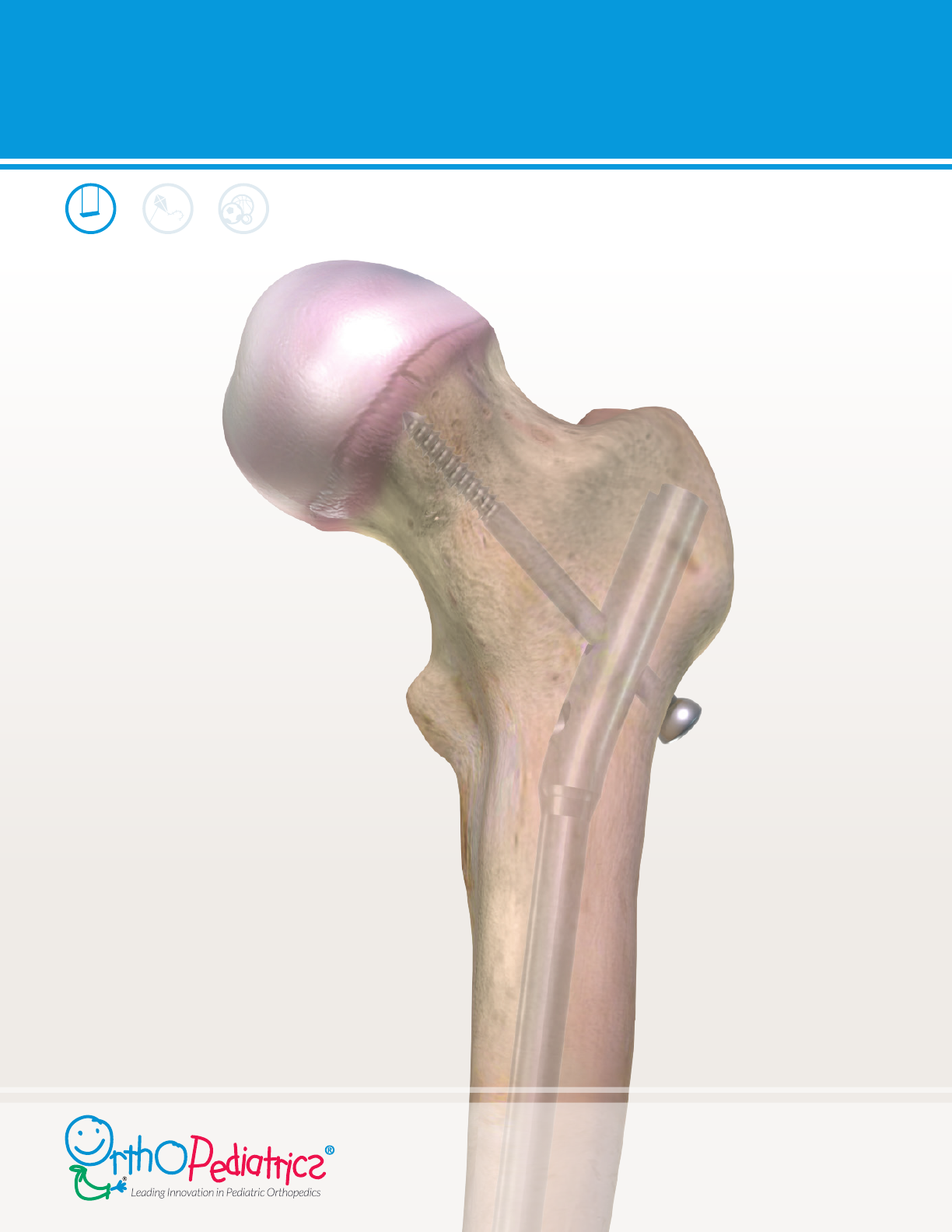
PediNail™ Pediatric Femoral Nail
SURGICAL TECHNIQUE

2
PediNail™
2

3
3
PediNail™
System Overview
Surgical Technique

4
PediNail™
4
Product Informaon

5
5
PediNail™

6
PediNail™
6
Proximal Locking Opons:
Distal Locking Opons:
Note: The 4.0mm locking screw is only used for distal locking of the 7mm nail.
1

7
7
PediNail™
Note: The 7mm and 8mm nails do not allow for proximal transverse locking bolt xaon. This should be taken into
consideraon when preoperavely planning.
Note: When selecng nail size, consider canal diameter, fracture paern, paent anatomy and postoperave
protocol.
2
1
8
PediNail™
8
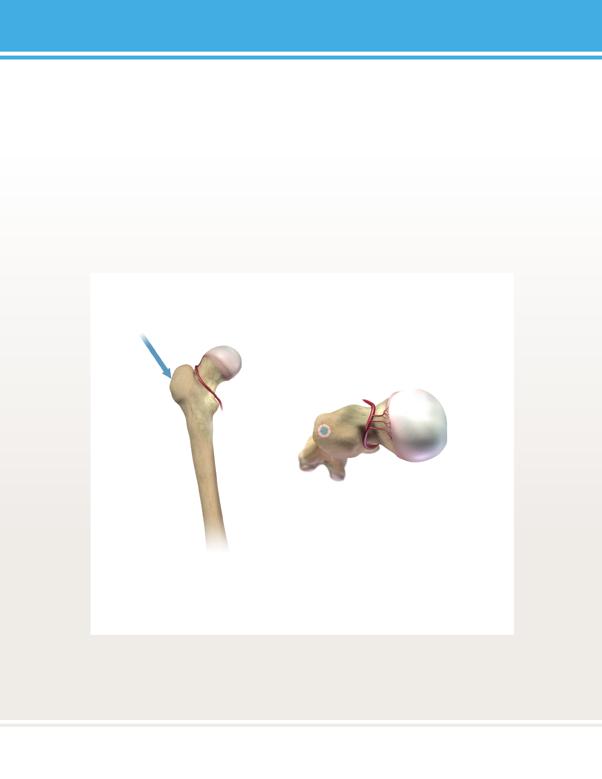
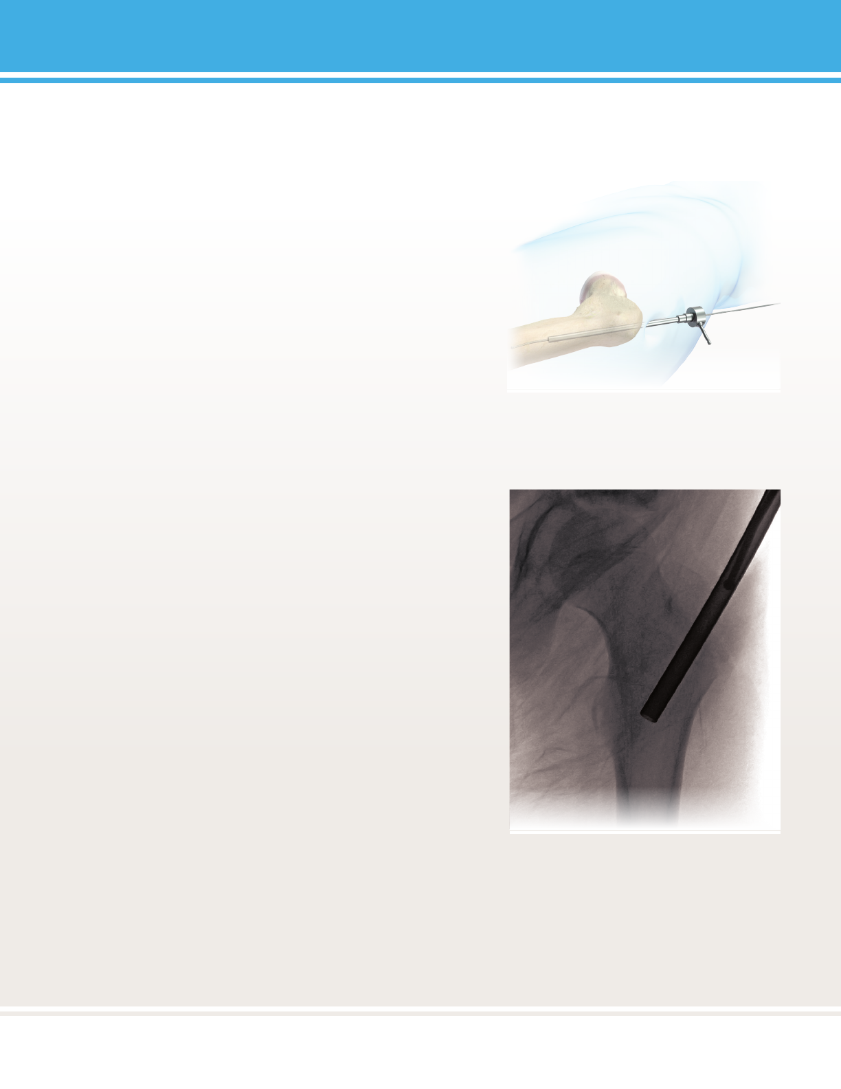
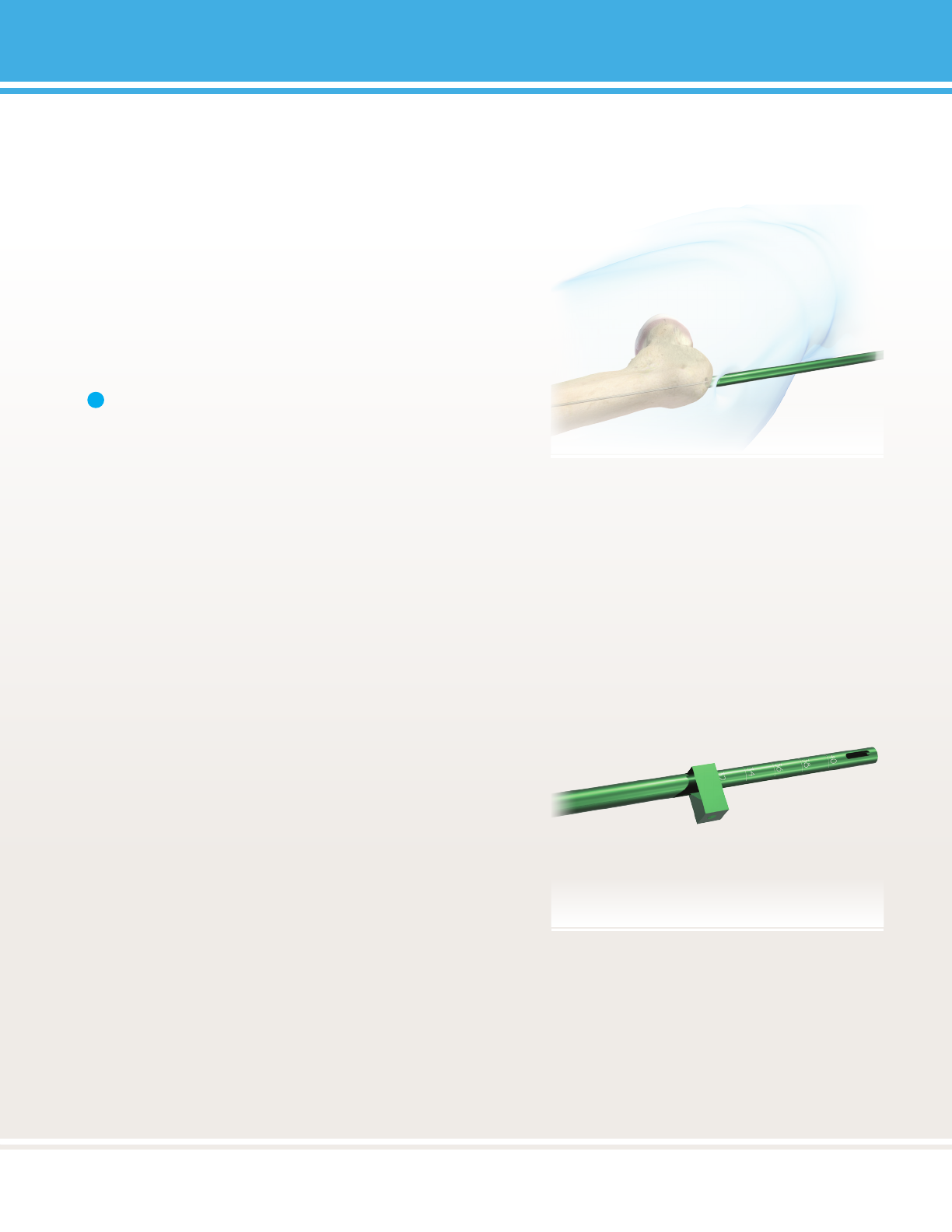
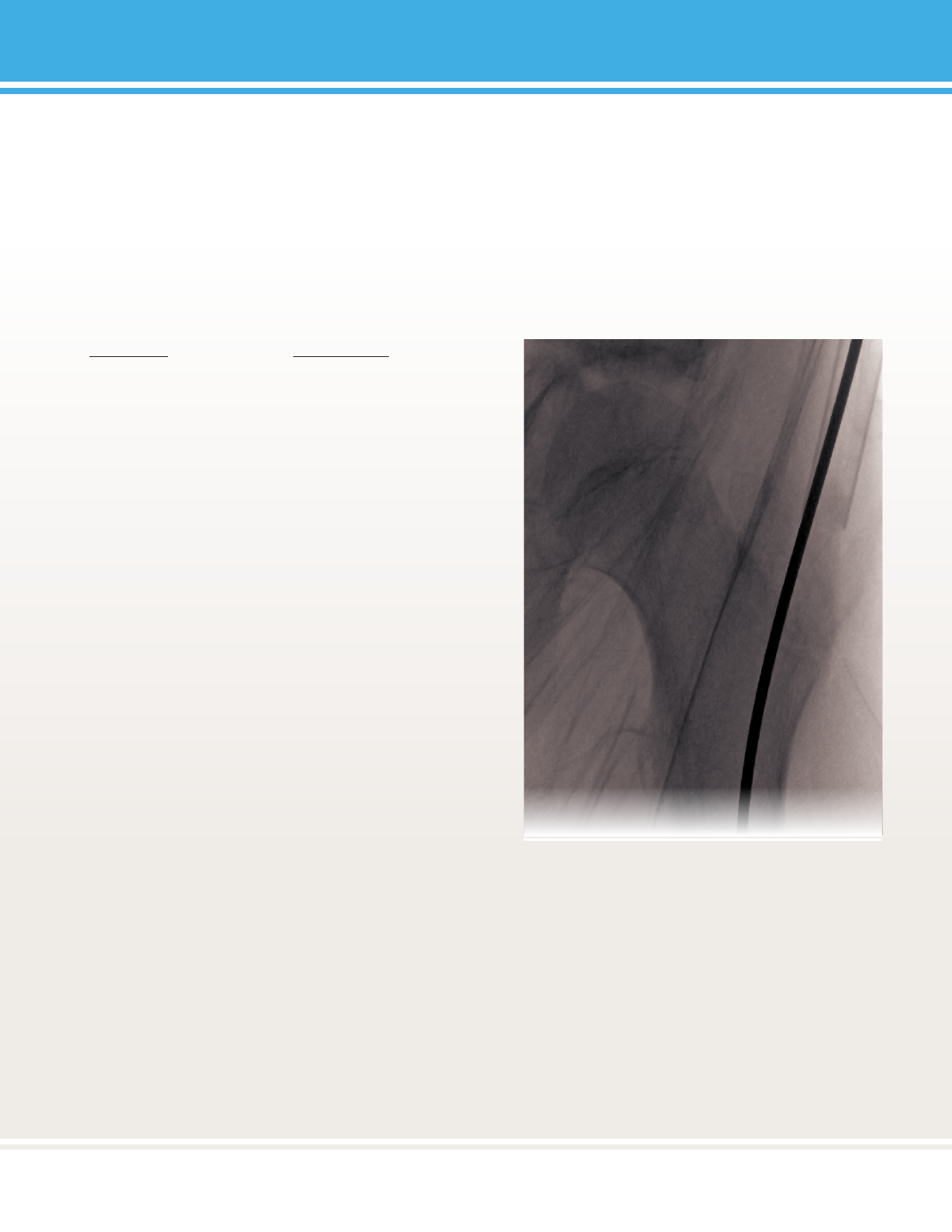
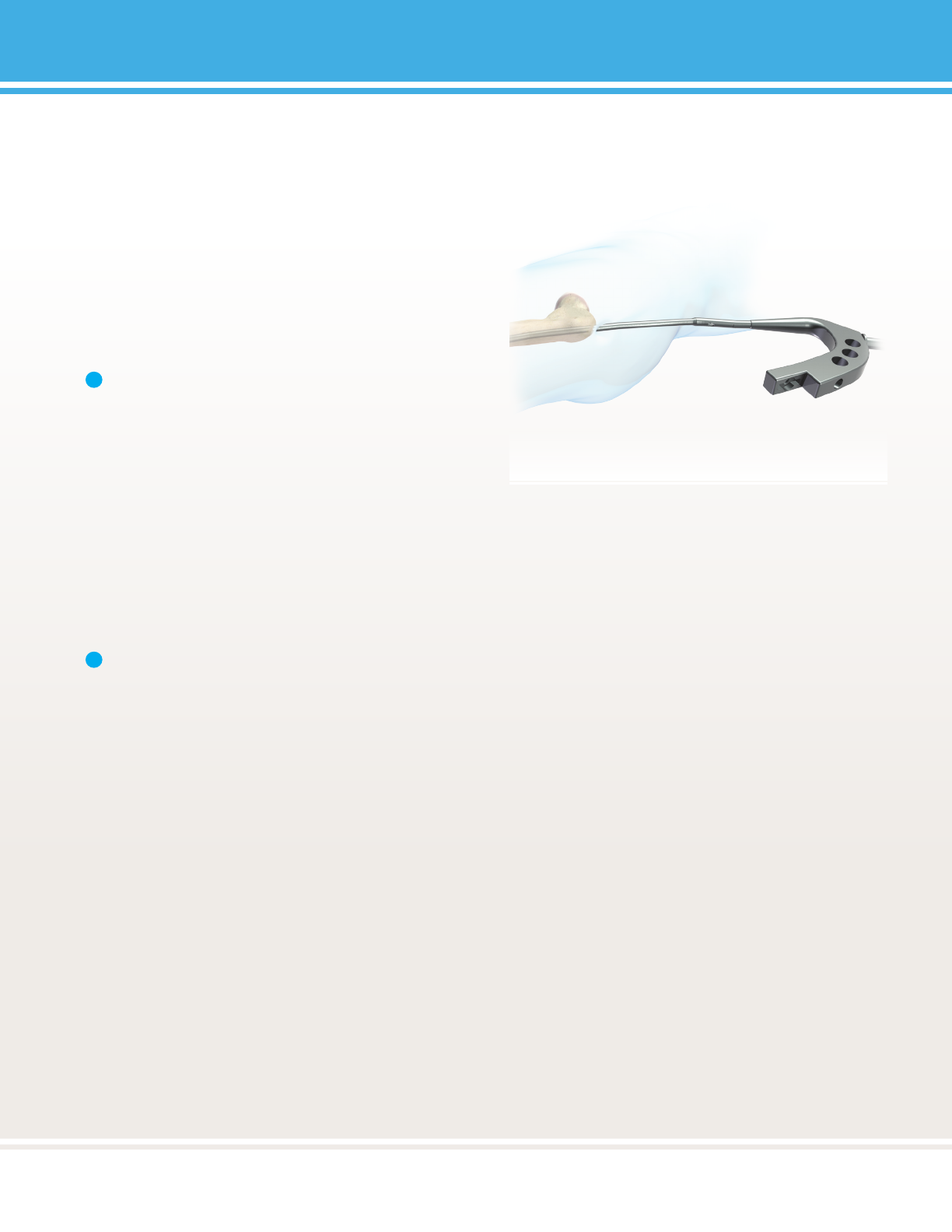
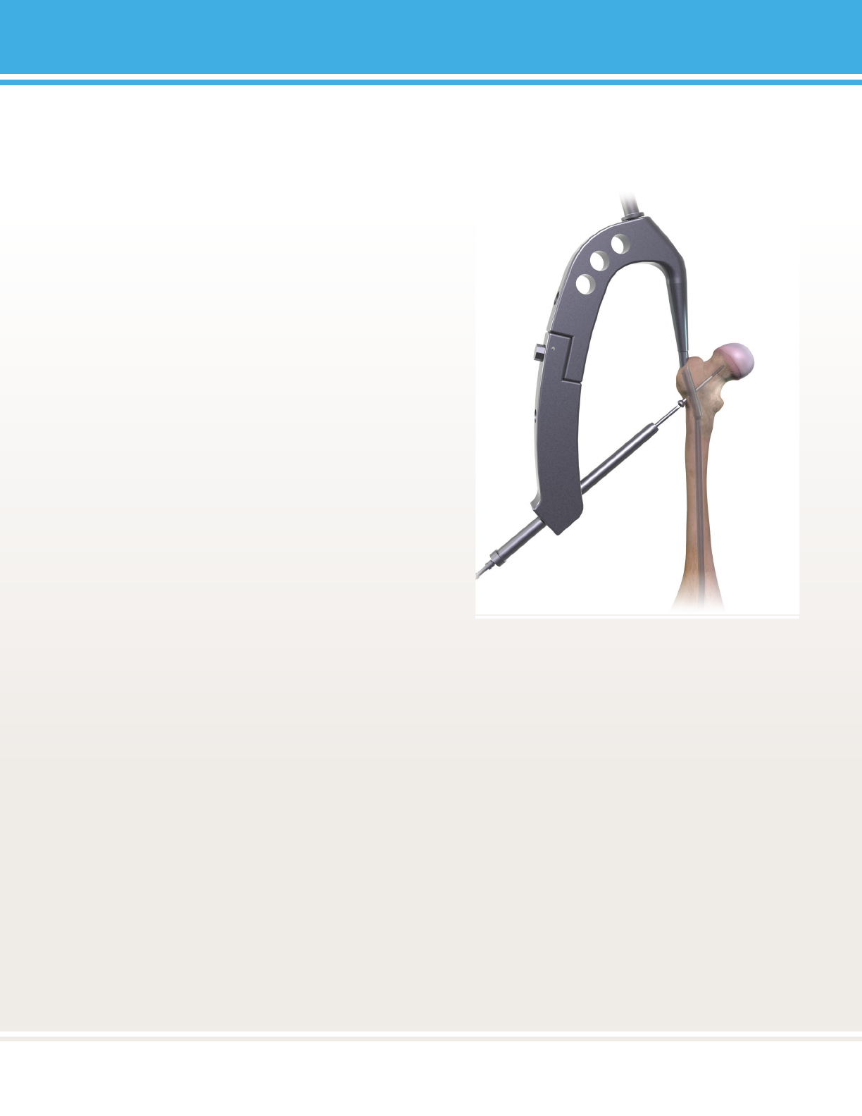
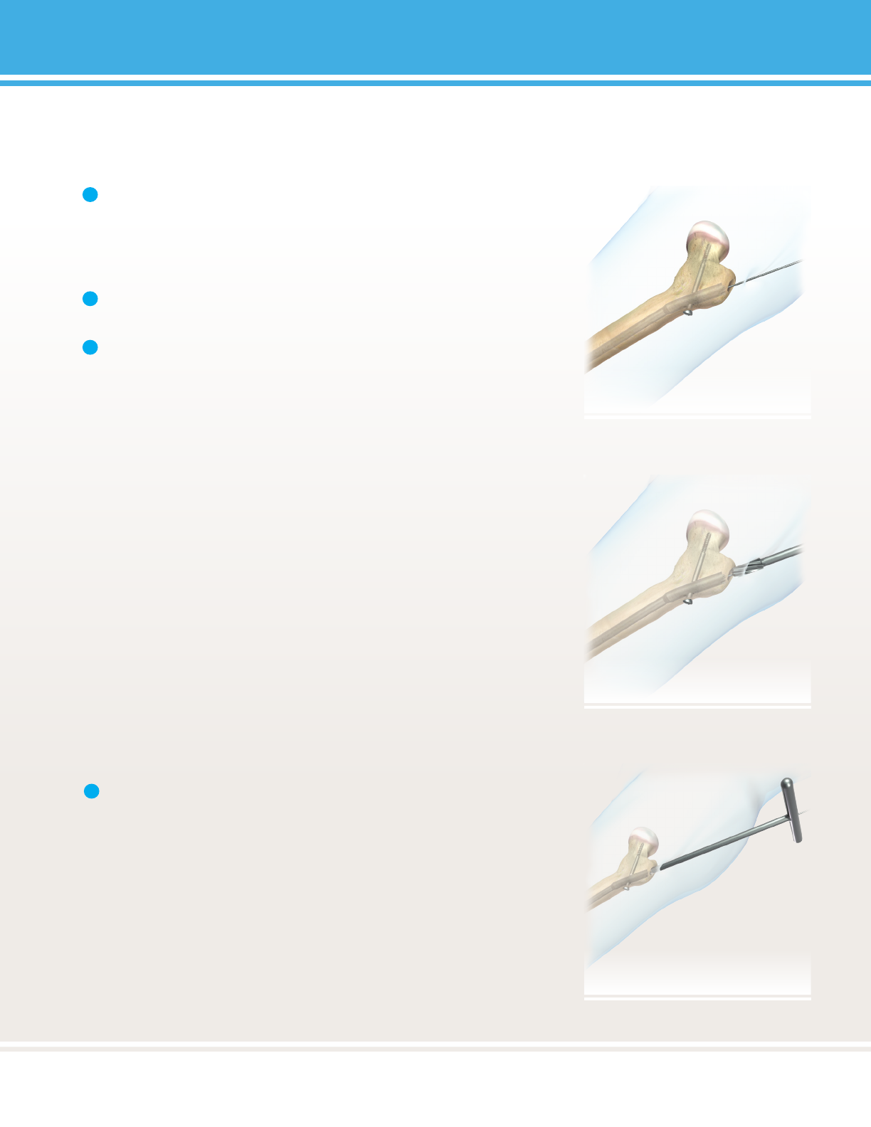
FIGURE 1:
9
9
PediNail™
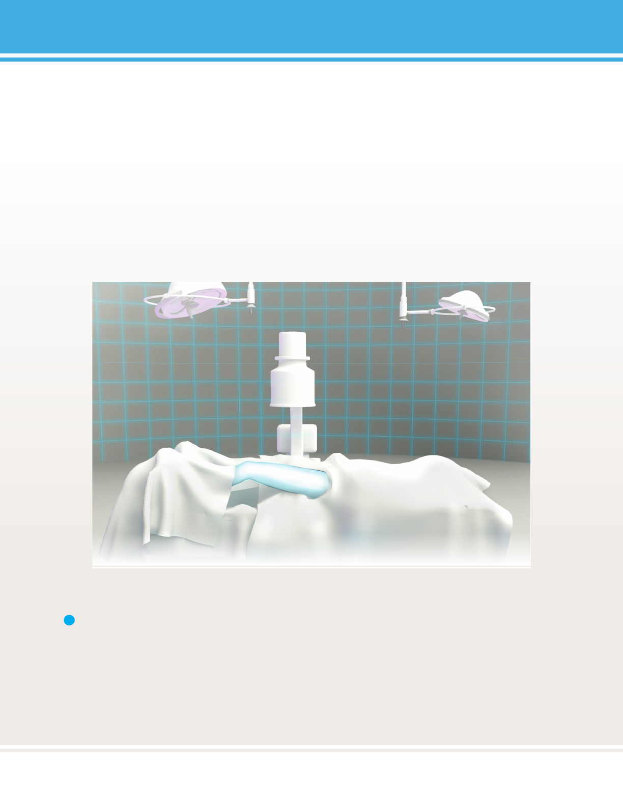
1Note: Alternavely, the paent may be posioned supine on a radiolucent table. The limb (or both limbs in
the case of bilateral procedures) can be prepared and draped free. This facilitates simultaneous irrigaon and
debridement of open femur fractures, bilateral derotaon osteotomy, or xaon of an ipsilateral bial fracture.
In order to bring the fracture out to length, an assistant may be required to apply manual tracon.
SURGICAL TECHNIQUE
FIGURE 2:
10
PediNail™
10
°
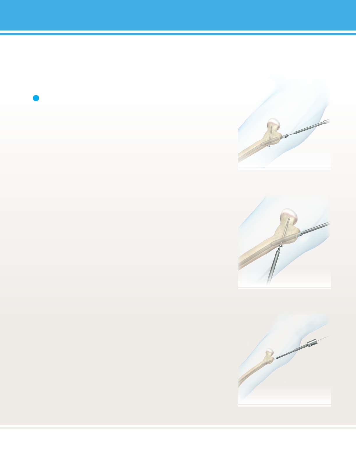
Note: Inspect pins and wires for any damage prior to use.
Ulizing damaged instruments may adversely aect the
outcome of the procedure.
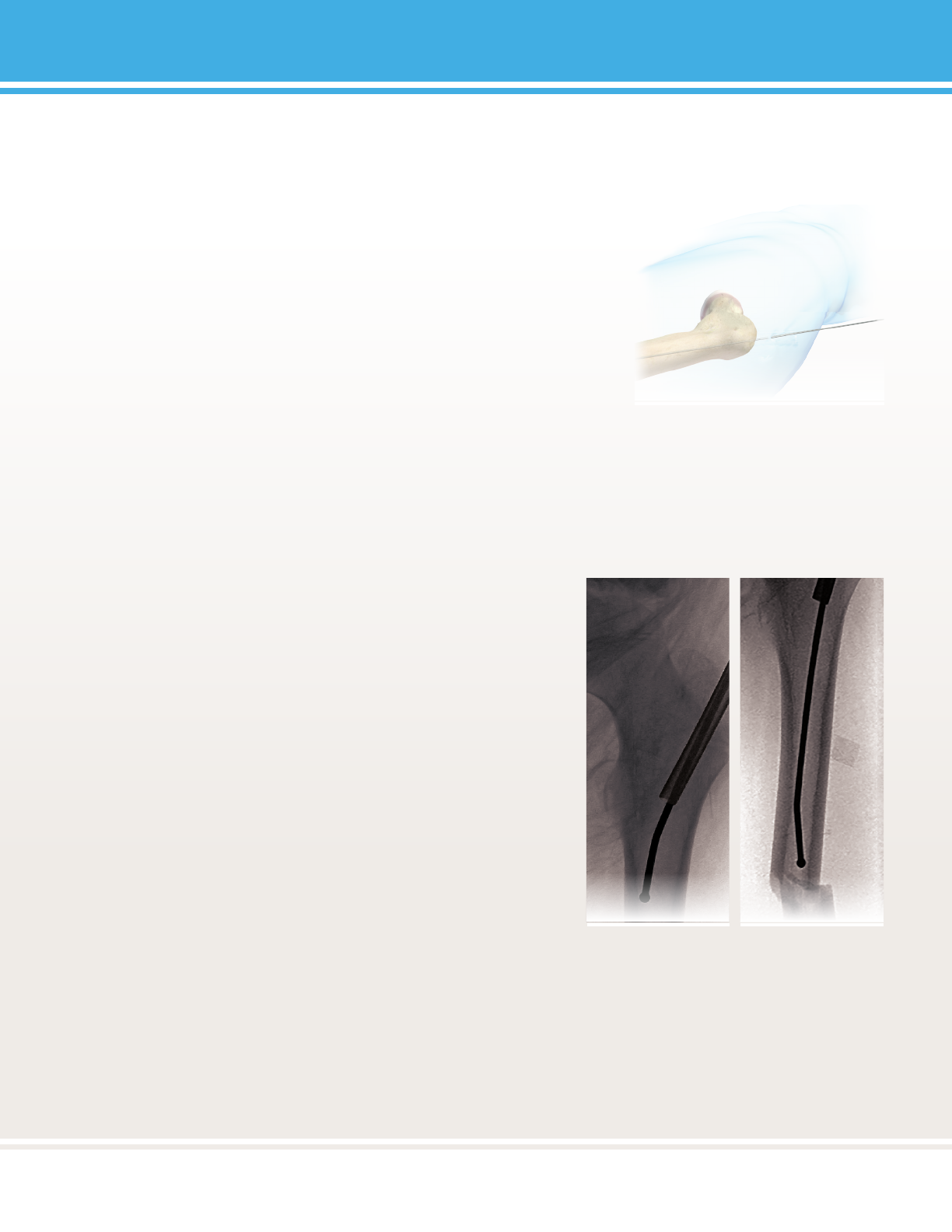
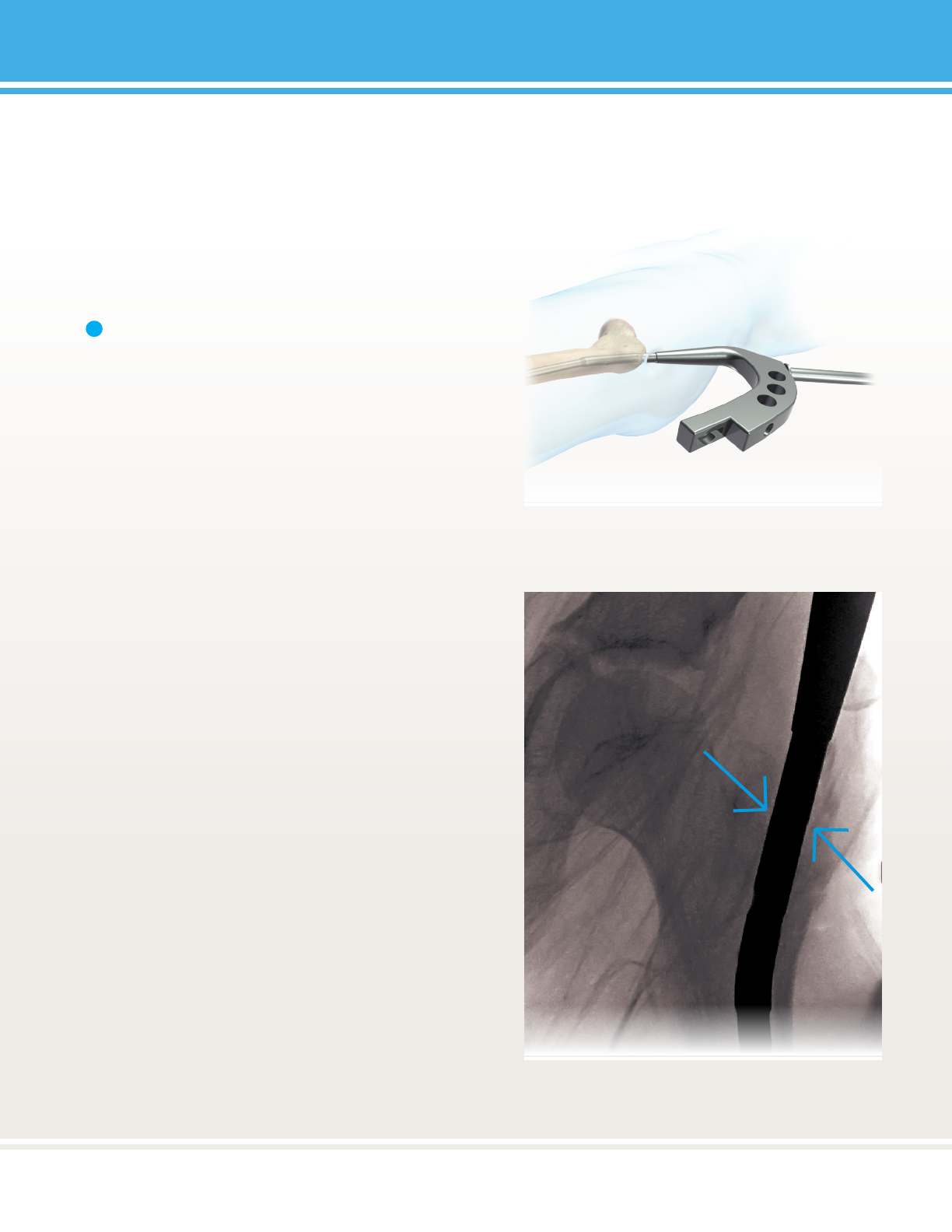
FIGURE 3:
FIGURE 4:
1
11
11
PediNail™
FIGURE 5:
FIGURE 6:
12
PediNail™
12
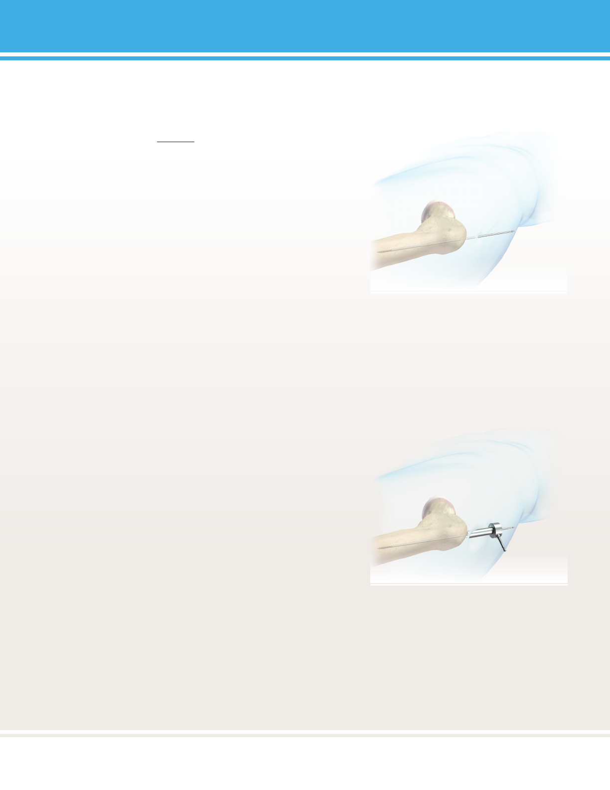
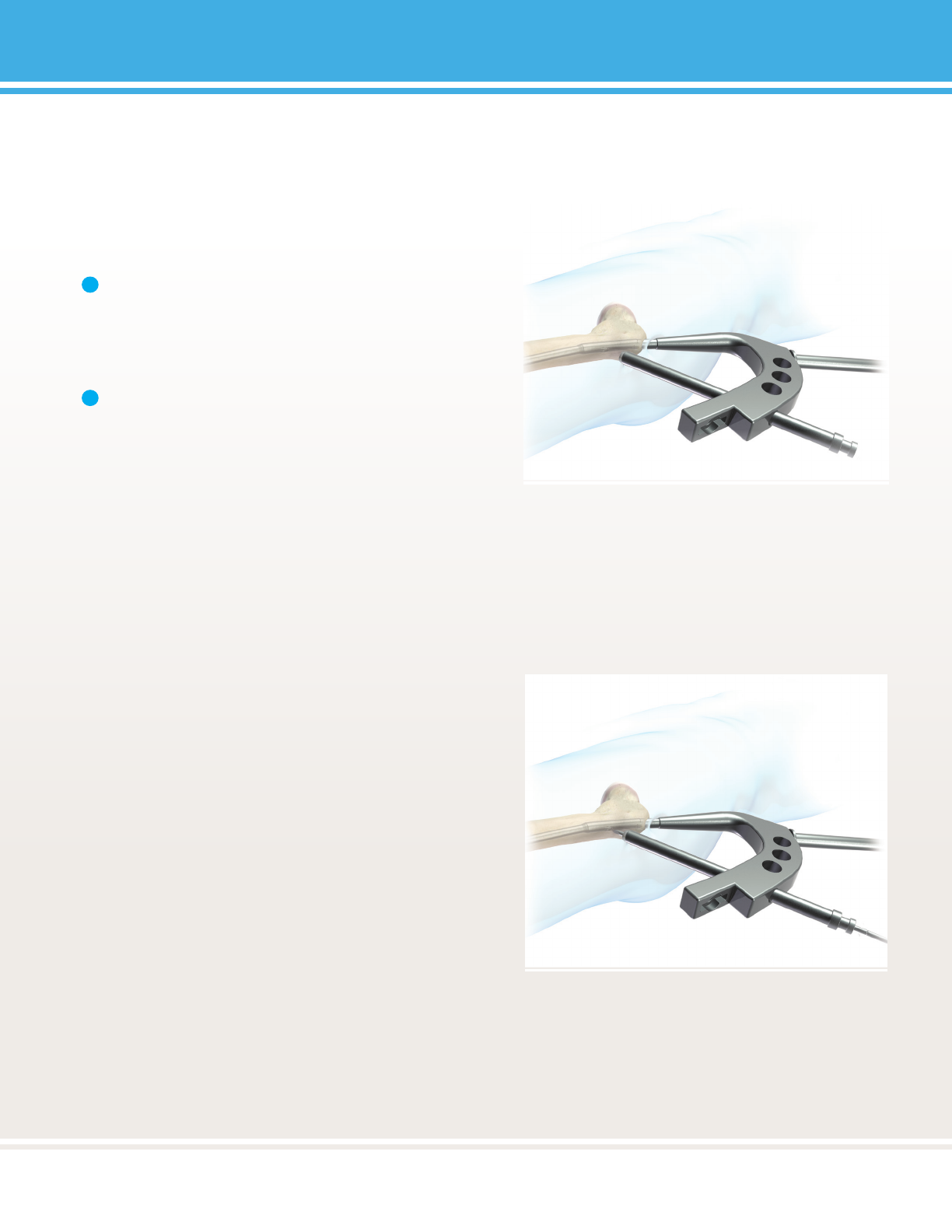
FIGURE 7:
FIGURE 8:
FIGURE 9:
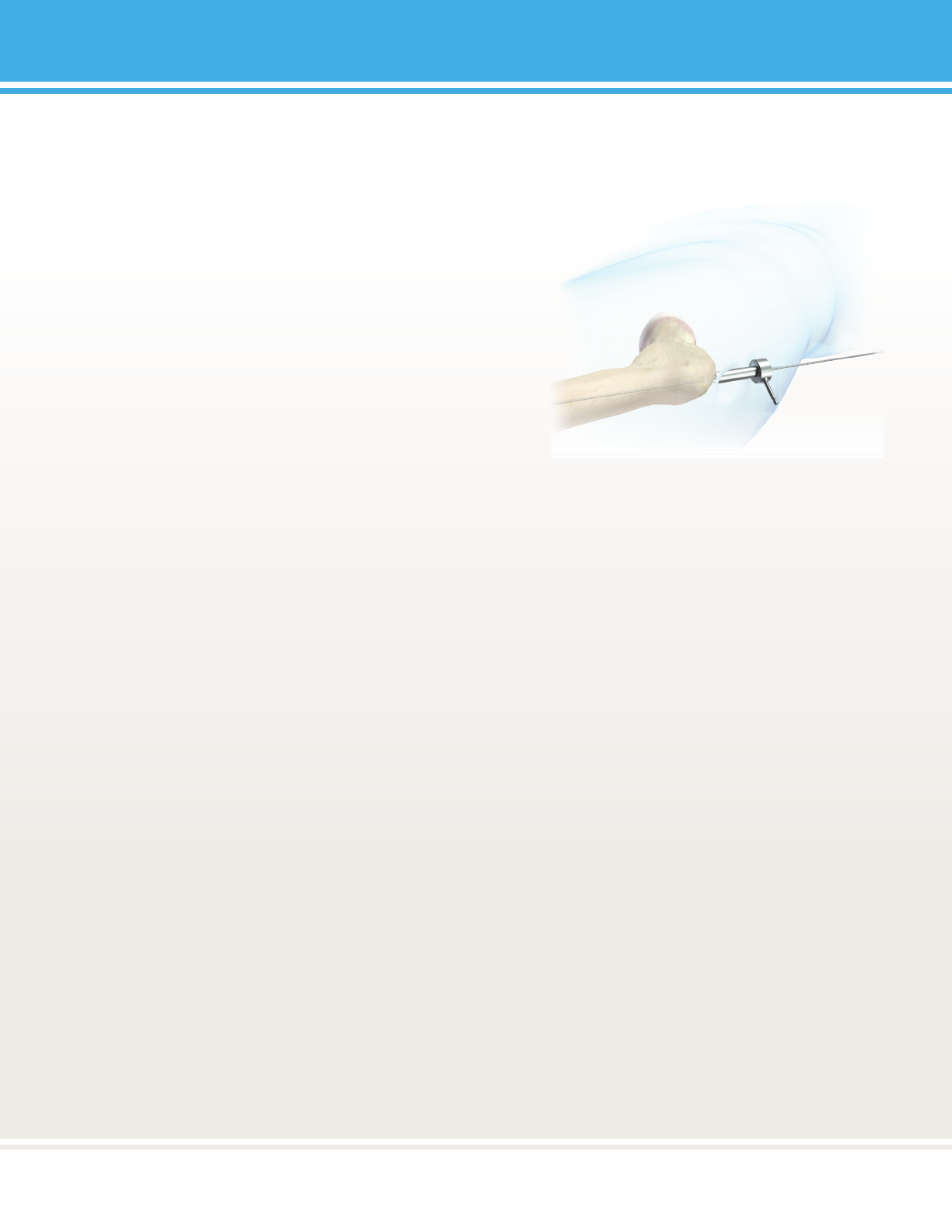
CAUTION:
Do not advance the guide wire or entry reamer past the medial femoral cortex.
13
13
PediNail™
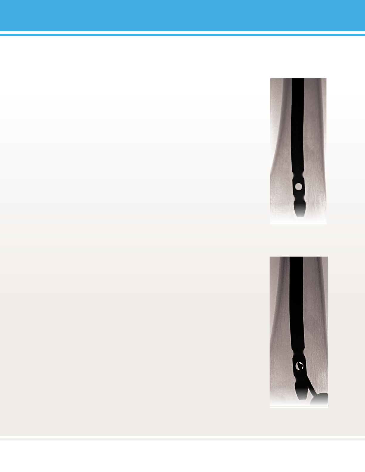
Note: If the 3.2mm Threaded Tipped Guide Wire appears to be lodged in the 9.5mm Cannulated Entry
Reamer, use the Obturator to ensure that the Guide Wire remains in place upon removal of the reamer.
Note: Refer to Secon 3: Reaming Technique (Reamer Use Guidelines).
1
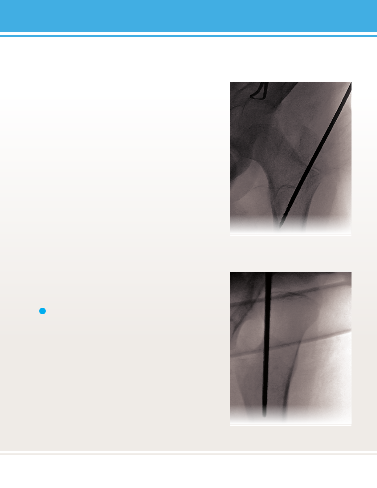
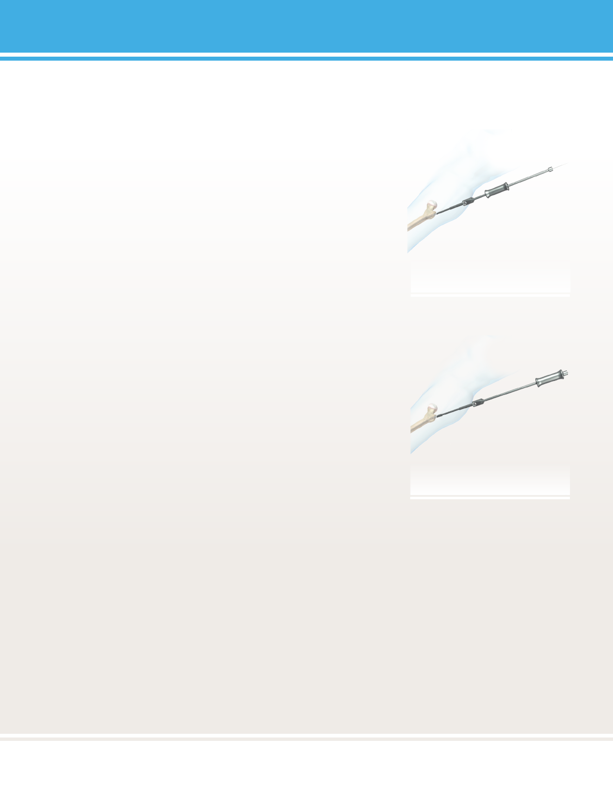
FIGURE 10:
2
14
PediNail™
14
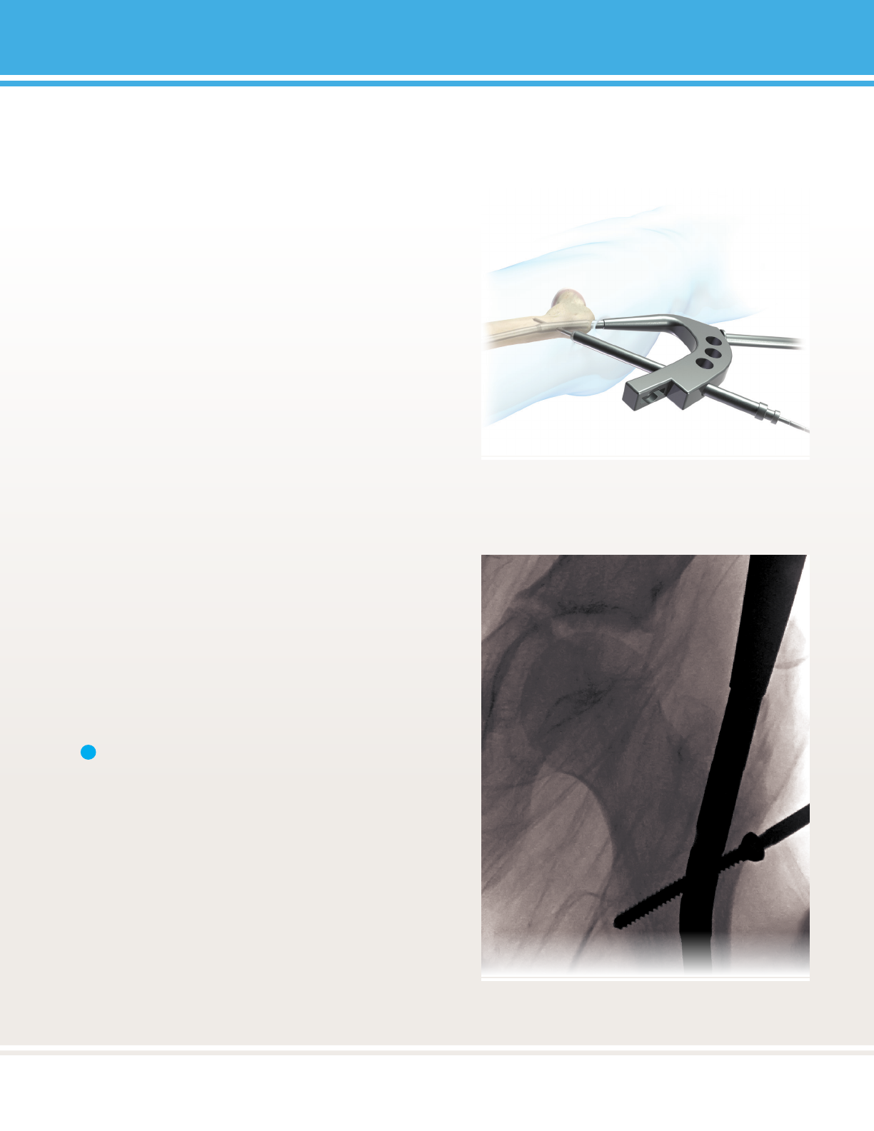
FIGURE 11:
FIGURE 13:
FIGURE 12:
15
15
PediNail™
FIGURE 14:
FIGURE 15:
16
PediNail™
16
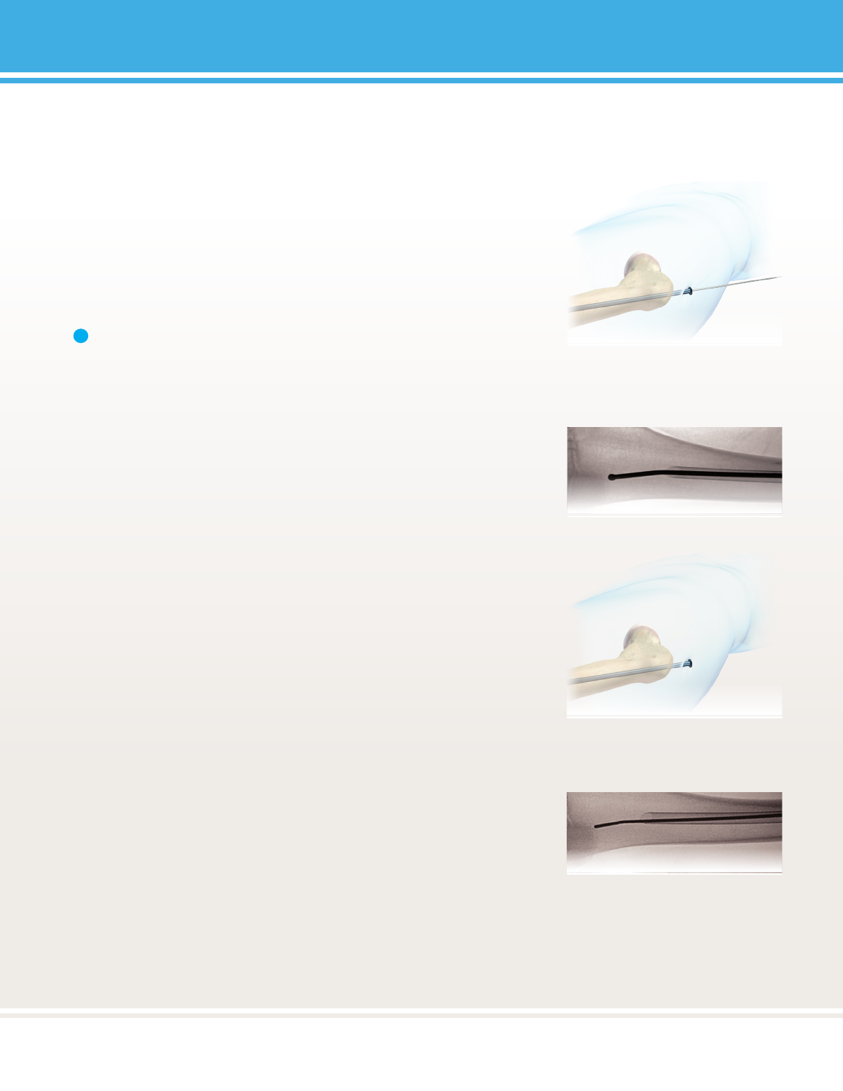
FIGURE 17a:
FIGURE 17b:
FIGURE 16:
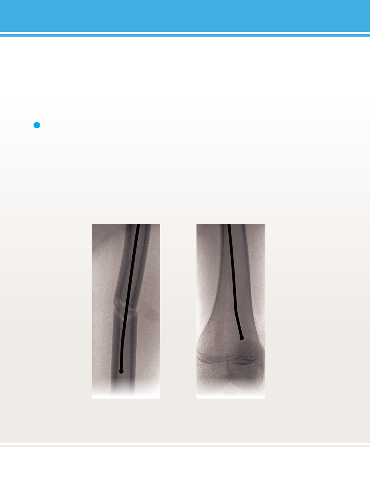
17
17
PediNail™
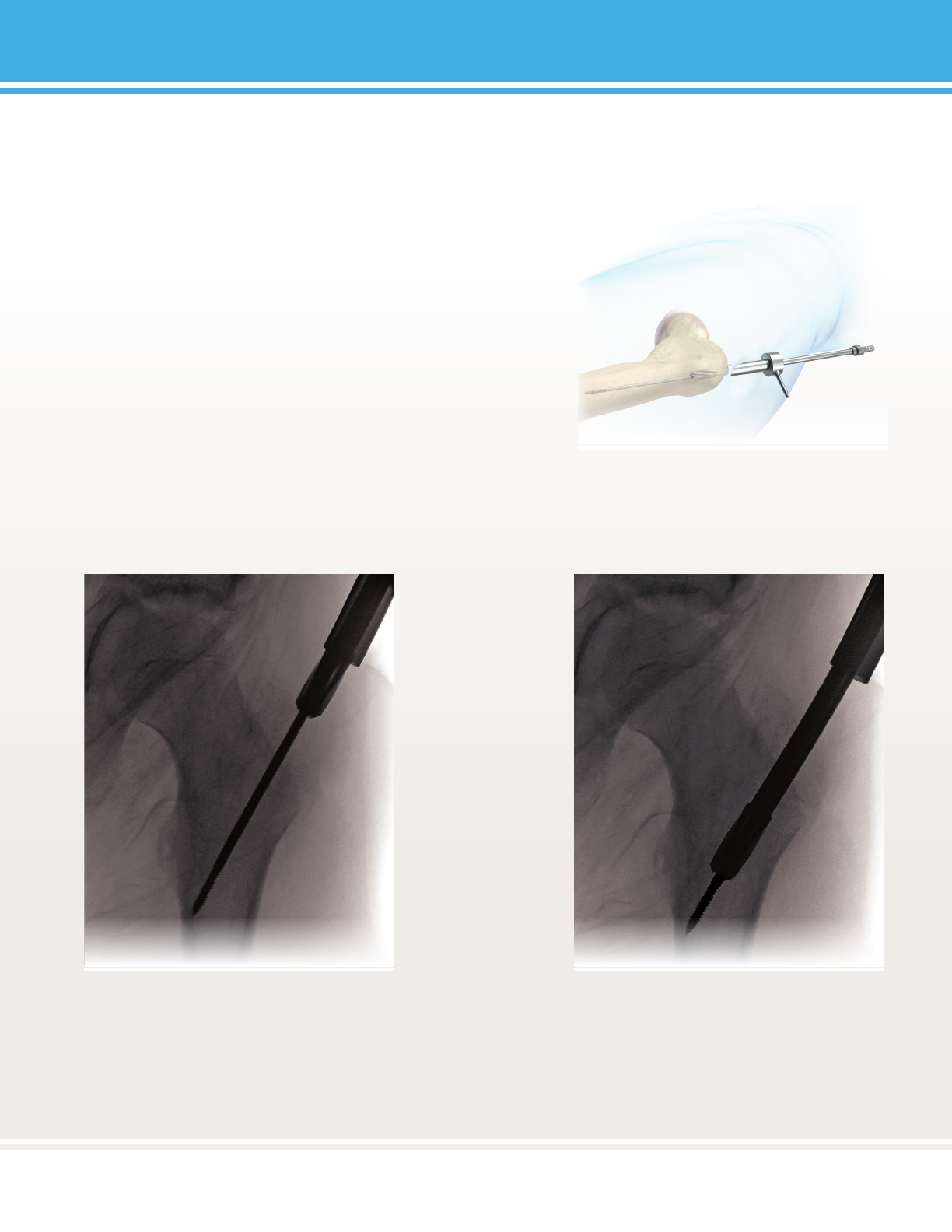
FIGURES 18a & 18b:
Note: Verify placement using AP and ML uoroscopy to ensure 2.7mm Ball Tipped Reaming Rod is in the distal
fragment.
CAUTION:
Do not advance 2.7mm Ball Tipped Reaming Rod into physis or joint space.
1
18
PediNail™
18
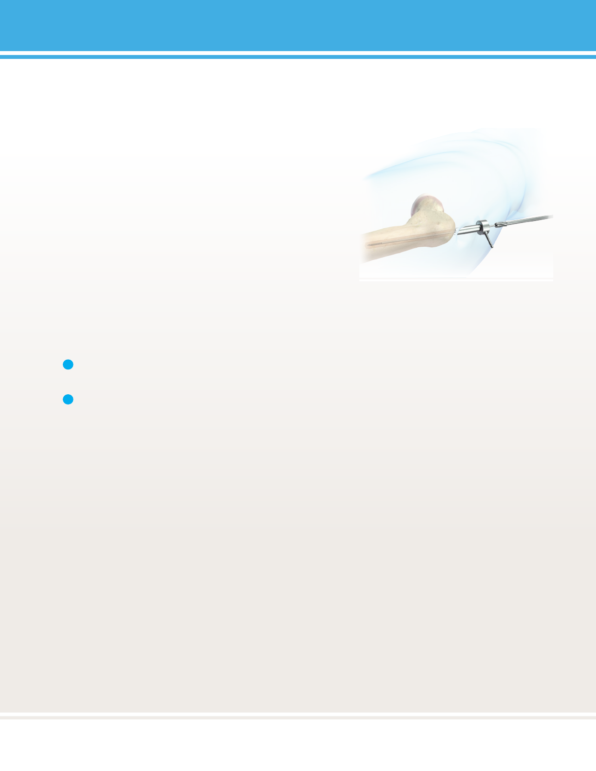
FIGURE 19:
FIGURE 20:
Note: It is advisable to verify nail length using a second
measurement method (i.e. two equal length reaming
rods or conrmaon with nail scale, found on the inside
of tray lid). If the guide wire is not visible in the window,
the 42mm length nail should be selected.
1
19
19
PediNail™
FIGURE 21:
Nail Length Nail Diameter
20
PediNail™
20
FIGURE 22:

21
21
PediNail™
CAUTION:
• ALWAYS FORWARD. Use power tool in the forward seng at
all mes.
• ALWAYS ON. Do not stop the power tool.
Note: Frequently clean the reamer utes to prevent clogging.
CAUTION:
Never reverse the reamer, as this could lead to reamer sha failure.
Note: It is not necessary to “ll” the canal or to connue reaming unl “chaer” is noted. Appropriate selecon of
nail diameter is not dependent upon geng a ght t in the isthmus of the femur.
CAUTION:
Do not ream past the distal bend in the 2.7mm Reaming Rod, as this may cause the reamer to bind and/or rupture.
WARNING:
When performing a femoral osteotomy, to reduce the likelihood of pulmonary emboli, prepare the osteotomy prior to
reaming or create vent holes in the femur.
CAUTION:
For 6mm, 6.5mm, 7.0mm one piece front cung reamers:
• Start with the 6mm reamer and go up in 0.5mm increments.
• Do not use in hard corcal bone.
• Recommended to over-ream 1 to 1.5mm over desired implant diameter.
2
1
22
PediNail™
22
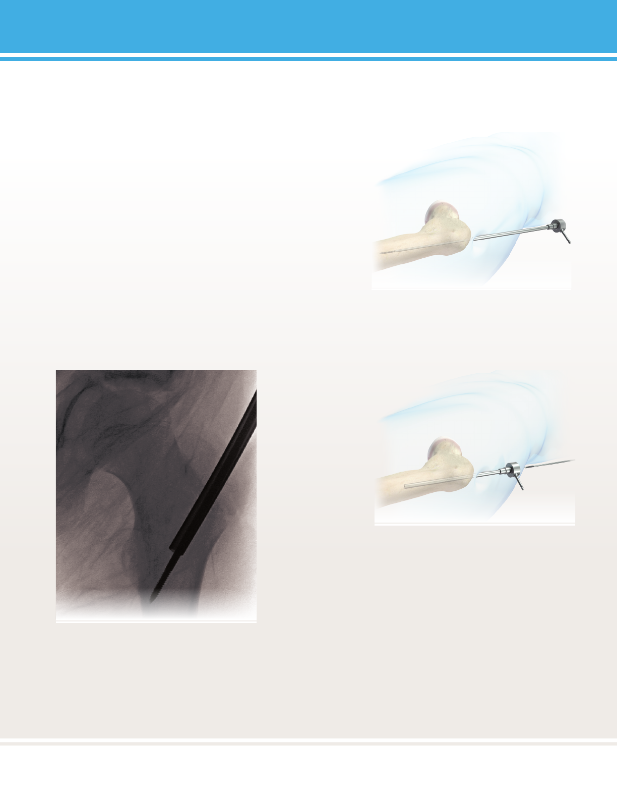
FIGURE 23:
FIGURE 25a:
1
FIGURE 24:
FIGURE 25b:
Note: Removal of the 2.7mm Ball Tipped Reaming Rod without
placement of the Exchange Tube or 2.0mm Guide Inseron Wire may
result in loss of reducon.
CAUTION:
If nail is implanted over 2.7mm Ball Tipped Reaming Rod, the reaming
rod will not be able to be removed.
23
23
PediNail™
4
FIGURES 26a & 26b:
CAUTION:
Be certain that the aachment bolt remains ght throughout the impacon process. Failure to do so may lead
to bolt breakage.
CAUTION:
Aachment Bolt is a single-use device. It may be used to perform a bi-lateral procedure on a single paent.
Note: Use the Ball Hex Driver to perform nal ghtening of components prior to inseron of the nail.
1
24
PediNail™
24
FIGURE 27:
Note: Be certain that the impacon rod is fully seated
with the ange on the impacon rod resng on the
targeng guide. Maintain ghtness and ange to
targeng guide contact throughout the impacon
process.
Note: If advancement of the nail is dicult,
remove the nail and ream another 0.5mm. It is
common to over ream the canal by 1-1.5mm.
1
2
25
25
PediNail™
FIGURE 28:
FIGURE 29:
Note: Failure to remove Smooth Guide Wire may result in
instrumentaon damage and metal debris.
1
26
PediNail™
26
FIGURE 30:
FIGURE 31:
Note: Do not apply excessive force to the targeng
construct or targeng might be compromised.
Note: Carefully remove the inner C-springs and clean
thoroughly. Be sure to replace the inner C-springs aer
cleaning. If the inner C-springs are missing from the guide
tubes, the tubes will not be self-retaining.
1
2
27
27
PediNail™
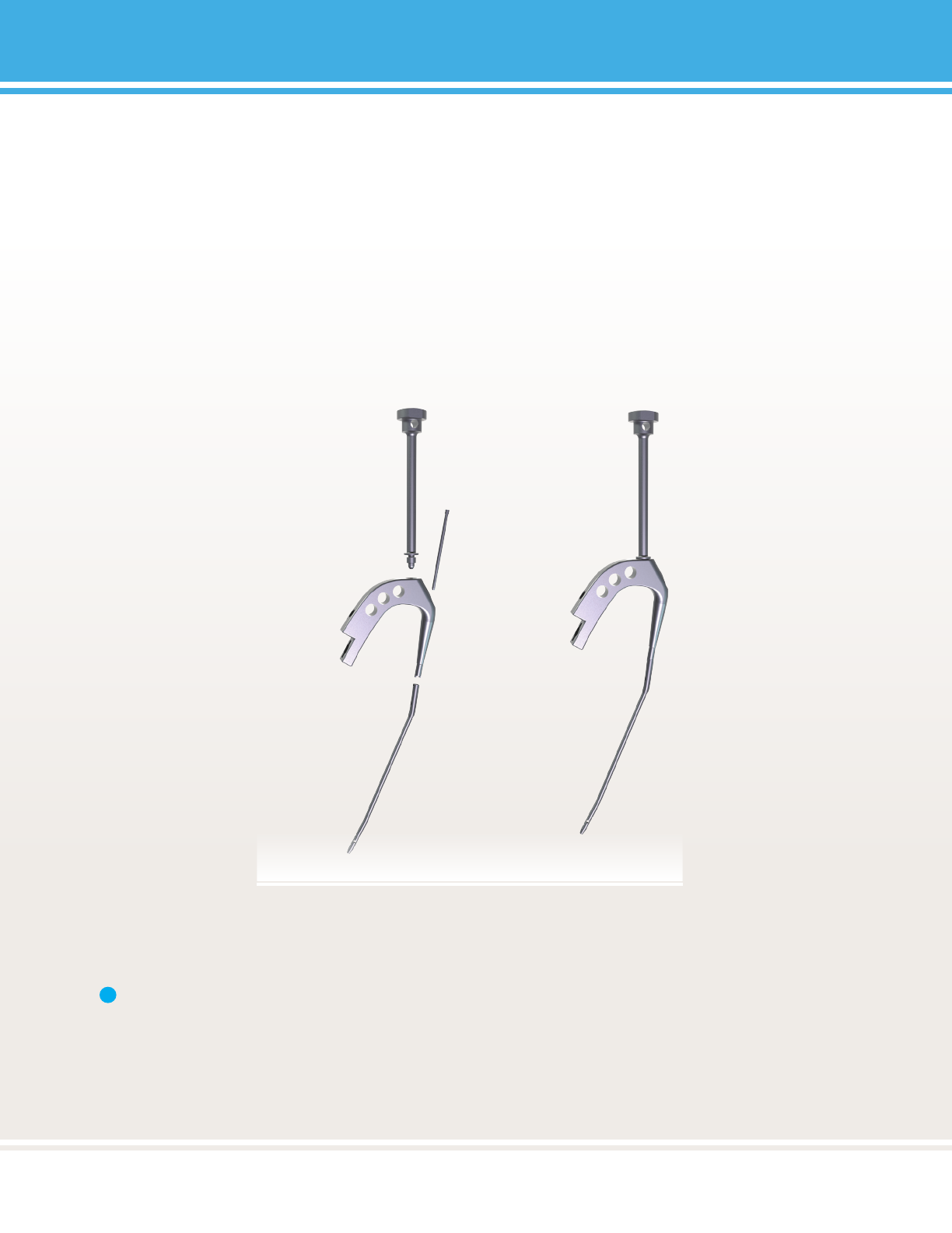
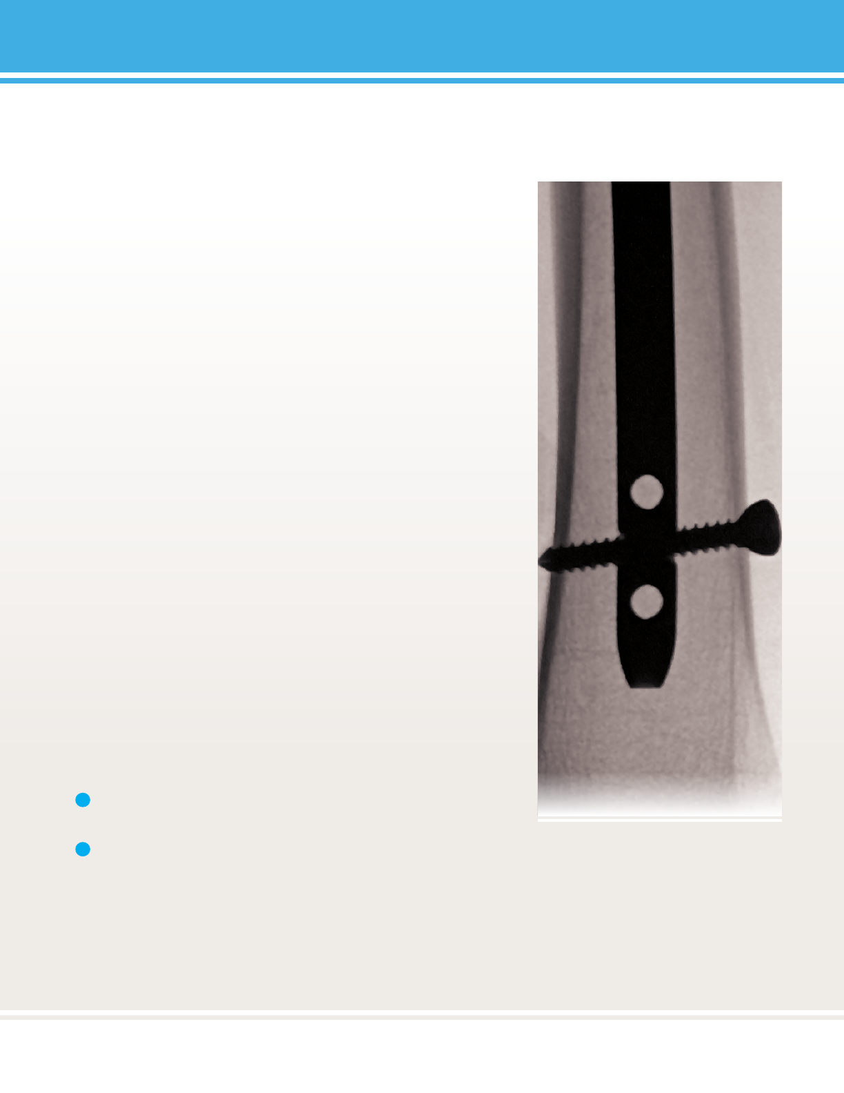
FIGURE 32:
FIGURE 33:
Note: If it is necessary to re-engage the screwdriver into
the screw head, it is recommended that the Inner Guide
Tube is reinserted into the Targeng Device rst.
1
28
PediNail™
28
FIGURE 34:
29
29
PediNail™
FIGURE 35:
FIGURE 36:
30
PediNail™
30
Note: The 0mm End Cap is not cannulated and must be
inserted without the 2.0mm Smooth Guide Wire.
Note: Do not nal ghten End Cap with cannulated
T-handle. Do not impact cannulated T-handle. Perform
nal ghtening with Ball Hex Driver.
FIGURE 37:
2
1

31
31
PediNail™
32
PediNail™
32
Note: For nail removal, the Bullet Tipped Extractor or
Extracon Bolt may be used. The Bullet Tipped Extractor
is not standard in the PediNail™ set. If the Bullet Tipped
Extractor is to be used, contact Customer Service prior to
nail removal.
Note: If a 0mm End cap is used, it must be removed prior
to inserng the Guide Wire.
Note: The Bullet Tipped Extractor and the Extracon Bolt
undergo signicant stress when removing intramedullary
nails. It is recommended that these items be used once
and discarded.
WARNING:
Do not allow reamer to contact metal implant.
Note: Do not impact Cannulated T-handle driver.
1
2
3
4
FIGURE 38:
FIGURE 39:
FIGURE 40:
33
33
PediNail™
Note: Ensure that the Extracon Adapter is ght to avoid
fracture of the nail.
1
FIGURE 41:
FIGURE 42:
FIGURE 43:
34
PediNail™
34
FIGURE 43:
FIGURE 44:

35
35
PediNail™
Item Number Qty Descripon Length (mm)

36
PediNail™
36
Item Number Qty Descripon Length (mm)

37
37
PediNail™
Item Number Qty Descripon Length (mm)

38
PediNail™
38

39
39
PediNail™
Item Number Qty Descripon Length (mm)
44
mm
mm

40
PediNail™
40
mm continued
Item Number Qty Descripon Length (mm)
mm

41
41
PediNail™
Item Number Qty Descripon Length (mm)

42
PediNail™
42
Item Number Qty Descripon Length (mm)

43
43
PediNail™
Item Number Qty Descripon Length (mm)

44
PediNail™
44
OrthoPediatrics, Children Are Not Just Small Adults, PediPlates, PediLoc,
Scwire and the Pedi logo are registered trademarks in the United States.
Pedi logo
This technique has been provided by one of our
medical advisors only as guidance and it is not
intended to limit the methods used by trained
and experienced surgeons.
CAUTION:
CAUTION:
CAUTION:
CAUTION:
CAUTION:
2850 Froner Drive • Warsaw, IN 46582 • ph: 574.268.6379 or 877.268.6339 • fax: 574.268.6302 • www.OrthoPediatrics.com
OrthoPediatrics, Children Are Not Just Small Adults, ArmorLink, PediFlex,
PediFrag, PediLoc, PediNail, PediPlates, PLEO, Response, Scwire, ShieldLoc,
OP Pedi logos
