PMD016254 2.0 Osteo Cool TM Surgical Technique
2016-08-22
: Pdf Pmd016254-2.0 Osteocooltm Surgical Technique PMD016254-2.0_OsteoCoolTM_Surgical_Technique 8 2016 pdf
Open the PDF directly: View PDF ![]() .
.
Page Count: 28
SURGICAL
TECHNIQUE
OsteoCool™
RF Ablation System and Bone Access Kits

OSTEOCOOL RF ABLATION SYSTEM AND BONE ACCESS KITS
SUBHEAD
3
1
OSTEOCOOL RF ABLATION SYSTEM AND BONE ACCESS KITS
TABLE OF CONTENTS
3 OsteoCool System Set-up
6 Patient Positioning
7 Use of OsteoCool Bone
Access Kits
9 Use of OsteoCool
Precision Drill
11 OsteoCool RF Ablation
Probe Selection and Tube Kit
Preparation
12 Insert OsteoCool Tube Kit into
the OsteoCool Pump Unit
12 Fill the burette with sterile water
14 Connect the probe to the
Tube Kit
15 Connect the OsteoCool RF
Ablation Probe(s) and OsteoCool
Connector Hub
16 Perform RF Ablation with
OsteoCool System
18 Optional Track RF Ablation with
OsteoCool System
19 Optional Temperature Monitoring
with Independent Thermocouple
20 Bone Access for Subsequent
Procedures
21 General Safety Guidelines
22 Product Ordering Information
23 Important Product Information
2
The OsteoCool RF Ablation Probe
uses a coaxial, bipolar technology
that delivers localized tumor ablation
and automatically moderates power
to keep RF heating within the desired
treatment range, reducing risks of
potential thermal damage to adjacent
structures. The active tip of the RF
Ablation Probe is internally-cooled with
circulating water. RF energy heats the
tissue while circulating water moderates
the temperature in close proximity to
the active tip. This combination creates
large volume lesions without excessive
heating at the active tip. The OsteoCool
RF Ablation Probes are sterile and
intended for use within a single
vertebral body.
The OsteoCool Bone Access Kit is a
single use device intended to contact
body tissues. Do not reuse, reprocess, or
resterilize.
The OsteoCool Independent
Thermocouple is for optional
temperature monitoring at or near the
site of ablation.
A physician using this equipment must
be familiar with spine anatomy, image-
guided spine procedures and vertebral
body access techniques.
Refer to the OsteoCool Instructions
for Use for Complete Generator and
Pump Setup.
The OsteoCool RF Ablation System
is indicated for palliative treatment
in spinal procedures by ablation of
metastatic malignant lesions in a
vertebral body. The System contains
an RF Generator, Peristaltic Pump and
the Connector hub, which provides two
channels for the use of the OsteoCool
RF Ablation Probes and two channels
for use of the OsteoCool Independent
Thermocouples.
Important
This guide does not replace the information in the Instructions for Use provided
with the components of the OsteoCool RF Ablation System, OsteoCool RF
Ablation Probes, OsteoCool Bone Access Kits and the OsteoCool Independent
Thermocouple. The Instructions for Use includes important information such as
warnings, precautions, contraindications, and troubleshooting. It is important to read
the Instructions For Use and these precautions carefully prior to device operation.
Additional help information can be accessed through the “help” button located on the
generator screen.
OSTEOCOOL RF ABLATION SYSTEM AND BONE ACCESS KITS
SURGICAL TECHNIQUE
3
OSTEOCOOL
SYSTEM
SET–UP
The OsteoCool System may be mounted to either a rolling Cart or a Table Top Desk Stand. For mounting the device
on a desk stand, proceed to the Desk Stand Assembly and Mounting. For mounting on the Cart, proceed to Cart
Mounting Instructions.
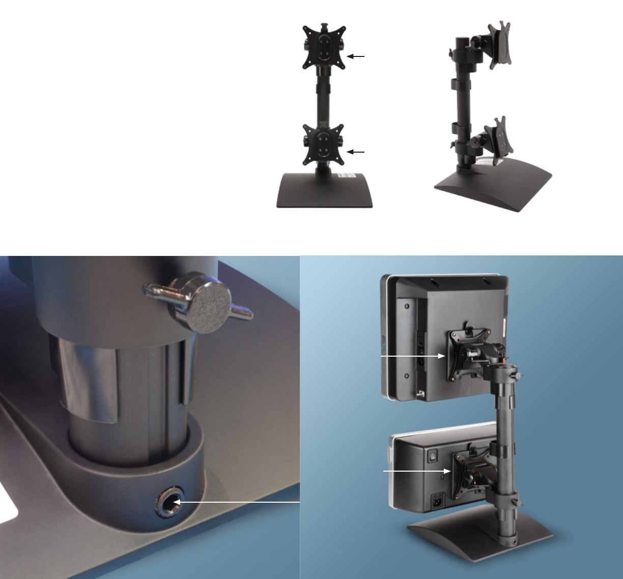
Desk Stand Assembly & Equipment Mounting
1. Assemble the desk stand by sliding the pole into
the base and tightening the set screw with the
provided Allen wrench (Figure 1).
2. Position the desk stand on a stable surface and in
close proximity to an electrical source.
3. Mount the pump by sliding the quick connect
bracket on the back of the pump down the
opposite mounting bracket located on the
bottom of the desk stand (Figure 2a). Mount the
generator by sliding the quick connect bracket
on the back of the generator down the opposite
mounting bracket located on the top of the desk
stand (Figure 2b).
4. Proceed to cable connection.
Figure 1 Figures 2a (Pump Bracket) and
2b (Generator Bracket)
Front View
Pump
Mount
RF-Generator
Mount
Isometric View
2a
2b
4
OSTEOCOOL RF ABLATION SYSTEM AND BONE ACCESS KITS
OSTEOCOOL SYSTEM SET-UP
Cart Mounting
1. Position the cart in proximity to an electrical source.
2. Lock the wheels on the cart before mounting
the devices.
3. Mount the pump by sliding the quick connect bracket
on the back of the pump down the opposite mounting
bracket located on the bottom of the cart (Figure 3a).
Mount the generator by sliding the quick connect
bracket on the back of the generator down the
opposite mounting bracket located on the top of the
cart (Figure 3b).
4. Do not adjust the position of the mounting brackets.
5. Proceed to cable connection.
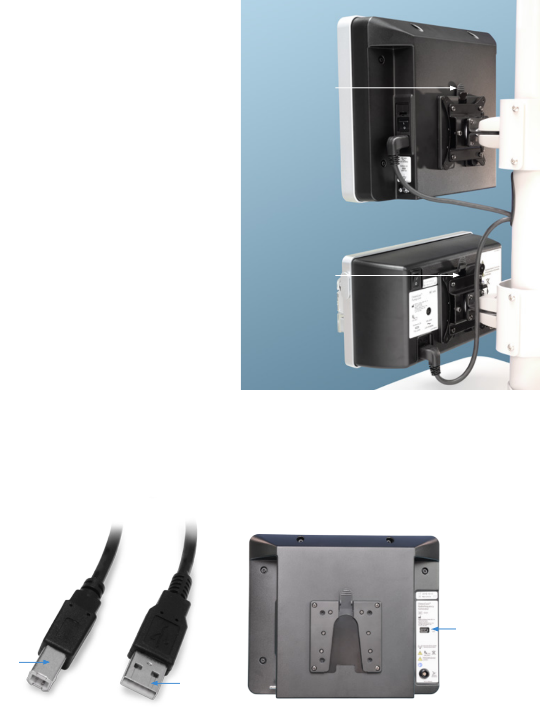
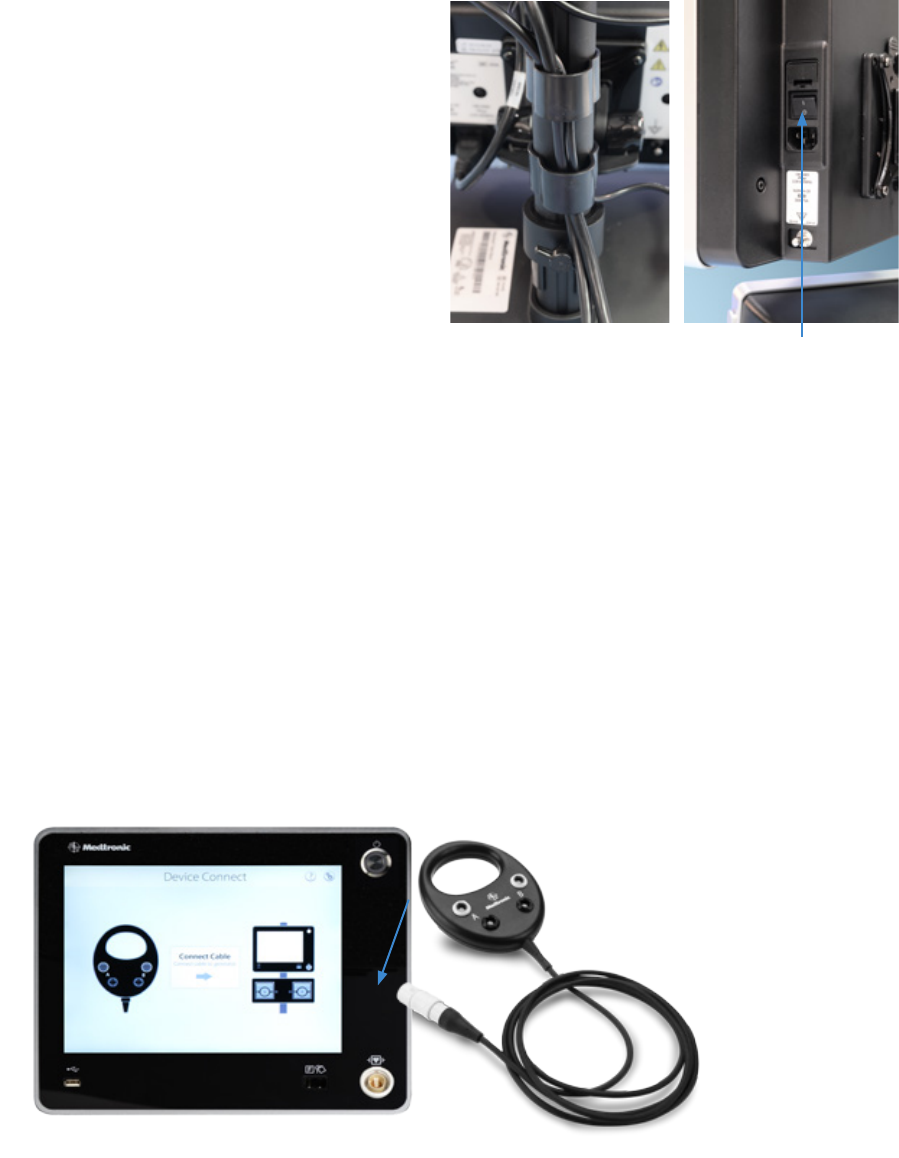
Connect Cables and Power on the Generator and Pump
1. After assembly, Connect pump and the generator with the
connector cable to USB ports on the back of both pump and
generator (Figures 4a and 4b).
Plug the USB Type A plug to the Generator, and the USB Type
B plug into the Pump.
Generator
Quick Connect
and Release
Pump
Quick Connect
and Release
3b
3a
Figures 3a and 3b
Figure 4b
USB Port
(for connecting
generator to
pump)
Figure 4a
Type B
Type A
5
Figure 5a Figure 5b
Power Switch
Figure 6
2. Connect power cables to the back of both the
generator and pump
a. Connecting Power Cables with the Desk Stand:
Route the cable to the backside of the pole and use
the clips on the desk stand to manage the power and
USB cables (Figure 5a).
b. Connecting Power Cables with the Cart:
The Cart is provided with cables that are fed through
the cart pole. Attach the connections located near the
mounting brackets to the back of the generator and
pump. The socket end of the cables, which come out
near the bottom of the cart pole, should be connected
directly to the power cables provided with the generator
and pump.
3. Plug both power cables into surge protector/power strip.
4. Power on the generator using the Power Switch located on
back of device (Figure 5b).
Note
The circular power button located on the front (top right
corner) of the device is to initiate radiofrequency ablation,
not to turn on power to the generator.
5. After powering on Generator, power on the pump using the
Power Switch located on the back of the device.
Note
Powering on the Pump before Powering on the Generator is
not recommended as it could lead to system error.
6. Following the on-screen setup instructions, connect the
Connector Hub to the front of the generator. (Figure 6)
Connect Cables and Power on the Generator and Pump
OSTEOCOOL RF ABLATION SYSTEM AND BONE ACCESS KITS
OSTEOCOOL SYSTEM SET-UP
6
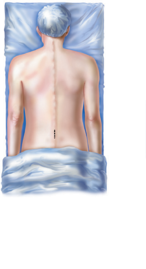
PATIENT POSITIONING
1. The patient should be placed in the prone position for access
to the spine.
2. Using appropriate image guidance conrm the target location
for treatment and proceed with the necessary skin incision.
7
USE OF
OSTEOCOOL
BONE ACCESS KITS
1. Insert the Stylet into the Cannula to
form the OsteoCool osteointroducer.
2. Using uoroscopic image guidance,
insert the osteointroducer at the
desired site.
3. Using manual control and appropriate
Note
Markings on the Cannulas should
be used as reference marks
only. They are not intended to
replace the use of uoroscopic
observation.
Note
The design of the OsteoCool
osteointroducer oers an internal stylet
that extends beyond the distal end of the
cannula. This design is intended to provide
a visual indication under image guidance of
where the posterior margin of the ablation
zone with the OsteoCool RF Ablation
probe will stop.
Caution
To maintain structural integrity, do
not advance the Cannula without the
Stylet fully inserted.
imaging guidance, advance the
osteointroducer through the soft
tissues into the selected bone to the
desired depth.
4. A surgical mallet may be used
to augment the insertion of the
osteointroducer.
8
OSTEOCOOL RF ABLATION SYSTEM AND BONE ACCESS KITS
USE OF OSTEOCOOL BONE ACCESS KITS
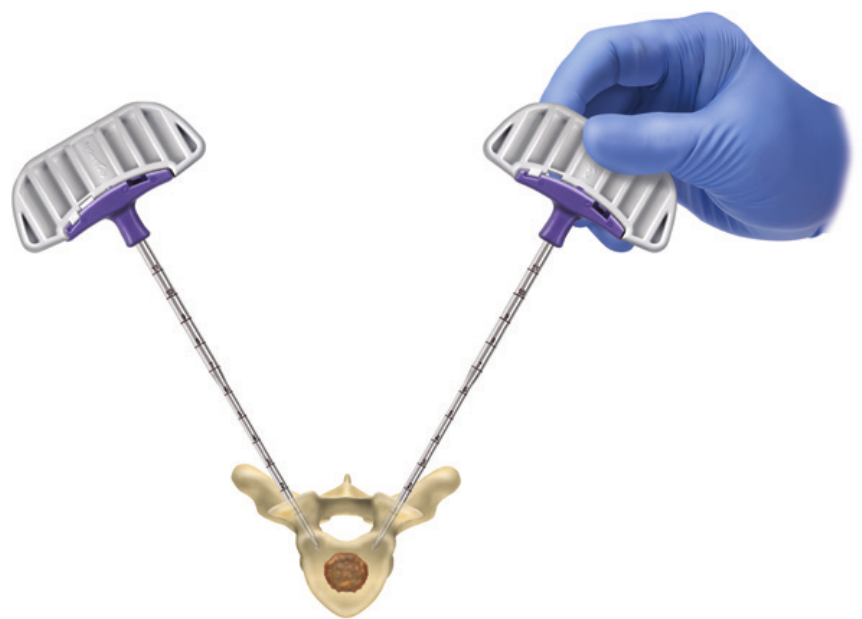
5. While holding the Cannula, rotate the
handle 180° counter-clockwise to
remove the Stylet. Proceed to use of
OsteoCool Precision Drill.
For bi-pedicular ablation, repeat the
steps above.
9
USE OF
OSTEOCOOL
PRECISION DRILL
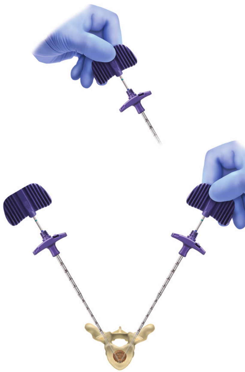
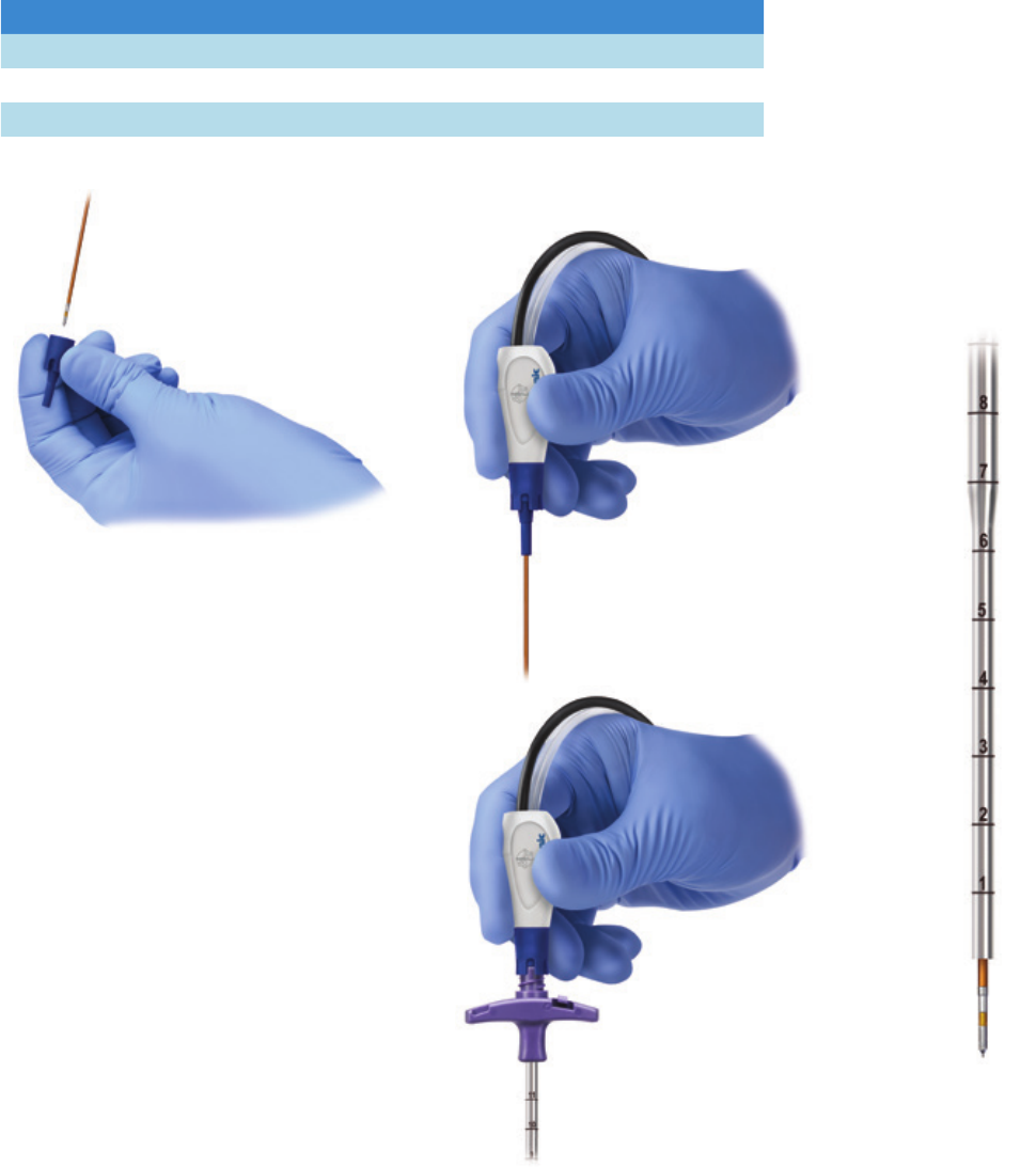
1. After gaining access into the
vertebral body using the OsteoCool
Osteoinducer, advance the
OsteoCool Precision Drill down the
Cannula lumen into the vertebral body.
2. Using manual control and imaging
guidance, rotate clockwise and
advance the Precision Drill to the
desired depth. This depth will serve as
the anterior boundary for the ablation
zone.
Note
The color markings on the proximal
shaft of the OsteoCool Precision Drill
correlate with sizes of the OsteoCool
RF Ablation Probes.
10
OSTEOCOOL RF ABLATION SYSTEM AND BONE ACCESS KITS
USE OF OSTEOCOOL PRECISION DRILL
3. Read the color marking on the
proximal end of the drill to to aid in
probe selection. If the drill positioning
is in between color markings, the user
should advance or retreat to a color
marking. Select the probe size which
corresponds with the color marking.
Note
Markings on the Drill should be used
as reference marks only. They are
not intended to replace the use of
uoroscopic observation.
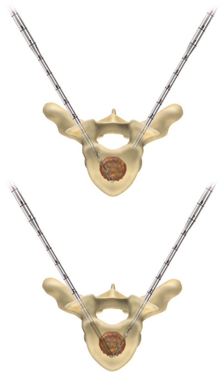
4. Remove the OsteoCool Precision
Drill from the Cannula lumen using
clockwise rotation. The target site
is now ready for ablation probe
placement.
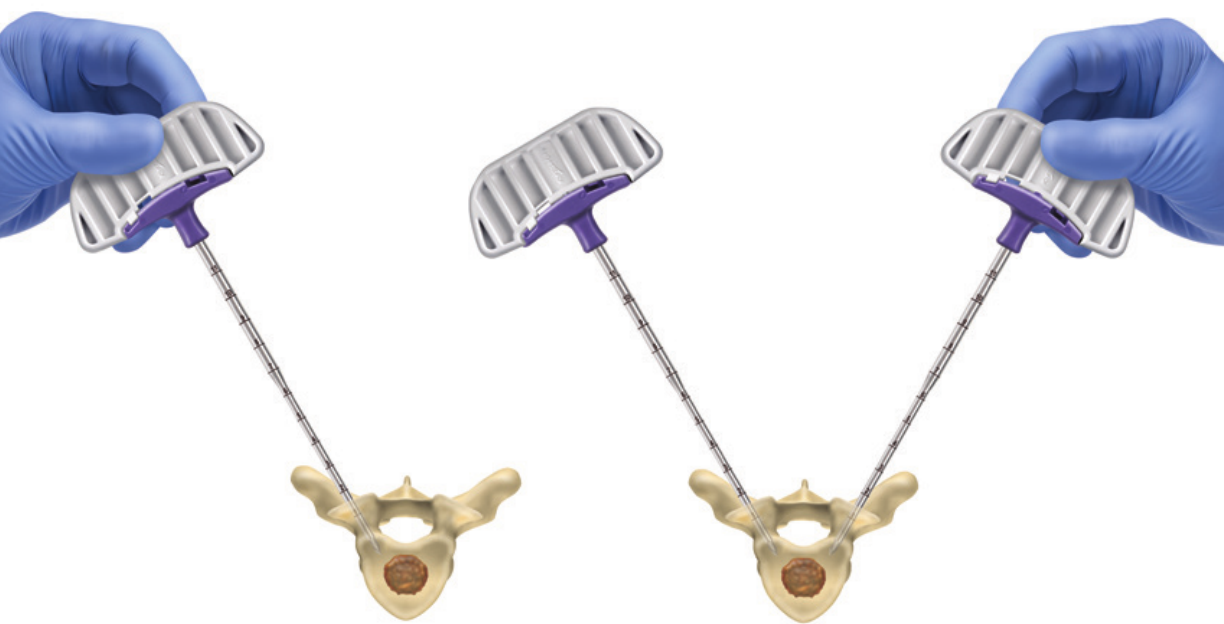
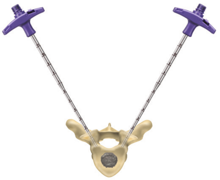
For bi-pedicular ablation, repeat
the steps above. Product testing
recommends a distance of 8-10mm
between the distal tips of the probes
to yield the largest ablation zone.
11
OSTEOCOOL RF ABLATION
PROBE SELECTION AND
TUBE KIT PREPARATION
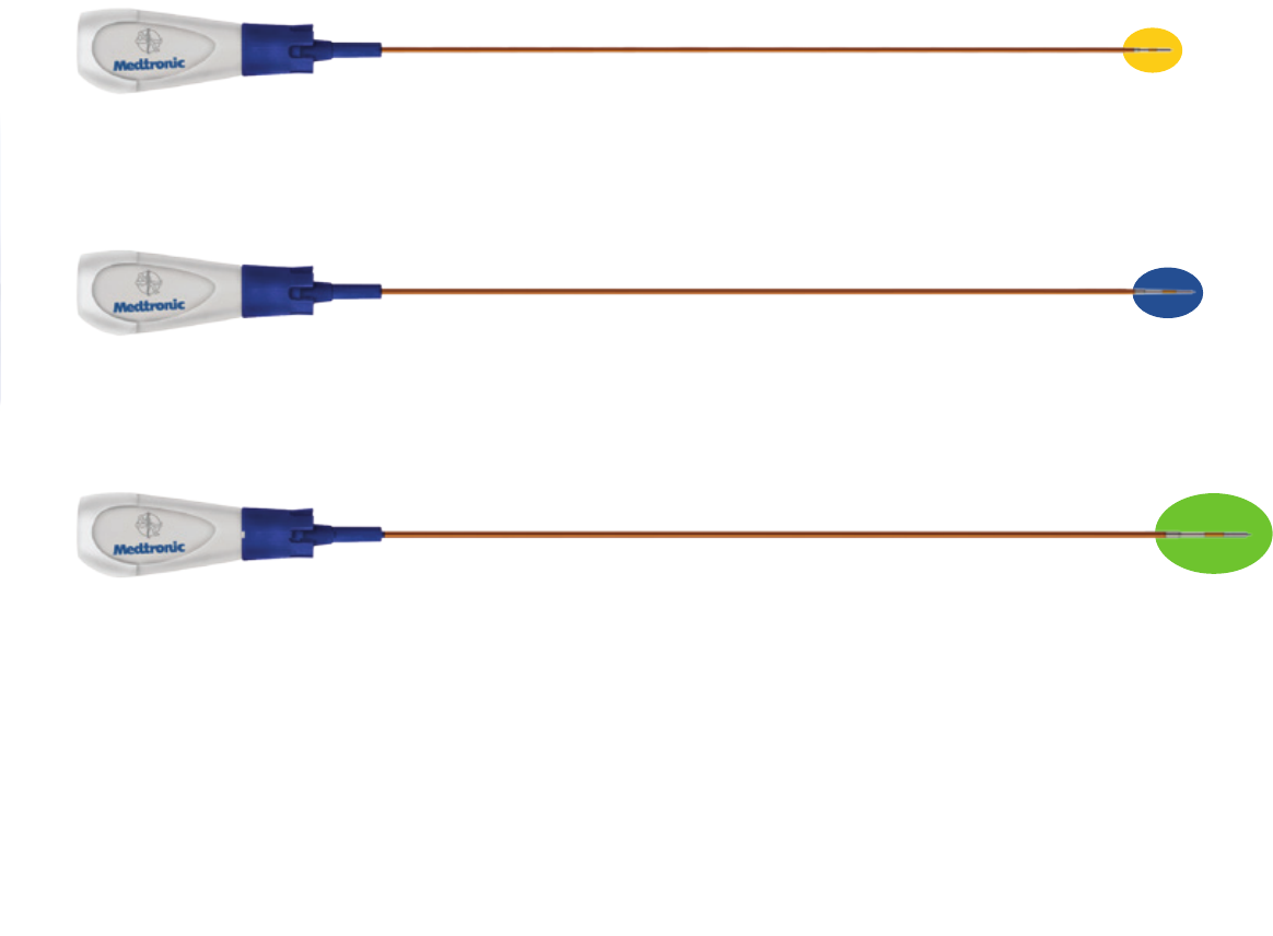
1. Select the OsteoCool RF ablation probe size of choice for the procedure.
Note
If the OsteoCool Precision Drill was used, select the probe size which
coordinates with the color marking on the drill shaft.
7mm Active Tip
11×10mm Ablation Zone
10mm Active Tip
17×13mm Ablation Zone
20mm Active Tip
29×21mm Ablation Zone
12
FILL OSTEOCOOL TUBE KIT
AND INSERT INTO PUMP UNIT
1. Once an OsteoCool RF Ablation Probe Kit has been chosen,
remove the Tube Kit and probe from the sterile package and
place in the sterile eld
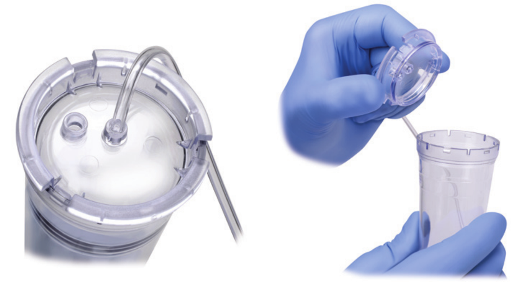
Fill the burette with sterile water
1. Fill the burette to the 70 mL mark with room temperature sterile water by one of the following options:
Option 1: injecting through the port in the lid or Option 2: removing the lid and pouring directly into the burette.
Burette Fill—Option 1
a. Inject sterile water through the port in the lid
a1. Place sterile syringe in the port.
a2. Inject 70 mL of sterile water at room temperature
into the burette.
Burette Fill—Option 2
a. Remove the lid and pour sterile water into the burette
a1. Open the lid by pressing in and up with your thumbs
around one of the three petals.
a2. Observe proper sterile handling technique while lling the
burette; do not place the lid of the burette down on a non
sterile surface.
a3. The ll lines on the burette represent 70 mL and 80 mL
respectively.
a4. After lling to between the lines, snap the lid back into
place on the burette.
13
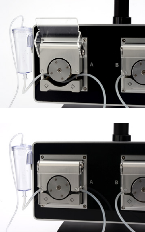
2. Put the burette into the Pump Unit’s burette holder.
3. Open the pump head lid and thread the thicker tubing
from the bottom of the burette into the pump head
tube holder.
4. Ensure that the tubing is properly placed between the
notches and along the center channel beneath the
pump head.
Warning
Improper positioning of the tubing can pinch the tube
and restrict the water ow.
5. Close the lid in order to hold the tubing in place. Leave
the luer lock caps on the tubing until you are ready to
connect the probes so the inner pathway of the tube
kit remains sterile.
OSTEOCOOL RF ABLATION SYSTEM AND BONE ACCESS KITS
USE OF OSTEOCOOL PRECISION DRILL
14
CONNECT
THE PROBE
TO THE TUBE KIT
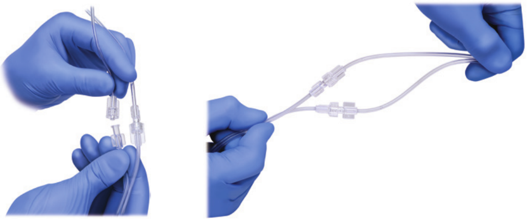
1. Pass the tubing and electrical connections on the probe out
of the sterile eld.
2. Remove the caps on the male and female luer locks for both
the Tube Kit and the chosen probe. Connect the appropriate
luer lock on the Tube Kit to the corresponding luer lock on the
probe.
Warning
DO NOT over tighten the connection. Maintain sterility of the
tubing’s inner pathway so in case water is accidentally spilled
in the sterile eld, sterility will not be compromised.
15
CONNECT TO
THE OSTEOCOOL
CONNECTOR HUB
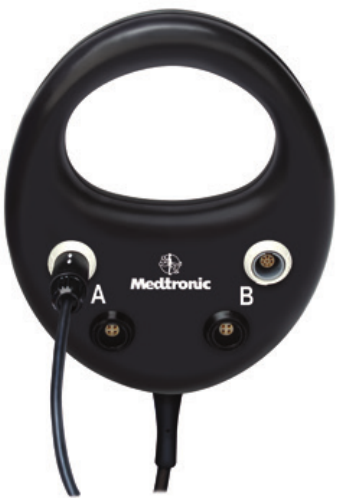
The OsteoCool Connector hub provides two channels for the
use of the OsteoCool RF Ablation Probes and two channels for
use of OsteoCool Independent Thermocouples (ITC).
The white ports (top) accept the RF ablation probes. The black
ports (bottom) accept the independent thermocouples.
1. Connect the male connector on the OsteoCool RF Ablation
Probe to the female connector on the OsteoCoolConnector
Hub.
2. Conrm via on-screen information that the OsteoCool
probe has been detected and is ready for use.
Note
The Generator will quickly detect the probe then indicate a
“High Impedance” error while the probe is outside of tissue.
When probe is placed in tissue, the “High Impedance” error
will automatically disappear.
16
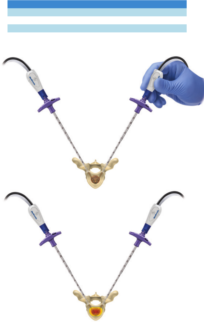
PERFORM RF ABLATION
WITH OSTEOCOOL SYSTEM
1. The RF Ablation probes are provided
with a pre-assembled spacer. Discard
or Keep the spacer based on the bone
access tool used. Reference chart
below:
2. Place the OsteoCool RF Ablation
probe through the bone access
cannula, ensuring it is fully seated in
the cannula.
Warning
Never force the probe in if signicant
resistance is felt.
3. Conrm under image guidance that
the proximal radiopaque marker
has fully surpassed the distal end of
the cannula.
Warning
Incorrect use of the spacer may result
in improper probe clearance from the
cannula.
Description/Size Part Number Directions
OsteoCool Bone Access Kit 10G 090 OCN002 Use with Spacer
OsteoCool Bone Access Kit 8G 090 OCN003 Use with Spacer
OsteoCool Bone Access Kit 13G 100 OCN005 Discard Spacer
Remove for use with OCN005. Proper use with
OCN002 and OCN003.
17
OSTEOCOOL RF ABLATION SYSTEM AND BONE ACCESS KITS
PERFORM RF ABLATION WITH OSTEOCOOL SYSTEM
4. When the screen shows “Ready,”
press on the RF Power button.
Ablation time is pre-set based on the
active tip size of the probe(s) being
used.
a. Pre-set ablation times are shown
at right.
Note
Additional modications to procedure
settings can be adjusted on the RF
Generator User Interface. Refer to
the User Manual for instruction on
changing these settings.
5. Allow the generator to complete the
ablation, monitoring intermittently for
any signs of error
on the generator screen.
a. The ablation will terminate
automatically as soon
as the set ablation time is reached.
6. After the ablation is complete, remove
the probe from the cannula and
detach from the tube kit and discard
as biohazardous waste. Detach the
tube kit from the generator and
discard as biohazardous waste.
7. The OsteoCool Bone Access Cannula
is still in place
and ready to accept other
instrumentation.
Label Color Product Code Active Tip Lesion Size Ablation Time
Yellow OCP107 and OCP207 7 mm 11 × 10 mm 6:30 min
Blue OCP110 and OCP210 10 mm 17 × 13 mm 7:30 min
Green OCP120 and OCP220 20 mm 29 × 21 mm 15:00 min
18
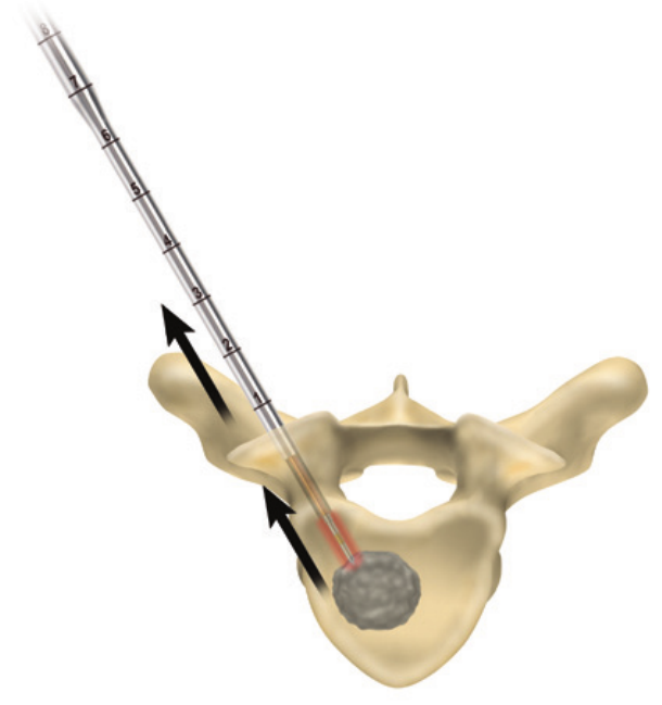
OPTIONAL TRACK
ABLATION WITH
OSTEOCOOL RF
ABLATION SYSTEM
1. To burn the track with the OsteoCool RF Ablation system,
select “Retract” on the Generator screen.
2. Press the RF power button.
3. The screen will signal when the RF ablation track burn
has initiated.
4. Slowly pull back on the RF ablation probe and cannula
simultaneously. When the desired end point for track ablation
is reached, press the RF power button to stop RF delivery.
Warning
Burning the track all the way to the skin can result in skin burns.
It is recommended to end track burn prior to this point.
19
OPTIONAL
TEMPERATURE
MONITORING
WITH THE INDEPENDENT
THERMOCOUPLE
The OsteoCool Independent Thermocouple provides real-time
temperature information to the user to assist in gauging ablation
zone margins to ensure there is no inadvertent thermal damage
to adjacent critical structures. The temperature detected by
the OsteoCool Independent Thermocouple is displayed by the
OsteoCool RF Generator.
1. Insert the Thermocouple into the provided introducer.
2. Connect the male connector on the thermocouple to the
female connector on the OsteoCool Connector Hub.
3. Conrm via on-screen information that the OsteoCool
Thermocouple (Sensor) has been detected.
4. Access site and place thermocouple in tissue to be monitored
20
BONE ACCESS
FOR SUBSEQUENT
PROCEDURES
Bone access can be used for a subsequent physician
directed procedure such as cementoplasty, vertebroplasty or
Kyphoplasty. Check to make sure that such procedures are
compatible with the OsteoCool Bone Access Introducer length
and gauge.
Indications for Use
Kyphon® Xpede™ Bone Cement is indicated for the treatment
of pathological fractures of the vertebral body due to
osteoporosis, cancer, or benign lesions using a cementoplasty
(i.e. kyphoplasty or vertebroplasty) procedure. Cancer includes
multiple myeloma and metastatic lesions, including those
arising from breast or lung cancer, or lymphoma. Benign lesions
include hemangioma and giant cell tumor. Pathologic fracture
may include a symptomatic vertebral body microfracture (as
documented by appropriate imaging and/or presence of a lytic
lesion) without obvious loss of vertebral body height.
Kyphon® HV-R® Bone Cement is indicated for the treatment
of pathological fractures of the vertebral body due to
osteoporosis, cancer, or benign lesions using a kyphoplasty or
vertebroplasty procedure. Cancer includes multiple myeloma
and metastatic lesions, including those arising from breast or
lung cancer, or lymphoma. Benign lesions include hemangioma
and giant cell tumor.
21
GENERAL
SAFETY GUIDELINES
For desired tissue heating and anatomical access abide by the
following guidelines:
Avoid advancing the probe into bone tissue without rst using
the introducer and drill to create a clear channel for the probe.
Forcing the probe through bone tissue may cause damage to
the probe.

22
OsteoCool RF Ablation Probes
OsteoCool RF Generator OC01
OsteoCool RF Pump OC02
OsteoCool RF Pump Cable OC03
OsteoCool Connector Hub OC04
OsteoCool RF Ablation Probes
Probe Kit OsteoCool RF 17G 7mm OCP107
Probe Kit OsteoCool RF 17G 10mm OCP110
Probe Kit OsteoCool RF 17G 20mm OCP120
Dual Probe Kit OsteoCool RF 17G 7mm OCP207
Dual Probe Kit OsteoCool RF 17G 10mm OCP210
Dual Probe Kit OsteoCool RF 17G 20mm OCP220
OsteoCool Bone Access Kits
OsteoCool Bone Access Kit 10G 090 OCN002
OsteoCool Bone Access Kit 8G 090 OCN003
OsteoCool Bone Access Kit 13G 100 OCN005
OsteoCool Carts and Stands
OsteoCool Cart Stand OCA01
OsteoCool Desk Stand OCA02
Temperature Monitoring
Thermocouple OsteoCool ITC 180mm OCN001
PRODUCT ORDERING
INFORMATION
23
IMPORTANT PRODUCT
INFORMATION
§ OsteoCool RF Ablation System: Intended for palliative
treatment in spinal procedures by ablation of metastatic
malignant lesions in a vertebral body.
§ OsteoCool Bone Access Kits: Indicated for percutaneous
access to bone.
§ OsteoCool Independent Thermocouple: Intended for
measuring tissue in temperature throughout an RF
ablation procedure.
The OsteoCool RF Ablation System is contraindicated for use
in the cervical spine and for use in patients with pacemakers or
other electronic implants.
24
OSTEOCOOL RF ABLATION SYSTEM AND BONE ACCESS KITS
NOTES

©2015 Medtronic Sofamor Danek USA, Inc. All Rights Reserved. PMD016254-2.0 31402
The surgical technique shown is
for illustrative purposes only. The
technique(s) actually employed in each
case will always depend upon the medical
judgment of the surgeon exercised
before and during surgery as to the best
mode of treatment for eachpatient.
Please see the package insert for the
complete list of indications, warnings,
precautions, and other important medical
information.
Consult instructions for use at this
website www.medtronic.com/manuals.
Note: Manuals can be viewed using a
current version of any major internet
browser. For best results, use Adobe
Acrobat® Reader with the browser.
Medtronic Sofamor Danek USA, Inc.
1800 Pyramid Place
Memphis, TN 38132
(901) 396-3133
(800) 876-3133
Customer Service: (800) 933-2635
Medtronic
Spinal and Biologics Business
Worldwide Headquarters
2600 Sofamor Danek Drive
Memphis, TN 38132
www.medtronic.com
