Polaris API Guide
User Manual: Pdf
Open the PDF directly: View PDF ![]() .
.
Page Count: 198 [warning: Documents this large are best viewed by clicking the View PDF Link!]
Polaris Application Program
Interface Guide
Revision 5
March 2011

Copyright 2005-2011 Northern Digital Inc. All Rights Reserved.
p Printed in Canada.
Revision Status
Revision Number Date Description
1 September 2005 Initial release. Describes the API that is compatible with Polaris
combined firmware revision 024, and Polaris Vicra/Polaris Spectra API
revision G.001.002.
2 July 2006 Added description of API revision G.001.003, best practices
information, and more details on user parameters.
3 September 2006 Minor edits.
4 May 2007 Added description of API revision G.001.004. This API revision
includes support for the hybrid Polaris Spectra System SCU, strobers,
GPIO devices, and active tools.
5 March 2011 Removed references to the Polaris System. Added description of API
revision G.001.005.
Part Number: IL-1070101

Polaris Application Program Interface Guide - Revision 5
Published by:
Northern Digital Inc.
103 Randall Dr.
Waterloo, Ontario, Canada N2V 1C5
Telephone: + (519) 884-5142
Toll Free: + (877) 634-6340
Global: + (800) 634 634 00
Facsimile: + (519) 884-5184
Website: www.ndigital.com
Copyright 2005-2010, Northern Digital Inc.
All rights reserved. No part of this document may be reproduced, transcribed, transmitted, distributed, modi-
fied, merged or translated into any language in any form by any means - graphic, electronic, or mechanical,
including but not limited to photocopying, recording, taping or information storage and retrieval systems - with-
out the prior written consent of Northern Digital Inc. Certain copying of the software included herein is unlawful.
Refer to your software license agreement for information respecting permitted copying.
DISCLAIMER OF WARRANTIES AND LIMITATION OF LIABILITIES
Northern Digital Inc. has taken due care in preparing this document and the programs and data on the elec-
tronic media accompanying this document including research, development, and testing.
This document describes the state of Northern Digital Inc.’s knowledge respecting the subject matter herein at
the time of its publication, and may not reflect its state of knowledge at all times in the future. Northern Digital
Inc. has carefully reviewed this document for technical accuracy. If errors are suspected, the user should con-
sult with Northern Digital Inc. prior to proceeding. Northern Digital Inc. makes no expressed or implied warranty
of any kind with regard to this document or the programs and data on the electronic media accompanying this
document.
Northern Digital Inc. makes no representation, condition or warranty to the user or any other party with respect
to the adequacy of this document or accompanying media for any particular purpose or with respect to its ade-
quacy to produce a particular result. The user’s right to recover damages caused by fault or negligence on the
part of Northern Digital Inc. shall be limited to the amount paid by the user to Northern Digital Inc. for the provi-
sion of this document. In no event shall Northern Digital Inc. be liable for special, collateral, incidental, direct,
indirect or consequential damages, losses, costs, charges, claims, demands, or claim for lost profits, data, fees
or expenses of any nature or kind.
Product names listed are trademarks of their respective manufacturers. Company names listed are trademarks
or trade names of their respective companies.

Polaris Application Program Interface Guide - Revision 5

Table of Contents
Polaris Application Program Interface Guide - Revision 5 i
Table of Contents
Read Me First! . . . . . . . . . . . . . . . . . . . . . . . . . . . . . . . . . . . . . . . . . . . . . . . . . . . . . . . . . . . . . . . . . . . . . . . iii
Warnings and Cautions . . . . . . . . . . . . . . . . . . . . . . . . . . . . . . . . . . . . . . . . . . . . . . . . . . .iii
About This Guide . . . . . . . . . . . . . . . . . . . . . . . . . . . . . . . . . . . . . . . . . . . . . . . . . . . . . . . . . . . . . . . . . . . . iv
Conventions . . . . . . . . . . . . . . . . . . . . . . . . . . . . . . . . . . . . . . . . . . . . . . . . . . . . . . . . . . . .iv
Contact Information . . . . . . . . . . . . . . . . . . . . . . . . . . . . . . . . . . . . . . . . . . . . . . . . . . . . . .iv
1 List of Commands . . . . . . . . . . . . . . . . . . . . . . . . . . . . . . . . . . . . . . . . . . . . . . . . . . . . . . . . . . . . . . . . . . .1
2 Changes in Implementation . . . . . . . . . . . . . . . . . . . . . . . . . . . . . . . . . . . . . . . . . . . . . . . . . . . . . . . . . . .4
2.1 Differences Between Polaris Vicra/Polaris Spectra API Revision G.001.002 and
G.001.003 . . . . . . . . . . . . . . . . . . . . . . . . . . . . . . . . . . . . . . . . . . . . . . . . . . . . . . . . . . 5
2.2 Differences Between Polaris Vicra/Polaris Spectra API Revision G.001.003 and
G.001.004 . . . . . . . . . . . . . . . . . . . . . . . . . . . . . . . . . . . . . . . . . . . . . . . . . . . . . . . . . . 7
2.3 Differences Between Polaris Vicra/Polaris Spectra API Revision G.001.004 and
G.001.005 . . . . . . . . . . . . . . . . . . . . . . . . . . . . . . . . . . . . . . . . . . . . . . . . . . . . . . . . . 11
3 Communicating with an NDI System . . . . . . . . . . . . . . . . . . . . . . . . . . . . . . . . . . . . . . . . . . . . . . . . . . .12
3.1 Communication Overview. . . . . . . . . . . . . . . . . . . . . . . . . . . . . . . . . . . . . . . . . . . . . 12
3.2 Operating Modes . . . . . . . . . . . . . . . . . . . . . . . . . . . . . . . . . . . . . . . . . . . . . . . . . . . . 12
3.3 General Syntax . . . . . . . . . . . . . . . . . . . . . . . . . . . . . . . . . . . . . . . . . . . . . . . . . . . . . 13
3.4 Receiving System Replies. . . . . . . . . . . . . . . . . . . . . . . . . . . . . . . . . . . . . . . . . . . . . 14
3.5 Best Practices. . . . . . . . . . . . . . . . . . . . . . . . . . . . . . . . . . . . . . . . . . . . . . . . . . . . . . . 15
3.6 Port Handles . . . . . . . . . . . . . . . . . . . . . . . . . . . . . . . . . . . . . . . . . . . . . . . . . . . . . . . 16
4 User Parameters . . . . . . . . . . . . . . . . . . . . . . . . . . . . . . . . . . . . . . . . . . . . . . . . . . . . . . . . . . . . . . . . . . . 20
4.1 About User Parameters . . . . . . . . . . . . . . . . . . . . . . . . . . . . . . . . . . . . . . . . . . . . . . . 20
4.2 User Parameter Commands . . . . . . . . . . . . . . . . . . . . . . . . . . . . . . . . . . . . . . . . . . . . 21
4.3 Device Names . . . . . . . . . . . . . . . . . . . . . . . . . . . . . . . . . . . . . . . . . . . . . . . . . . . . . . 21
4.4 Alerts User Parameters . . . . . . . . . . . . . . . . . . . . . . . . . . . . . . . . . . . . . . . . . . . . . . . 23
4.5 Bump Sensor User Parameters . . . . . . . . . . . . . . . . . . . . . . . . . . . . . . . . . . . . . . . . . 30
4.6 User-Defined User Parameters . . . . . . . . . . . . . . . . . . . . . . . . . . . . . . . . . . . . . . . . . 30

Table of Contents
ii Polaris Application Program Interface Guide - Revision 5
4.7 Complete List of User Parameters . . . . . . . . . . . . . . . . . . . . . . . . . . . . . . . . . . . . . . . 31
5 Commands. . . . . . . . . . . . . . . . . . . . . . . . . . . . . . . . . . . . . . . . . . . . . . . . . . . . . . . . . . . . . . . . . . . . . . . . 37
6 Error and Warning Code Definitions. . . . . . . . . . . . . . . . . . . . . . . . . . . . . . . . . . . . . . . . . . . . . . . . . . 167
6.1 Error Code Definitions. . . . . . . . . . . . . . . . . . . . . . . . . . . . . . . . . . . . . . . . . . . . . . . 167
6.2 Warning Code Definitions . . . . . . . . . . . . . . . . . . . . . . . . . . . . . . . . . . . . . . . . . . . . 170
Appendix A Keyed Features . . . . . . . . . . . . . . . . . . . . . . . . . . . . . . . . . . . . . . . . . . . . . . . . . . . . . . . . . 171
Appendix B Sample C Routines . . . . . . . . . . . . . . . . . . . . . . . . . . . . . . . . . . . . . . . . . . . . . . . . . . . . . . 175
Abbreviations and Acronyms . . . . . . . . . . . . . . . . . . . . . . . . . . . . . . . . . . . . . . . . . . . . . . . . . . . . . . . . . 183

Read Me First!
Polaris Application Program Interface Guide - Revision 5 iii
Read Me First!
This guide describes the Application Program Interface (API) commands that can be used with the
Polaris Vicra System, and the Polaris Spectra System. Before sending any commands to the system,
read the user guide that accompanied your system to ensure that you have a full understanding of the
functionality.
Read this chapter before continuing with the rest of the guide.
Warnings and Cautions
Warnings
In all NDI documentation, warnings are marked by this symbol. Follow the information in the accompanying
paragraph to avoid personal injury.
1. When using reply option 0800 with the BX (page 47) or TX (page 146) command, you must
take appropriate action to detect the following events: the tool or marker is out of volume, the
bump sensor has been tripped, or the system is outside of the optimal operating temperature
range. You must determine whether these events are detrimental to your application. If one or
more of the events listed occurs, reply option 0800 enables the system to return data that may
lead to inaccurate conclusions and may cause personal injury.
Cautions
Caution! In all NDI documentation, cautions are marked with the word “Caution!”. Follow the information in the
accompanying paragraph to avoid damage to equipment.
1. Before an input/output line on a synchronization port can be used as an input, its output value
must be set to a high level with SETIO (page 127). If you set the input to low and use the line as
an input, there will be incorrect status readings and you may cause damage to the interface
electronics.
Warning!

About This Guide
iv Polaris Application Program Interface Guide - Revision 5
About This Guide
This guide describes firmware revisions G.001.002, G.001.003, G.001.004 and G.001.005 of the API.
To determine the API revision number programmed into your system, use the APIREV command.
Conventions
Terminology
System refers to the Polaris Vicra System, or Polaris Spectra System.
Compatibility
This API guide describes several versions of the API. Some commands or options are not available
for each revision of the API. In this case, compatibility is indicated in columns at the right hand side
of the page. (See, for example, “List of Commands” on page 1.)
At the beginning of each command description, the systems compatible with the command are
listed. Where necessary, specific compatibility differences are listed in the Compatibility Notes near
the end of the command description.
Contact Information
If you have any questions regarding the content of this guide or the operation of this product, please
contact us:
NDI is committed to continuous improvements in the quality and versatility of its software and
hardware. To obtain the best results with your NDI system, check the NDI Support Site regularly for
update information: http://support.ndigital.com.
Email: APsupport@ndigital.com
Website: www.ndigital.com
Unit 301, 3/F Core Building 1
No. 1 Science Park East Avenue,
Hong Kong Science Park,
Shatin, New Territories,
Hong Kong
Phone: + (852) 2802 2205
Fax: + (852) 2802 0060
Fritz-Reichle-Ring 2
D-78315 Radolfzell
Germany
Phone: + 49 (77 32) 939 19 00
Global: + (800) 634 634 00
Fax: + 49 (77 32) 939 19 09
Email: support@ndieurope.com
Website: www.ndieurope.com
103 Randall Drive
Waterloo, ON, Canada N2V 1C5
Phone: + 1 (519) 884-5142
Toll Free: + 1 (877) 634-6340
Global: + (800) 634-634-00
Fax: + 1 (519) 884-5184
Email: support@ndigital.com
Website: www.ndigital.com

List of Commands
Polaris Application Program Interface Guide - Revision 5 1
1 List of Commands
Table 1-1 lists all the API commands, and whether they are supported by each revision of the API.
Compatibility is indicated as follows:
X indicates that the command is supported.
* indicates that the command is deprecated. Deprecated commands will no longer be enhanced to
support new hardware devices or new API features. Support for deprecated commands may be
discontinued in future releases.
Table 1-1 Alphabetical List of Commands
Command Page Description
G.001.002
G.001.003
G.001.004
G.001.005
3D 39 Returns the latest 3D position of either a single marker or multiple
markers. XXXX
APIREV 44 Returns the API revision number that functions with your system. X X X X
BEEP 45 Sounds the system beeper. X X X X
BX 47 Returns the latest tool transformations, individual marker posi-
tions, and system status in binary format. XXXX
COMM 58 Sets the serial communication settings of the system. X X X X
DFLT 61 Restores the user parameters to factory default values. X X X X
DSTART 63 Starts Diagnostic mode. X X X X
DSTOP 64 Stops Diagnostic mode. X X X X
ECHO 65 Returns exactly what is sent with the command. X X X X
GET 66 Returns the user parameter values. X X X X
GETINFO 68 Returns descriptive information about the user parameters. X X X X
GETIO 72 Returns the current status of the input/output lines of a synchroni-
zation port. XX
GETLOG 74 Returns the contents of a system log file. X X X X
HCWDOG 76 Sets up a host communication timeout check. * * * *
INIT 78 Initializes the system. X X X X
IRATE 79 Sets the illuminator rate. * * * *
IRED 81 Turns the markers on a wired tool on or off. X X
LED 83 Changes the state of visible LEDs on a wired tool. X X
PDIS 85 Disables the reporting of transformations for a particular port han-
dle. XXXX
PENA 86 Enables reporting of transformations for a particular port handle. X X X X
PFSEL 88 Sets which faces to use to track a multi-faced tool. X X X X
PHF 90 Releases system resources from an unused port handle. X X X X
PHINF 91 Returns port handle status, and information about the tool associ-
ated with the port handle, including physical port location. XXXX

List of Commands
2 Polaris Application Program Interface Guide - Revision 5
PHRQ 99 Assigns a port handle to a tool or GPIO device. X X X X
PHSR 101 Returns the number of assigned port handles and the port status for
each one. Assigns a port handle to a wired tool, GPIO device, or
strober.
XXXX
PINIT 104 Initializes a port handle. X X X X
PPRD 106 Reads data from the SROM device in a wired tool or GPIO device. X X
PPWR 108 Writes data to the SROM device in a wired tool or GPIO device. X X
PSEL 110 Selects an SROM device as the target for reading or writing with
PPRD or PPWR.XX
PSOUT 111 Sets the states of the general purpose input/output (GPIO) lines in
a GPIO device. XX
PSRCH 112 Returns a list of valid SROM device IDs for a wired tool or GPIO
device. XX
PURD 114 Reads data from the user section of the SROM device in a wired
tool or GPIO device. XX
PUWR 116 Writes data to the user section of a tool SROM device in a wired
tool or GPIO device. XX
PVWR 118 Assigns a tool definition file to a wireless tool, overrides a tool
definition file in a wired tool or GPIO device, and can be used to
test a tool definition file before permanently recording the tool def-
inition file onto the SROM device.
XXXX
RESET 120 Resets the system (can specify either a hard reset or a soft reset). X X X X
SAVE 122 Saves all non-volatile user parameters that have been changed. X X X X
SENSEL 123 Sets the IR sensitivity level, or returns the current IR sensitivity
level. ****
Serial
break 37 Resets the system (soft reset). X X X X
SET 125 Sets user parameter values. X X X X
SETIO 127 Sets the current status of the input/output lines of a synchroniza-
tion port. XX
SFLIST 129 Returns information about the supported features of the system. X X X X
SSTAT 136 Returns the status of the system processors. * * * *
SYSLOG 138 Writes data to the Position Sensor or System Control Unit log file. X X X X
TCTST 140 Returns diagnostics on the active markers of a wired tool. X X
TSTART 140 Starts Tracking mode. X X X X
TSTOP 143 Stops Tracking mode. X X X X
TTCFG 144 Sets up a configuration for a wired tool, so that you can test the
tool without using a tool definition file. XX
Table 1-1 Alphabetical List of Commands (Continued)
Command Page Description
G.001.002
G.001.003
G.001.004
G.001.005

List of Commands
Polaris Application Program Interface Guide - Revision 5 3
TX 146 Returns the latest tool transformations, individual marker posi-
tions, and system status in text format. XXXX
VER 158 Returns the firmware revision number of critical processors
installed in the system. XXXX
VGET 160 Retrieves data previously captured with VSNAP. XXXX
VSEL 163 Selects a characterized measurement volume. * * * *
VSNAP 165 Captures one complete frame sequence of video data from the sen-
sors. XXXX
Table 1-1 Alphabetical List of Commands (Continued)
Command Page Description
G.001.002
G.001.003
G.001.004
G.001.005

Changes in Implementation
4 Polaris Application Program Interface Guide - Revision 5
2 Changes in Implementation
This chapter describes the changes in implementation from previous versions of the API. Read this
chapter if you have written an application and you wish to update it to function with a more recent
version of the API.
Note If you have written an application for a Polaris combined firmware revision not listed above, contact NDI technical
support.
To update an application written for: To function with: Read:
Polaris Vicra
API revision G.001.002 Polaris Vicra or Polaris Spectra
API revision G.001.003 Page 5
Polaris Vicra or Polaris Spectra
API revision G.001.003 Polaris Vicra or Polaris Spectra
API revision G.001.004 Page 7
Polaris Vicra or Polaris Spectra
API revision G.001.004 Polaris Vicra or Polaris Spectra
API revision G.001.005 Page 7

Changes in Implementation
Polaris Application Program Interface Guide - Revision 5 5
2.1 Differences Between Polaris Vicra/Polaris Spectra API Revision G.001.002
and G.001.003
This section lists the changes between revisions G.001.002 and G.001.003 of the API. Read this
section if:
• you have written an application compatible with revision G.001.002 of the API for the
Polaris Vicra or Polaris Spectra System, and
• you wish to update the application to use some or all of the new features in revision
G.001.003 of the API.
These changes are additions to the API. Any applications written to function with revision
G.001.002 of the API will still function with revision G.001.003.
Addition to GETINFO
The GETINFO command has the following addition: GETINFO + will return top-level user
parameter categories. GETINFO <category>.+ will return the next level of categories under the
specified category. For example:
Change to PHINF
Reply option 0010 in the PHINF command now returns a value of 010 for a tool with marker
wavelength 930 nm if the tool was characterized using NDI 6D Architect version 2.02 or later. Tools
characterized with earlier versions of NDI 6D Architect will still have a value of 000 for a marker
wavelength of 930 nm.
Changes in Concepts
1. Device Names: Each device in the system configuration has a device name. Use the device
name as a prefix to a user parameter. This allows you to read or set user parameters for each
system component separately. If you omit the device name, the system will default to the
parameters for the first Position Sensor in the configuration (PS-0). In the case of a one-Position
Sensor passive system, this is the only Position Sensor. See “Device Names” on page 21 for
details.
2. Keyed Features: The system may use optional keyed features which, if enabled, may require
special consideration. For details on keyed features, see “Keyed Features” on page 171 and the
user guide that accompanied your system.
Command:
GETINFO +
Reply:
Device=;4;0003;;;;
Config=;4;0003;;;;
PS-0=;4;0003;;;;2D77
Command:
GETINFO PS-0.+
Reply:
Features=;4;0003;;;;
Info=;4;0003;;;;
Param=;4;0003;;;;
Cmd=;4;0003;;;;31E6
Command:
GETINFO PS-0.Features.+
Reply:
Hardware=;4;0003;;;;
Firmware=;4;0003;;;;
Tools=;4;0003;;;;
Keys=;4;0003;;;;1DF5

Changes in Implementation
6 Polaris Application Program Interface Guide - Revision 5
New User Parameters
New user parameters are as follows:
New User Parameter Description Access Rules
Param.Laser.Laser Status Starts/stops firing the positioning laser. Use this
parameter when the Positioning Laser keyed feature is
enabled. See “Positioning Laser” on page 174 for
details.
Read, write
Config.Multi Firmware.Load
Combined Firmware Revision Combined firmware revision to load on next reset
(selection automatically saves when set). Use this
parameter when the Multi Firmware keyed feature is
enabled. See “Multi Firmware Feature” on page 172
for details.
Read, write
Config.Multi Firmware.Update
Combined Firmware Revision Combined firmware revision to replace on next
upgrade or downgrade. Use this parameter when the
Multi Firmware keyed feature is enabled. See “Multi
Firmware Feature” on page 172 for details.
Read, write, save
Config.Password Enter the password to enable the ability to change and
save the system configuration. Use this parameter
when the Password Protect keyed feature is enabled.
See “Password Protect Feature” on page 174 for
details.
Read, write
Config.Combined Firmware
Revision Combined firmware revision of the current system
configuration. Read
Device.Type.0 Type of device in the system configuration. Read
Device.Instance.0 Instance of this type of device in the system configu-
ration. Read

Changes in Implementation
Polaris Application Program Interface Guide - Revision 5 7
2.2 Differences Between Polaris Vicra/Polaris Spectra API Revision G.001.003
and G.001.004
This section lists the changes between revisions G.001.003 and G.001.004 of the API. Read this
section if:
• you have written an application compatible with revision G.001.003 of the API for the
Polaris Vicra or Polaris Spectra System, and
• you wish to update the application to use some or all of the new features in revision
G.001.004 of the API.
These changes are additions to the API. Any applications written to function with revision
G.001.002 or G.001.003 of the API will still function with revision G.001.004.
New Commands
New commands are as follows:
Changes in Concepts
1. Data rate: In API revisions G.001.002 and G.001.003, it was possible to get repeated
information from the system if you requested information at a faster rate than the system could
update. This behaviour has been changed for the commands 3D (page 39), BX (page 47), and
TX (page 146), so that the system will return a maximum of one reply per frame. This matches
the behaviour of Polaris combined firmware revisions 018 and 024. For all other commands, it
is still possible to request and receive a reply more than once per frame.
2. GPIO devices: GPIO devices can be used with the hybrid Polaris Spectra System, and are
connected to the System Control Unit (SCU) or strobers. Like active tools, GPIO devices are
New Command Description
GETIO (page 72) Returns the status of the input/output lines of a synchronization port.
IRED (page 81) Turns the markers on a wired tool on or off.
LED (page 83) Changes the state of visible LEDs on a wired tool.
PPRD (page 106) Reads data from the SROM device in a wired tool or GPIO device.
PPWR (page 108) Writes data to the SROM device in a wired tool or GPIO device.
PSEL (page 110) Selects a tool SROM device as the target for reading or writing with PPRD or PPWR.
PSOUT (page 111) Sets the states of the general purpose input/output (GPIO) lines in a GPIO device.
PSRCH (page 112) Returns a list of valid SROM device IDs for a wired tool or GPIO device.
PURD (page 114) Reads data from the user section of the SROM device in a wired tool or GPIO device.
PUWR (page 116) Writes data to the user section of the SROM device in a wired tool or GPIO device.
SETIO (page 127) Sets the status of the input/output lines of a synchronization port.
TCTST (page 140) Returns diagnostics on the active markers of a wired tool.
TTCFG (page 144) Sets up a configuration for a wired tool, so that you can test the tool without using a
tool definition file.

Changes in Implementation
8 Polaris Application Program Interface Guide - Revision 5
assigned a port handle, which must be initialized and enabled before the GPIO device can be
used.
3. Strobers: Strobers provide an interface for active tools, and can be used with the hybrid Polaris
Spectra System. Like active tools, strobers are assigned a port handle. It is not necessary to
initialize and enable the port handle for a strober. The SCU contains an “internal strober”; the
tool ports and GPIO port on the front of the SCU are part of this internal strober. The internal
strober is also assigned a port handle.
4. Log files: The Position Sensor and SCU now each have their own log file. Previous versions of
the API supported only the Position Sensor and so the system only had one log file. This change
results in a change in the log name specified in the commands GETLOG (page 74) and
SYSLOG (page 138). See these commands for details.
5. Alerts: The alerts in the Info.Status.Alerts and Info.Status.New Alerts user parameters are
defined differently for the SCU and strober than for the Position Sensor. For details, see “Alerts
User Parameters” on page 23.
6. LED behaviour: The behaviour of the LEDs on the Position Sensor has changed. To see which
alerts now have different LED behaviour, see “Position Sensor Alerts” on page 24.
7. Diagnostic pending bit: The “diagnostic pending” bit (bit 8 in the BX or TX system status)
now indicates whenever an alert is detected or cleared in the Info.Status.New Alerts user
parameter. Previously, the “diagnostic pending” bit was set only when an alert was detected.
8. VSnap User Parameters: The user parameters Cmd.VSnap.Illuminated Frame and
Cmd.VSnap.Background Frame, used to specify which frames to capture with the VSNAP
(page 165) command, can now only be set when the system is in Setup mode. Previously these
parameters could be set in any mode, but did not take effect until the next DSTART (page 63) or
TSTART (page 142) commmand was issued.
9. Param.Tracking.Sensitivity and Param.Tracking.Selected Volume: These two user
parameters can now be set only when the system is in Setup mode. Previously these user
parameters could be set in any mode, but would not take effect while the system was in Tracking
or Diagnostic modes.
10. Alerts Parameters: The system response (LEDs and error codes) to some of the Position
Sensor alerts has changed. See Table 4-2 on page 24 for details. New alerts have been defined
for the SCU and strobers. See Table 4-3 on page 27 and Table 4-4 on page 29 for details.
11. Alerts System Response: Some of the alerts indicated in the alerts parameters result in the
system not returning data unless reply option 0x0800 is used with the BX or TX command (see
“Alerts User Parameters” on page 23 for details). Previously, the system resumed returning data
once the Info.Status.New Alerts parameter was read, regardless of whether the alert was
actually resolved. Now the system will not return data in these cases until the alert is resolved.
Changed Commands
1. BX (page 47) and TX (page 146)
• Bits 6 and 7 in <System Status> report when a port handle has become occupied or
unoccupied due to an active tool, strober, or GPIO device being connected or disconnected.
• Reply option 0x0001: For GPIO devices, <Port Status> bits 1, 2, and 3 report the status of
GPIO lines defined as inputs. (For wired tools, these bits report switch status).

Changes in Implementation
Polaris Application Program Interface Guide - Revision 5 9
• Reply option 0x0004 reports the 3D position of a single, stray marker on an active tool.
2. GETLOG (page 74): The way the log name is specified has changed, to allow access to the
logs in both the Position Sensor and the SCU. If you specify the log name using the format from
previous versions of the API, the system will retrieve the log file for the Position Sensor. This
maintains backwards compatibility with previous versions of the API.
3. PHINF (page 91)
• Reply option 0x0001: Strobers are reported as <main type> 08 and GPIO devices are
reported as <main type> 0C.
• Reply option 0x0001: For GPIO devices, <Port Status> bits 1, 2, and 3 report the status of
GPIO lines defined as inputs. (For wired tools, these bits report switch status).
• Reply option 0x0008: For GPIO devices, bits 1, 2, and 3 report the status of GPIO lines
defined as inputs, and bits 5, 6, and 7 report the status of GPIO lines defined as outputs with
feedback. (For wired tools, bits 1, 2, and 3 report switch status, and bits 5, 6, and 7 report
LED status.)
• Reply option 0x0020: For Polaris, Polaris Vicra, and passive Polaris Spectra, <hardware
device> is the Position Sensor serial number. For hybrid Polaris Spectra, this is the device
name of the strober that the tool is plugged into (STB-1 or STB-2). If the tool is plugged
into the SCU, this is STB-0.
• Reply option 0x0040: This new reply option reports the status of the four GPIO lines in a
GPIO device.
4. PHRQ (page 99): For hybrid Polaris Spectra, specifying all wildcards for the <hardware
device> for a wired tool or GPIO device will default to STB-0 (the tool ports on the SCU).
5. SYSLOG (page 138): A log name must now be specified, to allow access to the logs in both the
Position Sensor and the SCU. If you do not specify a log name, the system will write to the log
file for the Position Sensor. This maintains backwards compatibility with previous versions of
the API.
6. TCTST (page 140): The low threshold for marker current is now 0x0A.
7. VER (page 158): Reply option 3 now reports information for the System Control Unit. The
second line of the response was the Tool Interface Unit part number for Polaris. For Polaris
Spectra, the second line of the response is the serial number of the System Control Unit.
New Error Code
A new error code, 0x42, indicates when the command is specific to a device that is not connected to
the system.
New Device Types
The following new device types are supported:
Device Type Hardware Device
SCU System Control Unit
STB Strober

Changes in Implementation
10 Polaris Application Program Interface Guide - Revision 5
In G.001.003, only a device type of PS (Position Sensor) was supported. For details on device types,
see “Device Names” on page 21.
New User Parameters
New user parameters are as follows:
New User Parameter Description Access Rules Hardware Device
Param.Serial Port Hardware configuration of the serial port. Read SCU
Param.Strober Name User-defined strober name (up to 31 chars). Read, write Strobers
Features.Firmware.
Package Number Current firmware package number Read Position Sensor,
SCU
Features.Firmware.
Available Versions List of firmware revisions loaded in the
device Read Position Sensor,
SCU
Features.Firmware.
Available Combined
Firmware Revisions
List of combined firmware revisions loaded
in the device. Read Position Sensor,
SCU
Features.Firmware.
Combined Firmware
Revision
Current combined firmware revision of the
device. Read Position Sensor,
SCU
Param.System Ext
Sync Mode Enables/disables the external sync mode
(see the user guide for details). Read, write SCU
Config.Multi
Firmware.Available
Combined Firmware
Revisions
List of combined firmware revisions loaded
in the system. Read Config (no hardware
device specified.)

Changes in Implementation
Polaris Application Program Interface Guide - Revision 5 11
2.3 Differences Between Polaris Vicra/Polaris Spectra API Revision G.001.004
and G.001.005
This section lists the changes between revisions G.001.004 and G.001.005 of the API. Read this
section if:
• you have written an application compatible with revision G.001.004 of the API for the
Polaris Vicra or Polaris Spectra System, and
• you wish to update the application to use some or all of the new features in revision
G.001.005 of the API.
These changes are additions to the API. Any applications written to function with revision
G.001.002, G.001.003 or G.001.004 of the API will still function with revision G.001.005.
New User Parameters
New user parameters are as follows:
Changed Commands
1. GET (page 66) and GETINFO (page 68): On a multi-line GET or GETINFO command, there is
no longer a <LF> beteen the last parameter=value pair and the <CR>.
2. PINIT (page 104): WARNING05 (In combined firmware 006 and later, WARNING05 is
returned when the system selects a default marker wavelength to track a tool (if the tool’s tool
definition file did not specify a marker wavelength)).
New User Parameter Description Access Rules Hardware Device
Param.Default
wavelength.
Return Warning
Enables/disables returning a warning on
PINIT if the default wavelength was
selected for the tool corresponding to the
port handle.
Read, write Position Sensor
Features.Firmware.
Safeloader Version
Current safeloader firmware revision
number. Read Position Sensor,
SCU

Communicating with an NDI System
12 Polaris Application Program Interface Guide - Revision 5
3 Communicating with an NDI System
This chapter describes various aspects of communicating with an NDI system. It contains the
following sections:
•“Communication Overview” on page 12
•“Operating Modes” on page 12
•“General Syntax” on page 13
•“Receiving System Replies” on page 14
•“Best Practices” on page 15
•“Port Handles” on page 16
3.1 Communication Overview
From the application perspective, the Polaris Vicra, or Polaris Spectra System is a serial device,
which is listening for incoming commands. Upon receiving a command, the system performs some
action and returns the status of this action. The system never initiates communication with the
application except on power up or reset, when it returns RESET<CRC16><CR>. (If only an SCU is
connected it will return SCUONLY<CRC16><CR>.)
Immediately after sending a command, the application can begin to poll the serial buffer for a reply.
Most commands reply almost instantaneously. After reaching the end of the reply, the application
can send another command. There may be some delay in the response of the PINIT command, and
the commands used to read from and write to an SROM device in a wired tool.
Note The application must read the complete response from the system before sending another command. Failure to
do so may result in an error or in unpredictable system behaviour.
3.2 Operating Modes
The system has three modes of operation: Setup, Tracking, and Diagnostic. Some commands will
only work if they are sent while the system is in a specific mode of operation. If a command is sent
when the system is in a mode not valid for that command, the system returns ERROR0C.
Setup
Setup mode allows you to configure the system and tools. Tasks done while the system is in Setup
mode may include initializing the system, writing to the SROM device on a tool, or checking the
system firmware revision.
The order of the commands sent while in Setup mode is important. For example, a port handle must
be initialized (PINIT) before it can be enabled (PENA).
The system enters the Setup mode either on successful power up, on sending a reset, or on exiting
from Tracking or Diagnostic modes.

Communicating with an NDI System
Polaris Application Program Interface Guide - Revision 5 13
Tracking
In Tracking mode, the system measures the positions and orientations of tools in real time and
returns the information to the host computer when requested. The BX and TX commands are the
most commonly used commands in Tracking mode.
The system enters Tracking mode on successful TSTART command and exits Tracking mode on
TSTOP command.
Diagnostic
Diagnostic mode allows you to control and observe tools, but not track them.
The system enters Diagnostic mode on successful DSTART command and exits Diagnostic mode on
DSTOP command.
3.3 General Syntax
Commands must be sent from the host computer to the system in one of the two following formats.
To ensure the integrity of data transmission, NDI recommends using format 1, as well as verifying
the returned CRC on the host computer.
Format 1
<Command><:><Parameter1><Parameter2>...<ParameterN><CRC16><CR>
A <:> must be sent with every command even if no parameters are required. There are no characters
or spaces separating the parameters or the individual parts of the commands, except in user
parameter names and string values used with the SET, GET, GETINFO, DFLT, and SYSLOG
commands. Commands and parameters are not case-sensitive, except for user parameter names and
string values used with the SET, GET, GETINFO, DFLT, and SYSLOG commands.
This format requires a 16-bit CRC value and therefore may be more useful in application software.
The application software can incorporate a CRC calculation and add it to the command each time a
command is sent to the system. Including a CRC provides a communications check to ensure that
there are no communication problems between the system and the host computer. The CRC is used
in both the commands and replies. It is based on all the characters in the command, up to the CRC
itself. It is calculated using the polynomial x16 +x
15 +x
2+ 1. See “Sample C Routines” on
page 175 for sample code to calculate the CRC.
Format 2
<Command><SPACE><Parameter1><Parameter2>...<ParameterN><CR>
A <SPACE> must be sent with every command even if no parameters are required. There are no
characters or spaces separating the parameters or the individual parts of the commands, except in
user parameter names and string values used with the SET, GET, GETINFO, DFLT, and SYSLOG
commands. Commands and parameters are not case-sensitive, except for user parameter names and
string values used with the SET, GET, GETINFO, DFLT, and SYSLOG commands.
It is not necessary to calculate a Cyclic Redundancy Check (CRC) value when using this format, so
this format is useful for sending commands to the system in an application such as a terminal
program.

Communicating with an NDI System
14 Polaris Application Program Interface Guide - Revision 5
3.4 Receiving System Replies
Binary Replies
Commands BX, GETLOG, and VGET return binary replies. All other commands return ASCII
replies.
If a complete command is received by the system, replies are sent back in the format:
<Reply><CRC16>
The system always returns <CRC16> in the reply regardless of whether the command was sent in
format 1 or format 2. The <Reply> will be either the requested data, or ERROR<error code>. The
<error code> is a two-digit hexadecimal error number. See “Error Code Definitions” on page 167
for a listing of all the error messages associated with error numbers.
Binary replies are returned in little endian format. For example, a 32-bit reply is returned in the
format:
ASCII Replies
All commands return ASCII replies except BX, GETLOG, and VGET, which return binary replies.
If a complete command is received by the system, replies are sent back in the format:
<Reply><CRC16><CR>
The system always returns <CRC16> in the reply regardless of whether the command was sent in
format 1 or format 2. The <Reply> will be either the requested data, OKAY, WARNING,
WARNING<warning code>, or ERROR<error code>.
•WARNING is returned only with the PINIT command. See PINIT (page 104) or “Warning
Code Definitions” on page 170 for details.
•WARNING<warning code> is returned only with the PENA command. See “Warning Code
Definitions” on page 170 for a listing of the warning messages.
•The
<error code> is a two-digit hexadecimal error number. See “Error Code Definitions”
on page 167 for a listing of all the error messages associated with error numbers.
Bits 7 - 0 15 - 8 23 - 16 31 - 24
Reply byte n n + 1 n + 2 n + 3

Communicating with an NDI System
Polaris Application Program Interface Guide - Revision 5 15
3.5 Best Practices
This section provides guidelines on how to write an application in order to minimize updates
required when there are changes to the API. If your application is written correctly, it will still work
when additions are made to the API; you will only need to update your application if you wish to
take advantage of the new features.
• Ignore the value of any returned field that is listed as “reserved” in the API guide. The
values of reserved fields may change in future API releases.
• Program the application to allow all possible values of a returned field, not only the values
that are currently defined. This allows for future expansion. For example, if a field returns
one character, but currently only characters 0 and 1 are defined, do not write your
application such that 0 and 1 are the only acceptable values; more values may be defined in
the future.
• Use the frame number, and not the host computer clock, to identify when data was collected.
The frame number is incremented by 1 at a constant rate of 60 Hz. Associating a time from
the host computer clock to replies from the system assumes that the duration of time
between raw data collection and when the reply is received by the host computer is constant.
This is not necessarily the case. The frame number is returned with the command BX
(page 47) or TX (page 146).
• Use both the shape type and the shape parameters to represent the characterized
measurement volume graphically. There may be multiple volumes with the same shape
type. All volumes of the same shape type use the shape parameters the same way. The shape
type and shape parameters are returned with the command SFLIST (page 129).
• When checking the firmware revision, check only the combined firmware revision, not the
firmware revision of the individual components. The combined firmware revision ensures
that all components in a system have compatible firmware. To check the combined firmware
revision, read the value of the user parameter Config.Combined Firmware Revision or use
the command VER 5 (page 158). See “User Parameters” on page 20 for information on
reading user parameters.
• When checking for protocol compatibility, check for the API revision instead of the
combined firmware revision. An application written for a particular API revision will
function with any system that supports that API revision. See the command APIREV
(page 44) for details.
• Use an application-specific parameter file to set the user parameter values every time the
system is initialized. This ensures that the settings are consistent every time, and allows you
to adopt new values or incorporate new parameters without having to update the application
software. See “User Parameters” on page 20 for information on setting user parameters.
• Use device names to access user parameters. See “Device Names” on page 21 for
instructions on how to determine the device names of the hardware devices in your system
and how to access user parameters using device names.
•Use GET Device.* to determine which devices are in the system configuration, instead of
programming device names directly into the application. This will allow the addition or
removal of devices without breaking the application. When setting or reading a user
parameter value for every hardware device in the system, create a loop to repeat the action
for every device name determined using GET Device.*. See “Device Names” on page 21

Communicating with an NDI System
16 Polaris Application Program Interface Guide - Revision 5
for instructions on how to determine the device names of the hardware devices in your
system and how to access user parameters using device names.
• Read the timeout values of the API commands from the user parameter
Info.Timeout.<command name>; do not program the timeout values directly into the
application. See “User Parameters” on page 20 for information on user parameters. Note:
since the timeout values are the same for every system configuration, it is not necessary to
prefix the Info.Timeout user parameters with a device name unless you are communicating
with an SCU that is not connected to a Position Sensor. (In this case you must use the SCU’s
device name.)
• Do not use the system log to record minor system events. The system log is intended for
major milestones only, and may not have enough space to accommodate numerous minor
entries. For minor entries, use the user parameters Param.User.String0 to
Param.User.String4 as required. These parameters can be used for any purpose; the system
does not make use of them. For example, an incoming inspection result might be a major
milestone to be saved in the system log; a cleaning schedule might be a minor entry to be
saved in a user parameter. See “User-Defined User Parameters” on page 30 for information
on these user parameters.
3.6 Port Handles
About Port Handles
The system assigns each tool, GPIO device, and strober a port handle. Port handles are two
characters in hexadecimal format, 0x01 to 0xFF.
Port handles can be assigned to tools only while the system is in Setup mode.
Port Handle Commands
The following commands are used for port handles:
Command Description
PHSR (page 101) Returns the number of assigned port handles and the port status for each one.
Assigns a port handle to a wired tool or GPIO device.
PHRQ (page 99) Assigns a port handle to a tool or GPIO device. PHRQ is followed by
PVWR.
PVWR (page 118) Assigns a tool definition file to a tool, overrides a tool definition file in a
wired tool or GPIO device, and can be used to test a tool definition file before
permanently recording the tool definition file onto the SROM device of a
wired tool or GPIO device.
PINIT (page 104) Initializes a port handle.
PHINF (page 91) Returns port handle status, and information about the tool, GPIO device, or
strober associated with the port handle, including physical port location.

Communicating with an NDI System
Polaris Application Program Interface Guide - Revision 5 17
The order in which these commands are used is detailed in Figure 3-1 on page 18 (for wired tools)
and Figure 3-2 on page 19 (for wireless tools).
Disabled Transformations
A transformation may be reported as DISABLED if:
• the port handle was not enabled with PENA (page 86),
• the port handle has been disabled with PDIS (page 85), or
• a wired tool, GPIO device, or strober has been disconnected and the port handle has not
been freed.
Unoccupied Port Handle
A port handle may be reported as UNOCCUPIED if:
• the tool, GPIO device, or strober has been disconnected and port handle information is
requested using PHINF (page 91), or
• you have requested a port handle with PHRQ (page 99) but you have not yet used PVWR
(page 118) to associate a tool definition file with the port handle.
PHF (page 90) Releases system resources from an unused port handle. This is required if a
tool, GPIO device, or strober is disconnected. If a tool, GPIO device, or
strober is disconnected and then reconnected, the system assigns it a new port
handle. The old handle is reported as disabled and should be freed using PHF.
PENA (page 86) Enables reporting of transformations for a particular port handle.
PDIS (page 85) Disables the reporting of transformations for a particular port handle.
Command Description
Communicating with an NDI System
18 Polaris Application Program Interface Guide - Revision 5
Flow Charts for Port Handle Usage
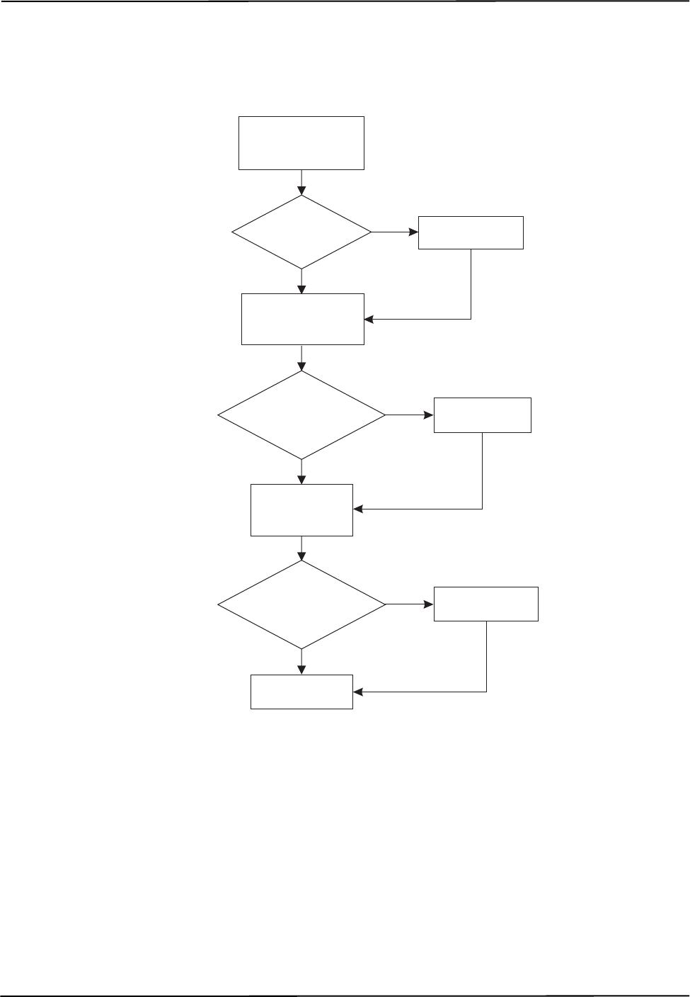
Figure 3-1 details the logic for using port handles with wired tools, GPIO devices, and strobers.
Initializing and enabling a strober is optional.
Figure 3-1 Flow Chart for Port Handle Usage - Wired Tools
no
no
no
Get port handles
that need to be freed
(PHSR 01)
Are there port
handles to be
freed?
yes Free port handle
(PHF)
Get port handles that
need to be initialized
(PHSR 02)
Are there
port handles
to be initialized?
Start tracking
(TSTART)
Enable port
handles (PENA)
Are there
port handles
to be enabled?
Get port handles
to be enabled
(PHSR 03)
Initialize handles
(PINIT)
yes
yes
Communicating with an NDI System
Polaris Application Program Interface Guide - Revision 5 19
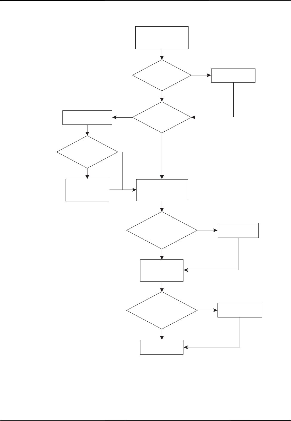
Figure 3-2 details the logic for using port handles with wireless tools.
Figure 3-2 Flow Chart for Port Handle Usage - Wireless Tools
no
no
yes
yes
no
no
Get port handles
that need to be freed
(PHSR 01)
Are there port
handles to be
freed?
yes Free port handle
(PHF)
Do I need a
handle for a port?
Get port handles that
need to be initialized
(PHSR 02)
Are there
port handles
to be initialized?
Start tracking
(TSTART)
Enable port
handles (PENA)
Are there
port handles
to be enabled?
Get port handles
to be enabled
(PHSR 03)
Request port handle
(PHRQ)
Do I need to
load a tool definition
file?
Load tool
definition file
(PVWR)
no
Initialize handles
(PINIT)
yes
yes

User Parameters
20 Polaris Application Program Interface Guide - Revision 5
4 User Parameters
This chapter contains the following sections about user parameters:
•“About User Parameters” on page 20
•“User Parameter Commands” on page 21
•“Device Names” on page 21
•“Alerts User Parameters” on page 23
•“Bump Sensor User Parameters” on page 30
•“User-Defined User Parameters” on page 30
•“Complete List of User Parameters” on page 31
4.1 About User Parameters
The user parameters store values for different aspects of the Polaris Vicra or Polaris Spectra System.
Some user parameters store values for the full system configuration; others store values pertaining to
a particular hardware device in the system. Some user parameters are read-only parameters that store
useful information about the system; some user parameter values can be changed, to allow you to
configure the system.
User parameters fall under the following categories:
•Image Capture User Parameters: These user parameters are used in conjunction with the
VSNAP and VGET commands to store settings and values related to image capture.
•Settings User Parameters: These user parameters store settings for each hardware device in
the system. For example, the illuminator rate and the available characterized measurement
volumes are stored in the settings user parameters.
•Information User Parameters: These user parameters store status information for each
hardware device in the system, and command timeout values.
•Features User Parameters: These user parameters store information about the features of
each hardware device in the system.
•System Configuration User Parameters: These user parameters store information about the
configuration of the system. These user parameters describe the configuration of the entire
system, not a particular device.
•Hardware Device Information User Parameters: These user parameters store information
about which hardware devices are part of the system.
For a full list of user parameters, see page 31.

User Parameters
Polaris Application Program Interface Guide - Revision 5 21
4.2 User Parameter Commands
The following commands are used with the user parameters:
See the individual commands for more details.
4.3 Device Names
Note Device names are supported in API revisions G.001.003 and later.
Each hardware device in the system configuration has a unique device name. For passive systems,
the Position Sensor is the only hardware device. For hybrid systems, the Position Sensor, System
Control Unit, and strobers each have a device name.
Each hardware device has its own set of user parameters. Each Position Sensor and System Control
Unit has its own log file. Device names allow you to specify for which hardware device you wish to
access the user parameters or log file.
Note For information on the log files, see GETLOG (page 74) and SYSLOG (page 138).
Determining the Devices in the System Configuration
Use the GET command to determine which hardware devices are in your system. To ensure future
compatibility if more devices are integrated into your system, your application should read the list of
devices every time you connect to a system, or whenever a component is connected or disconnected.
Note The list of devices does not update while the system is in tracking mode. If a strober is connected while the
system is in tracking mode, the list of devices will not show the change until the system exits tracking mode.
The most general method of reading the list of devices to ensure consistent behaviour in the future is
as follows:
Command Description
DFLT (page 61) Restores the user parameters to factory default values.
GET (page 66) Returns user parameter values.
GETINFO (page 68) Returns user parameter values and descriptive information
about the user parameters, including use details, possible
values, and access rules.
SET (page 125) Sets user parameter values.
SAVE (page 122) Saves all non-volatile user parameters that have been changed.

User Parameters
22 Polaris Application Program Interface Guide - Revision 5
Command:
GET Device.*
Reply:
Device.Type.0=SCU
Device.Instance.0=0
Device.Type.1=PS
Device.Instance.1=0
Device.Type.2=STB
Device.Instance.2=0
Device.Type.3=STB
Device.Instance.3=1
Device.Type.4=STB
Device.Instance.4=2C845
The reply gives information about every device in the system configuration. For each device, there
are two parameters:
•Device.Type.X describes the type of connected device. Device types are as follows:
•Device.Instance.X describes the instance of that type of device in the configuration.
Parameters with the same X index value (for example, Device.Type.0 and Device.Instance.0)
describe the same device.
In the example above, the reply is for a hybrid Polaris Spectra System with an a System Control
Unit, a Position Sensor, and two strobers. Since the System Control Unit also contains an internal
strober, a total of three strobers are enumerated.
Constructing Device Names
User parameters for a particular device can always be accessed using the full device name. To
construct the device name for a particular device, use the following syntax:
<Device.Type.X>-<Device.Instance.X>
For the configuration in the example above, the device names are SCU-0, PS-0, STB-0, STB-1, and
STB-2. The internal strober in the System Control Unit is always STB-0.
Accessing User Parameters Using Device Names
Each device has its own set of user parameters. To ensure that the user parameters for the correct
device are accessed, prefix the parameter with the device name. All references to user parameters for
a device can be made using the device name. To access the user parameters for a particular device,
use the following syntax:
<Device.Type.X>-<Device.Instance.X>.<User Parameter>
For example, use GET PS-0.Param.Tracking.Sensitivity to check the sensitivity level for
the Position Sensor.
Device.Type Parameter Hardware Device
PS Position Sensor
SCU System Control Unit
STB Strober

User Parameters
Polaris Application Program Interface Guide - Revision 5 23
To view information about the parameters supported by the device, use the following commands:
GET PS-0.*
GETINFO PS-0.+
GETINFO PS-0.*
Note See the GET (page 66) and GETINFO (page 68) commands for details.
The system configuration user parameters (beginning with Config) and the hardware device user
parameters (beginning with Device) describe the configuration of the entire system. Do not prefix
these user parameters with a device name.
4.4 Alerts User Parameters
The alerts user parameters describe the status of a particular hardware device in the system. To
access the user parameters for a particular device, prefix the parameter with the device name as
described in “Device Names” on page 21.
Alerts User Parameters
Table 4-1 describes the alerts user parameters.
Table 4-1 Alerts User Parameters
User
Parameter Description
Info.Status.
Alerts This user parameter describes the current state of the hardware device by reporting the alerts listed in
Table 4-2 (for the Position Sensor), Table 4-3 (for the System Control Unit), or Table 4-4 (for the
strobers).
The bit corresponding to a particular alert is set when the system first detects the condition. This is
accompanied by the system response detailed in Table 4-2, Table 4-3, or Table 4-4. The bit is cleared
when the condition no longer exists. Note: the “bump detected” bit will be cleared only when you set the
Param.Bump Detector.Clear Position Sensor user parameter to “1”.
Info.Status.
New Alerts Read this user parameter when the diagnostic pending bit is set (bit 8 in the BX or TX system status).
This user parameter lists the current alerts status whenever an alert is set or cleared. The act of reading
this parameter clears both this parameter and the diagnostic pending bit.
The bit corresponding to a particular alert is set when the system first detects the condition, and is cleared
when the system first detects that the condition has been resolved. This is accompanied by the system
response detailed in Table 4-2, Table 4-3, or Table 4-4. The act of reading this user parameter clears it.
Info.Status.
Alerts Overflow Read this user parameter if the overflow bit is set in the user parameter Info.Status.Alerts or
Info.Status.New Alerts for a particular hardware device. No bits are currently defined in this parameter.
Param.Simu-
lated Alerts Simulates the Info.Status.Alerts parameter for the hardware device specified, for testing purposes. To
test the response of a particular alert, set the value of this parameter to the value of the alert (see
Table 4-2, Table 4-3, or Table 4-4).

User Parameters
24 Polaris Application Program Interface Guide - Revision 5
Position Sensor Alerts
Table 4-2 describes the Position Sensor alerts that are returned by the Info.Status.Alerts and
Info.Status.New Alerts user parameters. The returned value is an integer, which you must convert
to an 8-character hexadecimal number. The hexadecimal number is made up of the following
individual alert values OR’d together:
Table 4-2 Position Sensor Alerts
Hexadecimal
Value Alert System Response Position Sensor LED
Indication
0x00000001 Non-recoverable parameter fault
The system parameter file or
some other critical file is missing
or has been corrupted (CRC
check failed).
INIT returns ERROR15 Error LED: on
Status LED: off
0x00000002 Sensor parameter fault
The sensor parameters were not
programmed properly, or cannot
be read by the system.
INIT returns ERROR15 Error LED: on
Status LED: off
0x00000004 Main voltage fault
The input voltage to the Position
Sensor is outside of the operating
range. This may be caused by a
problem with the power supply.
Sets diagnostic pending bit (bit
8) in TX or BX system status.
Need reply option 0800 in TX or
BX to return data.
Power LED: off
Status LED: on
Error LED: on
0x00000008 Sensor voltage fault
One of the voltages supplied to
the sensor is outside of the
operating range. This may be
caused by a hardware failure.
Sets diagnostic pending bit (bit
8) in TX or BX system status.
Need reply option 0800 in TX or
BX to return data.
Error LED: on
Status LED: off
0x00000010 Illuminator voltage fault
The illuminator voltage is outside
of operating range. This may be
caused by a hardware failure.
Sets diagnostic pending bit (bit
8) in TX or BX system status. Error LED: on
Status LED: off
0x00000020 Illuminator current fault
The illuminator current is outside
of operating range. This may be
caused by a hardware failure.
Sets diagnostic pending bit (bit
8) in TX or BX system status. Error LED: on
Status LED: off
0x00000040 Left sensor temperature fault
The left sensor temperature
sensor is outside of functional
range.
INIT returns ERROR15
Sets diagnostic pending bit (bit
8) in TX or BX system status.
The system will not return
tracking data, even if reply
option 0800 in TX/BX is used.
(API revision G.001.003 and
earlier: INIT is possible; system
returns data in TX and BX if
0800 option is used.)
Error LED: on
Status LED: off

User Parameters
Polaris Application Program Interface Guide - Revision 5 25
0x00000080 Right sensor temperature fault
The right sensor temperature
sensor is outside of functional
range.
INIT returns ERROR15
Sets diagnostic pending bit (bit
8) in TX or BX system status.
The system will not return
tracking data, even if reply
option 0800 in TX/BX is used.
(API revision G.001.003 and
earlier: INIT is possible; system
returns data in TX and BX if
0800 option is used.)
Error LED: on
Status LED: off
0x00000100 Main temperature fault
The main board temperature
sensor is outside of functional
range.
INIT returns ERROR15
Sets diagnostic pending bit (bit
8) in TX or BX system status.
The system will not return
tracking data, even if reply
option 0800 in TX/BX is used.
(API revision G.001.003 and
earlier: INIT is possible; system
returns data in TX and BX if
0800 option is used.)
Error LED: on
Status LED: off
0x00000200
to
0x00080000
Reserved
0x00100000 System battery fault
The system battery power is too
low. This may be caused by a
worn-out battery, or the battery
may not be connected. This
battery powers the bump sensor
and the system clock.
Sets diagnostic pending bit (bit
8) in TX or BX system status.
Need reply option 0800 in TX or
BX to return data.
Status LED: on
Error LED: flashing
0x00200000 Bump detected
The bump sensor has detected a
bump.
Sets diagnostic pending bit (bit
8) in TX or BX system status.
Need reply option 0800 in TX or
BX to return data.
Status LED: on
Error LED: flashing
0x00400000 Reserved
0x00800000 Firmware incompatible
The combination of firmware on
the Position Sensor is not
compatible. This may be caused
by a failed attempt to update the
firmware.
INIT returns ERROR2E Status LED: on
Error LED: on
(API revision
G.001.003 and earlier:
status LED is on; error
LED is flashing.)
Table 4-2 Position Sensor Alerts (Continued)
Hexadecimal
Value Alert System Response Position Sensor LED
Indication

User Parameters
26 Polaris Application Program Interface Guide - Revision 5
Note Some of the alerts indicated in Table 4-2 result in the system not returning data unless reply option 0x0800 is
used with the BX or TX command. In API revision G.001.003 and earlier, the system resumed returning data once
the Info.Status.New Alerts parameter was read, regardless of whether the alert was not resolved. In API revision
G.001.004 and later, the system will not return data in these cases until the alert is resolved.
0x01000000 Recoverable parameter fault
The user parameter file has been
corrupted (CRC check failed) or
is missing. To correct this
problem, check that the settings
of the user parameters are set
correctly, and save them (use
SAVE (page 122)).
INIT returns ERROR15 Status LED: on
Error LED: on
(API revision
G.001.003 and earlier:
status LED is on; error
LED is flashing.)
0x02000000 Internal flash memory is full
The system cannot store any
additional data to the file system.
The flash memory can only be
cleared by NDI.
Sets diagnostic pending bit (bit
8) in TX or BX system status. Status LED: on
Error LED: off
(API revision
G.001.003 and earlier:
status LED is on; error
LED is flashing.)
0x04000000 Positioning Laser battery fault
The laser battery power is too
low. This may be caused by a
worn-out battery, or the battery
may not be connected.
Sets diagnostic pending bit (bit
8) in TX or BX system status. Status LED: on
Error LED: off
(API revision
G.001.003 and earlier:
status LED is off;
error LED is flashing.)
0x08000000
and
0x10000000
Reserved
0x20000000 Temperature characterized high
The Position Sensor temperature
is above the optimal operating
range (see the user guide for
details).
Sets temperature bit (bit 9) in
TX or BX system status.
Need reply option 0800 in TX or
BX to return data.
Status LED: on
0x40000000 Temperature characterized low
The Position Sensor temperature
is below the optimal operating
range (see the user guide for
details).
Sets temperature bit (bit 9) in
TX or BX system status.
Need reply option 0800 in TX or
BX to return data.
Power LED: flashes
during warm-up when
system is first
powered on.
Status LED: on
0x80000000 Overflow.
Read the value of the user
parameter Info.Status.Alerts
Overflow.
Status LED: on
Table 4-2 Position Sensor Alerts (Continued)
Hexadecimal
Value Alert System Response Position Sensor LED
Indication

User Parameters
Polaris Application Program Interface Guide - Revision 5 27
System Control Unit Alerts
Table 4-3 describes the SCU alerts that are returned by the Info.Status.Alerts and Info.Status.New
Alerts user parameters. The returned value is an integer, which you must convert to an 8-character
hexadecimal number. The hexadecimal number is made up of the following individual alert values
OR’d together:
Table 4-3 System Control Unit Alerts
Hexadecimal
Value Alert System Response SCU LED
Indication
0x00000001 Non-recoverable parameter fault
The system parameter file or some
other critical file is missing or has been
corrupted (CRC check failed).
INIT returns ERROR15 Error LED: on
Status LED: off
Rear LED: amber
0x00000002 Position Sensor current fault
The Position Sensor current is outside
of the expected range. This may be
caused by a problem with the Position
Sensor, SCU, or cables.
Sets diagnostic pending bit (bit
8) in TX or BX system status. Status LED: on
Error LED: on
Rear LED: amber
0x00000004 Position Sensor communication fault
The SCU can detect the Position
Sensor, but cannot communicate with
it. This may be caused by a problem
with the Position Sensor or cable.
Sets diagnostic pending bit (bit
8) in TX or BX system status. Status LED: on
Error LED: on
Rear LED: amber
0x00000008 Reserved
0x00000010 Internal strober communication fault
The SCU can detect the internal
strober, but cannot communicate with
it.
Sets diagnostic pending bit (bit
8) in TX or BX system status. Error LED: on
Status LED: off
Rear LED: amber
0x00000020 Strober communication fault
The SCU can detect the strober
connected to the SCU, but cannot
communicate with it.
Sets diagnostic pending bit (bit
8) in TX or BX system status. Status LED: on
Error LED: on
Rear LED: amber
0x00000040 Strober communication fault
The SCU can detect the second
connected strober, but cannot
communicate with it.
Sets diagnostic pending bit (bit
8) in TX or BX system status. Status LED: on
Error LED: on
Rear LED: amber
0x00000080
to
0x00080000
Reserved
0x00100000 Too many strobers
Too many strobers are connected to the
system.
Sets diagnostic pending bit (bit
8) in TX or BX system status. Status LED: on
Error LED: off
Rear LED: green

User Parameters
28 Polaris Application Program Interface Guide - Revision 5
0x00200000 No strober connected to strober cable
The SCU can detect a strober cable
with no strober connected.
Sets diagnostic pending bit (bit
8) in TX or BX system status. Status LED: on
Error LED: off
Rear LED: green
0x00400000 System firmware incompatible
Not all components in the system have
compatible firmware. To correct this,
update the firmware, or load a different
firmware revision (if the Multi
Firmware feature is installed).
INIT returns ERROR2E Status LED: on
Error LED: on
Rear LED: amber
0x00800000 Firmware incompatible
The combination of firmware on the
SCU is not compatible. This may be
caused by a failed attempt to update the
firmware.
INIT returns ERROR2E Status LED: on
Error LED: on
Rear LED: amber
0x01000000 Recoverable parameter fault
The user parameter file has been
corrupted (CRC check failed) or is
missing. To correct this problem, check
that the settings of the user parameters
are set correctly, and save them (use
SAVE (page 122)).
INIT returns ERROR15 Status LED: on
Error LED: on
Rear LED: amber
0x02000000 Internal flash memory is full
The system cannot store any additional
data to the file system. The flash
memory can only be cleared by NDI.
Sets diagnostic pending bit (bit
8) in TX or BX system status. Status LED: on
Error LED: off
Rear LED: green
0x04000000 External sync frequency out-of-range
The system will have aliased the out-
of-range external sync frequency in
order to continue to operate.
Sets diagnostic pending bit (bit
8) in TX or BX system status. Status LED: on
Error LED: off
Rear LED: green
0x08000000
to
0x40000000
Reserved
0x80000000 Overflow.
Read the value of the user parameter
Info.Status.Alerts Overflow.
Status LED: on
Rear LED: green
Table 4-3 System Control Unit Alerts (Continued)
Hexadecimal
Value Alert System Response SCU LED
Indication

User Parameters
Polaris Application Program Interface Guide - Revision 5 29
Strober Alerts
Table 4-4 describes the strober alerts that are returned by the Info.Status.Alerts and
Info.Status.New Alerts user parameters. The returned value is an integer, which you must convert
to an 8-character hexadecimal number. The hexadecimal number is made up of the following
individual alert values OR’d together:
Table 4-4 Strober Alerts
Hexadecimal
Value Alert System Response Strober LED
Indication
0x00000001 Non-recoverable parameter fault
The system parameter data or some other
critical data is missing or has been
corrupted (CRC check failed).
Sets diagnostic pending bit
(bit 8) in TX or BX system
status.
Status LED: off
Error LED: on
0x00000002 Marker current fault
The marker current is above the limit
when no markers are activated. This is a
strober hardware fault.
Sets diagnostic pending bit
(bit 8) in TX or BX system
status.
Status LED: off
Error LED: on
0x00000004 Input voltage fault.
The input voltage to the strober is outside
of the expected range. This may be
caused by a problem with the strober,
SCU, or cables.
Sets diagnostic pending bit
(bit 8) in TX or BX system
status.
Status LED: off
Error LED: on
0x00000008 Internal voltage 1 fault
The internal voltage 1 is outside of the
expected range. This may be caused by a
problem with the strober, SCU, or cables.
Sets diagnostic pending bit
(bit 8) in TX or BX system
status.
Status LED: off
Error LED: on
0x00000010 Internal voltage 2 fault
The internal voltage 2 is outside of the
expected range. This may be caused by a
problem with the strober, SCU, or cables.
Sets diagnostic pending bit
(bit 8) in TX or BX system
status.
Status LED: off
Error LED: on
0x00000020 to
0x00400000 Reserved
0x00800000 Firmware incompatible
The combination of firmware on the
strober is not compatible. This may be
caused by a failed attempt to update the
firmware.
Sets diagnostic pending bit
(bit 8) in TX or BX system
status.
Status LED: on
Error LED: on
0x01000000 Recoverable parameter fault
The user parameter data has been
corrupted or is missing. To correct this
problem, check that the settings of the
user parameters are set correctly.
Sets diagnostic pending bit
(bit 8) in TX or BX system
status.
Status LED: on
Error LED: on
0x02000000 to
0x80000000 Reserved

User Parameters
30 Polaris Application Program Interface Guide - Revision 5
4.5 Bump Sensor User Parameters
Table 4-5 lists the user parameters that relate to the bump sensor. For details on the bump sensor, see
the user guide that accompanied your system.
4.6 User-Defined User Parameters
There are five user parameters, Param.User.String0 to Param.User.String4, that can be used to
store user-defined information. For example, these parameters could be used to keep track of the
system maintenance or cleaning schedule. These parameters can be used for any purpose; the system
does not make use of them.
The user-defined user parameters are associated with a particular hardware device in the system. To
access the user parameters for a particular device, prefix the parameter with the device name as
described in “Device Names” on page 21.
Table 4-5 Bump Sensor User Parameters
User Parameter Description
Info.Status.Bump
Detected This user parameter indicates when the system has detected a bump.
The system sets this user parameter to “1” upon detecting a bump. The system resets
this user parameter to “0” once you have set the Param.Bump Detector.Clear user
parameter to “1”.
Param.Bump
Detector.Clear Set this user parameter to clear all bumps detected up to that point. This clears the
“bump detected” bit in the Info.Status.Alerts user parameter, and sets the
Info.Status.Bump Detected user parameter and the
Param.Bump Detector.Bumped user parameter to “0”.
Values: “1” clears all detected bumps. The system will automatically reset this user
parameter to “0”.
Param.Bump
Detector.Bumped This user parameter indicates when the system has detected a bump.
The system sets this user parameter to “1” upon detecting a bump. The system resets
this user parameter to “0” once you have set the Param.Bump Detector.Clear user
parameter to “1.”
Param.Bump
Detector.
Bump Detection
This user parameter enables the bump detector.
Valu es:
“1” bump detector enabled (default).
“0” bump detector disabled.

User Parameters
Polaris Application Program Interface Guide - Revision 5 31
4.7 Complete List of User Parameters
The following tables list the user parameters for the Polaris Vicra and Polaris Spectra Systems. If
you have upgraded the firmware in your system, you may have access to additional user parameters.
To view a complete list of user parameters for your system, use the command GET * (for parameter
names and values) or GETINFO * (for parameter names, values, and usage details).
Image Capture User Parameters
The following user parameters are used in conjunction with the VSNAP and VGET commands. See
VSNAP (page 165) and VGET (page 160) for details. These user parameters apply only to the
Position Sensor. To access these user parameters, prefix the user parameter name with the device
name of the Position Sensor.
Table 4-6 Image Capture User Parameters
User Parameter Name Description Access Rules
Cmd.VSnap.Illuminated Frame Forces the collection of a frame with illuminators on.
API revision G.001.004 and later: can only be set in
Setup mode.
API revision G.001.003 and earlier: takes effect on
next DSTART or TSTART.
Read, write
Cmd.VSnap.Background Frame Forces the collection of a background frame with
illuminators off.
API revision G.001.004 and later: can only be set in
Setup mode.
API revision G.001.003 and earlier: takes effect on
next DSTART or TSTART.
Read, write
Cmd.VSnap.Manual Shutter Exposure time for illuminated and background
frames [usec] Read, write
Cmd.VSnap.Frame Types Enumeration of tool classes reported in a frame
sequence
Read
Cmd.VGet.Threshold.Shutter Time Exposure time for threshold calculations [usec] Read, write
Cmd.VGet.Threshold.Trigger Spot detection trigger threshold [% full scale] Read
Cmd.VGet.Threshold.Background Background suppression threshold [% full scale] Read
Cmd.VGet.Sensor.Color Depth Number of bits per pixel on the video sensor Read
Cmd.VGet.Sensor.Width Number of horizontal pixels on the video sensor Read
Cmd.VGet.Sensor.Height Number of vertical pixels on the video sensor Read
Cmd.VGet.Start X Image capture start column Read, write
Cmd.VGet.End X Image capture end column Read, write
Cmd.VGet.Color Depth Image capture returned bits per pixel Read, write
Cmd.VGet.Stride Image capture horizontal pixel step Read, write
Cmd.VGet.Sample Option Image capture sample option for the stride; see
VGET (page 160) for details. Read, write
Cmd.VGet.Compression Image capture returned data compression Read, write

User Parameters
32 Polaris Application Program Interface Guide - Revision 5
Settings User Parameters
The following user parameters store settings for the hardware devices indicated in the Hardware
Device column. To access the user parameters for a particular device, prefix the user parameter
name with the device name (see “Device Names” on page 21 for details).
Table 4-7 System Settings User Parameters
User Parameter Name Description Access Rules Hardware
Device
Param.Laser.Laser Status Starts/stops firing the positioning
laser. Use this parameter when the
Positioning Laser keyed feature is
enabled. See “Positioning Laser” on
page 174 for details. The laser will
turn off automatically after 60 s.
Read, write Position Sensor
Param.User.String0 User-defined string (up to 63 chars) Read, write, save Position Sensor,
SCU
Param.User.String1 User-defined string (up to 63 chars) Read, write, save Position Sensor,
SCU
Param.User.String2 User-defined string (up to 63 chars) Read, write, save Position Sensor,
SCU
Param.User.String3 User-defined string (up to 63 chars) Read, write, save Position Sensor,
SCU
Param.User.String4 User-defined string (up to 63 chars) Read, write, save Position Sensor,
SCU
Param.Firmware.
Current Version Current firmware revision number Read Position Sensor,
SCU
Param.Tracking.
Available Volumes Available characterized measure-
ment volumes Read Position Sensor
Param.Tracking.
Selected Volume Selects a characterized measure-
ment volume.
Can only be set in Setup mode.
Read, write Position Sensor
Param.Tracking.Sensitivity Background IR sensitivity level (1-
highest, 7-lowest) Read, write, save Position Sensor
Param.Tracking.Illuminator
Rate Illuminator activation frequency
[Hz]
Can only be set in Setup mode.
Read, write Position Sensor
Param.Default Wavelength.
Return Warning Enables/disables returning a warn-
ing on PINIT if the default wave-
length was selected for the tool
corresponding to the port handle.
Read, write Position Sensor
Param.Bump Detector.
Bump Detection Enables the bump sensor. Read, write, save Position Sensor
Param.Bump Detector.Clear Set to 'Clear' (1) to acknowledge
reported bumps. Read, write Position Sensor
Param.Bump Detec-
tor.Bumped Indicates if the system has detected
a bump. Read Position Sensor

User Parameters
Polaris Application Program Interface Guide - Revision 5 33
Information User Parameters
The following user parameters store status information for the hardware devices indicated in the
Hardware Device column, and command timeout values. To access the user parameters for a
particular device, prefix the user parameter name with the device name (see “Device Names” on
page 21 for details).
Param.System Beeper Enables/disables the beeper
sequence on system reset. Read, write, save Position Sensor,
SCU
Param.Watch Dog Timer If non-zero, the Position Sensor
beeps if no host communication
occurs after this amount of time
(sec).
Read, write Position Sensor
Param.Simulated Alerts Simulates the 'Info.Status.Alerts'
parameter, for testing purposes. Read, write, save
(read/write only
on strobers)
Position Sensor,
SCU, strobers
Param.Host Connection Communication port being used for
this connection Read Position Sensor,
SCU
Param.Serial Port Hardware configuration of the serial
port. Read SCU
Param.Strober Name User-defined strober name (up to 31
chars). Read, write
(saves on write) Strobers
Param.System Ext Sync Mode Enables/disables the external sync
mode (see the user guide for
details).
Read, write SCU
Table 4-8 Information User Parameters
User Parameter Name Description Access
Rules Hardware
Device
Info.Timeout.<command> Timeout for the specified command (sec). For the
SCU, only the following commands have timeout
values: APIREV, COMM, DFLT, ECHO, GET,
GETINFO, GETIO, GETLOG, INIT, SETIO,
SYSLOG, RESET, SAVE, SET,VER.
Read Position Sensor,
SCU
Info.Status.System Mode System operating mode Read Position Sensor
Info.Status.Alerts System hardware and operating status flags; see
“Alerts User Parameters” on page 23 for details. Read Position Sensor,
SCU, strobers
Info.Status.New Alerts System hardware and operating status flags; see
“Alerts User Parameters” on page 23 for details. Read Position Sensor,
SCU, strobers
Info.Status.Alerts Overflow System hardware and operating status flags over-
flow; see “Alerts User Parameters” on page 23
for details.
Read Position Sensor,
SCU
Info.Status.Bump Detected Indicates if the system has detected a bump. Read Position Sensor
Info.Status.New Log Entry Indicates a new system log entry has been made;
set to 'False' (0) to clear. Read,
write Position Sensor,
SCU
Table 4-7 System Settings User Parameters

User Parameters
34 Polaris Application Program Interface Guide - Revision 5
Features User Parameters
The following user parameters store information about the features for the hardware devices
indicated in the Hardware Device column. To access the user parameters for a particular device,
prefix the user parameter name with the device name (see “Device Names” on page 21 for details).
Table 4-9 Features User Parameters
User Parameter Name Description Access Rules Hardware
Device
Features.Keys.Installed
Keys.0 'Value' is the name of the installed fea-
ture. Read Position Sensor,
SCU
Features.Keys.Disabled Keys List of disabled keyed features; change
takes effect on next reset. See page 171
for details.
Read, write,
save Position Sensor,
SCU
Features.Tools.Enabled Tools Maximum number of tools that can be
enabled simultaneously Read Position Sensor
Features.Tools.Active Ports Maximum number of wired active
tools that can be enabled simultane-
ously
Read Position Sensor
Features.Tools.Passive Ports Maximum number of passive tools that
can be enabled simultaneously Read Position Sensor
Features.Tools.Wireless Ports Maximum number wireless active tools
that can be enabled simultaneously Read Position Sensor
Features.Firmware.Version Current firmware revision number Read Position Sensor,
SCU, strobers
Features.Firmware.
Major Version Current firmware major revision
number Read Position Sensor,
SCU
Features.Firmware.
Minor Version Current firmware minor revision
number Read Position Sensor,
SCU
Features.Firmware.
Build Number Current firmware build revision
number Read Position Sensor,
SCU
Features.Firmware.Available
Versions List of firmware revisions loaded in the
device Read Position Sensor,
SCU
Features.Firmware.
Maximum Versions Number of firmware revisions that may
be stored in the device simultaneously Read Position Sensor,
SCU
Features.Firmware.
Configuration Check System configuration checksum (for
NDI use only) Read Position Sensor,
SCU
Features.Firmware.Package
Number Current firmware package number Read Position Sensor,
SCU
Features.Hardware.
Serial Number Hardware device serial number Read Position Sensor,
SCU, strobers
Features.Hardware.
OEM Number Hardware device customer number Read Position Sensor,
SCU, strobers
Features.Hardware.Model Hardware device model name Read Position Sensor,
SCU, strobers

User Parameters
Polaris Application Program Interface Guide - Revision 5 35
System Configuration User Parameters
The following user parameters store information about the configuration of the system. These user
parameters describe the configuration of the entire system, not a particular device. Do not prefix
these user parameters with a device name.
Features.Firmware.
Safeloader Version Current safeloader firmware revision
number. Read Position Sensor,
SCU
Features.Firmware.
Available Combined
Firmware Revisions
List of combined firmware revisions
loaded in the device. Read Position Sensor,
SCU
Features.Firmware.
Combined Firmware Revision Current combined firmware revision of
the device. Read Position Sensor,
SCU
Table 4-10 System Configuration User Parameters
User Parameter Name Description Access Rules
Config.Multi Firmware.
Load Combined Firmware
Revision
Combined firmware revision to load on next reset
(selection automatically saves when set). Use this
parameter when the Multi Firmware keyed feature is
enabled. See “Multi Firmware Feature” on page 172 for
details.
Read, write
Config.Multi Firmware.
Update Combined Firmware
Revision
Combined firmware revision to replace on next upgrade
or downgrade. Use this parameter when the Multi Firm-
ware keyed feature is enabled. See “Multi Firmware
Feature” on page 172 for details.
Read, write, save
Config.Password Enter the password to enable the ability to change and
save the system configuration. Use this parameter when
the Password Protect keyed feature is enabled. See
“Password Protect Feature” on page 174 for details.
Read, write
Config.Multi Firmware.
Available Combined
Firmware Revisions
List of combined firmware revisions loaded in the sys-
tem. Read
Config.Combined Firmware
Revision Current combined firmware revision of the system. Read
Table 4-9 Features User Parameters (Continued)

User Parameters
36 Polaris Application Program Interface Guide - Revision 5
Hardware Device Information User Parameters
The following user parameters store information about the hardware devices in the system. Do not
prefix these user parameters with a device name. See “Device Names” on page 21 for information
on how to use the hardware device user parameters.
Table 4-11 Hardware Device User Parameters
User Parameter Name Description Access Rules
Device.Type.0 Type of device in the system configuration Read
Device.Instance.0 Instance of this type of device in the system configuration Read

Resetting the System with a Serial Break
Polaris Application Program Interface Guide - Revision 5 37
5 Commands
Before sending any commands to the system, read the user guide that accompanied your system to
ensure that you have a full understanding of the system functionality. The user guide is available on
the NDI Support Site at http://support.ndigital.com.
Resetting the System with a Serial Break
Resets the system.
Operating Mode
All modes
Compatibility
All systems
Syntax
The method depends on the host computer.
Reply
RESET<CRC16><CR>
Usage Notes
1. The serial break is a special condition, and is specific to the host computer operating system.
Refer to your computer manuals to determine how to generate a serial break.
2. The serial break is a good recovery method in the following situations:
• System warm boot: the system is powered up, but you don’t know the communication setup,
or which mode the system is in.
• Synchronization error: while in the Tracking mode, the BX or TX reply status returns that
synchronization errors have occurred.
• Loss of communication: the host computer and the system can no longer communicate.
3. After a serial break:
• All processors receive a soft reset. Use RESET 1 to perform a hard reset.
• The system serial communication settings return to the default values: 9600 baud, 8 data
bits, no parity, 1 stop bit, and no hardware handshaking.
• Upon initialization, the SCU emits one beep, and the Position Sensor emits a distinctive 2-
beep sequence. To disable the beep, use the command SET (page 125) to set the value of the
user parameter Param.System Beeper to “0”, then use the command SAVE (page 122). For
more information on user parameters, see “User Parameters” on page 20.

Commands
38 Polaris Application Program Interface Guide - Revision 5
Compatibility Notes
1. A serial break will reset the system if it is physically connected to the host computer. For
systems that use a wireless connection, use RESET (page 120) to reset the system.
2. After a serial break, all processors receive a soft reset. Use RESET 1 to perform a hard reset.
3. If only an SCU is present, the reply string will be SCUONLYC3E3.
Example
Command:
N/A
Reply:
RESETBE6F

3D
Polaris Application Program Interface Guide - Revision 5 39
3D
Returns the latest three-dimensional marker position of a single marker or multiple markers.
Operating Mode
Diagnostic, Tracking)
Compatibility
All systems
Prerequisite Command
IRED (page 81), only for active markers in Diagnostic mode
Syntax
3D<SPACE><Port Handle><Reply Option><CR>
Replies
Upon Success:
<Number of Visible Markers><LF>
<Reply Option n Data><CRC16><CR>
On Error:
ERROR<Error Code><CRC16><CR>
See page 167 for error code definitions.
Parameter Description
Port
Handle
2 hexadecimal characters.
Specifies for which type of marker the system will report data (see “Usage Notes” on
page 43 for details). The specified port handle must be initialized (PINIT) and enabled
(PENA).
Reply
Option
Specifies which information will be returned.
The reply options cannot be OR’d.
Valid Values:
1Single marker 3D data, with error value
2Single marker 3D data, with error value and out-of-volume information
3Single marker 3D data, with line separation value
4Single marker 3D data, with line separation value and out-of-volume information
53D data for up to 50 markers, with line separation and out-of-volume information

Commands
40 Polaris Application Program Interface Guide - Revision 5
Reply Option 1 - 3D data for a single marker, with error value
<Reply Option 1 Data> = <Tx><Ty><Tz><Error Value>
Reply Component Description
Number of
Visible
Markers
3 characters
(a sign and 2 decimal digits)
The number of markers detected by the system.
For reply options 1 to 4, only one marker can be in view. If more than one marker is in
view, the system will return 00 for the number of markers.
Reply Option
n Data
The data specific to the requested reply option. See the reply option information below
for details:
Reply option 1 (3D data for a single marker, with error value)
Reply option 2 (3D data for a single marker, with error value and out-of-volume infor-
mation)
Reply option 3 (3D data for a single marker, with line separation value)
Reply option 4 (3D data for a single marker, with line separation value and out-of-vol-
ume information)
Reply option 5 (3D data for up to 50 markers, with line separation and out-of-volume
information)
Reply Component Description
Tx, Ty, Tz 9 characters each
(a sign, and 8 decimal digits with an implied decimal in the position XXXX . XXXX)
Position of the marker, in the coordinate system of the Position Sensor.
Error Value 4 characters
(a sign, and 3 decimal digits with an implied decimal in the position X . XX)
The normalized error number associated with the calculation for this marker position.
Note: The Polaris Vicra and Polaris Spectra Systems will not calculate an error, and
will return +000 instead.
Possible Values:
+000 (best case) to +100 (worst case)

3D
Polaris Application Program Interface Guide - Revision 5 41
Reply Option 2 - 3D data for a single marker, with error value and out-of-volume information
<Reply Option 2 Data> = <Tx><Ty><Tz><Error Value><Out of Volume>
Reply Option 3 - 3D data for a single marker, with line separation value
<Reply Option 3 Data> = <Tx><Ty><Tz><Line Separation>
Reply Component Description
Tx, Ty, Tz 9 characters each
(a sign, and 8 decimal digits with an implied decimal in the position XXXX . XXXX)
Position of the marker, in the coordinate system of the Position Sensor.
Error Value 4 characters
(a sign, and 3 decimal digits with an implied decimal in the position X . XX)
The normalized error number associated with the calculation for this marker position.
Note: The Polaris Vicra and Polaris Spectra Systems will not calculate an error, and
will return +000 instead.
Possible Values:
+000 (best case) to +100 (worst case)
Out of Volume 1 hexadecimal character
Indicates whether the marker is outside the characterized measurement volume.
Possible Values:
0 The marker is inside the characterized measurement volume.
1 The marker is out of volume.
Reply Component Description
Tx, Ty, Tz 9 characters each
(a sign, and 8 decimal digits with an implied decimal in the position XXXX . XXXX)
Position of the marker, in the coordinate system of the Position Sensor.
Line
Separation
4 characters
(a sign, and 3 decimal digits with an implied decimal in the position X . XX)
The minimum distance (in mm) between the two lines of sight calculated from the
marker image on the left and right sensor to the IR source.
Possible Values:
+000 (best case) to +999 (worst case)

Commands
42 Polaris Application Program Interface Guide - Revision 5
Reply Option 4 - 3D data for a single marker, with line separation value and out-of-volume information
<Reply Option 4 Data> = <Tx><Ty><Tz><Line Separation><Out of Volume>
Reply Option 5 - 3D data for up to 50 markers, with line separation value and out-of-volume information
<Reply Option 5 Data> =
<Tx1><Ty1><Tz1><Line Separation 1><Out of Volume 1><LF>
...
<Tx50><Ty50><Tz50><Line Separation 50><Out of Volume 50><LF>
Reply Component Description
Tx, Ty, Tz 9 characters each
(a sign, and 8 decimal digits with an implied decimal in the position XXXX . XXXX)
Position of the marker, in the coordinate system of the Position Sensor.
Line
Separation
4 characters
(a sign, and 3 decimal digits with an implied decimal in the position X . XX)
The minimum distance (in mm) between the two lines of sight calculated from the
marker image on the left and right sensor to the IR source.
Possible Values:
+000 (best case) to +999 (worst case)
Out of Volume 1 hexadecimal character
Indicates whether the marker is outside the characterized measurement volume.
Possible Values:
0 The marker is inside the characterized measurement volume.
1 The marker is out of volume.
Reply Component Description
Txn, Tyn, Tzn 9 characters each
(a sign, and 8 decimal digits with an implied decimal in the position XXXX . XXXX)
Position of the nth marker, in the coordinate system of the Position Sensor. The system
will report up to 50 3D positions, including phantom markers. If the system detects
more than 50 IR sources, it will only report the first 50. The IR sources are not reported
in any particular order.
Line
Separation n
4 characters
(a sign, and 3 decimal digits with an implied decimal in the position X . XX)
Line separation of the nth marker. The minimum distance (in mm) between the two
lines of sight calculated from the marker image on the left and right sensor to the IR
source.
Possible Values:
+000 (best case) to +999 (worst case)

3D
Polaris Application Program Interface Guide - Revision 5 43
Usage Notes
1. The specified port handle must be initialized using PINIT (page 104) and enabled using PENA
(page 86).
2. You may need to use the 3D command about ten times if it is sent immediately after using IRED
(page 81). This allows time for the system to implement the activation signature and optimize
the signal by adjusting the range control.
3. Reply Options 1 to 4: You cannot have more than one marker in view. Any other IR sources in
view will prevent the system from returning marker data.
4. Reply Option 5: The system does not distinguish between real markers, phantom markers, or
other IR sources. You must determine whether the reported marker positions are valid. See the
user guide for more information on phantom markers.
5. The 3D command returns data regardless of the bump status, temperature status, and other
system status conditions. Before trusting the marker positions returned by the 3D command, you
should check these conditions by reading the Info.Status.Alerts user parameter. (Use the GET
(page 66) command to check the value of user parameters.) You can use the BX (page 47) or TX
(page 146) command to request 3D data that is filtered when the bump status, temperature
status, or other system conditions are not ideal.
Compatibility Notes
Reply Option 1 and Reply Option 2: The system will not calculate an error, and will return an error
value of +000.
Example
Command:
3D 011
Reply:
+01-12345678+12345678-12345678+0954B7B
In this case, one marker is in view.
Out of Volume
n
1 hexadecimal character
Indicates whether the nth marker is outside the characterized measurement volume.
Possible Values:
0 The marker is inside the characterized measurement volume.
1 The marker is out of volume.
Reply Component Description

Commands
44 Polaris Application Program Interface Guide - Revision 5
APIREV
Returns the API revision number that functions with your system.
Operating Mode
All modes
Compatibility
All systems
Syntax
APIREV<SPACE><CR>
Replies
Upon Success:
<Family>.<Major revision number>.<Minor revision number><CRC16><CR>
On Error:
ERROR<Error Code><CRC16><CR>
See page 167 for error code definitions.
Compatibility Notes
The APIREV command is compatible with the Polaris Vicra System and the Polaris Spectra System.
Example
Command:
APIREV
Reply:
G.001.004A0C0
Reply Component Description
Family 1 ASCII character. This character is always G.. (Other types of NDI measurement
systems use other characters.)
Major revision
number
3 ASCII characters
The major revision number is incremented whenever there is an incompatible change
in the API. (Whenever a command is deprecated or when its response is changed in a
way that may break an application.)
Minor revision
number 3 ASCII characters
The minor number is incremented whenever there is an addition to the API that is
compatible with all existing applications and usage. (Compatible changes are addi-
tions to the API command or option set that will not affect any existing applications.)

BEEP
Polaris Application Program Interface Guide - Revision 5 45
BEEP
Sounds the system beeper.
Operating Mode
All modes
Compatibility
All systems
Syntax
BEEP<SPACE><Number of Beeps><CR>
Replies
Upon Success:
<Beep Status><CRC16><CR>
On Error:
ERROR<Error Code><CRC16><CR>
See page 167 for error code definitions.
Usage Notes
1. The beep duration is shorter than the beep used for reset and fatal error conditions.
2. Disabling the system beeper (by setting the value of the user parameter Param.System Beeper)
does not affect the BEEP command.
Compatibility Notes
The system will never return a beep status of 0. If you send the BEEP command while the system is
busy beeping, the system will return a beep status of 1, but will not initiate the second sequence of
beeps.
Parameter Description
Number of Beeps Valid Values:
1 to 9
Reply Component Description
G.001.002
G.001.003
G.001.004
G.001.005
Beep Status Possible Values:
0 The system is busy beeping.
1 Beeping has started. X X X X

Commands
46 Polaris Application Program Interface Guide - Revision 5
Example
Command:
BEEP 1
Reply:
1D4C1

BX
Polaris Application Program Interface Guide - Revision 5 47
BX
Returns the latest tool transformations, individual marker positions, and system status in binary
format.
Operating Mode
Tracking
Compatibility
All systems
Syntax
BX<SPACE><Reply Option><CR>
Replies
Upon Success:
<Start Sequence><Reply Length><Header CRC><01(Number of Handles)>
<Handle 1><Handle 1 Status><Reply Opt 0001 Data>...<Reply Opt 0008 Data>
...
<Handle n><Handle n Status><Reply Opt 0001 Data>...<Reply Opt 0008 Data>
<Reply Option 1000 Data>
<System Status><CRC16>
Parameter Description
G.001.002
G.001.003
G.001.004
G.001.005
Reply
Option
Optional. Specifies which information will be returned. If no reply option
is specified, the system returns information for reply option 0001.
The reply options are hexadecimal numbers that can be OR’d. If multiple
reply options are used, the replies are returned for each port handle in order
of increasing option value, with the following exceptions:
Reply option 0800 is not reported separately from the other options; it sim-
ply enables the system to return certain information in the other options.
Reply option 1000 is reported after all handle-specific options but before
the <system status> and <CRC16>.
Valid Values:
0001 Transformation data (default) X X X X
0002 Tool and marker information X X X X
0004 3D position of a single stray active marker X X
0008 3D positions of markers on tools X X X X
0800 Transformations not normally reported X X X X
1000 3D positions of stray passive markers X X X X

Commands
48 Polaris Application Program Interface Guide - Revision 5
Note The reply for the BX command is binary data.
Note If a handle status is “disabled,” the system will not return any of <Reply Option 0001 Data>...
<Reply Option 0008> for that port handle.
On Error:
ERROR<Error Code><CRC16><CR>
See page 167 for error code definitions.
Reply Component Description
G.001.002
G.001.003
G.001.004
G.001.005
Start
Sequence
2 bytes: A5C4
Indicates the start of the BX reply.
XXXX
Reply Length 2 bytes
Indicates the number of bytes in the reply body between the
<Header CRC> and the <CRC16>, exclusive.
XXXX
Header CRC 2 bytes
CRC16 of <Start Sequence> and <Reply Length>
XXXX
Number of
Handles
1 byte
The number of port handles for which information is returned.
XXXX
Handle n 1 byte
The port handle whose information follows.
XXXX
Handle Status 1 byte
Possible Values:
01 Valid X X X X
02 Missing X X X X
04 Disabled X X X X

BX
Polaris Application Program Interface Guide - Revision 5 49
Note The “diagnostic pending” bit is set whenever an alert is detected or cleared. To view the alerts status and clear
the diagnositc pending bit, use GET (page 66) to check the Info.Status.New Alerts user parameter for every
hardware device in the system. See “Usage Notes” on page 56 for more details. (For API revision G.001.003 and
earlier, the diagnositc pending bit did not indicate when an alert was cleared.)
Reply Option
m Data
The data specific to the requested reply option. See the reply
option information below for details:
Reply option 0001 (transformation data) (default) X X X X
Reply option 0002 (tool and marker information) X X X X
Reply option 0004 (latest 3D position of single, stray, active
marker) XX
Reply option 0008 (3D position of markers on tools) X X X X
Reply option 0800 (reporting all transformations) X X X X
Reply option 1000 (3D position of stray passive markers) X X X X
System Status 2 bytes
The status of the system.
Bit field:
bit 0 System communication synchronization error XXXX
bits 1 and 2 Reserved
bit 3 Recoverable system processing exception. XXXX
bits 4 and 5 Reserved
bit 6 Some port handle has become occupied XX
bit 7 Some port handle has become unoccupied XX
bit 8 Diagnostic pending XXXX
bit 9 Temperature (system is not within operating tem-
perature range)
XXXX
bits 10 to 15 Reserved
Reply Component Description
G.001.002
G.001.003
G.001.004
G.001.005

Commands
50 Polaris Application Program Interface Guide - Revision 5
Reply Option 0001 - Transformation Data
<Reply Option 0001 Data> = <Q0><Qx><Qy><Qz><Tx><Ty><Tz><Error><Port Status>
<Frame Number>
or
<Reply Option 0001 Data> = <Port Status><Frame Number>
Reply Component Description
G.001.002
G.001.003
G.001.004
G.001.005
Q0, Qx, Qy, Qz 4 bytes each
Rotational components of the transformation, quaternion, unit-
less, reported as IEEE 32-bit, single precision, floating point
numbers. The value for Q0 is always non-negative.
XXXX
Tx, Ty, Tz 4 bytes each
Translational components of the transformation, in mm,
reported as IEEE 32-bit, single precision, floating point num-
bers.
XXXX
Error 4 bytes
The error is an RMS value, given in mm. It is the result of the
least squares minimization between the marker geometry in the
tool definition file and the data from the tool’s markers meas-
ured by the system. Reported as IEEE 32-bit, single precision,
floating point number.
XXXX

BX
Polaris Application Program Interface Guide - Revision 5 51
Note If the handle status is “missing,” the system returns only the port status and the frame number.
- Tools are reported as missing if a transformation cannot be determined.
- GPIO devices and strober port handles that are initialized and enabled are reported as missing.
- In the event of a system error that prevents tracking, all tools and GPIO devices are reported as missing.
Port Status 4 bytes
Bit field:
bit 0 Occupied X X X X
bit 1 Switch 1 closed/GPIO line 1 active X X
bit 2 Switch 2 closed/GPIO line 2 active X X
bit 3 Switch 3 closed/GPIO line 3 active X X
bits 4 Initialized X X X X
bit 5 Enabled X X X X
bit 6 Out of volume X X X X
bit 7 Partially out of volume X X X X
bit 8 Algorithm limitation (processing requires more
buffer than is available) XXXX
bit 9 IR interference (a large bright IR object) X X X X
bits 10 and 11 Reserved
bit 12 Processing exception (same as tool information
bit 7 in reply option 0002) XXXX
bit 13 Reserved
bit 14 Fell behind while processing (same as tool
information bit 3 in reply option 0002)XXXX
bit 15 Data buffer limitation (too much data; for
example, too many markers) XXXX
bits 16 to 31 Reserved
Frame Number 4 byte unsigned number
The frame number is an internal counter related to data acquisi-
tion. The counter starts at power up and does not reset until the
system is reset (either with RESET or a serial break), the system
is powered up again, or reply option 80 is sent with the TSTART
command. The frame rate is 60 Hz. The frame number corre-
sponds to the frame in which the raw data, used to calculate the
accompanying transformation, was collected.
XXXX
Reply Component Description
G.001.002
G.001.003
G.001.004
G.001.005

Commands
52 Polaris Application Program Interface Guide - Revision 5
Reply Option 0002 - Tool and Marker Information
<Reply Option 0002 Data> = <Tool Information><Marker Information>
Example - Marker Information: A tool with markers located at T, R, C, and A, where all four markers
were used to determine the calculation, would have the following reply:
Reply Option 0004 - 3D Position of Single Stray Active Marker
<Reply Option 0004 Data> = <Status><Tx><Ty><Tz>
or
Reply Component Description
G.001.002
G.001.003
G.001.004
G.001.005
Tool
Information
1 byte
Bit field:
bit 0 Bad transformation fit X X X X
bit 1 Not enough acceptable markers for transformation X X X X
bit 2 IR interference—environmental IR is interfering
with the system (combination of port status bits 9
and 15 in reply option 0001)
XXXX
bit 3 Fell behind while processing (same as port status
bit 14 in reply option 0001)XXXX
bits 4 to 6 Tool face used X X X X
bit 7 Processing exception (same as port status bit 12 in
reply option 0001) XXXX
Marker
Information
10 bytes (4 bits per marker)
See below for an example.
Possible Values:
0000 Not used because it was missing X X X X
0001 Not used because it exceeded the maximum
marker angle XXXX
0010 Not used because it exceeded the maximum 3D
error for the tool XXXX
0011 Used to calculate the transformation X X X X
0100 Used to calculate the transformation, but it is out of
volume XXXX
0101 Not used because it was outside the characterized
measurement volume and was not needed to calcu-
late a transformation.
XXXX
Marker T S R Q ... D C B A
Reply 0011 0000 0011 0000 ... 0000 0011 0000 0011

BX
Polaris Application Program Interface Guide - Revision 5 53
<Reply Option 0004 Data> = <Status>
Note If no stray active marker is defined (for example, for wireless port handles, GPIO devices, strobers, or wired tools
with no stray marker defined in the tool definition file), the status is 00, and no position information is returned. If
the marker is missing, or if the marker is out of volume and reply option 0800 is not used, the system returns only
the status.
Reply
Component Description
G.001.002
G.001.003
G.001.004
G.001.005
Status 1 byte
The status of the stray active marker. A stray marker on an active tool
is not fixed with respect to the other markers that make up the tool.
Bit field:
bit 0 Valid stray active marker X X
bit 1 Marker is missing X X
bit 2 Reserved
bit 3 Marker is out of volume X X
bits 4 to 7 Reserved
Tx, Ty, Tz 4 bytes each
Position of the marker in the coordinate system of the Position Sen-
sor, reported as IEEE 32-bit, single precision, floating point numbers.
The marker position is reported only if the marker status is “valid,” or
“out of volume” and reply option 0800 is used.
XX

Commands
54 Polaris Application Program Interface Guide - Revision 5
Reply Option 0008 - 3D Position of Markers On Tools
<Reply Option 0008 Data> = <Number of Markers><Out of
Volume><Txn><Tyn><Tzn>
Example - Out of Volume The information is returned in the format illustrated in the following
example: one bit per marker, in little endian format. In this example there are nine markers, all of
which are out of volume:
Reply Option 0800 - Reporting All Transformations
This option enables the reporting of transformations or translations in situations where translations
or transformations are calculated, but by default are not reported by the system. Such situations
include:
• The tool or marker is outside of the characterized measurement volume.
• The bump sensor has been tripped.
• The system is outside of the optimal operating temperature range.
Reply Component Description
G.001.002
G.001.003
G.001.004
G.001.005
Number of
Markers
1 byte
Number of markers used in tool transformations.
XXXX
Out of Volume 1 byte/8 markers (1 bit per marker)
The bit is set when the marker is outside the characterized meas-
urement volume (see example below).
Reply size = (number of markers)/8, rounded up to the nearest
integer.
XXXX
Txn, Tyn, and
Tzn
4 bytes each
Position of the nth marker, reported in the coordinate system of
the Position Sensor, reported as IEEE 32-bit, single precision,
floating point numbers. The system will report the positions of
markers used in tool transformations, as well as markers that
exceeded the maximum marker angle or maximum 3D error spec-
ified in the tool definition file.
See “Usage Notes” on page 56 for more information.
XXXX
Marker Number 987654321
Bit Field 0000000111111111
Reply 01FF
Reply Byte nn + 1

BX
Polaris Application Program Interface Guide - Revision 5 55
• Other system conditions are not ideal; see “Alerts User Parameters” on page 23 for a full list
of these conditions.
This reply option must be OR’d with reply option 0001 to obtain transformations for tools in the
situations listed above. It must be OR’d with reply options 0004, 0008, or 1000 to obtain position
information for markers in the situations listed above.
When using reply option 0800 with the BX command, you must take appropriate action to detect the events listed
above, and determine whether they are detrimental to your application. If one or more of the events listed above
occurs, reply option 0800 enables the system to return data that may lead to inaccurate conclusions and may
cause personal injury.
Appropriate action to detect the events listed above includes:
• reading the out-of-volume flag in reply options 0001 and 0002 when tracking tools
• reading the out-of-volume information in reply options 0004, 0008, and 1000 when tracking
stray markers
• reading the temperature flag in the system status
• reading the diagnostic pending bit in the system status
• reading the Info.Status.New Alerts user parameter for every hardware device in the system
when the diagnostic pending bit is set. See “Usage Notes” on page 56 for details.
Reply Option 1000 - 3D Position of Stray Passive Markers
<Reply Option 1000 Data> = <Number of Markers><Out of
Volume><Txn><Tyn><Tzn>
Warning!
Reply Component Description
G.001.002
G.001.003
G.001.004
G.001.005
Number of
Markers
1 byte
Number of stray markers.
XXXX
Out of Volume 1 byte/8 markers (1 bit per marker)
The bit is set when the marker is outside the characterized meas-
urement volume (see example below).
Reply size = (number of markers)/8, rounded up to the nearest
integer.
XXXX
Txn, Tyn, Tzn 4 bytes each
Position of the nth marker in the coordinate system of the Posi-
tion Sensor, reported as IEEE 32-bit, single precision, floating
point numbers.
XXXX

Commands
56 Polaris Application Program Interface Guide - Revision 5
Note At least one passive port handle must be enabled, to activate the illuminators on the Position Sensor. If no
passive port handles are enabled, <Number of Markers> will return 00 and no other data will be returned.
Stray passive markers are defined as markers which are not used to calculate any of the
transformations for any enabled, passive tools. Stray active wireless tool markers are not reported.
Example - Out of Volume The information is returned in the format illustrated in the following
example: one bit per marker, in little endian format. In this example there are nine markers, all of
which are out of volume:
Usage Notes
1. The BX reply format requires fewer characters than the text format; this allows transformations
to be reported more quickly. For replies in text format, use TX (page 146).
2. To use the BX command, the data bits parameter must be set to 0 (8 bits) using COMM
(page 58).
3. Replies are returned in little endian format.
4. By default, transformations will not be reported if the tool is either partially or wholly out of the
characterized measurement volume, if the bump sensor has been tripped, if the system is outside
of the optimal operating temperature range, or if certain other alerts have occurred (see “Alerts
User Parameters” on page 23 for details). To report these transformations, you must use reply
option 0800 OR’d with the desired reply option(s). The accuracy of these transformations is
unknown.
5. Reply Option 0001:
• When the “diagnostic pending” bit is set in the system status, use GET (page 66) to read the
Info.Status.New Alerts user parameter for every hardware device in the system. The act of
reading these parameters clears the parameters and the “diagnostic pending” bit. For more
information on alerts and their associated user parameters, see “Alerts User Parameters” on
page 23.
• For wired tools, bits 1, 2, and 3 in the port status report switch status. For GPIO devices,
these bits report the status of GPIO lines defined as inputs.
6. Reply Option 0008: Markers are returned in alphabetical according to how they are labelled in
the tool definition file. For example, for a tool with markers labelled A, G, M and S, the system
will return the marker positions in the order A G M S. Reply option 0008 only returns data for
markers that the system detects. To identify which marker is which, compare the reply option
0008 data to the data returned with reply option 0002. The marker order is the same for both
replies; each marker that does not have a <marker information> status of 0000 (“missing”) in
reply option 0002 corresponds to a marker in reply option 0008.
Marker Number 987654321
Bit Field 0000000111111111
Reply 01FF
Reply Byte nn + 1

BX
Polaris Application Program Interface Guide - Revision 5 57
Compatibility Notes
1. System Status:
• The external IR bit (bit 1) and system CRC error bit (bit 2) are not used by the system.
• In API revision G.001.004 and later, the diagnostic pending bit (bit 8) is set whenever an
alert is detected or cleared. In API revision G.001.003 and earlier, the diagnostic pending bit
is set only when an alert is detected.
2. Reply Option 0002:
• Reply 0010 means that the marker was not used because it exceeded the maximum 3D error
for the tool.
Example
Command:
BX 0801
Reply:
A5C4005723130201013F3AF3CABE5B7209BF1C07713E635592C39E831F43332973C500511
33DA5BD9F00000031000002CC02013EA1B5D03D137D21BD787C673F72394A4286B6CB4360
6EF4C50468C13ED4E74100000031000002CD000059C9
This is the hexadecimal representation of the binary data being returned. This example returns data
for two tools.

Commands
58 Polaris Application Program Interface Guide - Revision 5
COMM
Sets the serial communication settings for the system.
Operating Mode
All modes
Compatibility
All systems
Syntax
COMM<SPACE><Baud Rate><Data Bits><Parity><Stop Bits><Hardware
Handshaking><CR>
Parameter Description
G.001.002
G.001.003
G.001.004
G.001.005
Baud Rate The data transmission rate between the system and the host compu-
ter, in bits per second. The default baud rate is 9600 bps.
Valid Values:
0 9600 bps X X X X
1 14 400 bps X X X X
2 19 200 bps X X X X
3 38 400 bps X X X X
4 57 600 bps X X X X
5 115 200 bps X X X X
6 921 600 bps X X X X
7 1 228 739 bps X X X X
Data Bits The data bits must be set to 8 bits in order to use any command that
returns binary data (BX, GETLOG, or VGET). The default is 8 data
bits.
Valid Values:
0 8 bits XXXX
1 7 bits XXXX
Parity The default is no parity.
Valid Values:
0None XXXX
1 Odd XXXX
2 Even X X X X

COMM
Polaris Application Program Interface Guide - Revision 5 59
Replies
Upon Success:
OKAY<CRC16><CR>
On Error:
ERROR<Error Code><CRC16><CR>
See page 167 for error code definitions.
Usage Notes
1. The system serial communication parameters have a default setting of 00000 (i.e. 9600 baud, 8
data bits, no parity, 1 stop bit, hardware handshaking off).
2. To use any command that returns binary data (BX, GETLOG, or VGET), you must set the data
bits to 0 (8 bits).
3. If you change the baud rate using the COMM command, you must also change your host
computer baud rate; otherwise, a system reset or other unexpected communication behaviour
will occur. The host application should wait approximately 100 ms after receiving the OKAY
reply from the system before changing its own communication parameters.
4. NDI strongly recommends using hardware handshaking when using the higher baud rates.
5. Most Windows applications do not allow you to choose 1.2 Mbaud. To allow you to
communicate at this speed, NDI has aliased 19 200 baud to 1.2 Mbaud when using a USB
connection. Thus, to communicate at 1.2 MB:
a) Connect the system using a USB connection (this is the only option for passive systems).
b) Set the system to 1.2 Mbaud (<baud rate> parameter value 7).
c) Set the application on the host computer to 19 200 baud. The virtual COM driver maps the
communications speed to 1.2 Mbaud, so the application will actually communicate with the
system at 1.2 Mbaud.
Stop Bits The default is one stop bit.
Valid Values:
0 1 bit X X X X
1 2 bits XXXX
Hardware
Handshaking
The default is no hardware handshaking.
Valid Values:
0 Off XXXX
1On XXXX
Parameter Description
G.001.002
G.001.003
G.001.004
G.001.005

Commands
60 Polaris Application Program Interface Guide - Revision 5
Do not set the System to 19 200 baud when using a USB connection; if the system is set to
19 200 baud, it will be unable to communicate with the host computer, because setting the host
application to 19 200 baud will result in the aliased rate of 1.2 Mbaud.
Example
Command:
COMM 30001
Reply:
OKAYA896
This changes the serial communication parameters to 38400 baud, 8 data bits, no parity, 1 stop bit,
hardware handshaking on.

DFLT
Polaris Application Program Interface Guide - Revision 5 61
DFLT
Restores the user parameters to factory default values.
Operating Mode
All modes
Compatibility
All systems
Syntax
DFLT<SPACE><User Parameter Name><CR>
Replies
Upon Success:
OKAY<CRC16><CR>
On Error:
ERROR<Error Code><CRC16><CR>
See page 167 for error code definitions.
Usage Notes
1. The user parameter name may include a trailing wild card character (*).
2. Use DFLT * to return all user parameters to their default values.
3. The user parameter values set using the DFLT command persist until the system is reset or
initialized. To save the user parameters at their factory default values, use SAVE (page 122)
after using the DFLT command.
4. To view a list of user parameters and their current values, use GET *.
5. User parameter names are case-sensitive.
6. For more information on user parameters, see “User Parameters” on page 20.
Example
Command:
DFLT *
Parameter Description
User Parameter
Name
A string, identifying the name of the user parameter. May include a trailing wild card
character (*)
Use DLFT * to restore all user parameters to default values.
User parameter names are case-sensitive.

Commands
62 Polaris Application Program Interface Guide - Revision 5
Reply:
OKAYA896

DSTART
Polaris Application Program Interface Guide - Revision 5 63
DSTART
Starts Diagnostic mode.
Operating Mode
Setup
Compatibility
All systems
Prerequisite Command
INIT (page 78)
Syntax
DSTART<SPACE><Reply Option><CR>
Replies
Upon Success:
OKAY<CRC16><CR>
On Error:
ERROR<Error Code><CRC16><CR>
See page 167 for error code definitions.
Usage Notes
If the reply option 80 is not used, only resetting the system resets the counter for the frame number.
The frame number is reported in reply option 0001 of the TX (page 146) and BX (page 47)
commands.
Example
Command:
DSTART
Reply:
OKAYA896
Parameter Description
Reply Option 80 (Optional, resets the frame counter to zero)

Commands
64 Polaris Application Program Interface Guide - Revision 5
DSTOP
Stops Diagnostic mode.
Operating Mode
Diagnostic
Compatibility
All systems
Prerequisite Command
DSTART (page 63)
Syntax
DSTOP<SPACE><CR>
Replies
Upon Success:
OKAY<CRC16><CR>
On Error:
ERROR<Error Code><CRC16><CR>
See page 167 for error code definitions.
Example
Command:
DSTOP
Reply:
OKAYA896

ECHO
Polaris Application Program Interface Guide - Revision 5 65
ECHO
Returns exactly what is sent with the command.
Operating Mode
All modes
Compatibility
All systems
Syntax
ECHO<SPACE><Any ASCII characters><CR>
Replies
Upon Success:
Exactly what is sent with the command, with <CRC16><CR>.
On Error:
ERROR<Error Code><CRC16><CR>
See page 167 for error code definitions.
Compatibility Notes
The ECHO command can handle a maximum of 1037 characters. Exceeding this number will cause
the system to return error 02.
Example
Command:
ECHO Testing!
Reply:
Testing!A81C

Commands
66 Polaris Application Program Interface Guide - Revision 5
GET
Returns the user parameter values.
Operating Mode
All modes
Compatibility
All systems
Syntax
GET<SPACE><User Parameter Name><CR>
Replies
Upon Success:
<User Parameter Name>=<value><LF> (repeated for each user parameter name,
but no line feed after the last parameter)
<CRC16><CR>
On Error:
ERROR<Error Code><CRC16><CR>
See page 167 for error code definitions.
Usage Notes
1. The user parameter name may include a trailing wild card character (*).
2. Use GET * to return the names and values of all user parameters.
3. Numeric user parameter values are returned as decimal strings.
4. User parameter names are case-sensitive.
Parameter Description
User Parameter
Name
A string, identifying the name of the user parameter. May include a trailing wild card
character (*).
Use GET * to return all user parameter values.
User parameter names are case-sensitive.
Reply Component Description
User Parameter Name Variable size
Full name of the user parameter
Value Value of the user parameter

GET
Polaris Application Program Interface Guide - Revision 5 67
5. For descriptive information about each user parameter, including type, attributes, and possible
values, use the GETINFO command.
6. For more information on user parameters, see “User Parameters” on page 20.
Compatibility Notes
Accessing parameters by prefixing them with a device name (e.g. GET PS-0.*) is not supported
by API revision G.001.002 or earlier.
Example
Command:
GET PS-0.Info.Status.New Alerts
Reply:
PS-0.Info.Status.New Alerts=06E75

Commands
68 Polaris Application Program Interface Guide - Revision 5
GETINFO
Returns descriptive information about the user parameters.
Operating Mode
All modes
Compatibility
All systems
Syntax
GETINFO<SPACE><User Parameter Name><CR>
Replies
Upon Success:
<User Parameter Name>=<Value>;<Type>;<Attribute>;<Minimum>;<Maximum>;
<Enumeration>;<Description><LF> (repeated for each user parameter, but no
line feed after last parameter)
<CRC16><CR>
On Error:
ERROR<Error Code><CRC16><CR>
See page 167 for error code definitions.
Parameter Description
User Parameter
Name
A string, identifying the name of the user parameter. May include a trailing wild card
character (*).
Use GETINFO * to return information for all user parameters.
Use GETINFO + to return top-level user parameter categories.
Use GETINFO <category>.+ to return the next level of categories under the speci-
fied category. See the examples on page 70.
User parameter names are case-sensitive.
Reply Component Description
User Parameter
Name
Variable size
Full name of the user parameter
Value Variable size
Value of the user parameter

GETINFO
Polaris Application Program Interface Guide - Revision 5 69
Usage Notes
1. The user parameter name may include a trailing wild card character (*).
2. Use GETINFO * to return information for all user parameters.
3. Use GETINFO + to return top-level user parameter categories. Use GETINFO <category>.+
to return the next level of categories under the specified category. See the examples on page 70.
4. Numeric user parameter values are returned as decimal strings.
5. User parameter names are case-sensitive.
6. For list of user parameters and values without descriptive information, use the GET command.
Type 1 hexadecimal character
Describes the data type.
Possible Values:
0 Boolean
1 Integer
2Float
3 String
4 Category
Attribute 1 to 4 hexadecimal characters
Describes the access rules.
Bit field:
bit 0 Read
bit 1 Write
bit 2 Save
bit 3 Volatile
bit 4 Keyed (cannot be changed unless key is supplied)
bit 5 Enabled keyed parameter
bits 6 to 15 Reserved (may not all be set to 0)
Minimum Minimum allowed value of the user parameter. For a string, the minimum number
of characters allowed.
If minimum = maximum = 0, no range check is performed.
Maximum Maximum allowed value of the user parameter. For a string, the maximum number
of characters allowed.
If minimum = maximum = 0, no range check is performed.
Enumeration Comma-separated enumeration list. This is a list of possible values that the user
parameter can take, and corresponds to the values in the <Value> field (the first
item in the list corresponds to value 0, the second item corresponds to value 1, etc.).
Description Describes the user parameter’s function.
Reply Component Description

Commands
70 Polaris Application Program Interface Guide - Revision 5
7. For more information on user parameters, see “User Parameters” on page 20
Compatibility Notes
Accessing parameters by prefixing them with a device name (e.g. GETINFO PS-0.*) is not
supported by API revision G.001.002 or earlier.
Example 1
Command:
GETINFO PS-0.Info.Status.Bump Detected
Reply:
PS-0.Info.Status.Bump Detected=0;1;D;0;1;False,True;Indicates if the
system has detected a bump1865
The system returns descriptive information for the specified parameter.
Example 2
Command:
GETINFO +
Reply:
Device=;4;0003;;;;
Config=;4;0003;;;;
PS-0=;4;0003;;;;2D77
The system returns the top-level user parameter categories.
Example 3
Command:
GETINFO PS-0.+
Reply:
Features=;4;0003;;;;
Info=;4;0003;;;;
Param=;4;0003;;;;
Cmd=;4;0003;;;;31E6
The system returns the next level of user parameter categories for the device PS-0 (the first Position
Sensor in the configuration).
Example 4
Command:
GETINFO PS-0.Features.+
Reply:
Hardware=;4;0003;;;;
Firmware=;4;0003;;;;
Tools=;4;0003;;;;
Keys=;4;0003;;;;1DF5

GETINFO
Polaris Application Program Interface Guide - Revision 5 71
The system returns the next level of user parameter categories under the “Features” category for the
device PS-0 (the first Position Sensor in the configuration).

Commands
72 Polaris Application Program Interface Guide - Revision 5
GETIO
Returns the current status of the general purpose input/output lines of a synchronization port.
Operating Mode
All modes
Compatibility
hybrid Polaris Spectra System
Prerequisite Command
INIT (page 78)
Syntax
GETIO<SPACE><CR>
Replies
Upon Success:
<Input/Output Line Status><CRC16><CR>
On Error:
ERROR<Error Code><CRC16><CR>
See page 167 for error code definitions.
Usage Notes
Caution! Before an input/output line on a synchronization port can be used as an input, its output value must be set to a
high level with SETIO (page 127). If you set the input to low and use the line as an input, there will be incorrect
status readings and you may cause damage to the interface electronics.
1. The System Control Unit on the hybrid Polaris Spectra System each have one general purpose
digital input/output line, on pin 2 of the synchronization port.
2. To set the GPIO line of a synchronization port to either a high or low value, use SETIO
(page 127).
Reply Component Description
<Input/Output Line
Status>
4 hexadecimal characters (16 bits)
Each bit in the 16-bit flag field represents one possible input/output line. The
reply is 1 for a high level and 0 for a low level at the input line (positive logic).
Currently, only bit zero of the status field is used. All unused bits will be
reported as zero by default.

GETIO
Polaris Application Program Interface Guide - Revision 5 73
Compatibility Notes
The GETIO command is compatible with the hybrid Polaris Spectra System.
Example
Command:
GETIO
Reply:
0001<CRC16>

Commands
74 Polaris Application Program Interface Guide - Revision 5
GETLOG
Returns the contents of the Position Sensor or System Control Unit log file.
Operating Mode
All modes
Compatibility
All systems
Syntax
GETLOG<SPACE><Offset><Length><Logname><CR>
Replies
Upon Success:
<Header><Length><Header CRC><Data><Data CRC>
Note The reply for the GETLOG command is binary data.
On Error:
ERROR<Error Code><CRC16><CR>
Parameter Description
Offset 8 hexadecimal character string
Specifies the offset of the data requested within the file.
Length 4 hexadecimal character string
Specifies the requested amount of data, in bytes. A maximum of 2048 bytes may be
requested at one time.
Logname String identifying the name of the log. Log names are case-sensitive.
API revision Name of log file
API revision G.001.003 and
earlier sysinfo
API revision G.001.004 and
later \<Device Name>\sysinfo
(See “Device Names” on page 21 for device name details.)

GETLOG
Polaris Application Program Interface Guide - Revision 5 75
See page 167 for error code definitions.
Usage Notes
1. To use the GETLOG command, the data bits must be set to 0 (8 bits) using COMM (page 58).
2. To read the entire log file:
a) Start with an offset of 0, and request 2048 bytes of data.
b) Increment the offset by 2048, and request another 2048 bytes of data.
c) Repeat step b) until the reply length of the data is less than 2048. This indicates that you
have reached the end of the log file.
3. Replies are returned in little endian format.
4. To write to a log, use SYSLOG (page 138).
Compatibility Notes
1. For API revisions G.001.003 and earlier, the log name is sysinfo. For API revisions G.001.004
and later, the log name is \<Device Name>\sysinfo. If the \<Device Name>\ is omitted, the
system will retrieve the log file for hardware device PS-0 (the Position Sensor).
2. For passive systems, only the Position Sensor log file is available.
Example
Command:
GETLOG 000000000800\PS-0\sysinfo
Reply Component Description
Header 2 bytes: A5C4
Indicates the start of the GETLOG reply.
Length 2 bytes
The number of bytes of data being returned.
Header CRC 2 bytes
CRC16 for header.
Data Up to 2048 bytes of binary data
Data CRC 2 hexadecimal characters
CRC16 of the <Data> section.

Commands
76 Polaris Application Program Interface Guide - Revision 5
HCWDOG
Sets up a host communication timeout check.
Operating Mode
Setup
Compatibility
All Systems (deprecated)
Syntax
HCWDOG<SPACE><Timeout Value><CR>
Replies
Upon Success:
OKAY<CRC16><CR>
On Error:
ERROR<Error Code><CRC16><CR>
See page 167 for error code definitions.
Usage Notes
1. If a value is set, and no host command is received before the timeout expires, the system will
sound two quick beeps every three seconds until a host command is received by the system or
the value is set to 0000.
2. This command provides a method to determine if the application has stopped functioning. For
example, if a timeout of 10 seconds (000A) has been set and the system does not receive a
command from the application within 10 seconds, the system will beep twice every three
seconds.
Compatibility Notes
The HCWDOG command has been deprecated for the Polaris Vicra and Polaris Spectra Systems. To
set a value for the timeout check for the Polaris Vicra or Polaris Spectra System, use the command
SET (page 125) to set the user parameter Param.Watch Dog Timer.
Parameter Description
Timeout Value 4 hexadecimal characters
The number of seconds that the system waits for a host command. A value of ‘0000’
does not perform a check.

HCWDOG
Polaris Application Program Interface Guide - Revision 5 77
Example
Command:
HCWDOG 000A
Reply:
OKAYA896

Commands
78 Polaris Application Program Interface Guide - Revision 5
INIT
Initializes the system.
Operating Mode
All modes
Compatibility
All systems
Syntax
INIT<SPACE><CR>
Replies
Upon Success:
OKAY<CRC16><CR>
On Error:
ERROR<Error Code><CRC16><CR>
See page 167 for error code definitions.
Usage Notes
1. During power up or system reset, the system configuration is determined. The configuration
includes firmware revisions and the characterized measurement volumes for which the Position
Sensor has been calibrated. The INIT command ensures that the system configuration was
determined successfully.
2. The system will automatically return to Setup mode after using the INIT command.
3. The INIT command sets any modified user parameters back to the saved values. To prevent
modified values from being reset, send the SAVE command before sending INIT.
4. If ERROR2E or ERROR15 is returned, there may be a system fault that is indicated by the alerts
in the Info.Status. New Alerts or Info.Status.Alerts user parameter on one or more devices.
Use GET to read these user parameters. See “Alerts User Parameters” on page 23 for details.
Example
Command:
INIT
Reply:
OKAYA896

IRATE
Polaris Application Program Interface Guide - Revision 5 79
IRATE
Sets the illuminator rate.
Operating Mode
Setup
Compatibility
All Systems (deprecated)
Prerequisite Command
INIT (page 78)
Syntax
IRATE<SPACE><Illuminator Rate><CR>
Replies
Upon Success:
OKAY<CRC16><CR>
On Error:
ERROR<Error Code><CRC16><CR>
See page 167 for error code definitions.
Usage Notes
The circuitry in the NDI active wireless tool kit limits its activation rate to 20 Hz.
Compatibility Notes
1. The IRATE command has been deprecated for the Polaris Vicra and Polaris Spectra Systems. To
set the illuminator rate for the Polaris Vicra or Polaris Spectra System, use the command SET
(page 125) to set the user parameter Param.Tracking.Illuminator Rate.
2. Polaris Vicra: The Polaris Vicra System does not support illuminator rates of 30 Hz or 60 Hz.
Parameter Description
G.001.002
G.001.003
G.001.004
G.001.005
Illuminator Rate Sets the number of times per second that the illuminators
emit IR.
020 Hz ****
130 Hz ****
260 Hz ****

Commands
80 Polaris Application Program Interface Guide - Revision 5
Example
Command:
IRATE 0
Reply:
OKAYA896

IRED
Polaris Application Program Interface Guide - Revision 5 81
IRED
Turns the markers on a wired tool on or off.
Operating Mode
Diagnostic
Compatibility
hybrid Polaris Spectra System
Prerequisite Command
PENA (page 86)
Syntax
IRED<SPACE><Port Handle><Marker Activation Signature><CR>
Replies
Upon Success:
OKAY<CRC16><CR>
On Error:
ERROR<Error Code><CRC16><CR>
See page 167 for error code definitions.
Parameter Description
Port Handle 2 hexadecimal characters
Marker Activation Signature 8 hexadecimal characters (32 bits)
One bit for each marker. Set the bits corresponding to the markers
you wish to activate. See example in Usage Notes.
Bit field:
bit 0 Marker A
bit 1 Marker B
bit 2 Marker C
... ...
bit 19 Marker T
bits 20 to
31 Reserved

Commands
82 Polaris Application Program Interface Guide - Revision 5
Usage Notes
There are 20 marker positions, labelled “A” to “T.” To specify that a marker should be turned on, set
the bit corresponding to that marker to 1. For example, you will need to set the bit field as follows if
you wanted to activate markers B, G, M and T:
Compatibility Notes
The IRED command is compatible with the hybrid Polaris Spectra System.
Example
Command:
IRED 0A00081042
Reply:
OKAYA896
Marker Location TSRQPONMLKJ IHGFEDCBA
Bit 31- 20191817161514131211109876543210
Bit Value 0 10000001000001000010
Activation Signature
Parameter Value 0 0 081042

LED
Polaris Application Program Interface Guide - Revision 5 83
LED
Changes the state of visible LEDs on a wired tool or GPIO device.
Operating Mode
All modes
Compatibility
hybrid Polaris Spectra System
Prerequisite Command
INIT (page 78)
Syntax
LED<SPACE><Port Handle><LED Number><State><CR>
Replies
Upon Success:
OKAY<CRC16><CR>
On Error:
ERROR<Error Code><CRC16><CR>
See page 167 for error code definitions.
Usage Notes
1. For a GPIO device:
• The LED command can only be used on a GPIO line that is defined as output, or output with
feedback, in the tool definition file.
• The LED command can only be used to set GPIO lines 1, 2, and 3.
Parameter Description
Port Handle 2 hexadecimal characters
LED Number Specifies the LED.
Valid values:
1 to 3
State Sets the state of the specified LED.
B Blank (not on)
FFlash
S Solid on

Commands
84 Polaris Application Program Interface Guide - Revision 5
• The “flash” state does not cause an LED on a GPIO device to flash, this state behaves like
the “solid on” state.
2. The visible LEDs are only activated while the system is in Tracking and Diagnostic modes.
Compatibility Notes
The LED command is compatible with the hybrid Polaris Spectra System.
Example
Command:
LED 0A1S
Reply:
OKAYA896

PDIS
Polaris Application Program Interface Guide - Revision 5 85
PDIS
Disables the reporting of transformations for a particular port handle.
Operating Mode
Setup
Compatibility
All systems
Prerequisite Command
PENA (page 86)
Syntax
PDIS<SPACE><Port Handle><CR>
Replies
Upon Success:
OKAY<CRC16><CR>
On Error:
ERROR<Error Code><CRC16><CR>
See page 167 for error code definitions.
Example
Command:
PDIS 01
Reply:
OKAYA896
Parameter Description
Port Handle 2 hexadecimal characters

Commands
86 Polaris Application Program Interface Guide - Revision 5
PENA
Enables the reporting of transformations for a particular port handle.
Operating Mode
Setup
Compatibility
All systems
Prerequisite Command
PINIT (page 104)
Syntax
PENA<SPACE><Port Handle><Tool Tracking Priority><CR>
Replies
Upon Success:
OKAY<CRC16><CR>
or
WARNING02<CRC16><CR> (Indicates that the tool you are trying to enable is a unique geometry tool
that doesn’t meet the unique geometry requirements.)
WARNING03<CRC16><CR> (Indicates that the tool you are trying to enable is a unique geometry tool
that conflicts with another unique geometry tool already loaded and enabled.)
WARNING04<CRC16><CR> (Indicates that the tool you are trying to enable is a unique geometry tool
that doesn’t meet the unique geometry requirements, and conflicts with another unique geometry
tool already loaded and enabled.)
On Error:
ERROR<Error Code><CRC16><CR>
Parameter Description
Port Handle 2 hexadecimal characters
Tool Tracking Priority Describes the type of tool.
Valid Values:
S Static: a static tool is considered to be relatively immobile, e.g. a
reference tool.
D Dynamic: a dynamic tool is considered to be in motion, e.g. a probe.
B Button box: a button box can have switches and LEDs, but no mark-
ers. No transformations are returned for a button box tool, but
switch status is returned.

PENA
Polaris Application Program Interface Guide - Revision 5 87
See page 167 for error code definitions.
Usage Notes
1. It is not necessary to enable the port handle for a strober.
2. Select a tool tracking priority of “button box” for a GPIO device.
3. A tool with a tool tracking priority of “button box” does not affect the tracking rate of the
system.
4. Strober port handles and GPIO port handles do not affect the tracking rate of the system.
5. The system does not make use of the tool tracking priority. You must still specify a value, but it
does not matter which tool tracking priority you choose.
6. When the PENA command is issued, the system compares the tool being enabled with currently
enabled tools for conflicting unique geometry constraints. This process is almost instantaneous.
If the tool doesn’t meet the unique geometry constraints, or conflicts with a tool that is already
enabled, the system will issue a WARNING02, WARNING03, or WARNING04.
7. The system will still enable the tool when the system returns WARNING02, WARNING03 or
WARNING04; however, the tool may not track properly since the unique geometry is
compromised.
8. For more information on unique geometry tools and unique geometry constraints, see the
“Polaris Tool Design Guide.”
Example
Command:
PENA 01D
Reply:
OKAYA896

Commands
88 Polaris Application Program Interface Guide - Revision 5
PFSEL
Sets which tool faces to use to track a multi-faced tool.
Operating Mode
Setup
Compatibility
All systems
Prerequisite Command
PINIT (page 104)
Syntax
PFSEL<SPACE><Port Handle><Face Selection Mask><CR>
Replies
Upon Success:
OKAY<CRC16><CR>
On Error:
ERROR<Error Code><CRC16><CR>
See page 167 for error code definitions.
Usage Notes
1. When a tool is initialized, the face selection defaults to a value of 0xFF, so all faces are tracked
by default.
2. To include a tool face to be tracked, set the corresponding bit. For example, if you wish to track
faces 0 and 5, the face selection value is 0x21, as shown in the following table:
3. If the system returns error code 23, the face selection did not include any of the valid faces of the
selected tool.
Parameter Description
Port Handle 2 hexadecimal characters
Face Selection 2 hexadecimal characters (8 bits)
Set the bits corresponding to the faces you wish to track.
Tool Face Number 76543210
Bit Value 00100001
Face Selection Hexadecimal Value 21

PFSEL
Polaris Application Program Interface Guide - Revision 5 89
Example
Command:
PFSEL 0121
Reply:
OKAYA896

Commands
90 Polaris Application Program Interface Guide - Revision 5
PHF
Releases system resources from an unused port handle.
Operating Mode
Setup
Compatibility
All systems
Prerequisite Command
PHRQ (page 99)
Syntax
PHF<SPACE><Port Handle><CR>
Replies
Upon Success:
OKAY<CRC16><CR>
On Error:
ERROR<Error Code><CRC16><CR>
See page 167 for error code definitions.
Usage Notes
1. The PHF command should be used whenever a tool, GPIO device, or strober is disconnected.
This optimizes the use of system resources. If PHF is not used, the system will be unable to
assign a port handle after the maximum number of port handles has been reached.
2. If a tool, GPIO device, or strober is disconnected then reconnected, it is a assigned a new port
handle. The old port handle is no longer in use and should be freed using PHF.
Example
Command:
PHF 01
Reply:
OKAYA896
This frees port handle 01, so it is no longer assigned.
Parameter Description
Port Handle 2 hexadecimal characters

PHINF
Polaris Application Program Interface Guide - Revision 5 91
PHINF
Returns port handle status, information about the tool associated with the port handle, and the
physical location of a port handle.
Operating Mode
Setup
Compatibility
All systems
Prerequisite Command
PHSR (page 101) or PHRQ (page 99)
Syntax
PHINF<SPACE><Port Handle><Reply Option><CR>
Parameter Description
G.001.002
G.001.003
G.001.004
G.001.005
Port
Handle
2 hexadecimal characters
Reply
Option
Optional. Specifies which information will be returned. If no reply
option is specified, the system returns information for reply option
0001.
The reply options are hexadecimal numbers that can be OR’d. If multi-
ple reply options are used, the replies are returned in order of increasing
option value.
Valid Values:
0001 Tool information (default) XXXX
0002 Wired tool electrical information XXXX
0004 Tool part number XXXX
0008 Switch and visible LED information XXXX
0010 Tool marker type and wavelength XXXX
0020 Physical port location XXXX
0040 GPIO device status XX

Commands
92 Polaris Application Program Interface Guide - Revision 5
Replies
Upon Success:
If there is a tool definition file assigned to the port handle:
<Reply Option 0001 Data><Reply Option 0002 Data>...<Reply Option 0020
Data><CRC16><CR>
Note The physical location of a port handle is the only information available unless PHINF has been preceded by PINIT
(page 104).
If no tool definition file is assigned to the port handle:
UNOCCUPIED<CRC16><CR>
On Error:
ERROR<Error Code><CRC16><CR>
See page 167 for error code definitions.

PHINF
Polaris Application Program Interface Guide - Revision 5 93
Reply Option 0001 - Tool Information
<Reply Option 0001 Data> = <Tool Type><Manufacturer’s ID><Tool
Revision><Serial Number><Port Status>
Reply Component Description
Tool Type 8 characters
<Tool Type> = <Main Type><Number of Switches><Number of
Visible LEDs> <Reserved><Subtype>
Main Type 2 hexadecimal characters
Possible Values:
01 Reference
02 Probe
03 Button box or foot switch
04 Software-defined
05 Microscope tracker
06 Reserved
07 Calibration device
08 Strober or Tool Docking Station
09 Isolation box
0A C-arm tracker
0B Catheter
0C GPIO device
0D to FF Reserved
Number of
Switches
1 character
Number of
Visible LEDs
1 character
Reserved 2 characters
Subtype 2 characters
Manufacturer’s
ID
12 characters
Tool Revision 3 characters
Serial Number 8 hexadecimal characters (32 bits)
Bit field:
bits 0 to 9 Sequence number (one-based)
bits 10 to 18 Day of year (zero-based, e.g. Jan 1 is day 0 and Dec 31 is day
364)
bits 19 to 22 Month (zero-based)
bits 23 to 31 Year (year is <current year> - 1900, e.g. the year 2009 is 109)

Commands
94 Polaris Application Program Interface Guide - Revision 5
Reply Option 0002 - Wired Tool Electrical Information
You can test the electrical current of all the markers on a tool using TCTST (page 140).
Reply Option 0004 - Tool Part Number
Port Status 2 hexadecimal characters (8 bits)
Bit field:
bit 0 Tool-in-port
bit 1 Switch 1 closed/GPIO line 1 active
bit 2 Switch 2 closed/GPIO line 2 active
bit 3 Switch 3 closed/GPIO line 3 active
bit 4 Port initialized
bit 5 Port enabled
bit 6 Reserved
bit 7 Tool-in-port from current sensing
Reply Component Description
Reply Option 0002 Data 8 hexadecimal characters
Wired tool electrical information. The electrical current is tested for two
conditions: over and under. An “over” current condition indicates that
there is a short circuit in either the cable or the marker. An “under” cur-
rent condition indicates that there is either a break in the cable or the
marker has burnt out.
Bit field:
bits 0 to 19 Marker failed. Bit 0 = marker A, ..., bit 19 = marker T
bits 20 to 29 Reserved
bit 30 Under
bit 31 Over
Reply Component Description
Reply Option 0004 Data 20 characters
The part number of the tool.
Reply Component Description

PHINF
Polaris Application Program Interface Guide - Revision 5 95
Reply Option 0008 - Switch and Visible LED Information
Reply Component Description
Reply Option 0008 Data 2 hexadecimal characters (8 bits)
This option reports the information found in the tool description. It is not
information sensed by the hardware. GPIO lines defined as inputs are
reported in bits 1, 2, and 3. GPIO lines defined as outputs with feedback
are reported in bits 5, 6, and 7.
Bit field:
bit 0 Tool-in-port switch supported
bit 1 Switch 1/GPIO line 1 supported
bit 2 Switch 2/GPIO line 2 supported
bit 3 Switch 3/GPIO line 3 supported
bit 4 Tool tracking LED supported
bit 5 LED 1/GPIO line 1 supported
bit 6 LED 2/GPIO line 2 supported
bit 7 LED 3/GPIO line 3 supported

Commands
96 Polaris Application Program Interface Guide - Revision 5
Reply Option 0010 - Tool Marker Type and Wavelength
Reply Option 0020 - Physical Port Location
<Reply Option 0020 Data> = <Hardware Device><System Type><Tool Type>
<Port Number><Reserved>
Reply Component Description
G.001.002
G.001.003
G.001.004
G.001.005
Reply Option 0010
Data
2 hexadecimal characters (8 bits)
Bits 0 to 2 give information on the marker wavelength:
000 9x0 nm (See “Compatibility Notes” on
page 98.) XXXX
001 880 nm X X X X
010 930 nm X X X
100 870 nm X X X X
Bits 3 to 7 give information on the marker type:
00000 Reserved
00001 NDI active X X X X
00010 NDI ceramic X X X X
00011 Unknown active X X X X
00100 Unknown passive X X X X
00101 Passive sphere X X X X
00110 Passive disc X X X X
00111 NDI Radix X X X X
01000 to
11111 Reserved
Reply Component Description
Hardware
Device
8 characters
For Polaris Vicra, and passive or active wireless tools used with the Polaris Spectra,
this is the Position Sensor serial number.
For Polaris Spectra active tools, this is the device name of the strober that the tool is
plugged into (STB-1 or STB-2). If the tool is plugged into the System Control Unit,
this is STB-0.
System Type 1 character
Possible values:
Reserved

PHINF
Polaris Application Program Interface Guide - Revision 5 97
Reply Option 0040 - GPIO Device Status
<Reply Option 0040 Data> = <GPIO line 1><GPIO line 2><GPIO line 3>
<GPIO line 4>
Usage Notes
1. The physical location of a port handle is the only information available unless PHINF has been
preceded by PINIT (page 104).
2. Port handles for tools that have been disconnected will be reported as UNOCCUPIED and no
additional information will be returned.
3. Reply option 0001: For wired tools, bits 1, 2, and 3 in the port status report switch status. For
GPIO devices, these bits report the status of GPIO lines defined as inputs.
4. Reply option 0008: For wired tools, bits 1, 2, and 3 report switch status, and bits 5, 6, and 7
report LED status. For GPIO devices, bits 1, 2, and 3 report the status of GPIO lines defined as
inputs, and bits 5, 6, and 7 report the status of GPIO lines defined as outputs with feedback.
Tool Type 1 character
Possible values:
0Wired
1 Wireless
Port Number 2 ASCII characters
Possible values:
01 to 03 Used for Polaris Spectra wired tools
04 Used for Polaris Spectra GPIO devices
00 Used for Polaris Spectra or Polaris Vicra wireless tools, and strobers
Reserved 2 characters
Reply Component Description
GPIO line n 1 hexadecimal character
Status of the nth GPIO line in a GPIO device.
Possible Values:
0 Not available, or defined as a tool tracking LED
1 Input
2 Output
3 Visible LED
4Always high
Reply Component Description

Commands
98 Polaris Application Program Interface Guide - Revision 5
Compatibility Notes
1. Reply option 0010: A value of 010 for marker wavelength can be returned only for tools
characterized using NDI 6D Architect version 2.02 or later. Tools characterized with earlier
versions of NDI 6D Architect will have a value of 000 for a marker wavelength of 930 nm.
2. Reply option 0040: This option is only supported by the hybrid Polaris Spectra System.
Example
Command:
PHINF 040001
Reply:
08000000NDI 00132C3D301110893
Tool Type
Serial Number
Tool Revision
Manufacturer's
ID
Port Status
CRC

PHRQ
Polaris Application Program Interface Guide - Revision 5 99
PHRQ
Assigns a port handle to a tool or GPIO device.
Operating Mode
Setup
Compatibility
All systems
Prerequisite Command
INIT (page 78)
Syntax
PHRQ<SPACE><Hardware Device><System Type><Tool Type><Port Number>
<Reserved><CR>
Parameter Description
Hardware
Device
8 characters
The hardware device must match the one returned by PHINF (page 91) reply option
0020, or use wild card characters (*). For active tools and GPIO devices connected to
the Polaris Spectra, specifying all wildcards will default to hardware device STB-0
(the tool ports on the System Control Unit).
System Type 1 character
Valid Values:
Use a wild card character (*).
Tool Type 1 character
This must be specified for wireless tools.
Valid Values:
0Wired
1 Wireless (passive or active wireless)
Or use wild card characters (*) for wired tools.

Commands
100 Polaris Application Program Interface Guide - Revision 5
Replies
Upon Success:
<Port Handle><CRC16><CR>
On Error:
ERROR<Error Code><CRC16><CR>
See page 167 for error code definitions.
Usage Notes
1. Use PHRQ to assign a port handle to a wireless tool or to a wired tool that has neither a tool-in-
port diode or a marker in position A of the tool wiring matrix. If a wired tool has a tool-in-port
diode or a marker in position A of the tool wiring matrix, use PHSR (page 101) to detect the tool
and assign it a port handle.
2. Wireless tools: You must specify the tool type. All other parameters may be left as wild card
characters (*).
3. Wired tools and GPIO devices: You must specify the port number. All other parameters may
be left as wild card characters (*).
4. After using PHRQ, you must use PVWR (page 118) to assign a tool definition file to the tool. If
you do not assign a tool definition file to the tool, the port handle will be reported as unoccupied
when it is initialized with PINIT (page 104).
Example
Command:
PHRQ *********1****
Reply:
04D715
This requests a port handle for a wireless tool.
Port Number 2 characters
The physical port number where a wired tool is plugged in. This must be specified for
wired tools.
Valid Values:
01 to 03 Used for Polaris Spectra wired tools
04 Used for Polaris Spectra GPIO devices
00 or ** Used for wireless tools
Reserved 2 characters
Use wild card characters (*).
Parameter Description

PHSR
Polaris Application Program Interface Guide - Revision 5 101
PHSR
Returns the number of assigned port handles and the port status for each one. Assigns a port handle
to a wired tool, GPIO device, or strober.
Operating Mode
Setup
Compatibility
All systems
Prerequisite Command
INIT (page 78)
Syntax
PHSR<SPACE><Reply Option><CR>
Replies
Upon Success:
<Number of Port Handles>
<1st Port Handle><1st Port Handle Status>
<2nd Port Handle><2nd Port Handle Status>
...
<nth Port Handle><nth Port Handle Status>
<CRC16><CR>
On Error:
ERROR<Error Code><CRC16><CR>
See page 167 for error code definitions
Parameter Description
Reply Option Specifies which information will be returned. If no reply option is specified, the system
returns information for reply option 00.
The reply options cannot be OR’d.
Valid Values:
00 Reports all allocated port handles (default)
01 Reports port handles that need to be freed
02 Reports port handles that are occupied, but not initialized or enabled
03 Reports port handles that are occupied and initialized, but not enabled
04 Reports enabled port handles

Commands
102 Polaris Application Program Interface Guide - Revision 5
Usage Notes
1. When you send the PHSR command, the system will detect and assign port handles to any wired
tools, GPIO devices and strobers that do not already have a port handle assigned (i.e. any wired
tools, GPIO devices or strobers that were plugged in after the last PHSR call). It will then return
the requested port handle information.
2. The system will detect a wired tool if the tool has a tool-in-port diode, or a marker in position A
of the tool wiring matrix. If you are using a wired tool that does not meet this criteria, you will
need to request a port handle for the tool using PHRQ.
3. If you unplug a wired tool, GPIO device, or strober while the system is in tracking mode, the
port handle will be reported as “disabled” in the replies to the BX and TX commands. If you
reconnect the tool, it will need a new port handle.
4. If you connect a wired tool, GPIO device, or strober to the system while the system is in
tracking mode (either reconnecting a tool/GPIO device/strober that was just unplugged, or
connecting a new tool/GPIO device/strober), you will have to take the following steps before the
system will report the tool, GPIO device, or strober:
a) Exit tracking mode (TSTOP).
b) Assign, initialize, and enable a port handle for the tool, GPIO device, or strober, as outlined
in Figure 3-1 on page 18. (Initializing and enabling is optional for strobers.)
Reply Component Description
Number of Port Handles 2 hexadecimal characters
The number of allocated port handles of the type specified in the reply
option. If no reply option is specified, the number returned is the total
number of allocated port handles.
nth Port Handle 2 hexadecimal characters
Specifies the port handle whose status follows.
nth Port Handle Status 3 hexadecimal characters (12 bits)
Bit field:
bit 0 Occupied
bit 1 Switch 1 closed
bit 2 Switch 2 closed
bit 3 Switch 3 closed
bit 4 Initialized
bit 5 Enabled
bit 6 Reserved
bit 7 Tool detected from current sensing
bit 8 to 11 Reserved

PHSR
Polaris Application Program Interface Guide - Revision 5 103
c) Re-enter tracking mode (TSTART).
5. PHSR will report wireless tool ports as unoccupied if you have requested a port handle (using
PHRQ (page 99)) but have not yet associated a tool definition file for the port handle (using
PVWR (page 118)).
6. To obtain a port handle for a wireless tool, use PHRQ.
Examples
Command:
PHSR
Reply:
001414
In this case, there are no occupied port handles.
Command:
PHSR
Reply:
0101031F1AF
In this case, there is one occupied port handle, which is initialized and enabled.

Commands
104 Polaris Application Program Interface Guide - Revision 5
PINIT
Initializes a port handle.
Operating Mode
Setup
Compatibility
All systems
Prerequisite Command
PVWR (page 118) or PHSR (page 101)
Syntax
PINIT<SPACE><Port Handle><CR>
Replies
Upon Success:
OKAY<CRC16><CR>
or
WARNING (Indicates that a non-fatal tool error has been encountered, e.g. a burnt out marker.)
or
WARNING05 (In combined firmware 006 and later, WARNING05 is returned when the system
selects a default marker wavelength to track a tool (if the tool’s tool definition file did not specify a
marker wavelength)).
On Error:
ERROR<Error Code><CRC16><CR>
See page 167 for error code definitions.
Usage Notes
1. Use PINIT in the following cases:
a) Wired tool: Use PINIT to initialize a port handle for a wired tool or GPIO device after you
have assigned a port handle using PHSR. If you are using PVWR to override an SROM
device, use PINIT after assigning a tool definition file using PVWR.
b) Wireless tool: Use PINIT to initialize a port handle for a wireless tool after you have
assigned a port handle using PHRQ and assigned a tool definition file using PVWR.
Parameter Description
Port Handle 2 hexadecimal characters

PINIT
Polaris Application Program Interface Guide - Revision 5 105
2. It is not necessary to initialize the port handle for a strober.
3. If the tool description is drawn from a tool definition file that has been loaded using PVWR
(page 118), initialization involves unpacking and verifying the tool definition file. This process
is almost instantaneous.
4. If the tool description is drawn from an SROM device, initialization involves reading,
unpacking, and verifying the tool definition file contents, and testing electrical current through
all the markers to detect burnt out markers. This process takes approximately two seconds if
successful, or several seconds longer if a problem is encountered and retries are attempted by
the system.
5. The port handle will still initialize when the system returns WARNING. or WARNING05.
Example
Command:
PINIT 01
Reply:
OKAYA896
This initializes port handle 01.

Commands
106 Polaris Application Program Interface Guide - Revision 5
PPRD
Reads data from the SROM device in a wired tool or GPIO device.
Operating Mode
Setup
Compatibility
hybrid Polaris Spectra System
Prerequisite Command
PSEL (page 110)
Syntax
PPRD<SPACE><Port Handle><SROM Device Address><CR>
Replies
Upon Success:
<SROM Device Data><CRC16><CR>
The SROM device data is 64 bytes (128 hexadecimal characters) of data.
On Error:
ERROR<Error Code><CRC16><CR>
See page 167 for error code definitions.
Usage Notes
1. The SROM device is a 2-KB write-once device that must be read in 64-byte chunks. An SROM
device is considered blank if its contents are all 0xFFs.
2. PPRD reads 64 bytes of data from the SROM device starting at a specified SROM device
address.
3. You must select the SROM device as the reading target with PSEL (page 110) before sending
the PPRD command.
Parameter Description
Port Handle 2 hexadecimal characters
SROM Device Address 4 hexadecimal characters
Valid Values:
0x0000 to 0x07C0

PPRD
Polaris Application Program Interface Guide - Revision 5 107
Compatibility Notes
The PPRD command is fully compatible with the hybrid Polaris Spectra System
Example
Command:
PPRD 010000
Reply:
0123456789ABCDEF0123456789ABCDEF0123456789ABCDEF0123456789ABCDEF012345678
9ABCDEF0123456789ABCDEF0123456789ABCDEF0123456789ABCDEF66A5

Commands
108 Polaris Application Program Interface Guide - Revision 5
PPWR
Writes data to the SROM device in a wired tool or GPIO device.
Operating Mode
Setup
Compatibility
hybrid Polaris Spectra System
Prerequisite Command
PSEL (page 110)
Syntax
PPWR<SPACE><Port Handle><SROM Device Address><SROM Device Data><CR>
Replies
Command:
OKAY<CRC16><CR>
On Error:
ERROR<Error Code><CRC16><CR>
See page 167 for error code definitions.
Usage Notes
1. PPWR writes 64 bytes of data to the SROM device starting at a specified SROM device address.
2. You must select the SROM device as the reading target with PSEL (page 110) before sending
the PPWR command.
3. The data must be formatted into unsigned ASCII characters. Each byte of binary data can be
represented by two hexadecimal characters, which are then sent to the system in ASCII (4 bits
per ASCII character).
4. The tool description section of tool SROM device is a 1-Kbyte, write-once area that must be
written in 64-byte chunks. If the information being written to the system is less than 64 bytes in
Parameter Description
Port Handle 2 hexadecimal characters
SROM Device Address 4 hexadecimal characters
Valid values:
0x0000 to 0x07C0
SROM Device Data 64 bytes (128 hexadecimal characters) of data

PPWR
Polaris Application Program Interface Guide - Revision 5 109
size, then the remainder of the chunk must be padded out with ones to maintain the 64-byte size
before being written to the system.
5. An SROM device is considered blank if its contents are all 0xFFs.
6. The recommended procedure to follow for updating an SROM device is:
a) Read the contents of the SROM device using PSEL (page 110) and PPRD (page 106).
b) Modify the data.
c) Write the modified data back to the SROM device using PSEL (page 110) and PPWR.
Compatibility Notes
The PPWR command is fully compatible with the hybrid Polaris Spectra System.
Example
Command:
PPWR 0100C000000000000000000000000000000000000000000000000000000000000000
0000000000000000000000000000000000000000000000000000000000000000009731
Reply:
OKAYA896

Commands
110 Polaris Application Program Interface Guide - Revision 5
PSEL
Selects an SROM device as the target for reading or writing with PPRD or PPWR.
Operating Mode
Setup
Compatibility
hybrid Polaris Spectra System
Prerequisite Command
INIT (page 78)
Syntax
PSEL<SPACE><Port Handle><SROM Device ID><CR>
Replies
Command:
OKAY<CRC16><CR>
On Error:
ERROR<Error Code><CRC16><CR>
See page 167 for error code definitions.
Compatibility Notes
The PSEL command is fully compatible with the hybrid Polaris Spectra System.
Example
Command:
PSEL 010B3876530000005B
Reply:
OKAYA896
Parameter Description
Port Handle 2 hexadecimal characters
Tool SROM Device ID 16 characters
Use PSRCH (page 112) to determine the SROM device ID.

PSOUT
Polaris Application Program Interface Guide - Revision 5 111
PSOUT
Sets the states of the output lines in a GPIO (general purpose input/output) device.
Operating Mode
All modes
Syntax
PSOUT<SPACE><Port Handle><GPIO 1 State><GPIO 2 State><GPIO 3 State><GPIO 4
State><CR>
Replies
Upon Success:
OKAY<CRC16><CR>
On Error:
ERROR<Error Code><CRC16><CR>
See page 84 for error code definitions.
Usage Notes
You can check the status of a GPIO line using PHINF (page 91), BX (page 47), or TX (page 146).
Example
Command:
PSOUT 0ANSNN
Reply:
OKAYA896
Parameter Description
Port Handle 2 hexadecimal characters
GPIO n State State of the nth GPIO line
Valid Values:
N No change
S Solid on
OOff

Commands
112 Polaris Application Program Interface Guide - Revision 5
PSRCH
Returns a list of valid SROM device IDs for a wired tool or GPIO device.
Operating Mode
Setup
Compatibility
hybrid Polaris Spectra System
Prerequisite Command
INIT (page 78)
Syntax
PSRCH<SPACE><Port Handle><CR>
Replies
Upon Success:
<Number of SROM devices><SROM device 1 ID><SROM device 2 ID>...<SROM
device 7 ID> <CRC16><CR>
Note For a single tool or GPIO device, only the first SROM device ID is reported and the remainder are blank. The
remaining six positions are reserved for special functionality.
On Error:
ERROR<Error Code><CRC16><CR>
See page 167 for error code definitions.
Usage Notes
The SROM device has an embedded ID, which is a unique, 16 character, alphanumeric identifier.
The SROM device ID is used to select an SROM device as a target with PSEL (page 110).
Parameter Description
Port Handle 2 hexadecimal characters
Reply Component Description
Number of SROM devices 1 character
SROM device n ID 16 characters

PSRCH
Polaris Application Program Interface Guide - Revision 5 113
Compatibility Notes
The PSRCH command is fully compatible with the hybrid Polaris Spectra System.
Example
Command:
PSRCH 01
Reply:
10B3876530000005B 7FFF
There are 96 spaces between B and 7. The spaces are place holders for the SROM device ID
numbers 2 to 7.

Commands
114 Polaris Application Program Interface Guide - Revision 5
PURD
Reads data from the user section of the SROM device in a wired tool or GPIO device.
Operating Mode
Setup
Compatibility
hybrid Polaris Spectra System
Prerequisite Command
INIT (page 78)
Syntax
PURD<SPACE><Port Handle><User SROM Device Address><CR>
Replies
Upon Success:
<SROM Device Data><CRC16><CR>
The SROM device data is 64 bytes (128 hexadecimal characters) of data.
On Error:
ERROR<Error Code><CRC16><CR>
See page 167 for error code definitions.
Usage Notes
1. The SROM device is automatically selected as the reading target when this command is issued,
so you do not need to find and specify the SROM device ID. The SROM device address has an
implied offset in the command which places the user information at the correct SROM device
address.
2. The PURD command returns 64 bytes of data at a time.
Compatibility Notes
The PURD command is fully compatible with the hybrid Polaris Spectra System.
Parameter Description
Port Handle 2 hexadecimal characters
User SROM Device Address 4 hexadecimal characters
Valid values:
0x0000 to 0x03C0

PURD
Polaris Application Program Interface Guide - Revision 5 115
Example
Command:
PURD:010000
Reply:
0022446688AACCEE0022446688AACCEE0022446688AACCEE0022446688AACCEE002244668
8AACCEE0022446688AACCEE0022446688AACCEE0022446688AACCEE3CC0

Commands
116 Polaris Application Program Interface Guide - Revision 5
PUWR
Writes data to the user section of the SROM device in a wired tool or GPIO device.
Operating Mode
Setup
Compatibility
hybrid Polaris Spectra System
Prerequisite Command
INIT (page 78)
Syntax
PUWR<SPACE><Port Handle><User SROM device address><User SROM device
Data><CR>
Replies
Upon Success:
OKAY<CRC16><CR>
On Error:
ERROR<Error Code><CRC16><CR>
See page 167 for error code definitions.
Usage Notes
1. The SROM device is automatically selected as the reading target when this command is issued,
so you do not need to find and specify the SROM device ID. The SROM device address has an
implied offset in the command which places the user information at the correct SROM device
address.
2. The data must be formatted into unsigned ASCII characters. Each byte of binary data can be
represented by two hexadecimal characters, which are then sent to the system in ASCII (4 bits
per ASCII character).
Parameter Description
Port Handle 2 hexadecimal characters
User SROM device address 4 hexadecimal characters
Valid values:
0x0000 to 0x03C0
User SROM device data 64 bytes of data to write (128 hexadecimal characters)

PUWR
Polaris Application Program Interface Guide - Revision 5 117
3. The user section of SROM devices is a 1-Kbyte, write-once area that must be written in 64-byte
chunks. If the information being written to the system is less than 64 bytes in size, then the
remainder of the chunk must be padded out with ones to maintain the 64-byte size before being
written to the system.
4. The recommended procedure to follow for updating an SROM device is outlined below:
a) Read the contents of the SROM device using PURD (page 114).
b) Modify the data read.
c) Write the modified data back to the SROM device using PUWR.
Compatibility Notes
The PUWR command is fully compatible with the hybrid Polaris Spectra System.
Example
Command:
PUWR 01008000000000000000000000000000000000000000000000000000000000000000
00000000000000000000000000000000000000000000000000000000000000000A927
Reply:
OKAYA896

Commands
118 Polaris Application Program Interface Guide - Revision 5
PVWR
Assigns a tool definition file to a wireless tool, or overrides the SROM device in a wired tool or
GPIO device.
Operating Mode
Setup
Compatibility
All systems
Prerequisite Command
PHRQ (page 99) or PHSR (page 101)
Syntax
PVWR<SPACE><Port Handle><Start Address><Tool Definition File Data><CR>
Replies
Upon Success:
OKAY<CRC16><CR>
On Error:
ERROR<Error Code><CRC16><CR>
See page 167 for error code definitions.
Usage Notes
1. Use PVWR in the following cases:
• To assign a tool definition file to a wireless tool after using PHRQ.
• To assign a tool definition file to a wired tool or GPIO device, to override the SROM device
in the tool.
Parameter Description
Port Handle 2 hexadecimal characters
Start Address 4 hexadecimal characters
Increment the start address by 64 bytes with each chunk of data sent
for a particular port handle.
Valid values:
0x0000 to 0x03C0
Tool Definition Data 64 bytes (128 hexadecimal characters) of data

PVWR
Polaris Application Program Interface Guide - Revision 5 119
• To assign a tool definition file to a wired tool or GPIO device, to test the tool definition file
before permanently recording the tool definition file onto the SROM device.
2. The data must be formatted into unsigned ASCII characters. Each byte of binary data can be
represented by two hexadecimal characters, which are then sent to the system in ASCII (4 bits
per ASCII character).
3. Data is sent to the system in 64-byte chunks (128 hexadecimal characters). The last chunk must
be padded out with zeroes to maintain the 64-byte size before being written to the system.
4. If a wireless tool port is the target of this command, the port becomes occupied when the first 64
bytes of information is written. Any previous initialization for the port is lost.
5. Use PVWR to assign a tool definition file to a wireless tool after using PHRQ (page 99).
6. After using PVWR, initialize (PINIT) and enable (PENA) the port handle in order to track the
tool.
7. To permanently write a tool definition file to an SROM device, use PPWR (page 108).
Example
Command:
PVWR 0200004E444900551C000001000000000000010100000001A419335A000000030000
000300000000000040000000000000000000000000000000000000000000000000
Reply:
OKAYA896

Commands
120 Polaris Application Program Interface Guide - Revision 5
RESET
Resets the system.
Operating Mode
All modes
Compatibility
All systems
Syntax
RESET<SPACE><Reset Option><CR>
Replies
Upon Success:
RESET<CRC16><CR>
or
SCUONLY<CRC16><CR>
(If the SCU is connected and no Position Sensor is connected.)
On Error:
ERROR<Error Code><CRC16><CR>
See page 167 for error code definitions.
Usage Notes
1. RESET can only be used when the host computer and the system are at the same baud rate. To
reset the system when the baud rates do not match or when the system is in an unknown state,
use a serial break.
2. The reply will be sent at the default communications settings (9600 baud, 8 data bits, no parity,
1 stop bit, hardware handshaking off).
Parameter Description
Reset Option Optional. Specifies the type of reset. If no reset option is specified, the system performs
a RESET 1.
The reset options cannot be OR’d.
Valid Values:
0 Generates a soft reset, and resets the baud rate to 9600. Does not power cycle the
Position Sensor.
1 Performs a board-level reset of all hardware devices, and resets the baud rate to
9600. (Default)

RESET
Polaris Application Program Interface Guide - Revision 5 121
Example
Command:
RESET 0
Reply:
RESETBE6F

Commands
122 Polaris Application Program Interface Guide - Revision 5
SAVE
Saves all non-volatile user parameters that have been changed (on all connected devices).
Operating Mode
All modes
Compatibility
All systems
Syntax
SAVE<SPACE><CR>
Replies
Upon Success:
OKAY<CRC16><CR>
On Error:
ERROR<Error Code><CRC16><CR>
See page 167 for error code definitions.
Usage Notes
1. To restore the user parameters to factory default values, use the DFLT (page 61) command. To
save the user parameters at their factory default values, use the SAVE command after using the
DFLT command.
2. On systems that have the Password Protect keyed feature enabled, user parameters can only be
saved after the correct password is entered. To enter the password, use SET Config.Password=
<password>, where <password> is the correct password. For more information on the
Password Protect keyed feature, see the user guide.
3. To set user parameter values, use the SET (page 125) command.
4. For more information on user parameters, see “User Parameters” on page 20.
Example
Command:
SAVE
Reply:
OKAYA896

SENSEL
Polaris Application Program Interface Guide - Revision 5 123
SENSEL
Sets the IR sensitivity level, or returns the current IR sensitivity level.
Operating Mode
Setup
Compatibility
All systems (deprecated)
Prerequisite Command
INIT (page 78)
Syntax
SENSEL<SPACE><Option><CR>
Note For sensitivity levels corresponding to the Polaris Vicra or Polaris Spectra System, refer to the appropriate user
guide. To set the sensitivity level for the Polaris Vicra or Polaris Spectra System, use the command SET to set the
user parameter “Param.Tracking.Sensitivity.”
Replies
Upon Success:
For option 0:
<Current sensitivity level><CRC16><CR>
For options 1 to 7:
OKAY<CRC16><CR>
On Error:
ERROR<Error Code><CRC16><CR>
Parameter Description
Option Valid Values:
0 Returns the current sensitivity level
1-7 Refer to the appropriate user guide
(Sensitivity level 4 is the default level for the Polaris Vicra and Polaris
Spectra Systems.)

Commands
124 Polaris Application Program Interface Guide - Revision 5
See page 167 for error code definitions.
Usage Notes
1. Sensitivity level 4 is the default level for the Polaris Vicra and Polaris Spectra Systems. See the
user guide for full details on the sensitivity levels for these systems.
2. The level set using SENSEL persists until a RESET or INIT (page 78) command is issued.
Compatibility Notes
The SENSEL command has been deprecated for the Polaris Vicra and Polaris Spectra Systems. To
set the sensitivity level for the Polaris Vicra or Polaris Spectra System, use the command SET
(page 125) to set the user parameter Param.Tracking.Sensitivity.
Examples
Command:
SENSEL 3
Reply:
OKAYA896
Command:
SENSEL 0
Reply:
31540
Reply Component Description
Current sensitivity
level
1 character
The infrared light sensitivity level currently being used by the system.

SET
Polaris Application Program Interface Guide - Revision 5 125
SET
Sets user parameter values.
Operating Mode
All modes
Compatibility
All systems
Syntax
SET<SPACE><User Parameter Name>=<Value><CR>
Replies
Upon Success:
OKAY<CRC16><CR>
On Error:
ERROR<Error Code><CRC16><CR>
See page 167 for error code definitions.
Usage Notes
1. To view a list of user parameters and their current values, use GET *. For a description of the
user parameters, use GETINFO *.
2. The user parameter values set using the SET command persist until the system is reset or
initialized. To save the user parameter values, use SAVE (page 122). To reset user parameters to
their default values, use DFLT (page 61).
3. User parameter names are case-sensitive.
4. For more information on user parameters, see “User Parameters” on page 20
Compatibility Notes
Accessing parameters by prefixing them with a device name (e.g. SET
PS-0.Param.Tracking.Sensitivity=1) is not supported by API revision G.001.002 or earlier.
Parameter Description
User Parameter
Name
A case-sensitive string, identifying the name of the user parameter.
Value The value to set.
Numerical values are decimal unless preceded by 0x. For boolean values, 1 is true
and 0 is false.

Commands
126 Polaris Application Program Interface Guide - Revision 5
Example
Command:
SET PS-0.Param.Tracking.Sensitivity=1
Reply:
OKAYA896
This sets the infrared light sensitivity level to level 1 on the first Position Sensor in the
configuration.

SETIO
Polaris Application Program Interface Guide - Revision 5 127
SETIO
Sets the general purpose input/output lines of a synchronization port to either a high or low value.
Operating Mode
All modes
Compatibility
hybrid Polaris Spectra System
Prerequisite Command
INIT (page 78)
Syntax
SETIO<SPACE><Input/Output Line Status><CR>
Replies
Upon Success:
OKAY<CRC16><CR>
On Error:
ERROR<Error Code><CRC16><CR>
See page 167 for error code definitions.
Usage Notes
1. The System Control Unit on the hybrid Polaris Spectra System has one general purpose digital
input/output line, on pin 2 of the synchronization port.
2. To request the current status of the general purpose input/output lines of a synchronization port
use GETIO (page 72).
Compatibility Notes
The SETIO command is compatible with the hybrid Polaris Spectra System.
Parameter Description
Input/Output
Line Status 4 hexadecimal characters (16 bits)
Each bit in the 16-bit flag field represents one possible input/output line. Use 1 for a
high level and 0 for a low level at the input line (positive logic). Currently, only bit zero
of the status field is used.

Commands
128 Polaris Application Program Interface Guide - Revision 5
Example
Command:
SETIO 0001
Reply:
OKAYA896

SFLIST
Polaris Application Program Interface Guide - Revision 5 129
SFLIST
Returns information about the supported features of the system.
Operating Mode
Setup
Compatibility
All systems
Syntax
SFLIST<SPACE><Reply Option><CR>
The reply options cannot be OR’d.
Replies
Upon Success:
<Reply Option n Data><CRC16><CR>
On Error:
ERROR<Error Code><CRC16><CR>
See page 167 for error code definitions.
Parameter Description
G.001.002
G.001.003
G.001.004
G.001.005
Reply Option Specifies which information will be returned.
The reply options cannot be OR'd.
Valid values:
00 Summary of supported features XXXX
01 Number of active tool ports XXXX
02 Number of wireless tool ports XXXX
03 Number of characterized measurement volumes and wave-
lengths; volume shapes and supported wavelengths
XXXX
04 The number of wired tool ports available which support tool-
in-port detection from current sensing
XXXX
05 Number of active wireless tool XXXX

Commands
130 Polaris Application Program Interface Guide - Revision 5
Reply Option 00 - Supported Features Summary
Reply Option 01 - Number of Active Tool Ports
Reply Option 02 - Number of Wireless Tool Ports
Reply Component Description
Reply Option n Data The data specific to the requested reply option. See the reply option informa-
tion below for details:
Reply option 00 (Summary of supported features)
Reply option 01 (Number of active tool ports)
Reply option 02 (Number of wireless tool ports)
Reply option 03 (Number of characterized measurement volumes and wave-
lengths; volume shapes and supported wavelength)
Reply option 04 (The number of wired tool ports available which support
tool-in-port detection from current sensing)
Reply option 05 (Number of active wireless tools)
Reply Component Description
Reply Option 00 Data 8 hexadecimal characters (32 bits)
Bit field:
bit 0 Active tool ports available
bit 1 Passive tool ports available
bit 2 Multiple volume characterization parameters supported
bit 3 Tool-in-port from current sensing available
bit 4 Active wireless tool ports available
bit 5 Reserved
bits 7 to 31 Reserved
Reply Component Description
Reply Option 01 Data 1 hexadecimal character
The number of wired tool ports.
Reply Component Description
Reply Option 02 Data 1 hexadecimal character
The number of wireless tool ports.

SFLIST
Polaris Application Program Interface Guide - Revision 5 131
Reply Option 03 - Volumes
<Reply Option 03 Data> =
<Number of Volumes>
<1st Shape Type><1st Shape Parameter><1st Number of Wavelengths
Supported><1st Supported Wavelengths><LF>
...
<nth Shape Type><nth Shape Parameter><nth Number of Wavelengths
Supported><nth Supported Wavelengths><LF>
Reply Option 04 - Number of Active Tool Ports Supporting Tool-in-Port Detection From Current Sensing
Reply Option 05 - Number of Active Wireless Ports
Reply Component Description
Number of Volumes 1 hexadecimal character
nth Shape Type 1 hexadecimal character
Possible values:
5 Pyramid or extended pyramid measurement volume
(Polaris Spectra)
7 Polaris Vicra measurement volume
nth Shape Parameter 10 parameters, 7 characters each (a sign, and six digits with an
implied decimal in the position XXXX . XX)
(See pages 132 to 133 for details.)
nth Number of Wavelengths
Supported
1 hexadecimal character
nth Supported Wavelengths 1 character per wavelength supported
Possible values:
0 930 nm (see “Usage Notes” on page 135)
1 880 nm
4 870 nm
Reply Component Description
Reply Option 04 Data 1 hexadecimal character
Reply Component Description
Reply Option 05 Data 1 hexadecimal character
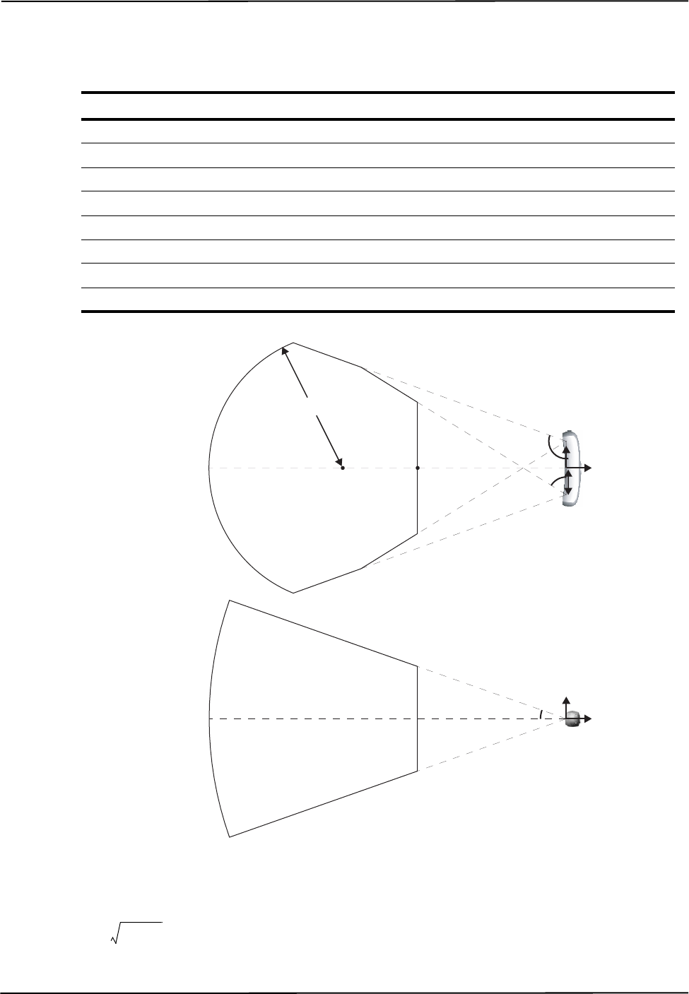
Commands
132 Polaris Application Program Interface Guide - Revision 5
Polaris Vicra System - Shape Parameters
<Shape Parameter> in reply option 03 returns the following values (illustrated in Figure 5-2):
Figure 5-1 Polaris Vicra Volume Parameters
The back curve of the volume is the “visible” section of the torus defined by the equation
. “Visible” means within the Position Sensor field of view, defined by
D1, D2, D3, and D4, for z < D8.
Shape Parameter Value Description
D1 100 mm Half baseline
D2 582.00º Outside volume angle - top view (scaled by 10)
D3 1099.00º Inside volume angle - top view (scaled by 10)
D4 194.00º Half volume angle - side view (scaled by 10)
D5 to D7 Reserved
D8 -830 mm z-coordinate centre of back curve
D9 506 mm Radius of back curve
D10 -557 mm z-coordinate of front of volume
D4
D9
D8 D10 D1
D2
D3
Top View
Side View
y
z
-x
z
D8 x2z2
––()y2
+D9
2
=
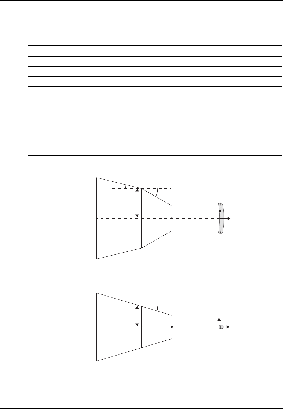
SFLIST
Polaris Application Program Interface Guide - Revision 5 133
Polaris Spectra System - Shape Parameters
For the pyramid measurement volume, <Shape Parameter> in reply option 03 returns the following
values (illustrated in Figure 5-2):
Figure 5-2 Pyramid Volume Parameters (Polaris Spectra)
Shape Parameter Value Description
D1 -2400 mm z-coordinate of back of volume
D2 -1532 mm z-coordinate where sides of volume change slope
D3 -950 mm z-coordinate of front of volume
D4 572 mm Half width of volume at z = D2
D5 398 mm Half height of volume z = D2
D6 0569.46 Slope of front part of volume sides in the yz-plane (scaled by 1000)
D7 0243.03 Slope of back part of volume sides in the yz-plane (scaled by 1000)
D8 0297.73 Slope of volume top and bottom in the xz-plane (scaled by 1000)
D9 9999.99 mm Maximum half width of volume (unrestricted)
D10 9999.99 mm Maximum half height of volume (unrestricted)
D1
Side View
D1
Top View
γ
D5
D8 = tan(γ) x 1000
D3
D2
D3D2
D4
βα
D6 = tan(α) x 1000
D7 = tan(β) x 1000
y
z
-x
z
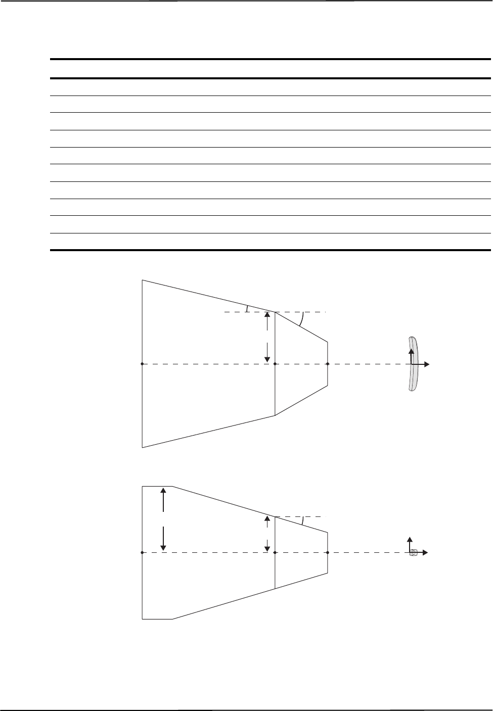
Commands
134 Polaris Application Program Interface Guide - Revision 5
For the extended pyramid measurement volume, <Shape Parameter> in reply option 03 returns the
following values (illustrated in Figure 5-3):
Figure 5-3 Extended Pyramid Volume Parameters (Polaris Spectra)
Shape Parameter Value Description
D1 -3000 mm z-coordinate of back of volume
D2 -1532 mm z-coordinate where sides of volume change slope
D3 -950 mm z-coordinate of front of volume
D4 572 mm Half width of volume at z = D2
D5 398 mm Half height of volume z = D2
D6 0569.46 Slope of front part of volume sides in the yz-plane (scaled by 1000)
D7 0243.03 Slope of back part of volume sides in the yz-plane (scaled by 1000)
D8 0297.73 Slope of volume top and bottom in the xz-plane (scaled by 1000)
D9 9999.99 mm Maximum half width of volume (unrestricted)
D10 735 mm Maximum half height of volume
D1
Side View
D1
Top View
D10 γ
D5
D8 = tan(γ) x 1000
D3
D2
D3D2
D4
βα
D6 = tan(α) x 1000
D7 = tan(β) x 1000
y
z
-x
z

SFLIST
Polaris Application Program Interface Guide - Revision 5 135
Usage Notes
1. Use both the shape type and the shape parameters to represent the characterized measurement
volume graphically. There may be multiple volumes with the same shape type. All volumes of
the same shape type use the shape parameters the same way.
2. Reply option 03: A characterized measurement volume that supports wavelength value 0
(930 nm) supports the wavelength values of 000 (9x0 nm) and 010 (930 nm) returned with
PHINF (page 91).
Examples
Command:
SFLIST
Reply:
0000003FEEEC
Command:
SFLIST 03
Reply:
17+010000+058200+109900+019400+000000+000000+000000-083000+050600-055700241D837
Number of Volumes
D2
D1
Shape Type
D3
D4
# of Wavelengths
Wavelength
D10
D6
D8
D7
D9
D5
CRC

Commands
136 Polaris Application Program Interface Guide - Revision 5
SSTAT
Returns the status of the system processors.
Operating Mode
All modes
Compatibility
All systems (deprecated)
Syntax
Syntax
SSTAT<SPACE><Reply Option><CR>
Replies
Upon Success:
<Reply Option 0001 Data><Reply Option 0002 Data><Reply Option 0004
Data><CRC16><CR>
On Error:
ERROR<Error Code><CRC16><CR>
See page 167 for error code definitions.
Reply Option 0001 - Control Processor Status
Parameter Description
Reply Option The reply options are hexadecimal numbers that can be OR'd. If multiple reply options
are used, the replies are returned in order of increasing option value.
Valid Values:
0001 Control processor status
0002 Left and right sensor processor status
0004 Tool Interface Unit processor status
Reply Component Description
Reply Option 0001 Data 2 hexadecimal characters (8 bits)
Bit field:
bits 0 to 7 Reserved

SSTAT
Polaris Application Program Interface Guide - Revision 5 137
Reply Option 0002 - Left and Right Sensor Processor Status
Reply Option 0004 - Tool Interface Unit Processor Status
Usage Notes
1. All status bits are persistent for as long as the system is turned on. They can only be cleared by a
serial break or reset.
2. If any of the bits indicate a failure, reset your system and then try SSTAT again. If the problem
persists, contact NDI.
Compatibility Notes
The SSTAT command has been deprecated for the Polaris Vicra and Polaris Spectra Systems. To
read the status of the Polaris Vicra or Polaris Spectra System, use the command GET (page 66) to
read the user parameter Info.Status.Alerts.
Example
Command:
SSTAT 0001
Reply:
001414
Reply Component Description
Reply Option 0002 Data 2 hexadecimal characters (8 bits)
Bit field:
bit 0 to 7 Reserved
Reply Component Description
Reply Option 0004 Data 2 hexadecimal characters (8 bits)
Bit field:
bit 0 to 7 Reserved

Commands
138 Polaris Application Program Interface Guide - Revision 5
SYSLOG
Writes data to the Position Sensor or System Control Unit log file.
Operating Mode
All modes
Compatibility
All systems
Syntax
SYSLOG<SPACE>\<Device Name>\<Category>=<Message><CR>
(API revision G.001.004 or later)
or
SYSLOG<SPACE><Category>=<Message><CR>
(API revision G.001.003 or earlier)
Replies
Upon Success:
OKAY<CRC16><CR>
On Error:
ERROR<Error Code><CRC16><CR>
See page 167 for error code definitions.
Usage Notes
1. The system log in each hardware device can store up to 100 Kbytes of data. It is intended to
record events central to the life of the device. The system automatically records events such as
firmware updates, bump sensor events, and hardware faults in the log.
2. To read the log, use GETLOG (page 74).
Parameter Description
Device
Name
Selects a hardware device to write to. See “Device Names” on page 21 for information on
device names.
Category A string, up to 12 characters
Specifies the log entry category or source. If you enter more than 12 characters, the system
will truncate the category to 12 characters.
Message A string, up to 256 characters.
Contains the log message. If you enter more than 256 characters, the system will truncate the
message to 256 characters.

SYSLOG
Polaris Application Program Interface Guide - Revision 5 139
Compatibility Notes
For passive systems, only the Position Sensor log file is available.
Example
Command:
SYSLOG \SCU-0\Test=This is a SYSLOG test!
Reply:
OKAYA896

Commands
140 Polaris Application Program Interface Guide - Revision 5
TCTST
Returns diagnostics on the active markers of a wired tool.
Operating Mode
Setup
Compatibility
hybrid Polaris Spectra System
Prerequisite Command
INIT (page 78)
Syntax
TCTST<SPACE><Port Handle><CR>
Replies
Upon success:
<Marker A Current><Marker B Current>...<Marker T Current><CRC16><CR>
On Error:
ERROR<Error Code><CRC16><CR>
See page 167 for error code definitions.
Usage Notes
1. If the result is less than 0x0A either there is no marker, or there is a problem with the diode that
has caused an open circuit.
2. If the result is greater than 0x0A the marker is either okay or it has short-circuited. The exact
value cannot be predicted as it depends upon the System Control Unit and the tool design (cable
length, number of markers, and marker configuration). This value should be determined on a
historical basis for each particular tool design.
3. You cannot test a visible LED, since the System Control Unit cannot reliably test the low current
of an LED because the LED current result may be corrupted from electrical noise.
Parameter Description
Port Handle 2 hexadecimal characters
Reply Component Description
Marker n Current 2 hexadecimal characters
The electrical current of the markers.

TCTST
Polaris Application Program Interface Guide - Revision 5 141
Compatibility Notes
The TCTST is fully compatible with the hybrid Polaris Spectra System.
Example
Command:
TCTST 01
Reply:
9400000000940100000092000000009400000000DF24

Commands
142 Polaris Application Program Interface Guide - Revision 5
TSTART
Starts Tracking mode.
Operating Mode
Setup
Compatibility
All systems
Prerequisite Command
INIT (page 78)
Syntax
TSTART<SPACE><Reply Option><CR>
Replies
Upon Success:
OKAY<CRC16><CR>
On Error:
ERROR<Error Code><CRC16><CR>
See page 167 for error code definitions.
Usage Notes
If the reply option 80 is not used, only resetting the system resets the counter for the frame number.
The frame number is reported in reply option 0001 of the TX (page 146) and BX (page 47)
commands.
Example
Command:
TSTART
Reply:
OKAYA896
Parameter Description
Reply Option 80 (Optional, resets the frame counter to zero)

TSTOP
Polaris Application Program Interface Guide - Revision 5 143
TSTOP
Stops tracking mode.
Operating Mode
Tracking
Compatibility
All systems
Prerequisite Command
TSTART (page 142)
Syntax
TSTOP<SPACE><CR>
Replies
Upon Success:
OKAY<CRC16><CR>
On Error:
ERROR<Error Code><CRC16><CR>
See page 167 for error code definitions.
Example
Command:
TSTOP
Reply:
OKAYA896

Commands
144 Polaris Application Program Interface Guide - Revision 5
TTCFG
Sets up a configuration for a wired tool, so that you can test the tool without using a tool definition
file.
Operating Mode
Setup
Compatibility
hybrid Polaris Spectra System
Prerequisite Command
INIT (page 78)
Syntax
TTCFG<SPACE><Port Handle><CR>
Replies
Upon Success:
OKAY<CRC16><CR>
On Error:
ERROR<Error Code><CRC16><CR>
See page 167 for error code definitions.
Usage Notes
1. TTCFG internally sets up a test configuration for a wired tool, so that it can be tested without
having a tool definition file. This is useful for testing the wiring in the tool before characterizing
the tool. For example, after sending TTCFG, you can:
• use TCTST to test the current
• in diagnostic mode, use IRED to individually activate the markers.
2. After sending the TTCFG command, you will need to initialize (PINIT) and enable (PENA) the
port handle before using any other commands that list these as prerequisites.
3. With the test configuration, the tool cannot be tracked.
Compatibility Notes
The TTCFG command is compatible with the hybrid Polaris Spectra System.
Parameter Description
Port Handle 2 hexadecimal characters

TTCFG
Polaris Application Program Interface Guide - Revision 5 145
Example
Command:
TTCFG 0A
Reply:
OKAYA896

Commands
146 Polaris Application Program Interface Guide - Revision 5
TX
Returns the latest tool transformations, individual marker positions, and system status in text format.
Operating Mode
Tracking
Compatibility
All systems
Syntax
TX<SPACE><Reply Option><CR>
Replies
Upon Success:
<# of Handles><Handle 1><Reply Opt 0001 Data>...<Reply Opt 0008 Data><LF>
...
<Handle n><Reply Option 0001 Data>...<Reply Option 0008 Data><LF>
<Reply Option 1000 Data><System Status><CRC16><CR>
Note If the port handle is disabled, the system returns the string DISABLED instead of
<Reply Option 0001 Data>...<Reply Option 0008 Data>.
Parameter Description
G.001.002
G.001.003
G.001.004
G.001.005
Reply
Option
Optional. Specifies which information will be returned. If no reply option
is specified, the system returns information for reply option 0001.
The reply options are hexadecimal numbers that can be OR’d. If multiple
reply options are used, the replies are returned for each port handle in
order of increasing option value, with the following exceptions:
Reply option 0800 is not reported separately from the other options; it sim-
ply enables the system to return certain information in the other options.
Reply option 1000 is reported after all handle-specific options but before
the <system status> and <CRC16>.
Valid Values:
0001 Transformation data (default) X X X X
0002 Tool and marker information X X X X
0004 3D position of a single stray active marker X X
0008 3D positions of markers on tools X X X X
0800 Transformations not normally reported X X X X
1000 3D positions of stray passive markers X X X X

TX
Polaris Application Program Interface Guide - Revision 5 147
On Error:
ERROR<Error Code><CRC16><CR>
See page 167 for error code definitions.
Note The “diagnostic pending” bit is set whenever an alert is detected or cleared. To view the alerts status and clear
the diagnositc pending bit, use GET (page 66) to check the Info.Status.New Alerts user parameter for every
hardware device in the system. See “Usage Notes” on page 56 for more details. (Note: For API revision G.001.003
and earlier, the diagnostic pending bit did not indicate when an alert was cleared.)
Reply
Component Description
G.001.002
G.001.003
G.001.004
G.001.005
Number of
Handles
2 hexadecimal characters
The number of port handles for which information is returned.
XXXX
Handle n 2 hexadecimal characters
The port handle whose information follows.
XXXX
Reply
Option m
Data
The data specific to the requested reply option. See the reply option
information below for details:
Reply option 0001 (transformation data) (default) XXXX
Reply option 0002 (tool and marker information) XXXX
Reply option 0004 (latest 3D position of single, stray, active marker) XX
Reply option 0008 (3D position of markers on tools) XXXX
Reply option 0800 (reporting all transformations) XXXX
Reply option 1000 (3D position of stray passive markers) XXXX
System
Status
4 hexadecimal characters (16 bits)
The status of the system.
Bit field:
bit 0 System communication synchronization error XXXX
bits 1 and 2 Reserved
bit 3 Recoverable system processing exception. XXXX
bits 4 and 5 Reserved
bit 6 Some port handle has become occupied XX
bit 7 Some port handle has become unoccupied XX
bit 8 Diagnostic pending XXXX
bit 9 Temperature (system is not within operating temper-
ature range)
XXXX
bits 10 to 15 Reserved

Commands
148 Polaris Application Program Interface Guide - Revision 5
Reply Option 0001 - Transformation Data
<Reply Option 0001 Data> = <Q0><Qx><Qy><Qz><Tx><Ty><Tz><Error><Port Status>
<Frame Number>
or
<Reply Option 0001 Data> = MISSING<Port Status><Frame Number>
Reply
Component Description
G.001.002
G.001.003
G.001.004
G.001.005
Q0, Qx, Qy,
Qz
6 characters each
(a sign, and 5 decimal digits with an implied decimal in the posi-
tion X . XXXX)
Rotational component of the transformation, quaternion, unitless.
The value for Q0 is always non-negative.
XXXX
Tx, Ty, Tz 7 characters each
(a sign, and 6 decimal digits with an implied decimal in the posi-
tion XXXX . XX)
Translational components of the transformation, in mm.
XXXX
Error 6 characters
(a sign, and 5 decimal digits with an implied decimal in the posi-
tion X . XXXX)
The error is an RMS value, given in mm. It is the result of the least
squares minimization between the marker geometry in the tool def-
inition file and the data from the tool’s markers measured by the
system.
XXXX

TX
Polaris Application Program Interface Guide - Revision 5 149
Note The system returns the string MISSING, followed by the port status and frame number, in the following situations:
- Tools are reported as missing if a transformation cannot be determined.
- GPIO devices and strober port handles that are initialized and enabled are reported as missing.
- In the event of a system error that prevents tracking, all tools and GPIO devices are reported as missing.
Port Status 8 hexadecimal characters (32 bits)
Bit field:
bit 0 Occupied X X X X
bit 1 Switch 1 closed/GPIO line 1 active X X
bit 2 Switch 2 closed/GPIO line 2 active X X
bit 3 Switch 3 closed/GPIO line 3 active X X
bit 4 Initialized X X X X
bit 5 Enabled X X X X
bit 6 Out of volume X X X X
bit 7 Partially out of volume X X X X
bit 8 Algorithm limitation (processing requires more
buffer than is available) XXXX
bit 9 IR interference (a large bright IR object) X X X X
bits 10 and 11 Reserved
bit 12 Processing exception (same as tool information bit
7 in reply option 0002) XXXX
bit 13 Reserved
bit 14 Fell behind while processing (same as tool infor-
mation bit 3 in reply option 0002)XXXX
bit 15 Data buffer limitation (too much data; for example,
too many markers) XXXX
bits 16 to 31 Reserved
Frame Number 8 hexadecimal characters
The frame number is an internal counter related to data acquisition.
The counter starts at power up and does not reset until the system is
reset (either with RESET or a serial break), the system is powered
up again, or reply option 80 is sent with the TSTART command.
The frame number corresponds to the frame in which the raw data,
used to calculate the accompanying transformation, was collected.
XXXX
Reply
Component Description
G.001.002
G.001.003
G.001.004
G.001.005

Commands
150 Polaris Application Program Interface Guide - Revision 5
Reply Option 0002 - Tool and Marker Information
<Reply Option 0002 Data> = <Tool Information><Marker Information>
Example - Marker Information: A tool with markers located at T, R, C, and A, where all four markers
were used to determine the calculation, would have the reply 30300000000000000303, as
illustrated:
Reply Option 0004 - 3D Position of Single Stray Active Marker
<Reply Option 0004 Data> = <Status><Tx><Ty><Tz>
Reply
Component Description
G.001.002
G.001.003
G.001.004
G.001.005
Tool
Information
2 hexadecimal characters (8 bits)
Bit field:
bit 0 Bad transformation fit X X X X
bit 1 Not enough acceptable markers for transformation X X X X
bit 2 IR interference—environmental IR is interfering with
the system (combination of port status bits 9 and 15 in
reply option 0001)
XXXX
bit 3 Fell behind while processing (same as port status bit 14
in reply option 0001)XXXX
bits 4 to 6 Tool face used X X X X
bit 7 Processing exception (same as port status bit 12 in
reply option 0001) XXXX
Marker
Information
20 hexadecimal characters (1 per marker)
See below for an example.
Possible Values:
0 Not used because it was missing X X X X
1 Not used because it exceeded the maximum marker
angle XXXX
2 Not used because it exceeded the maximum 3D error
for the tool XXXX
3 Used to calculate the transformation X X X X
4 Used to calculate the transformation, but it is out of
volume XXXX
5 Not used because it was outside the characterized
measurement volume and was not needed to calculate
a transformation.
XXXX
Marker Letter T S R Q ... D C B A
Reply Char (Hex) 3 0 3 0 ... 0 3 0 3

TX
Polaris Application Program Interface Guide - Revision 5 151
or
<Reply Option 0004 Data> = <Status>
Note If no stray active marker is defined (for example, for wireless port handles, GPIO devices, or strobers, or wired
tools with no stray marker defined in the tool definition file), the status is 00, and no position information is
returned. If the marker is missing, or if the marker is out of volume and reply option 0800 is not used, the system
returns only the status.
Reply Component Description
G.001.002
G.001.003
G.001.004
G.001.005
Status 2 hexadecimal characters (8 bits)
The status of the stray active marker. A stray marker on an active
tool is not fixed with respect to the other markers that make up the
tool.
Bit field:
bit 0 Valid stray active marker X X
bit 1 Marker is missing X X
bit 2 Reserved
bit 3 Marker is out of volume X X
bits 4 to 7 Reserved
Tx, Ty, Tz 7 characters each
(a sign, and 6 decimal digits with an implied decimal in the posi-
tion XXXX . XX)
Position of the marker, reported in the coordinate system of the
Position Sensor. The marker position is reported only if the
marker status is “valid,” or if the status is “out of volume” and
reply option 0800 is used.
XX

Commands
152 Polaris Application Program Interface Guide - Revision 5
Reply Option 0008 - 3D Position of Markers on Tools
<Reply Option 0008 Data> = <Number of Markers><Out of
Volume><Txn><Tyn><Tzn>
Example - Out of Volume: The information is returned in the format illustrated in the following
example: one bit per marker, in little endian format. In this example there are nine markers, all of
which are out of volume:
Reply Component Description
G.001.002
G.001.003
G.001.004
G.001.005
Number of
Markers
2 hexadecimal characters
Number of markers used in tool transformations.
XXXX
Out of Volume 1 hexadecimal character per 4 markers (1 bit per marker)
The bit is set when the marker is outside the characterized meas-
urement volume (see example below).
Reply size = (number of markers)/4, rounded up to the nearest
integer.
XXXX
Txn, Tyn, and
Tzn
7 characters each
(a sign, and 6 decimal digits with an implied decimal in the posi-
tion XXXX . XX)
Position of the nth marker, reported in the coordinate system of
the Position Sensor. The system will report the positions of
markers used in tool transformations, as well as markers that
exceeded the maximum marker angle or maximum 3D error
specified in the tool definition file.
See “Usage Notes” on page 155 for more information.
Reply size:
If reply option 0800 is not used, reply size = (21 characters) x
(number of markers inside the characterized measurement vol-
ume).
If reply option 0800 is used, reply size = (21 characters) x (total
number of markers).
XXXX
Marker Number 987654321
Bit Field 000111111111
Reply 1FF

TX
Polaris Application Program Interface Guide - Revision 5 153
Reply Option 0800 - Reporting All Transformations
This option enables the reporting of transformations or translations in situations where translations
or transformations are calculated, but by default are not reported by the system. Such situations
include:
• The tool or marker is outside of the characterized measurement volume.
• The bump sensor has been tripped.
• The system is outside of the optimal operating temperature range.
• Other system conditions are not ideal; see “Alerts User Parameters” on page 23 for a full list
of these conditions.
This reply option must be OR’d with reply option 0001 to obtain transformations for tools in the
situations listed above. It must be OR’d with reply options 0004, 0008, or 1000 to obtain position
information for markers in the situations listed above.
When using reply option 0800 with the TX command, you must take appropriate action to detect the events listed
above, and determine whether they are detrimental to your application. If one or more of the events listed above
occurs, reply option 0800 enables the system to return data that may lead to inaccurate conclusions and may
cause personal injury.
Appropriate action to detect the events listed above includes:
• reading the out-of-volume flag in reply options 0001 and 0002 when tracking tools
• reading the out-of-volume information in reply options 0004, 0008, and 1000 when tracking
stray markers
• reading the temperature flag in the system status
• reading the diagnostic pending bit in the system status
• reading the Info.Status.New Alerts user parameter for every hardware device in the system
when the diagnostic pending bit is set. See “Usage Notes” on page 155 for details.
Warning!

Commands
154 Polaris Application Program Interface Guide - Revision 5
Reply Option 1000 - 3D Position of up to 50 Stray Passive Markers
<Reply Option 1000 Data> = <Number of Markers><Out of
Volume><Txn><Tyn><Tzn>
Note At least one passive port handle must be enabled, to activate the illuminators on the Position Sensor. If no
passive port handles are enabled, <Number of Markers> will return 00 and no other data will be returned.
Stray passive markers are defined as markers which are not used to calculate any of the
transformations for any enabled, passive tools. Stray active wireless tool markers are not reported.
Example - Out of Volume The information is returned in the format illustrated in the following
example: one bit per marker, in little endian format. In this example there are nine markers, all of
which are out of volume:
Reply Component Description
G.001.002
G.001.003
G.001.004
G.001.005
Number of
Markers
2 hexadecimal characters
Number of stray markers.
XXXX
Out of Volume 1 hexadecimal character per 4 markers (1 bit per marker)
The bit is set when the marker is outside the characterized meas-
urement volume (see example below).
Reply size = (number of markers)/4, rounded up to the nearest
integer.
XXXX
Txn, Tyn, Tzn 7 characters each
(a sign, and 6 decimal digits with an implied decimal in the posi-
tion XXXX . XX)
Position of the nth marker, reported in the coordinate system of
the Position Sensor.
Reply size:
If reply option 0800 is not used, reply size = (21 characters) x
(number of markers inside the characterized measurement vol-
ume).
If reply option 0800 is used, reply size = (21 characters) x (total
number of markers).
XXXX
Marker Number 987654321
Bit Field 000111111111
Reply 1FF

TX
Polaris Application Program Interface Guide - Revision 5 155
Usage Notes
1. The TX format is easier to parse than the binary format; it is useful when troubleshooting, or
observing data as it is collected. For replies in binary format, use BX (page 47).
2. By default, transformations will not be reported if the tool is either partially or wholly out of the
characterized measurement volume, if the bump sensor has been tripped, or if the system is
outside of the optimal operating temperature range. To report these transformations, you must
use reply option 0800 OR’d with the desired reply option(s). The accuracy of these
transformations is unknown.
3. Reply Option 0001:
• When the “diagnostic pending” bit is set in the system status, use GET (page 66) to read the
Info.Status.New Alerts user parameter for every hardware device in the system. The act of
reading these parameters clears the parameters and the “diagnostic pending” bit. For more
information on alerts and their associated user parameters, see “Alerts User Parameters” on
page 23.
• For wired tools, bits 1, 2, and 3 in the port status report switch status. For GPIO devices,
these bits report the status of GPIO lines defined as inputs.
4. Reply Option 0008: Markers are returned in alphabetical order according to how they are
labelled in the tool definition file. For example, for a tool with markers labelled A, G, M and S,
the system will return the marker positions in the order A G M S. Reply option 0008 only
returns data for markers that the system detects. To identify which marker is which, compare the
reply option 0008 data to the data returned with reply option 0002. The marker order is the same
for both replies; each marker that does not have a <marker information> status of 0 (“missing”)
in reply option 0002 corresponds to a marker in reply option 0008
5. Reply Option 1000: At least one passive tool definition file must be initialized and enabled in
order for the system to return stray passive marker data. If no passive tool definition files are
enabled, this reply option will return 00.
Compatibility Notes
1. System Status:
• In API revision G.001.004 and later, the diagnostic pending bit (bit 8) is set whenever an
alert is detected or cleared. In API revision G.001.003 and earlier, the diagnostic pending bit
is set only when an alert is detected.
2. Reply Option 0002:
• Marker information value 2 means that the marker was not used because it exceeded the
maximum 3D error for the tool.
Examples
Example 1
Command:
TX 0001

Commands
156 Polaris Application Program Interface Guide - Revision 5
Reply:
The system reports that there is one tool, which is missing. Notice the port status, which indicates
that the tool is occupied, initialized, enabled, and out of volume.
Example 2
Command:
TX 0801
Reply:
With the 0800 reply option applied, the system reports the missing tool. Notice the port status, which
indicates that the tool is occupied, initialized, enabled, and out of volume.
# of Handles
Handle Number
Port Status
Frame Number
System Status
CRC
0102MISSING0000007100002211
0000D2A5
# of Handles
qz
tx
Handle Number
ty
Port Status
Frame Number
tz
Error
qy
qx
q0
System Status
CRC
0102+08126+02988-02040+04568-031514+043184-117696+02981000000710000227A
00003F84

TX
Polaris Application Program Interface Guide - Revision 5 157
Example 3
Command:
TX 0001
Reply:
The system reports that there is one tool, whose port handle is disabled. It also reports the system
status.
Example 4
Command:
TX 1001
Reply:
The system reports the transformation for one tool (first line of the reply), and the positions of three
stray passive markers (second line of the reply).
# of Handles
Handle Number
System Status
CRC
0101DISABLED
000001C5
# of Handles
qz
tx
Handle Number
ty
Port Status
Frame Number
tz
Error
qy
qx
q0
# of markers
Out of Volume
tx1
ty1
tz1
tx2
ty2
tz2
tx3
ty3
tz3
System Status
CRC
0101+08565-01538-04254+02481-006263+027579-099121+020540000003100000368
030-005386+033057-098807-003108+036484-095986-000609+040221-0928270000D105

Commands
158 Polaris Application Program Interface Guide - Revision 5
VER
Returns the firmware revision number of critical processors installed in the system.
Operating Mode
Setup
Compatibility
All systems
Syntax
VER<SPACE><Reply Option><CR>
Replies
Upon Success:
Reply Options 0 to 4, and 6:
<Type of Firmware><LF>
<NDI Serial Number><LF>
<Characterization Date><LF> (included only for Reply Option 0 and 4)
<Freeze Tag><LF>
<Freeze Date><LF>
Parameter Description
G.001.002
G.001.003
G.001.004
G.001.005
Reply Option Specifies which information will be returned.
The reply options cannot be OR'd.
Valid Values:
0 System Control Processor (Position Sensor) X X X X
1 Reserved
2 Reserved
3 System Control Unit Processor X X
4 System Control Processor (Position Sensor), with enhanced revi-
sion numbering.
The revision numbering is XXX.YYY, where XXX = major revi-
sion and YYY = minor revision. The major revision number is
always the same as the revision number for parameter value 0.
XXXX
5 Combined firmware revision number.
The revision numbering format is XXX. Only the number is
reported; there is no information about the type of system.
****
6 Reserved

VER
Polaris Application Program Interface Guide - Revision 5 159
<Copyright Information><LF>
<CRC16><CR>
Reply Option 5:
<Combined Firmware Revision><CRC16><CR>
On Error:
ERROR<Error Code><CRC16><CR>
See page 167 for error code definitions.
Usage Notes
1. If you send the command VER 5 after the INIT command has replied with ERROR2E, the reply
will be “???”, because component versions are incompatible.
Compatibility Notes
1. You can also obtain the combined firmware revision of the system by using the command GET
(page 66) to read the value of the user parameter Config.Combined Firmware Revision. See
“User Parameters” on page 20 for more information on user parameters.
2. Reply Options 3: Is not supported by passive systems. For Polaris Spectra, the second line of
the response is the serial number of the System Control Unit.
Examples
Command:
VER 4
Reply:
Polaris Spectra Control Firmware
NDI S/N: P7-00733
Characterization Date: 06/04/08
Freeze Tag: Polaris Spectra Rev 006.001
Freeze Date: 03/26/08
(C) Northern Digital Inc.
4923
Command:
VER 5
Reply:
0124A94

Commands
160 Polaris Application Program Interface Guide - Revision 5
VGET
The VGET command retrieves data previously captured with VSNAP (page 165).
Operating Mode
All modes
Compatibility
All systems
Prerequisite Command
VSNAP (page 165)
Syntax
VGET<SPACE><Row><Sensor><Frame Index><Start Column><End
Column><Stride><CR>
Parameter Description
Row 4 hexadecimal characters
Specifies the row of data to retrieve.
Valid Values:
0 to the value of the user parameter Cmd.VGet.Sensor.Height - 1.
Sensor 2 hexadecimal characters
Specifies which sensor’s data to return.
Valid values:
0 Left sensor
1 Right sensor
Frame Index 2 hexadecimal characters
The index into the array of frames captured by the VSNAP (page 165) command. Speci-
fies which frame’s data to return. The frame index is zero-based.
The tool class for each frame is returned in the VSNAP reply; to retrieve information for
a particular tool class, use the frame index for that frame returned in the VSNAP reply.
Start Column 4 hexadecimal characters
Indicates the first column to retrieve. Optional (see “Usage Notes” on page 162).
Valid Values:
0 to the value of the user parameter Cmd.VGet.Sensor.Width - 1.

VGET
Polaris Application Program Interface Guide - Revision 5 161
Replies
Upon Success:
<Header><Length><HeaderCRC><Data><DataCRC>
Note The reply for the VGET command is binary data.
On Error:
ERROR<Error Code><CRC16><CR>
See page 167 for error code definitions.
End Column 4 hexadecimal characters
Indicates the first column to retrieve. Optional (see “Usage Notes” on page 162).
Valid Values:
0 to the value of the user parameter Cmd.VGet.Sensor.Width - 1.
Stride 2 hexadecimal characters
Indicates the stride count to use from start to end column. A lower stride count results in
a higher resolution. The stride options are described in “Usage Notes” on page 162. To
specify which stride option to use, set the value of the user parameter Cmd.VGet.Sam-
ple Option. Optional (see “Usage Notes” on page 162).
Parameter Description
Reply Component Description
Header 2 bytes: A5C4
Indicates the start of the VGET reply.
Length 2 bytes
Indicates data length.
Header CRC 2 bytes
CRC16 for header.
Data Up to 2048 bytes of binary data. The data is a sequence of greyscale pixel intensities.
The intensity for each pixel is given by x bits of data, where x is the value of the user
parameter Cmd.VGet.Color Depth (see “Usage Notes” on page 162). A pixel inten-
sity of 0 is black, and an intensity of 2x-1 is white.
DataCRC 2 bytes
CRC16 of the <Data> section.

Commands
162 Polaris Application Program Interface Guide - Revision 5
Usage Notes
1. The VGET command retrieves one row of data. To retrieve an entire image, use a sequence of
VGET commands. For a lower resolution image, retrieve fewer rows.
2. To use the VGET command, the data bits must be set to 0 (8 bits) using COMM (page 58).
3. Replies are returned in little endian format.
4. The parameters <Start Column>, <End Column>, and <Stride> are optional. You can instead set
the values of the user parameters Cmd.VGet.Start X, Cmd.VGet.End X, and
Cmd.VGet.Stride for the start column, end column, and stride, respectively.
5. A lower stride count results in a higher resolution. To specify the stride option to use, set the
value of the user parameter Cmd.VGet.Sample Option. Options are as follows:
• Point (Cmd.VGet.Sample Option = 0): For a stride of n, returns every nth pixel.
• Average (Cmd.VGet.Sample Option = 1): For a stride of n, returns the average of the n
pixels.
• Peak (Cmd.VGet.Sample Option = 2): For a stride of n, returns the maximum value of the n
pixels.
6. To adjust the number of bits per pixel returned, set the value of the user parameter
Cmd.VGet.Color Depth. A higher value results in higher picture quality and longer reply
length.
7. For diagnostic purposes, it may be helpful to colour-code the image data according to the
internal thresholds used by the system. Since these thresholds are dynamic and vary with
exposure time and other factors, they have to be retrieved individually for each frame. To
determine the threshold values:
a) Set the value of the user parameter Cmd.VGet.Threshold.Shutter Time to the exposure
time for the frame and sensor whose threshold you wish to determine. The exposure time is
returned in the VSNAP response.
b) Read the value of the user parameter Cmd.VGet.Threshold.Trigger. This value is a
function of the exposure time and the sensitivity level (described in the user guide). In order
for a marker to be detected by the system, at least on pixel must exceed this threshold.
c) Read the value of the user parameter Cmd.VGet.Threshold.Background. Ideally only
markers exceed this threshold.
8. To read user parameter values, use GET (page 66). To set user parameter values, use SET
(page 125). For more information on user parameters, see “User Parameters” on page 20.
Example
Command:
VGET 000100010010002001

VSEL
Polaris Application Program Interface Guide - Revision 5 163
VSEL
Selects a characterized measurement volume.
Operating Mode
Setup
Compatibility
All systems (deprecated)
Prerequisite Command
INIT (page 78)
Syntax
VSEL<SPACE><Volume Number><CR>
Replies
Upon Success:
OKAY<CRC16><CR>
On Error:
ERROR<Error Code><CRC16><CR>
See page 167 for error code definitions.
Usage Notes
Use SFLIST (page 129) to determine which measurement volumes are available.
Compatibility Notes
The VSEL command has been deprecated for the Polaris Vicra and Polaris Spectra Systems. To
select a measurement volume for the Polaris Vicra or Polaris Spectra System, use the command SET
(page 125) to set the user parameter Param.Tracking.Selected Volume.
Parameter Description
Volume Number 1 hexadecimal character
Possible Values:
1 to the maximum returned by SFLIST (page 129)

Commands
164 Polaris Application Program Interface Guide - Revision 5
Example
Command:
VSEL 1
Reply:
OKAYA896

VSNAP
Polaris Application Program Interface Guide - Revision 5 165
VSNAP
Captures one complete sequence of video data from the sensors. (See the “Usage Notes” on
page 166 for details.)
Operating Mode
Diagnostic, Tracking
Compatibility
All systems
Syntax
VSNAP<SPACE><CR>
Replies
Upon Success:
<Frame Number><Number of Frames><Number of Sensors>
<Frame 0 Type><Frame 0 Exposure Time 0><Frame 0 Exposure Time 1>...
<Frame 1 Type><Frame 1 Exposure Time 0><Frame 1 Exposure Time 1>...
...
<CRC16><CR>
On Error:
ERROR<Error Code><CRC16><CR>
See page 167 for error code definitions.
Reply Component Description
Frame Number 8 hexadecimal characters
The frame number of the first frame in the sequence
Number of
Frames
2 hexadecimal characters
The number of frames in the sequence
Number of
Sensors
2 hexadecimal characters
The number of sensors for each frame. This is always 2.
Frame n Type 2 hexadecimal characters
The tool class of frame n. The list of possible values is reported as the enumeration
list in user parameter Cmd.VSnap.Frame Types. (See GETINFO (page 68) for
details on reading the enumeration list of a user parameter.) A value of 0F indicates
a frame that is used only for timing purposes, and contains no useful data.

Commands
166 Polaris Application Program Interface Guide - Revision 5
Usage Notes
1. The VSNAP command captures one complete sequence of video data from the sensors. The
captured data is stored in internal memory; to retrieve the data, use VGET (page 160). A
complete sequence of data consists of the following frames:
• A frame for each type of tool loaded (passive or active wireless). This allows you to see
exactly what the Position Sensor detects while it is tracking.
• An illuminated frame (illuminators are activated), if the user parameter
Cmd.VSnap.Illuminated Frame is enabled (set to 1). This allows you to detect any
infrared light sources caused by reflections.
• A background frame (illuminators are off), if the user parameter
Cmd.VSnap.Background Frame is enabled (set to 1). This allows you to detect any
environmental infrared light.
Note The “Cmd.VSnap.Illuminated Frame” and “Cmd.VSnap.Background Frame” user parameters can only be set
when the system is in Setup mode.
2. The exposure time (the amount of time during which the sensors collect light) for the
illuminated and background frames is the value of the user parameter
Cmd.VSnap.Manual Shutter.
3. To read user parameter values, use GET (page 66). To set user parameter values, use SET
(page 125). For more information on user parameters, see “User Parameters” on page 20.
Example
Command:
VSNAP
Reply:
Frame n
Exposure Time m
4 hexadecimal characters
The exposure time of the mth sensor in µsec. Sensor 0 is the left sensor and sensor 1
is the right sensor, from the point of view of the Position Sensor.
Reply Component Description
00000D9C03020208070807040FFB0FFB050FFB0FFB1263
Frame Number
CRC
Frame0 Type
Number of Sensors
Number of Frames
Frame0 Exp Time1
Frame0 Exp Time2
Frame2 Exp Time1
Frame1 Exp Time1
Frame2 Type
Frame1 Exp Time2
Frame2 Exp Time0
Frame1 Type

Error and Warning Code Definitions
Polaris Application Program Interface Guide - Revision 5 167
6 Error and Warning Code Definitions
6.1 Error Code Definitions
If the system receives an invalid command, it responds to the host with the message
ERROR<Error Code>. Table 6-1 identifies the error codes and their definitions.
Table 6-1 Error Code Definitions
Error
Code Definition
01 Invalid command.
02 Command too long.
03 Command too short.
04 Invalid CRC calculated for command; calculated CRC does not match the one sent.
05 Time-out on command execution.
06 Unable to set up new communication parameters. This occurs if one of the
communication parameters is out of range.
07 Incorrect number of parameters.
08 Invalid port handle selected.
09 Invalid mode selected. Either the tracking priority is out of range, or an incorrect priority
was selected (e.g. the tool has markers defined and “button box” was selected).
0A Invalid LED selected. The LED selected is out of range.
0B Invalid LED state selected. The LED state selected is out of range.
0C Command is invalid while in the current mode.
0D No tool is assigned to the selected port handle.
0E Selected port handle not initialized. The port handle needs to be initialized before the
command is sent.
0F Selected port handle not enabled. The port handle needs to be enabled before the
command is sent.
10 System not initialized. The system must be initialized before the command is sent.
11 Unable to stop tracking. This occurs if there are hardware problems. Please contact NDI.
12 Unable to start tracking. This occurs if there are hardware problems. Please contact NDI.
13 Hardware error: unable to read the SROM device.
14 Invalid Position Sensor characterization parameters.
15 Unable to initialize the system. This occurs if:
• the system could not return to Setup mode
• there are internal hardware problems. Please contact NDI.
• there are internal parameter errors. Use GET to read the Info.Status.Alerts
parameter for more details.

Error and Warning Code Definitions
168 Polaris Application Program Interface Guide - Revision 5
16 Unable to start Diagnostic mode. This occurs if there are hardware problems. Please
contact NDI.
17 Unable to stop Diagnostic mode. This occurs if there are hardware problems. Please
contact NDI.
18 Reserved
19 Unable to read device's firmware version information. This occurs if:
• the processor selected is out of range
• the system is unable to inquire firmware version information from a processor
1A Internal system error. This occurs when the system is unable to recover after:
•too much IR
• a system processing exception
1B Reserved
1C Unable to set marker activation signature.
1D Unable to find SROM device IDs.
1E Unable to read SROM device data. This occurs if the system is:
• unable to auto-select the first SROM device on the given port handle as a target to
read from
• unable to read a page of SROM device data successfully
1F Unable to write SROM device data. This can occur if:
• the system is unable to auto-select the first SROM device on the given port handle as
a target for writing to
• an SROM device on the given port handle has not previously been selected with the
PSEL command as a target to write to
• the system is unable to write a page of SROM device data successfully
20 Unable to select SROM device for given port handle and SROM device ID.
21 Unable to test electrical current on tool.
22 Enabled tools are not supported by selected volume parameters. For example, a Position
Sensor cannot track a tool if the volume parameter set does not include the marker
wavelength of an enabled tool.
23 Command parameter is out of range.
24 Unable to select measurement volume. This occurs if:
• the selected volume is not available
• there are internal hardware errors. Please contact NDI.
25 Unable to determine the system’s supported features list. This occurs if the system is
unable to read all the hardware information.
26-27 Reserved
28 Too many tools are enabled, or the configuration of tools loaded requires too many
frames.
Table 6-1 Error Code Definitions (Continued)
Error
Code Definition

Error and Warning Code Definitions
Polaris Application Program Interface Guide - Revision 5 169
29 Reserved
2A No memory is available for dynamic allocation (heap is full).
2B The requested port handle has not been allocated.
2C The requested port handle has become unoccupied.
2D All handles have been allocated.
2E Incompatible firmware versions. This can occur if:
• a firmware update failed
• components with incompatible firmware are connected
To correct the problem, update the firmware. If the Multi Firmware feature is installed,
select a valid combined firmware revision.
2F Invalid port description.
30 Requested port is already assigned a port handle.
31 Invalid input or output state.
32 Invalid operation for the device associated with the specified port handle.
33 Feature not available.
34 User parameter does not exist.
35 Invalid value type (e.g. string instead of integer).
36 User parameter value set is out of valid range.
37 User parameter array index is out of valid range.
38 User parameter size is incorrect.
39 Permission denied; file or user parameter is read-only.
3A Reserved
3B File not found.
3C Error writing to file.
3D-3F Reserved
40 Tool definition file error. This occurs if:
• the CRC failed
• the file format is invalid
41 Tool characteristics not supported. This occurs when one of the following fields in the
tool definition file is outside of the range supported by the system:
• number of markers
• number of faces
• number of groups
• number of markers per face (unique geometry tools only)
42 Device not present. This occurs when the command is specific to a device that is not
connected to the system.
Table 6-1 Error Code Definitions (Continued)
Error
Code Definition

Error and Warning Code Definitions
170 Polaris Application Program Interface Guide - Revision 5
6.2 Warning Code Definitions
WARNING and WARNING05 are returned with the returned with the PINIT command.
WARNING02, WARNING03, and WARNING04 are returned with the PENA command.
43-A1 Reserved
A2 General purpose input/output access on synchronization port failed.
A3-F0 Reserved
F1-FF Reserved
Table 6-1 Error Code Definitions (Continued)
Error
Code Definition
Table 6-2 Warning Code Definitions
Warning Definition
WARNING A non-fatal tool error has been encountered, e.g. a burnt out marker.
WARNING02 The tool you are trying to enable is a unique geometry tool that doesn’t meet the
unique geometry requirements.
WARNING03 The tool you are trying to enable is a unique geometry tool that conflicts with
another unique geometry tool already loaded and enabled.
WARNING04 The tool you are trying to enable is a unique geometry tool that doesn’t meet the
unique geometry requirements, and conflicts with another unique geometry tool
already loaded and enabled.
WARNING05 The system has selected a default marker wavelength to track a tool (if the tool’s
tool definition file did not specify a marker wavelength). Applicable to Combined
revision 006 or later.

Keyed Features
Polaris Application Program Interface Guide - Revision 5 171
Appendix A Keyed Features
This section describes how to use the API commands and user parameters with the keyed features.
For more information on keyed features, see the user guide that accompanied your system. For more
information on user parameters, see “User Parameters” on page 20.
A.1 Disabling and Enabling Keyed Features
Disabling a keyed feature makes that feature unavailable. Enabling a keyed feature makes the
feature available. A keyed feature is enabled upon installation.
To disable or enable a keyed feature:
1. Use the API command SET to set the value of the user parameter
Features.Keys.Disabled Keys.
The value of this parameter is a comma-separated list. To disable a keyed feature, add its name
to the comma-separated list. To re-enable a keyed feature, remove its name from the comma-
separated list. For example:
“SET PS-0.Features.Keys.Disabled Keys=Multi Firmware” will disable the Multi Firmware
feature. “SET PS-0.Features.Keys.Disabled Keys=Multi Firmware,Password Protect” will
disable both the Multi Firmware and the Password Protect features.
“SET PS-0.Features.Keys.Disabled Keys=” will re-enable all the installed features keys.
2. Use the API command SAVE to save the settings.
3. Reset the system (use the API command RESET or perform a serial break). The changed
settings take effect upon system reset.

Keyed Features
172 Polaris Application Program Interface Guide - Revision 5
A.2 Multi Firmware Feature
The multi firmware feature allows the system to contain more than one combined firmware revision.
When the multi firmware feature is enabled, you can specify which combined firmware revision the
system will use on its next reset or power up.
Changing the Combined Firmware Revision Currently in Use
Procedure Example
1. (Optional) Determine which combined
firmware revision is currently in use: use the
API command GET to read the user parameter
Config.Combined Firmware Revision.
Command: GET Config.Combined Firmware
Revision
Reply: Config.Combined Firmware
Revision=002<CRC16>
2. Determine which combined firmware
revisions are available:
API revision G.001.004 and later: use the
API command GET (page 66) to read the user
parameter Config.Multi Firmware.Available
Combined Firmware Revisions.
The list of possible firmware revisions is
given in the enumerated list. In this example,
the firmware revisions are 002, 003, and ???.
Command: GET Config.Multi Firmware.
Available Combined Firmware Revisions
Reply: 002,003,???<CRC16>
API revision G.001.003 or earlier: use
GETINFO (page 68) to read the user
parameter Config.Multi Firmware.Load
Combined Firmware Revision.)
The list of possible firmware revisions is
given in the enumerated list returned by
GETINFO. In this example, the firmware
revisions are 002, 003, and ???.
Command: GETINFO Config.Multi
Firmware.Load Combined Firmware Revision
Reply: Config.Multi Firmware.Load
Combined Firmware
Revision=0;1;3;0;255;002,003,???;
Combined firmware revision to load on
next reset (selection automatically
saves when set)<CRC16>
Note: In order to be available for use in a
hybrid Polaris Spectra system, a combined
firmware revision must be present in both the
Position Sensor and the SCU, and must be
located in the same position in the enumerated
list for both components.

Keyed Features
Polaris Application Program Interface Guide - Revision 5 173
3. Select the desired combined firmware
revision: use the API command SET to set the
value of the user parameter
Config.Multi Firmware.Load Combined
Firmware Revision.
The enumeration is zero-based. For example,
to select second item in the list (revision 003),
set the value of the user parameter to 1.
This parameter value is automatically saved
when set. The selected combined firmware
revision is loaded on the next reset.
Command: SET Config.Multi Firmware.Load
Combined Firmware Revision=1
Reply: OKAY<CRC16>
4. Reset the system: use the API command
RESET, or perform a serial break. Command: RESET 0
Reply: RESET<CRC16>
Procedure Example

Keyed Features
174 Polaris Application Program Interface Guide - Revision 5
A.3 Password Protect Feature
The password protect feature provides security against changes to the system configuration. When
the password feature is enabled, you must enter the correct password before you can:
• save user parameter values,
• update the firmware, or
• install, disable, or enable a keyed feature.
If the correct password has not been entered, user parameter values can be changed (using the
command SET) but not saved (using the command SAVE). The user parameters will return to their
previous values upon system reset or initialization.
To enter the password, use the command SET (page 125) to set the value of the user parameter
Config.Password to the correct password. If the system is subsequently reset or initialized, you will
have to re-enter the password before you can make changes to the system configuration.
When this feature is installed, GET Config.Password will always return the reply
Config.Password=******<CRC16>.
The password is obtained from NDI.
Note If the multi firmware feature is also installed, you can switch between different combined firmware revisions
already installed on the system without setting the password.
A.4 RS-422 Feature
The RS-422 feature configures the serial port on the rear of the SCU to use RS-422 protocol. (When
this feature is not installed or enabled, the serial port on the rear of the SCU is configured to use RS-
232 protocol.)
To determine the current configuration of the serial port, read the value of the user parameter
Param.Serial Port.
A.5 Positioning Laser
The positioning laser is located in the Polaris Spectra Position Sensor, and indicates the centre of the
characterized measurement volume. This feature allows you to properly position the Position
Sensor, or position objects in the measurement volume. Unlike the other keyed features, the
positioning laser feature cannot be purchased after you obtain the system; the laser hardware must
be installed when the system is manufactured. For full details on the positioning laser, see the user
guide that accompanied your system.

Sample C Routines
Polaris Application Program Interface Guide - Revision 5 175
Appendix B Sample C Routines
The following sample C routines are included for reference:
The following defines are used by the sample C routines:
/*
* Conversion factors.
*/
#define RAD_TO_DEGREES (180 / 3.1415926)
/*
* Defined data types.
*/
typedef float
RotationMatrix[3][3];
typedef struct Rotation
{
float
fRoll, /* rotation about the object's z-axis (Euler angle) */
fPitch, /* rotation about the object's y-axis (Euler angle) */
fYaw; /* rotation about the object's x-axis (Euler angle) */
} Rotation;
typedef struct QuatRotation
{
float
fQ0,
fQX,
fQY,
fQZ;
} QuatRotation;
Table 6-3 Sample C Routines
Routine Description
CalcCRC16 Calculates a running CRC16 using the polynomial X^16 + X^15 + X^2 + 1.
EulerAngleTrig Determines the sine and cosine of the Euler angles.
DetermineR Calculates the 3x3 rotation matrix which corresponds to the given Euler angles.
CvtQuatToRotationMatrix Determines the rotation matrix that corresponds to the given quaternion values.
DetermineEuler Calculates the Euler angles given the 3x3 rotation matrix.
CvtQuatToEulerRotation Determines the rotation in Euler angles (degrees) that corresponds to the given
quaternion rotation.

Sample C Routines
176 Polaris Application Program Interface Guide - Revision 5
B.1 CalcCRC16
The following is a sample C routine, for calculating a running 16 bit CRC, as used in
communications between the host computer and the Polaris System.
/*****************************************************************
Name: CalcCRC16
Input Values:
int
data :Data value to add to running CRC16.
unsigned int
*puCRC16 :Ptr. to running CRC16.
Output Values:
None.
Returned Value:
None.
Description:
This routine calculates a running CRC16 using the polynomial
X^16 + X^15 + X^2 + 1.
*****************************************************************/
void CalcCRC16( int data, unsigned int *puCRC16 )
{
static int
oddparity[16] = { 0, 1, 1, 0, 1, 0, 0, 1, 1, 0, 0, 1, 0, 1, 1, 0 };
data = (data ^ (*puCRC16 & 0xff)) & 0xff;
*puCRC16 >>= 8;
if ( oddparity[data & 0x0f] ^ oddparity[data >> 4] )
{
*puCRC16 ^=0xc001
} /* if */
data <<= 6;
*puCRC16 ^= data;
data <<= 1;
*puCRC16 ^= data;
} /* CalcCRC16 */

Sample C Routines
Polaris Application Program Interface Guide - Revision 5 177
B.2 EulerAngleTrig
/********************************************************************
Name: EulerAngleTrig
Input Values:
Rotation
*pdtRotationAngle :Ptr to struct containing the roll, pitch, yaw
Euler angles which define the required rotation.
Output Values:
Rotation
*pdtSinAngle :Ptr to struct containing the sine of the roll, pitch,
yaw Euler angles.
*pdtCosAngle :Ptr to struct containing the cosine of the roll, pitch,
yaw Euler angles.
Returned Value:
None.
Description:
This routine determines the sine and cosine of the Euler angles.
*********************************************************************/
static void EulerAngleTrig( Rotation *pdtRotationAngle,
Rotation *pdtSinAngle,
Rotation *pdtCosAngle )
{
pdtSinAngle->fRoll= sin( pdtRotationAngle->fRoll );
pdtSinAngle->fPitch= sin( pdtRotationAngle->fPitch );
pdtSinAngle->fYaw = sin( pdtRotationAngle->fYaw );
pdtCosAngle->fRoll= cos( pdtRotationAngle->fRoll );
pdtCosAngle->fPitch= cos( pdtRotationAngle->fPitch );
pdtCosAngle->fYaw= cos( pdtRotationAngle->fYaw );
} /* EulerAngleTrig */

Sample C Routines
178 Polaris Application Program Interface Guide - Revision 5
B.3 DetermineR
/********************************************************************
Name: DetermineR
Input Values:
Rotation
*pdtRotationAngle :Ptr to struct containing the roll, pitch, yaw
Euler angles which define the required rotation.
Output Values:
RotationMatrix
dtRotationMatrix :The 3x3 rotation matrix to be determined.
Returned Value:
None.
Description:
This routine calculates the 3x3 rotation matrix which corresponds to the
given Euler angles.
********************************************************************/
void DetermineR( Rotation *pdtRotationAngle, RotationMatrix
dtRotationMatrix )
{
Rotation
dtSinAngle, /* the sine of the roll, pitch, and yaw angles */
dtCosAngle; /* the cosine of the roll, pitch, and yaw angles */
/*
* Might as well determine the sine and cosine of the given Euler
*angles right from the start
*/
EulerAngleTrig( pdtRotationAngle, &dtSinAngle, &dtCosAngle );
/*
* Fill in the rotation matrix.
*/
dtRotationMatrix[0][0] = dtCosAngle.fRoll * dtCosAngle.fPitch;
dtRotationMatrix[0][1] = dtCosAngle.fRoll * dtSinAngle.fPitch *
dtSinAngle.fYaw - dtSinAngle.fRoll * dtCosAngle.fYaw;
dtRotationMatrix[0][2] = dtCosAngle.fRoll * dtSinAngle.fPitch *
dtCosAngle.fYaw + dtSinAngle.fRoll * dtSinAngle.fYaw;
dtRotationMatrix[1][0] = dtSinAngle.fRoll * dtCosAngle.fPitch;
dtRotationMatrix[1][1] = dtSinAngle.fRoll * dtSinAngle.fPitch *
dtSinAngle.fYaw + dtCosAngle.fRoll * dtCosAngle.fYaw;
dtRotationMatrix[1][2] = dtSinAngle.fRoll * dtSinAngle.fPitch *
dtCosAngle.fYaw - dtCosAngle.fRoll * dtSinAngle.fYaw;
dtRotationMatrix[2][0] = - dtSinAngle.fPitch;
dtRotationMatrix[2][1] = dtCosAngle.fPitch * dtSinAngle.fYaw;
dtRotationMatrix[2][2] = dtCosAngle.fPitch * dtCosAngle.fYaw;
} /* DetermineR */

Sample C Routines
Polaris Application Program Interface Guide - Revision 5 179
B.4 CvtQuatToRotationMatrix
/********************************************************************
Name: CvtQuatToRotationMatrix
Input Values:
QuatRotation
*pdtQuatRot :Ptr to the quaternion rotation.
Output Values:
RotationMatrix
dtRotationMatrix :The 3x3 determined rotation matrix.
Returned Value:
None.
Description:
This routine determines the rotation matrix that corresponds
to the given quaternion.
Let the quaternion be represented by:
| Q0 |
Q = | Qx |
| Qy |
| Qz |
and the rotation matrix by:
| M00 M01 M02 |
M = | M10 M11 M12 |
| M20 M21 M22 |
then assuming the quaternion, Q, has been normalized to convert
Q to M we use the following equations:
M00 = (Q0 * Q0) + (Qx * Qx) - (Qy * Qy) - (Qz * Qz)
M01 = 2 * ((Qx * Qy) - (Q0 * Qz))
M02 = 2 * ((Qx * Qz) + (Q0 * Qy))
M10 = 2 * ((Qx * Qy) + (Q0 * Qz))
M11 = (Q0 * Q0) - (Qx * Qx) + (Qy * Qy) - (Qz * Qz)
M12 = 2 * ((Qy * Qz) - (Q0 * Qx))
M20 = 2 * ((Qx * Qz) - (Q0 * Qy))
M21 = 2 * ((Qy * Qz) + (Q0 * Qx))
M22 = (Q0 * Q0) - (Qx * Qx) - (Qy * Qy) + (Qz * Qz)
*********************************************************************/
void CvtQuatToRotationMatrix( QuatRotation *pdtQuatRot,
RotationMatrix dtRotMatrix )
{
float
fQ0Q0,
fQxQx,
fQyQy,
fQzQz,
fQ0Qx,

Sample C Routines
180 Polaris Application Program Interface Guide - Revision 5
fQ0Qy,
fQ0Qz,
fQxQy,
fQxQz,
fQyQz;
/*
* Determine some calculations done more than once.
*/
fQ0Q0 = pdtQuatRot->fQ0 * pdtQuatRot->fQ0;
fQxQx = pdtQuatRot->fQX * pdtQuatRot->fQX;
fQyQy = pdtQuatRot->fQY * pdtQuatRot->fQY;
fQzQz = pdtQuatRot->fQZ * pdtQuatRot->fQZ;
fQ0Qx = pdtQuatRot->fQ0 * pdtQuatRot->fQX;
fQ0Qy = pdtQuatRot->fQ0 * pdtQuatRot->fQY;
fQ0Qz = pdtQuatRot->fQ0 * pdtQuatRot->fQZ;
fQxQy = pdtQuatRot->fQX * pdtQuatRot->fQY;
fQxQz = pdtQuatRot->fQX * pdtQuatRot->fQZ;
fQyQz = pdtQuatRot->fQY * pdtQuatRot->fQZ;
/*
* Determine the rotation matrix elements.
*/
dtRotMatrix[0][0] = fQ0Q0 + fQxQx - fQyQy - fQzQz;
dtRotMatrix[0][1] = 2.0 * (-fQ0Qz + fQxQy);
dtRotMatrix[0][2] = 2.0 * (fQ0Qy + fQxQz);
dtRotMatrix[1][0] = 2.0 * (fQ0Qz + fQxQy);
dtRotMatrix[1][1] = fQ0Q0 - fQxQx + fQyQy - fQzQz;
dtRotMatrix[1][2] = 2.0 * (-fQ0Qx + fQyQz);
dtRotMatrix[2][0] = 2.0 * (-fQ0Qy + fQxQz);
dtRotMatrix[2][1] = 2.0 * (fQ0Qx + fQyQz);
dtRotMatrix[2][2] = fQ0Q0 - fQxQx - fQyQy + fQzQz;
} /* CvtQuatToRotationMatrix */

Sample C Routines
Polaris Application Program Interface Guide - Revision 5 181
B.5 DetermineEuler
/*******************************************************************
Name: DetermineEuler
Input Values:
RotationMatrix
dtRotationMatrix :The 3x3 rotation matrix to convert.
Output Values:
Rotation
*pdtEulerRot :Rotation is Euler angle format.
Roll, pitch, yaw Euler angles which define the required rotation.
Returned Value:
None.
Description:
This routine calculates the Euler angles given the 3x3 rotation matrix.
*******************************************************************/
void DetermineEuler( RotationMatrix dtRotMatrix, Rotation *pdtEulerRot )
{
float
fRoll,
fCosRoll,
fSinRoll;
fRoll = atan2( dtRotMatrix[1][0], dtRotMatrix[0][0] );
fCosRoll = cos( fRoll );
fSinRoll = sin( fRoll );
pdtEulerRot->fRoll = fRoll;
pdtEulerRot->fPitch = atan2( -dtRotMatrix[2][0],
(fCosRoll * dtRotMatrix[0][0]) + (fSinRoll *
dtRotMatrix[1][0]) );
pdtEulerRot->fYaw = atan2(
(fSinRoll * dtRotMatrix[0][2]) -
(fCosRoll * dtRotMatrix[1][2]),
(-fSinRoll * dtRotMatrix[0][1]) +
(fCosRoll * dtRotMatrix[1][1]) );
} /* DetermineEuler */

Sample C Routines
182 Polaris Application Program Interface Guide - Revision 5
B.6 CvtQuatToEulerRotation
/**************************************************************
Name: CvtQuatToEulerRotation
Input Values:
QuatRotation
*pdtQuatRot :Ptr to the quaternion rotation.
Output Values:
Rotation
*pdtEulerRot :Ptr to the determined rotation Euler angles.
Returned Value:
None.
Description:
This routine determines the rotation in Euler angles (degrees)that
corresponds to the given quaternion rotation.
******************************************************************/
void CvtQuatToEulerRotation( QuatRotation *pdtQuatRot, Rotation *pdtEulerRot )
{
RotationMatrix
dtRotMatrix;
CvtQuatToRotationMatrix( pdtQuatRot, dtRotMatrix );
DetermineEuler( dtRotMatrix, pdtEulerRot );
pdtEulerRot->fYaw *= RAD_TO_DEGREES;
pdtEulerRot->fPitch *= RAD_TO_DEGREES;
pdtEulerRot->fRoll *= RAD_TO_DEGREES;
} /* CvtQuatToEulerRotation */

Abbreviations and Acronyms
Polaris Application Program Interface Guide - Revision 5 183
Abbreviations and Acronyms
Abbreviation
or Acronym Definition
API Application Program Interface
CPLD Complex Programmable Logic Device
CRC Cyclic Redundancy Check
EPROM Erasable Programmable Read Only Memory
GPIO General Purpose Input/Output
IEEE Institute of Electrical and Electronic Engineers
IRED Infrared light Emitting Diode
LED Light Emitting Diode
OOV Out of Volume
Rev xx Combined firmware revision. For example, rev 24
refers to combined firmware revision 024.
RMS Root Mean Square
SCU System Control Unit
SROM Serial Read Only Memory
TIP Tool-In-Port

Abbreviations and Acronyms
184 Polaris Application Program Interface Guide - Revision 5

Polaris Application Program Interface Guide - Revision 5 185
Index
Index
Numerics
3D command, 39
3D marker positions, 39
3D position
markers on tools, 54, 152
single stray active marker, 52, 150
stray passive markers, 55, 154
A
activation signature, 81
active tools
activation signature, 81
electrical information, 94
number of ports available, 34, 130
active wireless tools
number of ports available, 34, 130
alerts, 23, 33
simulated, 33
algorithm limitation, 51, 149
API changes
see changes in implementation
API revision, 44
APIREV command, 44
assigning
a port handle, 99, 101
a tool definition file, 118
B
bad transformation fit, 52, 150
battery, 153
baud rate, 58
BEEP command, 45
beeper, 33
buffer limitation, 51, 149
bump sensor
reporting data when triggered, 54, 153
user parameters, 30, 32, 33
button box, 86, 93
BX command, 47
C
C routine defines, 175
calibration device, 93
C-arm tracker, 93
catheter, 93
cautions, iii
changes in implementation, 4–10
G.001.002 to G.001.003, 5–6
G.001.003 to G.001.004, 7–10
G.001.004 to G.001.005, 11
characterized measurement volume
Polaris Spectra, 133
Polaris Vicra, 132
selecting, 163
shape types and parameters, 131
user parameters, 32
combined firmware revision, 35, 158
COMM command, 58
commands
complete list, 1
deprecated, 1
reply format, 14
syntax, 13
timeouts, 33
used with user parameters, 21
communication
loss of, 37
parameters, 58
timeout check, 76
with an NDI system, 12
compatibility, iv
configuration of a tool, 144
contact information, iv
control processor status, 136
conventions, iv
CRC
calculating using a C routine, 176
reply format, 14
current sensing, 94
current test, 140
customer number, 34
D
data bits, 58
data buffer limitation, 51, 149
default user parameter values, 61

186 Polaris Application Program Interface Guide - Revision 5
Index
defines, 175
deprecated commands list, 1
device
information, 36
instance, 36
names, 21
type, 36
DFTL command, 61
Diagnostic mode, 13
start, 63
stop, 64
diagnostic pending, 49, 147
disabled port handle, 17, 48, 146
disabling
keyed features, 171
port handles, 85
DSTART command, 63
DSTOP command, 64
dynamic tool, 86
E
ECHO command, 65
electrical current test, 140
electrical information, 94
email NDI, iv
enabled tools, 34
enabling
keyed features, 171
port handles, 86
enumeration list, 69
erroralgorithm limitation, 51, 149
bad transformation fit, 52, 150
codes, 167
data buffer limitation, 51, 149
fell behind while processing, 51, 52, 149, 150
IR interference, 51, 52, 149, 150
not enough markers, 52, 150
processing exception, 49, 51, 52, 147, 149,
150
RMS error, 50, 148
synchronization, 49, 147
temperature out of range, 49, 147
Euler angles
converting from quaternion, 182
converting to rotation matrix, 178
determining from rotation matrix, 181
determining sine and cosine, 177
F
faces, selecting, 88
feature keys, 34
enabling and disabling, 171
multi firmware, 172
password protect, 122, 174
positioning laser, 174
features of the system, 129
fell behind while processing, 51, 52, 149, 150
firmware
multiple versions, 172
versions, 158
foot switch, 93
frame number, 51, 149
freeing port handles, 90
G
G.001.002
changes from G.001.002 to G.001.003, 5–6
G.001.003
changes from G.001.002 to G.001.003, 5–6
changes from G.001.003 to G.001.004, 7–10
G.001.004
changes from G.001.003 to G.001.004, 7–10
G.001.005
changes from G.001.004 to G.001.005, 11
general purpose input/output
setting, 127
status, 72
GET command, 66
GETINFO command, 68
GETIO command, 72
GETLOG command, 74
GPIO
see general purpose input/output
setting the status, 2, 7
status, 111
GPIO device, 93
status, 97
GPIO status, 51
H
handles
see port handles
hard reset, 120
hardware device
see device
hardware handshaking, 59

Polaris Application Program Interface Guide - Revision 5 187
Index
hardware model, 34
HCWDOG command, 76
I
illuminator rate, 32, 79
image capture
commands, 160, 165
user parameters, 31
implementation changes
see changes in implementation
information user parameters, 33
INIT command, 78
initializing
port handles, 104
the system, 78
input/output line
setting, 127
status, 72
IR interference, 51, 52, 149, 150
sensitivity level, 123
IRATE command, 79
IRED command, 81
IRED marker activation, 81
isolation box, 93
K
keyed features, 34
enabling and disabling, 171
multi firmware, 35, 172
password protect, 35, 174
positioning laser, 174
L
laserkeyed feature, 174
status, 32
LEDsee also visible LEDs
LED command, 83
line separation, 41, 42
list of commands, 1
log file, 33
retrieving, 74
writing to, 138
M
manufacturer’s ID, 93
markers
3D positions, 39
activating, 81
information, 52, 150
missing, 52, 150
wavelength, 96
maximum marker angle, 52, 150
microscope, 93
missing
marker, 52, 150
transformation, 51, 149
mode, 33
Diagnostic, 13
Setup, 12
Tracking, 13
model, 34
modes of operation, 12
multi firmware feature, 35, 172
multi-faced tool, selecting faces, 88
N
NDI, iv
not enough markers, 52, 150
O
operating modes, 12
out of volume
markers on tools, 54, 150, 152
reporting OOV data, 54, 153
stray active marker, 53, 151
stray passive markers, 55, 154
tools, 51, 149
output line
setting, 127
status, 72
P
parameters
see user parameters
parity, 58
part number of tool, 94
partially out of volume, 51, 149

188 Polaris Application Program Interface Guide - Revision 5
Index
passive tools
number of ports available, 34, 130
password protect feature, 35, 122, 174
PDIS command, 85
PENA command, 86
PFSEL command, 88
phantom markers, 43
PHF command, 90
PHINF command, 91
PHRQ command, 99
PHSR command, 101
physical port location, 96
PINIT command, 104
port handles, 101
about, 16
disabled, 146
disabling, 85
enabling, 86
freeing, 90
information, 101
initializing, 104
physical location, 91
physical port location, 96
requesting, 99
status, 91, 101
tool information, 91
unoccupied, 17
usage, 18
port status, 51, 94, 149
positioning laser feature, 174
PPRD command, 106
PPWR command, 108
probe, 93
processing exception, 49, 51, 52, 147, 149, 150
processors status, 136
PSEL command, 110
PSOUT, 111
PSRCH command, 112
PURD command, 114
PUWR command, 116
PVWR command, 118
Q
quaternion
converting to Euler angles, 182
converting to rotation matrix, 179
R
reading the SROM device, 106, 114
receiving replies, 14
reference tool, 93
releasing port handles, 90
reply format, 14
requesting a port handle, 99
RESET command, 120
resetting the system, 37, 120
revision of API, 44
RMS error, 50, 148
rotation matrix
converting from Euler, 178
converting from quaternion, 179
converting to Euler angles, 181
S
SAVE command, 122
selecting an SROM device target, 110
selecting faces, 88
sending commands, 13
SENSEL command, 123
sensitivity level, 32, 123
serial break, 37
serial communication parameters, 58
serial number
Position Sensor, 34
tool, 93
SET command, 125
SETIO command, 127
settings user parameters, 32
Setup mode, 12
SFLIST command, 129
simulated alerts, 33
soft reset, 120
software-defined tool, 93
SROM device
ID, 110
reading, 106, 114
searching for IDs, 112
selecting, 110
writing to, 108, 116
SROM Image file
see tool definition file
SSTAT command, 136
startDiagnostic mode, 63
Tracking mode, 142
static tool, 86
status
port handles, 51, 91, 149
switches, 51, 94, 149
system, 49
system processors, 136

Polaris Application Program Interface Guide - Revision 5 189
Index
stopDiagnostic mode, 64
Tracking mode, 143
stop bits, 59
stray markers
3D position, 154
active, 52
passive, 55
strober, 93
switches
number of, 93
status, 51, 94, 149
supported, 95
sync port
setting the value, 127
status, 72
synchronization error, 37, 49, 147
syntax, 13
SYSLOG command, 138
system alerts, 23, 33
system battery, 153
system beeper, 33, 45
system configuration user parameters, 35
system control processor, 158
system features, 129
system log, 33, 138
system mode, 33
system processors status, 136
system status, 49, 147
T
TCTST command, 140
temperature out of range
error, 49, 147
reporting data, 153
test configuration, 144
testing electrical current, 140
timeout
commands, 33
host communication, 33, 76
tool definition file, 118
Tool Docking Station, 93
Tool Interface Unit
processor status, 137
tool-in-port, 94, 100, 102, 130
toolsactive wireless, 34
enabled, 34
information, 52, 150
part number, 94
passive, 34
physical location, 96
revision, 93
serial number, 93
SROM device ID, 110
test configuration, 144
tracking LED, 95
tracking priority, 86
type, 93
tracking LED, 95
Tracking mode, 13
start, 142
stop, 143
tracking priority, 86
transformations
bad fit, 52, 150
binary, 47
disabled, 17
missing, 51, 149
text, 146
TSTART command, 142
TSTOP command, 143
TTCFG command, 144
TX command, 146
type of tool, 93
U
unique geometry requirements, 86, 170
unoccupied port handle, 17
user parameters
about, 20
alerts parameters, 23
bump sensor parameters, 30
commands, 21
device names, 21
enumeration list, 69
hardware device information, 36
image capture parameters, 31
information parameters, 33
restoring default values, 61
retrieving descriptive information, 68
retrieving parameter categories, 68
retrieving values, 66
saving values, 122
setting values, 125
settings parameters, 32
system configuration, 35

190 Polaris Application Program Interface Guide - Revision 5
Index
V
VER command, 158
version of API, 44
versions of firmware, 158
VGET command, 160
video capture, 160, 165
visible LEDs
controlling, 83
number of, 93
supported, 95
tool tracking LED, 95
VSEL command, 163
VSNAP command, 165
W
warm boot, 37
warning codes, 86, 170
warning message, 105
warnings, iii
watch dog timer, 33
wavelength of markers, 96
writing to the SROM device, 108, 116
