Polyethylene Surgical Technique 0612 83 512
2013-11-21
: Pdf Polyethylene Surgical Technique 0612 83 512 Polyethylene_Surgical_Technique_0612_83_512 11 2013 pdf
Open the PDF directly: View PDF ![]() .
.
Page Count: 44
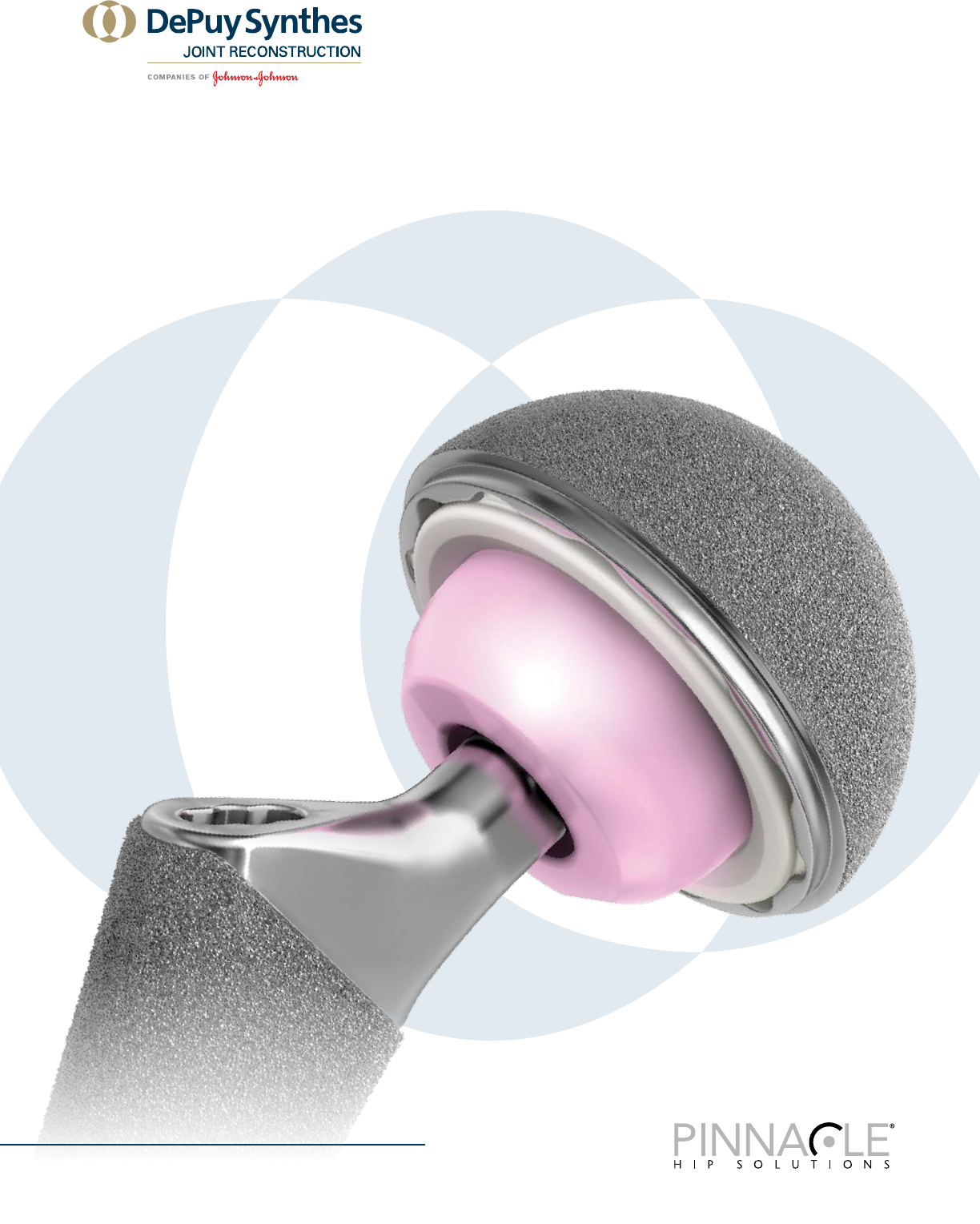
Surgical Technique
PINNACLE®
HIP SOLUTIONS
Polyethylene Surgical Technique


PINNACLE® HIP SOLUTIONS Polyethylene Surgical Technique DePuy Synthes Joint Reconstruction 3
SURGICAL TECHNIQUE
ORDERING INFORMATION
TABLE OF CONTENTS
Introduction 4
Templating and Pre-Operative Planning 6
Surgical Approach – Anterolateral 8
Surgical Approach – Posterolateral 10
Acetabular Reaming 12
Acetabular Shell Trialing and Positioning 13
Implanting A PINNACLE PRIMARY Acetabular Shell 18
Implanting the Acetabular Shell with Screw Fixation 22
Implanting the Acetabular Shell with Spikes 23
Polyethylene Liner Insertion and Impaction 24
Polyethylene Liner Extraction 26
Functional Assessment 28
Closure 29
Tight Exposure and Stability Tips 30
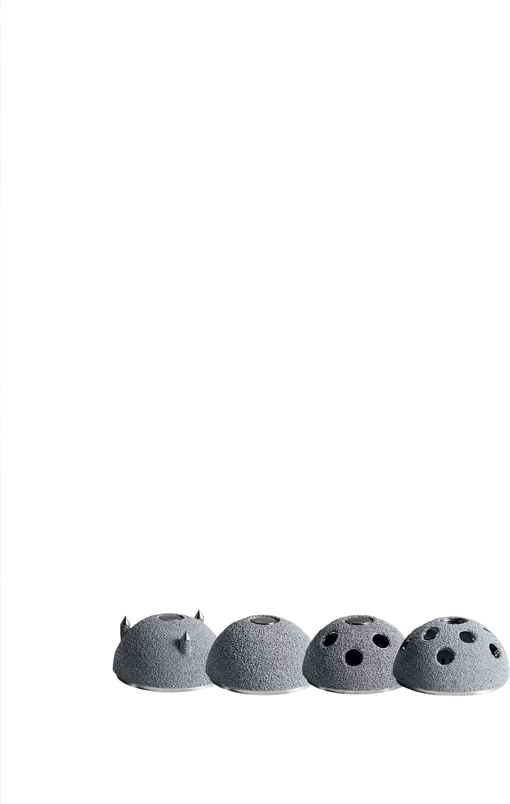
Shell Options 32
Femoral Head Options 34
Polyethylene Liner Options 36
Polyethylene Liner Thickness Chart 40
SURGICAL
TECHNIQUE
Hip reconstruction has become a successful answer for
degenerative hip disease in a more demanding patient
population1. In addition, hip replacement can provide
mobility and pain relief to patients with hip dysplasia
or posttraumatic arthritis. Experience with total hip
arthroplasty has resulted in a more comprehensive
understanding of hip anatomy and biomechanics and
advances in surgical technique. These advances have
allowed the development of more efficient instrumentation
and increasingly sophisticated implant design.
The PINNACLE® Acetabular Hip System primary surgical
technique has been developed in consultation with an
experienced surgeon design team and provides the surgeon
with general guidance when implanting the PINNACLE
Acetabular Hip System.
The primary goal of total hip arthroplasty is the anatomic
reconstruction of the hip joint, resulting in favorable
prosthetic joint load and function. Mechanically, the goals
are to create a stable articulation with an optimized range
of motion, restore biomechanics for muscular efficiency
and equalize limb lengths. Meeting these goals begins
with a thorough analysis of the hip with comparison to
the contralateral side in anteroposterior (A/P) and lateral
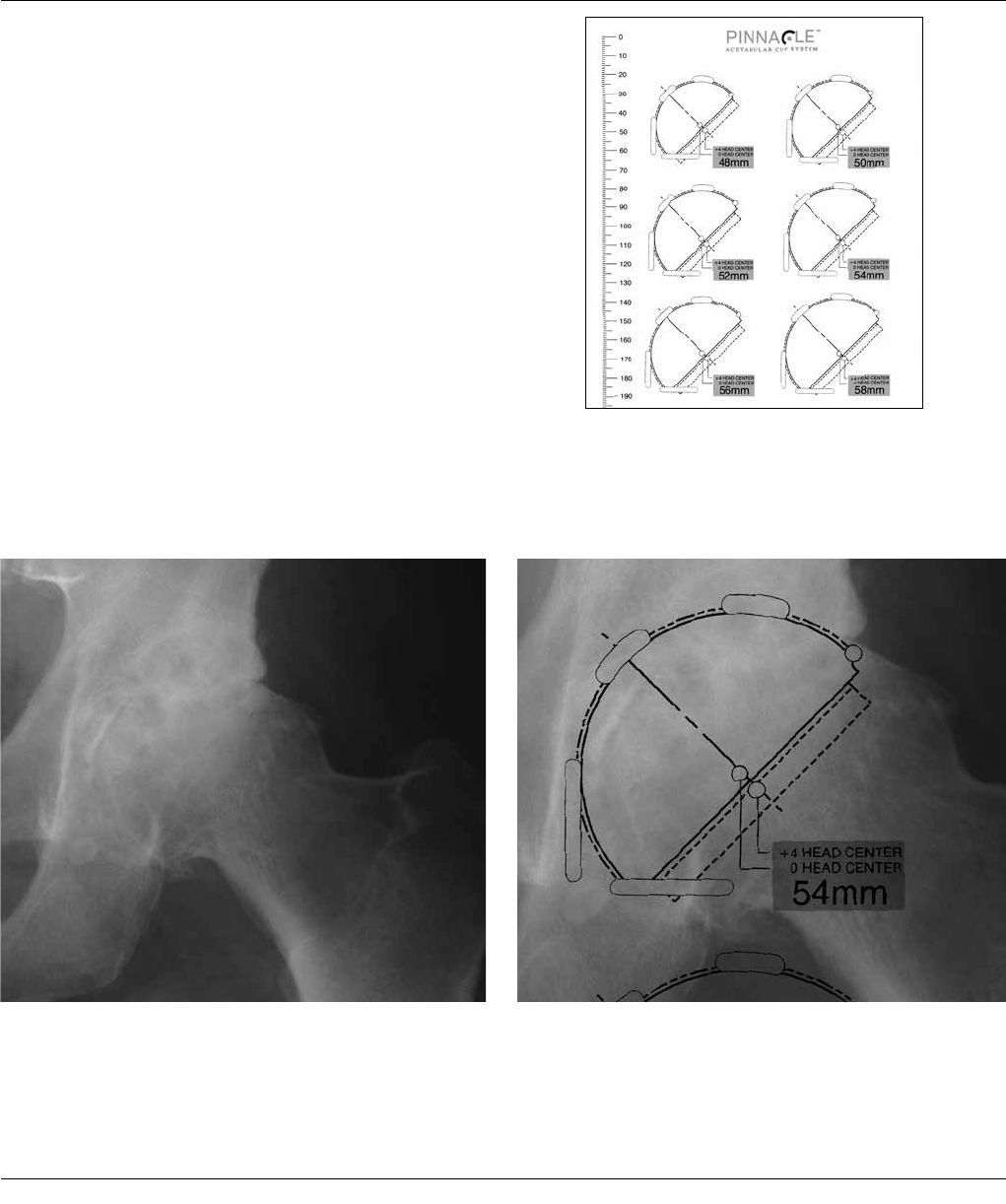
projections. The desired magnification for all imaging
should be 20 percent, which corresponds to the acetate
templates provided for the PINNACLE Acetabular System
(Figure 1A). Magnification markers taped to the patient’s
leg at the level of the trochanter will assist in determining
actual magnification.
For the A/P projection, place both extremities in 15
degrees of internal rotation to position the head and neck
parallel to the coronal plane. Center the beam on the
symphysis pubis and ensure the proximal femoral shaft is
included in the radiograph. The radiographs should clearly
demonstrate the acetabular configuration and the
endosteal and periosteal contours of the femoral head,
neck and proximal femur.
TEMPLATING AND
PRE-OPERATIVE PLANNING
6 DePuy Synthes Joint Reconstruction PINNACLE® HIP SOLUTIONS Polyethylene Surgical Technique
Frequently, the affected hip is fixed in external rotation,
which leads one to underestimate the amount of offset
present. In this situation it may be helpful to template
the normal hip. Take a Lowenstein lateral with the
patient on his/her side, and the trochanter, ankle and
knee on the table. Alternately, take a Johnson’s lateral
for a detailed examination of the anatomic version and
anterior osteophytes. Take into consideration any
anatomical anomaly, dysplasia, previous fracture or leg
length discrepancy.
PINNACLE Acetabular Templates are oriented at 45
degrees and allow measurement of any Hip that can be
accommodated by the PINNACLE Acetabular Cup System
primary components (38 – 72 mm). Using the A/P
radiograph, position the template at a targeted 40-45
degrees to the inter-teardrop or interischial line so that
the inferomedial aspect of the cup abuts the teardrop
and the superior-lateral cup is not excessively uncovered
(Figures 1B and 1C).
Figure 1A
Figure 1C: Positioned Acetabular TemplateFigure 1B: Acetabulum with Good Lateral Coverage
PINNACLE® HIP SOLUTIONS Polyethylene Surgical Technique DePuy Synthes Joint Reconstruction 7
ANTEROLATERAL SURGICAL APPROACH
Use the approach with which you are most familiar. CERAMAX Hip System
instrumentation was designed to accommodate all surgical approaches.
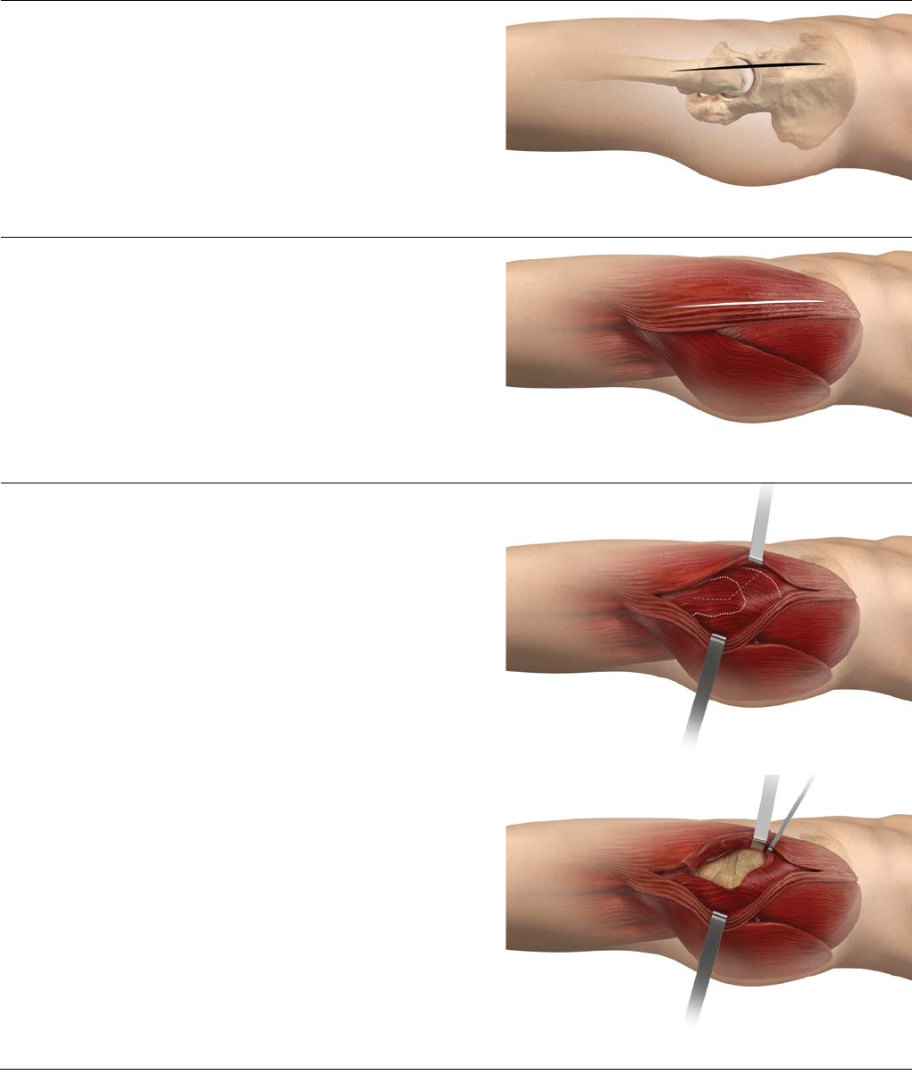
Fascial Incision
The iliotibial band is split under the skin incision,
extending proximally into the gluteus maximus or in
between the maximus and the tensor fascia lata muscles
(Figure 3).
Initial Exposure
Palpate the anterior and posterior borders of the gluteus
medius. The gluteus medius is split from the trochanter,
parallel to its fibers, releasing the anterior 1/2 to 1/3 of
the muscle (Figure 4).
The gluteus medius should not be split more than 4cm
from the tip of the greater trochanter. Care must be
taken to ensure the inferior branch of the superior
gluteal nerve is not damaged. The gluteus minimus is
exposed and released either with or separate from the
gluteus medius. Flexion and external rotation of the leg
facilitates exposure of the hip capsule, which is incised
(capsulotomy) or excised (capsulectomy) depending on
surgeon preference (Figure 5).
Skin Incision
For the anterolateral approach, place the patient in the
lateral decubitus position and execute a skin incision that
extends from distal to proximal, centered over the
anterior aspect of the femur, continuing over the greater
trochanter tip (Figure 2).
Figure 2: Skin Incision
Figure 4: Gluteus Medius Split
Figure 5: Capsulotomy/Capsulectomy
Figure 3: Fascial Incision
8 DePuy Synthes Joint Reconstruction PINNACLE® HIP SOLUTIONS Polyethylene Surgical Technique
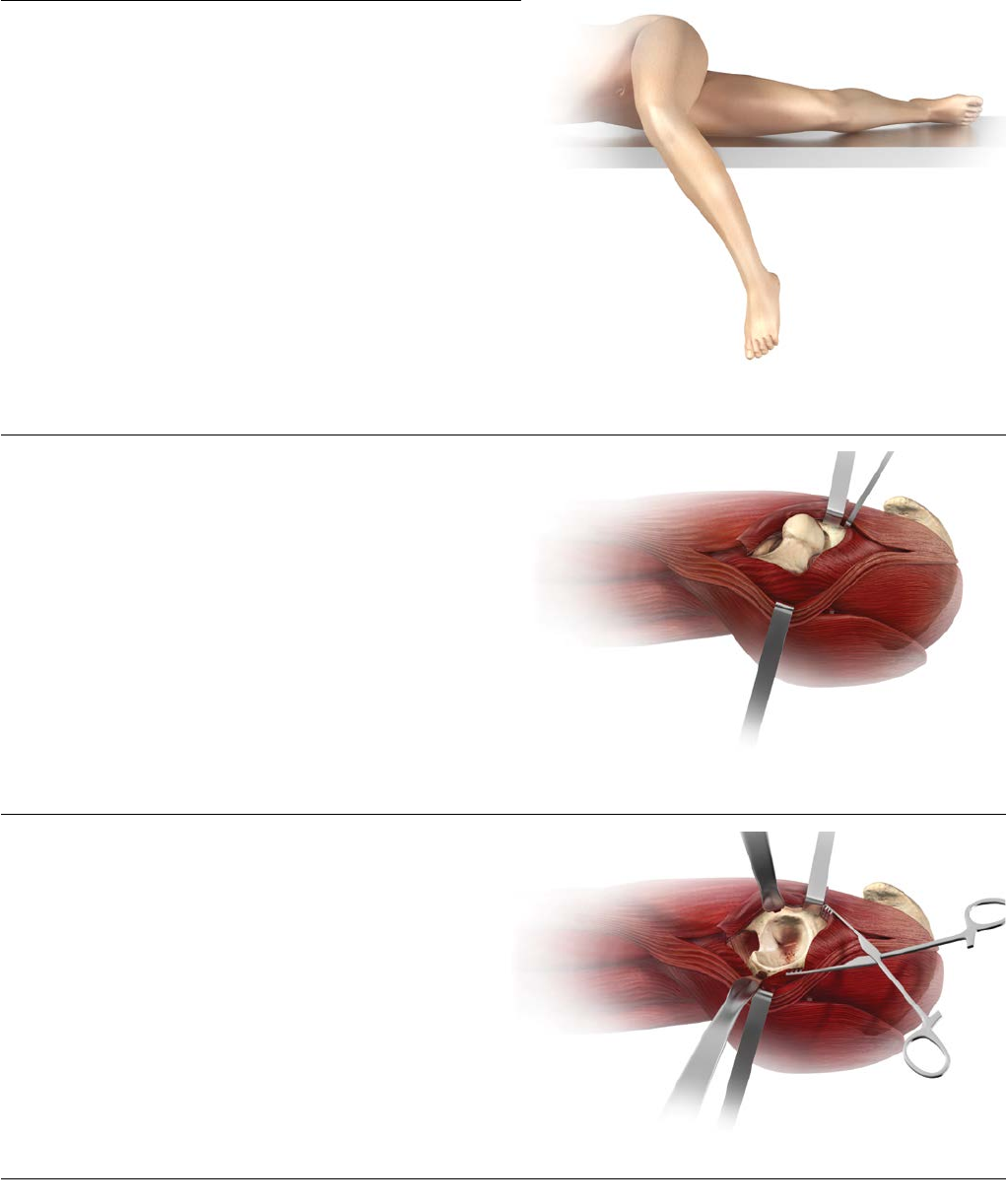
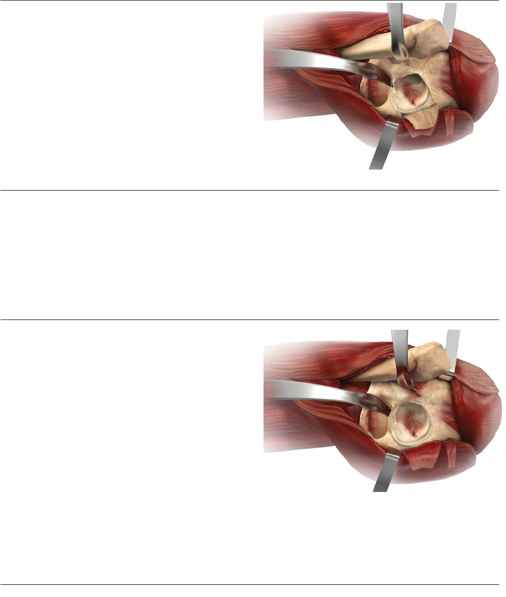
Femoral Neck Osteotomy
Perform a femoral neck osteotomy based upon the proto-
col for the selected femoral prosthesis (Figure 7). Exposure
of the acetabulum is accomplished by placing the leg
back on the table in slight flexion and external rotation.
Use a self-retaining retractor to spread the medius and
minimus anteriorly and the hip capsule posteriorly.
Acetabular Exposure
Carefully place another retractor over the anterior inferior
wall of the acetabulum. The final retractor is placed in the
acetabular notch beneath the transverse ligament and
pulls the femur posteriorly (Figure 8).
Hip Dislocation
Dislocate the hip with gentle adduction, external rotation
and flexion. The patient’s leg is now across the contralat-
eral leg and the foot is placed in a sterile pouch (not
shown, Figure 6). If dislocation is difficult, additional infe-
rior capsule may be released.
Figure 7: Femoral Neck Osteotomy
Figure 6: Hip Dislocation
Figure 8: Acetabular Exposure
PINNACLE® HIP SOLUTIONS Polyethylene Surgical Technique DePuy Synthes Joint Reconstruction 9
POSTEROLATERAL SURGICAL APPROACH
Use the approach with which you are most familiar. CERAMAX Hip System
instrumentation was designed to accommodate all surgical approaches.
Figure 9: Skin Incision
Figure 10: Fascial Incision
Figure 11: Short External Rotators
Figure 12: Quadratus Femoris Incision
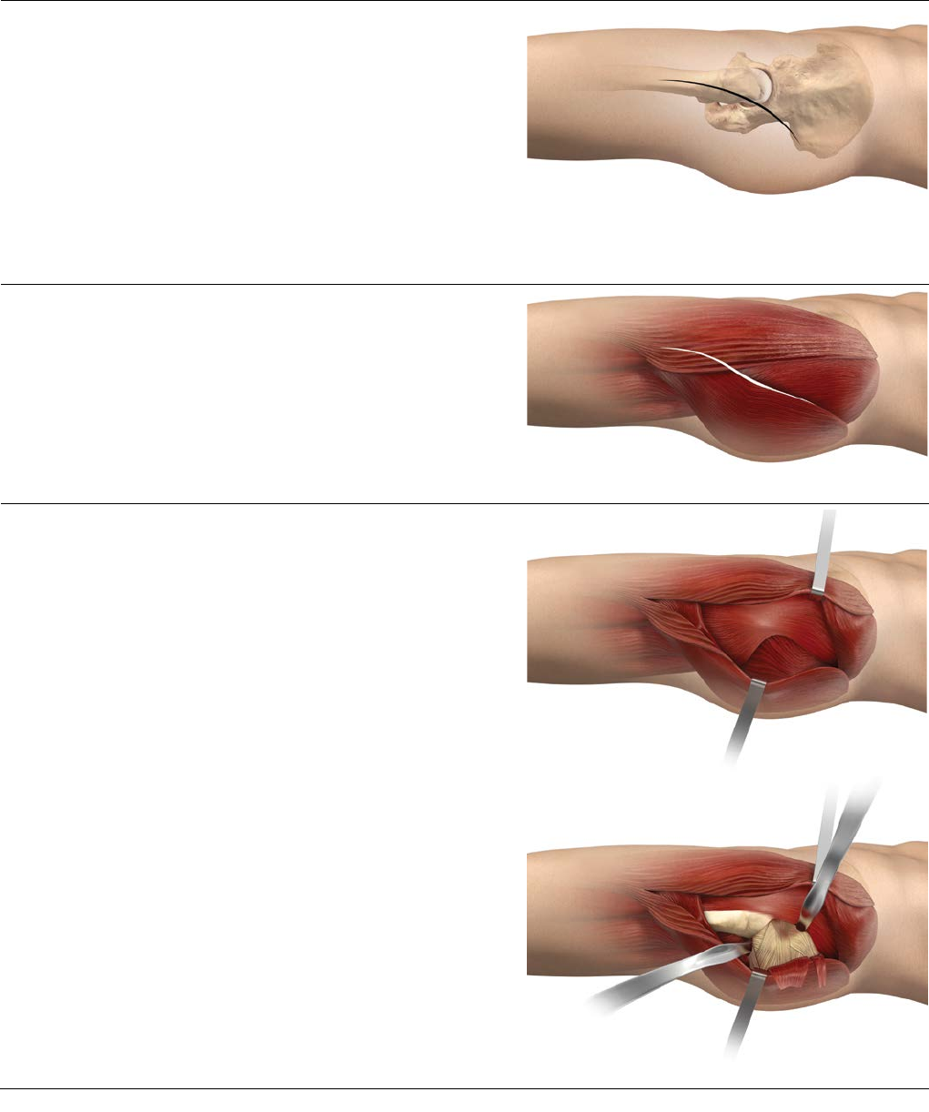
Skin Incision
For the posterolateral approach, place the patient in the
lateral decubitus position. Ensure that the operating table
is parallel to the floor and that the patient is adequately
secured to the table to improve accuracy.
Center the skin incision over the greater trochanter,
carrying it distally over the femoral shaft for about
15 cm and proximally in a gently curving posterior arc of
about 30 degrees for about the same distance (Figure 9)
Fascial Incision
Incise the iliotibial tract distally following the skin incision
(Figure 10). Develop the incision proximally by blunt
dissection of the gluteus maximus along the direction of
its fibers.
Initial Exposure
Place the leg in extension and internal rotation. Utilize self-
retaining retractors to facilitate the exposure. Gently sweep
loose tissue posteriorly, exposing the underlying short
external rotators and quadratus femoris (Figure 11).
Identify the posterior margin of the gluteus medius muscle
proximally and the tendon of the gluteus maximus distally.
Use caution to protect the sciatic nerve.
Incise the quadratus femoris, leaving a cuff of tissue for
later repair (Figure 12). This exposes the terminal branch
of the medial circumflex artery, which lies deep to the
proximal third of the quadratus femoris. Identify the
piriformis tendon, the obturator internus tendon (conjoint
with the gemelli tendons) and the tendon of the
obturator externus, and free them from their insertions at
the greater trochanter. The piriformis and the conjoint
tendon may be tagged for subsequent reapproximation.
10 DePuy Synthes Joint Reconstruction PINNACLE® HIP SOLUTIONS Polyethylene Surgical Technique
Posterior Capsulotomy
Retract the short rotator muscles posteromedially together
with the gluteus maximus (with consideration to the
proximity of the sciatic nerve), thus exposing the posterior
capsule (refer to Figure 12). Place cobra retractors
anteriorly and inferiorly (Figure 13).
Open the capsule posteriorly starting at the acetabular
margin at about 12 o’clock and heading to the base of the
neck, around the base of the neck inferiorly and back to
the inferior acetabulum, creating a posteriorly based flap
for subsequent repair. Excise additional anteriorsuperior
capsule to enhance dislocation of the hip. Alternatively the
capsule can be excised (capsulectomy). Figure 13: Posterior Capsulotomy
Femoral Exposure
Place a superior pin or retractor in the ilium at
approximately the 12 o’clock position. The pin placement
is approximately 2 cm superior to the acetabular margin.
Caution should be taken not to penetrate the medial wall
of the ilium. Measure leg length and dislocate the hip
through a combination of flexion, adduction and internal
rotation. Osteotomize the femoral neck in accordance with
the protocol of the femoral component you have selected.
Acetabular Exposure
One key to proper acetabular component positioning is
adequate surgical exposure. Following femoral neck
resection, pass a curved retractor, which straddles the
pubis, or a blunt cobra over the anterior column to
displace the femur anteriorly (Figure 14).
Position a second retractor at the acetabular notch, inferior
to the transverse acetabular ligament. An additional
retractor may be positioned posteriorly to retract the
capsule or short external rotators.
Care should be taken to position retractors to avoid injury
to the sciatic nerve. Obtain an unobstructed view of the
acetabulum. Excise the entire labrum and remove
osteophytes to identify the true anterior and posterior
acetabular margins. Release or resect the transverse
ligament, together with any accompanying osteophytes. A
branch of the obturator artery is often encountered. Clear
all soft tissue from the fovea to define the true medial wall.
Figure 14: Acetabular Exposure
Note: A detailed technique on the Anterior
Approach is also available and is Catalog Number
0612-15-511.
PINNACLE® HIP SOLUTIONS Polyethylene Surgical Technique DePuy Synthes Joint Reconstruction 11
Deepened
Hemispherical
Acetabulum
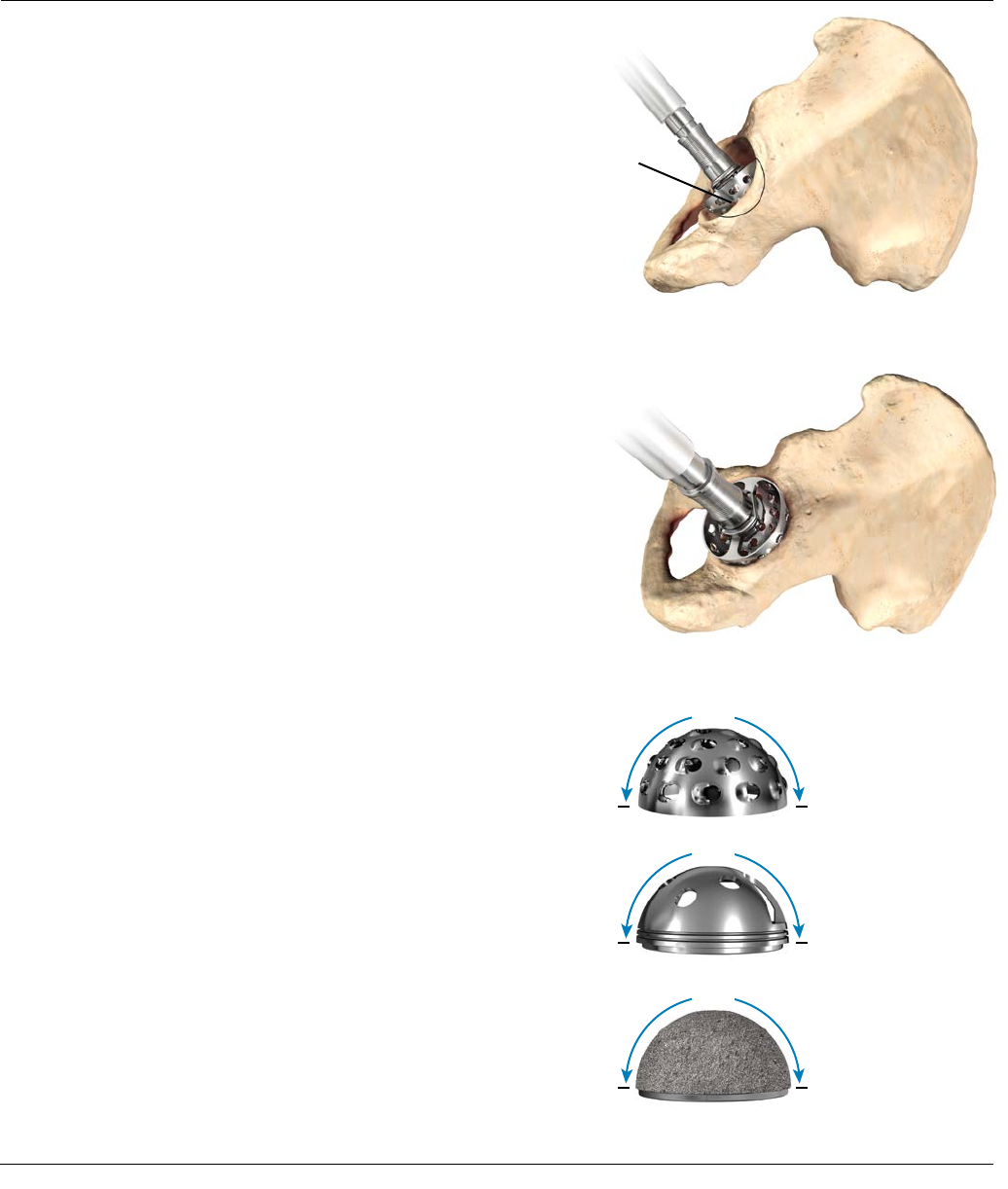
ACETABULAR REAMING
The goal of acetabular reaming is to restore the center of
the natural acetabulum.
Initially, employ a grater 6-8 mm smaller than the
anticipated acetabular component size to deepen the
acetabulum to the level determined by pre-operative
templating (Figures 15 and 16). Subsequent reaming
should proceed in 1-2 mm increments. Center the graters
in the acetabulum until the deepened socket becomes a
true hemisphere. Use a curette to free all cysts of fibrous
tissue. Pack any defects densely with cancellous bone.
It is important to understand that all PINNACLE Acetabular
Hip System instrumentation is marked with true dimensions
meaning, for example, a 54mm grater reams a 54mm
cavity (Figure 17). The graters, shell trials and acetabular
implants are all hemispherical and measure 180 degrees
around the dome to the level of the coating on the final
shell.
Under-reaming of the acetabulum to allow the press-fit of
the final shell is dependent on bone quality and the size of
the acetabular component. A 1 mm under-ream is usually
sufficient in smaller sockets, while a larger socket may
require a 1-2 mm under-ream. Likewise, soft bone will
more readily accommodate a greater press-fit of the
acetabular component than sclerotic bone.
In some patients, line-to-line reaming may be sufficient to
achieve stability.
The orientation and depth of acetabular reaming often
determines the orientation and depth of the final shell
seating. It is important to ream where the final shell is to be
positioned. As such, a part of the grater head will be visible
on the superolateral rim when reaming (Figure 16).
Figure 15: Acetabular Reaming
Figure 16: Acetabular Reaming
A 54 mm
QUICKSET® grater
reams a 54 mm
cavity.
A 54 mm trial shell
is 54 mm in
diameter.
A 54 mm PINNACLE
acetabular shell is 54
mm in diameter as
measured over the
POROCOAT® Porous
Coating.
180˚
180˚
180˚
Figure 17
12 DePuy Synthes Joint Reconstruction PINNACLE® HIP SOLUTIONS Polyethylene Surgical Technique
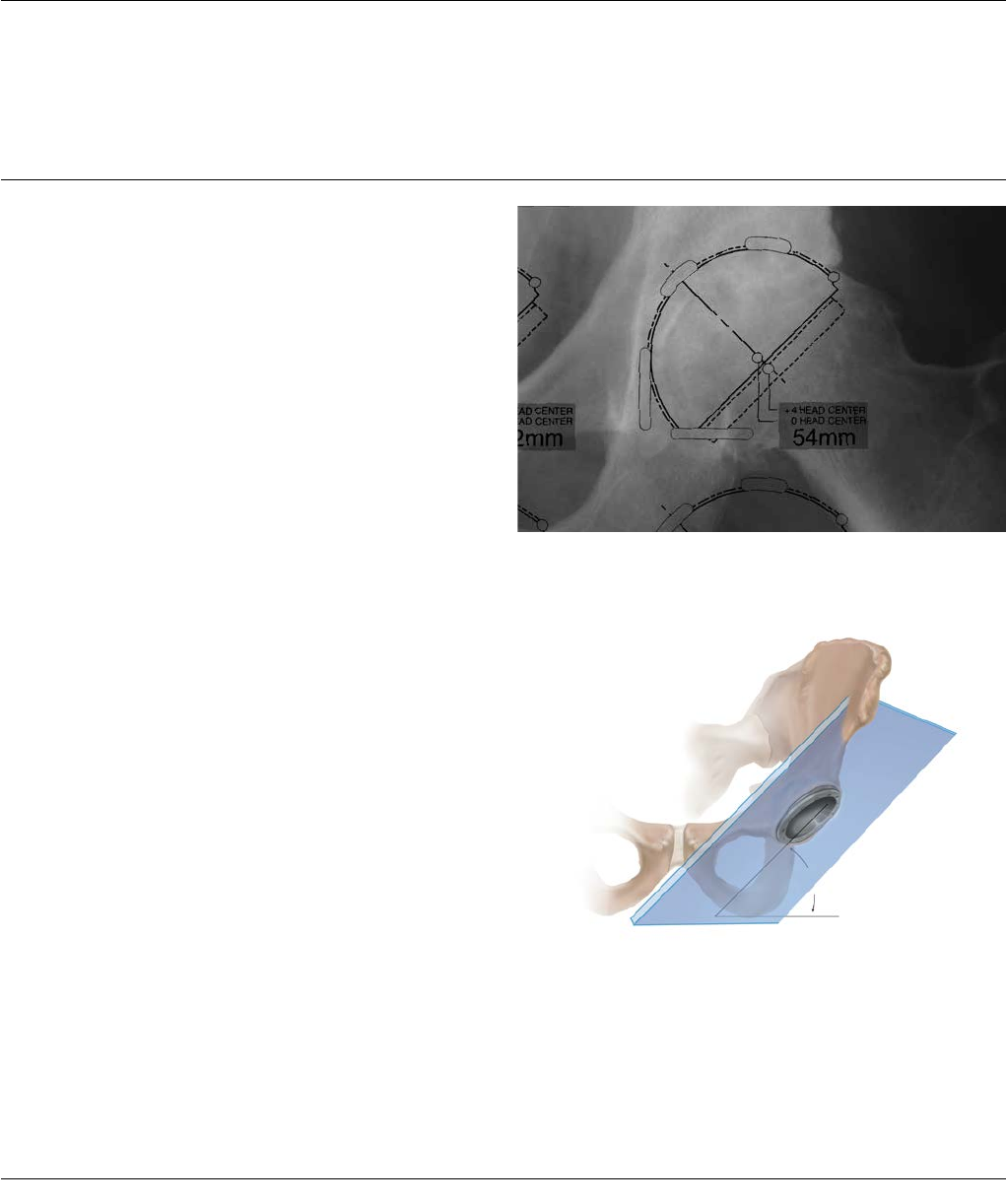
40°-45°
ACETABULAR SHELL
TRIALING AND POSITIONING
Peer-reviewed publications highlight the importance of acetabular component positioning in relation to short- and long-
term outcomes during total hip arthroplasty for all types of bearing materials2-9. Cup positioning should be varied to
optimize fixation, range of motion and dislocation resistance and minimize the likelihood of subluxation, impingement
and edge-loading. This may be assessed during pre-operative planning, acetabular preparation and shell trialing.
Sub-optimal component positioning may lead to edge loading, dislocation, increased wear and polyethylene fracture 2-9.
Determining the Abduction Angle
The pre-operative A/P radiograph can help determine the
targeted abduction angle and be helpful in determining
how much of the acetabular component should be left
uncovered to provide the proper implant abduction angle
(Figures 18 and 19). The targeted shell abduction (as
measured on radiographs) should be 40-45 degrees
taking into account local soft tissue and anatomic
landmarks.The landmarks for acetabular component
positioning are the medial wall of the acetabulum (the
radiographic tear drop) and the lateral-superior rim of
the acetabulum.
Figure 18: Pre-operative determination of abduction angle
Figure 19: 40°-45° targeted shell abduction (as measured on radiographs)
PINNACLE® HIP SOLUTIONS Polyethylene Surgical Technique DePuy Synthes Joint Reconstruction 13

ACETABULAR SHELL
TRIALING AND POSITIONING
Determining Proper Anteversion
The most reliable method for determining anteversion is
the use of the bony landmarks or the transverse
acetabular ligament10. Other methods are subject to error
through a change in patient position during the
procedure. Defining the bony landmarks of the ischium
and pubis during exposure greatly facilitates acetabular
component positioning.
The plane created by the pubis and the ischium can serve
as a guide for acetabular shell orientation. The shell
should be slightly more anteverted than the pubis/ischial
plane. This relationship should remain constant regardless
of the depth of reaming, and the preoperative A/P X-ray
can be helpful in determining how much of the
acetabular component should be left uncovered to
provide the proper implant abduction angle (Figure 20).
The targeted shell anteversion (as measured on
radiographs) should be 15-20 degrees taking into account
local soft tissue and anatomic landmarks (Figure 21).
Shell trials in 1 mm incremental sizes are available to
assess shell fit and orientation. Contingent on the quality
of the prepared bone, select the acetabular trial equal to
or 1 mm larger in diameter than the final grater size. The
"true dimension" of the shell trial is as marked on each
trial (i.e. a shell trial marked "54 mm" measures 54 mm
in diameter at the rim). Peripheral rim ridges on the shell
trial enhance the stability during trial reduction. Liner
trials that are marked with an even size fit both even-
sized and smaller odd-sized shell trials. For example, a 54
mm polyethylene liner trial fits both the 54 mm and the
53 mm shell trials (refer to Figure 24). Using shell and
liner trials in conjunction with the femoral component
trials aid in ensuring optimum position of the
components.
Figure 20: Pre-operative assessment of coverage of the acetabulum
Figure 21: 15°-20° targeted shell anteversion (as measured on radiographs)
14 DePuy Synthes Joint Reconstruction PINNACLE® HIP SOLUTIONS Polyethylene Surgical Technique
ACETABULAR SHELL
TRIALING AND POSITIONING
Determining Proper Anteversion
An alignment guide is provided to assist with shell
positioning. However, shell orientation in the patient
depends on patient position. The alignment guide does
not allow for variation in patient position with respect to
the operating table. It should be noted that patient
orientation can vary thoughout the procedure.
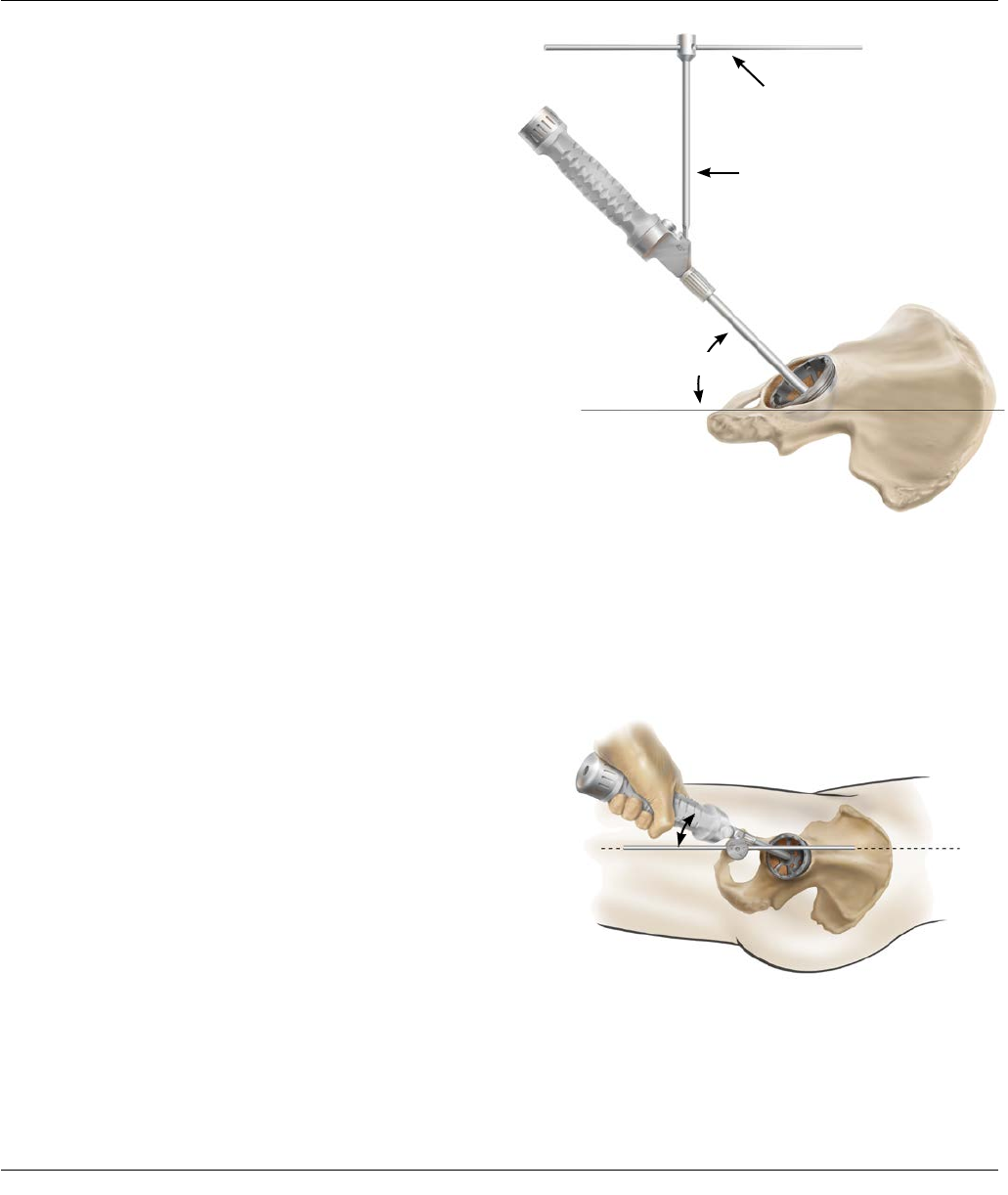
The Pinnacle Hip alignment guide system may be used to
indicate an acceptable level of acetabular shell inclination
and version. Once assembled, the inserter handle should
be raised until the vertical bar is perpendicular to the
plane of the operating table with the patient in the lateral
decubitus position and the version guide parallel to the
floor (Figure22).
The inserter handle should then be rotated until the
extended arm of the version guide is in line with the
patient's longitudinal axis (Figure 23).
The extended arm of the version guide follows the long
axis of the patient’s body, corresponding to the affected
hip, to achieve appropriate anteversion.
Confirm complete shell trial seating by sighting through
the holes and cutouts in the acetabular shell trial. The
screw hole pattern in the trial shell replicates the Pinnacle
Sector Shell implant screw hole pattern to assist with
screw targeting.
Do not use the shell trial to prepare screw holes. Prepare
screw holes only through the final implant.
The version guide is marked with 30 degree striations,
which provides an indication of operative anterversion.
Operative anteversion differs from radiographic
anteversion due to the projection of angles on a
radiograph. Therefore, the 30 degree striation equates to
a radiographic anteversion of 20 degrees, as measured on
postoperative radiographs.
Figure 23: Position the extended arm of the version guide
on the long body axis to determine anteversion
Operative angle of 40 - 45°
30°
Mid Line Body
Parallel to Floor
Vertical
Figure 22: Hold the version guide parallel to the
operating table to determine the abduction angle
PINNACLE® HIP SOLUTIONS Polyethylene Surgical Technique DePuy Synthes Joint Reconstruction 15
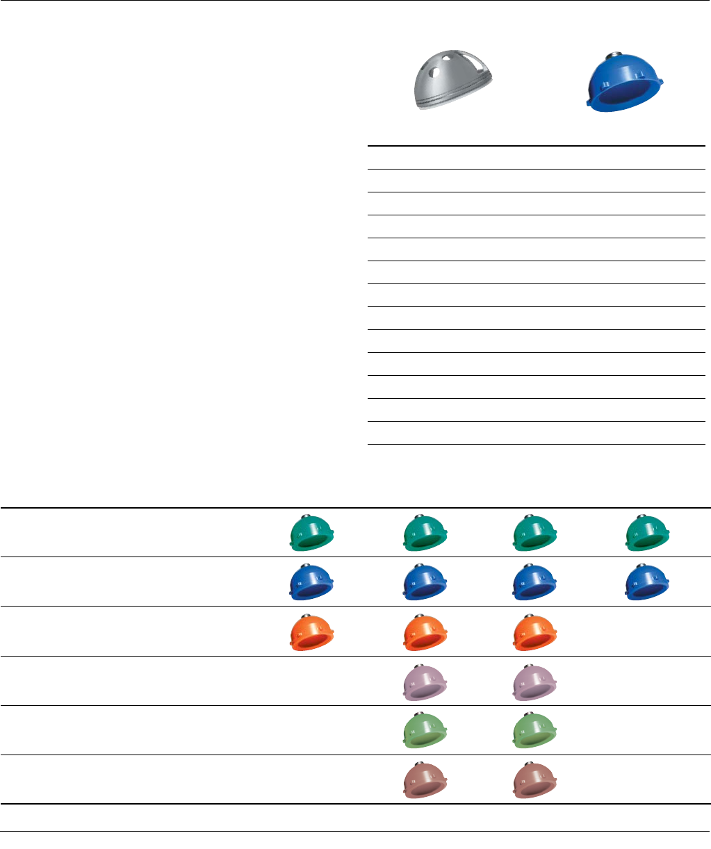
Figure 25
Figure 24
Shell Trial Size (mm) Liner Trial Size (mm)
47, 48 48
49, 50 50
51, 52 52
53, 54 54
55, 56 56
57, 58 58
59, 60 60
61, 62 62
63, 64 64
65, 66 66
67, 68* 68
69, 70* 70
71, 72* 72
*Appropriate spacer trials to be utilized for head diameters of 28, 32 and 36mm.
Note: PINNACLE Bantam Trials are outlined in the PINNACLE Compatibility
Guide, Catalog Number 0612-26-510.
ACETABULAR SHELL
TRIALING AND POSITIONING
Polyethylene Liner Trials
Following positioning and seating of the acetabular shell
trial, place the appropriate sized liner trial into the shell
trial (Figure 24). Secure the liner trial to the shell trial
through the apical hole screw using a standard hex head
screwdriver. There are various liner configurations for all
head sizes ranging from 28-48mm. Refer to Figure 25 for
details on the liner configurations.
With the femoral component trials in position, assess
stability and range of motion. Couple the liner trial with
the shell trial in the desired position. For liner alternatives
other than neutral, there is an orientation reference etch
mark on the liner trial and liner implant.
SHELL AND LINER TRIAL SIZES
Neutral +4 Neutral +4 10 Degree Lipped
28 mm polyethylene trial liners are GREEN
32 mm polyethylene trial liners are BLUE
36 mm polyethylene trial liners are ORANGE
40 mm polyethylene trial liners are PINK
44 mm polyethylene trial liners are LIME
48 mm polyethylene trial liners are TAN
16 DePuy Synthes Joint Reconstruction PINNACLE® HIP SOLUTIONS Polyethylene Surgical Technique
ACETABULAR SHELL
TRIALING AND POSITIONING
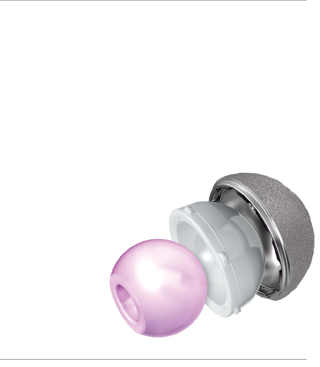
Polyethylene Liner Configurations
Within the PINNACLE Acetabular System, a variety of liner
designs are available. Each design has specific benefits. It
is important for the surgeon to understand the geometry
of the various liner alternatives and their impact on joint
biomechanics and range of motion.11
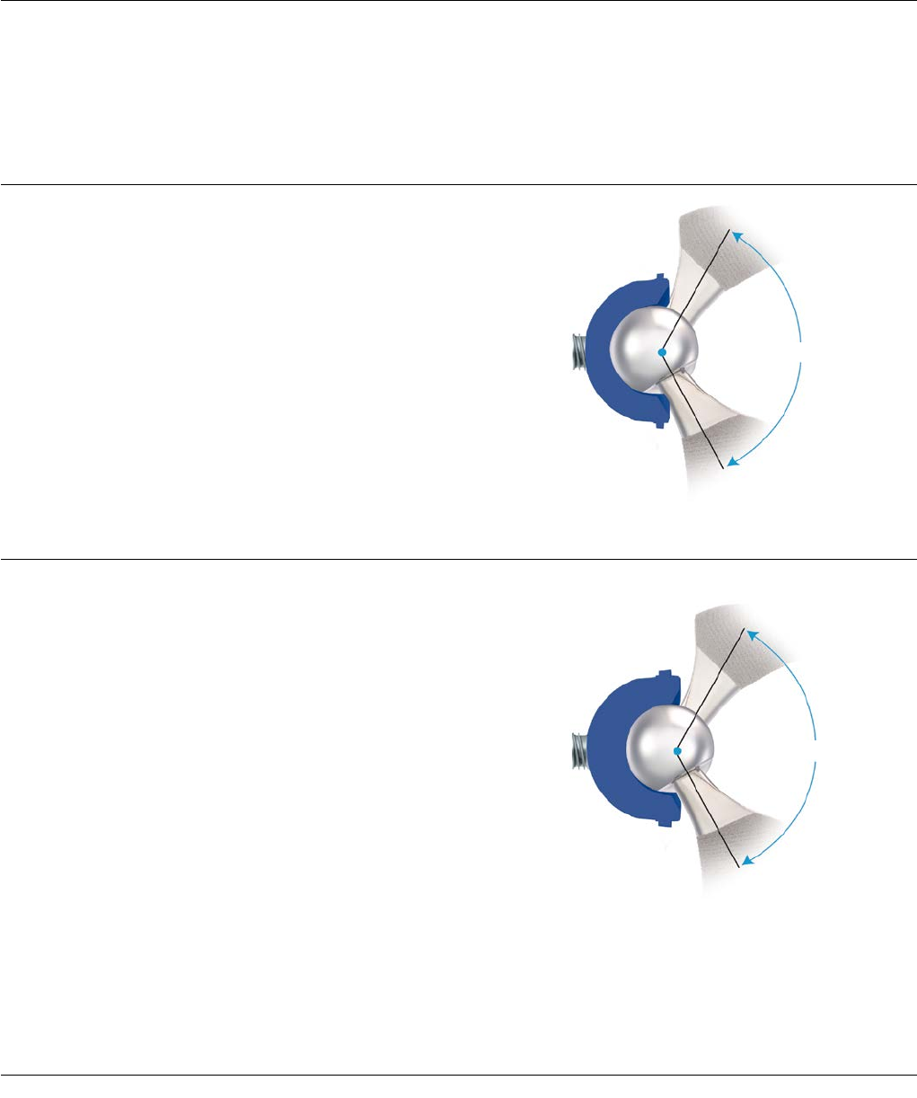
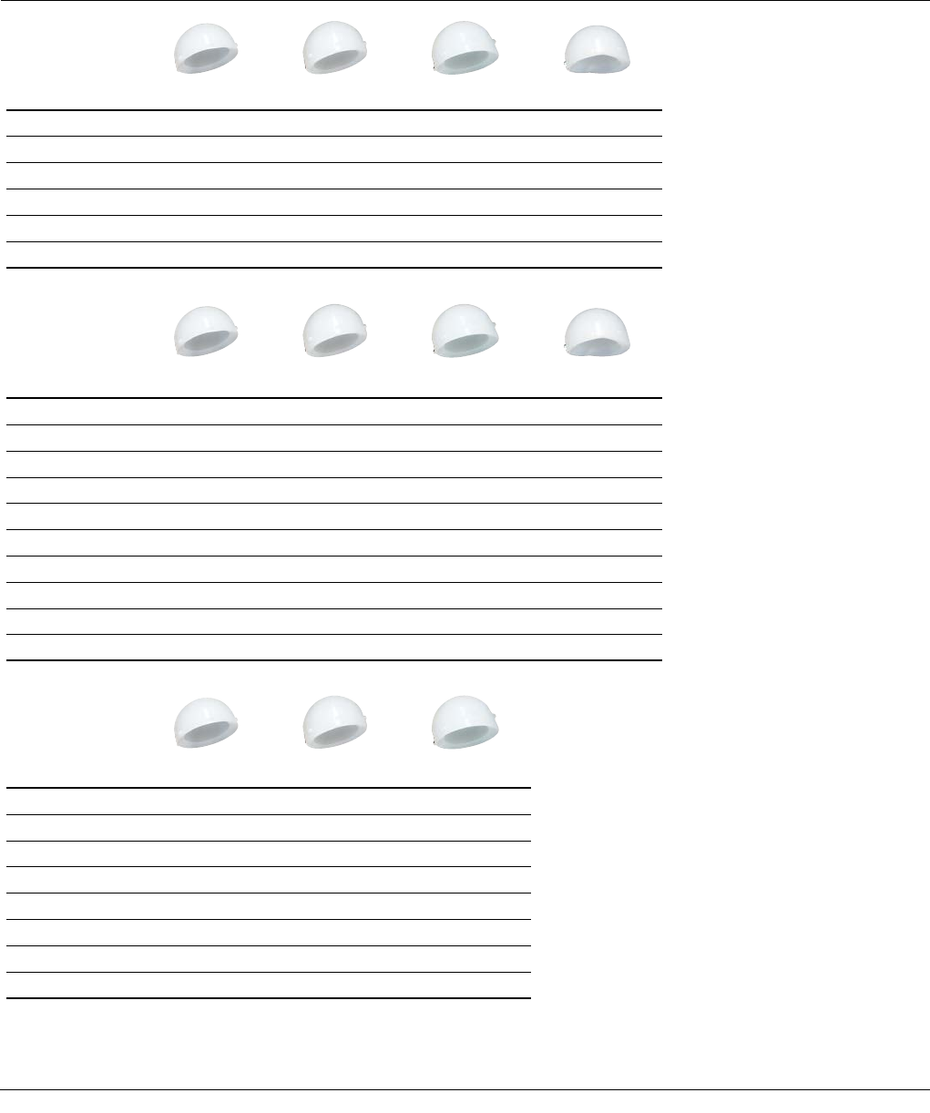
Neutral Liner
The neutral liner provides 180 degrees of head coverage.
The wide face chamfer is optimized for range of motion.
The range of motion measured is 139 degrees with a
SUMMIT® Taper Stem and a 32mm ARTICUL/EZE® Head.
The femoral head’s center of rotation is concentric with
the outer diameter of the shell (Figure 26A).
+4 Neutral Liner
Like the neutral liner, the +4 neutral liner provides 180
degrees of head coverage. The wide face chamfer is
optimized for range of motion. The range of motion
measured is 139 degrees with a standard SUMMIT Stem
and a 32mm ARTICUL/EZE head. This liner provides a 4
mm lateralization of the femoral head’s center of rotation.
This 4 mm offset both increases soft tissue tensioning and
provides 4 mm of increased polyethylene thickness in the
shell’s dome region. This lateralized liner can be used as
an alternative to a longer neck and may enable the
surgeon to avoid using a skirted head. A +4 neutral liner
will result in about 3 mm of additional leg length and
about 3 mm of additional offset if the cup is inserted at a
45-degree abduction angle, as compared to a neutral
liner (Figure 26B).
139°
Figure 26A: Neutral Liner – 32 mm ID
with SUMMIT® Tapered Hip System
139°
Figure 26B: +4 Neutral Liner – 32 mm ID
with SUMMIT Hip Stem
PINNACLE® HIP SOLUTIONS Polyethylene Surgical Technique DePuy Synthes Joint Reconstruction 17
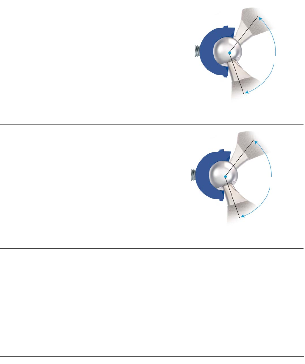
134°
Figure 26C: +4 10-Degree Face-Changing Liner –
32 mm ID with SUMMIT Hip Stem
130°
Figure 26D: Lipped Liner – 32 mm ID
with SUMMIT Hip Stem
+4 10-Degree (Face-Changing) Liners
Like the other liners, the +4 10-degree liner provides 180
degrees of head coverage, and the wide chamfer is
optimized for range of motion, which is 134 degrees with
a SUMMIT stem and a 32mm ARTICUL/EZE head. This
liner lateralizes the femoral head 4 mm, and a 10-degree
face change alters inclination/version dependent upon
placement of the liner (Figure 26C).
Lipped Liner
This liner provides 180 degrees of head coverage plus a 4
mm build-up for added stability. It also features a face-
change of 15 degrees that will alter inclination/version
dependent upon placement of the liner. The range of
motion is measured at 130 degrees with a standard
SUMMIT stem and a 32 mm ARTICUL/EZE head. The lip
on this liner can provide additional stability; however, the
impact on range of motion and early impingement must
be understood (Figure 26D).
Constrained Liners
Constrained liners are available for the PINNACLE System
and are described in the EScTM Liner Surgical Technique,
Cat. No. 0608-58-000.
ACETABULAR SHELL
TRIALING AND POSITIONING
18 DePuy Synthes Joint Reconstruction PINNACLE® HIP SOLUTIONS Polyethylene Surgical Technique
Range of Motion (ROM) tested with a CORAIL Stem in accordance with ISO 21535:2007 (E) standard for a physiologically positioned shell and stem12.
* ALTRX® liners in sizes 40, 44 and 48 mm ID are part of the AltrX LD system and are manufactured with a Charnley bore
Neutral +4 Neutral +4 10° Face Lipped
Head Size/
Liner Inner
Diameter
Flexion /
Extension
Abduction /
Adduction
Flexion /
Extension
Abduction /
Adduction
Flexion /
Extension
Abduction /
Adduction
Flexion /
Extension
Abduction /
Adduction
28 mm 166˚ 119˚ 167˚ 121˚ 165˚ 115˚ 143˚ 105˚
32 mm 177˚ 127˚ 177˚ 127˚ 172˚ 121˚ 151˚ 113˚
36 mm 177˚ 127˚ 180˚ 128˚ 174˚ 122˚ N/A N/A
40 mm* N/A N/A 177˚ 127˚ 173˚ 121˚ N/A N/A
44 mm* N/A N/A 174˚ 126˚ 170˚ 120˚ N/A N/A
48 mm* N/A N/A 171˚ 124˚ 165˚ 112˚ N/A N/A
Figure 27
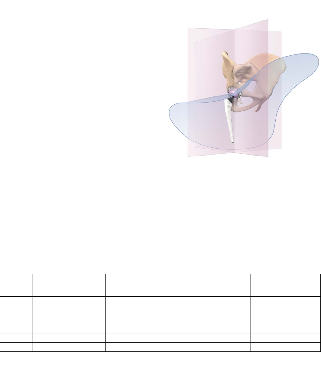
Polyethylene Liner Configurations
The range of motion (ROM) data of physiologically
positioned acetabular and femoral components differs
from the commonly discussed sweep angles outlined on
the prior page. The physiologic ROM can be described by
maximum achievable movement in flexion and extension
and abduction and adduction.
The required ranges of angular movement between the
acetabular and femoral components in a total hip joint
replacement are specified in a well-recognized industry
standard12. In accordance with this standard, the table
below was created to show the physiologic ROM data for
combinations of PINNACLE Hip and the CORAIL® Hip
System, including shells, inserts, femoral heads and
femoral components, using 3-dimensional digital
models11 (Figure 27).
The acetabular component model was oriented into an
initial position, which is considered a neutral position for
a physiologically oriented acetabular cup component in
terms of abduction and version. From the neutral
position, the femoral stem was rotated until the neck of
the stem made contact with the rim of the acetabular
shell.
The angles achieved in each direction about each axis are
shown in the following table (this data shows theoretical
numbers and clinical results may be reduced due to
skeletal impingement or the presence of soft tissues):
ACETABULAR SHELL
TRIALING AND POSITIONING
LINER OPTIONS
PINNACLE® HIP SOLUTIONS Polyethylene Surgical Technique DePuy Synthes Joint Reconstruction 19
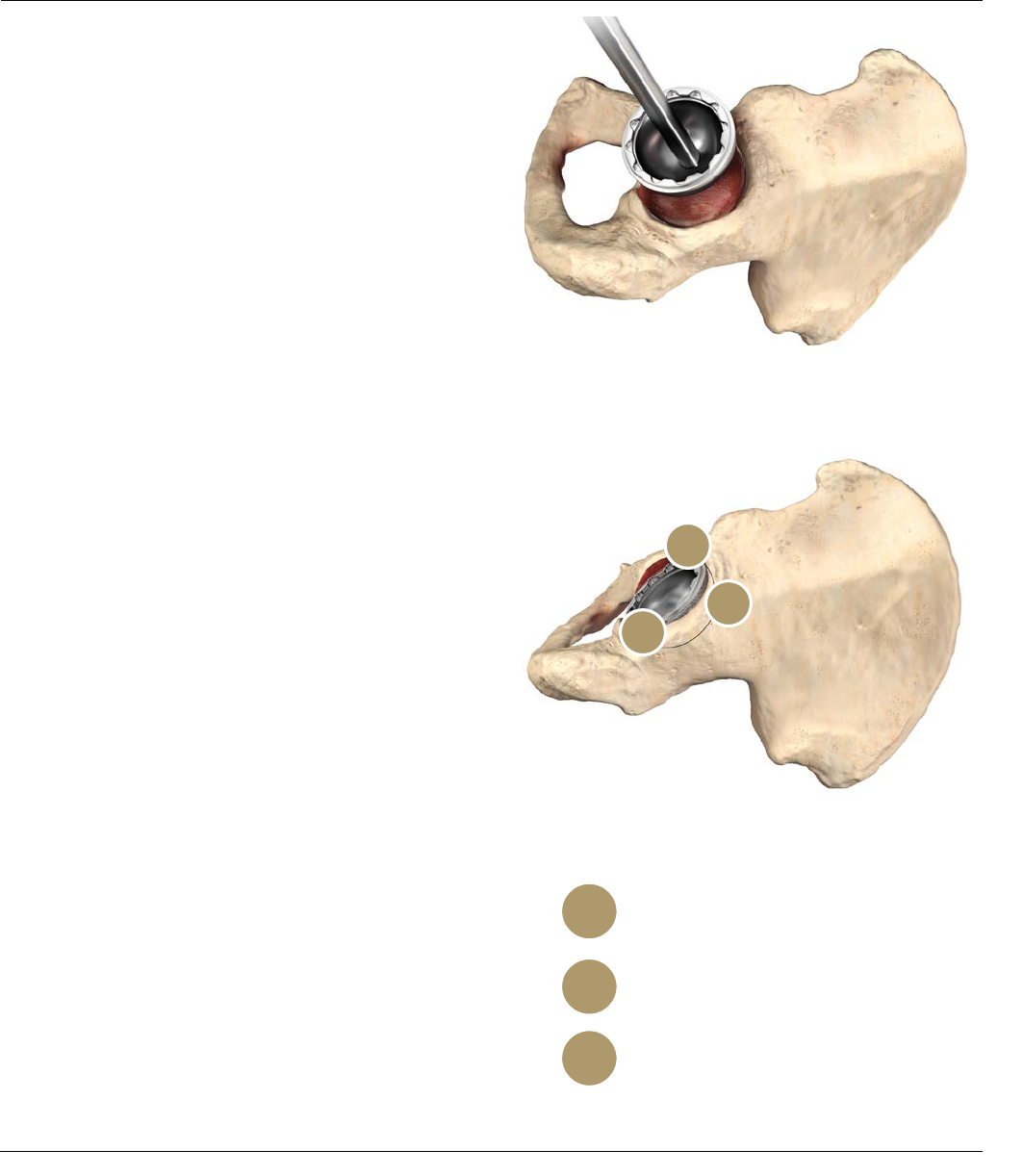
Anterior notch
Check for psoas tendon impingement
with large diameter heads
Posterior
Check toe-off impingement
Supero-lateral rim
Shell coating / reamer visible
1
2
3
IMPLANTING THE
ACETABULAR SHELL
Shell Insertion
Each PINNACLE Acetabular Shell style is implanted using
the same basic surgical technique; however, some shell
styles have technique-specific tips that help facilitate
implantation. This technique demonstrates the insertion
of a PINNACLE Hip 100 Series (no-hole) shell. Before
implanting the final prosthesis, take the hip through a full
range of motion and stability assessment with all trial
components in position.
Securely thread the final acetabular shell prosthesis onto
the impactor (Figure 28). Use the Pinnacle Hip external
alignment guide to assist in component orientation (refer
to Figures 22 and 23).
Since the natural acetabulum is inclined at an average
angle of 50-55 degrees, a replacement acetabular
component implanted at the correct position will have
some shell coating visible above the rim of the
acetabulum. To achieve the targeted shell position of 40-
45 degrees of inclination and 15-20 degrees of
anteversion, it is recommend that 4-6mm of coating
should be left exposed. It should be noted, however, that
the amount of coating to be left visible is dependant on
the angle of the patient's acetabulum and the size of the
component used. The three anatomical regions indicated
in Figure 29 assist with cup position.
After confirming alignment, impact the prosthesis into
position. Given the nature of a hemispherical acetabular
component, rim contact will occur before dome seating
occurs. This may require additional impaction to ensure
seating. Confirm seating by sighting through the apical
hole or, if present, screw holes. An apical hole eliminator
may be inserted with a standard hex head screwdriver
following shell impaction. Following final component
seating, if adjustments to the shell orientation are
necessary, thread the impactor handle back into the apical
hole to adjust the shell position. Avoid adjusting the shell
position by impacting the Variable Interface Prosthesis
(VIP) taper region and/or shell face with a punch or similar
instrument, as this may cause damage to the VIP taper
inside the PINNACLE Hip shell.
Figure 28
Figure 29: Confirm Acetabular Shell Alignment
3
2
1
20 DePuy Synthes Joint Reconstruction PINNACLE® HIP SOLUTIONS Polyethylene Surgical Technique
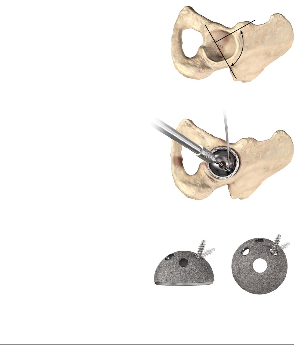
Screw Insertion
The PINNACLE System includes the Sector and Multi-hole
shell options that are designed for insertion with screws.
The Sector shell is referenced on the following pages to
demonstrate the surgical technique for implantation of the
shell with screw fixation.
QUICKSET® Acetabular Screw Instruments are
recommended for screw insertion. The Sector shell has
two medial hole alternatives, which are placed to enable
screw placement up the posterior column in either the
right or left hip. The single lateral screw provides
additional access to the ilium.
Select holes where the prosthesis is to be anchored with
cancellous screws so that the screws lie within a safe
quadrant. The safe quadrant is defined by two lines from
the anterior-inferior iliac spine through the center of the
acetabulum and posterior by a line from the sciatic notch
to the center of the acetabulum (Figure 30).
The 3.8mm drill bit is controlled by the drill guide as it
passes through selected holes into the acetabulum (Figure
31). The screw angle may vary by as much as a total of 34
degrees (Figure 32). The effective lengths of the 7 drill bits
available are 25, 30, 35, 40, 45, 55, and 70 mm. By
seating the drill bit completely into the guide, holes
corresponding to the effective length of the drill bit will be
created.
IMPLANTING THE ACETABULAR
SHELL WITH SCREW FIXATION
Safe
Quadrant
34°
34°
Figure 32: Screw Angulation
Figure 30
Figure 31: Drill Guide
PINNACLE® HIP SOLUTIONS Polyethylene Surgical Technique DePuy Synthes Joint Reconstruction 21
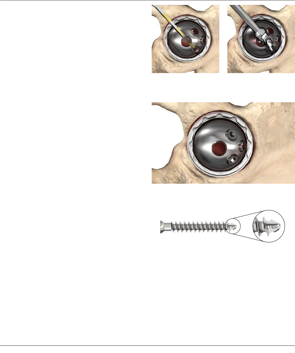
Figure 36: Screw Tip
IMPLANTING THE ACETABULAR
SHELL WITH SCREW FIXATION
Verify hole depth using the QUICKSET Depth Instruments
Gauge. Alternating colors on the depth gauge represent
10 mm increments (Figure 33).
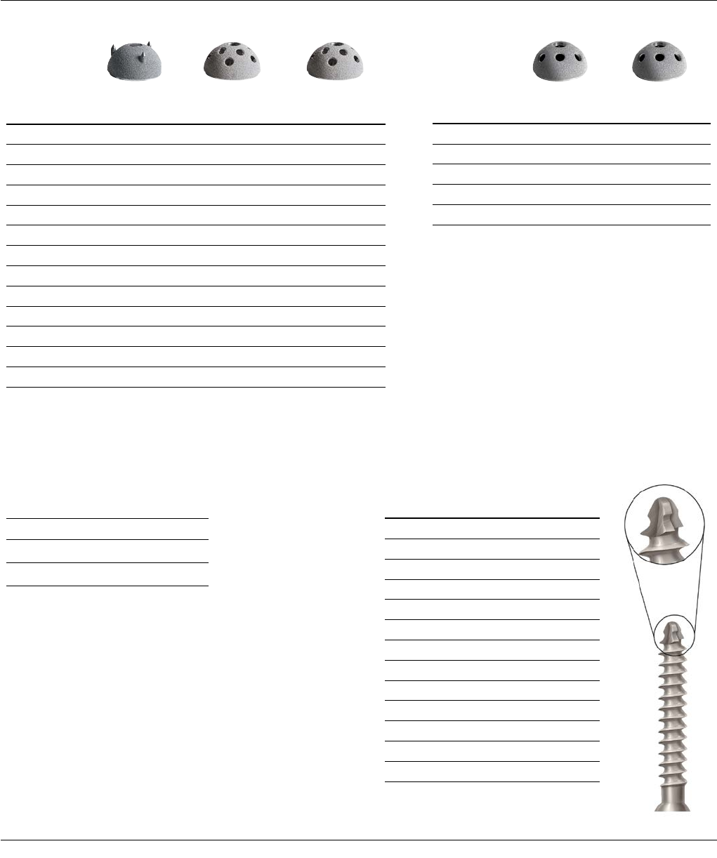
Insert 6.5 mm PINNACLE Hip Cancellous Bone Screws
using a hex head screwdriver (Figures 34 and 35).
The 6.5 mm self-tapping screws have four-point cutting
flutes with a blunt tip to reduce the risk of neurovascular
injury (Figure 36).
Figure 33: Depth Gauge Figure 34: Screw Insertion
Figure 35: Screw Insertion
22 DePuy Synthes Joint Reconstruction PINNACLE® HIP SOLUTIONS Polyethylene Surgical Technique
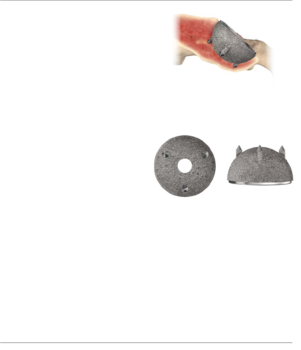
Figure 37: Prior to shell impaction, spikes and rim engage
simultaneously when the shell is centered and aligned
Figure 38
Spike Orientation Spike Length
IMPLANTING THE ACETABULAR
SHELL WITH SPIKES
300 Series Shell Insertion
Spikes are placed along the radius of the PINNACLE Hip
300 Series shell and are coated for additional fixation
(Figures 37 and 38). The spike height in the 300 Series
shell ensures that the spike contacts bone on insertion at
the same point that the shell contacts the rim of the
prepared acetabulum. This gives the surgeon greater
control when inserting the 300 Series shell and ensures
the shell bottoms out in the dome of the acetabulum.
The recommended acetabular reaming technique for the
PINNACLE 300 Shell is either 1 mm under or line-to-line
with the shell size dependent on bone quality. It is
important that the cup is well centered in the prepared
acetabular cavity in the predetermined alignment
indicated by the trial before being impacted.
PINNACLE® HIP SOLUTIONS Polyethylene Surgical Technique DePuy Synthes Joint Reconstruction 23
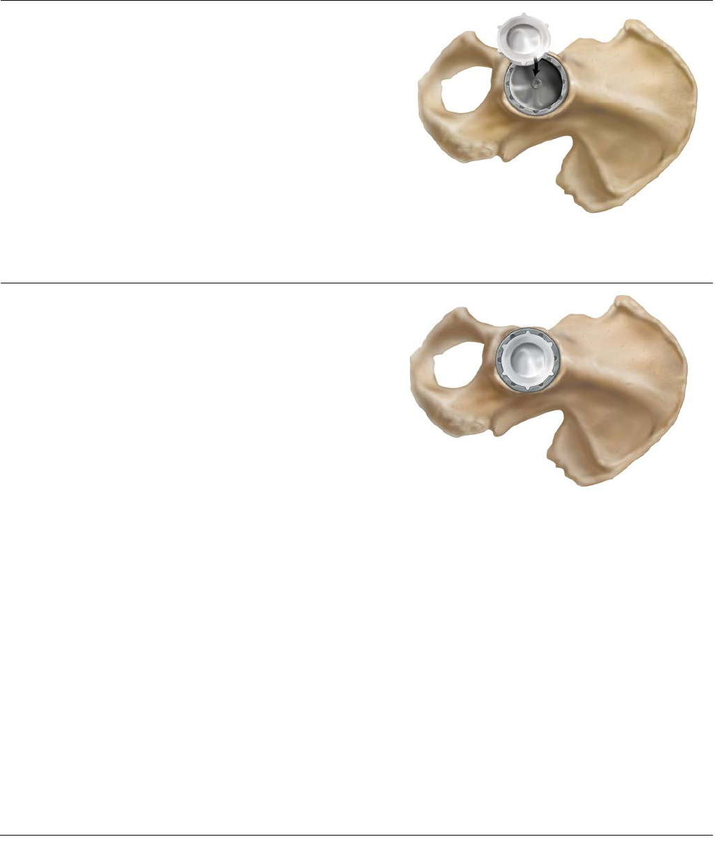
Figure 40: Align the liner anti-rotation tabs with shell scallops
POLYETHYLENE LINER
INSERTION AND IMPACTION
Following insertion of the final acetabular shell and
femoral component, the liner trials can be used in the
shell to confirm liner selection and evaluate joint stability
and range of motion. Prior to inserting the final
acetabular liner, thoroughly irrigate and clean the shell. It
is important to check the shell/liner locking groove for
debris. Remove all soft tissue from the face of the shell so
as not to impede liner seating (Figure 39). Remove all soft
tissue from the face of the shell so as not to impede liner
seating (Figure 39) while also ensuring all screws (if used)
are seated flush. An apex hole eliminator may be used
prior to liner insertion.
Prior to insertion/impaction, mate the liner anti-rotational
device (ARD) tabs with the ARD scallops on the shell
(Figure 40). There are six ARD tabs on the liners and 12
ARD scallops for shell diameters 48-72 mm. There are
four ARD tabs and eight ARD scallops in shell diameters
38-46 mm. This allows the liner to be rotated in
30-degree increments for shells 48-72 mm and 45-degree
increments for 38-46 mm.
Figure 39: Liner Insertion
24 DePuy Synthes Joint Reconstruction PINNACLE® HIP SOLUTIONS Polyethylene Surgical Technique
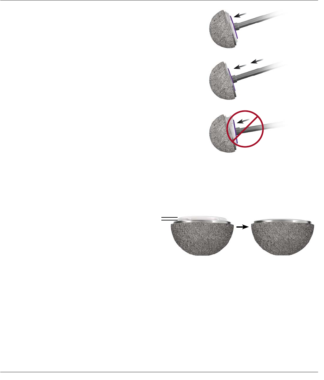
Figure 41: Liner Impaction
Figure 42: Liner Seating Height for a neutral liner
Neutral Liner
not seated fully
Neutral Liner seated fully
Seat the liner using the inner diameter (ID) liner impactor
that corresponds to the selected implant. Because the
locking mechanism is tapered, it is important to impact
the liner on-axis into the shell with multiple medium
blows (Figure 41).
Impacting the liner in a tilted position may prevent
complete seating.
Seating is visually confirmed when the liner ARDs are
flush with the face of the acetabular shell; however, the
liner face will remain proud in relation to the shell face by
approximately 1 mm for a neutral liner to 4mm for a
laterlized liner (Figure 42).
PINNACLE® HIP SOLUTIONS Polyethylene Surgical Technique DePuy Synthes Joint Reconstruction 25
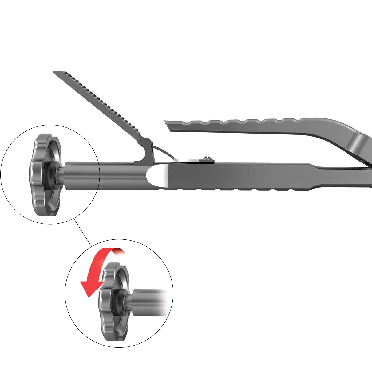
A polyethylene liner extractor is available to aid in
polyethylene liner extraction and to help ensure the
PINNACLE Shell is not damaged during polyethylene liner
extraction (Figure 43).
Open the extractor jaws and extend the ARD pin from the
extractor tip. Place the ARD pin into an empty ARD and
tightly close the jaws of the extractor (Figure 44). The teeth
of the extractor should dig into the inner diameter of the
polyethylene.
Once the ARD tip and teeth are secure on the
polyethylene, advance the extraction knob clockwise until
the polyethylene is removed (Figures 45 and 46).
Note: It is important to note that an extracted
polyethylene liner cannot be reused.
Figure 45
Figure 43: Polyethylene Liner Extractor
POLYETHYLENE LINER EXTRACTION
26 DePuy Synthes Joint Reconstruction PINNACLE® HIP SOLUTIONS Polyethylene Surgical Technique
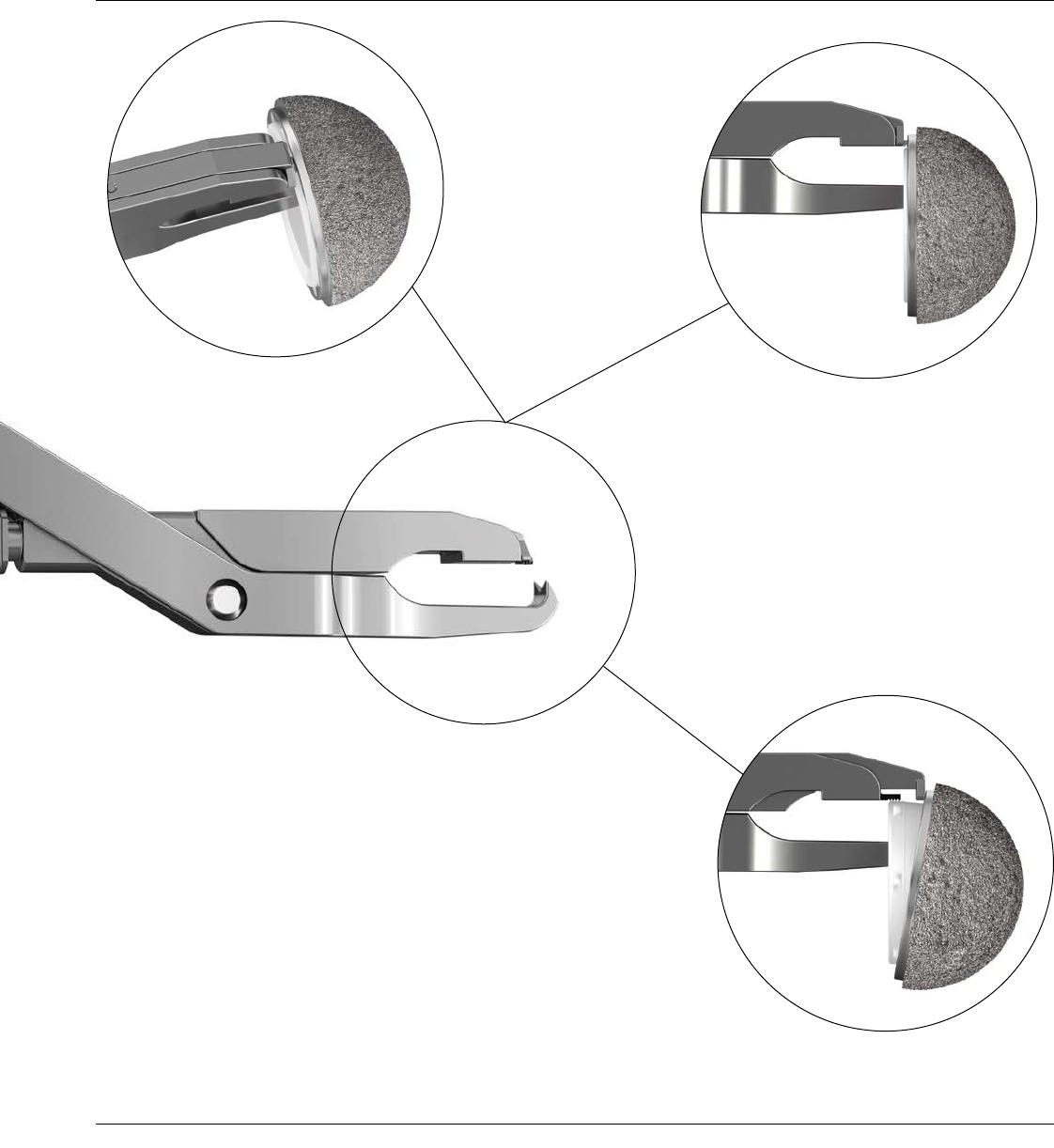
Figure 44
Figure 46
PINNACLE® HIP SOLUTIONS Polyethylene Surgical Technique DePuy Synthes Joint Reconstruction 27
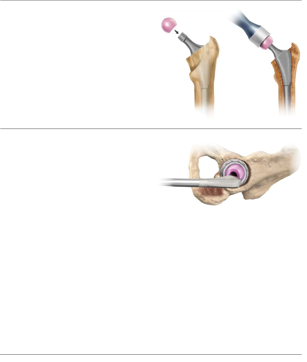
Figure 47 Figure 48
Figure 49
FUNCTIONAL ASSESSMENT
Select the appropriate femoral head, and place it onto the
clean, dry trunion of the selected stem. Apply finger
pressure to firmly seat the head onto the stem. Utilizing
the femoral head impactor, impact the femoral head onto
the stem with two moderate blows (Figures 47 and 48).
Once the head is impacted, the hip is then reduced with
final components in place.
Correct component placement is critical for the longevity
of the hip reconstruction. Figure 49 depicts the position
of the femoral component neck with relation to the
opening of the acetabular component with the
reconstructed hip in neutral rotation.
28 DePuy Synthes Joint Reconstruction PINNACLE® HIP SOLUTIONS Polyethylene Surgical Technique
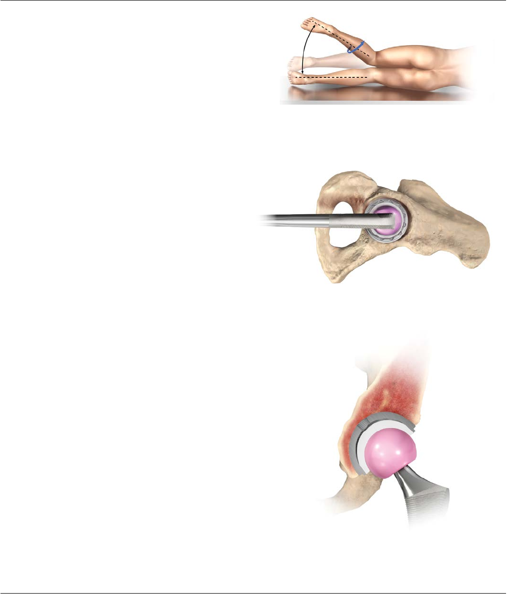
Figure 50: Combined Anteversion
Figure 51
Figure 52
To assess the combined anteversion of the femoral stem
and acetabular component, place the patient in the
lateral decubitus position with the operative hip gently
flexed and internally rotated (Figure 50) until the
circumference of the femoral head becomes coplanar
with the opening of the acetabular insert (i.e., the axis of
the femoral neck is perpendicular to the insert face). This
position is depicted through a frontal view in Figure 51
and through a lateral view in Figure 52.
The angle between horizontal and the internally rotated
operative leg provides an estimate of combined
anteversion of the acetabular component and the femoral
stem. Combined anteversion at 30-40 degrees is generally
acceptable.
Closure
Closure is based on the surgeon’s preference and the
individual case. If the capsule is retained, it is closed
separately. The gluteus minimus and gluteus medius can
be closed separately or as a single unit. At least one stitch
is passed through bone. Tension is relieved during the
repair with slight internal rotation. The repair should be
tested throughout the hip range of motion.
PINNACLE® HIP SOLUTIONS Polyethylene Surgical Technique DePuy Synthes Joint Reconstruction 29

TIGHT EXPOSURE AND
STABILITY TIPS
TIGHT EXPOSURE
If the exposure is tight, completely incise the anterior capsule, perform a partial or complete release of the gluteus
maximus tendon and release the reflected head of the rectus femoris.
STABILITY ASSESSMENT
Posterior Instability
With the trial implants in place, place the hip in 90 degrees of flexion, neutral abduction and internally rotate until sub-
luxation. If there is less than 60 degrees of internal rotation, determine the cause of instability.
Prosthetic Impingement
PROBLEM
• Femoral implant neck levers on the component rim.
SOLUTION
• Reposition shell to correct version/abduction.
• Increase head size and evaluate.
• Increase anteversion of the stem.
Soft Tissue Laxity
PROBLEM
• Lax soft tissue leading to multidirectional instability.
SOLUTION
• Increase the neck length.
• Advance the trochanter.
Bony Impingement
PROBLEM
• Prosthetic neck levers on anterior acetabular
osteophyte.
• Greater trochanter impinging on ilium.
SOLUTION
• Remove anterior osteophytes from the acetabulum.
Increase stem offset to move trochanter away from
the ilium.
• Remove anterior trochanteric bone.
Soft Tissue Impingement
PROBLEM
• Redundant anterior capsule causes head to lever
out of socket.
SOLUTION
• Resect redundant anterior capsule.
30 DePuy Synthes Joint Reconstruction PINNACLE® HIP SOLUTIONS Polyethylene Surgical Technique

STABILITY ASSESSMENT
Anterior Instability
With the implant trial in place, place the hip in extension and maximally externally rotate; subluxation should not occur.
If subluxation occurs, assess the following:
Prosthetic Impingement
PROBLEM
• Prosthetic neck impinges on the acetabular cup.
SOLUTION
• Reposition acetabular component to decrease
anteversion.
• Decrease anteversion of the femoral stem.
• Increase the head size and re-evaluate.
Bony Impingement
PROBLEM
• Femur impinges on the ischium.
SOLUTION
• Increase femoral offset.
• Decrease acetabular or stem anteversion.
THE KEYS TO MANAGING
STABILITY ARE:
1. Ensure the appropriate anteversion/abduction of the
acetabular and femoral components.
2. Restore correct leg length and femoral offset.
3. Repair the posterior capsule and rotators.
4. Work with the patient to ensure appropriate
post-operative precautions are followed.
PINNACLE® HIP SOLUTIONS Polyethylene Surgical Technique DePuy Synthes Joint Reconstruction 31

Size 100 Series
POROCOAT®
100 Series
GRIPTION®
100 Series
DUOFIX®
Sector
POROCOAT
Sector
GRIPTION
Sector
DUOFIX
44 mm N/A 1217-31-044 N/A N/A N/A N/A
46 mm N/A 1217-31-046 N/A N/A N/A N/A
48 mm 1217-01-048 1217-31-048 1217-11-048 1217-22-048 1217-32-048 1217-12-048
50 mm 1217-01-050 1217-31-050 1217-11-050 1217-22-050 1217-32-050 1217-12-050
52 mm 1217-01-052 1217-31-052 1217-11-052 1217-22-052 1217-32-052 1217-12-052
54 mm 1217-01-054 1217-31-054 1217-11-054 1217-22-054 1217-32-054 1217-12-054
56 mm 1217-01-056 1217-31-056 1217-11-056 1217-22-056 1217-32-056 1217-12-056
58 mm 1217-01-058 1217-31-058 1217-11-058 1217-22-058 1217-32-058 1217-12-058
60 mm 1217-01-060 1217-31-060 1217-11-060 1217-22-060 1217-32-060 1217-12-060
62 mm 1217-01-062 1217-31-062 1217-11-062 1217-22-062 1217-32-062 1217-12-062
64 mm 1217-01-064 1217-31-064 1217-11-064 1217-22-064 1217-32-064 1217-12-064
66 mm 1217-01-066 1217-31-066 1217-11-066 1217-22-066 1217-32-066 1217-12-066
Shell Options
ORDERING INFORMATION
32 DePuy Synthes Joint Reconstruction PINNACLE® HIP SOLUTIONS Polyethylene Surgical Technique
Size 300 Series
POROCOAT
Multi-Hole
POROCOAT
Multi-Hole
GRIPTION
48 mm 1217-03-048 1217-20-048 1217-30-048
50 mm 1217-03-050 1217-20-050 1217-30-050
52 mm 1217-03-052 1217-20-052 1217-30-052
54 mm 1217-03-054 1217-20-054 1217-30-054
56 mm 1217-03-056 1217-20-056 1217-30-056
58 mm 1217-03-058 1217-20-058 1217-30-058
60 mm 1217-03-060 1217-20-060 1217-30-060
62 mm 1217-03-062 1217-20-062 1217-30-062
64 mm 1217-03-064 1217-20-064 1217-30-064
66 mm 1217-03-066 1217-20-066 1217-30-066
68 mm N/A 1217-20-068 1217-30-068
70 mm N/A 1217-20-070 1217-30-070
72 mm N/A 1217-20-072 1217-30-072
Size Bantam
POROCOAT
Bantam
GRIPTION
38mm 1217-20-038 1217-30-038
40mm 1217-20-040 1217-30-040
42mm 1217-20-042 1217-30-042
44 mm 1217-20-044 1217-30-044
46 mm 1217-20-046 1217-30-046
PINNACLE SCREW OPTIONS
6.5 Cancellous Dome Screws
Length Cat. No.
8 mm 1217-08-500
15 mm 1217-15-500
20 mm 1217-20-500
25 mm 1217-25-500
30 mm 1217-30-500
35 mm 1217-35-500
40 mm 1217-40-500
45 mm 1217-45-500
50 mm 1217-50-500
55 mm 1217-55-500
60 mm 1217-60-500
65 mm 1217-65-500
70 mm 1217-70-500
Apex Hole Eliminator
Cat. No.
38 - 42 mm N/A
48 - 66 mm 1246-03-000
PINNACLE® HIP SOLUTIONS Polyethylene Surgical Technique DePuy Synthes Joint Reconstruction 33

METAL AND CERAMIC
FEMORAL HEAD OPTIONS
ARTICUL/EZE 12/14
M-Spec Metal Heads
Size OD Cat. No.
+1.5
+5
+8.5
28 mm
1365-11-500
1365-12-500
1365-13-500
-2
+1.5
+5
+8.5
+12
+15.5
36 mm
1365-50-000
1365-51-000
1365-52-000
1365-53-000
1365-54-000
1365-55-000
-2
+1.5
+5
+8.5
+12
+15.5
40 mm
1365-04-000
1365-05-000
1365-06-000
1365-07-000
1365-08-000
1365-09-000
-2
+1.5
+5
+8.5
+12
+15.5
44 mm
1365-60-000
1365-61-000
1365-62-000
1365-63-000
1365-64-000
1365-65-000
-2
+1.5
+5
+8.5
+12
+15.5
48 mm
1365-67-000
1365-68-000
1365-69-000
1365-70-000
1365-79-000
1365-80-000
S-ROM® 11/13
M-Spec Metal Heads
Size OD Cat. No.
+0
+3
+6
28 mm
1365-16-500
1365-17-500
1365-18-500
-3
+0
+3
+6
+9
+12
36 mm
1365-26-000
1365-31-000
1365-32-000
1365-33-000
1365-34-000
1365-36-000
-3
+0
+3
+6
+9
+12
40 mm
1365-41-500
1365-42-500
1365-43-500
1365-44-500
1365-45-500
1365-47-500
-3
+0
+3
+6
+9
+12
44 mm
1365-61-500
1365-62-500
1365-63-500
1365-64-500
1365-65-500
1365-66-500
ARTICUL/EZE 12/14
Standard Metal Heads
Size OD Cat. No.
+4
+7 22.225 mm 1365-29-000
1365-30-000
+1.5
+5
+8.5
+12
+15.5
28 mm
1365-11-000
1365-12-000
1365-13-000
1365-14-000*
1365-15-000*
+1
+5
+9
+13
32 mm
1365-21-000
1365-22-000
1365-23-000
1365-24-000*
S-ROM® 11/13
Standard Metal Heads
Size OD Cat. No.
+0 22.225 mm 52-2002
+0
+3
+6
+9
+12
28 mm
52-2028
87-5953
52-2029
87-5954*
52-2030*
+0
+3
+6
+9
+12
32 mm
52-2032
87-5955
52-2033
87-5956
52-2034*
* Skirted heads
34 DePuy Synthes Joint Reconstruction PINNACLE® HIP SOLUTIONS Polyethylene Surgical Technique

ARTICUL/EZE 12/14
BIOLOX delta TS
Ceramic Heads
Size OD Cat. No.
+1.5
+5
+8.5
+12
28 mm
1365-28-710
1365-28-720
1365-28-730
1365-28-740
+1
+5
+9
32 mm
1365-32-710
1365-32-720
1365-32-730
+1.5
+5
+8.5
+12
36 mm
1365-36-710
1365-36-720
1365-36-730
1365-36-740
+1.5
+5
+8.5
+12
40 mm
1365-40-710
1365-40-720
1365-40-730
1365-40-740
+1.5
+5
+8.5
+12
44 mm
1365-44-710
1365-44-720
1365-44-730
1365-44-740
ARTICUL/EZE 12/14
BIOLOX® delta
Ceramic Heads
Size OD Cat. No.
+1.5
+5
+8.5
28 mm
1365-28-310
1365-28-320
1365-28-330
+1
+5
+9
32 mm
1365-32-310
1365-32-320
1365-32-330
+1.5
+5
+8
+12
36 mm
1365-36-310
1365-36-320
1365-36-330
1365-36-340
S-ROM 11/13 BIOLOX
delta Ceramic Heads
Size OD Cat. No.
+0
+3
+6
28 mm
1365-28-210
1365-28-220
1365-28-230
+0
+3
+6
32 mm
1365-32-210
1365-32-220
1365-32-230
+0
+3
+6
+9
+12
36 mm
1365-36-210
1365-36-220
1365-36-230
1365-36-240
1365-36-250
PINNACLE® HIP SOLUTIONS Polyethylene Surgical Technique DePuy Synthes Joint Reconstruction 35
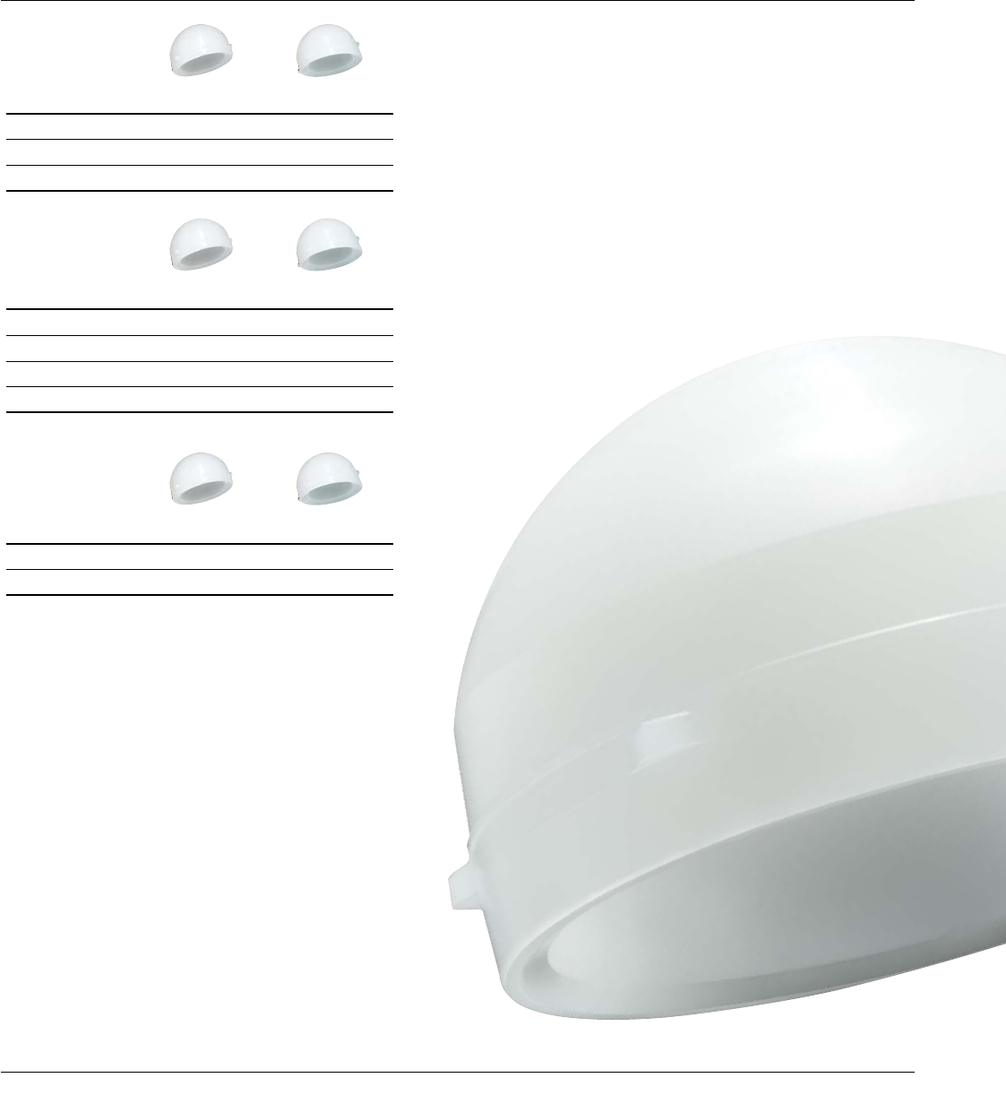
ALTRX® POLYETHYLENE
LINER OPTIONS
28 mm
Neutral +4 Neutral +4 10º Lipped
44 mm 1221-28-044 - 1221-28-144 -
46 mm 1221-28-046 - 1221-28-146 -
48 mm 1221-28-048 1221-28-448 1221-28-148 1221-28-248
50 mm 1221-28-050 1221-28-450 1221-28-150 1221-28-250
52 mm 1221-28-052 - - 1221-28-252
54 mm 1221-28-054 - - 1221-28-254
36 mm
Neutral +4 Neutral +4 10º
52 mm 1221-36-052 1221-36-452 1221-36-152
54 mm 1221-36-054 1221-36-454 1221-36-154
56 mm 1221-36-056 1221-36-456 1221-36-156
58 mm 1221-36-058 1221-36-458 1221-36-158
60 mm 1221-36-060 1221-36-460 1221-36-160
62 mm 1221-36-062 1221-36-462 1221-36-162
64 mm 1221-36-064 1221-36-464 1221-36-164
66 mm 1221-36-066 1221-36-466 1221-36-166
32 mm
Neutral +4 Neutral +4 10º Lipped
48 mm 1221-32-048 1221-32-448 1221-32-148 -
50 mm 1221-32-050 1221-32-450 1221-32-150 -
52 mm 1221-32-052 1221-32-452 1221-32-152 1221-32-252
54 mm 1221-32-054 1221-32-454 1221-32-154 1221-32-254
56 mm 1221-32-056 - - 1221-32-256
58 mm 1221-32-058 - - 1221-32-258
60 mm - - - 1221-32-260
62 mm - - - 1221-32-262
64 mm - - - 1221-32-264
66 mm - - - 1221-32-266
36 DePuy Synthes Joint Reconstruction PINNACLE® HIP SOLUTIONS Polyethylene Surgical Technique
ALTRX LD POLYTHYLENE
LINER OPTIONS
40 mm
+4 Neutral +4 10º
56 mm 1221-40-456 1221-40-156
58 mm 1221-40-458 1221-40-158
60 mm 1221-40-460 1221-40-160
44 mm
+4 Neutral +4 10º
62 mm 1221-44-462 1221-44-162
64 mm 1221-44-464 1221-44-164
66 mm 1221-44-466 1221-44-166
68 mm 1221-44-468 1221-44-168
48 mm
+4 Neutral +4 10º
70 mm 1221-48-470 1221-48-170
72 mm 1221-48-472 1221-48-172
PINNACLE® HIP SOLUTIONS Polyethylene Surgical Technique DePuy Synthes Joint Reconstruction 37
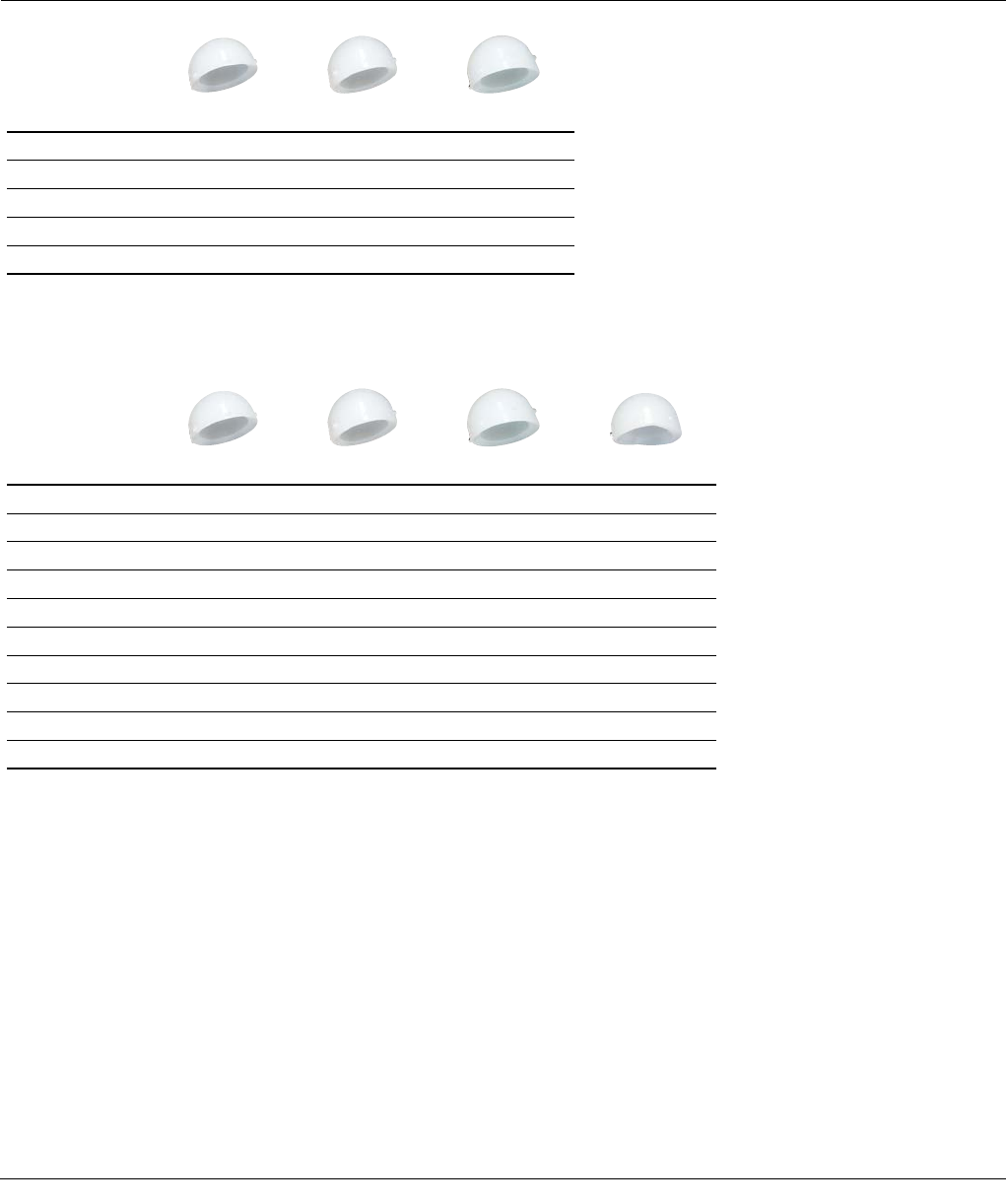
22.225 mm
Neutral 10º +4 10º
38 mm 1219-22-038 1219-22-138 -
40 mm 1219-22-040 1219-22-140 -
42 mm 1219-22-042 1219-22-142 -
44 mm 1219-22-044 1219-22-144 -
46 mm 1219-22-046 1219-22-146 -
28 mm
Neutral +4 Neutral +4 10º Lipped
44 mm 1219-28-044 - 1219-28-144 -
46 mm 1219-28-046 - 1219-28-146 -
48 mm 1219-28-048 1219-28-448 1219-28-148 1219-28-248
50 mm 1219-28-050 1219-28-450 1219-28-150 1219-28-250
52 mm 1219-28-052 1219-28-452 1219-28-152 1219-28-252
54 mm 1219-28-054 1219-28-454 1219-28-154 1219-28-254
56 mm 1219-28-056 1219-28-456 1219-28-156 1219-28-256
58 mm 1219-28-058 1219-28-458 1219-28-158 1219-28-258
60 mm 1219-28-060 - 1219-28-160 -
62 mm 1219-28-062 - 1219-28-162 -
MARATHON® CROSS-LINKED
POLYETHYLENE LINER OPTIONS
38 DePuy Synthes Joint Reconstruction PINNACLE® HIP SOLUTIONS Polyethylene Surgical Technique

36 mm
Neutral +4 Neutral +4 10º
52 mm -1219-36-452 1219-36-152
54 mm -1219-36-454 1219-36-154
56 mm 1219-36-056 1219-36-456 1219-36-156
58 mm 1219-36-058 1219-36-458 1219-36-158
60 mm 1219-36-060 1219-36-460 1219-36-160
62 mm 1219-36-062 1219-36-462 1219-36-162
64 mm 1219-36-064 1219-36-464 1219-36-164
66 mm 1219-36-066 1219-36-466 1219-36-166
68 mm 1219-36-068 - 1219-36-168
70 mm 1219-36-070 - 1219-36-170
72 mm 1219-36-072 - 1219-36-172
32 mm
Neutral +4 Neutral +4 10º Lipped
48 mm -1219-32-448 1219-32-148 -
50 mm -1219-32-450 1219-32-150 -
52 mm 1219-32-052 1219-32-452 1219-32-152 1219-32-252
54 mm 1219-32-054 1219-32-454 1219-32-154 1219-32-254
56 mm 1219-32-056 1219-32-456 1219-32-156 1219-32-256
58 mm 1219-32-058 1219-32-458 1219-32-158 1219-32-258
60 mm 1219-32-060 1219-32-460 1219-32-160 1219-32-260
62 mm 1219-32-062 1219-32-462 1219-32-162 1219-32-262
64 mm 1219-32-064 1219-32-464 1219-32-164 1219-32-264
66 mm 1219-32-066 1219-32-466 1219-32-166 1219-32-266
68 mm - 1219-32-468 - 1219-32-268
70 mm - 1219-32-470 - 1219-32-270
72 mm - 1219-32-472 - 1219-32-272
PINNACLE® HIP SOLUTIONS Polyethylene Surgical Technique DePuy Synthes Joint Reconstruction 39

22.225mm
Neutral
22.225mm
+4 10°
28mm
Neutral
28mm
+4 Neutral
28mm
+4 10°
28mm
Lipped
32mm
Neutral
32mm
+4 Neutral
32mm
+4 10°
Dome
(mm)
45
Degree
(mm)
Dome
(mm)
45
Degree
(mm)
Dome
(mm)
45
Degree
(mm)
Dome
(mm)
45
Degree
(mm)
Dome
(mm)
45
Degree
(mm)
Dome
(mm)
45
Degree
(mm)
Dome
(mm)
45
Degree
(mm)
Dome
(mm)
45
Degree
(mm)
Dome
(mm)
45
Degree
(mm)
Shell Size (OD) mm
38 5.6 5.0 5.6 5.0
40 6.6 6.0 6.6 6.0
42 7.6 6.9 7.6 6.9
44 8.6 7.9 8.6 7.9 5.5 4.9 7.5 6.5
46 9.6 8.9 9.6 8.9 6.5 5.9 8.5 7.1
48 6.7 6.4 9.5 8.1 9.5 8.1 6.7 6.4 5.9 5.1 7.5 6.1 7.5 6.1
50 7.8 7.4 10.5 9.2 10.5 9.2 7.8 7.4 6.3 5.7 8.5 7.1 8.5 7.1
52 8.1 8.0 11.5 10.2 11.5 10.2 8.1 8.0 6.9 6.5 10.8 8.3 10.8 8.3
54 8.5 8.5 12.5 11.2 12.5 11.2 8.5 8.5 7.9 7.4 11.8 9.3 11.8 9.3
56 9.5 9.5 13.5 12.2 13.5 12.2 9.5 9.5 8.3 8.0 12.2 10.2 12.2 10.2
58 10.3 10.3 14.3 12.9 14.3 12.9 10.3 10.3 8.3 8.3 12.4 11.0 12.4 11.0
60 11.0 11.0 15.0 13.7 9.0 9.0 13.1 11.8 13.1 11.8
62 11.8 11.8 15.8 14.4 9.8 9.8 13.9 12.5 13.9 12.5
64 10.5 10.5 14.6 13.3 14.6 13.3
66 11.3 11.3 15.4 14.0 15.4 14.0
68 16.0 15.1
70 17.0 15.7
72 18.0 16.7
Thickness at
45° Angle
Dome Thickness
POLYETHYLENE LINER
THICKNESS
40 DePuy Synthes Joint Reconstruction PINNACLE® HIP SOLUTIONS Polyethylene Surgical Technique

Thickness at
45° Angle
32mm
Lipped
36mm
Neutral
36mm
+4 Neutral
36mm
+4 10°
40mm
+4 Neutral
40mm
+4 10°
44mm
+4 Neutral
44mm
+4 10°
48mm
+4 Neutral
48mm
+4 10°
Dome
(mm)
45
Degree
(mm)
Dome
(mm)
45
Degree
(mm)
Dome
(mm)
45
Degree
(mm)
Dome
(mm)
45
Degree
(mm)
Dome
(mm)
45
Degree
(mm)
Dome
(mm)
45
Degree
(mm)
Dome
(mm)
45
Degree
(mm)
Dome
(mm)
45
Degree
(mm)
Dome
(mm)
45
Degree
(mm)
Dome
(mm)
45
Degree
(mm)
38
Shell Size (OD) mm
40
42
44
46
48
50
6.9 6.5 5.5 4.9 7.5 6.2 7.5 6.2 52
7.9 7.4 5.6 5.3 8.5 7.2 8.5 7.2 54
8.3 8.0 6.2 6.0 9.5 8.2 9.5 8.2 7.5 6.1 7.5 6.1 56
8.3 8.3 6.9 6.7 10.3 8.9 10.3 8.9 8.3 6.9 8.3 6.9 58
9.0 9.0 7.5 7.3 11.0 9.7 11.0 9.7 9.0 7.6 9.0 7.6 60
9.8 9.8 7.7 7.7 11.8 10.4 11.8 10.4 7.7 6.4 7.7 6.4 62
10.5 10.5 8.5 8.5 12.5 11.2 12.5 11.2 8.5 7.2 8.5 7.2 64
11.3 11.3 9.2 9.2 13.3 11.9 13.3 11.9 9.2 7.9 9.2 7.9 66
12.0 12.0 10.0 10.0 14.0 12.7 10.0 8.7 10.0 8.7 68
13.0 13.0 11.0 11.0 15.0 13.7 9.0 7.7 9.0 7.7 70
14.0 14.0 12.0 12.0 16.0 14.7 10.0 8.7 10.0 8.7 72
PINNACLE® HIP SOLUTIONS Polyethylene Surgical Technique DePuy Synthes Joint Reconstruction 41

IMPORTANT:
This Essential Product Information sheet does not include
all of the information necessary for selection and use
of a device. Please see full labeling for all necessary
information.
INTENDED USE/INDICATIONS:
Total Hip Arthroplasty (THA) is intended to provide
increased patient mobility and reduce pain by replacing
the damaged hip joint articulation in patients where
there is evidence of sufficient sound bone to seat and
support the components.
THA IS INDICATED
for a severely painful and/or disabled joint from
osteoarthritis, traumatic arthritis, rheumatoid arthritis or
congenital hip dysplasia; avascular necrosis of the femoral
head; acute traumatic fracture of the femoral head or
neck; failed previous hip surgery; and certain cases of
ankylosis.
POROUS-COATED PINNACLE
ACETABULAR CUPS ARE INDICATED
for cementless applications. Self-Centering Hip Prostheses
and Hemi-Hip Prostheses are intended to be used for
hemi-hip arthroplasty where there is evidence of a
satisfactory natural acetabulum and sufficient femoral
bone to seat and support the femoral stem. The Cathcart
is not intended for use in total hip arthroplasty.
HEMI-HIP ARTHROPLASTY IS INDICATED
in the following conditions: Acute fracture of the
femoral head or neck that cannot be reduced and
treated with internal fixation; fracture dislocation of the
hip that cannot be appropriately reduced and treated
with internal fixation; avascular necrosis of the femoral
head; non-union of femoral neck fractures; certain high
subcapital and femoral neck fractures in the elderly;
degenerative arthritis involving only the femoral head in
which the acetabulum does not require replacement; and
pathology involving only the femoral head/neck and/or
proximal femur that can be adequately treated by hemi-
hip arthroplasty.
TOTAL HIP PROSTHESES, SELF-CENTERING
HIP PROSTHESES AND HEMI-HIP PROSTHESES
ESSENTIAL PRODUCT INFORMATION
CONTRAINDICATIONS:
THA and hemi-hip arthroplasty are contraindicated
in cases of: active local or systemic infection; loss of
musculature, neuromuscular compromise or vascular
deficiency in the affected limb, rendering the procedure
unjustifiable; poor bone quality; Charcot’s or Paget’s
disease; for hemi-hip arthroplasty – pathological
conditions of the acetabulum that preclude the use
of the natural acetabulum as an appropriate articular
surface. Ceramic heads without inner titanium sleeves
are contraindicated in revision surgery when the femoral
stem is not being replaced or for use with any other than
a polyethylene or metal-backed polyethylene cup.
WARNINGS AND PRECAUTIONS:
Ceramic coated femoral stem prostheses are indicated for
uncemented press fit fixation.
CAUTION: DO NOT USE BONE CEMENT FOR
FIXATION OF A CERAMIC COATED PROSTHESIS.
Components labeled for “Cemented Use Only” are to
be implanted only with bone cement. The following
conditions tend to adversely affect hip replacement
implants: excessive patient weight, active sports
participation, high levels of patient activity, manual labor,
alcohol and drug addition, likelihood of falls, poor bone
stock, metabolic disorders, history of infections, severe
deformities leading to impaired fixation or improper
positioning, tumors of the supporting bone structures,
allergic reactions to materials, congenital dysplasia of the
hip, tissue reactions, and disabilities of other joints.
ADVERSE EVENTS:
The following are the most frequent adverse events
after hip arthroplasty: change in position of the
components, loosening of components, wear or fracture
of components, dislocation, infection, peripheral
neuropathies, tissue reaction.
42 DePuy Synthes Joint Reconstruction PINNACLE® HIP SOLUTIONS Polyethylene Surgical Technique

ADDITIONAL INSTRUCTIONS
• Use caution when handling ceramic components during
assembly to avoid damage to components.
• It is important not to disassemble/reassemble the ceramic
femoral head from the mating femoral stem. Doing so may
damage these mating surfaces and lead to early failure.
• Ensure that the outer diameter of the femoral head matches
the inner diameter of the acetabular liner by verifying
labeling. Sizing mismatch may result in premature implant
failure.
• While rare, ceramic head fracture may occur and requires
care in the retrieval of all particles from the operative site.
Carefully remove any ceramic particles or shards manually or
with a pulse lavage. Remove any tissue which may have been
affected by abrasion particles.
• Examine instruments and confirm functionality prior to use.
Instruments that have been subjected to overuse or misuse
conditions are susceptible to failure or may damage implants
and should not be used.
REFERENCES:
1. Learmonth ID, Young C, Rorabeck C. The operation of the century:
total hip replacement. Lancet 2007;370:1508-19.
2. Brodner W, Grübl A, Jankovsky R, Meisinger V, Lehr S, Gottsauner-
Wolf FJ. Cup inclination and serum concentration of cobalt and
chromium after metal-on-metal total hip arthroplasty. J Arthroplasty.
2004;19(8 Suppl 3):66-70.
3. Williams S, Leslie I, Isaac G, Jin Z, Ingham E, Fisher J. Tribology and
wear of
metal-on-metal hip prostheses: influence of cup angle and head
position. J Bone Joint Surg. 2008;90A (Suppl 3):111-7.
4. Udomkiat P, Dorr LD, Wan Z. Cementless hemispheric porous-coated
sockets implanted with press-fit technique without screws: average
ten-year follow-up.
J Bone Joint Surg. 2002;84A:1195-200.
5. Schmalzried TP, Guttmann D, Grecula M, Amstutz H. The relationship
between the design, position, and articular wear of acetabular
components inserted without cement and the development of pelvic
osteolysis. J Bone Joint Surg.1994;76A:677-688.
6. Kennedy JG, Rogers WB, Soffee KE, et al. Effect of acetabular
component orientation on recurrent dislocation, pelvic osteolysis,
polyethylene wear and component migration. J Arthroplasty
1998;13:530-534.
7. Prudhommeaux F, Hamadouche M, Nevelos J, et al. Wear of alumina-
on-alumina total hip arthroplasty at a mean 11-year followup. Clin
Orthop Relat Res. 2000; 397:113.
8. Walter WL, O’Toole GC, Walter WK, Ellis A, Zicat BA. Squeaking in
ceramic-on-ceramic hips: the importance of acetabular component
orientation. J Arthroplasty. 2007;22:496-503.
9. Tower SS, Currier JH, Currier BH, Lyford KA, Van Citters DW,
Mayor MB. Rim cracking of the cross-linked longevity polyethylene
acetabular liner after total hip arthroplasty. J Bone Joint Surg.
2007;89A(10):2212-7.
10. Archbold HAP et al. The transverse acetabular ligament: an aid to
orientation of the acetabular component during primary total hip
replacement. J Bone Joint Surg. 2006;88B:883-6.
11. Data on file – DVE-001038-ROM December 2008.
12. ISO 21535:2007(E)
PINNACLE® HIP SOLUTIONS Polyethylene Surgical Technique DePuy Synthes Joint Reconstruction 43

DePuy Orthopaedics, Inc.
700 Orthopaedic Drive
Warsaw, IN 46582
T. +1 (800) 366-8143
www.depuysynthes.com
© DePuy Orthopaedics, Inc. 2013. All rights reserved.
0612-83-512 2.5M 06/13
Limited Warranty and Disclaimer: DePuy Orthopaedics products are sold with a limited warranty to the original purchaser against defects in workmanship
and materials. Any other express or implied warranties, including warranties of merchantability or fitness, are hereby disclaimed.
WARNING: In the USA, this product has labeling limitations. See package insert for complete information.
CAUTION: USA Law restricts these devices to sale by or on the order of a physician.
Not all products are currently available in all markets.
Biolox® delta is a trademark of CeramTec GmbH.
Third party trademarks used herein are trademarks of their respective owners.
