Programming Manual
User Manual: Pdf
Open the PDF directly: View PDF ![]() .
.
Page Count: 394 [warning: Documents this large are best viewed by clicking the View PDF Link!]
- B-63943EN-2/07 Vol 1/1
- B-63943EN-2/07
- SAFETY PRECAUTIONS
- TABLE OF CONTENTS
- 1 GENERAL
- 2 MACRO COMPILER AND MACRO EXECUTOR
- 3 EXECUTION MACRO FUNCTION
- 3.1 GENERAL
- 3.2 CALLING AN EXECUTION MACRO
- 3.2.1 Overview
- 3.2.2 Simple Call (G65)
- 3.2.3 Modal Call (G66/G66.1)
- 3.2.4 Macro Call Using G Code
- 3.2.5 Macro Call Using G Code with Decimal Point
- 3.2.6 Macro Call Using G Code (Specification of 1 Set)
- 3.2.7 Macro Call Using G Code (Specification of 3 Sets)
- 3.2.8 Macro Modal Call Using G Code
- 3.2.9 Special Macro Call Using G Code
- 3.2.10 Macro Call Using M Code
- 3.2.11 Macro Call Using M Code (Specification of 3 Sets)
- 3.2.12 Special Macro Call Using M Code
- 3.2.13 Special Macro Call Using Axis Address
- 3.2.14 Special Macro Call Using T Code
- 3.2.15 Special Macro Call Using D Code
- 3.2.16 Special Macro Call Using H Code
- 3.2.17 Special Macro Call Using S Code
- 3.2.18 Subprogram Call (M98)
- 3.2.19 Subprogram Call Using M Code
- 3.2.20 Subprogram Call Using M Code in the Specified Range
- 3.2.21 Subprogram Call Using M Code (Specification of 3 Sets)
- 3.2.22 Subprogram Call Using S Code
- 3.2.23 Subprogram Call Using T Code
- 3.2.24 Subprogram Call Using Second Auxiliary Function Code
- 3.2.25 Subprogram Call Using Specific Code
- 3.2.26 Subprogram Call for User Program
- 3.2.27 P-CODE Workpiece Number Search
- 3.2.28 Macro Call Argument for Axis Name Expansion
- 3.3 DIAGNOSIS DATA
- 3.4 LIMITATIONS ON EXECUTION MACROS
- 3.4.1 Commands which cannot Use Execution Macros
- 3.4.2 Functions which cannot Use Execution Macros
- 3.4.3 Optional Block Skip
- 3.4.4 Interruption Type Custom Macro
- 3.4.5 Axis Specification and Extended Axis Name Specification Using an Axis Number
- 3.4.6 Method of Variable Specification for Address N in the Programmable Data Input Mode
- 3.4.7 G Code System Conversion (for a Lathe System)
- 3.5 DIFFERENCES FROM THE Series 16i
- 4 CONVERSATIONAL MACRO FUNCTION AND AUXILIARY MACRO FUNCTION
- 5 MACRO VARIABLES
- 5.1 MACRO VARIABLE LIST
- 5.2 LOCAL VARIABLES (#1 TO #33) / ARRAY-TYPE VARIABLES (#1 TO #99)
- 5.3 COMMON VARIABLES (#100 TO #199 AND #500 TO #999)
- 5.4 P-CODE VARIABLES (#10000 TO #19999)
- 5.5 EXTENDED P-CODE VARIABLES (#20000 TO #89999)
- 5.6 P-CODE VARIABLES/EXTENDED P-CODE VARIABLES IN THE MULTI-PATH CONTROL SYSTEM
- 5.7 CUSTOM MACRO COMMON VARIABLES (#99100 TO #99999)
- 5.8 CUSTOM MACRO SYSTEM VARIABLES (#1000 AND UP, #10000 AND UP, #100000 AND UP)
- 5.9 ARITHMETIC AND LOGIC OPERATION
- 5.10 DIFFERENCES FROM THE Series 16i
- 6 MACRO EXECUTOR FUNCTION
- 6.1 SCREEN DISPLAY FUNCTIONS
- 6.1.1 Screen Coordinate System
- 6.1.2 Screen Display Identification Variables (#8681 and #8682)
- 6.1.3 Screen Display Control Codes
- 6.1.3.1 Screen clear (G202)
- 6.1.3.2 Color specification (G240)
- 6.1.3.3 Drawing start point setting (G242)
- 6.1.3.4 Command for display with background color (G250)
- 6.1.3.5 Character display (G243)
- 6.1.3.6 Direct language specification function
- 6.1.3.7 User-defined character registration and display function (G319)
- 6.1.3.8 Drawing line type specification (G244)
- 6.1.3.9 Prompt statement display (G280)
- 6.1.3.10 Linear drawing (G01)
- 6.1.3.11 Circular drawing (clockwise) (G02)
- 6.1.3.12 Circular drawing (counterclockwise) (G03)
- 6.1.3.13 Cursor display (rectangular cursor) (G230)
- 6.1.3.14 Graphic cursor function (G249)
- 6.1.3.15 Cursor control (#8505, #8506, and #8507)
- 6.1.3.16 Absolute mode (G390)/incremental mode (G391) specification
- 6.1.3.17 Graphic coordinate system setting (G392)
- 6.1.3.18 Rapid traverse rate specification (G311)
- 6.1.3.19 Rapid traverse drawing (G300)
- 6.1.3.20 Graphic filling function (G206)
- 6.1.3.21 Rectangular display (G204)
- 6.1.3.22 Marking (G321)
- 6.1.3.23 Shift function for graphic screen adjustment
- 6.1.3.24 Reading of the graphic state (#8800)
- 6.1.3.25 Brightness modulation mode display on the monochrome LCD and base color
- 6.1.3.26 Differences from the Series 16i
- 6.1.4 Character String Registration Program Number Specification (#8509)
- 6.1.5 Screen Control Function (#8510, #8571)
- 6.1.6 State Display Mask Function on the Conversational Macro Screen
- 6.1.7 O and N Number Display Mask Function
- 6.1.8 Soft Key Frame Display Mask Function
- 6.1.9 Display 7 Soft Keys Data on the 12 Soft Keys Type
- 6.1.10 User Help Screen Control Function
- 6.2 KEY INPUT AND DATA INPUT CONTROL
- 6.3 Specification of a PMC Path in Multi-Path PMCs (#8603)
- 6.4 ADDRESS FUNCTIONS
- 6.5 PMC ADDRESS READING/WRITING (G310)
- 6.6 CNC DATA READING/WRITING
- 6.7 READER/PUNCHER INTERFACE
- 6.8 MEMORY CARD CONTROL
- 6.9 CNC PROGRAM REFERENCING AND WRITING, AND PROGRAM INFORMATION READING
- 6.10 CUTTING TIME, DISTANCE READ AND PRESET FUNCTIONS
- 6.11 RELATIVE COORDINATE READ AND PRESET FUNCTIONS (#8996 TO #8999)
- 6.12 ARRAY-TYPE PROCESSING AND REFERENCING OF P-CODE VARIABLES
- 6.13 TORQUE LIMIT OVERRIDE CONTROL (#8990 TO #8993 AND #8621 TO #8628)
- 6.14 PMC AXIS CONTROL
- 6.15 FILE CONTROL
- 6.16 AXIS-DIRECTION-BY-AXIS-DIRECTION INTERLOCK FUNCTION (#8600, #8601, #8607, AND #8608)
- 6.17 WINDOW FUNCTION (#8996 TO #8999)
- 6.17.1 General
- 6.17.2 Alarm Information and External Alarm Information
- 6.17.3 Axis, Relative Coordinate, Servo Motor Load Current Value, and Positional Deviation value
- 6.17.4 Run Time and Parts Count
- 6.17.5 Diagnosis Information
- 6.17.6 System, Servo, and PMC Series Information
- 6.17.7 Differences from the Series 16i
- 6.18 FUNCTION FOR SEARCHING DATA TABLES FOR CONTROL VARIABLES
- 6.1 SCREEN DISPLAY FUNCTIONS
- 7 DEBUGGING FUNCTION
- 8 OPERATION
- 9 PARAMETERS
- APPENDIX
- INDEX
- REVISION RECORD
- B-63943EN-2/07
- Addendum
FANUC Series 30+/31+/32+-MODEL A
FANUC Series 30+/31+/32+-MODEL B
FANUC Series 35+-MODEL B
FANUC Series 0+-MODEL F
FANUC Power Motion +-MODEL A
PROGRAMMING MANUAL
B-63943EN-2/07
Macro Executor

• No part of this manual may be reproduced in any form.
• All specifications and designs are subject to change without notice.
The products in this manual are controlled based on Japan’s “Foreign Exchange and
Foreign Trade Law”. The export of Series 30i-A/B, Series 31i-A5/B5 from Japan is subject
to an export license by the government of Japan. Other models in this manual may also be
subject to export controls.
Further, re-export to another country may be subject to the license of the government of
the country from where the product is re-exported. Furthermore, the product may also be
controlled by re-export regulations of the United States government.
Should you wish to export or re-export these products, please contact FANUC for advice.
In this manual we have tried as much as possible to describe all the various matters.
However, we cannot describe all the matters which must not be done, or which cannot be
done, because there are so many possibilities.
Therefore, matters which are not especially described as possible in this manual should be
regarded as ”impossible”.
B-63943EN-2/07
SAFETY PRECAUTIONS
s-1
SAFETY PRECAUTIONS
DEFINITION OF WARNING, CAUTION, AND NOTE
This manual includes safety precautions for protecting the user and preventing damage to the machine.
Precautions are classified into Warning and Caution according to their bearing on safety. Also,
supplementary information is described as a Note. Read the Warning, Caution, and Note thoroughly
before attempting to use the machine.
WARNING
Applied when there is a danger of the user being injured or when there is a
danger of both the user being injured and the equipment being damaged if the
approved procedure is not observed.
CAUTION
Applied when there is a danger of the equipment being damaged, if the
approved procedure is not observed.
NOTE
The Note is used to indicate supplementary information other than Warning and
Caution.
• Read this manual carefully, and store it in a safe place.
GENERAL WARNINGS FOR CNC APPLICATION DEVELOPMENT
WARNING
Be careful enough for the following warnings when you develop two or more
applications or use networks.
If you neglect them, there is a danger of the user being injured or there is a
danger of both the user being injured and the equipment being damaged.
1 Be careful enough if you write an identical NC data, an identical PMC data or a
series of related data set by two or more above applications including network
functions. Because they are executed based on each individual cycles (in other
words, asynchronous cycles), there is a possibility that the data will be written in
an unexpected order.
Therefore, do NOT write above data in the following cases.
- Applications and network functions
- Two or more applications
- Two or more network functions
Data, applications and network functions of interest are listed in below. However,
all may not be listed completely because new features will be added in the
future.
SAFETY PRECAUTIONS
B-63943EN-2/07
- s-2 -
WARNING
2 Be careful enough that you must prevent PMC signals in the same byte from
being written by the following two or more applications including network
functions. While an application reads and writes one byte of PMC signals, other
applications may write the same byte.
3 Be careful enough if you process a PMC signal set that is related to a NC
function by using the following two or more applications including network
functions. Because they are executed based on each individual cycles (in other
words, asynchronous cycles), there is a possibility that the NC may receive the
PMC signal set in an unexpected order.
4 Generally, when multi-byte data are read or written at once among the following
two or more applications including network functions, the coherency of the read
multi-byte data (in other words, reading all latest data at once) is not guaranteed.
To ensure the coherency of the multi-byte data, prepare flags to notify the
completion of reading or writing process that is separated from the entity of the
data and make the handshaking process to access the data by using the flags.
Data List Table
Category Data
General data for NC
Parameter, Tool compensation value and related data,
Work zero offset value and related data, Workpiece
coordinate system shift value and related data, Macro
variable, P-CODE variable, Program and related data,
Tool management function data, Tool life management
data, Error compensation related data , Overtravel check
(Interference check) related data
PMC data PMC signal, PMC parameter
List Table of Applications and Network Functions
Category Functions
Applications PMC Ladder, Macro Executor, C Language Executor, FANUC PICTURE,
FOCAS2
Network functions FL-net, EtherNet/IP, PROFINET, Modbus/TCP, PROFIBUS-DP, DeviceNet,
CC-Link
5 CNC has functions that read or write PMC signals in other than the G/F address.
Be careful enough if the above mentioned applications and network read or write
PMC signals used by these functions. When reading or writing the same PMC
signal, applications or CNC functions may work in an unexpected manner.
B-63943EN-2/07
SAFETY PRECAUTIONS
s-3
GENERAL WARNINGS FOR MACRO EXECUTOR APPLICATION
DEVELOPMENT
WARNING
1 Be careful enough if you write an NC data which can influence working of
machine. There is a possibility that the NC may work with a wrong NC data. In
this case, it may cause an unexpected machine behavior and also tools,
machines or workpieces may be damaged.
You have to make it sure that the writing of the NC data is safe and proper,
when modifying the NC data which can influence working of machine.
The NC data which can influence working of machine is as follows. All of them
may not be mentioned below when new application or function will be released.
NC data which can influence working of machine :
NC parameter, NC program, Tool offset value, Pitch error compensation
data, Work zero offset value, Custom macro value, P code macro value
2 Be careful enough if you write a PMC signal. There is a possibility that the NC
may work with a wrong PMC signal. In this case, it may cause an unexpected
machine behavior and also tools, machines or workpieces may be damaged.
You have to make it sure that the writing of the PMC signal is safe and proper,
when modifying the PMC signal.

B-63943EN-2/07
TABLE OF CONTENTS
c-1
TABLE OF CONTENTS
SAFETY PRECAUTIONS ............................................................................ s-1
DEFINITION OF WARNING, CAUTION, AND NOTE ............................................. s-1
GENERAL WARNINGS FOR CNC APPLICATION DEVELOPMENT ..................... s-1
GENERAL WARNINGS FOR MACRO EXECUTOR APPLICATION
DEVELOPMENT ..................................................................................................... s-3
1 GENERAL ............................................................................................... 1
2 MACRO COMPILER AND MACRO EXECUTOR ................................... 3
2.1 MACRO COMPILER ...................................................................................... 3
2.1.1 P-CODE Macro and P-CODE File ........................................................................... 3
2.2 MACRO EXECUTOR .................................................................................... 5
2.3 P-CODE MACRO .......................................................................................... 6
2.3.1 Limitations on Commands ....................................................................................... 6
2.3.2 Differences from the Series 16i ................................................................................ 8
2.4 MODULE DIVISION FUNCTION ................................................................... 8
2.4.1 Method of Module Addition ..................................................................................... 8
2.5 MULTI-PATH CONTROL FUNCTION ......................................................... 10
2.5.1 Independent Operating Environment for Each Path ............................................... 10
2.5.2 P-CODE Variables/Extended P-CODE Variables Common to Paths .................... 11
2.5.3 Multiple P-CODE Macros Independent of Paths ................................................... 11
2.5.4 Reading the Path Number Currently under Execution (#8531) ............................. 12
3 EXECUTION MACRO FUNCTION ........................................................ 13
3.1 GENERAL ................................................................................................... 13
3.2 CALLING AN EXECUTION MACRO ........................................................... 13
3.2.1 Overview ................................................................................................................ 13
3.2.1.1 Macro call and subprogram call ......................................................................... 13
3.2.1.2 Passing of arguments ......................................................................................... 22
3.2.1.3 Local variable levels .......................................................................................... 25
3.2.2 Simple Call (G65) .................................................................................................. 27
3.2.3 Modal Call (G66/G66.1) ........................................................................................ 27
3.2.4 Macro Call Using G Code ...................................................................................... 28
3.2.5 Macro Call Using G Code with Decimal Point ...................................................... 29
3.2.6 Macro Call Using G Code (Specification of 1 Set) ................................................ 30
3.2.7 Macro Call Using G Code (Specification of 3 Sets) .............................................. 31
3.2.8 Macro Modal Call Using G Code ........................................................................... 32
3.2.8.1 Macro call using a cancel G code for a macro modal call using G code ........... 36
3.2.8.2 Variable for checking whether a modal call is in progress ................................ 36
3.2.9 Special Macro Call Using G Code ......................................................................... 36
3.2.10 Macro Call Using M Code ..................................................................................... 39
3.2.11 Macro Call Using M Code (Specification of 3 Sets) .............................................. 40
3.2.12 Special Macro Call Using M Code ......................................................................... 41
3.2.13 Special Macro Call Using Axis Address ................................................................ 43
3.2.14 Special Macro Call Using T Code .......................................................................... 47
3.2.15 Special Macro Call Using D Code ......................................................................... 50
3.2.16 Special Macro Call Using H Code ......................................................................... 52
3.2.17 Special Macro Call Using S Code .......................................................................... 55
3.2.18 Subprogram Call (M98) ......................................................................................... 57
3.2.19 Subprogram Call Using M Code ............................................................................ 57

TABLE OF CONTENTS
B-63943EN-2/07
c-2
3.2.20 Subprogram Call Using M Code in the Specified Range ....................................... 58
3.2.21 Subprogram Call Using M Code (Specification of 3 Sets) .................................... 59
3.2.22 Subprogram Call Using S Code ............................................................................. 61
3.2.23 Subprogram Call Using T Code ............................................................................. 62
3.2.24 Subprogram Call Using Second Auxiliary Function Code .................................... 63
3.2.25 Subprogram Call Using Specific Code ................................................................... 64
3.2.26 Subprogram Call for User Program ........................................................................ 65
3.2.27 P-CODE Workpiece Number Search ..................................................................... 70
3.2.28 Macro Call Argument for Axis Name Expansion .................................................. 71
3.3 DIAGNOSIS DATA ...................................................................................... 73
3.4 LIMITATIONS ON EXECUTION MACROS ................................................. 73
3.4.1 Commands which cannot Use Execution Macros .................................................. 73
3.4.2 Functions which cannot Use Execution Macros .................................................... 74
3.4.3 Optional Block Skip ............................................................................................... 74
3.4.4 Interruption Type Custom Macro ........................................................................... 74
3.4.5 Axis Specification and Extended Axis Name Specification Using an Axis
Number ................................................................................................................... 74
3.4.5.1 Axis specification using an axis number ........................................................... 74
3.4.5.2 Specification of an extended axis name ............................................................. 76
3.4.6 Method of Variable Specification for Address N in the Programmable Data
Input Mode ............................................................................................................. 78
3.4.7 G Code System Conversion (for a Lathe System) .................................................. 79
3.5 DIFFERENCES FROM THE Series 16i ....................................................... 81
4 CONVERSATIONAL MACRO FUNCTION AND AUXILIARY MACRO
FUNCTION ............................................................................................ 85
4.1 CONVERSATIONAL MACRO FUNCTION .................................................. 85
4.1.1 Execution and Termination .................................................................................... 86
4.1.2 Command ............................................................................................................... 88
4.2 AUXILIARY MACRO FUNCTION ................................................................ 88
4.2.1 Execution and Termination .................................................................................... 89
4.2.2 Command ............................................................................................................... 90
4.2.3 Execution Cycle ..................................................................................................... 90
4.3 EXECUTION CONTROL CODE .................................................................. 91
4.4 EXECUTION CONTROL VARIABLES (#8500, #8550, #8551, AND
#8530) ......................................................................................................... 93
4.5 COMMON CONVERSATIONAL MACRO FUNCTION ................................ 94
4.6 FATAL ERROR ............................................................................................ 95
4.7 DIFFERENCES FROM THE Series 16i ....................................................... 96
5 MACRO VARIABLES ........................................................................... 99
5.1 MACRO VARIABLE LIST ............................................................................ 99
5.2 LOCAL VARIABLES (#1 TO #33) / ARRAY-TYPE VARIABLES (#1 TO
#99) ........................................................................................................... 101
5.3 COMMON VARIABLES (#100 TO #199 AND #500 TO #999) .................. 101
5.4 P-CODE VARIABLES (#10000 TO #19999) .............................................. 103
5.5 EXTENDED P-CODE VARIABLES (#20000 TO #89999) ......................... 104
5.6 P-CODE VARIABLES/EXTENDED P-CODE VARIABLES IN THE
MULTI-PATH CONTROL SYSTEM ........................................................... 105
5.6.1 Writing and Reading P-CODE Variables/Extended P-CODE Variables
between Paths ....................................................................................................... 105

B-63943EN-2/07
TABLE OF CONTENTS
c-3
5.7 CUSTOM MACRO COMMON VARIABLES (#99100 TO #99999) ............ 106
5.8 CUSTOM MACRO SYSTEM VARIABLES (#1000 AND UP, #10000
AND UP, #100000 AND UP) ...................................................................... 107
5.8.1 Writing and Reading the System Variables of Other Paths .................................. 108
5.8.2 P-CODE Macro UI/UO Separation Function ....................................................... 109
5.8.3 Caution ................................................................................................................. 111
5.9 ARITHMETIC AND LOGIC OPERATION .................................................. 112
5.10 DIFFERENCES FROM THE Series 16i ..................................................... 113
6 MACRO EXECUTOR FUNCTION ....................................................... 115
6.1 SCREEN DISPLAY FUNCTIONS .............................................................. 120
6.1.1 Screen Coordinate System .................................................................................... 121
6.1.2 Screen Display Identification Variables (#8681 and #8682)................................ 127
6.1.3 Screen Display Control Codes ............................................................................. 127
6.1.3.1 Screen clear (G202) ......................................................................................... 128
6.1.3.2 Color specification (G240) .............................................................................. 129
6.1.3.3 Drawing start point setting (G242) .................................................................. 130
6.1.3.4 Command for display with background color (G250) ..................................... 131
6.1.3.5 Character display (G243) ................................................................................. 140
6.1.3.6 Direct language specification function ............................................................ 144
6.1.3.7 User-defined character registration and display function (G319) .................... 150
6.1.3.8 Drawing line type specification (G244) ........................................................... 154
6.1.3.9 Prompt statement display (G280) .................................................................... 155
6.1.3.10 Linear drawing (G01) ...................................................................................... 155
6.1.3.11 Circular drawing (clockwise) (G02) ................................................................ 155
6.1.3.12 Circular drawing (counterclockwise) (G03) .................................................... 155
6.1.3.13 Cursor display (rectangular cursor) (G230) ..................................................... 157
6.1.3.14 Graphic cursor function (G249) ...................................................................... 157
6.1.3.15 Cursor control (#8505, #8506, and #8507) ...................................................... 158
6.1.3.16 Absolute mode (G390)/incremental mode (G391) specification ..................... 158
6.1.3.17 Graphic coordinate system setting (G392) ...................................................... 159
6.1.3.18 Rapid traverse rate specification (G311) ......................................................... 159
6.1.3.19 Rapid traverse drawing (G300) ....................................................................... 160
6.1.3.20 Graphic filling function (G206) ....................................................................... 161
6.1.3.21 Rectangular display (G204) ............................................................................. 162
6.1.3.22 Marking (G321) ............................................................................................... 164
6.1.3.23 Shift function for graphic screen adjustment ................................................... 165
6.1.3.24 Reading of the graphic state (#8800) ............................................................... 165
6.1.3.25 Brightness modulation mode display on the monochrome LCD and base
color ................................................................................................................. 165
6.1.3.26 Differences from the Series 16i ....................................................................... 166
6.1.4 Character String Registration Program Number Specification (#8509) ............... 167
6.1.5 Screen Control Function (#8510, #8571) ............................................................. 167
6.1.5.1 Screen reading ................................................................................................. 167
6.1.5.2 Screen switching .............................................................................................. 170
6.1.6 State Display Mask Function on the Conversational Macro Screen .................... 171
6.1.7 O and N Number Display Mask Function ............................................................ 171
6.1.8 Soft Key Frame Display Mask Function .............................................................. 171
6.1.9 Display 7 Soft Keys Data on the 12 Soft Keys Type ........................................... 171
6.1.9.1 Differences from the Series 16i ....................................................................... 173
6.1.10 User Help Screen Control Function ..................................................................... 173
6.1.10.1 Differences from the Series 16i ....................................................................... 176
6.2 KEY INPUT AND DATA INPUT CONTROL ............................................... 176
6.2.1 Command Key Input Variable (#8501) ................................................................ 176
6.2.2 Data Input Control Variable (#8502) ................................................................... 179

TABLE OF CONTENTS
B-63943EN-2/07
c-4
6.2.3 Extended Data Input Control Variable (#8552) ................................................... 180
6.2.4 Consecutive Input of Cursor and Page Keys ........................................................ 181
6.2.5 Key Input Line Control (#8561 to #8563) ............................................................ 181
6.2.6 MDI Key Image Reading Function (#8549) ........................................................ 182
6.2.6.1 Differences from the Series 16i ....................................................................... 184
6.3 Specification of a PMC Path in Multi-Path PMCs (#8603) ......................... 185
6.4 ADDRESS FUNCTIONS............................................................................ 185
6.4.1 PMC Address Reference ...................................................................................... 185
6.4.2 CNC Parameter Reference.................................................................................... 187
6.4.2.1 Differences from the Series 16i ....................................................................... 187
6.5 PMC ADDRESS READING/WRITING (G310) ........................................... 188
6.5.1 Differences from the Series 16i ............................................................................ 190
6.5.2 Notes on I/O Signals Updated by Other Than PMC ............................................ 190
6.6 CNC DATA READING/WRITING ............................................................... 191
6.6.1 Writing Setting Parameters and Parameters ......................................................... 191
6.6.1.1 Completion code .............................................................................................. 194
6.6.1.2 Differences from the Series 16i ....................................................................... 195
6.6.2 Writing and Reading Pitch Error Compensation Data ......................................... 195
6.6.2.1 Completion code .............................................................................................. 196
6.7 READER/PUNCHER INTERFACE ............................................................ 197
6.7.1 General ................................................................................................................. 197
6.7.2 Function ................................................................................................................ 198
6.7.3 Macro Variable Input/Output Functions .............................................................. 201
6.7.4 Data Transmission/Reception Waiting ................................................................. 205
6.7.5 FANUC Cassette Control ..................................................................................... 207
6.7.6 Completion Codes (#8539) .................................................................................. 211
6.7.6.1 Differences from the Series 16i ....................................................................... 212
6.8 MEMORY CARD CONTROL ..................................................................... 213
6.8.1 General ................................................................................................................. 213
6.8.2 Functions .............................................................................................................. 214
6.8.3 Completion Codes (#8539) .................................................................................. 218
6.8.3.1 Differences from the Series 16i ....................................................................... 219
6.9 CNC PROGRAM REFERENCING AND WRITING, AND PROGRAM
INFORMATION READING ........................................................................ 220
6.9.1 General ................................................................................................................. 220
6.9.2 Referencing and Writing CNC Programs ............................................................. 221
6.9.3 Reading Program Information (#8527, #8528) .................................................... 233
6.9.4 Completion code (#8529) ..................................................................................... 233
6.9.5 Limitations ............................................................................................................ 234
6.9.6 Appendix tables .................................................................................................... 235
6.9.7 Differences from the Series 16i ............................................................................ 235
6.10 CUTTING TIME, DISTANCE READ AND PRESET FUNCTIONS ............. 236
6.10.1 Differences from the Series 16i ............................................................................ 238
6.11 RELATIVE COORDINATE READ AND PRESET FUNCTIONS (#8996
TO #8999) ................................................................................................. 238
6.11.1 Differences from the Series 16i ............................................................................ 239
6.12 ARRAY-TYPE PROCESSING AND REFERENCING OF P-CODE
VARIABLES ............................................................................................... 240
6.12.1 Differences from the Series 16i ............................................................................ 241
6.13 TORQUE LIMIT OVERRIDE CONTROL (#8990 TO #8993 AND #8621
TO #8628) ................................................................................................. 242
6.14 PMC AXIS CONTROL ............................................................................... 243

B-63943EN-2/07
TABLE OF CONTENTS
c-5
6.14.1 PMC Axis Control Using G Code ........................................................................ 243
6.14.1.1 General ............................................................................................................. 243
6.14.1.2 Details of control codes ................................................................................... 245
6.14.1.3 Limitations ....................................................................................................... 248
6.14.2 PMC Axis Control Using Variables ..................................................................... 248
6.14.2.1 General ............................................................................................................. 248
6.14.2.2 Details of control variables .............................................................................. 250
6.14.3 Caution ................................................................................................................. 252
6.14.4 Differences from the Series 16i ............................................................................ 252
6.14.5 Control Examples ................................................................................................. 252
6.14.6 To detect an alarm for unselected PMC axis control ............................................ 254
6.15 FILE CONTROL ......................................................................................... 254
6.15.1 General ................................................................................................................. 254
6.15.2 Setup Procedure .................................................................................................... 254
6.15.3 Setting ................................................................................................................... 256
6.15.4 Error Messages ..................................................................................................... 256
6.15.5 List of Commands ................................................................................................ 257
6.15.6 Caution ................................................................................................................. 260
6.16 AXIS-DIRECTION-BY-AXIS-DIRECTION INTERLOCK FUNCTION
(#8600, #8601, #8607, AND #8608) .......................................................... 261
6.16.1 Differences from the Series 16i ............................................................................ 263
6.17 WINDOW FUNCTION (#8996 TO #8999) ................................................. 263
6.17.1 General ................................................................................................................. 263
6.17.2 Alarm Information and External Alarm Information ........................................... 267
6.17.3 Axis, Relative Coordinate, Servo Motor Load Current Value, and Positional
Deviation value..................................................................................................... 272
6.17.4 Run Time and Parts Count ................................................................................... 274
6.17.5 Diagnosis Information .......................................................................................... 275
6.17.6 System, Servo, and PMC Series Information ....................................................... 276
6.17.7 Differences from the Series 16i ............................................................................ 277
6.18 FUNCTION FOR SEARCHING DATA TABLES FOR CONTROL
VARIABLES ............................................................................................... 277
7 DEBUGGING FUNCTION ................................................................... 281
7.1 GENERAL ................................................................................................. 281
7.2 DISPLAYING AND SETTING ON THE DEBUGGER SCREEN ................ 281
7.3 DIRECT SETTING BY PARAMETER AND KEY ....................................... 285
7.4 DIFFERENCES FROM THE Series 16i ..................................................... 286
8 OPERATION ....................................................................................... 287
8.1 DISPLAYING AND SETTING MACRO VARIABLE VALUES .................... 287
9 PARAMETERS .................................................................................... 296
9.1 COMPILE PARAMETERS ......................................................................... 296
9.2 EXECUTOR PARAMETERS ..................................................................... 316
APPENDIX
A ERROR NO. LIST ................................................................................ 333
B CODE TABLES ................................................................................... 338
C DIFFERENCES FROM THE Series 16i .............................................. 346

TABLE OF CONTENTS
B-63943EN-2/07
c-6
C.1 MACRO COMPILER .................................................................................. 346
C.2 EXECUTION MACRO FUNCTIONS .......................................................... 346
C.3 CONVERSATIONAL MACRO FUNCTIONS AND AUXILIARY MACRO
FUNCTIONS .............................................................................................. 351
C.4 MACRO VARIABLES ................................................................................ 352
C.5 MACRO EXECUTOR FUNCTIONS ........................................................... 354
C.6 DEBUG FUNCTION .................................................................................. 360
C.7 PARAMETERS .......................................................................................... 361
C.7.1 Parameters That Must Always Be Set .................................................................. 361
C.7.2 Parameters That Have Been Added, Changed, and Abolished ............................ 361
C.7.2.1 Compile parameters ......................................................................................... 361
C.7.2.2 Executor parameters ........................................................................................ 364
B-63943EN-2/07
1.GENERAL
- 1 -
1 GENERAL
Some NC programs such as programs created using custom macros need not be modified once created.
Others such as machining programs differ depending on the machining target.
This function can convert a custom macro program created by the machine tool builder to an executable
macro program, load the executable macro program (P-CODE macro) into FLASH ROM (called F-ROM
in the following), and execute it.
The function which converts a custom macro program to an executable macro program is called the
macro compiler. The function which reads and executes a P-CODE macro is called the macro executor.
Features
• The execution speed is high because a custom macro program is loaded after converted to an
executable so that the machining time can be reduced and the machining precision can be improved.
• Any custom macro is not destroyed because it is loaded into F-ROM so that reliability is improved.
• Because executable macro programs are loaded into F-ROM, program editing memory can
efficiently be used.
• The user can call the execution format macro program with an easy call procedure without being
conscious of the registered program. On the program edit memory, custom macros can be prepared
and executed in the standard manner.
• Since the converted program into execution format is not indicated on the program display, the
machine tool builder’s knowhow can be protected.
• A conversational macro function is available. This function allows the machine tool builder to create
original screens.
• An auxiliary macro function is available. This function can execute each P-CODE macro regardless
of which mode or screen is selected.
• Programming errors in each P-CODE macro to be executed using the conversational macro function
or auxiliary macro function can easily be detected using a debugging function.
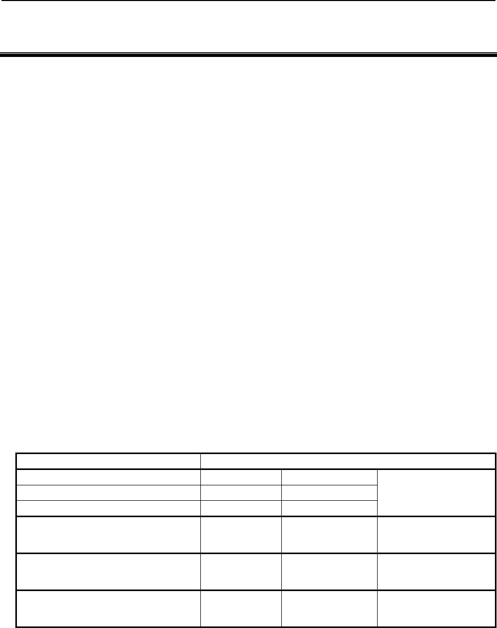
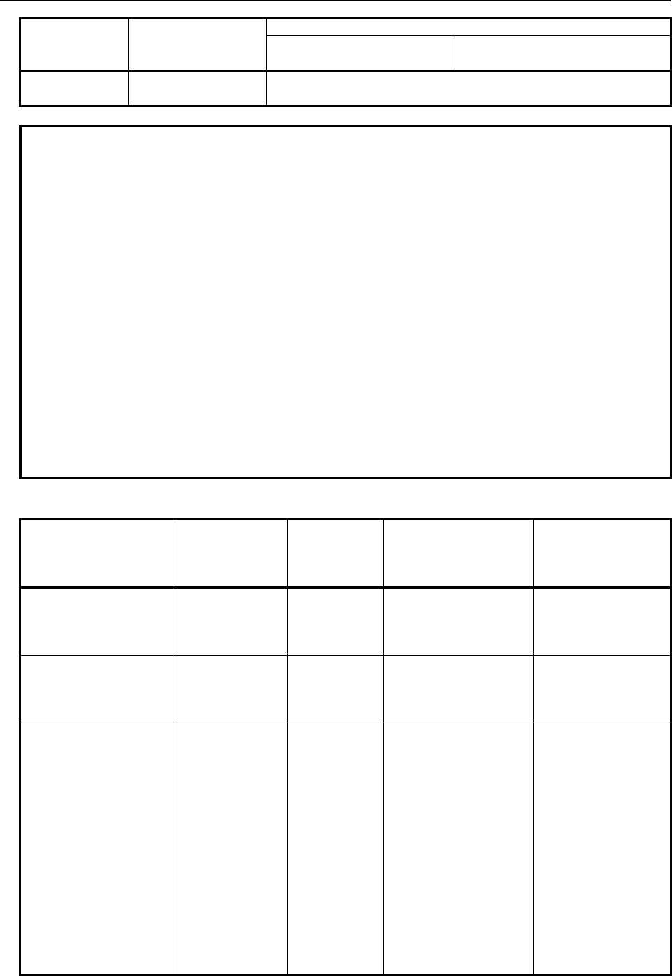
This manual covers the following models.
In this manual, the following abbreviations may be used for the models:
Model name Abbreviation
FANUC Series 30i-MODEL A/B 30i -A/B Series 30i FANUC Series 30i/31i/32i,
Series 30i/31i/32i,
30i/31i/32i -A/B
FANUC Series 31i-MODEL A/B 31i-A/B Series 31i
FANUC Series 32i- MODEL A/B 32i -A/B Series 32i
FANUC Series 35i- MODEL B 35i -B Series 35i
FANUC Series 35i、
Series 35i、
35i -B
FANUC Series 0i- MODEL F 0i -F Series 0i
FANUC Series 0i、
Series 0i、
0i -F
FANUC Power Motion i- MODEL A PMi -A PMi
FANUC PMi、
Series PMi、
PMi -A
Definition of terms
The words used in the explanation are defined as follows.
(1) P-CODE file/module
MEM format file created by linking an executable macro program compiled by the personal
computer with compile parameters

1.GENERAL
B-63943EN-2/07
- 2 -
With the module division function, a P-CODE file is referred to as a module.
(2) P-CODE macro, P-CODE program
Execution type macro program prepared by a machine tool builder, being compiled and registered to
F-ROM.
(3) Execution macro
Macro program to operate machine in P-CODE macro.
(4) Conversational macro
Macro program to operate screen in P-CODE macro.
(5) Auxiliary macro
Macro program to make an auxiliary operation for the execution macro and the conversational
macro in P-CODE macro.
(6) User program
Program prepared by end-user for program edit memory.
(7) Compile parameter
The term, compile parameter, used in this manual does not represent an ordinary CNC parameter but
represents a parameter determined by the link control file when a P-CODE file is created. (Refer to
"FANUC Series 30i/31i/32i/35i/PMi Macro Compiler PROGRAMMING MANUAL
(B-66263EN)".) This means that the compile parameters cannot be modified, for example, through
the MDI panel and so on.
(8) Parameter/Executor parameter
The term, parameter or executor parameter, used in this manual represents an ordinary CNC
parameter. This means that the parameters and executor parameters can be modified, for example,
through the MDI panel and so on.
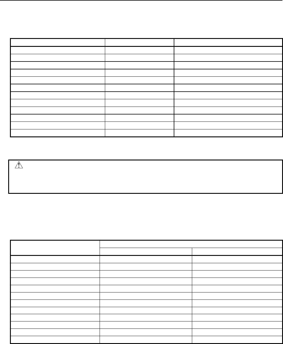
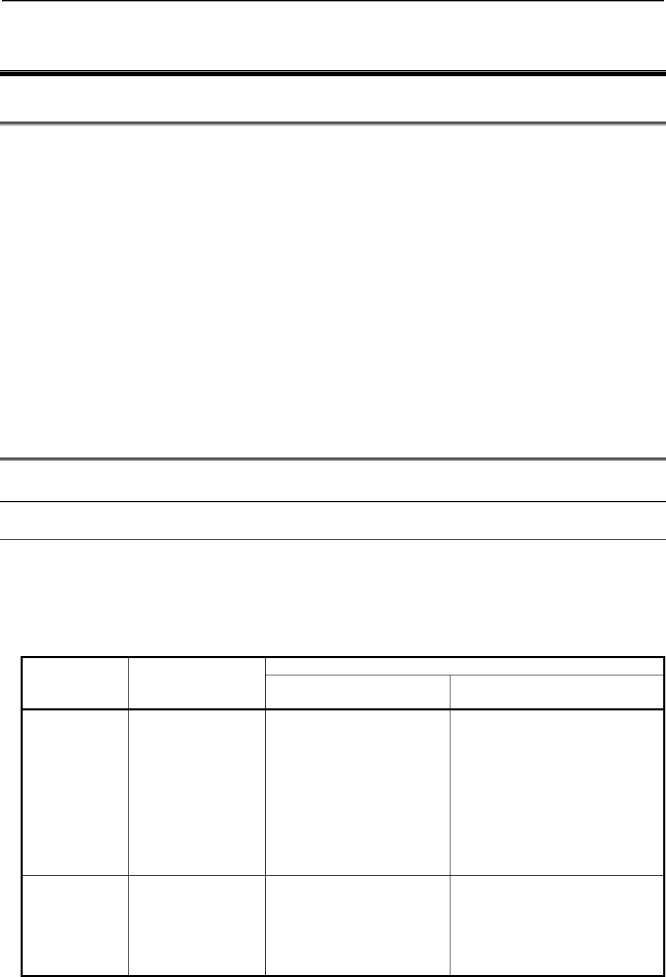
(9) Controlled axis number and spindle number in a multi-path system
• Relative controlled axis/spindle number in a path
Referred to as the nth axis in a path/nth spindle in a path or as the nth axis/nth spindle.
• Controlled axis number and spindle number in the entire system
Referred to as the system common nth axis and system common nth spindle.
Example :
The Z-axis in the second path is referred to as
the second axis in the path or the second axis as the relative controlled axis number in the path, and
the system common fifth axis as the controlled axis number in the entire system.
1st path 2nd path
X axis X axis
Y axis Z axis
Z axis
B-63943EN-2/07
2.MACRO COMPILER AND MACRO EXECUTOR
- 3 -
2 MACRO COMPILER AND MACRO
EXECUTOR
2.1 MACRO COMPILER
The macro compiler converts (compiles) a custom macro program (P-CODE source program) to an
executable macro program. Then, the macro compiler links the executable macro program with compile
parameters and converts it to a MEM-format file.
The created MEM-format file is loaded into F-ROM (FLASH ROM module).
* For details such as operation procedures, refer to "FANUC Series 30i/31i/32i/35i/PMi Macro
Compiler PROGRAMMING MANUAL (B-66263EN)."
2.1.1
P-CODE Macro and P-CODE File
A P-CODE file is converted to a MEM-format file and is then registered from a memory card to F-ROM
in the FANUC Series 30i –A/B, 31i –A/B, or 32i –A/B, 35i –B, 0i –F, Power Motion i –A (referred to as
the Series 30i/31i/32i/35i/0i-F/PMi in the remainder of this manual). A P-CODE file loaded into F-ROM
can also be saved onto a memory card.
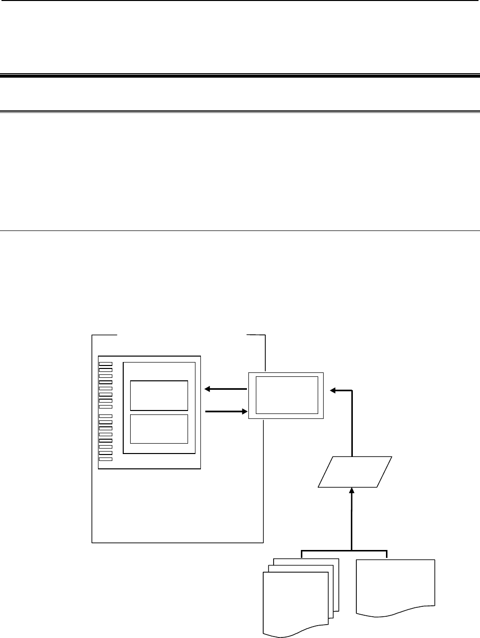
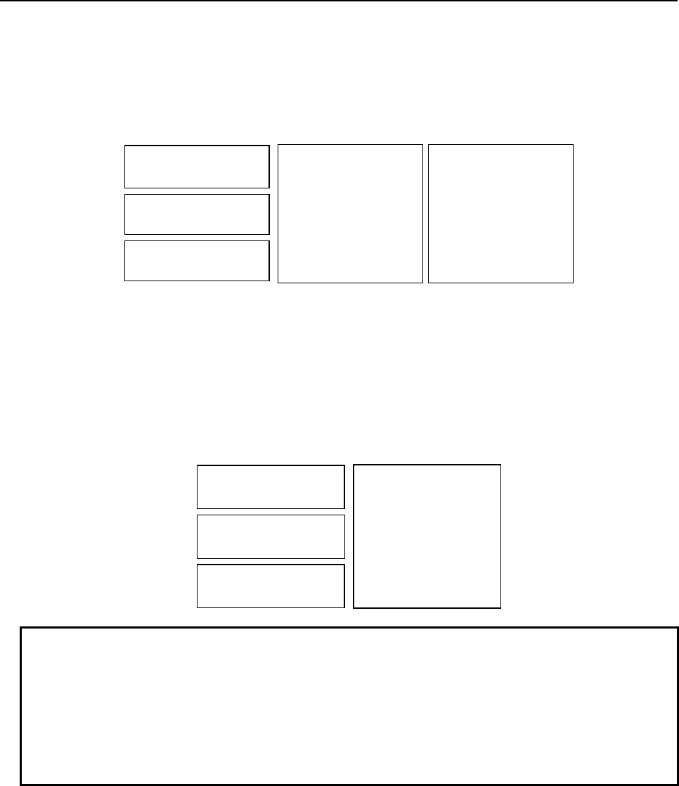
Concept of saving and registering a P-CODE file
P-CODE file
O9000;
#1=#2+#5;
:
M99;
9001=00010000
9002=10000011
:
P-CODE
source program
Compile parameter
Compile&Link&
Conversion to the
memory card format
Memory card
F-ROM
LOAD
SAVE
Compile
parameter
P-CODE
macro
P-CODE file
Series 30i
–
A/B Series 35i
–
B
Series 31i
–
A/B Series 0i
–
F
Series 32i
–
A/B Power Motion i
–
A
2.MACRO COMPILER AND MACRO EXECUTOR
B-63943EN-2/07
- 4 -
P-CODE file size
The size of a P-CODE file is set using one of the compile parameters in the Table 2.1 (a):
Table 2.1 (a)
P-CODE file size BIT name Compile parameter number
4096Kbyte(4Mbyte) M4MB 9001#2
3072Kbyte(3Mbyte) M3MB 9000#6
2048Kbyte(2Mbyte) M2MB 9000#5
1536Kbyte(1.5Mbyte) M512,M1MB 9000#3,#4
1024Kbyte(1Mbyte) M1MB 9000#4
896Kbyte M128,M256,M512 9000#1,#2,#3
768Kbyte M256,M512 9000#2,#3
640Kbyte M128,M512 9000#1,#3
512Kbyte M512 9000#3
384Kbyte M128,M256 9000#1,#2
256Kbyte M256 9000#2
128Kbyte M128 9000#1
If the ROM-format file created by linking compile parameters is larger than the size set as listed in the
Table 2.1 (a), an error (ROM SIZE OVER) occurs when the macro linker is executed.
CAUTION
To use a P-CODE file, an option is required. If a P-CODE file loaded into the
CNC is larger than the size allowed by the option, the CNC does not start up with
error USER FILE(P-CODE):SIZE OVER.
P-CODE macro size
The actual size of a P-CODE macro which can be created depends on the P-CODE file size as listed in the
Table 2.1 (b). For the second and third modules, see Section 2.4, "MODULE DIVISION FUNCTION".
Table 2.1 (b)
P-CODE file size P-CODE macro size
Basic module 2nd/3rd module
4096Kbyte 4000Kbyte 4075Kbyte
3072Kbyte 2976Kbyte 3051Kbyte
2048Kbyte 1952Kbyte 2027Kbyte
1536Kbyte 1440Kbyte 1515Kbyte
1024Kbyte 928Kbyte 1003Kbyte
896Kbyte 800Kbyte 875Kbyte
768Kbyte 672Kbyte 747Kbyte
640Kbyte 544Kbyte 619Kbyte
512Kbyte 416Kbyte 491Kbyte
384Kbyte 288Kbyte 363Kbyte
256Kbyte 160Kbyte 235Kbyte
128Kbyte 32Kbyte 107Kbyte
B-63943EN-2/07
2.MACRO COMPILER AND MACRO EXECUTOR
- 5 -
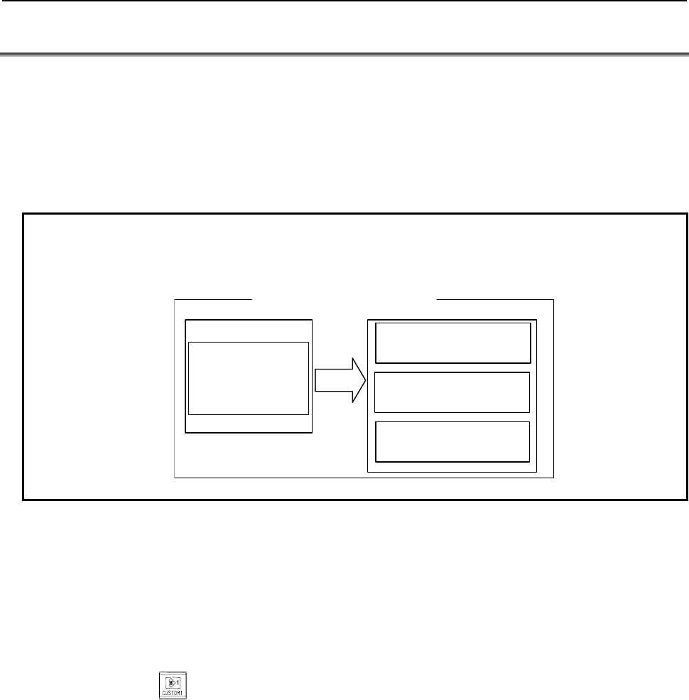
2.2 MACRO EXECUTOR
The macro executor has execution macro function, conversational macro function, and auxiliary macro
function.
The P-CODE number (specified by " P-CODE_NUMBER=" in the link control file) for each of an
execution macro, conversational macro, and auxiliary macro executed on each path is selected by
specifying parameters Nos. 9048 to 9050 separately for each macro. If any of parameters Nos. 9048 to
9050 is set to 0, the corresponding macro is disabled. If all of the execution macro, conversational macro,
and auxiliary macro are disabled, no P-CODE file is loaded.
Example
For a system that executes an execution macro and conversational macro, set
parameter No. 9050 for an auxiliary macro to 0.
P-CODE1 file
P-CODE_NUMBER=01
P-CODE file for
execution/
conversational
macro
LOAD
Execution macro
Parameter No.9048=1
Conversational macro
Parameter No.9049=1
Auxiliary macro
Parameter No.9050=0
Series 30i/31i/32i/35i/0i-F/PMi
F-ROM D-RAM
Execution macro function
When the user specifies a G, M, T, or specific code and so on specified by a compile parameter from a
user program, the execution macro function calls and executes the macro program for operating the
machine (execution macro) that is in a P-CODE macro.
The user can also execute a user program not to call an execution macro, but to execute a custom macro
program.
Conversational macro function
When function key
is pressed, the conversational macro function calls and executes a macro
program for processing screens (conversational macro) that is in a P-CODE macro.
The screen displayed by the user program is called the conventional macro screen or user screen.
Auxiliary macro function
At power-on, the auxiliary macro function calls and executes a macro program for performing auxiliary
processing (auxiliary macro) that is in a P-CODE macro.
2.MACRO COMPILER AND MACRO EXECUTOR
B-63943EN-2/07
- 6 -
2.3 P-CODE MACRO
A P-CODE macro means an executable macro program created by compiling a P-CODE source program
using the macro compiler and loaded it into F-ROM.
Program number
The program number range is from 1 to 99999999.
NOTE
To use a 5-digit or longer program number, set the bit 3 (ON8) of parameter
No.11304 to 1.
Sequence number
The sequence number range is from 1 to 99999999.
- Note
NOTE
No sequence number must be added to any block with an O number.
(The sequence number is invalidated if added.)
Number of digits of a valid setting
The maximum number of digits of a valid setting is 9.
Maximum number of P-CODE macros
The maximum number of P-CODE macros is 1000.
2.3.1
Limitations on Commands
NOTE
For each macro executor function, there may be limitations other than listed
below. See the explanation of each macro executor function.
Custom macro and real time macro
P-CODE macros cannot use real time macro commands. They can use only custom macro commands, but
they cannot use some custom macro commands, and there are limitations on others.
Some commands run differently when used in P-CODE macros from when used in custom macros. For
details, see Chapter 3, "Execution Macro Function".
Custom macro command P-CODE macro
A program can be specified with its program
number or name.
A program can be specified with its program number only.
A constant value consisting of up to 12 digits
Maximum value : ±999999999999
Minimum value : ±0.00000000001
9 digits
±999999999
±0.00000001
The maximum allowable number of digits of a
macro variable number is 6.
9 digits
Chamfer command (,C_) and corner R
command (,R_) Not allowed
The name of a nonvolatile custom macro
common variable can be specified. The same specification is enabled by defining a symbol name(*1).
B-63943EN-2/07
2.MACRO COMPILER AND MACRO EXECUTOR
- 7 -
Custom macro command P-CODE macro
The name of a system variable can be
specified.
The same specification is enabled by defining a symbol name(*1).
As subscript [n] for a name, only a constant can be specified(*2).
The name of a system constant can be
specified.
The same specification is enabled by defining a symbol name(*1).
As subscript [n] for a name, only a constant can be specified(*2).
SETVN is possible. Not allowed
An indirect axis address can be specified. Not allowed
Real time macro command Not allowed
*1 With a P-CODE macro, a symbol name used in a source program can be defined in the symbol
definition file. By defining a system variable/constant name used with a custom macro by using this
function, the same specification as done with the custom macro is enabled. For details, refer to
"FANUC Series 30i/31i/32i/35i/PMi Macro Compiler PROGRAMMING MANUAL (B-66263EN)".
NOTE
Bit symbols such as [#_M_SBK], [#_M_FIN], [#_M_FHD], [#_M_OV], and
[#_EST] cannot be defined.
*2 As subscript [n] for a name, only a constant can be specified. No variable and operation can be
specified.
[Example]
@[#_ABSMT[1]] #5021 : Allowed → When #101=[#_ABSMT[1]] is coded, it is replaced
with #101=#5021.
@[#_ABSMT[#100]] #5021 : Not allowed
Specifying an extended axis name
A P-CODE macro cannot specify an extended axis directly with its extended axis name set in parameter
No. 1025 or 1026.
If wishing to use an extended axis name in an execution macro, use the function for specifying an axis
with an axis number. For details, see Subsection 3.3.5, "Axis Specification and Extended Axis Name
Specification Using an Axis Number".
Variable specification for address N in the Programmable Data Input (G10)
With the P-CODE macro, the code of address N cannot be specified using a variable. To specify address
N by using a variable in the programmable data input mode (between G10 and G11), specify address
"NN" instead of address N. For details, see Subsection 3.3.6, "Method of Variable Specification for
Address N in the Programmable Data Input Mode".
Optional block skip
When a block with a sequence number is skipped using the optional block skip function, a block
consisting of only the sequence number is created.
Example
Original program Command to be executed when skipped
/1 N1 X100.; N1;
N2 /2 Y200.; N2;
When N1 is skipped as listed above, the similar operation as for N2 is performed.
CAUTION
An optional block skip command can be executed in execution, auxiliary, and
conversational macros. Carefully execute the command so that the same optional
block skip signal will not be used.
2.MACRO COMPILER AND MACRO EXECUTOR
B-63943EN-2/07
- 8 -
2.3.2
Differences from the Series 16i
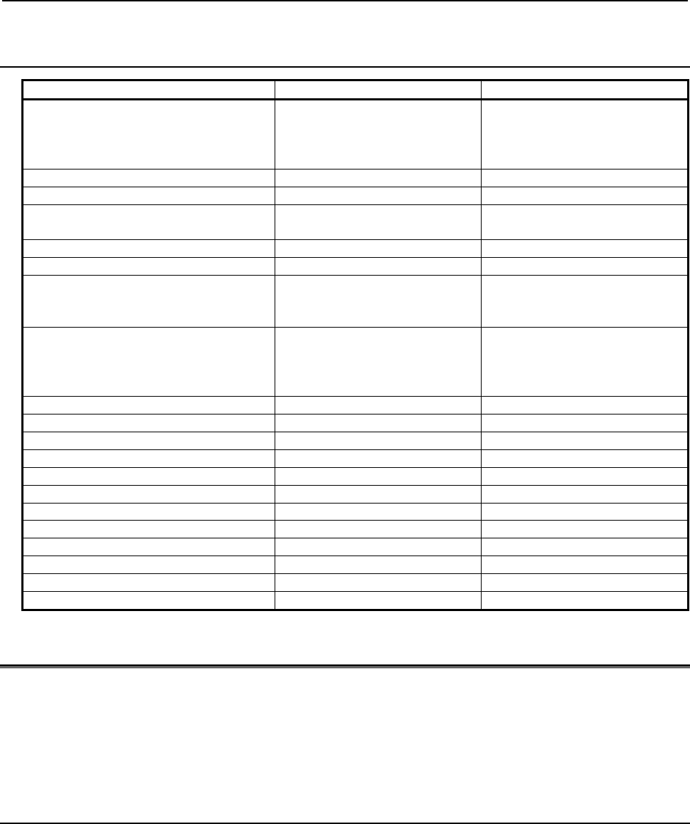
Function Series 16i/18i/21i Series 30i/31i/32i/35i/0i-F/PMi
Program - Programs from O1 to O9999
can be created.
- Up to 400 programs can be
registered.
- Programs from O1 to
O99999999 can be created.
- Up to 1000 programs can be
registered.
Sequence number N1 to N99999 N1 to N99999999
Number of digits of a valid setting Up to 8 digits Up to 9 digits
Number of digits of a macro variable
number
Up to 6 digits Up to 9 digits
Number of IF statements in one program Up to 400 IF statements Up to 2000 IF statements
Number of IF statement nesting levels Up to 3 levels Up to 10 levels
Optional block skip Specifiable with an execution
macro only
Specifiable with an execution
macro, auxiliary macro, or
conversational macro
Specification of abbreviations of operation
commands (specification of the first two
characters only, such as RO for ROUND
and FI for FIX)
Not allowed Allowed
PRM[#j] Not allowed Allowed
PRM[#j,#k] Not allowed Allowed
PRM[#j]/[#k] Not allowed Allowed
PRM[#j,#k]/[#l] Not allowed Allowed
ATAN[#j] Not allowed Allowed
ATAN[#j,#k] Not allowed Allowed
ATN[#j] Not allowed Allowed
ATN[#j,#k] Not allowed Allowed
ATN[#j/#k] Not allowed Allowed
RND[#j] Not allowed Allowed
SQR[#j] Not allowed Allowed
POW[#i,#j] Not allowed Allowed
2.4
MODULE DIVISION FUNCTION
This function additionally registers multiple P-CODE files (modules) with one path and assigns higher
priority to the added modules.
With this function, multiple modules can be separately managed in a variety of applications. For example,
a module serving as the function base and a module for making an addition/modification can be combined.
Alternatively, a function is given to one module, and another function is given to another mode.
2.4.1
Method of Module Addition
Set a P-CODE number for each macro executor module then perform loading with the boot system. (Set a
P-CODE number with "P-CODE_NUMBER=" in the link control file.)
Set a P-CODE number for a module serving as the base (hereinafter referred to as a basic module) in
parameters Nos. 9048 to 9050. Set the same P-CODE number in all of parameters Nos. 9048 to 9050.
Set a P-CODE number for the second module to be added in parameter No. 9055. Set a P-CODE number
for the third module in parameter No. 9056.
B-63943EN-2/07
2.MACRO COMPILER AND MACRO EXECUTOR
- 9 -
Example of setting 1
To a system that has an execution macro, conversational macro, and auxiliary macro as the basic module,
an execution macro module is added as the second module and the third module.
Basic module
Parameter No.9048=1
(Basic execution macro)
Parameter No.9049=1
(Conversational macro)
Parameter No.9050=1
(Auxiliary macro)
Parameter No.9055=2
(2nd execution macro)
* Set the compile
parameters related to
the conversational and
auxiliary macros to 0.
Parameter No.9056=3
(3rd execution macro)
* Set the compile
parameters related to
the conversational and
auxiliary macros to 0.
2nd module 3rd module
* If a value other than 1 is set in any of parameters Nos. 9048 to 9050, the second and third modules
are disabled.
Example of setting 2
To a system that has an execution macro, conversational macro, and auxiliary macro as the basic module,
an execution macro and auxiliary macro are added.
Basic module
Execution macro
Parameter No.9048=1
Conversational macro
Parameter No.9049=0
A
uxiliary macro
Parameter No.9050=1
Parameter No.9055=3
2nd module
NOTE
1 This function is disabled when modules with different execution/conversational/
auxiliary macros are used within the same path.
Set all of parameters Nos. 9048 to 9050 to the same P-CODE number or 0 (for
nonuse).
2 Whether to enable/disable an execution macro, conversational macro, and
auxiliary macro is set using parameters Nos. 9048 to 9050. This setting cannot
be made using parameters Nos. 9055 and 9056.
Compile parameter
As the compile parameter, priority is given to the nonzero value of an additional module. This means that
the compile parameter cannot be set to 0 by setting an additional module.
The order of priority from higher to lower is: third module to second module to basic module.
2.MACRO COMPILER AND MACRO EXECUTOR
B-63943EN-2/07
- 10 -
Example
When basic module P-CODE number = 1, second module P-CODE number = 2,
and third module P-CODE number = 3:
1. Compile parameter No. 9010 of P-CODE number 1 = 100
Compile parameter No. 9010 of P-CODE number 2 = 200
Compile parameter No. 9010 of P-CODE number 3 = 300
→ Compile parameter No. 9010 = 300 is enabled.
2. Compile parameter No. 9038 of P-CODE number 1 = 0
Compile parameter No. 9038 of P-CODE number 2 = 3000
Compile parameter No. 9038 of P-CODE number 3 = 0
Compile parameter No. 9038 = 3000 is enabled.
3. Compile parameter No. 9100#0 of P-CODE number 1 = 1
Compile parameter No. 9100#0 of P-CODE number 2 = 0
Compile parameter No. 9100#0 of P-CODE number 3 = 0
→ Bit 0 of compile parameter No. 9100 = 1 is enabled.
P-CODE program
Higher priority is given to an additional module at P-CODE program call time.
The third module, second module, and basic module are searched in this order for a program to be called.
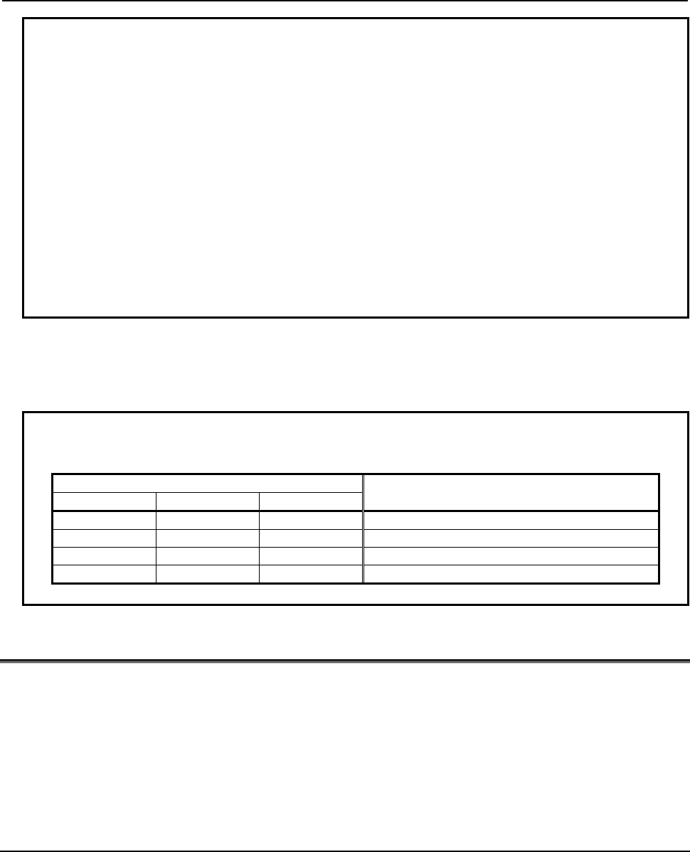
Example
When basic module P-CODE number = 1, second module P-CODE number = 2,
and third module P-CODE number = 3
Registered program P-CODE file number actually executed
P-CODE1 P-CODE2 P-CODE3
O9010 O9010 of P-CODE1 is executed.
O9011 O9011 O9011 of P-CODE2 is executed.
O9012 O9012 O9012 O9012 of P-CODE3 is executed.
O9013 O9013 O9013 O9013 of P-CODE3 is executed.
2.5
MULTI-PATH CONTROL FUNCTION
The macro executor of the Series 30i/31i/32i/35i/0i-F/PMi is designed to enable independent path-by-path
operation and data sharing in a multi-path system and to build an efficient system.
The macro executor has three features:
<1> Independent operating environment for each path
<2> Variable area that can be easily shared among paths
<3> Multiple P-CODE macros independent of paths
2.5.1
Independent Operating Environment for Each Path
An independent operation can be performed in each path.
Execution macro : Usable in automatic operation by each path
Conversational macro : A conversational macro program of the path selected on the screen display is
executed.
Auxiliary macro : Auxiliary macros as many as up to the number of paths are executed
simultaneously.
B-63943EN-2/07
2.MACRO COMPILER AND MACRO EXECUTOR
- 11 -
So, executor parameters, local variables, common variables (#100 and up, #500 and up), and system
variables are provided separately for each path.
2.5.2
P-CODE Variables/Extended P-CODE Variables Common to
Paths
For P-CODE variables (#10000 and up)/extended P-CODE variables (#20000 and up), multiple variable
areas can be allocated on an S-RAM file. No fixed variable area is assigned to each path. Instead, a
variable area can be selected for each path by using parameters Nos. 9051 and 9052.
• When a different variable area number is set for each path in parameters Nos. 9051 and 9052
→ The variables are used as independent variables for each path.
• When the same variable area number is set for all paths in parameters Nos. 9051 and 9052
→ The variables are used as variables common to all paths.
Example of setting
P-CODE variables (#10000 and up) are shared by all paths, and extended P-CODE variables (#20000 and
up) are used separately by each path.
Executor parameter
No.9051=1
No.9052=1
Path 1
Executor parameter
No.9051=1
No.9052=2
Path 2
Executor parameter
No.9051=1
No.9052=3
Path 3
(Not used)
For path 2
#20000 and up
Variable area 2 Variable area 3
(Not used)
For path 3
#20000 and up
Variable area 1
Common to all paths
#10000-#19999
For path 1
#20000 and up
Set the number of variable areas and variable type (floating-point or integer) for each of variables 1, 2, 3,
and so on in the parameters Nos. 9053 and 9054, bit 3 of parameter No. 9033, and bit 4 of parameter No.
9033 for each of paths 1, 2, 3, and so on.
2.5.3
Multiple P-CODE Macros Independent of Paths
P-CODE macros can be shared among paths.
P-CODE macros executed by each path are selected using parameters Nos. 9048 to 9050 for execution
macros, conversational macros, and auxiliary macros.
In this way, P-CODE macros can be grouped for sharing, or divided separately into execution macros,
conversational macros, and auxiliary macros.
2.MACRO COMPILER AND MACRO EXECUTOR
B-63943EN-2/07
- 12 -
Example of setting 1
- When conversational macros/auxiliary macros are shared
Different execution macros are used for each path, and the conversational macros/auxiliary macros of
P-CODE1 only are used. P-CODE2 and P-CODE3 include execution macros only, so that the F-ROM
can be saved.
Executor parameter
No.9048=1
No.9049=1
No.9050=1
Path 1
Executor parameter
No.9048=2
No.9049=1
No.9050=1
Path 2
Executor parameter
No.9048=3
No.9049=1
No.9050=1
Path 3
Execution macros
for path 1
Conversational
macros common to
all paths
Auxiliary macros
common to all paths
P-CODE1
Execution macros
for path 2
P-CODE2
Execution macros
for path 3
P-CODE3
Example of setting 2
- When P-CODE macros are divided separately into execution
macros/conversational macros/auxiliary macros
Execution macros, conversational macros, and auxiliary macros are registered separately in each P-CODE.
Macro replacement is enabled on the basis of each P-CODE.
Executor parameter
No.9048=1
No.9049=2
No.9050=3
Path 1
Executor parameter
No.9048=1
No.9049=2
No.9050=3
Path 2
Executor parameter
No.9048=1
No.9049=2
No.9050=3
Path 3
P-CODE 1 P-CODE 2
Execution macro
Conversational macro
Auxiliary macro
P-CODE 3
2.5.4
Reading the Path Number Currently under Execution (#8531)
The path number currently under execution can be read with #8531.
Example:
When O9010 is called with Gxxx on both of paths 1, 2, and 3 under the setting above, the execution
macro program of P-CODE1 can divide processing for each path with #8531 as described below.
O9010
IF [#8531 EQ 1] THEN
Execution processing for path 1
IF [#8531 EQ 2] THEN
Execution processing for path 2
IF [#8531 EQ 3] THEN
Execution processing for path 3
B-63943EN-2/07
3.EXECUTION MACRO FUNCTION
- 13 -
3 EXECUTION MACRO FUNCTION
3.1 GENERAL
Execution macro
An execution macro is a loaded P-CODE macro which is operated as a machining program.
A registered P-CODE macro cannot be executed singly.
A registered P-CODE macro is called for execution from a user program by using a call code such as G,
M, S, T, D, or H specified by a compile parameter. An execution macro allows the similar specification as
done with a custom macro.
At this time, an argument can be specified in a macro call, and can be referenced as a local variable by a
P-CODE macro (execution macro).
Which P-CODE to be executed by each path is set in parameter No. 9048.
User program / Custom macro
A user program means an NC program loaded into program memory or an NC program to be executed as
an execution macro caller during DNC or MDI operation.
A custom macro means an NC program to be called as a macro or subprogram in a user program.
3.2 CALLING AN EXECUTION MACRO
3.2.1
Overview
3.2.1.1
Macro call and subprogram call
Execution macro calls can roughly be divided into two types: macro calls and subprogram calls. Macro
calls are further divided into two types: special macro calls, and other macro calls.
Simple calls and modal calls are also included in macro calls. A simple call (also called a macro call) calls
an execution macro only in the specified block. A modal call calls an execution macro in each block until
G67 is specified.
Subprogram call
Macro call
Macro call using
G65/G66/G66.1/G/M code Special macro call
(Note 2)
Argument-specifi
cation Not allowed
All specifications after a call
code are passed as arguments
(#1 to #33). Two types are
available: argument
specification I and II.
All addresses specified in the block
other than address N are passed as
arguments to #1 to #33. Argument
specification II cannot be used.
Up to five G codes are used as
arguments in the ascending order of
G code group numbers. If multiple
codes are specified in another
address, the last code specified is
used as an argument.
NC command
specified in the
same block
The NC statement is
first executed, then
the execution macro
is called.
A command after a call code is
treated as an argument. For a
command before a call code,
alarm PS0127 is issued. (A call
code must be specified at the
start of the block.)
Treated as an argument. (A call
code need not be placed at the start
of the block.)
(Note 3)
3.EXECUTION MACRO FUNCTION
B-63943EN-2/07
- 14 -
Subprogram call
Macro call
Macro call using
G65/G66/G66.1/G/M code Special macro call
(Note 2)
Local variables The level does not
change
(Note 1)
. The level changes.
NOTE
1 Usually, the level is not changed by a subprogram call.
When bit 3 (LCLLV) of compile parameter No. 9163 is set to 1, Series 16i
compatibility is provided. This means that the level changes only when an
execution macro is called as a subprogram from a user program (using an
M/S/T/second auxiliary function/specific code). (When an execution macro calls
another execution macro or calls a user program as a subprogram, the level
does not change as in the case where bit 3 (LCLLV) of compile parameter No.
9163 is set to 0.)
2 Special macro calls include calls using a G code / M code / D code / H code / S
code / T code / axis address.
3 The call code commanded in first is effective when two or more call codes are
commanded in the same block. In this case, codes except the call codes are
regarded as follows.
• When the first call code is subprogram call, the execution macro is called
after the words except call codes are executed as NC sentence .
• When the first call code is macro call, except the call codes are regarded as
arguments.
Types of calls
Call code Program number
called
Common
variable for
storing a
specified code
Parameters to be set Remarks
Simple call (G65) Specified at
address P. None None
No execution macro
can be called from
any user program
using this command.
Modal call (G66,G66.1) Specified at
address P. None None
No execution macro
can be called from
any user program
using this command.
Macro call using G code O9010 to O9019 None Compile parameters
Nos. 9013 to 9022
- By setting bit 5
(GMACC) of
compile parameter
No. 9104 to 1, a
special macro call
is made.
- By setting bit 1
(PRDGCAL) of
compile parameter
No. 9103 to 1, use
of a G code with a
decimal point is
enabled.
- Modal calls are
allowed.

B-63943EN-2/07
3.EXECUTION MACRO FUNCTION
- 15 -
Call code Program number
called
Common
variable for
storing a
specified code
Parameters to be set Remarks
Macro call using G code
(specification of 1 set) Parameter setting None Compile parameters
Nos. 9045 to 9047
- By setting bit 5
(GMACC) of
compile parameter
No. 9104 to 1, a
special macro call
is made.
- Only G codes with
no decimal point
can be used.
- Modal calls are
allowed.
Macro call using G code
(specification of 3 sets) Parameter setting None
Compile parameters
Nos. 9129 to 9131
- By setting bit 5
(GMACC) of
compile parameter
No. 9104 to 1, a
special macro call
is made.
- Only G codes with
no decimal point
can be used.
- Modal calls are
allowed.
Compile parameters
Nos. 9132 to 9134
Compile parameters
Nos. 9135 to 9137
Macro call using a
cancel G code for a
macro modal call using
G code
O9006 None
Bit 4 (MDLP) of compile
parameter No.9008 and
Compile parameter
No.9034)
Possible only when a
macro modal call
using G code is made
with the Series 16i
method (bit 0 (GMC)
of compile parameter
No. 9163 = 1)
Macro call using M code O9020 to O9029 None Compile parameters
Nos. 9023 to 9032
Macro call using M code
(specification of 3 sets) Parameter setting None
Compile parameters
Nos. 9120 to 9122
By setting bit 4
(EXMSCL) of compile
parameter No. 9103
to 1, a special macro
call is made.
Compile parameters
Nos. 9123 to 9125
Compile parameters
Nos. 9126 to 9128
Special macro call using
axis address
O9009 or O9031
to O9030+n (n :
number of axes)
#27
Compile parameters
AxnCL
(No. 9005#0 to #3,
No. 9008#0 to #3,
No. 9164#0 to #7
No. 9165#0 to #7)
and AXCLS (No.9005#4)
A call can be masked
with bits 0 to 7 (OnM)
of parameter No. 9010
and bits 0 to 7 (OnM)
of parameter No. 9020
to No. 9021.
Special macro call using
T code O9008 #27
Bit 7 (TMACC ) of
compile parameter No.
9005
A call can be masked
with bit 0 (MTC) of
parameter No. 9011.
Special macro call using
D code O9040 #27
Bit 0 (DMACC) of
compile parameter
No.9104
A call can be masked
with bit 0 (MDC) of
parameter No. 9012.
Special macro call using
H code O9041 #27
Bit 1 (HMACC) of
compile parameter
No.9104
A call can be masked
with bit 1 (MHC) of
parameter No. 9012.
3.EXECUTION MACRO FUNCTION
B-63943EN-2/07
- 16 -
Call code Program number
called
Common
variable for
storing a
specified code
Parameters to be set Remarks
Special macro call using
S code O9042 #27
Bit 2 (SMACC) of
compile parameter
No.9104
A call can be masked
with bit 2 (MSC) of
parameter No. 9012.
Subprogram call (M98) Specified at
address P. None None
No execution macro
can be called from
any user program
using this command.
Subprogram call using
M code O9001 to O9003 None Compile parameters
Nos. 9010 to 9012
Subprogram call using
M code in the specified
range
O9009 #148
Compile parameters
Nos. 9042 and 9043
By setting bit 3 (MSCL)
of compile parameter
No. 9009 to 1, a
special macro call is
made.
Subprogram call using
M code (specification of
3 sets)
Parameter setting None
Compile parameters
Nos. 9111 to 9113
By setting bit 4
(EXMSCL) of compile
parameter No. 9103 to
1, a special macro call
is made.
Compile parameters
Nos. 9114 to 9116
Compile parameters
Nos. 9117 to 9119
Subprogram call using S
code O9029 #147
Bit 0 (SSC) of compile
parameter No. 9105
Subprogram call using T
code O9000 #149
Bit 0 (TCAL) of compile
parameter No. 9002
Subprogram call using
second auxiliary function
code
O9028 #146
Bit 1 (BSC) of compile
parameter No. 9105
Subprogram call using
specific code O9004, O9005 #146
#147
Bit 1 (ACL1) and Bit 2
(ACL2) of compile
parameter No.9002
Parameters Nos.6090
and 6091
Subprogram call for user
program
(*2)
Specified at
address P. None Compile parameter No.
9033
A user program in
program memory is
called from an
execution macro.
P-CODE workpiece
number search
Set for a control
variable. None Bit 6 (PWSR) of compile
parameter No. 9002
An execution macro
is called preceding
the main program at
the start of automatic
operation.
*2 Function specific to execution macros. This function calls no execution macro.
NOTE
1 The correspondence between codes used for macro and subprogram calls and
the numbers of called programs, and whether to call a subprogram/macro are
determined by compile parameters. The compile parameters are registered in
the F-ROM at compile time. Be sure to specify the compile parameters at
compile time.
2 Set a code for a subprogram call using a specific code in parameters Nos. 6090
and 6091 at execution time.
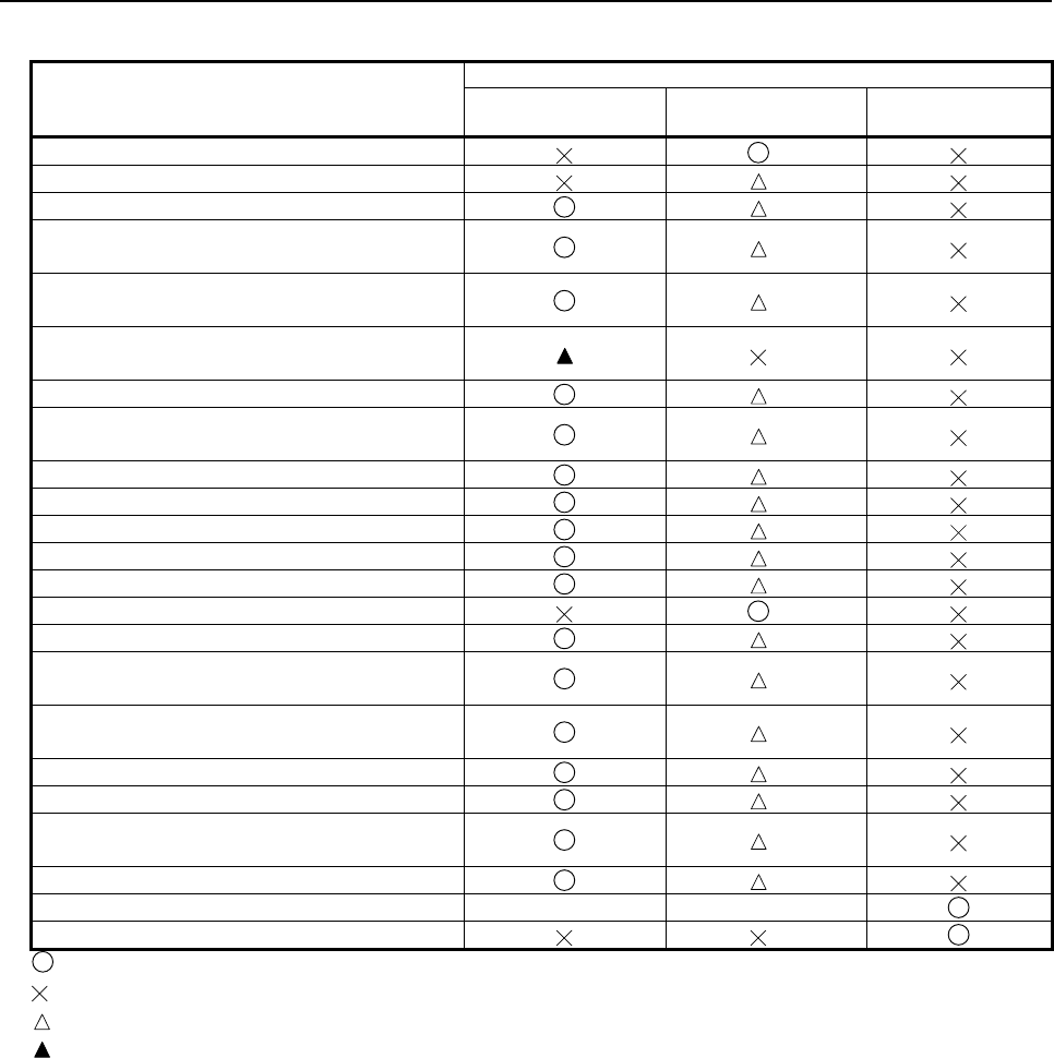
B-63943EN-2/07
3.EXECUTION MACRO FUNCTION
- 17 -
Usable call command
Call method (call source → call destination)
User program
→Execution macro
Execution macro
→Execution macro
Execution macro
→User program
Simple call of execution macro (G65)
Modal call of execution macro (G66, G66.1)
Macro call and special macro call using G code
Macro call and special macro call using G code
(specification of 1 set)
Macro call and special macro call using G code
(specification of 3 sets)
Macro call using a cancel G code for a macro
modal call using G code
Macro call using M code
Macro call using M code and special macro call
(specification of 3 sets)
Special macro call using axis address
Special macro call using T code
Special macro call using D code
Special macro call using H code
Special macro call using S code
Subprogram call of execution macro (M98)
Subprogram call using M code
Subprogram call and special macro call using
M code in the specified range
Subprogram call and special macro call using
M code (specification of 3 sets)
Subprogram call using S code
Subprogram call using T code
Subprogram call using second auxiliary
function code
Subprogram call using specific code
Subprogram call of user program - -
External device subprogram call (M198)
: Allowed
: Not allowed (treated as an ordinary G code, auxiliary function code, special code, or axis address)
: Depends on bit 2 (PCDC) of compile parameter No. 9163 and bit 6 (GMP) of parameter No. 6008.
: Allowed only if bit 0 (GMC) of compile parameter No. 9163 is set to 1.
See "Limitations on calls" described later for details.
Limitations on calls
The limitations described below are applied when an execution macro is called from a user program or
another execution macro and when an execution macro is called after a user program is called as a
subprogram. Furthermore, three major methods are available for calling an execution macro. One method
uses G65/G66 (G66.1)/M98, the second method uses G codes, and the third method uses other codes
(M/S/T/D/H/second auxiliary function code/special code/axis address). The limitations depend on these
methods.
(1) When an execution macro is called from a user program
• G65, G66, G66.1, or M98 cannot be used.
(A program within a user program is called.)
• No limitation is applied to calls using G/M/S/T/D/H/second auxiliary function code/special
code/axis address. From a custom macro called using G/M/S/T/second auxiliary function
code/special code, an execution macro call using G/M/S/T/D/H/second auxiliary function
code/special code/axis address can also be made.
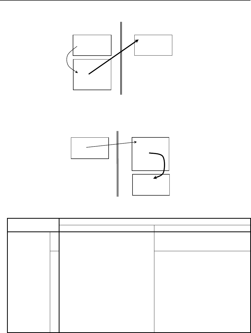
3.EXECUTION MACRO FUNCTION
B-63943EN-2/07
- 18 -
(Example) From a user program called using a G code in a custom macro, an execution macro call using
G code can be made.
Within execution macro
:
Gxx
:
O9010
:
M99
Within user program
O9010
:
Gxx
:
M99
(2) When an execution macro is called from another execution macro
From an execution macro called from a user program, only G65 or M98 can usually call another
execution macro. However, by using bit 6 (GMP) of parameter No. 6008 and bit 2 (PCDC) of
compile parameter No. 9163, the following operation is performed:
:
Gxx
:
O90xx
:
M99
Within user program Within execution macro
O90xx
:
Mxx
:
M99
* In the description, the G/M/S/T/D/H/second auxiliary function codes/special codes are generically
referred to as each code.
Bit 2 (PCDC) of Compile parameter No. 9163
0 1
Bit 6 (GMP) of
parameter No.
6008
0
Calls using G65 and M98 only are allowed.
Other types of calls are disabled.
Calls using G65, M98, G66, and G66.1 are
allowed.
Other types of calls are disabled.
1
- Calls using G65, M98, G66, and G66.1
are allowed.
- From an execution macro called using a
G code, another execution macro can be
called using a code other than G codes
(or using an axis address).
- From an execution macro called using a
code other than G codes (or using an
axis address), another execution macro
can be called using a G code.
- Other types of calls (G code to G code,
code other than G codes to code other
than G codes) are disabled.
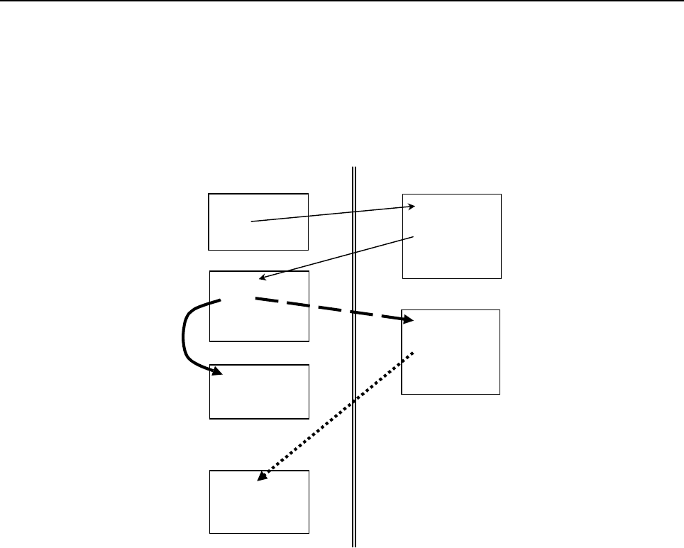
B-63943EN-2/07
3.EXECUTION MACRO FUNCTION
- 19 -
(3) When a user program is called from an execution macro
From a user program called as a subprogram from an execution macro, another program can be called. In
this case, three types of calls can be made as described below. The limitations depend on the settings of
bit 6 (GMP) of parameter No. 6008, bit 2 (PCDC) of compile parameter No. 9163, and bit 6 (C16) of
compile parameter No. 9163.
(a) Calling another user program in program memory
(b) Calling an execution macro
(c) Calling a subprogram of the user program after an execution macro is called
:
Gxx
:
Opp1
Mxx
:
M99
Oxxxx
:
M99
O90xx
:
MxxPpp1
:
M99
(a) O90xx
:
MxxPpp2
:
M99
(b)
O pp2
:
M99
(c)
Within user program Within execution macro
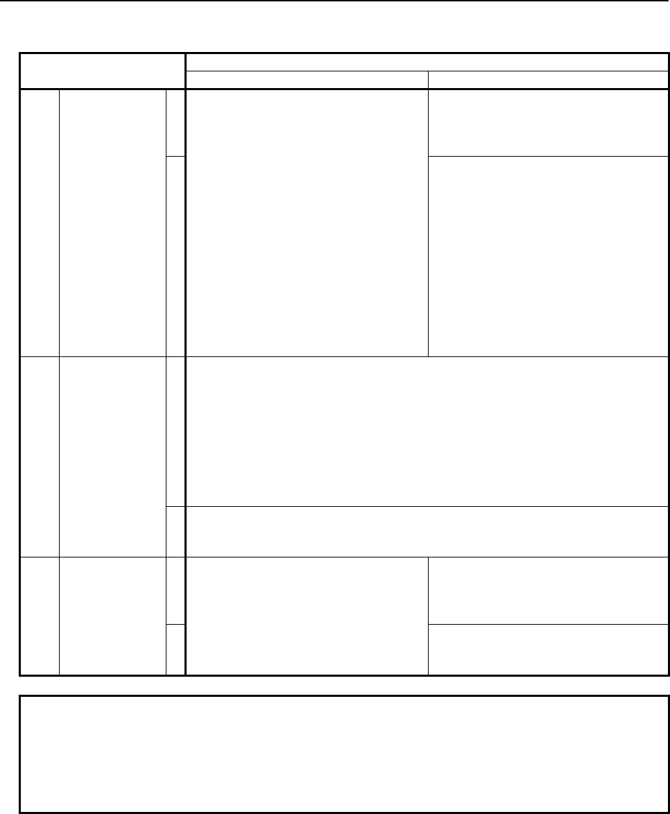
3.EXECUTION MACRO FUNCTION
B-63943EN-2/07
- 20 -
* In the description, the G/M/S/T/D/H/second auxiliary function codes/special codes are generically
referred to as each code.
Bit 2 (PCDC) of Compile parameter No. 9163
0 1
(a)
Bit 6 (GMP) of
parameter No.
6008
0
User macro calls using G65, M98, G66,
and G66.1 only are allowed.
Other types of calls are disabled.
User macro calls using G65, M98, G66,
and G66.1 only are allowed.
Other types of calls are disabled.
1
- From an execution macro called
using a G code, a user program can
be called using a code other than G
codes (or using an axis address).
- From an execution macro called
using a code other than G codes (or
using an axis address), a user
program can be called using a G
code.
Other types of calls (G code to G code,
code other than G codes to code other
than G codes) are disabled.
(b)
Bit 6 (C16) of
compile
parameter No.
9163
0
When bit 6 (GMP) of parameter No. 6008 is set to 0:
Once a user program is called, no execution macro can be called.
When bit 6 (GMP) of parameter No. 6008 is set to 1:
- From a user program called using a G code, an execution macro can be
called using a code other than G codes (or using an axis address).
- From a user program called using a code other than G codes (or using an
axis address), an execution macro can be called using a G code.
Other types of calls (G code to G code, code other than G codes to code other
than G codes) are disabled.
1
Each code (or axis address) can be used to call an execution macro (in the same
manner as in “(1) How to call an execution macro”) regardless of the setting of bit 6
(GMP) of parameter No. 6008.
(c)
Bit 6 (GMP) of
parameter No.
6008
0 After an execution macro is called, the
user program cannot be called again.
(The duplicate calling of a user program
is disabled.)
After an execution macro is called, the
user program cannot be called again.
(The duplicate calling of a user program
is disabled.)
1
A user program can be called. (The
duplicated calling of a user program is
allowed.)
NOTE
1 If an attempt is made to execute a call command not allowed, the command is
treated as an ordinary G/M/S/T/D/H/second auxiliary function/axis address code.
2 If bit 0 (GMC) of compile parameter No. 9163 is set to 1, the same processing as
performed when bit 6 (GMP) of parameter No. 6008 is set to 0 and bit 2 (PCDC)
of compile parameter No. 9163 is set to 0 is performed.
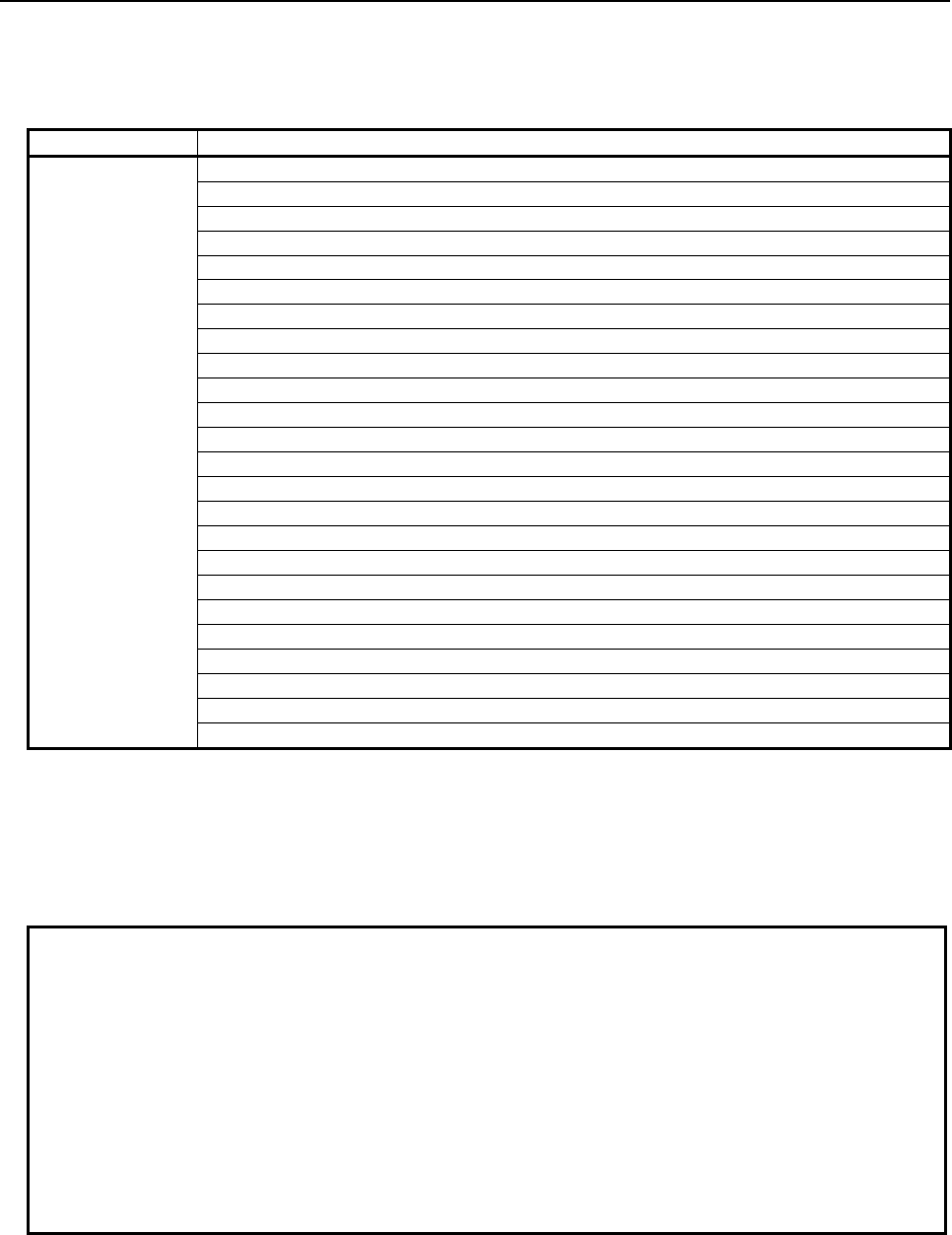
B-63943EN-2/07
3.EXECUTION MACRO FUNCTION
- 21 -
Priority of calls
If a call code is set doubly with a custom macro or another call code in a parameter or compile parameter,
the priority indicated in the Table 3.2 (a) governs:
Table 3.2 (a)
Priority Call
High Simple call of execution macro (G65)
↑ Modal call of execution macro (G66,G66.1)
| Macro call using G code
| Macro call using G code (specification of 1 set)
| Macro call using G code (specification of 3 sets)
| Macro call using M code
| Macro call using M code (specification of 3 sets)
| Special macro call using M code
| Special macro call using axis address
| Special macro call using T code
| Special macro call using D code
| Special macro call using H code
| Special macro call using S code
| Subprogram call of execution macro (M98)
| External device subprogram call (M198)
(*1)
| Subprogram call for user program
| Subprogram call using specific code
| Subprogram call using M code
| Subprogram call using M code in the specified range
| Subprogram call using M code (specification of 3 sets)
| Subprogram call using S code
| Subprogram call using T code
↓ Subprogram call using second auxiliary function code
Low Macro call/subprogram call which calls custom macro
(*2)
*1 This priority is applied when an external device subprogram call is executed from an execution
macro.
*2 By setting bit 1 (MCA) of parameter No. 9013 to 1, priority can be given to a custom macro call
rather than to all execution macro calls. (If the code for an execution macro call set in a compile
parameter is the same as the code for a custom macro call set in a parameter, priority is given to the
custom macro call.)
Example
1 If 100 is set in both of compile parameter No. 9023 and compile parameter No.
9010, and M100 is set to enable both of a macro call using M code and a
subprogram call using M code, a macro call using M code is made when M100
is specified actually.
2 If 100 is set in both of parameter No. 6050 and compile parameter No. 9013 as
a G code for calling O9010:
• The execution macro O9010 is called when bit 1 (MCA) of parameter No.
9013 is set to 0.
• The user program O9010 is called when bit 1 (MCA) of parameter No. 9013
is set to 1.
Nesting
Execution macro calls can be nested to a depth of fifteen levels including only subprogram calls, to a
depth of five levels including only macro calls, or to a depth of fifteen levels including subprogram calls
and macro calls (to a depth of five levels for macro calls). This does not include custom macros.
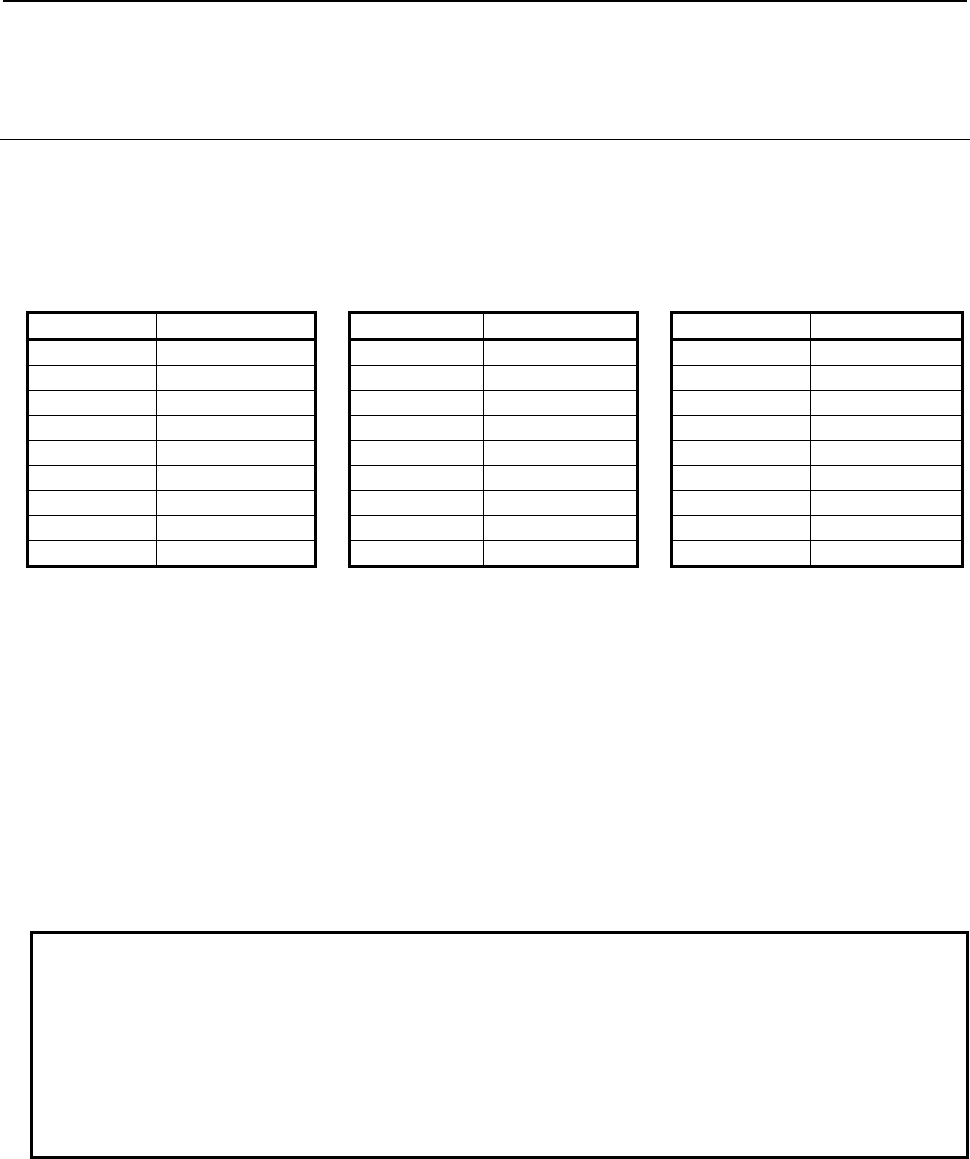
3.EXECUTION MACRO FUNCTION
B-63943EN-2/07
- 22 -
Subprogram calls for user programs and external device subprogram calls from execution macros are
included in the custom macro nesting levels.
3.2.1.2
Passing of arguments
For a macro call, arguments can be specified.
Two types of argument specification are available. Argument specification I uses addresses other than O
once each. Argument specification II uses A, B, and C once each and also uses I, J, and K up to ten times.
The type of argument specification is determined automatically according to the addresses used.
- Argument specification I
Address Variable number Address Variable number Address Variable number
A #1 J
(*1)
#5 R #18
B #2 K
(*1)
#6 S #19
C #3 L
(*2)
#12 T #20
D #7 M
1
(*3)
#13 U #21
E #8 N
(*4)
#14 V #22
F #9 M
2
(*3)
#14 W #23
G
(*2)
#10 M
3
(*3)
#15 X #24
H #11 P
(*2)
#16 Y #25
I
(*1)
#4 Q #17 Z #26
• Basically, each address other than O is used once.
• An address that need not be specified can be omitted. The value of the local variable corresponding
to an omitted address is set to <null>.
• Addresses other than I, J, and K need not be specified in alphabetical order.
• If the same codes are specified more than once in an address other than M, the last code specified is
used as an argument.
[Example] gg: Call code
Ggg A1 A2 A3 → To #1, 3 is passed.
*1 Usually, addresses I, J, and K must be specified in alphabetical order.
When bit 7 (IJK) of parameter No. 6008 is set to 1, addresses I, J, and K need not be specified in
alphabetical order.
Example
1 When bit 7 (IJK) of parameter No. 6008 is set to 0:
If I_J_K_ is specified, I=#4, J=#5, and K=#6 are set. However, if K_J_I_ is
specified, argument specification II is applied, and K=#6, J=#8, and I=#10 are
set.
2 When bit 7 (IJK) of parameter No. 6008 is set to 1:
Even if K_J_I_ is specified, argument specification I is applied. This means that
I=#4, J=#5, and K=#6 are set as in the case where I_J_K_ is specified.
*2 Usually, addresses G, L, and P cannot be used as arguments.
In the case of a macro call using G code/M code, addresses G, L, and P can be used when bit 5
(MCARG) of compile parameter No. 9008 is set to 1.
Moreover, addresses G, L, and P can be used for a special macro call.

B-63943EN-2/07
3.EXECUTION MACRO FUNCTION
- 23 -
NOTE
1 An NC command input format limitation is applied to address G. If G1000 is
specified, for example, alarm PS0010 is issued.
2 If multiple G codes are specified, the last G code specified is used as an
argument.
A G code not belonging to group 00 is passed as modal information to the
subsequent blocks.
*3 Up to three M codes specified in address M are used as arguments.
• Of the fourth and subsequent M codes, the last M code specified is passed to #15.
• If address N is also used as an argument in a macro call using G code or M code, the second
specified M code or the N code, whichever specified later, is passed to #14.
• In a special macro call using axis address/G/T/D/H/S code, only one M code is usually used as
an argument. When bit 7 (M3B) of parameter No. 3404 is set to 1, up to three M codes are used
as arguments.
• In a special macro call using M code, only the calling M code and the last M code specified are
used as arguments, regardless of the setting of bit 7 (M3B) of parameter No. 3404.
Example 1
Suppose that a block for a macro call using M code specifies multiple M codes
(M300 = Calling M code).
• When five M codes are specified in one block:
M300 M1 M2 M3 M4 M5 → #13=1, #14=2, #15=5
• When an N code is specified after the second M code:
M300 M1 M2 N10 M3 → #13=1, #14=10, #15=3
• When an N code is specified before the second M code:
M300 M1 N10 M2 M3 → #13=1, #14=2, #15=3
Example 2
Suppose that a block for a special macro call using T code specifies multiple M
codes (T300= Call code).
• When the bit 7 (M3B) of parameter No.3404 is set to 0;
M1 N10 M2 T300 M3 M4 M5 → #27=300, #13=5, #14=<null>, #15=<null>
• When the bit 7 (M3B) of parameter No.3404 is set to 1;
M1 N10 M2 T300 M3 M4 M5 → #27=300, #13=1, #14=2, #15=5
* In a special macro call using T code, address N is not used as an argument.
Example 3
Suppose that a special macro call using M code is made (M300 = Call code).
M1 M2 M300 M3 M4 M5 → #27=300, #13=5, #14=<null>, #15=<null>
* The argument is the same when bit 7(M3B) of parameter No.3404 is set to 1.
*4 Address N is used as an argument when address N is specified after an address other than O and N in
a macro call using G code or M code.
Address N is used as an argument in a special macro call using M code, regardless of where address
N is specified.
Address N is not used as an argument in a special macro call using axis address/G/T/D/H/S code.
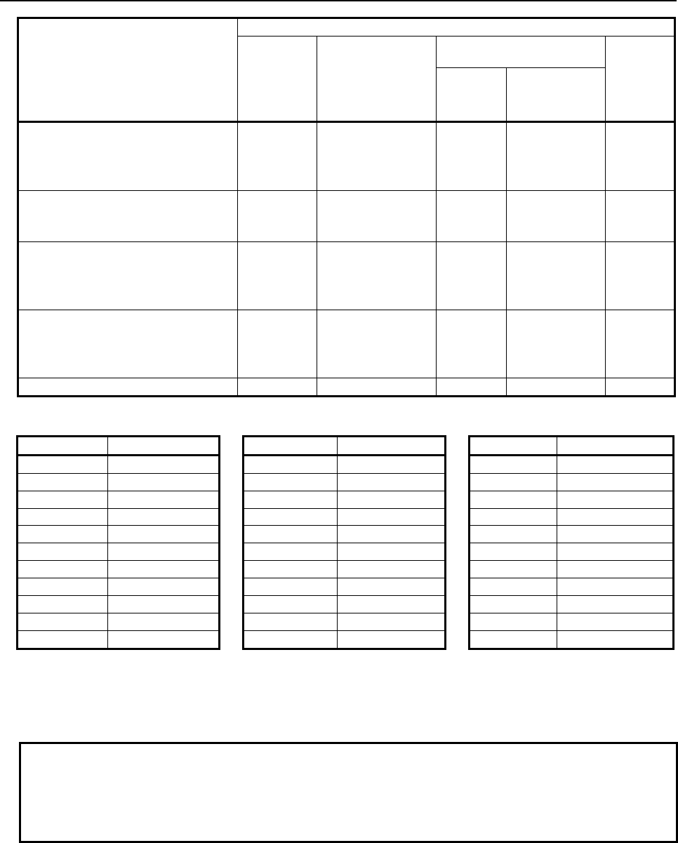
3.EXECUTION MACRO FUNCTION
B-63943EN-2/07
- 24 -
Type of call
Address used as an argument
A, B, C, D,
E, F, H, I, J,
K, Q, R, S,
T, U, V, W,
X, Y, Z
G, L, P
M
N
1st (M
1
) 2nd (M
2
),
3rd (M
3
)
- Execution macro simple call
(G65)
- Execution macro modal call:
Move command call (G66)
Specifiable Not specifiable Specifiable Not specifiable Not
specifiable
- Execution macro modal call:
Block-by-block call (G66.1)
(Blocks after G66.1 block)
Specifiable Specifiable Specifiable Not specifiable Specifiable
- Macro call using G/M code
Specifiable
Specifiable when bit
5 (MCARG) of
compile parameter
No. 9008 is set to 1
Specifiable Specifiable Specifiable
- Special macro call using axis
address / G / T / D / H / S code Specifiable Specifiable Specifiable
Specifiable when
bit 7 (M3B) of
parameter No.
3404 is set to 1
Not
specifiable
- Special macro call using M code Specifiable Specifiable Specifiable Not specifiable Specifiable
- Argument specification II
Address Variable number Address Variable number Address Variable number
A #1 K
3
#12 J
7
#23
B #2 I
4
#13 K
7
#24
C #3 J
4
#14 I
8
#25
I
1
#4 K
4
#15 J
8
#26
J
1
#5 I
5
#16 K
8
#27
K
1
#6 J
5
#17 I
9
#28
I
2
#7 K
5
#18 J
9
#29
J
2
#8 I
6
#19 K
9
#30
K
2
#9 J
6
#20
I
10
#31
I
3
#10 K
6
#21
J
10
#32
J
3
#11 I
7
#22
K
10
#33
• Argument specification II uses A, B, and C once each and uses I, J, and K up to ten times.
• Subscripts of I, J, and K for indicating the order of argument specification are not written in the
actual program.
NOTE
1 In a special macro call, argument specification II cannot be used.
2 When bit 7 (IJK) of parameter No. 6008 is set to 1, argument specification I is
applied, regardless of the specification order of I, J, and K. So, argument
specification II cannot be used.
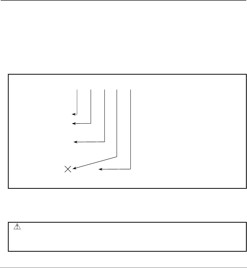
B-63943EN-2/07
3.EXECUTION MACRO FUNCTION
- 25 -
- Limitation
Format
Specify a macro call code (G65/G66/G66.1/Gg/Mm) for other than special macro calls before all
arguments.
Mixture of argument specifications I and II
The CNC internally identifies argument specification I and argument specification II. If a mixture of
argument specification I and argument specification II is specified, the type of argument specification
specified later takes precedence.
Example
G65 A1.0 B2.0 I-3.0 I4.0 D5.0 P1000 ;
(Variables)
#1:1.0
#2:2.0
#3:
#4:-3.0
#5:
#6:
#7:4.0 5.0
When both the I4.0 and D5.0 arguments are commanded for variable #7
in this example, the latter, D5.0, is valid.
Position of the decimal point
The units used for argument data passed without a decimal point correspond to the least input increment
of each address.
CAUTION
The value of an argument passed without a decimal point may vary according to
the system configuration of the machine. It is good practice to use decimal points
in macro call arguments to maintain program compatibility.
3.2.1.3
Local variable levels
• Each time a macro is called (such as G65, G66, G66.1/Gg/Mm/Tt/axis address), the local variable
level is incremented by one. The values of the local variables at the previous level are saved in the
CNC.
• When M99 is executed in a macro program, control returns to the calling program. At that time, the
local variable level is decremented by one; the values of the local variables saved when the macro
was called are restored.
• Usually, the local variable level does not change due to a subprogram call. If, however, an execution
macro is called from a user program, using a subprogram call (call with an M/S/T/second auxiliary
function/specific code), the level can be changed (equivalent to the Series 16i) as with a macro call
by setting bit 3 (LCLLV) of compile parameter No. 9163 to 1.
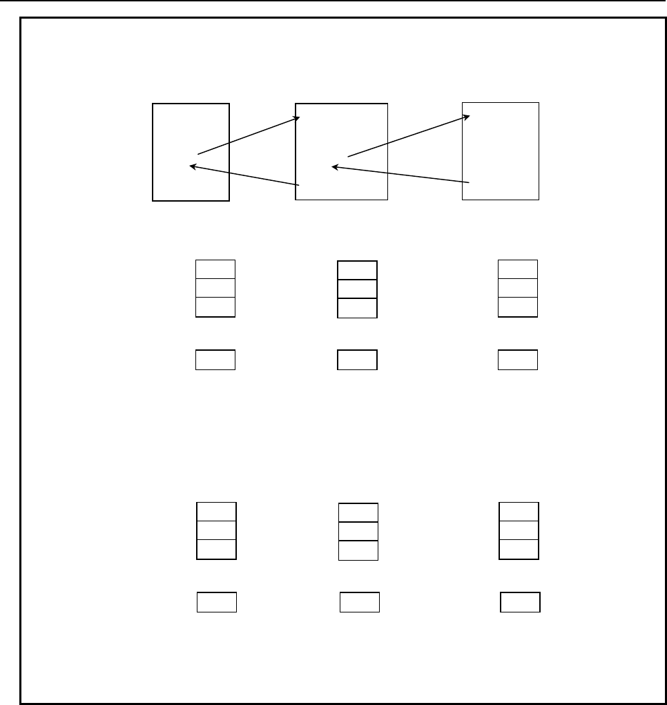
3.EXECUTION MACRO FUNCTION
B-63943EN-2/07
- 26 -
Example
Local variables
(Level 0)
Local variables
(Level 0)
Local variables
(Level 0)
1.0
# 1
null
# 2
null
# 3
:
:
null
# 33
:
:
1.0
# 1
2.0
# 2
null
# 3
:
:
null
# 33
:
:
1.0
# 1
2.0
# 2
3.0
# 3
:
:
null
# 33
:
:
- When bit 3 (LCLLV) of compile parameter No. 9163 is set to 0
The local variable level does not change because
a subprogram call is made as in the case of a
custom macro.
(The local variables at the call source are used.)
User program
(
Main pro
g
ram
)
O0001 ;
:
#1=1.0 ;
M200 ;
:
M30 ;
O9001 ;
:
#2=2.0 ;
M98 P1 ;
:
M99 ;
O0001 ;
:
#3=3.0 ;
:
:
M99 ;
Execution
macro
Execution
macro
Subprogram
call Subprogram
call
M code for calling O9001 as a subprogram is M200.
Local variables
(Level 0) Local variables
(Level 1) Local variables
(Level 1)
1.0
# 1
null
# 2
null
# 3
:
:
null
# 33
:
:
null
# 1
2.0
# 2
null
# 3
:
:
null
# 33
:
:
null
# 1
2.0
# 2
3.0
# 3
:
:
null
# 33
:
:
For a subprogram call
from an execution macro,
the local variable level
does not change.
(The local variables at the
call source are used.)
The local variable level
changes, although a
subprogram call is made.
(The local variables at the
call destination are used.)
- When bit 3 (LCLLV) of compile parameter No. 9163 is set to 1
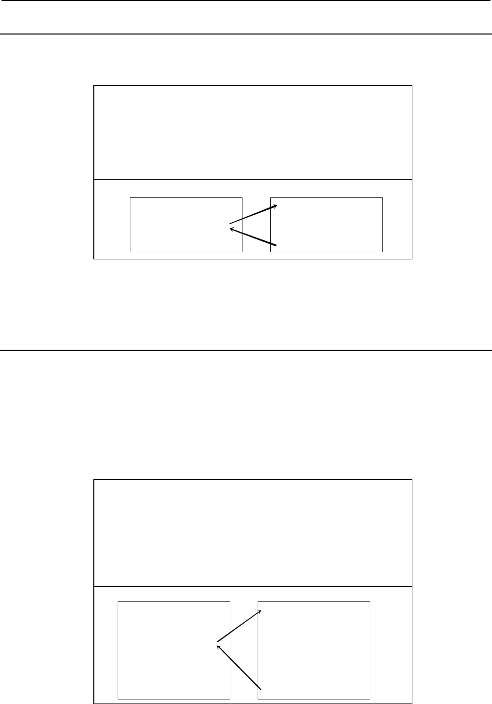
B-63943EN-2/07
3.EXECUTION MACRO FUNCTION
- 27 -
3.2.2
Simple Call (G65)
An execution macro specified using address P is called as a macro.
Format
G65 P p L l
<argument-specification> ;
G65 : Call command.
Must be specified before any argument.
P : Program number of an execution macro to
be called
l : R epetition count (1 by default)
1 to 99999999
argument : Data to be passed to the execution
macro. Argument specifications I and II
are available.
O9010 ;
:
G65 P100 L2 A1.0 B2.0 ;
:
M99 ;
O0100 ;
#3=#1+#2 ;
IF [#3 GT 360] GOTO 9 ;
G00 G91 X#3 ;
N9 M99 ;
Execution macro Execution macro
Limitation
No execution macro can be called from any user program using this command. This command can be
specified only for calling an execution macro from another execution macro.
3.2.3
Modal Call (G66/G66.1)
A modal call is performed for the execution macro specified at address P.
The specifications such as move command call (G66) operation, block-by-block call (G66.1) operation,
and multi-level modal calls are exactly the same as for custom macros. See the specifications of custom
macros as well.
Whether an execution macro program is called in a modal call (macro modal call using a G66/G66.1/G
code) or not can be checked using variable #8680. For details, see Subsection 3.2.8.2, "Variable for
checking whether a modal call is in progress".
Format
G66 P p L l
<argument-specification> ;
G66 : Call command.
Must be specified before any argument.
P : Program number of an execution macro to
be called
l : R epetition count (1 by default)
1 to 99999999
argument : Data to be passed to the execution
macro. Argument specifications I and II
are available. Arguments only in G66
blocks are passed to local variables.
O9010 ;
:
G66 P100 L2 A1.0 B2.0 ;
G00 G90 X100.0 Y150.0 ;
Y200.0
X150.0 Y300. 0
G67 ;
:
M99 ;
O0100 ;
:
G00 Z-#1 ;
G01 Z-#2 F300 ;
:
:
:
:
M99 ;
Execution macro Execution macro
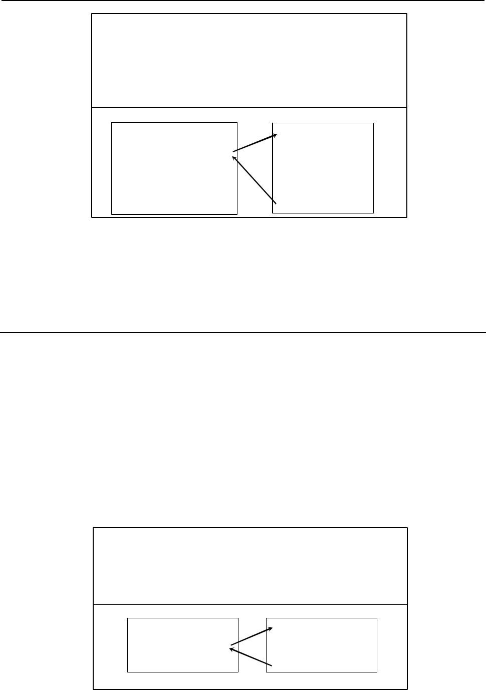
3.EXECUTION MACRO FUNCTION
B-63943EN-2/07
- 28 -
G66.1 P p L l
<argument-specification> ;
G66.1: Call comm and.
Must be specified before any argument.
P : Program number of an execution macro to be
called
l : Repetition count (1 by default)
1 to 99999999
argument : Data to be passed to the execution
macro. Argument specifications I and II
are available.
Execution macro Execution macro
O9010 ;
:
G66.1 P100 L2 A1.0 B2.0 F100;
A10.0 B20.0 F300 ;
A0 B-30.0 ;
F1000 ;
G67 ;
M99 ;
O0100 ;
:
G00 Z-#1 ;
G01 Z-#2 F#9 ;
:
:
:
M99
;
Limitation
1 No execution macro can be called from any user program using this command. This command can
be specified only for calling an execution macro from another execution macro.
2 This command can be specified only when bit 2 (PCDC) of compile parameter No. 9163 is set to 1.
3 In the modal call mode by G66.1, G10 cannot be specified.
3.2.4
Macro Call Using G Code
• Execution macro O9010 to O9019 is called using the G code specified for compile parameters Nos.
9013 to 9022 as a macro.
• By setting 9999 in compile parameters Nos. 9013 to No. 9022, macro calling of O9010 to O9019 is
enabled with "G0" in addition to "G9999".
• When bit 5 (GMACC) of compile parameter No. 9104 is set to 1, a special macro call is made. For
details, see Subsection 3.2.9, "Special Macro Call Using G Code".
• When a negative G code is set in one of compile parameters Nos. 9013 to 9022, the corresponding
execution macro is called in the modal mode. For details, see Subsection 3.2.8, "Macro Modal Call
Using G Code".
• When bit 1 (PRDGCAL) of compile parameter No. 9103 is set to 1, a call using a G code with a
decimal point can be made. For details, see Subsection 3.2.5, "Macro Call Using G Code with
Decimal Point".
Format
Gg L l <argument-specification> ; g : Call G code.
Must be specified before any argument.
l
(*2)
: Repetition count (1 by default)
1 to 99999999
argument : Data to be passed to the execution
macro. Argument specifications I and II
are available.
User program
(*1)
Execution macro
O0001 ;
:
G81 X10.0 Y20.0 Z-10.0 ;
:
M30 ;
O9010 ;
:
:
:
N9 M99 ;
Compile parameter No.9013=81
B-63943EN-2/07
3.EXECUTION MACRO FUNCTION
- 29 -
*1 When bit 2 (PCDC) of compile parameter No. 9163 is set to 1, a call can be made from an execution
macro.
*2 When bit 5 (MCARG) of compile parameter No. 9008 is set to 1, address L is also used as an
argument, so that the number of repeats cannot be specified.
Correspondence between parameter numbers and program numbers
Program number Compile parameter number
O9010 9013
O9011 9014
O9012 9015
O9013 9016
O9014 9017
O9015 9018
O9016 9019
O9017 9020
O9018 9021
O9019 9022
Argument specification
• Argument specification I or II is automatically determined according to the address used.
• When bit 5 (MCARG) of compile parameter No. 9008 is set to 1, address G/L/P is also used as an
argument. So, the number of repeats cannot be specified.
• Address N, when specified before a call G code, is used not as an argument but as a sequence
number.
• Up to three M codes specified in address M are used as arguments. Of the fourth and subsequent M
codes, the last M code specified is passed to #15. If address N is specified, however, the second
specified M code or the N code, whichever specified later, is used as an argument.
[Example] Ggg: Call code
(1) When an N code is specified after the second M code:
Ggg M1 M2 N100 M3 M4 M5 → #13=1,#14=100,#15=5
(2) When an N code is specified before the second M code:
Ggg M1 N100 M2 M3 M4 M5 → #13=1,#14=2,#15=5
Limitation
1 If a G code exceeding 9999 is set, the macro call is invalidated.
2 Usually, when an execution macro is called from a program called using a G code, only a G65 or
M98 command can be specified. When bit 2 (PCDC) of compile parameter No. 9163 is set to 1, G66
and G66.1 are also available. Moreover, when bit 2 (PCDC) of compile parameter No. 9163 is set to
1, a call using an M/S/T/D/H/second auxiliary function/specific code/axis address can be made from
a program called using a G code by setting bit 6 (GMP) of parameter No. 6008 to 1. Parameter GMP
is an ordinary parameter, so that this parameter can be modified, for example, through the MDI
panel.
3.2.5
Macro Call Using G Code with Decimal Point
By setting bit 1 (PRDGCAL) of compile parameter No. 9103 to 1, O9010 to O9019 specified in compile
parameters No. 9013 to No. 9022 can be called using a G code with a decimal point. A call code with no
decimal point and a call code with a decimal point are not distinguished from each other. So, a macro call
can be made with either a G code with a decimal point or a G code with no decimal point.
• By setting 9999 in compile parameter No. 9013 to No. 9022, O9010 to O9019 can be called using
"G0.0" in addition to "G9.999", "G99.99", "G999.9", and "G999.9". In this case, the call code may
also be "G0.", "G.0", or "G0.00".

3.EXECUTION MACRO FUNCTION
B-63943EN-2/07
- 30 -
Example
When bit 1 (PRDGCAL) of compile parameter No. 9103 is set to 1 and compile
parameter No. 9013 is set to 123, O9010 can be called by specifying any of
G1.23, G12.3, and G123.
3.2.6
Macro Call Using G Code (Specification of 1 Set)
Execution macros to be called using a G code can be added by setting the start number of G codes to be
used for macro calls, the start number of execution macros to be called, and the number of definitions for
compile parameters.
• When bit 5 (GMACC) of compile parameter No. 9104 is set to 1, a special macro call is made. For
details of modal calls, see Subsection 3.2.9, "Special Macro Call Using G Code".
• When a negative number is set as the start G code number, modal calls are defined for the
corresponding execution macros. For details of modal calls, see Subsection 3.2.8, "Macro Modal
Call Using G Code".
The format, argument specification, and limitation are the same as for Subsection 3.2.4, “Macro Call
Using G code”.
Parameter setting
Compile parameter No. 9045 : Start G code number
Compile parameter No. 9046 : Number of definitions
Compile parameter No. 9047 : Start execution macro number
Example
When 900 is set for parameter No. 9045, 100 is set for parameter No. 9046, and
8000 is set for parameter No. 9047, the macro calls for the following
combinations are defined. When -900 is set for parameter No. 9045, the modal
calls for the same combinations are defined.
G900
→ O8000
G901
→ O8001
G902
→ O8002
:
G999
→ O8099
Limitation
1 This type of macro call is invalidated in the following cases:
<1> A value outside the valid range is set for a compile parameter.
<2> The defined G code range exceeds 9999.
<3> The defined program number range exceeds 99999999.
NOTE
To use a program number with an O number of five or more digits, set bit 3
(ON8) of parameter No. 11304 to 1.
2 G codes used for macro calls are not used as call commands in this type of macro call even when
included in the setting range.
B-63943EN-2/07
3.EXECUTION MACRO FUNCTION
- 31 -
3.2.7
Macro Call Using G Code (Specification of 3 Sets)
Up to three sets, each consisting of a start G code number used for macro calling, start execution macro
number to be called, and the number of execution macros to be defined, can be set.
When bit 5 (GMACC) of compile parameter No. 9104 is set to 1, a special macro call is made. For details
of modal calls, see Subsection 3.2.9, "Special Macro Call Using G Code".
When a negative number is set as the start G code number of each set, the corresponding execution
macros are called in the modal mode. For details of modal calls, see Subsection 3.2.8, "Macro Modal Call
Using G Code".
The format, argument specification, and limitation are the same as for Subsection 3.2.4, “Macro Call
Using G code”.
Parameter setting
Table 3.2.7 indicates the compile parameters to be set for each set.
Table 3.2.7
1st set 2nd set 3rd set
Start G code number 9129 9132 9135
Number of execution macros to be defined 9130 9133 9136
Start execution macro number 9131 9134 9137
Example
Setting of the 1st set: No. 9129=900 No. 9131=8000 No. 9130=10
Setting of the 2nd set: No. 9132=950 No. 9134=8100 No. 9133=30
Setting of the 3rd set: No. 9135=1000 No. 9137=8900 No. 9136=5
The settings above define the following sets of macro calls:
1st set 2nd set 3rd set
G900 → O8000 G950 → O8100 G1000 → O8900
G901 → O8001 G951 → O8101 G1001 → O8901
G902 → O8002 G952 → O8102 G1002 → O8902
: : : : G1003 → O8903
G909 → O8009 G979 → O8129 G1004 → O8904
When No. 9129 = -900 is set, the same set of modal calls as the 1st set is
defined. Similarly, when No. 9132 = -950 and No. 9135 = -1000 are set, the
same sets of modal calls as the 2nd and 3rd sets are defined, respectively.
Limitation
1 This type of macro call is invalidated in the following cases:
<1> A value outside the valid range is set for a compile parameter.
<2> The defined G code range exceeds 9999.
<3> The defined program number range exceeds 99999999.
NOTE
To use a program number with an O number of five or more digits, set bit 3
(ON8) of parameter No. 11304 to 1.
2 Three types of macro calling based on G codes are available as indicated below. If the range of G
codes set in <1> duplicates the ranges of G codes set in <2> or <3>, the G code priority order is,
from high to low, <1> to <2> to <3>.
<1> Individual specification :
Compile parameters Nos. 9013 to 9022

3.EXECUTION MACRO FUNCTION
B-63943EN-2/07
- 32 -
<2> Specification of 1 set :
Compile parameters Nos. 9045 to 9047
<3> Specification of 3 sets :
Compile parameters Nos. 9129 to 9131, 9132 to 9134, 9135 to 9137
3.2.8
Macro Modal Call Using G Code
• If a negative number is set in a compile parameters Nos. 9013 to 9022, the corresponding execution
macro is called in the modal mode.
• By setting -9999 in compile parameter No. 9013 to No. 9022, O9010 to O9019 can be called in the
modal mode with "G0" in addition to "G9999". (This function is disabled when multiple G code
macro calls are specified.)
• This capability is usable for multiple macro calls using G code. In this case, set a negative number as
a start G code number in compile parameter No. 9045 or in compile parameters Nos. 9129, 9132,
and 9135 for each set.
• Two modal call methods are available: the standard method and the Series 16i method.
• The variable #8680 can be used to check if an execution macro is called in a modal call (macro
modal call using a G66/G66.1/G code). For details of modal calls, see Subsection 3.2.8.2, "Variable
for checking whether a modal call is in progress".
(1) Standard method (when bit 0 (GMC) of compile parameter No. 9163 is set
to 0)
Until the modal call cancel G code (G67) is specified, the execution macro is called with the specified G
code in the modal mode equivalent to G66/G66.1 for custom macros.
The functions such as move command call (G66) operation, block-by-block call (G66.1) operation, and
multi-level modal calls are exactly the same as for custom macros. See the specifications of custom
macros as well.
Cancel G code
When G67 is specified, no macro modal call is made in the subsequent blocks. (See the custom macro
specifications.)
Passing of arguments
The same operation as for custom macro move command call (G66) operation and block-by-block call
(G66.1) operation is performed. (See the custom macro specifications.)
G10 command
In the modal call mode by the block-by-block call (G66.1), G10 cannot be specified.
Call in the modal call mode
• In the modal call mode, a simple call (G65)/subprogram call (M98) can be made. No other call codes
will result in macro calls/subprogram calls; modal calls of execution macro programs will be made.
• A modal call will also be effective in the program called with a simple call (G65)/subprogram call
(M98) in a user program.
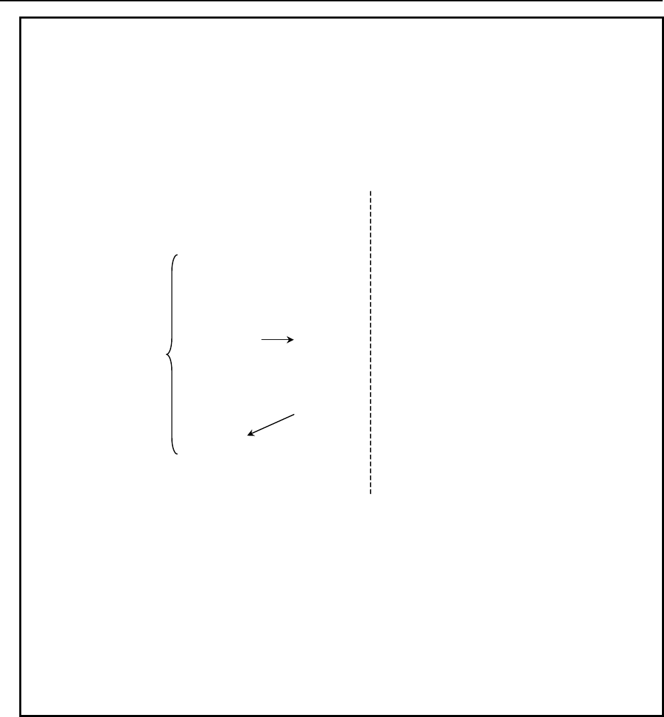
B-63943EN-2/07
3.EXECUTION MACRO FUNCTION
- 33 -
Example
Bit 1 (MCT) of compile parameter No.9163=0: Modal call equivalent to G66.1
Compile parameter No. 9013= 42: With G42, O9010 is called as a macro.
Compile parameter No. 9014=-110: With G110, O9011 is called as a macro
in the modal mode.
Compile parameter No. 9010= 100: With M100, O9001 is called as a sub
program.
User program Execution macro
O4000
N1G01F500
N2G110X10Y10
N3X20Y20
N4M100X30Y30
N5G65P1000
N6X60Y60
N7G42X100Y100
N8X110Y110
N9G67
N10M30
O1000
N10X51Y51
N20X52Y52
N30M99
(Call method)
N2 Modal
N3 Modal
N4 Modal
N5 Simple
N10 Modal
N20 Modal
N6 Modal
N7 Modal
N8 Modal
Modal call mode
• M100 in N4 is an M code for a subprogram call, but because the mode is the
modal call mode, M100 becomes an argument together with other codes (X30
and Y30 in the example) and O9011 is called in the modal mode.
• With G65 in N5, no modal call is made but O1000 is called in the simple mode,
and a modal call is made in the called user program O1000.
• G42 in N7 is a G code for a macro call, but because the mode is the modal call
mode equivalent to G66.1, G42 becomes an argument together with other codes
(X100 and Y100 in the example) and O9011 is called in the modal mode.
Limitation
Same as those on the move command calling (G66) and each-block calling (G66.1) of custom macros.
(See the custom macro specifications.)
(2) Series16i method (when bit 0 (GMC) of compile parameter No. 9163 is set
to 1)
If bit 0 (GMC) of compile parameter No. 9163 is set to 1, modal calls of the Series 16i method can be
made by setting bit 1 (MCT) of compile parameter No. 9163 to 0. The specifications of such modal calls
are different from those of the each-block calling (G66.1) of custom macros, and have several features.
An execution macro (O9010 to O9019) is called in the modal mode with a specified G code until a cancel
G code (G167 or the G code specified in compile parameter No. 9034) is specified.

3.EXECUTION MACRO FUNCTION
B-63943EN-2/07
- 34 -
When a modal call G code is specified and each NC command block is specified subsequently, a specified
macro is called unconditionally (equivalent to G66.1). In this case, those addresses other than O and N are
not executed but are used as arguments.
Moreover, the execution macro program O9006 can be called with a cancel G code for a macro modal
call using G code. For details, see Subsection 3.2.8.1 "Macro call using a cancel G code for a macro
modal call using G code".
Cancel G code
When G167 is specified, no macro modal call is made in the subsequent blocks.
(When G67 is specified, a modal call is not canceled but results in alarm PS1100.)
Instead of G167, the G code specified with compile parameter No. 9034 can be used as a cancel G code.
Passing of arguments
G, L, and P are newly used as arguments. Their correspondence to variables is: G: #10, L: #12, and P:
#16. If N is specified after an address other than O and N, N is also used as an argument. In this case, the
variable corresponding to N is #14. However, an NC command input format limitation is applied to
address G. If G1000 is specified, for example, alarm PS0010 is issued.
G10 command
In the modal call mode, G10 cannot be specified. However, G10 can be specified in the program called by
Macro Call Using G/M Code of an execution macro even in the modal call mode.
Call in the modal call mode
• In the modal call mode, a simple call (G65)/subprogram call (M98) and a macro call of an execution
macro, using a G/M code can be made. No other call codes result in subprogram calls/macro
program calls; modal calls of execution macro programs will be made.
• A modal call will also be effective in the program called with a simple call (G65)/subprogram call
(M98) in a user program. It is not enabled in a macro call of an execution macro but is enabled when
control returns to the user program.
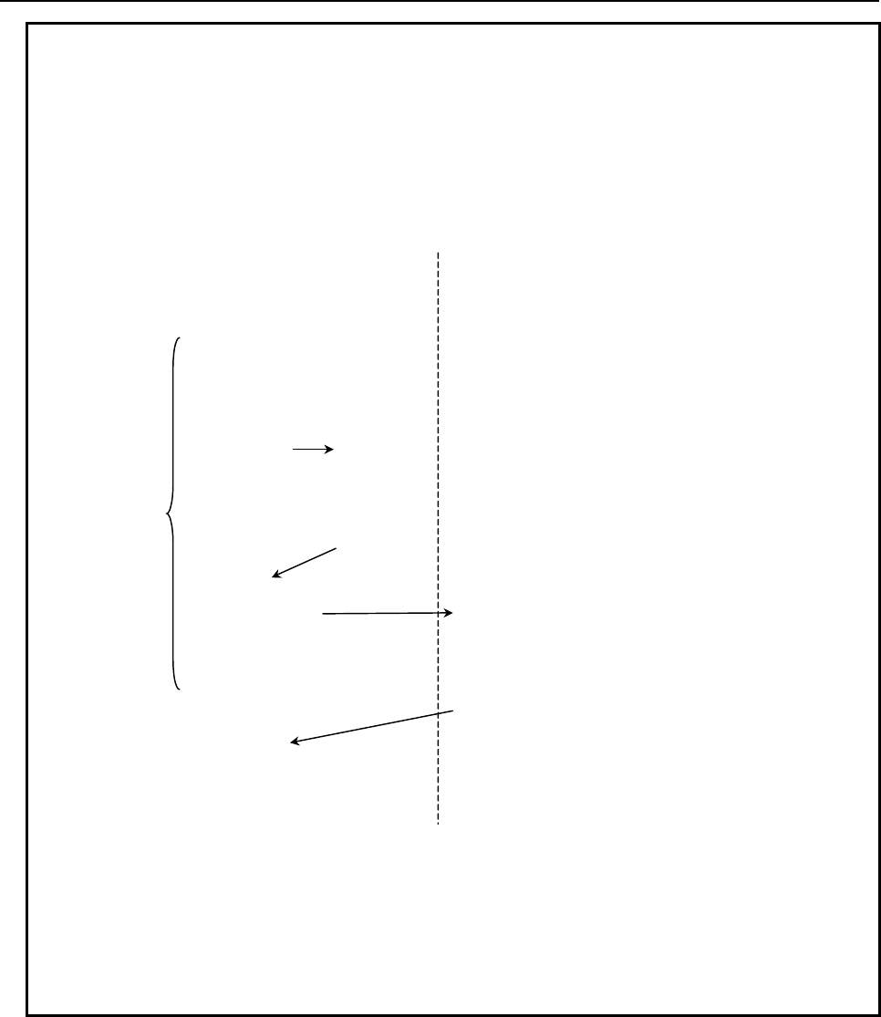
B-63943EN-2/07
3.EXECUTION MACRO FUNCTION
- 35 -
Example
Bit 1 (MCT) of compile parameter No.9163=0: Modal call equivalent to G66.1
Compile parameter No. 9013= 42: With G42, O9010 is called as a macro.
Compile parameter No. 9014=-110: With G110, O9011 is called as a macro
in the modal mode.
Compile parameter No. 9010= 100: With M100, O9001 is called as a sub
program.
User program Execution macro
O4000
N1G01F500
N2G110X10Y10
N3X20Y20
N4M100X30Y30
N5G65P1000
N6X60Y60
N7G42X100Y100
N8X110Y110
N9G167
N10M30
O1000
N10X51Y51
N20X52Y52
N30M99
O9010
N100X101Y101
N200X102Y102
N300M99
(Call method)
N2 Modal
N3 Modal
N4 Modal
N5 Simple
N10 Modal
N20 Modal
N6 Modal
N7 Macro
X and Y movement only
X and Y movement only
N8 Modal
Modal call mode
• M100 in N4 is an M code for a subprogram call, but because the mode is the
modal call mode, M100 becomes an argument together with other codes (X30
and Y30 in the example) and O9011 is called in the modal mode.
• With G65 in N5, no modal call is made but O1000 is called in the simple mode,
and a modal call is made in the called user program O1000.
• With G42 in N7, no modal call is made but a macro call using a specified G code
is made, and no modal call is made in the called execution macro O9010.
Limitation
1 This method is useful only when an execution macro is called from a user program.
This method performs the same operation as performed when bit 6 (GMP) of parameter No. 6008 is
set to 0 and bit 2 (PCDC) of compile parameter No. 9163 is set to 0.
2 Address L is also used as an argument, so that no repetition count can be specified.
3 No modal calls can be nested. No modal call can be nested with G66/G66.1.
4 In a modal call, no custom macro call using G/M/T/second auxiliary function code/special code can
be made; modal calls of execution macro programs will be made.
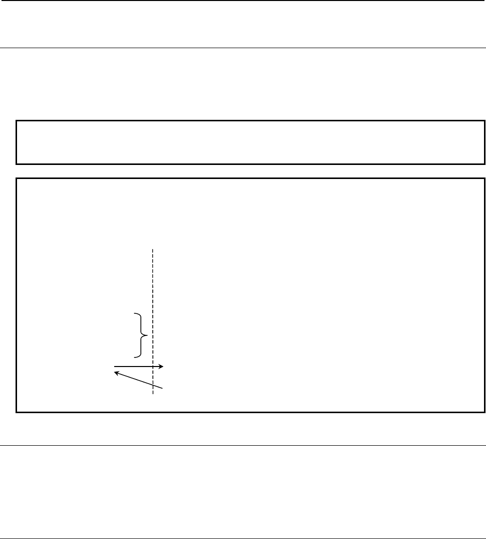
3.EXECUTION MACRO FUNCTION
B-63943EN-2/07
- 36 -
3.2.8.1
Macro call using a cancel G code for a macro modal call
using G code
By setting bit 4 (MDLP) of compile parameter No. 9008 to 1, the execution macro program O9006 can be
called when a cancel G code (G167 or the G code specified in compile parameter No. 9034) for a macro
modal call using G code is specified. Thus, a macro program for performing processing after a modal call
can be coded.
NOTE
This function is enabled only when bit 0 (GMC) of compile parameter No. 9163 is
set to 1.
Example
Compile parameter No.9013= -100: With G100, O9010 is called as a macro in
the modal mode.
User program Execution macro
O4000
G01F500
G100X10Y10
X20Y20
:
G167X0Y0Z0
M30
O9006
X#24Z#26
M99
O9010 is called block
by block in this range.
3.2.8.2
Variable for checking whether a modal call is in progress
The variable #8680 can be used to check if an execution macro is called in a modal call (macro modal call
using a G66/G66.1/G code).
#8680 =0: Not in a macro modal call
=1: In a macro modal call
3.2.9
Special Macro Call Using G Code
When bit 5 (GMACC) of compile parameter No. 9104 is set to 1, all of the following macro calls using G
code are treated as special macro calls:
(1) Macro call using G code
(2) Macro call using G code (specification of 1 set)
(3) Macro call using G code (specification of 3 sets)
• When a macro call using a G code with a decimal point, a macro modal call using a G code, or a
macro call using a cancel G code for a macro modal call using G code is enabled, such a macro call
is also treated as a special macro call.
• The same program numbers and parameters as called and set for macro calls using respective G
codes are called and set.
• By setting 9999 in compile parameter No. 9013 to No. 9022, O9010 to O9019 can be call as special
macros using "G0" in addition to "G9999". (This function is disabled in the case of specification of 1
set and specification of 3 sets.)
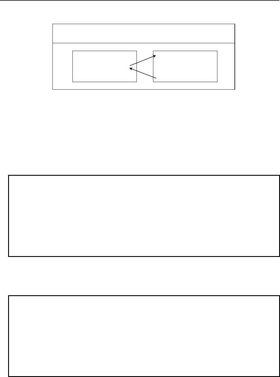
B-63943EN-2/07
3.EXECUTION MACRO FUNCTION
- 37 -
Format
Gg <argument-specification> ; g : Call G code.
argument : Data to be passed to the execution macro.
Argument specifications I is available.
User program
(*1)
Execution macro
O0001 ;
:
G01G91X10.Y20.G100 ;
:
M30 ;
O9010 ;
:
:
:
M99 ;
Compile parameter No.9013=100
*1 When bit 2 (PCDC) of compile parameter No. 9163 is set to 1, a call can be made from an execution
macro.
Call code
In contrast to a macro call using a G code, a G code in a block is used as a call command unless another
call command is specified before the G code. When multiple call commands are specified, the first call
code specified is selected. A subsequent call code is used as an argument if the first call code specified is
for a macro call. A subsequent call code is executed as an ordinary NC statement if the first call code
specified is for a subprogram call.
Example
When a special macro call using G100 and a subprogram call using M100 are
enabled for the machine
a) G100 M06; Calls a macro using G100.
b) G01 X100. G100; Calls a macro using G100.
c) G100 M100; Calls a macro using G100. (M100 is an argument.)
d) M100 G100; A call is made with M100 before G100, so that G100 is
treated as an ordinary G code, resulting in alarm PS0010.
* If a special macro call is made with a G code (in cases of a to c), the specified
addresses including the call code G100 are used as arguments.
Argument
1. All addresses specifiable with a machine except address N are used as arguments. Those addresses
that are used as arguments are just specified addresses, and no modal change is made.
Example
When a setting is made so that O9010 is called as a special macro with G100
O0001
N1G90G00X50.0;
N2G91G01X100.0G100;
N3 X150.;
:
O9010;
X#24;
M99;
G91G01 of N2 are just treated as arguments, and the modal state remains to be
G90 G00. For this reason, O9010 and N3 causes a rapid traverse to X100.0 and
X150.0 respectively.
2. When an address is specified with no decimal point, a decimal point is added to the value passed to a
local variable according to bit 0 (DPI) of parameter No. 3401.
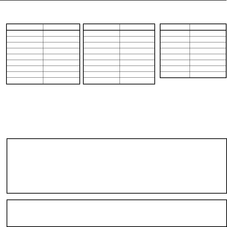
3.EXECUTION MACRO FUNCTION
B-63943EN-2/07
- 38 -
3. There are the following relationships between addresses and local variables:
In the case of address G, the specified call G code is passed to #27, and up to five of other G codes
in the ascending order of G code group numbers are used as arguments and passed to #28 to #32.
Address Variable number Address Variable number Address Variable number
A #1 J #5 S #19
B #2 K #6 T #20
C #3 L #12 U #21
D #7 M #13 V #22
E #8 M2
(*1)
#14 W #23
F #9 M3
(*1)
#15 X #24
G #27 to #32 P #16 Y #25
H #11 Q #17 Z #26
I #4 R #18
*1 : When bit 7 (M3B) of parameter No. 3404 is set to 1, up to three M codes specified in address M are
used as arguments. Of the fourth and subsequent M codes, the last M code specified is passed to
#15.
[Example] M1 M2 N100 G300 M3 M4 ; (G300 : Call code)
(1) Bit 7 (M3B) of parameter No.3404 is set to 0:
#27=300, #13=4, #14 =<null>, #15 =<null>
(2) Bit 7 (M3B) of parameter No.3404 is set to 1:
#27=300, #13=1, #14=2, #15=4
Example
If "G91 G28 X123.45678 G100;" is specified on an IS-B machine that enables a
special macro call to be made using G100, the arguments are passed as follows:
#24
→123.457
#27
→ 100
#28
→28.0
#29
→91.0
Others are set to <null>.
NOTE
The specifiable addresses and specification range conform to the specification
address range of the CNC. For example, address M does not allow the decimal
point to be used. So, the specification of G100 M1.23; results in alarm PS0007.
Limitation
1 Address L is also used as an argument, so that no repetition count can be specified.
2 No specified address is evaluated. So, an execution macro is called by a specified address without
making a modal change.
3 The other limitations are the same as for a macro call using a respective G code.
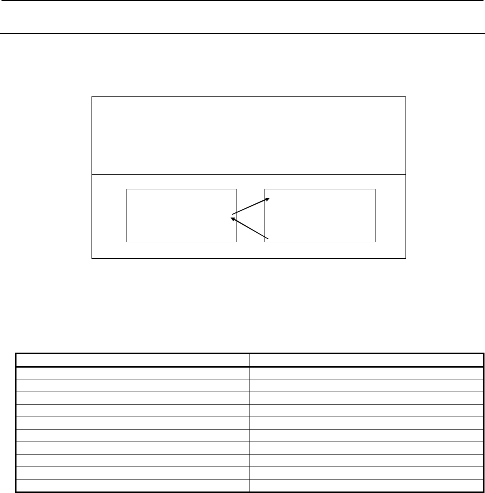
B-63943EN-2/07
3.EXECUTION MACRO FUNCTION
- 39 -
3.2.10
Macro Call Using M Code
Execution macro O9020 to 9029 is called using the M code specified for compile parameters Nos. 9023
to 9032 as a macro.
Format
Mm Ll <argument-specification> ;m : Call M code. Must be specified before an
y
argument.
l
(*2)
: Repetition count (1 by default)
1 to 99999999
argument : Data to be passed to the execution
macro. Argument specifications I and II
are available.
User program
(*1)
Execution macro
O0001 ;
:
M200 X10.0 Y20.0 Z-10.0 ;
:
M30 ;
O9020 ;
:
:
:
N9 M99 ;
Compile parameter No.9023=200
*1 When bit 2 (PCDC) of compile parameter No. 9163 is set to 1, a call can be made from an execution
macro.
*2 When bit 5 (MCARG) of compile parameter No. 9008 is set to 1, address L is also used as an
argument, so that the number of repeats cannot be specified.
Correspondence between parameter numbers and program numbers
Program number Compile parameter number
O9020 9023
O9021 9024
O9022 9025
O9023 9026
O9024 9027
O9025 9028
O9026 9029
O9027 9030
O9028 9031
O9029 9032
Argument specification
• Argument specification I or II is automatically determined according to the address used.
• When bit 5 (MCARG) of compile parameter No. 9008 is set to 1, address G/L/P is also used as an
argument. So, no repetition count can be specified.
• Address N, when specified before a call M code, is used not as an argument but as a sequence
number.
• Up to three M codes specified in address M are used as arguments. Of the fourth and subsequent M
codes, the last M code specified is passed to #15. Address N is specified, however, the second
specified M code or the N code, whichever specified later, is used as an argument.
[Example] Mmm: Call code
(1) When an N code is specified after the second M code:
Mmm M1 M2 N100 M3 M4 M5 → #13=1,#14=100,#15=5
(2) When an N code is specified before the second M code:
Mmm M1 N100 M2 M3 M4 M5 → #13=1,#14=2,#15=5
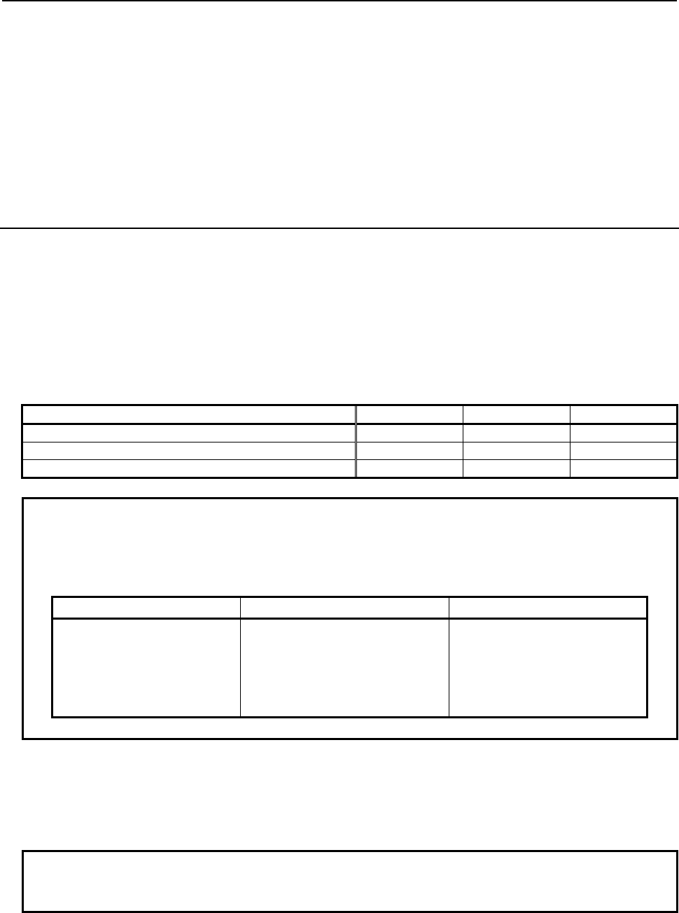
3.EXECUTION MACRO FUNCTION
B-63943EN-2/07
- 40 -
Limitation
1 If an M code exceeding 99999999 is set, the macro call is invalidated. (The M code is output as an
ordinary M code.)
2 Usually, when an execution macro is called from a program called using an M code, only a G65 or
M98 command can be specified. When bit 2 (PCDC) of compile parameter No. 9163 is set to 1, G66
and G66.1 are also available. Moreover, when bit 2 (PCDC) of compile parameter No. 9163 is set to
1, a call using a G code can be made from a program called using an M code by setting bit 6 (GMP)
of parameter No. 6008 to 1. Parameter GMP is an ordinary parameter, so that this parameter can be
modified, for example, through the MDI panel.
3.2.11
Macro Call Using M Code (Specification of 3 Sets)
Up to three sets, each consisting of a start M code number used for macro calling, start execution macro
number to be called, and the number of execution macros to be defined, can be set in compile parameters.
This capability can additionally define three separate sets of execution macros. The format, argument
specification, and limitation are the same as for Subsection 3.2.10, “Macro call using M code”.
When bit 4 (EXMSCL) of compile parameter No. 9103 is set to 1, a special macro call is made. For
details, see Subsection 3.2.12, "Special Macro Call Using M Code".
Parameter setting
The table below indicates the compile parameters to be set for each set.
1st set 2nd set 3rd set
Start M code number 9120 9123 9126
Number of execution macros to be defined 9121 9124 9127
Start execution macro number 9122 9125 9128
Example
Setting of the 1st set: No. 9120=100 No. 9122=8000 No. 9121=10
Setting of the 2nd set: No. 9123=150 No. 9125=8100 No. 9124=30
Setting of the 3rd set: No. 9126=200 No. 9128=8900 No. 9127=5
The settings above define the following sets of macro calls:
1st set 2nd set 3rd set
M100 → O8000 M150 → O8100 M200 → O8900
M101 → O8001 M151 → O8101 M201 → O8901
M102 → O8002 M152 → O8102 M202 → O8902
: : : : M203 → O8903
M109 → O8009 M179 → O8129 M204 → O8904
Limitation
1 This type of macro call is invalidated in the following cases:
<1> A value outside the valid range is set for a compile parameter.
<2> The defined M code range exceeds 99999999.
<3> The defined program number range exceeds 99999999.
NOTE
To use a program number with an O number of five or more digits, set bit 3
(ON8) of parameter No. 11304 to 1.
2 M codes used for macro calls are not used as call commands in this type of macro call even when
included in the setting range.
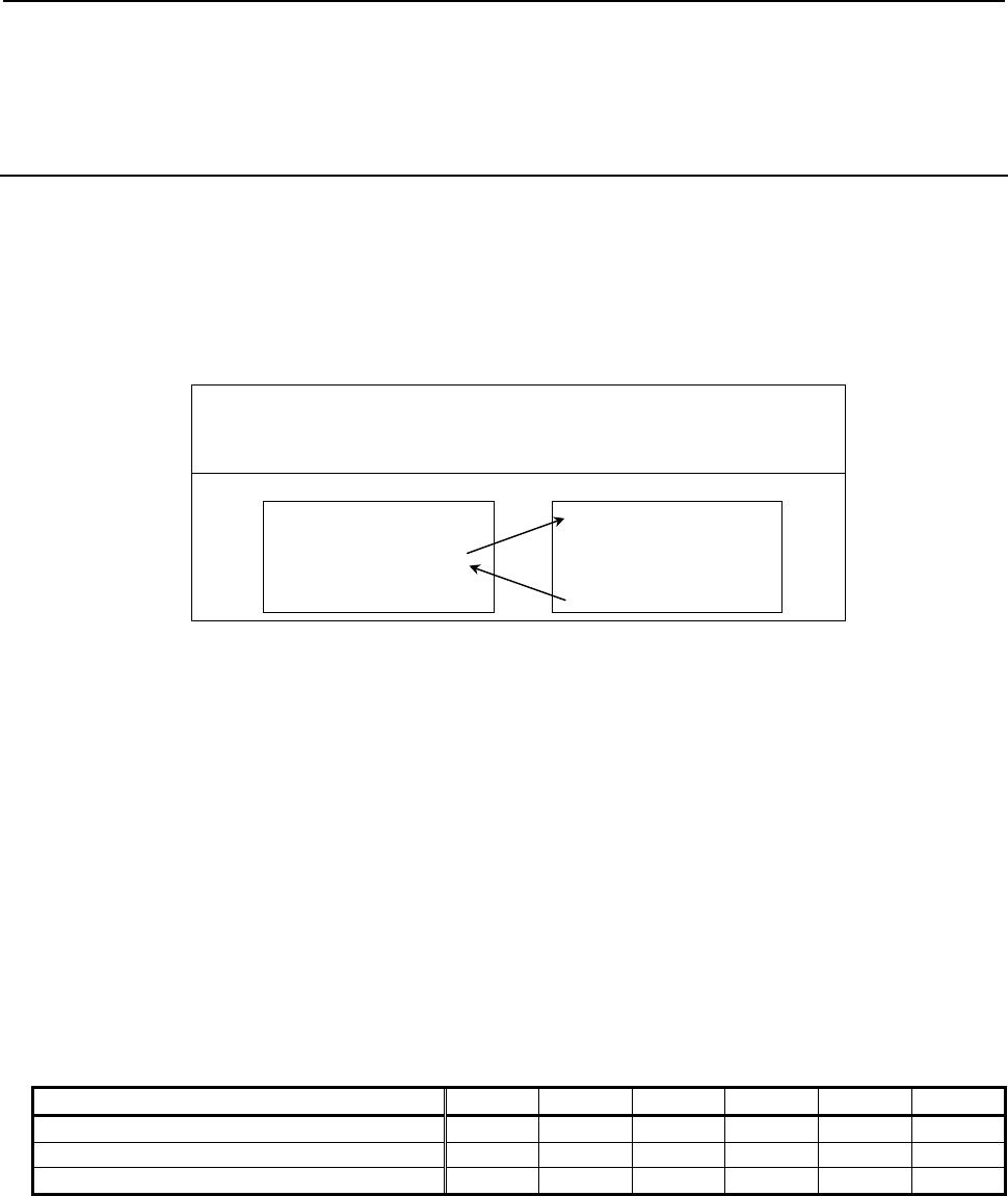
B-63943EN-2/07
3.EXECUTION MACRO FUNCTION
- 41 -
3 If the M code range of a call based on specification of 3 sets duplicates the M code of a call based on
compile parameter Nos. 9023 to 9032, the call based on compile parameter Nos. 9023 to 9032 has
higher priority.
3.2.12
Special Macro Call Using M Code
By setting bit 3 (MSCL) of compile parameter No. 9009, a subprogram call using a range specification M
code can be treated as a special macro call.
Moreover, by setting bit 4 (EXMSCL) of compile parameter No. 9103, a total of 6 sets consisting of
macro calls (specification of 3 sets) using M code and subprogram calls (specification of 3 sets) using M
code can be treated as special macro calls.
Format
Mm <argument-specification> ; m : Call M code.
argument : Data to be passed to the execution
macro. Argument specifications I is
available.
User program
(*1)
Execution macro
O0001 ;
:
G01G91X10.Y20.M100 ;
:
M30 ;
Oxxxx ;
:
:
:
M99 ;
*1 When bit 2 (PCDC) of compile parameter No. 9163 is set to 1, a call can be made from an execution
macro.
Parameter setting
- Special macro call using a range specification M code
When bit 3 (MSCL) of compile parameter No. 9009 is set to 1, a subprogram call using the range
specification M codes set in the compile parameter No. 9042 and No. 9043 is treated as a special macro
call. The called program number is O9009 at all times.
- Special macro call (specification of 6 sets) using M code
When bit 4 (EXMSCL) of compile parameter No. 9103 is set to 1, macro calls (specification of 3 sets)
using the M codes set in compile parameter No. 9120 to No. 9128 and subprogram calls (specification of
3 sets) using the M codes set in compile parameter No. 9111 to No. 9119 are treated as special macro
calls.
The table below indicates the compile parameters to be specified for each set.
1st set 2nd set 3rd set 4th set 5th set 6th set
Start M code number 9111 9114 9117 9120 9123 9126
Number of execution macros to be defined 9112 9115 9118 9121 9124 9127
Start execution macro number 9113 9116 9119 9122 9125 9128

3.EXECUTION MACRO FUNCTION
B-63943EN-2/07
- 42 -
Example
Setting of the 1st set: No.9111=100 No.9113=8000 No.9112=10
Setting of the 2nd set: No.9114=150 No.9116=8100 No.9115=30
Setting of the 3rd set: No.9117=200 No.9119=8900 No.9118=5
When the settings above are made, the following three sets of special macro
calls are defined:
1st set 2nd set 3rd set
M100 → O8000 M150 → O8100 M200 → O8900
M101 → O8001 M151 → O8101 M201 → O8901
M102 → O8002 M152 → O8102 M202 → O8902
: : : : M203 → O8903
M109 → O8009 M179 → O8129 M204 → O8904
Call code
In contrast to a macro call using an M code, an M code in a block is used as a call command unless
another call command is specified before the M code. When multiple call codes are specified, the first call
code specified is selected. A subsequent call code is used as an argument if the first call code specified is
for a macro call. A subsequent call code is executed as an ordinary NC statement if the first call code
specified is for a subprogram call.
Example
When a special macro call using M100 and a subprogram call using M10 are
enabled for the machine
a) M100 S1000; Calls a macro using M100.
b) G01 X100. M100; Calls a macro using M100.
c) M100 M10; Calls a macro using M100. (M10 is an argument.)
d) M10 M100; Processes M100 as an usual M code, then calls a
subprogram using M10.
* If a special macro call is made with M100 (in cases of a to c), all specified
addresses including the call code M100 are used as arguments.
Argument
1 All addresses specifiable on the machine are treated as arguments. Those addresses that are used as
arguments are just specified addresses, and no modal change is made. (However, address N is used
as an argument, and a modal change is made.)
Example
When a setting is made so that O9020 is called as a special macro with M100
O0001
N1G90G00X50.0;
N2G91G01X100.0M100;
N3 X150.;
:
O9020;
X#24;
M99;
G91G01 of N2 are just treated as arguments, and the modal state remains to be
G90 G00. For this reason, O9020 and N3 causes a rapid traverse to X100.0 and
X150.0 respectively.
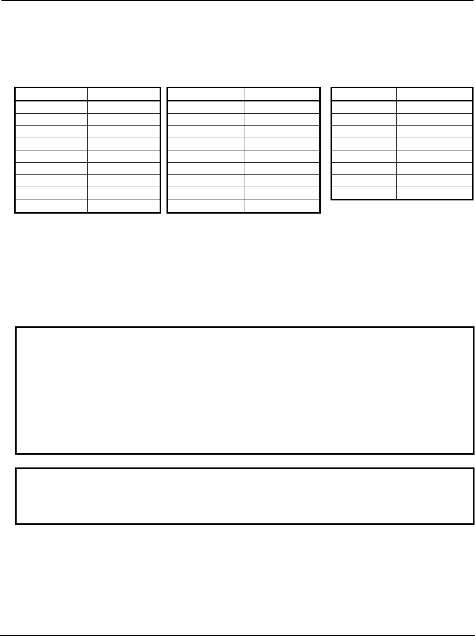
B-63943EN-2/07
3.EXECUTION MACRO FUNCTION
- 43 -
2. When an address is specified with no decimal point, a decimal point is added to the value passed to a
local variable according to bit 0 (DPI) of parameter No. 3401.
3. There are the following relationships between addresses and local variables:
The first five addresses G in ascending order of G code groups are used as arguments and passed to
variables #28 to #32.
Address Variable number Address Variable number Address Variable number
A #1 J #5 S #19
B #2 K #6 T #20
C #3 L #12 U #21
D #7 M
(*1)
#13 V #22
E #8 M (call) #27 W #23
F #9 N
(*2)
#14 X #24
G #28 to #32 P #16 Y #25
H #11 Q #17 Z #26
I #4 R #18
*1 In the case of address M, the call M code is passed to #27, and another M code is passed to #13,
regardless of the setting of bit 7 (M3B) of parameter No. 3404. When multiple M codes are specified,
the last M code specified is passed to #13.
*2 Address N is also used as an argument together with a sequence number. When multiple N codes are
specified, the last N code specified is selected.
[Example]
N10 M1 M2 N100 M300 M3 M4 ; (M300 : call code) → #27=300, #13=4, #14=100, #15=<null>
The sequence number is 100.
Example
If "G91 G28 X123.45678 M100;" is specified on an IS-B machine that enables a
special macro call to be made using M100, the arguments are passed as
follows:
#24
→123.457
#27
→ 100
#28
→28.0
#29
→91.0
Others are set to <null>.
NOTE
The specifiable addresses and specification range conform to the specification
address range of the CNC. For example, address L does not allow the decimal
point to be used. So, the specification of M100 L1.23; results in alarm PS0007.
Limitation
1 Address L is also used as an argument, so that no repetition count can be specified.
2 The other limitations are the same as for a subprogram call using a range specification M code, a
macro call (specification of 3 sets) using M code, or a subprogram call (specification of 3 sets) using
M code.
3.2.13
Special Macro Call Using Axis Address
When bits 0 to 3 of compile parameter No. 9005, bits 0 to 3 of compile parameter No. 9008, and bits 0 to
7 of compile parameters Nos. 9164 and 9165 are set, an execution macro is called using an axis address
(controlled axis move command) as a macro.
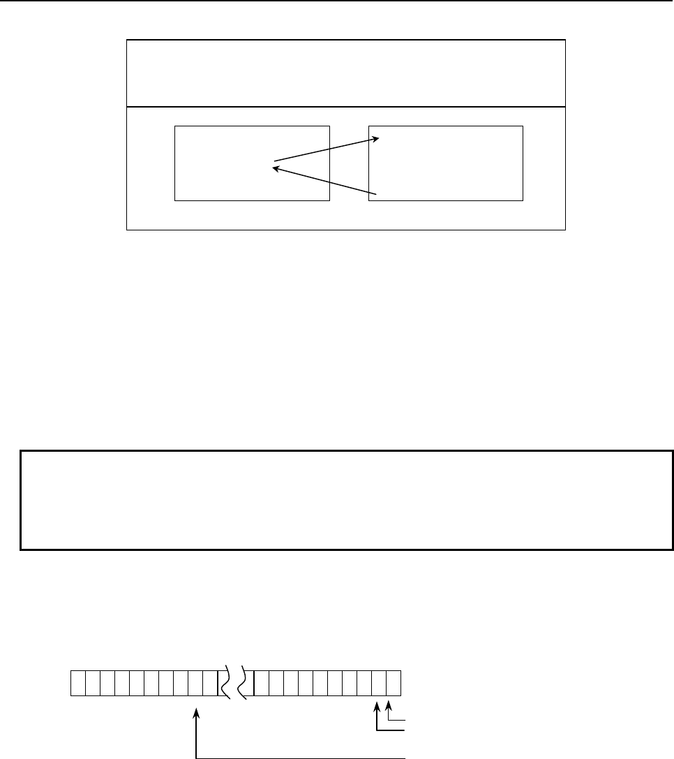
3.EXECUTION MACRO FUNCTION
B-63943EN-2/07
- 44 -
Format
xx <argument-specification> ; xx : Call code.
argument : Data to be passed to the execution
macro. Argument specifications I is
available.
User program
(*1)
Execution macro
O0001 ;
:
G91G01X100.0 ;
:
M30 ;
O9009 ;
:
:
:
M99 ;
Bit 4 (AXCLS) of compile parameter No. 9005=0
*1 When bit 2 (PCDC) of compile parameter No. 9163 is set to 1, a call can be made from an execution
macro.
Selecting axes
Select the target controlled axes for a macro call using each bits 0 to 3 of compile parameter No. 9005,
bits 0 to 3 of compile parameter No. 9008, and bits 0 to 7 of compile parameters Nos. 9164 and 9165 for
each axis. These parameters are initialized to the values set for P-CODE at power-on.
For the target axes for a macro call, a macro call can also be disabled using each bit of parameters Nos.
9010 and 9020 to 9021 for each axis for which the macro call is to be disabled as required. These
parameters can be changed using MDI because they are ordinary parameters.
Example
When parameter No. 9005 is set to 00000111 for a machine having five axes, X,
Y, Z, A, and C, a macro call is enabled for X, Y, and Z axes.
When parameter No. 9010 is set to 00000101, a macro call is disabled for X and
Z axes.
Variables
Variable #8690 can be used to set and check each axis for which this type of macro call is disabled. The
value set for this variable is reflected in parameters Nos. 9010 and 9020 to 9021. The following shows the
relationships between variable settings and parameter settings:
#31 ...................... #23 ................................................. #0
#8690
1st axis in path
2nd axis in path
24th axis in path
:
#0 to #7 : Corresponds to parameter No. 9010 and used to control the 1st to 8th axes in the path.
#8 to #15 : Corresponds to parameter No. 9020 and used to control the 9th to 16th axes in the path.
#16 to #23 : Corresponds to parameter No. 9021 and used to control the 17th to 24th axes in the
path.
= 1 : Disables the macro call for the 1st axis. (Bit 0 of parameter No. 9010=1)
= 2 : Disables the macro call for the 2nd axis. (Bit 1 of parameter No. 9010=1)
= 4 : Disables the macro call for the 3rd axis. (Bit 2 of parameter No. 9010=1)
:
:
=8388608 : Disables the macro call for the 24th axis. (Bit 7 of parameter No. 9021=1)

B-63943EN-2/07
3.EXECUTION MACRO FUNCTION
- 45 -
To disable the macro call for multiple axes, set the algebraic sum of the value set for each axis.
Example
To invalidate the call of the 1st and 3rd axes, #8690 = (1+4) = 5 can be set. To
invalidate the call of the 1st, 16th, and 24th axes, the following can also be
specified:
#100=2
#1=1-1
#16=16-1
#24=24-1
#101=POW[#100,#1] ; 1st axis
#116=POW[#100,#16] ; 16th axes
#124=POW[#100,#24] ; 24th axes
#8690=#101+#116+#124
#8690 =8421377 can be read.
NOTE
1 It may take time until the value set for the variable is reflected in parameters Nos.
9010 and 9020 to 9021, depending on the CNC operation status. Whether a
macro call is enabled or disabled depends on the values set for the parameters
when the macro call is issued.
2 This variable can be written and referenced using an execution macro,
conversational macro, or auxiliary macro.
Selecting an execution macro
When multiple axes for which macro calls are enabled are set, whether to always call the same execution
macro or call an execution macro for each axis can be selected using bit 4 (AXCLS) of compile parameter
No. 9005.
AXCLS =0: Always calls O9009.
=1: First axis specification → Calls O9031.
Second axis specification → Calls O9032.
:
nth axis specification → Calls O9030+n
Call code
1 In contrast to a macro call using a G or M code, an axis address specified as a call code in a block is
used as a call command unless another call code is specified before the axis address. When multiple
call commands are specified, the first call code specified is selected. A subsequent call code is used
as an argument if the first call code specified is for a macro call. A subsequent call code is executed
as an ordinary NC statement if the first call code specified is for a subprogram call.
2 When multiple axis addresses for macro calls are specified in the same block, the axis address which
appears first in the block is used as a call command.
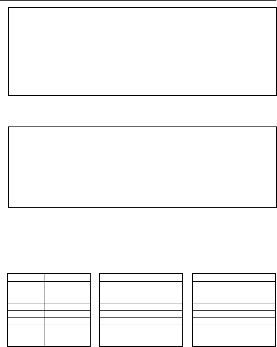
3.EXECUTION MACRO FUNCTION
B-63943EN-2/07
- 46 -
Example
When a special macro call using X and Y and a subprogram call using M100 are
enabled for the machine
a) X100. B10; Calls a macro using X100.
b) G91 G01 X100.; Calls a macro using X100.
c) Y200. X100.; Calls a macro using Y200.
d) X100. M100; Calls a macro using X100. (M100 is an argument.)
e) M100 X100.; Calls a subprogram using M100 after the tool moves along
the X axis according to X100.
* If a special macro call is made with X and Y (in cases of a to d), all specified
addresses including the call codes X100. and Y200. are used as arguments.
Argument
1 All addresses specifiable with a machine except address N are used as arguments. Those addresses
that are used as arguments are just specified addresses, and no modal change is made.
Example
For a machine that enables macro calls using X and Z
O0001;
N1G90G00Y-50.0F500;
N2G91G01X100.0Z120.0;
N3Y50.0.;
:
O9009;
X#27Z#26;
M99;
G91G01 of N2 are just treated as arguments, and the modal state remains to be
G90 G00. So, O9009 and N3 causes a rapid traverse to X100.0, Z120.0 and
Y50.0 respectively.
2 When an address is specified with no decimal point, a decimal point is added to the value passed to a
local variable according to bit 0 (DPI) of parameter No. 3401.
3 There are the following relationships between addresses and local variables:
The axis address used as a call code is passed to variable #27.
The first five addresses G in ascending order of G code groups are used as arguments and passed to
variables #28 to #32.
Address Variable number Address Variable number Address Variable number
A #1 J #5 S #19
B #2 K #6 T #20
C #3 L #12 U #21
D #7 M #13 V #22
E #8 M2
(*1)
#14 W #23
F #9 M3
(*1)
#15 X #24
G #28 to 32 P #16 Y #25
H #11 Q #17 Z #26
I #4 R #18 ABS/INC
NOTE
#33
*1 : When bit 7 (M3B) of parameter No. 3404 is set to 1, up to three M codes specified in address M are
used as arguments. Of the fourth and subsequent M codes, the last M code specified is passed to
#15.
[Example] M1 M2 N100 X300. M3 M4 ; (X300. : Axis address (call code))
(1) Bit 7 (M3B) of parameter No.3404 is set to 0:
#27=300, #13=4, #14=<null>, #15=<null>
(2) Bit 7 (M3B) of parameter No.3404 is set to 1:
#27=300, #13=1, #14=2, #15=4
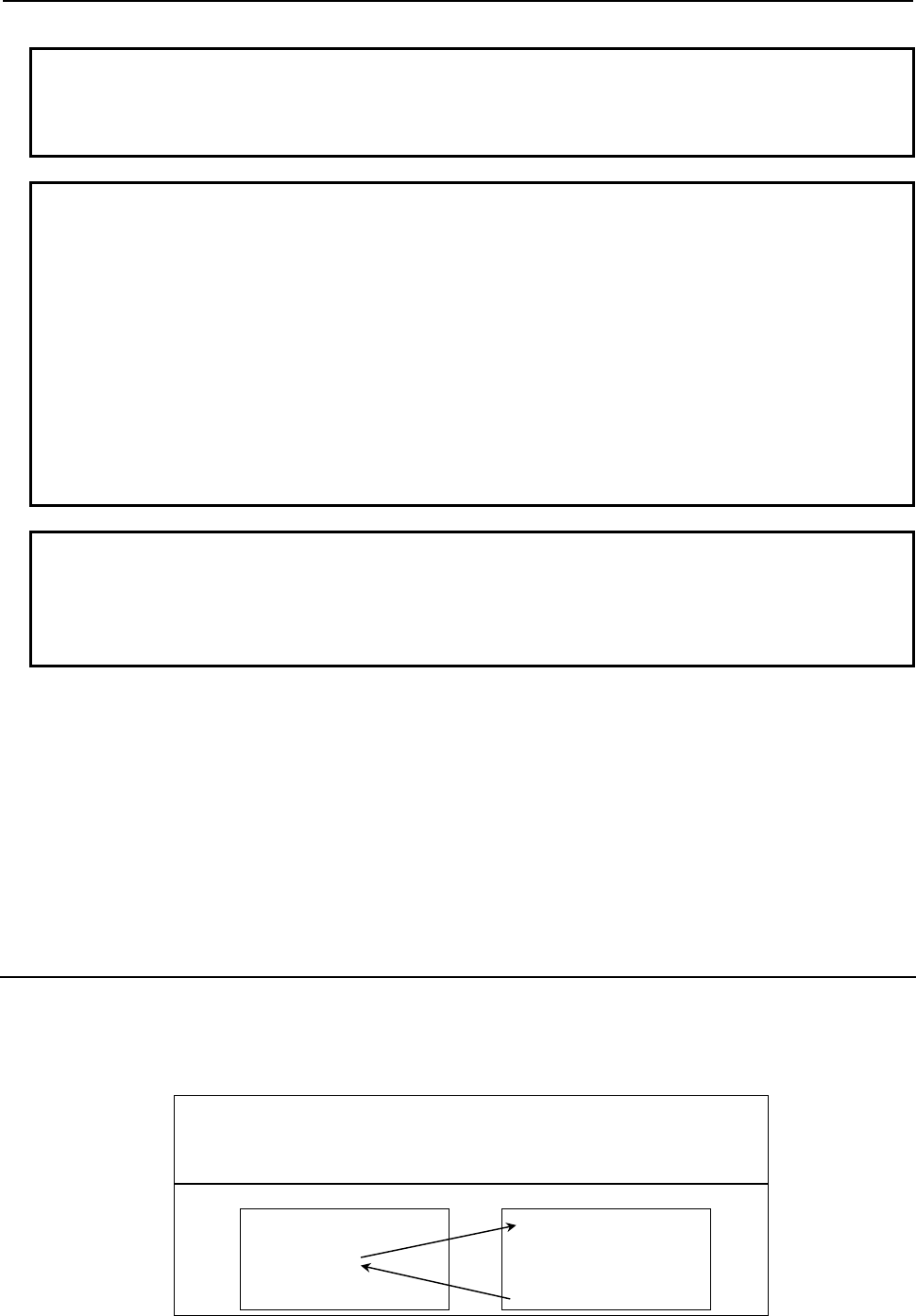
B-63943EN-2/07
3.EXECUTION MACRO FUNCTION
- 47 -
NOTE
When G code system A is used on a lathe system, whether the call address is
specified as an absolute command or incremental command is posted to #33
(<null> for an absolute command or 1.0 for an incremental command).
Example
When the X-axis is a call axis
1 When G91 G28 X123.45678 T999; is specified for an IS-B machine, values are
passed as follows:
#20
→999.0
#27
→123.457
#28
→ 28.0
#29
→ 91.0
Others are set to <null>.
2 On a lathe system for which G code system A is used
When X100.0; is specified: #27 = 100.0, and #33 = <null>
When U100.0; is specified: #27 = 100.0 and #33 = 1.0
NOTE
The specifiable addresses and specification range conform to the specification
address range of the CNC. For example, address M does not allow the decimal
point to be used. So, the specification of X123.456 M1.23; results in alarm
PS0007.
Limitation
1 Usually, when an execution macro is called from a program called using an axis address, only a G65
or M98 command can be specified. When bit 2 (PCDC) of compile parameter No. 9163 is set to 1,
G66 and G66.1 are also available.
2 When bit 2 (PCDC) of compile parameter No. 9163 is set to 1, a call using a G code can be made
from a program called using an axis address by setting bit 6 (GMP) of parameter No. 6008 to 1. This
parameter is an ordinary parameter, so that parameter GMP can be modified, for example, through
the MDI panel.
3 Address L is also used as an argument, so that no repetition count can be specified.
3.2.14
Special Macro Call Using T Code
When bit 7 (TMACC) of compile parameter No. 9005 is set to 1, execution macro O9008 is called as a
macro by using a T code.
Format
Tt <argument-specification> ; t : Call T code.
argument : Data to be passed to the execution
macro. Argument specifications I is
available.
User program
(*1)
Execution macro
O0001 ;
:
T20A2B3M06 ;
:
M30 ;
O9008;
:
:
:
M99 ;
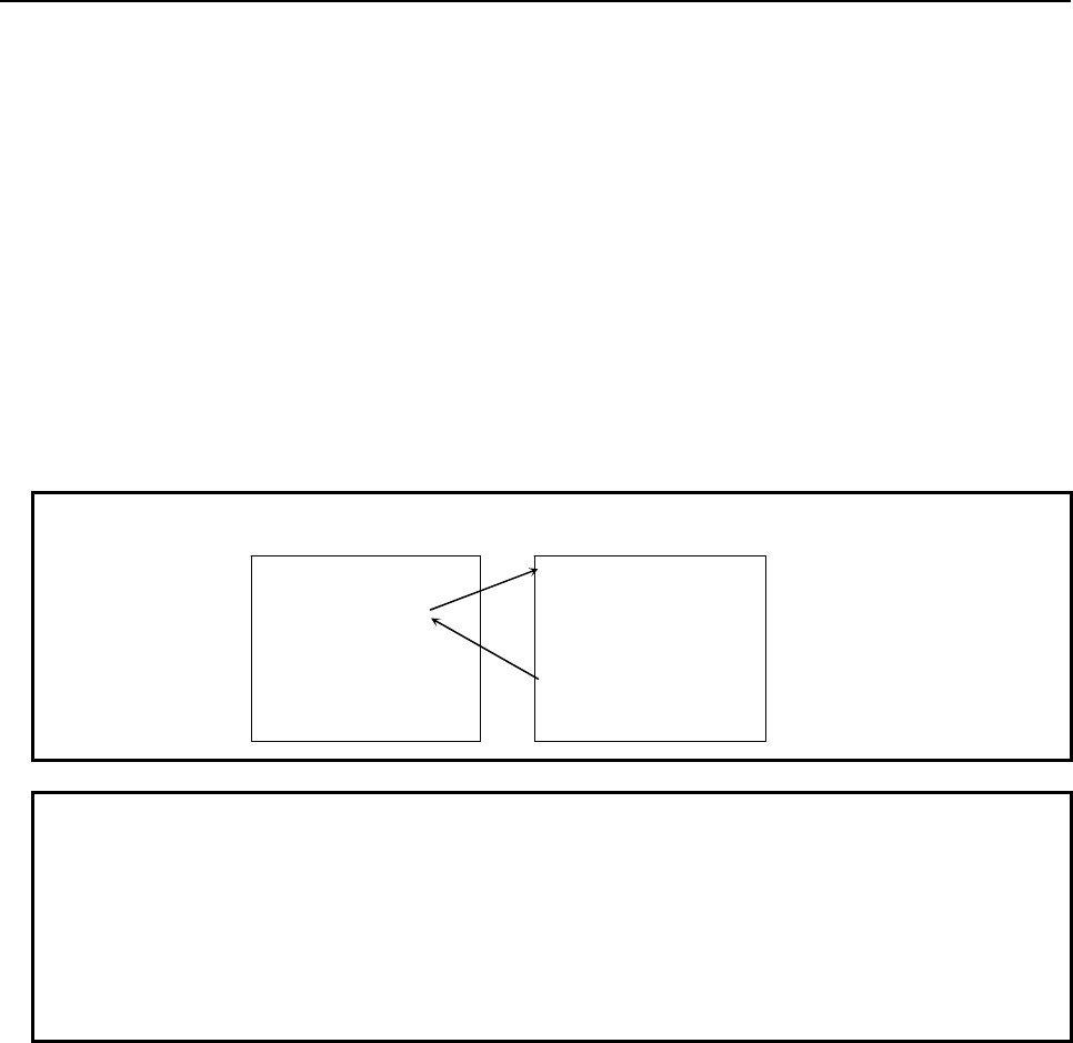
3.EXECUTION MACRO FUNCTION
B-63943EN-2/07
- 48 -
*1 When bit 2 (PCDC) of compile parameter No. 9163 is set to 1, a call can be made from an execution
macro.
Parameter
When bit 7 (TMACC) of compile parameter No. 9005 is set to 1, this type of macro call is enabled. This
parameter is initialized to the values set for P-CODE at power-on.
Bit 0 (MTC) of parameter No. 9011 can be used to disable this type of macro call as required. This
parameter is an ordinary parameter, so that parameter MTC can be modified, for example, through the
MDI panel.
Variable
Variable #8691 can be used to enable or disable this type of call and check the setting. The value set for
this variable is reflected in bit 0 (MTC) of parameter No. 9011.
#8691 = 0: Enables a call using a T code. (MTC = 0)
= 1: Disables a call using a T code. (MTC = 1)
Example
User program Execution macro
NOTE
1 A value other than 0 or 1 cannot be set for this variable.
2 It may take time until the value set for the variable is reflected in bit 0 (MTC) of
parameter No. 9011, depending on the CNC operation status. Whether this type
of macro call is enabled or disabled depends on the value set for the parameter
when the macro call is issued.
3 This variable can be written and referenced using an execution macro,
conversational macro , or auxiliary macro.
Call code
In contrast to a macro call using a G or M code, a T code in a block is used as a call command unless
another call command is specified before the T code. When multiple call commands are specified, the
first call code specified is selected. A subsequent call code is used as an argument if the first call code
specified is for a macro call. A subsequent call code is executed as an ordinary NC statement if the first
call code specified is for a subprogram call.
O0001 ;
:
T20A20.0B30.0M06 ;
G00X20.Z30.;
:
T12;
:
M02;
O9008 ;
G00 X#1Z#2;
:
#8691=1;
:
M99;
← Functions as
ordinary T code
command.
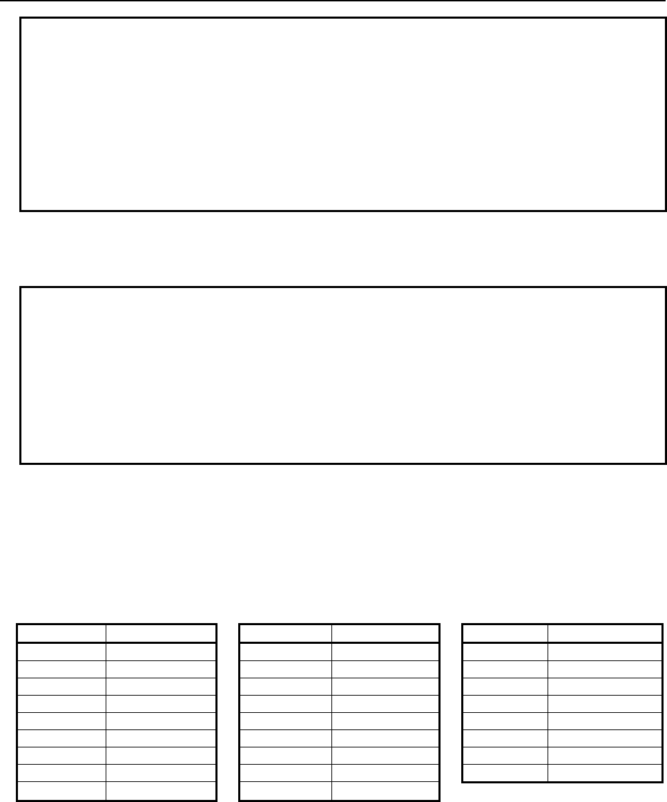
B-63943EN-2/07
3.EXECUTION MACRO FUNCTION
- 49 -
Example
When a macro call using a T code and a subprogram call using M100 are
enabled for the machine
a) T123 M06; Calls a macro using T123.
b) G01 X100. T123; Calls a macro using T123.
c) T123 M100; Calls a macro using T123.
d) M100 T123; Processes T123 as a T code, then calls a subprogram
using M100.
* When a special macro call using a T code is performed (a to c), all specified
addresses including the T code are treated as arguments.
Argument
1 All addresses specifiable with a machine except address N are used as arguments. Those addresses
that are used as arguments are just specified addresses, and no modal change is made.
Example
O0001
N1G90G00X50.0;
N2 G91G01X100.0T123;
N3 X150.;
:
O9008;
X#24;
M99;
G91G01 of N2 are just treated as arguments, and the modal state remains to be
G90 G00. For this reason, O9008 and N3 causes a rapid traverse to X100.0 and
X150.0 respectively.
2 When an address is specified with no decimal point, a decimal point is added to the value passed to a
local variable according to bit 0 (DPI) of parameter No. 3401.
3 There are the following relationships between addresses and local variables:
Address T is passed to variable #27.
The first five addresses G in ascending order of G code groups are used as arguments and passed to
variables #28 to #32.
Address Variable number Address Variable number Address Variable number
A #1 J #5 S #19
B #2 K #6 T #27
C #3 L #12 U #21
D #7 M #13 V #22
E #8 M2
(*1)
#14 W #23
F #9 M3
(*1)
#15 X #24
G #28 to 32 P #16 Y #25
H #11 Q #17 Z #26
I #4 R #18
*1: When bit 7 (M3B) of parameter No. 3404 is set to 1, up to three M codes specified in address M are
used as arguments. Of the fourth and subsequent M codes, the last M code specified is passed to
#15.
[Example] M1 M2 N100 T300 M3 M4 ; (T300 : Call code)
(1) Bit 7 (M3B) of parameter No.3404 is set to 0:
#27=300, #13=4, #14=<null>, #15=<null>
(2) Bit 7 (M3B) of parameter No.3404 is set to 1:
#27=300, #13=1, #14=2, #15=4
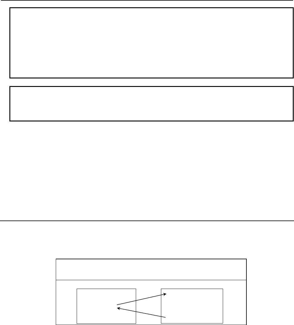
3.EXECUTION MACRO FUNCTION
B-63943EN-2/07
- 50 -
Example
When G91 G28 X123.45678 T999; is specified for an IS-B machine, values are
passed as follows:
#24
→123.457
#27
→999.0
#28
→ 28.0
#29
→ 91.0
Others are set to <null>.
NOTE
The specifiable addresses and specification range conform to the specification
address range of the CNC. For example, address M does not allow the decimal
point to be used. So, the specification of T123 M1.23; results in alarm PS0007.
Limitation
1 Usually, when an execution macro is called from a program called using a T code, only a G65 or
M98 command can be specified. When bit 2 (PCDC) of compile parameter No. 9163 is set to 1, G66
and G66.1 are also available.
2 When bit 2 (PCDC) of compile parameter No. 9163 is set to 1, a call using a G code can be made
from a program called using a T code by setting bit 6 (GMP) of parameter No. 6008 to 1. This
parameter is an ordinary parameter, so that parameter GMP can be modified, for example, through
the MDI panel.
3 Address L is also used as an argument, so that no repetition count can be specified.
3.2.15
Special Macro Call Using D Code
When bit 0 (DMACC) of compile parameter No. 9104 is set to 1, execution macro O9040 is called as a
macro by using a D code.
Format
Dd <argument-specification> ; d : Call D code.
argument : Data to be passed to the execution macro.
Argument specifications I is available.
User program
(*1)
O0001;
:
G42X100.D12;
:
M30;
O9040;
:
:
:
M99;
Execution macro
*1 When bit 2 (PCDC) of compile parameter No. 9163 is set to 1, a call can be made from an execution
macro.
Parameter
When bit 0 (DMACC) of compile parameter No. 9104 is set to 1, this type of macro call is enabled. This
parameter is initialized to the values set for P-CODE at power-on.
Bit 0 (MDC) of parameter No. 9012 can be used to disable this type of macro call as required. This
parameter is an ordinary parameter, so that parameter MDC can be modified, for example, through the
MDI panel.
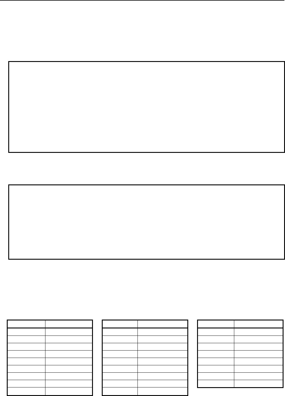
B-63943EN-2/07
3.EXECUTION MACRO FUNCTION
- 51 -
Call code
In contrast to a macro call using a G or M code, a D code in a block is used as a call command unless
another call command is specified before the D code. When multiple call commands are specified, the
first call code specified is selected. A subsequent call code is used as an argument if the first call code
specified is for a macro call. A subsequent call code is executed as an ordinary NC statement if the first
call code specified is for a subprogram call.
Example
When a macro call using a D code and a subprogram call using M100 are
enabled for the machine
a) D123 M06; Calls a macro using D123.
b) G41 X100. D123; Calls a macro using D123.
c) D123 M100; Calls a macro using D123. (M100 is an argument.)
d) M100 D123; Processes D123 as an ordinary D code, then calls a
subprogram using M100.
* When a special macro call using a D code is performed (a to c), all specified
addresses including the D code are treated as arguments.
Argument
1. All addresses specifiable with a machine except address N are used as arguments. Those addresses
that are used as arguments are just specified addresses, and no modal change is made.
Example
O0001
N1G90G00X50.0;
N2 G91G01X100.0D123;
N3 X150.;
:
O9040;
X#24;
M99;
G91G01 of N2 are just treated as arguments, and the modal state remains to be
G90 G00. For this reason, O9040 and N3 causes a rapid traverse to X100.0 and
X150.0 respectively.
2 When an address is specified with no decimal point, a decimal point is added to the value passed to a
local variable according to bit 0 (DPI) of parameter No. 3401.
3 There are the following relationships between addresses and local variables:
Address D is passed to variable #27.
The first five addresses G in ascending order of G code groups are used as arguments and passed to
variables #28 to #32.
Address Variable number Address Variable number Address Variable number
A #1 J #5 S #19
B #2 K #6 T #20
C #3 L #12 U #21
D #27 M #13 V #22
E #8 M2
(*1)
#14 W #23
F #9 M3
(*1)
#15 X #24
G #28 to 32 P #16 Y #25
H #11 Q #17 Z #26
I #4 R #18
*1: When bit 7 (M3B) of parameter No. 3404 is set to 1, up to three M codes specified in address M are
used as arguments. Of the fourth and subsequent M codes, the last M code specified is passed to
#15.
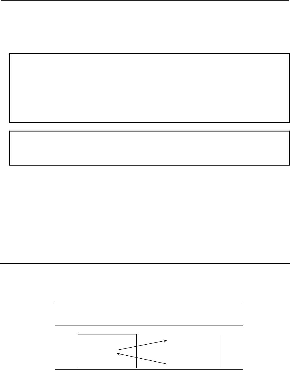
3.EXECUTION MACRO FUNCTION
B-63943EN-2/07
- 52 -
[Example] M1 M2 N100 D300. M3 M4 ; (D300. : Call code)
(1) Bit 7 (M3B) of parameter No.3404 is set to 0:
#27=300, #13=4, #14=<null>, #15=<null>
(2) Bit 7 (M3B) of parameter No.3404 is set to 1:
#27=300, #13=1, #14=2, #15=4
Example
When G91 G28 X123.45678 D56; is specified for an IS-B machine, values are
passed as follows:
#24
→123.457
#27
→ 56.0
#28
→ 28.0
#29
→ 91.0
Others are set to <null>.
NOTE
The specifiable addresses and specification range conform to the specification
address range of the CNC. For example, address M does not allow the decimal
point to be used. So, the specification of D123 M1.23; results in alarm PS0007.
Limitation
1 Usually, when an execution macro is called from a program called using a D code, only a G65 or
M98 command can be specified. When bit 2 (PCDC) of compile parameter No. 9163 is set to 1, G66
and G66.1 are also available.
2 When bit 2 (PCDC) of compile parameter No. 9163 is set to 1, a call using a G code can be made
from a program called using a D code by setting bit 6 (GMP) of parameter No. 6008 to 1. This
parameter is an ordinary parameter, so that parameter GMP can be modified, for example, through
the MDI panel.
3 Address L is also used as an argument, so that no repetition count can be specified.
3.2.16
Special Macro Call Using H Code
When bit 1 (HMACC) of compile parameter No. 9104 is set to 1, execution macro O9041 is called as a
macro by using an H code.
Format
Hh argument-specification> ; h : Call H code.
argument : Data to be passed to the execution macro.
Argument specifications I is available.
User program
(*1)
Execution macro
O0001 ;
:
G43Z100H12 ;
:
M30 ;
O9041;
:
:
:
M99 ;
*1 When bit 2 (PCDC) of compile parameter No. 9163 is set to 1, a call can be made from an execution
macro.
Parameter
When bit 1 (HMACC) of compile parameter No. 9104 is set to 1, this type of macro call is enabled. This
parameter is initialized to the values set for P-CODE at power-on.

B-63943EN-2/07
3.EXECUTION MACRO FUNCTION
- 53 -
Bit 1 (MHC) of parameter No. 9012 can be used to disable this type of macro call as required. This
parameter is an ordinary parameter, so that parameter MHC can be modified, for example, through the
MDI panel.
Call code
In contrast to a macro call using a G or M code, an H code in a block is used as a call command unless
another call command is specified before the H code. When multiple call commands are specified, the
first call code specified is selected. A subsequent call code is used as an argument if the first call code
specified is for a macro call. A subsequent call code is executed as an ordinary NC statement if the first
call code specified is for a subprogram call.
Example
When a macro call using an H code and a subprogram call using M100 are
enabled for the machine
a) H123 M06; Calls a macro using H123.
b) G43 Z100. H123; Calls a macro using H123.
c) H123 M100; Calls a macro using H123. (M100 is an argument.)
d) M100 H123; Processes H123 as an ordinary H code, then calls a
subprogram using M100.
* When a special macro call using an H code is performed (a to c), all specified
addresses including the H code are treated as arguments.
Argument
1. All addresses specifiable with a machine except address N are used as arguments. Those addresses
that are used as arguments are just specified addresses, and no modal change is made.
Example
O0001;
N1G90G00X50.0;
N2 G91G01Z100.0H123;
N3 X150.;
:
O9041;
X#24;
M99;
G91G01 of N2 are just treated as arguments, and the modal state remains to be
G90 G00. For this reason, O9041 and N3 causes a rapid traverse to X100.0 and
X150.0 respectively.
2 When an address is specified with no decimal point, a decimal point is added to the value passed to a
local variable according to bit 0 (DPI) of parameter No. 3401.
3 There are the following relationships between addresses and local variables:
Address H is passed to variable #27.
The first five addresses G in ascending order of G code groups are used as arguments and passed to
variables #28 to #32.
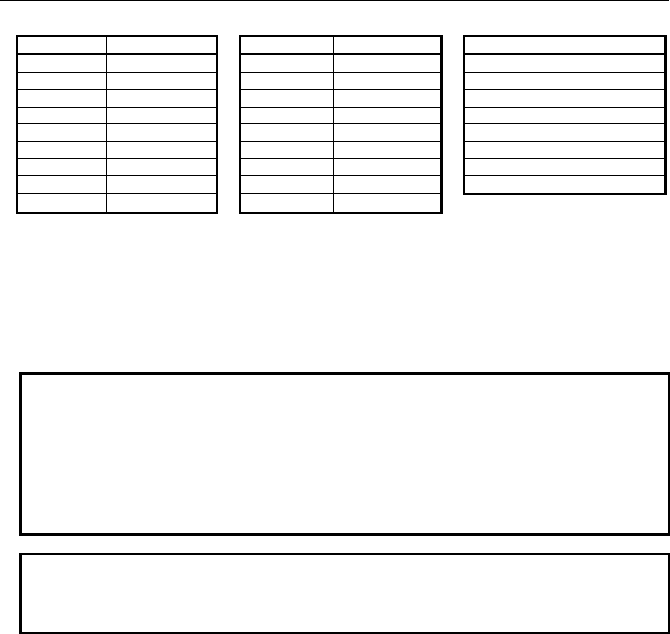
3.EXECUTION MACRO FUNCTION
B-63943EN-2/07
- 54 -
Address Variable number Address Variable number Address Variable number
A #1 J #5 S #19
B #2 K #6 T #20
C #3 L #12 U #21
D #7 M #13 V #22
E #8 M2
(*1)
#14 W #23
F #9 M3
(*1)
#15 X #24
G #28 to 32 P #16 Y #25
H #27 Q #17 Z #26
I #4 R #18
*1: When bit 7 (M3B) of parameter No. 3404 is set to 1, up to three M codes specified in address M are
used as arguments. Of the fourth and subsequent M codes, the last M code specified is passed to
#15.
[Example] M1 M2 N100 H300 M3 M4 ; (H300 : Call code)
(1) Bit 7 (M3B) of parameter No.3404 is set to 0:
#27=300, #13=4, #14=<null>, #15=<null>
(2) Bit 7 (M3B) of parameter No.3404 is set to 1:
#27=300, #13=1, #14=2, #15=4
Example
When G91 G28 Z123.45678 H56; is specified for an IS-B machine, values are
passed as follows:
#26
→123.457
#27
→ 56.0
#28
→ 28.0
#29
→ 91.0
Others are set to <null>.
NOTE
The specifiable addresses and specification range conform to the specification
address range of the CNC. For example, address M does not allow the decimal
point to be used. So, the specification of H123 M1.23; results in alarm PS0007.
Limitation
1 Usually, when an execution macro is called from a program called using an H code, only a G65 or
M98 command can be specified. When bit 2 (PCDC) of compile parameter No. 9163 is set to 1, G66
and G66.1 are also available.
2 When bit 2 (PCDC) of compile parameter No. 9163 is set to 1, a call using a G code can be made
from a program called using an H code by setting bit 6 (GMP) of parameter No. 6008 to 1. This
parameter is an ordinary parameter, so that parameter GMP can be modified, for example, through
the MDI panel.
3 Address L is also used as an argument, so that no repetition count can be specified.
4 If the C-axis is used on a lathe system, H is used for an incremental command, so that no call
command using an H code can be specified.
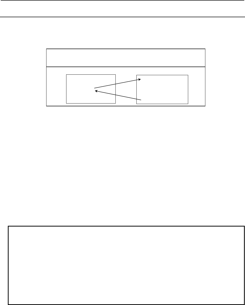
B-63943EN-2/07
3.EXECUTION MACRO FUNCTION
- 55 -
3.2.17
Special Macro Call Using S Code
When bit 2 (SMACC) of compile parameter No. 9104 is set to 1, execution macro O9042 is called as a
macro by using an S code.
Format
Ss <argument-specification> ; s : Call S code.
argument : Data to be passed to the execution macro.
Argument specifications I is available.
User program
(*1)
Execution macro
O0001 ;
:
M03S1000 ;
:
M30 ;
O9042;
:
:
:
M99 ;
*1 When bit 2 (PCDC) of compile parameter No. 9163 is set to 1, a call can be made from an execution
macro.
Parameter
When bit 2 (SMACC) of compile parameter No. 9104 is set to 1, this type of macro call is enabled. This
parameter is initialized to the values set for P-CODE at power-on.
Bit 2 (MSC) of parameter No. 9012 can be used to disable this type of macro call as required. This
parameter is an ordinary parameter, so that parameter MSC can be modified, for example, through the
MDI panel.
Call code
In contrast to a macro call using a G or M code, an S code in a block is used as a call command unless
another call command is specified before the S code. When multiple call commands are specified, the first
call code specified is selected. A subsequent call code is used as an argument if the first call code
specified is for a macro call. A subsequent call code is executed as an ordinary NC statement if the first
call code specified is for a subprogram call.
Example
When a macro call using an S code and a subprogram call using M100 are
enabled for the machine
a) S123 M03; Calls a macro using S123.
b) G00 Z100. S123; Calls a macro using S123.
c) S123 M100; Calls a macro using S123.(M100 is an argument.)
d) M100 S123; Processes S123 as an ordinary S code, then calls a
subprogram using M100.
* When a special macro call using an S code is performed (a to c), all specified
addresses including the S code are treated as arguments.
Argument
1. All addresses specifiable with a machine except address N are used as arguments. Those addresses
that are used as arguments are just specified addresses, and no modal change is made.
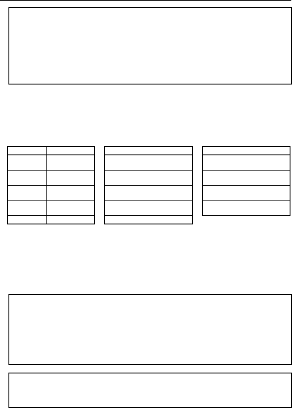
3.EXECUTION MACRO FUNCTION
B-63943EN-2/07
- 56 -
Example
O0001
N1G90G00X50.0;
N2 G91G01Z100.0S123;
N3 X150.;
:
O9042;
X#24;
M99;
G91G01 of N2 are just treated as arguments, and the modal state remains to be
G90 G00. For this reason, O9042 and N3 causes a rapid traverse to X100.0 and
X150.0 respectively.
2 When an address is specified with no decimal point, a decimal point is added to the value passed to a
local variable according to bit 0 (DPI) of parameter No. 3401.
3 There are the following relationships between addresses and local variables:
Address S is passed to variable #27.
The first five addresses G in ascending order of G code groups are used as arguments and passed to
variables #28 to #32.
Address Variable number Address Variable number Address Variable number
A #1 J #5 S #27
B #2 K #6 T #20
C #3 L #12 U #21
D #7 M #13 V #22
E #8 M2
(*1)
#14 W #23
F #9 M3
(*1)
#15 X #24
G #28 to 32 P #16 Y #25
H #11 Q #17 Z #26
I #4 R #18
*1: When bit 7 (M3B) of parameter No. 3404 is set to 1, up to three M codes specified in address M are
used as arguments. Of the fourth and subsequent M codes, the last M code specified is passed to
#15.
[Example] M1 M2 N100 S300 M3 M4 ; (S300 : Call code)
(1) Bit 7 (M3B) of parameter No.3404 is set to 0:
#27=300, #13=4, #14=<null>, #15=<null>
(2) Bit 7 (M3B) of parameter No.3404 is set to 1:
#27=300, #13=1, #14=2, #15=4
Example
When G91 G28 X123.45678 S5600; is specified for an IS-B machine, values are
passed as follows:
#24
→123.457
#27
→5600.0
#28
→ 28.0
#29
→ 91.0
Others are set to <null>.
NOTE
The specifiable addresses and specification range conform to the specification
address range of the CNC. For example, address M does not allow the decimal
point to be used. So, the specification of S123 M1.23; results in alarm PS0007.
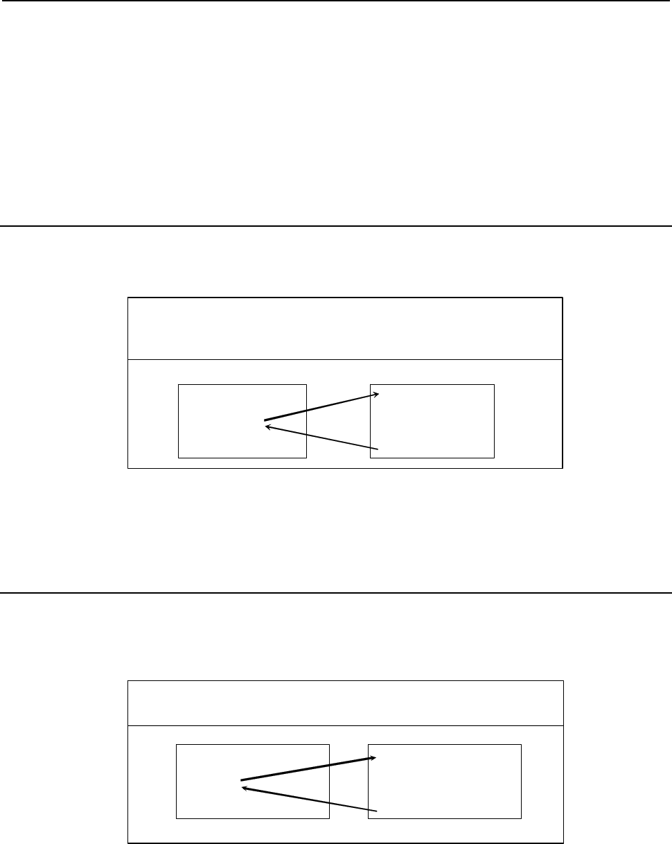
B-63943EN-2/07
3.EXECUTION MACRO FUNCTION
- 57 -
Limitation
1 Usually, when an execution macro is called from a program called using an S code, only a G65 or
M98 command can be specified. When bit 2 (PCDC) of compile parameter No. 9163 is set to 1, G66
and G66.1 are also available.
2 When bit 2 (PCDC) of compile parameter No. 9163 is set to 1, a call using a G code can be made
from a program called using an S code by setting bit 6 (GMP) of parameter No. 6008 to 1. This
parameter is an ordinary parameter, so that parameter GMP can be modified, for example, through
the MDI panel.
3 Address L is also used as an argument, so that no repetition count can be specified.
3.2.18
Subprogram Call (M98)
The execution macro specified at address P is called as a subprogram.
Format
M98 P p L l ;
M98 : Call command
P : Program number of an execution macro to be called
l : R epetition count (1 by default)
1 to 99999999
O9010 ;
:
M98 P100 L2 ;
:
M30 ;
O0100 ;
:
:
:
M99 ;
Execution macro Execution macro
Limitation
No execution macro can be called from any user program using this command. This command can be
specified only for calling an execution macro from another execution macro.
3.2.19
Subprogram Call Using M Code
Execution macro O9001 to O9003 is called as a subprogram using the M code specified for compile
parameters Nos. 9010 to 9012.
Format
Mm L l ; m : Call M code
l : Repetition count (1 by default )
1 to 99999999
User program
(*
1)
Execution macro
O0001 ;
:
M200 L2 ;
:
M30 ;
O9001 ;
:
:
:
M99 ;
Compile parameter No.9010=200
*1 When bit 2 (PCDC) of compile parameter No. 9163 is set to 1, a call can be made from an execution
macro.
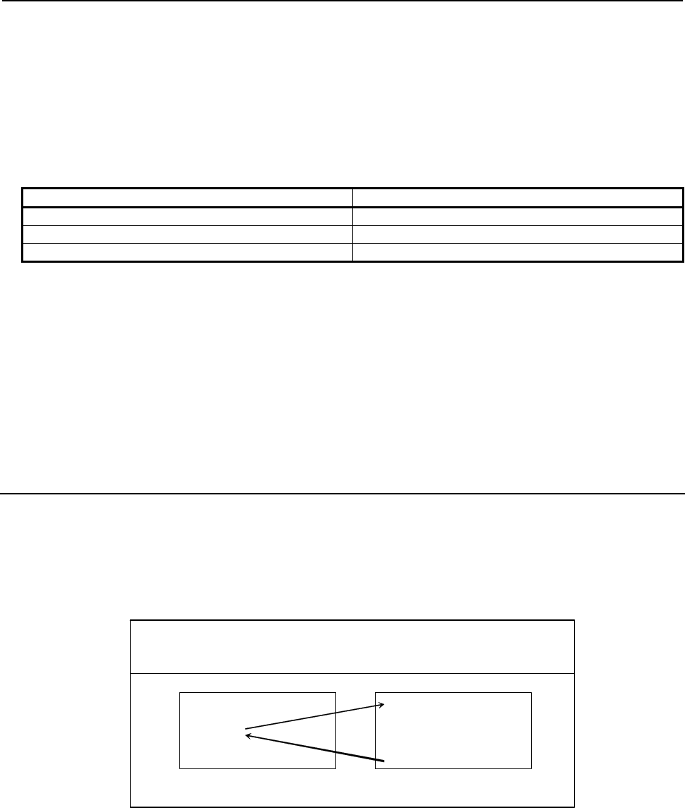
3.EXECUTION MACRO FUNCTION
B-63943EN-2/07
- 58 -
Local variable levels
By setting bit 3 (LCLLV) of compile parameter No. 9163 to 1, the level can be changed as in the case of
macro calls when an execution macro is called from a user program. In this case, all local variables are set
to <null> when an execution macro is called. (Series 16i compatibility specifications)
When an execution macro is called from another execution macro, the level remains unchanged as in the
case where bit 3 (LCLLV) of compile parameter No. 9163 is set to 0. In this case, the local variables at
the call source are passed.
Correspondence between parameter numbers and program numbers
Program number Compile parameter number
O9001 9010
O9002 9011
O9003 9012
Limitation
1 If an M code exceeding 99999999 is set, the subprogram call is invalidated. (The M code is output
as an ordinary M code.)
2 Usually, when an execution macro is called from a program called using an M code, only a G65 or
M98 command can be specified. When bit 2 (PCDC) of compile parameter No. 9163 is set to 1, G66
and G66.1 are also available. Moreover, when bit 2 (PCDC) of compile parameter No. 9163 is set to
1, a call using a G code can be made from a program called using an M code by setting bit 6 (GMP)
of parameter No. 6008 to 1. Parameter GMP is an ordinary parameter, so that this parameter can be
modified, for example, through the MDI panel.
3.2.20
Subprogram Call Using M Code in the Specified Range
Execution macro O9009 is called as a subprogram using an M code in the range specified by compile
parameters Nos. 9042 and 9043.
When bit 3 (MSCL) of compile parameter No. 9009 is set to 1, a special macro call is made. For details,
see Subsection 3.2.12, "Special Macro Call Using M Code".
Format
Mm L l ; m : C all M code
l : R epetition count (1 by default)
1 to 99999999
User program
(
1
)
Execution macro
O0001 ;
:
M200 L2 ;
:
M30 ;
O9009 ;
:
:
:
M99 ;
Compile parameter No.9042=200, No.9043=210
*1 When bit 2 (PCDC) of compile parameter No. 9163 is set to 1, a call can be made from an execution
macro.
Argument
The specified M code is passed to variable #148.

B-63943EN-2/07
3.EXECUTION MACRO FUNCTION
- 59 -
Local variable levels
By setting bit 3 (LCLLV) of compile parameter No. 9163 to 1, the level can be changed as in the case of
macro calls when an execution macro is called from a user program. In this case, all local variables are set
to <null> when an execution macro is called. (Series 16i compatibility specifications)
When an execution macro is called from another execution macro, the level remains unchanged as in the
case where bit 3 (LCLLV) of compile parameter No. 9163 is set to 0. In this case, the local variables at
the call source are passed.
Limitation
1 Usually, when an execution macro is called from a program called using an M code, only a G65 or
M98 command can be specified. When bit 2 (PCDC) of compile parameter No. 9163 is set to 1, G66
and G66.1 are also available. Moreover, when bit 2 (PCDC) of compile parameter No. 9163 is set to
1, a call using a G code can be made from a program called using an M code by setting bit 6 (GMP)
of parameter No. 6008 to 1. Parameter GMP is an ordinary parameter, so that this parameter can be
modified, for example, through the MDI panel.
2 This type of subprogram call is invalidated in the following cases:
<1> A value outside the valid range is set for a compile parameter No.9042 or 9043.
<2> The value set for compile parameter No. 9042 is greater than the value set for parameter No.
9043.
3 M codes used for macro and subprogram calls are not used as call codes in this type of subprogram
call even when included in the setting range. If duplicate M codes are set, the following priority
order is applied:
<1> Macro call using M code
(compile parameters Nos. 9023 to 9032 and 9120 to 9128)
<2> Subprogram call using M code
(compile parameters Nos. 9010 to 9012)
<3> Subprogram call using an M code in the specified range
(compile parameters Nos. 9042 and 9043)
3.2.21
Subprogram Call Using M Code (Specification of 3 Sets)
Up to three sets, each consisting of a start M code number used for subprogram calling, start execution
macro number to be called, and the number of execution macros to be defined, can be set in compile
parameters. This capability can additionally define three separate sets of execution macros.
When bit 4 (EXMSCL) of compile parameter No. 9103 is set to 1, a special macro call is made. For
details, see Subsection 3.2.12, "Special Macro Call Using M Code".
Local variable levels
By setting bit 3 (LCLLV) of compile parameter No. 9163 to 1, the level can be changed as in the case of
macro calls when an execution macro is called from a user program. In this case, all local variables are set
to <null> when an execution macro is called. (Series 16i compatibility specifications)
When an execution macro is called from another execution macro, the level remains unchanged as in the
case where bit 3 (LCLLV) of compile parameter No. 9163 is set to 0. In this case, the local variables at
the call source are passed.
Parameter setting
The table below indicates the compile parameters to be set for each set.
1st set 2nd set 3rd set
Start M code number 9111 9114 9117
Number of execution macros to be defined 9112 9115 9118
Start execution macro number 9113 9116 9119
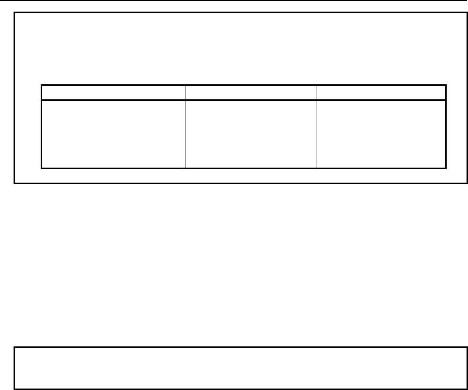
3.EXECUTION MACRO FUNCTION
B-63943EN-2/07
- 60 -
Example
Setting of the 1st set: No. 9111=100 No. 9113=8000 No. 9112=10
Setting of the 2nd set: No. 9114=150 No. 9116=8100 No. 9115=30
Setting of the 3rd set: No. 9117=200 No. 9119=8900 No. 9118=5
The settings above define the following sets of subprogram calls:
1st set 2nd set 3rd set
M100 → O8000 M150 → O8100 M200 → O8900
M101 → O8001 M151 → O8101 M201 → O8901
M102 → O8002 M152 → O8102 M202 → O8902
: : : : M203 → O8903
M109 → O8009 M179 → O8129 M204 → O8904
Limitation
1 Usually, when an execution macro is called from a program called using an M code, only a G65 or
M98 command can be specified. When bit 2 (PCDC) of compile parameter No. 9163 is set to 1, G66
and G66.1 are also available. Moreover, when bit 2 (PCDC) of compile parameter No. 9163 is set to
1, a call using a G code can be made from a program called using an M code by setting bit 6 (GMP)
of parameter No. 6008 to 1. Parameter GMP is an ordinary parameter, so that this parameter can be
modified, for example, through the MDI panel.
2 This type of subprogram call is invalidated in the following cases:
<1> A value outside the valid range is set for a compile parameter.
<2> The defined M code range exceeds 99999999.
<3> The defined program number range exceeds 99999999.
NOTE
To use a program number with an O number of five or more digits, set bit 3
(ON8) of parameter No. 11304 to 1.
3 M codes used for macro and subprogram calls are not used as call codes in this type of subprogram
call even when included in the setting range. If duplicate M codes are set, the following priority
order is applied:
<1> Macro call using M code
(compile parameters Nos. 9023 to 9032 and 9120 to 9128)
<2> Subprogram call using M code
(compile parameters Nos. 9010 to 9012)
<3> Subprogram call using an M code in the specified range
(compile parameters Nos. 9042 and 9043)
<4> Subprogram call using M code (specification of 3 sets)
(compile parameters Nos. 9111 to 9113, 9114 to 9116, and 9117 to 9119)
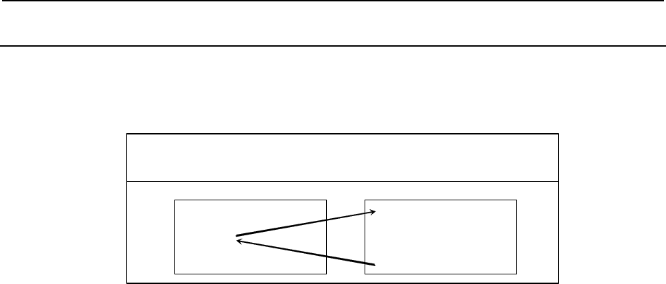
B-63943EN-2/07
3.EXECUTION MACRO FUNCTION
- 61 -
3.2.22
Subprogram Call Using S Code
When bit 2 (SMACC) of compile parameter No. 9104 is set to 0 and bit 0 (SSC) of parameter No. 9105 is
set to 1, execution macro O9029 is called as a subprogram using an S code.
Format
Ss L l ; s : C all S code
l : Repetition count (1 by default)
1 to 99999999
User program
(*
1)
Execution macro
O0001 ;
:
S200 L2 ;
:
M30 ;
O9029 ;
:
:
:
M99 ;
*1 When bit 2 (PCDC) of compile parameter No. 9163 is set to 1, a call can be made from an execution
macro.
Argument
The specified S code is passed to variable #147.
Local variable levels
By setting bit 3 (LCLLV) of compile parameter No. 9163 to 1, the level can be changed as in the case of
macro calls when an execution macro is called from a user program. In this case, all local variables are set
to <null> when an execution macro is called. (Series 16i compatibility specifications)
When an execution macro is called from another execution macro, the level remains unchanged as in the
case where bit 3 (LCLLV) of compile parameter No. 9163 is set to 0. In this case, the local variables at
the call source are passed.
Limitation
1 Usually, when an execution macro is called from a program called using an S code, only a G65 or
M98 command can be specified. When bit 2 (PCDC) of compile parameter No. 9163 is set to 1, G66
and G66.1 are also available.
2 When bit 2 (PCDC) of compile parameter No. 9163 is set to 1, a call using a G code can be made
from a program called using an S code by setting bit 6 (GMP) of parameter No. 6008 to 1. Parameter
GMP is an ordinary parameter, so that this parameter can be modified, for example, through the
MDI panel.
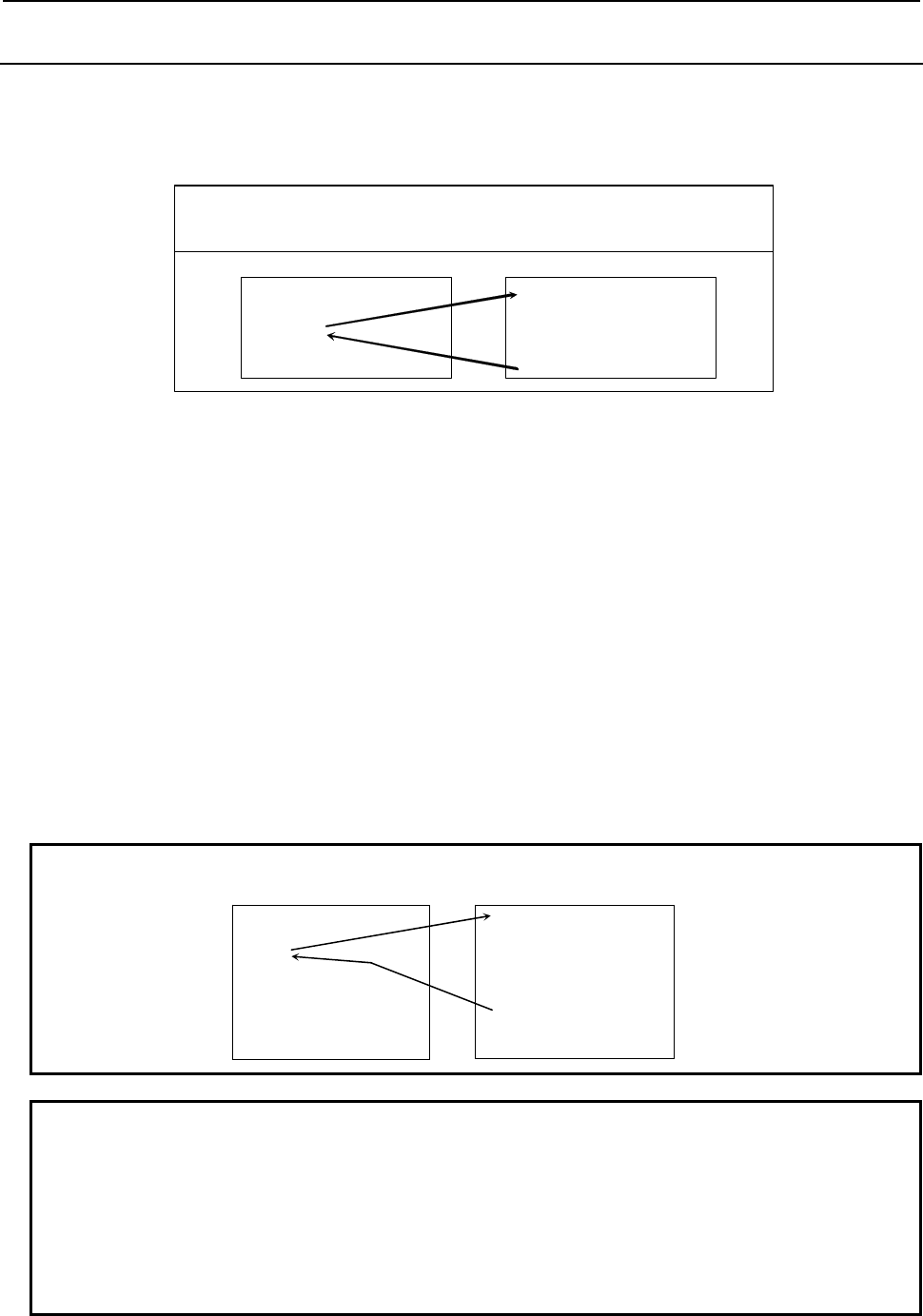
3.EXECUTION MACRO FUNCTION
B-63943EN-2/07
- 62 -
3.2.23
Subprogram Call Using T Code
When bit 7 (TMACC) of compile parameter No. 9005 is set to 0 and bit 0 (TCAL) of compile parameter
No. 9002 is set to 1, execution macro O9000 is called as a subprogram using a T code.
Format
Tt L l ; t : Call T code
l : Repetition count (1 by default)
1 to 99999999
User program
(*
1)
Execution macro
O0001 ;
:
T200 L2 ;
:
M30 ;
O9000 ;
:
:
:
M99 ;
*1 When bit 2 (PCDC) of compile parameter No. 9163 is set to 1, a call can be made from an execution
macro.
Parameter
Setting bit 7 (TMACC) of compile parameter No. 9005 to 0 and bit 0 (TCAL) of compile parameter No.
9002 to 1 enables this type of subprogram call. These parameters are initialized to the values set for
P-CODE at power-on.
Bit 0 (MTC) of parameter No. 9011 can be used to disable this type of subprogram call as required. This
parameter is an ordinary parameter, so that parameter MTC can be modified, for example, through the
MDI panel.
Variables
Variable #8691 can be used to enable or disable this type of subprogram call and check the setting. The
value set for this variable is reflected in bit 0 (MTC) of parameter No. 9011.
#8691 =0 : Enables a call using a T code. (MTC=0)
=1 : Disables a call using a T code. (MTC=1)
Example
User program Execution macro
NOTE
1 A value other than 0 or 1 cannot be set for this variable.
2 It may take time until the value set for the variable is reflected in bit 0 (MTC) of
parameter No. 9011, depending on the CNC operation status. Whether this type
of call is enabled or disabled depends on the value set for the parameter when
the call is issued.
3 This variable can be written and referenced using an execution macro,
conversational macro, or auxiliary macro.
O0001 ;
:
T11;
G00X20.0Z30.0;
:
T12;
:
M02;
O9000 ;
G00 X…;
:
#8691=1;
:
M99;
← Functions as
ordinary T code
command.
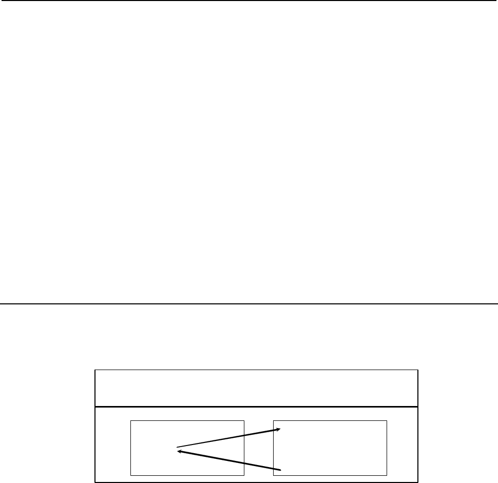
B-63943EN-2/07
3.EXECUTION MACRO FUNCTION
- 63 -
Argument
The specified T code is passed to variable #149.
Local variable levels
By setting bit 3 (LCLLV) of compile parameter No. 9163 to 1, the level can be changed as in the case of
macro calls when an execution macro is called from a user program. In this case, all local variables are set
to <null> when an execution macro is called. (Series 16i compatibility specifications)
When an execution macro is called from another execution macro, the level remains unchanged as in the
case where bit 3 (LCLLV) of compile parameter No. 9163 is set to 0. In this case, the local variables at
the call source are passed.
Limitation
1 Usually, when an execution macro is called from a program called using a T code, only a G65 or
M98 command can be specified. When bit 2 (PCDC) of compile parameter No. 9163 is set to 1, G66
and G66.1 are also available.
2 When bit 2 (PCDC) of compile parameter No. 9163 is set to 1, a call using a G code can be made
from a program called using a T code by setting bit 6 (GMP) of parameter No. 6008 to 1. Parameter
GMP is an ordinary parameter, so that this parameter can be modified, for example, through the
MDI panel.
3.2.24
Subprogram Call Using Second Auxiliary Function Code
When bit 1 (BSC) of compile parameter No. 9105 is set to 1, execution macro O9028 is called as a
subprogram using a second auxiliary function code.
Format
Bb L l ; b : Call second auxiliary function code
l : Repetition count (1 by default)
1 to 99999999
User program
(*1
)
Execution macro
O0001 ;
:
B100 L2 ;
:
M30 ;
O9028 ;
:
:
:
M99 ;
*1 When bit 2 (PCDC) of compile parameter No. 9163 is set to 1, a call can be made from an execution
macro.
Argument
The specified second auxiliary function code is passed to variable #146.
Local variable levels
By setting bit 3 (LCLLV) of compile parameter No. 9163 to 1, the level can be changed as in the case of
macro calls when an execution macro is called from a user program. In this case, all local variables are set
to <null> when an execution macro is called. (Series 16i compatibility specifications)
When an execution macro is called from another execution macro, the level remains unchanged as in the
case where bit 3 (LCLLV) of compile parameter No. 9163 is set to 0. In this case, the local variables at
the call source are passed.
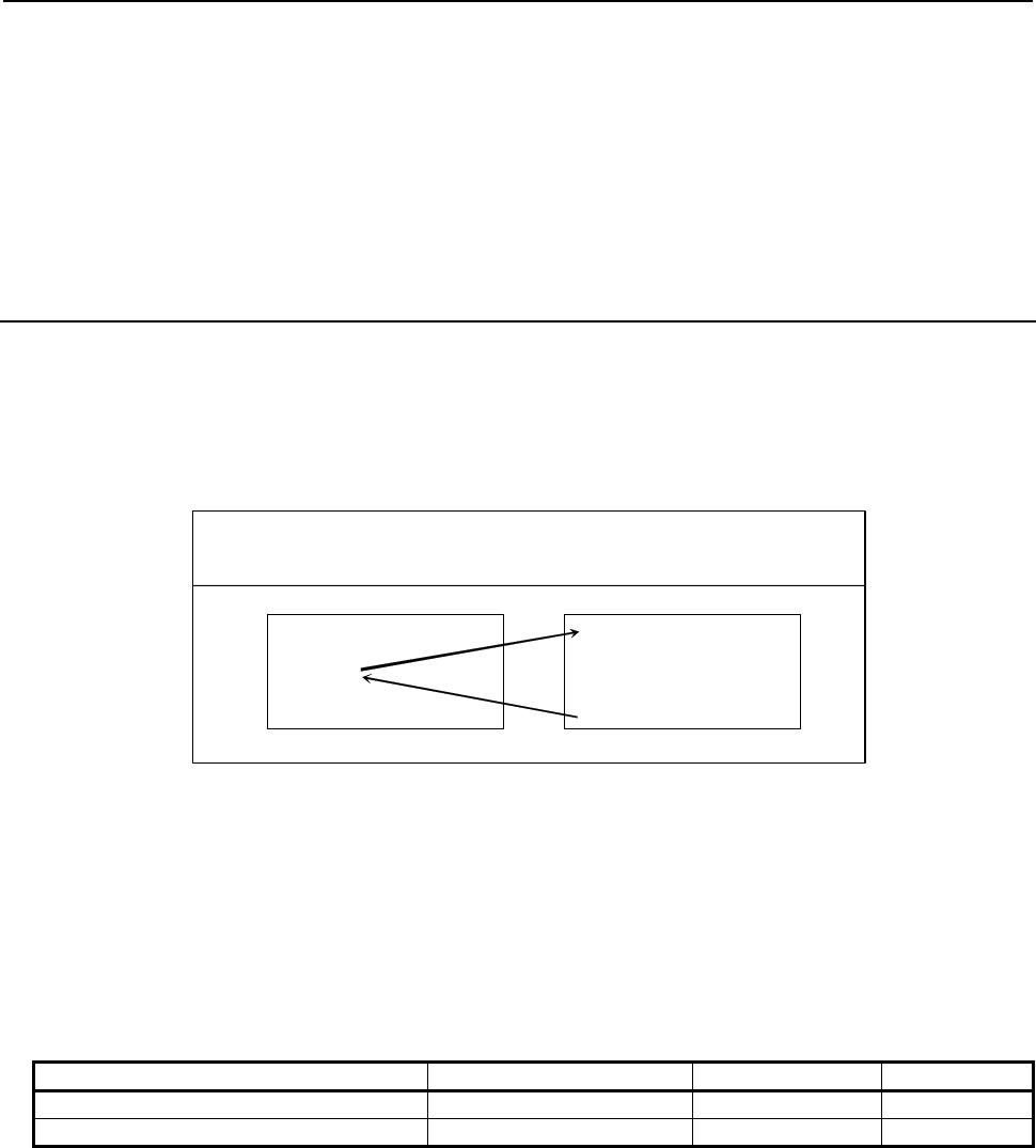
3.EXECUTION MACRO FUNCTION
B-63943EN-2/07
- 64 -
Limitation
1 Usually, when an execution macro is called from a program called using a second auxiliary function
code, only a G65 or M98 command can be specified. When bit 2 (PCDC) of compile parameter No.
9163 is set to 1, G66 and G66.1 are also available.
2 When bit 2 (PCDC) of compile parameter No. 9163 is set to 1, a call using a G code can be made
from a program called using a second auxiliary function code by setting bit 6 (GMP) of parameter
No. 6008 to 1. Parameter GMP is an ordinary parameter, so that this parameter can be modified, for
example, through the MDI panel.
3.2.25
Subprogram Call Using Specific Code
When bit 1/2 (ACL1/ACL2) of compile parameter No. 9002 is set to 1, execution macro O9004/9005 is
called as a subprogram by using the NC address (ASCII code converted to a decimal character code)
specified in parameters Nos. 6090 and 6091. The parameters Nos. 6090 and 6091 are ordinary parameters,
so that the parameters can be modified, for example, through the MDI panel.
Format
A
a L l ; a : Call specific code
l : Repetition count (1 by default)
1 to 99999999
User program
(*
1)
Execution macro
O0001 ;
:
E100 L2 ;
:
M30 ;
O9004 ;
:
:
:
M99 ;
Parameter No.6090=69(E)
*1 When bit 2 (PCDC) of compile parameter No. 9163 is set to 1, a call can be made from an execution
macro.
Call code
None of addresses O, N, P, L, and G and axis name addresses can be used as the call command for a
subprogram call using a specific code.
Correspondence among parameter numbers, program numbers, and
argument numbers
Parameter for enabling a call Parameter for a call code Program number Argument
Bit 1 (AC1) of compile parameter No. 9002 No.6090 O9004 #146
Bit 2 (AC2) of compile parameter No. 9002 No.6091 O9005 #147
Local variable levels
By setting bit 3 (LCLLV) of compile parameter No. 9163 to 1, the level can be changed as in the case of
macro calls when an execution macro is called from a user program. In this case, all local variables are set
to <null> when an execution macro is called. (Series 16i compatibility specifications)
When an execution macro is called from another execution macro, the level remains unchanged as in the
case where bit 3 (LCLLV) of compile parameter No. 9163 is set to 0. In this case, the local variables at
the call source are passed.
Limitation
1 Usually, when an execution macro is called from a program called using a specific code, only a G65
or M98 command can be specified. When bit 2 (PCDC) of compile parameter No. 9163 is set to 1,
G66 and G66.1 are also available.
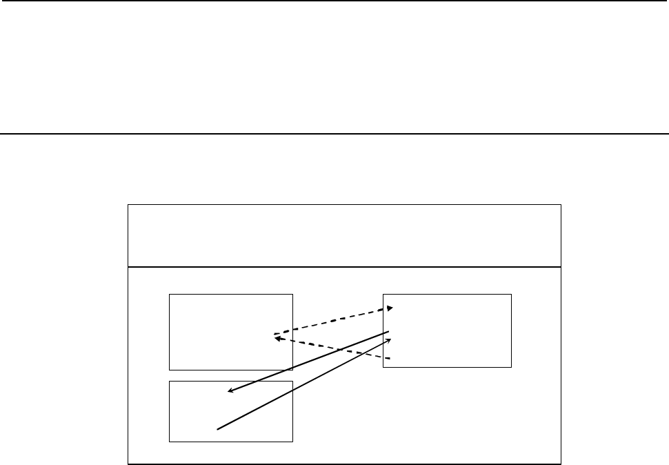
B-63943EN-2/07
3.EXECUTION MACRO FUNCTION
- 65 -
2 When bit 2 (PCDC) of compile parameter No. 9163 is set to 1, a G code can be made from a
program called using a specific code by setting bit 6 (GMP) of parameter No. 6008 to 1. Parameter
GMP is an ordinary parameter, so that this parameter can be modified, for example, through the
MDI panel.
3.2.26
Subprogram Call for User Program
A user program is called as a subprogram using the M code specified for compile parameter No. 9033.
Format
User program
Compile parameter No.9013=81
O9010 ;
:
M300 P100 L2 ;
:
M99 ;
Compile parameter
No.9033=300
O0001 ;
:
G81 X10.0 Z-10.0 ;
:
M
30
;
Mm P p L l ; m : Call M code
P : Program number of a execution program to be called
l : Repetition count (1 by default)
1 to 99999999
Execution macro
O0100 ;
:
:
M99 ;
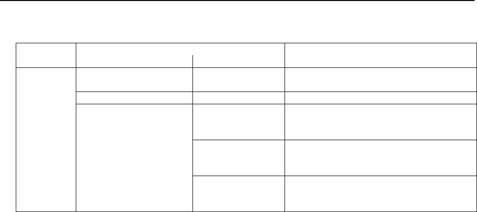
3.EXECUTION MACRO FUNCTION
B-63943EN-2/07
- 66 -
Priority level of Search target folders
When User program is called, it searches for each folder according to the priority level of the table below.
Priority Parameter SCF(No.3457#7) Note
0 1
High
Folder where the main
program is stored ←
↑ LIBRARY ←
|
|
|
There are only the
above-mentioned two
folders.
MTB2
This folder can be excluded from search
target folders by setting the bit1 (MC2) of
parameter No. 3457.
|
|
|
MTB1
This folder can be excluded from search
target folders by setting the bit2 (MC1) of
parameter No. 3457.
↓
Low SYSTEM
This folder can be excluded from search
target folders by setting the bit3 (SYS) of
parameter No. 3457.
Nesting and local variables
Each subprogram call for a user program is assumed to call a custom macro as a subprogram using M98
and is counted among custom macro nesting levels.
The local variables at the calling execution macro are passed, regardless of the state of bit 3 (LCLLV) of
compile parameter No. 9163.
Limitation
1 If an M code exceeding 99999999 is set, the call is invalidated. (The M code is output as an ordinary
M code.)
2 From a user program called as a subprogram from an execution macro, another program can be
called. In this case, three types of calls can be made as described below. The limitations depend on
the settings of bit 6 (GMP) of parameter No. 6008, bit 2 (PCDC) of compile parameter No. 9163,
and bit 6 (C16) of compile parameter No. 9163.
(a) Calling another user program in program memory
(b) Calling an execution macro
(c) Calling a subprogram of the user program after an execution macro is called
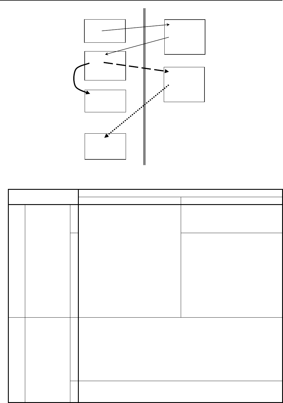
B-63943EN-2/07
3.EXECUTION MACRO FUNCTION
- 67 -
:
Gxx
:
Opp1
Mxx
:
M99
Oxxxx
:
M99
O90xx
:
MxxPpp1
:
M99
(a) O90xx
:
MxxPpp2
:
M99
(b)
O pp2
:
M99
(c)
Within user program Within execution macro
* G/M/S/T/D/H/second auxiliary function code/special code are collectively referred to as a code in
the explanation below.
Bit 2 (PCDC) of Compile parameter No. 9163
0 1
(a)
Bit 6 (GMP) of
parameter No.
6008
0
User program calls using G65, M98,
G66, and G66.1 only are allowed.
Other types of calls are disabled.
User program calls using G65, M98,
G66, and G66.1 only are allowed.
Other types of calls are disabled.
1
- From an execution macro called
using a G code, a user program can
be called using a code other than G
codes (or using an axis address).
- From an execution macro called
using a code other than G codes (or
using an axis address), a user
program can be called using a G
code.
Other types of calls (G code to G code,
code other than G codes to code other
than G codes) are disabled.
(b)
Bit 6 (C16) of
compile
parameter No.
9163
0
When bit 6 (GMP) of parameter No. 6008 is set to 0:
Once a user program is called, no execution macro can be called.
When bit 6 (GMP) of parameter No. 6008 is set to 1:
- From a user program called using a G code, an execution macro can be
called using a code other than G codes (or using an axis address).
- From a user program called using a code other than G codes (or using an
axis address), an execution macro can be called using a G code.
Other types of calls (G code to G code, code other than G codes to code other
than G codes) are disabled.
1
Each code (or axis address) can be used to call an execution macro (in the same
manner as in “How to call an execution macro”) regardless of the setting of bit 6
(GMP) of parameter No. 6008.
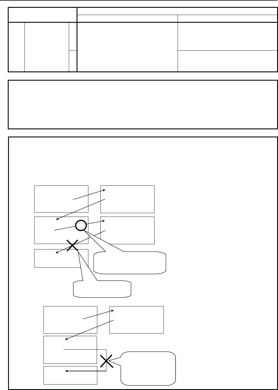
3.EXECUTION MACRO FUNCTION
B-63943EN-2/07
- 68 -
Bit 2 (PCDC) of Compile parameter No. 9163
0 1
(c)
Bit 6 (GMP) of
parameter No.
6008
0 After an execution macro is called, the
user program cannot be called again.
(The duplicate calling of a user program
is disabled.)
After an execution macro is called, the
user program cannot be called again.
(The duplicate calling of a user program
is disabled.)
1
A user program can be called. (The
duplicated calling of a user program is
allowed.)
NOTE
1 If a disabled type of call is attempted, the command is treated as an ordinary
G/M/S/T/D/H/second auxiliary function/axis address code.
2 The same behavior as for bit 6 (GMP) of parameter No. 6008 = 0 and bit 2
(PCDC) of compile parameter No. 9163 = 0 occurs if bit 0 (GMC) of compile
parameter No. 9163 = 1.
Example 1
When bit 6 (GMP) of parameter No. 6008 and bit 2 (PCDC) of compile
parameter No. 9163 are set to 0 and bit 6 (C16) of compile parameter No. 9163
is set to 1
O0001 ;
:
G100X10.0Z20.0;
:
M02;
O9010 ;
:
MmmP1000;
:
M99;
O9011 ;
:
MmmP1001;
:
M99;
O1001 ;
:
M99;
O1000 ;
:
G200.0;
:
M99;
Duplicate user program
call is not allowed.
1. User program Execution macro
A
n execution macro call using
G code can be made from a
program called using G code.
O0001 ;
:
G100X10.0Z20.0;
:
M02;
O9010 ;
:
MmmP1000;
:
M99;
O9020 ;
:
M99;
O1000 ;
:
M100 ;
:
M99; Calls other than user
program calls using
G65, M98, G66, and
G66.1 are not
allowed.
2. User program Execution macro
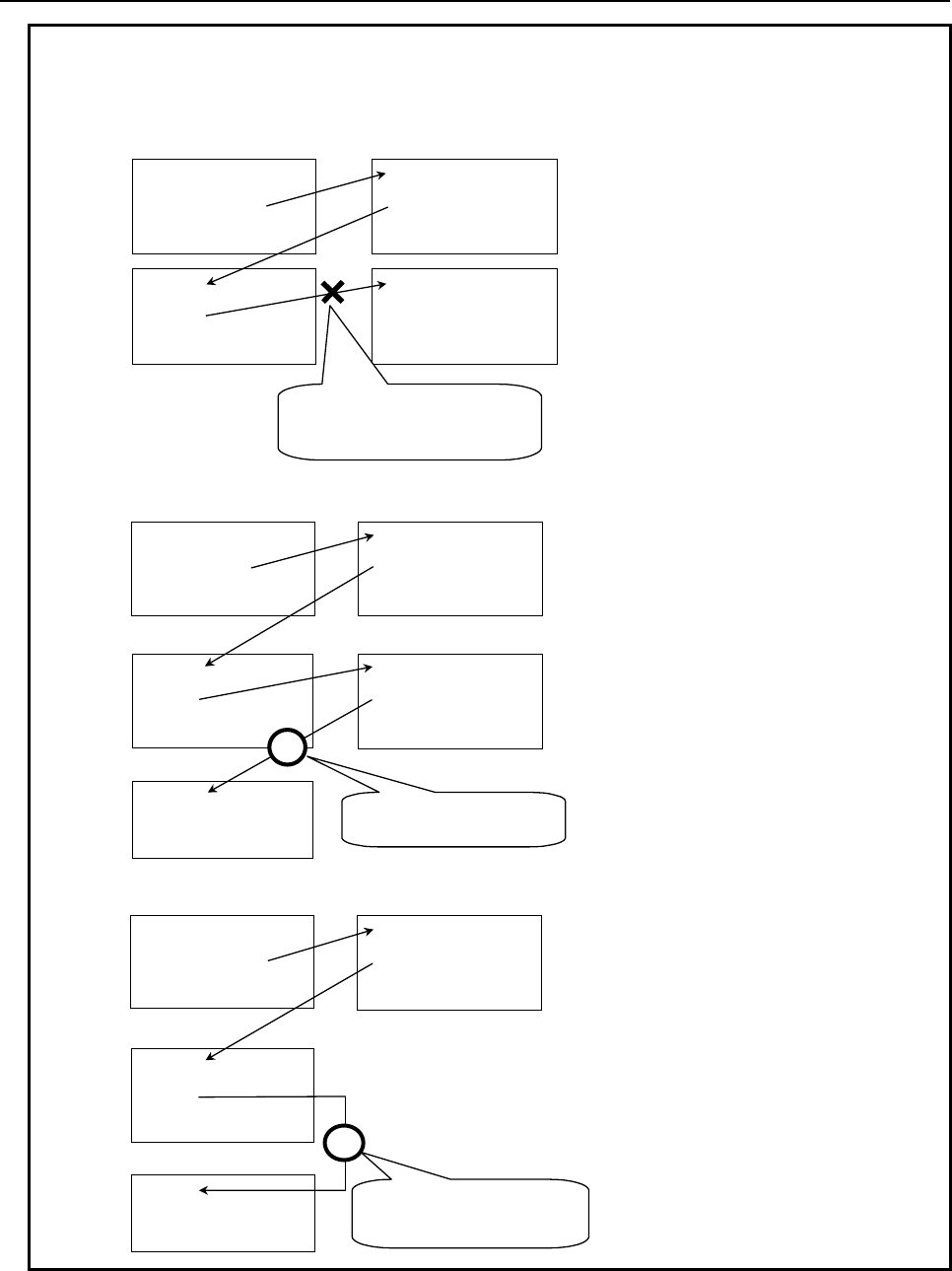
B-63943EN-2/07
3.EXECUTION MACRO FUNCTION
- 69 -
Example 2
When both of bit 6 (GMP) of parameter No. 6008 and bit 2 (PCDC) of compile
parameter No. 9163 are set to 1
O0001 ;
:
G100X10.0Z20.0;
:
M02;
O9010 ;
:
MmmP1000;
:
M99;
O9011 ;
:
MmmP1001;
:
M99;
O1000 ;
:
G200.0;
:
M99;
From a program called using G
code, including a custom macro, a
call using G code cannot be made.
1. User program Execution macro
O0001 ;
:
G100X10.Z20.;
:
M02;
O9010 ;
:
MmmP1000;
:
M99;
O9020 ;
:
MmmP1001;
:
M99;
O1001 ;
:
:
M99;
O1000 ;
:
M100 ;
:
M99;
A
n additional user program
can be called.
2. User program Execution macro
O0001 ;
:
G100X10.0Z20.0;
:
M02;
O9010 ;
:
MmmP1000;
:
M99;
O9020 ;
:
:
M99;
O1000 ;
:
M100 ;
:
M99;
From a program called using G
code, a user program can be
called using M, S, T, and so forth.
3. User program Execution macro
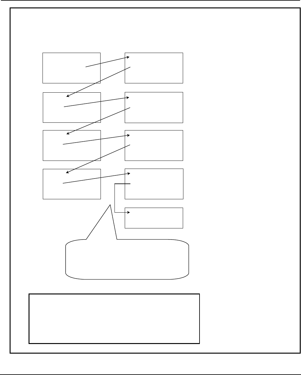
3.EXECUTION MACRO FUNCTION
B-63943EN-2/07
- 70 -
Example 3
When bit 6 (GMP) of parameter No. 6008, bit 2 (PCDC) of compile parameter
No. 9163, and bit 6 (C16) of compile parameter No. 9163 are set to 1
O0001 ;
:
G100X10.0Z20.0;
:
M02;
O9010 ;
:
MmmP1000;
:
M99;
O9011 ;
:
MmmP1001;
:
M99;
O1001 ;
:
M100;
:
M99;
O1000 ;
:
G110.;
:
M99;
O9020 ;
:
MmmP1002;
:
M99;
O1002 ;
:
M200;
:
M99;
O9021 ;
:
T123 M06;
:
M99;
(1)
(2)
O9008 ;
:
M99;
×
- If bit 6 (C16) of compile parameter No. 9163 is set to 1, no limitation
is imposed on calling of an execution macro from a user program.
- If bit 6 (GMP) of parameter No. 6008 is set to 1 and bit 2 (PCDC) of
compile parameter No. 9163 is set to 1, a duplicate user program call
can be made.
If the above are combined, user program calls and execution macro
calls can be made repeatedly until the allowed nesting level is reached.
One call using G code is made in (1) and one
call using not G code is made in (2). So, no
additional user program can be called from a
user program and no additional execution
macro can be called from an execution macro.
User program Execution macro
3.2.27
P-CODE Workpiece Number Search
When automatic operation is started in the memory or DNC operation mode, the execution macro
specified for variable #8610 is executed before the main program.
Call conditions and operation
(a) Bit 6 (PWSR) of compile parameter No. 9002 is set to 1.
(b) The memory or DNC operation mode is selected.
B-63943EN-2/07
3.EXECUTION MACRO FUNCTION
- 71 -
(c) The program number of an execution macro is set for variable #8610 using a conversational macro
or auxiliary macro before the start of automatic operation.
(d) The main program is selected.
When the above four conditions are satisfied, starting automatic operation:
(1) The execution macro specified by #8610 is called. When bit 4 (P98) of compile parameter No. 9163
is set to 0, the call is equivalent to a simple call (G65). When bit 4 (P98) of compile parameter No.
9163 is set to 1, the call is equivalent to a subprogram call.
(2) Executes the main program after termination of the execution macro.
NOTE
No execution macro is called if the main program is not selected. In this case,
alarm (PS1079)” PROGRAM FILE NOT FOUND” can be issued by setting bit 5
(NPA) of parameter No. 9035 to 1.
Warning
WARNING
When conditions a) to d) are satisfied, this function calls an execution macro
regardless of the user program to be started. For this reason, take
countermeasures such as issuing a warning message using an auxiliary macro or
PMC and setting interlock processing to prevent operator errors when using this
function.
Nesting and local variables
The execution macro is counted among execution macro nesting levels. Because the execution macro is
called in the simple call (G65) or subprogram call (M98) mode, another execution macro can be called
from the called execution macro using any call method.
In the simple call (G65) mode, the execution macro is executed using a local variable level different from
the level the main program uses. In other words, the local variables used by the execution macro are not
passed to the main program.
In the subprogram call (M98) mode, the execution macro uses the same local variable level as the main
program. In other words, the local variables used by the execution macro are passed to the main program.
3.2.28
Macro Call Argument for Axis Name Expansion
Macro argument can be specified to the address of axis name expansion. By setting the parameter
(No.11647), the address of axis name expansion is allocated to local variable number(#1 - #33).
This function is effective to not only an axis name expansion but also a usual axis address of one
character. A usual axis address of one character can allocate to the local variable number (#1-#33).
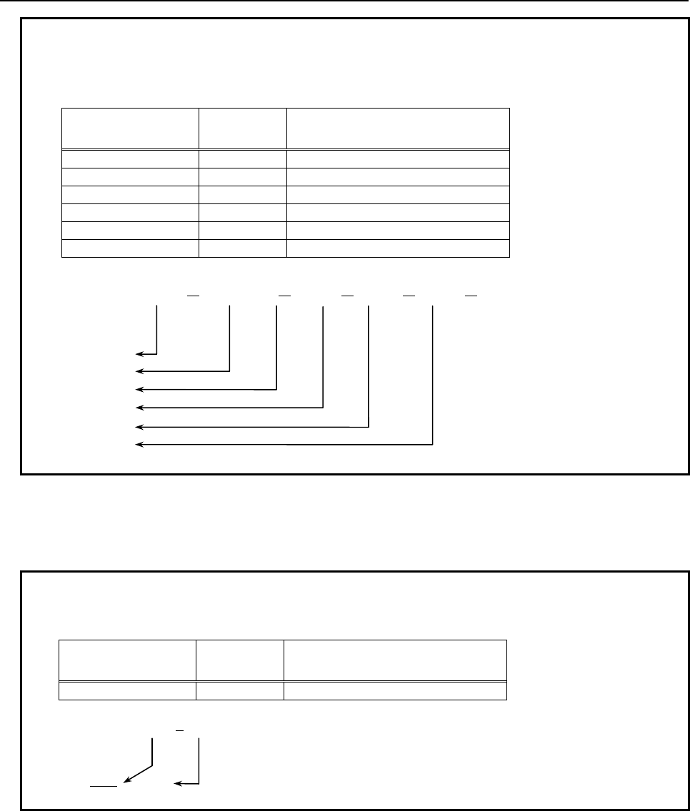
3.EXECUTION MACRO FUNCTION
B-63943EN-2/07
- 72 -
Example
In case of the following axis configuration, if all arguments are specified, the
relationship between the parameter (No.11647) and local variable number is as
follows.
Allocating the same local variable
Please do not allocate the same local variable to 2 or more arguments. If the same local variable is
allocated, the argument specified later becomes effective.
Example
When 2 arguments of XA1=10.0 and D20.0 are commanded to local variable #7,
the later argument D20.0 becomes effective.
Using the same axis name
When using the same axis name, the parameter (No.11647) setting of the smallest axis number becomes
effective. The setting of the other axis becomes invalid.
Axis name Parameter
(No.11647) Local variable
XA1 (*1) 1 Argument is set to #1
XA2 (*1) 2 Argument is set to #2
Y 0 Argument is set to #25
Z 21 Argument is set to #21
C 0 Argument is set to #3
C2 (*1) 22 Argument is set to #22
(
*1
)
Axis name ex
p
ansion
G65 XA1=10.0 XA2=20.0 Y30.0 Z40.0 C50.0 C2=60.0
P1000;
(Variable)
#1: 10.0
#2: 20.0
#25: 30.0
#21: 40.0
#3: 50.0
Axis name Parameter
(No.11647) Local variable
XA1 (*1) 7 Argument is set to #7
(*1) Axis name expansion
G65 XA1=10.0 D20.0 P1000;
(Variable)
#7: 10.0 20.0
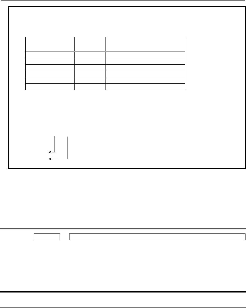
B-63943EN-2/07
3.EXECUTION MACRO FUNCTION
- 73 -
Example
When using the same axis name and using the axis name expansion, the
relationship between the parameter (No.11647) and local variable number is as
follows.
The setting range of the parameter
The setting range of the parameter (No.11647) is 0,1-33. This corresponds to local variable number
(#1-#33). When other values are set, the setting of the axis is invalid. Therefore, when using the axis
name expansion, the alarm (PS0129) occurs by commanding the axis. If the axis does not use the axis
name expansion, the argument is assigned to original local variable (#1-#33).
3.3
DIAGNOSIS DATA
Diagnosis 1493 Number of blocks in the macro statements executed by a custom macro/execution macro
[Data type] 2-word
[Unit of data] Block
Displays the number of blocks in the macro statements executed by a custom
macro/execution macro per 1024 ms.
It provides an indication of the actual processing speed of macro statements.
3.4
LIMITATIONS ON EXECUTION MACROS
3.4.1
Commands which cannot Use Execution Macros
• Command using a comma (,) such as optional-angle chamfering/corner rounding
• SETVN
• Arbitrary axis name setting
• Real time custom macro command
Axis name Parameter
(No.11647) Local variable
XA1 (*1) 0 The argument for XA1 is invalid
XA1 (*1) 2 Invalid setting
YA2 (*1) 3 Argument is set to #3
YA2 (*1) 4 Invalid setting
C 5 Argument is set to #5
C 6 Invalid setting
(
*1
)
Axis name ex
p
ansion
G65 XA1=10.0 YA2=20.0 C30.0 P1000 ;
Because the argument for XA1 is invalid, the alarm (PS0129) “USE 'G' AS ARGUMENT”
occurs.
G65 YA2=20.0 C30.0 P1000 ;
(Variable)
#3: 20.0
#5: 30.0
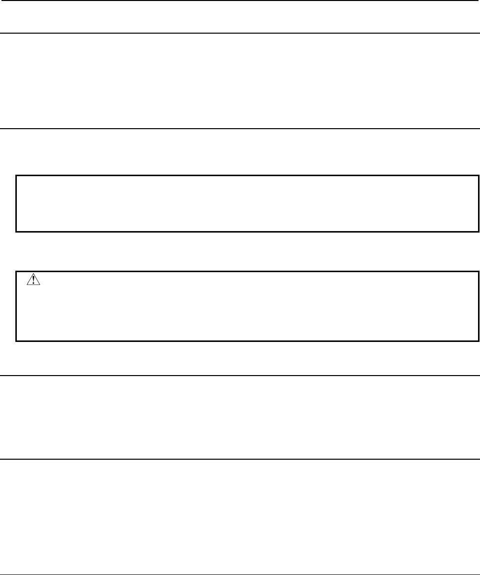
3.EXECUTION MACRO FUNCTION
B-63943EN-2/07
- 74 -
3.4.2
Functions which cannot Use Execution Macros
• Playback
• Manual numeric command
• Background drawing
• Multiple repetitive cutting cycle
3.4.3
Optional Block Skip
When a block with a sequence number in an execution macro is skipped using the optional block skip
function, a block consisting of only the sequence number is created.
Example
Original program Command to be executed when skipped
/1 N1 X100.; N1;
N2 /2 Y200.; N2;
When N1 is skipped as listed above, the similar operation as for N2 is performed.
CAUTION
When such a block is skipped in an execution macro, the block consists of only
the sequence number with no travel distance. For this reason, if such a block is
skipped in the cutter or another compensation mode, the tool path may differ from
that in a user program.
3.4.4
Interruption Type Custom Macro
A program interrupted using an interruption type custom macro always calls a user program. It cannot call
an execution macro program.
3.4.5
Axis Specification and Extended Axis Name Specification
Using an Axis Number
Usually, an axis is specified with its axis name, but can also be specified with the symbol name
corresponding to its axis number. This is called axis specification using an axis number.
If an extended axis name is enabled (bit 0 (EEA) of parameter No. 1000 = 1), a user program specifies a
program with the program axis names, the second and third axis names, set in parameters Nos. 1025 and
1026, but a P-CODE macro cannot specify a program directly with the extended axis names set in
parameters Nos. 1025 and 1026. Specify a program using an axis specification using an axis number.
3.4.5.1
Axis specification using an axis number
Usually, an axis is specified with its axis name, as in X100.0, but can also be specified with the symbol
name corresponding to its axis number.
When an execution macro is executed, the specified symbol name is automatically converted to the axis
name set in the corresponding axis number parameter No. 1020.
This means that multiple machines that have axes with the same axis number but different axis names,
such as a machine that has the 4th axis as the B-axis and another that has the 4th axis as the C-axis can be
used in a single P-CODE macro.
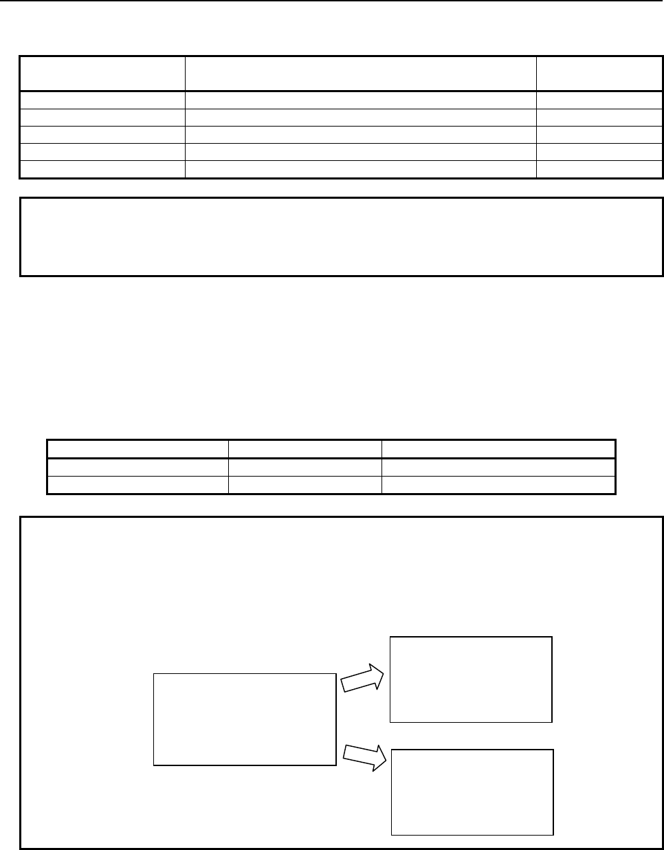
B-63943EN-2/07
3.EXECUTION MACRO FUNCTION
- 75 -
Axis numbers corresponding to symbol names
The axis numbers corresponding to the symbol names to be specified in a P-CODE macro are as follows:
Symbol name to be
specified
Symbol name in an incremental command G code
system A
(Note)
Corresponding
axis number
&A YA 1st axis
&B YB 2nd axis
&C YC 3rd axis
: : :
&X YX 24th axis
NOTE
If parameter No. 1020 that correspond to the axis number specified with a
symbol name with an incremental command in G code system A for a lathe
system is other than X, Z, C, and Y, alarm PS0009 is issued at execution time.
Specification with a symbol name
Usually, an axis is specified with an address plus a numeric value, as in X100.0, but in an axis
specification using an axis number, a symbol name is followed by a numeric value enclosed in brackets,
as in &A[100.0].
[Example]
If, on a machine that has an axis configuration of X, Z, Y, and C in G code system A for a lathe
system (parameter No. 1020 = 88, 90, 89, and 67), the tool is to be moved along the 4th axis (C-axis),
follow the table below.
Normal specification Specification with a symbol name
Absolute programming C100.0 &D[100.0]
Incremental programming H100.0 YD[100.0]
Example
If the same P-CODE macro is to be executed on a machine with an axis
configuration of X, Y, Z, and B and another machine with an axis configuration of
X, Y, Z, and C
Program to be converted at execution
P-CODE macro
G0 &A[0] &B[0] &C[0] &D[0]
G91 G01 &D[100.0] F100.
Machine with an axis
configuration of X, Y, Z,
and B
G0 X0 Y0 Z0 B0
G91 G01 B100.0 F100.
Machine with an axis
configuration of X, Y, Z,
and C
G0 X0 Y0 Z0 C0
G91 G01 C100.0 F100.
Changing the axis numbers corresponding to symbol names
Axis numbers corresponding to the symbol names to be specified in a P-CODE macro are predetermined,
such as the 1st axis for &A, the 2nd axis for &B, ..., and the 24th axis for &X ("YA", "YB", ... and "YX"
for incremental commands in G code system A), but the axis number corresponding to a specified symbol
name can be changed freely by setting in parameter No. 9076 the axis number to correspond to the
symbol name.
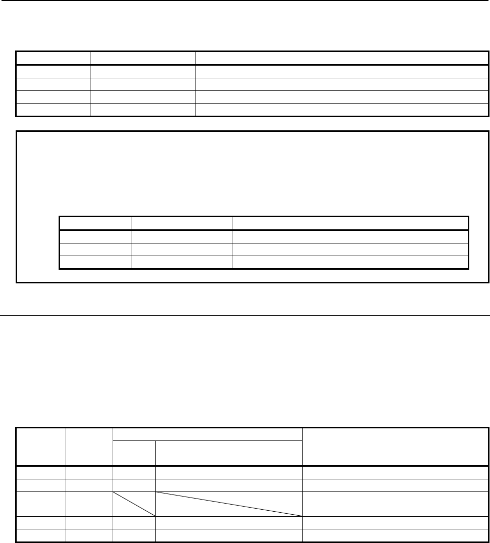
3.EXECUTION MACRO FUNCTION
B-63943EN-2/07
- 76 -
For example, if the 1st axis is to be specified with &B and the 2nd axis with &A, make the following
settings in parameter No. 9076.
Axis number Parameter No.9076 Remarks
1st axis 2 Change the axis number to correspond to &B (YB) to the 1st axis.
2nd axis 1 Change the axis number to correspond to &A (YA) to the 2nd axis.
3rd axis 0 No changes (3rd axis to be controlled with &C (YC)).
4th axis 0 No changes (4th axis to be controlled with &D (YD)).
NOTE
If 2 or more axes are specified for the same axis number, alarm PW1106 will be
issued at power on.
[Example]
If parameter No.9076 is set as listed below, alarm PW1106 will be issued at
power on.
Axis number Parameter No.9076 Remarks
1st axis 2 The 1st axis corresponds to &B (YB).
2nd axis 1 The 2nd axis corresponds to &A (YA).
3rd axis 2 The same setting as that for the 1st axis is invalid.
3.4.5.2
Specification of an extended axis name
A P-CODE macro cannot specify an extended axis directly with its extended axis name set in parameter
No. 1025 or 1026. It specifies an extended axis using an axis specification using an axis number.
When an execution macro is executed, the specified symbol name is automatically converted to the
extended axis name set in the corresponding axis number parameter No. 1020, 1025, or 1026.
For a 5-axis machine such as the one below, for example, a custom macro specifies extended axes with
extended axis names as in XA1=100.0 ZM200.0, but a P-CODE macro specifies them using an axis
specification using an axis number as in &A[100.0] &D[200.0].
Axis
number
Axis
name
Specification in a P-CODE macro
Remarks
For an incremental command
in G code system A
1 XA1 &A UA1 is specified with YA.
2 XA2 &B UA2 is specified with YB.
3 Y Not an extended axis name, thus specified
with address Y as usual.
4 ZM &D WM is specified with YD.
5 ZS &E WS is specified with YE.
Symbol definition for an extended axis name
By defining the symbol for an extended axis name, a macro program can be coded with the same axis
name as that in a custom macro.
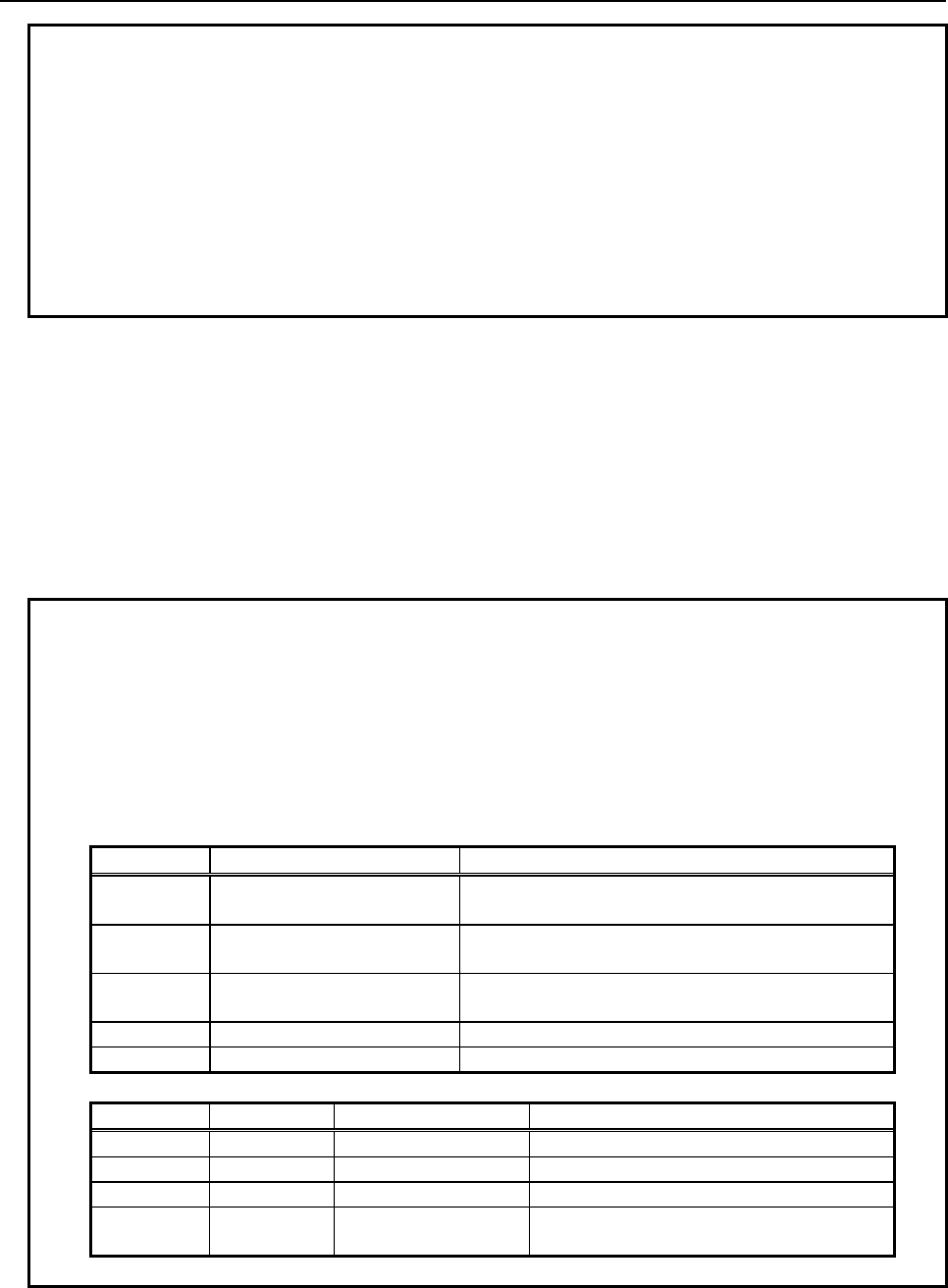
B-63943EN-2/07
3.EXECUTION MACRO FUNCTION
- 77 -
Example
For the machine in a lathe system in which the 4th axis is ZA2 (parameters No.
1020 = 90, No. 1025 = 65, and No. 1026 = 50),
@ZA2 &D /*Axis name definition for an absolute command
@WA2 YD /*Axis name definition for an incremental command
by defining the symbols above, a macro program can be coded with the same
extended axis name as that in a custom macro, as shown below.
ZA2[100.]; → Moves the ZA2-axis to 100.0.
WA2[100.];
→ Moves the ZA2-axis +100.0.
Changing the axis numbers corresponding to symbol names
Axis numbers corresponding to the symbol names to be specified in a P-CODE macro are predetermined,
such as the 1st axis for &A, the 2nd axis for &B, ..., and the 24th axis for &X ("YA", "YB", ... and "YX"
for incremental commands in G code system A), but the axis number corresponding to a specified symbol
name can be changed freely by setting in parameter No. 9076 the axis number to correspond to the
symbol name.
This means that multiple machines that have axes with the same extended axis name but different axis
numbers, such as a machine that has the B2-axis as the 5th axis and another that has the B2-axis as the 6th
axis can be used in a single P-CODE macro.
Example 1
To use P-CODE macros created in a 5-axis (X, Y, Z, B1 (&D), B2 (&E))
configuration on a machine in a 4-axis configuration (1st axis = X, 2nd axis = Y,
3rd axis = Z, and 4th axis = B2), set parameter No. 9076 as follows:
[P-CODE macro]
Symbol definition
@B1 &D /* Defines an axis name for the 4th axis.
@B2 &E /* Defines an axis name for the 5th axis.
Axis number Axis name to be specified Remarks
1st axis X Axis with no expansion axis name is specified with no
modification.
2nd axis Y Axis with no expansion axis name is specified with no
modification.
3rd axis Z Axis with no expansion axis name is specified with no
modification.
4th axis B1 &D (4th axis) is specified.
5th axis B2 &E (5th axis) is specified.
[Settings on the machine]
Axis number Axis name Parameter No. 9076 Remarks
1st axis X 0 Not an expansion axis name
2nd axis Y 0 Not an expansion axis name
3rd axis Z 0 Not an expansion axis name
4th axis B2 5
The axis number (5th axis) corresponding to
&E is changed to the 4th axis.
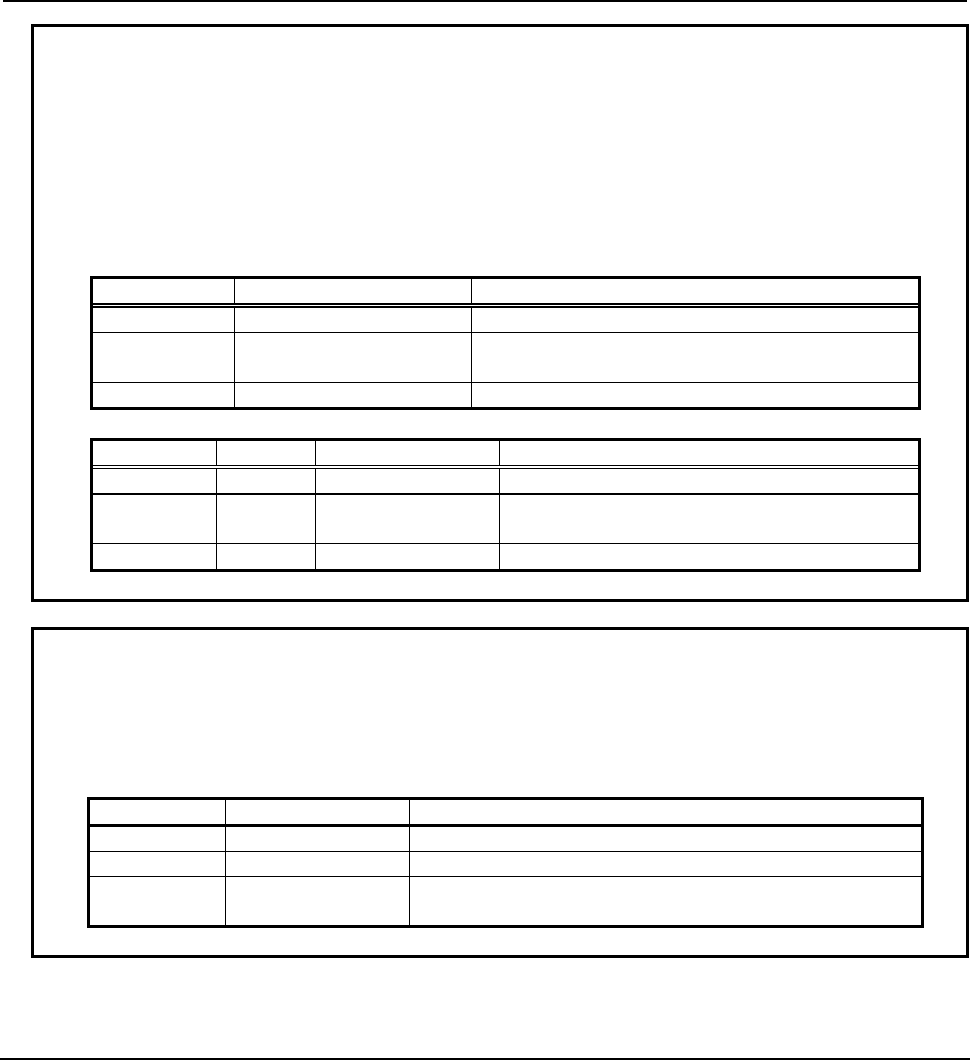
3.EXECUTION MACRO FUNCTION
B-63943EN-2/07
- 78 -
Example 2
To use P-CODE macros created in a 3-axis (XA(&A), Y, ZA2(&C)) configuration
on a machine in a 3-axis configuration (1st axis = XA, 2nd axis = ZA2, and 3rd
axis = Y), set parameter No. 9076 as follows:
[P-CODE macro]
Symbol definition
@XA &A /* Defines an axis name for the 1st axis.
@ZA2 &C /* Defines an axis name for the 3rd axis.
Axis number Axis name to be specified Remarks
1st axis XA &A (1st axis) is specified.
2nd axis Y Axis with no expansion axis name is specified with no
modification.
3rd axis ZA2 &C (3rd axis) is specified.
[Settings on the machine]
Axis number Axis name Parameter No. 9076 Remarks
1st axis XA 0 &A remains to be the 1st axis.
2nd axis ZA2 3
The axis number (3rd axis) corresponding to &C is
changed to the 2nd axis.
3rd axis Y 0 Not an expansion axis name
NOTE
If 2 or more axes are specified for the same axis number, alarm PW1106 will be
issued at power on.
[Example]
If parameter No. 9076 is set as listed below, alarm PW1106 will be issued at
power on.
Axis number Parameter No.9076 Remarks
1st axis 2 The 1st axis is &B (YB).
2nd axis 1 The 2nd axis is &A(YA).
3rd axis 2 Invalid because the parameter setting is the same as for the
1st axis
3.4.6
Method of Variable Specification for Address N in the
Programmable Data Input Mode
With a P-CODE macro, address N may not be specified using a variable. (If such an attempt is made, a
compile error occurs.)
When address N in the programmable data input mode (between G10 and G11) is to be specified in an
execution macro, specify address "NN" instead of address N.
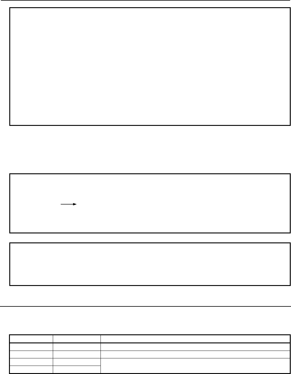
B-63943EN-2/07
3.EXECUTION MACRO FUNCTION
- 79 -
Example
To set the value 4 in parameter No. 0022 by using the programmable parameter
input function
P-CODE macro
O0010;
:
#100=22;
#101=4;
G10 L52;
NN#100 R#101; → Executed as N#100 R#101, resulting in N22R4
G11 ;
:
M99 ;
Limitation
Address NN used with this function can be used only to substitute for address N used in data input based
on the G10 command. Address NN cannot be used as a jump destination sequence number for a command
such as the GOTO command.
Example
O9011;
#100=10;
GOTO #100; PS alarm (NN#100 is not regarded as the jump destination N10.)
:
NN#100;
M99;
NOTE
This function can be used in the following series and edition of the macro
compiler.
A08B-9010-J600#EN07 : V01.4 or later
A08B-9010-J604#EN11 : V01.0 or later
3.4.7
G Code System Conversion (for a Lathe System)
When a P-CODE program for a lathe system is created, which G code system (A, B, or C) is used can be
set using bit 0 (SP_G_B) and bit 1 (SP_G_C) of compile parameter No. 9004.
SP_G_C SP_G_B G code system in P-CODE program
0 0 G code system A
0 1 G code system B
1 0 G code system C
1 1
Thus, the G codes in the P-CODE program are executed after being automatically converted to the G
codes of the G code system set in bit 6 (GSB) and bit 7 (GSC) of parameter No. 3401.
However, if a P-CODE file created to G code system B or C is executed on a machine set to G code
system A, nonexistent G code groups such as groups 03 and 11 are not converted. (For example, G90 is
treated as an outer surface/inner surface turning cycle command.)
NG

3.EXECUTION MACRO FUNCTION
B-63943EN-2/07
- 80 -
If a P-CODE program created to G code system A (with both of bit 0 (SP_G_B) and bit 1 (SP_G_C) of
compile parameter No. 9004 set to 0) is executed on a machine set to G code system B or C, an operation
based on an incremental command is performed on the axes specified with U_, V_, W_, and H_.
However, no modal change is made.
Check the G code system set in bit 6 (GSB) and bit 7 (GSC) of parameter No. 3401 and create a P-CODE
program according to a desired G code system.
Example
1 When a P-CODE macro created to G code system A (SP_G_B = 0, SP_G_C = 0)
is executed on a machine set to G code system B (GSB = 1, GSC = 0)
P-CODE Operation on NC
G50X0; → Converted to G92X0;
G00X100.; → Positioned at X100. in absolute mode
U100.; → A movement is made by 100.0 on X-axis in incremental mode.
(The modal code G90/G91 is not changed.)
2 Example of P-CODE macro created to G code system B (SP_G_B = 1, SP_G_C
= 0) (On a machine set to G code system A, G90 is treated as an outer
surface/inner surface turning cycle command, and G91 results in alarm PS0010.
So, G90 and G91 are not to be specified.)
#100=P3401;
#100=#100 AND 192;
→
Bits 6 and 7 of parameter No. 3401
IF [#100 EQ 0]
THEN
On a machine set to G code system A
G94;
G92 Z0.;
G00Z100.
U100.
:
:
→
→
→
→
Converted to G98
Converted to G50Z0
Makes a movement to 100 on Z-axis in ABS mode.
Makes a movement by +100 on X-axis in INC mode.
(Note: Bit 4 (UVW) of parameter No. 3400 must be
set to 1.)
ELSE On a machine set to G code system B or C
G94;
G92 Z0.;
G90G00 Z100.;
G91X100.;
:
ENDIF
→
→
→
→
Leaves G94 unchanged.
Leaves G92Z0 unchanged.
Makes a movement to 100 on Z-axis in ABS mode.
Makes a movement by +100 on X-axis in INC mode.
The modal code is G91.
NOTE
1 To execute a P-CODE program created to G code system B or C, bit 0 (SP_G_B)
and bit 1 (SP_G_C) of compile parameter No. 9004 must be set at all times.
2 Only G codes are converted. For example, the U_V_W_H_ command created to
G code system A is not converted to G91X_Y_Z_C_.
3 G code groups 03 and 11 do not exist in G code system A. So, when a P-CODE
program created to G code system B or C is executed on a machine set to G
code system A, G90/G91 and G98/G99 are not converted. For example, G90 is
treated not as an absolute command but as an outer surface/inner surface
turning cycle command.
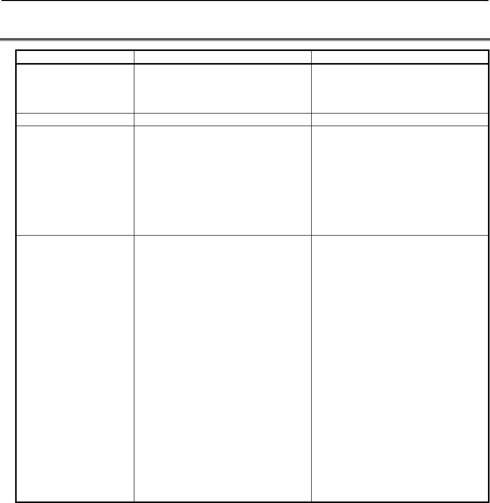
B-63943EN-2/07
3.EXECUTION MACRO FUNCTION
- 81 -
3.5 DIFFERENCES FROM THE Series 16i
Function Series 16i/18i/21i Series 30i/31i/32i/35i/0i-F/PMi
Program - Programs from O1 to O9999 can be
created.
- Up to 400 programs can be registered.
- Programs from O1 to O99999999 can
be created.
- Up to 1000 programs can be
registered.
Sequence number N1 to N99999 N1 to N99999999
NC command specified in
a block containing a macro
call code based on a G or
M code
- If the NC command is specified before
the call code, it is ignored (with the
modal information updated). If the NC
command is specified after the call
code, it is treated as an argument.
- If multiple call codes are specified, the
first code is used for calling, and the
subsequent code or codes are treated
as arguments.
If the NC command is specified before
the call code, alarm PS0127 (NC
statement/macro statement duplication)
is issued. If the NC command is specified
after the call code, it is treated as an
argument.
Usable call command When an execution macro is called from
another execution macro, only G65/M98
can be specified.
(For example, an execution macro called
using a G code from a user program
cannot make a call by using an M code.)
When an execution macro is called from
another execution macro, G66/G66.1 can
be used in addition to G65/M98 if bit 2
(PCDC) of compile parameter No. 9163
is set to 1. Moreover, if bit 2 (PCDC) of
compile parameter No. 9163 is set to 1,
and bit 6 (GMP) of parameter No. 6008 is
set to 1, an M/S/T/D/H/second auxiliary
function/specific code/axis address can
be called from an execution macro called
with a G code, and calling based on a G
code is possible from an execution macro
called with M/S/T/D/H/second auxiliary
function/specific code/axis address.
If bit 6 (GMP) of parameter No. 6008 is
set to 0 or bit 2 (PCDC) of compile
parameter No. 9163 is set to 0, the series
are equivalent to Series 16i.
For details, see "Usable call command"
and "Limitations on calls" in Subsection
3.2.1.1, "Macro call and subprogram
call".

3.EXECUTION MACRO FUNCTION
B-63943EN-2/07
- 82 -
Function Series 16i/18i/21i Series 30i/31i/32i/35i/0i-F/PMi
Priority if the call code in
the custom macro set in a
parameter is the same as
the call code in the
execution macro set in a
compile parameter
- In a macro call using a G code, by
setting bit 0 (MCG) of parameter No.
9013 to 1, the program in the custom
macro is called with a G code.
(This is effective to a macro call
using a G code. With any other call
code, the execution macro is given
priority.)
- In all macro/subprogram calls, a
custom macro program is called by
setting bit 1 (MCA) of parameter No.
9013 to 1. (This is effective to all call
codes.)
Example:
If 100 is set in both parameter No.
6050 and compile parameter No.
9013 and 110 is set in both
parameter No. 6071 and compile
parameter No. 9010, and if
parameter bit MCG is set to 1,
O9010 in the custom macro is called
when G100 is specified and O9001
is called when M110 is specified.
Example:
If 100 is set in both parameter No.
6050 and compile parameter No.
9013 and 110 is set in both
parameter No. 6071 and compile
parameter No. 9010, and if
parameter bit MCA is set to 1, O9010
in the custom macro is called when
G100 is specified and O9001 in the
custom macro is called when M110
is specified.
Nesting - 4 levels of subprogram calls
- 4 levels of macro calls
- 15 levels of subprogram calls alone
- 5 levels of macro calls alone
15 levels when combined
Repetition based on
address L
When an execution macro is called from
a user program (other than G65/M98 and
calling of a user program as a
subprogram), the number of repeats
cannot be specified.
The number of repeats can be specified
in calls other than special macro calls
based on G/M/H/D/S/T code/axis
address in which address L is also used
as an argument. (However, when bit 5
(MCARG) of compile parameter No. 9008
is set to 1, address L is also used as an
argument, so that the number of repeats
cannot be specified in macro calling
based on a G/M code.)
Passing of arguments When bit 5 (MCARG) of compile
parameter No. 9008 is set to 1, G, L, N,
and P are additionally used as
arguments.
Even when bit 5 (MCARG) of compile
parameter No. 9008 is set to 0, N and P
are used as arguments. For address N,
the number of digits after the decimal
place becomes 0.
When bit 5 (MCARG) of compile
parameter No. 9008 is set to 1, G and L
are also used as arguments. Note that an
NC command input format limitation is
applied to address G. (For example,
specifying G1000 results in alarm
PS0010.)
O and N values and G codes other than
the 00 group are passed as modal
information to the subsequent blocks.
By setting bit 6 (INVIJK) of compile
parameter No. 9103 to 1, argument
specification I can be used regardless of
the order in which I, J, and K are
specified.
By setting bit 7 (IJK) of parameter No.
6008 to 1, argument specification I can
be used regardless of the order in which
I, J, and K are specified.

B-63943EN-2/07
3.EXECUTION MACRO FUNCTION
- 83 -
Function Series 16i/18i/21i Series 30i/31i/32i/35i/0i-F/PMi
Local variable level When an execution macro is called with a
subprogram call from a user program, the
local variable level changes just like the
macro call.
A choice can be made by setting bit 3
(LCLLV) of compile parameter No. 9163.
=0 : The local variable level does not
change due to a subprogram call,
like the custom macro level.
=1 : Equivalent to Series 16i.
Macro call using a G code Special macro calling is disabled. If bit 5 (GMACC) of compile parameter
No. 9104 is set to 1, this results in special
macro calling.
Macro call using a G code
(specification of multiple
calls)
- Modal calling is disabled.
- Special macro calling is disabled.
- Modal calling is enabled.
- If bit 5 (GMACC) of compile
parameter No. 9104 is set to 1, this
results in special macro calling.
Macro modal call using a
G code
Only equivalent to G66.1. Different
specifications from those of a macro
modal call of a custom macro using a G
code. For example, a modal call is
canceled with G167 or the G code
specified with compile parameter No.
9034.
- Whether the call is equivalent to
G66/G66.1 can be selected with bit 1
(MCT) of compile parameter No.
9163.
- A choice can be made by setting bit
0 (GMC) of compile parameter No.
9163 as follows:
=0 : Same specifications as those of
a macro modal call of a custom
macro using a G code. For
example, it is canceled with G67.
=1 : Can be made equivalent to
Series 16i by setting bit 1 (MCT)
of compile parameter No. 9163
to 0.
G code for canceling a
macro modal call using a
G code
By using a cancellation G code, the
execution macro program O9006 can be
called as a macro.
Special macro call using a
T code/axis address
If a G code in G code group 01 exists,
G80 may be generated and 80. may be
included in variables #28 to #32.
Even if a G code in G code group 01
exists, G80 will never be generated.
An argument is truncated to include the
effective digits only, using the address
specifiable in the NC, and passed.
(Example) X123.45678 is regarded as
#24=123.456
An argument is rounded off to include the
effective digits only, using the address
specifiable in the NC, and passed.
(Example) X123.45678 is regarded as
#24=123.457
A macro is called after modal change
using the address specified in the call
block. (By setting bits 4 and 7 of compile
parameter No. 9101 to 1, modal change
can be disabled.)
A macro is called without modal change
using the address specified in the call
block.
The handling of a block for calling a
single command consisting of only a call
code depends on bit 6 (NOPB) of
compile parameter No. 9004 as follows:
=0: An empty block is generated, then
the execution macro is called after
execution.
=1: The execution macro is called
immediately without generating an
empty block.
No empty block is generated. (The
compile parameter NOPB is not used.)

3.EXECUTION MACRO FUNCTION
B-63943EN-2/07
- 84 -
Function Series 16i/18i/21i Series 30i/31i/32i/35i/0i-F/PMi
Subprogram call using a
specific code/M/T code
The handling of a block for calling a
single command consisting of only a call
code depends on bit 6 (NOPB) of
compile parameter No. 9004 as follows:
=0: An empty block is generated, then
the execution macro is called after
execution.
=1: The execution macro is called
immediately without generating an
empty block.
No empty block is generated. (The
compile parameter NOPB is not used.)
When a user program calls an execution
macro as a subprogram or calls another
user program as a subprogram, the level
of the local variables changes. (All local
variables are set to <null>.)
As with a custom macro, the local
variable level does not change due to a
subprogram call. (When an execution
macro is called from a user program, the
local variables set in the user program
are passed.) However, when bit 3
(LCLLV) of compile parameter No. 9163
is set to 1, compatibility with the Series
16i is provided. This means that when an
execution macro is called from a user
program, the level can be changed as in
the case of a macro call.
Subprogram call using
G66/G66.1 and an S
code/second auxiliary
function code
Not allowed G66/G66.1 can be used to call an
execution macro from another execution
macro. Subprogram calling based on an
S code/second auxiliary function code is
enabled when an execution macro is
called from a user macro or another
execution macro.
Subprogram call for user
program
The specification of a return destination
sequence number at the time of return is
disabled.
The specification of a return destination
sequence number at the time of return is
enabled.
From a called user program, another
user program can be called with
G65/M98/G66 only.
Limitations differ depending on bit 6
(GMP) of parameter No. 6008, bit 2
(PCDC) of compile parameter No. 9163,
and bit 6 (C16) of compile parameter No.
9163.
For details, see Subsection 3.2.26,
"Subprogram Call for User Program".
The duplicate calling of a user program
from an execution macro is disabled.
The duplicate calling of a user program
from an execution macro is enabled.
P-CODE workpiece
number search
Equivalent to macro calling only A function equivalent to a simple call
(G65)/subprogram call (M98) can be
selected.
An execution macro s executed even
when the main program is not selected.
No execution macro is executed when
the main program is not selected (when
there is no program to run).
Interruption type custom
macro that is executing an
execution macro
An interruption type custom macros is
invalid. (An interrupt signal may not be
operated when an execution macro is
being executed.)
An interruption type custom macros is
valid even when an execution macro is
being executed. The interrupted program
calls a user program. (It is impossible to
allow an execution macro to interrupt.)
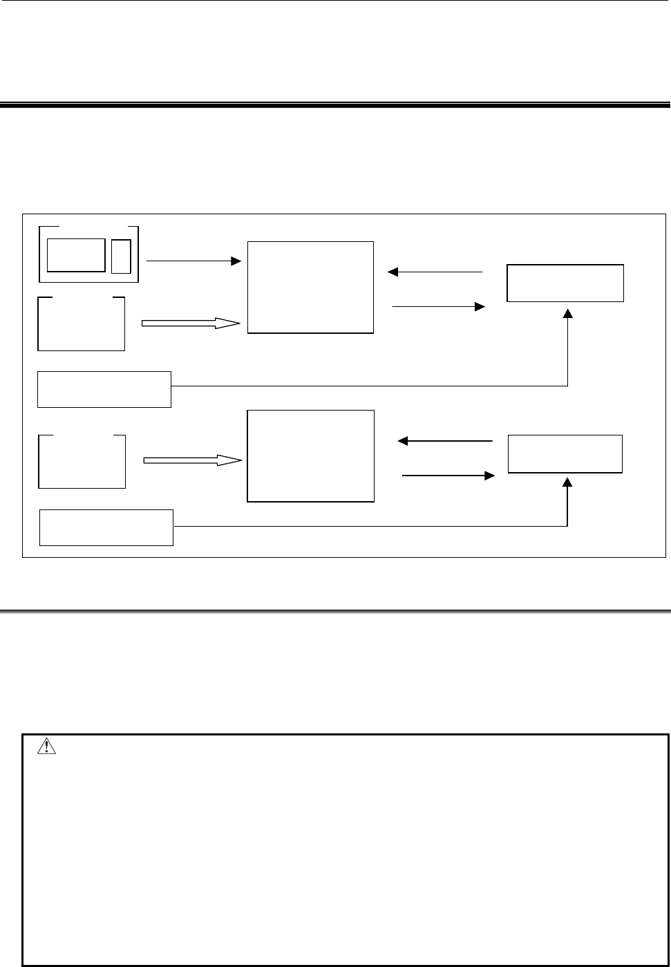
B-63943EN-2/07
4.CONVERSATIONAL MACRO FUNCTION AND AUXILIARY MACRO FUNCTION
- 85 -
4 CONVERSATIONAL MACRO FUNCTION
AND AUXILIARY MACRO FUNCTION
The conversational macro function allows the machine tool builder to create original screens. The
auxiliary macro function can be executed regardless of which mode or screen is selected.
Conceptual diagram of the conversational macro function and auxiliary
macro function
CUSTOM key
LCD/MDI
Compile parameter
No.9038
Control variable
#8530
Control variable
#8500
A
t power-on
Program number
specification
Program number
modification
A
lways
executed
Conversational
macro
F-ROM
A
t power-on
Conversational macro
function
Auxiliary macro
function
F-ROM
Auxiliary
macro
Compile parameter
No.9039
Program number
specification
Program number
modification
4.1 CONVERSATIONAL MACRO FUNCTION
The conversational macro function independently executes a conversational macro loaded into F-ROM in
parallel with ordinary part program operation.
This function is executed at a level lower than that of automatic operation processing. This function is
independent of the operation mode or automatic operation status.
Caution
CAUTION
1 The execution of the conversational macro function is processed at a lower level
than that of the CNC operation internally. Therefore, the execution of the
conversational macro function will not affect the processing speed of the CNC
operation, but the processing speed of the conversational macro function may
become slow while the CNC operation is ON. So, the conversational macro
function is not suitable for machine control that requires cyclic operation or
speedy processing.
2 The conversational macro function cannot execute any NC statements for the
CNC operation. If any are specified, the function ignores them.
3 NC statements in the conversational macro function differ from NC statements in
the meaning of addresses and in usage.
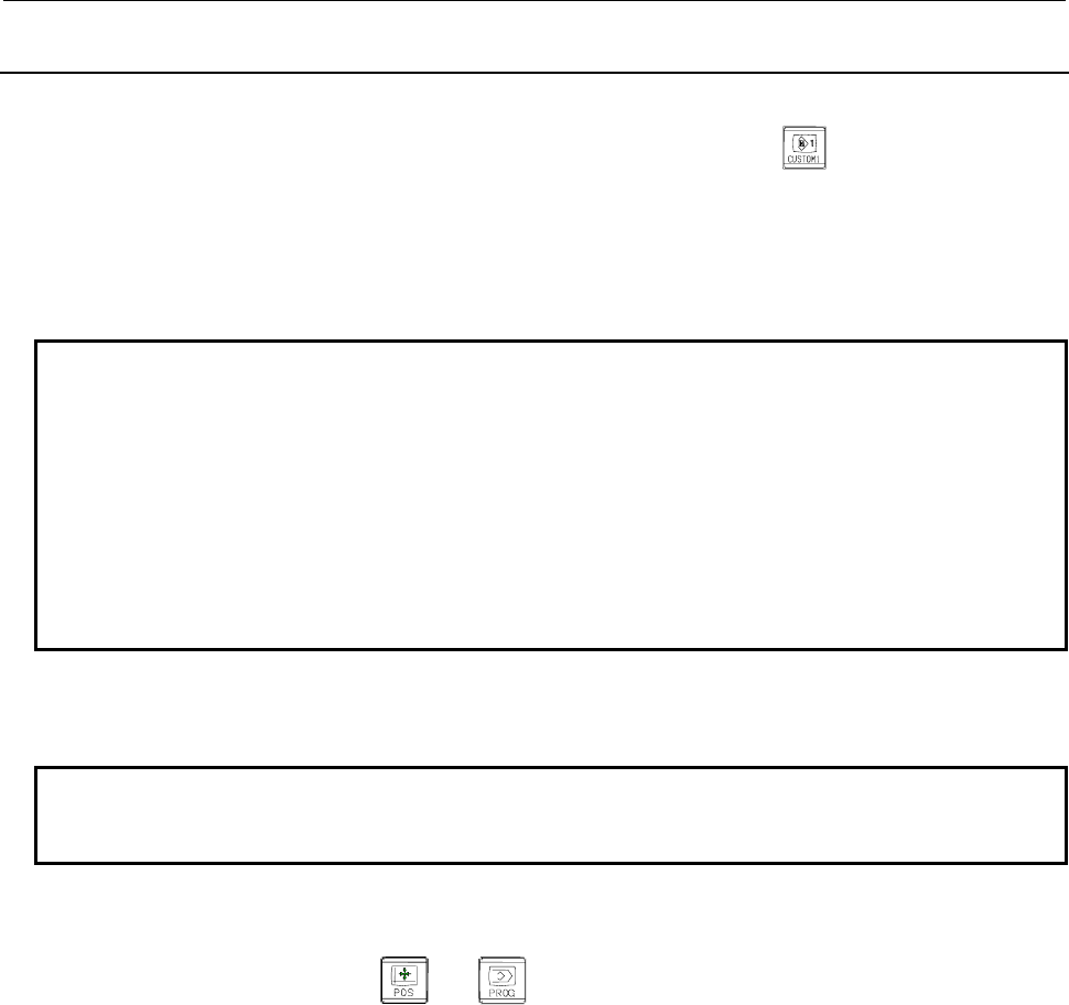
4.CONVERSATIONAL MACRO FUNCTION AND AUXILIARY MACRO FUNCTION
B-63943EN-2/07
- 86 -
4.1.1
Execution and Termination
Execution
The conversational macro function is executed by pressing the function key
on the MDI panel.
Which P-CODE is executed on each path is set in parameter No. 9049.
When the conversational macro function is executed, the conversational macro main program with the
value of the control variable for executing a conversational macro (#8500) as the program number is
executed. When the power is turned on, the value of compile parameter No.9038 is set for the control
variable for executing a conversational macro (#8500).
NOTE
1 An error may occur and execution may not be able to be continued. Such an
error includes the case where no P-CODE macro is found as the conversational
macro with the value of the control variable for executing a conversational macro
(#8500) as the program number. In this case, a message indicating that a fatal
error occurs is displayed on the conversational macro screen. (For details, see
Section 4.6, "FATAL ERROR.")
2 If the conversational macro screen is displayed when the value of the
conversational macro execution control variable (#8500) is 0, only O numbers, N
numbers, status information, and soft keys are displayed.
- Initial screen at power-on
When bit 5 (DAUX) of compile parameter No. 9002 is set to 1, the conversational macro function is
executed at power-on.
NOTE
If P-CODE programs are installed on multiple paths, and bit 5 (DAUX) of compile
parameter No. 9002 for a P-CODE is set to 1, this function is enabled.
Termination
Terminate execution of the conversational macro function using one of the following methods:
(1) Press a function key (such as or ) on the MDI panel.
(2) Set the control variable for executing a conversational macro (#8500) to 0.
(3) Screen switching request based on the screen control variable (#8510)
(4) Screen switching request from the system due to an alarm or another event
In the event of a factor to terminate execution of the conversational macro function,
in the case of (1), the screen switches to the selected one.
in the case of (2), only O numbers/N numbers/status display/soft keys are shown.
in the case of (3), the screen switches to the one specified with variable #8510.
in the case of (4), the screen switches to the one requested by the system.
The timing for determining whether a cause for ending the execution of the conversational macro function
has occurred depends on the setting of bit 3 (TM99) of compile parameter No. 9160 as described below.
• When bit 3 (TM99) of compile parameter No. 9160 is set to 0
When the block being executed ends, whether a cause for ending the execution of the conversational
macro function has occurred is determined.
In this case, execution of the main program is not continued until the program end instruction
(execution control code M99/M99Pp) but the screen is switched immediately.
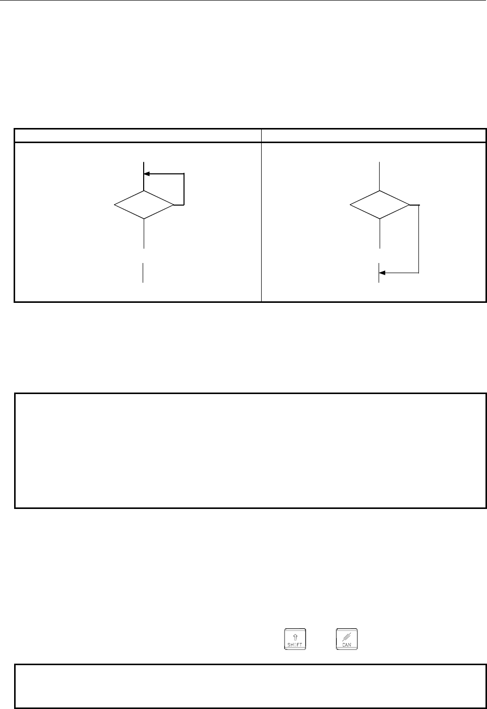
B-63943EN-2/07
4.CONVERSATIONAL MACRO FUNCTION AND AUXILIARY MACRO FUNCTION
- 87 -
• When bit 3 (TM99) of compile parameter No. 9160 is set to 1
When the program end instruction (execution control code M99/M99Pp) in the main program of the
conversational macro is executed, whether a cause for ending the execution of the conversational
macro function has occurred is determined.
In this case, the execution of the program end instruction (execution control code M99/M99Pp) of
the main program is used for determination. So, care needs to be used in programming.
If the written program is like the following bad sample program, the screen cannot be switched to
another screen and the system enters the hang-up state.
Bad sample Good sample
Key input?
O1234 ;
NO
YES
Key input processing
M99 ;
Key input?
O1234 ;
NO
YES
Key input processing
M99 ;
When programming a conversational macro, always specify M99 in the same way as for a PMC ladder
program to create a program which returns to the beginning of the main program. Alternatively, specify
M99Pp to create a cyclic program which returns to the sequence number specified for M99Pp.
For the above reasons, do not program a conversational macro in which the GOTO command causes a
branch in the backward direction.
NOTE
If a main program such as those described below must be executed until the end
of the program (M99/M99Pp), set bit 3 (TM99) of compile parameter No. 9160 to
1.
• Program that must always close a reader/puncher interface, memory card,
and so on.
• Program in which the variable value set in a conversational macro is
expected by an auxiliary macro.
- Forced termination
To recover from the hang-up state, execution of the conversational macro function can forcibly be
terminated.
By setting bit 2 (AFT) of parameter No. 9036 to 1, the execution of the auxiliary macro function can be
terminated forcibly together with the conversational macro function. For details, see Section 4.2,
"AUXILIARY MACRO FUNCTION".
- Procedure
If the system enters the hang-up state, simultaneously press and .
NOTE
Recovery from the hang-up state is not always guaranteed. Carefully program a
conversational macro.
4.CONVERSATIONAL MACRO FUNCTION AND AUXILIARY MACRO FUNCTION
B-63943EN-2/07
- 88 -
4.1.2
Command
Commands that can be used
Macro statements and NC statements (special G code commands) can be written in conversational macros
as in the case of CNC part programs.
Macro statements can have commands and macro variables similar to those for custom macros. Macro
variables include local variables, common variables, and P-CODE variables. In addition, the macro
executor function is available. This function can read keys, display screens, and perform other processing.
NC statements in conversational macros cannot execute NC statements for the CNC operation. If any are
specified, they are ignored. NC statements in conversational macros differ from NC statements in the
meaning of addresses and in usage.
For details, see Chapter 5, "Macro Variables," and Chapter 6, "MACRO EXECUTOR FUNCTION."
CAUTION
Carefully use system variables #3000, #3003, #3004, and #3006 because they
affect automatic operation.
Commands that cannot be used
The following custom macro commands cannot be used, among others:
(1) Modal call and macro call using a G, M, T, H, D, or S code or axis address
(2) Subprogram call using an M, S, or T code, M code in the specified range, second auxiliary function
code, or specific code
(3) External output commands BPRNT, DPRNT, POPEN, and PCLOS
4.2
AUXILIARY MACRO FUNCTION
The conversational macro function is executed using function key
, but the auxiliary macro function
does not need such an operation or command. After power-on, the auxiliary macro function starts
execution immediately.
This function is executed at a level lower than that of automatic operation processing. This function is
independent of the operation mode or automatic operation status.
Caution
CAUTION
1 The auxiliary macro function is executed at a level lower than that of CNC
operation processing. Therefore, execution of the auxiliary macro function does
not affect the speed of CNC operation processing, but the speed at which the
auxiliary macro function is executed may become low during CNC operation. So,
the auxiliary macro function is not suitable for machine control that requires
cyclic operation or speedy processing.

B-63943EN-2/07
4.CONVERSATIONAL MACRO FUNCTION AND AUXILIARY MACRO FUNCTION
- 89 -
- Example
There is no guarantee that modal information of all blocks can be read surely
even if the following commands of reading modal information is programmed
in auxliary macro.
#101=#4314; Modal information on the block currently being executed
(sequence number)
#102=#4201; Modal information on the block currently being executed
(G code group 1)
#103=#4203; Modal information on the block currently being executed
(G code group 3)
2 The auxiliary macro function cannot execute any NC statement for CNC
operation.
4.2.1
Execution and Termination
Execution
After power-on, the auxiliary macro function is always executed.
Which P-CODE is executed on each path is set in parameter No. 9050.
After the auxiliary macro function enters the constant execution state, it executes the auxiliary macro
main program with the value of the control variable for executing an auxiliary macro (#8530) as the
program number. When the power is turned on, the value of compile parameter No. 9039 is set for the
control variable for executing an auxiliary macro (#8530).
NOTE
During reader/punch interface control using an auxiliary macro, the screen may
not be switched to another screen.
An error may occur and execution may not be able to be continued. Such an
error includes the case where no P-CODE macro is found as the auxiliary macro
with the value of the control variable for executing an auxiliary macro (#8530) as
the program number. In this case, a message indicating that a fatal error occurs
is displayed on the conversational macro screen. (For details, see Section 4.6,
"Fatal Error.")
Termination
The auxiliary macro function does not terminate because it is always executed. Setting the control
variable for executing an auxiliary macro (#8530) to 0 places the auxiliary macro function in the wait
state when a program end command (execution control code M99 or M99Pp) in the main program is
executed. The function remains in the wait state until a program number is set for the control variable for
executing an auxiliary macro (#8530) again.
A program must be created to be cyclic just like a conversational macro.
- Forced termination
By setting bit 2 (AFT) of parameter No. 9036 to 1, the execution of the auxiliary macro function can be
terminated forcibly together with the conversational macro function. At this time, the auxiliary macro
function of all paths is terminated forcibly and the auxiliary macro execution control variable (#8530) is
set to 0. For reexecution of the auxiliary macro function, set the auxiliary macro main program number in
#8530 on a screen such as the P code variable screen.
- Procedure
Simultaneously press and .
4.CONVERSATIONAL MACRO FUNCTION AND AUXILIARY MACRO FUNCTION
B-63943EN-2/07
- 90 -
NOTE
Recovery from the hang-up state is not always guaranteed. Carefully program a
auxiliary macro.
CAUTION
Usually, set bit 2 (AFT) of parameter No. 9036 to 0 to prevent the auxiliary
macro function from being terminated by an erroneous forced termination
operation.
4.2.2
Command
Commands that can be used
A main difference between the conversational macro function and auxiliary macro function is that the
control codes for the macro executor function that are related to key reading and screen display are not
available for the auxiliary macro function.
NC statements in auxiliary macros cannot execute NC statements for the CNC operation. If any are
specified, they are ignored. NC statements in auxiliary macros differ from NC statements for the CNC
operation in the meaning of addresses and in usage.
For details, see Chapter 5, "Macro Variables," and Chapter 6, "Macro Executor Functions."
CAUTION
Carefully use system variables #3000, #3003, #3004, and #3006 because they
affect automatic operation.
Commands that cannot be used
The following custom macro commands cannot be used, among others:
(1) Modal call and macro call using a G, M, T, H, D, or S code or axis address
(2) Subprogram call using an M, S, or T code, M code in the specified range, second auxiliary function
code, or specific code
(3) External output commands BPRNT, DPRNT, POPEN, and PCLOS
4.2.3
Execution Cycle
Whether an auxiliary macro is executed depends on whether a conversational macro is executed.
When a conversational macro is executed
- Sequential execution (when bit 1 (SEP) of parameter No. 9033 is set to 0)
Auxiliary macro and conversational macro are sequentially executed.
Each macro is continuously executed until the main program end instruction (execution control code
M99/M99Pp) is executed. When a main program run ends, control is transferred to another macro.
NOTE
The execution times of an auxiliary macro and conversational macro affect each
other. For example, if the size of the auxiliary macro (the number of blocks to be
executed) increases, the conversational macro cannot be executed until the M99
block of the auxiliary macro is executed. Until that time, the display of the
conversational macro stops.
- Parallel execution (when bit 1 (SEP) of parameter No. 9033 is set to 1)
Unlike sequential execution, an auxiliary macro and conversational macro are executed in parallel.
B-63943EN-2/07
4.CONVERSATIONAL MACRO FUNCTION AND AUXILIARY MACRO FUNCTION
- 91 -
Auxiliary macro blocks as many as set in parameter No. 9066 are executed each time. A conversational
macro is continuous executed, regardless of the state of the auxiliary macro. So, the execution times of an
auxiliary macro and conversational macro affect each other less in parallel execution than in sequential
execution.
CAUTION
The conversational macro is not synchronized with the auxiliary macro in the
parallel execution mode. When the same macro variable or macro executor
function is to be used, program the conversational macro and auxiliary macro so
that no competition will occur.
When no conversational macro is executed (when the conversational macro
screen is not displayed)
The auxiliary macro is repeatedly executed.
Blocks as many as set in parameter No. 9066 are executed each time, regardless of the setting of bit 1
(SEP) of parameter No. 9033.
Number of auxiliary macro blocks executed
Number of auxiliary macro blocks executed
When the conversational macro screen is displayed
and
sequential execution is specified (bit 1 (SEP) of
parameter No. 9033 is set to 0)
The main program is executed until the end (M99).
When a screen other than the conversational macro
screen is displayed
or
parallel execution is specified (bit 1 (SEP) of parameter
No. 9033 is set to 1)
Blocks as many as set in parameter No. 9066 are
executed.
When the value of parameter No. 9066 is 0 or less, 100
blocks are executed.
Diagnosis data
Diagnosis 1494 Number of blocks in executed by an auxiliary macro
[Data type] 2-word
[Unit of data] Block
Displays the number of blocks executed by an auxiliary macro per 1024 ms.
It provides an indication of the actual processing speed of auxiliary macros.
Caution
CAUTION
Execution of the auxiliary macro is affected by the CNC operation processing
time because the auxiliary macro is executed at a level lower than that of CNC
operation processing. For this reason, the specified intervals are not guaranteed.
If the number of execution blocks in the auxiliary macro is increased and the
processing time becomes longer, the screen may be displayed slowly.
4.3
EXECUTION CONTROL CODE
The following control codes are available for controlling execution.
These control codes can be specified in conversational macros and auxiliary macros.
G65 : Macro call
M98: Subprogram call
M99: Program end

4.CONVERSATIONAL MACRO FUNCTION AND AUXILIARY MACRO FUNCTION
B-63943EN-2/07
- 92 -
Macro call (G65)
- Format
G65 Pp <Ll> <argument-specification> ;
P : Program number of a P-CODE macro to be called
L : Repetition count (1 by default)
argument : Data to be passed to the P-CODE macro. (Argument specifications I and II are
available.)
Specify G65 before any argument.
Macro calls can be nested to a depth of fifteen levels including only macro calls or to a depth of fifteen
levels including subprogram calls and macro calls.
Subprogram call (M98)
- Format
M98 Pp <Ll> ;
P : Program number of a P-CODE macro to be called
L : Repetition count (1 by default)
Subprogram calls can be nested to a depth of fifteen levels including only subprogram calls or to a depth
of fifteen levels including subprogram calls and macro calls.
Program end (M99<Pp>)
- Format
M99 <Pp> ;
P : Sequence number of the calling P-CODE macro
(By default, control is returned to the block following the call command in the calling
macro.)
- M99<Pp> command in the conversational macro main program
Always specify M99<Pp> at the end of the main program.
M99<Pp> in the main program is a special command unlike subprogram end.
When M99<Pp> is executed in the main program, execution of the conversational macro temporarily
terminates. Then, the following processing is performed:
1 Determines whether to terminate the conversational macro function.
When the conversational macro function is executed again after terminated, executes the
conversational macro specified by the control variable for executing a conversational macro (#8500)
from the beginning regardless of the <Pp> specification.
2 When the value of the control variable for executing a conversational macro (#8500) is changed,
erases both character and graphic displays, then executes the new conversational macro. When the
value is not changed, repeatedly executes the same macro without erasing both character and graphic
displays. When <Pp> is specified, starts execution from the block with the sequence number
specified by p.
3 Initializes the local variables to <null>.
- M99<Pp> command in the auxiliary macro main program
Always specify M99<Pp> at the end of the main program.
M99<Pp> in the main program is a special command unlike subprogram end.
When M99<Pp> is executed in the main program, execution of the auxiliary macro temporarily
terminates. Then, the following processing is performed:
1 Checks whether the value of the control variable for executing an auxiliary macro (#8530) is 0.
When the value is 0, places the auxiliary macro function in the wait state.
B-63943EN-2/07
4.CONVERSATIONAL MACRO FUNCTION AND AUXILIARY MACRO FUNCTION
- 93 -
When the program number of an auxiliary macro is set for the control variable for executing an
auxiliary macro (#8530) again, executes the specified auxiliary macro from the beginning regardless
of the <Pp> specification.
2 When the value of the control variable for executing an auxiliary macro (#8530) is changed,
executes the new auxiliary macro. When the value is not changed, repeatedly executes the same
auxiliary macro. When <Pp> is specified, starts execution from the block with the sequence number
specified by p.
3 Initializes the local variables to <null>.
4.4
EXECUTION CONTROL VARIABLES (#8500, #8550, #8551,
AND #8530)
Control variable for executing a conversational macro (#8500, #8550, and
#8551)
For conversational macro execution, three screens are available.
Conversational macro screen Conversational macro execution control variable
Conversational macro screen 1 (User screen 1) #8500
Conversational macro screen 2 (User screen 3) #8550
Conversational macro screen 3 (User screen 3) #8551
Each time the function key
is pressed, screen display sequentially switches from one screen to
another. A conversational macro program to be executed is selected according to the value of the
conversational macro execution control variable corresponding to a selected screen.
The conversational macro control variables are initialized to the values set in compile parameter Nos.
9038, 9040, and 9041 when the power is turned on.
A conversational macro program to be executed can be changed by rewriting the conversational macro
execution control variable. If a conversational macro execution control variable is rewritten, the character
display and graphic display are erased and initialized after execution of the program end instruction (M99
block) of the main program of the conversational macro program being executed then a new
conversational macro program is executed.
If 0 is set in a conversational macro execution control variable, the screen display returns to the screen
displayed before selection of the conversational macro screen.
If the value of a conversational macro execution control variable remains unchanged, the same
conversational macro program is executed repeatedly. In this case, character display and graphic display
are not erased and initialized.
Control variable for executing an auxiliary macro (#8530)
This control variable sets the main program number of an auxiliary macro.
The auxiliary macro execution control variable #8530 is initialized to the value set in compile parameter
No. 9039 when the power is turned on.
By rewriting the auxiliary macro execution control variable #8530, the auxiliary macro program to be
executed can be changed. If the auxiliary macro execution control variable #8530 is rewritten, the
program end instruction (M99 block) of the main program of the auxiliary macro program being executed
is executed, then a new auxiliary macro program is executed. If the auxiliary macro execution control
variable #8530 is not rewritten, the same auxiliary macro program is executed repeatedly.
If 0 is set in the auxiliary macro execution control variable #8530, the execution of the auxiliary macro
program ends after the program end instruction (M99 block) of the main program of the auxiliary macro
program is executed.

4.CONVERSATIONAL MACRO FUNCTION AND AUXILIARY MACRO FUNCTION
B-63943EN-2/07
- 94 -
4.5 COMMON CONVERSATIONAL MACRO FUNCTION
When the multi-path control function is used, the conversational macro function of the first path can be
executed, regardless of the path selection made by the path selection signal and the setting of parameter
No. 9049, by setting bit 0 (TTDSP) of compile parameter No. 9007 to 1.
In this case, the O/N display, status display, variables used, and all macro executor functions usable with
a conversational macro become identical to those used with the first path.
When bit 0 (TTDSP) of compile parameter No.9007 is set to 0;
• P-CODE macro with which a conversational macro is used
P-CODE file set in parameter No. 9049 of the path selected by the path selection signal
• O/N display and status display
The statuses of the programs of the path selected by the path selection signal are displayed.
• Used common variables, system variables, control variables, P-CODE variables, and so forth
The variables of the path selected by the path selection signal are used.
• All macro executor functions usable with a conversational macro
The functions of the path selected by the path selection signal are executed.
[Example]
See the description of the CNC parameters for the address function.
→ See the description of the parameters of the path selected by the path selection signal.
Relative axis coordinate read and preset function
→ Relative coordinates on the axes of the path selected by the path selection signal
When bit 0 (TTDSP) of compile parameter No.9007 is set to 1;
• P-CODE macro with which a conversational macro is used
P-CODE file set in parameter No. 9049 of the first path
• O/N display and status display
The statuses of the programs of the first path are displayed.
• Used common variables, system variables, control variables, P-CODE variables, and so forth
The variables of the first path are used.
• All macro executor functions usable with a conversational macro
Same as for the first path
[Example]
See the description of the CNC parameters for the address function.
→ See the description of the parameters of the first path.
Relative axis coordinate read and preset function
→ Relative coordinates on the axes of the first path
NOTE
The setting of bit 0 (TTDSP) of compile parameter No. 9007 contained in the
P-CODE file that is set in parameter No. 9049 of the path selected by the path
selection signal is valid.
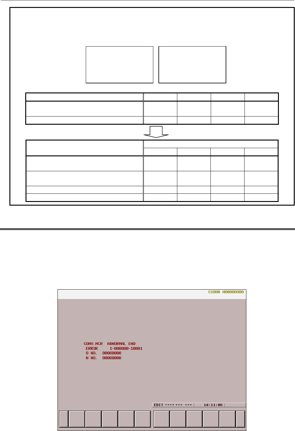
B-63943EN-2/07
4.CONVERSATIONAL MACRO FUNCTION AND AUXILIARY MACRO FUNCTION
- 95 -
Example
When parameter No. 9049 is set for each path as described below in a 4-path
system where two P-CODE files are loaded
P-CODE1 file
P-CODE_NUMBER=01
P9007=xxxxxxx0
:
:
P-CODE2 file
P-CODE_NUMBER=02
P9007=xxxxxxx1
:
:
Path 1 Path 2 Path 3 Path 4
Parameter No.9049
(P-CODE file number used) 1 2 0 1
Bit 0 (TTDSP) of compile parameter No.9007 0 1 Not used 0
Screen selected by the path selection screen
Path 1 Path 2 Path 3 Path 4
P-CODE macro with which a conversational
macro is used
P-CODE1
file
P-CODE1
file - P-CODE1
file
O/N number and status display, path number
display, etc. 1st path 1st path Invalid
screen 4th path
All variables used 1st path 1st path Disabled 4th path
All conversational macro functions 1st path 1st path Disabled 4th path
4.6
FATAL ERROR
An error may occur and execution may not be able to be continued during execution of a conversational
macro or auxiliary macro. Such an error includes the case where a P-CODE macro program is not found.
In this case, the screen is forcibly switched to the conversational macro screen and a message indicating
that a fatal error occurred is displayed.
If such an error occurs during execution of an auxiliary macro, the control variable for executing an
auxiliary macro (#8530) is preset to 0 and execution of the auxiliary macro is terminated.
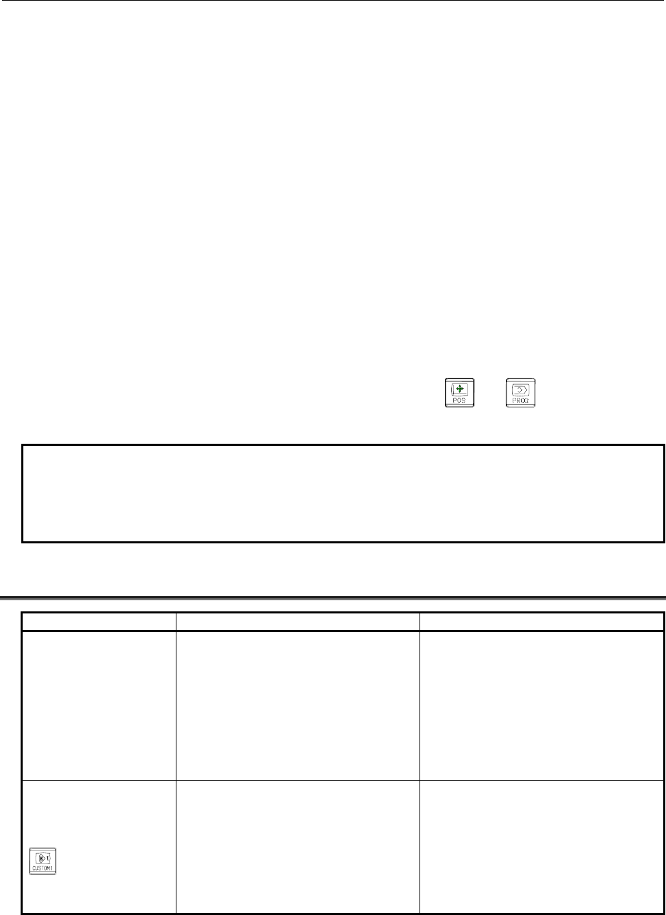
4.CONVERSATIONAL MACRO FUNCTION AND AUXILIARY MACRO FUNCTION
B-63943EN-2/07
- 96 -
The following items are displayed on the conversational macro screen:
• Name of the P-CODE macro in which a fatal error occurred
• Message "ABNORMAL END"
• Error information
a-bbbbbb-ccccc
a : 0: No error occurred.
1: An error occurred in a macro statement command.
2: An error occurred in an NC statement command.
bbbbbb : • Variable number for a macro statement
(0 is displayed for other than a variable.)
• G code for an NC statement
ccccc : Error number
When no error occurred, 0 is displayed.
For details of the error, see Appendix A, "ERROR NO. LIST."
• Number of the program in which the error occurred
• Sequence number for which the error occurred
Clearing the error information display screen
Error information display can be canceled by pressing function key or and terminating the
conversational macro function.
NOTE
If an error occurs during execution of an auxiliary macro, the control variable for
executing an auxiliary macro (#8530) is preset to 0. To restart execution of an
auxiliary macro, set the program number for the control variable for executing an
auxiliary macro (#8530).
4.7
DIFFERENCES FROM THE Series 16i
Function Series 16i/18i/21i Series 30i/31i/32i/35i/0i-F/PMi
Conversational macro
execution
If a conversational macro that has the
value of the conversational macro
execution control variable (#8500) as its
program number is not found, no
conversational macro is executed.
If an error that prevents execution from
being continued occurs as in the case
where a conversational macro that has
the value of the conversational macro
execution control variable (#8500) as its
program number is not found, the
conversational macro screen displays the
occurrence of a fatal error (error number
10001).
If there is one
conversational macro
screen, the operation to
be performed when the
key is pressed on
the conversational macro
screen.
Control returns to the beginning of the
main program of the conversational
macro again, and then the operation is
executed. By setting bit 4 (CNCHG) of
compile parameter No. 9006 to 1, the
pressing of the key can be ignored and
the operation can be executed
continuously.
The pressing of the key is ignored. (Same
situation when bit 4 (CNCHG) of compile
parameter No. 9006 for Series 16i is set
to 1.)

B-63943EN-2/07
4.CONVERSATIONAL MACRO FUNCTION AND AUXILIARY MACRO FUNCTION
- 97 -
Function Series 16i/18i/21i Series 30i/31i/32i/35i/0i-F/PMi
Timing for determining
whether a cause for
ending the execution of
the conversational macro
function has occurred
When the program end instruction
(execution control code M99/M99Pp) in
the main program of the conversational
macro is executed, whether a cause for
ending the execution of the
conversational macro function has
occurred is determined.
- When bit 3 (TM99) of compile
parameter No. 9160 is set to 0:
When the block being executed ends,
whether a cause for ending the
execution of the conversational
macro function has occurred is
determined. Execution of the main
program is not continued until the
program end instruction (execution
control code M99/M99Pp) but the
screen is switched immediately.
- When bit 3 (TM99) of compile
parameter No. 9160 is set to 1:
Same as for Series 16i
Auxiliary macro execution An auxiliary macro that has the program
number set in compile parameter No.
9039 is executed. (Unlike a
conversational macro, programs to be
executed cannot be controlled using a
variable.)
The main program of an auxiliary macro
that has the value of the auxiliary macro
execution control variable (#8530) as its
program number is executed. (As with a
conversational macro, programs to be
executed can be controlled using the
variable.) When the power is turned on,
the value of compile parameter No. 9039
is set in the auxiliary macro execution
control variable (#8530).
If a program that has the program number
set in compile parameter No. 9039 is not
found, no program is executed.
If an error that prevents execution from
being continued occurs as in the case
where an auxiliary macro that has the
value of the auxiliary macro execution
control variable (#8530) as its program
number is not found, the conversational
macro screen displays the occurrence of
a fatal error.
Conversational macro
and auxiliary macro
execution cycle
Auxiliary macros and conversational
macros are sequentially executed in this
order. (Execution is switched by an M99
block.)
Auxiliary macros and conversational
macros can be executed in parallel by
switching each time blocks as many as
the number set in parameter No. 9066 are
executed.
When bit 1 of parameter No. 9033 is set
to 0, sequential execution is performed as
with the Series 16i.
Forced termination of a
conversational
macro/auxiliary macro
Hold down the rightmost soft key [>]
(continuous menu key) and the numeric
key
on the MDI unit for about 10
seconds.
Press the key and key on
the MDI unit simultaneously. To enable
forced termination of an auxiliary macro,
bit 2 (AFT) of parameter No. 9036 must
be set to 1.

4.CONVERSATIONAL MACRO FUNCTION AND AUXILIARY MACRO FUNCTION
B-63943EN-2/07
- 98 -
Function Series 16i/18i/21i Series 30i/31i/32i/35i/0i-F/PMi
Alarm during
conversational macro
and auxiliary macro
execution
If a conversational macro that has the
value of #8500 as its program number is
not found, no conversational macro is
executed.
If a conversational macro that has the
value of #8500 as its program number is
not found, the conversational macro
screen displays an error.
If the GOTO destination N or N specified
with G243P_ cannot be found, the alarm
is ignored and the next block is executed.
If the GOTO destination N or N specified
with G243P_ cannot be found, a message
indicating that a fatal error occurs is
displayed on the conversational macro
screen (error number: 10002) and the
conversational or auxiliary macro is
stopped.
Execution control code The execution control codes are M98 and
M99. (G65 is not usable.)
The execution control codes are G65,
M98, and M99.
Specification of repetition Repetition cannot be specified using M98
used with a conversational macro/
auxiliary macro.
Repetition can be specified using address
L with G65/M98.
Nesting 4 levels of calls 15 levels of calls when macro calls and
subprogram calls are combined
Local variables Local variables cannot be used with a
conversational macro/auxiliary macro.
Local variables can be used with a
conversational macro/auxiliary macro.
B-63943EN-2/07
5.MACRO VARIABLES
- 99 -
5 MACRO VARIABLES
5.1 MACRO VARIABLE LIST
The following variables can be used in P-CODE macros.
Variable
number Type Remarks
Conversational
macro
Auxiliary
macro
Execution
macro
#1 to 33 Local
variable
The local variables used in a
conversational macro and those
used in an auxiliary macro are
independent of one another.
The local variables used in an
execution macro can also be used
in a custom macro.
If array-type variables are effective,
no local variables can be used in
conversational macros and
auxiliary macros.
{ { {
#1 to 99 Array-type
variable
Array-type variables cannot be
used if local variables are effective.
(This applies to the array-type
variables in conversational macros
and auxiliary macros.)
{ { ×
#100 to
199
Volatile
common
variable
The same volatile common
variable can be used in any of
conversational macros, auxiliary
macros, and execution macros.
Using bits 0 (MV0) and 1 (MV1) of
parameter No. 9034, it is possible
to specify whether volatile common
variables can also be used as
custom macro common variables
or they are to be used as
independent P-CODE macro
common variables.
{ { {
#500 to
999
Nonvolatile
common
variable
The same nonvolatile common
variable can be used in any of
conversational macros, auxiliary
macros, and execution macros.
Using bits 2 (MV2) to 7(MV7) of
parameter No. 9034, it is possible
to specify whether nonvolatile
common variables can also be
used as custom macro common
variables or they are to be used as
independent P-CODE macro
common variables.
{ { {
#1000 to
8499
Custom
macro
system
variable
The variables used in custom
macros can also be used as system
variables.
{ { {

5.MACRO VARIABLES
B-63943EN-2/07
- 100 -
Variable
number Type Remarks
Conversational
macro
Auxiliary
macro
Execution
macro
#8500 to
8999
P-CODE
control
variable
See the List of control variables in
Chapter 6, “MACRO EXECUTOR
FUNCTION”.
{ { {
#10000 to
19999
P-CODE
variable
The same P-CODE variable can
be used in any of conversational
macros, auxiliary macros, and
execution macros. The upper limit
on the variable number is
determined with bit 3 (EV2) of
parameter No. 9033 and
parameter No. 9053.
* To use the variable as a custom
macro system variable, use
#110000 or larger.
{ { {
#20000 to
89999
Extended
P-CODE
variable
The same extended P-CODE
variable can be used in any of
conversational macros, auxiliary
macros, and execution macros.
The upper limit on the variable
number is determined with bit 4
(EVF) of parameter No. 9033 and
parameter No. 9054.
* To use the variable as a custom
macro system variable, use
#120000 or larger.
{ { {
#99100 to
99199
Volatile
custom
macro
common
variable
The same variable can be used in
any of conversational macros,
auxiliary macros, and execution
macros.
(#99000 + Custom macro variable
number)
{ { {
#99500 to
99999
Nonvolatile
custom
macro
common
variable
The same variable can be used in
any of conversational macros,
auxiliary macros, and execution
macros.
(#99000 + Custom macro variable
number)
{ { {
#100000 to
199999
Custom
macro
system
variable
Variables shared for custom macros
are used.
(#100000 + System variable
number)
When variable #8572 is set to 0:
#100000 + Custom macro
system variable number. (In this
case, variables #100000 to
#100999 cannot be used.)
When variable #8572 is set to 1:
Custom macro system variable
#100000 and up
{ { {

B-63943EN-2/07
5.MACRO VARIABLES
- 101 -
5.2 LOCAL VARIABLES (#1 TO #33) / ARRAY-TYPE
VARIABLES (#1 TO #99)
Local variables can be used in any of conversational macros, auxiliary macros, and execution macros.
The local variables used in an execution macro, those used in a conversational macro, and those used in
an auxiliary macro are independent of one another. The local variables used in an execution macro can
also be used in a custom macro.
NOTE
If array-type variables are effective, local variables are not effective in
conversational macros and auxiliary macros.
In execution macros, local variables are effective regardless of whether
array-type variables are effective or not.
If a P-CODE variable is to be referenced by a conversational macro or auxiliary macro as an array-type
variable, an array-type variable (#1 to #99) can be used. See Section 6.12, "ARRAY-TYPE
PROCESSING AND REFERENCING OF P-CODE VARIABLES" for details.
5.3 COMMON VARIABLES (#100 TO #199 AND #500 TO #999)
Common variables can be used in any of conversational macros, auxiliary macros, and execution macros,
and the same common variable can be used in any of them. It is possible to specify whether to use
common variables as custom macro common variables or use them as P-CODE macro common variables,
independent of custom macro common variables. To do this, use bits 0 (MV0) to 7 (MV7) of parameter
No. 9034.
NOTE
To make a parameter setting that use a custom macro common variable, an
option for custom macro is required. If the parameters are set so that variables
#150 to #199 and #550 to #999 are used as custom macro common variables,
an option for additional custom macro common variables is required.
Variable protection
By setting variable numbers for the appropriate parameters in the same way as in custom macros, multiple
common variables (#500 to #999) can be protected. The parameters used for the protection differ
depending on whether P-CODE macro common variables are used or custom macro common variables
are used.
NOTE
Parameters Nos. 9067 to 9068 are for P-CODE macro common variables.
Parameters Nos. 6031 to 6032 are for custom macro common variables.
Reset
P-CODE macro common variables are not cleared by a reset. By setting bit 4 (RSC) of parameter No.
9000 to 1, however, the P-CODE macro common variables #100 to #199 can be cleared to <null> by a
reset.
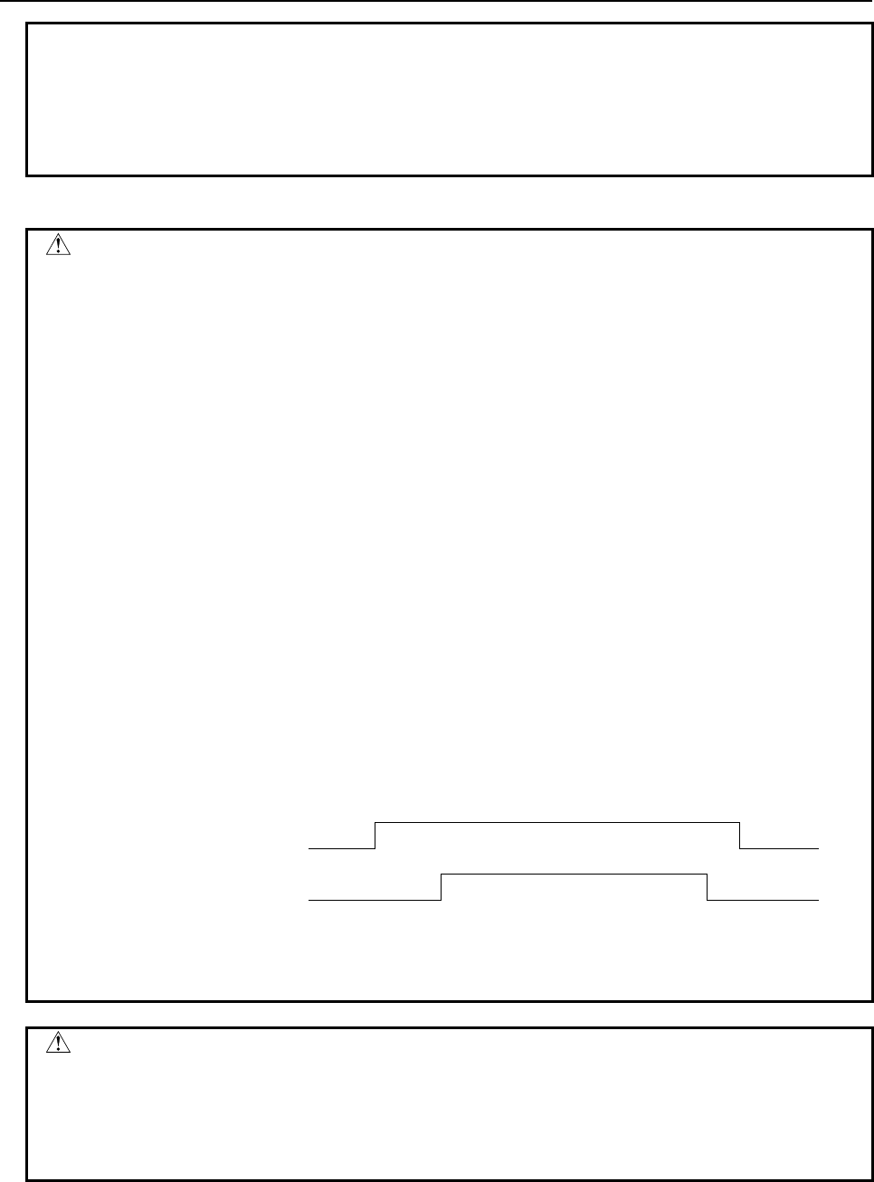
5.MACRO VARIABLES
B-63943EN-2/07
- 102 -
NOTE
Bit 4 (RSC) of parameter No. 9000 is used for P-CODE macro common
variables. The custom macro common variables #100 to #199 are not affected,
regardless of the states of bits 0 (MV0) and 1 (MV1) of parameter No. 9034.
The custom macro common variables #100 to #199 depend on bit 6 (CCV) of
parameter No. 6001.
Caution
CAUTION
The same common variable can be used in any of conversational macros,
auxiliary macros, and execution macros, but caution is necessary. If the common
variable used in an execution macro and a user program is the same as the
common variable used in a conversational macro and an auxiliary macro, writing
may occur from the execution macro while writing is performed from the
conversational macro or auxiliary macro because execution macros have a
higher processing level than conversational macros and auxiliary macros, with
the result that the values written by the execution macro may be overwritten by
the remaining processing of the conversational macro or auxiliary macro. For this
reason, make sure that the variables used in execution macros are different from
those used in conversational macros and auxiliary macros.
Example
Bit 0 of #100 is used as the execution macro flag, and bit 1 of #100 is used as the
auxiliary macro flag.
To set bit 0 to ON: #100=#100 OR 1
To set bit 1 to ON: #100=#100 OR 2
Execution macro Auxiliary macro
:
#100 = #100 OR 1 ;
:
:
#100 = #100 OR 2 ;
:
Auxiliary macro
Execution macro
The value of #100 read at the start of auxiliary macro processing is written to #100
after auxiliary macro processing, so a value written during execution macro
processing may be lost.
WARNING
Take care that you do not write the same variable (custom macro common
variable or P-CODE macro common variable) with several applications like C
language executor. If there is data duplication writing in the system, the data not
intended is input, and the machine may behave in an unexpected manner and
tool, workpiece, and the machine may also be damaged.

B-63943EN-2/07
5.MACRO VARIABLES
- 103 -
5.4 P-CODE VARIABLES (#10000 TO #19999)
P-CODE variables can be used in P-CODE macros.
P-CODE variables start with #10000, and the number of P-CODE variables that can be used is
determined using the appropriate parameter.
It is possible to specify whether to use P-CODE variables as floating-point data variables or integer data
variables, using the bit 3 (EV2) of parameter No. 9033.
Setting
1. Set the variable type for bit 3 (EV2) of parameter No. 9033.
2. Set the number of variables for parameter No. 9053.
When 1 is set in the parameter, one variable can be used.
The maximum value that can be set for this parameter is 10000.
If this parameter is 0, no P-CODE variables can be used.
- Caution on setting
The maximum value that can be set for parameter No. 9053 is 10000. The actual maximum value that can
be set, however, depends on the free space of the backup memory.
To determine the free space of the backup memory, select "7.MACRO COMPILER UTILITY" →
"1.USER FILE INFORMATION" from the menu on the IPL monitor screen to display the following,
referring to Appendix, "STARTING OF THE IPL MONITOR," in the Maintenance Manual
(B-64485EN). (For details, see Subsection 6.15.2, "Setup Procedure".)
CURRENT DATA :
USER FILE AREA SIZE = xx
NUMBER OF USER FILE = xx
DATA AREA SIZE (BYTE) = xx
SRAM FREE = xx
The value displayed next to "SRAM FREE" × 512 bytes is the free space of the backup memory. From
the free space of the backup memory and the size to be used, decide on the setting of parameter No. 9053.
The relationship between the setting of parameter No. 9053 and the size used is as follows:
For floating-point data (bit 3 (EV2) of parameter No.9033 is set to 0):
Parameter No.9053 × 8 bytes
For integer data (bit 3 (EV2) of parameter No.9033 is set to 1):
Parameter No.9053 × 2 bytes
NOTE
1 For integer data, a value in the range of -32768 to +32767 can be set in a
variable. If the value has a fractional part, it is rounded off to the nearest integer
number. A <null> representation is not possible. If a P-CODE variable of the
integer data type appears in an <expression>, it is converted to floating-point
data before the expression is evaluated.
2 P-CODE variables retain their values even after the power is turned off.
3 The free space of the backup memory must not be exceeded.
If a setting is made that exceeds the free space of the backup memory, "FILE
ALLOCATION ERROR” appears at power-on and the system stops at the IPL
monitor screen.
If this occurs, select "0.END IPL" to terminate the IPL monitor, and set
parameter No. 9053 to a value that does not exceeds the free space of the
backup memory.
5.MACRO VARIABLES
B-63943EN-2/07
- 104 -
WARNING
Take care that you do not write the same P-CODE variable with several
applications like C language executor. If there is data duplication writing in the
system, the data not intended is input, and the machine may behave in an
unexpected manner and tool, workpiece, and the machine may also be
damaged.
5.5
EXTENDED P-CODE VARIABLES (#20000 TO #89999)
Extended P-CODE variables can be used in P-CODE macros.
Extended P-CODE variables start with #20000, and the number of extended P-CODE variables that can
be used is determined using the appropriate parameter.
It is possible to specify whether to use extended P-CODE variables as floating-point data variables or
integer data variables, using the bit 4 (EVF) of parameter No. 9033.
Setting
1. Set the variable type for bit 4 (EVF) of parameter No. 9033.
2. Set the number of variables for parameter No. 9054.
When 1 is set in the parameter, one variable can be used.
The maximum number that can be set for this parameter is 70000.
If this parameter is 0, no extended P-CODE variables can be used.
- Caution on setting
The maximum value that can be set for parameter No. 9054 is 70000. The actual maximum value that can
be set, however, depends on the free space of the backup memory.
To determine the free space of the backup memory, select "7.MACRO COMPILER UTILITY" →
"1.USER FILE INFORMATION" from the menu on the IPL monitor screen to display the following,
referring to Appendix, "STARTING OF THE IPL MONITOR," in the Maintenance Manual
(B-64485EN). (For details, see Subsection 6.15.2, "Setup Procedure".)
CURRENT DATA :
USER FILE AREA SIZE = xx
NUMBER OF USER FILE = xx
DATA AREA SIZE (BYTE) = xx
SRAM FREE = xx
The value displayed next to "SRAM FREE" × 512 bytes is the free space of the backup memory. From
the free space of the backup memory and the size to be used, decide on the setting of parameter No. 9054.
The relationship between the setting of parameter No. 9054 and the size used is as follows:
For floating-point data (bit 4 (EVF) of parameter No.9033 is set to 0): Parameter No. 9054 × 8 bytes
For integer data (bit 4 (EVF) of parameter No.9033 is set to 1): Parameter No. 9054 × 2 bytes
NOTE
1 For integer data, a value in the range of -32768 to +32767 can be set in a
variable. If the value has a fractional part, it is rounded off to the nearest integer
number. A <null> representation is not possible. If an extended P-CODE
variable of the integer data type appears in an <expression>, it is converted to
floating-point data before the expression is evaluated.
2 Extended P-CODE variables retain their values even after the power is turned
off.
B-63943EN-2/07
5.MACRO VARIABLES
- 105 -
NOTE
3 The free space of the backup memory must not be exceeded.
If a setting is made that exceeds the free space of the backup memory, "FILE
ALLOCATION ERROR" appears at power-on and the system stops at the IPL
monitor screen.
If this occurs, select "0.END IPL" to terminate the IPL monitor, and set
parameter No. 9054 to a value that does not exceeds the free space of the
backup memory.
WARNING
Take care that you do not write the same extended P-CODE variable with
several applications like C language executor. If there is data duplication writing
in the system, the data not intended is input, and the machine may behave in an
unexpected manner and tool, workpiece, and the machine may also be
damaged.
5.6
P-CODE VARIABLES/EXTENDED P-CODE VARIABLES IN
THE MULTI-PATH CONTROL SYSTEM
When P-CODE programs are installed on multiple paths, whether to use the variables of each path or to
use the P-CODE variables (#10000 and up) and extended P-CODE variables (#20000 and up) of a
specified path number can be chosen.
Setting
Parameter No. 9051
=0 : The P-CODE variables (#10000 and up) of each path are used.
=1 to 10 : The P-CODE variables (#10000 and up) of a specified path are used.
Parameter No. 9052
=0 : The extended P-CODE variables (#20000 and up) of each path are used.
=1 to 10 : The extended P-CODE variables (#20000 and up) of a specified path are used.
5.6.1
Writing and Reading P-CODE Variables/Extended P-CODE
Variables between Paths
The P-CODE variables (#10000 and up) and extended P-CODE variables (#20000 and up) of a specified
path can be read and written.
Read
- Format
G316 Pp Dd Ll;
P : Variable number of the local path
D : Variable number of the remote path
(P-CODE variable #10000 to #19999 or extended P-CODE variable #20000 to #89999)
L : Remote path number (1 to 10) *Omissible
* When L is omitted, the remote path is determined as follows:
Local path = 1: The remote path is fixed at 2.
Local path = Other than 1: The remote path is fixed at 1.
The value of variable number #d of remote path number #l is read into variable number #p of the local
path.
5.MACRO VARIABLES
B-63943EN-2/07
- 106 -
Example
G316 P10000 D20000 L3;
The data of variable number #20000 of path number 3 is read into variable
number #10000 of the local path.
Write
- Format
G316 Dd Qq Ll;
Q : Variable number of the local path
D : Variable number of the remote path
L : Remote path number (1 to 10) *Omissible
* When L is omitted, the remote path is determined as follows:
Local path = 1: The remote path is fixed at 2.
Local path = Other than 1: The remote path is fixed at 1.
The value of variable number #q of the local path is written into variable number #d of remote path
number 1.
Example
G316 Q10000 D20000 L3;
The value of variable number #10000 of the local path is written into variable
number #20000 of remote path number 3.
5.7
CUSTOM MACRO COMMON VARIABLES (#99100 TO
#99999)
Using numbers #99100 to #99999, it is possible to write and read values to and from custom macro
common variables (#100 to #199 and #500 to #999) from conversational macros, auxiliary macros, and
execution macros.
The number of the variable to be written and read plus 99000 is the number to be used.
#99100 corresponds to variable #100.
:
#99199 corresponds to variable #199.
#99500 corresponds to variable #500.
:
#99999 corresponds to variable #999.
NOTE
If the option for additional custom macro common variables is not attached, it is
possible to write and read values from only variables #100 to #149 and #500 to
#549.
WARNING
Take care that you do not write the same custom macro common variable with
several applications like C language executor. If there is data duplication writing
in the system, the data not intended is input, and the machine may behave in an
unexpected manner and tool, workpiece, and the machine may also be
damaged.
B-63943EN-2/07
5.MACRO VARIABLES
- 107 -
5.8 CUSTOM MACRO SYSTEM VARIABLES (#1000 AND UP,
#10000 AND UP, #100000 AND UP)
All system variables that can be used in custom macros can be used in execution macros, conversational
macros, and auxiliary macros.
However, #10000 to #19999 are used as P-CODE variables, and #20000 to #89999 are used as extended
P-CODE variables. If any of custom macro system variables #10000 to #89999 has a duplicate number,
100000 is added to its variable number when it is read or written.
If any of custom macro system variable #100000 and up has a duplicate number, it is selected by using
control variable #8572 whether it should correspond to variable #10000 and up or directly to #100000
and up.
Control variable #8572
=0 : Variables #110000 to #189999 are treated as custom macro system variables #10000 to #89999.
(Specify them with custom macro system variable numbers + 100000.)
=1 : They are treated directly as variable number #100000 and up.
(Specify them with custom macro system variable numbers.)
Specified number #8572=0 #8572=1
1000 to 8499 #1000 to #8499 (custom macro system
variables)
#1000 to #8499 (custom macro system
variables)
10000 to 89999 #10000 to #89999 (P-CODE variables) #10000 to #89999 (P-CODE variables)
99100 to 99999 Correspond to custom macro common
variables #100 to #999.
Correspond to custom macro common
variables #100 to #999.
100000 and up
Correspond to custom macro system
variables whose variable number is equal to
the specified variable number minus
100000.
(#101000 to #189999 correspond to system
variables #1000 to #89999.)
Correspond to custom macro common
variables #100000 or larger.
* If wishing to use custom macro system
variables #10000 to #89999, set
variable #8572 to 0.
Refer to FANUC Series 30i/31i/32i-MODEL A or FANUC Series 30i/31i/32i-MODEL B OPERATOR’S
MANUAL/ FANUC Series 35i-MODEL B OPERATOR’S MANUAL/ FANUC Series 0i-MODEL F
OPERATOR’S MANUAL/ FANUC Power Motion i-MODEL A for details of system variables.
Example
#8572=0 → Variable #100000 and up correspond to system variable numbers
minus 100000.
#100=#10001 → P-CODE variable #10001 is assigned to #100.
#101=#110001 → The tool offset value of No. 1 is assigned to #101 (equivalent
to custom macro system variable #10001).
#8572=1 → Variables #100000 and up correspond directly to system variables.
#100=#10001 → P-CODE variable #10001 is assigned to #100.
#101=#100001 → The end point position of the previous block (workpiece
coordinate system) is assigned to #101.
5.MACRO VARIABLES
B-63943EN-2/07
- 108 -
5.8.1
Writing and Reading the System Variables of Other Paths
By specifying the path number in the high-order 8th and 9th digit positions of a system variable number,
it is possible to read or write the system variable of the specified path.
While this operation is available for any type of macro (execution, conversational, and auxiliary), it is not
possible to read or write the system variable of a path for which the use of the relevant P-CODE is
disabled (set to 0) in the corresponding parameters Nos. 9048 to 9050.
For information about the variables that can be read and written, see the list of readable and writable
variables.
Format
#ppxxxxxxx
pp : Path number
Omitted = Local path
(*)
1 = 1st path
: :
10 = 10th path
(*) If the path number is omitted, the result is the same as with the normal system variable command
(e.g., #5021 to #5040 or #100051 to #100100).
xxxxxxx : System variable number (1000 and up,100000 and up Note)
NOTE
If wishing to write and read system variable #100000 and up, set variable #8572
to 1.
#8572
=0: Variables #110000 to #120000 are treated as custom macro system
variables #10000 to #20000.
(Specify them with custom macro system variable numbers + 100000.)
=1: They are treated directly as variable numbers #100000 and up.
(Specify them with custom macro system variable numbers.)
Example
1st path machine coordinate value 2nd path machine coordinate value
X1123.456 X2-123.456
Y145.670 Z278.900
Z1345.789 C245.000
In this case, if #100=#5023 is executed for the first path, the machine coordinate
value 345.789 of the third axis of the local path is read in #100.
If #100=#20005023 is executed, the machine coordinate value 45.0 of the third
axis of the second path is read in #100.
List of readable and writable variables
For details of the system variables, refer to the descriptions of the individual system variables in the
FANUC Series 30i/31i/32i-MODEL A or FANUC Series 30i/31i/32i-MODEL B OPERATOR’S
MANUAL/ FANUC Series 35i-MODEL B OPERATOR’S MANUAL/ FANUC Series 0i-MODEL F
OPERATOR’S MANUAL/ FANUC Power Motion i-MODEL A OPERATOR’S MANUAL..
System variable number Attribute Description
#2001 to #2999 R/W Tool compensation value
B-63943EN-2/07
5.MACRO VARIABLES
- 109 -
System variable number Attribute Description
#10001 to #19999 Note) Since #10000 to #19999 are P-CODE variables, they are read
and written as #110000 to #119999. (#8572 is set to 0.)
#5001 to #5020
#100001 to #100050
R End point position of the previous block (workpiece coordinate system)
Note) #100001 to #100050 are used when #8572 is set to 1.
#5021 to #5040
#100051 to #100100
R Specified current position (machine coordinate system)
Note) #100051 to #100100 are used when #8572 is set to 1.
#5041 to #5060
#100101 to #100150
R Specified current position (workpiece coordinate system)
Note) #100101 to #100150 are used when #8572 is set to 1.
M
System variable number Attribute Description
#5081 to #5100
#100201 to #100250
R Tool length offset value in the currently executed block
Note) #100201 to #100250 are used when #8572 is set to 1.
T
System variable number Attribute Description
#5081 to #5083
#5121 to #5123
R Tool offset value in the currently executed block
NOTE
1 If a path number out of the range is specified, one of the following occurs:
Execution macro : Alarm PS0115 is generated.
Conversational/Auxiliary macro : The command is ignored.
2 A variable cannot be specified by its name.
3 If wishing to write and read system variable #100000 and up, set variable #8572
to 1.
4 To write and read data on the 10th path, set bit 0 (F16) of parameter No. 6008 to
0. If bit 0 (F16) of parameter No. 6008 is set to 1, operation precision is up to
eight digits. Thus, if an operation command such as #100=#[100005000+#1] is
issued to write and read the data on the 10th path, operation may not be
performed correctly.
5.8.2
P-CODE Macro UI/UO Separation Function
It is possible to use different signals in P-CODE macros from those used in user programs, as interface
input signals, which can be read from custom macro system variables #1000 to #1015, #1032, #1110 to
#1115, and #1132, and interface output signals to be sent.
By setting bit 3 (EUI) of parameter No. 9035 to 1, the signals written and read to and from system
variables in P-CODE macros (conversational macros, auxiliary macros, and execution macros) become
the following interface signals.
NOTE
If this function is used, the UI/UO signals in user programs (other than P-CODE
macros) are ordinary interface signals.
- Variables #1000 to #1015 and #1032
By reading custom macro system variables #1000 to #1015 and #1032, the states of the input signals for
P-CODE macros can be determined.
5.MACRO VARIABLES
B-63943EN-2/07
- 110 -
- Variables #1100 to #1115 and #1132
By using custom macro system variables #1100 to #1115 and #1132, the output signals for P-CODE
macros can be read and written.
- Input signals for P-CODE macros
EUI00 to EUI15 <G082 to G083>
[Classification] Input signal
[Function] The control unit is not provided with any related function. These signals can be read by a
P-CODE macro, as a kind of custom macro system variable, and are used as interfaces
between the P-CODE macro and the PMC. They correspond to custom macro system
variables, as follows:
Signal Number of signals Variable Value correspondence
EUI00
EUI01
EUI02
EUI03
:
EUI14
EUI15
1
1
1
1
:
1
1
#1000
#1001
#1002
#1003
:
#1014
#1015
"0" corresponds to 0 and "1" to 1.
EUI00 to EUI15 16 #1032 16-bit binary code
These custom macro system variables cannot be used on the left side of an assignment statement.
- Output signals for P-CODE macros
EUO00 to EUO15 <F084 to F085>
[Classification] Output signal
[Function] The control unit is not provided with any related function. These signals can be read and
written by a P-CODE macro, as a kind of custom macro system variable, and are used as
interfaces between the P-CODE macro and the PMC. They correspond to custom macro
system variables, as follows:
Signal Number of signals Variable Value correspondence
EUO00
EUO01
EUO02
EUO03
:
EUO14
EUO15
1
1
1
1
:
1
1
#1100
#1101
#1102
#1103
:
#1114
#1115
"0" corresponds to 0 and "1" to 1.
EUO00 to EUO15 16 #1132 16-bit binary code
These custom macro system variables can be used on both the right and left sides of an assignment
statement.
When a system variable is used on the right side of an assignment statement, the value stored (sent) when
the variable was last used on the left side of an assignment statement is assumed.
- Signal addresses
#7 #6 #5 #4 #3 #2 #1 #0
G082 EUI07 EUI06 EUI05 EUI04 EUI03 EUI02 EUI01 EUI00
G083 EUI15 EUI14 EUI13 EUI12 EUI11 EUI10 EUI09 EUI08
B-63943EN-2/07
5.MACRO VARIABLES
- 111 -
#7 #6 #5 #4 #3 #2 #1 #0
F084 EUO07 EUO06 EUO05 EUO04 EUO03 EUO02 EUO01 EUO00
F085 EUO15 EUO14 EUO13 EUO13 EUO11 EUO10 EUO09 EUO008
5.8.3
Caution
CAUTION
It is possible to specify custom macro system variables #3000, #3003, #3004,
and #3006 from conversational macros and auxiliary macros. Use great caution
when specifying the variables because they affect automatic operation.
Displaying an alarm message using variable #3000
Specifying variable #3000 from a conversational macro or auxiliary macro places the CNC in the alarm
state. On the alarm message screen, the number of the specified macro alarm is displayed along with the
message. Placing the CNC in the alarm state causes automatic operation to stop.
Specifying the variable from an execution macro has the same effect as specifying it from a user program.
- Caution
CAUTION
Specifying variable #3000 from a conversational macro or auxiliary macro
causes automatic operation to stop due to an alarm.
Displaying an operator message using variable #3006
Specifying variable #3006 from a conversational macro or auxiliary macro causes a message to be
displayed on the external operator message screen and automatic operation to stop.
Specifying the variable from an execution macro has the same effect as specifying it from a custom macro
program.
- NOTE
NOTE
Specifying variable #3006 from a conversational macro or auxiliary macro
causes automatic operation to stop.
Judging machining simulation of MANUAL GUIDE i using variable #3010
If you want to prevent the macro executor program from running during machining simulation of
MANUAL GUIDE i , change its processing according to the state of system variable #3010.
For details, refer to "FANUC MANUAL GUIDE i Common to Lathe System/Machining Center System
OPERATOR'S MANUAL (B-63874EN)"
Writing a custom macro system variables
WARNING
Take care that you do not write the same data like tool compensation value with
several applications like C language executor. If there is data duplication writing
in the system, the data not intended is input, and the machine may behave in an
unexpected manner and tool, workpiece, and the machine may also be
damaged.

5.MACRO VARIABLES
B-63943EN-2/07
- 112 -
5.9 ARITHMETIC AND LOGIC OPERATION
Various operations can be performed on variables. Program an arithmetic and logic operation in the same
way as for a general arithmetic expression.
#i=<expression>
<Expression>
The expression to the right of the arithmetic and logic operation contains constants and/or variables
combined by a function or operator. Variables #j and #k below can be replaced with a constant. If a
constant used in an expression has no decimal point, it is assumed to end with a decimal point.
Table 5.9 (a) Arithmetic and logic operation
Type of operation Operation Description
<1> Definition or
replacement
#i=#j Definition or replacement of a variable
<2> Addition-type
operations
#i=#j+#k
#i=#j-#k
#i=#j OR #k
#i=#j XOR #k
Addition
Subtraction
Logical OR (bit by bit of 32 bits)
Exclusive OR (bit by bit of 32 bits)
<3> Multiplication-type
operations
#i=#j*#k
#i=#j/#k
#i=#j AND #k
#i=#j MOD #k
Multiplication
Division
Logical AND (bit by bit of 32 bits)
Remainder (A remainder is obtained after #j and #k are
rounded to their nearest whole numbers. When #j is a
negative value, #i is assumed to be a negative value.)
<4> Functions #i=SIN[#j]
#i=COS[#j]
#i=TAN[#j]
#i=ASIN[#j]
#i=ACOS[#j]
#i=ATAN[#j]
#i=ATAN[#j]/[#k]
#i=ATAN[#j,#k]
#i=SQRT[#j]
Sine (in degrees)
Cosine (in degrees)
Tangent (in degrees)
Arc sine
Arc cosine
Arc tangent (one argument), ATN can also be used.
Arc tangent (two arguments), ATN can also be used.
Arc tangent (two arguments), ATN can also be used.
Square root, SQR can also be used.
#i=ABS[#j]
#i=BIN[#j]
#i=BCD[#j]
#i=ROUND[#j]
#i=FIX[#j]
#i=FUP[#j]
#i=LN[#j]
#i=EXP[#j]
#i=POW[#j,#k]
#i=ADP[#j]
#i=PRM[#j]
#i=PRM[#j,#k]
#i=PRM[#j]/[#l]
#i=PRM[#j,#k]/[#l]
Absolute value
Conversion from BCD to binary
Conversion from binary to BCD
Rounding off, RND can also be used.
Rounding down to an integer
Rounding up to an integer
Natural logarithm
Exponent using base e (2.718...)
Power (#j to the #kth power)
Addition of a decimal point
Parameter reading (system common, path, or machine group
parameter)
Parameter reading (system common, path, or machine group
parameter bit number specification)
Parameter reading (axis or spindle parameter)
Parameter reading (axis or spindle parameter bit number
specification)
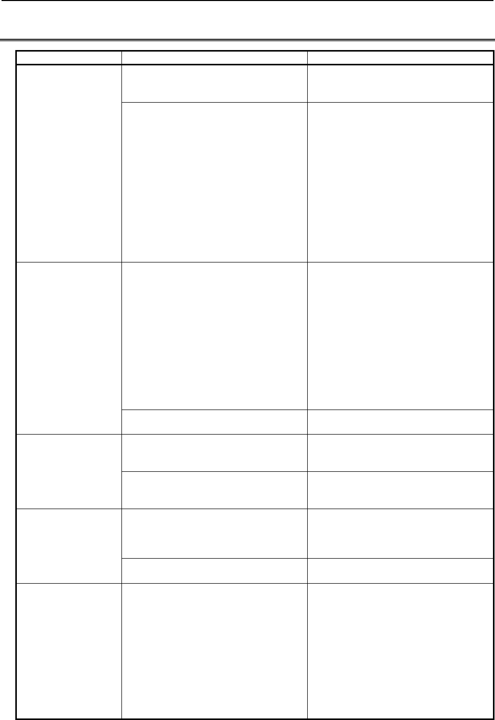
B-63943EN-2/07
5.MACRO VARIABLES
- 113 -
5.10 DIFFERENCES FROM THE Series 16i
Function Series 16i/18i/21i Series 30i/31i/32i/35i/0i-F/PMi
Local variables Local variables can be used with an
execution macro only.
If array-type variables are invalid
(#8518=0), local variables can be used
even with conversational/auxiliary macros.
The local variables used are different from
those used with custom macros. So, even
when an execution macro is called as a
subprogram from a user program, the local
variable level changes, and the calling
local variable is not passed.
Local variables are assigned separately to
execution/conversational/auxiliary macros.
However, they are common to execution
and custom macros. So, when a
subprogram is called, the local variable
level does not change, and the calling local
variable is passed. (However, if bit 3
(LCLLV) of compile parameter No. 9163 is
set to 1, the local variable level changes
and the calling local variable is not passed
as with the Series 16i when an execution
macro is called as a subprogram from a
user program.)
Common variables - Common variables that can be used
are #100 to #149 and #500 to #531.
In an execution macro, however, #150
to #199 and #532 to #999 can be used
as custom macro common variables.
- Common variables are shared among
execution/conversational/auxiliary
macros. They are separate from
custom macro common variables
(#100 to #149 and #500 to #531).
- Common variables that can be used
are #100 to #199 and #500 to #999.
- Whether common variables are shared
among execution/
conversational/auxiliary macros,
whether common variables are
P-CODE macro common variables
independent of custom macros, and
whether common variables are custom
macro common variables can be
chosen using bits 0 to 7 (MV0 to MV7)
of parameter No. 9034
Common variables cannot be protected. As with custom macros, multiple common
variables can be protected.
P-CODE variables P-CODE variables are used as variables
for floating-point data.
Whether P-CODE variables are used as
variables for floating-point data or for
integer data can be chosen.
The number of variables is set in a compile
parameter. When 1 is set, 100 variables
can be used.
The number of variables is set in
parameter No. 9053. When 1 is set, 1
variables can be used.
Extended P-CODE
variables
The number of variables is set in a compile
parameter. When 1 is set, 12 variables for
floating-point data or 30 variables for
integer data can be used.
The number of variables is set in
parameter No. 9054, regardless of the data
format. When 1 is set, one variable can be
used.
Program memory is used. Program memory is not used because a
dedicated area is used.
P-CODE variables /
extended P-CODE
variables between
paths
- By setting bit 1 (TTVR1) of compile
parameter No. 9007 to 1, it is possible
to write and read the P-CODE
variables of the first path in all paths.
- By setting bit 2 (TTVR2) of compile
parameter No. 9007 to 1, it is possible
to write and read the extended
P-CODE variables of the first path in
all paths.
- It can be selected using parameters
Nos. 9051 and 9052 whether to use
the P-CODE variables/extended
P-CODE variables of each path should
be used or those of a specified path
number should be used.
* If wishing to use the same variables in
multiple paths, set the same value in
parameter No. 9051 for P-CODE
variables and in parameter No. 9052
for extended P-CODE variables.
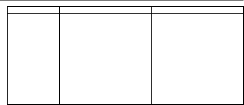
5.MACRO VARIABLES
B-63943EN-2/07
- 114 -
Function Series 16i/18i/21i Series 30i/31i/32i/35i/0i-F/PMi
Variable display Variables cannot be input or output. Execution, conversational, and auxiliary
macros have their respective variable
screens. (Variables other than local
variables and control variables are actually
common to execution, conversational, and
auxiliary macros.)
Common variables, P-CODE variables,
and extended P-CODE variables can be
input and output.
For details, see Chapter 8, "Operation".
P-CODE macro
UI/UO separation
function
To use input/output signals for P-CODE
macros EUI00 to EUI15 <G082 to G083> /
EUO00 to EUO15 <F084 to F085>, set bit
0 (DIOC) of compile parameter No. 9006 to
1.
To use input/output signals for P-CODE
macros EUI00 to EUI15 <G082 to G083> /
EUO00 to EUO15 <F084 to F085>, set bit
3 (EUI) of parameter No. 9035 to 1.
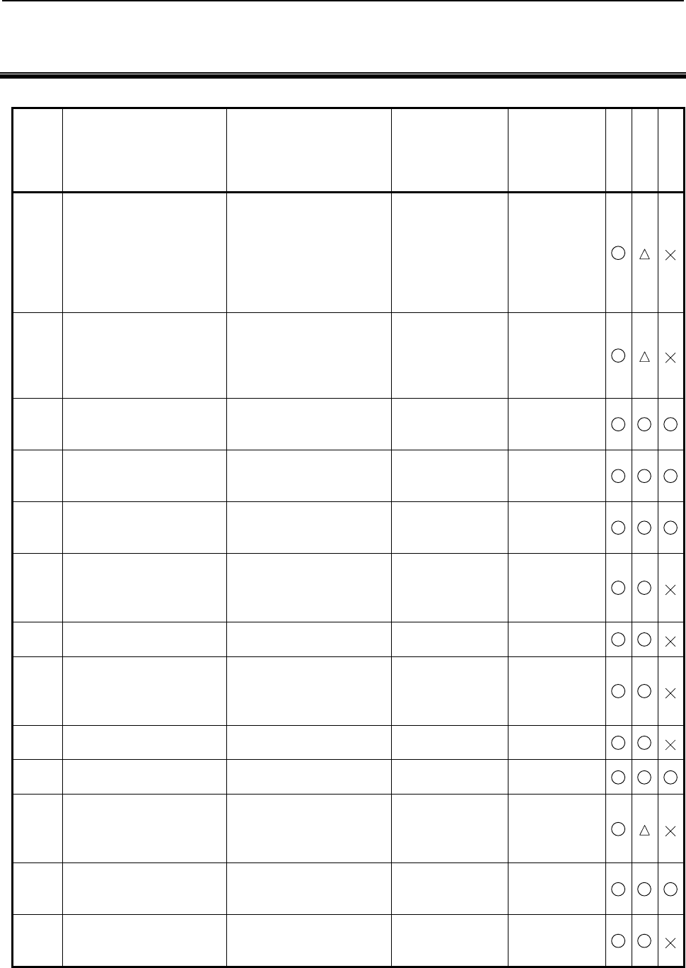
B-63943EN-2/07
6.MACRO EXECUTOR FUNCTION
- 115 -
6 MACRO EXECUTOR FUNCTION
List of macro executor functions, related G codes, and related control variables
Section Function Outline of function Related G code Related control
variable
Conversational
Auxiliary
Execution
6.1 Screen display functions
Controls conversational macro
screen display.
(Control on character display,
graphic display, cursor display,
and so forth)
G202, G240, G242,
G243, G244, G250,
G01, G02, G03,
G230, G249, G280,
G390, G391, G392,
G311, G300, G206,
G204, G317, G319
#8509, #8510,
#8571, #8555,
#8556
6.2 Key input and data input
control
Reads MDI key input states,
input data values, and so forth. ____
#8501, #8502,
#8503, #8504,
#8508, #8552,
#8549, #8533,
#8561 to #8563
6.3 Specification of a PMC path in
multi-path PMCs (#8603)
Enables specification of a PMC
path using control variable
#8603 in multi-path PMCs.
____ #8603
6.4 Address functions
Reads the data of PMC
addresses or CNC parameter
values.
____ ____
6.5 PMC address reading/writing
Reads and writes the data of
PMC addresses D, R, C, K, T,
E, X, and Y.
G310 ____
6.6 CNC data reading/writing
Reads parameters and setting
parameters and reads and
writes pitch error compensation
data.
G314 ____
6.7
6.8
Reader/punch interface /
Memory card control
Exercises RS232C and
memory card control. G330 to G339 #8537 to #8539
6.9
CNC program referencing and
writing, and program
information reading
Registers, deletes, and
modifies CNC part programs,
and reads program information
and background state.
G320 to G322
G325 to G329
#8520 to #8523
#8527 to #8529
6.10 Cutting Time and Distance
Read and Preset Functions
Reads and presets cutting time
and cutting distance. ____ #8553, #8554
6.11 Relative Coordinate Read and
Preset Functions
Reads and presets relative
coordinates. G310 #8996 to #8999
6.12
Array-Type Processing and
Referencing of P-CODE
Variables
Controls processing of
array-type variables or a
variable string in handling of
macro variables.
G315 #8511 to #8519
6.13 Torque Limit Override Control
Enables the torque limit
override value to be changed
to a specified value.
____ #8990 to #8993
#8621 to #8628
6.14 PMC axis control
Enables PMC controlled axes
to be controlled through the
PMC axis control interface.
G340, G341, G344,
G345, G346, G348,
G349, G350, G351
#8602
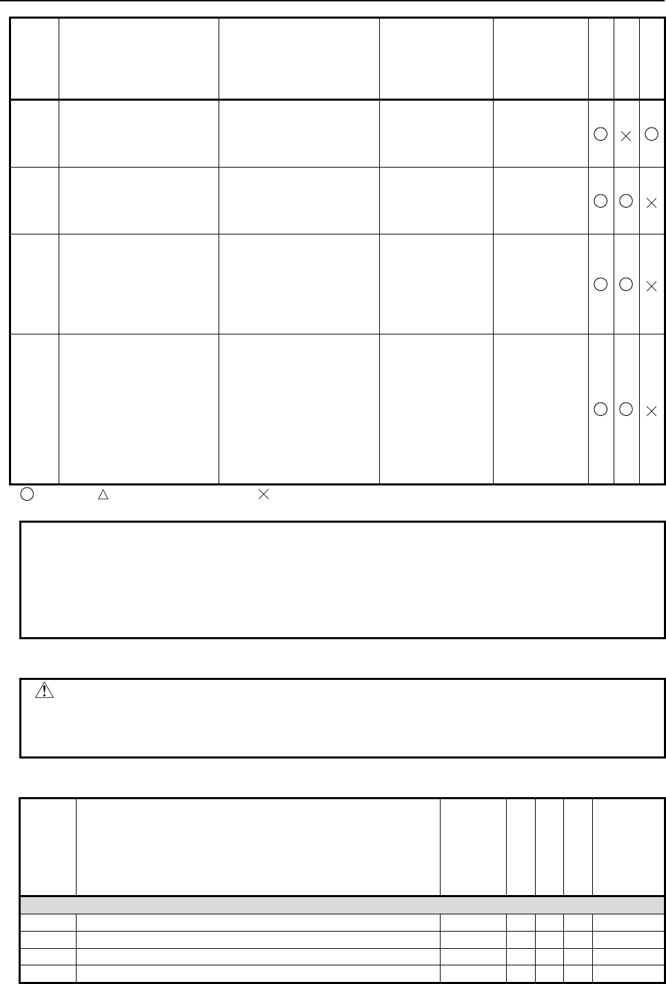
6.MACRO EXECUTOR FUNCTION
B-63943EN-2/07
- 116 -
Section Function Outline of function Related G code Related control
variable
Conversational
Auxiliary
Execution
6.15 File control Creates and deletes files, and
reads and writes data.
FGEN, FDEL,
FOPEN, FCLOS,
FREAD, FWRIT,
FPSET
____
6.16 Axis-direction-by-axis-direction
interlock function
Enables interlock in each axis
direction, and enables a move
axis and move direction on the
rising edge of the SKIP signal.
____ #8600, #8607,
#8601, #8608
6.17 Window Function
Enables alarm information,
relative coordinates, run time,
parts count, and system
information such as system
series and edition information
to be referenced.
____ #8996 to #8999
6.18 Function for Searching Data
Tables for Control Variables
Searches a data table
consisting of sets made up by
multiple successive control
variables according to a
specified condition. If a target
control variable is found, the
set number of the data table
including that variable is
returned.
G400 #8650 to #8655
: Usable, : Usable in some cases, : Not usable
NOTE
1 The G codes described in Section 6.1 cannot be executed with auxiliary macro
functions.
2 G315, described in Section 6.12, is a G code that cannot be executed with
auxiliary macro functions.
3 The G codes described in Section 6.14 requires the PMC axis control option.
Caution
CAUTION
Even those functions that are usable in multiple P-CODE macros (conversational
macros, auxiliary macros, and execution macros) must not be used
simultaneously.
G code list
G code Function Modal /
One-shot
Conversational
Auxiliary
Execution
Reference
item
Screen display functions
G01 Linear display Modal
{
X X
G02 Circular display (CW) Modal
{
X X
G03 Circular display (CCW) Modal
{
X X
G202 Screen clear One-shot
{
X X
B-63943EN-2/07
6.MACRO EXECUTOR FUNCTION
- 117 -
G code Function Modal /
One-shot
Conversational
Auxiliary
Execution
Reference
item
G204 Rectangular display One-shot
{
X X
G206 Filling One-shot
{
X X
G230 Cursor (rectangular cursor) display One-shot
{
X X
G240 Screen/graphic display color One-shot
{
X X
G242 Graphic start point Modal
{
X X
G243 Character display Modal
{
X X
G244 Graphic line type command One-shot
{
X X
G249 Graphic cursor function One-shot
{
X X
G250 Command for display with background color One-shot
{
X X
G280 Prompt statement display One-shot
{
X X
G300 Rapid traverse drawing Modal
{
X X
G311 Specification of rapid traverse rate for rapid traverse drawing One-shot
{
X X
G317 Marking One-shot
{
X X
G319 User-defined character registration One-shot
{
{
X
G390 Absolute mode specification Modal
{
X X
G391 Incremental mode specification Modal
{
X X
G392 Graphic coordinate system setting One-shot
{
X X
CNC program referencing and writing
G320 Program registration One-shot
{
{
X
G321 Program deletion One-shot
{
{
X
G322 Program condensing One-shot
{
{
X
G325 Block read One-shot
{
{
X
G326 Block write One-shot
{
{
X
G327 Block deletion One-shot
{
{
X
G328 Block read (characters) One-shot
{
{
X
G329 Block write (characters) One-shot
{
{
X
Reader/puncher interface / Memory card control
G330 Line open One-shot
{
{
X
G331 Line close One-shot
{
{
X
G335 One-character read (reception) One-shot
{
{
X
G336 Write (transmission) Modal
{
{
X
G337 Variable data read (reception) One-shot
{
{
X
G338 Variable data write (transmission) One-shot
{
{
X
G339 FANUC CASSETTE control One-shot
{
{
X
PMC axis control
G340 Rapid traverse command One-shot
{
{
X
G341 Cutting feed command One-shot
{
{
X
G344 Dwell command One-shot
{
{
X
G345 Reference position return command One-shot
{
{
X
G346 Auxiliary function command One-shot
{
{
X
G348 State signal read command One-shot
{
{
X
G349 Command signal write command One-shot
{
{
X
Other functions
G310 Relative coordinate presetting Modal
{
{
{
G310 PMC data read/write Modal
{
{
{
G314 CNC data read/write One-shot
{
{ X
G315 Array-type data processing One-shot
{
{ X
G316 Inter-multi-path control variable read/write function One-shot
{
{ X
G400 Function for searching data tables for control variables One-shot
{
{ X
6.MACRO EXECUTOR FUNCTION
B-63943EN-2/07
- 118 -
List of control variables
Variable No. Function Type R/W
Conversational
Auxiliary
Execution
Variable related to macro variables
#8572 Control of switching between system variables and P-CODE
variables Integer R/W
{{{
Execution macro call masking function
#8690 Execution macro call masking variable 1
(Axis address call masking) Integer R/W
{{{
#8691 Execution macro call masking variable 2
(Macro calls and subprogram calls with T codes) Integer R/W
{{{
Modal call function
#8680 Modal call recognition variable Integer R/
{{{
P-CODE workpiece number search
#8610 Program number Integer R/W
{ {
X
Execution control variable
#8500 Conversational macro execution control variable 1
(User screen 1) Integer R/W
{{{
#8550 Conversational macro execution control variable 2
(User screen 2) Integer R/W
{{{
#8551 Conversational macro execution control variable 3
(User screen 3) Integer R/W
{{{
#8555 User help screen execution control variable Integer R/W
{ {
X
#8530 Auxiliary macro execution variable Integer R/W
{{{
Screen display control
#8509 Character string registration program variable Floating R/W
{ {
X
#8510 Function screen control variable Integer R/W
{ {
X
#8571 Sub menu screen control variable Integer R/
{ {
X
#8556 User help screen control variable Integer R/W
{ {
X
Screen display identification
#8681 Display device identification Integer R/
{ {
X
#8682 Identification of display with background color Integer R/
{ {
X
Graphic state reading
#8800 Graphic state reading variable Integer R/
{
X X
Cursor control
#8505 Cursor control variable Integer R/W
{ {
X
#8506 Cursor X position control variable Integer R/W
{ {
X
#8507 Cursor Y position control variable Integer R/W
{ {
X
Key input and data input control
#8501 Key input control variable Integer R/
{
X X
#8502 Data input control variable Floating R/W
{
X X
#8503 Numeric data variable Floating R/
{
X X
#8504 Address data variable Floating R/
{
X X
#8508 Character string input Floating R/
{
X X
Key input line control
#8561 Key input line display position X coordinate Integer R/W
{ {
X
#8562 Key input line display position Y coordinate Integer R/W
{ {
X
#8563 Allowable number of key input characters Integer R/W
{ {
X
Extended data input control variable
#8552 Variable number setting Floating R/W
{
X X
MDI key image reading function
#8549 MDI key image reading Integer R/
{ {
X
B-63943EN-2/07
6.MACRO EXECUTOR FUNCTION
- 119 -
Variable No. Function Type R/W
Conversational
Auxiliary
Execution
#8533 MDI keyboard type reading Integer R/
{ {
X
Multi-path control
#8531 Execution path number reading Integer R/
{{{
#8603 Specification of a PMC path in multi-path PMCs Integer R/W
{{{
Reader/puncher interface
#8537 Completion code (auxiliary macro execution result) Floating R/
{ {
X
#8538 Completion code (conversational macro execution result) Floating R/
{ {
X
#8539 Completion code (common to auxiliary macros and
conversational macros) Floating R/
{ {
X
Referencing and writing CNC programs
#8520 Program number specification Integer R/W
{ {
X
#8521 Block number specification Integer R/W
{ {
X
#8522 Storage variable number specification Integer R/W
{ {
X
#8523 Variable number for specifying the number of decimal
places Integer R/W
{ {
X
Program information read
#8527 Number of registered programs Integer R/
{ {
X
#8528 Free CNC program memory space Integer R/
{ {
X
#8529 Completion number Integer R/
{ {
X
Cutting time and distance read and preset functions
#8553 Reading and presetting the cutting time Integer R/W
{ {
X
#8554 Reading and presetting a cutting distance Integer R/W
{ {
X
Relative coordinate read and preset functions
#8996 Completion code Integer R/
{ {
X
#8997 Intra-path controlled axis number Integer R/W
{ {
X
#8998 Relative coordinate read selection code Integer R/W
{ {
X
#8999 Relative coordinate data Floating R/
{ {
X
Array-type processing and referencing of P-CODE variables
#8511 Source data Floating R/W
{ {
X
#8512 Source two-dimensional array number Integer R/W
{ {
X
#8513 Source three-dimensional array number Integer R/W
{ {
X
#8514 Destination two-dimensional array number Integer R/W
{ {
X
#8515 Destination three-dimensional array number Integer R/W
{ {
X
#8516 Number of one-dimensional array elements Integer R/W
{ {
X
#8517 Number of two-dimensional array elements Integer R/W
{ {
X
#8518 (1 whenever used) Integer R/W
{ {
X
#8519 Array start variable number Integer R/W
{ {
X
Torque limit override control
#8621 to #8628 Torque limit override values of the 1st to 8th axes in a path Integer R/W
{{{
#8990 Read/write selection Integer R/W
{{{
#8991 Controlled axis number in a path Integer R/W
{{{
#8992 Torque limit override value Integer R/W
{{{
#8993 Completion code Floating R/
{{{
PMC axis control
#8602 PMC controlled axis selection Integer R/W
{ {
X
#8700 PMC controlled axis selection variable (macro variable
command type) Integer R/W
{ {
X
#8710,#8720
#8730,#8740 PMC command signal variable Integer R/W
{ {
X
6.MACRO EXECUTOR FUNCTION
B-63943EN-2/07
- 120 -
Variable No. Function Type R/W
Conversational
Auxiliary
Execution
#8711,#8721
#8731,#8741 PMC control command variable Integer R/W
{ {
X
#8712,#8722
#8732,#8742 PMC cutting feed variable Integer R/W
{ {
X
#8713,#8723
#8733,#8743 PMC control travel distance variable Integer R/W
{ {
X
#8715,#8725
#8735,#8745 Variables for reading PMC status signals Integer R/W
{ {
X
Axis-direction-by-axis-direction interlock function
#8600 (1 to 16 axes)
#8607 (17 to 24
axes)
Axis-direction-by-axis-direction interlock control variables Integer R/W
{ {
X
#8601 (1 to 16 axes)
#8608 (17 to 24
axes)
Movement axis and direction variables for the rise time of
the SKIP signal Integer R/
{ {
X
Window function
#8996 Completion code Integer R/
{ {
X
#8997 Axis number Integer R/W
{ {
X
#8998 System information ID Integer R/W
{ {
X
#8999 System information Floating R/
{ {
X
Function for searching data tables for control variables
#8650
Start macro variable number in the search target data
table (for READ)
Start macro variable number in the set next to the
retrieved data table set number (#8655) (for WRITE)
Integer R/W
{ {
X
#8651 The number of macro variables forming a set in the data
table Integer R/W
{ {
X
#8652
The number of search target data table sets (for READ)
Set value minus the number of sets that have already
been retrieved (for WRITE)
Integer R/W
{ {
X
#8653 Lower limit to the search value Floating R/W
{ {
X
#8654 Upper limit to the search value Floating R/W
{ {
X
#8655 The data table set number where a control variable that
satisfies the search condition is contained Integer R/
{ {
X
NOTE
The variable types are as follows:
Floating : Floating-point type
Integer : Integer type
When an attempt is made to input a <null> value to a variable of the integer type,
the value is changed to zero before being input.
6.1
SCREEN DISPLAY FUNCTIONS
In the descriptions below, the terms, type of 12 soft keys and type of 7 soft keys, represent the following
display units:
Type of 12 soft keys : Type of display unit (10.4" LCD, 15" LCD, 19" LCD) with (10 + 2) horizontal
soft keys
Type of 7 soft keys : Type of display unit (8.4" LCD) with (5 + 2) horizontal soft keys
B-63943EN-2/07
6.MACRO EXECUTOR FUNCTION
- 121 -
6.1.1
Screen Coordinate System
The coordinate system used with the conversational macro function for character display and cursor
display is referred to as the character coordinate system.
The coordinate system used with the conversational macro function for graphic display is referred to as
the graphic coordinate system.
In each coordinate system, the X-axis represents the horizontal direction, and the Y-axis represents the
vertical direction.
Character coordinate system
One unit represents one character.
The display range depends on the display device size, bit 2 (CM30) of compile parameter No. 9009, and
whether the screen has the background color or not.
- For 8.4" LCD (type of 7 soft keys)
Screen with background color
(Bit 0 (VGAR) of compile parameter
No. 9100 = 1)
Screen without background color (Bit 0 (VGAR) of compile
parameter No. 9100 = 0)
Bit 2 (CM30) of compile parameter No. 9009
1 0
The display range is 19 lines by 40
characters.
The specified values are as follows:
X coordinate: 0 to 39 from left to right
Y coordinate: 0 to 18 from top to bottom
The 13th and 15th lines cannot be
displayed, because the system uses
them for key input and state display,
respectively (the 14th line is also used
for state display when 1 is set in bit 4
(EXST) of compile parameter No.
9160).
See Fig. 6.1.1(a).
The display range is 19 lines by 40
characters.
The specified values are as
follows:
X coordinate: 0 to 39 from left to
right
Y coordinate: 0 to 18 from top to
bottom
The 15th and 16th lines cannot be
displayed, because the system
uses them for key input and state
display, respectively.
See Fig. 6.1.1(b).
The display range is 16 lines by 40
characters (the first two lines and
last one line cannot be displayed).
The specified values are as follows:
X coordinate: 0 to 39 from left to
right
Y coordinate: 0 to 15 from top to
bottom
The 13th and 14th lines cannot be
displayed, because the system
uses them for key input and state
display, respectively.
See Fig. 6.1.1(c).
[Note]
A command for display beyond this range is ignored.
6.MACRO EXECUTOR FUNCTION
B-63943EN-2/07
- 122 -
0 0 0 0 0 0 0 0 0 0 1 1 1 1 1 1 1 1 1 1 2 2 2 2 2 2 2 2 2 2 3 3 3 3 3 3 3 3 3 3
0 1 2 3 4 5 6 7 8 9 0 1 2 3 4 5 6 7 8 9 0 1 2 3 4 5 6 7 8 9 0 1 2 3 4 5 6 7 8 9
Fig. 6.1.1 (a) Character coordinate (type of 7 soft keys, with background color)
0 0 0 0 0 0 0 0 0 0 1 1 1 1 1 1 1 1 1 1 2 2 2 2 2 2 2 2 2 2 3 3 3 3 3 3 3 3 3 3
0 1 2 3 4 5 6 7 8 9 0 1 2 3 4 5 6 7 8 9 0 1 2 3 4 5 6 7 8 9 0 1 2 3 4 5 6 7 8 9
Fig. 6.1.1 (b) Character coordinate (type of 7 soft keys, without background color)
B-63943EN-2/07
6.MACRO EXECUTOR FUNCTION
- 123 -
0 0 0 0 0 0 0 0 0 0 1 1 1 1 1 1 1 1 1 1 2 2 2 2 2 2 2 2 2 2 3 3 3 3 3 3 3 3 3 3
0 1 2 3 4 5 6 7 8 9 0 1 2 3 4 5 6 7 8 9 0 1 2 3 4 5 6 7 8 9 0 1 2 3 4 5 6 7 8 9
Fig. 6.1.1 (c) Character coordinate (type of 7 soft keys, without background color)
- For 10.4", 15", or 19" LCD (type of 12 soft keys)
Screen with background color
(Bit 0 (VGAR) of compile parameter
No. 9100 = 1)
Screen without background color (Bit 0 (VGAR) of compile
parameter No. 9100 = 0)
Bit 2 (CM30) of compile parameter No. 9009
1 0
The display range is 30 lines by 80
characters.
The specified values are as follows:
X coordinate: 0 to 79 from left to right
Y coordinate: 0 to 29 from top to bottom
The 22nd and 24th lines cannot be
displayed, because the system uses
them for key input and state display,
respectively (the 23rd line is also used
for state display when 1 is set in bit 4
(EXST) of compile parameter No.
9160).
See Fig. 6.1.1(d).
The display range is 30 lines by 80
characters.
The specified values are as
follows:
X coordinate: 0 to 79 from left to
right
Y coordinate: 0 to 29 from top to
bottom
The 23rd and 24th lines cannot be
displayed, because the system
uses them for key input and state
display, respectively.
See Fig. 6.1.1(e).
The display range is 25 lines by 80
characters (the first three lines and
last two lines cannot be displayed).
The specified values are as follows:
X coordinate: 0 to 79 from left to
right
Y coordinate: 0 to 24 from top to
bottom
The 20th and 21st lines cannot be
displayed, because the system
uses them for key input and state
display, respectively.
See Fig. 6.1.1(f).
[Note]
A command for display beyond this range is ignored.
6.MACRO EXECUTOR FUNCTION
B-63943EN-2/07
- 124 -
00000000001111111111222222222233333333334444444444555555555566666666667777777777
01234567890123456789012345678901234567890123456789012345678901234567890123456789
Fig. 6.1.1 (d) Character coordinate (type of 12 soft keys, with background color)
00000000001111111111222222222233333333334444444444555555555566666666667777777777
01234567890123456789012345678901234567890123456789012345678901234567890123456789
Fig. 6.1.1 (e) Character coordinate (type of 12 soft keys, without background color)
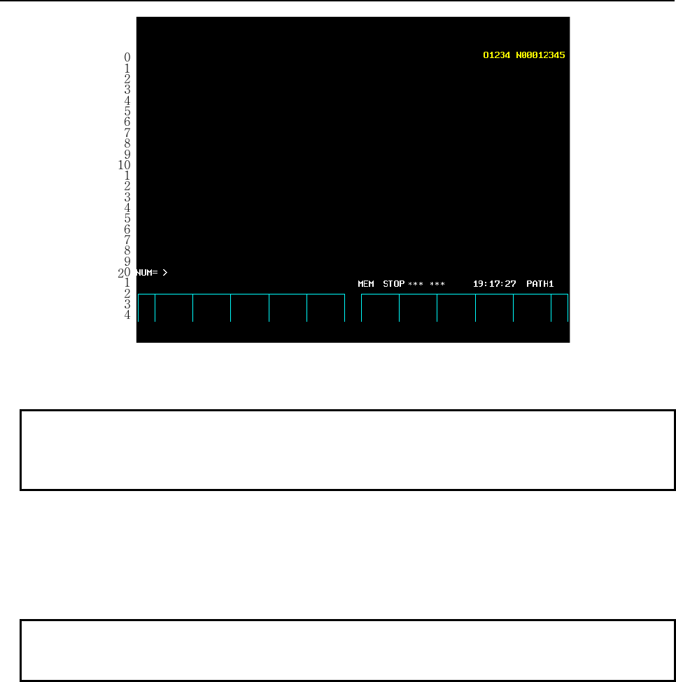
B-63943EN-2/07
6.MACRO EXECUTOR FUNCTION
- 125 -
00000000001111111111222222222233333333334444444444555555555566666666667777777777
01234567890123456789012345678901234567890123456789012345678901234567890123456789
Fig. 6.1.1 (f) Character coordinate (type of 12 soft keys, without background color)
NOTE
For 15"/19" LCD units, on the conversational macro screen, the character
coordinate is the same as that of 10.4" LCD units. Vertical soft keys are not
displayed.
Graphic coordinate
One unit is one dot.
The screen center (X,Y)=(0,0).
Along the X-axis, display at -320 to 319 (from left to right) can be specified. Along the Y-axis, display at
-232 to 247 (from bottom to top) can be specified. A command for display beyond this range is ignored.
NOTE
For 8.4" LCD unit (type of 7 soft keys), be sure to set bit 2 (HRGR) of compile
parameter No. 9003 to 1.
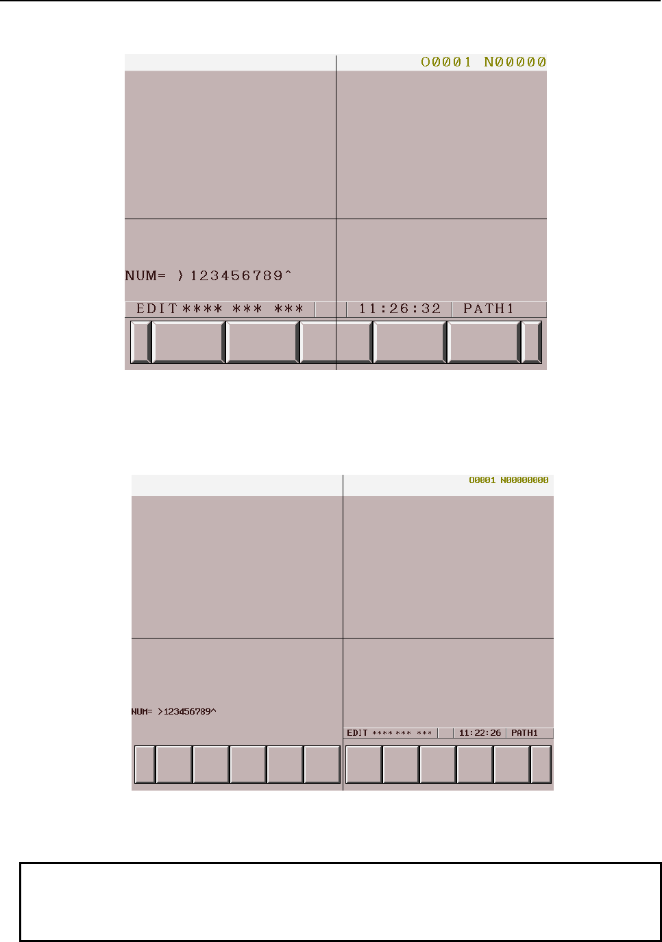
6.MACRO EXECUTOR FUNCTION
B-63943EN-2/07
- 126 -
(-320,0) (319,0)
(0,247)
(0,0)
(0,-232)
Fig. 6.1.1 (g) Graphic coordinate (type of 7 soft keys)
(-320,0) (319,0)
(0,247)
(0,0)
(0,-232)
Fig. 6.1.1 (h) Graphic coordinate (type of 12 soft keys)
NOTE
For 15"/19" LCD units, on the conversational macro screen, the graphic
coordinate is the same as that of 10.4" LCD units. Vertical soft keys are not
displayed.
B-63943EN-2/07
6.MACRO EXECUTOR FUNCTION
- 127 -
6.1.2
Screen Display Identification Variables (#8681 and #8682)
Display device identification (#8681)
#8681 : Display device identification control variable
0 : 8.4” LCD
1 : 10.4” LCD
2 : 15” LCD, 19” LCD
NOTE
For 15"/19" LCD units, on the conversational macro screen, the character
coordinates and graphic coordinates are the same as that of 10.4" LCD units.
Therefore, when changing coordinates depending on the display unit, handle the
values read by this variable for 1 and 2 as identical values.
Identification of display with background color (#8682)
#8682 : Control variable for identification of display with background color
0 : Without background color
1 : With background color
6.1.3
Screen Display Control Codes
The screen display control codes are listed below. The meanings of the control codes and addresses are
different from those of ordinary NC statements. The screen display control codes cannot be specified with
execution macros. (G01, G02, and G03 are CNC linear/circular interpolation commands.)
G202 : Screen clear
G240 : Color specification
G242 : Drawing start point setting
G250 : Command for display with background color
G243 : Character display
G244 : Drawing line type specification
G280 : Prompt statement display
G01 : Linear drawing
G02 : Circular drawing (clockwise)
G03 : Circular drawing (counterclockwise)
G230 : Cursor display (rectangular cursor)
G249 : Graphic cursor
G390 : Absolute mode specification
G391 : Incremental mode specification
G392 : Graphic coordinate system setting
G311 : Rapid traverse rate specification
G300 : Rapid traverse drawing
G206 : Graphic filling
G204 : Rectangular display
G317 : Marking
G202, G240, G249, G250, G244, G280, G230, G311, G206, G204, and G317 are one-shot G codes.
G243, G01, G02, G03, G242, and G300 are modal G codes, and are treated as those belong to the same G
code group.
G390 and G391 are also modal G code, but belong to a different G code group from the above modal G
code group.
6.MACRO EXECUTOR FUNCTION
B-63943EN-2/07
- 128 -
NOTE
When bit 4 (NVGA) of compile parameter No. 9167 is set to 1, G242, G244,
G249, G250, G01, G02, G03, G392, G311, G300, G206, G204, and G317
cannot be used.
Modal addresses and their meanings
X : X coordinate in the character coordinate system, X coordinate of the drawing end point in the graphic
coordinate system, speed ratio X of rapid traverse drawing
Y : Y coordinate in the character coordinate system, Y coordinate of the drawing end point in the graphic
coordinate system, speed ratio Y of rapid traverse drawing
I : X coordinate of the center of circular drawing in the graphic coordinate system, X coordinate of a
diagonal point in rectangular display
J : Y coordinate of the center of circular drawing in the graphic coordinate system, Y coordinate of a
diagonal point in rectangular display
A : Character size (character display)
B : Blinking specification (character display)
F : Format for numeric value display (character display)
Z : Zero suppression specification for numeric value display (character display)
NOTE
Addresses X and Y are used as modal addresses common to character display
and graphic display.
One-shot addresses and their meanings
D : Numeric value to be displayed
K : Number of spaces to be displayed
C : Character code
P : Sequence number, screen specification, attribute specification, drawing line type specification
M : Mark number (marking)
L : Cursor length (cursor display), blinking specification (character display)
NOTE
For macro calls, all addresses are treated as arguments.
6.1.3.1
Screen clear (G202)
This code clears either the graphic screen or character screen (or both) according to the specification of
address P.
Specifying addresses X, Y, I, and J results in partial clear. If they are omitted, the entire screen is cleared.
The soft keys are not cleared.
Format
G202 Xx Yy Ii Jj Pp ;
X : X coordinate start point in the character coordinate system
Y : Y coordinate start point in the character coordinate system
I : Number of characters to be partially cleared (X coordinate)
J : Number of characters to be partially cleared (Y coordinate)
P=1 : Clears the graphic screen.
=2 : Clears the character screen.
=3 : Clears both the graphic and character screens.
Character screen clear
The screen is cleared with the color of color palette 0 (base color).

B-63943EN-2/07
6.MACRO EXECUTOR FUNCTION
- 129 -
Graphic display clear
• For display with background color (when bit 0 (VGAR) of compile parameter No. 9100 is set to 1):
The color of color palette 15 is used.
• For display without background color (when bit 0 (VGAR) of compile parameter No. 9100 is set to 0):
The color of color palette 0 is used.
NOTE
When bit 4 (NVGA) of compile parameter No. 9167 is set to 1, P2 and P3 only
are valid. (P3, even when specified, has the same effect as P2.)
6.1.3.2
Color specification (G240)
The colors of line segments and characters specified in a conversational program can be chosen from
sixteen colors in character display/graphic display.
As a background color for character display, one of sixteen colors can be specified.
Format
G240 Pp Cc Ll ;
P: Specification of color for character display/graphic display
When a minus (-) value is specified, characters are displayed in reverse video.
P = 0 : Color of color palette 0 Standard color: Black (base color)
= 1 : Color of color palette 1 Standard color: Red
= 2 : Color of color palette 2 Standard color: Green
= 3 : Color of color palette 3 Standard color: Yellow
= 4 : Color of color palette 4 Standard color: Blue
= 5 : Color of color palette 5 Standard color: Purple
= 6 : Color of color palette 6 Standard color: Light blue
= 7 : Color of color palette 7 Standard color: White
= 8 : Color of color palette 8 Standard color: Dark gray
= 9 : Color of color palette 9 Standard color: Dark red
=10 : Color of color palette 10 Standard color: Dark green
=11 : Color of color palette 11 Standard color: Dark yellow
=12 : Color of color palette 12 Standard color: Dark blue
=13 : Color of color palette 13 Standard color: Dark purple
=14 : Color of color palette 14 Standard color: Dark aqua green
=15 : Color of color palette 15 Standard color: Light gray
C: Specification of background color for character display
C = 0 : Color of color palette 0 Standard color: Black
= 1 : Color of color palette 1 Standard color: Red
= 2 : Color of color palette 2 Standard color: Green
= 3 : Color of color palette 3 Standard color: Yellow
= 4 : Color of color palette 4 Standard color: Blue
= 5 : Color of color palette 5 Standard color: Purple
= 6 : Color of color palette 6 Standard color: Light blue
= 7 : Color of color palette 7 Standard color: White
= 8 : Color of color palette 8 Standard color: Dark gray
= 9 : Color of color palette 9 Standard color: Dark red
=10 : Color of color palette 10 Standard color: Dark green
=11 : Color of color palette 11 Standard color: Dark yellow
=12 : Color of color palette 12 Standard color: Dark blue
=13 : Color of color palette 13 Standard color: Dark purple
=14 : Color of color palette 14 Standard color: Dark aqua green
=15 : Color of color palette 15 Standard color: Light gray
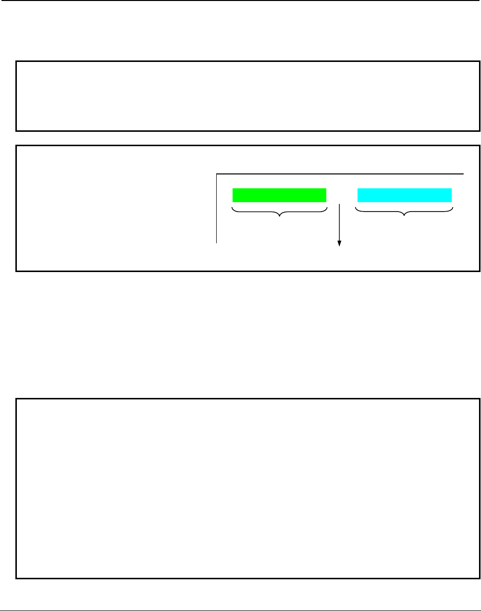
6.MACRO EXECUTOR FUNCTION
B-63943EN-2/07
- 130 -
L: Specification of blinking
L = 0 : Without blinking
= 1 : With blinking
NOTE
For the standard color in the case of display with background color (when bit 0
(VGAR) of compile parameter No. 9100 is set to 1), see "Standard color
palettes" in Subsection 6.1.3.4, "Command for display with background color
(G250)".
Example
G240 P1 C2 ;
G243 X0 Y0 (ABC) ;
G240 P0 C7 ; A B C - X Y Z
G243 (-) ;
G240 P5 C4 ;
G243(XYZ) ;
When addresses P and C only are specified, the specification is handled in the same way as 0 is specified
in address L.
G240 P1 ; Character color ...................................................................... Color of color palette 1
Background color ........................................................................... (No change)
Blinking ....................................................................................... Without blinking
G240 C1 ; Character color ...................................................................... (No change)
Background color ........................................................................... Color of color palette 1
Blinking ....................................................................................... Without blinking
NOTE
1 If G240 is not specified even once, color palette 7 is used for character
display/graphic display, and color palette 0 is used for background color for
character display without blinking.
2 When bit 4 (NVGA) of compile parameter No. 9167 is set to 1, the function of
address C cannot be used.
3 When a monochrome LCD unit is used as a display device, brightness is to be
used as described below (for the standard color).
The values of address P can be arranged in the order of higher to lower
brightness as follows: 7, 3, 12, 6, 2, 5, 1, 4, 8, 9, 11, 10, 0 (where 2 = 5 and 9 =
11). Actually, one brightness value cannot be easily distinguished from another.
So, the use of 7 and 2 only is recommended for creation.
4 The color palette settings made on the CNC are used.
6.1.3.3
Drawing start point setting (G242)
This code allows specification of the drawing start point in the graphic coordinate system, using addresses
X and Y. The next drawing starts at that point.
Format
G242 Xx Yy ;
X : X coordinate of the drawing start point
Y : Y coordinate of the drawing start point
Green background
/Red character
White background
/Black character
Blue background
/Purple character

B-63943EN-2/07
6.MACRO EXECUTOR FUNCTION
- 131 -
NOTE
1 This code is disabled when bit 4 (NVGA) of compile parameter No. 9167 is set to
1.
2 The commands of addresses X and Y are:
- Absolute commands at all times when bit 3 (INCD) of compile parameter No.
9167 is set to 0.
- Switched between absolute and incremental commands by G390/G391 when
bit 3 (INCD) of compile parameter No. 9167 is set to 1.
6.1.3.4
Command for display with background color (G250)
By setting bit 0 (VGAR) of compile parameter No. 9100 to 1, display with background color is enabled
with a conversational macro.
For display with background color, graphic display is used. If a graphic command is specified at the same
position, display with background color is overwritten. Similarly, display with background color
overwrites display based on a graphic command.
When the screen clear command (G202) is specified, graphic display is cleared by the color of color
palette 15.
NOTE
1 This code is disabled when bit 4 (NVGA) of compile parameter No. 9167 is set to
1.
2 This code is disabled when bit 2 (VRM) of parameter No. 9011 is set to 1.
3 If a graphic command is specified at the same position, display with background
color is overwritten. Similarly, display with background color overwrites display
based on a graphic command.
4 When character display or graphic display is cleared using the screen clear
command (G202), the background display of display with background color can
disappear, or a coordinate change can occur. A coordinate change occurs when
the window frame mode is used.
5 When the screen clear command (G202) is executed, graphic display is cleared
by the color of color palette 15.
6 When the standard color is specified, the value of the color palette for character
display differs from that for graphic display. The display color specified with the
display color specification command (G240) differs between character display
and graphic display.
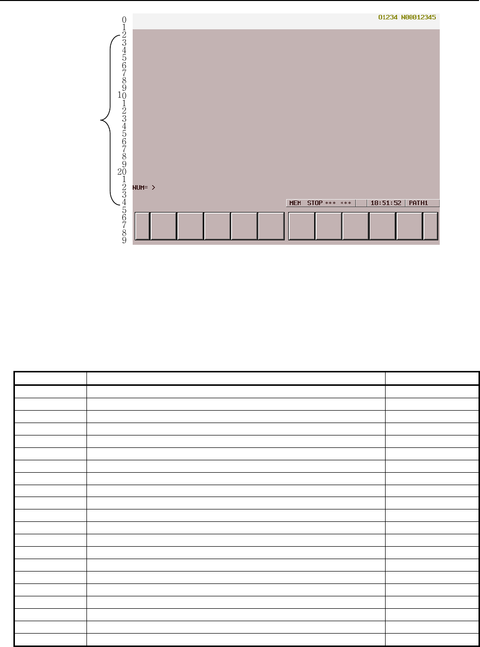
6.MACRO EXECUTOR FUNCTION
B-63943EN-2/07
- 132 -
00000000001111111111222222222233333333334444444444555555555566666666667777777777
01234567890123456789012345678901234567890123456789012345678901234567890123456789
Data display
area
Screen with background color (type of 12 soft keys)
Format
G250 P_ <parameter> ;
P_ : Item number specification
<
parameter
> : Parameter specification of each item
List of items
Item (P_) Description Parameter
000 Clears screen display with background color. None
001 Clears the data display area only. None
002 Clears the background of screen display with background color. None
003 Clears only the background of the data display area. None
010 Displays a convex group frame. X_ Y_ I_ J_
011 Displays a concave group frame. X_ Y_ I_ J_
012 Displays an input frame. X_ Y_ C_
015 Displays a key input line frame. X_ Y_
018
(*1)
Displays a selection window frame. X_ Y_
019
(*1)
Displays a nonselection window frame. X_ Y_
020
(*1)
Registers a window frame mode. X_ Y_ R_
021
(*1)
Selects a window fame mode. R_
022
(*1)
Performs mode display of a selection window frame. R_
023
(*1)
Performs mode display of a nonselection window frame. R_
024
(*1)
Performs mode display of a selection window frame background. R_
025
(*1)
Performs mode display of a nonselection window frame background. R_
030 Displays the soft key unselected state. None
031 Displays the soft key pressed state. R_ (B_)
040 Sets a graphic color palette (1 palette). R_ A_ B_ C_
041 Sets a character color palette (1 palette). R_ A_ B_ C_
042 Sets a graphic/character color palette. R_
*1 Item that can be specified with 10.4", 15", and 19" LCD units.
- The background of screen display with background color means the graphic display plane. On the
screen, a graphic display plane and character display plane are placed one over the other for display.
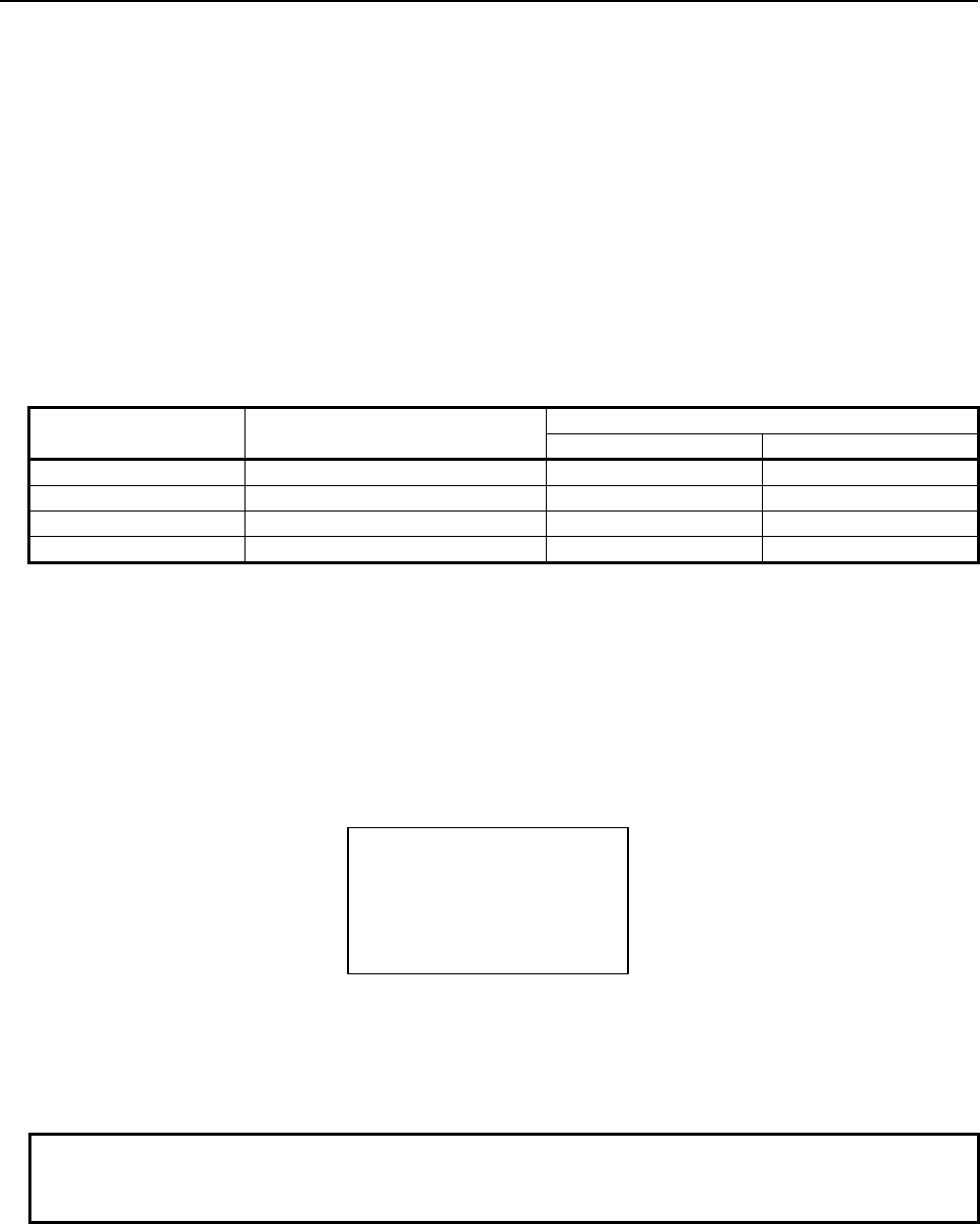
B-63943EN-2/07
6.MACRO EXECUTOR FUNCTION
- 133 -
- For display with background color, a graphic display plane is used.
- The window frame mode is a mode using the selection/nonselection window frame as the reference.
This means that in character display, the top-left point of each window frame represents coordinates
(0,0). However, graphic display coordinates are not affected.
Details of items
- P000
- P001
Clears display with background color and character display.
- P002
- P003
Clears only display with background color.
Item number Range to be cleared Plane to be cleared
Character Graphic
P000
Entire screen To be cleared. To be cleared.
P001
Data display area only To be cleared. To be cleared.
P002
Entire screen Not to be cleared. To be cleared.
P003
Data display area only Not to be cleared. To be cleared.
- P010 X_ Y_ I_ J_
- P011 X_ Y_ I_ J_
P10 displays a convex group frame, and P11 displays a concave group frame.
X : Top-left point (X coordinate) of the frame
Y : Top-left point (Y coordinate) of the frame
I : Bottom-right point (X coordinate) of the frame
J : Bottom-right point (Y coordinate) of the frame
The points X, Y, I, and J represent coordinates in character display.
(X, Y)
(I, J)
A rectangular frame is specified using the parameters above.
If a specified frame is larger than the screen, the specification is ignored.
Only display with background color is provided.
NOTE
The commands specified in addresses X, Y, I, and J become absolute
commands at all times.
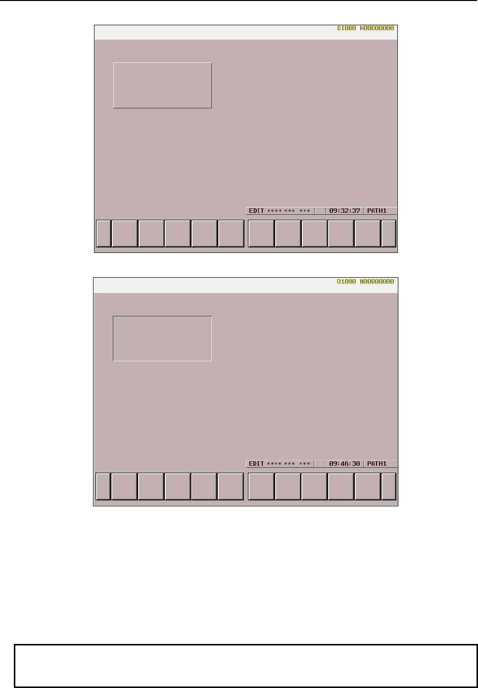
6.MACRO EXECUTOR FUNCTION
B-63943EN-2/07
- 134 -
- When G250 P10 X5 Y5 I30 J10 is specified
- When G250 P11 X5 Y5 I30 J10 is specified
- P012 X_ Y_ C_
Displays an input frame.
X : Frame start point (X coordinate)
Y : Frame start point (Y coordinate)
C : Frame length
The points X and Y represent coordinates in character display.
The length C represents a character width.
The size of a frame is fixed at 1 line along the Y-axis. If a specified frame of this size is larger than the
display area of the screen, the specification is ignored.
Only display with background color is provided.
NOTE
The commands specified in addresses X and Y become absolute commands at
all times.
B-63943EN-2/07
6.MACRO EXECUTOR FUNCTION
- 135 -
- P015 X_ Y_
Displays a key input line frame.
X : Frame start point (X coordinate)
Y : Frame start point (Y coordinate)
The points X and Y represent coordinates in character display.
The size of a frame is fixed at 40 characters along the X-axis and at 1 line along the Y-axis. If a specified
frame of this size is larger than the display area of the screen, the specification is ignored.
Only display with background color is provided.
NOTE
The commands specified in addresses X and Y become absolute commands at
all times.
- P018 X_ Y_
- P019 X_ Y_
P018 displays a selection window frame, and P019 displays a nonselection window frame.
X : Frame start point (X coordinate)
Y : Frame start point (Y coordinate)
The points X and Y represent coordinates in character display.
The size of a frame is fixed at 41 characters along the X-axis and at 14 lines along the Y-axis. If a
specified frame of this size is larger than the display area of the screen, the specification is ignored.
- When G250 P18 X20 Y10 is specified
6.MACRO EXECUTOR FUNCTION
B-63943EN-2/07
- 136 -
- When G250 P19 X20 Y10 is specified
NOTE
1 These commands are valid with 10.4”, 15”, and 19” LCD units only.
2 The commands specified in addresses X and Y become absolute commands at
all times.
- P020 X_ Y_ R_
Registers a window frame mode.
R : Frame number (1 to 3)
X : Frame start point (X coordinate)
Y : Frame start point (Y coordinate)
The points X and Y represent coordinates in character display.
The size of a frame is fixed at 41 characters along the X-axis and at 14 lines along the Y-axis. If a
specified frame of this size is larger than the display area of the screen, the specification is ignored.
NOTE
1 These commands are valid with 10.4”, 15”, and 19” LCD units only.
2 The commands specified in addresses X and Y become absolute commands at
all times.
- P021 R_
Selects a frame registered with P020.
This command does not display a frame but only selects a frame.
R : Selection number of a frame registered with P20
NOTE
1 These commands are valid with 10.4”, 15”, and 19” LCD units only.
2 When bit 3 (INCD) of compile parameter No. 9167 is set to 1, the current
coordinates for incremental specification are preset.

B-63943EN-2/07
6.MACRO EXECUTOR FUNCTION
- 137 -
- P022 R_
- P024 R_
Displays a frame registered with P020, as a selection window frame.
P022 clears the character display in a range.
R : Selection number of a frame registered with P20
NOTE
1 These commands are valid with 10.4”, 15”, and 19” LCD units only.
2 When bit 3 (INCD) of compile parameter No. 9167 is set to 1, the current
coordinates for incremental specification are preset.
- P023 R_
- P025 R_
Displays a frame registered with P020, as a non-selection window frame.
P023 clears the character display in a range.
R : Selection number of a frame registered with P20
NOTE
1 These commands are valid with 10.4”, 15”, and 19” LCD units only.
2 When bit 3 (INCD) of compile parameter No. 9167 is set to 1, the current
coordinates for incremental specification are preset.
- P030
Displays the soft key unselected state.
- P031 R_ B_
Displays the soft key pressed state.
R : Soft key number
(For the type of 7 soft keys: Soft keys 1 to 5)
(For the type of 12 soft keys: Soft keys 1 to 10)
B : Soft key number
(For the type of 7 soft keys: Soft keys 1 to 5)
(For the type of 12 soft keys: Soft keys 1 to 10)
- For the type of 7 soft keys
1 = Selects soft key 1.
2 = Selects soft key 2.
3 = Selects soft key 3.
4 = Selects soft key 4.
5 = Selects soft key 5.
- For the type of 12 soft keys
1 = Selects soft key 1.
2 = Selects soft key 2.
3 = Selects soft key 3.
4 = Selects soft key 4.
5 = Selects soft key 5.
6 = Selects soft key 6.
7 = Selects soft key 7.
8 = Selects soft key 8.
9 = Selects soft key 9.
10 = Selects soft key 10.
When two soft keys are to be selected, one soft key is selected using address R, and the other using
address B.
6.MACRO EXECUTOR FUNCTION
B-63943EN-2/07
- 138 -
Example
When G250 P31 R2 B8 ; is specified, soft key 2 and soft key 8 are selected.
NOTE
The specification of 0 for R has the effect of the specification of P30.
- P040 R_ A_ B_ C_
- P041 R_ A_ B_ C_
Sets a specified color palette. P040 sets a graphic color palette. P041 sets a character color palette.
R : Color palette number (0 to 15)
A : R value of R/G/B
B : G value of R/G/B
C : B value of R/G/B
- P042 R_
Sets all graphic and character color palettes as standard colors.
R : =0 : Standard color for screen display with background color
=1 : Standard color for screen display without background color
- The RGB values of the individual color palettes are set as standard colors for display with
background color when R = 0 is set, and are set as standard colors for display without background
color when R = 1 is set. For the setting of each color palette, see the item of Standard color palettes.
Standard color palettes
- Screen display with background color
Graphic color
R value G value B value Color
Color palette 0 0 0 0 Black
Color palette 1 15 0 0 Red
Color palette 2 0 15 0 Green
Color palette 3 15 15 0 Yellow
Color palette 4 0 0 15 Blue
Color palette 5 15 0 15 Purple
Color palette 6 0 15 15 Light blue
Color palette 7 15 15 15 White
Color palette 8 0 0 15 Blue
Color palette 9 0 11 11 Deep light blue
Color palette 10 15 15 15 White
Color palette 11 10 9 9 Dark gray
Color palette 12 15 15 15 White
Color palette 13 12 11 11 Gray
Color palette 14 4 4 4 Light black
Color palette 15 12 11 11 Gray
Character color
R value G value B value Color
Color palette 0 0 0 0 Black (base color)
Color palette 1 8 0 0 Dark red
Color palette 2 0 8 0 Dark green
Color palette 3 8 8 0 Ocher
Color palette 4 15 15 0 Yellow
Color palette 5 15 0 15 Purple
Color palette 6 0 8 8 Peacock blue
Color palette 7 3 1 1 Light black
Color palette 8 15 15 15 White
B-63943EN-2/07
6.MACRO EXECUTOR FUNCTION
- 139 -
R value G value B value Color
Color palette 9 13 13 13 Light gray (light)
Color palette 10 12 12 12
↓
Color palette 11 11 11 11
↓
Color palette 12 10 10 10 Gray
Color palette 13 9 9 9
↓
Color palette 14 8 8 8
↓
Color palette 15 7 7 7 Light black (dark)
- Screen display without background color
Graphic color
R value G value B value Color
Color palette 0 0 0 0 Black
Color palette 1 15 0 0 Red
Color palette 2 0 15 0 Green
Color palette 3 15 15 0 Yellow
Color palette 4 0 0 15 Blue
Color palette 5 15 0 15 Purple
Color palette 6 0 15 15 Light blue
Color palette 7 15 15 15 White
Color palette 8 0 0 15 Blue
Color palette 9 0 11 11 Deep light blue
Color palette 10 15 15 15 White
Color palette 11 10 9 9 Dark gray
Color palette 12 15 15 15 White
Color palette 13 12 11 11 Gray
Color palette 14 4 4 4 Light black
Color palette 15 12 11 11 Gray
Character color
R value G value B value Color
Color palette 0 0 0 0 Black (base color)
Color palette 1 15 0 0 Red
Color palette 2 0 15 0 Green
Color palette 3 15 15 0 Yellow
Color palette 4 0 0 15 Blue
Color palette 5 15 0 15 Purple
Color palette 6 0 15 15 Light blue
Color palette 7 15 15 15 White
Color palette 8 14 14 14 Light gray (light)
Color palette 9 13 13 13
↓
Color palette 10 12 12 12
↓
Color palette 11 11 11 11 Gray
Color palette 12 10 10 10
↓
Color palette 13 9 9 9
↓
Color palette 14 8 8 8
↓
Color palette 15 7 7 7 Light black (dark)
6.MACRO EXECUTOR FUNCTION
B-63943EN-2/07
- 140 -
6.1.3.5
Character display (G243)
This code displays characters.
Format
G243 Xx Yy Aa Bb Cc Kk Ff.e Dd Zz Pp
(_) ( ' _ ' ) (*_*) (&?'_')
Note
;
NOTE
For a direct specification of Simplified Chinese characters and European
languages, use (&1’_ ’) for Simplified Chinese characters and with (&2’_ ’) for
Russian Cyrillic characters. For details, see Subsection 6.1.3.6, "Direct language
specification function".
- Addresses X and Y
Addresses X and Y are used to specify the display position of the character string in the character
coordinate system.
X : X coordinate of the display position of the character string
Y : Y coordinate of the display position of the character string
NOTE
1 When specifying both X and Y, specify them in succession.
2 The commands of addresses X and Y are:
- Absolute commands at all times when bit 3 (INCD) of compile parameter No.
9167 is set to 0.
- Switched between absolute and incremental commands by G390/G391 when
bit 3 (INCD) of compile parameter No. 9167 is set to 1.
- (_)
( and ) are used to directly specify the character string to be displayed. The characters that can be
enclosed in ( and ) are the alphabetic characters (uppercase only), digits, the minus sign, the decimal point,
and spaces.
Example
G243(FANUC);
"FANUC" is displayed.
- (‘_’)
(' and ') are used to specify the character string (of single- and double-byte characters) to be displayed.
The characters that can be enclosed in (' and ') are the characters given in the Katakana Code Table and
the Chinese and Hiragana Code Table in Appendix B.
Hiragana and Chinese characters each take a space twice wider than a single-byte character.
Example
G243(' ');;
"" is displayed.
- (*_*)
(* and *) are used to specify the internal codes corresponding to the character string to be displayed. The
character codes must be specified in hexadecimal.
The codes must be delimited by a space. Hiragana and Kanji characters each take a space twice wider
than a single-byte character.
B-63943EN-2/07
6.MACRO EXECUTOR FUNCTION
- 141 -
Example
G243(*46 41 4E 55 43 2D*) ;
G243(*4E 43 20 4175 4356*) ;
"" is displayed.
NOTE
Use the JIS codes (codes given in the Katakana Code Table and the Chinese
and Hiragana Code Table in Appendix B).
- Address A
Address A specifies the character size.
A=1 : Standard size
=2 : Double size (two times wider and one time higher)
=3 : Triple size (three times wider and two times higher)
• Double-size characters can be used to display standard-size characters (codes in the katakana code
table, alphanumeric code table (excluding lowercase alphabetic characters), and symbol table in
Appendix B, "Code Tables") in the same size as for kanji characters. Kanji and hiragana codes
cannot be displayed. However, in coding with (_), usable codes are limited. In coding with ('_'), the
single quotation mark (') (27) cannot be displayed as a double-size character.
• The triple size is three times wider and two times higher than the standard size. The characters that
can be displayed with the triple size are the alphabetic characters, digits, the minus sign, the decimal
point, and the space. No other characters can be displayed with the triple size.
Example
- Standard size G243 Xx Yy A1 (8)
- Double size G243 Xx Yy A2 (8)
- Triple size G243 Xx Yy A3 (8)
-
Address B
Address B specifies blinking control.
B=0 : Does not blink the character string.
=1 : Blinks the character string less frequently according to the software timer (ON for about 1/2 second and
OFF for about 1/4 second).
=2 : Blinks the character string frequently according to the software timer (ON for about 1/4 second and OFF
for about 1/8 second).
NOTE
When B1 or B2 is specified for blinking, the character string may be displayed or
erased according to the state of the timer. So, unless displayed repeatedly, the
character string continues to be displayed or erased.
Specifying B1 or B2 causes all the subsequent character strings to blink.

6.MACRO EXECUTOR FUNCTION
B-63943EN-2/07
- 142 -
Example
If the initial setting of #100 is 1 and O1000 is called repeatedly in the processing
below, ABC blinks. However, XYZ, which is called only once, continues to be
displayed or erased.
O1000
G243X10Y10B1(ABC)
IF[#100 EQ 1] THEN
G243X10Y12B1(XYZ)
#100=0
ENDIF
- Address K
Address K specifies the number of spaces. The specified number of spaces are displayed.
K : Specification of the number of spaces
When spaces are displayed, the affected coordinates are updated.
- Address C
Address C is used to directly specify the character codes to be displayed. The codes that can be specified
are 32 to 95 (20 to 5F in hexadecimal) and 160 to 223 (A0 to DF in hexadecimal).
Do not attempt to display codes other than those that can be specified.
C : Direct specification of the character code to be displayed
Example
G243 C65 ;
"A" is displayed.
NOTE
Use ASCII codes.
- Address P
Address P specifies the number of the sequence containing a character string.
The character string in the single block determined with the sequence number specified for P in the
program set in the character string registration program control variable (#8509) is displayed.
By using the 5th digit of address P, up to nine character string registration programs can be freely selected.
Define the character string registration program control variable (#8509) as the start program number of
character string registration programs. The number (0 to 8) specified in the 5th digit of address P added to
the start program number functions as the number of the program where an actual character string is
registered.
Ponnnn
o : Selects a program (0 to 8) from character string registration programs.
* The value 0 represents the program being executed.
nnnn : Sequence number (0001 to 9999)
Example
#8509=1000 ;
G243 P10;
→ Displays the character string of sequence number N10 in O1000.
G243 P80010;
→ Displays the character string of sequence number N10 in O1008.
Address P executes a specified block after completion of the block.

B-63943EN-2/07
6.MACRO EXECUTOR FUNCTION
- 143 -
Example
O9000 ;
:
#8509=8000 ;
G243 (ABC) P20 ;
:
M99 ;
O8000 ;
:
N10 (IJK) ;
N20 (XYZ) ;
:
M99 ;
O9100 ;
:
#8509=8000 ;
G243 P20 (ABC) ;
:
M99 ;
When O9000 is executed, the character string in the single block with the
sequence number 20 of program No. 8000 is displayed. Thus, "ABCXYZ" is
displayed.
Even when O9100 is executed, "ABCXYZ" is displayed.
In a character string registration program, a display position can be specified.
Example
O9000 ;
:
#8509=8000 ;
G243 X0 Y0 ;
G243 P20 ;
:
M99 ;
O
8000 ;
:
N10 (IJK) ;
N20 X10 Y20 (XYZ) ; → Display position specification
:
M99 ;
When O9000 is executed, ”XYZ" is displayed at (X10,Y20).
NOTE
When #8509 is set to 0, the block of a sequence number specified in the
program being executed is executed.
- Address D
Address D specifies the numeric value to be displayed:
D : Specification of the numeric value to be displayed
The number of significant digits of the value that can be specified directly for address D is 9.
The number of display significant digits for address D is, however, 12, so that values in the range of
-999999999999 to -0.000000001, 0, and 0.000000001 to 999999999999 can be displayed. The number of
decimal places can be up to 9.
- Address F
Address F specifies the format in which a numeric value is to be displayed. To the left side of the decimal
point, specify the number of digits of the numeric value to be displayed; to the right side, specify the
number of decimal places.
F : Specification of the format in which a numeric value is to be displayed
The valid range of address F is 1.0 to 12.6. The decimal places to be specified to the right side of the
decimal point must be a single digit of 0 to 9. Note that the number of display digits varies with the
specified value and the value of address Z.

6.MACRO EXECUTOR FUNCTION
B-63943EN-2/07
- 144 -
- Address Z
Address Z specifies whether to suppress leading zeros when a numeric value is displayed. When Z is
equal to 0, the sign is not displayed.
Z=0 : Does not suppress leading zeros.
=1 : Suppresses leading zeros.
Example
1 G243 D-123.4567 F8.3 Z1;
"∆∆-123.457" is displayed. (10-character display)
2 G243 D-123.4567 F8.3 Z0;
"00123.457" is display. (9-character display)
3 G243 D-123.4567 F8.0 Z1;
"∆∆∆∆-123" is displayed. (9-character display)
4 G243 D-123.4567 F8.0 Z0;
"00000123" is displayed. (8-character display)
(
∆ represents a space.)
NOTE
The number of digits of the integer part, which is equal to the number of display
digits minus the number of decimal places, both specified for address F, must be
equal to or greater than the number of digits of the integer part of the numeric
value specified for address D. Otherwise, the numeric value is not displayed
correctly.
- Limitation
NOTE
1 Character strings are displayed in the order in which they are specified.
2 The same address cannot be specified twice.
3 F and Z become effective first.
4 Up to five character strings enclosed in any of (_), ('_'), and (*_*) can be
specified in a single block, in total.
5 Up to 255 characters can be specified in a single block, in total.
6.1.3.6
Direct language specification function
Using a macro compiler that supports the direct language specification function, it is possible to specify
characters of a specific language directly.
The direct language specification function supports the following languages:
• Simplified Chinese characters
• Russian Cyrillic characters
The direct language specification using the macro executor is supported for the character display
conversational macro (G243), macro alarm (#3000), and macro message (#3006).
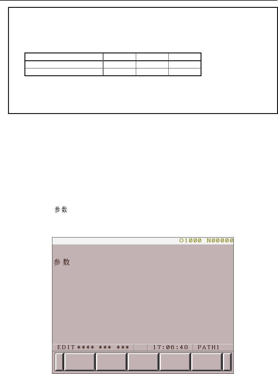
B-63943EN-2/07
6.MACRO EXECUTOR FUNCTION
- 145 -
NOTE
1 The function is not supported for prompt statement display (G280).
2 Russian Cyrillic characters can be used only for the character display
conversational macro (G243). The relationship between the usable functions and
languages is shown below.
Language G243 #3000 #3006
Simplified Chinese characters Usable Usable Usable
Russian Cyrillic characters Usable Not usable Not usable
3 This function can be used with the macro compiler below.
• Macro Compiler
A08B-9010-J600#EN07 : V01.4 or later
A08B-9010-J604#EN11 : V01.0 or later
The direct language specification function allows one-byte ASCII code characters to be specified as well.
The specifiable ASCII codes are 20H to 5FH one-byte character codes.
Simplified Chinese characters
To display simplified Chinese characters, use the G243 (character display) command.
A character string can be written directly between "(&1'" and "')" using simplified Chinese characters
(GB2312).
・Example 1 Displaying simplified Chinese characters "参数" in the character
coordinate system (0,3)
G243 X0 Y3 (&1' ');
If this command is executed, the characters are displayed at the character coordinate system position (0,3)
as shown Fig. 6.1.3 (a).
Fig. 6.1.3 (a)
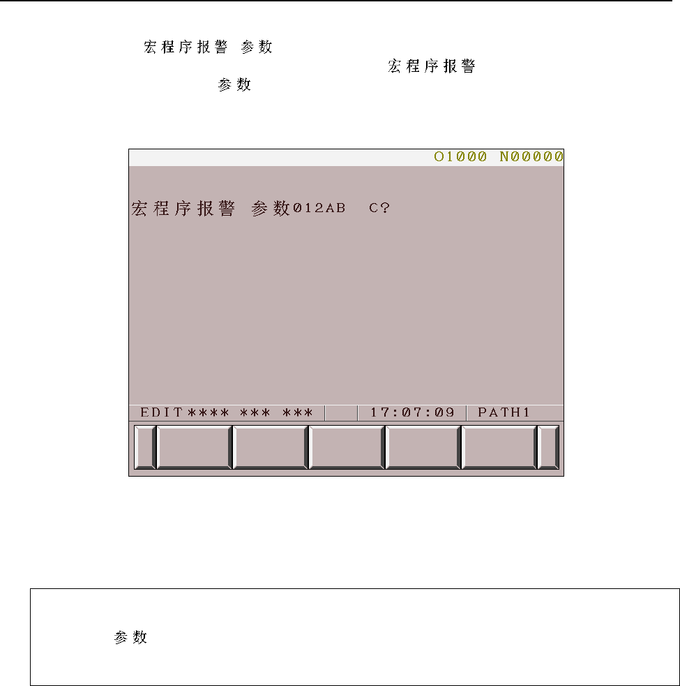
6.MACRO EXECUTOR FUNCTION
B-63943EN-2/07
- 146 -
・Example 2 Displaying simplified Chinese characters and one-byte characters
G243 X0. Y3. (&1' 012AB C?') ;
This command specifies simplified Chinese characters " ", a one-byte space character,
simplified Chinese characters " ", one-byte alphanumeric characters "012AB", two one-byte space
characters, a one-byte alphanumeric character "C", and a one-byte mark "?".
If this command is executed, the characters are displayed at the character coordinate system position (0,3)
as shown Fig. 6.1.3 (b).
Fig. 6.1.3 (b)
・Example 3 Displaying simplified Chinese characters using address P of G243
#8509=1000;
G243 X0 Y3 P10;
→ The character string in "N10", which is the sequence number of O1000, is displayed.
O1000;
:
N10(&1' ') ;
:
M99;
If this command is executed, the characters are displayed at the character coordinate system position (0,3)
as shown Fig. 6.1.3 (c).
For information about address P of G243, see the section describing address P of character display
(G243) in Subsection 6.1.3.5.
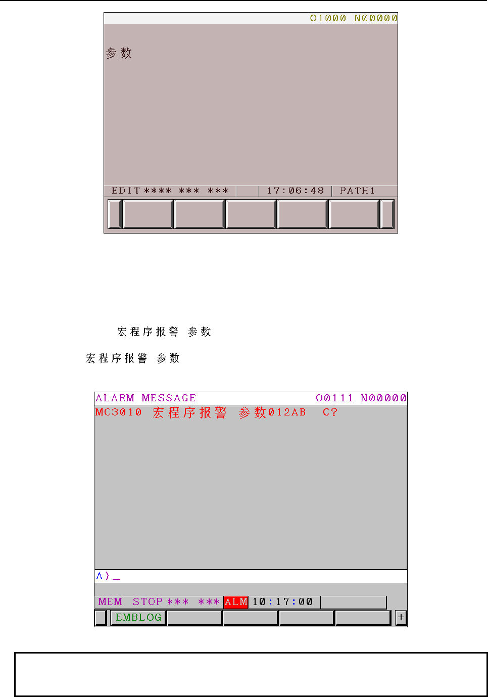
B-63943EN-2/07
6.MACRO EXECUTOR FUNCTION
- 147 -
Fig. 6.1.3 (c)
・Specifying characters using a macro alarm system variable
To display simplified Chinese characters, write the character string, enclosed by "(&1'" and "')", after the
alarm number of system variable #3000. Up to 26 one-byte characters can be displayed. As for simplified
Chinese characters (GB2312), up to 13 characters can be displayed.
Example) Displaying " 012AB C?" as an alarm message
#3000=10(&1' 012AB C?') ;
If this command is executed, the characters are displayed as shown Fig. 6.1.3 (d).
Fig. 6.1.3 (d)
NOTE
Simplified Chinese character strings are not output correctly to the operation
history punch.
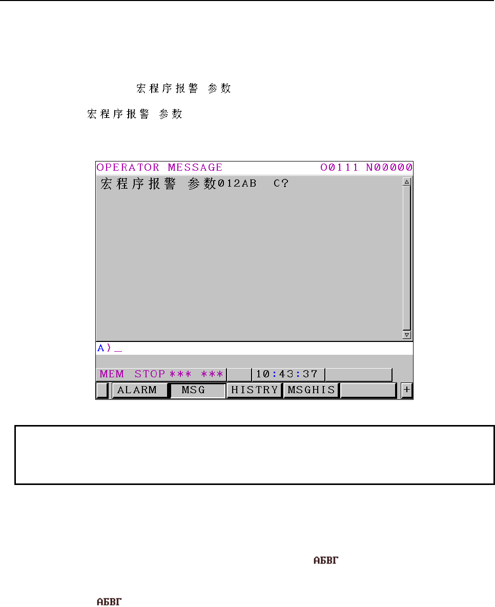
6.MACRO EXECUTOR FUNCTION
B-63943EN-2/07
- 148 -
・Specifying characters using a macro message system variable
To display simplified Chinese characters, write the character string, enclosed by "(&1'" and "')", after the
number of system variable #3006. Up to 26 one-byte characters can be displayed. As for simplified
Chinese characters (GB2312), up to 13 characters can be displayed.
Example) Displaying "
012AB C?
" as a macro message
#3006=10(&1' 012AB C?') ;
If this command is executed, the characters are displayed as shown Fig. 6.1.3 (e).
Fig. 6.1.3 (e)
NOTE
1 Simplified Chinese character strings are not output to the operation history
punch.
2 Simplified Chinese character strings are not displayed in alarm history display.
Russian Cyrillic characters
To display Russian Cyrillic characters, use the G243 (character display) command.
A character string can be written directly between "(&2'" and "')" using Russian Cyrillic characters.
・Example 1 Displaying Russian Cyrillic characters " " in the character
coordinate system (0,3)
G243 X0 Y3 (&2' ') ;
If this command is executed, the characters are displayed at the character coordinate system position (0,3)
as shown Fig. 6.1.3 (f).
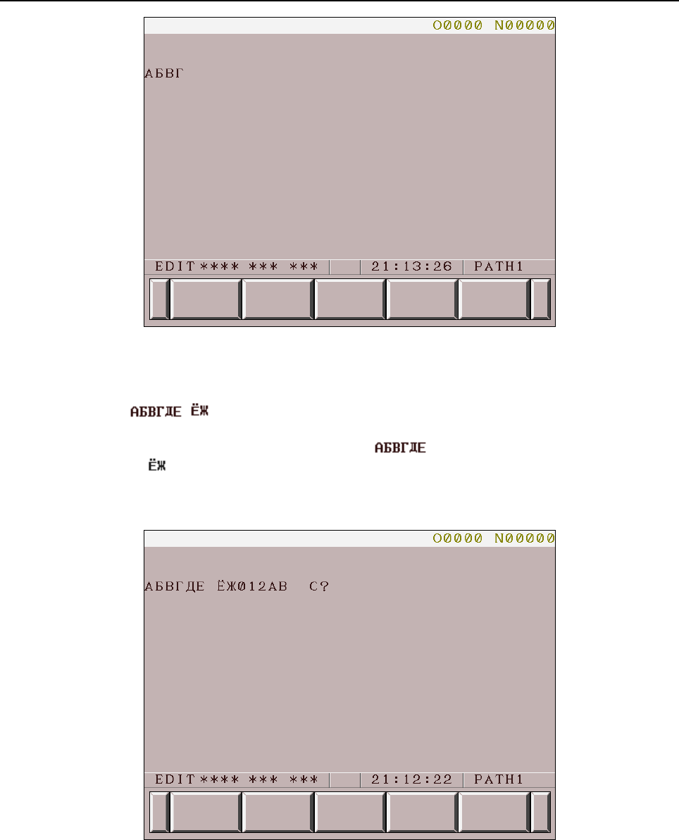
B-63943EN-2/07
6.MACRO EXECUTOR FUNCTION
- 149 -
Fig. 6.1.3 (f)
・Example 2 Displaying Russian Cyrillic characters and one-byte characters
G243 X0. Y3. (&2' 012AB C?') ;
This command specifies Russian Cyrillic characters " ", a one-byte space character, Russian
Cyrillic characters " ", one-byte alphanumeric characters "012AB", two one-byte space characters, a
one-byte alphanumeric character "C", and a one-byte mark "?".
If this command is executed, the characters are displayed at the character coordinate system position (0,3)
as shown Fig. 6.1.3 (g).
Fig. 6.1.3 (g)
・Example 3 Displaying Russian Cyrillic characters using address P of G243
#8509=1000;
G243 X0 Y3 P10;
→ The character string "N10", which is the sequence number of O1000, is displayed.
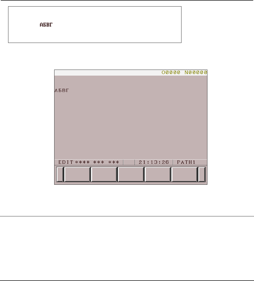
6.MACRO EXECUTOR FUNCTION
B-63943EN-2/07
- 150 -
O1000;
:
N10(&2' ') ;
:
M99;
If this command is executed, the characters are displayed at the character coordinate system position (0,3)
as shown Fig. 6.1.3 (h).
For information about address P of G243, see the section describing address P of character display
(G243) in Subsection 6.1.3.5.
Fig. 6.1.3 (h)
6.1.3.7
User-defined character registration and display function
(G319)
A character pattern uniquely created and registered by the user is called a user-defined character.
The user-defined character registration command (G319) is used to store user-defined characters in the
user-defined character memory, and the G243 (character display) command is used to display registered
character patterns.
The user-defined character memory is managed with numbers, and machine tool builders are allowed to
use the user-defined character memory in the following range:
Type of 7 soft keys: Up to 71 characters from 256 to 326
Type of 12 soft keys: Up to 256 characters from 256 to 511
Registration method
Format
G319 Pp Qq ;
- Address P
P : Number of the variable at the top that defines the character pattern
- Address Q
Q : Number of the user-defined character to be registered (decimal)
256 to 326 (for the type of 7 soft keys)
256 to 511 (for the type of 12 soft keys)

B-63943EN-2/07
6.MACRO EXECUTOR FUNCTION
- 151 -
A user-defined character consists of the following number of dots:
• Type of 7 soft keys: horizontal 16 dots × vertical 25 dots = 400 dots
• Type of 12 soft keys: horizontal 8 dots × vertical 16 dots = 128 dots
Each row of the character pattern data is stored in a variable array in binary coded decimal format. The
G319 command registers the character pattern in this variable array to the user-defined character memory.
NOTE
1 Make sure that the user-defined character number is in the range of 256 to 326
(for the type of 7 soft keys) or 256 to 511 (for the type of 12 soft keys). If an
out-of-range number is specified, the G319 command is ignored.
2 The user-defined character memory may also be used by other applications
developed by machine tool builders (e.g., C Language Executor). Take care to
avoid contention for user-defined character numbers.
3 Character patterns need to be registered in the user-defined character memory
after each power-on. (Turning off the power deletes the registered character
patterns.)
4 Make sure that the character pattern definition value is in the range of 0 to 255
(for the type of 7 soft keys) or 0 to 65535 (for the type of 12 soft keys).
・Character pattern example for the type of 7 soft keys
1234567890123456
Binary
Decimal
1○○○○○○○○○○○○○○○○
0000000000000000
0
2○○○○○○○○○○○○○○○○
0000000000000000
0
3○○○○○○●●●●○○○○○○
0000001111000000 960
4○○○○○●●●●●○○○○○○
0000011111000000 1984
5○○○○●●●●●●○○○○○○
0000111111000000 4032
6○○○○○○●●●●○○○○○○
0000001111000000 960
7○○○○○○●●●●○○○○○○
0000001111000000 960
8○○○○○○●●●●○○○○○○
0000001111000000 960
9○○○○○○●●●●○○○○○○
0000001111000000 960
10○○○○○○●●●●○○○○○○
0000001111000000 960
11○○○○○○●●●●○○○○○○
0000001111000000 960
12○○○○○○●●●●○○○○○○
0000001111000000 960
13○○○○○○●●●●○○○○○○
0000001111000000 960
14○○○○○○●●●●○○○○○○
0000001111000000 960
15○○○○○○●●●●○○○○○○
0000001111000000 960
16○○○○○○●●●●○○○○○○
0000001111000000 960
17○○○○○○●●●●○○○○○○
0000001111000000 960
18○○○○○○●●●●○○○○○○
0000001111000000 960
19○○○○○○●●●●○○○○○○
0000001111000000 960
20○○○○○○●●●●○○○○○○
0000001111000000 960
21○○○○○○●●●●○○○○○○
0000001111000000 960
22○○○○○○●●●●○○○○○○
0000001111000000 960
23○○○○●●●●●●●●○○○○
0000111111110000 4080
24○○○○○○○○○○○○○○○○
0000000000000000
0
25○○○○○○○○○○○○○○○○
0000000000000000
0
●
: On (blinking)
〇
: Off (steady off)
6.MACRO EXECUTOR FUNCTION
B-63943EN-2/07
- 152 -
・Character pattern example for the type of 12 soft keys
12345678
Binary
Decimal
1○○○○○○○○
00000000
0
2○○○●●○○○
00011000
24
3○○●●●○○○
00111000 56
4○○○●●○○○
00011000 24
5○○○●●○○○
00011000 24
6○○○●●○○○
00011000 24
7○○○●●○○○
00011000 24
8○○○●●○○○
00011000 24
9○○○●●○○○
00011000 24
10○○○●●○○○
00011000 24
11○○○●●○○○
00011000 24
12○○○●●○○○
00011000 24
13○○○●●○○○
00011000 24
14○○○●●○○○
00011000 24
15○○●●●●○○
00111100 60
16○○○○○○○○
00000000
0
Display method
To display a registered user-defined character, specify the character display command (G243) as follows.
Format
G243 Xx Yy Aa Qq ;
or
G243 Xx Yy Aa (”8qqqq”) ;
- Addresses X and Y
In addresses X and Y, specify the display position of the character string using the character coordinate
system.
X : X coordinate of the display position of the character string
Y : Y coordinate of the display position of the character string
- Address A
In address A, specify the character size.
A=1 : Standard-size character
A=2 : Double-size character (two times horizontally and one time vertically)
A=3 : Triple-size character (three times horizontally and two times vertically)
As for double-size and triple-size characters, the user-defined characters of the specified user-defined
character numbers, as well as those of the specified user-defined character numbers + α, are displayed
collectively. The display method is described below.
Example
- Standard size G243 Xx Yy A1 Q256 ; /* or (“8100”)
256
- Double size G243 Xx Yy A2 Q256 ; /* or (“8100”)
256 257
B-63943EN-2/07
6.MACRO EXECUTOR FUNCTION
- 153 -
- Triple size G243 Xx Yy A3 Q256 ; /* or (“8100”)
256 257 258
259 260 261
(The number in each cell represents a user-defined character number.)
- Address Q
Q : Number of the user-defined character to be displayed (decimal)
Address Q is equivalent to address Q of the user-defined character registration command (G319).
NOTE
Do not specify two or more identical addresses in the same one block.
If two or more identical addresses are specified, the later specified address value
takes effect.
- (”8qqq”)
"8" is a fixed value indicating user-defined character display.
qqq : Number of the user-defined character to be displayed (hexadecimal)
In qqq, specify address Q of the user-defined character registration command (G319) in
hexadecimal notation.
100h to 146h (for the type of 7 soft keys)
100h to 1FFh (for the type of 12 soft keys)
Example
An example of registering and displaying user-defined characters for the type of
12 soft keys is shown below.
/* 12345678
#110 = 1 ; /* 1 ○○○○○○○●
#111 = 3 ; /* 2 ○○○○○○●●
#112 = 7 ; /* 3 ○○○○○●●●
#113 = 15 ; /* 4 ○○○○●●●●
#114 = 255 ; /* 5 ●●●●●●●●
#115 = 96 ; /* 6 ○●●○○○○○
#116 = 51 ; /* 7 ○○●●○○●●
#117 = 25 ; /* 8 ○○○●●○○●
#118 = 12 ; /* 9 ○○○○●●○○
#119 = 14 ; /* 10 ○○○○●●●○
#120 = 31 ; /* 11 ○○○●●●●●
#121 = 31 ; /* 12 ○○○●●●●●
#122 = 63 ; /* 13 ○○●●●●●●
#123 = 60 ; /* 14 ○○●●●●○○
#124 = 112 ; /* 15 ○●●●○○○○
#125 = 192 ; /* 16 ●●○○○○○○
G319 P110 Q256 ; /* Registered to user-defined character number 256
6.MACRO EXECUTOR FUNCTION
B-63943EN-2/07
- 154 -
/* 12345678
#110 = 128 ; /* 1●○○○○○○○
#111 = 192 ; /* 2●●○○○○○○
#112 = 224 ; /* 3●●●○○○○○
#113 = 240 ; /* 4●●●●○○○○
#114 = 255 ; /* 5●●●●●●●●
#115 = 6 ; /* 6
○○○○○●●○
#116 = 204 ; /* 7●●○○●●○○
#117 = 152 ; /* 8●○○●●○○○
#118 = 48 ; /* 9
○○●●○○○○
#119 = 112 ; /* 10○●●●○○○○
#120 = 248 ; /* 11●●●●●○○○
#121 = 248 ; /* 12●●●●●○○○
#122 = 252 ; /* 13●●●●●●○○
#123 = 60 ; /* 14○○●●●●○○
#124 = 14 ; /* 15○○○○●●●○
#125 = 3 ; /* 16○○○○○○●●
G319 P110 Q257 ; /* Registered to user-defined character number 257
G243 X5 Y2 A2 Q256 ; /* Displaying user-defined character numbers 256 and 257
/* or
/*G243 X5 Y2 A2 ("8100")
6.1.3.8
Drawing line type specification (G244)
This code specifies the type of the line segment to be drawn by linear or circular drawing.
Format
G244 Pp ;
P=0 : Solid line
=1 : Broken line
=2 : Alternate long and short dash line
=3 : Alternate long and two short dashes line
=4 : Erasure
=5 : Dotted line
=17 : Broken line where broken parts are not drawn
=18 : Alternate long and short dash line where broken parts are not drawn
=19 : Alternate long and two short dashes line where broken parts are not drawn
=21 : Dotted line where broken parts are not drawn
NOTE
1 This code is disabled when bit 4 (NVGA) of compile parameter No. 9167 is set to
1.
2 Solid line is automatically assumed when the graphic screen clear code (G202)
is issued.
3 For each of the lines where broken parts are not drawn (P = 17, 18, 19, and 21),
parts where the line is broken are not drawn. For a screen without background
color, specify with P of 1, 2, 3, or 5 and for a screen with background color,
specify with P of 17, 18, 19, or 21.

B-63943EN-2/07
6.MACRO EXECUTOR FUNCTION
- 155 -
6.1.3.9
Prompt statement display (G280)
A prompt statement is a statement that prompts input. In character string input mode (data input control
variable #8502 is equal to 3), a prompt statement of up to 39 characters can be displayed on the key input
line.
The character string can be specified in the same way as with G243.
Format
G280 Cc Kk Pp ( _ ) ;
C : Character code. (See the explanation of G243.)
K : Number of spaces. (See the explanation of G243.)
P : Number of the sequence containing a character string. (See the explanation of G243.)
( _ ) : Character string to be displayed. (See the explanation of G243)
NOTE
1 G280 is a one-shot G code, which means that the code is effective only in the
block in which it is specified.
2 If a prompt statement is displayed with multiple addresses, a single space is
automatically inserted between the character string displayed with one address
and that displayed with another.
6.1.3.10
Linear drawing (G01)
This code draws a straight line up to the specified X and Y coordinates, with the line type specified with
G244 and the color specified with G240.
Format
G01 Xx Yy ;
X : X coordinate of the end point of linear drawing
Y : Y coordinate of the end point of linear drawing
NOTE
1 This code is disabled when bit 4 (NVGA) of compile parameter No. 9167 is set to
1.
2 The commands of addresses X and Y are:
- Absolute commands at all times when bit 3 (INCD) of compile parameter No.
9167 is set to 0.
- Switched between absolute and incremental commands by G390/G391 when
bit 3 (INCD) of compile parameter No. 9167 is set to 1.
6.1.3.11
Circular drawing (clockwise) (G02)
6.1.3.12
Circular drawing (counterclockwise) (G03)
An arc is drawn using the line type specified by G244 and the color specified by G240, ending at the
point of specified X and Y coordinates. Two methods are available to specify the center (I,J) of an arc.
When the bit 3(INCD) of compile parameter No. 9167 is set to 0 :
Not only the end coordinates of an arc but also the center coordinates of the arc are specified using
absolute coordinates.
When the bit 3(INCD) of compile parameter No. 9167 is set to 1 :
The vector from the start point of an arc to the center of the arc is used for specification.
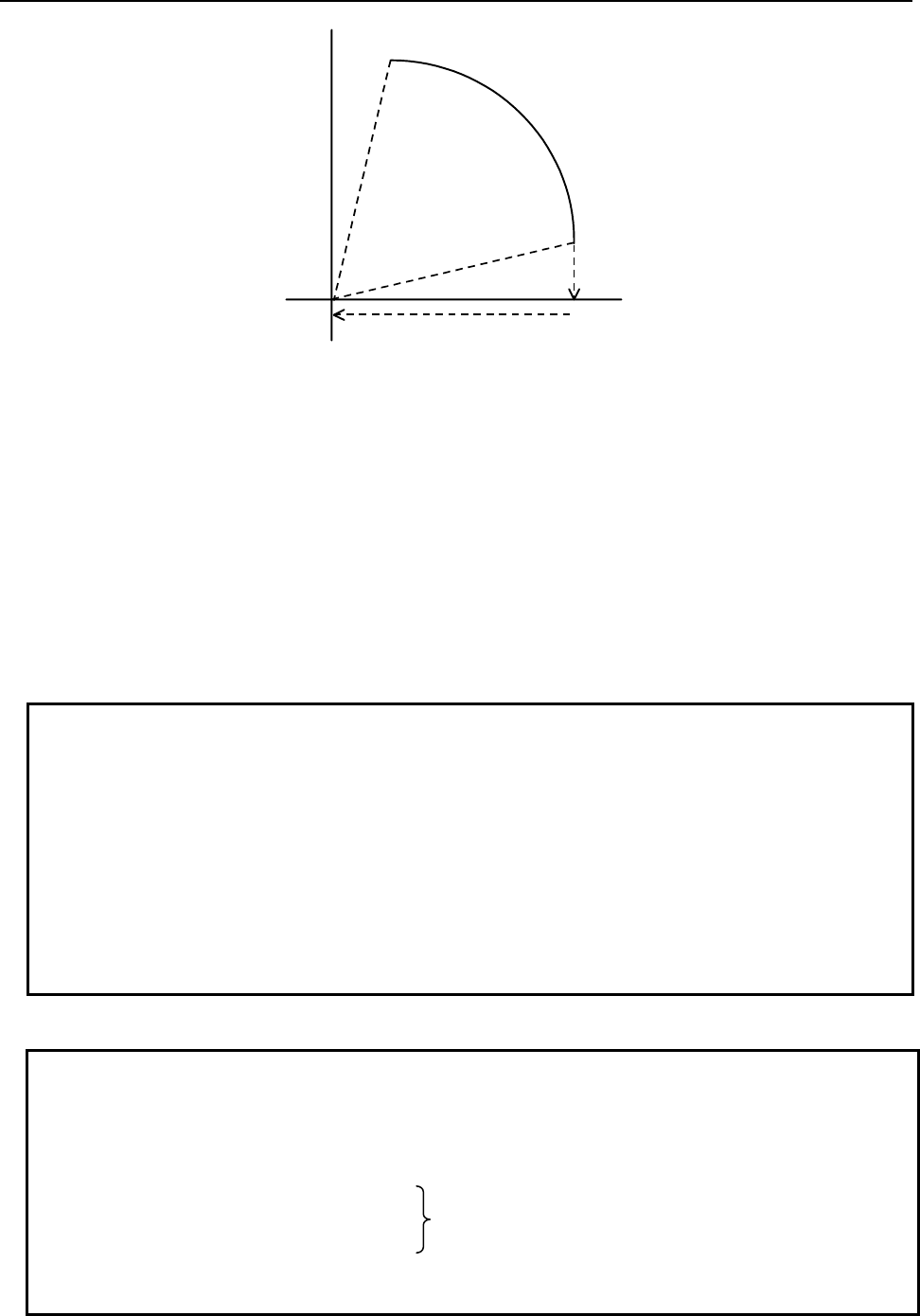
6.MACRO EXECUTOR FUNCTION
B-63943EN-2/07
- 156 -
Center
I
J
Start point
(X,Y) End point
G02 draws an arc clockwise.
G03 draws an arc counterclockwise.
Format
G02 Xx Yy Ii Jj ;
G03 Xx Yy Ii Jj ;
X : X coordinate of the end point of circular drawing
Y : Y coordinate of the end point of circular drawing
I : X coordinate of the center of circular drawing
(Component of the X-direction vector from the start point of the arc to the center of the arc when bit 3
(INCD) of compile parameter No. 9167 is set to 1)
J : Y coordinate of the center of circular drawing
(Component of the Y-direction vector from the start point of the arc to the center of the arc when bit 3
(INCD) of compile parameter No. 9167 is set to 1)
NOTE
1 This code is disabled when bit 4 (NVGA) of compile parameter No. 9167 is set to
1.
2 The commands of addresses X and Y are:
- Absolute commands at all times when bit 3 (INCD) of compile parameter No.
9167 is set to 0.
- When bit 3 (INCD) of compile parameter No. 9167 is set to 1, the commands of
addresses X and Y are switched between absolute and incremental commands
by G390/G391.
3 The command values of addresses I and J are based on the vector from the
start point of an arc to the center of the arc.
Example of program for circular drawing
Example
Bit 3(INCD) of compile parameter No.9167 =1
G390 G242 X150.0 Y0.0 ; ........... Set the drawing start point.
G01 X250.0 ; ............................... Draw a straight line to X250. using an
absolute command.
G02 X150.0 I-50.0 J0.0 ; I represents the X-direction vector
component as seen from the start point of
an arc to the center of the arc.
G391G03 X-300.0 I-150.0 ;
G01 X300.0 ;
Since X, Y, I, and J are modal addresses, the previously specified values are
assumed if they are omitted.
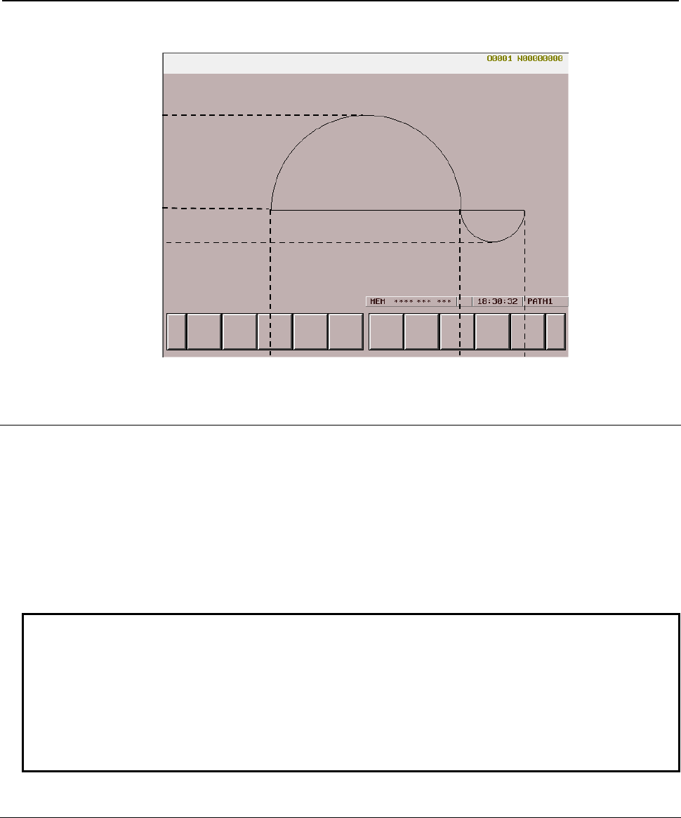
B-63943EN-2/07
6.MACRO EXECUTOR FUNCTION
- 157 -
When the program above is executed, the following is drawn in the graphic coordinate system:
150
0
-50
-150 150 250
6.1.3.13
Cursor display (rectangular cursor) (G230)
This code displays the character cursor yellow in reverse video.
Format
G230 Xx Yy Ll ;
Addresses X and Y specify the display position of the cursor in the character coordinate system.
X : X coordinate of the cursor display position
Y : Y coordinate of the cursor display position
Address L specifies the length of the cursor.
L : Specification of the cursor length
NOTE
1 The cursor is erased when the cursor length is set to 0.
2 The cursor can also be erased by the character screen clear code (G202).
3 The commands of addresses X and Y are:
- Absolute commands at all times when bit 3 (INCD) of compile parameter No.
9167 is set to 0.
- Switched between absolute and incremental commands by G390/G391 when
bit 3 (INCD) of compile parameter No. 9167 is set to 1.
6.1.3.14
Graphic cursor function (G249)
Graphic cursor display can be provided with a conversational macro.
Format
G249 Pp Xx Yy ;
P : Control command
=0 : Display ON (turned on)
=1 : Display ON (low-speed blink display)
=2 : Display ON (high-speed blink display)
=3 : Display OFF

6.MACRO EXECUTOR FUNCTION
B-63943EN-2/07
- 158 -
X : X coordinate of the graphic cursor display position
Y : Y coordinate of the graphic cursor display position
NOTE
1 This code is disabled when bit 4 (NVGA) of compile parameter No. 9167 is set to
1.
2 The commands of addresses X and Y are:
- Absolute commands at all times when bit 3 (INCD) of compile parameter No.
9167 is set to 0.
- Switched between absolute and incremental commands by G390/G391 when
bit 3 (INCD) of compile parameter No. 9167 is set to 1.
3 Addresses X and Y may be omitted. For an omitted address, the value
previously specified with G249 is used.
4 Moving the graphic cursor does not affect the current position in the graphic
coordinate system.
5 If the graphic screen is cleared with “G202 P1 ;” or “G202 P3 ;”, the graphic
cursor is erased. Moreover, the position of the graphic cursor is initialized to
(0,0).
6.1.3.15
Cursor control (#8505, #8506, and #8507)
By setting a value in the cursor control variable #8505, the cursor can be displayed.
#8505=0: Erases the cursor.
=1: Displays the cursor.
When the power is turned on, the value of #8505 is 0.
The cursor can be displayed at a desired position by setting a value in the cursor X position control
variable #8506 and the cursor Y position control variable #8507. Specify a cursor position in the
character coordinate system.
NOTE
1 The cursor drawn is displayed as an underscore (_). This function is different
from cursor control (rectangular cursor) based on G230, and can be used
together with the rectangular cursor.
2 Even when the screen clear function (G202) is specified, the control variables
#8505, #8506, and #8507 are not affected. So, the cursor displayed is not
moved or erased.
3 Even if an attempt is made for character coordinate system compensation on a
8.4" LCD unit, compensation is not performed.
4 The cursor is colored according to the color at the position where the cursor is
placed.
6.1.3.16
Absolute mode (G390)/incremental mode (G391) specification
When bit 3 (INCD) of compile parameter No. 9167 is set to 1, whether a coordinate command in the
character coordinate system and graphic coordinate system is an absolute mode command (G390) or
incremental mode command (G391) is to be specified.
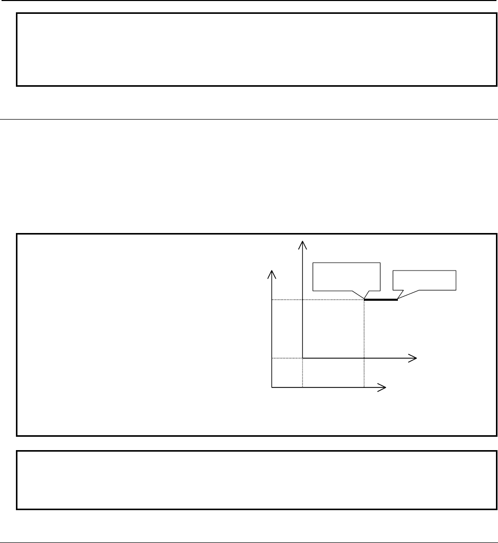
B-63943EN-2/07
6.MACRO EXECUTOR FUNCTION
- 159 -
NOTE
1 When bit 3 (INCD) of compile parameter No. 9167 is set to 0, an absolute mode
command is specified at all times.
2 These codes are effective to G204, G230, G242, G243, G300, G249, G01, G02,
G03, G206, and G317.
6.1.3.17
Graphic coordinate system setting (G392)
This code sets the current position to a specified position in the graphic coordinate system. The
subsequent drawing commands are executed in this coordinate system.
Format
G392 Xx Yy ;
X : X coordinate
Y : Y coordinate
Example
N01 G242 X100.0 Y100.0 ;
N02 G392 X60.0 Y60.0 ;
N03 G01 X100.0 ;
When the above program is
executed, the position (100, 100)
assumed in N01 changes to (60,
60) in N02, and linear drawing is
performed from (60, 60) to (100, 60)
in N03.
As a result, the origin position shifts
by (40, 40).
40
60
0
0
N03(100,60)
N01(100,100)
N02(60,60)
60
100
0
100
0 40
NOTE
1 The specified X and Y coordinates are always assumed absolute.
2 This code is disabled when bit 4 (NVGA) of compile parameter No. 9167 is set to
1.
6.1.3.18
Rapid traverse rate specification (G311)
This code specifies the X- and Y-axis speed ratios assumed during rapid traverse drawing.
Format
G311 Xx Yy ;
Specify a speed ratio when performing rapid traverse drawing.
X : Rapid traverse drawing speed ratio in the X axis
Y : Rapid traverse drawing speed ratio in the Y axis
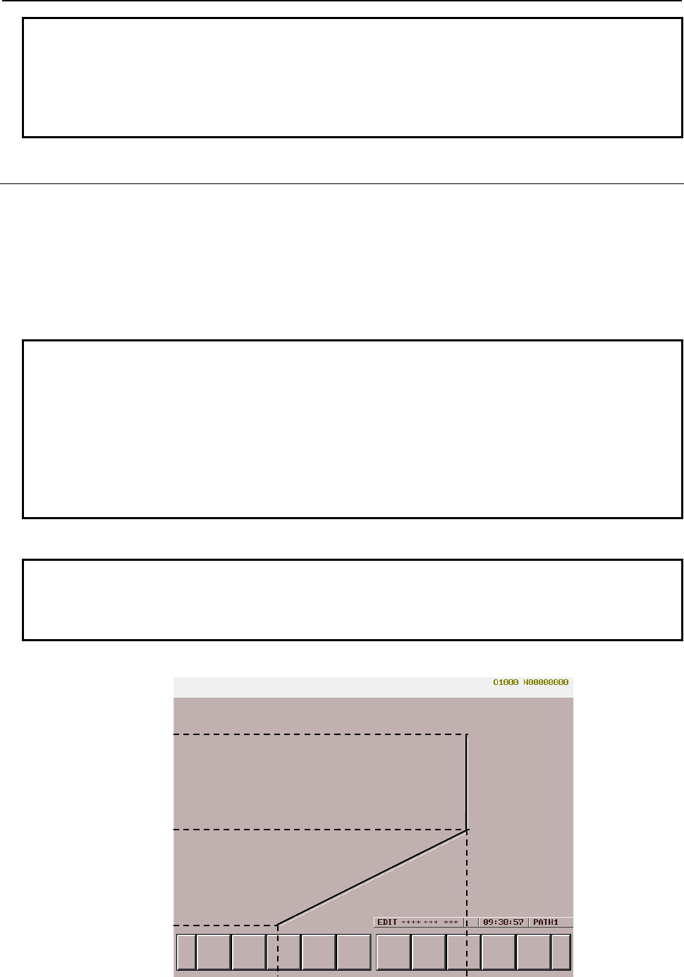
6.MACRO EXECUTOR FUNCTION
B-63943EN-2/07
- 160 -
NOTE
1 The rapid traverse drawing speed ratios must be positive integer numbers in the
range of 1 to 32767.
2 The specified X and Y values are always assumed absolute.
3 This code is disabled when bit 4 (NVGA) of compile parameter No. 9167 is set to
1.
6.1.3.19
Rapid traverse drawing (G300)
This code performs drawing with rapid traverse from the current position to a specified point. The path is
determined with the rapid traverse rate specification.
Format
G300 Xx Yy ;
X : X coordinate for rapid traverse drawing
Y : Y coordinate for rapid traverse drawing
NOTE
1 The commands of addresses X and Y are:
- Absolute commands at all times when bit 3 (INCD) of compile parameter No.
9167 is set to 0.
- Switched between absolute and incremental commands by G390/G391 when
bit 3 (INCD) of compile parameter No. 9167 is set to 1.
2 Non-linear drawing is always performed regardless of the CNC parameters.
3 This code is disabled when bit 4 (NVGA) of compile parameter No. 9167 is set to
1.
Rapid traverse drawing program example
Example
G311 X200.0 Y100.0 ;
G242 X-150.0 Y-150.0 ;
G300 X150.0 Y150.0 ;
When the above program is executed, drawing is performed in the graphic coordinate system as shown
below.
-150
0
150
-150 150
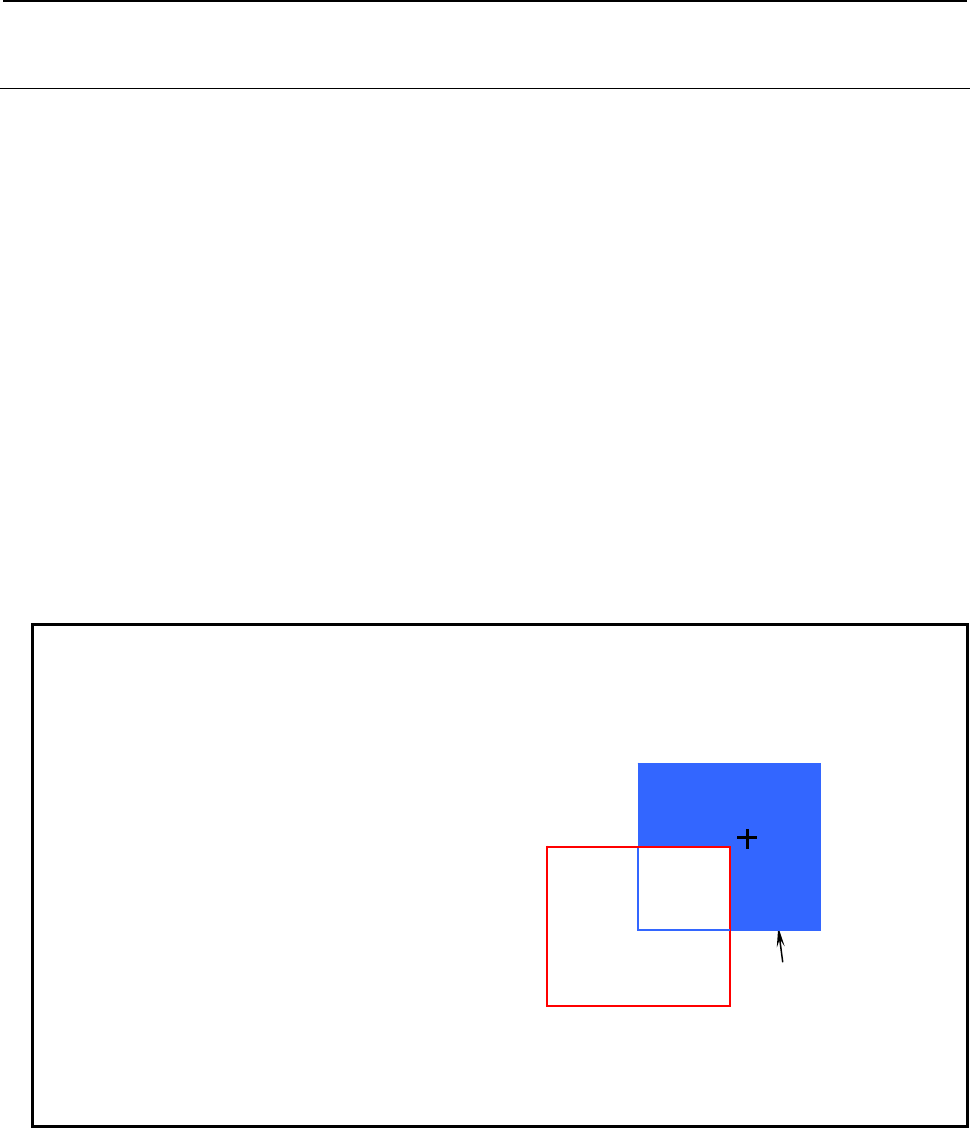
B-63943EN-2/07
6.MACRO EXECUTOR FUNCTION
- 161 -
6.1.3.20
Graphic filling function (G206)
With the graphic function, an area to be filled is to be drawn by solid lines beforehand. Then, an arbitrary
point in the area and a boundary color for filling are to be specified together with G206. As the color for
filling, the display color specified when G206 is specified is used.
Format
G206 Xx Yy Pp ;
X : Arbitrary point in an area to be filled (X coordinate)
Y : Arbitrary point in an area to be filled (Y coordinate)
P : Boundary color for filling
Boundary color for filling (Pp)
P = 0 : Same as filling color
= 8 : Other than black (color palette with 0 set for R, G, and, B)
- The color of color palette 8 cannot be used.
- The colors of P1 to P7 and P9 to P15 are the same as for G240. So, see Subsection 6.1.3.2, "Color
specification (G240)". (No minus (-) value can be specified.)
- When the same color as used for filling or P0 is specified as the boundary color, those lines in other
colors that are placed in the area to be filled are filled.
- When P8 is specified as the boundary color, the innermost area is filled.
Example
1 When P8 (color other than the color palette with 0 set for all of R, G, and B) is
specified as the boundary color:
G240P1; ..... Red line
G244P0; ..... Solid line
G242X0.0Y0.0;
G01X100.0;
Y100.0;
X0.0;
Y0.0;
G240P4; ..... Blue line
G242X50.0Y50.0;
G01X150.0;
Y150.0;
X50.0;
Y50.0;
G206P8X110.0Y110.0; → The innermost area is filled.
Red line
Blue line
Filled in
blue
(110,110)
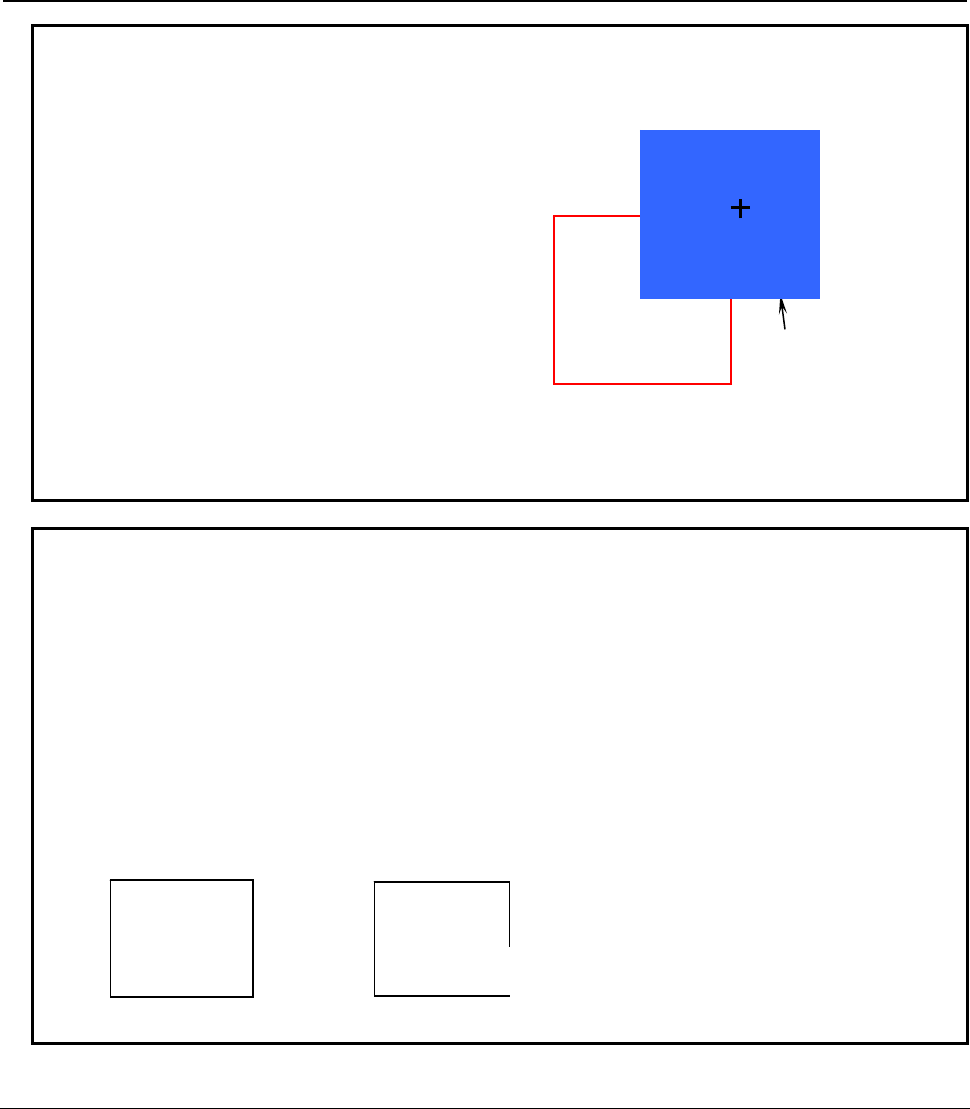
6.MACRO EXECUTOR FUNCTION
B-63943EN-2/07
- 162 -
Example
2 When P0 (same as the color for filling) is specified as the boundary color:
G240P1; ..... Red line
G244P0; ..... Solid line
G242X0.0Y0.0;
G01X100.0;
Y100.0;
X0.0;
Y0.0;
G240P4; ..... Blue line
G242X50.0Y50.0;
G01X150.0;
Y150.0;
X50.0;
Y50.0;
G206P0X110.0Y110.0; → The red lines in the area to be filled are filled.
NOTE
1 This code is disabled when bit 4 (NVGA) of compile parameter No. 9167 is set to
1.
2 The commands of addresses X and Y are:
- Absolute commands at all times when bit 3 (INCD) of compile parameter No.
9167 is set to 0.
- Switched between absolute and incremental commands by G390/G391 when
bit 3 (INCD) of compile parameter No. 9167 is set to 1.
3 When bit 3 (GPNT) of compile parameter No. 9003 is set to 1, the color of color
palette 8 can be used. In this case, P16 is used to specify a boundary color other
than black (with 0 set for all of R, G, and B).
4 A fill area must be defined by a closed line.
6.1.3.21
Rectangular display (G204)
This code fills the rectangle having points (X, Y) and (I, J) as diagonal points with the color specified for
P, and fills the edge of the outer frame with the color specified with G240.
Format
G204 Xx Yy Ii Jj [Pp] ;
X : X coordinate of the rectangular display start position
Y : Y coordinate of the rectangular display start position
I : X coordinate of the rectangular display end position
J : Y coordinate of the rectangular display end position
P : Color with which the rectangle is to be filled
The setting of color is the same as for P of G240. So, see Subsection 6.1.3.2, "Color specification (G240)".
No minus (-) value can be specified.
Red line
Blue line
Filled in
blue
(110,110)
A
llowed Not allowed
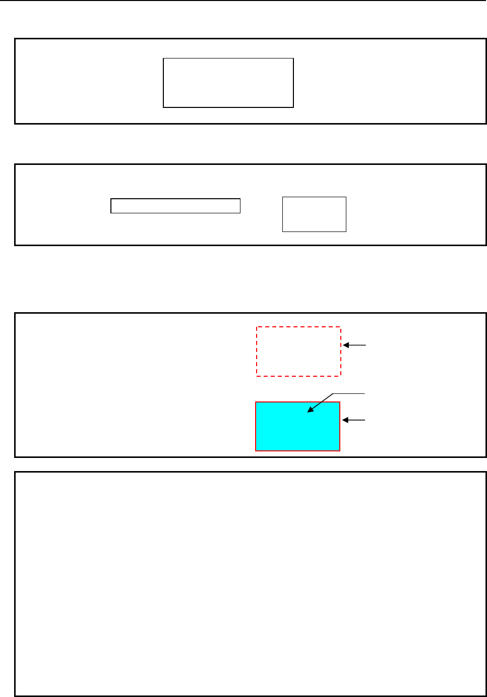
B-63943EN-2/07
6.MACRO EXECUTOR FUNCTION
- 163 -
[ ] may be omitted.
Example
The points specified by addresses X and Y and addresses I and J may be at any positions that can form a
rectangle.
Example
• When P is not specified, filling is not performed, but the outer frame only is drawn using the color
specified by G240.
• The line type of a rectangle is specified using the line type command (G244P_).
Example
1 When P is not specified:
2 When P is specified:
NOTE
1 This code is disabled when bit 4 (NVGA) of compile parameter No. 9167 is set to
1.
2 The commands of addresses X and Y are:
- Absolute commands at all times when bit 3 (INCD) of compile parameter No.
9167 is set to 0.
- Switched between absolute and incremental commands by G390/G391 when
bit 3 (INCD) of compile parameter No. 9167 is set to 1.
3 When specifying fill processing, be sure to specify a solid line.
4 Fill processing starts at the point defined by the midpoint between addresses X
and I and the midpoint between addresses Y and J.
5 The boundary color of fill processing is handled as a frame line color (specified
by G240P_).
6 After execution with address P specified, the color specification (G240P_) is
updated to the color of address P to change the color of the subsequent line
segments and character strings.
(Xx,Yy)
(Ii,Jj)
(Ii,Jj)
(Xx,Yy)
(Ii,Jj)
(Xx,Yy)
G244P1; ........ Dashed line
G240P1; ........ Red line
G204 X-200. Y150.0 I0.0 J10.0 ;
G244P0; ........ Solid line
G240P1; ........ Red line
G204 X-200. Y150.0 I0.0 J10.0 P6 ;
Red frame line
Red frame line
Light blue within frame
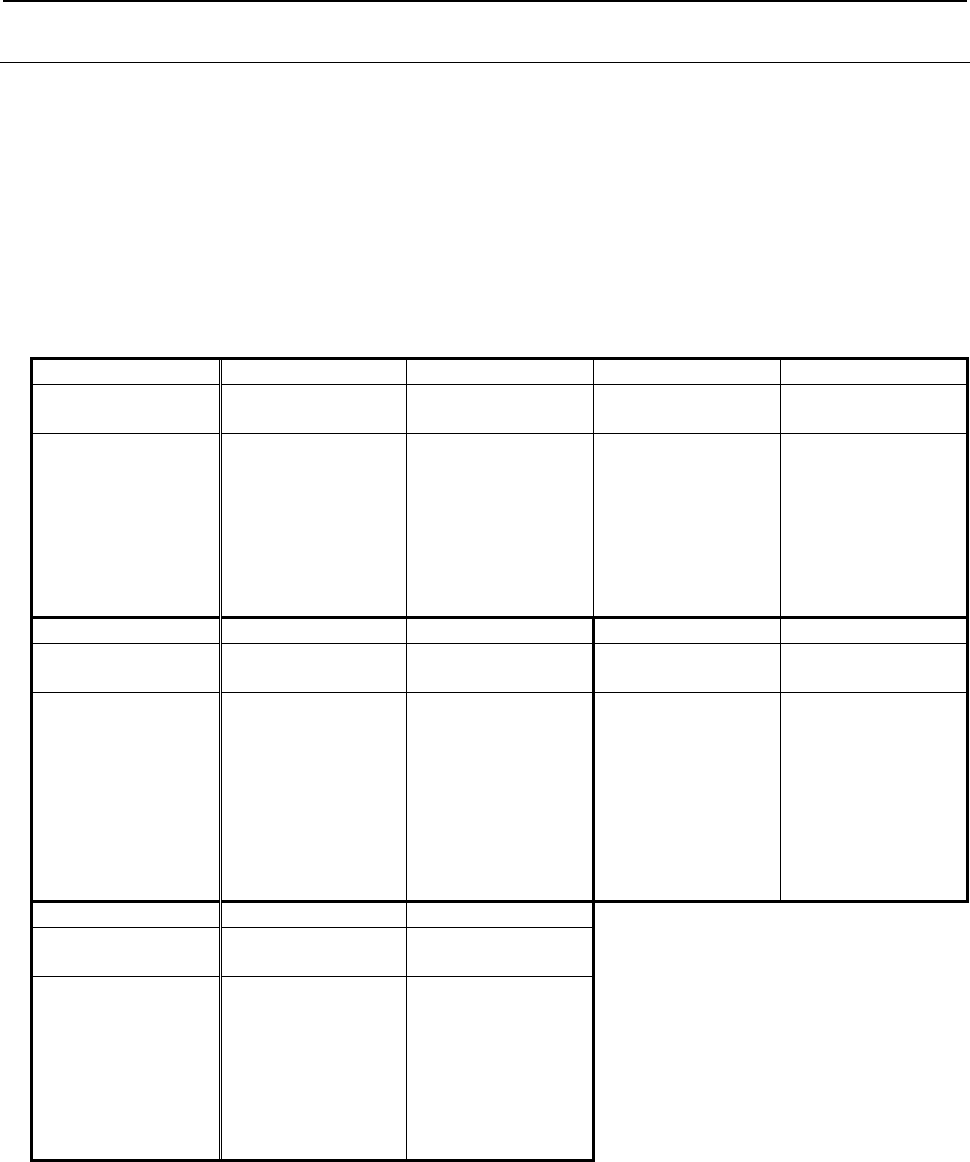
6.MACRO EXECUTOR FUNCTION
B-63943EN-2/07
- 164 -
6.1.3.22
Marking (G321)
This code draws the mark specified for M with the color specified for P at the position specified for X and
Y (graphic coordinates).
Format
G317 Xx Yy Mm Pp ;
X : X coordinate of the position at which a mark is to be displayed
Y : Y coordinate of the position at which a mark is to be displayed
M : Specification of the number of the mark to be displayed
P : Specification of the color of the mark to be displayed
The available marks are shown below as dot patterns, together with the mark numbers.
Mark number
1 2 3 4
Mark Origin mark Arrow head pointing
upward
Arrow head pointing
downward
Arrow head pointing to
the left
00000
0 0000
0 00000
0 00000
0000*0000
0000 0
0000 0
000 0
00000
*
0 0
0 0
0
0
0 0
0 0
0 0
*
0
0
0
*
0
0
0
Mark number
5 6 7 8
Mark Arrow head pointing to
the right
Arrow head pointing to
the upper left
Arrow head pointing to
the lower left
Arrow head pointing to
the upper right
0
0
0
*
0
0
0
*000
0
0
0
0
0
0
*000
000*
0
0
0
Mark number
9 10
Mark Arrow head pointing to
the lower right Black, round mark
0
0
0
000*
000
00000
0000000
000*000
0000000
00000
000
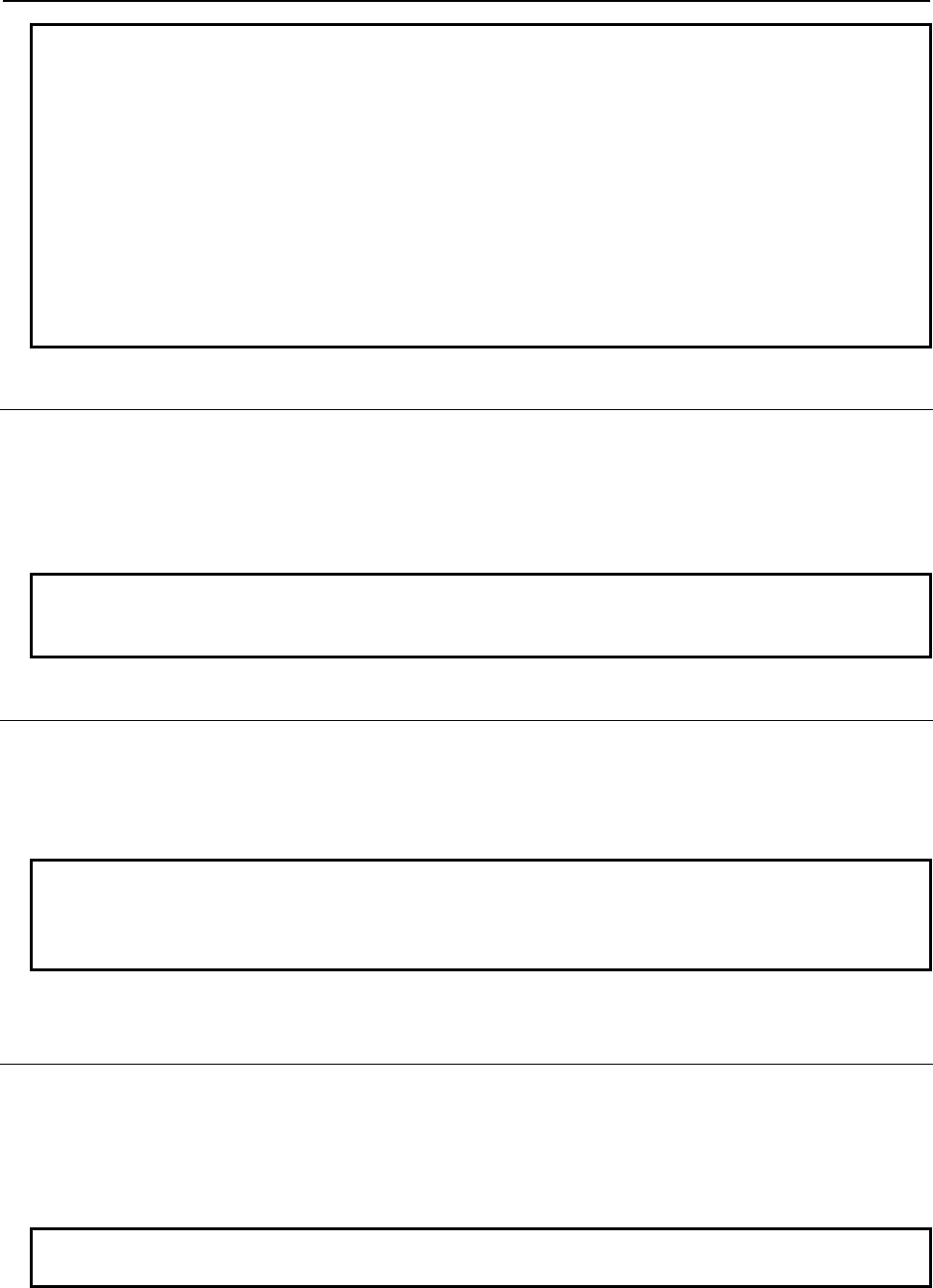
B-63943EN-2/07
6.MACRO EXECUTOR FUNCTION
- 165 -
NOTE
1 The asterisk "*" indicates the position specified for X and Y.
2 The commands of addresses X and Y are:
- Absolute commands at all times when bit 3 (INCD) of compile parameter No.
9167 is set to 0.
- Switched between absolute and incremental commands by G390/G391 when
bit 3 (INCD) of compile parameter No. 9167 is set to 1.
3 This code is disabled when bit 4 (NVGA) of compile parameter No. 9167 is set to
1.
4 When address P is omitted, the mark is displayed by the color palette 7.
5 When addresses X and Y are omitted, the mark is displayed at the current
position.
6.1.3.23
Shift function for graphic screen adjustment
This function allows shifting of the origin of the graphic coordinate system on the conversational macro
screen in units of dots by using compile parameters Nos. 9048 and 9049.
The X coordinate of the current origin of the graphic coordinate system is changed to the coordinate
specified for compile parameter No.9048. The Y coordinate of the current origin of the graphic coordinate
system is changed to the coordinate specified for compile parameter No.9049.
NOTE
This code is disabled when bit 4 (NVGA) of compile parameter No. 9167 is set to
1.
6.1.3.24
Reading of the graphic state (#8800)
By reading graphic state reading variable #8800, it can be determined whether the graphics is available in
conversational macro.
#8800 = 0 : The graphics is available in conversational macro.
#8800 = 1 : The graphics is not available in conversational macro.
NOTE
When bit 4 (NVGA) of compile parameter No. 9167 is set to 1, graphic display
cannot be used. So, 1 is read from the graphic state read variable #8800 at all
times.
6.1.3.25
Brightness modulation mode display on the monochrome
LCD and base color
On the monochrome LCD, bit 2 (MVD) of parameter No. 9033 can be used to put the conversational
macro screen in the brightness modulation mode.
The brightness of the screen is specified using the display color type specification control code (G240).
If the screen is not put in the brightness modulation mode, all colors except for color palette 0 (standard
color of black) are displayed as a color on color palette 7 (standard color of white).
NOTE
The monochrome LCD is for the Series 30i /31i /32i -A.

6.MACRO EXECUTOR FUNCTION
B-63943EN-2/07
- 166 -
6.1.3.26
Differences from the Series 16i
Function Series 16i/18i/21i Series 30i/31i/32i/35i/0i-F/PMi
Graphic resolution For an indicator with 7 soft keys
Bit 2 (HRGR) of compile parameter
No. 9003 = 0
Standard mode: 320
×
270 dots
Bit 2 (HRGR) of compile parameter
No. 9003 = 1
High resolution mode: 640
×
480
dots
640
×
480 dots as standard
Be sure to set bit 2 (HRGR) of compile parameter
No. 9003 to 1.
Character display
(G243)
Address X, Y
Absolute command only When bit 3 (INCD) of compile parameter No. 9167
is set to 1, switching between the absolute
command and incremental command is enabled
with G390/G391.
Character display
(G243)
Address D
The number of significant display
digits is 8.
The number of significant display digits is 12.
(However, no more than 9 digits can be specified
using an immediate value.)
Character
display(G243)
Address F
The maximum number of digits is 8.
The number of decimal places is 3.
The maximum number of digits is 12.
The number of decimal places is 6.
Number of character
string sets specifiable
in a single character
display (G243) block
As many (_), (’_’), and (*_*) sets as
necessary can be specified in the
same block.
Up to five (_), (’_’), and (*_*) sets in total are
effective in the same block.
Sequence of modal
addresses processed
with a conversational
macro
Unlike ordinary NC programs, the
conversational macro program
processes each address in the
sequence in which they were
specified.
Example of operation
<1> F8.3;
G243 F5.1 D#100;
→
#100 is represented with
F5.1.
<2> F8.3;
G243 D#100 F5.1;
→
#100 is represented with
F8.3.
Like ordinary NC programs, the conversational
macro program processes data other than
character strings in block units. Therefore,
operations do not change according to the
specified sequence.
Example of operation
<1> F8.3;
G243 F5.1 D#100;
→
#100 is represented with F5.1.
<2> F8.3;
G243 D#100 F5.1;
→
#100 is represented with F5.1.
Display if the same
addresses are
specified in the same
block (G243)
They are all displayed in the order in
which they are specified.
The same addresses can be
specified in a single block, as in
G243X_Y_C_C_.
The last address becomes effective. Thus, the
same addresses cannot be specified in a single
block as in G243X_Y_C_C_. They must be
specified in separate blocks as shown below.
G243X_Y_C_;
C_;
Linear drawing (G01)
Addresses X and Y
Absolute command only When bit 3 (INCD) of compile parameter No. 9167
is set to 1, switching between the absolute
command and incremental command is enabled
with G390/G391.
Circular drawing (G02
and G03)
Addresses X, Y, I,
and J
Absolute command only When bit 3 (INCD) of compile parameter No. 9167
is set to 1, switching between the absolute
command and incremental command is enabled
with G390/G391.
Graphic filling function
(G206)
Addresses X and Y
Absolute command only When bit 3 (INCD) of compile parameter No. 9167
is set to 1, switching between the absolute
command and incremental command is enabled
with G390/G391.

B-63943EN-2/07
6.MACRO EXECUTOR FUNCTION
- 167 -
Function Series 16i/18i/21i Series 30i/31i/32i/35i/0i-F/PMi
Rectangular display
(G204)
Addresses X, Y, I,
and J
Absolute command only When bit 3 (INCD) of compile parameter No. 9167
is set to 1, switching between the absolute
command and incremental command is enabled
with G390/G391.
Cursor (rectangular
cursor) display (G230)
Not possible. X: X coordinate of the cursor display position
Y: Y coordinate of the cursor display position
L: Cursor length command
Graphic cursor
function (G249)
Addresses X and Y
Absolute command only When bit 3 (INCD) of compile parameter No. 9167
is set to 1, switching between the absolute
command and incremental command is enabled
with G390/G391.
Drawing start point
setting (G242)
Addresses X and Y
Absolute command only When bit 3 (INCD) of compile parameter No. 9167
is set to 1, switching between the absolute
command and incremental command is enabled
with G390/G391.
Prompt statement
display
(G280)
Not allowed In the character string input mode (data input
control variable #8502 = 3), up to 39 characters
can be displayed on the key input line.
Graphic coordinate
system setting (G392)
Not allowed A specified position is set up as the current
position.
The subsequent drawing commands are executed
in this coordinate system.
Rapid traverse rate
specification (G311)
Not allowed X:Rapid traverse drawing speed ratio in the X axis
Y:Rapid traverse drawing speed ratio in the Y axis
Rapid traverse
drawing (G300)
Not allowed X:X coordinate for rapid traverse drawing
Y:Y coordinate for rapid traverse drawing
Marking (G317) Not allowed This code draws the mark specified for M with the
color specified for P at the position specified for X
and Y.
Base color for a
monochrome LCD
White Bit 0 (BGW) of parameter No.9032:
=0 : Black
=1 : White
NOTE: The monochrome LCD is for the Series 30
i
/31
i
/32
i
-A.
6.1.4
Character String Registration Program Number Specification
(#8509)
Variable #8509 is the control variable for specifying the program in which a character string is registered.
See the explanation of address P of G243 in Section 6.1.3.5, "Character display" for details.
6.1.5
Screen Control Function (#8510, #8571)
Variable #8510 or #8571 can be used to determine which function or sub menu screen is currently
displayed on the CNC screen.
In addition, variable #8510 can be used to switch the CNC screen to the desired function or sub menu
screen by writing the corresponding value to the variable.
6.1.5.1
Screen reading
Reading the function screen
By reading the value of variable #8510, it can be determined which function screen is currently being
displayed.
The values that can be read from variable #8510 are as given in Table 6.1.5.1 (a).
6.MACRO EXECUTOR FUNCTION
B-63943EN-2/07
- 168 -
Table 6.1.5.1 (a)
Function screen Value of #8510
: POSITION screen 0
: PROGRAM screen 1
: OFFSET/SETTING screen 2
: SYSTEM screen (parameter, diagnosis, and so on) 3
: ALARM/MESSAGE screen 4
: GRAPHIC screen 5
: USER screen
(conversational macro screen, C Language Executor screen) 6
: C Language Executor screen 7
NOTE
With the small keyboard, both the GRAPHIC and USER screens are controlled
using the key. The value of #8510 is 5 when displaying the GRAPHIC
screen and 6 when displaying USER screen.
Reading the sub menu screen
By reading the value of variable #8571, it can be determined which sub menu screen is currently being
displayed.
The values that can be read from variable #8571 are as given in Table 6.1.5.1 (b).
Table 6.1.5.1 (b)
Sub menu screen Value of #8571
: Current position display screen (absolute coordinate system) 1
: Current position display screen (relative coordinate system) 2
: Current position display screen (overall coordinate systems) 3
: Manual pulse interruption screen 4
: Operating monitor screen 6
: 3-dimensional manual feed screen 7
: Program display screen 1
: Program list screen 2
: Next program display screen 3
: Program check screen 4
: Machining time display screen 6
: Manual numerical command screen 7
: Program restart screen 8
: Tool offset screen 1
: Setting data screen 2
: Workpiece coordinate system setting screen 3
: Macro variable screen 6
: Software operator’s panel screen 8
: Tool management screen or tool life management screen 9
: Y-axis offset screen 11
: Workpiece coordinate system shift screen 12
: Tool compensation/second geometry tool offset screen 13
: Precision level selection screen 17
B-63943EN-2/07
6.MACRO EXECUTOR FUNCTION
- 169 -
Sub menu screen Value of #8571
: Chuck and tail stock barrier setting screen 21
: Language specification screen 22
: Operation level setting screen 23
: Wrong operation prevention setting screen 24
: Parameter screen 1
: Self diagnosis screen 2
: SERVO GUIDE Mate screen 3
: System configuration screen 4
: Memory contents display screen 6
: Pitch error compensation screen 7
: Setting screen for servo parameters 8
: Setting screen for spindle parameters 9
: PMC maintenance screen 11
: PMC ladder screen 12
: PMC configuration screen 13
: Machining parameter tuning screen 16
: ALL I/O screen 17
: Operation history screen 19
: Color setting screen 21
: Periodic maintenance screen 22
: Maintenance information screen 23
: FSSB setting screen 27
: Parameter tuning screen 28
: Setting screen for embedded Ethernet port 31
: Setting screen for PCMCIA Ethernet card 32
: Setting screen for Ethernet board 33
: M code group setting screen 37
: 3-dimensional error compensation screen 39
: Alarm screen 1
: Message screen 2
: Alarm history screen 3
: Message history screen 4
: Graphic parameter screen 1
: Graphic screen 2
: Conversational macro screen (user screen 1) 1
: Conversational macro screen (user screen 2) 2
: Conversational macro screen (user screen 3) 3
: C Language Executor screen (user screen 1) 4
: C Language Executor screen (user screen 2) 5
: C Language Executor screen (user screen 3) 6
: C Language Executor screen (user screen 4) 7
: C Language Executor screen (user screen 5) 8
: C Language Executor screen (user screen 1) 50
: C Language Executor screen (user screen 2) 51
: C Language Executor screen (user screen 3) 52
: C Language Executor screen (user screen 4) 53
: C Language Executor screen (user screen 5) 54
NOTE
1 An option may be required depending on the screen.
2 Screens other than those listed Table 6.1.5.1 (b) are not supported.
6.MACRO EXECUTOR FUNCTION
B-63943EN-2/07
- 170 -
6.1.5.2
Screen switching
Switching function screens
By writing to variable #8510 one of the 1-digit values given in Table 6.1.5.2 (a), the screen can be
switched to the specified function screen.
Table 6.1.5.2 (a)
Function screen Value of #8510
: POSITION screen 0
: PROGRAM screen 1
: OFFSET/SETTING screen 2
: SYSTEM screen (parameter, diagnosis, and so on) 3
: ALARM/MESSAGE screen 4
: GRAPHIC screen 5
: USER screen
(conversational macro screen, C Language Executor screen) 6
: C Language Executor screen 7
Switching sub menu screens
By writing to variable #8510 one of the 2-digit values given in Table 6.1.5.2 (b), the screen can be
switched to the specified function screen.
Table 6.1.5.2 (b)
Sub menu screen Value of #8510
: Current position display screen (absolute coordinate system) 101
: Current position display screen (relative coordinate system) 102
: Current position display screen (overall coordinate systems) 103
: Manual pulse interruption screen 104
: Operating monitor screen 106
: 3-dimensional manual feed screen 107
: Program display screen 11
: Program list screen 12
: Next program display screen 13
: Program check screen 14
: Machining time display screen 16
: Manual numerical command screen 17
: Program restart screen 18
: Tool offset screen 21
: Setting data screen 22
: Workpiece coordinate system setting screen 23
: Macro variable screen 26
: Software operator’s panel screen 28
: Tool management screen or tool life management screen 29
: Parameter screen 31
: Self diagnosis screen 32
: SERVO GUIDE Mate screen 33
: System configuration screen 34
: Memory contents display screen 36
: Pitch error compensation screen 37
: Setting screen for servo parameters 38
: Setting screen for spindle parameters 39
B-63943EN-2/07
6.MACRO EXECUTOR FUNCTION
- 171 -
Sub menu screen Value of #8510
: Alarm screen 41
: Message screen 42
: Alarm history screen 43
: Message history screen 44
: Graphic parameter screen 51
: Graphic screen 52
: Conversational macro screen (user screen 1) 61
: Conversational macro screen (user screen 2) 62
: Conversational macro screen (user screen 3) 63
: C Language Executor screen (user screen 1) 64
: C Language Executor screen (user screen 2) 65
: C Language Executor screen (user screen 3) 66
: C Language Executor screen (user screen 4) 67
: C Language Executor screen (user screen 5) 68
: C Language Executor screen (user screen 1) 70
: C Language Executor screen (user screen 2) 71
: C Language Executor screen (user screen 3) 72
: C Language Executor screen (user screen 4) 73
: C Language Executor screen (user screen 5) 74
NOTE
1 An option may be required depending on the screen.
2 Screens other than those listed Table 6.1.5.2 (b) are not supported.
6.1.6
State Display Mask Function on the Conversational Macro
Screen
By setting bit 2 (STDM) of compile parameter No. 9006 to 1, state display (mode and status display) on
each of conversational macro screens 1, 2, and 3 can be disabled.
In this way, the 17th line for the type of 7 soft keys and the 24th line for the type of 12 soft keys can be
controlled by a conversational macro.
6.1.7
O and N Number Display Mask Function
By setting bit 0 (ONMSK) of compile parameter No. 9003 to 1, the display of O and N numbers on a
conversational macro screen (each of user screens 1, 2, and 3) can be disabled.
6.1.8
Soft Key Frame Display Mask Function
By setting bit 7 (MSFT) of compile parameter No. 9100 to 1, the display of a soft key frame on a
conversational macro screen (each of user screens 1, 2, and 3) can be disabled. This function, however, is
enabled only for display without background color.
6.1.9
Display 7 Soft Keys Data on the 12 Soft Keys Type
In conversational macro (user screen 1), this function is useful to sharing the character display between 7
soft keys type and 12 soft keys type.
By specifying bit 5 (US19W) of compile parameter No. 9006, it is possible to provide the display of the
type of 7 soft keys when a conversational macro screen (user screen 1) is displayed. In this screen, the
overall position indication (for up to five axes) is displayed at the top of the macro screen of the type of 7
soft keys created by the conversational macro function, and modal information similar to that shown on
the program check screen is shown on the left side.
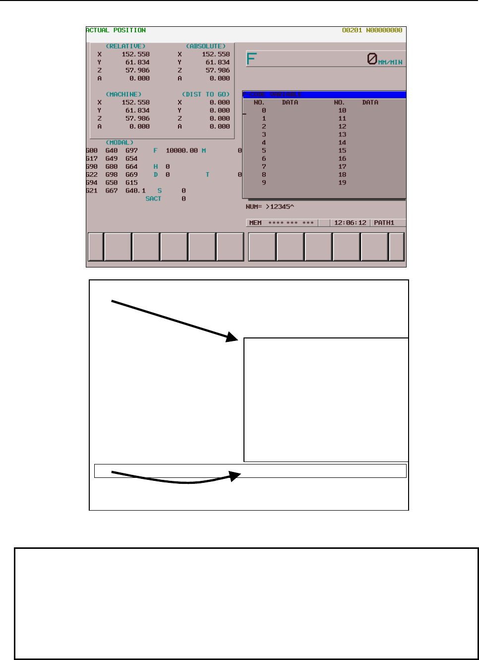
6.MACRO EXECUTOR FUNCTION
B-63943EN-2/07
- 172 -
(2)
Conversational macro screen
(3) (4)
Key input line
(1)
← Character coordinate and cursor control (#8506, #8507) position (X = 0,
Y = 0) when bit 6 (C9WN) of compile parameter No. 9100 is set to 0
Key input line start position when 0 is set in
bit 3 (US19WK) of compile parameter No.
9007
↓
←Character coordinate and cursor
control position (X=0, Y=0) when bit 6
(C9WN) of compile parameter No.
9100 is set to 1
Key input line start position when 1
is set in bit 3 (US19WK) of compile
parameter No. 9007
(5)
←Key input line start position when 1 is set in bit 0
(US19WG) of compile parameter No.9168
(Screen image)
NOTE
1 This function is enabled if a 10.4” LCD is used.
2 This function is not available for other conversational macro screens (user
screens 2 and 3). In these screens, a macro screen fills the whole screen space.
3 In the overall position indication, the location information of up to five axes is
displayed.
4 Extended axis name (parameter Nos.1025,1026), axis display order (parameter
No.3130) are invalid for this screen.
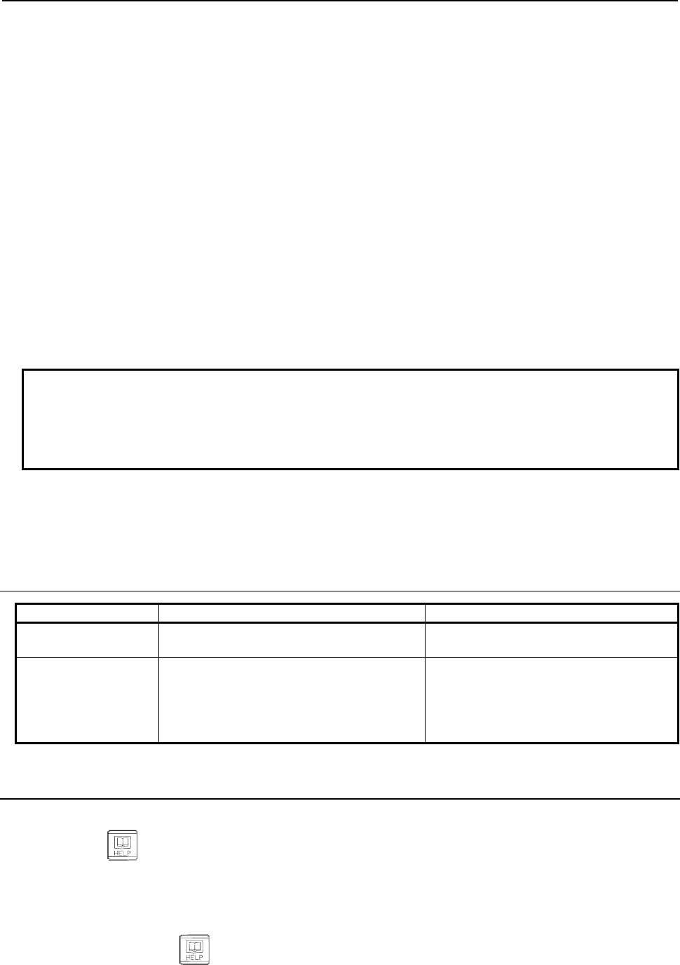
B-63943EN-2/07
6.MACRO EXECUTOR FUNCTION
- 173 -
Position compensation for the character coordinate system
On a screen with background color, if bit 6 (C9WN) of compile parameter No. 9100 is set to 1, the start
point of the character coordinate and the cursor control position (#8506, #8507) can be compensated for
to the upper left position of the window frame of the type of 7 soft keys (position <2> in the screen image
diagram).
This makes the upper left of the display area of the type of 7 soft keys the start point (where both the X
and Y coordinates are 0).
Position compensation for the key input line
When 1 is set in bit 3 (US19WK) of compile parameter No. 9007, the position of the key input line can be
moved below the window frame of the type of 7 soft keys (<4> in the screen image diagram).
Display of 24 groups of G-code modal information
When the compile parameter US19WG(No.9168#0) set to 1, the G-code modal information on 24 groups
is displayed.
When the US19WG set to 0, the G-code modal information on 18 groups is displayed.
Display order depends on the setting of displaying G-code group (the parameter D01~D32(No.3124#0~
3127#7)).
NOTE
When the compile parameter US19WK(No.9007#3) set to 0, and the setting with
background color is enabled, the position for displaying the key input line is
changed under G-code group display area. (The position of (5) on the screen
image)
Display of Run Time and Parts Count
When the option of "Run hour and parts count display" is enabled, the number of machined parts, run
time, and cycle time is displayed as well as the program check screen.
6.1.9.1
Differences from the Series 16i
Function Series 16i/18i/21i Series 30i/31i/32i/35i/0i-F/PMi
Position indication Position indication currently selected on the
program screen
Overall position indication for up to five
axes
Character coordinate
of cursor control when
bit 6 (C9WN) of
compile parameter No.
9100 is set to 1
The cursor control position is the same as
that when C9WN is set to 0.
Just like the character coordinate, the
cursor control position (#8506, #8507) is
also X0, Y0.
6.1.10
User Help Screen Control Function
This function allows the user to add a unique help screen (user help screen).
Pressing the key displays the added item on the Help (Initial Menu) screen. It is also possible to
add a character string inside the frame of soft key [F1]. Pressing soft key [F1] in the Help (Initial Menu)
screen or selecting the added item by moving the cursor or by some other means displays the user help
screen.
It is also possible to have the user help screen displayed immediately, without displaying the Help (Initial
Menu) screen, when the key is pressed.
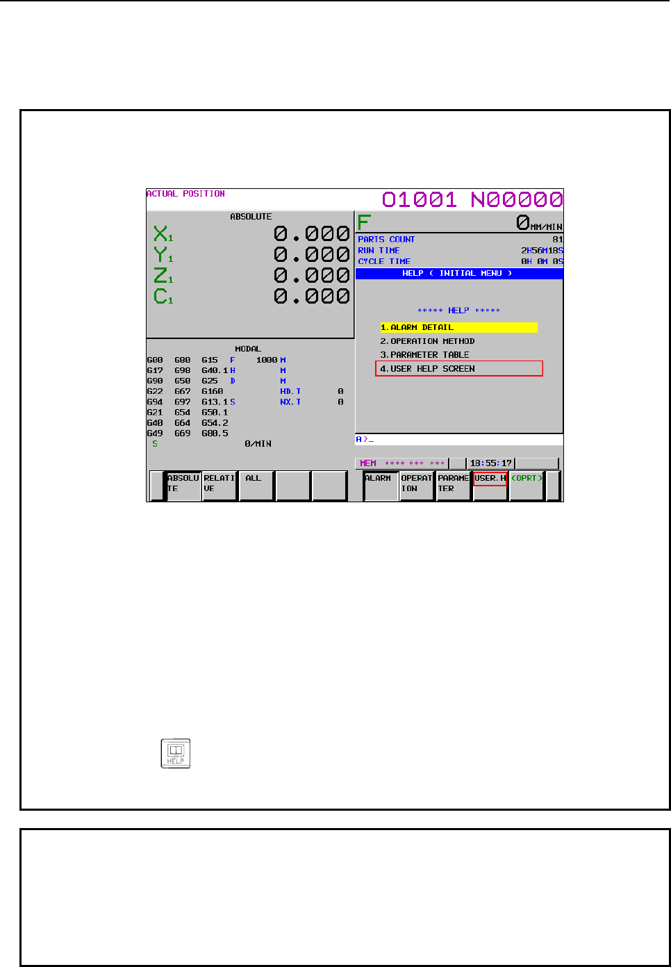
6.MACRO EXECUTOR FUNCTION
B-63943EN-2/07
- 174 -
Adding an item to the Help (Initial Menu) screen
In compile parameter No. 9050, set the number of the program to be added to the Help (Initial Menu)
screen. Create the program to be added, using the color specification command G240 and character
display command G243, as in the example given below.
Example
This example adds "USER HELP SCREEN" as the fourth item and displays
"USER.H" inside the frame of soft key [F1].
Compile parameter
P9050=3000
/*Program to be added
O3000 ;
G240 Pp ; ← Color specification (optional)
G243 ('USER HELP SCREEN'); ← Character string to be added
G240 Pp ; ← Color specification (optional)
G243 ('USER.H'); ← Soft key character string
M99 ;
Pressing the key displays the Help (Initial Menu) screen with the added
item in it. Pressing soft key [USER.H] or selecting '4. USER HELP SCREEN' by
moving the cursor or by some other means displays the user help screen.
NOTE
1 The display position of the character string of the added item in the Help (Initial
Menu) screen, as well as that of the character string in the soft key frame are
fixed. The display position coordinates cannot be specified using addresses X
and Y of G243. If addresses X and Y are specified, they are ignored.
2 The color specification of the character string must be based on the color palette
of the CNC system.
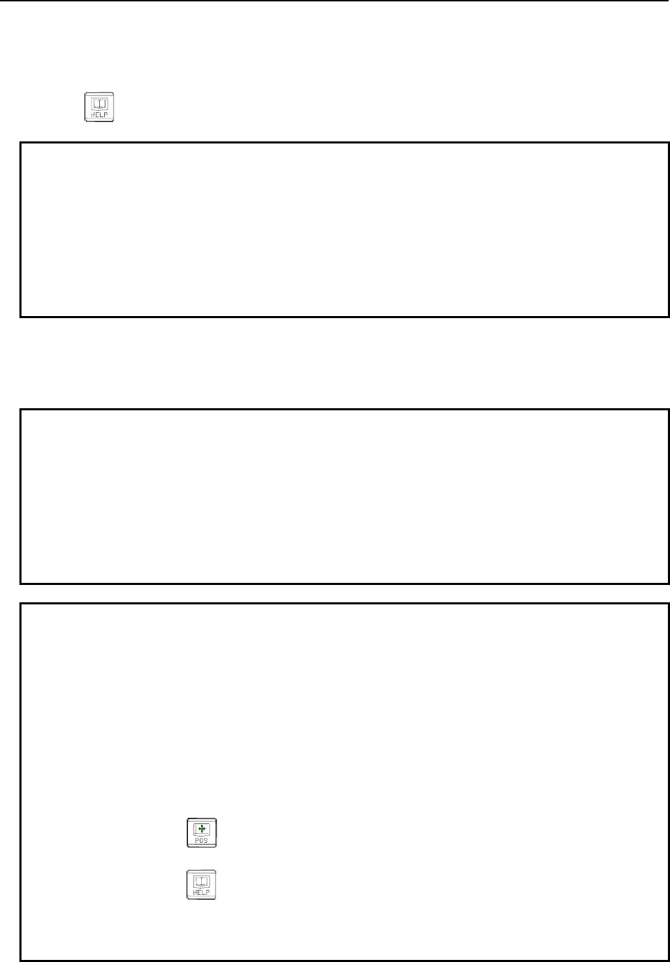
B-63943EN-2/07
6.MACRO EXECUTOR FUNCTION
- 175 -
User help screen
In compile parameter No. 9051, set the number of the main program that will execute the user help screen.
The user help screen program can use the function equivalent to that of the conversational macro.
To have the user help screen displayed immediately, without displaying the Help (Initial Menu) screen,
when the key is pressed, set 1 in bit 7 (HPU) of parameter No. 3109.
Example
Compile parameter
P9051=3001
/*User help screen program
O3001 ;
G243 X00 Y00 ('USER HELP SCREEN');
: :
M99 ;
- Execution control variable #8555
The main program of the user help screen can be changed to another program by changing the execution
control variable (#8555). The execution control variable (#8555) performs the same function as the
conversational macro execution control variables (#8500, #8550, and #8551).
Example
This example changes the main program of the user help screen from O3001 to
O3002.
/*Main program of the user help screen
O3001 ;
:
#8555 = 3002 ;
M99 ;
NOTE
Each time the Help (Initial Menu) screen is changed to the user help screen, the
value of #8555 is rewritten by the program number set in compile parameter No.
9051) and executed as the main program of the user help screen.
Compile parameter
P9051=3001
[User help screen] …The main program is O3001.
↓ Rewrite the variable as #8555=3002;.
[User help screen] …The main program is O3002.
↓ Press the key.
Current position screen]
↓ Press the key.
[Help (Initial Menu) screen]
↓ Change to the user help screen.
[User help screen] …The main program is O3001.
6.MACRO EXECUTOR FUNCTION
B-63943EN-2/07
- 176 -
- Control variable #8556
Writing a value in control variable #8556 in the main program of the user help screen enables you to go
back to the screen prior to the Help (Initial Menu) screen.
Example
To go back to the screen prior to the Help (Initial Menu) screen by using #8556
in the main program of the user help screen (O3001), specify the command as
follows.
O3001 ;
:
#8556 = 1 ;
M99 ;
When the screen prior to the help screen is the current position screen, you will
return to the current position screen.
[Current position screen]
↓
[Help (Initial Menu) screen]
↓
[User help screen] #8556=1;
6.1.10.1
Differences from the Series 16i
Function Series 16i/18i/21i Series 30i/31i/32i/35i/0i-F/PMi
Help (Initial Menu) screen All the addresses of G243 are
available.
Only address P and character strings are
available.
(The character string display position and
character size cannot be specified.)
Help (Initial Menu) screen "4." is not automatically added to
the added character string.
"4." is automatically added to the added character
string.
Help screen / User help
screen
While the conversational macro
screen is being displayed, the
key can be used to display
the Help screen/User help screen.
While the conversational macro screen is being
displayed, the screen cannot be switched to the
Help screen/User help screen, using the
key.
6.2
KEY INPUT AND DATA INPUT CONTROL
6.2.1
Command Key Input Variable (#8501)
Command key input can be read from variable #8501.
If there is no command key input, the value of variable #8501 is 0.
Once there is command key input, variable #8501 retains its value, not accepting any subsequent
command key input until it is read by a command.
When read by a command, variable #8501 becomes ready to accept command key input and changes its
value to 0. It is not possible to write a value to variable #8501.
The command keys are given below, together with the corresponding values of variable #8501.
Command keys of the type of 7 soft keys
Page key 1 SOFT FUNCTION KEY LEFT 11
Page key 2 SOFT FUNCTION KEY 1 12
B-63943EN-2/07
6.MACRO EXECUTOR FUNCTION
- 177 -
Cursor key 3 SOFT FUNCTION KEY 2 13
Cursor key 4 SOFT FUNCTION KEY 3 14
ALTER key 5 SOFT FUNCTION KEY 4 15
INSRT key 6 SOFT FUNCTION KEY 5 16
DELETE key 7 SOFT FUNCTION KEY RIGHT 17
INPUT key 8
RESET key 10
Cursor key 18
Cursor key 19
The arrangement and names of the soft function keys are as follows:
(0) (1) (2) (3) (4) (5) (6)
[ ] [ ] [ ] [ ] [ ]
(0)
(1)
(2)
(3)
: SOFT FUNCTION KEY LEFT
: SOFT FUNCTION KEY1
: SOFT FUNCTION KEY2
: SOFT FUNCTION KEY3
(4)
(5)
(6)
: SOFT FUNCTION KEY4
: SOFT FUNCTION KEY5
: SOFT FUNCTION KEY RIGHT
Command keys of the type of 12 soft keys
Page key 1 SOFT FUNCTION KEY LEFT 20
Page key 2 SOFT FUNCTION KEY 1 21
Cursor key 3 SOFT FUNCTION KEY 2 22
Cursor key 4 SOFT FUNCTION KEY 3 23
ALTER key 5 SOFT FUNCTION KEY 4 24
INSRT key 6 SOFT FUNCTION KEY 5 25
DELETE key 7 SOFT FUNCTION KEY 6 26
INPUT key 8 SOFT FUNCTION KEY 7 27
RESET key 10 SOFT FUNCTION KEY 8 28
Cursor key 18 SOFT FUNCTION KEY 9 29
Cursor key 19 SOFT FUNCTION KEY 10 30
SOFT FUNCTION KEY RIGHT 31
6.MACRO EXECUTOR FUNCTION
B-63943EN-2/07
- 178 -
The arrangement and names of the soft function keys are as follows:
(0) (1) (2) (3) (4) (5) (6) (7) (8) (9) (10) (11)
(0)
(1)
(2)
(3)
(4)
(5)
: SOFT FUNCTION KEY LEFT
: SOFT FUNCTION KEY1
: SOFT FUNCTION KEY2
: SOFT FUNCTION KEY3
: SOFT FUNCTION KEY4
: SOFT FUNCTION KEY5
(6)
(7)
(8)
(9)
(10)
(11)
: SOFT FUNCTION KEY6
: SOFT FUNCTION KEY7
: SOFT FUNCTION KEY8
: SOFT FUNCTION KEY9
: SOFT FUNCTION KEY10
: SOFT FUNCTION KEY RIGHT
- When vertical soft keys are provided
VERTICAL SOFT KEY 0 32
VERTICAL SOFT KEY 1 33
VERTICAL SOFT KEY 2 34
VERTICAL SOFT KEY 3 35
VERTICAL SOFT KEY 4 36
VERTICAL SOFT KEY 5 37
VERTICAL SOFT KEY 6 38
VERTICAL SOFT KEY 7 39
VERTICAL SOFT KEY 8 40
The arrangement and names of the vertical soft keys are as follows:
(
8
)
(
7
)
(
6
)
(
5
)
(
4
)
(
3
)
(
2
)
(
1
)
(
0
)
(0)
(1)
(2)
(3)
(4)
: VERTICAL SOFT KEY 0
: VERTICAL SOFT KEY 1
: VERTICAL SOFT KEY 2
: VERTICAL SOFT KEY 3
: VERTICAL SOFT KEY 4
(5)
(6)
(7)
(8)
: VERTICAL SOFT KEY 5
: VERTICAL SOFT KEY 6
: VERTICAL SOFT KEY 7
: VERTICAL SOFT KEY 8
NOTE
Do not use VERTICAL SOFT KEY 0 because it is used on the CNC system.
B-63943EN-2/07
6.MACRO EXECUTOR FUNCTION
- 179 -
- Identification of decimal point input
When a decimal point is input, the value of #8501 is incremented by α. The value of α is as follows:
Bit 5(KY20) of compile parameter
No.9003
Bit 1(KY100) of compile parameter
No.9160 +α value
0 0 0 (code itself)
1 0
+20 for the type of 7 soft keys
+40 for the type of 12 soft keys
1 or 0 1 +100
Example of use
When bit 1 (KY100) of compile parameter No. 9160 is set to 1.
If <1> is keyed, #8503=1.0 and #8501=8 results.
If <1.> is keyed, #8503=1.0 and #8501=108 results.
In this way, whether a decimal point is input can be checked.
6.2.2
Data Input Control Variable (#8502)
#8502 : Data input control variable
#8503 : Numeric data variable
#8504 : Address data variable
#8508 : Character string variable
By setting the following values in data input control variable #8502, the input of numeric data, address
data, and character string is controlled.
#8502 = 0 : No data input
= 1 : Input of numeric data
= 2 : Input of address data and numeric data
= 3 : Input of character strings
(1) No data input (#8502 = 0)
Nothing is displayed on the data input line, and no data can be input.
When the power is turned on, the value of #8502 is set to 0.
(2) Input of numeric data (#8502 = 1)
"NUM=" is displayed on the key input line, and numeric data can be input. The input numeric data
can be read from numeric data variable #8503. By setting bit 6 (NNUM) of compile parameter No.
9006 to 1, NUM= can be hidden.
(3) Input of address data and numeric data (#8502 = 2)
"ADR=" is displayed first on the key input line, and address data can be input. When address data
has been input, NUM= is then displayed to enable numeric data to be input.
The input address data and numeric data can be read from address data variable #8504 and numeric
data variable #8503, respectively. The addresses that can be input and their corresponding values of
variable #8504 are given below.
A
: 1
B
: 2
C
: 3
D
: 4
E
: 5
F
: 6
G : 7 H : 8 I : 9 J : 10 K : 11 L : 12
M
: 13 N : 14 O : 15 P : 16 Q : 17 R : 18
S
: 19
T : 20 U : 21 V : 22 W : 23 X : 24
Y : 25 Z : 26
(4) Input of character strings (#8502 = 3)
Nothing is displayed on the key input line, but character data can be input. The input characters can
be read from character string variable #8508 in the order in which they are input. The data that can
be read is ASCII codes. After the last character is read, <null> is read. The maximum allowable
number of characters in a character string is 73.
A prompt statement can be displayed on the data input line, using the G280 command.
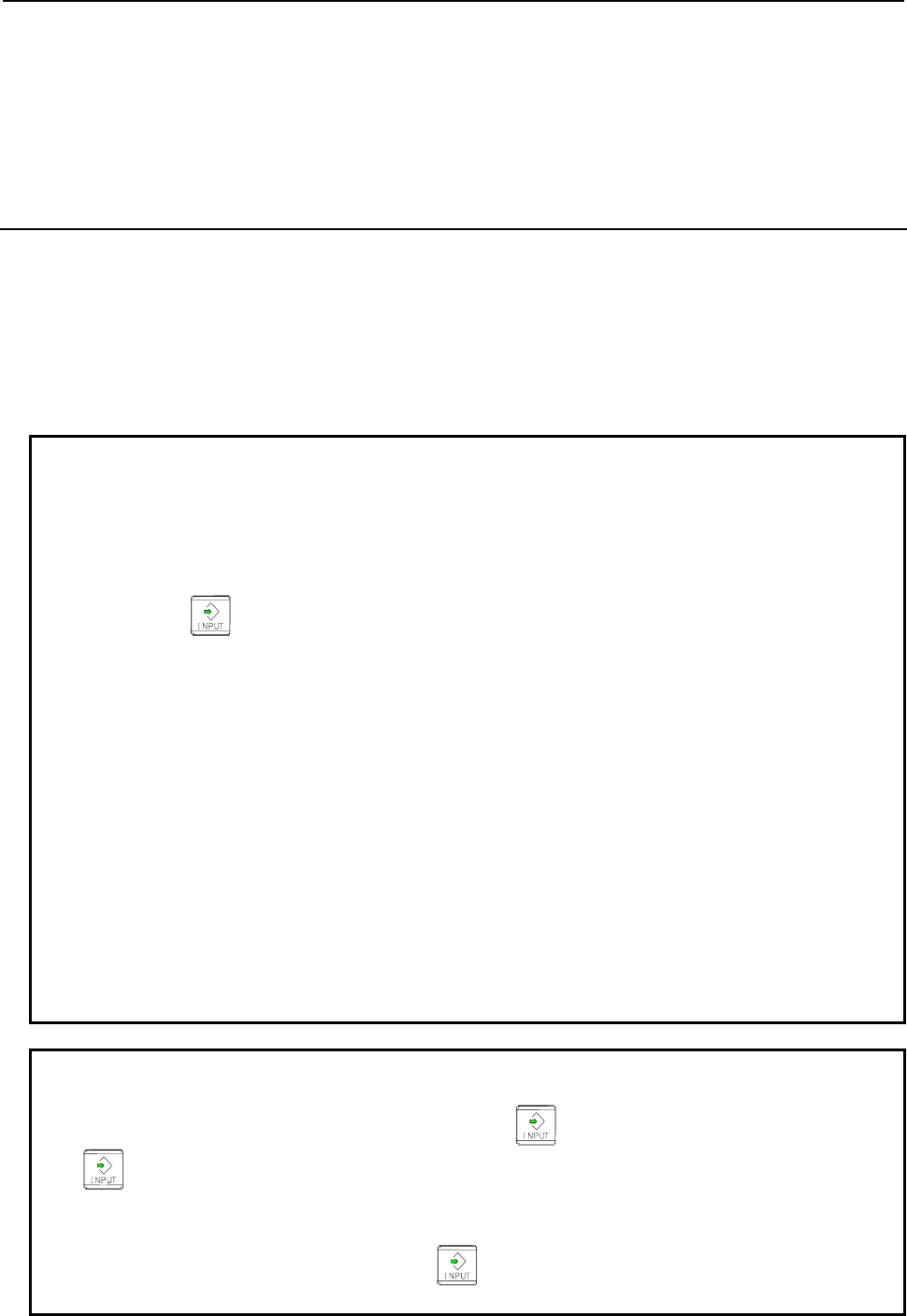
6.MACRO EXECUTOR FUNCTION
B-63943EN-2/07
- 180 -
The key input line returns to the initial state due to the input of a command key that causes the value of
command key input variable #8501 to change from 0 to a non-0 value. Then, the input numeric data,
address data, and character data can be read from the numeric data variable, address data variable, and
character string variable, respectively. When neither numeric data or address data is input, the values of
variables #8503 and #8504 are <null>. The numeric data variable and the address data variable retain
their values until input is made again.
6.2.3
Extended Data Input Control Variable (#8552)
By setting 3 in #8502 and setting a variable number in #8552, the character string input mode is set and
">" is displayed in the input line to enable address data and numeric data to be input.
When a command key that causes command key input variable #8501 to be set to a non-zero value is
input, the data input line returns to its initial state. The input numeric data and address data can be read
from 32 variables starting with the one having the variable number set in variable #8552, as ASCII code
data.
If nothing has been input, 32 <null> codes are read.
Example
Assume that the variables are set as follows:
#8502=3;
#8552=500;
and that the following is input:
0123456ABCD
When the key is pressed, the following data is read from the variables:
#500=48
#501=49
#502=50
#503=51
#504=52
#505=53
#506=54
#507=65
#508=66
#509=67
#510=68
#511=<Null>
:
#531=<Null>
#8501=8
NOTE
1 The macro variables starting with the one having the number set in variable
#8552 retain their previous values until the key is pressed. It is after the
key is pressed that the new values are set in these variables.
2 The values of variables #8503 and #8504 are not guaranteed.
3 If a non-zero macro variable number is set in variable #8552, this function is
executed unconditionally when the key is pressed.
In this case, the input data cannot be read from character string variable #8508.
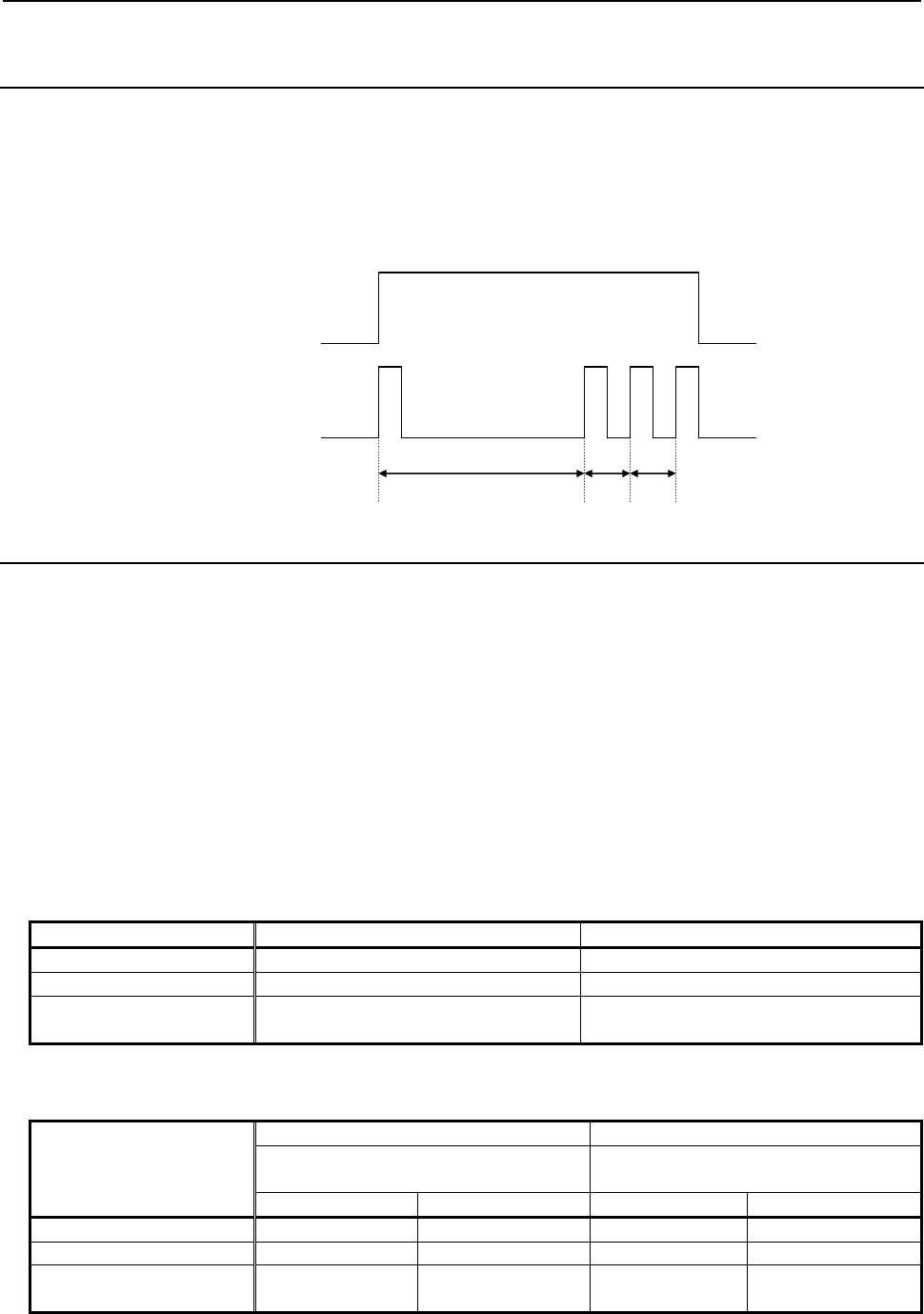
B-63943EN-2/07
6.MACRO EXECUTOR FUNCTION
- 181 -
6.2.4
Consecutive Input of Cursor and Page Keys
Command key input variable #8501 allows consecutive input of cursor and page keys.
When a cursor or page key is pressed and held down, the data for the cursor or page key is set in variable
#8501 with the following timing, and can be read consecutively. Note that the cursor or page key is not
buffered in variable #8501 but that the data is read with the following timing.
6.2.5
Key Input Line Control (#8561 to #8563)
The display position (X and Y coordinates) of the key input line on the conversational macro screen and
the allowable number of key input characters can be controlled using conversational macros.
Control variables
#8561 : X coordinate of the key input line display position
#8562 : Y coordinate of the key input line display position
#8563 : Allowable number of key input characters
If you switch to the conversational macro screen from another screen, the variable values are reset to their
initial values shown below. Whenever you have switched screens, therefore, you need to set these control
variables again.
Initial values
• Screen with background color (when 1 is set in bit 0 (VGAR) of compile parameter No. 9100 and 0
is set in bit 2 (VRM) of parameter No. 9011)
Type of 7 soft keys Type of 12 soft keys
X coordinates 0 0
Y coordinates 13 22
Allowable number of key
input characters 32 32
• Screen without background color (when 0 is set in bit 0 (VGAR) of compile parameter No. 9100 or
1 is set in bit 2 (VRM) of parameter No. 9011)
Type of 7 soft keys Type of 12 soft keys
Bit 2 (CM30) of compile parameter No.
9009
Bit 2 (CM30) of compile parameter No.
9009
1 0 1 0
X coordinates 0 0 0 0
Y coordinates 15 13 23 20
Allowable number of key
input characters 32 32 32 32
It is assumed below that data is read from variable #8501 as soon as it is
set.
Page key ON
OFF
#8501 = Data
#8501 = 0
256 32 32 (MSEC)
6.MACRO EXECUTOR FUNCTION
B-63943EN-2/07
- 182 -
#8561, #8562 (X and Y coordinates of the key input line display position)
Specify the display position of the key input line.
#8561: X coordinates
#8562: Y coordinates
NOTE
The display position is changed as soon as you write a value in #8562.
Therefore, be sure to set #8561 first and then #8562.
#8563 (allowable number of key input characters)
Specify the maximum number of characters that can be input on the key input line. If 0 is set, the
maximum number returns to the initial value of 32 characters.
6.2.6
MDI Key Image Reading Function (#8549)
From control variable #8549, the MDI key images showing the current MDI key pressing states can be
read. Using this variable, the states of the MDI keys currently pressed can be monitored.
And, when bit 2 (VGET) of compile parameter No.9168 is set to 1, the key images of virtual MDI key
can be read.
The pressing of the key + a key can be distinguished from the pressing of the key once. See the
key code list for details.
This variable holds the image of MDI keys as a decimal number. A key image value assumes an 8-bit
binary number.
As a key code, the value of a key image in the pressed state is represented using a decimal number from
00 to FF.
Example
When the key is pressed, the key code is 90H. In #8549, 144 is set.
Example of use
To cause "PUSH" to blink while the key is pressed and held down on the
standard MDI keyboard, enter the following:
:
#100=#8501 ;
IF [#100 NE 2] GOTO 20 ;
N10 G243 X0 Y0 A1 B1 (PUSH);
#101 = #8549 ;
IF [#101 NE 143] GOTO 20 ;
M99 P10 ;
N20 G243 X0 Y0 A1 K4 ;
:
Key code list
"F0" to "F9", "FR", and "FL" in the key code table are the key codes of soft keys. "VF1" to "VF9" are the
key codes for vertical soft keys.
• Type of 7 soft keys
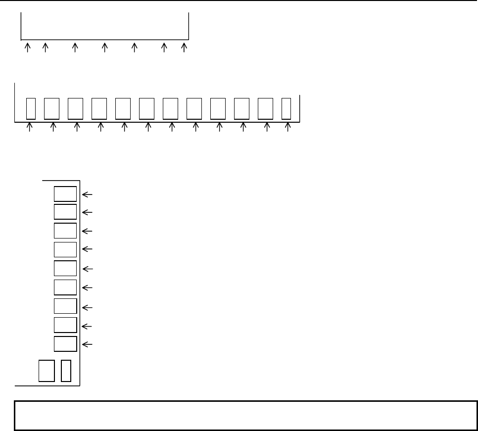
B-63943EN-2/07
6.MACRO EXECUTOR FUNCTION
- 183 -
“FL” “ F4” “F3” “F2” “F1” “F0” “FR”
[ ] [ ] [ ] [ ] [ ]
• Type of 12 soft keys
“FL” “F9”
“F8”
“F7”
“F6”
“F5”
“F4”
“F3”
“F2”
“F1”
“F0” “FR”
• Vertical soft keys
“VF9”
“VF7”
“VF8”
”VF6”
“VF1”
“VF5”
“VF4”
“VF3”
“VF2”
NOTE
Do not use VF1 because it is used on the CNC system.
"BACK SPACE", "SPCL", "MENU", and "KEY ON/OFF" in the key code table are the original key
codes of virtual MDI key.
MDI keyboard type reading variable
By reading variable #8533, the type of the MDI keyboard can be determined.
#8533 = 0 : Standard keyboard
= 2 : Small keyboard
= 3 : QWERTY keyboard
When virtual MDI key is valid and bit 2 (VGET) of compile parameter No.9168 is set to 1, the value 0
can be read in #8533 regardless of the kind of the connected MDI keyboard.
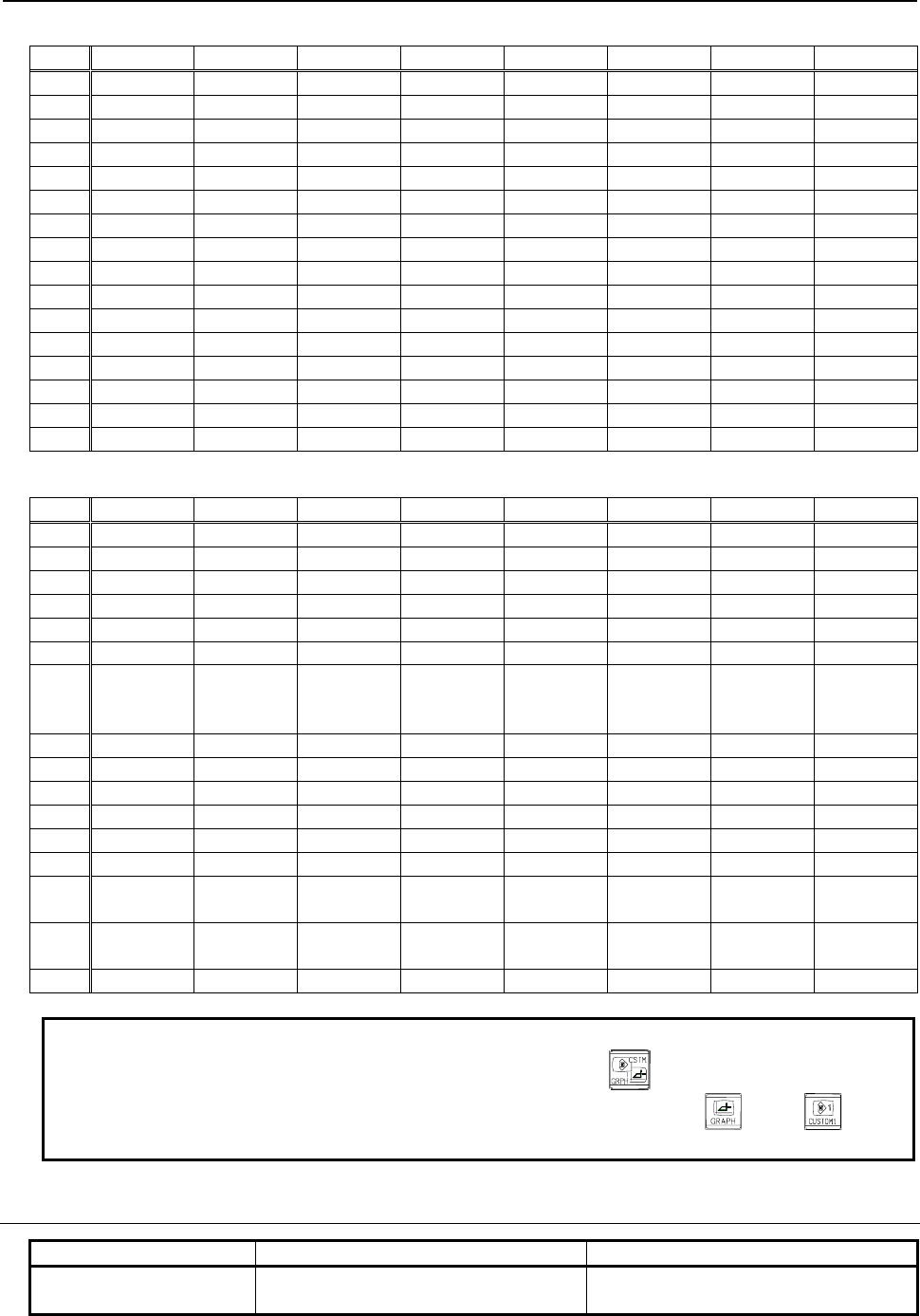
6.MACRO EXECUTOR FUNCTION
B-63943EN-2/07
- 184 -
(00H to 7FH) *
Parentheses ( ) indicate the character for a QWERTY keyboard.
0 1 2 3 4 5 6 7
0
SP 0 @ P
1
( ! ) 1 A Q
2
( “ ) 2 B R
3
# 3 C S
4
( $ ) 4 D T
5
( % ) 5 E U
6
& 6 F V
7
( ‘ ) 7 G W
8
( 8 H X
9
TAB ) 9 I Y
A
EOB * ( : ) J Z
B
+ ( ; ) K [
C
, ( < ) L ( ¥¥ )
D
- = M ]
E
.
( > ) N ( ~ )
F
/ ? O ( _ )
(80H to FFH)
8 9 A B C D E F
0
RESET VF1 F0
1
VF2 F1
2
VF3 F2
3
VF4 F3
4
SHIFT INSERT VF5 AUX F4
5
DELETE VF6 F5
6
CAN/
BACK
SPACE
ALTER VF7 F6
7
ALT VF8 F7
8 →
INPUT VF9 POS F8
9 ←
PROG F9
A ↓
HELP OFS/SET
B ↑
CTRL SYSTEM
C
ABC/abc SPCL MESSAGE
D
MENU
GRAPH
(Note)
E
PAGE
↓
KEY
ON/OFF CUSTOM1
(Note)
FR
F
PAGE
↑
CUSTOM2 FL
NOTE
For the small keyboard, 0EDH corresponds to the key.
For the standard keyboard, 0EDH and 0EEH correspond to and
keys, respectively.
6.2.6.1
Differences from the Series 16i
Function Series 16i/18i/21i Series 30i/31i/32i/35i/0i-F/PMi
MDI keyboard type
reading (#8533)
The function is not available. #8533 can be read using a
conversational or auxiliary macro.
B-63943EN-2/07
6.MACRO EXECUTOR FUNCTION
- 185 -
Function Series 16i/18i/21i Series 30i/31i/32i/35i/0i-F/PMi
MDI key image reading
(#8549)
Cannot be read using an auxiliary macro. - Can also be read using an auxiliary
macro.
- Some MDI key images are different.
6.3
Specification of a PMC Path in Multi-Path PMCs (#8603)
In multi-path PMCs, a PMC path can be specified with control variable #8603.
#8603 =0,1 : 1st PMC
=2 : 2nd PMC
=3 : 3rd PMC
By specifying a PMC path, using control variable #8603, before PMC address reference, PMC address
reading/writing (G310), and the axis-direction-by-axis-direction interlock function (#8600, #8601, #8607,
#8608), data for the second and third PMCs can be accessed. If nothing is specified, commands are
always for the first PMC.
Example
If, for the CNC in a 2-path system, the first path is to be accessed for the first
PMC, and the second path is to be accessed for the second PMC:
(1st path) (2nd path)
#8603=1; #8603=2;
G310R_Q_; G310R_Q_;
NOTE
Control variable #8603 is common to conversational macros, auxiliary macros,
and execution macros like other control variables. Thus, caution is required so
that it is not accessed by these macros at the same time.
6.4
ADDRESS FUNCTIONS
An address function returns the contents of a PMC address or the contents of a CNC parameter as a
function value.
An address function cannot be used on the left side of an expression because the contents cannot be
written.
For multi-path PMCs, specify a PMC path using control variable #8603. For details, see Section 6.3,
"Specification of a PMC Path in Multi-Path PMCs (#8603)".
6.4.1
PMC Address Reference
Format
<address><address-number>
or
<address><address-number>.<bit-position>
The valid range of each PMC address is as shown in Table 6.4.1 (a).
6.MACRO EXECUTOR FUNCTION
B-63943EN-2/07
- 186 -
Table 6.4.1 (a)
Address 30i-A/H
G 0 to 767 (0.0 to 767.7)
1000 to 1767 (1000.0 to 1767.7)
2000 to 2767 (2000.0 to 2767.7)
3000 to 3767 (3000.0 to 3767.7)
4000 to 4767 (4000.0 to 4767.7)
5000 to 5767 (5000.0 to 5767.7)
6000 to 6767 (6000.0 to 6767.7)
7000 to 7767 (7000.0 to 7767.7)
8000 to 8767 (8000.0 to 8767.7)
9000 to 9767 (9000.0 to 9767.7)
F 0 to 767 (0.0 to 767.7)
1000 to 1767 (1000.0 to 1767.7)
2000 to 2767 (2000.0 to 2767.7)
3000 to 3767 (3000.0 to 3767.7)
4000 to 4767 (4000.0 to 4767.7)
5000 to 5767 (5000.0 to 5767.7)
6000 to 6767 (6000.0 to 6767.7)
7000 to 7767 (7000.0 to 7767.7)
8000 to 8767 (8000.0 to 8767.7)
9000 to 9767 (9000.0 to 9767.7)
X 0 to 127 (0.0 to 127.7)
200 to 327 (200.0 to 327.7)
400 to 527 (400.0 to 527.7)
600 to 727 (600.0 to 727.7)
1000 to 1127 (1000.0 to 1127.7)
Y 0 to 127 (0.0 to 127.7)
200 to 327 (200.0 to 327.7)
400 to 527 (400.0 to 527.7)
600 to 727 (600.0 to 727.7)
1000 to 1127 (1000.0 to 1127.7)
E 0 to 9999 (0.0 to 9999.7)
R 0 to 7999 (0.0 to 7999.7)
9000 to 9499 (9000.0 to 9499.7)
D 0 to 9999 (0.0 to 9999.7)
T 0 to 499 (0.0 to 499.7)
9000 to 9499 (9000.0 to 9499.7)
K 0 to 99 (0.0 to 99.7)
900 to 999 (900.0 to 999.7)
C 0 to 399 (0.0 to 399.7)
5000 to 5199 (5000.0 to 5199.7)
NOTE
If a value exceeding the applicable valid range is specified, the correct value
cannot be read. Refer to PMC PROGRAMMING MANUAL for details.
<Address>, <address number>, or <bit position> is to be coded directly using numeric values or coded
using a variable, #[<expression>], or [<expression>].
B-63943EN-2/07
6.MACRO EXECUTOR FUNCTION
- 187 -
Example
1 #100 =G100.1
The value of bit 1 of PMC address G100 is set in variable #100.
2 #100 = T10
The contents of PMC address T10 is set in variable #100.
3 #101 = C22.2
The value of bit 2 of PMC address C22 is set in variable #101.
4 Instead of coding directly using a numeric value as described above,
G#[#100+1] or G[#100+1].[[#100-1]/2] can be coded.
5 The PMC address that can be used are G, F, X, Y, E, R, D, T, K, and C. The
notation must conform to the description in PMC Ladder. Refer to PMC
PROGRAMMING MANUAL for details.
6.4.2
CNC Parameter Reference
Format
P<parameter-number>
or
P<parameter-number>.<
controlled-axis-number-in-a-path/spindle-number-in-a-path
>
- Refer to Parameter Manual for details of parameters.
- As for path type parameters, those of the currently selected path are read.
- As for bit type parameters, bit position data cannot be specified. So, obtain a necessary bit position
with an instruction such as the AND instruction.
- <Parameter number>, <controlled-axis-number-in-a-path>, or <spindle-number-in-a-path> is to be
coded directly using a numeric value or coded using a variable, #[<expression>], or [<expression>].
Example
1 #100 = P1000
The value of CNC parameter No. 1000 is set in macro variable #100.
2 #100 = P1020.2
The value of the 2nd axis of CNC parameter No. 1020 is set in macro variable
#100.
3 Instead of coding directly using a numeric value as described above, P#100 or
P#100.#101 can be coded.
NOTE
If a nonexistent parameter number is specified, 0 is read.
6.4.2.1
Differences from the Series 16i
Function Series 16i/18i/21i Series 30i/31i/32i/35i/0i-F/PMi
Parameter There are parameters whose numbers
have been changed and those that have
been changed to the real type or path type.

6.MACRO EXECUTOR FUNCTION
B-63943EN-2/07
- 188 -
6.5 PMC ADDRESS READING/WRITING (G310)
Data can be read from and written to PMC addresses using the conversational, auxiliary, and execution
macro function. With an execution macro, the G310 block is executed as an NC statement. By setting 1 in
bit 4 (NOB) of parameter No. 9036, however, it is also possible to execute it as a macro statement. When
the block is executed as a macro statement, the macro will not be stopped by single block execution.
For multi-path PMCs, specify a PMC path using control variable #8603. For details, see Section 6.3,
"Specification of a PMC Path in Multi-Path PMCs (#8603)".
PMC address writing
- Format
G310 Dd Qq Ll
;
G310 Rr Qq Ll
;
G310 Cc Qq Ll
;
G310 Kk Qq Ll
;
G310 Tt Qq Ll
;
G310 Ee Qq Ll
;
G310 Yy Qq Ll
;
D
: PMC address D
R
: PMC address R
C
: PMC address C
K
: PMC address K
T
: PMC address T
E
: PMC address E
Y
: PMC address Y
Q
: Data to be written
L
: Data size
Specifiable data lengths are 1, 2, and 4 bytes only. If none is specified, or if the data length is
not correct, 1 byte is assumed.
The data specified for address Q is written to PMC addresses D, R, C, K, T, E, and Y with the size
specified for address L. The data specified for address Q is rounded off to the nearest integer value, as
required, and converted into binary format before being written.
If the data is a negative numeric value, it is converted to a two's complement.
If the data to be written is more than a word, the lowest byte is written to the lowest address, the second
lowest byte to the second lowest address, and so on.
Example
#100 = -500.0 ;
G310 D300 Q#100 L4 ;
When the above program is executed, the following data is written to the PMC
data area (D300 to D303).
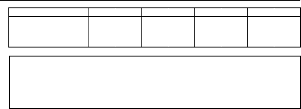
B-63943EN-2/07
6.MACRO EXECUTOR FUNCTION
- 189 -
Bit 7 6 5 4 3 2 1 0
D300
D301
D302
D303
0
1
1
1
0
1
1
1
0
1
1
1
0
1
1
1
1
1
1
1
1
1
1
1
0
1
1
1
0
0
1
1
The two's complement of the decimal number -500.0 is FFFFFE0CH.
NOTE
1 Data cannot be specified in bit units.
2 If the specified data exceeds the byte length specified for address L, the
specified byte length of data is written and no error handling is performed.
In the example, if "L1" is specified, the lowest byte (0CH) of -500.0 is written in
D300 only.
PMC address reading
- Format
G310 Dd Pp Ll
;
G310 Rr Pp Ll
;
G310 Cc Pp Ll
;
G310 Kk Pp Ll
;
G310 Tt Pp Ll
;
G310 Ee Pp Ll
;
G310 Xx Pp Ll
;
G310 Yy Pp Ll
;
D
: PMC address D
R
: PMC address R
C
: PMC address C
K
: PMC address K
T
: PMC address T
E
: PMC address E
X
: PMC address X
Y
: PMC address Y
P
: Number of the variable in which data is to be set
L
: Data size
Specifiable data lengths are 1, 2, and 4 bytes only. If none is specified, or if the data
length is not correct, 1 byte is assumed.
By specifying a variable number for address P with the control code (G310) command, data can be read
from PMC addresses D, R, C, K, T, E, X, and Y. By using address L, 2/4-byte data can be read as a batch.
The data that has been read is regarded to be binary format data with the specified byte length, converted,
and stored in the variable specified for address P.
If the data to be read is more than a word, the data from the lowest address is written to the lowest byte,
the data from the second lowest address to the second lowest byte, and so on.
6.MACRO EXECUTOR FUNCTION
B-63943EN-2/07
- 190 -
Example
Assume that the PMC data area (D400 and D401) contains the following data:
D400= 0CH
D401= FEH
and that the following is issued:
G310 D400 P101 L2;
then, "-500.0" is input to variable #101.
6.5.1
Differences from the Series 16i
Function Series 16i/18i/21i Series 30i/31i/32i/35i/0i-F/PMi
G310 command in an
execution macro
The G310 block is executed as a
macro statement.
Value of bit 4 (NOB) of parameter No. 9036:
0: Executed as an NC statement.
1: Executed as a macro statement.
Writing data to and reading
data from the PMC
The readable and writable
addresses are X, Y, D, R, C, and K.
The readable and writable addresses are X,
Y, D, R, C, K , T, and E.
6.5.2
Notes on I/O Signals Updated by Other Than PMC
Applications like macro executor (Note1) directly update I/O signals independently of PMC sequence
program execution. Similarly, I/O signals transmitted over networks (Note1) directly update I/O signals
independently of PMC sequence program execution. Applications like macro executor and PMC
sequence program are executed with individual cycle, i.e. asynchronous.
Therefore, when PMC sequence program uses signals updated via applications like macro executor or
network, or applications like macro executor or network use signals updated PMC sequence program, the
following should be noted:
WARNING
When you develop these applications, take care of the following notes.
If the following notes are ignored, the machine may behave in an unexpected
manner and tool, workpiece, and the machine may also be damaged.
As for details, refer to “SAFETY PRECAUTIONS”.
NOTE
As for kinds of applications like macro executor and networks, refer to “SAFETY
PRECAUTIONS”.
(1) Note on input signals
Signals, which are already written with PMC sequence program, must not be written with
applications like macro executor or networks.
(2) Note on output signals
When output signals are updated via an application like macro executor or network, the output
signals, which are just being updated, may be transferred to I/O device, just like PMC sequence
program. Please take care when referring to plural signals at the I/O device.
When an input signal transmitted via an application like macro executor or network is referenced at
more than one place in the PMC sequence program, the same value is not guaranteed to be
referenced within the same cycle of the sequence program.
To refer to the same value of the input signal within the same cycle, store the input signal status in
temporary area such as internal relay and refer to it.

B-63943EN-2/07
6.MACRO EXECUTOR FUNCTION
- 191 -
(3) Note on multiple-byte data
Generally, when multiple-byte data is input or output via an application like macro executor or
network, concurrence of the data (a condition free from data splitting) is not guaranteed. To ensure
multiple-byte data concurrence, please make use of handshaking process that uses signals to notify
reading/writing completion.
(4) Distributed processing of signals
You must take care that when distributing the processing of signals related to a NC function to
several applications (applications like macro executor and ladder program). Because of said
asynchronous of applications, unexpected processing order may happen.
(5) Note when writing bit signals
Please do not write bit signals in the same byte address with plural programs such as PMC sequence
program, applications like macro executor and network. If there is duplication writing in the same
byte address, each bit signal may not be updated correctly.
6.6 CNC DATA READING/WRITING
The following CNC data can be written/read.
1. Writing setting parameters and parameters
2. Writing and reading pitch error compensation data
6.6.1
Writing Setting Parameters and Parameters
Prepare consecutive P-CODE variables; the number of variables to be prepared is four plus the number of
data items to be set. The CNC parameters can be written by executing the G314 command after setting
data beginning with the first number.
Data to be set in variables
(1) Variable number + 0 : Completion code (setting not required)
(2) Variable number + 1 : Parameter number
(3) Variable number + 2 : Control axis/spindle number at which to start writing
(4) Variable number + 3 : Number of control axes/spindles to be written
(5) Variable number + 4 : Setting data (1st)
: :
Variable number + (4+n-1) : Setting data (nth)
* n: 4 + (maximum number of control axes - 1) or 4 + (maximum number of spindles - 1)
(1) Writing completion code (output data)
• This does not need to be set.
• The completion code is set after the parameter writing command (G314).
(2) Parameter number (input data)
• Set the number of the parameter to be written.
(3) Control axis/spindle number at which to start writing (input data)
• If the parameter to be written is of the axis or spindle type, specify the intra-path control axis
(spindle) number at which to start writing.
• Specifying a control axis/spindle number plus 100 is regarded as specifying it as a system
common control axis (spindle) number. (Example: To specify the fifth system common axis,
specify 105.)
• If the parameter is of any type other than the axis or spindle type, this setting is ignored.
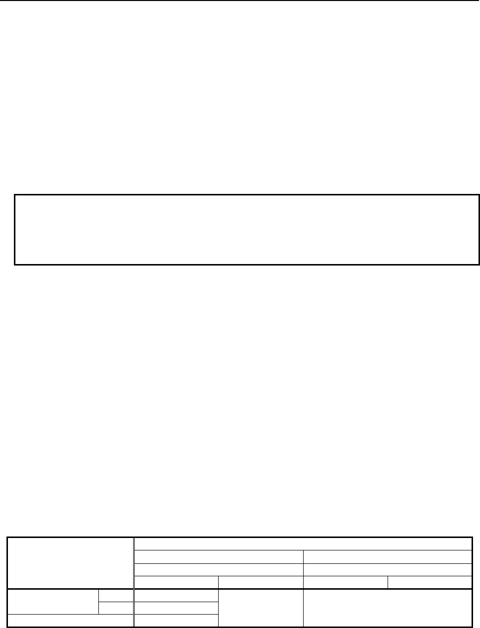
6.MACRO EXECUTOR FUNCTION
B-63943EN-2/07
- 192 -
(4) Number of control axes/spindles to be written (input data)
• Specify the number of data items to be written, beginning with the number specified in (3).
• If -1 is set, it is assumed that all control axes (spindles) are specified.
• If the parameter is of any type other than the axis or spindle type, this setting is ignored.
(5) Setting data (input data)
• Set the parameter values to be written.
• Set data in as many variables as the number of axes (spindles) that is specified by (4) variable
number + 3.
• If the parameter is of the bit type, the bit positions cannot be specified. In that case, set a value
obtained by converting the bit image of the entire parameter (eight bits) into decimal format.
Make sure that this act of setting parameters does not affect other bit parameters, such as setting
a value obtained by ORing the parameter values to be written to the parameter values that are
read by the CNC parameter reference function (see Subsection 6.4.2).
NOTE
In variable number + 4 and later, set parameter data correctly. If writing data for
multiple control axes (spindles), be sure to set the data for all the specified
control axe (spindles).
Otherwise, the normality of the written data will not be guaranteed.
After setting the above data, start the parameter writing command from a conversational or auxiliary
macro program in the format shown below.
Format
G314 Pp [ Ll ] [ Tt ] [ Ss ] ; [ ] is optional.
p : First variable number of the variables storing data
l = 0 (or omitted)
= 1 to maximum number of paths
:
:
The local path is assumed.
Specify the path number to be written.
t = 0 (or omitted)
= 1 to maximum number of tool groups
:
:
The local machine group number is assumed.
Specify the machine group number to be written.
s = 0 (or omitted)
= 1
:
:
Data is written to a CNC parameter. (Bit 0 (PWE) of parameter No.
8900 must be set to 1.)
Data is written to a setting parameter.
When 0 is set in bit 0 (PWE) of parameter No. 8900, specifying S1 allows data to be written only in
setting parameters. When 1 is set in bit 0 (MPE) of parameter No. 9036, data can be written in all writable
parameters. (See Table 6.6.1 (a).)
Note that parameter No. 9036 can be written using this function, regardless of the state of bit 0 (PWE) of
parameter No. 8900.
Table 6.6.1 (a)
Bit 0 (PWE) of parameter No. 8900
0 1
Bit 0 (MPE) of parameter No. 9036 Bit 0 (MPE) of parameter No. 9036
0 1 0 1
Setting parameter S=1 Allowed
Allowed Allowed
S=0 Not allowed
Parameter Not allowed

B-63943EN-2/07
6.MACRO EXECUTOR FUNCTION
- 193 -
Example
1 For an axis type parameter
This example shows how to change parameter No. 1320 for the 2nd and 3rd axes
of 2nd path (local path) in a system where 1st path consists of three control axes
and 2nd path consists of four control axes.
<1> When specifying intra-path control axis numbers
(#10000 not required)
#10001=1320;
#10002=2 ;
#10003=2;
#10004=1000;
#10005=2000;
G314 P10000 ;
. . .
. . .
. . .
. . .
. . .
. . .
→
Setting not required (completion code)
Parameter No.1320
Specification of the 2nd axis in a path
Number of data items to be written = 2
Data to be written (1st)
Data to be written (2nd)
Write the parameter.
<2> When specifying system common control axis numbers
(#11000 not required)
#11001=1320;
#11002=105 ;
#11003=2;
#11004=1000;
#11005=2000;
G314 P11000 ;
. . .
. . .
. . .
. . .
. . .
. . .
→
Setting not required (completion code)
Parameter No.1320
Specification of the system common 5th axis
Number of data items to be written = 2
Data to be written (1st)
Data to be written (2nd)
Write the parameter.
2 For a system common parameter
Parameter No.0020: Change the communication equipment settings.
(#12000 not required)
#12001=20 ;
#12002=0 ;
#12003=0 ;
#12004=4 ;
G314 P12000 ;
IF[#12000 NE 0]GOTO 900;
Writing is completed.
N900;
Error processing
. . .
. . .
. . .
. . .
. . .
→
→
Does not need to be set in the completion code.
Parameter No.0020
Set 0.
Set 0.
Data to be written
Write the parameter.
Check the completion code to confirm normal
end.
3 Bit 2 (INI) of bit type parameter No. 0000: Set 1 only for the switch between mm
and inch.
(#13000 not required)
#13001=0 ;
#13002=0 ;
#13003=0 ;
#13004= [ P0 ] OR 4;
G314 P13000 ;
IF[#13000 NE 0]GOTO 900;
Writing is completed.
N900;
Error processing
. . .
. . .
. . .
. . .
. . .
→
→
Does not need to be set in the completion code.
Parameter No.0000
Set 0.
Set 0.
Using the parameter reading function, read
parameter No. 0000. Mask the read value, and
set only bit 2. (Specify the value in decimal.)
Write the parameter.
Check the completion code to confirm normal
end.
6.MACRO EXECUTOR FUNCTION
B-63943EN-2/07
- 194 -
Example
4 Set setting parameter No. 3123 of the 3rd path to 10 (if bit 0 (PWE) of parameter
No. 8900 is set to 0)
(#14000 not required)
#14001=3123 ;
#14002=0 ;
#14003=0 ;
#14004=10;
G314 P14000 L3 S1;
IF[#14000 NE 0]GOTO 900;
Writing is completed.
N900;
Error processing
. . .
. . .
. . .
. . .
. . .
→
→
Setting not required (completion code)
Setting parameter number
Set 0.
Set 0.
Data to be written
Specify a path number for L3 and setting
parameter writing for S1, and execute.
Check the completion code to confirm normal
end.
NOTE
1 The command cannot be executed during axis movement. The completion code
-1 is returned.
2 Depending on the parameter, P/W alarm No. 0000 may occur. In that case, it is
necessary to turn off the power.
CAUTION
Before changing any parameter during automatic operation, consider thoroughly
whether it is OK to change the data in question.
WARNING
Take care that you do not write the same parameter with several applications
like C language executor. If there is data duplication writing in the system, the
data not intended is input, and the machine may behave in an unexpected
manner and tool, workpiece, and the machine may also be damaged.
6.6.1.1
Completion code
Check the completion code of the parameter writing command.
Value Description
0 Normal end
-1 The axis is moving or is not ready for data writing.
3 The specified number of the parameter to be written is invalid.
4 Invalid data is set for axis specification.
5 The setting data is invalid.
7 The data of the parameter corresponding to the specified parameter number is protected.
8 An invalid value is specified in the G314 block data (P, L, T, or S).
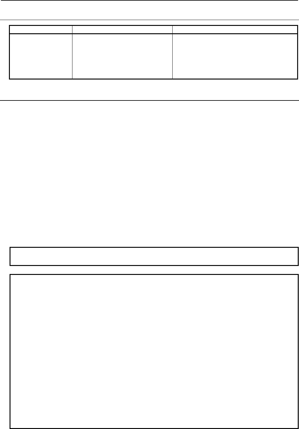
B-63943EN-2/07
6.MACRO EXECUTOR FUNCTION
- 195 -
6.6.1.2
Differences from the Series 16i
Function Series 16i/18i/21i Series 30i/31i/32i/35i/0i-F/PMi
Parameter writing G312 is used. G314 is used.
Because there are parameters whose numbers
are different from those of Series 16
i
/18
i
/21
i
or
whose types have been changed to the integer
type or path type, the G code, format, setting
method, and so forth are different.
6.6.2
Writing and Reading Pitch Error Compensation Data
By preparing multiple data items to be written to or read from any consecutive P-CODE variables and
specifying G314 K2, the following pitch error compensation data can be written or read.
• Stored pitch error compensation
• Bi-directional pitch error compensation
• Straightness compensation
Format
G314 K2 Ww Pp Ss Ee
K2 : Causes the function to become a pitch error compensation write/read function.
w = 1
= 0
:
:
Causes the function to become a write command.
Causes the function to become a read command.
p : Specify the top variable number of the variable group to store read data or write data.
s :
Specify the compensation point number of the pitch error compensation data at which to
start writing or reading.
e : Specify the compensation point number of the pitch error compensation data at which to
end writing or reading.
NOTE
If K2 is omitted, parameter writing is performed.
Example
1 Writing the values set in variables #10000 to #10010 to pitch error compensation
data items No. 100 to No. 110
<1> In the 11 P-CODE variables #10000 to #10010, set the data to be written.
#10000=1 ... Data to be written (1st)
#10001=2 ... Data to be written (2nd)
:
#10010=11 ... Data to be written (11th)
<2> Specify the writing of pitch error compensation data.
G314 K2 W1 P10000 S100 E110
<3> Check the completion code (#8579).
2 Reading pitch error compensation data items No. 200 to No. 210 into variables
#10000 and up
<1> Specify the reading of pitch error compensation data.
G314 K2 W0 P10000 S200 E210
<2> Check the completion code (#8579).
<3> If the reading terminates normally, the data items have been read into
P-CODE variables #10000 to #10010.
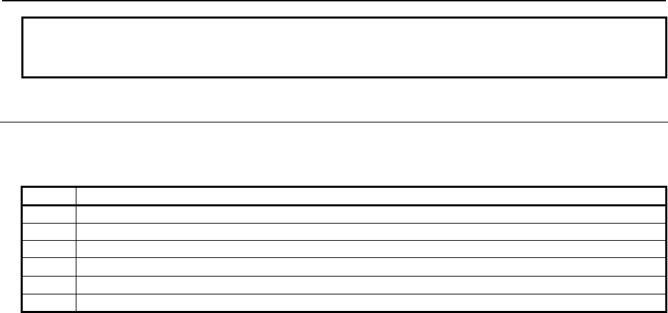
6.MACRO EXECUTOR FUNCTION
B-63943EN-2/07
- 196 -
NOTE
If the variable group to store data contains invalid variable, the completion code
(#8579) is set to 115.
6.6.2.1
Completion code
When the reading or writing of pitch error compensation data is specified, check the completion code
(#8579).
Value Description
0 Normal end
3 The specified data contains an error, or the necessary data is not specified.
5 The write data contains an error.
6 The pitch error compensation option is not set.
7 Writing is not possible because of the 8-level data protection function.
115 An unusable variable number is specified.
B-63943EN-2/07
6.MACRO EXECUTOR FUNCTION
- 197 -
6.7 READER/PUNCHER INTERFACE
6.7.1
General
The communication line can be controlled with the conversational macro function/auxiliary macro
function when the communication line is not used for other purposes, for example, by the CNC.
Line control is performed using the following seven control codes.
Line control functions are effective when bit 7 (EXT1) of compile parameter No. 9002 is 1.
G330: Line open
G331: Line close
G335: 1-byte reception
G336: Data transmission
G337: Macro variable input
G338: Macro variable output
G339: File information reading/file deletion
One of the following four line control methods can be selected when a line is opened.
(1) Hard flow control
The line is opened in bidirectional mode and the macro executor does not perform output control
with control codes DC1 to DC4. Use this method when creating a user-unique protocol. When an
overflow is detected in the receive buffer, the remote device is requested to stop/resume transmission
by turning the control signal RS on/off.
(2) Reception control (automatic control with DC1/DC3)
When the line is opened, the DC1 code is automatically sent to request the remote device to send
data. When the line is closed, the DC3 code is sent. When an overflow is detected in the receive
buffer, control is automatically performed with DC1 and DC3. When the line is opened in reception
control mode, G336 for data transmission and G338 for macro variable output cannot be executed.
(3) Transmission control (automatic control with DC2/DC4)
When the line is opened, the DC2 code is automatically sent to request the remote device to receive
data. When the line is closed, the DC4 code is sent. The interruption and resumption of transmission
due to DC3 and DC1 from the remote device are automatically performed.
When the line is opened in transmission control mode, G335 for 1-byte reception and G337 for
macro variable input cannot be executed.
(4) File control
When the FANUC Handy File, FANUC Floppy Cassette, FANUC FA Card, FANUC Program File
Mate, or Memory card is used, and the line is opened in file control mode, it is possible to acquire
file names and sizes, delete files, and change file names.
Completion codes are available for checking whether input/output processing has been executed correctly.
Check the completion code after executing a control code.
All completion codes are for read only.
#8537 : Completion code for the result of executing an auxiliary macro
#8538 : Completion code for the result of executing a conversational macro
#8539 : Completion code common to auxiliary macros and conversational macros
See Section 6.7.6, "Completion codes" for details of completion codes.
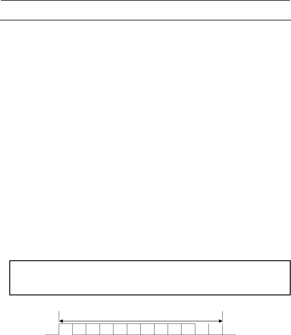
6.MACRO EXECUTOR FUNCTION
B-63943EN-2/07
- 198 -
6.7.2
Function
Line open G330
- Format
G330 Pp Bb Ss Cc ;
P : Interface number and control method of the input/output device for the foreground
= 1 : Hard flow control with RS-232-C1
= 2 : Hard flow control with RS-232-C2
= 11 : Reception control with RS-232-C1
= 12 : Reception control with RS-232-C2
= 21 : Transmission control with RS-232-C1
= 22 : Transmission control with RS-232-C2
= 31 : File control with RS-232-C1
= 32 : File control with RS-232-C2
B : Baud rate of the input/output device
1: 50b/s 3: 110b/s 4: 150b/s
6: 300b/s 7: 600b/s 8: 1200b/s
9: 2400b/s 10: 4800b/s 11: 9600b/s
12: 19200b/s
S : Number of stop bits and parity bits
= 1 : 1 stop bit, without parity
= 2 : 2 stop bits, without parity
=11 : 1 stop bit, odd parity
=12 : 2 stop bits, odd parity
=21 : 1 stop bit, even parity
=22 : 2 stop bits, even parity
C : Output code specification
= 1 : ASCII code
= 2 : ISO code
NOTE
1 When the FANUC Handy File, FANUC Floppy Cassette, FANUC FA Card, or
FANUC Program File Mate is used, specify C2.
2 If address C is not specified, ASCII code is used.
- Explanation
Line close G331
- Format
G331 ;
- Explanation
This code closes an open line.
When a line is closed, the completion code is always 0 (normal termination).
One character
a b1 b2 b3 b4 b5 b6 b7 b8 c d1 d2
a : Start bit (1 bit)
b : Information bit (8 bits)
c : Parity bit (0 or 1 bit)
d : Stop bit (1 or 2 bits)

B-63943EN-2/07
6.MACRO EXECUTOR FUNCTION
- 199 -
1-byte reception G335
- Format
G335 Pp ;
P : Number of the macro variable in which the received data is to be stored
- Explanation
This code reads one byte of received data and stores it in a specified macro variable.
Received data is once stored in the receive buffer (592 bytes) then is read one byte at a time by this
control code.
If the receive buffer is about to overflow due to a delay in reading the buffer relative to the reception of
data, one of the following operations is performed according to the control method specified when the
line is opened.
(1) When hard flow control is used
When a receive buffer overflow is detected (when the size of free space is 25 bytes or less), the
control signal RS is set to OFF to send a request to the remote device to stop transmission. When the
receive buffer becomes available (when the size of free space exceeds 567 bytes) as read processing
proceeds, the signal (RS) is set to ON to request the remote device to resume transmission.
(2) When read control (DC1/DC3 automatic control) is used
When a receive buffer overflow is detected (when the size of free space is 25 bytes or less), a "DC3"
code is automatically output to request the remote device to stop transmission. When the receive
buffer becomes available (when the size of free space exceeds 567 bytes) as read processing
proceeds, a "DC1" code is output to request the remote device to resume transmission.
(3) When transmission control (DC2/DC4 automatic control) is used
When the line is opened in the transmission control mode, one-byte read control cannot be exercised.
If the code is specified, 8 is set in the completion code.
About the behavior if there is no receiving data, refer to “6.7.4 Data Transmission/ Reception Waiting”.
Example
G330 P11 Bb Ss Cc;
#100=10000;
N100 G335 P#100 ;
IF[#[#100] EQ 37] GOTO999;
IF [#8539 NE 0] GOTO900 ;
Processing of the read data
#100=#100+1;
(#10000~:Received data)
GOTO 100
N900 Error processing
N999 G331;
→
→
→
→
→
→
→
Open a line by RS-232-C 1 reception control.
Read data in #10000 and later.
Check the end of data by ‘%’(ASCII code is
37).
Check for any error.
Next byte
Repeat until there is no more data.
Close the line.
Data transmission G336
- Format
G336 Cc (_) (‘_’) (*_*) Kk Ff.e Dd Pp Zz R100 ;
C : Specify a code to be directly output. (Specify one character.)
Code conversion processing is not performed. Specify this address when outputting a code other than
the control codes (DC1 to DC4) and ASCII/ISO codes.
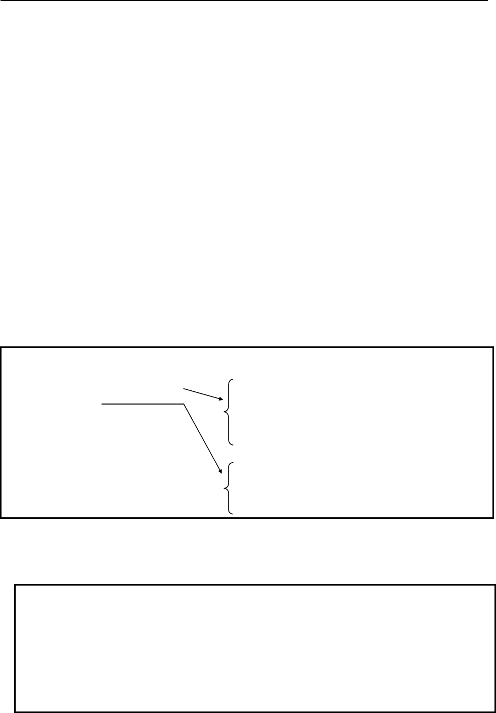
6.MACRO EXECUTOR FUNCTION
B-63943EN-2/07
- 200 -
K : Specify the number of non-punch holes.
The output code is not a space (20h) but a null code (00h) (non-punch).
(‘_’)
(*_*)
: Single-byte characters (codes listed in the katakana code table, alphanumeric code table, and symbol
code table in Appendix B, "CODE TABLES") can be used. Kanji and hiragana codes cannot be used.
R100 : Data is not transmitted in the block in which the next transmission command is specified but is stored
temporarily in the transmit buffer. The data is transmitted at the same time a data transmission block
(G336/G338) in which the next transmission command is not specified or line close block (G331) is
executed.
The other addresses are the same as for screen display control (G243). So, see Subsection 6.1.3.5,
"Character display (G243)".
- Explanation
• Data is transmitted in a specified format.
• Before being transmitted, a specified character string is converted to ASCII or ISO code according
to the specification at line open time.
• When a line is opened in reception control mode, data transmission cannot be executed. If an attempt
is made to execute it, a completion code of 8 is set.
• Data is not transmitted character by character but is stored in the transmit buffer and transmitted
collectively on a per-block basis (when the EOB command is found).
• If R100 is specified in a block, data is not transmitted in that block, allowing the data to be
transmitted at the same time as a data transmission block (G336) in which R100 is not specified.
This enables you to delay the transmission of blocks until a desired block by specifying R100 in
each of those blocks, when, for example, one-character command is specified in two or more blocks
using address C, thereby allowing the whole bunch of data to be transmitted at once and speeding up
the execution of a macro program.
Example
G330 P21 Bb Ss Cc; →
G336 C18 K20 (FANUC) R100;
K20 C20 ;
IF [#8539 NE 0] GOTO900 ;
Transmission processing
completed
N900 Error processing;
G331;
Open a line by RS-232-C 1 transmission control.
C18 : DC2(12h)
K20 : 20 null codes (Feed)
FANUC (ASCII / ISO / EIA code)
* Since R100 is specified, the data is not
transmitted in this block.
K20 : 20 null codes (Feed)
C20 : DC4(14h)
* Since R100 is not specified, the whole bunch
of data is transmitted at once in this block.
• Also, when only data transmission (G336/G338) is performed between line opening and closing, you
can delay transmission until after the 255-byte transmit buffer is full, by setting 1 in bit 4 (CWB) of
parameter No. 9035. The specification of R100 is irrelevant to this function.
NOTE
1 When only one byte, such as a control code, is transmitted, or when output and
input are performed alternately between line opening and closing, set 0 in bit 4
(CWB) of parameter No. 9035. If 1 is set, data is transmitted in units of 255 bytes,
hindering the normal exchange of data.
2 The size of the transmit buffer is 255 bytes.
If the transmit buffer size is exceeded, 255 bytes of data are transmitted. Also,
when line close (G331) is executed, the data stored in the transmit buffer is
transmitted as well.
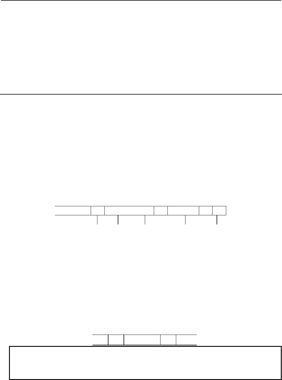
B-63943EN-2/07
6.MACRO EXECUTOR FUNCTION
- 201 -
• By specifying bit 0 (NTV) of compile parameter No. 9167, it is possible to prevent the TV check
space from being output when "LF" is output.
NTV = 0: The TV check space is output when "LF" is output.
NTV = 1: The TV check space is not output when "LF" is output.
• About the behavior if the data transmission has been stopped, refer to “6.7.4 Data Transmission/
Reception Waiting”.
6.7.3
Macro Variable Input/Output Functions
Macro variable data input G337
- Format
G337 Pp Qq R99 ;
P : Read variable number (valid when variable number "N" is not specified in the macro variable data to
be read)
Q : Number of read variables (optional)
R : Continuous reading specification (optional)
- Explanation
This code sets the macro variable data received from a line opened in reception control mode into the
macro variable having a specified number.
The data format of macro variable data is as follows:
LF N ⎯⎯⎯ P ⎯⎯⎯ LF P ⎯⎯⎯ LF %
Leading portion
Start of input
Variable
number
Variable data Variable data Data end
Any information that may precede the first appearance of "LF" on the data is ignored. The information
ranging from the first "LF" to the data end ("%") is regarded to be significant.
In significant information, the section delimited by two "LFs" is called a block. A single block contains
the data for a single macro variable. In a block, address "N" indicates the variable number, and address
"P" indicates variable data.
Address "N" is optional. When it is omitted, the variable number is assumed to be the variable number in
the immediately preceding block plus 1.
When "N" is omitted in the first block, the variable number specified for address "P" with G337 is
assumed. This makes it possible to prepare a data without address "N" and store the data in any desired
macro variable using "G337 Pp."
Address "P" on the data indicates the value of the variable, and cannot be omitted. If the value is null (#0),
"P" must be followed by "LF" without specifying the numeric value, as shown below.
LF N ⎯⎯⎯ P LF
NOTE
1 G337 is a one-shot code.
2 In a significant information section, any codes other than "LF," data end "%,"
addresses "N" and "P," and subsequent numeric data are ignored.
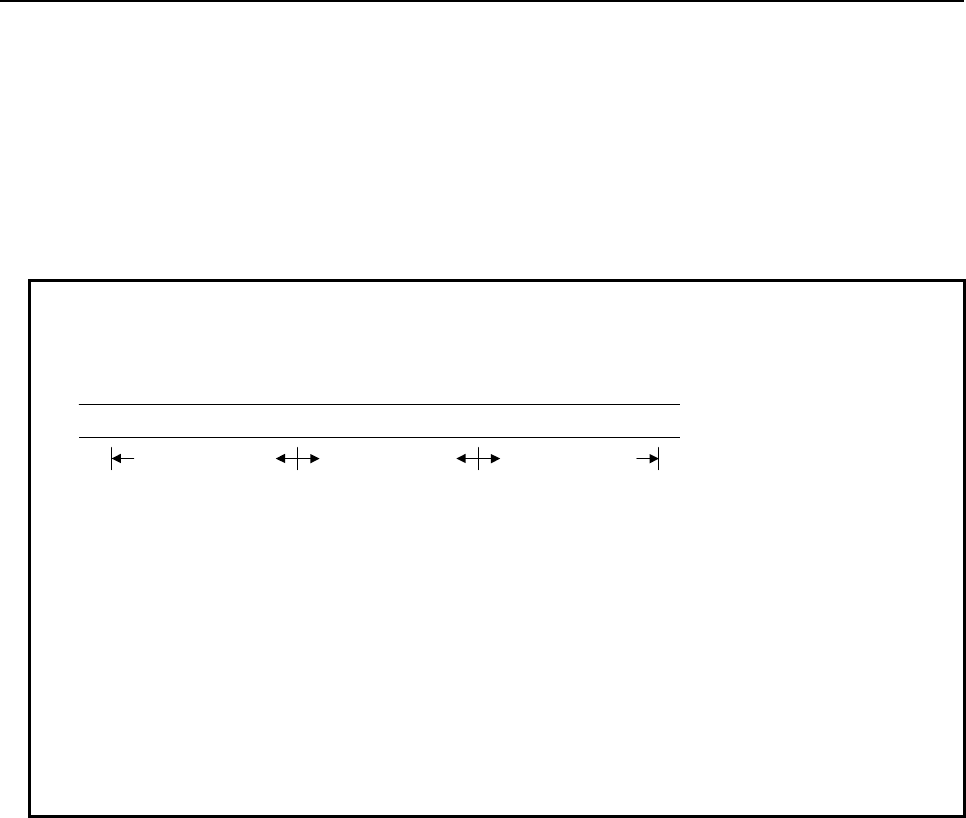
6.MACRO EXECUTOR FUNCTION
B-63943EN-2/07
- 202 -
By using address Q, the number of variables to be read can be specified. When the specified number of
variables have been read, a completion code (#8539) of 99 is set, notifying that continuous reading is
possible. If the data end "%" is read before the specified number of variables are read, a completion code
(#8539) of 0 is set. When address Q is omitted, an infinite number of variables is assumed.
When the number of variables to be read is specified and a completion code (#8539) of 99 is set, the
subsequent macro variable data can be read by specifying R99.
When continuous reading R99 is not specified, the data for the next variable will be lost because of the
significant information check (discarding of the data up to the first ":(LF).")
EXAMPLE
Input of macro variable data
To read the following data in which macro variable number address "N" is
omitted, enter the following:
G330 Pp Bp ..... ;
G337 P100 Q10 ; The data for the first 10 variables is stored in variables #100 to #109.
IF [#8539 NE 99] GOTO 888 ; (#8539=99 for normal processing)
:
G337 P15000 Q20 R99 ; The data for the next 20 variables is stored in variables #15000 to #15019.
IF [#8539 NE 99] GOTO 888 ; (#8539=99 for normal processing)
:
G337 P16000 R99 ; The data for the remaining variables is stored in variable #16000 and above.
IF [#8539 NE 0] GOTO 888 ; (#8539=0 for normal processing)
:
N888 Error processing
G331 ;
About the behavior if there is no receiving data, refer to “6.7.4 Data Transmission/ Reception Waiting”.
Macro variable data output G338
- Format
G338 Pp Qq Ff.e Zz Rr;
P : Specification of the number of the first output macro variable
Q : Specification of the number of output macro variable data items
F : Specification of the output format of macro variable data (modal value in the case of omission)
f : Specifies the total number of digits.
e : Specifies the number of decimal places.
Z : Specification of the zero suppression of macro variable data (modal value in the case of omission)
z = 0 : Does not perform zero suppression.
1 : Performs zero suppression.
R : Data format of output data
r = 0 : Standard format. (The standard format is also assumed when “R” is omitted.)
r = 1 : Does not output variable numbers.
r = 10 : Does not output % (EOR) at the end of data.
r = 11 : Does not output variable numbers and % (EOR) at the end of data
r = 20 : Does not output % (EOR) at the start of data.
r = 21 : Does not output variable numbers and % (EOR) at the start of data.
r = 30 : Does not output % (EOR) at the start and end of data.
% LF P____ LF .... P____ LF P____ LF .... P____ LF P____ LF .... P____ LF %
Data for 10
variables
Data for 20
variables
Data for the
remaining variables
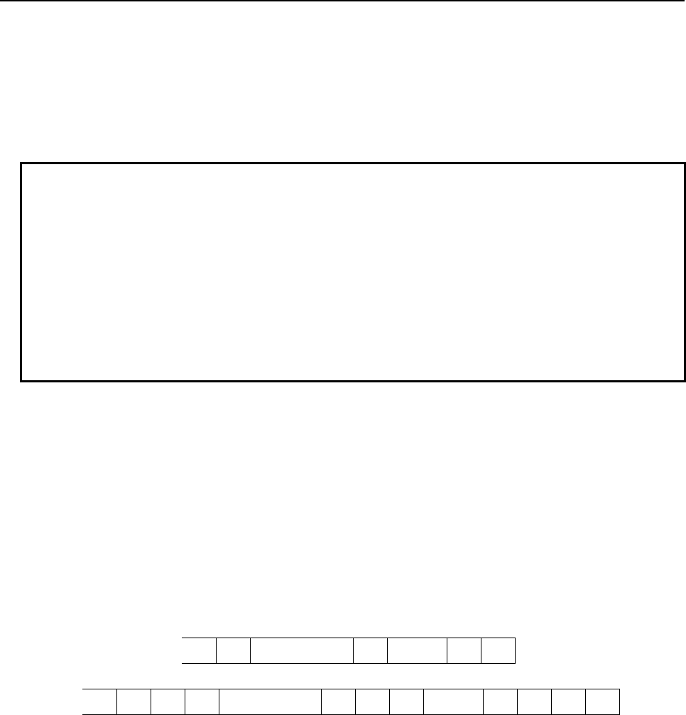
B-63943EN-2/07
6.MACRO EXECUTOR FUNCTION
- 203 -
r = 31 : Does not output variable numbers and % (EOR) at the start and end of data.
r=1xx : (xx=00,01,11,20,21,30,31)
Normally, data is transmitted collectively on a per-block basis (when the EOB command is
found). However, by adding 100 to each of the values after R above (r = 100, 101, 110, 111,
120, 121, 130, 131), it is possible to prevent the data from being transmitted in the current
block and have the stored data transmitted collectively when the G338 command is
executed in the regular data format (r = 0, 1, 10, 11, 20, 21, 30, 31).
NOTE
1 The value specified for address F is treated in the same way as that specified
with screen display control G243, except F-9.8 and F-9.9. See Section 6.1.3.5,
"Character display" for details.
F-9.8 and F-9.9 will be described in detail later.
2 The value specified for address Z is treated in the same way as that specified
with screen display control G243. See Section 6.1.3.5, "Character display" for
details.
3 If improper data is specified for the variable number, output processing is
interrupted and a completion code of 115 is set.
4 G338 is a one-shot G code.
- Explanation
This code converts specified macro variable data to a predetermined data format and sends it from a line
opened in transmission control mode The output code depends on the C specification when the line is
opened.
The output data format is the same as the input format: Address "N" for the first variable number and
address "P" for variable data are output to the first block, the specified number of variable data items are
output consecutively to the subsequent blocks, with address "P," and finally, the data end ("%") code is
output.
Using bit 6 (PTCH) of compile parameter No. 9003, it is possible to output a "CR" code to each block. It
can be used to start a new line on a printing device.
PTCH = 0: "CR" is not output after "LF."
% LF N10000P1234 LF P5678 LF %
PTCH = 1: "CR" is output twice after "LF."
% L F CR CR N1 0 000P 1 2 34 L F CR CR P567 8 LF CR CR %
For address F, the following specifications are possible:
When -9.9 is specified for f, the significant digits of macro variable data is automatically identified and
output. The maximum number of digits that can be output is 12. The output data format is the same as
that described above.
If, however, the variable data is outside the following range:
-999999999999. to-0.00000000001
999999999999. to0.00000000001
"LF" is output following "P" in the same way as when the data is null.
When -9.8 is specified for f, data is output in floating-point format. The output data format is the same as
that described above, except that address "Q" is output instead of address "P" and the variable data is
fixed to 16 characters.
The macro variable data that has been output in this data format can be read by using G337; the data is
stored in the appropriate variables in floating-point format.
6.MACRO EXECUTOR FUNCTION
B-63943EN-2/07
- 204 -
NOTE
1 f is set to 9.3 when the power is turned on. When a value is specified for address
F, that value is stored. When F is omitted, the previously specified value takes
effect.
2 z is set to 0 when the power is turned on. When a value is specified for address
Z, that value is stored. When Z is omitted, the previously specified value takes
effect.
- When variable numbers are not output, the output variable data can be stored in any desired
variables using address P with macro variable input function G337.
- By exercising control on output of "%" (EOR) with address R, multiple variable groups can be
output in one-data format.
- Data is not transmitted character by character but is stored in the transmit buffer and transmitted
collectively on a per-block basis (when the EOB command is found).
- Moreover, when only data transmission (G336/G338) is performed between line opening and
closing, you can delay transmission until after the 255-byte transmit buffer is full, by setting 1 in bit
4 (CWB) of parameter No. 9035. The specification of R1xx is irrelevant to this function.
- Feeding control is not performed at the time of output. To use a paper tape puncher or some other
tool for feeding, use data transmission G336.
- About the behavior if the data transmission has been stopped, refer to “6.7.4 Data Transmission/
Reception Waiting”.
NOTE
1 When output and input are performed alternately between line opening and
closing, set 0 in bit 4 (CWB) of parameter No. 9035. If 1 is set, data is transmitted
in units of 255 bytes, hindering the normal exchange of data.
2 The size of the transmit buffer is 255 bytes.
If the transmit buffer size is exceeded, 255 bytes of data are transmitted. Also,
when line close (G331) is executed, the data stored in the transmit buffer is
transmitted as well.
B-63943EN-2/07
6.MACRO EXECUTOR FUNCTION
- 205 -
Example 1) Macro variable output (without the R1xx command)
G330 Pp Bp ..... ;
:
G338 P10000 Q10 F8.3 Z1 R11 ;
IF[#8539 NE 0]GOTO999;
:
G338 P11000 Q20 F8.3 Z1 R31;
IF[#8539 NE 0]GOTO999;
:
G338 P12000 Q10 F8.3 Z1 R21;
IF[#8539 NE 0]GOTO999;
:
N999 Error processing
G331 ;
→
→
→
→
→
Open the line
Outputs % (EOR) at the start and outputs 10 data
items from #10000 without variable numbers.
Does not output % (EOR) at the end.
Does not output % (EOR) at the start or end nor
variable numbers. Outputs 20 data items from
#11000. This block of data follows the above data.
Does not output % (EOR) at the start nor variable
numbers. Outputs 10 data items from #12000
after the above data and % (EOR) at the end.
Close the line.
% LF P____ LF .... P____ LF P____ LF .... P____ LF P____ LF .... P____ LF %
Q10R11 Q20R31 Q10R21
#10000~#10009 #11000~#11019 #12000~#12019
Example 2) Macro variable output (with the R1xx command)
G330 Pp Bp ..... ;
G338 P10000 Q10 F8.3 Z1 R111 ;
IF[#8539 NE 0]GOTO999;
:
G338 P11000 Q20 F8.3 Z1 R131 ;
IF[#8539 NE 0]GOTO999;
:
G338 P12000 Q10 F8.3 Z1 R121;
IF [#8539 NE 0] GOTO 999 ;
:
N999 Error processing
G331 ;
→
→
→
→
→
Open the line
Stores 10 data items from #10000 after % (EOR)
at the start in the transmit buffer without variable
numbers. Does not append % (EOR) at the end.
Stores 20 data items from #11000 after the above
data in the transmit buffer without appending %
(EOR) at the start or end and variable numbers.
Stores 10 data items from #12000 after the above
data and % (EOR) at the end in the transmit buffer
without appending % (EOR) at the start and
variable numbers.
Closes the line after transmitting all the codes in
the transmit buffer.
6.7.4
Data Transmission/Reception Waiting
When entering the state that the command waits for transmission/reception, the behavior depends on the
following parameters.
Compile parameter No.9056 : Time-out period for waiting for transmission/reception.
Bit 3 (DTW) of Executor paramete
r
N
o.9037
: When Compile parameter No.9056 is set to 0, the behavior of the
G335 command depends on this parameter.
Bit 1 (RCN) of Executor paramete
r
N
o.9035
: When entering the state that the command waits for
transmission/reception, the behavior depends on this parameter
whether to discontinue the command with the reset key
6.MACRO EXECUTOR FUNCTION
B-63943EN-2/07
- 206 -
G335 : 1-byte reception
G336 : Data
transmission
G337 : Macro
variable data
input
G338 : Macro
variable data
output
When compile parameter
No.9056 is set to 0 and bit 3
(DTW) of executor parameter
No.9037 is set to 0 :
Completion code variable
#8539 is set to 255 and
block is over at once.
When compile parameter
No.9056 is set to 0 and bit 3
(DTW) of executor parameter
No.9037 is set to 1 :
The block is not ended
while there is no receive
data.
When compile parameter
No.9056 is set to not 0 :
Time-out period for waiting
for reception (1 to 180sec).
If the system is placed in
the data reception waiting
state for a specified time,
completion code variable
#8539 is set to 255.
The operation of the block is decided depending on a
set value of compile parameter No.9056.
0 : The block is not ended while there is no
data.
1 to 180 : Time-out period for waiting for transmission
/reception (1 to 180sec).
If the system is placed in the data
transmission/reception waiting state for a
specified time, completion code variable
#8539 is set to 255.
By setting bit 1 (RCN) of executor parameter No.9035 to 1, the block can be ended by
an NC reset even within the wait time.

B-63943EN-2/07
6.MACRO EXECUTOR FUNCTION
- 207 -
Example
Program in which cancellation is taken into consideration
09000;
N1 G330 Pp Bp … ; Line open
N2 IF [#8539 NE 0] GOTO 10;
N3 G335 P500; 1-byte reception
N4 IF [#8539 NE 0] GOTO 11;
N5 G331; Line close
:
N11 G331;
N12 G243 X0 Y1 (DATA INPUT ERROR);
:
If, in block N3, the reception waiting state continues even after the time set for
compile parameter No.9056, block N3 is terminated and control jumps from
block N4 to the error handling block N11. At this time, completion code variable
#8539 is set to 255.
Setting bit 1 (RCN) of parameter No. 9035 enables block N3 to end at a reset
when the block is waiting for reception. At this time, completion code variable
#8539 is set to 12.
NOTE
A reset caused by compile parameter No.9056 or by setting bit 1 (RCN) of
executor parameter No.9035 to 1 is also valid for a transmit/receive instruction
used with an auxiliary macro. If transmission/reception is to be performed by an
auxiliary macro, therefore, the possibility that the RESET key may be pressed
regardless of the state of the auxiliary macro must be taken into consideration
during programming.
6.7.5
FANUC Cassette Control
Using line open G330 and file information control G339, it is possible to read file data from FANUC
Handy File, FANUC Floppy Cassette, FANUC FA Card, and FANUC PROGRAM File Mate, create and
delete files, and perform other operations.
Searching for the beginning of a file G330
File creation G330
File information reading G330/G339 P1
File deletion G330/G339 P2
File renaming G330/G339 P3
NOTE
For addresses B, S, and C, see the section handling line open (G330).
However, set ISO(2) in address C.
Searching for the beginning of a file G330
- Format
G330 Pp Bb Ss Cc (Ll / Ff / Aa) ;

6.MACRO EXECUTOR FUNCTION
B-63943EN-2/07
- 208 -
- Explanation
When a line is opened in reception control mode, with one of address L, F, and A specified, it is possible
to search for the beginning of a specified file on the FANUC cassette.
For an explanation of specifying addresses P, B, S, and C, see the explanation of line open G330. Address
P must be reading control (p = 11/12 ....).
Select one of addresses L, F, and A, referring to the following explanation.
(1) Searching for the beginning of a file using its file name
By specifying address L, it is possible to search for the beginning of a file using its file name.
Set the ASCII codes (decimal) of the file name in macro variables having consecutive 17 numbers and
specify the number of the first macro variable for address L.
Example
To search for the beginning of the file "ABCD," set 65 (A), 66 (B), 67 (C), 68 (D),
32, 32, ..., and 32 (space) in 17 macro variables #100 to #116.
G330 P11 B10 S12 C2 L100 ;
The above command searches for the beginning of the file "ABCD."
NOTE
1 The file name must consist of 17 characters. If the file name consists of less than
17 characters, fill the remaining variables with a value of 32 (space) to make the
name consist of 17 characters.
2 The file name can use alphanumeric characters and spaces. The file name
cannot, however, start with a space. If this occurs, a completion code of 8 is set.
(2) Searching for the beginning of a file using its file number
By specifying address F, it is possible to search for the beginning of a file using its file number.
Specify the number of the file to search for (1 to 9999).
Example
To search for the beginning of a file with file number 3.
G330 P11 B10 S12 C2 F3;
(3) Searching for the beginning of the next file
By specifying address A, it is possible to search for the beginning of the file following the one the
beginning of which has been searched for. Use this address to read files in succession. For address A,
always specify 1 (a = 1). Otherwise, a completion code of 8 is set.
Example
To search for the beginning of the file following the one the beginning of which
has been searched for.
G330 P11 B10 S12 C2 A1 ;

B-63943EN-2/07
6.MACRO EXECUTOR FUNCTION
- 209 -
File creation G330
- Format
G330 Pp Bb Ss Cc (Ll / Ff) ;
- Explanation
When a line is opened in transmission control mode, with either address L or F specified, it is possible to
create a new file on the FANUC cassette.
For an explanation of specifying addresses P, B, S, and C, see the explanation of line open G330. Address
P must be writing control (p = 21/22 ....).
Select either address L or F, referring to the following explanation.
(1) Creating a file with a file name
By specifying address L, it is possible to create a file with a file name. Set the ASCII codes (decimal) of
the file name in macro variables having consecutive 17 numbers and specify the number of the first macro
variable for address L.
Example
To create a file "ABCD," set 65 (A), 66 (B), 67 (C), 68 (D), 32, 32, ..., and 32
(space) in 17 macro variables #100 to #116.
G330 P21 B10 S12 C2 L100 ;
The above command crates a file with the file name "ABCD."
NOTE
1 The file name must consist of 17 characters. If the file name consists of less than
17 characters, fill the remaining variables with a value of 32 (space) to make the
name consist of 17 characters.
2 The file name can use alphanumeric characters and spaces. The file name
cannot, however, start with a space. If this occurs, a completion code of 8 is set.
3 The created file is added at the end of the already registered ones.
(2) Creating a file with a file number
By specifying address F, it is possible to create a new file with a specified file number. Specify the
number of the file to be created (1 to 9999).
Example
To create a file with file number 3, enter the following:
G330 P21 B10 S12 C2 F3 ;
NOTE
1 When a file is created with a file number, the existing file with that file number is
deleted, as well as any files with the subsequent file numbers.
For the FANUC Handy File in DOS format, however, the files with the file
numbers subsequent to the specified number are not deleted.
2 This method of creating a file with a file number allows only an existing file
number to be specified. To add a new file, create it with a file name.

6.MACRO EXECUTOR FUNCTION
B-63943EN-2/07
- 210 -
File information control G330/G339
- Format
G330 Pp Bb Ss ;
p = 31: File control with RS-232-C1
32: File control with RS-232-C2
For an explanation of addresses B and S, see the explanation of line open G330.
G339 Pp (Ll Ss Ff) ;
p = 1: Reads file information
2: Deletes a file
3: Rename a file
Specify addresses L, S, and F as required.
- Explanation
G339 can be used to read file information, delete a file, and rename a file.
File information reading G339 P1
File deletion G339 P2
File renaming G339 P3
To enable of the use of this function, the control mode must be file information control mode when the
line is opened (G330). To specify file information control mode, specify 31/32 ... for address P when
opening the line.
NOTE
When the line is opened in file information control mode, two or more successive
operations such as a file information read operation followed by a file deletion
operation cannot be specified in one line open period. If, for example, file
information is to be read and checked and then the file is to be deleted, the line
must be opened and closed for each operation, as in the example below.
Example
Order in which commands are issued
1) Open the line in file information control mode.
2) File information reading
3) Line close
4) Open the line in file information control mode.
5) File deletion
6) Line close
(1) File information reading G339 P1
G339 P1 stores file information (file name and size) in specified macro variables.
G339 P1 Ff Ll Ss ;
F : File number specification (1 to 9999)
L : Number of the first one of the consecutive 17 macro variables used to store the 17-character file
name to be read. The file name is stored as ASCII codes (decimal).
B-63943EN-2/07
6.MACRO EXECUTOR FUNCTION
- 211 -
S : Number of the macro variable used to store the file size to be read
By reading file information by specifying a file number for address F and then issuing G339 P1 with a
file number omitted, the file information for the next file number can be read. If a file with the specified
file number does not exist, a completion code of 11 is set.
(2) File deletion G339 P2
G339 P2 deletes a specified file.
G339 P2 (Ll / Ff) ;
Specify the file with its file name or file number.
L : Number of the first one of the consecutive 17 macro variables used to store the 17-character file
name of the file to be deleted. The file name must be set with ASCII codes (decimal).
F : File number specification (1 to 9999)
NOTE
When a file is deleted, any subsequent files are moved backward, with their file
numbers changed. Bear this in mind when issuing a command with a file number
after deleting a file.
(3) File renaming
G339 P3 renames a specified file.
G339 P3 Ll Ff ;
Specify the file number of the file to be renamed and the new file name.
F : File number specification (1 to 9999)
L : Number of the first one of the consecutive 17 macro variables containing the ASCII codes of the
new 17-character file name
6.7.6
Completion Codes (#8539)
Completion codes are returned for G330 to G339 commands. If an error occurs, its description is set in a
completion code. Check the completion code after issuing a command.
There are three types of completion codes:
#8537 : Completion code for the result of executing an auxiliary macro
#8538 : Completion code for the result of executing a conversational macro
#8539 : Completion code common to auxiliary commands and conversational macros
When the command specified in an auxiliary macro program is completed, a completion code is set in
both variables #8537 and #8539. If the command specified in a conversational macro program is
completed, a completion code is set in both variables #8538 and #8539.
#8539 Description
0 Normal termination
1 The line is not open.
2 Line error (DR signal off)
3 Line error (overrun error)
4 Line error (buffer over error)
5 Line error (framing error, parity error)
6 No line function option.
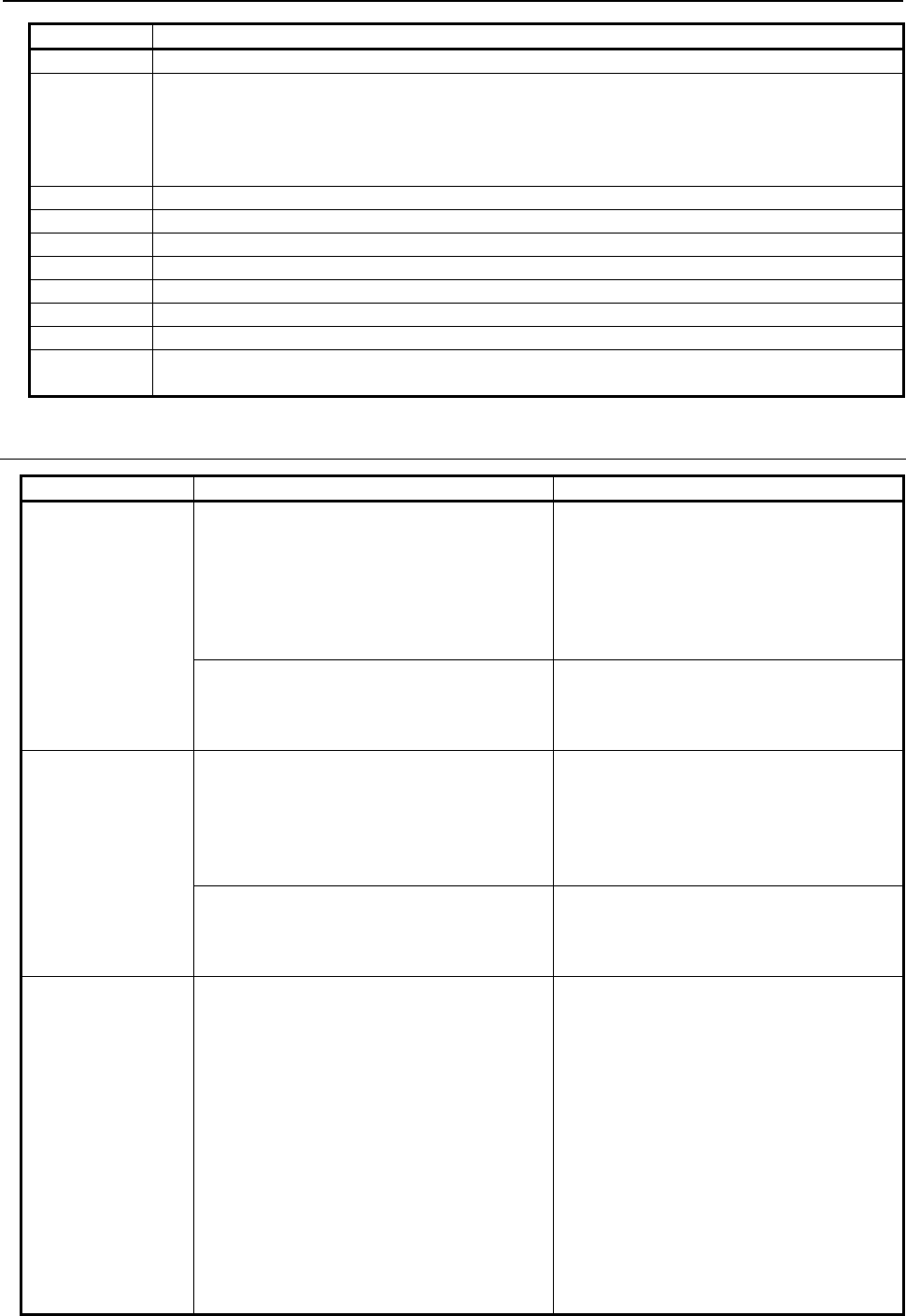
6.MACRO EXECUTOR FUNCTION
B-63943EN-2/07
- 212 -
#8539 Description
7 The line is busy.
8 (1) Data (P, Q, R, and so forth) specified in a block of G330 to G339 is incorrect, or necessary
data is not specified.
(2) G336 or G338 was issued in reception control mode.
(3) G335 or G337 was issued in transmission control mode.
(4) G339 was specified in a mode other than file control mode.
9 Invalid data format
10 Invalid file number
11 A file with the number specified with the file information reading code does not exist.
12 Operation was stopped by an NC reset in the data transmission/reception waiting state.
99 With macro variable input function G337, the continuous reading of macro variables is possible.
115 An undefined variable number is specified.
211 Line error (CD signal off)
255 The specified time has elapsed since the system entered the data transmission/reception waiting
state.
6.7.6.1
Differences from the Series 16i
Function Series 16i/18i/21i Series 30i/31i/32i/35i/0i-F/PMi
G335 : 1-byte
reception
When there is no
received data.
- When there is no received data,
completion code variable #8539 is set to
255 and block is over at once.
- When there is no received data, the
operation of the block is decided depending
on a set value of executor parameter
No.9056 and bit 3 (DTW) of executor
parameter No.9037.
Refer to “6.7.4 Data Transmission/
Reception Waiting” for details.
- There is no setting for the block can be
ended by an NC reset even within the wait
time.
- By setting bit 1 (RCN) of executor
parameter No.9035 to 1, the block can be
ended by an NC reset even within the
wait time.
G337 : Macro
variable
data input
When there is no
received data.
- When there is no received data,
completion code variable #8539 is set to
255 and block is over at once.
- When there is no received data, the
operation of the block is decided depending
on a set value of executor parameter
No.9056.
Refer to “6.7.4 Data Transmission/
Reception Waiting” for details.
- There is no setting for the block can be
ended by an NC reset even within the wait
time.
- By setting bit 1 (RCN) of executor
parameter No.9035 to 1, the block can be
ended by an NC reset even within the
wait time.
G336 : Data
transmission
G338 : Macro
variable data
output
When transmission
is waiting.
- When transmission is waiting, the
operation of the block is decided
depending on a set value of executor
parameter No.9056.
0: Time-out period for waiting for
transmission (5000msec).
1 to 32767: Time-out period for waiting for
transmission (1 to 32767msec).
-1: The block is not ended while
transmission is waiting.
If the system is placed in the
data transmission waiting state
for a specified time, completion
code variable #8539 is set to
12.
- When transmission is waiting, the
operation of the block is decided
depending on a set value of executor
parameter No.9056.
Refer to “6.7.4 Data Transmission/
Reception Waiting” for details.

B-63943EN-2/07
6.MACRO EXECUTOR FUNCTION
- 213 -
Function Series 16i/18i/21i Series 30i/31i/32i/35i/0i-F/PMi
- By setting bit 4 (RCN) of compile
parameter No.9009 to 1, the block can be
ended by an NC reset even within the wait
time.
- By setting bit 1 (RCN) of executor
parameter No.9035 to 1, the block can be
ended by an NC reset even within the
wait time.
G336/338 data
transmission timing
Data is output on a code-by-code basis. Data is output on a per-block basis. Also,
the next output command (R100/R1xx)
allows data to be stored in the transmit
buffer and to be output when a G336 or 338
command without the next output command
is executed, thus speeding up macro
execution.
G336 data writing
Addresses are processed in the order they
are specified.
Operation example
<1> F8.3;
G336 F5.1 D#100;
→
#100 is output with
F5.1.
<2> F8.3;
G336 D#100 F5.1;
→
#100 is output with
F8.3.
Data is processed in blocks. Therefore, the
operation is not changed by the order the
addresses are specified.
Operation example
<1> F8.3;
G336 F5.1 D#100;
→
#100 is output
with F5.1.
<2> F8.3;
G336 D#100 F5.1;
→
#100 is output
with F5.1.
If identical addresses are specified in the
same one block, they are output in the order
in which they are specified.
More than one address can be specified in a
block, as in G336C_C_.
If two or more identical addresses are
specified in the same one block, the last
specified address takes effect. It is not
allowed to specify more than one address in
a block, as in G336C_C_.
Addresses must be specified in separate
blocks as shown below.
G336C_;
C_;
Any number of ( _ ), ( ’_ ’), and (*_*)
combinations may be specified in the same
one block.
Up to five ( _ ), ( ’_ ’), and (*_*) combinations
may be specified in total in the same one
block.
Space is not output when "LF" is output. Bit 0 (NTV) of compile parameter No. 9167
allows you to choose whether to output TV
check space when "LF" is output.
G338 macro
variable data
output
- The maximum number of digits for
automatic decimal point position output of
F-9.9 is 9.
- F-9.8 specifies output in a special
floating-point format.
- The maximum number of digits for
automatic decimal point position output
of F-9.9 is 12.
- F-9.8 specifies output in the
IEEE-compliant floating-point format.
Data output in the special format of the
Series 16
i
cannot be read with G337.
Completion code
(#8539)
Added partially
6.8
MEMORY CARD CONTROL
6.8.1
General
Memory card control can be executed using the same commands that are used for the reader/puncher
interface.
Memory card control is enabled when bit 7 (EXT1) of compile parameter No. 9002 is set to 1.

6.MACRO EXECUTOR FUNCTION
B-63943EN-2/07
- 214 -
G330 : Memory card open
G331 : Memory card close
G335 : 1-byte reading
G336 : Data writing
G337 : Macro variable input
G338 : Macro variable output
G339 : File information reading/file deletion
Completion codes are also used, as with the reader/puncher interface.
See Section 6.8.3, "Completion codes" for details of completion codes.
6.8.2
Functions
Memory card open G330
- Format
G330 Pp (Ll / Ff) ;
P
= 14 : Memory card read control (Specify a file name.)
= 24 : Memory card write control (Specify a file name.)
= 34 : File control based on memory card
L : Specify the start variable number of the variable string storing the file name.
In read mode, a search for the beginning of the file is made based on this file name.
In write mode, a new file is created using this file name.
F : Specify the file number.
In read mode, the data is read from the file specified by this file number.
In write mode, the data is overwritten to the file specified by this file number.
- Explanation
By setting the lower one digit specified for P to "4", the memory card is opened and made usable
according to the control method and control conditions.
Example
G330 P24 L100 ;
IF [#8539 NE 0] GOTO900 ;
Open processing completed
N900 Error processing
- Memory card read control
The read control mode can be set by setting P=14 when the memory card is opened.
When address L or address F is specified in the read control mode, a specified file on the memory card is
found and the file data is read.
Heading by file name
When the start variable number of the variable string where a desired file name is stored is specified with
address L, a heading based on the file name can be made.
A file name consists of 12 variable strings (file name (8 characters) + period + extension (3 characters))
and a decimal ASCII code.

B-63943EN-2/07
6.MACRO EXECUTOR FUNCTION
- 215 -
Example
To search for the beginning of the file ”ABC.DAT”, set 65 (A), 66 (B), 67 (C), 46
(.), 68 (D), 65 (A), 84 (T), 32, ..., 32 (space) in 12 common variables #100 to
#111.
G330 P14 L100 ;
NOTE
1 A file name must consist of 12 characters. If a file name is shorter than 12
characters, pad 32 (space) at the following unused character position(s) to make
a 12-character file name.
2 Specify a file name + extension by using alphanumeric characters. If a file name
starts with code 32 (space), however, completion code 114 is returned.
Heading by file number
The file search by the file number can be done by specifing address F.
Specify the file number to search for (1 to 9999).
Example
To search for the file number 3.
G330 P14 F3;
NOTE
If the specified file doesn't exist, completion code variable #8539 is set to 114.
- Memory card write control
The write control mode can be set by setting P=24 when the memory card is opened. When address L is
specified in the write control mode, a new file can be created on the memory card and data can be written
into the file.
Creation by file name
When the start variable number of the variable string where a desired file name is stored is specified with
address L, a new file can be created under a specified file name on the memory card and data can be
written into the file. A file name consists of 12 variable strings and a decimal ASCII code.
Example
To create a file named ”ABC.DAT”, set 65 (A), 66 (B), 67 (C), 46 (.), 68 (D), 65
(A), 84 (T), 32, ..., 32 (space) in 12 common variables #100 to #111.
G330 P24 L100 ;
NOTE
1 A file name must consist of 12 characters. If a file name is shorter than 12
characters, pad 32 (space) at the following unused character position(s) to make
a 12-character file name.
2 Specify a file name + extension by using alphanumeric characters. If a file name
starts with code 32 (space), however, completion code 122 is returned.
Memory card close G331
- Format
G331 ;

6.MACRO EXECUTOR FUNCTION
B-63943EN-2/07
- 216 -
- Explanation
This code ends memory card control.
Memory card close processing is terminated normally at all times. (Completion code=0)
1-byte reading G335
- Format
G335 Pp ;
P : Number of a macro variable to which read data is assigned
- Explanation
The file on the memory card is read from the beginning, one byte at a time, and the read data is assigned
to the specified macro variable. When there is no more data to read, completion code 121 is set.
For a byte read, open memory card control in the read control mode (P=14).
Example
G330 P14 L500 ;
#100=10000;
N100 G335 P#100 ;
IF [#8539 EQ 121] GOTO999 ;
IF [#8539 NE 0] GOTO900 ;
Processing of the read data
#100=#100+1;
(#10000~ : Read data)
GOTO100
N900 Error processing
N999 G331
Next processing
→
→
→
→
→
→
→
Open in read control mode
Read into #10000 and up.
Check the end of data.
Check for any error.
Next byte
Repeat until there is no more data.
Close memory card
Data writing G336
- Format
G336 Cc (_) (‘_’) (*_*) Kk Ff.e Dd Pp Zz ;
C : Specify a code to be directly output. (Specify one character.)
Code conversion processing is not performed. Specify this address when outputting a code other than
the ASCII codes.
K : Specify the number of space characters (20h).
(‘_’)
(*_*)
: Single-byte characters (codes listed in the katakana code table, alphanumeric code table, and symbol
code table in Appendix B "CODE TABLES") can be used. Kanji and hiragana codes cannot be used.
The other addresses are the same as for screen display control (G243). So, see Subsection 6.1.3.5,
"Character display (G243)".
- Explanation
Data is output in a specified format.
A specified character string is converted to ASCII codes for output.
Open memory card control in the write control mode (P=24).
B-63943EN-2/07
6.MACRO EXECUTOR FUNCTION
- 217 -
Example
G330 P24 L500 ;
G336 C9 K20 (FANUC) ;
K30;
IF [#8539 NE 0] GOTO900 ;
Write processing completed
G331;
GOTO1000;
N900 Error processing
N1000 Next processing
Open in write control mode
C9 : Horizontal tab
K20 : 20 space characters (20h).
FANUC (ASCII code)
30 space characters (20h)
Macro variable input G337
- Format
G337 Pp Qq R99 ;
- Explanation
Macro variable data is read from the memory card opened in the read control mode, and is assigned to
specified macro variable.
This processing is the same as macro variable data input (G337) described in Section 6.7,
"READER/PUNCHER INTERFACE", except that data is input from the memory card.
Macro variable output G338
- Format
G338 Pp Qq Ff.e Zz Rr;
- Explanation
In the write control mode, the data of a specified macro variable is converted to a specified format for
output.
This processing is the same as macro variable data output (G338) described in Section 6.7,
"READER/PUNCHER INTERFACE", except that data is output to the memory card.
File information reading/file deletion G339
- Format
G339 Pp (Ff Ll Ss) ;
p = 1 : File information reading
2 : File deletion
Specify address L/S and F as required for processing.
- Explanation
By specifying G339, file information on the memory card can be read and a file on the memory card can
be deleted.
Before this function can be used, the file information control mode must be set when the line is opened
(G330). To set the file information control mode, specify p = 34 in address P when opening the line. At
this time, the specification of a file (L) is not necessary. (G330 P34 ;)
(1) File information reading G339 P1
By specifying G339 P1, file information (file name and size) can be read into a specified macro variable.
G339 P1 Ff Ll Ss ;

6.MACRO EXECUTOR FUNCTION
B-63943EN-2/07
- 218 -
F : Specify a file by file number (1 to 9999).
L : Specify the start number of the 12 consecutive macro variables storing the read 12-character file
name. The file name is stored in ASCII code format (decimal).
S : Number of the macro variable storing the read file size
If there is no directory corresponding to the specified file number, completion code 114 is returned.
Example
G330 P34 ;
G339 P1 F1 L101 S100 ;
IF [#8539 NE 0] GOTO100 ;
Read processing completed
G331 ;
GOTO200 ;
N100 Error processing
N200 Next processing
→
→
→
Open in file information control mode
Read file information
Close memory card
(2) File deletion G339 P2
By specifying G339 P2, the specified file can be deleted.
G339 P2 (Ff Ll) ;
F : Number of the file to be deleted (1 to 9999)
L : Start number of the variable string where the name (ASCII code) of a file to be deleted is stored.
Example
To delete a file named ”ABC.DAT”, set 65 (A), 66 (B), 67 (C), 46 (.), 68 (D), 65
(A), 84 (T), 32, ..., 32 (space) in 12 common variables #100 to #111.
G330 P34 ;
G339 P2 L100 ;
IF [#8539 NE 0] GOTO100 ;
Read processing completed
G331 ;
GOTO200 ;
N100 Error processing
N200 Next processing
→
→
→
Open in file information control mode
File deletion
Close memory card
6.8.3
Completion Codes (#8539)
Completion codes are returned for G330 to G339 commands. If an error occurs, its description is set in a
completion code. Check the completion code after issuing a command.
There are three types of completion codes:
#8537 : Completion code for the result of executing an auxiliary macro
#8538 : Completion code for the result of executing a conversational macro
#8539 : Completion code common to auxiliary commands and conversational macros
When the command specified in an auxiliary macro program is completed, a completion code is set in
both variables #8537 and #8539. If the command specified in a conversational macro program is
completed, a completion code is set in both variables #8538 and #8539.
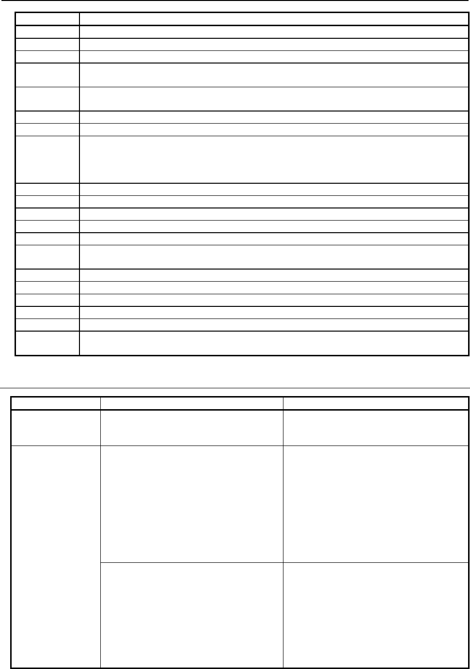
B-63943EN-2/07
6.MACRO EXECUTOR FUNCTION
- 219 -
#8539 Description
0 Normal termination
1 The memory card is not opened.
6 A necessary option is not specified.
7 The memory card cannot be opened because it is used with another function.
Or, it is write-protected.
8 Data (P, Q, R, and so forth) specified in a block of G330 to G339 is incorrect, or necessary data is
not specified.
9 Invalid data format
10 The file number is invalid.
12 (1) The specified time has elapsed since the system entered the data transmission/reception
waiting state.
(2) The command has been interrupted by an NC reset while waiting for data input or output when
1 is set in bit 1 (RCN) of parameter No. 9035.
30 Memory card not inserted yet
32 The battery power of the memory card is low.
99 With macro variable input function G337, the continuous reading of macro variables is possible.
102 Insufficient free space on memory card
114 Specify file not found
115 The specified file is protected.
An undefined variable number was specified.
117 The file is not opened in a correct mode.
121 End of file
122 Illegal file name specified
130 A file with the same name already exists on memory card.
141 Close the file.
150 (1) Memory card cannot be recognized.
(2) An error occurred on memory card.
6.8.3.1
Differences from the Series 16i
Function Series 16i/18i/21i Series 30i/31i/32i/35i/0i-F/PMi
G330 Memory card
write control
When creating by the file name is specified
and the file with the same name exists on
the memory card, the file is overwritten.
When creating by the file name is specified
and the file with the same name exists, the
file is not opened and an error occurs.
G336 data writing
Addresses are processed in the order they
are specified.
Operation example
<1> F8.3;
G336 F5.1 D#100;
→
#100 is output
with F5.1.
<2> F8.3;
G336 D#100 F5.1;
→
#100 is output
with F8.3.
Data is processed in blocks. Therefore, the
operation is not changed by the order the
addresses are specified.
Operation example
<1> F8.3;
G336 F5.1 D#100;
→
#100 is output
with F5.1.
<2> F8.3;
G336 D#100 F5.1;
→
#100 is output
with F5.1.
If identical addresses are specified in the
same one block, they are output in the order
in which they are specified.
More than one address can be specified in a
block, as in G336C_C_.
If two or more identical addresses are
specified in the same one block, the last
specified address takes effect. It is not
allowed to specify more than one address in
a block, as in G336C_C_.
Addresses must be specified in separate
blocks as shown below.
G336C_;
C_;
6.MACRO EXECUTOR FUNCTION
B-63943EN-2/07
- 220 -
Function Series 16i/18i/21i Series 30i/31i/32i/35i/0i-F/PMi
Any number of (_), (’_’), and (*_*)
combinations may be specified in the same
one block.
Up to five (_), (’_’), and (*_*) combinations
may be specified in total in the same one
block.
Space is not output when "LF" is output. Bit 0 (NTV) of compile parameter No. 9167
allows you to choose whether to output TV
check space when "LF" is output.
G338 macro
variable data
output
- The maximum number of digits for
automatic decimal point position output
of F-9.9 is 9.
- F-9.8 specifies output in a special
floating-point format.
- The maximum number of digits for
automatic decimal point position output
of F-9.9 is 12.
- F-9.8 specifies output in the
IEEE-compliant floating-point format.
Data output in the special format of the
Series 16
i
cannot be read with G337.
Memory card
completion codes
(#8539)
Some codes have been added or changed.
6.9
CNC PROGRAM REFERENCING AND WRITING, AND
PROGRAM INFORMATION READING
6.9.1
General
Using the conversational macro function and auxiliary macro function enables CNC part programs to be
registered, deleted, and modified.
Program and block numbers are used to manage CNC programs. The block number begins with the
address "O" block of the program and then increments by 1 for each EOB.
A macro-based CNC program is comprised of blocks that are a repetition of two variables (address code
and value) representing data at one word.
Using this function requires that bit 7 (EXT1) of compile parameter No. 9002 to be set 1.
Example
O0001; Block No. 1
G00 X10; Block No. 2
M03 S1000; Block No. 3
:
Program No. 0001, block No. 3, storage variable No. 100
#100= 13 .......... Address M
#101= 3 .......... Value
#102= 19 .......... Address S
#103=1000 ......... Value
#104= 27 .......... Address EOB
Control commands are issued by specifying G codes (G320 to G329) with macros. Completion code
(#8529) is available which can be used to check whether specified functions have been executed normally.
Completion code (#8529) should be checked after G320 to G329 are executed.
The completion code is 0 in the case of normal termination. When the completion code is other than 0, an
alarm code for this function is issued.

B-63943EN-2/07
6.MACRO EXECUTOR FUNCTION
- 221 -
Target folder
Target folders in which NC programs are to be registered, deleted, and changed are
If parameter No. 3467 is set to 0
The default folder in the background.
If parameter No. 3467 is set to a value other than 0
Folder specified for parameter No. 3467 from the initial folder.
NOTE
If "6. path-by-path folder" is selected for parameter No. 3467, the target folder is
the folder of the displayed path if the command is from a conversational macro;
and if the command is from an auxiliary macro, it is the folder of the path in
which the auxiliary macro is being executed.
Control variables
#8520 : Program number specification
#8521 : Block number specification
#8522 : Storage variable number specification
#8523 : Variable number for specifying the number of decimal places
#8527 : Number of registered programs (read-only)
#8528 : Free-space capacity of CNC program memory (read-only)
#8529 : Completion code (read-only)
Control codes
G320 : Newly registers a program.
G321 : Deletes a program.
G325 : Reads a specified word-type block.
G326 : Writes a specified word-type block.
G327 : Deletes a block.
G322 : Condenses a program.
G328 : Reads a specified character-type block.
G329 : Writes a specified character-type block.
6.9.2
Referencing and Writing CNC Programs
Newly registering a program (G320)
- Format
G320;
- Explanation
To newly register a program, issue G320 by specifying a program number (#8520) for the program.
Example
To register O0002:
#8520=2;
G320;
IF [#8529 NE 0] GOTO 900;
Registration completed
N900;
Error
6.MACRO EXECUTOR FUNCTION
B-63943EN-2/07
- 222 -
Newly registering a program involves the same processing as for "Oxxxx"+"INSERT" (editing); no EOB
is inserted.
Example
O0002 %
Deleting a program (G321)
- Format
G321;
- Explanation
To delete a program, issue G321 by specifying the program number (#8520) of the program.
Example
To delete O0003:
#8520=3;
G321;
IF [#8529 NE 0] GOTO 900;
Deletion completed
N900;
Error
Reading a specified block (G325/G328)
(1) Reading a specified word-type block (G325)
- Format
G325 Pp;
p : Maximum allowable number of variable data items
(When omitted: Until (EOB) or %(EOR))
- Explanation
A block can be read into a specified variable area by specifying its program number and block number.
The block number used here is relative to the O-number block, which is counted as block No. 1.
Therefore, it is different from a sequence number (Nxxxx). A block number is used also in G326, G327,
G328, and G329.
By using address P, specify the maximum number of readable variables. If a block to be read is so large
that the variables more than the specified maximum number of readable variables are required, the read
processing is stopped, and completion code 210 is set in #8529.
When a value specified without the decimal point is read, the position of the decimal point is determined
by bit 0 (DPI) of parameter No. 3401. By setting 1 in bit 2 (PRDPI) of compile parameter No. 9160, it is
also possible to keep calculator type decimal point input.

B-63943EN-2/07
6.MACRO EXECUTOR FUNCTION
- 223 -
Example 1
* The minimum setting unit is that of the IS-B (0.001) machine.
[NC program]
O0004;
G92 X0. M08;
G90 G00 X10.5 Z15 M05;
[Macro program]
#8520=4;
#8521=3;
#8522=100;
G325 P11;
IF [#8529 NE 0] GOTO 900;
Read completed
N900;
Error
Executing the above macro programs causes program data to be stored in an area starting at #100
specified using storage variable number #8522, as follows:
#100= 7 ........ Address G
#101= 90 ........ Value
#102= 7 ........ Address G
#103= 0 ........ Value
#104= 24 ........ Address X
#105= 10.5 ........ Value
#106= 26 ........ Address Z
#107= 0.015 ........ Value
........ 15.0 when 1 is set in bit 2 (PRDPI) of compile parameter No.
9160
#108= 13 ........ Address M
#109= 5 ........ Value
#110= 27 ........ Address EOB
If a program does not end with an EOB, or the location of an EOR is specified with a block number, the
EOR (28) is stored as an address. If any block number after the EOR block is specified, completion code
"211" is set and the block is not read.
Example 2
O0004;
G92 X0. M08;
M02%
Assuming the above steps, the variable area will be:
#100=13 ............... Address M
#101= 2 ................ Value
#102=28 ............... Address EOR
6.MACRO EXECUTOR FUNCTION
B-63943EN-2/07
- 224 -
Example 3
O0004;
G92 X0. M08;
%
Assuming the above steps, the variable area will be:
#100=28 ............... Address EOR
- Reading the O-number block
By setting bit 6 (PG1O) of compile parameter No. 9160, it is possible to select the data to be read actually
when the O-number block is read by setting 1 in block number variable #8521.
Bit 6 (PG1O) of compile parameter No. 9160
=0: All words including the O number can be read.
=1: Words excluding the O number can be read.
Example
[NC program]
O0011 N10 G00X0 ;
N20 M05;
[Macro program]
#8520=11;
#8521=1;
#8522=100;
G325 P9;
IF [#8529 NE 0] GOTO 900;
Read completed
N900;
Error
If this macro program is executed, the program data is stored, beginning with
#100, as follows.
Variable read Bit 6 (PG1O) of compile parameter No. 9160
0 1
#100 15: Address O 14: Address N
#101 11: Value 10: Value
#102 14: Address N 7 : Address G
#103 10: Value 0 : Value
#104 7 : Address G 24: Address X
#105 0 : Value 0 : Value
#106 24: Address X 27: Address EOB
#107 0 : Value
#108 27: Address EOB
- Processing for a block other than a word-type block
If a block read using the function for reading a specified word-type block (G325) is not a word-type block
(but a character-type block), completion code 253 is returned to #8529 for notification. If this completion
code is returned, read the block again by using the function for reading a specified character-type block
(G328).

B-63943EN-2/07
6.MACRO EXECUTOR FUNCTION
- 225 -
Example 2
#8520 = Program number ;
#8521 = Block number;
#8522 = Read variable number;
G325 ; (Reading a specified word-type block)
IF [#8529 EQ 253] GOTO 100;
:
N100 G328 ; (Reading a specified character-type block)
NOTE
This command cannot read an extended address (extended axis name or
extended spindle name). Use the function for reading a specified character-type
block (G328).
(2) Reading a specified character-type block (G328)
- Format
G328 Pp;
p : Maximum allowable number of variable data items
(When omitted: Until (EOB) or %(EOR))
- Explanation
Even if a block specified in a CNC program is not represented as a word-type block (in the format
"address + number"), this command enables the block to be read to a specified variable area by converting
each character to an ASCII code (decimal). At this time, the control commands (WHILE/IF/...) and the
functions (SIN/COS/FUP/..) are represented as special codes.
By using address P, specify the maximum number of readable variables. If a block to be read is so large
that the variables more than the specified maximum number of readable variables are required, the read
processing is stopped, and completion code 210 is set in #8529.
Example 1
#8520 = Program number ;
#8521 = Block number;
#8522=100;(Read variable number)
G328 P9 ;
IF [#8529 NE 0] GOTO 900; (Error check)
When the block is "#1=SIN[#2];", the following is read:
#100 : 35 " # "
#101 : 49 " 1 "
#102 : 61 " = "
#103 : 276 "SIN"
#104 : 91 " [ "
#105 : 35 " # "
#106 : 50 " 2 "
#107 : 93 " ] "
#108 : 59 " ; "
6.MACRO EXECUTOR FUNCTION
B-63943EN-2/07
- 226 -
・Reading the O-number block
By setting bit 6 (PG1O) of compile parameter No. 9160, it is possible to select the data to be read actually
when the O-number block is read by setting 1 in block number variable #8521.
Bit 6 (PG1O) of compile parameter No. 9160
=0: All characters including the O number can be read.
=1: Characters excluding the O number can be read.
NOTE
When the O-number block is read by setting 1 in block number variable #8521,
the length of the read O-number block is always 8 digits.
Example
[NC program]
O0011(ABC) ;
N20 M05;
[Macro program]
#8520=11;
#8521=1;
#8522=100;
G328 P15;
IF [#8529 NE 0] GOTO 900;
Read completed
N900;
Error
If this macro program is executed, the program data is stored, beginning with
#100, as follows.
Variable read Bit 6 (PG1O) of compile parameter No. 9160
0 1
#100 79: ”O” 40: ”(“
#101 48: ”0” 65: ”A“
#102 48: ”0” 66: ”B“
#103 48: ”0” 67: ”C“
#104 48: ”0” 41: ”)“
#105 48: ”0” 59: ”;“
#106 48: ”0”
#107 49: ”1”
#108 49: ”1”
#109 40: ”(“
#110 65: ”A“
#111 66: ”B“
#112 67: ”C“
#113 41: ”)“
#114 59: ”;“
High-speed sequential reading from a specified block (G325/G328)
Consecutive blocks can be read sequentially from a specified block at high speed.
This can be done using one of the two methods described below. In either case, data cannot be read
properly if the program is edited while the blocks are being read. If this is inconvenient, read the blocks
by setting 0 in bit 5 (PRS) of parameter No. 9036 and +1 in block number variable #8521.
B-63943EN-2/07
6.MACRO EXECUTOR FUNCTION
- 227 -
(1) Specifying -1 in block number variable #8521
Series16i compatible function
(2) Specifying bit 5 (PRS) of parameter No. 9036
It is possible to switch between regular block reading and high-speed block reading only by setting
the parameter as necessary, without changing the macro program for regular block reading whereby
blocks are read by specifying +1 in block number variable #8521.
CAUTION
Do not edit the program during high-speed block reading.
Doing so hinders proper data reading.
(1) Specifying -1 in block number variable #8521
After executing the block read command (G325/G328), set "-1" in block number variable #8521 and
specify block read (G325/G328) repeatedly. This enables high-speed block reading.
<1> Execute the block read command (G325/G328).
One block of program data corresponding to the block specified in #8521 is stored sequentially
from the variable number specified in #8522.
<2> Specify -1 in block number variable #8521.
<3> Specify the block read command (G325/G328) repeatedly.
By specifying -1 in #8521, program data is stored sequentially from the variable number used
in <1>.
NOTE
If the read operation is performed again after the end block (EOR block) of the
program is read, the completion code (#8529) is 251 instead of 211.
Example 1
[NC program]
O0004 N1 G90 G01 X100 Y100 F10000 ;
N2 X101 Y101 ;
N3 X102 Y102 ;
N4 X103 Y103 ;
:
N10 X109 Y109 ;

6.MACRO EXECUTOR FUNCTION
B-63943EN-2/07
- 228 -
[Macro program]
#8520 = 4 /* Program number specification */
#8521 = 1 /* Block number specification */
#8522 = 100 /* Storing variable number specification */
G325 /* Specified word-type block reading */
IF [ #8529 NE 0 ] /* Error check */
GOTO 70
/****** Processing of the read data ********/
#8521 = -1 /* High-speed data reading specification */
#500 =0
WHILE [ #500 LT 10 ] DO1
G325 /* Specified word-type block reading */
IF [ #8529 NE 0 ] /* Error check */
GOTO 70
/****** Processing of the read data ********/
#500 = #500 + 1
END1
:
N70 /****** Error processing ********/
:
If the command shown above is executed, program data N1 to N10 are stored sequentially, with 15
stored in #100 specified by storing variable number #8522, 4 stored in #101, 14 stored in #102, and
so on.
(2) Specifying bit 5 (PRS) of parameter No. 9036
If "1" is set in bit 5 of parameter No. 9036 when consecutive blocks are to be read sequentially,
those blocks can be read at high speed by specifying block read (G325/G328) repeatedly while
specifying +1 in block number variable #8521.

B-63943EN-2/07
6.MACRO EXECUTOR FUNCTION
- 229 -
Example 2
[NC program]
O0004 N1 G90 G01 X100 Y100 F10000 ;
N2 X101 Y101 ;
N3 X102 Y102 ;
N4 X103 Y103 ;
:
N10 X109 Y109 ;
[Macro program]
#8520 = 4 /* Program number specification */
#8521 = 1 /* Block number specification */
#8522 = 100 /* Storing variable number specification */
WHILE [ #8521 LE 10 ] DO1
G325 /* Specified word-type block reading */
IF [ #8529 NE 0 ] /* Error check */
GOTO 70
/****** Processing of the read data ********/
#8521=#8521+1 /* Next block number specification
END1
:
N70 /****** Error processing ********/
:
Writing a specified block (G326/G329)
(1) Writing a specified word-type block (G326)
- Format
G326 Pp;
p : Maximum allowable number of variable data items
- Explanation
Program data created in a variable area can be written at the end of a block specified using a program
number and block number. The maximum allowable number of variable data items is specified using
address P. If there is address EOB within the specified variable data, the data up to the EOB is written. If
there is address EOR, the data up to the data immediately before the EOR is written. If there is neither
EOB nor EOR, a number of data items specified using address P are written.
Example
[NC program]
O0004;
G92 X0. M08;
G90 G00 X10.5 M05;

6.MACRO EXECUTOR FUNCTION
B-63943EN-2/07
- 230 -
[Macro program]
#8520=4;
#8521=2;
#8522=100;
#100=7;
#101=1;
#102=24;
#103=20.5;
#104=6;
#105=1000;
#106=27;
G326 P7;
IF [#8529 NE 0] GOTO 900;
Write completed
N900;
Error
Executing the above macro program causes the following blocks to be inserted in the program.
O0004;
G92 X0. M08;
G1 X20.5 F1000.;
G90 G0 X10.5 M05;
If a block number is specified only in EOR or a later number is specified, the completion code is "211"
and the write operation is not performed. Specifying 1 as a block number enables a program to be written
to a program that has only a program number, however.
NOTE
1 This command cannot register a program.
If an attempt is made to register a program (with "O" placed at the start of write
data), the error code (#8529=202) is posted.
2 This command cannot write an extended address (extended axis name or
extended spindle name). Use the function for writing a specified character-type
block (G329).
(2) Writing a specified character-type block (G329)
- Format
G329 Pp;
p : Maximum allowable number of variable data item
- Explanation
Even when program data is not represented in the word-type format, program data created on a
character-by-character basis can be written using this function. First, define program data by using ASCII
code in a macro variable area beforehand. Then, use this command to write the program data after the
block specified by program number and block number. An EOB is specified using ";" (59), and an EOR is
specified using "%" (37).

B-63943EN-2/07
6.MACRO EXECUTOR FUNCTION
- 231 -
By using address P, specify the maximum number of variable data items. If specified variable data
includes address EOB, the data up to EOB is written. If specified variable data includes address EOR, the
data up to the data immediately before the EOR is written. If specified variable data includes neither EOB
nor EOR, the number of data items specified by address P are written.
Example
#8520 = Program number ;
#8521 = Block number;
#8522 = ASCII code string start number
G329P10;
IF [#8529 NE 0] GOTO 900; (Error check)
The command P for specifying the maximum number of write data items is the same as for the function
for writing a specified word-type block (G326).
NOTE
This command cannot register a program.
If an attempt is made to register a program (with "O" placed at the start of write
data), the error code (#8529=202) is posted.
Specifying the location of a decimal point for each address when writing a
block
When writing a block, the number of decimal places can be specified at each address. The number of
decimal places at address A is specified using a value assigned to a variable number specified in #8523.
The number of decimal places for each address can be determined as follows:
#8523=501;
#501 is used to represent the number of decimal places at address A.
#502 is used to represent the number of decimal places at address B.
:
#525 is used to represent the number of decimal places at address Y.
#526 is used to represent the number of decimal places at address Z.
Specify <null> or integer 0 to 7 as the number of decimal places. If <null> is specified, an address with
no decimal place is assumed.
Example
If address code = A and value = 1.2345678:
Decimal place specification = <null> A1
=0 A1.
=1 A1.2
=2 A1.23
=3 A1.235 *
=4 A1.2346 *
=5 A1.23457 *
=6 A1.234568 *
=7 A1.2345678
* The numeral is rounded off to the specified number of decimal places.

6.MACRO EXECUTOR FUNCTION
B-63943EN-2/07
- 232 -
Example
If #8523 is 0, the least input increment at a specified address is used.
Special example
Usually in G325 and G326, a block consisting of a word based on a combination of address and value,
and an EOB is used as a unit of processing as stated above. Therefore, it is impossible to use a macro
variable to represent a block skip command that is not accompanied by a value as shown below. In this
case, a <null> variable is used to represent it.
Example
Block skip specification
/M00;
→ #100= 29 Address /
#101= <null> Value <null>
#102= 13 Address M
#103= 0 Value 0
#104= 27 Address EOB
Deleting a block (G377)
- Format
G327;
- Explanation
G327 deletes a block specified using program and block numbers.
Example
#8520=4;
#8521=3;
G327;
IF [#8529 NE 0] GOTO 900;
Deletion completed
N900;
Error
Executing the above commands deletes block No. 3 from program O0004.
Condensing a program (G322)
- Format
G322;
- Explanation
G322 condenses program memory and sorts out free areas. Using program number specification variable
(#8520) supports two program condense types (entire program memory and specified programs). The
result of condensing is reported using a completion code (#8529).
- If #8520 = 0
The entire program memory is subjected to condense processing. First specify #8520 = 0, then issue
condense function control code (G322).
B-63943EN-2/07
6.MACRO EXECUTOR FUNCTION
- 233 -
Example 1
#8520=0
G322 ;
IF [#8529 NE 0] GOTO 900;
Entire memory condensed
N900;
Error
- If a program number is specified in #8520
Only a specified program number is subjected to condense processing. First set a desired program
number in #8520, then issue condense function control code (G322).
Example 2
#8520=1234;
G322;
IF [#8529 NE 0] GOTO 900;
O1234 condensed
N900;
Error
6.9.3
Reading Program Information (#8527, #8528)
Number of registered programs (#8527)
#8527: Number of registered programs
The number of programs registered in the program memory of the CNC can be read using this variable.
NOTE
1 Variable #8527 cannot be written to.
2 The number of folders is also counted in the number of programs.
Free space of the CNC program memory (#8528)
#8528: Free space of the CNC program memory (in characters)
The free space of the CNC program memory can be read using this variable.
NOTE
Variable #8528 cannot be written to.
6.9.4
Completion code (#8529)
After execution of each operation, check the completion code.
#8529 Description
0 Normal end.
1 An attempt was made to open a program file that was already open.
2 An attempt to open a program file failed because it was being used by another user.
3 An attempt to open a program file failed because it did not exist.
4 An attempt was made to edit a program already being edited.
10 A specified program has not been registered.
6.MACRO EXECUTOR FUNCTION
B-63943EN-2/07
- 234 -
#8529 Description
11 An existing program number was specified .
12 The program file area has no free space.
13 Too many programs are registered (registration of an excessive number of programs).
15 An attempt was made to edit a word that could not be.
16 An attempt was made to edit a program that could not be.
18 The setting of parameter No.3467 exceeds the valid range.
74 An incorrect program number was specified.
110 An attempt was made to write an out-of-range value (12 digits). (G326)
115 A macro variable number for editing is incorrect.
200 A specified character code cannot be found. (G329)
202 An attempt is made to write ”O” at the start. (G329)
203 The free space of the program is below the number of pages (500 bytes per page) specified for
compile parameter No. 9054. (G320, G326, G329)
210 In reading specified blocks, an attempt was made to read blocks the number of which exceeds the
maximum number of blocks that can be read.
211 A block number beyond the EOR block was specified. (The completion code is 251 if high-speed
reading is performed with -1 specified in block number variable #8521.)
251 An incorrect block number was specified.
252 An attempt was made to edit an address not found in the address code table. Or, the address is not
of the word type (address + value).
253 A specified block is not in word-type (address + value) format.
254 Program editing is disabled by the memory protection signal (KEY3) or the 8-level data protection
function. (When bit 1 (KEYC) of compile parameter No. 9006 is set to 0)
255
- An attempt was made to edit the main program or the running program.
- An attempt was made to edit a program being edited in the background.
- Bit 7 (EXT1) of compile parameter No. 9002 is set to 0.
6.9.5
Limitations
Foreground operation
Target folders in which NC programs are to be registered, deleted, and changed are
If parameter No. 3467 is set to 0
The default folder in the background.
If parameter No. 3467 is set to a value other than 0
Folder specified for parameter No. 3467 from the initial folder.
Thus, to run a created or edited program in the foreground, the program must be selected.
Number of address value digits that can be written
The maximum number of address value digits that can be written using G326 or G329 is the number of
digits of the address value that can be specified.
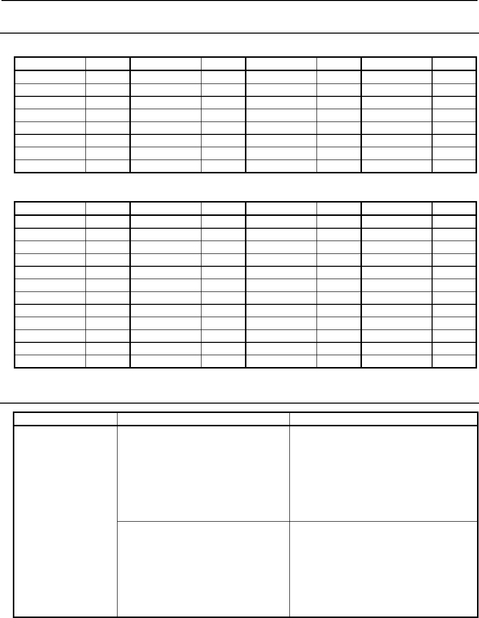
B-63943EN-2/07
6.MACRO EXECUTOR FUNCTION
- 235 -
6.9.6
Appendix tables
Address code table
Address Code Address Code Address Code Address Code
A 1 B 2 C 3 D 4
E 5 F 6 G 7 H 8
I 9 J 10 K 11 L 12
M 13 N 14 O 15 P 16
Q 17 R 18 S 19 T 20
U 21 V 22 W 23 X 24
Y 25 Z 26
EOB 27 EOR 28 / 29
Special code table
Instruction Code Instruction Code Instruction Code Instruction Code
IF 258 THEN 271 BIN 283 SETVN 295
WHILE 259 XOR 272 FIX 284 ADP 296
GOTO 260 OR 273 FUP 285 POW 297
DO 261 AND 274 ROUND 286 FGEN 298
END 262 ACOS 287 FDEL 299
GE 264 SIN 276 ASIN 288 FOPEN 300
GT 265 COS 277 LN 289 FCLOS 301
LE 266 TAN 278 EXP 290 FPSET 302
LT 267 ATAN 279 POPEN 291 FREAD 303
NE 268 SQRT 280 PCLOS 292 FWRIT 304
EQ 269 ABS 281 DPRNT 293
MOD 270 BCD 282 BPRNT 294
6.9.7
Differences from the Series 16i
Function Series 16i/18i/21i Series 30i/31i/32i/35i/0i-F/PMi
Specified word-type
block reading (G325)
When a value specified without the
decimal point is read, the position of the
decimal point is always determined by
calculator type decimal point input.
When a value specified without the decimal
point is read, the position of the decimal point
is determined as follows.
Bit 2 (PRDPI) of compile parameter No. 9160
=0: Determined by bit 0 (DPI) of parameter
No. 3401
=1: Always determined by calculator type
decimal point input
When the O-number block is read with 1
specified in block number variable
#8521, the O number cannot be read.
When the O-number block is read with 1
specified in block number variable #8521, the
operation differs depending on bit 6 (PG1O)
of compile parameter No. 9160, as follows.
=0: All words including the O number can
be read.
=1: Words excluding the O number can be
read.

6.MACRO EXECUTOR FUNCTION
B-63943EN-2/07
- 236 -
Function Series 16i/18i/21i Series 30i/31i/32i/35i/0i-F/PMi
Specified
character-type block
reading (G328)
When the O-number block is read with 1
specified in block number variable
#8521, the O number cannot be read.
When the O-number block is read with 1
specified in block number variable #8521, the
operation differs depending on bit 6 (PG1O)
of compile parameter No. 9160, as follows.
=0: All characters including the O number
can be read.
=1: Characters excluding the O number can
be read.
Specified word-type
block writing (G326)
When data is read having one or more 0s
after the decimal point, the 0s after the
decimal point are not output regardless
of the decimal point position.
(Example)
When address code = X, value =
123.000, and number of digits after
the decimal point
= 3
X123. is written.
When data is read having one or more 0s
after the decimal point, the 0s are output
based on the decimal point position.
(Example)
When address code = X, value =
123.000, and number of digits after the
decimal point
= 3
X123.000 is written.
Program condensation Only the program specified with #8520 #8520=0: The entire program memory is
condensed.
#8520
≠
0: A specified program is
condensed.
Program editing
prohibition
If the memory protection signal (KEY3) is
off, program editing is disabled.
By setting bit 1 (KEYC) of compile parameter
No. 9006 to 1, editing is possible even in the
program editing prohibited state due to the
memory protection signal (KEY3) or the
8-level data protection function.
Completion code
(#8529)
In addition to the completion codes
indicated in the completion code list,
there are completion codes posted with
the same numbers as PS alarm
numbers.
Detail completion codes are provided. No
codes other than those indicated in the list
are output.
Special code Usable codes are added.
Background editing
option
A background editing function is
required.
No background editing function is required.
Program number during
background editing
(#8525)
Program number during background
editing can be read.
Reading is now possible even in the
background editing status and, therefore,
variable #8525 is disabled. "0" is always
read.
Background editing
status (#8526)
It can be read whether background
editing is stopped (= 0) or active (= 1).
Reading is now possible even in the
background editing status and, therefore,
variable #8526 is disabled. "0" is always
read.
6.10
CUTTING TIME, DISTANCE READ AND PRESET
FUNCTIONS
Control variables can be used to read and preset the cutting time and cutting distance. This function can
be used to manage the service life of tools.
Reading and presetting the cutting time (#8553)
By using #8553, the cumulative cutting time parameters Nos.6753 and 6754 can be read and preset. The
value of #8553 is the sum of the parameters Nos. 6753 and 6754 and its unit is the hour as with the macro
variable (#3002). The clock precision is 16 msec.

B-63943EN-2/07
6.MACRO EXECUTOR FUNCTION
- 237 -
When a preset operation is performed, a value less than one minute is discarded, and the values of the
parameters Nos. 6753 and 6754 are also preset.
Example 1
#100=#8553 ;
→ The cutting time is read into #100.
(When #100=5.755, the cutting time is 5 hours, 45 minutes,
and 18 seconds.)
#8553=0 ; → However, cutting time is preset to 0; the related parameters
(parameter Nos. 6753 and 6754) are also preset to 0.
Example 2
#8553=5.755 ;
→ A time period less than 1 minute is set to 0. So, 5.75 is set in
#8553. In this case, 0 is set in parameter No. 6753, and 345 is
set in parameter No. 6754.
NOTE
Switching on the power does not reset #8553 to 0.
Reading and presetting a cutting distance (#8554)
#8554 adds up the cutting distance specified in commands such as G01 (linear interpolation), G02, and
G03 (circular interpolation). The unit depends on the setting of bit 0 (CUNIT) of compile parameter No.
9160 as follows:
=0: Integer value. (In the case of IS-B/metric input, #8554=1000 for a cutting distance of 1.0 mm)
=1: Real value. (In the case of IS-B/metric input, #8554=1.0 for a cutting distance of 1.0 mm)
Their measurement unit is the least input increment for the reference axis.
Writing a value to #8554 enables the cutting distance to be preset.
Example
#100 = #8554 ; → The cutting distance is read into #100.
#8554 = 0 ; → The cutting distance is preset to 0.
- Cumulative cutting distance along an arbitrary axis only
A cumulative calculation can be made by excluding an axis selected using bit 0 (NDTx) of parameter No.
9026.
However, this function is valid only during linear interpolation using a code such as G01. During circular
interpolation using the G02 or G03 command, for example, even an axis selected using bit 0 (NDTx) of
parameter No. 9026 is included in a cumulative cutting distance calculation.
Example
When, on a machine with 1st axis = X and 2nd axis = Y, bit 0 (NDTx) of
parameter No. 9026 for the 1st axis is set to 1:
1 G01 X_ Y_ F_;
#100 = #8554 ; → The cutting distance of the axis other than the 1st axis can
be read.
2 G17;
G02 X_ Y_ I_ J_ F_;
#100 = #8554 ; → The cutting distance of all axes including the 1st axis can
be read.
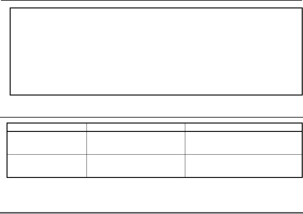
6.MACRO EXECUTOR FUNCTION
B-63943EN-2/07
- 238 -
NOTE
1 To use the cutting distance read and preset functions, the following settings are
required:
Bit 7 (EXT1) of compile parameter No.9002 = 1
Bit 7 (CUTLG) of compile parameter No.9004 = 1
2 Even if cutting is stopped by a reset, the travel distance of the block is added
because a tool move distance is added to #8554 at the start of cutting block
execution.
3 When the power is turned on, #8554 is not set to 0. The cumulative value is
clamped to 2147483648. Management by the user is requested.
6.10.1
Differences from the Series 16i
Function Series 16i/18i/21i Series 30i/31i/32i/35i/0i-F/PMi
Cutting period reading and
presetting
Even if presetting is performed,
parameter Nos. 6753 and 6754 are
not modified.
Both reading and presetting are performed
based on parameter Nos. 6753 and 6754.
Cutting distance
accumulation along arbitrary
axes only
The 1st, 2nd, and 3rd controlled
axes only can be selected.
All axes can be selected.
6.11
RELATIVE COORDINATE READ AND PRESET FUNCTIONS
(#8996 TO #8999)
These functions enable reading and presetting of relative coordinates.
Reading relative coordinates
By setting an ID number for reading relative coordinates in #8998 and setting an axis number in #8997,
relative coordinates can be read using #8999.
#8998 Information ID 110 : Reading of the relative coordinates of the 1st controlled axis in the path
111 : Reading of the relative coordinates of the 2nd controlled axis in the path
112 : Reading of the relative coordinates of the 3rd controlled axis in the path
113 : Reading of the relative coordinates of the 4th controlled axis in the path
114 : Reading of the relative coordinates of the 5th controlled axis in the path
115 : Reading of the relative coordinates of the 6th controlled axis in the path
116 : Reading of the relative coordinates of the 7th controlled axis in the path
117 : Reading of the relative coordinates of the 8th controlled axis in the path
118 : Reading of the relative coordinates of the 1st to 24th controlled axes in
the path
#8997 Axis number : 1 to the maximum number of controlled axes in the path
(Usable only when #8998=118)
#8999 Relative coordinate
#8996 Completion code 0: Normal end.
-1: Abnormal end.

B-63943EN-2/07
6.MACRO EXECUTOR FUNCTION
- 239 -
Example
If the relative coordinate of the 1st axis is -123.456, executing the following steps
sets #500 with -123456.
#8998 = 118;
#8997 = 1; (acquires the information about the 1st axis)
#500 = #8999;
- Note
NOTE
1 If a value other than 1 to the maximum number of controlled axes in the path is
specified in #8997, the value read from #8999 is <null>.
2 When the power is switched on, #8999 is reset to 0.
3 The unit of a read value is the least input increment for a specified axis.
Presetting relative coordinates
- Format
G310 Aa Qq ;
a : Controlled-axis number to be subjected to presetting (1 to the number of controlled axes in the path), or axis
ID No. (110 to 117)
q : Coordinate to be preset
Address Q specifies the coordinate to be preset.
Q = -999999999 to +999999999
Executing this control code presets the relative coordinate.
Example
To preset the relative coordinate of the 1st axis to -123.45, issue:
G310 A1 Q-123450 ;
or
G310 A110 Q-123450 ;
- Note
NOTE
1 If a value other than 1 to the maximum number of controlled axes in the path or
axis ID Nos. 110 to 117 in address A, or address A is not specified, the
specification of G310 is ignored.
2 The unit of address Q is the least input increment of the specified axis.
3 In an execution macro, the G310 block is executed as an NC statement.
However, by setting 1 in bit 4 (NOB) of parameter No. 9036, it is also possible to
execute it as a macro statement.
6.11.1
Differences from the Series 16i
Function Series 16i/18i/21i Series 30i/31i/32i/35i/0i-F/PMi
If specified in an
execution macro
If specified in an execution macro, a
G310 block is executed as a macro
statement.
If specified in an execution macro, a G310
block is executed depending on bit 4 (NOB)
of parameter No. 9036 as follows:
=0 : as an NC statement.
=1 : as a macro statement.

6.MACRO EXECUTOR FUNCTION
B-63943EN-2/07
- 240 -
6.12 ARRAY-TYPE PROCESSING AND REFERENCING OF
P-CODE VARIABLES
Array-type processing of P-CODE variables
This function controls processing of array-type macro variables or a sequence of macro variables.
1) Clearing array-type variables and a sequence of variables (continuous writing of specified data)
2) Transferring from array-type variables or a sequence of variable to a sequence of variables
Each type of processing is performed by first defining an array, a sequence of variables, or data in each of
the following control variables, then issuing control code G315.
#8511 : Source data
#8512 : Source two-dimensional array number or the start variable number of a sequence of variables
#8513 : Source three-dimensional array number
#8514 : Destination two-dimensional array number or the start variable number of a sequence of
variables
#8515 : Destination three-dimensional array number
- Format
G315 P (processing code) K (number of data items to be processed);
P001
(P1)
: Stores data from #8511 to K consecutive variables starting at the one specified in #8514.
P002
(P2)
: Transfers data from K consecutive variables starting at the one specified in #8512 to K consecutive
variables starting at the one specified in #8514 (transfer in ascending order).
P003
(P3)
: Transfers data from K consecutive variables starting at the one specified in #8512 to K consecutive
variables starting at the one specified in #8514 (transfer in descending order).
P101 : Stores data from #8511 to K consecutive array-type variables starting at array-type variable #1
specified in #8514 and #8515.
P102 : Transfers data from K consecutive array-type variables starting at array-type variable #1 specified in
#8512 and #8513 to K consecutive array-type variables starting at array-type variable #1 specified in
#8514 and #8515 (ascending order).
P103 : Transfers data from K consecutive array-type variables starting at array-type variable #1 specified in
#8512 and #8513 to K consecutive array-type variables starting at array-type variable #1 specified in
#8514 and #8515 (descending order).
Each process code consists of three digits and specifies the type of processing to be performed. Leading
zeros are omissible.
A difference between P2 and P3 and between P102 and P103 is whether a transfer progresses from a
small variable number to a large or from a large to a small.
Example
If #8512 = 10000 and #8514 = 10010,
G315 P2 K3; is equivalent to the following steps:
#10010 = #10000
#10011 = #10001
#10012 = #10002, and
G315 P3 K3; is equivalent to the following steps:
#10012 = #10002
#10011 = #10001
#10010 = #10000
B-63943EN-2/07
6.MACRO EXECUTOR FUNCTION
- 241 -
Array-type referencing of P-CODE variables
P-CODE variables (10000 and up) can be referenced as two-dimensional or three-dimensional array-type
variables. Previously assigning proper values to the following array control variables enables variable
numbers #1 to #99 to be used to reference the P-CODE variables for the corresponding array elements.
Array control variables
#8512 : Two-dimensional array number
#8513 : Three-dimensional array number
#8516 : Number of one-dimensional array elements
#8517 : Number of two-dimensional array elements
#8518 : 1
#8519 : Array start variable number
Variables #1 to #99 are used to reference the P-CODE variables by previously specifying array types
using array control variables #8516 to #8519, then specifying the target array numbers using #8512 and
#8513.
The P-CODE variables are associated with the array elements as shown below.
P-CODE variable number
= #8519 + ((#8516*#8517)*(#8513 - 1))
+ (#8516*(#8512 -1)) + (specified variable number - 1)
Example
If #8516 = 10, #8517 = 5, and #8519 = 10100,
(1) #1 with #8512 = 1 and #8513 = 1 specified corresponds to #10100.
(2) #10 with #8512 = 3 and #8513 = 2 specified corresponds to #10179.
When the power is turned on, each array control variable is set up as follows:
#8512 to #8517 = 1 and #8519 = 10000
So, when using P-CODE variables as two-dimensional arrays, you need not beware of #8513 and #8517.
NOTE
When using variables #1 to #99 to reference P-CODE variables as array-type,
set #8518 = 1. If #8518 = 0, an alarm is issued, because #1 to #33 are treated
as local variables and #34 to #99 are treated as unusable. When the power is
turned on, #8518 is set to 0.
Caution
CAUTION
No check is made on any variable and calculated variable number for validity.
Use a macro program to make validity checks if necessary.
6.12.1
Differences from the Series 16i
Function Series 16i/18i/21i Series 30i/31i/32i/35i/0i-F/PMi
Processing and
referencing P-CODE
variables as array type
Variables 1 to 99 are always
array-type variables.
Variables can be switched between local
variables and array-type variables with the
setting of variable #8518.
=0 : Variables #1 to #33 are local variables, and
#34 to #99 are unusable.
=1 : Variables #1 to #99 are array-type variables.
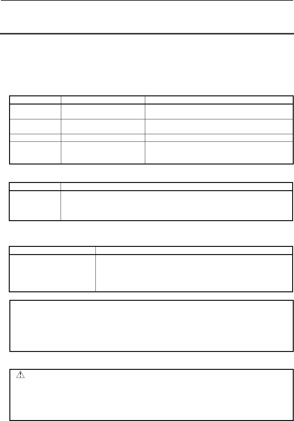
6.MACRO EXECUTOR FUNCTION
B-63943EN-2/07
- 242 -
6.13 TORQUE LIMIT OVERRIDE CONTROL (#8990 TO #8993
AND #8621 TO #8628)
Assigning appropriate values to #8990 to #8992 enables the torque limit override to be changed to the
specified value. Assigning appropriate values to #8990 and #8991 enables a torque limit override value to
be read into #8992. Whether setting and changing ended normally can be sensed by accessing #8993.
Values for the 1st axis to the 8th axis can be read and written using also #8621 to #8628. (Series 16i
compatible)
(1) When #8990 to #8993 are used.
Control variable Set value Description
#8990 100
101
Writes a torque limit override value.
Reads a torque limit override value.
#8991 1 to maximum number of
controlled axes in a path Controlled axis number in a path
#8992 0 to 255 Torque limit override value
#8993 0 or -1
Completion code
0: Normal end
-1: An out-of-range value is set in #8991 or #8992.
(2) When #8621 to #8628 are used. (Series 16i compatible)
Control variable Description
#8621
#8622
:
#8628
Torque limit override value of the 1st controlled axis in a path
Torque limit override value of the 2nd controlled axis in a path
:
Torque limit override value of the 8th controlled axis in a path
For the 9th axis and up, only the method of (1) using #8990 to #8993 can be used.
Relationship between settings and torque limit override values
Set value Torque limit override value
0
:
127
:
255
0%
:
50%
:
100%
Example
To set the torque limit override value of the 3rd axis to 50%, set the variables in
the order shown below.
#8990 = 100 ....... Write operation specification
#8991 = 3 ........... 3rd axis specification
#8992 = 127 ....... Override value specification
Caution
CAUTION
1 When the power is turned on, the torque limit override value for each axis is set
to 100%.
2 In the case of an execution macro, if an attempt is made to specify a value
outside the range of 1 to the maximum number of intra-path controlled axes in
#8991 or a value outside the range of 0 to 255 in #8992, alarm PS110 occurs.
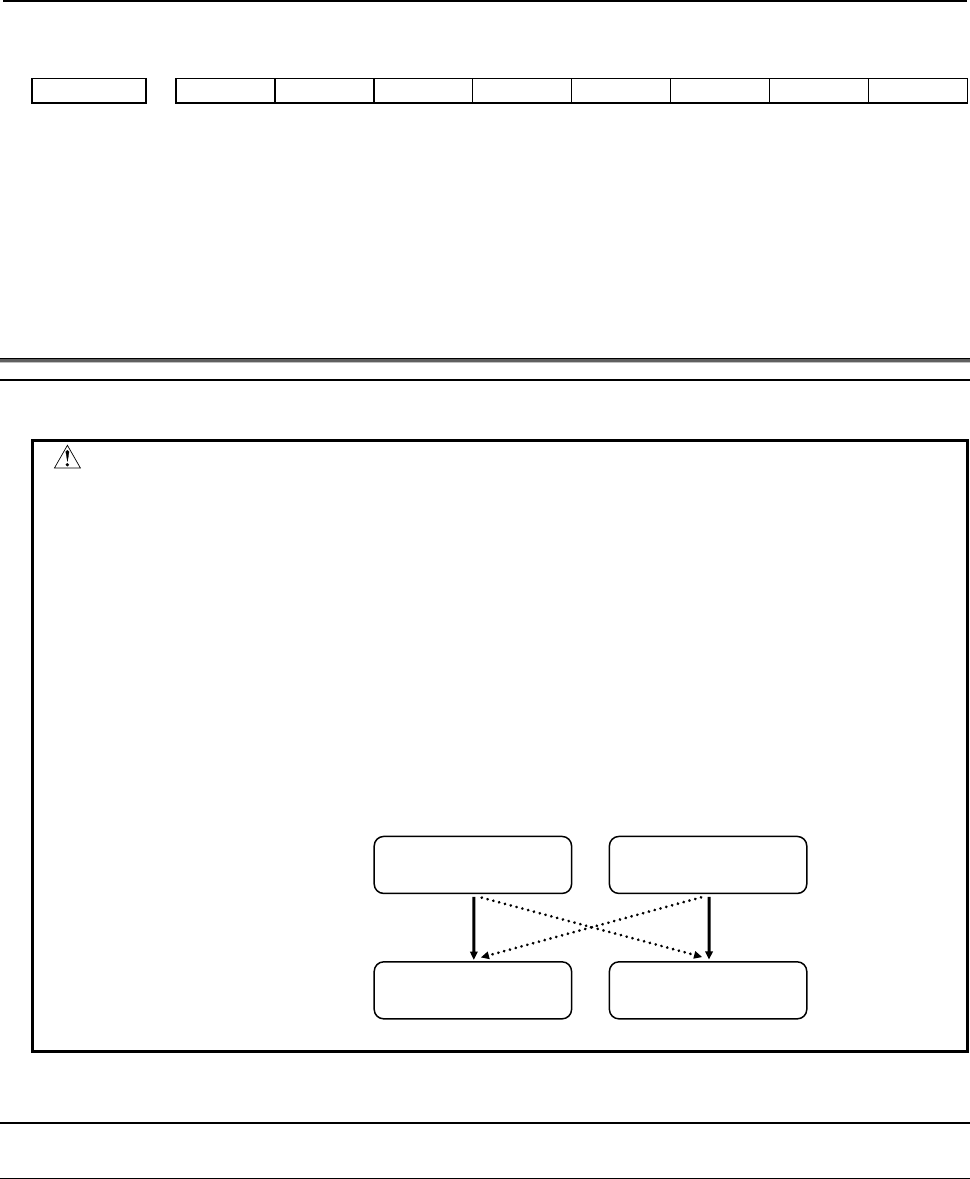
B-63943EN-2/07
6.MACRO EXECUTOR FUNCTION
- 243 -
Parameter
#7 #6 #5 #4 #3 #2 #1 #0
6286 TQO
[Input type] Parameter input
[Data type] Bit axis
#0 TQO Specifies whether to enable the torque limit override function, as follows:
0: Disable (100% override)
1: Enable
6.14
PMC AXIS CONTROL
Warning
WARNING
1 PMC axis control must be executed while the PMC controlled-axis selection
variable(#8700) or controlled axis selection signals EAX1 to EAX8 are "1".
If PMC controlled-axis selection variable(#8700) and controlled axis selection
signals EAX1 to EAX8 are "0", the command cannot be accepted.
Therefore, the machine may behave in an unexpected manner.
2 PMC axis control is able to command by PMC ladder and macro executor.
In case of use PMC axis control, “controlled axis selection” and “PMC axis
control command”, use the same command method. If you use the different
command method to “controlled axis selection” and “PMC axis control
command”, “PMC axis control command” may be ignored, or the command may
execute incorrect axis motion. Therefore, the machine may behave in an
unexpected manner.
6.14.1
PMC Axis Control Using G Code
6.14.1.1
General
A PMC axis control interface can be used to control the PMC controlled axis. The following eight
different control codes are available. Which PMC controlled axis to control is to be specified using the
PMC controlled group selection variable (#8602) and the PMC controlled-axis selection variable (#8700).
G340 → Rapid traverse command
G341 → Cutting feed command
G344 → Dwell command
G345 → Reference position return command
OK
Macro executor
command
Macro executor
command
OK
PMC ladder
command
PMC ladder
command
Controlled axis
selection
PMC axis control
command
NG
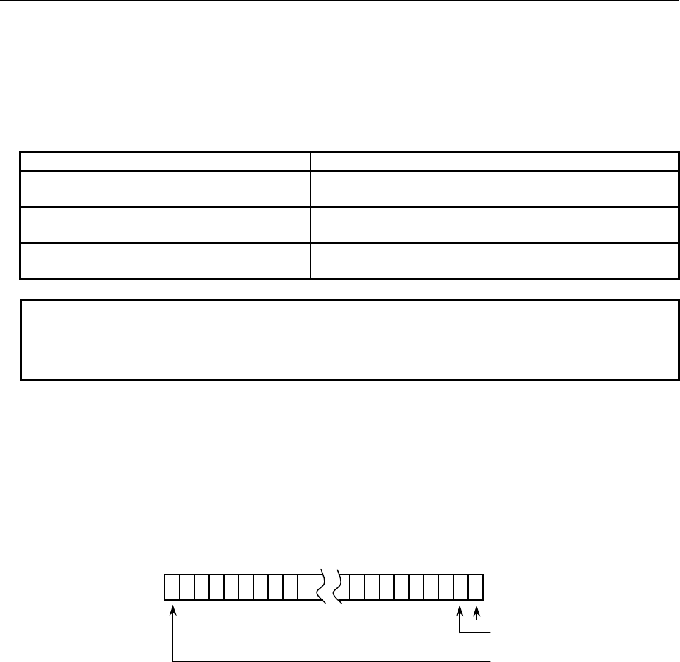
6.MACRO EXECUTOR FUNCTION
B-63943EN-2/07
- 244 -
G346 → Auxiliary function command
G348 → Status signal read command
G349 → Command signal write command
G350 → Machine coordinate system positioning
#8602: PMC controlled-group selection variable
Specify a controlled group.
#8602 Controlled group
0 1st group
1 2nd group
: :
: :
38 39th group
39 40th group
NOTE
1 If an integer out of a range between 0 and 39 is specified in #8602, the control
command is ignored.
2 When the power is turned on, #8602 = 0.
#8700: PMC controlled-axis selection variable
Specify the bit position corresponding to the controlled axis number to be selected.
For a multi-path system, the meaning of an axis number differs depending on bit 7 (PMX16) of compile
parameter No. 9160.
Bit 7 (PMX16) of compile parameter No.9160
=0: System common controlled axis number
=1: Relative controlled axis number in a path
#31………………………………………………………#1#0
#8700
1st axis
2nd axis
:
32nd axis
= 0: Axis specified by controlled axis selection signals EAX1 to EAX8<G136>
= 1: 1st axis
= 2: 2nd axis
= 4: 3rd axis
:
:
When setting multiple axes, set the logical sum of the values to be set for those axes.

B-63943EN-2/07
6.MACRO EXECUTOR FUNCTION
- 245 -
Example
1 In a 2-path system with 3-axis machines for both paths, to select the 1st axis of
the 2nd path from the 2nd path, specify the following:
• If bit 7 (PMX16) of compile parameter No. 9160 is set to 0, specify the system
common 4th axis.
#8700 = 16
• If bit 7 (PMX16) of compile parameter No. 9160 is set to 1, specify the 1st
axis in the path.
#8700 = 1
2 To set the 1st or 3rd axis as a target axis, variable #8700 can be set to 5 (= 1 +
4). To set the 1st, 16th, or 24th axis as a target axis, the following can also be
specified.
#100=2
#1=1-1
#16=16-1
#24=24-1
#101=POW[#100,#1] ; 1st axis
#116=POW[#100,#16] ; 16th axis
#124=POW[#100,#24] ; 24th axis
#8700=#101+#116+#124
NOTE
1 If specifying an axis number with variable #8700, set controlled axis selection
signals EAX1 to EAX8 <G136> to 0. Otherwise, the logical sum of controlled axis
selection signals EAX1 to EAX8 <G136> and #8700 is assumed.
<Example>
If EAX1 is set to 1, and #8700 is set to 2, the 1st and 2nd axes are target
controlled axes.
2 If parameter No. 8010 does not relate the group and axis specified by #8602 and
#8700, the control command is ignored. When 0 is specified in #8700, however,
only the axis specified by controlled axis selection signals EAX1 to EAX8
<G136> is controlled.
3 When the power is turned on, #8700 = 0.
For details, refer to the CONNECTION MANUAL (FUNCTION).
6.14.1.2
Details of control codes
Rapid traverse command (G340)
- Format
G340 Xx ;
x : Travel distance
- Explanation
This command specifies rapid traverse for the PMC controlled axis. Address X specifies a travel distance
always in incremental mode.
This command performs the same operation as "G00" of CNC.

6.MACRO EXECUTOR FUNCTION
B-63943EN-2/07
- 246 -
Cutting feed command (G341)
- Format
G341 Xx Ff ;
x : Travel distance
f : Feedrate
- Explanation
This command specifies cutting feed for the PMC controlled axis. Address X specifies a travel distance
always in incremental mode. The feedrate is specified using address F.
This command performs the same operation as "G94 G01" (in T series G code system A, "G98 G01") of
CNC.
Dwell command (G344)
- Format
G344 Px ; or G344 Xx ;
x : Dwell value
- Explanation
This command specifies dwell for the PMC controlled axis. Address P or X specifies a dwell value.
This command performs the same operation as "G04" of CNC.
Reference position return command (G345)
- Format
G345 ;
- Explanation
This command specifies a reference position return for the PMC controlled axis.
After moving by rapid traverse in the reference position return direction set by bit 5 (ZMIx) of parameter
No. 1006, this command performs the same operation as the manual reference position return function of
the CNC.
Auxiliary function command (G346)
- Format
G346 Mm ;
m : Auxiliary function code
- Explanation
This command specifies an auxiliary function for the PMC axis control interface. Address M specifies an
auxiliary function code.
This command performs the same operation as an auxiliary function of the CNC.
Status signal read command (G348)
- Format
G348 Pp ;
p : Variable number
- Explanation
This command reads into the variable the variable number of which is specified at address P the states of
the output signals <F130, F133, F136, F139> of the corresponding PMC axis control interface.
#7 #6 #5 #4 #3 #2 #1 #0
EBSYg#p EOTNg#p EOTPg#p EGENg#p EDENg#p EIALg#p ECKZg#p EINPg#p
A group number is represented by a combination of g and p.
Range of g: 1 to 4
Range of p: 1 to 10
Group number = g + (p-1) × 4

B-63943EN-2/07
6.MACRO EXECUTOR FUNCTION
- 247 -
<1> EBSYg#p (Axis control command read completion signal)
This signal indicates that the CNC has read PMC axis control command data for one block and
stored it in a buffer.
<2> EOTNg#p (Negative direction overtravel signal)
This signal indicates an overtravel state.
<3> EOTPg#p (Positive direction overtravel signal)
This signal indicates an overtravel state.
<4> EGENg#p (Axis moving signal)
This signal indicates the state of movement on an axis.
<5> EDENg#p (Auxiliary function executing signal)
This signal indicates the state of auxiliary function execution.
<6> EIALg#p (Alarm signal)
This signal indicates the alarm state related to PMC axis control.
<7> ECKZg#p (Following zero check signal)
This signal indicates the following zero state.
<8> EINPg#p (In-position signal)
This signal indicates in-position state.
Example
When EDENg#p = 1, G348 P100; results in the following : #100 = 8
Command signal write command (G349)
- Format
G349 Pp ;
P : Command value
- Explanation
This command writes a value specified at address P as a command signal for the corresponding PMC axis
control interface.
The states of the input signals <G142, G154, G166, G178> of the PMC do not change.
#7 #6 #5 #4 #3 #2 #1 #0
EBUFg#p ECLRg#p ESTPg#p ESOFg#p ESBKg#p EMBUFg#p ECKZg#p EFINg#p
A group number is represented by a combination of g and p.
Range of g: 1 to 4
Range of p: 1 to 10
Group number = g + (p-1) × 4
<1> ECLRg#p (Reset signal)
This signal resets a PMC axis control command.
<2> ESTPg#p (Axis control temporary stop signal)
This signal temporarily stops movement before the execution of a block is completed.
<3> ESBKg#p (Block stop signal)
This signal causes a stop for each command block.

6.MACRO EXECUTOR FUNCTION
B-63943EN-2/07
- 248 -
<4> EMBUFg#p (Buffering disable signal)
This signal causes the buffering disabled state.
Example
When ECLRg#p = 1:
G349 P64; (64 = 01000000b)
NOTE
EBUFg#p (Axis control command read signal), ESOFg#p (Servo off signal),
ECKZg#p (Following zero check signal), and EFINg#p (Auxiliary function
completion signal) in the input signals <G142, G154, G166, G178> cannot be
written.
Machine coordinate system positioning (G350)
- Format
G350 Xx ;
X : Travel distance
- Explanation
This command performs machine coordinate system positioning for the PMC controlled axis. Address X
specifies a travel distance using an absolute position in the machine coordinate system.
6.14.1.3
Limitations
Command buffering
PMC axis control is implemented by issuing more than one commands sequentially. So, command blocks
are buffered on the CNC side. To put another way, when the CNC is executing a block, another command
can be issued as long as the CNC's buffer has room to receive it. Note, however, that if the buffer has no
room to receive a new command, the new command is kept waiting while the previous command is being
executed, that is, until the previous command is finished to create room in the buffer. Executing G3xx
causes buffering; so the EBSYg#p (axis control command read completion signal) is not needed.
Auxiliary function command
The auxiliary function command can be implemented using G346, but the auxiliary function strobe signal
EMFg#p cannot be controlled on the macro side. It should be controlled by the PMC.
Unit of data
The travel distance (dwell value) specified at address X and the feedrate specified at address F should be
represented in the least input increment of the specified axis.
6.14.2
PMC Axis Control Using Variables
6.14.2.1
General
A conversational macro enables PMC axis control to be exercised using variables through the PMC axis
control interface.
Control is exercised by combining the variables below.
#8700 → PMC controlled-axis selection variable
Up to four groups can be controlled per path, and the relationships between control variables and groups
are as given in Table 6.14.2.1 (a). To specify an axis number, use variable #8700, PMC controlled-axis
selection variable, as in PMC axis control using G code.
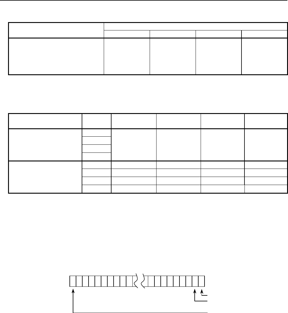
B-63943EN-2/07
6.MACRO EXECUTOR FUNCTION
- 249 -
Table 6.14.2.1 (a)
Variable name Variable area
(4p-3) group (4p-2) group (4p-1) group (4p) group
PMC command signal variable #8710 #8720 #8730 #8740
PMC control command variable #8711 #8721 #8731 #8741
PMC cutting feedrate variable #8712 #8722 #8732 #8742
PMC control travel distance variable #8713 #8723 #8733 #8743
PMC state signal read variable #8715 #8725 #8735 #8745
As four groups (4p-3) to (4p), it can be selected with the setting of bit 7 (PMX16) of compile parameter
No. 9160 whether to use groups 1 to 4 universally regardless of the path or to use groups 1 to 40
depending on the path.
Bit 7 (PMX16) compile
parameter No.9160 Path (4p-3) group
#8710~#8715
(4p-2) group
#8720~#8725
(4p-1) group
#8730
~
8735
(4p) group
#8740~#8745
=0
Path 1
Group 1 Group 2 Group 3 Group 4
Path 2
:
Path 10
=1
Path 1 Group 1 Group 2 Group 3 Group 4
Path 2 Group 5 Group 6 Group 7 Group 8
: : : : :
Path 10 Group 37 Group 38 Group 39 Group 40
#8700: PMC controlled-axis selection variable
Specify the bit position corresponding to the controlled axis number to be selected.
For a multi-path system, the meaning of an axis number differs depending on bit 7 (PMX16) of compile
parameter No. 9160.
Bit 7 (PMX16) of compile parameter No.9160
=0: System common controlled axis number
=1: Relative controlled axis number in a path
#31………………………………………………………#1#0
#8700
1st axis
2nd axis
:
32nd axis
= 0: Axis specified by controlled axis selection signals EAX1 to EAX8<G136>
= 1: 1st axis
= 2: 2nd axis
= 4: 3rd axis
:
:
When setting multiple axes, set the logical sum of the values to be set for those axes.

6.MACRO EXECUTOR FUNCTION
B-63943EN-2/07
- 250 -
Example
1 In a 2-path system with 3-axis machines for both paths, to select the 1st axis of
the 2nd path from the 2nd path, specify the following:
• If bit 7 (PMX16) of compile parameter No. 9160 is set to 0, specify the system
common 4th axis.
#8700 = 16
• If bit 7 (PMX16) of compile parameter No. 9160 is set to 1, specify the 1st
axis in the path.
#8700 = 1
2 To set the 1st or 3rd axis as a target axis, variable #8700 can be set to 5 (= 1 +
4). To set the 1st, 16th, or 24th axis as a target axis, the following can also be
specified.
#100=2
#1=1-1
#16=16-1
#24=24-1
#101=POW[#100,#1] ; 1st axis
#116=POW[#100,#16] ; 16th axis
#124=POW[#100,#24] ; 24th axis
#8700=#101+#116+#124
NOTE
1 For selection of a controlled axis, #8700 (PMC controlled-axis selection variable)
is to be set.
2 If specifying an axis number with variable #8700, set controlled axis selection
signals EAX1 to EAX8 <G136> to 0. Otherwise, the logical sum of controlled axis
selection signals EAX1 to EAX8 <G136> and #8700 is assumed.
<Example>
If EAX1 is set to 1, and #8700 is set to 2, the 1st and 2nd axes are target
controlled axes.
3 If parameter No. 8010 does not relate the group and axis specified by #8602 and
#8700, the control command is ignored. When 0 is specified in #8700, however,
only the axis specified by controlled axis selection signals EAX1 to EAX8
<G136> is controlled.
4 When the power is turned on, #8700 = 0.
For details, refer to the CONNECTION MANUAL (FUNCTION).
6.14.2.2
Details of control variables
PMC command signal variables (#8710, #8720, #8730, #8740)
When a numeric value is written to a PMC command signal variable (#8710, #8720, #8730, and #8740),
the corresponding command signal of the PMC axis control interface is written to. However, data cannot
be written to signal "EFINx". The states of the input signals <G142, G154, G166, G178> of the PMC do
not change.
#7 #6 #5 #4 #3 #2 #1 #0
EBUFx ECLRx ESTPx ESOFx ESBKx EMBUFx ELCKZx EFINx
x represents a group number from 1 to 4.
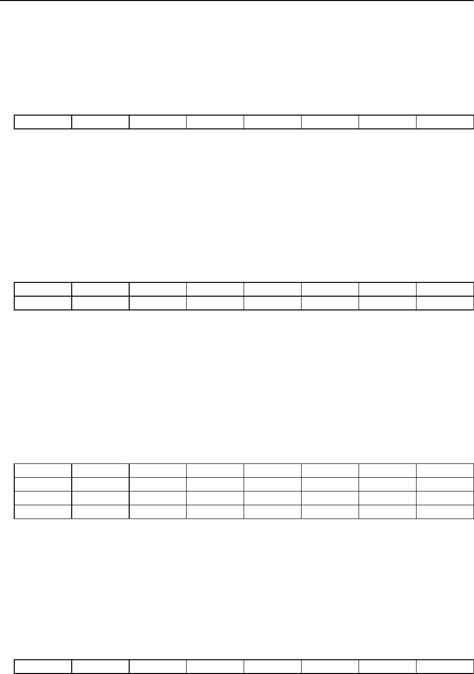
B-63943EN-2/07
6.MACRO EXECUTOR FUNCTION
- 251 -
Control command variables (#8711, #8721, #8731, and #8741)
When a control command is written to a control command variable (#8711, #8721, #8731, and #8741),
the corresponding axis control command signal is written to. The control command variables can also be
read from.
For writing : The states of the input signals <G143, G155, G167, G179> of the PMC do not change.
For reading : The states of the input signals <G143, G155, G167, G179> of the PMC are read.
#7 #6 #5 #4 #3 #2 #1 #0
EC6x EC5x EC4x EC3x EC2x EC1x EC0x
x represents a group number from 1 to 4.
Cutting feed control variables (#8712, #8722, #8732, and #8742)
When a numeric value is written to a cutting feed control variable (#8712, #8722, #8732, and #8742), the
cutting feedrate is written to the corresponding command data signals. The cutting feed control variables
can also be read from.
For writing : The states of the input signals <G144 to G145, G156 to G157, G168 to G169, G180 to
G181> of the PMC do not change.
For reading : The states of the input signals <G144 to G145, G156 to G157, G168 to G169, G180 to
G181> of the PMC are read.
#7 #6 #5 #4 #3 #2 #1 #0
EIF7x EIF6x EIF5x EIF4x EIF3x EIF2x EIF1x EIF0x
EIF15x EIF14x EIF13x EIF12x EIF11x EIF10x EIF9x EIF8x
x represents a group number from 1 to 4.
Control travel distance variables (#8713, #8723, #8733, and #8743)
When a numeric value is written to a control travel distance variable (#8713, #8723, #8733, and #8743),
the axis travel distance, dwell time, or auxiliary function code is written to the corresponding command
data signals. The control travel distance variables can also be read from.
For writing : The states of the input signals <G146 to G149, G158 to G161, G170 to G173, G182 to
G185> of the PMC do not change.
For reading : The states of the input signals <G146 to G149, G158 to G161, G170 to G173, G182 to
G185> of the PMC are read.
#7 #6 #5 #4 #3 #2 #1 #0
EID7x EID6x EID5x EID4x EID3x EID2x EID1x EID0x
EID15x EID14x EID13x EID12x EID11x EID10x EID9x EID8x
EID23x EID22x EID21x EID20x EID19x EID18x EID17x EID16x
EID31x EID30x EID29x EID28x EID27x EID26x EID25x EID24x
x represents a group number from 1 to 4.
Travel distance units depend on bit 5 (TDVDPI) of compile parameter No. 9160:
=0 : Calculator type decimal point input
=1 : Least input increment
PMC state signal read variables (#8715, #8725, #8735, and #8745)
To a PMC state signal read variable (#8715, #8725, #8735, and #8745), the corresponding state signal
<F130, F133, F136, and F139> of the PMC axis control interface is written.
To a variable, one-byte signal interface data is assigned in decimal format.
#7 #6 #5 #4 #3 #2 #1 #0
EBSYx EOTNx EOTPx EGENx EDENx EIALx ECKZx EINPx
x represents a group number from 1 to 4.
6.MACRO EXECUTOR FUNCTION
B-63943EN-2/07
- 252 -
For details of each signal, refer to the CONNECTION MANUAL (FUNCTION).
6.14.3
Caution
CAUTION
1 An auxiliary function can be specified using "G346". However, the auxiliary
function strobe signal "EMFg#p" cannot be controlled with a conversational
macro. Control the signal from the PMC.
2 When this function is performing PMC axis control, do not issue a control
command from the PMC side. To be specific, do not issue a PMC axis control
command, for example, by causing the conversational macro to use the UO
signal to inform the PMC that PMC axis control is under way and eventually
allowing the PMC to reference this signal. Be careful especially when a ladder or
macro program is updated to add or change a PMC axis control sequence.
3 Once this function is used to perform PMC axis control, before causing the PMC
to perform PMC axis control to the same axis, stop the macro program (if it has
been activated) and reset the target axis on the PMC side (set the ECLRg#p to
1).
6.14.4
Differences from the Series 16i
Function Series 16i/18i/21i Series 30i/31i/32i/35i/0i-F/PMi
Travel distance specified
by a control travel distance
variable (#8713, #8723,
#8733, or #8743) for
variable-based PMC axis
control
Least input increment Bit 5 (TDVDPI) of compile parameter No. 9160
=0 : Calculator type decimal point input
=1 : Least input increment
PMC controlled-axis
selection variable (#8700)
Specified with a relative controlled
axis number in the path.
Bit 7 (PMX16) of compile parameter No. 9160
=0 : Specified with a system common controlled
axis number.
=1 : Specified with a relative controlled axis
number in the path.
PMC axis control using
variables
For the relationships between control
variables and groups, use four
groups A to D for each path.
Bit 7 (PMX16) of compile parameter No. 9160
=0 : Use groups 1 to 4 regardless of the path.
=1 : Use groups (4N - 3) to (4N) depending on
the path
(where N denotes a path number (1 to 10)).
6.14.5
Control Examples
With "PMC axis control" using the macro executor, giving a move command is sufficient, regardless of
whether it is a G code or variable, as long as all that is needed is to output a simple move command in
response to some trigger event. In order to monitor the move completion of the specified block and
alarms, however, it is necessary to monitor the states of the PMC command signal variables (#87x0) and
PMC state signal read variables (#87x5).
(1) State management
In cases where the program waits for the move completion after outputting the move command, if a
loop occurs within the macro, the screen is locked during that time. It is therefore necessary to set a
state variable for state management.

B-63943EN-2/07
6.MACRO EXECUTOR FUNCTION
- 253 -
Example
#100 : State variable
#100<>1 : Regular state
A trigger event is monitored. Upon detection of a trigger event, a move
command is output, setting 1 in #100.
#100=1 : Axis moving
The program waits for the move to complete. Upon completion, an error
check is made and the value of #100 is returned to 0.
(2) Monitoring of the move completion
The move completion can be monitored using the following three events:
• The state of the PMC command signal variable (#87x0) EBUFx is the same as that of the PMC
state signal read variable (#87x5) EBSYx.
• The PMC state signal read variables (#87x5) EGENx and ECKZx are both set to 0.
• The PMC state signal read variable (#87x5) EINPx is set to 1.
Example
IF[ [#87x0 AND 128] NE [#87x5 AND 128] ] GOTO 999
IF[ [#87x5 AND 18] NE 0 ] GOTO 999 → Moving
IF[ [#87x5 AND 1] NE 1] GOTO 999
Move completed
(3) Check after the move completion
Whether the PMC axis has moved to the specified position correctly is determined by checking after
the move completion whether the axis has reached the target coordinates. If the coordinates are
checked after the move completion and the axis is not at the target position, the move operation has
been canceled due to an alarm, emergency stop, or some other cause.
Sample program
• Moving the axis by 100 mm when the state of the signal (R100.0) changes from OFF to ON
#100 : State variable
#101 : R100.0 OFF→ON Monitoring variable
#102 : Target position arrival check variable
O1000 IF[ #100 EQ 1 ] GOTO 100
IF[ R100.0 EQ 1 && #101 EQ 0 ] THEN
#102 = #504x + 100.0 /* R100.0 OFF=>ON
G340 X100.0 /* Stores the target position.
#100 = 1 /* Outputs the move command.
GOTO 999 /* State variable=1
ENDIF
#101 = R100.0
GOTO 999
N100 IF[ [#87x0 AND 128] NE [#87x5 AND 128] ] GOTO 999
IF[ [#87x5 AND 18] NE 0 ] GOTO 999 /* Axis moving
IF[ [#87x5 AND 1] NE 1] GOTO 999
IF[ ABS[#504x - #102] GT 0.000001 ] THEN
/*Error processing*/
ENDIF
#101 = R100.0 /* Read R100.0 for next detection
#100 = 0 /* State variable=0
N999 M99
%

6.MACRO EXECUTOR FUNCTION
B-63943EN-2/07
- 254 -
6.14.6
To detect an alarm for unselected PMC axis control
If the controlled axis selection signals EAX1 to EAX8 are 0, execution of PMC axis control command is
ignored. When the bit 2 (EZC) of parameter No.8019 is set to 1, controlled axis selection signals EAX1 to
EAX8 state are 0, alarm DS1451 “IMPROPER PMC AXIS COMMAND” is detected when the PMC axis
control command is executed. Unexpected operation of the machine can be prevented by alarm stop.
When the bit 2 (EZC) of parameter No.8019 is set to 1, alarm DS1451 is detected under the following
conditions.
Monitor the following functions:
- PMC axis control using signal.
- PMC axis control using G code of macro executor.
- PMC axis control using variables of macro executor.
In both of following (1) and (2) conditions, alarm is detected by PMC axis control command.
State of PMC controlled-axis selection variable (#8700) or Controlled axis selection signals EAX1 to
EAX8 <Gn136> of the other group does not affect.
(1) Controlled axis selection signals EAX1 to EAX8 <Gn136> of commanded group is set to 0.
(2) PMC controlled-axis selection variable (#8700) of commanded group is set to 0.
Alarm DS1451 is detected in the path that belongs to group of PMC axis control. Automatic operation of
the path is stopped, operation of PMC axis control of the group is stopped. Further, in the alarm signal
AL<Fn001.0> and alarm signal EIALg <F130.2, F133.2, F136.2, F139.2> is set to 1. If PMC axis control
command from the different path, stop the automatic operation by setting the bit 1 (IAL) of parameter
No.8100 to 0.
6.15 FILE CONTROL
6.15.1
General
The following types of file control can be performed with the conversational macro and execution macro.
1. Generating a file
2. Deleting a file
3. Reading data
4. Writing data
NOTE
The file control can not be performed with the auxiliary macro.
6.15.2
Setup Procedure
File control first requires that a user file area be set up.
To set up the user file area, follow the steps below:
1. While holding down the
and
,. MDI keys, switch on the power.
2. When the IPL monitor screen, below, appears, press the 7 and keys, and select "7.
MACRO COMPILER UTILITY".
B-63943EN-2/07
6.MACRO EXECUTOR FUNCTION
- 255 -
IPL MENU
0. END IPL
1. DUMP MEMORY
3. CLEAR FILE
4. MEMORY CARD UTILITY
5. SYSTEM ALARM UTILITY
6. FILE SRAM CHECK UTILITY
7. MACRO COMPILER UTILITY
?
When the macro compiler utility screen, below, appears, press the
2 and keys, and
select "2. USER FILE SETTING".
MACRO COMPILER UTILITY MENU
0. END
1. USER FILE INFORMATION
2. USER FILE SETTING
3. USER FILE FORMAT
?
3. First, the currently set values are displayed as follows:
CURRENT DATA :
USER FILE AREA SIZE = xx
NUMBER OF USER FILE = xx
DATA AREA SIZE (BYTE) = xx
SRAM FREE = xx
4. According to the displays, specify the size of the user file area and the number of files that can be
generated in the user file area.
MODIFY DATA :
USER FILE AREA SIZE = ?
NUMBER OF USER FILE = ?
If you want to change the data, enter the desired value, and press the key. If you do not want
to change the data, enter nothing and press the key. If you want to cancel the setting, press
the key.
5. When setting ends, the following message is displayed.
• If the setting has not been changed:
"DATA NOT CHANGED" is displayed.
• If setting has been completed normally:
The new setting is displayed in the same manner as at step 4, and "DATA SETTING END" is
displayed.
• If an invalid value has been specified:
"SETTING ERROR" is displayed and followed by a description of the cause of the error.
6. Pressing the key displays the macro compiler utility screen again.
7. After user file area setup is completed normally, perform formatting.
In the macro compiler utility screen, press the
3 and keys, and select "3. USER FILE
FORMAT".
8. When "USER FILE FORMAT OK? [Y/N]" is displayed, press the key.
9. When formatting ends normally, "USER FILE FORMAT: END" is displayed.
6.MACRO EXECUTOR FUNCTION
B-63943EN-2/07
- 256 -
10. Pressing the key displays the macro compiler utility screen again.
11. Press the 0 and keys, and select "0. END".
12. When you return to the IPL monitor screen, press the 0 and keys, and select "0. END
IPL".
13. The IPL monitor screen is exited, and a usual screen appears.
If you want to check only the present settings of the user file, press the 1 and keys on
the macro compiler utility screen, and select "1. USER FILE INFORMATION".
6.15.3
Setting
The relationships among the user file area, the number of files that can be generated in the user file area,
and the size actually assigned to data areas are as described below:
1. The number of files that can be generated in the user file area must be a multiple of 16. If a specified
value is not a multiple of 16, it is rounded up to the nearest multiple of 16.
2. The size of the user file area must satisfy the following condition.
User file area size ≥ (1 + the number of files that can be generated in the user file area + the number
of files that can be generated in the user file area/16)
3. The size actually allotted to data areas (in bytes) is calculated by the following expression.
Allotted size = [{user file area size - (1 + the number of files that can be generated in the user file
area/16)} × 496] [bytes]
The maximum value that can be set as a user file area varies with the free space in the backup memory.
The size of the backup memory free space is displayed at SRAM FREE in step 4 of the setup procedure.
Actually, the maximum value that can be set is as follows:
(Backup memory free space + current user file area size)
The current user file area size is displayed at USER FILE AREA in step 4 of the setup procedure.
Example
[Example of setup]
<1>
• User file area = 18
• If the number of files that can be generated in the user file area = 16, the
size that can be allotted is:
[{18 - (1 + 16/16)} × 496 ] = 7936 [bytes]
<2>
• User file area = 100
• If the number of files that can be generated in the user file area = 48, the
size that can be allotted is:
[{100 - (1 + 48/16)} × 496] = 47616 [bytes]
6.15.4
Error Messages
The following table lists the error messages that may be displayed when the user file is set up.
Message Description
FILE AREA TOO LARGE A specified user file size is greater than the maximum size that can be set up.
FILE AREA TOO SMALL The relationship between the user file area size and the number of files that can be
generated in the user file area does not satisfy the condition stated in item 2 above.
B-63943EN-2/07
6.MACRO EXECUTOR FUNCTION
- 257 -
6.15.5
List of Commands
Generating a file
Function This command generates a file.
Format FGEN (file-number, file-size, status-variable-number)
Explanation The <file-number> parameter numbers a file to be generated. The file is accessed using
this number. See Table 6.15.6 (a) for the values that can be used as file numbers.
The <file-size> parameter specifies the size of a file to be generated. The unit of the size is
bytes.
The <status-variable-number> parameter specifies the macro variable number to which the
execution result of the command is returned. The user must check this value. See Table
6.15.6 (e) for the status values.
Only the macro variable and the numerical value can be described in the specification of
the <file-number>, the <file-size>, and the <status-variable-number>.
The common variable and the P-CODE variable can be used as the macro variable.
Sample statement FGEN (200,120,100)
This statement generates a file that is numbered 200 and is 120 bytes large. The result of
executing the statement is returned to macro variable #100.
FGEN (#500,#501,100)
This statement generates a file that is numbered #500 and is #501 bytes large. The result
of executing the statement is returned to macro variable #100.
Deleting a file
Function This command deletes a file.
Format FDEL (file-number, status-variable number)
Explanation The <file-number> parameter specifies a file to be deleted. See Table 6.15.6 (a) for the
values that can be used as file numbers.
The <status-variable-number> parameter specifies the macro variable number to which the
execution result of the command is returned. The user must check this value. See Table
6.15.6 (e) for the status values.
Only the macro variable and the numerical value can be described in the specification of
the <file-number> and the <status-variable-number>.
The common variable and the P-CODE variable can be used as the macro variable.
Caution A file that is open cannot be deleted.
Sample statement FDEL (200,100)
This statement deletes file No. 200. The result of executing the statement is returned to
macro variable #100.
FDEL (#600,100)
This statement deletes file No. #600. The result of executing the statement is returned to
macro variable #100.
6.MACRO EXECUTOR FUNCTION
B-63943EN-2/07
- 258 -
Opening a file
Function This command opens a file.
Format FOPEN (file-number, access-mode, status-variable-number)
Explanation The <file-number> parameter specifies a file to be opened. See Table 6.15.6 (a) for the
values that can be used as file numbers.
The <access-mode> parameter specifies a read or write mode. See Table 6.15.6 (b) for the
access mode values that can be specified.
The <status-variable-number> parameter specifies the macro variable number to which the
execution result of the command is returned. The user must check this value. See Table
6.15.6 (e) for the status values.
This status variable number is valid also for FCLOS, FREAD, FWRIT, and FPSET.
Only the macro variable and the numerical value can be described in the specification of the
<file-number>, the <access-mode>, and the <status-variable-number>.
The common variable and the P-CODE variable can be used as the macro variable.
Caution Up to 10 files can be open at the same time.
The file open command cannot be executed for a file that is already open.
Sample statement FOPEN (200,1,100)
This statement opens file No. 200 in both write and read modes. The result of executing the
statement is returned to macro variable #100.
FOPEN (#600,1,100)
This statement opens file No. #600 in both write and read modes. The result of executing the
statement is returned to macro variable #100.
Closing a file
Function This command closes a file.
Format FCLOS (file-number)
Explanation The <file-number> parameter specifies a file to be closed. See Table 6.15.6 (a) for the values
that can be used as file numbers.
The result of executing this command is returned to the macro variable number specified in
FOPEN. The user must check this value. See Table 6.15.6 (e) for the status values.
Only the macro variable and the numerical value can be described in the specification of the
<file-number>.
The common variable and the P-CODE variable can be used as the macro variable.
Sample statement FCLOS (200)
This statement closes file No. 200. The result of executing this statement is returned to the
status variable number specified when the file was opened.
FCLOS (#600)
This statement closes file No. #600. The result of executing this statement is returned to the
status variable number specified when the file was opened.
Reading data from a file
Function This command reads the contents of a file.
Format FREAD (file-number, data-type, data-variable-number)
Explanation The <file-number> parameter specifies a file to be read from. See Table 6.15.6 (a) for the
values that can be used as file numbers.
The <data-type> parameter specifies the type of the data to be read. See Table 6.15.6 (c) for
the data type values.
The <data-variable-number> parameter specifies the number of the macro variable to which
the read data is to be assigned.
The result of executing this command is returned to the macro variable number specified in
FOPEN. The user must check this value. See Table 6.15.6 (e) for the status values.
Only the macro variable and the numerical value can be described in the specification of the
<file-number>, the <data-type>, and the <data-variable-number>.
The common variable and the P-CODE variable can be used as the macro variable.
Caution After data is read, its pointer is updated automatically.
B-63943EN-2/07
6.MACRO EXECUTOR FUNCTION
- 259 -
Sample statement FREAD (200,2,500)
The data currently indicated by the pointer of file No. 200 is read in binary form 1 (word type)
and assigned to macro variable #500. The result of executing this statement is returned to the
status variable number specified when the file was opened.
FREAD (#600,2,#601)
The data currently indicated by the pointer of file No. #600 is read in binary form 1 (word type)
and assigned to macro variable #[#601]. The result of executing this statement is returned to
the status variable number specified when the file was opened.
Writing data to a file
Function This command writes data to a file.
Format FWRIT (file-number, data-type, data)
Explanation The <file-number> parameter specifies a file to be written to. See Table 6.15.6 (a) for the
values that can be used as file numbers.
The <data-type> parameter specifies the type of the data to be written. See Table 6.15.6
(c) for the data type values.
The <data> parameter specifies the data to be written.
The result of executing this command is returned to the macro variable number specified in
FOPEN. The user must check this value. See Table 6.15.6 (e) for the status values.
Only the macro variable and the numerical value can be described in the specification of
the <file-number>, the <data-type>, and the <data>.
The common variable and the P-CODE variable can be used as the macro variable.
Caution After data is written, its pointer is updated automatically.
Sample statement FWRIT (200,2,123)
The data 123 is written to a location currently indicated by the pointer of file No. 200 in
binary form 1 (word type). The result of executing this statement is returned to the status
variable number specified when the file was opened.
FWRIT (#600,2,#601)
The data #601 is written to a location currently indicated by the pointer of file No. #600 in
binary form 1 (word type). The result of executing this statement is returned to the status
variable number specified when the file was opened.
Setting a file pointer
Function This command sets a file pointer.
Format FPSET (file-number, pointer-type, pointer)
Explanation The <file-number> parameter specifies the file for which a pointer is to be set up. See
Table 6.15.6 (a) for the values that can be used as file numbers.
The <pointer-type> parameter specifies the type of the pointer to be set up. See Table
6.15.6 (d) for the type values.
The <pointer> specifies a desired pointer according to the specified type.
The result of executing this command is returned to the macro variable number specified in
FOPEN. The user must check this value. See Table 6.15.6 (e) for the status values.
Only the macro variable and the numerical value can be described in the specification of
the <file-number>, the <pointer-type>, and the <pointer>.
The common variable and the P-CODE variable can be used as the macro variable.
Caution If pointer type 0 is specified, the <pointer> parameter is nullified.
If pointer type 2 is specified, the positive and negative values of the <pointer> parameter
correspond to the backward and forward directions from the current pointer, respectively.
Sample statement FPSET (200,2,12)
This statement advances the current pointer of file No. 200 by 12. The result of executing
this statement is returned to the status variable number specified when the file was
opened.
FPSET (#600,2,#601)
This statement advances the current pointer of file No. #600 by #601. The result of
executing this statement is returned to the status variable number specified when the file
was opened.
6.MACRO EXECUTOR FUNCTION
B-63943EN-2/07
- 260 -
6.15.6
Caution
CAUTION
1 To read data from a file, specify the same conditions as used when the data was
written. (Satisfy the following conditions.)
• The file pointer for reading points to the same location as for writing.
• The data type for reading is the same as for writing.
If the above conditions are not satisfied, the read data may differ from the write
data.
2 If the data type is binary form 1 or 2, writing <null> data results in 0 being written.
NOTE
In the file control command, the following descriptions cannot be used.
• Use of space (Example: FGEN(400,4800, 13000)
• Use of symbol definition (Example: FGEN(400,4800,_RET_CODE)
Table 6.15.6 (a) File numbers
Value Description
200 to 999999999 File
Table 6.15.6 (b) Access mode values
Value Description
0 Read mode
1 Read and write mode
Table 6.15.6 (c) Data type values
Value Description
0 Floating point form (8 bytes)
2 Binary form 1 (Word type : 2 bytes)
3 Binary form 2 (Long type : 4 bytes)
Table 6.15.6 (d) Pointer type values
Value Description
0 Sets the pointer to the start point.
1 Sets the pointer relative to the start point.
2 Sets the pointer relative to the current location.
Table 6.15.6 (e) Status values
Value Description
0 Normal end
1 The specified file is missing.
2 The specified file is not open.
3 A maximum number (10) of files that can be open at the same time are already open.
4 A maximum number of files that can be generated at the same time have already been
generated.
5 The file area is already full.
6 The specified pointer is invalid.
7 The specified file size is invalid.
8 The attempt to open the file failed.
9 The specified file has not been closed.
10 The specified access mode is invalid.
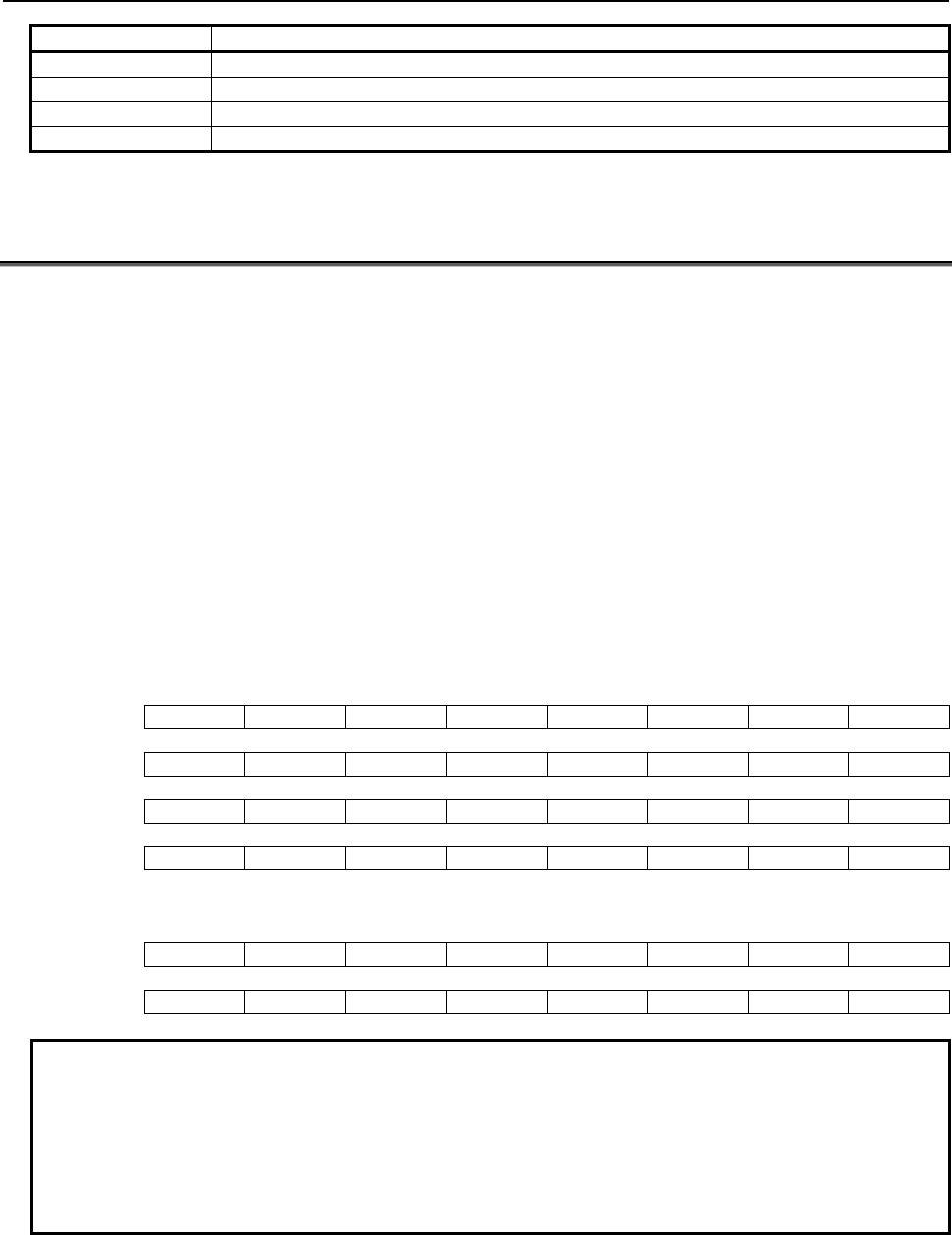
B-63943EN-2/07
6.MACRO EXECUTOR FUNCTION
- 261 -
Value Description
11 An existing file was specified.
12 An I/O error has occurred.
13 The specified file number is invalid.
14 The specified data type is invalid.
6.16
AXIS-DIRECTION-BY-AXIS-DIRECTION INTERLOCK
FUNCTION (#8600, #8601, #8607, AND #8608)
The axis-direction-by-axis-direction interlock control variables (#8600 and #8607) can be used to apply
interlock for individual axes and their movement directions. The movement axis and direction variables
for the rise time of the skip signal (#8601 and #8608) can be used to detect the axis that runs when the
skip signal rises, and its direction.
This function is enabled when bit 0 (XIT) of parameter No. 9035 is set to 1.
The axis-direction-by-axis-direction interlock function is enabled only in the axis-direction-by-axis-
direction interlock mode, that is, in the JOG or HNDL mode in which the PMC internal relay (R area)
signal specified in parameters Nos. 9069 and 9070 is on. For multi-path PMCs, specify a PMC path using
control variable #8603. For details, see Section 6.3, "SPECIFICATION OF A PMC PATH IN
MULTI-PATH PMCS (#8603)".
Each digit of the binary numbers assigned to #8600, #8601, #8607, and #8608 corresponds to the
movement axis and its direction. In addition, #8600 and #8601 support the 1st to 16th axes, and #8607
and #8608, the 17th to 24th axes.
#8600 and #8601 (1st to 16th controlled axes in a path)
#7 #6 #5 #4 #3 #2 #1 #0
0BYTE AX4- AX4+ AX3- AX3+ AX2- AX2+ AX1- AX1+
1BYTE AX8- AX8+ AX7- AX7+ AX6- AX6+ AX5- AX5+
2BYTE AX12- AX12+ AX11- AX11+ AX10- AX10+ AX9- AX9+
3BYTE AX16- AX16+ AX15- AX15+ AX14- AX14+ AX13- AX13+
#8607 and #8608 (17th to 24th controlled axes in a path)
#7 #6 #5 #4 #3 #2 #1 #0
0BYTE AX20- AX20+ AX19- AX19+ AX18- AX18+ AX17- AX17+
1BYTE AX24- AX24+ AX23- AX23+ AX22- AX22+ AX21- AX21+
Example
1 If #8600 and #8601 have a binary number of 1000000000000001, they indicate
the positive direction of the 1st axis (AX1+) and the negative direction of the 8th
axis (AX8-). This binary number is equivalent to 32769 in decimal.
2 If #8607 and #8608 have a binary number of 1000000000000001, they indicate
the positive direction of the 17th axis (AX17+) and the negative direction of the
24th axis (AX24-). This binary number is equivalent to 32769 in decimal.
Axis-direction-by-axis-direction interlock control variables (#8600 and #8607)
When both #8600 and #8607 are 0, interlock is applied to all axes when the skip signal is on.
The skip signal is one of the signals shown below, depending on bit 6 (SKX) of parameter No. 9035.
When bit 6 (SKX) of parameter No.9035 is set to 0;
SKIPP<Gn006.6>
6.MACRO EXECUTOR FUNCTION
B-63943EN-2/07
- 262 -
When bit 6 (SKX) of parameter No.9035 is set to 1;
• SKIP<X004.7> (when the 1st PMC is used)
SKIP<X013.7> (when the 2nd PMC is used)
SKIP<X011.7> (when the 3rd PMC is used)
• By setting bit 2 (XSG) of parameter No. 3008 and parameter No. 3012, it is possible to map the
skip signal to an arbitrary X address.
Even if this function is not used for the 17th axis and those assigned a higher axis number, not only #8600
but also #8607 must be 0. #8601 and #8608 reflect the axes that are caused to stop when the skip signal
becomes on and the direction in which the axes were moving just before they stopped. These control
variables retain the information until the skip signal is turned off and on again. Interlock is kept applied to
the axes and directions that correspond to the values of the control variables. To release interlock, turn off
the PMC internal relay (R area).
If either #8600 or #8607 is not 0, interlock is applied to the axes and directions indicated by #8600 or
#8607.
#8600 corresponds to the 1st to 16th controlled axes in a path, and #8607 corresponds to the 17th to 24th
controlled axes in a path.
NOTE
Set data in #8607 and #8600 in the stated sequence. Interlock begins when data
is set in #8600.
Consider the following example.
#8607=32769; .... (Positive direction of the 17th axis, negative direction of the 24th
axis)
#8600=1; ............ (Positive direction of the 1st axis) → At this point, interlock is
applied to the 1st, 17th,
and 24th axes.
To release interlock, reset #8600 and #8607 to 0, or turn off the PMC internal relay (R area) to reset these
control variables to 0. Immediately after the power is switched on, or when the axis-direction-by-
axis-direction interlock function is disabled (parameter bit 0 (XIT) of parameter No. 9035 = 0 or the PMC
internal relay (R area) is off), #8600 and #8607 are 0.
Movement axis and direction variables for the rise time of the skip signal
(#8601 and #8608)
When the state of the skip signal is changed from off to on, #8601 and #8608 indicate the axis that moved
most recently and the direction of its movement.
The skip signal is one of the signals shown below, depending on bit 6 (SKX) of parameter No. 9035.
When bit 6 (SKX) of parameter No.9035 is set to 0;
SKIPP<Gn006.6>
When bit 6 (SKX) of parameter No.9035 is set to 1;
• SKIP<X004.7> (when the 1st PMC is used)
SKIP<X013.7> (when the 2nd PMC is used)
SKIP<X011.7> (when the 3rd PMC is used)
• By setting bit 2 (XSG) of parameter No. 3008 and parameter No. 3012, it is possible to map the skip
signal to an arbitrary X address.
#8601 corresponds to the 1st to 16th controlled axes in a path, and #8608 corresponds to the 17th to 24th
controlled axes in a path.
#8601 and #8608 retains their values until the state of the skip signal changes from off to on again. When
the PMC internal relay (R area) is turned off, both #8601 and #8608 are reset to 0, thereby disabling this
function.
B-63943EN-2/07
6.MACRO EXECUTOR FUNCTION
- 263 -
NOTE
Any value can be written to neither #8601 nor #8608.
6.16.1
Differences from the Series 16i
Function Series 16i/18i/21i Series 30i/31i/32i/35i/0i-F/PMi
PMC internal relay (R
area) signal
Selected using compile parameters No.
9035 and No. 9036.
Set using parameters Nos. 9069 and 9070.
SKIP signal Determined by the SKIP<X004.7> signal. Can be set using bit 6 (SKX) of parameter No.
9035.
=0 : SKIPP <Gn006.6>
=1 : SKIP <X004.7>
6.17
WINDOW FUNCTION (#8996 TO #8999)
6.17.1
General
The window function enables referencing of the following system information:
1. Alarm information and external alarm information
2. Relative coordinates, servo motor load current value, positional deviation value
3. Run hour and parts count
4. Diagnosis information
5. System series information, servo series information, and PMC series information
Window control variables
#8998 : System information ID
#8997 : Axis number
#8999 : System information
#8996 : Completion code
Method of using
Set #8998 with the ID No. of the system information to be referenced.
If the system information depends on the controlled axis or spindle, set #8997 with the number of the
controlled axis or spindle.
Now read-accessing #8999 enables you to view the information about the system.
Then, #8996 indicates whether the window function was executed normally (0 for normal end and -1 for
abnormal end).

6.MACRO EXECUTOR FUNCTION
B-63943EN-2/07
- 264 -
Example 1
Alarm information
(1) PS alarm monitoring
#8998=1 ; → The system information ID for alarms is 1.
#500=#8999 ; → Acquires alarm information.
#500=#500 AND 8 ; → Checks for a PS alarm condition.
IF[#500EQ0]GOTO 90 ;
#8998=11 ; → The system information ID for PS alarms is 11.
#500=#8999 ; → Acquires a PS alarm number.
#501=#8996 ; → Sets the result of executing this function.
N90 M99 ;
When these steps are executed, #500 is set with a PS alarm number, then #501
is set with information about whether the window function was executed
normally.
(2) OT alarm monitoring
(Monitoring of + direction stored stroke limit 1 on the 1st axis in the path)
#8998= 28 ; → The ID for axis-type OT alarm flag 1 is 28.
#8997= 1 ; → Axis number (1st axis)
#500=#8999 ; → Acquires the contents of ID No. 28.
#500=#500 AND 1 ;
#501=#8996 ; → Sets the result of executing this function.
N90 M99 ;
When these steps are executed, #500 is set with 1 if the tool is in the forbidden
area for stored stroke limit 1. Then #501 is set with information about whether
the window function was executed normally.
Example 2
Parts total
#8998=200 ; → The ID for the parts total is 200.
#500=#8999 ;
#501=#8996 ;
→ Sets the result of executing this function.
When these steps are executed, #500 is set with the parts total. Then #501 is
set with information about whether the window function was executed normally.
NOTE
#8996 is set with -1 (abnormal end) if:
• A value assigned to #8998 is invalid, or
• The value entered in #8997 exceeds the maximum number of controlled axes
in the path or the maximum number of spindles in the path.

B-63943EN-2/07
6.MACRO EXECUTOR FUNCTION
- 265 -
Lists of reference systems and the related information ID Nos.
ID No.
(#8998)
Axis ID No.
(#8997)
Information
1
5
11
13
20
21
22
23
24
25
26
27
28
30
37
41
42
43
44
45
46
47
48
49
55
56
57
58
59
100
102
110
111
112
113
114
115
116
117
118
-
-
-
-
-
-
-
-
-
-
-
-
1 to maximum number of controlled axes in the path
-
1 to maximum number of controlled axes in the path
-
-
-
-
-
-
-
-
1 to maximum number of controlled axes in the path
-
-
-
-
-
-
-
-
-
-
-
-
-
-
-
1 to maximum number of controlled axes in the path
A
larm basic flag
OH alarm flag
PS alarm number
MC alarm number (user alarm)
OT alarm No.500 (1st to 8th axes)
OT alarm No.501 (1st to 8th axes)
OT alarm No.502 (1st to 8th axes)
OT alarm No.503 (1st to 8th axes)
OT alarm No.504 (1st to 8th axes)
OT alarm No.505 (1st to 8th axes)
OT alarm No.506 (1st to 8th axes)
OT alarm No.507 (1st to 8th axes)
OT alarm No.500 to 507
SV alarm No.401,404
SV alarm No.401,404 (1st to 24th axes)
SV alarm No.410 to 417 (1st axis)
SV alarm No.410 to 417 (2nd axis)
SV alarm No.410 to 417 (3rd axis)
SV alarm No.410 to 417 (4th axis)
SV alarm No.410 to 417 (5th axis)
SV alarm No.410 to 417 (6th axis)
SV alarm No.410 to 417 (7th axis)
SV alarm No.410 to 417 (8th axis)
SV alarm No.410 to 417 (1st to 24th axes)
External alarm flag
External alarm number 1
External alarm number 2
External alarm number 3
External alarm number 4
Number of controlled axes in a path
Total number of controlled axes
Relative coordinate of the 1st axis
Relative coordinate of the 2nd axis
Relative coordinate of the 3rd axis
Relative coordinate of the 4th axis
Relative coordinate of the 5th axis
Relative coordinate of the 6th axis
Relative coordinate of the 7th axis
Relative coordinate of the 8th axis
Relative coordinates (1st to 24th axes)
200
201
202
210
220
221
222
223
224
225
226
227
-
-
-
-
-
-
-
-
-
-
-
-
Parts total
Parts required
Parts count
Power-on time
Cumulative operation time : minute
Cumulative operation time : millisecond
Cutting time : minute
Cutting time : millisecond
Free timer : minute
Free timer : millisecond
Cycle time : minute
Cycle time : millisecond

6.MACRO EXECUTOR FUNCTION
B-63943EN-2/07
- 266 -
ID No.
(#8998)
Axis ID No.
(#8997)
Information
411
412
413
414
415
416
417
418
419
-
-
-
-
-
-
-
-
1 to maximum number of controlled axes in the path
Servo motor load current value, 1st axis
Servo motor load current value, 2nd axis
Servo motor load current value, 3rd axis
Servo motor load current value, 4th axis
Servo motor load current value, 5th axis
Servo motor load current value, 6th axis
Servo motor load current value, 7th axis
Servo motor load current value, 8th axis
Servo motor load current value (1st to 24th axes)
700
701
-
-
Diagnosis
Diagnosis
800
801
802
803
804
805
806
807
808
-
-
-
-
-
-
-
-
1 to maximum number of controlled axes in the path
Positional deviation value of the 1st axis
Positional deviation value of the 2nd axis
Positional deviation value of the 3rd axis
Positional deviation value of the 4th axis
Positional deviation value of the 5th axis
Positional deviation value of the 6th axis
Positional deviation value of the 7th axis
Positional deviation value of the 8th axis
Positional deviation values (1st to 24th axes)
8000
8001
8002
8003
8005
8006
8007
8008
-
-
-
-
-
-
-
-
System series information digit 4
System series information digit 3
System series information digit 2
System series information digit 1
System edition information digit 4
System edition information digit 3
System edition information digit 2
System edition information digit 1
8020
8021
8022
8023
8025
8026
8027
8028
-
-
-
-
-
-
-
-
Servo series information digit 4
Servo series information digit 3
Servo series information digit 2
Servo series information digit 1
Servo edition information digit 4
Servo edition information digit 3
Servo edition information digit 2
Servo edition information digit 1
8030
8031
8032
8033
8035
8036
8037
8038
-
-
-
-
-
-
-
-
PMC series information digit 4
PMC series information digit 3
PMC series information digit 2
PMC series information digit 1
PMC edition information digit 4
PMC edition information digit 3
PMC edition information digit 2
PMC edition information digit 1
8040
8041
8042
8043
8045
8046
8047
8048
-
-
-
-
-
-
-
-
Ladder series information digit 4
Ladder series information digit 3
Ladder series information digit 2
Ladder series information digit 1
Ladder edition information digit 4
Ladder edition information digit 3
Ladder edition information digit 2
Ladder edition information digit 1
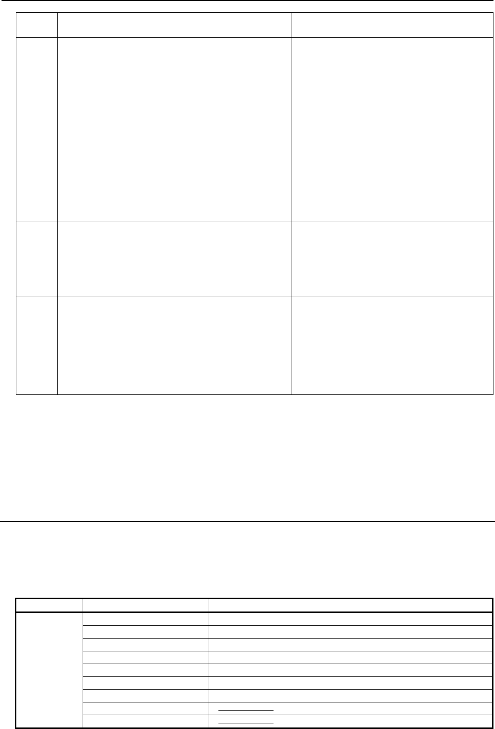
B-63943EN-2/07
6.MACRO EXECUTOR FUNCTION
- 267 -
ID No.
(#8998)
Axis ID No.
(#8997)
Information
10043
10308
10309
10361
10379
10403
10410
10411
10445
10552
10710
10712
10750
10752
10764
-
1 to maximum number of controlled axes in the path
1 to maximum number of controlled axes in the path
1 to maximum number of controlled axes in the path
-
1 to maximum number of spindles in the path
1 to maximum number of spindles in the path
1 to maximum number of spindles in the path
1 to maximum number of spindles in the path
1 to maximum number of controlled axes in the path
1 to maximum number of spindles in the path
1 to maximum number of spindles in the path
1 to maximum number of controlled axes in the path
1 to maximum number of controlled axes in the path
1 to maximum number of controlled axes in the path
Diagnosis data No.43
Diagnosis data No.308
Diagnosis data No.309
Diagnosis data No.361
Diagnosis data No.379
Diagnosis data No.403
Diagnosis data No.410
Diagnosis data No.411
Diagnosis data No.445
Diagnosis data No.552
Diagnosis data No.710
Diagnosis data No.712
Diagnosis data No.750
Diagnosis data No.752
Diagnosis data No.764
11110 to
11115
11120 to
11294
-
-
Option information items Nos. 1110 to 1115 on
the diagnosis screen
(Non-bit-type option information items)
Option information items Nos. 1120 to 1294 on
the diagnosis screen
(Bit-type option information items)
11701
11703
13500
13570
13700
13701
14001
16507
1 to maximum number of controlled axes in the path
1 to maximum number of spindles in the path
1 to maximum number of controlled axes in the path
-
1 to maximum number of controlled axes in the path
1 to maximum number of controlled axes in the path
1 to maximum number of controlled axes in the path
-
Diagnosis data No.1701
Diagnosis data No.1703
Diagnosis data No.3500
Diagnosis data No.3570
Diagnosis data No.3700
Diagnosis data No.3701
Diagnosis data No.4001
Diagnosis data No.6507
Each axis ID No. (#8997) corresponds to an axis as listed below:
• Controlled axes
1st axis controlled in the path : 1
2nd axis controlled in the path : 2
:
24th axis controlled in the path : 24
6.17.2
Alarm Information and External Alarm Information
The alarm basic flag (ID No. 1) indicate the category of an alarm (if occurs).
For details, see "Detail information about each alarm." Bit information is output as 1 byte (0 to 255) or 2
byte (0 to 65535) to #8999 (see the example given for the alarm basic flag).
Alarm basic flag
ID No. (#8998) Bit information (#8999) Information
1
0001h SW alarm
0002h PW alarm
0004h IO alarm
0008h PS/SR/MC alarm
0010h OT alarm
0020h OH alarm
0040h SV alarm
0080h
0100h
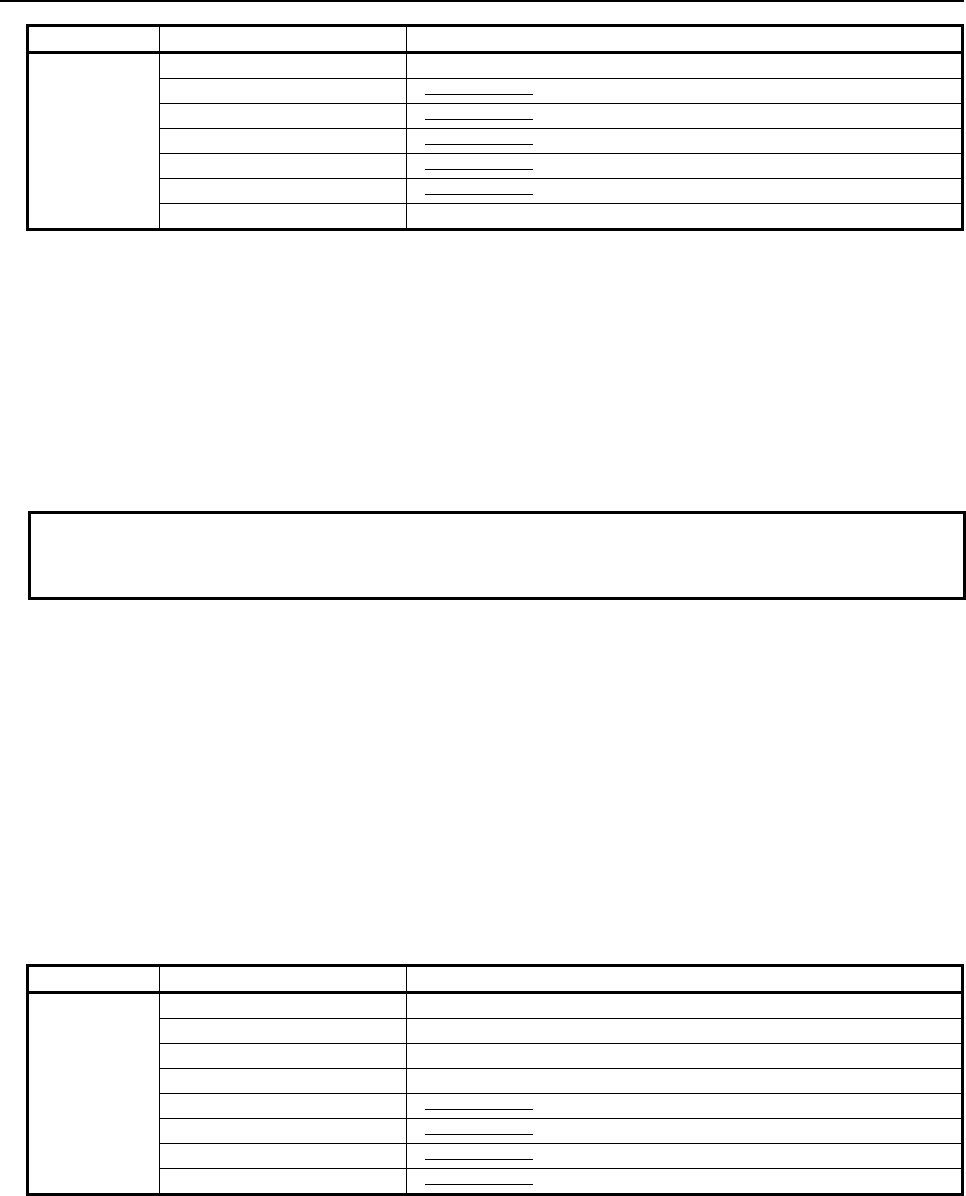
6.MACRO EXECUTOR FUNCTION
B-63943EN-2/07
- 268 -
ID No. (#8998) Bit information (#8999) Information
0200h SP alarm
0400h
0800h
1000h
2000h
4000h
8000h External alarm
SW alarm : When this bit is 1, it means that the SW alarm flag is set with data.
PW alarm : When this bit is 1, it means that the PW alarm flag is set with data.
IO alarm : When this bit is 1, it means that the IO alarm flag is set with data.
PS/SR/MC alarm : When this bit is 1, it means that the PS, SR, or MC alarm flag is set with data.
OT alarm : When this bit is 1, it means that the OT alarm flag is set with data.
OH alarm : When this bit is 1, it means that the OH alarm flag is set with data.
SV alarm : When this bit is 1, it means that the SV alarm flag is set with data.
SP alarm : When this bit is 1, it means that the SP alarm flag is set with data.
External alarm : When this bit is 1, it means that the external alarm flags (1 to 4) are set with data.
Example
If the PS alarm and external alarm have occurred, 32776 (8008h) is output to
#8999.
Detail information about each alarm
ID numbers used to acquire detail information about each alarm are listed below.
For the PS, SR, MC, and external alarms, their alarm number is output to #8999. For other alarms, numbers
within the range of 0 to 128 or 0 to 32768 are output to #8999 as one byte, two bytes, or four bytes of bit
information. For the bit information, the related alarm number can be recognized from the corresponding bit
listed in any of the following tables.
For detailed descriptions of the alarm corresponding to each alarm, refer to Appendix A, "Alarm List" in
OPERATOR’S MANUAL.
- External alarm flag
By using the external alarm flag (ID No. 55), which external alarm, if issued, is on can be checked.
For detailed information, see the descriptions of external alarms 1 to 4 (ID Nos. 56 to 59).
ID No. (#8998) Bit information (#8999) Information
55
01h External alarm 1
02h External alarm 2
04h External alarm 3
08h External alarm 4
10h
20h
40h
80h
- Alarm number information
An alarm number can be read from alarm number information (ID Nos. 11, 13, 56, 57, 58, and 59). MC
alarm number (ID No. 13) information is valid only when 255 is indicated by PS alarm (ID No. 11)
information.
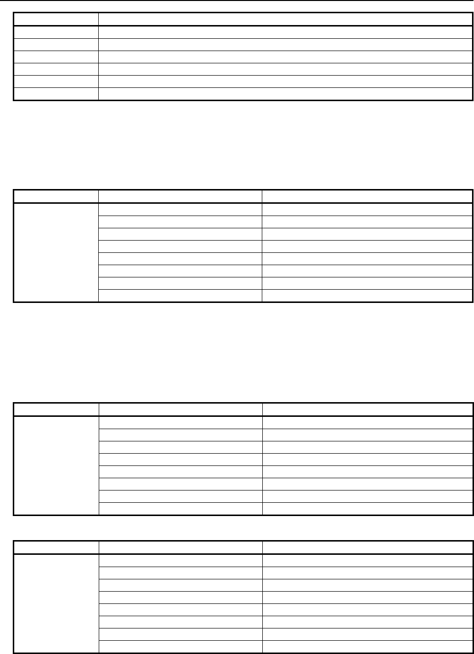
B-63943EN-2/07
6.MACRO EXECUTOR FUNCTION
- 269 -
ID No. (#8998) Alarm number (#8999)
11 PS/SR alarm number
13 MC alarm number (User alarm)
56 External alarm number 1
57 External alarm number 2
58 External alarm number 3
59 External alarm number 4
- Bit information
Overheat alarm
ID No. 5 provides details of an overheat alarm by outputting a number from 0 to 255 as one-byte bit
information.
OH alarm flag
ID No. (#8998) Bit information (#8999) Alarm number
5
01h OH700
02h ----------
04h ----------
08h ----------
10h OH701
20h ----------
40h ----------
80h ----------
Overtravel alarm (1st axis to 8th axes)
ID Nos. 20 to 27 provide details of the overtravel alarms of the 1st to 8th axes by outputting a
number from 0 to 255 as one-byte bit information.
Information bits 0 to 7 of ID Nos. 20 to 27 correspond to the 1st to 8th axes. To reference the 9th
axis and up, use ID No. 28.
OT alarm flag
ID No. (#8998) Bit information (#8999) Alarm number
20
01h OT500 (1st axis)
02h OT500 (2nd axis)
04h OT500 (3rd axis)
08h OT500 (4th axis)
10h OT500 (5th axis)
20h OT500 (6th axis)
40h OT500 (7th axis)
80h OT500 (8th axis)
OT alarm flag
ID No. (#8998) Bit information (#8999) Alarm number
21
01h OT501 (1st axis)
02h OT501 (2nd axis)
04h OT501 (3rd axis)
08h OT501 (4th axis)
10h OT501 (5th axis)
20h OT501 (6th axis)
40h OT501 (7th axis)
80h OT501 (8th axis)
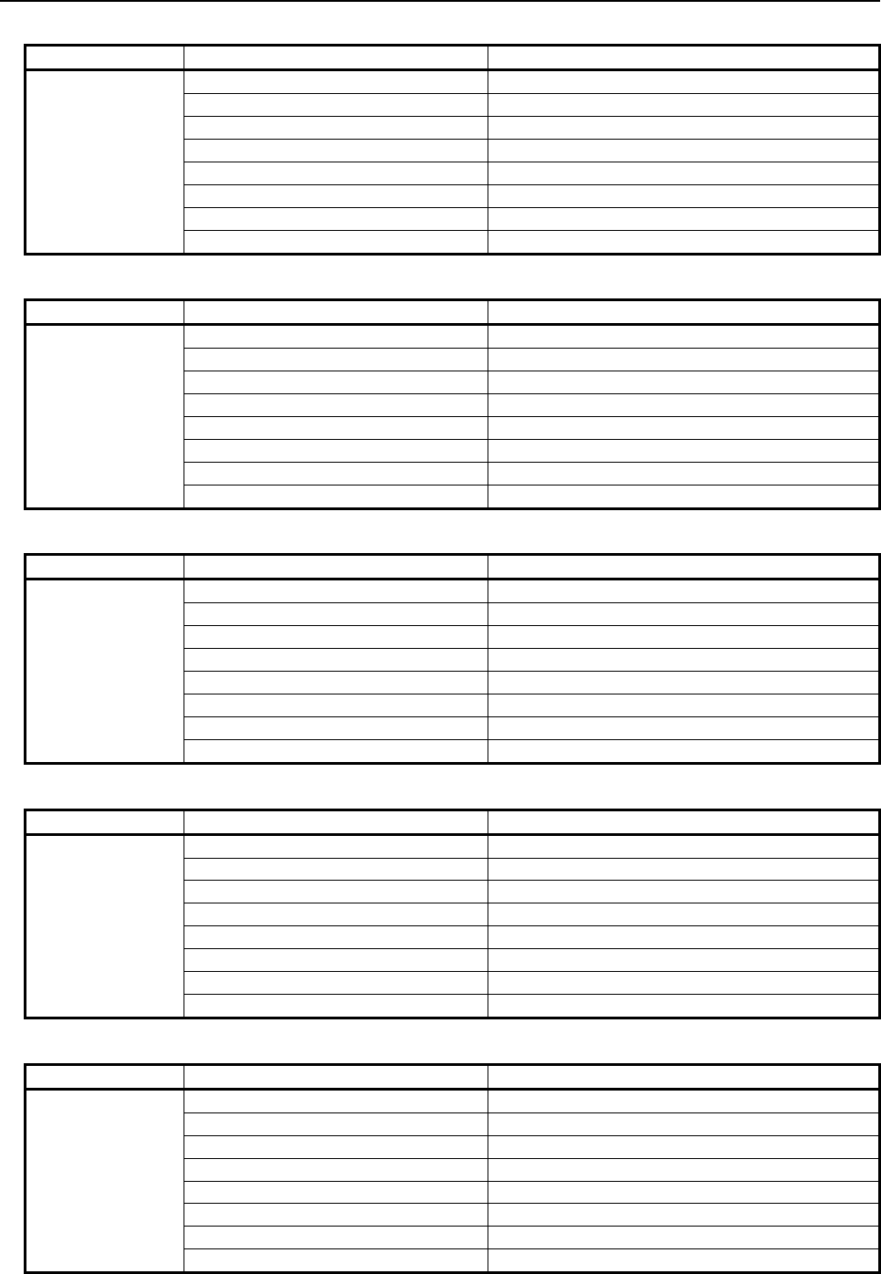
6.MACRO EXECUTOR FUNCTION
B-63943EN-2/07
- 270 -
OT alarm flag
ID No. (#8998) Bit information (#8999) Alarm number
22
01h OT502 (1st axis)
02h OT502 (2nd axis)
04h OT502 (3rd axis)
08h OT502 (4th axis)
10h OT502 (5th axis)
20h OT502 (6th axis)
40h OT502 (7th axis)
80h OT502 (8th axis)
OT alarm flag
ID No. (#8998) Bit information (#8999) Alarm number
23
01h OT503 (1st axis)
02h OT503 (2nd axis)
04h OT503 (3rd axis)
08h OT503 (4th axis)
10h OT503 (5th axis)
20h OT503 (6th axis)
40h OT503 (7th axis)
80h OT503 (8th axis)
OT alarm flag
ID No. (#8998) Bit information (#8999) Alarm number
24
01h OT504 (1st axis)
02h OT504 (2nd axis)
04h OT504 (3rd axis)
08h OT504 (4th axis)
10h OT504 (5th axis)
20h OT504 (6th axis)
40h OT504 (7th axis)
80h OT504 (8th axis)
OT alarm flag
ID No. (#8998) Bit information (#8999) Alarm number
25
01h OT505 (1st axis)
02h OT505 (2nd axis)
04h OT505 (3rd axis)
08h OT505 (4th axis)
10h OT505 (5th axis)
20h OT505 (6th axis)
40h OT505 (7th axis)
80h OT505 (8th axis)
OT alarm flag
ID No. (#8998) Bit information (#8999) Alarm number
26
01h OT506 (1st axis)
02h OT506 (2nd axis)
04h OT506 (3rd axis)
08h OT506 (4th axis)
10h OT506 (5th axis)
20h OT506 (6th axis)
40h OT506 (7th axis)
80h OT506 (8th axis)
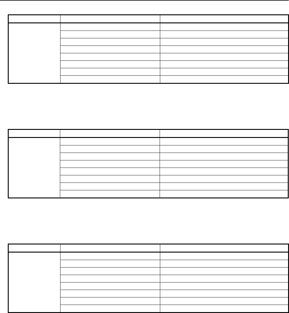
B-63943EN-2/07
6.MACRO EXECUTOR FUNCTION
- 271 -
OT alarm flag
ID No. (#8998) Bit information (#8999) Alarm number
27
01h OT507 (1st axis)
02h OT507 (2nd axis)
04h OT507 (3rd axis)
08h OT507 (4th axis)
10h OT507 (5th axis)
20h OT507 (6th axis)
40h OT507 (7th axis)
80h OT507 (8th axis)
Overtravel alarm (1st axis to 24th axes)
ID No.28 provides details of an overtravel alarm by outputting a number from 0 to 255 as one-byte
bit information. In #8997, be sure to specify an axis to be referenced.
OT alarm flag
ID No. (#8998) Bit information (#8999) Alarm number
28
01h OT500
02h OT501
04h OT502
08h OT503
10h OT504
20h OT505
40h OT506
80h OT507
Servo alarm No.401, No.404
ID No. 30 provides details of servo alarm No. 401 and No. 404 by outputting a number from 0 to
255 as one-byte bit information. Use ID No. 37 to make an axis-by-axis reference.
SV alarm flag
ID No. (#8998) Bit information (#8999) Alarm number
30
01h ----------
02h SV401
04h ----------
08h ----------
10h SV404
20h ----------
40h ----------
80h ----------
Servo alarm No.401, No.404 (1st to 24th axes)
ID No. 37 provides details of servo alarm No. 401 and No. 404 by outputting a number from 0 to
255 as one-byte bit information. In #8997, be sure to specify an axis to be referenced.
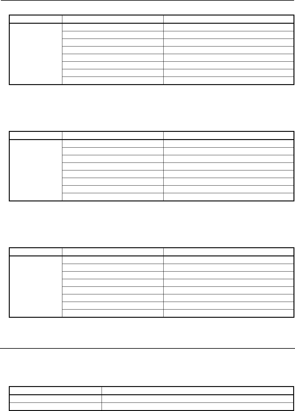
6.MACRO EXECUTOR FUNCTION
B-63943EN-2/07
- 272 -
SV alarm flag
ID No. (#8998) Bit information (#8999) Alarm number
37
01h ----------
02h SV401
04h ----------
08h ----------
10h SV404
20h ----------
40h ----------
80h ----------
Servo alarm No.411 to No.417 (1st to 8th axes)
ID Nos. 41 to 48 provide details of servo alarm Nos. 411 to 417 by outputting a number from 0 to
255 as one-byte bit information. ID Nos. 41 to 48 correspond to the 1st axis to the 8th axis.
SV alarm flag
ID No. (#8998) Bit information (#8999) Alarm number
41 to 48
01h SV411
02h SV413
04h SV415
08h ----------
10h ----------
20h SV410
40h ----------
80h SV417
Servo alarm No.411 to No.417 (1st to 24th axes)
ID No. 49 provides details of servo alarm Nos. 411 to 417 by outputting a number from 0 to 255 as
one-byte bit information. In #8997, be sure to specify an axis to be referenced.
SV alarm flag
ID No. (#8998) Bit information (#8999) Alarm number
49
01h SV411
02h SV413
04h SV415
08h ----------
10h ----------
20h SV410
40h ----------
80h SV417
6.17.3
Axis, Relative Coordinate, Servo Motor Load Current Value,
and Positional Deviation value
Axis
ID No.100 enables you to reference the maximum number of controlled axes in the path, and ID No.102
enables you to reference the maximum number of controlled axes in the entire system.
ID No. (#8998) Information (#8999)
100 Maximum number of controlled axes in the path
102 Maximum number of controlled axes in the entire system
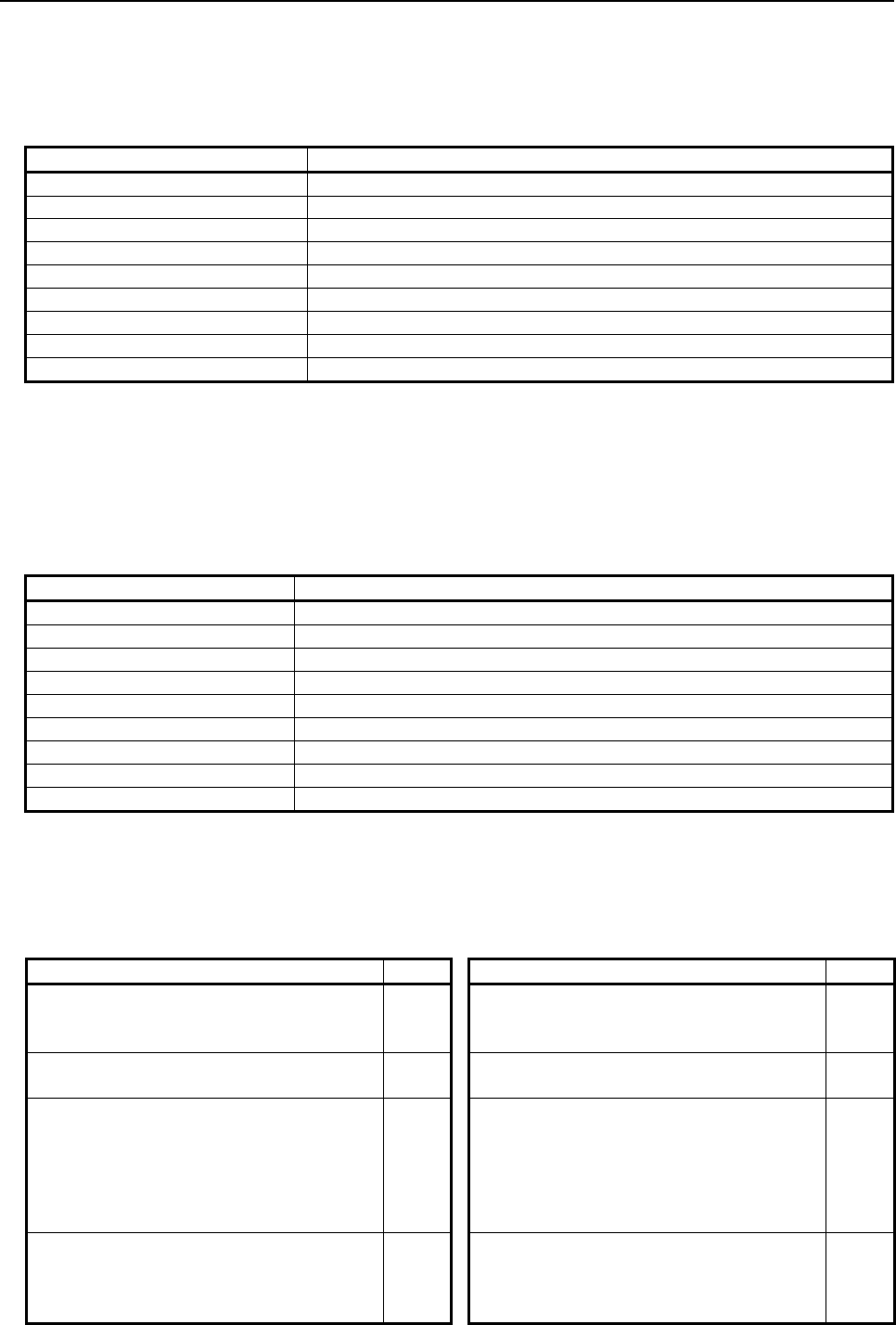
B-63943EN-2/07
6.MACRO EXECUTOR FUNCTION
- 273 -
Relative coordinate value (1st to 24th axes)
ID Nos.110 to 117 enable you to reference the relative coordinates of the 1st to the 8th axes in the path.
By specifying an axis with ID No. 118, the relative coordinates of the 1st to the 24th axes in the path can
be referenced. In #8997, be sure to specify an axis to be referenced.
ID No. (#8998) Information (#8999)
110 Relative coordinate of the 1st axis
111 Relative coordinate of the 2nd axis
112 Relative coordinate of the 3rd axis
113 Relative coordinate of the 4th axis
114 Relative coordinate of the 5th axis
115 Relative coordinate of the 6th axis
116 Relative coordinate of the 7th axis
117 Relative coordinate of the 8th axis
118 Relative coordinate value (1st to 24th axes)
Servo motor load current value (1st to 24th axes)
ID Nos. 411 to 418 enable you to reference the load current values of the servo motors of the 1st to the
8th axes in the path.
The read data is input as values in the range of -6554 to +6554.
By specifying an axis with ID No. 419, the load current values of the servo motors of the 1st to the 24th
axes in the path can be referenced. In #8997, be sure to specify an axis to be referenced.
ID No. (#8998) Information (#8999)
411 Servo motor load current value of the 1st axis
412 Servo motor load current value of the 2nd axis
413 Servo motor load current value of the 3rd axis
414 Servo motor load current value of the 4th axis
415 Servo motor load current value of the 5th axis
416 Servo motor load current value of the 6th axis
417 Servo motor load current value of the 7th axis
418 Servo motor load current value of the 8th axis
419 Servo motor load current value (1st to 24th axes)
Actual load current value
Actual load current value can be determined as follows:
(AD×N) / 6554 = Load current value (A peak)
AD : Input value (#8999 value)
N: See the table below.
Motor models N value Motor models N value
βi
S0.2/5000,
βi
S0.3/5000
4
αi
S8/4000,
αi
S8/6000,
αi
S12/4000,
αi
F12/3000,
αi
F22/3000,
αi
S22/4000HV,
αi
S30/4000HV,
αi
S40/4000HV,
α
C30/1500
i
80
αi
S2/5000HV,
αi
S2/6000HV,
αi
S4/5000HV,
βi
S2/4000HV,
βi
S4/4000HV,
βi
S8/3000HV
10
αi
S22/4000,
αi
S30/4000,
αi
S40/4000,
αi
F30/3000,
αi
F40/3000,
αi
F40/3000 FAN
160
αi
S2/5000,
αi
S2/6000,
αi
S4/5000,
αi
F1/5000,
αi
F2/5000,
αi
F4/4000HV,
αi
F8/3000HV,
α
C4/3000
i
,
α
C8/2000
i
,
α
C12/2000
i
,
βi
S0.4/5000,
βi
S0.5/5000,
βi
S0.5/6000,
βi
S1/5000,
βi
S1/6000,
βi
S2/4000,
βi
S4/4000,
βi
S8/3000,
βi
S12/3000HV,
βi
S22/2000HV
20
αi
S50/3000HV,
αi
S50/3000HV FAN,
αi
S100/2500HV,
αi
S200/2500HV
180
αi
F4/4000,
αi
F8/3000,
αi
S8/4000HV,
αi
S8/6000HV,
αi
S12/4000HV,
αi
F12/3000HV,
αi
F22/3000HV,
α
C22/2000
i
,
βi
S12/3000,
βi
S22/2000
40
αi
S50/3000,
αi
S50/3000FAN,
αi
S100/2500,
αi
S200/2500,
αi
S300/2000,
αi
S500/2000,
αi
S300/2000HV,
αi
S500/2000HV,
αi
S1000/2000HV
360
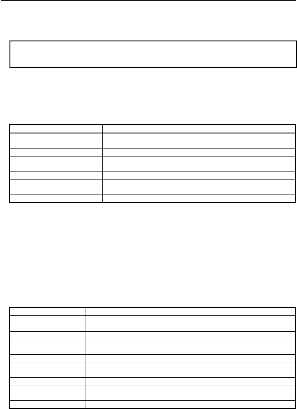
6.MACRO EXECUTOR FUNCTION
B-63943EN-2/07
- 274 -
The load current value determined with the above calculation formula is the one for the maximum current
value of the motor. Thus, it is lower than the continuous rated current value of the motor that is displayed
on the servo adjustment screen, etc.
NOTE
If the motor used is not found in this table, refer to the maximum current of the
applicable servo amplifier contained in the specifications of the motor used.
Positional deviation value (1st to 24th axes)
ID Nos. 800 to 807 enable you to reference the positional deviation values of the 1st to the 8th axes in the
path.
By specifying an axis with ID No. 808, the positional deviation values of the 1st to the 24th axes in the
path can be referenced. In #8997, be sure to specify an axis to be referenced.
ID No. (#8998) Information (#8999)
800 Positional deviation value of the 1st axis
801 Positional deviation value of the 2nd axis
802 Positional deviation value of the 3rd axis
803 Positional deviation value of the 4th axis
804 Positional deviation value of the 5th axis
805 Positional deviation value of the 6th axis
806 Positional deviation value of the 7th axis
807 Positional deviation value of the 8th axis
808 Positional deviation value (1st to 24th axes)
6.17.4
Run Time and Parts Count
The unit of information provided by ID Nos. 210, 220, 222, 224, and 226 is "minute".
Example:
When ID No. 210 indicates 360, it means 6 hours.
When ID No. 220 indicates 369, it means 6 hours and 09 minutes.
When ID No. 224 indicates 359, it means 5 hours and 59 minutes.
The unit of information provided by ID Nos. 221, 223, 225, and 227 is "1/1000 second".
Example:
When ID No. 221 indicates 3000, it means 3 seconds.
When ID No. 221 indicates 36000, it means 36 seconds.
ID No. (#8998) Information (#8999)
200 Parts total
201 Parts required
202 Parts count
210 Power-on time (minute)
220 Cumulative operation time (minute)
221 Cumulative operation time (millisecond)
222 Cutting time (minute)
223 Cutting time (millisecond)
224 Free timer (minute)
225 Free timer (millisecond)
226 Cycle time (minute)
227 Cycle time (millisecond)
B-63943EN-2/07
6.MACRO EXECUTOR FUNCTION
- 275 -
6.17.5
Diagnosis Information
ID Nos. 700 and 701 output a number from 0 to 255 as one-byte bit information.
Diagnosis Information
ID No. (#8998) Bit information (#8999) Meaning
700
01h ---------------------------------------------
02h ---------------------------------------------
04h ---------------------------------------------
08h Inposition check
10h Feedrate override 0%.
20h Inter/Start Lock on
40h Speed Arrival on
80h ---------------------------------------------
Diagnosis Information
ID No. (#8998) Bit information (#8999) Meaning
701
01h ---------------------------------------------
02h ---------------------------------------------
04h ---------------------------------------------
08h ---------------------------------------------
10h Jog Feed Override 0%
20h ---------------------------------------------
40h ---------------------------------------------
80h ---------------------------------------------
Following diagnosis data can be read. The read data follow the specification of each diagnosis data.
ID No.
(#8998) Diagnosis data No. Meaning
10043 43 Number of the current display language of the CNC screen
10308 308 Servo motor temperature
10309 309 Pulsecoder temperature
10361 361 Compensation pulses (NC)
10379 379 Test number of an MCC off Test
10403 403 Spindle motor temperature
10410 410 Spindle load meter indication
10411 411 Spindle motor speed indication
10445 445 Position data of position coder
10552 552 Error between semi-closed and closed loops
10710 710 Spindle error state
10712 712 Spindle warning state
10750 750 OVC level
10752 752 DC link voltage information
10764 764 Inertia estimation value
11701 1701 Servo leakage resistance data
11703 1703 Spindle leakage resistance data
13500 3500 Synchronization error amount
13570 3570 Wrong operation prevention function
13700 3700 Sequence number of a brake test
13701 3701 Cause of the interruption of a brake test
14001 4001 Belonging path of axis in flexible path axis assignment
16507 6507 Active machine configuration set No.

6.MACRO EXECUTOR FUNCTION
B-63943EN-2/07
- 276 -
6.17.6
System, Servo, and PMC Series Information
System series information, servo series information, PMC series, and ladder series information are output
using ID Nos. 8000 to 8008, ID Nos. 8020 to 8028, ID Nos. 8030 to 8038, and ID Nos. 8040 to 8048,
respectively.
Each output value is a decimal representation of ASCII code.
• ID No. 8000 : System series information digit 4
• ID No. 8001 : System series information digit 3
• ID No. 8002 : System series information digit 2
• ID No. 8003 : System series information digit 1
• ID No. 8005 : System edition information digit 4
• ID No. 8006 : System edition information digit 3
• ID No. 8007 : System edition information digit 2
• ID No. 8008 : System edition information digit 1
• ID No. 8020 : Servo series information digit 4
• ID No. 8021 : Servo series information digit 3
• ID No. 8022 : Servo series information digit 2
• ID No. 8023 : Servo series information digit 1
• ID No. 8025 : Servo edition information digit 4
• ID No. 8026 : Servo edition information digit 3
• ID No. 8027 : Servo edition information digit 2
• ID No. 8028 : Servo edition information digit 1
• ID No. 8030 : PMC series information digit 4
• ID No. 8031 : PMC series information digit 3
• ID No. 8032 : PMC series information digit 2
• ID No. 8033 : PMC series information digit 1
• ID No. 8035 : PMC edition information digit 4
• ID No. 8036 : PMC edition information digit 3
• ID No. 8037 : PMC edition information digit 2
• ID No. 8038 : PMC edition information digit 1
• ID No. 8040 : Ladder series information digit 4
• ID No. 8041 : Ladder series information digit 3
• ID No. 8042 : Ladder series information digit 2
• ID No. 8043 : Ladder series information digit 1
• ID No. 8045 : Ladder edition information digit 4
• ID No. 8046 : Ladder edition information digit 3
• ID No. 8047 : Ladder edition information digit 2
• ID No. 8048 : Ladder edition information digit 1
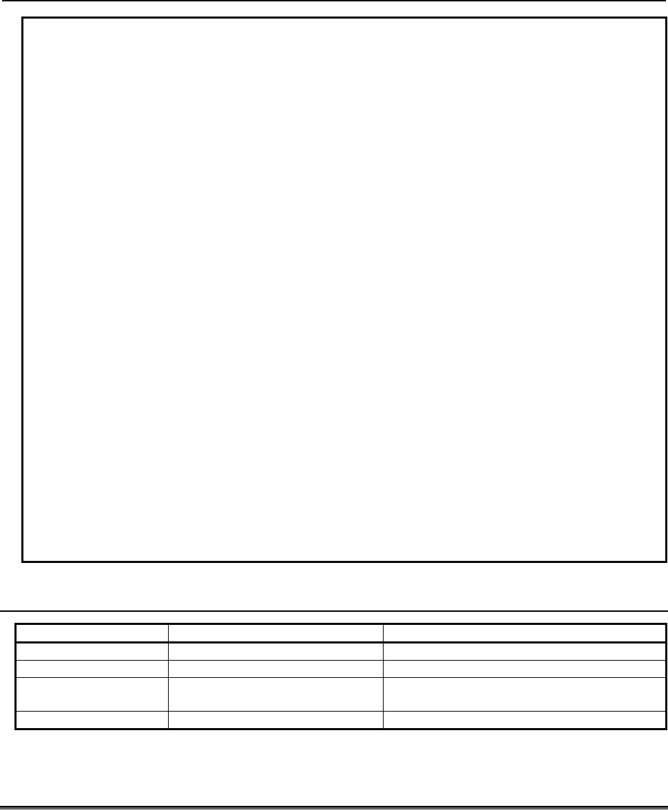
B-63943EN-2/07
6.MACRO EXECUTOR FUNCTION
- 277 -
Example
Assume the following for a system of series G003 and edition 0001:
#8998=8000 ;
#500=#8999 ;
→ Saves system series information digit 4
#8998=8001 ;
#501=#8999 ;
→ Saves system series information digit 3
#8998=8002 ;
#502=#8999 ;
→ Saves system series information digit 2
#8998=8003 ;
#503=#8999 ;
→ Saves system series information digit 1
#8998=8005 ;
#504=#8999 ;
→ Saves system edition information digit 4
#8998=8006 ;
#505=#8999 ;
→ Saves system edition information digit 3
#8998=8007 ;
#506=#8999 ;
→ Saves system edition information digit 2
#8998=8008 ;
#507=#8999 ;
→ Saves system edition information digit 1
Assume the following for a system of series G003 and edition 0001:
#500 = 71 ‘G’ 4th digit of system series information
#501 = 48 ‘0’ 3rd digit of system series information
#502 = 48 ‘0’ 2nd digit of system series information
#503 = 51 ‘3’ 1st digit of system series information
#504 = 48 ‘0’ 4th digit of system edition information
#505 = 48 ‘0’ 3rd digit of system edition information
#506 = 48 ‘0’ 2nd digit of system edition information
#507 = 49 ‘1’ 1st digit of system edition information
6.17.7
Differences from the Series 16i
Function Series 16i/18i/21i Series 30i/31i/32i/35i/0i-F/PMi
Alarm information Alarm numbers, formats, etc. are changed.
Diagnosis information Diagnosis numbers, formats, etc. are changed.
Axis specification Specify a controlled axis number/spindle number
with #8997.
Completion code A completion code is set in #8996.
6.18
FUNCTION FOR SEARCHING DATA TABLES FOR
CONTROL VARIABLES
This function searches a data table, which contains sets of consecutive control variables, for a control
variable that satisfies a specified condition. If it finds the target control variable, it returns the data table
set number where the target control variable is contained.
The function can read the following data:
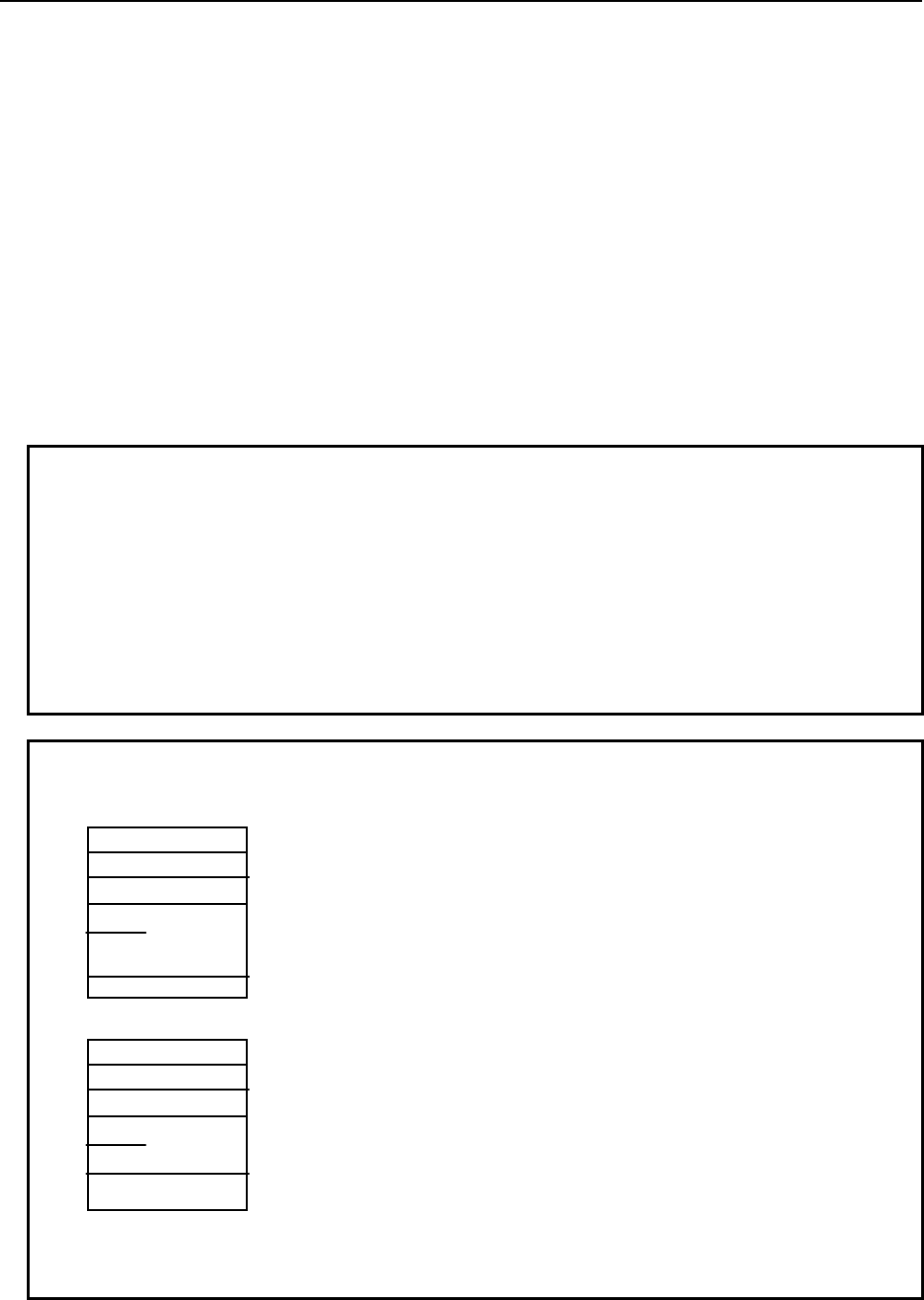
6.MACRO EXECUTOR FUNCTION
B-63943EN-2/07
- 278 -
Format
Input
#8650 : Start control variable number in the search target data table (setting: 1 or greater)
#8651 : The number of macro variables that forms a set in the data table (setting: 1 or greater)
#8652 : The number of search target data table sets (setting: 1 or greater)
#8653 : Lower limit to the search value (sign and decimal point can be entered)
#8654 : Upper limit to the search value (sign and decimal point can be entered)
G400 : Search execution (searches for control variable X that satisfies: #8653
≤
X
≤
#8654)
Output
#8655 : The data table set number where a control variable that satisfies the search condition is
contained (0 or greater), or
= -1 : There is no control variable that satisfies the condition.
= -2 : The setting of any of #8650 to #8652 is invalid (0 or less has been set).
= -3 : #8653
≤
#8654 is not satisfied.
#8650 : Start control variable number in the set next to the retrieved data table set number (#8655)
#8652 : Set value minus the number of sets that have already been retrieved
NOTE
1 If #8655 = -1:
#8650 = 1 (next control variable number in the search target data table)
#8652 = 0
2 The set number begins with 0, but the minimum value of #8652 (the number of
search data table sets) is 1.
3 If more than one control variable satisfies the search condition, a search ends by
returning the data table set number that contains the first control variable to be
found.
4 Only #8655 is a read-only variable.
Example
Data table
#20000
#20010
Set 0
#8650=20000 ;
#8651=10 ;
#8652=400 ;
#8653=10.5 ;
#8654=11.5 ;
G400 ;
#
1
00
=
#8655
;
Set 1
With the above steps, this function searches the data table shown at the
left, in which the first control variable begins with #20000 and ten control
variables form one set, for a control variable that satisfies the condition
10.5 ≤ X ≤ 11.5. If it finds such a control variable, it returns the set
number where the control variable is contained, using #8655. If no such
control variable is found, -1 is returned.
If X = #20011 (set 1), for example, executing G400 results in:
#8655 = 1 : Set 1
#8650 = 20020 : Start control variable number in set 2
#8652 = 398 : 400 – 2

B-63943EN-2/07
6.MACRO EXECUTOR FUNCTION
- 279 -
Combining with array-type references
Combining this function with array-type references makes it easy to reference the data table.
Example
If the previous sample program is combined with array-type references:
#8513=1 ;
#8516=10 ; *1)
#8517=1 ;
#8518=1 ; *2)
#8519=20000 ; *3)
#8650=20000 ;
#8651=10 ;
#8652=400 ;
#8653=10.5 ;
#8654=11.5 ;
G400 ;
IF[#8655 LT 0] GOTO 999 ; .......... Go to the remaining search processing
#8512=#8655 + 1 ; *4)
:
The data table elements of a set that was retrieved can be referenced using #1
to #99 provided that #8512, #8518, and #8519 will not be changed.
#8519=#8650 ; *5)
G400 ;
IF[#8655 LT 0] GOTO 999 ; .......... Go to the remaining search processing
#8512=#8655 + 1 ;
NOTE
*1) Specifies the number of elements of a data table set (number of control
variables). The array-type references that can be used are only #1 to #99; so the
maximum allowable number of elements is 99.
*2) Before starting to make array-type references, set #8518 = 1. #1 to #99 function
as array-type reference variables while #8518 = 1.
*3) Sets the start macro variable number of an array.
*4) Sets an array number (set number + 1) to be used for array-type references.
This associates #1 to #99 as follows:
#1: = #[0 + [#8519 + [#8512 -1] * #8516]]
#2: = #[1 + [#8519 + [#8512 -1] * #8516]]
#3: = #[2 + [#8519 + [#8512 -1] * #8516]]
As many definitions as the number of elements set in #8516 follow.
*5) To continue the second or subsequent searches, just change the start macro
variable number of the array; array-type references can be continued
accordingly.

6.MACRO EXECUTOR FUNCTION
B-63943EN-2/07
- 280 -
Note
NOTE
1 This function is valid only with the conversational macro and auxiliary macro
functions.
2 The macro variable numbers in the search target data table must be
consecutive. Otherwise, a search cannot be performed correctly. In addition, be
careful not to specify a nonexisting control variable number or system variable as
a search target.
3 A search target control variable can be either a custom macro variable or
P-CODE macro variable.
B-63943EN-2/07
7.DEBUGGING FUNCTION
- 281 -
7 DEBUGGING FUNCTION
7.1 GENERAL
The debugging function allows debugging of conversational macros and auxiliary macros. When the
conversational macro function is executed, the debugger starts, displaying a debugger screen on the
conversational macro screen. The debugger has the following functions:
(1) Displaying the operation status
(2) Displaying the program number of an executed P-CODE macro
(3) Displaying the sequence number of an executed P-CODE macro
(4) Displaying the number of blocks in an executed P-CODE macro
(5) Single-block execution
(6) Break function
Break by program number
Break by sequence number
Break by the number of executed blocks
Break by repeat count
(7) Displaying and setting macro variables (five variables)
(8) Changing targets
(9) Temporarily erasing the debugger screen and re-displaying it
(10) Displaying error information regarding an executed P-CODE macro
Single-block execution and break conditions can also be set directly by pressing an appropriate key
instead of setting from the debugger screen.
NOTE
1 When using the debugging function, set bit 0 (DBG) of parameter No. 9033 to 1.
2 When the debugging function is used, entering data from the keyboard displays
the data in the data input line even if the content of the data input control
variable (#8502) is 0.
3 With a machine whose MDI keyboard is a small one, the debugging function
cannot be used.
(From a small keyboard, it is not possible to enter the input mode of the
debugger screen.)
7.2 DISPLAYING AND SETTING ON THE DEBUGGER
SCREEN
This section explains the procedures for displaying the debugger screen and making settings on the
screen.
Displaying the debugger screen
Press function key
to execute the conversational macro function.
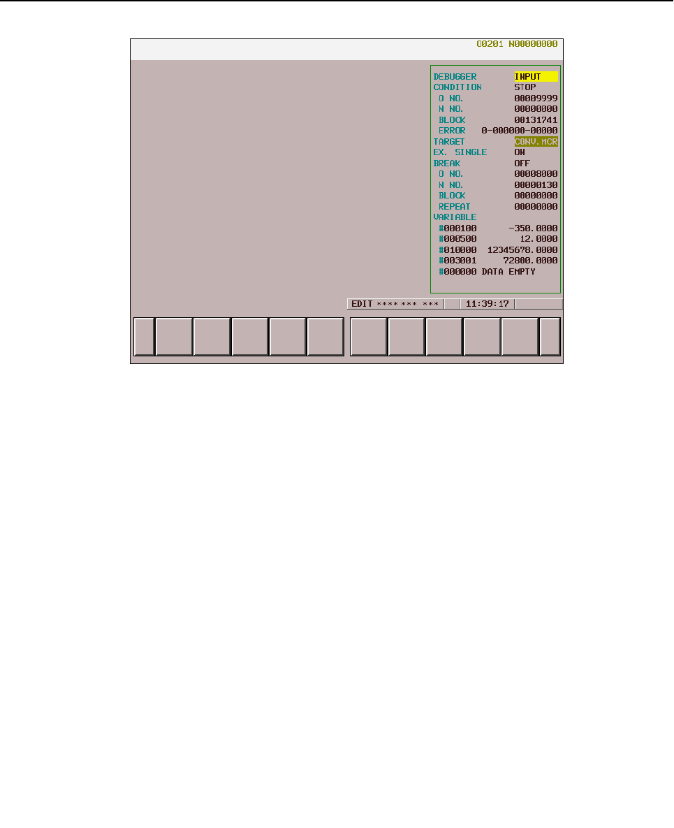
7.DEBUGGING FUNCTION
B-63943EN-2/07
- 282 -
Debugger screen
The following items are displayed:
(1) Whether to enable key input
When key input from the debugger is enabled, INPUT is indicated.
(2) Operation condition
The operation condition of a target P-CODE macro is indicated by blinking. While the P-CODE
macro is being executed, EXEC is indicated. When the macro is stopped, STOP is indicated.
(3) Program number
The program number with which the target P-CODE macro has been executed is indicated.
(4) Sequence number
The sequence number with which the target P-CODE macro has been executed is indicated.
(5) Number of blocks
The number of blocks executed by the target P-CODE macro is indicated with a value up to
99999999.
(6) Error information
Error information about the execution of the target P-CODE macro is displayed.
ERROR a-bbbbbb-ccccc
a : 0 No error
1 An error occurred in macro statement specification.
2 An error occurred in NC statement specification.
bbbbbb : • For a macro statement, a variable number is indicated. (For other than variables, 0 is
indicated.)
• For an NC statement, a G code is indicated.
ccccc : Error No.
When there is no error, 0 is indicated. For details of errors, refer to Appendix A, "ERROR NO.
LIST."
(7) Target
The currently selected target is indicated.
(8) Single-block execution status
For single-block execution, ON is indicated. For continuous operation, OFF is indicated.
(9) Break function status
When the break function is enabled, ON is indicated. When the break function is disabled, OFF is
indicated.
(10) Break conditions
Program number by which a break is caused
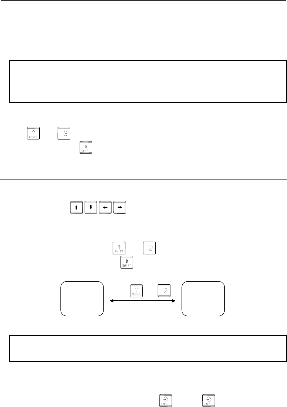
B-63943EN-2/07
7.DEBUGGING FUNCTION
- 283 -
Sequence number by which a break is caused
Number of blocks by which a break is caused
Repeat count by which a break is caused
(11) Macro variables (five variables)
The macro variables with set numbers are indicated. When P-CODE macro execution is stopped by
single-block execution or the break function, the macro variables are re-displayed automatically.
NOTE
1 The number of executed blocks is preset to 0 when the program end command
(M99<Pp>) has been executed in the main program of the P-CODE macro.
2 When no sequence number is assigned to a block in the P-CODE macro, the
sequence number of the previously executed block is indicated.
- Temporarily erasing and displaying the debugger screen
The debugger screen can be erased and displayed temporarily.
Press and . The debugger screen is erased and re-displayed alternately. (With personal
computer function, press and soft key [F3]. For details of soft key [F3], see Section 6.2, "Key
Input and Data Input Control".)
Setting from the debugger screen
When setting single-block execution and break conditions, switch the key input mode to key input from
the debugger.
Then, use cursor keys to move the cursor
to an item you want to set.
Key input switching
To perform key input switching, press and .
((With personal computer function, press and soft key [F2].)
When the key input mode has been changed, INPUT appears on the debugger screen.
INPUT on the debugger
screen disappears.
Conversational
macro input
enabled
Debugger
input enabled
Press and .
INPUT appears on the
debugger screen.
NOTE
When a P-CODE macro is stopped by single-block execution or the break
function, the key input mode switches to the debugger input automatically.
Setting a target
Set a P-CODE macro to be debugged. The P-CODE macro must be in the stopped state. If the P-CODE
macro is not stopped, set single-block execution to ON to stop the macro.
To set a target, move the cursor to the target, then press . Pressing selects the conversational
macro and auxiliary macro alternately.
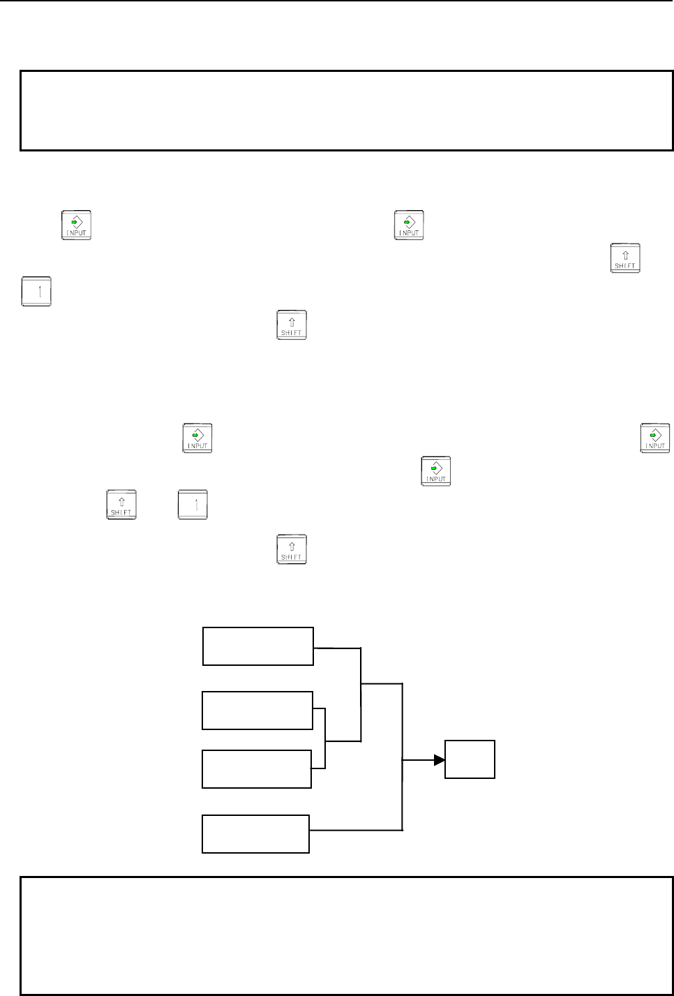
7.DEBUGGING FUNCTION
B-63943EN-2/07
- 284 -
Immediately after power is turned on, the conversational macro is initially selected. Later, the target set
with the debugger is selected.
NOTE
When switching between targets is performed, execution of the P-CODE macro
that has been set as the target so far starts. For a new target P-CODE macro,
single-block execution and the break function are enabled.
Single-block execution
Enable single-block execution (set to ON). Move the cursor to OFF in the single-block execution field.
Press to set ON. To reset the setting to OFF, press again. When the setting is changed to
ON during P-CODE macro execution, the execution stops. To re-execute the macro, press and
.
(With personal computer function, press and soft key [F1].)
Break function
P-CODE macro execution must be in the stopped state. Move the cursor to the break condition you want
to set.
Type a value, then press . Next, move the cursor to OFF in the break condition field. Press
to change the setting to ON. To reset the setting to OFF, press again. To re-execute the P-CODE
macro, press and .
(With personal computer function, press and soft key [F1].)
The relationship among break conditions is shown in the figure below. When the status of the P-CODE
macro being executed matches the break conditions, the execution of the P-CODE macro is stopped.
When 0 is set in a break condition, that condition is excluded from the break conditions.
Program No.
Sequence No.
Number of blocks
OR
Repeat count
AND Stop
AND
NOTE
1 The number of executed blocks is preset to 0 when the program end command
(M99<Pp>) has been executed in the main program of the P-CODE macro.
2 When no sequence number is assigned to a block in the P-CODE macro, the
sequence number of the previously executed block is used to make a decision
on a break.
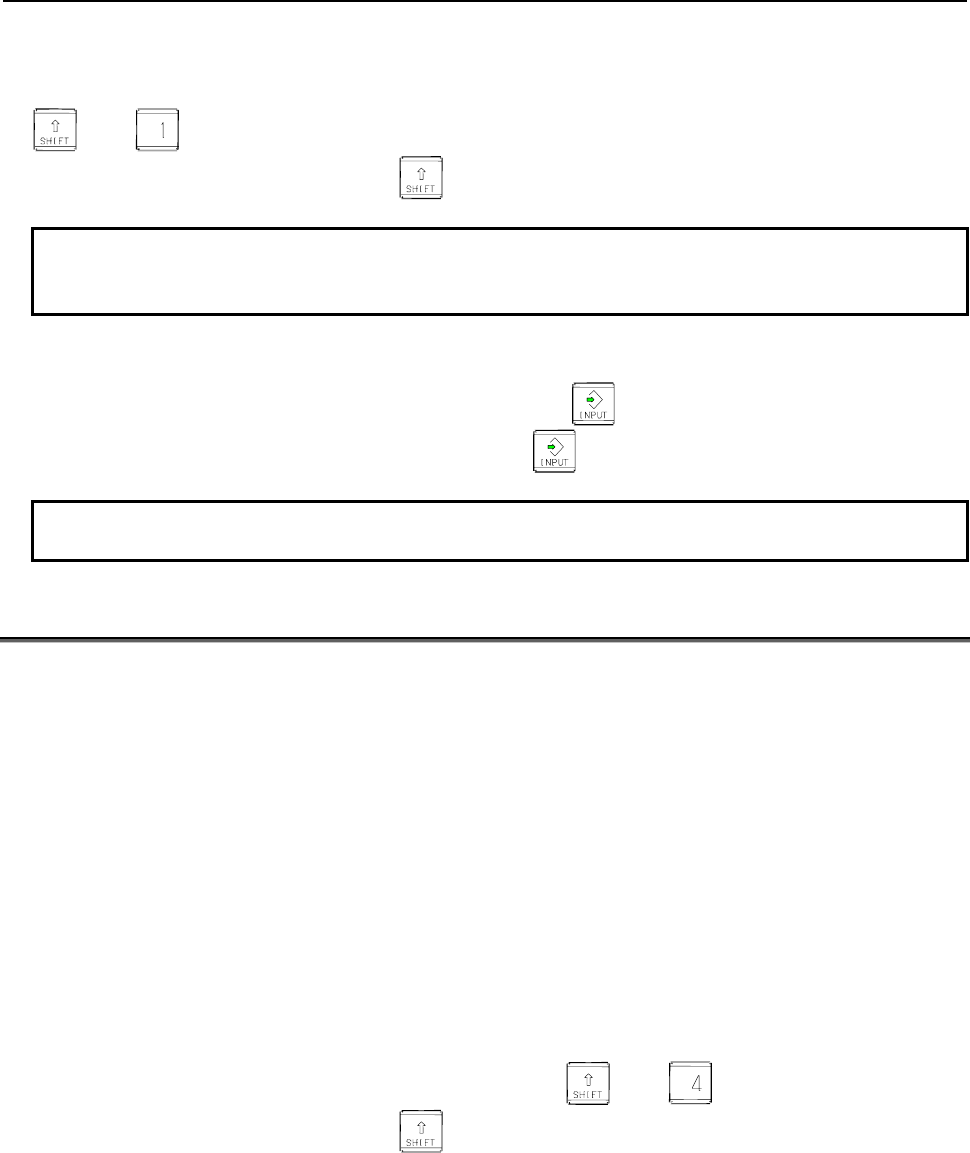
B-63943EN-2/07
7.DEBUGGING FUNCTION
- 285 -
Restarting a P-CODE macro
To restart a P-CODE macro that has been stopped by single-block execution or the break function, press
and .
(With personal computer function, press and soft key [F1].)
NOTE
When the target is a conversational macro, an execution restart automatically
causes key input to switch from the debugger to conversational macro.
Setting macro variables
Move the cursor to a number, type a new number, and press .
Move the cursor to a value, type a new value, and press .
NOTE
Input of EMPTY is not allowed.
7.3
DIRECT SETTING BY PARAMETER AND KEY
Break condition setting by parameter
If a non-zero value is set in parameter No. 9002 or 9003, break conditions are set as follows according to
the parameter setting and the break function is enabled (ON) when the conversational macro function has
been executed to start the debugger:
• Program number to cause a break : Parameter No. 9002
• Sequence number to cause a break: Parameter No. 9003
These parameters are ordinary parameters, so that these parameter can be modified, for example, through
the MDI unit.
Single-block execution by parameter
If bit 2 (STP) of parameter No. 9000 is set to 1, single-block execution is enabled (ON) when the
conversational macro function has been executed to start the debugger.
Single-block execution by key
If the debugger has been started by executing the conversational macro function, single-block execution
is enabled (ON) and disabled (OFF) alternately by pressing and .
(With personal computer function, press and soft key [F4].)
Break condition setting by key input
If the debugger has been started by executing the conversational macro function and the target P-CODE
macro is in the stopped state, break conditions can be set, and the break function can be enabled (ON) by
following the steps explained below.
(1) Type break conditions.
• For a program number (Oxxxxxxxx)
• For a sequence number (Nxxxxxxxx)
• For the number of blocks (Bxxxxxxxx)
7.DEBUGGING FUNCTION
B-63943EN-2/07
- 286 -
• For a repeat count (Lxxxxxxxx)
(2) Press and .
(With personal computer function, press and soft key [F5].)
(3) When and are pressed without inputting any break condition, the break function is
disabled (OFF).
(With personal computer function, press and soft key [F5].)
Debugging an auxiliary macro
The auxiliary macro function allows an auxiliary macro to be executed immediately after the CNC is
turned on if the program number of the auxiliary macro is set in the auxiliary macro control variable
(#8530). To debug an auxiliary macro starting with the first block, follow the steps explained below.
(1) Set bit 1 (NDP) of parameter No. 9000 to 1 to display the P-CODE macro variable screen.
(2) On the P-CODE macro variable screen, set 0 in #8530.
(3) Start the debugger, and enable single-block execution (ON).
(4) Change the target to the auxiliary macro.
(5) In #8530, set the program number of the auxiliary macro you want to execute. Then, the first block
of the auxiliary macro is executed then stopped.
7.4 DIFFERENCES FROM THE Series 16i
Function Series 16i/18i/21i Series 30i/31i/32i/35i/0i-F/PMi
Break function By parameter setting, conversational macro
program execution can be stopped at the
position of a specified program and
sequence number.
The debug function enables program
execution to be stopped by specifying a
program number, sequence number, the
number of execution blocks, or the number
of repeats.
B-63943EN-2/07
8.OPERATION
- 287 -
8 OPERATION
8.1 DISPLAYING AND SETTING MACRO VARIABLE VALUES
In addition to the custom macro variable screen, an execution macro variable screen, conversational
macro variable screen, and auxiliary macro variable screen (hereinafter collectively called the P-CODE
macro variable screen) are provided.
This screen is used to display and set the values of the variables listed below.
For details of the individual variables, see Chapter 5, "MACRO VARIABLES".
Variable number Type Remarks
#1 to 33 Local variable The local variables for the execution, conversational, and auxiliary
macro variable screens are displayed.
(The local variables of the current nest level are displayed.)
When array-type variables are effective (#8518 = 1), the conversational
and auxiliary macro variable screens display array-type variables.
#1 to 99 Array-type variable The array-type variables are displayed on the conversational and
auxiliary macro variable screens when array-type variables are
effective (#8518 = 1). (The display of array-type variables and the
display of local variables are mutually exclusive.)
#100 to 199 Volatile common
variable
The P-CODE macro common variables are displayed. Custom macro
common variables are displayed when volatile common variables are
also used as custom macro common variables using bits 0 (MV0) and
1 (MV1) of parameter No. 9034.
#500 to 999 Nonvolatile common
variable
The P-CODE macro common variables are displayed. Custom macro
common variables are displayed when nonvolatile common variables
are also used as custom macro common variables using bits 2 (MV2)
to 7 (MV7) of parameter No. 9034.
#1000 and up System variable The custom macro system variables are displayed. (The system
variables #10000 and up cannot be displayed. The system variables
#100000 and up cannot be displayed.)
#8500 to 8999 Control variable The control variables that can use execution, conversational, and
auxiliary macros are displayed. (For details, see Chapter 6, "MACRO
EXECUTOR FUNCTION".)
#10000 to 19999 P-CODE variable As many as the number determined by parameter No. 9053 are
displayed.
#20000 to 89999 Extended P-CODE
variable
As many as the number determined by parameter No. 9054 are
displayed.
NOTE
The display of local variables of custom macro and execution macro on the
macro variable screen can be switched as follows according to bit3 (LVD) of
parameter No.24306.
- In case of bit3 (LVD) of parameter No.24306 is 0.
Local variables of custom macro and execution macro display common value.
- In case of bit3 (LVD) of parameter No.24306 is 1.
Local variables of custom macro and execution macro display separate
value. (FS16i compatible specification)
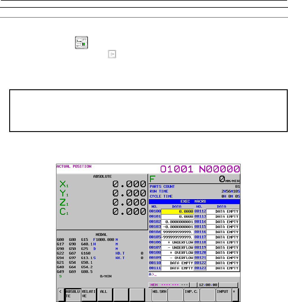
8.OPERATION
B-63943EN-2/07
- 288 -
Displaying macro variable values
Display the P-CODE macro variable screen by following the procedure described below.
(1) Press function key .
(2) Press the continuous menu key several times until soft key [MACRO] is displayed.
(3) Press soft key [MACRO].
(4) Press soft key [EXEC MACRO] to display the execution macro variable screen.
Press soft key [CONV. MACRO] to display the conversational macro variable screen.
Press soft key [AUX MACRO] to display the auxiliary macro variable screen.
NOTE
1 This screen is displayed by setting 1 in bit 1 (NDP) of parameter No. 9000.
2 The execution, conversational, and auxiliary macro variable screens are
displayed only when the corresponding P-CODE macros set in parameters Nos.
9048 to 9050 are effective.
P-CODE macro variable screen
The macro variable numbers and values are displayed.
Execution macro variable screen
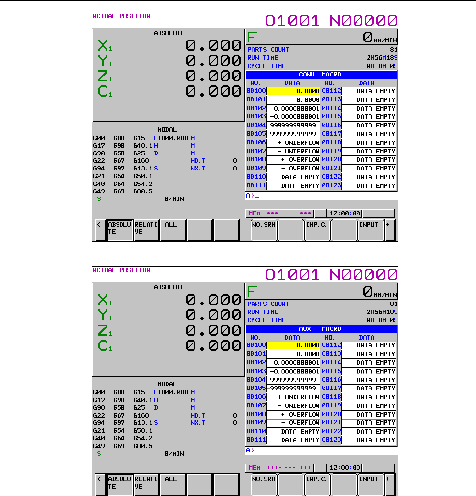
B-63943EN-2/07
8.OPERATION
- 289 -
Conversational macro variable screen
Auxiliary macro variable screen
Macro variable name screen (#500 to #549)
When common variables #500 to #549 are also used as custom macro common variables by setting bit 2
(MV2) of parameter No. 9034, the variable names of #500 to #549 can be displayed.
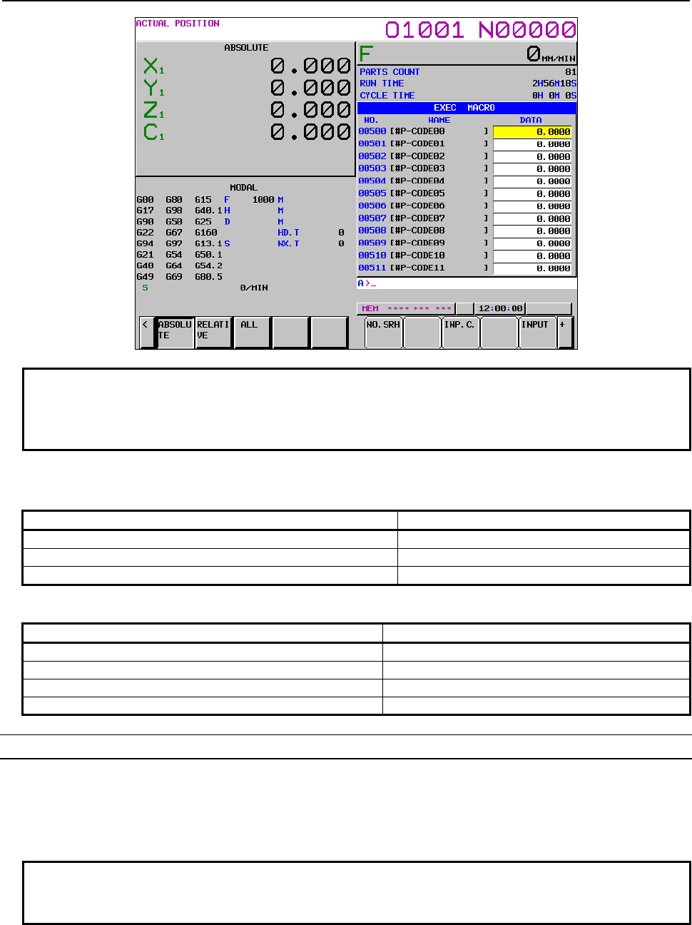
8.OPERATION
B-63943EN-2/07
- 290 -
NOTE
Variable names are displayed only when bit 2 (MV2) of parameter No. 9034 is set
to use custom common variables as P-CODE macro common variables as well
and bit 5 (VRN) of parameter No. 3207 is set to display variable names.
Variable values
Depending on the condition, variable values are displayed as follows.
Condition Variable value display
When the macro variable value is empty "DATA EMPTY" is displayed.
When the macro variable is write enabled The field is displayed in yellow reverse video.
When the macro variable is read protected or unusable The field is blank.
If the operation results in a variable value that cannot be displayed, the following is displayed.
Variable value range Variable value display
0 < Variable value < +0.00000000001 + Underflow
-0.00000000001 < Variable value < 0 - Underflow
999999999999 < Variable value + Overflow
Variable value < -999999999999 - Overflow
Setting a variable value
The macro variables whose values can be set are only write-enabled macro variables.
Mode setting
Set the MDI mode.
NOTE
The mode restriction can be disabled by using bit 6 (MCM) of parameter No.
3290.
Cursor movement
Move the cursor to the macro variable whose value is to be set.
Method 1
B-63943EN-2/07
8.OPERATION
- 291 -
Move the cursor by pressing page keys and/or and cursor keys , , ,
and/or .
Method 2
(1) Enter the number of the macro variable.
(2) Press soft key [NO.SRH].
Counter input (C input)
(1) Move the cursor to the macro variable whose value is to be set.
(2) Enter the relative coordinate axis name.
(3) Press soft key [INP.C.].
"EMPTY" input
(1) Move the cursor to the macro variable for which "DATA EMPTY" is to be displayed.
(2) Press soft key [INPUT].
Write protection for P-CODE macro common variables
By setting variable numbers in parameters Nos. 9067 to 9068, it is possible to write-protect multiple
P-CODE macro common variables (#500 to #999) or, in other words, make them read only. This
protection is effective for both the input and all clear operations from the P-CODE macro variable screen
using the MDI and write operations using macro programs. If a macro program specifies WRITE (used on
the left side) for any common variable within the set range, alarm PS0116 occurs.
Inputting and outputting variable values
The values of the macro variables listed below can be output to an external input/output device.
They can also be input from an external input/output device.
Variable number Type Remarks
#100 to 199 Volatile common
variable
Either P-CODE macros or custom macros are output based on the
setting of bits 0 (MV0) and 1 (MV1) of parameter No. 9034.
#500 to 999 Nonvolatile common
variable
Either P-CODE macros or custom macros are output based on the
setting of bits 2 (MV2) to 7 (MV7) of parameter No. 9034.
#10000 to 19999 P-CODE variable As many as the number determined by parameter No. 9053 are output.
#20000 to 89999 Extended P-CODE
variable
As many as the number determined by parameter No. 9054 are output.
Variable value output
The macro variables registered in CNC memory are output to an external input/output device.
- Mode setting
Set the EDIT mode.
NOTE
During an emergency stop, the macro variables can be output regardless of the
mode.
- Output procedure
Press soft key [(OPRT)].
Press the continuous menu key several times until soft key [PUNCH] is displayed.

8.OPERATION
B-63943EN-2/07
- 292 -
Method 1 (when the output file name is not specified)
(1) Press soft key [PUNCH].
(2) Press soft key [EXEC].
NOTE
When the output file name is not specified, the default file name "PCODE.TXT"
is assumed.
Method 2 (when the output file name is specified - 1)
(1) Press soft key [PUNCH].
(2) Enter the file name.
(3) Press soft key [EXEC].
Method 3 (when the output file name is specified - 2)
(1) Enter the file name.
(2) Press soft key [PUNCH].
(3) Press soft key [EXEC].
Pressing soft key [EXEC] outputs the macro variable data, during which the word "OUTPUT" blinks at
the lower right corner of the screen. When the punch operation is complete, the word "OUTPUT"
disappears.
- Output format
Variable value output format
A macro variable value is output in hexadecimal notation using a bit image of double-precision
floating-point data.
Therefore, the values of the data cannot be checked directly.
Variable value comment output
When 1 is set in bit 0 (MCO) of parameter No. 6019, the macro variable number and variable data value
are output as a comment after % in the output data. This allows the data value to be checked directly. The
output data is a comment, which is ignored at the time of input.
The output data range is nine digits before the decimal point and eight digits after the decimal point. If
there are ten or more digits before the decimal point, "±OVER FLOW" is output. If there are nine or more
digits after the decimal point, the decimal part is rounded off at the ninth digit when output. Also, since
the maximum total output length is 15 digits, if the output data is 16 digits or longer, it is rounded off at
the 16th digit. Note that, because the maximum output length before the decimal point is nine digits, if
there are ten or more digits before the decimal point, "±OVER FLOW" is output.
When "Data (empty)" is displayed in the "Value" field, "EMPTY" is output.
B-63943EN-2/07
8.OPERATION
- 293 -
Output example
Example if bit 2 (MV2) of parameter No. 9034 is set to 1 (variables #500 to
#549 are also used as custom macro common variables)
%
G10L86P100(0000000000000000) ……… When the value is 0
G10L86P101(FFFFFFFFFFFFFFFF) …… When the value is <null>
G10L86P102(C18FCA0555555555) …… When the value is normal
:
G10L85P501(41CDCD6500000000)
G10L85P502(0000000000000000)
:
G10L86P550(0000000000000000)
:
G10L86P999(0000000000000000)
G10L86P10000(0000000000000000)
:
G10L86P89999(40F5F8F000000000)
SETVN500[P-CODE00] …………………………… Variable name
SETVN501[P-CODE01]
SETVN502[P-CODE02]
:
M02
% ………………………………………………… End of the data section
--------------------
P100(0.0)
P101(EMPTY)
P102(-66666666.6666667)
:
P501(+OVER FLOW)
P502(0.0)
:
P550(0.0)
:
P999(0.0)
P10000(0.0)
:
P89999(89999.0)
%
Custom macro variable (L85)
Comment
P-CODE macro variable /
P-CODEvariable(L86)
P-CODE macro variable (L86)
NOTE
1 Variable names (SETVN500[.......] to 549[.......]) are output only when the
variables are also used as custom macro common variables by using bit 2 (MV2)
of parameter No. 9034.
2 The comment section after M02% is output only when 1 is set in bit 0 (MCO) of
parameter No. 6019.
8.OPERATION
B-63943EN-2/07
- 294 -
The G10L number has the following meanings.
G10L number Meaning Remarks
L85 Custom macro data
- Volatile common variable
- Nonvolatile common variable
When common variables are also used
as custom macro common variables by
using bits 0 to 7 (MV0 to MV7) of
parameter No. 9034
L86 P-CODE data
- Volatile common variable
- Nonvolatile common variable
- P-CODE variable
- Extended P-CODE variable
When common variables are set as
independent P-CODE macro common
variables by using bits 0 to 7 (MV0 to
MV7) of parameter No. 9034
Variable value input
The macro variables registered in an external input/output device are input to CNC memory.
- Mode setting
Set the EDIT mode.
NOTE
During an emergency stop, the macro variables can be input regardless of the
mode.
- Input procedure
Press soft key [(OPRT)].
Press the continuous menu key several times until soft key [READ] is displayed.
Method 1 (when the input file name is not specified)
(1) Press soft key [READ].
(2) Press soft key [EXEC].
NOTE
When the input file name is not specified, the default file name "PCODE.TXT" is
assumed.
Method 2 (when the input file name is specified - 1)
(1) Press soft key [READ].
(2) Enter the file name.
(3) Press soft key [EXEC].
Method 3 (when the input file name is specified - 2)
(1) Enter the file name.
(2) Press soft key [READ].
(3) Press soft key [EXEC].
Pressing soft key [EXEC] inputs the macro variable data, during which the word "INPUT" blinks at the
lower right corner of the screen. When the read operation is complete, the word "INPUT" disappears.
- Input format
The input format is the same as the output format. (For details, see the output format.)

B-63943EN-2/07
8.OPERATION
- 295 -
NOTE
1 If the input format is invalid, an SR alarm occurs and the data input is
interrupted.
2 A different alarm is issued depending on the content of the input data.
- If a G code other than G10 or an L code other than L85 or L86 is specified
SR0114 “ILLEGAL EXPRESSION FORMAT”
- If an address other than the G, L, or P code is specified
SR1300 “ILLEGAL ADDRESS”
- If the line begins with a character other than an address character
SR1301 “MISSING ADDRESS”
- If the specified P code is P200 to P499 or P1000 to P9999
SR1302 “ILLEGAL DATA NUMBER”
- If the setting of bits 0 to 7 (MV0 to MV7) of parameter No. 9034 does not
match the L code specification
SR2050 “#200-#999ILLEGAL P-CODE MACRO COMMON INPUT (NO
OPTION)“
- If more variable numbers than the number determined by parameter No.
9053 are specified when the specified P code is P10000 to P19999
SR2053 “P-CODE VARIABLE NUMBER IS OUTSIDE OF RANGE”
- If more variable numbers than the number determined by parameter No.
9054 are specified when the specified P code is P20000 to P89999
SR2054 “EXTENDED P-CODE VARIABLE NUMBER IS OUTSIDE OF
RANGE”
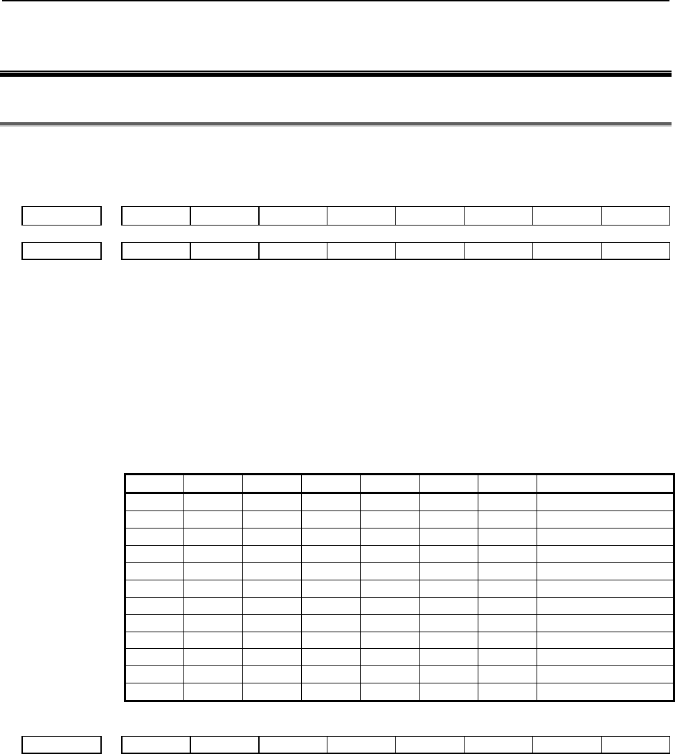
9.PARAMETERS
B-63943EN-2/07
- 296 -
9 PARAMETERS
9.1 COMPILE PARAMETERS
When the power is turned on, the compile parameters are initialized to the values set in P-CODE variables.
So, these parameters cannot be modified, for example, from the MDI panel and so on.
#7 #6 #5 #4 #3 #2 #1 #0
9000 M3MB M2MB M1MB M512 M256 M128
9001 M4MB
[Data type] Bit
Select a P-CODE file capacity.
No.9000
# 1 M128
# 2 M256
# 3 M512
# 4 M1MB
# 5 M2MB
# 6 M3MB
No.9001 # 2 M4MB
M4MB M3MB M2MB M1MB M512 M256 M128 P-CODE file size
0 0 0 0 0 0 1 128Kbyte
0 0 0 0 0 1 0 256Kbyte
0 0 0 0 0 1 1 384Kbyte
0 0 0 0 1 0 0 512Kbyte
0 0 0 0 1 0 1 640Kbyte
0 0 0 0 1 1 0 768Kbyte
0 0 0 0 1 1 1 896Kbyte
0 0 0 1 0 0 0 1Mbyte
0 0 0 1 1 0 0 1.5Mbyte
0 0 1 0 0 0 0 2Mbyte
0 1 0 0 0 0 0 3Mbyte
1 0 0 0 0 0 0 4Mbyte
#7 #6 #5 #4 #3 #2 #1 #0
9002 EXT1 PWSR DAUX ACL2 ACL1 TCAL
[Data type] Bit
#0 TCAL Subprogram call using a T code is:
0: Disabled.
1: Enabled.
#1 ACL1 Subprogram call using a specific code (O9004/#146) is:
0: Disabled.
1: Enabled.
B-63943EN-2/07
9.PARAMETERS
- 297 -
#2 ACL2 Subprogram call using a specific code (O9005/#147) is:
0: Disabled.
1: Enabled.
#5 DAUX When the power is turned on, the conversational macro function is:
0: Not executed.
1: Executed.
NOTE
When the display demands other than the conversational macro
screen have been generated when the power is turned on, the
conversational macro function might not be executed.
Example:
It is given priority to display alarm screen when the alarm is
generated when the power is turned on. As a result, the
conversational macro function might not be executed.
#6 PWSR P-CODE workpiece number search is:
0: Disabled.
1: Enabled.
#7 EXT1 The extended functions (CNC program reference/write, cutting distance accumulation/
preset, and reader/puncher interface control) are:
0: Disabled.
1: Enabled.
#7 #6 #5 #4 #3 #2 #1 #0
9003 PTCH KY20 GPNT * ONMSK
[Data type] Bit
#0 ONMSK On the conversational macro screen, O and N numbers are:
0: Displayed.
1: Not displayed.
#2 *
NOTE
For 7.2" and 8.4" LCD units, be sure to set this parameter to 1.
#3 GPNT When a color other than black is to be specified as boundary color with the graphic filling
function (G206):
0: P8 is used for specification.
1: P16 is used for specification.
NOTE
When this parameter is set to 0, color palette 8 is used as
boundary color, and cannot be used for filling. When using color
palette 8 for filling, set this parameter to 1.
#5 KY20 For a key-input variable allowing decimal point input, #8501 is:
0: Not incremented by α.
1: Incremented by α.
α: +20 for a display unit with 7 soft keys
9.PARAMETERS
B-63943EN-2/07
- 298 -
+40 for a display unit with 12 soft keys
Example
Example where this parameter is set to 1 for an indicator with 7 soft
keys:
For <1> and , #8503=1.0, #8501=8
For <1.> and , #8503=1.0, #8501=28
Thus, whether the decimal point is entered can be identified.
NOTE
When using a system with vertical soft keys, use bit 1 (KY100) of
compile parameter No. 9160.
#6 PTCH In macro variable output (G338), an EOB is output as:
0: LF.
1: LF CR CR.
#7 #6 #5 #4 #3 #2 #1 #0
9004 CUTLG SP_G_C SP_G_B
[Data type] Bit
#0 SP_G_B
#1 SP_G_C For lathe systems, specify the G code system, A, B, or C, used to create the P-CODE
programs.
SP_G_C SP_G_B G code system used in P-CODE programs
0 0 G code system A
0 1 G code system B
1 0 G code system C
1 1
#7 CUTLG Cutting distance accumulation/preset (#8554) is:
0: Disabled.
1: Enabled.
#7 #6 #5 #4 #3 #2 #1 #0
9005 AX4CL AX3CL AX2CL AX1CL
9008 AX8CL AX7CL AX6CL AX5CL
9164 X16CL X15CL X14CL X13CL X12CL X11CL X10CL X09CL
9165 X24CL X23CL X22CL X21CL X20CL X19CL X18CL X17CL
[Data type] Bit
Special macro call using an axis address is:
0: Disabled.
1: Enabled.
B-63943EN-2/07
9.PARAMETERS
- 299 -
Select a control axis number within the path, using a bit:
No. 9005 #0 AX1CL 1st axis
#1 AX2CL 2nd axis
#2 AX3CL 3rd axis
#3 AX4CL 4th axis
No. 9008 #0 AX5CL 5th axis
#1 AX6CL 6th axis
#2 AX7CL 7th axis
#3 AX8CL 8th axis
No. 9164 #0 X09CL 9th axis
#1 X10CL 10th axis
:
#7 X16CL 16th axis
No. 9165 #0 X17CL 17th axis
#1 X18CL 18th axis
:
#7 X24CL 24th axis
#7 #6 #5 #4 #3 #2 #1 #0
9005 TMACC AXCLS
[Data type] Bit
#4 AXCLS In macro call using an axis address:
0: O9009 is called at all times as an execution macro.
1: A different execution macro is called for each axis.
1st axis → O9031 is called.
2nd axis → O9032 is called.
:
n-th axis → O9030+n is called.
#7 TMACC Special macro call using a T code is:
0: Disabled.
1: Enabled.
#7 #6 #5 #4 #3 #2 #1 #0
9006 NNUM US19W STDM KEYC
[Data type] Bit
#1 KEYC With the CNC program reference/write function, the memory protection signal (KEY3)
and 8-level data protection function are:
0: Checked.
(When protection is provided, completion code #8529=254.)
1: Not checked.
#2 STDM On the conversational macro screen, state display (mode and status display) is:
0: Not masked.
1: Masked.
9.PARAMETERS
B-63943EN-2/07
- 300 -
#5 US19W For the 12-soft key type, conversational macro user screen 1 is:
0: Not displayed as the 7-soft key type.
1: Displayed as the 7-soft key type.
#6 NNUM When data input control is enabled on the conversational macro screen, the "NUM"
prompt is:
0: Displayed.
1: Not displayed.
#7 #6 #5 #4 #3 #2 #1 #0
9007 US19WK TTDSP
[Data type] Bit
#0 TTDSP The common conversational macro functions are:
0: Not used.
1: Used.
Setting this parameter to 1 causes the conversational macro functions for path 1 to be
executed regardless of what path is selected with the path select signal and what the
parameter No.9049 setting is. (In this case, the O/N and status displays, the variables used,
and all the macro executor functions usable with conversational macros are the same as
for path 1.)
#3 US19WK When the 7-soft key type display is specified for the 12-soft key type bit 5 (US19W) of
compile parameter No. 9006 = 1), the position for displaying the key input line is:
0: Not changed.
1: Changed to within the display area for the 7-soft key type.
#7 #6 #5 #4 #3 #2 #1 #0
9008 MCARG MDLP
[Data type] Bit
#4 MDLP A cancel G code (G167 or a G code specified using compile parameter No. 9034) for G
code-based modal calls calls:
0: Nothing (only a modal call is canceled).
1: O9006 (a modal call is canceled and O9006 is called).
NOTE
This parameter is valid only when the Series 16i method (bit 0
(GMC) of compile parameter No. 9163 = 1) is used for modal calls.
(If bit 0 (GMC) of compile parameter No. 9163 = 0, G67 cancels
modal calls but does not call O9006 regardless of what the setting of
this compile parameter is.)
#5 MCARG In a G/M code macro call, P, L, and G are:
0: Not used as arguments.
1: Used as arguments.
When this parameter is set to 1, the argument correspondence is: G#10, L#12, P#16.
B-63943EN-2/07
9.PARAMETERS
- 301 -
NOTE
Input format restrictions regarding NC commands are placed on
address G. For example, specifying G1000 results in alarm
PS0010 being issued. If there are two or more G codes, only the
last G code will be an argument. O, N, and non-00 group G codes
are passed as modal information to the next block.
#7 #6 #5 #4 #3 #2 #1 #0
9009 MSCL CM30
[Data type] Bit
#2 CM30 On the conversational macro screen, all lines are:
0: Not used.
(For an indicator with 12 soft keys, 25 out of the 30 lines are used. For an indicator
with 7 soft keys, 16 out of the 19 lines are used.)
1: Used.
#3 MSCL A subprogram call based on a range-specified M code specified using compile parameters
Nos. 9042 and 9043 is regarded as:
0: An ordinary subprogram call
1: A special macro call
9010 M code for calling program number 9001 as a subprogram
9011 M code for calling program number 9002 as a subprogram
9012 M code for calling program number 9003 as a subprogram
[Data type] Integer
[Valid data range] 1 to 99999999
Set an M code for calling each of program numbers 9001 to 9003 as a subprogram.
9013 G code for calling program number 9010 as a macro
9014 G code for calling program number 9011 as a macro
9015 G code for calling program number 9012 as a macro
9016 G code for calling program number 9013 as a macro
9017 G code for calling program number 9014 as a macro
9018 G code for calling program number 9015 as a macro
9019 G code for calling program number 9016 as a macro
9020 G code for calling program number 9017 as a macro
9021 G code for calling program number 9018 as a macro
9022 G code for calling program number 9019 as a macro
[Data type] Integer
9.PARAMETERS
B-63943EN-2/07
- 302 -
[Valid data range] -9999 to 9999
Set a G code for calling each of program numbers 9010 to 9019 as a macro.
(When a negative value is set, modal call is performed.)
If this parameter is set to 9999, “G0” as well as "G9999" can call O9010 to O9019, using
macros. (If the parameter is set to -9999, “G0” as well as "G9999" can make macro modal
calls.)
9023 M code for calling program number 9020 as a macro
9024 M code for calling program number 9021 as a macro
9025 M code for calling program number 9022 as a macro
9026 M code for calling program number 9023 as a macro
9027 M code for calling program number 9024 as a macro
9028 M code for calling program number 9025 as a macro
9029 M code for calling program number 9026 as a macro
9030 M code for calling program number 9027 as a macro
9031 M code for calling program number 9028 as a macro
9032 M code for calling program number 9029 as a macro
[Data type] Integer
[Valid data range] 1 to 99999999
Set a M code for calling each of program numbers 9020 to 9029 as a macro.
9033 M code for calling a user program as a subprogram
[Data type] Integer
[Valid data range] 1 to 99999999 (except 02, 30, 98, and 99)
Set an M code for calling a user program as a subprogram.
9034 G code for canceling G code-based modal calls
[Data type] Integer
[Valid data range] 1 to 9999
Specify a G code for canceling G code-based modal calls. If 0 is specified, G167 is used
as a cancel G code.
NOTE
This parameter is valid only when the Series 16i method (bit 0
(GMC) of compile parameter No. 9163 = 1) is used for modal calls.
(If bit 0 (GMC) of compile parameter No. 9163 = 0, G67 cancels
modal calls regardless of what the setting of this compile parameter
is.)
B-63943EN-2/07
9.PARAMETERS
- 303 -
9038 Conversational macro main program number (for user screen 1)
9040 Conversational macro main program number (for user screen 2)
9041 Conversational macro main program number (for user screen 3)
[Data type] Integer
[Valid data range] 1 to 99999999
Set the main program number of a conversational macro.
NOTE
The program number specified in each parameter is set in the
corresponding conversational macro execution control variable
when the power is turned on.
9039 Auxiliary macro main program number
[Data type] Integer
[Valid data range] 1 to 99999999
Set the main program number of an auxiliary macro.
NOTE
The program number specified in this parameter is set in the
auxiliary macro execution control variable when the power is turned
on.
9042 Code for subprogram call using a range specification M code (lower limit)
9043 Code for subprogram call using a range specification M code (upper limit)
[Data type] Integer
[Valid data range] 1 to 99999999
Set a range of codes for subprogram call using a range specification M code.
NOTE
1 If a value not within the specifiable range is set, or a specified
range is such that No. 9042 > No. 9043, subprogram call using a
range specification M code is disabled.
2 An M code used for macro call/subprogram call is not used as a
calling code even when the M code is within the setting range.
9111 Start M code of subprogram call using an M code (specification of 3 sets) (1st set)
9112 Count of subprogram call using an M code (specification of 3 sets) (1st set)
9113 Start program number of subprogram call using an M code (specification of 3 sets) (1st set)
9114 Start M code of subprogram call using an M code (specification of 3 sets) (2nd set)
9115 Count of subprogram call using an M code (specification of 3 sets) (2nd set)
9.PARAMETERS
B-63943EN-2/07
- 304 -
9116 Start program number of subprogram call using an M code (specification of 3 sets) (2nd set)
9117 Start M code of subprogram call using an M code (specification of 3 sets) (3rd set)
9118 Count of subprogram call using an M code (specification of 3 sets) (3rd set)
9119 Start program number of subprogram call using an M code (specification of 3 sets) (3rd set)
9120 Start M code of macro call using an M code (specification of 3 sets) (1st set)
9121 Count of macro call using an M code (specification of 3 sets) (1st set)
9122 Start program number of macro call using an M code (specification of 3 sets) (1st set)
9123 Start M code of macro call using an M code (specification of 3 sets) (2nd set)
9124 Count of macro call using an M code (specification of 3 sets) (2nd set)
9125 Start program number of macro call using an M code (specification of 3 sets) (2nd set)
9126 Start M code of macro call using an M code (specification of 3 sets) (3rd set)
9127 Count of macro call using an M code (specification of 3 sets) (3rd set)
9128 Start program number of macro call using an M code (specification of 3 sets) (3rd set)
[Data type] Integer
[Valid data range] Start M code
(Nos. 9111, 9114, 9117, 9120, 9123, and 9126) : 1 to 99999999
Count
(Nos. 9112, 9115, 9118, 9121, 9124, and 9127) : 1 and up
The upper limit depends on the start M code and start program number.
Start program number
(Nos. 9113, 9116, 9119, 9122, 9125, and 9128) : 1 to 99999999
NOTE
1 In the following cases, this call is disabled:
(1) In a compile parameter, a value not within the range is set.
(2) A defined M code range (start M code number + count) exceeds
99999999.
(3) A defined program number range (start program number +
count) exceeds 99999999.
2 An M code used for macro/subprogram call, even when included in
the setting range, is not used as an instruction for this subprogram
call.
B-63943EN-2/07
9.PARAMETERS
- 305 -
NOTE
3 If duplicate M codes are set, the M codes are valid according to the
priority order below.
(1) Macro call using an M code
(Compile parameters Nos. 9023 to 9032)
(2) Subprogram call using an M code
(Compile parameters Nos. 9010 to 9012)
(3) Subprogram call using a range specification M code
(Compile parameters Nos. 9042 and 9043)
(4) Subprogram call using an M code (specification of 3 sets)
(Compile parameters Nos. 9111 to 9113, 9114 to 9116, and
9117 to 9119)
9045 Start G code of macro call using an G code (specification of 1 set)
9046 Count of macro call using an G code (specification of 1 set)
9047 Start program number of macro call using an G code (specification of 1 set)
9129 Start G code of macro call using an G code (specification of 3 sets) (1st set)
9130 Count of macro call using an G code (specification of 3 sets) (1st set)
9131 Start program number of macro call using an G code (specification of 3 sets) (1st set)
9132 Start G code of macro call using an G code (specification of 3 sets) (2nd set)
9133 Count of macro call using an G code (specification of 3 sets) (2nd set)
9134 Start program number of macro call using an G code (specification of 3 sets) (2nd set)
9135 Start G code of macro call using an G code (specification of 3 sets) (3rd set)
9136 Count of macro call using an G code (specification of 3 sets) (3rd set)
9137 Start program number of macro call using an G code (specification of 3 sets) (3rd set)
[Data type] Integer
[Valid data range] Start G code
(parameters Nos. 9045, 9129, 9132, and 9135) : -9999 to 9999 (except 0)
Count (parameters Nos. 9046, 9130, 9133, and 9136) : 1 to 9999
Start program number (parameters Nos. 9047, 9131, 9134, and 9137) :
1 to 99999999
If a negative value is set as a start G code number (parameters Nos. 9045, 9129, 9132,
and 9135), modal call results. Use bit 1 (MCT) of parameter No. 9163 for setting of move
command call (G66)/call of each block (G66.1).

9.PARAMETERS
B-63943EN-2/07
- 306 -
NOTE
1 In the following cases, this call is disabled:
(1) In a compile parameter, a value not within the range is set.
(2) A defined G code range (start G code number + count) exceeds
9999.
(3) A defined program number range (start program number +
count) exceeds 99999999.
2 A G code used for macro call, even when included in the setting
range, is not used as an instruction for this macro call.
3 If duplicate G codes are set, the G codes are valid according to the
priority order below.
Three types of macro call using G codes are available as indicated
below. If the range of G codes set in <1> duplicates the ranges of
G codes set in <2> or <3>, the G code priority order is, from high to
low, <1> to <2> to <3>.
(1) Individual specification :
Compile parameters Nos. 9013 to 9022
(2) Specification of 1 sets :
Compile parameters Nos. 9045 to 9047
(3) Specification of 3 sets :
Compile parameters Nos. 9129 to 9131, 9132 to 9134, and
9135 to 9137
9048 Graphic coordinate system shift amount (X-axis)
9049 Graphic coordinate system shift amount (Y-axis)
[Data type] Integer
[Unit of data] dot
[Valid data range] -320 to 319
Set a graphic coordinate system shift amount.
9050 Program number to add the item to the help (initial menu) screen
[Data type] Integer
[Valid data range] 1 to 99999999
For the user help screen control function, set a program number to add the item to the
help (initial menu) screen.
9051 User help screen program number
[Data type] Integer
[Valid data range] 1 to 99999999
Set the main program number for the user help screen.
NOTE
Each time switching occurs from the help (initial menu) screen or
NC screen to the user help screen, #8555 is initialized with a
program number specified with the compile parameter No. 9051
and executed as the main program for the user help screen.
B-63943EN-2/07
9.PARAMETERS
- 307 -
9054 Free space when the program write/delete function is executed
[Data type] Integer
[Unit of data] Page (500byte/page)
[Valid data range] 0 to
If the number of free pages in the program memory becomes the number of pages set in
this parameter or less, the functions for program insertion (G320), block writing (G326,
G329), and block deletion (G327) are not executed. (Completion code #8529=203)
9056 Time-out period for waiting for transmission/reception
[Data type] Integer
[Unit of data] sec
[Valid data range] 0 to 180
Set a time-out period to be applied when the transmission/reception function (G335 to
G338) for reader/puncher interface control waits for transmission/reception.
No time-out occurs when 0 is set.
#7 #6 #5 #4 #3 #2 #1 #0
9100 MSFT C9WN DLMT VKLN VGAR
[Data type] Bit
#0 VGAR When the display command with background color (G250) is specified:
0: Display with background color is disabled.
1: Display with background color is enabled.
#4 VKLN In background color display, background display for the key input line is:
0: Not provided.
1: Provided.
#5 DLMT The area of display with background color is:
0: Not limited to the data area.
1: Limited to the data area.
NOTE
1 Please set 0 usually.
2 The setting DLMT=1 is effective for 10.4" display device. The range
of the display is as follows.
DLMT=0: X is 0 to 79 and Y is 0 to 29
DLMT=1: X is 0 to 79 and Y is 2 to 24 (Upper 2 rows and Lower 5
rows are ignored)
#6 C9WN When the 7-soft key type display is selected for the 12-soft key type (bit 5 (US19W) of
compile parameter No. 9006 = 1), the character display coordinates are:
0: Not adjusted as the 7-soft key window display (the same coordinates as for the
12-soft key type display).
1: Adjusted as the 7-soft key window display.
NOTE
This parameter is valid only for screens with a background (bit 0
(VAGR) of compile parameter No. 9100 = 1).
9.PARAMETERS
B-63943EN-2/07
- 308 -
#7 MSFT When no background color is specified (bit 0 (VGAR) of compile parameter No.9100 =
0), the conversational macro screen:
0: Displays a soft key frame.
1: Does not display a soft key frame.
#7 #6 #5 #4 #3 #2 #1 #0
9103 EXMSCL PRDGCAL
[Data type] Bit
#1 PRDGCAL G code macro call with decimal point is:
0: Disabled.
1: Enabled.
#4 EXMSCL Up to 3 macro calls based on M codes specified with compile parameters Nos. 9120 to
9128 and up to 3 subprogram calls based on M codes specified with compile parameters
Nos. 9111 to 9119 are made as:
0: Ordinary macro or subprogram calls.
1: Special macro calls.
#7 #6 #5 #4 #3 #2 #1 #0
9104 GMACC SMACC HMACC DMACC
[Data type] Bit
#0 DMACC Special macro call using a D code is:
0: Disabled.
1: Enabled.
#1 HMACC Special macro call using an H code is:
0: Disabled.
1: Enabled.
#2 SMACC S code-based macro or subprogram calls are made as:
0: Ordinary macro or subprogram calls.
1: Special macro calls.
#5 GMACC G code-based macro calls are made as:
0: Ordinary macro calls.
1: Special macro calls.
#7 #6 #5 #4 #3 #2 #1 #0
9105 BSC SSC
[Data type] Bit
#0 SSC Subprogram call using an S code is:
0: Disabled.
1: Enabled.
#1 BSC Subprogram call using a second auxiliary function code is:
0: Disabled.
1: Enabled.
B-63943EN-2/07
9.PARAMETERS
- 309 -
#7 #6 #5 #4 #3 #2 #1 #0
9160 PMX16 PG1O TDVDPI EXST TM99 PRDPI KY100 CUNIT
[Data type] Bit
#0 CUNIT The unit of a cumulative cutting distance value (#8554) is:
0: Integer value.
1: Real value.
NOTE
The cutting distance 1.0 mm on a machine with the reference axis
based on IS-B/metric input depends on the setting of this
parameter as follows:
0: #8554=1000
1: #8554=1.0
#1 KY100 For a key-input variable allowing decimal point input, #8501 is:
0: Not incremented by 100.
1: Incremented by 100.
NOTE
Example where this parameter is set to 1 for an indicator with 7 soft
keys:
For <1> and , #8503=1.0, #8501=8
For <1.> and , #8503=1.0, #8501=108
Thus, whether the decimal point is entered can be identified.
#2 PRDPI For the word-type specified-block read (G325) of the CNC program reference function,
the decimal places of the value read:
0: Follow the setting of bit 0 (DPI) of parameter No. 3401.
1: Are always of a calculator type decimal point input.
NOTE
If this parameter is 1, the behavior is equivalent to that of the
Series 16i.
#3 TM99 A check to see if a cause to end conversational macro function execution has occurred is
made when:
0: The execution of the current block ends.
If the cause is found, screen switching occurs immediately, before the program end
instruction (execution control code M99/M99Pp) in the main program is executed.
1: The program end instruction (execution control code M99/M99Pp) in the
conversational macro main program is executed.
If the cause is found, screen switching occurs after the program end instruction
(execution control code M99/M99Pp) in the main program is executed.
NOTE
If this parameter is 1, the behavior is equivalent to that of the
Series 16i.
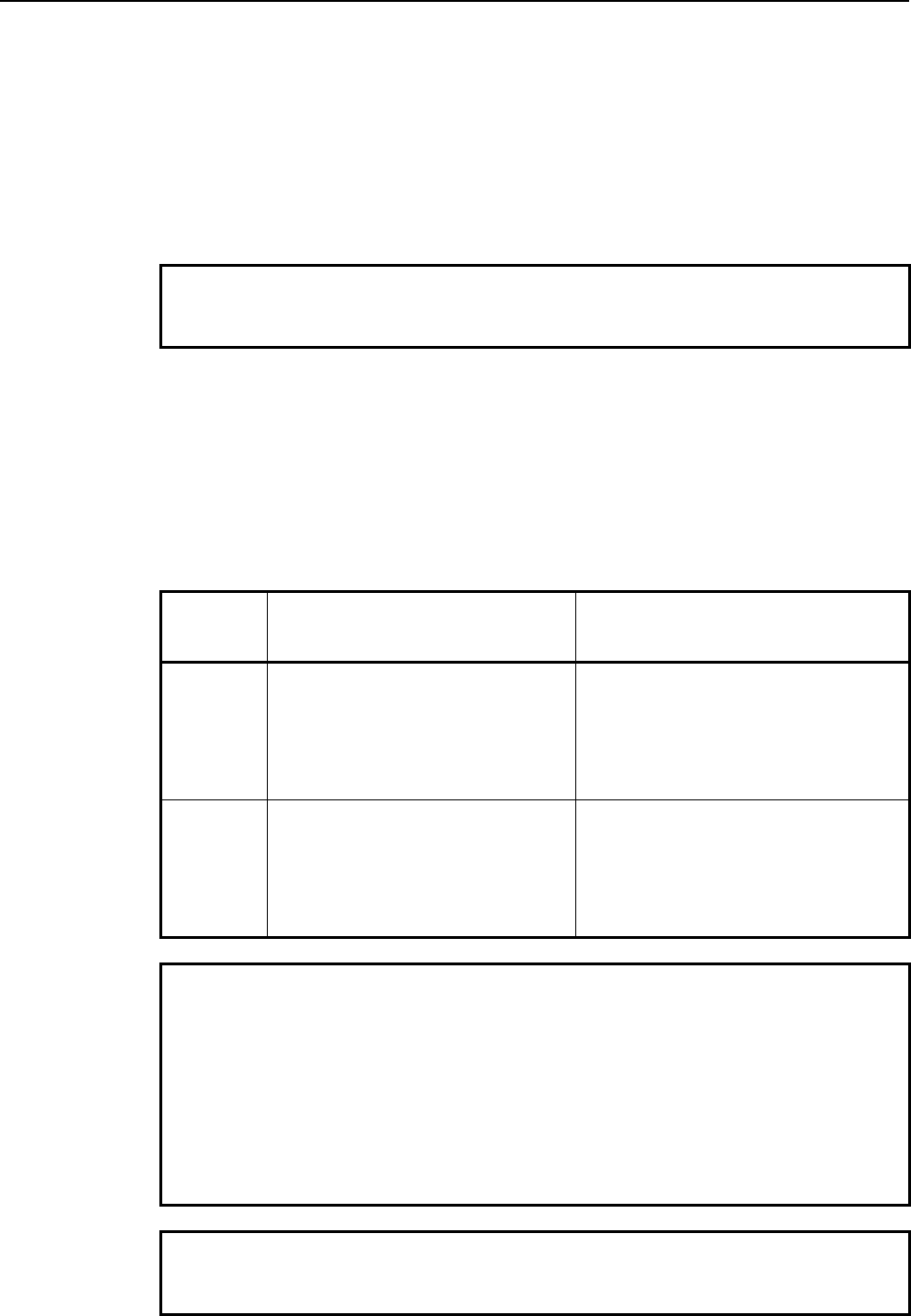
9.PARAMETERS
B-63943EN-2/07
- 310 -
#4 EXST In the status display of the conversational macro screen, three-dimensional interference
check in progress or program coordinate system switching is:
0: Not indicated.
1: Indicated.
#5 TDVDPI In variable-based PMC axis control, the distance to move specified with control travel
distance variables (#8713, #8723, #8733, and #8743) is regarded as of:
0: Calculator type decimal point input.
1: Least input increment.
NOTE
If this parameter is 1, the behavior is equivalent to that of the
Series 16i.
#6 PG1O In a specified-block read (G325/G328), if an attempt is made to read an O number block
by assigning 1 to a block number variable (#8521):
0: All words (characters) including the O number can be read.
1: Words (characters) not including the O number can be read.
#7 PMX16 In PMC axis control, the controlled-axis number selected using the axis select variable
(#8700) and the relationships between control variables and groups in variable-based
PMC axis control are specified as listed below:
PMX16 Control axis number selected using
the axis select variable (#8700)
Relationships between control
variables and groups in variable-based
PMC axis control
0 System-common control axis number Groups 1 to 4 regardless of the path
involved
#8710 to #8715: Group 1 is used.
#8720 to #8725: Group 2 is used.
#8730 to #8735: Group 3 is used.
#8740 to #8745: Group 4 is used.
1 Relative control axis number within
each path
Groups 4N-3 to 4N depending on the
path involved
#8710 to #8715: Group 4N-3 is used.
#8720 to #8725: Group 4N-2 is used.
#8730 to #8735: Group 4N-1 is used.
#8740 to #8745: Group 4N is used.
Example
In a 2-path system with each path containing a 3-axis machine,
path 2 can select the 1st axis in the path by specifying the:
• System-common 4th axis if bit 7 (PMX16) of compile parameter
No. 9160 = 0.
#8700 = 16
• 1st axis in the path if bit 7 (PMX16) of compile parameter No.
9160 = 1.
#8700 = 1
NOTE
If this parameter is 1, the behavior is equivalent to that of the
Series 16i.
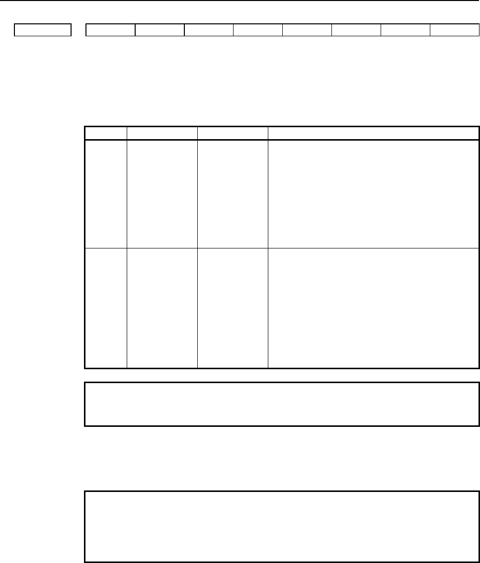
B-63943EN-2/07
9.PARAMETERS
- 311 -
#7 #6 #5 #4 #3 #2 #1 #0
9163 C16 P98 LCLLV PCDC MCT GMC
[Data type] Bit
#0 GMC Modal calls are of the:
0: Standard method.
1: Series 16i method.
GMC Call type Cancel G code Characteristic
0 Modal call using
a G66/G66.1/G
code
G67 • Modal call nesting is usable.
• Bit 1 (MCT) of compile parameter No. 9163
can be used to specify which type, G66.1 or
G66, G code-based modal calls are
corresponding to.
• How an execution macro calls another
execution macro is determined according to bit
2 (PCDC) of compile parameter No. 9163 and
bit 6 (GMP) of parameter No. 6008.
1 Modal call
using a G code
G167 or G
code specified
using compile
parameter No.
9034
• Modal call nesting is unusable.
• Bit 2 (PCDC) of compile parameter No. 9163
is disabled, that is, equivalent to “= 0” (for
example, only G65 and M98 are usable for an
execution macro to call another execution
macro).
• Specifying bit 4 (MDLP) of compile parameter
No. 9008 =1 makes a macro call usable to call
an O9006 execution macro program when a
cancel code is specified.
NOTE
If this parameter is 1, the behavior is equivalent to that of the
Series 16i.
#1 MCT Macro modal call using a G code is:
0: Block-by-block call (equivalent to G66.1).
1: Move command call (equivalent to G66).
NOTE
This parameter is valid only for modal calls of the standard method
(bit 0 (GMC) of compile parameter No. 9163 = 0).
For modal calls of the Series 16i method (bit 0 (GMC) of compile
parameter No. 9163 = 1), set this parameter to 0.
#2 PCDC How to make calls from an execution macro that was called from a user program, using a
code like G/M/T…, varies depending on the combination of this parameter and bit 6
(GMP) of parameter No. 6008. For details, see the following table.
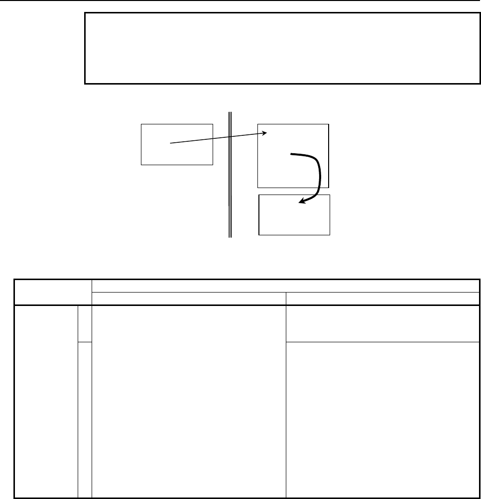
9.PARAMETERS
B-63943EN-2/07
- 312 -
NOTE
This parameter is valid only for modal calls of the standard method
(bit 0 (GMC) of compile parameter No. 9163 = 0).
For modal calls of the Series 16i method (bit 0 (GMC) of compile
parameter No. 9163 = 1), this parameter is regarded as 0.
How to make a call from an execution macro
:
Gxx
:
O90xx
:
M99
Within user program Within execution macro
O90xx
:
Mxx
:
M99
(1) How to call an execution macro
Bit 2 (PCDC) of Compile parameter No. 9163
0 1
Bit 6 (GMP)
of
parameter
No. 6008
0
Calls using G65 and M98 only are allowed.
Other types of calls are disabled.
- Calls using G65, M98, G66, and G66.1
are allowed.
Other types of calls are disabled.
1
- Calls using G65, M98, G66, and G66.1
are allowed.
- From an execution macro called using a
G code, another execution macro can be
called using a code other than G codes
(or using an axis address).
- From an execution macro called using a
code other than G codes (or using an axis
address), another execution macro can
be called using a G code.
- Other types of calls (G code to G code,
code other than G codes to code other
than G codes) are disabled.
(In the description, the G/M/S/T/D/H/second auxiliary function codes/special codes are generically
referred to as each code.)
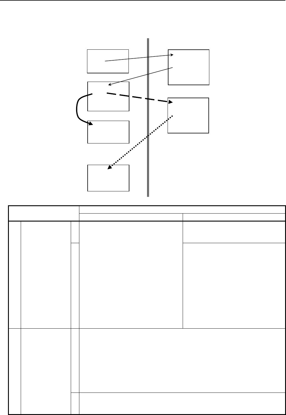
B-63943EN-2/07
9.PARAMETERS
- 313 -
(2) How to make a call after a user program is called
(a) Calling another user program in program memory
(b) Calling an execution macro
(c) Calling a subprogram of the user program after an execution macro is called
:
Gxx
:
Opp1
Mxx
:
M99
Oxxxx
:
M99
O90xx
:
MxxPpp1
:
M99
(a) O90xx
:
MxxPpp2
:
M99
(b)
O pp2
:
M99
(c)
Within user
p
ro
g
ram Within execution macro
Bit 2 (PCDC) of Compile parameter No. 9163
0 1
ⓐ
Bit 6 (GMP) of
parameter No.
6008
0
User program calls using G65, M98,
G66, and G66.1 only are allowed.
Other types of calls are disabled.
User program calls using G65, M98,
G66, and G66.1 only are allowed.
Other types of calls are disabled.
1
- From an execution macro called
using a G code, a user program can
be called using a code other than G
codes (or using an axis address).
- From an execution macro called
using a code other than G codes (or
using an axis address), a user
program can be called using a G
code.
Other types of calls (G code to G code,
code other than G codes to code other
than G codes) are disabled.
ⓑ
Bit 6 (C16) of
compile
parameter No.
9163
0
When bit 6 (GMP) of parameter No. 6008 is set to 0:
Once a user program is called, no execution macro can be called.
When bit 6 (GMP) of parameter No. 6008 is set to 1:
- From a user program called using a G code, an execution macro can be
called using a code other than G codes (or using an axis address).
- From a user program called using a code other than G codes (or using an
axis address), an execution macro can be called using a G code.
Other types of calls (G code to G code, code other than G codes to code other
than G codes) are disabled.
1
Each code (or axis address) can be used to call an execution macro (in the same
manner as in (1), “How to call an execution macro) regardless of the setting of bit 6
(GMP) of parameter No. 6008.
9.PARAMETERS
B-63943EN-2/07
- 314 -
Bit 2 (PCDC) of Compile parameter No. 9163
0 1
ⓒ
Bit 6 (GMP) of
parameter No.
6008
0 After an execution macro is called, the
user program cannot be called again.
(The duplicate calling of a user program
is disabled.)
After an execution macro is called, the
user program cannot be called again.
(The duplicate calling of a user program
is disabled.)
1
A user program can be called. (The
duplicated calling of a user program is
allowed.)
NOTE
1 If a disabled type of call is attempted, the command is treated as
an ordinary G/M/S/T/D/H/second auxiliary function/axis address
code.
2 The same behavior as for bit 6 (GMP) of parameter No. 6008 = 0
and bit 2 (PCDC) of compile parameter No. 9163 = 0 occurs if bit 0
(GMC) of compile parameter No. 9163 = 1.
#3 LCLLV If an execution macro is called as a subprogram from a user program (subprogram call
using an M/S/T/second auxiliary function/specific code), the local variable level:
0: Does not change.
(The local variable at the calling source is used.)
1: Changes.
(The local variable at the called destination is used. (Equivalent to that of the Series
16i.))
#4 P98 The execution macro for P-CODE workpiece number search is:
0: Called as a macro.
The local variable used with the execution macro cannot be used with the main
program.
1: Called as a subprogram.
The local variable used with the execution macro is passed to the main program.
#6 C16 When an execution macro program is called from a program called as a subprogram from
a user program:
0: Each non-G code, such as M/T/S/…, or an axis code cannot use each non-G code,
such as M/T/S/…, or an axis code to call an execution macro. In addition, a program
called using a G code cannot use a G code to call an execution macro (no call can be
made at all if bit 6 (GMP) of parameter No. 6008 = 0).
1: Regardless of the setting of bit 6 (GMP) of parameter No. 6008, each code, such as
G/M/T/S/…, and axis address can be used to call an execution macro in the same
manner as when an execution macro is called from a user program. (Equivalent to
the behavior of the Series 16i.)
#7 #6 #5 #4 #3 #2 #1 #0
9167 PL30 NVGA INCD NTV
[Data type] Bit
#0 NTV When an "LF" is output with G336 (data transmission), a space for a TV check is:
0: Output.
1: Not output.
B-63943EN-2/07
9.PARAMETERS
- 315 -
#3 INCD The coordinates (X,Y,I,J) in the character coordinate system or graphic coordinate system
are:
0: Specified in the absolute specification mode at all times.
1: Switchable between the absolute specification mode and incremental specification
mode with G390/G391. (Valid for G204, G230, G242, G243, G300, G249, G250,
G01, G02, G03, G206, and G317)
#4 NVGA This parameter is used with applications created for character cards of the old type, and is
usually set to 0.
0: Normal mode
1: Equivalent to character cards (All graphic commands are ignored.)
#7 PL30 For screens with a background, the coloration of the color palette is set to the standard
colors of the:
0: Conversational macro screen of the Series 16i.
1: Series 30i.
#7 #6 #5 #4 #3 #2 #1 #0
9168 VGET PAN US19WG
[Data type] Bit
#0 US19WG When the 7-soft key type display is specified for the 12-soft key type (the compile
parameter US19W(No.9006#5)=1), the number of display groups of G-code modal
information is:
0: 18 groups.
1: 24 groups.
#1 PAN In the parameter writing command (G314), when two or more parameter writings are
executed by specifying the intra-path control axis (spindle) number, Next parameter
writing of the intra-path control axis (spindle) number is :
0: Order of the system common control axis (spindle) number.
1: Order of the intra-path control axis (spindle) number.
Example : 2path-6axes, parameter No.981=1, 2, 1, 2, 1, 2 (X1, X2, Y1, Y2, Z1, Z2)
Control axis/spindle number at which to start writing : 2,
Number of control axes/spindles to be written : 2
PAN(No.9168#1)=0 : Parameter writing Y1 and Y2.
PAN(No.9168#1)=1 : Parameter writing Y1 and Z1.
#2 VGET For virtual MDI key, the control variables of MDI keyboard type reading(#8533) and
MDI key image reading(#8549) are :
0: Disabled.
1: Enabled.
When this compile parameter is set to 1, the following value can be read.
- In #8533, the value 0 can be read as the kind of virtual MDI key regardless of the
kind of the connected MDI keyboard.
- In #8549, the key images of virtual MDI key can be read.
9.PARAMETERS
B-63943EN-2/07
- 316 -
9.2 EXECUTOR PARAMETERS
When the power is turned on, the general parameters are not initialized to the values set in P-CODE
variables. So, these parameters can be modified, for example, from the MDI panel and so on.
#7 #6 #5 #4 #3 #2 #1 #0
3109 HPU
[Input type] Parameter input
[Data type] Bit path
#7 HPU When the user help screen control function is enabled, pressing the key displays
the:
0: Help (initial menu) screen.
1: User help screen.
#7 #6 #5 #4 #3 #2 #1 #0
9000 RSC STP NDP SQN
[Input type] Parameter input
[Data type] Bit path
#0 SQN During execution macro execution, the program number and sequence number are:
0: Not displayed.
The program and sequence numbers of a calling user program are kept displayed
until program control is returned to the calling user macro after the end of the
execution macro.
1: Displayed.
#1 NDP On the macro variable screen, the P-CODE variable screen is:
0: Not displayed.
1: Displayed.
#2 STP When a conversational macro/auxiliary macro is executed using the debug function:
0: The macro is executed in the continuous mode.
1: The macro is executed in the single block mode.
This parameter is valid when bit 0 (DBG) of parameter No. 9033 is set to 1.
NOTE
When this parameter is set, the power must be turned off before
operation is continued.
#4 RSC Upon reset, the P-CODE macro common variables (#100 to #199) are:
0: Not cleared to <null>.
1: Cleared to <Null>.
NOTE
This parameter does not affect the custom macro common
variables #100 to #199, regardless of the states of bits 0 (MV0) and
1 (MV1) of parameter No. 9034.
The custom macro common variables #100 to #199 depend on bit
6 (CCV) of parameter No. 6001.
B-63943EN-2/07
9.PARAMETERS
- 317 -
9002 Conversational macro/auxiliary macro program number subject to breaking
[Input type] Parameter input
[Data type] 2-word path
[Valid data range] 1 to 99999999
Set the program number of a conversational macro/auxiliary macro subject to breaking by
the debug function.
This parameter is valid when bit 0 (DBG) of parameter No. 9033 is set to 1.
NOTE
If either this parameter or parameter No. 9003 is set to a value
other than 0 when the conversational macro function is executed,
the break function is enabled, and the program number set in this
parameter and the sequence number set in parameter No. 9003
are set as break conditions.
9003 Conversational macro/auxiliary macro sequence number subject to breaking
[Input type] Parameter input
[Data type] 2-word path
[Valid data range] 1 to 99999999
Set the sequence number of a conversational macro/auxiliary macro subject to breaking
by the debug function.
This parameter is valid when bit 0 (DBG) of parameter No. 9033 is set to 1.
NOTE
If either this parameter or parameter No. 9002 is set to a value
other than 0 when the conversational macro function is executed,
the break function is enabled, and the sequence number set in this
parameter and the program number set in parameter No. 9002 are
set as break conditions.
#7 #6 #5 #4 #3 #2 #1 #0
9010 08M 07M 06M 05M 04M 03M 02M 01M
9020 16M 15M 14M 13M 12M 11M 10M 09M
9021 24M 23M 22M 21M 20M 19M 18M 17M
[Input type] Parameter input
[Data type] Bit path
The axes for which special macro call using an axis address is enabled are:
0: Enabled.
1: Disabled.
With these parameters, special macro call using an axis address enabled with the compile
parameters Nos. 9005, 9008, 9164, and 9165 can be disabled.
Select a control axis number within the path, using a bit.
9.PARAMETERS
B-63943EN-2/07
- 318 -
No. 9010 #0 01M 1st axis
#1 02M 2nd axis
: : :
#7 08M 8th axis
No. 9020 #0 09M 9th axis
#1 10M 10th axis
: : :
No. 9021 #7 24M 24th axis
#7 #6 #5 #4 #3 #2 #1 #0
9011 VRM MTC
[Input type] Parameter input
[Data type] Bit path
#0 MTC Special macro call/subprogram call using a T code is:
0: Enabled.
1: Disabled.
With this parameter, call using a T code enabled with bit 0 (TCAL) of compile parameter
No. 9002 or bit 7 (TMACC) of compile parameter No. 9005 can be disabled.
#2 VRM The conversational macro screen is:
0: Displayed with background color.
1: Not displayed with background color.
This parameter is valid when bit 0 (VGAR) of compile parameter No. 9100 is set to 1.
#7 #6 #5 #4 #3 #2 #1 #0
9012 MSC MHC MDC
[Input type] Parameter input
[Data type] Bit path
#0 MDC Special macro call using a D code is:
0: Enabled.
1: Disabled.
This parameter can be used to disable D code-based special macro calls that have been
enabled, using bit 0 (DMACC) of compile parameter No. 9104.
#1 MHC Special macro call using an H code is:
0: Enabled.
1: Disabled.
This parameter can be used to disable H code-based special macro calls that have been
enabled, using bit 1 (HMACC) of compile parameter No. 9104.
#2 MSC Special macro call using an S code is:
0: Enabled.
1: Disabled.
This parameter can be used to disable S code-based special macro calls that have been
enabled, using bit 2 (SMACC) of compile parameter No. 9104.
B-63943EN-2/07
9.PARAMETERS
- 319 -
#7 #6 #5 #4 #3 #2 #1 #0
9013 MCA
[Input type] Parameter input
[Data type] Bit path
#1 MCA If an execution macro call code specified using a compile parameter has the same setting
as for a custom macro call code specified using a parameter:
0: The execution macro call is enabled.
1: The custom macro call is enabled.
Example
If both parameter No. 6050 and compile parameter No. 9013
specify 100 as a G code for calling O9010:
• O9010 specified in the execution macro is called if bit 1 (MCA)
of parameter No. 9013 = 0.
• O9010 specified in the user program is called if bit 1 (MCA) of
parameter No. 9013 = 1.
#7 #6 #5 #4 #3 #2 #1 #0
9026 NDTx
[Input type] Parameter input
[Data type] Bit axis
#0 NDTx In a cumulative cutting distance calculation, an axis is:
0: Included.
1: Not included.
NOTE
This parameter is valid only during linear interpolation as with the
G01 command. (During circular interpolation as with the G02 or
G03 command, an axis for which this parameter is set to 1 is also
included in a cumulative cutting distance calculation.)
#7 #6 #5 #4 #3 #2 #1 #0
9032 BGW
[Input type] Parameter input
[Data type] Bit
NOTE
When this parameter is set, the power must be turned off before
operation is continued.
#0 BGW The screen background color of the monochrome LCD is:
0: Black.
1: White. (Equivalent to that of the Series 16i.)
NOTE
The monochrome LCD is for the Series 30i /31i /32i -A.
9.PARAMETERS
B-63943EN-2/07
- 320 -
#7 #6 #5 #4 #3 #2 #1 #0
9033 SHS EVF EV2 MVD SEP DBG
[Input type] Parameter input
[Data type] Bit path
NOTE
When at least one of these parameters is set, the power must be
turned off before operation is continued.
#0 DBG A conversational macro is started in:
0: Normal mode.
1: Debug mode.
#1 SEP An auxiliary macro and conversational macro are:
0: Executed sequentially.
(An auxiliary macro and conversational macro are executed alternately. If M99 is
executed in one main program, control is transferred to the other main program.)
1: Executed in parallel.
(An auxiliary macro and conversational macro are executed in parallel. When an
auxiliary macro is executed, blocks as many as the number set in parameter No.
9066 are executed at certain intervals.)
#2 MVD Monochrome display is provided:
0: Using two tones.
1: Using the brightness modulation mode.
NOTE
The monochrome LCD is for the Series 30i /31i /32i -A.
#3 EV2 P-CODE variables (#10000 and up) hold:
0: Floating-point data.
1: Integer data.
NOTE
Re-setting this parameter clears all data assigned to the P-CODE
variables (#10000 and up) and extended P-CODE variables
(#20000 and up) for all paths to 0.
#4 EVF Extended P-CODE variables (#20000 and up) hold:
0: Floating-point data.
1: Integer data.
NOTE
Re-setting this parameter clears all data assigned to the extended
P-CODE variables (#20000 and up) and P-CODE variables
(#10000 and up) for all paths to 0.
#5 SHS When the high-speed cycle machining function is enabled, variables #20000 and up are
used as:
0: High-speed cycle machining data variables.
1: Expansion P code variables.
B-63943EN-2/07
9.PARAMETERS
- 321 -
#7 #6 #5 #4 #3 #2 #1 #0
9034 MV7 MV6 MV5 MV4 MV3 MV2 MV1 MV0
[Input type] Parameter input
[Data type] Bit path
NOTE
When at least one of these parameters is set, the power must be
turned off before operation is continued.
#0 MV0 The common variables #100 to #149 used by a P-CODE macro are:
0: P-CODE macro common variables independent of the custom macro common
variables.
1: Shared as custom macro common variables.
#1 MV1 The common variables #150 to #199 used by a P-CODE macro are:
0: P-CODE macro common variables independent of the custom macro common
variables.
1: Shared as custom macro common variables.
#2 MV2 The common variables #500 to #549 used by a P-CODE macro are:
0: P-CODE macro common variables independent of the custom macro common
variables.
1: Shared as custom macro common variables.
#3 MV3 The common variables #550 to #599 used by a P-CODE macro are:
0: P-CODE macro common variables independent of the custom macro common
variables.
1: Shared as custom macro common variables.
#4 MV4 The common variables #600 to #699 used by a P-CODE macro are:
0: P-CODE macro common variables independent of the custom macro common
variables.
1: Shared as custom macro common variables.
#5 MV5 The common variables #700 to #799 used by a P-CODE macro are:
0: P-CODE macro common variables independent of the custom macro common
variables.
1: Shared as custom macro common variables.
#6 MV6 The common variables #800 to #899 used by a P-CODE macro are:
0: P-CODE macro common variables independent of the custom macro common
variables.
1: Shared as custom macro common variables.
#7 MV7 The common variables #900 to #999 used by a P-CODE macro are:
0: P-CODE macro common variables independent of the custom macro common
variables.
1: Shared as custom macro common variables.
9.PARAMETERS
B-63943EN-2/07
- 322 -
#7 #6 #5 #4 #3 #2 #1 #0
9035 SKX NPA CWB EUI RCN XIT
[Input type] Parameter input
[Data type] Bit path
#0 XIT Interlock in each axis direction is:
0: Disabled.
1: Enabled.
#1 RCN Upon NC reset, reader/puncher control based on a conversational macro is:
0: Not stopped.
1: Stopped with completion code (#8539)=12.
#3 EUI As the UI/UO signals, a P-CODE macro uses:
0: UI000 to UI015 and UO000 to UO015.
1: EUI00 to EUI15 and EUO00 to EUO15.
#4 CWB When the data transmission (G336) command in reader/puncher control or the macro
variable data output (G338) command is executed, actual data transmission is carried out:
0: In units of blocks.
1: When the send buffer (255 bytes) becomes full or the line close (G331) command is
executed.
NOTE
1 Even when this parameter is 0 (data is sent in units of blocks), no
data is sent with a block which contains the R1xx command.
2 When only 1 byte (for example control code) is to be sent or when
output and input are to be performed alternately since the line is
opened until the line is closed, set this parameter to 0. If it is set to
1, data transmission cannot be performed normally because data is
transmitted 255 bytes at a time.
#5 NPA When a P-CODE work number search is enabled, an attempt to start automatic operation
with no main program selected results in:
0: Nothing being performed.
1: Alarm PS1079 being issued.
#6 SKX The skip signal to be referenced by a linear or rotation axis move direction variable
(#8601/#8608) when the skip signal rises is the:
0: SKIPP signal (Gn006.6).
1: SKIP signal (X004.7).
If this parameter is 1:
1. X013.7 for the 2nd PMC and X011.7 for the 3rd PMC.
2. X address assigned by parameter No. 3012 if bit 2 (XSG) of parameter No.
3008 = 1.
NOTE
If this parameter is 1, the behavior is equivalent to that of the
Series 16i.
B-63943EN-2/07
9.PARAMETERS
- 323 -
#7 #6 #5 #4 #3 #2 #1 #0
9036 PRS NOB AMP AFT MPE
[Input type] Parameter input
[Data type] Bit
#0 MPE When bit 0 (PWE) of parameter No. 8900 = 0, the parameter write (G314) function can
write to:
0: The parameters whose input type is setting input and parameter No. 9036.
1: All writable parameters.
If bit 0 (PWE) of parameter No. 8900 = 1, however, the parameter write function can
write to all writable parameters regardless of the setting of this parameter.
#2 AFT The forcible end of the auxiliary macro function is:
0: Disabled.
1: Enabled.
If this parameter is 1, pressing the and keys simultaneously makes it
possible to forcibly end the conversational macro and auxiliary macro functions.
NOTE
Usually, set this parameter to 0 in order to keep auxiliary macro
function execution from stopping accidentally.
#3 AMP When the reader/puncher interface/memory card control function is performing
input/output, using auxiliary macros, the INPUT/OUTPUT status is:
0: Displayed.
1: Not displayed.
#4 NOB With execution macros, the G310 (relative coordinate preset and PMC data read/write
functions) block is executed as:
0: NC statement.
1: Macro statement.
NOTE
If this parameter is 1, the behavior is equivalent to that of the
Series 16i.
#5 PRS The specified-block command (G325/G328) in the CNC program reads:
0: Always a specified block after confirming it.
1: A specified block and those that follow it sequentially at high speed.
NOTE
When this parameter is 1, do not edit programs during high-speed
read; no correct data may be read.
9048 P-CODE macro number of an execution macro
[Input type] Parameter input
[Data type] Byte path
[Valid data range] 1 to 20
Select the P-CODE number (number specified with P-CODE_NUMBER= in the link
control file) where an execution macro to be executed with each path is held.
9.PARAMETERS
B-63943EN-2/07
- 324 -
NOTE
1 With a path for which this parameter is set to 0, the execution
macro is not executed.
2 When this parameter is set, the power must be turned off before
operation is continued.
9049 P-CODE macro number of a conversational macro
[Input type] Parameter input
[Data type] Byte path
[Valid data range] 1 to 20
Select the P-CODE number (number specified with P-CODE_NUMBER= in the link
control file) where an conversational macro to be executed with each path is held.
NOTE
1 With a path for which this parameter is set to 0, the conversational
macro is not executed.
2 When this parameter is set, the power must be turned off before
operation is continued.
9050 P-CODE macro number of an auxiliary macro
[Input type] Parameter input
[Data type] Byte path
[Valid data range] 1 to 20
Select the P-CODE number (number specified with P-CODE_NUMBER= in the link
control file) where an auxiliary macro to be executed with each path is held.
NOTE
1 With a path for which this parameter is set to 0, the auxiliary macro
is not executed.
2 When this parameter is set, the power must be turned off before
operation is continued.
9051 Area number of P-CODE variables (#10000 and up)
[Input type] Parameter input
[Data type] Byte path
[Valid data range] 1 to 10
Set the area number for the P-CODE variables (#10000 to #19999) used by the macro
executor of each path.
If the same area is selected for multiple paths, the P-CODE variables can be shared as
common variables among the multiple paths.
NOTE
When this parameter is set, the power must be turned off before
operation is continued.
9052 Area number of extended P-CODE variables (#20000 and up)
[Input type] Parameter input
B-63943EN-2/07
9.PARAMETERS
- 325 -
[Data type] Byte path
[Valid data range] 1 to 10
Set the area number for the extended P-CODE variables (#20000 and up) used by the
macro executor of each path.
If the same area is selected for multiple paths, the extended P-CODE variables can be
shared as common variables among the multiple paths.
NOTE
When this parameter is set, the power must be turned off before
operation is continued.
9053 Number of P-CODE variables (#10000 and up)
[Input type] Parameter input
[Data type] 2-word path
[Valid data range] 0 to 10000
Set the number of P-CODE variables.
NOTE
1 When this parameter is set, the power must be turned off before
operation is continued.
2 Re-setting this parameter clears all data assigned to the P-CODE
variables (#10000 and up) and extended P-CODE variables (#20000
and up) for all paths to 0.
9054 Number of extended P-CODE variables (#20000 and up)
[Input type] Parameter input
[Data type] 2-word path
[Valid data range] 0 to 70000
Set the number of extended P-CODE variables.
NOTE
1 When this parameter is set, the power must be turned off before
operation is continued.
2 Re-setting this parameter clears all data assigned to the extended
P-CODE variables (#20000 and up) and P-CODE variables (#10000
and up) for all paths to 0.
9055 P-CODE number of the 2nd module
[Input type] Parameter input
[Data type] Byte path
[Valid data range] 1 to 20
Select a P-CODE number (number specified with P-CODE_NUMBER= in the link
control file) in which there is a 2nd-module program to be executed in each path.

9.PARAMETERS
B-63943EN-2/07
- 326 -
NOTE
1 When this parameter is set, the power must be turned off before
operation is continued.
2 The 2nd module is invalid in a path for which this parameter is 0.
3 This parameter is valid only when the P-CODE numbers specified
in parameters Nos. 9048 to 9050 are 0 or the same number as
specified in this parameter.
Example:
When No. 9048=1, No. 9049=0, and No. 9050=1:
This parameter is valid.
When No. 9048=2, No. 9049=0, and No. 9050=1:
This parameter is invalid.
9056 P-CODE number of the 3rd module
[Input type] Parameter input
[Data type] Byte path
[Valid data range] 1 to 20
Select a P-CODE number (number specified with P-CODE_NUMBER= in the link
control file) in which there is a 3rd-module program to be executed in each path.
NOTE
1 When this parameter is set, the power must be turned off before
operation is continued.
2 The 3rd module is invalid in a path for which this parameter is 0.
3 This parameter is valid only when the P-CODE numbers specified
in parameter Nos. 9048 to 9050 are 0 or the same number as
specified in this parameter.
Example:
When No. 9048=1, No. 9049=0, and No. 9050=1:
This parameter is valid.
When No. 9048=2, No. 9049=0, and No. 9050=1:
This parameter is invalid.
9066 Number of blocks to be executed with the auxiliary macro function
[Input type] Parameter input
[Data type] 2-word path
[Valid data range] 0 to 1000
In parallel execution (with bit 1 (SEP) of parameter No. 9033 set to 1), the auxiliary
macro function executes several auxiliary macro blocks at certain intervals.
With this parameter, set the number of blocks to be executed at a time. (Blocks as many
as the set number + 1 are executed at a time.)
Specify the number of auxiliary macro blocks to be executed at a time.
If this parameter is 0, however, 100 blocks are assumed.
This parameter is valid for concurrent execution (bit 1 (SEP) of parameter No. 9033 = 1)
and when a screen other than the conversational macro screen is being displayed.
B-63943EN-2/07
9.PARAMETERS
- 327 -
NOTE
During conversational macro execution (while the conversational
macro screen is being displayed), sequential execution (bit 1 (SEP)
of parameter No. 9033 = 0) continues till the program end
instruction (execution control code M99/M99Pp) in the main
program regardless of the setting of this parameter.
9067 Protection range of P-CODE macro common variables (#500 to #999) (start)
[Input type] Parameter input
[Data type] Word path
[Valid data range] 500 to 999
9068 Protection range of P-CODE macro common variables (#500 to #999) (end)
[Input type] Parameter input
[Data type] Word path
[Valid data range] 500 to 999
Set the range of nonvolatile P-CODE macro common variables (#500 to #999) which
must not be written to.
NOTE
If a value not within the specifiable range is set, or a specified
range is such that No. 9067 > No. 9068, the P-CODE macro
common variables are not protected from writing.
9069 PMC internal relay (R area) address of an interlock mode signal for each axis direction
[Input type] Parameter input
[Data type] 2-word path
[Valid data range] 0 to
9070 PMC internal relay (R area) bit position of an interlock mode signal for each axis direction
[Input type] Parameter input
[Data type] Byte path
[Valid data range] 0 to 7
Specify the PMC internal relay (R area) signal that determines the control mode of the
interlock function for each axis direction.
Address: Specify the number of the R area,
Bit position: Specify the bit position of the signal.
NOTE
1 In the following cases, the interlock function for each axis direction
is disabled:
(1) An address not in the R area is specified.
(2) An incorrect bit position is specified.
(3) Bit 0 (XIT) of parameter No. 9035 is set to 0.
2 When specifying the R area for the 2nd- or 3rd-path PMC, specify
the path for the PMC, using control variable #8603 in advance.
9.PARAMETERS
B-63943EN-2/07
- 328 -
9072
Number of blocks for which macro statements in the execution macro program are executed in
succession
[Input type] Parameter input
[Data type] 2-word path
[Valid data range] 0 to 99999999
Specify the number of blocks for which macro statements in the execution macro
program are executed in succession. If this parameter is 0, 500 blocks are assumed.
NOTE
This parameter is valid only for macro statements in the execution
macro program. It affects no macro statement in the custom macro
program.
The setting of this parameter takes effect only when a specified
number of macro statement blocks continue.
9076 Axis number to be newly used in an axis number-based axis command
[Input type] Parameter input
[Data type] Byte axis
[Valid data range] 0 to number of controlled axes
With the axis number-based axis command in an execution macro, there is a fixed
correspondence between the symbol names specified with the P-CODE macro and axis
numbers like: &A for the 1st axis, &B for the 2nd axis, ..., &X for the 24th axis (for an
incremental command in G code system A, “YA”, “YB”, …, “YX”). However, using this
parameter to specify axis numbers for symbol names makes it possible to change the
correspondence between the symbol names and axis numbers freely.
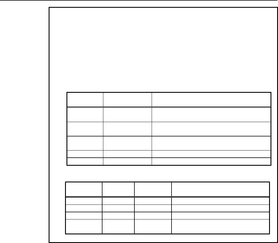
B-63943EN-2/07
9.PARAMETERS
- 329 -
Example 1
To use P-CODE macros created in a 5-axis (X, Y, Z, B1 (&D), B2
(&E)) configuration on a machine in a 4-axis configuration (1st axis =
X, 2nd axis = Y, 3rd axis = Z, and 4th axis = B2), set parameter No.
9076 as follows:
[P-CODE macro]
Symbol definition
@B1 &D /* Defines an axis name for the 4th axis.
@B2 &E /* Defines an axis name for the 5th axis.
Axis number Axis name to be
specified Remark
1st axis X Axis with no expansion axis name is specified with
no modification.
2nd axis Y Axis with no expansion axis name is specified with
no modification.
3rd axis Z Axis with no expansion axis name is specified with
no modification.
4th axis B1 &D (4th axis) is specified.
5th axis B2 &E (5th axis) is specified.
[Settings on the machine]
Axis number Axis name Parameter
No. 9076 Remark
1st axis X 0 Not an expansion axis name
2nd axis Y 0 Not an expansion axis name
3rd axis Z 0 Not an expansion axis name
4th axis B2 5 The axis number (5th axis) corresponding
to &E is changed to the 4th axis.
9.PARAMETERS
B-63943EN-2/07
- 330 -
Example 2
To use P-CODE macros created in a 3-axis (XA(&A), Y, ZA2(&C))
configuration on a machine in a 3-axis configuration (1st axis = XA,
2nd axis = ZA2, and 3rd axis = Y), set parameter No. 9076 as
follows:
[P-CODE macro]
Symbol definition
@XA &A /* Defines an axis name for the 1st axis.
@ZA2 &C /* Defines an axis name for the 3rd axis.
[Settings on the machine]
Axis number Axis name Parameter
No. 9076 Remark
1st axis XA 0 &A remains to be the 1st axis.
2nd axis ZA2 3 The axis number (3rd axis) corresponding
to &C is changed to the 2nd axis.
3rd axis Y 0 Not an expansion axis name
Axis number Axis name to be
specified Remark
1st axis XA &A (1st axis) is specified.
2nd axis Y Axis with no expansion axis name is specified with no
modification.
3rd axis ZA2 &C (3rd axis) is specified.
NOTE
1 If 2 or more axes are specified for the same axis number, alarm
PW1106 will be issued at power on.
[Example]
If parameter No. 9076 is set as listed below, alarm PW1106 will be
issued at power on.
Axis number Parameter
No.9076 Remark
1st axis 2 The 1st axis is &B (YB).
2nd axis 1 The 2nd axis is &A(YA).
3rd axis 2 Invalid because the parameter setting is the same
as for the 1st axis.
2 When this parameter is set, the power must be turned off before
operation is continued.
APPENDIX

B-63943EN-2/07
APPENDIX
A.ERROR NO. LIST
- 333 -
A ERROR NO. LIST
The error No. list given below explains the meanings of the error Nos. displayed as follows:
• Error Nos. displayed on the debugger screen of the debugging function
• Error Nos. displayed on the CONVERSATIONAL MACRO screen when a fatal error (an error that
prevents continuation of execution) occurs during execution of a conversational macro or auxiliary
macro, stopping the execution of the macro
Error Nos. are classified as follows:
(1) 1 to 9999 : Numbers that match the PS/SR alarm numbers
(2) 10001 and up : Fatal error numbers
(3) 10101 and up : Numbers displayed only on the debugger screen
(4) 99999 : Error No. when a conversational macro or auxiliary macro terminates forcibly.
The error Nos. from 1 to 9999 indicate errors in commands that can be used also in the execution macro.
For the execution macro, a PS/SR alarm is issued when an error occurs, and automatic operation must be
stopped. Therefore, the error Nos. from 1 to 9999 match the error Nos. of PS/SR alarms. If an error No.
from 1 to 9999 that is not indicated in the table shown below is displayed, refer to Appendix H, "ALARM
LIST" in " FANUC Series 30i/31i/32i OPERATOR’S MANUAL (Common to Lathe System/Machining
Center System)" (B-63944EN) , "FANUC Series 35i-MODEL B OPERATOR’S MANUAL"
(B-64524EN), "FANUC Series 0i-MODEL F OPERATOR’S MANUAL" (B-64604EN), "FANUC Power
Motion i-MODEL A OPERATOR’S MANUAL" (B-64574EN).
Error Nos. (1 to 9999)
Error Nos. that match error Nos. of PS/SR alarms
Error No. Description
00003 The allowable number of digits is exceeded.
00006 Illegal use of a minus sign
00007 Illegal use of a decimal point
00009 Incorrect address
00010 Incorrect G code
00029 Format error
00085 Overrun error (1)
00086 DR signal off (1)
00087 Buffer overflow (1)
00110 Integer value overflow
00111 Fraction value overflow
00112 Division by zero
00115 A variable number is beyond the allowable range.
00116 Write-protected variable
00119 An argument is beyond the allowable range.
00125 Illegal macro statement format
01115 Read-protected variable
01143 Illegal print statement format
01305 Data is beyond the allowable range.
01333 Data write error
01590 TH error
01591 TV error
01805 I/O interface illegal command
01806 I/O interface operation error
01807 I/O interface parameter error
01808 Device opened twice
01823 Framing error (1)
A.ERROR NO. LIST
APPENDIX
B-63943EN-2/07
- 334 -
Error No. Description
01830 DR signal off (2)
01832 Overrun error (2)
01833 Framing error (2)
01834 Buffer overflow (2)
Error Nos. (10001 and up)
Fatal errors that prevent execution of a conversational macro/auxiliary macro
Error No. Description
10001 Program not found
10002 Sequence number not found
10003 Illegal P-CODE
10004 Too many multiplexed macros
10005 Too many multiplexed subprograms
10006 Program end
10007 Address P error
10008 Sequence number error
10009 Program number error
Error Nos. (10101 and up)
Errors displayed only by the debugger
Error No. Description
10101 Too many arguments
10102 Too long string
10103 Illegal PMC address
10104 PMC address error
10105 PMC bit error
10106 No graphic option
10107 No string
10108 Specification by execution macro is impossible.
11001 File not found
11002 File not opened
11003 Too many open files
11004 Too many files
11005 Too large file size
11006 Pointer error
11007 File size error
11008 File open error
11009 File not closed
11010 Illegal access mode
11011 Duplicate file
11012 I/O error
11013 Illegal file number
11014 Illegal data type
11015 Write-protected data
11016 Controlled-axis error
11017 Decimal point error
11018 Empty data input error
11019 Specification by conversational macro is impossible.
11020 Specification by auxiliary macro is impossible.
11021 Specification by execution macro/auxiliary macro is impossible.
11022 Specification by auxiliary macro/conversational macro is impossible.
11023 Illegal block delete number

B-63943EN-2/07
APPENDIX
A.ERROR NO. LIST
- 335 -
Error No. Description
11024 File I/O error
11026 No PMC-axis control option
11027 Address A out of range
11028 Address B out of range
11029 Address C out of range
11030 Address D out of range
11031 Address E out of range
11032 Address F out of range
11033 Address G out of range
11034 Address H out of range
11035 Address I out of range
11036 Address J out of range
11037 Address K out of range
11038 Address L out of range
11039 Address M out of range
11040 Address N out of range
11041 Address O out of range
11042 Address P out of range
11043 Address Q out of range
11044 Address R out of range
11045 Address S out of range
11046 Address T out of range
11047 Address U out of range
11048 Address V out of range
11049 Address W out of range
11050 Address X out of range
11051 Address Y out of range
11052 Address Z out of range
11053 No address A command
11054 No address B command
11055 No address C command
11056 No address D command
11057 No address E command
11058 No address F command
11059 No address G command
11060 No address H command
11061 No address I command
11062 No address J command
11063 No address K command
11064 No address L command
11065 No address M command
11066 No address N command
11067 No address O command
11068 No address P command
11069 No address Q command
11070 No address R command
11071 No address S command
11072 No address T command
11073 No address U command
11074 No address V command
11075 No address W command
11076 No address X command
11077 No address Y command
11078 No address Z command

A.ERROR NO. LIST
APPENDIX
B-63943EN-2/07
- 336 -
Error No. Description
11079 Duplicate address command
11080 System error (graphic)
11081 System error (character)
11082 Travel distance is 0 in PMC axis control.
11083 Read error in PMC axis control
11084 Illegal axis number in PMC axis control
11086 Not dwell time
11087 Too many servo axes
11088 Too many controlled axes
11089 Bit 7 (EXT1) of compile parameter No. 9002 is 0.
11090 #8502 data illegal
11093 Read failure in window function
11101 Duplicate open operation
11102 Being used by another user
11103 Program not found
11104 Program being edited
11110 Program not found
11111 Duplicate program number
11112 No free area
11113 Too many items registered
11115 Editing impossible (word)
11116 Editing impossible (program)
11174 Illegal program number specified
11204 Illegal address format
11215 Illegal macro variable number
11300 Specified character code not found (G329)
11302 Attempt made to write "O" at the beginning (G329)
11303 Program size exceeding the number of pages (500 bytes/page) specified in compile
parameter No. 9054
11310 Maximum number of readable variables exceeded
11311 Block number specification beyond the EOR block
11352 Illegal block number specified
11353 Word type error
11354 Protected by the data protection key or 8-level data protection function
(When bit 1 (KEYC) of compile parameter No. 9006 is set to 0)
11355 Background editing is in progress, or bit 7 (EXT1) of compile parameter (No. 9002) is set
to 0.
11401 Line not opened yet
11402 Line error (DR signal off)
11403 Line error (Overrun error )
11404 Line error (Buffer over error)
11405 Line error (Framing error, Parity error)
11406 Line function option not selected
11407 Line being used
11408
The value of data (such as P, Q, and R) specified in a block of G330 to G339 is
incorrect, or necessary data is not specified.
In receive control mode, G336 or G338 was specified.
In transmit control mode, G335 or G337 was specified.
In a mode other than file control mode, G339 was specified.
11409 Illegal data format
11410 Illegal file number
11411 The file with a number specified to read file information is not found.
11412
A specified time has elapsed in data transmission/reception wait state.
Operation was stopped by a reset during data transmission/reception wait state.
(When bit 4 (RSRST) of compile parameter No. 9009 is set to 1)
B-63943EN-2/07
APPENDIX
A.ERROR NO. LIST
- 337 -
Error No. Description
11499 Continuous macro variable reading is enabled by the macro variable input function
G337.
11515 Undefined variable number specified
11611 Line error (CD signal off)
11655 No receive data
11807 The memory card cannot be opened because it is used with another function.
Or, it is write-protected.
11830 Memory card not inserted yet
11832 Low battery voltage
11902 Insufficient free space on memory card
11914 Specified file not found
11915 The specified file is protected.
An undefined variable number is specified.
11917 File not opened in correct mode
11921 End of file
11922 The specified file name is illegal.
11930 File with the same name already present on memory card
11941 Close the file.
11950
Memory card cannot be recognized.
Memory card was accessed illegally.
An error occurred on memory card.
Error No. (99999)
Error when a conversational macro is terminated forcibly
Error No. Description
99999 The conversational or auxiliary macro function is terminated forcibly.
B.CODE TABLES
APPENDIX
B-63943EN-2/07
- 338 -
B CODE TABLES
Code table of Japanese 'Katakana'
ア B1 イ B2 ウ B3 エ B4 オ B5
カ B6 キ B7 ク B8 ケ B9 コ BA
サ BB シ BC ス BD セ BE ソ BF
タ C0 チ C1 ツ C2 テ C3 ト C4
ナ C5 ニ C6 ヌ C7 ネ C8 ノ C9
ハ CA ヒ CB フ CC ヘ CD ホ CE
マ CF ミ D0 ム D1 メ D2 モ D3
ヤ D4 ユ
D5 ヨ
D6
ラ D7 リ D8 ル D9 レ DA ロ DB
ワ DC ヲ
A6
ン DD
ァ A7 ィ A8 ゥ A9 ェ AA ォ AB
ッ
AF
ャ AC ュ
AD ョ
AE
” DE ° DF 。 A1 「 A2 」 A3
、 A4 ・ A5 ~ A0 - B0
Code table of alphanumeric characters
A 41 B 42 C 43 D 44 E 45
F 46 G 47 H 48 I 49 J 4A
K 4B L 4C M 4D N 4E O 4F
P 50 Q 51 R 52 S 53 T 54
U 55 V 56 W 57 X 58 Y 59
Z 5A
a 61 b 62 c 63 d 64 e 65
f 66 g 67 h 68 i 69 j 6A
k 6B l 6C m 6D n 6E o 6F
p 70 q 71 r 72 s 73 t 74
u 75 v 76 w 77 x 78 y 79
z 7A
0 30 1 31 2 32 3 33 4 34
5 35 6 36 7 37 8 38 9 39
Code table of symbols
20 ! 21 “ 22 # 23 $ 24
% 25 & 26 ‘ 27 ( 28 ) 29
* 2A + 2B , 2C - 2D . 2E
/ 2F : 3A ; 3B < 3C = 3D
> 3E ? 3F @ 40 [ 5B ¥ 5C
] 5D ^ 5E _ 5F
Code table of Japanese 'Kanji' and 'Hiragana'
ア ぁ 2421 あ 2422 阿 3024 哀 3025 愛 3026 挨 3027 逢 3029 悪 302D
握 302E 旭 3030 圧 3035 斡 3036 扱 3037 宛 3038 安 3042 暗 3045
案 3046 闇 3047 鞍 3048

B-63943EN-2/07
APPENDIX
B.CODE TABLES
- 339 -
イ ぃ 2423 い 2424 以 304A 伊 304B 位 304C 依 304D 偉 304E 囲 304F
委 3051 威 3052 意 3055 慰 3056 易 3057 椅 3058 為 3059 異 305B
移 305C 維 305D 緯 305E 胃 305F 萎 3060 衣 3061 違 3063 遺 3064
医 3065 井 3066 域 3068 育 3069 一 306C 稲 3070 印 3075 員 3077
因 3078 引 307A 飲 307B 院 3121 陰 3122 隠 3123
ウ ぅ 2425 う 2426 右 3126 宇 3127 羽 3129 雨 312B 渦 3132 嘘 3133
唄 3134 浦 313A 瓜 313B 噂 313D 運 313F 雲 3140
エ ぇ 2427 え 2428 営 3144 影 3146 映 3147 栄 3149 永 314A 泳 314B
洩 314C 英 3151 衛 3152 鋭 3154 液 3155 益 3157 駅 3158 越 315B
閲 315C 円 315F 園 3160 宴 3163 延 3164 援 3167 沿 3168 演 3169
炎 316A 煙 316C 縁 316F 遠 3173 鉛 3174 塩 3176
オ ぉ 2429 お 242A 汚 3178 凹 317A 央 317B 奥 317C 往 317D 応 317E
押 3221 横 3223 欧 3224 王 3226 黄 322B 岡 322C 沖 322D 億 322F
屋 3230 憶 3231 臆 3232 牡 3234 乙 3235 恩 3238 温 3239 穏 323A
音 323B
カ か 242B が 242C 下 323C 化 323D 仮 323E 何 323F 価 3241 佳 3242
加 3243 可 3244 夏 3246 家 3248 科 324A 暇 324B 果 324C 架 324D
歌 324E 河 324F 火 3250 稼 3254 箇 3255 花 3256 荷 3259 華 325A
菓 325B 課 325D 貨 325F 過 3261 我 3266 牙 3267 画 3268 芽 326A
賀 326C 雅 326D 介 3270 会 3271 解 3272 回 3273 壊 3275 廻 3276
快 3277 怪 3278 懐 327B 拐 327D 改 327E 械 3323 海 3324 灰 3325
界 3326 皆 3327 絵 3328 開 332B 階 332C 貝 332D 劾 332F 外 3330
害 3332 慨 3334 概 3335 涯 3336 街 3339 該 333A 垣 3340 各 3346
拡 3348 格 334A 核 334B 殻 334C 獲 334D 確 334E 穫 334F 覚 3350
角 3351 較 3353 郭 3354 閣 3355 隔 3356 革 3357 学 3358 楽 335A
額 335B 掛 335D 笠 335E 潟 3363 割 3364 括 3367 活 3368 渇 3369
滑 336A 株 3374 刈 3422 乾 3425 冠 3427 寒 3428 刊 3429 勧 342B
巻 342C 喚 342D 完 3430 官 3431 寛 3432 干 3433 幹 3434 患 3435
感 3436 慣 3437 換 3439 敢 343A 歓 343F 汗 3440 漢 3441 環 3444
甘 3445 監 3446 看 3447 管 3449 簡 344A 緩 344B 缶 344C 肝 344E
観 3451 貫 3453 還 3454 鑑 3455 間 3456 閑 3457 関 3458 陥 3459
韓 345A 館 345B 丸 345D 含 345E 岸 345F 眼 3463 岩 3464 顔 3469
願 346A
キ き 242D ぎ 242E 企 346B 危 346D 喜 346E 器 346F 基 3470 奇 3471
寄 3473 岐 3474 希 3475 幾 3476 揮 3478 机 3479 旗 347A 既 347B
期 347C 棄 347E 機 3521 帰 3522 毅 3523 気 3524 汽 3525 祈 3527
季 3528 稀 3529 徽 352B 規 352C 記 352D 貴 352E 起 352F 軌 3530
輝 3531 騎 3533 鬼 3534 偽 3536 戯 353A 技 353B 擬 353C 欺 353D

B.CODE TABLES
APPENDIX
B-63943EN-2/07
- 340 -
犠 353E 疑 353F 義 3541 議 3544 菊 3546 喫 354A 詰 354D 却 3551
客 3552 脚 3553 逆 3555 丘 3556 久 3557 休 3559 及 355A 吸 355B
宮 355C 弓 355D 急 355E 救 355F 求 3561 泣 3563 球 3565 究 3566
窮 3567 級 3569 糾 356A 給 356B 旧 356C 牛 356D 去 356E 居 356F
巨 3570 拒 3571 拠 3572 挙 3573 虚 3575 許 3576 距 3577 漁 3579
魚 357B 亨 357C 享 357D 京 357E 供 3621 競 3625 共 3626 協 3628
叫 362B 境 362D 強 362F 恐 3632 挟 3634 教 3635 橋 3636 況 3637
狂 3638 狭 3639 胸 363B 脅 363C 興 363D 郷 363F 鏡 3640 響 3641
驚 3643 仰 3644 凝 3645 業 3648 局 3649 曲 364A 極 364B 玉 364C
勤 3650 均 3651 巾 3652 錦 3653 琴 3657 禁 3658 筋 365A 緊 365B
近 3661 金 3662 銀 3664
ク く 242F ぐ 2430 九 3665 句 3667 区 3668 矩 366B 苦 366C 駆 366E
具 3671 愚 3672 空 3675 偶 3676 遇 3678 隅 3679 屑 367D 屈 367E
掘 3721 靴 3724 熊 3727 繰 372B 君 372F 訓 3731 群 3732 軍 3733
郡 3734
ケ け 2431 げ 2432 係 3738 傾 3739 刑 373A 兄 373B 啓 373C 型 373F
契 3740 形 3741 径 3742 慶 3744 憩 3746 掲 3747 携 3748 敬 3749
景 374A 系 374F 経 3750 継 3751 茎 3754 計 3757 警 3759 軽 375A
芸 375D 迎 375E 劇 3760 撃 3762 激 3763 隙 3764 桁 3765 傑 3766
欠 3767 決 3768 潔 3769 穴 376A 結 376B 血 376C 月 376E 件 376F
倹 3770 健 3772 兼 3773 券 3774 剣 3775 圏 3777 堅 3778 嫌 3779
建 377A 憲 377B 懸 377C 拳 377D 検 3821 権 3822 犬 3824 献 3825
研 3826 絹 3828 県 3829 肩 382A 見 382B 謙 382C 軒 382E 鍵 3830
険 3831 験 3833 元 3835 原 3836 厳 3837 幻 3838 弦 3839 減 383A
源 383B 現 383D 言 3840 限 3842
コ こ 2433 ご 2434 個 3844 古 3845 呼 3846 固 3847 己 384A 庫 384B
弧 384C 戸 384D 故 384E 湖 3850 狐 3851 誇 3858 雇 385B 顧 385C
五 385E 互 385F 午 3861 娯 3864 後 3865 御 3866 語 386C 誤 386D
護 386E 交 3872 侯 3874 候 3875 光 3877 公 3878 功 3879 効 387A
勾 387B 厚 387C 口 387D 向 387E 喉 3922 坑 3923 好 3925 孔 3926
孝 3927 工 3929 巧 392A 幸 392C 広 392D 康 392F 弘 3930 抗 3933
拘 3934 控 3935 攻 3936 更 3939 校 393B 構 393D 江 393E 洪 393F
港 3941 溝 3942 甲 3943 硬 3945 稿 3946 紅 3948 絞 394A 綱 394B
耕 394C 考 394D 肯 394E 航 3952 荒 3953 行 3954 衡 3955 講 3956
貢 3957 購 3958 郊 3959 鉱 395B 鋼 395D 降 395F 項 3960 香 3961
高 3962 剛 3964 号 3966 合 3967 克 396E 刻 396F 告 3970 国 3971
穀 3972 酷 3973 黒 3975 腰 3978 骨 397C 込 397E 此 3A21 頃 3A22
今 3A23 困 3A24 婚 3A27 根 3A2C 混 3A2E

B-63943EN-2/07
APPENDIX
B.CODE TABLES
- 341 -
サ さ 2435 ざ 2436 左 3A38 差 3A39 査 3A3A 砂 3A3D 鎖 3A3F 座 3A42
挫 3A43 債 3A44 催 3A45 再 3A46 最 3A47 妻 3A4A 彩 3A4C 才 3A4D
採 3A4E 栽 3A4F 済 3A51 災 3A52 砕 3A55 祭 3A57 細 3A59 菜 3A5A
裁 3A5B 載 3A5C 際 3A5D 剤 3A5E 在 3A5F 材 3A60 罪 3A61 財 3A62
坂 3A64 阪 3A65 咲 3A69 崎 3A6A 作 3A6E 削 3A6F 昨 3A72 柵 3A74
策 3A76 索 3A77 錯 3A78 桜 3A79 冊 3A7D 刷 3A7E 察 3B21 拶 3B22
撮 3B23 擦 3B24 札 3B25 殺 3B26 雑 3B28 皿 3B2E 三 3B30 傘 3B31
参 3B32 山 3B33 撒 3B35 散 3B36 産 3B3A 算 3B3B 讃 3B3E 賛 3B3F
酸 3B40 残 3B44
シ し 2437 じ 2438 仕 3B45 伺 3B47 使 3B48 刺 3B49 史 3B4B 四 3B4D
士 3B4E 始 3B4F 姉 3B50 姿 3B51 子 3B52 市 3B54 師 3B55 志 3B56
思 3B57 指 3B58 支 3B59 施 3B5C 旨 3B5D 枝 3B5E 止 3B5F 死 3B60
私 3B64 糸 3B65 紙 3B66 紫 3B67 脂 3B69 至 3B6A 視 3B6B 詞 3B6C
詩 3B6D 試 3B6E 誌 3B6F 資 3B71 歯 3B75 事 3B76 似 3B77 字 3B7A
寺 3B7B 持 3B7D 時 3B7E 次 3C21 治 3C23 磁 3C27 示 3C28 耳 3C2A
自 3C2B 辞 3C2D 式 3C30 識 3C31 軸 3C34 七 3C37 失 3C3A 室 3C3C
湿 3C3E 質 3C41 実 3C42 芝 3C47 縞 3C4A 写 3C4C 射 3C4D 捨 3C4E
斜 3C50 煮 3C51 社 3C52 者 3C54 謝 3C55 車 3C56 借 3C5A 尺 3C5C
釈 3C61 若 3C63 弱 3C65 主 3C67 取 3C68 守 3C69 手 3C6A 殊 3C6C
狩 3C6D 種 3C6F 趣 3C71 酒 3C72 首 3C73 受 3C75 寿 3C77 授 3C78
樹 3C79 需 3C7B 収 3C7D 周 3C7E 就 3D22 修 3D24 秀 3D28 秋 3D29
終 3D2A 習 3D2C 臭 3D2D 舟 3D2E 衆 3D30 襲 3D31 蹴 3D33 週 3D35
集 3D38 住 3D3B 充 3D3C 十 3D3D 従 3D3E 柔 3D40 渋 3D42 縦 3D44
重 3D45 宿 3D49 祝 3D4B 縮 3D4C 熟 3D4F 出 3D50 術 3D51 述 3D52
春 3D55 瞬 3D56 準 3D60 盾 3D62 純 3D63 巡 3D64 順 3D67 処 3D68
初 3D69 所 3D6A 暑 3D6B 緒 3D6F 署 3D70 書 3D71 諸 3D74 助 3D75
叙 3D76 女 3D77 序 3D78 除 3D3C 傷 3D7D 勝 3E21 商 3E26 唱 3E27
奨 3E29 将 3E2D 小 3E2E 少 3E2F 尚 3E30 床 3E32 承 3E35 招 3E37
掌 3E38 昇 3E3A 昭 3E3C 消 3E43 渉 3E44 焼 3E46 焦 3E47 照 3E48
省 3E4A 称 3E4E 章 3E4F 笑 3E50 紹 3E52 衝 3E57 訟 3E59 証 3E5A
詳 3E5C 象 3E5D 賞 3E5E 鐘 3E62 障 3E63 上 3E65 乗 3E68 剰 3E6A
城 3E6B 場 3E6C 壌 3E6D 常 3E6F 情 3E70 条 3E72 浄 3E74 状 3E75
蒸 3E78 錠 3E7B 飾 3E7E 植 3F22 織 3F25 職 3F26 色 3F27 触 3F28
食 3F29 伸 3F2D 信 3F2E 侵 3F2F 唇 3F30 寝 3F32 審 3F33 心 3F34
振 3F36 新 3F37 森 3F39 浸 3F3B 深 3F3C 申 3F3D 真 3F3F 神 3F40
紳 3F42 芯 3F44 親 3F46 診 3F47 身 3F48 辛 3F49 進 3F4A 針 3F4B
震 3F4C 人 3F4D 刃 3F4F 尽 3F54 陣 3F58

B.CODE TABLES
APPENDIX
B-63943EN-2/07
- 342 -
ス す 2439 ず 243A 須 3F5C 酢 3F5D 図 3F5E 吹 3F61 垂 3F62 推 3F64
水 3F65 粋 3F68 遂 3F6B 酔 3F6C 錐 3F6D 数 3F74 据 3F78 杉 3F79
裾 3F7E 澄 4021 寸 4023
セ せ 243B ぜ 243C 世 4024 瀬 4025 是 4027 制 4029 勢 402A 征 402C
性 402D 成 402E 政 402F 整 4030 星 4031 晴 4032 正 4035 清 4036
生 4038 盛 4039 精 403A 聖 403B 声 403C 製 403D 西 403E 誠 403F
誓 4040 請 4041 青 4044 静 4045 税 4047 席 404A 昔 404E 析 404F
石 4050 積 4051 籍 4052 績 4053 責 4055 赤 4056 跡 4057 切 405A
接 405C 折 405E 設 405F 節 4061 説 4062 雪 4063 絶 4064 舌 4065
先 4068 千 4069 占 406A 宣 406B 専 406C 尖 406D 川 406E 戦 406F
扇 4070 栓 4072 泉 4074 浅 4075 洗 4076 染 4077 潜 4078 旋 407B
線 407E 繊 4121 船 4125 選 412A 銑 412D 鮮 412F 前 4130 善 4131
漸 4132 然 4133 全 4134 繕 4136
ソ そ 243D ぞ 243E 塑 413A 礎 4143 粗 4146 素 4147 組 4148 訴 414A
阻 414B 創 414F 双 4150 倉 4152 奏 4155 層 4158 想 415B 捜 415C
掃 415D 挿 415E 操 4160 早 4161 巣 4163 争 4168 相 416A 窓 416B
総 416D 草 4170 装 4175 走 4176 送 4177 騒 417B 像 417C 増 417D
臓 4221 蔵 4222 贈 4223 造 4224 促 4225 側 4226 則 4227 即 4228
息 4229 束 422B 測 422C 足 422D 速 422E 俗 422F 属 4230 族 4232
続 4233 卒 4234 其 4236 揃 4237 存 4238 尊 423A 損 423B 村 423C
タ た 243F だ 2440 他 423E 多 423F 太 4240 詑 4242 堕 4244 妥 4245
惰 4246 打 4247 体 424E 対 4250 耐 4251 帯 4253 待 4254 怠 4255
態 4256 戴 4257 替 4258 滞 425A 袋 425E 貸 425F 退 4260 隊 4262
代 4265 台 4266 大 4267 第 4268 題 426A 滝 426C 卓 426E 宅 4270
択 4272 拓 4273 濯 4275 託 4277 濁 4279 諾 427A 叩 4321 達 4323
奪 4325 脱 4326 棚 432A 谷 432B 誰 432F 単 4331 嘆 4332 担 4334
探 4335 旦 4336 淡 4338 炭 433A 短 433B 端 433C 誕 4342 団 4344
弾 4346 断 4347 暖 4348 段 434A 男 434B 談 434C
チ ち 2441 ぢ 2442 値 434D 知 434E 地 434F 恥 4351 池 4353 置 4356
致 4357 遅 4359 馳 435A 築 435B 畜 435C 竹 435D 筑 435E 秩 4361
茶 4363 着 4365 中 4366 仲 4367 宙 4368 忠 4369 抽 436A 昼 436B
柱 436C 注 436D 虫 436E 鋳 4372 駐 4373 貯 4379 丁 437A 兆 437B
帳 4422 庁 4423 張 4425 彫 4426 徴 4427 懲 4428 挑 4429 朝 442B
町 442E 脹 4431 腸 4432 調 4434 超 4436 跳 4437 長 4439 頂 443A
鳥 443B 直 443E 沈 4440 珍 4441 賃 4442
ツ っ 2443 つ 2444 づ 2445 墜 4446 追 4449 痛 444B 通 444C 塚 444D
爪 445E 吊 445F 釣 4460

B-63943EN-2/07
APPENDIX
B.CODE TABLES
- 343 -
テ て 2446 で 2447 低 4463 停 4464 定 446A 底 446C 庭 446D 廷 446E
抵 4471 提 4473 程 4478 締 4479 訂 447B 釘 4523 泥 4525 摘 4526
敵 4528 滴 4529 的 452A 笛 452B 適 452C 撤 4531 鉄 4534 典 4535
天 4537 展 4538 店 4539 添 453A 貼 453D 転 453E 点 4540 伝 4541
殿 4542 田 4544 電 4545
ト と 2448 ど 2449 吐 4547 塗 4549 徒 454C 登 4550 途 4553 都 4554
砥 4556 努 4558 度 4559 土 455A 怒 455C 倒 455D 党 455E 冬 455F
凍 4560 刀 4561 島 4567 投 456A 東 456C 盗 4570 湯 4572 灯 4574
当 4576 等 4579 答 457A 筒 457B 糖 457C 統 457D 到 457E 藤 4623
討 4624 踏 4627 逃 4628 透 4629 陶 462B 頭 462C 闘 462E 働 462F
動 4630 同 4631 堂 4632 導 4633 胴 4639 道 463B 銅 463C 峠 463D
得 4640 徳 4641 特 4643 督 4644 毒 4647 独 4648 読 4649 凸 464C
突 464D 届 464F 曇 465E 鈍 465F
ナ な 244A 内 4662 謎 4666 鍋 4669 馴 466B 縄 466C 南 466E 軟 4670
難 4671
ニ に 244B 二 4673 匂 4677 肉 4679 日 467C 乳 467D 入 467E 尿 4722
任 4724 認 4727
ヌ ぬ 244C
ネ ね 244D 熱 472E 年 472F 念 4730 燃 4733 粘 4734
ノ の 244E 悩 473A 濃 473B 納 473C 能 473D 脳 473E 農 4740
ハ は 244F ば 2450 ぱ 2451 把 4744 覇 4746 波 4748 派 4749 破 474B
馬 474F 廃 4751 拝 4752 排 4753 敗 4754 杯 4755 背 4758 肺 4759
配 475B 倍 475C 媒 475E 買 4763 売 4764 博 476E 拍 476F 泊 4771
白 4772 舶 4775 薄 4776 爆 477A 縛 477B 麦 477E 箱 4822 肌 4829
畑 482A 八 482C 発 482F 髪 4831 罰 4833 抜 4834 閥 4836 伴 483C
判 483D 半 483E 反 483F 搬 4842 板 4844 汎 4846 版 4847 犯 4848
班 4849 繁 484B 般 484C 販 484E 範 484F 飯 4853 番 4856 盤 4857
ヒ ひ 2452 び 2453 ぴ 2454 否 485D 彼 4860 悲 4861 扉 4862 批 4863
比 4866 泌 4867 疲 4868 皮 4869 秘 486B 肥 486E 被 486F 費 4871
避 4872 非 4873 飛 4874 備 4877 尾 4878 微 4879 美 487E 鼻 4921
匹 4924 菱 4929 必 492C 筆 492E 百 4934 俵 4936 標 4938 氷 4939
票 493C 表 493D 評 493E 描 4941 病 4942 秒 4943 品 494A 浜 494D
貧 494F 敏 4952
フ ふ 2455 ぶ 2456 ぷ 2457 不 4954 付 4955 夫 4957 婦 4958 富 4959
布 495B 府 495C 怖 495D 敷 495F 普 4961 浮 4962 父 4963 符 4964
腐 4965 負 4969 武 4970 舞 4971 部 4974 封 4975 風 4977 伏 497A
副 497B 復 497C 幅 497D 服 497E 福 4A21 腹 4A22 複 4A23 払 4A27

B.CODE TABLES
APPENDIX
B-63943EN-2/07
- 344 -
沸 4A28 仏 4A29 物 4A2A 分 4A2C 噴 4A2E 憤 4A30 奮 4A33 粉 4A34
紛 4A36 文 4A38 聞 4A39
ヘ へ 2458 べ 2459 ぺ 245A 丙 4A3A 併 4A3B 兵 4A3C 幣 4A3E 平 4A3F
柄 4A41 並 4A42 閉 4A44 米 4A46 頁 4A47 壁 4A49 癖 4A4A 別 4A4C
偏 4A50 変 4A51 片 4A52 編 4A54 辺 4A55 返 4A56 便 4A58 勉 4A59
弁 4A5B
ホ ほ 245B ぼ 245C ぽ 245D 保 4A5D 捕 4A61 歩 4A62 補 4A64 募 4A67
墓 4A68 慕 4A69 母 4A6C 簿 4A6D 倣 4A6F 包 4A71 報 4A73 宝 4A75
崩 4A78 捧 4A7B 放 4A7C 方 4A7D 法 4B21 泡 4B22 縫 4B25 胞 4B26
芳 4B27 訪 4B2C 豊 4B2D 飽 4B30 乏 4B33 亡 4B34 傍 4B35 剖 4B36
妨 4B38 帽 4B39 忘 4B3A 忙 4B3B 房 4B3C 暴 4B3D 望 4B3E 棒 4B40
紡 4B42 肪 4B43 膨 4B44 防 4B49 北 4B4C 僕 4B4D 撲 4B50 釦 4B55
没 4B57 本 4B5C 翻 4B5D
マ ま 245E 摩 4B60 磨 4B61 魔 4B62 枚 4B67 毎 4B68 幕 4B6B 膜 4B6C
末 4B76 迄 4B78 万 4B7C 満 4B7E
ミ み 245F 味 4C23 未 4C24 魅 4C25 密 4C29 脈 4C2E 妙 4C2F 民 4C31
ム む 2460 務 4C33 夢 4C34 無 4C35 矛 4C37 霧 4C38
メ め 2461 名 4C3E 命 4C3F 明 4C40 盟 4C41 迷 4C42 鳴 4C44 滅 4C47
免 4C48 綿 4C4A 面 4C4C
モ も 2462 模 4C4F 茂 4C50 毛 4C53 盲 4C55 網 4C56 耗 4C57 木 4C5A
黙 4C5B 目 4C5C 戻 4C61 問 4C64 紋 4C66 門 4C67
ヤ ゃ 2463 や 2464 冶 4C6A 夜 4C6B 野 4C6E 矢 4C70 役 4C72 約 4C73
薬 4C74 訳 4C75 躍 4C76
ユ ゅ 2465 ゆ 2466 油 4C7D 諭 4D21 輸 4D22 優 4D25 勇 4D26 友 4D27
有 4D2D 由 4D33 誘 4D36 遊 4D37 郵 4D39 融 4D3B
ヨ ょ 2467 よ 2468 予 4D3D 余 4D3E 与 4D3F 誉 4D40 預 4D42 幼 4D44
容 4D46 揚 4D48 揺 4D49 曜 4D4B 様 4D4D 洋 4D4E 溶 4D4F 用 4D51
葉 4D55 要 4D57 踊 4D59 陽 4D5B 養 4D5C 抑 4D5E 浴 4D61 翼 4D63
ラ ら 2469 螺 4D66 裸 4D67 来 4D68 頼 4D6A 雷 4D6B 絡 4D6D 落 4D6E
乱 4D70 卵 4D71 欄 4D73 覧 4D77
リ り 246A 利 4D78 理 4D7D 裏 4E22 里 4E24 離 4E25 陸 4E26 律 4E27
率 4E28 立 4E29 略 4E2C 流 4E2E 留 4E31 粒 4E33 隆 4E34 慮 4E38
旅 4E39 虜 4E3A 了 4E3B 両 4E3E 寮 4E40 料 4E41 療 4E45 稜 4E47
良 4E49 量 4E4C 領 4E4E 力 4E4F 緑 4E50 林 4E53 臨 4E57 輪 4E58
隣 4E59
ル る 246B 塁 4E5D 涙 4E5E 累 4E5F 類 4E60
レ れ 246C 令 4E61 例 4E63 冷 4E64 励 4E65 礼 4E69 鈴 4E6B 隷 4E6C
霊 4E6E 暦 4E71 歴 4E72 列 4E73 劣 4E74 烈 4E75 裂 4E76 恋 4E78
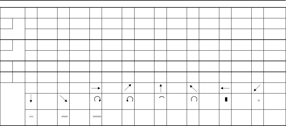
B-63943EN-2/07
APPENDIX
B.CODE TABLES
- 345 -
練 4E7D 連 4F22
ロ ろ 246D 路 4F29 労 4F2B 浪 4F32 漏 4F33 老 4F37 郎 4F3A 六 4F3B
録 4F3F 論 4F40
ワ ゎ 246E わ 246F 和 4F42 話 4F43 歪 4F44 脇 4F46 惑 4F47 枠 4F48
詫 4F4D 湾 4F51 腕 4F53
ヲ を 2472
ン ん 2473
特殊 α 2641 β 2642 2F40 2F41 2F42 2F43 2F44 2F45
記号 2F46 2F47 2F48 2F49
2F4A 2F4B 2F4C 2F50
2F51 2F52 2F53
C.DIFFERENCES FROM THE Series 16i APPENDIX
B-63943EN-2/07
- 346 -
C DIFFERENCES FROM THE Series 16i
C.1 MACRO COMPILER
Function Series 16i/18i/21i Series 30i/31i/32i/35i/0i-F/PMi
Program - Programs from O1 to O9999 can be
created.
- Up to 400 programs can be
registered.
- Programs from O1 to O99999999
can be created.
- Up to 1000 programs can be
registered.
Sequence number N1 to N99999 N1 to N99999999
Number of digits of a valid
setting
Up to 8 digits Up to 9 digits
Number of digits of a
macro variable number
Up to 6 digits Up to 9 digits
Number of IF statements in
one program
Up to 400 IF statements Up to 2000 IF statements
Number of IF statement
nesting levels
Up to 3 levels Up to 10 levels
Optional block skip Specifiable with an execution macro only Specifiable with an execution macro,
auxiliary macro, or conversational macro
Specification of
abbreviations of operation
commands (specification of
the first two characters
only, such as RO for
ROUND and FI for FIX)
Not allowed Allowed
PRM[#j]
PRM[#j,#k]
PRM[#j]/[#l]
PRM[#j,#k]/[#l]
Not allowed Allowed
ATAN[#j] Not allowed Allowed
ATAN[#j,#k] Not allowed Allowed
ATN[#j] Not allowed Allowed
ATN[#j,#k] Not allowed Allowed
ATN[#j/#k] Not allowed Allowed
RND[#j] Not allowed Allowed
SQR[#j] Not allowed Allowed
POW[#i,#j] Not allowed Allowed
C.2
EXECUTION MACRO FUNCTIONS
Function Series 16i/18i/21i Series 30i/31i/32i/35i/0i-F/PMi
Program - Programs from O1 to O9999 can be
created.
- Up to 400 programs can be registered.
- Programs from O1 to O99999999 can
be created.
- Up to 1000 programs can be
registered.
Sequence number N1 to N99999 N1 to N99999999

B-63943EN-2/07
APPENDIX
C.DIFFERENCES FROM THE Series 16i
- 347 -
Function Series 16i/18i/21i Series 30i/31i/32i/35i/0i-F/PMi
NC command specified in
a block containing a macro
call code based on a G or
M code
- If the NC command is specified before
the call code, it is ignored (with the
modal information updated). If the NC
command is specified after the call
code, it is treated as an argument.
- If multiple call codes are specified, the
first code is used for calling, and the
subsequent code or codes are treated
as arguments.
If the NC command is specified before
the call code, alarm PS0127 (NC
statement/macro statement duplication)
is issued. If the NC command is specified
after the call code, it is treated as an
argument.
Usable call command When an execution macro is called from
another execution macro, only G65/M98
can be specified.
(For example, an execution macro called
using a G code from a user program
cannot make a call by using an M code.)
When an execution macro is called from
another execution macro, G66/G66.1 can
be used in addition to G65/M98 if bit 2
(PCDC) of compile parameter No. 9163
is set to 1. Moreover, if bit 2 (PCDC) of
compile parameter No. 9163 is set to 1,
and bit 6 (GMP) of parameter No. 6008 is
set to 1, an M/S/T/D/H/second auxiliary
function/specific code/axis address can
be called from an execution macro called
with a G code, and calling based on a G
code is possible from an execution macro
called with M/S/T/D/H/second auxiliary
function/specific code/axis address.
If bit 6 (GMP) of parameter No. 6008 is
set to 0 or bit 2 (PCDC) of compile
parameter No. 9163 is set to 0, the series
are equivalent to Series 16i.
For details, see "Usable call command"
and "Limitations on calls" in Subsection
3.2.1.1, "Macro call and subprogram
call".
Priority if the call code in
the custom macro set in a
parameter is the same as
the call code in the
execution macro set in a
compile parameter
- In a macro call using a G code, by
setting bit 0 (MCG) of parameter No.
9013 to 1, the program in the custom
macro is called with a G code.
(This is effective to a macro call
using a G code. With any other call
code, the execution macro is given
priority.)
Example:
If 100 is set in both parameter No.
6050 and compile parameter No.
9013 and 110 is set in both
parameter No. 6071 and compile
parameter No. 9010, and if
parameter bit MCG is set to 1,
O9010 in the custom macro is called
when G100 is specified and O9001
is called when M110 is specified.
- In all macro/subprogram calls, a
custom macro program is called by
setting bit 1 (MCA) of parameter No.
9013 to 1. (This is effective to all call
codes.)
Example:
If 100 is set in both parameter No.
6050 and compile parameter No.
9013 and 110 is set in both
parameter No. 6071 and compile
parameter No. 9010, and if
parameter bit MCA is set to 1, O9010
in the custom macro is called when
G100 is specified and O9001 in the
custom macro is called when M110
is specified.
Nesting - 4 levels of subprogram calls
- 4 levels of macro calls
- 15 levels of subprogram calls alone
- 5 levels of macro calls alone
15 levels when combined

C.DIFFERENCES FROM THE Series 16i APPENDIX
B-63943EN-2/07
- 348 -
Function Series 16i/18i/21i Series 30i/31i/32i/35i/0i-F/PMi
Repetition based on
address L
When an execution macro is called from
a user program (other than G65/M98 and
calling of a user program as a
subprogram), the number of repeats
cannot be specified.
The number of repeats can be specified
in calls other than special macro calls
based on G/M/H/D/S/T code/axis
address in which address L is also used
as an argument. (However, when bit 5
(MCARG) of compile parameter No. 9008
is set to 1, address L is also used as an
argument, so that the number of repeats
cannot be specified in macro calling
based on a G/M code.)
Passing of arguments When bit 5 (MCARG) of compile
parameter No. 9008 is set to 1, G, L, N,
and P are additionally used as
arguments.
Even when bit 5 (MCARG) of compile
parameter No. 9008 is set to 0, N and P
are used as arguments. For address N,
the number of digits after the decimal
place becomes 0.
When bit 5 (MCARG) of compile
parameter No. 9008 is set to 1, G and L
are also used as arguments. Note that an
NC command input format limitation is
applied to address G. (For example,
specifying G1000 results in alarm
PS0010.)
O and N values and G codes other than
the 00 group are passed as modal
information to the subsequent blocks.
By setting bit 6 (INVIJK) of compile
parameter No. 9103 to 1, argument
specification I can be used regardless of
the order in which I, J, and K are
specified.
By setting bit 7 (IJK) of parameter No.
6008 to 1, argument specification I can
be used regardless of the order in which
I, J, and K are specified.
Local variable level When an execution macro is called with a
subprogram call from a user program, the
local variable level changes just like the
macro call.
A choice can be made by setting bit 3
(LCLLV) of compile parameter No. 9163.
=0 : The local variable level does not
change due to a subprogram call,
like the custom macro level.
=1 : Equivalent to Series 16i.
Macro call using a G code Special macro calling is disabled. If bit 5 (GMACC) of compile parameter
No. 9104 is set to 1, this results in special
macro calling.
Macro call using a G code
(specification of multiple
calls)
- Modal calling is disabled.
- Special macro calling is disabled.
- Modal calling is enabled.
- If bit 5 (GMACC) of compile
parameter No. 9104 is set to 1, this
results in special macro calling.

B-63943EN-2/07
APPENDIX
C.DIFFERENCES FROM THE Series 16i
- 349 -
Function Series 16i/18i/21i Series 30i/31i/32i/35i/0i-F/PMi
Macro modal call using a
G code
Only equivalent to G66.1. Different
specifications from those of a macro
modal call of a custom macro using a G
code. For example, a modal call is
canceled with G167 or the G code
specified with compile parameter No.
9034.
- Whether the call is equivalent to
G66/G66.1 can be selected with bit 1
(MCT) of compile parameter No.
9163.
- A choice can be made by setting bit
0 (GMC) of compile parameter No.
9163 as follows:
=0 : Same specifications as those of
a macro modal call of a custom
macro using a G code. For
example, it is canceled with G67.
=1 : Can be made equivalent to
Series 16i by setting bit 1 (MCT)
of compile parameter No. 9163
to 0.
G code for canceling a
macro modal call using a
G code
By using a cancellation G code, the
execution macro program O9006 can be
called as a macro.
Special macro call using a
T code/axis address
If a G code in G code group 01 exists,
G80 may be generated and 80. may be
included in variables #28 to #32.
Even if a G code in G code group 01
exists, G80 will never be generated.
An argument is truncated to include the
effective digits only, using the address
specifiable in the NC, and passed.
(Example) X123.45678 is regarded as
#24=123.456
An argument is rounded off to include the
effective digits only, using the address
specifiable in the NC, and passed.
(Example) X123.45678 is regarded as
#24=123.457
A macro is called after modal change
using the address specified in the call
block. (By setting bits 4 and 7 of compile
parameter No. 9101 to 1, modal change
can be disabled.)
A macro is called without modal change
using the address specified in the call
block.
The handling of a block for calling a
single command consisting of only a call
code depends on bit 6 (NOPB) of
compile parameter No. 9004 as follows:
=0: An empty block is generated, then
the execution macro is called after
execution.
=1: The execution macro is called
immediately without generating an
empty block.
No empty block is generated. (The
compile parameter NOPB is not used.)
Subprogram call using a
specific code/M/T code
The handling of a block for calling a
single command consisting of only a call
code depends on bit 6 (NOPB) of
compile parameter No. 9004 as follows:
=0: An empty block is generated, then
the execution macro is called after
execution.
=1: The execution macro is called
immediately without generating an
empty block.
No empty block is generated. (The
compile parameter NOPB is not used.)

C.DIFFERENCES FROM THE Series 16i APPENDIX
B-63943EN-2/07
- 350 -
Function Series 16i/18i/21i Series 30i/31i/32i/35i/0i-F/PMi
When a user program calls an execution
macro as a subprogram or calls another
user program as a subprogram, the level
of the local variables changes. (All local
variables are set to <null>.)
As with a custom macro, the local
variable level does not change due to a
subprogram call. (When an execution
macro is called from a user program, the
local variables set in the user program
are passed.) However, when bit 3
(LCLLV) of compile parameter No. 9163
is set to 1, compatibility with the Series
16i is provided. This means that when an
execution macro is called from a user
program, the level can be changed as in
the case of a macro call.
Subprogram call using
G66/G66.1 and an S
code/second auxiliary
function code
Not allowed G66/G66.1 can be used to call an
execution macro from another execution
macro. Subprogram calling based on an
S code/second auxiliary function code is
enabled when an execution macro is
called from a user macro or another
execution macro.
Subprogram call for user
program
The specification of a return destination
sequence number at the time of return is
disabled.
The specification of a return destination
sequence number at the time of return is
enabled.
From a called user program, another
user program can be called with
G65/M98/G66 only.
Limitations differ depending on bit 6
(GMP) of parameter No. 6008, bit 2
(PCDC) of compile parameter No. 9163,
and bit 6 (C16) of compile parameter No.
9163.
For details, see Subsection 3.2.26,
"Subprogram Call for User Program".
The duplicate calling of a user program
from an execution macro is disabled.
The duplicate calling of a user program
from an execution macro is enabled.
P-CODE workpiece
number search
Equivalent to macro calling only A function equivalent to a simple call
(G65)/subprogram call (M98) can be
selected.
An execution macro is executed even
when the main program is not selected.
No execution macro is executed when
the main program is not selected (when
there is no program to run).
Interruption type custom
macro that is executing an
execution macro
An interruption type custom macros is
invalid. (An interrupt signal may not be
operated when an execution macro is
being executed.)
An interruption type custom macros is
valid even when an execution macro is
being executed. The interrupted program
calls a user program. (It is impossible to
allow an execution macro to interrupt.)
B-63943EN-2/07
APPENDIX
C.DIFFERENCES FROM THE Series 16i
- 351 -
C.3 CONVERSATIONAL MACRO FUNCTIONS AND
AUXILIARY MACRO FUNCTIONS
Function Series 16i/18i/21i Series 30i/31i/32i/35i/0i-F/PMi
Conversational macro
execution
If a conversational macro that has the
value of the conversational macro
execution control variable (#8500) as its
program number is not found, no
conversational macro is executed.
If an error that prevents execution from
being continued occurs as in the case
where a conversational macro that has
the value of the conversational macro
execution control variable (#8500) as its
program number is not found, the
conversational macro screen displays the
occurrence of a fatal error (error number
10001).
If there is one
conversational macro
screen, the operation to
be performed when the
key is pressed on
the conversational macro
screen.
Control returns to the beginning of the
main program of the conversational
macro again, and then the operation is
executed. By setting bit 4 (CNCHG) of
compile parameter No. 9006 to 1, the
pressing of the key can be ignored and
the operation can be executed
continuously.
The pressing of the key is ignored. (Same
situation when bit 4 (CNCHG) of compile
parameter No. 9006 for Series 16i is set
to 1.)
Timing for determining
whether a cause for
ending the execution of
the conversational macro
function has occurred
When the program end instruction
(execution control code M99/M99Pp) in
the main program of the conversational
macro is executed, whether a cause for
ending the execution of the
conversational macro function has
occurred is determined.
- When bit 3 (TM99) of compile
parameter No. 9160 is set to 0:
When the block being executed ends,
whether a cause for ending the
execution of the conversational
macro function has occurred is
determined. Execution of the main
program is not continued until the
program end instruction (execution
control code M99/M99Pp) but the
screen is switched immediately.
- When bit 3 (TM99) of compile
parameter No. 9160 is set to 1:
Same as for Series 16i
Auxiliary macro execution An auxiliary macro that has the program
number set in compile parameter No.
9039 is executed. (Unlike a
conversational macro, programs to be
executed cannot be controlled using a
variable.)
The main program of an auxiliary macro
that has the value of the auxiliary macro
execution control variable (#8530) as its
program number is executed. (As with a
conversational macro, programs to be
executed can be controlled using the
variable.) When the power is turned on,
the value of compile parameter No. 9039
is set in the auxiliary macro execution
control variable (#8530).
If a program that has the program number
set in compile parameter No. 9039 is not
found, no program is executed.
If an error that prevents execution from
being continued occurs as in the case
where an auxiliary macro that has the
value of the auxiliary macro execution
control variable (#8530) as its program
number is not found, the conversational
macro screen displays the occurrence of
a fatal error.
C.DIFFERENCES FROM THE Series 16i APPENDIX
B-63943EN-2/07
- 352 -
Function Series 16i/18i/21i Series 30i/31i/32i/35i/0i-F/PMi
Conversational macro
and auxiliary macro
execution cycle
Auxiliary macros and conversational
macros are sequentially executed in this
order. (Execution is switched by an M99
block.)
Auxiliary macros and conversational
macros can be executed in parallel by
switching each time blocks as many as
the number set in parameter No. 9066 are
executed.
When bit 1 of parameter No. 9033 is set
to 0, sequential execution is performed as
with the Series 16i.
Forced termination of a
conversational
macro/auxiliary macro
Hold down the rightmost soft key [>]
(continuous menu key) and the numeric
key
on the MDI unit for about 10
seconds.
Press the key and key on
the MDI unit simultaneously. To enable
forced termination of an auxiliary macro,
bit 2 (AFT) of parameter No. 9036 must
be set to 1.
Alarm during
conversational macro
and auxiliary macro
execution
If a conversational macro that has the
value of #8500 as its program number is
not found, no conversational macro is
executed.
If a conversational macro that has the
value of #8500 as its program number is
not found, the conversational macro
screen displays an error.
If the GOTO destination N or N specified
with G243P_ cannot be found, the alarm
is ignored and the next block is executed.
If the GOTO destination N or N specified
with G243P_ cannot be found, a message
indicating that a fatal error occurs is
displayed on the conversational macro
screen (error number: 10002) and the
conversational or auxiliary macro is
stopped.
Execution control code The execution control codes are M98 and
M99. (G65 is not usable.)
The execution control codes are G65,
M98, and M99.
Specification of repetition Repetition cannot be specified using M98
used with a conversational macro/
auxiliary macro.
Repetition can be specified using address
L with G65/M98.
Nesting 4 levels of calls 15 levels of calls when macro calls and
subprogram calls are combined
Local variables Local variables cannot be used with a
conversational macro/auxiliary macro.
Local variables can be used with a
conversational macro/auxiliary macro.
C.4
MACRO VARIABLES
Function Series 16i/18i/21i Series 30i/31i/32i/35i/0i-F/PMi
Local variables Local variables can be used with an
execution macro only.
If array-type variables are invalid
(#8518=0), local variables can be used
even with conversational/auxiliary macros.
The local variables used are different from
those used with custom macros. So, even
when an execution macro is called as a
subprogram from a user program, the local
variable level changes, and the calling
local variable is not passed.
Local variables are assigned separately to
execution/conversational/auxiliary macros.
However, they are common to execution
and custom macros. So, when a
subprogram is called, the local variable
level does not change, and the calling local
variable is passed. (However, if bit 3
(LCLLV) of compile parameter No. 9163 is
set to 1, the local variable level changes
and the calling local variable is not passed
as with the Series 16i when an execution
macro is called as a subprogram from a
user program.)

B-63943EN-2/07
APPENDIX
C.DIFFERENCES FROM THE Series 16i
- 353 -
Function Series 16i/18i/21i Series 30i/31i/32i/35i/0i-F/PMi
Common variables - Common variables that can be used
are #100 to #149 and #500 to #531.
In an execution macro, however, #150
to #199 and #532 to #999 can be used
as custom macro common variables.
- Common variables are shared among
execution/conversational/auxiliary
macros. They are separate from
custom macro common variables
(#100 to #149 and #500 to #531).
- Common variables that can be used
are #100 to #199 and #500 to #999.
- Whether common variables are shared
among execution/ conversational/
auxiliary macros, whether common
variables are P-CODE macro common
variables independent of custom
macros, and whether common
variables are custom macro common
variables can be chosen using bits 0 to
7 (MV0 to MV7) of parameter No.
9034
Common variables cannot be protected. As with custom macros, multiple common
variables can be protected.
P-CODE variables P-CODE variables are used as variables
for floating-point data.
Whether P-CODE variables are used as
variables for floating-point data or for
integer data can be chosen.
The number of variables is set in a compile
parameter. When 1 is set, 100 variables
can be used.
The number of variables is set in
parameter No. 9053. When 1 is set, 1
variables can be used.
Extended P-CODE
variables
The number of variables is set in a compile
parameter. When 1 is set, 12 variables for
floating-point data or 30 variables for
integer data can be used.
The number of variables is set in
parameter No. 9054, regardless of the data
format. When 1 is set, one variable can be
used.
Program memory is used. Program memory is not used because a
dedicated area is used.
P-CODE variables /
extended P-CODE
variables between
paths
- By setting bit 1 (TTVR1) of compile
parameter No. 9007 to 1, it is possible
to write and read the P-CODE
variables of the first path in all paths.
- By setting bit 2 (TTVR2) of compile
parameter No. 9007 to 1, it is possible
to write and read the extended
P-CODE variables of the first path in
all paths.
- It can be selected using parameters
Nos. 9051 and 9052 whether to use
the P-CODE variables/extended
P-CODE variables of each path should
be used or those of a specified path
number should be used.
* If wishing to use the same variables in
multiple paths, set the same value in
parameter No. 9051 for P-CODE
variables and in parameter No. 9052
for extended P-CODE variables.
Variable display Variables cannot be input or output. Execution, conversational, and auxiliary
macros have their respective variable
screens. (Variables other than local
variables and control variables are actually
common to execution, conversational, and
auxiliary macros.)
Common variables, P-CODE variables,
and extended P-CODE variables can be
input and output.
For details, see Chapter 8, "Operation".
P-CODE macro UI/UO
separation function
To use input/output signals for P-CODE
macros EUI00 to EUI15 <G082 to G083> /
EUO00 to EUO15 <F084 to F085>, set bit
0 (DIOC) of compile parameter No. 9006 to
1.
To use input/output signals for P-CODE
macros EUI00 to EUI15 <G082 to G083> /
EUO00 to EUO15 <F084 to F085>, set bit
3 (EUI) of parameter No. 9035 to 1.

C.DIFFERENCES FROM THE Series 16i APPENDIX
B-63943EN-2/07
- 354 -
C.5 MACRO EXECUTOR FUNCTIONS
Function Series 16i/18i/21i Series 30i/31i/32i/35i/0i-F/PMi
Graphic resolution For an indicator with 7 soft keys
Bit 2 (HRGR) of compile parameter No.
9003 = 0
Standard mode: 320×270 dots
Bit 2 (HRGR) of compile parameter No.
9003 = 1
High resolution mode: 640×480 dots
640×480 dots as standard
Be sure to set bit 2 (HRGR) of compile
parameter No. 9003 to 1.
Character display (G243)
Address X, Y
Absolute command only When bit 3 (INCD) of compile parameter
No. 9167 is set to 1, switching between
the absolute command and incremental
command is enabled with G390/G391.
Character display (G243)
Address D
The number of significant display digits is
8.
The number of significant display digits is
12.
(However, no more than 9 digits can be
specified using an immediate value.)
Character display(G243)
Address F
The maximum number of digits is 8.
The number of decimal places is 3.
The maximum number of digits is 12.
The number of decimal places is 6.
Number of character string
sets specifiable in a single
character display (G243)
block
As many (_), (’_’), and (*_*) sets as
necessary can be specified in the same
block.
Up to five (_), (’_’), and (*_*) sets in total
are effective in the same block.
Sequence of modal
addresses processed with
a conversational macro
Unlike ordinary NC programs, the
conversational macro program
processes each address in the sequence
in which they were specified.
Example of operation
<1> F8.3;
G243 F5.1 D#100;
→ #100 is represented with F5.1.
<2> F8.3;
G243 D#100 F5.1;
→ #100 is represented with F8.3.
Like ordinary NC programs, the
conversational macro program
processes data other than character
strings in block units. Therefore,
operations do not change according to
the specified sequence.
Example of operation
<1> F8.3;
G243 F5.1 D#100;
→ #100 is represented with F5.1.
<2> F8.3;
G243 D#100 F5.1;
→ #100 is represented with F5.1.
Display if the same
addresses are specified in
the same block (G243)
They are all displayed in the order in
which they are specified.
The same addresses can be specified in
a single block, as in G243X_Y_C_C_.
The last address becomes effective.
Thus, the same addresses cannot be
specified in a single block as in
G243X_Y_C_C_. They must be specified
in separate blocks as shown below.
G243X_Y_C_;
C_;
Linear drawing (G01)
Addresses X and Y
Absolute command only When bit 3 (INCD) of compile parameter
No. 9167 is set to 1, switching between
the absolute command and incremental
command is enabled with G390/G391.
Circular drawing (G02 and
G03)
Addresses X, Y, I, and J
Absolute command only When bit 3 (INCD) of compile parameter
No. 9167 is set to 1, switching between
the absolute command and incremental
command is enabled with G390/G391.
Graphic filling function
(G206)
Addresses X and Y
Absolute command only When bit 3 (INCD) of compile parameter
No. 9167 is set to 1, switching between
the absolute command and incremental
command is enabled with G390/G391.

B-63943EN-2/07
APPENDIX
C.DIFFERENCES FROM THE Series 16i
- 355 -
Function Series 16i/18i/21i Series 30i/31i/32i/35i/0i-F/PMi
Rectangular display (G204)
Addresses X, Y, I, and J
Absolute command only When bit 3 (INCD) of compile parameter
No. 9167 is set to 1, switching between
the absolute command and incremental
command is enabled with G390/G391.
Cursor (rectangular cursor)
display (G230)
Not possible. X: X coordinate of the cursor display
position
Y: Y coordinate of the cursor display
position
L: Cursor length command
Graphic cursor function
(G249)
Addresses X and Y
Absolute command only When bit 3 (INCD) of compile parameter
No. 9167 is set to 1, switching between
the absolute command and incremental
command is enabled with G390/G391.
Drawing start point setting
(G242)
Addresses X and Y
Absolute command only When bit 3 (INCD) of compile parameter
No. 9167 is set to 1, switching between
the absolute command and incremental
command is enabled with G390/G391.
Prompt statement display
(G280)
Not allowed In the character string input mode (data
input control variable #8502 = 3), up to
39 characters can be displayed on the
key input line.
Graphic coordinate system
setting (G392)
Not allowed A specified position is set up as the
current position.
The subsequent drawing commands are
executed in this coordinate system.
Rapid traverse rate
specification (G311)
Not allowed X:Rapid traverse drawing speed ratio in
the X axis
Y:Rapid traverse drawing speed ratio in
the Y axis
Rapid traverse drawing
(G300)
Not allowed X:X coordinate for rapid traverse drawing
Y:Y coordinate for rapid traverse drawing
Marking (G317) Not allowed This code draws the mark specified for M
with the color specified for P at the
position specified for X and Y.
Base color for a
monochrome LCD
White Bit 0 (BGW) of parameter No.9032:
=0 : Black
=1 : White
NOTE: The monochrome LCD is for the
Series 30i /31i /32i -A.
Display of the type of 7 soft
keys with the type of 12
soft keys
Position indication currently selected on
the program screen
Overall position indication for up to five
axes
On a screen with background color, if bit
6 (C9WN) of compile parameter No.
9100 is set to 1, it is only for the
character coordinate that the upper left
position of the display area of the type of
7 soft keys is X0,Y0. (The cursor control
position is the same as that if C9WN is
set to 0.)
On a screen with background color, if bit
6 (C9WN) of compile parameter No.
9100 is set to 1, it is both for the
character coordinate and the cursor
control position (#8506, #8507) that the
upper left position of the display area of
the type of 7 soft keys is X0,Y0.
Help (Initial Menu) screen All the addresses of G243 are available. Only address P and character strings are
available.
(The character string display position and
character size cannot be specified.)
"4." is not automatically added to the
added character string.
"4." is automatically added to the added
character string.
C.DIFFERENCES FROM THE Series 16i APPENDIX
B-63943EN-2/07
- 356 -
Function Series 16i/18i/21i Series 30i/31i/32i/35i/0i-F/PMi
Help screen / User help
screen
While the conversational macro screen is
being displayed, the
key can be used to display the
Help screen/User help screen.
While the conversational macro screen is
being displayed, the screen cannot be
switched to the Help screen/User help
screen, using the key.
Key input line control
(#8561 to #8563) - #8561 : X coordinate of the key
input line display position
- #8562 : Y coordinate of the key
input line display position
- #8563 : Number of characters that
can be key-input
- #8564 : Prompt display color,
display type
- #8565 : Key input line display color,
display type
Only the position of the key input line can
be changed with #8561 to #8563. (#8564
or #8565 are not supported.)
MDI keyboard type reading
(#8533)
The function is not available. #8533 can be read using a
conversational or auxiliary macro.
MDI key image reading
(#8549)
Cannot be read using an auxiliary macro. - Can also be read using an auxiliary
macro.
- Some MDI key images are different.
PMC address reference The readable addresses are G, F, X, Y,
R, D, T, K, and C.
- The readable addresses are G, F, X,
Y, R, D, T, K, C, and E
- The data range is different.
CNC parameter reference There are parameters whose numbers
have been changed and those that have
been changed to the real type or path
type.
PMC address
reading/writing (G310)
The readable and writable addresses are
X, Y, D, R, C, and K.
The readable and writable addresses are
X, Y, D, R, C, K , T, and E.
The G310 block is executed as a macro
statement.
Value of bit 4 (NOB) of parameter No.
9036:
0: Executed as an NC statement.
1: Executed as a macro statement.
Writing setting parameters
and parameters
G312 is used. G314 is used.
Because there are parameters whose
numbers are different from those of
Series 16i/18i/21i or whose types have
been changed to the integer type or path
type, the G code, format, setting method,
and so forth are different.
Reader/puncher interface
G335/G337
When there is no
received data.
- When there is no received data,
completion code variable #8539 is set
to 255 and block is over at once.
- When there is no received data, the
operation of the block is decided
depending on a set value of executor
parameter No.9056.
0: The block is not ended
while there is no receive
data.
1 to 180: Time-out period for waiting
for reception (1 to 180sec).
If the system is placed in
the data reception waiting
state for a specified time,
completion code variable
#8539 is set to 255.

B-63943EN-2/07
APPENDIX
C.DIFFERENCES FROM THE Series 16i
- 357 -
Function Series 16i/18i/21i Series 30i/31i/32i/35i/0i-F/PMi
- There is no setting for the block can
be ended by an NC reset even within
the wait time.
- By setting bit 1 (RCN) of executor
parameter No.9035 to 1, the block can
be ended by an NC reset even within
the wait time.
Reader/puncher interface
G336/G338
Transmission is waiting.
- When transmission is waiting, the
operation of the block is decided
depending on a set value of executor
parameter No.9056.
0: Time-out period for waiting
for transmission
(5000msec).
1 to 32767: Time-out period for waiting
for transmission (1 to
32767msec).
-1: The block is not ended
while transmission is
waiting.
If the system is placed in
the data transmission
waiting state for a
specified time, completion
code variable #8539 is set
to 12.
- When transmission is waiting, the
operation of the block is decided
depending on a set value of executor
parameter No.9056.
0: The block is not ended
while there is no
transmitted data.
1 to 180: Time-out period for waiting
for transmission (1 to
180sec).
If the system is placed in
the data transmission
waiting state for a specified
time, completion code
variable #8539 is set to
255.
- By setting bit 4 (RCN) of compile
parameter No.9009 to 1, the block can
be ended by an NC reset even within
the wait time.
- By setting bit 1 (RCN) of executor
parameter No.9035 to 1, the block can
be ended by an NC reset even within
the wait time.
Reader/puncher interface
G336/338
data transmission timing
Data is output on a code-by-code basis. Data is output on a per-block basis. Also,
the next output command (R100/R1xx)
allows data to be stored in the transmit
buffer and to be output when a G336 or
338 command without the next output
command is executed, thus speeding up
macro execution.
Reader/puncher interface/
memory card control
G336 (data writing)
Addresses are processed in the order
they are specified.
Operation example
<1> F8.3;
G336 F5.1 D#100;→ #100 is output
with F5.1.
<2> F8.3;
G336 D#100 F5.1;→ #100 is output
with F8.3.
Data is processed in blocks. Therefore,
the operation is not changed by the order
the addresses are specified.
Operation example
<1> F8.3;
G336 F5.1 D#100; → #100 is
output with
F5.1.
<2> F8.3;
G336 D#100 F5.1; → #100 is
output with
F5.1.
If identical addresses are specified in the
same one block, they are output in the
order in which they are specified.
More than one address can be specified
in a block, as in G336C_C_.
If two or more identical addresses are
specified in the same one block, the last
specified address takes effect. It is not
allowed to specify more than one
address in a block, as in G336C_C_.
Addresses must be specified in separate
blocks as shown below.
G336C_;
C_;

C.DIFFERENCES FROM THE Series 16i APPENDIX
B-63943EN-2/07
- 358 -
Function Series 16i/18i/21i Series 30i/31i/32i/35i/0i-F/PMi
Any number of ( _ ), ( ’_ ’), and (*_*)
combinations may be specified in the
same one block.
Up to five ( _ ), ( ’_ ’), and (*_*)
combinations may be specified in total in
the same one block.
Space is not output when "LF" is output. Bit 0 (NTV) of compile parameter No.
9167 allows you to choose whether to
output TV check space when "LF" is
output.
Reader/puncher interface/
memory card control
G338 (macro variable data
output)
- The maximum number of digits for
automatic decimal point position
output of F-9.9 is 9.
- F-9.8 specifies output in a special
floating-point format.
- The maximum number of digits for
automatic decimal point position
output of F-9.9 is 12.
- F-9.8 specifies output in the
IEEE-compliant floating-point format.
Data output in the special format of
the Series 16i cannot be read with
G337.
Reader/puncher interface/
memory card control
completion code (#8539)
Added partially
G330 Memory card read
control
Both address ’F’ (file number) and
address ’L’ (file name) can be used to
specify a file.
Only address ’L’ (file name) can be used
to specify a file.
G330 Memory card write
control
If a file with the same name exists on the
memory card, the file is overwritten.
If a file with the same name exists, an
error occurs and the file cannot be
opened.
CNC program referencing
and writing
To use this function, the background
editing function is required as an CNC
function.
No background editing function is
required.
The program number under background
editing can be read with #8525.
Reading is now possible even in the
background editing status and, therefore,
variable #8525 is disabled. "0" is always
read.
It can be read with #8526 whether
background editing is stopped (= 0) or
active (= 1).
Reading is now possible even in the
background editing status and, therefore,
variable #8526 is disabled. "0" is always
read.
If the memory protection signal (KEY3) is
off, program editing is impossible.
By setting bit 1 (KEYC) of compile
parameter No. 9006 to 1, editing is
possible even in the program editing
prohibited state due to the memory
protection signal (KEY3) or the 8-level
data protection function.
Reading a specified
word-type block (G325) of
CNC program referencing
and writing
When a value specified without the
decimal point is read, the position of the
decimal point is always determined by
calculator type decimal point input.
When a value specified without the
decimal point is read, the position of the
decimal point is determined as follows.
Bit 2 (PRDPI) of compile parameter No.
9160
=0: Determined by bit 0 (DPI) of
parameter No. 3401
=1: Always determined by calculator
type decimal point input

B-63943EN-2/07
APPENDIX
C.DIFFERENCES FROM THE Series 16i
- 359 -
Function Series 16i/18i/21i Series 30i/31i/32i/35i/0i-F/PMi
When the O-number block is read with 1
specified in block number variable
#8521, the O number cannot be read.
When the O-number block is read with 1
specified in block number variable
#8521, the operation differs depending
on bit 6 (PG1O) of compile parameter
No. 9160, as follows.
=0: All words including the O number
can be read.
=1: Words excluding the O number can
be read.
Reading a specified
character-type block
(G328) of CNC program
referencing and writing
When the O-number block is read with 1
specified in block number variable
#8521, the O number cannot be read.
When the O-number block is read with 1
specified in block number variable
#8521, the operation differs depending
on bit 6 (PG1O) of compile parameter
No. 9160, as follows.
=0: All characters including the O
number can be read.
=1: Characters excluding the O number
can be read.
Writing a specified
word-type block (G326) of
CNC program referencing
and writing
When data is read having one or more
0s after the decimal point, the 0s after
the decimal point are not output
regardless of the decimal point position.
(Example)
When address code = X, value =
123.000, and number of digits after
the decimal point = 3
X123. is written.
When data is read having one or more
0s after the decimal point, the 0s are
output based on the decimal point
position.
(Example)
When address code = X, value =
123.000, and number of digits after
the decimal point = 3
X123.000 is written.
Program condensation of
CNC program referencing
and writing
Only the program specified with #8520 #8520=0: The entire program memory
is condensed.
#8520≠0: A specified program is
condensed.
Completion code of CNC
program referencing and
writing (#8529)
In addition to the completion codes
indicated in the completion code list,
there are completion codes posted with
the same numbers as PS alarm
numbers.
Detail completion codes are provided. No
codes other than those indicated in the
list are output.
Special code of CNC
program referencing and
writing
Usable codes are added.
Cutting period reading and
presetting
Even if presetting is performed,
parameter Nos. 6753 and 6754 are not
modified.
Both reading and presetting are
performed based on parameter Nos.
6753 and 6754.
Cutting distance
accumulation along
arbitrary axes only
The first, second, and third controlled
axes only can be selected.
All axes can be selected.
Relative coordinate
presetting
If specified in an execution macro, a
G310 block is executed as a macro
statement.
If specified in an execution macro, a
G310 block is executed depending on bit
4 (NOB) of parameter No. 9036 as
follows:
=0 : as an NC statement.
=1 : as a macro statement.
C.DIFFERENCES FROM THE Series 16i APPENDIX
B-63943EN-2/07
- 360 -
Function Series 16i/18i/21i Series 30i/31i/32i/35i/0i-F/PMi
Processing and
referencing P-CODE
variables as array type
Variables 1 to 99 are always array-type
variables.
Variables can be switched between local
variables and array-type variables with
the setting of variable #8518.
=0 : Variables #1 to #33 are local
variables, and
#34 to #99 are unusable.
=1 : Variables #1 to #99 are array-type
variables.
PMC axis control PMC controlled-axis selection variable
#8700 is specified with a relative
controlled axis number in the path.
PMC controlled-axis selection variable
#8700 is specified depending on bit 7
(PMX16) of compile parameter No.9160
as follows:
=0 : Specified with a system common
controlled axis number.
=1 : Specified with a relative controlled
axis number in the path.
For relationships between control
variables and groups, use four groups A
to D for each path.
Bit 7 (PMX16) of compile parameter No.
9160
=0 : Use groups 1 to 4 regardless of the
path.
=1 : Use groups (4N - 3) to (4N)
depending on the path
(where N denotes a path number (1
to 10)).
The travel distance specified by a control
travel distance variable (#8713, #8723,
#8733, or #8743) is represented in the
least input increment.
Depending on the bit 5 (TDVDPI) of
compile parameter No. 9160, the travel
distance specified by a control travel
distance variable (#8713, #8723, #8733,
or #8743) is represented in
=0 : Calculator type decimal point input
=1 : Least input increment.
Axis-direction-by-axis-direc
tion interlock function
(#8600, #8601, #8607,
#8608)
The PMC internal relay (R area) signal is
set with compile parameters Nos. 9035
and 9036.
The PMC internal relay (R area) signal is
set with parameters Nos. 9069 and 9070.
The skip signal is determined by the
SKIP <X004.7> signal.
The skip signal can be selected with bit 6
(SKX) of parameter No. 9035.
=0 : SKIPP<Gn006.6>
=1 : SKIP<X004.7>
Window function Controlled axis number/spindle number
are specified with #8997.
A completion code is set in #8996.
Alarms etc. have been changed.
Diagnoses etc. are changed.
C.6
DEBUG FUNCTION
Function Series 16i/18i/21i Series 30i/31i/32i/35i/0i-F/PMi
Break function By parameter setting, conversational
macro program execution can be
stopped at the position of a specified
program and sequence number.
The debug function enables program
execution to be stopped by specifying a
program number, sequence number, the
number of execution blocks, or the
number of repeats.
B-63943EN-2/07
APPENDIX
C.DIFFERENCES FROM THE Series 16i
- 361 -
C.7 PARAMETERS
In migrating from the Series 16i to the Series 30i, it is necessary to consider those parameters that have
been changed to compile parameters to executor parameters and those parameters that must newly be set.
C.7.1
Parameters That Must Always Be Set
9048 P-CODE number of an execution macro
Select the P-CODE number (number specified by "P-CODE_NUMBER=" in the link control file) of the
execution macro program to be executed in each path.
* The execution macro is not executed in any path for which 0 is set.
9049 P-CODE number of a conversational macro
Select the P-CODE number (number specified by "P-CODE_NUMBER=" in the link control file) of the
conversational macro program to be executed in each path.
* The conversational macro is not executed in any path for which 0 is set.
9050 P-CODE number of an auxiliary macro
Select the P-CODE number (number specified by "P-CODE_NUMBER=" in the link control file) of the
auxiliary macro program to be executed in each path.
* The auxiliary macro is not executed in any path for which 0 is set.
If using P-CODE variables (#10000 and up)
9051 Area number of P-CODE variables (#10000 and up)
9053 Number of P-CODE variables (#10000 and up)
If using extended P-CODE variables (#20000 and up)
9052 Area number of extended P-CODE variables (#20000 and up)
9054 Number of extended P-CODE variables (#20000 and up)
C.7.2
Parameters That Have Been Added, Changed, and Abolished
C.7.2.1
Compile parameters
Series 16i/18i/21i Series 30i/31i/32i/35i/0i-F/PMi Description
Bit 3 (EVF) of compile parameter
No.9002
Changed to bit 4 (EVF) of
parameter No. 9033.
Format of extended P-CODE variable area
(#20000 and up)
Bit 4 (XDIL) of compile parameter
No.9002
Changed to bit 0 (XIT) of
parameter No. 9035.
Whether the axis-direction-by-axis-direction
interlock function is enabled or disabled
Bit 2 (HRGR) of compile
parameter No.9003
Always set it to 1.
Bit 4 (HRGC) of compile
parameter No.9004 and bit 7
(HRGCC) of compile parameter
No.9008
Converged into bit 2 (MVD) of
parameter No. 9033.
Note: For a monochrome LCD, the base
color differs depending on bit 0
(BGW) of parameter No. 9032.
The monochrome LCD is for the
Series 30i /31i /32i -A.
Bit 6 (NOP_B) of compile
parameter No.9004
Abolished. No free blocks will be created. (Only the
operation to be performed if bit 6 of compile
parameter No. 9004 is set to 1)

C.DIFFERENCES FROM THE Series 16i APPENDIX
B-63943EN-2/07
- 362 -
Series 16i/18i/21i Series 30i/31i/32i/35i/0i-F/PMi Description
Bit 5 (RSCRS) of compile
parameter No.9005
Abolished. The RS signal is not turned OFF when the
reader/puncher interface sends "DC3".
(Only the operation to be performed if bit 5
of compile parameter No. 9005 is set to 1)
Bit 0 (DIOC) of compile
parameter No.9006
Changed to bit 3 (EUI) of
parameter No. 9035.
Specification of the UI/UO signals of an
execution macro/conversational macro
Bit 5 (DAUX) of compile
parameter No.9002 and bit 3
(DAUXR) of compile parameter
No.9006
Converged into bit 5 (DAUX) of
compile parameter No. 9002. Whether the screen is switched to the
conversational macro screen at power-on.
Bit 4 (CNCHG) of compile
parameter No.9006
Abolished. If, while a program is being executed on the
conversational macro screen, the
[CUSTOM] key is pressed, the program will
never be executed starting at the beginning
of the main program of the conversational
macro. (Only the operation to be performed
if bit 4 of compile parameter No. 9006 is set
to 1)
Bit 1 (TTVR1) of compile
parameter No.9007
Changed to parameter No. 9051. By specifying the area for the P-CODE
variables (#10000 and up) to be used for
each path and setting the same area, the
variables are specified as common ones.
Bit 2 (TTVR2) of compile
parameter No.9007
Changed to parameter No. 9052. By specifying the area for the extended
P-CODE variables (#20000 and up) to be
used for each path and setting the same
area, the variables are specified as
common ones.
Bit 4 (PRRST) of compile
parameter No.9009
Changed to bit 1 (RCN) of
parameter No. 9035.
Whether the reader/puncher control due to
a conversational macro should be
interrupted with an NC reset.
Compile parameter No.9035 Changed to parameter No. 9069. PMC internal relay (R area) address and bit
position of axis-direction-by-axis-direction
interlock mode signal
Compile parameter No.9036 Changed to parameter No. 9070.
Compile parameter No.9037 Changed to parameter No. 9053.
* The number of parameters is
changed to 1, with the unit of
data being "1".
Number of P-CODE variables (#10000 and
up) to use
Note: One variable is used if parameter
No. 9053 is set to 1. (Only #10000
can be used.)
Compile parameter No.9044 Changed to parameter No. 9054.
* The number of parameters is
changed to 1, with the unit of
data being "1".
Number of extended P-CODE variables
(#20000 and up) to use
Note: One variable is used if parameter
No. 9054 is set to 1. (Only #20000
can be used.)
Compile parameter No.9055 Abolished. The conversational macro alarm/auxiliary
macro alarm functions are not provided.
Use the debugging function.
Bit 2 (CUR2) of compile
parameter No.9100
Abolished. Abolished because of the enhancement of
the P-CODE variable screen.
Bit 4 (TMCMD) of compile
parameter No.9101
Abolished. In a special macro call using a T code, a
modal call will never change due to the call
T code. (Only the operation to be performed
if bit 4 of compile parameter No. 9101 is set
to 1)
Bit 7 (AXMODL) of compile
parameter No.9101
Abolished. In a special macro call using an axis
address, a modal call will never change due
to the axis address. (Only the operation to
be performed if bit 7 of compile parameter
No. 9101 is set to 1)
Bits 0 (NOCAL1) to 2 (NOCAL3)
of compile parameter No.9102
Changed to bit 0 (NDTx) of
parameter No. 9026.
Whether or not included in the cumulative
cutting distance.
Supports all axes.

B-63943EN-2/07
APPENDIX
C.DIFFERENCES FROM THE Series 16i
- 363 -
Series 16i/18i/21i Series 30i/31i/32i/35i/0i-F/PMi Description
Bit 2 (G80NOAG) of compile
parameter No.9103
Abolished. Even if a G code in G code group 01 is
specified in a special macro call, G80 will
never be generated. (Only the operation to
be performed if bit 2 of compile parameter
No. 9103 is set to 1)
Bit 3 (ARGEF) of compile
parameter No.9103
Abolished. Abolished because arguments E and F are
always separate from each other in a
special macro call (E being #8 and F being
#9).
Bit 5 (SHSCYCL) of compile
parameter No.9103
Changed to bit 5 (SHS) of
parameter No. 9033.
Whether to use variable #20000 and up as
extended P-CODE variables when the
high-speed cycle cutting function is enabled
Bit 6 (INVIJK) of compile
parameter No.9103
Changed to bit 7 (IJK) of
parameter No. 6008.
Whether to use argument addresses I, J,
and K as argument I only.
* Also used as custom macro parameters.
None Bit 5 (GMACC) of compile
parameter No.9104
A macro call using a G code can be used
as a special macro call function.
None Bit 0 (SSC) of compile parameter
No.9105
A subprogram call using an S code can be
made.
None Bit 1 (BSC) of compile parameter
No.9105
A subprogram call using a second auxiliary
function code can be made.
Compile parameter No.9110 Changed to parameter No. 9072. Number of blocks that process macro
statements in an execution macro program
consecutively.
None Bit 0 (CUNIT) of compile
parameter No.9160
The unit of the cumulative cutting distance
(#8554) can be made a real value.
None Bit 1 (KY100) of compile
parameter No.9160
Whether to add +100 to #8501 for a key
input variable with decimal point
programming
None Bit 2 (PRDPI) of compile
parameter No.9160
By setting this compile parameter bit to 1, in
reading a specified word-type block (G325)
with the CNC program reference function,
the decimal point position of the read-out
numeric value is always subject to
calculator type decimal point input
(equivalent to the Series 16i).
None Bit 3 (TM99) of compile
parameter No.9160
By setting this compile parameter bit to 1,
the conversational macro function does not
terminate until M99 is executed (equivalent
to the Series 16i).
None Bit 5 (TDVDPI) of compile
parameter No.9160
By setting this compile parameter bit to 1, in
PMC axis control using variables, the travel
distance specified for control travel distance
variables (#8713, #8723, #8733, #8743) is
represented in the least input increment
(equivalent to the Series 16i).
None Bit 6 (PG10(No.9160#6) By setting this compile parameter bit to 1, if,
in reading a specified block (G325/G328),
an O-number block is read by setting 1 in
block number variable #8521, words
(characters) excluding the O number can be
read (equivalent to the Series 16i).
None Bit 7 (PMX16) of compile
parameter No.9160
By setting this compile parameter bit to 1, in
PMC axis control, the number of the
controlled axis selected with axis selection
variable #8700 becomes a relative
controlled axis number in the path
(equivalent to the Series 16i).
None Bit 0 (GMC) of compile
parameter No.9163
By setting this compile parameter bit to 1, a
modal call using a G code is equivalent to
that of the Series 16i.
C.DIFFERENCES FROM THE Series 16i APPENDIX
B-63943EN-2/07
- 364 -
Series 16i/18i/21i Series 30i/31i/32i/35i/0i-F/PMi Description
None Bit 1 (MCT) of compile parameter
No.9163
A macro modal call using a G code can be
made into move command calling
(equivalent to G66).
None Bit 2 (PCDC) of compile
parameter No.9163
An execution macro can be called from
another execution macro, using codes other
than G65 and M98.
None Bit 3 (LCLLV) of compile
parameter No.9163
By setting this compile parameter bit to 1,
the local variable level is changed if an
execution macro is called from a user
program, using a subprogram call
(equivalent to the Series 16i).
None Bit 4 (P98) of compile parameter
No.9163
An execution macro for P-CODE workpiece
number search can be made equivalent to a
subprogram call.
None Bit 6 (C16) of compile parameter
No.9163
By setting this compile parameter bit to 1,
an execution macro can be called using all
call codes when an execution macro
program is to be called for user program
called using a subprogram call (equivalent
to the Series 16i).
None Bit 0 (X09CL) of compile
parameter No.9164 to bit 7
(X24CL) of compile parameter
No.9165
For use with special macro program calls
using the 9th- to 24-axis addresses
None Bit 0 (NTV) of compile parameter
No.9167
Whether to output spaces for a TV check
when "LF" is output with G336 (data
transmission)
None Bit 3 (INCD) of compile
parameter No.9167
It is possible to switch between absolute
and incremental commands, using G390
and G391, for coordinates (X, Y, I, J) in the
character/graphic coordinate systems. (See
Subsection 6.1.3.16, "Absolute mode
(G390)/incremental mode (G391)
specification".)
None Bit 7 (PL30) of compile
parameter No.9167
For a screen with background color, the
color of the color palette can be selected
between the Series 16i standard color and
Series 30i standard color.
C.7.2.2
Executor parameters
Series 16i/18i/21i Series 30i/31i/32i/35i/0i-F/PMi Description
Bit 2 (STP) of parameter No.9000 Abolished. (Meaning varies in this
parameter according to the same
parameter number of Series16i.)
Abolished because the break state of a
conversational/auxiliary macro is checked
using the debugging function.
None Bit 2 (STP) of parameter No.9000 When the debugging function is enabled (bit
0 (DBG) of parameter No. 9033 = 1), it is
possible to select between continuous
operation and single-block execution when
starting a conversational macro.
Bit 3 (EXS) of parameter
No.9000
Abolished. Even if feed hold is applied while a macro
statement block of an execution macro is
being executed, it does not stop there.
(Only the operation to be performed if bit 3
of parameter No. 9000 is set to 1.)

B-63943EN-2/07
APPENDIX
C.DIFFERENCES FROM THE Series 16i
- 365 -
Series 16i/18i/21i Series 30i/31i/32i/35i/0i-F/PMi Description
Bit 7 (L2R) of parameter No.9000 Abolished. For an execution macro of macro
statements only, it is not possible to keep
executing the execution macro only (without
executing conversational/auxiliary macros
or displaying).
Note that the number of blocks to be
executed consecutively is specified for
parameter No. 9072.
Bits 4 (ASTP), 6 (MAAM), and 7
(MAAM) of parameter No.9011
Abolished. The conversational macro alarm/auxiliary
macro alarm functions are not provided.
Use the debugging function.
(See Chapter 7, "Debugging Function".)
Bit 0 (MCG) of parameter
No.9013
Abolished. Made effective to not only macro calls using
a G code but also all other calls. Thus, the
parameter No. is changed.
See the description of bit 1 (MCA) of
parameter No. 9013.
None Bit 1 (MCA) of parameter
No.9013
If the call code of the custom macro set with
a parameter is the same as the call code of
the execution macro set with a compile
parameter, the call of the custom macro can
be given priority.
None Bit 0 (09M) of parameter No.9020
to bit 7 (24M) of parameter
No.9021
For use with special macro program calls
using the 9th- to 24th-axis addresses
None Bit 0 (BGW) of parameter
No.9032
By setting this compile parameter bit to 1,
the base color can be set to white for a
monochrome LCD (equivalent to the Series
16i).
NOTE: The monochrome LCD is for the
Series 30i /31i /32i -A.
None Bit 0 (DBG) of parameter
No.9033
Whether to start a conversational macro in
debug mode. (See Chapter 7, "Debugging
Function".)
None Bit 1 (SEP) of parameter
No.9033
Auxiliary/conversational macros can be
executed in parallel. (See Subsection 4.2.3,
"Execution Cycle".)
None Bit 3 (EV2) of parameter No.9033 P-CODE variables (#10000 and up) can be
made integer data.
None Bits 0 (MV0) to 7 (MV7)of
parameter No.9034
Common variables (#100 to #199 and #500
to #999) can be made common variables of
custom macros. (See Section 5.3,
"Common Variables".)
None Bit 4 (CWB) of parameter
No.9035
In a reader/puncher interface output
command (G336/G338), high-speed output
is possible by specifying R100.
None Bit 5 (NPA) of parameter
No.9035
In the state in which a main program is not
selected (there is no program to run),
automatic operation cannot be started. By
setting this parameter bit to 1, this causes
an alarm.
None Bit 6 (SKX) of parameter
No.9035
By setting this parameter to 1, in
#8601/#8608 (movement axis and direction
variables for the rise time of the skip signal),
SKIP (X signal) is set as the skip signal
(equivalent to the Series 16i).
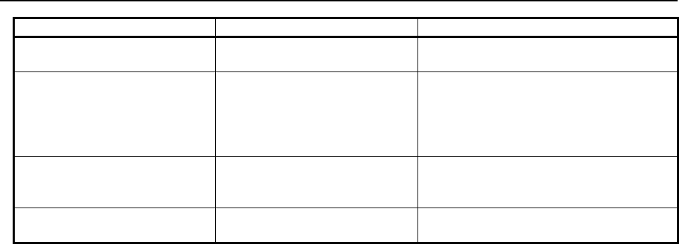
C.DIFFERENCES FROM THE Series 16i APPENDIX
B-63943EN-2/07
- 366 -
Series 16i/18i/21i Series 30i/31i/32i/35i/0i-F/PMi Description
None Bit 2 (AFT) of parameter No.9036 The auxiliary macro function can be
terminated forcibly.
None Bit 4 (NOB) of parameter
No.9036
By setting this parameter bit to 1, a G310
(relative coordinate preset function and
PMC data read/write function) of an
execution macro is executed as a macro
statement (same as the Series 16i).
None Bit 5 (PRS) of parameter
No.9036
In a command to read a specified block of a
CNC program (G325/G328), consecutive
blocks can be read at high speed.
None Parameters Nos.9067 and 9068 Any range of common variables #500 to
#999 can be protected.

B-63943EN-2/07
INDEX
i-1
INDEX
<A>
Absolute mode (G390)/incremental mode (G391)
specification ............................................................. 158
ADDRESS FUNCTIONS ............................................ 185
Alarm Information and External Alarm Information ... 267
Appendix tables ............................................................ 235
ARITHMETIC AND LOGIC OPERATION ............... 112
ARRAY-TYPE PROCESSING AND REFERENCING
OF P-CODE VARIABLES ...................................... 240
AUXILIARY MACRO FUNCTION ............................. 88
Axis Specification and Extended Axis Name
Specification Using an Axis Number ........................ 74
Axis specification using an axis number ........................ 74
Axis, Relative Coordinate, Servo Motor Load Current
Value, and Positional Deviation value ...................... 272
AXIS-DIRECTION-BY-AXIS-DIRECTION
INTERLOCK FUNCTION (#8600, #8601, #8607,
AND #8608) ............................................................. 261
<B>
Brightness modulation mode display on the
monochrome LCD and base color ........................... 165
<C>
CALLING AN EXECUTION MACRO ........................ 13
Caution ........................................................... 111,252,260
Character display (G243) ............................................. 140
Character String Registration Program Number
Specification (#8509) ............................................... 167
Circular drawing (clockwise) (G02) ............................. 155
Circular drawing (counterclockwise) (G03) ................. 155
CNC DATA READING/WRITING ............................ 191
CNC Parameter Reference ........................................... 187
CNC PROGRAM REFERENCING AND WRITING,
AND PROGRAM INFORMATION READING ..... 220
CODE TABLES ........................................................... 338
Color specification (G240) ........................................... 129
Command .................................................................. 88,90
Command for display with background color (G250) .. 131
Command Key Input Variable (#8501) ........................ 176
Commands which cannot Use Execution Macros .......... 73
COMMON CONVERSATIONAL MACRO
FUNCTION ................................................................ 94
COMMON VARIABLES (#100 TO #199 AND #500
TO #999) .................................................................. 101
COMPILE PARAMETERS .................................. 296,361
Completion code ................................................... 194,196
Completion code (#8529) ............................................. 233
Completion Codes (#8539) ................................... 211,218
Consecutive Input of Cursor and Page Keys ................ 181
Control Examples ......................................................... 252
CONVERSATIONAL MACRO FUNCTION ............... 85
CONVERSATIONAL MACRO FUNCTION AND
AUXILIARY MACRO FUNCTION ......................... 85
CONVERSATIONAL MACRO FUNCTIONS AND
AUXILIARY MACRO FUNCTIONS ..................... 351
Cursor control (#8505, #8506, and #8507) .................. 158
Cursor display (rectangular cursor) (G230) ................. 157
CUSTOM MACRO COMMON VARIABLES (#99100
TO #99999) .............................................................. 106
CUSTOM MACRO SYSTEM VARIABLES (#1000
AND UP, #10000 AND UP, #100000 AND UP) .... 107
CUTTING TIME, DISTANCE READ AND PRESET
FUNCTIONS ........................................................... 236
<D>
Data Input Control Variable (#8502) ........................... 179
Data Transmission/Reception Waiting ......................... 205
DEBUG FUNCTION ................................................... 360
DEBUGGING FUNCTION ......................................... 281
DEFINITION OF WARNING, CAUTION, AND
NOTE ........................................................................ s-1
Details of control codes ................................................ 245
Details of control variables .......................................... 250
DIAGNOSIS DATA ...................................................... 73
Diagnosis Information .................................................. 275
Direct language specification function ......................... 144
DIRECT SETTING BY PARAMETER AND KEY .... 285
Display 7 Soft Keys Data on the 12 Soft Keys Type ... 171
DISPLAYING AND SETTING MACRO VARIABLE
VALUES .................................................................. 287
DISPLAYING AND SETTING ON THE DEBUGGER
SCREEN .................................................................. 281
Drawing line type specification (G244) ....................... 154
Drawing start point setting (G242) ............................... 130
<E>
Error Messages ............................................................. 256
ERROR NO. LIST ....................................................... 333
Execution and Termination ....................................... 86,89
EXECUTION CONTROL CODE ................................. 91
EXECUTION CONTROL VARIABLES (#8500,
#8550, #8551, AND #8530) ...................................... 93
Execution Cycle ............................................................. 90
EXECUTION MACRO FUNCTION ............................ 13
EXECUTION MACRO FUNCTIONS ........................ 346
EXECUTOR PARAMETERS .............................. 316,364
Extended Data Input Control Variable (#8552) ........... 180
EXTENDED P-CODE VARIABLES (#20000 TO
#89999) .................................................................... 104
<F>
FANUC Cassette Control ............................................. 207
FATAL ERROR ............................................................ 95
FILE CONTROL ......................................................... 254
Function ....................................................................... 198
FUNCTION FOR SEARCHING DATA TABLES FOR
CONTROL VARIABLES ....................................... 277
Functions ...................................................................... 214

INDEX
B-63943EN-2/07
i-2
Functions which cannot Use Execution Macros ............. 74
<G>
G Code System Conversion (for a Lathe System) .......... 79
GENERAL .......... 1,13,197,213,220,243,248,254,263,281
GENERAL WARNINGS FOR CNC APPLICATION
DEVELOPMENT ...................................................... s-1
GENERAL WARNINGS FOR MACRO EXECUTOR
APPLICATION DEVELOPMENT .......................... s-3
Graphic coordinate system setting (G392) ................... 159
Graphic cursor function (G249) ................................... 157
Graphic filling function (G206) ................................... 161
<I>
Independent Operating Environment for Each Path ....... 10
Interruption Type Custom Macro ................................... 74
<K>
KEY INPUT AND DATA INPUT CONTROL ........... 176
Key Input Line Control (#8561 to #8563) .................... 181
<L>
Limitations ............................................................ 234,248
Limitations on Commands ............................................... 6
LIMITATIONS ON EXECUTION MACROS .............. 73
Linear drawing (G01) ................................................... 155
List of Commands ........................................................ 257
Local variable levels ...................................................... 25
LOCAL VARIABLES (#1 TO #33) / ARRAY-TYPE
VARIABLES (#1 TO #99) ...................................... 101
<M>
Macro call and subprogram call ..................................... 13
Macro Call Argument for Axis Name Expansion .......... 71
Macro call using a cancel G code for a macro modal call
using G code ............................................................... 36
Macro Call Using G Code .............................................. 28
Macro Call Using G Code (Specification of 1 Set) ........ 30
Macro Call Using G Code (Specification of 3 Sets)....... 31
Macro Call Using G Code with Decimal Point .............. 29
Macro Call Using M Code ............................................. 39
Macro Call Using M Code (Specification of 3 Sets) ...... 40
MACRO COMPILER ............................................... 3,346
MACRO COMPILER AND MACRO EXECUTOR ....... 3
MACRO EXECUTOR ..................................................... 5
MACRO EXECUTOR FUNCTION ............................ 115
MACRO EXECUTOR FUNCTIONS .......................... 354
Macro Modal Call Using G Code ................................... 32
Macro Variable Input/Output Functions ...................... 201
MACRO VARIABLE LIST ........................................... 99
MACRO VARIABLES ........................................... 99,352
Marking (G321) ........................................................... 164
MDI Key Image Reading Function (#8549)................. 182
MEMORY CARD CONTROL .................................... 213
Method of Module Addition ............................................ 8
Method of Variable Specification for Address N in the
Programmable Data Input Mode ............................... 78
Modal Call (G66/G66.1) ................................................ 27
MODULE DIVISION FUNCTION ................................. 8
MULTI-PATH CONTROL FUNCTION ....................... 10
Multiple P-CODE Macros Independent of Paths ........... 11
<N>
Notes on I/O Signals Updated by Other Than PMC .... 190
<O>
O and N Number Display Mask Function .................... 171
OPERATION ............................................................... 287
Optional Block Skip ....................................................... 74
Overview ........................................................................ 13
<P>
PARAMETERS .................................................... 296,361
Parameters That Have Been Added, Changed, and
Abolished ................................................................. 361
Parameters That Must Always Be Set .......................... 361
Passing of arguments ..................................................... 22
P-CODE MACRO ............................................................ 6
P-CODE Macro and P-CODE File ................................... 3
P-CODE Macro UI/UO Separation Function ............... 109
P-CODE VARIABLES (#10000 TO #19999) ............. 103
P-CODE Variables/Extended P-CODE Variables
Common to Paths ....................................................... 11
P-CODE VARIABLES/EXTENDED P-CODE
VARIABLES IN THE MULTI-PATH CONTROL
SYSTEM .................................................................. 105
P-CODE Workpiece Number Search ............................. 70
PMC ADDRESS READING/WRITING (G310) ......... 188
PMC Address Reference .............................................. 185
PMC AXIS CONTROL ............................................... 243
PMC Axis Control Using G Code ................................ 243
PMC Axis Control Using Variables ............................. 248
Prompt statement display (G280) ................................. 155
<R>
Rapid traverse drawing (G300) .................................... 160
Rapid traverse rate specification (G311) ...................... 159
READER/PUNCHER INTERFACE ........................... 197
Reading of the graphic state (#8800) ........................... 165
Reading Program Information (#8527, #8528) ............ 233
Reading the Path Number Currently under Execution
(#8531) ....................................................................... 12
Rectangular display (G204) ......................................... 162
Referencing and Writing CNC Programs ..................... 221
RELATIVE COORDINATE READ AND PRESET
FUNCTIONS (#8996 TO #8999) ............................ 238
Run Time and Parts Count ........................................... 274
<S>
SAFETY PRECAUTIONS ........................................... s-1
Screen clear (G202) ..................................................... 128
Screen Control Function (#8510, #8571) ..................... 167
Screen Coordinate System ........................................... 121
Screen Display Control Codes ..................................... 127
SCREEN DISPLAY FUNCTIONS ............................. 120

B-63943EN-2/07
INDEX
i-3
Screen Display Identification Variables (#8681 and
#8682)....................................................................... 127
Screen reading .............................................................. 167
Screen switching .......................................................... 170
Setting .......................................................................... 256
Setup Procedure ........................................................... 254
Shift function for graphic screen adjustment ................ 165
Simple Call (G65) .......................................................... 27
Soft Key Frame Display Mask Function ...................... 171
Special Macro Call Using Axis Address ........................ 43
Special Macro Call Using D Code ................................. 50
Special Macro Call Using G Code ................................. 36
Special Macro Call Using H Code ................................. 52
Special Macro Call Using M Code ................................. 41
Special Macro Call Using S Code .................................. 55
Special Macro Call Using T Code .................................. 47
Specification of a PMC Path in Multi-Path PMCs
(#8603) ..................................................................... 185
Specification of an extended axis name ......................... 76
State Display Mask Function on the Conversational
Macro Screen ............................................................ 171
Subprogram Call (M98) ................................................. 57
Subprogram Call for User Program ................................ 65
Subprogram Call Using M Code .................................... 57
Subprogram Call Using M Code (Specification of 3
Sets) ............................................................................ 59
Subprogram Call Using M Code in the Specified Range
.................................................................................... 58
Subprogram Call Using S Code ..................................... 61
Subprogram Call Using Second Auxiliary Function
Code ........................................................................... 63
Subprogram Call Using Specific Code ........................... 64
Subprogram Call Using T Code ..................................... 62
System, Servo, and PMC Series Information ............... 276
<T>
To detect an alarm for unselected PMC axis control .... 254
TORQUE LIMIT OVERRIDE CONTROL (#8990 TO
#8993 AND #8621 TO #8628) ................................ 242
<U>
User Help Screen Control Function ............................. 173
User-defined character registration and display function
(G319) ...................................................................... 150
<V>
Variable for checking whether a modal call is in
progress ...................................................................... 36
<W>
WINDOW FUNCTION (#8996 TO #8999) ................. 263
Writing and Reading P-CODE Variables/Extended
P-CODE Variables between Paths ........................... 105
Writing and Reading Pitch Error Compensation Data . 195
Writing and Reading the System Variables of Other
Paths ......................................................................... 108
Writing Setting Parameters and Parameters ................. 191
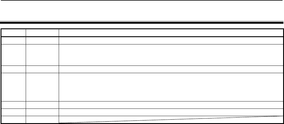
B-63943EN-2/07
REVISION RECORD
r-1
REVISION RECORD
Edition Date Contents
07 Dec., 2014
Addition of Series 0i-MODEL F
06 Mar., 2014
• Addition of following items
- General warnings for CNC application development
• Correction of errors
05 Sep., 2012
Addition of Series 35i-MODEL B, Power Motion i -MODEL A
04 Aug., 2011
• Addition of following items
- Macro Call Argument for Axis Name Expansion
• Addition and correction of parameters
• Correction of errors
03 Jul., 2010 Addition of Series 30i/31i/32i-MODEL B
02 Jul., 2009 Total revision
01 Jun., 2003
FANUC Series 30i/ 31i/ 32i-MODEL B
FANUC Series 0i-MODEL F
USB memory control in Macro executor
1. Type of applied technical documents
Name
FANUC Series 30i/31i/32i-MODEL A
FANUC Series 30i/31i/32i-MODEL B
FANUC Series 35i-MODEL B
FANUC Series 0i-MODEL F
FANUC Power Motion i-MODEL A
Macro Executor
PROGRAMMING MANUAL
Spec.No./Version B-63943EN-2/07
2. Summary of change
Group Name / Outline
New, Add,
Correct,
Delete
Applicable
Date
Basic Function
Optional Function
Descriptions about USB memory control in
Macro executor are added.
This function is included in Macro executor.
Add Immediately
Unit
Maintenance
parts
Notice
This function is available in the following CNC control software.
FS30i-B :G301,G311,G321,G331,G351 / 66.0 or later
FS31i-B5 :G421,G431 / 66.0 or later
FS31i-B :G401,G411 / 66.0 or later
FS32i-B :G501,G511 / 66.0 or later
FS0i-F
:
D4G1,D6G1 / 05.0 or later
Correction
Another
B-63943EN-2/07-01
Title
Draw
No.
Ed. Date Design Description
Date Feb. 6, 2015 Design Apprv.
1/10
page
FANUC Series 30i/31i/32i-MODEL B
FANUC Series 0i-MODEL F
USB memory control in Macro executor
G code Function Modal /
One-shot
Conversational
Auxiliary
Execution
Reference
item
Reader/puncher interface / Memory card control / USB memory control
G330
Line open
One-shot
X
G331
Line close
One-shot
X
G335
One-character read (reception)
One-shot
X
G336
Write (transmission)
Modal
X
G337
Variable data read (reception)
One-shot
X
G338
Variable data write (transmission)
One-shot
X
G339
FANUC CASSETTE control
One-shot
X
The following description is added in "G code list" of "6 MACRO EXECUTOR FUNCTION".
B-63943EN-2/07-01
Title
Draw
No.
Ed. Date Design Description
Date Feb. 6, 2015 Design Apprv.
2/10
page
FANUC Series 30i/31i/32i-MODEL B
FANUC Series 0i-MODEL F
USB memory control in Macro executor
6.9 USB MEMORY CONTROL
6.9.1 General
USB memory control can be executed using the same commands that are used for the reader/puncher interface
and Memory card control. USB memory control is enabled when bit 7 (EXT1) of compile parameter No. 9002
is set to 1.
G330 : USB memory open
G331 : USB memory close
G335 : 1-byte reading
G336 : Data writing
G337 : Macro variable input
G338 : Macro variable output
G339 : File information reading/file deletion
Completion codes are also used, as with the reader/puncher interface and Memory card control.
See following section "Completion codes" for details of completion codes.
NOTE
This function is available in the following models.
- FANUC Series 30i/31i/32i-MODEL B
- FANUC Series 0i-MODEL F
6.9.2 Functions
USB memory open G330
- Format
G330 Pp Ll ;
P
= 18
:
USB memory read control (Specify a file name.)
= 28
:
USB memory write control (Specify a file name.)
= 38
:
File control based on USB memory
L : Specify the start variable number of the variable string storing the file name.
In read mode, a search for the beginning of the file is made based on this file name.
In write mode, a new file is created using this file name.
- Explanation
By setting the lower one digit specified for P to "8", the USB memory is opened and made usable according to
the control method and control conditions.
The following description is added as "6.9 USB MEMORY CONTROL".
Section number of sections after "6.9 USB MEMORY CONTROL" is incremented.
B-63943EN-2/07-01
Title
Draw
No.
Ed. Date Design Description
Date Feb. 6, 2015 Design Apprv.
3/10
page
FANUC Series 30i/31i/32i-MODEL B
FANUC Series 0i-MODEL F
USB memory control in Macro executor
Example
G330 P28 L100 ;
IF [#8539 NE 0] GOTO900 ;
Open processing completed
N900 Error processing
- USB memory read control
The read control mode can be set by setting P=18 when USB memory is opened.
When address L is specified in the read control mode, a specified file on USB memory is found and the file data
is read.
Heading by file name
When the start variable number of the variable string where a desired file name is stored is specified with
address L, a heading based on the file name can be made. A file name consists of 2-33 variable strings and a
decimal ASCII code. Number of maximum characters of file name can be 32 or 12 by bit 1 (SFU) of parameter
No.11506.
NOTE
1 If bit 1 (SFU) of parameter No.11506 is set to 0, number of maximum characters
of file name is 32. Set 32 (space) to the next position of the file name.
2 If bit 1 (SFU) of parameter No.11506 is set to 1, number of maximum characters
of file name is 12. If a file name is shorter than 12 characters, set 32 (space) to
the next position of the file name.
3 Specify a file name + extension by using alphanumeric characters.
4 If head 8 characters of the file name is "FORFANUC", completion code 122 is
returned.
5 Only the files in the USB memory root directory can be found.
Example
G330 P18 L100 ;
If set following values in common variables #100 to #107, the file "ABC.DAT" is
found by above command.
Variable number
Setting value
#100
65(A)
File name
#101
66(B)
#102
67(C)
#103
46(.)
#104
68(D)
#105
65(A)
#106
84(T)
#107
32(space)
End of file name
B-63943EN-2/07-01
Title
Draw
No.
Ed. Date Design Description
Date Feb. 6, 2015 Design Apprv.
4/10
page
FANUC Series 30i/31i/32i-MODEL B
FANUC Series 0i-MODEL F
USB memory control in Macro executor
- USB memory write control
The write control mode can be set by setting P=28 when USB memory is opened. When address L is specified
in the write control mode, a new file can be created on USB memory and data can be written into the file.
Creation by file name
When the start variable number of the variable string where a desired file name is stored is specified with
address L, a new file can be created under a specified file name on USB memory and data can be written into
the file. A file name consists of 2-33 variable strings and a decimal ASCII code. Number of maximum
characters of file name can be 32 or 12 by bit 1 (SFU) of parameter No.11506.
NOTE
1 If bit 1 (SFU) of parameter No.11506 is set to 0, number of maximum characters
of file name is 32. Set 32 (space) to the next position of the file name.
2 If bit 1 (SFU) of parameter No.11506 is set to 1, number of maximum characters
of file name is 12. If a file name is shorter than 12 characters, set 32 (space) to
the next position of the file name.
3 Specify a file name + extension by using alphanumeric characters.
4 If head 8 characters of the file name is "FORFANUC", completion code 122 is
returned.
5 Files can be created only in the USB memory root directory.
Example
G330 P28 L100 ;
If set following values in common variables #100 to #107, the file "ABC.DAT" can
be created by above command.
Variable number
Setting value
#100
65(A)
File name
#101
66(B)
#102
67(C)
#103
46(.)
#104
68(D)
#105
65(A)
#106
84(T)
#107
32(space)
End of file name
USB memory close G331
- Format
G331 ;
- Explanation
This code ends USB memory control.
USB memory close processing is terminated normally at all times. (Completion code=0)
B-63943EN-2/07-01
Title
Draw
No.
Ed. Date Design Description
Date Feb. 6, 2015 Design Apprv.
5/10
page
FANUC Series 30i/31i/32i-MODEL B
FANUC Series 0i-MODEL F
USB memory control in Macro executor

1-byte reading G335
- Format
G335 Pp ;
P : Number of a macro variable to which read data is assigned
- Explanation
The file on USB memory is read from the beginning, one byte at a time, and the read data is assigned to the
specified macro variable. When there is no more data to read, completion code 121 is set.
For a byte read, open USB memory control in the read control mode (P=18).
Data writing G336
- Format
G336 Cc (_) (‘_’) (*_*) Kk Ff.e Dd Pp Zz ;
C
:
Specify a code to be directly output. (Specify one character.)
Code conversion processing is not performed. Specify this address when outputting a code other than
the ASCII codes.
K
:
Specify the number of space characters (20h).
(‘_’)
(*_*)
: Single-byte characters (codes listed in the katakana code table, alphanumeric code table, and symbol
code table in Appendix B "CODE TABLES") can be used. Kanji and hiragana codes cannot be used.
The other addresses are the same as for screen display control (G243).
- Explanation
Data is output in a specified format. A specified character string is converted to ASCII codes for output.
Open USB memory control in the write control mode (P=28).
Macro variable input G337
- Format
G337 Pp Qq R99 ;
- Explanation
Macro variable data is read from USB memory opened in the read control mode, and is assigned to specified
macro variable.
This processing is the same as macro variable data input (G337) in the reader/puncher interface and Memory
card control, except that data is input from USB memory.
Macro variable output G338
- Format
G338 Pp Qq Ff.e Zz Rr;
- Explanation
In the write control mode, the data of a specified macro variable is converted to a specified format for output.
This processing is the same as macro variable data output (G338) in the reader/puncher interface and Memory
card control, except that data is output to USB memory.
File information reading/file deletion G339
- Format
G339 Pp (Ff Ll Ss) ;
B-63943EN-2/07-01
Title
Draw
No.
Ed. Date Design Description
Date Feb. 6, 2015 Design Apprv.
6/10
page
FANUC Series 30i/31i/32i-MODEL B
FANUC Series 0i-MODEL F
USB memory control in Macro executor
p = 1 : File information reading
2 : File deletion
Specify address L/S and F as required for processing.
- Explanation
By specifying G339, file information on USB memory can be read and a file on USB memory can be deleted.
Before this function, the file information control mode must be set when the USB memory is opened (G330). To
set the file information control mode, specify p = 38 in address P when opening the USB memory. At this time,
the specification of a file (L) is not necessary. (G330 P38 ;)
(1) File information reading G339 P1
By specifying G339 P1, file information (file name and size) can be read into a specified macro variable.
G339 P1 Ff Ll Ss ;
F : Specify a file by file number (1 to 512).
L : Specify the start number of the consecutive macro variables for storing the read file name.
The file name is stored in ASCII code format (decimal).
S : Number of the macro variable for storing the read file size.
NOTE
1 If bit 1 (SFU) of parameter No.11506 is set to 0, number of maximum characters
of file name is 32. Unused character positions for getting file name are set 32
(space) to make a 33-character file name.
2 If bit 1 (SFU) of parameter No.11506 is set to 1, number of maximum characters
of file name is 12. If a file name is shorter than 12 characters, Unused character
positions for getting file name are set 32 (space) to make a 12-character file
name.
3 Only file information of files in the USB memory root directory can be read.
4 If there is no file corresponding to the specified file number, completion code 114
is returned.
5 If USB memory is accessed by methods other than USB memory control, file
information read by G339 P1 command might be illegal. In this case, close USB
memory control once by G331.
B-63943EN-2/07-01
Title
Draw
No.
Ed. Date Design Description
Date Feb. 6, 2015 Design Apprv.
7/10
page
FANUC Series 30i/31i/32i-MODEL B
FANUC Series 0i-MODEL F
USB memory control in Macro executor
Example
- bit 1 (SFU) of parameter No.11506 is set to 1.
- The name of file that file number is 1 is "ABC.DAT".
- The size of file that file number is 1 is 123 byte.
In the above conditions, common variables #100 to #133 are set the following
values by G339 command.
#100 = 123
#101 - #133 = 65 (A), 66 (B), 67 (C), 46 (.), 68 (D), 65 (A), 84 (T), 32,...32(space)
G330 P38 ;
G339 P1 F1 L101 S100 ;
IF [#8539 NE 0] GOTO100 ;
Read processing completed
G331 ;
GOTO200 ;
N100 Error processing
N200 Next processing
→
→
→
Open in file information control mode
Read file information
Close USB memory
(2) File deletion G339 P2
By specifying G339 P2, the specified file can be deleted.
G339 P2 Ll ;
L : Start number of the variable string where the name (ASCII code) of a file to be deleted is stored.
NOTE
1 If bit 1 (SFU) of parameter No.11506 is set to 0, number of maximum characters
of file name is 32. Set 32 (space) to the next position of the file name.
2 If bit 1 (SFU) of parameter No.11506 is set to 1, number of maximum characters
of file name is 12. If a file name is shorter than 12 characters, set 32 (space) to
the next position of the file name.
3 Specify a file name + extension by using alphanumeric characters.
4 If head 8 characters of the file name is "FORFANUC", completion code 122 is
returned.
5 Only the files in the USB memory root directory can be deleted.
B-63943EN-2/07-01
Title
Draw
No.
Ed. Date Design Description
Date Feb. 6, 2015 Design Apprv.
8/10
page
FANUC Series 30i/31i/32i-MODEL B
FANUC Series 0i-MODEL F
USB memory control in Macro executor
Example
To delete a file named ”ABC.DAT”, set 65 (A), 66 (B), 67 (C), 46 (.), 68 (D), 65
(A), 84 (T), 32 (space) in 8 common variables #100 to #107.
G330 P38 ;
G339 P2 L100 ;
IF [#8539 NE 0] GOTO100 ;
Read processing completed
G331 ;
GOTO200 ;
N100 Error processing
N200 Next processing
→
→
→
Open in file information control mode
File deletion
Close USB memory
6.9.3 Completion Codes (#8539)
Completion codes are returned for G330 to G339 commands. If an error occurs, its description is set in a
completion code. Check the completion code after issuing a command.
There are three types of completion codes:
#8537 : Completion code for the result of executing an auxiliary macro
#8538 : Completion code for the result of executing a conversational macro
#8539 : Completion code common to auxiliary commands and conversational macros
When the command specified in an auxiliary macro program is completed, a completion code is set in both
variables #8537 and #8539. If the command specified in a conversational macro program is completed, a
completion code is set in both variables #8538 and #8539.
#8539
Description
0
Normal termination
1
USB memory is not opened.
6
A necessary option is not specified.
7 USB memory cannot be opened because it is used with another function.
Or, it is write-protected.
8 Data (P, Q, R, and so forth) specified in a block of G330 to G339 is incorrect, or necessary data is
not specified.
9
Invalid data format
10
The file number is invalid.
12 (1) The specified time has elapsed since the system entered the data transmission/reception
waiting state.
(2) The command has been interrupted by an NC reset while waiting for data input or output
when 1 is set in bit 1 (RCN) of parameter No. 9035.
30
USB memory not inserted yet
34
Initialization process of USB memory has not been completed yet.
99
With macro variable input function G337, the continuous reading of macro variables is possible.
102
Insufficient free space on USB memory
114
Specify file not found
115 The specified file is protected.
An undefined variable number was specified.
117
The file is not opened in a correct mode.
121
End of file
B-63943EN-2/07-01
Title
Draw
No.
Ed. Date Design Description
Date Feb. 6, 2015 Design Apprv.
9/10
page
FANUC Series 30i/31i/32i-MODEL B
FANUC Series 0i-MODEL F
USB memory control in Macro executor
#8539
Description
122
Illegal file name specified
130
A file with the same name already exists on USB memory.
141
Close the file.
150 (1) USB memory cannot be recognized.
(2) An error occurred on USB memory.
B-63943EN-2/07-01
Title
Draw
No.
Ed. Date Design Description
Date Feb. 6, 2015 Design Apprv.
10/10
page
FANUC Series 30i/31i/32i-MODEL B
FANUC Series 0i-MODEL F
USB memory control in Macro executor
