Programming Manual PMC
User Manual: Pdf
Open the PDF directly: View PDF ![]() .
.
Page Count: 1575 [warning: Documents this large are best viewed by clicking the View PDF Link!]
- B-64513EN/03 Vol 1/1
- B-64513EN/03
- SAFETY PRECAUTIONS
- TABLE OF CONTENTS
- 1 OVERVIEW OF PMC
- 1.1 WHAT IS PMC?
- 1.2 WHAT IS LADDER LANGUAGE?
- 1.3 SEQUENCE PROGRAM CREATION PROCEDURE
- 1.4 EXECUTION OF SEQUENCE PROGRAM
- 1.5 LADDER DIVIDING MANAGEMENT FUNCTION
- 1.5.1 Divided Ladder Program
- 1.5.2 Program Execution when Using Ladder Dividing Management
- 1.5.3 PMC Memory when Using Ladder Dividing Management
- 1.5.4 Sub Program in Divided Ladder
- 1.5.5 Message Display Function (DISPB instruction) when Using Ladder Dividing Management Function
- 1.5.6 Making Method of Divided Ladder Program
- 1.5.7 Adding/Updating/Deleting Divided Ladder Program
- 1.5.8 Input/Output of All Divided Ladder Programs
- 1.6 MULTI-PATH PMC FUNCTION
- 1.7 COMMUNICATION METHOD for EXTERNAL I/O DEVICE
- 1.8 1st LEVEL EXECUTION CYCLE of LADDER in 1ms/2ms
- 2 PMC SPECIFICATIONS
- 2.1 SPECIFICATIONS
- 2.1.1 Basic Specifications
- 2.1.2 Total Ladder Steps of Multi-path PMC
- 2.1.3 Determination of PMC Memory Type
- 2.1.4 Program Capacity
- 2.1.5 Used Memory Size of Sequence Program
- 2.1.6 PMC Addresses
- 2.1.7 Basic Instructions
- 2.1.8 Functional Instructions (Arranged in Sequence of Instruction Group)
- 2.1.9 Functional Instructions (Arranged in Sequence of SUB No.)
- 2.2 PMC SIGNAL ADDRESSES
- 2.2.1 Addresses for Signals Between the PMC and CNC (F, G)
- 2.2.2 Addresses of Signals Between the PMC and Machine (X, Y)
- 2.2.3 Internal Relay Addresses (R)
- 2.2.4 System Relay Addresses (R9000, Z0)
- 2.2.5 Extra Relay Addresses (E)
- 2.2.6 Message Display Addresses (A)
- 2.2.7 Timer Addresses (T)
- 2.2.8 Counter Addresses (C)
- 2.2.9 Keep Relay Addresses (K)
- 2.2.10 Nonvolatile Memory Control Address (K)
- 2.2.11 System Keep Relay Addresses (K)
- 2.2.12 Data Table Addresses (D)
- 2.2.13 Addresses for Multi-path PMC Interface (M, N)
- 2.2.14 Subprogram Number Addresses (P)
- 2.2.15 Label Number Addresses (L)
- 2.3 PMC PARAMETERS
- 2.4 PARAMETERS FOR THE PMC SYSTEM
- 2.5 COMPATIBILITY BETWEEN PMC MEMORY TYPE
- 2.6 COMPATIBILITY WITH CONVENTIONAL MODELS
- 2.6.1 Compatibility with Series 30i/31i/32i-A PMC
- 2.6.2 Compatibility between 30i/31i/32i-A DCSPMC and 30i/31i/32i/35i-B, 0i-F DCSPMC
- 2.6.3 Compatibility with the PMCs for the 16i/18i/21i-B
- 2.6.4 Compatibility with the PMCs for the 15i-A/B
- 2.6.5 Compatibility with series 0i-D PMC
- 2.6.6 Compatibility between 0i-D DCSPMC and 30i/31i/32i/35i-B DCSPMC
- 2.6.7 Compatibility between 35i-B PMC and PMC-SB5/SB6 for Power Mate i-D
- 2.6.8 Compatibility between Power Motion i-A PMC and PMC-SB5/SB6 for Power Mate i-H
- 2.6.9 Compatibility between 0i-F PMC and 30i/31i/32i/35i-B PMC
- 2.6.10 Compatibility between 0i-F DCSPMC and 30i/31i/32i/35i-B DCSPMC
- 2.6.11 The Convert Method of Source Program Using FANUC LADDER-III
- 2.7 PMC MESSAGE MULTI-LANGUAGE DISPLAY FUNCTION
- 2.8 BATTERY BACKUP DATA
- 2.9 File Name of Flash ROM related to PMC
- 2.1 SPECIFICATIONS
- 3 COMMUNICATION WITH I/O DEVICE
- 3.1 I/O Link i and I/O Link
- 3.2 WHAT IS THE I/O LINK?
- 3.2.1 Configuration of an I/O Link
- 3.2.2 Numbers of Input Points and of Output Points of the I/O Link
- 3.2.3 Assignment Method
- 3.2.3.1 Assignment Method for I/O Unit-MODEL A
- 3.2.3.2 Assignment Method for I/O Unit-MODEL B
- 3.2.3.3 Assignment Method for Distribution I/O Connection Panel I/O Modules and Distribution I/O Operator's Panel I/O Modules
- 3.2.3.4 Assignment Method for the Power Mate
- 3.2.3.5 Assignment Method for I/O Link Connection Units
- 3.2.3.6 Assignment Method for a Handy Machine Operator's Panel
- 3.2.3.7 Assignment Method for an AS-i Converter Unit
- 3.2.3.8 FS0 Operator's Panel
- 3.2.4 Setting I/O Address For I/O Link Channel
- 3.2.5 Selectable I/O Link Assignment Function
- 3.3 WHAT IS I/O Link i ?
- 3.4 I/O Link / I/O Link i CONNECTION CHECK FUNCTION
- 3.5 ASSIGNMENT OF NETWORK DEVICES TO X/Y ADDRESS
- 4 LADDER LANGUAGE
- 4.1 BASIC INSTRUCTIONS
- 4.1.1 Details of the Basic Instructions
- 4.1.2 RD Instruction
- 4.1.3 RD.NOT Instruction
- 4.1.4 WRT Instruction
- 4.1.5 WRT.NOT Instruction
- 4.1.6 AND Instruction
- 4.1.7 AND.NOT Instruction
- 4.1.8 OR Instruction
- 4.1.9 OR.NOT Instruction
- 4.1.10 RD.STK Instruction
- 4.1.11 RD.STK.NOT Instruction
- 4.1.12 AND.STK Instruction
- 4.1.13 OR.STK Instruction
- 4.1.14 SET Instruction
- 4.1.15 RST Instruction
- 4.1.16 RDPT Instruction
- 4.1.17 ANDPT Instruction
- 4.1.18 ORPT Instruction
- 4.1.19 RDPT.STK Instruction
- 4.1.20 RDNT Instruction
- 4.1.21 ANDNT Instruction
- 4.1.22 ORNT Instruction
- 4.1.23 RDNT.STK Instruction
- 4.1.24 PUSH Instruction / POP Instruction
- 4.2 FUNCTIONAL INSTRUCTIONS
- 4.3 TIMER
- 4.4 COUNTER
- 4.5 DATA TRANSFER
- 4.5.1 MOVB (Transfer of 1 Byte: SUB 43)
- 4.5.2 MOVW (Transfer of 2 Bytes: SUB 44)
- 4.5.3 MOVD (Transfer of 4 Bytes: SUB 47)
- 4.5.4 MOVN (Transfer of an Arbitrary Number of Bytes: SUB 45)
- 4.5.5 MOVE (Logical Product Transfer: SUB 8)
- 4.5.6 MOVOR (Data Transfer After Logical Sum: SUB 28)
- 4.5.7 XMOVB (Binary Index Modifier Data Transfer: SUB 35)
- 4.5.8 XMOV (Indexed Data Transfer: SUB 18)
- 4.5.9 MOVBT (Bit Transfer: SUB 224)
- 4.5.10 SETNB (Data Setting (1 Byte Length) : SUB 225) SETNW (Data Setting (2 Bytes Length) : SUB 226) SETND (Data Setting (4 Bytes Length) : SUB 227)
- 4.5.11 XCHGB (Data Exchange (1 Byte Length) : SUB 228) XCHGW (Data Exchange (2 Bytes Length) : SUB 229) XCHGD (Data Exchange (4 Bytes Length) : SUB 230)
- 4.5.12 SWAPW (Data Swap (2 Bytes Length) : SUB 231) SWAPD (Data Swap (4 Bytes Length) : SUB 232)
- 4.5.13 DSCHB (Binary Data Search: SUB 34)
- 4.5.14 DSCH (Data Search: SUB 17)
- 4.6 TABLE DATA
- 4.6.1 TBLRB (Reading Data from Table (1 Byte Length) : SUB 233) TBLRW (Reading Data from Table (2 Bytes Length) : SUB 234) TBLRD (Reading Data from Table (4 Bytes Length) : SUB 235)
- 4.6.2 TBLRN (Reading Data from Table (Arbitrary Bytes Length) : SUB 236)
- 4.6.3 TBLWB (Writing Data to Table (1 Byte Length) : SUB 237) TBLWW (Writing Data to Table (2 Bytes Length) : SUB 238) TBLWD (Writing Data to Table (4 Bytes Length) : SUB 239)
- 4.6.4 TBLWN (Writing Data to Table (Arbitrary Bytes Length) : SUB 240)
- 4.6.5 DSEQB(Searching Data from Table(=)(1 Byte Length):SUB 241) DSEQW(Searching Data from Table(=)(2 Bytes Length):SUB 242) DSEQD(Searching Data from Table(=)(4 Bytes Length):SUB 243) DSNEB(Searching Data from Table(≠)(1 Byte Length):SUB 244) DSNEW(Searching Data from Table(≠)(2 Bytes Length):SUB 245) DSNED(Searching Data from Table(≠)(4 Bytes Length):SUB 246) DSGTB(Sear
- 4.6.6 DMAXB (Maximum Data (1 Byte Length): SUB 259) DMAXW (Maximum Data (2 Bytes Length) : SUB 260) DMAXD (Maximum Data (4 Bytes Length) : SUB 261)
- 4.6.7 DMINB (Minimum Data (1 Byte Length): SUB 262) DMINW (Minimum Data (2 Bytes Length): SUB 263) DMIND (Minimum Data (4 Bytes Length): SUB 264)
- 4.7 COMPARISON
- 4.7.1 Signed Binary Comparison (=) EQB (1 Byte Length: SUB 200) EQW (2 Bytes Length: SUB 201) EQD (4 Bytes Length: SUB 202)
- 4.7.2 Signed Binary Comparison (≠) NEB (1 Byte Length: SUB 203) NEW (2 Bytes Length: SUB 204) NED (4 Bytes Length: SUB 205)
- 4.7.3 Signed Binary Comparison (>) GTB (1 Byte Length: SUB 206) GTW (2 Bytes Length: SUB 207) GTD (4 Bytes Length: SUB 208)
- 4.7.4 Signed Binary Comparison (<) LTB (1 Byte Length: SUB 209) LTW (2 Bytes Length: SUB 210) LTD (4 Bytes Length: SUB 211)
- 4.7.5 Signed Binary Comparison (≥) GEB (1 Byte Length: SUB 212) GEW (2 Bytes Length: SUB 213) GED (4 Bytes Length: SUB 214)
- 4.7.6 Signed Binary Comparison (≤) LEB (1 Byte Length: SUB 215) LEW (2 Bytes Length: SUB 216) LED (4 Bytes Length: SUB 217)
- 4.7.7 Signed Binary Comparison (Range) RNGB (1 Byte Length: SUB 218) RNGW (2 Bytes Length: SUB 219) RNGD (4 Bytes Length: SUB 220)
- 4.7.8 COMPB (Comparison Between Binary Data: SUB 32)
- 4.7.9 COMP (Comparison: SUB 15)
- 4.7.10 COIN (Coincidence Check: SUB 16)
- 4.8 BIT OPERATION
- 4.8.1 DIFU (Rising Edge Detection: SUB 57)
- 4.8.2 DIFD (Falling Edge Detection: SUB 58)
- 4.8.3 EOR (Exclusive OR: SUB 59)
- 4.8.4 AND (Logical AND: SUB 60)
- 4.8.5 OR (Logical OR: SUB 61)
- 4.8.6 NOT (Logical NOT: SUB 62)
- 4.8.7 PARI (Parity Check: SUB 11)
- 4.8.8 SFT (Shift Register: SUB 33)
- 4.8.9 EORB (Exclusive OR (1 Byte Length) : SUB 265) EORW (Exclusive OR (2 Bytes Length) : SUB 266) EORD (Exclusive OR (4 Bytes Length) : SUB 267)
- 4.8.10 ANDB (Logical AND (1 Byte Length) : SUB 268) ANDW (Logical AND (2 Bytes Length) : SUB 269) ANDD (Logical AND (4 Bytes Length) : SUB 270)
- 4.8.11 ORB (Logical OR (1 Byte Length) : SUB 271) ORW (Logical OR (2 Bytes Length) : SUB 272) ORD (Logical OR (4 Bytes Length) : SUB 273)
- 4.8.12 NOTB (Logical NOT (1 Byte Length) : SUB 274) NOTW (Logical NOT (2 Bytes Length) : SUB 275) NOTD (Logical NOT (4 Bytes Length) : SUB 276)
- 4.8.13 SHLB (Bit Shift Left (1 Byte Length) : SUB 277) SHLW (Bit Shift Left (2 Bytes Length) : SUB 278) SHLD (Bit Shift Left (4 Bytes Length) : SUB 279)
- 4.8.14 SHLN (Bit Shift Left (Arbitrary Bytes Length) : SUB 280)
- 4.8.15 SHRB (Bit Shift Right (1 Byte Length) : SUB 281) SHRW (Bit Shift Right (2 Bytes Length) : SUB 282) SHRD (Bit Shift Right (4 Bytes Length) : SUB 283)
- 4.8.16 SHRN (Bit Shift Right (Arbitrary Bytes Length) : SUB 284)
- 4.8.17 ROLB (Bit Rotation Left (1 Byte Length) : SUB 285) ROLW (Bit Rotation Left (2 Bytes Length) : SUB 286) ROLD (Bit Rotation Left (4 Bytes Length) : SUB 287)
- 4.8.18 ROLN (Bit Rotation Left (Arbitrary Bytes Length) : SUB 288)
- 4.8.19 RORB (Bit Rotation Right (1 Byte Length) : SUB 289) RORW (Bit Rotation Right (2 Bytes Length) : SUB 290) RORD (Bit Rotation Right (4 Bytes Length) : SUB 291)
- 4.8.20 RORN (Bit Rotation Right (Arbitrary Bytes Length) : SUB 292)
- 4.8.21 BSETB (Bit Set (1 Byte Length) : SUB 293) BSETW (Bit Set (2 Bytes Length) : SUB 294) BSETD (Bit Set (4 Bytes Length) : SUB 295)
- 4.8.22 BSETN (Bit Set (Arbitrary Bytes Length) : SUB 296)
- 4.8.23 BRSTB (Bit Reset (1 Byte Length) : SUB 297) BRSTW (Bit Reset (2 Bytes Length) : SUB 298) BRSTD (Bit Reset (4 Bytes Length) : SUB 299)
- 4.8.24 BRSTN (Bit Reset (Arbitrary Bytes Length) : SUB 300)
- 4.8.25 BTSTB (Bit Test (1 Byte Length) : SUB 301) BTSTW (Bit Test (2 Bytes Length) : SUB 302) BTSTD (Bit Test (4 Bytes Length) : SUB 303)
- 4.8.26 BTSTN (Bit Test (Arbitrary Bytes Length) : SUB 304)
- 4.8.27 BPOSB (Bit Search (1 Byte Length) : SUB 305) BPOSW (Bit Search (2 Bytes Length) : SUB 306) BPOSD (Bit Search (4 Bytes Length) : SUB 307)
- 4.8.28 BPOSN (Bit Search (Arbitrary Bytes Length) : SUB 308)
- 4.8.29 BCNTB (Bit Count (1 Byte Length) : SUB 309) BCNTW (Bit Count (2 Bytes Length) : SUB 310) BCNTD (Bit Count (4 Bytes Length) : SUB 311)
- 4.8.30 BCNTN (Bit Count (Arbitrary Bytes Length) : SUB 312)
- 4.9 CODE CONVERSION
- 4.9.1 COD (Code Conversion: SUB 7)
- 4.9.2 CODB (Binary Code Conversion: SUB 27)
- 4.9.3 DCNV (Data Conversion: SUB 14)
- 4.9.4 DCNVB (Extended Data Conversion: SUB 31)
- 4.9.5 DEC (Decode: SUB 4)
- 4.9.6 DECB (Binary Decoding: SUB 25)
- 4.9.7 TBCDB (Binary to BCD Conversion (1 Byte Length) : SUB 313) TBCDW (Binary to BCD Conversion (2 Bytes Length) : SUB 314) TBCDD (Binary to BCD Conversion (4 Bytes Length) : SUB 315)
- 4.9.8 FBCDB (BCD to Binary Conversion (1 Byte Length) : SUB 313) FBCDW (BCD to Binary Conversion (2 Bytes Length) : SUB 314) FBCDD (BCD to Binary Conversion (4 Bytes Length) : SUB 315)
- 4.10 OPERATION INSTRUCTION
- 4.10.1 ADDB (Binary Addition: SUB 36)
- 4.10.2 SUBB (Binary Subtraction: SUB 37)
- 4.10.3 MULB (Binary Multiplication: SUB 38)
- 4.10.4 DIVB (Binary Division: SUB 39)
- 4.10.5 ADD (BCD Addition: SUB 19)
- 4.10.6 SUB (BCD Subtraction: SUB 20)
- 4.10.7 MUL (BCD Multiplication: SUB 21)
- 4.10.8 DIV (BCD Division: SUB 22)
- 4.10.9 NUMEB (Definition of Binary Constants: SUB 40)
- 4.10.10 NUME (BCD Definition of Constant: SUB 23)
- 4.10.11 ADDSB (Addition (1 Byte Length) : SUB 319) ADDSW (Addition (2 Bytes Length) : SUB 320) ADDSD (Addition (4 Bytes Length) : SUB 321)
- 4.10.12 SUBSB (Subtraction (1 Byte Length) : SUB 322) SUBSW (Subtraction (2 Bytes Length) : SUB 323) SUBSD (Subtraction (4 Bytes Length) : SUB 324)
- 4.10.13 MULSB (Multiplication (1 Byte Length) : SUB 325) MULSW (Multiplication (2 Bytes Length) : SUB 326) MULSD (Multiplication (4 Bytes Length) : SUB 327)
- 4.10.14 DIVSB (Division (1 Byte Length) : SUB 328) DIVSW (Division (2 Bytes Length) : SUB 329) DIVSD (Division (4 Bytes Length) : SUB 330)
- 4.10.15 MODSB (Remainder (1 Byte Length) : SUB 331) MODSW (Remainder (2 Bytes Length) : SUB 332) MODSD (Remainder (4 Bytes Length) : SUB 333)
- 4.10.16 INCSB (Increment (1 Byte Length) : SUB 334) INCSW (Increment (2 Bytes Length) : SUB 335) INCSD (Increment (4 Bytes Length) : SUB 336)
- 4.10.17 DECSB (Decrement (1 Byte Length) : SUB 337) DECSW (Decrement (2 Bytes Length) : SUB 338) DECSD (Decrement (4 Bytes Length) : SUB 339)
- 4.10.18 ABSSB (Absolute Value (1 Byte Length) : SUB 340) ABSSW (Absolute Value (2 Bytes Length) : SUB 341) ABSSD (Absolute Value (4 Bytes Length) : SUB 342)
- 4.10.19 NEGSB (Sign Inversion (1 Byte Length) : SUB 343) NEGSW (Sign Inversion (2 Bytes Length) : SUB 344) NEGSD (Sign Inversion (4 Bytes Length) : SUB 345)
- 4.11 INSTRUCTIONS RELATED TO CNC FUNCTIONS
- 4.11.1 DISPB (Display Message: SUB 41)
- 4.11.1.1 Numerical data display
- 4.11.1.2 Defining characters not found in the CNC MDI keys
- 4.11.1.3 Notes when this functional instruction is used in subroutine
- 4.11.1.4 Message shift function
- 4.11.1.5 PMC message multi-language display function
- 4.11.1.6 Ladder dividing management function
- 4.11.1.7 Common PMC Memory mode of Multi-path PMC
- 4.11.2 EXIN (External Data Input: SUB 42)
- 4.11.3 WINDR (Reading CNC Window Data: SUB 51)
- 4.11.4 WINDW (Writing CNC Window Data: SUB 52)
- 4.11.5 AXCTL (Axis Control by PMC: SUB 53)
- 4.11.6 PSGN2 (Position Signal: SUB 63)
- 4.11.7 PSGNL (Position Signal: SUB 50)
- 4.11.1 DISPB (Display Message: SUB 41)
- 4.12 PROGRAM CONTROL
- 4.12.1 COM (Common Line Control: SUB 9)
- 4.12.2 COME (Common Line Control End: SUB 29)
- 4.12.3 JMP (Jump: SUB 10)
- 4.12.4 JMPE (Jump End: SUB 30)
- 4.12.5 JMPB (Label Jump 1: SUB 68)
- 4.12.6 JMPC (Label Jump 2: SUB 73)
- 4.12.7 LBL (Label: SUB 69)
- 4.12.8 CALL (Conditional Subprogram Call: SUB 65)
- 4.12.9 CALLU (Unconditional Subprogram Call: SUB 66)
- 4.12.10 SP (Subprogram: SUB 71)
- 4.12.11 SPE (End of a Subprogram: SUB 72)
- 4.12.12 END1 (1st Level Sequence Program End: SUB 1)
- 4.12.13 END2 (2nd Level Sequence Program End: SUB 2)
- 4.12.14 END3 (3rd Level Sequence Program End: SUB 48)
- 4.12.15 END (End of a Ladder Program: SUB 64)
- 4.12.16 NOP (No Operation: SUB 70)
- 4.12.17 CS (Case Call: SUB 74)
- 4.12.18 CM (Sub Program Call in Case Call: SUB 75)
- 4.12.19 CE (End of Case Call: SUB 76)
- 4.13 ROTATION CONTROL
- 4.14 INVALID INSTRUCTIONS
- 4.15 NOTE ON PROGRAMMING
- 4.1 BASIC INSTRUCTIONS
- 5 WINDOW FUNCTIONS
- 5.1 FORMATS OF CONTROL DATA
- 5.2 LOW-SPEED RESPONSE AND HIGH-SPEED RESPONSE
- 5.3 LIST OF WINDOW FUNCTIONS
- 5.4 CNC INFORMATION
- 5.4.1 Reading CNC System Information (High-speed Response)
- 5.4.2 Reading a Tool Offset (High-speed Response)
- 5.4.3 Writing a Tool Offset (Low-speed Response)
- 5.4.4 Reading a Workpiece Origin Offset Value (High-speed Response)
- 5.4.5 Writing a Workpiece Origin Offset Value (Low-speed Response)
- 5.4.6 Reading a Parameter (High-speed Response)
- 5.4.7 Writing a Parameter (Low-speed Response)
- 5.4.8 Reading a Real Type Parameter (High-speed Response)
- 5.4.9 Writing a Real Type Parameter (Low-speed Response)
- 5.4.10 Reading Setting Data (High-speed Response)
- 5.4.11 Writing Setting Data (Low-speed Response)
- 5.4.12 Reading a Custom Macro Variable (High-speed Response)
- 5.4.13 Writing a Custom Macro Variable (Low-speed Response)
- 5.4.14 Reading a Custom Macro Variable (Variable Number Extension) (Low-speed Response)
- 5.4.15 Writing a Custom Macro Variable (Variable Number Extension) (Low-speed Response)
- 5.4.16 Reading the CNC Alarm Status (High-speed Response)
- 5.4.17 Reading the Current Program Number (High-speed Response)
- 5.4.18 Reading the Current Sequence Number (High-speed Response)
- 5.4.19 Reading Modal Data (High-speed Response)
- 5.4.20 Reading Diagnosis Data (Low-speed Response)
- 5.4.21 Reading Diagnosis Data (High-speed Response)
- 5.4.22 Reading a P-CODE Macro Variable (High-speed Response)
- 5.4.23 Writing a P-CODE Macro Variable (Low-speed Response)
- 5.4.24 Reading CNC Status Information (High-speed Response)
- 5.4.25 Reading the Current Program Number (8-digits Program Numbers) (High-speed Response)
- 5.4.26 Entering Data on the Program Check Screen (Low-speed Response)
- 5.4.27 Reading Clock Data (Date and Time) (High-speed Response)
- 5.4.28 Writing Clock Data (Date and Time) (Low-speed Response)
- 5.4.29 Reading the Pitch Error Compensation Value (High-speed Response)
- 5.4.30 Writing the Pitch Error Compensation Value (Low-speed Response)
- 5.4.31 Tool Figure Making Instruction for 3D Interference Check Function (Low-speed Response)
- 5.4.32 Reading Detailed Information of CNC Alarm
- 5.4.33 Command for Changing the Interference Object for 3D Interference Check Function (Low-speed Response)
- 5.4.34 Reading CNC ID Number (Low-speed Response)
- 5.4.35 Reading repetition count for subprogram calls / canned cycle (High-speed Response)
- 5.5 AXIS INFORMATION
- 5.5.1 Reading the Actual Velocity of Controlled Axes (High-speed Response)
- 5.5.2 Reading the Absolute Position (Absolute Coordinates) of Controlled Axes (High-speed Response)
- 5.5.3 Reading the Machine Position (Machine Coordinates) of Controlled Axes (High-speed Response)
- 5.5.4 Reading a Skip Position (Stop Coordinates of Skip Operation (G31)) of Controlled Axes (High-speed Response)
- 5.5.5 Reading the Servo Delay for Controlled Axes (High-speed Response)
- 5.5.6 Reading the Acceleration/Deceleration Delay on Controlled Axes (High-speed Response)
- 5.5.7 Reading the Feed Motor Load Current Value (A/D Conversion Data) (High-speed Response)
- 5.5.8 Reading the Actual Spindle Speed (High-speed Response)
- 5.5.9 Reading the Relative Position on a Controlled Axis (Highspeed Response)
- 5.5.10 Reading the Remaining Travel (High-speed Response)
- 5.5.11 Reading the Actual Velocity of each Controlled Axis (Highspeed Response)
- 5.5.12 Reading Actual Spindle Speeds (High-speed Response)
- 5.5.13 Entering Torque Limit Data for the Digital Servo Motor (Lowspeed Response)
- 5.5.14 Reading Load Information of the Spindle Motor (Serial Interface) (High-speed Response)
- 5.5.15 Reading a Chopping Data (Low-speed Response)
- 5.5.16 Reading the Actual Speed of Servo Motor (High-speed Response)
- 5.5.17 Reading the Estimate Disturbance Torque Data (High-speed Response)
- 5.5.18 Reading a Fine Torque Sensing Data (Statistical Calculation Results) (High-speed Response)
- 5.5.19 Reading a Fine Torque Sensing Data (Store Data) (Highspeed Response)
- 5.5.20 Presetting the Relative Coordinate (Low-speed Response)
- 5.5.21 Reading the Three-Dimensional Error Compensation Data (Low-Speed Response)
- 5.5.22 Writing the Three-Dimensional Error Compensation Data (Low-Speed Response)
- 5.5.23 Reading the Position of Controlled Axes
- 5.5.24 Reading slider position of the Control function for link type press (High-speed Response)
- 5.5.25 Reading position of lower dead point of the Control function for link type press (High-speed Response)
- 5.5.26 Reading main gear angle of the Control function for link type press (High-speed Response)
- 5.5.27 Reading analog monitor unit data (High-speed Response)
- 5.5.28 Reading the Axes Command Value (High-speed Response)
- 5.6 TOOL LIFE MANAGEMENT FUNCTION
- 5.6.1 Reading The Tool Life Management Data (Tool Group Number) (High-speed Response)
- 5.6.2 Reading Tool Life Management Data (Number of Tool Groups) (High-speed Response)
- 5.6.3 Reading Tool Life Management Data (Number of Tools) (High-speed Response)
- 5.6.4 Reading Tool Life Management Data (Tool Life) (High-speed Response)
- 5.6.5 Reading Tool Life Management Data (Tool Life Counter) (High-speed Response)
- 5.6.6 Reading Tool Life Management Data (Tool Length Compensation Number (1): Tool Number) (High-speed Response)
- 5.6.7 Reading Tool Life Management Data (Tool Length Compensation Number (2): Tool Order Number) (High-speed Response)
- 5.6.8 Reading Tool Life Management Data (Cutter Radius Compensation Number (1): Tool Number) (High-speed Response)
- 5.6.9 Reading Tool Life Management Data (Cutter Radius Compensation Number (2): Tool Order Number) (High-speed Response)
- 5.6.10 Reading Tool Life Management Data (Tool Information (1): Tool Number) (High-speed Response)
- 5.6.11 Reading Tool Life Management Data (Tool Information (2): Tool Order Number) (High-speed Response)
- 5.6.12 Reading Tool Life Management Data (Tool Number) (High-speed Response)
- 5.6.13 Reading the Tool Life Management Data (Tool Life Counter Type) (High-speed Response)
- 5.6.14 Registering Tool Life Management Data (Tool Group) (Low-speed Response)
- 5.6.15 Writing Tool Life Management Data (Tool Life) (Low-speed Response)
- 5.6.16 Writing Tool Life Management Data (Tool Life Counter) (Low-speed Response)
- 5.6.17 Writing Tool Life Management Data (Tool Life Counter Type) (Low-speed Response)
- 5.6.18 Writing Tool Life Management Data (Tool Length Compensation Number (1): Tool Number) (Low-speed Response)
- 5.6.19 Writing Tool Life Management Data (Tool Length Compensation Number (2): Tool Order Number) (Low-speed Response)
- 5.6.20 Writing Tool Life Management Data (Cutter Radius Compensation Number (1): Tool Number) (Low-speed Response)
- 5.6.21 Writing Tool Life Management Data (Cutter Radius Compensation Number (2): Tool Order Number) (Low-speed Response)
- 5.6.22 Writing the Tool Life Management Data (Tool Information (1): Tool Number) (Low-speed Response)
- 5.6.23 Writing the Tool Management Data (Tool Information (2): Tool Order Number) (Low-speed Response)
- 5.6.24 Writing Tool Life Management Data (Tool Number) (Low-speed Response)
- 5.6.25 Reading The Tool Life Management Data (Tool Group Number) (High-speed Response) (8-digits Tool Number)
- 5.6.26 Reading Tool Life Management Data (Tool Information (1): Tool Number) (High-speed Response) (8-digits Tool Number)
- 5.6.27 Registering Tool Life Management Data (Tool Group Number) (Low-speed Response) (8-digits Tool Number)
- 5.6.28 Reading Tool Life Management Data (Tool Length Compensation Number (1): Tool Number) (High-speed Response) (8-digits Tool Number)
- 5.6.29 Reading Tool Life Management Data (Cutter Radius Compensation Number (1): Tool Number) (High-speed Response) (8-digits Tool Number)
- 5.6.30 Writing Tool Life Management Data (Tool Length Compensation Number (1): Tool Number) (Low-speed Response) (8-digits Tool Number)
- 5.6.31 Writing Tool Life Management Data (Cutter Radius Compensation Number (1): Tool Number) (Low-speed Response) (8-digits Tool Number)
- 5.6.32 Writing the Tool Life Management Data (Tool Information (1): Tool Number) (Low-speed Response) (8-digits Tool Number)
- 5.6.33 Deleting Tool life Management Data (Tool Group) (Low-speed Response)
- 5.6.34 Deleting Tool life Management Data (Tool Data) (Low-speed Response)
- 5.6.35 Clearing Tool Life Management Data (Tool Life Counter and Tool Information) (Low-speed Response)
- 5.6.36 Writing Tool Life Management Data (Arbitrary Group Number) (Low-speed Response)
- 5.6.37 Writing Tool Life Management Data (Remaining Tool Life) (Low-speed Response)
- 5.7 TOOL MANAGEMENT FUNCTIONS
- 5.7.1 Exchanging Tool Management Data Numbers in a Magazine Management Table (Low-speed Response)
- 5.7.2 Searching for a Free Pot (Low-speed Response)
- 5.7.3 Registering New Tool Management Data (Low-speed Response)
- 5.7.4 Writing Tool Management Data (Low-speed Response)
- 5.7.5 Deleting Tool Management Data (Low-speed Response)
- 5.7.6 Reading Tool Management Data (Low-speed Response)
- 5.7.7 Writing a Specified Type of Tool Management Data (Low-speed Response)
- 5.7.8 Searching for Tool Management Data (Low-speed Response)
- 5.7.9 Shifting Tool Management Data (Low-speed Response)
- 5.7.10 Searching for a Free Pot (Oversize Tools Supported) (Low-speed Response)
- 5.7.11 Reading the Total Tool Life Data (Low-speed Response)
- 5.7.12 Writing Tool Management Data by Specified Data (Low-speed Response)
- 5.7.13 Deleting Tool Management Data by Specified Data (Low-speed Response)
- 5.7.14 Reading Tool Management Data by Specified Data (Low-speed Response)
- 5.7.15 Writing Each Tool Management Data by Specified Data (Low-speed Response)
- 5.7.16 Writing Magazine Property Data (Low-speed Response)
- 5.7.17 Reading Magazine Property Data (Low-speed Response)
- 5.7.18 Writing Pot Property Data (Low-speed Response)
- 5.7.19 Reading Pot Property Data (Low-speed Response)
- 5.7.20 Searching for a Free Pot by Specified Data (Low-speed Response)
- 5.7.21 Reading a Tool Geometry Data (Low-speed Response)
- 5.7.22 Writing a Tool Geometry Data (Low-speed Response)
- 5.7.23 Moving Tool Management Data Numbers in a Magazine Management Table (Low-speed Response)
- 5.7.24 Reading free number of Multi edge group / Tool offset (High-speed Response)
- 5.7.25 Writing Edge Data (Low-speed Response)
- 5.7.26 Reading Edge Data (Low-speed Response)
- 5.7.27 Writing Each Edge Data (Low-speed Response)
- 5.7.28 Reading the Total Tool Life Data of an Edge (Low-speed Response)
- 6 OPERATING THE PMC SCREEN
- 7 PMC DIAGNOSIS AND MAINTENANCE
SCREENS ([PMC MAINTE])
- 7.1 MONITORING PMC SIGNAL STATUS ([STATUS] SCREEN)
- 7.2 CHECKING PMC ALARMS ([PMC ALARM] SCREEN)
- 7.3 SETTING AND DISPLAYING PMC PARAMETERS
- 7.4 DATA INPUT/OUTPUT ([I/O] SCREEN)
- 7.4.1 Memory Card and USB Memory
- 7.4.2 Setting the Communication Port ([PORT SETING] Screen)
- 7.4.3 Displaying a File List ([LIST] Screen)
- 7.4.4 Setting an I/O Target PMC
- 7.4.5 Note on Inputting of Sequence Program
- 7.4.6 Outputting a Sequence Program to the Memory Card or the USB Memory
- 7.4.7 Inputting a Sequence Program from the Memory Card or the USB Memory
- 7.4.8 Comparing Sequence Programs with Memory Card Files or USB Memory Files
- 7.4.9 Saving Sequence Programs to the Flash ROM
- 7.4.10 Inputting Sequence Programs from the Flash ROM
- 7.4.11 Comparing Sequence Programs with Flash ROM Files
- 7.4.12 Outputting a Sequence Program to the FLOPPY
- 7.4.13 Inputting a Sequence Program from the FLOPPY
- 7.4.14 Comparing Sequence Programs with FLOPPY Files
- 7.4.15 Outputting Sequence Programs to Other Devices (via the RS-232C Port)
- 7.4.16 Inputting Sequence Programs from Other Devices (via the RS-232C Port)
- 7.4.17 Comparing Sequence Programs with Files of Other Devices (via the RS-232C Port)
- 7.4.18 Outputting PMC Parameters to the Memory Card or the USB memory
- 7.4.19 Inputting PMC Parameters from the Memory Card or the USB Memory
- 7.4.20 Comparing PMC Parameters with Memory Card Files or USB Memory Files
- 7.4.21 Outputting PMC Parameters to the FLOPPY
- 7.4.22 Inputting PMC Parameters from the FLOPPY
- 7.4.23 Comparing PMC Parameters with FLOPPY Files
- 7.4.24 Outputting PMC Parameters to Other Devices (via the RS-232C Port)
- 7.4.25 Inputting PMC Parameters from Other Devices (via the RS-232C Port)
- 7.4.26 Comparing PMC Parameters with Files of Other Devices (via the RS-232C Port)
- 7.4.27 Outputting Message Data for Multi-Language Display to the Memory Card or the USB memory
- 7.4.28 Inputting Message Data for Multi-Language Display from the Memory Card or the USB memory
- 7.4.29 Comparing Message Data for Multi-Language Display with Memory Card Files or USB Memory Files
- 7.4.30 Saving Message Data for Multi-Language Display to the Flash ROM
- 7.4.31 Inputting Message Data for Multi-Language Display from the Flash ROM
- 7.4.32 Comparing Message Data for Multi-Language Display with Flash ROM Files
- 7.4.33 Outputting Trace setting data to the Memory Card or the USB Memory
- 7.4.34 Inputting Trace Setting Data from the Memory Card or the USB Memory
- 7.4.35 Outputting I/O Configuration data to the Memory Card or USB Memory
- 7.4.36 Inputting I/O Configuration data from the Memory Card or USB Memory
- 7.4.37 Comparing I/O Configuration data with Memory Card Files or USB Memory Files
- 7.4.38 Saving I/O Configuration data to the Flash ROM
- 7.4.39 Inputting I/O Configuration data from the Flash ROM
- 7.4.40 Comparing I/O Configuration data with Flash ROM Files
- 7.4.41 Deleting Memory Card/USB memory Files or Formatting a Memory Card
- 7.4.42 Deleting One or All FLOPPY Files
- 7.5 DISPLAYING I/O DEVICES CONNECTION STATUS ([I/O DEVICE] SCREEN)
- 7.6 TRACING AND DISPLAYING PMC SIGNAL STATUS
- 7.7 MONITORING I/O DIAGNOSIS ([I/O DGN] SCREEN)
- 8 LADDER DIAGRAM MONITOR AND
EDITOR SCREENS ([PMC LADDER])
- 8.1 DISPLAYING A PROGRAM LIST ([LIST] SCREEN)
- 8.2 MONITORING LADDER DIAGRAMS ([LADDER] SCREEN)
- 8.3 EDITING LADDER PROGRAMS
- 8.3.1 Operating on the LADDER DIAGRAM EDITOR Screen
- 8.3.2 Setting the LADDER DIAGRAM EDITOR Screen
- 8.3.3 NET EDITOR Screen
- 8.3.4 Structure of Valid Net
- 8.3.5 Optimization
- 8.3.6 FUNCTIONAL INSTRUCTION LIST Screen
- 8.3.7 FUNCTIONAL INSTRUCTION DATA TABLE EDITOR Screen
- 8.3.8 Operating on the FUNCTIONAL INSTRUCTION DATA TABLE EDITOR Screen
- 8.3.9 PROGRAM LIST EDITOR Screen
- 8.3.10 Setting the PROGRAM LIST EDITOR Screen
- 8.4 SELECTING AND DISPLAYING THE NECESSARY LADDER NET ([SWITCH] SCREEN])
- 8.5 ADDRESS ALTERATION FUNCTION
- 8.6 FUNCTION TO REFERENCE ADDRESSES IN USE
- 8.7 FUNCTION TO AUTOMATICALLY INPUT UNUSED ADDRESSES
- 8.8 AUTOMATICALLY INPUTTING UNUSED PARAMETER NUMBERS
- 8.9 DUPLICATION DETECTION IN LADDER EDITING
- 8.10 CHECKING OF DUPLICATE COIL ([DUP. CHECK] SCREEN)
- 8.11 DISPLAYING A SUBPROGRAM LIST ([SPLIST] SCREEN)
- 8.12 OPERATION BY TOUCH PANEL
- 8.12.1 Operation List of the Touch Panel
- 8.12.2 Operation of Program List Viewer Screen
- 8.12.3 Operation of Ladder Diagram Monitor Screen
- 8.12.4 Operation of Ladder Diagram Editor Screen
- 8.12.5 Operation of Net Editor Screen
- 8.12.6 Operation of Program List Editor Screen
- 8.12.7 Operation of Collective Monitor Screen
- 8.12.8 Operation of Subprogram List Display Screen
- 8.13 Adding of Sampling Address of Signal Trace
- 9 PMC CONFIGURATION DATA SETTING
SCREENS ([PMC CONFIG])
- 9.1 DISPLAYING AND EDITING TITLE DATA ([TITLE] SCREENS)
- 9.2 DISPLAYING AND EDITING SYMBOL AND COMMENT DATA ([SYMBOL] SCREENS)
- 9.3 DISPLAYING AND EDITING MESSAGE DATA ([MESAGE] SCREENS)
- 9.4 DISPLAYING AND EDITING I/O MODULE ALLOCATION DATA ([MODULE] SCREENS)
- 9.5 DISPLAYING AND CHANGING PMC SETTINGS ([SETING] SCREENS)
- 9.6 DISPLAYING THE STATUS OF PMCS AND CHANGING THE TARGET PMC ([PMC STATUS] SCREENS)
- 9.7 DISPLAYING AND SETTING PARAMETERS FOR THE ONLINE FUNCTION ([ONLINE] SCREEN)
- 9.8 DISPLAYING AND SETTING SYSTEM PARAMETERS ([SYSTEM PARAM] SCREENS)
- 9.9 DISPLAYING AND SETTING CONFIGURATION PARAMETERS ([CONFIG PARAM] SCREENS)
- 9.10 DISPLAYING AND EDITING OF I/O Link i ASSIGNMENT
([I/O LINK I] SCREEN)
- 9.10.1 Displaying of Group Information of I/O Link i Assignment Data
- 9.10.2 Displaying of Slot Information of I/O Link i Assignment Data
- 9.10.3 Displaying of Title Information of I/O Link i Assignment Data
- 9.10.4 Setting of Effective Group of I/O Link i Assignment Data (Selectable Assignment Function)
- 9.10.5 Editing of Group Information of I/O Link i Assignment Data
- 9.10.6 Changing of Slot Information of I/O Link i Assignment Data
- 9.10.7 Adding of Slot Information of I/O Link i Assignment Data
- 9.11 PMC Program List Screen
- 10 STEP SEQUENCE FUNCTION
- 10.1 OVERVIEW
- 10.2 STEP SEQUENCE BASICS
- 10.3 CONFIGURATION AND OPERATION OF
STEP–SEQUENCE PROGRAMS
- 10.3.1 Step
- 10.3.2 Initial Step
- 10.3.3 Transition
- 10.3.4 Divergence of Selective Sequence
- 10.3.5 Convergence of Selective Sequence
- 10.3.6 Divergence of Simultaneous Sequence
- 10.3.7 Convergence of Simultaneous Sequence
- 10.3.8 Jump
- 10.3.9 Label
- 10.3.10 Block Step
- 10.3.11 Initial Block Step
- 10.3.12 End Of Block Step
- 10.4 EXTENDED LADDER INSTRUCTIONS
- 10.5 SPECIFICATION OF STEP SEQUENCE
- 10.6 STEP SEQUENCE SCREEN OPERATION
- 10.6.1 Displaying a Step Sequence Diagram
- 10.6.2 History of Display
- 10.6.3 Program List Display Screen
- 10.6.4 Step Sequence Display Screen
- 10.6.5 Setting the Step Sequence Diagram Screen
- 10.6.6 Subprogram List Display Screen
- 10.6.7 Setting Subprogram List Screen
- 10.6.8 Ladder Diagram Monitor Screen
- 10.6.9 Collective Monitor Screen
- 10.7 EXECUTION STATE DISPLAY
- 10.8 TIME MONITOR FUNCTION
- 11 FUNCTION BLOCK FUNCTION
- 11.1 OVERVIEW
- 11.2 FUNCTION BLOCK DEFINITION
- 11.3 FUNCTION BLOCK CALL
- 11.4 EXECUTING A FUNCTION BLOCK
- 11.5 DISPLAYING AND EDITING A FUNCTION BLOCK
- 11.5.1 Program List Display Screen
- 11.5.2 LADDER DIAGRAM MONITOR Screen
- 11.5.3 Displaying Internal and External Variables in the Monitor (FB Instance Monitor Display)
- 11.5.4 Displaying the FB Body Program
- 11.5.5 Setting the Display Format of the LADDER DIAGRAM MONITOR Screen
- 11.5.6 LADDER DIAGRAM EDITOR Screen
- 11.5.7 NET EDITOR Screen
- 11.5.8 Address Alteration Function
- 11.5.9 Address Map Display Screen
- 11.5.10 Duplicate Coil Check Screen
- 11.5.11 Subprogram List Display Screen
- 11.5.12 Title Screen
- 11.6 DISPLAYING AND EDITING SYMBOL AND COMMENT
- 12 PMC ALARM MESSAGES AND ACTIONS TO TAKE
- APPENDIX
- INDEX
- REVISION RECORD
- B-64513EN/03
- Addendum
- B-64513EN/03-01
- B-64513EN/03-02/01
- Contents
- 1 SUMMARY
- 2 APPLIED SOFTWARE
- 3 OVERVIEW OF PMC
- 4 PMC SPECIFICATIONS
- 4.1 SPECIFICATIONS
- 4.1.1 Basic Specifications
- 4.1.2 Total Ladder Steps of Multi-path PMC
- 4.1.3 Determination of PMC Memory Type
- 4.1.4 Program Capacity
- 4.1.5 Used Memory Size of Sequence Program
- 4.1.6 PMC Addresses
- 4.1.7 Basic Instructions
- 4.1.8 Functional Instructions (Arranged in Sequence of Instruction Group)
- 4.1.9 Functional Instructions (Arranged in Sequence of SUB No.)
- 4.2 PMC SIGNAL ADDRESSES
- 4.2.1 Addresses for Signals Between the PMC and CNC (F, G)
- 4.2.2 Addresses of Signals Between the PMC and Machine (X, Y)
- 4.2.3 Internal Relay Addresses (R)
- 4.2.4 System Relay Addresses (R9000, Z0)
- 4.2.5 Extra Relay Addresses (E)
- 4.2.6 Message Display Addresses (A)
- 4.2.7 Timer Addresses (T)
- 4.2.8 Counter Addresses (C)
- 4.2.9 Keep Relay Addresses (K)
- 4.2.10 System Keep Relay Addresses (K)
- 4.2.11 Data Table Addresses (D)
- 4.2.12 Addresses for Multi-path PMC Interface (M, N)
- 4.2.13 Subprogram Number Addresses (P)
- 4.2.14 Label Number Addresses (L)
- 4.3 PMC PARAMETERS
- 4.4 PARAMETERS FOR THE PMC SYSTEM
- 4.5 COMPATIBILITY BETWEEN PMC MEMORY TYPE
- 4.6 COMPATIBILITY WITH CONVENTIONAL MODELS
- 4.1 SPECIFICATIONS
- 5 COMMUNICATION WITH I/O DEVICE
- 6 LADDER LANGUAGE
- (a) Input signal (ACT)
- (a) PID control data address
- (b) Preset setting value
- (c) Process variable input address
- (d) Manipulated value output address
- (e) Work memory address
- Contents
PROGRAMMING MANUAL
B-64513EN/03
PMC
FANUC Series 30
+
-MODEL B
FANUC Series 31+-MODEL B
FANUC Series 32+-MODEL B
FANUC Series 35+-MODEL B
FANUC Power Motion +-MODEL A
FANUC Series 0+-MODEL F

• No part of this manual may be reproduced in any form.
• All specifications and designs are subject to change without notice.
The products in this manual are controlled based on Japan’s “Foreign Exchange and
Foreign Trade Law”. The export from Japan may be subject to an export license by the
government of Japan.
Further, re-export to another country may be subject to the license of the government of
the country from where the product is re-exported. Furthermore, the product may also be
controlled by re-export regulations of the United States government.
Should you wish to export or re-export these products, please contact FANUC for advice.
The products in this manual are manufactured under strict quality control. However, when
using any of the products in a facility in which a serious accident or loss is predicted due to
a failure of the product, install a safety device.
In this manual we have tried as much as possible to describe all the various matters.
However, we cannot describe all the matters which must not be done, or which cannot be
done, because there are so many possibilities.
Therefore, matters which are not especially described as possible in this manual should be
regarded as ”impossible”.

B-64513EN/03
SAFETY PRECAUTIONS
s-1
SAFETY PRECAUTIONS
DEFINITION OF WARNING, CAUTION, AND NOTE
This manual includes safety precautions for protecting the user and preventing damage to the machine.
Precautions are classified into Warning and Caution according to their bearing on safety. Also,
supplementary information is described as a Note. Read the Warning, Caution, and Note thoroughly
before attempting to use the machine.
WARNING
Applied when there is a danger of the user being injured or when there is a
danger of both the user being injured and the equipment being damaged if the
approved procedure is not observed.
CAUTION
Applied when there is a danger of the equipment being damaged, if the
approved procedure is not observed.
NOTE
The Note is used to indicate supplementary information other than Warning and
Caution.
• Read this manual carefully, and store it in a safe place.

SAFETY PRECAUTIONS
B-64513EN/03
s-2
GENERAL WARNINGS FOR CNC APPLICATION DEVELOPMENT
WARNING
Be careful enough for the following warnings when you develop two or more
applications or use networks.
If you neglect them, there is a danger of the user being injured or there is a danger
of both the user being injured and the equipment being damaged.
1 Be careful enough if you write an identical NC data, an identical PMC data or a
series of related data set by two or more above applications including network
functions. Because they are executed based on each individual cycles (in other
words, asynchronous cycles), there is a possibility that the data will be written in
an unexpected order.
Therefore, do NOT write above data in the following cases.
- Applications and network functions
- Two or more applications
- Two or more network functions
Data, applications and network functions of interest are listed in below. However,
all may not be listed completely because new features will be added in the
future.
2 Be careful enough that you must prevent PMC signals in the same byte from
being written by the following two or more applications including network
functions. While an application reads and writes one byte of PMC signals, other
applications may write the same byte.
3 Be careful enough if you process a PMC signal set that is related to a NC
function by using the following two or more applications including network
functions. Because they are executed based on each individual cycles (in other
words, asynchronous cycles), there is a possibility that the NC may receive the
PMC signal set in an unexpected order.
4 Generally, when multi-byte data are read or written at once among the following
two or more applications including network functions, the coherency of the read
multi-byte data (in other words, reading all latest data at once) is not guaranteed.
To ensure the coherency of the multi-byte data, prepare flags to notify the
completion of reading or writing process that is separated from the entity of the
data and make the handshaking process to access the data by using the flags.

B-64513EN/03
SAFETY PRECAUTIONS
s-3
Data List Table
Category Data
General data for NC
Parameter, Tool compensation value and related data,
Work zero offset value and related data,
Workpiece coordinate system shift value and related data,
Macro variable, P-CODE variable, Program and related data,
Tool management function data, Tool life management data,
Error compensation related data,
Overtravel check (Interference check) related data,
Software operator’s panel related data
PMC data PMC signal, PMC parameter
Data for Laser,
Punch press or Wire
cut
Tool data for punch press and related data, Safety zone data and related data,
Laser cutting condition data and related data, Laser oscillator setting data and
related data, Wire consumption compensation data, Guide position
compensation data, Workpiece leveling data
Other data Parameters for Data Server, Parameters for network setting
List Table of Applications and Network Functions
Category Functions
Applications PMC Ladder, Macro Executor, C Language Executor, FANUC PICTURE,
FOCAS2
Network functions FL-net, EtherNet/IP, PROFINET, Modbus/TCP, PROFIBUS-DP, DeviceNet,
CC-Link
5 CNC has functions that read or write PMC signals in other than the G/F address.
Be careful enough if the above mentioned applications and network read or write
PMC signals used by these functions. When reading or writing the same PMC
signal, applications or CNC functions may work in an unexpected manner. For
details of these CNC functions, refer to “APPENDIX C”.

SAFETY PRECAUTIONS
B-64513EN/03
s-4
GENERAL WARNINGS OR NOTES FOR LADDER PROGRAM
WARNING
1 If the ladder program is stopped while the machine is operating, the machine
may behave in an unexpected working. Before stopping the ladder program,
ensure that there are no people near the machine and that the tool cannot
collide with the work piece or machine.
Otherwise, there is an operator’s extreme risk of death or serious injury, and
tool, work piece, and machine may be damaged.
2 You have to pay special attention to modify running the ladder program. If you
modify the ladder program in wrong way, or update the ladder program with the
machine in improper status, it may cause unexpected working of the machine.
You have to make it sure that modifications you make on the ladder program is
appropriate, the machine is in proper status, and nobody is near the machine,
when you update the ladder program.
3 If macro variables, NC parameters, tool offsets, and etc. which can influence
working of machine, are written with the PMC window instructions, the machine
may behave in an unexpected working. You have to make it sure that the writing
of these data is safety and proper, when modifying these data with the
instructions.
The NC Data are listed in below. However, all may not be listed completely
because new features will be added in the future.
Category Data
General data for NC
Parameter, Tool compensation value and related data,
Work zero offset value and related data,
Workpiece coordinate system shift value and related data,
Macro variable, P-CODE variable, Program and related data,
Tool management function data, Tool life management data,
Error compensation related data,
Overtravel check (Interference check) related data,
Software operator’s panel related data
NOTE
Ladder programs, PMC parameters, Multi-language message data and I/O
configuration data (I/O Link i assignment data) are stored in non-volatile memory
in the CNC unit. Usually, they are retained even if the power is turned off. Such
data may be deleted by misoperation, however, or it may prove necessary to
delete all data from non-volatile memory as part of error recovery. To guard
against the occurrence of the above, and assure quick restoration of deleted
data, backup all vital data, and keep the backup copy in a safe place.

B-64513EN/03
TABLE OF CONTENTS
c-1
TABLE OF CONTENTS
SAFETY PRECAUTIONS ............................................................................ s-1
DEFINITION OF WARNING, CAUTION, AND NOTE ............................................. s-1
GENERAL WARNINGS FOR CNC APPLICATION DEVELOPMENT ..................... s-2
GENERAL WARNINGS OR NOTES FOR LADDER PROGRAM ........................... s-4
1 OVERVIEW OF PMC .............................................................................. 1
1.1
WHAT IS PMC? ............................................................................................. 1
1.1.1 Basic Configuration of PMC .................................................................................... 1
1.1.2 I/O Signals of PMC .................................................................................................. 1
1.1.3 PMC Signal Addresses ............................................................................................. 2
1.2
WHAT IS LADDER LANGUAGE? ................................................................. 5
1.2.1 Ladder Diagram Format ........................................................................................... 5
1.2.2 Signal Name (Symbol Name) ................................................................................... 5
1.2.3 Comment .................................................................................................................. 6
1.2.4 Graphic Symbols of Relays and Coils ...................................................................... 6
1.2.5 Line Number and Net Number ................................................................................. 6
1.2.6 Difference Between Relay Sequence Circuit and Ladder Sequence Program ......... 7
1.2.7 Specification of Extended Symbol and Comment .................................................... 8
1.3
SEQUENCE PROGRAM CREATION PROCEDURE .................................. 11
1.3.1 Determining Specification ...................................................................................... 11
1.3.2 Creating Ladder Diagram ....................................................................................... 11
1.3.3 Editing Sequence Program ..................................................................................... 11
1.3.4 Transferring and Writing Sequence Program to PMC ........................................... 12
1.3.5 Checking Sequence Program .................................................................................. 13
1.3.6 Storage and Management of Sequence Program .................................................... 13
1.4
EXECUTION OF SEQUENCE PROGRAM ................................................. 14
1.4.1 Execution Procedure of Sequence Program ........................................................... 15
1.4.2 Repetitive Operation ............................................................................................... 16
1.4.3 Processing Priority (1st Level, 2nd Level, and 3rd Level) ..................................... 16
1.4.4 Structured Sequence Program ................................................................................ 19
1.4.4.1 Implementation .................................................................................................. 19
1.4.4.2 Sub programming and nesting ........................................................................... 24
1.4.4.3 Notes on using subroutines ................................................................................ 28
1.4.5 Synchronization Processing of I/O Signals ............................................................ 30
1.4.6 Interlock ................................................................................................................. 34
1.4.7 Notes on I/O Signals Updated by Other Than PMC .............................................. 34
1.5
LADDER DIVIDING MANAGEMENT FUNCTION ....................................... 36
1.5.1 Divided Ladder Program ........................................................................................ 37
1.5.2 Program Execution when Using Ladder Dividing Management ............................ 38
1.5.3 PMC Memory when Using Ladder Dividing Management ................................... 41
1.5.4 Sub Program in Divided Ladder ............................................................................. 42
1.5.5 Message Display Function (DISPB instruction) when Using Ladder Dividing
Management Function ............................................................................................ 43
1.5.6 Making Method of Divided Ladder Program ......................................................... 44
1.5.7 Adding/Updating/Deleting Divided Ladder Program ............................................ 45
1.5.8 Input/Output of All Divided Ladder Programs ...................................................... 45
1.6
MULTI-PATH PMC FUNCTION ................................................................... 47
1.6.1 Execution Order and Execution Time Percentage .................................................. 49
1.6.2 Interface Between CNC and PMC ......................................................................... 51
1.6.3 Multi-Path PMC Interface ...................................................................................... 52

TABLE OF CONTENTS
B-64513EN/03
c-2
1.6.4 Common PMC Memory Mode of Multi-Path PMC ............................................... 53
1.7
COMMUNICATION METHOD for EXTERNAL I/O DEVICE ........................ 55
1.7.1 I/O Link i and I/O Link .......................................................................................... 55
1.7.2 Setting I/O Address for I/O Link i .......................................................................... 56
1.7.3 Setting I/O Address for I/O Link ............................................................................ 57
1.8
1st LEVEL EXECUTION CYCLE of LADDER in 1ms/2ms .......................... 59
1.8.1 Execution cycle of a ladder .................................................................................... 59
1.8.2 Maximum execution time ....................................................................................... 62
1.8.3 Notice in programming of the 1st level .................................................................. 63
1.8.4 Operation when using the Ladder Dividing Management Function ...................... 64
1.8.5 Operation when using the Multi-path PMC Function ............................................ 66
2 PMC SPECIFICATIONS ........................................................................ 68
2.1
SPECIFICATIONS ....................................................................................... 68
2.1.1 Basic Specifications ............................................................................................... 68
2.1.2 Total Ladder Steps of Multi-path PMC .................................................................. 70
2.1.3 Determination of PMC Memory Type ................................................................... 72
2.1.4 Program Capacity ................................................................................................... 73
2.1.5 Used Memory Size of Sequence Program .............................................................. 75
2.1.6 PMC Addresses ...................................................................................................... 76
2.1.7 Basic Instructions ................................................................................................... 78
2.1.8 Functional Instructions (Arranged in Sequence of Instruction Group) .................. 79
2.1.9 Functional Instructions (Arranged in Sequence of SUB No.) ................................ 86
2.2
PMC SIGNAL ADDRESSES ........................................................................ 92
2.2.1 Addresses for Signals Between the PMC and CNC (F, G) .................................... 92
2.2.2 Addresses of Signals Between the PMC and Machine (X, Y) ............................... 93
2.2.3 Internal Relay Addresses (R) .................................................................................. 95
2.2.4 System Relay Addresses (R9000, Z0) .................................................................... 95
2.2.5 Extra Relay Addresses (E).................................................................................... 104
2.2.6 Message Display Addresses (A) ........................................................................... 106
2.2.7 Timer Addresses (T) ............................................................................................. 106
2.2.8 Counter Addresses (C) ......................................................................................... 107
2.2.9 Keep Relay Addresses (K) ................................................................................... 107
2.2.10 Nonvolatile Memory Control Address (K) ........................................................... 107
2.2.11 System Keep Relay Addresses (K) ....................................................................... 108
2.2.12 Data Table Addresses (D) .................................................................................... 115
2.2.13 Addresses for Multi-path PMC Interface (M, N) ................................................. 118
2.2.14 Subprogram Number Addresses (P) ..................................................................... 118
2.2.15 Label Number Addresses (L) ............................................................................... 118
2.3
PMC PARAMETERS ................................................................................. 119
2.3.1 Cautions for Reading from/Writing to Nonvolatile Memory ............................... 120
2.3.2 PMC Parameter Format ........................................................................................ 121
2.4
PARAMETERS FOR THE PMC SYSTEM ................................................. 129
2.4.1 Setting Parameters ................................................................................................ 129
2.4.2 PMC System Parameters ...................................................................................... 131
2.4.3 CNC Parameters Related to the PMCs ................................................................. 132
2.5
COMPATIBILITY BETWEEN PMC MEMORY TYPE ................................ 150
2.5.1 Compatibility between PMC Memory-A and PMC Memory-B .......................... 150
2.5.2 Compatibility between PMC Memory-B and PMC Memory-C/D....................... 150
2.5.3 Compatibility with PMC Memory-C and PMC Memory-D ................................ 151
2.6
COMPATIBILITY WITH CONVENTIONAL MODELS ................................ 152
2.6.1 Compatibility with Series 30i/31i/32i-A PMC ..................................................... 152

B-64513EN/03
TABLE OF CONTENTS
c-3
2.6.2 Compatibility between 30i/31i/32i-A DCSPMC and 30i/31i/32i/35i-B, 0i-F
DCSPMC .............................................................................................................. 153
2.6.3 Compatibility with the PMCs for the 16i/18i/21i-B ............................................. 153
2.6.4 Compatibility with the PMCs for the 15i-A/B ..................................................... 155
2.6.5 Compatibility with series 0i-D PMC .................................................................... 156
2.6.6 Compatibility between 0i-D DCSPMC and 30i/31i/32i/35i-B DCSPMC ........... 156
2.6.7 Compatibility between 35i-B PMC and PMC-SB5/SB6 for Power Mate i-D ..... 157
2.6.8 Compatibility between Power Motion i-A PMC and PMC-SB5/SB6 for
Power Mate i-H .................................................................................................... 159
2.6.9 Compatibility between 0i-F PMC and 30i/31i/32i/35i-B PMC ........................... 161
2.6.10 Compatibility between 0i-F DCSPMC and 30i/31i/32i/35i-B DCSPMC ............ 161
2.6.11 The Convert Method of Source Program Using FANUC LADDER-III .............. 162
2.7
PMC MESSAGE MULTI-LANGUAGE DISPLAY FUNCTION .................... 164
2.7.1 Usage of PMC Message Multi-Language Display Function ................................ 164
2.7.2 Multi-Language Display ....................................................................................... 166
2.7.3 Maximum Number of Message ............................................................................ 167
2.7.4 Display of European Characters ........................................................................... 168
2.7.5 Display of Simplified Chinese and Korean (Hangul Characters) ......................... 169
2.8
BATTERY BACKUP DATA ........................................................................ 171
2.9 File Name of Flash ROM related to PMC .................................................. 173
3 COMMUNICATION WITH I/O DEVICE ............................................... 174
3.1
I/O Link i and I/O Link ................................................................................ 174
3.2 WHAT IS THE I/O LINK? ........................................................................... 175
3.2.1 Configuration of an I/O Link ................................................................................ 176
3.2.2 Numbers of Input Points and of Output Points of the I/O Link ........................... 177
3.2.3 Assignment Method ............................................................................................. 178
3.2.3.1 Assignment Method for I/O Unit-MODEL A ................................................. 183
3.2.3.2 Assignment Method for I/O Unit-MODEL B .................................................. 185
3.2.3.3 Assignment Method for Distribution I/O Connection Panel I/O Modules and
Distribution I/O Operator's Panel I/O Modules ............................................... 187
3.2.3.4 Assignment Method for the Power Mate ......................................................... 192
3.2.3.5 Assignment Method for I/O Link Connection Units ....................................... 193
3.2.3.6 Assignment Method for a Handy Machine Operator's Panel ........................... 195
3.2.3.7 Assignment Method for an AS-i Converter Unit ............................................. 196
3.2.3.8 FS0 Operator's Panel ....................................................................................... 197
3.2.4 Setting I/O Address For I/O Link Channel ........................................................... 205
3.2.4.1 Outline ............................................................................................................. 205
3.2.4.2 Assignment Method ......................................................................................... 206
3.2.4.3 Dual Assignment of I/O Link Channel ............................................................ 206
3.2.5 Selectable I/O Link Assignment Function ........................................................... 210
3.2.5.1 Outline ............................................................................................................. 210
3.2.5.2 Example ........................................................................................................... 212
3.2.5.3 Notes ................................................................................................................ 216
3.3
WHAT IS I/O Link i ? ................................................................................. 217
3.3.1 Configuration of I/O Link i .................................................................................. 218
3.3.2 Input / Output Points ............................................................................................ 219
3.3.3 Update Cycle of Signals ....................................................................................... 220
3.3.4 Safety I/O ............................................................................................................. 222
3.3.5 I/O Link i Selectable Assignment Data Function ................................................. 223
3.3.6 Assignment Method of I/O Link i ........................................................................ 225
3.3.7 Directions for Use of I/O Link i in Dual Check Safety Function ......................... 228
3.4
I/O Link / I/O Link i CONNECTION CHECK FUNCTION ........................... 230
3.5 ASSIGNMENT OF NETWORK DEVICES TO X/Y ADDRESS .................. 231

TABLE OF CONTENTS
B-64513EN/03
c-4
4 LADDER LANGUAGE ........................................................................ 232
4.1
BASIC INSTRUCTIONS ............................................................................ 232
4.1.1 Details of the Basic Instructions ........................................................................... 234
4.1.2 RD Instruction ...................................................................................................... 236
4.1.3 RD.NOT Instruction ............................................................................................. 237
4.1.4 WRT Instruction ................................................................................................... 238
4.1.5 WRT.NOT Instruction .......................................................................................... 239
4.1.6 AND Instruction ................................................................................................... 240
4.1.7 AND.NOT Instruction .......................................................................................... 241
4.1.8 OR Instruction ...................................................................................................... 242
4.1.9 OR.NOT Instruction ............................................................................................. 243
4.1.10 RD.STK Instruction .............................................................................................. 244
4.1.11 RD.STK.NOT Instruction .................................................................................... 245
4.1.12 AND.STK Instruction .......................................................................................... 246
4.1.13 OR.STK Instruction .............................................................................................. 247
4.1.14 SET Instruction..................................................................................................... 249
4.1.15 RST Instruction .................................................................................................... 250
4.1.16 RDPT Instruction ................................................................................................. 251
4.1.17 ANDPT Instruction .............................................................................................. 253
4.1.18 ORPT Instruction ................................................................................................. 254
4.1.19 RDPT.STK Instruction ......................................................................................... 255
4.1.20 RDNT Instruction ................................................................................................. 256
4.1.21 ANDNT Instruction .............................................................................................. 258
4.1.22 ORNT Instruction ................................................................................................. 259
4.1.23 RDNT.STK Instruction ........................................................................................ 260
4.1.24 PUSH Instruction / POP Instruction ..................................................................... 261
4.2
FUNCTIONAL INSTRUCTIONS ................................................................ 262
4.2.1 Format of the Functional Instructions .................................................................. 262
4.3
TIMER ....................................................................................................... 267
4.3.1 TMR (On-delay Timer: SUB 3) ........................................................................... 268
4.3.2 TMRB (Fixed On-delay Timer: SUB 24) ............................................................ 270
4.3.3 TMRBF (Fixed Off-delay Timer: SUB 77) .......................................................... 272
4.3.4 TMRC (On-delay Timer: SUB 54) ....................................................................... 274
4.3.5 TMRST (Stop Watch Timer (1ms Accuracy) : SUB 221) TMRSS
(Stop Watch Timer (1sec Accuracy) : SUB 222) ................................................. 277
4.4
COUNTER ................................................................................................. 281
4.4.1 CTR (Counter: SUB 5) ......................................................................................... 282
4.4.2 CTRB (Fixed Counter: SUB 56) .......................................................................... 288
4.4.3 CTRC (Counter: SUB 55) .................................................................................... 290
4.4.4 CTRD (Counter (4 Bytes Length) : SUB 223) ..................................................... 292
4.5
DATA TRANSFER ..................................................................................... 295
4.5.1 MOVB (Transfer of 1 Byte: SUB 43) .................................................................. 296
4.5.2 MOVW (Transfer of 2 Bytes: SUB 44) ............................................................... 297
4.5.3 MOVD (Transfer of 4 Bytes: SUB 47) ................................................................ 298
4.5.4 MOVN (Transfer of an Arbitrary Number of Bytes: SUB 45) ............................ 299
4.5.5 MOVE (Logical Product Transfer: SUB 8) .......................................................... 301
4.5.6 MOVOR (Data Transfer After Logical Sum: SUB 28) ........................................ 303
4.5.7 XMOVB (Binary Index Modifier Data Transfer: SUB 35) ................................. 304
4.5.8 XMOV (Indexed Data Transfer: SUB 18) ........................................................... 312
4.5.9 MOVBT (Bit Transfer: SUB 224) ........................................................................ 314
4.5.10 SETNB (Data Setting (1 Byte Length) : SUB 225)
SETNW (Data Setting (2 Bytes Length) : SUB 226)
SETND (Data Setting (4 Bytes Length) : SUB 227) ............................................ 317

B-64513EN/03
TABLE OF CONTENTS
c-5
4.5.11 XCHGB (Data Exchange (1 Byte Length) : SUB 228)
XCHGW (Data Exchange (2 Bytes Length) : SUB 229)
XCHGD (Data Exchange (4 Bytes Length) : SUB 230) ...................................... 319
4.5.12 SWAPW (Data Swap (2 Bytes Length) : SUB 231)
SWAPD (Data Swap (4 Bytes Length) : SUB 232) ............................................. 321
4.5.13 DSCHB (Binary Data Search: SUB 34) ............................................................... 324
4.5.14 DSCH (Data Search: SUB 17) ............................................................................. 327
4.6
TABLE DATA ............................................................................................. 329
4.6.1 TBLRB (Reading Data from Table (1 Byte Length) : SUB 233)
TBLRW (Reading Data from Table (2 Bytes Length) : SUB 234)
TBLRD (Reading Data from Table (4 Bytes Length) : SUB 235) ....................... 330
4.6.2 TBLRN (Reading Data from Table (Arbitrary Bytes Length) : SUB 236) .......... 333
4.6.3 TBLWB (Writing Data to Table (1 Byte Length) : SUB 237)
TBLWW (Writing Data to Table (2 Bytes Length) : SUB 238)
TBLWD (Writing Data to Table (4 Bytes Length) : SUB 239) ........................... 336
4.6.4 TBLWN (Writing Data to Table (Arbitrary Bytes Length) : SUB 240) .............. 339
4.6.5 DSEQB(Searching Data from Table(=)(1 Byte Length):SUB 241)
DSEQW(Searching Data from Table(=)(2 Bytes Length):SUB 242)
DSEQD(Searching Data from Table(=)(4 Bytes Length):SUB 243)
DSNEB(Searching Data from Table(≠)(1 Byte Length):SUB 244)
DSNEW(Searching Data from Table(≠)(2 Bytes Length):SUB 245)
DSNED(Searching Data from Table(≠)(4 Bytes Length):SUB 246)
DSGTB(Searching Data from Table(>)(1 Byte Length):SUB 247)
DSGTW(Searching Data from Table(>)(2 Bytes Length):SUB 248)
DSGTD(Searching Data from Table(>)(4 Bytes Length):SUB 249)
DSLTB(Searching Data from Table(<)(1 Byte Length):SUB 250)
DSLTW(Searching Data from Table(<)(2 Bytes Length):SUB 251)
DSLTD(Searching Data from Table(<)(4 Bytes Length):SUB 252)
DSGEB(Searching Data from Table(
≥
)(1 Byte Length):SUB 253)
DSGEW(Searching Data from Table(
≥
)(2 Bytes Length):SUB 254)
DSGED(Searching Data from Table(
≥
)(4 Bytes Length) :SUB 255)
DSLEB(Searching Data from Table(
≤
)(1 Byte Length) :SUB 256)
DSLEW(Searching Data from Table(
≤
)(2 Bytes Length) :SUB 257)
DSLED(Searching Data from Table(
≤
)(4 Bytes Length) :SUB 258) .................. 342
4.6.6 DMAXB (Maximum Data (1 Byte Length): SUB 259)
DMAXW (Maximum Data (2 Bytes Length) : SUB 260)
DMAXD (Maximum Data (4 Bytes Length) : SUB 261) .................................... 346
4.6.7 DMINB (Minimum Data (1 Byte Length): SUB 262)
DMINW (Minimum Data (2 Bytes Length): SUB 263)
DMIND (Minimum Data (4 Bytes Length): SUB 264) ....................................... 349
4.7
COMPARISON .......................................................................................... 352
4.7.1 Signed Binary Comparison (=)
EQB (1 Byte Length: SUB 200)
EQW (2 Bytes Length: SUB 201)
EQD (4 Bytes Length: SUB 202) ......................................................................... 353
4.7.2 Signed Binary Comparison (≠)
NEB (1 Byte Length: SUB 203)
NEW (2 Bytes Length: SUB 204)
NED (4 Bytes Length: SUB 205) ......................................................................... 355
4.7.3 Signed Binary Comparison (>)
GTB (1 Byte Length: SUB 206)
GTW (2 Bytes Length: SUB 207)
GTD (4 Bytes Length: SUB 208) ......................................................................... 357

TABLE OF CONTENTS
B-64513EN/03
c-6
4.7.4 Signed Binary Comparison (<)
LTB (1 Byte Length: SUB 209)
LTW (2 Bytes Length: SUB 210)
LTD (4 Bytes Length: SUB 211) ......................................................................... 359
4.7.5 Signed Binary Comparison (≥)
GEB (1 Byte Length: SUB 212)
GEW (2 Bytes Length: SUB 213)
GED (4 Bytes Length: SUB 214) ......................................................................... 361
4.7.6 Signed Binary Comparison (≤)
LEB (1 Byte Length: SUB 215)
LEW (2 Bytes Length: SUB 216)
LED (4 Bytes Length: SUB 217) ......................................................................... 363
4.7.7 Signed Binary Comparison (Range)
RNGB (1 Byte Length: SUB 218)
RNGW (2 Bytes Length: SUB 219)
RNGD (4 Bytes Length: SUB 220) ...................................................................... 365
4.7.8 COMPB (Comparison Between Binary Data: SUB 32) ....................................... 367
4.7.9 COMP (Comparison: SUB 15) ............................................................................. 370
4.7.10 COIN (Coincidence Check: SUB 16) ................................................................... 372
4.8
BIT OPERATION ....................................................................................... 374
4.8.1 DIFU (Rising Edge Detection: SUB 57) ............................................................. 376
4.8.2 DIFD (Falling Edge Detection: SUB 58) ............................................................ 378
4.8.3 EOR (Exclusive OR: SUB 59) ............................................................................ 380
4.8.4 AND (Logical AND: SUB 60) ............................................................................ 382
4.8.5 OR (Logical OR: SUB 61) .................................................................................. 384
4.8.6 NOT (Logical NOT: SUB 62) ............................................................................. 386
4.8.7 PARI (Parity Check: SUB 11) ............................................................................. 388
4.8.8 SFT (Shift Register: SUB 33) ............................................................................. 390
4.8.9 EORB (Exclusive OR (1 Byte Length) : SUB 265)
EORW (Exclusive OR (2 Bytes Length) : SUB 266)
EORD (Exclusive OR (4 Bytes Length) : SUB 267) ........................................... 392
4.8.10 ANDB (Logical AND (1 Byte Length) : SUB 268)
ANDW (Logical AND (2 Bytes Length) : SUB 269)
ANDD (Logical AND (4 Bytes Length) : SUB 270) ........................................... 395
4.8.11 ORB (Logical OR (1 Byte Length) : SUB 271)
ORW (Logical OR (2 Bytes Length) : SUB 272)
ORD (Logical OR (4 Bytes Length) : SUB 273) ................................................. 398
4.8.12 NOTB (Logical NOT (1 Byte Length) : SUB 274)
NOTW (Logical NOT (2 Bytes Length) : SUB 275)
NOTD (Logical NOT (4 Bytes Length) : SUB 276) ............................................ 401
4.8.13 SHLB (Bit Shift Left (1 Byte Length) : SUB 277)
SHLW (Bit Shift Left (2 Bytes Length) : SUB 278)
SHLD (Bit Shift Left (4 Bytes Length) : SUB 279) ............................................. 403
4.8.14 SHLN (Bit Shift Left (Arbitrary Bytes Length) : SUB 280) ................................ 406
4.8.15 SHRB (Bit Shift Right (1 Byte Length) : SUB 281)
SHRW (Bit Shift Right (2 Bytes Length) : SUB 282)
SHRD (Bit Shift Right (4 Bytes Length) : SUB 283) .......................................... 409
4.8.16 SHRN (Bit Shift Right (Arbitrary Bytes Length) : SUB 284) ............................. 412
4.8.17 ROLB (Bit Rotation Left (1 Byte Length) : SUB 285)
ROLW (Bit Rotation Left (2 Bytes Length) : SUB 286)
ROLD (Bit Rotation Left (4 Bytes Length) : SUB 287) ...................................... 415
4.8.18 ROLN (Bit Rotation Left (Arbitrary Bytes Length) : SUB 288) ......................... 418

B-64513EN/03
TABLE OF CONTENTS
c-7
4.8.19 RORB (Bit Rotation Right (1 Byte Length) : SUB 289)
RORW (Bit Rotation Right (2 Bytes Length) : SUB 290)
RORD (Bit Rotation Right (4 Bytes Length) : SUB 291) .................................... 421
4.8.20 RORN (Bit Rotation Right (Arbitrary Bytes Length) : SUB 292) ....................... 424
4.8.21 BSETB (Bit Set (1 Byte Length) : SUB 293)
BSETW (Bit Set (2 Bytes Length) : SUB 294)
BSETD (Bit Set (4 Bytes Length) : SUB 295) ..................................................... 427
4.8.22 BSETN (Bit Set (Arbitrary Bytes Length) : SUB 296) ........................................ 429
4.8.23 BRSTB (Bit Reset (1 Byte Length) : SUB 297)
BRSTW (Bit Reset (2 Bytes Length) : SUB 298)
BRSTD (Bit Reset (4 Bytes Length) : SUB 299) ................................................. 431
4.8.24 BRSTN (Bit Reset (Arbitrary Bytes Length) : SUB 300) .................................... 433
4.8.25 BTSTB (Bit Test (1 Byte Length) : SUB 301)
BTSTW (Bit Test (2 Bytes Length) : SUB 302)
BTSTD (Bit Test (4 Bytes Length) : SUB 303) ................................................... 435
4.8.26 BTSTN (Bit Test (Arbitrary Bytes Length) : SUB 304) ...................................... 437
4.8.27 BPOSB (Bit Search (1 Byte Length) : SUB 305)
BPOSW (Bit Search (2 Bytes Length) : SUB 306)
BPOSD (Bit Search (4 Bytes Length) : SUB 307) ............................................... 439
4.8.28 BPOSN (Bit Search (Arbitrary Bytes Length) : SUB 308) .................................. 441
4.8.29 BCNTB (Bit Count (1 Byte Length) : SUB 309)
BCNTW (Bit Count (2 Bytes Length) : SUB 310)
BCNTD (Bit Count (4 Bytes Length) : SUB 311) ............................................... 443
4.8.30 BCNTN (Bit Count (Arbitrary Bytes Length) : SUB 312) .................................. 445
4.9
CODE CONVERSION ............................................................................... 447
4.9.1 COD (Code Conversion: SUB 7) ........................................................................ 448
4.9.2 CODB (Binary Code Conversion: SUB 27) ........................................................ 451
4.9.3 DCNV (Data Conversion: SUB 14) .................................................................... 454
4.9.4 DCNVB (Extended Data Conversion: SUB 31).................................................. 456
4.9.5 DEC (Decode: SUB 4) ........................................................................................ 458
4.9.6 DECB (Binary Decoding: SUB 25) .................................................................... 460
4.9.7 TBCDB (Binary to BCD Conversion (1 Byte Length) : SUB 313)
TBCDW (Binary to BCD Conversion (2 Bytes Length) : SUB 314)
TBCDD (Binary to BCD Conversion (4 Bytes Length) : SUB 315) ................... 463
4.9.8 FBCDB (BCD to Binary Conversion (1 Byte Length) : SUB 313)
FBCDW (BCD to Binary Conversion (2 Bytes Length) : SUB 314)
FBCDD (BCD to Binary Conversion (4 Bytes Length) : SUB 315).................... 465
4.10
OPERATION INSTRUCTION .................................................................... 467
4.10.1 ADDB (Binary Addition: SUB 36) ..................................................................... 468
4.10.2 SUBB (Binary Subtraction: SUB 37) .................................................................. 470
4.10.3 MULB (Binary Multiplication: SUB 38) ............................................................ 472
4.10.4 DIVB (Binary Division: SUB 39) ....................................................................... 474
4.10.5 ADD (BCD Addition: SUB 19) .......................................................................... 476
4.10.6 SUB (BCD Subtraction: SUB 20) ....................................................................... 478
4.10.7 MUL (BCD Multiplication: SUB 21) .................................................................. 480
4.10.8 DIV (BCD Division: SUB 22) ............................................................................ 482
4.10.9 NUMEB (Definition of Binary Constants: SUB 40) ........................................... 484
4.10.10 NUME (BCD Definition of Constant: SUB 23) .................................................. 486
4.10.11 ADDSB (Addition (1 Byte Length) : SUB 319)
ADDSW (Addition (2 Bytes Length) : SUB 320)
ADDSD (Addition (4 Bytes Length) : SUB 321) ................................................ 487
4.10.12 SUBSB (Subtraction (1 Byte Length) : SUB 322)
SUBSW (Subtraction (2 Bytes Length) : SUB 323)
SUBSD (Subtraction (4 Bytes Length) : SUB 324) ............................................. 489

TABLE OF CONTENTS
B-64513EN/03
c-8
4.10.13 MULSB (Multiplication (1 Byte Length) : SUB 325)
MULSW (Multiplication (2 Bytes Length) : SUB 326)
MULSD (Multiplication (4 Bytes Length) : SUB 327) ........................................ 491
4.10.14 DIVSB (Division (1 Byte Length) : SUB 328)
DIVSW (Division (2 Bytes Length) : SUB 329)
DIVSD (Division (4 Bytes Length) : SUB 330) .................................................. 493
4.10.15 MODSB (Remainder (1 Byte Length) : SUB 331)
MODSW (Remainder (2 Bytes Length) : SUB 332)
MODSD (Remainder (4 Bytes Length) : SUB 333)............................................. 495
4.10.16 INCSB (Increment (1 Byte Length) : SUB 334)
INCSW (Increment (2 Bytes Length) : SUB 335)
INCSD (Increment (4 Bytes Length) : SUB 336) ................................................ 497
4.10.17 DECSB (Decrement (1 Byte Length) : SUB 337)
DECSW (Decrement (2 Bytes Length) : SUB 338)
DECSD (Decrement (4 Bytes Length) : SUB 339) .............................................. 499
4.10.18 ABSSB (Absolute Value (1 Byte Length) : SUB 340)
ABSSW (Absolute Value (2 Bytes Length) : SUB 341)
ABSSD (Absolute Value (4 Bytes Length) : SUB 342) ....................................... 501
4.10.19 NEGSB (Sign Inversion (1 Byte Length) : SUB 343)
NEGSW (Sign Inversion (2 Bytes Length) : SUB 344)
NEGSD (Sign Inversion (4 Bytes Length) : SUB 345) ........................................ 503
4.11
INSTRUCTIONS RELATED TO CNC FUNCTIONS .................................. 505
4.11.1 DISPB (Display Message: SUB 41) .................................................................... 506
4.11.1.1 Numerical data display .................................................................................... 511
4.11.1.2 Defining characters not found in the CNC MDI keys ..................................... 512
4.11.1.3 Notes when this functional instruction is used in subroutine .......................... 516
4.11.1.4 Message shift function ..................................................................................... 516
4.11.1.5 PMC message multi-language display function............................................... 519
4.11.1.6 Ladder dividing management function ............................................................ 519
4.11.1.7 Common PMC Memory mode of Multi-path PMC ......................................... 519
4.11.2 EXIN (External Data Input: SUB 42) ................................................................. 521
4.11.3 WINDR (Reading CNC Window Data: SUB 51) ............................................... 526
4.11.4 WINDW (Writing CNC Window Data: SUB 52) ............................................... 528
4.11.5 AXCTL (Axis Control by PMC: SUB 53) .......................................................... 530
4.11.6 PSGN2 (Position Signal: SUB 63) ....................................................................... 536
4.11.7 PSGNL (Position Signal: SUB 50) ...................................................................... 540
4.12
PROGRAM CONTROL .............................................................................. 546
4.12.1 COM (Common Line Control: SUB 9) ............................................................... 547
4.12.2 COME (Common Line Control End: SUB 29) ................................................... 550
4.12.3 JMP (Jump: SUB 10) .......................................................................................... 551
4.12.4 JMPE (Jump End: SUB 30) ................................................................................. 553
4.12.5 JMPB (Label Jump 1: SUB 68) ........................................................................... 554
4.12.6 JMPC (Label Jump 2: SUB 73) ........................................................................... 556
4.12.7 LBL (Label: SUB 69) .......................................................................................... 558
4.12.8 CALL (Conditional Subprogram Call: SUB 65) ................................................. 559
4.12.9 CALLU (Unconditional Subprogram Call: SUB 66) .......................................... 560
4.12.10 SP (Subprogram: SUB 71) .................................................................................. 561
4.12.11 SPE (End of a Subprogram: SUB 72) ................................................................. 562
4.12.12 END1 (1st Level Sequence Program End: SUB 1) ............................................. 562
4.12.13 END2 (2nd Level Sequence Program End: SUB 2) ............................................ 563
4.12.14 END3 (3rd Level Sequence Program End: SUB 48) .......................................... 563
4.12.15 END (End of a Ladder Program: SUB 64) .......................................................... 564
4.12.16 NOP (No Operation: SUB 70) ............................................................................. 564
4.12.17 CS (Case Call: SUB 74) ....................................................................................... 564
4.12.18 CM (Sub Program Call in Case Call: SUB 75) .................................................... 567

B-64513EN/03
TABLE OF CONTENTS
c-9
4.12.19 CE (End of Case Call: SUB 76) ........................................................................... 568
4.13
ROTATION CONTROL .............................................................................. 569
4.13.1 ROT (Rotation Control: SUB 6) ......................................................................... 570
4.13.2 ROTB (Binary Rotation Control: SUB 26) ......................................................... 573
4.14
INVALID INSTRUCTIONS ......................................................................... 576
4.15 NOTE ON PROGRAMMING ..................................................................... 577
5 WINDOW FUNCTIONS ....................................................................... 578
5.1
FORMATS OF CONTROL DATA .............................................................. 579
5.2 LOW-SPEED RESPONSE AND HIGH-SPEED RESPONSE .................... 580
5.2.1 Note on the Programming of a Low-speed Response Window Instruction ......... 581
5.3
LIST OF WINDOW FUNCTIONS ............................................................... 582
5.3.1 List of Window Functions (Function Group Order) ............................................. 582
5.3.2 List of Window Functions (Function Code Order) .............................................. 586
5.3.3 Compatibility with Conventional Models ............................................................ 589
5.4
CNC INFORMATION ................................................................................. 592
5.4.1 Reading CNC System Information (High-speed Response) ................................ 592
5.4.2 Reading a Tool Offset (High-speed Response) .................................................... 594
5.4.3 Writing a Tool Offset (Low-speed Response) ...................................................... 596
5.4.4 Reading a Workpiece Origin Offset Value (High-speed Response) .................... 598
5.4.5 Writing a Workpiece Origin Offset Value (Low-speed Response) ...................... 600
5.4.6 Reading a Parameter (High-speed Response) ...................................................... 602
5.4.7 Writing a Parameter (Low-speed Response) ........................................................ 604
5.4.8 Reading a Real Type Parameter (High-speed Response) ..................................... 606
5.4.9 Writing a Real Type Parameter (Low-speed Response)....................................... 610
5.4.10 Reading Setting Data (High-speed Response)...................................................... 614
5.4.11 Writing Setting Data (Low-speed Response) ....................................................... 616
5.4.12 Reading a Custom Macro Variable (High-speed Response) ................................ 618
5.4.13 Writing a Custom Macro Variable (Low-speed Response) .................................. 620
5.4.14 Reading a Custom Macro Variable (Variable Number Extension)
(Low-speed Response) ......................................................................................... 622
5.4.15 Writing a Custom Macro Variable (Variable Number Extension)
(Low-speed Response) ......................................................................................... 624
5.4.16 Reading the CNC Alarm Status (High-speed Response) ..................................... 626
5.4.17 Reading the Current Program Number (High-speed Response) ........................... 628
5.4.18 Reading the Current Sequence Number (High-speed Response) ......................... 630
5.4.19 Reading Modal Data (High-speed Response) ...................................................... 631
5.4.20 Reading Diagnosis Data (Low-speed Response) .................................................. 641
5.4.21 Reading Diagnosis Data (High-speed Response) ................................................. 643
5.4.22 Reading a P-CODE Macro Variable (High-speed Response) .............................. 645
5.4.23 Writing a P-CODE Macro Variable (Low-speed Response) ................................ 648
5.4.24 Reading CNC Status Information (High-speed Response) .................................. 651
5.4.25 Reading the Current Program Number (8-digits Program Numbers)
(High-speed Response) ......................................................................................... 653
5.4.26 Entering Data on the Program Check Screen (Low-speed Response) ................. 655
5.4.27 Reading Clock Data (Date and Time) (High-speed Response) ............................ 656
5.4.28 Writing Clock Data (Date and Time) (Low-speed Response) .............................. 658
5.4.29 Reading the Pitch Error Compensation Value (High-speed Response) ............... 662
5.4.30 Writing the Pitch Error Compensation Value (Low-speed Response) ................. 663
5.4.31 Tool Figure Making Instruction for 3D Interference Check Function
(Low-speed Response) ......................................................................................... 665
5.4.32 Reading Detailed Information of CNC Alarm ..................................................... 667
5.4.33 Command for Changing the Interference Object for 3D Interference Check Function
(Low-speed Response) ......................................................................................... 672

TABLE OF CONTENTS
B-64513EN/03
c-10
5.4.34 Reading CNC ID Number (Low-speed Response) ............................................... 673
5.4.35 Reading repetition count for subprogram calls / canned cycle
(High-speed Response) ......................................................................................... 674
5.5
AXIS INFORMATION ................................................................................ 676
5.5.1 Reading the Actual Velocity of Controlled Axes (High-speed Response) ........... 676
5.5.2 Reading the Absolute Position (Absolute Coordinates) of Controlled Axes
(High-speed Response) ......................................................................................... 677
5.5.3 Reading the Machine Position (Machine Coordinates) of Controlled Axes
(High-speed Response) ......................................................................................... 679
5.5.4 Reading a Skip Position (Stop Coordinates of Skip Operation (G31)) of Controlled
Axes (High-speed Response) ............................................................................... 681
5.5.5 Reading the Servo Delay for Controlled Axes (High-speed Response) ............... 683
5.5.6 Reading the Acceleration/Deceleration Delay on Controlled Axes
(High-speed Response) ......................................................................................... 685
5.5.7 Reading the Feed Motor Load Current Value (A/D Conversion Data)
(High-speed Response) ......................................................................................... 687
5.5.8 Reading the Actual Spindle Speed (High-speed Response) ................................. 689
5.5.9 Reading the Relative Position on a Controlled Axis (High-speed Response) ...... 690
5.5.10 Reading the Remaining Travel (High-speed Response) ....................................... 692
5.5.11 Reading the Actual Velocity of each Controlled Axis (High-speed Response) ... 694
5.5.12 Reading Actual Spindle Speeds (High-speed Response) ..................................... 696
5.5.13 Entering Torque Limit Data for the Digital Servo Motor
(Low-speed Response) ......................................................................................... 699
5.5.14 Reading Load Information of the Spindle Motor (Serial Interface)
(High-speed Response) ......................................................................................... 701
5.5.15 Reading a Chopping Data (Low-speed Response) ............................................... 703
5.5.16 Reading the Actual Speed of Servo Motor (High-speed Response) .................... 706
5.5.17 Reading the Estimate Disturbance Torque Data (High-speed Response) ............ 711
5.5.18 Reading a Fine Torque Sensing Data (Statistical Calculation Results)
(High-speed Response) ......................................................................................... 716
5.5.19 Reading a Fine Torque Sensing Data (Store Data) (High-speed Response) ........ 719
5.5.20 Presetting the Relative Coordinate (Low-speed Response) ................................. 724
5.5.21 Reading the Three-Dimensional Error Compensation Data
(Low-Speed Response) ......................................................................................... 726
5.5.22 Writing the Three-Dimensional Error Compensation Data
(Low-Speed Response) ......................................................................................... 728
5.5.23 Reading the Position of Controlled Axes ............................................................. 731
5.5.23.1 Reading the machine position of controlled axes ............................................ 731
5.5.23.2 Reading the absolute position of controlled axes ............................................ 733
5.5.23.3 Reading the remaining travel ........................................................................... 735
5.5.24 Reading slider position of the Control function for link type press
(High-speed Response) ......................................................................................... 738
5.5.25 Reading position of lower dead point of the Control function for link type press
(High-speed Response) ......................................................................................... 740
5.5.26 Reading main gear angle of the Control function for link type press
(High-speed Response) ......................................................................................... 742
5.5.27 Reading analog monitor unit data (High-speed Response) .................................. 744
5.5.28 Reading the Axes Command Value (High-speed Response) ............................... 746
5.6
TOOL LIFE MANAGEMENT FUNCTION .................................................. 749
5.6.1 Reading The Tool Life Management Data (Tool Group Number)
(High-speed Response) ......................................................................................... 749
5.6.2 Reading Tool Life Management Data (Number of Tool Groups)
(High-speed Response) ......................................................................................... 751
5.6.3 Reading Tool Life Management Data (Number of Tools)
(High-speed Response) ......................................................................................... 753

B-64513EN/03
TABLE OF CONTENTS
c-11
5.6.4 Reading Tool Life Management Data (Tool Life)
(High-speed Response) ......................................................................................... 755
5.6.5 Reading Tool Life Management Data (Tool Life Counter)
(High-speed Response) ......................................................................................... 757
5.6.6 Reading Tool Life Management Data
(Tool Length Compensation Number (1): Tool Number)
(High-speed Response) ......................................................................................... 759
5.6.7 Reading Tool Life Management Data
(Tool Length Compensation Number (2): Tool Order Number)
(High-speed Response) ......................................................................................... 761
5.6.8 Reading Tool Life Management Data
(Cutter Radius Compensation Number (1): Tool Number)
(High-speed Response) ......................................................................................... 763
5.6.9 Reading Tool Life Management Data
(Cutter Radius Compensation Number (2): Tool Order Number)
(High-speed Response) ......................................................................................... 765
5.6.10 Reading Tool Life Management Data
(Tool Information (1): Tool Number) (High-speed Response) ............................ 767
5.6.11 Reading Tool Life Management Data
(Tool Information (2): Tool Order Number)
(High-speed Response) ......................................................................................... 769
5.6.12 Reading Tool Life Management Data (Tool Number)
(High-speed Response) ......................................................................................... 771
5.6.13 Reading the Tool Life Management Data (Tool Life Counter Type)
(High-speed Response) ......................................................................................... 773
5.6.14 Registering Tool Life Management Data (Tool Group) (Low-speed Response) . 775
5.6.15 Writing Tool Life Management Data (Tool Life) (Low-speed Response) ........... 777
5.6.16 Writing Tool Life Management Data (Tool Life Counter)
(Low-speed Response) ......................................................................................... 779
5.6.17 Writing Tool Life Management Data (Tool Life Counter Type)
(Low-speed Response) ......................................................................................... 781
5.6.18 Writing Tool Life Management Data
(Tool Length Compensation Number (1): Tool Number)
(Low-speed Response) ......................................................................................... 783
5.6.19 Writing Tool Life Management Data
(Tool Length Compensation Number (2): Tool Order Number)
(Low-speed Response) ......................................................................................... 785
5.6.20 Writing Tool Life Management Data
(Cutter Radius Compensation Number (1): Tool Number)
(Low-speed Response) ......................................................................................... 787
5.6.21 Writing Tool Life Management Data
(Cutter Radius Compensation Number (2): Tool Order Number)
(Low-speed Response) ......................................................................................... 789
5.6.22 Writing the Tool Life Management Data
(Tool Information (1): Tool Number)
(Low-speed Response) ......................................................................................... 791
5.6.23 Writing the Tool Management Data
(Tool Information (2): Tool Order Number)
(Low-speed Response) ......................................................................................... 793
5.6.24 Writing Tool Life Management Data (Tool Number)
(Low-speed Response) ......................................................................................... 795
5.6.25 Reading The Tool Life Management Data
(Tool Group Number) (High-speed Response)
(8-digits Tool Number) ........................................................................................ 797

TABLE OF CONTENTS
B-64513EN/03
c-12
5.6.26 Reading Tool Life Management Data
(Tool Information (1): Tool Number) (High-speed Response)
(8-digits Tool Number) ........................................................................................ 799
5.6.27 Registering Tool Life Management Data
(Tool Group Number) (Low-speed Response)
(8-digits Tool Number) ........................................................................................ 801
5.6.28 Reading Tool Life Management Data
(Tool Length Compensation Number (1): Tool Number)
(High-speed Response) (8-digits Tool Number) .................................................. 803
5.6.29 Reading Tool Life Management Data
(Cutter Radius Compensation Number (1): Tool Number)
(High-speed Response) (8-digits Tool Number) .................................................. 805
5.6.30 Writing Tool Life Management Data
(Tool Length Compensation Number (1): Tool Number)
(Low-speed Response) (8-digits Tool Number) ................................................... 807
5.6.31 Writing Tool Life Management Data
(Cutter Radius Compensation Number (1): Tool Number)
(Low-speed Response) (8-digits Tool Number) ................................................... 809
5.6.32 Writing the Tool Life Management Data
(Tool Information (1): Tool Number) (Low-speed Response)
(8-digits Tool Number) ........................................................................................ 811
5.6.33 Deleting Tool life Management Data (Tool Group)
(Low-speed Response) ......................................................................................... 813
5.6.34 Deleting Tool life Management Data (Tool Data)
(Low-speed Response) ......................................................................................... 814
5.6.35 Clearing Tool Life Management Data
(Tool Life Counter and Tool Information)
(Low-speed Response) ......................................................................................... 815
5.6.36 Writing Tool Life Management Data (Arbitrary Group Number)
(Low-speed Response) ......................................................................................... 816
5.6.37 Writing Tool Life Management Data (Remaining Tool Life)
(Low-speed Response) ......................................................................................... 818
5.7
TOOL MANAGEMENT FUNCTIONS ........................................................ 820
5.7.1 Exchanging Tool Management Data Numbers in a Magazine Management Table
(Low-speed Response) ......................................................................................... 821
5.7.2 Searching for a Free Pot (Low-speed Response) .................................................. 823
5.7.3 Registering New Tool Management Data (Low-speed Response) ....................... 825
5.7.4 Writing Tool Management Data (Low-speed Response) ..................................... 830
5.7.5 Deleting Tool Management Data (Low-speed Response) .................................... 835
5.7.6 Reading Tool Management Data (Low-speed Response) .................................... 837
5.7.7 Writing a Specified Type of Tool Management Data
(Low-speed Response) ......................................................................................... 841
5.7.8 Searching for Tool Management Data (Low-speed Response) ............................ 846
5.7.9 Shifting Tool Management Data (Low-speed Response) ..................................... 848
5.7.10 Searching for a Free Pot (Oversize Tools Supported)
(Low-speed Response) ......................................................................................... 850
5.7.11 Reading the Total Tool Life Data (Low-speed Response) ................................... 853
5.7.12 Writing Tool Management Data by Specified Data (Low-speed Response) ....... 855
5.7.13 Deleting Tool Management Data by Specified Data
(Low-speed Response) ......................................................................................... 861
5.7.14 Reading Tool Management Data by Specified Data
(Low-speed Response) ......................................................................................... 863
5.7.15 Writing Each Tool Management Data by Specified Data
(Low-speed Response) ......................................................................................... 868
5.7.16 Writing Magazine Property Data (Low-speed Response) .................................... 874

B-64513EN/03
TABLE OF CONTENTS
c-13
5.7.17 Reading Magazine Property Data (Low-speed Response) ................................... 876
5.7.18 Writing Pot Property Data (Low-speed Response) .............................................. 878
5.7.19 Reading Pot Property Data (Low-speed Response) ............................................. 880
5.7.20 Searching for a Free Pot by Specified Data
(Low-speed Response) ......................................................................................... 882
5.7.21 Reading a Tool Geometry Data (Low-speed Response) ...................................... 885
5.7.22 Writing a Tool Geometry Data (Low-speed Response) ....................................... 887
5.7.23 Moving Tool Management Data Numbers in a Magazine Management Table
(Low-speed Response) ......................................................................................... 889
5.7.24 Reading free number of Multi edge group / Tool offset
(High-speed Response) ......................................................................................... 892
5.7.25 Writing Edge Data (Low-speed Response) .......................................................... 894
5.7.26 Reading Edge Data (Low-speed Response) ......................................................... 897
5.7.27 Writing Each Edge Data (Low-speed Response) ................................................. 900
5.7.28 Reading the Total Tool Life Data of an Edge (Low-speed Response) ................. 903
6 OPERATING THE PMC SCREEN ...................................................... 905
6.1
OPERATION SCREENS OF THE PMC AND SOFT KEY
ORGANIZATION ....................................................................................... 907
6.1.1 Transition of the PMC Screens............................................................................. 907
6.1.2 Basic Screen Operations ....................................................................................... 908
6.2
DISPLAY AND OPERATION CONDITIONS FOR SCREENS ................... 910
6.2.1 Programmer Protection Function ......................................................................... 910
6.2.2 PMC Parameter Input/Output Conditions ............................................................ 917
6.2.3 Password Function for Ladder Program ............................................................... 920
6.2.4 Partial Protection Function for Ladder Program .................................................. 922
6.2.5 Password Function for I/O Configuration Data .................................................... 923
6.2.6 Protection of Data at 8 Levels .............................................................................. 924
6.3
DISPLAY OF DIVIDED LADDER PROGRAM ........................................... 927
6.4 MULTI-PMC DISPLAY ............................................................................... 928
6.5 DISPLAYING EXTENDED SYMBOL AND COMMENT ............................. 930
7 PMC DIAGNOSIS AND MAINTENANCE SCREENS
([PMC MAINTE]) ................................................................................. 932
7.1
MONITORING PMC SIGNAL STATUS ([STATUS] SCREEN) .................. 933
7.1.1 Forced I/O Function ............................................................................................. 935
7.1.2 Forced I/O Screen ................................................................................................. 939
7.2
CHECKING PMC ALARMS ([PMC ALARM] SCREEN) ............................. 942
7.3 SETTING AND DISPLAYING PMC PARAMETERS .................................. 943
7.3.1 Setting and Displaying Timers ([TIMER] Screen) ............................................... 944
7.3.2 Setting and Displaying Counter Values ([COUNTR] Screen) ............................. 947
7.3.3 Setting and Displaying Keep Relays ([KEEP RELAY] Screen) .......................... 949
7.3.4 Setting and Displaying Data Tables ([DATA] Screen) ........................................ 951
7.4
DATA INPUT/OUTPUT ([I/O] SCREEN) ................................................... 960
7.4.1 Memory Card and USB Memory ......................................................................... 965
7.4.2 Setting the Communication Port ([PORT SETING] Screen) ............................... 966
7.4.3 Displaying a File List ([LIST] Screen) ................................................................. 968
7.4.4 Setting an I/O Target PMC ................................................................................... 970
7.4.5 Note on Inputting of Sequence Program .............................................................. 972
7.4.6 Outputting a Sequence Program to the Memory Card or the USB Memory ........ 973
7.4.7 Inputting a Sequence Program from the Memory Card or the USB Memory ...... 974
7.4.8 Comparing Sequence Programs with Memory Card Files or
USB Memory Files ............................................................................................... 976

TABLE OF CONTENTS
B-64513EN/03
c-14
7.4.9 Saving Sequence Programs to the Flash ROM ..................................................... 977
7.4.10 Inputting Sequence Programs from the Flash ROM ............................................ 978
7.4.11 Comparing Sequence Programs with Flash ROM Files ....................................... 980
7.4.12 Outputting a Sequence Program to the FLOPPY ................................................. 980
7.4.13 Inputting a Sequence Program from the FLOPPY ............................................... 981
7.4.14 Comparing Sequence Programs with FLOPPY Files ........................................... 983
7.4.15 Outputting Sequence Programs to Other Devices (via the RS-232C Port) ......... 984
7.4.16 Inputting Sequence Programs from Other Devices (via the RS-232C Port) ....... 985
7.4.17 Comparing Sequence Programs with Files of Other Devices
(via the RS-232C Port) ......................................................................................... 986
7.4.18 Outputting PMC Parameters to the Memory Card or the USB memory .............. 987
7.4.19 Inputting PMC Parameters from the Memory Card or the USB Memory ........... 988
7.4.20 Comparing PMC Parameters with Memory Card Files or USB Memory Files ... 990
7.4.21 Outputting PMC Parameters to the FLOPPY ....................................................... 991
7.4.22 Inputting PMC Parameters from the FLOPPY ..................................................... 992
7.4.23 Comparing PMC Parameters with FLOPPY Files ............................................... 993
7.4.24 Outputting PMC Parameters to Other Devices (via the RS-232C Port) .............. 994
7.4.25 Inputting PMC Parameters from Other Devices (via the RS-232C Port) ............ 995
7.4.26 Comparing PMC Parameters with Files of Other Devices
(via the RS-232C Port) ......................................................................................... 996
7.4.27 Outputting Message Data for Multi-Language Display to the Memory Card or the
USB memory ........................................................................................................ 997
7.4.28 Inputting Message Data for Multi-Language Display from the Memory Card or the
USB memory ........................................................................................................ 998
7.4.29 Comparing Message Data for Multi-Language Display with Memory Card Files or
USB Memory Files ............................................................................................. 1000
7.4.30 Saving Message Data for Multi-Language Display to the Flash ROM .............. 1001
7.4.31 Inputting Message Data for Multi-Language Display from the Flash ROM ...... 1002
7.4.32 Comparing Message Data for Multi-Language Display with Flash ROM Files 1003
7.4.33 Outputting Trace setting data to the Memory Card or the USB Memory .......... 1004
7.4.34 Inputting Trace Setting Data from the Memory Card or the USB Memory ....... 1005
7.4.35 Outputting I/O Configuration data to the Memory Card or USB Memory ........ 1006
7.4.36 Inputting I/O Configuration data from the Memory Card or USB Memory ...... 1007
7.4.37 Comparing I/O Configuration data with Memory Card Files or
USB Memory Files ............................................................................................. 1008
7.4.38 Saving I/O Configuration data to the Flash ROM .............................................. 1009
7.4.39 Inputting I/O Configuration data from the Flash ROM ...................................... 1010
7.4.40 Comparing I/O Configuration data with Flash ROM Files ................................ 1010
7.4.41 Deleting Memory Card/USB memory Files or Formatting a Memory Card ..... 1011
7.4.42 Deleting One or All FLOPPY Files .................................................................... 1012
7.5
DISPLAYING I/O DEVICES CONNECTION STATUS
([I/O DEVICE] SCREEN) ......................................................................... 1013
7.5.1 Registration of I/O Devices Configuration ......................................................... 1017
7.5.2 Check of I/O Link Connection ........................................................................... 1018
7.6
TRACING AND DISPLAYING PMC SIGNAL STATUS ........................... 1021
7.6.1 Signal Trace Function ([TRACE] Screen) ......................................................... 1021
7.6.2 Setting of Trace Parameter ([TRACE SETING] Screen) ................................... 1022
7.6.3 Execution of Trace ............................................................................................. 1027
7.6.4 Operation after Execution of Trace .................................................................... 1028
7.6.5 Automatic Start of Trace Setting ........................................................................ 1030
7.6.6 Trace Result Output ............................................................................................ 1031
7.7
MONITORING I/O DIAGNOSIS ([I/O DGN] SCREEN) ............................ 1035
7.7.1 I/O DIAGNOSIS Screen .................................................................................... 1036
7.7.2 SETTING Screen of I/O DIAGNOSIS .............................................................. 1043

B-64513EN/03
TABLE OF CONTENTS
c-15
8 LADDER DIAGRAM MONITOR AND EDITOR SCREENS
([PMC LADDER]) .............................................................................. 1046
8.1
DISPLAYING A PROGRAM LIST ([LIST] SCREEN) ............................... 1048
8.1.1 Setting the Program List Screen ......................................................................... 1050
8.2
MONITORING LADDER DIAGRAMS ([LADDER] SCREEN) .................. 1051
8.2.1 Operating on the LADDER DIAGRAM MONITOR Screen ............................. 1054
8.2.2 Setting the Display Format of the LADDER DIAGRAM MONITOR Screen .. 1058
8.2.3 Display Format for Parameters ........................................................................... 1065
8.2.4 FUNCTIONAL INSTRUCTION DATA TABLE VIEWER Screen ................. 1077
8.3
EDITING LADDER PROGRAMS ............................................................. 1079
8.3.1 Operating on the LADDER DIAGRAM EDITOR Screen ................................. 1081
8.3.2 Setting the LADDER DIAGRAM EDITOR Screen .......................................... 1084
8.3.3 NET EDITOR Screen ......................................................................................... 1090
8.3.4 Structure of Valid Net ........................................................................................ 1099
8.3.4.1 Structure of standard type net ........................................................................ 1099
8.3.4.2 Structure of extended type net ....................................................................... 1100
8.3.4.3 Ladder that is not programmable ................................................................... 1105
8.3.5 Optimization ....................................................................................................... 1106
8.3.6 FUNCTIONAL INSTRUCTION LIST Screen .................................................. 1107
8.3.7 FUNCTIONAL INSTRUCTION DATA TABLE EDITOR Screen .................. 1109
8.3.8 Operating on the FUNCTIONAL INSTRUCTION DATA TABLE EDITOR
Screen ................................................................................................................. 1110
8.3.9 PROGRAM LIST EDITOR Screen ................................................................... 1112
8.3.10 Setting the PROGRAM LIST EDITOR Screen ................................................. 1114
8.4
SELECTING AND DISPLAYING THE NECESSARY LADDER NET
([SWITCH] SCREEN]) ............................................................................. 1115
8.4.1 Collective Monitor Function .............................................................................. 1115
8.4.2 Collective Monitor Screen .................................................................................. 1116
8.5
ADDRESS ALTERATION FUNCTION .................................................... 1119
8.5.1 Screen Structures ................................................................................................ 1119
8.5.2 Operating on the Screen ..................................................................................... 1120
8.6
FUNCTION TO REFERENCE ADDRESSES IN USE ............................. 1122
8.6.1 Address Map Display Screen ............................................................................. 1122
8.6.2 Operating on the Screen ..................................................................................... 1123
8.7
FUNCTION TO AUTOMATICALLY INPUT UNUSED ADDRESSES ....... 1124
8.8 AUTOMATICALLY INPUTTING UNUSED PARAMETER NUMBERS ..... 1125
8.9 DUPLICATION DETECTION IN LADDER EDITING ............................... 1126
8.9.1 DETECTION OF DOUBLE COILS .................................................................. 1126
8.9.2 DUPLICATION DETECTION OF PARAMETER NUMBER OF FUNCTIONAL
INSTRUCTIONS ............................................................................................... 1126
8.10
CHECKING OF DUPLICATE COIL ([DUP. CHECK] SCREEN) .............. 1128
8.11 DISPLAYING A SUBPROGRAM LIST ([SPLIST] SCREEN) ................... 1131
8.11.1 Display history of a Subprogram ........................................................................ 1131
8.11.2 Subprogram List Display Screen ........................................................................ 1133
8.11.3 Setting Subprogram List Screen ......................................................................... 1134
8.12
OPERATION BY TOUCH PANEL ........................................................... 1135
8.12.1 Operation List of the Touch Panel...................................................................... 1136
8.12.2 Operation of Program List Viewer Screen ......................................................... 1137
8.12.3 Operation of Ladder Diagram Monitor Screen ................................................... 1139
8.12.4 Operation of Ladder Diagram Editor Screen ...................................................... 1142
8.12.5 Operation of Net Editor Screen .......................................................................... 1143
8.12.6 Operation of Program List Editor Screen ........................................................... 1144

TABLE OF CONTENTS
B-64513EN/03
c-16
8.12.7 Operation of Collective Monitor Screen ............................................................ 1146
8.12.8 Operation of Subprogram List Display Screen .................................................. 1149
8.13
Adding of Sampling Address of Signal Trace........................................... 1151
9 PMC CONFIGURATION DATA SETTING SCREENS
([PMC CONFIG]) ............................................................................... 1153
9.1
DISPLAYING AND EDITING TITLE DATA ([TITLE] SCREENS) ............. 1154
9.1.1 Displaying Title Data ......................................................................................... 1154
9.1.2 Editing Title Data ............................................................................................... 1156
9.1.3 Displaying Title Data (Message) ........................................................................ 1159
9.2
DISPLAYING AND EDITING SYMBOL AND COMMENT DATA
([SYMBOL] SCREENS) ........................................................................... 1162
9.2.1 Displaying Symbol and Comment Data ............................................................. 1162
9.2.2 Editing Symbol and Comment Data ................................................................... 1164
9.2.3 Partially Changing Symbol and Comment Data................................................. 1166
9.2.4 Registering New Symbol and Comment Data .................................................... 1168
9.2.5 Displaying Extended Symbol and Comment ..................................................... 1170
9.2.6 Editing Extended Symbol and Comment ........................................................... 1173
9.2.7 Adding an Extended Symbol and Comment ...................................................... 1177
9.3
DISPLAYING AND EDITING MESSAGE DATA ([MESAGE] SCREENS) 1179
9.3.1 Displaying Message Data ................................................................................... 1179
9.3.2 Editing Message Data ......................................................................................... 1181
9.3.3 Editing Desired Message Data ........................................................................... 1184
9.4
DISPLAYING AND EDITING I/O MODULE ALLOCATION DATA
([MODULE] SCREENS) ........................................................................... 1187
9.4.1 Displaying I/O Module Allocation Data ............................................................ 1187
9.4.2 Editing I/O Module Allocation Data .................................................................. 1188
9.5
DISPLAYING AND CHANGING PMC SETTINGS
([SETING] SCREENS) ............................................................................. 1191
9.6 DISPLAYING THE STATUS OF PMCS AND CHANGING THE TARGET PMC
([PMC STATUS] SCREENS) ................................................................... 1199
9.6.1 Starting and Stopping Sequence Programs ......................................................... 1200
9.6.2 Displaying the status of the 1st level execution cycle in 1ms/2ms ([PMC
STATUS(1,2ms LADDER)] screen) .................................................................. 1201
9.7
DISPLAYING AND SETTING PARAMETERS FOR THE ONLINE FUNCTION
([ONLINE] SCREEN) ............................................................................... 1202
9.7.1 Setting Parameters for the Online Function ....................................................... 1204
9.7.2 Communication Status........................................................................................ 1206
9.7.3 About Ethernet Communication Parameters ...................................................... 1207
9.7.4 About Connection Log of Ethernet .................................................................... 1209
9.8
DISPLAYING AND SETTING SYSTEM PARAMETERS
([SYSTEM PARAM] SCREENS) .............................................................. 1211
9.8.1 Displaying and Setting the Counter Data Type .................................................. 1211
9.8.2 Displaying and Setting Parameters for an FS0 Operator's Panel ........................ 1213
9.8.3 Displaying and Setting Parameters for the Selectable I/O Link Assignment Function
............................................................................................................................ 1216
9.9
DISPLAYING AND SETTING CONFIGURATION PARAMETERS
([CONFIG PARAM] SCREENS) .............................................................. 1219
9.9.1 Menu for Setting Configuration Parameters ....................................................... 1219
9.9.2 Setting the CNC-PMC Interface ......................................................................... 1221
9.9.3 Setting the Machine Signal Interface ................................................................. 1225

B-64513EN/03
TABLE OF CONTENTS
c-17
9.9.4 Setting the Parameters Related to Ladder Execution ......................................... 1229
9.9.5 Setting the PMC Memory Type ......................................................................... 1232
9.10
DISPLAYING AND EDITING OF I/O Link i ASSIGNMENT
([I/O LINK I] SCREEN) ............................................................................. 1234
9.10.1 Displaying of Group Information of I/O Link i Assignment Data ..................... 1235
9.10.2 Displaying of Slot Information of I/O Link i Assignment Data ......................... 1238
9.10.3 Displaying of Title Information of I/O Link i Assignment Data ........................ 1239
9.10.4 Setting of Effective Group of I/O Link i Assignment Data
(Selectable Assignment Function) ...................................................................... 1241
9.10.5 Editing of Group Information of I/O Link i Assignment Data ........................... 1243
9.10.6 Changing of Slot Information of I/O Link i Assignment Data ........................... 1248
9.10.7 Adding of Slot Information of I/O Link i Assignment Data .............................. 1250
9.11
PMC Program List Screen ....................................................................... 1252
9.11.1 Output of program list information file .............................................................. 1254
10 STEP SEQUENCE FUNCTION ......................................................... 1255
10.1
OVERVIEW ............................................................................................. 1255
10.1.1 Step Sequence Method ....................................................................................... 1255
10.1.2 Graphical Symbols ............................................................................................. 1258
10.1.3 Editing and Debugging Step Sequence Programs .............................................. 1259
10.2
STEP SEQUENCE BASICS .................................................................... 1260
10.2.1 Terminology ....................................................................................................... 1260
10.2.2 Execution of Step Sequence ............................................................................... 1267
10.3
CONFIGURATION AND OPERATION OF STEP–SEQUENCE
PROGRAMS ............................................................................................ 1270
10.3.1 Step ..................................................................................................................... 1270
10.3.2 Initial Step .......................................................................................................... 1272
10.3.3 Transition ........................................................................................................... 1273
10.3.4 Divergence of Selective Sequence ..................................................................... 1273
10.3.5 Convergence of Selective Sequence ................................................................... 1274
10.3.6 Divergence of Simultaneous Sequence .............................................................. 1275
10.3.7 Convergence of Simultaneous Sequence ............................................................ 1275
10.3.8 Jump ................................................................................................................... 1277
10.3.9 Label ................................................................................................................... 1278
10.3.10 Block Step .......................................................................................................... 1279
10.3.11 Initial Block Step ................................................................................................ 1280
10.3.12 End Of Block Step .............................................................................................. 1280
10.4
EXTENDED LADDER INSTRUCTIONS .................................................. 1281
10.4.1 Functional Instruction TRSET ........................................................................... 1281
10.4.2 PMC Address (S Address).................................................................................. 1281
10.5
SPECIFICATION OF STEP SEQUENCE ................................................ 1283
10.5.1 Specification ....................................................................................................... 1283
10.5.2 General Rules ..................................................................................................... 1283
10.5.3 Exclusive Control for Functional Instructions ................................................... 1289
10.6
STEP SEQUENCE SCREEN OPERATION ............................................ 1292
10.6.1 Displaying a Step Sequence Diagram ................................................................ 1292
10.6.2 History of Display .............................................................................................. 1294
10.6.3 Program List Display Screen .............................................................................. 1294
10.6.4 Step Sequence Display Screen ........................................................................... 1295
10.6.5 Setting the Step Sequence Diagram Screen ........................................................ 1297
10.6.6 Subprogram List Display Screen ........................................................................ 1299
10.6.7 Setting Subprogram List Screen ......................................................................... 1299
10.6.8 Ladder Diagram Monitor Screen ........................................................................ 1299

TABLE OF CONTENTS
B-64513EN/03
c-18
10.6.9 Collective Monitor Screen .................................................................................. 1299
10.7
EXECUTION STATE DISPLAY ............................................................... 1300
10.7.1 Step Sequence State Display Screen (Global) .................................................... 1300
10.7.2 Step Sequence State Display Screen (Subprogram) ........................................... 1302
10.8
TIME MONITOR FUNCTION ................................................................... 1304
10.8.1 Time Monitor Setting Screen ............................................................................. 1305
11 FUNCTION BLOCK FUNCTION ....................................................... 1307
11.1
OVERVIEW ............................................................................................. 1307
11.1.1 Item Names ......................................................................................................... 1308
11.1.2 Overview of Specifications ................................................................................ 1309
11.1.3 Memory Usage Related to Function Blocks ....................................................... 1313
11.1.4 Assignment of FB Variable ................................................................................ 1314
11.2
FUNCTION BLOCK DEFINITION ............................................................ 1315
11.2.1 Function Block Name ......................................................................................... 1315
11.2.2 Variable Information .......................................................................................... 1316
11.2.3 FB Body Program ............................................................................................... 1324
11.2.4 Other Information ............................................................................................... 1326
11.3
FUNCTION BLOCK CALL ....................................................................... 1328
11.3.1 Function Block Call Positions ............................................................................ 1328
11.3.2 Creating a Function Block Call Section ............................................................. 1328
11.4
EXECUTING A FUNCTION BLOCK ........................................................ 1331
11.5 DISPLAYING AND EDITING A FUNCTION BLOCK ............................... 1333
11.5.1 Program List Display Screen .............................................................................. 1334
11.5.2 LADDER DIAGRAM MONITOR Screen ........................................................ 1335
11.5.3 Displaying Internal and External Variables in the Monitor
(FB Instance Monitor Display) ........................................................................... 1342
11.5.4 Displaying the FB Body Program ...................................................................... 1343
11.5.5 Setting the Display Format of the LADDER DIAGRAM MONITOR Screen .. 1344
11.5.6 LADDER DIAGRAM EDITOR Screen ............................................................ 1349
11.5.7 NET EDITOR Screen ......................................................................................... 1352
11.5.8 Address Alteration Function .............................................................................. 1352
11.5.9 Address Map Display Screen ............................................................................. 1354
11.5.10 Duplicate Coil Check Screen .............................................................................. 1355
11.5.11 Subprogram List Display Screen ........................................................................ 1356
11.5.12 Title Screen ......................................................................................................... 1358
11.6
DISPLAYING AND EDITING SYMBOL AND COMMENT ....................... 1359
11.6.1 Extended Symbol and Comment Screen ............................................................ 1359
11.6.2 Displaying Extended Symbol and Comment ..................................................... 1360
12 PMC ALARM MESSAGES AND ACTIONS TO TAKE ..................... 1361
12.1
ALARM MESSAGE LIST ......................................................................... 1361
12.1.1 Messages That May Be Displayed on the PMC Alarm Screen .......................... 1361
12.1.2 PMC System Alarm Messages ........................................................................... 1369
12.1.3 Operation Errors ................................................................................................. 1375
12.1.4 I/O Communication Error Messages .................................................................. 1390
12.2
I/O Link COMMUNICATION ERRORS AND ACTIONS TO TAKE .......... 1395
12.2.1 Causes of Communication Errors ....................................................................... 1396
12.2.2 Check Items ........................................................................................................ 1398
12.2.3 Sample Cases ...................................................................................................... 1400

B-64513EN/03
TABLE OF CONTENTS
c-19
APPENDIX
A CHARACTER CODE TABLE ............................................................ 1409
A.1
Simplified chinese character code table (GB2312 code) ......................... 1409
A.2 Korean character code table .................................................................... 1424
A.3 Russian (Cyrillic) character code table .................................................... 1430
A.4 Turkish character code table ................................................................... 1431
B LANGUAGE ID TABLE ..................................................................... 1432
C LIST OF CNC FUNCTIONS USING PMC SIGNALS OTHER THAN G/F
ADDRESS ......................................................................................... 1433
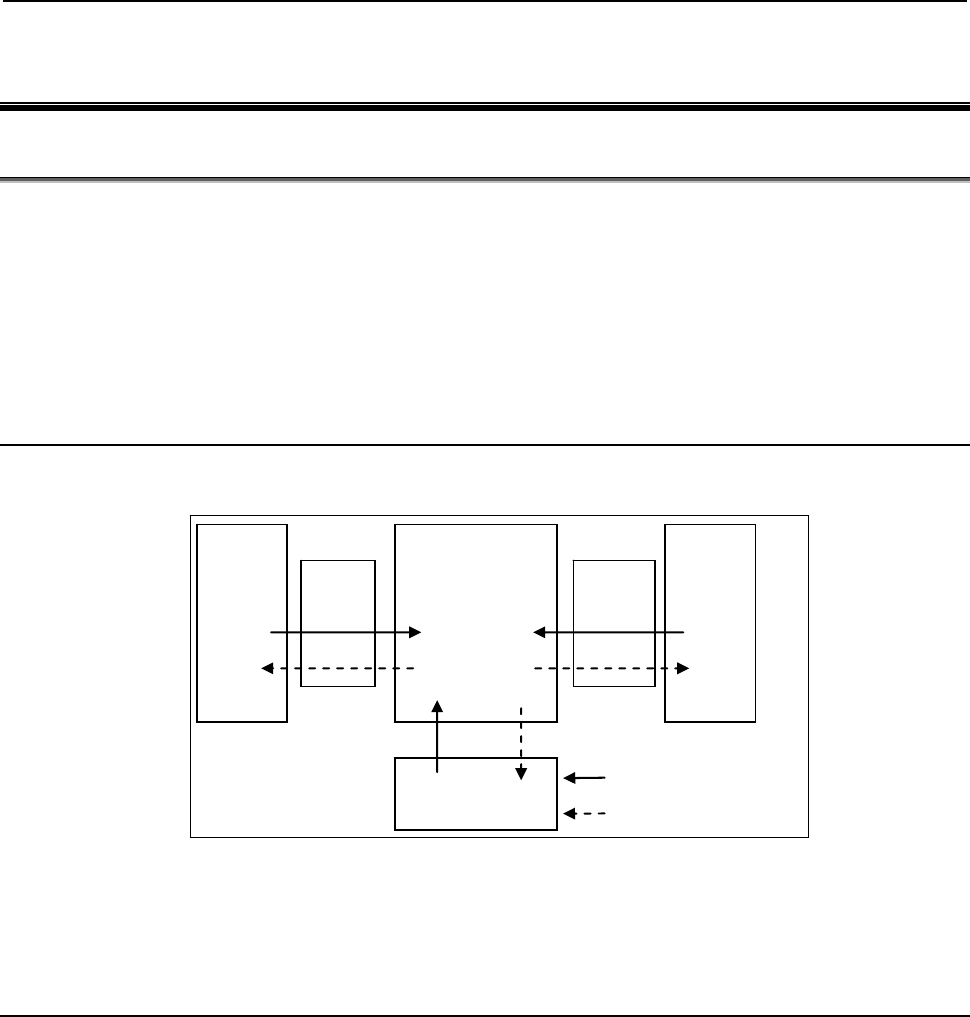
B-64513EN/03
1.OVERVIEW OF PMC
- 1 -
1 OVERVIEW OF PMC
1.1 WHAT IS PMC?
The programmable machine controller (PMC) is a programmable controller (PC) built into a CNC to
perform sequence control for a machine tool (spindle rotation, tool change, machine operator's panel control,
and so on).
Sequence control is to perform control steps successively in a predetermined sequence or according to the
logic operation.
Programs for performing sequence control for machine tools are called sequence programs. Generally,
sequence programs coded in the Ladder language are used.
1.1.1 Basic Configuration of PMC
The following is the basic configuration of the PMC:
CNC
Internal
I/O
PMC
Sequence
program
External
I/O
Machine
Internal relay
Signal input to PMC
Signal output from PMC
Fig. 1.1.1 Basic configuration of PMC
The sequence program reads input signals, performs operations, and outputs results in a predetermined
sequence.
1.1.2
I/O Signals of PMC
Input signals of the PMC include signals input from the CNC (such as M and T function signals) and signals
input from the machine (such as the cycle start button and feed hold signal button). Output signals of the
PMC include signals output to the CNC (such as the cycle start command and feed hold signal command)
and signals output to the machine (such as turret rotation and spindle stop). The PMC controls these I/O
signals by executing a sequence program to control the machine tool.
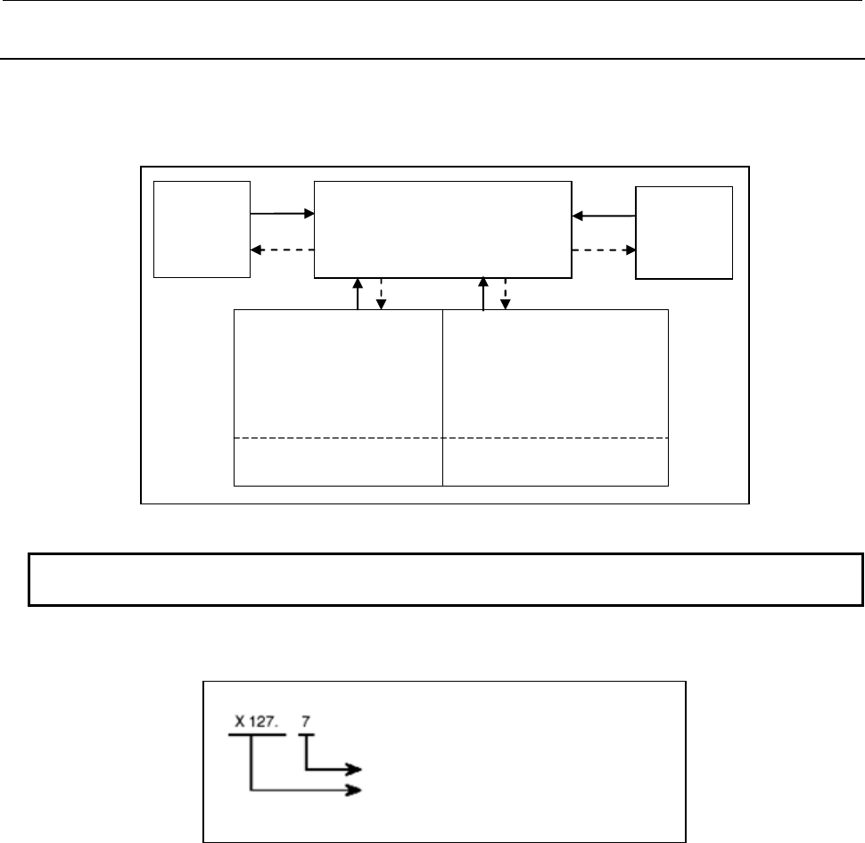
1.OVERVIEW OF PMC
B-64513EN/03
- 2 -
1.1.3
PMC Signal Addresses
PMC signal addresses indicate the locations of I/O signals exchanged with the machine, I/O signals
exchanged with the CNC, and signals for internal relays and data (PMC parameters) in nonvolatile memory.
PMC addresses are roughly classified as shown in Fig. 1.1.3 (a).
PMC
Signals
to/from CNC
Signals
to/from
machine
(MT)
Internal relay (R)
Extra relay (E)
Nonvolatile memory
(1) Variable timer (T)
(2) Counter (C)
(3) Keep relay (K)
(4) Data table (D)
(5) Extra relay (E)
(NOTE)
F
G
X
Y
Fig. 1.1.3 (a) PMC-related addresses
NOTE
Optionally, extra relays (E) may be assigned to nonvolatile memory locations.
The PMC signal address format consists of an address number and bit number (0 to 7) as follows:
Bit number (0 to 7)
A
ddress number (letter followed by decimal
number)
Fig. 1.1.3 (b) PMC address format
The first letter of an address number represents the type of the signal.
In sequence programs, an address of a byte may be specified. In the above example, specify X127 to
specify a byte address. In this case, the period "." and bit number are unnecessary.

B-64513EN/03
1.OVERVIEW OF PMC
- 3 -
Table 1.1.3 lists the address symbols and corresponding signals.
Table 1.1.3 Address Symbols and signal types
Symbol Signal type
F Input signal from CNC to PMC (CNC
→
PMC)
G Output signal from PMC to CNC (PMC
→
CNC)
X Input signal from machine to PMC (MT
→
PMC)
Y Output signal from PMC to machine (PMC
→
MT)
R Internal relay
E Extra relay
A Message display
T Variable timer
C Counter
K Keep relay
D Data table
M Input signal from another PMC path
N Output signal to another PMC path
L Label number
P Subprogram number
(1) Addresses of signals between the PMC and CNC (F and G)
These addresses are assigned to interface signals between the CNC and PMC. The relationships
between the signals and addresses are defined by the CNC.
F indicates an input signal from the CNC to PMC.
G indicates an output signal from the PMC to CNC.
(2) Addresses of signals between the PMC and machine (X and Y)
I/O signals exchanged with an externally connected machine can be assigned to any addresses within
an available range to control the machine.
X indicates an input signal from the machine to PMC.
Y indicates an output signal from the PMC to machine.
(3) Addresses of internal relays and extra relays (R and E)
These addresses are used to temporarily store operation results during sequence program execution
processing.
Optionally, E addresses may be assigned to nonvolatile memory locations.
The address locations of internal relays also include a reserved area used by the PMC system software.
The signals in the reserved area cannot be written by sequence programs.
(4) Signal addresses for message display (A)
Instruction “DISPB” used in sequence programs include instructions to display a message on the CNC
screen. These addresses are used by such instructions.

1.OVERVIEW OF PMC
B-64513EN/03
- 4 -
(5) Nonvolatile memory addresses
The contents of these address locations are not erased even when the power is turned off.
These addresses are used for management of the data items listed below. These data items are called
PMC parameters.
(a) Variable timer (T)
(b) Counter (C)
(c) Keep relay (K)
A reserved area used by the PMC system software is partly included.
(d) Data table (D)
(e) Extra relay (E)
Optionally, E addresses may be assigned to nonvolatile memory locations.
These addresses are used to temporarily store operation results during sequence program
execution processing.
(6) Multi-path PMC interface address (M, N)
These addresses are used to the Multi-path PMC interface.
M indicates an input signal from another PMC path.
N indicates an output signal to another PMC path.
(7) Other addresses
(a) Label number (L)
Sequence program instructions include an instruction to cause a jump to a specified position in
the middle of processing. This address indicates the jump destination used by this instruction.
The contents of L address cannot be read/written in sequence program.
(b) Subprogram number (P)
In sequence programs, a main program can call subprograms. P addresses indicate the numbers
of these subprograms. The contents of P address cannot be read/written in sequence program.
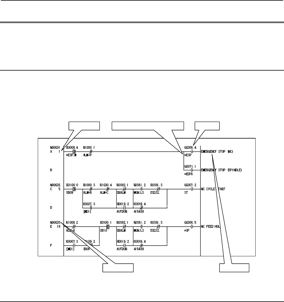
B-64513EN/03
1.OVERVIEW OF PMC
- 5 -
1.2 WHAT IS LADDER LANGUAGE?
The Ladder language is one of sequence programming languages. This programming language, which
represents the sequence and logic operations of I/O signals by ladder diagrams, is widely used by sequence
control engineers. This language is mainly used for PMCs.
1.2.1 Ladder Diagram Format
Designers develop and see ladder diagrams in the design stage. However, other people (for example, many
maintenance engineers) have much more chances to see ladder diagrams than the designers of the ladder
diagrams have. Therefore, the designers should create ladder diagrams so that these diagrams are
intelligible to any one.
The following is the format of ladder diagrams:
AddressSignal name (symbol name)
Comment
Line No.
Net No.
The meanings of ladder diagram contents will be described later.
1.2.2
Signal Name (Symbol Name)
Symbol names representing I/O signal names can be assigned to PMC addresses. It is recommended that
signal names (symbol names) suitable for I/O signals be assigned as explained below.
(1) Signal names may consist of any alphanumeric characters and the special symbols. The number of
characters that can be entered varies depending on the PMC model. For the allowable number of
characters, see the table in Subsection 2.1.1.
(2) As the names of the signals between the CNC and PMC, use the signal names indicated in the address
table of the PMC without modifications.
(3) Some CNC signals are input from the machine or output to the machine. The names of these signals
are distinguished by prefixing X or Y to the names of signals between the CNC and PMC.
For example, a single block input signal is represented as XSBK by prefixing X, while a start lamp
output signal is represented as YSTL by prefixing Y.
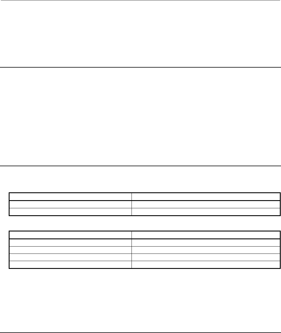
1.OVERVIEW OF PMC
B-64513EN/03
- 6 -
The names of some signals between the CNC and PMC, however, exceed the maximum allowable
number of characters as a result of prefixing X or Y to the names. In such a case, delete the last
character of the signal name.
(*SECLP → X*SECL)
(4) The same signal name (symbol name) cannot be assigned to more than one signal address.
1.2.3
Comment
A comment can be added to each symbol in the symbol table so that it can be indicated as a comment on a
relay or coil in the sequence program. The number of characters that can be entered varies depending on the
PMC model. For the number of characters that can be entered, see the table in Subsection 2.1.1.
For all relays and coils that are output signals to the machine, add a comment to provide a detailed signal
explanation. For other auxiliary relays, provide explanations of the signals if these relays have significant
meanings in sequence control.
In particular for machine-related input signals, be sure to provide a detailed signal explanation as a
comment in the symbol table.
Add detailed comments to signals dedicated to the machine so that one can guess the meanings of these
signals just from the symbol names.
1.2.4
Graphic Symbols of Relays and Coils
Ladder diagrams use the following relay symbols:
Relays (contacts)
Instruction representation Function
-| |- Normally open contact (contact A)
-|/ |- Normally closed contact (contact B)
Coils
Instruction representation Function
-
{
- Coil
-
{
{
- Negated coil
-(S)- Set coil
-(R)- Reset coil
These instructions perform a 1-bit operation and are called basic instructions.
In addition, there are functional instructions that enable easy programming of complicated operations for
processing byte, word, and double-word data, which are difficult to program just using basic instructions.
The symbol formats of the functional instructions are slightly different from instruction to instruction. For
details, see the description of each functional instruction in Chapter 4.
1.2.5
Line Number and Net Number
A line number is indicated in every line of ladder diagrams.
A continuous ladder circuit from a contact to a coil is called a net. A net number is also indicated for each
net.
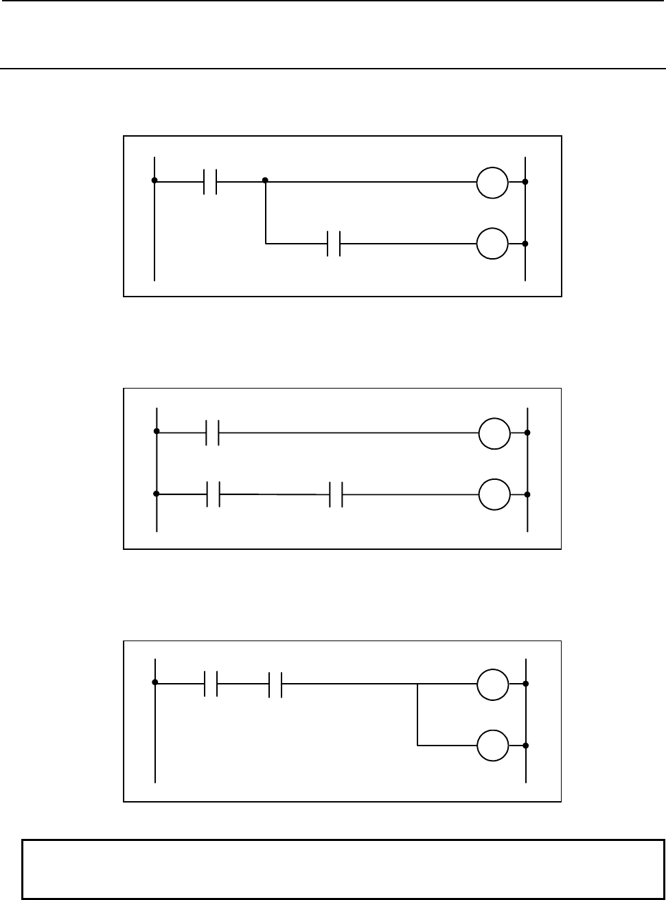
B-64513EN/03
1.OVERVIEW OF PMC
- 7 -
1.2.6
Difference Between Relay Sequence Circuit and Ladder
Sequence Program
In general relay sequence circuits, because of a limited number of relay contacts, one contact may be shared
by several relays to minimize the number of contacts used. Fig. 1.2.6 (a) gives an example.
R1
R2
A
B
Fig. 1.2.6 (a)
With the PMC, relay contacts are considered to be unlimited, so ladder diagrams are created as shown in Fig.
1.2.6 (b).
R1
R2
A
B
A
Fig. 1.2.6 (b)
In a relay sequence circuit having no contact between a branch point and a coil as shown in Fig. 1.2.6 (c), a
similar ladder diagram can be created even for the PMC.
R1
R2
A
B
Fig. 1.2.6 (c)
NOTE
The extended PMC ladder instruction function allows the sequence circuits like
Fig. 1.2.6(a). For details, see 8.3.4.
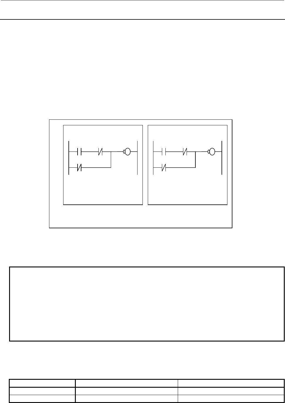
1.OVERVIEW OF PMC
B-64513EN/03
- 8 -
1.2.7
Specification of Extended Symbol and Comment
Using extended symbol and comment, you can use following functions.
• Local symbols effective in sub programs
• Extension of maximum character length of symbol and comment
• Multi-language support of comment
• Multiple definitions of symbol and comment to one signal
• Data type definition
• Automatic address assignment at compiling on FANUC LADDER-III
(1) Local symbols effective in sub programs
You can define local symbols effective only in a sub program. So you can define local symbols having
same string in other sub programs. Local symbols defined in different sub programs do not conflict.
Using local symbols, symbol conflict does not occur. Therefore, it is easy to develop ladder in modular
programming technique. In addition, it is easy to reuse sequence programs. When you have to program
a similar program in some sub programs, copy the logic to another sub program, redefine the local
symbols, and compile on FANUC LADDER-III.
NOTE
1 Same local symbol names are not allowed in the same sub program.
2 Same symbol name of global symbol and local symbol are not allowed.
3 Local symbol cannot be defined to address P. Symbol definition to address P must
be global symbol.
4 You cannot create a sequence program using extended symbol and comment
only with CNC. To create it, you have to use FANUC LADDER-III.
5 When you use the function block function, it becomes extended symbol and
comment form automatically.
(2) Extension of maximum character length of symbol and comment
Maximum character length of a symbol and comment is extended as follows. So you can describe in
details.
Kind Extended type Basic type
symbol 40 characters in maximum 16 characters in maximum
comment 4 set 255 characters in maximum 1 set 30 characters in maximum
Global Symbol :
X*ESP = X8.4
Lock = X100.0
A
larm = R1000.0
*ESP = G8.4
P1 (Control_Path1)
Alarm
X*ESP
*ESP
Lock
Lock = X100.1
A
larm = R2000.0
*ESP = G1008.4
P2 (Control_Path2)
Alarm
X*ESP
*ESP
Lock

B-64513EN/03
1.OVERVIEW OF PMC
- 9 -
(3) Multi language support
One symbol entry has four comments set in maximum.
Displaying comment set can automatically selected by display language setting in CNC. By describing
each comment set in different languages, you can display comment in all PMC screens in multi
languages. This is very useful in maintenance.
NOTE
For the language attribute, refer to "APPENDIX B. LANGUAGE ID TABLE".
(4) Multiple definitions of symbol and comment to one signal
You can define multiple symbols and comments to the same signal.
NOTE
When multiple symbol and comment are defined to the same signal, you can
search the names by each symbol. On the other hand the symbol on PMC screen
is displayed one of these symbol names. So if you search symbols, displayed
symbol name on searched position may be different from searched word.
(5) Data type definition
You can define symbol and comment with data type definition.
Data type Meaning
BOOL Boolean
BYTE 8 bits integer
WORD 16 bits integer
DWORD 32 bits integer
LABEL Label (Address L)
PROG Sub program (Address P)
NOTE
1 In ladder editing screen, for example, BYTE type symbol can be set to the WORD
type parameter of a function. But it is recommended that data type of the symbol
should be consistent with the data type of the parameter that it is assigned to.
2 When two or more symbols are defined with a signal and these symbols have
different data types the symbol name of largest data type is displayed on PMC
screens.
(6) Automatic address assignment at compiling on FANUC LADDER-III
On FANUC LADDER-III, when programming by symbol names without actual addresses, this
function assigns addresses to them automatically.
CAUTION
The assignment of address may change by modifying symbol / comment data.
NOTE
By setting 1 to K903.5 of system keep relay, the signal state of the symbols whose
addresses are assigned automatically can be initialized when updating sequence
program to the one of different symbol / comment data.
In this case, changing the symbol / comment data whose address is not assigned
automatically will also initialize all signal states of the address range for automatic
assignment to 0.
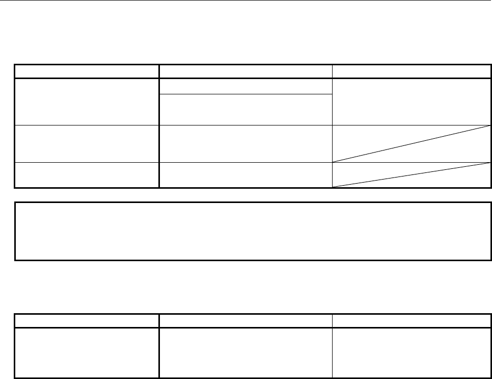
1.OVERVIEW OF PMC
B-64513EN/03
- 10 -
(7) Available characters
Those characters can be used.
- Available characters for symbol:
Kind Extended type Basic type
The character that can be used
as the symbol
A to Z, a to z, 0 to 9, _ A to Z, a to z, 0 to 9, _ Space,
! ” # $ % & ’ ( ) * + , . - < = > ? @ [ / ] ^
` { | } ~ ; :
! ” # & ’ ( ) * + , - < = > ? @ [ / ] ^ ` { | } ~
(Note)
The character that cannot be
used for the first character of the
symbol
% $
The character that cannot be
used for the symbol
Space,
; : .
NOTE
Although it is allowed to use special characters in symbol, using only alphabets,
digits and _(underscore) to comply with the variable name defined in IEC61131-3 is
recommended.
- Available characters for comment:
(a) English comment and Japanese comment:
Kind Extended type Basic type
The character that can be used
as the comment
A to Z, a to z, 0 to 9, Space
! ” # & ’ ( ) * + , . - < = > ? @ [ / ] ^ _ ` { | }
~ ; :
A to Z, a to z, 0 to 9, Space,
! ” # $ % & ’ ( ) * + , . - < = > ? @ [ / ] ^
_ ` { | } ~ ; :
(b) Multi-language comment:
Refer to "Appendix A. CHARACTER CODE TABLE".

B-64513EN/03
1.OVERVIEW OF PMC
- 11 -
1.3 SEQUENCE PROGRAM CREATION PROCEDURE
This section briefly explains how to create a program for providing sequence control for a machine tool by
using the Ladder language as an example. When creating a sequence program, see the necessary manual for
editing after understanding the contents of this chapter thoroughly.
1.3.1 Determining Specification
First, determine the specifications of the control target. Calculate the number of I/O signals, and determine
the interfaces of the I/O signals.
In this step, creation of interface specifications is recommended.
1.3.2 Creating Ladder Diagram
After determining specifications, represent control operations with a ladder diagram. Timer, counter, and
other functions that cannot be represented by relay symbols are called functional instructions. Represent
these functional instructions with corresponding symbols.
When using offline programmer or built-in edit function explained in "Editing Sequence Program" in the
next subsection, you can enter a sequence program in a ladder diagram form. At the time of sequence
program editing, you can make entry while creating a ladder diagram on the display screen, so you need not
prepare a ladder diagram in advance.
If you want to create a sequence program efficiently, however, it is recommended that you should create a
ladder diagram in advance.
Ladder diagrams are referenced as maintenance drawings by FANUC maintenance engineers, maintenance
engineers of machine tool builders, and maintenance engineers of end users not only domestically but also
in foreign countries. Therefore, try to create as intelligible ladder diagrams as possible.
1.3.3 Editing Sequence Program
A sequence program in the Ladder language is edited with one of the following two methods:
(1) PC programmer
FANUC supplies FANUC LADDER-III as sequence program development software for FANUC
PMC. Use of FANUC LADDER-III allows you to edit a program in the Ladder language on a
personal computer.
(2) Built-in programmer
The PMC software built into the CNC has a built-in edit function. With this function, a program in the
Ladder language can be edited.
By using either of these editing methods, a sequence program can be entered in a ladder diagram form from
the EDITOR screen. FANUC LADDER-III can also output an entered sequence program to a printer in a
ladder diagram form.
Furthermore, FANUC LADDER-III provides a function for converting a program in a ladder diagram form
to mnemonic form or vice versa. By using this function, you can edit the program in mnemonic form with
a text editor.
Fig. 1.3.3 shows an example of a ladder diagram, and Table 1.3.3 shows an example of a mnemonic form.
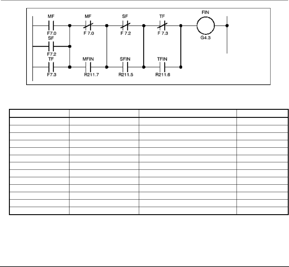
1.OVERVIEW OF PMC
B-64513EN/03
- 12 -
A
uxiliary function
completion
signal
Fig. 1.3.3
Table 1.3.3
Step No. Instruction Address No. & bit No. Remarks
1 RD F7.0 MF
2 OR F7.2 SF
3 OR F7.3 TF
4 RD.NOT.STK F7.0 MF
5 OR R211.7 MFIN
6 AND.STK
7 RD.NOT.STK F7.2 SF
8 OR R211.5 SFIN
9 AND.STK
10 RD.NOT.STK F7.3 TF
11 OR R211.6 TFIN
12 AND.STK
13 WRT G4.3 FIN
During sequence program editing, signal names (symbols) and comments can be entered for I/O signals,
relays, and coils. Easy-to-understand signal names and comments should be entered to improve program
maintainability.
1.3.4
Transferring and Writing Sequence Program to PMC
After completing editing for the sequence program, input (transfer) the program to the PMC. This operation
is unnecessary when you have edited the program by using the built-in programmer.
When you have edited the sequence program by using the PC programmer, input the sequence program
from the editing environment (the personal computer (PC)) to the PMC. The following input methods can
be used:
(1) Input from the I/O screen
The sequence program on the PC is input to the PMC via a memory card or a USB memory.
(2) Input from the online monitor screen
For data input, connect the PC containing the sequence program to the CNC via Ethernet or RS-232C.
After inputting the sequence program, write it in the flash ROM. This operation can be done with the
DATA I/O screen of the PMC.

B-64513EN/03
1.OVERVIEW OF PMC
- 13 -
1.3.5
Checking Sequence Program
After writing the sequence program in the flash ROM, check the sequence program.
The sequence program can be checked in the following two ways:
(1) Checking with a simulator
Connect a simulator (consisting of lamps and switches) instead of the machine. Instead of using input
signals from the machine, turn the switches on and off to input signals, and confirm output signals by
checking the on/off states of the lamps.
(2) Checking by system operation
Connect the machine to make checks. Before starting the operation, take safety measures because
when the sequence program is executed for the first time, an unpredictable motion can occur.
1.3.6
Storage and Management of Sequence Program
When the sequence program is completed after checking, it should be stored and managed by the machine
tool builder.
The sequence program can be output to the printer in a ladder diagram form by using the PC programmer.
The output ladder diagram should be attached as a maintenance drawing to the machine together with other
attached materials such as a power magnetic cabinet circuit diagram.
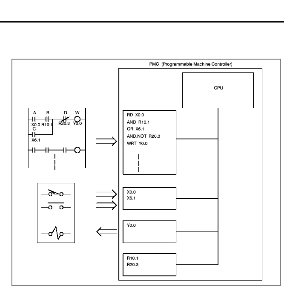
1.OVERVIEW OF PMC
B-64513EN/03
- 14 -
1.4 EXECUTION OF SEQUENCE PROGRAM
Sequence programs in the Ladder language are executed in the order of instructions coded in the ladder
diagrams.
Fig. 1.4 shows how a sequence program is executed.
Sequence program
memory
Sequence
program
input
Control target such as machine tool
Input circuit
Output circuit
Internal relay (RAM)
Fig. 1.4 Sequence program execution by PMC
The RD instruction causes the CPU to read the signal of the input circuit at address X0.0 and set the read
data in the operation register. Next, the AND instruction causes the CPU to AND the set data with the
internal relay state at address R10.1 and set the result in the operation register. The CPU then executes the
subsequent instructions at high speed, and the operation result is output to the output circuit at address Y0.0.
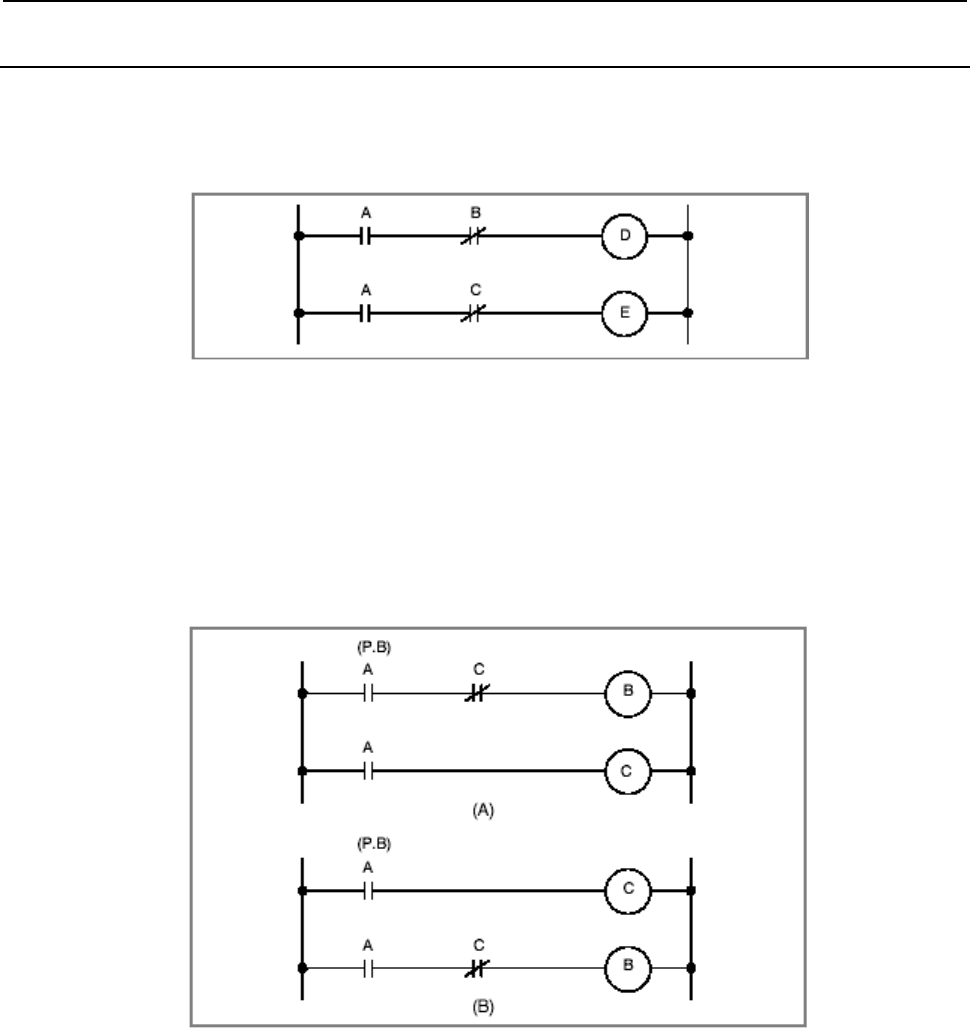
B-64513EN/03
1.OVERVIEW OF PMC
- 15 -
1.4.1
Execution Procedure of Sequence Program
In general relay sequence circuits, relays operate at exactly the same time. This means that when relay A
operates in the following figure, relays D and E operate at exactly the same time (when contacts B and C are
both off).
Fig 1.4.1 (a)
In PMC sequence control, on the other hand, relays in the circuit operate sequentially. When relay A in Fig.
1.4.1 (a) operates, relay D operates, then relay E operates.
Therefore, in PMC sequence control, relays operate in the order coded in the ladder diagram (the order of
programming). The sequential operations in this sequence are performed at high speed, but some
instructions are affected by the execution order.
Accordingly, in the ladder diagrams shown in Fig. 1.4.1 (b), there is a distinctive difference in operation
between the PMC sequence and the sequence of the relay circuit.
Fig. 1.4.1 (b) Circuit examples
(1) For relay sequence circuit
(A) and (B) in Fig. 1.4.1 (b) operate in the same manner. When A (P.B) is turned on, current flows
through coils B and C, turning on B and C simultaneously. After C is turned on (after relay operation
time), B is turned off.
(2) For PMC programming
In (A) in Fig. 1.4.1 (b), as with the relay sequence circuit, when A (P.B) is turned on, B and C are
turned on, then B is turned off after a certain time elapses (after a time required for one cycle of the
PMC sequence). In (B) in Fig. 1.4.1 (b), turning on A (P.B) turns on C but does not turn on B even
momentarily.
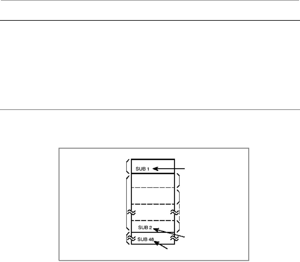
1.OVERVIEW OF PMC
B-64513EN/03
- 16 -
1.4.2
Repetitive Operation
A sequence program is executed until the end of the ladder diagram (the end of the program) is reached,
then program execution is repeated from the beginning of the ladder diagram (the beginning of the
program).
The execution time from the beginning to the end of the ladder diagram (the time required for one cycle) is
a time for processing the sequence program once and is called a scan.
This processing time depends on the sequence control scale (the number of steps) and the size of the 1st
level sequence described below. A shorter processing time results in a better signal response in the
sequence.
1.4.3
Processing Priority (1st Level, 2nd Level, and 3rd Level)
A sequence program consists of two operation parts: a high-speed sequence part called the 1st level, which
is executed every several msec, and a normal sequence part called the 2nd level. When the model used
allows use of the 3rd level, the 3rd level sequence part is added. (See Fig. 1.4.3 (a).)
Specifies end of 3rd level sequence
Sequence program
1st level sequence part
2nd level sequence part
3rd level sequence part
(only with model that can
use 3rd level)
Specifies end of 1st level
sequence
Division 1
Division 2
Division n
Specifies end of 2nd level
sequence
Fig. 1.4.3 (a) Sequence program structure
The 1st level sequence part is a high-speed sequence part that is executed every ladder execution cycle. The
ladder execution cycle is 1, 2, 4 or 8 msec, which is set in a CNC parameter. If the execution of the 1st level
program requires a long time, the overall execution time including the 2nd level (sequence processing time)
is extended. So, the 1st level sequence part should be created so that it can be processed in a short time
where possible. The 2nd level sequence part is executed every (ladder execution cycle × n) msec (where n
is the number by which the 2nd level is divided). The 3rd level sequence part is executed when the PMC is
idle.
(1) Division of the 2nd level program
The 2nd level program must be divided to execute the 1st level program. The order of sequence
program execution is illustrated in Fig. 1.4.3 (b), where the number of divisions is assumed to be n.
After the last division (division n) of the 2nd level program is executed, the sequence program is
executed from the beginning. Therefore, when the number of divisions is n, the execution cycle of the
overall sequence program is expressed as the ladder execution cycle × n msec.
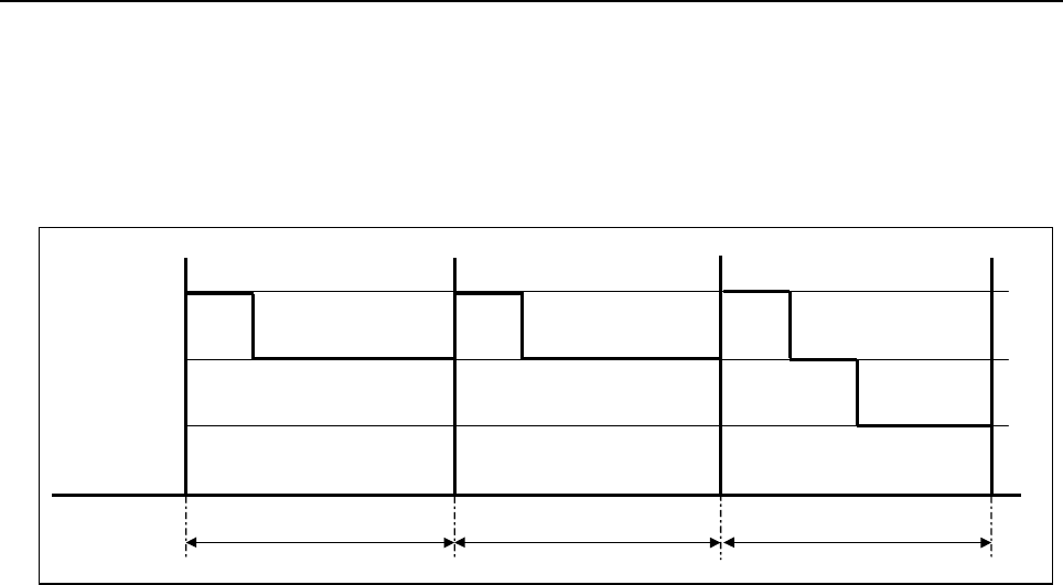
B-64513EN/03
1.OVERVIEW OF PMC
- 17 -
As the amount of the 1st level sequence part increases, the amount of the 2nd level sequence portion
executed within the ladder execution cycle decreases. As a result, the number of divisions n increases,
which increases the overall execution time including the 2nd level (sequence processing time).
Therefore, the 1st level sequence program part should be minimized where possible. The division
number of 2nd level may be indefinite because of changing of the working condition of functional
instructions in 1st level and 2nd level.
1st level
2nd level
3rd level
Ladder execution cycle (4 or 8 ms) Ladder execution cycle (4 or 8 ms)
Division 1 Division 2
Ladder execution cycle(4 or 8 ms)
Last division n
3rd level
processing
Fig. 1.4.3 (b) Sequence program execution order
(2) 1st level sequence part
It is high-speed sequence operation. Only high-speed sequence processing such as processing of a
pulse signal with a short signal width in time is performed.
These signals include emergency stop and feed hold signals.
(3) 3rd level sequence part
The 3rd level sequence processing is performed during the remaining time from the end of the last
division (n) of the 2nd level until the 1st level processing restarts (see Fig. 1.4.3 (b)).
It is possible to program the 3rd level, but the execution cycle period of time for processing the 3rd
level sequence part is not guaranteed to maintain program compatibility with conventional models.
Therefore, the 1st and 2nd level sequence parts should be programmed without using the 3rd level
sequence part.
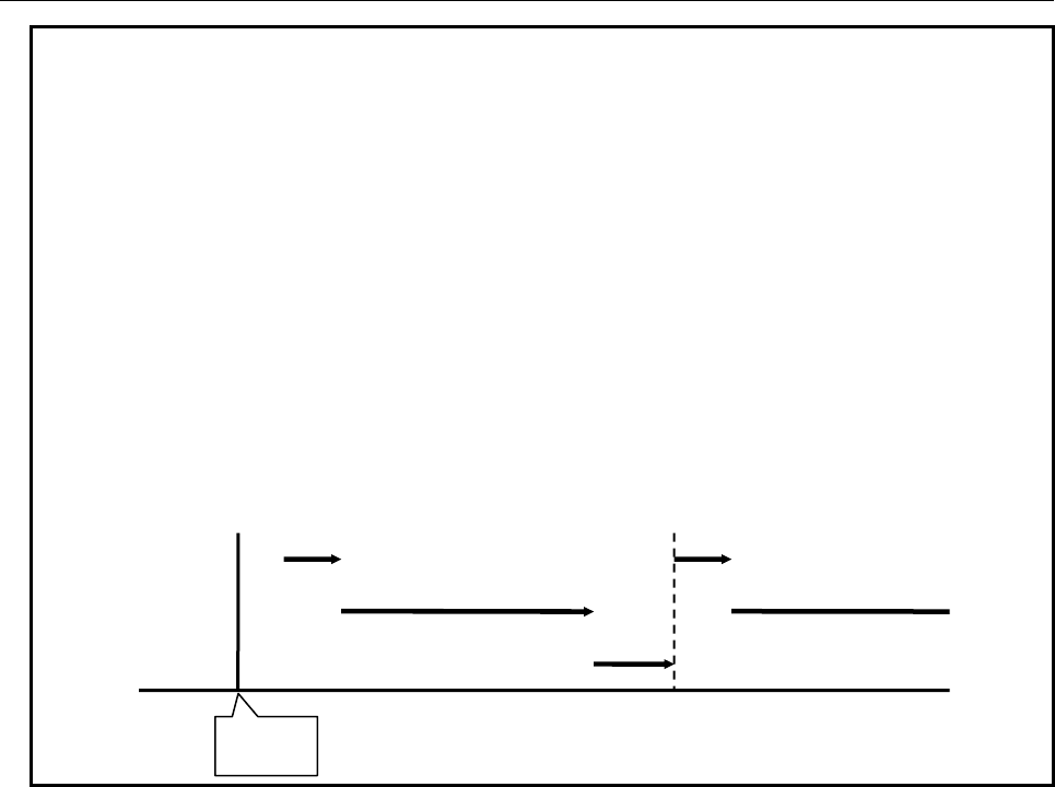
1.OVERVIEW OF PMC
B-64513EN/03
- 18 -
NOTE
1 The ladder program is executed initially to set the input signals for the CNC (G
signals) like the following chart until the beginning of cyclic operation of the CNC
from the power on of the CNC. The initial execution is different from the cyclic
execution. Therefore the ladder program is not executed at the constant period
and is continuously and repeatedly executed. The execution of each level of the
ladder program is not divided. They are executed from the top of the program to
the end of the program in the order of the following chart. After finishing the initial
execution of the ladder, the CNC starts the cyclic operation.
2 In the initial execution of the ladder program, the operations of the following
functional instructions are different from the normal operations.
- TMR、TMRB、TMRC、TMRST、TMRSS
The timer is not executed and the time is always 0 in the initial execution.
- WINDR、WINDW、AXCTL、EXIN、DISPB、PSGNL、PSGN2
They are executed as the NOP instruction (No operation) in the initial
execution.
1
st
l
e
v
e
l
2nd level
3rd level
Power on
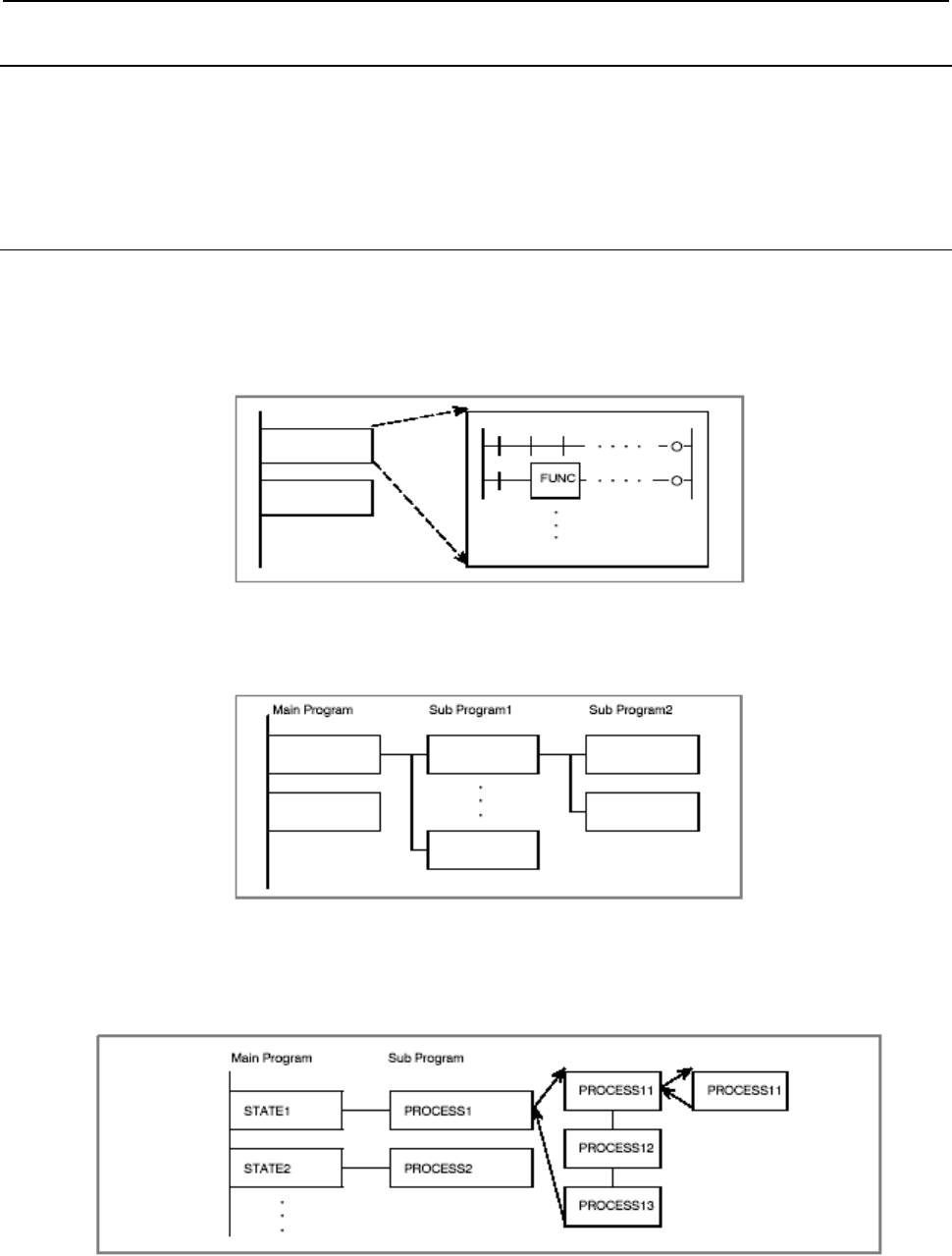
B-64513EN/03
1.OVERVIEW OF PMC
- 19 -
1.4.4
Structured Sequence Program
Structured ladder coding has the following advantages:
• Programming is easy to understand, therefore programming becomes easier.
• Program errors can be found easily.
• Troubleshooting can be done easily.
1.4.4.1
Implementation
Three major implementation techniques are supported.
(1) Use of routines
Ladder sequence processing units are created so that they can be treated as routines.
Job A
Job B
(2) Nesting
Ladder routines created in (1) are connected to configure a ladder sequence.
Job A
Job B
Job A
1
Job A
n
Job A
11
Job A
12
(3) Conditional branch
The main program loops and determines conditions. If conditions are satisfied, a subprogram process
is executed. If the conditions are not satisfied, the subprogram process is skipped.
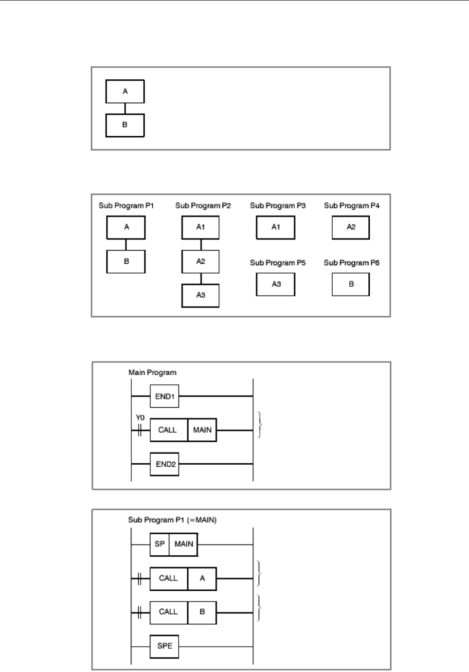
1.OVERVIEW OF PMC
B-64513EN/03
- 20 -
Application example
(1) Example
Suppose that there are four major jobs.
If Y0 is 1, workpiece machining request is assumed to be issued,
and processing is performed. (Conditional)
A
: <1> Pick up workpiece from pallet. (A1)
<2> Machine workpiece. (A2)
<3> Return workpiece to pallet. (A3)
B: <4> Move pallet.
(2) Program configuration
(3) Program coding
Machine workpiece.
Machine workpiece.
Move pallet.
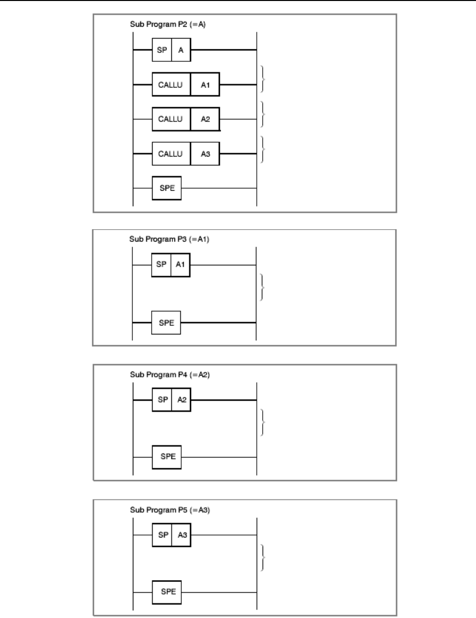
B-64513EN/03
1.OVERVIEW OF PMC
- 21 -
Pick up workpiece from pallet.
Machine workpiece.
Return workpiece to pallet.
Ladder representation
Pick up workpiece
from pallet.
Ladder representation
Machine workpiece.
Ladder representation
Return workpiece to pallet.

1.OVERVIEW OF PMC
B-64513EN/03
- 22 -
Ladder representation
Move pallet.
Specifications
(1) Main program
A ladder program consisting of the 1st ladder level and 2nd ladder level is called a main program. You
can create just one main program. Subprogram calls from the 1st ladder level are not allowed. Any
number of subprogram calls from the 2nd ladder level may be made. Functional instructions JMP and
COM must be closed within the main program and each subprogram.
(2) Subprogram
Programs called from the 2nd ladder level are referred to as subprograms. A subprogram is a program
unit enclosed by functional instructions SP and SPE. Up to 512 or 5000 subprograms can be created
for one PMC.
(3) Nesting
A subprogram can call another subprogram.
Up to eight levels of subprograms can be nested.
Recursive calls are not permitted.
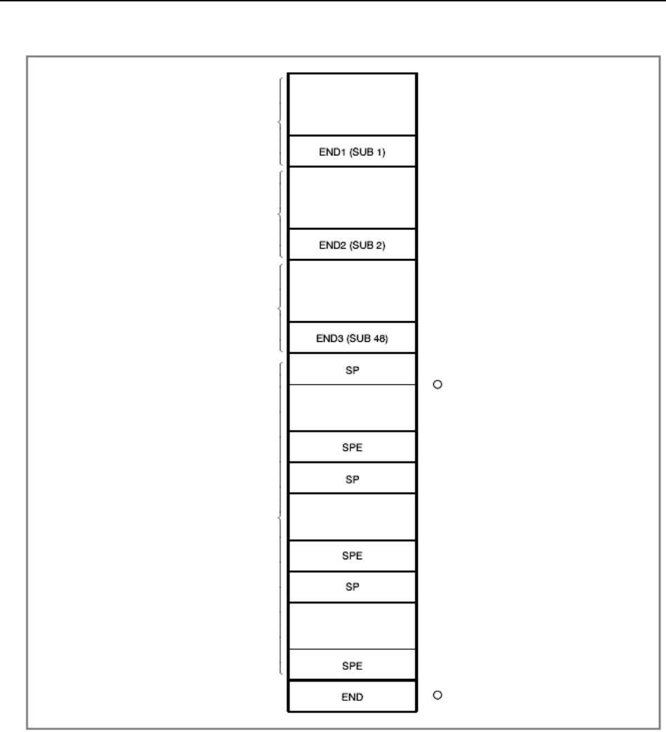
B-64513EN/03
1.OVERVIEW OF PMC
- 23 -
(4) Programming order when subprograms are used
Code subprograms after 2nd and 3rd
levels.
1st level sequence
part
2nd level sequence
part
3rd level sequence
part (only with model
that can use 3rd
level)
Subprograms
End of sequence
program End of entire sequence program is
indicated by END instruction.
Fig. 1.4.4.1
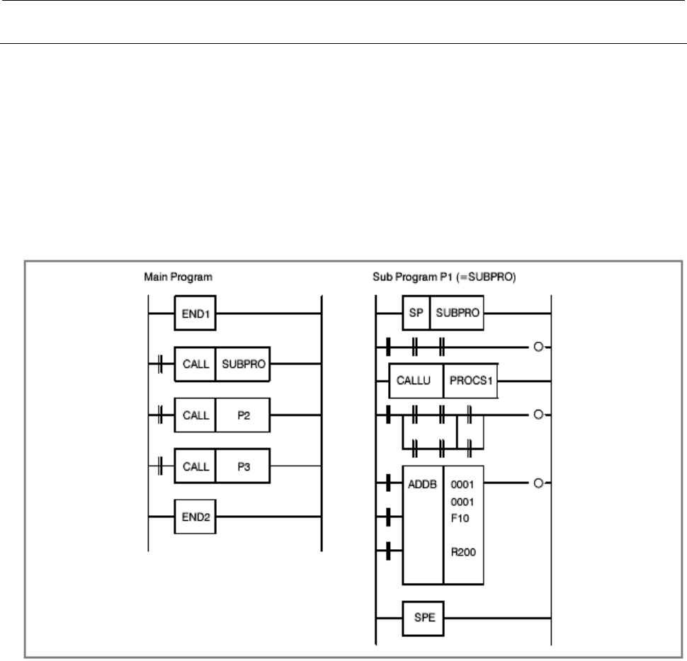
1.OVERVIEW OF PMC
B-64513EN/03
- 24 -
1.4.4.2
Sub programming and nesting
Function
A conditional call (or unconditional call) is coded in the main program, and the name of a subprogram to be
executed is specified. In the subprogram, the subprogram name and a ladder sequence to be executed are
coded.
When a conditional call specifying Pn (representing a program name) is made, a subprogram named Pn is
called and executed.
A subroutine name can be assigned by adding a symbol or comment to Pn.
In the example shown in Fig. 1.4.4.2 (a), the main program calls three subprograms. These calls are all
conditional calls. Subprogram P1 is named SUBPRO. Subprogram P1 calls subprogram PROCS1
unconditionally.
Fig. 1.4.4.2 (a) Example of subprogramming and nesting
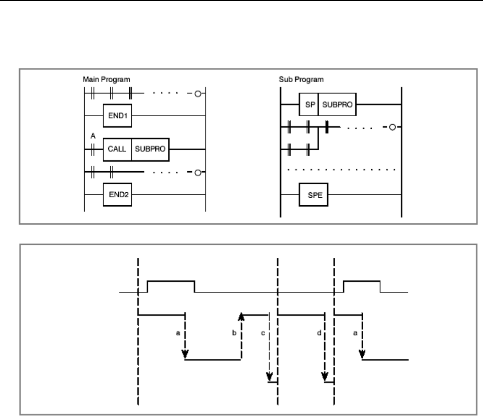
B-64513EN/03
1.OVERVIEW OF PMC
- 25 -
Execution method
The main program is always active. Subprograms are active only when called by another program.
In the following example, subprogram SUBPRO is called by signal A.
Main
program
Program cycle
Signal A
Subprogram
Management
program
Execution flow
(1) A subprogram call by functional instruction CALL transfers control to the subprogram.
(2) When the execution of the subprogram is completed, control is returned to the main program.
(3) When the execution of the main program is completed, the ladder program post processing is
performed.
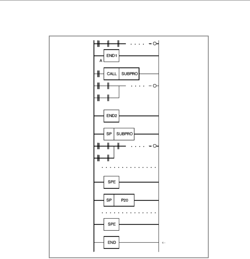
1.OVERVIEW OF PMC
B-64513EN/03
- 26 -
Creating a program
After the 1st, 2nd, and 3rd level ladder programs, create subprograms in the similar manner.
Creation example
Be sure to code this.
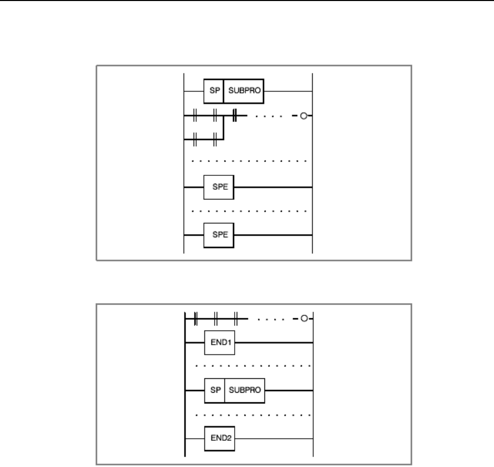
B-64513EN/03
1.OVERVIEW OF PMC
- 27 -
Inhibit items
(1) Subprograms are nested.
(2) A subprogram is created within the 1st, 2nd, or 3rd level ladder program.

1.OVERVIEW OF PMC
B-64513EN/03
- 28 -
1.4.4.3
Notes on using subroutines
(1) DISPB
(2) EXIN
(3) WINDR (low-speed type only)
(4) WINDW (low-speed type only)
(5) AXCTL
For the above functional instructions, ACT = 1 must be held until transfer completion information (coil) is
set to 1.
When using these functional instructions in subprograms, note the following prohibition:
(1) When one of the above functional instructions is being used within a subprogram and is not yet
completed (processing is in progress), the subprogram call is canceled. (ACT for the CALL
instruction is set to 0.)
CAUTION
The subsequent operation of the above functional instruction is not guaranteed.
(2) When one of the above functional instructions is being used within a subprogram and is not yet
completed (processing is in progress), the subroutine is called from another subprogram.
CAUTION
Because the preceding function is being processed, the subsequent operation of
the above functional instruction is not guaranteed.
When a subprogram using the above functional instructions is called from more than one place, exclusive
control is required. An example of using the WINDR instruction (low-speed type) is given below.
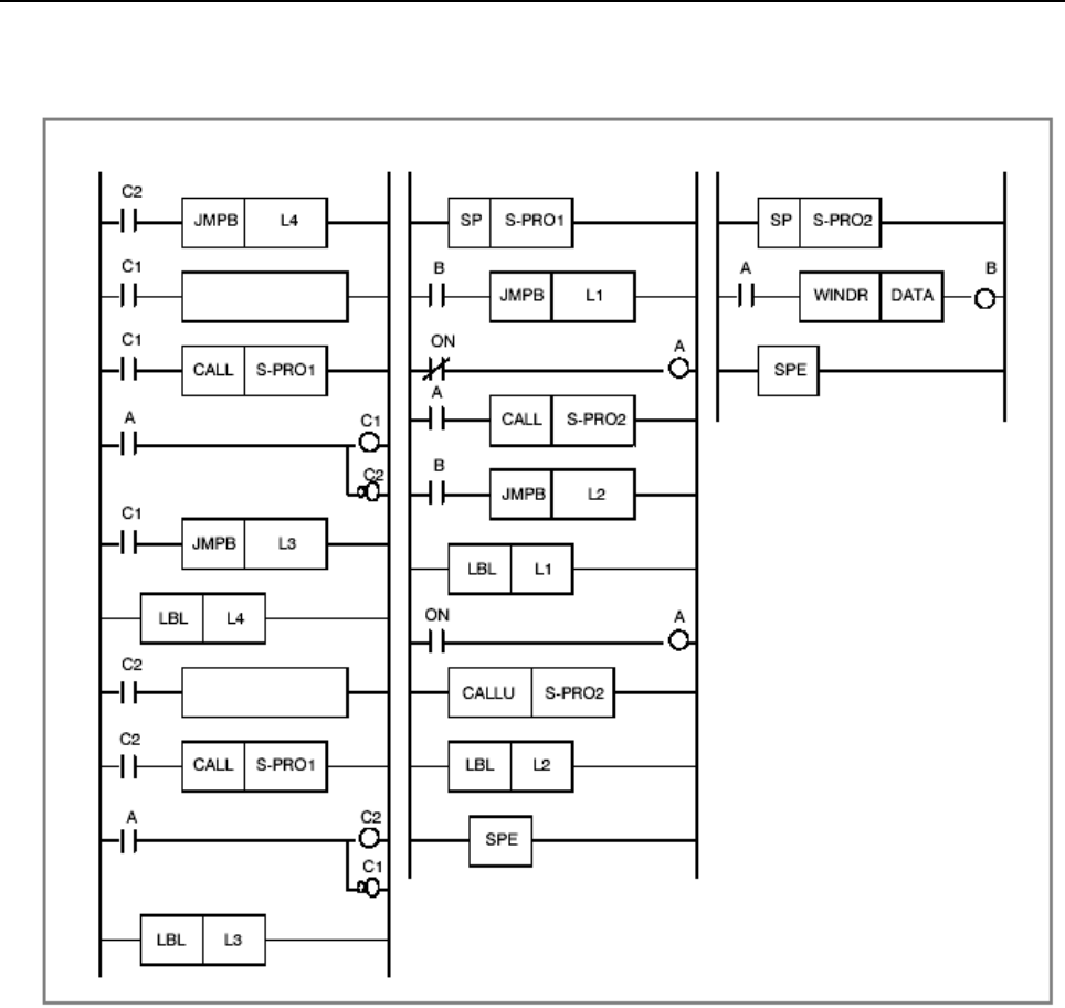
B-64513EN/03
1.OVERVIEW OF PMC
- 29 -
Example:
A subprogram is called from two places. (When the WINDR instruction is used)
Main program Subprogram 1 Subprogram 2
Set DATA1.
Set DATA2.
Explanation:
Subprogram 1 controls ACT (A) and W1 (B) of WINDR (subprogram 2).
The main program determines which data (C1 or C2) is to be used according to A controlled by subprogram
1. Upon completion of the WINDR instruction, the next data is set, and the other CALL instruction is
executed. In the subsequent operation, these steps are repeated.
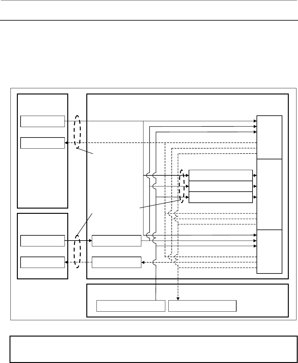
1.OVERVIEW OF PMC
B-64513EN/03
- 30 -
1.4.5
Synchronization Processing of I/O Signals
Signals input to the PMC include input signals from the CNC (such as M function and T function signals)
and input signals from the machine (such as cycle start and feed hold signals). Signals output from the PMC
include output signals to the CNC (such as cycle start and feed hold signals) and output signals to the
machine (such as turret rotation and spindle stop signals).
The relationships between these signals and the PMC are shown in Fig. 1.4.5 (a), in which input signals are
input to the input memory of the PMC, and output signals are issued from the PMC.
As shown in Fig. 1.4.5 (a), the input signals are synchronized during 1 scan of the 2nd level sequence part.
CNC
Machine Tool
PMC
Another PMC path
2nd level
sequence part
3rd level
sequence part
Sequence
program
1st level
sequence part
Input signal from CNC (F)
Input signal from machine (X)
Input signal from another PMC path(M)
Transferred
at start of
2nd level
2nd level synchronous input signal memory
Transferred every
4ms or 8ms
Transferred
via I/O Link
or I/O Link i
Input signal from machine (X)
Input signal memory
Output signal to machine (Y)
Output signal memory
Input signal from machine
Output signal to machine
Input signal from CNC (F)
Input memory of CNC
Output signal to CNC (G)
Output memory of CNC
Input signal from another PMC path (M) Output signal to another PMC path (N)
Fig. 1.4.5 (a) I/O signals of PMC
NOTE
The 2nd level synchronous input signal memories are F, X, and M address. Other
addresses are not synchronous input signals.
Input signal processing
(1) Input memory of the CNC
Signals input from the CNC to PMC are set in the memory of the CNC and are normally transmitted to
the PMC at intervals of 4 or 8 msec. Since the 1st and 3rd level sequence parts directly reference and
process these signals, these signals are not synchronized with input signals from the CNC. See the
description of following “Notes on programming asynchronous I/O signals”.

B-64513EN/03
1.OVERVIEW OF PMC
- 31 -
(2) Input signals from the machine (I/O Link or I/O Link i)
Signals input from the machine are transmitted to the input signal memory via the input circuit (I/O
Link or I/O Link i). The 1st and 3rd level sequence parts read the input signals from the input signal
memory and process them.
(3) Input signal memory
The input signal memory stores signals transmitted from the machine at regular intervals.
The 1st and 3rd level sequence parts of the PMC read and process signals stored in this memory. In
this case, the signal set in the input signal memory is not synchronized with the 1st and 3rd level
sequence parts. For notes on asynchronous processing, see the description of following “Notes on
programming asynchronous I/O signals”.
NOTE
In case of the I/O link i, there are two modes for the transmission cycle of input
signals. They are the normal mode (2msec) and the high speed mode (0.5msec).
In case of the I/O link channel 1 and 2, the transmission cycle of the input signals
is 2msec. In case of the I/O link channel 3, it depends on the execution cycle of 1st
level ladder (4msec or 8msec).
(4) 2nd level synchronous input signal memory
The 2nd level synchronous input signal memory stores signals processed by the 2nd level sequence
part of the PMC. Signals synchronized with the 2nd level sequence part are set in this memory.
Input signals in the input signal memory and input signals from the CNC are automatically transmitted
to the 2nd level synchronous input signal memory at the beginning of the 2nd level sequence part.
Therefore, the status of the 2nd level synchronous input signal memory is kept unchanged during the
time from the beginning of the 2nd level sequence part until the end of the sequence part.
The programmer function automatically performs processing so that the 1st and 3rd level sequence
parts use input signals in the input signal memory and input signals from the CNC while the 2nd level
sequence part uses the 2nd level synchronous input signal memory. (This need not be considered
during programming.)
NOTE
The 2nd level synchronous input signal memories are F, X, and M address. Other
addresses are not synchronous input signals.
Output signal processing
(1) Output memory to the CNC
Signals output from the PMC to CNC are set in the output memory of the CNC. Normally, the PMC
transmits signals to the output memory of the CNC at intervals of 4 or 8 msec.
(2) Output signals to the machine (I/O Link or I/O Link i)
Signals output to the machine are transmitted from the output signal memory of the PMC to the output
circuit (I/O Link or I/O Link i).
CAUTION
The output signals, which are just being updated in sequence program, may be
transmitted to I/O device. Please take care when referring to plural signals at the
I/O device.
(3) Output signal memory
The output signal memory is set by the sequence program of the PMC. Signals set in the output signal
memory are transmitted to the machine at regular intervals.
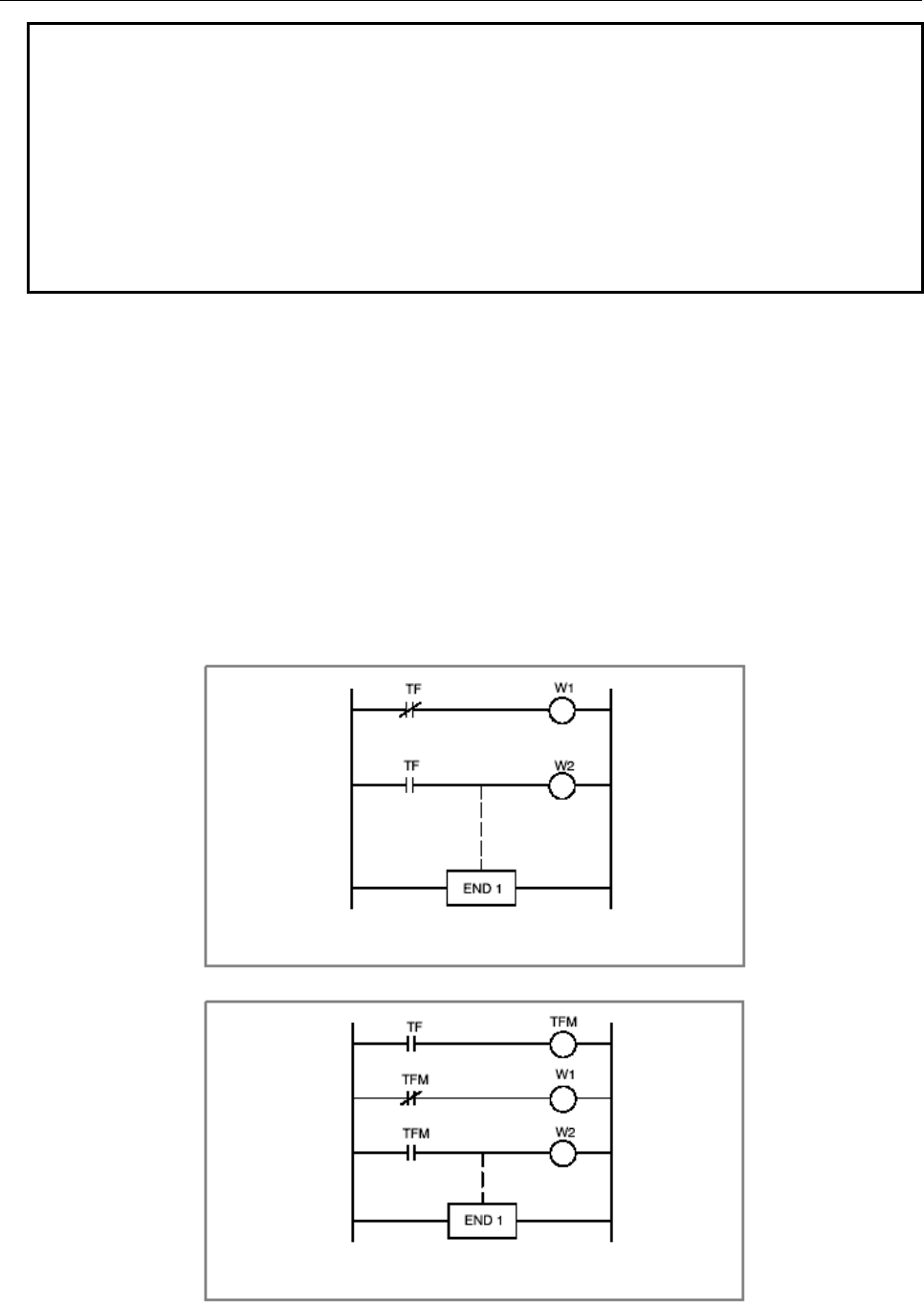
1.OVERVIEW OF PMC
B-64513EN/03
- 32 -
NOTE
1 The statuses of the input memory of the CNC, input signals from the machine,
output memory of the CNC, and output signals to the machine can be viewed on
the SIGNAL STATUS screen of the PMC. For the SIGNAL STATUS screen, see
Section 7.1.
2 In case of the I/O link i, there are two modes for the transmission cycle of I/O
signals exchanged with the machine. They are the normal mode (2msec) and the
high speed mode (0.5msec). In case of the I/O Link, the transmission cycle of I/O
signals exchanged with the machine is normally 2msec. However, it depends on
the setting of the channel of the I/O Link. For details, see Section 3.2.
Notes on programming asynchronous I/O signals
Normal input signals from the CNC are transmitted to the PMC at intervals of 4 or 8 msec. Normal output
signals to the CNC are transmitted from the PMC at intervals of 4 or 8 msec. Therefore, I/O signals
exchanged with the CNC are usually transmitted at intervals of 4 or 8 msec. When creating a sequence
program, note that the input signals from the CNC are not synchronized with the 1st and 3rd level sequence
program parts. Because the input signals from the CNC are asynchronous, the status of an input signal from
the CNC may change during execution of the 1st level sequence program part, which can lead to a problem
as shown in Fig. 1.4.5 (b). To prevent such a problem, write the TF signal to an internal relay at the
beginning of the 1st level sequence part so that the subsequent operation of the 1st level sequence program
part references the internal relay. Then, the TF signal can be treated as a synchronous signal. See Fig. 1.4.5
(c).
Signals input from the machine via the I/O Link and signals input from other control units over a network
are also asynchronous, so these signals should be treated in a similar manner.
If the TF status changes to 1 after TF=0 is read first,
W1 and W2 may be set to 1 momentarily.
Fig. 1.4.5 (b)
When the TF signal is made synchronized, neither W1
nor W2 is set to 1.
Fig. 1.4.5 (c)
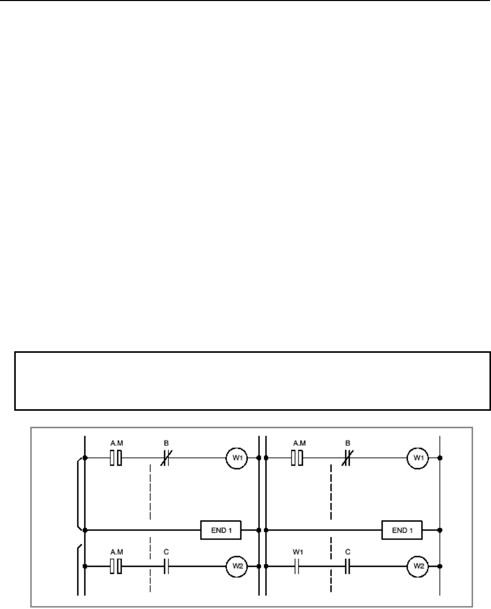
B-64513EN/03
1.OVERVIEW OF PMC
- 33 -
Difference in signal status between 1st level and 2nd level sequence parts
The status of the same input signal may become different between the 1st and 2nd level sequence parts. The
1st level sequence part uses the input signal memory for signal processing while the 2nd level sequence part
uses the 2nd level synchronous input signal memory. Therefore, it is possible that an input signal for the
2nd level sequence part lags behind the input signal for the 1st level sequence part by a cycle of the 2nd
level sequence execution at the worst.
When creating a sequence program, note the following:
Signal status
A.M On (pulse signal with short pulse width in time)
B Off
C On
When the 1st level is executed, the following difference can occur between Fig. 1.4.5 (d) and Fig. 1.4.5 (e):
(1) For Fig. 1.4.5 (d)
Even when W1 = 1, W2 may not be 1. (This is because the A.M signal may differ between the 1st level
and 2nd level.)
(2) For Fig. 1.4.5 (e)
If W1 = 1, W2 is always 1.
When performing the sequence shown in Fig. 1.4.5 (d), do the following:
At the 1st level, perform the high-speed sequence processing applied when the A.M signal status
changes (operating).
At the 2nd level, perform the sequence processing applied when the A.M signal status does not change
(stopped).
NOTE
In the middle of 1st level processing, a signal status change may occur
asynchronously with the sequence program processing. For details, see
Subsection 1.4.7.
1st level
2nd level
Fig. 1.4.5 (d) Fig. 1.4.5 (e)

1.OVERVIEW OF PMC
B-64513EN/03
- 34 -
1.4.6
Interlock
In sequence control, considering how to provide an interlock is a key design issue from the safety point of
view. Of course, an interlock must be provided by sequence programs. Furthermore, an interlock must also
be provided at the end of the electrical circuit in the power magnetic cabinet of the machine. Even when an
interlock is provided logically by a sequence program (software), the interlock by the sequence program
will not work if the hardware for executing the sequence program fails for a certain cause. Therefore, be
sure to provide an interlock within the power magnetic cabinet of the machine to ensure safety of the
operator and prevent machine damage.
1.4.7
Notes on I/O Signals Updated by Other Than PMC
I/O signals transmitted over networks (Note1) are directly updated with network boards, independently of
PMC sequence program execution.
Similarly, other applications (Note1) directly update I/O signals independently of PMC sequence program
execution. PMC sequence program and other applications are executed with individual cycle, i.e.
asynchronous.
Therefore, when PMC sequence program uses signals updated via network or other applications, or network
or other applications use signals updated PMC sequence program, the following should be noted:
WARNING
When you develop these applications, please take care of the following notes.
If the following notes are ignored, the machine may behave in an unexpected
manner and also tools, work pieces, and the machine may be damaged.
As for details, refer to “SAFETY PRECAUTIONS”.
NOTE
1 As for kinds of networks and other applications, refer to “SAFETY
PRECAUTIONS”.
2 As for CNC functions using PMC signals other than G/F address, refer to
“APPENDIX C”.
(1) Note on input signals
Signals, which are already written with PMC sequence program, must not be written with networks or
other applications.
When an input signal transmitted via a network or another application is referenced at more than one
place in the PMC sequence program, the same value is not guaranteed to be referenced within the same
cycle of the sequence program.
To refer to the same value of the input signal within the same cycle, store the input signal status in
temporary area such as internal relay and refer to it.
(2) Note on output signals
When output signals are updated via a network or other applications, the output signals, which are just
being updated, may be transmitted to I/O device, just like PMC sequence program. Please take care
when referring to plural signals at the I/O device.
(3) Note on multi-byte data
Generally, when multi-byte data ate input at once via a network or another application, the coherency
of the read multi-byte data (in other words, reading all latest data at once) is not guaranteed. To ensure
the coherency of multi-byte data, prepare flags to notify of the completion of read or write process that
is separated from the entity of data and make the handshaking process to access the data by using the
flags.

B-64513EN/03
1.OVERVIEW OF PMC
- 35 -
(4) Distributed processing of signals
Be careful enough that you process a PMC signal set that is related to a NC function by using two or
more applications (ladder program and other applications). Because they are executed based on
individual cycle (asynchronous cycle), the PMC signal set may be passed to the NC in an unexpected
order.
(5) Note when writing bit signals
Do not write bit signals in the same byte address from two or more programs such as PMC sequence
program, network and other applications. If bit signals written by the ladder program are being written
from other applications, there is a possibility that each the bit signals are not written correctly.
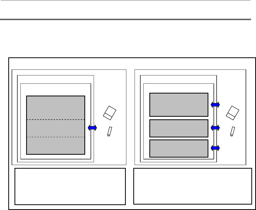
1.OVERVIEW OF PMC
B-64513EN/03
- 36 -
1.5 LADDER DIVIDING MANAGEMENT FUNCTION
The ladder dividing management function enables you to divide the ladder program into plural files and
input/output each file and set the protection by a password individually.
You can manage the sequence program as a main ladder program and some divided ladder programs by
using this function.
Memory card
USB memory
PMC
Divided ladder program 2
(Safety feature)
Divided ladder program 1
(Individual feature)
Main ladder program
(Basic feature)
CNC
<An example of using this function>
You can edit/input/output/protect the whole
sequence program.
PMC
CNC
<An example of not using this function>
(The ladder of
safety feature)
(The ladder of
Individual feature)
Sequence program
(The ladder of basic
f)
You can divide the ladder program into a main program
and some divided programs. Moreover, you can
edit/input/ output/protect the program individually.
You can also input/output all programs together by
using the all backup/restore function.
Memory card
USB memory
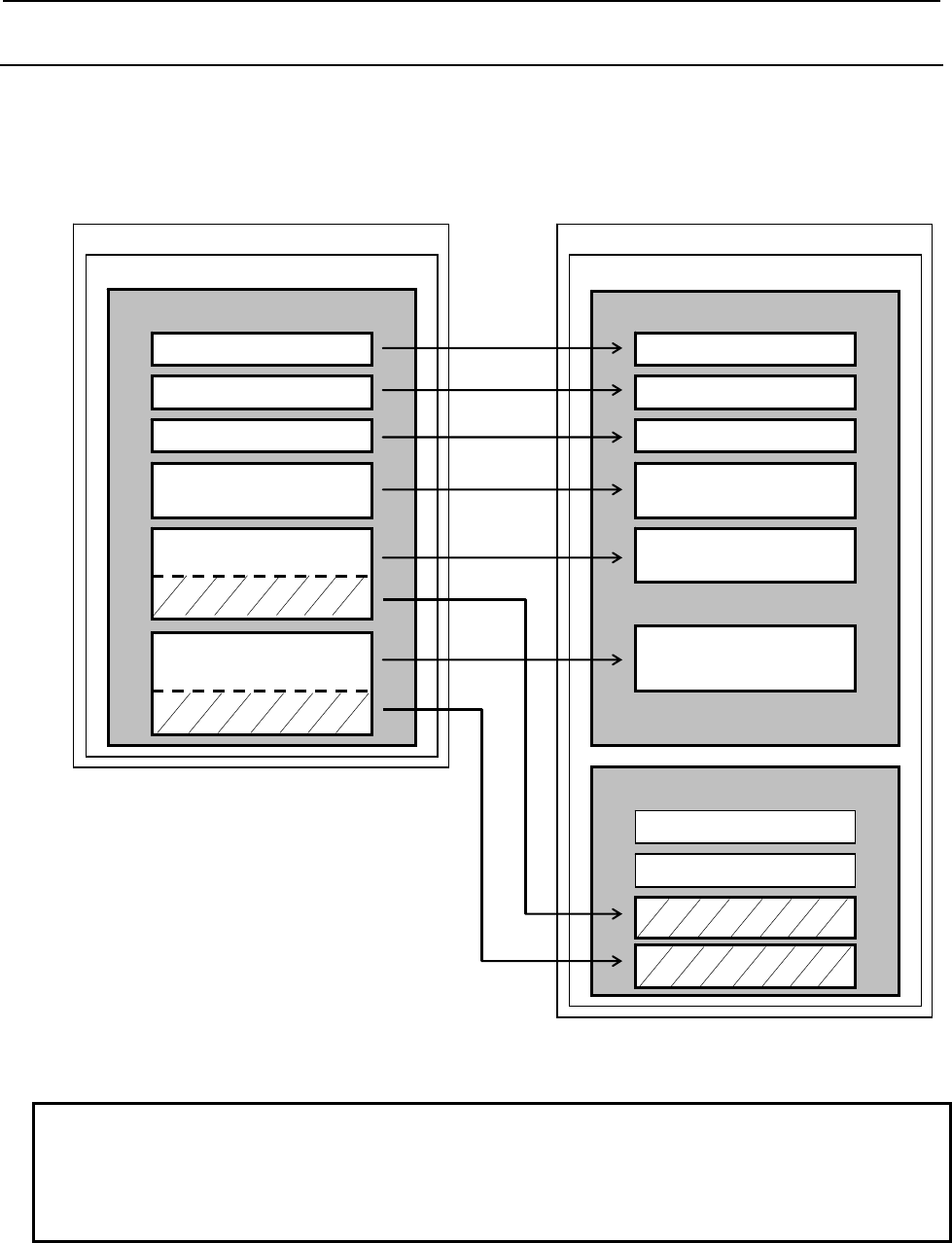
B-64513EN/03
1.OVERVIEW OF PMC
- 37 -
1.5.1
Divided Ladder Program
The divided ladder programs include a part of the ladder program and a part of symbols and comments and
are handled as individual files. You can set the system parameters and title data to every divided program
individually.
PMC
Divided ladder program
Main ladder program
CNC
<An example of using this function>
PMC
CNC
<An example of not using this function>
Title data
System parameter (Note)
Ladder program
Symbols/Comments
Ladder program
Symbols/Comments
Sequence program
I/O Link assignment data
Title data
System parameter
Ladder program
Symbols/Comments
Message data
I/O Link assignment data
Title data
System parameter
Message data
Fig. 1.5.1 Notion of the ladder dividing management function
NOTE
The system parameters, which can be set in the divided ladder program, are
“Setting of comment display language”, “Assignment address of symbols” and
“Assignment address of function blocks”. These parameters can be set on FANUC
LADDER-III.
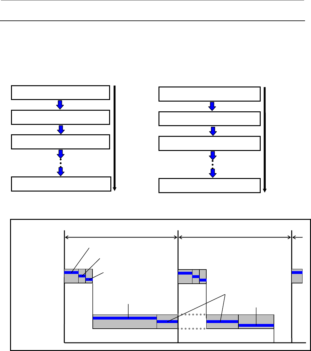
1.OVERVIEW OF PMC
B-64513EN/03
- 38 -
1.5.2
Program Execution when Using Ladder Dividing Management
When executing the program of ladder dividing management function, these are combined into one
program at every execution levels.
At first, the main program is executed, and the divided ladder programs are executed in order of program
number. The program number of divided ladder program is specified when making the sequence program
on FANUC LADDER-III.
Main ladder program (Level 1)
Divided ladder program No.99 (Level 1)
Divided ladder program No.1 (Level 1)
Divided ladder program No.2 (Level 1) Execution order
Main ladder program (Level 2)
Divided ladder program No.99 (Level 2)
Divided ladder program No.1 (Level 2)
Divided ladder program No.2 (Level 2)
Execution order
Ladder execution cycle (4 or 8ms)
Level 1 of main ladder
Level 1 of divided ladder 2
Level 1of divided ladder 1
Ladder execution cycle (4 or 8ms)
Level 2
Level 1
Level 2 of main ladder Level 2 of divided ladder 2
Level 2 of divided ladder 1
Fig. 1.5.2 (a) Ladder execution of the ladder dividing management function
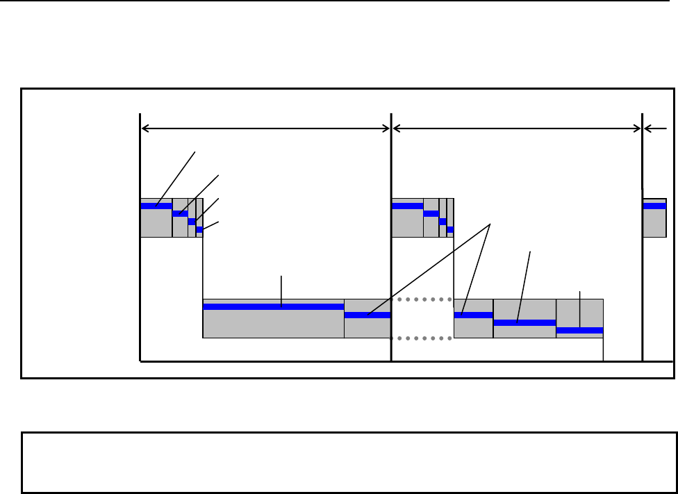
B-64513EN/03
1.OVERVIEW OF PMC
- 39 -
The program numbers do not need to be consecutive. For instance, three divided ladder program number
can be set to No.10, 20 and 30. In this case, non-exist divided program number is skipped and the program
of the next number is executed.
Ladder execution cycle (4 or 8ms)
Level 1 of main ladder
Level 1 of divided ladder 20
Level 1 of divided ladder 10
Ladder execution cycle (4 or 8ms)
Level 2
Level 1
Level 2 of main ladder Level 2 of divided
ladder 30
Level 2 divided ladder 10
Level 1 of divided ladder 30
Level 2 of divided ladder 20
Fig. 1.5.2 (b) Ladder execution when discontinuous number of divided ladder program
NOTE
When an error occurs in one ladder program, none of these ladder programs will
start the execution.
Execution start order of ladder program when a power-on.
The ladder program is executed initially to set the input signals for the CNC (G signals) like the following
chart until the beginning of cyclic operation of the CNC from the power on of the CNC. The initial
execution is different from the cyclic execution. Therefore the ladder program is not executed at the
constant period and is continuously and repeatedly executed. The execution of each level of the ladder
program is not divided. They are executed from the top of the program to the end of the program in the order
of the following chart. After finishing the initial execution of the ladder, the CNC starts the cyclic
operation.
In the initial execution of the ladder program, the operations of the following functional instructions are
different from the normal operations.
- TMR、TMRB、TMRC、TMRST、TMRSS
The timer is not executed and the time is always 0 in the initial execution.
- WINDR、WINDW、AXCTL、EXIN、DISPB、PSGNL、PSGN2
They are executed as the NOP instruction (No operation) in the initial execution.
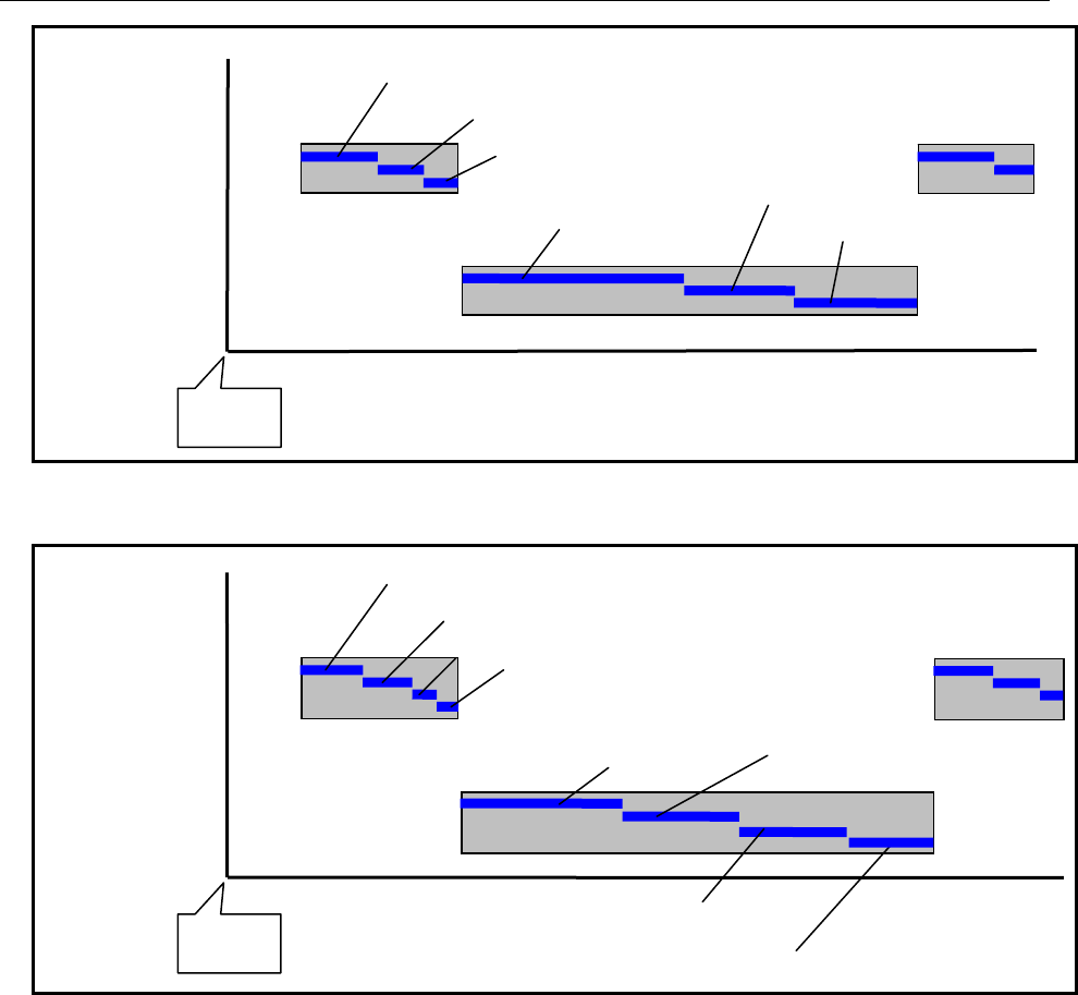
1.OVERVIEW OF PMC
B-64513EN/03
- 40 -
Fig.1.5.2 (c) Execution start order of ladder program when a power on.
(when using the ladder dividing management function)
Fig.1.5.2 (d) Execution start order of ladder program when a power-on.
(when discontinuous number of divided ladder program)
Level 1 of main ladder
Level 1of divided ladder 2
Level 1of divided ladder 1
Level 2
Level 1
Level 2 of main ladder Level 2 of divided ladder 2
Level 2 of divided ladder 1
Power on
Level 1 of main ladder
Level 1of divided ladder 20
Level 1of divided ladder 10
Level 2
Level 1
Level 2 of main ladder
Level 2 of divided ladder 30
Level 2 of divided ladder 10
Level 1of divided ladder 30
Level 2 of divided ladder 20
Power on
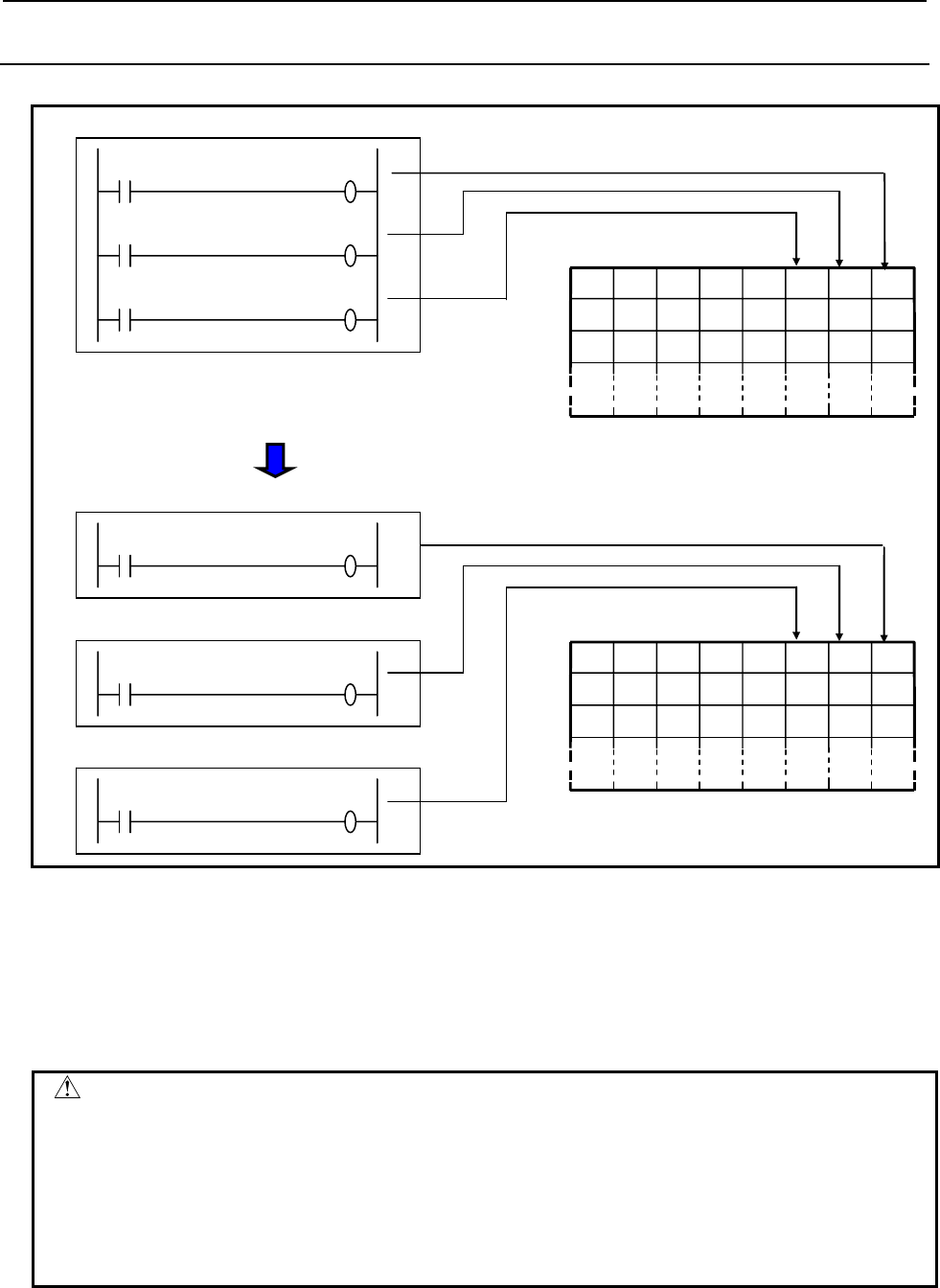
B-64513EN/03
1.OVERVIEW OF PMC
- 41 -
1.5.3
PMC Memory when Using Ladder Dividing Management
On the ladder dividing management function, referred PMC memories are common memories.
Sequence program
DI2 R0.1
DI3 R0.2
DI1 R0.0
1 2 0 4 5 3 7 6
R2
R0
R1
:
PMC memories
Main ladder program
DI2 R0.1
Divided ladder program 1
DI3 R0.2
Divided ladder program 2
DI1 R0.0
1 2 0 4 5 3 7 6
R2
R0
R1
:
PMC memories
When using the ladder dividing management function
Fig. 1.5.3 PMC memory access when using the ladder dividing management function
The following data are also shared between some divided programs.
・ PMC parameters
・ Functional instructions using PMC parameters, such as TMR(SUB 3), CTR(SUB 5) and CTRB(SUB
56)
・ Programmer protection function (System Keep Relay)
CAUTION
1 You should not overwrite the same PMC memory from two or more ladder
programs.
2 You should not duplicate the timer number of TMR(SUB 3), the counter number of
CTR(SUB 5) and CTRB(SUB 56) over all of ladder programs. However, the timer
number of TMRB(SUB 24), TMRBF(SUB 77), and the rising edge number of
DIFU(SUB 57) and the falling edge number of DIFD(SUB 58) can be same number
between main and divided ladder programs.
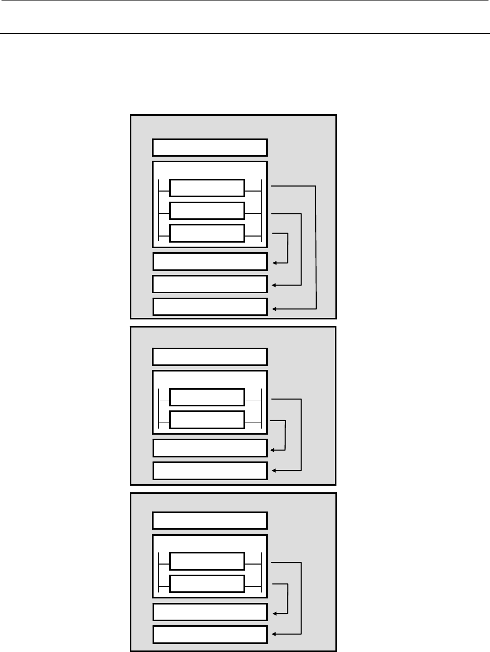
1.OVERVIEW OF PMC
B-64513EN/03
- 42 -
1.5.4
Sub Program in Divided Ladder
To use the ladder dividing management function, you can make programs of level 1, level 2 and
subprograms in every divided ladder programs.
The subprogram number can be defined separately in main ladder program and every divided ladder
program. However, a subprogram defined in other ladder program cannot be called.
Divided ladder program 2
Divided ladder program 1
Main ladder program
Level 2
P2
P1
Level 1
P5000
Level 2
P1
Level 1
P5000
Level 2
P2
Level 1
P5000
CALLU : P2
CALLU : P5000
CALLU : P1
CALLU : P2
CALLU : P5000
CALLU : P1
CALLU : P5000
Fig. 1.5.4 Definition of sub programs using the ladder dividing management function
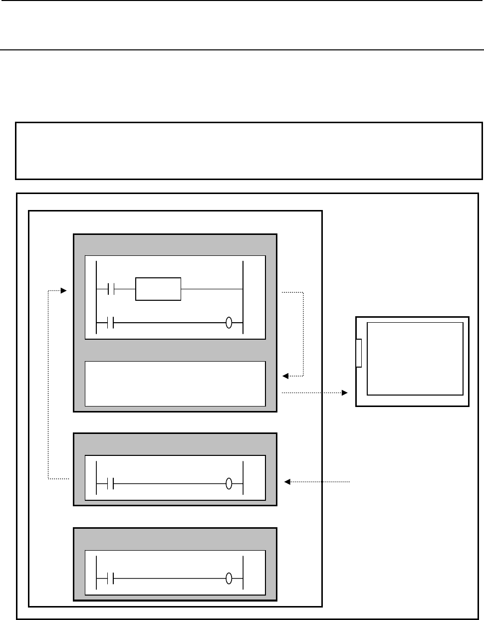
B-64513EN/03
1.OVERVIEW OF PMC
- 43 -
1.5.5
Message Display Function (DISPB instruction) when Using
Ladder Dividing Management Function
When using the ladder dividing management function, the message data is defined in the main ladder
program.
By switching on the request memory of message display (A address) from a divided ladder program, the
messages, which are defined in the main ladder program, can be displayed.
NOTE
You do not need to program DISPB instruction in every divided ladder program.
You can program DISPB instruction only in main ladder program. As for details of
DISPB instruction, refer to the section “4.11.1”.
Main ladder program
DI2 A0.1
Ladder program
Divided ladder program 1
DI3 A0.2
A0.0 1000ALARM-1
A0.1 1001ALARM-2
A0.2 1002ALARM-3
Ladder program
Message data
DI1 A0.0
DISPB
ON
CNC screen
Case of A0.1=ON
1001 ALARM-2
Divided ladder program 2
Ladder program
Fig. 1.5.5 Message display using the ladder dividing management function
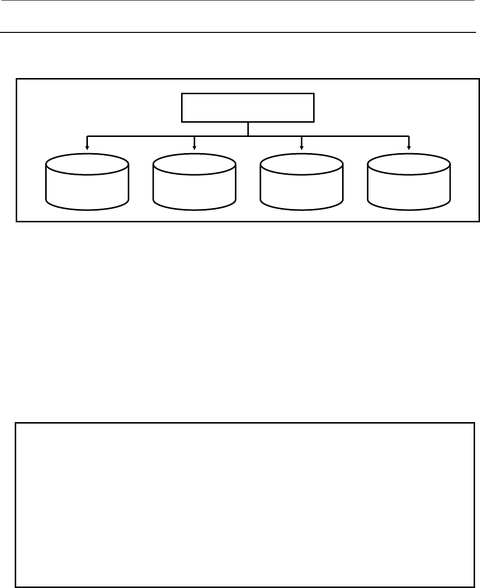
1.OVERVIEW OF PMC
B-64513EN/03
- 44 -
1.5.6
Making Method of Divided Ladder Program
When using the ladder dividing management function, you can use FANUC LADDER-III to make some
program files for a main ladder and some divided ladders.
BasicFunc.LAD
(Main ladder)
OptionalFunc.LAD
(Divided ladder 01)
SafetyFunc.LAD
(Divided ladder 10)
CustomFunc.LAD
(Divided ladder 99)
FANUC LADDER-III
Making main ladder is the same way as making ladder when not using this function.
When making new divided ladder program on FANUC LADDER-III, the following information are
required.
(1) PMC path
Specify the PMC path of the target PMC.
(2) PMC memory type
Specify the PMC memory type of the target PMC.
(3) Divide ladder program number
Specify a divided number of the ladder program.
When executing ladder program, divided ladder programs are executed in order of the number.
This number decides the file name for flash ROM on CNC.
NOTE
1 You can make new divided ladder program on FANUC LADDER-III. On PMC
screen, You can edit the divided ladder program but cannot make new divided
ladder program.
2 Divided ladder program number can be changed in system parameter screen on
FANUC LADDER-III. To modify the PMC path or the PMC memory, use “PMC
Type changed and save” on FANUC LADDER-III.
3 The range of divided ladder program number is 1 to 99. When storing the flash
ROM, the file of same name is overwritten. Therefore, you should set different
number to each divided ladder program file. You can use any number within the
range.
4 When using multi-path PMC, the same number can be used in every PMC path.
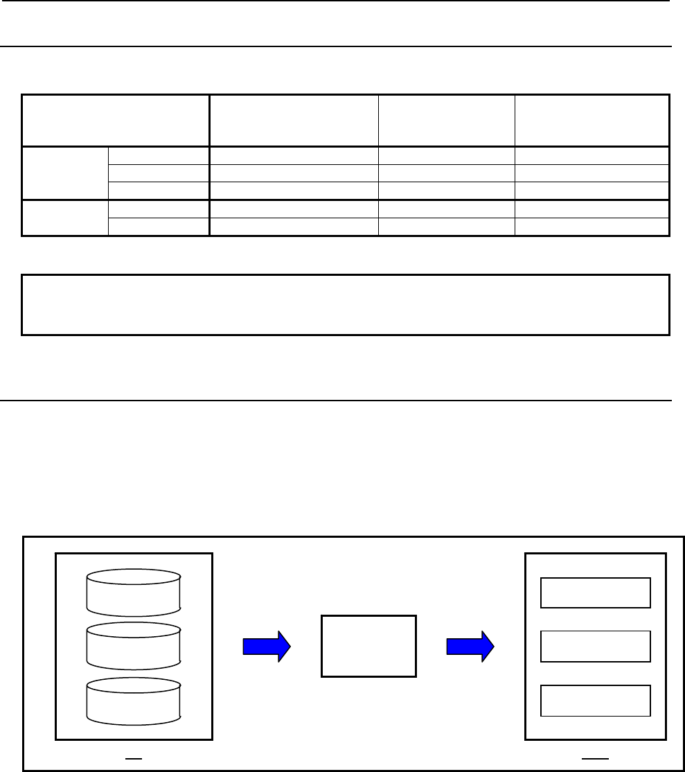
B-64513EN/03
1.OVERVIEW OF PMC
- 45 -
1.5.7
Adding/Updating/Deleting Divided Ladder Program
To add/update/delete divided ladder program on CNC, you can use the following features.
Boot system All backup/restore
function
(IPL screen)
PMC I/O screen
Operation Adding
○
◎
-
Update
○
◎
○
Deletion
○
-
-
Utilize Media Memory Card
○
◎
○
USB Memory
-
◎
○
(○: Available(Operation for one file), ◎:Available (Operation for all files), -: Unavailable)
NOTE
For details of the boot system and the IPL screen, refer to the maintenance
manual of each CNC series.
1.5.8
Input/Output of All Divided Ladder Programs
Divided ladder programs can be input/output to/from CNC by the all backup/restore function on the IPL
screen.
By using the command line execution function in FANUC LADDER-III, plural LAD files can be compiled
and exported to USB memory or memory card at once.
By these functions, plural divided ladder programs, which are created with FANUC LADDER-III, can be
written to the CNC collectively.
PMC1-03.LAD
Memory card
or
USB Memory
PC CNC
Command line
Execution function All backup/restore
function
PMC1-01.LAD
PMC1-02.LAD
L101PMC1.000
L102PMC1.000
L103PMC1.000

1.OVERVIEW OF PMC
B-64513EN/03
- 46 -
Example: Inputting plural divided programs to CNC using memory card
The following example is the procedure of exporting three divided ladder programs (PMC1-01.LAD,
PMC1-02.LAD, PMC1-03.LAD) to the memory card on “E” drive of PC and writing them to CNC
collectively.
(1) Attach an empty memory card to PC. (Note1)
(2) Make a command file (export_all.txt) as follows. (Note2,3)
FlOpen PMC1-01.LAD
Compile
Export /MemData E:\L101PMC1.000
FlClose
FlOpen PMC1-02.LAD
Compile
Export /MemData E:\L102PMC1.000
FlClose
FlOpen PMC1-03.LAD
Compile
Export /MemData E:\L103PMC1.000
FlClose
(3) At the command prompt, specify the command file of the item (2) and execute FANUC LADDER-III.
C:\> "C:\Program Files\FANUC PMC Programmer\FANUC LADDER-3\Fladder.exe" /cmdfile=export_all.txt
(4) Attach the memory card to CNC and turn the power on with pressing “.” and “-“ on the MDI keys
(5) The IPL screen appears. Select “12. BATCH DATA BACKUP/RESTORE”.
(6) The BATCH DATA BACKUP/RESTORE MENU appears and select “2. BATCH DATA
RESTORE(MEMORY CARD → CNC)”.
(7) “BATCH DATA RESTORE OK ? (NO=0,YES=1)” appears and select “1”.
(8) “POWER MUST BE OFF” appears and reboot the power of the CNC.
NOTE
1 In the all backup/restore function, all files, which are at root directory of memory
card or USB memory, are written to CNC. Therefore, you should use empty
memory card or USB card because the CNC do not execute correctly when there
are some unnecessary files in the memory card or the USB memory.
2 You can use arbitrary command file name of FANUC LADDER-III.
If changing to other name, change the name specified in the item (3), too.
3 The ladder file name specified in the export command (Ex: L101PMC1.000) is
used in PC, memory card or USB memory. You can use arbitrary file name
regardless of the dividing ladder program number for the registration of CNC.
To change the divided ladder number, change the setting of divided ladder
number in the system parameter screen on FANUC LADDER-III.
4 We recommend the ladder file name for outputting from CNC by the all
backup/restore function to the file name in the export command if there is no
special reason. In the all backup/restore function, the file having the name on flash
ROM of CNC with the extension “.000” is output. For the file name on flash ROM,
refer to “2.9”.
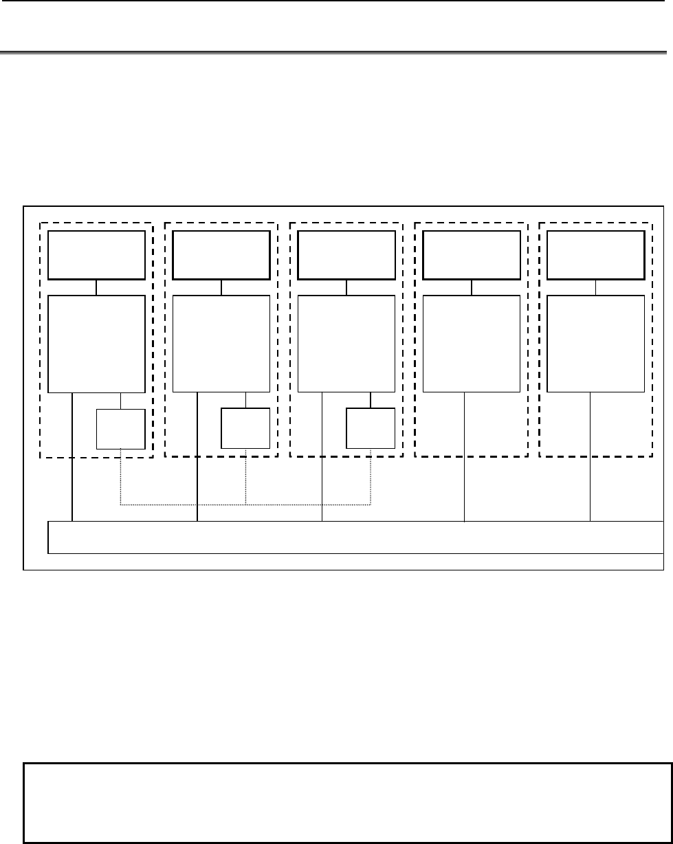
B-64513EN/03
1.OVERVIEW OF PMC
- 47 -
1.6 MULTI-PATH PMC FUNCTION
The multi-path PMC function allows one PMC system to execute multiple sequence programs at the same
time.
PMC memory for each sequence program is basically independent, and the same PMC address can be used
for different purposes of the individual PMCs. Extra relays (E addresses) can be shared among PMCs as
shared memory. All PMCs can read from and write to this area, so the area can be used for the interface
between the PMCs. M,N addresses can be also used for the interface between the PMCs.
1st PMC
X0~, Y0~,
F0~, G0~,
R0~, A0~,
T0~, C0~,
K0~, D0~,
P1~, L1~
Shared memory(E0~)
2nd PMC
X0~, Y0~,
F0~, G0~,
R0~, A0~,
T0~, C0~,
K0~, D0~,
P1~, L1~
3rd PMC
X0~, Y0~,
F0~, G0~,
R0~, A0~,
T0~, C0~,
K0~, D0~,
P1~, L1~
M0~,
N0~
M0~,
N0~
M0~,
N0~
4th PMC
X0~, Y0~,
F0~, G0~,
R0~, A0~,
T0~, C0~,
K0~, D0~,
P1~, L1~
5th PMC
X0~, Y0~,
F0~, G0~,
R0~, A0~,
T0~, C0~,
K0~, D0~,
P1~, L1~
Fig. 1.6 (a) PMC memory of multi-path PMC function
A program for each PMC is saved as an independent file and can be edited, updated, and backed up
separately.
The CNC systems and the I/O Link channels to be controlled by PMCs can be changed by CNC parameter
setting. In a parameter-set configuration, one PMC may control all CNC systems, or each PMC may control
a different CNC system.
Fig. 1.6 (b) shows a configuration example.
NOTE
The multi-path PMC function is the option function.
In Series 30i/31i/32i/35i-B, Power Motion i-A, the maximum path number is 5
paths. In Series 0i-F, the maximum path number is 3 paths.
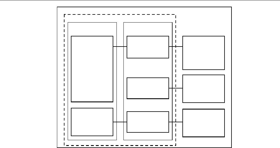
1.OVERVIEW OF PMC
B-64513EN/03
- 48 -
CNC PMC
Operator's
panel for
machine
control, etc.
Operator's
panel for
loader, etc.
Peripheral
equipment,
etc.
1st PMC
2nd PMC
3rd PMC
Machine
control group
Loader
control group
Fig. 1.6 (b) Multi-path PMC function configuration example
If the series 30i/31i/32i/35i-B, the Power Motion i-A or the series 0i-F system is used to control more than
one CNC path, some paths can be grouped to share data within a group and to stop all the paths in the group
if an alarm condition occurs in one of the paths. The group is referred to as the machine group.
The system supports up to 3 machine groups. Each group has a separate emergency stop signal address.
A PMC is basically assigned to each machine group.
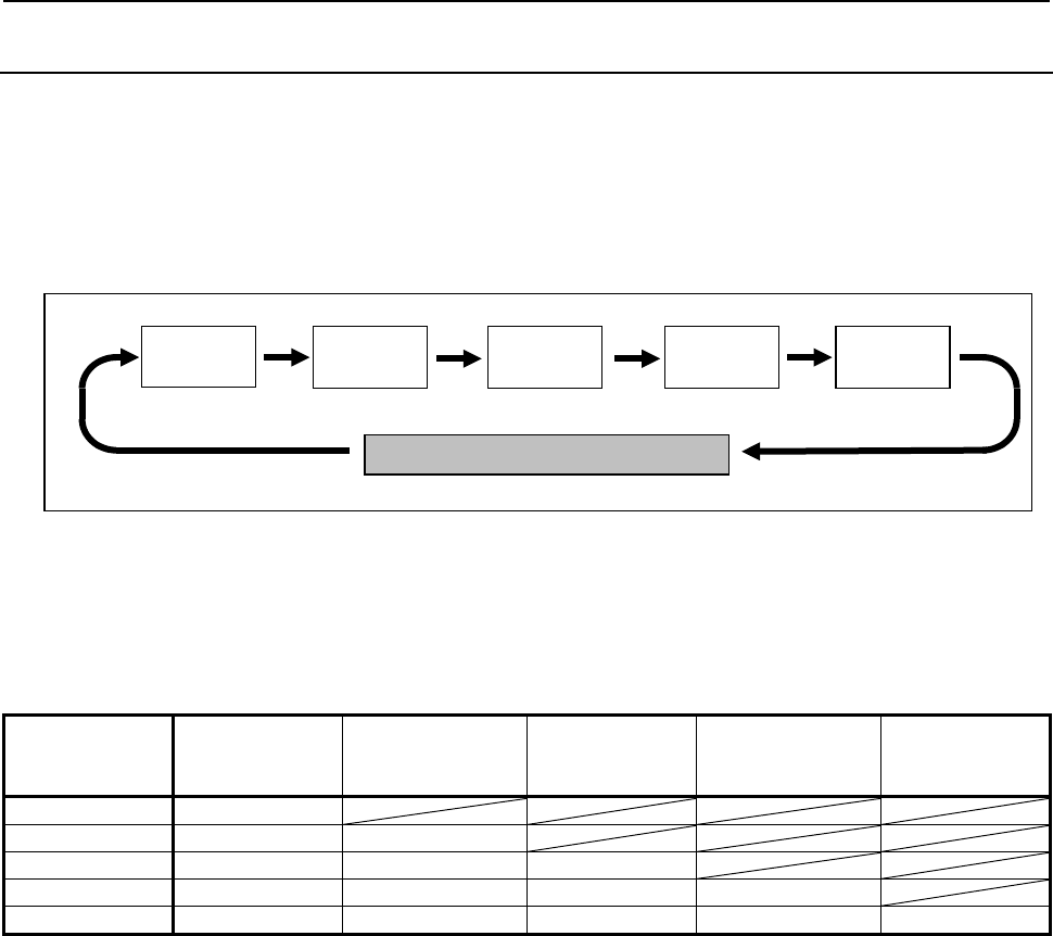
B-64513EN/03
1.OVERVIEW OF PMC
- 49 -
1.6.1
Execution Order and Execution Time Percentage
For the multi-path PMC function, the order of PMC execution and execution time percentages of the PMCs
can be set with CNC parameters.
Execution order
If parameters related to the execution order are not set (0 is set), the following order sequence is assumed by
default:
1st path
PMC
2nd path
PMC
3rd path
PMC
O
t
h
er process
i
ng suc
h
as trac
i
ng
5th path
PMC
4th path
PMC
Fig. 1.6.1 (a) Default execution order of multiple PMCs
Execution time percentage
If parameters related to execution time percentages are not set (0 is set), the following execution time
percentages are assumed by default:
Table 1.6.1 (a) Execution time percentages of multiple PMCs
The number
of PMC path
PMC path
of the 1st order
of execution
PMC path
of the 2nd order
of execution
PMC path
of the 3rd order
of execution
PMC path
of the 4th order
of execution
PMC path
of the 5th order
of execution
1 path 100%
2 paths 85% 15%
3 paths 75% 15% 10%
4 paths 70% 10% 10% 10%
5 paths 60% 10% 10% 10% 10%
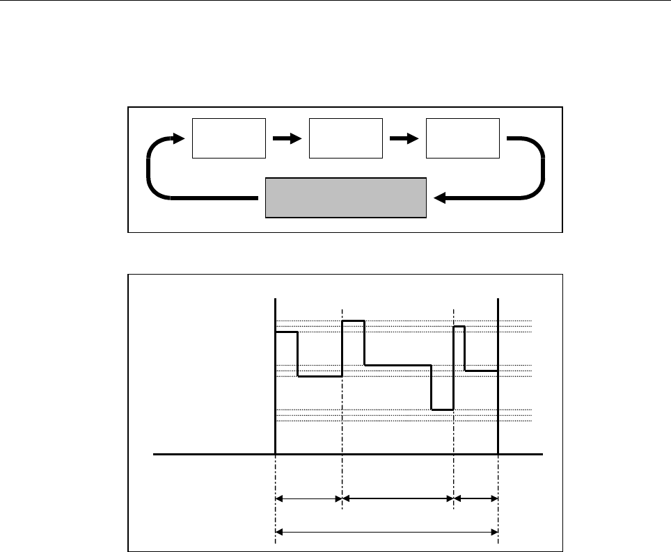
1.OVERVIEW OF PMC
B-64513EN/03
- 50 -
An example of changing the execution order and execution time percentages by setting CNC parameters is
explained below. In the following, sequence programs are executed in the order from the third PMC to the
first PMC to the second PMC with the execution time percentage of the third PMC set to 30%, the
percentage of the first PMC to 50%, and the percentage of the second PMC to 20%:
3rd PMC 1st PMC 2nd PMC
Other processing such as
tracing
Fig. 1.6.1 (b) Example of setting execution order of multiple PMCs
Level 1
Level 2
Level 3
3rd PMC
(30%)
1st PMC
(50%)
2nd PMC
(20%)
Ladder execution cycle (4 or 8 msec)
Fig. 1.6.1 (c) Example of setting execution time percentages of multiple PMCs
For details of parameter setting, see Subsection 2.4.3.
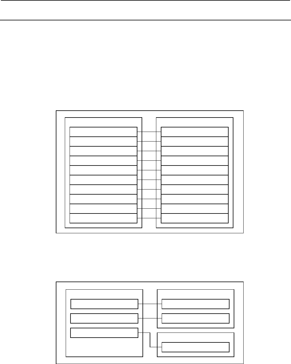
B-64513EN/03
1.OVERVIEW OF PMC
- 51 -
1.6.2
Interface Between CNC and PMC
The PMC to control the interface between the CNC and PMC and PMC addresses (F/G addresses) can be
set with CNC parameters.
With these parameter settings, a desired interface control system can be built, in which the entire
CNC-PMC interface of the CNC may be controlled by a single PMC or the CNC-PMC interface may be
controlled by multiple PMCs.
For the CNC-PMC interface, a memory area consisting of 10 blocks, each of which is an addressable,
768-byte DI/DO area, is provided.
When viewed from the ladder program in each PMC, these addresses begin with 0.
If these parameters are not set (0 is set), the initial settings are assumed, where the F/G addresses of the CNC
equals the F/G addresses of the first PMC as follows:
CNC 1st PMC
F/G0 to F/G767 of CNC
F/G1000 to F/G1767 of CNC
F/G2000 to F/G2767 of CNC
F/G3000 to F/G3767 of CNC
F/G4000 to F/G4767 of CNC
F/G5000 to F/G5767 of CNC
F/G6000 to F/G6767 of CNC
F/G7000 to F/G7767 of CNC
F/G8000 to F/G8767 of CNC
F/G9000 to F/G9767 of CNC
F/G0 to F/G767 of 1st PMC
F/G1000 to F/G1767 of 1st PMC
F/G2000 to F/G2767 of 1st PMC
F/G3000 to F/G3767 of 1st PMC
F/G4000 to F/G4767 of 1st PMC
F/G5000 to F/G5767 of 1st PMC
F/G6000 to F/G6767 of 1st PMC
F/G7000 to F/G7767 of 1st PMC
F/G8000 to F/G8767 of 1st PMC
F/G9000 to F/G9767 of 1st PMC
Fig. 1.6.2 (a) Initial settings for CNC-PMC interface
In the following example, F/G0 to F/G767 and F/G1000 to F/G1767 of the CNC are assigned to F/G0 to
F/G767 and F/G1000 to F/G1767 of the first PMC, and F/G2000 to F/G2767 of the CNC are assigned to
F/G0 to F/G767 of the second PMC:
CNC 1st PMC
F/G0 to F/G767 of CNC F/G0 to F/G767 of 1st PMC
2nd PMC
F/G0 to F/G767 of 2nd PMC
F/G1000 to F/G1767 of 1st PMCF/G1000 to F/G1767 of CNC
F/G2000 to F/G2767 of CNC
Fig. 1.6.2 (b) Setting example for CNC-PMC interface
For details of parameter setting, see Subsection 2.4.3.
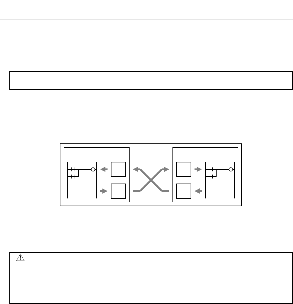
1.OVERVIEW OF PMC
B-64513EN/03
- 52 -
1.6.3
Multi-Path PMC Interface
The multi-path PMC interface is the communication means between two PMC paths.
Generally, each path of multi-path PMC system has individual PMC memory space except E address. And,
E address can be used to share data of multi-path PMC system. However, this method has a risk that the
memory is over written by other PMC path inappropriately.
NOTE
This interface cannot be used in 4th-path PMC and 5th-path PMC.
When using this function, the input and output signals of each path become definitely. Therefore, you can
send or receive the data on between two PMC paths safely.
When you output data to N address at one of PMC paths, it can be referenced by M address in other PMC
path.
Ex.) When using this function with 1st PMC and 2nd PMC :
1st PMC 2nd PMC
M
N
M
N
Moreover, signals of M address are synchronized during 1 scan of 2nd level program. Therefore, you can
reference the same signal status on the first step and the last step of level2 program, like as X and F address.
For details of setting for two PMC paths, see Subsection 2.4.3.
WARNING
The E address can be used to share data of multi-path PMC system. However,
The E address is not synchronized during 1 scan of 2nd level program. Therefore,
the value of the address may be changed during execution of 2nd level program.
You must take care that the memory is not overwritten by other PMC path in
multi-path PMC system.
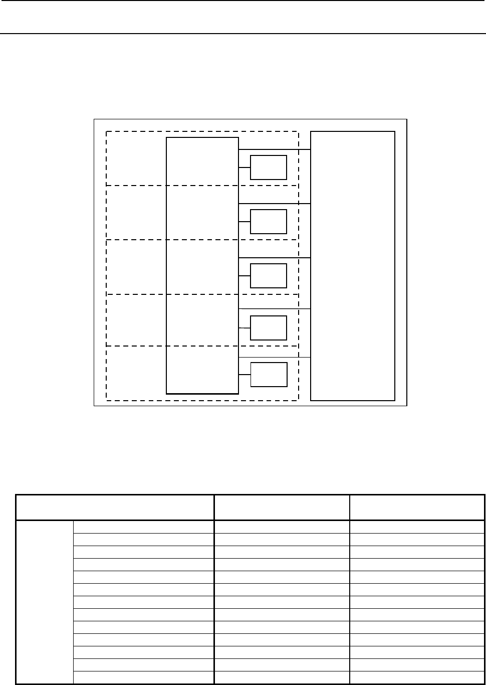
B-64513EN/03
1.OVERVIEW OF PMC
- 53 -
1.6.4
Common PMC Memory Mode of Multi-Path PMC
On the 2nd-path and 3rd-path PMC, the "Common PMC Memory mode" to share all the PMC Memory with
1st-path PMC has become selectable.
When using the Common PMC Memory mode, a program that controls a related process can be divided to
multi-path Sequence Programs.
And, those Sequence Programs can be inputted/outputted, edited and saved independently.
1st PMC
X0 -, Y0 -,
F0 -, G0 -,
R0 -, A0 -,
T0 -, C0 -,
K0 -, D0 -,
M0 -, N0 -,
S1 -, E0 -
(Common Memory)
Sequence
Program L1 -,
P1 -
2nd PMC
3rd PMC
Sequence
Program L1 -,
P1 -
Sequence
Program L1 -,
P1 -
4th PMC Sequence
Program
5th PMC Sequence
Program
L1 -,
P1 -
L1 -,
P1 -
Fig. 1.5.4 (a) Configuration of the Common PMC Memory mode
See "9.9.5 Setting the PMC Memory Type" to enable the Common PMC Memory mode.
There are come differences in the following specifications in the Independent PMC Memory mode and the
Common PMC Memory mode.
Table 1.6.4 (a) Comparison of Independent PMC Memory mode and Common PMC Memory mode
Data and Functions Independent PMC Memory
mode Common PMC Memory mode
Sequence
program
Ladder each PMC path each PMC path
(TMR, CTR, CTRB) each PMC path shared by all PMC paths
(DISPB) each PMC path program to 1st-path PMC
Title each PMC path each PMC path
Symbol & Comment each PMC path each PMC path
Message data each PMC path each PMC path
I/O Link assignment each PMC path each PMC path
System parameter each PMC path each PMC path
(Counter data type) each PMC path 1st-path PMC is effective
- Inputting/Outputting each PMC path each PMC path
- Password function each PMC path each PMC path
- Programmer protection each PMC path 1st-path PMC is effective
- Protection of data at 8 levels each PMC path each PMC path

1.OVERVIEW OF PMC
B-64513EN/03
- 54 -
Data and Functions Independent PMC Memory
mode Common PMC Memory mode
PMC
Parameter
Timer each PMC path shared by all PMC paths
Counter each PMC path shared by all PMC paths
Keep Relay each PMC path shared by all PMC paths
Data Table each PMC path shared by all PMC paths
Data Table control data each PMC path shared by all PMC paths
Setting Parameter each PMC path shared by all PMC paths
- Inputting/Outputting each PMC path 1st-path PMC is effective
- Programmer protection each PMC path 1st-path PMC is effective
- Protection of data at 8 levels each PMC path 1st-path PMC is effective
WARNING
1 Please separate the range of PMC Memory that will be written by each PMC path.
And, don't write to the same address from other PMC paths because it will often
cause a problem. If making such a program it will be difficult to fix a problem.
2 When using the Common PMC Memory mode, the memory of PMC Parameter is
shared by those PMC paths, too. Therefore, don't set any duplicated number of
functional instructions that is used for PMC Parameter in those PMC paths.
<Functional instructions using PMC Parameter>
- TMR (Timer : SUB 3)
- CTR (Counter : SUB 5)
- CTRB (Fixed Counter : SUB 56)
But, the instruction number of the following functional instructions can be used for
each PMC path, also in the Common PMC Memory mode.
<Functional instructions numbered each PMC path>
- TMRB (Fixed Timer : SUB 24)
- TMRBF (Off Delay Fixed Timer : SUB 77)
- DIFU (Rising Edge Detection : SUB 57)
- DIFD (Falling Edge Detection : SUB 58)
NOTE
1 To use the Common PMC Memory mode in the 2nd to 5th-path PMC, select the
same PMC type as 1st-path PMC on FANUC LADDER-III.
2 The Data Table Control data is also shared between PMC paths that are used in
the Common PMC Memory mode.
3 L address and P address, that is used for the labels of jump or sub-program call,
can be used for each PMC path independently in the Common PMC Memory
mode, too.
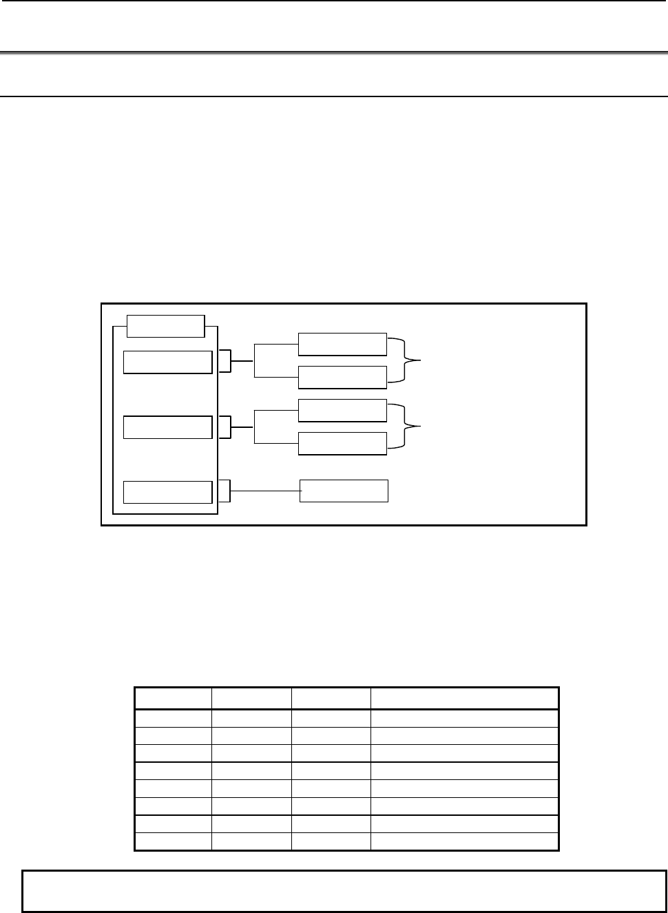
B-64513EN/03
1.OVERVIEW OF PMC
- 55 -
1.7 COMMUNICATION METHOD for EXTERNAL I/O DEVICE
1.7.1 I/O Link i and I/O Link
For the high-speed serial interface which transmits input/output signals between the PMC and each I/O
device, there are two communication methods. They are the FANUC I/O Link i and the FANUC I/O Link.
You can use up to three channels for the serial interface. The communication method for the channel 1 and
the channel 2 can be specified by the CNC parameter. The channel 3 can be used only for the I/O Link.
For the details of the setting of the CNC parameter, see subsection “2.4.3”.
As for the transmission cycle of the signals from the I/O Link i, you can choose from the normal mode
(2msec) and the high-speed mode (0.5msec). You can specify the mode for each group of I/O devices.
The transmission cycle of the signals from the I/O Link is “2msec” for the channel 1 and 2. For the channel
3, it depends on the ladder execution period (4msec/8msec).
Channel 1
Channel 2
Channel 3 I/O Link
I/O Link i
I/O Link
I/O Link i
I/O Link
Select by CNC parameter
CNC
Select by CNC parameter
Fig. 1.7.1 (a) Setting of the communication method for each channels
The maximum I/O points of the I/O Link i are 2048 poins/2048 points for each channel. The maximum I/O
points of the I/O Link are 1024 points/1024 points for each channel.
The maximum I/O points for a system are 4096 points/4096 points (0i-F: 2048 points/2048 points) in total.
You can use one or more channels of the I/O Link i and the I/O Link, however the total points cannot exceed
the maximum points of the PMC system.
[The example of the selectable case of the I/O Link i and the I/O Link]
Channel 1 Channel 2 Channel 3 Total points (DI / DO)
I/O Link
i
I/O Link
i
-
4096 / 4096 (Note)
I/O Link
i
I/O Link I/O Link 4096 / 4096 (Note)
I/O Link
i
I/O Link
-
3072 / 3072 (Note)
I/O Link I/O Link I/O Link 3072 / 3072 (Note)
I/O Link
i
-
-
2048 / 2048
I/O Link I/O Link
-
2048 / 2048
I/O Link
-
I/O Link 2048 / 2048
I/O Link
-
-
1024 / 1024
NOTE
For the series 0i-F, the total points (DI/DO) are 2048/2048 points.
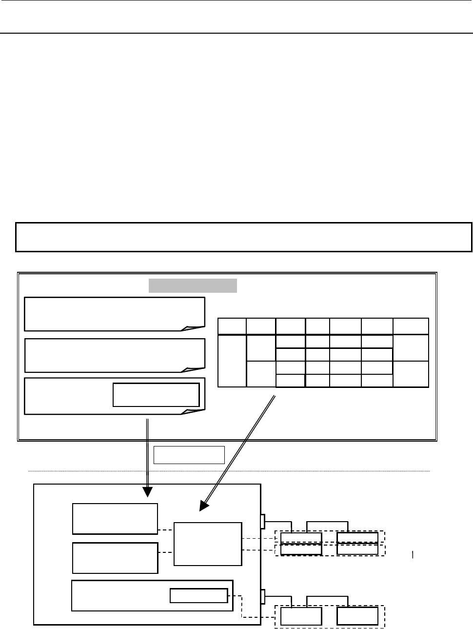
1.OVERVIEW OF PMC
B-64513EN/03
- 56 -
1.7.2
Setting I/O Address for I/O Link i
For the I/O addresses assignment of the I/O Link i channels, you set the I/O addresses and the PMC path to
each group and the slot of I/O devices which is connected to channels for the I/O Link i. The assignment is
operated in the FANUC LADDER-III and is programmed independent of the sequence program (.LAD file).
For the details, see the FANUC LADDER-III Operation’s Manual (B-66234EN).
The assignment date of the I/O Link i is loaded to a CNC as a I/O configuration data. I/O signals of the I/O
Link i are controlled by the I/O configuration data.
For details of I/O Link i, see Subsection 3.3.
For details of the setting operation of the I/O configuration data on the CNC screen, see Subsection 9.10.
The following figure is the multi-path PMC system overview using the I/O Link i.
• 1st PMC: The sequence program using I/O devices connected to the channel 1(I/O Link i)
• 2nd PMC: The sequence program using I/O devices connected to the channel 1(I/O Link i)
• 3rd PMC: The sequence program using I/O devices connected to the channel 2(I/O Link)
NOTE
The multi-path PMC function is an optional function.
FANUC LADDER-Ⅲ
1st path sequence program I/O Link i assignment data (FIL file)
2nd-path PMC
3rd-path PMC
X/Y0 ~ 127
Channel 2 (I/O Link)
Channel 1(I/O Link i)
Group 0
(normal mode)
1st-path PMC
I/O configuration
data
Slot 1
2nd path sequence program
3rd path
sequence program
I/O module assignment
X/Y0 ~ 127
CNC
channel PMCgroup slot Transferred
period
PMC1
PMC2
PMC2
PMC1
Normal
(2msec)
High-speed
(0.5msec)
1
2
1
2
0
1
1
Slot 2
Slot 1
Slot 2
Group 1
(high speed mode)
Group 0 Group 1
Loading
X address
X0000
X0010
X0030
X0020
Y address
Y0000
Y0010
Y0030
Y0020
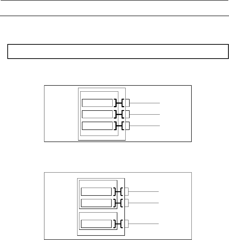
B-64513EN/03
1.OVERVIEW OF PMC
- 57 -
1.7.3
Setting I/O Address for I/O Link
The I/O addresses of I/O Link channels can be assigned with CNC parameters. Moreover, setting the dual
assignment can divide one I/O link channel into two blocks and assign them to different PMC path.
For details of setting, see Subsection 9.9.3.For details of parameter setting, see Subsection 2.4.3.
NOTE
This function cannot be used for the I/O Link i.
Assign one I/O link channel to one PMC path
The I/O addresses of I/O Link channels can be assigned with CNC parameters.
If these parameters are not set (0 is set), all channels are assigned to the first PMC by default as follows:
1st PMC
X/Y0 to X/Y127
X/Y200 to X/Y327
X/Y400 to X/Y527
Channel 1
Channel 2
Channel 3
Fig. 1.7.3 (a) Default I/O addresses of I/O Link channels
In the following example, channel 1 is assigned to X/Y0 to X/Y127 of the first PMC, channel 2 is assigned
to X/Y200 to X/Y327 of the first PMC, and channel 3 is assigned to X/Y0 to X/Y127 of the second PMC:
1st PMC
X/Y0 to X/Y127
X/Y200 to X/Y327
Channel 1
Channel 2
2nd PMC
X/Y0 to X/Y127 Channel 3
Fig. 1.7.3 (b) Example of I/O address assignment for I/O Link channels
Assign one I/O link channel to two PMC paths
When multi-path path PMC function is used, you can use plural channels. However, there is the case of the
wasteful assignment in which the number of I/O link channel is lacking and the assigned I/O points are few.
The dual assignment of I/O Link channel can assign I/O devices on one I/O link channel to two PMC paths
effectively. To do so, the rest parts of one channel can be used in another PMC path and it is not necessary
to use more channels than it is needed. The dual assignment of I/O Link channel can be assigned with CNC
parameters.
In the following example, channel 1 is assigned to X/Y0 to X/Y127 of the first PMC and channel 2 is
assigned to X/Y200 to X/Y327 of the first PMC and X/Y0 to X/Y127 of the second PMC. As for the
channel 2, the former collection of the groups is referred to as "first block" and the latter is referred to as
"second block".
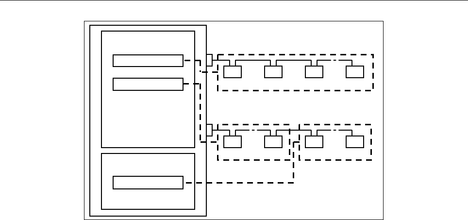
1.OVERVIEW OF PMC
B-64513EN/03
- 58 -
1st PMC
X/Y0 to 127
X/Y200 to 327
2nd PMC
Channel 1
~~
~
Group 0 Group n
Group 0 Group 1 Group 2 Group n
Group 0 Group n
1st Block 2nd Block
Channel 2
X/Y0 to 127
Fig. 1.7.3 (c) Example of Dual Assignment of I/O Link Channel
For details of parameter setting, see Subsection 3.2.4.3.
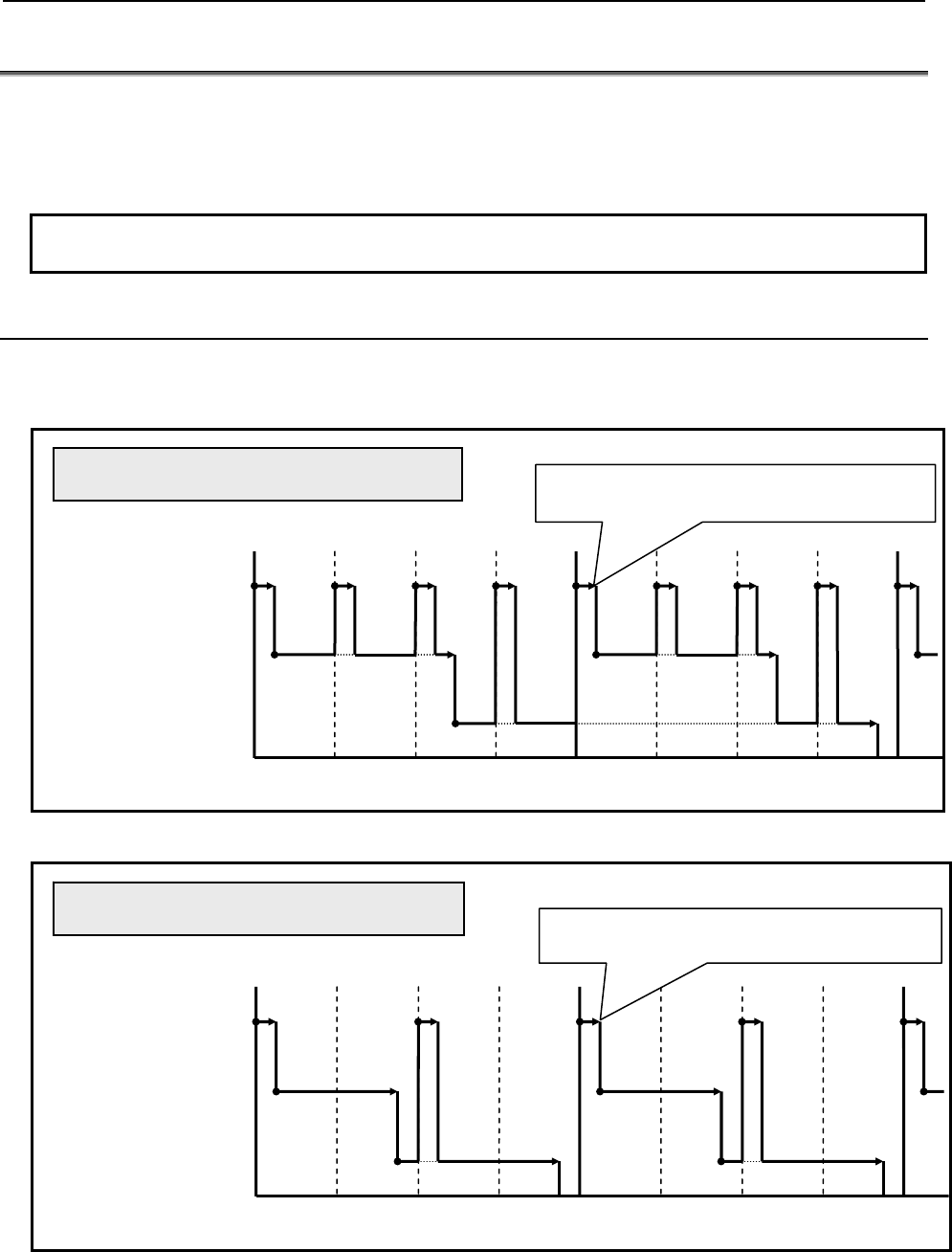
B-64513EN/03
1.OVERVIEW OF PMC
- 59 -
1.8 1st LEVEL EXECUTION CYCLE of LADDER in 1ms/2ms
The 1st level execution cycle of a ladder program can be chosen from 1ms, 2ms, 4ms, or 8ms with a CNC
parameter.
The 1ms or 2ms of the 1st level execution cycle, a part of specifications differ to the 4ms or 8ms of the 1st
level execution cycle.
NOTE
This function cannot be used for the Series 0i-F.
1.8.1
Execution cycle of a ladder
When the setting of the 1st level execution cycle is 1ms or 2ms, the 1st level is executed in a 1ms or 2ms
cycle, and the 2nd and 3rd levels are executed in a 4ms cycle.
Example of 1st level execution cycle is 1ms
2nd level
(4ms cycle)
3rd level
(4ms cycle)
4ms 8ms 0
1st level
(1ms cycle)
The 2nd and 3rd levels are executed in a 4ms
cycle, even if the program is completed within 3ms.
Example of 1st level execution cycle is 2ms
2nd level
(4ms cycle)
3rd level
(4ms cycle)
4ms 8ms 0
1st level
(2ms cycle)
The 2nd and 3rd levels are executed in a 4ms
cycle, even if the program is completed within 2ms.
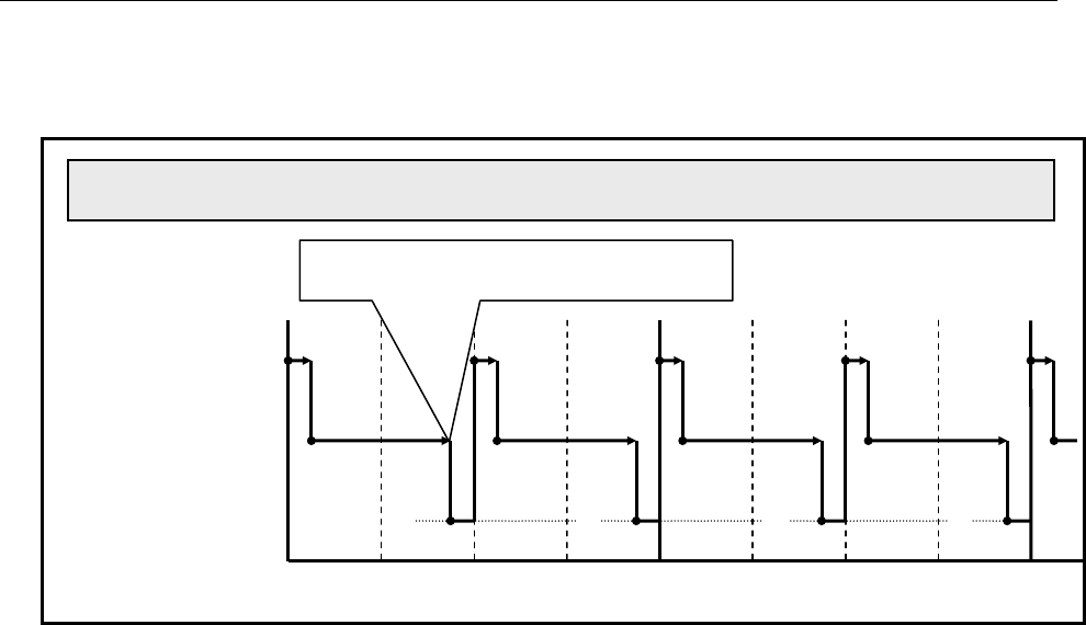
1.OVERVIEW OF PMC B-64513EN/03
- 60 -
When the execution cycle of the 1st level is 2ms, the 2nd and 3rd levels can also be executed in a 2ms cycle
by setting of a CNC parameter. Please refer to "3.4 CNC Parameters Related to the PMCs" of this document
for details.
Example of 1st level execution cycle is 2ms, 2nd and 3rd levels execution cycles are also 2ms.
2nd level
(2ms cycle)
3rd level
(2ms cycle)
4ms
8ms
0
1st level
(2ms cycle)
The 2nd level is also executed in a 2ms cycle.
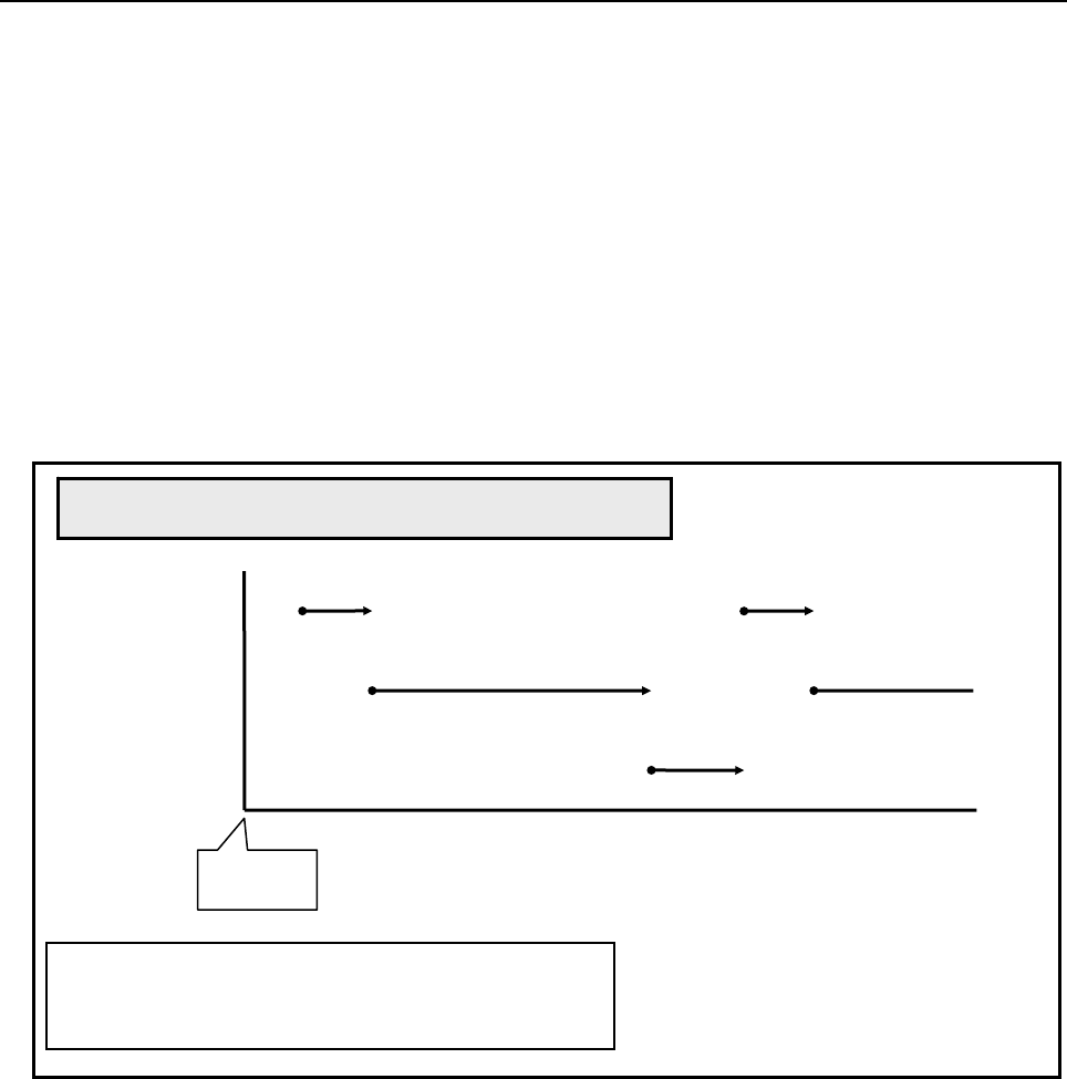
B-64513EN/03
1.OVERVIEW OF PMC
- 61 -
Execution start order of ladder program when a power-on.
The ladder program is executed initially to set the input signals for the CNC (G signals) like the following
chart until the beginning of cyclic operation of the CNC from the power on of the CNC. The initial
execution is different from the cyclic execution. Therefore the ladder program is not executed at the
constant period and is continuously and repeatedly executed. The execution of each level of the ladder
program is not divided. They are executed from the top of the program to the end of the program in the order
of the following chart. After finishing the initial execution of the ladder, the CNC starts the cyclic
operation.
In the initial execution of the ladder program, the operations of the following functional instructions are
different from the normal operations.
- TMR、TMRB、TMRC、TMRST、TMRSS
The timer is not executed and the time is always 0 in the initial execution.
- WINDR、WINDW、AXCTL、EXIN、DISPB、PSGNL、PSGN2
They are executed as the NOP instruction (No operation) in the initial execution.
Execution start order of ladder program when a power-on
2nd level
3rd level
1st level
Power on
[Structure of a ladder]
- PMC path
:
1st PMC (PMC1)
- ladder of execution cycles 1ms
:
PMC1-1
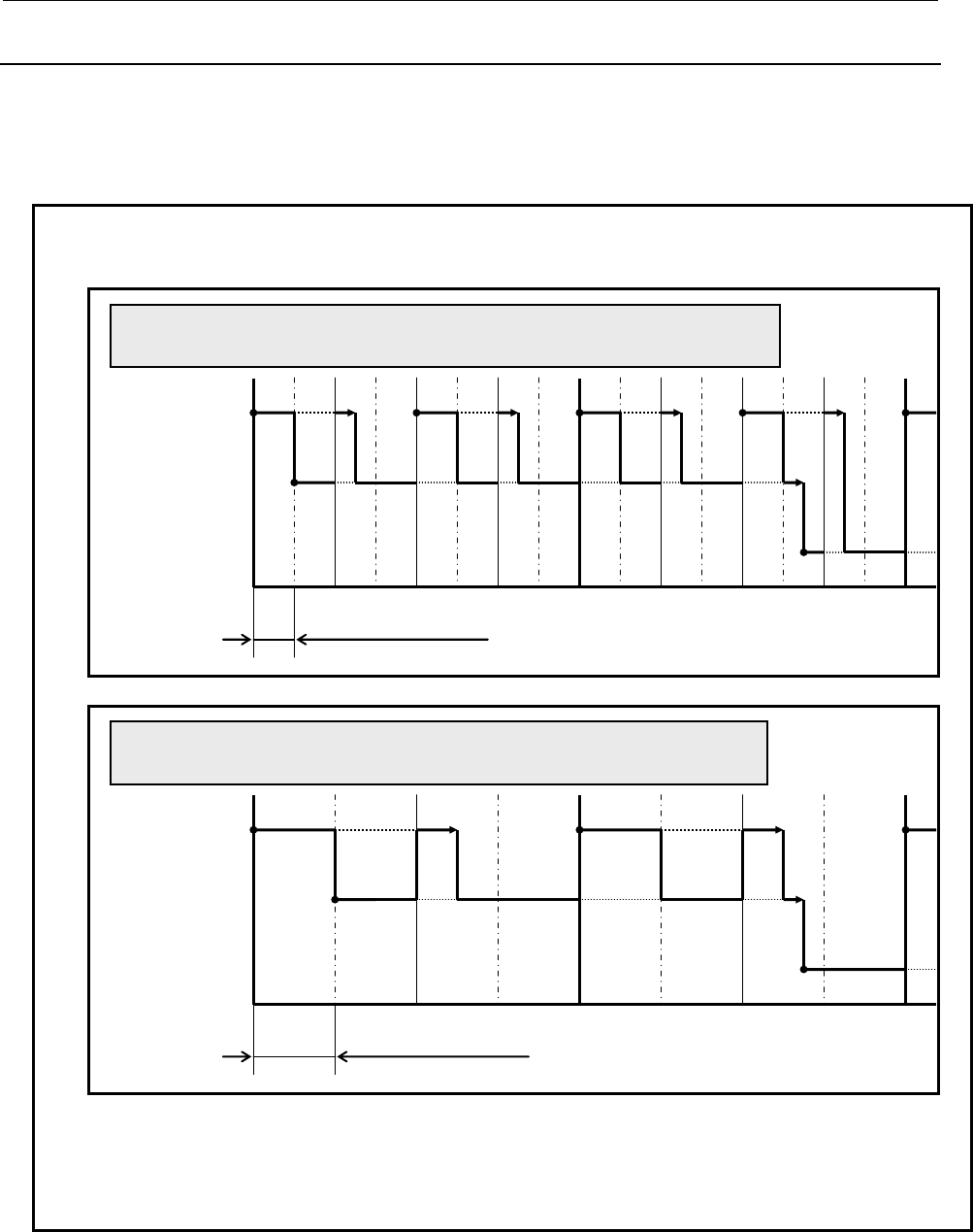
1.OVERVIEW OF PMC
B-64513EN/03
- 62 -
1.8.2
Maximum execution time
When a setting of an execution cycle is 1ms, the maximum execution time of the 1st level of ladder is 0.5ms.
And when a setting of an execution cycle is 2ms, the maximum execution time of the 1st level of ladder is
1ms. Because the 1st level of ladder has high execution frequency, it badly affects the scan time of the 2nd
level of ladder. Therefore, please make the 1st level of ladder execute as fast as possible.
Note
1 When the 1st level of ladder whose execution cycle is 1ms or 2ms exceeds the
maximum execution time, execution is divided to the next cycle.
1st level
2nd level
3rd level
4ms 8ms 0
Example when the 1st level of ladder whose execution cycle is 1ms
exceeds the maximum execution time (0.5ms).
maximum execution time (0.5ms)
1st level
2nd level
3rd level
4ms 8ms 0
Example when the 1st level of ladder whose execution cycle is 2ms
exceeds the maximum execution time (1ms).
maximum execution time (1ms)
2 The execution time of the 1st level of ladder whose execution cycle is 1ms or 2ms can
be checked on the PMC status (1,2ms ladder) screen. Please refer to "9.6.2
Displaying the status of the 1st level execution cycle in 1ms/2ms ([PMC status (1,2ms
ladder)] screen)" of this document for details.
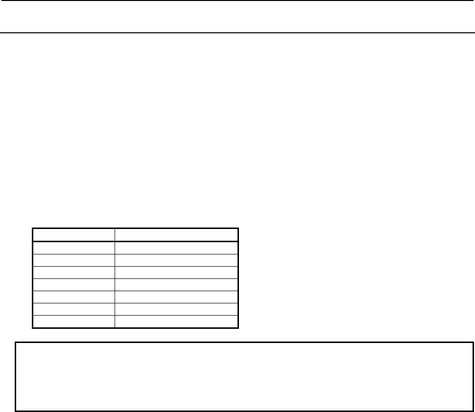
B-64513EN/03
1.OVERVIEW OF PMC
- 63 -
1.8.3
Notice in programming of the 1st level
Because the 1st level of ladder whose execution cycle is 1ms or 2ms has high execution frequency, it badly
affects the scan time of the 2nd level of ladder. Therefore, please make the 1st level of ladder execute as fast
as possible.
Generally, processing of functional instructions takes longer time than basic instructions. Therefore, please
make the 1st level of ladder whose execution cycle is 1ms and 2ms with fewer functional instructions.
Moreover, the performance will not be improved even if the following functional instructions execute in the
cycle faster than the execution cycle of CNCs because they operate by exchanging data between CNC and
PMC. Therefore, please do not use the following functional instructions in the 1st level of ladder whose
execution cycle is 1ms or 2ms. If these functional instructions are used on the 1st level of ladder whose
execution cycle is 1ms or 2ms, they are processed as NOP instructions. If you want to refer to the result of
following functional instructions in the 1st level of ladder, these functional instructions should be
programmed in 2nd level and refer to the result in 1st level.
Sub number Instruction name
41 DISPB
42 EXIN
51 WINDR
52 WINDW
53 AXCTL
50 PSGNL
63 PSGN2
NOTE
The execution time of the 1st level of ladder whose execution cycle is 1ms or 2ms
can be checked on the PMC status (1,2ms ladder) screen. Please refer to "9.6.2
Displaying the status of the 1st level execution cycles 1ms/2ms ([PMC status
(1,2ms ladder)] screen)" of this document for details.
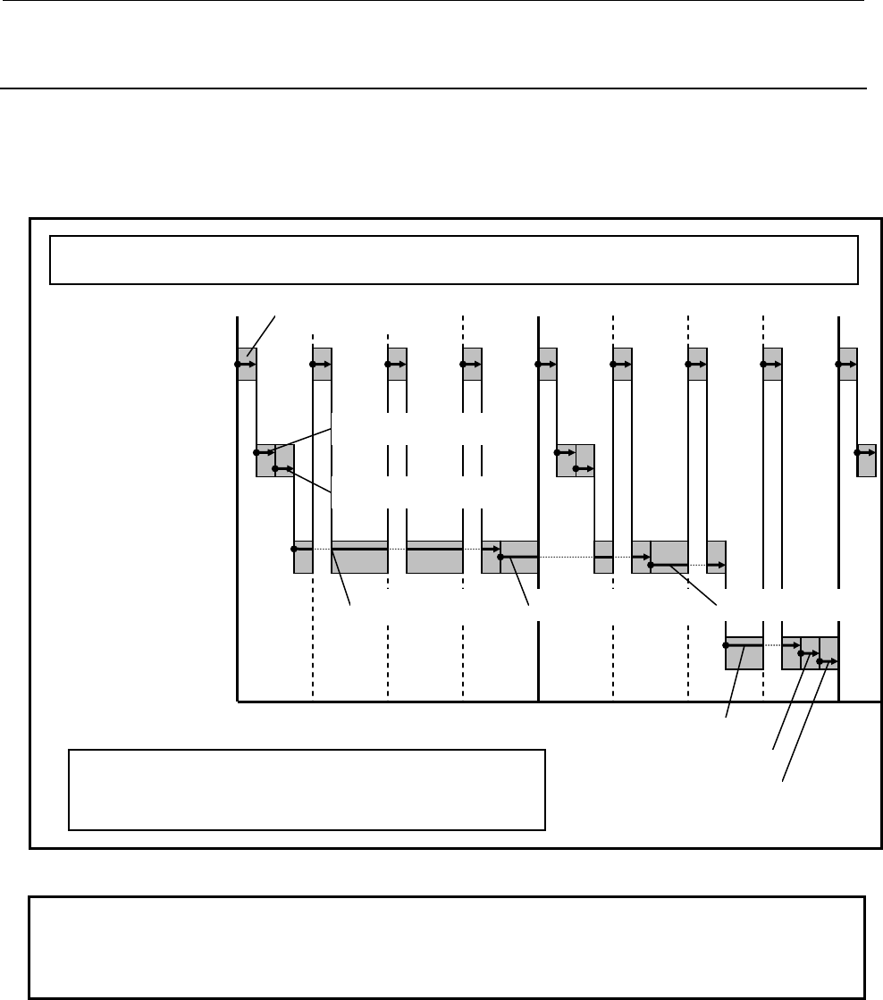
1.OVERVIEW OF PMC
B-64513EN/03
- 64 -
1.8.4
Operation when using the Ladder Dividing Management
Function
When using the 1st level execution cycle in 1ms, 2ms and the Ladder Dividing Management Function, you
can select one ladder from main ladder and divided ladder programs, and can execute it in 1ms or 2ms cycle.
The 1st level of other ladder programs, and the 2nd and 3rd level of all ladder programs are executed in a
4ms cycle.
Example when using the Ladder Dividing Management Function (1st level execution cycle 1ms)
1st level of others
2nd level of all
3rd level of all
4ms 8ms 0
1st level of ladder
whose execution cycle
is 1ms
1st level of PMC1-1
2nd level of PMC1 2nd level of PMC1-1
1st level of PMC1-99
2nd level of PMC1-99
3rd level of PMC1
3rd level of PMC1-1
3rd level of PMC1-99
1st level of PMC1
[Structure of a ladder]
- Divided ladder : PMC1, PMC1-1, PMC1-99
- ladder of execution cycles 1ms : PMC1-1
(selected one)
NOTE
The 1st level of ladder that is executed in 1ms or 2ms cycle is selected by CNC
parameter No.11945 and 11946. Please refer to "2.4.3 CNC Parameters Related
to the PMCs" for details.

B-64513EN/03
1.OVERVIEW OF PMC
- 65 -
Execution start order of ladder program when a power-on.
The ladder program is executed initially to set the input signals for the CNC (G signals) like the following
chart until the beginning of cyclic operation of the CNC from the power on of the CNC. The initial
execution is different from the cyclic execution. Therefore the ladder program is not executed at the
constant period and is continuously and repeatedly executed. The execution of each level of the ladder
program is not divided. They are executed from the top of the program to the end of the program in the order
of the following chart. After finishing the initial execution of the ladder, the CNC starts the cyclic
operation.
In the initial execution of the ladder program, the operations of the following functional instructions are
different from the normal operations.
- TMR、TMRB、TMRC、TMRST、TMRSS
The timer is not executed and the time is always 0 in the initial execution.
- WINDR、WINDW、AXCTL、EXIN、DISPB、PSGNL、PSGN2
They are executed as the NOP instruction (No operation) in the initial execution.
2nd level of PMC1-99
2nd level of PMC1-1
1st level of
ladder whose
execution cycle
is 1ms
1st level of
others
2nd level of all
3rd level of all
Power on
1st level of PMC1-1
2nd level of PMC1
3rd level of PMC1
1st level of PMC1
1st level of PMC1-99
3rd level of PMC1-1
3rd level of PMC1-99
[Structure of a ladder]
- Divided ladder : PMC1, PMC1-1, PMC1-99
- ladder of execution cycles 1ms : PMC1-1
Execution start order of ladder program when a power-on
(when using the Ladder Dividing Management Function)
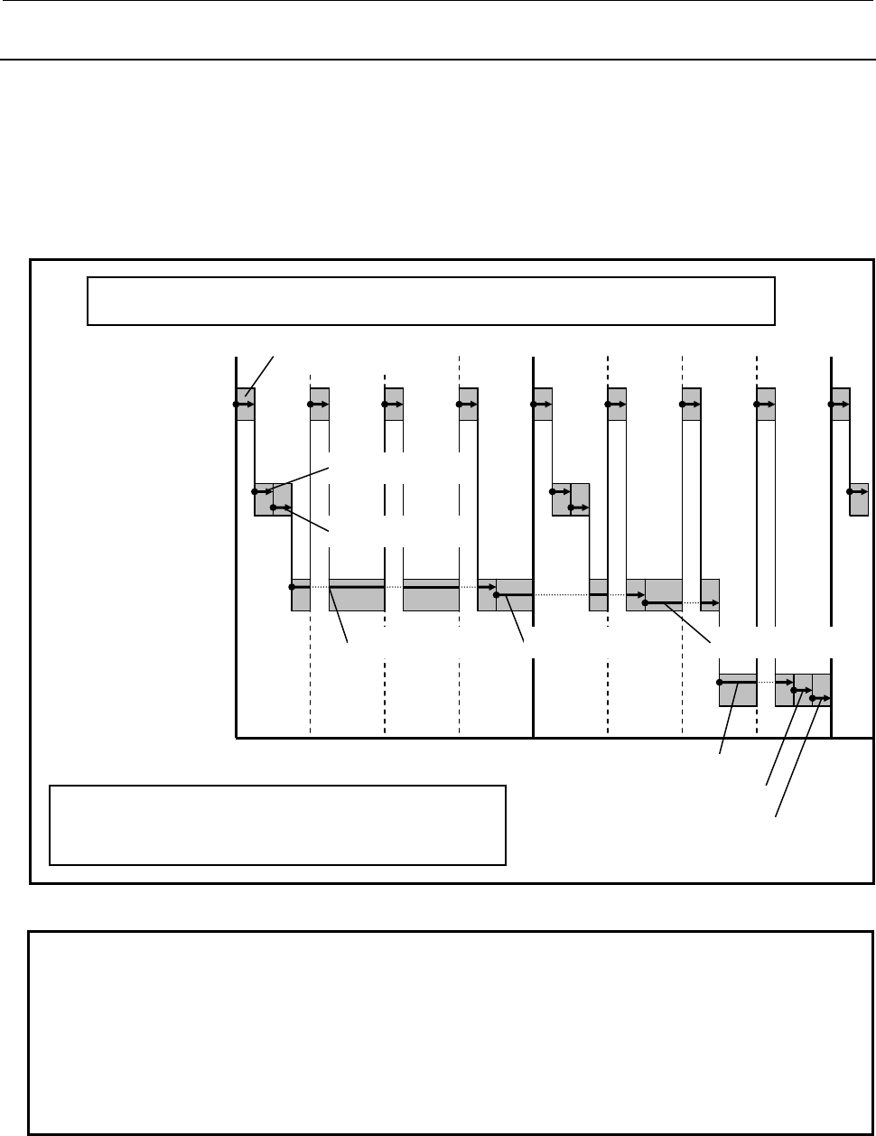
1.OVERVIEW OF PMC
B-64513EN/03
- 66 -
1.8.5
Operation when using the Multi-path PMC Function
When using the 1st level execution cycle in 1ms, 2ms and the Multi-path PMC Function, you can select one
PMC path from multi-path PMC (except for DCSPMC), and can execute it in 1ms or 2ms cycle. The 1st
level of other PMC path, and the 2nd and 3rd level of all PMC paths are executed in a 4ms cycle.
In this case, ladder programs of all PMC paths are executed continuously for each ladder execution level.
Therefore, the setting (CNC parameter No.11905-11909) of the execution time rate for each PMC path is
ineffective.
Example when using the Multi-path PMC Function (1st level execution cycle 1ms)
1st level of others
2nd level of all
3rd level of all
4ms 8ms 0
1st level of ladder whose
execution cycle is 1ms
1st level of PMC2
2nd level of PMC1 2nd level of PMC2
1st level of PMC3
2nd level of PMC3
3rd level of PMC1
3rd level of PMC2
3rd level of PMC3
1st level of PMC1
[Structure of a ladder]
- Multi-path PMC : 3Paths(PMC1 to PMC3)
- ladder of execution cycles 1ms : PMC2
(selected one)
NOTE
1 The 1st level of ladder that is executed in 1ms or 2ms cycle is selected by CNC
parameter No.11945 and 11946. Please refer to "2.4.3 CNC Parameters Related
to the PMCs" for details.
2 When using both the multi-path PMC function and ladder dividing management
function, the 1st level execution cycle in 1ms, 2ms can be used. In this case, one
1st level of ladder is selected from all ladder programs by setting CNC parameter
No.11945 and No.11946.
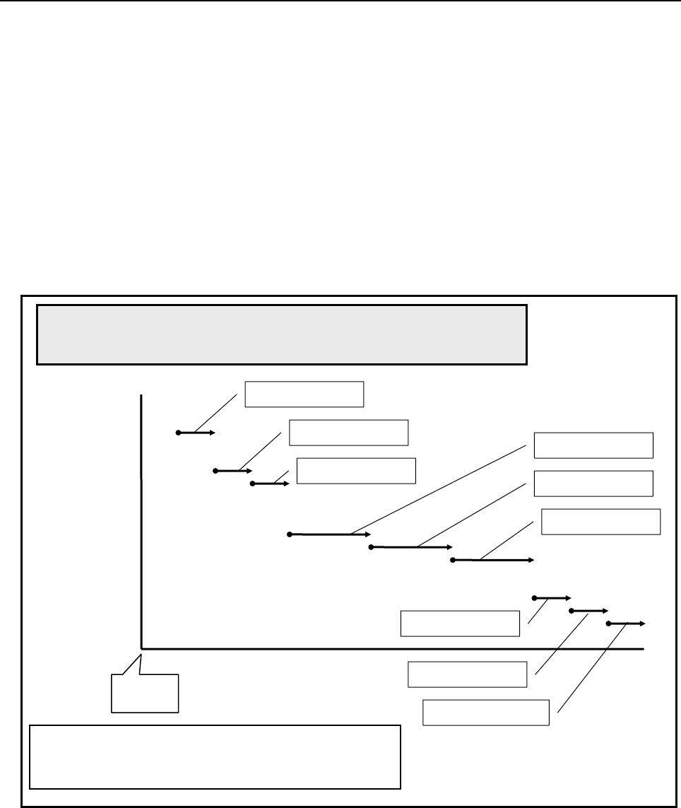
B-64513EN/03
1.OVERVIEW OF PMC
- 67 -
Execution start order of ladder program when a power-on.
The ladder program is executed initially to set the input signals for the CNC (G signals) like the following
chart until the beginning of cyclic operation of the CNC from the power on of the CNC. The initial
execution is different from the cyclic execution. Therefore the ladder program is not executed at the
constant period and is continuously and repeatedly executed. The execution of each level of the ladder
program is not divided. They are executed from the top of the program to the end of the program in the order
of the following chart. After finishing the initial execution of the ladder, the CNC starts the cyclic
operation.
In the initial execution of the ladder program, the operations of the following functional instructions are
different from the normal operations.
- TMR、TMRB、TMRC、TMRST、TMRSS
The timer is not executed and the time is always 0 in the initial execution.
- WINDR、WINDW、AXCTL、EXIN、DISPB、PSGNL、PSGN2
They are executed as the NOP instruction (No operation) in the initial execution.
2nd level of all
3rd level of all
1st level of
ladder whose
execution cycle
is 1ms
Power on
1st level of PMC2
2nd level of PMC1
3rd level of PMC1
Execution start order of ladder program when a power-on
(when using the Multi-path PMC Function)
1st level of
others
1st level of PMC1
1st level of PMC3
2nd level of PMC2
2nd level of PMC3
3rd level of PMC2
3rd level of PMC3
[Structure of a ladder]
- Multi-path PMC : 3Paths(PMC1 to PMC3)
- ladder of execution cycles 1ms : PMC2

2.PMC SPECIFICATIONS
B-64513EN/03
- 68 -
2 PMC SPECIFICATIONS
2.1 SPECIFICATIONS
2.1.1 Basic Specifications
Table 2.1.1 (a) Basic specifications of each PMC path
Function 1st to 5th path PMC DCSPMC (Note1) Reference
Multi-Path PMC function Maximum 5 paths
(0i-F:Maximum 3 paths)
- 1.6
PMC Memory Type 1st PMC
PMC Memory-B, C, D
2nd to 5th PMC
PMC Memory-A, B, C
Common PMC Memory with 1st PMC
- 2.1.3
Programming language Ladder
Step sequence(Note2)
Function block
Ladder
Function block
4
10
11
Divided ladder program
- Number of programs
- File number
40(0i-F:16)
1 to 99
None
2.1.4
Number of ladder levels 3 2 (Note3) 1.4.3
Level 1 execution period 1ms, 2ms, 4ms or 8ms
(0i-F:4ms or 8ms)
8ms 1.8, 2.4.3
Processing power
- Basic instruction processing
speed (transition contact)
9.1ns/step
(0i-F:18.2ns/step)
1µs/step
-
Program capacity
- Ladder
- Symbol & Comment
- Message
Up to about 300,000 steps
(0i-F:100,000steps)
At least 1KB
At least 8KB
Up to about 5,000 steps
At least 1KB
At least 8KB
2.1.2, 2.1.4
Instructions
- Basic instructions
- Functional instructions
24
218
24
210
2.1.7
2.1.8, 2.1.9
CNC interface 2.2.1
- Inputs (F) 768 bytes×10 768 bytes
- Outputs (G) 768 bytes×10 768 bytes
DI/DO 2.2.2, 3
- Inputs (X) Up to 4,096 points
(0i-F:2,048 points)
Up to 896 points
- Outputs(Y) Up to 4,096 points
(0i-F:2,048 points)
Up to 896 points
Symbol & Comment 1.2.7, 2.1.5
- Number of symbol characters 40 40
- Number of comment characters 255×4 255×4
Program storage area
(Flash ROM)
Max. 5MB (total size of sequence
program of all PMC paths and
PMC message multi-language
data)
128 KB 2.1.4

B-64513EN/03
2.PMC SPECIFICATIONS
- 69 -
NOTE
1 This PMC is used for Dual Check Safety function (option) and handles the safety
related signals.
2 The Step Sequence is available in the main ladder of 1st PMC.
3 A program can be created on level 3 to maintain source-level compatibility with
programs for other models, but it is not executed.
Table 2.1.1 (b) Basic specifications of each PMC Memory Type
Function
1st to 5th PMC DCSPMC
PMC
Memory-A
PMC
Memory-B
PMC
Memory-C
PMC
Memory-D (Note 1)
PMC Memory
• Internal relay (R) 1,500 bytes 8,000 bytes 16,000 bytes 60,000 bytes 1,500 bytes
• System Relay
(R9000 or Z)
500 bytes 500 bytes 500 bytes 500 bytes 500 bytes
• Extra relay (E) (Note2) 10,000 bytes 10,000 bytes 10,000 bytes 10,000 bytes (Note 3)
• Message display (A)
⋅ Display requests 2,000 points 2,000 points 4,000 points 6,000 points (Note 4)
⋅ Status displays 2,000 points 2,000 points 4,000 points 6,000 points (Note 4)
• Nonvolatile memory
• Timer (T)
⋅ Variable timer 80 bytes
(40 pieces)
500 bytes
(250 pieces)
1,000 bytes
(500 pieces)
1,000 bytes
(500 pieces)
80 bytes
(40 pieces)
⋅ Variable timer
precision
80 bytes
(40 pieces)
500 bytes
(250 pieces)
1,000 bytes
(500 pieces)
1,000 bytes
(500 pieces)
80 bytes
(40 pieces)
• Counter (C)
⋅ Variable counter 80 bytes
(20 pieces)
400 bytes
(100 pieces)
800 bytes
(200 pieces)
1200 bytes
(300 pieces)
80 bytes
(20 pieces)
⋅ Fixed counter 40 bytes
(20 pieces)
200 bytes
(100 pieces)
400 bytes
(200 pieces)
600 bytes
(300 pieces)
40 bytes
(20 pieces)
• Keep relay (K)
⋅ User area 20 bytes 100 bytes 200 bytes 300 bytes 20 bytes
⋅ System area 100 bytes 100 bytes 100 bytes 100 bytes 100 bytes
• Data table (D) 3,000 bytes 10,000 bytes 20,000 bytes
(Note 5)
60,000 bytes
(Note 5)
3,000 bytes
• Step sequence
⋅ Step number (S) (None) 2,000 bytes 2,000 bytes 2,000 bytes (None)
Functional instructions
• Variable timers (TMR) 40 pieces 250 pieces 500 pieces 500 pieces 40 pieces
• Fixed timers
(TMRB/TMRBF)
100 pieces 500 pieces 1,000 pieces 1,500 pieces 100 pieces
• Variable counters
(CTR)
20 pieces 100 pieces 200 pieces 300 pieces 20 pieces
• Fixed counters (CTRB) 20 pieces 100 pieces 200 pieces 300 pieces 20 pieces
• Rising/Falling edge
detection (DIFU/DIFD)
256 pieces 1,000 pieces 2,000 pieces 3,000 pieces 256 pieces
• Labels (LBL) 9,999 pieces 9,999 pieces 9,999 pieces 9,999 pieces 9,999 pieces
• Subprograms (SP) 512 pieces 5,000 pieces 5,000 pieces 5,000 pieces 512 pieces
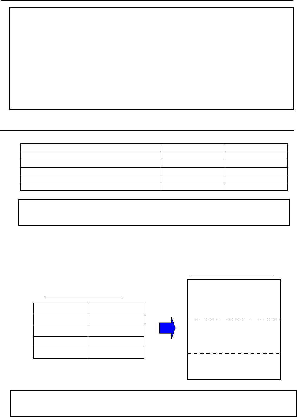
2.PMC SPECIFICATIONS
B-64513EN/03
- 70 -
NOTE
1 This PMC is used for Dual Check Safety function (option).
2 The extra relay is common memory for the multi-PMC function. This means that
its size covers all of PMCs. Moreover, It is possible to use the extra relay as
nonvolatile memory by the option.
3 No extra relay is available for DCS PMC.
4 The message display relay is ineffective in DCS PMC because the message
display function is unavailable in it.
5 Under the configuration having two or more paths of PMC Memory-C or one path
of PMC Memory-D, specify the "Nonvolatile PMC data table area expansion
40KB" option. If this option is not added, the expanded data table area (D10000~)
is not kept after rebooting CNC. Refer to subsection 2.1.3 for details.
2.1.2
Total Ladder Steps of Multi-path PMC
For the multi-path PMC system, you can specify a ladder step option by the total step of all of PMCs.
Option name Specification Maximum ladder size
PMC Ladder Function 24,000 Step Basic 102KB
PMC Ladder Function 32,000 Step H990#32K 136KB
PMC Ladder Function 64,000 Step H990#64K 272KB
PMC Ladder Function 100,000 Step H990#100K 425KB
PMC Ladder Function 300,000 Step (Note) H990#300K 1,275KB
NOTE
The option “PMC Ladder Function 300,000 Steps” is not supported for the
Series 0i-F.
Example 1 (The case of using ladder dividing management function)
A main ladder and two divided ladder programs are used. When the main ladder program requires 25,000
steps and the 1st divided ladder program requires 20,000 steps and the 2nd divided ladder program
requires 15,000 steps, the “PMC ladder function 64,000 step” option is necessary.
PMC Ladder 64,000 steps option
Divided ladder program 2
(15,000 steps)
Main ladder program (25,000 steps)
Divided ladder program 1
(20,000 steps)
Ladder steps
Main ladder 25,000 steps
Divided ladder 1 20,000 steps
Divided ladder 2 15,000 steps
Total 60,000 steps
Ladder steps of each program
NOTE
Total size of main ladder program and some divided ladder programs are limited
by the maximum size of specified step option.
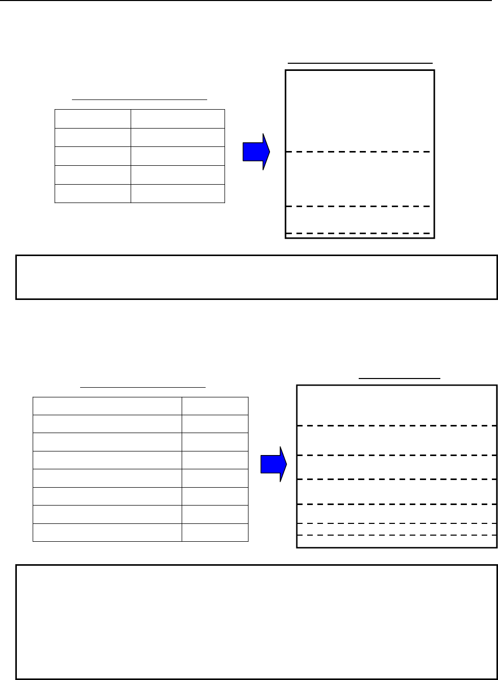
B-64513EN/03 2.PMC SPECIFICATIONS
- 71 -
Example 2 (The case of using multi-path PMC)
When the 1st PMC requires 48,000 steps, the 2nd PMC requires 32,000 steps and the 3rd PMC requires
16,000 steps on 3-path PMC system, the “PMC ladder function 100,000 step” option is necessary.
PMC Ladder 100,000 steps option
3rd PMC (16,000 steps)
1st PMC (48,000 steps)
2nd PMC (32,000 steps)
Ladder steps
1st PMC
48,000 steps
2nd PMC
32,000 steps
3rd PMC
16,000 steps
Total
96,000 steps
Ladder steps of each PMC path
NOTE
Total size of main ladder program and some divided ladder programs are limited
by the maximum size of specified step option.
Example 3 (The case of using ladder dividing management function and
Multi-path PMC function together)
The following case uses three PMC paths and six sequence programs. When the total steps are 90,000
steps, the “PMC ladder function 100,000 step” option is necessary.
100,000 step option
Divided ladder 2 of 1st path PMC (15,000 steps)
Main ladder of 1st path PMC (25,000 steps)
Divided ladder 1 of 1st path PMC (20,000 steps)
Steps
Main ladder of 1st path PMC
25,000 steps
Divided ladder 1 of 1st path PMC
20,000 steps
Divided ladder 2 of 1st path PMC
15,000 steps
Main ladder of 2nd path PMC
15,000 steps
Divided ladder of 2nd path PMC
10,000 steps
Main ladder of 3rd path PMC
5,000 steps
Total
90,000 steps
Ladder steps of each program
Main ladder of 3rd path PMC (5,000 steps)
Main ladder of 2nd path PMC (15,000 steps)
Divided ladder of 2nd path PMC (10,000 steps)
NOTE
1 Total size of main ladder program and some divided ladder programs are limited
by the maximum size of specified step option.
2 If the total steps of sequence programs exceed the step number of specified step
option, the PMC alarm “ER03 PROGRAM SIZE ERROR(OPTION)” occurs in the
path just when the excess of steps is detected. The sequence program of the
PMC path, in which the alarm occurs, will not be executed.
3 The total steps does not include the ladder steps of dual check safety PMC.

2.PMC SPECIFICATIONS
B-64513EN/03
- 72 -
2.1.3
Determination of PMC Memory Type
PMC memory type
There are four PMC memory types i.e. memory-A, memory-B, memory-C and memory-D. These
memory types differ in the size of PMC address. For the 2nd to 5th path PMC, the PMC memory can be
also shared with the 1st path PMC. The DCS PMC does not have plural PMC memory types.
For the details of the PMC memory type, refer to subsection “2.1.1”. As for the CNC parameter for the
PMC memory type, refer to subsection “2.4.3”.
The following is the selectable PMC memory types in each PMC path.
1st path PMC 2nd to 5th path PMC Remark
PMC-memory B (default)
PMC-memory C
PMC-memory A (default)
PMC-memory B
PMC-memory C
Shared with 1st path PMC
You can specify up to three paths both of
PMC-memory B and C in total.
PMC-memory D Shared with 1st path PMC
Nonvolatile area of the data table in each PMC memory type
The following table is the data table number and basic nonvolatile area of each PMC memory type.
Table 2.1.3 (a) Data table number of each PMC memory type
PMC memory type Data Table Basic nonvolatile area
PMC memory-A 3,000 bytes 3,000 bytes
PMC memory-B 10,000 bytes 10,000 bytes
PMC memory-C 20,000 bytes 20,000 bytes (In case of using one path of
PMC-memory C)
10,000 bytes (In case of using two or more
paths of PMC-memory C)
PMC memory-D 60,000 bytes 10,000 bytes
NOTE
To use two or more paths of PMC memory-C or one path of PMC memory-D,
specify the option “Nonvolatile PMC data table area expansion (40KB)”. If this
option is not specified, the data at D10000 and subsequent addresses is not
saved.
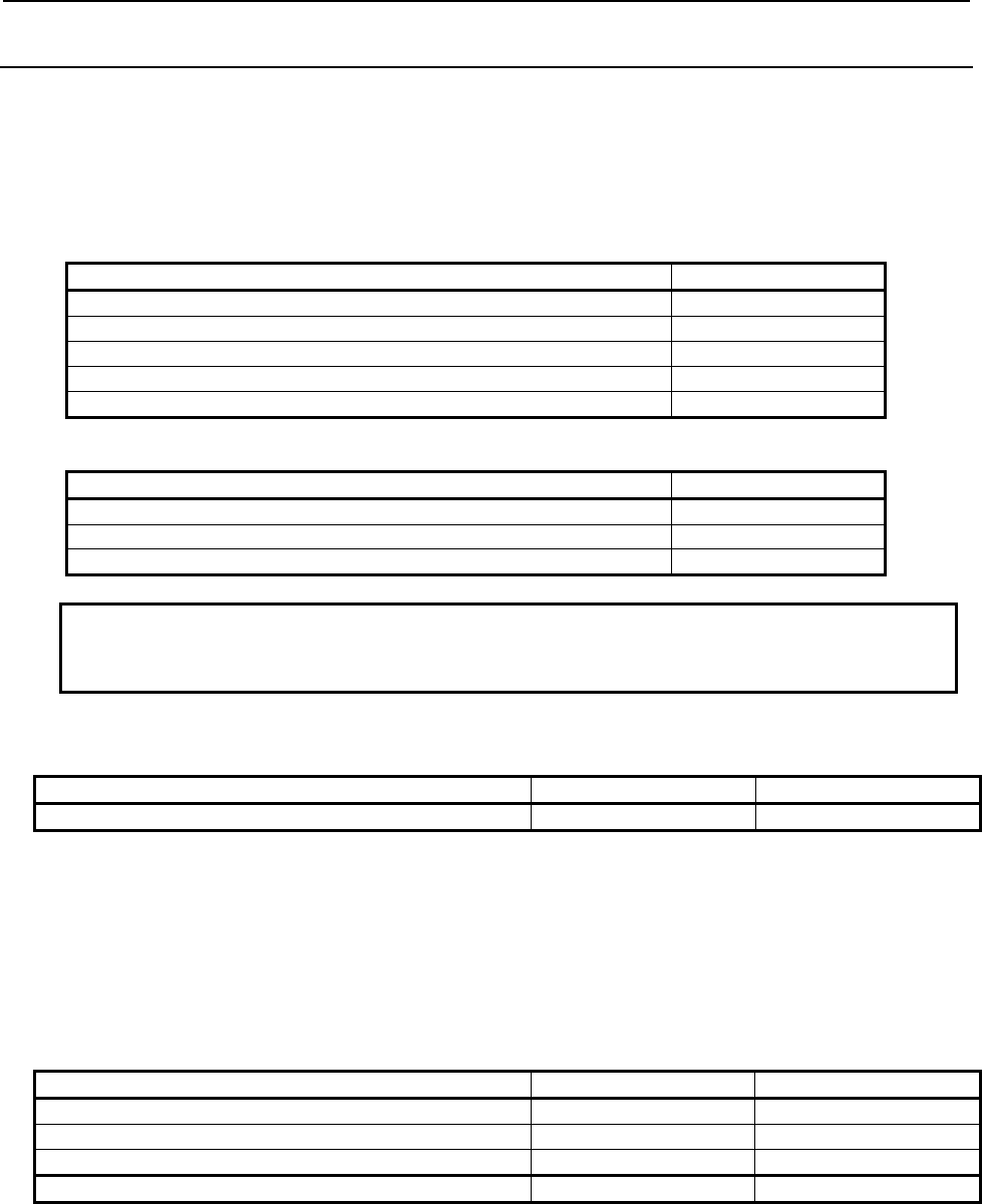
B-64513EN/03
2.PMC SPECIFICATIONS
- 73 -
2.1.4
Program Capacity
All of the memory size, to which save the sequence program and multi-language PMC message data for
all PMC paths, is specified as the combination of the following two options. The size of each data is
calculated per 128KB.
Minimum unit of the size of divided ladder program is also 128KB. You can make up to 40(Note1)
programs of main ladder and divided ladder within specified total memory size.
(1) PMC Ladder step option
Option name Memory size
PMC Ladder Function 24,000 Steps (Basic) 256 KB
PMC Ladder Function 32,000 Steps 384 KB
PMC Ladder Function 64,000 Steps 768 KB
PMC Ladder Function 100,000 Steps 1 MB (1,024 KB)
PMC Ladder Function 300,000 Steps (Note2) 3 MB (3,072 KB)
(2) PMC Symbol, Comment and Message capacity expansion option
Option name Memory size
PMC Symbol, Comment and Message capacity expansion (512KB) 512KB
PMC Symbol, Comment and Message capacity expansion (1MB) 1MB (1,024KB)
PMC Symbol, Comment and Message capacity expansion (2MB) (Note2) 2MB (2,048KB)
NOTE
1 For the series 0i-F, up to 16 programs can be made.
2 These options are not supported for the Series 0i-F.
Configuration example 1 (Basic configuration)
Kind of data Ladder steps Memory size
Sequence program 50,000 steps 640KB
The following option is required for above configuration.
(1) “PMC Ladder Function 64,000 Steps”
Specify the ladder steps.
Configuration Example 2 (The case of using ladder dividing management
function)
Kind of data Ladder steps Memory size
Main ladder program 30,000 steps 384KB
Divided ladder program 1 10,000 steps 128KB
Divided ladder program 2 10,000 steps 128KB
(Total) 50,000 steps 640KB
The following option is required for above configuration.
(1) “PMC Ladder Function 64,000 Steps”
Specify the total ladder steps.

2.PMC SPECIFICATIONS
B-64513EN/03
- 74 -
Configuration example 3 (The case of using PMC message multi language
display function)
Kind of data Ladder steps Memory size
Main ladder program 30,000 steps 384KB
Divided ladder program 1 10,000 steps 128KB
Divided ladder program 2 10,000 steps 128KB
PMC message multi-language display data 0 256KB
(Total) 50,000 steps 896KB
The following options are required for above configuration.
(1) “PMC Ladder Function 64,000 Steps”
Specify the total ladder steps.
(2) “PMC Symbol, Comment and Message capacity expansion 512KB”
Specify the memory capacity to add to “PMC Ladder Function Step Option”. The memory size of
“PMC Ladder Function 64,000 steps” is 768KB. Therefore, this option is necessary because it is
short of memory by 128KB.
Configuration example 4 (The case of using multi-path PMC)
Kind of data Ladder steps Memory size
Main ladder program of 1st path PMC 30,000 steps 384KB
Divided ladder program 1 of 1st path PMC 10,000 steps 128KB
Divided ladder program 2 of 1st path PMC 10,000 steps 128KB
Sequence program of 2nd path PMC 30,000 steps 384KB
Sequence program of 3rd path PMC 15,000 steps 128KB
PMC message multi-language display data of 1st path PMC 0 256KB
PMC message multi-language display data of 2nd path PMC 0 128KB
(Total) 95,000 steps 1,536KB
The following options are required for above configuration.
(1) “Multi-Path PMC Function (3-Paths)”
Specify the path number according to using PMC path.
(2) “PMC Ladder Function 100,000 Steps”
Specify the total ladder steps.
(3) “PMC Symbol, Comment and Message capacity expansion 512KB”
Specify the memory capacity to add to “PMC Ladder Function Step Option”. The memory size of
“PMC Ladder Function 100,000 steps” is 1024KB. Therefore, this option is necessary because it is
short of memory by 512KB.
NOTE
1 When the total size is exceed the specified memory capacity by options, the alarm
“ER02 PROGRAM SIZE OVER” or “WN64 MESSAGE FILE SIZE OVER“ occurs in
the PMC path in which detected the error.
2 When plural data are edited, inputted or outputted at the same time using CNC
screen or FANUC LADDER-III, the data may not be expanded even if the total size
is under the specified memory capacity. In this case, stop the simultaneous
operations and retry the modification one by one.
3 Above memory size does not include the memory for DCS PMC. The memory size
of DCS PMC is 128KB.

B-64513EN/03
2.PMC SPECIFICATIONS
- 75 -
2.1.5
Used Memory Size of Sequence Program
The following table lists the memory capacity used by sequence programs. When creating the sequence
programs, keep their total size within this memory capacity.
Table 2.1.5 (a) Used memory size for each data
Category Item Required memory size (Note 1)
Ladder (Note 2) Basic instruction Refer to table 2.1.8.
Functional instruction Refer to table 2.1.9 and table2.1.10.
Functional instruction parameter 4 bytes
Symbol/comment
conventional type (Note 2)
One definition of symbol/comment
(Including symbol string)
24 bytes
One comment character 1 byte (Note 3)
Symbol/comment extended
type (Note 2)
One definition of symbol/comment 16 - 23 bytes (Note 5)
One symbol character 1 byte
One comment character 1 byte (Note 3)
One sub-program 8 bytes (Note 6)
Message (Note 2) One message character (alphanumeric
characters)
1 byte (Note 4)
Others Area used by the system About 16K bytes
(PMC Memory-A, B, DCS PMC)
About 24K bytes (Note 7)
(PMC Memory-C)
About 32K bytes (Note 7)
(PMC Memory-D)
NOTE
1 The total sequence program size (including all items such as ladders,
symbols/comments, and messages) cannot exceed the sequence program
memory storage capacity. If a ladder, symbol/ comment, or message is large,
the size of other categories may be limited.
2 The PMC programmer may adjust arrangement of these items in the sequence
program memory to improve processing efficiency. As a result, up to 1K byte
(1024 bytes) may be added to the sum of the sizes of individual items.
3 Each full-size character takes a memory capacity of 2 bytes.
4 For Japanese and special characters, each character in a character code
notation (including leading and trailing "@" characters) takes a memory capacity
of one byte. See descriptions about the DISPB function instructions for the
character input code notation.
5 One definition of extended symbol and comment takes 16-23 bytes plus the
memory according to the length of symbol and comment.
6 8 bytes are taken for a sub-program when local symbols are defined in the
sub-program.
7 In the PMC Memory-C, the system area is expanded by about 8KB from PMC
Memory-A or B. In the PMC Memory-D, the area is expanded by about 16KB
from PMC Memory-A or B. Therefore, available memory size for Symbol,
Comment and Message data is smaller than PMC Memory-A and B. If the
program overflowed by converting PMC Memory Type, decrease the Symbol,
Comment or Message data, or upgrade the Ladder step option to larger size.

2.PMC SPECIFICATIONS
B-64513EN/03
- 76 -
2.1.6
PMC Addresses
Table 2.1.6 (a) PMC Address list (1)
Signals Symbol 1st to 5th path PMC DCSPMC
PMC Memory-A PMC Memory-B PMC Memory-C PMC Memory-D (Note 1)
Input signal
to the PMC
from the machine
X X0 ~ X127
X200 ~ X327
X400 ~ X527
X600 ~ X727
X0 ~ X127
X200 ~ X327
X400 ~ X527
X600 ~ X727
X0 ~ X127
X200 ~ X327
X400 ~ X527
X600 ~ X727
X0 ~ X127
X200 ~ X327
X400 ~ X527
X600 ~ X727
X0 ~ X127
X1000 ~ X1127
(Note 2)
X1000 ~ X1127
(Note 2)
X1000 ~ X1127
(Note 2)
X1000 ~ X1127
(Note 2)
Output signal
from the PMC
to the machine
Y Y0 ~ Y127
Y200 ~ Y327
Y400 ~ Y527
Y600 ~ Y727
Y0 ~ Y127
Y200 ~ Y327
Y400 ~ Y527
Y600 ~ Y727
Y0 ~ Y127
Y200 ~ Y327
Y400 ~ Y527
Y600 ~ Y727
Y0 ~ Y127
Y200 ~ Y327
Y400 ~ Y527
Y600 ~ Y727
Y0 ~ Y127
Y1000 ~ Y1127
(Note 2)
Y1000 ~ Y1127
(Note 2)
Y1000 ~ Y1127
(Note 2)
Y1000 ~ Y1127
(Note 2)
Input signal
to the PMC
from the CNC
F F0 ~ F767
F1000 ~ F1767
F2000 ~ F2767
F3000 ~ F3767
F4000 ~ F4767
F5000 ~ F5767
F6000 ~ F6767
F7000 ~ F7767
F8000 ~ F8767
F9000 ~ F9767
F0 ~ F767
F1000 ~ F1767
F2000 ~ F2767
F3000 ~ F3767
F4000 ~ F4767
F5000 ~ F5767
F6000 ~ F6767
F7000 ~ F7767
F8000 ~ F8767
F9000 ~ F9767
F0 ~ F767
F1000 ~ F1767
F2000 ~ F2767
F3000 ~ F3767
F4000 ~ F4767
F5000 ~ F5767
F6000 ~ F6767
F7000 ~ F7767
F8000 ~ F8767
F9000 ~ F9767
F0 ~ F767
F1000 ~ F1767
F2000 ~ F2767
F3000 ~ F3767
F4000 ~ F4767
F5000 ~ F5767
F6000 ~ F6767
F7000 ~ F7767
F8000 ~ F8767
F9000 ~ F9767
F0 ~ F767
Output signal from
the PMC
to the CNC
G G0 ~ G767
G1000 ~ G1767
G2000 ~ G2767
G3000 ~ G3767
G4000 ~ G4767
G5000 ~ G5767
G6000 ~ G6767
G7000 ~ G7767
G8000 ~ G8767
G9000 ~ G9767
G0 ~ G767
G1000 ~ G1767
G2000 ~ G2767
G3000 ~ G3767
G4000 ~ G4767
G5000 ~ G5767
G6000 ~ G6767
G7000 ~ G7767
G8000 ~ G8767
G9000 ~ G9767
G0 ~ G767
G1000 ~ G1767
G2000 ~ G2767
G3000 ~ G3767
G4000 ~ G4767
G5000 ~ G5767
G6000 ~ G6767
G7000 ~ G7767
G8000 ~ G8767
G9000 ~ G9767
G0 ~ G767
G1000 ~ G1767
G2000 ~ G2767
G3000 ~ G3767
G4000 ~ G4767
G5000 ~ G5767
G6000 ~ G6767
G7000 ~ G7767
G8000 ~ G8767
G9000 ~ G9767
G0 ~ G767
Input signal
from other PMC path
M M0 ~ M767
(Note 3)
M0 ~ M767
(Note 3)
M0 ~ M767
(Note 3)
M0 ~ M767
(Note 3)
Output signal
to other PMC path
N N0 ~ N767
(Note 3)
N0 ~ N767
(Note 3)
N0 ~ N767
(Note 3)
N0 ~ N767
(Note 3)
Internal relay R R0 ~ R1499 R0 ~ R7999 R0 ~ R15999 R0 ~ R59999 R0 ~ R1499
System relay R / Z R9000 ~ R9499 R9000 ~ R9499 Z0 ~ Z499 Z0 ~ Z499 R9000 ~ R9499
Extra relay E E0 ~ E9999
(Note 4)
E0 ~ E9999
(Note 4)
E0 ~ E9999
(Note 4)
E0 ~ E9999
(Note 4)
(Note 5)
Message display
・Display request
・Display status
A
A0 ~ A249
A9000 ~ A9249
A0 ~ A249
A9000 ~ A9249
A0 ~ A499
A9000 ~ A9499
A0 ~ A749
A9000 ~ A9749
A0 ~ A249
A9000 ~ A9249

B-64513EN/03
2.PMC SPECIFICATIONS
- 77 -
Table 2.1.6 (b) PMC Address list (2)
Signals Symbol 1st to 5th path PMC DCSPMC
PMC Memory-A PMC Memory-B PMC Memory-C PMC Memory-D (Note 1)
Timer T
T0 ~ T79
T9000 ~ T9499
T0 ~ T499
T9000 ~ T9499
T0 ~ T999
T9000 ~ T9999
T0 ~ T999
T9000 ~ T9999
T0 ~ T79
T9000 ~ T9079
・Variable timer
・Variable timer
precision (Note 6)
Counter C
C0 ~ C79
C5000 ~ C5199
C0 ~ C399
C5000 ~ C5199
C0 ~ C799
C5000 ~ C5399
C0~C1199
C5000~C5599
C0 ~ C79
C5000 ~ C5039
・Variable counter
・Fixed counter
Keep relay K
K0 ~ K19
K900 ~ K999
K0 ~ K99
K900 ~ K999
K0 ~ K199
K900 ~ K999
K0 ~ K299
K900 ~ K999
K0 ~ K19
K900 ~ K999
・User area
・System area
Data table D D0 ~ D2999 D0 ~ D9999 D0 ~ D19999
(Note7)
D0 ~ D59999
(Note7)
D0 ~ D2999
Label L L1 ~ L9999 L1 ~ L9999 L1 ~ L9999 L1 ~ L9999 L1 ~ L9999
Subprogram P P1 ~ P512 P1 ~ P5000 P1 ~ P5000 P1 ~ P5000 P1 ~ P512
Step number
(Step sequence)
S (none) S1 ~ S2000 S1 ~ S2000 S1 ~ S2000 (none)
NOTE
1 This PMC is used for Dual Check Safety function (option).
2 This area is reserved for PMC management software. Do not use it in user
programs.
3 The M/N addresses cannot be used in 4th and 5th path PMC.
4 This area is common memory for the multi-path PMC function. Each program can
write and read the same value in the area.
5 No extra relay is available for the Dual Check Safety PMC.
6 This area is used to specify the precision of a variable timer.
- Don't modify the value of active timer and its precision except for writing same
value.
- Don't set the value other than the following range.
- If above rules are violated, the behavior of the timer is not guaranteed.
The value of precision
0: Default (8msec or 48msec)
1: 1msec
2: 10msec
3: 100msec
4: 1sec
5: 1min
7 To save all area of the data table, the “Nonvolatile PMC data table area expansion
(40KB)” option may be necessary.

2.PMC SPECIFICATIONS
B-64513EN/03
- 78 -
2.1.7
Basic Instructions
Table 2.1.7 Basic instruction list
Instruction name Required memory size 1st to 5th path PMC DCSPMC (Note)
RD 4 bytes
{ {
RD.NOT 4 bytes
{ {
WRT 4 bytes
{ {
WRT.NOT 4 bytes
{ {
AND 4 bytes
{ {
AND.NOT 4 bytes
{ {
OR 4 bytes
{ {
OR.NOT 4 bytes
{ {
RD.STK 4 bytes
{ {
RD.NOT.STK 4 bytes
{ {
AND.STK 4 bytes
{ {
OR.STK 4 bytes
{ {
SET 4 bytes
{ {
RST 4 bytes
{ {
RDPT 12 bytes ● ●
ANDPT 12 bytes ● ●
ORPT 12 bytes ● ●
RDPT.STK 12 bytes ● ●
RDNT 12 bytes ● ●
ANDNT 12 bytes ● ●
ORNT 12 bytes ● ●
RDNT.STK 12 bytes ● ●
PUSH 4 bytes ● ●
POP 4 bytes ● ●
({: Usable. ●: The Extended PMC Ladder Instruction Function. ×: Unusable.)
NOTE
This PMC is used for Dual Check Safety function (option). See "Dual Check
Safety Connection Manual" of each CNC series for details.

B-64513EN/03
2.PMC SPECIFICATIONS
- 79 -
2.1.8
Functional Instructions (Arranged in Sequence of Instruction
Group)
Table 2.1.8 (a) Functional instruction list (arranged in sequence of instruction group) (1)
Instruction
group
Instruction
name
SUB
No. Processing
Required
memory
size
(byte)
1st to 5th
PMC
DCS
PMC
(Note1)
Timer 1 TMR 3 On-delay timer 8 { {
2 TMRB 24 Fixed on-delay timer 12 { {
3 TMRBF 77 Fixed off-delay timer 12 { {
4 TMRC 54 On-delay timer 16 { {
5 TMRST 221 Stop watch timer (1 ms accuracy) 20 ● ●
6 TMRSS 222 Stop watch timer (1 sec accuracy) 20 ● ●
Counter 1 CTR 5 Counter processing 8 { {
2 CTRB 56 Counter processing 12 { {
3 CTRC 55 Counter processing 12 { {
4 CTRD 223 Counter processing (4 byte length) 12 ● ●
Data 1 MOVB 43 1-byte transfer 12 { {
transfer 2 MOVW 44 2-byte transfer 12 { {
3 MOVD 47 4-byte transfer 12 { {
4 MOVN 45 Transfer of arbitrary number of bytes 16 { {
5 MOVE 8 Data transfer after logical product 20 { {
6 MOVOR 28 Data transfer after logical sum 16 { {
7 XMOVB 35 Index modification binary data transfer 24 { {
8 XMOV 18 Index modification data transfer 20 { {
9 MOVBT 224 Bit transfer 24 ● ●
10 SETNB 225 Data setting (1 byte length) 20 ● ●
11 SETNW 226 Data setting (2 byte length) 20 ● ●
12 SETND 227 Data setting (4 byte length) 20 ● ●
13 XCHGB 228 Data exchange (1 byte length) 12 ● ●
14 XCHGW 229 Data exchange (2 byte length) 12 ● ●
15 XCHGD 230 Data exchange (4 byte length) 12 ● ●
16 SWAPW 231 Data swap (2 byte length) 16 ● ●
17 SWAPD 232 Data swap (4 byte length) 16 ● ●
18 DSCHB 34 Binary data search 24 { {
19 DSCH 17 Data search 20 { {
Table 1 TBLRB 233 Reading data from table (1 byte length) 24 ● ●
Data 2 TBLRW 234 Reading data from table (2 byte length) 24 ● ●
3 TBLRD 235 Reading data from table (4 byte length) 24 ● ●
4 TBLRN 236 Reading data from table
(Arbitrary byte length)
28 ● ●
5 TBLWB 237 Writing data to table (1 byte length) 24 ● ●
6 TBLWW 238 Writing data to table (2 byte length) 24 ● ●
7 TBLWD 239 Writing data to table (4 byte length) 24 ● ●
8 TBLWN 240 Writing data to table (Arbitrary byte length) 28 ● ●
9 DSEQB 241 Searching data from table (=) (1 byte length) 28 ● ●
10 DSEQW 242 Searching data from table (=) (2 byte length) 28 ● ●
({: Usable. ●: The Extended PMC Ladder Instruction Function. ∆: Executed as NOP instruction (Note 2). ×: Unusable.)

2.PMC SPECIFICATIONS
B-64513EN/03
- 80 -
Table 2.1.8 (b) Functional instruction list (arranged in sequence of instruction group) (2)
Instruction
group
Instruction
name
SUB
No. Processing
Required
memory
size
(byte)
1st to 5th
PMC
DCS
PMC
(Note1)
Table
Data
11 DSEQD 243 Searching data from table (=) (4 byte length) 28 ● ●
12 DSNEB 244 Searching data from table (≠) (1 byte length) 28 ● ●
13 DSNEW 245 Searching data from table (≠) (2 byte length) 28 ● ●
14 DSNED 246 Searching data from table (≠) (4 byte length) 28 ● ●
15 DSGTB 247 Searching data from table (>) (1 byte length) 28 ● ●
16 DSGTW 248 Searching data from table (>) (2 byte length) 28 ● ●
17 DSGTD 249 Searching data from table (>) (4 byte length) 28 ● ●
18 DSLTB 250 Searching data from table (<) (1 byte length) 28 ● ●
19 DSLTW 251 Searching data from table (<) (2 byte length) 28 ● ●
20 DSLTD 252 Searching data from table (<) (4 byte length) 28 ● ●
21 DSGEB 253
Searching data from table (≧) (1 byte length) 28 ● ●
22 DSGEW 254
Searching data from table (≧) (2 byte length) 28 ● ●
23 DSGED 255
Searching data from table (≧) (4 byte length) 28 ● ●
24 DSLEB 256
Searching data from table (≦) (1 byte length) 28 ● ●
25 DSLEW 257
Searching data from table (≦) (2 byte length) 28 ● ●
26 DSLED 258
Searching data from table (≦) (4 byte length) 28 ● ●
27 DMAXB 259 Maximum data (1 byte length) 28 ● ●
28 DMAXW 260 Maximum data (2 byte length) 28 ● ●
29 DMAXD 261 Maximum data (4 byte length) 28 ● ●
30 DMINB 262 Minimum data (1 byte length) 28 ● ●
31 DMINW 263 Minimum data (2 byte length) 28 ● ●
32 DMIND 264 Minimum data (4 byte length) 28 ● ●
({: Usable. ●: The Extended PMC Ladder Instruction Function. ∆: Executed as NOP instruction (Note 2). ×: Unusable.)

B-64513EN/03
2.PMC SPECIFICATIONS
- 81 -
Table 2.1.8 (c) Functional instruction list (arranged in sequence of instruction group) (3)
Instruction
group
Instruction
name
SUB
No. Processing
Required
memory
size
(byte)
1st to 5th
PMC
DCS
PMC
(Note1)
Comparison 1 EQB 200 Signed Binary Comparison (=) (1 byte length) 16 { {
2 EQW 201 Signed Binary Comparison (=) (2 byte length) 16 { {
3 EQD 202 Signed Binary Comparison (=) (4 byte length) 16 { {
4 NEB 203 Signed Binary Comparison (≠) (1 byte length) 16 { {
5 NEW 204 Signed Binary Comparison (≠) (2 byte length) 16 { {
6 NED 205 Signed Binary Comparison (≠) (4 byte length) 16 { {
7 GTB 206 Signed Binary Comparison (>) (1 byte length) 16 { {
8 GTW 207 Signed Binary Comparison (>) (2 byte length) 16 { {
9 GTD 208 Signed Binary Comparison (>) (4 byte length) 16 { {
10 LTB 209 Signed Binary Comparison (<) (1 byte length) 16 { {
11 LTW 210 Signed Binary Comparison (<) (2 byte length) 16 { {
12 LTD 211 Signed Binary Comparison (<) (4 byte length) 16 { {
13 GEB 212
Signed Binary Comparison (≧) (1 byte length) 16 { {
14 GEW 213
Signed Binary Comparison (≧) (2 byte length) 16 { {
15 GED 214
Signed Binary Comparison (≧) (4 byte length) 16 { {
16 LEB 215
Signed Binary Comparison (≦) (1 byte length) 16 { {
17 LEW 216
Signed Binary Comparison (≦) (2 byte length) 16 { {
18 LED 217
Signed Binary Comparison (≦) (4 byte length) 16 { {
19 RNGB 218 Signed Binary Comparison (range) (1 byte length) 20 { {
20 RNGW 219 Signed Binary Comparison (range) (2 byte length) 20 { {
21 RNGD 220 Signed Binary Comparison (range) (4 byte length) 20 { {
22 COMPB 32 Comparison between binary data 20 { {
23 COMP 15 Comparison 16 { {
24 COIN 16 Coincidence check 16 { {
({: Usable. ●: The Extended PMC Ladder Instruction Function. ∆: Executed as NOP instruction (Note 2). ×: Unusable.)

2.PMC SPECIFICATIONS
B-64513EN/03
- 82 -
Table 2.1.8 (d) Functional instruction list (arranged in sequence of instruction group) (4)
Instruction
group
Instruction
name
SUB
No. Processing
Required
memory
size
(byte)
1st to 5th
PMC
DCS
PMC
(Note1)
Bit 1 DIFU 57 Rising-edge detection 8 { {
operation 2 DIFD 58 Falling-edge detection 8 { {
3 EOR 59 Exclusive OR 20 { {
4 AND 60 Logical AND 20
{ {
5 OR 61 Logical OR 20
{ {
6 NOT 62 Logical NOT 16
{ {
7 PARI 11 Parity check 8
{ {
8 SFT 33 Shift register 8
{ {
9 EORB 265 Exclusive OR (1 byte length) 20 ● ●
10 EORW 266 Exclusive OR (2 byte length) 20 ● ●
11 EORD 267 Exclusive OR (4 byte length) 20 ● ●
12 ANDB 268 Logical AND (1 byte length) 20 ● ●
13 ANDW 269 Logical AND (2 byte length) 20 ● ●
14 ANDD 270 Logical AND (4 byte length) 20 ● ●
15 ORB 271 Logical OR (1 byte length) 20 ● ●
16 ORW 272 Logical OR (2 byte length) 20 ● ●
17 ORD 273 Logical OR (4 byte length) 20 ● ●
18 NOTB 274 Logical NOT (1 byte length) 16 ● ●
19 NOTW 275 Logical NOT (2 byte length) 16 ● ●
20 NOTD 276 Logical NOT (4 byte length) 16 ● ●
21 SHLB 277 Bit shift left (1 byte length) 20 ● ●
22 SHLW 278 Bit shift left (2 byte length) 20 ● ●
23 SHLD 279 Bit shift left (4 byte length) 20 ● ●
24 SHLN 280 Bit shift left (Arbitrary byte length) 24 ● ●
25 SHRB 281 Bit shift right (1 byte length) 20 ● ●
26 SHRW 282 Bit shift right (2 byte length) 20 ● ●
27 SHRD 283 Bit shift right (4 byte length) 20 ● ●
28 SHRN 284 Bit shift right (Arbitrary byte length) 24 ● ●
29 ROLB 285 Bit rotation left (1 byte length) 20 ● ●
30 ROLW 286 Bit rotation left (2 byte length) 20 ● ●
31 ROLD 287 Bit rotation left (4 byte length) 20 ● ●
32 ROLN 288 Bit rotation left (Arbitrary byte length) 24 ● ●
33 RORB 289 Bit rotation right (1 byte length) 20 ● ●
34 RORW 290 Bit rotation right (2 byte length) 20 ● ●
35 RORD 291 Bit rotation right (4 byte length) 20 ● ●
36 RORN 292 Bit rotation right (Arbitrary byte length) 24 ● ●
37 BSETB 293 Bit set (1 byte length) 16 ● ●
38 BSETW 294 Bit set (2 byte length) 16 ● ●
39 BSETD 295 Bit set (4 byte length) 16 ● ●
40 BSETN 296 Bit set (Arbitrary byte length) 20 ● ●
41 BRSTB 297 Bit reset (1 byte length) 16 ● ●
42 BRSTW 298 Bit reset (2 byte length) 16 ● ●
43 BRSTD 299 Bit reset (4 byte length) 16 ● ●
44 BRSTN 300 Bit reset (Arbitrary byte length) 20 ● ●
45 BTSTB 301 Bit test (1 byte length) 16 ● ●
46 BTSTW 302 Bit test (2 byte length) 16 ● ●
47 BTSTD 303 Bit test (4 byte length) 16 ● ●
({: Usable. ●: The Extended PMC Ladder Instruction Function. ∆: Executed as NOP instruction (Note 2). ×: Unusable.)

B-64513EN/03
2.PMC SPECIFICATIONS
- 83 -
Table 2.1.8 (e) Functional instruction list (arranged in sequence of instruction group) (5)
Instruction
group
Instruction
name
SUB
No. Processing
Required
memory
size
(byte)
1st to 5th
PMC
DCS
PMC
(Note1)
Bit 48 BTSTN 304 Bit test (Arbitrary byte length) 20 ● ●
operation 49 BPOSB 305 Bit search (1 byte length) 12 ● ●
50 BPOSW 306 Bit search (2 byte length) 12 ● ●
51 BPOSD 307 Bit search (4 byte length) 12 ● ●
52 BPOSN 308 Bit search (Arbitrary byte length) 16 ● ●
53 BCNTB 309 Bit count (1 byte length) 12 ● ●
54 BCNTW 310 Bit count (2 byte length) 12 ● ●
55 BCNTD 311 Bit count (4 byte length) 12 ● ●
56 BCNTN 312 Bit count (Arbitrary byte length) 16 ● ●
Code
conversion
1 COD 7 Code conversion 16+n
(Note5)
{ {
2 CODB 27 Binary code conversion 20+n
(Note5)
{ {
3 DCNV 14 Data conversion 12 { {
4 DCNVB 31 Extended data conversion 16
{ {
5 DEC 4 Decoding 12
{ {
6 DECB 25 Binary decoding 20
{ {
7 TBCDB 313 Binary to BCD conversion (1 byte length) 16 ● ●
8 TBCDW 314 Binary to BCD conversion (2 byte length) 16 ● ●
9 TBCDD 315 Binary to BCD conversion (4 byte length) 16 ● ●
10 FBCDB 316 BCD to Binary conversion (1 byte length) 16 ● ●
11 FBCDW 317 BCD to Binary conversion (2 byte length) 16 ● ●
12 FBCDD 318 BCD to Binary conversion (4 byte length) 16 ● ●
Operation 1 ADDB 36 Binary addition 20 { {
2 SUBB 37 Binary subtraction 20 { {
3 MULB 38 Binary multiplication 20 { {
4 DIVB 39 Binary division 20 { {
5 ADD 19 BCD addition 20 { {
6 SUB 20 BCD subtraction 20 { {
7 MUL 21 BCD multiplication 20 { {
8 DIV 22 BCD division 20
{ {
9 NUMEB 40 Binary constant definition 16 { {
10 NUME 23 BCD-constant definition 12 { {
11 ADDSB 319 Addition (1 byte length) 20 ● ●
12 ADDSW 320 Addition (2 byte length) 20 ● ●
13 ADDSD 321 Addition (4 byte length) 20 ● ●
14 SUBSB 322 Subtraction (1 byte length) 20 ● ●
15 SUBSW 323 Subtraction (2 byte length) 20 ● ●
16 SUBSD 324 Subtraction (3 byte length) 20 ● ●
17 MULSB 325 Multiplication (1 byte length) 20 ● ●
18 MULSW 326 Multiplication (2 byte length) 20 ● ●
19 MULSD 327 Multiplication (4 byte length) 20 ● ●
({: Usable. ●: The Extended PMC Ladder Instruction Function. ∆: Executed as NOP instruction (Note 2). ×: Unusable.)

2.PMC SPECIFICATIONS
B-64513EN/03
- 84 -
Table 2.1.8 (f) Functional instruction list (arranged in sequence of instruction group) (6)
Instruction
group
Instruction
name
SUB
No. Processing
Required
memory
size
(byte)
1st to 5th
PMC
DCS
PMC
(Note1)
Operation 20 DIVSB 328 Division (1 byte length) 20 ● ●
21 DIVSW 329 Division (2 byte length) 20 ● ●
22 DIVSD 330 Division (4 byte length) 20 ● ●
23 MODSB 331 Remainder (1 byte length) 20 ● ●
24 MODSW 332 Remainder (2 byte length) 20 ● ●
25 MODSD 333 Remainder (4 byte length) 20 ● ●
26 INCSB 334 Increment (1 byte length) 8 ● ●
27 INCSW 335 Increment (2 byte length) 8 ● ●
28 INCSD 336 Increment (4 byte length) 8 ● ●
29 DECSB 337 Decrement (1 byte length) 8 ● ●
30 DECSW 338 Decrement (2 byte length) 8 ● ●
31 DECSD 339 Decrement (4 byte length) 8 ● ●
32 ABSSB 340 Absolute value (1 byte length) 16 ● ●
33 ABSSW 341 Absolute value (2 byte length) 16 ● ●
34 ABSSD 342 Absolute value (4 byte length) 16 ● ●
35 NEGSB 343 Sign inversion (1 byte length) 16 ● ●
36 NEGSW 344 Sign inversion (2 byte length) 16 ● ●
37 NEGSD 345 Sign inversion (4 byte length) 16 ● ●
CNC 1 DISPB 41 Message display 8 { ∆
Function 2 EXIN 42 External data input 8 { ∆
3 WINDR 51 CNC window data read 8 { ∆
4 WINDW 52 CNC window data write 8 { ∆
5 AXCTL 53 PMC axis control 12 { ∆
6 PSGN2 63 Position signal 8
{ ∆
7 PSGNL 50 Position signal 12
{ ∆
Program 1 COM 9 Common line control 8 { {
control 2 COME 29 End of common line control 4 { {
3 JMP 10 Jump 12 { {
4 JMPE 30 End of jump 4 { {
5 JMPB 68 Label jump 1 16 { {
6 JMPC 73 Label jump 2 16 { {
7 LBL 69 Label 12
{ {
8 CALL 65 Conditional subprogram call 12 { {
9 CALLU 66 Unconditional subprogram call 12
{ {
10 SP 71 Subprogram 8
{ {
11 SPE 72 End of subprogram 4 { {
12 END1 1 End of first-level program 4 { {
13 END2 2 End of second-level program 4 { {
({: Usable. ●: The Extended PMC Ladder Instruction Function. ∆: Executed as NOP instruction (Note 2). ×: Unusable.)

B-64513EN/03
2.PMC SPECIFICATIONS
- 85 -
Table 2.1.8 (g) Functional instruction list (arranged in sequence of instruction group) (7)
Instruction
group
Instruction
name
SUB
No. Processing
Required
memory
size
(byte)
1st to 5th
PMC
DCS
PMC
(Note1)
Program
control
14 END3 48 End of third-level program 4 {
(Note 3)
∆
(Note4)
15 END 64 End of ladder program 4 { {
16 NOP 70 No operation 8
{ {
17 CS 74 Case call 8
{ {
18 CM 75 Sub program call in case call 12 { {
19 CE 76 End of case call 4 { {
Rotation 1 ROT 6 Rotation control 20 { {
control 2 ROTB 26 Binary rotation control 24 { {
Invalid 1 SPCNT 46 Spindle control 16 ∆ ∆
instruction 2 DISP 49 Message display 16+n
(Note5)
∆ ∆
3 MMCWR 98 MMC window data read 12 ∆ ∆
4 MMCWW 99 MMC window data write 12 ∆ ∆
5 FNC90 90 Arbitrary-function instruction 1 8 ∆ ∆
6 FNC91 91 Arbitrary-function instruction 2 8 ∆ ∆
7 FNC92 92 Arbitrary-function instruction 3 8 ∆ ∆
8 FNC93 93 Arbitrary-function instruction 4 8 ∆ ∆
9 FNC94 94 Arbitrary-function instruction 5 8 ∆ ∆
10 FNC95 95 Arbitrary-function instruction 6 8 ∆ ∆
11 FNC96 96 Arbitrary-function instruction 7 8 ∆ ∆
12 FNC97 97 Arbitrary-function instruction 8 8 ∆ ∆
({: Usable. ●: The Extended PMC Ladder Instruction Function. ∆: Executed as NOP instruction (Note 2). ×: Unusable.)
NOTE
1 This term stands for the Dual Check Safety PMC (option).
2 These instructions are intended to maintain source-level compatibility with programs
for conventional models. They are treated as a NOP instruction (instruction that
performs no operation).
3 The 3rd level sequence part is available for the compatibility with programs for
conventional models. However, the execution cycle period for processing the 3rd
level sequence part is not guaranteed. See Section 1.4.3 "Processing priority".
4 This instruction is intended to maintain source-level compatibility with programs for
other models. A program can be created on level 3, but it is not executed.
5 Memory size increases by the number of data tables to be used. In the COD
instruction, CODB instruction (1byte length), CODB instruction (2byte length), or
DISP instruction, 2 bytes are added for each data. And, when the number of data
is odd, 2 bytes are added moreover. In the CODB instruction, 4 bytes are added
for each data.

2.PMC SPECIFICATIONS
B-64513EN/03
- 86 -
2.1.9
Functional Instructions (Arranged in Sequence of SUB No.)
Table 2.1.9 (a) Functional instruction list (arranged in sequence of SUB No.) (1)
Instruction
name
SUB
No. Processing
Required
memory
size
(byte)
1st to 5th
PMC
DCSPMC
(Note1)
END1 1 End of first-level program 4 { {
END2 2 End of second-level program 4 { {
TMR 3 Timer processing 8 { {
DEC 4 Decoding 12 { {
CTR 5 Counter processing 8 { {
ROT 6 Rotation control 20 { {
COD 7 Code conversion 16+n
(Note5)
{ {
MOVE 8 Data transfer after logical product 20 { {
COM 9 Common line control 8 { {
JMP 10 Jump 12
{ {
PARI 11 Parity check 8 { {
DCNV 14 Data conversion 12 { {
COMP 15 Comparison 16 { {
COIN 16 Coincidence check 16 { {
DSCH 17 Data search 20 { {
XMOV 18 Index modification data transfer 20 { {
ADD 19 Addition 20
{ {
SUB 20 Subtraction 20
{ {
MUL 21 Multiplication 20
{ {
DIV 22 Division 20
{ {
NUME 23 Constant definition 12 { {
TMRB 24 Fixed-timer processing 12 { {
DECB 25 Binary decoding 20 { {
ROTB 26 Binary rotation control 24 { {
CODB 27 Binary code conversion 20+n
(Note5)
{ {
MOVOR 28 Data transfer after logical sum 16 { {
COME 29 End of common line control 4 { {
JMPE 30 End of jump 4 { {
DCNVB 31 Extended data conversion 16 { {
COMPB 32 Binary comparison 20 { {
SFT 33 Shift register 8 { {
DSCHB 34 Binary data search 24 { {
XMOVB 35 Index modification binary data transfer 24 { {
ADDB 36 Binary addition 20 { {
SUBB 37 Binary subtraction 20 { {
MULB 38 Binary multiplication 20 { {
DIVB 39 Binary division 20 { {
NUMEB 40 Binary constant definition 16 { {
DISPB 41 Message display 8 { ∆
EXIN 42 External data input 8 { ∆
MOVB 43 1-byte transfer 12 { {
MOVW 44 2-byte transfer 12 { {
MOVN 45 Transfer of arbitrary number of bytes 16 { {
({: Usable. ●: The Extended PMC Ladder Instruction Function. ∆: Executed as NOP instruction (Note 2). ×: Unusable.)

B-64513EN/03
2.PMC SPECIFICATIONS
- 87 -
Table 2.1.9 (b) Functional instruction list (arranged in sequence of SUB No.) (2)
Instruction
name
SUB
No. Processing
Required
memory
size
(byte)
1st to 5th
PMC
DCS
PMC
(Note1)
SPCNT 46 Spindle control 16 ∆ ∆
MOVD 47 4-byte transfer 12 { {
END3 48 End of third-level program 4 {
(Note3)
∆
(Note4)
DISP 49 Message display 16+n
(Note5)
∆ ∆
PSGNL 50 Position signal 12 { ∆
WINDR 51 CNC window data read 8 { ∆
WINDW 52 CNC window data write 8 { ∆
AXCTL 53 PMC axis control 12 { ∆
TMRC 54 Timer processing 16 { {
CTRC 55 Counter processing 12 { {
CTRB 56 Counter processing 12 { {
DIFU 57 Rising-edge detection 8 { {
DIFD 58 Falling-edge detection 8 { {
EOR 59 Exclusive OR 20 { {
AND 60 Logical AND 20 { {
OR 61 Logical OR 20
{ {
NOT 62 Logical NOT 16
{ {
PSGN2 63 Position signal 8 { ∆
END 64 End of ladder program 4 { {
CALL 65 Conditional subprogram call 12 { {
CALLU 66 Unconditional subprogram call 12 { {
JMPB 68 Label jump 1 16 { {
LBL 69 Label 12
{ {
NOP 70 No operation 8 { {
SP 71 Subprogram 8
{ {
SPE 72 End of subprogram 4 { {
JMPC 73 Label jump 2 16 { {
CS 74 Case call 8
{ {
CM 75 Sub program call in case call 12 { {
CE 76 End of case call 4 { {
TMRBF 77 Fixed off-delay timer 12 { {
FNC90 90 Arbitrary-function instruction 1 8 ∆ ∆
FNC91 91 Arbitrary-function instruction 2 8 ∆ ∆
FNC92 92 Arbitrary-function instruction 3 8 ∆ ∆
FNC93 93 Arbitrary-function instruction 4 8 ∆ ∆
FNC94 94 Arbitrary-function instruction 5 8 ∆ ∆
FNC95 95 Arbitrary-function instruction 6 8 ∆ ∆
FNC96 96 Arbitrary-function instruction 7 8 ∆ ∆
FNC97 97 Arbitrary-function instruction 8 8 ∆ ∆
MMCWR 98 MMC window data read 12 ∆ ∆
MMCWW 99 MMC window data write 12 ∆ ∆
({: Usable. ●: The Extended PMC Ladder Instruction Function. ∆: Executed as NOP instruction (Note 2). ×: Unusable.)

2.PMC SPECIFICATIONS
B-64513EN/03
- 88 -
Table 2.1.9 (c) Functional instruction list (arranged in sequence of SUB No.) (3)
Instruction
name
SUB
No. Processing
Required
memory
size
(byte)
1st to 5th
PMC
DCSPMC
(Note1)
EQB 200 Signed Binary Comparison (=)(1 byte length) 16 { {
EQW 201 Signed Binary Comparison (=)(2 byte length) 16 { {
EQD 202 Signed Binary Comparison (=)(4 byte length) 16 { {
NEB 203 Signed Binary Comparison (≠)(1 byte length) 16 { {
NEW 204 Signed Binary Comparison (≠)(2 byte length) 16 { {
NED 205 Signed Binary Comparison (≠)(4 byte length) 16 { {
GTB 206 Signed Binary Comparison (>)(1 byte length) 16 { {
GTW 207 Signed Binary Comparison (>)(2 byte length) 16 { {
GTD 208 Signed Binary Comparison (>)(4 byte length) 16 { {
LTB 209 Signed Binary Comparison (<)(1 byte length) 16 { {
LTW 210 Signed Binary Comparison (<)(2 byte length) 16 { {
LTD 211 Signed Binary Comparison (<)(4 byte length) 16 { {
GEB 212
Signed Binary Comparison (≧)(1 byte length) 16 { {
GEW 213
Signed Binary Comparison (≧)(2 byte length) 16 { {
GED 214
Signed Binary Comparison (≧)(4 byte length) 16 { {
LEB 215
Signed Binary Comparison (≦)(1 byte length) 16 { {
LEW 216
Signed Binary Comparison (≦)(2 byte length) 16 { {
LED 217
Signed Binary Comparison (≦)(4 byte length) 16 { {
RNGB 218 Signed Binary Comparison (range)(1 byte length) 20 { {
RNGW 219 Signed Binary Comparison (range)(2 byte length) 20 { {
RNGB 220 Signed Binary Comparison (range)(4 byte length) 20 { {
TMRST 221 Stop watch timer (1 ms accuracy) 20 ● ●
TMRSS 222 Stop watch timer (1 sec accuracy) 20 ● ●
CTRD 223 Counter processing (4 byte length) 12 ● ●
MOVBT 224 Bit transfer 24 ● ●
SETNB 225 Data setting (1 byte length) 20 ● ●
SETNW 226 Data setting (2 byte length) 20 ● ●
SETND 227 Data setting (4 byte length) 20 ● ●
XCHGB 228 Data exchange (1 byte length) 12 ● ●
XCHGW 229 Data exchange (2 byte length) 12 ● ●
XCHGD 230 Data exchange (4 byte length) 12 ● ●
SWAPW 231 Data swap (2 byte length) 16 ● ●
SWAPD 232 Data swap (4 byte length) 16 ● ●
TBLRB 233 Reading data from table (1 byte length) 24 ● ●
TBLRW 234 Reading data from table (2 byte length) 24 ● ●
TBLRD 235 Reading data from table (4 byte length) 24 ● ●
TBLRN 236 Reading data from table (Arbitrary byte length) 28 ● ●
TBLWB 237 Writing data to table (1 byte length) 24 ● ●
TBLWW 238 Writing data to table (2 byte length) 24 ● ●
TBLWD 239 Writing data to table (4 byte length) 24 ● ●
({: Usable. ●: The Extended PMC Ladder Instruction Function. ∆: Executed as NOP instruction (Note 2). ×: Unusable.)

B-64513EN/03
2.PMC SPECIFICATIONS
- 89 -
Table 2.1.9 (d) Functional instruction list (arranged in sequence of SUB No.) (4)
Instruction
name
SUB
No. Processing
Required
memory
size
(byte)
1st to 5th
PMC
DCSPMC
(Note1)
TBLWN 240 Writing data to table (Arbitrary byte length) 28 ● ●
DSEQB 241 Searching data from table (=)(1 byte length) 28 ● ●
DSEQW 242 Searching data from table (=)(2 byte length) 28 ● ●
DSEQD 243 Searching data from table (=)(4 byte length) 28 ● ●
DSNEB 244 Searching data from table (≠)(1 byte length) 28 ● ●
DSNEW 245 Searching data from table (≠)(2 byte length) 28 ● ●
DSNED 246 Searching data from table (≠)(4 byte length) 28 ● ●
DSGTB 247 Searching data from table (>)(1 byte length) 28 ● ●
DSGTW 248 Searching data from table (>)(2 byte length) 28 ● ●
DSGTD 249 Searching data from table (>)(4 byte length) 28 ● ●
DSLTB 250 Searching data from table (<)(1 byte length) 28 ● ●
DSLTW 251 Searching data from table (<)(2 byte length) 28 ● ●
DSLTD 252 Searching data from table (<)(4 byte length) 28 ● ●
DSGEB 253
Searching data from table (≧)(1 byte length) 28 ● ●
DSGEW 254
Searching data from table (≧)(2 byte length) 28 ● ●
DSGED 255
Searching data from table (≧)(4 byte length) 28 ● ●
DSLEB 256
Searching data from table (≦)(1 byte length) 28 ● ●
DSLEW 257
Searching data from table (≦)(2 byte length) 28 ● ●
DSLED 258
Searching data from table (≦)(4 byte length) 28 ● ●
DMAXB 259 Maximum data (1 byte length) 28 ● ●
DMAXW 260 Maximum data (2 byte length) 28 ● ●
DMAXD 261 Maximum data (4 byte length) 28 ● ●
DMINB 262 Minimum data (1 byte length) 28 ● ●
DMINW 263 Minimum data (2 byte length) 28 ● ●
DMIND 264 Minimum data (4 byte length) 28 ● ●
EORB 265 Exclusive OR (1 byte length) 20 ● ●
EORW 266 Exclusive OR (2 byte length) 20 ● ●
EORD 267 Exclusive OR (4 byte length) 20 ● ●
ANDB 268 Logical AND (1 byte length) 20 ● ●
ANDW 269 Logical AND (2 byte length) 20 ● ●
ANDD 270 Logical AND (4 byte length) 20 ● ●
ORB 271 Logical OR (1 byte length) 20 ● ●
ORW 272 Logical OR (2 byte length) 20 ● ●
ORD 273 Logical OR (4 byte length) 20 ● ●
NOTB 274 Logical NOT (1 byte length) 16 ● ●
NOTW 275 Logical NOT (2 byte length) 16 ● ●
NOTD 276 Logical NOT (4 byte length) 16 ● ●
SHLB 277 Bit shift left (1 byte length) 20 ● ●
SHLW 278 Bit shift left (2 byte length) 20 ● ●
SHLD 279 Bit shift left (4 byte length) 20 ● ●
({: Usable. ●: The Extended PMC Ladder Instruction Function. ∆: Executed as NOP instruction (Note 2). ×: Unusable.)

2.PMC SPECIFICATIONS
B-64513EN/03
- 90 -
Table 2.1.9 (e) Functional instruction list (arranged in sequence of SUB No.) (5)
Instruction
name
SUB
No. Processing
Required
memory
size
(byte)
1st to 5th
PMC
DCSPMC
(Note1)
SHLN 280 Bit shift left (Arbitrary byte length) 24 ● ●
SHRB 281 Bit shift right (1 byte length) 20 ● ●
SHRW 282 Bit shift right (2 byte length) 20 ● ●
SHRD 283 Bit shift right (4 byte length) 20 ● ●
SHRN 284 Bit shift right (Arbitrary byte length) 24 ● ●
ROLB 285 Bit rotation left (1 byte length) 20 ● ●
ROLW 286 Bit rotation left (2 byte length) 20 ● ●
ROLD 287 Bit rotation left (4 byte length) 20 ● ●
ROLN 288 Bit rotation left (Arbitrary byte length) 24 ● ●
RORB 289 Bit rotation right (1 byte length) 20 ● ●
RORW 290 Bit rotation right (2 byte length) 20 ● ●
RORD 291 Bit rotation right (4 byte length) 20 ● ●
RORN 292 Bit rotation right (Arbitrary byte length) 24 ● ●
BSETB 293 Bit set (1 byte length) 16 ● ●
BSETW 294 Bit set (2 byte length) 16 ● ●
BSETD 295 Bit set (4 byte length) 16 ● ●
BSETN 296 Bit set (Arbitrary byte length) 20 ● ●
BRSTB 297 Bit reset (1 byte length) 16 ● ●
BRSTW 298 Bit reset (2 byte length) 16 ● ●
BRSTD 299 Bit reset (4 byte length) 16 ● ●
BRSTN 300 Bit reset (Arbitrary byte length) 20 ● ●
BTSTB 301 Bit test (1 byte length) 16 ● ●
BTSTW 302 Bit test (2 byte length) 16 ● ●
BTSTD 303 Bit test (4 byte length) 16 ● ●
BTSTN 304 Bit test (Arbitrary byte length) 20 ● ●
BPOSB 305 Bit search (1 byte length) 12 ● ●
BPOSW 306 Bit search (2 byte length) 12 ● ●
BPOSD 307 Bit search (4 byte length) 12 ● ●
BPOSN 308 Bit search (Arbitrary byte length) 16 ● ●
BCNTB 309 Bit count (1 byte length) 12 ● ●
BCNTW 310 Bit count (2 byte length) 12 ● ●
BCNTD 311 Bit count (4 byte length) 12 ● ●
BCNTN 312 Bit count (Arbitrary byte length) 16 ● ●
TBCDB 313 Binary to BCD conversion (1 byte length) 16 ● ●
TBCDW 314 Binary to BCD conversion (2 byte length) 16 ● ●
TBCDD 315 Binary to BCD conversion (4 byte length) 16 ● ●
FBCDB 316 BCD to Binary conversion (1 byte length) 16 ● ●
FBCDW 317 BCD to Binary conversion (2 byte length) 16 ● ●
FBCDD 318 BCD to Binary conversion (4 byte length) 16 ● ●
ADDSB 319 Addition (1 byte length) 20 ● ●
({: Usable. ●: The Extended PMC Ladder Instruction Function. ∆: Executed as NOP instruction (Note 2). ×: Unusable.)

B-64513EN/03
2.PMC SPECIFICATIONS
- 91 -
Table 2.1.9 (f) Functional instruction list (arranged in sequence of SUB No.) (6)
Instruction
name
SUB
No. Processing
Required
memory
size
(byte)
1st to 5th
PMC
DCSPMC
(Note1)
ADDSW 320 Addition (2 byte length) 20 ● ●
ADDSD 321 Addition (4 byte length) 20 ● ●
SUBSB 322 Subtraction (1 byte length) 20 ● ●
SUBSW 323 Subtraction (2 byte length) 20 ● ●
SUBSD 324 Subtraction (3 byte length) 20 ● ●
MULSB 325 Multiplication (1 byte length) 20 ● ●
MULSW 326 Multiplication (2 byte length) 20 ● ●
MULSD 327 Multiplication (4 byte length) 20 ● ●
DIVSB 328 Division (1 byte length) 20 ● ●
DIVSW 329 Division (2 byte length) 20 ● ●
DIVSD 330 Division (4 byte length) 20 ● ●
MODSB 331 Remainder (1 byte length) 20 ● ●
MODSW 332 Remainder (2 byte length) 20 ● ●
MODSD 333 Remainder (4 byte length) 20 ● ●
INCSB 334 Increment (1 byte length) 8 ● ●
INCSW 335 Increment (2 byte length) 8 ● ●
INCSD 336 Increment (4 byte length) 8 ● ●
DECSB 337 Decrement (1 byte length) 8 ● ●
DECSW 338 Decrement (2 byte length) 8 ● ●
DECSD 339 Decrement (4 byte length) 8 ● ●
ABSSB 340 Absolute value (1 byte length) 16 ● ●
ABSSW 341 Absolute value (2 byte length) 16 ● ●
ABSSD 342 Absolute value (4 byte length) 16 ● ●
NEGSB 343 Sign inversion (1 byte length) 16 ● ●
NEGSW 344 Sign inversion (2 byte length) 16 ● ●
NEGSD 345 Sign inversion (4 byte length) 16 ● ●
({: Usable. ●: The Extended PMC Ladder Instruction Function. ∆: Executed as NOP instruction (Note 2). ×: Unusable.)
NOTE
1 This term stands for the Dual Check Safety PMC (option).
2 These instructions are intended to maintain source-level compatibility with programs
for conventional models. They are treated as a NOP instruction (instruction that
performs no operation).
3 The 3rd level sequence part is available for the compatibility with programs for
conventional models. However, the execution cycle period for processing the 3rd
level sequence part is not guaranteed. See Section 1.4.3 "Processing priority".
4 This instruction is intended to maintain source-level compatibility with programs for
other models. A program can be created on level 3, but it is not executed.
5 Memory size increases by the number of data tables to be used. In the COD
instruction, CODB instruction (1byte length), CODB instruction (2byte length), or
DISP instruction, 2 bytes are added for each data. And, when the number of data is
odd, 2 bytes are added moreover. In the CODB instruction, 4 bytes are added for
each data.

2.PMC SPECIFICATIONS
B-64513EN/03
- 92 -
2.2 PMC SIGNAL ADDRESSES
This section describes the use of each PMC address. See Subsection 2.1.6 for explanations about all
address types and ranges.
2.2.1 Addresses for Signals Between the PMC and CNC (F, G)
These addresses are interface areas between PMC and CNC. Refer to the applicable CNC connection
manual for details.
(1) Signals from the CNC to the PMC
Data kind 1st path PMC 2nd to 5th path PMC
(Option)
DCSPMC
(Option)
Input signals from
CNC to PMC
F0 ~ F767
F1000 ~ F1767
F2000 ~ F2767
F3000 ~ F3767
F4000 ~ F4767
F5000 ~ F5767
F6000 ~ F6767
F7000 ~ F7767
F8000 ~ F8767
F9000 ~ F9767
F0 ~ F767
F1000 ~ F1767
F2000 ~ F2767
F3000 ~ F3767
F4000 ~ F4767
F5000 ~ F5767
F6000 ~ F6767
F7000 ~ F7767
F8000 ~ F8767
F9000 ~ F9767
F0 ~ F767
(2) Signals from the PMC to the CNC
Data kind 1st path PMC 2nd to 5th path PMC
(Option)
DCSPMC
(Option)
Output signals to CNC
from PMC
G0 ~ G767
G1000 ~ G1767
G2000 ~ G2767
G3000 ~ G3767
G4000 ~ G4767
G5000 ~ G5767
G6000 ~ G6767
G7000 ~ G7767
G8000 ~ G8767
G9000 ~ G9767
G0 ~ G767
G1000 ~ G1767
G2000 ~ G2767
G3000 ~ G3767
G4000 ~ G4767
G5000 ~ G5767
G6000 ~ G6767
G7000 ~ G7767
G8000 ~ G8767
G9000 ~ G9767
G0 ~ G767
NOTE
The PMC paths corresponding to each CNC path to be controlled can be set. As
for details, refer to “CNC Parameters Related to the PMCs” in subsection “2.4.3”.

B-64513EN/03
2.PMC SPECIFICATIONS
- 93 -
2.2.2
Addresses of Signals Between the PMC and Machine (X, Y)
These addresses are interface areas between PMC and machines.
(1) Assignment of the FANUC I/O Link / I/O Link i
(a) Signals input from the machine to the PMC
1st to 5th path PMC
The addresses for four channels, X0 to X127, X200 to X327, X400 to X527, and X600 to
X727, can be used for the signals input to PMCs. Each address is not fixed at a specific
channel. They can be assigned to any channel. See "I/O Link input/output addresses"
in Subsection 2.4.3 for details. As for I/O Link i, see subsection “3.3.6”.
Dual-check safety (DCS)
The addresses for one channel, X0 to X127, are used for the signals input to the DCS.
These addresses can be assigned to channel 3 for I/O Link. As for I/O Link i, see
subsection “3.3.6”.
(b) Signals output from the PMC to the machine
1st to 5th path PMC
The addresses for four channels, Y0 to Y127, Y200 to Y327, Y400 to Y527, and Y600 to
Y727, can be used for signals output from PMCs. Each address is not fixed at a specific
channel. They can be assigned to any channel. See "I/O Link input/output addresses"
in Subsection 2.4.3 for details. As for I/O Link i, see subsection “3.3.6”.
Dual-check safety (DCS)
The addresses for one channel, Y0 to Y127, are used for the signals output from the DCS.
These addresses can be assigned to channel 3 for I/O Link. As for I/O Link i, see
subsection “3.3.6”.
NOTE
X/Y addresses can be also used for network devices. As for details, refer to “The
input/output address used by network device” in subsection “2.4.3”.
(2) Address-fixed CNC signals input from the machine
The CNC processes signals input from the machine (listed in Table 2.2.2) by referencing fixed
addresses. Be sure to assign specified addresses.
Table 2.2.2 Address-fixed input signals
Signal name Symbol
Address
NC Path 1 NC Path 2 NC Path 3
Common
to T/M
Skip signal SKIP X4.7 X13.7 X11.7
Emergency stop signal (machine group 1) *ESP X8.4 (Note 1)
Emergency stop signal (machine group 2) *ESP X8.0 (Note 1)
Emergency stop signal (machine group 3) *ESP X8.1 (Note 1)
Deceleration signal for 1st-axis reference
position return *DEC1 X9.0 X7.0 X10.0
Deceleration signal for 2nd-axis reference
position return *DEC2 X9.1 X7.1 X10.1
Deceleration signal for 3rd-axis reference
position return *DEC3 X9.2 X7.2 X10.2
Deceleration signal for 4th-axis reference
position return *DEC4 X9.3 X7.3 X10.3
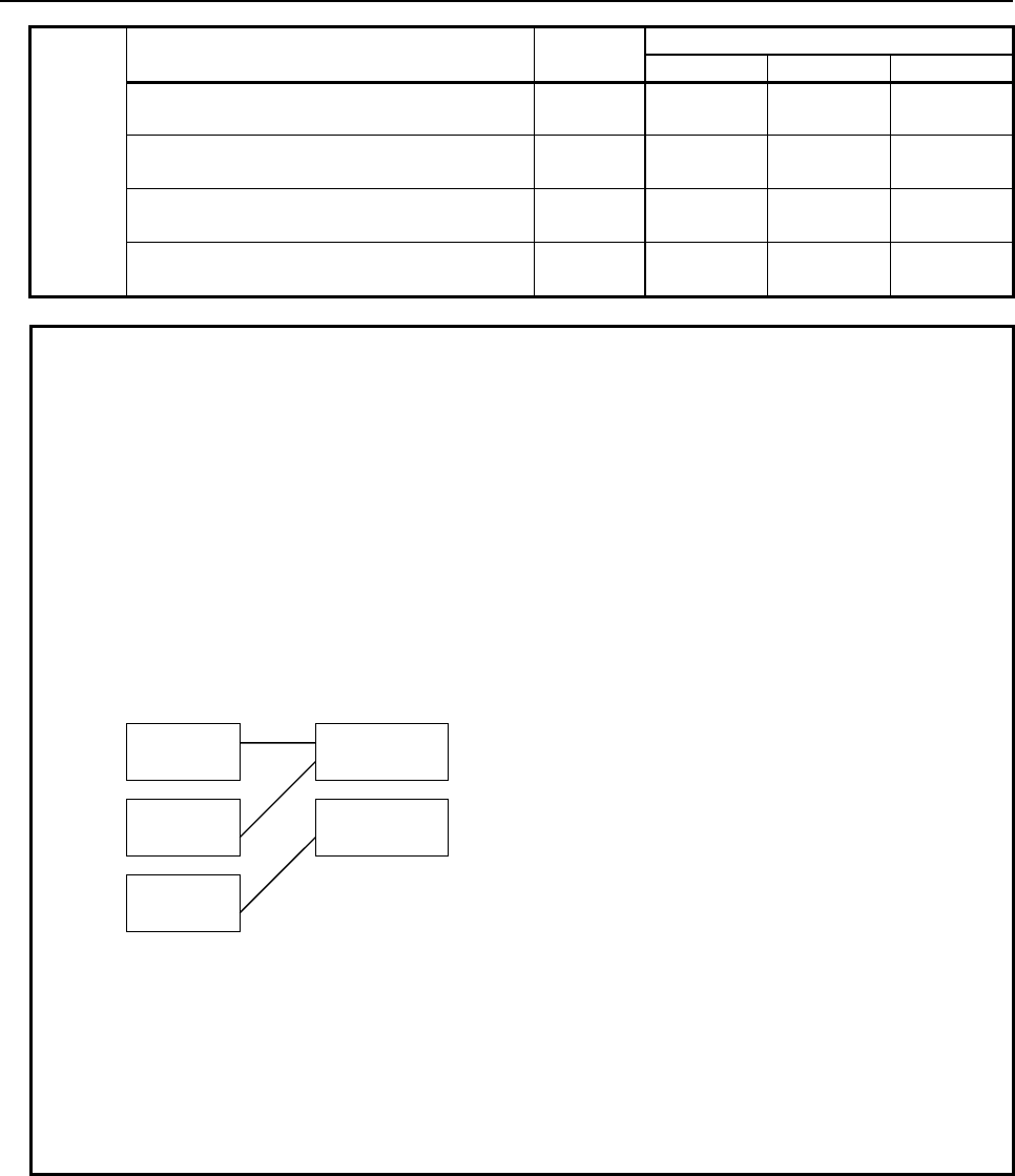
2.PMC SPECIFICATIONS
B-64513EN/03
- 94 -
Signal name Symbol
Address
NC Path 1 NC Path 2 NC Path 3
Deceleration signal for 5th-axis reference
position return *DEC5 X9.4 X7.4 X10.4
Deceleration signal for 6th-axis reference
position return *DEC6 X9.5 X7.5 X10.5
Deceleration signal for 7th-axis reference
position return *DEC7 X9.6 X7.6 X10.6
Deceleration signal for 8th-axis reference
position return *DEC8 X9.7 X7.7 X10.7
NOTE
1 If the Series 30i/31i/32i/35i-B, the Power Motion i-A or the Series 0i-F system is
used to control more than one NC path, some NC paths can be grouped to share
data within the group and to stop all the paths in the group if an alarm condition
occurs in one of the paths. The group is referred to as a machine group.
The system supports up to 3 machine groups. Each group has a separate
emergency stop signal address.
2 The emergency stop signal address is common signal address in a machine
group. But other signals has individual address with each NC path. For example,
in the following configuration, X11.7 does not mean “the skip signal” in first
PMCs. In second PMCs, it means “the skip signal”.
CNC PMC
Path 1
Path 2
Path 3
First PMC
Second PMC
3 Path-specific, X address-based input signals are assigned to up to 3 NC paths.
For additional NC paths, therefore, bit 2 of CNC parameter No. 3008 must be
used to assign such input signals.
4 The X address for an axis-specific deceleration signal (*DECn) for reference
position return is assigned to 8 axes of each of up to 3 NC paths. For additional
paths and axes, therefore, bit 2 of CNC parameter No. 3008, CNC parameter
Nos. 3013 and 3014 must be used to assign the X address.
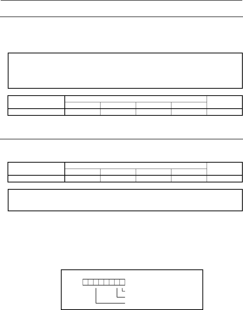
B-64513EN/03
2.PMC SPECIFICATIONS
- 95 -
2.2.3
Internal Relay Addresses (R)
These addresses are a work area used in sequence programs.
Signals that interface with other control units can be assigned to these bytes over the FA network. It can
also be used as the interface with the C language executor and FOCAS2 functions.
Turning on the power clears these areas to 0.
NOTE
This address is not synchronized in the 2nd level ladder. A value of a signal in
this address may change during the execution of 2nd level ladder same as 1st
and 3rd level ladder when it is written by other program (Ex. Network function, C
language executor).
Data kind 1st to 5th path PMC DCSPMC
PMC Memory-A PMC Memory-B PMC Memory-C PMC Memory-D
User area R0 to R1499 R0 to R7999 R0 to R15999 R0 to R59999 R0 to R1499
2.2.4
System Relay Addresses (R9000, Z0)
These addresses are a system information area. The area cannot be written from sequence programs.
Table 2.2.4 Address of System Relay
Data kind 1st to 5th path PMC DCSPMC
PMC Memory-A PMC Memory-B PMC Memory-C PMC Memory-D
System relays R9000 to R9499 R9000 to R9499 Z0 to Z499 Z0 to Z499 R9000 to R9499
NOTE
1 The address conversion of the System Relays is necessary when a Sequence
Program is changed between PMC Memory-A/B and PMC Memory-C/D.
Operation results of functional instructions
This area holds information necessary for individual ladder levels, such as the operation results of
functional instructions. This information is saved/restored when the task is switched.
(1) R9000, Z0 (operation output register for the ADDB, SUBB, MULB, DIVB, and COMPB functional
instructions)
1032
54
7 6
R9000
Z0
The result is negative.
The result is 0.
The result has overflowed.
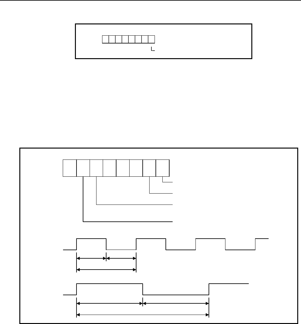
2.PMC SPECIFICATIONS
B-64513EN/03
- 96 -
(2) R9000, Z0 (error output for the EXIN, WINDR, and WINDW functional instructions)
1032
54
7 6
R9000
Z0
The result is erroneous.
(3) R9002 to R9005, Z2 to Z5 (operation output registers for the DIVB functional instruction)
The remainder of a division performed with the DIVB functional instruction is output to these
addresses.
System timers
Four signals can be used as system timers.
Their specifications are as follows.
(1) The case that the 1st level execution cycle is 1, 2 or 4ms.
R9091
Z91
10325 4 7 6
Constantly OFF signal
Constantly ON signal
200 ms cyclic signal
(100 ms ON and 100 ms OFF)
1 sec cyclic signal
(500 ms ON and 500 ms OFF)
R9091.5
Z91.5
100 ms
200 ms
100 ms
R9091.6
Z91.6
500 ms
1 sec
500 ms
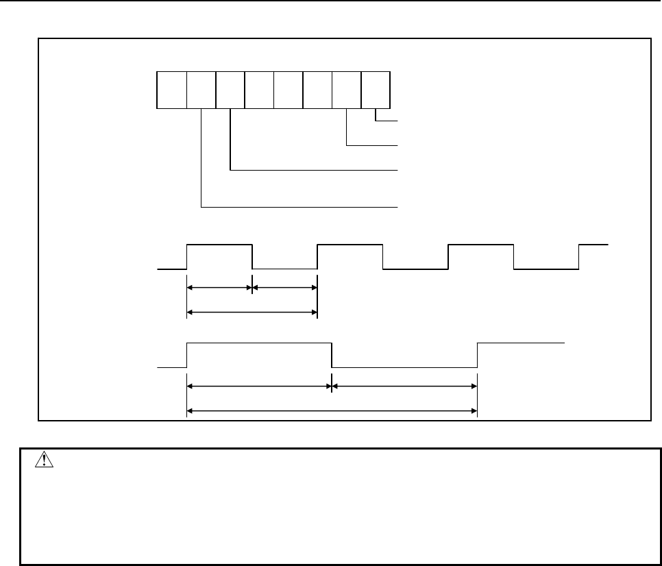
B-64513EN/03
2.PMC SPECIFICATIONS
- 97 -
(2) The case that the 1st level execution cycle is 8ms.
CAUTION
1 Each signal is initially OFF.
2 The signals R9091.0, R9091.1, Z91.0 and Z91.1 are set at the beginning of the
1st level of ladder on every cycle.
3 Each pulse signal (ON-OFF signal) may have an error of ±1, 2, 4 or 8 ms (ladder
execution cycle).
R9091
Z91
10325 47 6
Constantly OFF signal
Constantly ON signal
200 ms cyclic signal
(104 ms ON and 96 ms OFF)
1 sec cyclic signal
(504 ms ON and 496 ms OFF)
R9091.5
Z91.5
104 ms
200 ms
96 ms
R9091.6
Z91.6
504 ms
1 sec
496 ms
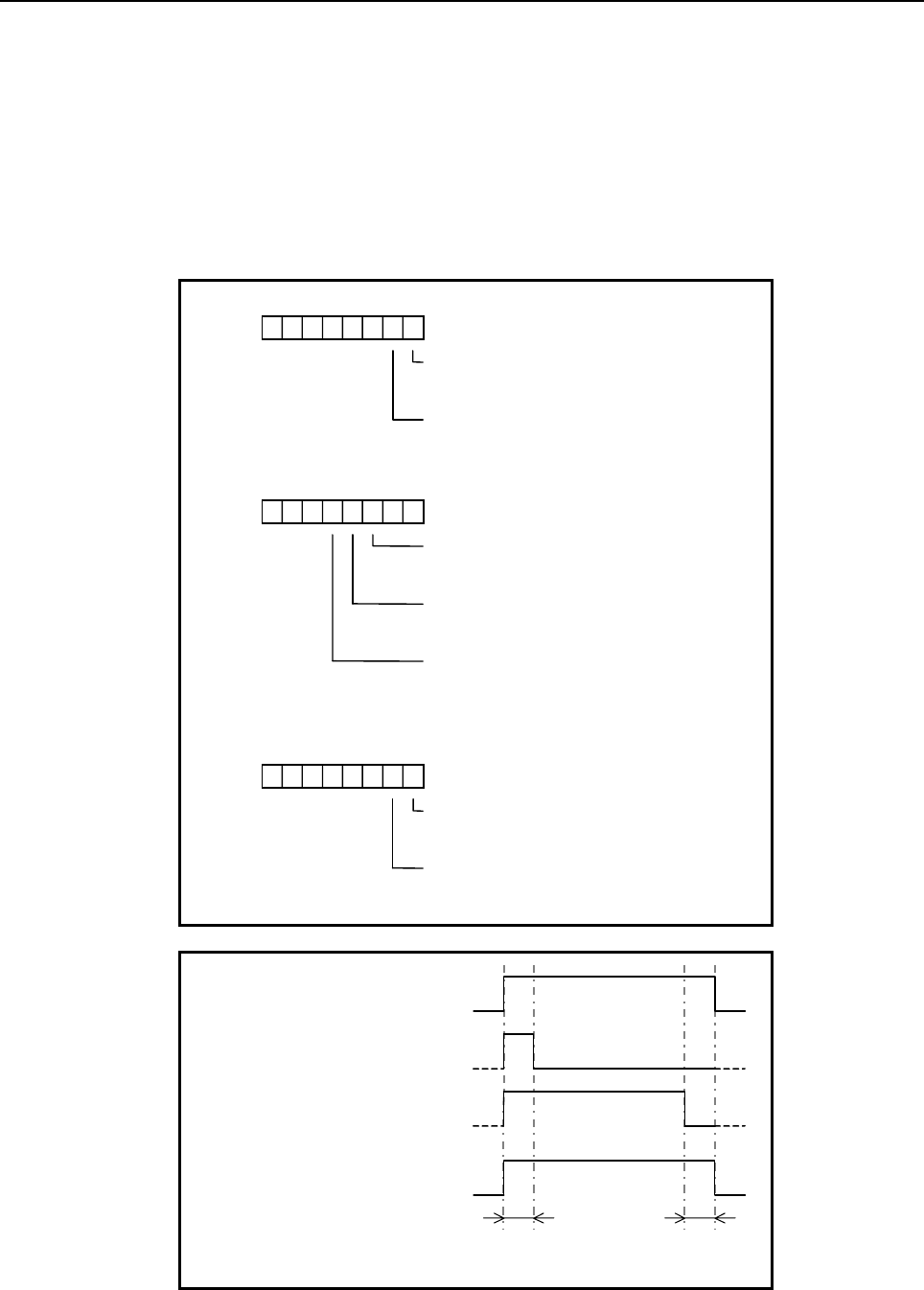
2.PMC SPECIFICATIONS
B-64513EN/03
- 98 -
Ladder execution start signal
Ladder stop signal
Ladder execution status signal
Using the ladder execution start and stop signals in a ladder program can detect when the ladder program
starts and stops.
Referencing the ladder execution status signal from an external system or program, such as the network
board, C Language executor program, FOCAS2 Ethernet, or HSSB library, can detect the execution status
of the ladder program.
103 25 4 7 6
R9015
Z15
Ladder stop signal
(can be referenced only from the Ladder
program)
Ladder execution start signal
(can be referenced only from the Ladder
program)
103 25 4 7 6
R9091
Z91
1st Ladder execution status signal
0 : Ladder at a stop
1 : Ladder being executed
2nd Ladder execution status signal
0 : Ladder at a stop
1 : Ladder being executed
3rd Ladder execution status signal
0 : Ladder at a stop
1 : Ladder being executed
103 2
5 4
7 6
R9093
Z93
4th Ladder execution status signal
0 : Ladder at a stop
1 : Ladder being executed
5th Ladder execution status signal
0 : Ladder at a stop
1 : Ladder being executed
RUN
STOP
Execution status of Ladder
Ladder execution status signal
(R9091.2 to 4, R9093.0 to 1
Z91.2 to 4, Z93.0 to 1)
Ladder execution start signal
(R9015.0, Z15.0)
Ladder stop signal
(R9015.1, Z15,1)
1
0
1
0
1
0
One ladder
scan cycle
One ladder
scan cycle

B-64513EN/03
2.PMC SPECIFICATIONS
- 99 -
(1) Ladder execution start signal (R9015.0, Z15.0)
When directed to start ladder program execution, the system software starts executing the ladder
program, turns on this signal, and keeps it on for the first one scan cycle. Like R9000 and Z0, this
signal indicates the status of ladder execution corresponding to each ladder execution level. For
this reason, this signal is securely turned on for the first one scan cycle after the start of execution no
matter on what execution level the signal is referenced. This signal is turned on when:
(a) Ladder execution begins at power turn-on.
(b) The [RUN] soft key on the PMC screen is pressed.
(c) FANUC LADDER-III or a ladder editing package directs the ladder to start.
Referring this signal in a ladder program can detect when ladder execution has begun, making it
possible to program preprocessing related to ladder execution.
CAUTION
This signal can be referred only from the ladder program. Do not refer to it from
an external system or program, such as the network board, the C Language
executor program or the PMC signal trace function, as it indicates the status of
ladder execution separately for each ladder execution level.
(2) Ladder stop signal (R9015.1, Z15.1)
When directed to stop ladder program execution, the system software turns off this signal and keeps
it off for the last one scan before stopping ladder program execution. Like R9000 and Z0, this
signal indicates the status of ladder execution corresponding to each ladder execution level. For
this reason, this signal is securely turned off for the last one scan before the stop of execution no
matter on what execution level the signal is referenced. This signal is turned off when:
(a) The [STOP] soft key on the PMC screen is pressed.
(b) FANUC LADDER-III or a ladder editing package directs the ladder to stop.
(c) On the PMC DATA I/O screen, the ladder program is loaded to the PMC.
(d) FANUC LADDER-III or a ladder editing package stores the ladder program to the PMC.
Referencing this signal in a ladder program can detect when ladder execution stops, making it
possible to program post processing related to ladder execution (that is, preprocessing for ladder
execution stop). Before the ladder is stopped, for example, it is possible to put signals in a proper
state for safety purposes.
CAUTION
1 This signal can be referred only from the ladder program. Do not refer to it from
an external system or program, such as the network board, the C Language
executor program or the PMC signal trace function, as it indicates the status of
ladder execution separately for each ladder execution level.
2 If the power is turned off or a CNC system alarm occurs, ladder execution and I/O
signal transfer are immediately stopped for safety purposes. In this case,
therefore, this signal cannot be used.
NOTE
This signal is not turned off in above-mentioned (c) and (d) on the setting that a
ladder program can be updated without stopping the ladder program (CNC
parameter No.11933#5 = 1). For details of the parameter, refer to “2.4.3”.
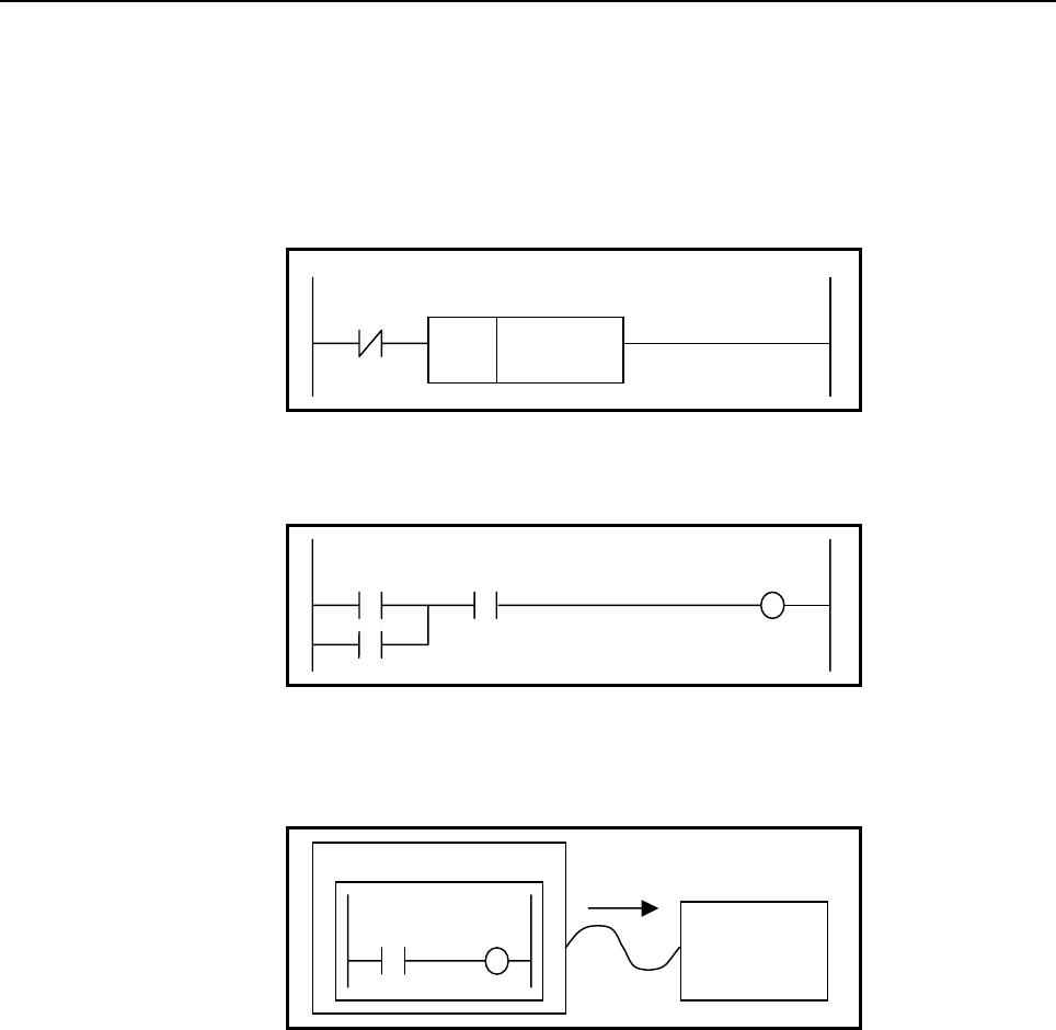
2.PMC SPECIFICATIONS
B-64513EN/03
- 100 -
(3) Ladder execution status signal (R9091.2 to 4, R9093.0 to 1, Z91.2 to 4, Z93.0 to 1)
Referring this signal from an external system or program, such as the network board, C language
executor program, FOCAS2 Ethernet, or HSSB library, can detect the execution status of the ladder
program.
(4) Example of using the signals
(a) Example of calling a subprogram just before the ladder stops
R9015.1
(Z15.1)
SUB65
CALL
Pxxxx
(b) Example of forcibly turning off an output signal programmed on the first ladder level just
before the ladder stops
Input
R9015.1
(Z15.1) Output
(c) Example of sending an execution-in-progress signal to the outside
Outputting the status of this signal as the DO signal (output address from the PMC) assigned to
the I/O Link causes the CNC unit to be interlocked with an external system.
CNC Unit
I/O Link slave
Y0.0
R9015.1
(Z15.1)
Y0.0
I/O Link
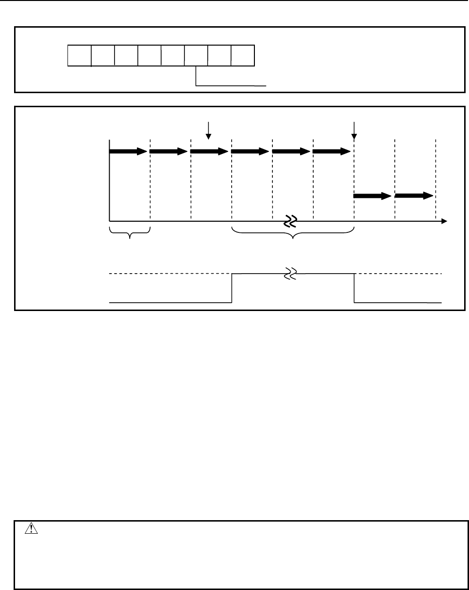
B-64513EN/03
2.PMC SPECIFICATIONS
- 101 -
Ladder update notification signal
When the updating of a ladder program is directed, the system software turns on the ladder update
notification signal and keeps it on until the updating of the ladder program is completed. The signal is
turned on in the following case.
(a) A ladder program is edited on the PMC ladder editing function.
(b) A ladder program is edited on the online editing function of FANUC LADDER-III or Ladder
Editing Package.
When CNC parameter No.11933#5 = 1, the setting that a ladder program can be updated without stopping
the ladder program, this signal is also turned on in the following case.
(c) On the PMC DATA I/O screen, the ladder program is loaded to the PMC.
(d) FANUC LADDER-III or Ladder Editing Package stores a ladder program to the PMC.
To refer to the signal in a ladder program, the update timing of the ladder program can be detected.
Therefore, you can program some procedures which are necessary to update the ladder program. For
example, you can program a procedure which makes the machine a status of the emergency stop.
CAUTION
The signal can be referred only from the ladder program. Do not refer to it from an
external system or program, such as the network board, the C Language
executor program or the PMC signal trace function, as it indicates the status of
ladder execution separately for each ladder execution level.
One ladder
scan cycle
Updating
Beginning of update
Time
1
0
Execution of
ladder program
after updating
Completion of update
Execution of
ladder program
before updating
Ladder update
notification signal
(R9015.2、Z15.2)
R9015
Z15
0123 4 5 6 7
Ladder update notification signal
2.PMC SPECIFICATIONS
B-64513EN/03
- 102 -
NOTE
1 The period that the signal has being turned on, is not fixed. It depends on the size
of the ladder program, etc.
2 When using the ladder dividing management function, the signal is valid in all the
ladder programs.
3 When using the multi-path PMC function, the signal is valid in only the program of
the PMC path, and invalid in other PMC paths.
PMC alarm / warning status
You can know the status of the alarm and warning of PMC.
(1) 1st PMC to 5th PMC
R9080
Z80
103 25 4 7 6
Alarm / warning occurrence state of the 1st PMC
0 : No alarm / warning
1 : Alarm / warning occurs
R9130
Z130
103 25 4 7 6
Alarm / warning occurrence state of the 2nd PMC
0 : No alarm / warning
1 : Alarm / warning occurs
R9144
Z144
103 25 4 7 6
Alarm / warning occurrence state of the 3rd PMC
0 : No alarm / warning
1 : Alarm / warning occurs
R9158
Z158
103 25 4 7 6
Alarm / warning occurrence state of the 4th PMC
0 : No alarm / warning
1 : Alarm / warning occurs
R9304
Z304
103 25 4 7 6
Alarm / warning occurrence state of the 5th PMC
0 : No alarm / warning
1 : Alarm / warning occurs
(2) DCSPMC
R9080
Z80
103 25 4 7 6
Alarm / warning occurrence state of the DCSPMC
0 : No alarm / warning
1 : Alarm / warning occurs

B-64513EN/03
2.PMC SPECIFICATIONS
- 103 -
I/O Link i Status Alarm: detected abnormalities information
You can know the status alarm of the I/O Link i.
Channel 1: R9268 to R9275 (Z268 to Z275)
Channel 2: R9276 to R9283 (Z276 to Z283)
Refer to "Status Alarm" of each CNC model's CONNECTION MANUAL (HARDWARE) for more
information.
NOTE
1 The status alarm is not cleared until you turn off the power.
2 The information output to the system relay area is only one group per a channel.
The group is that the status alarm is most detected first.
3 The address of status alarm is the common address regardless of the PMC path. it
is the same address in all of the PMC paths including the DCSPMC.
2.PMC SPECIFICATIONS
B-64513EN/03
- 104 -
2.2.5
Extra Relay Addresses (E)
These addresses are a work area used in sequence programs. When using the multi-path PMC function,
the area becomes a common memory. The same value can be read and written in sequence programs of
each PMC path.
Extra relays can be used in the same manner as for internal relays.
Signals that interface with other control units can be assigned to these bytes over the FA network. It can
also be used as the interface with the C language executor and FOCAS2 functions.
Turning on the power clears this area to 0. (Note2)
NOTE
1 These addresses are not synchronized in the 2nd level ladder. A value of a signal
in these addresses may change during the execution of 2nd level ladder same as
1st and 3rd level ladder when it is written in other program (Ex. Network function,
C language executor).
2 The extra relay addresses (E) can be optionally configured as nonvolatile.
When they are nonvolatile, turning off the power does not erase the memory
contents.
Table 2.2.5 Address of Extra Relay
Data kind 1st to 5th path PMC DCSPMC
PMC Memory-A PMC Memory-B PMC Memory-C PMC Memory-D
Extra relays E0 to E9999 E0 to E9999 E0 to E9999 E0 to E9999 -
System Keep Relays related to Extra Relays
The following system keep relays have influence on managing extra relays.
K906.3 EOUTPUT (Available on 1st PMC only)
0: On the I/O screen, the E address is output when PMC parameters are output.
1: On the I/O screen, the E address is not output when PMC parameters are output.
K906.7 EXRELAYCTLOUT (Available on 1st PMC only)
0 : Extra relay control data will not be included in PMC parameter output.
1 : Extra relay control data will be included in PMC parameter output.
K909.5 EXRELAYSCRENBL (Available on 1st to 5th PMC)
0 : Data table screen does not show extra relays.
1 : Data table screen shows extra relays also.
Control data for Extra Relay
Similarly to the data table (D) address, extra relays can be displayed and modified in proper format for
their usage by extra relay control data. To enable the extra relay control data, set 1 to system keep relay
K909.5, and it will reveal the soft key to reach EXTRA RELAY CONTROL screen in DATA TABLE
CONTROL screen, and one to reach EXTRA RELAY screen in DATA TABLE screen.
(1) Extra relay control configuration
Extra relays can be displayed and modified in EXTRA RELAY screen. You can change the data
format (such as “Binary” or “BCD”) and the size of each extra relay group, using the extra relay
control data.
The extra relay control data are not accessible from the sequence program. However, they can be
stored and loaded to/from a memory card as a part of a PMC parameter file.
General configuration of extra relays controlled by extra relay control data is shown in figure 2.2.5
(a), and its details in figure 2.2.5 (b).

B-64513EN/03
2.PMC SPECIFICATIONS
- 105 -
NOTE
1 Although an address of odd number can be set to the start address of an extra
relay table, it is not recommended because the functional instructions such as
DSCHB work faster at even addresses than at odd addresses.
2 Extra relays (E) can be included only in PMC parameter output from 1st PMC. If
you set 1 to the system keep relay K906.3, no information of extra relays is
included in PMC parameter output.
3 You have an option on the format of the extra relays when you include the extra
relays in the PMC parameter output. See “2.3.2 PMC Parameter Format” for the
detail of the format of the extra relays.
4 Even if the extra relays are not configured as non-volatile memory, their control
data are non-volatile.
(2) Table control data
Table control data are the data to control the extra relay tables.
Unless these data are properly set, you can not properly view or edit the contents of extra relay tables
described in (3) below.
First, you configure the table control data properly, referring to the explanation in this section.
You can reach EXTRA RELAY CONTROL screen by [EXTRA RELAY] soft key in DATA
TABLE CONTROL screen. The soft key is displayed when 1 is set to the system keep relay
K909.5.
(a) Number of table groups
Set number of groups that you are planning to divide the extra relays. The maximum number is
100.
(b) Table group 1 control data – Table group n control data
Each extra relay table has its table control data. Each table control data consists of the same
items; table start address, table parameter, data type, and the number of data items.
(i) Table start address
This item decides the start address of the area used for each extra relay table.
(ii) Table parameter
#7 #6 #5 #4 #3 #2 #1 #0
SIGN HEX MASK COD
COD
0: Data in this table are displayed in binary format.
1: Data in this table are displayed in BCD format.
MASK
0: The contents of this table are not protected.
1: The contents of this table are protected.
HEX
0: Data in this table are displayed in binary or BCD format. (COD is effective)
1: Data in this table are displayed in hexadecimal format.
SIGN
0: Data in this table are displayed as signed numbers.
1: Data in this table are displayed as unsigned numbers.
NOTE
1 The setting of COD (bit 0) is effective when HEX (bit 2) = 0.
2 The setting of SIGN (bit 3) is effective when COD (bit 0) = 0 and HEX (bit 2) = 0.
2.PMC SPECIFICATIONS
B-64513EN/03
- 106 -
(iii) Data type
This item decides the length of data in this table.
0 : 1 byte length
1 : 2 bytes length
2 : 4 bytes length
3 : 8 bits
(iv) Number of data items
This item decides the number of data items in this table.
(3) Extra relay table
You can create groups of extra relays dividing the area of extra relays (E address).
“Number of table groups” in the table control data decides the number of these groups of extra
relays.
You can reach EXTRA RELAY screen by [EXTRA RELAY] soft key in DATA TABLE screen.
The soft key is displayed when 1 is set to the system keep relay K909.5.
2.2.6
Message Display Addresses (A)
These addresses are areas used for requesting a message display and outputting a message status.
See descriptions about the DISPB functional instruction in Chapter 4 for explanations about how to use
this area.
Turning on the power clears this area to 0.
Table 2.2.6 Address of Message display
Data kind 1st to 5th path PMC DCSPMC
PMC Memory-A PMC Memory-B PMC Memory-C PMC Memory-D
Message display request
(points)
A0 to A249
(2,000 points)
A0 to A249
(2,000 points)
A0 to A499
(4,000 points)
A0 to A749
(6,000 points)
-
Message display status A9000 to A9249 A9000 to A9249 A9000 to A9499 A9000 to A9749 -
2.2.7
Timer Addresses (T)
These addresses are areas for setting values and the precision of variable timers (the TMR instruction).
The memory contents are kept even if turning off the power.
Table 2.2.7 Address of variable timer
Data kind 1st to 5th path PMC DCSPMC
PMC Memory-A PMC Memory-B PMC Memory-C PMC Memory-D
Variable timer
(Number of timers)
T0 to T79
(40 pieces)
T0 to 499
(250 pieces)
T0 to T999
(500 pieces)
T0 to T999
(500 pieces)
T0 to T79
(40 pieces)
precision T9000 to T9079 T9000 to 9499 T0 to T9999 T0 to T9999 T9000 to T9079
B-64513EN/03
2.PMC SPECIFICATIONS
- 107 -
2.2.8
Counter Addresses (C)
These addresses are areas used for variable counters (the CTR instruction) and fixed counters (the CTRB
instruction).
The memory contents are kept even if turning off the power.
Table 2.2.8 Address of counters
Data kind 1st to 5th path PMC DCSPMC
PMC Memory-A PMC Memory-B PMC Memory-C PMC Memory-D
Variable counter
(Number of counters)
C0 to C79
(20 pieces)
C0 to C399
(100 pieces)
C0 to C799
(200 pieces)
C0 to C1199
(300 pieces)
C0 to C79
(20 pieces)
Fixed counter
(Number of counters)
C5000 to C5039
(20 pieces)
C5000 to C5199
(100 pieces)
C5000 to C5399
(200 pieces)
C5000 to C5599
(300 pieces)
C5000 to C5039
(20 pieces)
2.2.9
Keep Relay Addresses (K)
These addresses are a work area in which data are kept even if turning the power off.
Table 2.2.9 Address of keep relays
Data kind 1st to 5th path PMC DCSPMC
PMC Memory-A PMC Memory-B PMC Memory-C PMC Memory-D
Keep relays K0 to K19 K0 to K99 K0 to K199 K0 to K299 K0 to K19
2.2.10
Nonvolatile Memory Control Address (K)
This address is intended to be used in, for example, the configuration in which the position of a movable
mechanical part (such as a lathe turret) is stored as code data (such as BCD) to nonvolatile memory to
preserve the current machine position even when the power is turned off.
#7 #6 #5 #4 #3 #2 #1 #0
K909 MWRTF2 MWRTF
On the KEEP RELAY screen, it is possible to set and display the address of the nonvolatile memory. It
is also possible for a sequence program to read or write the address.
If the power is accidentally turned off when the turret is rotating, the turret stops at an unexpected
position and a mismatch occurs between the current position stored in the memory and the actual turret
position. When the power is resumed and a normal operation begins, the mismatch results in an
incorrect sequence operation.
To prevent such a malfunction, make a check by using nonvolatile memory control in a sequence program
as follows:
(1) Write "1" to MWRTF for the nonvolatile memory control before the turret starts moving.
(2) Start the turret.
(3) After the turret has stopped, reset MWRTF to "0".
(4) If the power is turned off after the turret has started, therefore, MWRTF stays at "1".
(5) When the CNC power is turned on, MWRTF2 is set to "1" automatically if MWRTF is "1", thus
informing the sequence program of the failure.
To sum up, the sequence program performs steps (1) to (4) and checks for an abnormal condition,
using MWRTF2. If an abnormal condition (NWRTF2 = 1) is detected, an alarm is raised to the
operator, using a user-created alarm output program.
2.PMC SPECIFICATIONS
B-64513EN/03
- 108 -
(6) Recognizing the alarm, the operator resets MWRTF and MWRTF2 to "0" on the KEEP RELAY
screen.
(7) After making the memory content match the actual turret position, restart operation.
2.2.11
System Keep Relay Addresses (K)
These addresses are an area for the setting of PMC system.
The memory contents are kept even if turning off the power.
Table 2.2.11 Address of System keep relay
Data kind 1st to 5th path PMC DCSPMC
PMC Memory-A PMC Memory-B PMC Memory-C PMC Memory-D
System keep relays K900 to K999 K900 to K999 K900 to K999 K900 to K999 K900 to K999
Explained below is the meaning of each bit of the system keep relay address. The bits and addresses left
unused are reserved for use by the system.
The system keep relays indicated with an asterisk (*) can be set up, using setting parameters.
#7 #6 #5 #4 #3 #2 #1 #0
K900
DTBLDSP MEMINP AUTORUN PRGRAM LADMASK
[Data type] Bit
LADMASK PMC program view inhibit(*)
0: The sequence program is allowed to be viewed.
1: The sequence program is inhibited from being viewed.
PRGRAM Programmer function enable(*)
0: The built-in programmer function is disabled.
1: The built-in programmer function is enabled.
AUTORUN PMC program execute(*)
0: The sequence program is automatically started when the power is turned on.
1: The sequence program is started, using the sequence program execution soft key.
MEMINP Memory write permit(*)
0: The forcing and override functions are disabled.
1: The forcing and override functions are enabled.
NOTE
Using the override function requires setting "Override enable" (K906.0).
DTBLDSP Data table GRP setting display(*)
0: The DATA TABLE CONTROL screen is displayed.
1: The DATA TABLE CONTROL screen is not displayed.
#7 #6 #5 #4 #3 #2 #1 #0
K901 EDTENBL
[Data type] Bit
EDTENBL Editing permit(*)
0: The sequence program is inhibited from being changed.
1: The sequence program is allowed to be changed.
B-64513EN/03
2.PMC SPECIFICATIONS
- 109 -
#7 #6 #5 #4 #3 #2 #1 #0
K902 PROTPRM HIDEPRM ALLWSTOP FROM-WRT
[Data type] Bit
FROM-WRT Save after edit(*)
0: After being edited, the sequence program is not automatically written to flash ROM.
1: After being edited, the sequence program is automatically written to flash ROM.
ALLWSTOP PMC stop enable(*)
0: The sequence program is inhibited from being started/stopped.
1: The sequence program is allowed to be started/stopped.
HIDEPRM PMC parameter view inhibit(*)
0: PMC parameters are allowed to be displayed and sent to the outside.
1: PMC parameters are inhibited from being displayed or sent to the outside.
PROTPRM PMC parameter change inhibit(*)
0: PMC parameters are allowed to be changed and read.
1: PMC parameters are inhibited from being changed or read.
#7 #6 #5 #4 #3 #2 #1 #0
K903 CLRATVAR CLRFBVAR ASKPASS
SYMEX
DISP
[Data type] Bit
SYMEXDISP Displaying type of Additional Information Line when using Basic type of Symbol and
Comment data.
0: Displays Symbol and Comment with fixed length.
1: Displays left justified Symbol and Comment with flexible length (like an Extended
type Symbol and Comment data).
Fig. 2.2.11 (a) Additional Information Line with K903.1=0
Fig. 2.2.11 (b) Additional Information Line with K903.1=1
NOTE
To make the setting of K903.1 effective, turn off and on power of the CNC.
ASKPASS Asking for password
0: You are asked to enter password for the program protected by password.
1: You are not asked to enter password for the program protected by password.
CLRFBVAR Initialization of FB variable area at updating sequence program
0: Clear FB variable area when FB variable is changed.
1: Not clear FB variable area.
NOTE
Refer to “11.1.4 Assignment of FB variable” about address assignment of FB
variable.

2.PMC SPECIFICATIONS
B-64513EN/03
- 110 -
CLRATVAR Initialization of the memory area for automatic address assignment at updating sequence
program
0: Not clear the area to which addresses are assigned automatically.
1: Clear the area to which addresses are assigned automatically when changing symbol
data other than FB variable.
NOTE
Refer to “(6) Automatic address assignment at compiling on FANUC LADDER-III”
of “1.2.7 Extension of a symbol and comment” about automatic address
assignment.
#7 #6 #5 #4 #3 #2 #1 #0
K906
EXRELAY
CTLOUT KEEPSYS TRCST EOUTPUT IOLNKCHK IOGRPSEL OVRRID
[Data type] Bit
OVRRID Override enable(*)
0: The override function is disabled.
1: The override function is enabled.
NOTE
Using the override function requires setting "Memory write permit" (K900.4).
IOGRPSEL IO GROUP SELECTION screen(*)
0: The selectable I/O Link assignment function setting screen is not displayed.
1: The selectable I/O Link assignment function setting screen is displayed.
IOLNKCHK
0: The I/O Link / I/O Link i connection check function is enabled.
1: The I/O Link / I/O Link i connection check function is disabled.
EOUTPUT (Available only on 1st PMC)
0: On the I/O screen, the E address is output when PMC parameters are output.
1: On the I/O screen, the E address is not output when PMC parameters are output.
TRCST Trace function start(*) (Available only on 1st PMC)
0: The trace function is not executed when the power is turned on.
1: The trace function is automatically executed when the power is turned on.
KEEPSYS KEEP RELAY (SYSTEM) (*)
0: The KEEP RELAY (K900-K919) screen is not displayed.
1: The KEEP RELAY (K900-K919) screen is displayed..
EXRELAYCTLOUT
(Available only on 1st PMC)
0: Extra relay control data will not be included in PMC parameter output.
1: Extra relay control data will be included in PMC parameter output.
#7 #6 #5 #4 #3 #2 #1 #0
K907 IOCNFEDT
[Data type] Bit
IOCNFEDT Editing of I/O configuration data (*) (Available only on 1st PMC)
0: Forbids editing of I/O configuration data.
1: Allows editing of I/O configuration data.
B-64513EN/03
2.PMC SPECIFICATIONS
- 111 -
#7 #6 #5 #4 #3 #2 #1 #0
K909 MWRTF2 MWRTF
EXRELAY
SCRENBL
LADSET
INDPNT
[Data type] Bit
LADSETINDPNT
0: All PMC paths use a common configuration of Ladder diagram display format.
1: Each PMC path uses an individual configuration of Ladder diagram display format.
EXRELAYSCRENBL
0: Data table screen does not show extra relays.
1: Data table screen shows extra relays also.
MWRTF For nonvolatile memory control. See Subsection “2.2.10”.
MWRTF2 For nonvolatile memory control. See Subsection “2.2.10”.
K916 Message shift start address (LOW)
K917 Message shift start address (HIGH)
Message shift start address(*)
[Valid data range] Range of the A addresses
This area is used to specify the message shift start address value (word type) by
converting it to bit data form.
The bit offset for the A addresses is calculated as follows:
A address Calculation Bit offset
Ax.y x × 8 + y = z
Example:
A0.0 0 × 8 + 0 = 0
A249.7 249 × 8 + 7 = 1999
K918 Message shift amount (LOW)
K919 Message shift amount (HIGH)
Message shift amount(*)
[Valid data range] 1 to 9999
This area is used to specify the message shift amount value (word type) by converting it
to bit data form.
#7 #6 #5 #4 #3 #2 #1 #0
K920 Group 7 Group 6 Group 5 Group 4 Group 3 Group 2 Group 1 Group 0
[Data type] Bit
Group 0 to 7 For the selectable I/O Link assignment function, whether to enable or disable assignment
of group 0 to 7 to addresses X/Y0 to X/Y127 is specified. (*)
0: Assignment of each group to the corresponding bit position is disabled.
1: Assignment of each group to the corresponding bit position is enabled

2.PMC SPECIFICATIONS
B-64513EN/03
- 112 -
#7 #6 #5 #4 #3 #2 #1 #0
K921
Group 15 Group 14 Group 13 Group 12 Group 11 Group 10 Group 9 Group 8
[Data type] Bit
Group 8 to 15 For the selectable I/O Link assignment function, whether to enable or disable assignment
of group 8 to 15 to addresses X/Y0 to X/Y127 is specified. (*)
0: Assignment of each group to the corresponding bit position is disabled.
1: Assignment of each group to the corresponding bit position is enabled.
#7 #6 #5 #4 #3 #2 #1 #0
K922
Group 15 Group 14 Group 13 Group 12 Group 11 Group 10 Group 9 Group 8
[Data type] Bit
Group 0 to 7 For the selectable I/O Link assignment function, whether to enable or disable assignment
of group 0 to 7 to addresses X/Y200 to X/Y327 is specified. (*)
0: Assignment of each group to the corresponding bit position is disabled.
1: Assignment of each group to the corresponding bit position is enabled.
#7 #6 #5 #4 #3 #2 #1 #0
K923
Group 15 Group 14 Group 13 Group 12 Group 11 Group 10 Group 9 Group 8
[Data type] Bit
Group 8 to 15 For the selectable I/O Link assignment function, whether to enable or disable assignment
of group 8 to 15 to addresses X/Y200 to X/Y327 is specified. (*)
0: Assignment of each group to the corresponding bit position is disabled.
1: Assignment of each group to the corresponding bit position is enabled.
#7 #6 #5 #4 #3 #2 #1 #0
K924 Group 7 Group 6 Group 5 Group 4 Group 3 Group 2 Group 1 Group 0
[Data type] Bit
Group 0 to 7 For the selectable I/O Link assignment function, whether to enable or disable assignment
of group 0 to 7 to addresses X/Y400 to X/Y527 is specified. (*)
0: Assignment of each group to the corresponding bit position is enabled.
1: Assignment of each group to the corresponding bit position is enabled.
#7 #6 #5 #4 #3 #2 #1 #0
K925
Group 15 Group 14 Group 13 Group 12 Group 11 Group 10 Group 9 Group 8
[Data type] Bit
Group 8 to 15 For the selectable I/O Link assignment function, whether to enable or disable assignment
of group 8 to 15 to addresses X/Y400 to X/Y527 is specified. (*)
0: Assignment of each group to the corresponding bit position is disabled.
1: Assignment of each group to the corresponding bit position is enabled.
#7 #6 #5 #4 #3 #2 #1 #0
K926 Group 7 Group 6 Group 5 Group 4 Group 3 Group 2 Group 1 Group 0
[Data type] Bit
Group 0 to 7 For the selectable I/O Link assignment function, whether to enable or disable assignment
of group 0 to 7 to addresses X/Y600 to X/Y727 is specified. (*)
0: Assignment of each group to the corresponding bit position is disabled.
1: Assignment of each group to the corresponding bit position is enabled.

B-64513EN/03
2.PMC SPECIFICATIONS
- 113 -
#7 #6 #5 #4 #3 #2 #1 #0
K927
Group 15 Group 14 Group 13 Group 12 Group 11 Group 10 Group 9 Group 8
[Data type] Bit
Group 8 to 15 For the selectable I/O Link assignment function, whether to enable or disable assignment
of group 8 to 15 to addresses X/Y600 to X/Y727 is specified. (*)
0: Assignment of each group to the corresponding bit position is disabled.
1: Assignment of each group to the corresponding bit position is enabled.
#7 #6 #5 #4 #3 #2 #1 #0
K928
Group 7 Group 6 Group 5 Group 4 Group 3 Group 2 Group 1 Group 0
[Data type] Bit
Group 0 to 7 For the selectable I/O Link i assignment function, whether to enable or disable
assignment of group 0 to 7 of channel 1 is specified.
0: Assignment of each group to the corresponding bit position is disabled.
1: Assignment of each group to the corresponding bit position is enabled.
#7 #6 #5 #4 #3 #2 #1 #0
K929
Group 15 Group 14 Group 13 Group 12 Group 11 Group 10 Group 9 Group 8
[Data type] Bit
Group 8 to 15 For the selectable I/O Link i assignment function, whether to enable or disable
assignment of group 8 to 15 of channel 1 is specified.
0: Assignment of each group to the corresponding bit position is disabled.
1: Assignment of each group to the corresponding bit position is enabled.
#7 #6 #5 #4 #3 #2 #1 #0
K930
Group 23 Group 22 Group 21 Group 20 Group 19 Group 18 Group 17 Group 16
[Data type] Bit
Group 16 to 23 For the selectable I/O Link i assignment function, whether to enable or disable
assignment of group 16 to 23 of channel 1 is specified.
0: Assignment of each group to the corresponding bit position is disabled.
1: Assignment of each group to the corresponding bit position is enabled.
#7 #6 #5 #4 #3 #2 #1 #0
K932
Group 7 Group 6 Group 5 Group 4 Group 3 Group 2 Group 1 Group 0
[Data type] Bit
Group 0 to 7 For the selectable I/O Link i assignment function, whether to enable or disable
assignment of group 0 to 7 of channel 2 is specified.
0: Assignment of each group to the corresponding bit position is disabled.
1: Assignment of each group to the corresponding bit position is enabled.
#7 #6 #5 #4 #3 #2 #1 #0
K933
Group 15 Group 14 Group 13 Group 12 Group 11 Group 10 Group 9 Group 8
[Data type] Bit
Group 8 to 15 For the selectable I/O Link i assignment function, whether to enable or disable
assignment of group 8 to 15 of channel 2 is specified.
0: Assignment of each group to the corresponding bit position is disabled.
1: Assignment of each group to the corresponding bit position is enabled.
2.PMC SPECIFICATIONS
B-64513EN/03
- 114 -
#7 #6 #5 #4 #3 #2 #1 #0
K934
Group 23 Group 22 Group 21 Group 20 Group 19 Group 18 Group 17 Group 16
[Data type] Bit
Group 16 to 23 For the selectable I/O Link i assignment function, whether to enable or disable
assignment of group 16 to 23 of channel 2 is specified.
0: Assignment of each group to the corresponding bit position is disabled.
1: Assignment of each group to the corresponding bit position is enabled.
#7 #6 #5 #4 #3 #2 #1 #0
K935
REGIODEV SELPMC
[Data type] Bit
SELPMC Displaying PMC program list screen (Only the setting in the first path PMC is available.)
0: When pressing the [SWITCH PMC] soft key, selected sequence program switches.
1: When pressing the [SWITCH PMC] soft key, PMC program list screen is displayed.
Note
1 This soft key is displayed when using ladder dividing management function or
multi-path PMC function.
2 At 8-level protection setting screen, this soft key switches PMC path whether
K935.0=0 or 1.
When inputting PMC path number / divided number and pressing the [SWITCH PMC] soft key, it
becomes the following actions whether K935.0=0 or 1.
Operation Action
Inputting “PMC path number” and pressing
[SWITCH PMC]
It selects specified main ladder of PMC path.
Inputting “PMC path number” - “divided
number” and pressing [SWITCH PMC]
It selects specified divided ladder.
REGIODEV Register of I/O device configuration. (*) (Available only on 1st PMC)
0: Forbids register of I/O device configuration.
1: Allows register/deletion of I/O device configuration.
B-64513EN/03
2.PMC SPECIFICATIONS
- 115 -
2.2.12
Data Table Addresses (D)
These addresses are work areas in which data are kept even if turning the power off.
PMC sequence control sometimes requires a sizable amount of numeric data (hereinafter referred to as
data table). If the contents of a data table can be set or read freely, they can be used as various PMC
sequence control data, such as tool numbers of tools on the ATC magazine.
Each table can have an arbitrary size as long as it fits the data table memory, and 1-, 2-, and 4-byte binary
and BCD data can be used for each table separately; so it is possible to configure efficient, easy-to-use
tables.
Data in a data table can be set or displayed on the DATA TABLE screen.
Data set in data tables can also be easily read and written with the sequence program using functional
instructions such as data search (DSCHB) and index modification data transfer (XMOVB).
The following table lists the number of bytes that can be used.
Signals that interface with other control units can be assigned to these bytes over the FA network. It can
also be used as the interface with the C language executor and FOCAS2 functions.
NOTE
These addresses are not synchronized in the 2nd level ladder. A value of a signal
in these addresses may change during the execution of 2nd level ladder same as
1st and 3rd level ladder when it is written in other program (Ex. Network function,
C language executor).
Table 2.2.12 Address of Data table
Data kind 1st to 5th path PMC DCSPMC
PMC Memory-A PMC Memory-B PMC Memory-C PMC Memory-D
Data table D0 to D2999 D0 to D9999 D0 to D19999 D0 to D59999 D0 to D2999
NOTE
The basic nonvolatile area is 10,000bytes. To make a nonvolatile area of D10000
or more, you should specify the option “Nonvolatile PMC Data Table Area
Expansion (40KB)”. Refer to subsection “2.1.3” for details.

2.PMC SPECIFICATIONS
B-64513EN/03
- 116 -
(1) Data table configuration
The PMC data table consists of table control data and data tables. The table control data manages
the data form (binary or BCD) and size of each table.
Creating a data table requires first setting up table control data from the DATA TABLE CONTROL
screen.
The sequence program cannot read or write the table control data. If the USB memory, and so on,
are used to read or write the contents of the nonvolatile memory, however, the table control data is
read or written together.
NOTE
In some cases, the start address of a data table is odd. If an odd number of
1-byte data tables are created, for example, the start address of the next data
table may be odd. This setting is acceptable. However, an even start address
assures faster operations than an odd start address. We recommend you use
even start addresses whenever possible.
(2) Table control data
The table control data is used to manage data tables.
Unless this data is correctly set up, it is impossible to create data tables, explained in (3), correctly.
While referencing the descriptions in this item, first set up table control data and then data tables.
(a) Number of table groups
This item specifies how many groups are to form the data table, using a binary number.
(b) Table group 1 control data to table group n control data
Each data table is provided with table control data. The meaning of data (table start address,
table parameter, data type, and the number of data items) set up as table control data is the same
for all table groups.
(i) Table start address
This item specifies the start address of a data area used for each data table.
(ii) Table parameter
#7 #6 #5 #4 #3 #2 #1 #0
SIGN HEX MASK COD
COD
0: Data in the data table is in binary form.
1: Data in the data table is in BCD form.
MASK
0: The contents of the data table is not protected.
1: The contents of the data table is protected.
HEX
0: Data in the data table is in binary or BCD form.
1: Data in the data table is in HEX form.
SIGN
0: Data in the data table is signed.
1: Data in the data table is unsigned.
NOTE
1 The setting of COD (bit 0) is valid if HEX (bit 2) = 0.
2 The setting of SIGN (bit 3) is valid if COD (bit 0) = 0 and HEX (bit 2) = 0.
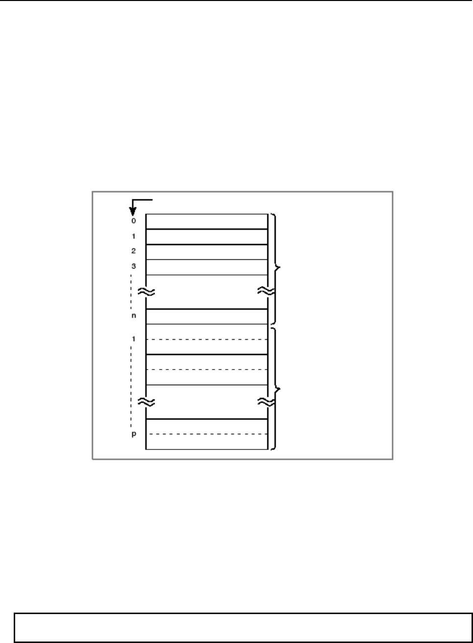
B-64513EN/03
2.PMC SPECIFICATIONS
- 117 -
(iii) Data type
This item specifies the length of data in the data table.
0 : 1 byte long
1 : 2 bytes long
2 : 4 bytes long
3 : 8 bits
(iv) Number of data items
This item specifies the number of data items in the data table.
(3) Data table
A data table can be divided into several groups, and each group can be created within the memory
range (address D) for the data table.
The number of groups is determined according to the number of table control data table groups.
Table group 1
(1-byte data)
Intra-table number
Table group 2
(2-byte data)
Data in each data table can be 1-, 2, or 4-byte data depending on the data type of the corresponding
table control data.
If the table data is 1-byte data, one intra-table number in the corresponding data table is assigned to
one byte of data. If the table data is 2-byte data, one intra-table number is assigned to two bytes of
data.
(4) Creating data for a data table
Data for a data table is created by specifying an intra-table number for the data table and entering the
data into the table from the DATA TABLE screen. A specific method for specifying intra-table
numbers is available for individual data table groups separately.
NOTE
The sequence program can also read and write the data table.
2.PMC SPECIFICATIONS
B-64513EN/03
- 118 -
2.2.13
Addresses for Multi-path PMC Interface (M, N)
These addresses are used to the Multi-path PMC interface area.
(1) Input signals from another PMC path
Data kind 1st to 3rd path PMC DCSPMC
PMC Memory-A PMC Memory-B PMC Memory-C PMC Memory-D
Input signals M0 to M767 M0 to M767 M0 to M767 M0 to M767 (unavailable)
(2) Output signals to another PMC path
Data kind 1st to 3rd path PMC DCSPMC
PMC Memory-A PMC Memory-B PMC Memory-C PMC Memory-D
Output signals N0 to N767 N0 to N767 N0 to N767 N0 to N767 (unavailable)
NOTE
These interfaces cannot be used in 4th and 5th path PMC.
2.2.14
Subprogram Number Addresses (P)
These addresses are subprogram number for specifying the subprogram.
The subprogram number is used in the CALL, CALLU and CM instructions and applied subprogram is
called.
Data kind 1st to 5th path PMC DCSPMC
PMC Memory-A PMC Memory-B PMC Memory-C PMC Memory-D
Subprogram number P1 to P512 P1 to P5000 P1 to P5000 P1 to P5000 P1 to P512
2.2.15
Label Number Addresses (L)
These addresses are label number for specifying the label (LBL instruction).
The label number is used in the JMPB and JMPC instructions and jumps to applied LBL instruction.
The same label number can be specified for different instructions as long as the instructions are not within
the same program unit (main program or subprogram).
Data kind 1st to 5th path PMC DCSPMC
PMC Memory-A PMC Memory-B PMC Memory-C PMC Memory-D
Label number L1 to L9999 L1 to L9999 L1 to L9999 L1 to L9999 L1 to L9999
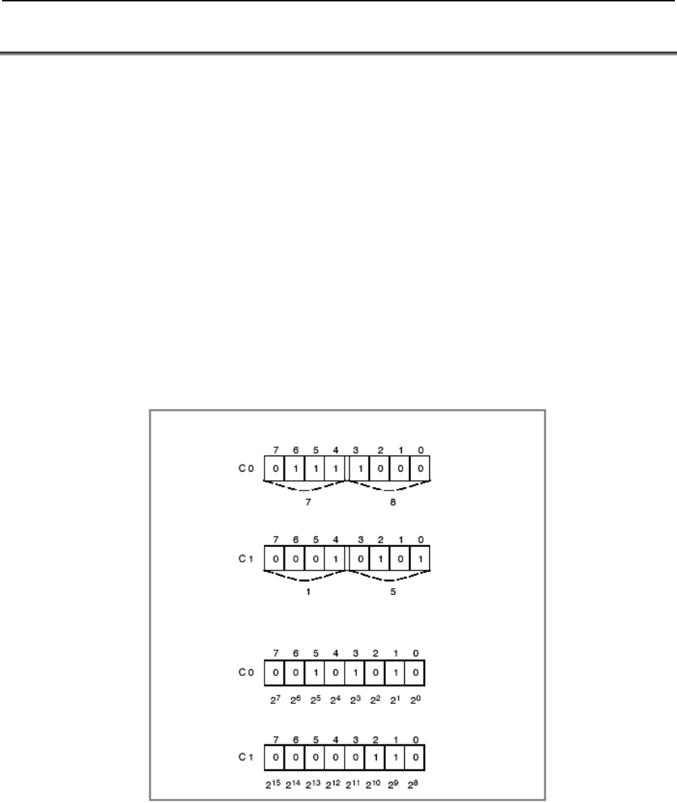
B-64513EN/03
2.PMC SPECIFICATIONS
- 119 -
2.3 PMC PARAMETERS
The term "PMC parameter" refers to any of the timer, counter, keep relay parameters, and data table.
PMC parameters are held in nonvolatile memory, whose contents are not lost even when the power is
turned off.
(1) Timer
This parameter specifies a timer value.
It is possible to set and display the timer value on the TIMER screen.
The sequence program can read and write the timer setting.
(2) Counter
This parameter is used for a counter preset value and cumulative value. It is possible to set and
display these values on the COUNTER screen. Sequence program instructions can also read and
write these settings. See Subsection 2.2.8 for details of the counter addresses.
Counter data is two bytes in ether BCD or binary form. Higher-order bits are held at higher
addresses. Whether the counter address is BCD or binary is determined according to the
corresponding PMC system parameter.
The default setting is binary form.
(Example) If the counter addresses of the PMC are C0 and C1, and the preset value is 1578
BCD format (1578)
Binary format (1578)
To change the lower digit of the preset value to a certain value, using a 1-byte processing instruction
in the sequence program, write the new data by specifying C0 with an output address in the
parameter of a functional instruction.
(3) Keep relay
This parameter is used for parameters for sequence control, keep relays, and others.
It can be set and displayed from the KEEP RELAY screen.
It can also be read and written, using instructions in the sequence program.

2.PMC SPECIFICATIONS
B-64513EN/03
- 120 -
The data set up or displayed from the KEEP RELAY screen is 8-bit binary data. On the KEEP
RELAY screen, therefore, each of the eighth digits is set or displayed as 0 or 1.
(4) Data table
The data table enables a set of numeric data (data table) to be used for PMC sequence control.
See Subsection “2.2.12”for details.
(5) Extra relay
Extra relays are volatile memory, which can be used as extension of ordinary internal relays, or as
common memory for the interface of PMC paths. Because the extra relays can be non-volatile by
option, and you can also use them as extension of data table or keep relays.
See “2.2.5 Extra Relay Addresses (E)” for more detail about extra relays.
2.3.1
Cautions for Reading from/Writing to Nonvolatile Memory
All data in the nonvolatile memory can be read and written with the sequence program. The memory
from which the sequence program reads and to which it writes is not nonvolatile in effect. It has the
same data as in the nonvolatile memory in a form of nonvolatile memory image (RAM). For this reason,
turning off the power lets the data of nonvolatile memory image disappear. However, data is sent from
the nonvolatile memory as nonvolatile memory image immediately after the power is resumed, thus
restoring the previous data correctly.
If the sequence program rewrites the nonvolatile memory image, the changed data is automatically sent to
the nonvolatile memory.
Data at more than one address in the nonvolatile memory image can be rewritten at any time. The
changed data is automatically sent to the nonvolatile memory.
Therefore, reading from and writing to the nonvolatile memory with the sequence program does not
require any special processing. Writing to the nonvolatile memory takes time (about 200 msec),
however.
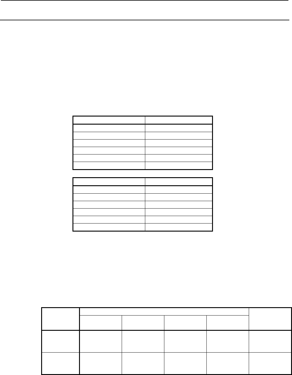
B-64513EN/03
2.PMC SPECIFICATIONS
- 121 -
2.3.2
PMC Parameter Format
This subsection describes the format used in outputting the contents of the PMC parameter to an external
device. As for the operation of output, refer to section 7 “sequence program and PMC parameter I/O”.
(1) Header information
The data begins with header information. Its format is as follows:
[Format]
%
(PMC = xxx, MSID = n)
PMC = xxx "xxx" is the model name of the PMC.
MSID = n "n" is ID information.
The following table lists values that can be set as "xxx" or "n".
PMC Series “xxx”
30i-B PMC 30I-B
31i-B PMC 31I-B
32i-B PMC 32I-B
35i-B PMC 35I-B
Power Motion i-A PMC PMI-A
0i-F PMC 0I-F
PMC Path “n”
1st path PMC 1
2nd path PMC 2
3rd path PMC 3
4th path PMC 4
5th path PMC 5
DCS PMC 9
(2) Timer (T)
[Format]
N60xxxx Pnnnnn;
N600xxxx Pnnnnn;
[Data Contents]
N60xxxx or N600xxxx : parameter number
Specify the sum of the timer address (T) offset and 600000 or 6000000. The number in the
following table can be used.
1st to 5th path PMC
DCSPMC
PMC
Memory-A
PMC
Memory-B
PMC
Memory-C
PMC
Memory-D
Timer setting
value
N600000
to
N600078
N600000
to
N600498
N600000
to
N600998
N6000000
to
N6000998
N600000
to
N600078
Timer
accuracy
N609000
to
N609078
N609000
to
N609498
N609000
to
N609998
N6009000
to
N6009998
N609000
to
N609078
Pnnnnn The numbers from N600000 mean the timer value
The unit of the value depends on the timer accuracy which are numbers from N609000.
For example, when the timer accuracy is 3(100ms) and this value is 5, the timer value
means 500ms. The range of effective value is from 0 to 32767.
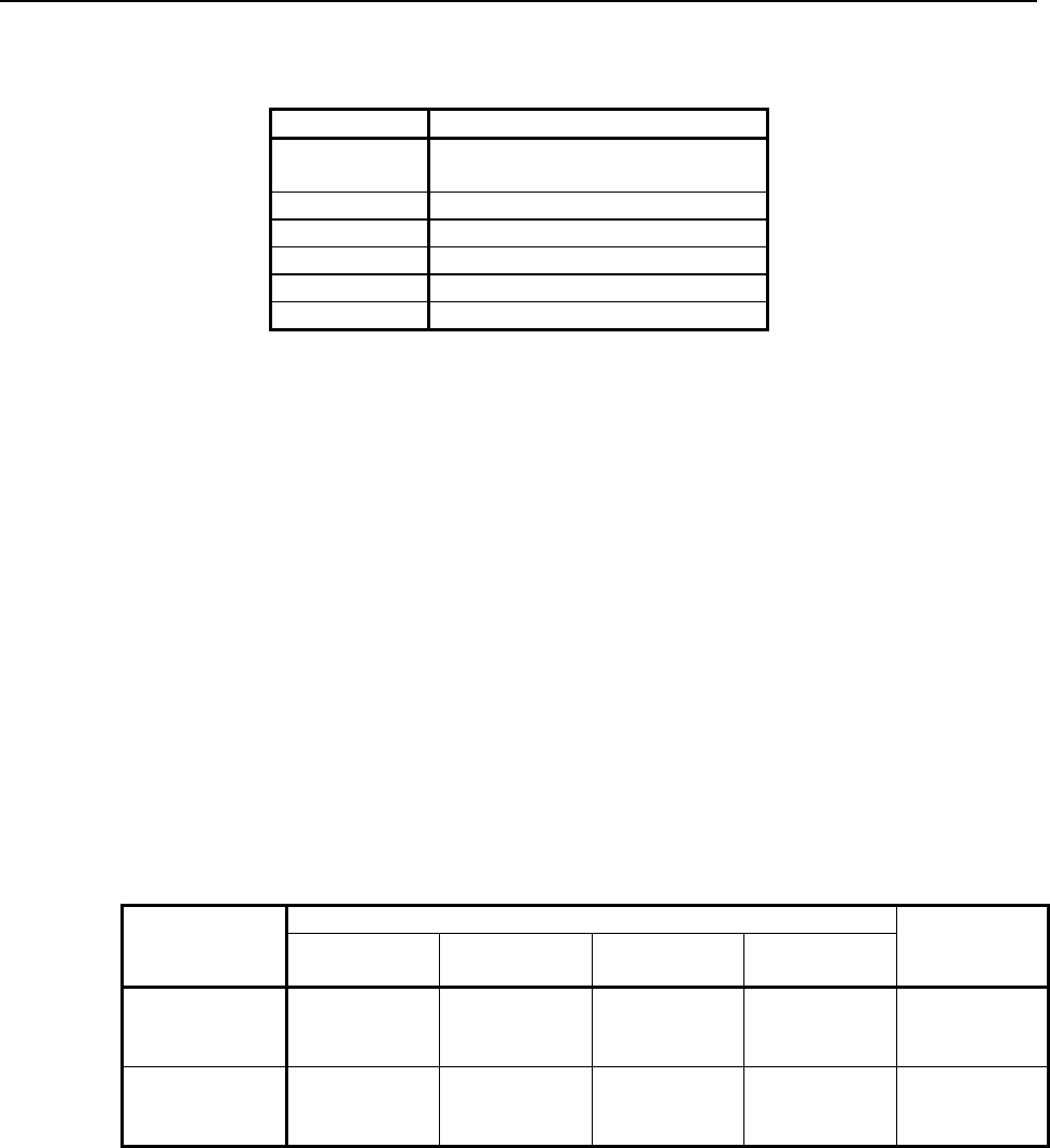
2.PMC SPECIFICATIONS
B-64513EN/03
- 122 -
The numbers from N609000 mean the timer accuracy. Each value is the following timer
accuracy.
Value Timer accuracy
0 Timer number1~8 : 48ms
Timer number9~ : 8ms
1 1ms
2 10ms
3 100ms
4 1 sec.
5 1 min.
(Example)
N600000 P1; (Timer number 1 T0)
N600002 P20; (Timer number 2 T2)
.
N600498 P32767; (Timer number 250 T498)
N609000 P0; (Timer number 1 T9000)
N609002 P0; (Timer number 2 T9002)
.
N609498 P0; (Timer number 250 T9498)
(3) Counter (C)
[Format]
N61xxxx Pnnnnn;
N610xxxx Pnnnnn;
[Data Contents]
N61xxxx or N610xxxx; parameter number
Specify the sum of the counter address (C) offset and 610000 or 6100000. The number in
the following table can be used.
1st to 5th path PMC
DCSPMC
PMC
Memory-A
PMC
Memory-B
PMC
Memory-C
PMC
Memory-D
Variable counter
(CTR)
N610000
to
N610078
N610000
to
N610398
N610000
to
N610798
N6100000
to
N6101198
N610000
to
N610078
Fixed counter
(CTRB)
N615000
to
N615038
N615000
to
N615198
N615000
to
N615398
N6105000
to
N6105598
N615000
to
N615038
Pnnnnn Counter address value in decimal notation
For the variable counter, the preset and current values appear alternately. For the fixed
counter, only the current values appear.
It has a size of 2 bytes and can range from 0 to 32767 for a range. The counter addresses
are assumed to be binary for input/output no matter whether the counter data type is
specified as BCD or binary.
(Example)
N610000 P7; (Counter number 1 C0)
N610002 P7; ( C2)
.

B-64513EN/03
2.PMC SPECIFICATIONS
- 123 -
N610396 P9999; (Counter number 100 C396)
N610398 P0; ( C398)
N615000 P7; (Fixed-counter number 1 C5000)
N615002 P20; (Fixed-counter number 2 C5002)
.
N615198 P9999; (Fixed-counter number 100 C5198)
(4) Keep relay (K)
[Format]
N62xxxx Pnnnnnnnn;
N620xxxx Pnnnnnnnn;
[Data Contents]
N62xxxx or N620xxxx Parameter number
Specify the sum of the keep relay address (K) offset and 620000 or 6200000. The number
in the following table can be used.
1st to 5th path PMC
DCSPMC
PMC
Memory-A
PMC
Memory-B
PMC
Memory-C
PMC
Memory-D
User area N620000
to
N620019
N620000
to
N620099
N620000
to
N620199
N6200000
to
N6200299
N620000
to
N620019
System area N620900
to
N620999
N620900
to
N620999
N620900
to
N620999
N6200900
to
N6200999
N620900
to
N620999
Pnnnnnnnn Keep relay address value in binary notation
It can range from 00000000 to 11111111.
(Example)
N620000 P00000000; (K0)
N620001 P11111111; (K1)
.
N620099 P10101010; (K99)
N620900 P00000000; (K900)
N620901 P11111111; (K901)
.
N620999 P10101010; (K999)
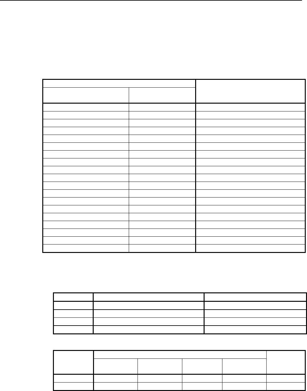
2.PMC SPECIFICATIONS
B-64513EN/03
- 124 -
(5) Data (D)
(a) Data table control
[Format]
N630xxx Pnnnnn;
N6300xxx Pnnnnn;
[Data Contents]
N630xxx or N6300xxx Parameter Number
Parameter number
Contents
PMC Memory-A,B,C,
DCSPMC PMC Memory-D
N630000 N6300000 The group number
N630002 N6300002 Parameter of group1
N630003 N6300003 Data type of group 1
N630004 N6300004 Data size of group 1 (byte)
N630006 N6300006 Start address of group 1
N630010 N6300010 Parameter of group2
N630011 N6300011 Data type of group 2
N630012 N6300012 Data size of group 2 (byte)
N630014 N6300014 Start address of group 2
… … …
N630002 + ((n-1)×8) N6300002 + ((n-1)×8) Parameter of group n
N630003 + ((n-1)×8) N6300003 + ((n-1)×8) Data type of group n
N630004 + ((n-1)×8) N6300004 + ((n-1)×8) Data size of group n (byte)
N630006 + ((n-1)×8) N6300006 + ((n-1)×8) Start address of group n
… … …
N630794 N6300794 Parameter of group 100
N630795 N6300795 Data type of group 100
N630796 N6300796 Data size of group 100 (byte)
N630798 N6300798 Start address of group 100
Pnnnnn Control data table address value.
The range of "The group number" is 1 to 100.
The range of "Table parameter" is 00000000 to 11111111.
The range of "Data type" is as follows.
Data type Data table output format Range
0 1 byte signed decimal number -128 to 127
1 2 byte signed decimal number -32768 to 32767
2 4 byte signed decimal number -2147483648 to 2147483647
3 Binary notation 00000000 to 11111111
The range of "Data size" and "Start address" is as follows.
1st to 5th path PMC
DCSPMC
PMC
Memory-A
PMC
Memory-B
PMC
Memory-C
PMC
Memory-D
Data Size 1 to 3000 1 to 10000 1 to 20000 1 to 60000 1 to 3000
Start address 0 to 2999 0 to 9999 0 to 19999 0 to 59999 0 to 2999
(Example)
N630000 P2;
N630002 P00000000;
N630003 P0;
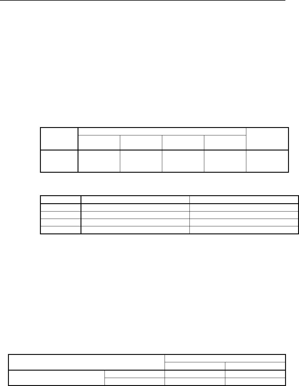
B-64513EN/03
2.PMC SPECIFICATIONS
- 125 -
N630004 P10;
N630006 P0;
N630010 P00000001;
N630011 P0;
N630012 P10;
N630014 P10;
(b) Data table
[Format]
N64xxxx Pnnnnn;
N64xxxxx Pnnnnn;
[Data Contents]
N64xxxx to N65xxxx or N64xxxxx Parameter number
Specify the sum of the data table address (D) offset and 640000 or 6400000. The number
in the following table can be used.
1st to 5th path PMC
DCSPMC
PMC
Memory-A
PMC
Memory-B
PMC
Memory-C
PMC
Memory-D
Data table N640000
to
N642999
N640000
to
N649999
N640000
to
N659999
N6400000
to
N6459999
N640000
to
N642999
Pnnnnn Data table address value
Its size depends on the "data type" of data table control data.
Data type Data table output format Range
0 1 byte signed decimal number -128 to 127
1 2 byte signed decimal number -32768 to 32767
2 4 byte signed decimal number -2147483648 to 2147483647
3 Binary notation 00000000 to 11111111
(Example)
N640000 P-128;
N640001 P100;
N640002 P0;
.
N640010 P1000;
N640012 P-1;
.
N649992 P50000000;
N649996 P50000000;
(6) Extra memory (E)
You can choose how the extra relays are stored in PMC parameter file by settings of system keep
relays as follows:
Output format of extra relays Output extra relay K906.3
0 (yes) 1 (no)
Output extra relay control data
K906.7
0 (no) Byte format No output
1 (yes) Table format No output
In “Byte format”, all extra relays are stored as byte data, and no information of extra relay control
data is included.
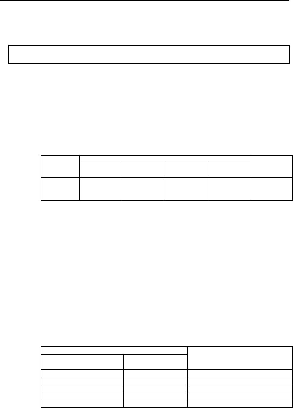
2.PMC SPECIFICATIONS
B-64513EN/03
- 126 -
In “Table format”, extra relays are stored in the same manner as the data table; they are stored in the
format according to the extra relay control data, and the information of the control data is also
included.
If you choose “No output”, no information about extra relays are included in PMC parameter file.
NOTE
Extra relays (E) can be included only in PMC parameter output from 1
st
PMC.
The details of these formats are as follows:
(a) Byte format
[Format]
N69xxxx Pnnnnn;
N690xxxx Pnnnnn;
[Data Contents]
N69xxxx or N690xxxx Parameter number
Specify the sum of the offset number of the extra relay and 690000 or 6900000. The
number in the following table can be used.
1st to 5th path PMC
DCSPMC
PMC
Memory-A
PMC
Memory-B
PMC
Memory-C
PMC
Memory-D
Extra relay N690000
to
N699999
N690000
to
N699999
N690000
to
N699999
N6900000
to
N6909999
N690000
to
N699999
Pnnnnn The value of the extra relay
It is shown in signed decimal number. Its valid range is –128 to 127.
(Example)
N690000 P-128;
N690001 P100;
・
N699998 P127;
N699999 P0;
%
(b) Table format (Control data part)
[Format]
N635xxx Pnnnnn;
N6305xxx Pnnnnn;
[Data Contents]
N635xxx or N6305xxx Parameter Number
Parameter number
Contents
PMC Memory-A,B,C,
DCSPMC PMC Memory-D
N635000 N6305000 The group number
N635002 N6305002 Parameter of group1
N635003 N6305003 Data type of group 1
N635004 N6305004 Data size of group 1 (byte)
N635006 N6305006 Start address of group 1
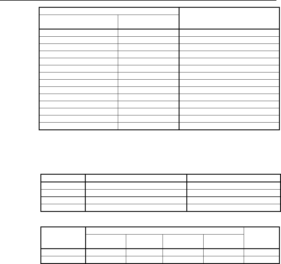
B-64513EN/03
2.PMC SPECIFICATIONS
- 127 -
Parameter number
Contents
PMC Memory-A,B,C,
DCSPMC PMC Memory-D
N635010 N6305010 Parameter of group2
N635011 N6305011 Data type of group 2
N635012 N6305012 Data size of group 2 (byte)
N635014 N6305014 Start address of group 2
… … …
N635002 + ((n-1)×8) N6305002 + ((n-1)×8) Parameter of group n
N635003 + ((n-1)×8) N6305003 + ((n-1)×8) Data type of group n
N635004 + ((n-1)×8) N6305004 + ((n-1)×8) Data size of group n (byte)
N635006 + ((n-1)×8) N6305006 + ((n-1)×8) Start address of group n
… … …
N635794 N6305794 Parameter of group 100
N635795 N6305795 Data type of group 100
N635796 N6305796 Data size of group 100 (byte)
N635798 N6305798 Start address of group 100
Pnnnnn Control data table address value.
The range of "The group number" is 1 to 100.
The range of "Table parameter" is 00000000 to 11111111.
The range of "Data type" is as follows.
Data type Data table output format Range
0 1 byte signed decimal number -128 to 127
1 2 byte signed decimal number -32768 to 32767
2 4 byte signed decimal number -2147483648 to 2147483647
3 Binary notation 00000000 to 11111111
The range of "Data size" and "Start address" is as follows.
1st to 5th path PMC
DCSPMC
PMC
Memory-A
PMC
Memory-B
PMC
Memory-C
PMC
Memory-D
Data Size 1 to 3000 1 to 10000 1 to 20000 1 to 60000 1 to 3000
Start address 0 to 2999 0 to 9999 0 to 19999 0 to 59999 0 to 2999
(Example)
N635000 P2;
N635002 P00000000;
N635003 P0;
N635004 P10;
N635006 P0;
N635010 P00000001;
N635011 P0;
N635012 P10;
N635014 P10;
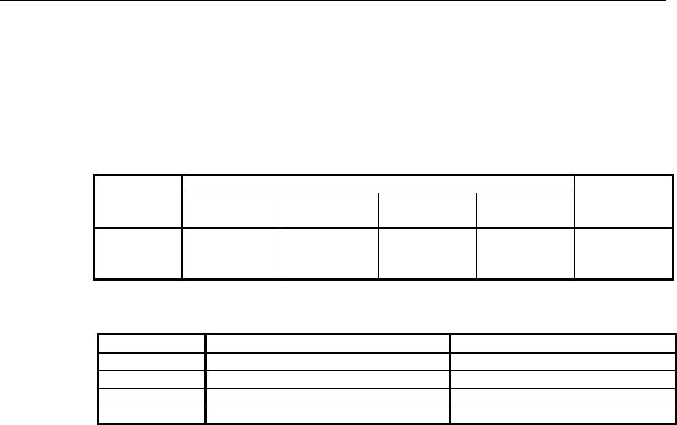
2.PMC SPECIFICATIONS
B-64513EN/03
- 128 -
(c) Table format (Extra relay part)
[Format]
N69xxxx Pnnnnn;
N690xxxx Pnnnnn;
[Data Contents]
N69xxxx or N690xxxx Parameter Number
Specify the sum of the offset number of the extra relay and 690000 or 6900000. The
number in the following table can be used.
1st to 5th path PMC
DCSPMC
PMC
Memory-A
PMC
Memory-B
PMC
Memory-C
PMC
Memory-D
Data table N690000
to
N699999
N690000
to
N699999
N690000
to
N699999
N6900000
to
N6909999
N690000
to
N699999
Pnnnnn The value of the extra relay
Its data size depends on the “Data type” of the control data that the extra relay belongs to.
Data type Data table output format Range
0 1 byte signed decimal number -128 to 127
1 2 byte signed decimal number -32768 to 32767
2 4 byte signed decimal number -2147483648 to 2147483647
3 Binary notation 00000000 to 11111111
(Example)
N690000 P-128;
N690001 P100;
N690002 P0;
・
N690010 P1000;
N690012 P-1;
・
N699992 P50000000;
N699996 P50000000;

B-64513EN/03
2.PMC SPECIFICATIONS
- 129 -
2.4 PARAMETERS FOR THE PMC SYSTEM
2.4.1 Setting Parameters
The parameters set up on the PMC SETTING screen are called the setting parameters. Part of the
system keep relays described earlier can be set up using setting parameters.
This subsection describes the setting parameters for each setup menu.
See Section 9.5 for explanations about the setting screen and how to use it.
(1) Trace function start (K906.5 0: Manual. 1: Automatic.)
This item specifies whether to allow the trace function to be executed automatically when the power
is turned on. The default setting is "Manual" (not automatic execution).
(2) Editing permit (K901.6 0: No. 1: Yes.)
This item specifies whether to enable the functions related to program editing. The default setting
is "No" (not to enable).
(3) Save after edit (K902.0 0: No. 1: Yes.)
This item specifies whether to perform an automatic write to flash ROM after program editing.
The default setting is "No" (not to perform an automatic write).
(4) Memory write permit (K900.4 0: No. 1: Yes.)
This item specifies whether to enable the forcing and override functions. The default setting is
"No" (not to enable).
NOTE
Using the override function requires setting "Override enable" (K906.0).
(5) Data table GRP setting display (K900.7 0: Yes. 1: No.)
This item specifies whether to display the DATA TABLE CONTROL screen. The default setting
is "Yes" (to display).
(6) PMC parameter view inhibit (K902.6 0: No. 1: Yes.)
This item specifies whether to inhibit the PMC PARAM screens (TIMER, COUNTER, KEEP
RELAY, DATA TABLE screens) from being displayed and the PMC parameter data from being
sent to the outside. The default setting is "No" (not to inhibit).
(7) PMC parameter change inhibit (K902.7 0: No. 1: Yes.)
This item specifies whether to inhibit data from being input from the PMC PARAM screens
(TIMER, COUNTER, KEEP RELAY, and DATA TABLE screens) and the PMC parameter data
from being input from the outside. The default setting is "No" (no to inhibit).
(8) PMC program view inhibit (K900.0 0: No. 1: Yes.)
This item specifies whether to inhibit the sequence program from being viewed. The default
setting is "No" (not to inhibit).
(9) IO GROUP SELECTION screen (K906.1 0: Hide. 1: Display.)
This item specifies whether to display the selectable I/O Link assignment function setting screen or
the I/O configuration viewer (I/O link i selectable I/O). The default setting is "Hide" (not to display).

2.PMC SPECIFICATIONS
B-64513EN/03
- 130 -
(10) PMC program execute (K900.2 0: Automatic. 1: Manual.)
This item specifies whether to cause the sequence program to be started automatically when the
power is turned on. The default setting is "Automatic" (to cause automatic start).
(11) PMC stop enable (K902.2 0: No. 1: Yes.)
This item specifies whether to allow the sequence program to start/stop. The default setting is "No"
(not to allow).
(12) Programmer function enable (K900.1 0: No. 1: Yes.)
This item specifies whether to enable the built-in programmer function. The default setting is "No"
(not to enable).
(13) Override enable (K906.0 0: No. 1: Yes.)
This item specifies whether to enable the override function. The default setting is "No" (not to
enable).
NOTE
Using the override function requires setting "Memory write permit" (K900.4).
(14) I/O configuration data edit enable (K907.0 0: No. 1: Yes.)
This item specifies whether to enable the editing of I/O configuration data. The default setting is
"No" (not to enable).
(15) I/O device configuration register enable (K935.1 0: No. 1: Yes.)
This item specifies whether to enable the register/deletion of I/O device configuration. The default
setting is "No" (not to enable).
(16) Message shift amount (K918, K919)
This item specifies how much to shift the message display request bits in displaying
language-specific information, using the DISPB functional instruction. No default setting is
available.
(17) Message shift start address (K916, K917)
This item lets you input the start bit address for the area of message display request bits to be shifted
in displaying language-specific information, using the DISPB functional instruction. No default
setting is available.
(18) Selectable I/O Link assignment function: Selecting a valid group: (K920-K927 0:No. 1:Yes.)
This item specifies a group to be enabled or disabled for the selectable I/O Link assignment function
for individual addresses. The default setting is 0 (disable) for all groups.
See subsection 3.2.5 for the selectable I/O Link assignment function.
(19) Keep relay (system) (K906.6 0: Hide. 1: Show.)
If you set " KEEP RELAY (SYSTEM)" to "SHOW", The KEEP RELAY (K900-K919) screen is
enabled.
The default setting is "Hide" (not to display).

B-64513EN/03
2.PMC SPECIFICATIONS
- 131 -
2.4.2
PMC System Parameters
The parameters set up on the PMC SYSTEM PARAMETER screen are called the system parameters.
This subsection describes the system parameters for each setup menu.
See Section 9.8 for explanations about the how to operate the SYSTEM PARAMETER screen.
(1) Counter type
This item specifies the data type of a counter value used on the COUNTER screen (CTR functional
instruction). It can be represented in either binary or BCD form.
(2) FS0-compatible operator's panel
This item specifies whether to connect an operator's panel for the FS0. If the setting is "Yes",
specify also the DI/DO address to which the operator's panel is actually connected, the address of the
KEY image transferred from the operator's panel, and the address of the LED image to be
transferred to the operator's panel.
(a) DI address
This item specifies the start address of the external DI to which the operator's panel is actually
connected, using PMC addresses (X0 to X127, X200 to X327, X400 to X527, or X600 to
X727).
(b) DO address
This item specifies the start address of the external DO to which the operator's panel is actually
connected, using PMC addresses (Y0 to Y127, Y200 to Y327, Y400 to Y527, or Y600 to
Y727).
(c) Key input image address
This item specifies the start address of the KEY image to be referenced by the user program,
using a PMC address. Usually, set up an arbitrary internal relay (R) area.
(d) LED output image address
This item specifies the start address of the LED image generated by the user program, using
PMC addresses. Usually, set up an arbitrary internal relay area (R).
(3) Selectable I/O Link assignment function
This item specifies whether to enable/disable the selectable I/O Link assignment function for each
address and the number of the related basic groups.
(a) Function enable
This item specifies whether to enable/disable the selectable I/O Link assignment function.
(b) Number of basic groups
This item specifies the number of groups that are always enabled no matter what machine
configuration is employed.
See subsection 3.2.5 for explanations about the selectable I/O Link assignment function.

2.PMC SPECIFICATIONS
B-64513EN/03
- 132 -
2.4.3
CNC Parameters Related to the PMCs
The CNC parameters related to the PMCs can be divided into those for controlling communication with
FANUC LADDER-III and ladder editing package and those for setting up the PMCs.
The following table summaries the CNC parameters related to the PMCs.
Table 2.4.3 (a) Summary of the CNC parameters related to the PMCs
No. Use Remarks
24 Setting up communication with ladder development tools PMC online connection function
11900 to 11904 Execution sequence for multiple PMCs 1st to 5th path PMC
11905 to 11909 Percent execution time for multiple PMCs 1st to 5th path PMC
11910 to 11912 I/O Link input/output address Channels 1 to 3
11914 (Note) 2nd, 3rd level execution cycle of ladder Common to 1st to 5th path PMC
11915 to 11917 Input/output address of dual assignment of I/O Link
channel
Second Block of Channels 1 to 3
11920 to 11929 CNC interface control address CNC10 system
11930 Ladder 1st level execution period 1st to 5th path PMC
11931#0 Run/stop of Ladder 1st to 5th path PMC
11931#1 The display number of external alarms/operator
messages
External data input, External
message
11931#5 Ladder dividing management function Common to 1st to 5th path PMC
11931#7 Clearing of PMC nonvolatile memory
11932 Multi path PMC interface
11933#0,#1 I/O Link communication method Channel 1, 2
11933#5 Running/stopping of ladder program when updating
11936 The number of PMC paths
11937 to 11939 The input / output address used by network devices 1st to 5 th path PMC,
X/Y0 to 727
11940 to 11944 PMC Memory Type 1st to 5th path PMC
11945 (Note) The PMC path that the 1st level execution cycle in 1ms or
2ms is applied when using multi-path PMC function.
1st to 5th path PMC
11946 (Note) The divided ladder that the 1st level execution cycle in
1ms or 2ms is applied when using ladder dividing
management function.
Divided ladder program 1 to 99
NOTE
These parameters are unavailable for the series 0i-F.
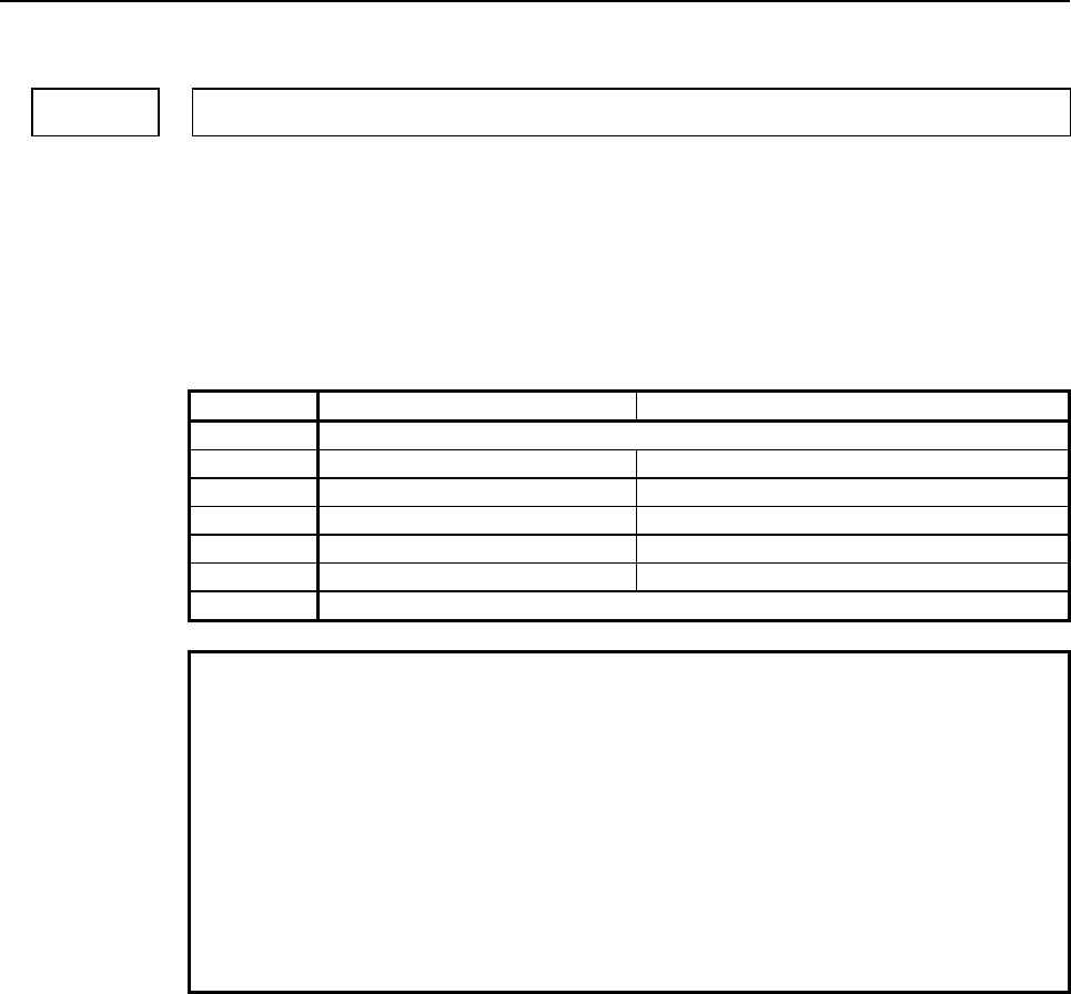
B-64513EN/03
2.PMC SPECIFICATIONS
- 133 -
Communication parameters
00024 Setting up communication with ladder development tools
(FANUC LADDER-III and ladder editing package)
[Input type] Setting input
[Data type] Integer
[Valid data range] 0 to 255
This item specifies whether to enable/disable the PMC online connection function.
Entering this parameter makes it possible to enable/disable the PMC online setup function
without displaying the PMC online setup screen.
Setting RS-232C High-speed interface
0 The settings on the PMC online setup screen are changed.
1 To be used (channel 1) Not to be used
2 To be used (channel 2) Not to be used
10 Not to be used To be used
11 To be used (channel 1) To be used
12 To be used (channel 2) To be used
255 Communication is forced to stop (equivalent to the [EMG STOP] soft key).
NOTE
1 The setting of this parameter is put into effect when it is changed or
the power is turned on. It is unnecessary to turn the power off and
on again after the parameter is re-set.
2 The setting changed on the PMC online setup screen is not
reflected to this parameter.
3 As for the RS-232C, the communication settings, such as a baud
rate, specified on the PMC online setup screen are valid. The valid
settings are a baud rate of 9600 bps, no parity, and two stop bits if
no change has been made on the PMC online setup screen since
installation.
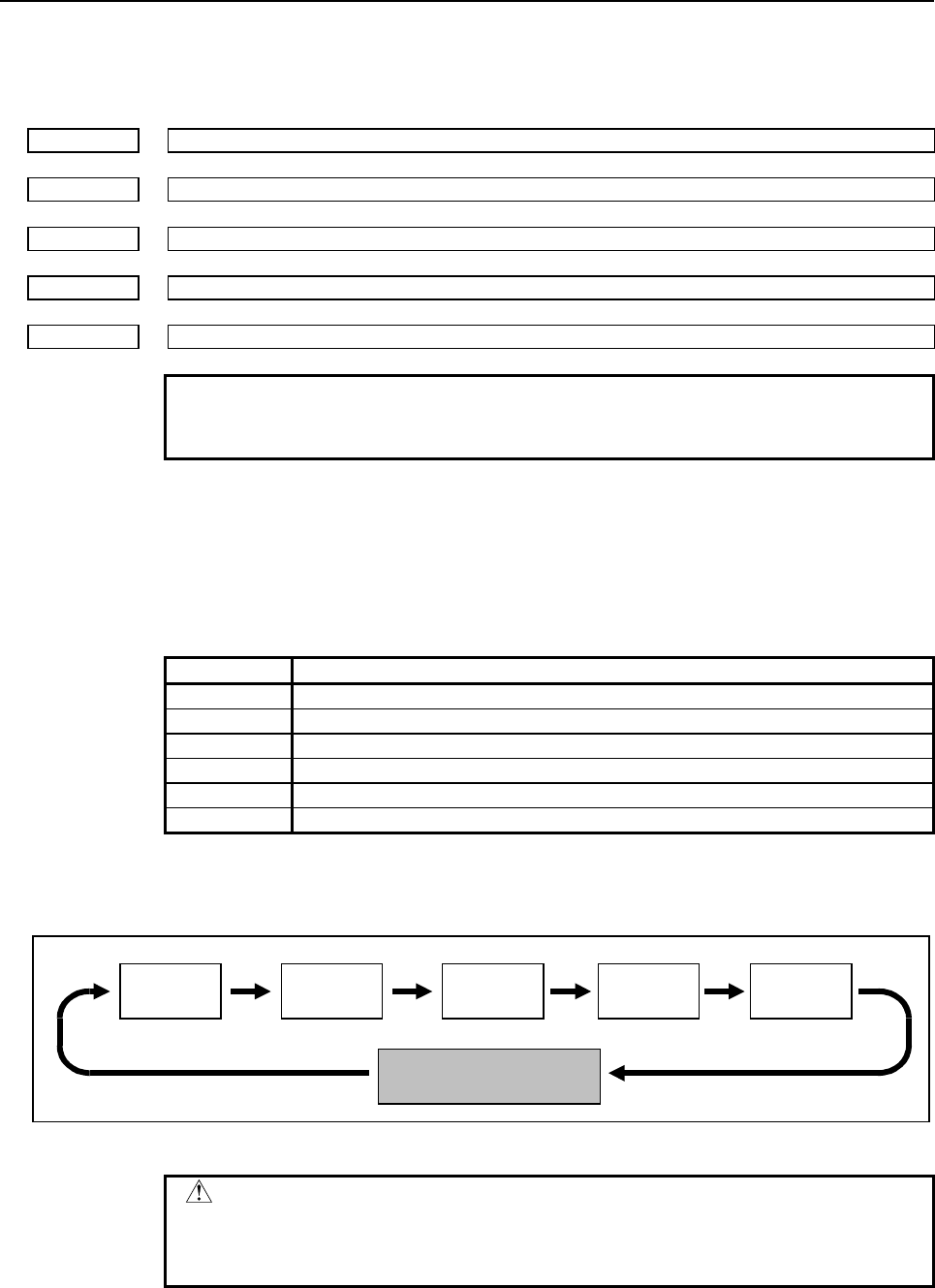
2.PMC SPECIFICATIONS
B-64513EN/03
- 134 -
PMC setup parameters
Execution sequence for multiple PMCs
11900 PMC having the first priority in execution sequence
11901 PMC having the second priority in execution sequence
11902 PMC having the third priority in execution sequence
11903 PMC having the fourth priority in execution sequence
11904 PMC having the fifth priority in execution sequence
NOTE
Once any of these parameters is re-set, it is necessary to turn the
power off and on again.
[Input type] Parameter input
[Data type] Integer
[Valid data range] 0 to 5
This item specifies the execution sequence for each PMC if the multi-path PMC function
is used.
Setting PMC
0 Standard setting (see below)
1 1st PMC
2 2nd PMC
3 3rd PMC
4 4th PMC
5 5th PMC
When all these parameters are 0, the standard execution sequence setting shown below is
used.
1st PMC 2nd PMC 3rd PMC
Other processing such as
tracing
5th PMC 4th PMC
Fig. 2.4.3 (a) Standard execution sequence for multiple PMCs
CAUTION
If any of these parameters is nonzero, a duplicate or missing
number results in the PMC alarm "ER50 PMC EXECUTION
ORDER ERROR", thus disabling all the PMCs from starting.
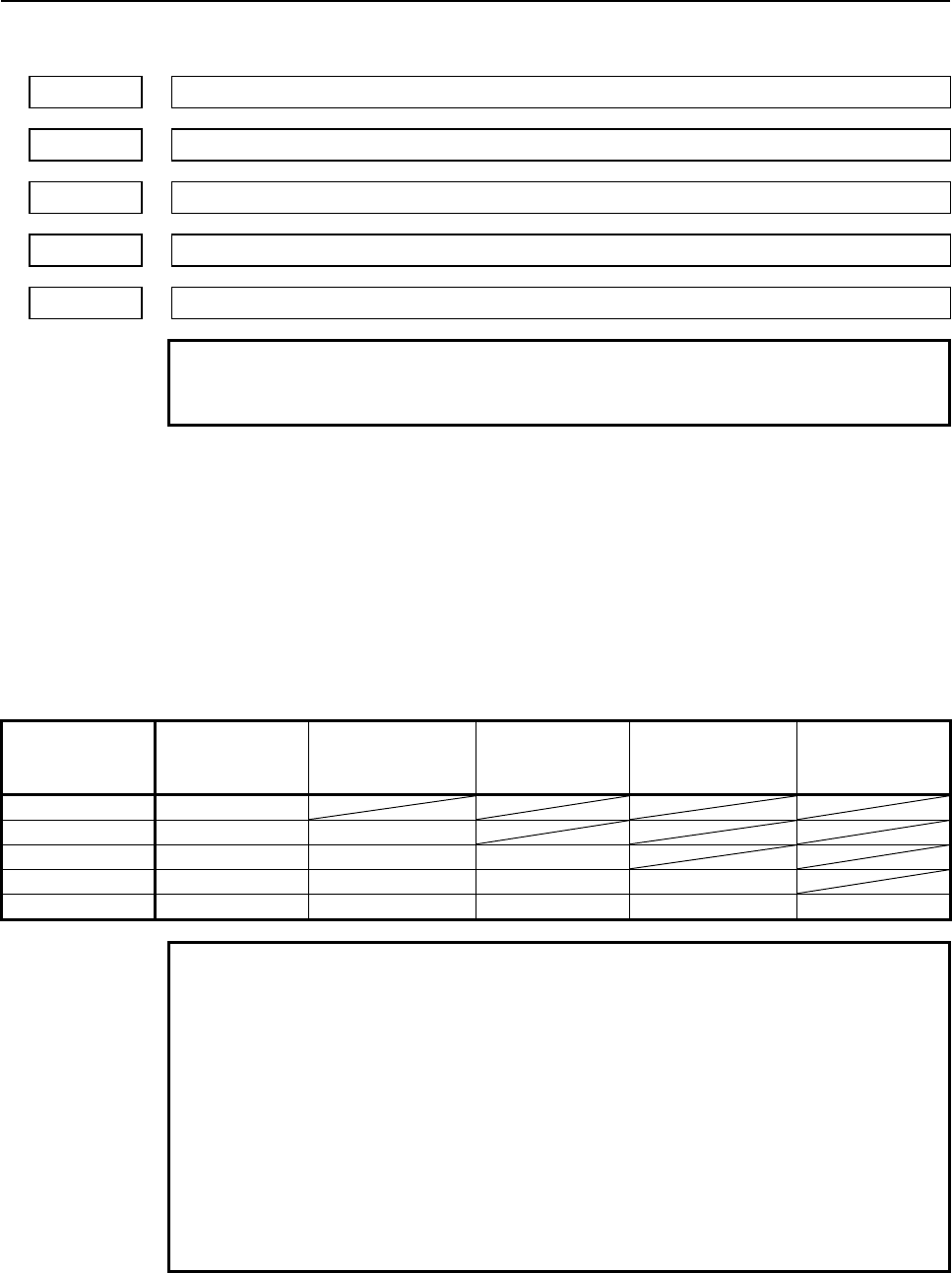
B-64513EN/03
2.PMC SPECIFICATIONS
- 135 -
Percent execution time for multiple PMCs
11905 Percent execution time for the PMC having the first priority in execution sequence
11906 Percent execution time for the PMC having the second priority in execution sequence
11907 Percent execution time for the PMC having the third priority in execution sequence
11908 Percent execution time for the PMC having the fourth priority in execution sequence
11909 Percent execution time for the PMC having the fifth priority in execution sequence
NOTE
Once any of these parameters is re-set, it is necessary to turn the
power off and on again.
[Input type] Parameter input
[Data type] Byte
[Valid data range] 0 to 100
This item specifies the percent execution time for each PMC if the multi-path PMC
function is used.
When all these parameters are 0, the standard execution time settings listed below are
used.
Table 2.4.3 (b) Standard settings of the percent execution time for multiple PMCs
The number
of PMC path
PMC path
of the 1st order
of execution
PMC path
of the 2nd order
of execution
PMC path
of the 3rd order
of execution
PMC path
of the 4th order
of execution
PMC path
of the 5th order
of execution
1 path 100%
2 paths 85% 15%
3 paths 75% 15% 10%
4 paths 70% 10% 10% 10%
5 paths 60% 10% 10% 10% 10%
NOTE
1 If these parameters are set to too low a value, it may be impossible
to start the first level on every scan.
2 Even if you input the same program in both second and third PMC,
the scan time of both programs may not correspond because of
changing of the waiting time by execution timing.
3 If the sum of these parameter settings exceeds 100, the PMC alarm
"ER51 PMC EXECUTION PERCENTAGE ERROR" occurs, thus
disabling all PMC from starting.
4 When using the Common PMC Memory mode, the execution time
of those PMCs are merged, and programs are sequentially
executed within the merged time.

2.PMC SPECIFICATIONS
B-64513EN/03
- 136 -
I/O Link input/output addresses
11910 I/O Link channel 1 input/output addresses
11911 I/O Link channel 2 input/output addresses
11912 I/O Link channel 3 input/output addresses
NOTE
Once any of these parameters is re-set, it is necessary to turn the
power off and on again.
[Input type] Parameter input
[Data type] Word
[Valid data range] 0, 100 to 103, 200 to 203, 300 to 303, 400 to 403, 500 to 503, 900
This item specifies input/output addresses for an I/O Link channel.
The channel in which I/O Link i is used is not required this item.
Table 2.4.3 (c) I/O Link channel input/output addresses
Setting Input/output address
0 Standard setting (see below)
100 X0 to X127/Y0 to Y127 for the 1st PMC
101 X200 to X327/Y200 to Y327 for the 1st PMC
102 X400 to X527/Y400 to Y527 for the 1st PMC
103 X600 to X727/Y600 to Y727 for the 1st PMC
200 X0 to X127/Y0 to Y127 for the 2nd PMC
201 X200 to X327/Y200 to Y327 for the 2nd PMC
202 X400 to X527/Y400 to Y527 for the 2nd PMC
203 X600 to X727/Y600 to Y727 for the 2nd PMC
300 X0 to X127/Y0 to Y127 for the 3rd PMC
301 X200 to X327/Y200 to Y327 for the 3rd PMC
302 X400 to X527/Y400 to Y527 for the 3rd PMC
303 X600 to X727/Y600 to Y727 for the 3rd PMC
400 X0 to X127/Y0 to Y127 for the 4th PMC
401 X200 to X327/Y200 to Y327 for the 4th PMC
402 X400 to X527/Y400 to Y527 for the 4th PMC
403 X600 to X727/Y600 to Y727 for the 4th PMC
500 X0 to X127/Y0 to Y127 for the 5th PMC
501 X200 to X327/Y200 to Y327 for the 5th PMC
502 X400 to X527/Y400 to Y527 for the 5th PMC
503 X600 to X727/Y600 to Y727 for the 5th PMC
900 X0 to X127/Y0 to Y127 for the dual-check safety PMC
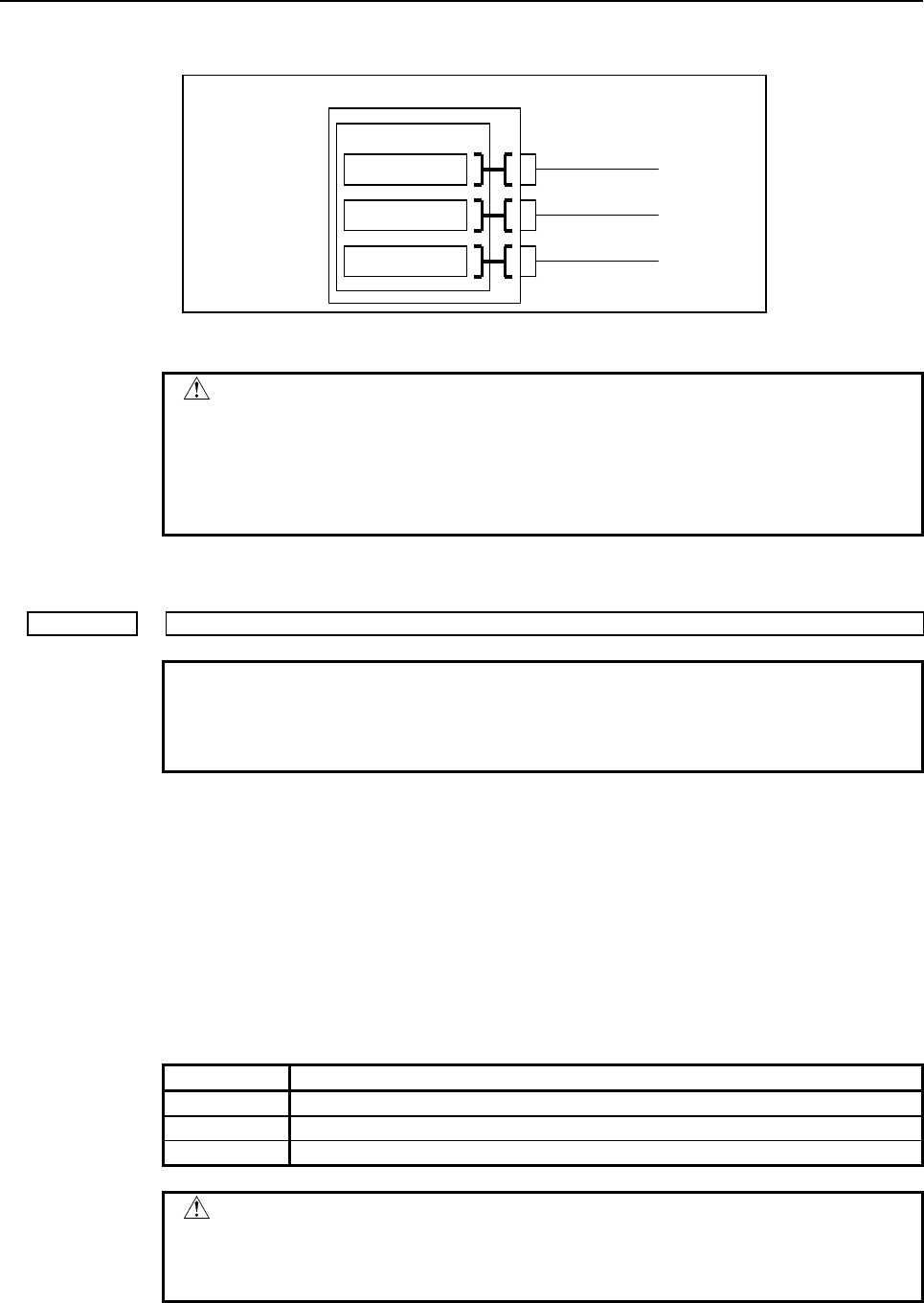
B-64513EN/03
2.PMC SPECIFICATIONS
- 137 -
If all these parameters are 0, all channels are assigned to the 1st PMC (standard setting) as
shown below.
First PMC
X/Y0 to X/Y127
X/Y200 to X/Y327
X/Y400 to X/Y527
Channel 1
Channel 2
Channel 3
Fig. 2.4.3 (b) Standard input/output address setting for the I/O Link channel
CAUTION
1 If any of these parameters is nonzero, a duplicate number results in
the PMC alarm "ER52 I/O Link CHANNEL ASSIGNMENT ERROR",
thus disabling all the PMCs from starting.
2 If these parameters are not set up in part, it is impossible to assign a
PMC address to the related channel.
2nd, 3rd level execution cycle
11914 2nd / 3rd level execution cycle of ladder
NOTE
1 Once this parameter is set, it is necessary to turn off and on the
power.
2 This parameter is unavailable for the series 0i-F.
[Input type] Byte input
[Data type] Byte
[Valid data range] 0, 2, 4
When using the 1st level of ladder execution cycle in 2ms, the execution cycle of the
following ladder programs is specified.
- 2nd level ladder of all
- 3rd level ladder of all
- The 1st level of ladder when using the Ladder Dividing Management Function or
Multi-path PMC Function and not using the 1st level of ladder execution cycle in 2ms.
Setting Meaning
2 Executed at a 2ms cycle.
4 Executed at a 4ms cycle.
0 Executed at a standard (4ms) cycle.
CAUTION
1 Setting this parameter to a value other than 0, 2, or 4 results in the
PMC alarm "ER55 LADDER EXECUTION CYCLE SETTING
ERROR", and all PMCs are not executed.

2.PMC SPECIFICATIONS
B-64513EN/03
- 138 -
Input/output addresses of dual assignment of I/O Link channel
11915 Input/output addresses of the second block of I/O Link channel 1
11916 Input/output addresses of the second block of I/O Link channel 2
11917 Input/output addresses of the second block of I/O Link channel 3
NOTE
Once any of these parameters is re-set, it is necessary to turn the
power off and on again.
[Input type] Parameter input
[Data type] Word
[Valid data range] 0, 100 to 103, 200 to 203, 300 to 303, 400 to 403, 500 to 503
This item specifies input/output addresses for an I/O Link channel.
The channel in which I/O Link i is used is not required this item.
Table 2.4.3 (d) I/O Link channel input/output addresses
Setting Input/output address
0 Standard setting (see below)
100 X0 to X127/Y0 to Y127 for the 1st PMC
101 X200 to X327/Y200 to Y327 for the 1st PMC
102 X400 to X527/Y400 to Y527 for the 1st PMC
103 X600 to X727/Y600 to Y727 for the 1st PMC
200 X0 to X127/Y0 to Y127 for the 2nd PMC
201 X200 to X327/Y200 to Y327 for the 2nd PMC
202 X400 to X527/Y400 to Y527 for the 2nd PMC
203 X600 to X727/Y600 to Y727 for the 2nd PMC
300 X0 to X127/Y0 to Y127 for the 3rd PMC
301 X200 to X327/Y200 to Y327 for the 3rd PMC
302 X400 to X527/Y400 to Y527 for the 3rd PMC
303 X600 to X727/Y600 to Y727 for the 3rd PMC
400 X0 to X127/Y0 to Y127 for the 4th PMC
401 X200 to X327/Y200 to Y327 for the 4th PMC
402 X400 to X527/Y400 to Y527 for the 4th PMC
403 X600 to X727/Y600 to Y727 for the 4th PMC
500 X0 to X127/Y0 to Y127 for the 5th PMC
501 X200 to X327/Y200 to Y327 for the 5th PMC
502 X400 to X527/Y400 to Y527 for the 5th PMC
503 X600 to X727/Y600 to Y727 for the 5th PMC
If these parameters are 0, the dual assignment of I/O link channel is invalid.
CAUTION
1 If any of these parameters and parameter no. 11910 to 11913 is
nonzero, a duplicate number results in the PMC alarm "ER52 I/O
Link CHANNEL ASSIGNMENT ERROR", thus disabling all the
PMCs from starting.
2 If the second block of channel 3 is used in the 1st to 5th path PMC
when the first block of channel 3 is used in DCS PMC, do not assign
to the safe-related I/O signals of DCS function.
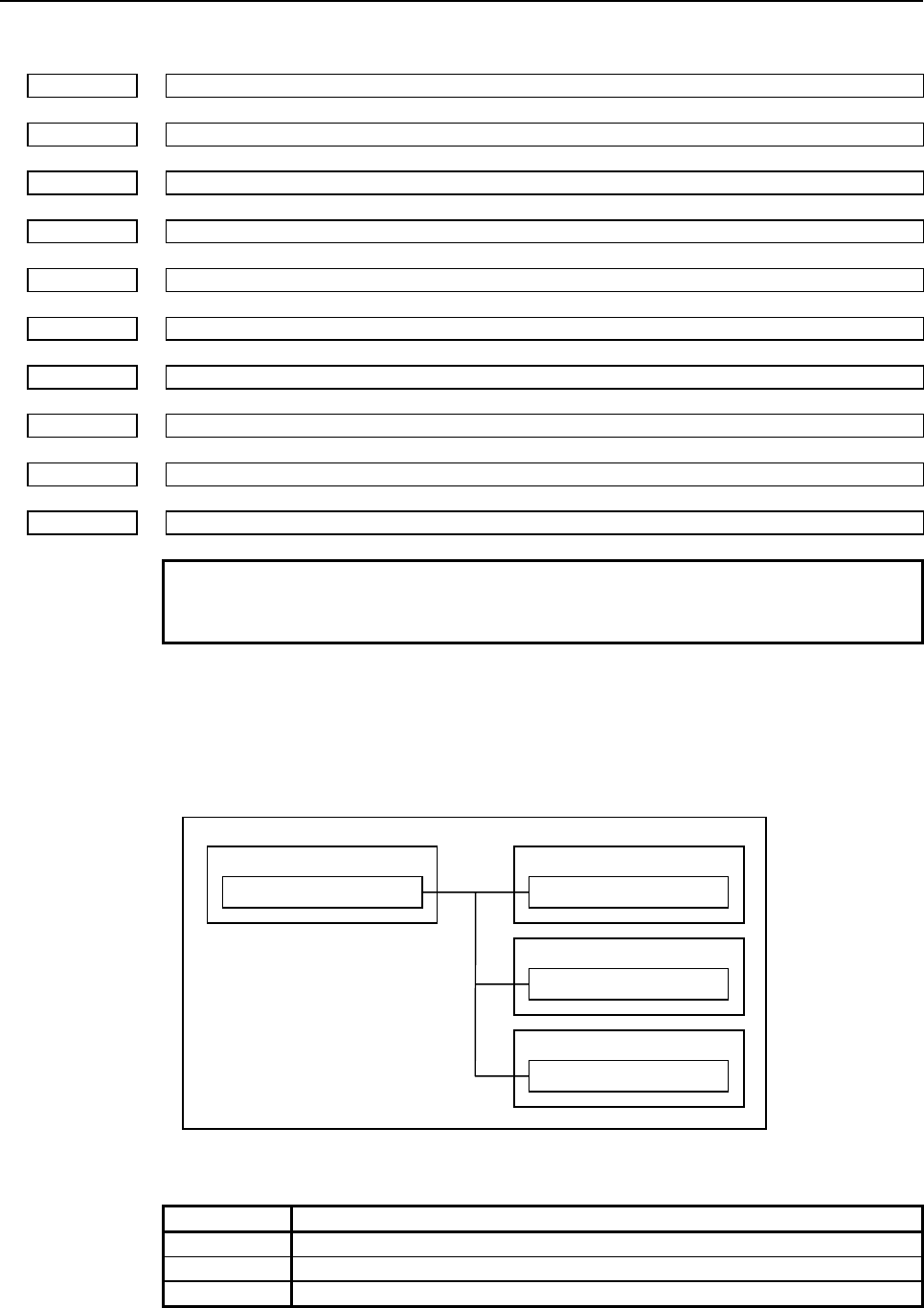
B-64513EN/03
2.PMC SPECIFICATIONS
- 139 -
CNC-PMC interface
11920 CNC-PMC interface 1 input/output address
11921 CNC-PMC interface 2 input/output address
11922 CNC-PMC interface 3 input/output address
11923 CNC-PMC interface 4 input/output address
11924 CNC-PMC interface 5 input/output address
11925 CNC-PMC interface 6 input/output address
11926 CNC-PMC interface 7 input/output address
11927 CNC-PMC interface 8 input/output address
11928 CNC-PMC interface 9 input/output address
11929 CNC-PMC interface 10 input/output address
NOTE
Once any of these parameters is re-set, it is necessary to turn the
power off and on again.
[Input type] Parameter input
[Data type] Word
[Valid data range] 0, 100 to 109, 200 to 209, 300 to 309, 400 to 409, 500 to 509
This item assigns a PMC F/G address to a CNC F/G address.
CNC First PMC
CNC F/G address First-PMC F/G address
Second PMC
Second-PMC F/G address
Third PMC
Third-PMC F/G address
Fig. 2.4.3 (c) CNC-PMC interface assignment concept
Table 2.4.3 (e) CNC-PMC interface input/output address
Setting Input/output address
0 Standard setting (see below)
100 F0 to 767/G0 to G767 for the 1st PMC
101 F1000 to F1767/G1000 to G1767 for the 1st PMC

2.PMC SPECIFICATIONS
B-64513EN/03
- 140 -
Setting Input/output address
102 F2000 to F2767/G2000 to G2767 for the 1st PMC
103 F3000 to F3767/G3000 to G3767 for the 1st PMC
104 F4000 to F4767/G4000 to G4767 for the 1st PMC
105 F5000 to F5767/G5000 to G5767 for the 1st PMC
106 F6000 to F6767/G6000 to G6767 for the 1st PMC
107 F7000 to F7767/G7000 to G7767 for the 1st PMC
108 F8000 to F8767/G8000 to G8767 for the 1st PMC
109 F9000 to F9767/G9000 to G9767 for the 1st PMC
200 F0 to F767/G0 to G767 for the 2nd PMC
201 F1000 to F1767/G1000 to G1767 for the 2nd PMC
202 F2000 to F2767/G2000 to G2767 for the 2nd PMC
203 F3000 to F3767/G3000 to G3767 for the 2nd PMC
204 F4000 to F4767/G4000 to G4767 for the 2nd PMC
205 F5000 to F5767/G5000 to G5767 for the 2nd PMC
206 F6000 to F6767/G6000 to G6767 for the 2nd PMC
207 F7000 to F7767/G7000 to G7767 for the 2nd PMC
208 F8000 to F8767/G8000 to G8767 for the 2nd PMC
209 F9000 to F9767/G9000 to G9767 for the 2nd PMC
300 F0 to F767/G0 to G767 for the 3rd PMC
301 F1000 to F1767/G1000 to G1767 for the 3rd PMC
302 F2000 to F2767/G2000 to G2767 for the 3rd PMC
303 F3000 to F3767/G3000 to G3767 for the 3rd PMC
304 F4000 to F4767/G4000 to G4767 for the 3rd PMC
305 F5000 to F5767/G5000 to G5767 for the 3rd PMC
306 F6000 to F6767/G6000 to G6767 for the 3rd PMC
307 F7000 to F7767/G7000 to G7767 for the 3rd PMC
308 F8000 to F8767/G8000 to G8767 for the 3rd PMC
309 F9000 to F9767/G9000 to G9767 for the 3rd PMC
400 F0 to F767/G0 to G767 for the 4th PMC
401 F1000 to F1767/G1000 to G1767 for the 4th PMC
402 F2000 to F2767/G2000 to G2767 for the 4th PMC
403 F3000 to F3767/G3000 to G3767 for the 4th PMC
404 F4000 to F4767/G4000 to G4767 for the 4th PMC
405 F5000 to F5767/G5000 to G5767 for the 4th PMC
406 F6000 to F6767/G6000 to G6767 for the 4th PMC
407 F7000 to F7767/G7000 to G7767 for the 4th PMC
408 F8000 to F8767/G8000 to G8767 for the 4th PMC
409 F9000 to F9767/G9000 to G9767 for the 4th PMC
500 F0 to F767/G0 to G767 for the 5th PMC
501 F1000 to F1767/G1000 to G1767 for the 5th PMC
502 F2000 to F2767/G2000 to G2767 for the 5th PMC
503 F3000 to F3767/G3000 to G3767 for the 5th PMC
504 F4000 to F4767/G4000 to G4767 for the 5th PMC
505 F5000 to F5767/G5000 to G5767 for the 5th PMC
506 F6000 to F6767/G6000 to G6767 for the 5th PMC
507 F7000 to F7767/G7000 to G7767 for the 5th PMC
508 F8000 to F8767/G8000 to G8767 for the 5th PMC
509 F9000 to F9767/G9000 to G9767 for the 5th PMC
If all these parameters are 0, the standard setting is used, that is, "CNC F/G address = 1st
PMC F/G address" is satisfied.
B-64513EN/03
2.PMC SPECIFICATIONS
- 141 -
CNC First PMC
F/G0 to F/G767 for the CNC
F/G1000 to F/G1767 for the CNC
F/G2000 to F/G2767 for the CNC
F/G3000 to F/G3767 for the CNC
F/G4000 to F/G4767 for the CNC
F/G5000 to F/G5767 for the CNC
F/G6000 to F/G6767 for the CNC
F/G7000 to F/G7767 for the CNC
F/G8000 to F/G8767 for the CNC
F/G9000 to F/G9767 for the CNC
F/G0 to F/G767 for the first PMC
F/G1000 to F/G1767 for the first PMC
F/G2000 to F/G2767 for the first PMC
F/G3000 to F/G3767 for the first PMC
F/G4000 to F/G4767 for the first PMC
F/G5000 to F/G5767 for the first PMC
F/G6000 to F/G6767 for the first PMC
F/G7000 to F/G7767 for the first PMC
F/G8000 to F/G8767 for the first PMC
F/G9000 to F/G9767 for the first PMC
Fig. 2.4.3 (d) CNC-PMC interface initial settings
CAUTION
1 If any of these parameters is nonzero, a duplicate number results in
the PMC alarm "ER54 NC-PMC I/F ASSIGNMENT ERROR", thus
disabling all the PMCs from starting.
2 If these parameters are not set up in part, it is impossible to assign a
PMC address to the related CNC F/G address.
Level 1 execution period
11930 Ladder level execution period
NOTE
Once this parameter is re-set, it is necessary to turn the power off
and on again.
[Input type] Byte input
[Data type] Byte
[Valid data range] 0, 1, 2, 4, 8
This item specifies an execution period for ladder level 1.
Setting Meaning
1 (Note2,3) Executed at a 1ms cycle.
2 (Note2,3) Executed at a 2ms cycle.
4 Executed at a 4-msec interval.
0, 8 Executed at an 8-msec interval.
2.PMC SPECIFICATIONS
B-64513EN/03
- 142 -
NOTE
1 The level 1 execution period cannot be set for each PMC path
independently.
2 Refer to "1.8” when this parameter is set to a value “1” or “2”.
3 The value “1” and “2” are unavailable for the series 0i-F.
CAUTION
1 Setting this parameter to a value other than 0,1,2,4, or 8 results in
the PMC alarm "ER55 LEVEL1 EXECUTION CYCLE ERROR", and
all PMCs are not executed.
Start or stop of the ladder
#7 #6 #5 #4 #3 #2 #1 #0
11931 NMC LDV M16 PCC
[Data type] Bit
#0 PCC This item specifies start or stop of the ladder as follows:
0: The ladder is started or stopped independently for each PMC.
1: The ladders in all PMCs are started or stopped together.
NOTE
1 Once this parameters is re-set, it is necessary to turn the power off
and on again.
2 When using the Common PMC Memory mode, those programs are
started or stopped together regardless of this parameter.
#1 M16 For the external data input function or the external message function, the maximum
number of the external alarm messages and the external operator’s messages which can be
displayed is as follows:
0: 4
1: 16
#5 LDV Ladder dividing management function is:
0: Not available
1: Available
NOTE
If this parameter changed, it is necessary to turn the power off and
on again. When setting to “0” in this parameter, the divided ladder
programs in the flash ROM are ignored and only main ladder
program is executed and displayed.
#7 NMC When the PMC alarm "ER09 PMC LABEL CHECK ERROR" occurs, the nonvolatile
memory of PMC is cleared by:
0: Turning on power of CNC with pressing "O" and "Z" MDI keys
1: Turning on power of CNC without any operation
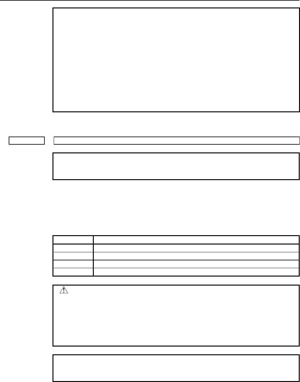
B-64513EN/03
2.PMC SPECIFICATIONS
- 143 -
NOTE
Set NMC = 0 generally.
If you change some PMC setting, such as number of PMC paths,
PMC memory type, etc., the PMC alarm "ER09 PMC LABEL
CHECK ERROR" occurs and nonvolatile memory of PMC have to
be cleared. To clear the nonvolatile memory of PMC, you have to
turn on power of CNC with pressing "O" and "Z" MDI keys generally.
If NMC = 1, the nonvolatile memory of PMC is cleared automatically
at the turning on power of CNC when the PMC alarm "ER09"
occurs. Note that the setting NMC = 1 may cause undesirable clear
of nonvolatile memory of PMC by unintended change of PMC
setting.
Multi-path PMC interface
11932 Multi-path PMC interface
NOTE
Once this parameters is re-set, it is necessary to turn the power off
and on again.
[Input type] Parameter input
[Data type] Integer
[Valid data range] 0, 1, 2, 3
Select the PMC path to use the Multi-path PMC interface.
Setting Meaning
0 Not use the Multi-path PMC interface
1 Use the Multi-path PMC interface between 1ST and 2ND PMC.
2 Use the Multi-path PMC interface between 1ST and 3RD PMC.
3 Use the Multi-path PMC interface between 2ND and 3RD PMC.
CAUTION
When you set an inappropriate value to this parameter, the PMC
alarm "ER57 MULTI-PATH PMC I/F ASSIGNMENT ERROR"
occurs and all PMC paths are stopped.
If the PMC path specified by this parameter is not available, the
PMC alarm "ER57 MULTI-PATH PMC I/F ASSIGNMENT ERROR"
also occurs and all PMC paths are stopped.
NOTE
When using the Common PMC Memory mode, this function is
unavailable between those PMCs.
2.PMC SPECIFICATIONS
B-64513EN/03
- 144 -
Communication method with I/O device
Running/stopping of ladder program when updating
#7 #6 #5 #4 #3 #2 #1 #0
11933 SRL C2T C1T
[Input type] Parameter input
[Data type] Bit
NOTE
Once these parameters are re-set, it is necessary to turn the power
off and on again.
#0
C1T
Specifies the communication method of channel 1.
0 : I/O Link is used.
1 : I/O Link i is used.
#1 C2T
Specifies the communication method of channel 2.
0 : I/O Link is used.
1 : I/O Link i is used.
NOTE
1 When you set the channel to “use I/O Link”, set the parameter
no.11910 to 11912, also.
2 For the series 0i-F, the default value of these parameters is “1”.
#5 SRL
When reading a ladder program in the I/O screen or by other operations:
0 : The execution of the ladder program is stopped automatically.
1 : The execution of the ladder program is not stopped. The ladder program is exchanged
and running continuously after the completion of reading of the ladder program.
NOTE
1 When you set the channel to “use I/O Link”, set the parameter
no.11910 to 11912, also.
2 For the series 0i-F, the default value of these parameters is “1”.
The number of PMC paths
11936 The number of PMC paths
NOTE
Once this parameter is re-set, it is necessary to turn the power off
and on again.
[Data type] Integer
[Valid data range] 0, 1, 2, 3, 4, 5
This item specifies the number of PMC paths within the option of multi-path PMC
function. When the value is 0 or out of valid data range, all of PMC paths which is
specified by a multi-path PMC option is effective.

B-64513EN/03
2.PMC SPECIFICATIONS
- 145 -
The input / output address used by network device
#7 #6 #5 #4 #3 #2 #1 #0
11937 P24 P23 P22 P21 P14 P13 P12
P11
[Data type] Bit
Input and output signals of network devices, such as Profibus, Profinet or iPendant etc.,
can be assigned to X/Y address area, such as X0-X127/Y0-Y127 or X200-327/Y200-327
etc. Network devices can be assigned to the X/Y address area to which any I/O Link and
I/O Link i devices are not assigned.
When you assign network device to X/Y address area, you have to set 1 to this parameter
for the corresponding area.
#0 P11 X/Y 0 to 127 of the 1st path PMC are:
0: Not used
1: Used
#1 P12 X/Y 200 to 327 of the 1st path PMC are:
0: Not used
1: Used
#2 P13 X/Y 400 to 527 of the 1st path PMC are:
0: Not used
1: Used
#3 P14 X/Y 600 to 727 of the 1st path PMC are:
0: Not used
1: Used
#4 P21 X/Y 0 to 127 of the 2nd path PMC are:
0: Not used
1: Used
#5 P22 X/Y 200 to 327 of the 2nd path PMC are:
0: Not used
1: Used
#6 P23 X/Y 400 to 527 of the 2nd path PMC are:
0: Not used
1: Used
#7 P24 X/Y 600 to 727 of the 2nd path PMC are:
0: Not used
1: Used
#7 #6 #5 #4 #3 #2 #1 #0
11938 P44 P43 P42 P41 P34 P33 P32
P31
[Data type] Bit
#0 P31 X/Y 0 to 127 of the 3rd path PMC are:
0: Not used
1: Used

2.PMC SPECIFICATIONS
B-64513EN/03
- 146 -
#1 P32 X/Y 200 to 327 of the 3rd path PMC are:
0: Not used
1: Used
#2 P33 X/Y 400 to 527 of the 3rd path PMC are:
0: Not used
1: Used
#3 P34 X/Y 600 to 727 of the 3rd path PMC are:
0: Not used
1: Used
#4 P41 X/Y 0 to 127 of the 4th path PMC are:
0: Not used
1: Used
#5 P42 X/Y 200 to 327 of the 4th path PMC are:
0: Not used
1: Used
#6 P43 X/Y 400 to 527 of the 4th path PMC are:
0: Not used
1: Used
#7 P44 X/Y 600 to 727 of the 4th path PMC are:
0: Not used
1: Used
#7 #6 #5 #4 #3 #2 #1 #0
11939 P54 P53 P52
P51
[Data type] Bit
#0 P51 X/Y 0 to 127 of the 5th path PMC are:
0: Not used
1: Used
#1 P52 X/Y 200 to 327 of the 5th path PMC are:
0: Not used
1: Used
#2 P53 X/Y 400 to 527 of the 5th path PMC are:
0: Not used
1: Used
#3 P54 X/Y 600 to 727 of the 5th path PMC are:
0: Not used
1: Used

B-64513EN/03
2.PMC SPECIFICATIONS
- 147 -
NOTE
1 Once these parameters are set, it is necessary to turn off and on the power.
2 This parameter should be set only for the X /Y address area to which the network
device is assigned, because this parameter may affect the ladder execution
performance.
3 Network devices cannot be assigned to the X/Y address area to which any I/O
Link and I/O Link i are assigned.
4 In case of using I/O Link i, assign network devices to the X/Y address area to
which any I/O Link i devices are not assigned, then set this parameter for
corresponding area.
5 In case of using I/O Link and the parameter No.11910-11912 are set to 0 (default
setting), I/O Link devices are assigned to X0-X127/Y0-Y127,
X200-X327/Y200-Y327 and X400-X527/Y400-Y527 area of 1st PMC path. In this
case for 1st PMC path, network devices can only be assigned to
X600-X727/Y600-Y727 area.
If all parameters are not set to 0, network devices can be assigned to the X/Y
address area to which any I/O Link channels are not assigned, and set this
parameter for corresponding area accordingly.
Example) When I/O Link channel 1 is assigned to X0-X127/Y0-Y127 of 1st PMC
path, and network device can be assigned to X200-327/Y200-327,
set the parameter No.11910=100, No.11911=0, No.11912=0, No.11937#1=1.
PMC Memory Type
11940 PMC Memory Type of 1st PMC
11941 PMC Memory Type of 2nd PMC
11942 PMC Memory Type of 3rd PMC
11943 PMC Memory Type of 4th PMC
11944 PMC Memory Type of 5th PMC
NOTE
Once this parameters is re-set, it is necessary to turn the power off
and on again.
[Input type] Parameter input
[Data type] Integer
[Valid data range] -1, 0, 1, 2, 3, 4
Select a PMC Memory Type of each PMC path. Refer to "Table 2.1.1 Basic specification
of each PMC Memory Type" for details of each PMC Memory Type.
Setting Meaning
0 Use standard setting of PMC Memory Type.
1 Use PMC Memory-A.
2 Use PMC Memory-B.
3 Use PMC Memory-C.
4 Use PMC Memory-D.

2.PMC SPECIFICATIONS
B-64513EN/03
- 148 -
Setting Meaning
-1 The 2nd to 5th paths PMC share the PMC Memory with 1st path PMC.
The following is the selectable PMC memory types in each PMC path.
1st path PMC 2nd to 5th path PMC Remark
PMC-memory B (default)
PMC-memory C (note)
PMC-memory A (default)
PMC-memory B
PMC-memory C (note)
Shared with 1st path PMC
You can specify up to three paths
both of PMC-memory B and C in
total.
PMC-memory D (note) Shared with 1st path PMC
CAUTION
1 Setting an invalid value to this parameter results in the PMC alarm
"ER58 PMC MEMORY TYPE SETTING ERROR" and all sequence
programs for each PMC will not be started.
2 PMC nonvolatile memory must be initialized after changing PMC
Memory Type. Therefore, make a backup of PMC parameter before
changing PMC Memory Type. Refer to the "2.7 DATA BACKED UP
BY THE BATTERY" of PMC Programming Manual about the
operation of initializing PMC nonvolatile memory.
NOTE
1 To use all data table area as nonvolatile memory with PMC
Memory-C/D, specify the option "Nonvolatile PMC data table area
expansion (40KB)". If this option does not be specified, the
expanded data table area (D10000 or more) does not keep the
memory after rebooting CNC.
The PMC path that the 1st level execution cycle in 1ms or 2ms is applied when
using multi-path PMC function
11945 The PMC path that the 1st level execution cycle in 1ms or 2ms is applied
when using multi-path PMC function
NOTE
1 Once this parameter is set, it is necessary to turn off and on the
power.
2 This parameter is unavailable for the series 0i-F.
[Data type] Integer
[Valid data range] 0, 1 to 5
When using the 1st level execution cycle in 1ms, 2ms and the Multi-path PMC Function,
the PMC path that 1st level of ladder executed in 1ms or 2ms cycle is specified.
If 0 is set for this parameter, the 1st path PMC is selected.
B-64513EN/03
2.PMC SPECIFICATIONS
- 149 -
NOTE
1 Refer to "3 The 1st level execution cycles of ladder in 1ms/2ms" of
this document about operation of the Ladder 1st level execution
cycle in 1ms or 2ms.
2 When you use the ladder dividing management function, set CNC
parameter No.11946.
CAUTION
Setting this parameter to an invalid value results in the PMC alarm
"ER55 LADDER EXECUTION CYCLE SETTING ERROR", and all
PMCs are not executed.
The divided ladder that the 1st level execution cycle in 1ms or 2ms is applied when
using ladder dividing management function
11946 The divided ladder that the 1st level execution cycle in 1ms or 2ms is applied
when using ladder dividing management function
NOTE
1 Once this parameter is set, it is necessary to turn off and on the
power.
2 This parameter is unavailable for the series 0i-F.
[Data type] Integer
[Valid data range] 0, 1 to 99
When using the 1st level execution cycle in 1ms, 2ms and the ladder dividing
management function, the divided ladder (or main ladder program) that 1st level of ladder
executed in 1ms or 2ms cycle is specified.
If 0 is set for this parameter, the main ladder program is selected.
NOTE
1 Refer to "1.8” for operation of the Ladder 1st level execution cycle in
1ms or 2ms.
2 When you use the multi-path PMC function, set CNC parameter
No.11945.
CAUTION
Setting this parameter to an invalid value results in the PMC alarm
"ER55 LADDER EXECUTION CYCLE SETTING ERROR", and all
PMCs are not executed.

2.PMC SPECIFICATIONS
B-64513EN/03
- 150 -
2.5 COMPATIBILITY BETWEEN PMC MEMORY TYPE
2.5.1 Compatibility between PMC Memory-A and PMC Memory-B
The sequence program for the PMC Memory-B has highly compatibility of the source program with the
one for the PMC Memory-A.
You can convert a sequence program for the PMC Memory-A to one for the PMC Memory-B by using
the conversion function of FANUC LADDER-III.
WARNING
A little difference of execution timing may exist between PMC Memory Types.
Therefore, you should check again whether the program works correctly after
changing the PMC Memory Types even if the program worked fine before
changing the PMC Memory Type.
PMC parameter compatibility
PMC parameters outputted from on the PMC Memory-A can be loaded into the PMC Memory-B without
any modification.
When loading PMC parameters outputted on the PMC Memory-B to the PMC Memory-A, the data
outside the address range will be lost.
2.5.2
Compatibility between PMC Memory-B and PMC Memory-C/D
The sequence program for the PMC Memory-C and PMC Memory-D has highly compatibility of the
source program with the one for the PMC Memory-B.
A sequence program for the PMC Memory-B can be used on the PMC Memory-C or PMC Memory-D by
converting PMC type and changing addresses R9000 - R9499 to Z0 - Z499 with FANUC LADDER-III.
WARNING
A little difference of execution timing may exist between PMC Memory Types.
Therefore, you should check again whether the program works correctly after
changing the PMC Memory Types even if the program worked fine before
changing the PMC Memory Type.
CAUTION
1 In the PMC Memory-C or PMC Memory-D, the System Relay is changed to
Z0-Z499 from R9000-R9499 because the size of Internal Relay (R Address) is
expanded.
2 In the PMC Memory-C or PMC Memory-D, the system used area increases 8KB
from PMC Memory-B. Therefore, available memory size for Symbol, Comment
and Message data is smaller than the PMC Memory-B. If the program overflowed
by converting PMC Memory Type, decrease the size of Symbol, Comment or
Message data, or upgrade the Ladder step option to larger size.

B-64513EN/03
2.PMC SPECIFICATIONS
- 151 -
PMC parameter compatibility
PMC parameters outputted from on the PMC Memory-B can be loaded into the PMC Memory-C or PMC
Memory-D without any modification.
When loading PMC parameters outputted on the PMC Memory-C or PMC Memory-D to the PMC
Memory-B, the data outside the address range will be lost.
2.5.3
Compatibility with PMC Memory-C and PMC Memory-D
The sequence program for the PMC Memory-D has highly compatibility of the source program with the
one for the PMC Memory-C.
You can convert a sequence program for the PMC Memory-C to one for the PMC Memory-D using the
conversion function of FANUC LADDER-III.
WARNING
A little difference of execution timing may exist between PMC Memory Types.
Therefore, you should check again whether the program works correctly after
changing the PMC Memory Types even if the program worked fine before
changing the PMC Memory Types.
PMC parameter compatibility
PMC parameters outputted from on the PMC Memory-C can be loaded into the PMC Memory-D without
any modification.
When loading PMC parameters outputted on the PMC Memory-D to the PMC Memory-C, the data
outside the address range will be lost.

2.PMC SPECIFICATIONS
B-64513EN/03
- 152 -
2.6 COMPATIBILITY WITH CONVENTIONAL MODELS
2.6.1 Compatibility with Series 30i/31i/32i-A PMC
Ladder program compatibility
The series 30i/31i/32i/35i-B PMC is highly compatible with the series 30i/31i/32i-A PMC on the source
level.
You can use the sequence program of the series 30i/31i/32i-A PMC on the series 30i/31i/32i/35i-B by
changing the PMC model using FANUC LADDER-III.
Transporting programs require modification because the specifications of the following functions have
been changed.
(1) In case of 30i/31i/32i-A PMC, the basic instruction execution speed is 25 ns/step. In case of the
series 30i/31i/32i/35i-B PMC, it is 9.1ns/step.
(2) As the execution speed of instructions become fast, the following items about execution timing may
be changed.
- The execution cycle of both first and second level of ladder
- The timing of the execution cycle of first level of ladder according to the partition of second
level ladder
- The timing between ladder execution and I/O transfer or F,G signals
- The timing between ladder execution and DCSPMC ladder execution
The working test of the machine is necessary.
(3) As the execution speed of CNC or PMC become fast, the execution timing between the CNC
processing and the ladder execution or the DSCPMC ladder execution may be changed.
(4) When setting an illegal value, that is not written in the programming manual, into parameters of
functional instructions, the result may be different from the series 30i/31i/32i-A PMC.
PMC parameter compatibility
PMC parameters outputted from the series 30i/31i/32i-A PMC can be loaded into the series
30i/31i/32i/35i-B PMC without any modification.
The compatibility between PMC memory B and C of the series 30i/31i/32i/35i-B PMC is same as the
compatibility between PMC memory B and C of the series 30i/31i/32i-A PMC.
File names in PMC [I/O] screen
In 30i/31i/32ii/35i-B PMC, PMC file names, which are created in PMC [I/O] screen, are different from
the names in 30i/31i/32i-A PMC. For details, refer to subsection ”7.4”.
Kind of data PMC path File name of
30i/31i/32i-A PMC
File name of
30i/31i/32i/35i-B PMC
Sequence program 1st path PMC PMC1_LAD.xxx PMC1.xxx
2nd path PMC PMC2_LAD.xxx PMC2.xxx
3rd path PMC PMC3_LAD.xxx PMC3.xxx
4th path PMC
-
PMC4.xxx
5th path PMC
-
PMC5.xxx
DCS PMC PMCS_LAD.xxx PMCS.xxx
Message data for multi-language
display
1st path PMC PMC1_MSG.xxx M1PMCMSG.xxx
2nd path PMC PMC2_MSG.xxx M2PMCMSG.xxx
3rd path PMC PMC3_MSG.xxx M3PMCMSG.xxx
4th path PMC
-
M4PMCMSG.xxx
5th path PMC
-
M5PMCMSG.xxx
(xxx:Data number in three-digit)

B-64513EN/03
2.PMC SPECIFICATIONS
- 153 -
2.6.2
Compatibility between 30i/31i/32i-A DCSPMC and
30i/31i/32i/35i-B, 0i-F DCSPMC
Ladder program compatibility
The series 30i/31i/32i/35i-B, 0i-F DCSPMC is highly compatible with the series 30i/31i/32i-A DCSPMC
on the source level.
You can use the sequence program of the series 30i/31i/32i-A DCSPMC on the series 30i/31i/32i-B by
changing the PMC model using FANUC LADDER-III.
Transporting programs require modification because the specifications of the following functions have
been changed.
(1) As the execution speed of instructions become fast, the following items about execution timing may
be changed.
- The execution cycle of both first and second level of ladder
- The timing of the execution cycle of first level of ladder according to the partition of second
level ladder
- The timing between ladder execution and I/O transfer
The working test of the machine is necessary.
(2) As the execution speed of CNC or PMC become fast, the execution timing between the CNC
processing and the ladder execution or the DSCPMC ladder execution may be changed.
(3) The level 1execution period for DCSPMC is only 8msec, and is unrelated to the setting of the level 1
execution period for PMC ladder.
(4) When setting an illegal value, that is not written in the programming manual, into parameters of
functional instructions, the result may be different from the series 30i/31i/32i-A DCSPMC.
PMC parameter compatibility
PMC parameters output from the series 30i/31i/32i-A DCSPMC can be loaded into the series
30i/31i/32i/35i-B DCSPMC without any modification.
2.6.3
Compatibility with the PMCs for the 16i/18i/21i-B
The series 30i/31i/32i/35i-B PMC is highly compatible with the PMC-MODEL SB7 (PMC-SB7) and
PMC-MODEL SA1 (PMC-SA1) for the Series 16i/18i/21i-MODEL B (16i/18i/21i-B) on the source
level.
Transporting programs require modification because the specifications of the following functions have
been changed.
(1) In case of PMC-SB7 and PMC-SA1, the first level execution period is fixed at 8 msec. In case of the
series 30i/31i/32i/35i-B PMC, it can be switched between 4 and 8 msec, using a CNC parameter.
(2) In case of PMC-SB7, the basic instruction execution speed is 33 ns/step. In case of PMC-SA1, the
basic instruction execution speed is 5.0μs/step. In case of the series 30i/31i/32i/35i-B PMC, it is
9.1ns/step. The execution speed of functional instructions becomes fast.
(3) As the execution speed of instructions become fast, the following items about execution timing may
be changed.
- The execution cycle of both first and second level of ladder
- The timing of the execution cycle of first level of ladder according to the partition of second
level ladder
- The timing between ladder execution and I/O transfer
The working test of the machine is necessary.
(4) The used size of system, some functional instructions and symbol/comment are changed. Generally,
the program size of the series 30i/31i/32i/35i-B PMC becomes bigger than one for PMC-SB7 even if
2.PMC SPECIFICATIONS
B-64513EN/03
- 154 -
the same source program is converted. If the program size exceeds the capacity of the flash ROM,
change the ladder step option or reduce the symbol and comment.
(5) For the PMC-SB7 and PMC-SA1, the timer precision defined with the TMR functional instruction is
fixed at a certain value. For the series 30i/31i/32i/35i-B PMC, the timer precision can be set up for
each timer number separately. See Subsection 4.3.1 for details.
(6) The nonvolatile memory control keep relay (MWRTF and MWRTF2) has been changed from K16
to K909.
(7) In the PMC-SA1 and loader control PMCs, the keep relay system area has been changed from "K17
to K20" to "K900 to K999".
(8) Window function "Reading diagnosis data" is a Low-speed response type.
(9) When using Window function "No.30 Reading the servo delay for controlled axes" with the data
number N=0, the data is read with input unit. When using the function with the data number N=1,
the data is read with detection unit. On the series 16i/18i/21i-B, the data is always read with
detection unit.
(10) When using Window function "No.31 Reading the acceleration / deceleration delay on controlled
axes" with the data number N=0, the data is read with input unit. When using the function with the
data number N=1, the data is read with detection unit. On the series 16i/18i/21i-B, the data is always
read with machine unit.
(11) A part of window function for PMC-MODEL SB7 and SA1 is not supported. See “5 Window
function” for available window function.
(12) The contents of the completion codes for some window functions are changed. See “5 Window
function” for the completion codes.
(13) The MMCWR, MMCWW, and FNC90 to FNC97 functional instructions are treated as a NOP.
(14) Programs can be created on the third level because of program compatibility. The operations on
the third level are not guaranteed with respect to timing, however. Use only the first and second
levels in programming.
(15) When setting an illegal value, that is not written in the programming manual, into parameters of
functional instructions, the result may be different from PMC-SB7 and PMC-SA1.
PMC parameter compatibility
Table 2.6.3 Compatibility with the PMCs for the Series 16i/18i/21i-MODEL B
Model 1st PMC
2nd to 5th PMC
(option)
Dual-check
safety PMC
(option)
PMC-SA1
{ { {
PMC-SB7
{△
▲
({: Upward-compatible. ▲: Partly compatible △: Partly compatible for some PMC memory
types)
Parameters prepared for conventional PMC models can be loaded to the series 30i/31i/32i/35i-B PMC.
The series 30i/31i/32i/35i-B PMC has a smaller address range than the PMC-SB7 indicated as "Partly
compatible" in Table 2.6.3. Therefore, the parameters prepared for these models can be loaded partly
into the series 30i/31i/32i/35i-B PMC. Any data that does not fit the address range is discarded.
In case of the PMC memory-A of the 2nd to 5th PMC, the address range is a smaller than one of the
PMC-SB7. Therefore, the parameters prepared for these models can be loaded partly into the series
30i/31i/32i/35i-B PMC. Any data that does not fit the address range is discarded.
See Subsection 2.3.2. for the parameter format.

B-64513EN/03
2.PMC SPECIFICATIONS
- 155 -
2.6.4
Compatibility with the PMCs for the 15i-A/B
The series 30i/31i/32i/35i-B PMC is compatible with the PMC-MODEL NB6 (PMC-NB6) for the series
15i-MODEL A/B (15i-A/B) with respect to instructions on the source level except for some functions.
The specifications of these functions have been changed, thus requiring modification in transporting
programs. In addition, the arrangement and specifications of the DI/DO signals (addresses G and F)
used with the CNC vary between the series 30i/31i/32i/35i-B and 15i-A/B. For their sequences, it is
necessary to modify signal addresses and control logic.
(1) In case of 15i-A/B, the first level execution period is fixed at 8 msec. In case of the series
30i/31i/32i/35i-B PMC, it can be switched between 4 and 8 msec, using a CNC parameter.
(2) In case of PMC-NB6, the basic instruction execution speed is 85 ns/step. In case of the series
30i/31i/32i/35i-B PMC, it is 9.1ns/step. The execution speed of functional instructions becomes fast.
(3) As the execution speed of instructions become fast, the following items about execution timing may
be changed.
- The execution cycle of both first and second level of ladder
- The timing of the execution cycle of first level of ladder according to the partition of second
level ladder
- The timing between ladder execution and I/O transfer
The working test of the machine is necessary.
(4) The used size of system, some functional instructions and symbol/comment are changed. Generally,
the program size of the series 30i/31i/32i/35i-B PMC becomes bigger than one for PMC-NB6 even
if the same source program is converted. If the program size exceeds the capacity of the flash ROM,
change the ladder step option or reduce the symbol and comment.
(5) In case of PMC-NB6, the timer precision defined with the TMR functional instruction is fixed at a
certain value. In case of the series 30i/31i/32i/35i-B PMC, the timer precision can be set up for
each timer number separately. See Subsection 4.3.1 for details.
(6) The arrangement and specifications of the DI/DO signals (addresses G and F) used with the CNC
vary between the series 30i/31i/32i/35i-B and 15i-A/B. Refer to the respective connection
manuals.
(7) The nonvolatile memory control keep relay (MWRTF and MWRTF2) has been changed from K16
to K909.
(8) The SPCNT functional instruction is not supported. It is treated as a NOP.
(9) As for the WINDR and WINDW functional instructions, there is no compatibility between the new
and conventional PMC models, because the structures of their control data are different.
(10) Programs can be created on the third level because of program compatibility. The operations on
the third level are not guaranteed with respect to timing, however. Use only the first and second
levels in programming.
(11) When setting an illegal value, that is not written in the programming manual, into parameters of
functional instructions, the result may be different from PMC-NB6.
PMC parameter compatibility
The format of the data table control data is different between the PMC-NB6 and the series
30i/31i/32i/35i-B PMC. In case of the PMC-NB6, the data size of each group set in the data table control
screen is output. In case of the series 30i/31i/32i/35i-B, the data size and the data type of each group set in
the data table control screen is output. Refer to subsection “2.3.2”, for details of the format of the data
table for the series 30i/31i/32i/35i-B.

2.PMC SPECIFICATIONS
B-64513EN/03
- 156 -
2.6.5
Compatibility with series 0i-D PMC
Ladder program compatibility
The series 30i/31i/32i/35i-B and 0i-F PMC is highly compatible with the series 0i-D PMC on the source
level.
You can use the sequence program of the series 0i-D PMC on the series 30i/31i/32i/35i-B and 0i-F by
changing the PMC model using FANUC LADDER-III.
Transporting programs require modification because the specifications of the following functions have
been changed.
(1) In case of 0i-D PMC, the basic instruction execution speed is 25 ns/step. In case of the series
30i/31i/32i/35i-B PMC and 0i-F, it is 9.1ns/step.
(2) As the execution speed of instructions become fast, the following items about execution timing may
be changed.
- The execution cycle of both first and second level of ladder
- The timing of the execution cycle of first level of ladder according to the partition of second
level ladder
- The timing between ladder execution and I/O transfer or F,G signals
- The timing between ladder execution and DCSPMC ladder execution
The working test of the machine is necessary.
(3) As the execution speed of CNC or PMC become fast, the execution timing between the CNC
processing and the ladder execution or the DSCPMC ladder execution may be changed.
(4) When setting an illegal value, that is not written in the programming manual, into parameters of
functional instructions, the result may be different from the series 0i-D PMC.
PMC parameter compatibility
PMC parameters outputted from the series 0i-D PMC can be loaded into the series 30i/31i/32i/35i-B and
0i-F PMC without any modification.
2.6.6
Compatibility between 0i-D DCSPMC and 30i/31i/32i/35i-B
DCSPMC
Ladder program compatibility
The series 30i/31i/32i/35i-B and 0i-F DCSPMC is highly compatible with the series 0i-D DCSPMC on
the source level.
You can use the sequence program of the series 0i-D DCSPMC on the series 30i/31i/32i-B and 0i-F by
changing the PMC model using FANUC LADDER-III.
Transporting programs require modification because the specifications of the following functions have
been changed.
(1) As the execution speed of instructions become fast, the following items about execution timing may
be changed.
- The execution cycle of both first and second level of ladder
- The timing of the execution cycle of first level of ladder according to the partition of second
level ladder
- The timing between ladder execution and I/O transfer
The working test of the machine is necessary.
(2) As the execution speed of CNC or PMC become fast, the execution timing between the CNC
processing and the ladder execution or the DSCPMC ladder execution may be changed.
(3) The level 1execution period for DCSPMC is only 8msec, and is unrelated to the setting of the level 1
execution period for PMC ladder.
(4) When setting an illegal value, that is not written in the programming manual, into parameters of
functional instructions, the result may be different from the series 0i-D DCSPMC.

B-64513EN/03
2.PMC SPECIFICATIONS
- 157 -
PMC parameter compatibility
PMC parameters output from the series 0i-D DCSPMC can be loaded into the series 30i/31i/32i/35i-B
and 0i-F DCSPMC without any modification.
2.6.7
Compatibility between 35i-B PMC and PMC-SB5/SB6 for
Power Mate i-D
The series 35i-B PMC is highly compatible with the PMC-MODEL SB5/SB6 (PMC-SB5/SB6) for the
series Power Mate i-MODEL D (Power Mate i-D) on the source level.
Transporting programs require modification because the specifications of the following functions have
been changed.
(1) In case of PMC-SB5/SB6, the first level execution period is fixed at 8 msec. In case of the series
35i-B PMC, it can be switched between 4 and 8 msec, using a CNC parameter.
(2) In case of PMC-SB5/SB6, the basic instruction execution speed is 85 ns/step. In case of the series
35i-B PMC, it is 9.1ns/step. The execution speed of functional instructions becomes fast.
(3) As the execution speed of instructions become fast, the following items about execution timing may
be changed.
- The execution cycle of both first and second level of ladder
- The timing of the execution cycle of first level of ladder according to the partition of second
level ladder
- The timing between ladder execution and I/O transfer or F,G signals
The working test of the machine is necessary.
(4) The used size of system, some functional instructions and symbol/comment are changed. Generally,
the program size of the series 35i-B PMC becomes bigger than one for PMC-SB5/SB6 even if the
same source program is converted. If the program size exceeds the capacity of the flash ROM,
change the ladder step option or reduce the symbol and comment.
(5) The functional instruction “DISP” in the PMC-SB5/SB6 is not supported on the series 35i-B PMC.
Convert into the instruction “DISPB”.
(6) The meaning of the following system keep relays is changed for the improvement of some functions.
- Improvement of the signal trace function
Keep relays PMC-SB5/SB6 35i-B PMC
K900.5/K17.5 Signal trace function starts automatically.
-
K900.6/K17.6 Signal Analysis function starts automatically.
-
K906.5
-
Signal trace function for embedded
screen starts automatically.
- Improvement of the programmer protection function
Keep relays PMC-SB5/SB6 35i-B PMC
K900/K17.0 Hide ladder program. The sequence program is inhibited from
being viewed
- Improvement of the I/O Link selectable assignment function
Keep relays PMC-SB5/SB6 35i-B PMC
K904 to K905 Effective group selection
-
K920 to K927
-
Enable or disable assignment for the
selectable I/O Link assignment function

2.PMC SPECIFICATIONS
B-64513EN/03
- 158 -
(7) The meaning of the NC parameter No.24 is changed.
Value PMC-SB5/SB6 35i-B PMC
0 Disables ”RS–232C” and enables ”HIGH
SPEED I/F”.
However, enables ”HIGH SPEED I/F” if the
LADDER EDITING PACKAGE or the
Ethernet option exists.
The settings on the online monitor setting
screen
are effective.
1 Enables ”Channel 1 of RS–232C” and
disables
”HIGH SPEED I/F”.
The same meaning as the left.
2 Enables ”Channel 2 of RS–232C” and
disables
”HIGH SPEED I/F”.
The same meaning as the left.
10 Reserve (Don’t use this setting.) Disables ”RS–232C” and enables ”HIGH
SPEED I/F”.
11 Enables ”Channel 1 of RS–232C” and ”HIGH
SPEED I/F”.
The same meaning as the left.
12 Enables ”Channel 2 of RS–232C” and ”HIGH
SPEED I/F”.
The same meaning as the left.
255 Terminates communication forcibly.
It is the same effect as soft key [EMG ST].
The same meaning as the left.
(8) The built-in I/O card is not supported on the series 35i-B PMC. Use external I/O devices of I/O Link
or I/O Link i.
(9) For the PMC-SB5/SB6, the timer precision defined with the TMR functional instruction is fixed at a
certain value. For the series 35i-B PMC, the timer precision can be set up for each timer number
separately. See Subsection 4.3.1 for details.
(10) The nonvolatile memory control keep relay (MWRTF and MWRTF2) has been changed from K16
to K909.
(11) Window function "Reading diagnosis data" is a Low-speed response type.
(12) When using Window function "No.30 Reading the servo delay for controlled axes" with the data
number N=0, the data is read with input unit. When using the function with the data number N=1,
the data is read with detection unit. On PMC-SB5/SB6, the data is always read with detection unit.
(13) When using Window function "No.31 Reading the acceleration / deceleration delay on controlled
axes" with the data number N=0, the data is read with input unit. When using the function with the
data number N=1, the data is read with detection unit. On PMC-SB5/SB6, the data is always read
with machine unit.
(14) A part of window function for PMC-SB5/SB6 is not supported. See “5 Window function” for
available window function.
(15) The contents of the completion codes for some window functions are changed. See “5 Window
function” for the completion codes.
(16) The MMCWR, MMCWW, and FNC90 to FNC97 functional instructions are treated as a NOP.
(17) When setting an illegal value, that is not written in the programming manual, into parameters of
functional instructions, the result may be different from PMC-SB5/SB6.
PMC parameter compatibility
Parameters prepared for PMC-SB5/SB6 can be loaded to the series 35i-B PMC.
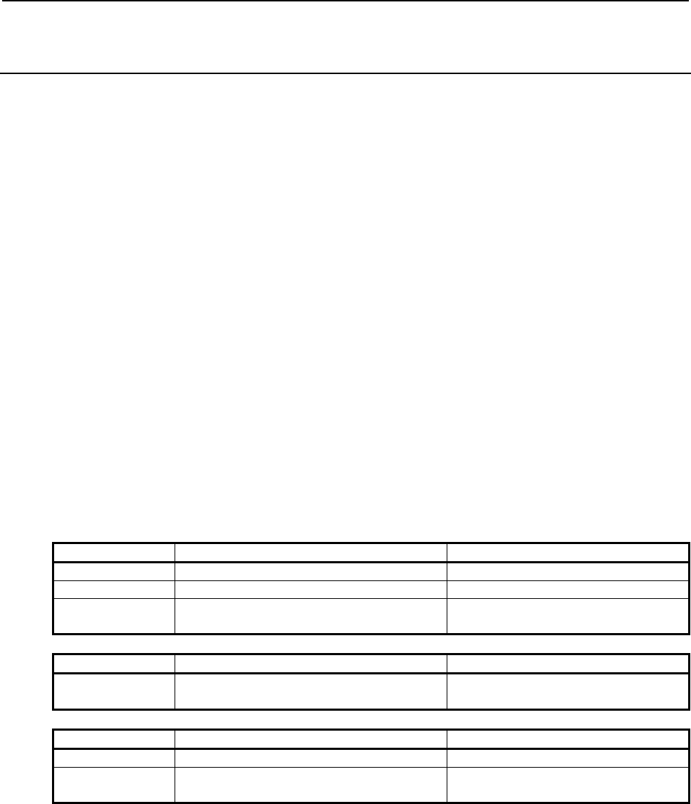
B-64513EN/03
2.PMC SPECIFICATIONS
- 159 -
2.6.8
Compatibility between Power Motion i-A PMC and
PMC-SB5/SB6 for Power Mate i-H
The series 35i-B PMC is highly compatible with the PMC-MODEL SB5/SB6 (PMC-SB5/SB6) for the
Power Mate i-MODEL D (Power Mate i-D) on the source level.
Transporting programs require modification because the specifications of the following functions have
been changed.
(1) In case of PMC-SB5/SB6, the first level execution period is fixed at 8 msec. In case of the series
35i-B PMC, it can be switched between 4 and 8 msec, using a CNC parameter.
(2) The interrupt-type PMC function is not supported.
(3) In case of PMC-SB5/SB6, the basic instruction execution speed is 85 ns/step. In case of the series
35i-B PMC, it is 9.1ns/step. The execution speed of functional instructions becomes fast.
(4) As the execution speed of instructions become fast, the following items about execution timing may
be changed.
- The execution cycle of both first and second level of ladder
- The timing of the execution cycle of first level of ladder according to the partition of second
level ladder
- The timing between ladder execution and I/O transfer or F,G signals
The working test of the machine is necessary.
(5) The used size of system, some functional instructions and symbol/comment are changed. Generally,
the program size of the series 35i-B PMC becomes bigger than one for PMC-SB5/SB6 even if the
same source program is converted. If the program size exceeds the capacity of the flash ROM,
change the ladder step option or reduce the symbol and comment.
(6) The functional instruction “DISP” in the PMC-SB5/SB6 is not supported on the series 35i-B PMC.
Convert into the instruction “DISPB”.
(7) The meaning of the following system keep relays is changed for the improvement of some functions.
- Improvement of the signal trace function
Keep relays PMC-SB5/SB6 35i-B PMC
K900.5/K17.5 Signal trace function starts automatically.
-
K900.6/K17.6 Signal Analysis function starts automatically.
-
K906.5
-
Signal trace function for embedded
screen starts automatically.
- Improvement of the programmer protection function
Keep relays PMC-SB5/SB6 35i-B PMC
K900/K17.0 Hide ladder program. The sequence program is inhibited from
being viewed
- Improvement of the I/O Link selectable assignment function
Keep relays PMC-SB5/SB6 35i-B PMC
K904 to K905 Effective group selection
-
K920 to K927
-
Enable or disable assignment for the
selectable I/O Link assignment function

2.PMC SPECIFICATIONS
B-64513EN/03
- 160 -
(8) The meaning of the NC parameter No.24 is changed.
Value PMC-SB5/SB6 35i-B PMC
0 Disables ”RS–232C” and enables ”HIGH
SPEED I/F”.
However, enables ”HIGH SPEED I/F” if the
LADDER EDITING PACKAGE or the
Ethernet option exists.
The settings on the online monitor
setting screen
are effective.
1 Enables ”Channel 1 of RS–232C” and
disables
”HIGH SPEED I/F”.
The same meaning as the left.
2 Enables ”Channel 2 of RS–232C” and
disables
”HIGH SPEED I/F”.
The same meaning as the left.
10 Reserve (Don’t use this setting.) Disables ”RS–232C” and
enables ”HIGH SPEED I/F”.
11 Enables ”Channel 1 of RS–232C” and ”HIGH
SPEED I/F”.
The same meaning as the left.
12 Enables ”Channel 2 of RS–232C” and ”HIGH
SPEED I/F”.
The same meaning as the left.
255 Terminates communication forcibly.
It is the same effect as soft key [EMG ST].
The same meaning as the left.
(9) The built-in I/O card is not supported on the series 35i-B PMC. Use external I/O devices of I/O Link
or I/O Link i.
(10) The slave function of I/O Link is not supported. For communication with CNC, use I/O Link
connection unit or Fl-net.
(11) For the PMC-SB5/SB6, the timer precision defined with the TMR functional instruction is fixed at a
certain value. For the series 35i-B PMC, the timer precision can be set up for each timer number
separately. See Subsection 4.3.1 for details.
(12) The functional instruction PSGNL and PSGN2 do not support the actual position load function of
absolute position detector.
(13) The nonvolatile memory control keep relay (MWRTF and MWRTF2) has been changed from K16
to K909.
(14) Window function "Reading diagnosis data" is a Low-speed response type.
(15) When using Window function "No.30 Reading the servo delay for controlled axes" with the data
number N=0, the data is read with input unit. When using the function with the data number N=1,
the data is read with detection unit. On PMC-SB5/SB6, the data is always read with detection unit.
(16) When using Window function "No.31 Reading the acceleration / deceleration delay on controlled
axes" with the data number N=0, the data is read with input unit. When using the function with the
data number N=1, the data is read with detection unit. On PMC-SB5/SB6, the data is always read
with machine unit.
(17) A part of window function for PMC-SB5/SB6 is not supported. See “3.4 Window function” for
available window function.
(18) The contents of the completion codes for some window functions are changed. See “3.4 Window
function” for the completion codes.
(19) The MMCWR, MMCWW, and FNC90 to FNC97 functional instructions are treated as a NOP.
PMC parameter compatibility
Parameters prepared for PMC-SB5/SB6 can be loaded to the series 35i-B PMC.

B-64513EN/03
2.PMC SPECIFICATIONS
- 161 -
2.6.9
Compatibility between 0i-F PMC and 30i/31i/32i/35i-B PMC
Ladder program compatibility
The series 0i-F PMC is highly compatible with the series 30i/31i/32i/35i-B PMC on the source level.
You can use the sequence program of the series 30i/31i/32i/35i-B PMC on the series 0i-F PMC by
changing the PMC model using FANUC LADDER-III.
As the execution speed of instructions is different, the following items about execution timing may be
changed.
- The execution cycle of both first and second level of ladder
- The timing of the execution cycle of first level of ladder according to the partition of second
level ladder
- The timing between ladder execution and I/O transfer
The working test of the machine is necessary.
PMC parameter compatibility
PMC parameters outputted from the series 30i/31i/32i/35i-B PMC can be loaded into the series 0i-F PMC
without any modification.
2.6.10
Compatibility between 0i-F DCSPMC and 30i/31i/32i/35i-B
DCSPMC
Ladder program compatibility
The series 0i-F DCSPMC is equal to the series 30i/31i/32i/35i-B DCSPMC.
The series 0i-F DCSPMC is highly compatible with the series 30i/31i/32i/35i-B DCSPMC on the source
level.
You can use the sequence program of the series 30i/31i/32i-B DCSPMC on the series 0i-F by changing
the PMC model using FANUC LADDER-III.
As the execution speed of instructions is different, the following items about execution timing may be
changed.
- The execution cycle of both first and second level of ladder
- The timing of the execution cycle of first level of ladder according to the partition of second
level ladder
- The timing between ladder execution and I/O transfer
The working test of the machine is necessary.
PMC parameter compatibility
PMC parameters output from the series 30i/31i/32i/35i-B DCSPMC can be loaded into 0i-F DCSPMC
without any modification.
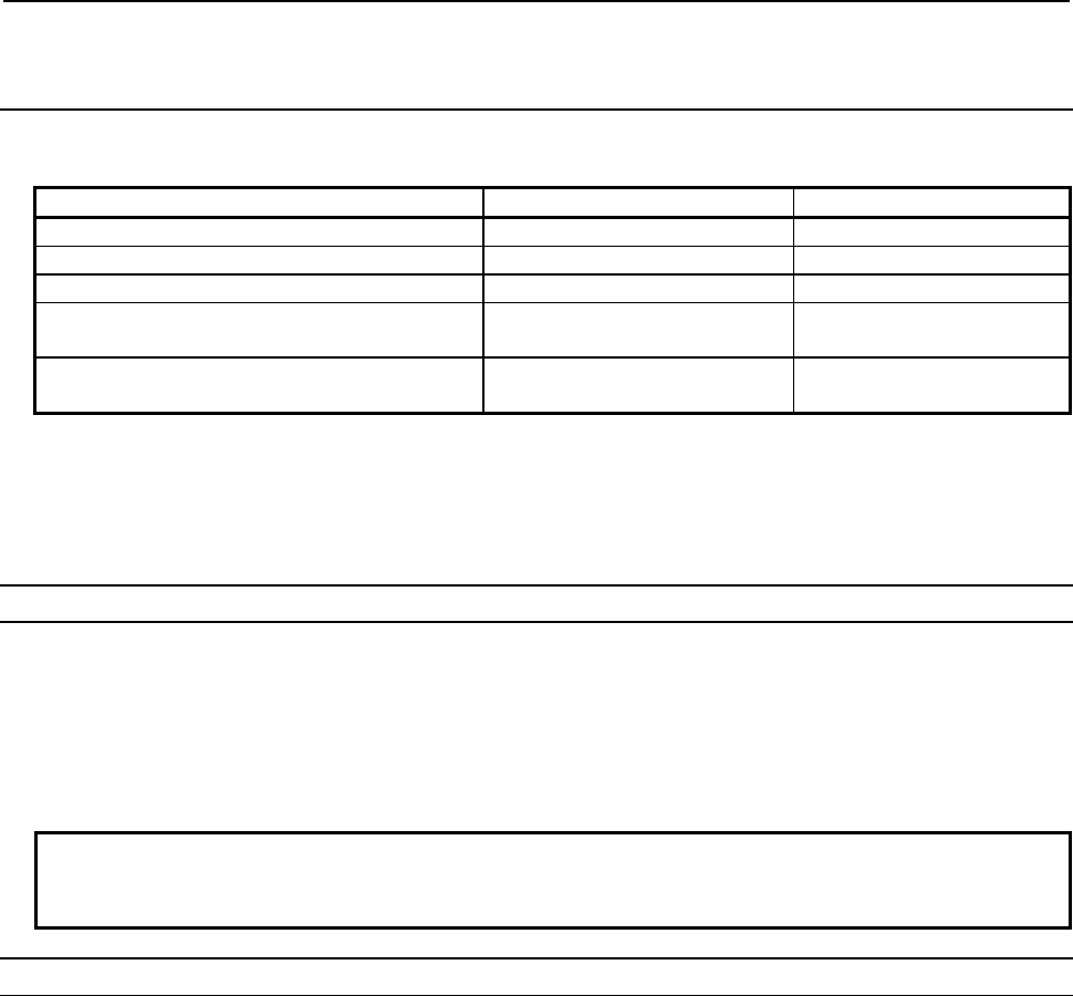
2.PMC SPECIFICATIONS
B-64513EN/03
- 162 -
2.6.11
The Convert Method of Source Program Using FANUC
LADDER-III
The version of FANUC LADDER-III applied to the series 30i/31i/32i/35i-B PMC is 6.30.
Name Drawing number Note
FANUC LADDER-III A08B-9210-J505 For one PC
FANUC LADDER-III (10 users) A08B-9210-J541 For 10 PCs
FANUC LADDER-III (20 users) A08B-9210-J542 For 20 PCs
FANUC LADDER-III (Site license) A08B-9210-J543 For unlimited PC numbers in
a site of a corporation
FANUC LADDER-III Upgrade A08B-9210-J544 For upgrade your software to
the latest version
FANUC LADDER-III is used to convert a sequence program of other PMC models to the one of the
series 30i/31i/32i/35i-B, 0i-F PMC.
Changing PMC model is possible easily with using the "PMC Type changed and save" function of
FANUC LADDER-III.
(1) Converting with "PMC type changed and save" function.
The conversion procedure to the first PMC of the series 30i-B from PMC-SB7 is as follows.
i) Activate FANUC LADDER-III, and open the original ladder program for PMC-SB7.
ii) Select [File] - [PMC Type changed and save].
iii) Input the destination ladder program name, and select PMC Type, PMC Path and PMC Memory,
and press the [Ok] button.
NOTE
For detailed operation, see the section "3.18 PMC TYPE CHANGED AND SAVE"
of "FANUC LADDER-III OPERATOR'S MANUAL(B-66234EN)".
(2) Converting with mnemonic conversion
The sequence of the conversion to the first PMC of the series 30i-B from PMC-SB7 is as follows.
i) Convert a source program into the mnemonic file by FANUC LADDER-III.([Tool]->[Source
Program Convert])
ii) Change the system parameters in the mnemonic file for PMC-SB7 by text editor. (“4 PMC-SB7” ->
“4 30i-B PMC”)
If the mnemonic file has insufficient parameters for the first PMC of the series 30i-B from
PMC-SB7, the initial values are set with conversion for the source program.
The mnemonic file format of the system parameter for the first PMC of the series 30i-B is as
follows.

B-64513EN/03
2.PMC SPECIFICATIONS
- 163 -
%@0
2 BINARY 2: Counter type (BINARY or BCD)
3 NO 3: Operator panel (YES or NO)
4 30i-B PMC 4: PMC type (30i-B PMC)
31 1 31: Number of display language (comment) (1-16)
32 -1 32: CNC display language number 1 (-1, 0-127)
33 0 33: Comment set number 1 (0-16)
%
iii) Create a new LAD file for the first PMC of the series 30i-B by FANUC LADDER-III.
iv) Convert the mnemonic file to the source program.([Tool] -> [Mnemonic Convert])
NOTE
For detailed operation, see the section "11.19 HOW TO CONVERT FROM
CONVENTIONAL MODEL" of "FANUC LADDER-III OPERATOR'S MANUAL
(B-66234EN)".

2.PMC SPECIFICATIONS
B-64513EN/03
- 164 -
2.7 PMC MESSAGE MULTI-LANGUAGE DISPLAY FUNCTION
The PMC message multi-language display function manages the language of alarm message and operator
message, switching the language according to the language setting of CNC using message data defined in
various languages. The message data for this function is stored into a memory card format data,
separated from the data of ladder program, and loaded into CNC individually. Up to 6,000 messages
can be registered for each language.
This function, when compared with the conventional multi-language display capability based on the
message shift function, has the following features:
• Because “A” address area does not need to be divided for messages of each language, all bits of “A”
address can be used for each language, and available number of message is increased.
• Switching the language of alarm messages and operator messages do not need power cycle of CNC,
and the language follows the setting of CNC display language dynamically.
• A message data file can be replaced, independently of ladder program.
2.7.1 Usage of PMC Message Multi-Language Display Function
To utilize the PMC message multi-language display function, you need to prepare the data files with
FANUC LADDER-III and store them into CNC as described below:
Step 1) At first, prepare a ladder program. The message data in the ladder program must have alarm
numbers associated.
Step 2) Prepare a mnemonic file of multi-language message data. The mnemonic file is a text file,
and can be created and edited by some text editor application on PC. The alarm numbers in
the mnemonic file must correspond with the alarm numbers in the message data of the ladder
program.
Step 3) Make the memory card format file of the ladder program by compile process on FANUC
LADDER-III as usual.
Step 4) Make the memory card format file of the multi-language message data using “Multi-language
PMC Message Creation Tool” included in FANUC LADDER-III which supports this function.
Step 5) Store these memory card format files created in step 3 and 4. You can use Boot Menu to store
them directly into Flash ROM, or you can use PMC I/O screen to read them into the memory,
and then write them into Flash ROM.
You can store two or more language sets of messages into a multi-language message data file. And you
can prepare two or more multi-language message data files to enable switching the available language of
the messages by altering the message file in CNC afterwards.
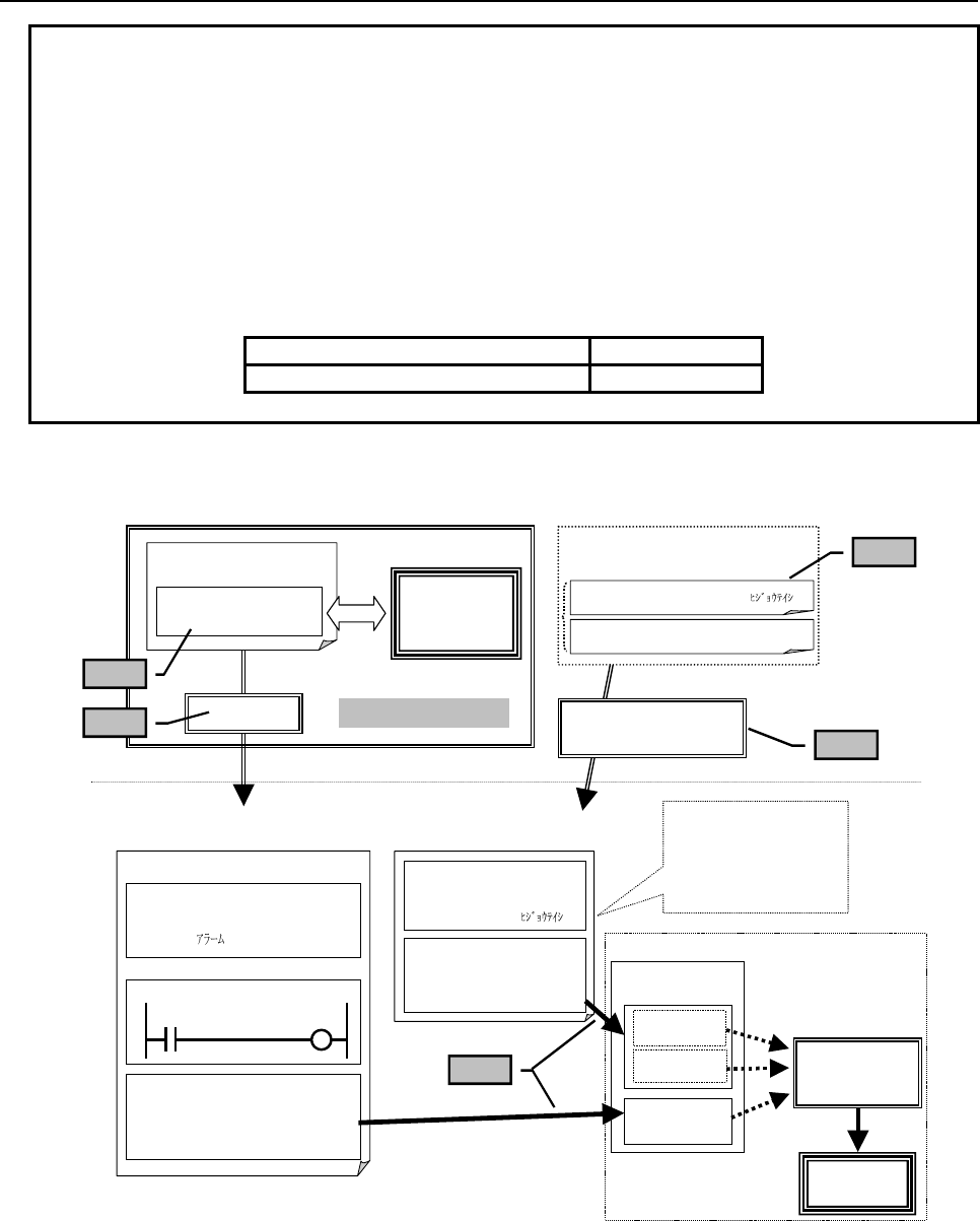
B-64513EN/03
2.PMC SPECIFICATIONS
- 165 -
NOTE
1 Message data for multi-language display cannot be created, browsed, or edited
on the CNC screen. To create or edit the message data, FANUC LADDER-III is
required.
2 If the ladder program uses the extended symbol and comment feature, you can
use symbols in multi-language message data instead of “A” address notation.
Otherwise, you have to use “A” address notation only. On the ladder dividing
management function, the symbols defined in main ladder program can be used
for the message data for multi-language display.
3 For instructions of FANUC LADDER-III and file format of multi-language message
data mnemonic file, refer to the following manual:
Manual title Drawing No.
FANUC LADDER-III Operator's Manual B-66234EN
Outline of the process flow from data creation to display them with PMC message multi-language display
function
Mnemonic file (Message)
PC
Japanese
ALM1001 “1001 ”
German
ALM1001 “1001 E.ST
ö
P”
Compile
Message (standard)
A
000.0→“1001 E.STOP”
A
000.1→“1002 FUSE IS BLOWN”
:
PMC sequence program
(Memory card format file)
:
Symbol and comment data
ALM1001 A000.0
$1 ‘ No.1001’
:
Ladder data
A0000.0
Message (option)
(Memory card format file)
2nd message data
(German)
A
LM1001 “1001 E.ST
ö
P”
1st message data
(Japanese)
ALM1001 “1001 ”
CNC
Flash ROM
English
(Others)
German
Japanese
Multi-language PMC
Message Creation Tool
Message
display/editor
screen
To be loaded using
the CNC boot menu
or PMC I/O screen
as with a PMC
sequence program
FANUC LADDER-III
CNC
ID code:%@4-D (ANSI/Unicode)
Message
screen
Ladder program
DISPB function
CNC Display
Language
Step 2
Step 4
Step 5
Step 3
Message (Standard)
A
LM1001 “1001 E.STOP”
Step 1

2.PMC SPECIFICATIONS
B-64513EN/03
- 166 -
2.7.2
Multi-Language Display
By setting the display language attribute for each message data item for multi-language display to be
edited, the language of alarm/operator messages to be displayed can be dynamically switched to match
the CNC display language. Up to 6,000 messages can be registered for each language.
Language attribute (language ID) of message data is specified in mnemonic file of multi-language
message data.
NOTE
1 For the language ID, refer to "APPENDIX B. LANGUAGE ID TABLE".
2 The message data, in which unsupported language ID is specified, is not
displayed.
Alarm number setting
To display messages of multi-language message data, alarm numbers at least have to be defined at the
corresponding entries in ordinary message data in ladder program. And each alarm number of “A”
address has to have identical alarm number in multi-language message data and in ordinary message data.
If they differ with each other, alarm number of ordinary message data will be used.
Selection of language
If messages of required language are not found in multi-language message data, English messages will be
used instead. If English messages are not found either, messages in ordinary message data in ladder
program will be used.
NOTE
1 A message defined in multi-language message data will not be displayed unless
the corresponding message data in ladder program has valid alarm number.
2 If messages of current language has no corresponding message entry to the bit
of “A” address that has turned on, alarm message without any message will be
issued, with the alarm number that is defined at corresponding entry in ordinary
message data. If ordinary message data has no valid alarm number at the
entry, no alarm is issued.
3 It may take a while to change the language of alarm and operator messages after
changing display language of CNC. The more messages per a language are
defined especially using symbol, the longer time it tends to take to switch them.

B-64513EN/03
2.PMC SPECIFICATIONS
- 167 -
2.7.3
Maximum Number of Message
The number of displayable alarm messages and the number of displayable operator messages can be
extended to 16 by the following NC parameter:
NC parameter No. 11931 bit 1 = 0: Displays up to 4 messages (conventional specification).
1: Displays up to 16 messages.
NOTE
To increase the number of displayable messages on the CNC screen, the
relevant NC parameter needs to be set. If the number of displayable messages
is increased by setting the NC parameter, the number of displayable messages
also increases with DISPB instruction, even without using multi-language display
function.
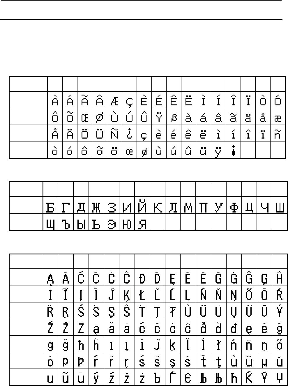
2.PMC SPECIFICATIONS
B-64513EN/03
- 168 -
2.7.4
Display of European Characters
With the conventional PMC message function, for example a European character such as “À” can be
edited only in the code format notation, enclosing the character code between “@0D” and “01@”. With
the PMC message multi-language display function, you can edit these characters as a normal character to
create message data on personal computer.
The European characters, which are available on CNC screen, are listed in the following table:
Table 2.7.4(a) European character type1 code table
Character
Code +0 +1 +2 +3 +4 +5 +6 +7 +8 +9 +A +B +C +D +E +F
A0
B0
C0
D0
* The character code in the table is for the code format notation. which is enclosed by "@0D" and "01@"
Table 2.7.4 (b) European character type2 code table
Character
Code
+0 +1 +2 +3 +4 +5 +6 +7 +8 +9 +A +B +C +D +E +F
A0
B0
* The character code in the table is for the code format notation which is enclosed by "@0E" and "01@"
Table 2.7.4 (c) European character type 3 code table
Character
Code
+0 +1 +2 +3 +4 +5 +6 +7 +8 +9 +A +B +C +D +E +F
60
70
80
90
A0
B0
C0
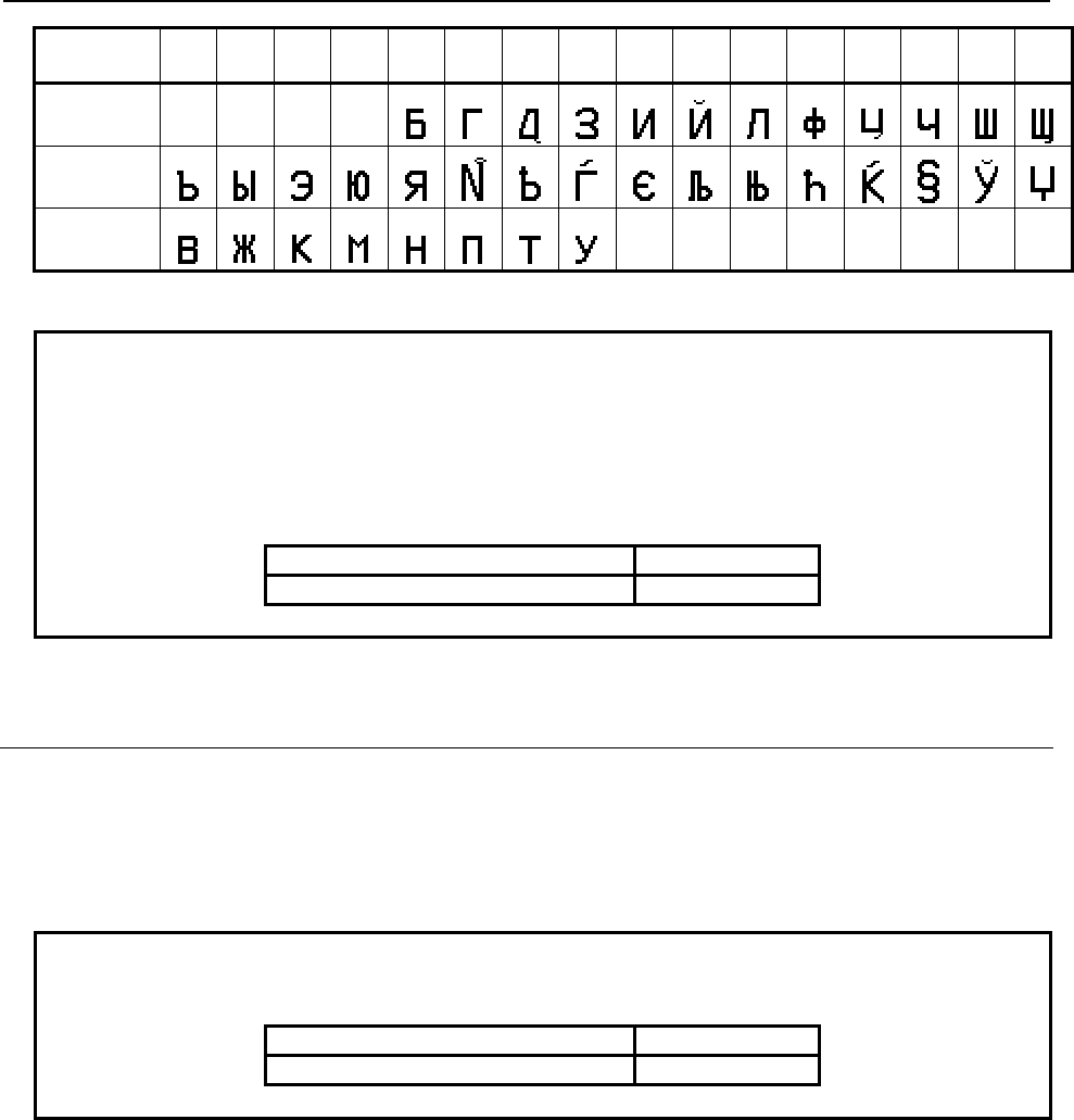
B-64513EN/03
2.PMC SPECIFICATIONS
- 169 -
Character
Code
+0 +1 +2 +3 +4 +5 +6 +7 +8 +9 +A +B +C +D +E +F
D0
E0
F0
* The character code in the table is for the code format notation which is enclosed by "@05" and "01@"
NOTE
1 The characters that can be displayed on CNC screen are as same as ones that
can be displayed by conventional DISPB function. If code of a character that
can not be displayed is contained in message data, the character will not be
displayed.
2 For instructions for editing message data on personal computer, refer to the
following manual:
Manual title Drawing No.
FANUC LADDER-III Operator's Manual B-66234EN
2.7.5
Display of Simplified Chinese and Korean (Hangul
Characters)
With the PMC message multi-language display function, you can edit Simplified Chinese and Korean
(Hangul characters) as a normal character to create message data on personal computer. All Multi-byte
characters of Simplified Chinese code (GB2312) can be displayed on CNC. But some Korean (Hangul)
characters cannot be displayed on CNC. The Korean (Hangul characters) which are available on CNC
screen are listed in the following table.
NOTE
For instructions for editing message data of Simplified Chinese and Korean
(Hangul characters) on personal computer, refer to the following manual:
Manual title Drawing No.
FANUC LADDER-III Operator's Manual B-66234EN

2.PMC SPECIFICATIONS
B-64513EN/03
- 170 -
Hangul characters that can be displayed on CNC screen

B-64513EN/03
2.PMC SPECIFICATIONS
- 171 -
2.8 BATTERY BACKUP DATA
Some data on the CNC is preserved by the battery so that the data will not be lost even when the main
power is turned off.
The battery backup data is lost when the battery voltage decreases. Therefore, the data needs to be saved
to an external device periodically, and the battery needs to be replaced with a new one.
NOTE
For the method of battery replacement, refer to "Maintenance Manual" of each
CNC series.
With the PMC, the following data is preserved by the battery:
Type of data Data item
PMC parameters (Note 1) Timer (T)
Counter (C)
Keep relay (K)
Data table (D)
Data table control data
Extra relay (E) (Note 2)
Settings of various functions and screens Setting of the PMC data I/O function
Setting of the online function
Setting of the trace function
Setting of the ladder diagram screen
Setting of the I/O diagnosis screen
NOTE
1 A delay occurs in PMC parameter backup operation. For details, see
Subsection 2.3.1, "Cautions for Reading from/Writing to Nonvolatile Memory ".
2 The data is preserved when using the nonvolatile PMC extra relay function
(option).
By the following functions, battery backup data can be saved to an external device.
Type of data External device Function Remarks
PMC parameters Memory card
Handy File
RS-232C device
Writing PMC parameters
from the PMC data I/O
screen
For details, see Section 7.4.
Personal
Computer
Loading PMC parameters
with FANUC LADDER-III
For details, see FANUC
LADDER-III OPERATOR’S
MANUAL (B-66234EN)”.
All CNC data (including
PMC parameters and the
settings of various functions
and screens)
Memory card Backing up the S-RAM with
the boot system
For details, see MAINTENANCE
MANUAL
(30
i
/31
i
/32
i
-B:B-64485EN,
35
i
-B:B-64525EN)".
PMC battery backup data can be cleared by the following operation:
Type of data Operation
PMC parameters,
Settings of various functions and screens
Select [3.CLEAR FILE] - [5:PMC-PARA.DAT] from the IPL menu.
Hold down "O" and "Z" when turning on the power to the CNC.

2.PMC SPECIFICATIONS
B-64513EN/03
- 172 -
WARNING
Take special care when clearing PMC parameters. When PMC parameters are
cleared, the machine may malfunction. After clearing PMC parameters, be sure
to set the correct values again.
NOTE
PMC battery backup data is also cleared when the entire memory of the CNC is
cleared. For operation to clear the entire memory of the CNC, refer to
"Maintenance Manual (30i/31i/32i-B:B-64485EN, 35i-B:B-64525EN)".

B-64513EN/03
2.PMC SPECIFICATIONS
- 173 -
2.9 File Name of Flash ROM related to PMC
The file names of flash ROM related to PMC are as follows.
Kind of data File name of flash
ROM
Sequence program
(Main ladder program)
1st path PMC PMC1
2nd path PMC PMC2
3rd path PMC PMC3
4th path PMC PMC4
5th path PMC PMC5
DCSPMC PMCS
Sequence program
(Divided ladder program)
Divided ladder program number 1 of 1st path PMC L101PMC1
Divided ladder program number 2 of 1st path PMC L102PMC1
Divided ladder program number 3 of 1st path PMC L103PMC1
:
:
Divided ladder program number 98 of 1st path PMC L198PMC1
Divided ladder program number 99 of 1st path PMC L199PMC1
Divided ladder program number 1 of 2nd path PMC L201PMC2
:
:
Divided ladder program number 99 of 2nd path PMC L299PMC2
Divided ladder program number 1 of 3rd path PMC L301PMC3
:
:
Divided ladder program number 99 of 3rd path PMC L399PMC3
Divided ladder program number 1 of 4th path PMC L401PMC4
:
:
Divided ladder program number 99 of 4th path PMC L499PMC4
Divided ladder program number 1 of 5th path PMC L501PMC5
:
:
Divided ladder program number 99 of 5th path PMC L599PMC5
Message data for multi-
language display
1st path PMC M1PMCMSG
2nd path PMC M2PMCMSG
3rd path PMC M3PMCMSG
4th path PMC M4PMCMSG
5th path PMC M5PMCMSG
I/O configuration data IOCONF
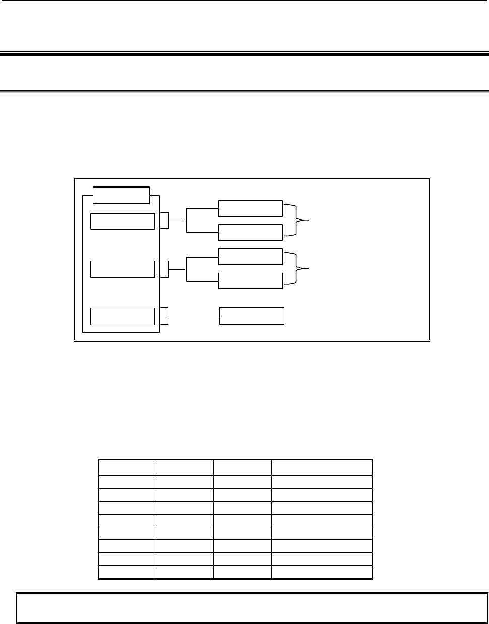
3.COMMUNICATION WITH I/O DEVICE
B-64513EN/03
- 174 -
3 COMMUNICATION WITH I/O DEVICE
3.1 I/O Link i and I/O Link
There are two communication methods for the high-speed serial interface which transmits input/output
signals between the PMC and I/O devices. They are the FANUC I/O Link i and the FANUC I/O Link.
You can use up to three channels for the serial interface. The communication method for channel 1 and
channel 2 can be specified by the CNC parameter. The channel 3 can be used only for the I/O Link.
For the details of the setting of the CNC parameter, see subsection “2.4.3”.
Channel 1
Channel 2
Channel 3 I/O Link
I/O Link i
I/O Link
I/O Link i
I/O Link
Switched by CNC parameter
11933#0
CNC
Switched by CNC parameter
11933#1
Fig. 3.1 Setting of communication method for each channel
The maximum I/O points of the I/O Link i are 2048 poins/2048 points for each channel. The maximum
I/O points of the I/O Link are 1024 points/1024 points for each channel. The maximum I/O points for a
PMC system are 4096 points/4096 points (0i-F: 2048 points/2048 points). You can use one or more
channels of the I/O Link i and the I/O Link however the total points cannot exceed the maximum points
of the PMC system.
[Example of the selectable case of the I/O Link i and the I/O Link]
Channel 1 Channel 2 Channel 3 Total points (DI / DO)
I/O Link i I/O Link i - 4096 / 4096 (Note)
I/O Link i I/O Link I/O Link 4096 / 4096 (Note)
I/O Link i I/O Link - 3072 / 3072 (Note)
I/O Link I/O Link I/O Link 3072 / 3072 (Note)
I/O Link i - - 2048 / 2048
I/O Link I/O Link - 2048 / 2048
I/O Link - I/O Link 2048 / 2048
I/O Link - - 1024 / 1024
NOTE
For the series 0i-F, the total points (DI/DO) are 2048/2048 points.
For the multi-path PMC, the DI/DO of one channel can be assigned to plural PMC paths efficiently using
the I/O Link i. The connect position of I/O devices can be defined as group/slot number.
As for the transmission cycle of the signals from the I/O Link i, there are two modes of the normal mode
(2msec) and the high-speed mode (0.5msec). You can specify the mode for each group of I/O devices.
For details, refer to subsection “3.3.3”.
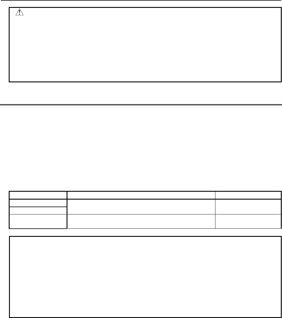
B-64513EN/03
3.COMMUNICATION WITH I/O DEVICE
- 175 -
CAUTION
1 For an I/O Link i channel, You should use I/O devices applied to the I/O Link i.
Or for an I/O Link channel, you should use I/O devices applied to the I/O Link. If
you use an inadaptable I/O device, all of I/O devices after the device cannot be
connected.
2 In case of using the dual check safety function, you can build the system by
using only devices of the I/O Link i or only devices of the I/O Link. You cannot
build the system by using both the I/O Link i and the I/O Link. If you use I/O Link,
I/O devices for DCSPMC must be connected to channel 3.
3.2
WHAT IS THE I/O LINK?
The FANUC I/O Link is one of the serial interfaces and transmits input/output signals between the PMC
and each I/O device at a high speed.
Available channels are three channels and for each channel, up to 1024 DI points and up to 1024 DO
points can be connected and controlled from the PMC.
The update cycle of the signals from I/O Link depends on the combination with each PMC and each I/O
Link channel. The following table shows the update cycle of the signals from I/O Link when each PMC
uses each I/O Link channel.
Table 3.2 (a) Update cycle of the signals from I/O Link
1st to 5th path PMC DCSPMC
Channel 1 2msec (cannot use)
Channel 2
Channel 3 Ladder 1st level execution cycle is 1, 2 or 4ms : 4ms
Ladder 1st level execution cycle is 8ms : 8ms 2msec
NOTE
1 When the 1st to 5th path PMC uses I/O Link channel 3, the update cycle of the
signals from I/O Link channel 3 becomes 4 msec or 8 msec. In this case, note
that the response of the CNC for the changing of the direct reference signals,
such as skip signals, reference position return deceleration signals and
emergency stop signals, becomes slower than the using of channel 1 or 2.
2 When using the I/O Link, the last 1byte of the X address for which no I/O device
is assigned (normally X127, X327, X527 or X727) is used by the system.
Therefore, some bits at these X addresses may be changed.
Do not use X addresses for which no I/O device is assigned.
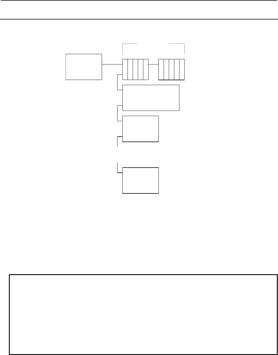
3.COMMUNICATION WITH I/O DEVICE
B-64513EN/03
- 176 -
3.2.1
Configuration of an I/O Link
The following figure shows a basic configuration of the I/O Link.
I/O Link
master
Operator's panel
connection unit
Slaves
Power Mate
: : : : :
: : : : :
Group 0
Group 1
Group 2
Group 15
I/O Unit I/O Unit
(1) The I/O Link consists of one master and multiple slaves.
Master: CNC (such as Series 30i-B)
Slaves: I/O Unit-MODEL A, Power Mate, operator's panel connection unit, and other devices
(2) Up to 16 groups of slaves can be connected to one I/O Link.
Group numbers 0 to 15 are sequentially assigned. Number 0 is assigned to the group nearest to the
master.
The number of connected slaves in a group differs depending on the types of slaves.
(3) Any slave can be connected in any group. One group must consist of slaves of the same type,
however.
NOTE
1 Turn the power to the slaves and master on simultaneously or turn the power to
the slaves on before turning the power to the master.
2 When turning the power to the master off, also turn the power to all slaves off.
Turn the power to all slaves on again before turning the power to the master on or
turn the power to all slaves and the master on simultaneously. Turn the power to
the master on after turning the power to all slaves on or turn the power to the
master and all slaves on simultaneously.
3 For the maximum number of slaves per group that can be connected, refer to the
hardware connection manual for each I/O device used as a slave.
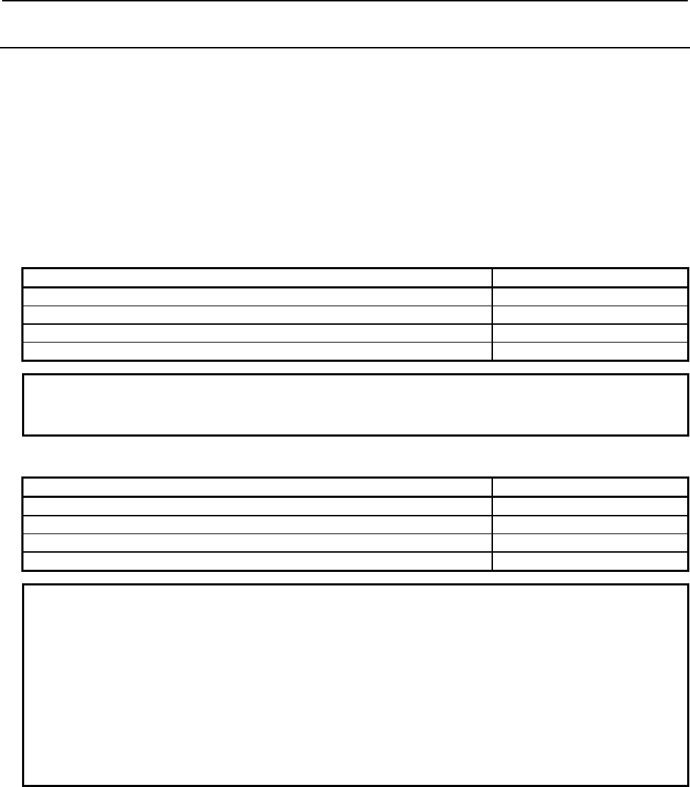
B-64513EN/03
3.COMMUNICATION WITH I/O DEVICE
- 177 -
3.2.2
Numbers of Input Points and of Output Points of the I/O Link
The I/O Link has up to 1024 input points and up to 1024 output points for each channel when viewed
from the master. These I/O points can be assigned to each slave to periodically pass I/O data between the
master and each slave.
Each slave occupies the predetermined number of I/O points.
The total number of I/O points occupied by all slaves connected to one channel is up to 1024 points (128
bytes) for each of input and output.
The number of I/O points occupied by one group is up to 256 points (32 bytes) for each of input and
output.
Obtain the number of occupied I/O points as follows.
[Number of output points]
Total number of points required for output modules used in one group Number of occupied I/O points
0 to 32 32
40 to 64 64
72 to 128 128
136 to 256 256
NOTE
When obtaining the number of points, assume that the number of points required
for AOA05E is 8 and that of points required for AOA12F is 16.
[Number of input points]
Total number of points required for input modules used in one group Number of occupied I/O points
0 to 32 32
40 to 64 64
72 to 128 128
136 to 256 256
NOTE
The number of occupied I/O points may differ from the actual number of I/O
points. For example, if the number of input points is smaller than or equal to that
of output points for a group, the number of input points is assumed equal to that
of output points. For this reason, when the number of input points for the actually
connected hardware components is 128 and that of output points is 256, the
number of occupied input points is assumed to be 256 because there is the
following relationship between the numbers of input points and of output points:
128 (number of input points)≦256 (number of output points)
For more specific rules, see Section 3.2.3.

3.COMMUNICATION WITH I/O DEVICE
B-64513EN/03
- 178 -
3.2.3
Assignment Method
To use an I/O device as a slave, assign connection information to X addresses (input) and Y addresses
(output) of the PMC. The machine tool builder should determine addresses to be used for input/output of
each I/O device in a sequence program. Connection information can be assigned to these determined
addresses using the PMC screen or FANUC LADDER-III. The information is written in the flash ROM
together with the sequence program. For this reason, the set information is not changed unless the
sequence program is changed.
Information to be set to addresses includes the connection location and module name of each I/O device.
The connection location of an I/O device is represented by its group, base, and slot numbers. For the
module name, set a name representing connected I/O device.
Setting the connection location
I/O devices can roughly be divided into the following three types according to the method for specifying
the connection location.
(1) Type of I/O device whose connection location is specified with its group, base, and slot numbers
I/O Unit-MODEL A is of this type. Specify the connection location with its group, base, and slot
numbers.
The range of valid settings of each item is as follows:
Group = 0 to 15
Base = 0 and 1
Slot = 1 to 10 (number of a slot on a I/O Unit-MODEL A base board)
(2) Type of I/O device whose connection location is specified with its group and slot numbers
I/O Unit-MODEL B and handy machine operator's panels are of this type. Always set the base
number to 0.
The range of valid settings of each item is as follows:
Group = 0 to 15
Base = 0 (Always set 0.)
Slot = 0 to 30 (NOTE)
NOTE
For detailed information on settings, see Subsections 3.2.3.2 and 3.2.3.6.
(3) Type of I/O device whose connection location is specified with its group number
Machine operator's panel interface unit, I/O Link connection unit, Power Mate, and other devices are
of this type. One unit of this type occupies one group. When using this type, always set the base
number to 0 and the slot number to 1.
The range of valid settings of each item is as follows:
Group = 0 to 15
Base = 0 (Always set 0.)
Slot = 1 (Always set 1.)

B-64513EN/03
3.COMMUNICATION WITH I/O DEVICE
- 179 -
Setting the module name
Set the module name at the X or Y address assigned as input/output of each I/O device. For the module
name, see Tables 3.2 (a) to (c).
The number of bytes of the address occupied is determined for each module name. The number of
occupied I/O points per byte is 8.
These module names are able to replace modules having same number of points.
Module name Occupied address
/1 to /8 1 to 8 bytes for input
1 to 8 bytes for output
/12 12 bytes for input
12 bytes for output
/16 16 bytes for input
16 bytes for output
/20 20 bytes for input
20 bytes for output
/24 24 bytes for input
24 bytes for output
/28 28 bytes for input
28 bytes for output
/32 32 bytes for input
32 bytes for output
NOTE
1 Assign the start byte of an analog input module (AD04A) or analog output module
(DA02A) to an even input address (X ) or even output address (Y ).
2 Always read an A/D converted digital value from an input address (X ) or
write a digital value to be converted to an analog value to an output address
(Y ) in word (16-bit) units.
For details of the assignment method, see the assignment method for each I/O device described later.
When you want to set assignment data using the I/O module screen, for required operations, see Section
9.4.

3.COMMUNICATION WITH I/O DEVICE
B-64513EN/03
- 180 -
Table 3.2.3 (a) Module names (1)
Name Module name
(actual module name) Occupied address Specifications
Input modules for
I/O Unit-MODEL A
ID32A (AID32A1) 4 bytes for input A03B-0807-J101
ID32B (AID32B1) 4 bytes for input A03B-0807-J102
ID16C (AID16C) 2 bytes for input A03B-0807-J103
ID16D (AID16D) 2 bytes for input A03B-0807-J104
ID32E (AID32E1) 4 bytes for input A03B-0807-J105
ID32E (AID32E2) 4 bytes for input A03B-0807-J110
ID32F (AID32F1) 4 bytes for input A03B-0807-J106
ID32F (AID32F2) 4 bytes for input A03B-0807-J109
IA16G (AIA16G) 2 bytes for input A03B-0807-J107
AD04A (AAD04A) 8 bytes for input A03B-0807-J051
AD04A (AAD04B) 8 bytes for input A03B-0819-J063
ES01A (AES01A) 1 byte for input A03B-0807-C108
ID08F (AID08F) 1 byte for input A03B-0807-C112
Output modules for
I/O Unit-MODEL A
OD32A (AOD32A1) 4 bytes for output A03B-0807-J162
OD08C (AOD08C) 1 byte for output A03B-0807-J151
OD08D (AOD08D) 1 byte for output A03B-0807-J152
OD16C (AOD16C) 2 bytes for output A03B-0807-J153
OD16D (AOD16D) 2 bytes for output A03B-0807-J154
OD32C (AOD32C1) 4 bytes for output A03B-0807-J155
OD32C (AOD32C2) 4 bytes for output A03B-0807-J172
OD32D (AOD32D1) 4 bytes for output A03B-0807-J156
OD32D (AOD32D2) 4 bytes for output A03B-0807-J167
OA05E (AOA05E) 1 byte for output A03B-0807-J157
OA08E (AOA08E) 1 byte for output A03B-0807-J158
OA12F (AOA12F) 2 bytes for output A03B-0807-J159
OR08G (AOR08G) 1 byte for output A03B-0807-J160
OR16G (AOR16G) 2 bytes for output A03B-0807-J161
DA02A (ADA02A) 4 bytes for output A03B-0807-J052
DA02A (ADA02B) 4 bytes for output A03B-0819-J060
BK01A (ABK01A) 1 byte for output A03B-0807-C164
OA08K (AOA08K) 1 byte for output A03B-0807-C169
OD08L (AOD08L) 1 byte for output A03B-0807-C170
OD16D (AOD16D2) 2 bytes for output A03B-0807-C171
OR08I (AOR08I3) 1 byte for output A03B-0807-C166
OR08J (AOR08J3) 1 byte for output A03B-0807-C168
Output modules with
an output protection
function for I/O Unit-
MODEL A
/2 (AOD16DP) 2 bytes for output A03B-0807-J182
/1 (AOD08DP) 1 byte for input
A03B-0819-J183
/1 (AOD08DP) 1 byte for output
Input/output module
for I/O Unit-MODEL A
IO24I (AIO40A) 3 bytes for input A03B-0807-C200
IO16O (AIO40A) 2 bytes for output

B-64513EN/03
3.COMMUNICATION WITH I/O DEVICE
- 181 -
Table 3.2.3 (b) Module names (2)
Name Module name
(actual module name) Occupied address Specifications
FANUC CNC SYSTEM
FANUC Power Mate FS04A 4 bytes for input
4 bytes for output
FANUC Series 0-C
(compatible with the FANUC I/O Link)
FANUC Power Mate-MODEL
A/B/C/D/E/F/H
FS08A 8 bytes for input
8 bytes for output
OC02I 16 bytes for input
FANUC Power Mate i-MODEL D/H
OC02O 16 bytes for output
OC03I 32 bytes for input
OC03O 32 bytes for output
/
12 bytes for input
12 bytes for output
Specify a value of 12, 16, 20, 24, 28 or 32
for indicating the number of bytes for
input/output.
16 bytes for input
16 bytes for output
20 bytes for input
20 bytes for output
24 bytes for input
24 bytes for output
28 bytes for input
28 bytes for output
32 bytes for input
32 bytes for output
I/O Link
β
amplifier OC02I 16 bytes for input FANUC SERVO MOTOR
β
series
I/O Link option
OC02O 16 bytes for output
Connection unit 1 CN01I 12 bytes for input A20B-1005-0310
CN01O 8 bytes for output
Connection unit 2 CN02I 24 bytes for input A20B-1003-0200
CN02O 16 bytes for output
Operator's panel
connection unit A
/8 8 bytes for input A16B-2200-0661 (sink type)
A16B-2201-0731 (source type)
/4 4 bytes for output
Operator's panel
connection unit B
CN01I 12 bytes for input A16B-2200-0660 (sink type)
A16B-2201-0730 (source type)
CN01O 8 bytes for output
Machine operator's
panel interface unit
OC02I 16 bytes for input
A16B-2201-0110
OC02O 16 bytes for output
OC03I 32 bytes for input
OC03O 32 bytes for output
Modules for I/O Unit-
MODEL B #
bytes for input Specify a value of 1 to 8 indicating the
number of bytes for input/output for .
bytes for output
## 4 bytes for input Specify an area for reading the power on-off
state of each unit of I/O Unit-MODEL B.
I/O Link connection unit
/
1 to 8 bytes for input
1 to 8 bytes for
output
Specify a value of 1 to 8, 12, 16, 20, 24, 28
or 32 for indicating the number of bytes for
input/output.
12 bytes for input
12 bytes for output
16 bytes for input
16 bytes for output
20 bytes for input
20 bytes for output
24 bytes for input
24 bytes for output
28 bytes for input
28 bytes for output
32 bytes for input
32 bytes for output
OC02I 16 bytes for input

3.COMMUNICATION WITH I/O DEVICE
B-64513EN/03
- 182 -
Table 3.2.3 (c) Module names (3)
Name
Module name
(actual module
name)
Occupied address Specifications
I/O Link connection unit OC02O 16 bytes for output
OC03I 32 bytes for input
OC03O 32 bytes for output
Distribution I/O connection
panel I/O modules
CM03I 3 bytes for input Basic unit only
CM06I 6 bytes for input Uses expansion unit 1.
CM09I 9 bytes for input Uses expansion unit 2.
CM12I 12 bytes for input Uses expansion unit 3.
CM13I 13 bytes for input Uses the first MPG.
CM14I 14 bytes for input Uses the second MPG.
CM15I 15 bytes for input Uses the third MPG.
CM16I 16 bytes for input Uses DO alarm detection.
CM02O 2 bytes for output Basic unit only
CM04O 4 bytes for output Uses expansion unit 1.
CM06O 6 bytes for output Uses expansion unit 2.
CM08O 8 bytes for output Uses expansion unit 3.
Distribution I/O operator's
panel I/O modules
CM06I 6 bytes for input
CM13I 13 bytes for input Uses the first MPG.
CM14I 14 bytes for input Uses the second MPG.
CM15I 15 bytes for input Uses the third MPG.
CM16I 16 bytes for input Uses DO alarm detection.
CM04O 4 bytes for output
CM08O 8 bytes for output
External I/O cards A and D
for the Power Mate
/6 6 bytes for input A16B-2201-0071 (A)
/4 4 bytes for output A16B-2202-0733 (D)
External I/O cards B and E
for the Power Mate
OC01I 12 bytes for input A16B-2201-0070 (B)
OC01O 8 bytes for output A16B-2202-0732 (E)
External I/O cards C and F
for the Power Mate
/3 3 bytes for input A16B-2600-0150(C)
/2 2 bytes for output A16B-2600-0170 (F)
Handy machine operator's
panel
(NOTE 3)
#2 2 bytes for input
2 bytes for output
## 4 bytes for input
AS-i converter unit OC03I 32 bytes for input
OC03O 32 bytes for output
NOTE
1 For the specifications and connection of each I/O device, refer to the relevant
hardware connection manual.
2 For the assignment method for each I/O device, see Subsections 3.2.3.1 to
3.2.3.8.
3 As assignment data for a handy machine operator's panel, assign multiple
module names successively. For details, see Subsection 3.2.3.6.
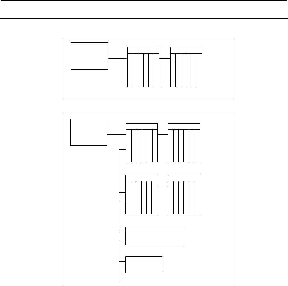
B-64513EN/03
3.COMMUNICATION WITH I/O DEVICE
- 183 -
3.2.3.1
Assignment Method for I/O Unit-MODEL A
Fig. 3.2.3.1 (a) and 3.2.3.1 (b) show sample configurations of I/O Unit-MODEL A.
I/O Link
master Group 0
Base 0
I/O Unit
A
I
F
0
1
A
Slot 1
Slot 2
Slot 3
Slot 4
Slot 5
Base 1
I/O Unit
A
I
F
0
1
B
Slot 1
Slot 2
Slot 3
Slot 4
Slot 5
Fig. 3.2.3.1 (a)
I/O Link
master Group 0
Group 1
Operator's panel
connection unit
Power Mate
Base 0
Base 0
Group 2
Group 3
Base 0
I/O Unit
A
I
F
0
1
A
Slot 1
Slot 2
Slot 3
Slot 4
Slot 5
Base 1
I/O Unit
A
I
F
0
1
B
Slot 1
Slot 2
Slot 3
Slot 4
Slot 5
Base 0
I/O Unit
A
I
F
0
1
A
Slot 1
Slot 2
Slot 3
Slot 4
Slot 5
Base 1
I/O Unit
A
I
F
0
1
B
Slot 1
Slot 2
Slot 3
Slot 4
Slot 5
Fig. 3.2.3.1 (b)
Assignment method
(1) Group number
For I/O Unit-MODEL A, up to two I/O units can be connected when interface module AIF01A is
used as the basic unit and expansion interface module AIF01B is also used. This is called the base
expansion function. This set of up to two I/O units comprises one group (see Fig. 3.2.3.1 (a)).
When required I/O modules cannot be contained only in one group or when multiple I/O units are to
be distributed at distant locations on the machine side, the second AIF01A can be connected to the
first AIF01A using a cable to add a group. (See Fig. 3.2.3.1 (b).)

3.COMMUNICATION WITH I/O DEVICE
B-64513EN/03
- 184 -
(2) Base number
One group consists of up to two I/O base units. The base number of the I/O unit on which interface
module AIF01A is mounted is 0; the base number of the other I/O unit is 1.
In other words, when the base expansion function is used, the base number of the basic unit is
always 0 and that of the expansion unit is always 1. When the base expansion function is not used,
the base number is always 0.
(3) Slot number
On one I/O base unit, up to five (ABU05A) or ten (ABU10A) I/O modules can be mounted
depending on the type of I/O base unit. The location of each module on the I/O base unit is
represented by a slot number. For each base unit, the location of the I/O interface module is 0 and
slot numbers 1 to 10 are assigned from left to right. Each module can be mounted into any desired
slot. I/O modules may not be mounted closely from left to right. An intermediate slot may not be
used.
(4) Module name
For module names, see Tables 3.2.3 (a) to (c) in Section 3.2.3 above. Actual module names begin
with A. When setting a module name, remove this A. Some actual module names may end with a
numeric character. In this case, when setting a module name, also remove the numeric character.
(Example 1) To set module AID16D, enter ID16D.
(Example 2) To set module AID32A1, enter ID32A.
NOTE
For I/O Unit-MODEL A, when assigning 3, 5, 6, or 7 bytes, change the module
name as follows.
Do not use IO24I, /3, /5, /6, or /7 as a module name.
Module names
Before change
→ After change
IO24I → /4
/3 → /4
/5 → /8
/6 → /8
/7 → /8
Related hardware manual
"FANUC I/O Unit-MODEL A Connection and Maintenance Manual" (B-61813E)
NOTE
For the specifications and connection of I/O Unit-MODEL A and related I/O
modules, refer to the hardware connection manual for each I/O device.
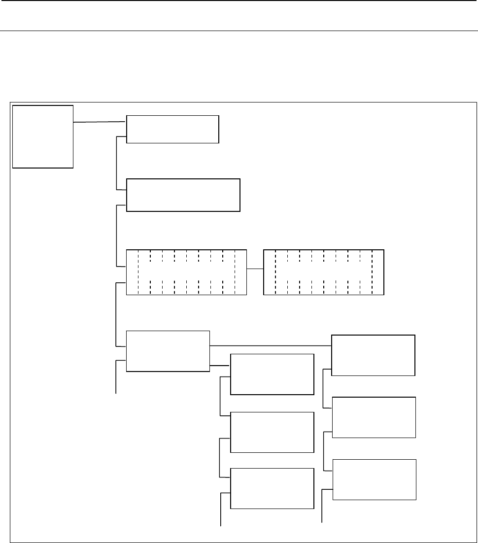
B-64513EN/03
3.COMMUNICATION WITH I/O DEVICE
- 185 -
3.2.3.2
Assignment Method for I/O Unit-MODEL B
I/O Unit-MODEL B can be used together with I/O Link devices such as the Power Mate, operator's panel
interface unit, connection unit, and I/O Unit-MODEL A. In this case, I/O Unit-MODEL B comprises one
group and other units cannot be contained in the group.
An example of connection is shown below.
[Cannel]=1
Operator’s Panel
Interface Unit
I/O Unit-B
Interface Unit
Power Mate i
[BASE]=0, [SLOT]=1
[BASE]=0, [SLOT]=1
I/O Unit- MODEL A I/O Unit- MODEL A
[BASE]=0
[BASE]=1
I/O Unit-B
DI/DO Unit
(Unit No.=1)
I/O Unit-B
DI/DO Unit
(Unit No.=20)
I/O Unit-B
DI/DO Unit
(Unit No.=5)
I/O Unit-B
DI/DO Unit
(Unit No.=30)
I/O Unit-B
DI/DO Unit
(Unit No.=10)
I/O Unit-B
DI/DO Unit
(Unit No.=9)
[BASE]=0, [SLOT]=1
[BASE]=0, [SLOT]=5
[BASE]=0, [SLOT]=30
[BASE]=0, [SLOT]=20
[BASE]=0, [SLOT]=10
[BASE]=0, [SLOT]=9
[GROUP]=0
[GROUP]=1
[GROUP]=2
[GROUP]=3
I/O Link
MASTER
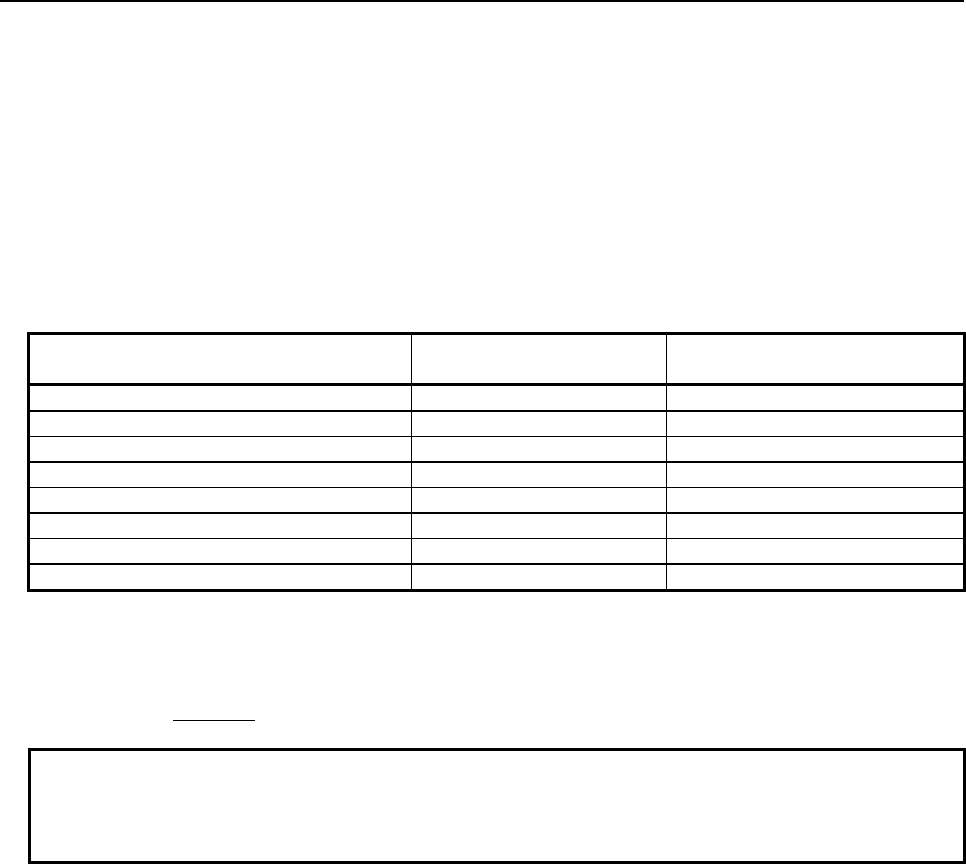
3.COMMUNICATION WITH I/O DEVICE
B-64513EN/03
- 186 -
Assignment method
As the group number, set the group number used in the configuration. As the base number, always set 0.
As the slot number, set the unit number of a DI/DO unit of I/O Unit-MODEL B. To assign power on-off
information, set 0 for the slot number.
Set the following values for the slot number and assignment name:
Slot number:
0: Power on-off information
1 to 30: Unit number
Assignment name:
Module name representing the address occupied by the I/O Unit-MODEL B DI/DO unit (see Table
3.2.3 (b).)
Number of input or output points required
for [basic unit] + [expansion unit] Assignment name Occupied address
1 byte #1 1 byte for input/output
2 bytes #2 2 bytes for input/output
3 bytes #3 3 bytes for input/output
4 bytes #4 4 bytes for input/output
6 bytes #6 6 bytes for input/output
8 bytes #8 8 bytes for input/output
10 bytes #10 10 bytes for input/output
Power on-off information ## 4 bytes for input
Example of setting
To connect an I/O Unit-MODEL B DI/DO unit with unit number 10 whose occupied address is 3 bytes in
GROUP=1:
Enter 1.0.10.#3.
NOTE
When channel 2 and 3 are also used to connect I/O devices, the maximum total
number of groups used for connecting I/O Unit-MODEL B with channels 1 to 3 is
8.
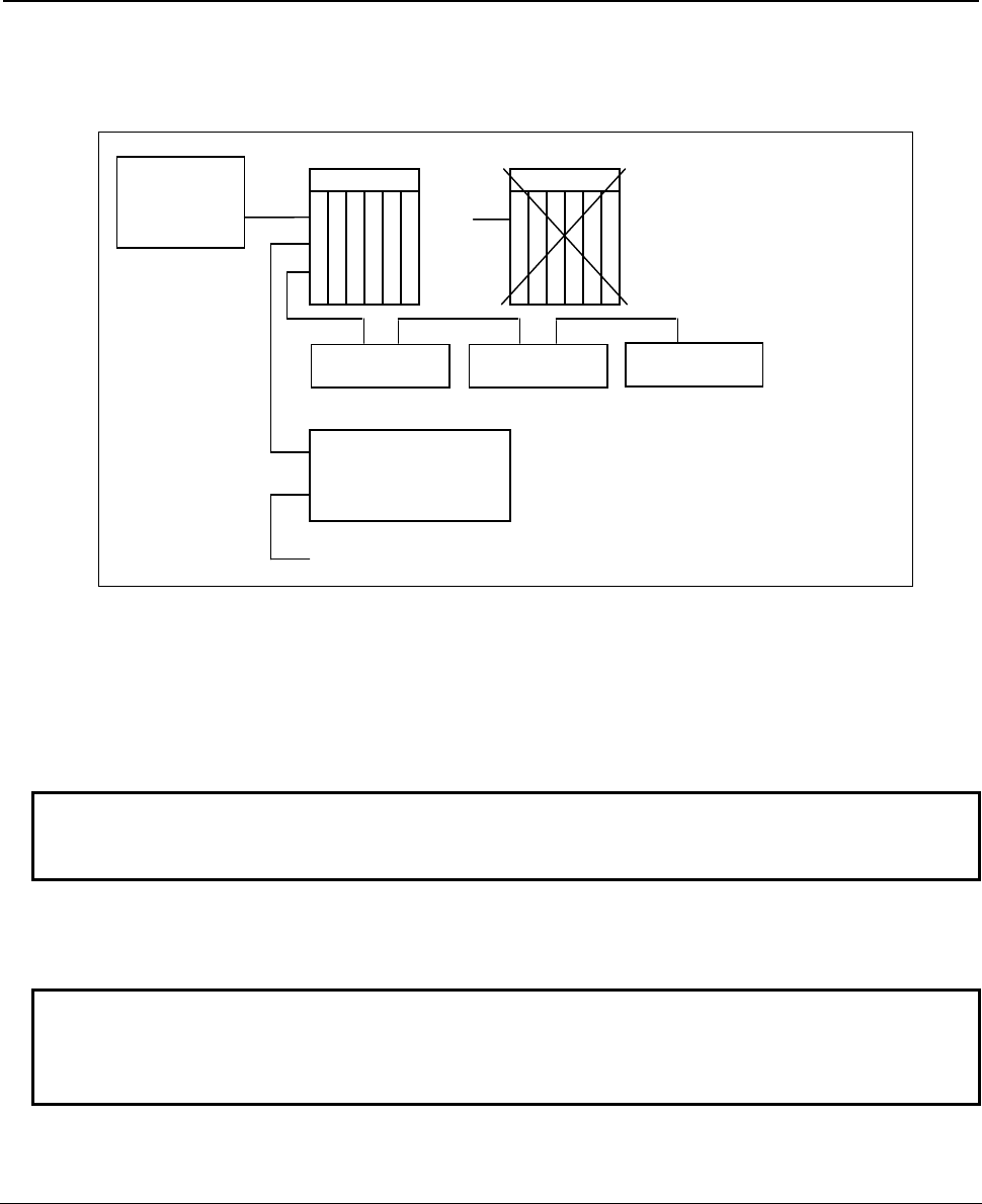
B-64513EN/03
3.COMMUNICATION WITH I/O DEVICE
- 187 -
Interface module incorporating I/O Unit-MODEL A
Interface module AIF02C can control communication both with I/O Unit-MODEL A and with I/O Unit-
MODEL B.
I/O Link
master Group 0
Group 1
I/O Unit-MODEL B
DI/DO unit
Operator's panel
connection unit
Group 2
I/O Unit-MODEL B
DI/DO unit
I/O Unit-MODEL B
DI/DO unit
I/O Unit
A
I
F
0
2
C
Slot 1
Slot 2
Slot 3
Slot 4
Slot 5
I/O Unit
A
I
F
0
1
B
Slot 1
Slot 2
Slot 3
Slot 4
Slot 5
For the AIF02C, the base expansion function of the AIF02A is removed and the functions of the I/O Unit-
MODEL B interface unit are added.
You cannot use only the I/O Unit-MODEL B without using the I/O Unit-MODEL A. The base expansion
function cannot also be used.
The AIF02C occupies two groups. Assignment is required for each of I/O Unit-MODEL A and I/O Unit-
MODEL B.
NOTE
For details of the AIF02C, refer to "FANUC I/O Unit-MODEL A Connection and
Maintenance Manual" (B-61813E).
Related hardware manual
"FANUC I/O Unit-MODEL B Connection Manual" (B-62163E)
NOTE
For the setting of each I/O Unit-MODEL B unit and the specifications and
connection of related I/O modules, refer to the hardware connection manual for
each I/O device in addition to the above connection manual.
3.2.3.3
Assignment Method for Distribution I/O Connection Panel I/O
Modules and Distribution I/O Operator's Panel I/O Modules
For the I/O Link, when assigning connection information of a connection panel or operator's panel I/O
module, set an I/O Link serial number (0 for the module nearest to the I/O Link master CNC) for the
group number, always set 0 for the base number, and always set 1 for the slot number. When basic and
expansion connection panel I/O modules are used, assign one connection information item for all modules
in one I/O Link group. For a distribution I/O module unlike I/O Unit-MODEL A, the slot number need
not be specified. For the module name used to set assignment data, see "Distribution I/O connection
panel I/O modules" in Table 3.2.1(b).
An example of assignment is shown below.
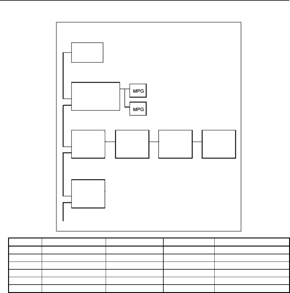
3.COMMUNICATION WITH I/O DEVICE B-64513EN/03
- 188 -
Example of assignment
72 input points (16 general-purpose points + 56 matrix points), 56 output points
(X4…, Y0…)
Operator's panel
I/O module
A20B-2002-0470
JD1B
JD1A
96 input points, 64 output points (X20…, Y10…)
Connection
panel I/O
basic module
JD1B
JD1A
Expansion
module 1
Expansion
module 2
Expansion
module 3
24 input points, 16 output points (X100…, Y100…)
Connection
panel I/O
basic module
JD1B
JD1A
Example)
CNC
JD1A
Group number
Base number
Slot number
Assignment name
X004
0
0
1
CM14I
X020
1
0
1
CM12I
X100
2
0
1
CM03I
Y000
0
0
1
CM08O
Y010
1
0
1
CM08O
Y100
2
0
1
CM02O
Connection panel I/O modules
For signal mapping of connection panel I/O modules, refer to the connection manual (hardware) for the
CNC used as the I/O Link master.
Assignment data is described below for each configuration of basic and expansion modules.
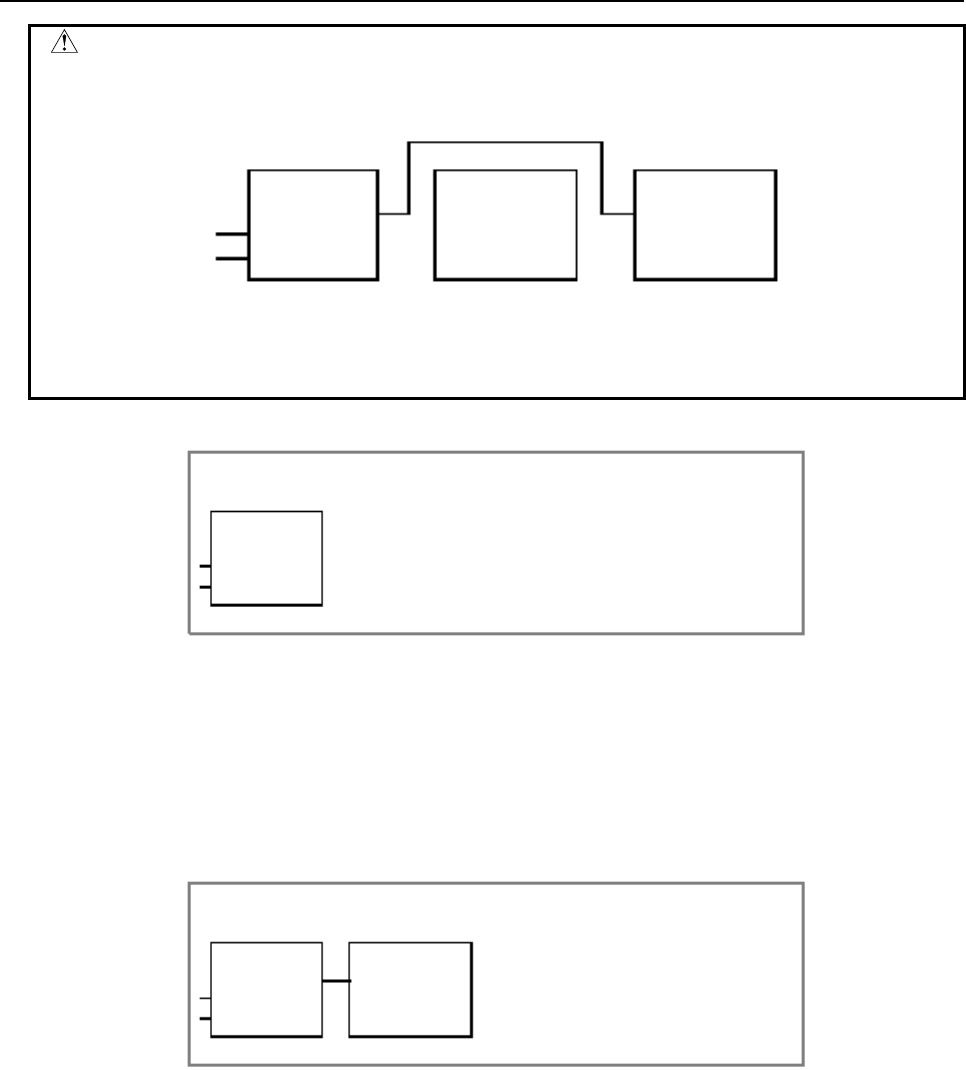
B-64513EN/03
3.COMMUNICATION WITH I/O DEVICE
- 189 -
CAUTION
Always connect expansion modules 1, 2, and 3 in this order closely. Any
intermediate expansion module cannot be skipped.
Basic
module
JD1B
JD1A
Expansion
module 1 Expansion
module 2
You may want to make the above configuration so that expansion module 1 is not
yet mounted and assign only expansion module 2, but such configuration does
not work.
(1) Only basic module
24 input points, 16 output points
Basic
module
JD1B
JD1A
(a) When DO alarm detection is not used
• When no manual pulse generator is used
Input: X=CM03I, output: Y=CM02O
(b) When DO alarm detection is used
• Regardless of the number of manual pulse generators
Input: X=CM16I, output: Y=CM02O
(2) Basic module + expansion module 1
Basic
module
JD1B
JD1A
Expansion
module 1
48 input points, 32 output points
(a) When DO alarm detection is not used
• When no manual pulse generator is used
Input: X=CM06I, output: Y=CM04O
• When one manual pulse generator is used
Input: X=CM13I, output: Y=CM04O
(b) When DO alarm detection is used
• Regardless of the number of manual pulse generators
Input: X=CM16I, output: Y=CM04O
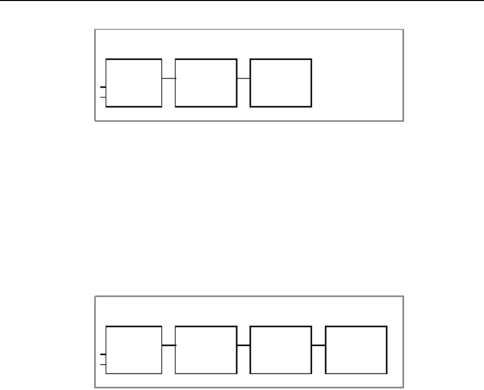
3.COMMUNICATION WITH I/O DEVICE
B-64513EN/03
- 190 -
(3) Basic module + expansion module 1 + expansion module 2
Basic
module
JD1B
JD1A
Expansion
module 1 Expansion
module 2
72 input points, 48 output points
(a) When DO alarm detection is not used
• When no manual pulse generator is used
Input: X=CM09I, output: Y=CM06O
• When one manual pulse generator is used
Input: X=CM13I, output: Y=CM06O
• When two manual pulse generators are used
Input: X=CM14I, output: Y=CM06O
(b) When DO alarm detection is used
• Regardless of the number of manual pulse generators
Input: X=CM16I, output: Y=CM06O
(4) Basic module + expansion module 1 + expansion module 2 + expansion module 3
Basic
module
JD1B
JD1A
Expansion
module 1
Expansion
module 2
96 input points, 64 output points
Expansion
module 3
(a) When DO alarm detection is not used
• When no manual pulse generator is used
Input: X=CM12I, output: Y=CM08O
• When one manual pulse generator is used
Input: X=CM13I, output: Y=CM08O
• When two manual pulse generators are used
Input: X=CM14I, output: Y=CM08O
• When three manual pulse generators are used
Input: X=CM15I, output: Y=CM08O
(b) When DO alarm detection is used
• Regardless of the number of manual pulse generators
Input: X=CM16I, output: Y=CM08O

B-64513EN/03
3.COMMUNICATION WITH I/O DEVICE
- 191 -
Operator's panel I/O modules
For signal mapping of operator's panel I/O modules, refer to the connection manual (hardware) for the
CNC used as the I/O Link master.
(1) Operator's panel I/O module (compatible with matrix input, A20B-2002-0470)
Operator's panel
I/O module
JD1B
JD1A
Input: 16 general-purpose points + 56 matrix points
Output: 56 matrix points
(a) When DO alarm detection is not used
• When no manual pulse generator is used
Input: X=CM12I, output: Y=CM08O
• When one manual pulse generator is used
Input: X=CM13I, output: Y=CM08O
• When two manual pulse generators are used
Input: X=CM14I, output: Y=CM08O
• When three manual pulse generators are used
Input: X=CM15I, output: Y=CM08O
(b) When DO alarm detection is used
• Regardless of the number of manual pulse generators
Input: X=CM16I, output: Y=CM08O
(2) Operator's panel I/O module (A20B-2002-0520, A20B-2002-0521)
Operator's panel
I/O module
JD1B
JD1A
48 input points
32 output points
(a) When DO alarm detection is not used
• When no manual pulse generator is used
Input: X=CM06I, output: Y=CM04O
• When one manual pulse generator is used
Input: X=CM13I, output: Y=CM04O
• When two manual pulse generators are used
Input: X=CM14I, output: Y=CM04O
• When three manual pulse generators are used
Input: X=CM15I, output: Y=CM04O
(b) When DO alarm detection is used
• Regardless of the number of manual pulse generators
Input: X=CM16I, output: Y=CM04O
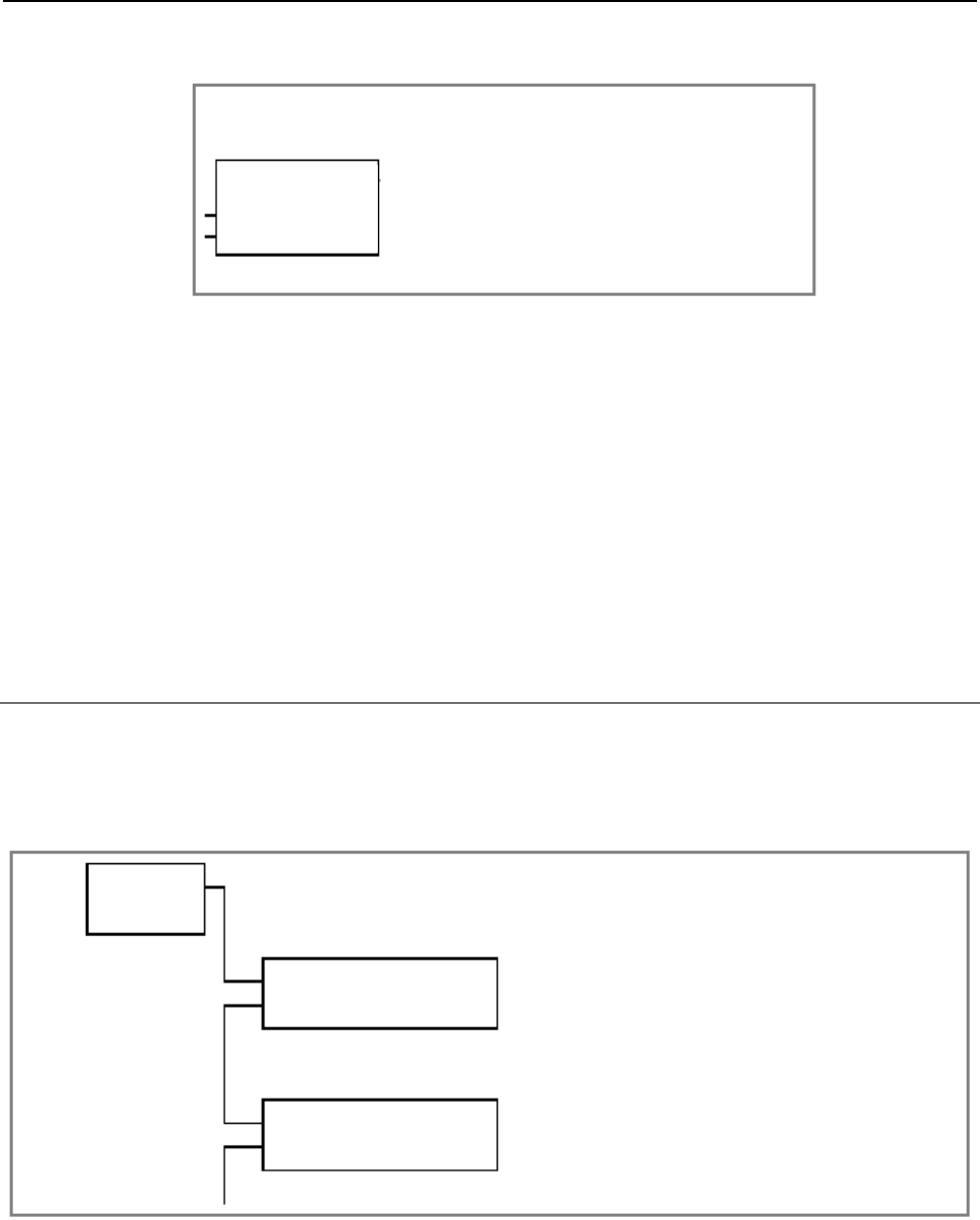
3.COMMUNICATION WITH I/O DEVICE
B-64513EN/03
- 192 -
(3) Distribution I/O machine operator's panel
(A20B-8001-0721, A20B-8001-0720, A20B-8001-0210)
Operator's panel
I/O module
JD1B
JD1A
Input: 8 points for override signals and so on + 24 general-purpose points + 64
matrix points
Output: 64 matrix points
(a) When DO alarm detection is not used
• When no manual pulse generator is used
Input: X=CM12I, output: Y=CM08O
• When one manual pulse generator is used
Input: X=CM13I, output: Y=CM08O
• When two manual pulse generators are used
Input: X=CM14I, output: Y=CM08O
• When three manual pulse generators are used
Input: X=CM15I, output: Y=CM08O
(b) When DO alarm detection is used
• Regardless of the number of manual pulse generators
Input: X=CM16I, output: Y=CM08O
3.2.3.4
Assignment Method for the Power Mate
To use Power Mate-MODEL D/H, Power Mate i-MODEL D/H, or I/O Link
β
amplifier as an I/O Link
slave, assign its connection information on the I/O Link master.
On the I/O Link slave, assignment is not required because the addresses are fixed.
An example of connection is shown below.
Operator's panel
interface unit
I/O LINK
MASTER
[GROUP] = 0
[GROUP] = 1
[BASE] = 0, [SLOT] = 1
[BASE] = 0, [SLOT] = 1
Power Mate
Assignment method
For the group number, set the group number used in the configuration.
For the base number, always set 0.
For the slot number, always set 1.
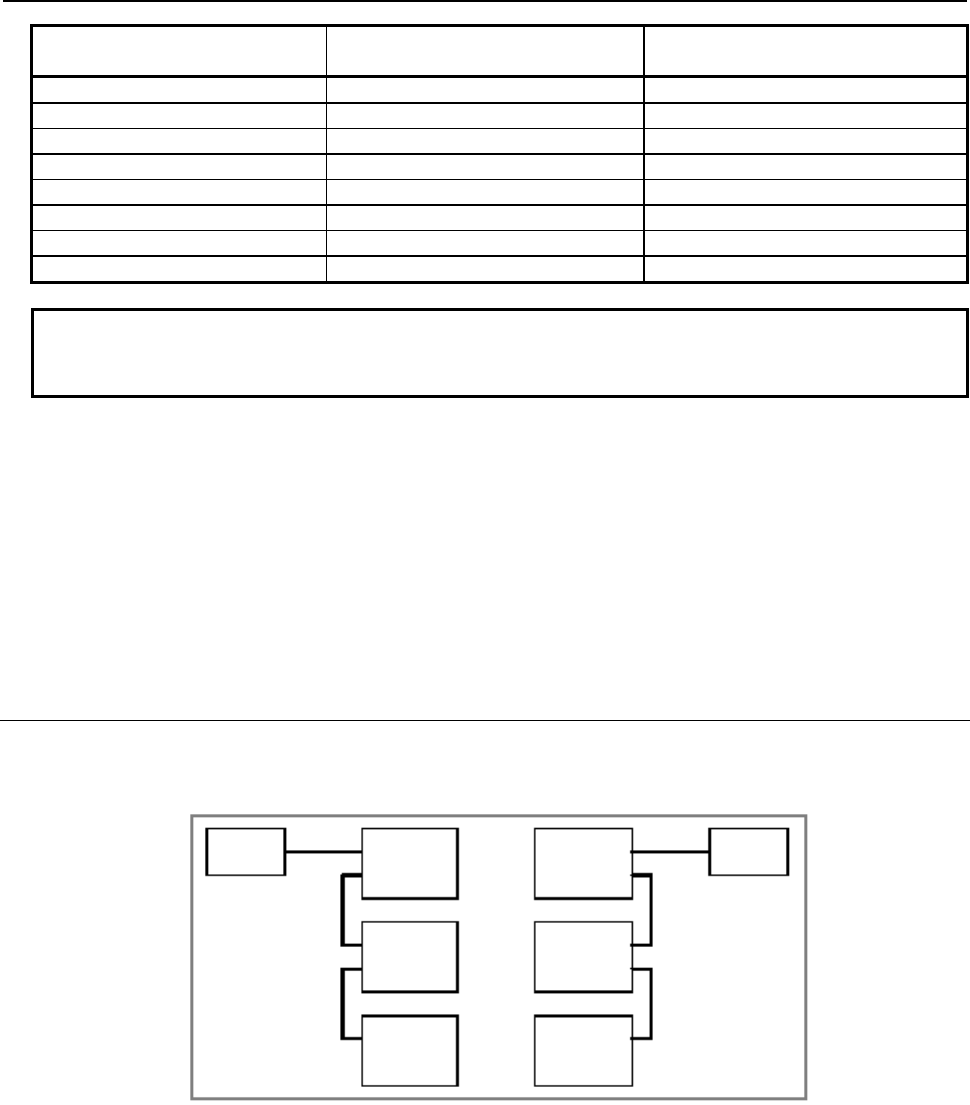
B-64513EN/03
3.COMMUNICATION WITH I/O DEVICE
- 193 -
Number of input/output points
(input/output)
Input device assignment name
(module name)
Output device assignment name
(module name)
32/32 FS04A FS04A
64/64 FS08A FS08A
96/96 /12 /12
128/128 OC02I or /16 OC02O or /16
160/160 /20 /20
192/192 /24 /24
224/224 /28 /28
256/256 OC03I or /32 OC03O or /32
NOTE
1 Assign input and output module names with the same number of points.
2 For the I/O Link β amplifier, assign OC02I/OC02O.
Examples of settings
To connect Power Mate i-D with 256/256 points in group 1:
Enter 1.0.1.OC03I for input and 1.0.1.OC03O for output.
To connect Power Mate i-D with 224/224 points in group 2:
Enter 2.0.1. /28 for input and 2.0.1. /28 for output.
To connect an I/O Link
β
amplifier in group 1:
Enter 1.0.1.OC02I for input and 1.0.1.OC02O for output.
3.2.3.5
Assignment Method for I/O Link Connection Units
Conventionally, to exchange data between CNCs A and B, the devices indicated by (a) in the figure
below must be connected. (Any I/O units can be used to exchange data.)
CNC A I/O Unit
Model A
I/O Unit
Model A
I/O Unit
Model A
I/O Unit
Model A
I/O Unit
Model A
I/O Unit
Model A
CNC B
(a)
↔
An I/O Link connection unit replaces the connected devices to eliminate cable connection and enable the
power to each master or slave to be turned on and off independently.
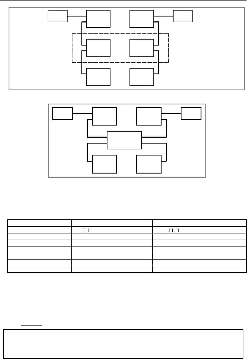
3.COMMUNICATION WITH I/O DEVICE
B-64513EN/03
- 194 -
←These devices are replaced with an
I/O Link connection unit.
CNC A I/O Unit
Model A
I/O Unit
Model A
I/O Unit
Model A
I/O Unit
Model A
I/O Unit
Model A
I/O Unit
Model A
CNC B
(a)
↔
Therefore, when an I/O Link connection unit is used, the connection is as follows.
I/O Link
connection unit
CNC A I/O Unit
Model A
I/O Unit
Model A
I/O Unit
Model A
I/O Unit
Model A
CNC B
Assignment method
Assignment data is determined according to the types of I/O devices replaced with an I/O Link
connection unit.
Occupied address Input device assignment name Output device assignment name
1 to 8 / ( :Numeric character 1 to 8) / ( :Numeric character 1 to 8)
12 /12 /12
16 OC02I or /16 OC02O or /16
20 /20 /20
24 /24 /24
28 /28 /28
32 OC03I or /32 OC03O or /32
Example of setting
To connect a connection unit whose occupied address is 16 bytes in GROUP=1 as an input device:
Enter 1.0.1.OC02I.
To connect a connection unit whose occupied address is 28 bytes in GROUP=1 as an input device:
Enter 1.0.1. /28.
NOTE
For details of the hardware connection method, particularly connection of a power
supply, refer to the hardware connection manual for each related master/slave
device.
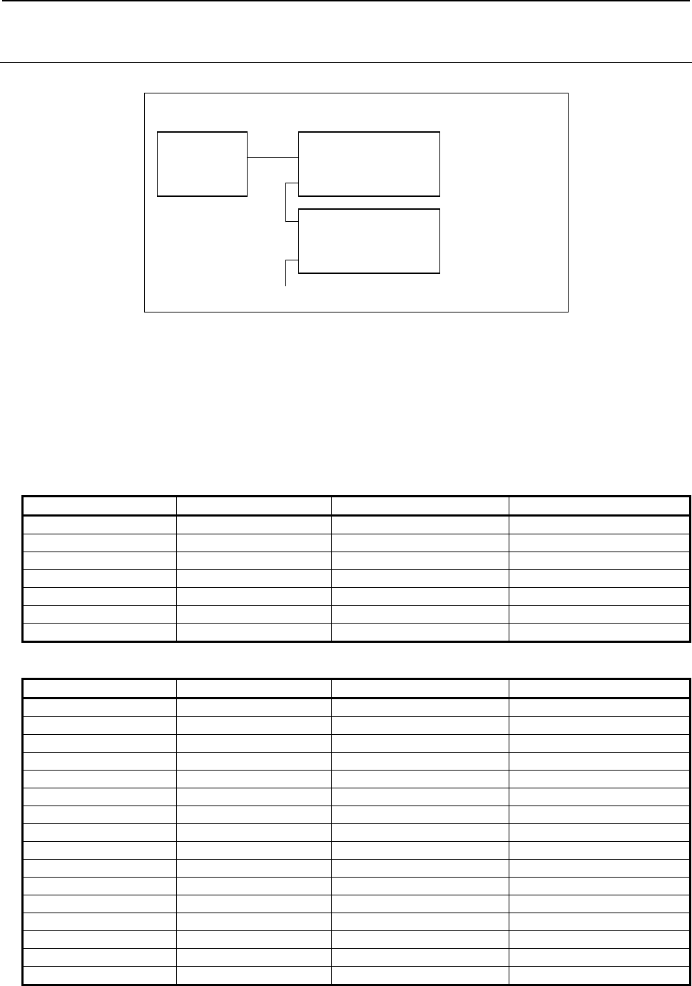
B-64513EN/03
3.COMMUNICATION WITH I/O DEVICE
- 195 -
3.2.3.6
Assignment Method for a Handy Machine Operator's Panel
An example of connecting a handy machine operator's panel to the I/O Link is shown below.
I/O Link
master
Handy machine
operator's panel Group 0
Group 1
Operator's panel
connection unit
Assignment method
Assign 16 bytes to X addresses and 32 bytes to Y addresses contiguously starting from any address for
each group. Set the group number used in the configuration for the group number and always set 0 for the
base number. Set the slot number and assignment name as shown in the table below. The number of
occupied input points for each group is 32 bytes, which is the same as that of output points, because of
limitations of the I/O Link.
[Examples of assigning X addresses]
X address Slot number Assignment name Occupied address
Xn+0 0 ## 4 bytes
Xn+4 1 #2 2 bytes
Xn+6 2 #2 2 bytes
Xn+8 3 #2 2 bytes
Xn+10 4 #2 2 bytes
Xn+12 5 #2 2 bytes
Xn+14 6 #2 2 bytes
[Examples of assigning Y addresses]
Y address Slot number Assignment name Occupied address
Yn+0 7 #2 2 bytes
Yn+2 8 #2 2 bytes
Yn+4 9 #2 2 bytes
Yn+6 10 #2 2 bytes
Yn+8 11 #2 2 bytes
Yn+10 12 #2 2 bytes
Yn+12 13 #2 2 bytes
Yn+14 14 #2 2 bytes
Yn+16 15 #2 2 bytes
Yn+18 16 #2 2 bytes
Yn+20 17 #2 2 bytes
Yn+22 18 #2 2 bytes
Yn+24 19 #2 2 bytes
Yn+26 20 #2 2 bytes
Yn+28 21 #2 2 bytes
Yn+30 22 #2 2 bytes
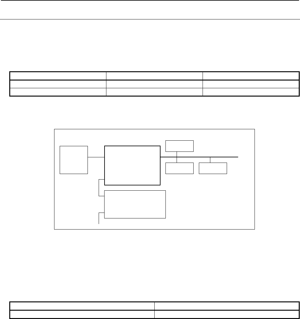
3.COMMUNICATION WITH I/O DEVICE
B-64513EN/03
- 196 -
3.2.3.7
Assignment Method for an AS-i Converter Unit
An I/O Link-AS-i converter unit converts I/O from the I/O Link to the AS-Interface (called AS-i below)
to enable the use of AS-i slave module DI/DO signals as a standalone unit.
The AS-i comes in two main versions: Ver. 2.0 and Ver. 2.1. Two types of I/O Link-AS-i converter units
are available for each of these versions.
An I/O Link-AS-i converter unit for Ver. 2.0 differs from that for Ver. 2.1 in the following points.
For Ver. 2.0 For Ver. 2.1
Number of input/output points 256 input points/256 output points 512 input points/512 output points
Occupied groups 1 group Contiguous 2 groups
For each version, an example of connection is shown and the assignment method is described below.
Example of connection for Ver. 2.0
I/O Link
master
I/O Link-AS-i
converter unit for
Ver 2.0
Group 0
Group 1
Operator's panel
connection unit
AS-
i
power
supply
AS-i slave AS-i slave
Assignment method for Ver. 2.0
For the group number ([GROUP]), set the group number used in the configuration. (Set 0 for the above
example of connection.)
For the base number ([BASE]), always set 0.
For the slot number ([SLOT]), always set 1.
An I/O Link-AS-i converter unit occupies 256 points (32 bytes) for both input and output. Therefore, the
assignment names are as follows.
Input device assignment name Output device assignment name
OC03I OC03O
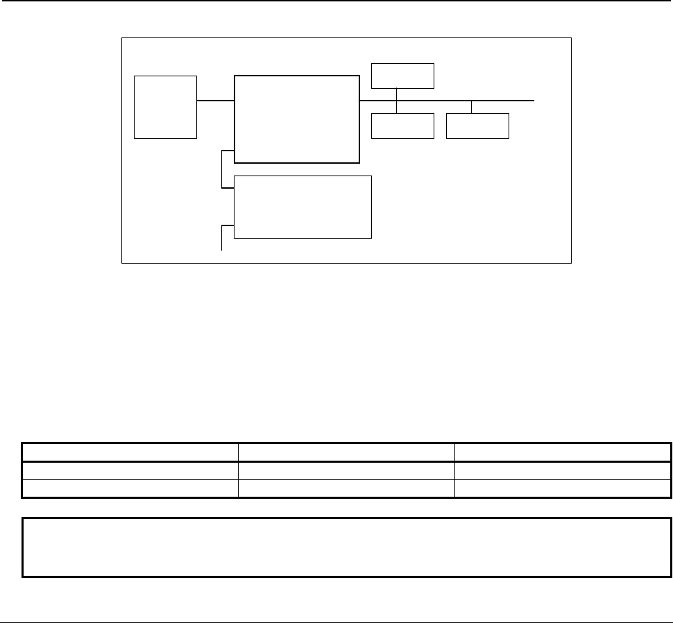
B-64513EN/03
3.COMMUNICATION WITH I/O DEVICE
- 197 -
Example of connection for Ver. 2.1
I/O Link
master
I/O Link-AS-i
converter unit for
Ver 2.1
Groups 0 and 1
Group 2
Operator's panel
connection unit
AS-
i
power
supply
AS-i slave AS-i slave
Assignment method for Ver. 2.1
For the group number ([GROUP]), set the numbers for two contiguous groups in the configuration. Set 0
and 1 for the above example of connection.
For the base number ([BASE]), always set 0.
For the slot number ([SLOT]), always set 1.
An I/O Link-AS-i converter unit occupies 512 points for both input and output, 256 points (32 bytes) per
group. Therefore, the assignment names per group are the same as for an I/O Link-AS-i converter unit
for Ver. 2.0. Set the same assignment names for each occupied group number.
Group number Input device assignment name Output device assignment name
n OC03I OC03O
n + 1 OC03I OC03O
NOTE
An I/O Link-AS-i converter unit for Ver. 2.1 cannot be used as a converter unit
for Ver. 2.0 with assignment data for Ver. 2.0.
3.2.3.8
FS0 Operator's Panel
The FS0 operator's panel consists of many key-operated switches, LEDs, a rotary switch, and other
components. The status of each of key-operated switches and lamps is coded and as many signal lines as
the number of actual switches are not required to connect the operator's panel to a CNC. PMC
management software automatically codes the status and transfers data.
These operations require only that simple bit images indicating the switches, LEDs, and other
components to be operated by a PMC ladder program.
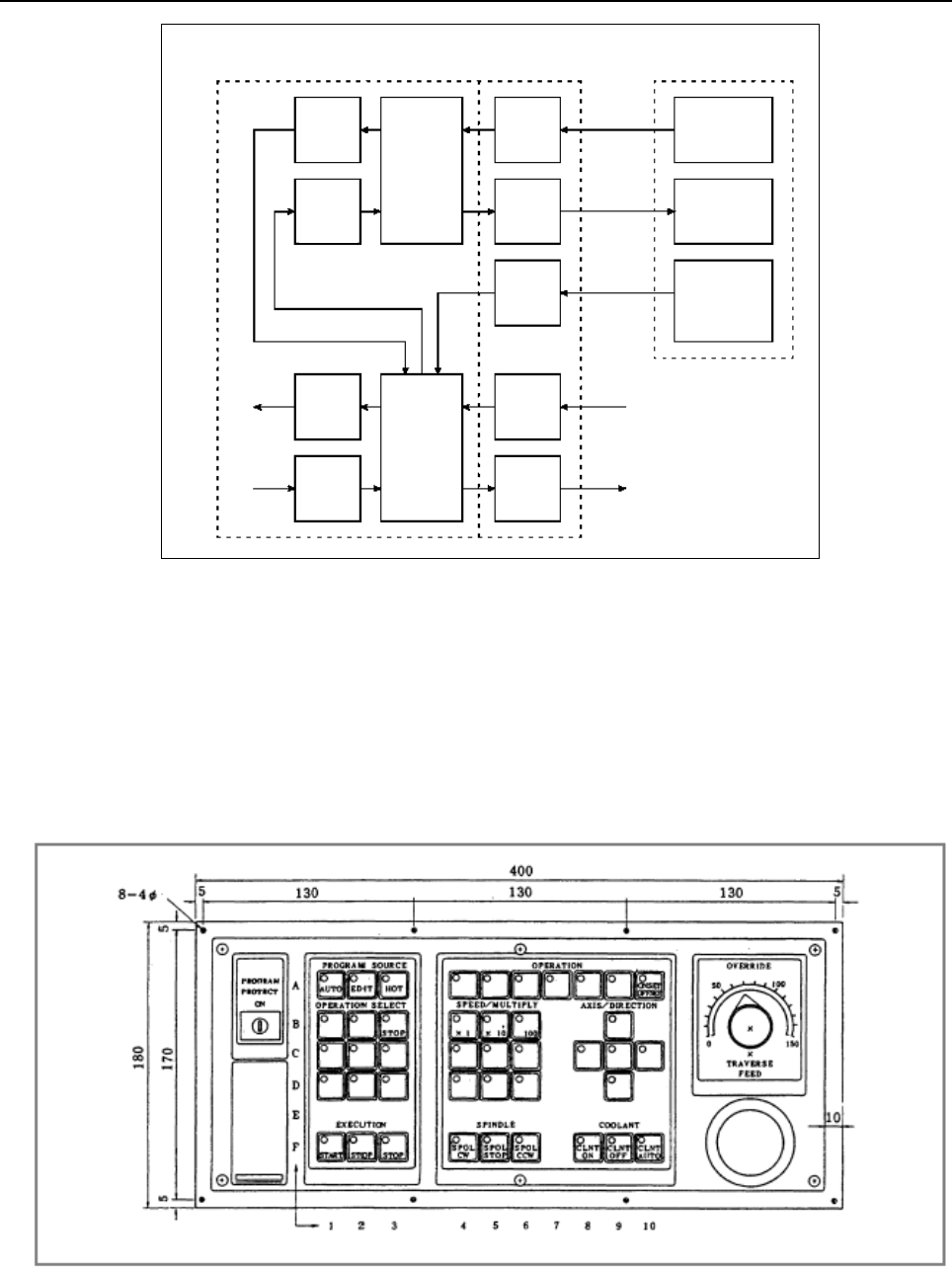
3.COMMUNICATION WITH I/O DEVICE
B-64513EN/03
- 198 -
CNC
Bit
images
Rk…
Bit
images
Rl…
PMC
manage-
ment
software
Input
Xn…
Output
Ym…
Input
X*…
Input
X*…
Output
Y*…
PMC
ladder
program
(user)
Coding
Coding
Contact
FS0 o
p
erator's
p
anel
Interface with
another machine
CNC
software
Keyboard
Protect key
Emergency stop
button
Override rotary
switch, etc.
LED
G*…
(X)
F*…
Fig. 3.2.3.8 (a) Block diagram of connection of an operator's panel
An operator's panel consists of the following keys, LEDs, and other components:
• Key-operated switches (sheet keys)
42 keys (0-TC)
46 keys (0-MC)
• LEDs (red) on all key-operated switches
• Override rotary switch (4 bits)
• Emergency stop button (1 bit)
• Program protect key (1 bit)
Fig. 3.2.3.8 (b) Operator's panel for 0-TC
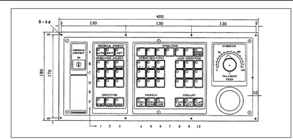
B-64513EN/03
3.COMMUNICATION WITH I/O DEVICE
- 199 -
Fig. 3.2.3.8 (c) Operator's panel for 0-MC
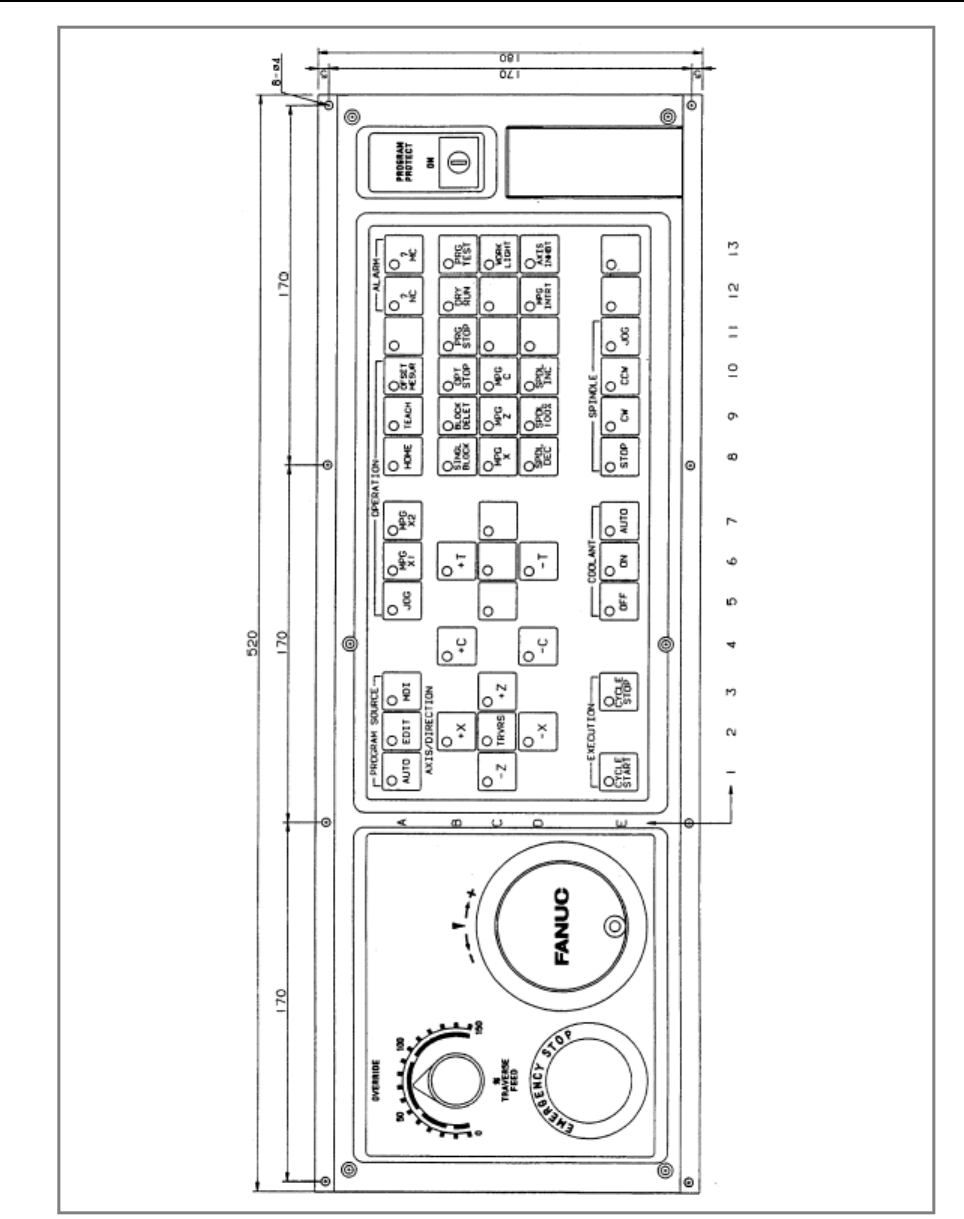
3.COMMUNICATION WITH I/O DEVICE
B-64513EN/03
- 200 -
Fig. 3.2.3.8 (d) Machine operator's panel for the 0-TC full-keyboard 9-inch CRT/MDI unit
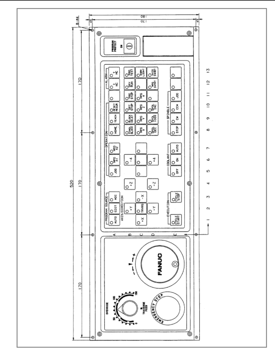
B-64513EN/03
3.COMMUNICATION WITH I/O DEVICE
- 201 -
Fig. 3.2.3.8 (e) Machine operator's panel for the 0-MC full-keyboard 9-inch CRT/MDI unit
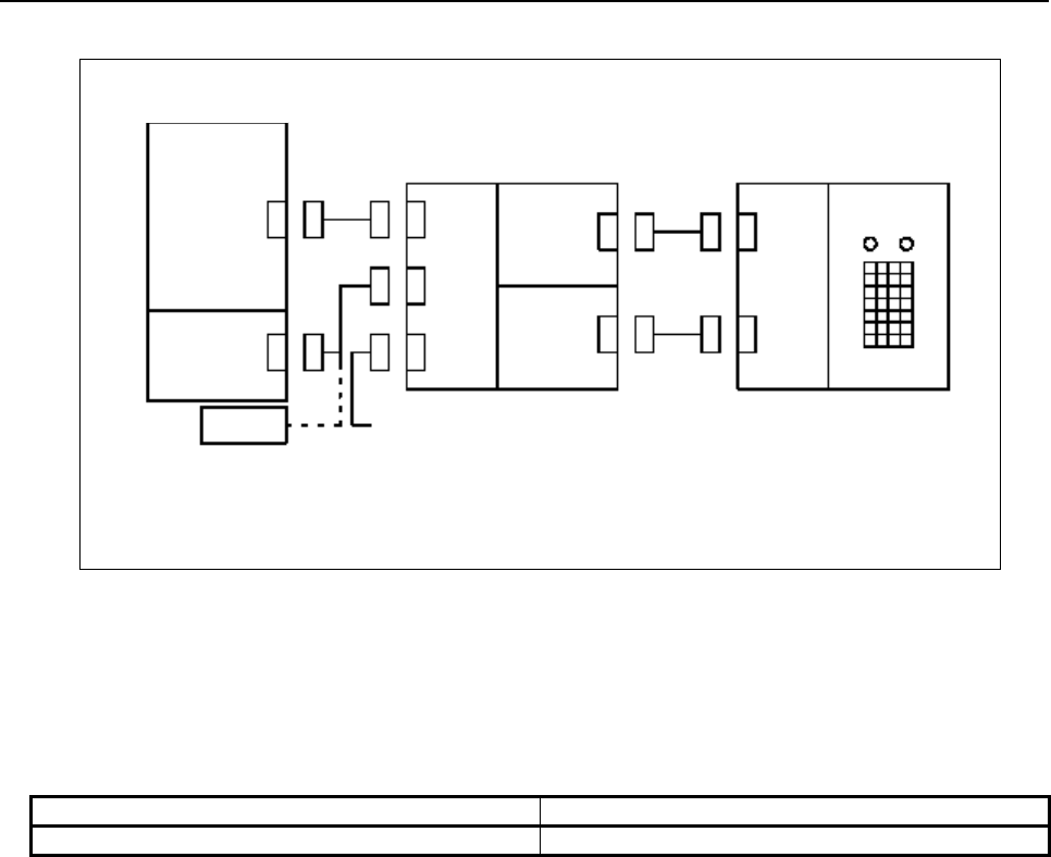
3.COMMUNICATION WITH I/O DEVICE
B-64513EN/03
- 202 -
Example of connection
DI module: +24 V common, 24 ms
(Example) AID32A1
DO module: 0 V common
(Example) AOD32A1
I/O unit
DI
module
DO
module
A
nother I/O unit
FS0 operator's panel
MAIN CPU
JD1A
(I/O Link)
PSU
CP6
24 VDC
I/O Link
JD1B
CP32
JD1A
M1A
M2A
CNC
Assignment method
For the group number ([GROUP]), set the group number used in the configuration.
For the base number ([BASE]), always set 0.
For the slot number ([SLOT]), always set 1.
For the above example of connection, the FS0 operator's panel occupies 32 points (4 bytes) for both input
and output. Therefore, the assignment names are as follows.
Input device assignment name Output device assignment name
ID32A OD32A
Operator's panel connection signals
- Emergency stop signal (*ESP)
This signal is directly monitored by the CNC and is assigned at the fixed address.
For connection, refer to the section describing the interface between the CNC and PMC in the CNC
connection manual.
- Override signals (*OV1 to *OV8) and program protect key signal (KEY)
For these signals, the relevant key-operated switch contact signals are directly input to the PMC. Directly
process these signals with a PMC ladder program.
For connection, refer to the section describing the interface between the CNC and PMC in the CNC
connection manual.
- Key-operated switch signals (Xn, Xn+2)
Each key-operated switch signal is coded by PMC management software and input to the relevant PMC
address R as a bit image.
Whether a required key is pressed can be determined by checking the bit image of the key-operated
switch using the user PMC ladder program. (See Tables 3.2.3.8(a), 3.2.3.8(b), and 3.2.3.8(c).) When a
key is pressed, the bit corresponding to the key is 1.
Up to two keys can be input simultaneously. Do not use any keyboard input method for a user PMC
program that requires simultaneous pressing of three or more keys. If three or more keys are pressed
simultaneously, they are not input correctly.
It takes up to 60 ms until the bit corresponding to a key is set to 1 (0) after the key is pressed (released).
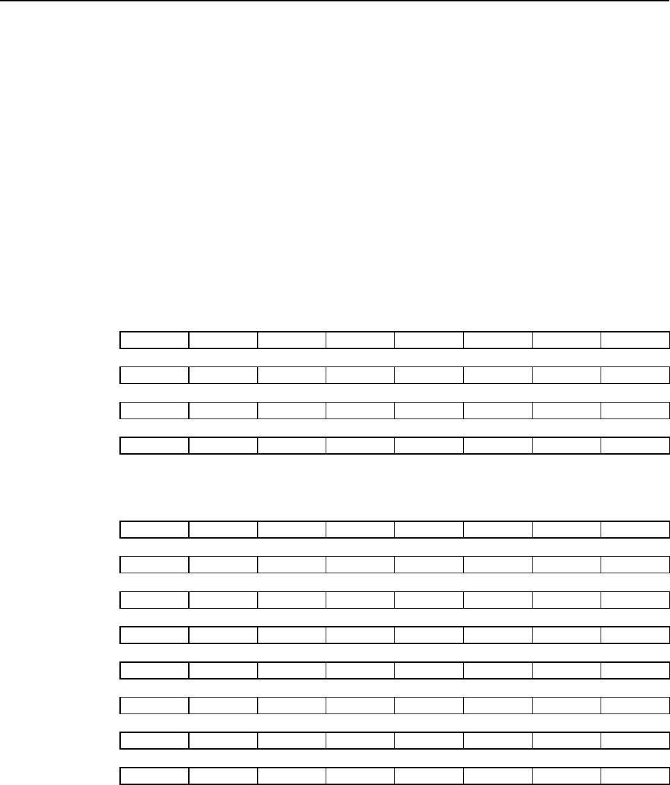
B-64513EN/03
3.COMMUNICATION WITH I/O DEVICE
- 203 -
The address of a key-operated switch signal (Xn to Xn+2: Table 3.2.3.8(a)) and the address of its bit
image (Rk to Rk+7: Tables 3.2.3.8(b) and (c)) can be defined as the fixed address or an unused address
without restrictions.
- LED signals (Ym)
Create each LED signal at PMC address R as a bit image in the user PMC ladder program. PMC
management software converts the bit image of the LED signal to a coded output signal. (See Tables
3.2.3.8(a), (b), and (c).) When a value of 1 is written in an LED bit image, the corresponding LED is
automatically turned on. In the same way, when a value of 0 is written, the LED is turned off. All LEDs
are off at power-on.
It takes up to 200 ms until an LED is turned on (off) after a value of 1 (0) is written in the corresponding
bit image by the PMC.
The address of an LED signal (Ym: Table 3.2.3.8(a)) and the address of its bit image (Rl to Rl+7: Tables
3.2.3.8(b) and (c)) can be defined as the fixed address or an unused address without restrictions.
Table 3.2.3.8(a) Key-operated switch and LED signal addresses
#7 #6 #5 #4 #3 #2 #1 #0
Xn KD7 KD6 KD5 KD4 KD3 KD2 KD1 KD0
Xn+1
Xn+2 KST KA3 KA2 KA1 KA0
Ym LD7 LD6 LD5 LD4 LD3 LD2 LD1 LD0
Table 3.2.3.8(b) Key-operated switch and LED signal bit image addresses
(For a compact operator's panel)
KEY/LED #7 #6 #5 #4 #3 #2 #1 #0
Rk/Rl F3 F2 F1 D1 C1 B1 A1
Rk+1/Rl+1 F4 D2 C2 B2 A2
Rk+2/Rl+2 D4 D3 C4 C3 B4 B3 A4 A3
Rk+3/Rl+3 F6 F5 D5 C5 B5 A5
Rk+4/Rl+4 F8 D6 C6 B6 A6
Rk+5/Rl+5 D8 C8 B8 A8 A7
Rk+6/Rl+6 F9 D9 C9 B9 A9
Rk+7/Rl+7 F10 D10 C10 B10 A10

3.COMMUNICATION WITH I/O DEVICE
B-64513EN/03
- 204 -
Table 3.2.3.8(c) Key-operated switch and LED signal bit image addresses
(for a full-keyboard operator's panel)
KEY/LED #7 #6 #5 #4 #3 #2 #1 #0
Rk/Rl E1 C1 A1 E6 D6 C6 B6 A6
Rk+1/Rl+1 E2 C2 A2 E7 D7 C7 B7 A7
Rk+2/Rl+2 E3 C3 A3 E8 D8 C8 B8 A8
Rk+3/Rl+3 E5 C4 A4 E9 D9 C9 B9 A9
Rk+4/Rl+4 D2 C5 A5 E10 D10 C10 B10 A10
Rk+5/Rl+5 D4 D5 B2 E11 D11 C11 B11 A11
Rk+6/Rl+6 D1 B1 B4 E12 D12 C12 B12 A12
Rk+7/Rl+7 D3 B3 B5 E13 D13 C13 B13 A13
Setting addresses
Use the system parameter screen to set key-operated switch and LED signal addresses and bit image
addresses.
For details of screen operations, see Section 9.8 described later. For details of parameters to be set, see
Section 2.4 described earlier.
The following simply describes how values set on the system parameter screen are set at addresses shown
in Tables 3.2.3.8(a), (b), and (c).
Example:
On the system parameter screen, specify that the FS0 operator's panel is to be used. Then, set the start
key-operated switch address for "DI address", start LED signal address for "DO address", start key-
operated switch bit image address for "key input image address", and start LED signal bit image address
for "LED output image address".
When the following values are set:
DI address: X0
DO address: Y0
Key input image address: R900
LED output image address: R910
The addresses shown in Tables 3.2.3.8(a), (b), and (c) are set to the following PMC addresses:
Xn → X0000
Xn+1 → X0001
Xn+2 → X0002
Ym → Y0000
Rk / Rl → R0900 / R0910
Rk+1 / Rl+1 → R0901 / R0911
Rk+2 / Rl+2 → R0902 / R0912
Rk+3 / Rl+3 → R0903 / R0913
Rk+4 / Rl+4 → R0904 / R0914
Rk+5 / Rl+5 → R0905 / R0915
Rk+6 / Rl+6 → R0906 / R0916
Rk+7 / Rl+7 → R0907 / R0917
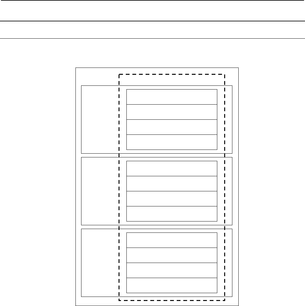
B-64513EN/03
3.COMMUNICATION WITH I/O DEVICE
- 205 -
3.2.4
Setting I/O Address For I/O Link Channel
3.2.4.1
Outline
Interface between PMC and external I/O devices consists of I/O address of 128 bytes of X/Y0 to X/Y127,
X/Y200 to X/Y327, X/Y400 to X/Y527, and X/Y600 to X/Y727 as shown below.
Interface between PMC and external I/O
1st PMC Input / Output Address
X0 to X127 / Y0 to Y127
Input / Output Address
X200 to X327 / Y200 to Y327
Input / Output Address
X400 to X527 / Y400 to Y527
Input / Output Address
X600 to X727 / Y600 to Y727
2nd PMC
3rd PMC
Input / Output Address
X0 to X127 / Y0 to Y127
Input / Output Address
X200 to X327 / Y200 to Y327
Input / Output Address
X400 to X527 / Y400 to Y527
Input / Output Address
X600 to X727 / Y600 to Y727
Input / Output Address
X0 to X127 / Y0 to Y127
Input / Output Address
X200 to X327 / Y200 to Y327
Input / Output Address
X400 to X527 / Y400 to Y527
Input / Output Address
X600 to X727 / Y600 to Y727
Fig. 3.2.4.1 Interface between PMC and external I/O
To use I/O Link, it is necessary to set the I/O addresses in each channel. They can be set in the
Configuration parameter screen. The setting information of each channel is PMC path and I/O addresses
of 128 bytes. The information is reflected to CNC parameter. The setting is made effective at the next
power-on.
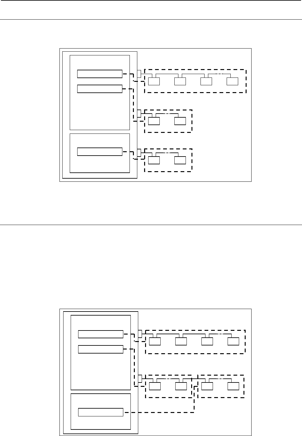
3.COMMUNICATION WITH I/O DEVICE
B-64513EN/03
- 206 -
3.2.4.2
Assignment Method
In the following example, channel 1 is set to X/Y0 to X/Y127 of the first PMC, channel 2 is set to
X/Y200 to X/Y327 of the first PMC, and channel 3 is set to X/Y0 to X/Y127 of the second PMC on the
configuration parameter screen.
1st PMC
2nd PMC
Channel 1
~
Channel 2
~
Channel 3
~
Grou
p
0 Grou
p
n
Grou
p
0 Grou
p
n
Grou
p
0 Grou
p
1 Grou
p
2 Grou
p
n
X/Y0 to 127
X/Y200 to 327
X/Y0 to 127
Fig. 3.2.4.2 Example of using 2 PMCs and 3 I/O Link Channels
For details of setting, see Subsection 9.9.3.
3.2.4.3
Dual Assignment of I/O Link Channel
When multi-path PMC function is used, plural I/O link channels may be necessary. However, there is the
case of the wasteful assignment in which the number of I/O link channel is lacking and the assigned I/O
points are few.
The dual assignment of I/O Link channel can assign I/O devices of one I/O link channel to two PMC
paths effectively. To do so, the rest parts of one channel can be used in another PMC path and it is not
necessary to add more options than it is needed. The dual assignment of I/O Link channel can be assigned
with CNC parameters.
In the following Fig. 3.2.4.3(a) is the example that shows how to use two channels by dividing channel 2
into two blocks in the configuration of Fig. 3.2.4.3
1st PMC
X/Y0 to 127
X/Y200 to 327
2nd PMC
Channel 1
~~
~
Grou
p
0 Grou
p
n
Group 0 Group 1 Group 2 Group n
Grou
p
0 Grou
p
n
1st Block 2nd Block
Channel 2
X/Y0 to 127
Fig. 3.2.4.3 (a) Example of using 2 PMCs and 2 I/O Link Channels
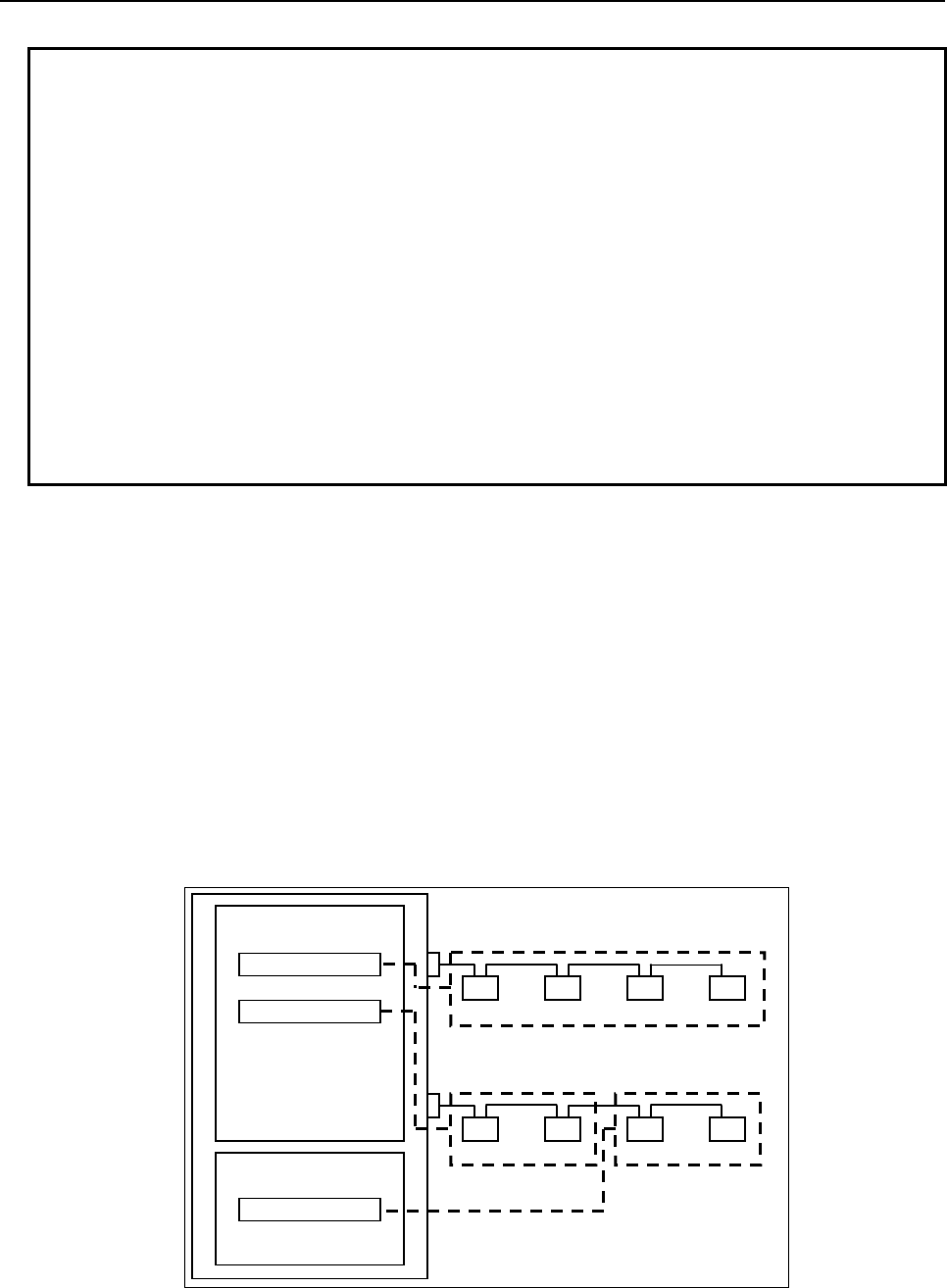
B-64513EN/03
3.COMMUNICATION WITH I/O DEVICE
- 207 -
NOTE
1 Up to 2 blocks are available in one channel.
2 Up to 16 groups of slaves can be connected to total of first and second block.
The total number of I/O points occupied by all slaves connected to total of first
and second block is up to 1024 points for each of input and output. (For details
of I/O points, refer to "FANUC I/O Unit-MODEL A Connection and Maintenance
Manual" (B-61813E)).
3 When second block is used and any alarm occurs, group no of the alarm
message is displayed according to the I/O device wiring group no.
4 When second block is used, the selectable I/O Link assignment function is
available in each block independently.
5 The OVERRIDE function of the forced input/output function is available even if
second block is used.
6 When second block is used, it is recommended to enable the I/O Link
connection check function to prevent a malfunction about the mistake of the
setting.
Setting of dual assignment
To use the second block, see the following procedure.
(1) I/O module assignment
The module assignment is edited on FANUC LADDER-III or built-in edit function and is saved
with the sequence program in the same way as not using the second block. Take care of the total
group number and total points of each slave.
(2) Setting the machine signal interface
Set the input/output addresses to first and second block for each channel of I/O link in configuration
parameter screen.
(3) Re-boot the CNC and confirmation
The example that is assigned like followings is explained here.
1st PMC
X/Y0 to 127
X/Y200
to 327
2nd PMC
Channel 1
Grou
p
0 Grou
p
1
Grou
p
0 Grou
p
1 Grou
p
2 Grou
p
3
Grou
p
0 Grou
p
1
1st Block 2nd Block
Channel 2
X/Y0 to 127
X0 X20 X30 X50
X200 X210 X0 X30
Fig. 3.2.4.3(b) Example of using 2 PMCs and 2 I/O Link Channels
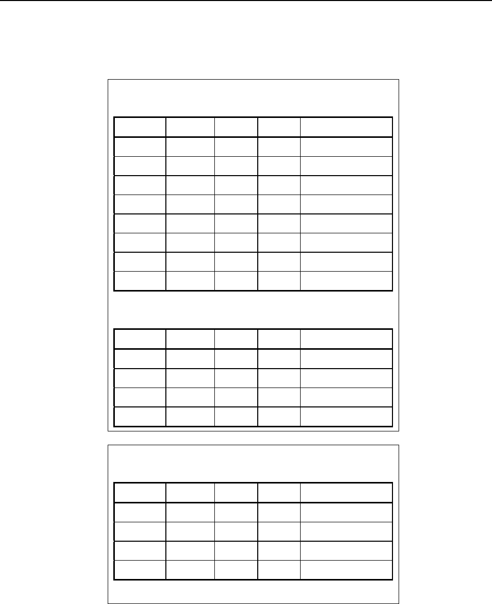
3.COMMUNICATION WITH I/O DEVICE
B-64513EN/03
- 208 -
Step1 I/O module assignment
The group number from 0 is set to the assigned data in each block. On the I/O MODULE EDITOR screen,
channel 1 is assigned to X/Y0 to X/Y127 of the first PMC and channel 2 is assigned to X/Y200 to
X/Y327 of the first PMC and X/Y0 to X/Y127 of the second PMC.
1st PMC
・Assignment of X/Y0 to 127
Address Group Base Slot Name
X0000 0 0 1 /2
: : : : :
X0020 1 0 1 FS08A
: : : : :
X0030 2 0 1 CM16I
: : : : :
X0050 3 0 1 /8
: : : : :
・Assignment of X/Y200 to 327
Address Group Base Slot Name
X0200 0 0 1 /2
: : : : :
X0210 1 0 1 CM16I
: : : : :
2nd PMC
・Assignment of X/Y0 to 127
Address Group Base Slot Name
X0000 0 0 1 /2
: : : : :
X0030 1 0 1 CM16I
: : : : :
Set group number 0 to the top I/O device of second block.
For details of setting, see Subsection 9.4.2.
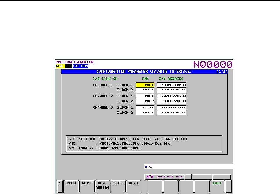
B-64513EN/03
3.COMMUNICATION WITH I/O DEVICE
- 209 -
Step2 Setting the machine signal interface
Set the input/output addresses of the I/O Link to each channel, on the PMC CONFIGRATION
PARAMETER (MACHINE INTERFACE) screen.
(1) Assign X0/Y0 of the first PMC to channel 1.
(2) Assign X200/Y200 of the first PMC to the first block of channel 2.
(3) Assign X0/Y0 of the second PMC to the second block of channel 2.
Fig. 3.2.4.3(c) Setting of the PMC configuration parameter setting screen
For details of setting, see Subsection 9.9.3.
Step3 Re-boot the CNC and confirmation
To reflect the setting data, reboot the CNC. Check the input/output signals of each I/O Link channel and
confirm the reflection of the setting.
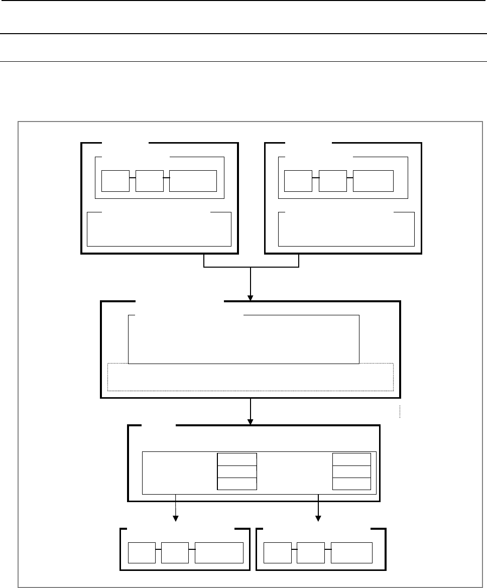
3.COMMUNICATION WITH I/O DEVICE
B-64513EN/03
- 210 -
3.2.5
Selectable I/O Link Assignment Function
3.2.5.1
Outline
This function enables the common use of a sequence program for several machines which have different
I/O device configuration with each other, by setting the parameter to enable/disable each group in I/O link
assignment data.
The I/O link assignment data of both the
machine A and the machine B are merged.
X0 0.0.1 FS08A (Power Mate)
X8 1.0.1 OC02I (Connection Unit)
I/O link assignment data
I/O devices
CNC Power
Mate
Connection
Unit
Machine A
X0 0.0.1 FS08A (Power Mate)
X24 1.0.1 I D32E (I/O Unit)
I/O link assignment data
I/O devices
Power
Mate
I/O
Unit
Machine B
Off line programmer
Make ROM format file with I/O link assignment data that is used in both the
machine A and the machine B.
A
sequence program is sent to CNC.
Set effective I/O groups on parameter.
CNC
Machine A: I/O devices
Power
Mate
Connection
Unit
Machine B: I/O devices
Power
Mate
I/O
Unit
Power Mate Enable Power Mate Enable
Connection Unit Enable Connection Unit Disable
I/O Unit Disable I/O Unit Enable
CNC
CNC CNC
X0 0.0.1 FS08A (Power Mate)
X8 1.0.1 OC02I (Connection Unit)
X24 2.0.1 ID32E (I/O Unit)
I/O link assignment data
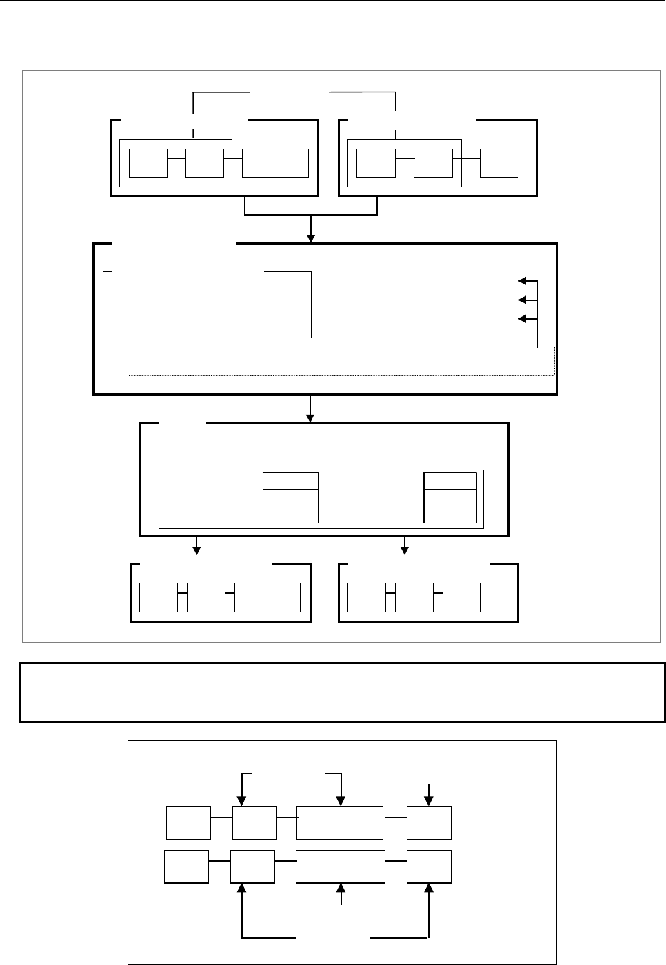
B-64513EN/03
3.COMMUNICATION WITH I/O DEVICE
- 211 -
The I/O devices that are used in all machines can be set as basic part of configuration that is always
effective.
The I/O link assignment data of the
machine A and the machine B are merged.
CNC Power
Mate
Connection
Unit
Power
Mate
I/O
Unit
X0 0.0.1 FS08A (Power Mate)
X8 1.0.1 OC02I (Connection Unit)
X24 2.0.1 ID32E (I/O Unit)
I/O link assignment data
Off line programmer
Basic part (always connected)
Optional group by parameter
Optional group by parameter
The sequence program is sent to CNC
Set effective I/O group on parameter.
CNC
Machine A : I/O devices
Power
Mate
Connection
Unit
Machine B : I/O devices
Power
Mate
I/O
Unit
Determine the basic part and the optional part of I/O link assignment data.
Machine B: I/O devices
Power Mate Basic Power Mate Basic
Connection Unit Enable Connection Unit Disable
I/O Unit Disable I/O Unit Enable
CNC
CNC CNC
Machine A: I/O devices
Basic part
NOTE
When you set a basic part, you have to assign devices of basic part continuously
from group 0. And the basic part is connected with the top of the link.
CNC Power
Mate Connection
Unit
I/O
Unit
Power
Mate
Connection
Unit
I/O
Unit
Basic part
Optional part
NG
OK
Basic part
Optional part
CNC

3.COMMUNICATION WITH I/O DEVICE
B-64513EN/03
- 212 -
This function requires setting the following parameters. These parameters can be set for each channel.
For details of each parameter, see Sections 2.4 and 9.5.
(1) ENABLE SELECTION:
Enables/Disables this function in the system parameter.
(2) BASIC GROUP COUNT:
Sets the counts of group in basic part in the system parameter. (This part must be assigned
continuously from group 0.) The basic groups in I/O link assignment data are always effective on all
machine configurations.
(3) EFFECTIVE GROUP SELECTION:
Sets the group of optional I/O device that is connected with each machine in the setting parameter.
This parameter doesn't affect the basic part.
3.2.5.2
Example
There are three machines which have different configurations of I/O devices, each other.
• Configuration A
A machine which has a distribution I/O machine operator's panel and a connection panel I/O
connected with channel 1 of NC.
Channel 1
CNC
Distribution I/O machine
o
p
erator's
p
anel
Connection panel I/O
Group 0 Group 1
Channel 2
No connection
• Configuration B
A machine which has a distribution I/O machine operator's panel and a Power Mate connected with
channel 1 of NC.
Channel 1
CNC
Distribution I/O machine
o
p
erator's
p
anel
Power Mate
Group 0 Group 1
Channel 2
No connection
• Configuration C
A machine which has the configuration A on channel 1 and two beta amplifiers on channel 2.
Channel 1
CNC
Distribution I/O machine
o
p
erator's
p
anel
Connection panel I/O
Group 0 Group 1
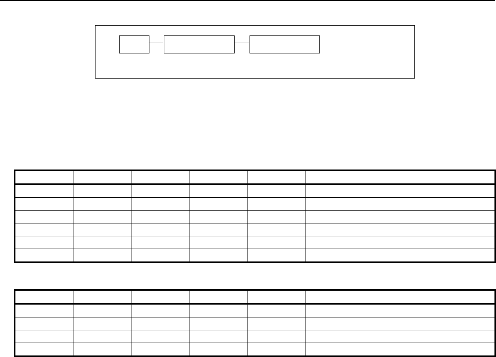
B-64513EN/03
3.COMMUNICATION WITH I/O DEVICE
- 213 -
Channel 2
CNC
Group 0
Beta amp.
Group 1
Beta amp.
These machines can use a common sequence program which has I/O link assignment data that includes
all I/O device configurations. The contents of parameters for each I/O device configuration are as shown
below.
(1) The contents of I/O link assignment data in sequence program
Channel 1
Address Group Base Slot Name I/O device
X0000 0 0 1 CM12I Distribution I/O machine operator’s panel
: : : : : :
X0020 1 0 1 CM03I Connection panel I/O
: : : : : :
X0030 2 0 1 FS08A Power Mate
: : : : : :
Channel 2
Address Group Base Slot Name I/O device
X0200 0 0 1 OC02I Beta amp.
: : : : : :
X0220 1 0 1 OC02I Beta amp.
: : : : : :

3.COMMUNICATION WITH I/O DEVICE
B-64513EN/03
- 214 -
(2) The contents of parameter
• Configuration A
• System parameter
X0000/Y0000
ENABLE SELECTION = YES
BASIC GROUP COUNT = 1
X0200/Y0200
ENABLE SELECTION = YES
BASIC GROUP COUNT = 0
• Setting parameter
Group NO.: 00 01 02 03 04 05 06 07
X0000/Y0000 * 1 0 0 0 0 0 0
08 09 10 11 12 13 14 15
0 0 0 0 0 0 0 0
Group NO.: 00 01 02 03 04 05 06 07
X0200/Y0200 0 0 0 0 0 0 0 0
08 09 10 11 12 13 14 15
0 0 0 0 0 0 0 0
• Configuration B
• System parameter
X0000/Y0000
ENABLE SELECTION = YES
BASIC GROUP COUNT = 1
X0200/Y0200
ENABLE SELECTION = YES
BASIC GROUP COUNT = 0
• Setting parameter
Group NO.: 00 01 02 03 04 05 06 07
X0000/Y0000 * 0 1 0 0 0 0 0
08 09 10 11 12 13 14 15
0 0 0 0 0 0 0 0
Group NO.: 00 01 02 03 04 05 06 07
X0200/Y0200 0 0 0 0 0 0 0 0
08 09 10 11 12 13 14 15
0 0 0 0 0 0 0 0
• Configuration C
• System parameter
X0000/Y0000
ENABLE SELECTION = YES
BASIC GROUP COUNT = 1
X0200/Y0200
ENABLE SELECTION = YES
BASIC GROUP COUNT = 0
• Setting parameter
Group NO.: 00 01 02 03 04 05 06 07
X0000/Y0000 * 1 0 0 0 0 0 0
08 09 10 11 12 13 14 15
0 0 0 0 0 0 0 0
Group NO.: 00 01 02 03 04 05 06 07
X0200/Y0200 1 1 0 0 0 0 0 0
08 09 10 11 12 13 14 15
0 0 0 0 0 0 0 0

B-64513EN/03
3.COMMUNICATION WITH I/O DEVICE
- 215 -
(3) The actual contents of I/O link assignment data modified by the parameter
• Configuration A
Channel 1
Address Group Base Slot Name I/O device
X0000 0 0 1 CM12I Distribution I/O machine operator’s panel
: : : : : :
X0020 1 0 1 CM03I Connection panel I/O
: : : : : :
Channel 2
No connection
• Configuration B
Channel 1
Address Group Base Slot Name I/O device
X0000 0 0 1 CM12I Distribution I/O machine operator’s panel
: : : : : :
X0030 1 0 1 FS08A Power Mate
: : : : : :
Channel 2
No connection
• Configuration C
Channel 1
Address Group Base Slot Name I/O device
X0000 0 0 1 CM12I Distribution I/O machine operator’s panel
: : : : : :
X0020 1 0 1 CM03I Connection panel I/O
: : : : : :
Channel 2
Address Group Base Slot Name I/O device
X0200 0 0 1 OC02I Beta amp.
: : : : : :
X0220 1 0 1 OC02I Beta amp.
: : : : : :
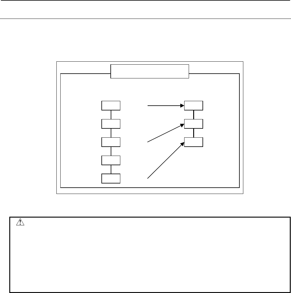
3.COMMUNICATION WITH I/O DEVICE
B-64513EN/03
- 216 -
3.2.5.3
Notes
(1) If PMC-parameters are cleared, cycling the power of CNC links only the basic part.
(2) After selecting the assignment data, the I/O devices are linked with shifted group number of
effective I/O link assignment data.
You can check the actual result of connection using the I/O Link connection display screen.
Before selection
A
fter selection
Group 0
Group 1
Group 2
Group 3
Group 4
Group 0
Group 1
Group 2
Effective
I/O link assignment data
Effective
Effective
Not effective
Not effective
(3) You can not exchange the order of the I/O group number.
WARNING
1 If the machine is linked again with incorrect setting of I/O link assignment
parameters, the machine may perform unexpected operation. If you want to
have the machine linked with I/O devices under the selected I/O link assignment
data, you have to turn off and on power after the confirmation of the correct
connection of the I/O devices.
2 To prevent any operator error caused in a case as described in "WARNING 1"
above, it is recommended that the "I/O Link connection check function" be
enabled. For details, see Section 3.4.
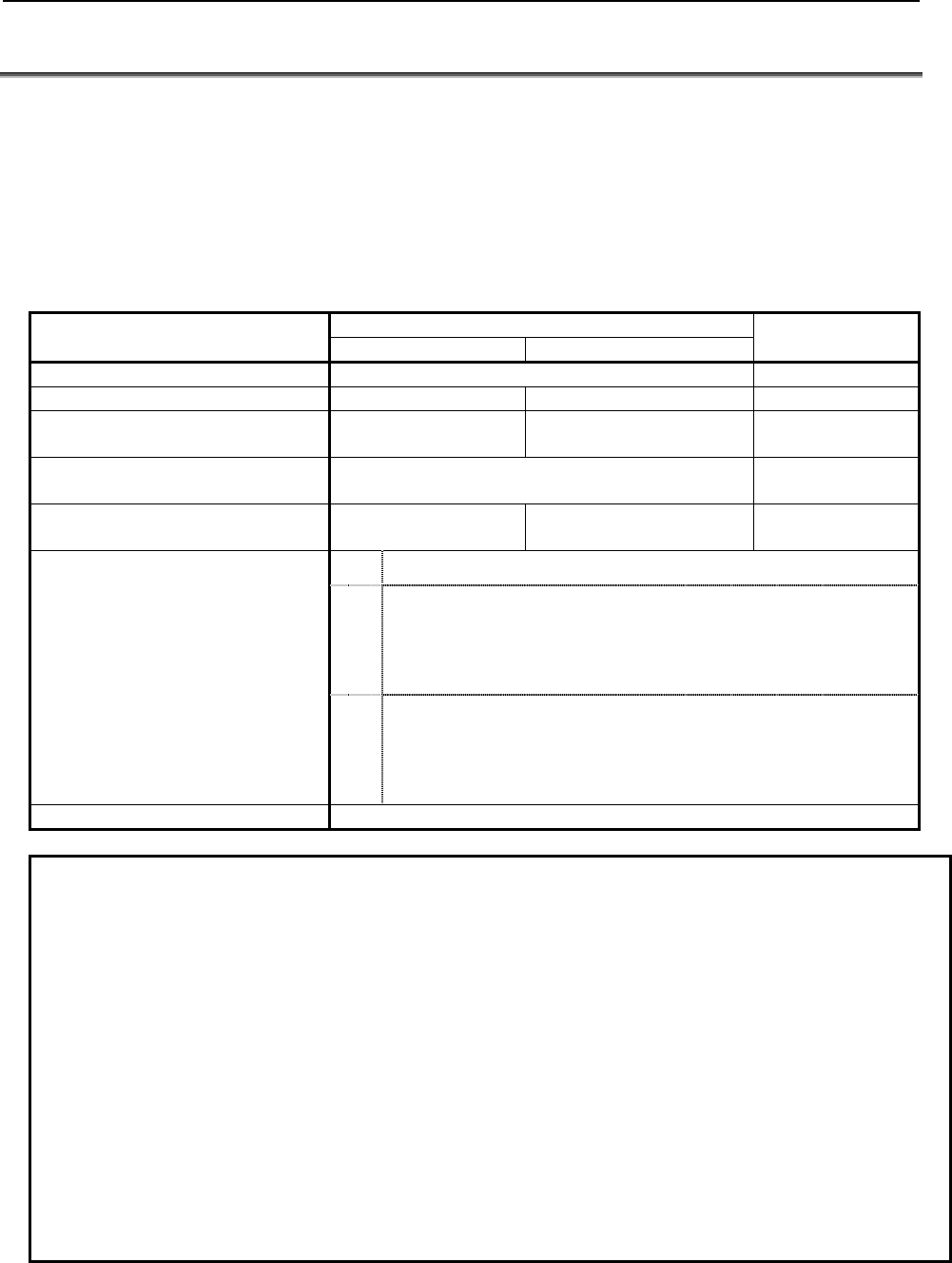
B-64513EN/03
3.COMMUNICATION WITH I/O DEVICE
- 217 -
3.3 WHAT IS I/O Link i ?
The I/O Link i is one of the serial interfaces which transmits input/output signals at a high speed between
the PMC and I/O devices.
Available channels are two channels and for each channel, up to 2048 DI points and up to 2048 DO
points can be connected and controlled from the PMC.
As for the transmission cycle of the signals from I/O Link i, there are two modes of the normal mode
(2msec) and the high-speed mode (0.5msec). You can specify the mode for each group of I/O devices.
Fig. 3.3 Outline of specification of I/O Link i
Item I/O Link i I/O Link
Normal mode High-speed mode
Transmit speed 12Mbps 1.5Mbps
Update cycle(Note 2) 2ms 0.5ms 2ms
I/O points for one channel 2048 / 2048 512 / 512 1024 / 1024
(64 / 64) (Note 3)
I/O points for one group
512 / 512
(224 /224) (Note 3)
256 / 256
Maximum groups for one channel
(Note 3, Note4)
24
(4)
5
(4)
16
PMC control address 1st path PMC to 5th path PMC
DI: X0
~
X127
X200
~
X327
X400
~
X527
X600
~
X727
DO: Y0
~
Y127
Y200
~
Y327
Y400
~
Y527
Y600
~
Y727
Selection of effective group I/O link selectable assignment data function
NOTE
1 You can select a communication method from either the I/O Link i or the I/O Link for
each channel by setting the CNC parameter “Communication method of I/O
Device”. The default setting is the I/O Link mode (0i-F: I/O Link i mode). For details
of the parameter, refer to subsection “2.4.3”. For example, you can use the channel
1 as the I/O Link i, and the channel 2 as the I/O Link. In this case, the total I/O
points are 3072 points / 3072 points (0i-F: 2048 points / 2048 points).
2 You can select an update cycle mode from either the normal mode or the high-
speed mode for each group. You can make use of two modes in one channel. For
details, refer to subsection “3.3.3”.
3 The Inside of “( )” is the specification of dual check safety.
4 If you build the dual check safety system using the I/O Link i, you can make use of
up to 4 groups for DCSPMC. If you use two channels of the I/O Link i, the maximum
number of available groups is 4 groups. For details of the directions for the dual
check safety of I/O Link i, refer to subsection “3.3.7”.
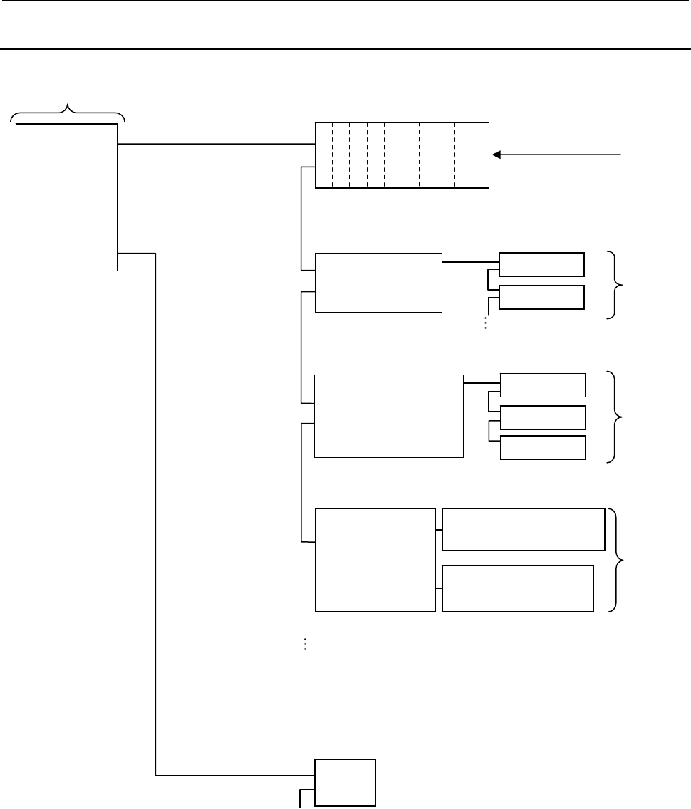
3.COMMUNICATION WITH I/O DEVICE
B-64513EN/03
- 218 -
3.3.1
Configuration of I/O Link i
The following shows a basic configuration example of the I/O Link i.
CNC
Master
Group0
I/O Unit- MODEL A
Channel 1
(1ch)
Channel2
(2ch)
Interface unit
I/O Unit- MODEL B
Slot 1
Group1
Group0
Slot 1
…
Distribution I/O
Connection panel
I/O module
Basic unit
Slot 1
Group2
Ex
p
ansion unit
Group3
Machine
operator’s panel
interface unit
Machine operator’s panel
Slot 1
Manual pulse generator
Slot 2
Slot 2
Slot 3
Slot 10
Slot 2
Slot 2
Slot 3
Slot 4
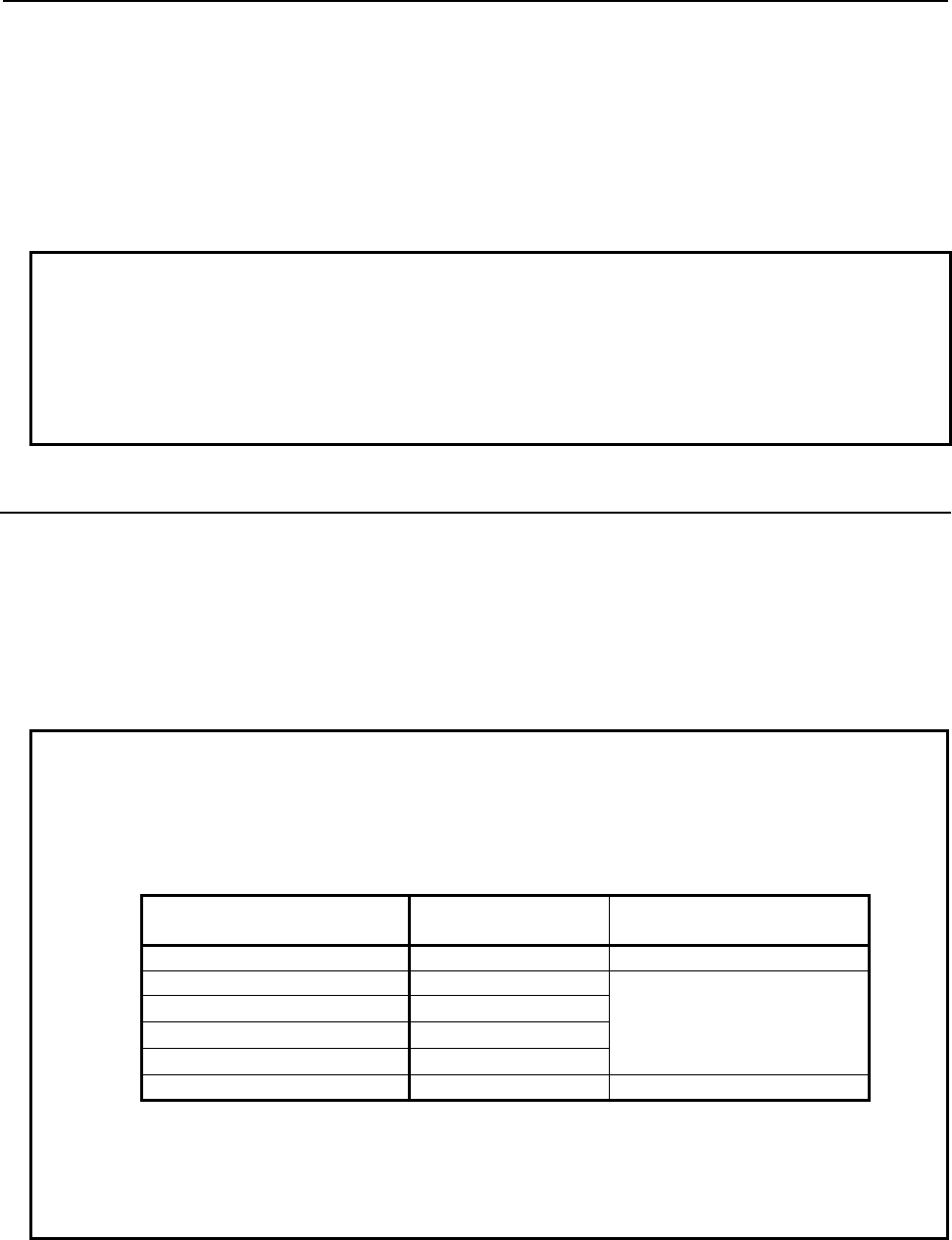
B-64513EN/03
3.COMMUNICATION WITH I/O DEVICE
- 219 -
(1) One master and several slaves constitute an I/O Link i network.
Master: CNC (such as Series30i-B).
Slave: I/O Unit-MODEL A, Machine operator’s panel interface unit, etc.
(2) The slave of up to 24 groups can be connected to one channel for the I/O Link i.
The group number is assigned to 0 to 23 in order near the master.
The number of slave, which can be connected in one group, is not fixed.
(3) It is not necessary to care the order of connected slaves. However, slaves of a different kind cannot
be connected in one group.
NOTE
1 The power of slaves should be turned on simultaneously with or before the
power supply of a master.
2 When the power of a master is turned off, the power of all of slaves should be
turned off.
3 For the maximum number of slaves which can be connected in one group, refer
to connection manual of each I/O devices.
3.3.2
Input / Output Points
The input/output points of I/O Link i are 2048 points/ 2048 points for each channel. By assigning the I/O
points to each slave, the I/O data can be communicated periodically between the master and slaves.
Each I/O devices occupies some I/O points.
The maximum I/O points, which can be occupied in one group, are 512 points / 512 points
(64bytes/64bytes).
And, the numbers of I/O points, which can be occupied in one group, are arranged with a multiple of 8
points. For example, if actual I/O points are 10 points, occupied I/O points are 16 points.
NOTE
1 When you use the high-speed mode, the maximum group number and I/O points
show in the following table. If you use both of the normal mode and the high-
speed mode, the maximum group number and I/O points are changed. For
details, refer to subsection “3.3.3”.
The group number of high-
speed mode
Maximum group
number
Maximum I/O points (all of
groups)
Non 24 group 2048 / 2048
1 group 17 group
512 to 2048 / 512 to 2048
2 group 14 group
3 group 11 group
4 group 8 group
5 group 5 group 512 / 512
2 The “safety I/O” used in the dual check safety function are assigned at a group
unit. The maximum I/O points of the “safety I/O” group are 224 points/224 points.
The “safety I/O” can be specified up to 4 groups for PMC1 to PMC5, and 4
groups for the DCSPMC. For details, refer to subsection “3.3.4”.
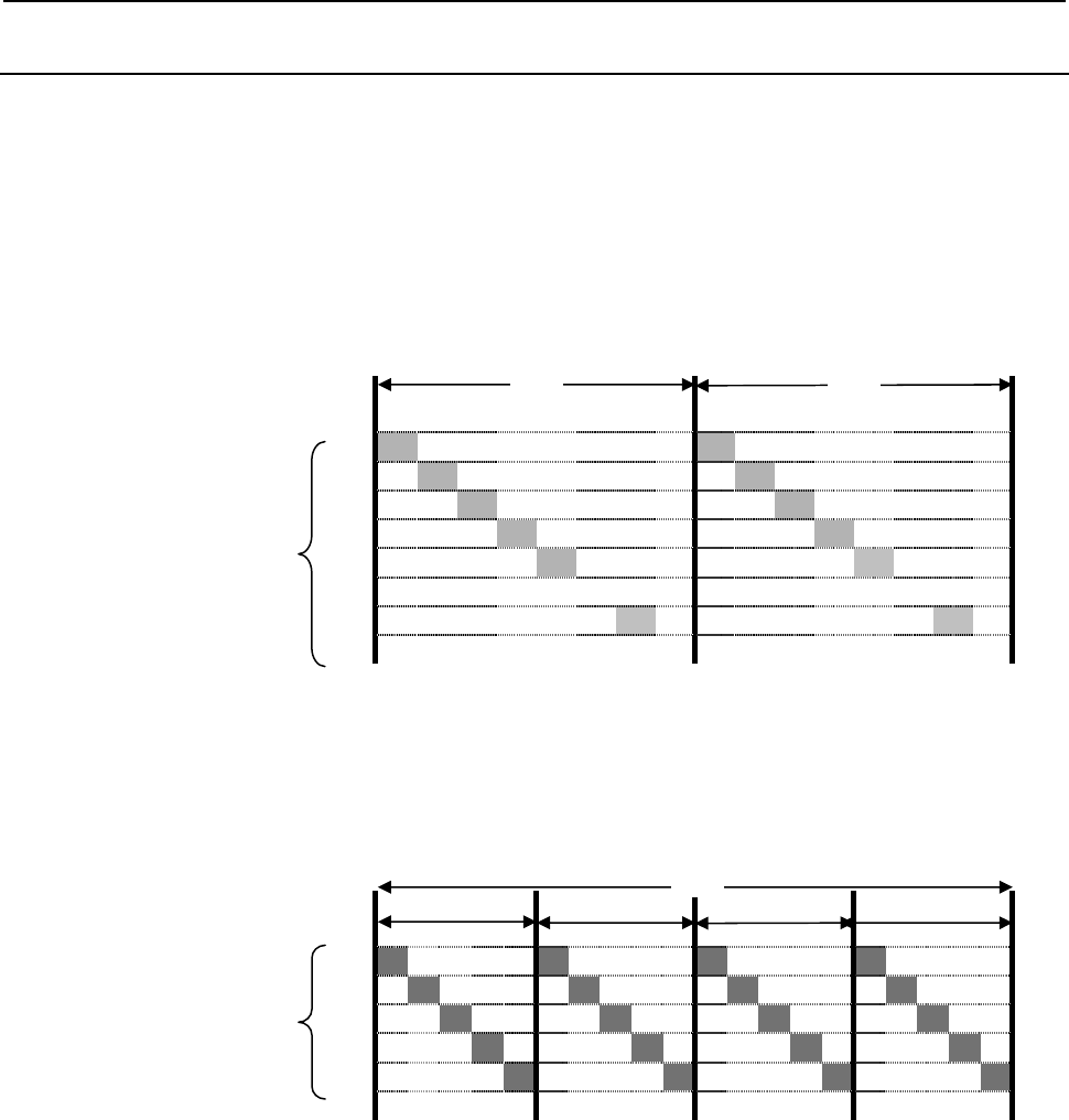
3.COMMUNICATION WITH I/O DEVICE
B-64513EN/03
- 220 -
3.3.3
Update Cycle of Signals
You can choose an update cycle from two modes of the normal mode (2msec cycle) and the high-speed
mode (0.5msec cycle) for each group unit. When the high-speed mode is used, the maximum number of
groups and I/O points are changed.
Transmission in only normal mode
If you can specify the normal mode for all of groups in one channel, the signal of all groups is transmitted
sequentially in group number order in a cycle of 2msec. In this case, it can connect a maximum of 24
groups, and the total number of a maximum of I/O points becomes 2048 points / 2048 points.
Group
0
1
2
3
4
: : :
23
Fig. 3.3.3(a) I/O transmission of Normal mode(24 groups)
Transmission in only high-speed mode
If you can specify the high-speed mode for all of groups in one channel, the signal of all groups is
transmitted sequentially in group number order in a cycle of 0.5msec. In this case, it can connect a
maximum of 5 groups, and the total number of a maximum of I/O points becomes 512 points / 512 points.
group
0
1
2
3
4
Fig. 3.3.3(b) I/O transmission of high-speed mode (5 groups)
2ms 2ms
Input 2048 points/
Output 2048 points
0.5ms 0.5ms 0.5ms 0.5ms
Input 512 points/
Output 512 points
2ms
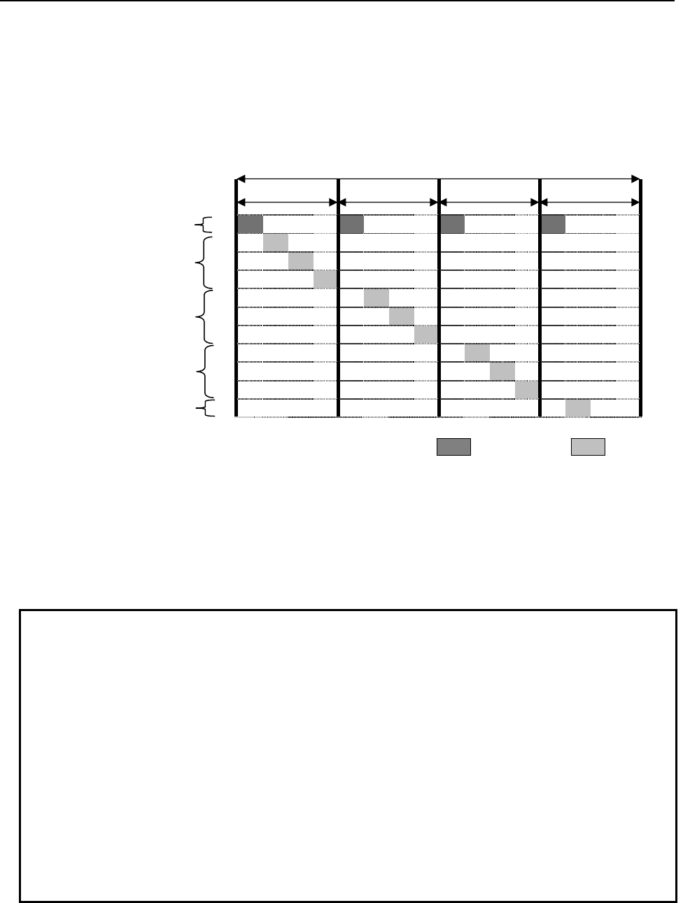
B-64513EN/03
3.COMMUNICATION WITH I/O DEVICE
- 221 -
Transmission in mixed modes
When the groups of the normal mode and the high-speed mode are mixed in one channel, the signal of all
groups is transmitted sequentially in a cycle of 0.5msec. In groups of the high-speed mode, they are
transmitted every 0.5msec from low group number. In the case of group in the normal mode, they are
transmitted in one of 4 times in cycle of 0.5msec, it means a cycle of 2msec. At this time, the signals, that
are subtracting the total points of high-speed mode from 512 points, can be transmitted in one cycle of
0.5msec.
Group
High-speed mode
0
1
Normal mode
2
(= 512 ‐ total points of high-speed
mode)
3
4
Normal mode
5
6
7
Normal mode
8
9
Normal mode
10
Fig. 3.3.3(c) high-speed mode 1group, normal mode 10group
When the groups of the normal mode and the high-speed mode are mixed, the number is converted in the
normal mode, and a maximum of 20 groups can be connected, and a maximum of I/O points are 2048
points/2048 points. The number of groups and I/O points of the normal mode is four times of number of
the high-speed mode. For example, 2 groups and 64/64 of I/O points in the high-speed mode equivalent to
8 groups and 256/256 of I/O points in the normal mode.
NOTE
1 The signals are transmitted in the group number order. If the sum total of input or
output points are exceeds 512 points, the group will be assigned to next cycle
time. For this reason, even if the total number of groups and I/O points is not
over maximum number, the PMC alarm “ER35”,”ER36”, “ER38” or “ER39” may
occur.
2 In the group of “safety I/O” for the dual check safety function, the redundant data
are added at the time of transmission. The data length of the redundant data is 4
bytes or 5 bytes in order to be even bytes. To calculate the total I/O points, add
the redundant data. For “safety I/O”, refer to subsection “3.3.4”.
The followings are the example of calculation of I/O points for “safety I/O”.
- In case of 64 points (8 bytes of real data):
Total 96 points (4 bytes of redundant data)
- In case of 88 points (11 bytes of real data):
Total 128 points (5 bytes of redundant data)
2ms
0.5ms 0.5ms 0.5ms 0.5ms
: high-speed : Normal

3.COMMUNICATION WITH I/O DEVICE
B-64513EN/03
- 222 -
3.3.4
Safety I/O
In the I/O Link i, the “safety I/O” which performs more reliable communication can be specified for a
group unit. The maximum I/O points of the “safety I/O” points are 224 points /224 points. The “safety
I/O” can be specified up to 4 groups for PMC1 to PMC5, and 4 groups for the DCSPMC.
It is necessary to specify this “safety I/O” to be a safety signals used in the dual check safety function.
For details of the dual check safety function in the I/O Link i, refer to subsection “3.3.7”.
NOTE
Redundant data is added to the group which is specified as “safety I/O”. The
length of added redundant data is 4 bytes or 5 bytes. It means that the length of
actual data becomes even-numbered bytes. The followings are example of
actual I/O points of the group specified as “safety I/O”.
・The case that the points of safety I/O are 64 points (8 bytes):
Actual I/O points are 96 points and redundant data is 4 bytes.
・The case that the points of safety I/O are 88 points (11 bytes):
Actual I/O points are 128 points and redundant data is 5 bytes.
・The case that the points of safety I/O are 224 points (28 bytes):
Actual I/O points are 256 points and redundant data is 4 bytes.
Safety I/O group status
You can confirm the groups which communicate as the “safety I/O” by the following system relays.
Address Contents
R9232.0 Group 0 of Channel 1 is the “safety I/O”.
R9232.1 Group 1 of Channel 1 is the “safety I/O”.
R9232.2 Group 2 of Channel 1 is the “safety I/O”.
R9232.3 Group 3 of Channel 1 is the “safety I/O”.
R9232.4 Group 4 of Channel 1 is the “safety I/O”.
R9232.5 Group 5 of Channel 1 is the “safety I/O”.
R9232.6 Group 6 of Channel 1 is the “safety I/O”.
R9232.7 Group 7 of Channel 1 is the “safety I/O”.
R9233.0 Group 8 of Channel 1 is the “safety I/O”.
R9233.1 Group 9 of Channel 1 is the “safety I/O”.
R9233.2 Group 10 of Channel 1 is the “safety I/O”.
R9233.3 Group 11 of Channel 1 is the “safety I/O”.
R9233.4 Group 12 of Channel 1 is the “safety I/O”.
R9233.5 Group 13 of Channel 1 is the “safety I/O”.
R9233.6 Group 14 of Channel 1 is the “safety I/O”.
R9233.7 Group 15 of Channel 1 is the “safety I/O”.
R9234.0 Group 16 of Channel 1 is the “safety I/O”.
R9234.1 Group 17 of Channel 1 is the “safety I/O”.
R9234.2 Group 18 of Channel 1 is the “safety I/O”.
R9234.3 Group 19 of Channel 1 is the “safety I/O”.
R9234.4 Group 20 of Channel 1 is the “safety I/O”.
R9234.5 Group 21 of Channel 1 is the “safety I/O”.
R9234.6 Group 22 of Channel 1 is the “safety I/O”.
R9234.7 Group 23 of Channel 1 is the “safety I/O”.
R9235.0 Group 0 of Channel 2 is the “safety I/O”.
R9235.1 Group 1 of Channel 2 is the “safety I/O”.
R9235.2 Group 2 of Channel 2 is the “safety I/O”.
R9235.3 Group 3 of Channel 2 is the “safety I/O”.
R9235.4 Group 4 of Channel 2 is the “safety I/O”.

B-64513EN/03
3.COMMUNICATION WITH I/O DEVICE
- 223 -
Address Contents
R9235.5 Group 5 of Channel 2 is the “safety I/O”.
R9235.6 Group 6 of Channel 2 is the “safety I/O”.
R9235.7 Group 7 of Channel 2 is the “safety I/O”.
R9236.0 Group 8 of Channel 2 is the “safety I/O”.
R9236.1 Group 9 of Channel 2 is the “safety I/O”.
R9236.2 Group 10 of Channel 2 is the “safety I/O”.
R9236.3 Group 11 of Channel 2 is the “safety I/O”.
R9236.4 Group 12 of Channel 2 is the “safety I/O”.
R9236.5 Group 13 of Channel 2 is the “safety I/O”.
R9236.6 Group 14 of Channel 2 is the “safety I/O”.
R9236.7 Group 15 of Channel 2 is the “safety I/O”.
R9237.0 Group 16 of Channel 2 is the “safety I/O”.
R9237.1 Group 17 of Channel 2 is the “safety I/O”.
R9237.2 Group 18 of Channel 2 is the “safety I/O”.
R9237.3 Group 19 of Channel 2 is the “safety I/O”.
R9237.4 Group 20 of Channel 2 is the “safety I/O”.
R9237.5 Group 21 of Channel 2 is the “safety I/O”.
R9237.6 Group 22 of Channel 2 is the “safety I/O”.
R9237.7 Group 23 of Channel 2 is the “safety I/O”.
3.3.5
I/O Link i Selectable Assignment Data Function
You can set the validity of the I/O assignment data of each group of the I/O Link i.
In order to communize the I/O assignment data for several machines which have different I/O device
configuration with each other, you can specify all of the I/O assignment data (a maximum of 24 groups)
in order to fill full set of configuration beforehand. According to the specification of each machine, this
function determines effective groups.
At this time, the number of effective I/O link assignment data is optimized, and applied I/O device is
linked. You can confirm the actual result of connection by the I/O Link connection status screen.
Confirmation of I/O Link i Selectable Assignment Function
The channel setting of the assignment data for the I/O Link i is used to enable this function.
Basic group number
On the channel setting of the assignment data of the I/O Link i, you can set the number of the basic
configuration groups. It must be to connect continuously from group 0. The assignment data of basic
group is effective in all of machine configuration.
Selection of effective groups
The selection of effective groups (own I/O device groups for each machine) is to set the system keep
relays (K928 to K933) of PMC1. The setting of this parameter is not effect to the basic groups.
#7 #6 #5 #4 #3 #2 #1 #0
K928 Group 7 Group 6 Group 5 Group 4 Group 3 Group 2 Group 1 Group 0
[Data type] Bit
Group 0 to 7 For the selectable I/O Link i assignment function, whether to enable or disable
assignment of group 0 to 7 of channel 1.
0: Assignment of each group to the corresponding bit position is disabled.
1: Assignment of each group to the corresponding bit position is enabled.

3.COMMUNICATION WITH I/O DEVICE
B-64513EN/03
- 224 -
#7 #6 #5 #4 #3 #2 #1 #0
K929
Group 15 Group 14 Group 13 Group 12 Group 11 Group 10 Group 9 Group 8
[Data type] Bit
Group 8 to 15 For the selectable I/O Link i assignment function, whether to enable or disable
assignment of group 8 to 15 of channel 1.
0: Assignment of each group to the corresponding bit position is disabled.
1: Assignment of each group to the corresponding bit position is enabled.
#7 #6 #5 #4 #3 #2 #1 #0
K930
Group 23 Group 22 Group 21 Group 20 Group 19 Group 18 Group 17 Group 16
[Data type] Bit
Group 16 to 23 For the selectable I/O Link i assignment function, whether to enable or disable
assignment of group 16 to 23 of channel 1.
0: Assignment of each group to the corresponding bit position is disabled.
1: Assignment of each group to the corresponding bit position is enabled.
#7 #6 #5 #4 #3 #2 #1 #0
K932
Group 7 Group 6 Group 5 Group 4 Group 3 Group 2 Group 1 Group 0
[Data type] Bit
Group 0 to 7 For the selectable I/O Link i assignment function, whether to enable or disable
assignment of group 0 to 7 of channel 2.
0: Assignment of each group to the corresponding bit position is disabled.
1: Assignment of each group to the corresponding bit position is enabled.
#7 #6 #5 #4 #3 #2 #1 #0
K933
Group 15 Group 14 Group 13 Group 12 Group 11 Group 10 Group 9 Group 8
[Data type] Bit
Group 8 to 15 For the selectable I/O Link i assignment function, whether to enable or disable
assignment of group 8 to 15 of channel 2.
0: Assignment of each group to the corresponding bit position is disabled.
1: Assignment of each group to the corresponding bit position is enabled.
#7 #6 #5 #4 #3 #2 #1 #0
K934
Group 23 Group 22 Group 21 Group 20 Group 19 Group 18 Group 17 Group 16
[Data type] Bit
Group 16 to 23 For the selectable I/O Link i assignment function, whether to enable or disable
assignment of group 16 to 23 of channel 2.
0: Assignment of each group to the corresponding bit position is disabled.
1: Assignment of each group to the corresponding bit position is enabled.
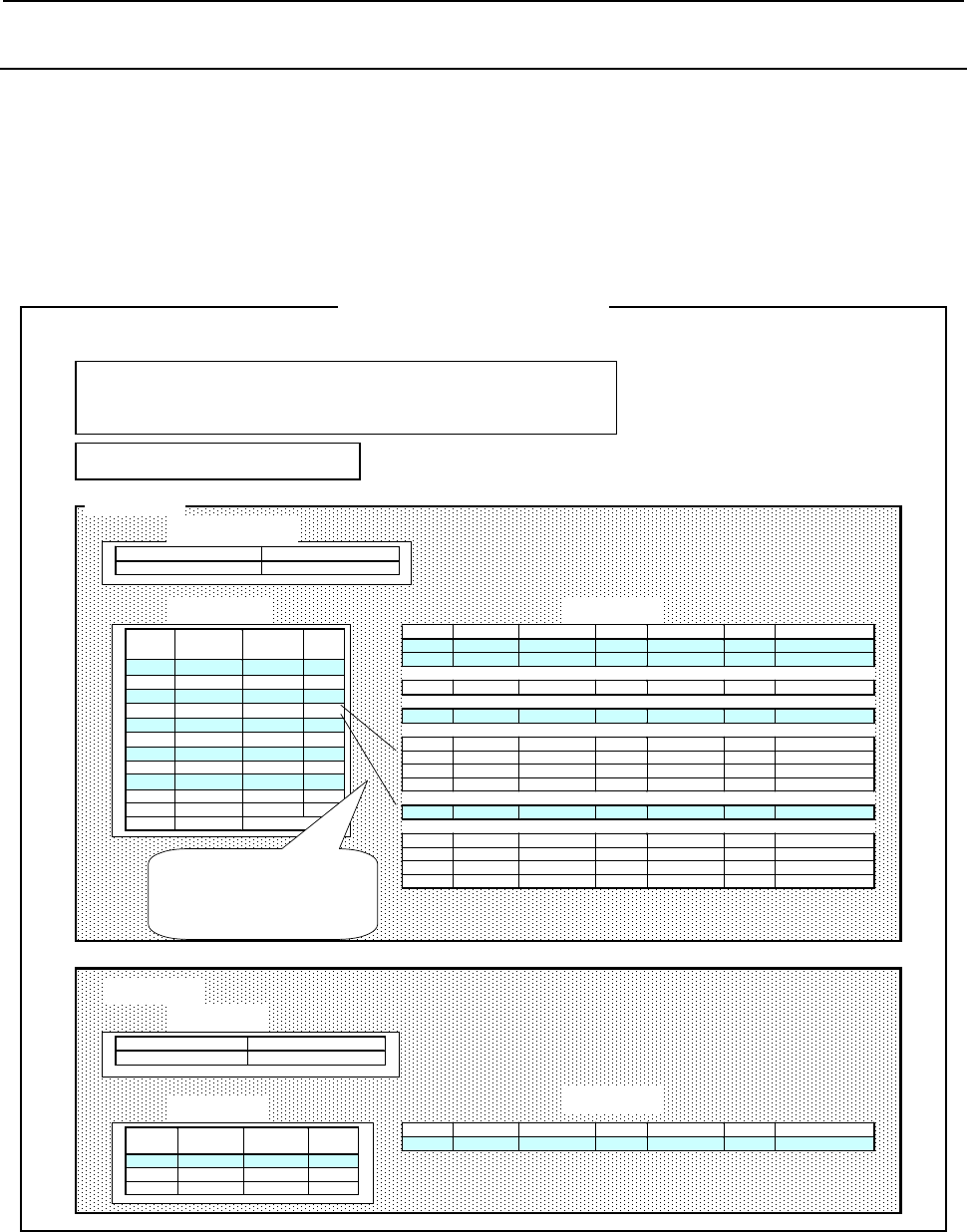
B-64513EN/03
3.COMMUNICATION WITH I/O DEVICE
- 225 -
3.3.6
Assignment Method of I/O Link i
When you use some I/O devices for slaves, it is necessary to set the I/O assignment data as the connection
information for each I/O device. In the connection information, there are “Connection location”, “High-
speed mode”, “Safety I/O mode”, “PMC path”, “X address (input)”, “Y address (output)”, “Data
length”, ”Use or not use of manual pulse module” and “Comment”. These information can be set in the
PMC screen or the FANUC LADDER-III. Moreover, you can set a password in order to protect the
assignment data and title data in the FANUC LADDER-III. The I/O assignment data for the I/O Link i
can be written into the flash ROM without the sequence program.
CHANNEL 1
Group High-speed
Mode
Safety I/O
Mode
MPG
0 * *
1
2
3 PMC
4
5 DCSPMC
6
7
8
:
:
23
Slot PMC X address Length Y address Length Comment
1PMC1 X0 13 Y0 8 Distribution
MPG PMC1 X14 3 0 MPG
1PMC2 X0 16 Y0 16 2201-0110
1PMC3 X0 6 Y0 2 Distribution
1PMC1 X200 2 0 0807-J103
2PMC2 X200 2 0 0807-J103
3PMC1 0 Y200 2 0807-J103
4PMC2 0 Y200 2 0807-J103
1PMC1 X300 8 Y300 8 PowerMate
1DCSPMC X0 2 0 DCSMAIN
2DCSPMC X8 2 0 DCSMAIN
3DCSPMC 0 Y0 2 DCSMAIN
4DCSPMC 0 Y8 2 DCSMAIN
Set the group information and slot
information separately. The “zoom” can
move to the “Slot information screen”
from the “Group information screen”
Selectable assignment Number of basic groups
Effective 2
Channel setting
Group setting Slot setting
CHANNEL 2
Title
Password
I/O Link i
A
ssignment data
Channel setting
Group setting Slot setting
Selectable assignment Number of Basic groups
Non-effective 0
Group High-speed
Mode
Safety I/O
Mode
MPG
0
:
23
Slot PMC X address Length Y address Length Comment
Fig. 3.3.6 Outline of assignment for I/O Link i
The assignment data for I/O Link i are set in each channel data, group data, and slot data separately.

3.COMMUNICATION WITH I/O DEVICE
B-64513EN/03
- 226 -
Item of channel setting
(1) Selectable assignment function
Set effective/non-effective of selectable assignment function for I/O Link i.
(2) Basic group number
Set the number of basic groups for selectable assignment.
Item of group setting
(1) Connection location “group”
Set the group number of connection location.
(2) High-speed mode “high-speed mode”
Set the mode of update cycle for each group by the soft-key.
In the column “High-speed mode”, the mode is shown as the following.
Space: Normal mode (2msec) (Default)
* : High-speed mode (0.5msec)
For details of update cycle, refer to subsection “3.3.3”.
(3) Safety I/O mode “Safety I/O”
Set the safety I/O mode for each group by the soft-key.
Space: Normal I/O (Default)
DCSPMC: Safety I/O for DCSPMC
PMC: Safety I/O for 1st PMC to 5th PMC
For the groups which is set to “ “ or “PMC”, you assign X/Y address of 1st PMC to 5th PMC. The
X/Y address of plural PMC path can be assigned in these groups.
For the group which is set to “DCSPMC”, the X/Y address of only DCSPMC can be assigned. The
maximum I/O points of the groups, which are set to “DCSPMC” or “PMC”, are 224 points/224
points.
(3) Manual pulse module “MPG”
Set the manual pulse module by the soft-key.
Space: Not use of the manual pulse module (Default)
* : Use of the manual pulse module
The “use of the manual pulse module” is set, “MPG” is displayed in the column “Slot” in the slot
data. The assignment data for the manual pulse module is set in the slot.
Example) In case that 3bytes from X14 is assigned for “MPG”.
Slot PMC X address X size Y address Y size
MPG PMC1 X14 3

B-64513EN/03
3.COMMUNICATION WITH I/O DEVICE
- 227 -
Item of Slot setting
(1) Connection location “Slot”
Set the slot number of connection location. For multi-path PMC, PMC path and address can be
assigned for each slot. You can use the addresses for plural PMC path in one channel.
Note
In group setting, “MPG” is displayed in the slot when the “use of manual pulse
module” is set.
(2) PMC path “PMC”
Set the PMC path.
“PMC1” to “PMC5” is set for each slot except setting “DCSPMC” in safety I/O mode.
“DCSPMC” is set for the group which is set “DCSPMC” in safety I/O mode.
(3) X address, Y address “X address, Y address”
Set the X address (input) and Y address (output) which is assigned to each I/O device. The ranges of
the address are X/Y0 to 127, X/Y200 to 327, X/Y400 to 527 and X/Y600 to 727.
Note
1 The X/Y address, which is set for the interface of I/O Link in PMC configuration
parameter, cannot be used. When some address is duplicated between I/O Link i
and I/O Link, the PMC alarm occurs at the power on.
(4) Data length “X size, Y size”
Set the data length by byte unit.
(5) Comment “Comment”
Set the comments up to 40 characters for I/O device. Available characters are as follows.
A to Z, a to z, 0 to 9, _!”#&’()”+,-< = >?@[/]^{|}~
Example) Drawing of Operator’s panel connection unit A
A16B-2200-0661
Others
The title and password can be set in FANUC LADDER-III.
(1) Title
Up 255 characters of title information can be set for title information of the assignment data.
Available characters are as follows.
A~Z, a~z, 0~9, space, Kana, Chinese character (a part), _!”#&$’()”+,-< = >?@[/]^{|}~
The contents of the title information can be confirmed in the I/O Link i assignment screen.
(2) Password protection
By the password, you can protect against the viewing or editing of the assignment data of I/O Link i.
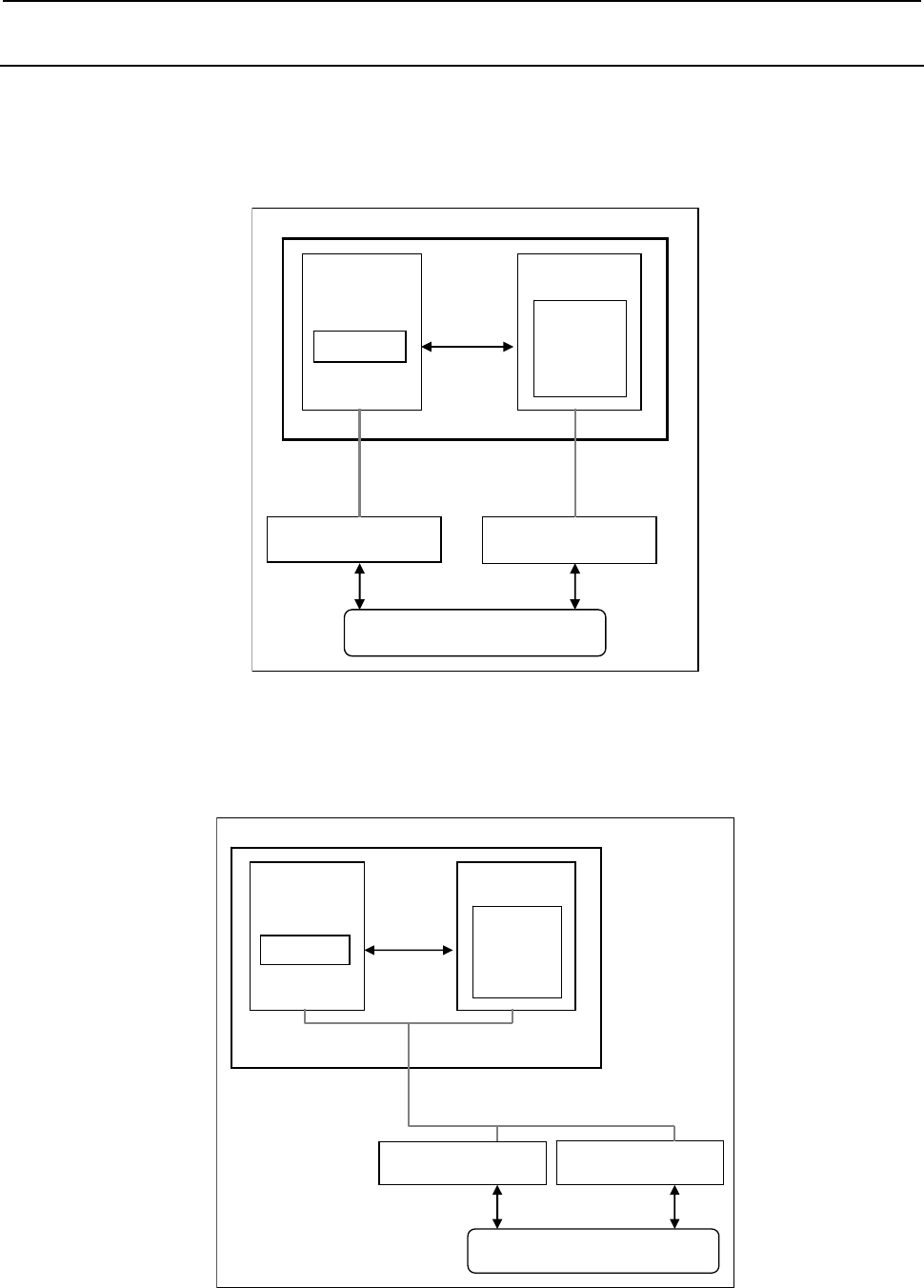
3.COMMUNICATION WITH I/O DEVICE
B-64513EN/03
- 228 -
3.3.7
Directions for Use of I/O Link i in Dual Check Safety Function
Summary
You can build the system for the dual check safety using either the I/O Link or the I/O Link i.
When you use the I/O Link for dual check safety, the I/O devices used in PMC1 to PMC5 are connected
to channel 1or 2, and the I/O devices used in DCSPMC are connected to channel 3. Therefore, two or
more channels are necessary for the dual check safety.
CNC
PMC
I/O for DCSPMC
I/O Link
CH3
Cross
Check
I/O for PMC
Safety I/O
DCSPMC
PMC1
to
PMC5
I/O Link
CH1
Fig. 3.3.7 (a) Dual check safety using 2 channel in I/O Link
When you use the I/O Link i for dual check safety, the I/O devices used in PMC1 to PMC5 are connected
to same channel used I/O devices for the DCSPMC. Therefore, only one channel is necessary for the dual
check safety.
CNC
PMC
I/O for DCSPMC
① ②
① ②
I/O Link i
Cross
Check
I/O for PMC
Safety I/O
① ②
DCSPMC
PMC1
to
PMC5
Fig. 3.3.7 (a) Dual check safety using 1 channel in I/O Link i

B-64513EN/03
3.COMMUNICATION WITH I/O DEVICE
- 229 -
Assignment for dual check safety
For the groups using in the dual check safety, you can set the “DCSPMC” or the “PMC” in the “safety
I/O mode” of the I/O assignment data. In the slots of the group that is set to the “DCSPMC” or the
“PMC”, the following PMC can be set.
DCSPMC: DCSPMC
PMC: PMC1 to PMC5
The maximum I/O points of the groups, which is set to the “DCSPMC” or the “PMC”, are 224 points
/224 points.

3.COMMUNICATION WITH I/O DEVICE
B-64513EN/03
- 230 -
3.4 I/O Link / I/O Link i CONNECTION CHECK FUNCTION
The I/O Link / I/O Link i connection check function always checks whether the number of I/O Link / I/O
Link i groups defined in a sequence program is the same as that of actually connected groups. When the
selectable I/O Link / I/O Link i assignment function is used, the I/O Link connection check function
compares the number of selected groups with that of connected groups.
If these numbers of groups do not match, the PMC alarm "ER97 I/O Link FAILURE (CHn Gxx)" is
issued. For action to be taken, see Section 12.1.
NOTE
1 All I/O devices connected to the channel in which this alarm occurs are not
linked.
2 The ladder program is executed regardless of whether this alarm occurs.
The execution of this function can be controlled using keep relay K906.2.
K906.2
0: Enables the I/O Link / I/O Link i connection check function. (Initial value)
1: Disables the I/O Link / I/O Link i connection check function.
CAUTION
If I/O devices are linked in the status in which an I/O device error or I/O device
connection error occurs or the setting of an I/O device is changed due to an
unintentional operation, the machine may not operate normally. This function
can always be operated to detect an I/O device error at power-on. To
troubleshoot problems with I/O devices easily, it is recommended that keep relay
K906.2 be set to the initial value (0).

B-64513EN/03
3.COMMUNICATION WITH I/O DEVICE
- 231 -
3.5 ASSIGNMENT OF NETWORK DEVICES TO X/Y ADDRESS
Input and output signals of network devices, such as a PROFIBUS, a PROFINET or an iPendant etc., can
be assigned to X/Y address area, such as X0-X127/Y0-Y127 or X200-327/Y200-327 etc. Network
devices can be assigned to the X/Y address area to which any I/O Link and I/O Link i devices are not
assigned.
When you assign network device to X/Y address area, you have to set 1 to the CNC parameter 11937 to
11939 for the corresponding area. For details, refer to “The input/output address used by network device”
of “2.4.3”.
NOTE
1 Once these parameters are set, it is necessary to turn off and on the power.
2 This parameter should be set only for the X /Y address area to which the
network device is assigned, because this parameter may affect the ladder
execution performance.
3 Network devices cannot be assigned to the X/Y address area to which any I/O
Link and I/O Link i are assigned.
4 In case of using I/O Link i, assign network devices to the X/Y address area to
which any I/O Link i devices are not assigned, then set this parameter for
corresponding area.
5 In case of using I/O Link and the parameter No.11910-11912 are set to 0
(default setting), I/O Link devices are assigned to X0-X127/Y0-Y127, X200-
X327/Y200-Y327 and X400-X527/Y400-Y527 area of 1st PMC path. In this case
for 1st PMC path, network devices can only be assigned to X600-X727/Y600-
Y727 area.
If all parameters are not set to 0, network devices can be assigned to the X/Y
address area to which any I/O Link channels are not assigned, and set this
parameter for corresponding area accordingly.
Example) When I/O Link channel 1 is assigned to X0-X127/Y0-Y127 of 1st PMC
path, and network device can be assigned to X200-327/Y200-327, set the
parameter No.11910=100, No.11911=0, No.11912=0, No.11937#1=1.
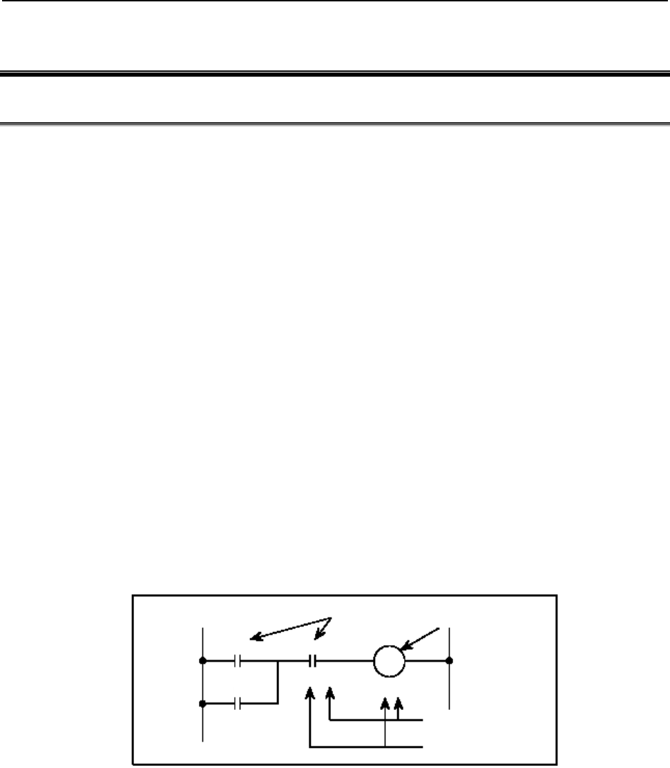
4.LADDER LANGUAGE
B-64513EN/03
- 232 -
4 LADDER LANGUAGE
4.1 BASIC INSTRUCTIONS
Designing a sequence program entails drawing a ladder diagram. Draw a ladder diagram by using relay
contact symbols as well as symbols representing the functional instructions described later. The logic laid
out in the ladder diagram is input to the programmer as a sequence program.
You can input a sequence program to the programmer in two ways - the relay symbol input method
whereby relay contact symbols and functional instruction symbols drawn in the ladder diagram are used
as they are (−⏐⏐−, −⏐/⏐−, −{−, etc.) and the mnemonic format input method that uses the mnemonic
language (PMC instructions such as RD, AND, and OR).
The relay symbol input method allows the ladder diagram format to be used as it is, thus letting you input
a sequence program in an intuitive, easy-to-understand manner. You will virtually have no trouble
creating a program even if you have little or no knowledge of the PMC instructions (basic instructions
such as RD, AND, and OR).
In fact, however, the content of a sequence program that is input using the relay symbol input method is
internally converted to instructions that are equivalent to the corresponding PMC instructions. Also, you
need to fully understand the functionalities of the functional instructions that are described later. It is
therefore necessary for you to carefully read the descriptions of the basic and functional instructions that
are given later in this manual.
For information about how to input PMC instructions to the programmer using relay and other symbols,
see Chapter 8.
When reading the descriptions of the PMC instructions, keep the following in mind.
(1) Signal addresses
An address is assigned to every relay coil and contact - that is, every signal - drawn in a ladder
diagram (see Fig. 4.1 (a)). An address consists of an address number and a bit number. A zero at
the beginning of an address may be omitted. For detailed information about addresses, see Section
2.2.
Signal name Relay name
Bit number
A
ddress number
R9.0
X8.1
Y20.4
R12.6
A
B RO
C
Fig. 4.1 (a) Signal addresses
(2) Types of instruction
There are two types of PMC instruction - basic instructions and functional instructions.
(a) Basic instructions
The basic instructions are most frequently used in designing a sequence program. There are
24 instructions, including AND and OR, each of which performs a one-bit operation.
(b) Functional instructions
The functional instructions are intended to make it easy to program those machine operations
that are difficult to code with the basic instructions alone. For the types of functional
instructions, see Subsection 2.1.8 or 2.1.9.
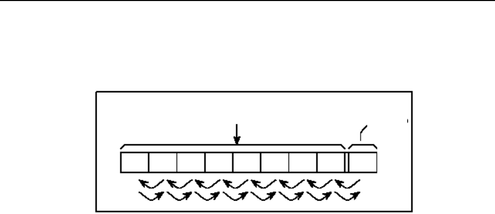
B-64513EN/03
4.LADDER LANGUAGE
- 233 -
(3) Storage of logical operation results
There is a register that stores the interim results of logical operations during the execution of a
sequence program.
This register consists of a total of nine bits, which is divided into a one-bit segment and an eight-bit
segment as shown in Fig. 4.1 (b).
Stack register
(Stores the interim results of previous operations temporarily.)
Contains the interim
result of the logical
operation currently
executed.
ST8 ST7 ST6 ST5 ST4 ST3 ST2 ST1 ST0
Fig. 4.1 (b) Structure of the register storing the results of logical operations
When an instruction (such as RD.STK) that temporarily stores the interim result of a logical
operation is executed, the current content of the register is shifted to the left and the interim logical
operation result is stacked in the register, as shown in the above figure. Conversely, when an
instruction (such as AND.STK) that retrieves a stacked signal is executed, the register content is
shifted to the right and the signal is retrieved. The last stacked signal is retrieved first. For
information about the actual uses and operations of these instructions, see the relevant descriptions
in this manual.

4.LADDER LANGUAGE
B-64513EN/03
- 234 -
4.1.1
Details of the Basic Instructions
Table 4.1.1 lists the types of the basic instructions and explains the processing they perform.
The difference between the two types of formats shown under Instruction is described below.
Mnemonic format:
The instructions are displayed in this format when you edit or print a ladder program that has been
converted to the mnemonic format with FANUC LADDER-III, by using a commercially available
text editor.
Mnemonic format (abbreviated):
These are the abbreviated forms of instructions that you can use when editing a ladder program that
has been converted to the mnemonic format with FANUC LADDER-III, by using a commercially
available text editor. If you input a file in this abbreviated format and convert it again to the ladder
diagram format with FANUC LADDER-III, the code in the file can still be recognized as being
written in the valid mnemonic format.
Detailed explanations of the individual basic instructions follow.
Table 4.1.1
No.
Instruction
Processing
Mnemonic
format
Mnemonic
format
(abbreviated)
1 RD R Reads the status of the specified signal and sets it in the ST0 bit.
2 RD.NOT RN Reads and reverses the logical status of the specified signal and sets it in
the ST0 bit.
3 WRT W
Outputs the logical operation result (the status of the ST0 bit) to the
specified address.
4 WRT.NOT WN Reverses and outputs the logical operation result (the status of the ST0
bit) to the specified address.
5 AND A Produces a logical product.
6 AND.NOT AN Reverses the logical status of the specified signal and produces a logical
product.
7 OR O Produces a logical sum.
8 OR.NOT ON Reverses the logical status of the specified signal and produces a logical
sum.
9 RD.STK RS Shifts the register content one bit to the left and sets the status of the
signal at the specified address in the ST0 bit.
10 RD.STK.NOT
(RD.NOT.STK)
RSN
(RNS)
Shifts the register content one bit to the left, reads and reverses the
logical status of the signal at the specified address, and sets it in the ST0
bit.
11 AND.STK AS Sets the logical product of the ST0 and ST1 bits in the ST1 bit and shifts
the register content one bit to the right.
12 OR.STK OS Sets the logical sum of the ST0 and ST1 bits in the ST1 bit and shifts the
register content one bit to the right.
13 SET SET
Finds the logical sum of the ST0 bit and the status of the signal at the
specified address and outputs it to the specified address.
14 RST RST
Finds the logical product of the reversed status of the ST0 bit and the
status of the signal at the specified address and outputs it to the specified
address.
15 RDPT RPT
Positive transition contact instruction. When rising transition (0→1) of the
specified signal is detected, "1" is set to the ST0 bit. Otherwise "0" is set
to the ST0 bit.
16 ANDPT APT
Positive transition contact instruction. When rising transition (0→1) of the
specified signal is detected, ST0 bit is not changed. Otherwise "0" is set
to the ST0 bit.

B-64513EN/03
4.LADDER LANGUAGE
- 235 -
No.
Instruction
Processing
Mnemonic
format
Mnemonic
format
(abbreviated)
17 ORPT OPT
Positive transition contact instruction. When rising transition (0→1) of the
specified signal is detected, "1" is set to the ST0 bit. Otherwise ST0 bit is
not changed.
18 RDPT.STK RPTS
Positive transition contact instruction. Shifts the stack register content
one bit to the left and when rising transition (0→1) of the specified signal
is detected, "1" is set to the ST0 bit. Otherwise "0" is set to the ST0 bit.
19 RDNT RNT
Negative transition contact instruction. When falling transition (1→0) of
the specified signal is detected, "1" is set to the ST0 bit. Otherwise "0" is
set to the ST0 bit.
20 ANDNT ANT
Negative transition contact instruction. When falling transition (1→0) of
the specified signal is detected ST0 bit is not changed. Otherwise "0" is
set to the ST0 bit.
21 ORNT ONT
Negative transition contact instruction. When falling transition (1→0) of
the specified signal is detected, "1" is set to the ST0 bit. Otherwise ST0
bit is not changed.
22 RDNT.STK RNTS
Negative transition contact instruction. Shifts the stack register content
one bit to the left and when falling transition (1→0) of the specified signal
is detected, "1" is set to the ST0 bit. Otherwise "0" is set to the ST0 bit.
23 PUSH PS Instruction to make a branch of circuit. Shifts the stack register one bit to
the left. The contents of ST0 bit are not changed.
24 POP PP
Instruction to make a branch of circuit. Shifts the stack register content
one bit to the right. (ST1→ST0)
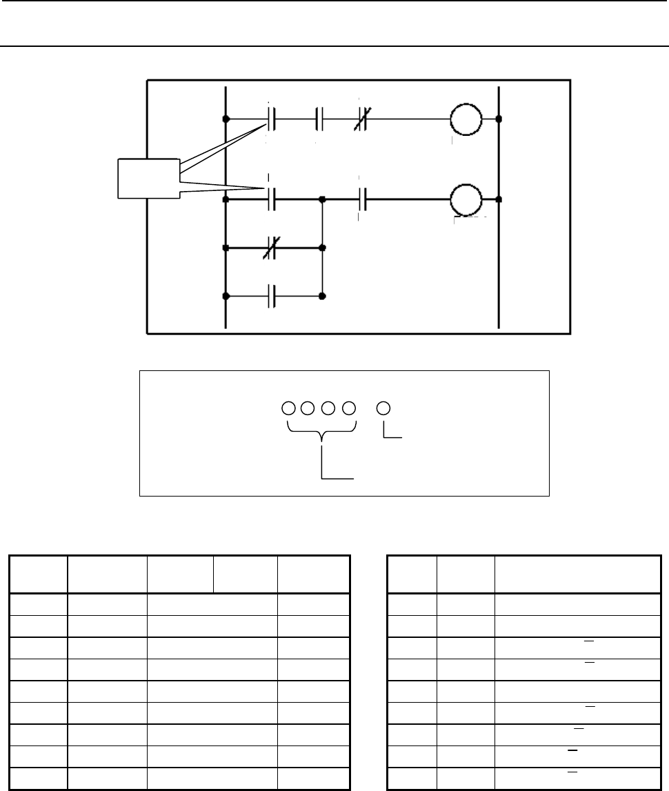
4.LADDER LANGUAGE
B-64513EN/03
- 236 -
4.1.2
RD Instruction
Format
RD
instruction
A
B C
D
E
F
G
X10.1 X2.0 R2.1
R5.4
R200.0
R200.1
X5.1
Y5.2
Y5.3
W2
W1
Fig. 4.1.2
Bit number
A
ddress numbe
r
.
(Address)
RD
Table 4.1.2
Mnemonic format Status of operation result
Step
number Instruction Address
No. Bit No. Remarks ST2 ST1 ST0
1 RD X10 .1 A A
2 AND X2 .0 B A⋅B
3 AND.NOT R2 .1 C A⋅B⋅C
4 WRT R200 .0 W1 output A⋅B⋅C
5 RD X5 .1 D D
6 OR.NOT Y5 .2 E D + E
7 OR Y5 .3 F D + E + F
8 AND R5 .4 G (D + E + F)⋅G
9 WRT R200 .1 W2 output (D + E + F)⋅G
Operation
(1) Use this instruction to start coding from contact A (−⏐⏐−). For examples of how the RD
instruction is used, see the ladder diagram shown in Fig. 4.1.2 and the input example in the
mnemonic format given in Table 4.1.2.
(2) The instruction reads the status (0 or 1) of the signal at the specified address and sets it in the ST0
bit.
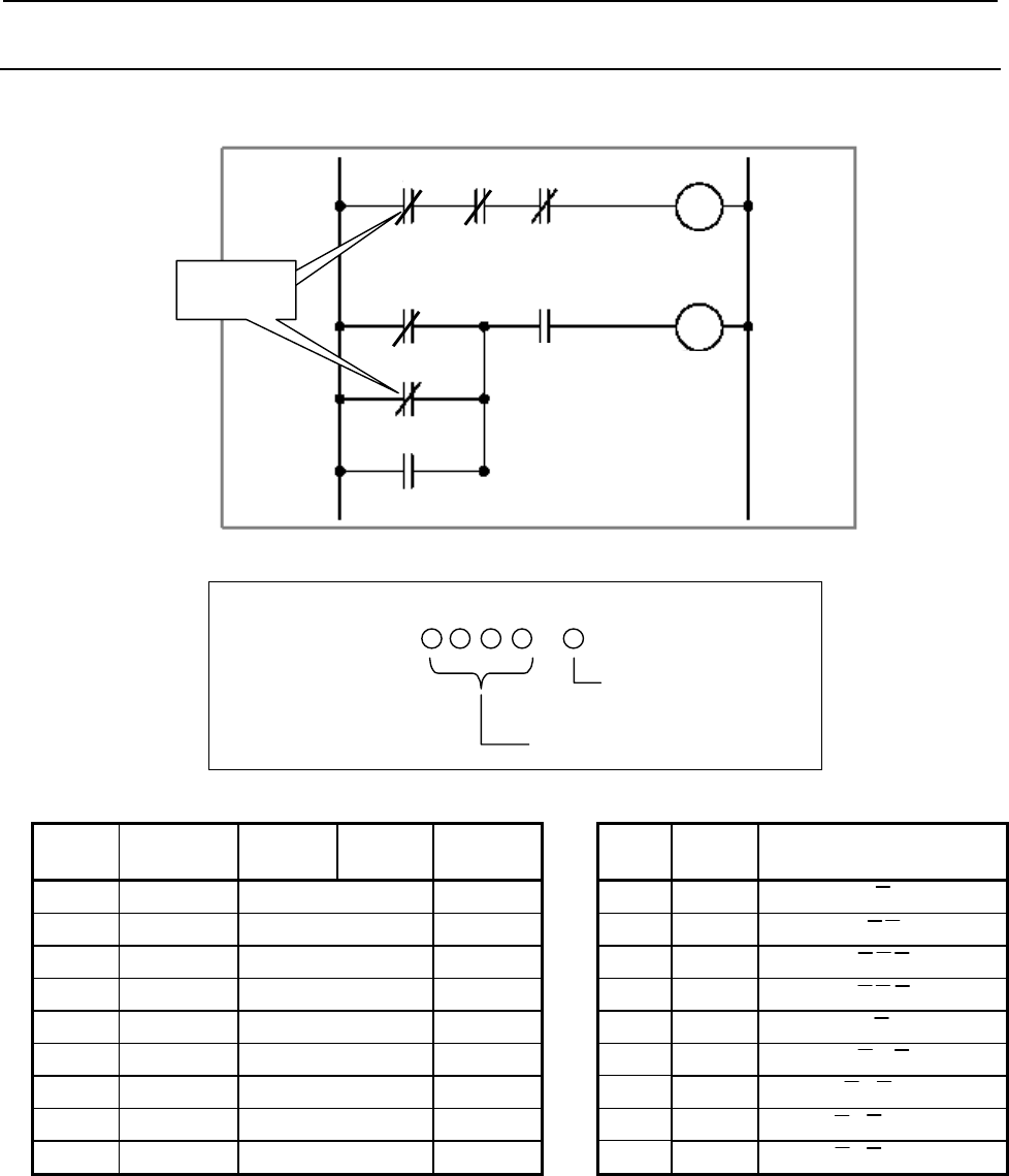
B-64513EN/03
4.LADDER LANGUAGE
- 237 -
4.1.3
RD.NOT Instruction
Format
A
B C
D
E
F
G
R1.1 F2.2 F3.3
R10.5
R210.1
G5.1
X4.2
Y10.7
W2
W1
RD.NOT 命令
RD.NOT
instruction
R210.2
Fig. 4.1.3
Bit number
A
ddress numbe
r
.
(Address)
RD.NOT
Table 4.1.3
Step
number Instruction Address
No. Bit No. Remarks ST2 ST1 ST0
1 RD.NOT R1 .1 A A
2 AND.NOT F2 .2 B A⋅B
3 AND.NOT F3 .3 C A⋅B⋅C
4 WRT R210 .1 W1 output A⋅B⋅C
5 RD.NOT G5 .1 D D
6 OR.NOT X4 .2 E D + E
7 OR Y10 .7 F D + E + F
8 AND R10 .5 G (D + E + F)⋅G
9 WRT R210 .2 W2 output (D + E + F)⋅G
Operation
(1) Use this instruction to start coding from contact B (−⏐/⏐−). For examples of how the RD.NOT
instruction is used, see the ladder diagram shown in Fig. 4.1.3 and the input example in the
mnemonic format given in Table 4.1.3.
(2) The instruction reads and reverses the logical status of the signal at the specified address and sets it
in the ST0 bit.
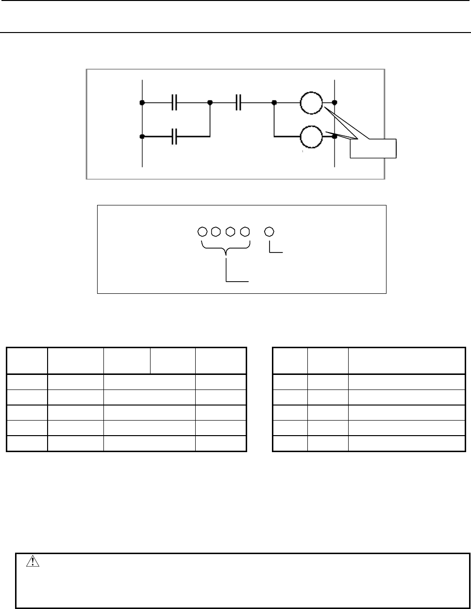
4.LADDER LANGUAGE
B-64513EN/03
- 238 -
4.1.4
WRT Instruction
Format
A
C
B
R220.1 G2.2 Y11.1
Y14.6
X4.2
W2
W1
WRT
instruction
Fig. 4.1.4
Table 4.1.4
Mnemonic format Status of operation result
Step
number Instruction Address
No. Bit No. Remarks ST2 ST1 ST0
1 RD R220 .1 A A
2 OR X4 .2 B A + B
3 AND G2 .2 C (A + B)⋅C
4 WRT Y11 .1 W1 output (A + B)⋅C
5 WRT Y14 .6 W2 output (A + B)⋅C
Operation
(1) The WRT instruction outputs the result of the logical operation, namely the status of the ST0 bit (0
or 1), to the specified address.
(2) The instruction can also output a logical operation result to two or more addresses simultaneously.
In that case, use the WRT instruction as shown in Fig. 4.1.4 and Table 4.1.4.
CAUTION
In each WRT,WRT.NOT instruction, specify different address. Double coil, which
means a coil with an address is often used in one ladder program, may occur
troubles of the execution timing in the sequence program. Don't use "double coil".
Bit number
A
ddress number
.
(Addres s)
WRT
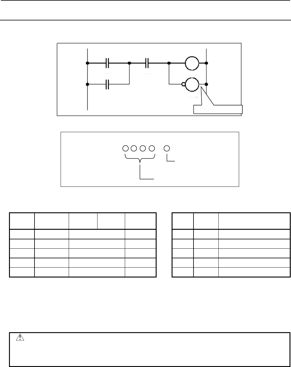
B-64513EN/03
4.LADDER LANGUAGE
- 239 -
4.1.5
WRT.NOT Instruction
Format
W2
W1
A C
B
R220.1 G2.2
Y14.6
X4.2
Y11.1
WRT.NOT instruction
Fig. 4.1.5
Bit number
A
ddress numbe
r
.
(Address)
WRT.NOT
Table 4.1.5
Mnemonic format Status of operation result
Step
number Instruction Address
No. Bit No. Remarks ST2 ST1 ST0
1 RD R220 .1 A A
2 OR X4 .2 B A + B
3 AND G2 .2 C (A + B)⋅C
4 WRT Y11 .1 W1 output (A + B)⋅C
5 WRT.NOT Y14 .6 W2 output (A + B)⋅C
Operation
The WRT.NOT instruction reverses and outputs the result of the logical operation, namely the status
of the ST0 bit, to the specified address. Fig. 4.1.5 and Table 4.1.5 show examples of how the
WRT.NOT instruction is used.
CAUTION
In each WRT,WRT.NOT instruction, specify different address. Double coil, which
means a coil with an address is often used in one ladder program, may occur
troubles of the execution timing in the sequence program. Don't use "double coil".
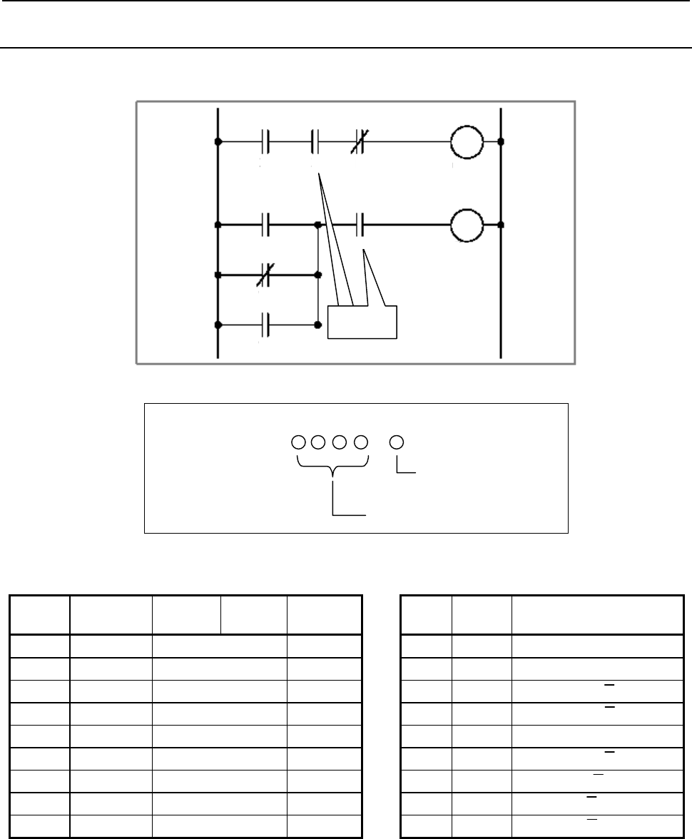
4.LADDER LANGUAGE
B-64513EN/03
- 240 -
4.1.6
AND Instruction
Format
W2
W1
A
ND??
A
ND
instruction
A
B C
D
E
F
G
X10.1 X2.0 R2.1
R5.4
X5.1
Y5.2
Y5.3
R200.0
R200.1
Fig. 4.1.6
Bit number
A
ddress numbe
r
.
(Address)
A
ND
Table 4.1.6
Mnemonic format Status of operation result
Step
number Instruction Address
No. Bit No. Remarks ST2 ST1 ST0
1 RD X10 .1 A A
2 AND X2 .0 B A⋅B
3 AND.NOT R2 .1 C A⋅B⋅C
4 WRT R200 .0 W1 output A⋅B⋅C
5 RD X5 .1 D D
6 OR.NOT Y5 .2 E D + E
7 OR Y5 .3 F D + E + F
8 AND R5 .4 G (D + E + F)⋅G
9 WRT R200 .1 W2 output (D + E + F)⋅G
Operation
(1) This instruction produces a logical product.
(2) For examples of how the AND instruction is used, see Fig. 4.1.6 and Table 4.1.6.
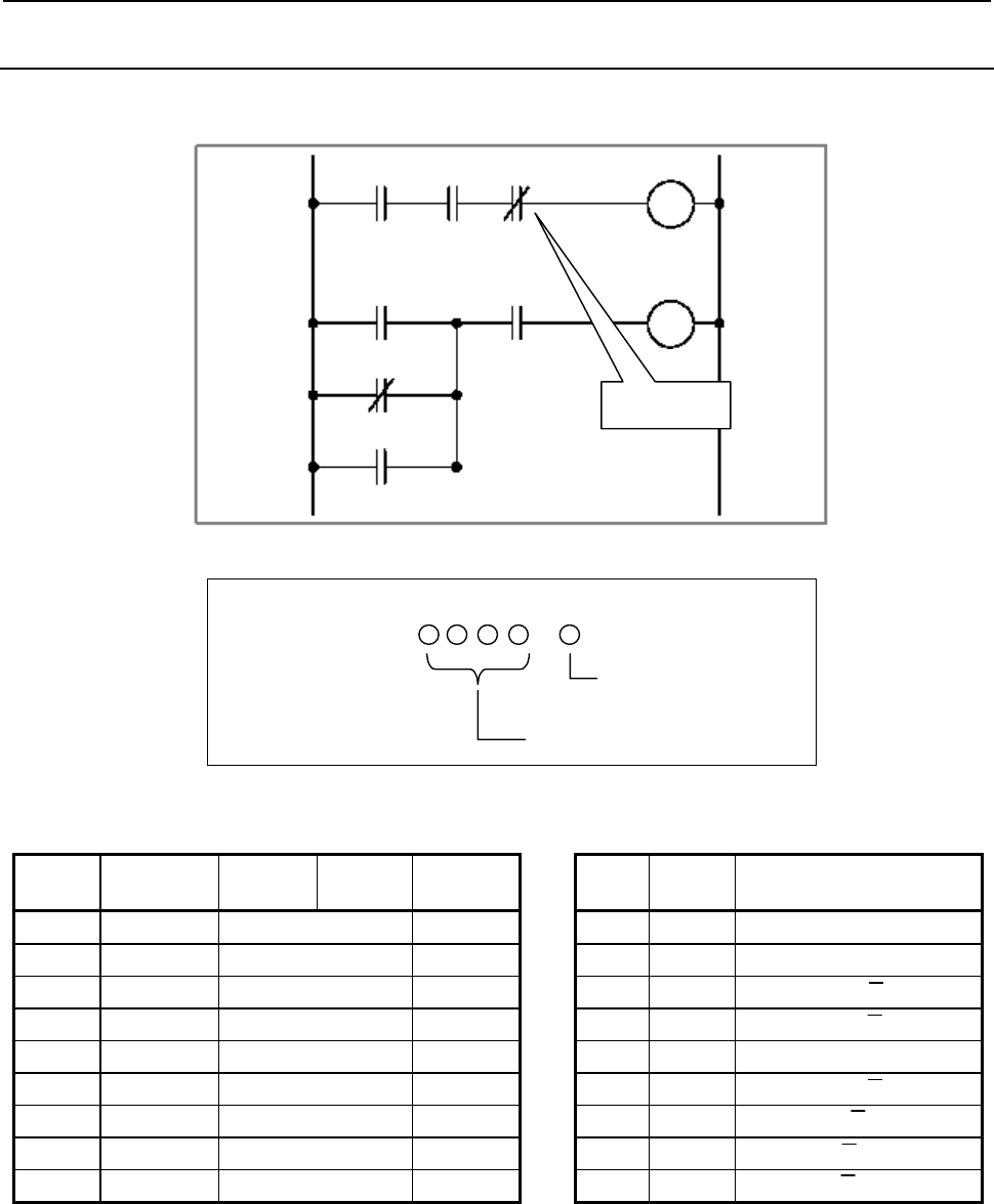
B-64513EN/03
4.LADDER LANGUAGE
- 241 -
4.1.7
AND.NOT Instruction
Format
W2
W1
A
B C
D
E
F
G
X10.1 X2.0 R2.1
R5.4
X5.1
Y5.2
Y5.3
R200.0
R200.1
A
ND.NOT
instruction
Fig. 4.1.7
Bit number
A
ddress numbe
r
.
(Address)
A
ND.NOT
Table 4.1.7
Mnemonic format Status of operation result
Step
number Instruction Address
No. Bit No. Remarks ST2 ST1 ST0
1 RD X10 .1 A A
2 AND X2 .0 B A⋅B
3 AND.NOT R2 .1 C A⋅B⋅C
4 WRT R200 .0 W1 output A⋅B⋅C
5 RD X5 .1 D D
6 OR.NOT Y5 .2 E D + E
7 OR Y5 .3 F D + E + F
8 AND R5 .4 G (D + E + F)⋅G
9 WRT R200 .1 W2 output (D + E + F)⋅G
Operation
(1) This instruction reverses the status of the signal at the specified address and produces a logical
product.
(2) For examples of how the AND.NOT instruction is used, see Fig. 4.1.7 and Table 4.1.7.
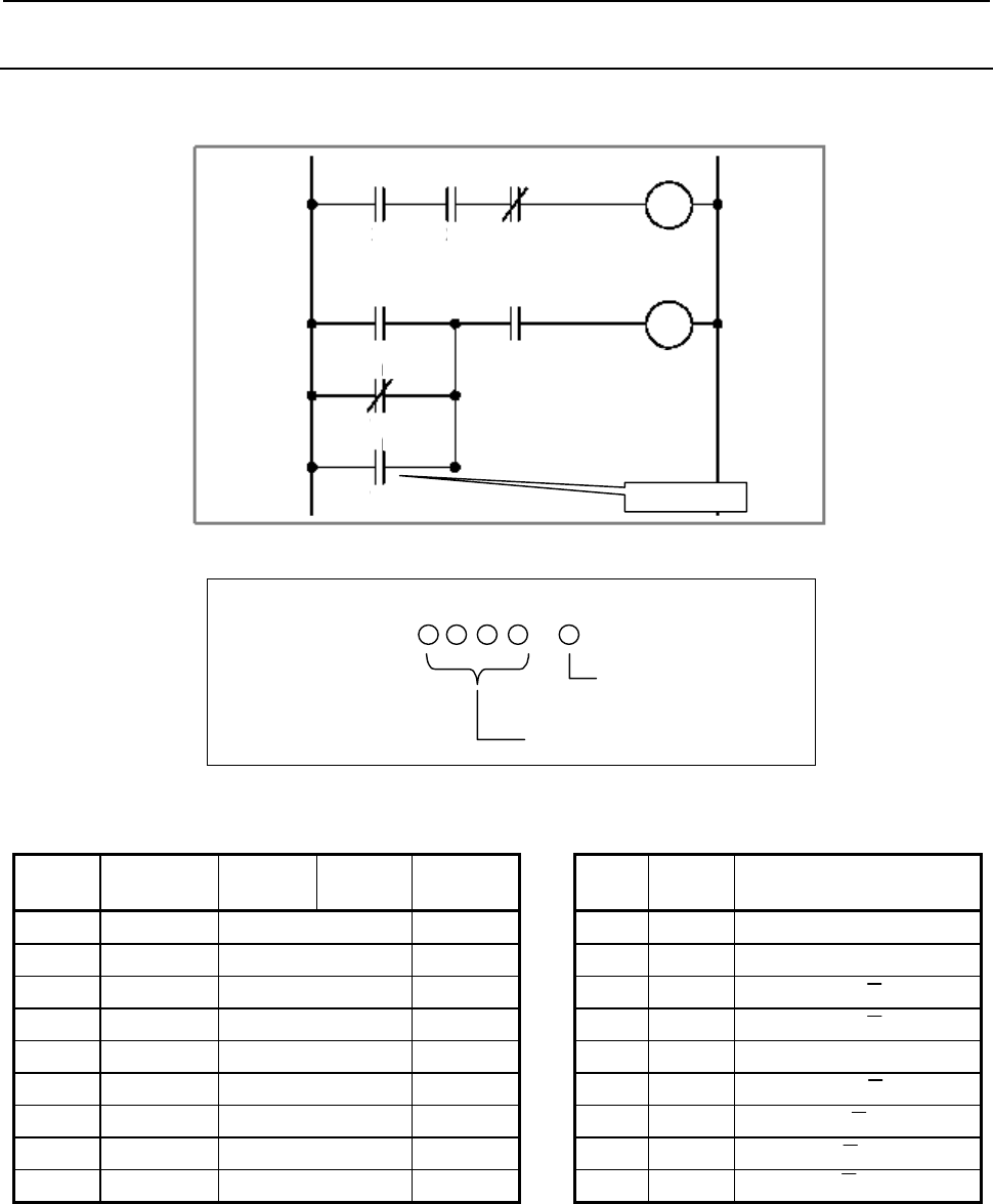
4.LADDER LANGUAGE
B-64513EN/03
- 242 -
4.1.8
OR Instruction
Format
W2
W1
OR instruction
A
B C
D
E
F
G
X10.1 X2.0 R2.1
R5.4
X5.1
Y5.2
Y5.3
R200.0
R200.1
Fig. 4.1.8
Bit number
A
ddress numbe
r
.
(Address)
O
R
Table 4.1.8
Mnemonic format Status of operation result
Step
number Instruction Address
No. Bit No. Remarks ST2 ST1 ST0
1 RD X10 .1 A A
2 AND X2 .0 B A⋅B
3 AND.NOT R2 .1 C A⋅B⋅C
4 WRT R200 .0 W1 output A⋅B⋅C
5 RD X5 .1 D D
6 OR.NOT Y5 .2 E D + E
7 OR Y5 .3 F D + E + F
8 AND R5 .4 G (D + E + F)⋅G
9 WRT R200 .1 W2 output (D + E + F)⋅G
Operation
(1) This instruction produces a logical sum.
(2) For examples of how the OR instruction is used, see Fig. 4.1.8 and Table 4.1.8.
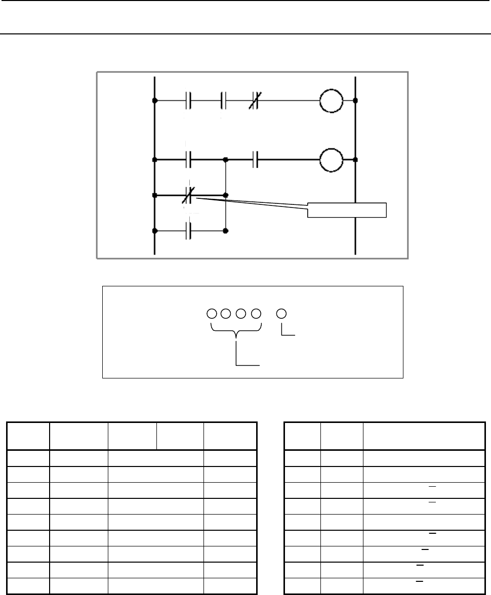
B-64513EN/03
4.LADDER LANGUAGE
- 243 -
4.1.9
OR.NOT Instruction
Format
OR.NOT instruction
W2
W1
A
B C
D
E
F
G
X10.1 X2.0 R2.1
R5.4
X5.1
Y5.2
Y5.3
R200.0
R200.1
Fig. 4.1.9
Bit number
A
ddress numbe
r
.
(Address)
OR.NOT
Table 4.1.9
Mnemonic format Status of operation result
Step
number Instruction Address
No. Bit No. Remarks ST2 ST1 ST0
1 RD X10 .1 A A
2 AND X2 .0 B A⋅B
3 AND.NOT R2 .1 C A⋅B⋅C
4 WRT R200 .0 W1 output A⋅B⋅C
5 RD X5 .1 D D
6 OR.NOT Y5 .2 E D + E
7 OR Y5 .3 F D + E + F
8 AND R5 .4 G (D + E + F)⋅G
9 WRT R200 .1 W2 output (D + E + F)⋅G
Operation
(1) This instruction reverses the status of the signal at the specified address and produces a logical sum.
(2) For examples of how the OR.NOT instruction is used, see Fig. 4.1.9 and Table 4.1.9.
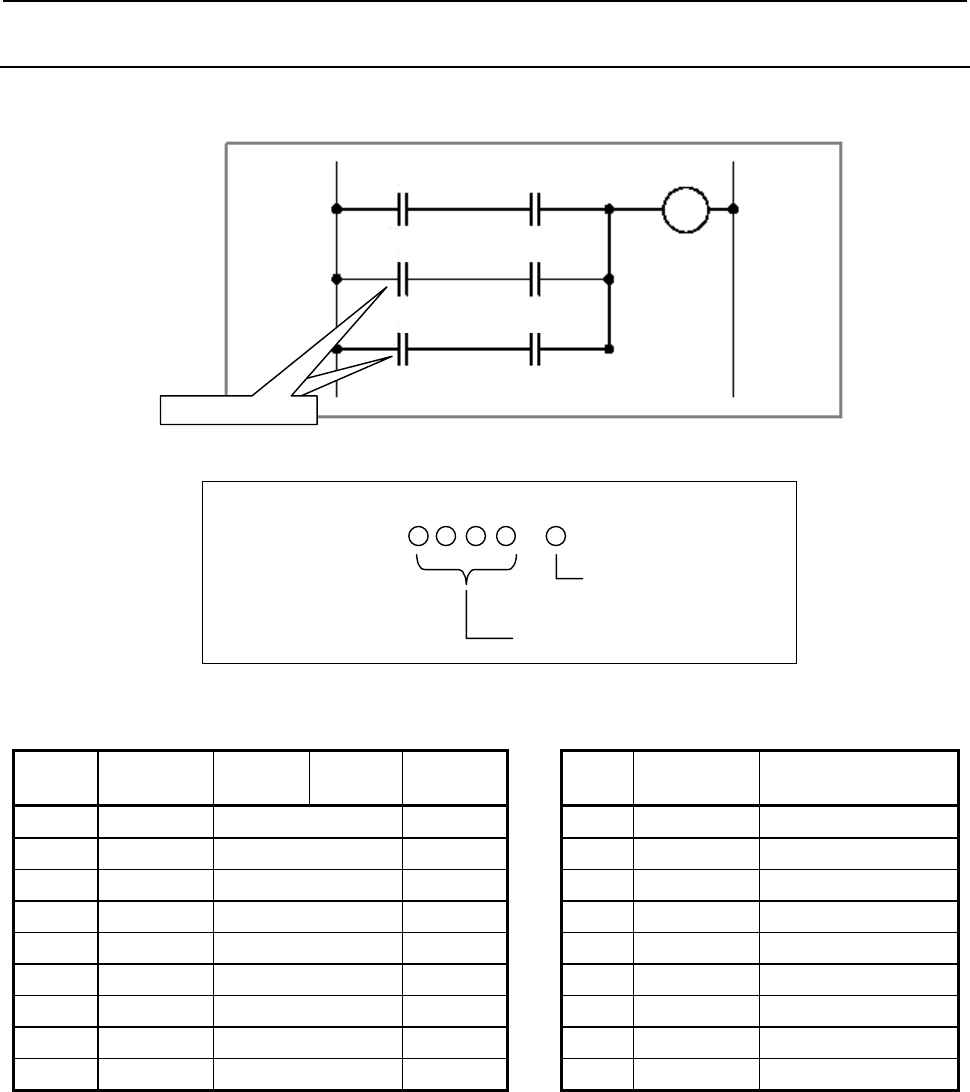
4.LADDER LANGUAGE
B-64513EN/03
- 244 -
4.1.10
RD.STK Instruction
Format
W1
A
C
X1.1 Y1.2 Y15.0
B D
X1.3 Y1.4
E F
R2.1 R3.5
RD.STK instruction
Fig. 4.1.10
Bit number
A
ddress numbe
r
.
(Address)
RD.ST
K
Table 4.1.10
Mnemonic format Status of operation result
Step
number Instruction Address
No. Bit No. Remarks ST2 ST1 ST0
1 RD X1 .1 A A
2 AND Y1 .2 C A⋅C
3 RD.STK X1 .3 B A⋅C B
4 AND Y1 .4 D A⋅C B⋅D
5 OR.STK A⋅C + B⋅D
6 RD.STK R2 .1 E A⋅C + B⋅D E
7 AND R3 .5 F A⋅C + B⋅D E⋅F
8 OR.STK A⋅C + B⋅D + E⋅F
9 WRT Y15 .0 W1 output A⋅C + B⋅D + E⋅F
Operation
(1) The RD.STK instruction stacks the interim result of a logical operation. Use this instruction when
the signal you specify is contact A (−⏐⏐−). After shifting the register content one bit to the left, the
instruction sets the status of the signal at the specified address in the ST0 bit.
(2) For examples of how the RD.STK instruction is used, see Fig. 4.1.10 and Table 4.1.10.
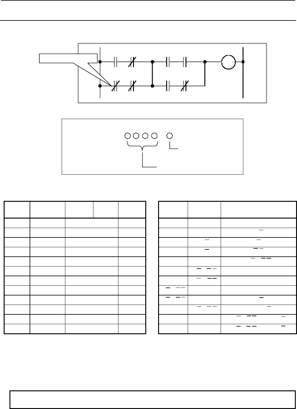
B-64513EN/03
4.LADDER LANGUAGE
- 245 -
4.1.11
RD.STK.NOT Instruction
Format
W1
RD.STK.NOT instruction
E
F
Y1.
2
Y1.3 Y15.7
G H
X1.6 Y1.7
A
B
X1.0 X1.1
C D
R1.4 R1.5
Fig. 4.1.11
Bit number
A
ddress number
.
(Address)
RD.STK.NO
T
Table 4.1.11
Mnemonic format Status of operation result
Step
number Instruction Address
No. Bit No. Remarks ST2 ST1 ST0
1 RD X1 .0 A A
2 AND.NOT X1 .1 B A⋅B
3 RD.STK.NOT R1 .4 C A⋅B C
4 AND.NOT R1 .5 D A⋅B C⋅D
5 OR.STK A⋅B + C⋅D
6 RD.STK Y1 .2 E A⋅B + C⋅D E
7 AND Y1 .3 F A⋅B + C⋅D E⋅F
8 RD.STK X1 .6 G A⋅B + C⋅DE⋅F G
9 AND.NOT Y1 .7 H A⋅B + C⋅DE⋅F G⋅H
10 OR.STK A⋅B + C⋅D E⋅F + G⋅H
11 AND.STK (A⋅B + C⋅D)⋅(E⋅F + G⋅H)
12 WRT Y15 .7 W1 output (A⋅B + C⋅D)⋅(E⋅F + G⋅H)
Operation
(1) The RD.NOT.STK instruction stacks the interim result of a logical operation. Use this instruction
when the signal you specify is contact B (−⏐/⏐−). After shifting the register content one bit to the
left, the instruction reverses the status of the signal at the specified address and sets it in the ST0 bit.
(2) For examples of how the RD.NOT.STK instruction is used, see Fig. 4.1.11 and Table 4.1.11.
NOTE
This instruction is effective even if describing as “RD.NOT.STK”.
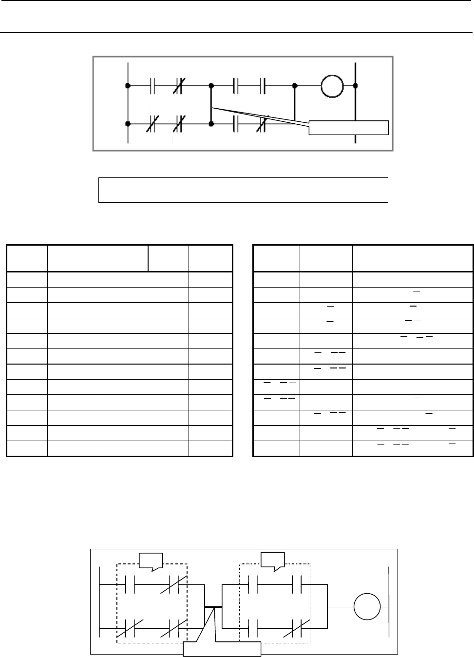
4.LADDER LANGUAGE
B-64513EN/03
- 246 -
4.1.12
AND.STK Instruction
Format
W1
E F
Y1.2 Y1.3 Y15.7
G H
X1.6 Y1.7
A
B
X1.0 X1.1
C D
R1.4 R1.5
A
ND.STK instruction
Fig. 4.1.12 (a)
AND.STK
Table 4.1.12
Mnemonic format Status of operation result
Step
number Instruction Address
No. Bit No. Remarks ST2 ST1 ST0
1 RD X1 .0 A A
2 AND.NOT X1 .1 B A⋅B
3 RD.NOT.STK R1 .4 C A⋅B C
4 AND.NOT R1 .5 D A⋅B C⋅D
5 OR.STK A⋅B + C⋅D
6 RD.STK Y1 .2 E A⋅B + C⋅D E
7 AND Y1 .3 F A⋅B + C⋅D E⋅F
8 RD.STK X1 .6 G A⋅B + C⋅DE⋅F G
9 AND.NOT Y1 .7 H A⋅B + C⋅DE⋅F G⋅H
10 OR.STK A⋅B + C⋅D E⋅F + G⋅H
11 AND.STK (A⋅B + C⋅D)⋅(E⋅F + G⋅H)
12 WRT Y15 .7 W1 output (A⋅B + C⋅D)⋅(E⋅F + G⋅H)
Operation
(1) The AND.STK instruction finds the logical product of the operation result stored in the ST0 bit and
that stored in the ST1 bit and sets it in the ST1 bit. The instruction then shifts the register content
one bit to the right and puts the resulting logical product into the ST0 bit. Fig. 4.1.12 (b) shows a
detailed image of what is shown in Fig. 4.1.12 (a).
A
B
CD
E F
GH
W1
A
ND.STK instruction
ST1 ST0
Fig. 4.1.12 (b)
(2) For examples of how the AND.STK instruction is used, see Fig. 4.1.12 (a) and Table 4.1.12.
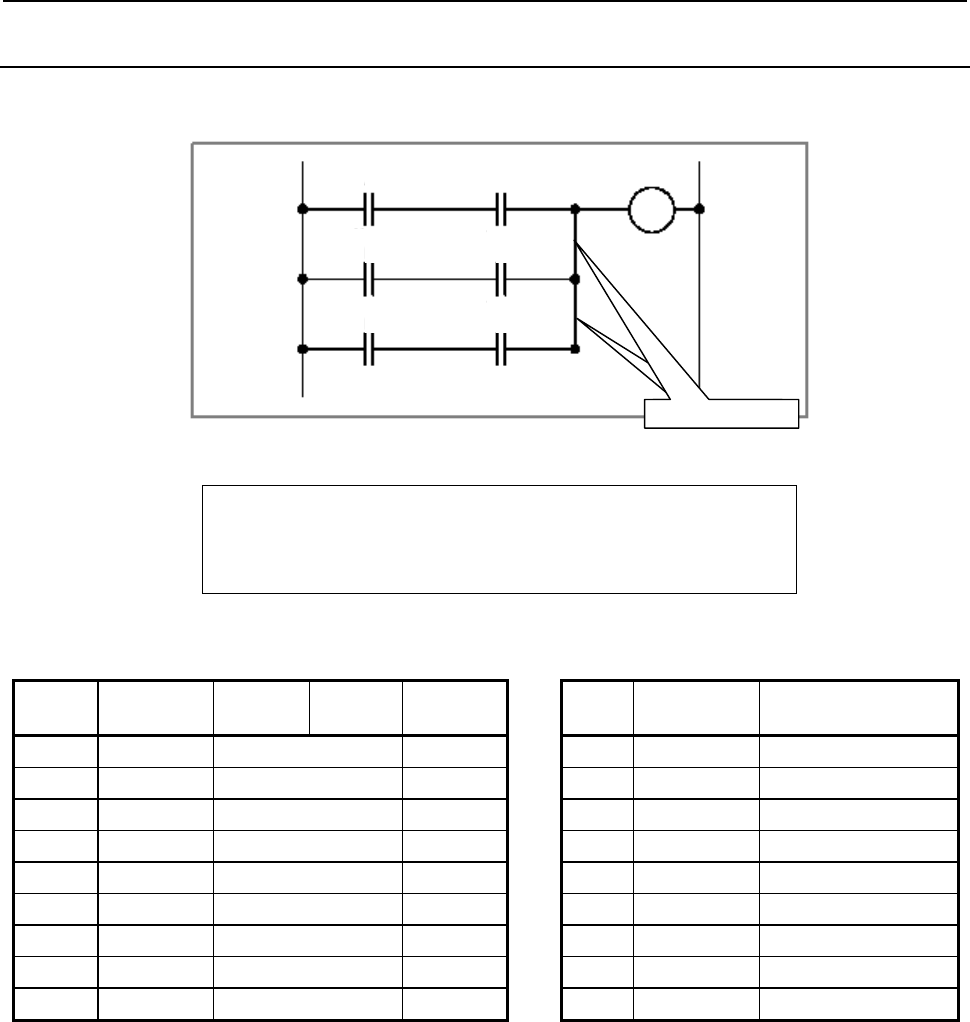
B-64513EN/03
4.LADDER LANGUAGE
- 247 -
4.1.13
OR.STK Instruction
Format
A
C
X1.1 Y1.2 Y15.0
B D
X1.3 Y1.4
E F
R2.1 R3.5
W1
RD.STK??
OR.STK instruction
Fig. 4.1.13 (a)
OR.ST
K
Table 4.1.13
Mnemonic format Status of operation result
Step
number Instruction Address
No. Bit No. Remarks ST2 ST1 ST0
1 RD X1 .1 A A
2 AND Y1 .2 C A⋅C
3 RD.STK X1 .3 B A⋅C B
4 AND Y1 .4 D A⋅C B⋅D
5 OR.STK A⋅C + B⋅D
6 RD.STK R2 .1 E A⋅C + B⋅D E
7 AND R3 .5 F A⋅C + B⋅D E⋅F
8 OR.STK A⋅C + B⋅D + E⋅F
9 WRT Y15 .0 W1 output A⋅C + B⋅D + E⋅F
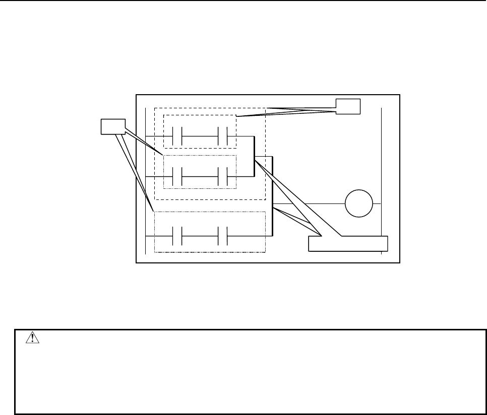
4.LADDER LANGUAGE
B-64513EN/03
- 248 -
Operation
(1) The OR.STK instruction finds the logical sum of the operation result stored in the ST0 bit and that
stored in the ST1 bit and sets it in the ST1 bit. The instruction then shifts the register content one
bit to the right and puts the resulting logical sum into the ST0 bit. Fig. 4.1.13 (b) shows a detailed
image of what is shown in Fig. 4.1.13 (a).
A
C
W1
BD
EF
ST1
ST0
ST1
ST0
OR.STK
??
OR.STK instruction
Fig. 4.1.13 (b)
(2) For examples of how the OR.STK instruction is used, see Fig. 4.1.13 (a) and Table 4.1.13.
CAUTION
In the example shown in Table 4.1.13, the OR.STK instruction is specified at step
number 5. You will obtain the same result if you place the OR.STK instruction
between step numbers 7 and 8. However, coding similar instructions, such as
OR.STK and AND.STK, successively makes you prone to errors. It is therefore
recommended to code your program as shown in Table 4.1.13.
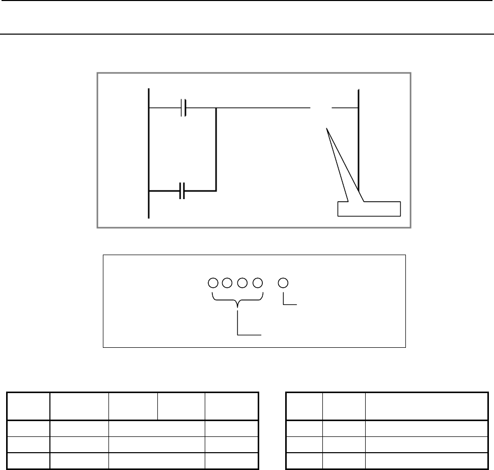
B-64513EN/03
4.LADDER LANGUAGE
- 249 -
4.1.14
SET Instruction
Format
SET instruction
A
B
X0.0
R0.0
C
(S)
Y0.0
Fig. 4.1.14
Bit number
A
ddress numbe
r
.
(Address)
SET
Table 4.1.14
Mnemonic format Status of operation result
Step
number Instruction Address
No. Bit No. Remarks ST2 ST1 ST0
1 RD R0 .0 A A
2 OR X0 .0 B A + B
3 SET Y0 .0 Y0.0 output A + B
Operation
(1) This instruction keeps the status of the specified address to ON. It finds the logical sum of the
operation result (ST0) and the specified address and outputs it to the specified address.
(2) For examples of how the SET instruction is used, see Fig. 4.1.14 and Table 4.1.14.
(3) Caution
• Relationship with COM and COME
When placed between the COM and COME instructions, the SET instruction behaves as
follows:
When the COM condition is set to ON (ACT = 1), the SET instruction runs normally.
When the COM condition is set to OFF (ACT = 0), the SET instruction does not run.
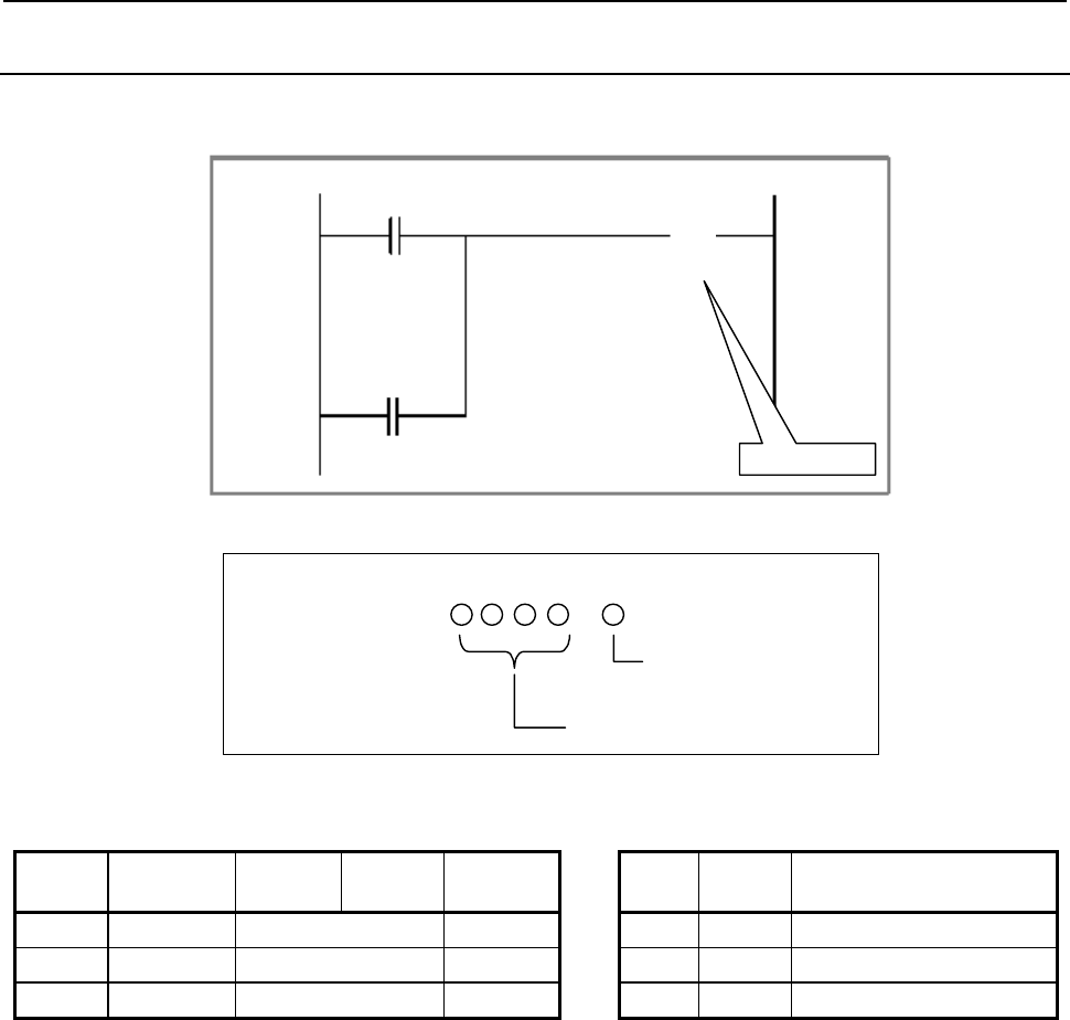
4.LADDER LANGUAGE
B-64513EN/03
- 250 -
4.1.15
RST Instruction
Format
RST instruction
A
B
X0.0
R0.0
C
(R)
Y0.0
Fig. 4.1.15
Bit number
A
ddress numbe
r
.
(Address)
RST
Table 4.1.15
Mnemonic format Status of operation result
Step
number Instruction Address
No. Bit No. Remarks ST2 ST1 ST0
1 RD R0 .0 A A
2 OR X0 .0 B A + B
3 RST Y0 .0 Y0.0 output A + B
Operation
(1) This instruction keeps the status of the specified address to OFF. It finds the logical product of the
operation result (ST0) and the specified reversed address and outputs it to the specified address.
(2) For examples of how the RST instruction is used, see Fig. 4.1.15 and Table 4.1.15.
(3) Caution
• Relationship with COM and COME
When placed between the COM and COME instructions, the RST instruction behaves as
follows:
When the COM condition is set to ON (ACT = 1), the RST instruction runs normally.
When the COM condition is set to OFF (ACT = 0), the RST instruction does not run.
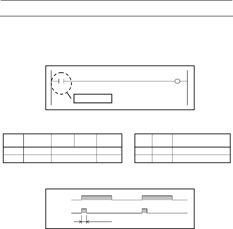
B-64513EN/03
4.LADDER LANGUAGE
- 251 -
4.1.16
RDPT Instruction
Positive transition contact instruction. When rising transition (0→1) of the specified signal is detected,
"1" is set to the ST0 bit. Otherwise "0" is set to the ST0 bit.
This instruction can specify the same address in two or more point in ladder circuit.
Format
Fig. 4.1.16(a) shows the ladder format and Table 4.1.16(a) shows the mnemonic format.
W1 A
X10.0 Y20.0
RDPT instruction
P
Fig. 4.1.16 (a) Format of RDPT instruction
Table4.1.16 (a) Mnemonic of RDPT instruction
Mnemonic format Status of operation result
Step
number Instruction Address
No. Bit No. Remarks ST2 ST1 ST0
1 RDPT X10 .0 A A(PT)
2 WRT Y20 .0 W1 output A(PT)
Operation
Timing chart in the above example is as follows.
A
W1
1 scan
Fig. 4.1.16 (b) Timing chart of RDPT instruction

4.LADDER LANGUAGE
B-64513EN/03
- 252 -
CAUTION
1 The bit, already turned on when a program is started after program reading by the
Input/Output function or Power ON, turns on the output with the scan at the
beginning just after starting.
2 An output may not be turned on when a bit changes with OFF→ON→OFF during
1 scan. Moreover, when validating the result of ladder edit, a scanning time
temporarily becomes larger.
3 In ladder edit, when the bit of the edited contact turns on, an output is turned on
with the scan of the beginning after edit.
4 When this instruction is skipped by Jump instruction or subroutine call instruction,
this instruction is not executed and the output of instruction does not change.
5 This instruction uses a work memory internally in order to detect bit transition.
The PMC Software or the FANUC LADDER-III searches the work memory
automatically in the domain which can be used, and is assigned. Therefore, the
program edited in a different procedure becomes mismatching at the comparing,
even when the appearance of ladder diagram is the same.
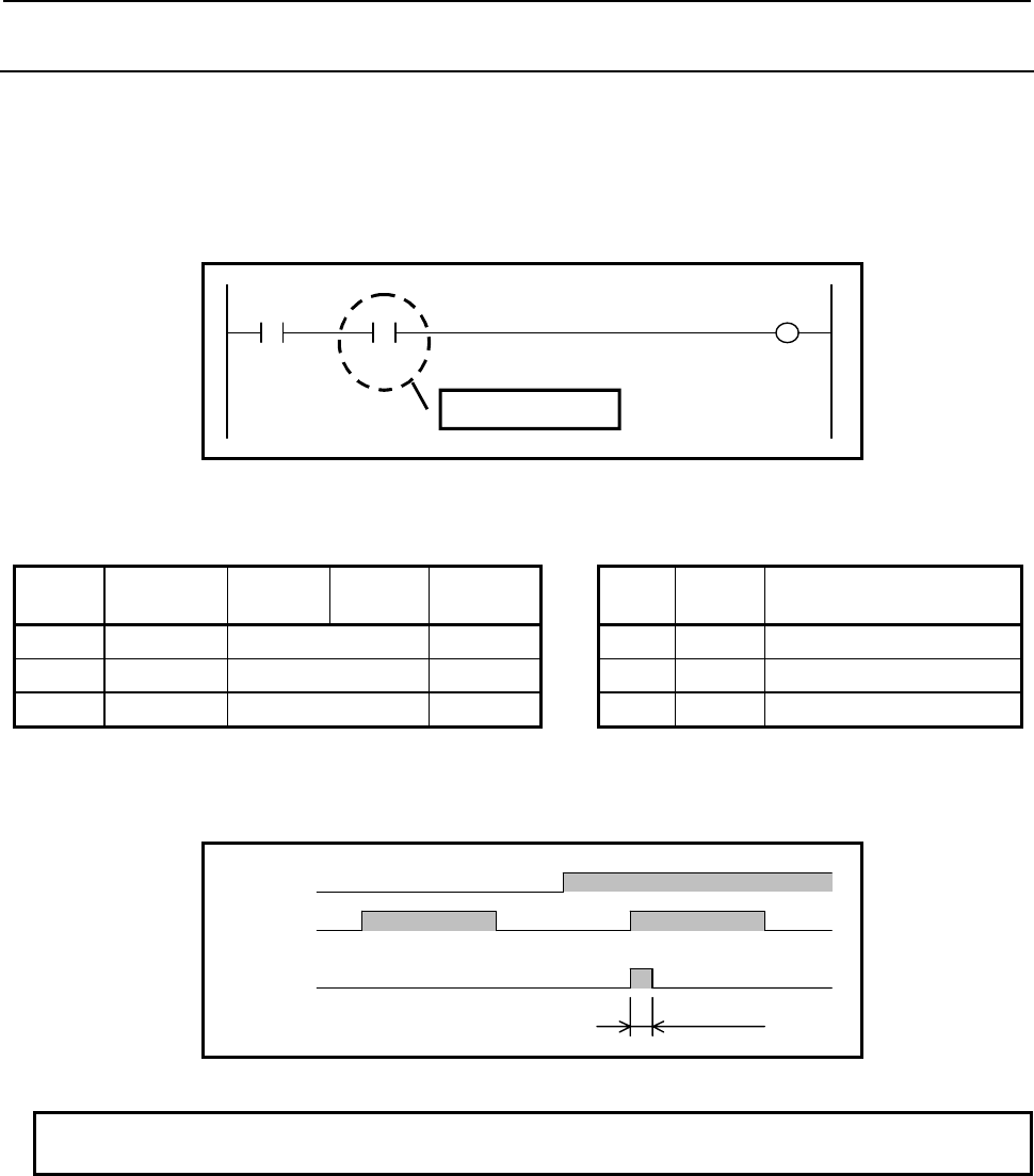
B-64513EN/03
4.LADDER LANGUAGE
- 253 -
4.1.17
ANDPT Instruction
Positive transition contact instruction.
This instruction produces a logical product from rising transition (0→1) of the specified signal and can
specify the same address in two or more point in ladder circuit.
Format
Fig. 4.1.17(a) shows the ladder format and Table 4.1.17(a) shows the mnemonic format.
W1 A
X10.0 Y30.0
B
R20.0
A
NDPT instruction
P
Fig. 4.1.17 (a) Format of ANDPT Instruction
Table 4.1.17 (a) Mnemonic of ANDPT Instruction
Mnemonic format Status of operation result
Step
number Instruction Address
No. Bit No. Remarks ST2 ST1 ST0
1 RD X10 .0 A A
2 ANDPT R20 .0 B A • B (PT)
3 WRT Y30 .0 W1 output A • B (PT)
Operation
Timing chart in the above example is as follows.
A
W1
1 scan
B
Fig. 4.1.17 (b) Timing chart of ANDPT Instruction
NOTE
Refer to "4.1.16 RDPT Instruction" notes about this instruction.
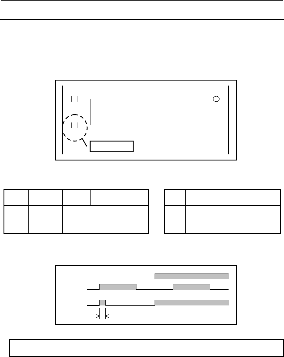
4.LADDER LANGUAGE
B-64513EN/03
- 254 -
4.1.18
ORPT Instruction
Positive transition contact instruction.
This instruction produces a logical sum from rising transition (0→1) of the specified signal and can
specify the same address in two or more point in ladder circuit.
Format
Fig. 4.1.18(a) shows the ladder format and Table 4.1.18(a) shows the mnemonic format.
W1 A
X10.0 Y30.0
B
R20.0
ORPT Instruction
P
Fig. 4.1.18 (a) Format of ORPT Instruction
Table 4.1.18 (a) Mnemonic of ORPT Instruction
Mnemonic format Status of operation result
Step
number Instruction Address
No. Bit No. Remarks ST2 ST1 ST0
1 RD X10 .0 A A
2 ORPT R20 .0 B A + B (PT)
3 WRT Y30 .0 W1 output A + B (PT)
Operation
Timing chart in the above example is as follows.
A
W1
1 scan
B
Fig. 4.1.18 (b) Timing chart of ORPT Instruction
NOTE
Refer to "4.1.16 RDPT Instruction" notes about this instruction.
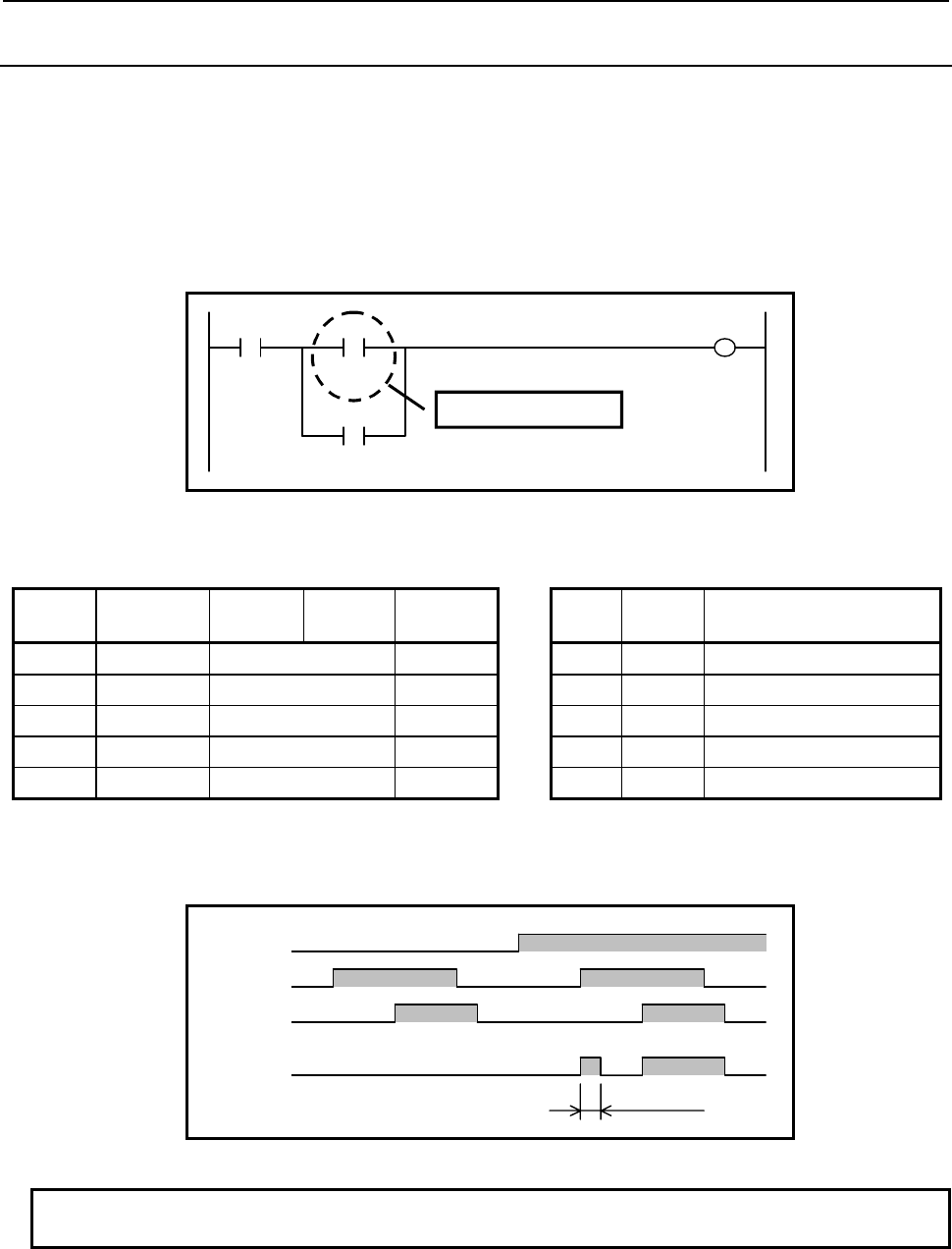
B-64513EN/03
4.LADDER LANGUAGE
- 255 -
4.1.19
RDPT.STK Instruction
Positive transition contact instruction. Shifts the stack register content one bit to the left and when rising
transition (0→1) of the specified signal is detected, "1" is set to the ST0 bit. Otherwise "0" is set to the
ST0 bit.
This instruction can specify the same address in two or more point in ladder circuit.
Format
Fig. 4.1.19(a) shows the ladder format and Table 4.1.19(a) shows the mnemonic format.
W1
Y40.0
A
X10.0
B
R20.0
C
R30.0
RDPT.STK instruction
P
Fig. 4.1.19 (a) Format of RDPT.STK Instruction
Table 4.1.19 (a) Mnemonic of RDPT.STK Instruction
Mnemonic format Status of operation result
Step
number Instruction Address
No. Bit No. Remarks ST2 ST1 ST0
1 RD X10 .0 A A
2 RDPT.STK R20 .0 B A B(PT)
3 OR R30 .0 C A B(PT) + C
4 AND.STK A • (B(PT) + C)
5 WRT Y40 .0 W1 output A • (B(PT) + C)
Operation
Timing chart in the above example is as follows.
A
W1
1 scan
B
C
Fig. 4.1.19 (b) Timing chart of RDPT.STK Instruction
NOTE
Refer to "4.1.16 RDPT Instruction" notes about this instruction.
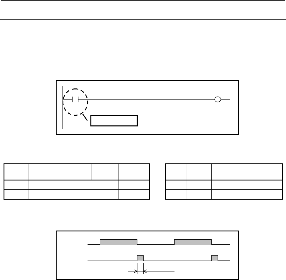
4.LADDER LANGUAGE
B-64513EN/03
- 256 -
4.1.20
RDNT Instruction
This is negative transition contact instruction. When falling transition (1→0) of the specified signal is
detected, "1" is set to the ST0 bit. Otherwise "0" is set to the ST0 bit.
This instruction can specify the same address in two or more point in ladder circuit.
Format
Fig. 4.1.20(a) shows the ladder format and Table 4.1.20(a) shows the mnemonic format.
W1 A
X10.0 Y20.0
RDNT Instruction
N
Fig. 4.1.20 (a) Format of RDNT Instruction
Table 4.1.20 (a) Mnemonic of RDNT Instruction
Mnemonic format Status of operation result
Step
number Instruction Address
No. Bit No. Remarks ST2 ST1 ST0
1 RDNT X10 .0 A A(NT)
2 WRT Y20 .0 W1 output A(NT)
Operation
Timing chart in the above example is as follows.
A
W1
1 scan
Fig. 4.1.20 (b) Timing chart of RDNT Instruction

B-64513EN/03
4.LADDER LANGUAGE
- 257 -
CAUTION
1 The bit, already turned off when a program is started after program reading by the
Input/Output function or Power ON, turns on the output with the scan at the
beginning just after starting.
2 An output may not be turned on when a bit changes with ON→OFF→ON during 1
scan. Moreover, when validating the result of ladder edit, a scanning time
temporarily becomes larger.
3 In ladder edit, when the bit contained in the edited ladder net has already turned
off, only the edited contact does not turned on with the scan of the beginning after
edit.
4 When this instruction is skipped by Jump instruction or subroutine call instruction,
this instruction is not executed and the output of instruction does not change.
5 This instruction uses a work memory internally in order to detect bit transition.
The PMC Software or the FANUC LADDER-III searches the work memory
automatically in the domain which can be used, and is assigned. Therefore, the
program edited in a different procedure becomes mismatching at the comparing,
even when the appearance of ladder diagram is the same.
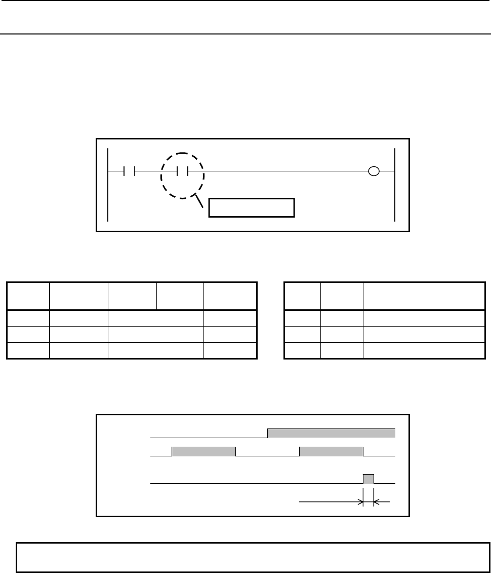
4.LADDER LANGUAGE
B-64513EN/03
- 258 -
4.1.21
ANDNT Instruction
This is negative transition contact instruction.
This instruction produces a logical product from falling transition (1→0) of the specified signal and can
specify the same address in two or more point in ladder circuit.
Format
Fig. 4.1.21(a) shows the ladder format and Table 4.1.21(a) shows the mnemonic format.
W1 A
X10.0 Y30.0
B
R20.0
A
NDNT Instruction
N
Fig. 4.1.21 (a) Format of ANDNT Instruction
Table4.1.21 (a) Mnemonic of ANDNT Instruction
Mnemonic format Status of operation result
Step
number Instruction Address
No. Bit No. Remarks ST2 ST1 ST0
1 RD X10 .0 A A
2 ANDNT R20 .0 B A • B (NT)
3 WRT Y30 .0 W1 output A • B (NT)
Operation
Timing chart in the above example is as follows.
A
W1
1 scan
B
Fig. 4.1.21 (b) Timing chart of ANDNT Instruction
NOTE
Refer to "4.1.20 RDNT Instruction" notes about this instruction.
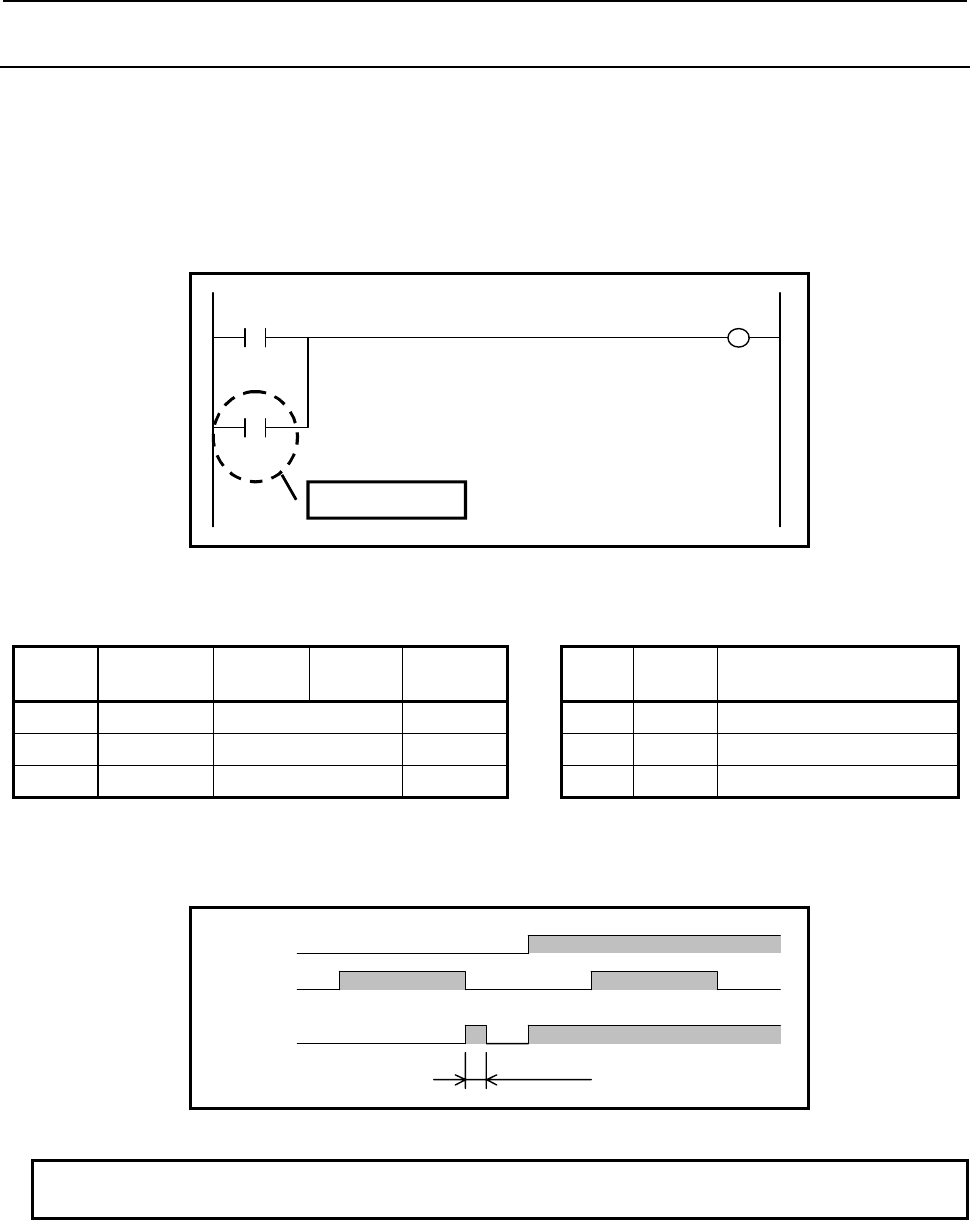
B-64513EN/03
4.LADDER LANGUAGE
- 259 -
4.1.22
ORNT Instruction
This is negative transition contact instruction.
This instruction produces a logical sum from falling transition (1→0) of the specified signal and can
specify the same address in two or more point in ladder circuit.
Format
Fig. 4.1.22(a) shows the ladder format and Table 4.1.22(a) shows the mnemonic format.
W1 A
X10.0 Y30.0
B
R20.0
ORNT Instruction
N
Fig. 4.1.22 (a) Format of ORNT Instruction
Table 4.1.22 (a) Mnemonic of ORNT Instruction
Mnemonic format Status of operation result
Step
number Instruction Address
No. Bit No. Remarks ST2 ST1 ST0
1 RD X10 .0 A A
2 ORNT R20 .0 B A + B (NT)
3 WRT Y30 .0 W1 output A + B (NT)
Operation
Timing chart in the above example is as follows.
A
W1
1 scan
B
Fig. 4.1.22 (b) Timing chart of ORNT Instruction
NOTE
Refer to "4.1.20 RDNT Instruction" notes about this instruction.
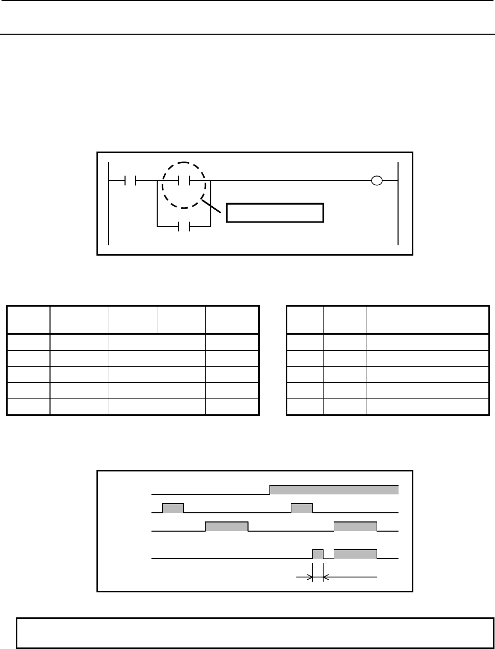
4.LADDER LANGUAGE
B-64513EN/03
- 260 -
4.1.23
RDNT.STK Instruction
This is negative transition contact instruction. Shifts the stack register content one bit to the left and when
falling transition (1→0) of the specified signal is detected, "1" is set to the ST0 bit. Otherwise "0" is set to
the ST0 bit.
This instruction can specify the same address in two or more point in ladder circuit.
Format
Fig. 4.1.23(a) shows the ladder format and Table 4.1.23(a) shows the mnemonic format.
W1
Y40.0
A
X10.0
B
R20.0
C
R30.0
RDNT.STK Instruction
N
Fig. 4.1.23 (a) Format of RDNT.STK Instruction
Table 4.1.23 (a) Mnemonic of RDNT.STK Instruction
Mnemonic format Status of operation result
Step
number Instruction Address
No. Bit No. Remarks ST2 ST1 ST0
1 RD X10 .0 A A
2 RDNT.STK R20 .0 B A B(NT)
3 OR R30 .0 C A B(NT) + C
4 AND.STK A • (B(NT) + C)
5 WRT Y40 .0 W1 output A • (B(NT) + C)
Operation
Timing chart in the above example is as follows.
A
W1
1 scan
B
C
Fig. 4.1.23 (b) Timing chart of RDNT.STK Instruction
NOTE
Refer to "4.1.20 RDNT Instruction" notes about this instruction.
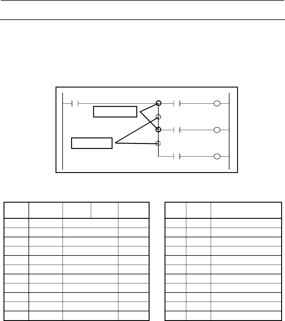
B-64513EN/03
4.LADDER LANGUAGE
- 261 -
4.1.24
PUSH Instruction / POP Instruction
This is an instruction to make a branch of circuit.
A PUSH instruction shifts the stack register one bit to the left. The current operation result (ST0) is not
changed.
A POP instruction shifts the stack register one bit to the right
Format
Fig. 4.1.24(a) shows the ladder format and Table 4.1.24(a) shows the mnemonic format.
W1
Y50.0
A
X10.0
B
R20.0
C
R30.0
PUSH Instruction
W2
Y60.0
W3
Y70.0
D
R40.0
POP Instruction
Fig. 4.1.24 (a) Format of PUSH and POP Instructions
Table 4.1.24 (a) Mnemonic of PUSH and POP Instructions
Mnemonic format Status of operation result
Step
number Instruction Address
No. Bit No. Remarks ST2 ST1 ST0
1 RD X10 .0 A A
2 PUSH A A
3 AND R20 .0 B A A • B
4 WRT Y50 .0 W1 output A A • B
5 POP A
6 PUSH A A
7 AND R30 .0 C A A • C
8 WRT Y60 .0 W2 output A A • C
9 POP A
10 AND R40 .0 D A • D
11 WRT Y70 .0 W3 output A • D
Operation
(1) In the above example, the value of A stored in ST0 is shift to ST1 by PUSH instruction before
performing the logical product of A and B. The value of ST0 is not changed.
(2) After outputting the operation result of the logical product of A and B to W1, the value of A stored
in ST1 is shifted to ST0 by POP instruction.
(3) Before performing the logical product of A and C, the value of A stored in ST0 is shifted to ST1 by
PUSH instruction. The value of ST0 is not changed.
(4) After outputting the operation result of the logical product of A and C to W2, the value of A stored
in ST1 is shifted to ST0 by POP instruction.
(5) The logical product of A and D is performed and an operation result is outputted to W3.
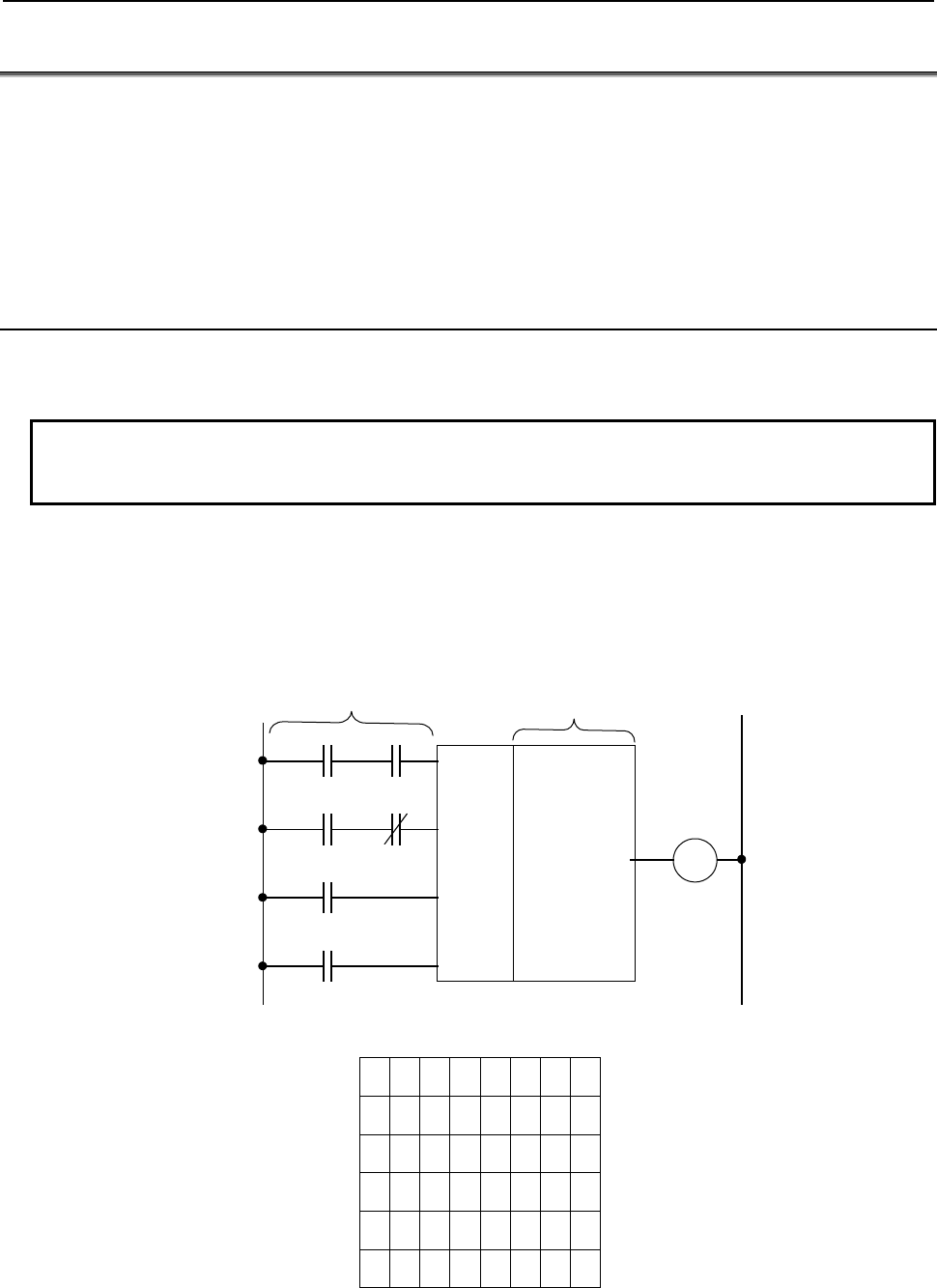
4.LADDER LANGUAGE
B-64513EN/03
- 262 -
4.2 FUNCTIONAL INSTRUCTIONS
When creating a sequence program, you may find it difficult to code certain types of functions with the
basic instructions alone that perform a one-bit logical operation each. One example is a shortcut control
function for a rotating part that involves numeric and other complex operations. To facilitate the
programming of these functions that are difficult to code with the basic instructions alone, a set of
functional instructions are available.
This section describes how to use each functional instruction. For a list of the functional instructions
and information about their specifications, see Subsection 2.1.8 or 2.1.9.
4.2.1 Format of the Functional Instructions
Before detailed descriptions of the individual functional instructions are given, this subsection explains
the format of the functional instructions and their general specifications.
NOTE
Read this subsection surely because it contains important information such as the
rules regarding the use of the functional instructions.
(1) Format of the functional instructions
Since the functional instructions cannot be represented using relay symbols, they need to be
represented in the format shown in Fig. 4.2.1 (a). The structure of a functional instruction consists
of control conditions, an instruction, parameters, an output coil (W1), a functional instruction
operation result register (R9000 to R9005 or Z0 to Z5).
Fig. 4.2.1 (a) Structure of a functional instruction
7654 3210
A
W1
B
R 10.1
R1.0 R1.1
C D
R 2.4 R 3.1
RST
R 5.7
ACT
R 7.1
(
3
)
(2)
(1)
(0)
(Note 1)
Control conditions Parameter
R9000 or Z0
R9001 or Z1
R9002 or Z2
R9003 or Z3
R9004 or Z4
R9005 or Z5
Parameter 1
Parameter 2
Parameter 3
Parameter 4
Instruction
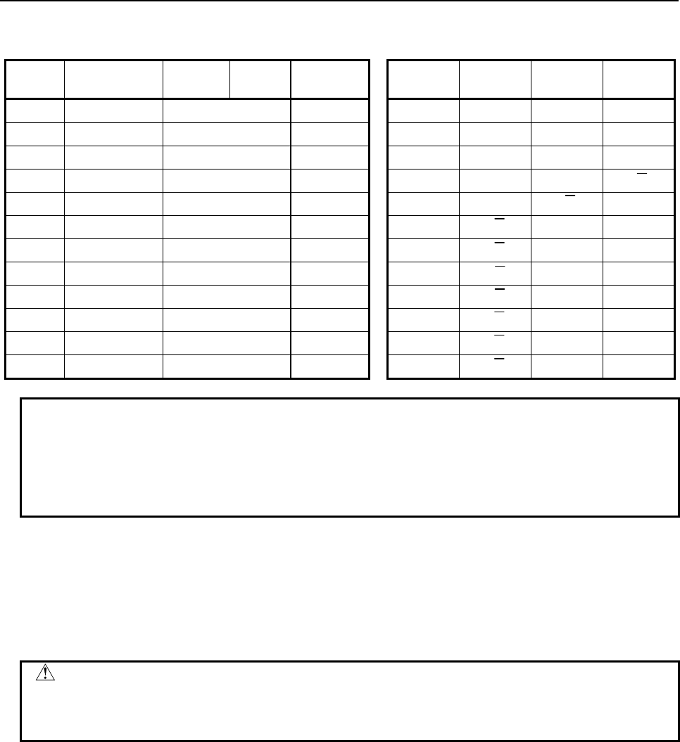
B-64513EN/03
4.LADDER LANGUAGE
- 263 -
Table 4.2.1 (a) Coding format of the functional instructions
Mnemonic format Status of operation result
Step
number Instruction Address
No. Bit No. Remarks ST3 ST2 ST1 ST0
1 RD R1 . 0 A A
2 AND R1 . 1 B A⋅B
3 RD.STK R2 . 4 C A⋅B C
4 AND.NOT R3 . 1 D A⋅B C⋅D
5 RD.STK R5 . 7 RST A⋅B C⋅D RST
6 RD.STK R7 . 1 ACT A⋅B C⋅D RST ACT
7 SUB {{ Instruction A⋅B C⋅D RST ACT
8 (PRM) (Note 2) {{{{ Parameter 1 A⋅B C⋅D RST ACT
9 (PRM) {{{{ Parameter 2 A⋅B C⋅D RST ACT
10 (PRM) {{{{ Parameter 3 A⋅B C⋅D RST ACT
11 (PRM) {{{{ Parameter 4 A⋅B C⋅D RST ACT
12 WRT R10. 1 W1 output A⋅B C⋅D RST W1
NOTE
1 The number within each pair of parentheses shown for the control conditions
represents the position in the register where the result is to be stored.
2 The term (PRM) in the Instruction fields for step numbers 8 to 11 means a
parameter. You do not need to input the term (PRM); just enter an address or
numeric data.
(2) Control conditions
The number of control conditions and the meanings of those conditions differ for each functional
instruction.
The control conditions are stored in the register, as shown in Table 4.2.1 (a). Once set, therefore,
the sequence of the control conditions is fixed. You cannot change the sequence or omit any of the
control conditions.
CAUTION
All functional instructions give precedence to the RST processing when they
include RST in their control conditions. Therefore, when RST = 1, the functional
instruction carries out the RST processing even if ACT = 0.
(3) Instruction
For the types of functional instructions, see Subsection 2.1.8 or 2.1.9.
To input the instruction with relay symbols, use the soft keys of the programmer.
(4) Parameters
Unlike the basic instructions, the functional instructions deal with numeric values. Therefore,
reference data values and addresses storing data may be entered in their parameters. The number of
parameters and the meanings of those parameters differ for each functional instruction.
(5) W1
W1 is the destination to which the functional instruction outputs its operation result when that result
can be represented by a one-bit value, 0 or 1. The designer can freely decide the address of W1.
The meaning of W1 differs for each functional instruction. Some functional instructions do not
have the W1 output.

4.LADDER LANGUAGE
B-64513EN/03
- 264 -
(6) Data to be processed
The data processed by the functional instructions is in two formats - binary coded decimal (BCD)
format and binary format. Formerly, the PMC system handled numeric data mainly in the BCD
format. However, dealing with all numeric data in the binary format is now recommended for the
following reasons.
(a) The numeric data exchanged between NC and PMC (M, S, T, and B codes) is in the binary
format.
(b) The CPU carries out all numeric data operations in the binary format. Therefore, if data is
provided in the binary format, the conversion between the BCD and binary formats becomes
unnecessary, thus speeding up the PMC processing.
(c) The use of binary format data allows you to handle a wider range of numeric data while at the
same time making it easier to deal with negative numeric data. This leads to an enhanced
operation capability. In principle, binary numeric data is handled in units of one byte (−128 to
+127), two bytes (−32,768 to +32,767), or four bytes (−2,147,483,648 to +2,147,483,647).
(d) When you enter numeric data using the CNC screen keys or display numeric data on the CNC
screen, you will experience no inconvenience because binary numeric data values are all set
and displayed in the decimal format. It is just that the data stored in the internal memory is
written in the binary format. You only need to exercise care when the sequence program
references memory. See item (7) for examples of numeric data. For the reasons mentioned
above, all the functional instructions described in this manual are designed to deal with binary
data and handle mainly binary data.
(7) Examples of numeric data
(a) BCD format data
Basically, the data processed in the BCD format is handled in units of one byte (0 to 99), two
bytes (0 to 9999), or four bytes (0 to 99,999,999; for the DCNVB instruction only). A
four-digit BCD data block is stored in two bytes of consecutive addresses, as in the following
example.
(Example) When BCD data 1234 is stored at addresses R250 and R251
00110 1
7654 32
0
1
0
0
3 4
R250
0 0 0 1 0 0
7654 32
1
1
0
0
1 2
R251
In the functional instruction, specify the address having the smaller number, R250.
Note) The low-order digits are stored in the smaller number address.
(b) Binary format data
Basically, the data processed in the binary format is handled in units of one byte (−128 to +127),
two bytes (−32,768 to +32,767), or four bytes (−2,147,483,648 to +2,147,483,647). The data
is stored at addresses R200, R201, R202, and R203, as shown below. Note that negative
numbers are set as two's complements.
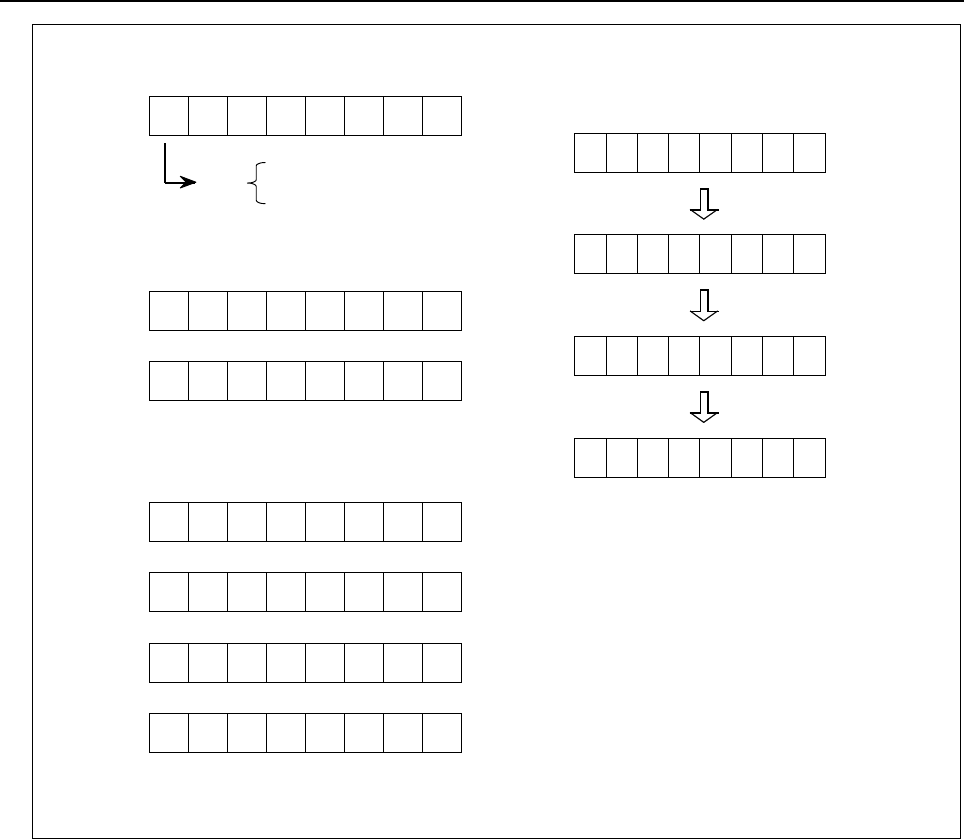
B-64513EN/03
4.LADDER LANGUAGE
- 265 -
One-byte data (−128 to +127)
±
7 6 5 4 3 2 1 0
R200 2
6
2
5
2
4
2
3
2
2
2
1
2
0
2
7
7 6 5 4 3 2 1 0
R200 2
6
2
5
2
4
2
3
2
2
2
1
2
0
Sign 0: Positive
1: Negative
±
R201 2
14
2
13
2
12
2
11
2
10
2
9
2
8
Two-byte data (−32,768 to +32,767)
2
7
7 6 5 4 3 2 1 0
R200 2
6
2
5
2
4
2
3
2
2
2
1
2
0
2
15
R201 2
14
2
13
2
12
2
11
2
10
2
9
2
8
Four-byte data (−2,147,483,648 to +2,147,483,647)
2
23
R202 2
22
2
21
2
20
2
19
2
18
2
17
2
16
± R203 2
30
2
29
2
28
2
27
2
26
2
25
2
24
In the functional instruction, specify the address having the
smallest number, R200.
000000
76543
0 1 (+1)
1 1 1 1 1 1 1 1 (‐1)
0 1 1 1 1 1 1 1 (+127)
1 0 0 0 0 0 0 1 (‐127)
2 1 0
(Example) One-byte data
(8) Addresses of numeric data processed by functional instructions
When the numeric data to be processed by a functional instruction consists of two or four bytes, it is
recommended to specify an even number or a multiple of four as the address of the numeric data in
the relevant parameter of that functional instruction. Specifying an even-numbered or
multiple-of-four address causes the functional instruction to execute slightly faster.
In the case of a functional instruction that mainly deals with binary data, such a parameter is marked
with an asterisk (*) in the parameter field of the diagram illustrating the format of the functional
instruction, as shown below.
An even-numbered or multiple-of-four address means that the letter R is followed by an even
number or a multiple of four in the case of an internal relay, or that the letter D is followed by an
even number or a multiple of four in the case of a data table.
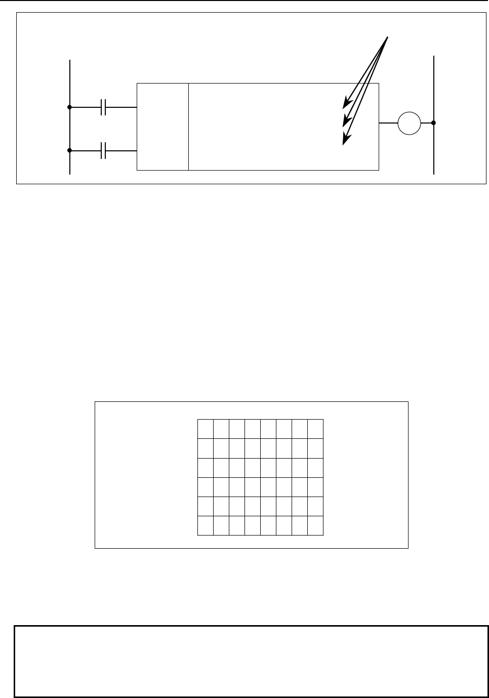
4.LADDER LANGUAGE
B-64513EN/03
- 266 -
Error output
RST
W1
A
CT
A
DDB
SUB36
{{{{ Format
*
{{{{ Augend data address
*
{{{{ Addend data
(
address
)
*
{{{{
Addition result out
p
ut address
* When the numeric data consists of two or four bytes, specify an even-numbered or multiple-of-four address
for each of those addresses marked with *. Doing so causes the functional instruction to execute faster.
Fig. 4.2.1 (b)
(9) Functional instruction operation result register
(R9000 to R9005, Z0 to Z5) (See Fig. 4.2.1 (c).)
The results of executing functional instructions are set in this register. The register is shared by all
the functional instructions. Therefore, if you do not reference the register immediately after
executing the target functional instruction, the operation data of that instruction is erased as a
subsequent functional instruction is executed.
Also note that the operation data of this register cannot be exchanged between sequence programs of
different levels. For example, when the subtraction instruction (SUBB) is executed in a first level
program and the result of its execution is set in the register, a second level program cannot reference
the set operation data by reading the register in the R9000 or Z0 range.
The operation data set in this register can be shared by sequence programs of the same level and is
maintained until immediately before a functional instruction is executed that sets subsequent
operation data in the register. The operation data to be set in this register differs for each functional
instruction. The sequence program can read this data but not write to this register.
76543210
R9000, Z0
R9001, Z1
R9002, Z2
R9003, Z3
R9004, Z4
R9005, Z5
Fig. 4.2.1 (c)
This register consists of six bytes, from R9000 to R9005 or Z0 to Z5. A single block of data can be read
from the register in bits or bytes at a time.
To read the data of the first bit of R9000, for example, specify RD R9000.1.
NOTE
In detailed explanation of each functional instruction, there are some functional
instructions which do not have description for “Operation Output Register (R9000
to R9005, Z0 to Z5)”. As for these functional instructions, result of the operation
output register just after execution of the functional instruction is uncertain.

B-64513EN/03
4.LADDER LANGUAGE
- 267 -
4.3 TIMER
The following types of timer instruction are available. Use any of these instructions as appropriate for
your purpose.
Instruction name Sub number Processing
1 TMR 3 On-delay timer
2 TMRB 24 Fixed on-delay timer
3 TMRBF 77 Fixed off-delay timer
4 TMRC 54 On-delay timer
5 TMRST 221 Stop watch timer (1 ms accuracy)
6 TMRSS 222 Stop watch timer (1 sec accuracy)
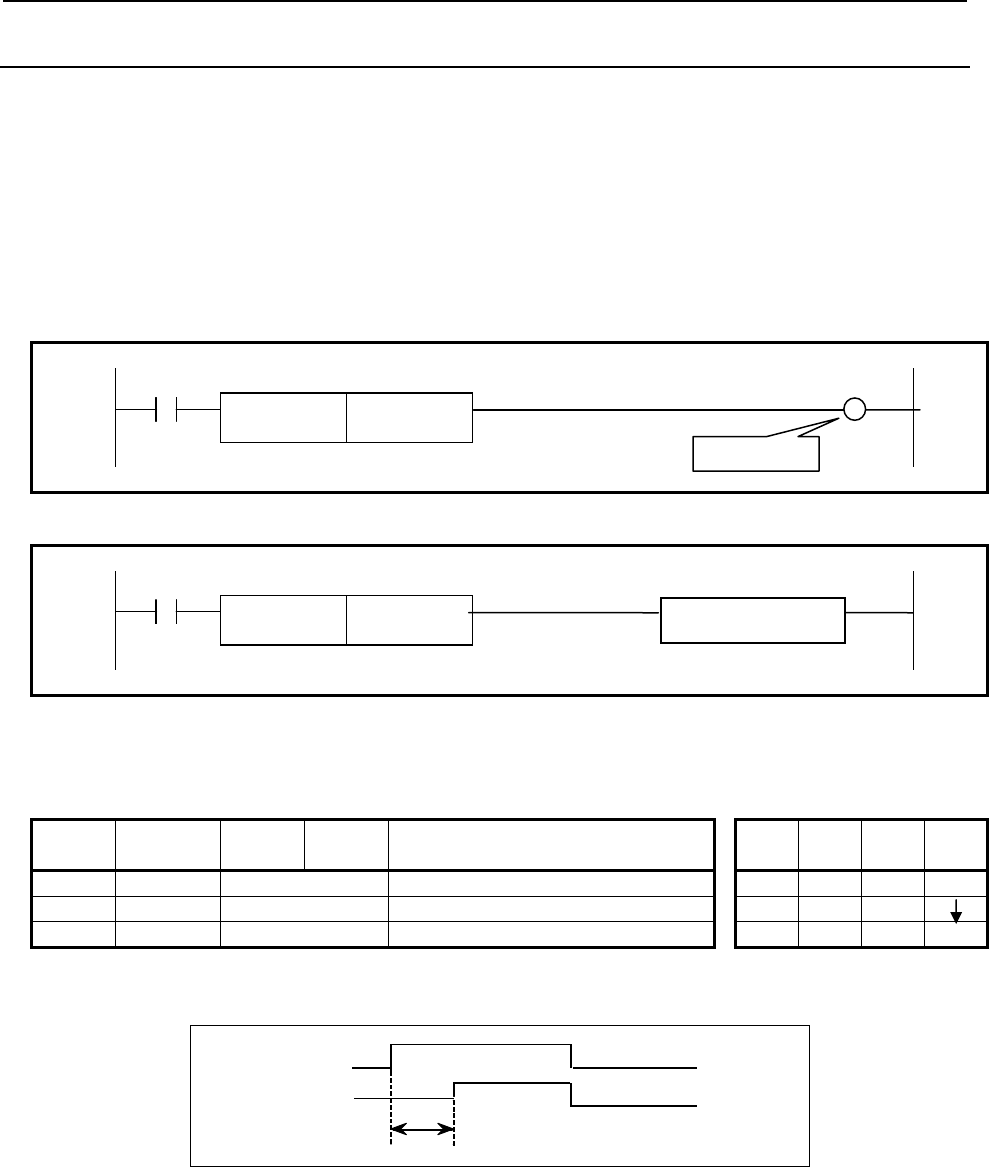
4.LADDER LANGUAGE
B-64513EN/03
- 268 -
4.3.1
TMR (On-delay Timer: SUB 3)
This is an on-delay timer.
Since you set the time in nonvolatile memory (T address) using the timer screen, you can change the set
time without changing the ladder diagram.
The timer number you specify in the parameter is a number displayed on the timer screen. The data type
in this instruction is binary type.
Format
The followings are the ladder format and the mnemonic format. In case of extended type format, another
functional instruction can be connected instead of a W1.
Normal format
ACT W1
SUB 3
TMR {{{ Timer number
Fig. 4.3.1 (a) Format of TMR instruction (Normal format)
Extended type format
ACT
SUB 3
TMR {{{ Timer number Functional Instruction
Fig. 4.3.1 (b) Format of TMR instruction (Extended type format)
Table 4.3.1 Mnemonic of TMR instruction (Normal format)
Mnemonic format Memory status of control
condition
Step
number Instruction Address
No. Bit No. Remarks ST3 ST2 ST1 ST0
1 RD {{{{ .{ ACT ACT
2 TMR {{{ Timer number
3 WRT {{{{ .{ Timer relay output W1
In the above mnemonic format, instruction name "TMR" at step number 2 can be abbreviated as "T".
W1
A
CT
T indicates the time set in this timer
command.
T
Fig. 4.3.1 (c) Operation of the timer
Control condition
ACT = 0: Turns off W1.
ACT = 1: Starts the timer.
Parameter
Set the timer number.
Timer relay
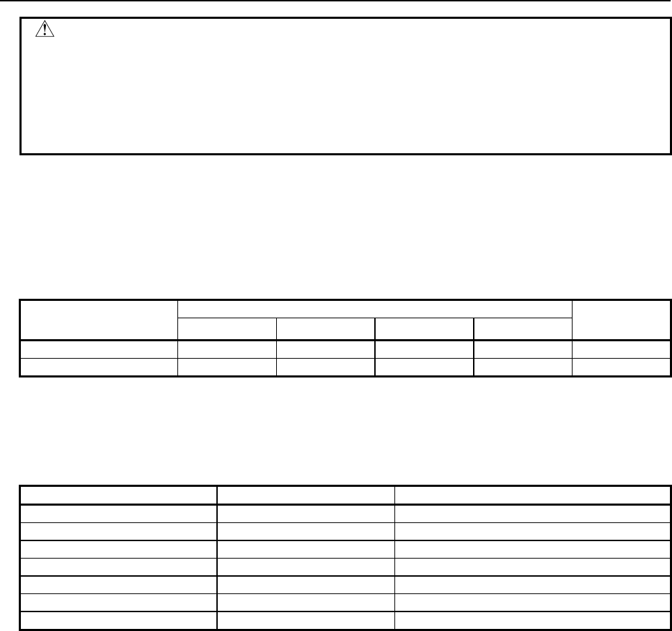
B-64513EN/03
4.LADDER LANGUAGE
- 269 -
WARNING
1 If the timer number is duplicated, or falls outside the valid range, the operation will
be unpredictable.
2 When using the ladder dividing management function, do not use the duplicated
timer number in different divided ladder programs on the same PMC path.
3 When using the Common PMC Memory mode, don't use the duplicated timer
number in multiple PMC paths.
Setting timers
The initial value of the timer setting time can be set in steps of 48 msec for timer numbers 1 to 8 and in
steps of 8 msec for timer numbers 9 and later. (For information about the number of timers of each
PMC, see the table below.) The setting time value is rounded down to a multiple of the unit time.
For example, if 38 msec is set, the remainder 6 (38 = 8 × 4 + 6) is discarded, and only 32 msec is actually
set.
Initial number of the timer
setting time
1st to 5th path PMC Dual check
safety PMC
PMC Memory-A PMC Memory-B PMC Memory-C PMC Memory-D
48-msec timer number
1 to 8 1 to 8 1 to 8 1 to 8 1 to 8
8-msec timer number
9 to 40 9 to 250 9 to 500 9 to 500 9 to 40
Timer accuracy
The timer screen allows you to set the accuracy of each timer individually. The setting time range and
error are as shown below. For detailed information about how to set the timer accuracy, see Subsection
7.3.1.
Timer type and number Setting time Maximum error
48 msec (1 to 8) (initial value) 48 msec to 1572.8 sec 1st level execution cycle (1, 2, 4 or 8ms)
8 msec (9 or larger) (initial value) 8 msec to 262.1 sec 1st level execution cycle (1, 2, 4 or 8ms)
1 msec (1 or larger) 1 msec to 32.7 sec 1st level execution cycle (1, 2, 4 or 8ms)
10 msec (1 or larger) 10 msec to 327.7 sec 1st level execution cycle (1, 2, 4 or 8ms)
100 msec (1 or larger) 100 msec to 54.6 min 1st level execution cycle (1, 2, 4 or 8ms)
1 sec (1 or larger) 1 sec to 546 min 1st level execution cycle (1, 2, 4 or 8ms)
1 min (1 or larger) 1 min to 546 h 1 sec
Error is caused only by operation time of the timer instruction. For example, when a timer instruction is
used in the 2nd level sequence part, the variation does not include the delay time (Max. 2nd level
sequence one cycle time) until the sequence actuates after the set time is reached.
Timer relay (W1)
When the time preset is reached with ACT = 1, the timer relay turns on. The designer can freely decide
the address of W1. In case of extended type format, another functional instruction can be connected
instead of a W1.
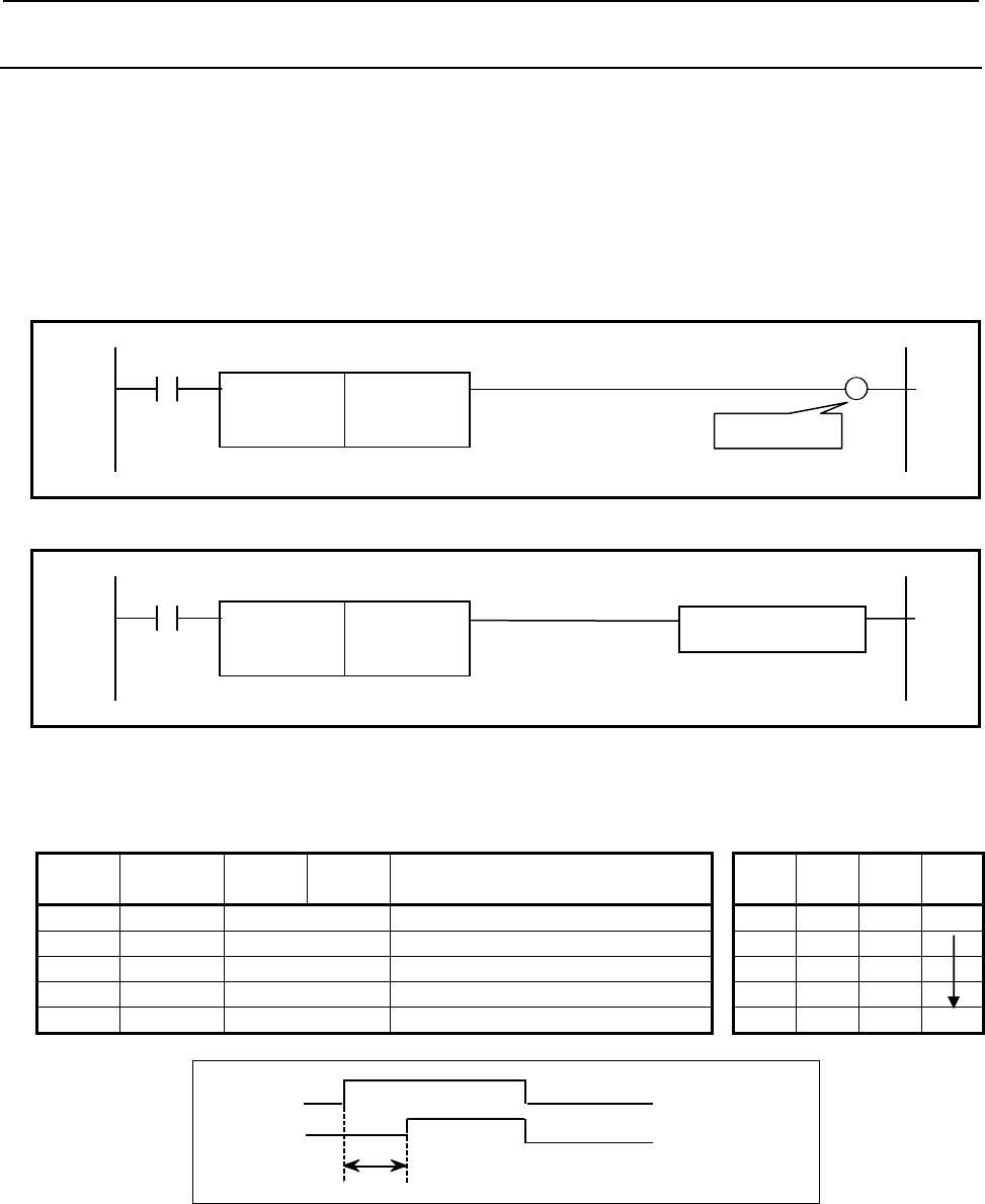
4.LADDER LANGUAGE
B-64513EN/03
- 270 -
4.3.2
TMRB (Fixed On-delay Timer: SUB 24)
This timer is used as a fixed on-delay timer.
Time present in this fixed timer is written to the memory together with the sequence program, so the time
once set cannot be changed unless the whole sequence program is exchanged. The data type in this
instruction is binary type.
Format
The followings are the ladder format and the mnemonic format. In case of extended type format, another
functional instruction can be connected instead of a W1.
Normal format
ACT W1
SUB 24
TMRB
{{{ Timer number
{{{{ Setting time
Fig. 4.3.2 (a) Format of TMRB instruction (Normal format)
Extended type format
ACT
SUB 24
TMRB
{{{ Timer number Functional Instruction
{{{{ Setting time
Fig. 4.3.2 (b) Format of TMRB instruction (Extended type format)
Table 4.3.2 Mnemonic of TMRB instruction (Normal format)
Mnemonic format Memory status of control
condition
Step
number Instruction Address
No. Bit No. Remarks ST3 ST2 ST1 ST0
1 RD {{{{ .{ ACT ACT
2 SUB 24 TMRB instruction
3 (PRM) {{{ Timer number
4 (PRM) {{{{ Setting time
5 WRT {{{{ .{ Timer relay output W1
W1
A
CT
T indicates the time set in this timer command.
T
Fig. 4.3.2 (c) Timer operation
Control condition
ACT = 0: Turns off W1.
ACT = 1: Starts the timer.
Timer relay
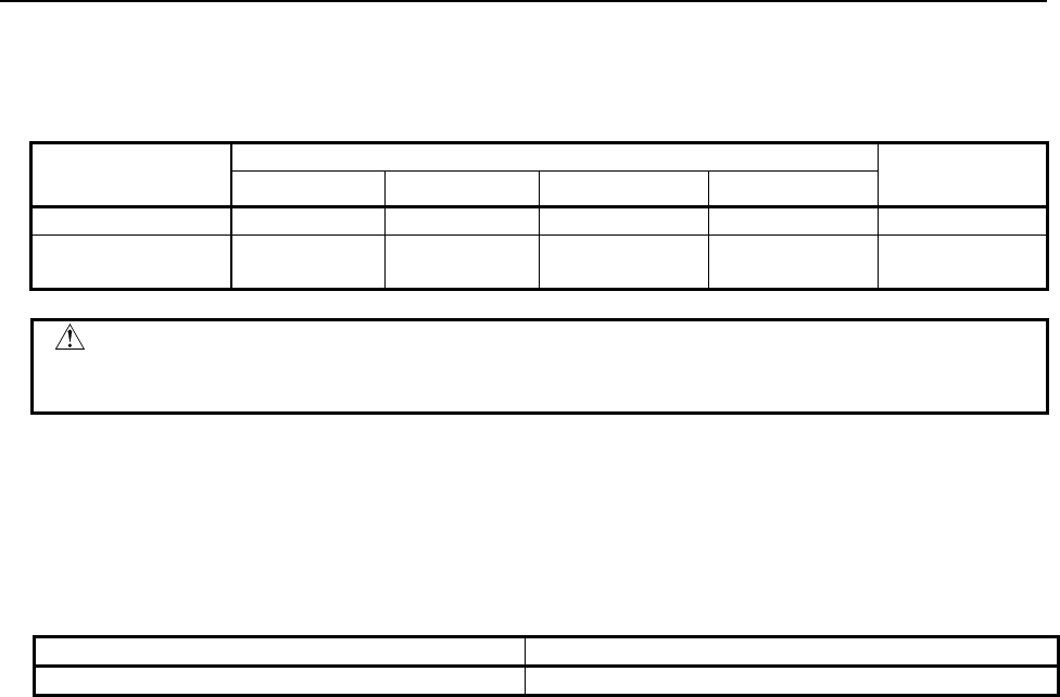
B-64513EN/03
4.LADDER LANGUAGE
- 271 -
Parameters
Specify the timer number of a fixed timer. The timer numbers and the setting time range are as shown
below.
1st to 5th path PMC Dual check
safety PMC
PMC Memory-A PMC Memory-B PMC Memory-C PMC Memory-D
Timer number
1 to 100 1 to 500 1 to 1000 1 to 1500 1 to 100
Setting time
1 to 32,760,000
(msec)
1 to 32,760,000
(msec)
1 to 32,760,000
(msec)
1 to 32,760,000
(msec)
1 to 32,760,000
(msec)
WARNING
If the same timer number is used more than once or if a timer number out of the
valid range is used, operation is unpredictable.
The maximum setting time is approximately 546 minutes.
Error of the timer
This instruction has the following error. Moreover, the execution time until the timer instruction is
executed in a sequence program (the maximum is the time of one cycle of each ladder execution level) is
added to the error.
Timer instruction Maximum Error
TMRB 1st level execution cycle (1, 2, 4 or 8ms)
Timer relay (W1)
The output W1 is turned on after certain time preset in the parameter of this instruction pasts after ACT =
1. The designer can freely decide the address of W1. In case of extended type format, another functional
instruction can be connected instead of a W1.
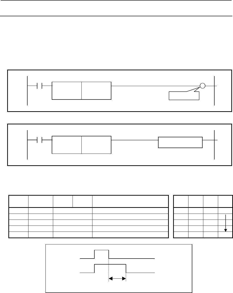
4.LADDER LANGUAGE
B-64513EN/03
- 272 -
4.3.3
TMRBF (Fixed Off-delay Timer: SUB 77)
This is the off-delay timer function whose timer preset value is fixed.
The timer preset value is written into the sequence program memory. Therefore, you have to modify
sequence program if you want to change the timer value. The data type in this instruction is binary type.
Format
The followings are the ladder format and the mnemonic format. In case of extended type format, another
functional instruction can be connected instead of a W1.
Normal format
ACT W1
SUB 77
TMRBF
{{{ Timer number
{{{{ Setting time
Fig. 4.3.3 (a) Format of TMRBF instruction (Normal format)
Extended type format
ACT
SUB 77
TMRBF
{{{ Timer number Functional Instruction
{{{{ Setting time
Fig. 4.3.3 (b) Format of TMRBF instruction (Extended type format)
Table 4.3.3 Mnemonic of TMRBF instruction (Normal format)
Mnemonic format Memory status of control
condition
Step
number Instruction Address
No. Bit No. Remarks ST3 ST2 ST1 ST0
1 RD {{{{ .{ ACT ACT
2 SUB 77 TMRBF instruction
3 (PRM) {{{ Timer number
4 (PRM) {{{{ Setting time
5 WRT {{{{ .{ Timer relay output W1
ACT
W1
T
T indicates the timer value.
Fig. 4.3.3 (c) Timer operation
Control condition
ACT=0: Starts the timer.
ACT=1: Reset the timer and turn on W1.
Timer relay
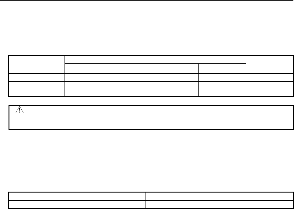
B-64513EN/03
4.LADDER LANGUAGE
- 273 -
Parameters
Specify the timer number of the fixed timer to the 1st parameter. You have to specify the unique timer
number for all the TMRB (SUB 24) and TMRBF (SUB 77) instructions.
Specify the timer value of the fixed timer to the 2nd parameter. The unit is millisecond.
The available timer number and timer value is shown below.
1st to 5th path PMC Dual check
safety PMC
PMC Memory-A PMC Memory-B PMC Memory-C PMC Memory-D
Timer number
1 to 100 1 to 500 1 to 1000 1 to 1500 1 to 100
Setting time
1 to 32,760,000
(msec)
1 to 32,760,000
(msec)
1 to 32,760,000
(msec)
1 to 32,760,000
(msec)
1 to 32,760,000
(msec)
WARNING
If the timer number of TMRB or TMRBF is conflicted or if the timer number is out of
range, the operation is not guaranteed.
The maximum timer value is approximately 546 minutes.
Error of the timer
This instruction has the following error. Moreover, the execution time until the timer instruction is
executed in a sequence program (the maximum is the time of one cycle of each ladder execution level) is
added to the error.
Timer instruction Maximum Error
TMRBF 1st level execution cycle (1, 2, 4 or 8ms)
Timer relay (W1)
When the input ACT is turned on, the output W1 will be turned on immediately and the timer instruction
will be reset. After that, when the input ACT is turned off, the timer instruction will be started and the
output W1 will be turned off after the specified time. If the input ACT is turned on again before the
time-up, the timer will be reset.
You can use any valid coil address for the W1. In case of extended type format, another functional
instruction can be connected instead of a W1.
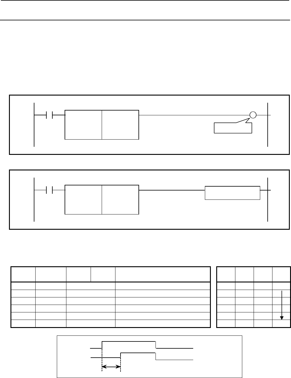
4.LADDER LANGUAGE
B-64513EN/03
- 274 -
4.3.4
TMRC (On-delay Timer: SUB 54)
This is the on-delay timer.
A timer setting time is set at an arbitrary address. There is no limit to the number of timers as long as
memory areas can be allocated for the timer instruction to use. The data type in this instruction is binary
type.
Format
The followings are the ladder format and the mnemonic format. In case of extended type format, another
functional instruction can be connected instead of a W1.
Normal format
ACT W1
SUB 54
TMRC
{Timer accuracy number
{{{{ Timer set time address
{{{{ Timer register address
Fig. 4.3.4 (a) Format of TMRC instruction (Normal format)
Extended type format
ACT
SUB 54
TMRC
{Timer accuracy number Functional Instruction
{{{{ Timer set time address
{{{{ Timer register address
Fig. 4.3.4 (b) Format of TMRC instruction (Extended format)
Table 4.3.4 Mnemonic of TMRC instruction (Normal format)
Mnemonic format Memory status of control
condition
Step
number Instruction Address
No. Bit No. Remarks ST3 ST2 ST1 ST0
1 RD {{{{ .{ ACT ACT
2 SUB 54 TMRC instruction
3 (PRM) {{{ Timer accuracy number
4 (PRM) {{{{ Timer set time address
5 (PRM) {{{{ Timer register address
6 WRT {{{{ .{ Timer relay output W1
W1
A
CT
T indicates the time set in this timer command.
T
Fig. 4.3.4 (c) Timer operation
Control condition
ACT = 0: Turns off W1.
ACT = 1: Starts the timer.
Timer relay
B-64513EN/03
4.LADDER LANGUAGE
- 275 -
Parameters
(a) Timer accuracy
The timer accuracy values, setting time range, and error are as shown below.
Timer
accuracy
Setting
number The range of setting time (Note) Margin of error
8 msec 0 8 msec to about 262.1 sec 1st level execution cycle (1, 2, 4 or 8ms)
48 msec 1 48 msec to about 26.2 min 1st level execution cycle (1, 2, 4 or 8ms)
1 sec 2 1 sec to about 546 min 1st level execution cycle (1, 2, 4 or 8ms)
10 sec 3 10 sec to about 91 h 1st level execution cycle (1, 2, 4 or 8ms)
1 min 4 1 min to about 546 h 1 sec
1 msec 5 1 msec to about 32.7 sec 1st level execution cycle (1, 2, 4 or 8ms)
10 msec 6 10 msec to about 327.7 sec 1st level execution cycle (1, 2, 4 or 8ms)
100 msec 7 100 msec to about 54.6 min 1st level execution cycle (1, 2, 4 or 8ms)
This instruction has the above error. Moreover, the execution time until the timer instruction is
executed in a sequence program (the maximum is the time of one cycle of each ladder execution
level) is added to the error.
NOTE
The value range of the setting time is between 0 and 32,767 for all timer
accuracies. For example, when the timer accuracy is 8 msec, the value 0
means 8 msec and the value 32,767 means 262,136 msec.
(b) Timer set time address
Sets the first address of the timer set time field.
The continuous 2-bytes memory space is required for the timer set time field.
The data table (field D) is normally used as this field.
TIME
Timer set time + 0
Timer set time + 1
TIME: Timer set time (1 to 32,767)
The timer setting time is converted to the binary format based on the timer accuracy (in units of 8
msec, 48 msec, etc.).
The timer setting time is shown as follows:
8 msec 8 to 262,136 msec
48 msec 48 to 1,572,816 msec
1 sec 1 to 32,767 sec
10 sec 10 to 327,670 sec
1 min 1 to 32,767 min
1 msec 1 to 32,767 msec
10 msec 10 to 327,670 msec
100 msec 100 to 3,276,700 msec

4.LADDER LANGUAGE
B-64513EN/03
- 276 -
(c) Timer register address
Set the start address of a timer register area.
A timer register area must be allocated to a continuous 4 bytes memory area starting from the set
address. The user area (R area) is used as a timer register area. This area should be used by the
PMC system, and therefore should not be used by the sequence program.
Timer register + 0
Timer register + 1
Timer register + 2
Timer register + 3
Timer register
Timer relay (W1)
The output W1 is turned on when the time specified in the parameter of this instruction elapses after ACT
is set to 1. The designer can freely decide the address of W1. In case of extended type format, another
functional instruction can be connected instead of a W1.
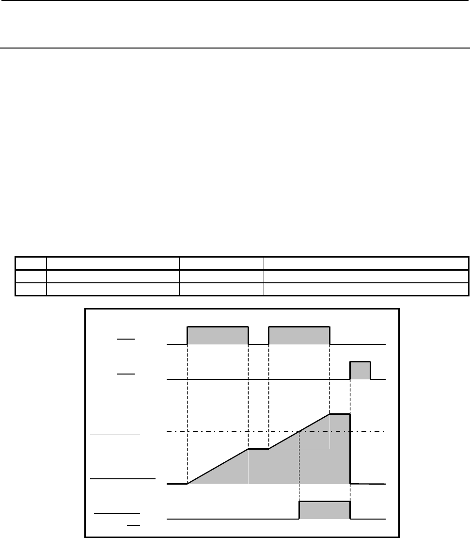
B-64513EN/03
4.LADDER LANGUAGE
- 277 -
4.3.5
TMRST (Stop Watch Timer (1ms Accuracy) : SUB 221)
TMRSS (Stop Watch Timer (1sec Accuracy) : SUB 222)
This is stop watch timer.
The stop watch timer instruction accumulates periods of time during which ACT=1 is set, and preserves
the cumulative value as an integration time. The integration time is not cleared when ACT=0. Instead,
when ACT=1 is set again, a continued measurement is made.
In "Setting time", a constant or a PMC memory address for storing data can be specified. An integration
time is output to a specified PMC address, so that the integration time can be output to the outside or used
for another operation.
When the integration time has reached "Setting time", timer relay W1=1 is set. If ACT=1 even when the
integration time has exceeded "Setting time", a measurement is continued until a maximum time is
reached. During this period as well, timer relay W1=1 is set.
To reset the integration time and timer relay to 0, set RST (Reset)=1.
As indicated below, two types of the stop watch timer instructions are available according to the timer
accuracy.
Table4.3.5 (a) Kinds of stop watch timer
Instruction name SUB No. Timer accuracy
1 TMRST 221 1 millisecond (ms)
2 TMRSS 222 1 sec
Integration time
Timer relay
W1
Setting time
On
Off
ACT
On
Off
RST
On
Off
Fig. 4.3.5 (a) Time chart of TMRST and TMRSS Instruction
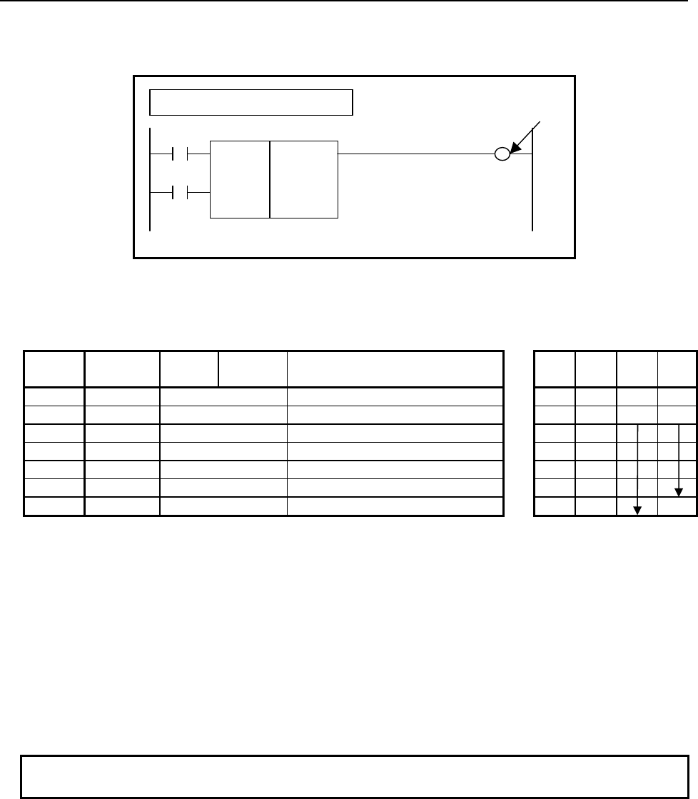
4.LADDER LANGUAGE
B-64513EN/03
- 278 -
Format
Fig. 4.3.5 (b) shows the ladder format and Table 4.3.5 (b) shows the mnemonic format.
Example: TMRST Instruction
SUB 221
TMRST
{{{{
{{{{
{{{{
Setting time (Address or Constant)
Integration time address
Timer register address
RST W1
ACT
Timer relay
Fig. 4.3.5 (b) Format of TMRST and TMRSS instruction
Table4.3.5 (b) Mnemonic of TMRST and TMRSS instruction
Mnemonic format Memory status of control
condition
Step
number Instruction Address
No. Bit No. Remarks ST3 ST2 ST1 ST0
1 RD ○○○○ .○ RST RST
2 RD.STK
○○○○ .○ ACT RST ACT
3 SUB 221 SUB No. (TMRST Instruction)
4 (PRM) ○○○○ Setting time (Address or Constant)
5 (PRM) ○○○○ Integration time address
6 (PRM) ○○○○ Timer register address
7 WRT ○○○○ .○ Timer relay output W1
Control condition
(a) Reset (RST)
RST=0: Reset operation is canceled.
RST=1: Reset operation is executed.
The integration time is reset to 0.
Even when input signal ACT=1 is set, reset operation has priority, and the stop watch timer
is stopped. W1=0 is also set.
(b) Input signal (ACT)
ACT=0: Integration is stopped.
ACT=1: Integration is started.
NOTE
Set RST to 1 only when reset operation is needed. Usually, set RST to 0.
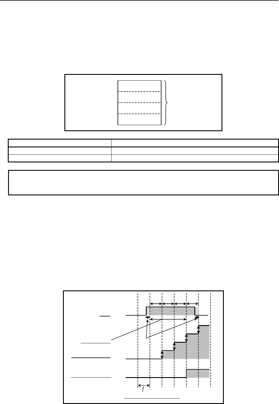
B-64513EN/03
4.LADDER LANGUAGE
- 279 -
Parameters
(a) Setting time
Specify a time-out period for the timer. A value from 0 to 2147483647 may be specified. If a
value out of this range is specified, integration operation is performed but timer relay W1=0 is set at
all times.
In this parameter, a constant or a PMC memory address for storing data can be specified.
If an address is specified, specify "Setting time" as signed binary data by using the contiguous four
bytes of memory starting from the specified address.
Specified address +0
Specified address +1 Setting time
(Signed binary data)
Specified address +2
Specified address +3
Instruction name Setting time
TMRST 0 to 2147483647 millisecond
TMRSS 0 to 2147483647 second
NOTE
When a Setting time is rewritten during execution of instruction, the result is
reflected immediately.
(b) Integration time address
Specify a PMC memory address for storing the integration time of the timer. One integration time
count corresponds to the timer accuracy.
An integration time address must be allocated to a continuous four bytes memory area starting from
the set address.
To preserve the integration time when the power to the CNC is turned on/off, the D area is usually
used. However, the delay corresponding to the cycle of backup of D area may cause an error at the
Integration time after turning on a power supply again when a power supply is turned off in
integration.
The figure below shows the relationships of the actual accumulation of integration time, ladder
execution cycle, ACT On/Off operation, and timer relay output.
Integration time
ACT
On
Off
ladder execution cycle
(1) (2) (3) (4)
(1)
(2)
(3)
(4)
Timer relay W1 On
Off
Setting time
Error
Fig. 4.3.5 (c) Increment of Integration time

4.LADDER LANGUAGE
B-64513EN/03
- 280 -
Integration time accumulation starts in the execution cycle immediately after ACT=1 (On) is set, and
continues until an execution cycle where ACT=0 (Off) is set. Timer relay W1=1 (On) is set when
the integration time has reached "Setting time".
A maximum error per measurement section (pair of ACT On/Off) is "±ladder execution cycle time".
NOTE
Do not perform rewriting of integration time during execution of instruction.
(c) Timer register address (work memory)
Specify the address of a 2 bytes PMC memory area to be used for integration time calculation. The
sequence program should not use this area. Usually, the R area is used.
Timer relay (W1)
W1 is turned on when the integration time has reached the set time.
NOTE
W1 must not be omitted.

B-64513EN/03
4.LADDER LANGUAGE
- 281 -
4.4 COUNTER
The following types of counter instruction are available. Use any of these instructions as appropriate for
your purpose.
Instruction name Sub number Processing
1 CTR 5 Counter processing
2 CTRB 56 Fixed counter processing
3 CTRC 55 Counter processing
4 CTRD 223 Counter processing (4 bytes length)
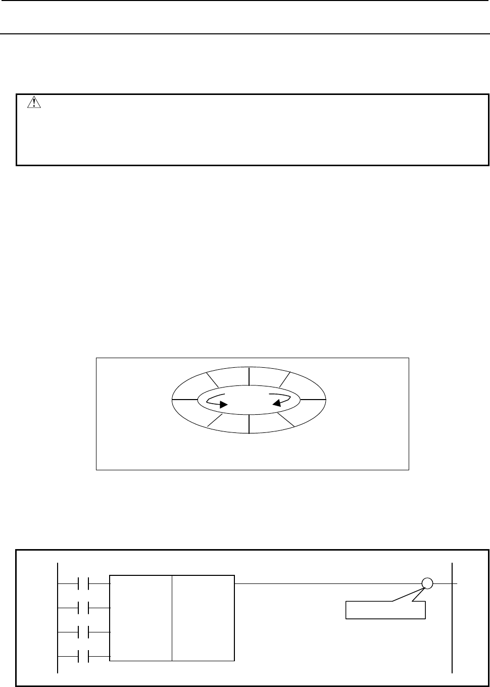
4.LADDER LANGUAGE
B-64513EN/03
- 282 -
4.4.1
CTR (Counter: SUB 5)
CTR is used as a counter. Counters are used for various purposes for NC machine tools.
Numerical data such as preset values and count values can be used with either BCD format or binary
format by a system parameter of PMC.
WARNING
When an incorrect BCD data was set to a BCD type counter, the movement of
CTR cannot be sure.
If changing the counter type, be sure to reconfigure the preset value and count
value.
This counter has the following functions to meet various applications.
(a) Preset counter
A signal is output when the preset count is reached. The number can be preset from the counter
screen, or set in the sequence program.
(b) Ring counter
Upon reaching the preset count, returns to the initial value by issuing another count signal.
(c) Up/down counter
The count can be either up or down.
(d) Selection of initial value
Select the initial value as either 0 or 1.
A combination of the preceding functions results in the ring counter below.
81
2
3
45
6
7
Presetting : 8
Initial value : 1
Such a counter permits the position of a rotor to be memorized.
Format
The followings are the ladder format and the mnemonic format.
CNO W1
SUB 5
UPD CTR
{{{ Counter number
RST
ACT
Fig. 4.4.1 (a) Format of CTR instruction
Count up output
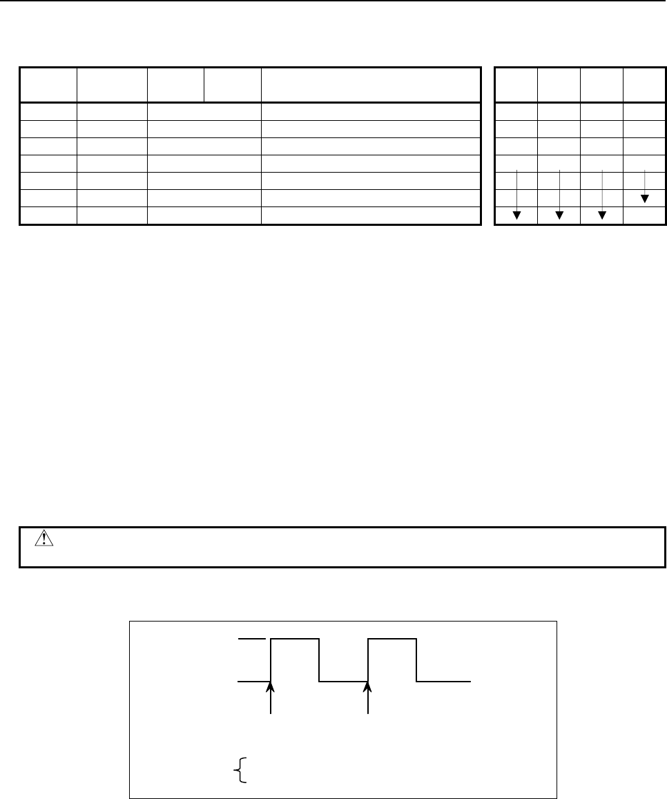
B-64513EN/03
4.LADDER LANGUAGE
- 283 -
Table 4.4.1 Mnemonic of CTR instruction
Mnemonic format Memory status of control
condition
Step
number Instruction Address
No. Bit No. Remarks ST3 ST2 ST1 ST0
1 RD {{{{ .{ CNO CNO
2 RD.STK {{{{ .{ UPD CNO UPD
3 RD.STK {{{{ .{ RST CNO UPD RST
4 RD.STK {{{{ .{ ACT CNO UPD RST ACT
5 SUB 5 CTR instruction
6 (PRM) {{{ Counter number
7 WRT {{{{ .{ Counter output W1
Control conditions
(a) Specify the initial value. (CNO)
CNO = 0: Begins the value of the counter with 0.
0, 1, 2, 3, ....., n.
CNO = 1: Begins the value of the counter with 1 (0 is not used).
1, 2, 3, ....., n.
(b) Specify up or down counter. (UPDOWM)
UPD = 0: Up counter. The counter begins with 0 when CNO = 0; 1 when CNO =1.
UPD = 1: Down counter. The counter begins with the preset value.
(c) Reset (RST)
RST = 0: Releases reset.
RST = 1: Enables reset.
W1 becomes 0.
The integrated value is reset to the initial value.
CAUTION
Set RST to 1, only when reset is required.
(d) Count signal (ACT)
"0"
"1"
Count Count
A
CT 0: Counter does not operate. W1 does not change.
1: Count is made by catching the rise of ACT.
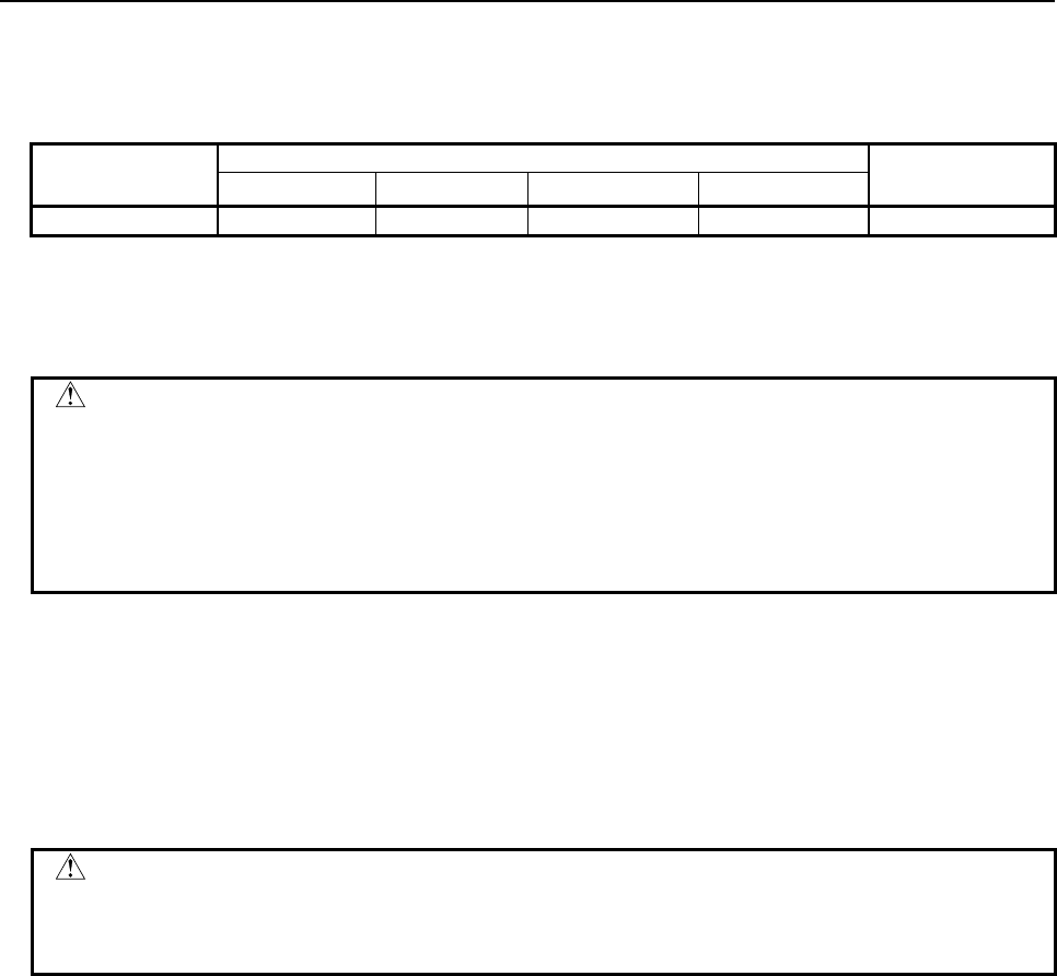
4.LADDER LANGUAGE
B-64513EN/03
- 284 -
Parameter
(a) Counter number
The numbers that can be used are shown below.
1st to 5th path PMC Dual check safety
PMC
PMC Memory-A PMC Memory-B PMC Memory-C PMC Memory-D
Counter number
1 to 20 1 to 100 1 to 200 1 to 300 1 to 20
The preset value and cumulative value that can be set are as follows:
Binary counter: 0 to 32,767
BCD counter: 0 to 9,999
WARNING
1 If the counter number is duplicated, or falls outside the valid range, the operation
will be unpredictable.
2 When using the ladder dividing management function, do not use the duplicated
counter number in different divided ladder programs on the same PMC path.
3 When using the Common PMC Memory mode, don't use the duplicated timer
number in multiple PMC paths.
Count up output (W1)
In case of up counter mode (UPD=0), when the count is up to a preset value, W1 = 1.
In case of down counter mode (UPD=1) and initial value 0(CNO=0), when the counter reaches 0, W1 is
set to 1.
In case of down counter mode (UPD=1) and initial value 1(CNO=1), when the counter reaches 1, W1 is
set to 1.
The address of W1 can be determined arbitrarily.
CAUTION
Two or more coils, WRT, WRT.NOT, SET or RST, that follow this instruction are
prohibited. You have to place a single coil instruction as the output of this
instruction.
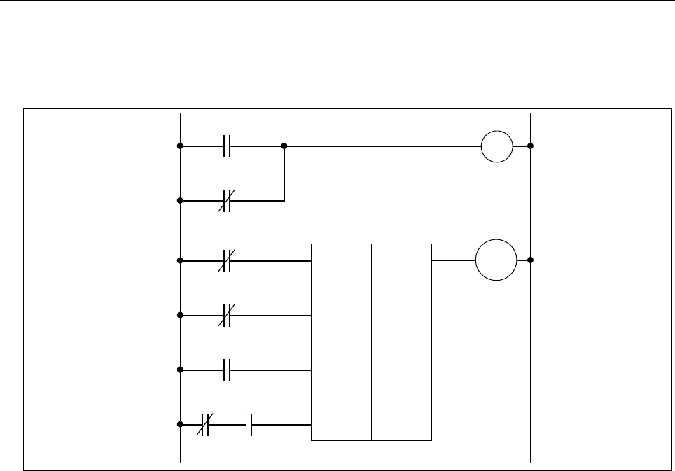
B-64513EN/03
4.LADDER LANGUAGE
- 285 -
Examples of using the counter
[Example 1]
A preset counter
The number of work pieces to be machined is counted. When the number reaches the preset count, a
signal is output.
L1
R200.1
L1
CTR
SUB 5
CRST.M
X36.0
CUP
R200.1
Y6.1
0001
Countup output
L1
R200.1
CUP
Y6.1
L1
R200.1
L1
R200.1
(UPDOWN)
(CNO)
(
RST
)
(ACT)
M30X
R200.3
Fig. 4.4.1 (b) Ladder diagram for the counter, example 1
(1) Control conditions
L1 is a circuit to make logic 1.
(a) Count start number
Since the count ranges from 0 to 9,999, contact B of L1 is used for making CNO = 0.
(b) Specify up and down
Since it is to be up counter, contact B of L1 is used make UPD = 0.
(c) Reset
The reset signal of the counter uses input signal CRST.M from the machine tool.
(d) Count signal
The count signal is M30X, which was decoded from the NC output M code. M30X contains
contact B of CUP to prevent counting past the preset value, as long as reset is not enabled after
count up.
(2) Counter number and W1
In this example, the first counter is used. The result of W1 is not used, but its address must be
determined.
(3) Operation
The number of work pieces to be machined is counted and when the number reaches 9999, CUP is
output.
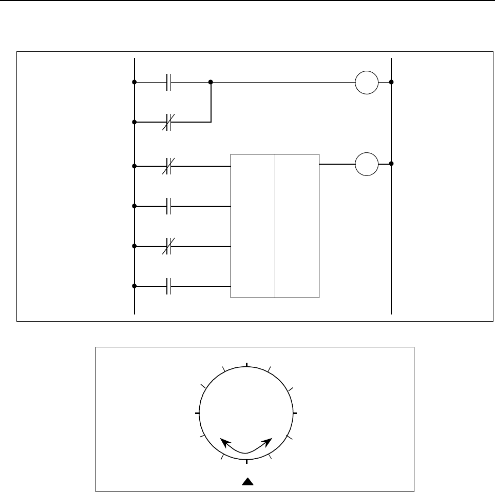
4.LADDER LANGUAGE
B-64513EN/03
- 286 -
[Example 2]
Using of the counter to store the position of a rotor.
L1
R200.1
REV
CTR
SUB 5
POS
X36.0
R200.1
0002
"1"
R200.1
R200.0
L1
R200.1
L1
R200.1
(
UPDOWN
)
(CNO)
(RST)
(
ACT
)
L1
R200.1
Fig. 4.4.1 (c) Ladder diagram for the counter, example 2
4
1
2
35
6
7
8
9
10
11
12
Fig. 4.4.1 (d) Indexing for a rotor
Fig. 4.4.1 (c) shows a ladder diagram for a counter to store the position of a rotor of Fig. 4.4.1 (d).
(1) Control conditions
(a) Count start number
When a 12-angle rotor shown in Fig. 4.4.1 (d) is used, the count starting number is 1.
Contact A of L1 is used for making CNO = 1.
(b) Specify up and down
The signal REV changes according to the then direction of rotation. It becomes 0 for forward
rotation and 1 for reverse rotation. Thus, the counter is an up counter for forward rotation and
a down counter for reverse rotation.
(c) Reset
In this example, since W1 is not used, RST = 0, and contact B of L1 is used.
(d) Count signal
The count signal POS turns on and off 12 times each time the rotor rotates once.

B-64513EN/03
4.LADDER LANGUAGE
- 287 -
(2) Counter number and W1
In this example, the second counter is used. The result of W1 is not used, but its address must be
determined.
(3) Operation
(a) Setting the preset value
Since the rotor to be controlled is 12-angle as shown in Fig. 4.4.1 (d), 12 must be preset in the
counter. It is set from the counter screen.
(b) Setting the current value
When the power is turned on, the position of the rotor must be equated with the count on the
counter. The count is set via the counter screen. Once a current value is set, then correct
current positions will be loaded to the counter every time.
(c) The POS signal turns on and off each time the rotor rotates.
The number of times of the POS signal turns on and off is counted by the counter 2, as below.
1, 2, 3, . . . 11, 12, 1, 2, . . .
For forward rotation
1, 12, 11, . . . 3, 2, 1, 12 . . .
For reverse rotation
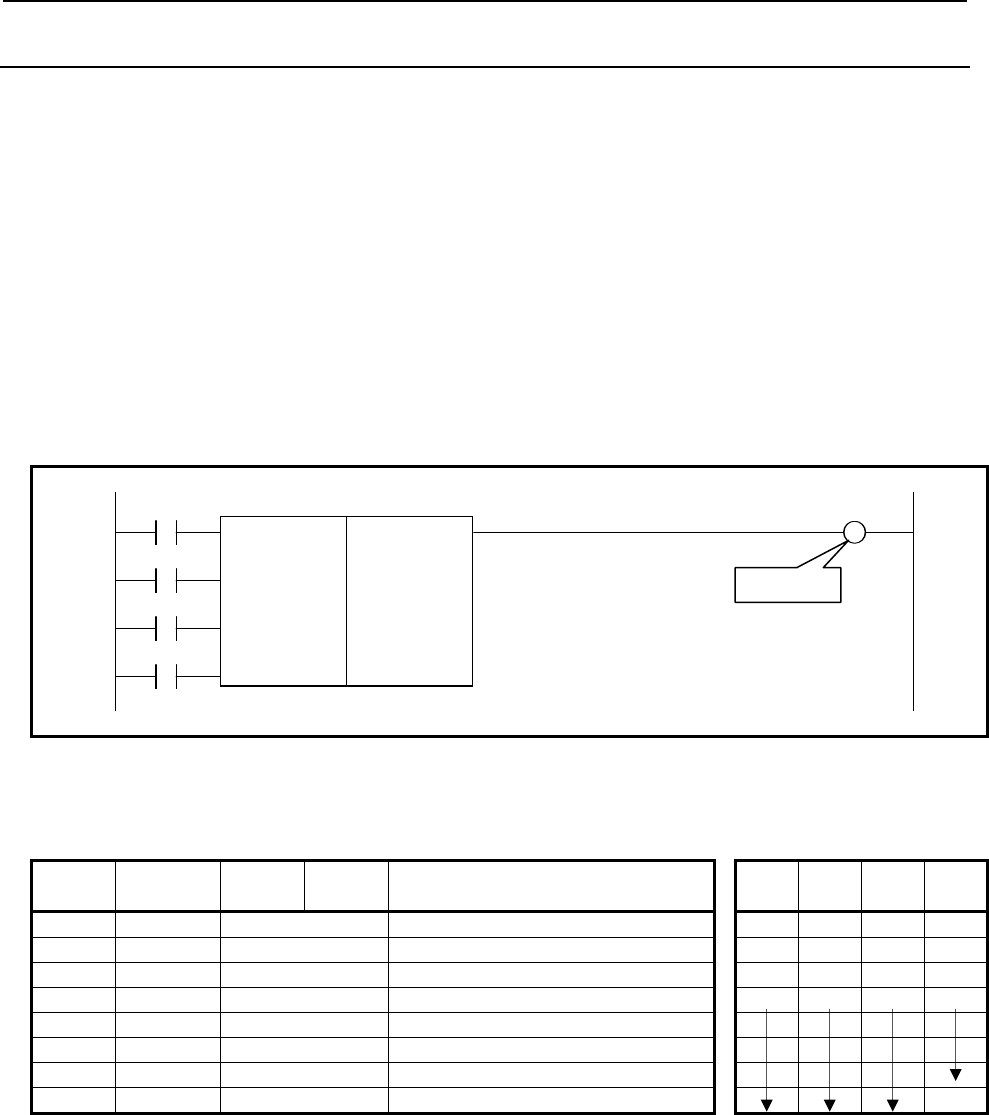
4.LADDER LANGUAGE
B-64513EN/03
- 288 -
4.4.2
CTRB (Fixed Counter: SUB 56)
CTRB is used as a counter. Numerical data such as preset values and count values can be used with
binary format. This counter has the following functions to meet various applications.
(a) Preset counter
Preset the count value. If the count reaches this preset value, outputs to show that.
(b) Ring counter
This is the ring counter which is reset to the initial value when the count signal is input after the
count reaches the preset value.
(c) Up/down counter
This is the reversible counter to be used as both up counter and down counter.
(d) Selection of initial value
Either 0 or 1 can be selected as the initial value.
Format
The followings are the ladder format the mnemonic format.
CNO W1
SUB 56
UPD CTRB
{{{ Counter number
{{{{ Preset value
RST
ACT
Fig. 4.4.2 Format of CTRB instruction
Table 4.4.2 Mnemonic of CTRB instruction
Mnemonic format Memory status of control
condition
Step
number Instruction Address
No. Bit No. Remarks ST3 ST2 ST1 ST0
1 RD {{{{ .{ CNO CNO
2 RD.STK {{{{ .{ UPD CNO UPD
3 RD.STK {{{{ .{ RST CNO UPD RST
4 RD.STK {{{{ .{ ACT CNO UPD RST ACT
5 SUB 56 CTRB instruction
6 (PRM) {{{ Counter number
7 (PRM) {{{{ Preset value
8 WRT {{{{ .{ Count up output W1
Control conditions
(a) Specifying the initial value (CNO)
CNO = 0: The counter value starts with "0". 0,1,2,3,.......,n
CNO = 1: The counter value starts with "1". 1,2,3,.........,n
(b) Specifying up or down (UPD)
UPD = 0: Up counter
The initial value is "0" when CNO = 0 or "1" when CNO = 1.
UPD = 1: Down counter
The initial value is the preset value.
Count up
B-64513EN/03
4.LADDER LANGUAGE
- 289 -
(c) Reset (RST)
RST = 0: Cancels reset.
RST = 1: Resets. W1 is reset to 0. The accumulated value is reset to the initial value.
CAUTION
Set RST to 1, only when reset is required.
(d) Count signal (ACT)
ACT = 0: The counter does not operate. W1 does not change.
ACT = 1: The counter operates at the rise of this signal.
Parameters
(a) Counter number
The numbers that can be used are shown below.
1st to 5th path PMC Dual check safety
PMC
PMC Memory-A PMC Memory-B PMC Memory-C PMC Memory-D
Counter number
1 to 20 1 to 100 1 to 200 1 to 300 1 to 20
WARNING
1 If the counter number is duplicated, or falls outside the valid range, the operation
will be unpredictable.
2 When using the ladder dividing management function, do not use the duplicated
counter number in different divided ladder programs on the same PMC path.
3 When using the Common PMC Memory mode, don't use the duplicated counter
number in multiple PMC paths.
(b) Preset value
Following value can be set as preset value.
Binary counter: 0 to 32,767
* CTRB is always binary counter. System parameter is ineffective.
Count up output (W1)
In case of the up counter mode (UPD=0), when the counter value reaches the preset value, W1 is set to 1.
In case of the down counter mode (UPD=1) and initial value 0(CNO=0), when the counter value reaches
0, W1 is set to 1.
In case of the down counter mode (UPD=1) and initial value 1(CNO=1), when the counter value reaches
1, W1 is set to 1.
The W1 address can be specified arbitrarily.
CAUTION
Two or more coils, WRT, WRT.NOT, SET or RST, that follow this instruction are
prohibited. You have to place a single coil instruction as the output of this
instruction.
Accumulate value
The address C5000s are used for accumulate value of the CTRB. Each CTRB consumes 2 bytes.
CTRB of counter number 1 uses C5000-5001 and CTRB of number 2 uses C5002-5003 for their
accumulate values.
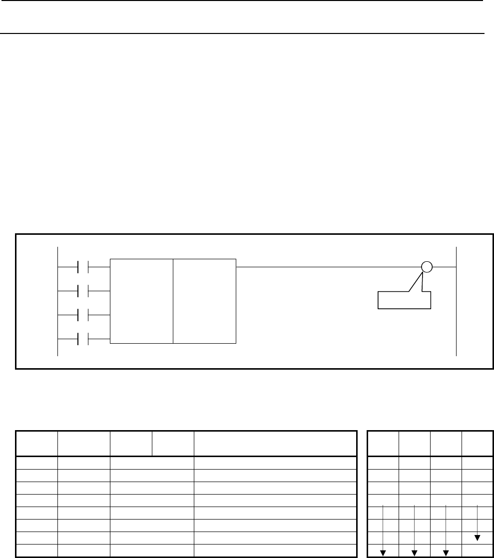
4.LADDER LANGUAGE
B-64513EN/03
- 290 -
4.4.3
CTRC (Counter: SUB 55)
The numeral data of this counter are all binary. This counter has the following functions and can be
used according to the application:
(a) Preset counter
Preset the count value and if the count reaches this preset value, outputs to show that.
(b) Ring counter
This is the ring counter which is reset to the initial value when the count signal is input after the
count reaches the preset value.
(c) Up/down counter
This is the reversible counter to be used as both the up counter and down counter.
(d) Selection of the initial value
Either 0 or 1 can be selected as the initial value.
Format
The followings are the ladder format and the mnemonic format.
CNO W1
SUB 55
UPD CTRC
{{{{ Counter preset value address
{{{{ Counter register address
RST
ACT
Fig. 4.4.3 Format of CTRC instruction
Table 4.4.3 Mnemonic of CTRC instruction
Mnemonic format Memory status of control
condition
Step
number Instruction Address
No. Bit No. Remarks ST3 ST2 ST1 ST0
1 RD {{{{ .{ CNO CNO
2 RD.STK {{{{ .{ UPD CNO UPD
3 RD.STK {{{{ .{ RST CNO UPD RST
4 RD.STK {{{{ .{ ACT CNO UPD RST ACT
5 SUB 55 CTRC instruction
6 (PRM) {{{{ Counter preset value address
7 (PRM) {{{{ Counter register address
8 WRT {{{{ .{ Count up output W1
Control conditions
(a) Specifying the initial value (CNO)
CNO = 0: The count value starts with "0". 0, 1, 2, 3, . . . n
CNO = 1: The count value starts with "1". 1, 2, 3, . . . n
(b) Specifying up or down count (UPD)
UPD = 0: Up counter. The initial value is "0" when CNO = 0 or "1" when CNO = 1.
UPD = 1: Down counter. The initial value is the preset value.
Count up
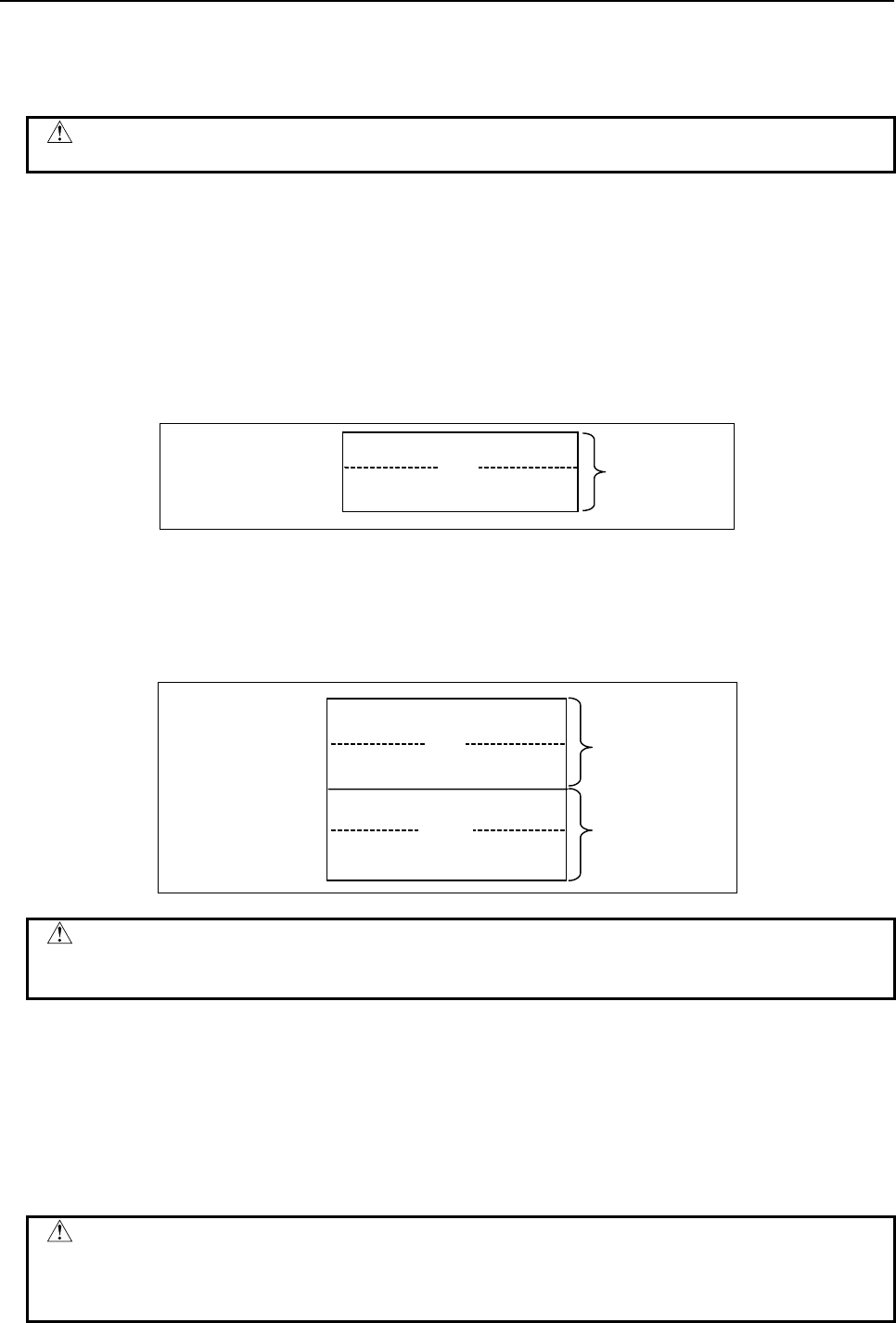
B-64513EN/03
4.LADDER LANGUAGE
- 291 -
(c) Reset (RST)
RST = 0: Reset cancelled.
RST = 1: Reset. W1 is reset to "0". The accumulated value is reset to the initial value.
CAUTION
Set RST to 1, only when reset is required.
(d) Count signal (ACT)
ACT = 0: The counter does not operate. W1 does not change.
ACT = 1: The counter operates at the rise of this signal.
Parameters
(a) Counter preset value address
The first address of the counter preset value field is set.
The continuous 2-byte memory space from the first address is required for this field. Field D is
normally used.
Counter preset value+0 CTR: Preset value
(0 to 32,767)
Counter preset value+1
CTR
The counter preset value is binary. Therefore, it ranges from 0 to 32,767.
(b) Counter register address
The first address of the counter register field is set.
The continuous 4-byte memory space from the first address is required for this field. Field D is
normally used.
CTR
WORK
Counter register +0
Counter register +1
Counter register +2
Counter register +3
Count value
WORK: Unusable
CAUTION
When R address is specified as the counter register address, the counter starts
with count value "0" at power on.
Count up output (W1)
In case of the up counter mode (UPD=0), when the counter value reaches the preset value, W1 is set to 1.
In case of the down counter mode (UPD=1) and initial value 0(CNO=0), when the counter value reaches
0, W1 is set to 1.
In case of the down counter mode (UPD=1) and initial value 1(CNO=1), when the counter value reaches
1, W1 is set to 1.
The W1 address can be specified arbitrarily.
CAUTION
Two or more coils, WRT, WRT.NOT, SET or RST, that follow this instruction are
prohibited. You have to place a single coil instruction as the output of this
instruction.
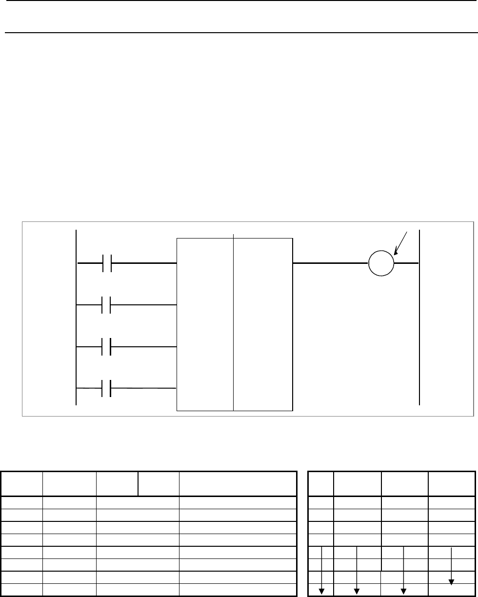
4.LADDER LANGUAGE
B-64513EN/03
- 292 -
4.4.4
CTRD (Counter (4 Bytes Length) : SUB 223)
This instruction is a counter of 4 bytes length binary data. This counter has the following functions and
can be used according to the application:
(a) Preset counter
Preset the count value and if the count reaches this preset value, outputs to show that.
(b) Ring counter
This is the ring counter which is reset to the initial value when the count signal is input after the
count reaches the preset value.
(c) Up/down counter
This is the reversible counter to be used as both the up counter and down counter.
(d) Selection of the initial value
Either 0 or 1 can be selected as the initial value.
Format
Fig. 4.4.4 shows the ladder format and Table 4.4.4 shows the mnemonic format.
CNO
UPDOWN
RST
A
CT
W1
CTRD
SUB 223
{{{{
{{{{
Counter preset value address
Counter register address
Countup
Fig. 4.4.4 Format of CTRD instruction
Table 4.4.4 Mnemonic of CTRD instruction
Mnemonic format Memory status of control condition
Step
number Instruction Address
No. Bit No. Remarks ST3 ST2 ST1 ST0
1 RD {{{{ .{ CNO CNO
2 RD. STK {{{{ .{ UPDOWN CNO UPDOWN
3 RD. STK {{{{ .{ RST CNO UPDOWN RST
4 RD. STK {{{{ .{ ACT CNO UPDOWN RST ACT
5 SUB 223 CTRD instruction
6 (PRM) {{{{ Counter preset value addres
s
7 (PRM) {{{{ Counter register address
8 WRT {{{{ .{ Count up output W1
Control conditions
(a) Specifying the initial value (CNO)
CNO = 0: The count value starts with "0". 0, 1, 2, 3, . . . n
CNO = 1: The count value starts with "1". 1, 2, 3, . . . n
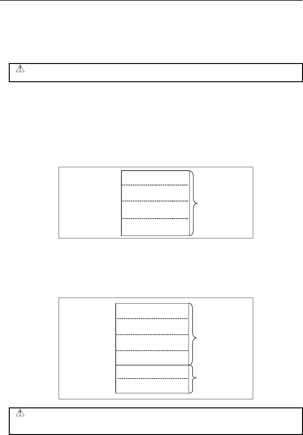
B-64513EN/03
4.LADDER LANGUAGE
- 293 -
(b) Specifying up or down count (UPDOWN)
UPDOWN = 0: Up counter. The initial value is "0" when CNO = 0 or "1" when CNO = 1.
UPDOWN = 1: Down counter. The initial value is the preset value.
(c) Reset (RST)
RST = 0: Reset cancelled.
RST = 1: Reset. W1 is reset to "0". The accumulated value is reset to the initial value.
CAUTION
Set RST to 1, only when reset is required.
(d) Count signal (ACT)
ACT = 0: The counter does not operate. W1 does not change.
ACT = 1: The counter operates at the rise of this signal.
Parameters
(a) Counter preset value address
The first address of the counter preset value field is set.
The continuous 4-byte memory space from the first address is required for this field. Address D is
normally used.
Counter
p
reset value+0
Counter Preset value
(0 to 2,147,483,647)
Counter
p
reset value+1
Counter
p
reset value+2
Counter
p
reset value+3
The counter preset value is binary. Therefore, it ranges from 0 to 2,147,483,647.
(b) Counter register address
The first address of the counter register field is set.
The continuous 6-byte memory space from the first address is required for this field. Address D is
normally used.
Counter register +0
Counter register +1
Counter register +2
Counter register +3
Count value
WORK: Unusable
Counter register +4
Counter register +5
(0 to 2,147,483,647)
CAUTION
When R address is specified as the counter register address, the counter starts
with count value "0" at power on.

4.LADDER LANGUAGE
B-64513EN/03
- 294 -
Count up output (W1)
In case of the up counter mode (UPDOWN=0), when the counter value reaches the preset value, W1 is set
to 1.
In case of the down counter mode (UPDOWN=1) and initial value 0(CNO=0), when the counter value
reaches 0, W1 is set to 1.
In case of the down counter mode (UPDOWN=1) and initial value 1(CNO=1), when the counter value
reaches 1, W1 is set to 1.
The W1 address can be specified arbitrarily.
NOTE
W1 is not omissible.
CAUTION
Two or more coils, WRT, WRT.NOT, SET or RST, that follow this instruction are
prohibited. You have to place a single coil instruction as the output of this
instruction.

B-64513EN/03
4.LADDER LANGUAGE
- 295 -
4.5 DATA TRANSFER
The following types of data transfer instruction are available. Use any of these instructions as
appropriate for your purpose.
Instruction name Sub number Processing
1 MOVB 43 Transfer of 1 byte
2 MOVW 44 Transfer of 2 bytes
3 MOVD 47 Transfer of 4 bytes
4 MOVN 45 Transfer of an arbitrary number of bytes
5 MOVE 8 Logical product transfer
6 MOVOR 28 Data transfer after logical sum
7 XMOVB 35 Binary index modifier data transfer
8 XMOV 18 Indexed data transfer
9 MOVBT 224 Bit transfer
10 SETNB 225 Data setting (1 byte length)
11 SETNW 226 Data setting (2 bytes length)
12 SETND 227 Data setting (4 bytes length)
13 XCHGB 228 Data exchange (1 byte length)
14 XCHGW 229 Data exchange (2 bytes length)
15 XCHGD 230 Data exchange (4 bytes length)
16 SWAPW 231 Data swap (2 bytes length)
17 SWAPD 232 Data swap (4 bytes length)
18 DSCHB 34 Binary data search
19 DSCH 17 Data search
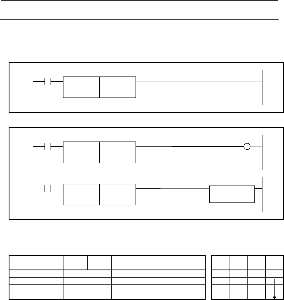
4.LADDER LANGUAGE
B-64513EN/03
- 296 -
4.5.1
MOVB (Transfer of 1 Byte: SUB 43)
The MOVB instruction transfers 1-byte data from a specified source address to a specified destination
address.
Format
The followings are the ladder format and the mnemonic format.
Normal format
ACT
SUB 43
MOVB
{{{{ Transfer source address
{{{{ Transfer destination address
Fig. 4.5.1(a) Format of MOVB instruction (Normal format)
Extended type format
ACT W1
SUB 43
MOVB
{{{{ Transfer source address
{{{{ Transfer destination address
ACT
SUB 43
MOVB
{{{{ Transfer source address
Functional Instruction
{{{{ Transfer destination address
Fig. 4.5.1(b) Format of MOVB instruction (Extended type format)
Table 4.5.1 Mnemonic of MOVB instruction (Normal format)
Mnemonic format Memory status of control
condition
Step
number Instruction Address
No. Bit No. Remarks ST3 ST2 ST1 ST0
1 RD {{{{ .{ ACT ACT
2 SUB 43 MOVB instruction
3 (PRM) {{{{ Transfer source address
4 (PRM) {{{{ Transfer destination address
Control condition
(a) Execution specification
ACT = 0: No data is transferred.
ACT = 1: One-byte data is transferred.
Parameters
(a) Transfer source address
Specify the source address for the transfer.
(b) Transfer destination address
Specify the destination address for the transfer.
Output (W1)
When the instruction is executed, W1=1 is set. W1 may be omitted.
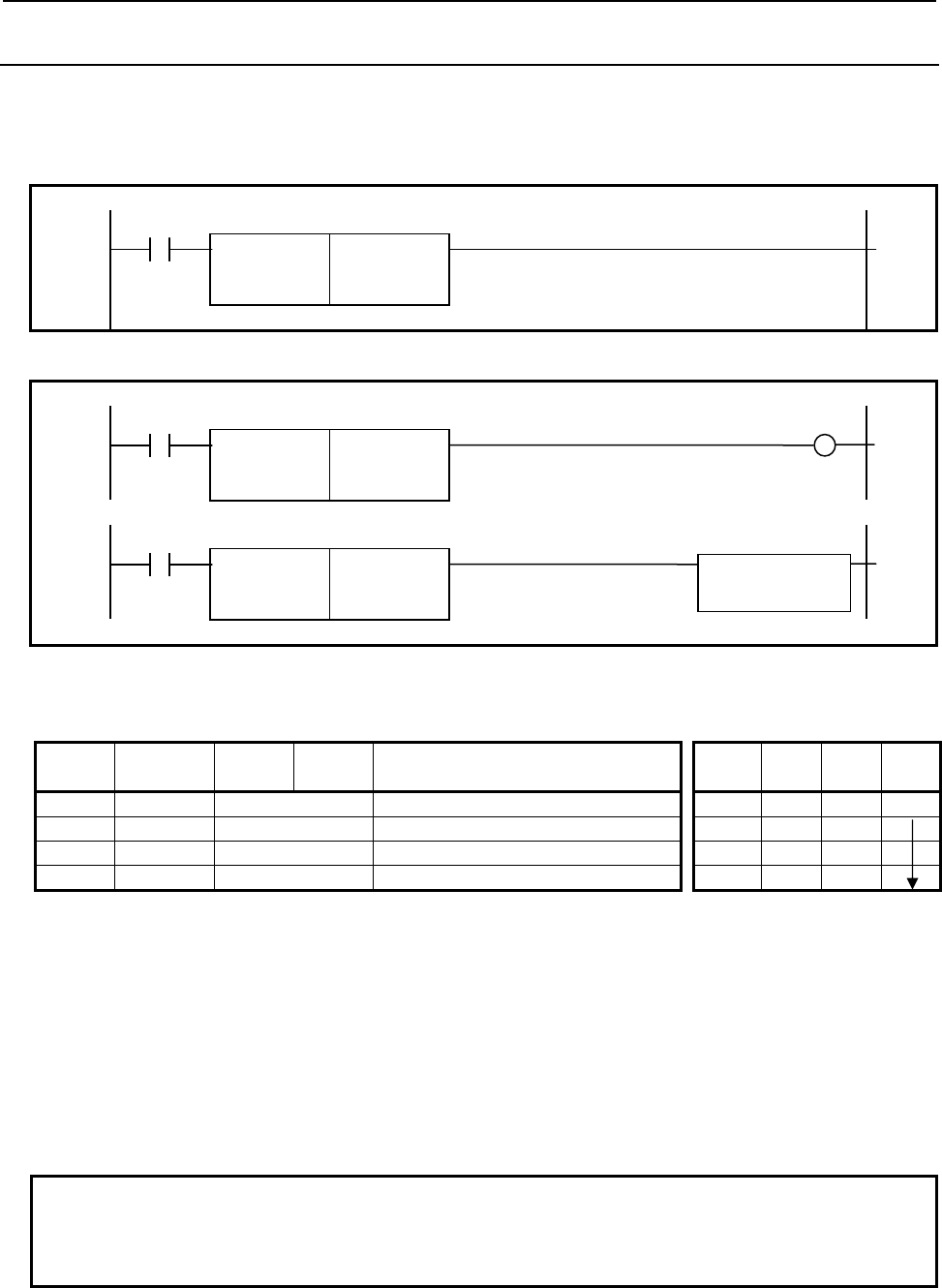
B-64513EN/03
4.LADDER LANGUAGE
- 297 -
4.5.2
MOVW (Transfer of 2 Bytes: SUB 44)
The MOVW instruction transfers 2-byte data from a specified source address to a specified destination
address.
Format
Fig. 4.5.2 shows the ladder format and Table 4.5.2 shows the mnemonic format.
Normal format
ACT
SUB 44
MOVW
{{{{ Transfer source address
{{{{ Transfer destination address
Fig. 4.5.2 (a) Format of MOVW instruction (Normal format)
Extended type format
ACT W1
SUB 44
MOVW
{{{{ Transfer source address
{{{{ Transfer destination address
ACT
SUB 44
MOVW
{{{{ Transfer source address
Functional Instruction
{{{{ Transfer destination address
Fig. 4.5.2(b) Format of MOVW instruction (Extended type format)
Table 4.5.2 Mnemonic of MOVW instruction (Normal format)
Mnemonic format
Memory status of control condition
Step
number Instruction Address
No. Bit No. Remarks ST3 ST2 ST1 ST0
1 RD {{{{ .{ ACT ACT
2 SUB 44 MOVW instruction
3 (PRM) {{{{ Transfer source address
4 (PRM) {{{{ Transfer destination address
Control condition
(a) Execution specification
ACT = 0: No data is transferred.
ACT = 1: Two-byte data is transferred.
Parameters
(a) Transfer source address
Specify the source address for the transfer.
(b) Transfer destination address
Specify the destination address for the transfer.
NOTE
Take care not to specify overlapped areas for source and destination. If the
source and destination areas are overlapped with each other, the result is not
guaranteed.
Output (W1)
When the instruction is executed, W1=1 is set. W1 may be omitted.
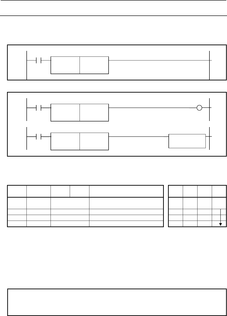
4.LADDER LANGUAGE
B-64513EN/03
- 298 -
4.5.3
MOVD (Transfer of 4 Bytes: SUB 47)
The MOVD instruction transfers 4-byte data from a specified source address to a specified destination
address.
Format
Fig. 4.5.3 shows the ladder format and Table 4.5.3 shows the mnemonic format.
Normal format
ACT
SUB 47
MOVD
{{{{ Transfer source address
{{{{ Transfer destination address
Fig. 4.5.3 (a) Format of MOVD instruction (Normal format)
Extended type format
ACT W1
SUB 47
MOVD
{{{{ Transfer source address
{{{{ Transfer destination address
ACT
SUB 47
MOVD
{{{{ Transfer source address
Functional Instruction
{{{{ Transfer destination address
Fig. 4.5.3(b) Format of MOVD instruction (Extended type format)
Table 4.5.3 Mnemonic of MOVD instruction (Normal format)
Mnemonic format
Memory status of control
condition
Step
number Instruction Address
No. Bit No. Remarks ST3 ST2 ST1 ST0
1 RD {{{
{
.{ ACT ACT
2 SUB 47 MOVD instruction
3 (PRM) {{{{ Transfer source address
4 (PRM) {{{{ Transfer destination address
Control condition
(a) Execution specification
ACT = 0: No data is transferred.
ACT = 1: Four-byte data is transferred.
Parameters
(a) Transfer source address
Specify the source address for the transfer.
(b) Transfer destination address
Specify the destination address for the transfer.
NOTE
Take care not to specify overlapped areas for source and destination. If the
source and destination areas are overlapped with each other, the result is not
guaranteed.
Output (W1)
When the instruction is executed, W1=1 is set. W1 may be omitted.
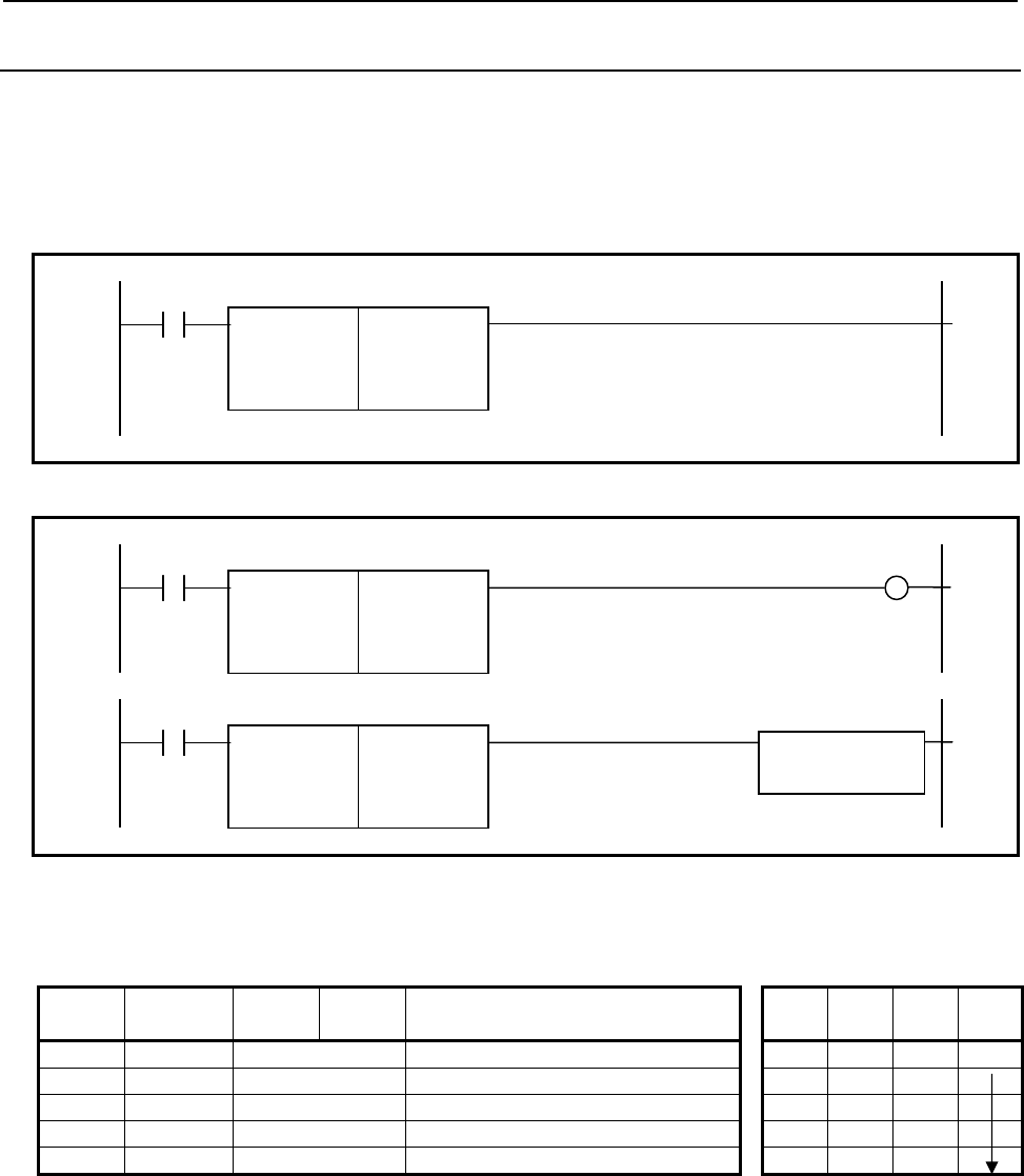
B-64513EN/03
4.LADDER LANGUAGE
- 299 -
4.5.4
MOVN (Transfer of an Arbitrary Number of Bytes: SUB 45)
The MOVN instruction transfers data consisting of an arbitrary number of bytes from a specified source
address to a specified destination address.
Format
Fig. 4.5.4 shows the ladder format and Table 4.5.4 shows the mnemonic format.
Normal format
ACT
SUB 45
MOVN
{ Number of bytes to be transferred
{{{{ Transfer source address
{{{{ Transfer destination address
Fig. 4.5.4 (a) Format of MOVN instruction (Normal format)
Extended type format
ACT W1
SUB 45
MOVN
{ Number of bytes to be transferred
{{{{ Transfer source address
{{{{ Transfer destination address
ACT
SUB 45
MOVN
{
Number of bytes to be transferred F
unctional Instruction
{{{{ Transfer source address
{{{{ Transfer destination address
Fig. 4.5.4(b) Format of MOVN instruction (Extended type format)
Table 4.5.4 Mnemonic of MOVN instruction (Normal format)
Mnemonic format Memory status of control
condition
Step
number Instruction Address
No. Bit No. Remarks ST3 ST2 ST1 ST0
1 RD {{{{ .{ ACT ACT
2 SUB 45 MOVN instruction
3 { Number of bytes to be transferred
4 (PRM) {{{{ Transfer source address
5 (PRM) {{{{ Transfer destination address
Control condition
(a) Execution specification
ACT = 0: No data is transferred.
ACT = 1: A specified number of bytes are transferred.
Parameters
(a) Number of bytes to be transferred
Specify the number of bytes to be transferred. An odd number can also be specified. A number
from 1 to 9,999 can be specified.

4.LADDER LANGUAGE
B-64513EN/03
- 300 -
CAUTION
Make sure that the source data area and destination data area are within the
PMC address range.
(b) Transfer source address
Specify the source address for the transfer.
(c) Transfer destination address
Specify the destination address for the transfer.
NOTE
Take care not to specify overlapped areas for source and destination. If the
source and destination areas are overlapped with each other, the result is not
guaranteed.
Output (W1)
When the instruction is executed, W1=1 is set. W1 may be omitted.
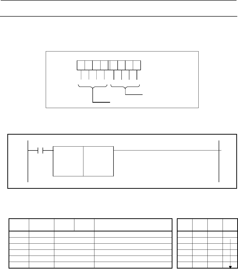
B-64513EN/03
4.LADDER LANGUAGE
- 301 -
4.5.5
MOVE (Logical Product Transfer: SUB 8)
The MOVE instruction executes logical product between a logical product data and an input data, and
outputs the results to a specified address. This instruction can be used to remove unnecessary bits from
eight-bit signals in a specific address, etc.
The input data is one byte (eight bits).
0 0 0 0 0 0
7
6
5
432
0
1
0
0
Input data
Low-orde r 4-b it d ata
{ { { { { {{ {
High-order 4-bit data
Logical p ro duct
data
Format
Fig. 4.5.5 (a) shows the ladder format and Table 4.5.5 shows the mnemonic format.
ACT
SUB 8
MOVE
{{{{ High-order 4-bit logical product data
{{{{ Low-order 4-bit logical product data
{{{{ Input data address
{{{{ Output address
Fig. 4.5.5 (a) Format of MOVE instruction
Table 4.5.5 Mnemonic of MOVE instruction
Mnemonic format Memory status of control
condition
Step
number Instruction Address
No. Bit No. Remarks ST3 ST2 ST1 ST0
1 RD {{{{ .{ ACT ACT
2 SUB 8 MOVE instruction
3 (PRM) {{{{ High-order 4-bit logical product data
4 (PRM) {{{{ Low-order 4 bit logical product data
5 (PRM) {{{{ Input data address
6 (PRM) {{{{ Output address
Execution specification
ACT = 0: MOVE instruction not executed.
ACT = 1: Executed.
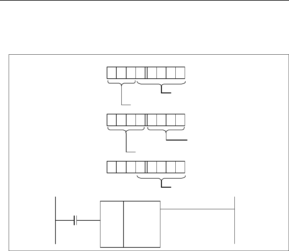
4.LADDER LANGUAGE
B-64513EN/03
- 302 -
Example of using the MOVE instruction
If a code signal and another signal co-exist at address X35 for an input signal from the machine tool, to
compare the code signal and a code signal at another address, the rest of signals in address X35 become
unnecessary. Thus, the MOVE instruction can be used to output only the code signal at address X35
address R210.
MOVE
SUB 8
A
R228.1
0001
11 11
X035
R210
7 6 5 4 3 2 1 0
A
ddres s X 35
Code signal
A
nother signal
0 001 1111
Logical product data
Low-order 4-bit logical product data
High-order 4-bit logical product data
0 0 0
A
ddress R210
Co de si
g
na l
High-order 4-bit logical product data
Low-order 4-bit logical product data
Input data address
Output addre ss
Fig. 4.5.5 (b) MOVE instruction ladder diagram
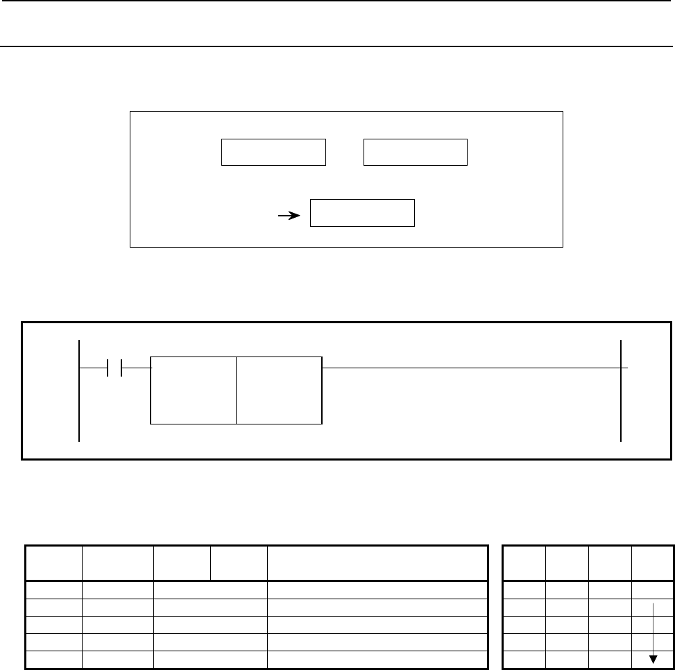
B-64513EN/03
4.LADDER LANGUAGE
- 303 -
4.5.6
MOVOR (Data Transfer After Logical Sum: SUB 28)
This instruction executes logical sum between an input data and a logical sum data and transfers the result
to the destination.
OR
Input data Logical sum data
Output data
Format
Fig. 4.5.6 shows the ladder format and Table 4.5.6 shows the mnemonic format.
ACT
SUB 28
MOVOR
{{{{ Input data address
{{{{ Logical sum data address
{{{{ Output address
Fig. 4.5.6 Format of MOVOR instruction
Table 4.5.6 Mnemonic of MOVOR instruction
Mnemonic format Memory status of control
condition
Step
number Instruction Address
No. Bit No. Remarks ST3 ST2 ST1 ST0
1 RD {{{{ .{ ACT ACT
2 SUB 28 MOVOR instruction
3 (PRM) {{{{ Input data address
4 (PRM) {{{{ Logical sum data address
5 (PRM) {{{{ Output address
Control condition
(a) Execution specification (ACT)
ACT = 0: Do not execute MOVOR.
ACT = 1: Execute MOVOR.
Parameters
(a) Input data address
Specify the address for the input data.
(b) Logical sum data address
Specifies the address of the logical sum data with which to OR the transferred data.
(c) Output address
This is the address to contain the logical sum obtained. It is also possible to obtain the logical sum
(OR) of the input and the logical sum data and output the result in the logical sum data address.
For this, you must set the logical sum data address for the output address.
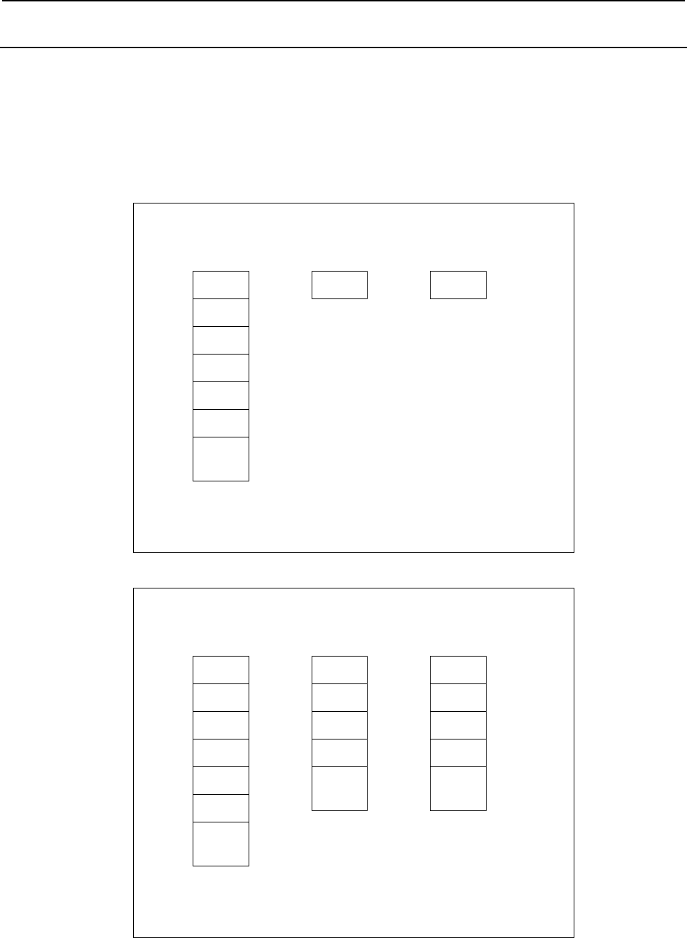
4.LADDER LANGUAGE
B-64513EN/03
- 304 -
4.5.7
XMOVB (Binary Index Modifier Data Transfer: SUB 35)
Reads or rewrites the contents of the data table. The value type in this instruction is binary.
There are two specifications - basic specification and extended specification - for setting the format
specification parameter in the XMOVB instruction. The extended specification allows two or more sets
of data to be read or written with a single instruction. For the details of the setting of a format
specification parameter, see the description of parameters.
(a) Read data from data table
DT[0] D
DT[1]
A
DT[2]
DT[3] B
DT[4]
DT[5] C
The number of data table elements: M (It specifies the storage address of numbe
r
of data table elements)
I3
Index: I
SB
In
p
ut/out
p
ut data: S
The operation of the instruction:
DT[I]
→ S
DT[M−1]
Data table: DT
Fig. 4.5.7 (a) Read data from data table (basic specification)
DT[0] D
DT[1]
A
DT[2]
DT[3] B
DT[4]
DT[5] C
DT[M−1]
Data table: DT
The number of data table elements: M (It specifies the storage address of numbe
r
of data table elements)
The number of index array elements: N (It specifies the format specification)
I[0] 1
Index
array: I
S[0] A
Input/output
data array: S
The operation of the instruction:
DT[I[n]]
→ S[n] (n = 0, 1, 2, ..., N−1)
I[1] 3
I[2] 5
I[3] 0
I[N−1]
S[1] B
S[2] C
S[3] D
S[N−1]
Fig. 4.5.7 (b) Read data from data table (extended specification)
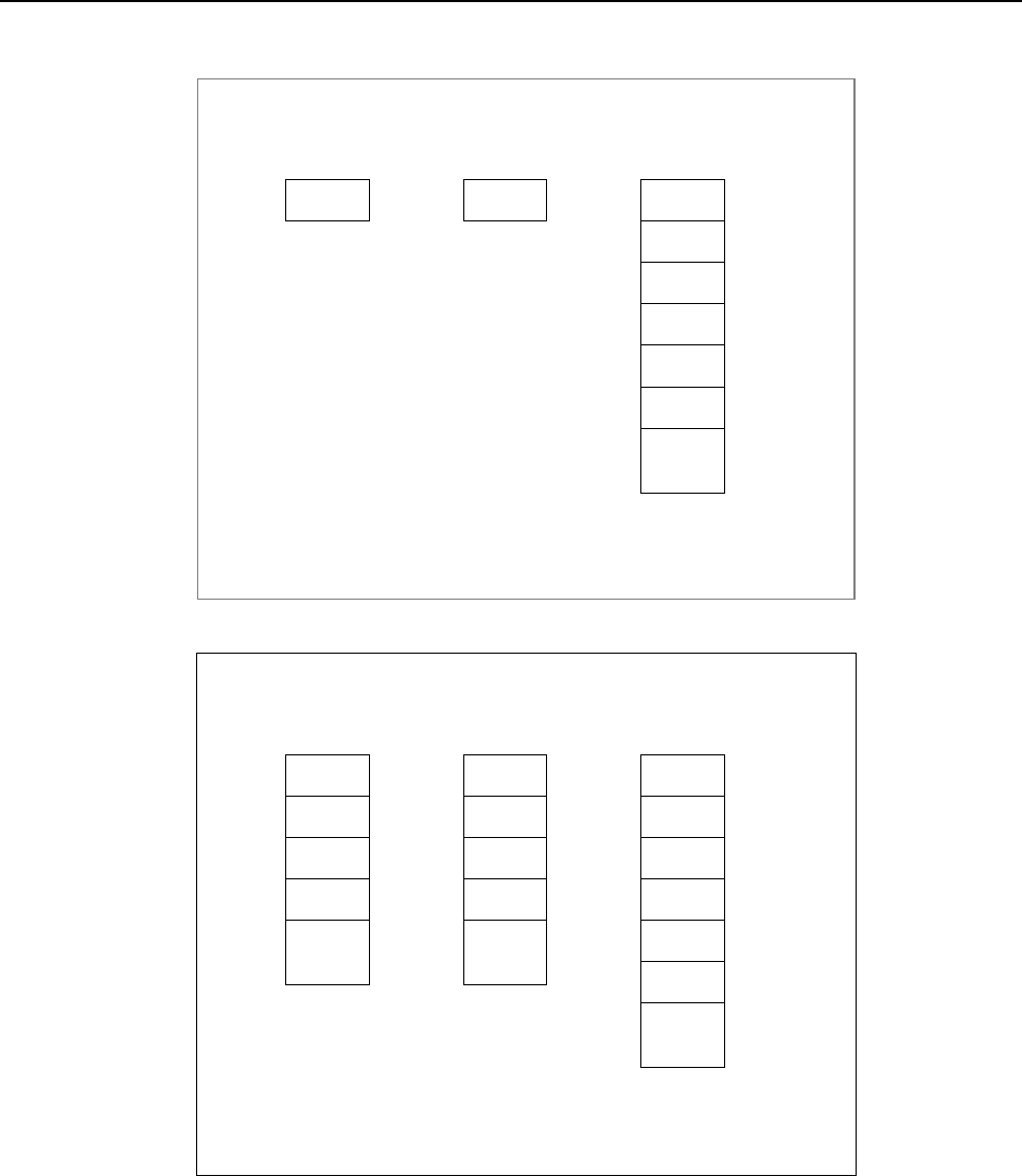
B-64513EN/03
4.LADDER LANGUAGE
- 305 -
(b) Write data to data table
S B
Input/output data: S
DT[0]
DT[1]
DT[2]
DT[3] B
DT[4]
DT[5]
DT[M−1]
Data table: DT
The number of data table elements: M (It specifies the storage address of numbe
r
of data table elements)
I3
Index: I
The operation of the instruction:
S→ DT
[
I
]
Fig. 4.5.7 (c) Write data to data table (basic specification)
DT[0] D
DT[1]
A
DT[2]
DT[3] B
DT[4]
DT[5] C
DT[M−1]
Data table: DT
S A
Input/output
data array: S
S[1] B
S[2] C
S[3] D
S[N−1]
The number of data table elements: M (It specifies the storage address of numbe
r
of data table elements)
The number of index array elements: N (It specifies the format specification)
I[0] 1
Index
array: I
The operation of the instruction:
S[n] → DT[I[n]] (n = 0, 1, 2, ...,
I[1] 3
I[2] 5
I[3] 0
I[N−1]
Fig. 4.5.7 (d) Write data to data table (extended specification)
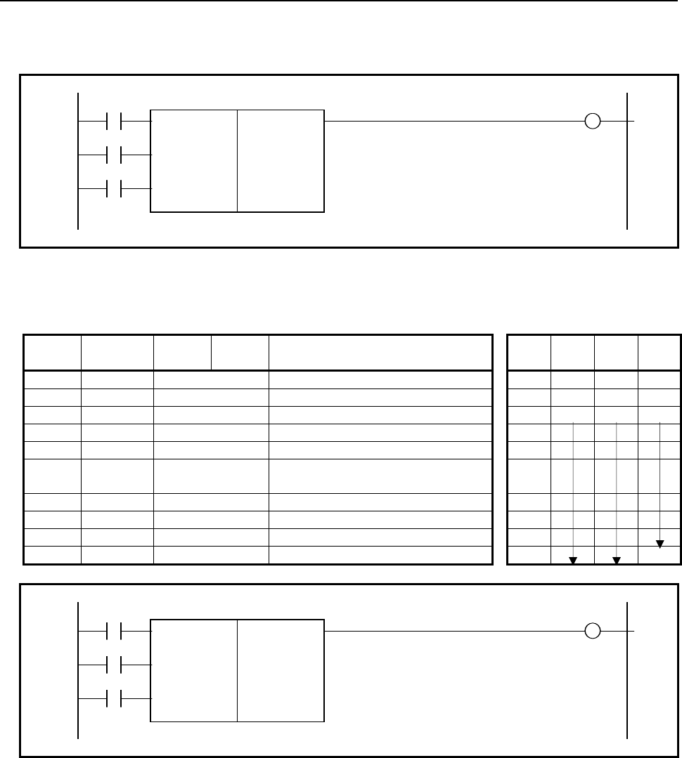
4.LADDER LANGUAGE
B-64513EN/03
- 306 -
Format
Figs. 4.5.7 (e) and (f) show the ladder format and Tables 4.5.7 (a) and (b) show the mnemonic format.
RW W1
SUB 35
RST XMOVB
{ Format specification
{{{{ Storage address of number of data table elements
ACT {{{{ Data table head address DT[ ]
{{{{ I/O data storage address S
{{{{ Index storage address I
Fig. 4.5.7 (e) Format of XMOVB instruction (basic specification)
Table 4.5.7 (a) Mnemonic of MOVOR instruction (basic specification)
Mnemonic format Memory status of control
condition
Step
number Instruction Address
No. Bit No. Remarks ST3 ST2 ST1 ST0
1 RD {{{{ .{ RW RW
2 RD.STK {{{{ .{ RST RW RST
3 RD.STK {{{{ .{ ACT RW RST ACT
4 SUB 35 XMOVB instruction
5 (PRM) { Format specification
6 (PRM) {{{{ Storage address of number of data
table elements
7 (PRM) {{{{ Data table head address
8 (PRM) {{{{ I/O data storage address
9 (PRM) {{{{ Index storage address
10 WRT {{{{ .{ Error output W1
RW W1
SUB 35
RST XMOVB
{{{{ Format specification
{{{{ Storage address of number of data table elements
ACT {{{{ Data table head address DT[ ]
{{{{ I/O data storage address S[ ]
{{{{ Index storage address I[ ]
Fig. 4.5.7 (f) Format of XMOVB instruction (extended specification)
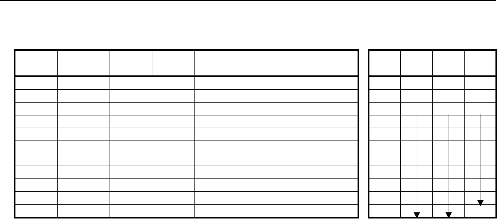
B-64513EN/03
4.LADDER LANGUAGE
- 307 -
Table 4.5.7 (b) Mnemonic of MOVOR instruction (extended specification)
Mnemonic format Memory status of control
condition
Step
number Instruction Address
No. Bit No. Remarks ST3 ST2 ST1 ST0
1 RD {{{{ .{ RW RW
2 RD.STK {{{{ .{ RST RW RST
3 RD.STK {{{{ .{ ACT RW RST ACT
4 SUB 35 XMOVB instruction
5 (PRM) {{{{ Format specification
6 (PRM) {{{{ Storage address of number of data
table elements
7 (PRM) {{{{ Data table head address
8 (PRM) {{{{ I/O data storage address
9 (PRM) {{{{ Index storage address
10 WRT {{{{ .{ Error output W1
Control conditions
(a) Read, write designation (RW)
RW = 0: Read data from data table.
RW = 1: Write data to data table.
(b) Reset (RST)
RST = 0: Reset release.
RST = 1: Reset. W1 = 0.
(c) Execution specification (ACT)
ACT = 0: Do not execute XMOVB instruction. There is no change in W1.
ACT = 1: Execute XMOVB instruction.
Parameters
(a) Format specification
Specify the data length in the first digit of the parameter.
0001: 1-byte length data
0002: 2-byte length data
0004: 4-byte length data
When setting format specification in the following extended format, XMOVB can read/write
multiple data in data table in 1 instruction.
Specify the data length (1, 2, or 4) to the 1st digit as above-mentioned. Specifies the number of the
index array elements to the 2nd and 3rd digit. Specifies 0 to the 4th digit.
0nn1: In case of reading/writing multiple (nn) data in data table by 1 byte length
0nn2: In case of reading/writing multiple (nn) data in data table by 2 bytes length
0nn4: In case of reading/writing multiple (nn) data in data table by 4 bytes length
The nn is the numerical value from 02 to 99. When setting 00 or 01, it works as the basic
specification in which one data transfer is performed by one instruction.
4.LADDER LANGUAGE
B-64513EN/03
- 308 -
Format specification (extended specification):
0 n n x
The byte length setting
1: 1 byte length
2: 2 byte length
4: 4 byte length
The number of the index array elements
00-01:
It works as the basic specification.
02-99:
Read/Write multiple (nn) data from/to data table.
CAUTION
Do not set an illegal value, that is not indicated above, into the "(a) Format
specification".
(b) Storage address of number of data table elements
Set to the memory at the byte length which set the number of the data table elements in "(a) Format
specification" and set the address to this parameter. The value which you can set depends on the
"(a) Format specification" setting.
1 byte length: 1 to 255
2 bytes length: 1 to 16384
4 bytes length: 1 to 16384
(c) Data table head address
Sets head address in the data table.
The memory of (byte length) × (number of data table elements) which was set in "(a) Format
specification" and "(b) Storage address of number of data table elements" is necessary.
(d) Input/Output data storage address
In case of the reading, set the address of the memory which stores a reading result. In case of the
writing, set the address of the memory which stores a writing result. The memory with the byte
length which set in "(a) Format specification" is necessary.
When setting format specification in the extended format, set the head address of the array. (In
case of the reading, set the head address of the array in which a reading result is stored. In case of
the writing, set the head address of the array in which a writing result is stored.) The memory of
(byte length) × (number of index array elements) which was set in "(a) Format specification" is
necessary.
(e) Index storage address
Set the address of the memory in which an index value is stored. The memory with the byte length
set in "(a) Format specification" is necessary. The effective range of number of data in index is as
follows according to the byte length set in "(a) Format specification".
Actually, set the value which is smaller than the value to set in "(b) Storage address of number of
data table elements" to the index.
When setting an index value above the value to set in "(b) Storage address of number of data table
elements", it causes an error output W1 = 1 in instruction execution.
1 byte length: 0 to 254
2 bytes length: 0 to 32,766
4 bytes length: 0 to 2,147,483,646
When setting format specification in the extended format, set an address at the head of the array in
which an index value is stored. The memory of (byte length) × (number of data in index array)
which was set in "(a) Format specification" is necessary.

B-64513EN/03
4.LADDER LANGUAGE
- 309 -
WARNING
1 You can not specify the table that includes different kind of address type or
discontinuous address area. In this case, operation is not guaranteed.
2 You have to set the "Storage address of number of data table elements" and the
"Data table head address" not to exceed the limit of its continuous address area.
If the table exceeds the limit of the continuous address area, operation is not
guaranteed. For example, when a range of address R is 0 to 7999 and the
"Format specification" is set to 1 and the "Data table head address" is set to
"R7990", you can set 10 or less to the "Storage address of number of data table
elements".
Error output (W1)
W1 = 0: No error
W1 = 1: Error found.
In the case where the index value set in "(e) Index storage address" exceeds the value set in "(b)
Storage address of number of data table elements", it becomes W1 = 1. The reading or writing of
the data table isn't executed.
When "(a) Format specification" is used for operation in the extended format, if the values of one or
more elements in the index array specified in (e) are greater than the value set in "(b) Storage
address of number of data table elements", it becomes W1 = 1. The reading or writing of a data
table is executed for the normal index values but not executed as for the wrong index values.
CAUTION
Two or more coils, WRT, WRT.NOT, SET or RST, that follow this instruction are
prohibited. You have to place a single coil instruction as the output of this
instruction.
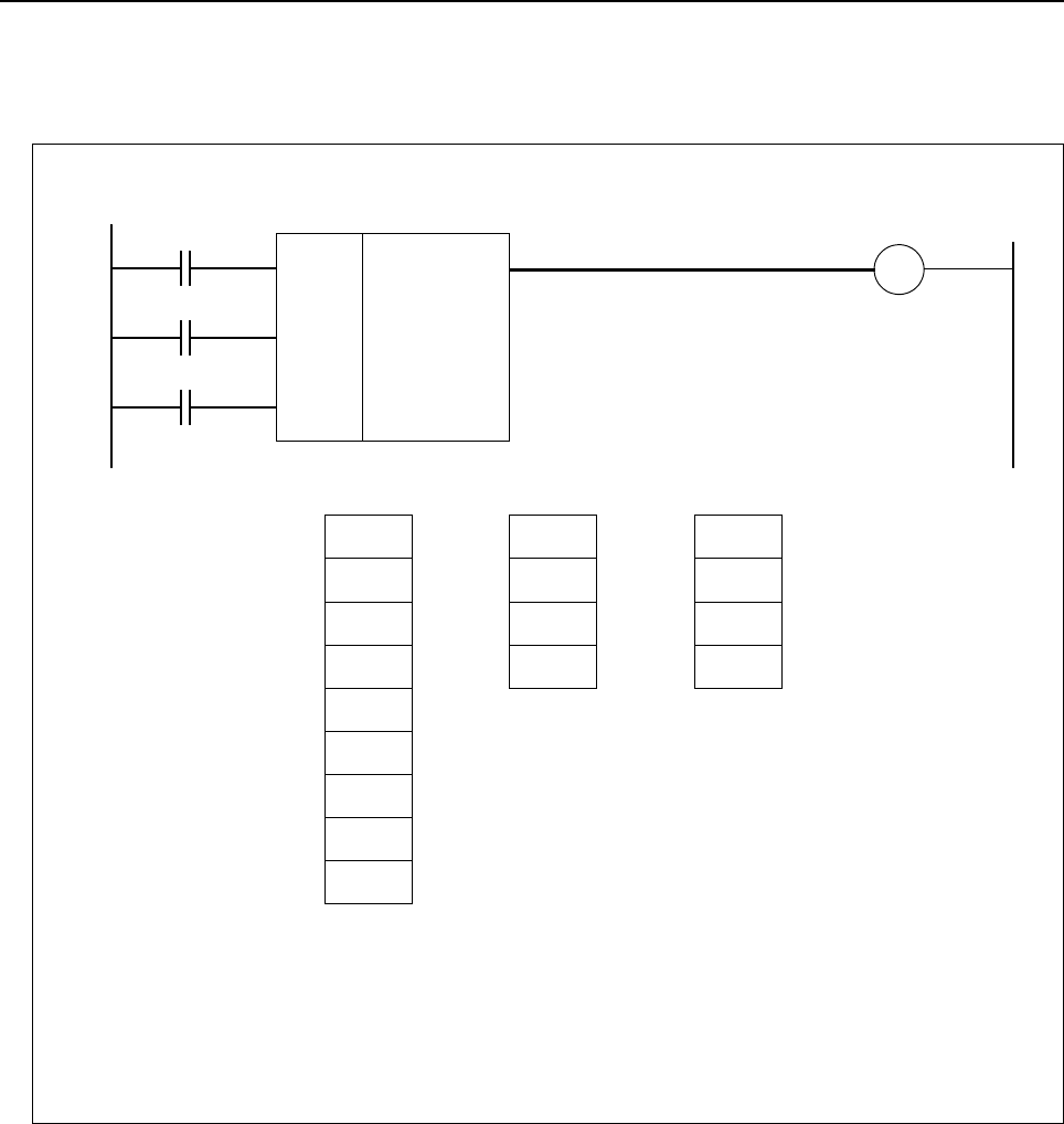
4.LADDER LANGUAGE
B-64513EN/03
- 310 -
Example for extended specification
(a) Read data from data table (extended specification)
XMOVB
RST = 0
A
CT = 1
W1
RW = 0
The number of data table elements: R0 = 9
The number of index array elements: 4
The operation of the instruction:
(1) R102
→ R200
(2) R105
→ R201
(3) R108
→ R202
(4) R100
→ R203
R100 D
R101
R102 A
R103
R104
R105 B
Data table
D0 2
Index array
R200 A
Input/output
data array
D1 5
D2 8
D3 0
R201 B
R202 C
R203 D
R106
R107
R108 C
0041
R0
R100
R200
D0
SUB 35
Fig. 4.5.7 (g) Example for XMOVB instruction (extended specification)
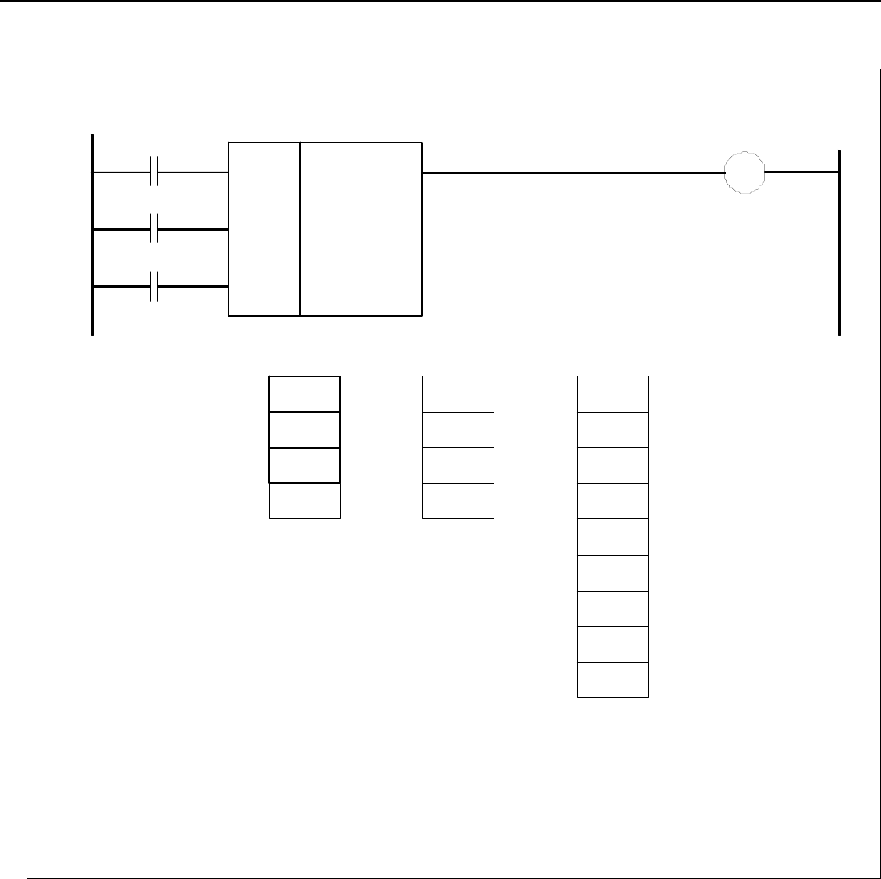
B-64513EN/03
4.LADDER LANGUAGE
- 311 -
(b) Write data to data table (extended specification)
RST = 0
A
CT = 1
W1 RW = 1
The number of data table elements: R0 = 9
The number of index array elements: 4
The op eratio n o f t he instructio n:
(1) R100 → R2 02
(2) R101 → R2 05
(3) R102 → R2 08
(4) R103 → R2 00
R200 D
R201
R202
A
R203
R204
R205 B
Data table
D0 2
I nde x array
R100 A
I npu t/o utp ut
dat a a rray
D1 5
D2 8
D3 0
R101 B
R102 C
R103 D
R206
R207
R208 C
XMOVB 0041
R0
R200
R100
D0
SUB 35
Fig. 4.5.7 (h) Example for XMOVB instruction (extended specification)
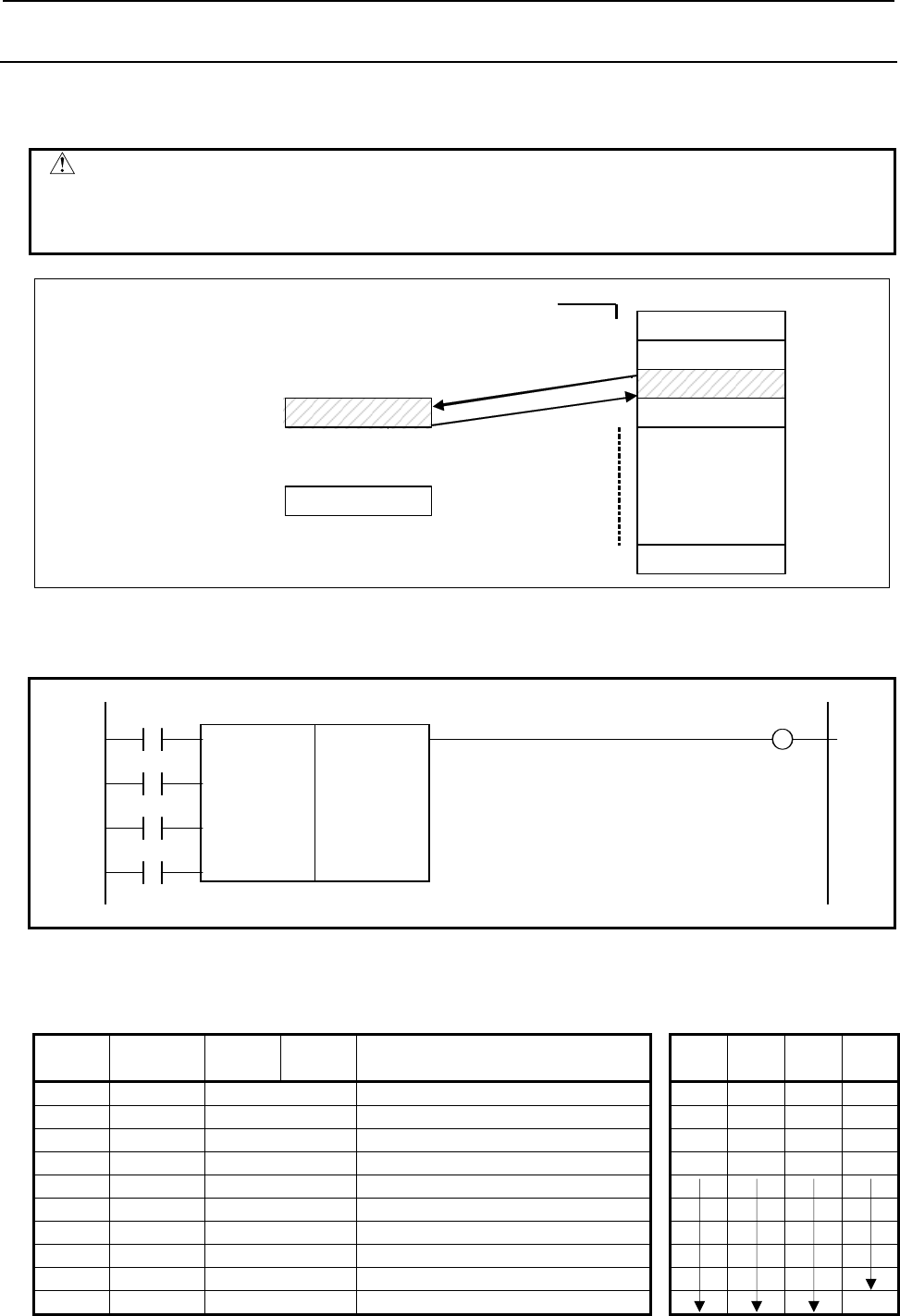
4.LADDER LANGUAGE
B-64513EN/03
- 312 -
4.5.8
XMOV (Indexed Data Transfer: SUB 18)
This instruction reads or rewrites the contents of the data table. The value type in this instruction is BCD
type.
CAUTION
The data table heading address specified here is table internal number 0. The
table internal number specified here, however, is different from that mentioned in
Subsection 2.2.12.
0
1
3
n
Table internal number Data table
Input or output data
2
2
T
able internal storing
i
nput or output data
<1> Read out data from the data table.
<2> Write data in the data table.
<1>
<2>
Fig. 4.5.8 (a) Reading and writing of data
Format
Fig. 4.5.8 (b) shows the ladder format and Table 4.5.8 shows the mnemonic format.
BYT W1
SUB 18
RW XMOV
{{{{ Number of data of the data table (Table capacity)
{{{{ Data table heading address
RST {{{{ Address storing input/output data
{{{{ Address storing table internal number
ACT
Fig. 4.5.8 (b) Format of XMOV instruction
Table 4.5.8 Mnemonic of XMOV instruction
Mnemonic format Memory status of control
condition
Step
number Instruction Address
No. Bit No. Remarks ST3 ST2 ST1 ST0
1 RD {{{{ .{ BYT BYT
2 RD.STK {{{{ .{ RW BYT RW
3 RD.STK {{{{ .{ RST BYT RW RST
4 RD.STK {{{{ .{ ACT BYT RW RST ACT
5 SUB 18 XMOV instruction
6 (PRM) {{{{ Number of data of the data table
7 (PRM) {{{{ Data table heading address
8 (PRM) {{{{ Address storing input/output data
9 (PRM) {{{{ Address storing table internal number
10 WRT {{{{ .{ Error output W1

B-64513EN/03
4.LADDER LANGUAGE
- 313 -
Control conditions
(a) Specify the number of digits of data. (BYT)
BYT = 0: Data stored in the data table, BCD in two digits long.
BYT = 1: Data stored in the data table, BCD in four digits long.
(b) Specify read or write (RW)
RW = 0: Data is read from the data table.
RW = 1: Data is written in the data table.
(c) Reset (RST)
RST = 0: Release reset.
RST = 1: Enables reset, that is, sets W1 to 0.
(d) Execution specification (ACT)
ACT = 0: The XMOV instruction is not executed. W1 does not change.
ACT = 1: The XMOV instruction is executed.
Parameters
(a) Number of data of the data table
Specifies the size of the data table. If the beginning of the data table is 0 and the end is n, n + 1 is set
as the number of data of the data table. The value, which you can set, depends on the control
condition "BYT".
BYT=0: 1 to 99
BYT=1: 1 to 9999
(b) Data table heading address
The address that can be used in a data table is fixed. When preparing a data table, the addresses to be
used must be determined beforehand, and the head address placed in that data table.
(c) Address storing input/output data
The input/output data storage address is the address storing the specified data, and is external to the
data table. The contents of the data table is read or rewritten.
(d) Address storing table internal number
The table internal number storage address is the address storing the table internal number of the data
to be read or rewritten.
This address requires memory specified by the number-of-digits designation (BYT).
WARNING
1 You can not specify the table that includes different kind of address type or
discontinuous address area. In this case, operation is not guaranteed.
2 You have to set the "Number of data of the data table" and the "Data table
heading address" not to exceed the limit of its continuous address area. If the
table exceeds the limit of the continuous address area, operation is not
guaranteed. For example, when a range of address R is 0 to 7999 and the control
condition "BYT" is set to 0 and the "Data table heading address" is set to
"R7990", you can set 10 or less to the "Number of data of the data table".
Error output
W1 = 0: There is no error.
W1 = 1: There is an error.
An error occurs if a table internal number exceeding the previously programmed number of the data
table is specified.
CAUTION
Two or more coils, WRT, WRT.NOT, SET or RST, that follow this instruction are
prohibited. You have to place a single coil instruction as the output of this
instruction.
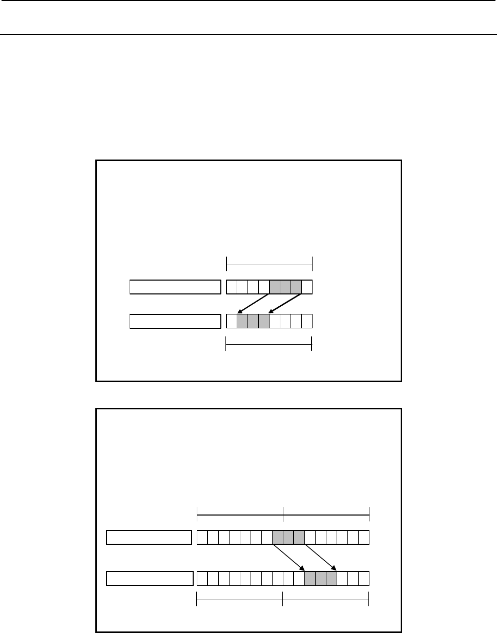
4.LADDER LANGUAGE
B-64513EN/03
- 314 -
4.5.9
MOVBT (Bit Transfer: SUB 224)
The Bit transfer instruction transfers multiple successive bits at a specified position to a destination
address.
Transfer source data is specified in "Transfer source address" and "Transfer source bit position". Transfer
destination data is specified in "Transfer destination address" and "Transfer destination bit position".
From "Transfer source bit position", data consisting of successive bits as many as "Number of bits to be
transferred" is transferred to "Transfer destination address".
When 3 bits are transferred from R100.1 to R500.4:
Number of bits to be transferred = 3
Transfer source address = R100
Transfer source bit position = 1
Transfer destination address = R500
Transfer destination bit position = 4
70
R100
Transfer source
612345
R500
Transfer destination
70612345
Positions other than R500.4-6 remain unchanged.
Fig. 4.5.9 (a) Example of MOVBT instruction (1)
When 3 bits are transferred from R100.6 to R500.3:
Number of bits to be transferred = 3
Transfer source address = R100
Transfer source bit position = 6
Transfer destination address = R500
Transfer destination bit position = 3
Positions other than R500.3-5 remain unchanged.
70
R101
Transfer source
612345 70
R100
612345
Transfer destination
R501 R500
706123457 0612345
Fig. 4.5.9 (b) Example of MOVBT instruction (2)
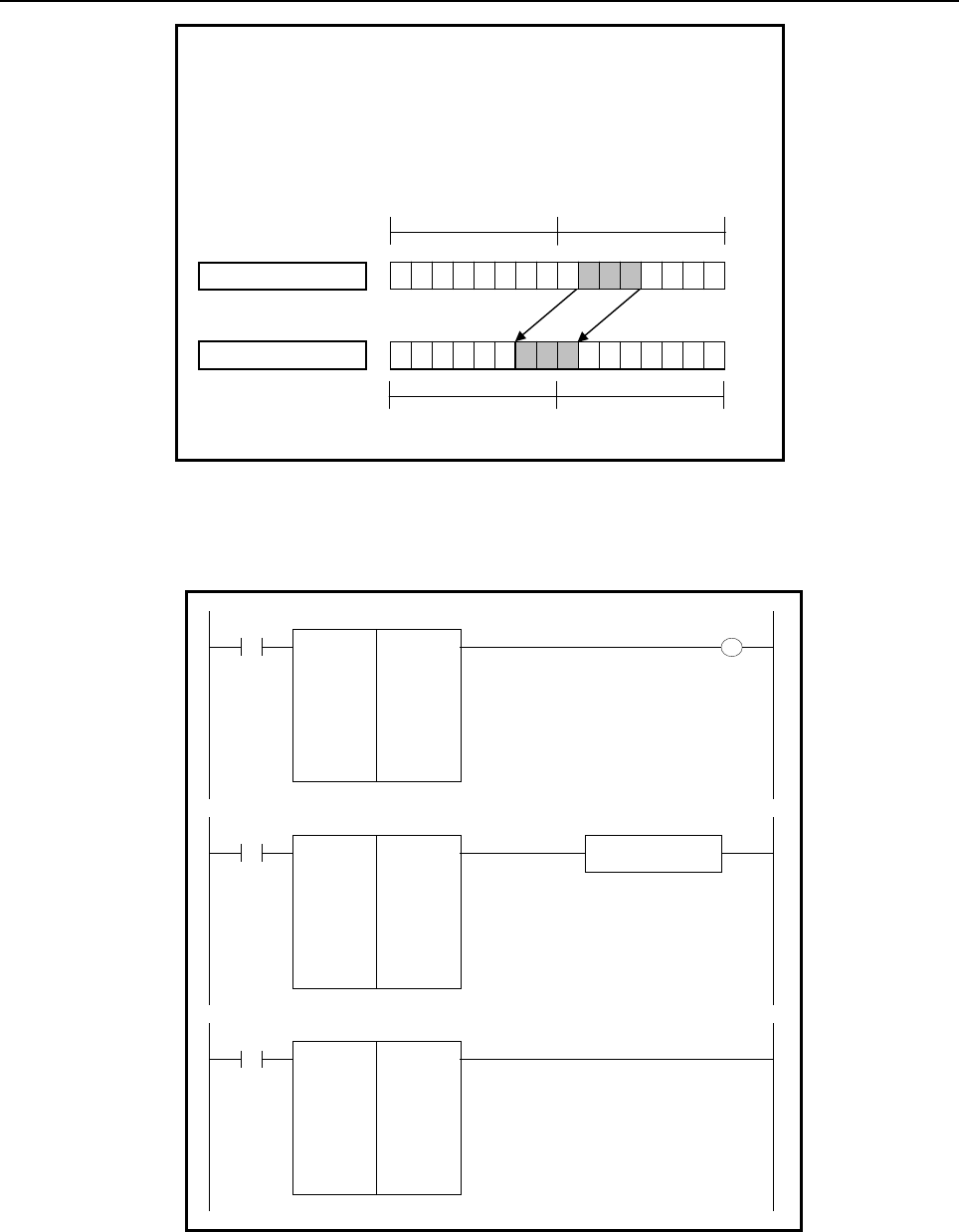
B-64513EN/03
4.LADDER LANGUAGE
- 315 -
When 3 bits are transferred from R100.4 to R500.7:
Number of bits to be transferred = 3
Transfer source address = R100
Transfer source bit position = 4
Transfer destination address = R500
Transfer destination bit position = 7
Positions other than R500.7, R501.0, and R501.1 remain unchanged.
70
R101
Transfer source
612345 70
R100
612345
Transfer destination
R501 R500
706123457 0612345
Fig. 4.5.9 (c) Example of MOVBT instruction (3)
Format
Fig. 4.5.9(d) shows the ladder format and Table 4.5.9 shows the mnemonic format.
SUB 224
MOVBT
{{{{
{{{{
{{{{
{{{{
{{{{
Number of bits to be transferred (Constant)
Transfer source address
Transfer source bit position (Constant)
Transfer destination address
Transfer destination bit position (Constant)
ACT W1
SUB 224
MOVBT
{{{{
{{{{
{{{{
{{{{
{{{{
ACT
SUB 224
MOVBT
{{{{
{{{{
{{{{
{{{{
{{{{
ACT ACT2
Functional Instruction
Fig. 4.5.9 (d) Format of MOVBT instruction
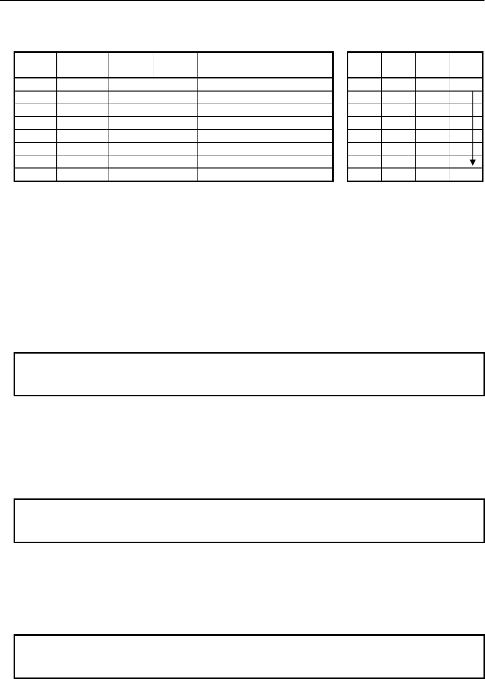
4.LADDER LANGUAGE
B-64513EN/03
- 316 -
Table 4.5.9 Mnemonic of MOVBT instruction
Mnemonic format
Memory status of control
condition
Step
number Instruction Address
No. Bit No. Remarks
ST3 ST2 ST1 ST0
1 RD {{{{ .{ ACT ACT
2 SUB 224 MOVBT instruction
3 (PRM) {{{{ Number of bits to be transferred
4 (PRM) {{{{ Transfer source address
5 (PRM) {{{{ Transfer source bit position
6 (PRM) {{{{ Transfer destination address
7 (PRM) {{{{ Transfer destination bit position
8 WRT {{{{ .{ Normal end output W1
Control condition
(a) Execution specification
ACT = 0: Instruction not executed.
ACT = 1: Executed.
Parameters
(a) Number of bits to be transferred
Specify the number of bits to be transferred. A number from 1 to 256 may be specified.
(b) Transfer source address
Specify the source address for the transfer.
NOTE
Bits are transferred even when "Transfer source address" and "Transfer
destination address" overlap each other.
(c) Transfer source bit position
Specify the transfer start bit position of transfer source data. A number from 0 to 7 may be
specified.
(d) Transfer destination address
Specify the destination address for the transfer.
NOTE
Bits are transferred even when "Transfer source address" and "Transfer
destination address" overlap each other.
(e) Transfer destination bit position
Specify the top bit position of transfer destination data. A number from 0 to 7 may be specified.
Output (W1)
When the instruction is executed, W1=1 is set. That is, W1 always assumes the same state as ACT.
NOTE
W1 may be omitted. Moreover, another functional instruction can be connected
instead of a coil.
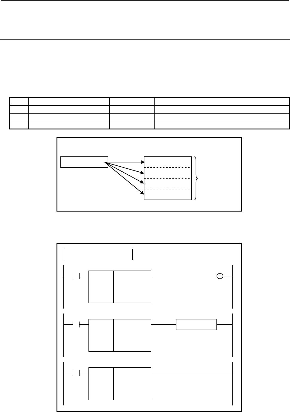
B-64513EN/03
4.LADDER LANGUAGE
- 317 -
4.5.10
SETNB (Data Setting (1 Byte Length) : SUB 225)
SETNW (Data Setting (2 Bytes Length) : SUB 226)
SETND (Data Setting (4 Bytes Length) : SUB 227)
The data setting instruction sets the same value in multiple data items at contiguous addresses.
In "Setting data", a constant or a PMC memory address for storing data can be specified.
As indicated below, three types of data setting instructions are available according to the type of data to
be set. In each instruction, "Setting data" and the data at "Setting destination address" are of the same
data type.
Table4.5.10 (a) Kinds of data setting instruction
Instruction name SUB No. Data type
1 SETNB 225 1 byte length data
2 SETNW 226 2 bytes length data
3 SETND 227 4 bytes length data
Setting destination address Setting data (address or constant)
Number of
setting data
A A
A
A
A
Fig. 4.5.10 (a) Example of data setting instruction
Format
Fig. 4.5.10(b) shows the ladder format and Table 4.5.10(b) shows the mnemonic format.
SUB 225
SETNB
{{{{
{{{{
{{{{
Number of setting data (Constant)
Setting data (Address or Constant)
Setting destination address
ACT W1
SUB 225
SETNB
{{{{
{{{{
{{{{
ACT
SUB 225
SETNB
{{{{
{{{{
{{{{
ACT ACT2
Functional Instruction
Example : SETNB Instruction
Fig. 4.5.10 (b) Format of SETNB, SETNW, SETND instruction
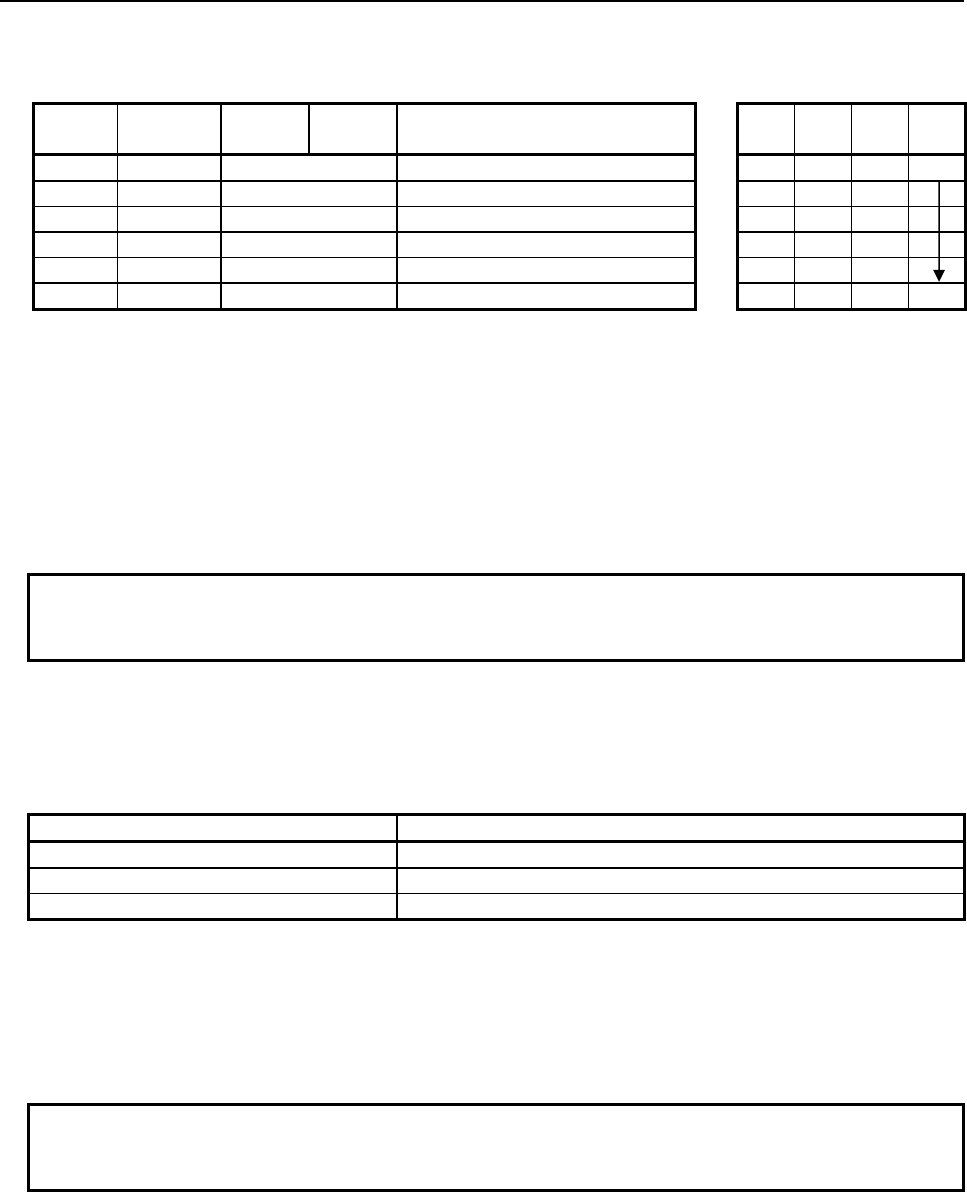
4.LADDER LANGUAGE
B-64513EN/03
- 318 -
Table 4.5.10 (b) Mnemonic of SETNB, SETNW, SETND instruction
Mnemonic format
Memory status of control
condition
Step
number Instruction Address
No. Bit No. Remarks
ST3 ST2 ST1 ST0
1 RD
{{{{
.
{
ACT ACT
2 SUB 225 SUB No. (SETNB instruction)
3 (PRM)
{{{{
Number of setting data (Constant)
4 (PRM)
{{{{
Setting data (Address or Constant)
5 (PRM)
{{{{
Setting destination address
6 WRT
{{{{
.
{
Normal end output W1
Control condition
(a) Execution specification
ACT = 0: Instruction not executed.
ACT = 1: Executed.
Parameters
(a) Number of setting data
Specify the number of setting data items. A number from 1 to 256 may be specified.
NOTE
Specify a valid number to the "Number of setting data", so that the area from
"Setting destination address" may be arranged within valid address range.
(b) Setting data
Specify data to be set. In this parameter, a constant or a PMC memory address for storing data can
be specified. Specify data by using signed binary data. A value within the following range may
be specified:
Instruction name Available values
SETNB -128 to 127
SETNW -32768 to 32767
SETND -2147483648 to 2147483647
(c) Setting destination address
Specify a setting destination address.
Output (W1)
When the instruction is executed, W1=1 is set. That is, W1 always assumes the same state as ACT.
NOTE
W1 may be omitted. Moreover, another functional instruction can be connected
instead of a coil.
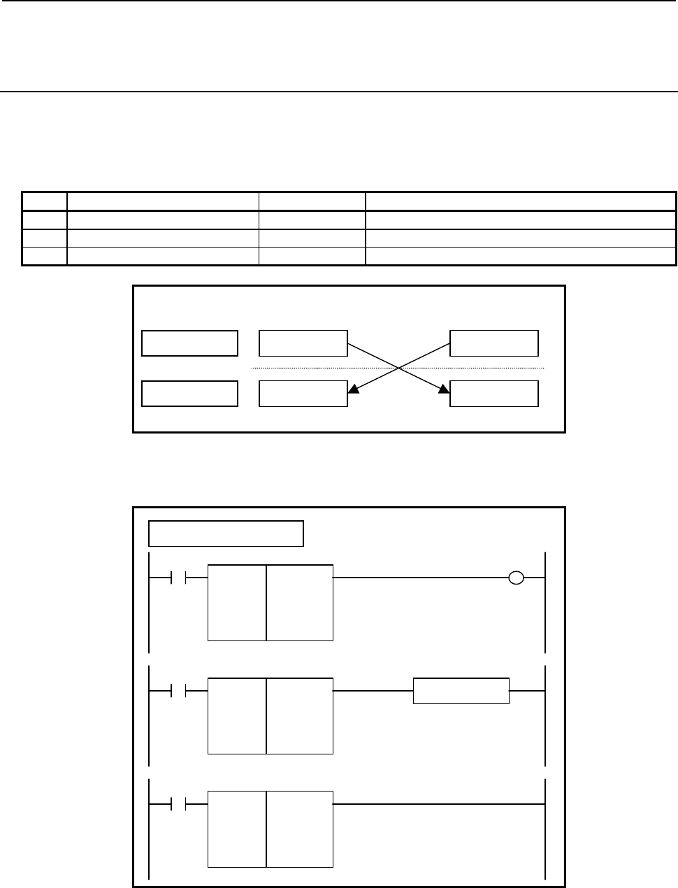
B-64513EN/03
4.LADDER LANGUAGE
- 319 -
4.5.11
XCHGB (Data Exchange (1 Byte Length) : SUB 228)
XCHGW (Data Exchange (2 Bytes Length) : SUB 229)
XCHGD (Data Exchange (4 Bytes Length) : SUB 230)
The data exchange instruction exchanges data between two specified addresses.
As indicated below, three types of data exchange instructions are available according to the type of data
to be exchanged. In each instruction, the data items at exchange addresses are of the same data type.
Table4.5.11 (a) Kinds of data exchange instruction
Instruction name SUB No. Data type
1 XCHGB 228 1 byte length data
2 XCHGW 229 2 bytes length data
3 XCHGD 230 4 bytes length data
A
ddress2
A
ddress1
Before exchange Data2 Data1
Data1 Data2
After exchange
Fig. 4.5.11 (a) Example of data exchange instruction
Format
Fig. 4.5.11(b) shows the ladder format and Table 4.5.11(b) shows the mnemonic format.
SUB 228
XCHGB
{{{{
{{{{
A
ddress1
A
ddress2
ACT W1
SUB 228
XCHGB
{{{{
{{{{
ACT
SUB 228
XCHGB
{{{{
{{{{
ACT ACT2
Functional instruction
Example : XCHGB Instruction
Fig. 4.5.11 (b) Format of XCHGB, XCHGW, XCHGD instruction
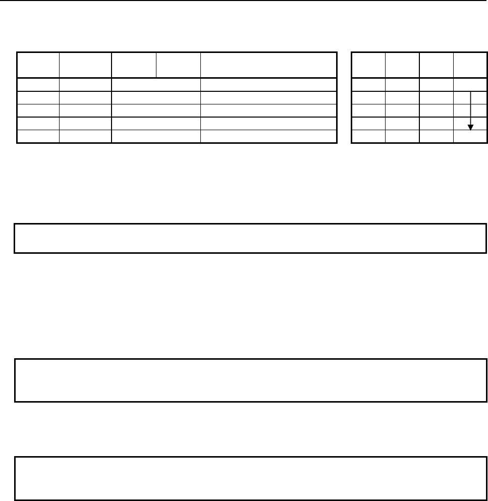
4.LADDER LANGUAGE
B-64513EN/03
- 320 -
Table 4.5.11(b) Mnemonic of XCHGB, XCHGW, XCHGD instruction
Mnemonic format
Memory status of control
condition
Step
number Instruction Address
No. Bit No. Remarks
ST3 ST2 ST1 ST0
1 RD
{{{{
.
{
ACT ACT
2 SUB 228 SUB No. (XCHGB instruction)
3 (PRM)
{{{{
Address 1
4 (PRM)
{{{{
Address 2
5 WRT
{{{{
.
{
Normal end output W1
Control condition
(a) Execution specification
ACT = 0: Instruction not executed.
ACT = 1: Executed.
NOTE
Data is exchanged in every cycle while ACT is kept on.
Parameters
(a) Address 1
Specify the 1st address which exchanges data.
(b) Address 2
Specify the 2nd address which exchanges data.
NOTE
If Address 1 and Address 2 areas are overlapped with each other, the result is not
guaranteed.
Output (W1)
When the instruction is executed, W1=1 is set. That is, W1 always assumes the same state as ACT.
NOTE
W1 may be omitted. Moreover, another functional instruction can be connected
instead of a coil.
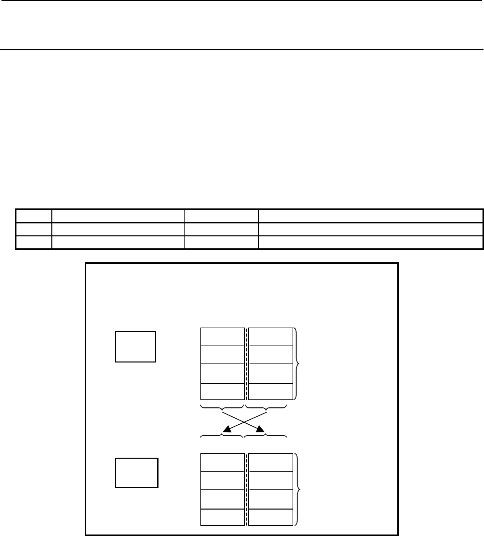
B-64513EN/03
4.LADDER LANGUAGE
- 321 -
4.5.12
SWAPW (Data Swap (2 Bytes Length) : SUB 231)
SWAPD (Data Swap (4 Bytes Length) : SUB 232)
The data swap instruction swaps the high-order data and low-order data of multiple data items at
contiguous addresses with each other.
The number of data items to be swapped is specified using a constant. Swap source data and a result
output destination are specified using addresses.
As indicated below, two types of data swap instructions are available according to the type of data to be
swapped. The SWAPW instruction swaps the higher one byte and lower one byte of each data item with
each other. The SWAPD instruction swaps the higher two bytes and lower two bytes of each data item
with each other.
In each instruction, source data and output data are of the same data type.
Table 4.5.12 (a) Kinds of data swap instruction
Instruction name SUB No. Data type
1 SWAPW 231 2 bytes length data
2 SWAPD 232 4 bytes length data
Example which swaps data 2 bytes long:
Number of data = 10
Source data top address = R100
Result output top address = D500
Result
output
Number
of data
=10
Source
data
Swap
(
2
)
(
1
)
(4) (3)
(20) (19)
15 8 7 0
R0100
R0102
R0118
:
D0500
D0502
D0518
(1) (2)
(
3
)
(
4
)
(
19
)
(
20
)
Number
of data
=10
15 8 7 0
:
: :
: :
Fig. 4.5.12 (a) Example of SWAPW instruction
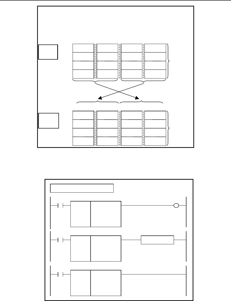
4.LADDER LANGUAGE
B-64513EN/03
- 322 -
Example which swaps data 4 bytes long:
Number of data = 10
Source data top address = R100
Result output top address = D500
Result
output Number
of data
=10
Source
data
Swap
(
4
)
(8)
(40)
31 24 23 16 15 8 7 0
R0100
R0104
R0136
:
D0500
D0504
D0536
(
2
)
(
1
)
(6) (5)
(38) (37)
(
2
)
(
1
)
(
6
)
(
5
)
(
38
)
(
37
)
(
4
)
(
3
)
(
8
)
(
7
)
(
40
)
(
39
)
Number
of data
=10
31 24 23 16 15 8 7 0
:
(
3
)
(7)
(39)
: : :
: : : : :
Fig. 4.5.12 (b) Example of SWAPD instruction
Format
Fig. 4.5.12(c) shows the ladder format and Table 4.5.12(b) shows the mnemonic format.
SUB 231
SWAPW
{{{{
{{{{
{{{{
Number of data (Constant)
Source data top address
Result output top address
ACT W1
SUB 231
SWAPW
{{{{
{{{{
{{{{
ACT
SUB 231
SWAPW
{{{{
{{{{
{{{{
ACT ACT2
Functional instruction
Example : SWAPW Instruction
Fig. 4.5.12 (c) Format of SWAPW, SWAPD instruction
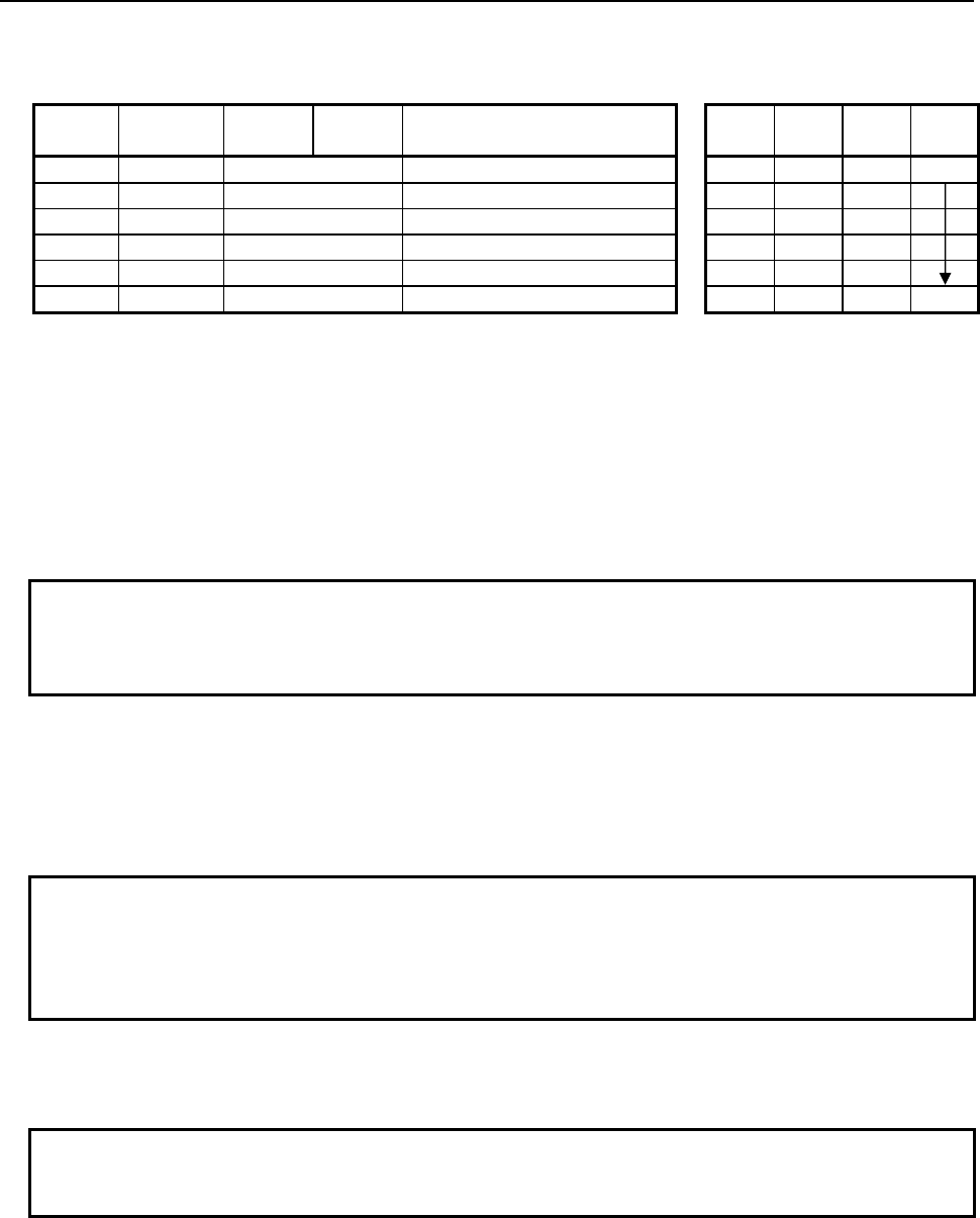
B-64513EN/03
4.LADDER LANGUAGE
- 323 -
Table 4.5.12 (b) Mnemonic of SWAPW, SWAPD instruction
Mnemonic format
Memory status of control
condition
Step
number Instruction Address
No. Bit No. Remarks
ST3 ST2 ST1 ST0
1 RD
{{{{
.
{
ACT ACT
2 SUB 231 SUB No. (SWAPW instruction)
3 (PRM)
{{{{
Number of data (Constant)
4 (PRM)
{{{{
Source data top address
5 (PRM)
{{{{
Result output top address
6 WRT
{{{{
.
{
Normal end output W1
Control condition
(a) Execution specification
ACT = 0: Instruction not executed.
ACT = 1: Executed.
Parameters
(a) Number of data
Specify the number of data items to be swapped. A number from 1 to 256 may be specified.
NOTE
Specify a valid number to the "Number of data", so that both of the area from
"Source data top address" and the area from "Result output top address" may be
arranged within valid address range.
(b) Source data top address
Specify the top address in which the swap data is stored.
(c) Result output top address
Specify the top of address which stores the result of an operation.
NOTE
If "Source data top address" and "Result output top address" match each other
completely, the instruction is executed normally. If the source data area partially
overlaps the result output area, normal operation of the instruction is not
guaranteed.
Output (W1)
When the instruction is executed, W1=1 is set. That is, W1 always assumes the same state as ACT.
NOTE
W1 may be omitted. Moreover, another functional instruction can be connected
instead of a coil.
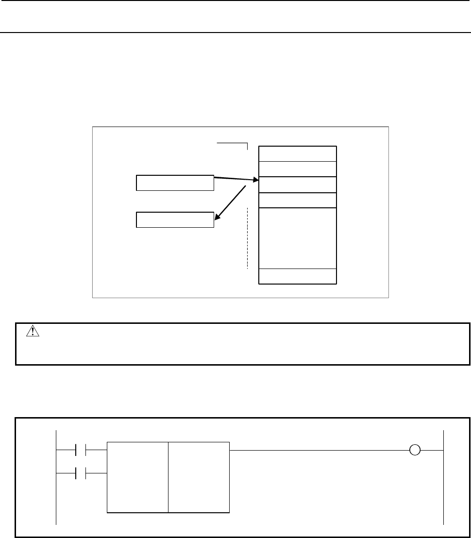
4.LADDER LANGUAGE
B-64513EN/03
- 324 -
4.5.13
DSCHB (Binary Data Search: SUB 34)
This function instruction instructs data search in the data table. DSCHB searches the data table for a
specified data, outputs an address storing it counting from the beginning of the data table. If the data
cannot be found, an output is made accordingly.
The numerical data handled in this instruction are all in binary format and number of data (table capacity)
in the data table can be specified by specifying the address, thus allowing change in table capacity even
after writing the sequence program in the flash ROM.
1
0
3
n
Table numbe r Data table
Search data
Search result output
100
100
2
2
Fig. 4.5.13 (a)
CAUTION
You can specify any R,E and D address for the data table in this functional
instruction.
Format
Fig. 4.5.13 (b) shows the ladder format and Table 4.5.13 shows the mnemonic format.
RST W1
SUB 34
ACT DSCHB
{
Format designation
{{{{
Storage address of number of data in data table
{{{{
Data table head address
{{{{
Search data address
{{{{
Output address of search result
Fig. 4.5.13 (b) Format of DSCHB instruction
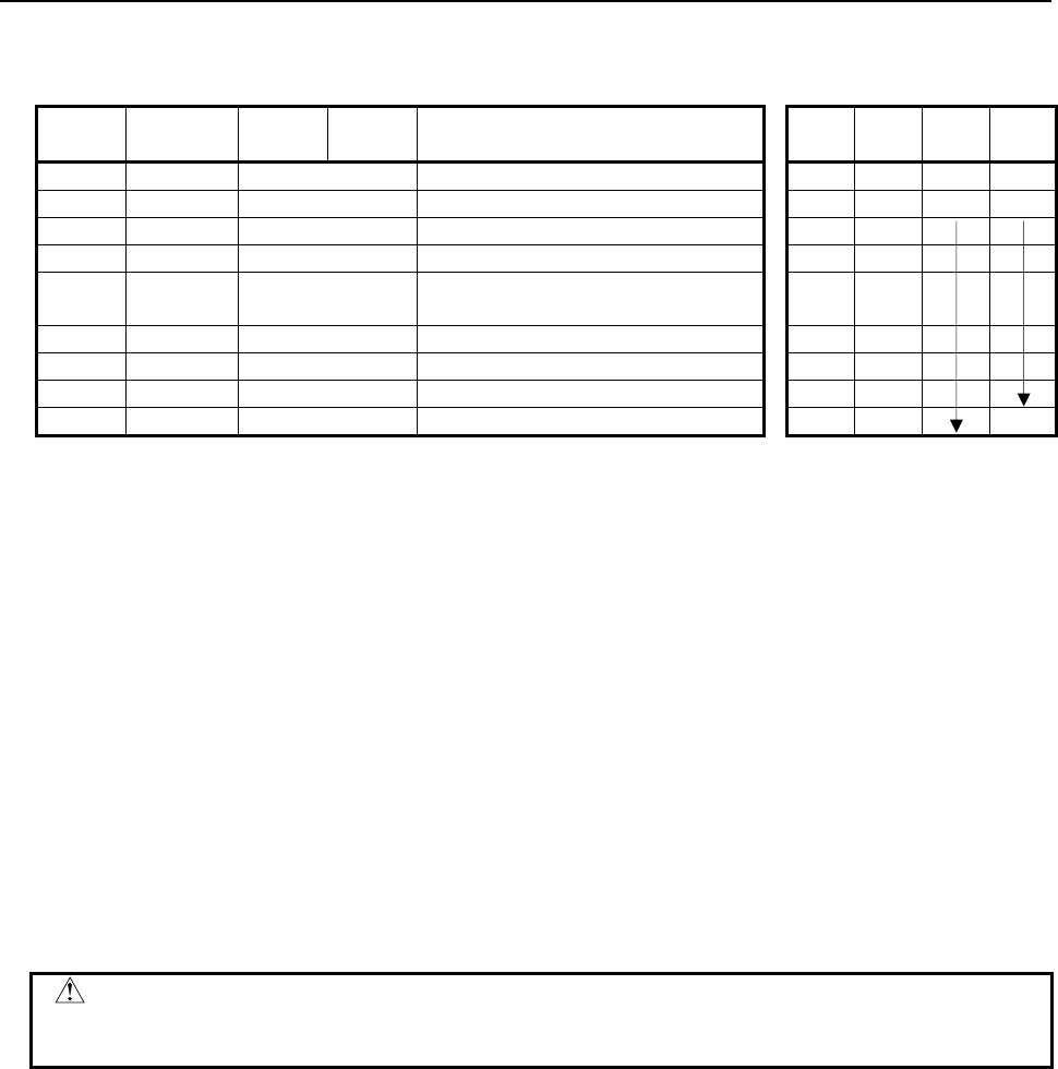
B-64513EN/03
4.LADDER LANGUAGE
- 325 -
Table 4.5.13 Mnemonic of DSCHB instruction
Mnemonic format Memory status of control
condition
Step
number Instruction Address
No. Bit No. Remarks ST3 ST2 ST1 ST0
1 RD
{{{{
.
{
RST RST
2 RD.STK
{{{{
.
{
ACT RST ACT
3 SUB 34 DSCHB instruction
4 (PRM)
{
Format designation
5 (PRM)
{{{{
Storage address of number of data in
data table
6 (PRM)
{{{{
Data table head address
7 (PRM)
{{{{
Search data address
8 (PRM)
{{{{
Output address of search result
9 WRT
{{{{
.
{
Search result W1
Control conditions
(a) Reset (RST)
RST = 0: Release reset
RST = 1: Reset. W1 = "0".
(b) Execution specification (ACT)
ACT = 0: Do not execute DSCHB instruction. W1 does not change.
ACT = 1: Execute DSCHB instruction. If the search data is found, table number where the data is
stored will be output. If the search data is not found, W1 becomes 1.
Parameters
(a) Format specification
Specifies data length. Specify byte length in the first digit of the parameter.
1: 1 byte length
2: 2 bytes length
4: 4 bytes length
CAUTION
Do not set an illegal value, that is not indicated above, into the "(a) Format
specification".
(b) Storage address of number of data in data table
Specifies address in which number of data in the data table is set.
This address requires memory of number of byte according to the format designation.
Number of data in the table is n + 1 (head number in the table is 0 and the last number is n). The
value which you can set depends on the "(a) Format designation".
1 byte length: 1 to 255
2 bytes length: 1 to 16384
3 bytes length: 1 to 16384
(c) Data table head address
Sets head address of data table.
(d) Search data address
The address in which search data is set.
(e) Output address of search result
After searching, if search data is found, the table number where the data is stored will be output.
The searched table number is output in this search result output address. This address requires
memory of number of byte according to the format designation.

4.LADDER LANGUAGE
B-64513EN/03
- 326 -
WARNING
1 You can not specify the table that includes different kind of address type or
discontinuous address area. In this case, operation is not guaranteed.
2 You have to set the "Storage address of number of data table elements" and the
"Data table head address" not to exceed the limit of its continuous address area.
If the table exceeds the limit of the continuous address area, operation is not
guaranteed. For example, when a range of address R is 0 to 7999 and the
"Format specification" is set to 1 and the "Data table head address" is set to
"R7990", you can set 10 or less to the "Storage address of number of data table
elements".
Search result (W1)
W1 = 0: Search data found.
W1 = 1: Search data not found.
CAUTION
Two or more coils, WRT, WRT.NOT, SET or RST, that follow this instruction are
prohibited. You have to place a single coil instruction as the output of this
instruction.
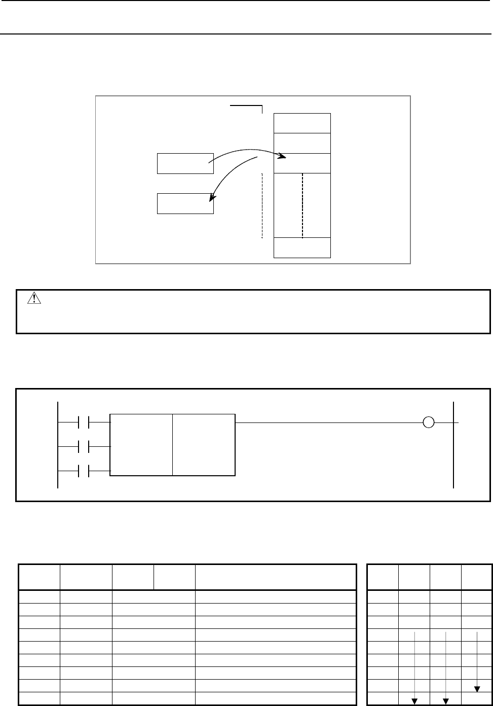
B-64513EN/03
4.LADDER LANGUAGE
- 327 -
4.5.14
DSCH (Data Search: SUB 17)
This function instruction instructs data search in the data table. DSCH searches the data table for a
specified data, outputs an address storing it counting from the beginning of the data table. If the data
cannot be found, an output is made accordingly. The value type in this instruction is BCD.
Search data
Data table
100
0
1
2
n
Table internal number
100
2
Search data result output
Fig. 4.5.14 (a)
CAUTION
You can specify any R,E and D address for the data table in this functional
instruction.
Format
Fig. 4.5.14 (b) shows the ladder format and Table 4.5.14 shows the mnemonic format.
BYT W1
SUB 17
RST DSCH
{{{{
Number of data of the data table (Table capacity)
{{{{
Data table heading address
ACT
{{{{
Search data address
{{{{
Search result output address
Fig. 4.5.14 (b) Format of DSCH instruction
Table 4.5.14 Mnemonic of DSCH instruction
Mnemonic format Memory status of control
condition
Step
number Instruction Address
No. Bit No. Remarks ST3 ST2 ST1 ST0
1 RD
{{{{
.
{
BYT BYT
2 RD.STK
{{{{
.
{
RST BYT RST
3 RD.STK
{{{{
.
{
ACT BYT RST ACT
4 SUB 17 DSCH instruction
5 (PRM)
{{{{
Number of data of the data table
6 (PRM)
{{{{
Data table heading address
7 (PRM)
{{{{
Search data address
8 (PRM)
{{{{
Search result output address
9 WRT
{{{{
.
{
Search result W1

4.LADDER LANGUAGE
B-64513EN/03
- 328 -
Control conditions
(a) Specify data size. (BYT)
BYT = 0: Data stored in the data table, BCD two digits long.
BYT = 1: Data stored in the data table, BCD four digits long.
(b) Reset (RST)
RST = 0: Release reset
RST = 1: Enables a reset, that is, sets W1 to 0.
(c) Execution specification (ACT)
ACT = 0: The DSCH instruction is not executed. W1 does not change.
ACT = 1: The DSCH is executed, and the table internal number storing the desired data is output.
If the data cannot be found, W1 = 1.
Parameters
(a) Number of data of the data table
Specify the size of the data table. If the beginning of the data table is 0 and the end is n, n + 1 is set
as the number of data of the data table. The value which you can set depends on the control
condition "BYT".
BYT=0: 1 to 99
BYT=1: 1 to 9999
(b) Data table heading address
Addresses that can be used in a data table are fixed. When preparing a data table, the addresses to
be used must be determined beforehand, specify the head address of a data table here.
(c) Search data address
Specify the address of the data to be searched.
(d) Search result output address
If the data being searched for is found, the internal number of the table storing the data is output to
this field. This address field is called a search result output address field.
The search result output address field requires memory whose size is the number of bytes
conforming to the size of the data specified by BYT.
WARNING
1 You can not specify the table that includes different kind of address type or
discontinuous address area. In this case, operation is not guaranteed.
2 You have to set the "Number of data of the data table" and the "Data table
heading address" not to exceed the limit of its continuous address area. If the
table exceeds the limit of the continuous address area, operation is not
guaranteed. For example, when a range of address R is 0 to 7999 and the control
condition "BYT" is set to 0 and the "Data table heading address" is set to
"R7990", you can set 10 or less to the "Number of data of the data table".
Search result (W1)
W1 = 0: Search data found.
W1 = 1: Search data not found.
CAUTION
Two or more coils, WRT, WRT.NOT, SET or RST, that follow this instruction are
prohibited. You have to place a single coil instruction as the output of this
instruction.

B-64513EN/03
4.LADDER LANGUAGE
- 329 -
4.6 TABLE DATA
The following types of table data instruction are available. Use any of these instructions as appropriate for
your purpose.
Instruction name Sub number Processing
1 TBLRB 233 Reading data from table (1 byte length)
2 TBLRW 234 Reading data from table (2 bytes length)
3 TBLRD 235 Reading data from table (4 bytes length)
4 TBLRN 236 Reading data from table (Arbitrary byte length)
5 TBLWB 237 Writing data to table (1 byte length)
6 TBLWW 238 Writing data to table (2 bytes length)
7 TBLWD 239 Writing data to table (4 bytes length)
8 TBLWN 240 Writing data to table (Arbitrary byte length)
9 DSEQB 241 Searching data from table (=)(1 byte length)
10 DSEQW 242 Searching data from table (=)(2 bytes length)
11 DSEQD 243 Searching data from table (=)(4 bytes length)
12 DSNEB 244 Searching data from table (≠)(1 byte length)
13 DSNEW 245 Searching data from table (≠)(2 bytes length)
14 DSNED 246 Searching data from table (≠)(4 bytes length)
15 DSGTB 247 Searching data from table (>)(1 byte length)
16 DSGTW 248 Searching data from table (>)(2 bytes length)
17 DSGTD 249 Searching data from table (>)(4 bytes length)
18 DSLTB 250 Searching data from table (<)(1 byte length)
19 DSLTW 251 Searching data from table (<)(2 bytes length)
20 DSLTD 252 Searching data from table (<)(4 bytes length)
21 DSGEB 253
Searching data from table (
≧
)(1 byte length)
22 DSGEW 254
Searching data from table (
≧
)(2 bytes length)
23 DSGED 255
Searching data from table (
≧
)(4 bytes length)
24 DSLEB 256
Searching data from table (
≦
)(1 byte length)
25 DSLEW 257
Searching data from table (
≦
)(2 bytes length)
26 DSLED 258
Searching data from table (
≦
)(4 bytes length)
27 DMAXB 259 Maximum data (1 byte length)
28 DMAXW 260 Maximum data (2 bytes length)
29 DMAXD 261 Maximum data (4 bytes length)
30 DMINB 262 Minimum data (1 byte length)
31 DMINW 263 Minimum data (2 bytes length)
32 DMIND 264 Minimum data (4 bytes length)
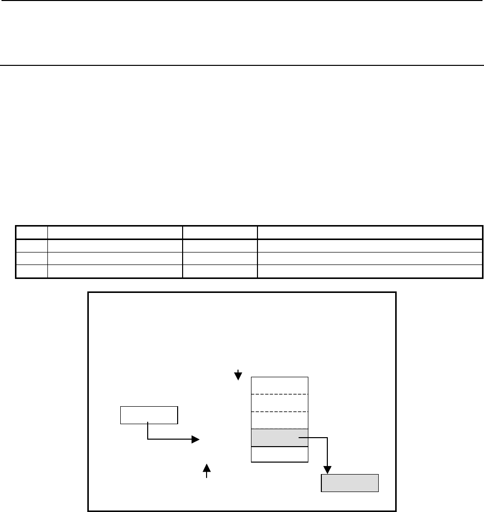
4.LADDER LANGUAGE
B-64513EN/03
- 330 -
4.6.1
TBLRB (Reading Data from Table (1 Byte Length) : SUB 233)
TBLRW (Reading Data from Table (2 Bytes Length) : SUB 234)
TBLRD (Reading Data from Table (4 Bytes Length) : SUB 235)
The Reading data from table instruction transfers data from a specified position in a table to another
address.
The top of a table is specified in "Table top address". In "Reading position", a data position is specified
relative to the top data position assumed to be 0.
In "Reading position", a constant or a PMC memory address for storing data can be specified.
As indicated below, three types of Reading data from table instructions are available according to the type
of data to be read from a table. In each instruction, the data in the table and data at "Transfer destination
address" are of the same data type. However, the data type of "Reading position" is two-byte signed
binary data at all times.
Table4.6.1 (a) Kinds of Reading data from table instruction
Instruction name SUB No. Data type
1 TBLRB 233 1 byte length data
2 TBLRW 234 2 bytes length data
3 TBLRD 235 4 bytes length data
When data 2 bytes long is read:
Number of data = 12
Table top address = D100
Reading position = D200
Transfer destination address = D300
Transfer destination address
D300
Table top address
0
1
10
:
11
Reading position
D200 10
The data No. in a table
D100
D102
D120
D122
::
Fig. 4.6.1 (a) Example of TBLRW instruction
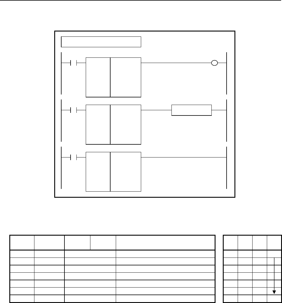
B-64513EN/03
4.LADDER LANGUAGE
- 331 -
Format
Fig. 4.6.1(b) shows the ladder format and Table 4.6.1(b) shows the mnemonic format.
SUB 233
TBLRB
{{{{
{{{{
{{{{
{{{{
Number of data (Constant)
Table top address
Reading position (Address or Constant)
Transfer destination address
ACT W1
SUB 233
TBLRB
{{{{
{{{{
{{{{
{{{{
ACT
SUB 233
TBLRB
{{{{
{{{{
{{{{
{{{{
ACT ACT2
Functional Instruction
Example : TBLRB Instruction
Fig. 4.6.1 (b) Format of TBLRB, TBLRW, TBLRD instruction
Table 4.6.1 (b) Mnemonic of TBLRB, TBLRW, TBLRD instruction
Mnemonic format
Memory status of
control condition
Step
number Instruction Address
No. Bit No. Remarks
ST3 ST2 ST1 ST0
1 RD
{{{{
.
{
ACT ACT
2 SUB 233 SUB No. (TBLRB instruction)
3 (PRM)
{{{{
Number of data (Constant)
4 (PRM)
{{{{
Table top address
5 (PRM)
{{{{
Reading position (Address or Constant)
6 (PRM)
{{{{
Transfer destination address
7 WRT
{{{{
.
{
Normal end output W1
Control condition
(a) Execution specification
ACT = 0: Instruction not executed.
ACT = 1: Executed.
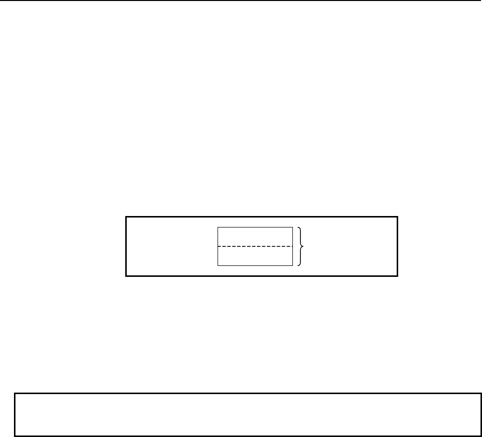
4.LADDER LANGUAGE
B-64513EN/03
- 332 -
Parameters
(a) Number of data
Specify the number of data items in a table. Ensure that the entire table is within the valid address
range.
(b) Table top address
Specify the top address of a table.
(c) Reading position
Specify a data position relative to the top data position assumed to be 0. A value from 0 to the
number of data items less 1 may be specified. If a value not within this valid range is specified, no
transfer operation is performed, and W1=0 is set.
In this parameter, a constant or a PMC memory address can be specified.
If an address is specified, specify "Reading position" as signed binary data by using the contiguous
two bytes of memory starting from the specified address.
Specified address +0
Specified address +1
Reading position
(Signed binary data)
(d) Transfer destination address
Specify the destination address for the read data.
Output (W1)
W1=1: A transfer operation is terminated normally
W1=0: No transfer operation is executed (ACT=0)
A value not within the valid range is specified in "Reading position"
NOTE
W1 may be omitted. Moreover, another functional instruction can be connected
instead of a coil.
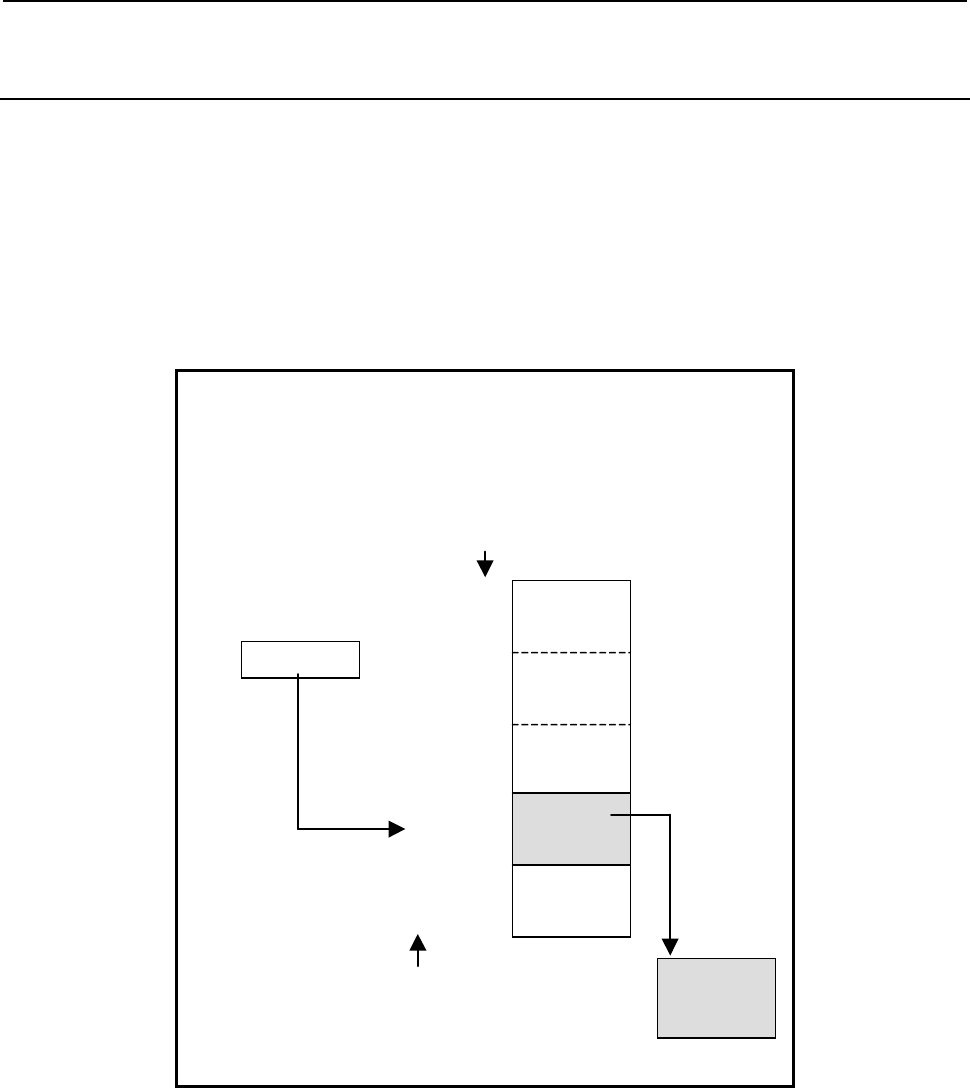
B-64513EN/03
4.LADDER LANGUAGE
- 333 -
4.6.2
TBLRN (Reading Data from Table (Arbitrary Bytes Length) :
SUB 236)
The Reading data from table instruction transfers data of a specified size from a specified position in a
table to another address.
The top of a table is specified in "Table top address". In "Reading position", a data position is specified
relative to the top data position assumed to be 0. In "Reading position", a constant or a PMC memory
address for storing data can be specified.
The byte length of data to be read from the table is specified in "Data size". The data in the table and
data at "Transfer destination address" are of the same data length. However, the data type of "Reading
position" is two-byte signed binary data at all times.
When data 6 bytes long is read:
Number of data = 12
Data size = 6
Table top address = D100
Reading position = D200
Transfer destination address = D300
Reading position
Table top address
D200 10
Transfer destination address
D300
:
D305
The data No. in a table
D100
:
D105
D106
:
D111
D160
:
D165
0
1
10
:
11
D166
:
D171
::
Fig. 4.6.2 (a) Example of TBLRN instruction
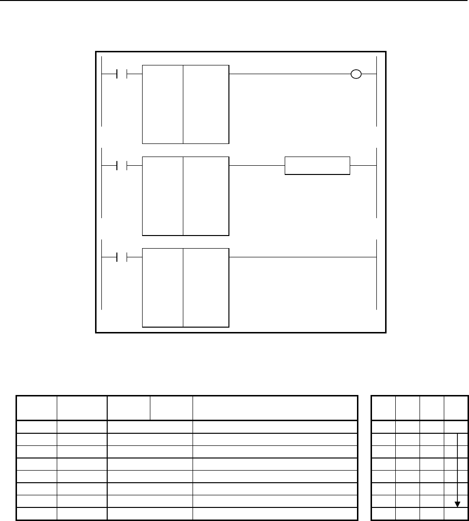
4.LADDER LANGUAGE
B-64513EN/03
- 334 -
Format
Fig. 4.6.2(b) shows the ladder format and Table 4.6.2(a) shows the mnemonic format.
SUB 236
TBLRN
{{{{
{{{{
{{{{
{{{{
{{{{
Number of data (Constant)
Data size (Constant)
Table top address
Reading position (Address or Constant)
Transfer destination address
ACT W1
SUB 236
TBLRN
{{{{
{{{{
{{{{
{{{{
{{{{
ACT
SUB 236
TBLRN
{{{{
{{{{
{{{{
{{{{
{{{{
ACT ACT2
Functional Instruction
Fig. 4.6.2 (b) Format of TBLRN instruction
Table 4.6.2 (a) Mnemonic of TBLRN instruction
Mnemonic format
Memory status of
control condition
Step
number Instruction Address
No. Bit No. Remarks
ST3 ST2 ST1 ST0
1 RD
{{{{
.
{
ACT ACT
2 SUB 236 SUB No. (TBLRN instruction)
3 (PRM)
{{{{
Number of data (Constant)
4 (PRM)
{{{{
Data size (Constant)
5 (PRM)
{{{{
Table top address
6 (PRM)
{{{{
Reading position (Address or Constant)
7 (PRM)
{{{{
Transfer destination address
8 WRT
{{{{
.
{
Normal end output W1
Control condition
(a) Execution specification
ACT = 0: Instruction not executed.
ACT = 1: Executed.
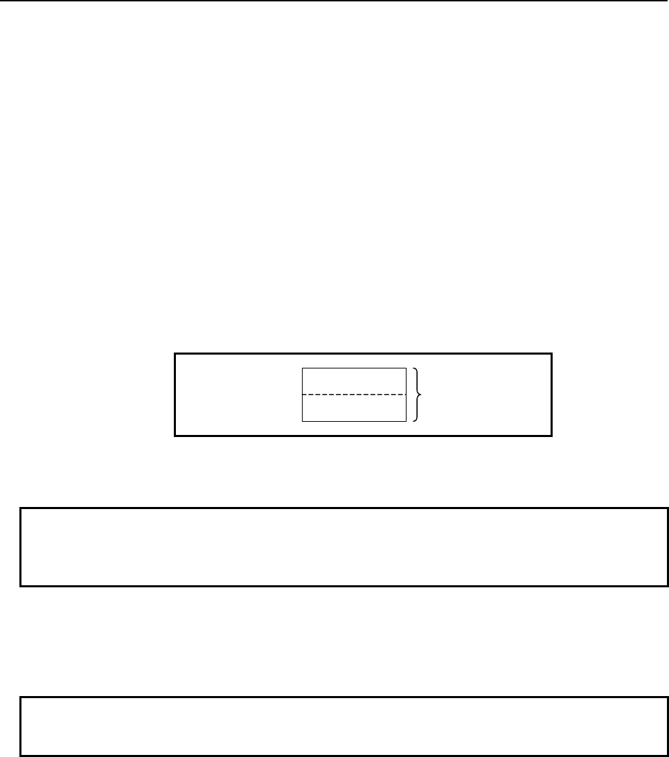
B-64513EN/03
4.LADDER LANGUAGE
- 335 -
Parameters
(a) Number of data
Specify the number of data items in a table. Ensure that the entire table is within the valid address
range.
(b) Data size
Specify the byte length of data to be read. A value from 1 to 256 may be specified.
(c) Table top address
Specify the top address of a table.
(d) Reading position
Specify a data position relative to the top data position assumed to be 0. A value from 0 to the
number of data items less 1 may be specified. If a value not within this valid range is specified, no
transfer operation is performed, and W1=0 is set.
In this parameter, a constant or a PMC memory address can be specified.
If an address is specified, specify "Reading position" as signed binary data by using the contiguous
two bytes of memory starting from the specified address.
Specified address +0
Specified address +1
Reading position
(Signed binary data)
(e) Transfer destination address
Specify the destination address for the read data.
NOTE
The operation of the instruction is not guaranteed if "Transfer destination address"
overlaps the table. Specify "Transfer destination address" that does not overlap
the table.
Output (W1)
W1=1: A transfer operation is terminated normally
W1=0: No transfer operation is executed (ACT=0)
A value not within the valid range is specified in "Reading position"
NOTE
W1 may be omitted. Moreover, another functional instruction can be connected
instead of a coil.
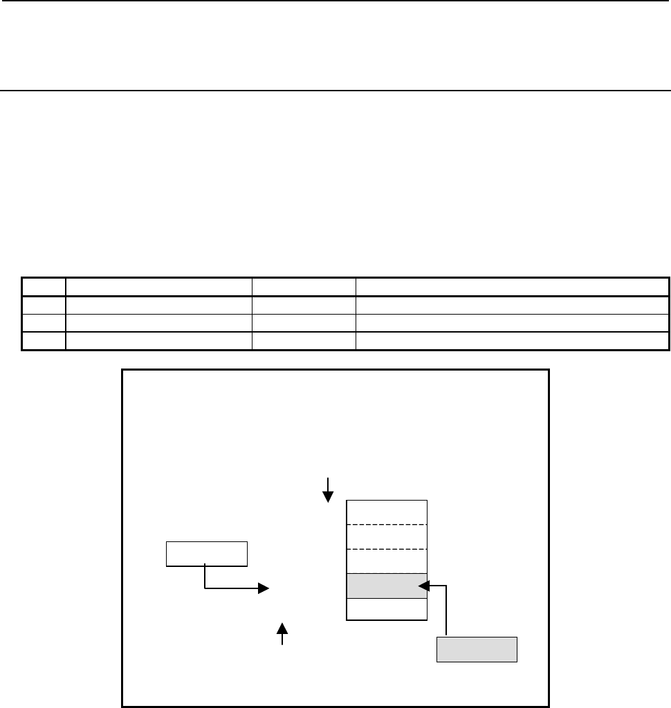
4.LADDER LANGUAGE
B-64513EN/03
- 336 -
4.6.3
TBLWB (Writing Data to Table (1 Byte Length) : SUB 237)
TBLWW (Writing Data to Table (2 Bytes Length) : SUB 238)
TBLWD (Writing Data to Table (4 Bytes Length) : SUB 239)
The Writing data to table instruction writes data to a specified position in a table.
The top of a table is specified in "Table top address". In "Writing position", a data position is specified
relative to the top data position assumed to be 0. In "Writing position", a constant or a PMC memory
address for storing data can be specified.
As indicated below, three types of writing data to table instructions are available according to the type of
data to be written to a table. In each instruction, the data in the table and transfer data are of the same
data type. However, the data type of "Writing position" is two-byte signed binary data at all times.
Table4.6.3 (a) Kinds of writing data to table instruction
Instruction name SUB No. Data type
1 TBLWB 237 1 byte length data
2 TBLWW 238 2 bytes length data
3 TBLWD 239 4 bytes length data
When data 2 bytes long is written:
Number of data = 12
Table top address = D100
Writing position = D200
Transfer data = D300
Writing position
Table top address
D200 10
Transfer data
D300
The data No. in a table
0
1
10
:
11
D100
D102
D120
D122
250
::
Fig. 4.6.3 (a) Example of TBLWW instruction
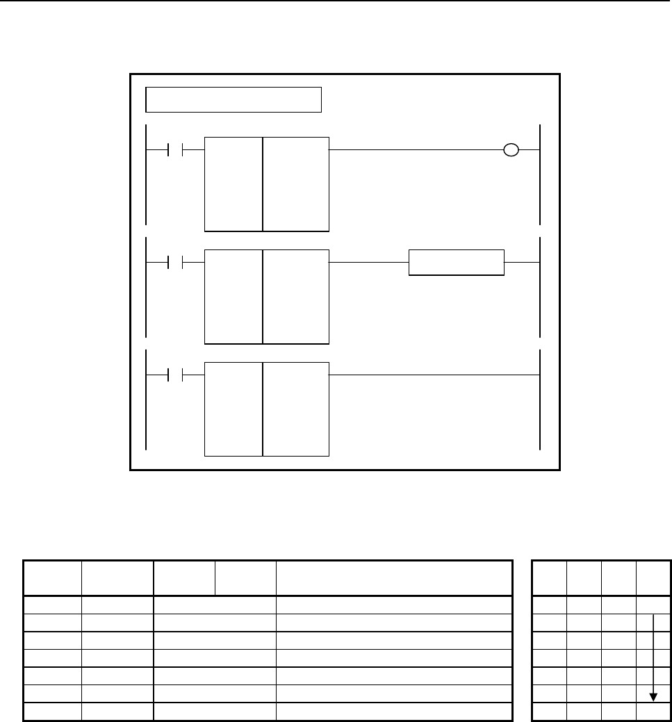
B-64513EN/03
4.LADDER LANGUAGE
- 337 -
Format
Fig. 4.6.3(b) shows the ladder format and Table 4.6.3(b) shows the mnemonic format.
SUB 237
TBLWB
{{{{
{{{{
{{{{
{{{{
Number of data (Constant)
Table top address
Writing position (Address or Constant)
Transfer data (Address or Constant)
ACT W1
SUB 237
TBLWB
{{{{
{{{{
{{{{
{{{{
ACT
SUB 237
TBLWB
{{{{
{{{{
{{{{
{{{{
ACT ACT2
Functional Instruction
Example : TBLWB Instruction
Fig. 4.6.3 (b) Format of TBLWB, TBLWW, TBLWD instruction
Table 4.6.3 (b) Mnemonic of TBLWB, TBLWW, TBLWD instruction
Mnemonic format
Memory status of
control condition
Step
number Instruction Address
No. Bit No. Remarks
ST3 ST2 ST1 ST0
1 RD
{{{{
.
{
ACT ACT
2 SUB 237 SUB No. (TBLWB instruction)
3 (PRM)
{{{{
Number of data (Constant)
4 (PRM)
{{{{
Table top address
5 (PRM)
{{{{
Writing position (Address or Constant)
6 (PRM)
{{{{
Transfer data (Address or Constant)
7 WRT
{{{{
.
{
Normal end output W1
Control condition
(a) Execution specification
ACT = 0: Instruction not executed.
ACT = 1: Executed.
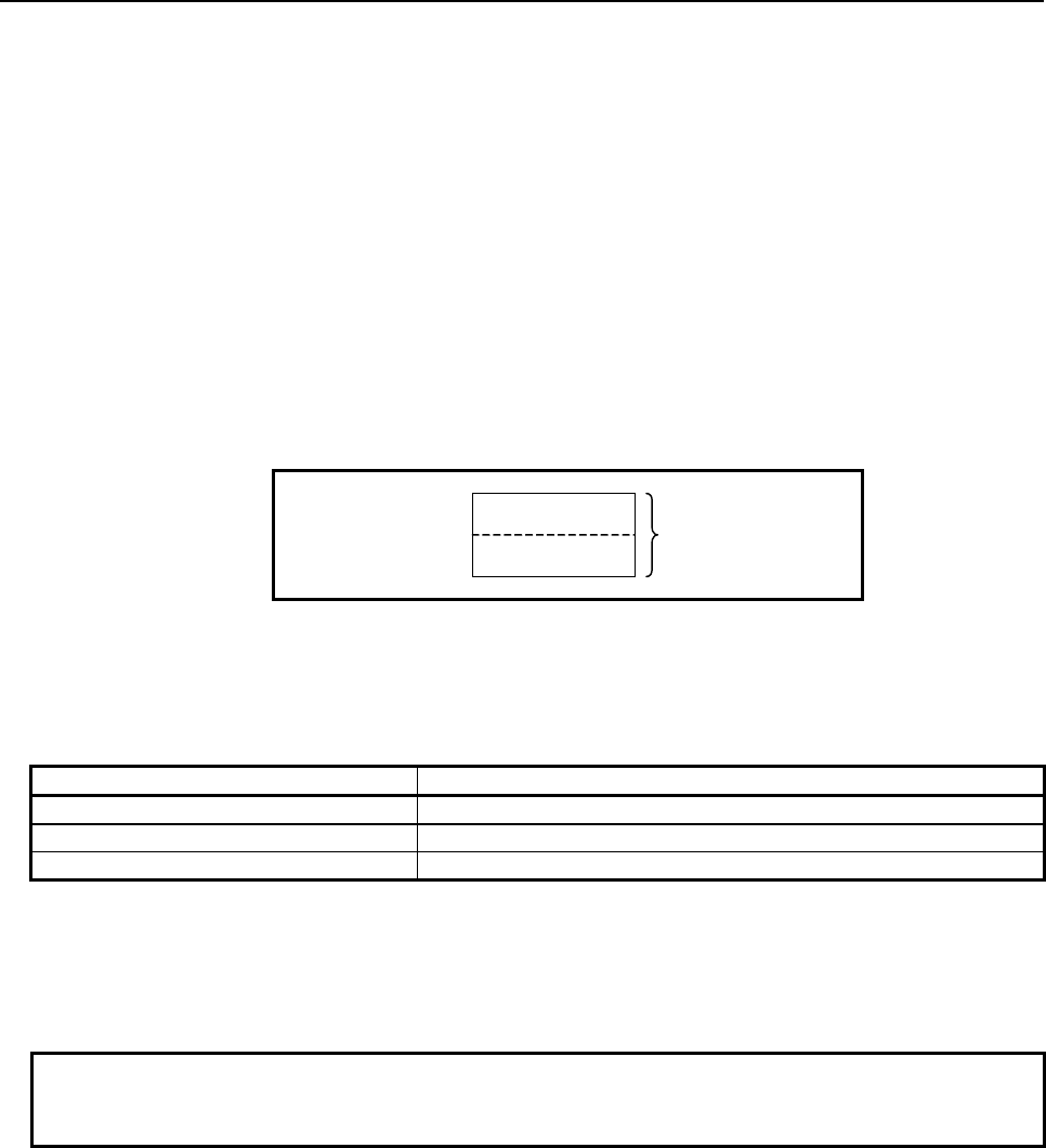
4.LADDER LANGUAGE
B-64513EN/03
- 338 -
Parameters
(a) Number of data
Specify the number of data items in a table. Ensure that the entire table is within the valid address
range.
(b) Table top address
Specify the top address of a table.
(c) Writing position
Specify a data position relative to the top data position assumed to be 0. A value from 0 to the
number of data items less 1 may be specified. If a value not within this valid range is specified, no
transfer operation is performed, and W1=0 is set.
In this parameter, a constant or a PMC memory address can be specified.
If an address is specified, specify "Writing position" as signed binary data by using the contiguous
two bytes of memory starting from the specified address.
Specified address +0
Specified address +1
Writing position
(Signed binary data)
(d) Transfer data
Specify data to be written. In this parameter, a constant or a PMC memory address for storing data
can be specified. Specify data by using signed binary data. A value within the following range
may be specified:
Instruction name Available value
TBLWB -128 to 127
TBLWW -32768 to 32767
TBLWD -2147483648 to 2147483647
Output (W1)
W1=1: A transfer operation is terminated normally
W1=0: No transfer operation is executed (ACT=0)
A value not within the valid range is specified in "Writing position"
NOTE
W1 may be omitted. Moreover, another functional instruction can be connected
instead of a coil.
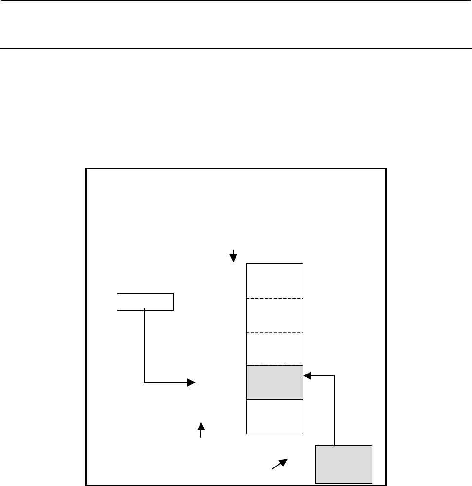
B-64513EN/03
4.LADDER LANGUAGE
- 339 -
4.6.4
TBLWN (Writing Data to Table (Arbitrary Bytes Length) : SUB
240)
The Writing data to table instruction writes data of a specified size to a specified position in a table.
The top of a table is specified in "Table top address". In "Writing position", a data position is specified
relative to the top data position assumed to be 0. In "Writing position", a constant or a PMC memory
address for storing data can be specified.
The byte length of data to be written to the table is specified in "Data size". The data in the table and
data at "Transfer data top address" are of the same data length. However, the data type of "Writing
position" is two-byte signed binary data at all times.
When data 6 bytes long is written:
Number of data = 12
Data size = 6
Table top address = D100
Writing position = D200
Transfer data top address = D300
Writing position
Table top address
D200 10
Transfer data top address
D300
:
D305
The data No. in a table
0
1
10
:
11
:
D100
:
D105
D106
:
D111
D160
:
D165
D166
:
D171
:
Fig. 4.6.4 (a) Example of TBLWN instruction
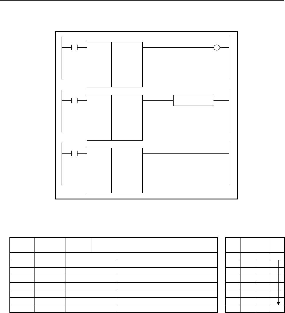
4.LADDER LANGUAGE
B-64513EN/03
- 340 -
Format
Fig. 4.6.4(b) shows the ladder format and Table 4.6.4 shows the mnemonic format.
SUB 240
TBLWN
{{{{
{{{{
{{{{
{{{{
{{{{
Number of data (Constant)
Data size (Constant)
Table top address
Writing position (Address or Constant)
Transfer data top address
ACT W1
SUB 240
TBLWN
{{{{
{{{{
{{{{
{{{{
{{{{
ACT
SUB 240
TBLWN
{{{{
{{{{
{{{{
{{{{
{{{{
ACT ACT2
Functional Instruction
Fig. 4.6.4 (b) Format of TBLWN instruction
Table 4.6.4 Mnemonic of TBLWN instruction
Mnemonic format
Memory status of
control condition
Step
number Instruction Address
No. Bit No. Remarks
ST3 ST2 ST1 ST0
1 RD
{{{{
.
{
ACT ACT
2 SUB 240 SUB No. (TBLWN instruction)
3 (PRM)
{{{{
Number of data (Constant)
4 (PRM)
{{{{
Data size (Constant)
5 (PRM)
{{{{
Table top address
6 (PRM)
{{{{
Writing position (Address or Constant)
7 (PRM)
{{{{
Transfer data top address
8 WRT
{{{{
.
{
Normal end output W1
Control condition
(a) Execution specification
ACT = 0: Instruction not executed.
ACT = 1: Executed.

B-64513EN/03
4.LADDER LANGUAGE
- 341 -
Parameters
(a) Number of data
Specify the number of data items in a table. Ensure that the entire table is within the valid address
range.
(b) Data size
Specify the byte length of data to be written. A value from 1 to 256 may be specified.
(c) Table top address
Specify the top address of a table.
(d) Writing position
Specify a data position relative to the top data position assumed to be 0. A value from 0 to the
number of data items less 1 may be specified. If a value not within this valid range is specified, no
transfer operation is performed, and W1=0 is set.
In this parameter, a constant or a PMC memory address can be specified.
If an address is specified, specify "Writing position" as signed binary data by using the contiguous
two bytes of memory starting from the specified address.
Specified address +0
Specified address +1
Writing position
(Signed binary data)
(e) Transfer data top address
Specify the start address of data to be written.
NOTE
The operation of the instruction is not guaranteed if "Transfer data top address"
overlaps the table. Specify "Transfer data top address" that does not overlap
the table.
Output (W1)
W1=1: A transfer operation is terminated normally
W1=0: No transfer operation is executed (ACT=0)
A value not within the valid range is specified in "Writing position"
NOTE
W1 may be omitted. Moreover, another functional instruction can be connected
instead of a coil.
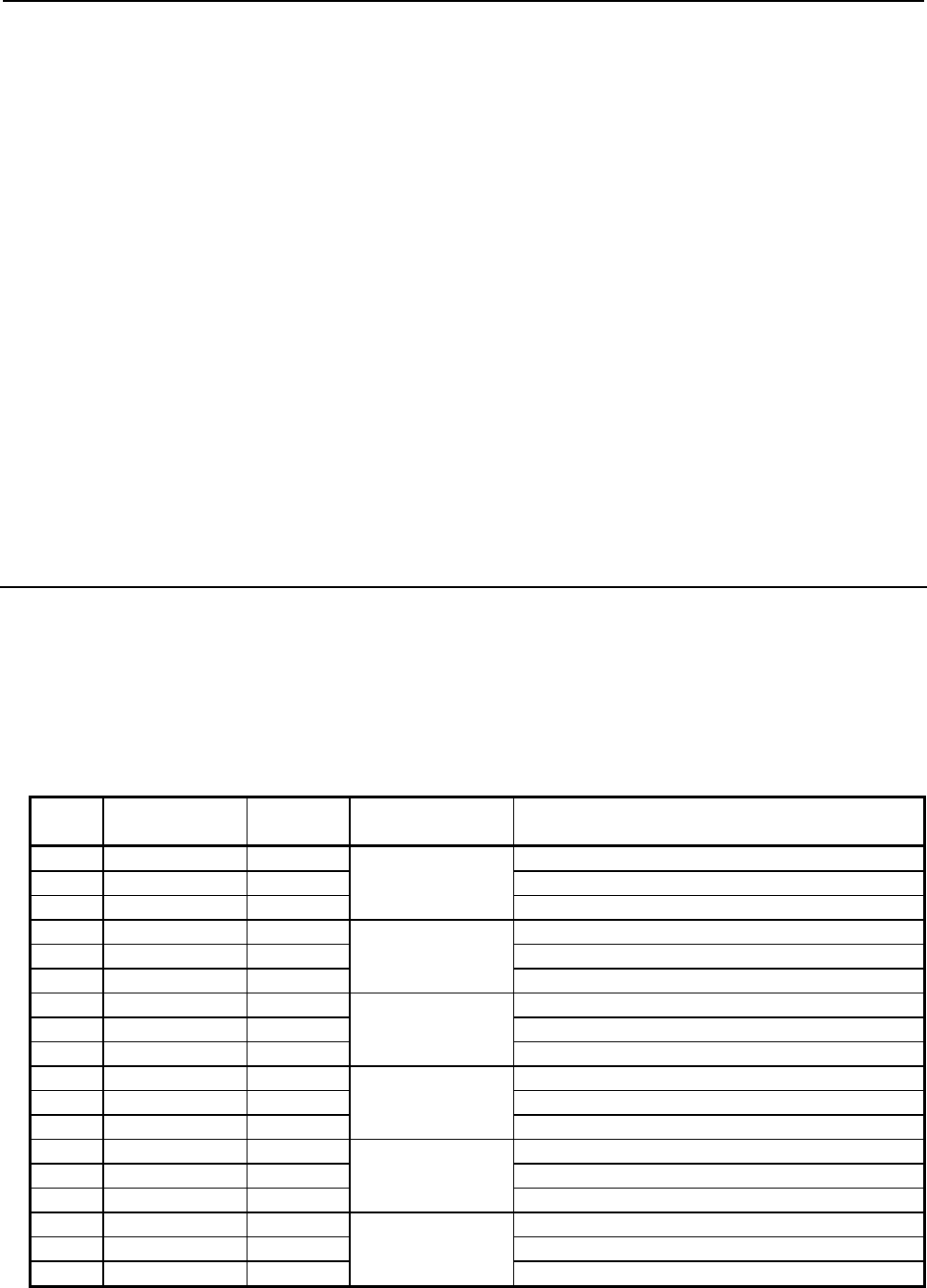
4.LADDER LANGUAGE
B-64513EN/03
- 342 -
4.6.5
DSEQB
(Searching Data from Table(=)(1 Byte Length):SUB 241)
DSEQW
(Searching Data from Table(=)(2 Bytes Length):SUB 242)
DSEQD
(Searching Data from Table(=)(4 Bytes Length):SUB 243)
DSNEB
(Searching Data from Table(≠)(1 Byte Length):SUB 244)
DSNEW
(Searching Data from Table(≠)(2 Bytes Length):SUB 245)
DSNED
(Searching Data from Table(≠)(4 Bytes Length):SUB 246)
DSGTB
(Searching Data from Table(>)(1 Byte Length):SUB 247)
DSGTW
(Searching Data from Table(>)(2 Bytes Length):SUB 248)
DSGTD
(Searching Data from Table(>)(4 Bytes Length):SUB 249)
DSLTB
(Searching Data from Table(<)(1 Byte Length):SUB 250)
DSLTW
(Searching Data from Table(<)(2 Bytes Length):SUB 251)
DSLTD
(Searching Data from Table(<)(4 Bytes Length):SUB 252)
DSGEB
(Searching Data from Table(≥)(1 Byte Length):SUB 253)
DSGEW
(Searching Data from Table(≥)(2 Bytes Length):SUB 254)
DSGED
(Searching Data from Table(≥)(4 Bytes Length) :SUB 255)
DSLEB
(Searching Data from Table(≤)(1 Byte Length) :SUB 256)
DSLEW
(Searching Data from Table(≤)(2 Bytes Length) :SUB 257)
DSLED
(Searching Data from Table(≤)(4 Bytes Length) :SUB 258)
The instruction searches a table for data that satisfies a specified condition and acquires the position of
found data.
As indicated below, eighteen types of Searching data from table instructions are available according to
the search condition and data type. In each instruction, the data in the table and "Search data" are of the
same data type. However, the data type of "Search starting position" and "Find position output address"
is two-byte signed binary data at all times.
Table4.6.5 (a) Kinds of Searching data from table instruction
Instruction
name
SUB
No.
Search
condition Data type
1 DSEQB 241 = 1 byte length signed binary data
2 DSEQW 242 2 bytes length signed binary data
3 DSEQD 243 4 bytes length signed binary data
4 DSNEB 244 ≠ 1 byte length signed binary data
5 DSNEW 245 2 bytes length signed binary data
6 DSNED 246 4 bytes length signed binary data
7 DSGTB 247 > 1 byte length signed binary data
8 DSGTW 248 2 bytes length signed binary data
9 DSGTD 249 4 bytes length signed binary data
10 DSLTB 250 < 1 byte length signed binary data
11 DSLTW 251 2 bytes length signed binary data
12 DSLTD 252 4 bytes length signed binary data
13 DSGEB 253
≧
1 byte length signed binary data
14 DSGEW 254 2 bytes length signed binary data
15 DSGED 255 4 bytes length signed binary data
16 DSLEB 256
≦
1 byte length signed binary data
17 DSLEW 257 2 bytes length signed binary data
18 DSLED 258 4 bytes length signed binary data
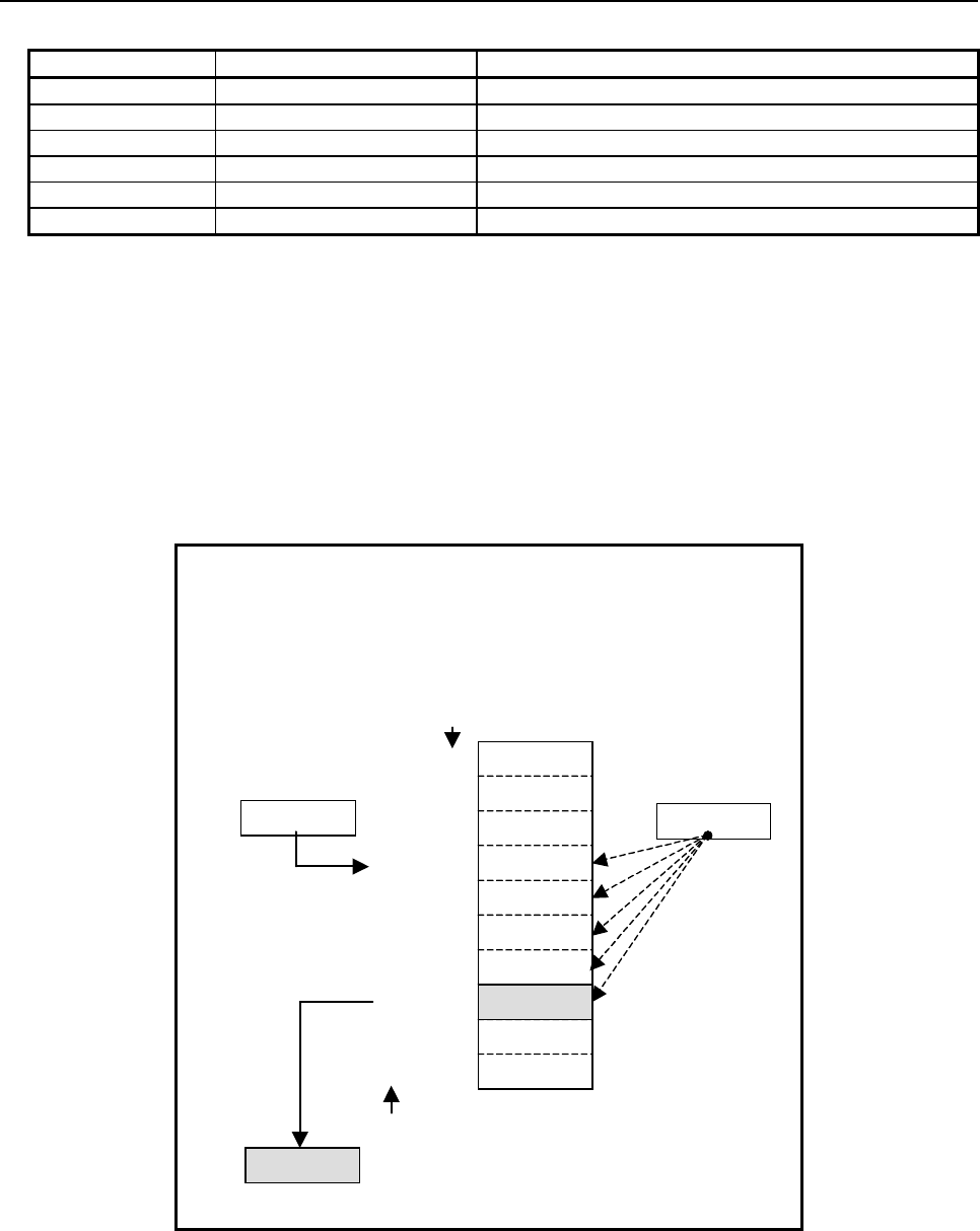
B-64513EN/03
4.LADDER LANGUAGE
- 343 -
Table4.6.5 (b) Concurrence conditions of search data
Instruction Search condition Concurrence conditions
DSEQx = Table data = search data
DSNEx ≠ Table data ≠ search data
DSGTx > Table data > search data
DSLTx < Table data < search data
DSGEx
≧
Table data
≧
search data
DSLEx
≦
Table data
≦
search data
The top of a table is specified in "Table top address". In "Search starting position", a data position is
specified relative to the top data position assumed to be 0. A value output to "Find position output
address" is also indicated as a data position relative to the top data position assumed to be 0. In "Search
starting position", a constant or a PMC memory address for storing data can be specified.
If a value not within the valid range is specified in "Search starting position", -1 is output to "Find
position output address", and W1=0 is set.
Moreover, if data that satisfies a specified condition is not found in the area from "Search starting
position" to the end of the table as a result of search operation, -1 is output to "Find position output
address", and W1=0 is set.
When data larger than "Search data" is to be found:
Number of data = 20
Table top address = D100
Search starting position = D200
Search data = D300
Find position output address = D400
Search starting position
Table top address
D200 3
Find position output address
D400
The data No. in a table
0
1
3
4
5
:
19
2
7
6
Search data
D300 175
7
10
200
4000
175
50
0
180
90
200
:
D100
D102
D106
D108
D114
D112
D110
D138
D104
:
Fig. 4.6.5 (a) Example of DSGTW instruction
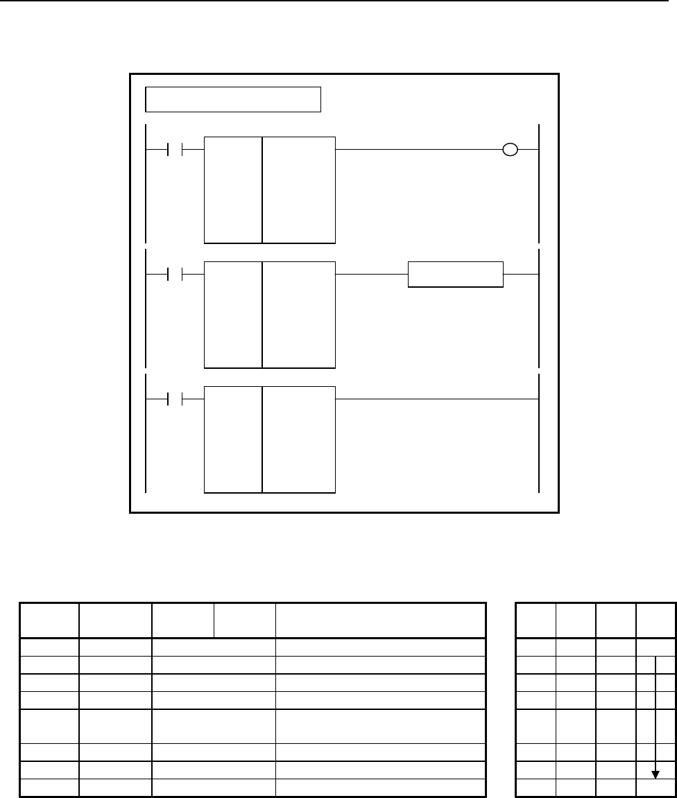
4.LADDER LANGUAGE
B-64513EN/03
- 344 -
Format
Fig. 4.6.5(b) shows the ladder format and Table 4.6.5(c) shows the mnemonic format.
SUB 241
DSEQB
{{{{
{{{{
{{{{
{{{{
{{{{
Number of data (Constant)
Table top address
Search starting position (Address or Constant)
Search data (Address or Constant)
Find position output address
ACT W1
SUB 241
DSEQB
{{{{
{{{{
{{{{
{{{{
{{{{
ACT
SUB 241
DSEQB
{{{{
{{{{
{{{{
{{{{
{{{{
ACT ACT2
Functional Instruction
Example : DSEQB Instruction
Fig. 4.6.5 (b) Format of DSEQx, DSNEx, DSGTx, DSLTx, DSGEx, DSLEx instruction
Table 4.6.5 (c) Mnemonic of DSEQx, DSNEx, DSGTx, DSLTx, DSGEx, DSLEx instruction
Mnemonic format
Memory status of control
condition
Step
number Instruction Address
No. Bit No. Remarks
ST3 ST2 ST1 ST0
1 RD
{{{{
.
{
ACT ACT
2 SUB 241 SUB No. (DSEQB instruction)
3 (PRM)
{{{{
Number of data (Constant)
4 (PRM)
{{{{
Table top address
5 (PRM)
{{{{
Search starting position (Address or
Constant)
6 (PRM)
{{{{
Search data (Address or Constant)
7 (PRM)
{{{{
Find position output address
8 WRT
{{{{
.
{
Result output W1
Control condition
(a) Execution specification
ACT = 0: Instruction not executed.
ACT = 1: Executed.
Parameters
(a) Number of data
Specify the number of data items in a table. Ensure that the entire table is within the valid address
range.
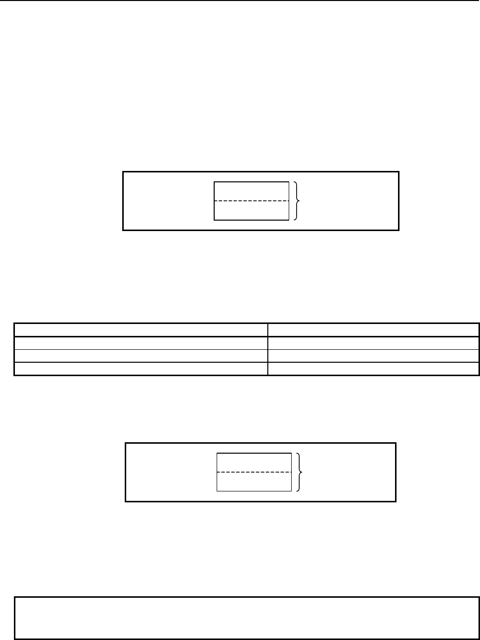
B-64513EN/03
4.LADDER LANGUAGE
- 345 -
(b) Table top address
Specify the top address of a table.
(c) Search starting position
Specify a search start data position relative to the top data position assumed to be 0. A value from
0 to the number of data items less 1 may be specified. If a value not within this valid range is
specified, no search operation is performed, -1 is output to "Find position output address", and
W1=0 is set.
In this parameter, a constant or a PMC memory address can be specified.
If an address is specified, specify "Search starting position" as signed binary data by using the
contiguous two bytes of memory starting from the specified address.
Specified address +0
Specified address +1
Search starting position
(Signed binary data)
(d) Search data
Specify a value to be compared with in search operation. A comparison is made with this data
according to the search condition of each instruction, and the position of data that satisfies the search
condition is acquired.
In this parameter, a constant or a PMC memory address for storing data can be specified. Specify
data by using signed binary data. A value within the following range may be specified:
Instruction name Available value
DSEQB DSNEB DSGTB DSLTB DSGEB DSLEB -128 to 127
DSEQW DSNEW DSGTW DSLTW DSGEW DSLEW -32768 to 32767
DSEQD DSNED DSGTD DSLTD DSGED DSLED -2147483648 to 2147483647
(e) Find position output address
Specify the address for outputting data that satisfies the specified condition as a result of search.
A find position is output as two-bye signed binary data.
If no data satisfies the specified condition, -1 is output, and W1=0 is set.
Specified address +0
Specified address +1
Find position
(Signed binary data)
Output (W1)
W1=1: Data that satisfies a specified condition is found
W1=0: No search operation is executed (ACT=0)
Data that satisfies a specified condition is not found in the area from "Search starting position" to
the end of the table
A value not within the valid range is set in "Search starting position"
NOTE
W1 may be omitted. Moreover, another functional instruction can be connected
instead of a coil.
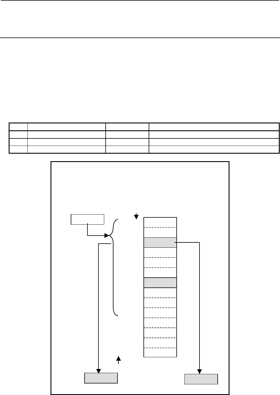
4.LADDER LANGUAGE
B-64513EN/03
- 346 -
4.6.6
DMAXB (Maximum Data (1 Byte Length): SUB 259)
DMAXW (Maximum Data (2 Bytes Length) : SUB 260)
DMAXD (Maximum Data (4 Bytes Length) : SUB 261)
The Maximum data instruction searches a table for maximum data and acquires the value and position of
found maximum data.
The top of a table is specified in "Table top address". A value output to "Find position output address"
is indicated as a data position relative to the top data position assumed to be 0.
A search is made starting at the top of a table. In "Number of search data", the number of data items to
be searched in the area from the top of a table to a desired search position is specified.
As indicated below, three types of Maximum data instructions are available according to the data type of
a table to be searched. In each instruction, the data in the table and data at "Maximum data output
address" are of the same data type. However, the data type of "Number of search data" and "Find
position output address" is two-byte signed binary data at all times.
Table4.6.6 (a) Kinds of Maximum data instruction
Instruction name SUB No. Data type
1 DMAXB 259 1 byte length signed data
2 DMAXW 260 2 bytes length signed data
3 DMAXD 261 4 bytes length signed data
When a table is searched for maximum data and its position:
Number of data = 20
Table top address = D100
Number of search data = D400
Maximum data output address = D200
Find position output address = D300
(Search range)
Table top address
Find position output address
D300
0
1
3
4
D100
D102
D106
D108
The data No. in a table
8
9
D114
D112
D116
D118
D1042
100
200
-2000
50
7
630000
-2000
2000
Maximum data output address
D200
10000
30000
5D110 720
2 30000
Number of search data
D400 10
D120
D122
10
11
:: :
0
0
019 D138
Fig. 4.6.6 (a) Example of DMAXW instruction

B-64513EN/03
4.LADDER LANGUAGE
- 347 -
Format
Fig. 4.6.6(b) shows the ladder format and Table 4.6.6(b) shows the mnemonic format.
SUB 259
DMAXB
{{{{
{{{{
{{{{
{{{{
{{{{
ACT
SUB 259
DMAXB
{{{{
{{{{
{{{{
{{{{
{{{{
Number of data (Constant)
Table top address
Number of search data (Address or Constant)
Maximum data output address
Find position output address
ACT W1
SUB 259
DMAXB
{{{{
{{{{
{{{{
{{{{
{{{{
Functional Instruction
ACT ACT2
Example : DMAXB Instruction
Fig. 4.6.6 (b) Format of DMAXB, DMAXW, DMAXD instruction
Table 4.6.6 (b) Mnemonic of DMAXB, DMAXW, DMAXD instruction
Mnemonic format
Memory status of control
condition
Step
number Instruction Address
No. Bit No. Remarks
ST3 ST2 ST1 ST0
1 RD
{{{{
.
{
ACT ACT
2 SUB 259 SUB No. (DMAXB instruction)
3 (PRM)
{{{{
Number of data (Constant)
4 (PRM)
{{{{
Table top address
5 (PRM)
{{{{
Number of search data (Address or
Constant)
6 (PRM)
{{{{
Maximum data output address
7 (PRM)
{{{{
Find position output address
8 WRT
{{{{
.
{
Normal end output W1
Control condition
(a) Execution specification
ACT = 0: Instruction not executed.
ACT = 1: Executed.
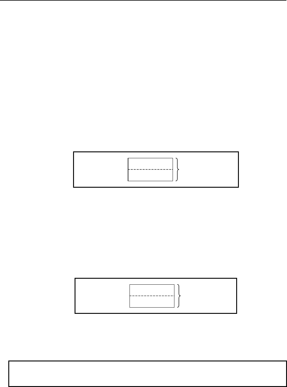
4.LADDER LANGUAGE
B-64513EN/03
- 348 -
Parameters
(a) Number of data
Specify the number of data items in a table. Ensure that the entire table is within the valid address
range.
This parameter indicates the total number of data items of a table. A data range to be searched is
specified using the "Number of search data" parameter.
(b) Table top address
Specify the top address of a table.
(c) Number of search data
Specify the number of data items to be searched for maximum data in a table. A value from 1 to
the value specified in the "Number of data" parameter may be specified. If a value not within this
valid range is specified, 0 is output to "Maximum data output address", -1 is output to "Find position
output address", and W1=0 is set.
In this parameter, a constant or a PMC memory address for storing data can be specified.
If an address is specified, specify a search range as signed binary data by using the contiguous two
bytes of memory starting from the specified address.
Specified address +0
Specified address +1
Number of search data
(Signed binary data)
(d) Maximum data output address
Specify the address to which maximum data is to be output as a result of search operation.
(e) Find position output address
Specify the address to which the position of maximum data is to be output as a result of search
operation.
A find position is output as two-bye signed binary data.
As data position information, the top of the table is indicated as 0, and the end of the table is indicated
as the number of data items less 1. If multiple maximum data items are found, the position nearest to
the top of the table is output.
Specified address +0
Specified address +1
Find position
(Signed binary data)
Output (W1)
W1=1: A search operation is terminated normally
W1=0: No search operation is executed (ACT=0)
A value not within the valid range is set in "Number of search data"
NOTE
W1 may be omitted. Moreover, another functional instruction can be connected
instead of a coil.
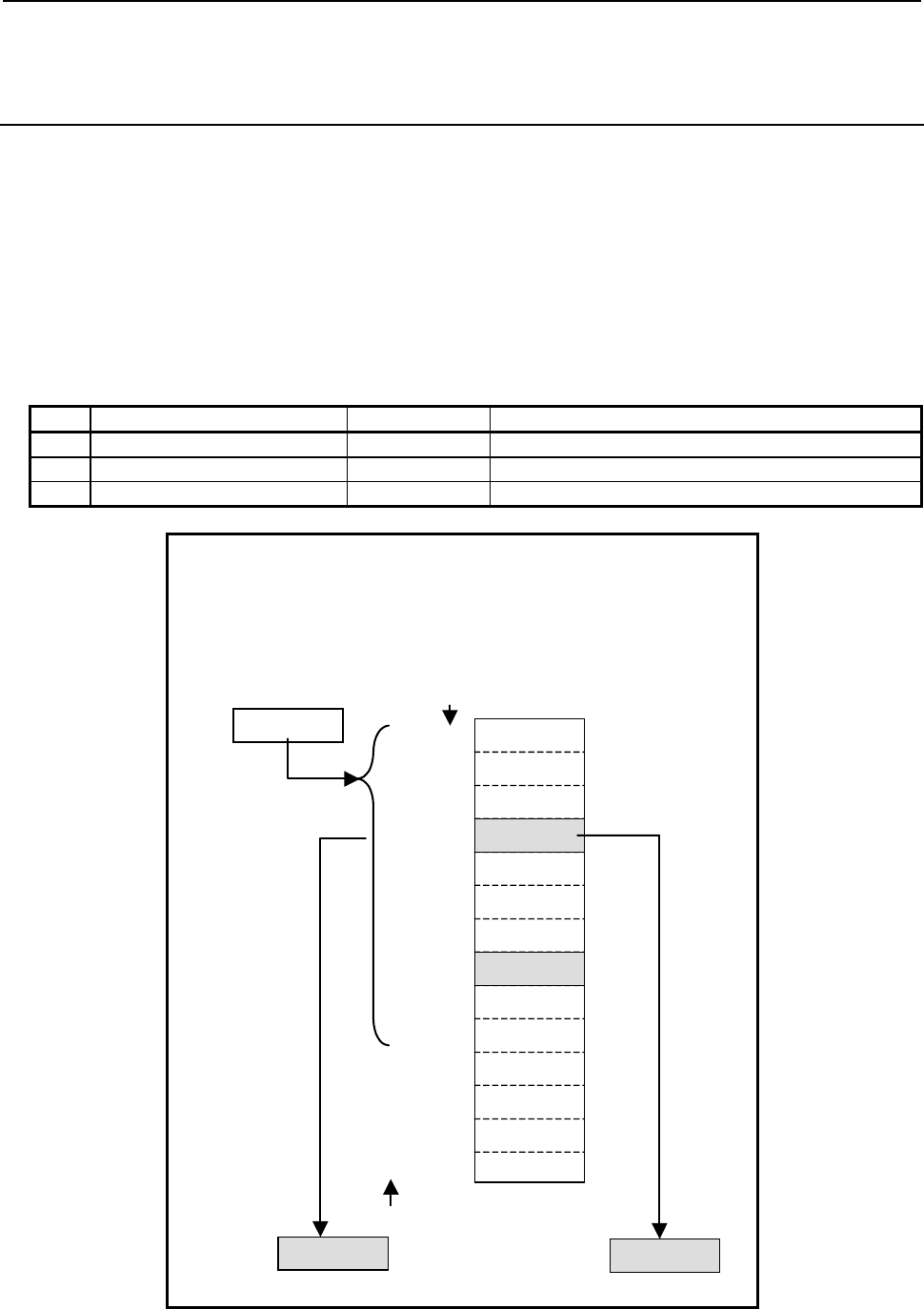
B-64513EN/03
4.LADDER LANGUAGE
- 349 -
4.6.7
DMINB (Minimum Data (1 Byte Length): SUB 262)
DMINW (Minimum Data (2 Bytes Length): SUB 263)
DMIND (Minimum Data (4 Bytes Length): SUB 264)
The Minimum data instruction searches a table for minimum data and acquires the value and position of
found minimum data.
The top of a table is specified in "Table top address". A value output to "Find position output address"
is indicated as a data position relative to the top data position assumed to be 0.
A search is made starting at the top of a table. In "Number of search data", the number of data items to
be searched in the area from the top of a table to a desired search position is specified.
As indicated below, three types of Minimum data instructions are available according to the data type of a
table to be searched. In each instruction, the data in the table and data at "Minimum data output
address" are of the same data type. However, the data type of "Number of search data" and "Find
position output address" is two-byte signed binary data at all times.
Table4.6.7 (a) Kinds of Minimum data instruction
Instruction name SUB No. Data type
1 DMINB 262 1 byte length signed data
2 DMINW 263 2 bytes length signed data
3 DMIND 264 4 bytes length signed data
When a table is searched for minimum data and its position:
Number of data = 20
Table top address = D100
Number of search data = D400
Minimum data output address = D200
Find position output address = D300
(Search range)
Table top address
Find position output address
D300
0
1
3
4
D100
D102
D106
D108
The data No. in a table
8
9
D114
D112
D116
D118
D1042
100
200
50
7
630000
-2000
2000
Minimum data output address
D200
10000
30000
5D110 720
3 -2000
Number of search data
D400 10
D120
D122
10
11
:: :
0
0
019 D138
-2000
Fig. 4.6.7 (a) Example of DMINW instruction
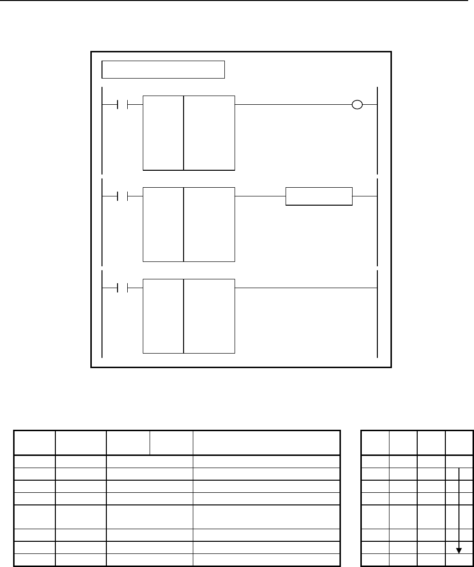
4.LADDER LANGUAGE
B-64513EN/03
- 350 -
Format
Fig. 4.6.7(b) shows the ladder format and Table 4.6.7(b) shows the mnemonic format.
SUB 262
DMINB
{{{{
{{{{
{{{{
{{{{
{{{{
ACT
SUB 262
DMINB
{{{{
{{{{
{{{{
{{{{
{{{{
Number of data (Constant)
Table top address
Number of search data (Address or Constant)
Minimum data output address
Find position output address
ACT W1
SUB 262
DMINB
{{{{
{{{{
{{{{
{{{{
{{{{
Functional Instruction
ACT ACT2
Example : DMINB Instruction
Fig. 4.6.7 (b) Format of DMINB, DMINW, DMIND instruction
Table 4.6.7 (b) Mnemonic of DMINB, DMINW, DMIND instruction
Mnemonic format
Memory status of control
condition
Step
number Instruction Address
No. Bit No. Remarks
ST3 ST2 ST1 ST0
1 RD
{{{{
.
{
ACT ACT
2 SUB 262 SUB No. (DMINB instruction)
3 (PRM)
{{{{
Number of data (Constant)
4 (PRM)
{{{{
Table top address
5 (PRM)
{{{{
Number of search data (Address or
Constant)
6 (PRM)
{{{{
Minimum data output address
7 (PRM)
{{{{
Find position output address
8 WRT
{{{{
.
{
Normal end output W1
Control condition
(a) Execution specification
ACT = 0: Instruction not executed.
ACT = 1: Executed.

B-64513EN/03
4.LADDER LANGUAGE
- 351 -
Parameters
(a) Number of data
Specify the number of data items in a table. Ensure that the entire table is within the valid address
range.
This parameter indicates the total number of data items of a table. A data range to be searched is
specified using the "Number of search data" parameter.
(b) Table top address
Specify the top address of a table.
(c) Number of search data
Specify the number of data items to be searched for minimum data in a table. A value from 1 to the
value specified in the "Number of data" parameter may be specified. If an invalid value is
specified, 0 is output to "Minimum data output address", -1 is output to "Find position output
address", and W1=0 is set.
In this parameter, a constant or a PMC memory address for storing data can be specified.
If an address is specified, specify a search range as signed binary data by using the contiguous two
bytes of memory starting from the specified address.
Specified address +0
Specified address +1
Number of search data
(Signed binary data)
(d) Minimum data output address
Specify the address to which minimum data is to be output as a result of search operation.
(e) Find position output address
Specify the address to which the position of minimum data is to be output as a result of search
operation.
A find position is output as two-bye signed binary data.
As data position information, the top of the table is indicated as 0, and the end of the table is indicated
as the number of data items less 1. If multiple minimum data items are found, the position nearest to
the top of the table is output.
Specified address +0
Specified address +1
Find position
(Signed binary data)
Output (W1)
W1=1: A search operation is terminated normally
W1=0: No search operation is executed (ACT=0)
A value not within the valid range is set in "Number of search data"
NOTE
W1 may be omitted. Moreover, another functional instruction can be connected
instead of a coil.

4.LADDER LANGUAGE
B-64513EN/03
- 352 -
4.7 COMPARISON
The following types of comparison instruction are available. Use any of these instructions as
appropriate for your purpose.
Instruction
name
Sub number Processing
1 EQB 200 1 byte Binary comparison (equal) (*1)
2 EQW 201 2 byte Binary comparison (equal) (*1)
3 EQD 202 4 byte Binary comparison (equal) (*1)
4 NEB 203 1 byte Binary comparison (not equal) (*1)
5 NEW 204 2 byte Binary comparison (not equal) (*1)
6 NED 205 4 byte Binary comparison (not equal) (*1)
7 GTB 206 1 byte Binary comparison (greater than) (*1)
8 GTW 207 2 byte Binary comparison (greater than) (*1)
9 GTD 208 4 byte Binary comparison (greater than) (*1)
10 LTB 209 1 byte Binary comparison (less than) (*1)
11 LTW 210 2 byte Binary comparison (less than) (*1)
12 LTD 211 4 byte Binary comparison (less than) (*1)
13 GEB 212 1 byte Binary comparison (greater or equal) (*1)
14 GEW 213 2 byte Binary comparison (greater or equal) (*1)
15 GED 214 4 byte Binary comparison (greater or equal) (*1)
16 LEB 215 1 byte Binary comparison (less or equal) (*1)
17 LEW 216 2 byte Binary comparison (less or equal) (*1)
18 LED 217 4 byte Binary comparison (less or equal) (*1)
19 RNGB 218 1 byte Binary comparison (range) (*1)
20 RNGW 219 2 byte Binary comparison (range) (*1)
21 RNGD 220 4 byte Binary comparison (range) (*1)
22 COMPB 32 Comparison between binary data
23 COMP 15 Comparison
24 COIN 16 Coincidence check
NOTE
1 You can set either constant or address to each parameter for the "(*1)" marked
instruction. When you input a number to its parameter on LADDER editing
screen, the input is recognized as a constant parameter. When you input a
symbol that is composed of digits and that may be considered as a number, the
input is recognized as a number and treated as a constant parameter too. If you
want to set such address that has a confusing symbol, you have to input the
address, not the symbol, to the parameter.
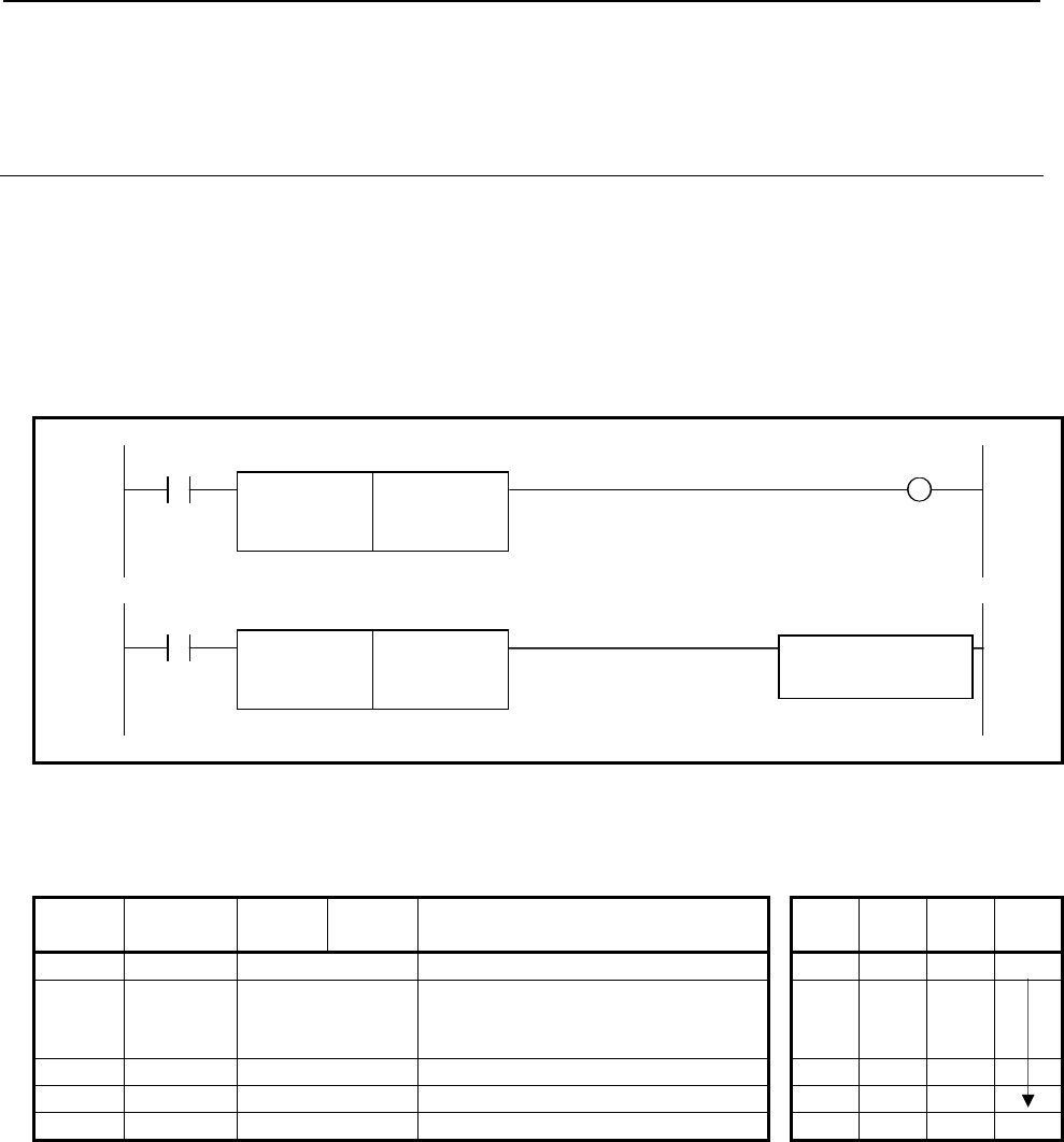
B-64513EN/03
4.LADDER LANGUAGE
- 353 -
4.7.1
Signed Binary Comparison (=)
EQB (1 Byte Length: SUB 200)
EQW (2 Bytes Length: SUB 201)
EQD (4 Bytes Length: SUB 202)
Using this instruction, you can know whether the "Data 1" equals to the "Data 2" or not.
The EQB instruction handles 1 byte length signed binary data.
The EQW instruction handles 2 bytes length signed binary data.
The EQD instruction handles 4 bytes length signed binary data.
Format
Fig. 4.7.1 shows the ladder format and Table 4.7.1 shows the mnemonic format.
Example: EQB instruction
ACT W1
SUB 200
EQB
{{{{
Data1 (Constant or Address)
{{{{
Data2 (Constant or Address)
ACT
SUB 200
EQB
{{{{
Data1 (Constant or Address) Functional Instruction
{{{{
Data2 (Constant or Address)
Fig. 4.7.1 Format of EQB, EQW and EQD instructions
Table 4.7.1 Mnemonic of EQB, EQW and EQD instructions
Mnemonic format Memory status of control
condition
Step
number Instruction Address
No. Bit No. Remarks ST3 ST2 ST1 ST0
1 RD
{{{{
.
{
ACT ACT
2 SUB 200
201
202
EQB instruction
EQW instruction
EQD instruction
3 (PRM)
{{{{
Data1 (Constant or Address)
4 (PRM)
{{{{
Data2 (Constant or Address)
5 WRT
{{{{
.
{
Result W1
Control condition
(a) Execution specification (ACT)
ACT=0: Do not execute the instruction. The W1 becomes 0.
ACT=1: Execute the instruction. The result is output to W1.
Parameters
(a) Data 1
(b) Data 2
You can specify the constant or any address. The valid data range is shown below.
EQB: -128 to 127
EQW: -32768 to 32767
EQD: -2147483648 to 2147483647

4.LADDER LANGUAGE
B-64513EN/03
- 354 -
Output (W1)
The result is output to W1.
W1=1: - ACT=1 and "Data 1" = "Data 2"
W1=0: - ACT=0
- ACT=1 and "Data 1" ≠ "Data2"
Operation Output Register (R9000, Z0)
This instruction does not update the operation output register. So, the operation output register will not
change after this instruction.
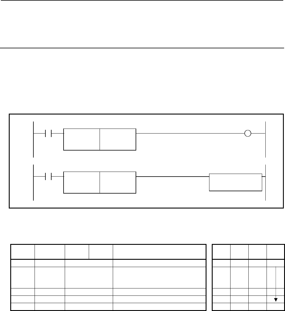
B-64513EN/03
4.LADDER LANGUAGE
- 355 -
4.7.2
Signed Binary Comparison (≠)
NEB (1 Byte Length: SUB 203)
NEW (2 Bytes Length: SUB 204)
NED (4 Bytes Length: SUB 205)
Using this instruction, you can know whether the "Data 1" does not equal to the "Data 2" or not.
The NEB instruction handles 1 byte length signed binary data.
The NEW instruction handles 2 bytes length signed binary data.
The NED instruction handles 4 bytes length signed binary data.
Format
Fig. 4.7.2 shows the ladder format and Table 4.7.2 shows the mnemonic format.
Example: NEB instruction
ACT W1
SUB 203
NEB
{{{{
Data1 (Constant or Address)
{{{{
Data2 (Constant or Address)
ACT
SUB 203
NEB
{{{{
Data1 (Constant or Address) Functional Instruction
{{{{
Data2 (Constant or Address)
Fig. 4.7.2 Format of NEB, NEW and NED instructions
Table 4.7.2 Mnemonic of NEB, NEW and NED instructions
Mnemonic format Memory status of control
condition
Step
number Instruction Address
No. Bit No. Remarks ST3 ST2 ST1 ST0
1 RD
{{{{
.
{
ACT ACT
2 SUB 203
204
205
NEB instruction
NEW instruction
NED instruction
3 (PRM)
{{{{
Data1 (Constant or Address)
4 (PRM)
{{{{
Data2 (Constant or Address)
5 WRT
{{{{
.
{
Result W1
Control condition
(a) Execution specification (ACT)
ACT=0: Do not execute the instruction. The W1 becomes 0.
ACT=1: Execute the instruction. The result is output to W1.
Parameters
(a) Data 1
(b) Data 2
You can specify the constant or any address. The valid data range is shown below.
NEB: -128 to 127
NEW: -32768 to 32767
NED: -2147483648 to 2147483647

4.LADDER LANGUAGE
B-64513EN/03
- 356 -
Output (W1)
The result is output to W1.
W1=1: - ACT=1 and "Data 1" ≠ "Data 2"
W1=0: - ACT=0
- ACT=1 and "Data 1" = "Data2"
Operation Output Register (R9000, Z0)
This instruction does not update the operation output register. So, the operation output register will not
change after this instruction.
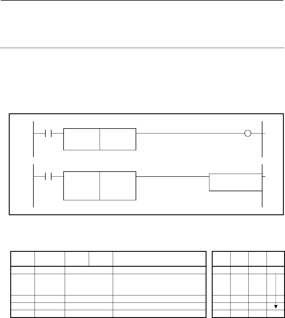
B-64513EN/03
4.LADDER LANGUAGE
- 357 -
4.7.3
Signed Binary Comparison (>)
GTB (1 Byte Length: SUB 206)
GTW (2 Bytes Length: SUB 207)
GTD (4 Bytes Length: SUB 208)
Using this instruction, you can know whether the "Data 1" is greater than the "Data 2" or not.
The GTB instruction handles 1 byte length signed binary data.
The GTW instruction handles 2 bytes length signed binary data.
The GTD instruction handles 4 bytes length signed binary data.
Format
Fig. 4.7.3 shows the ladder format and Table 4.7.3 shows the mnemonic format.
Example: GTB instruction
ACT W1
SUB 206
GTB
{{{{
Data1 (Constant or Address)
{{{{
Data2 (Constant or Address)
ACT
SUB 206
GTB
{{{{
Data1 (Constant or Address) Functional
Instruction
{{{{
Data2 (Constant or Address)
Fig. 4.7.3 Format of GTB, GTW and GTD instructions
Table 4.7.3 Mnemonic of GTB, GTW and GTD instructions
Mnemonic format Memory status of control
condition
Step
number Instruction Address
No. Bit No. Remarks ST3 ST2 ST1 ST0
1 RD
{{{{
.
{
ACT ACT
2 SUB 206
207
208
GTB instruction
GTW instruction
GTD instruction
3 (PRM)
{{{{
Data1 (Constant or Address)
4 (PRM)
{{{{
Data2 (Constant or Address)
5 WRT
{{{{
.
{
Result W1
Control condition
(a) Execution specification (ACT)
ACT=0: Do not execute the instruction. The W1 becomes 0.
ACT=1: Execute the instruction. The result is output to W1.
Parameters
(a) Data 1
(b) Data 2
You can specify the constant or any address. The valid data range is shown below.
GTB: -128 to 127
GTW: -32768 to 32767
GTD: -2147483648 to 2147483647

4.LADDER LANGUAGE
B-64513EN/03
- 358 -
Output (W1)
The result is output to W1.
W1=1: - ACT=1 and "Data 1" > "Data 2"
W1=0: - ACT=0
- ACT=1 and "Data 1" ≦ "Data2"
Operation Output Register (R9000, Z0)
This instruction does not update the operation output register. So, the operation output register will not
change after this instruction.
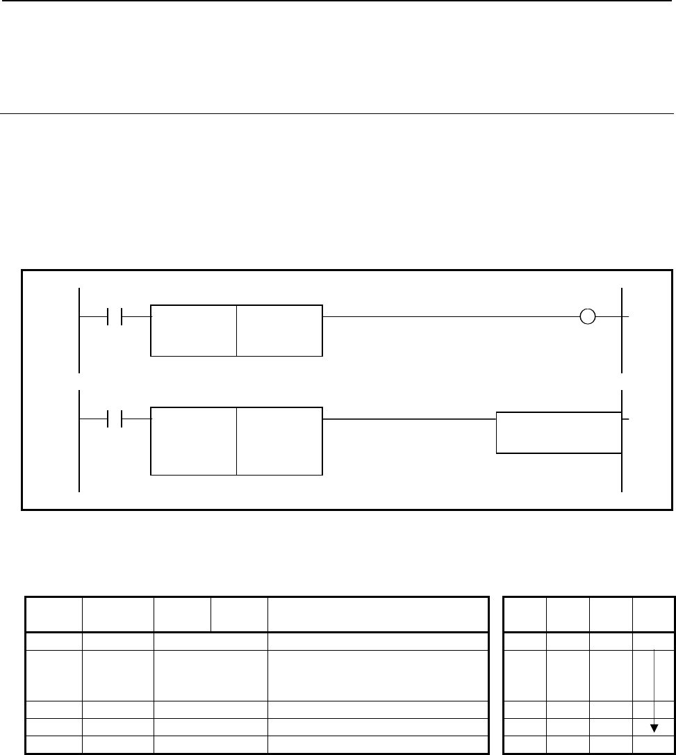
B-64513EN/03
4.LADDER LANGUAGE
- 359 -
4.7.4
Signed Binary Comparison (<)
LTB (1 Byte Length: SUB 209)
LTW (2 Bytes Length: SUB 210)
LTD (4 Bytes Length: SUB 211)
Using this instruction, you can know whether the "Data 1" is smaller than the "Data 2" or not.
The LTB instruction handles 1 byte length signed binary data.
The LTW instruction handles 2 bytes length signed binary data.
The LTD instruction handles 4 bytes length signed binary data.
Format
Fig. 4.7.4 shows the ladder format and Table 4.7.4 shows the mnemonic format.
Example: LTB instruction
ACT W1
SUB 209
LTB
{{{{
Data1 (Constant or Address)
{{{{
Data2 (Constant or Address)
ACT
SUB 209
LTB
{{{{
Data1 (Constant or Address) Functional
Instruction
{{{{
Data2 (Constant or Address)
Fig. 4.7.4 Format of LTB, LTW and LTD instructions
Table 4.7.4 Mnemonic of LTB, LTW and LTD instructions
Mnemonic format Memory status of control
condition
Step
number Instruction Address
No. Bit No. Remarks ST3 ST2 ST1 ST0
1 RD
{{{{
.
{
ACT ACT
2 SUB 209
210
211
LTB instruction
LTW instruction
LTD instruction
3 (PRM)
{{{{
Data1 (Constant or Address)
4 (PRM)
{{{{
Data2 (Constant or Address)
5 WRT
{{{{
.
{
Result W1
Control condition
(a) Execution specification (ACT)
ACT=0: Do not execute the instruction. The W1 becomes 0.
ACT=1: Execute the instruction. The result is output to W1.
Parameters
(a) Data 1
(b) Data 2
You can specify the constant or any address. The valid data range is shown below.
LTB: -128 to 127
LTW: -32768 to 32767
LTD: -2147483648 to 2147483647

4.LADDER LANGUAGE
B-64513EN/03
- 360 -
Output (W1)
The result is output to W1.
W1=1: - ACT=1 and "Data 1" < "Data 2"
W1=0: - ACT=0
- ACT=1 and "Data 1" ≧ "Data2"
Operation Output Register (R9000, Z0)
This instruction does not update the operation output register. So, the operation output register will not
change after this instruction.
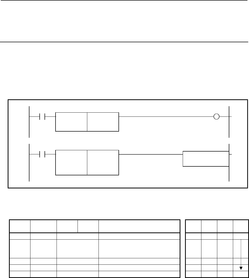
B-64513EN/03
4.LADDER LANGUAGE
- 361 -
4.7.5
Signed Binary Comparison (≥)
GEB (1 Byte Length: SUB 212)
GEW (2 Bytes Length: SUB 213)
GED (4 Bytes Length: SUB 214)
Using this instruction, you can know whether the "Data 1" is equal or greater than the "Data 2" or not.
The GEB instruction handles 1 byte length signed binary data.
The GEW instruction handles 2 bytes length signed binary data.
The GED instruction handles 4 bytes length signed binary data.
Format
Fig. 4.7.5 shows the ladder format and Table 4.7.5 shows the mnemonic format.
Example: GEB instruction
ACT W1
SUB 212
GEB
{{{{
Data1 (Constant or Address)
{{{{
Data2 (Constant or Address)
ACT
SUB 212
GEB
{{{{
Data1 (Constant or Address) Functional
Instruction
{{{{
Data2 (Constant or Address)
Fig. 4.7.5 Format of GEB, GEW and GED instructions
Table 4.7.5 Mnemonic of GEB, GEW and GED instructions
Mnemonic format Memory status of control
condition
Step
number Instruction Address
No. Bit No. Remarks ST3 ST2 ST1 ST0
1 RD
{{{{
.
{
ACT ACT
2 SUB 212
213
214
GEB instruction
GEW instruction
GED instruction
3 (PRM)
{{{{
Data1 (Constant or Address)
4 (PRM)
{{{{
Data2 (Constant or Address)
5 WRT
{{{{
.
{
Result W1
Control condition
(a) Execution specification (ACT)
ACT=0: Do not execute the instruction. The W1 becomes 0.
ACT=1: Execute the instruction. The result is output to W1.
Parameters
(a) Data 1
(b) Data 2
You can specify the constant or any address. The valid data range is shown below.
GEB: -128 to 127
GEW: -32768 to 32767
GED: -2147483648 to 2147483647

4.LADDER LANGUAGE
B-64513EN/03
- 362 -
Output (W1)
The result is output to W1.
W1=1: - ACT=1 and "Data 1" ≧ "Data 2"
W1=0: - ACT=0
- ACT=1 and "Data 1" < "Data2"
Operation Output Register (R9000, Z0)
This instruction does not update the operation output register. So, the operation output register will not
change after this instruction.

B-64513EN/03
4.LADDER LANGUAGE
- 363 -
4.7.6
Signed Binary Comparison (≤)
LEB (1 Byte Length: SUB 215)
LEW (2 Bytes Length: SUB 216)
LED (4 Bytes Length: SUB 217)
Using this instruction, you can know whether the "Data 1" is equal or smaller than the "Data 2" or not.
The LEB instruction handles 1 byte length signed binary data.
The LEW instruction handles 2 bytes length signed binary data.
The LED instruction handles 4 bytes length signed binary data.
Format
Fig. 4.7.6 shows the ladder format and Table 4.7.6 shows the mnemonic format.
Example: LEB instruction
ACT W1
SUB 215
LEB
{{{{
Data1 (Constant or Address)
{{{{
Data2 (Constant or Address)
ACT
SUB 215
LEB
{{{{
Data1 (Constant or Address) Functional
Instruction
{{{{
Data2 (Constant or Address)
Fig. 4.7.6 Format of LEB, LEW and LED instructions
Table 4.7.6 Mnemonic of LEB, LEW and LED instructions
Mnemonic format Memory status of control
condition
Step
number Instruction Address
No. Bit No. Remarks ST3 ST2 ST1 ST0
1 RD
{{{{
.
{
ACT ACT
2 SUB 215
216
217
LEB instruction
LEW instruction
LED instruction
3 (PRM)
{{{{
Data1 (Constant or Address)
4 (PRM)
{{{{
Data2 (Constant or Address)
5 WRT
{{{{
.
{
Result W1
Control condition
(a) Execution specification (ACT)
ACT=0: Do not execute the instruction. The W1 becomes 0.
ACT=1: Execute the instruction. The result is output to W1.
Parameters
(a) Data 1
(b) Data 2
You can specify the constant or any address. The valid data range is shown below.
LEB: -128 to 127
LEW: -32768 to 32767
LED: -2147483648 to 2147483647

4.LADDER LANGUAGE
B-64513EN/03
- 364 -
Output (W1)
The result is output to W1.
W1=1: - ACT=1 and "Data 1" ≦ "Data 2"
W1=0: - ACT=0
- ACT=1 and "Data 1" > "Data2"
Operation Output Register (R9000, Z0)
This instruction does not update the operation output register. So, the operation output register will not
change after this instruction.
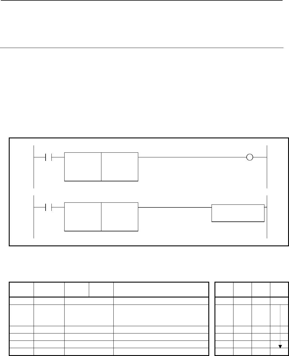
B-64513EN/03
4.LADDER LANGUAGE
- 365 -
4.7.7
Signed Binary Comparison (Range)
RNGB (1 Byte Length: SUB 218)
RNGW (2 Bytes Length: SUB 219)
RNGD (4 Bytes Length: SUB 220)
This instruction is the range comparison function. When following data conditions, the output W1
becomes 1.
- "Data 1" ≦ "Input data" ≦ "Data 2" or
"Data 2" ≦ "Input data" ≦ "Data 1"
The RNGB instruction handles 1 byte length signed binary data.
The RNGW instruction handles 2 bytes length signed binary data.
The RNGD instruction handles 4 bytes length signed binary data.
Format
Fig. 4.7.7 shows the ladder format and Table 4.7.7 shows the mnemonic format.
Example: LNGB instruction
ACT W1
SUB 218
RNGB
{{{{
Data1 (Constant or Address)
{{{{
Data2 (Constant or Address)
{{{{
Input data (Constant or Address)
ACT
SUB 218
RNGB
{{{{
Data1 (Constant or Address) Functional Instruction
{{{{
Data2 (Constant or Address)
{{{{
Input data (Constant or Address)
Fig. 4.7.7 Format of RNGB, RNGW and RNGD instructions
Table 4.7.7 Mnemonic of RNGB, RNGW and RNGD instructions
Mnemonic format Memory status of control
condition
Step
number Instruction Address
No. Bit No. Remarks ST3 ST2 ST1 ST0
1 RD
{{{{
.
{
ACT ACT
2 SUB 215
216
217
LEB instruction
LEW instruction
LED instruction
3 (PRM)
{{{{
Data1 (Constant or Address)
4 (PRM)
{{{{
Data2 (Constant or Address)
5 (PRM)
{{{{
Input data (Constant or Address)
6 WRT
{{{{
.
{
Result W1
Control condition
(a) Execution specification (ACT)
ACT=0: Do not execute the instruction. The W1 becomes 0.
ACT=1: Execute the instruction. The result is output to W1.

4.LADDER LANGUAGE
B-64513EN/03
- 366 -
Parameters
(a) Data 1
(b) Data 2
(c) Input data
You can specify the constant or any address. The valid data range is shown below.
RNGB: -128 to 127
RNGW: -32768 to 32767
RNGD: -2147483648 to 2147483647
Output (W1)
The result is output to W1.
W1=1: - ACT=1 and "Data 1 ≦ Input data ≦ Data 2"
- ACT=1 and "Data 2 ≦ Input data ≦ Data 1"
W1=0: - ACT=0
- ACT=1 and except for above condition.
Operation Output Register (R9000, Z0)
This instruction does not update the operation output register. So, the operation output register will not
change after this instruction.
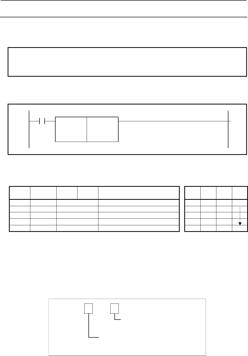
B-64513EN/03
4.LADDER LANGUAGE
- 367 -
4.7.8
COMPB (Comparison Between Binary Data: SUB 32)
This instruction compares 1, 2, and 4 byte binary data with one another. Results of comparison are set
in the operation output register (R9000, Z0). Sufficient numbers of bytes are necessary in the memory
to hold the input data and comparison data.
Note
To get detail comparison result for this instruction, it is necessary to program
ladder diagram using operation output register. For getting comparison result
easily, use above-mentioned binary comparison instructions.
Format
Fig. 4.7.8 shows the ladder format and Table 4.7.8 shows the mnemonic format.
ACT
SUB 32
COMPB
00
Format specification
{{{{
Input data (address)
{{{{
Address or data to be compared
Fig. 4.7.8 Format of COMPB instruction
Table 4.7.8 Mnemonic of COMPB instruction
Mnemonic format Memory status of control
condition
Step
number Instruction Address
No. Bit No. Remarks ST3 ST2 ST1 ST0
1 RD
{{{{
.
{
ACT ACT
2 SUB 32 COMPB instruction
3 (PRM)
00
Format specification
4 (PRM)
{{{{
Input data (address)
5 (PRM)
{{{{
Address of data to be compared W1
Control condition
(a) Execution specification (ACT)
ACT = 0: Do not execute COMPB.
ACT = 1: Execute COMPB.
Parameters
(a) Format specification
Specify data length (1,2, or 4 bytes) and format for the input data ('constants data' or 'address data').
Specification of data length
0
Specification of format
1: 1-byte length data
2: 2-byte length data
4: 4-byte length data
0
0: Constants
1: Address
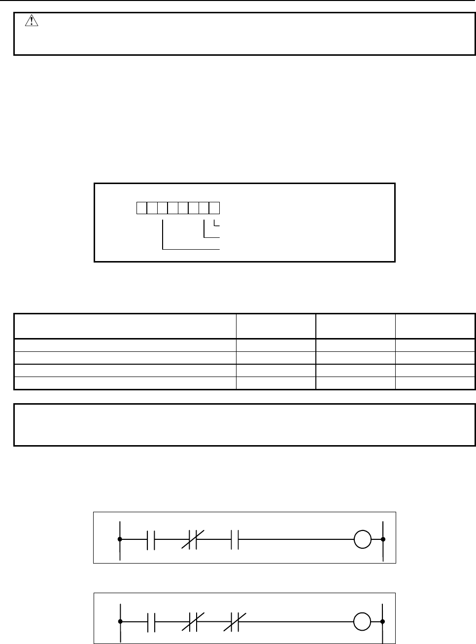
4.LADDER LANGUAGE
B-64513EN/03
- 368 -
CAUTION
Do not set an illegal value, that is not indicated above, into the "(a) Format
specification".
(b) Input data (address)
Format for the input data is determined by the specification in (a).
(c) Address of data to be compared
Indicates the address in which the comparison data is stored.
Operation output register (R9000, Z0)
The data involved in the operation are set in this register. This register is set with data on operation. If
register bit 1 is on, they indicate the following:
R9000
Z0
103 25 4
7 6
Negative ([input data] < [data compared])
Zero ([input data] = [data compared])
Overflow
The following table shows the relationship among the [input data], [data compared], and operation output
register.
R9000.5
Z0.5
R9000.1
Z0.1
R9000.0
Z0.0
[Input data] = [data compared] 0 0 1
[Input data] > [data compared] 0 0 0
[Input data] < [data compared] 0 1 0
Overflow 1 0 0
Note
Overflow would occur when difference between input data and data compared
exceeds specified data lengths.
Programming examples for the operation output register
Programming examples of comparison between two positive values are shown bellow.
(1) When checking that [input data] = [data compared]
Check result
A
CT R9000.5 R9000.0
(2) When checking that [input data] ≠ [data compared]
Check result
A
C
T
R9000.5 R9000.0
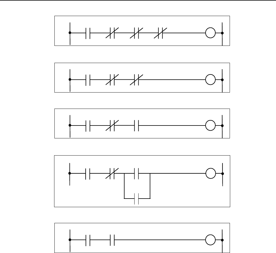
B-64513EN/03
4.LADDER LANGUAGE
- 369 -
(3) When checking that [input data] > [data compared]
Check result
A
C
T
R9000.5 R9000.1 R9000.0
(4) When checking that [input data] ≧ [data compared]
Check result
A
C
T
R9000.5 R9000.1
(5) When checking that [input data] < [data compared]
Check result
A
C
T
R9000.5 R9000.1
(6) When checking that [input data] ≦ [data compared]
Check result
A
CT R9000.5 R9000.0
R9000.1
(7) When checking for an overflow of the comparison operation
Check result
A
CT R9000.5
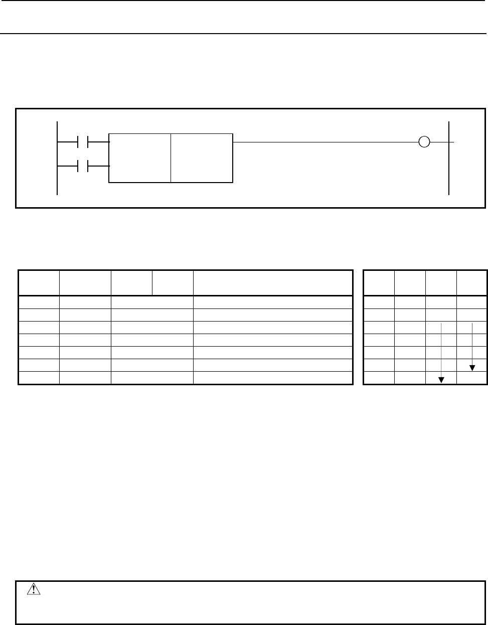
4.LADDER LANGUAGE
B-64513EN/03
- 370 -
4.7.9
COMP (Comparison: SUB 15)
Compares input and comparison values. The value type in this instruction is BCD.
Format
Fig. 4.7.9 shows the ladder format and Table 4.7.9 shows the mnemonic format.
BYT W1
SUB 15
ACT COMP
{
Format specification
{{{{
Input data
{{{{
Comparison data address
Fig. 4.7.9 Format of COMP instruction
Table 4.7.9 Mnemonic of COMP instruction
Mnemonic format Memory status of control
condition
Step
number Instruction Address
No. Bit No. Remarks ST3 ST2 ST1 ST0
1 RD
{{{{
.
{
BYT BYT
2 RD.STK
{{{{
.
{
ACT BYT ACT
3 SUB 15 COMP instruction
4 (PRM)
{
Format specification
5 (PRM)
{{{{
Input data
6 (PRM)
{{{{
Comparison data address
7 WRT
{{{{
.
{
Comparison result output W1
Control conditions
(a) Specify the data size. (BYT)
BYT = 0: Process data (input value and comparison value) is BCD two digits long.
BYT = 1: Process data (input value and comparison value) is BCD four digits long.
(b) Execution specification (ACT)
ACT = 0: The COMP instruction is not executed. W1 does not alter.
ACT = 1: The COMP instruction is executed and the result is output to W1.
Parameters
(a) Format specification
0: Specify input data with a constant.
1: Specify input data with an address
Not specify input data directly, but specify an address storing input data.
CAUTION
Do not set an illegal value, that is not indicated above, into the "(a) Format
specification".
(b) Input data
The input data can be specified as either a constant or the address storing it. The selection is made by
a parameter of format specification.
(c) Comparison data address
Specify the address storing the comparison data.

B-64513EN/03
4.LADDER LANGUAGE
- 371 -
Comparison result output(W1)
W1 = 0: Input data > Comparison data
W1 = 1: Input data ≦Comparison data
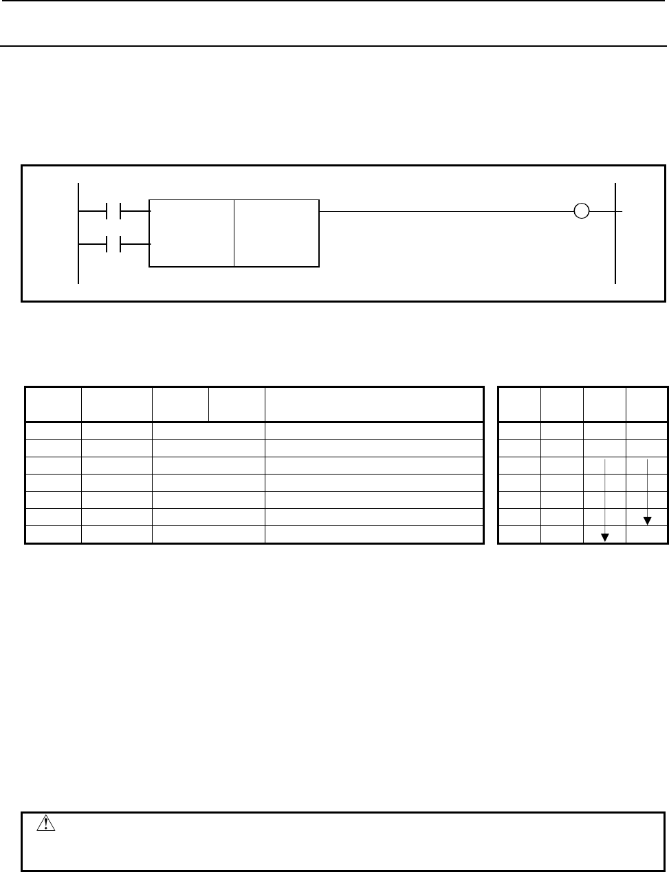
4.LADDER LANGUAGE
B-64513EN/03
- 372 -
4.7.10
COIN (Coincidence Check: SUB 16)
This instruction checks whether the input value and comparison value coincide.
The value type in this instruction is BCD.
Format
Fig. 4.7.10 shows the ladder format and Table 4.7.10 shows the mnemonic format.
BYT W1
SUB 16
ACT COIN
{
Format specification
{{{{
Input data
{{{{
Comparison data address
Fig. 4.7.10 Format of COIN instruction
Table 4.7.10 Mnemonic of COIN instruction
Mnemonic format Memory status of control
condition
Step
number Instruction Address
No. Bit No. Remarks ST3 ST2 ST1 ST0
1 RD
{{{{
.
{
BYT BYT
2 RD.STK
{{{{
.
{
ACT BYT ACT
3 SUB 16 COIN instruction
4 (PRM)
{
Format specification
5 (PRM)
{{{{
Input data
6 (PRM)
{{{{
Comparison data address
7 WRT
{{{{
.
{
Comparison result output W1
Control conditions
(a) Specify the data size.
BYT = 0: Process data (input value, and comparison values).
Each BCD is two digits long.
BYT = 1: Each BCD four digits long.
(b) Execution specification
ACT = 0: The COIN instruction is not executed. W1 does not change.
ACT = 1: The COIN instruction is executed and the result is output to W1.
Parameters
(a) Format specification
0: Specifies input data as a constant.
1: Specifies input data as an address.
CAUTION
Do not set an illegal value, that is not indicated above, into the "(a) Format
specification".
(b) Input data
The input data can be specified as either a constant or an address storing it. The selection is made by
a parameter of format designation.
(c) Comparison data address
Specify the address storing the comparison data.

B-64513EN/03
4.LADDER LANGUAGE
- 373 -
Comparison result output (W1)
W1 = 0: Input data ≠ Comparison data
W1 = 1: Input data = Comparison data

4.LADDER LANGUAGE
B-64513EN/03
- 374 -
4.8 BIT OPERATION
The following types of bit operation instruction are available. Use any of these instructions as
appropriate for your purpose.
Instruction name Sub number Processing
1 DIFU 57 Rising edge detection
2 DIFD 58 Falling edge detection
3 EOR 59 Exclusive OR
4 AND 60 Logical AND
5 OR 61 Logical OR
6 NOT 62 Logical NOT
7 PARI 11 Parity check
8 SFT 33 Shift register
9 EORB 265 Exclusive OR (1 byte length)
10 EORW 266 Exclusive OR (2 bytes length)
11 EORD 267 Exclusive OR (4 bytes length)
12 ANDB 268 Logical AND (1 byte length)
13 ANDW 269 Logical AND (2 bytes length)
14 ANDD 270 Logical AND (4 bytes length)
15 ORB 271 Logical OR (1 byte length)
16 ORW 272 Logical OR (2 bytes length)
17 ORD 273 Logical OR (4 bytes length)
18 NOTB 274 Logical NOT (1 byte length)
19 NOTW 275 Logical NOT (2 bytes length)
20 NOTD 276 Logical NOT (4 bytes length)
21 SHLB 277 Bit shift left (1 byte length)
22 SHLW 278 Bit shift left (2 bytes length)
23 SHLD 279 Bit shift left (4 bytes length)
24 SHLN 280 Bit shift left (Arbitrary bytes length)
25 SHRB 281 Bit shift right (1 byte length)
26 SHRW 282 Bit shift right (2 bytes length)
27 SHRD 283 Bit shift right (4 bytes length)
28 SHRN 284 Bit shift right (Arbitrary bytes length)
29 ROLB 285 Bit rotation left (1 byte length)
30 ROLW 286 Bit rotation left (2 bytes length)
31 ROLD 287 Bit rotation left (4 bytes length)
32 ROLN 288 Bit rotation left (Arbitrary bytes length)
33 RORB 289 Bit rotation right (1 byte length)
34 RORW 290 Bit rotation right (2 bytes length)
35 RORD 291 Bit rotation right (4 bytes length)
36 RORN 292 Bit rotation right (Arbitrary bytes length)
37 BSETB 293 Bit set (1 byte length)
38 BSETW 294 Bit set (2 bytes length)
39 BSETD 295 Bit set (4 bytes length)
40 BSETN 296 Bit set (Arbitrary bytes length)
41 BRSTB 297 Bit reset (1 byte length)
42 BRSTW 298 Bit reset (2 bytes length)
43 BRSTD 299 Bit reset (4 bytes length)
44 BRSTN 300 Bit reset (Arbitrary bytes length)
45 BTSTB 301 Bit test (1 byte length)
46 BTSTW 302 Bit test (2 bytes length)
47 BTSTD 303 Bit test (4 bytes length)
48 BTSTN 304 Bit test (Arbitrary bytes length)

B-64513EN/03
4.LADDER LANGUAGE
- 375 -
Instruction name Sub number Processing
49 BPOSB 305 Bit search (1 byte length)
50 BPOSW 306 Bit search (2 bytes length)
51 BPOSD 307 Bit search (4 bytes length)
52 BPOSN 308 Bit search (Arbitrary bytes length)
53 BCNTB 309 Bit count (1 byte length)
54 BCNTW 310 Bit count (2 bytes length)
55 BCNTD 311 Bit count (4 bytes length)
56 BCNTN 312 Bit count (Arbitrary bytes length)
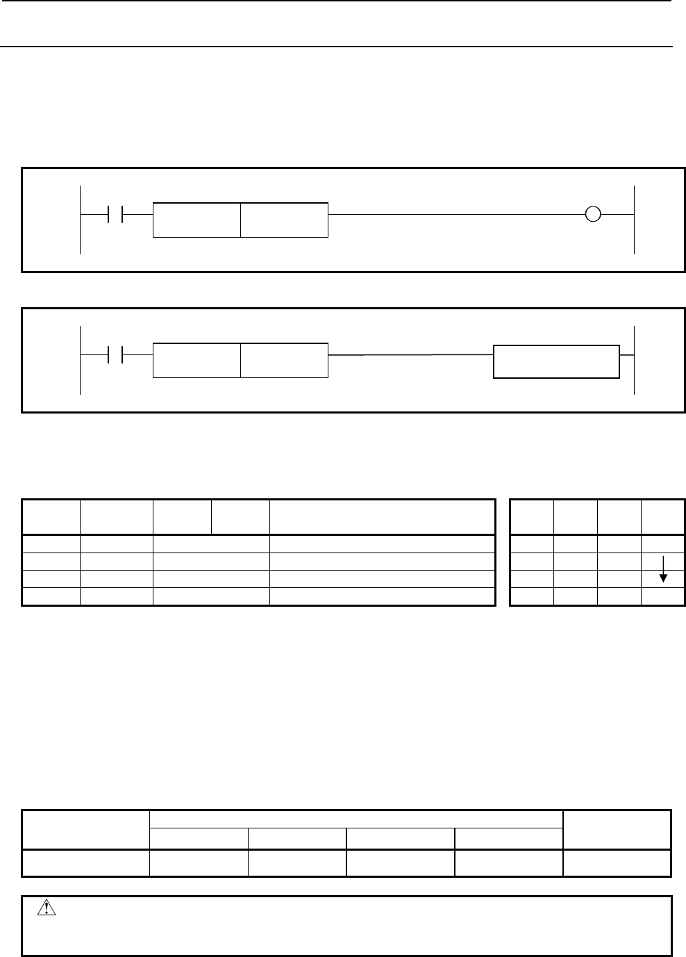
4.LADDER LANGUAGE
B-64513EN/03
- 376 -
4.8.1
DIFU (Rising Edge Detection: SUB 57)
The DIFU instruction sets the output signal to 1 for one scanning cycle on a rising edge of the input
signal.
Format
The followings are the ladder format and the mnemonic format.
Normal format
ACT W1
SUB 57
DIFU {{{{ Rising edge number
Fig. 4.8.1 (a) Format of DIFU instruction (Normal format)
Extended type format
ACT
SUB 57
DIFU {{{{ Rising edge number Functional Instruction
Fig. 4.8.1 (b) Format of DIFU instruction (Extended type format)
Table 4.8.1 Mnemonic of DIFU instruction (Normal format)
Mnemonic format Memory status of control
condition
Step
number Instruction Address
No. Bit No. Remarks ST3 ST2 ST1 ST0
1 RD {{{{ .{ ACT ACT
2 SUB 57 DIFU instruction
3 (PRM) {{{{ Rising edge number
4 WRT {{{{ .{ W1 W1
Control conditions
(a) Input signal (ACT)
On a rising edge (0 → 1) of the input signal, the output signal is set to 1.
Detection result
(a) Output signal (W1)
The output signal level remains at 1 for one scanning cycle of the ladder level where this functional
instruction is operating. Another functional instruction can be connected instead of W1.
Parameters
1st to 5th path PMC Dual check
safety PMC
PMC Memory-A PMC Memory-B PMC Memory-C PMC Memory-D
Rising edge number 1 to 256 1 to 1000 1 to 2000 1 to 3000 1 to 256
WARNING
If the same number is used for another DIFU instruction or a DIFD instruction
(described later) in one Ladder diagram, operation is not guaranteed.

B-64513EN/03
4.LADDER LANGUAGE
- 377 -
Operation
A
CT
OUT
1
2
3
4
Execution period
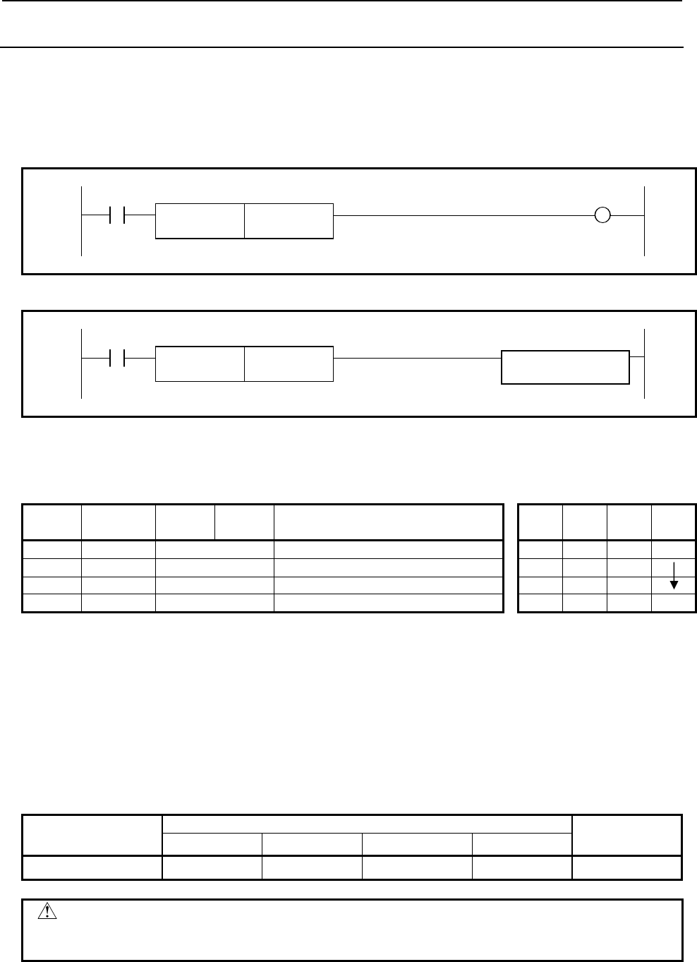
4.LADDER LANGUAGE
B-64513EN/03
- 378 -
4.8.2
DIFD (Falling Edge Detection: SUB 58)
The DIFD instruction set the output signal to 1 for one scanning period on a falling edge of the input
signal.
Format
The followings are the ladder format and the mnemonic format.
Normal format
ACT W1
SUB 58
DIFD {{{{ Falling edge number
Fig. 4.8.2 (a) Format of DIFD instruction (Normal format)
Extended type format
ACT
SUB 58
DIFD {{{{ Falling edge number Functional Instruction
Fig. 4.8.2 (b) Format of DIFD instruction (Extended type format)
Table 4.8.2 Mnemonic of DIFD instruction
Mnemonic format Memory status of control
condition
Step
number Instruction Address
No. Bit No. Remarks ST3 ST2 ST1 ST0
1 RD {{{{ .{ ACT ACT
2 SUB 58 DIFD instruction
3 (PRM) {{{{ Falling edge number
4 WRT {{{{ .{ W1 W1
Control conditions
(a) Input signal (ACT)
On a falling edge (1→0) of the input signal, the output signal is set to 1.
Detection result
(a) Output signal (W1)
The output signal level remains at 1 for one scanning period of the ladder level where this functional
instruction is operating. Another functional instruction can be connected instead of W1.
Parameters
1st to 5th path PMC Dual check
safety PMC
PMC Memory-A PMC Memory-B PMC Memory-C PMC Memory-D
Falling edge number 1 to 256 1 to 1000 1 to 2000 1 to 3000 1 to 256
WARNING
If the same number is used for another DIFD instruction or a DIFU instruction
(described above) in one ladder diagram, operation is not guaranteed.

B-64513EN/03
4.LADDER LANGUAGE
- 379 -
Operation
1
2
3
4
Execution period
OUT
A
CT
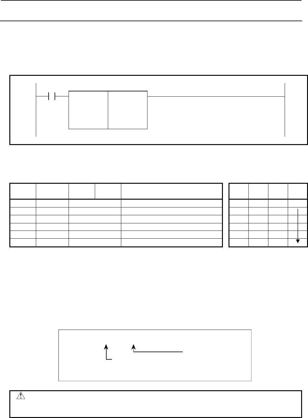
4.LADDER LANGUAGE
B-64513EN/03
- 380 -
4.8.3
EOR (Exclusive OR: SUB 59)
The EOR instruction exclusive-ORs the contents of address A with a constant (or the contents of address
B), and stores the result at address C. The value type in this instruction is binary.
Format
Fig. 4.8.3 shows the ladder format and Table 4.8.3 shows the mnemonic format.
ACT
SUB 59
EOR 00 Format specification
{{{{ Address A
{{{{ Constant or address B
{{{{ Address C
Fig. 4.8.3 Format of EOR instruction
Table 4.8.3 Mnemonic of EOR instruction
Mnemonic format Memory status of control
condition
Step
number Instruction Address
No. Bit No. Remarks ST3 ST2 ST1 ST0
1 RD {{{{ .{ ACT ACT
2 SUB 59 EOR instruction
3 (PRM) 00 Format specification
4 (PRM) {{{{ Address A
5 (PRM) {{{{ Constant or address B
6 (PRM) {{{{ Address C
Control conditions
(a) Input signal (ACT)
ACT=0: The EOR instruction is not executed.
ACT=1: The EOR instruction is executed.
Parameters
(a) Format specification
Specify a data length (1, 2, or 4 bytes), and an input data format (constant or address specification).
Data length specification
1:1 byte
2:2 bytes
4:4 bytes
Format specification
0: Constant
1: Address specification
0 0
CAUTION
Do not set an illegal value, that is not indicated above, into the "(a) Format
specification".
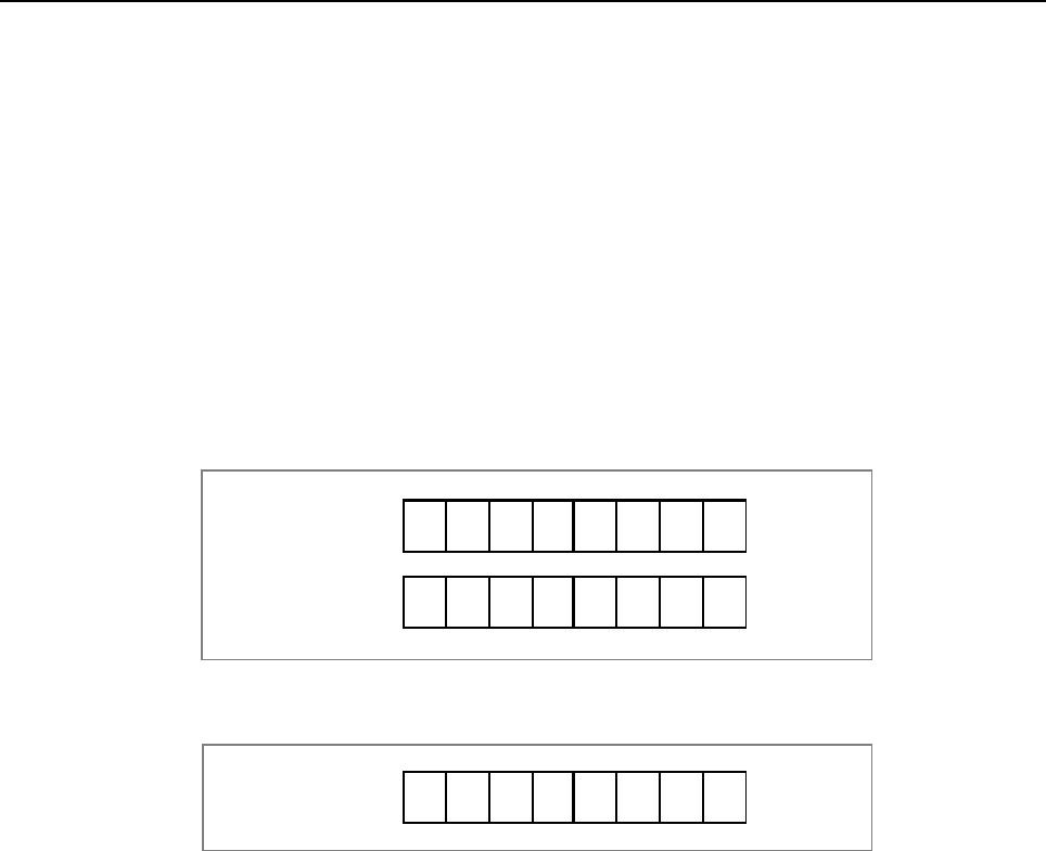
B-64513EN/03
4.LADDER LANGUAGE
- 381 -
(b) Address A
Address stored input data to be exclusive-ORed. The data length is specified in the format
specification.
(c) Constant or address B
Constant data or address stored input data to be exclusive-ORed with data of the item (b). When
address specification is selected in the format specification, the data would be treated as specified
data length.
(d) Address C
Address used to store the result of an exclusive OR operation. The result of the exclusive OR
operation is output with the length specified in the format specification.
Operation
When address A and address B hold the following data:
A
ddress B
11100011
01010101
A
ddress A
The result of the exclusive OR operation is as follows:
10110 1
10
A
ddress C
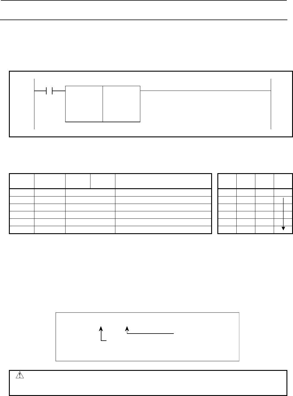
4.LADDER LANGUAGE
B-64513EN/03
- 382 -
4.8.4
AND (Logical AND: SUB 60)
The AND instruction ANDs the contents of address A with a constant (or the contents of address B), and
stores the result at address C. The value type in this instruction is binary.
Format
Fig. 4.8.4 shows the ladder format and Table 4.8.4 shows the mnemonic format.
ACT
SUB 60
AND 00 Format specification
{{{{ Address A
{{{{ Constant or address B
{{{{ Address C
Fig. 4.8.4 Format of AND instruction
Table 4.8.4 Mnemonic of AND instruction
Mnemonic format Memory status of control
condition
Step
number Instruction Address
No. Bit No. Remarks ST3 ST2 ST1 ST0
1 RD {{{{ .{ ACT ACT
2 SUB 60 AND instruction
3 (PRM) 00 Format specification
4 (PRM) {{{{ Address A
5 (PRM) {{{{ Constant or address B
6 (PRM) {{{{ Address C
Control conditions
(a) Input signal (ACT)
ACT=0: The AND instruction is not executed.
ACT=1: The AND instruction is executed.
Parameters
(a) Format specification
Specify a data length (1, 2, or 4 bytes), and an input data format (constant or address specification).
Data length specification
1: 1 byte
2: 2 bytes
4: 4 bytes
Format specification
0: Constant
1: Address specification
0 0
CAUTION
Do not set an illegal value, that is not indicated above, into the "(a) Format
specification".
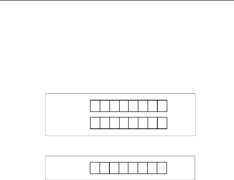
B-64513EN/03
4.LADDER LANGUAGE
- 383 -
(b) Address A
Address stored input data to be ANDed. The data length is specified in the format specification.
(c) Constant or address B
Constant data or address stored input data to be ANDed with. When address specification is selected
in the format specification, the data would be treated as specified data length.
(d) Address C
Address used to store the result of an AND operation. The result of the AND operation is output
with the length specified in the format specification.
Operation
When address A and address B hold the following data:
A
ddress B
11100011
01010101
A
ddress A
The result of the AND operation is as follows:
01000 0
01
A
ddress C
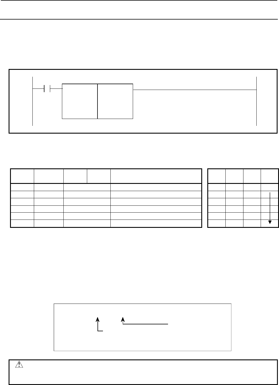
4.LADDER LANGUAGE
B-64513EN/03
- 384 -
4.8.5
OR (Logical OR: SUB 61)
The OR instruction ORs the contents of address A with a constant (or the contents of address B), and
stores the result at address C. The value type in this instruction is binary.
Format
Fig. 4.8.5 shows the ladder format and Table 4.8.5 shows the mnemonic format.
ACT
SUB 61
OR 00 Format specification
{{{{ Address A
{{{{ Constant or address B
{{{{ Address C
Fig. 4.8.5 Format of OR instruction
Table 4.8.5 Mnemonic of OR instruction
Mnemonic format Memory status of control
condition
Step
number Instruction Address
No. Bit No. Remarks ST3 ST2 ST1 ST0
1 RD {{{{ .{ ACT ACT
2 SUB 61 OR instruction
3 (PRM) 00 Format specification
4 (PRM) {{{{ Address A
5 (PRM) {{{{ Constant or address B
6 (PRM) {{{{ Address C
Control conditions
(a) Input signal (ACT)
ACT=0: The OR instruction is not executed.
ACT=1: The OR instruction is executed.
Parameters
(a) Format specification
Specify a data length (1, 2, or 4 bytes), and an input data format (constant or address specification).
Data length specification
1: 1 byte
2: 2 bytes
4: 4 bytes
Format specification
0: Constant
1: Address specification
0 0
CAUTION
Do not set an illegal value, that is not indicated above, into the "(a) Format
specification".
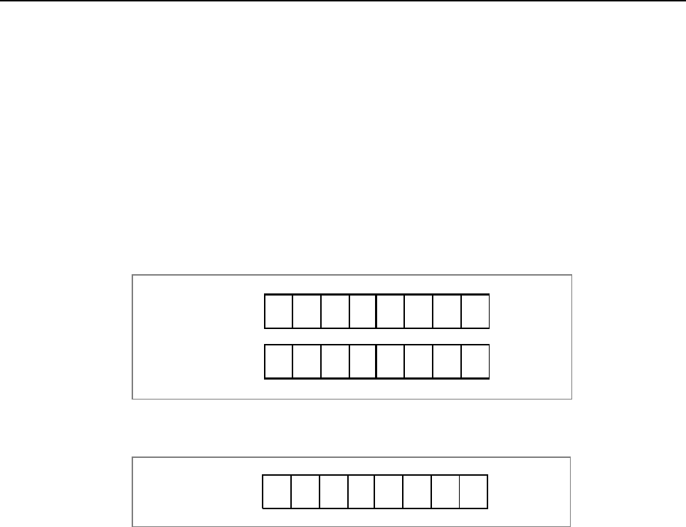
B-64513EN/03
4.LADDER LANGUAGE
- 385 -
(b) Address A
Address stored input data to be ORed. The data length is specified in the format specification.
(c) Constant or address B
Input data to be ORed with. When address specification is selected in the format specification, the
data would be treated as specified data length.
(d) Address C
Address used to store the result of an OR operation. The result is output with the length specified in
the format specification.
Operation
When address A and address B hold the following data:
A
ddress B
11100011
01010101
A
ddress A
The result of the OR operation is as follows:
11110 1
11
A
ddress C
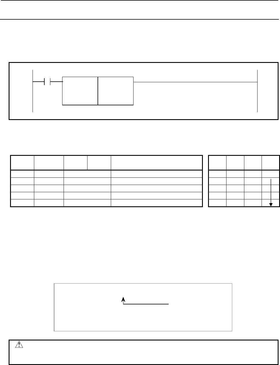
4.LADDER LANGUAGE
B-64513EN/03
- 386 -
4.8.6
NOT (Logical NOT: SUB 62)
The NOT instruction inverts each bit of the contents of address A, and stores the result at address B.
Format
Fig. 4.8.6 shows the ladder format and Table 4.8.6 shows the mnemonic format.
ACT
SUB 62
NOT 000 Format specification
{{{{ Address A
{{{{ Address B
Fig. 4.8.6 Format of NOT instruction
Table 4.8.6 Mnemonic of NOT instruction
Mnemonic format Memory status of control
condition
Step
number Instruction Address
No. Bit No. Remarks ST3 ST2 ST1 ST0
1 RD {{{{ .{ ACT ACT
2 SUB 62 NOT instruction
3 (PRM) 000 Format specification
4 (PRM) {{{{ Address A
5 (PRM) {{{{ Address C
Control conditions
(a) Input signal (ACT)
ACT=0: The NOT instruction is not executed.
ACT=1: The NOT instruction is executed.
Parameters
(a) Format specification
Specify a data length (1, 2, or 4 bytes).
Data length specification
1: 1 byte
2: 2 bytes
4: 4 bytes
0 0 0
CAUTION
Do not set an illegal value, that is not indicated above, into the "(a) Format
specification".
(b) Address A
Address stored input data to be inverted bit by bit. The data length is specified in the format
specification.
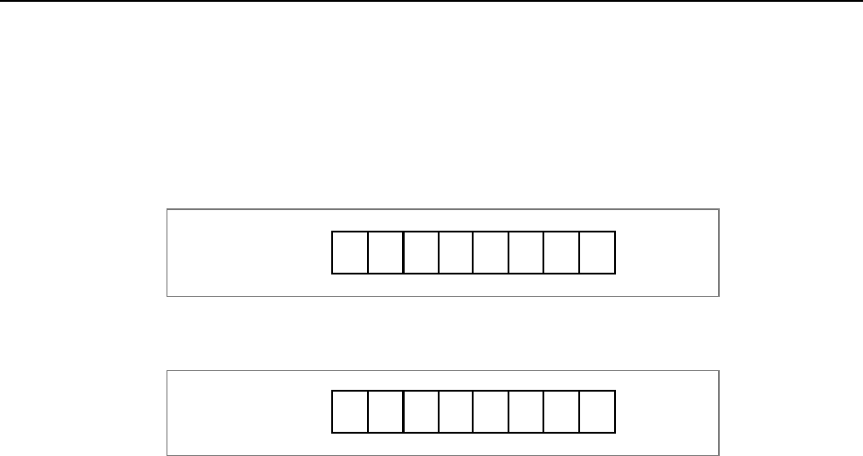
B-64513EN/03
4.LADDER LANGUAGE
- 387 -
(c) Address B
Address used to output the result of a NOT operation. The result length of the NOT operation is
output with the length specified in the format specification.
Operation
When address A holds the following data:
11100 0
11
A
ddress A
The result of the NOT operation is as follows:
00011 1
00
A
ddress B
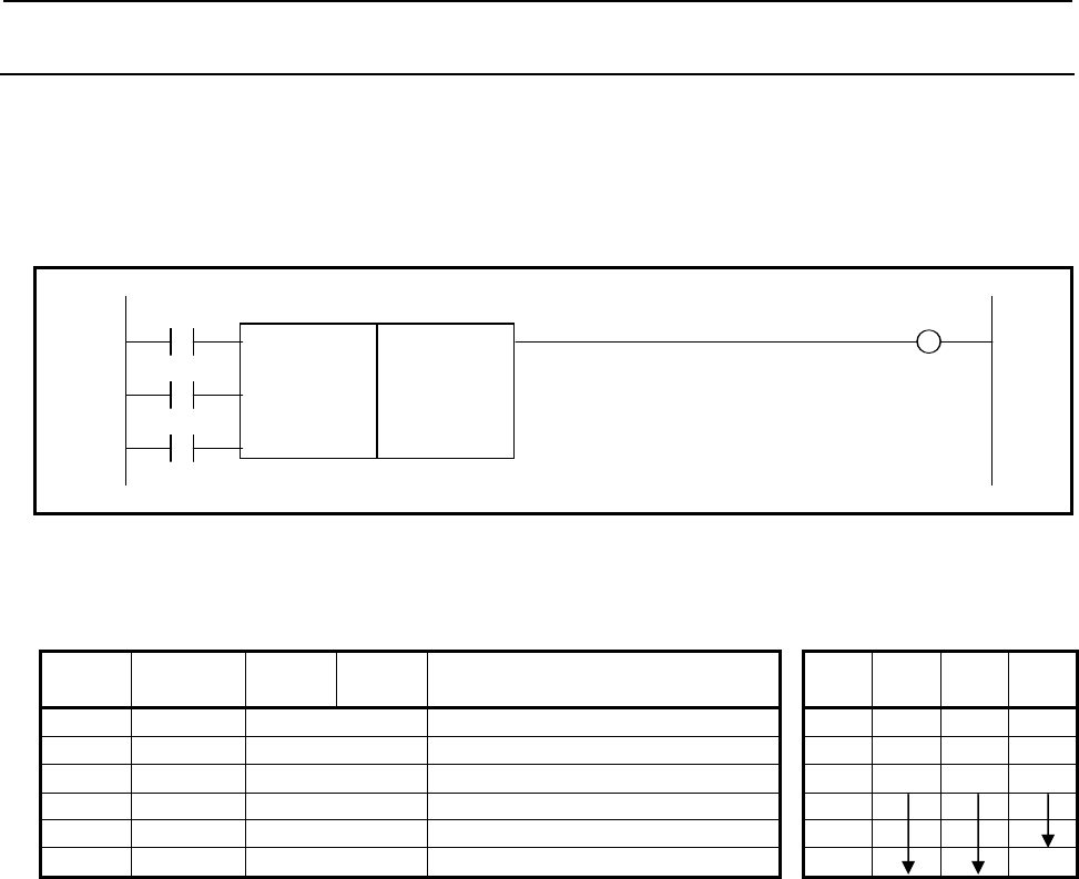
4.LADDER LANGUAGE
B-64513EN/03
- 388 -
4.8.7
PARI (Parity Check: SUB 11)
This instruction checks the parity of code signals, and outputs an error if an abnormality is detected. You
can specify either an even- or odd-parity check. Only 1 byte (eight bits) of data can be checked.
Format
Fig. 4.8.7 (a) shows the ladder format and Table 4.8.7 shows the mnemonic format.
O.E W1
SUB 11
RST PARI
{{{{ Check data address
ACT
Fig. 4.8.7 (a) Format of PARI instruction
Table 4.8.7 Mnemonic of PARI instruction
Mnemonic format Memory status of control
condition
Step
number Instruction Address
No. Bit No. Remarks ST3 ST2 ST1 ST0
1 RD {{{{ .{ O.E O.E
2 RD.STK {{{{ .{ RST O.E RST
3 RD.STK {{{{ .{ ACT O.E RST ACT
4 SUB 11 PARI instruction
5 (PRM) {{{{ Check data address
6 WRT {{{{ .{ Error output W1
Control conditions
(a) Specify even or odd. (O.E)
O.E=0: Even-parity check
O.E=1: Odd-parity check
(b) Reset (RST)
RST=0:
Disables reset.
RST=1:
Sets error output W1 to 0. That is, when a parity error occurs, setting RST to 1 results in
resetting.
(c) Execution command (ACT)
ACT=0: Parity checks are not performed. W1 does not alter.
ACT=1: Executes the PARI instruction, performing a parity check.
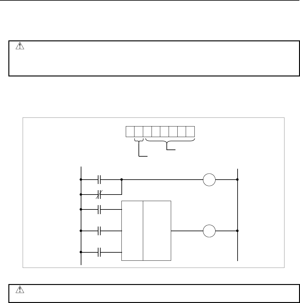
B-64513EN/03
4.LADDER LANGUAGE
- 389 -
Error output (W1)
If the results of executing the PARI instruction is abnormal, W1=1 and an error is posted. The W1
address can be determined arbitrarily.
CAUTION
Two or more coils, WRT, WRT.NOT, SET or RST, that follow this instruction are
prohibited. You have to place a single coil instruction as the output of this
instruction.
Example of using the PARI instruction
Fig. 4.8.7 (b) shows odd-parity checking of a code signal entered at address X036.
0
76 5 4 3 2 1 0
A
ddress X036
6-bit code signal
Odd-parity bit
PARI
SUB 11
A
X036
R228.0
ERST.M
X32.7
TF
F7.3
ERR
R228.0
R228.0
A
A
A
R228.0
Fig. 4.8.7 (b) Ladder diagram for the PARI instruction
NOTE
For bits 0 to 7, bits other than those for the parity check must be 0.
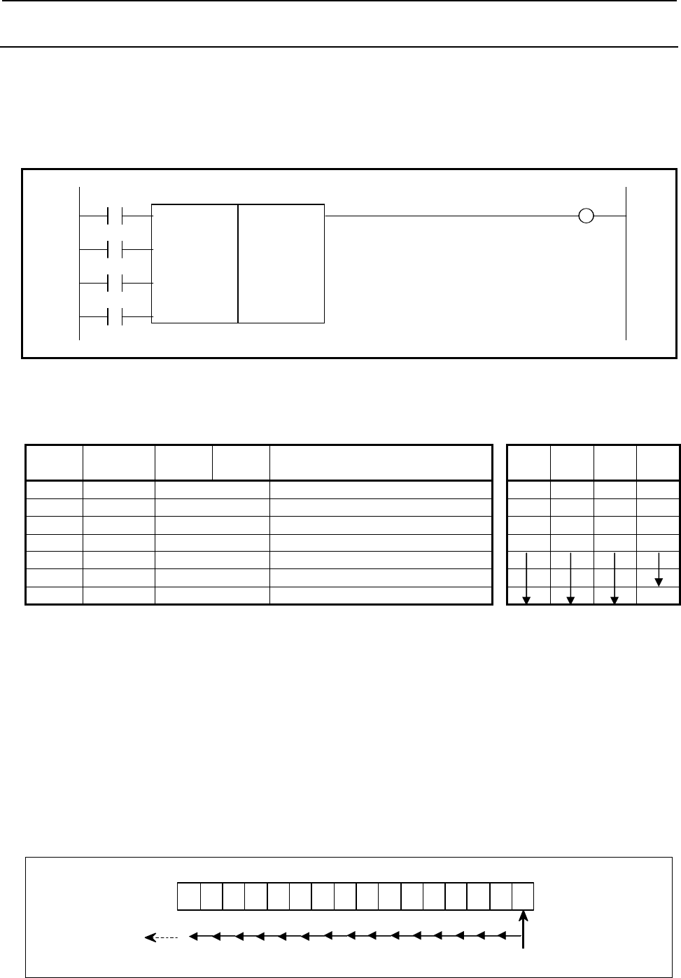
4.LADDER LANGUAGE
B-64513EN/03
- 390 -
4.8.8
SFT (Shift Register: SUB 33)
This instruction shifts 2 bytes (16-bit) data by a bit to the left or right. Note that W1=1 when data "1" is
shifted from the left extremity (bit 15) in left shift or from the right extremity (bit 0) in right shift.
Format
Fig. 4.8.8 shows the ladder format and Table 4.8.8 shows the mnemonic format.
DIR W1
SUB 33
CONT SFT
{{{{ Address of shift data
RST
ACT
Fig. 4.8.8 Format of SFT instruction
Table 4.8.8 Mnemonic of SFT instruction
Mnemonic format Memory status of control
condition
Step
number Instruction Address
No. Bit No. Remarks ST3 ST2 ST1 ST0
1 RD {{{{ .{ DIR DIR
2 RD.STK {{{{ .{ CONT DIR CONT
3 RD.STK {{{{ .{ RST DIR CONT RST
4 RD.STK {{{{ .{ ACT DIR CONT RST ACT
5 SUB 33 SFT instruction
6 (PRM) {{{{ Address of shift data
7 WRT {{{{ .{ Shifted-out output W1
Control conditions
(a) Shift direction specification (DIR)]
DIR=0: Left shift
DIR=1: Right shift
(b) Condition specification (CONT)
CONT=0:
On "1" bit shifts by one bit in the specified direction.
The condition of an adjacent bit (either right or left adjacent bit according to the specification
of shift direction DIR) is set to the original bit position of the on "1" bit.
Also, "0" is set to bit 0 after shifting in the left direction or set to hit 15 after shifting in the
right direction.
7 6 5 4 3
2
1 0 15 14 13 12 11 10 9 8
Lef t s hif
t
Bit shifts leftward every bit
Shift out at bit 15 Zero is set to bit 0.
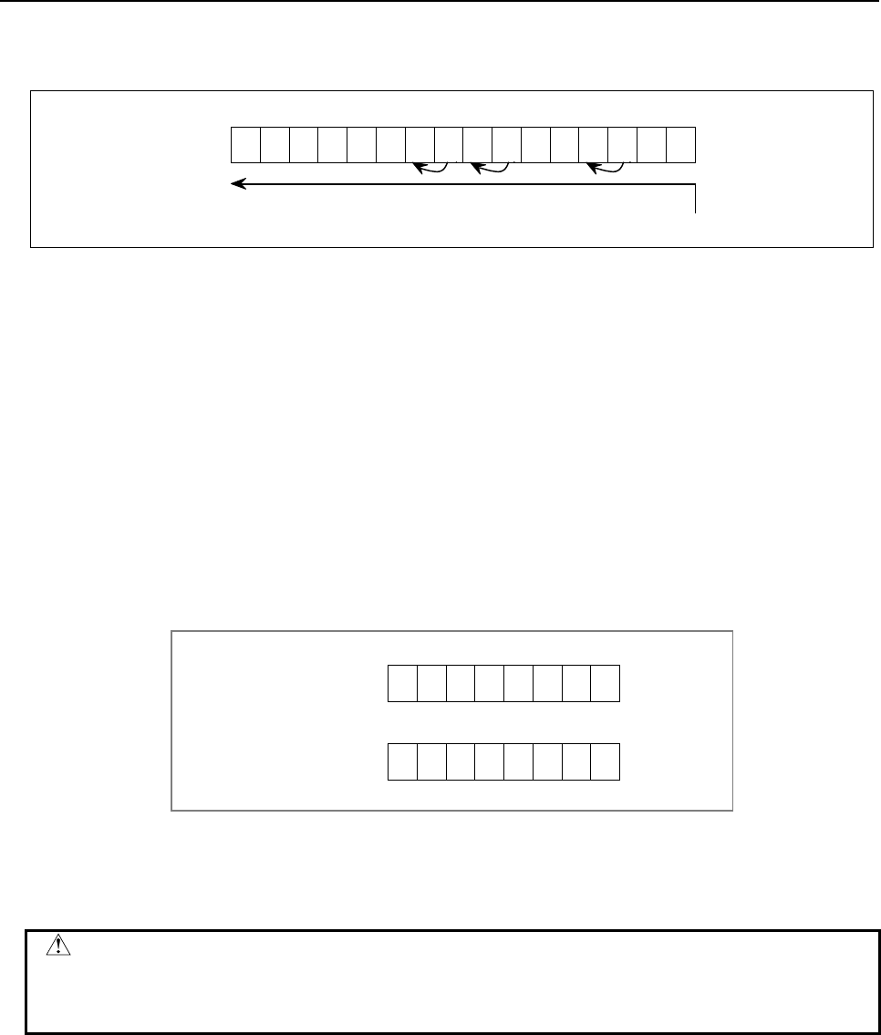
B-64513EN/03
4.LADDER LANGUAGE
- 391 -
CONT=1:
Shift is the same as above, but 1s are set to shifted bits.
9 8
15
14
13
12
11 10 7 6 5 4 3 2 1 0
Left shift 0
0
0
0
0
0
1
Each bit shifts leftward. Status 1 remains unchanged
1 0
0
<1> 1 0
0
<1> <1>
(c) Reset (RST)
The shifted out data (W1=1) is reset (W1=0).
RST=0: W1 is not reset.
RST=1: W1 is reset (W1=0).
(d) Actuation signal (ACT)
Shift processing is done when ACT=1. For shifting one bit only, execute an instruction when
ACT=1, and then, set ACT to 0 (ACT=0).
Parameters
(a) Shift data addresses
Sets shift data addresses. These designated addresses require a continuous 2 bytes memory for shift
data.
Bit numbers are represented by bit 0 to 15 as shown below. When addresses are designated for
programming, an address number is attached every 8 bits, and the designable bit numbers are 0 to 7.
15 98
14 13 12 11 10
76543210
Designated address
Designated address +1
Shifted out (W1)
W1=0: "0" was shifted out for the shift operation.
W1=1: "1" was shifted out for the shift operation.
CAUTION
Two or more coils, WRT, WRT.NOT, SET or RST, that follow this instruction are
prohibited. You have to place a single coil instruction as the output of this
instruction.
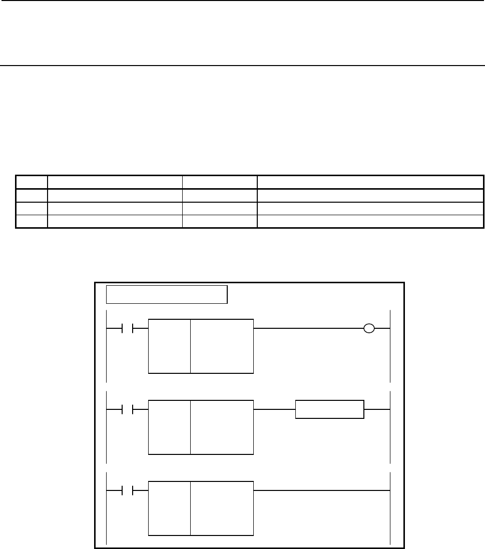
4.LADDER LANGUAGE
B-64513EN/03
- 392 -
4.8.9
EORB (Exclusive OR (1 Byte Length) : SUB 265)
EORW (Exclusive OR (2 Bytes Length) : SUB 266)
EORD (Exclusive OR (4 Bytes Length) : SUB 267)
The Exclusive OR instruction exclusive-ORs "Data A" with "Data B", and outputs the result to "Address
C".
In "Data A" and "Data B", a constant or a PMC memory address for storing data can be specified.
As indicated below, three types of Exclusive OR instructions are available according to the type of data to
be operated. In each instruction, "Data A", "Data B", and the data at "Address C" are of the same data
type.
Table4.8.9 (a) Kinds of Exclusive OR instruction
Instruction name SUB No. Data type
1 EORB 265 1 byte length
2 EORW 266 2 bytes length
3 EORD 267 4 bytes length
Format
The followings are the ladder format and the mnemonic format.
SUB 265
EORB
{{{{
{{{{
{{{{
ACT
Example : EORB Instruction
SUB 265
EORB
{{{{
{{{{
{{{{
Data A (Address or Constant)
Data B (Address or Constant)
A
ddress C
ACT W1
SUB 265
EORB
{{{{
{{{{
{{{{
Functional Instruction
ACT ACT2
Fig. 4.8.9 (a) Format of EORB, EORW, EORD instruction

B-64513EN/03
4.LADDER LANGUAGE
- 393 -
Table 4.8.9(b) Mnemonic of EORB, EORW, EORD instruction
Mnemonic format
Memory status of control
condition
Step
number Instruction Address
No. Bit No. Remarks
ST3 ST2 ST1 ST0
1 RD {{{{ .{ ACT ACT
2 SUB 265 SUB No. (EORB instruction)
3 (PRM) {{{{ Data A (Address or Constant)
4 (PRM) {{{{ Data B (Address or Constant)
5 (PRM) {{{{ Address C
6 WRT {{{{ .{ Normal end output W1
Control conditions
(a) Input signal (ACT)
ACT = 0: Instruction not executed.
ACT = 1: Executed.
Parameters
(a) Data A
Specify input data to be exclusive-ORed. In this parameter, a constant or a PMC memory address
for storing data can be specified. In case of constant, specify signed binary data. A value within the
following range may be specified:
Instruction name Available value
EORB -128 to 127
EORW -32768 to 32767
EORD -2147483648 to 2147483647
(b) Data B
Specify input data to be exclusive-ORed. In this parameter, a constant or a PMC memory address for
storing data can be specified. In case of constant, specify signed binary data. A value within the
same range as for "Data A" may be specified.
(c) Address C
Specify the address to which the result of exclusive-OR operation is to be output.
Output (W1)
When the instruction is executed, W1=1 is set. That is, W1 always assumes the same state as ACT.
NOTE
W1 may be omitted. Moreover, another functional instruction can be connected
instead of a coil.

4.LADDER LANGUAGE
B-64513EN/03
- 394 -
Operation
When "Data A" and "Data B" hold the following values, the value indicated below is output to "Address
C":
Binary data
Data
A
111 11000 (-29)
Data B 0 1 0 0 1101 (85)
Address C 1 0 1 1 0101 (-74)
Fig. 4.8.9 (b) Example of operation of the EORB, EORW, and EORD instructions
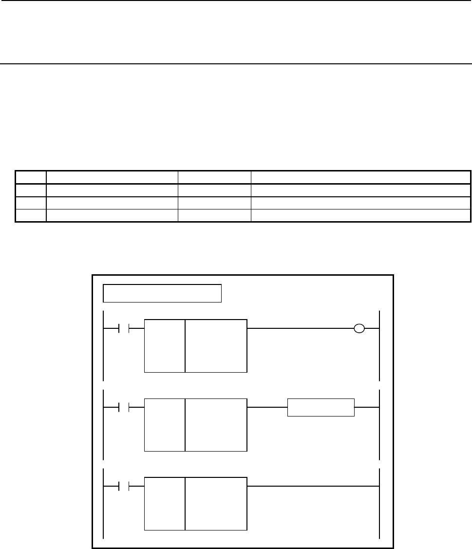
B-64513EN/03
4.LADDER LANGUAGE
- 395 -
4.8.10
ANDB (Logical AND (1 Byte Length) : SUB 268)
ANDW (Logical AND (2 Bytes Length) : SUB 269)
ANDD (Logical AND (4 Bytes Length) : SUB 270)
The Logical AND instruction logical-ANDs "Data A" with "Data B", and outputs the result to "Address
C".
In "Data A" and "Data B", a constant or a PMC memory address for storing data can be specified.
As indicated below, three types of Logical AND instructions are available according to the type of data to
be operated. In each instruction, "Data A", "Data B", and the data at "Address C" are of the same data
type.
Table4.8.10 (a) Kinds of Logical AND instruction
Instruction name SUB No. Data type
1 ANDB 268 1 byte length
2 ANDW 269 2 bytes length
3 ANDD 270 4 bytes length
Format
The followings are the ladder format and the mnemonic format.
SUB 268
A
NDB
{{{{
{{{{
{{{{
ACT
Example : ANDB Instruction
SUB 268
A
NDB
{{{{
{{{{
{{{{
Data A (Address or Constant)
Data B (Address or Constant)
A
ddress C
ACT W1
SUB 268
A
NDB
{{{{
{{{{
{{{{
Functional Instruction
ACT ACT2
Fig. 4.8.10 (a) Format of ANDB, ANDW, ANDD instruction

4.LADDER LANGUAGE
B-64513EN/03
- 396 -
Table 4.8.10(b) Mnemonic of ANDB, ANDW, ANDD instruction
Mnemonic format
Memory status of control
condition
Step
number Instruction Address
No. Bit No. Remarks
ST3 ST2 ST1 ST0
1 RD {{{{ .{ ACT ACT
2 SUB 268 SUB No. (ANDB instruction)
3 (PRM) {{{{ Data A (Address or Constant)
4 (PRM) {{{{ Data B (Address or Constant)
5 (PRM) {{{{ Address C
6 WRT {{{{ .{ Normal end output W1
Control conditions
(a) Input signal (ACT)
ACT = 0: Instruction not executed.
ACT = 1: Executed.
Parameters
(a) Data A
Specify input data to be logical-ANDed. In this parameter, a constant or a PMC memory address
for storing data can be specified. In case of constant, specify signed binary data. A value within the
following range may be specified:
Instruction name Available value
ANDB -128 to 127
ANDW -32768 to 32767
ANDD -2147483648 to 2147483647
(b) Data B
Specify input data to be logical-ANDed. In this parameter, a constant or a PMC memory address for
storing data can be specified. In case of constant, specify signed binary data. A value within the
same range as for "Data A" may be specified.
(c) Address C
Specify the address to which the result of logical-AND operation is to be output.
Output (W1)
When the instruction is executed, W1=1 is set. That is, W1 always assumes the same state as ACT.
NOTE
W1 may be omitted. Moreover, another functional instruction can be connected
instead of a coil.

B-64513EN/03
4.LADDER LANGUAGE
- 397 -
Operation
When "Data A" and "Data B" hold the following values, the value indicated below is output to "Address
C":
Binary data
Data
A
111 11000
(
-29
)
Data B 0 1 0 0 1101
(
85
)
Address C 0 1 0 0 1000
(
65
)
Fig. 4.8.10 (b) Example of operation of the ANDB, ANDW, and ANDD instructions
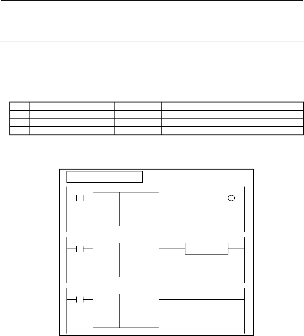
4.LADDER LANGUAGE
B-64513EN/03
- 398 -
4.8.11
ORB (Logical OR (1 Byte Length) : SUB 271)
ORW (Logical OR (2 Bytes Length) : SUB 272)
ORD (Logical OR (4 Bytes Length) : SUB 273)
The Logical OR instruction logical-ORs "Data A" with "Data B", and outputs the result to "Address C".
In "Data A" and "Data B", a constant or a PMC memory address for storing data can be specified.
As indicated below, three types of Logical OR instructions are available according to the type of data to
be operated. In each instruction, "Data A", "Data B", and the data at "Address C" are of the same data
type.
Table4.8.11 (a) Kinds of Logical OR instruction
Instruction name SUB No. Data type
1 ORB 271 1 byte length
2 ORW 272 2 bytes length
3 ORD 273 4 bytes length
Format
The followings are the ladder format and the mnemonic format.
SUB 271
ORB
{{{{
{{{{
{{{{
ACT
Example : ORB Instruction
SUB 271
ORB
{{{{
{{{{
{{{{
Data A (Address or Constant)
Data B (Address or Constant)
A
ddress C
ACT W1
SUB 271
ORB
{{{{
{{{{
{{{{
Functional Instruction
ACT ACT2
Fig. 4.8.11 (a) Format of ORB, ORW, ORD instruction
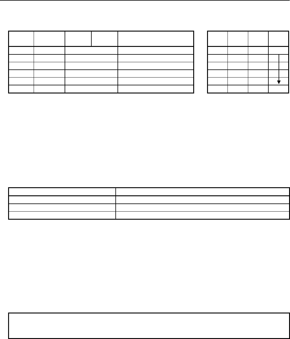
B-64513EN/03
4.LADDER LANGUAGE
- 399 -
Table 4.8.11(b) Mnemonic of ORB, ORW, ORD instruction
Mnemonic format
Memory status of control
condition
Step
number Instruction Address
No. Bit No. Remarks
ST3 ST2 ST1 ST0
1 RD {{{{ .{ ACT ACT
2 SUB 271 SUB No. (ORB instruction)
3 (PRM) {{{{ Data A (Address or Constant)
4 (PRM) {{{{ Data B (Address or Constant)
5 (PRM) {{{{ Address C
6 WRT {{{{ .{ Normal end output W1
Control conditions
(a) Input signal (ACT)
ACT = 0: Instruction not executed.
ACT = 1: Executed.
Parameters
(a) Data A
Specify input data to be logical-ORed. In this parameter, a constant or a PMC memory address for
storing data can be specified. In case of constant, specify signed binary data. A value within the
following range may be specified:
Instruction name Available value
ORB -128 to 127
ORW -32768 to 32767
ORD -2147483648 to 2147483647
(b) Data B
Specify input data to be logical-ORed. In this parameter, a constant or a PMC memory address for
storing data can be specified. In case of constant, specify signed binary data. A value within the
same range as for "Data A" may be specified.
(c) Address C
Specify the address to which the result of logical-OR operation is to be output.
Output (W1)
When the instruction is executed, W1=1 is set. That is, W1 always assumes the same state as ACT.
NOTE
W1 may be omitted. Moreover, another functional instruction can be connected
instead of a coil.
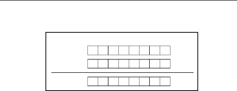
4.LADDER LANGUAGE
B-64513EN/03
- 400 -
Operation
When "Data A" and "Data B" hold the following values, the value indicated below is output to "Address
C":
Binary data
Data
A
111 11000
(
-29
)
Data B 0 1 0 0 1101
(
85
)
Address C 1 1 1 1 1101
(
-9
)
Fig. 4.8.11 (b) Example of operation of the ORB, ORW, and ORD instructions
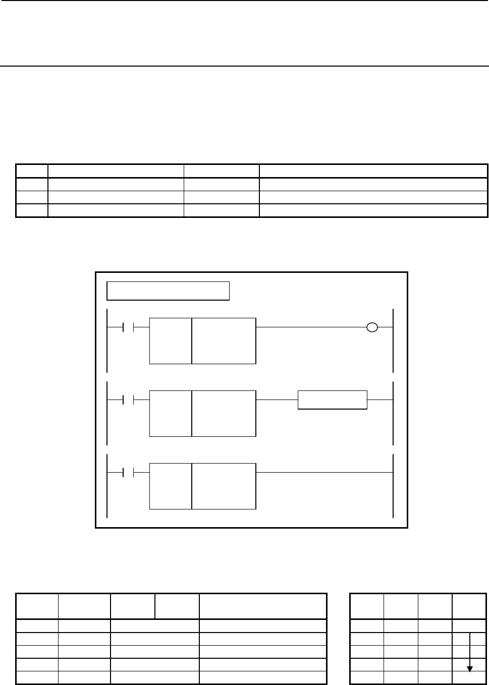
B-64513EN/03
4.LADDER LANGUAGE
- 401 -
4.8.12
NOTB (Logical NOT (1 Byte Length) : SUB 274)
NOTW (Logical NOT (2 Bytes Length) : SUB 275)
NOTD (Logical NOT (4 Bytes Length) : SUB 276)
The Logical NOT instruction performs a logical-NOT operation on "Data A" and outputs the result to
"Address B".
In "Data A", a constant or a PMC memory address for storing data can be specified.
As indicated below, three types of Logical NOT instructions are available according to the type of data to
be operated. In each instruction, "Data A" and the data at "Address B" are of the same data type.
Table4.8.12 (a) Kinds of Logical NOT instruction
Instruction name SUB No. Data type
1 NOTB 274 1 byte length
2 NOTW 275 2 bytes length
3 NOTD 276 4 bytes length
Format
The followings are the ladder format and the mnemonic format.
SUB 274
NOTB
○○○○
○○○○
ACT
Example : NOTB Instruction
SUB 274
NOTB
○○○○
○○○○
Data A (Address or Constant)
A
ddress B
ACT W1
SUB 274
NOTB
○○○○
○○○○
Functional Instruction
ACT ACT2
Fig. 4.8.12 (a) Format of NOTB, NOTW, NOTD instruction
Table 4.8.12(b) Mnemonic of NOTB, NOTW, NOTD instruction
Mnemonic format
Memory status of control
condition
Step
number Instruction Address
No. Bit No. Remarks
ST3 ST2 ST1 ST0
1 RD {{{{ .{ ACT ACT
2 SUB 274 SUB No. (ORB instruction)
3 (PRM) {{{{ Data A (Address or Constant)
4 (PRM) {{{{ Address B
5 WRT {{{{ .{ Normal end output W1
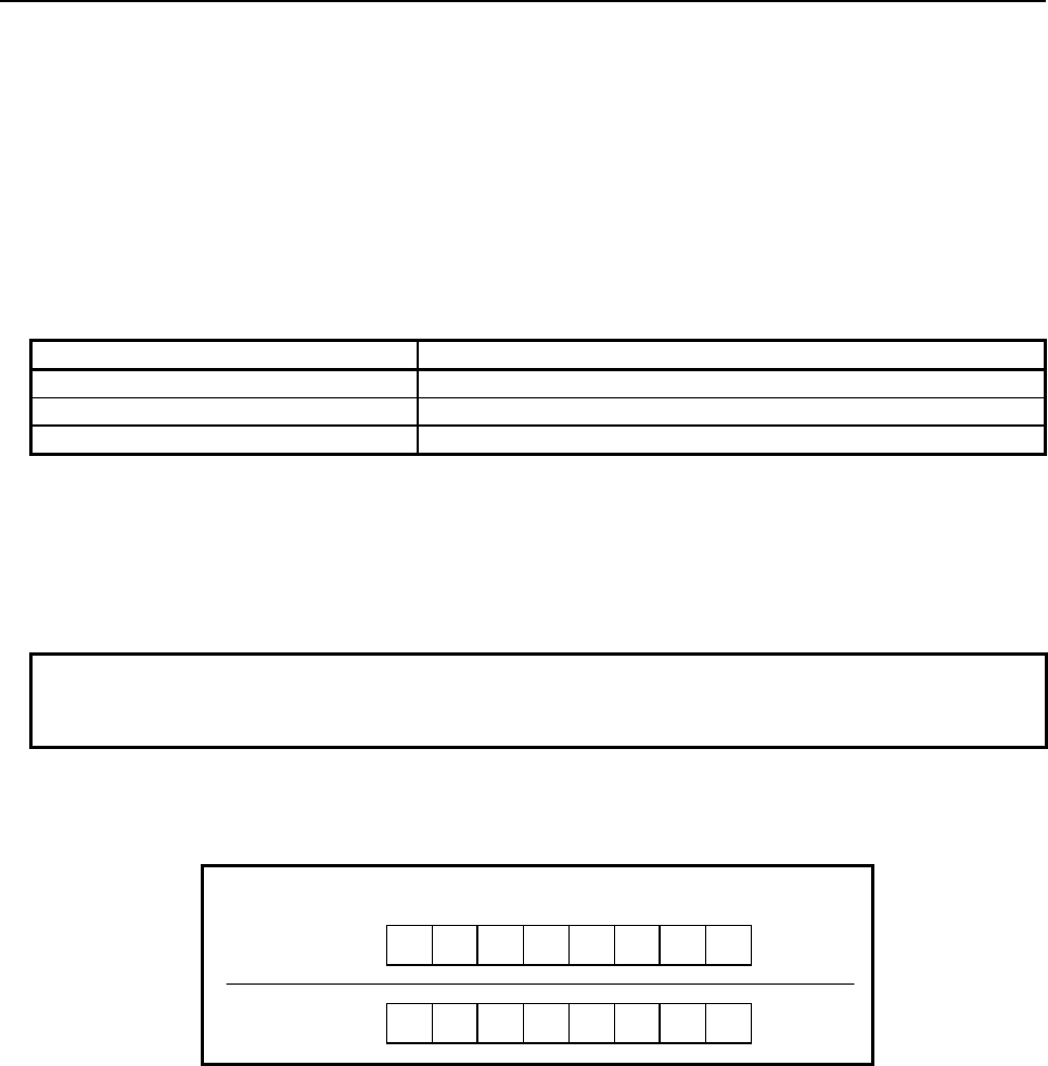
4.LADDER LANGUAGE
B-64513EN/03
- 402 -
Control conditions
(a) Input signal (ACT)
ACT = 0: Instruction not executed.
ACT = 1: Executed.
Parameters
(a) Data A
Specify input data on which a logical-NOT operation is to be performed. In this parameter, a
constant or a PMC memory address for storing data can be specified. In case of constant, specify
signed binary data. A value within the following range may be specified:
Instruction name Available value
NOTB -128 to 127
NOTW -32768 to 32767
NOTD -2147483648 to 2147483647
(b) Address B
Specify the address to which the result of logical-NOT operation is to be output.
Output (W1)
When the instruction is executed, W1=1 is set. That is, W1 always assumes the same state as ACT.
NOTE
W1 may be omitted. Moreover, another functional instruction can be connected
instead of a coil.
Operation
When "Data A" holds the following value, the value indicated below is output to "Address B":
Binary data
Data
A
111 11000 (-29)
Address B 0 0 0 0 0111 (28)
Fig. 4.8.12 (b) Example of operation of the NOTB, NOTW, and NOTD instructions
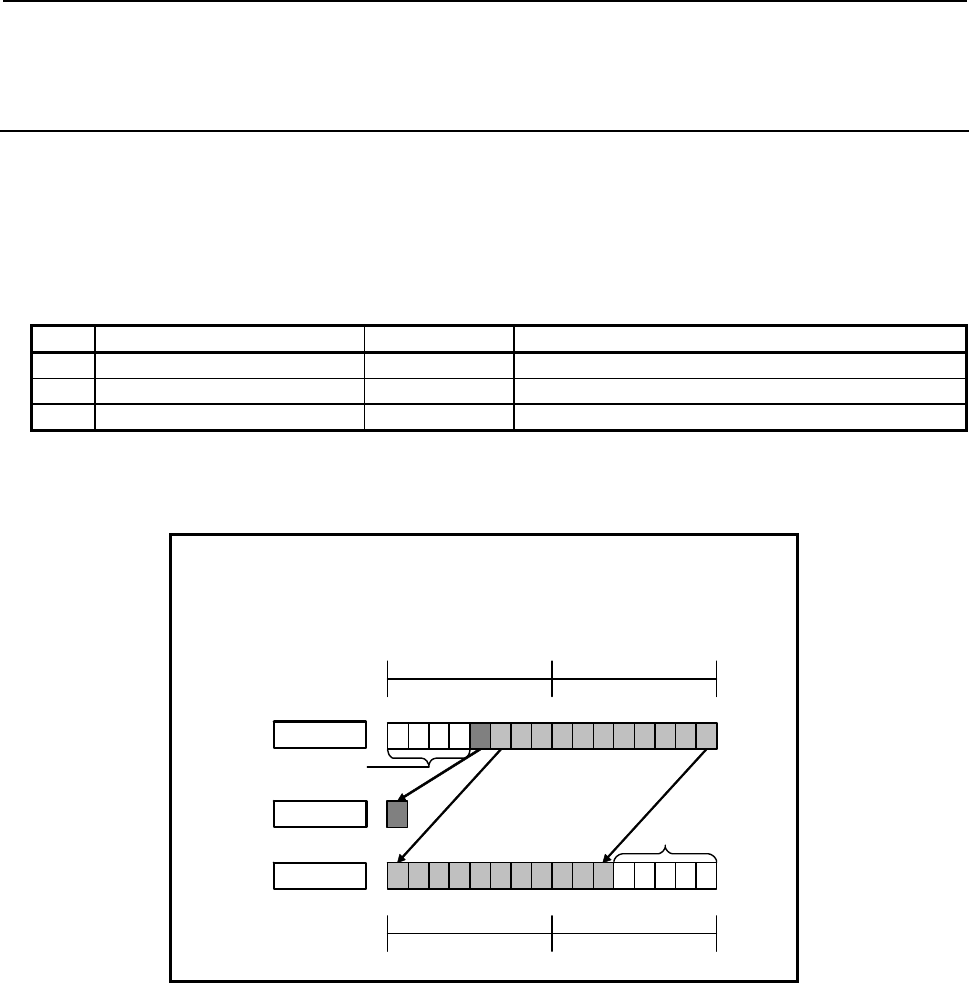
B-64513EN/03
4.LADDER LANGUAGE
- 403 -
4.8.13
SHLB (Bit Shift Left (1 Byte Length) : SUB 277)
SHLW (Bit Shift Left (2 Bytes Length) : SUB 278)
SHLD (Bit Shift Left (4 Bytes Length) : SUB 279)
The Bit shift left instruction shifts bit data to the left by a specified number of bits. In the empty bit
position(s) after shift operation, 0 is shifted in. The result of shift operation is output to a specified
address.
As indicated below, three types of Bit shift left instructions are available according to the type of data to
be operated. Shift source bit data and the data at a shift result output address are of the same data type.
Table4.8.13 (a) Kinds of Bit shift left instruction
Instruction name SUB No. Data type
1 SHLB 277 1 byte length data
2 SHLW 278 2 bytes length data
3 SHLD 279 4 bytes length data
The value of the last bit shifted out by a shift operation is output to W1. The value(s) of the preceding
left-side bit(s) are lost.
When data is shifted by 5 bits:
Shifting source data = R100
Number of shift bits = 5
Shift result output address = R102
7070
R101 R100
Shift source
15 1314 12 11 910 8 7 5643120
00 000
Bit 11 is output to W1. 0 is shifted in.
Bits 12 to 15 are
lost. Shifted left by a
specified number of
bits
W1
7070
R103 R102
Shift result
15 13
14 12 11 9
10 875
6431
20
Fig. 4.8.13 (a) Example of SHLW instruction
If 0 or a negative value is specified in "Number of shift bits", the data specified in "Shift source data" is
output to "Shift result output address" without modification, and W1=0 is set.
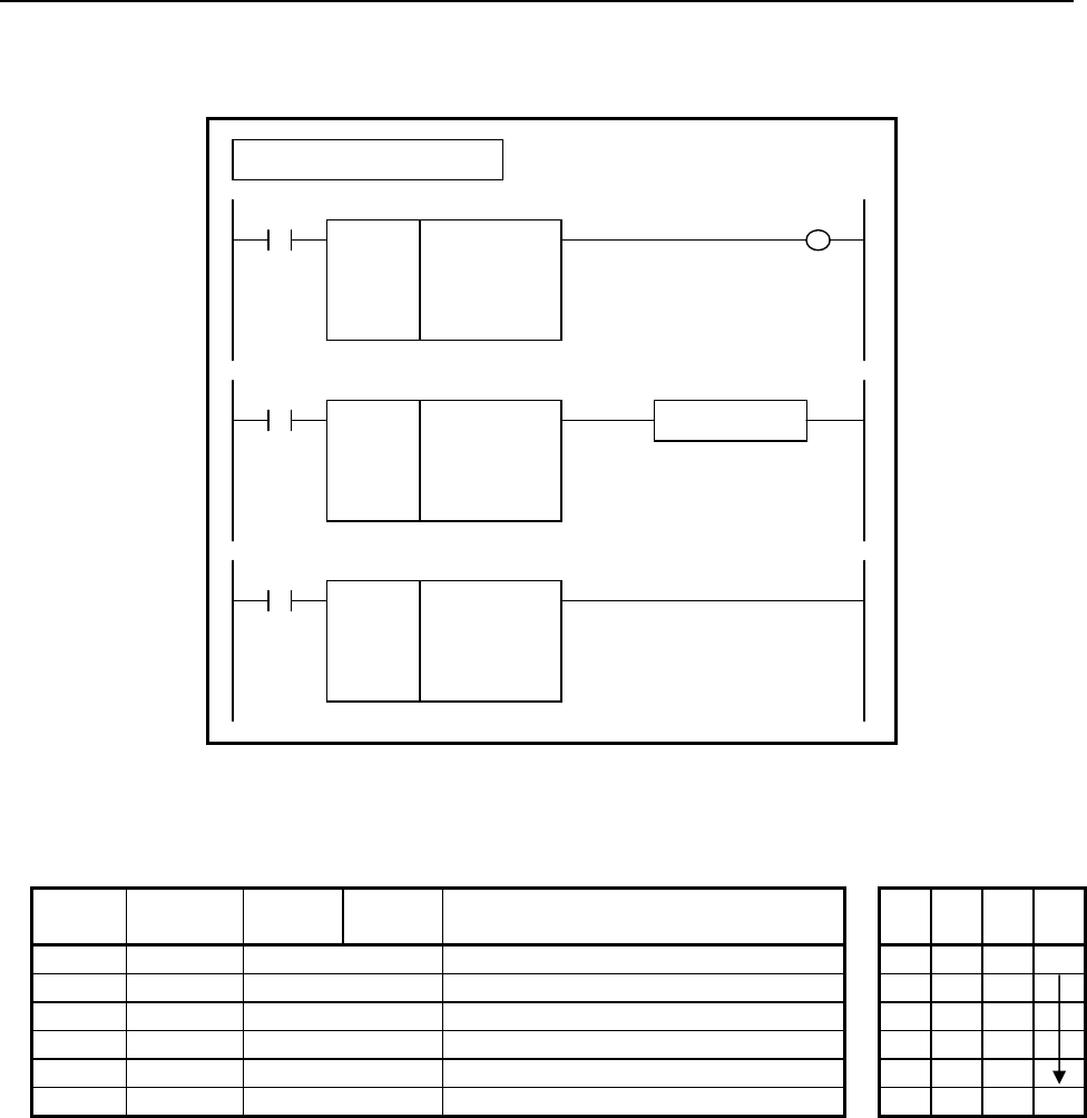
4.LADDER LANGUAGE
B-64513EN/03
- 404 -
Format
The followings are the ladder format and the mnemonic format.
SUB 277
SHLB
{{{{
{{{{
{{{{
ACT
Example : SHLB Instruction
SUB 277
SHLB
{{{{
{{{{
{{{{
Shifting source data (Address or Constant)
Number of shift bits (Address or Constant)
Shift result output address
ACT W1
SUB 277
SHLB
{{{{
{{{{
{{{{
Functional Instruction
ACT ACT2
Fig. 4.8.13 (b) Format of SHLB, SHLW, SHLD instruction
Table 4.8.13(b) Mnemonic of SHLB, SHLW, SHLD instruction
Mnemonic format
Memory status of
control condition
Step
number Instruction Address
No. Bit No. Remarks
ST3 ST2 ST1 ST0
1 RD {{{{ .{ ACT ACT
2 SUB 277 SUB No. (SHLB instruction)
3 (PRM) {{{{ Shifting source data (Address or Constant)
4 (PRM) {{{{ Number of shift bits (Address or Constant)
5 (PRM) {{{{ Shift result output address
6 WRT {{{{ .{ Shift out status output W1
Control conditions
(a) Input signal (ACT)
ACT = 0: Instruction not executed.
ACT = 1: Executed.
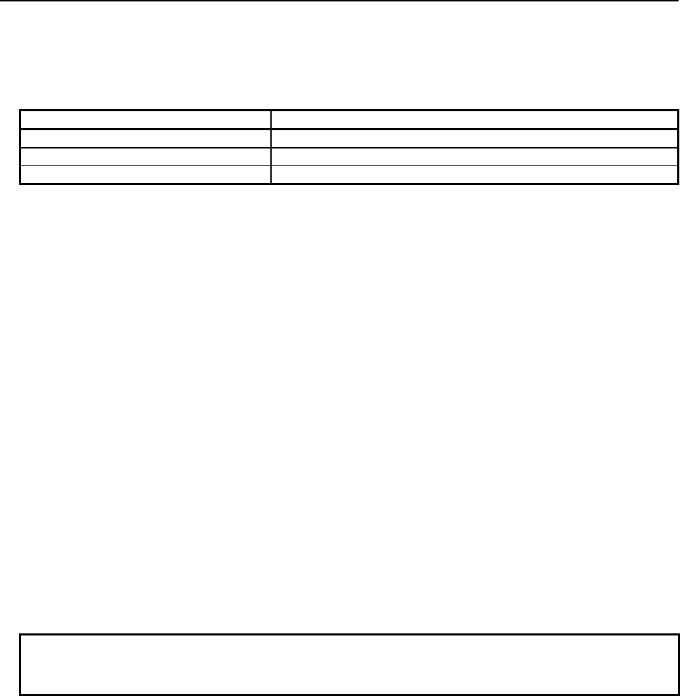
B-64513EN/03
4.LADDER LANGUAGE
- 405 -
Parameters
(a) Shifting source data
Specify bit shift source data. In this parameter, a constant or a PMC memory address for storing data
can be specified. Specify signed binary data. A value within the following range may be specified:
Instruction name Available value
SHLB -128 to 127
SHLW -32768 to 32767
SHLD -2147483648 to 2147483647
(b) Number of shift bits
By using signed binary data, specify the number of bits to be shifted. In this parameter, specify 0
or a greater value. If a value greater than 0 is specified, the data specified in "Shifting source data"
is shifted by a specified number of bits, and the result of shift operation is output to "Shift result
output address". If 0 is specified, the data specified in "Shifting source data" is output to "Shift
result output address" without modification, and W1=0 is set.
If a negative value is specified in this parameter, the data specified in "Shifting source data" is
output to "Shift result output address" without modification, and W1=0 is set as in the case where 0
is specified in this parameter. No shift operation in the opposite direction is performed.
In this parameter, a constant or a PMC memory address for storing data can be specified.
If an address is specified in this parameter, specify "Number of shift bits" by using memory of the
same size as for data type handled by each instruction. For example, with the SHLW instruction,
specify "Number of shift bits" by using memory 2 bytes long.
(c) Shift result output address
Specify the address to which the result of bit shift operation is to be output. The result of shift
operation is output to memory of the same size as for "Shifting source data".
Output (W1)
W1=1: The value of the last bit shifted out is 1.
W1=0: No shift operation is executed (ACT=0).
The value of the last bit shifted out is 0.
“0” or a negative value is specified in "Number of shift bits".
NOTE
W1 may be omitted. Moreover, another functional instruction can be connected
instead of a coil.
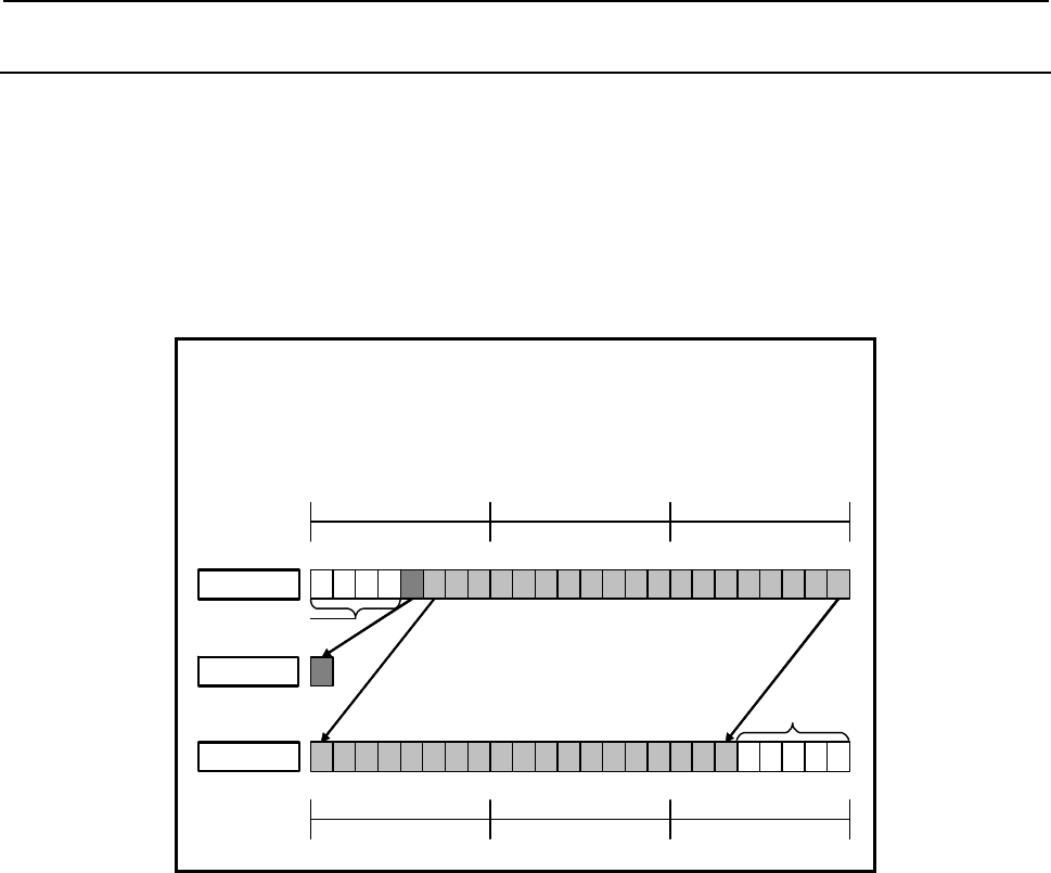
4.LADDER LANGUAGE
B-64513EN/03
- 406 -
4.8.14
SHLN (Bit Shift Left (Arbitrary Bytes Length) : SUB 280)
The Bit shift left instruction shifts bit data to the left by a specified number of bits. In the empty bit
position(s) after shift operation, 0 is shifted in. The result of shift operation is output to a specified
address.
The Bit shift left instruction performs a bit shift operation on a bit string of a specified data size.
Shifting source data and the result of shift operation are of the same data size.
The value of the last bit shifted out by shift operation is output to W1. The value(s) of the preceding
left-side bit(s) are lost.
When data is shifted by 5 bits:
Data size = 3
Shifting source data top address = R100
Number of shift bits = 5
Shift result output address = R103
Shift source
Bit 19 is output
to W1.
0 is shifted
in.
Bits 20 to 23
are lost.
Shifted left by a specified number of bits
W1
7 0 7 0
R105 R104
70
R103
00 0 0 0
15 13
14 12 11 9
10 875
6431
2 0
23 21
22 20
19 17
18 16
Shift result
7 0 7 0
R102 R101
70
R100
15 13
14 12 11 9
10 875
6431
2 0
23 21
22 20
19 17
18 16
Fig. 4.8.14 (a) Example of SHLN instruction
If 0 or a negative value is specified in "Number of shift bits", the shift source data is output to "Shift
result output address" without modification, and W1=0 is set.

B-64513EN/03
4.LADDER LANGUAGE
- 407 -
Format
The followings are the ladder format and the mnemonic format.
SUB 280
SHLN
{{{{
{{{{
{{{{
{{{{
ACT
Example : SHLN Instruction
SUB 280
SHLN
{{{{
{{{{
{{{{
{{{{
Data size (Constant)
Shifting source data top address
Number of shift bits (Address or Constant)
Shift result output address
ACT W1
SUB 280
SHLN
{{{{
{{{{
{{{{
{{{{
Functional Instruction
ACT ACT2
Fig. 4.8.14 (b) Format of SHLN instruction
Table 4.8.14 Mnemonic of SHLN instruction
Mnemonic format
Memory status of
control condition
Step
number Instruction Address
No. Bit No. Remarks
ST3 ST2 ST1 ST0
1 RD {{{{ .{ ACT ACT
2 SUB 280 SUB No. (SHLN instruction)
3 (PRM) {{{{ Data size (Constant)
4 (PRM) {{{{ Shifting source data top address
5 (PRM) {{{{ Number of shift bits (Address or Constant)
6 (PRM) {{{{ Shift result output address
7 WRT {{{{ .{ Shift out status output W1
Control conditions
(a) Input signal (ACT)
ACT = 0: Instruction not executed.
ACT = 1: Executed.
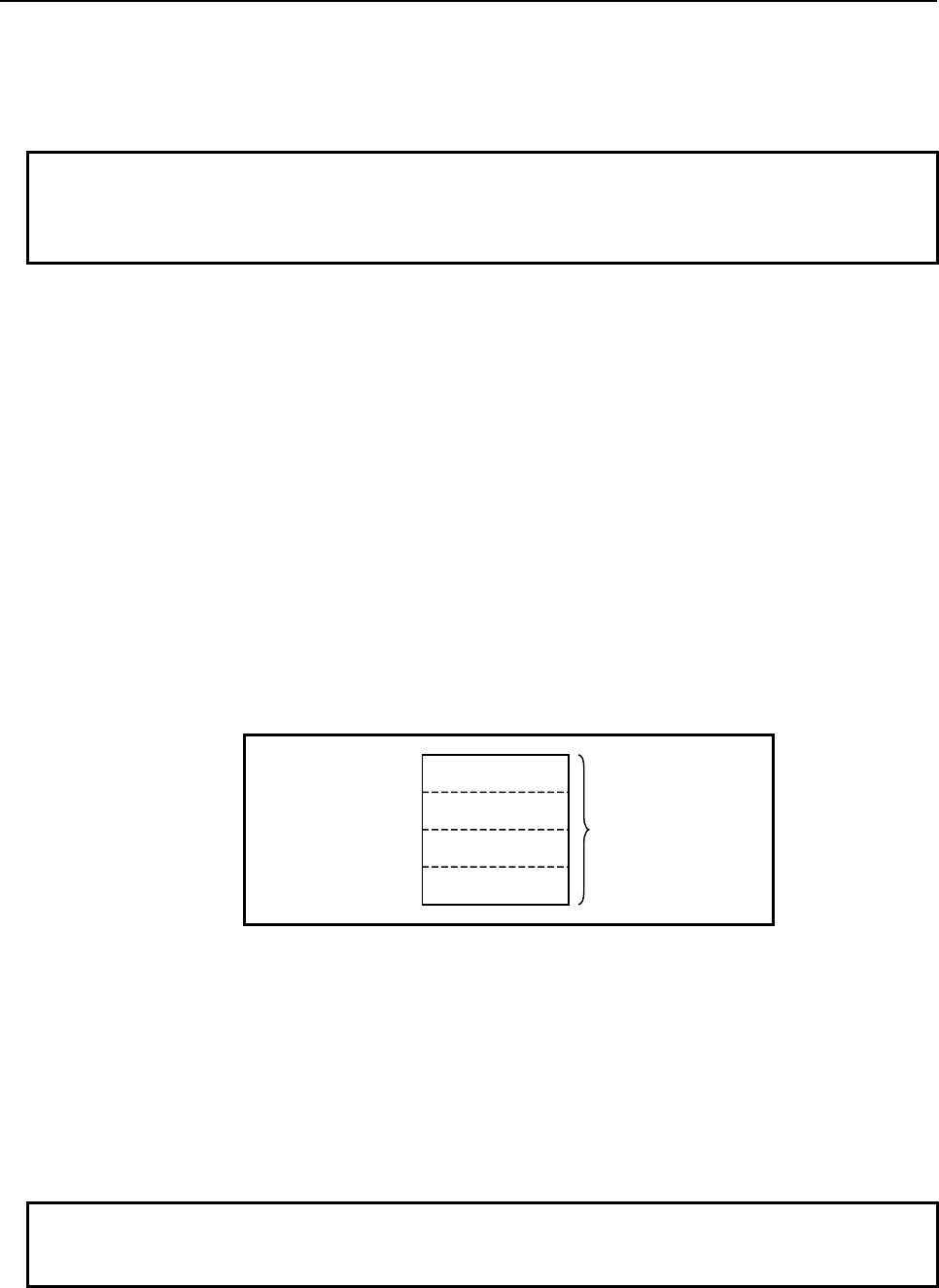
4.LADDER LANGUAGE
B-64513EN/03
- 408 -
Parameters
(a) Data size
Specify the number of bytes of data on which a bit shift operation is to be performed. A value from 1
to 256 may be specified.
NOTE
Specify a valid number to the "Data size", so that both of the area from "Shifting
source data top address" and the area from "Shift result output address" may be
arranged within valid address range.
(b) Shifting source data top address
Specify the start address of bit shift source data.
Specify a data size in "Data size" mentioned in (a) above.
(c) Number of shift bits
By using 4 bytes signed binary data, specify the number of bits to be shifted. In this parameter,
specify 0 or a greater value. If a value greater than 0 is specified, the shifting source data is shifted
by a specified number of bits, and the result of shift operation is output to "Shift result output
address". A value from 1 to ("Data size" × 8) may be specified. For example, if 6 is specified in
"Data size", a value from 1 to 48 may be specified in this parameter. If a value greater than the
valid range is specified, 0 is output to "Shift result output address", and W1=0 is set.
If 0 is specified, the shifting source data is output to "Shift result output address" without
modification, and W1=0 is set.
If a negative value is specified in this parameter, the shifting source data is output to "Shift result
output address" without modification, and W1=0 is set as in the case where 0 is specified in this
parameter. No shift operation in the opposite direction is performed.
In this parameter, a constant or a PMC memory address for storing data can be specified.
Specified address +0
Specified address +1 Number of shift bits
(Signed binary data)
Specified address +2
Specified address +3
(d) Shift result output address
Specify the start address of an area to which the result of bit shift operation is to be output. The
result of shift operation is output to memory of the same size as for shifting source data.
Output (W1)
W1=1: The value of the last bit shifted out is 1.
W1=0: No shift operation is executed (ACT=0).
The value of the last bit shifted out is 0.
“0” or a negative value is specified in "Number of shift bits".
NOTE
W1 may be omitted. Moreover, another functional instruction can be connected
instead of a coil.
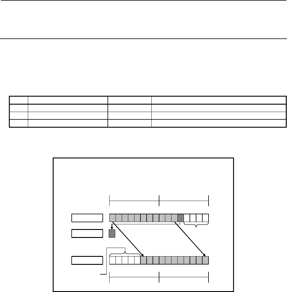
B-64513EN/03
4.LADDER LANGUAGE
- 409 -
4.8.15
SHRB (Bit Shift Right (1 Byte Length) : SUB 281)
SHRW (Bit Shift Right (2 Bytes Length) : SUB 282)
SHRD (Bit Shift Right (4 Bytes Length) : SUB 283)
The Bit shift right instruction shifts bit data to the right by a specified number of bits. In the empty bit
position(s) after shift operation, 0 is shifted in. The result of shift operation is output to a specified
address.
As indicated below, three types of Bit shift right instructions are available according to the type of data to
be operated. Shift source bit data and the data at a shift result output address are of the same data type.
Table4.8.15 (a) Kinds of Bit shift right instruction
Instruction name SUB No. Data type
1 SHRB 281 1 byte length data
2 SHRW 282 2 bytes length data
3 SHRD 283 4 bytes length data
The value of the last bit shifted out by shift operation is output to W1. The value(s) of the following
right-side bit(s) are lost.
When data is shifted by 5 bits:
Shifting source data = R100
Number of shift bits = 5
Shift result output address = R102
7070
R101 R100
Shift source
15 13
14 12 11 9
10 875
6431
20
00 000
Bit 4 is out
p
ut to W 1.
0 is shifted in.
Bits 0 to 3 are
lost.
Shifted right by a
specified number of bits
ト
W1
7070
R103 R102
Shift result
15 1314 12 11 910 8 7 5643120
Fig. 4.8.15 (a) Example of SHRW instruction
If 0 or a negative value is specified in "Number of shift bits", the shift source data is output to "Shift
result output address" without modification, and W1=0 is set.

4.LADDER LANGUAGE
B-64513EN/03
- 410 -
Format
The followings are the ladder format and the mnemonic format.
SUB 281
SHRB
{{{{
{{{{
{{{{
ACT
Example : SHRB Instruction
SUB 281
SHRB
{{{{
{{{{
{{{{
Shifting source data (Address or Constant)
Number of shift bits (Address or Constant)
Shift result output address
ACT W1
SUB 281
SHRB
{{{{
{{{{
{{{{
Functional Instruction
ACT ACT2
Fig. 4.8.15 (b) Format of SHRB, SHRW, SHRD instruction
Table 4.8.15(b) Mnemonic of SHRB, SHRW, SHRD instruction
Mnemonic format
Memory status of
control condition
Step
number Instruction Address
No. Bit No. Remarks
ST3 ST2 ST1 ST0
1 RD {{{{ .{ ACT ACT
2 SUB 281 SUB No. (SHRB instruction)
3 (PRM) {{{{ Shifting source data (Address or Constant)
4 (PRM) {{{{ Number of shift bits (Address or Constant)
5 (PRM) {{{{ Shift result output address
6 WRT {{{{ .{ Shift out status output W1
Control conditions
(a) Input signal (ACT)
ACT = 0: Instruction not executed.
ACT = 1: Executed.

B-64513EN/03
4.LADDER LANGUAGE
- 411 -
Parameters
(a) Shifting source data
Specify bit shift source data. In this parameter, a constant or a PMC memory address for storing data
can be specified.
Specify signed binary data. A value within the following range may be specified:
Instruction name Available value
SHRB -128 to 127
SHRW -32768 to 32767
SHRD -2147483648 to 2147483647
(b) Number of shift bits
By using signed binary data, specify the number of bits to be shifted. In this parameter, specify 0
or a greater value. If a value greater than 0 is specified, the data specified in "Shifting source data"
is shifted by a specified number of bits, and the result of shift operation is output to "Shift result
output address". If 0 is specified, the data specified in "Shifting source data" is output to "Shift
result output address" without modification, and W1=0 is set.
If a negative value is specified in this parameter, the data specified in "Shifting source data" is
output to "Shift result output address" without modification, and W1=0 is set as in the case where 0
is specified in this parameter. No shift operation in the opposite direction is performed.
In this parameter, a constant or a PMC memory address for storing data can be specified.
If an address is specified in this parameter, specify "Number of shift bits" by using signed binary
data of the same size as for data type handled by each instruction. For example, with the SHRW
instruction, specify "Number of shift bits" by using 2 bytes signed binary data.
(c) Shift result output address
Specify the address to which the result of bit shift operation is to be output. The result of shift
operation is output to memory of the same size as for "Shifting source data".
Output (W1)
W1=1: The value of the last bit shifted out is 1.
W1=0: No shift operation is executed (ACT=0).
The value of the last bit shifted out is 0.
“0” or a negative value is specified in "Number of shift bits".
NOTE
W1 may be omitted. Moreover, another functional instruction can be connected
instead of a coil.
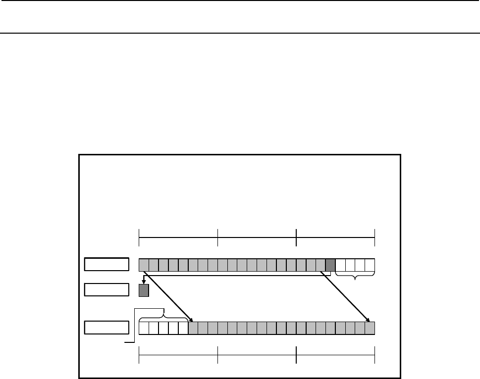
4.LADDER LANGUAGE
B-64513EN/03
- 412 -
4.8.16
SHRN (Bit Shift Right (Arbitrary Bytes Length) : SUB 284)
The Bit shift right instruction shifts bit data to the right by a specified number of bits. In the empty bit
position(s) after shift operation, 0 is shifted in. The result of shift operation is output to a specified
address.
The Bit shift right instruction performs a bit shift operation on a bit string of a specified data size.
Shifting source data and the result of shift operation are of the same data size.
The value of the last bit shifted out by shift operation is output to W1. The value(s) of the following
right-side bit(s) are lost.
When data is shifted by 5 bits:
Data size = 3
Shifting source data top address = R100
Number of shift bits = 5
Shift result output address = R103
Shift source
Bit 4 is out
p
ut to W1.
0 is shifted
in.
Bits 0 to 3 are
lost.
Shifted right by a specified number of bits
W1
7 0 7 0
R102 R101
70
R100
0 0 0 0 0
15 13
14 12 11 9
10 875
6431
20
23 21
22 20
19 17
18 16
7 0 7 0
R105 R104
70
R103
Shift result
15 13
14 12 11 9
10 875
6431
20
23 21
22 20
19 17
18 16
Fig. 4.8.16 (a) Example of SHRN instruction
If 0 or a negative value is specified in "Number of shift bits", the shift source data is output to "Shift
result output address" without modification, and W1=0 is set.
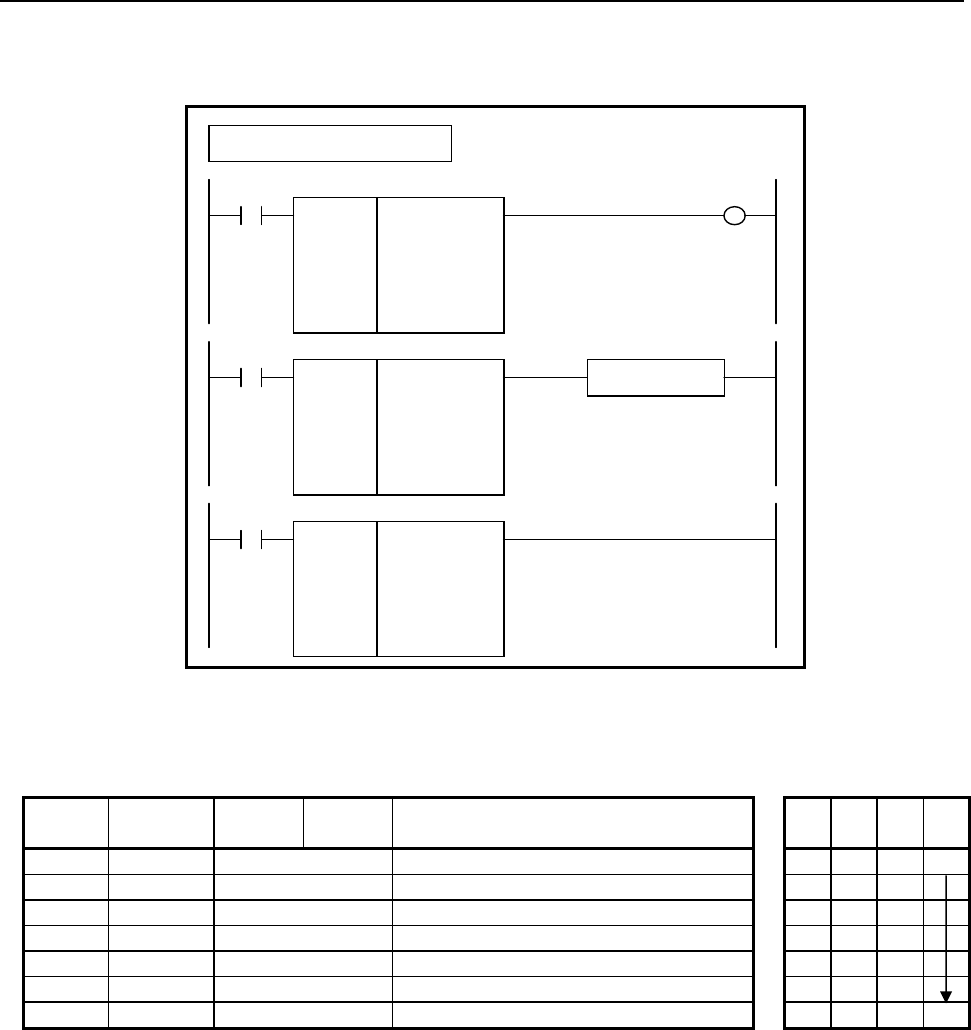
B-64513EN/03
4.LADDER LANGUAGE
- 413 -
Format
The followings are the ladder format and the mnemonic format.
SUB 284
SHRN
{{{{
{{{{
{{{{
{{{{
ACT
Example : SHRN Instruction
SUB 284
SHRN
{{{{
{{{{
{{{{
{{{{
Data size (Constant)
Shifting source data top address
Number of shift bits (Address or Constant)
Shift result output address
ACT W1
SUB 284
SHRN
{{{{
{{{{
{{{{
{{{{
Functional Instruction
ACT ACT2
Fig. 4.8.16 (b) Format of SHRN instruction
Table 4.8.16 Mnemonic of SHRN instruction
Mnemonic format
Memory status of
control condition
Step
number Instruction Address
No. Bit No. Remarks
ST3 ST2 ST1 ST0
1 RD {{{{ .{ ACT ACT
2 SUB 284 SUB No. (SHRN instruction)
3 (PRM) {{{{ Data size (Constant)
4 (PRM) {{{{ Shifting source data top address
5 (PRM) {{{{ Number of shift bits (Address or Constant)
6 (PRM) {{{{ Shift result output address
7 WRT {{{{ .{ Shift out status output W1
Control conditions
(a) Input signal (ACT)
ACT = 0: Instruction not executed.
ACT = 1: Executed.

4.LADDER LANGUAGE
B-64513EN/03
- 414 -
Parameters
(a) Data size
Specify the number of bytes of data on which a bit shift operation is to be performed. A value from 1
to 256 may be specified.
NOTE
Specify a valid number to the "Data size", so that both of the area from "Shifting
source data top address" and the area from "Shift result output address" may be
arranged within valid address range.
(b) Shifting source data top address
Specify the start address of bit shift source data.
Specify a data size in "Data size" mentioned in (a) above.
(c) Number of shift bits
By using 4 bytes signed binary data, specify the number of bits to be shifted. In this parameter,
specify 0 or a greater value. If a value greater than 0 is specified, the shifting source data is shifted
by a specified number of bits, and the result of shift operation is output to "Shift result output
address". A value from 1 to ("Data size" × 8) may be specified. For example, if 6 is specified in
"Data size", a value from 1 to 48 may be specified in this parameter. If a value greater than the
valid range is specified, 0 is output to "Shift result output address", and W1=0 is set.
If 0 is specified, the shifting source data is output to "Shift result output address" without
modification, and W1=0 is set.
If a negative value is specified in this parameter, the shifting source data is output to "Shift result
output address" without modification, and W1=0 is set as in the case where 0 is specified in this
parameter. No shift operation in the opposite direction is performed.
In this parameter, a constant or a PMC memory address for storing data can be specified.
Specified address +0
Specified address +1 Number of shift bits
(Signed binary data)
Specified address +2
Specified address +3
(d) Shift result output address
Specify the start address of an area to which the result of bit shift operation is to be output. The
result of shift operation is output to memory of the same size as for shifting source data.
Output (W1)
W1=1: The value of the last bit shifted out is 1.
W1=0: No shift operation is executed (ACT=0).
The value of the last bit shifted out is 0.
“0” or a negative value is specified in "Number of shift bits".
NOTE
W1 may be omitted. Moreover, another functional instruction can be connected
instead of a coil.
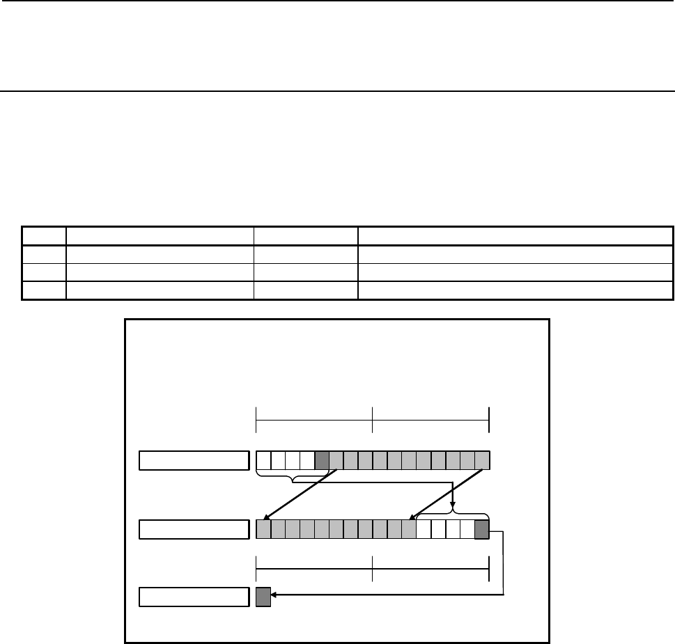
B-64513EN/03
4.LADDER LANGUAGE
- 415 -
4.8.17
ROLB (Bit Rotation Left (1 Byte Length) : SUB 285)
ROLW (Bit Rotation Left (2 Bytes Length) : SUB 286)
ROLD (Bit Rotation Left (4 Bytes Length) : SUB 287)
The Bit rotation left instruction rotates bit data to the left by a specified number of bits. The result of
rotation operation is output to a specified address.
As indicated below, three types of Bit rotation left instructions are available according to the type of data
to be operated. Rotation source bit data and the data at a rotation result output address are of the same
data type.
Table4.8.17 (a) Kinds of Bit rotation left instruction
Instruction name SUB No. Data type
1 ROLB 285 1 byte length data
2 ROLW 286 2 bytes length data
3 ROLD 287 4 bytes length data
When data is rotated by 5 bits:
Rotation source data = R100
Number of rotation bits = 5
Rotation result output address = R102
7070
R101 R100
Rotation source
15 13
14 12 11 9
10 875
6431
20
Bit 0 after rotation is output to W1.
Rotated left by a specified
number of bits
にテシ
W1
Rotation result
7070
R103 R102
15 13
14 12 11 9
10 875
6431
20
Fig. 4.8.17 (a) Example of ROLW instruction
The value of bit 0 after rotation is output to W1.
If 0 is specified in "Number of rotation bits", the data specified in "Rotation source data" is output to
"Rotation result output address" without modification, and W1=0 is set.
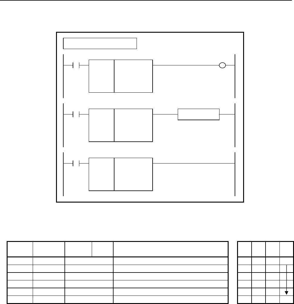
4.LADDER LANGUAGE
B-64513EN/03
- 416 -
Format
The followings are the ladder format and the mnemonic format.
SUB 285
ROLB
{{{{
{{{{
{{{{
ACT
Example : ROLB Instruction
SUB 285
ROLB
{{{{
{{{{
{{{{
Rotation source data (Address or Constant)
Number of rotation bits (Address or Constant)
Rotation result output address
ACT W1
SUB 285
ROLB
{{{{
{{{{
{{{{
Functional Instruction
ACT ACT2
Fig. 4.8.17 (b) Format of ROLB, ROLW, ROLD instruction
Table 4.8.17(b) Mnemonic of ROLB, ROLW, ROLD instruction
Mnemonic format
Memory status of
control condition
Step
number Instruction Address
No. Bit No. Remarks
ST3 ST2 ST1 ST0
1 RD {{{{ .{ ACT ACT
2 SUB 285 SUB No. (ROLB instruction)
3 (PRM) {{{{ Rotation source data (Address or Constant)
4 (PRM) {{{{ Number of rotation bits (Address or Constant)
5 (PRM) {{{{ Rotation result output address
6 WRT {{{{ .{ Last rotation bit output W1
Control conditions
(a) Input signal (ACT)
ACT = 0: Instruction not executed.
ACT = 1: Executed.

B-64513EN/03
4.LADDER LANGUAGE
- 417 -
Parameters
(a) Rotation source data
Specify bit rotation source data. In this parameter, a constant or a PMC memory address for storing
data can be specified.
Specify signed binary data. A value within the following range may be specified:
Instruction name Available value
ROLB -128 to 127
ROLW -32768 to 32767
ROLD -2147483648 to 2147483647
(b) Number of rotation bits
By using signed binary data, specify the number of bits to be rotated. In this parameter, specify 0
or a greater value. If a value greater than 0 is specified, the data specified in "Rotation source data"
is rotated by a specified number of bits, and the result of rotation operation is output to "Rotation
result output address". If 0 is specified, the data specified in "Rotation source data" is output to
"Rotation result output address" without modification, and W1=0 is set.
If a negative value is specified in this parameter, the data specified in "Rotation source data" is
output to "Rotation result output address" without modification, and W1=0 is set as in the case
where 0 is specified in this parameter. No rotation operation in the opposite direction is performed.
In this parameter, a constant or a PMC memory address for storing data can be specified.
If an address is specified in this parameter, specify "Number of rotation bits" by using signed binary
data of the same size as for data type handled by each instruction. For example, with the ROLW
instruction, specify "Number of rotation bits" by using 2 bytes signed binary data.
(c) Rotation result output address
Specify the address to which the result of rotation operation is to be output. The result of rotation
operation is output to memory of the same size as for "Rotation source data".
Output (W1)
W1=1: The value of bit 0 after rotation is 1.
W1=0: No rotation operation is executed (ACT=0).
The value of bit 0 after rotation is 0.
“0” or a negative value is specified in "Number of rotation bits".
NOTE
W1 may be omitted. Moreover, another functional instruction can be connected
instead of a coil.
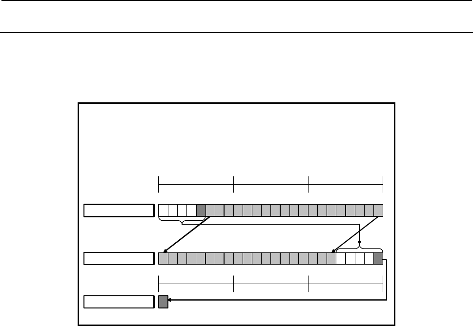
4.LADDER LANGUAGE
B-64513EN/03
- 418 -
4.8.18
ROLN (Bit Rotation Left (Arbitrary Bytes Length) : SUB 288)
The Bit rotation left instruction rotates bit data to the left by a specified number of bits. The result of
rotation operation is output to a specified address.
The Bit rotation left instruction performs a bit rotation operation on a bit string of a specified data size.
Rotation source data and the result of rotation operation are of the same data size.
When data is rotated by 5 bits:
Data size = 3
Rotation source data top address = R100
Number of rotation bits = 5
Rotation result output address = R103
Rotation source
Bit 0 after rotation is output to W1.
Rotated left by a specified
number of bits
テシ
W1
7 0 7 0
R102 R101
70
R100
15 13
14 12 11 9
10 875
6431
2 0
23 21
22 20 19 17
18 16
Rotation result
7 0 7 0
R105 R104
70
R103
15 1314 12 11 910 8 7 56431 2 0 23 2122 20 19 1718 16
Fig. 4.8.18 (a) Example of ROLN instruction
The value of bit 0 after rotation is output to W1.
If 0 is specified in "Number of rotation bits", the rotation source data is output to "Rotation result output
address" without modification, and W1=0 is set.

B-64513EN/03
4.LADDER LANGUAGE
- 419 -
Format
The followings are the ladder format and the mnemonic format.
SUB 288
ROLN
{{{{
{{{{
{{{{
{{{{
ACT
Example : ROLN Instruction
SUB 288
ROLN
{{{{
{{{{
{{{{
{{{{
Data size (Constant)
Rotation source data top address
Number of rotation bits (Address or Constant)
Rotation result output address
ACT W1
SUB 288
ROLN
{{{{
{{{{
{{{{
{{{{
Functional Instruction
ACT ACT2
Fig. 4.8.18 (b) Format of ROLN instruction
Table 4.8.18 Mnemonic of ROLN instruction
Mnemonic format
Memory status of
control condition
Step
number Instruction Address
No. Bit No. Remarks
ST3 ST2 ST1 ST0
1 RD {{{{ .{ ACT ACT
2 SUB 288 SUB No. (ROLN instruction)
3 (PRM) {{{{ Data size (Constant)
4 (PRM) {{{{ Rotation source data top address
5 (PRM) {{{{ Number of rotation bits (Address or Constant)
6 (PRM) {{{{ Rotation result output address
7 WRT {{{{ .{ Last rotation bit output W1
Control conditions
(a) Input signal (ACT)
ACT = 0: Instruction not executed.
ACT = 1: Executed.
4.LADDER LANGUAGE
B-64513EN/03
- 420 -
Parameters
(a) Data size
Specify the number of bytes of data on which a bit rotation operation is to be performed. A value
from 1 to 256 may be specified.
NOTE
Specify a valid number to the "Data size", so that both of the area from "Rotation
source data top address" and the area from "Rotation result output address" may
be arranged within valid address range.
(b) Rotation source data top address
Specify the start address of rotation source data. Specify a data size in "Data size" mentioned in (a)
above.
(c) Number of rotation bits
By using 4 bytes signed binary data, specify the number of bits to be rotated. In this parameter,
specify 0 or a greater value. If a value greater than 0 is specified, the rotation source data is rotated
by a specified number of bits, and the result of rotation operation is output to "Rotation result output
address". A value from 1 to ("Data size" × 8) may be specified. For example, if 6 is specified in
"Data size", a value from 1 to 48 may be specified in this parameter. If a value greater than the
valid range is specified, the number of specified bits is divided by the value obtained by "Data size"
× 8 then a rotation operation is performed using the remainder as the specified number of bits. If 0
is specified, the rotation source data is output to "Rotation result output address" without
modification, and W1=0 is set.
If a negative value is specified in this parameter, the rotation source data is output to "Rotation result
output address" without modification, and W1=0 is set as in the case where 0 is specified in this
parameter. No rotation operation in the opposite direction is performed.
In this parameter, a constant or a PMC memory address for storing data can be specified.
Specified address +0
Specified address +1 Number of rotation bits
(Signed binary data)
Specified address +2
Specified address +3
(d) Rotation result output address
Specify the start address of an area to which the result of rotation operation is to be output. The
result of rotation operation is output to memory of the same size as for rotation source data.
Output (W1)
W1=1: The value of bit 0 after rotation is 1.
W1=0: No rotation operation is executed (ACT=0).
The value of bit 0 after rotation is 0.
“0” or a negative value is specified in "Number of rotation bits".
NOTE
W1 may be omitted. Moreover, another functional instruction can be connected
instead of a coil.
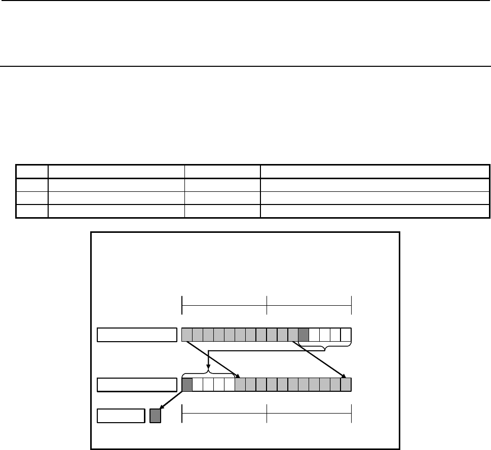
B-64513EN/03
4.LADDER LANGUAGE
- 421 -
4.8.19
RORB (Bit Rotation Right (1 Byte Length) : SUB 289)
RORW (Bit Rotation Right (2 Bytes Length) : SUB 290)
RORD (Bit Rotation Right (4 Bytes Length) : SUB 291)
The Bit rotation right instruction rotates bit data to the right by a specified number of bits. The result of
rotation operation is output to a specified address.
As indicated below, three types of Bit rotation right instructions are available according to the type of
data to be operated. Rotation source bit data and the data at a rotation result output address are of the
same data type.
Table4.8.19 (a) Kinds of Bit rotation right instruction
Instruction name SUB No. Data type
1 RORB 289 1 byte length data
2 RORW 290 2 bytes length data
3 RORD 291 4 bytes length data
When data is rotated by 5 bits:
Rotation source data = R100
Number of rotation bits = 5
Rotation result output address = R102
7 0 7 0
R101 R100
Rotation source
Rotation result
15 13
14 12 11 9
10 875
6431
20
The most significant bit after rotation is output to W1.
Rotated right by
a specified number of bits
右方向
にテシン
W1 7 0 7 0
R103 R102
15 13
14 12 11 9
10 875
6431
20
Fig. 4.8.19 (a) Example of RORW instruction
The value of the most significant bit (bit 15 in the example above) after rotation is output to W1.
If 0 is specified in "Number of rotation bits", the data specified in "Rotation source data" is output to
"Rotation result output address" without modification, and W1=0 is set.

4.LADDER LANGUAGE
B-64513EN/03
- 422 -
Format
The followings are the ladder format and the mnemonic format.
SUB 289
RORB
{{{{
{{{{
{{{{
ACT
Example : RORB Instruction
SUB 289
RORB
{{{{
{{{{
{{{{
Rotation source data (Address or Constant)
Number of rotation bits (Address or Constant)
Rotation result output address
ACT W1
SUB 289
RORB
{{{{
{{{{
{{{{
Functional Instruction
ACT ACT2
Fig. 4.8.19 (b) Format of RORB, RORW, RORD instruction
Table 4.8.19(b) Mnemonic of RORB, RORW, RORD instruction
Mnemonic format
Memory status of
control condition
Step
number Instruction Address
No. Bit No. Remarks
ST3 ST2 ST1 ST0
1 RD {{{{ .{ ACT ACT
2 SUB 289 SUB No. (RORB instruction)
3 (PRM) {{{{ Rotation source data (Address or Constant)
4 (PRM) {{{{ Number of rotation bits (Address or Constant)
5 (PRM) {{{{ Rotation result output address
6 WRT {{{{ .{ Last rotation bit output W1
Control conditions
(a) Input signal (ACT)
ACT = 0: Instruction not executed.
ACT = 1: Executed.
B-64513EN/03
4.LADDER LANGUAGE
- 423 -
Parameters
(a) Rotation source data
Specify bit rotation source data. In this parameter, a constant or a PMC memory address for storing
data can be specified.
Specify signed binary data. A value within the following range may be specified:
Instruction name Available value
RORB -128 to 127
RORW -32768 to 32767
RORD -2147483648 to 2147483647
(b) Number of rotation bits
By using signed binary data, specify the number of bits to be rotated. In this parameter, specify 0
or a greater value. If a value greater than 0 is specified, the data specified in "Rotation source data"
is rotated by a specified number of bits, and the result of rotation operation is output to "Rotation
result output address". If 0 is specified, the data specified in "Rotation source data" is output to
"Rotation result output address" without modification, and W1=0 is set.
If a negative value is specified in this parameter, the data specified in "Rotation source data" is
output to "Rotation result output address" without modification, and W1=0 is set as in the case
where 0 is specified in this parameter. No rotation operation in the opposite direction is performed.
In this parameter, a constant or a PMC memory address for storing data can be specified.
If an address is specified in this parameter, specify "Number of rotation bits" by using signed binary
data of the same size as for data type handled by each instruction. For example, with the RORW
instruction, specify "Number of rotation bits" by using 2 bytes signed binary data.
(c) Rotation result output address
Specify the address to which the result of rotation operation is to be output. The result of rotation
operation is output to memory of the same size as for "Rotation source data".
Output (W1)
W1=1: The value of the most significant bit after rotation is 1.
W1=0: No rotation operation is executed (ACT=0).
The value of the most significant bit after rotation is 0.
“0” or a negative value is specified in "Number of rotation bits".
NOTE
W1 may be omitted. Moreover, another functional instruction can be connected
instead of a coil.
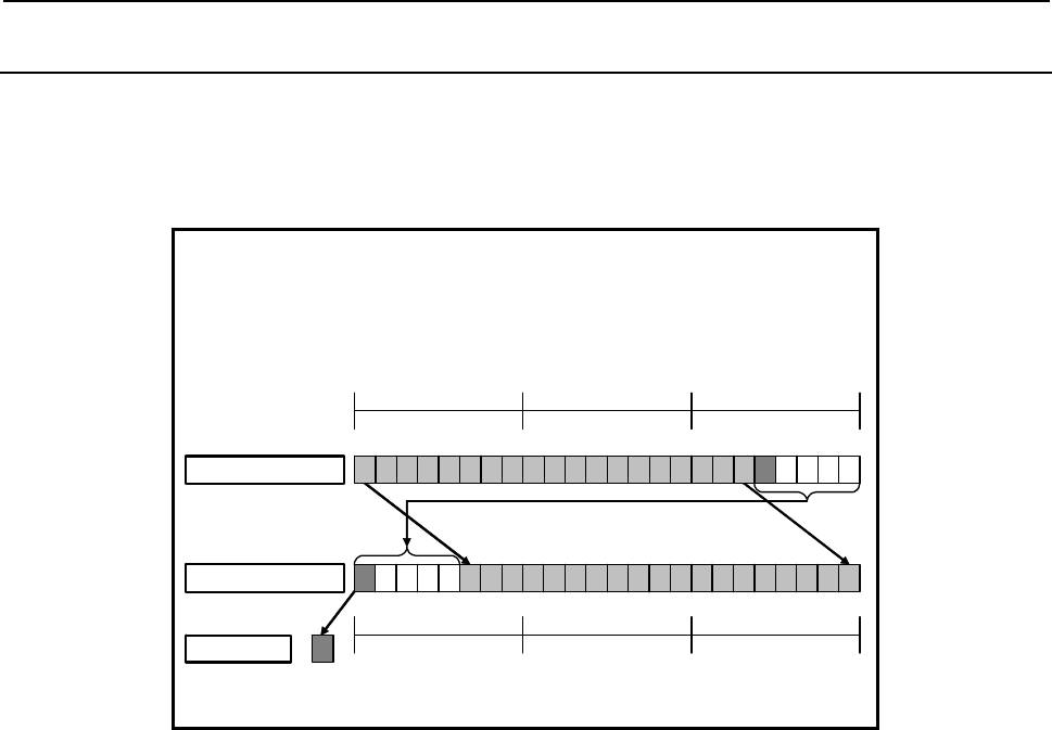
4.LADDER LANGUAGE
B-64513EN/03
- 424 -
4.8.20
RORN (Bit Rotation Right (Arbitrary Bytes Length) : SUB 292)
The Bit rotation right instruction rotates bit data to the right by a specified number of bits. The result of
rotation operation is output to a specified address.
The Bit rotation right instruction performs a bit rotation operation on a bit string of a specified data size.
Rotation source data and the result of rotation operation are of the same data size.
When data is rotated by 5 bits:
Data size = 3
Rotation source data top address = R100
Number of rotation bits = 5
Rotation result output address = R103
Rotation result
The most significant bit after rotation is output to W1.
Rotated right by a specified number of bits
W1
7 0 7 0
R102 R101
70
R100
15 13
14 12 11 9
10 875
6431
2 0
23 21
22 20 19 17
18 16
Rotation source
7 0 7 0
R105 R104
70
R103
15 1314 12 11 910 8 7 56431 2 0 23 2122 20 19 1718 16
Fig. 4.8.20 (a) Example of RORN instruction
The value of the most significant bit (bit 15 in the example above) at the last address after rotation is
output to W1.
If 0 is specified in "Number of rotation bits", the rotation source data is output to "Rotation result output
address" without modification, and W1=0 is set.

B-64513EN/03
4.LADDER LANGUAGE
- 425 -
Format
The followings are the ladder format and the mnemonic format.
SUB 292
RORN
{{{{
{{{{
{{{{
{{{{
ACT
Example : RORN Instruction
SUB 292
RORN
{{{{
{{{{
{{{{
{{{{
Data size (Constant)
Rotation source data top address
Number of rotation bits (Address or Constant)
Rotation result output address
ACT W1
SUB 292
RORN
{{{{
{{{{
{{{{
{{{{
Functional Instruction
ACT ACT2
Fig. 4.8.20(b) Format of RORN instruction
Table 4.8.20 Mnemonic of RORN instruction
Mnemonic format
Memory status of
control condition
Step
number Instruction Address
No. Bit No. Remarks
ST3 ST2 ST1 ST0
1 RD {{{{ .{ ACT ACT
2 SUB 292 SUB No. (RORN instruction)
3 (PRM) {{{{ Data size (Constant)
4 (PRM) {{{{ Rotation source data top address
5 (PRM) {{{{ Number of rotation bits (Address or Constant)
6 (PRM) {{{{ Rotation result output address
7 WRT {{{{ .{ Last rotation bit output W1
Control conditions
(a) Input signal (ACT)
ACT = 0: Instruction not executed.
ACT = 1: Executed.
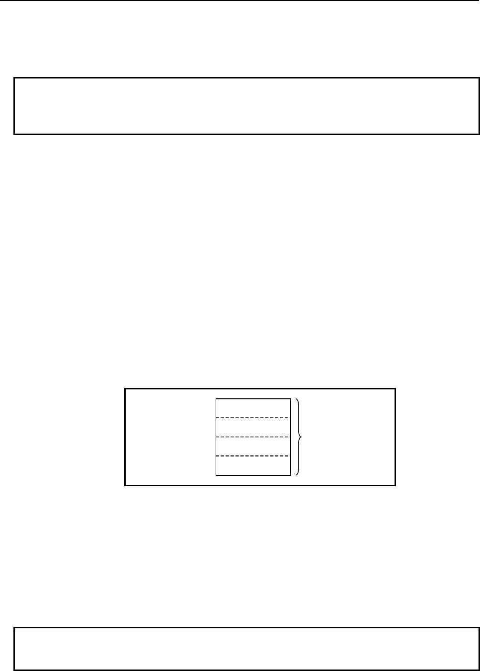
4.LADDER LANGUAGE
B-64513EN/03
- 426 -
Parameters
(a) Data size
Specify the number of bytes of data on which a bit rotation operation is to be performed. A value
from 1 to 256 may be specified.
NOTE
Specify a valid number to the "Data size", so that both of the area from "Rotation
source data top address" and the area from "Rotation result output address" may
be arranged within valid address range.
(b) Rotation source data top address
Specify the start address of rotation source data. Specify a data size in "Data size" mentioned in (a)
above.
(c) Number of rotation bits
By using 4 bytes signed binary data, specify the number of bits to be rotated. In this parameter,
specify 0 or a greater value. If a value greater than 0 is specified, the rotation source data is rotated
by a specified number of bits, and the result of rotation operation is output to "Rotation result output
address". A value from 1 to ("Data size" × 8) may be specified. For example, if 6 is specified in
"Data size", a value from 1 to 48 may be specified in this parameter. If a value greater than the
valid range is specified, the number of specified bits is divided by the value obtained by "Data size"
× 8 then a rotation operation is performed using the remainder as the specified number of bits. If 0
is specified, the rotation source data is output to "Rotation result output address" without
modification, and W1=0 is set.
If a negative value is specified in this parameter, the rotation source data is output to "Rotation result
output address" without modification, and W1=0 is set as in the case where 0 is specified in this
parameter. No rotation operation in the opposite direction is performed.
In this parameter, a constant or a PMC memory address for storing data can be specified.
Specified address +0
Specified address +1 Number of rotation bits
(Signed binary data)
Specified address +2
Specified address +3
(d) Rotation result output address
Specify the start address of an area to which the result of rotation operation is to be output. The
result of rotation operation is output to memory of the same size as for rotation source data.
Output (W1)
W1=1: The value of the most significant bit at the last address after rotation is 1.
W1=0: No rotation operation is executed (ACT=0).
The value of the most significant bit at the last address after rotation is 0.
“0” or a negative value is specified in "Number of rotation bits".
NOTE
W1 may be omitted. Moreover, another functional instruction can be connected
instead of a coil.
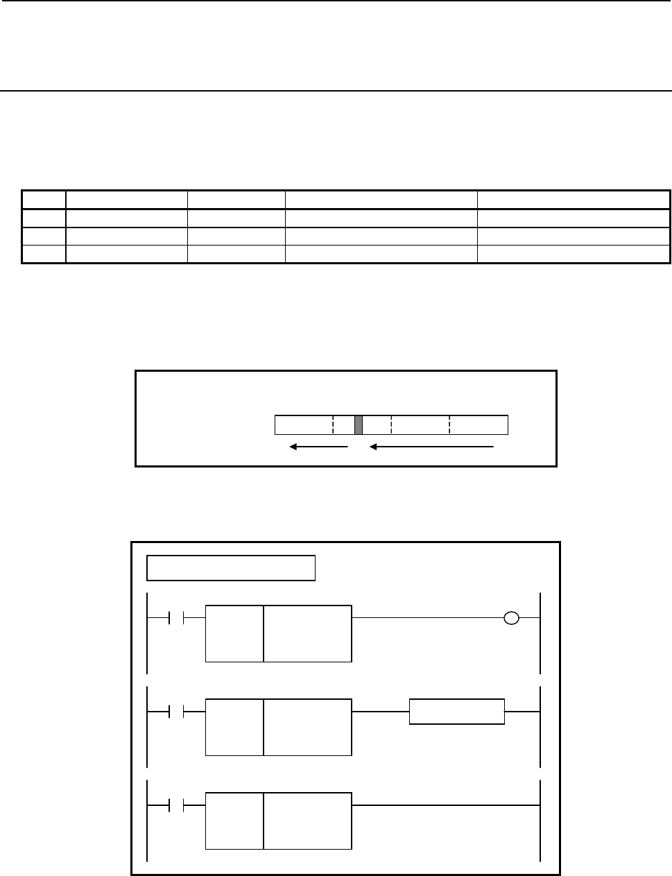
B-64513EN/03
4.LADDER LANGUAGE
- 427 -
4.8.21
BSETB (Bit Set (1 Byte Length) : SUB 293)
BSETW (Bit Set (2 Bytes Length) : SUB 294)
BSETD (Bit Set (4 Bytes Length) : SUB 295)
The Bit set instruction sets the bit at a specified bit position to ON (=1).
As indicated below, three types of Bit set instructions are available according to the type of data to be
operated.
Table4.8.21 (a) Kinds of Bit set instruction
Instruction name SUB No. Data type Useful range of bit position
1 BSETB 293 1 byte length data 0 to 7
2 BSETW 294 2 bytes length data 0 to 15
3 BSETD 295 4 bytes length data 0 to 31
A bit position is identified by sequentially counting bit positions, starting with 0, from the least
significant bit of a specified address.
For example, if R100 is specified in "Data address", and 20 is specified in "Bit position" with the BSETD
instruction, R102.4 is set to ON.
70707070
R103 R102 R101 R100
31 20 0
A
ddress
Bit position
4
Format
The followings are the ladder format and the mnemonic format.
SUB 293
BSETB
{{{{
{{{{
Data address
Bit position (Address or Constant)
ACT W1
Example : BSETB Instruction
SUB 293
BSETB
{{{{
{{{{
Functional Instruction
ACT ACT2
SUB 293
BSETB
{{{{
{{{{
ACT
Fig. 4.8.21 (a) Format of BSETB, BSETW, BSETD instruction

4.LADDER LANGUAGE
B-64513EN/03
- 428 -
Table 4.8.21(b) Mnemonic of BSETB, BSETW, BSETD instruction
Mnemonic format
Memory status of
control condition
Step
number Instruction Address
No. Bit No. Remarks
ST3 ST2 ST1 ST0
1 RD {{{{ .{ ACT ACT
2 SUB 293 SUB No. (BSETB instruction)
3 (PRM) {{{{ Data address
4 (PRM) {{{{ Bit position (Address or Constant)
5 WRT {{{{ .{ Normal end output W1
Control conditions
(a) Input signal (ACT)
ACT = 0: Instruction not executed.
ACT = 1: Executed.
Parameters
(a) Data address
Specify the address of data on which a bit operation is to be performed.
(b) Bit position
Specify the position of a bit to be set to ON. Specify 0 or a greater value in "Bit position". For the
range of values specifiable in "Bit position", see Table 4.8.21 (a), "Kinds of Bit set instruction".
In this parameter, a constant or a PMC memory address for storing data can be specified.
If an address is specified in this parameter, specify "Bit position" by using signed binary data of the
same size as for data type handled by each instruction. For example, with the BSETW instruction,
specify "Bit position" by using 2 bytes signed binary data.
If a value not within the valid range is specified in this parameter, the data is not modified, and W1=0
is set.
Output (W1)
W1=1: The operation is terminated normally.
W1=0: No operation is executed (ACT=0).
The "Bit position" is not within the valid range.
NOTE
W1 may be omitted. Moreover, another functional instruction can be connected
instead of a coil.

B-64513EN/03
4.LADDER LANGUAGE
- 429 -
4.8.22
BSETN (Bit Set (Arbitrary Bytes Length) : SUB 296)
The Bit set instruction sets the bit at a specified bit position in a bit string of the size specified in "Data
size" to ON (=1).
A bit position is identified by sequentially counting bit positions, starting with 0, from the least
significant bit of the start address.
For example, if R100 is specified in "Data top address", 6 is specified in "Data size", and 36 is specified
in "Bit position", R104.4 is set to ON.
7 07 07 07 07 07 0
R105 R104 R103 R102 R101 R100
47 36 0
Data size = 6
A
ddress
Bit position
4
Format
The followings are the ladder format and the mnemonic format.
SUB 296
BSETN
{{{{
{{{{
{{{{
Data size (Constant)
Data top address
Bit position (Address or Constant)
ACT W1
SUB 296
BSETN
{{{{
{{{{
{{{{
Functional Instruction
ACT ACT2
SUB 296
BSETN
{{{{
{{{{
{{{{
ACT
Fig. 4.8.22 Format of BSETN instruction
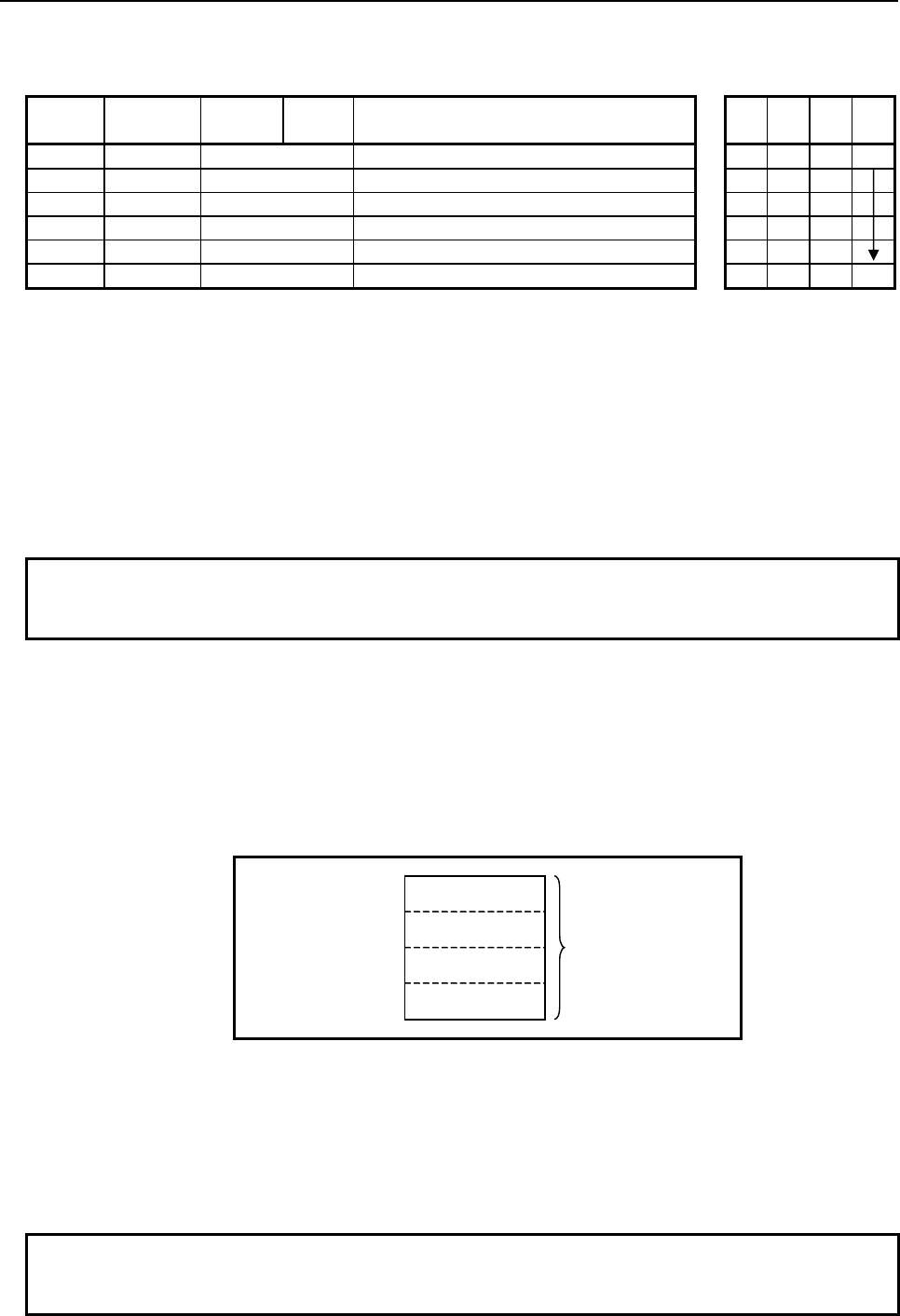
4.LADDER LANGUAGE
B-64513EN/03
- 430 -
Table 4.8.22 Mnemonic of BSETN instruction
Mnemonic format
Memory status of
control condition
Step
number Instruction Address
No. Bit No. Remarks
ST3 ST2 ST1 ST0
1 RD {{{{ .{ ACT ACT
2 SUB 296 SUB No. (BSETN instruction)
3 (PRM) {{{{ Data size (Constant)
4 (PRM) {{{{ Data top address
5 (PRM) {{{{ Bit position (Address or Constant)
6 WRT {{{{ .{ Normal end output W1
Control conditions
(a) Input signal (ACT)
ACT = 0: Instruction not executed.
ACT = 1: Executed.
Parameters
(a) Data size
Specify the number of bytes of data on which a bit operation is to be performed. A value from 1 to
256 may be specified.
NOTE
Specify a valid number to the "Data size", so that the area from "Data top
address" may be arranged within valid address range.
(b) Data top address
Specify the start address of data.
(c) Bit position
By using 4 bytes signed binary data, specify the position of a bit to be set to ON. A value from 0 to
("Data size"×8‐1) may be specified. For example, if 6 is specified in "Data size", a value from 0
to 47 may be specified.
In this parameter, a constant or a PMC memory address for storing data can be specified.
Specified address +0
Specified address +1 Bit position
(Signed binary data)
Specified address +2
Specified address +3
If a value not within the valid range is specified in this parameter, the data is not modified, and W1=0
is set.
Output (W1)
W1=1: The operation is terminated normally.
W1=0: No operation is executed (ACT=0).
The "Bit position" is not within the valid range.
NOTE
W1 may be omitted. Moreover, another functional instruction can be connected
instead of a coil.
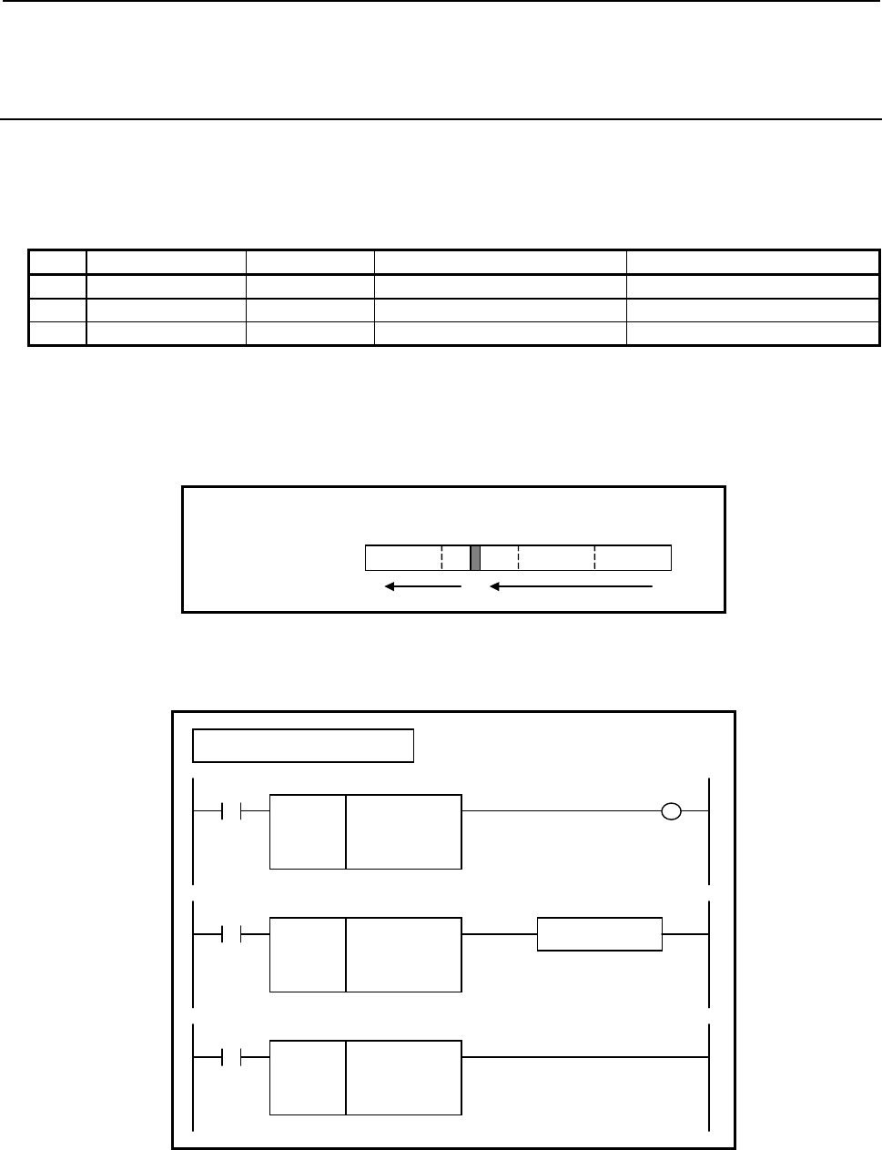
B-64513EN/03
4.LADDER LANGUAGE
- 431 -
4.8.23
BRSTB (Bit Reset (1 Byte Length) : SUB 297)
BRSTW (Bit Reset (2 Bytes Length) : SUB 298)
BRSTD (Bit Reset (4 Bytes Length) : SUB 299)
The Bit reset instruction sets the bit at a specified bit position to OFF (=0).
As indicated below, three types of Bit reset instructions are available according to the type of data to be
operated.
Table4.8.23 (a) Kinds of Bit reset instruction
Instruction name SUB No. Data type Useful range of bit position
1 BRSTB 297 1 byte length data 0 to 7
2 BRSTW 298 2 bytes length data 0 to 15
3 BRSTD 299 4 bytes length data 0 to 31
A bit position is identified by sequentially counting bit positions, starting with 0, from the least
significant bit of a specified address.
For example, if R100 is specified in "Data address", and 20 is specified in "Bit position" with the BRSTD
instruction, R102.4 is set to OFF.
70707070
R103 R102 R101 R100
31 20 0
A
ddress
Bit position
4
Format
The followings are the ladder format and the mnemonic format.
SUB 297
BRSTB
{{{{
{{{{
Data address
Bit position (Address or Constant)
ACT W1
Example : BRSTB Instruction
SUB 297
BRSTB
{{{{
{{{{
Functional Instruction
ACT ACT2
SUB 297
BRSTB
{{{{
{{{{
ACT
Fig. 4.8.23 Format of BRSTB, BRSTW, BRSTD instruction

4.LADDER LANGUAGE
B-64513EN/03
- 432 -
Table 4.8.23(b) Mnemonic of BRSTB, BRSTW, BRSTD instruction
Mnemonic format
Memory status of
control condition
Step
number Instruction Address
No. Bit No. Remarks
ST3 ST2 ST1 ST0
1 RD {{{{ .{ ACT ACT
2 SUB 297 SUB No. (BRSTB instruction)
3 (PRM) {{{{ Data address
4 (PRM) {{{{ Bit position (Address or Constant)
5 WRT {{{{ .{ Normal end output W1
Control conditions
(a) Input signal (ACT)
ACT = 0: Instruction not executed.
ACT = 1: Executed.
Parameters
(a) Data address
Specify the address of data on which a bit operation is to be performed.
(b) Bit position
Specify the position of a bit to be set to OFF. Specify 0 or a greater value in "Bit position". For
the range of values specifiable in "Bit position", see Table 4.8.23 (a), "Kinds of Bit reset
instruction".
In this parameter, a constant or a PMC memory address for storing data can be specified.
If an address is specified in this parameter, specify "Bit position" by using signed binary data of the
same size as for data type handled by each instruction. For example, with the BRSTW instruction,
specify "Bit position" by using 2 bytes signed binary data.
If a value not within the valid range is specified in this parameter, the data is not modified, and W1=0
is set.
Output (W1)
W1=1: The operation is terminated normally.
W1=0: No operation is executed (ACT=0).
The "Bit position" is not within the valid range.
NOTE
W1 may be omitted. Moreover, another functional instruction can be connected
instead of a coil.

B-64513EN/03
4.LADDER LANGUAGE
- 433 -
4.8.24
BRSTN (Bit Reset (Arbitrary Bytes Length) : SUB 300)
The Bit reset instruction sets the bit at a specified bit position in a bit string of the size specified in "Data
size" to OFF (=0).
A bit position is identified by sequentially counting bit positions, starting with 0, from the least
significant bit of the start address.
For example, if R100 is specified in "Data top address", 6 is specified in "Data size", and 36 is specified
in "Bit position", R104.4 is set to OFF.
7 07 07 07 07 07 0
R105 R104 R103 R102 R101 R100
47 36 0
Data size = 6
A
ddress
Bit position
4
Format
The followings are the ladder format and the mnemonic format.
SUB 300
BRSTN
{{{{
{{{{
{{{{
Data size (Constant)
Data top address
Bit position (Address or Constant)
ACT W1
SUB 300
BRSTN
{{{{
{{{{
{{{{
Functional Instruction
ACT ACT2
SUB 300
BRSTN
{{{{
{{{{
{{{{
ACT
Fig. 4.8.24 Format of BRSTN instruction

4.LADDER LANGUAGE
B-64513EN/03
- 434 -
Table 4.8.24 Mnemonic of BRSTN instruction
Mnemonic format
Memory status of
control condition
Step
number Instruction Address
No. Bit No. Remarks
ST3 ST2 ST1 ST0
1 RD {{{{ .{ ACT ACT
2 SUB 300 SUB No. (BRSTN instruction)
3 (PRM) {{{{ Data size (Constant)
4 (PRM) {{{{ Data top address
5 (PRM) {{{{ Bit position (Address or Constant)
6 WRT {{{{ .{ Normal end output W1
Control conditions
(a) Input signal (ACT)
ACT = 0: Instruction not executed.
ACT = 1: Executed.
Parameters
(a) Data size
Specify the number of bytes of data on which a bit operation is to be performed. A value from 1 to
256 may be specified.
NOTE
Specify a valid number to the "Data size", so that the area from "Data top
address" may be arranged within valid address range.
(b) Data top address
Specify the start address of data.
(c) Bit position
By using 4 bytes signed binary data, specify the position of a bit to be set to OFF. A value from 0
to ("Data size"×8‐1) may be specified. For example, if 6 is specified in "Data size", a value
from 0 to 47 may be specified.
In this parameter, a constant or a PMC memory address for storing data can be specified.
Specified address +0
Specified address +1 Bit position
(Signed binary data)
Specified address +2
Specified address +3
If a value not within the valid range is specified in this parameter, the data is not modified, and W1=0
is set.
Output (W1)
W1=1: The operation is terminated normally.
W1=0: No operation is executed (ACT=0).
The "Bit position" is not within the valid range.
NOTE
W1 may be omitted. Moreover, another functional instruction can be connected
instead of a coil.

B-64513EN/03
4.LADDER LANGUAGE
- 435 -
4.8.25
BTSTB (Bit Test (1 Byte Length) : SUB 301)
BTSTW (Bit Test (2 Bytes Length) : SUB 302)
BTSTD (Bit Test (4 Bytes Length) : SUB 303)
The Bit test instruction outputs the value of the bit at a specified bit position.
As indicated below, three types of Bit test instructions are available according to the type of data to be
operated.
Table4.8.25 (a) Kinds of Bit test instruction
Instruction name SUB No. Data type Useful range of bit position
1 BTSTB 301 1 byte length data 0 to 7
2 BTSTW 302 2 bytes length data 0 to 15
3 BTSTD 303 4 bytes length data 0 to 31
A bit position is identified by sequentially counting bit positions, starting with 0, from the least
significant bit of a specified address.
For example, if R100 is specified in "Data address", and 20 is specified in "Bit position" with the BTSTD
instruction, the state of R102.4 is output.
70707070
R103 R102 R101 R100
31 20 0
A
ddress
Bit position
4
Format
The followings are the ladder format and the mnemonic format.
SUB 301
BTSTB
{{{{
{{{{
Data address
Bit position (Address or Constant)
ACT W1
Example : BTSTB Instruction
SUB 301
BTSTB
{{{{
{{{{
Functional Instruction
ACT ACT2
SUB 301
BTSTB
{{{{
{{{{
ACT
Fig. 4.8.25 Format of BTSTB, BTSTW, BTSTD instruction
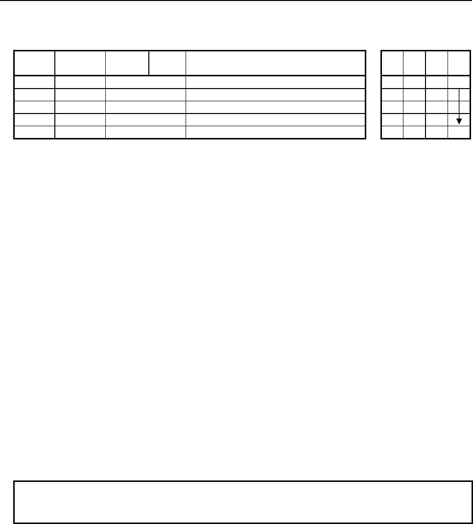
4.LADDER LANGUAGE
B-64513EN/03
- 436 -
Table 4.8.25 (b) Mnemonic of BTSTB, BTSTW, BTSTD instruction
Mnemonic format
Memory status of
control condition
Step
number Instruction Address
No. Bit No. Remarks
ST3 ST2 ST1 ST0
1 RD {{{{ .{ ACT ACT
2 SUB 301 SUB No. (BTSTB instruction)
3 (PRM) {{{{ Data address
4 (PRM) {{{{ Bit position (Address or Constant)
5 WRT {{{{ .{ Bit status output W1
Control conditions
(a) Input signal (ACT)
ACT = 0: Instruction not executed.
ACT = 1: Executed.
Parameters
(a) Data address
Specify the address of data on which a bit operation is to be performed.
(b) Bit position
Specify the position of a bit whose state is to be output. Specify 0 or a greater value in "Bit
position". For the range of values specifiable in "Bit position", see Table 4.8.25 (a), "Kinds of Bit
test instruction".
In this parameter, a constant or a PMC memory address for storing data can be specified.
If an address is specified in this parameter, specify "Bit position" by using signed binary data of the
same size as for data type handled by each instruction. For example, with the BTSTW instruction,
specify "Bit position" by using 2 bytes signed binary data.
If a value not within the valid range is specified in this parameter, W1=0 is set.
Output (W1)
W1=1: Specified bit is 1.
W1=0: Specified bit is 0.
No operation is executed (ACT=0).
The "Bit position" is not within the valid range.
NOTE
W1 may be omitted. Moreover, another functional instruction can be connected
instead of a coil.
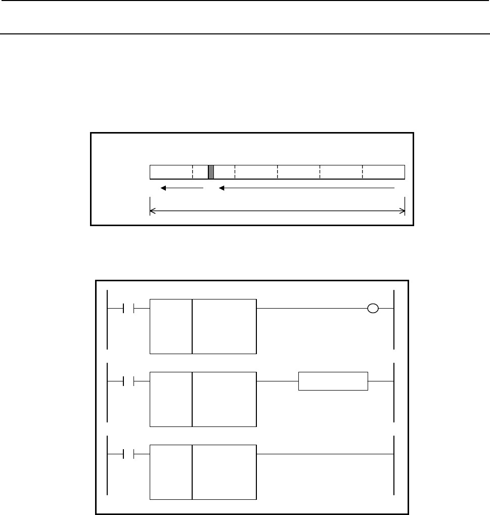
B-64513EN/03
4.LADDER LANGUAGE
- 437 -
4.8.26
BTSTN (Bit Test (Arbitrary Bytes Length) : SUB 304)
The Bit test instruction outputs the value of the bit at a specified bit position in a bit string of the size
specified in "Data size".
A bit position is identified by sequentially counting bit positions, starting with 0, from the least
significant bit of the start address.
For example, if R100 is specified in "Data top address", 6 is specified in "Data size", and 36 is specified
in "Bit position", the bit state of R104.4 is output.
7 07 07 07 07 07 0
R105 R104 R103 R102 R101 R100
47 36 0
Data size = 6
A
ddress
Bit position
4
Format
The followings are the ladder format and the mnemonic format.
SUB 304
BTSTN
{{{{
{{{{
{{{{
Data size (Constant)
Data top address
Bit position (Address or Constant)
ACT W1
SUB 304
BTSTN
{{{{
{{{{
{{{{
Functional Instruction
ACT ACT2
SUB 304
BTSTN
{{{{
{{{{
{{{{
ACT
Fig. 4.8.26 Format of BTSTN instruction

4.LADDER LANGUAGE
B-64513EN/03
- 438 -
Table 4.8.26 Mnemonic of BTSTN instruction
Mnemonic format
Memory status of
control condition
Step
number Instruction Address
No. Bit No. Remarks
ST3 ST2 ST1 ST0
1 RD {{{{ .{ ACT ACT
2 SUB 304 SUB No. (BTSTN instruction)
3 (PRM) {{{{ Data size (Constant)
4 (PRM) {{{{ Data top address
5 (PRM) {{{{ Bit position (Address or Constant)
6 WRT {{{{ .{ Normal end output W1
Control conditions
(a) Input signal (ACT)
ACT = 0: Instruction not executed.
ACT = 1: Executed.
Parameters
(a) Data size
Specify the number of bytes of data on which a bit operation is to be performed. A value from 1 to
256 may be specified.
NOTE
Specify a valid number to the "Data size", so that the area from "Data top
address" may be arranged within valid address range.
(b) Data top address
Specify the start address of data.
(c) Bit position
By using 4 bytes signed binary data, specify the position of a bit whose state is to be output. A
value from 0 to ("Data size"×8‐1) may be specified. For example, if 6 is specified in "Data size",
a value from 0 to 47 may be specified.
In this parameter, a constant or a PMC memory address for storing data can be specified.
Specified address +0
Specified address +1 Bit position
(Signed binary data)
Specified address +2
Specified address +3
If a value not within the valid range is specified in this parameter, W1=0 is set.
Output (W1)
W1=1: Specified bit is 1.
W1=0: Specified bit is 0.
No operation is executed (ACT=0).
The "Bit position" is not within the valid range.
NOTE
W1 may be omitted. Moreover, another functional instruction can be connected
instead of a coil.
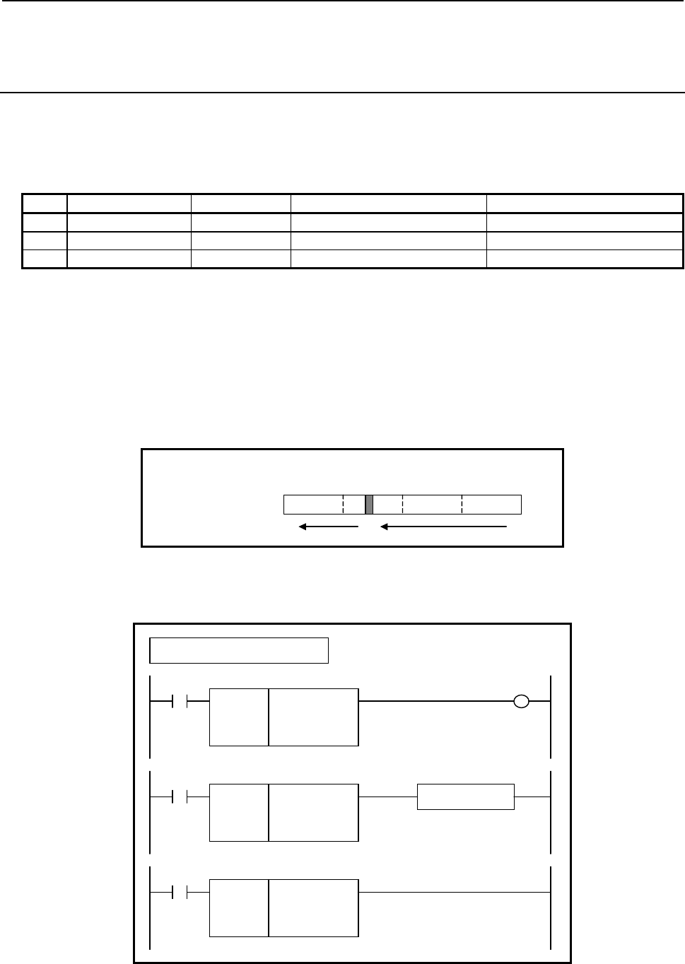
B-64513EN/03
4.LADDER LANGUAGE
- 439 -
4.8.27
BPOSB (Bit Search (1 Byte Length) : SUB 305)
BPOSW (Bit Search (2 Bytes Length) : SUB 306)
BPOSD (Bit Search (4 Bytes Length) : SUB 307)
The Bit search instruction acquires the bit position of a bit set to ON (=1).
As indicated below, three types of Bit search instructions are available according to the type of data to be
operated.
Table4.8.27 (a) Kinds of Bit search instruction
Instruction name SUB No. Data type Useful range of bit position
1 BPOSB 305 1 byte length data 0 to 7
2 BPOSW 306 2 bytes length data 0 to 15
3 BPOSD 307 4 bytes length data 0 to 31
Bits are searched in the order from bit 0 to bit 7 at the data top address then bits are searched in the order
from bit 0 to bit 7 at the next address. In this way, bit search operation is further performed for up to bit
7 of the last address.
The bit position of the bit that is first found to be ON is output.
A bit position is identified by sequentially counting bit positions, starting with 0, from the least
significant bit of the start address.
For example, if R100 is specified in "Data address" with the BPOSD instruction, and only R102.4 is set
to ON, 20 is output to "Bit position output address".
70707070
R103 R102 R101 R100
31 20 0
A
ddress
Bit position
4
Format
The followings are the ladder format and the mnemonic format.
SUB 305
BPOSB
{{{{
{{{{
Data address
Bit position output address
ACT W1
Example : BPOSB Instruction
SUB 305
BPOSB
{{{{
{{{{
Functional Instruction
ACT ACT2
SUB 305
BPOSB
{{{{
{{{{
ACT
Fig. 4.8.27 Format of BPOSB, BPOSW, BPOSD instruction
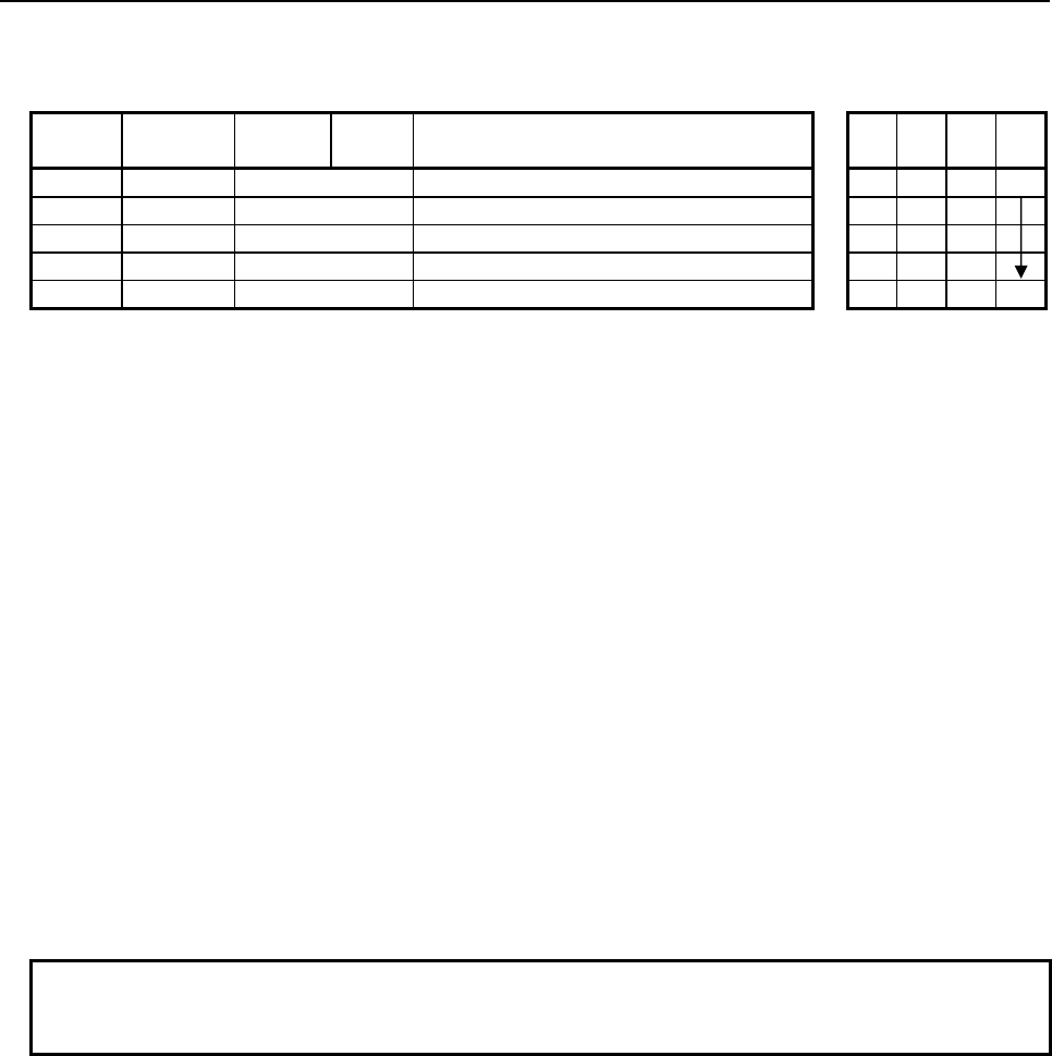
4.LADDER LANGUAGE
B-64513EN/03
- 440 -
Table 4.8.27(b) Mnemonic of BPOSB, BPOSW, BPOSD instruction
Mnemonic format
Memory status of
control condition
Step
number Instruction Address
No. Bit No. Remarks
ST3 ST2 ST1 ST0
1 RD {{{{ .{ ACT ACT
2 SUB 305 SUB No. (BPOSB instruction)
3 (PRM) {{{{ Data address
4 (PRM) {{{{ Bit position output address
5 WRT {{{{ .{ Normal end output W1
Control conditions
(a) Input signal (ACT)
ACT = 0: Instruction not executed.
ACT = 1: Executed.
Parameters
(a) Data address
Specify the address of data on which a bit operation is to be performed.
(b) Bit position output address
Specify the address to which the position of a bit found to be ON as the result of search operation is
to be output. Starting at the specified address, a bit position is output by using signed binary data
of the same size as for data type handled by each instruction. For example, with the BPOSW
instruction, a bit position is output by using 2 bytes signed binary data.
The start bit position number is 0.
If no bit is found to be ON as the result of search operation, -1 is output, and W1=0 is set.
Output (W1)
W1=1: The instruction is terminated normally.
W1=0: No operation is executed (ACT=0)
There is no bit set to ON.
NOTE
W1 may be omitted. Moreover, another functional instruction can be connected
instead of a coil.
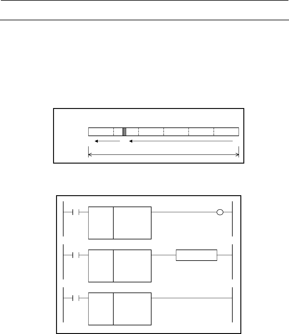
B-64513EN/03
4.LADDER LANGUAGE
- 441 -
4.8.28
BPOSN (Bit Search (Arbitrary Bytes Length) : SUB 308)
The Bit search instruction acquires the bit position of a bit set to ON (=1) in a bit string of the size
specified in "Data size".
Bits are searched in the order from bit 0 to bit 7 at "Data top address" then bits are searched in the order
from bit 0 to bit 7 at the next address. In this way, bit search operation is further performed for up to bit
7 of the last address.
The bit position of the bit that is first found to be ON is output.
A bit position is identified by sequentially counting bit positions, starting with 0, from the least
significant bit of the start address.
For example, if R100 is specified in "Data top address", 6 is specified in "Data size", and only R104.4 is
set to ON, 36 is output to "Bit position output address".
7 07 07 07 07 07 0
R105 R104 R103 R102 R101 R100
47 36 0
Data size = 6
A
ddress
Bit position
4
Format
The followings are the ladder format and the mnemonic format.
SUB 308
BPOSN
{{{{
{{{{
{{{{
Data size (Constant)
Data top address
Bit position output address
ACT W1
SUB 308
BPOSN
{{{{
{{{{
{{{{
Functional Instruction
ACT ACT2
SUB 308
BPOSN
{{{{
{{{{
{{{{
ACT
Fig. 4.8.28 Format of BPOSN instruction
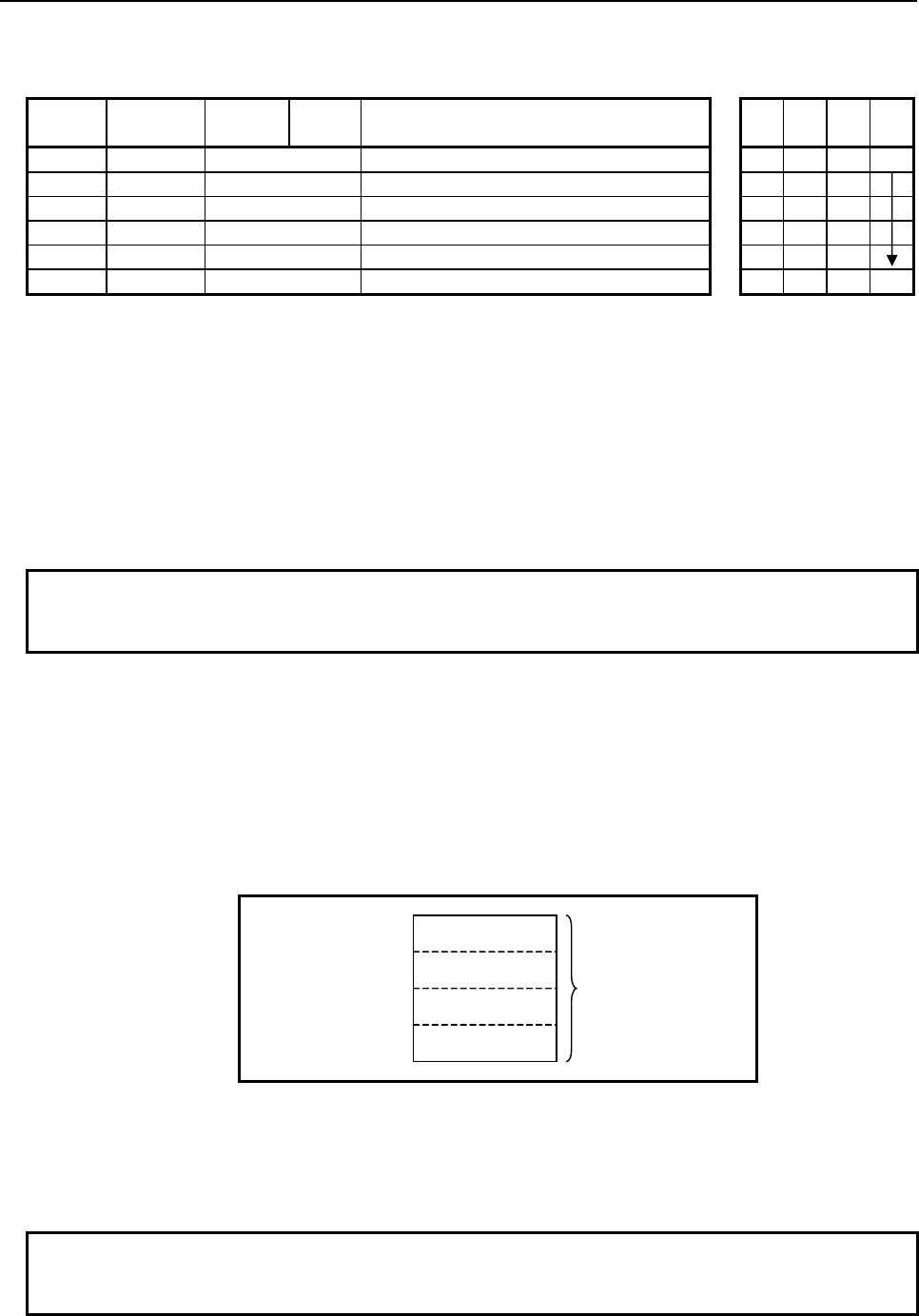
4.LADDER LANGUAGE
B-64513EN/03
- 442 -
Table 4.8.28 Mnemonic of BPOSN instruction
Mnemonic format
Memory status of
control condition
Step
number Instruction Address
No. Bit No. Remarks
ST3 ST2 ST1 ST0
1 RD {{{{ .{ ACT ACT
2 SUB 308 SUB No. (BPOSN instruction)
3 (PRM) {{{{ Data size (Constant)
4 (PRM) {{{{ Data top address
5 (PRM) {{{{ Bit position output address
6 WRT {{{{ .{ Normal end output W1
Control conditions
(a) Input signal (ACT)
ACT = 0: Instruction not executed.
ACT = 1: Executed.
Parameters
(a) Data size
Specify the number of bytes of data on which a bit operation is to be performed. A value from 1 to
256 may be specified.
NOTE
Specify a valid number to the "Data size", so that the area from "Data top
address" may be arranged within valid address range.
(b) Data top address
Specify the start address of data.
(c) Bit position output address
Specify the address to which a found bit position is to be output. A bit position is output by using 4
bytes signed binary data.
The start bit position number is 0.
If no bit is found to be ON as the result of search operation, -1 is output, and W1=0 is set.
Specified address +0
Specified address +1 Bit position
(Signed binary data)
Specified address +2
Specified address +3
Output (W1)
W1=1: The operation is terminated normally.
W1=0: No operation is executed (ACT=0).
There is no bit set to ON.
NOTE
W1 may be omitted. Moreover, another functional instruction can be connected
instead of a coil.
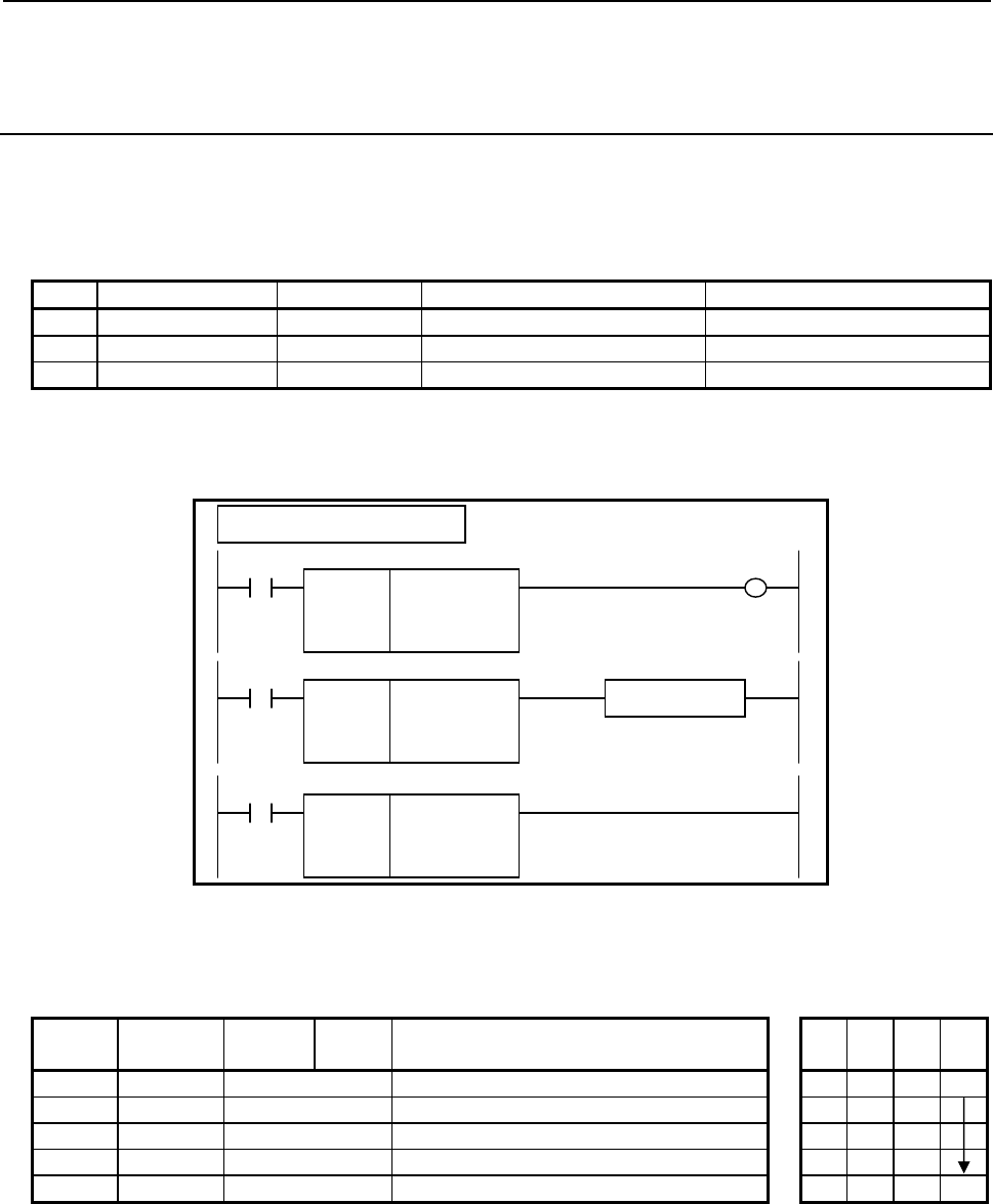
B-64513EN/03
4.LADDER LANGUAGE
- 443 -
4.8.29
BCNTB (Bit Count (1 Byte Length) : SUB 309)
BCNTW (Bit Count (2 Bytes Length) : SUB 310)
BCNTD (Bit Count (4 Bytes Length) : SUB 311)
The Bit count instruction acquires the number of bits set to ON (=1).
As indicated below, three types of Bit count instructions are available according to the type of data to be
operated.
Table4.8.29 (a) Kinds of Bit count instruction
Instruction name SUB No. Data type Useful range of bit position
1 BCNTB 309 1 byte length data 0 to 7
2 BCNTW 310 2 bytes length data 0 to 15
3 BCNTD 311 4 bytes length data 0 to 31
Format
The followings are the ladder format and the mnemonic format.
SUB 309
BCNTB
{{{{
{{{{
Data address
ON-Bit count output address
ACT W1
Example : BCNTB Instruction
SUB 309
BCNTB
{{{{
{{{{
Functional Instruction
ACT ACT2
SUB 309
BCNTB
{{{{
{{{{
ACT
Fig. 4.8.29 Format of BCNTB, BCNTW, BCNTD instruction
Table 4.8.29(b) Mnemonic BCNTB, BCNTW, BCNTD instruction
Mnemonic format
Memory status of
control condition
Step
number Instruction Address
No. Bit No. Remarks
ST3 ST2 ST1 ST0
1 RD {{{{ .{ ACT ACT
2 SUB 309 SUB No. (BCNTB instruction)
3 (PRM) {{{{ Data address
4 (PRM) {{{{ ON-Bit count output address
5 WRT {{{{ .{ Normal end output W1

4.LADDER LANGUAGE
B-64513EN/03
- 444 -
Control conditions
(a) Input signal (ACT)
ACT = 0: Instruction not executed.
ACT = 1: Executed.
Parameters
(a) Data address
Specify the address of data on which a bit operation is to be performed.
(b) ON-Bit count output address
Specify the address to which the number of bits set to ON is to be output. Starting at the specified
address, the number of bits set to ON is output to memory of the same size as for data type handled
by each instruction. For example, with the BCNTW instruction, the number of bits set to ON is
output by using 2 bytes signed binary data.
Output (W1)
W1=1: The operation is executed (ACT=1).
W1=0: No operation is executed (ACT=0).
NOTE
W1 may be omitted. Moreover, another functional instruction can be connected
instead of a coil.
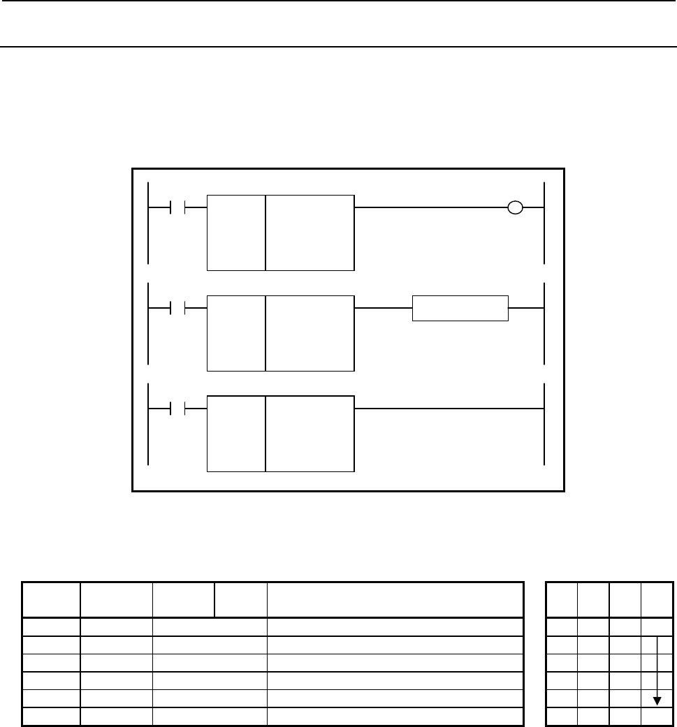
B-64513EN/03
4.LADDER LANGUAGE
- 445 -
4.8.30
BCNTN (Bit Count (Arbitrary Bytes Length) : SUB 312)
The Bit count instruction acquires the number of bits set to ON (=1) in a bit string of the size specified in
"Data size".
Format
The followings are the ladder format and the mnemonic format.
SUB 312
BCNTN
{{{{
{{{{
{{{{
Data size (Constant)
Data top address
ON-Bit count output address
ACT W1
SUB 312
BCNTN
{{{{
{{{{
{{{{
Functional Instruction
ACT ACT2
SUB 312
BCNTN
{{{{
{{{{
{{{{
ACT
Fig. 4.8.30 Format of BCNTN instruction
Table 4.8.30 Mnemonic of BCNTN instruction
Mnemonic format
Memory status of
control condition
Step
number Instruction Address
No. Bit No. Remarks
ST3 ST2 ST1 ST0
1 RD {{{{ .{ ACT ACT
2 SUB 312 SUB No. (BCNTN instruction)
3 (PRM) {{{{ Data size (Constant)
4 (PRM) {{{{ Data top address
5 (PRM) {{{{ ON-Bit count output address
6 WRT {{{{ .{ Normal end output W1
Control conditions
(a) Input signal (ACT)
ACT = 0: Instruction not executed.
ACT = 1: Executed.
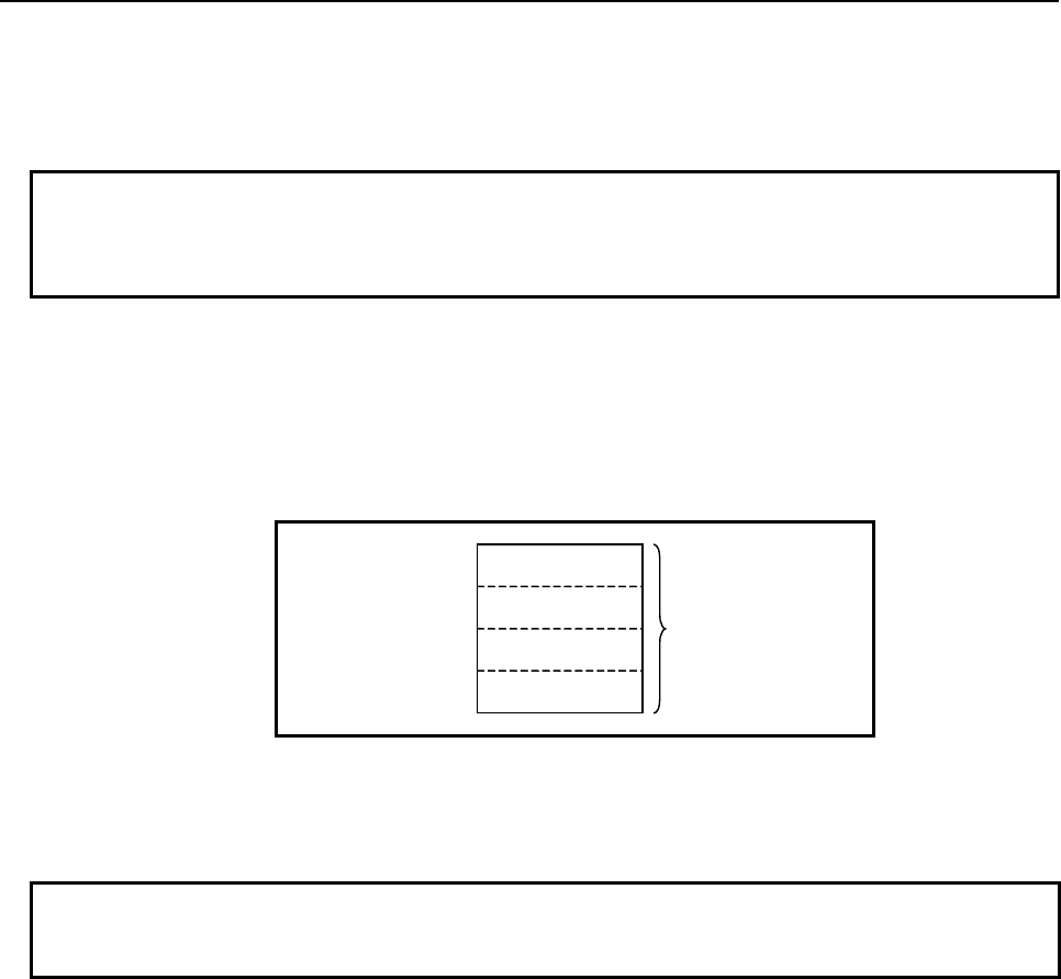
4.LADDER LANGUAGE
B-64513EN/03
- 446 -
Parameters
(a) Data size
Specify the number of bytes of data on which a bit operation is to be performed. A value from 1 to
256 may be specified.
NOTE
Specify a valid number to the "Data size", so that both of the area from "Data top
address" and the area from "Shift result output address" may be arranged within
valid address range.
(b) Data top address
Specify the start address of data.
(c) ON-Bit count output address
Specify the address to which the number of bits set to ON is to be output. The number of bits set to
ON is output by using 4 bytes signed binary data.
Specified address +0
Specified address +1 ON-Bit count
(Signed binary data)
Specified address +2
Specified address +3
Output (W1)
W1=1: The operation is executed (ACT=1).
W1=0: No operation is executed (ACT=0).
NOTE
W1 may be omitted. Moreover, another functional instruction can be connected
instead of a coil.

B-64513EN/03
4.LADDER LANGUAGE
- 447 -
4.9 CODE CONVERSION
The following types of code conversion instruction are available. Use any of these instructions as
appropriate for your purpose.
Instruction name Sub number Processing
1 COD 7 Code conversion
2 CODB 27 Binary code conversion
3 DCNV 14 Data conversion
4 DCNVB 31 Extended data conversion
5 DEC 4 Decoding
6 DECB 25 Binary decoding
7 TBCDB 313 Binary to BCD conversion (1 byte length)
8 TBCDW 314 Binary to BCD conversion (2 bytes length)
9 TBCDD 315 Binary to BCD conversion (4 bytes length)
10 FBCDB 316 BCD to Binary conversion (1 byte length)
11 FBCDW 317 BCD to Binary conversion (2 bytes length)
12 FBCDD 318 BCD to Binary conversion (4 bytes length)
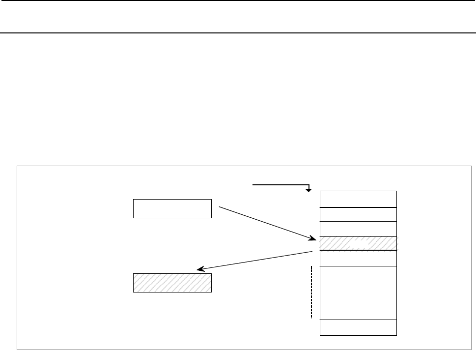
4.LADDER LANGUAGE
B-64513EN/03
- 448 -
4.9.1
COD (Code Conversion: SUB 7)
This instruction converts BCD codes into an arbitrary two- or four-digits BCD numbers. For code
conversion shown in Fig. 4.9.1 (a) the conversion input data address, conversion table, and convert data
output address must be provided.
Set a table address, in which the data to be retrieved from the conversion table is contained, to conversion
table input data address in a two-digits BCD number. The conversion table is entered in sequence with
the numbers to be retrieved in the two- or four-digits number. The contents of the conversion table of
the number entered in the conversion input data address is output to the convert data output address. As
shown in Fig. 4.9.1 (a), when 3 is entered in the conversion input data address, the contents 137 located at
3 in the conversion table is output to the convert data output address.
Conversion input
data address
{{{{
3
Specifies table internal
number (BCD two-digits). 137
3
2
1
0
Conversion table
4
n
Table internal address
Convert data
output address
{{{{
Data of the specified table internal address
is output to this address.
Fig. 4.9.1 (a) Code conversion diagram
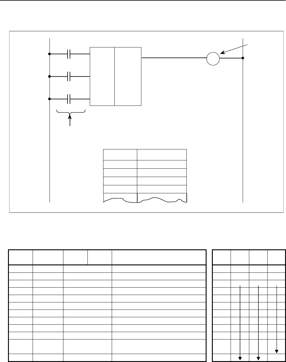
B-64513EN/03
4.LADDER LANGUAGE
- 449 -
Format
Fig. 4.9.1 (b) shows the ladder format and Table 4.9.1 shows the mnemonic format.
W1
BYT
COD
SUB 7
RST
{{{{. {
A
CT
{{{{. {
{{{{. {
{{{
{{{{
{{{{
Error output
Control condition
Table address Convert data
0
1
2
3
{ { { {
Size of table data
Conversion input data address
Converted data output address
{ { { {
{ { { {
{ { { {
Fig. 4.9.1 (b) Format of COD instruction
Table 4.9.1 Mnemonic of COD instruction
Mnemonic format Memory status of control
condition
Step
number Instruction Address
No. Bit No. Remarks ST3 ST2 ST1 ST0
1 RD {{{{ .{ BYT BYT
2 RD.STK {{{{ .{ RST BYT RST
3 RD.STK {{{{ .{ ACT BYT RST ACT
4 SUB 7 COD instruction
5 (PRM) {{{ Size of table data
6 (PRM) {{{{ Conversion input data address
7 (PRM) {{{{ Convert data output address
8 (PRM) {{{{ Convert data at table address 0
9 (PRM) {{{{ Convert data at table address 1
: : : :
7 + n (PRM) {{{{ Data at (n (convert data at table
address) - 1)
7 + n + 1 WRT {{{{ .{ Error output W1

4.LADDER LANGUAGE
B-64513EN/03
- 450 -
Control conditions
(a) Specify the data size. (BYT)
BYT=0: The conversion table data is to be BCD 2 digits.
BYT=1: The conversion table data is to be BCD 4 digits.
(b) Error output reset (RST)
RST=0: Disable reset
RST=1: Sets error output W1 to 0 (resets).
(c) Execution command (ACT)
ACT=0: The COD instruction is not executed. W1 does not change.
ACT=1: Executed.
Parameters
(a) Size of table data
A conversion table data address from 00 to 99 can be specified.
Specify n+1 as the size of table when n is the last table internal number.
(b) Conversion input data address
Specify the data address which includes the table number of BCD 2 digits (1-byte).
(c) Convert data output address
Specify the convert data output address. The convert data for BCD 2 digits requires 1-byte memory.
The convert data for BCD 4 digits requires 2-bytes memory.
Error output (W1)
W1=0: No operation is executed (ACT=0).
The conversion is completed normally.
W1=1: The number in the conversion input address is not within the conversion table range.
CAUTION
Two or more coils, WRT, WRT.NOT, SET or RST, that follow this instruction are
prohibited. You have to place a single coil instruction as the output of this
instruction.
Conversion data table
The size of the conversion data table is from 00 to 99.
The conversion data can be either BCD two digits or four digits, which is specified depends on the
control conditions.
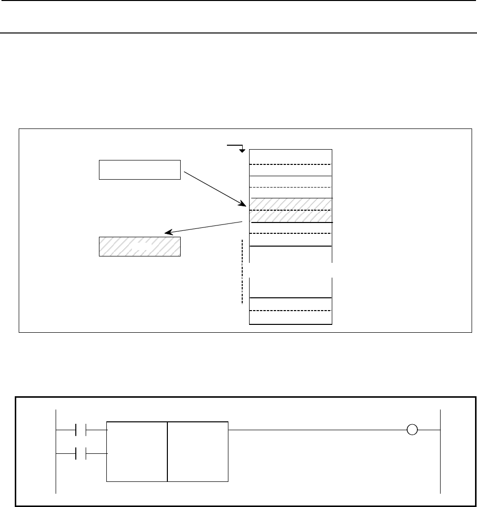
B-64513EN/03
4.LADDER LANGUAGE
- 451 -
4.9.2
CODB (Binary Code Conversion: SUB 27)
This instruction converts data in binary format to an optional binary format 1 byte, 2 bytes or 4 bytes
data.
Conversion input data address, conversion table, and conversion data output address are necessary for
data conversion; as shown in Fig. 4.9.2 (a).
Compared to the "COD Function Instruction", this CODB function instruction handles numerical data 1,
2 and 4 bytes length binary format data, and the conversion table can be extended to maximum 256.
Conversion data
address
{{{{
2
Specify table address here.
(binary format1 byte)
3
2
1
0
Conversion table
n
Table address
Conversion data
output address
{{{{
Data stored in the specified
table address is output to
this address
1250
(n: max. 255)
(Note 1) This table data is binary
format 2-byte data.
(Note 2) Conversion table is
written in the ROM
together together with
the program, because it
is defined in the
sequence program.
∼
∼∼
∼
Fig. 4.9.2 (a) Code conversion diagram
Format
Fig. 4.9.2 (b) shows the ladder format and Table 4.9.2 shows the mnemonic format.
RST W1
SUB 27
ACT CODB
{ Format specification
{{{ Number of conversion table data
{{{{ Conversion input data address
{{{{ Conversion data output address
Fig. 4.9.2 (b) Format of CODB instruction
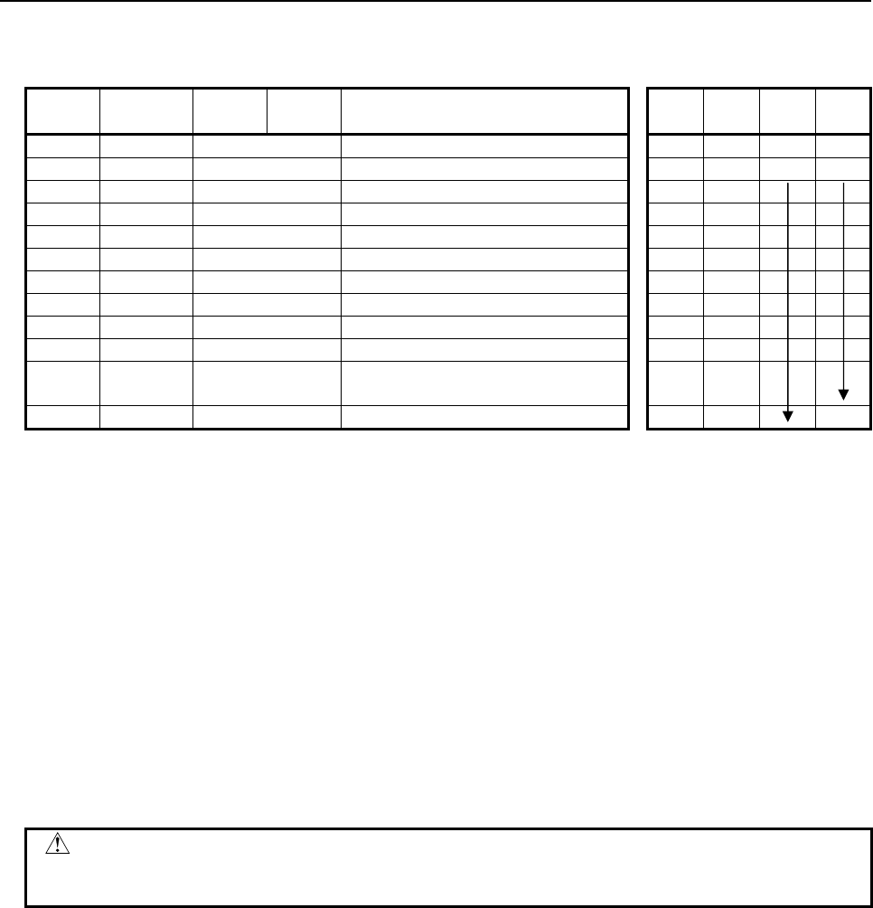
4.LADDER LANGUAGE
B-64513EN/03
- 452 -
Table 4.9.2 Mnemonic of CODB instruction
Mnemonic format Memory status of control
condition
Step
number Instruction Address
No. Bit No. Remarks ST3 ST2 ST1 ST0
1 RD {{{{ .{ RST RST
2 RD.STK {{{{ .{ ACT RST ACT
3 SUB 27 CODB instruction
4 (PRM) { Format specification
5 (PRM) {{{ Size of table data
6 (PRM) {{{{ Conversion input data address
7 (PRM) {{{{ Convert data output address
8 (PRM) {{{{ Convert data at table address 0
9 (PRM) {{{{ Convert data at table address 1
: : : :
7 + n (PRM) {{{{ Data at (n (convert data at table
address) - 1)
7 + n + 1 WRT {{{{ .{ Timer relay output W1
Control conditions
(a) Reset (RST)
RST=0: Do not reset error output W1.
RST=1: Reset error output W1 (W1=0).
(b) Activate command (ACT)
ACT=0: Do not execute CODB instruction
ACT=1: Execute CODB instruction.
Parameters
(a) Format specification
Specify the binary data size in the conversion table.
1: Numerical data is binary 1 byte data.
2: Numerical data is binary 2 bytes data.
4: Numerical data is binary 4 bytes data.
CAUTION
Do not set an illegal value, that is not indicated above, into the "(a) Format
specification".
(b) Number of conversion table data
Specify the size of conversion table (0 to 255).
(c) Conversion input data address
Specify the data address which includes the table number.
(d) Conversion data output address
Specify the convert data output address. The memory size, which is specified in the format
specification, is necessary.

B-64513EN/03
4.LADDER LANGUAGE
- 453 -
Conversion data table
Size of the conversion data table is maximum 256 (from 0 to 255).
Error output (W1)
W1=0: No operation is executed (ACT=0).
The conversion is completed normally.
W1=1: The number in the conversion data table is not within the conversion table range.
If the table number in the conversion input data address exceeds the number of the conversion table data
when executing the CODB instruction, W1=1.
CAUTION
Two or more coils, WRT, WRT.NOT, SET or RST, that follow this instruction are
prohibited. You have to place a single coil instruction as the output of this
instruction.
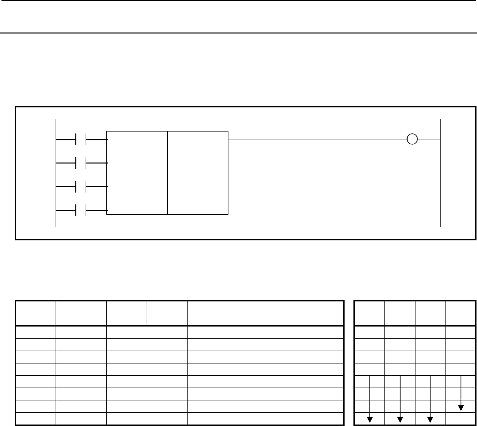
4.LADDER LANGUAGE
B-64513EN/03
- 454 -
4.9.3
DCNV (Data Conversion: SUB 14)
This instruction converts binary-code into BCD-code and vice versa.
Format
Fig. 4.9.3 shows the ladder format and Table 4.9.3 shows the mnemonic format.
BYT W1
SUB 14
CNV DCNV
{{{{ Input data address
{{{{ Conversion result output
RST
ACT
Fig. 4.9.3 Format of DCNV instruction
Table 4.9.3 Mnemonic of DCNV instruction
Mnemonic format Memory status of control
condition
Step
number Instruction Address
No. Bit No. Remarks ST3 ST2 ST1 ST0
1 RD {{{{ .{ BYT BYT
2 RD.STK {{{{ .{ CNV BYT CNV
3 RD.STK {{{{ .{ RST BYT CNV RST
4 RD.STK {{{{ .{ ACT BYT CNV RST ACT
5 SUB 14 DCNV instruction
6 (PRM) {{{{ Input data address
7 (PRM) {{{{ Conversion result output address
8 WRT {{{{ .{ W1 error output W1
Control conditions
(a) Specify data size. (BYT)
BYT=0: Process data in length of 1 byte (8 bits)
BYT=1: Process data in length of 2 bytes (16 bits)
(b) Specify the type of conversion (CNV)
CNV=0: Convert binary-code into BCD-code.
CNV=1: Convert BCD-code into binary-code.
(c) Reset (RST)
RST=0: Do not reset error output W1.
RST=1: Reset error output W1. That is, setting RST to 1 when W1=1, makes W1=0.
(d) Execution command (ACT)
ACT=0: Data is not converted. W1 will not alter.
ACT=1: Data is converted.

B-64513EN/03
4.LADDER LANGUAGE
- 455 -
Parameters
(a) Input data address
Specify the address of the input data
(b) Output address after conversion
Specify the address output data converted into BCD or binary type
Error output (W1)
W1=0: Normal complete
W1=1: Conversion error
The input data which should be BCD data, is binary data, or the data size (byte length)
specified in advance exceeds when converting binary data into BCD data.
CAUTION
Two or more coils, WRT, WRT.NOT, SET or RST, that follow this instruction are
prohibited. You have to place a single coil instruction as the output of this
instruction.
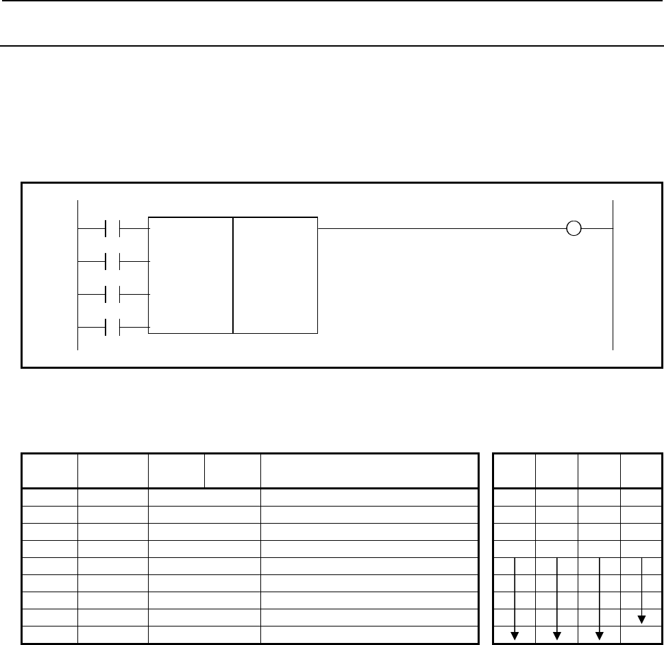
4.LADDER LANGUAGE
B-64513EN/03
- 456 -
4.9.4
DCNVB (Extended Data Conversion: SUB 31)
This instruction converts 1, 2, or 4 bytes binary code into BCD code or vice versa. To execute this
instruction, you must preserve the necessary number of bytes in the memory for the conversion result
output data.
Format
Fig. 4.9.4 shows the ladder format and Table 4.9.4 shows the mnemonic format.
SIN W1
SUB 31
CNV DCNVB
{ Format specification
{{{{ Input data address
RST {{{{ Conversion result output address
ACT
Fig. 4.9.4 Format of DCNVB instruction
Table 4.9.4 Mnemonic of DCNVB instruction
Mnemonic format Memory status of control
condition
Step
number Instruction Address
No. Bit No. Remarks ST3 ST2 ST1 ST0
1 RD {{{{ .{ SIN SIN
2 RD.STK {{{{ .{ CNV SIN CNV
3 RD.STK {{{{ .{ RST SIN CNV RST
4 RD.STK {{{{ .{ ACT SIN CNV RST ACT
5 SUB 31 DCNVB instruction
6 (PRM) { Size of table data
7 (PRM) {{{{ Conversion input data address
8 (PRM) {{{{ Conversion data output address
9 WRT {{{{ .{ Error output W1
Control conditions
(a) Sign of the data to be converted (SIN)
This parameter is significant only when you are converting BCD data into binary coded data. It
gives the sign of the BCD data.
Note that though it is insignificant when you are converting binary into BCD data, you cannot omit
it.
SIN=0: Data (BCD code) to be input is positive.
SIN=1: Data (BCD code) to be input is negative.
(b) Type of conversion (CNV)
CNV=0: Convert binary data into BCD data
CNV=1: Convert BCD data into binary data.
(c) Reset (RST)
RST=0: Do not reset error output W1.
RST=1: Reset error output W1. In other words, set W1=0.
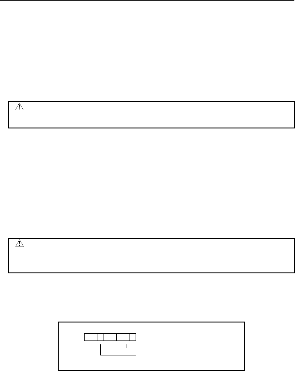
B-64513EN/03
4.LADDER LANGUAGE
- 457 -
(d) Execution command (ACT)
ACT=0: Data is not converted. The value of W1 remains unchanged.
ACT=1: Data is converted.
Parameters
(a) Format specification
Specify data length (1,2, or 4 bytes).
Use the first digit of the parameter to specify byte length.
1: 1 byte
2: 2 bytes
4: 4 bytes
CAUTION
Do not set an illegal value, that is not indicated above, into the "(a) Format
specification".
(b) Input data address
Specify the address containing the input data address.
(c) Address for the conversion result output
Specify the address to output the data converted to BCD or binary format.
Error output (W1)
W1=0: Normal complete
W1=1: Conversion error
The data to be converted is specified as BCD data but is found to be binary data, or the
specified number of bytes cannot contain (and hence an overflow occurs) the BCD data into
which a binary data is converted.
CAUTION
Two or more coils, WRT, WRT.NOT, SET or RST, that follow this instruction are
prohibited. You have to place a single coil instruction as the output of this
instruction.
Operation output register (R9000, Z0)
This register is set with data on operation. If register bit 1 is on, they signify the following.
For the positive/negative signs when binary data is converted into BCD data, see R9000 or Z0.
R9000
Z0
103 25 4
7 6
Negative
Overflow
(data exceeds the number of bytes specified)
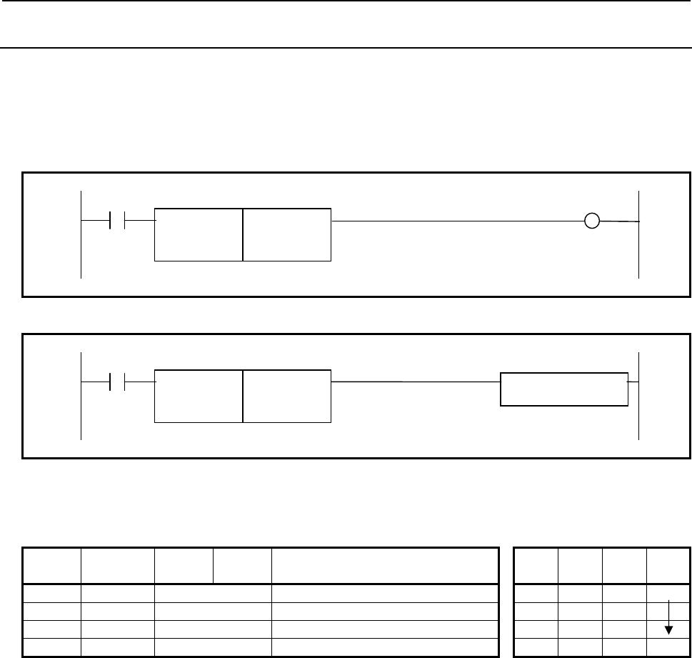
4.LADDER LANGUAGE
B-64513EN/03
- 458 -
4.9.5
DEC (Decode: SUB 4)
This instruction outputs 1 when the two-digit BCD code signal is equal to a specified number and 0 when
not. This is used mainly to decode M or T function. The value type in this instruction is BCD.
Format
Fig. 4.9.5 (a) shows the ladder format and Table 4.9.5 (a) shows the mnemonic format.
Normal format
ACT W1
SUB 4
DEC {{{{ Address of decode signal
{{{{ Decode instruction
Fig. 4.9.5 (a) Format of DEC instruction (Normal format)
Extended type format
ACT
SUB 4
DEC {{{{ Address of decode signal Functional Instruction
{{{{ Decode instruction
Fig. 4.9.5 (b) Format of DEC instruction (Extended type format)
Table 4.9.5 (a) Mnemonic of DEC instruction (Normal format)
Mnemonic format Memory status of control
condition
Step
number Instruction Address
No. Bit No. Remarks ST3 ST2 ST1 ST0
1 RD {{{{ .{ ACT ACT
2 DEC {{{{ Code signal address
3 (PRM) {{{{ Decode specification
4 WRT {{{{ .{ W1, decoding result output W1
The mnemonic-format instruction name "DEC" for step number 2 above may be abbreviated as "D".
Control condition
ACT=0: Turns the decoding result output off (W1).
ACT=1: Performs decoding.
When the specified number is equal to the code signal, W1=1; when not, W1=0.
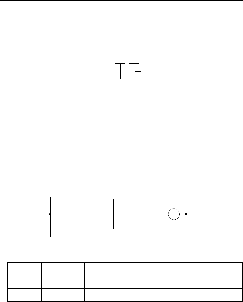
B-64513EN/03
4.LADDER LANGUAGE
- 459 -
Parameters
(a) Code signal address
Specify the address containing two-digit BCD code signals.
(b) Decode specification
There are two paths, the number and the number of digits.
Decode specification {{ {{
Number specification
Number of digits specification
(i) Number:
Specify the decode number.
It must always be decoded in two digits.
(ii) Number of digits:
01: The high-order digit of two decimal digits is set to 0 and only the low-order digit is
decoded.
10: The low-order digit is set to 0 and only the high-order digit is decoded.
11: Two decimal digits are decoded.
Decoding result output (W1)
W1=1: The status of the code signal at a specified address is equal to a specified number.
W1=0: The status of the code signal at a specified address is not equal to a specified number.
Example
DEC
R100.0
R200
W1
3011
R103.1 R228.1
SUB 4
Fig. 4.9.5 (c) Ladder diagram using the DEC instruction
Table 4.9.5 (b) Mnemonic for Fig. 4.9.5 (b)
Step number Instruction Address No. Bit No. Remarks
1 RD R100 .0
2 AND R103 .1
3 DEC R200
4 (PRM) 3011
5 WRT R228 .1
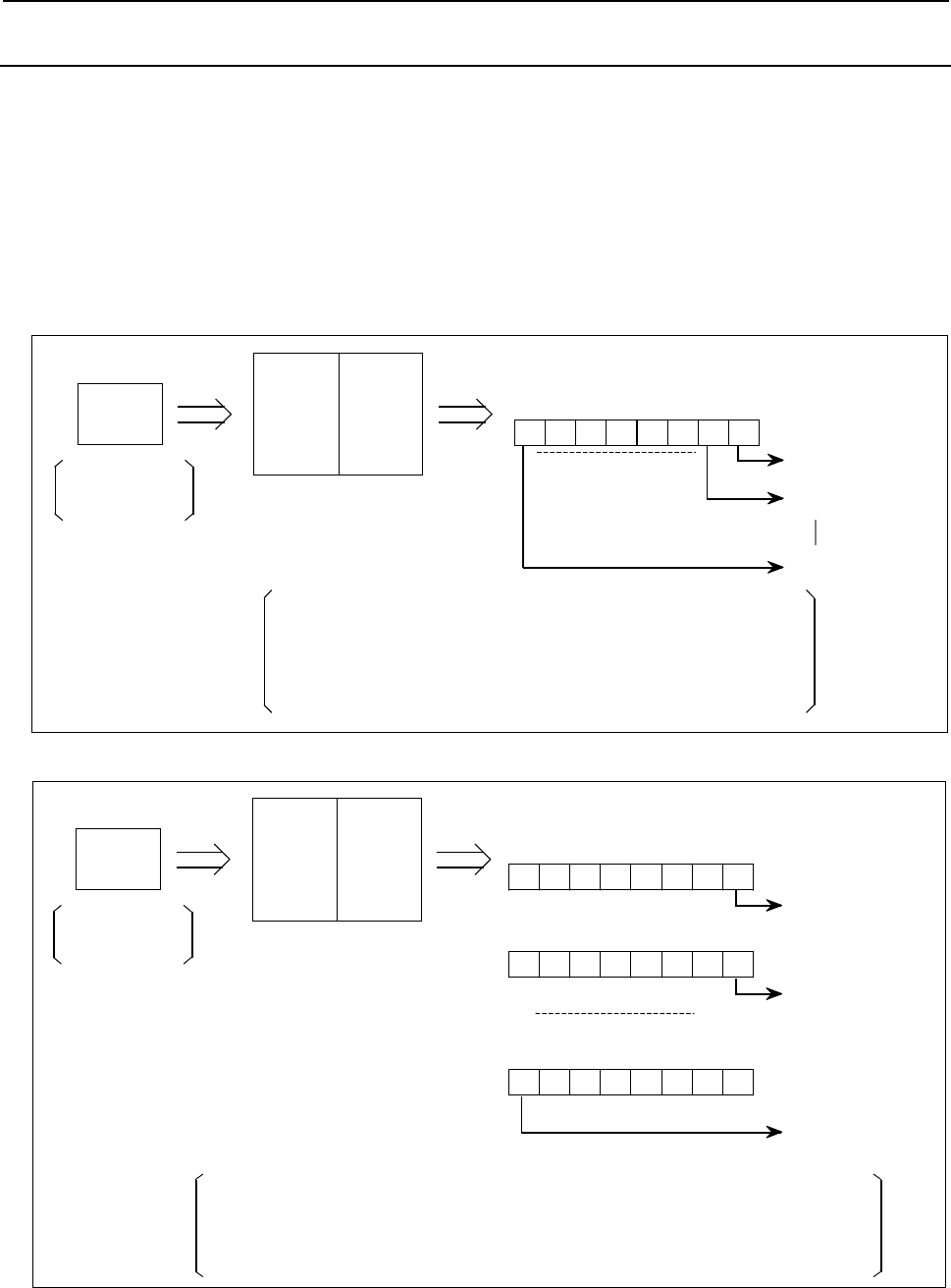
4.LADDER LANGUAGE
B-64513EN/03
- 460 -
4.9.6
DECB (Binary Decoding: SUB 25)
DECB decodes 1, 2 or 4 bytes binary code data. When one of the specified eight consecutive numbers
matches the code data, a logical high value (value 1) is set in the output data bit which corresponds to the
specified number. When these numbers do not match, a logical low value (value 0) is set.
Use this instruction for decoding data of the M or T function.
There are two specifications - basic specification and extended specification - for setting the format
specification parameter in the DECB instruction. The extended specification allows 8n consecutive
values to be decoded at a time. For the details of the setting of a format specification parameter, see the
description of parameters.
Format
SUB 25
DECB 7
Decode designating
number +0
Code
data
{
{{{{
{{{{
{{{{
6543210
Decode result output
Decode designating numbers
Eight numbers, each of which is added by 0, 1, 2, . . . , and 7 to the specified
number are decoded.
When number 62 is specified, for example, eight numbers of 62 to 69 are
decoded.
If code data is 62, 0 bit of output data is turned on; if 69, 7th bit is turned on.
1, 2 or 4-byte
binary code data Decode designating
number +1
Decode designating
number +7
Fig. 4.9.6 (a) Function of DECB instruction (basic specification)
DECB
SUB 25
7
Decode designating
number +0
Code
data
6543210
Decode result output
Decode designating numbers
8n numbers, each of which is added by 0, 1, 2, . . . , and (8n-1) to the specified number are
decoded. (n is set by the format specification parameter)
When number 62 is specified, for example, 8n numbers of 62 to 62+8n-1 are decoded.
If code data is 62, 0 bit of output data+0 is turned on; if 77, 7th bit of output data+1 is turned on.
1, 2 or 4-byte
binary code data 15 14 13 12 11 10 98
Decode designating
number +8
8(n-1)
Decode designating
number +(8n-1)
8n-1
0
{{{{
{{{{
{{{{
Fig. 4.9.6 (b) Function of DECB instruction (extended specification)
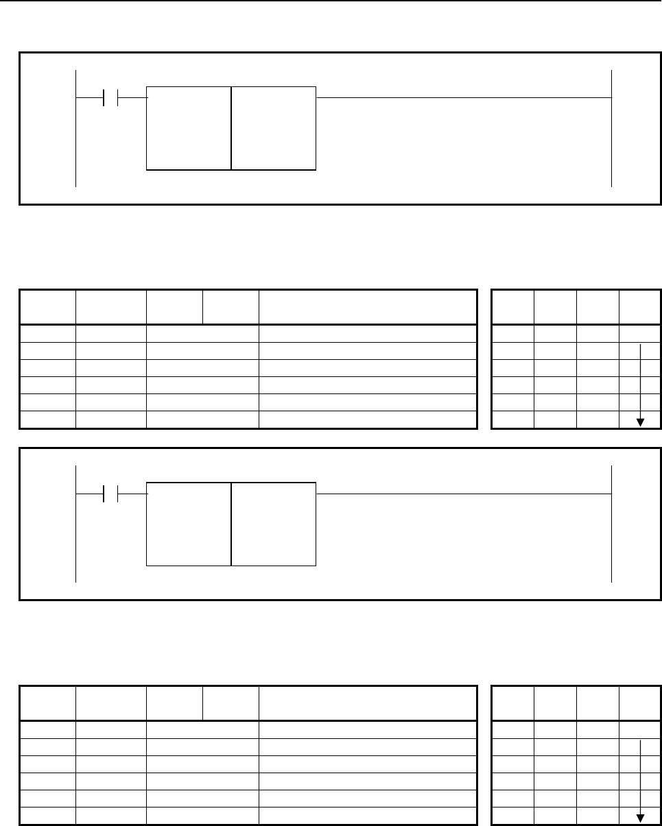
B-64513EN/03
4.LADDER LANGUAGE
- 461 -
Figs. 4.9.6 (c) and (d) show the ladder formats and Tables 4.9.6 (a) and (b) show the mnemonic formats.
ACT
SUB 25
DECB
{ Format specification
{{{{ Code data address
{{{{ Decode designation
{{{{ Decode result output address
Fig. 4.9.6 (c) Format of DECB instruction (basic specification)
Table 4.9.6 (a) Mnemonic of DECB instruction (basic specification)
Mnemonic format Memory status of control
condition
Step
number Instruction Address
No. Bit No. Remarks ST3 ST2 ST1 ST0
1 RD {{{{ .{ ACT ACT
2 SUB 25 DECB instruction
3 (PRM) { Format specification
4 (PRM) {{{{ Code data address
5 (PRM) {{{{ Decode designation
6 (PRM) {{{{ Decode result output address
ACT
SUB 25
DECB 0 Format specification
{{{{ Code data address
{{{{ Decode designation
{{{{ Decode result output address
Fig. 4.9.6 (d) Format of DECB instruction (extended specification)
Table 4.9.6 (b) Mnemonic of DECB instruction (extended specification)
Mnemonic format Memory status of control
condition
Step
number Instruction Address
No. Bit No. Remarks ST3 ST2 ST1 ST0
1 RD {{{{ .{ ACT ACT
2 SUB 25 DECB instruction
3 (PRM) 0 Format specification
4 (PRM) {{{{ Code data address
5 (PRM) {{{{ Decode designation
6 (PRM) {{{{ Decode result output address
Control conditions
(a) Command (ACT)
ACT=0: Resets all the output data bits.
ACT=1: Decodes data. The results of processing are set in the output data address.
4.LADDER LANGUAGE
B-64513EN/03
- 462 -
Parameters
(a) Format specification
Set the size of code data to the 1st digit of the parameter.
0001: Code data is in binary format of 1 byte length
0002: Code data is in binary format of 2 bytes length
0004: Code data is in binary format of 4 bytes length
When setting format specification in the following extended format, DECB can decode multiple (8 ×
n) bytes by 1 instruction.
0nn1: In case of decoding multiple (8 × nn) bytes and code data is binary format of 1 byte
length
0nn2: In case of decoding multiple (8 × nn) bytes and code data is binary format of 2 bytes
length
0nn4: In case of decoding multiple (8 × nn) bytes and code data is binary format of 4 bytes
length
The nn is the numerical value from 02 to 99. When setting 00 or 01, it works for decoding 8
numbers.
Format specification (extended specification) :
0 n n X
The byte length setting of code data
1: 1 byte length
2: 2 byte length
4: 4 byte length
The multiple decoding number setting
00-01:
It decodes 8 continuous numbers.
The decode result output address needs a memory of 1 byte length.
02-99:
It decodes multiple (8×nn) continuous numbers.
The decode result output address needs a memory of nn bytes length.
CAUTION
Do not set an illegal value, that is not indicated above, into the "(a) Format
specification".
(b) Code data address
Specify the numbers to be decoded.
(c) Number specification decode designation
Specify the numbers to be decoded.
(d) Decode result address
Specify an address where the decoded result shall be output.
One byte area is necessary in the memory for the output.
When executing this instruction in extended specification, the area of setting by the format
specification for the “nn” bytes is necessary.
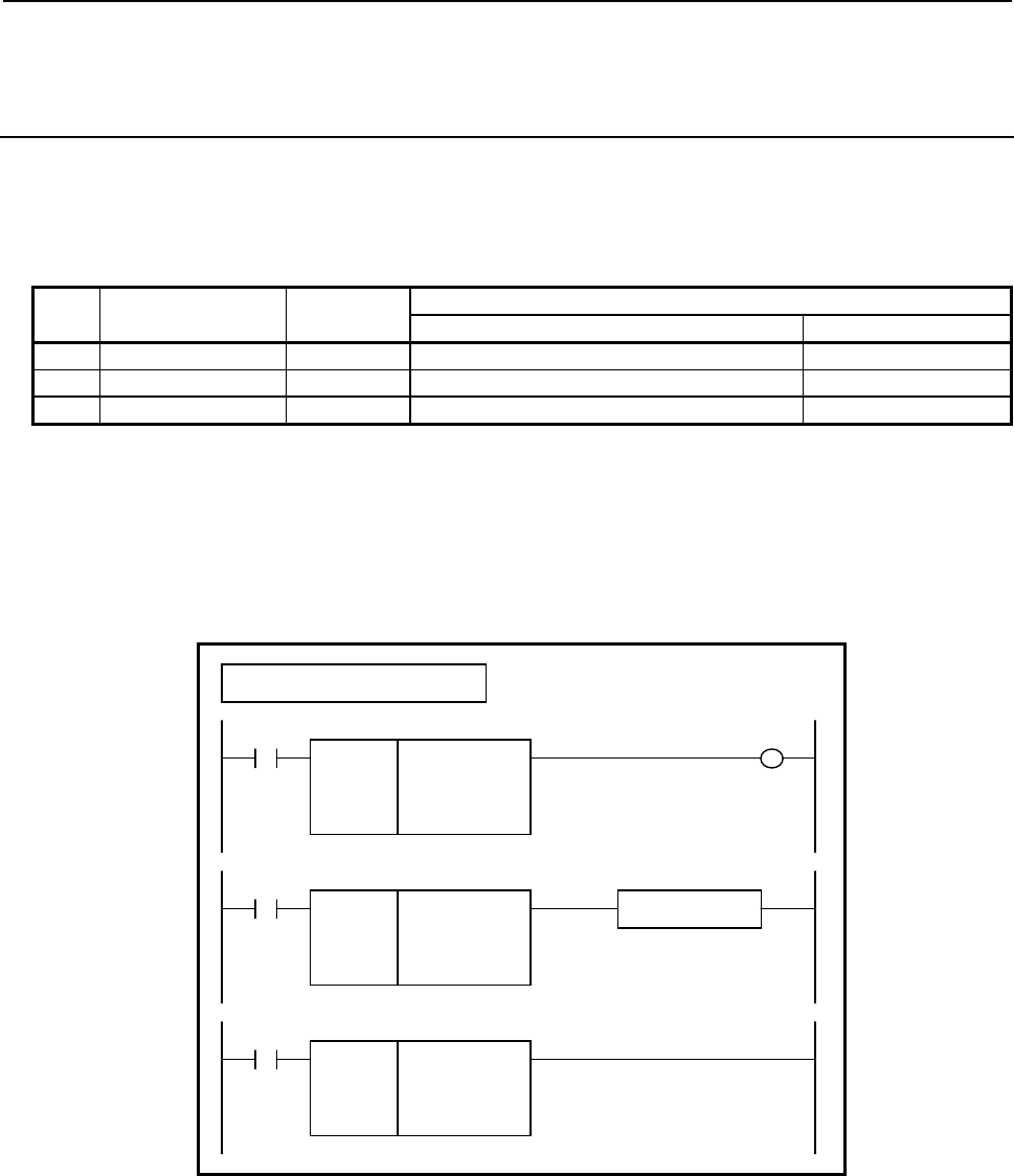
B-64513EN/03
4.LADDER LANGUAGE
- 463 -
4.9.7
TBCDB (Binary to BCD Conversion (1 Byte Length) : SUB 313)
TBCDW (Binary to BCD Conversion (2 Bytes Length) : SUB 314)
TBCDD (Binary to BCD Conversion (4 Bytes Length) : SUB 315)
The Binary to BCD conversion instruction converts binary data to BCD format data.
As indicated below, three types of Binary to BCD conversion instructions are available according to the
type of data to be converted.
Table 4.9.7 (a) Kinds of Binary to BCD conversion instruction
Instruction name SUB No. Data type
Source Destination
1 TBCDB 313 1 byte length signed binary 2-digit BCD
2 TBCDW 314 2 bytes length signed binary 4-digit BCD
3 TBCDD 315 4 bytes length signed binary 8-digit BCD
If conversion source binary data is not within the valid BCD format data range (if source binary data is a
negative value or is greater than the maximum allowable value), the result of conversion is not output,
and W1=0 is set.
Format
Fig. 4.9.7 shows the ladder format and Table 4.9.7(b) shows the mnemonic format.
SUB 313
TBCDB
○○○○
○○○○
ACT
Example : TBCDB Instruction
SUB 313
TBCDB
○○○○
○○○○
Source data
Result of conversion output address
(Address or Constant)
ACT W1
SUB 313
TBCDB
○○○○
○○○○
Functional Instruction
ACT ACT2
Fig. 4.9.7 Format of TBCDB, TBCDW, TBCDD instruction
4.LADDER LANGUAGE
B-64513EN/03
- 464 -
Table 4.9.7(b) Mnemonic of TBCDB, TBCDW, TBCDD instruction
Mnemonic format
Memory status of control
condition
Step
number Instruction Address
No. Bit No. Remarks
ST3 ST2 ST1 ST0
1 RD {{{{ .{ ACT ACT
2 SUB 313 SUB No. (TBCDB instruction)
3 (PRM) {{{{ Source data
4 (PRM) {{{{ Result of conversion output
address (Address or Constant)
5 WRT {{{{ .{ Normal end output W1
Control conditions
(a) Input signal (ACT)
ACT = 0: Instruction not executed.
ACT = 1: Executed.
Parameters
(a) Source data
Specify conversion source binary data. In this parameter, a constant or a PMC memory address for
storing data can be specified.
(b) Result of conversion output address
Specify the address to which BCD format data produced as the result of conversion is to be output.
Output (W1)
W1=1: The operation is terminated normally.
W1=0: No operation is executed. (ACT=0)
The conversion source data is not within the valid BCD format data range.
NOTE
1 W1 may be omitted. Moreover, another functional instruction can be connected
instead of a coil.
2 With the similar functional instruction DCNVB, W1=1 is set when an operation is
terminated abnormally. With TBCDB, TBCDW, and TBCDD, W1=1 is set when
an operation is terminated normally.
3 No data is output to the operation output registers (R9000, Z0).
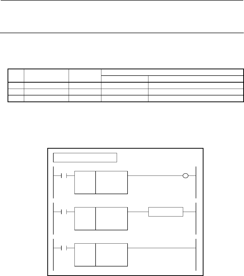
B-64513EN/03
4.LADDER LANGUAGE
- 465 -
4.9.8
FBCDB (BCD to Binary Conversion (1 Byte Length) : SUB 313)
FBCDW (BCD to Binary Conversion (2 Bytes Length) : SUB 314)
FBCDD (BCD to Binary Conversion (4 Bytes Length) : SUB 315)
The BCD to Binary conversion instruction converts BCD format data to binary data.
As indicated below, three types of BCD to Binary conversion instructions are available according to the
type of data to be converted.
Table 4.9.8 (a) Kinds of BCD to Binary conversion instruction
Instruction name SUB No. Data type
Source Destination
1 FBCDB 316 2-digit BCD 1 byte length signed binary
2 FBCDW 317 4-digit BCD 2 bytes length signed binary
3 FBCDD 318 8-digit BCD 4 bytes length signed binary
If conversion source data is invalid as BCD format data, the result of conversion is not output, and W1=0
is set.
Format
Fig. 4.9.8 shows the ladder format and Table 4.9.8(b) shows the mnemonic format.
SUB 316
FBCDB
○○○○
○○○○
ACT
Example : FBCDB Instruction
SUB 316
FBCDB
○○○○
○○○○
Source data
Result of conversion output address
(Address or Constant)
ACT W1
SUB 316
FBCDB
○○○○
○○○○
Functional Instruction
ACT ACT2
Fig. 4.9.8 Format of FBCDB, FBCDW, FBCDD instruction
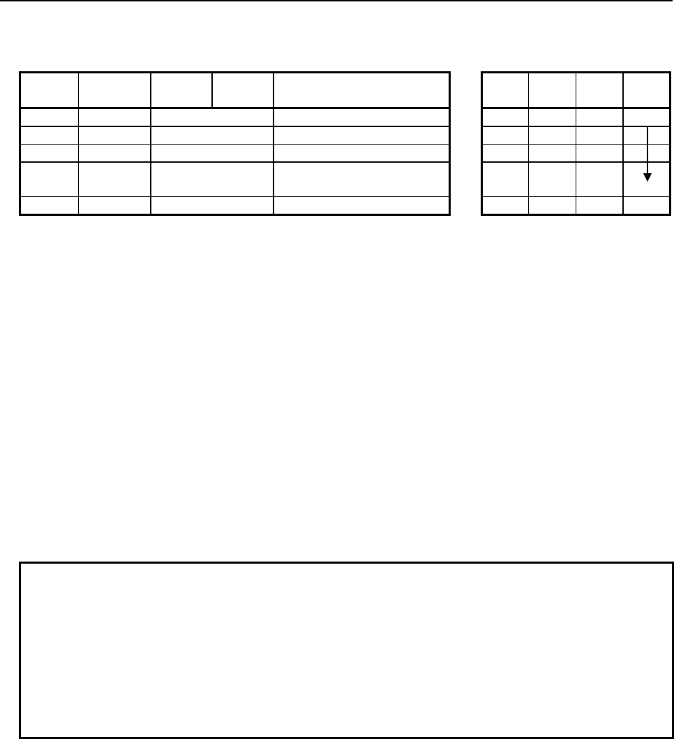
4.LADDER LANGUAGE
B-64513EN/03
- 466 -
Table 4.9.8(b) Mnemonic of FBCDB, FBCDW, FBCDD instruction
Mnemonic format
Memory status of control
condition
Step
number Instruction Address
No. Bit No. Remarks
ST3 ST2 ST1 ST0
1 RD {{{{ .{ ACT ACT
2 SUB 316 SUB No. (FBCDB instruction)
3 (PRM) {{{{ Source data
4 (PRM) {{{{ Result of conversion output
address (Address or Constant)
5 WRT {{{{ .{ Normal end output W1
Control conditions
(a) Input signal (ACT)
ACT = 0: Instruction not executed.
ACT = 1: Executed.
Parameters
(a) Source data
Specify conversion source BCD format data. In this parameter, a constant or a PMC memory
address for storing data can be specified.
(b) Result of conversion output address
Specify the address to which binary data produced as the result of conversion is to be output.
Output (W1)
W1=1: The operation is terminated normally.
W1=0: No operation is executed. (ACT=0)
The conversion source data is invalid as BCD format data.
NOTE
1 W1 may be omitted. Moreover, another functional instruction can be connected
instead of a coil.
2 With the similar functional instruction DCNVB, W1=1 is set when an operation is
terminated abnormally. With FBCDB, FBCDW, and FBCDD, W1=1 is set when
an operation is terminated normally.
3 No sign is specified for binary data output as the result of conversion. Invert the
sign by using NEGSx after conversion if necessary.
4 No data is output to the operation output registers (R9000, Z0).

B-64513EN/03
4.LADDER LANGUAGE
- 467 -
4.10 OPERATION INSTRUCTION
The following types of operation instruction are available. Use any of these instructions as appropriate for
your purpose.
Instruction name Sub number Processing
1 ADDB 36 Binary addition
2 SUBB 37 Binary subtraction
3 MULB 38 Binary multiplication
4 DIVB 39 Binary division
5 ADD 19 BCD addition
6 SUB 20 BCD subtraction
7 MUL 21 BCD multiplication
8 DIV 22 BCD division
9 NUMEB 40 Definition of binary constants
10 NUME 23 Definition of BCD constants
11 ADDSB 319 Addition (1 byte length)
12 ADDSW 320 Addition (2 bytes length)
13 ADDSD 321 Addition (4 bytes length)
14 SUBSB 322 Subtraction (1 byte length)
15 SUBSW 323 Subtraction (2 bytes length)
16 SUBSD 324 Subtraction (3 byte length)
17 MULSB 325 Multiplication (1 byte length)
18 MULSW 326 Multiplication (2 bytes length)
19 MULSD 327 Multiplication (4 bytes length)
20 DIVSB 328 Division (1 byte length)
21 DIVSW 329 Division (2 bytes length)
22 DIVSD 330 Division (4 bytes length)
23 MODSB 331 Remainder (1 byte length)
24 MODSW 332 Remainder (2 bytes length)
25 MODSD 333 Remainder (4 bytes length)
26 INCSB 334 Increment (1 byte length)
27 INCSW 335 Increment (2 bytes length)
28 INCSD 336 Increment (4 bytes length)
29 DECSB 337 Decrement (1 byte length)
30 DECSW 338 Decrement (2 bytes length)
31 DECSD 339 Decrement (4 bytes length)
32 ABSSB 340 Absolute value (1 byte length)
33 ABSSW 341 Absolute value (2 bytes length)
34 ABSSD 342 Absolute value (4 bytes length)
35 NEGSB 343 Sign inversion (1 byte length)
36 NEGSW 344 Sign inversion (2 bytes length)
37 NEGSD 345 Sign inversion (4 bytes length)
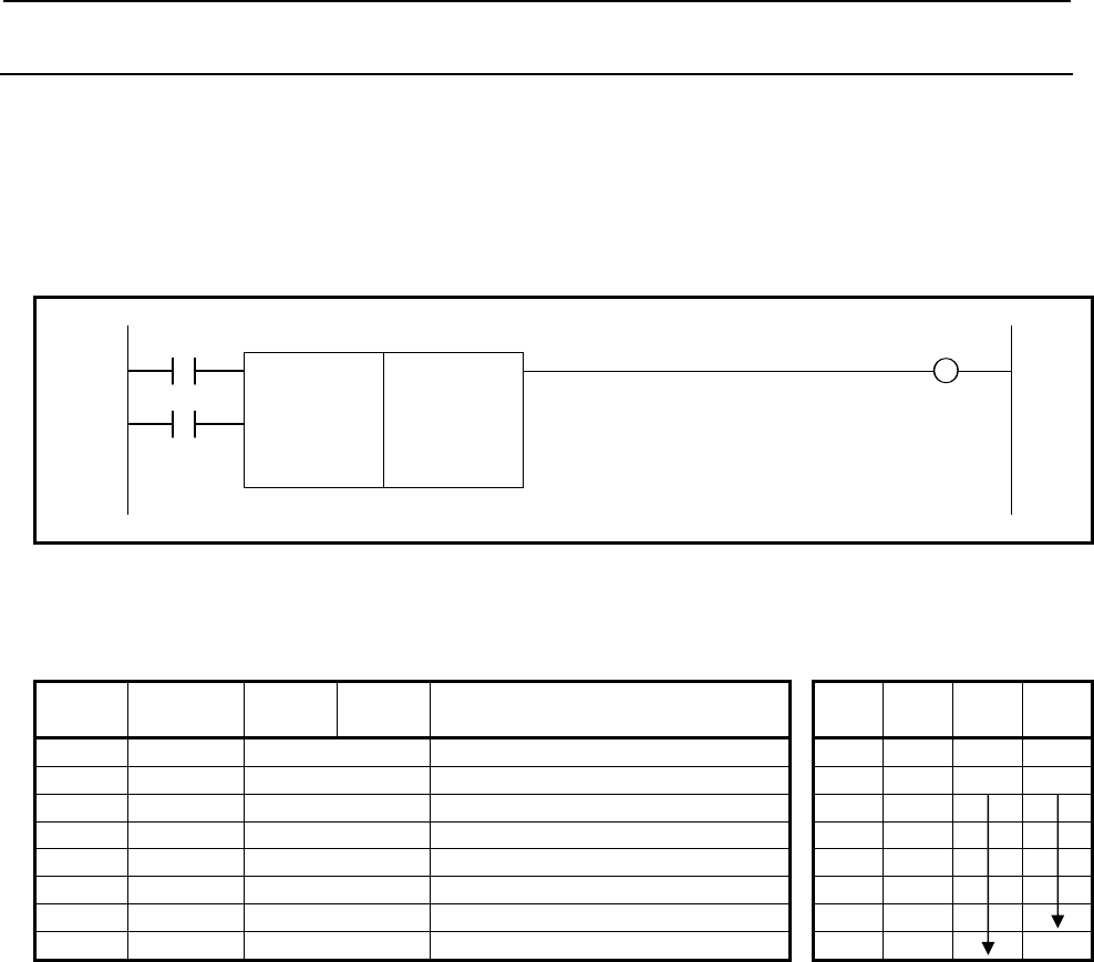
4.LADDER LANGUAGE
B-64513EN/03
- 468 -
4.10.1
ADDB (Binary Addition: SUB 36)
This instruction performs binary addition between 1, 2, and 4 bytes data. In the operation result register
(R9000, Z0), operating data is set besides the numerical data representing the operation results. The
required number of bytes is necessary to store each augend, the added, and the operation output data.
Format
Fig. 4.10.1 shows the ladder format and Table 4.10.1 shows the mnemonic format.
RST W1
SUB 36
ACT ADDB 00 Format specification
{{{{ Augend address
{{{{ Addend data (address or constant)
{{{{ Result output address
Fig. 4.10.1 Format of ADDB instruction
Table 4.10.1 Mnemonic of ADDB instruction
Mnemonic format Memory status of control
condition
Step
number Instruction Address
No. Bit No. Remarks ST3 ST2 ST1 ST0
1 RD {{{{ .{ RST RST
2 RD.STK {{{{ .{ ACT RST ACT
3 SUB 36 ADDB instruction
4 (PRM) 00 Format specification
5 (PRM) {{{{ Augend address
6 (PRM) {{{{ Addend data (address or constant)
7 (PRM) {{{{ Result output address
8 WRT {{{{ .{ Error output W1
Control conditions
(a) Reset (RST)
RST=0: Do not reset error output W1.
RST=1: Reset error output W1. That is, W1=0.
(b) Command (ACT)
ACT=0: Do not execute ADDB. W1 does not change.
ACT=1: Execute ADDB.
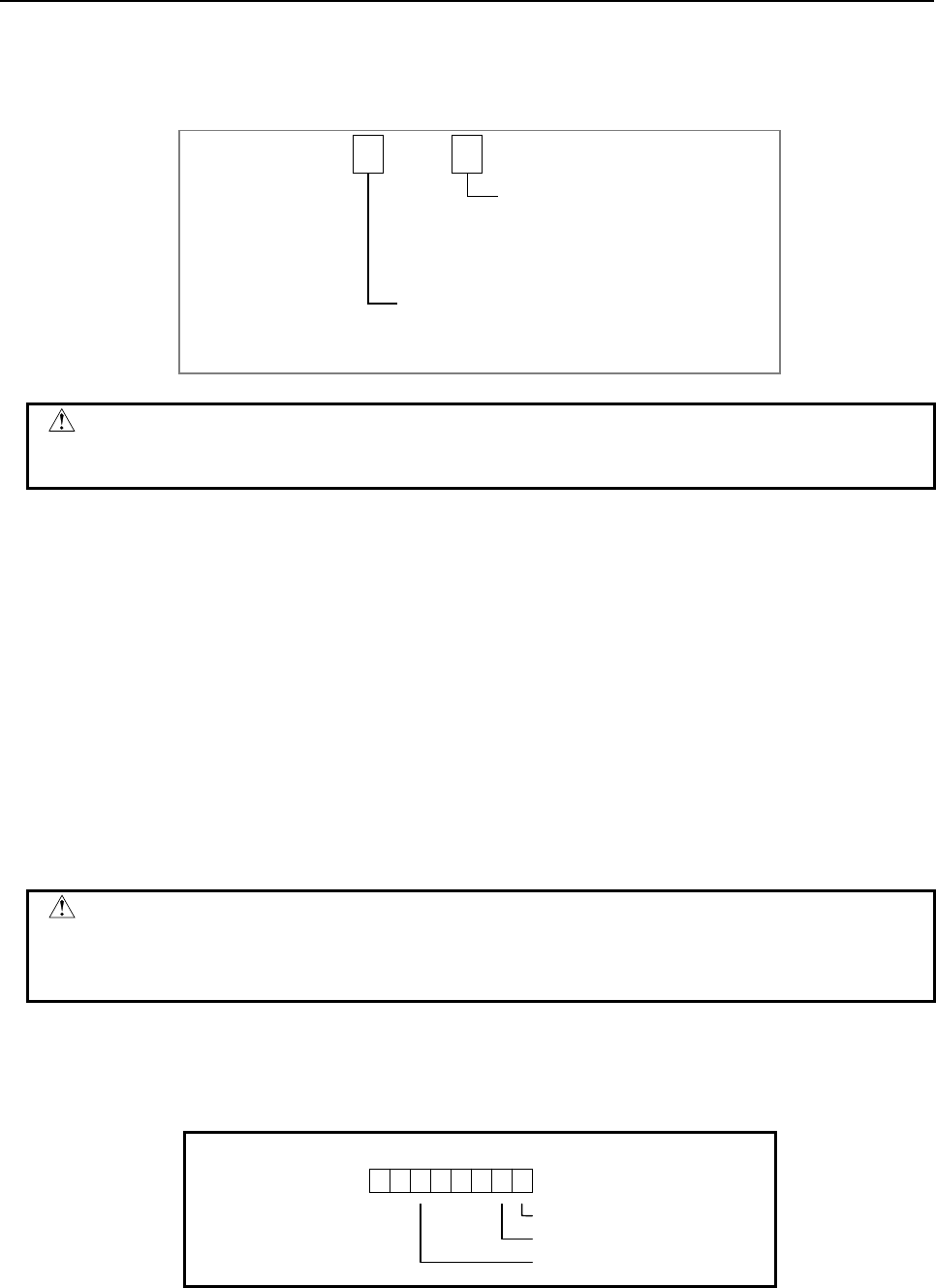
B-64513EN/03
4.LADDER LANGUAGE
- 469 -
Parameters
(a) Format specification
Specify data length (1, 2, and 4 bytes) and the format for the addend (constant or address).
Data length specification
1: 1 byte length data
2: 2 bytes length data
4: 4 bytes length data
0
Format specification
0: Constant data
1: Address data
0
CAUTION
Do not set an illegal value, that is not indicated above, into the "(a) Format
specification".
(b) Augend address
Specify the address of the augend.
(c) Addend data (address or constant)
Specification in (a) determines the format of the addend.
(d) Result output address
Specify the address of the result of operation.
Error output (W1)
W1=0: Operation correct
W1=1: Operation incorrect
W1 goes on (W1=1) if the result of addition exceeds the specified data length. Then, the result
will be output and the overflow flag and other flags will be output to the operation output register.
CAUTION
Two or more coils, WRT, WRT.NOT, SET or RST, that follow this instruction are
prohibited. You have to place a single coil instruction as the output of this
instruction.
Operation output register (R9000, Z0)
This register is set with data on operation. If register bit is on, they signify the following operation data:
R9000
Z0
103254
76
Negative
Zero
Overflow
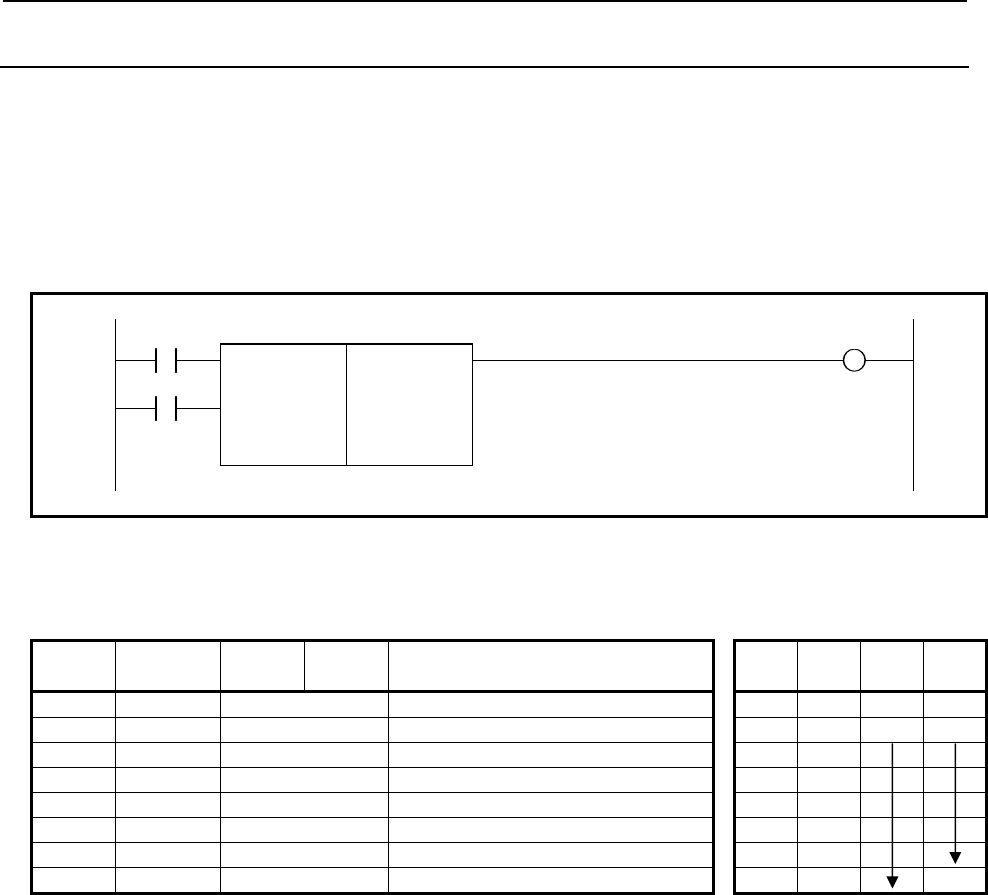
4.LADDER LANGUAGE
B-64513EN/03
- 470 -
4.10.2
SUBB (Binary Subtraction: SUB 37)
This instruction subtracts one data from another, both data being in the binary format of 1, 2 or 4 bytes.
In the operation result register (R9000, Z0), operation data is set besides the numerical data representing the
operation. A required number of bytes is necessary to store the subtrahend, minuend, and the result
(difference).
Format
Fig. 4.10.2 shows the ladder format and Table 4.10.2 shows the mnemonic format.
RST W1
SUB 37
ACT SUBB 00 Format specification
{{{{ Minuend address
{{{{ Subtrahend data (address or constant)
{{{{ Result output address
Fig. 4.10.2 Format of SUBB instruction
Table 4.10.2 Mnemonic of SUBB instruction
Mnemonic format Memory status of control
condition
Step
number Instruction Address
No. Bit No. Remarks ST3 ST2 ST1 ST0
1 RD {{{{ .{ RST RST
2 RD.STK {{{{ .{ ACT RST ACT
3 SUB 37 SUBB instruction
4 (PRM) 00 Format specification
5 (PRM) {{{{ Minuend address
6 (PRM) {{{{ Subtrahend data (address or constant)
7 (PRM) {{{{ Result output address
8 WRT {{{{ .{ Error output W1
Control conditions
(a) Reset (RST)
RST=0: Do not reset error output W1.
RST=1: Reset error output W1. That is, W1=0.
(b) Command (ACT)
ACT=0: Do not execute SUBB. W1 does not change.
ACT=1: Execute SUBB.
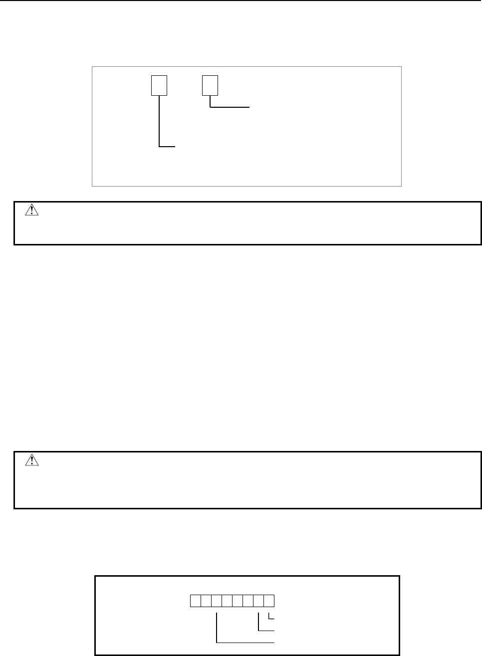
B-64513EN/03
4.LADDER LANGUAGE
- 471 -
Parameters
(a) Format specification
Specify data length (1, 2, and 4 bytes) and the format for the subtrahend (constant or address).
Data length specification
1: 1 byte length data
2: 2 bytes length data
4: 4 bytes length data
0
Format specification
0: Constant data
1: Address data
0
CAUTION
Do not set an illegal value, that is not indicated above, into the "(a) Format
specification".
(b) Minuend address
Specify the address of the minuend.
(c) Subtrahend data (address or constant)
Specification in (a) determines the format of the Subtrahend.
(d) Result output address
Specify the address of the result of operation.
Error output (W1)
W1=0: Operation correct
W1=1: Operation incorrect
W1 goes on (W1=1) if the result of subtraction exceeds the specified data length. Then, the result
will be output and the overflow flag and other flags will be output to the operation output register.
CAUTION
Two or more coils, WRT, WRT.NOT, SET or RST, that follow this instruction are
prohibited. You have to place a single coil instruction as the output of this
instruction.
Operation output register (R9000, Z0)
This register is set with data on operation. If register bit is on, they signify the following operation data:
R9000
Z0
103254
76
Negative
Zero
Overflow

4.LADDER LANGUAGE
B-64513EN/03
- 472 -
4.10.3
MULB (Binary Multiplication: SUB 38)
This instruction multiplies 1, 2, and 4 bytes binary data items. In the operation result register (R9000, Z0),
operation data is set besides the numerical data representing the operation.
A required number of bytes is necessary to store multiplicand, multiplier, and the result (product).
Format
Fig. 4.10.3 shows the ladder format and Table 4.10.3 shows the mnemonic format.
RST W1
SUB 38
ACT MULB 00 Format specification
{{{{ Multiplicand address
{{{{ Multiplier data (address or constant)
{{{{ Result output address
Fig. 4.10.3 Format of MULB instruction
Table 4.10.3 Mnemonic of MULB instruction
Mnemonic format Memory status of control
condition
Step
number Instruction Address
No. Bit No. Remarks ST3 ST2 ST1 ST0
1 RD {{{{ .{ RST RST
2 RD.STK {{{{ .{ ACT RST ACT
3 SUB 38 MULB instruction
4 (PRM) 00 Format specification
5 (PRM) {{{{ Multiplicand address
6 (PRM) {{{{ Multiplier data (address or constant)
7 (PRM) {{{{ Result output address
8 WRT {{{{ .{ Error output W1
Control conditions
(a) Reset (RST)
RST=0: Do not reset error output W1.
RST=1: Reset error output W1. That is, W1=0.
(b) Command (ACT)
ACT=0: Do not execute MULB. W1 does not change.
ACT=1: Execute MULB.
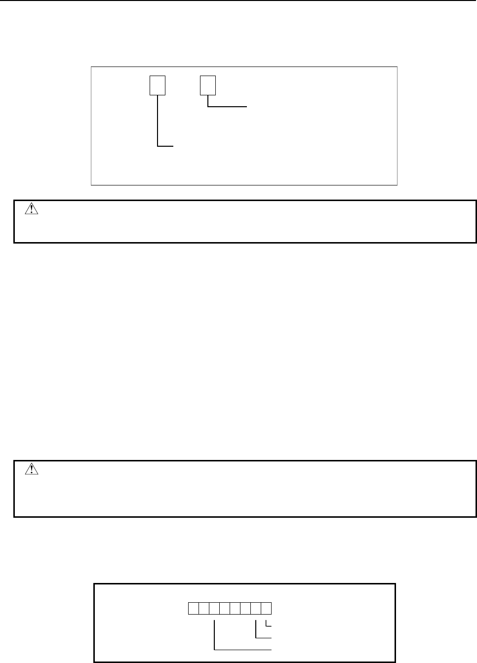
B-64513EN/03
4.LADDER LANGUAGE
- 473 -
Parameters
(a) Format specification
Specify data length (1, 2, and 4 bytes) and the format for the multiplier (constant or address).
Data length specification
1: 1 byte length data
2: 2 bytes length data
4: 4 bytes length data
0
Format specification
0: Constant data
1: Address data
0
CAUTION
Do not set an illegal value, that is not indicated above, into the "(a) Format
specification".
(b) Multiplicand address
Specify the address of the multiplicand.
(c) Multiplier data (address or constant)
Specification in (a) determines the format of the multiplier.
(d) Result output address
Specify the address of the result of operation.
Error output (W1)
W1=0: Operation correct
W1=1: Operation incorrect
W1 goes on (W1=1) if the result of multiplication exceeds the specified data length. Then, the
result will not be output and the overflow flag and other flags will be output to the operation
output register.
CAUTION
Two or more coils, WRT, WRT.NOT, SET or RST, that follow this instruction are
prohibited. You have to place a single coil instruction as the output of this
instruction.
Operation output register (R9000, Z0)
This register is set with data on operation. If register bit is on, they signify the following operation data:
R9000
Z0
103254
76
Negative
Zero
Overflow

4.LADDER LANGUAGE
B-64513EN/03
- 474 -
4.10.4
DIVB (Binary Division: SUB 39)
This instruction divides binary data items 1, 2, and 4 bytes in length. In the operation result register (R9000,
Z0), operation data is set and remainder is set to R9002 and following addresses.
A required number of bytes is necessary to store the dividend, divisor, and the result (quotient).
Format
Fig. 4.10.4 shows the ladder format and Table 4.10.4 shows the mnemonic format.
RST W1
SUB 39
ACT DIVB 00 Format specification
{{{{ Dividend address
{{{{ Divisor data (address or constant)
{{{{ Result output address
Fig. 4.10.4 Format of DIVB instruction
Table 4.10.4 Mnemonic of DIVB instruction
Mnemonic format Memory status of control
condition
Step
number Instruction Address
No. Bit No. Remarks ST3 ST2 ST1 ST0
1 RD {{{{ .{ RST RST
2 RD.STK {{{{ .{ ACT RST ACT
3 SUB 39 DIVB instruction
4 (PRM) 00 Format specification
5 (PRM) {{{{ Dividend address
6 (PRM) {{{{ Divisor data (address or constant)
7 (PRM) {{{{ Result output address
8 WRT {{{{ .{ Error output W1
Control conditions
(a) Reset (RST)
RST=0: Do not reset error output W1.
RST=1: Reset error output W1. That is, W1=0.
(b) Command (ACT)
ACT=0: Do not execute DIVB. W1 does not change.
ACT=1: Execute DIVB.
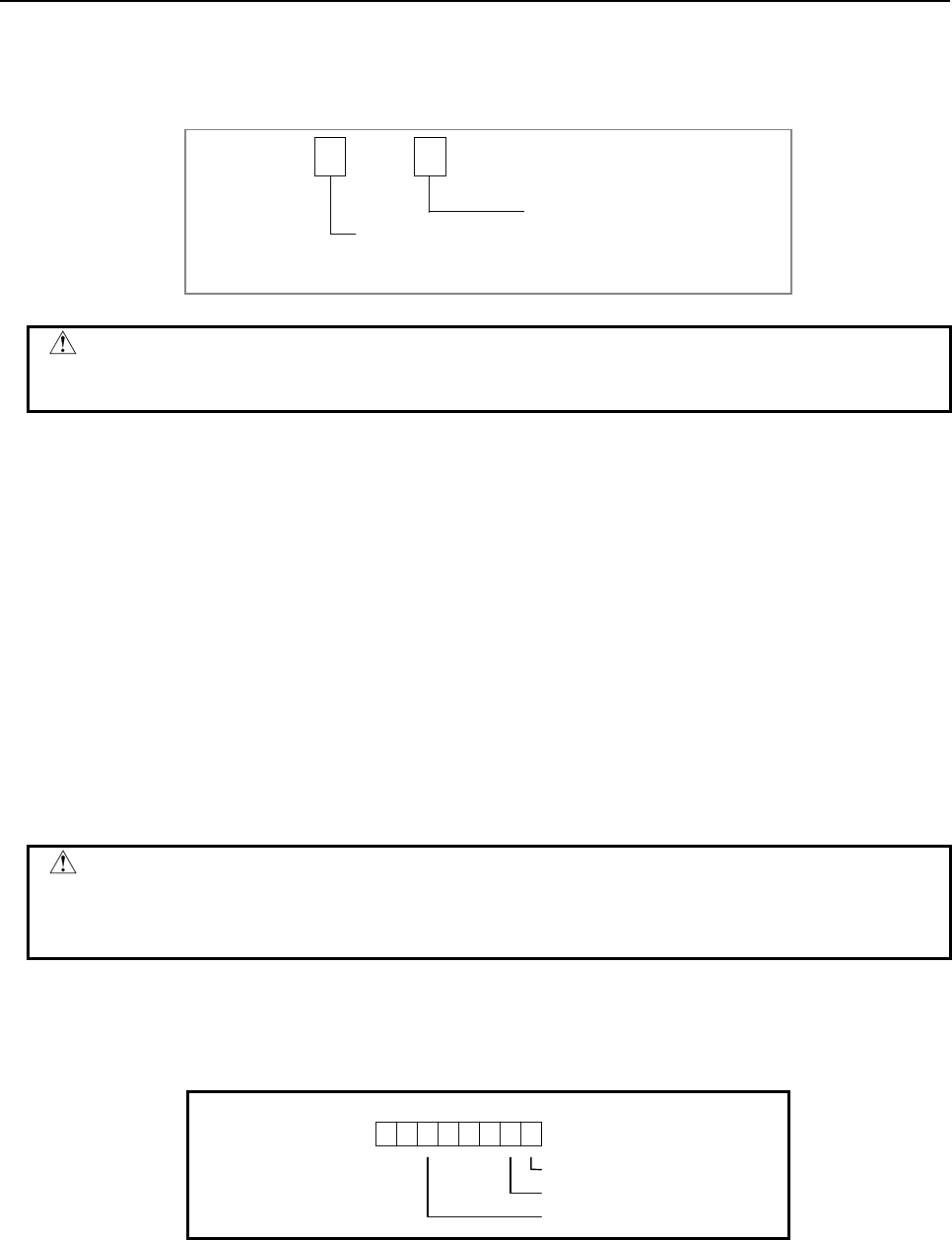
B-64513EN/03
4.LADDER LANGUAGE
- 475 -
Parameters
(a) Format specification
Specify data length (1, 2, and 4 bytes) and the format for the divisor (constant or address).
Data length specification
1: 1 byte length data
2: 2 bytes length data
4: 4 bytes length data
0 0
Format specification
0: Constant data
1: Address data
CAUTION
Do not set an illegal value, that is not indicated above, into the "(a) Format
specification".
(b) Dividend address
Specify the address of the dividend.
(c) Divisor data (address or constant)
Specification in (a) determines the format of the divisor.
(d) Result output address
Specify the address of the result of operation.
Error output (W1)
W1=0: Operation correct
W1=1: Operation incorrect
W1 goes on (W1=1) if the result exceeds the specified data length or zero is set to the divisor data.
Then, the result will not be output and the overflow flag and other flags will be output to the
operation output register.
CAUTION
Two or more coils, WRT, WRT.NOT, SET or RST, that follow this instruction are
prohibited. You have to place a single coil instruction as the output of this
instruction.
Operation output register (R9000, Z0)
This register is set with data on operation. If register bit is on, they signify the following operation data:
R9000
Z0
10325476
Negative
Zero
Overflow
Remainder output address
Depending on its length, the remainder is stored in one or more of registers R9002 to R9005 or Z2 to Z5.

4.LADDER LANGUAGE
B-64513EN/03
- 476 -
4.10.5
ADD (BCD Addition: SUB 19)
This instruction adds BCD 2 or 4 digits data.
Format
Fig. 4.10.5 shows the ladder format and Table 4.10.5 shows the mnemonic format.
BYT W1
SUB 19
RST ADD
{ Data format of addend
{{{{ Augend address
ACT {{{{ Addend (address or constant)
{{{{ Sum output address
Fig. 4.10.5 Format of ADD instruction
Table 4.10.5 Mnemonic of ADD instruction
Mnemonic format Memory status of control
condition
Step
number Instruction Address
No. Bit No. Remarks ST3 ST2 ST1 ST0
1 RD {{{{ .{ BYT BYT
2 RD.STK {{{{ .{ RST BYT RST
3 RD.STK {{{{ .{ ACT BYT RST ACT
4 SUB 19 ADD instruction
5 (PRM) { Addend format
6 (PRM) {{{{ Augend address
7 (PRM) {{{{ Addend (address or constant)
8 (PRM) {{{{ Sum output address
9 WRT {{{{ .{ Error output W1
Control conditions
(a) The number of digits of data. (BYT)
BYT=0: Data is BCD 2 digits long.
BYT=1: Data is BCD 4 digits long.
(b) Reset (RST)
RST=0: Do not reset error output W1.
RST=1: Reset error output W1, that is, W1=0.
(c) Execution command (ACT)
ACT=0: The ADD instruction is not executed. W1 does not change.
ACT=1: The ADD instruction is executed.

B-64513EN/03
4.LADDER LANGUAGE
- 477 -
Parameters
(a) Data format of addend
0: Specify addend with a constant.
1: Specify addend with an address.
CAUTION
Do not set an illegal value, that is not indicated above, into the "(a) Data format of
addend".
(b) Augend address
Specify the address storing the augend.
(c) Addend (address or constant)
Specify the addend depends on above (a).
(d) Sum output address
Specify the address to which the sum is to be output.
Error output
W1=0: Normal operation
W1=1: Abnormal operation. W1 is set to 1 to indicate an error, e.g. if the result of the addition exceeds
the data size specified for control condition (a) described above.
CAUTION
Two or more coils, WRT, WRT.NOT, SET or RST, that follow this instruction are
prohibited. You have to place a single coil instruction as the output of this
instruction.

4.LADDER LANGUAGE
B-64513EN/03
- 478 -
4.10.6
SUB (BCD Subtraction: SUB 20)
This instruction subtracts BCD 2 or 4 digits data.
Format
Fig. 4.10.6 shows the ladder format and Table 4.10.6 shows the mnemonic format.
BYT W1
SUB 20
RST SUB
{ Data format of subtrahend
{{{{ Minuend address
ACT {{{{ Subtrahend (address or constant)
{{{{ Difference output address
Fig. 4.10.6 Format of SUB instruction
Table 4.10.6 Mnemonic of SUB instruction
Mnemonic format Memory status of control
condition
Step
number Instruction Address
No. Bit No. Remarks ST3 ST2 ST1 ST0
1 RD {{{{ .{ BYT BYT
2 RD.STK {{{{ .{ RST BYT RST
3 RD.STK {{{{ .{ ACT BYT RST ACT
4 SUB 20 SUB instruction
5 (PRM) { Data format of subtrahend
6 (PRM) {{{{ Minuend address
7 (PRM) {{{{ Subtrahend (address or constant)
8 (PRM) {{{{ Difference output address
9 WRT {{{{ .{ Error output W1
Control conditions
(a) The number of digits of data. (BYT)
BYT=0: Data is BCD 2 digits long
BYT=1: Data is BCD 4 digits long
(b) Reset (RST)
RST=0: Do not reset error output W1.
RST=1: Reset error output W1, that is, W1=0.
(c) Execution command (ACT)
ACT=0: The SUB instruction is not executed. W1 does not change.
ACT=1: The SUB instruction is executed.

B-64513EN/03
4.LADDER LANGUAGE
- 479 -
Parameters
(a) Data format of subtrahend
0: Specify subtrahend with a constant.
1: Specify subtrahend with an address.
CAUTION
Do not set an illegal value, that is not indicated above, into the "(a) Data format of
subtrahend".
(b) Minuend address
Specify the address of the minuend.
(c) Subtrahend (address)
Specify the subtrahend depends on above (a).
(d) Difference output address
Specify the address to which the difference is output.
Error output (W1)
W1=0: Normal operation
W1=1: Abnormal operation. W1 is set 1 to indicate an error if the difference is negative.
CAUTION
Two or more coils, WRT, WRT.NOT, SET or RST, that follow this instruction are
prohibited. You have to place a single coil instruction as the output of this
instruction.
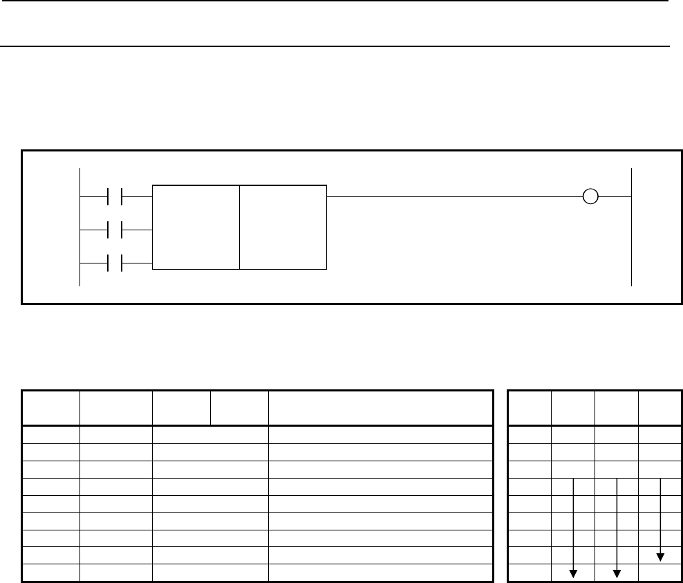
4.LADDER LANGUAGE
B-64513EN/03
- 480 -
4.10.7
MUL (BCD Multiplication: SUB 21)
This instruction multiplies BCD 2 or 4 digits data. The product must also be BCD 2 or 4 digits data.
Format
Fig. 4.10.7 shows the ladder format and Table 4.10.7 shows the mnemonic format.
BYT W1
SUB 21
RST MUL
{ Data format of multiplier
{{{{ Multiplicand address
ACT {{{{ Multiplier (address or constant)
{{{{ Product output address
Fig. 4.10.7 Format of MUL instruction
Table 4.10.7 Mnemonic of MUL instruction
Mnemonic format Memory status of control
condition
Step
number Instruction Address
No. Bit No. Remarks ST3 ST2 ST1 ST0
1 RD {{{{ .{ BYT BYT
2 RD.STK {{{{ .{ RST BYT RST
3 RD.STK {{{{ .{ ACT BYT RST ACT
4 SUB 21 MUL instruction
5 (PRM) { Data format of multiplier
6 (PRM) {{{{ Multiplicand address
7 (PRM) {{{{ Multiplier (address or constant)
8 (PRM) {{{{ Product output address
9 WRT {{{{ .{ Error output W1
Control conditions
(a) The number of digits of data. (BYT)
BYT=0: Data is BCD 2 digits long.
BYT=1: Data is BCD 4 digits long.
(b) Reset (RST)
RST=0: Do not reset error output W1.
RST=1: Reset error output W1, that is, W1=0.
(c) Execution command (ACT)
ACT=0: The MUL instruction is not executed. W1 does not change.
ACT=1: The MUL instruction is executed.

B-64513EN/03
4.LADDER LANGUAGE
- 481 -
Parameters
(a) Data format of multiplier
0: Specify multiplier with a constant.
1: Specify multiplier with an address.
CAUTION
Do not set an illegal value, that is not indicated above, into the "(a) Data format of
multiplier".
(b) Multiplicand address
Specify the address storing the multiplicand.
(c) Multiplier (address or constant)
Specify the multiplier depends on above (a).
(d) Product output address
Specify the address to which the product is output.
Error output
W1=0: Normal operation
W1=1: Abnormal operation. W1=1 is set to indicate an error if the product exceeds the specified size.
CAUTION
Two or more coils, WRT, WRT.NOT, SET or RST, that follow this instruction are
prohibited. You have to place a single coil instruction as the output of this
instruction.

4.LADDER LANGUAGE
B-64513EN/03
- 482 -
4.10.8
DIV (BCD Division: SUB 22)
This instruction divides BCD 2 or 4 digits data. Remainders are discarded.
Format
Fig. 4.10.8 shows the ladder format and Table 4.10.8 shows the mnemonic format.
BYT W1
SUB 22
RST DIV
{ Divisor data format designation
{{{{ Dividend address
ACT {{{{ Divisor (address or constant)
{{{{ Quotient output address
Fig. 4.10.8 Format of DIV instruction
Table 4.10.8 Mnemonic of DIV instruction
Mnemonic format Memory status of control
condition
Step
number Instruction Address
No. Bit No. Remarks ST3 ST2 ST1 ST0
1 RD {{{{ .{ BYT BYT
2 RD.STK {{{{ .{ RST BYT RST
3 RD.STK {{{{ .{ ACT BYT RST ACT
4 SUB 22 DIV instruction
5 (PRM) { Divisor data format designation
6 (PRM) {{{{ Dividend address
7 (PRM) {{{{ Divider (address or constant)
8 (PRM) {{{{ Quotient output address
9 WRT {{{{ .{ Error output W1
Control conditions
(a) The number of digits of data. (BYT)
BYT=0: Data is BCD 2 digits long.
BYT=1: Data is BCD 4 digits long.
(b) Reset (RST)
RST=0: Do not reset error output W1.
RST=1: Reset error output W1. That is, W1=0.
(c) Execution command (ACT)
ACT=0: The DIV instruction is not executed. W1 does not change.
ACT=1: The DIV instruction is executed.

B-64513EN/03
4.LADDER LANGUAGE
- 483 -
Parameters
(a) Divisor data format designation
0: Specify divisor data by constant.
1: Specify divisor data by address.
CAUTION
Do not set an illegal value, that is not indicated above, into the "(a) Divisor data
format designation".
(b) Dividend address
Specify the address storing the dividend.
(c) Divisor (address or constant)
Specify the divisor depends on above (a).
(d) Quotient output address
Specify the address to which the quotient is output.
Error output
W1=0: Normal operation
W1=1: Abnormal operation. W1=1 is set to indicate an error if the divider is 0.
CAUTION
Two or more coils, WRT, WRT.NOT, SET or RST, that follow this instruction are
prohibited. You have to place a single coil instruction as the output of this
instruction.
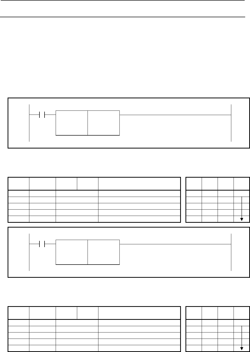
4.LADDER LANGUAGE
B-64513EN/03
- 484 -
4.10.9
NUMEB (Definition of Binary Constants: SUB 40)
This instruction defines 1, 2, or 4 bytes long binary constant. Data entered in decimal during programming
is converted into binary data during program execution. The binary data is stored in the specified memory
address(es).
There are two specifications - basic specification and extended specification - for setting the format
specification parameter in the NUMEB instruction. The extended specification allows all the set constants
to be defined simultaneously in an array having n elements. This extended specification is effective when
initializing a large memory area with value. For the details of the setting of a format specification parameter,
see the description of parameters.
Format
Figs. 4.10.9 (a) and (b) show the ladder formats and Tables 4.10.9 (a) and (b) show the mnemonic formats.
ACT
SUB 40
NUMEB
{ Format specification
{{{{ Constant
{{{{ Constant output address
Fig. 4.10.9 (a) Format of NUMEB instruction (basic specification)
Table 4.10.9 (a) Mnemonic of NUMEB instruction (basic specification)
Mnemonic format Memory status of control
condition
Step
number Instruction Address
No. Bit No. Remarks ST3 ST2 ST1 ST0
1 RD {{{{ .{ ACT ACT
2 SUB 40 NUMEB instruction
3 (PRM) { Format specification
4 (PRM) {{{{ Constant
5 (PRM) {{{{ Constant output address
ACT
SUB 40
NUMEB 0 Format specification
{{{{ Constant
{{{{ Constant output address
Fig. 4.10.9 (b) Format of NUMEB instruction (extended specification)
Table 4.10.9 (b) Mnemonic of NUMEB instruction (extended specification)
Mnemonic format Memory status of control
condition
Step
number Instruction Address
No. Bit No. Remarks ST3 ST2 ST1 ST0
1 RD {{{{ .{ ACT ACT
2 SUB 40 NUMEB instruction
3 (PRM) 0 Format specification
4 (PRM) {{{{ Constant
5 (PRM) {{{{ Constant output address

B-64513EN/03
4.LADDER LANGUAGE
- 485 -
Control conditions
(a) Command (ACT)
ACT=0: Do not execute NUMEB.
ACT=1: Execute NUMEB.
Parameters
(a) Format specification
Specify data length (1, 2, or 4 bytes).
Use the first parameter digit to specify byte length:
0001: Binary data of 1 byte length
0002: Binary data of 2 bytes length
0004: Binary data of 4 bytes length
When setting format specification in the following extended format, NUMEB can define all the set
constants simultaneously in an array having nn elements.
Specify data length (1, 2, or 4) to the 1st digit as above-mentioned.
Specify the number of the array in which is a constant to the 2nd and 3rd digit is defines.
Specify 0 to the 4th digit.
0nn1: In case of defining multiple (nn) data by 1 byte length
0nn2: In case of defining multiple (nn) data by 2 bytes length
0nn4: In case of defining multiple (nn) data by 4 bytes length
The n is the numerical value from 02 to 99. When setting 00 or 01, it works as the basic specification
that works for one data.
Format specification (extended specification):
0nnx
The byte length setting of constant
1: 1 byte length
2: 2 byte length
4: 4 byte length
Number of data in the array
00-01 :
It defines constant at 1 memory.
02-99 :
It defines constants at multiple (nn) memory.
CAUTION
Do not set an illegal value, that is not indicated above, into the "(a) Format
specification".
(b) Constant
Define constants in decimal format. Set a constant data within the effective range for the byte length
which is set in above (a).
(c) Constant output address
Specify the address of the area for output of the binary data. The memory of the number of bytes
which is set in above (a) is necessary.
When setting format specification in the extended format, it is necessary to reserve memory of (byte
length) × (number of array elements which define constant) which was set in above (a).
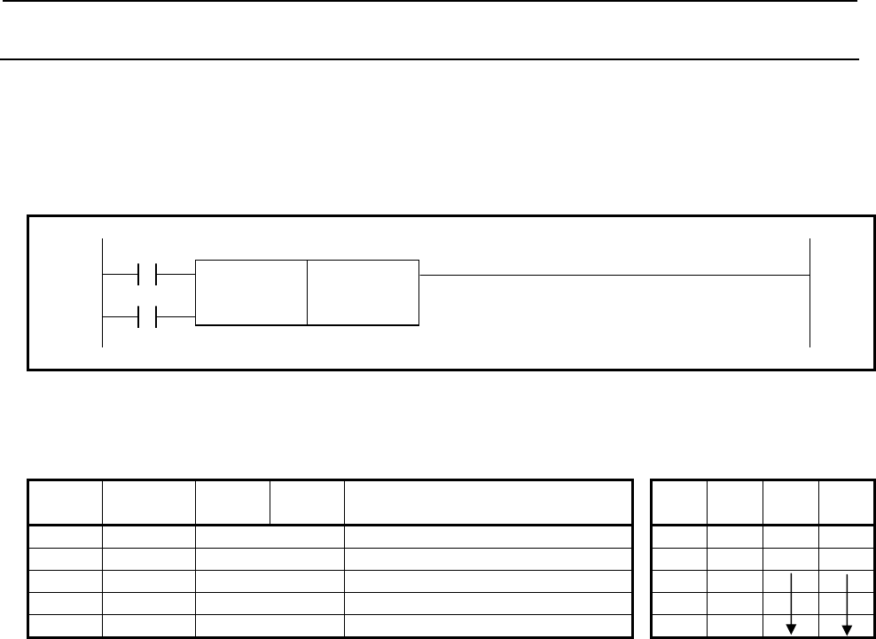
4.LADDER LANGUAGE
B-64513EN/03
- 486 -
4.10.10
NUME (BCD Definition of Constant: SUB 23)
This instruction defines constant of BCD type. Specified constant is set in specified constant output
address.
Format
Fig. 4.10.10 shows the ladder format and Table 4.10.10 shows the mnemonic format.
BYT
SUB 23
ACT NUME
{{{{ Constant
{{{{ Constant output address
Fig. 4.10.10 Format of NUME instruction
Table 4.10.10 Mnemonic of NUME instruction
Mnemonic format Memory status of control
condition
Step
number Instruction Address
No. Bit No. Remarks ST3 ST2 ST1 ST0
1 RD {{{{ .{ BYT BYT
2 RD.STK {{{{ .{ ACT BYT ACT
3 SUB 23 NUME instruction
4 (PRM) {{{{ Constant
5 (PRM) {{{{ Constant output address
Control conditions
(a) Specify the number of digits of a constant. (BYT)
BYT=0: Constant is BCD 2 digits long.
BYT=1: Constant is BCD 4 digits long.
(b) Execution command (ACT)
ACT=0: The NUME instruction is not executed.
ACT=1: The NUME instruction is executed.
Parameters
(a) Constant
Specify the constant as the number of digits specified for control condition (a).
(b) Constant output address
Specify the address to which the constant defined in parameter (a) is output.
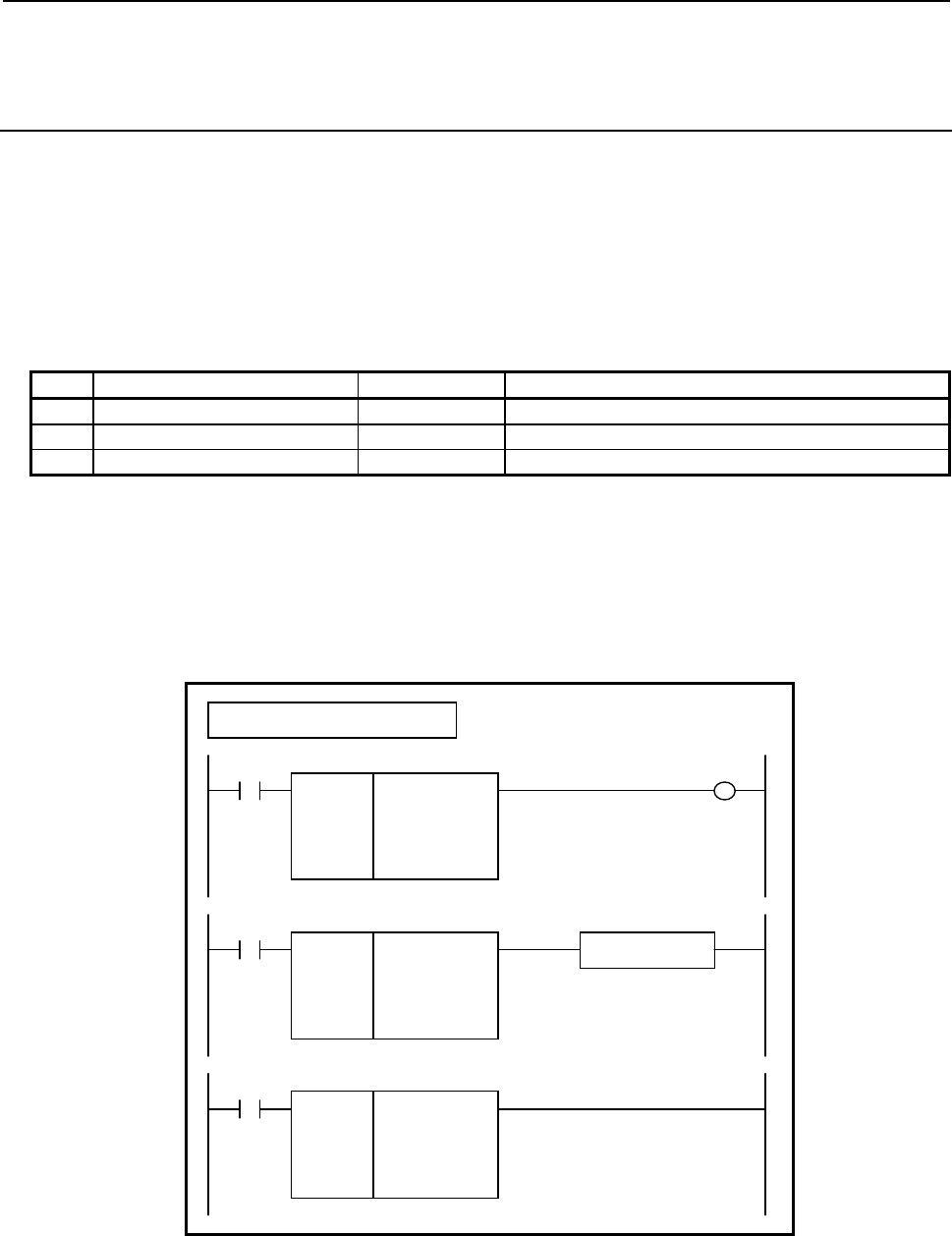
B-64513EN/03
4.LADDER LANGUAGE
- 487 -
4.10.11
ADDSB (Addition (1 Byte Length) : SUB 319)
ADDSW (Addition (2 Bytes Length) : SUB 320)
ADDSD (Addition (4 Bytes Length) : SUB 321)
The Addition instruction adds signed binary data.
In "Augend data" and "Addend data", a constant or a PMC memory address for storing data can be
specified.
As indicated below, three types of Addition instructions are available according to the type of data to be
operated. In each instruction, "Augend data", "Addend data", and the data at "Result output address" are of
the same data type.
Table4.10.11 (a) Kinds of Addition instruction
Instruction name SUB No. Data type
1 ADDSB 319 1 byte length signed binary data
2 ADDSW 320 2 bytes length signed binary data
3 ADDSD 321 4 bytes length signed binary data
If an operation results in a positive overflow, the maximum value of each data type is output to "Result
output address", and W1=0 is set.
If an operation results in a negative overflow, the minimum value of each data type is output to "Result
output address", and W1=0 is set.
Format
Fig. 4.10.11 shows the ladder format and Table 4.10.11(b) shows the mnemonic format.
SUB 319
A
DDSB
{{{{
{{{{
{{{{
ACT
Example : ADDSB Instruction
SUB 319
A
DDSB
{{{{
{{{{
{{{{
A
ugend data (Address or Constant)
A
ddend data (Address or Constant)
Result output address
ACT W1
SUB 319
A
DDSB
{{{{
{{{{
{{{{
Functional Instruction
ACT ACT2
Fig. 4.10.11 Format of ADDSB, ADDSW, ADDSD instruction

4.LADDER LANGUAGE
B-64513EN/03
- 488 -
Table 4.10.11(b) Mnemonic of ADDSB, ADDSW, ADDSD instruction
Mnemonic format
Memory status of control
condition
Step
number Instruction Address
No. Bit No. Remarks
ST3 ST2 ST1 ST0
1 RD {{{{ .{ ACT ACT
2 SUB 319 SUB No. (ADDSB instruction)
3 (PRM) {{{{ Augend data (Address or Constant)
4 (PRM) {{{{ Addend data (Address or Constant)
5 (PRM) {{{{ Result output address
6 WRT {{{{ .{ Normal end output W1
Control conditions
(a) Input signal (ACT)
ACT = 0: Instruction not executed.
ACT = 1: Executed.
Parameters
(a) Augend data
Specify an augend for addition operation. In this parameter, a constant or a PMC memory address for
storing data can be specified.
(b) Addend data
Specify an addend for addition operation. In this parameter, a constant or a PMC memory address for
storing data can be specified.
(c) Result output address
Specify the address to which the result of operation is to be output.
Output (W1)
W1=1: The operation is terminated normally.
W1=0: No operation is executed. (ACT=0)
The operation results in an overflow.
NOTE
1 W1 may be omitted. Moreover, another functional instruction can be connected
instead of a coil.
2 With the similar functional instruction ADDB, W1=1 is set when an operation is
terminated abnormally. With ADDSB, ADDSW, and ADDSD, W1=1 is set when
an operation is terminated normally.
3 No data is output to the operation output registers (R9000, Z0).

B-64513EN/03
4.LADDER LANGUAGE
- 489 -
4.10.12
SUBSB (Subtraction (1 Byte Length) : SUB 322)
SUBSW (Subtraction (2 Bytes Length) : SUB 323)
SUBSD (Subtraction (4 Bytes Length) : SUB 324)
The Subtraction instruction subtracts signed binary data.
In "Minuend" and "Subtrahend", a constant or a PMC memory address for storing data can be specified.
As indicated below, three types of Subtraction instructions are available according to the type of data to be
operated. In each instruction, "Minuend", "Subtrahend", and the data at "Result output address" are of the
same data type.
Table4.10.12 (a) Kinds of Subtraction instruction
Instruction name SUB No. Data type
1 SUBSB 322 1 byte length signed binary data
2 SUBSW 323 2 bytes length signed binary data
3 SUBSD 324 4 bytes length signed binary data
If an operation results in a positive overflow, the maximum value of each data type is output to "Result
output address", and W1=0 is set.
If an operation results in a negative overflow, the minimum value of each data type is output to "Result
output address", and W1=0 is set.
Format
Fig. 4.10.12 shows the ladder format and Table 4.10.12(b) shows the mnemonic format.
SUB 322
SUBSB
{{{{
{{{{
{{{{
ACT
Example : SUBSB Instruction
SUB 322
SUBSB
{{{{
{{{{
{{{{
Minuend (Address or Constant)
Subtrahend (Address or Constant)
Result output address
ACT W1
SUB 322
SUBSB
{{{{
{{{{
{{{{
Functional Instruction
ACT ACT2
Fig. 4.10.12 Format of SUBSB, SUBSW, SUBSD instruction
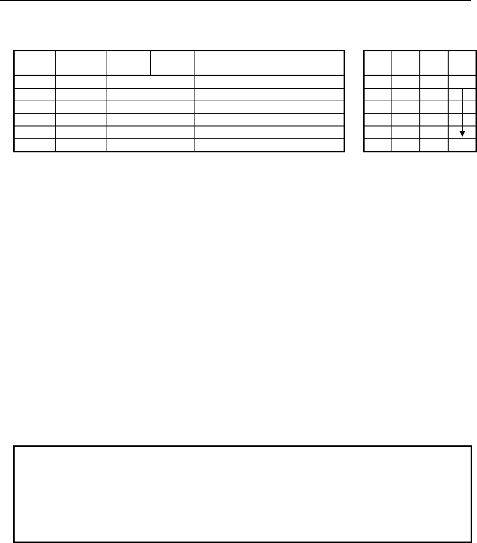
4.LADDER LANGUAGE
B-64513EN/03
- 490 -
Table 4.10.12(b) Mnemonic of SUBSB, SUBSW, SUBSD instruction
Mnemonic format
Memory status of control
condition
Step
number Instruction Address
No. Bit No. Remarks
ST3 ST2 ST1 ST0
1 RD {{{{ .{ ACT ACT
2 SUB 322 SUB No. (SUBSB instruction)
3 (PRM) {{{{ Minuend (Address or Constant)
4 (PRM) {{{{ Subtrahend (Address or Constant)
5 (PRM) {{{{ Result output address
6 WRT {{{{ .{ Normal end output W1
Control conditions
(a) Input signal (ACT)
ACT = 0: Instruction not executed.
ACT = 1: Executed.
Parameters
(a) Minuend
Specify a minuend for subtraction operation. In this parameter, a constant or a PMC memory address
for storing data can be specified.
(b) Subtrahend
Specify a subtrahend for subtraction operation. In this parameter, a constant or a PMC memory
address for storing data can be specified.
(c) Result output address
Specify the address to which the result of operation is to be output.
Output (W1)
W1=1: The operation is terminated normally.
W1=0: No operation is executed. (ACT=0)
The operation results in an overflow.
NOTE
1 W1 may be omitted. Moreover, another functional instruction can be connected
instead of a coil.
2 With the similar functional instruction SUBB, W1=1 is set when an operation is
terminated abnormally. With SUBSB, SUBSW, and SUBSD, W1=1 is set when an
operation is terminated normally.
3 No data is output to the operation output registers (R9000, Z0).
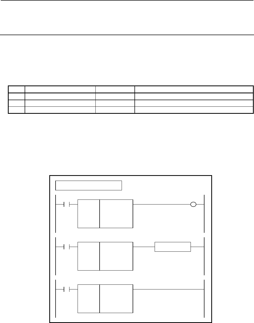
B-64513EN/03
4.LADDER LANGUAGE
- 491 -
4.10.13
MULSB (Multiplication (1 Byte Length) : SUB 325)
MULSW (Multiplication (2 Bytes Length) : SUB 326)
MULSD (Multiplication (4 Bytes Length) : SUB 327)
The Multiplication instruction multiplies signed binary data.
In "Multiplicand" and "Multiplier", a constant or a PMC memory address for storing data can be specified.
As indicated below, three types of Multiplication instructions are available according to the type of data to
be operated. In each instruction, "Multiplicand", "Multiplier", and the data at "Result output address" are of
the same data type.
Table 4.10.13 (a) Kinds of Multiplication instruction
Instruction name SUB No. Data type
1 MULSB 325 1 byte length signed binary data
2 MULSW 326 2 bytes length signed binary data
3 MULSD 327 4 bytes length signed binary data
If an operation results in a positive overflow, the maximum value of each data type is output to "Result
output address", and W1=0 is set.
If an operation results in a negative overflow, the minimum value of each data type is output to "Result
output address", and W1=0 is set.
Format
Fig. 4.10.13 shows the ladder format and Table 4.10.13(b) shows the mnemonic format.
SUB 325
MULSB
{{{{
{{{{
{{{{
ACT
Example : MULSB Instruction
SUB 325
MULSB
{{{{
{{{{
{{{{
Multiplicand (Address or Constant)
Multiplier (Address or Constant)
Result output address
ACT W1
SUB 325
MULSB
{{{{
{{{{
{{{{
Functional Instruction
ACT ACT2
Fig. 4.10.13 Format of MULSB, MULSW, MULSD instruction

4.LADDER LANGUAGE
B-64513EN/03
- 492 -
Table 4.10.13(b) Mnemonic of MULSB, MULSW, MULSD instruction
Mnemonic format
Memory status of control
condition
Step
number Instruction Address
No. Bit No. Remarks
ST3 ST2 ST1 ST0
1 RD {{{{ .{ ACT ACT
2 SUB 325 SUB No. (MULSB instruction)
3 (PRM) {{{{ Multiplicand (Address or Constant)
4 (PRM) {{{{ Multiplier (Address or Constant)
5 (PRM) {{{{ Result output address
6 WRT {{{{ .{ Normal end output W1
Control conditions
(a) Input signal (ACT)
ACT = 0: Instruction not executed.
ACT = 1: Executed.
Parameters
(a) Multiplicand
Specify a multiplicand for multiplication operation. In this parameter, a constant or a PMC memory
address for storing data can be specified.
(b) Multiplier
Specify a multiplier for multiplication operation. In this parameter, a constant or a PMC memory
address for storing data can be specified.
(c) Result output address
Specify the address to which the result of operation is to be output.
Output (W1)
W1=1: The operation is terminated normally.
W1=0: No operation is executed. (ACT=0)
The operation results in an overflow.
NOTE
1 W1 may be omitted. Moreover, another functional instruction can be connected
instead of a coil.
2 With the similar functional instruction MULB, W1=1 is set when an operation is
terminated abnormally. With MULSB, MULSW, and MULSD, W1=1 is set when
an operation is terminated normally.
3 No data is output to the operation output registers (R9000, Z0).

B-64513EN/03
4.LADDER LANGUAGE
- 493 -
4.10.14
DIVSB (Division (1 Byte Length) : SUB 328)
DIVSW (Division (2 Bytes Length) : SUB 329)
DIVSD (Division (4 Bytes Length) : SUB 330)
The Division instruction divides signed binary data.
In "Dividend" and "Divisor", a constant or a PMC memory address for storing data can be specified.
As indicated below, three types of Division instructions are available according to the type of data to be
operated. In each instruction, "Dividend", "Divisor", and the data at "Result output address" are of the same
data type.
Table 4.10.14 (a) Kinds of Division instruction
Instruction name SUB No. Data type
1 DIVSB 328 1 byte length signed binary data
2 DIVSW 329 2 bytes length signed binary data
3 DIVSD 330 4 bytes length signed binary data
If an operation results in an overflow, the maximum value of each data type is output to "Result output
address", and W1=0 is set.
If the divisor is 0, and the dividend is 0 or a positive value, the maximum value of each data type is output
to "Result output address", and W1=0 is set.
If the divisor is 0, and the dividend is a negative value, the minimum value of each data type is output to
"Result output address", and W1=0 is set.
Format
Fig. 4.10.14 shows the ladder format and Table 4.10.14(b) shows the mnemonic format.
SUB 328
DIVSB
{{{{
{{{{
{{{{
ACT
Example : DIVSB Instruction
SUB 328
DIVSB
{{{{
{{{{
{{{{
Dividend (Address or Constant)
Divisor (Address or Constant)
Result output address
ACT W1
SUB 328
DIVSB
{{{{
{{{{
{{{{
Functional Instruction
ACT ACT2
Fig. 4.10.14 Format of DIVSB, DIVSW, DIVSD instruction
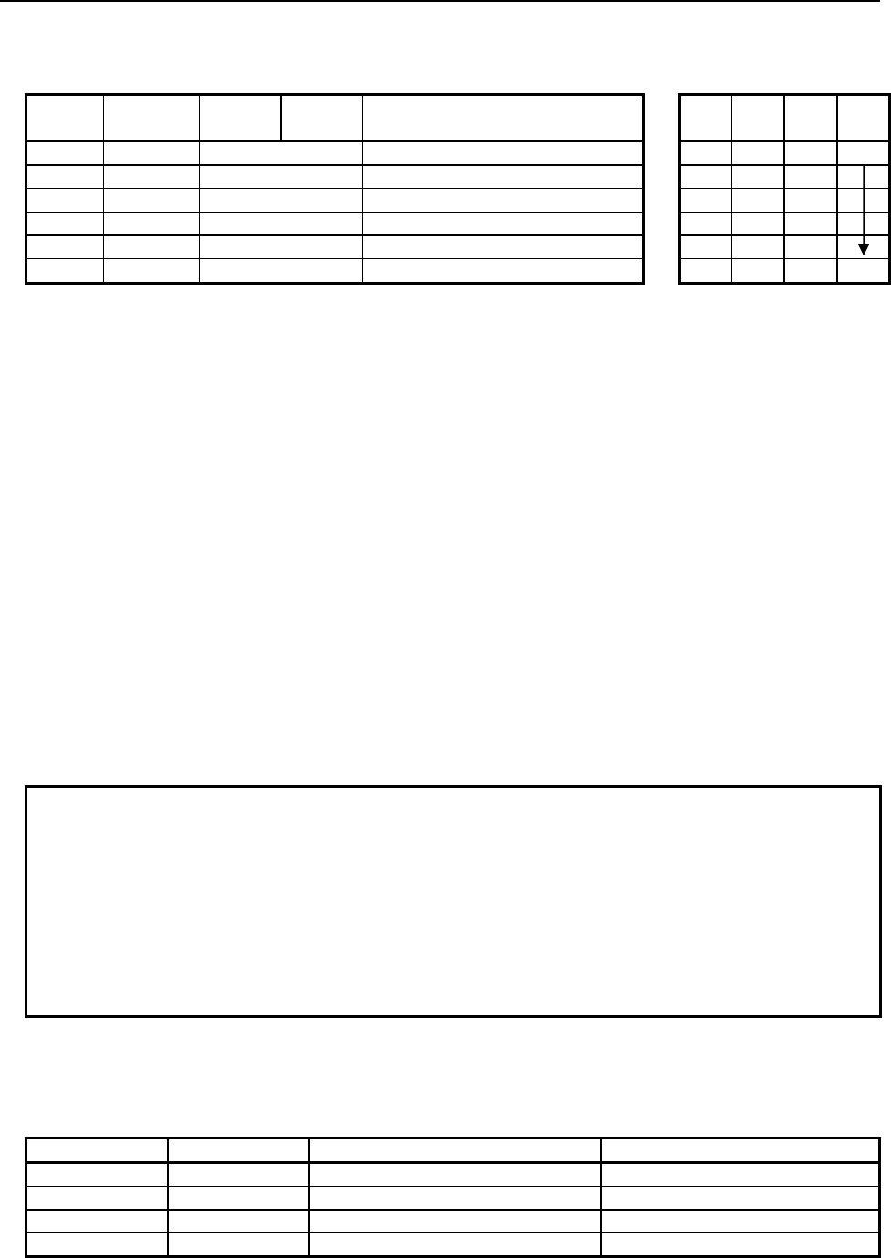
4.LADDER LANGUAGE
B-64513EN/03
- 494 -
Table 4.10.14(b) Mnemonic of DIVSB, DIVSW, DIVSD instruction
Mnemonic format
Memory status of control
condition
Step
number Instruction Address
No. Bit No. Remarks
ST3 ST2 ST1 ST0
1 RD {{{{ .{ ACT ACT
2 SUB 328 SUB No. (DIVSB instruction)
3 (PRM) {{{{ Dividend (Address or Constant)
4 (PRM) {{{{ Divisor (Address or Constant)
5 (PRM) {{{{ Result output address
6 WRT {{{{ .{ Normal end output W1
Control conditions
(a) Input signal (ACT)
ACT = 0: Instruction not executed.
ACT = 1: Executed.
Parameters
(a) Dividend
Specify a dividend for division operation. In this parameter, a constant or a PMC memory address for
storing data can be specified.
(b) Divisor
Specify a divisor for division operation. In this parameter, a constant or a PMC memory address for
storing data can be specified.
(c) Result output address
Specify the address to which the result of operation is to be output.
Output (W1)
W1=1: The operation is terminated normally.
W1=0: No operation is executed. (ACT=0)
The divisor is 0, or the operation results in an overflow.
NOTE
1 W1 may be omitted. Moreover, another functional instruction can be connected
instead of a coil.
2 With the similar functional instruction DIVB, W1=1 is set when an operation is
terminated abnormally. With DIVSB, DIVSW, and DIVSD, W1=1 is set when an
operation is terminated normally.
3 No data is output to the operation output registers (R9000, Z0).
4 No data is output to the remainder output addresses (R9002-R9005, Z2-Z5). To
calculate remainder data, use the MODSB, MODSW, or MODSD instruction.
Operation
The result of each operation depends on the signs of the dividend and divisor as indicated below.
Table 4.10.14 (c) State of sign in division operation (example)
Dividend Divisor Result of DIVSx Instruction Result of MODSx Instruction
20 3 6 2
20 -3 -6 2
-20 3 -6 -2
-20 -3 6 -2
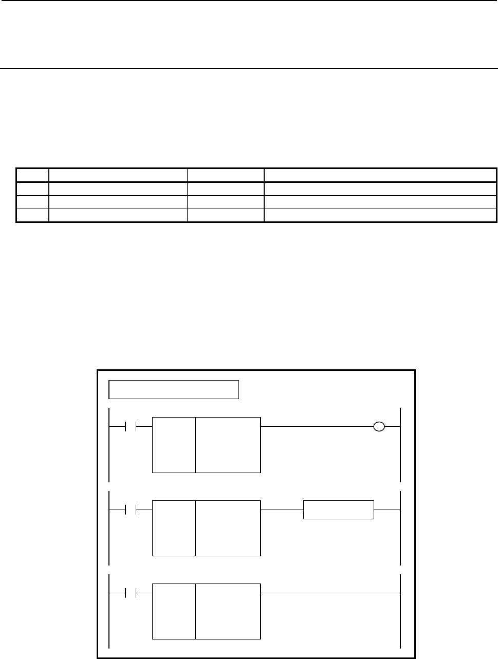
B-64513EN/03
4.LADDER LANGUAGE
- 495 -
4.10.15
MODSB (Remainder (1 Byte Length) : SUB 331)
MODSW (Remainder (2 Bytes Length) : SUB 332)
MODSD (Remainder (4 Bytes Length) : SUB 333)
The Remainder instruction divides signed binary data and calculates remainder data.
In "Dividend" and "Divisor", a constant or a PMC memory address for storing data can be specified.
As indicated below, three types of Remainder instructions are available according to the type of data to be
operated. In each instruction, "Dividend", "Divisor", and the data at "Result output address" are of the same
data type.
Table 4.10.15 (a) Kinds of Remainder instruction
Instruction name SUB No. Data type
1 MODSB 331 1 byte length signed binary data
2 MODSW 332 2 bytes length signed binary data
3 MODSD 333 4 bytes length signed binary data
If the quotient of a division operation results in an overflow (if "Dividend" is the minimum value of each
data type or the divisor is -1), 0 is output to "Result output address", and W1=1 is set.
If "Divisor" is 0, and "Dividend" is 0 or a positive value, the maximum value of each data type is output to
"Result output address", and W1=0 is set.
If "Divisor" is 0, and "Dividend" is a negative value, the minimum value of each data type is output to
"Result output address", and W1=0.
Format
Fig. 4.10.15 shows the ladder format and Table 4.10.15(b) shows the mnemonic format.
SUB 331
MODSB
{{{{
{{{{
{{{{
ACT
Example : MODSB Instruction
SUB 331
MODSB
{{{{
{{{{
{{{{
Dividend (Address or Constant)
Divisor (Address or Constant)
Result output address
ACT W1
SUB 331
MODSB
{{{{
{{{{
{{{{
Functional Instruction
ACT ACT2
Fig. 4.10.15 Format of MODSB, MODSW, MODSD instruction
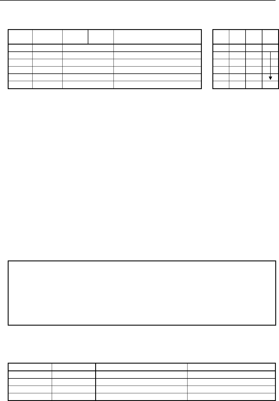
4.LADDER LANGUAGE
B-64513EN/03
- 496 -
Table 4.10.15(b) Mnemonic of MODSB, MODSW, MODSD instruction
Mnemonic format
Memory status of control
condition
Step
number Instruction Address
No. Bit No. Remarks
ST3 ST2 ST1 ST0
1 RD {{{{ .{ ACT ACT
2 SUB 331 SUB No. (MODSB instruction)
3 (PRM) {{{{ Dividend (Address or Constant)
4 (PRM) {{{{ Divisor (Address or Constant)
5 (PRM) {{{{ Result output address
6 WRT {{{{ .{ Normal end output W1
Control conditions
(a) Input signal (ACT)
ACT = 0: Instruction not executed.
ACT = 1: Executed.
Parameters
(a) Dividend
Specify a dividend for remainder operation. In this parameter, a constant or a PMC memory address
for storing data can be specified.
(b) Divisor
Specify a divisor for remainder operation. In this parameter, a constant or a PMC memory address for
storing data can be specified.
(c) Result output address
Specify the address to which the result of operation is to be output.
Output (W1)
W1=1: The operation is terminated normally.
W1=0: No operation is executed. (ACT=0)
The divisor is 0.
NOTE
1 W1 may be omitted. Moreover, another functional instruction can be connected
instead of a coil.
2 With the similar functional instruction DIVB, W1=1 is set when an operation is
terminated abnormally. With MODSB, MODSW, and MODSD, W1=1 is set when
an operation is terminated normally.
3 No data is output to the operation output registers (R9000, Z0).
4 No data is output to the remainder output addresses (R9002-R9005, Z2-Z5).
Operation
The result of each operation depends on the signs of the dividend and divisor as indicated below.
Table 4.10.15 (c) State of sign in division operation (example)
Dividend Divisor Result of DIVSx Instruction Result of MODSx Instruction
20 3 6 2
20 -3 -6 2
-20 3 -6 -2
-20 -3 6 -2

B-64513EN/03
4.LADDER LANGUAGE
- 497 -
4.10.16
INCSB (Increment (1 Byte Length) : SUB 334)
INCSW (Increment (2 Bytes Length) : SUB 335)
INCSD (Increment (4 Bytes Length) : SUB 336)
The Increment instruction increments signed binary data by 1.
As indicated below, three types of Increment instructions are available according to the type of data to be
operated.
Table 4.10.16 (a) Kinds of Increment instruction
Instruction name SUB No. Data type
1 INCSB 334 1 byte length signed binary data
2 INCSW 335 2 bytes length signed binary data
3 INCSD 336 4 bytes length signed binary data
If the Increment instruction is executed when data to be operated is the maximum value of a data type, the
data to be operated remains unchanged from the maximum value, and W1=0 is set.
For example, if data to be operated by the INCSW instruction is 32767, the data remains unchanged from
32767 as the result of operation, and W1=0 is set.
Format
Fig. 4.10.16 shows the ladder format and Table 4.10.16(b) shows the mnemonic format.
SUB 334
INCSB
{{{{
ACT
Example : INCSB Instruction
SUB 334
INCSB
{{{{
Data address
ACT W1
SUB 334
INCSB
{{{{
Functional Instruction
ACT ACT2
Fig. 4.10.16 Format of INCSB, INCSW, INCSD instruction

4.LADDER LANGUAGE
B-64513EN/03
- 498 -
Table 4.10.16(b) Mnemonic of INCSB, INCSW, INCSD instruction
Mnemonic format
Memory status of control
condition
Step
number Instruction Address
No. Bit No. Remarks
ST3 ST2 ST1 ST0
1 RD {{{{ .{ ACT ACT
2 SUB 334 SUB No. (INCSB instruction)
3 (PRM) {{{{ Data address
4 WRT {{{{ .{ Normal end output W1
Control conditions
(a) Input signal (ACT)
ACT = 0: Instruction not executed.
ACT = 1: Executed.
Parameters
(a) Data address
Specify the PMC memory address the value at which is to be incremented.
Output (W1)
W1=1: The operation is terminated normally.
W1=0: No operation is executed. (ACT=0)
The operation results in an overflow.
NOTE
W1 may be omitted. Moreover, another functional instruction can be connected
instead of a coil.
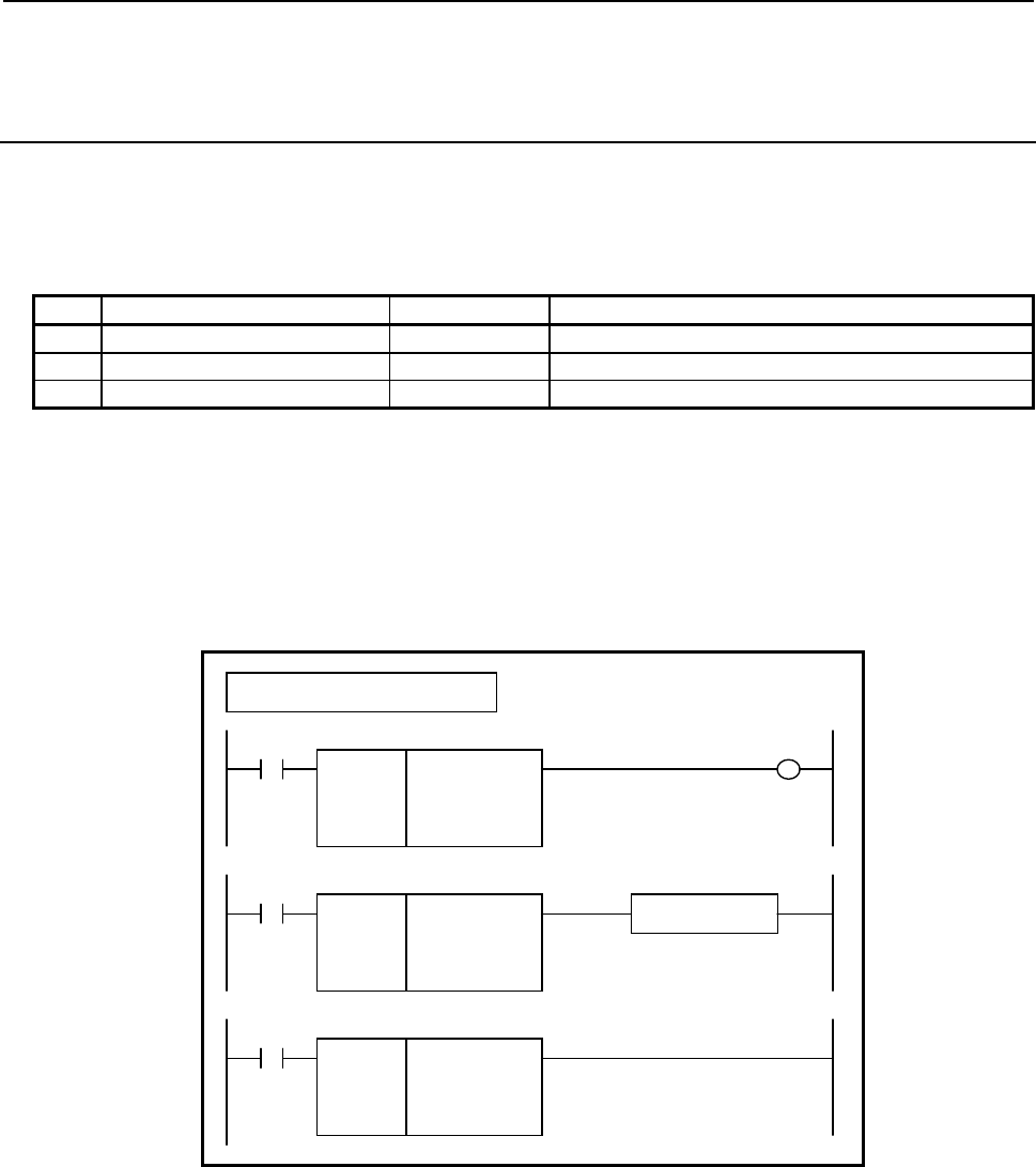
B-64513EN/03
4.LADDER LANGUAGE
- 499 -
4.10.17
DECSB (Decrement (1 Byte Length) : SUB 337)
DECSW (Decrement (2 Bytes Length) : SUB 338)
DECSD (Decrement (4 Bytes Length) : SUB 339)
The Decrement instruction decrements signed binary data by 1.
As indicated below, three types of Decrement instructions are available according to the type of data to be
operated.
Table 4.10.17 (a) Kinds of Decrement instruction
Instruction name SUB No. Data type
1 DECSB 337 1 byte length signed binary data
2 DECSW 338 2 bytes length signed binary data
3 DECSD 339 4 bytes length signed binary data
If the Decrement instruction is executed when data to be operated is the minimum value of a data type, the
data to be operated remains unchanged from the minimum value, and W1=0 is set.
For example, if data to be operated by the DECSW instruction is -32768, the data remains unchanged from
-32768 as the result of operation, and W1=0 is set.
Format
Fig. 4.10.17 shows the ladder format and Table 4.10.17(b) shows the mnemonic format.
SUB 337
DECSB
{{{{
ACT
Example : DECSB Instruction
SUB 337
DECSB
{{{{
Data address
ACT W1
SUB 337
DECSB
{{{{
Functional Instruction
ACT ACT2
Fig. 4.10.17 Format of DECSB, DECSW, DECSD instruction
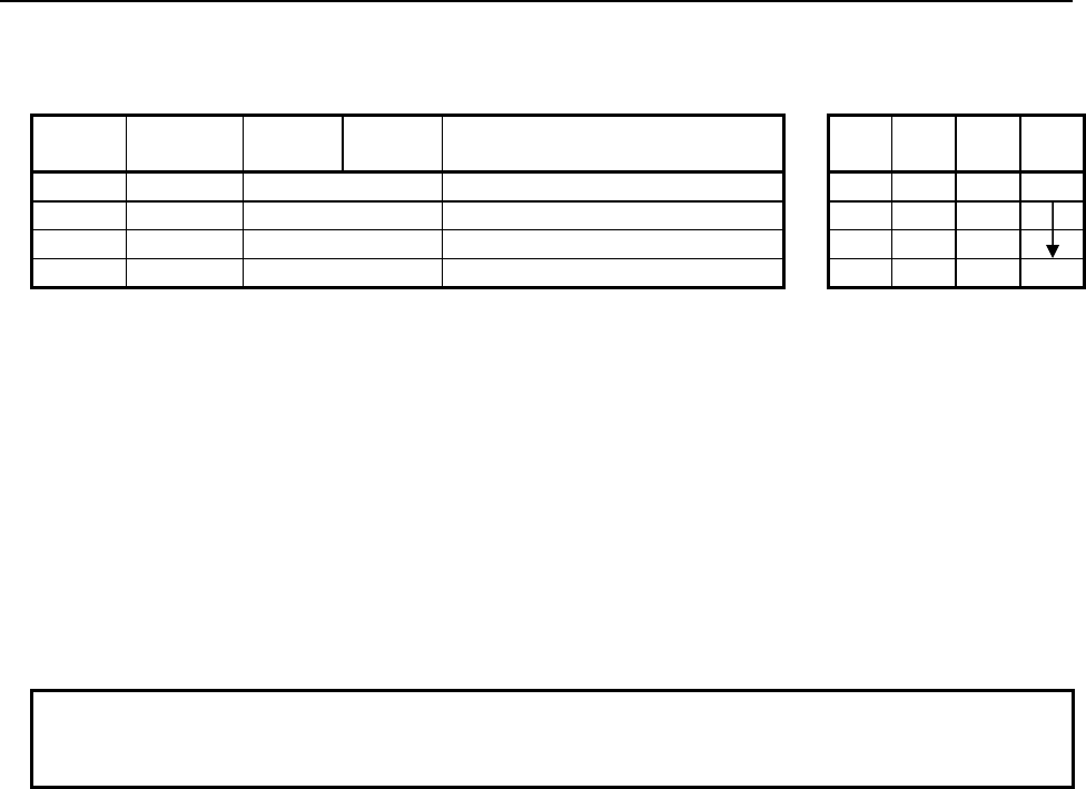
4.LADDER LANGUAGE
B-64513EN/03
- 500 -
Table 4.10.17(b) Mnemonic of DECSB, DECSW, DECSD instruction
Mnemonic format
Memory status of control
condition
Step
number Instruction Address
No. Bit No. Remarks
ST3 ST2 ST1 ST0
1 RD {{{{ .{ ACT ACT
2 SUB 337 SUB No. (DECSB instruction)
3 (PRM) {{{{ Data address
4 WRT {{{{ .{ Normal end output W1
Control conditions
(a) Input signal (ACT)
ACT = 0: Instruction not executed.
ACT = 1: Executed.
Parameters
(a) Data address
Specify the PMC memory address the value at which is to be decremented.
Output (W1)
W1=1: The operation is terminated normally.
W1=0: No operation is executed. (ACT=0)
The operation results in an overflow.
NOTE
W1 may be omitted. Moreover, another functional instruction can be connected
instead of a coil.

B-64513EN/03
4.LADDER LANGUAGE
- 501 -
4.10.18
ABSSB (Absolute Value (1 Byte Length) : SUB 340)
ABSSW (Absolute Value (2 Bytes Length) : SUB 341)
ABSSD (Absolute Value (4 Bytes Length) : SUB 342)
The Absolute value instruction calculates the absolute value of signed binary data.
In "Source data", a constant or a PMC memory address for storing data can be specified.
As indicated below, three types of Absolute value instructions are available according to the type of data to
be operated. In each instruction, "Source data" and the data at "Result output address" are of the same data
type.
Table 4.10.18 (a) Kinds of Absolute value instruction
Instruction name SUB No. Data type
1 ABSSB 340 1 byte length signed binary data
2 ABSSW 341 2 bytes length signed binary data
3 ABSSD 342 4 bytes length signed binary data
If an operation results in an overflow (if the minimum value of a data type is converted), the maximum
value of the data type is output to "Result output address", and W1=0 is set.
Format
Fig. 4.10.18 shows the ladder format and Table 4.10.18(b) shows the mnemonic format.
SUB 340
A
BSSB
{{{{
{{{{
ACT
Example : ABSSB Instruction
SUB 340
A
BSSB
{{{{
{{{{
Source data (Address or Constant)
Result output address
ACT W1
SUB 340
A
BSSB
{{{{
{{{{
Functional Instruction
ACT ACT2
Fig. 4.10.18 Format of ABSSB, ABSSW, ABSSD instruction
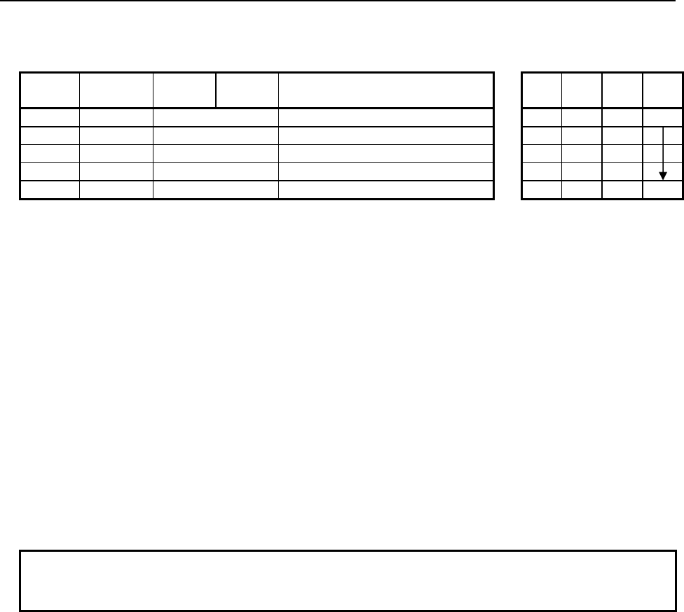
4.LADDER LANGUAGE
B-64513EN/03
- 502 -
Table 4.10.18(b) Mnemonic of ABSSB, ABSSW, ABSSD instruction
Mnemonic format
Memory status of control
condition
Step
number Instruction Address
No. Bit No. Remarks
ST3 ST2 ST1 ST0
1 RD {{{{ .{ ACT ACT
2 SUB 340 SUB No. (ABSSB instruction)
3 (PRM) {{{{ Source data (Address or Constant)
4 (PRM) {{{{ Result output address
5 WRT {{{{ .{ Normal end output W1
Control conditions
(a) Input signal (ACT)
ACT = 0: Instruction not executed.
ACT = 1: Executed.
Parameters
(a) Source data
Specify source data to be converted to an absolute value. In this parameter, a constant or a PMC
memory address for storing data can be specified.
(b) Result output address
Specify the address to which the result of operation is to be output.
Output (W1)
W1=1: The operation is terminated normally.
W1=0: No operation is executed. (ACT=0)
The operation results in an overflow.
NOTE
W1 may be omitted. Moreover, another functional instruction can be connected
instead of a coil.
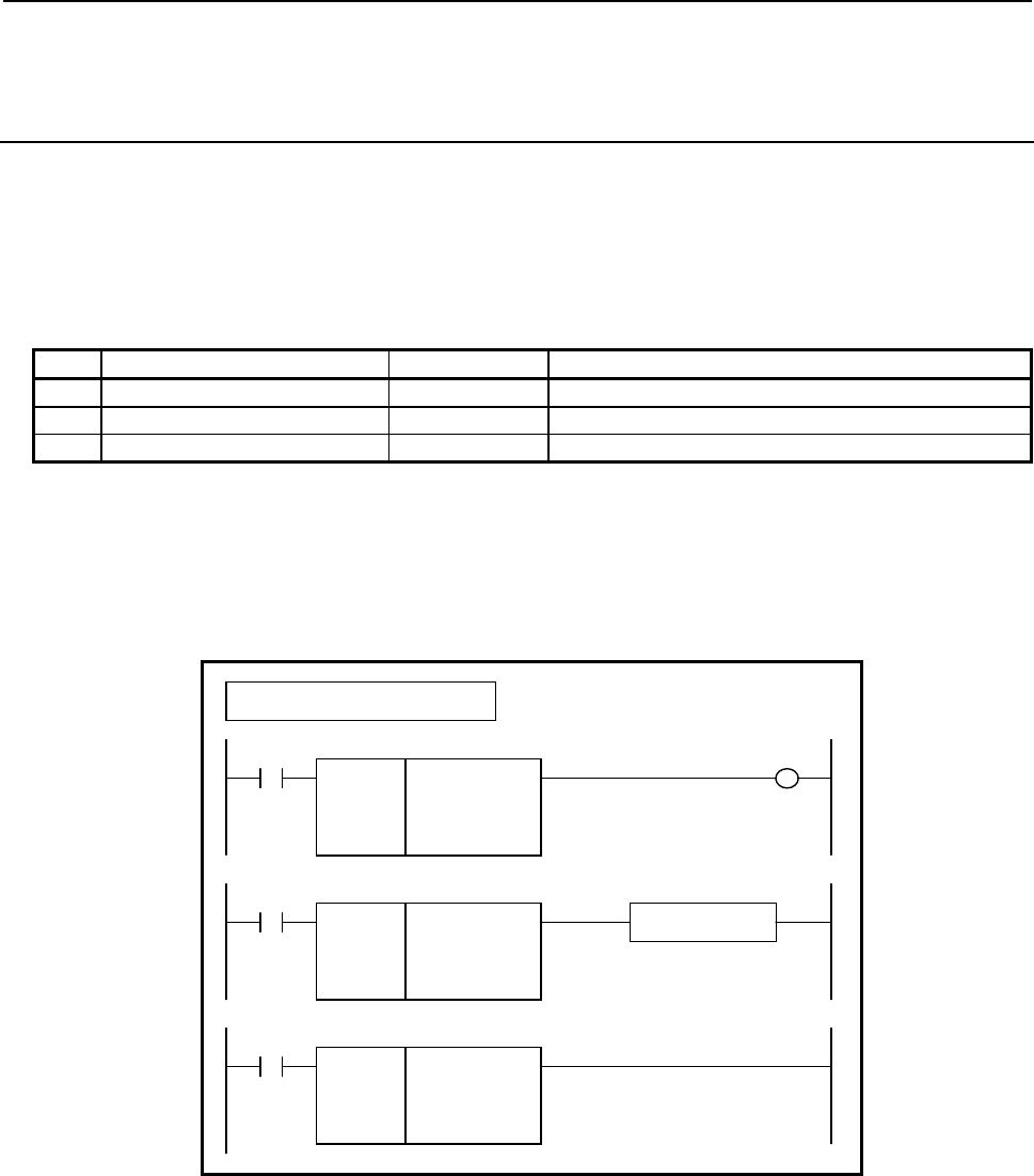
B-64513EN/03
4.LADDER LANGUAGE
- 503 -
4.10.19
NEGSB (Sign Inversion (1 Byte Length) : SUB 343)
NEGSW (Sign Inversion (2 Bytes Length) : SUB 344)
NEGSD (Sign Inversion (4 Bytes Length) : SUB 345)
The Sign inversion instruction inverts the sign of signed binary data.
In "Source data", a constant or a PMC memory address for storing data can be specified.
As indicated below, three types of Sign inversion instructions are available according to the type of data to
be operated. In each instruction, "Source data" and the data at "Result output address" are of the same data
type.
Table 4.10.19 (a) Kinds of Sign inversion instruction
Instruction name SUB No. Data type
1 NEGSB 343 1 byte length signed binary data
2 NEGSW 344 2 bytes length signed binary data
3 NEGSD 345 4 bytes length signed binary data
If an operation results in an overflow (if the minimum value of a data type is converted), the maximum
value of the data type is output to "Result output address", and W1=0 is set.
Format
Fig. 4.10.19 shows the ladder format and Table 4.10.19(b) shows the mnemonic format.
SUB 343
NEGSB
{{{{
{{{{
ACT
Example : NEGSB Instruction
SUB 343
NEGSB
{{{{
{{{{
Source data (Address or Constant)
Result output address
ACT W1
SUB 343
NEGSB
{{{{
{{{{
Functional Instruction
ACT ACT2
Fig. 4.10.19 Format of NEGSB, NEGSW, NEGSD instruction

4.LADDER LANGUAGE
B-64513EN/03
- 504 -
Table 4.10.19(b) Mnemonic of NEGSB, NEGSW, NEGSD instruction
Mnemonic format
Memory status of control
condition
Step
number Instruction Address
No. Bit No. Remarks
ST3 ST2 ST1 ST0
1 RD {{{{ .{ ACT ACT
2 SUB 343 SUB No. (NEGSB instruction)
3 (PRM) {{{{ Source data (Address or Constant)
4 (PRM) {{{{ Result output address
5 WRT {{{{ .{ Normal end output W1
Control conditions
(a) Input signal (ACT)
ACT = 0: Instruction not executed.
ACT = 1: Executed.
Parameters
(a) Source data
Specify source data whose sign is to be inverted. In this parameter, a constant or a PMC memory
address for storing data can be specified.
(b) Result output address
Specify the address to which the result of operation is to be output.
Output (W1)
W1=1: The operation is terminated normally.
W1=0: No operation is executed. (ACT=0)
The operation results in an overflow.
NOTE
W1 may be omitted. Moreover, another functional instruction can be connected
instead of a coil.

B-64513EN/03
4.LADDER LANGUAGE
- 505 -
4.11 INSTRUCTIONS RELATED TO CNC FUNCTIONS
The functions of the CNC can be used by means of the functional instructions of the PMC system. The
following types of instruction are available. Use any of these instructions as appropriate for your purpose.
Instruction name Sub number Processing
1 DISPB 41 Message display
2 EXIN 42 External data input
3 WINDR 51 Reading of CNC window data
4 WINDW 52 Writing of CNC window data
5 AXCTL 53 PMC axis control
6 PSGN2 63 Position signal
7 PSGNL 50 Position signal
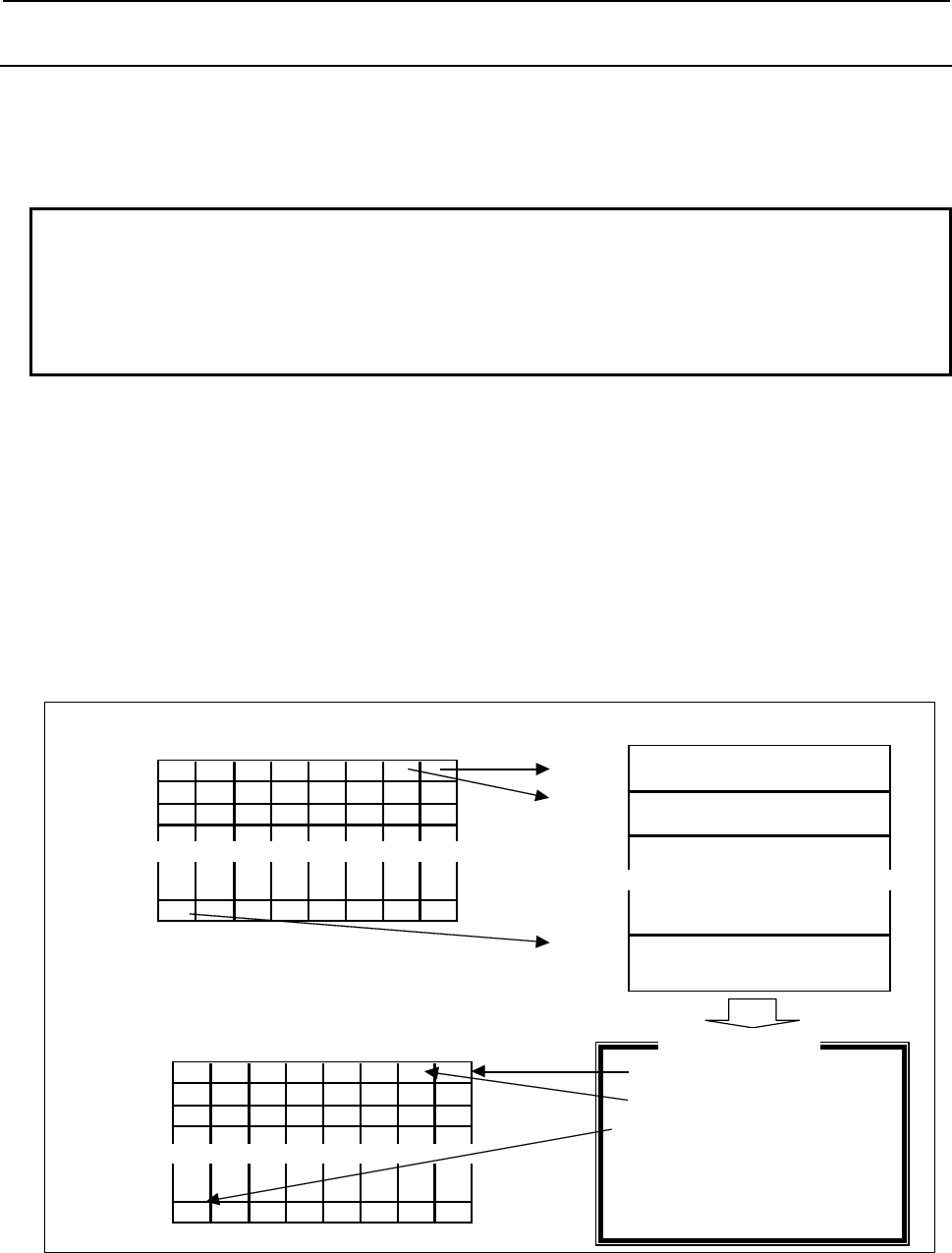
4.LADDER LANGUAGE
B-64513EN/03
- 506 -
4.11.1
DISPB (Display Message: SUB 41)
This instruction displays messages on the CNC screen. You can also specify the message number to
generate an alarm in the CNC.
You can program up to 6000 messages according to PMC memory type. You must use the special message
addresses in your program to simplify use of the messages. The following are the features of this function.
NOTE
1 To use this instruction requires that the external data input option or external
message option be set on the CNC side.
2 Program this instruction in the 2nd level, because it takes a lot of processing time.
3 This instruction cannot be used in the 1st level whose execution cycle is 1ms or
2ms. It is processed as an NOP instruction.
(a) In the program, specify 0 in the parameter and set ACT to 1. See Fig. 4.11.1 (a).
If you set any bit of the message display request memory (addresses A) to "1" when ACT = 1, the
instruction displays the message data defined in the message data table corresponding to that bit.
While the message is displayed, the bit of the message display status memory corresponding to that
message remains to be "1".
Even if multiple messages are requested simultaneously, the instruction does not necessarily display
all the requested messages. The number of messages that can be displayed simultaneously is
determined by the specifications of the CNC screen. For example, if the CNC is designed to display
up to four messages on its screen at a time, a fifth message cannot be displayed unless any of the four
currently displayed messages is cleared. This way, you can display the sixth and subsequent messages
as you clear the currently displayed messages one by one.
∼∼∼∼∼∼∼∼∼∼∼∼∼∼∼∼∼∼∼∼∼∼∼∼∼∼∼∼∼∼∼∼
7 6 5 4 3 2 1 0
A
0 0 0 0 0 0 0 1 1
A
1 0 0 0 0 0 0 0 0
A
2 0 0 0 0 0 0 0 0
|
|
|
A
249 1 0 0 0 0 0 0 0
∼∼∼∼∼∼∼∼∼∼∼∼∼∼∼∼∼∼∼∼∼∼∼∼∼∼∼∼∼∼∼∼∼∼∼∼
A
000.0 (Message data corresponding to
address A000.0)
A
000.1 (Message data corresponding to
address A000.1)
A
249.7 (Message data corresponding to
address A249.7)
xxxx:(Message of A000.0)
yyyy:(Message of A000.1)
zzzz:(Message of A249.7)
[ ] [ ] [ ] [ ] [ ]
7 6 5 4 3 2 1 0
A
9000 0 0 0 0 0 0 1 1
A
9001 0 0 0 0 0 0 0 0
A
9002 0 0 0 0 0 0 0 0
|
|
|
A
9249 1 0 0 0 0 0 0 0
Message display request memory
Message display status memory
NC message screen
Message data table
∼∼∼∼∼∼∼∼∼∼∼∼∼∼∼∼∼∼∼∼∼∼∼∼∼∼∼∼∼∼∼∼∼∼∼∼
Fig. 4.11.1 (a) Message display request memory, message display status memory, and message data table

B-64513EN/03
4.LADDER LANGUAGE
- 507 -
NOTE
When ACT = 0, no message display processing is performed at all. Make sure
that ACT is always set to "1" and code the program so that the message display
can be enabled or disabled by setting the data in the message display request
memory.
(i) Message display request memory
The message display request memory consists bits at A addresses on each PMC model. One bit
corresponds to one type of message data.
If you want to display a message on the CNC screen, set the corresponding display request memory 1.
Set 0 to erase the message of CNC screen.
(ii) Message display status memory
This memory locates at 2000 bits of the address A9000 to A9249, or at 4000 bits of the address A9000
to A9499. Each bit corresponds to a message. While displaying a message in CNC screen, the
corresponding bit is set to 1. The ladder can not write on this memory.
(iii) Message data table
This table stores messages corresponding to the message display request bits. The table is stored in the
EPROM together with the sequence program. Message data table numbers correspond to the message
display request memory addresses.
The message data table capacity is 256 characters (256 bytes). A message number and a message
character string are defined within this capacity.
A character prepared in CNC screen key consists of one byte, and 4 bytes are necessary for a message
number (consisting of 4 characters) in the next item. A character not covered by the CNC screen keys
requires two bytes (a half-width kana character and a European character) or four bytes (a kanji
character or other full-width character). For details, see the column "Defining characters not found in
the CNC screen" described later.
(iv) Message number
There are two specifications of standard specification and extended specification. When the number
of paths to be controlled is three or less, the standard specification can be applied to set message
numbers. When four or more paths are to be controlled, however, message numbers must be set based
on the extended specification.
• Standard specification (applicable when the number of paths to be controlled is three or less)
This message number consisting of 4 digits must always be defined at the start of each message
data. Using this four-digit number, set the type and number of the message and the CNC screen
on which the message is to be displayed. The CNC screen is as specified below by this message
number.
Message number CNC screen Display contents
1000 to 1999 Alarm screen (on path 1) Alarm message
• Path 1 is placed in the alarm state.
2000 to 2099(*Note) Operator message screen Operator message
2100 to 2999(*Note) Operator message (with no message number)
5000 to 5999 Alarm screen (on path 2)
Alarm message
• Path 2 is placed in the alarm state.
• The displayed message number is a specified number from
which 4000 is subtracted.
7000 to 7999 Alarm screen (on path 3)
Alarm message
• Path 3 is placed in the alarm state.
• The displayed message number is a specified number from
which 6000 is subtracted.

4.LADDER LANGUAGE
B-64513EN/03
- 508 -
NOTE
1 Normally, the number of the operator message with the message number is 100
(2000 to 2099) and the number of it without the message number is 900 (2100 to
2999). By setting into the CNC parameter No. 6310 "The number of the operator
message with the message number", you can change the number of it with the
message number.
(Example)
400 is set into the CNC parameter No.6310
- 2000 to 2399 displaying with the number
- 2400 to 2999 displaying without the number
2 You can change the specifications about message number and operator number
with CNC parameter No. 6301#0 or #1. For details, refer to “the parameter
manual”.
• Extended specification (The message with a machine group number)
Set the following string format at the start of each set of message data to indicate the type and
number of the message and the CNC screen on which the message is to be displayed.
The format is as follows:
Alarm message
AL1+000=
Operator message
OP1+000=
Explanation:
AL 1 + 000 =
<1> <2> <3>
<1>: The first two characters indicate whether the message is an alarm message or operator
message.
<2>: Represents a path number. In the case of an alarm message, specify a path number. In the
case of an operator message, specify the top path number in a machine group number.
(Note)
<3>: This value represents a message number with a maximum of four characters. In the case of
an operator message, it indicates whether the message has a message number or not.
NOTE
1 The path number specified with alarm message and operator message is the
interface path number in PMC side.
2 For the path number for the operator message, Specify the top path number. If you
specify other path number except the top, the operator message is not displayed.

B-64513EN/03
4.LADDER LANGUAGE
- 509 -
The following table shows the message numbers and the corresponding CNC screens.
Message number CNC screen Display contents
AL1+0= to AL1+4095= Alarm screen (Path 1) Alarm message
• Path 1 is placed in the alarm state.
AL2+0= to AL2+4095= Alarm screen (Path 2) Alarm message
• Path 2 is placed in the alarm state.
AL3+0= to AL3+4095= Alarm screen (Path 3) Alarm message
• Path 3 is placed in the alarm state.
AL4+0= to AL4+4095= Alarm screen (Path 4) Alarm message
• Path 4 is placed in the alarm state.
AL5+0= to AL5+4095= Alarm screen (Path 5) Alarm message
• Path 5 is placed in the alarm state.
AL6+0= to AL6+4095= Alarm screen (Path 6) Alarm message
• Path 6 is placed in the alarm state.
AL7+0= to AL7+4095= Alarm screen (Path 7) Alarm message
• Path 7 is placed in the alarm state.
AL8+0= to AL8+4095= Alarm screen (Path 8) Alarm message
• Path 8 is placed in the alarm state.
AL9+0= to AL9+4095= Alarm screen (Path 9) Alarm message
• Path 9 is placed in the alarm state.
AL10+0= to AL10+4095= Alarm screen (Path 10) Alarm message
• Path 10 is placed in the alarm state.
OPn+0= to OPn+4095= Operator message
screen
Operator message
• Specify the top of path number of NC machine group to
display the operator message to the "n".
NOTE
1 The message number may have leading zeros like "001".
2 Valid numbers of external alarm message are from 0 to 999 by default. You can
expand of message number the range to 0 to 4095 by setting 1 to CNC parameter
No.6301#0.
3 Valid numbers of external operator message are from 0 to 999 by default. You can
expand of message number the range to 0 to 4095 by setting 1 to CNC parameter
No.6301#1.
4 Valid numbers of external operator message with message number are from 0 to
99 by default. You can change the range of message number by CNC parameter
No.6310.
(b) You need not use numerical codes for message data input. Instead, when programming, directly key in
the characters making up the messages (from the CNC screen keyboard). For the characters that CNC
screen does not provide for, you must enter these characters by numerical data with special symbols
"@". For details, see the column "Defining characters not found in the CNC screen" described later.
(c) If you write the message data items in the ROM after programming, you cannot change them any more
(they will become fixed data items). The only exception is numerical values you want to use as
variables. You can display these values, existing in memory at the time when the message display
starts, by defining their memory addresses in the message data. Note, however, that their values in
memory cannot be displayed in real time. For details, refer to the following “Numerical data display”.
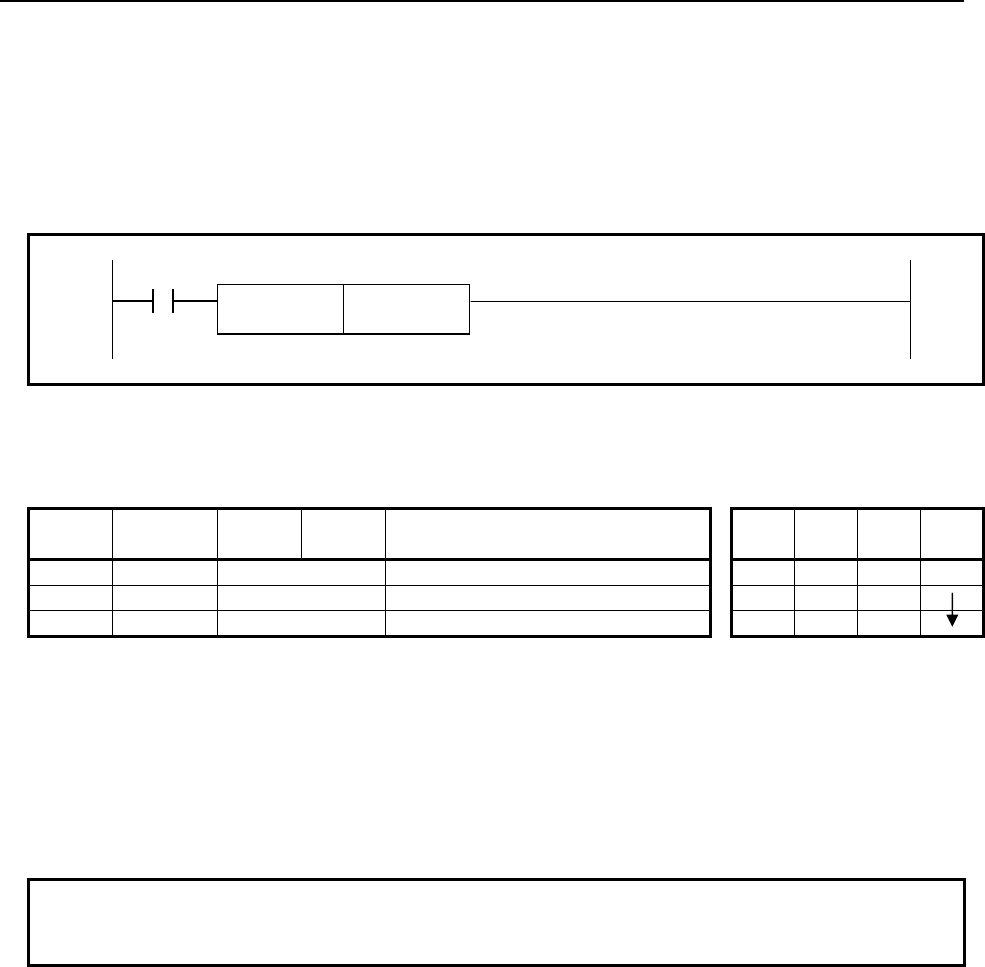
4.LADDER LANGUAGE
B-64513EN/03
- 510 -
(d) A message is displayed on the NC alarm message/operator message screen.
When using the DISPB instruction, you must satisfy the following conditions:
To use DISPB, the optional External Data Input function or External Message Display is necessary for
NC.
Format
Fig. 4.11.1(b) shows the ladder format and Table 4.11.1(a) shows the mnemonic format.
ACT
SUB 41
DISPB 0 (Not used)
Fig. 4.11.1 (b) Format of DISPB instruction
Table 4.11.1 (a) Mnemonic of DISPB instruction
Mnemonic format Memory status of control
condition
Step
number Instruction Address
No. Bit No. Remarks ST3 ST2 ST1 ST0
1 RD {{{{ .{ ACT ACT
2 SUB 41 DISPB instruction
3 (PRM) 0 (Not used)
Control conditions
ACT=0: Do not display messages on the CNC screen.
ACT=1: Display the messages on the CNC screen.
Parameter
This parameter is not used.
Enter "0" as the input value. (NOTE)
NOTE
Thanks to the compatibility with the former models, the instruction runs normally if
the entered value is in the range between 1 and 2000.
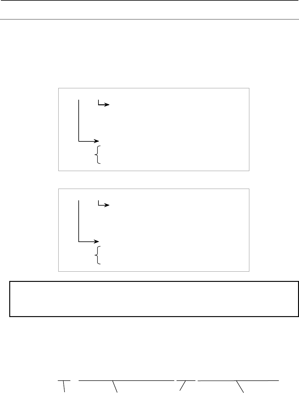
B-64513EN/03
4.LADDER LANGUAGE
- 511 -
4.11.1.1
Numerical data display
Some of variable numerical data can be displayed in the message.
To define the numerical data, enter the number of digits for the data and the data address in the messages.
To differentiate between the numerical data from the other message data, write it within [ ] in the message.
Since the brackets [ ] are used to contain numerical data, they are not themselves treated as symbols to be
included in the messages.
(a) Numerical data format
(i) Signed
A
ddress where the numerical data is stored
Set binary data in the specified address.
Set the "bid" data after the letter "I":
[Ibid,
{{{{
]
b: Number of bytes (1, 2, or 4)
i: Number of digits in the integer part (0 to 8)
d: Number of digits in the decimal part (0 to 8)
(ii) Unsigned
A
ddress where the numerical data is stored
Set binary data in the specified address.
Set the "bid" data after the letter "U".
[Ubid,
{{{{
]
b: Number of bytes (1, 2, or 4)
i: Number of digits in the integer part (0 to 8)
d: Number of digits in the decimal part (0 to 8)
NOTE
1 Sum of integer part digits and fractional part digits must be within 8.
2 Blank is displayed for digits exceeding 8 digits.
3 Do not use any space between the brackets, [ ].
Example of Numerical data display
The following message includes 3 digits of tool number and offset data for this tool.
Each data is put in memory of 2bytes. The address R500 is used for the tool number and R502 is used
for the offset data, and No. 1000 is used for the alarm number.
[Message definition]
A0000.0 1000 SPINDLE TOOL NO=[I230,R500]@0A@OFFSET DATA=[I212,R502]
[Display on the NC alarm screen when A0000.0 is set on]
EX1000 SPINDLE TOOL NO.=110
OFFSET DATA=3.33
Message number First line of message Renew line code Second message line
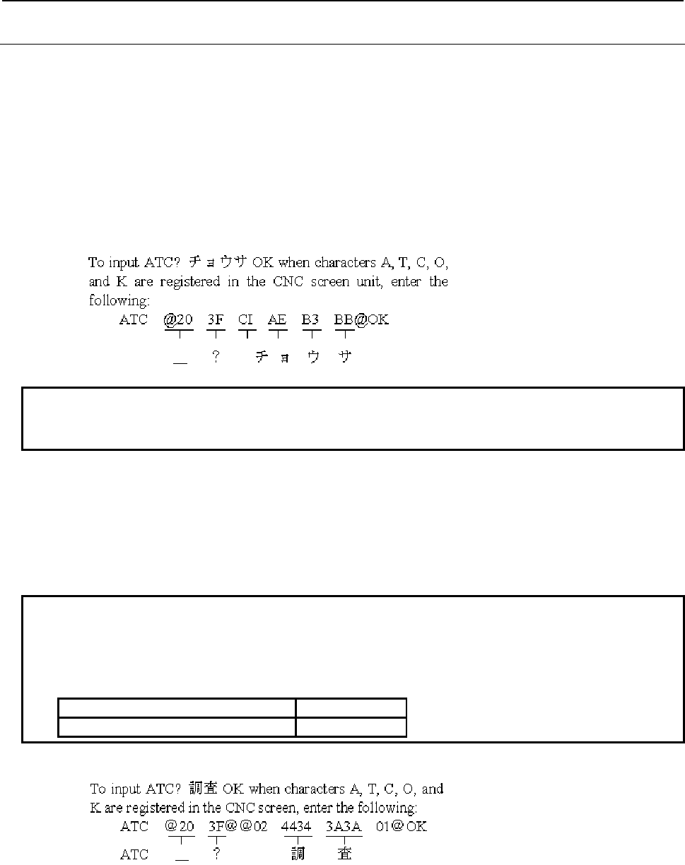
4.LADDER LANGUAGE
B-64513EN/03
- 512 -
4.11.1.2
Defining characters not found in the CNC MDI keys
Message characters not covered by the CNC MDI keys (kanji and half-width kana characters and European
character) can be input as follows:
(a) Half-width kana characters
(i) Data format
Numerical code enclosed with @ and @
(ii) Input method
Enter the numerical codes corresponding to the characters to be input, by referring to the
character code table (Table 4.11.1.2(a)). Each character requires two bytes.
Characters covered by the CNC screen keys can also be input in this way.
(iii) Example
NOTE
Spaces are used between each numerical code in example to understand easily,
but do not use them actually.
(b) Kanji (full-width) characters
(i) Data format
Numerical code enclosed with @02 and 01@
(ii) Input method
Enter the codes corresponding to the characters to input, in accordance with JIS level-1/2 kanji
set. Each character requires four bytes.
NOTE
1 It recommends that Kanji character is input from FANUC LADDER-III.
2 Some Kanji characters cannot be displayed. These characters can be checked by
“Invalid kanji character check button” on FANUC LADDER-III.
3 For operation of FANUC LADDER-III , refer to the following manual:
Manual title Drawing No.
FANUC LADDER-III Operator's Manual B-66234EN
(iii) Example
B-64513EN/03
4.LADDER LANGUAGE
- 513 -
(c) The European characters type 1
(i) Data format
Numerical code enclosed with @0D and 01@.
(ii) Input method
Enter the numerical codes corresponding to the characters to input, by referring to the character
code table (Table 4.11.1.2 (b)) which includes characters for writing languages such as German,
French, Italian, etc. Each character requires two bytes.
(iii) Example
To input “UNZULÄSSIGE” when characters U,N,Z,U,L,S,I,G , and E are registered in the CNC
screen, enter the following:
UNZUL @0D C1 01@ SSIGE
UNZUL Ä SSIGE
NOTE
You can only input the character code described in the character code table (Table
4.11.1.2 (b)) between “@0D” and “01@”.
(d) The European characters type 2
(i) Data format
Numerical code enclosed with @0E and 01@.
(ii) Input method
Enter the numerical codes corresponding to the characters to input, by referring to the character
code table (Table 4.11.1.2 (c)) which includes characters for writing Russian language. Each
character requires two bytes.
(iii) Example
To input “CИMBOЛ” when characters C,M,B, and O are registered in the CNC screen, enter the
following:
C @0E A5 01@ MBO @0E A8 01@
C И MBO Л
NOTE
You can only input the character code described in the character code table (Table
4.11.1.2 (c)) between “@0E” and “01@”.
(e) The European characters type 3
(i) Data format
Numerical code enclosed with @05 and 01@.
(ii) Input method
Enter the numerical codes corresponding to the characters to input, by referring to the character
code table (Table 4.11.1.2 (d)) which includes characters for writing languages such as Turkish,
Russian, etc. Each character requires two bytes.
(iii) Example
To input “ 123” when characters 1,2, and 3 are registered in the CNC screen, enter the
following:
@05 ED 01@ 123
123

4.LADDER LANGUAGE
B-64513EN/03
- 514 -
NOTE
You can only input the character code described in the character code table (Table
4.11.1.2 (d)) between “@05” and “01@”.
CAUTION
1 To define @, enter @40...@, where 40 is the code corresponding to
@40 . . . . @
Code for @
2 To renew the message line displayed on the CNC screen, input as:@ 0A @ at the
end of the data.
3 When using numerical codes, @ code occupies 1 byte, and space code occupies
2 bytes. (Space code = 20, 2 and 0 occupies 1 byte each).
4 The following control codes are used:
02: 2-byte code (kanji and hiragana characters)
0D: 1-byte code (European characters type 1)
0E: 1-byte code (European characters type 2)
05: 1-byte code (European characters type 3)
01: 1-byte code (alphanumeric and half-width kana characters)
Do not specify control code between control codes as follows. The characters may
not be correctly displayed.
@02 ... 02 ... 01@ @0D ... 0D ... 01@ @0E ... 0E ... 01@ @05 ... 05 ... 01@
@02 ... 01 ... 01@
5 Spaces are used between each numerical code in example to understand easily,
but do not use them actually.
6 Do not specify the character strings for numerical data display between control
codes such as @ and @, @02 and 01@, and etc.
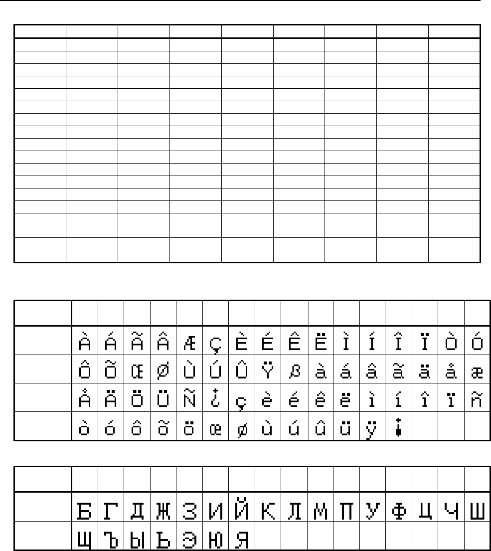
B-64513EN/03
4.LADDER LANGUAGE
- 515 -
Table 4.11.1.2 (a) Character code table
2 3 4 5 A B C D
0 Space 0 @ P ~ - (*3) タ ミ
1 ! 1 A Q
。 ア チ ム
2 ” 2 B R
「 イ ツ メ
3 # 3 C S
」 ウ テ モ
4 $ 4 D T
、 エ ト ヤ
5 % 5 E U
・ オ ナ ユ
6 & 6 F V
ヲ カ ニ ヨ
7 ’ 7 G W
ァ キ ヌ ラ
8 ( 8 H X
ィ ク ネ リ
9 ) 9 I Y
ゥ ケ ノ ル
A * : J Z
ェ コ ハ レ
B + ; K [ ォ サ ヒ ロ
C , < L
¥ ャ シ フ ワ
D - (*1) = M ] ュ ス ヘ ン
E キ > N
∧ ョ セ ホ ゛
(*4)
F / ? O
_ (*2) ッ ソ マ 。
(*5)
*1) Minus, *2) Under bar, *3) Long bar *4) Dakuten *5) Han-dakuten
Table 4.11.1.2 (b) European character type1 code table
Character
Code +0 +1 +2 +3 +4 +5 +6 +7 +8 +9 +A +B +C +D +E +F
A0
B0
C0
D0
Table 4.11.1.2 (c) European character type2 code table
Character
Code +0 +1 +2 +3 +4 +5 +6 +7 +8 +9 +A +B +C +D +E +F
A0
B0
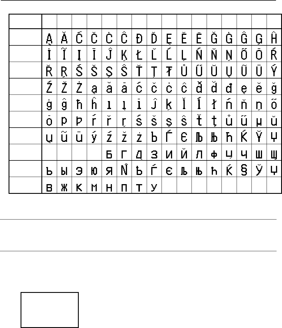
4.LADDER LANGUAGE
B-64513EN/03
- 516 -
Table 4.11.1.2 (d) European character type3 code table
Character
Code
+0 +1 +2 +3 +4 +5 +6 +7 +8 +9 +A +B +C +D +E +F
60
70
80
90
A0
B0
C0
D0
E0
F0
4.11.1.3
Notes when this functional instruction is used in subroutine
See Subsection 1.4.4.3 for details.
4.11.1.4
Message shift function
(a) General
In the message data areas corresponding to contiguous message display request memory locations,
message data can be displayed in any of several languages.
The language in which a message is displayed is selected by shifting the message display request bit
according to the address bit shift amount set the parameter in setting screen.
A0.0 Language 1
A0.1 Language 2
A0.2 Language 3
A0.3 Language 4
A0.4 Language 5
When A0.0 is turned on after setting the
message display request bit shift amount to 2,
the message display request bit is shifted by 2
bits to display language 3.
The parameters set on the setting screen are listed below. See Subsection 2.4.1 and Section 9.5 for
details.
• Message shift value
Message display request bit shift amount
• Message shift start address
Start bit address of the message display request bit area to be shifted
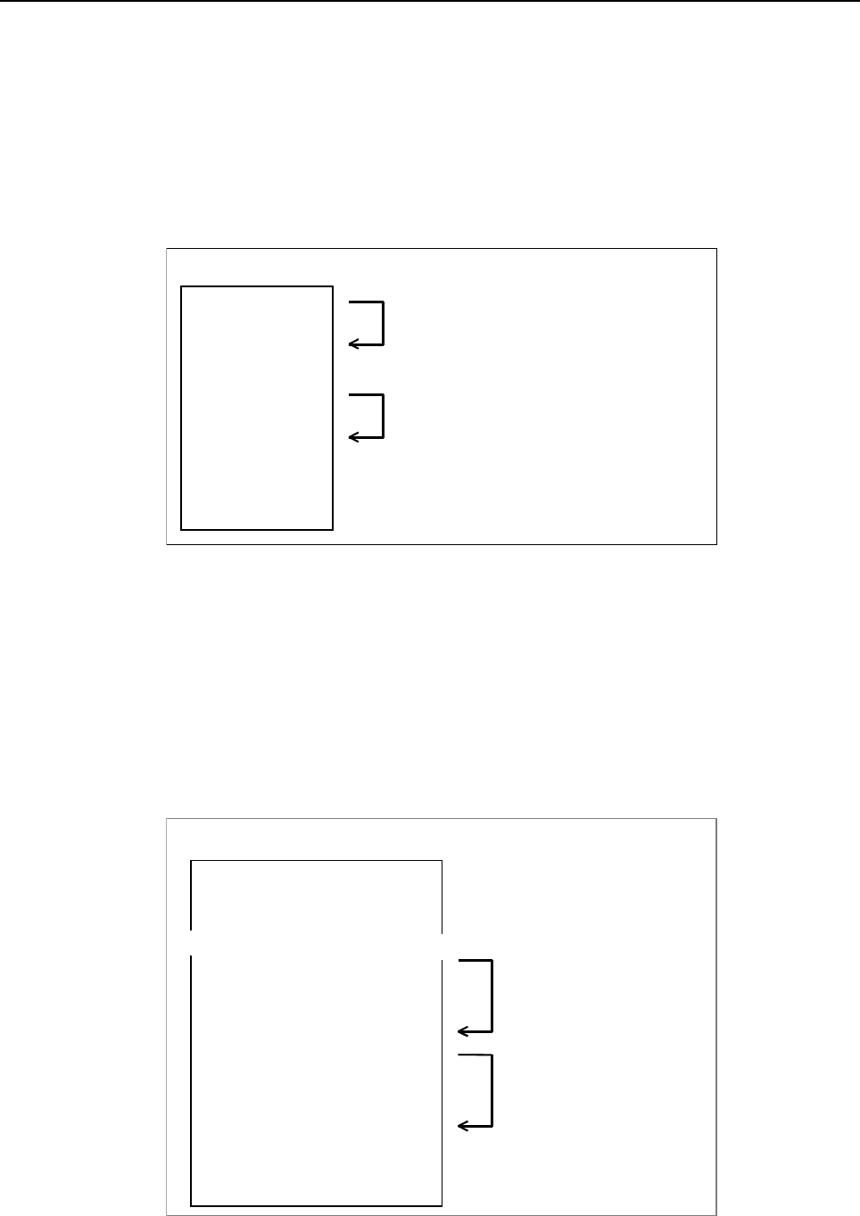
B-64513EN/03
4.LADDER LANGUAGE
- 517 -
(b) Examples
Example 1:
Message data in any of four languages is set starting at A0.0 in the order of Japanese, English,
Italian, German, Japanese and so on. The Italian message data is displayed.
Set the parameters as follows:
Message shift value : 2
Message shift start address : A0.0
(Message shift value = 0:Japanese/1:English/2:Italian/ 3:German)
Manipulate A0.0, A0.4, A1.0, and A1.4 with the ladder.
Message table
When A0.0 is turned on, Italian 1 is displayed.
(The message data is shifted by 2 bits).
When A0.4 is turned on, Italian 2 is displayed.
(The message data is shifted by 2 bits).
A0.0
A0.1
A0.2
A0.3
A0.4
A0.5
A0.6
A0.7
:
Am.n
Japanese 1
English 1
Italian 1
German 1
Japanese 2
English 2
Italian 2
German 2
:
:
Example 2:
As common alarm messages, English message data is displayed with A0.0 through A9.7.
Operator messages are set starting at A10.0 in the order of Japanese, English, Italian, German and
so on, and German message data is displayed.
Set the parameters as follows:
Message shift value : 3
Message shift start address : A10.0
(Message shift value = 0:Japanese/1:English/ 2:Italian/3:German)
Manipulate A10.0, A10.4, A11.0, A11.4, and so forth with the ladder.
When any of A0.0 to A9.7 is turned on, the message corresponding to the bit is displayed.
A0.0
A0.1
A0.2
A10.0
A10.1
A10.2
A10.3
A10.4
A10.5
A10.6
A10.7
:
:
A m.n
English A
English B
English C
Japanese 1
English 1
Italian 1
German 1
Japanese 2
English 2
Italian 2
German 2
:
:
:
(ALARM)
(ALARM)
(ALARM)
(OPE)
(OPE)
(OPE)
(OPE)
(OPE)
(OPE)
(OPE)
(OPE)
Messa
g
e table
When A0.1 is turned on, English
B is displayed.
When A10.0 is turned on,
German 1 is displayed. (The
message data is shifted by 3
bits).
∼∼
When A10.4 is turned on,
German 2 is displayed. (The
message data is shifted by 3
bits).

4.LADDER LANGUAGE
B-64513EN/03
- 518 -
Example 3:
As common alarm messages, English message data is displayed with A0.0 through A9.7.
Operator messages are set starting at A10.0 in the order of Japanese, English, Italian, German and
so on, with 40 successive messages assigned to each language. For these messages, German
message data is displayed.
Set the parameters as follows:
Message shift value : 120 (40 × 3)
Message shift start address : A10.0
(Message shift value = 0:Japanese/40:English/ 80:Italian/120:German)
Manipulate A10.0 through A14.7 with the ladder.
When any of A0.0 to A9.7 is turned on, the message corresponding to the bit is displayed.
A0.0
A0.1
A0.2
A10.0
A10.1
A15.0
A15.1
A20.0
A20.1
A25.0
A25.1
:
Am.n
English A
English B
English C
Japanese 1
Japanese 2
English 1
English 2
Italian 1
Italian 2
German 1
German 2
:
:
(ALARM)
(ALARM)
(ALARM)
(OPE)
(OPE)
(OPE)
(OPE)
(OPE)
(OPE)
(OPE)
(OPE)
Message table
When A0.1 is turned on, English
B is displayed.
When A10.0 is turned on,
German 1 is displayed.
When A10.1 is turned on,
German 2 is displayed.
(The message data is shifted
by 120 bits).
∼
∼
∼
∼
∼
∼
∼
∼
(c) Notes
The same message number should be assigned to a message in each language that has the same
meaning.
A0.0
A0.1
A10.0
A10.1
1000
1001
1000
1001
English A
English B
Japanese 1
Japanese 2
(ALARM)
(ALARM)
(OPE)
(OPE)
Message table
∼∼
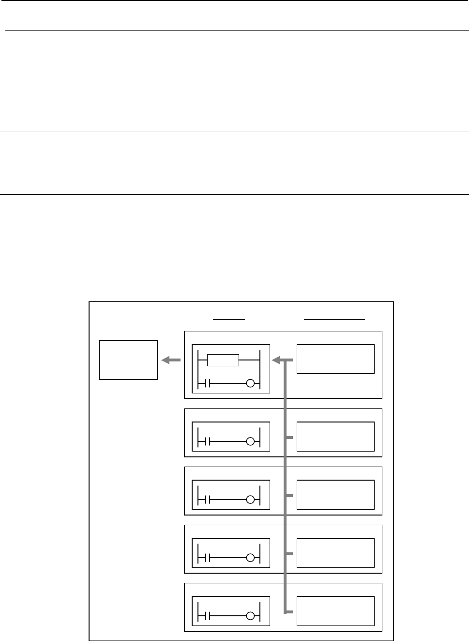
B-64513EN/03
4.LADDER LANGUAGE
- 519 -
4.11.1.5
PMC message multi-language display function
The PMC message multi-language display function manages the language of alarm message and operator
message stored in a separate file from ladder program, switching the language according to the language
setting of CNC using the message data defined in various languages.
For more details about this function, refer to “2.7 PMC MESSAGE MULTI-LANGUAGE DISPLAY
FUNCTION”.
4.11.1.6
Ladder dividing management function
When using the ladder dividing management function, refer to “1.5.5 Message Display Function (DISPB)
instruction) when Using Ladder Dividing Management Function”.
4.11.1.7
Common PMC Memory mode of Multi-path PMC
When using the Common PMC Memory mode, the Message Data can be defined at each PMC path. In this
case, make the program of DISPB functional instruction in the 1st-path PMC. As a result, it displays
message data of all PMC paths.
The following figure is an example in which the message of A0.0 in 1st-path PMC, the message of A0.1 in
2nd-path PMC, the message of A0.2 in 3rd-path PMC, the message of A0.3 in 4th-path PMC, and the
message of A0.4 in 5th-path PMC are defined.
CNC
A
LARM
SCREEN
1st-path PMC
2nd-path PMC
3rd-path PMC
A
0.0
1000PMC1 ERROR
A
0.1
1001PMC2 ERROR
A
0.2
1002PMC3 ERROR
LADDER MESSAGE DATA
A0.2
A0.1
A0.0
DISPB
4th-path PMC
5th-path PMC
A
0.3
1003PMC4 ERROR
A
0.4
1004PMC5 ERROR
A0.4
A0.3
When A0.0 is turned ON, the message of A0.0 defined in 1st-path PMC is displayed.
And, when A0.1 is turned ON, the message of A0.1 defined in 2nd-path PMC is displayed.
And, when A0.2 is turned ON, the message of A0.2 defined in 3rd-path PMC is displayed.

4.LADDER LANGUAGE
B-64513EN/03
- 520 -
And, when A0.3 is turned ON, the message of A0.3 defined in 4th-path PMC is displayed.
Similarly, when A0.4 is turned ON, the message of A0.4 defined in 5th-path PMC is displayed.
Moreover, the A0.0 message defined in 1st-path PMC can be displayed from 2nd-path PMC, too.
CAUTION
When using the Common PMC Memory mode, don't define message to the same
A Address from multiple PMC paths. If message is defined in multiple PMC paths,
only message defined in least numbered PMC path is displayed.
For example, if A0.1 is defined in the 1st-path PMC in the above case, the
message defined in the 1st-path PMC is displayed when A0.1 is turned on in
2nd-path PMC.

B-64513EN/03
4.LADDER LANGUAGE
- 521 -
4.11.2
EXIN (External Data Input: SUB 42)
This instruction enables the use of the external data input functions (options) of the CNC. It controls the
"external data input signals" to be exchanged between CNC and PMC and automatically executes the
CNC-PMC handshake sequence. The use of this instruction facilitates the execution of the external data
input functions.
WARNING
When you use this instruction in ladder program, do not write the "external data
input signals" with other applications.
If you process the PMC signal set related to this function by using two or more
applications, this function may execute incorrectly and it may cause an
unexpected machine behavior.
As for details, refer to “SAFETY PRECAUTIONS”.
NOTE
1 When you use this instruction, do not directly write the "external data input signals"
to be exchanged between CNC and PMC. Writing these signals directly causes
an adverse effect on the handshake sequence, potentially disabling the external
data input functions or causing them to malfunction.
2 This instruction cannot be used in the 1st level whose execution cycle is 1ms or
2ms. It is processed as an NOP instruction.
You can use the EXIN instruction only when optional external data input function is provided with NC.
Four-byte control data as described below is required for external data input function (option).
In addition to the basic specification, the extended specification is also supported that needs six bytes of
control data. With this setting, the extended operation can use ED16 to ED31 signals (for program number
O8 digits etc.). To use the extended specification, it is necessary to set to CNC parameter 6300#7 (EEX)=1.
CNC parameter
#7 #6 #5 #4 #3 #2 #1 #0
6300 EEX
[Data format] Bit type
EEX EXIN function of PMC
0: basic specification
1: extended specification
NOTE
1 To enable 8 digits of program number, set 1 to the CNC parameter No. 11304#3
(ON8).
2 To handle 8 digits of program number for EXIN instruction, set 1 to the CNC
parameter No. 6300#7 (EEX). This setting will be effective after cycling power of
CNC.
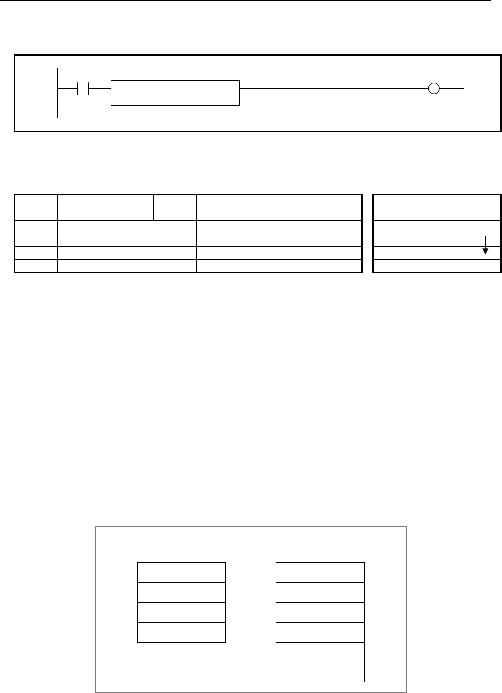
4.LADDER LANGUAGE
B-64513EN/03
- 522 -
Format
Fig. 4.11.2 shows the ladder format and Table 4.11.2 shows the mnemonic format.
ACT W1
SUB 42
EXIN {{{{ Control data address
Fig. 4.11.2 Format of EXIN instruction
Table 4.11.2 Mnemonic of EXIN instruction
Mnemonic format Memory status of control
condition
Step
number Instruction Address
No. Bit No. Remarks ST3 ST2 ST1 ST0
1 RD {{{{ .{ ACT ACT
2 SUB 42 EXIN instruction
3 (PRM) {{{{ Control data address
4 WRT {{{{ .{ Transmission completion W1
Control conditions
ACT=0: Do not process external data input/output.
ACT=1: Process external data input/output.
ACT is to be maintained '1' till the end of external data input/output. After external data input, reset ACT
(W1=1).
Parameter
(a) Control data
The control data needs 4 continuous bytes from the specification address. The path is specified to the
1st byte. The addresses G0 to G2 of the interface from PMC to NC are specified by after 3 bytes. For
2nd path, the addresses G1000 to G1002 are specified. For 3rd path, the addresses G2000 to G2002
are specified.
In case of the extended specification (program number O8 digits etc.), a control data is extended. In
this case, the control data address needs 6 continuous bytes from the specified address. The path is
specified in the 1st byte. The addresses G0 to G2 and G210 to G211 of the interface from PMC to NC
are specified in later 5 bytes. For 2nd path, the addresses G1000 to G1002 and G1210 to G1211 are
specified. For 3rd path, the addresses G2000 to G2002 and G2210 to G2211 are specified.
CTL+0
HEAD.NO.
ED0 to ED7
ED8 to ED15
EA0 to EA6,ESTB
CTL+0
+6
HEAD.NO.
ED0 to ED7
ED8 to ED15
ED16 to ED23
Basic specification Extended specification
(program number O8 digits etc.)
ED24 to ED31
EA0 to EA6,ESTB
+5
+4
+3
+2
+1
+4
+3
+2
+1

B-64513EN/03
4.LADDER LANGUAGE
- 523 -
[For single path control]
CTL+0 : 0
CTL+1 to CTL+3 : Data to be specified for G0 to G2
In case of the extended specification (program number O8 digits etc.), it sets CTL+1 to CTL+5 as
follows.
CTL+1 to CTL+2 : Data to be specified for G0 to G1
CTL+3 to CTL+4 : Data to be specified for G210 to G211
CTL+5 : Data to be specified for G2
[For multi path control]
(1) 1st path
CTL+0 : 0 or 1
CTL+1 to CTL+3 : Data to be specified for G0 to G2
In case of the extended specification (program number O8 digits etc.), it sets CTL+1 to CTL+5 as
follows.
CTL+1 to CTL+2 : Data to be specified for G0 to G1
CTL+3 to CTL+4 : Data to be specified for G210 to G211
CTL+5 : Data to be specified for G2
(2) 2nd path
CTL+0 : 2
CTL+1 to CTL+3 : Data to be specified for G1000 to G1002
In case of the extended specification (program number O8 digits etc.), it sets CTL+1 to CTL+5 as
follows.
CTL+1 to CTL+2 : Data to be specified for G1000 to G1001
CTL+3 to CTL+4 : Data to be specified for G1210 to G1211
CTL+5 : Data to be specified for G1002
(3) 3rd path
CTL+0 : 3
CTL+1 to CTL+3 : Data to be specified for G2000 to G2002
In case of the extended specification (program number O8 digits etc.), it sets CTL+1 to CTL+5 as
follows.
CTL+1 to CTL+2 : Data to be specified for G2000 to G2001
CTL+3 to CTL+4 : Data to be specified for G2210 to G2211
CTL+5 : Data to be specified for G2002
(4) 4th path
CTL+0 : 4
CTL+1 to CTL+3 : Data to be specified for G3000 to G3002
In case of the extended specification (program number O8 digits etc.), it sets CTL+1 to CTL+5 as
follows.
CTL+1 to CTL+2 : Data to be specified for G3000 to G3001
CTL+3 to CTL+4 : Data to be specified for G3210 to G3211
CTL+5 : Data to be specified for G3002

4.LADDER LANGUAGE
B-64513EN/03
- 524 -
(5) 5th path
CTL+0 : 5
CTL+1 to CTL+3 : Data to be specified for G4000 to G4002
In case of the extended specification (program number O8 digits etc.), it sets CTL+1 to CTL+5 as
follows.
CTL+1 to CTL+2 : Data to be specified for G4000 to G4001
CTL+3 to CTL+4 : Data to be specified for G4210 to G4211
CTL+5 : Data to be specified for G4002
(6) 6th path
CTL+0 : 6
CTL+1 to CTL+3 : Data to be specified for G5000 to G5002
In case of the extended specification (program number O8 digits etc.), it sets CTL+1 to CTL+5 as
follows.
CTL+1 to CTL+2 : Data to be specified for G5000 to G5001
CTL+3 to CTL+4 : Data to be specified for G5210 to G5211
CTL+5 : Data to be specified for G5002
(7) 7th path
CTL+0 : 7
CTL+1 to CTL+3 : Data to be specified for G6000 to G6002
In case of the extended specification (program number O8 digits etc.), it sets CTL+1 to CTL+5 as
follows.
CTL+1 to CTL+2 : Data to be specified for G6000 to G6001
CTL+3 to CTL+4 : Data to be specified for G6210 to G6211
CTL+5 : Data to be specified for G6002
(8) 8th path
CTL+0 : 8
CTL+1 to CTL+3 : Data to be specified for G7000 to G7002
In case of the extended specification (program number O8 digits etc.), it sets CTL+1 to CTL+5 as
follows.
CTL+1 to CTL+2 : Data to be specified for G7000 to G7001
CTL+3 to CTL+4 : Data to be specified for G7210 to G7211
CTL+5 : Data to be specified for G7002
(9) 9th path
CTL+0 : 9
CTL+1 to CTL+3 : Data to be specified for G8000 to G8002
In case of the extended specification (program number O8 digits etc.), it sets CTL+1 to CTL+5 as
follows.
CTL+1 to CTL+2 : Data to be specified for G8000 to G8001
CTL+3 to CTL+4 : Data to be specified for G8210 to G8211
CTL+5 : Data to be specified for G8002

B-64513EN/03
4.LADDER LANGUAGE
- 525 -
(10) 10th path
CTL+0 : 10
CTL+1 to CTL+3 : Data to be specified for G9000 to G9002
In case of the extended specification (program number O8 digits etc.), it sets CTL+1 to CTL+5 as
follows.
CTL+1 to CTL+2 : Data to be specified for G9000 to G9001
CTL+3 to CTL+4 : Data to be specified for G9210 to G9211
CTL+5 : Data to be specified for G9002
NOTE
Refer to the “CONNECTION MANUAL (FUNCTION)” for detailed data to be
specified concerning external data input.
Completion of transfer (W1)
This indicates end of transfer of external data. This transfer end condition shows the completion of a series
of external data input sequence. This functional instruction executes a series of transfer sequence, and
finally sets ESTB = 0 in the PMC → NC interface. As a result, W1 is set to 1 (W1 = 1) after confirming that
EREND = 0.
When W1 = 1, transfer of data is over. Reset ACT now.
CAUTION
1 The EXIN command cannot input multiple external data items at the same time.
Be sure to issue the next EXIN command (ACT = 1) after external data transfer
completion (W1 = 1).
2 Be sure to specify an interlock when the external data input function is used by
commands other than the function command EXIN.
3 When an external program number search, one of the external data input
functions, is executed, the end of data transfer (W1 = 1) means that the search
command has been accepted. Note that this does not mean the completion of the
program search. To confirm the completion of the program search, check the
search completion signal (ESEND = 1) after the data transfer completion (W1 = 1).
Operation output register (R9000, Z0)
If any of the following errors occurs during external data input, the bit in the operation output register is set.
In this case, external data transfer ends (W1 = 1).
EXIN error
R9000
Z0
7 6 5 4 3 2 1 0
(Description of errors)
• When the EXIN command (ACT = 1) is started, the strobe signal (ESTB) or EREND signal is already
on. The external data may be input by commands other than the function command EXIN.
Notes when this functional instruction is used in subroutine
See Subsection 1.4.4.3 for details.
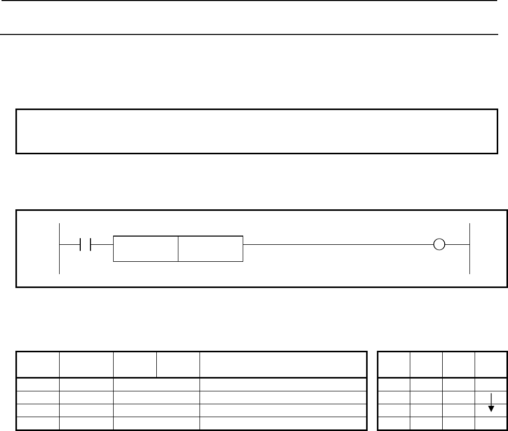
4.LADDER LANGUAGE
B-64513EN/03
- 526 -
4.11.3
WINDR (Reading CNC Window Data: SUB 51)
This function reads various data items via the window between the PMC and the CNC.
The "WINDR" is classified into two types. One type completes reading a data during one scan time.
Another type completes reading a data during a few scan times. The former is called the function of a
high-speed response and the latter is called the function of a low-speed response.
NOTE
This instruction cannot be used in the 1st level whose execution cycle is 1ms or
2ms. It is processed as an NOP instruction.
Format
Fig. 4.11.3 shows the ladder format and Table 4.11.3 shows the mnemonic format.
ACT W1
SUB 51
WINDR
{{{{ Control data address
Fig. 4.11.3 Format of WINDR instruction
Table 4.11.3 Mnemonic of WINDR instruction
Mnemonic format Memory status of control
condition
Step
number Instruction Address
No. Bit No. Remarks ST3 ST2 ST1 ST0
1 RD {{{{ .{ ACT ACT
2 SUB 51 WINDR instruction
3 (PRM) {{{{ Control data address
4 WRT {{{{ .{ Read completion W1
Control condition
ACT=0: The WINDR function is not executed.
ACT=1: The WINDR function is executed. Using the function of a high-speed response, it is possible to
read the data continuously by always keeping ACT on. However, using the function of a
low-speed response, as soon as reading a data is completed (W1=1), reset "ACT" once
(ACT=0).
Parameter
(a) Control data address
The PMC byte address is used to specify the area where control data is stored.
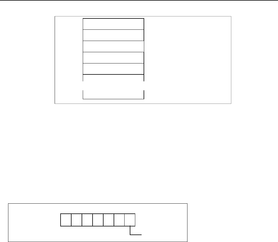
B-64513EN/03
4.LADDER LANGUAGE
- 527 -
Control data
CTL+0
Function code
Completion code
Data length
Data number
Data attribute
Read data * Only the size of the read data is
necessary for the data area below to
"CTL+10" usually.
* Set the control data area by sequence
program before executing the
"WINDR".
+2
+4
+6
+8
+10
+n
∼
∼
See Chapter 5 for details.
Reading completion (W1)
W1=0: "W1" is usually reset. The "W1=0" indicates that the "WINDR" is not executed or the "WINDR"
being executed now.
W1=1: "W1" is set when the reading a data is completed by the reading command (ACT=1). If the
function of a low-speed response is used, as soon as reading a data is completed (W1=1), reset
"ACT" (ACT=0).
Operation output register (R9000, Z0)
If an error occurs during execution of the "WINDR" or "WINDW", the bit in the operation output register is
set. At the same time, the reading completion is set (W1=1). Details of the error are output to the completion
code (CTL+2) in the control data area. See Chapter 5.
R9000
Z0
7 6 5 4 3 2 1 0
WINDR error
Notes when this functional instruction is used in subroutine
When you use the function of a low-speed response, there are a few limitations. See Subsection 1.4.4.3.
When you use the function of a high-speed response, there is no limitation.
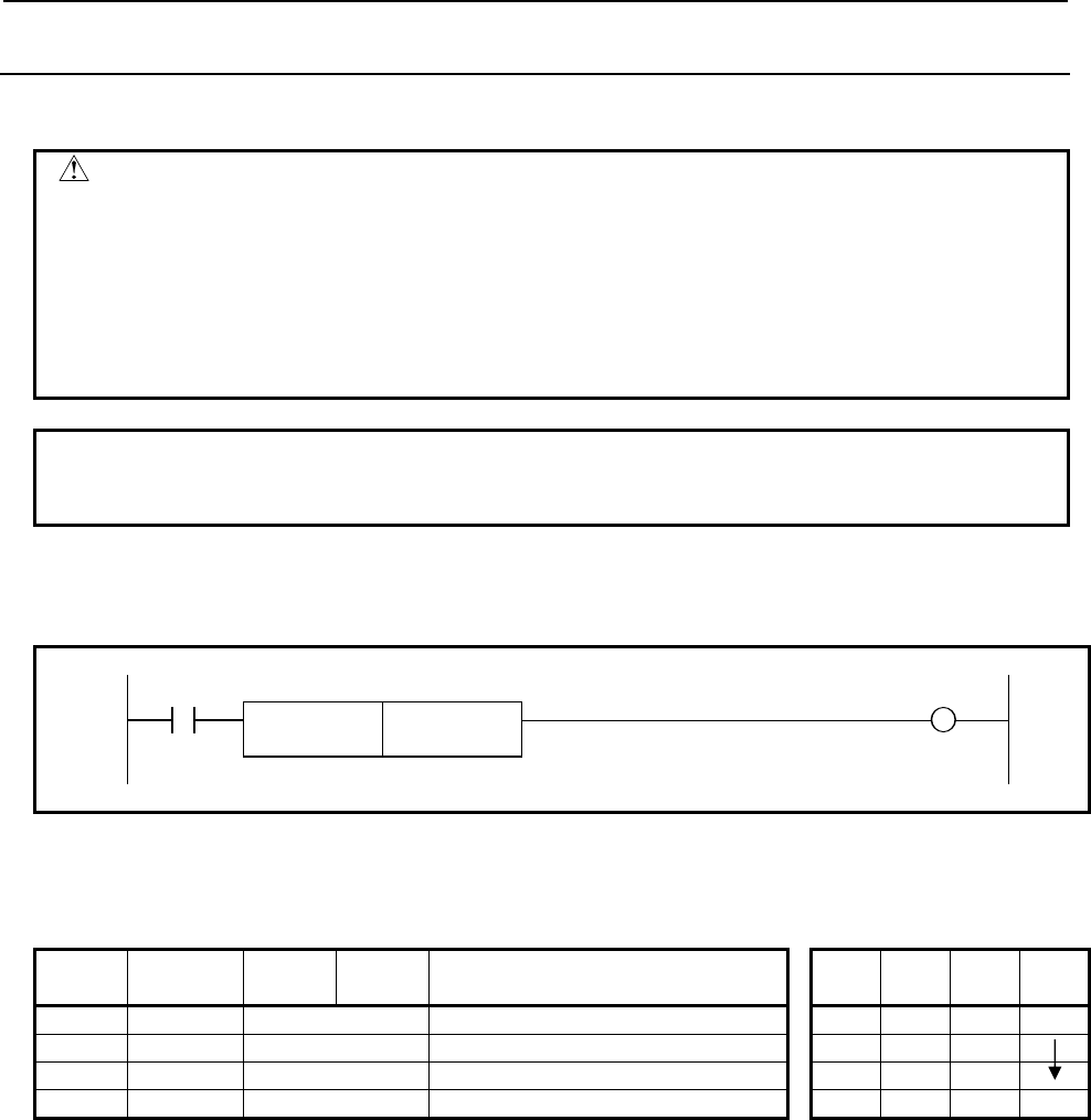
4.LADDER LANGUAGE
B-64513EN/03
- 528 -
4.11.4
WINDW (Writing CNC Window Data: SUB 52)
This function writes various data items via the window between the PMC and the CNC.
WARNING
When you write some NC data using both this instruction in ladder program and
other applications, take care that you do not write to the same data area.
If some values are written to the same data area by two or more applications
including ladder program, unexpected value may be written. In this case, it may
cause an unexpected machine behavior and also tools, work pieces, and
machines may be damaged.
As for details, refer to “SAFETY PRECAUTIONS”.
NOTE
This instruction cannot be used in the 1st level whose execution cycle is 1ms or
2ms. It is processed as an NOP instruction.
Format
Fig. 4.11.4 shows the ladder format and Table 4.11.4 shows the mnemonic format.
ACT W1
SUB 52
WINDW
{{{{ Control data address
Fig. 4.11.4 Format of WINDW instruction
Table 4.11.4 Mnemonic of WINDW instruction
Mnemonic format Memory status of control
condition
Step
number Instruction Address
No. Bit No. Remarks ST3 ST2 ST1 ST0
1 RD {{{{ .{ ACT ACT
2 SUB 52 WINDW instruction
3 (PRM) {{{{ Control data address
4 WRT {{{{ .{ Read completion W1
Control condition
ACT=0: The WINDW function is not executed.
ACT=1: The WINDW function is executed. As soon as writing a data is completed (W1=1), reset "ACT"
once (ACT=0).
Parameter
(a) Control data address
The PMC byte address is used to specify the area where control data is stored.
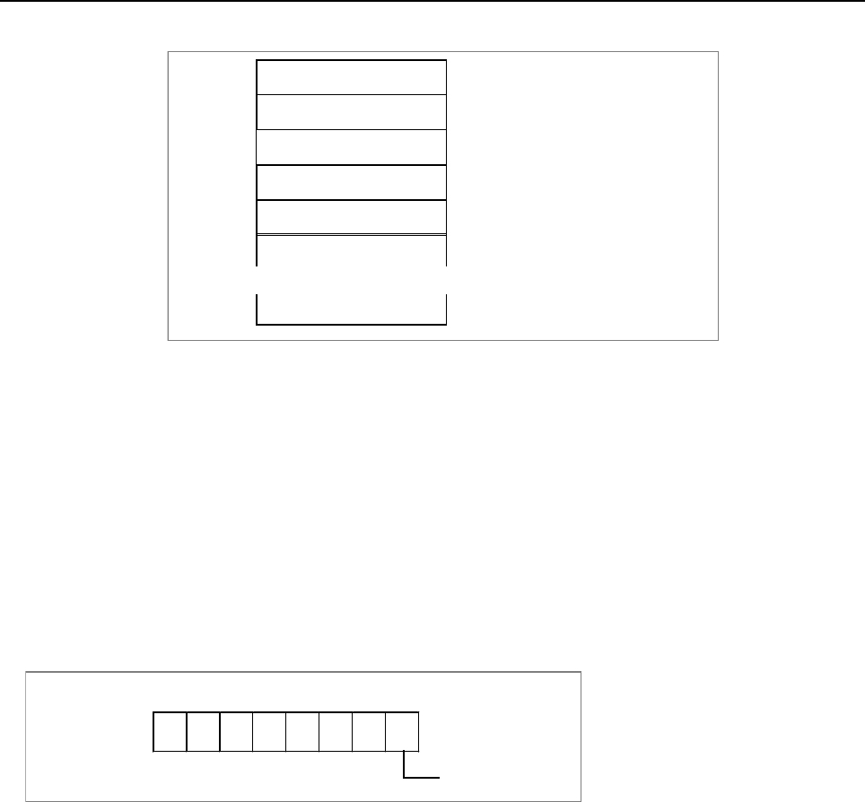
B-64513EN/03
4.LADDER LANGUAGE
- 529 -
Control data
CTL+0 Function code
Completion code
Data length
Data number
Data attribute
Writing data
* Set the control data area by sequence
program before executing the
"WINDW".
+2
+4
+6
+8
+10
+n
∼ ∼
See Chapter 5 for details.
Writing completion (W1)
W1=0: "W1" is usually reset. The "W1=0" indicates that the "WINDW" is not executed or the
"WINDW" being executed now.
W1=1: "W1" is set when the writing a data is completed by the writing command (ACT=1). As soon as
writing a data is completed (W1=1), reset "ACT" (ACT=0).
Operation output register (R9000, Z0)
If an error occurs during execution of the "WINDR" or "WINDW", the bit in the operation output register is
set. At the same time, the writing completion is set (W1=1). Details of the error are output to the completion
code (CTL+2) in the control data area. See Chapter 5.
WINDW error
R9000
Z0
7 6 5 4 3 2 1 0
Notes when this functional instruction is used in subroutine
When you use the function of a low-speed response, there are a few limitations. See Subsection 1.4.4.3.
When you use the function of a high-speed response, there is no limitation.
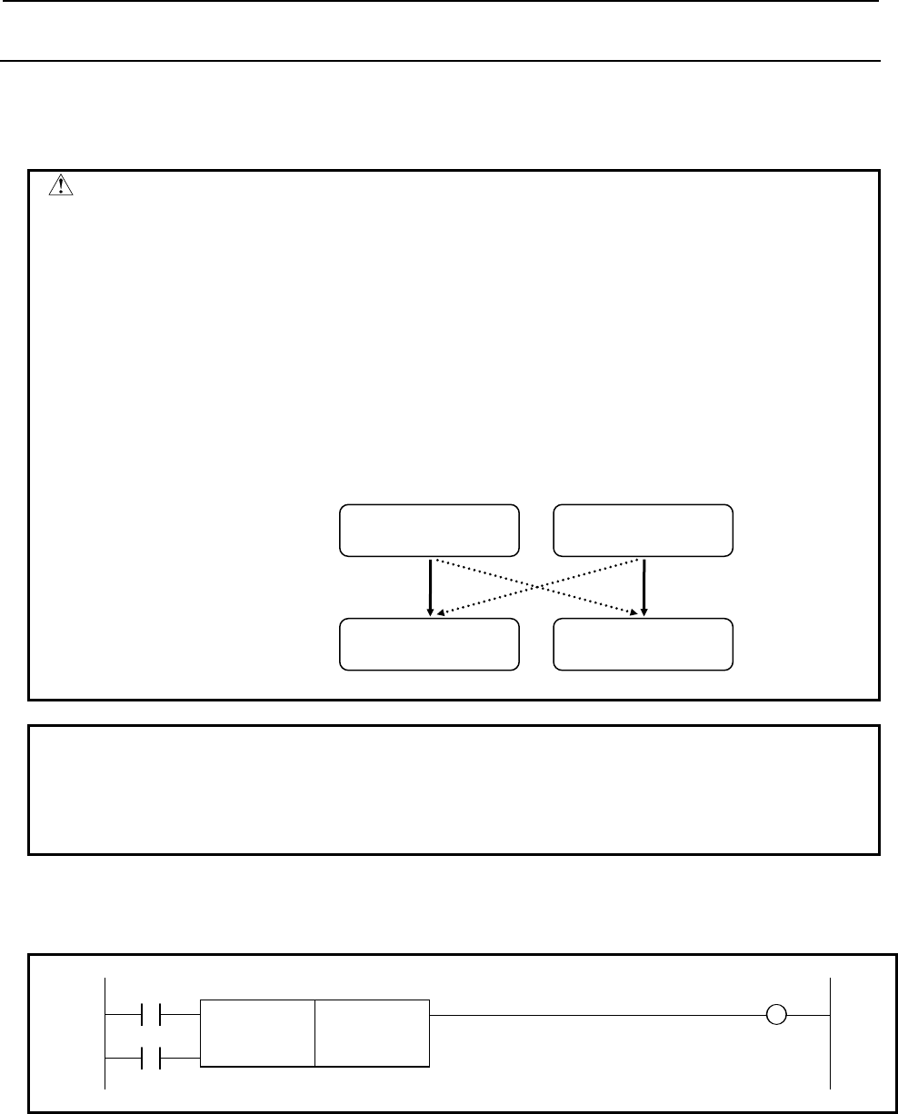
4.LADDER LANGUAGE
B-64513EN/03
- 530 -
4.11.5
AXCTL (Axis Control by PMC: SUB 53)
This instruction simplifies the handshake of DI/DO signal for the axis control by PMC. For details of the
PMC axis control, refer to section “PMC AXIS CONTROL” of “CONNECTION MANUAL
(FUNCTION)”.
WARNING
PMC axis control is able to command by PMC ladder and macro executor.
However, If you process the PMC signal set related to the PMC axis control by
using two or more applications, the machine may behave in an unexpected
manner and also tools, work pieces, and the machine may be damaged.
When you use this instruction (PMC axis control) in ladder program, you should
program the processing about this function only in same level of ladder program.
For example, when “controlled axis selection” is commanded in macro executor
and other “PMC axis controls” are commanded in ladder program, “PMC axis
control command” may be ignored, or the command may cause incorrect axis
motion.
NOTE
1 To use this function requires that the PMC axis control option be set on the CNC
side.
2 This instruction cannot be used in the 1st level whose execution cycle is 1ms or
2ms. It is processed as a NOP instruction.
Format
Fig. 4.11.5 shows the ladder format and Table 4.11.5 shows the mnemonic format.
RST W1
SUB 53
ACT AXCTL
{{{{ Group No. of DI/DO signal
{{{{ Axis control data address
Fig. 4.11.5 Format of AXCTL instruction
OK
Macro executor
command
Macro executor
command
OK
PMC ladder
command
PMC ladder
command
Controlled axis
selection
PMC axis control
command
NG
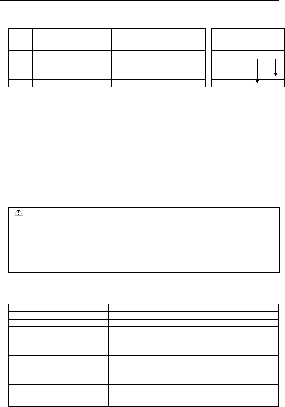
B-64513EN/03
4.LADDER LANGUAGE
- 531 -
Table 4.11.5 Mnemonic of AXCTL instruction
Mnemonic format Memory status of control
condition
Step
number Instruction Address
No. Bit No. Remarks ST3 ST2 ST1 ST0
1 RD {{{{ .{ RST RST
2 RD.STK {{{{ .{ ACT RST ACT
3 SUB 53 AXCTL instruction
4 (PRM) {{{{ Group No. of DI/DO signal
5 (PRM) {{{{ Axis control data address
6 WRT {{{{ .{ Processing completion W1
Control condition
(a) Input signal (ACT)
ACT=0: The AXCTL function is not executed.
If RST is 1, PMC axis control instruction reset processing is performed.
ACT=1: The AXCTL function is executed.
ACT is to be maintained '1' till the end of AXCTL processing.
And reset ACT immediately after the processing is complete (W1 = 1) or when the CNC
enters the alarm state.
(b) Reset (RST)
RST=0: Release reset.
RST=1: Set the reset signal (ECLRx) to 1 and W1 becomes 0. All the buffered commands are
invalidated and the command being executed is stopped.
If the CNC enters the alarm state, reset the PMC axis control instruction by setting ACT to
0.
CAUTION
1 Usually, set both ACT and RST to 0. Set ACT or RST to 1 only when executing the
instruction. Note that, while ACT or RST is set to 1, you cannot update the ladder
program after editing it.
2 If you make any change to the ladder program while RST is set to 1, you may be
unable to continue to execute the AXCTL instruction when re-executing the ladder
program. When changing the ladder program, set both ACT and RST to 0.
3 When RST and ACT become 1 at the same time, RST is prior to ACT.
Parameters
(a) Group number of DI/DO signal
Specify the DI/DO signal group by the number.
Set value Signal group number DI address DO address
1 1 G142 to G149, G150.5 F130 to F132, F142
2 2 G154 to G161, G162.5 F133 to F135, F145
3 3 G166 to G173, G174.5 F136 to F138, F148
4 4 G178 to G185, G186.5 F139 to F141, F151
1001 5 G1142 to G1149, G1150.5 F1130 to F1132, F1142
1002 6 G1154 to G1161, G1162.5 F1133 to F1135, F1145
1003 7 G1166 to G1173, G1174.5 F1136 to F1138, F1148
1004 8 G1178 to G1185, G1186.5 F1139 to F1141, F1151
2001 9 G2142 to G2149, G2150.5 F2130 to F2132, F2142
2002 10 G2154 to G2161, G2162.5 F2133 to F2135, F2145
2003 11 G2166 to G2173, G2174.5 F2136 to F2138, F2148
2004 12 G2178 to G2185, G2186.5 F2139 to F2141, F2151
3001 13 G3142 to G3149, G3150.5 F3130 to F3132, F3142
4.LADDER LANGUAGE
B-64513EN/03
- 532 -
Set value Signal group number DI address DO address
3002 14 G3154 to G3161, G3162.5 F3133 to F3135, F3145
3003 15 G3166 to G3173, G3174.5 F3136 to F3138, F3148
3004 16 G3178 to G3185, G3186.5 F3139 to F3141, F3151
4001 17 G4142 to G4149, G4150.5 F4130 to F4132, F4142
4002 18 G4154 to G4161, G4162.5 F4133 to F4135, F4145
4003 19 G4166 to G4173, G4174.5 F4136 to F4138, F4148
4004 20 G4178 to G4185, G4186.5 F4139 to F4141, F4151
5001 21 G5142 to G5149, G5150.5 F5130 to F5132, F5142
5002 22 G5154 to G5161, G5162.5 F5133 to F5135, F5145
5003 23 G5166 to G5173, G5174.5 F5136 to F5138, F5148
5004 24 G5178 to G5185, G5186.5 F5139 to F5141, F5151
6001 25 G6142 to G6149, G6150.5 F6130 to F6132, F6142
6002 26 G6154 to G6161, G6162.5 F6133 to F6135, F6145
6003 27 G6166 to G6173, G6174.5 F6136 to F6138, F6148
6004 28 G6178 to G6185, G6186.5 F6139 to F6141, F6151
7001 29 G7142 to G7149, G7150.5 F7130 to F7132, F7142
7002 30 G7154 to G7161, G7162.5 F7133 to F7135, F7145
7003 31 G7166 to G7173, G7174.5 F7136 to F7138, F7148
7004 32 G7178 to G7185, G7186.5 F7139 to F7141, F7151
8001 33 G8142 to G8149, G8150.5 F8130 to F8132, F8142
8002 34 G8154 to G8161, G8162.5 F8133 to F8135, F8145
8003 35 G8166 to G8173, G8174.5 F8136 to F8138, F8148
8004 36 G8178 to G8185, G8186.5 F8139 to F8141, F8151
9001 37 G9142 to G9149, G9150.5 F9130 to F9132, F9142
9002 38 G9154 to G9161, G9162.5 F9133 to F9135, F9145
9003 39 G9166 to G9173, G9174.5 F9136 to F9138, F9148
9004 40 G9178 to G9185, G9186.5 F9139 to F9141, F9151
(b) Axis control data address
Select the addresses of the locations that contain PMC axis control data.
2
Specify 0. Not used
Control command
Command data 1
Command data 2
(
EC0x to EC6x
)
(
EIF0x to EIF15x
)
(
EID0x to EID31x
)
(x=A/B/C/D)
1
3
4
5
6
7
+0

B-64513EN/03
4.LADDER LANGUAGE
- 533 -
The following functions are available.
Operation Control Command data 1 Command data 2
Rapid traverse 00H Feedrate (Note 1) Total travel amount
Cutting feed (feed per min.) 01H Feedrate (Note 2) Total travel amount
Cutting feed (feed per revolution) 02H Feedrate per revolution Total travel amount
Skip (feed per min.) 03H Feedrate Total travel amount
Dwell 04H Not used Dwell time
Reference pos. return 05H Feedrate (Note 1) Not used
Continuous feed (Note 3) 06H Feedrate Feed direction (Note 4)
1st ref. pos. return
2nd ref. pos. return
3rd ref. pos. return
4th ref. pos. return
07H
08H
09H
0AH
Feedrate (Note 1) Not used
Not used
Not used
Not used
External pulse synchronization
(Position coder) (Note 3)
0BH Pulse weighting Not used
External pulse synchronization (1st manual
pulse generator) (Note 3)
0DH Pulse weighting Not used
External pulse synchronization (2nd manual
pulse generator) (Note 3)
0EH Pulse weighting Not used
External pulse synchronization (3rd manual
pulse generator) (Note 3)
0FH Pulse weighting Not used
Speed command (Note 5) 10H Feedrate Not used
Torque control 11H Maximum feedrate Torque data
Auxiliary function 1 12H Not used Auxiliary function code
Auxiliary function 2 14H Not used Auxiliary function code
Auxiliary function 3 15H Not used Auxiliary function code
Machine coordinate system selection 20H Rapid traverse rate (Note 1) Machine coordinate
position
Cutting feedrate (sec/block) 21H Cutting feed time Total travel amount
CAUTION
1 The rapid traverse rate is effective when parameter RPD (No. 8002#0) is set to 1.
2 When you specify 0 for feedrate, CNC does not work. Release this state by RST =
1.
3 When you end a continuous feed or external pulse synchronization, set RST to 1.
And, continuous feed can't be used with buffering inhibits signal (EMBUFx) = 1.
You must set the signal to 0.
4 Specify the direction by most significant bit of command data 2.
5 Command control axis must be specified to rotary axis by setting parameter ROTx
(No. 1006#0) to 0.
6 For details such as the range of command data, refer to the NC connecting
manual.
7 The above table is not up-to-date. For the latest information, refer to the
descriptions about PMC axis control in the "CNC Connection Manual (Functions)".
4.LADDER LANGUAGE
B-64513EN/03
- 534 -
Example 1) In case of cutting feed (feed per min.)
2
Not used
(
S
p
ecif
y
0
)
.
0H
01H
Feedrate
Total travel amount
Command code for cutting feed.
(feed per min.)
unit : mm/min.
unit : 0.001mm
+0
1
3
4
5
6
7
Example 2) In case of machine coordinate positioning.
2
Not used (Specify 0).
0H
20H
0
or
Feedrate
Position in machine
coordinate system
Command code for machine coordinate
selection.
In case of CNC PRM8002#0 = 0 not used.
= 1 Feedrate.
(Absolute)
+0
1
3
4
5
6
7
CAUTION
It is necessary to set the CNC parameters relating to the axis movement.
End of command (W1)
W1=0: It is 0 usually.
W1=1: It will become 1 when the command of the axis control by PMC is buffered on CNC (when
EMBUFx=0) or when axis movement is completed (when EMBUFx=1). Specify ACT=0
immediately after processing is completed. (W1=1).
Operation output register (R9000, Z0)
When error occurs by processing the axis control by PMC, the bit of the operation output register will be set.
At the same time, processing is over (W1=1).
B-64513EN/03
4.LADDER LANGUAGE
- 535 -
R9000
Z0
103 25 4
7 6
Group number of DI/DO signal specification
error
NOTE
1 W1 becomes 1 regardless of the state of ACT.
2 It is not related to the state of the alarm signal (EIALx).
Remarks
(1) The following signals are processed in this functional instruction.
• Axis control command signals EC0g to EC6g (G143.0 to G143.6)
• Controlled axis feed signals EIF0g to EIF15g (G144 to G145)
• Axis control data signals EID0g to EID31g (G146 to G149)
• Axis control command read signal EBUFg (G142.7)
• Axis control command read completion signal EBSYg (F130.7)
• Reset signal ECLRg (G142.6)
As for other than above signals (like the following signals), it is necessary to process G-addresses
(X-addresses) from the ladder program directly.
• Axis control temporary stop signal ESTPx (G142.5, G154.5, G166.5, G178.5)
• Servo-off signal ESOFx (G142.4, G154.4, G166.4, G178.4)
• Block stop signal ESBKx (G142.3, G154.3, G166.3, G178.3)
• Block stop disable signal EMSBKx (G143.7, G155.7, G167.7, G179.7)
• Controlled axis selection signals EAX1 to EAX8 (G136.0 to 7)
• Feedrate override signals *EFOV0 to *EFOV7 (G151.0 to 7)
• Override cancellation signal EOVC (G150.5)
• Rapid traverse override signals EROV2, EROV1 (G150.1,0)
• Dry run signal EDRN (G150.7)
• Manual rapid traverse selection signal ERT (G150.6)
• Skip signal SKIP/ESKIP (X4.7, X4.6)
• Buffering disable signal EMBUFx (G142.2、G154.2, G166.2, G178.2)
(x=A/B/C/D)
WARNING
1 Above signals, which are processed in this functional instruction, cannot program
in the ladder.
2 Movement cannot be sure when controlled axis selection signal (EAXx) is
changed in the state of ACT=1.
3 PMC axis control must be executed while the PMC controlled-axis selection
variable (#8700) or controlled axis selection signals EAX1 to EAX8 are "1". If PMC
controlled-axis selection variable (#8700) and controlled axis selection signals
EAX1 to EAX8 are "0", the command cannot be accepted. Therefore, the machine
may behave in an unexpected manner.
(2) Buffering inhibit signal (EMBUFx)
0: The commands are buffered on the CNC.
Even if one command is being executed, the CNC accepts the next command as long as there is
vacancy in the buffer on CNC.
W1 will become 1 when the command of the axis control by PMC is buffered on CNC.
1: Prohibits the buffering on CNC.
W1 will become 1 when the movement of the instructed axis control by PMC is completed.
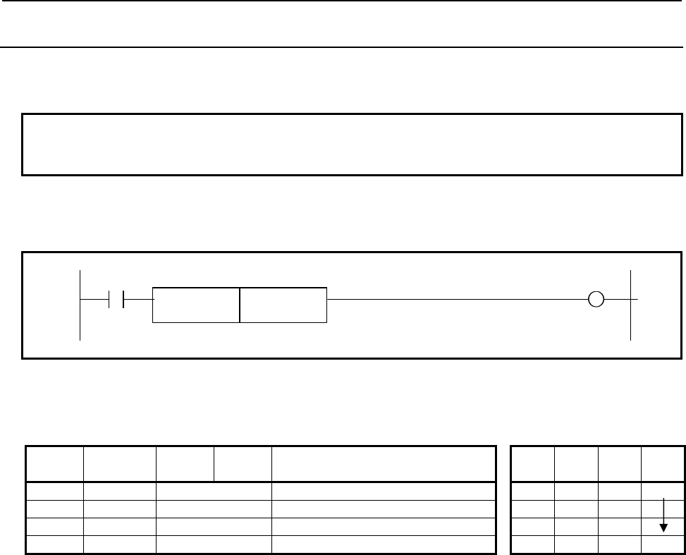
4.LADDER LANGUAGE
B-64513EN/03
- 536 -
4.11.6
PSGN2 (Position Signal: SUB 63)
This instruction is a position signal function. You can define the area of machine position for each PSGN2
instructions and you can know whether the current machine position is in the area or not.
NOTE
This instruction cannot be used in the 1st level whose execution cycle is 1ms or
2ms. It is processed as an NOP instruction.
Format
Fig. 4.11.6 shows the ladder format and Table 4.11.6 shows the mnemonic format.
ACT W1
SUB 63
PSGN2
{{{{ Control data (Address)
Fig. 4.11.6 Format of PSGN2 instruction
Table 4.11.6 Mnemonic of PSGN2 instruction
Mnemonic format Memory status of control
condition
Step
number Instruction Address
No. Bit No. Remarks ST3 ST2 ST1 ST0
1 RD {{{{ .{ ACT ACT
2 SUB 63 PSGN2 instruction
3 (PRM) {{{{ Control data (Address)
4 WRT {{{{ .{ Result W1
Control condition
(a) Command (ACT)
ACT=0: Do not execute the instruction. The W1 becomes 0.
ACT=1: Execute the instruction. The result is output to W1.
Parameters
(a) Control data
Set the top address of the control data. There are two format types for the control data. One is
"Extended format" and other is "Basic format". The "Extended format" can be specified the CNC path
or kind of machine position. The “Basic format” is for compatibility with conventional PMC system.
We recommend you to use the "Extended format" if you use this instruction on single-path CNC
system or you do not specify kind of machine position.
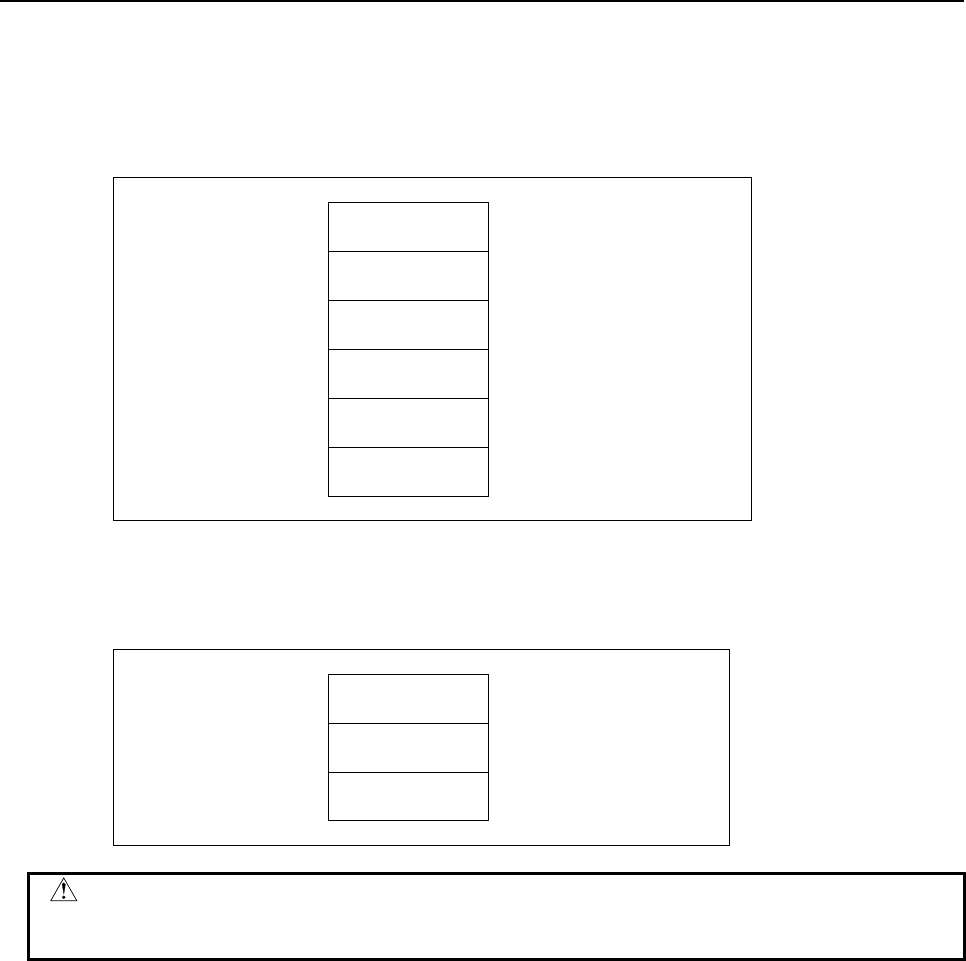
B-64513EN/03
4.LADDER LANGUAGE
- 537 -
[Extended format]
- Set first byte of the control data area to 0.
- You can specify kind of machine position.
- In case of multi-path CNC system, choose this format.
- The continuous 12-bytes memory is necessary.
Control data
(Extended format)
+0 0
(1byte)
Set zero.
+1 Kind of machine
position (1byte)
0: machine position
1: actual machine position
+2 CNC path number
(1byte)
1: path 1, 2: path 2...
+3 Axis number
(1byte)
1: 1st axis, 2: 2nd axis...
+4
Position a
(4byte)
Set to be a ≦ b.
+8
+11
Position b
(4byte)
[Basic format]
- This format is only available on single-path CNC system.
- The continuous 9-bytes memory is necessary.
Control data
(Basic format)
+0 Axis number
(1byte)
1: 1st axis, 2: 2nd axis...
+1
Position a
(4byte)
Set to be a ≦ b.
+5
+8
Position b
(4byte)
CAUTION
Be careful that it is recognized as "Extended format" if you set “Axis number” to 0
in the case of “Basic format”.
(i) Kind of machine position
This parameter is only available on "Extended format". Set the Kind of machine position with 1-byte
length binary data. If you set a value except for 0 or 1, this instruction terminates with error status and
W1 is turned off.
= 0: machine position
= 1: actual machine position
The machine position means that the value read by the window function code 28 "Reading the
Machine Position (Machine Coordinates) of Controlled Axes". The actual machine position means
that the value read by the window function code 428 "Reading the Actual Machine Position of
Controlled Axes".
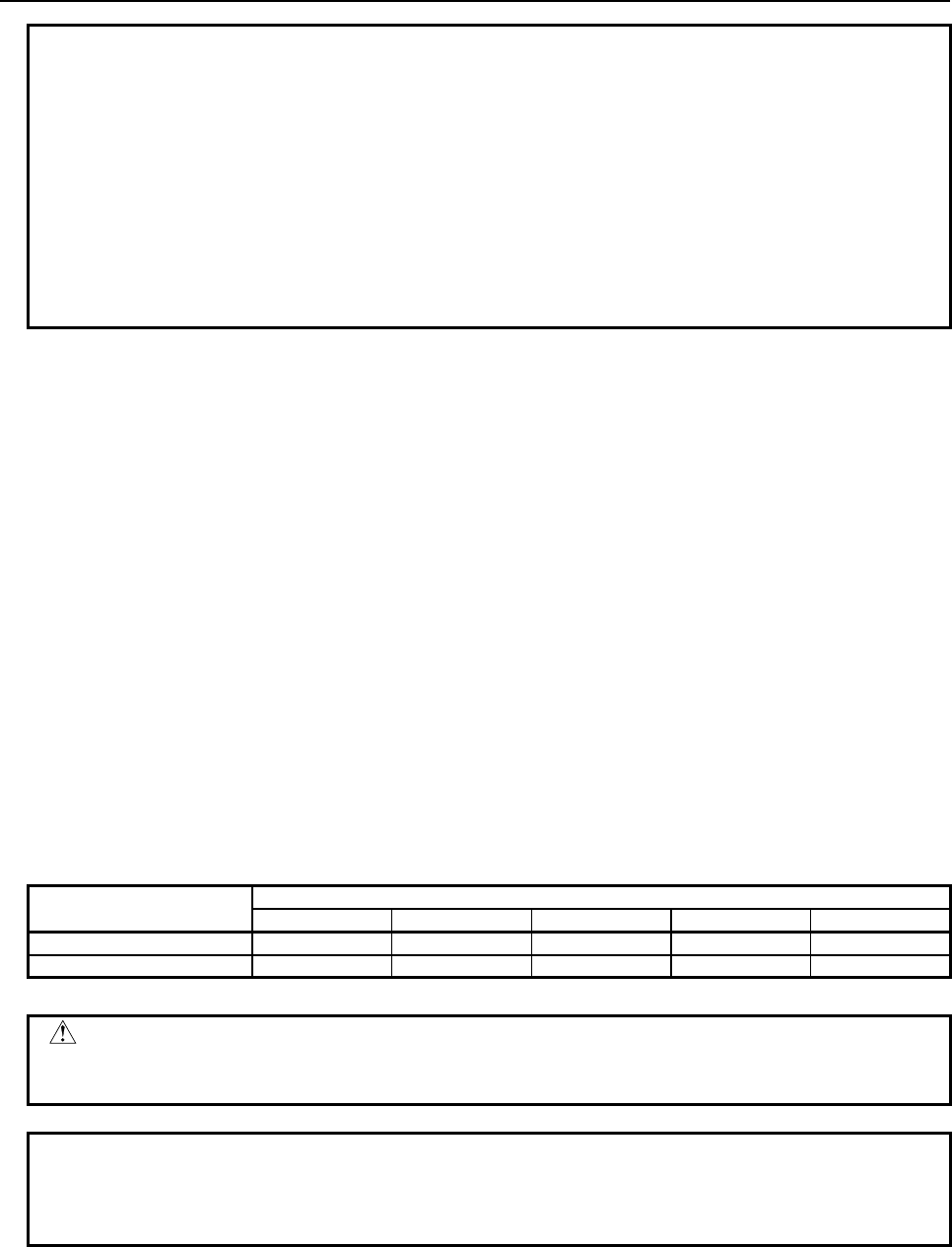
4.LADDER LANGUAGE
B-64513EN/03
- 538 -
NOTE
1 In case that CNC system software supports actual position reading function with
absolute-position detector, to use the actual position setting "Kind of machine
position" to 1, set the CNC parameter No.1806#5 and No.2224#1 to 1.
2 To use actual machine position that servo delay and acceleration/deceleration
delay is applied setting "Kind of machine position" to 1, set the CNC parameter
No.1806#5 to 0 and No.11313#7 to 1.
3 When "Kind of machine position" is 0, the update cycle of the machine position
becomes faster by setting the CNC parameter No. 11300#5 (MPH) to 1. You
should apply this setting only if necessary because this setting may lower the
performance of CNC a little.
(ii) CNC path number
This parameter is only available on "Extended format". Set the CNC path number with 1-byte length
binary data. If you set this parameter to zero, the path number is recognized as 1.
(Example)
= 1: 1st path CNC
= 2: 2nd path CNC
(iii) Axis number
Set the axis number with 1-byte length binary data. If you set this parameter to zero on "Extended
format", this instruction terminates with error.
(Example)
= 1: 1st axis
= 2: 2nd axis
(iv) Position a, b
Set the machine position with 4-bytes length binary data with machine unit. You must set positions to
be "Position a ≦ Position b". The position value "1" means the minimum unit of data with machine
unit.
For example, when the setting of minimum unit of data is "IS-B" and the setting of machine unit is
"mm", the position 10000 means "10.000mm".
Machine unit Minimum unit of data
IS-A IS-B IS-C IS-D IS-E
mm / deg. 0.01 0.001 0.0001 0.00001 0.000001
inch / deg. 0.001 0.0001 0.00001 0.000001 0.0000001
CAUTION
You must set positions to be "Position a ≦ Position b". If not, this instruction does
not work correctly.
NOTE
This instruction does not depend on the diameter or radius setting even using the
Diameter and Radius Setting Switching function. Set the position which depends
only on the setting of the CNC parameter No. 1006#3 (DIAx).
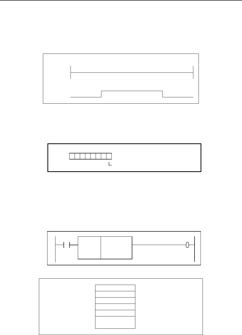
B-64513EN/03
4.LADDER LANGUAGE
- 539 -
Output (W1)
When the machine position is "Position a ≦ Machine position ≦ Position b", W1 is turned on.
W1=1: - ACT=1 and "Position a ≦ Machine position ≦ Position b"
W1=0: - ACT=0
- ACT=1 and "Machine position < Position a" or "Position b < Machine position"
- ACT=1 and invalid path or axis number is specified.
<The behavior of W1>
Machine
position
-
a b
+
W1=1
0
Operation Output Register (R9000, Z0)
When ACT=1 and some error occurs in this instruction, the corresponding bit of the operation output
register is set. In this case, W1 will be turned off. When ACT=0, the operation output register will not be
updated.
R9000
Z0
103 25 4
7 6
Invalid path or axis number
Example
The example of using this instruction is shown bellow.
- The control data address is R320.
- The setting of machine unit is "mm".
- The setting of minimum unit of data is "IS-B".
- The kind of machine position is actual machine position.
- The axis is 3rd axis on 2nd CNC path.
- The settings of machine position are "-800mm" and "123.456 mm".
SUB 63
PSGN2
R320
ACT W1
In this case, you should set the control data using "Extended format" as following.
Control data R320 0 (2byte) Set zero to this area.
(Extended format) R321 1 (1byte) 1: actual machine position
R322 2 (1byte) 2: path2
R323 3 (1byte) 3: 3rd axis
R324 -800000 (4byte) a = -800.000 mm
R328
R331
123456 (4byte) b = 123.456 mm
When ACT=1 and the machine position is equal or grater than -800 mm and is equal or smaller than
123.456 mm, the W1 is turned on.
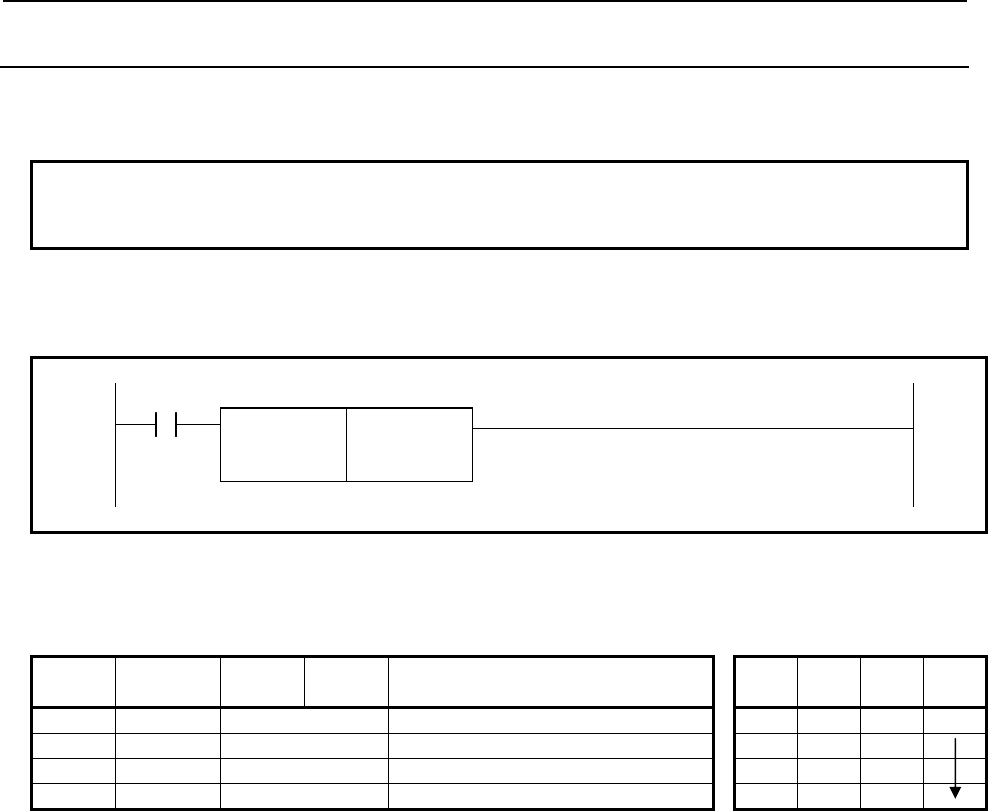
4.LADDER LANGUAGE
B-64513EN/03
- 540 -
4.11.7
PSGNL (Position Signal: SUB 50)
This instruction is a position signal function. You can define eight areas of machine position for each
PSGNL instructions and you can know the area where the machine position is currently located.
NOTE
This instruction cannot be used in the 1st level whose execution cycle is 1ms or
2ms. It is processed as an NOP instruction.
Format
Fig. 4.11.7 shows the ladder format and Table 4.11.7 shows the mnemonic format.
ACT
SUB 50
PSGNL
{{{{ Control data (Address)
{{{{ Output (Address)
Fig. 4.11.7 Format of PSGNL instruction
Table 4.11.7 Mnemonic of PSGNL instruction
Mnemonic format Memory status of control
condition
Step
number Instruction Address
No. Bit No. Remarks ST3 ST2 ST1 ST0
1 RD {{{{ .{ ACT ACT
2 SUB 50 PSGNL instruction
3 (PRM) {{{{ Control data (Address)
4 (PRM) {{{{ Output (Address)
Control condition
(a) Command (ACT)
ACT=0: Do not execute the instruction. The W1 becomes 0.
ACT=1: Execute the instruction. The result is output to "Output".
Parameters
(a) Control data
Set the top address of the control data. There are two format types for the control data. One is
"Extended format" and other is "Basic format". The "Extended format" can be specified the CNC path
or kind of machine position. The “Basic format” is for compatibility with conventional PMC system.
We recommend you to use the "Extended format" if you use this instruction on single-path CNC
system or you do not specify kind of machine position.

B-64513EN/03
4.LADDER LANGUAGE
- 541 -
[Extended format]
- Set first byte of the control data area to 0.
- You can specify kind of machine position.
- In case of multi-path CNC system, choose this format.
- The continuous 32-bytes memory is necessary.
Control data
(Extended format)
+0 0
(1byte)
Set zero.
+1 Kind of machine
position (1byte)
0: machine position
1: actual machine position
+2 CNC path number
(1byte)
1: path 1, 2: path 2...
+3 Axis number
(1byte)
1: 1st axis, 2: 2nd axis...
+4
Position a
(4byte)
Set to be a < b < c < d < e < f < g
+8 Position b
(4byte)
+12
Position c
(4byte)
+16
Position d
(4byte)
+20
Position e
(4byte)
+24
Position f
(4byte)
+28
+31
Position g
(4byte)
[Basic format]
- This format is only available on single-path CNC.
- The continuous 29-bytes memory is necessary.
Control data +0 Axis number
(1byte)
1: 1st axis, 2: 2nd axis...
+1 Position a
(4byte)
Set to be a < b < c < d < e < f < g
+5 Position b
(4byte)
+9
Position c
(4byte)
+13
Position d
(4byte)
+17
Position e
(4byte)
+21
Position f
(4byte)
+25
+28
Position g
(4byte)

4.LADDER LANGUAGE
B-64513EN/03
- 542 -
CAUTION
Be careful that it is recognized as "Extended format" if you set “Axis number” to 0
in the case of “Basic format”.
(i) Kind of machine position
This parameter is only available on "Extended format". Set the Kind of machine position with 1-byte
length binary data. If you set a value except for 0 or 1, this instruction terminates with error status and
W1 is turned off.
= 0: machine position
= 1: actual machine position
The machine position means that the value read by the window function code 28 "Reading the
Machine Position (Machine Coordinates) of Controlled Axes". The actual machine position means
that the value read by the window function code 428 "Reading the Actual Machine Position of
Controlled Axes".
NOTE
1 In case that CNC system software supports actual position reading function with
absolute-position detector, to use the actual position setting "Kind of machine
position" to 1, set the CNC parameter No.1806#5 and No.2224#1 to 1.
2 To use actual machine position that servo delay and acceleration/deceleration
delay is applied setting "Kind of machine position" to 1, set the CNC parameter
No.1806#5 to 0 and No.11313#7 to 1.
3 When "Kind of machine position" is 0, the update cycle of the machine position
becomes faster by setting the CNC parameter No. 11300#5 (MPH) to 1. You
should apply this setting only if necessary because this setting may lower the
performance of CNC a little.
(ii) CNC path number
This parameter is only available on "Extended format". Set the CNC path number with 1-byte length
binary data. If you set this parameter to zero, the path number is recognized as 1.
(Example)
= 1: 1st path CNC
= 2: 2nd path CNC
(iii) Axis number
Set the axis number with 1-byte length binary data. If you set this parameter to zero on "Extended
format", this instruction terminates with error.
(Example)
= 1: 1st axis
= 2: 2nd axis
(iv) Position a, b, c, d, e, f and g
Set the machine position with 4-bytes length binary data with machine unit. You must set positions to
be "Position a < b < c < d < e < f < g". The position value "1" means the minimum unit of data with
machine unit.
For example, when the setting of minimum unit of data is "IS-B" and the setting of machine unit is
"mm", the position 10000 means "10.000mm".
Machine unit Minimum unit of data
IS-A IS-B IS-C IS-D IS-E
mm / deg. 0.01 0.001 0.0001 0.00001 0.000001
inch / deg. 0.001 0.0001 0.00001 0.000001 0.0000001
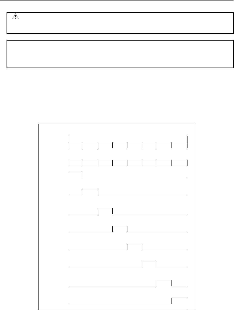
B-64513EN/03
4.LADDER LANGUAGE
- 543 -
CAUTION
1 You must set all positions to be "Position a < b < c < d < e < f < g". If not, this
instruction does not work correctly.
NOTE
This instruction does not depend on the diameter or radius setting even using the
Diameter and Radius Setting Switching function. Set the position which depends
only on the setting of the CNC parameter No. 1006#3 (DIAx).
(b) Output
Set the output address to this parameter. This output needs 1-byte length memory. When ACT=1, one
of the bits corresponding to the current machine position is turned on by this instruction. When
ACT=1 and any error occurs in this instruction, all bits of output will be turned off. When ACT=0, the
output will not be updated.
The correspondence between the setting of Position (a) to (g) and the bit signals of output are shown
below.
<The behavior of output>
Machine
Position
-
a b c d e f g
+
(1) (2) (3) (4) (5) (6) (7) (8)
7 6 5 4 3 2 1 0
Output (1) (2) (3) (4) (5) (6) (7) (8)
Output#7=1
=0
Output#6=1
=0
Output#5=1
=0
Output#4=1
=0
Output#3=1
=0
Output#2=1
=0
Output#1=1
=0
Output#0=1
=0
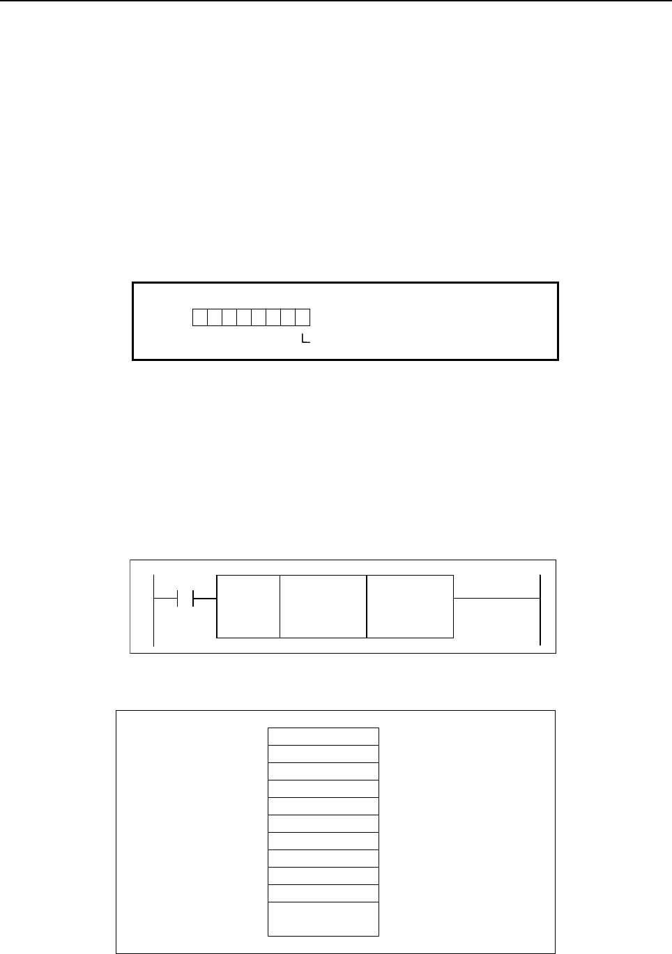
4.LADDER LANGUAGE
B-64513EN/03
- 544 -
When "Machine position ≦ a": Output#7=1
When "a < Machine position ≦ b": Output#6=1
When "b < Machine position ≦ c": Output#5=1
When "c < Machine position ≦ d": Output#4=1
When "d < Machine position ≦ e": Output#3=1
When "e < Machine position ≦ f": Output#2=1
When "f < Machine position ≦ g": Output#1=1
When "g < Machine position": Output#0=1
Operation Output Register (R9000, Z0)
When ACT=1 and any error occurs in this instruction, the corresponding bit of the operation output register
is set. In this case, all bits of output will be turned off. When ACT=0, the operation output register will not
be updated.
R9000
Z0
103 25 4
7 6
Invalid path or axis number
Example
The example of using this instruction is shown bellow.
- The control data address is R320.
- The output address is R319.
- The setting of machine unit is "mm".
- The setting of minimum unit of data is "IS-B".
- The kind of machine position is actual machine position.
- The axis is 3rd axis on 2nd CNC path.
- The each positions are "a = -400 mm", "b = -200 mm", "c = -100 mm", "d = 0 mm", "e = 10 mm",
"f = 100 mm" and "g = 123.456 mm".
SUB 50
PSGNL
R320
ACT R319
In this case, you should set the control data as following.
Control data R320 0 (1byte) Set zero to this area.
R321 1 (1byte) 1: actual machine position
R322 2 (1byte) 2: path2
R323 3 (1byte) 3: 3rd axis
R324 -400000 (4byte) a = -400 mm
R328 -200000 (4byte) b = -200 mm
R332 -100000 (4byte) c = -100 mm
R336 0 (4byte) d = 0 mm
R340 10000 (4byte) e = 10 mm
R344 100000 (4byte) f = 100 mm
R348
R351
123456 (4byte) g = 123.456 mm

B-64513EN/03
4.LADDER LANGUAGE
- 545 -
When "Machine pos. ≦ -400 mm": R319.7=1
When "-400 mm < Machine pos. ≦ -200 mm": R319.6=1
When "-200 mm < Machine pos. ≦ -100 mm": R319.5=1
When "-100 mm < Machine pos. ≦ 0 mm": R319.4=1
When "0 mm < Machine pos. ≦ 10 mm": R319.3=1
When "10 mm < Machine pos. ≦ 100 mm": R319.2=1
When "100 mm < Machine pos. ≦ 123.456 mm": R319.1=1
When "123.456 mm < Machine pos.": R319.0=1

4.LADDER LANGUAGE
B-64513EN/03
- 546 -
4.12 PROGRAM CONTROL
The following types of program control instruction are available. Use any of these instructions as
appropriate for your purpose.
Instruction name Sub number Processing
1 COM 9 Common line control
2 COME 29 Common line control end
3 JMP 10 Jump
4 JMPE 30 Jump end
5 JMPB 68 Label jump 1
6 JMPC 73 Label jump 2
7 LBL 69 Label
8 CALL 65 Conditional subprogram call
9 CALLU 66 Unconditional subprogram call
10 SP 71 Subprogram
11 SPE 72 End of a subprogram
12 END1 1 End of a first level program
13 END2 2 End of a second level program
14 END3 48 End of a third level program
15 END 64 End of a ladder program
16 NOP 70 No operation
17 CS 74 Case call
18 CM 75 Sub program call in case call
19 CE 76 End of case call
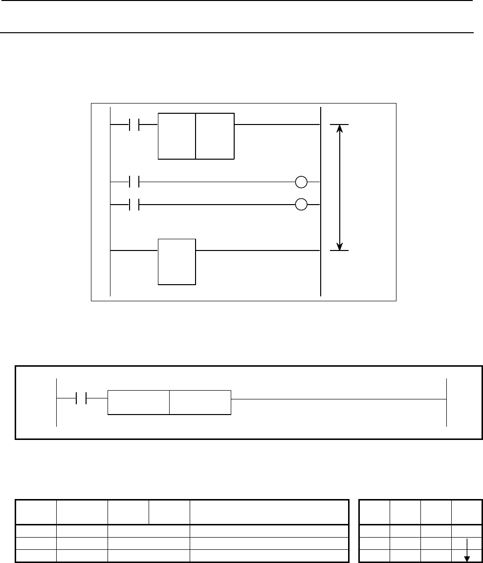
B-64513EN/03
4.LADDER LANGUAGE
- 547 -
4.12.1
COM (Common Line Control: SUB 9)
The coils in a region up to the common line control end instruction (COME) are controlled.
This instruction can control whole coils in section of the common line control.
When COME instruction is not specified bottom of the section, the "COM FUNCTION MISSING" error
results.
Range in
which the
COM
instruction is
effective
SUB 9
COM
0
SUB 29
COME
A
CT
Fig. 4.12.1 (a) Function of COM instruction
Format
Fig. 4.12.1 (b) shows the ladder format and Table 4.12.1 shows the mnemonic format.
ACT
SUB 9
COM 0
Fig. 4.12.1 (b) Format of COM instruction
Table 4.12.1 Mnemonic of COM instruction
Mnemonic format Memory status of control
condition
Step
number Instruction Address
No. Bit No. Remarks ST3 ST2 ST1 ST0
1 RD {{{{ .{ ACT ACT
2 SUB 9 COM instruction
3 (PRM) 0 Specify 0.
Control conditions
ACT=0: The coils within the region specified are unconditionally turned off (set to 0).
ACT=1: The program operates in the same way as when COM is not used.
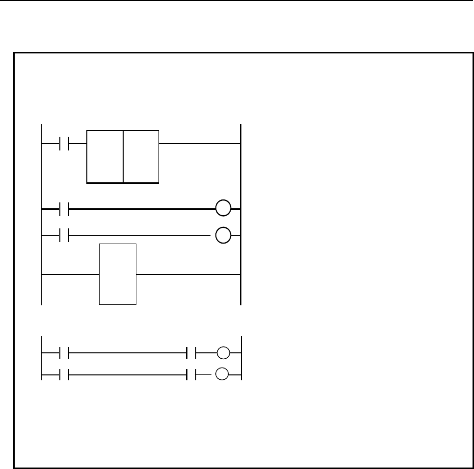
4.LADDER LANGUAGE
B-64513EN/03
- 548 -
Parameter
(a) Specify 0.
NOTE
1 The ladder diagram that includes the COM instruction as shown “Fig.1” is similar
in logic to the ladder diagram as shown “Fig.2”.
Fig.1
SUB 9
COM
0
A
C
T
ON OUT1
SUB 29
COME
{
OFF OUT
2
Fig.2
ON ACT OUT1
OFF ACT OUT2
{
2 A functional instruction in a range specified by COM executes processing,
regardless of ACT for COM. However, if ACT=0 for COM, the coil of the execution
result becomes 0.
3 Another COM instruction cannot be specified in the range by the COM instruction.
4 When the ACT of COM instruction is set to 0, coils of WRT.NOT instruction in the
range of common line becomes 1 unconditionally as described in NOTE 1.
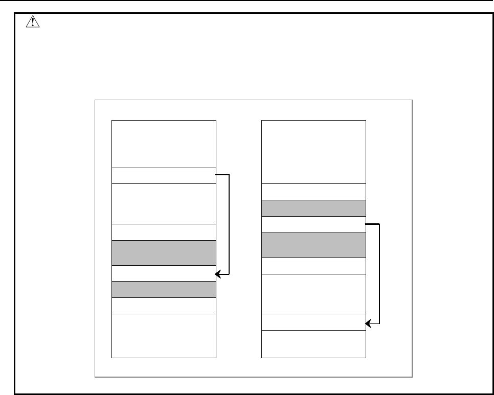
B-64513EN/03
4.LADDER LANGUAGE
- 549 -
CAUTION
Do not create a program in which a combination of JMP and JMPE instructions is
used to cause a jump to and from a sequence between the COM and COME
instructions. The ladder sequence may not be able to operate normally after the
jump.
JMP instruction
COM instruction
COME instruction
×
Prohibited
JMPE instruction
JMP instruction
COM instruction
COME instruction
JMPE instruction
×
Prohibited
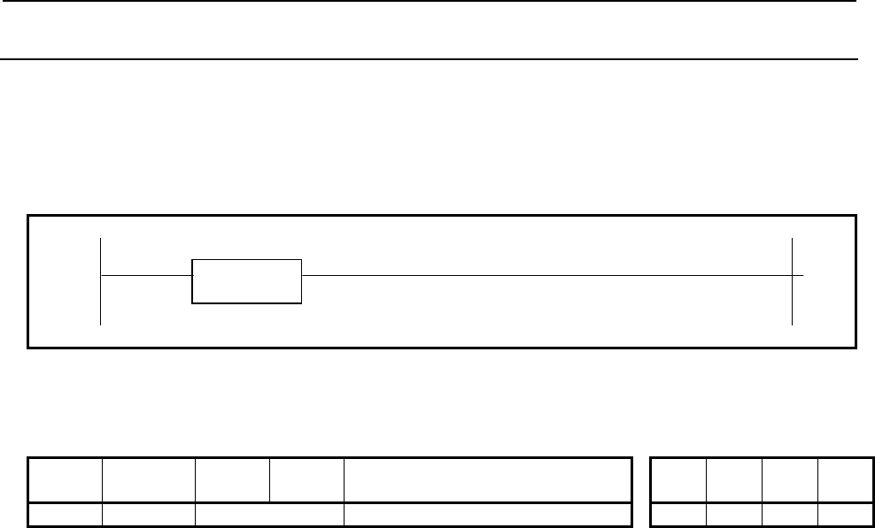
4.LADDER LANGUAGE
B-64513EN/03
- 550 -
4.12.2
COME (Common Line Control End: SUB 29)
This instruction indicates the end of region of common line control instruction (COM).
This instruction cannot be used alone. It must he used together with the COM instruction.
Format
Fig. 4.12.2 shows the ladder format and Table 4.12.2 shows the mnemonic format.
SUB 29
COME
Fig. 4.12.2 Format of COME instruction
Table 4.12.2 Mnemonic of COME instruction
Mnemonic format Memory status of control
condition
Step
number Instruction Address
No. Bit No. Remarks ST3 ST2 ST1 ST0
1 SUB 29 COME instruction
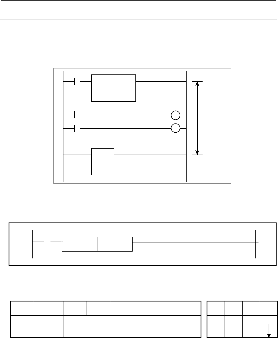
B-64513EN/03
4.LADDER LANGUAGE
- 551 -
4.12.3
JMP (Jump: SUB 10)
The JMP instruction causes a departure from the normal sequence to executing instructions. When a JMP
instruction is specified, processing jumps to a jump end instruction (JMPE) without executing the logical
instructions (including functional instructions) in the range delimited by a jump end instruction (JMPE).
(See Fig. 4.12.3 (a).) Specify a range to be skipped using the jump end instruction.
When the jump end instruction is not specified, the message JUMP FUNCTION MISSING is displayed.
Valid range
of the JMP
instruction
SUB 10
JMP
0
SUB 30
JMPE
A
CT
Fig. 4.12.3 (a) Function of JMP instruction
Format
Fig. 4.12.3 (b) shows the ladder format and Table 4.12.3 shows the mnemonic format.
ACT
SUB 10
JMP 0
Fig. 4.12.3 (b) Format of JMP instruction
Table 4.12.3 Mnemonic of JMP instruction
Mnemonic format Memory status of control
condition
Step
number Instruction Address
No. Bit No. Remarks ST3 ST2 ST1 ST0
1 RD {{{{ .{ ACT ACT
2 SUB 10 JMP instruction
3 (PRM) 0 Specify 0.
Control conditions
ACT=1: The logical instructions (including functional instructions) to next JMPE instruction are skipped.
ACT=0: The JMP instruction is ignored. It is performed from next step.

4.LADDER LANGUAGE
B-64513EN/03
- 552 -
Parameters
(a) Specify 0.
CAUTION
When you use this instruction between COM and COME instructions, the ladder
sequence may not be able to operate normally. For details, refer to “CAUTION” of
the section of COM instruction.
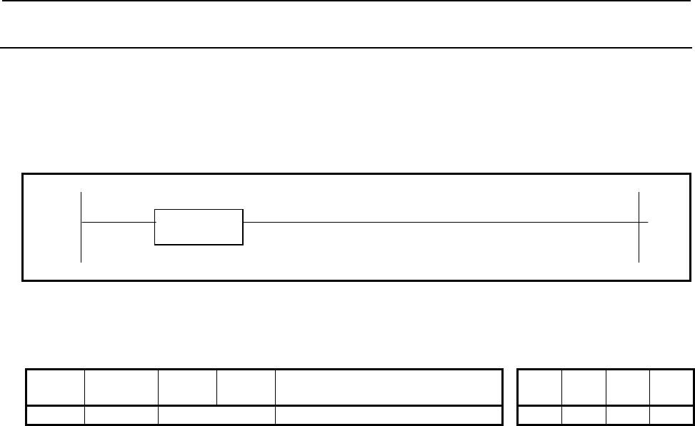
B-64513EN/03
4.LADDER LANGUAGE
- 553 -
4.12.4
JMPE (Jump End: SUB 30)
This instruction indicates the end of region of jump instruction (JMP).
This instruction cannot be used alone. It must be used together with the JMP instruction.
Format
Fig. 4.12.4 shows the ladder format and Table 4.12.4 shows the mnemonic format.
SUB 30
JMPE
Fig. 4.12.4 Format of JMPE instruction
Table 4.12.4 Mnemonic of JMPE instruction
Mnemonic format Memory status of control
condition
Step
number Instruction Address
No. Bit No. Remarks ST3 ST2 ST1 ST0
1 SUB 30 JMPE instruction
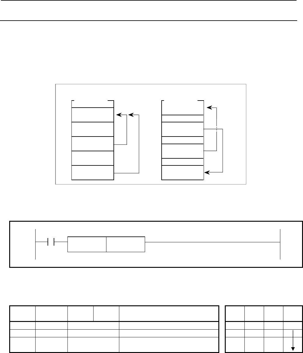
4.LADDER LANGUAGE
B-64513EN/03
- 554 -
4.12.5
JMPB (Label Jump 1: SUB 68)
This instruction transfers the control of ladder program to specified label.
It can jump freely before and after the instruction within main program or subprogram in which the
instruction is coded.
JMPB instruction is effective in the following programming.
• More than one jump instruction can be coded for the same label.
• Jump instructions can be nested.
Format
Fig. 4.12.5 shows the ladder format and Table 4.12.5 shows the mnemonic format.
ACT
SUB 68
JMPB L{{{{ Specification of the jump destination label
Fig. 4.12.5 Format of JMPB instruction
Table 4.12.5 Mnemonic of JMPB instruction
Mnemonic format Memory status of control
condition
Step
number Instruction Address
No. Bit No. Remarks ST3 ST2 ST1 ST0
1 RD {{{{ .{ ACT ACT
2 SUB 68 JMPB instruction
3 (PRM) L{{{{ Specification of the jump destination
label
Control conditions
ACT=0: The next instruction after the JMPB instruction is executed.
ACT=1: Control is transferred to the Ladder immediately after the specified label.
Program unit Program unit
LBL AA
LBL AA
JMPB BB
JMPB AA
JMPB AA
JMPB AA LBL BB
Ladder program

B-64513EN/03
4.LADDER LANGUAGE
- 555 -
Parameters
(a) Label specification
Specify the label of the jump destination. The label number must be specified in the L address form.
A value from L1 to L9999 can be specified.
CAUTION
1 For the specifications of this instruction, see the description of functional
instruction JMP.
2 When this instruction is used for jump back to a previous instruction, take care not
to cause an infinite loop.
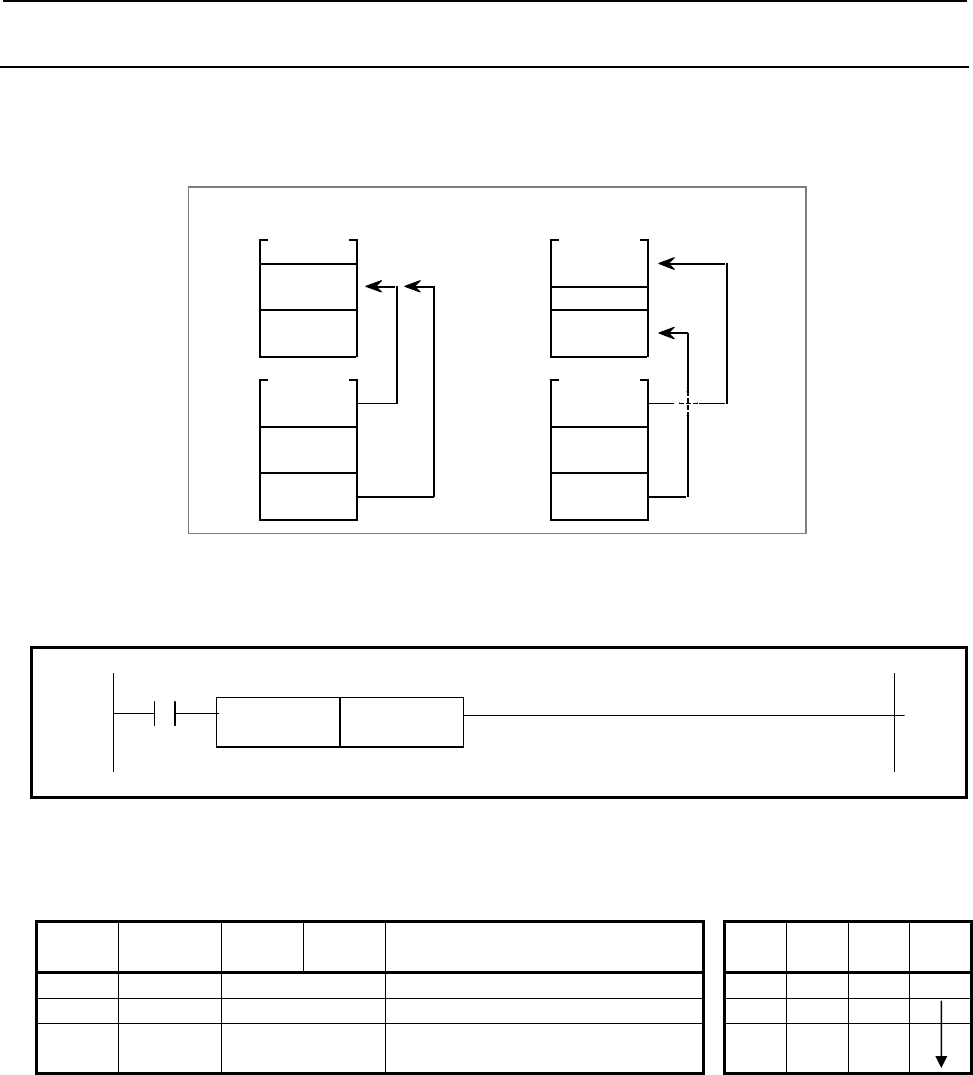
4.LADDER LANGUAGE
B-64513EN/03
- 556 -
4.12.6
JMPC (Label Jump 2: SUB 73)
This instruction returns the control from a subprogram to the main program of 2nd level. Be sure to code
the destination label in the main program of 2nd level. More than one jump instruction can be coded for the
same label.
JMPC AA
Ladder
p
ro
g
ram
Main program
LBL AA
LBL BB
JMPC BB
LBL AA
JMPC AA
JMPC AA
Subprogram
Main program
Subprogram
Format
Fig. 4.12.6 shows the ladder format and Table 4.12.6 shows the mnemonic format.
ACT
SUB 73
JMPC L{{{{ Specification of the jump destination label
Fig. 4.12.6 Format of JMPC instruction
Table 4.12.6 Mnemonic of JMPC instruction
Mnemonic format Memory status of control
condition
Step
number Instruction Address
No. Bit No. Remarks ST3 ST2 ST1 ST0
1 RD {{{{ .{ ACT ACT
2 SUB 73 JMPC instruction
3 (PRM) L{{{{ Specification of the jump destination
label
Control conditions
ACT=0: The instruction after the JMPC instruction is executed.
ACT=1: Control is transferred to the Ladder after the specified label.

B-64513EN/03
4.LADDER LANGUAGE
- 557 -
Parameters
(a) Label specification
Specify the label of the jump destination. The label number must be specified in the L address form.
A number from L1 to L9999 can be specified.
CAUTION
1 For the specifications of this instruction, see the description of functional
instruction JMP.
2 When this instruction is used for jump back to a previous instruction, take care not
to cause an infinite loop.
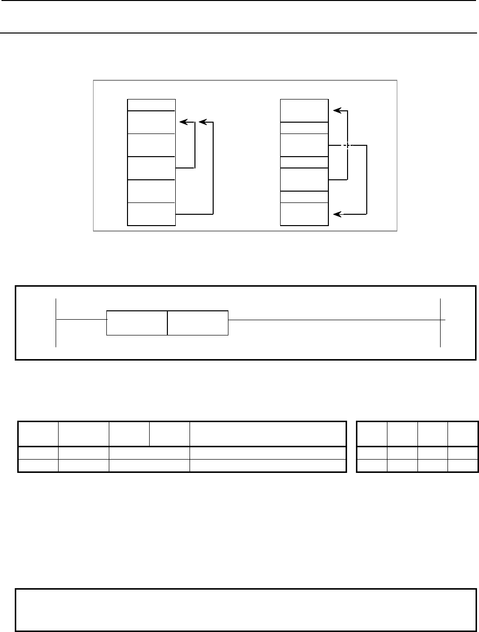
4.LADDER LANGUAGE
B-64513EN/03
- 558 -
4.12.7
LBL (Label: SUB 69)
It specifies the jump destination for the JMPB and JMPC instructions. (See the explanation of the JMPB
and JMPC instructions.)
Ladder program
LBL AA
LBL AA
JMPB BB
JMPB AA
JMPC AA
JMPC AA LBL BB
Format
Fig. 4.12.7 shows the ladder format and Table 4.12.7 shows the mnemonic format.
SUB 69
LBL L{{{{ Label specification
Fig. 4.12.7 Format of LBL instruction
Table 4.12.7 Mnemonic of LBL instruction
Mnemonic format Memory status of control
condition
Step
number Instruction Address
No. Bit No. Remarks ST3 ST2 ST1 ST0
1 SUB 69 LBL instruction
2 (PRM) L{{{{ Label specification
Parameters
(a) Label specification
Specify the jump destination for the JMPB and JMPC instructions. The label number must be
specified in the L address form. A label number from L1 to L9999 can be specified. Up to 256 labels
can be used in the main programs (level 1, level 2 and level3). Up to 256 labels can be used in a sub
program. The label number may be used to overlap in between the main program and sub program, or
in some sub programs.
NOTE
For the use of this instruction, see the description of functional instruction JMPB
and JMPC.
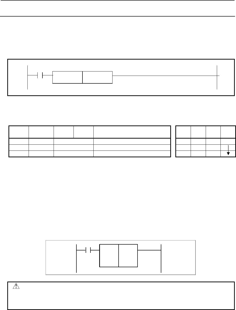
B-64513EN/03
4.LADDER LANGUAGE
- 559 -
4.12.8
CALL (Conditional Subprogram Call: SUB 65)
This instruction calls a subprogram. When a subprogram number is specified in CALL, a jump occurs to
the subprogram if a condition is satisfied.
Format
Fig. 4.12.8 shows the ladder format and Table 4.12.8 shows the mnemonic format.
ACT
SUB 65
CALL P{{{{ Subprogram number
Fig. 4.12.8 Format of CALL instruction
Table 4.12.8 Mnemonic of CALL instruction
Mnemonic format Memory status of control
condition
Step
number Instruction Address
No. Bit No. Remarks ST3 ST2 ST1 ST0
1 RD {{{{ .{ ACT ACT
2 SUB 65 CALL instruction
3 (PRM) P{{{{ Subprogram number
Control conditions
(a) Input signal
ACT=0: The CALL instruction is not executed.
ACT=1: The CALL instruction is executed.
Parameters
(a) Subprogram number
Specify the subprogram number of a subprogram to be called. The subprogram number must be
specified in the P address form.
Example: Calling of subprogram 1
SUB 65
CALL
P1
A
CT
CAUTION
Be careful when using the CALL instruction with the COM, COME, JMP, or JMPE
functional instruction.
For details, see Subsection 1.4.4.
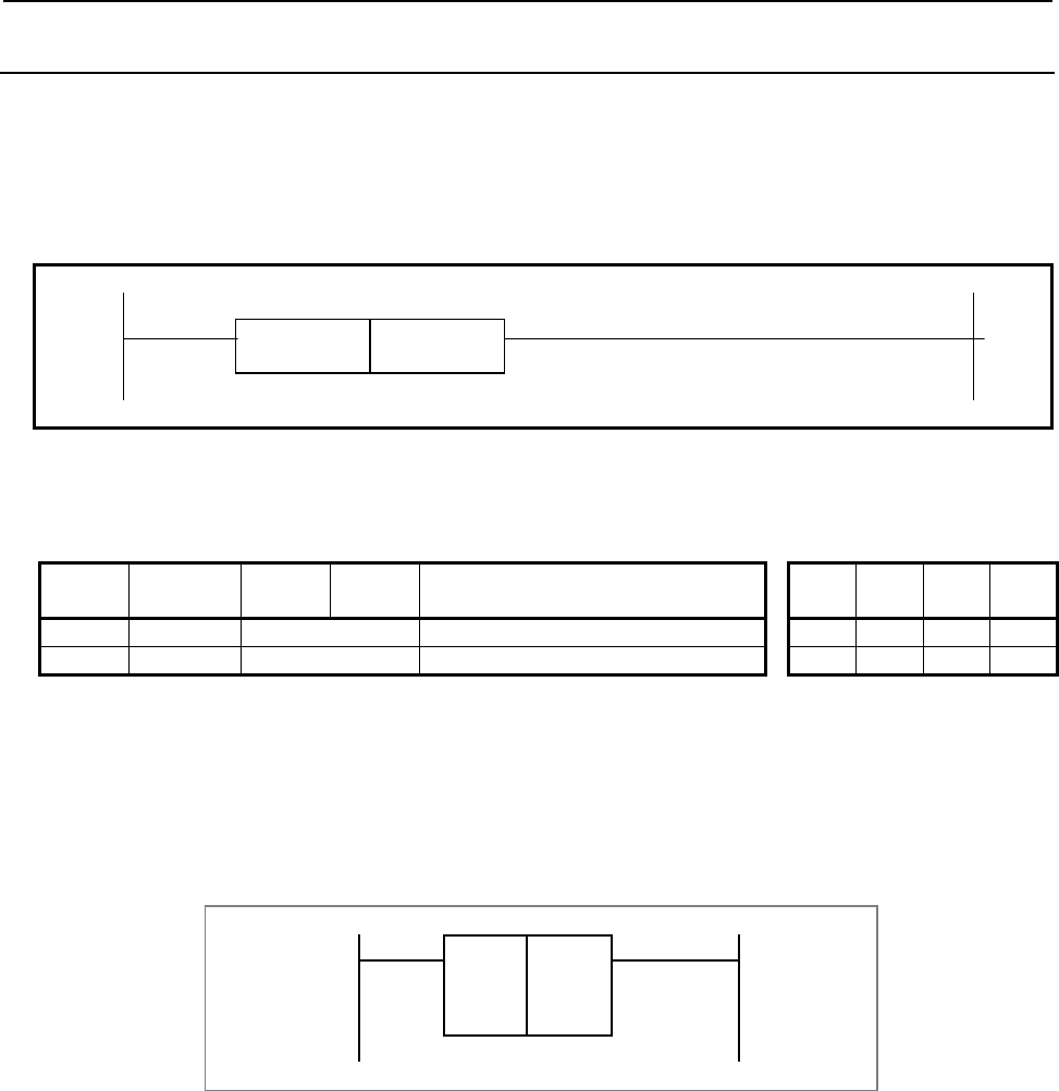
4.LADDER LANGUAGE
B-64513EN/03
- 560 -
4.12.9
CALLU (Unconditional Subprogram Call: SUB 66)
This instruction calls a subprogram. When a subprogram number is specified, a jump occurs to the
subprogram.
Format
Fig. 4.12.9 shows the ladder format and Table 4.12.9 shows the mnemonic format.
SUB 66
CALLU P{{{{ Subprogram number
Fig. 4.12.9 Format of CALLU instruction
Table 4.12.9 Mnemonic of CALLU instruction
Mnemonic format Memory status of control
condition
Step
number Instruction Address
No. Bit No. Remarks ST3 ST2 ST1 ST0
1 SUB 66 CALLU instruction
2 (PRM) P{{{{ Subprogram number
Parameters
(a) Subprogram number
Specify the subprogram number of a subprogram to be called. The subprogram number must be
specified in the P address form.
Example: Calling of subprogram 1
SUB 66
CALLU
P1
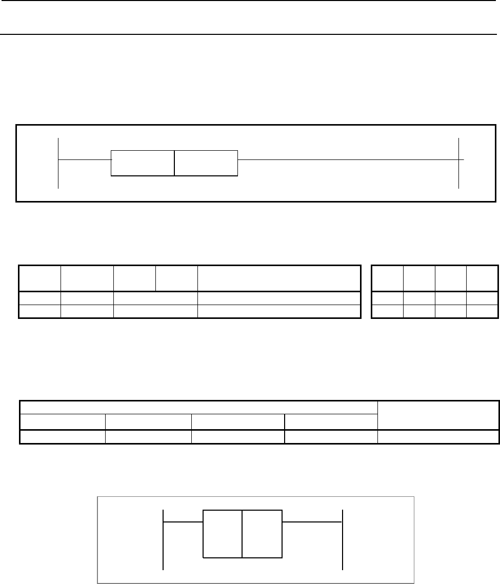
B-64513EN/03
4.LADDER LANGUAGE
- 561 -
4.12.10
SP (Subprogram: SUB 71)
This instruction is used to create a subprogram. A subprogram number is specified as a subprogram name.
SP is used with the SPE functional instruction (mentioned later) to specify the subprogram range.
Format
Fig. 4.12.10 shows the ladder format and Table 4.12.10 shows the mnemonic format.
SUB 71
SP P{{{{ Subprogram number
Fig. 4.12.10 Format of SP instruction
Table 4.12.10 Mnemonic of SP instruction
Mnemonic format Memory status of control
condition
Step
number Instruction Address
No. Bit No. Remarks ST3 ST2 ST1 ST0
1 SUB 71 SP instruction
2 (PRM) P{{{{ Subprogram number
Parameters
(a) Subprogram number
Specify the subprogram number of a subprogram to be coded following this instruction. The
subprogram number must be specified in the P address form.
1st to 5th path PMC Dual check safety PMC
PMC Memory-A PMC Memory-B PMC Memory-C PMC Memory-D
P1 to P512 P1 to P5000 P1 to P5000 P1 to P5000 P1 to P512
The specified subprogram number must be unique within the sequence program.
Example: When the subprogram number is set to 1
SUB 71
SP
P1
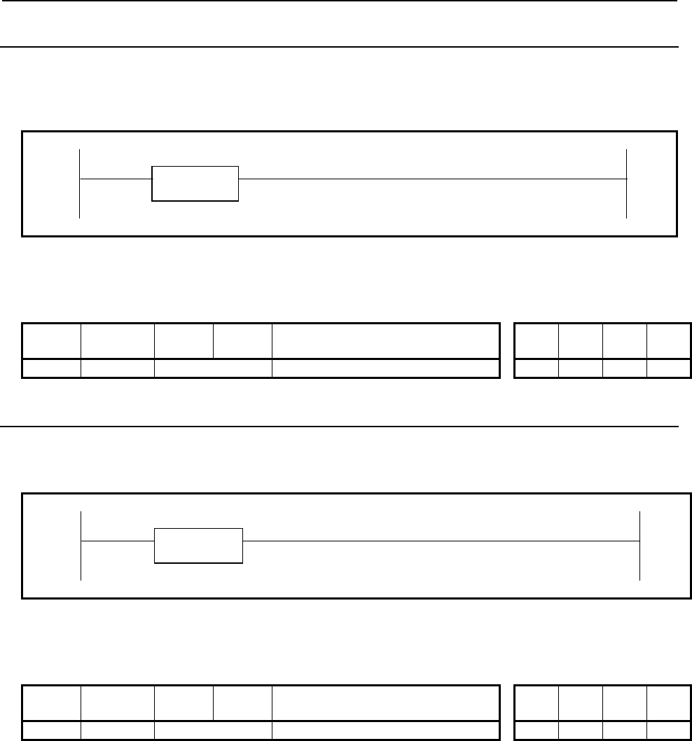
4.LADDER LANGUAGE
B-64513EN/03
- 562 -
4.12.11
SPE (End of a Subprogram: SUB 72)
This instruction indicates the end of a subprogram. SPE is used with the SP functional instruction. It
specifies the range of a subprogram. When this functional instruction has been executed, control is returned
to the functional instruction that called the subprogram.
SUB 72
SPE
Fig. 4.12.11 Format of SPE instruction
Table 4.12.11 Mnemonic of SPE instruction
Mnemonic format Memory status of control
condition
Step
number Instruction Address
No. Bit No. Remarks ST3 ST2 ST1 ST0
1 SUB 72 SPE instruction
4.12.12
END1 (1st Level Sequence Program End: SUB 1)
This instruction indicates the end of 1st level sequence. When there is no 1st level sequence, this is specified
at the beginning of the 2nd level sequence.
SUB 1
END1
Fig. 4.12.12 Format of END1 instruction
Table 4.12.12 Mnemonic of END1 instruction
Mnemonic format Memory status of control
condition
Step
number Instruction Address
No. Bit No. Remarks ST3 ST2 ST1 ST0
1 SUB 1 END1 instruction
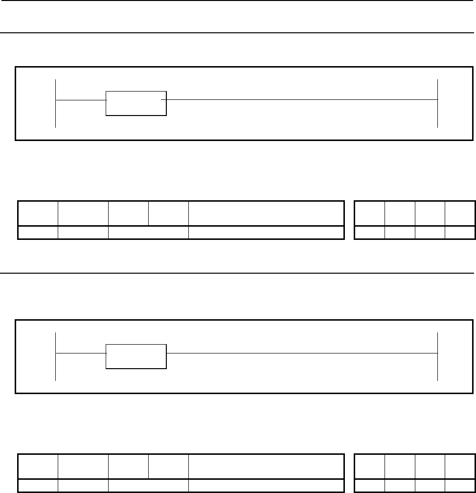
B-64513EN/03
4.LADDER LANGUAGE
- 563 -
4.12.13
END2 (2nd Level Sequence Program End: SUB 2)
This instruction indicates the end of 2nd level sequence.
SUB 2
END2
Fig. 4.12.13 Format of END2 instruction
Table 4.12.13 Mnemonic of END2 instruction
Mnemonic format Memory status of control
condition
Step
number Instruction Address
No. Bit No. Remarks ST3 ST2 ST1 ST0
1 SUB 2 END2 instruction
4.12.14
END3 (3rd Level Sequence Program End: SUB 48)
This instruction indicates the end of 3rd level sequence program. If there is no 3rd level sequence program,
this instruction need not be specified.
SUB 48
END3
Fig. 4.12.14 Format of END3 instruction
Table 4.12.14 Mnemonic of END3 instruction
Mnemonic format Memory status of control
condition
Step
number Instruction Address
No. Bit No. Remarks ST3 ST2 ST1 ST0
1 SUB 48 END3 instruction
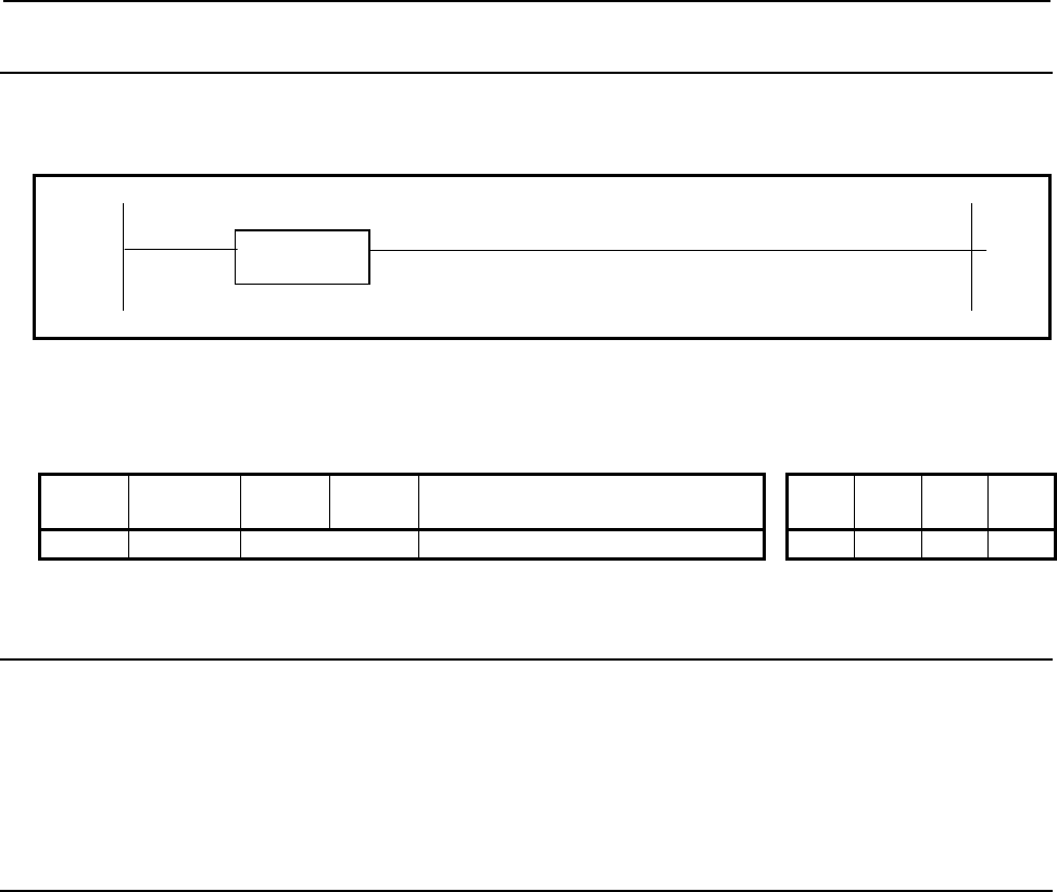
4.LADDER LANGUAGE
B-64513EN/03
- 564 -
4.12.15
END (End of a Ladder Program: SUB 64)
This instruction indicates the end of the end of a ladder program. END must be placed at the end of the
ladder program.
SUB 64
END
Fig. 4.12.15 Format of END instruction
Table 4.12.15 Mnemonic of END instruction
Mnemonic format Memory status of control
condition
Step
number Instruction Address
No. Bit No. Remarks ST3 ST2 ST1 ST0
1 SUB 64 END instruction
4.12.16
NOP (No Operation: SUB 70)
During creation of a ladder program using the programmer, if the program is compiled with specifying the
setting with which a net comment or form feed code is used and the point of the net comment is output,
position information of the net comment or form feed code is output as the NOP instruction. This
instruction performs no operation during execution of the ladder.
4.12.17
CS (Case Call: SUB 74)
The combination of one CS, one or more CM and one CE is used to construct a case call block.
The CS starts the case call block and the CE ends the block. Each CM that should be located between the CS
and CE specifies a sub program to be called in each case.
Executing case call block, the CS instruction evaluates the case number from its 1st parameter and only one
of CMs that is selected by the case number is activated and calls its associated sub program. When the case
number is 0, the 1st CM immediately after CS is executed and certain sub program is called. When the case
number is 1, the 2nd CM after CS is executed. The number from 0 to 255 is allowed as the case number.
When the case number except 0 through 255 is detected on CS, no sub program is called.
The CM instructions should be programmed immediately after the CS. Other functions except CM must not
be programmed between CS and CE. If not so, an error will be detected in ending of edit.
The case call block is available only in LEVEL2 and outside of a COM and COME block where normal
subprogram call instructions such as CALL and CALLU are allowed. The case call block can be
programmed wherever normal subprogram call instructions can be programmed.
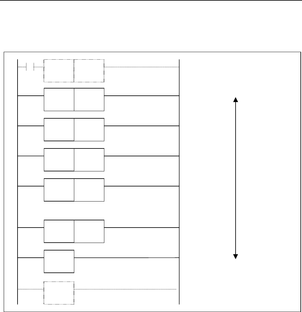
B-64513EN/03
4.LADDER LANGUAGE
- 565 -
In the following example program, the sub program corresponding to the case number is called.
• R100 = 0: The sub program P10 is called.
• R100 = 1: The sub program P20 is called.
• R100 = 2: The sub program P50 is called.
• R100 = n: The sub program P15 is called.
SUB74
CS
R100 Case number
SUB75
CM
P10 Sub
p
ro
g
ram address
SUB76
CE
SUB75
CM
P20 Sub
p
ro
g
ram address
SUB75
CM
P50 Sub
p
ro
g
ram address
SUB75
CM
P15 Sub
p
ro
g
ram address
Case number 0
Case number 1
Case number 2
Case number n
(255 in maximum)
..............
Case Call Block
SUB10
JMP
0
SUB30
JMPE
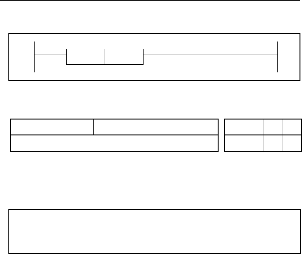
4.LADDER LANGUAGE
B-64513EN/03
- 566 -
Format
Fig. 4.12.17 shows the ladder format and Table 4.12.17 shows the mnemonic format.
SUB 74
CS {{{{ Case number (Signed integer in 2 bytes length)
Fig. 4.12.17 Format of CS instruction
Table 4.12.17 Mnemonic of CS instruction
Mnemonic format Memory status of control
condition
Step
number Instruction Address
No. Bit No. Remarks ST3 ST2 ST1 ST0
1 SUB 74 CS instruction
2 (PRM) {{{{ Case number (Address)
Parameters
(a) Case number
Set the address or symbol of the variable in which the case number is stored and commanded. The data
type is signed integer in 2 bytes length.
NOTE
Case number is evaluated by CS only once in every cycle. Even if you change the
case number in the sub program which is called by the case call block, this change
becomes effective in next cycle. This means that only one or no sub program is
called in each case call block in each cycle.
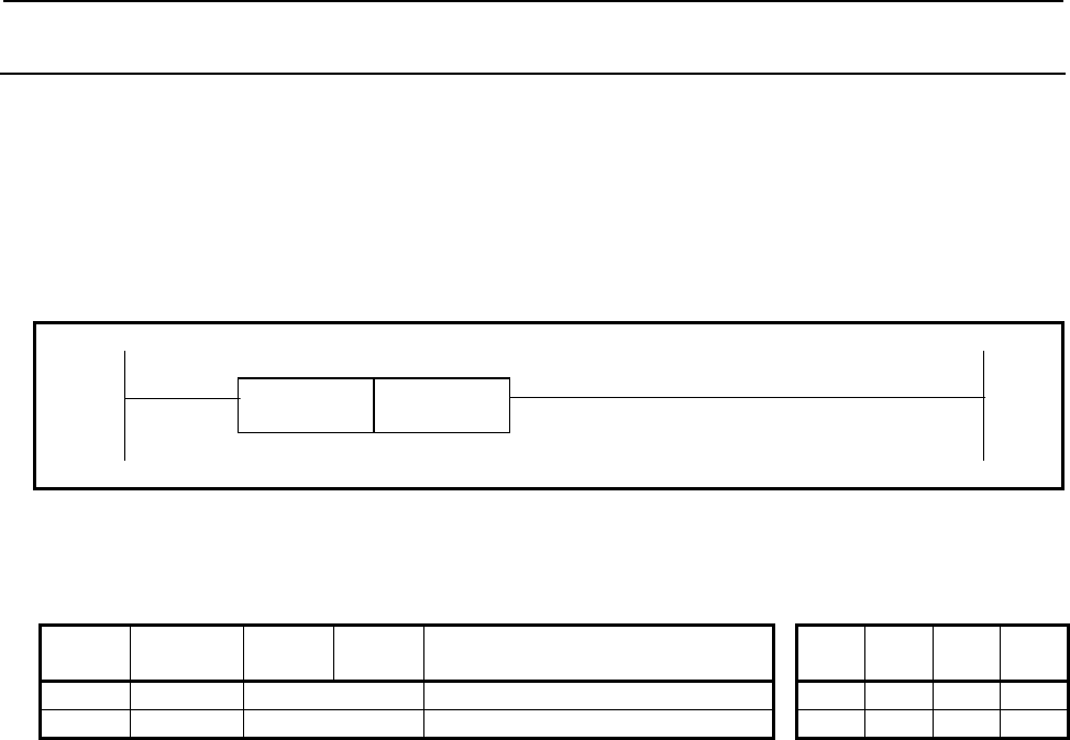
B-64513EN/03
4.LADDER LANGUAGE
- 567 -
4.12.18
CM (Sub Program Call in Case Call: SUB 75)
The combination of one CS, one or more CM and one CE is used to construct a case call block.
The CM that should be located between the CS and CE is used to specify a sub program to be called when
the case number meets the condition.
See the section 4.12.17 CS (Case Call: SUB 74) in details.
Format
Fig. 4.12.18 shows the ladder format and Table 4.12.18 shows the mnemonic format.
SUB 75
CM P{{{{ Sub program address (P address)
Fig. 4.12.18 Format of CM instruction
Table 4.12.18 Mnemonic of CM instruction
Mnemonic format Memory status of control
condition
Step
number Instruction Address
No. Bit No. Remarks ST3 ST2 ST1 ST0
1 SUB 75 CM instruction
2 (PRM) P{{{{ Sub program address (P address)
Parameters
(a) Sub program address
Set a P address or symbol of a sub program that is call in the case.
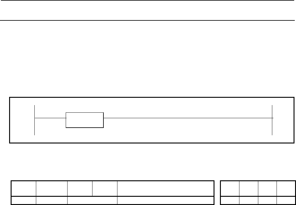
4.LADDER LANGUAGE
B-64513EN/03
- 568 -
4.12.19
CE (End of Case Call: SUB 76)
The combination of one CS, one or more CM and one CE is used to construct a case call block.
The CE ends the case call block.
See the section 4.12.17 CS (Case Call: SUB 74) in details.
Format
Fig.4.12.19 shows the ladder format and Table 4.12.19 shows the mnemonic format.
SUB 76
CE
Fig. 4.12.19 Format of CE instruction
Table 4.12.19 Mnemonic of CE instruction
Mnemonic format Memory status of control
condition
Step
number Instruction Address
No. Bit No. Remarks ST3 ST2 ST1 ST0
1 SUB 76 CE instruction

B-64513EN/03
4.LADDER LANGUAGE
- 569 -
4.13 ROTATION CONTROL
The following types of rotation control instruction are available. Use any of these instructions as
appropriate for your purpose.
Instruction name Sub number Processing
1 ROT 6 Rotation control
2 ROTB 26 Binary rotation control

4.LADDER LANGUAGE
B-64513EN/03
- 570 -
4.13.1
ROT (Rotation Control: SUB 6)
Controls rotors, such as the tool post, ATC, rotary table, etc., and is used for the following functions.
(a) Selection of the rotation direction via the shorter path.
(b) Calculation of the number of steps between the current position and the target position.
(c) Calculation of the position before the target or of the number of steps up to the position before the
target.
Format
Fig. 4.13.1 (a) shows the ladder format and Table 4.13.1 shows the mnemonic format.
RNO W1
SUB 6
BYT ROT
{{{{ Rotor indexing number
{{{{ Current position address
DIR {{{{ Target position address
{{{{ Result output address
POS
INC
ACT
Fig. 4.13.1 (a) Format of ROT instruction
Table 4.13.1 Mnemonic of ROT instruction
Mnemonic format Memory status of control
condition
Step
number
Instructio
n
Address
No. Bit No. Remarks
ST5 ST4 ST3 ST2 ST1 ST0
1 RD {{{{ .{ RNO
RNO
2 RD.STK {{{{ .{ BYT
RNO BYT
3 RD.STK {{{{ .{ DIR
RNO BYT DIR
4 RD.STK {{{{ .{ POS
RNO BYT DIR POS
5 RD.STK {{{{ .{ INC
RNO BYT DIR POS INC
6 RD.STK {{{{ .{ ACT
RNO BYT DIR POS INC ACT
7 SUB 6 ROT
8 (PRM) {{{{ Rotor indexing number
9 (PRM) {{{{ Current position address
10 (PRM) {{{{ Target position address
11 (PRM) {{{{ Result output address
12 WRT {{{{ .{ Output of rotation direction
W1

B-64513EN/03
4.LADDER LANGUAGE
- 571 -
Control conditions
(a) Specify the starting number of the rotor. (RNO)
RNO=0: Initial number of the position of the rotor is 0.
RNO=1: Initial number of the position of the rotor is 1.
(b) Specify the number of digits of the process data (position data). (BYT)
BYT=0: BCD two digits
BYT=1: BCD four digits
(c) Select the rotation direction via the shorter path or not. (DIR)
DIR=0: No rotation direction is selected. The rotation direction is only forward.
DIR=1: rotation direction is selected. See rotating direction output (W1) described below for details
on the rotation direction.
(d) Specify the operating conditions. (POS)
POS=0: Calculate the target position.
POS=1: Calculate the position before the target position.
(e) Specify the position or the number of steps. (INC)
INC=0: Calculate the number of the position. If the position before the target position is to be
calculated, specify INC=0 and POS=1
INC=1: Calculate the number of steps. If the difference between the current position and the target
position is to be calculated, specify INC=1 and POS=0.
(f) Execution command (ACT)
ACT=0: The instruction is not executed. W1 does not change.
ACT=1: The instruction is executed. If the operation results are required, set ACT to 1.
Parameters
(a) Rotor indexing number
Specify the rotor indexing number.
(b) Current position address
Specify the address storing the current position.
(c) Target position address
Specify the address storing the target position (or command value), for example the address storing the
NC output T code.
(d) Result output address
Specify the result output address.
NOTE
1 When POS is set to 1 and current position is same as target position, incorrect
result is calculated.
2 When the value, which is exceeds the rotor index number, is set in the current
poison and target position, incorrect result is calculated.
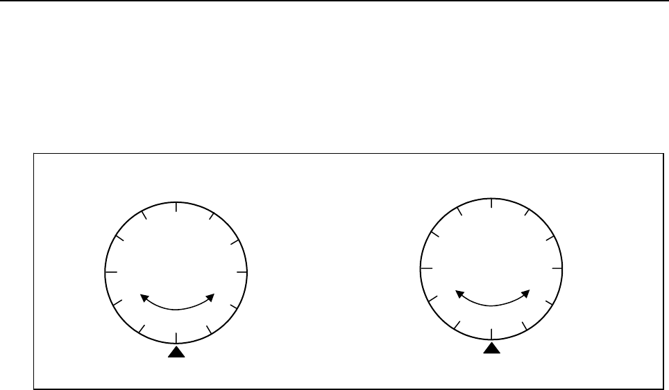
4.LADDER LANGUAGE
B-64513EN/03
- 572 -
Rotating direction output (W1)
The direction of rotation for control of rotation via the shorter path is output to W1. When W1=0, the
direction is forward (FOR). When W1=1, the direction is reverse (REV). The definition of FOR and REV
is shown in Fig. 4.13.1 (b). If the number given to the rotor is increasing, the rotation is FOR; if decreasing,
REV. The address of W1 can be determined arbitrarily. When, however, the result of W1 is to be used,
always check that ACT=1.
Fig. 4.13.1 (b) Rotation direction
FOR REV
(a) (b)
1
2
3
4
5
6
7
8
9
10
11 12
FOR
REV
1
2
3
4
567
8
9
10
11
12
An example of a 12-position rotor
Indexing fixed position
Indexing fixed position
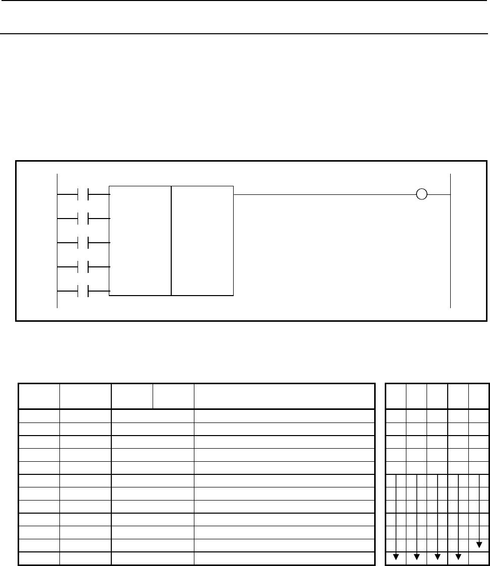
B-64513EN/03
4.LADDER LANGUAGE
- 573 -
4.13.2
ROTB (Binary Rotation Control: SUB 26)
This instruction is used to control rotating elements including the tool post, ATC (Automatic Tool Changer),
rotary table, etc. In the ROT command a parameter indicating the number of rotating element indexing
positions is a fixed data in programming. For ROTB, however, you can specify an address for the number
of rotating element index positions, allowing change even after programming. The data handled are all in
the binary format. Otherwise, ROTB instruction is coded in the same way as ROT instruction.
Format
Fig. 4.13.2 (a) shows the ladder format and Table 4.13.2 shows the mnemonic format.
RNO W1
SUB 26
DIR ROT
{ Format specification
{{{{ Rotating element indexed position address
POS {{{{ Current position address
{{{{ Target position address
INC {{{{ Result output address
ACT
Fig. 4.13.2 (a) Format of ROTB instruction
Table 4.13.2 Mnemonic of ROTB instruction
Mnemonic format Memory status of
control condition
Step
number Instruction Address
No. Bit No. Remarks
ST4 ST3 ST2 ST1 ST0
1 RD {{{{ .{ RNO
RNO
2 RD.STK {{{{ .{ DIR
RNO DIR
3 RD.STK {{{{ .{ POS
RNO DIR POS
4 RD.STK {{{{ .{ INC
RNO DIR POS INC
5 RD.STK {{{{ .{ ACT
RNO DIR POS INC ACT
6 SUB 26 ROTB
7 (PRM) { Format specification
8 (PRM) {{{{ Rotating element indexed position address
9 (PRM) {{{{ Current position address
10 (PRM) {{{{ Target position address
11 (PRM) {{{{ Result output address
12 WRT {{{{ .{ Output of rotation direction
W1

4.LADDER LANGUAGE
B-64513EN/03
- 574 -
Control conditions
(a) Specify the starting number of the rotor. (RNO)
RNO=0: Initial number of the position of the rotor is 0.
RNO=1: Initial number of the position of the rotor is 1.
(b) Specify the number of digits of the process data (position data). (BYT)
BYT=0: BCD two digits
BYT=1: BCD four digits
(c) Select the rotation direction via the shorter path or not. (DIR)
DIR=0: No rotation direction is selected. The rotation direction is only forward.
DIR=1: rotation direction is selected. See rotating direction output (W1) described below for details
on the rotation direction.
(d) Specify the operating conditions. (POS)
POS=0: Calculate the target position.
POS=1: Calculate the position before the target position.
(e) Specify the position or the number of steps. (INC)
INC=0: Calculate the number of the position. If the position before the target position is to be
calculated, specify INC=0 and POS=1
INC=1: Calculate the number of steps. If the difference between the current position and the target
position is to be calculated, specify INC=1 and POS=0.
(f) Execution command (ACT)
ACT=0: The instruction is not executed. W1 does not change.
ACT=1: The instruction is executed. If the operation results are required, set ACT to 1.
Parameters
(a) Format specification
Specify data length (1, 2, or 4 bytes). Use the first digit of the parameter to specify the number of
bytes.
1: 1 byte
2: 2 bytes
4: 4 bytes
All numerical data (number of indexed positions for the rotating elements, current address, etc.) are in
the binary format. Therefore, they require the memory space specified by data length.
CAUTION
Do not set an illegal value, that is not indicated above, into the "(a) Format
specification".
(b) Rotating element indexed position address
Specify the address containing the number of rotary element positions to be indexed.
(c) Target position address
Specify the address storing the target position (or command value), for example the address storing the
NC output T code.
(d) Result output address
Specify the result output address.
NOTE
1 Do not set negative value in each parameter.
2 When POS is set to 1 and current position is same as target position, incorrect
result is calculated.
3 When the value, which is exceeds the rotor index number, is set in the current
poison and target position, incorrect result is calculated.
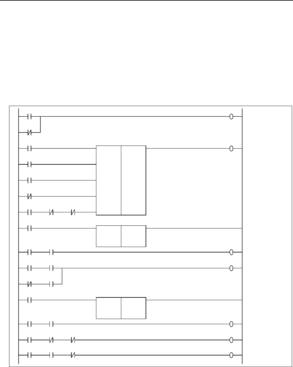
B-64513EN/03
4.LADDER LANGUAGE
- 575 -
Output for rotational direction (W1)
See the ROT instruction.
Example of using the ROTB instruction
Fig. 4.13.2 (b) illustrates a ladder diagram for a 12-position rotor to be controlled for rotation via the shorter
path and for deceleration at one position before the target.
• The target position is specified with the NC and 32 bits of binary code (address F26 to F29).
• The current position is entered with the binary code signal (address X41) from the machine tool.
• The result of calculating one position before the target is output to address R230 (work area).
• Operation starts with the output TF (address F7.3) from the NC.
• The binary compare instruction (COMPB) is used to detect the deceleration and stop positions.
Logic 1
A
R0228.0
A
R0228.0
A
R0228.0
Shorter path or not
A
R0228.0
A
R0228.0
A
R0228.0
A
R0228.0
TF
F0007.3
CCW-M
Y0005.7
CW-M
Y0005.6
CR-CCW
R0228.1
POS
INC
RNO
DIR
ACT
4
D0000
X0041
F0026
R0230
SUB 26
ROTB
Reference data format
Rotor indexing number
Current position address
Target position address
Result output address
TF
F0007.3
ACT
1004
R0230
X0041
SUB 32
COMPB
Reference data format
Reference data
Comparison data address
Deceleration
position detection
TF
F0007.3
R9000.0
TDEC
R0228.2
Deceleration
command
TF
F0007.3
TDEC
R0228.2
DEC-M
Y0005.5
DEC-M
Y0005.5
TCOMPB
R0228.3
TF
F0007.3
ACT
1004
F0026
X0041
SUB 32
COMPB
Reference data format
Reference data
Comparison data address Goal position
(stop position)
detection
TF
F0007.3
R9000.0
TCOMPB
R0228.3
Forward rotation
command
CR-CCW
R0228.1
TF
F0007.3
CW-M
Y0005.6
TCOMPB
R0228.3
Reverse rotation
command
CR-CCW
R0228.1
TF
F0007.3
CCW-M
Y0005.7
TCOMPB
R0228.3
Fig. 4.13.2 (b) Example of a ladder diagram for the ROTB instruction

4.LADDER LANGUAGE
B-64513EN/03
- 576 -
4.14 INVALID INSTRUCTIONS
The instructions listed below are invalid for 30i/31i/32i/35i-B, Power Motion i-A and 0i-F PMC.
If a ladder program used for another model is run on 30i/31i/32i/35i-B, Power Motion i-A or 0i-F PMC,
these instructions are not executed. They cause no error but are treated as NOP instructions (which perform
no operation when the ladder program is executed).
Instruction name Sub number Processing
SPCNT 46 Spindle control
DISP 49 Message display
MMCWR 98 Reading of MMC window data
MMCWW 99 Writing of MMC window data
FNC90 90 Auxiliary functional instruction 1
FNC91 91 Auxiliary functional instruction 2
FNC92 92 Auxiliary functional instruction 3
FNC93 93 Auxiliary functional instruction 4
FNC94 94 Auxiliary functional instruction 5
FNC95 95 Auxiliary functional instruction 6
FNC96 96 Auxiliary functional instruction 7
FNC97 97 Auxiliary functional instruction 8

B-64513EN/03
4.LADDER LANGUAGE
- 577 -
4.15 NOTE ON PROGRAMMING
Some functional instructions may cause the ladder program to take a long time to update or stop, or the
PMC alarm “WN03 ABORT NC-WINDOW/EXIN” may occur, or the ladder program is not able to update
or stop, if their ACT or RST condition remains on for no apparent reason.
To avoid such problems, when you code a ladder program using those functional instructions, you need to
design the ladder structure based on a thorough understanding of the control conditions of the individual
instructions you use.
Listed below are typical cases in which the ladder program will not stop.
• A low-speed window function is used for a WINDR or WINDW functional instruction, and its ACT
condition remains on after the end of command.
• In an EXIN instruction, its ACT condition remains on after the end of command.
• In an AXCTL instruction, its ACT condition or RST condition remains on after the end of command.
• The same processing is repeated by JMPB instruction and JMPC instruction.
It takes time for the following operations or the operation cannot be completed by the above-mentioned.
• Stopping the ladder program using a soft key on the screen
• Reading a new ladder program from a memory card or other medium, by using the data input and
output screen
• Updating the ladder program with changes made using the ladder diagram edit screen
If any of the above phenomena occurs, the functional instruction causing the problem needs to be fixed.
Check the functional instructions mentioned above to see whether there is any ACT or RST condition
remaining on, and correct the ladder program according to the following procedure.
1. Put the machine in safe condition and turn off the power of the CNC.
2. Turn on the power of the CNC while holding down the "CAN" and "Z" keys simultaneously, to restart
the NC with the ladder program halted.
3. In the ladder diagram edit screen, redesign the logic associated with the problematic functional
instruction. When done, set the ACT or RST condition to off. If the same operation is repeating
because of an inadequate JMPB or JMPC instruction, review the jump condition and, if necessary,
change the ladder structure.
4. Write the resulting logic to flash ROM using the I/O screen.
5. Run the ladder program.
If the ladder program does not stop or cannot be changed even after you make the correction, there may be
other functional instructions that have the same condition settings. Check for other functional instructions
having the same condition settings, besides the one you have corrected, and repeat the above procedure to
correct them all.

5.WINDOW FUNCTIONS
B-64513EN/03
- 578 -
5 WINDOW FUNCTIONS
This chapter describes the functions that can be executed with the WINDR (SUB 51) and WINDW (SUB
52) functional instructions, as well as the formats and other details of the control data to be set for
executing these functions.
As this function depends on the specification of CNC function, refer to the following CNC manuals with
this manual.
Manuals Series Drawings
CONNECTION MANUAL
(HARDWARE)
Series 30i /31i /32i-B B-64483EN
Series 35i-B B-64523EN
Power Motion i-A B-64573EN
Series 0i-F B-64603EN
CONNECTION MANUAL
(FUNCTION)
Series 30i /31i /32i-B B-64483EN-1
Series 35i-B B-64523EN-1
Power Motion i-A B-64573EN-1
Series 0i-F B-54603EN-1
OPERATOR’S MANUAL
Series 30i /31i /32i-B B-64484EN/01
(Common to Lathe System / Machining
Center System)
Series 35i-B B-64524EN
Power Motion i-A B-64574EN
Series 0i-F B-64604EN
PARAMETER MANUAL
Series 30i /31i /32i-B B-64490EN
Series 35i-B B-64530EN
Power Motion i-A B-64580EN
Series 0i-F B-64610EN
MAINTENANCE MANUAL Series 30i /31i /32i -B B-64485EN
Series 35i-B B-64525EN
Power Motion i-A B-64575EN
Series 0i-F B-64605EN
Macro Executor
PROGRAMMING MANUAL Series 30i /31i /32i/35i-B B-63943EN-2
WARNING
When you write some NC data using both this instruction in ladder program and
other applications, take care that you do not write to the same data area.
If some values are written to the same data area by two or more applications
including ladder program, unexpected value may be written. In this case, it may
cause an unexpected machine behavior and also tools, work pieces, and
machines may be damaged.
As for details, refer to “SAFETY PRECAUTIONS”.
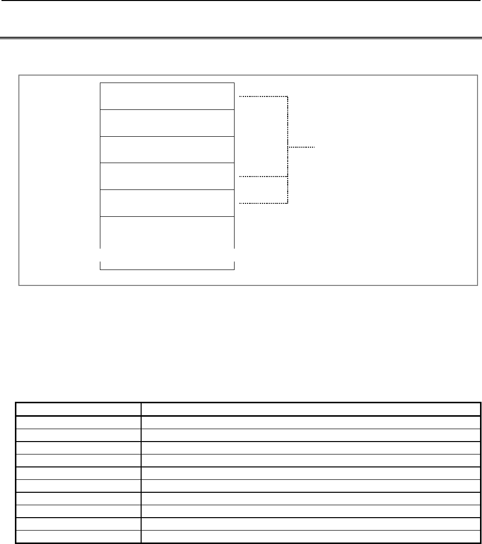
B-64513EN/03
5.WINDOW FUNCTIONS
- 579 -
5.1 FORMATS OF CONTROL DATA
Input and output control data has the following structure.
Top address +0
2
4
6
8
10
Function code
Completion code
Data length
(Byte length of data area)
Data number
Data attribute
Data area
≈≈
These data set as input data are remain
unchanged in the output data.
* Data length
Depends on the function.
(1) In the explanation of the window functions below, minuses (-) in the data structure fields indicate
that input data need not be set in these fields or that output data in these fields is not significant.
(2) All data is in binary unless otherwise specified.
(3) All data block lengths and data lengths are indicated in bytes.
(4) Output data is valid only when window processing terminates normally.
(5) Output data always includes one of the following completion codes. Note, however, that all of the
completion codes listed are not always provided for each function.
Completion code Meaning
0 Normal termination
1 Error (invalid function code)
2 Error (invalid data block length)
3 Error (invalid data number)
4 Error (invalid data attribute)
5 Error (invalid data)
6 Error (necessary option missing)
7 Error (write-protected)
113 Error (The CNC status is that the writing data cannot be allowed.)
-10 Processing (The CNC is processing now.)
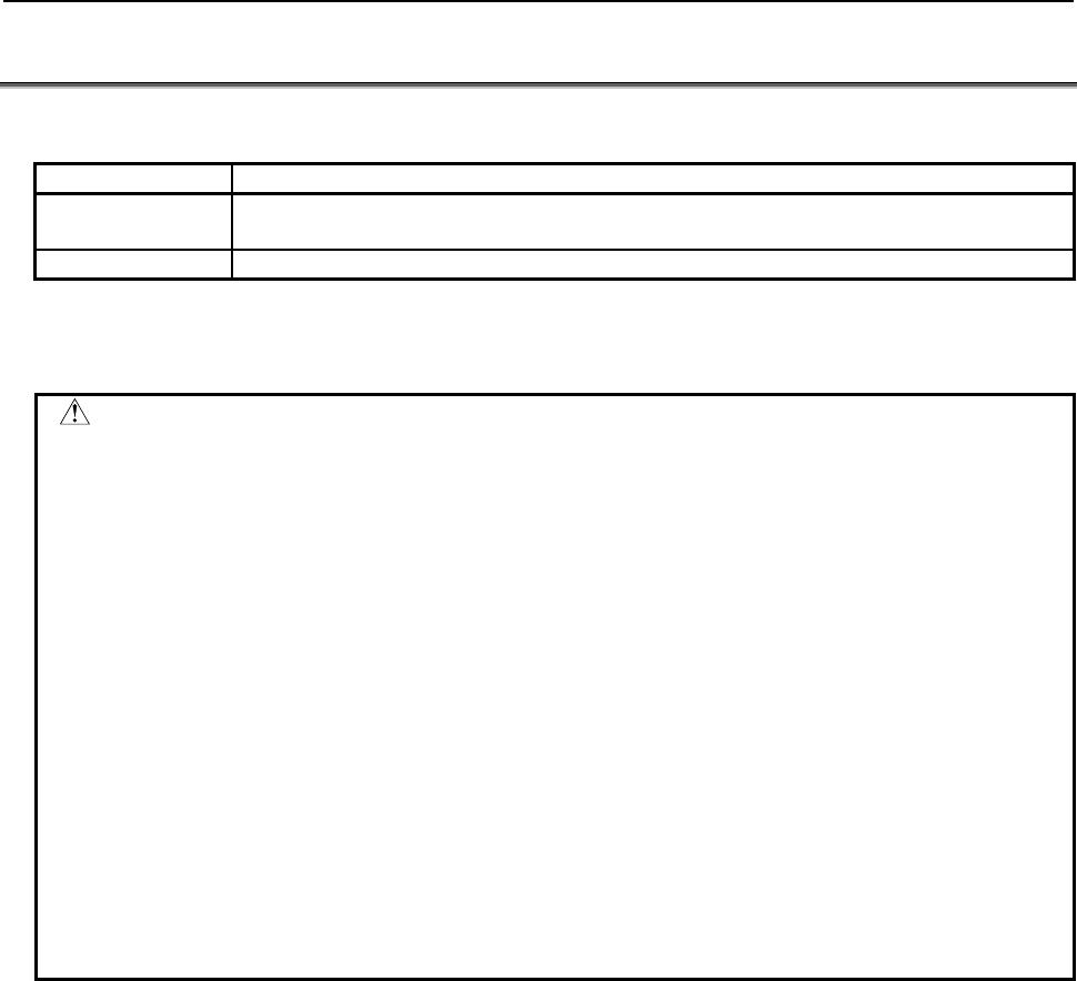
5.WINDOW FUNCTIONS
B-64513EN/03
- 580 -
5.2 LOW-SPEED RESPONSE AND HIGH-SPEED RESPONSE
There are two types of window function - one executed at high speed and the other executed at low speed.
TYPE Number of scans to be executed until the window instruction is completed
LOW TWO SCAN TIMES OR MORE (Depends on the CNC processing priority and operation
status.)
HIGH 1 SCAN TIME
When using the low-speed response window function, set ACT to 0 immediately after the data transfer
end data (W1) is set to 1 for the window instruction. For details, see "CAUTION" below.
CAUTION
1 The window instruction of a low-speed response is controlled exclusively with the
other window instructions of low-speed response.
Therefore, when the data is read or written continuously, it is necessary to clear
ACT of the functional instruction to 0 once when the completion information (W1)
become 1.
If you leave a window instruction of a low-speed response with W1=1 and
ACT=1, other window instructions of low-speed response do not work.
The window instruction of a high-speed response is not exclusively controlled like
a low-speed response. Therefore, when the data is read or written continuously,
you need not make ACT=0.
2 The completion of the other window instruction of low-speed response may be
delayed by the execution of application using FOCAS2 functions and C language
executor application. If some window instruction of a low speed response is
executed continuously with a high frequency, the completion of the other window
instruction of low-speed response will be delayed, or may not be done. You
should take care that the execution of application using FOCAS2 functions and C
language executor application may be delayed. The window instruction of a low-
speed response should be executed with the lowest required frequency.

B-64513EN/03
5.WINDOW FUNCTIONS
- 581 -
5.2.1
Note on the Programming of a Low-speed Response Window
Instruction
You need to design the ladder program to set ACT condition to off in a low-speed response window
instruction after the completion information (W1) became 1. If the ACT condition is kept to on after the
data transfer was completed, the PMC alarm “WN03 ABORT NC-WINDOW/EXIN” may occur or the
stop of the ladder program takes a long time in the following cases.
1. Stopping the ladder program using a soft key on the screen
2. Reading a new ladder program from a memory card or other medium, by using the DATA I/O
screen
3. Updating the ladder program with changes made using the LADDER DIAGRAM EDITOR screen
If the PMC alarm “WN03” occurs, the functional instruction causing the problem needs to be fixed. For
information about how to fix the problem, see Section 4.15.
When the PMC alarm “WN03” occurs, the low-speed response window does not be executed. Therefore,
the execution of the ladder program becomes unstable. To re-set the alarm, turn off and on the power of
CNC.

5.WINDOW FUNCTIONS
B-64513EN/03
- 582 -
5.3 LIST OF WINDOW FUNCTIONS
5.3.1 List of Window Functions (Function Group Order)
Group No. Description Function
code Response R/W
CNC information
(Section 5.4)
1 Reading CNC system information 0 High-speed R
2 Reading a tool offset 13 High-speed R
3 Write a tool offset 14 Low-speed W
4 Reading a work piece origin offset value 15 High-speed R
5 Writing a work piece origin offset value 16 Low-speed W
6 Reading a parameter 17, 154 High-speed R
7 Writing a parameter 18 Low-speed W
8 Reading a real type parameter 321 High-speed R
9 Writing a real type parameter 323 Low-speed W
10 Reading setting data 19, 155 High-speed R
11 Writing setting data 20 Low-speed W
12 Reading a custom macro variable 21 High-speed R
13 Writing a custom macro variable 22 Low-speed W
14 Reading a custom macro variable (variable number
extension)
437 Low-speed R
15 Writing a custom macro variable (variable number
extension)
438 Low-speed W
16 Reading the CNC alarm status 23 High-speed R
17 Reading the current program number 24 High-speed R
18 Reading the current sequence number 25 High-speed R
19 Reading modal data 32 High-speed R
20 Reading diagnosis data 33 Low-speed R
21 Reading diagnosis data (specific number only) 156 High-speed R
22 Reading the P-code macro variable 59 High-speed R
23 Writing the P-code macro variable 60 Low-speed W
24 Reading CNC status information 76 High-speed R
25 Reading the current program number (8-digit
program numbers) 90 High-speed R
26 Entering data on the program check screen 150 Low-speed W
27 Reading clock data (date and time) 151 High-speed R
28 Writing clock data (date and time) 139 Low-speed W
29 Reading the pitch error compensation data 395 High-speed R
30 Writing the pitch error compensation data 396 Low-speed W
31 Tool figure making instruction for 3D interference
check function 431 Low-speed W
32 Reading detailed information of CNC alarm 433 Low-speed R
33 Command for changing the interference object for
3D interference check function
436 Low-speed W
34 Reading the CNC ID number 447 Low-speed R
35 Reading the number of repeats for subprogram calls
/ canned cycle
449 High-speed R
Axis information
(Section 5.5)
1 Reading the actual velocity of controlled axes 26 High-speed R
2 Reading the absolute position (absolute coordinates)
of controlled axes 27 High-speed R
3 Reading the machine position (machine coordinates)
of controlled axes 28 High-speed R
4 Reading a skip position (stop coordinates of skip
operation (G31)) of controlled axes 29 High-speed R

B-64513EN/03
5.WINDOW FUNCTIONS
- 583 -
Group No. Description Function
code Response R/W
Axis information
(Section 5.5)
5 Reading the servo delay for controlled axes 30 High-speed R
6 Reading the acceleration/deceleration delay on
controlled axes 31 High-speed R
7 Reading the feed motor load current value (A/D
conversion data) 34 High-speed R
8 Reading the actual spindle speed 50 High-speed R
9 Reading the relative position on a controlled axis 74 High-speed R
10 Reading the remaining travel 75 High-speed R
11 Reading the actual velocity of each controlled axes 91 High-speed R
12 Reading actual spindle speeds 138 High-speed R
13 Entering torque limit data for the digital servo motor 152 Low-speed W
14 Reading load information of the spindle motor (serial
interface) 153 High-speed R
15 Reading a chopping data 206 Low-speed R
16 Reading the actual speed of servo motor 207 High-speed R
17 Reading the estimate disturbance torque data 211 High-speed R
18 Reading a fine torque sensing data (statistical
calculation results) 226 High-speed R
19 Reading a fine torque sensing data (store data) 232 High-speed R
20 Presetting the relative coordinate 249 Low-speed W
21 Reading the three-dimensional error compensation
data 413 Low-speed R
22 Writing the three-dimensional error compensation
data 414 Low-speed W
23 Reading the position of controlled axes 428 High-speed R
24 Reading slider position of the Control function for link
type press 386 High-speed R
25 Reading position of lower dead point of the Control
function for link type press 387 High-speed R
26 Reading main gear angle of the Control function for
link type press 388 High-speed R
27 Reading analog monitor unit data 435 High-speed R
28 Reading axes command value 446 High-speed R
Tool life
management
functions
(Section 5.6)
1 Reading the tool life management data (tool group
number) 38 High-speed R
2 Reading tool life management data (number of tool
groups) 39 High-speed R
3 Reading tool life management data (number of tools) 40 High-speed R
4 Reading tool life management data (tool life) 41 High-speed R
5 Reading tool life management data (tool life counter) 42 High-speed R
6 Reading tool life management data (tool length
compensation number (1): Tool number) 43 High-speed R
7 Reading tool life management data (tool length
compensation number (2): Tool order number) 44 High-speed R
8 Reading tool life management data (cutter radius
compensation number (1): Tool number) 45 High-speed R
9 Reading tool life management data (cutter radius
compensation number (2): Tool order number) 46 High-speed R
10 Reading tool life management data (tool information
(1): Tool number) 47 High-speed R
11 Reading tool life management data (tool information
(2): Tool order number) 48 High-speed R
12 Reading tool life management data (tool number) 49 High-speed R

5.WINDOW FUNCTIONS
B-64513EN/03
- 584 -
Group No. Description Function
code Response R/W
Tool life
management
functions
(Section 5.6)
13 Reading the tool life management data (tool life
counter type) 160 High-speed R
14 Registering tool life management data (tool group) 163 Low-speed W
15 Writing tool life management data (tool life) 164 Low-speed W
16 Writing tool life management data (tool life counter) 165 Low-speed W
17 Writing tool life management data (tool life counter
type) 166 Low-speed W
18 Writing tool life management data (tool length
compensation number (1): Tool number) 167 Low-speed W
19 Writing tool life management data (tool length
compensation number (2): Tool order number) 168 Low-speed W
20 Writing tool life management data (cutter radius
compensation number (1): Tool number) 169 Low-speed W
21 Writing tool life management data (cutter radius
compensation number (2): Tool order number) 170 Low-speed W
22 Writing tool life management data (tool information
(1): Tool number) 171 Low-speed W
23 Writing the tool management data (tool information
(2): Tool order number) 172 Low-speed W
24 Writing tool life management data (tool number) 173 Low-speed W
25 Reading the tool life management data (tool group
No.) (8-digit tool number) 200 High-speed R
26 Reading tool life management data (tool information
(1): Tool number) (8-digit tool number) 201 High-speed R
27 Registering tool life management data (tool group
number) (8-digit tool number) 202 Low-speed W
28
Reading tool life management data (tool length
compensation number (1): Tool number) (8-digit tool
number)
227 High-speed R
29
Reading tool life management data (cutter radius
compensation number (1): Tool number) (8-digit tool
number)
228 High-speed R
30
Writing tool life management data (tool length
compensation number (1): Tool number) (8-digit tool
number)
229 Low-speed W
31
Writing tool life management data (cutter radius
compensation number (1): Tool number) (8-digit tool
number)
230 Low-speed W
32 Writing the tool life management data (tool
information (1): Tool number) (8-digit tool number) 231 Low-speed W
33 Deleting tool life management data (tool group) 324 Low-speed W
34 Deleting tool life management data (tool data) 325 Low-speed W
35 Clearing tool life management data (tool life counter
and tool information) 326 Low-speed W
36 Writing tool life management data (arbitrary group
number) 327 Low-speed W
37 Writing tool life management data (remaining tool
life) 328 Low-speed W
Tool management
functions
(Section 5.7)
1 Exchanging tool management data numbers in a
magazine management table 329 Low-speed W
2 Searching for a free pot 330 Low-speed R
3 Registering new tool management data 331 Low-speed W
4 Writing tool management data 332 Low-speed W
5 Deleting tool management data 333 Low-speed W

B-64513EN/03
5.WINDOW FUNCTIONS
- 585 -
Group No. Description Function
code Response R/W
Tool management
functions
(Section 5.7)
6 Reading tool management data 334 Low-speed R
7 Writing a specified type of tool management data 335 Low-speed W
8 Searching for tool management data 366 Low-speed R
9 Shifting tool management data 367 Low-speed W
10 Searching for a free pot (oversize tools supported) 397 Low-speed R
11 Reading the total tool life data 409 Low-speed R
12 Writing tool management data by specified data 419 Low-speed W
13 Deleting tool management data by specified data 420 Low-speed W
14 Reading tool management data by specified data 421 Low-speed R
15 Writing each tool management data by specified
data 422 Low-speed W
16 Writing magazine property data 423 Low-speed W
17 Reading magazine property data 424 Low-speed R
18 Writing pot property data 425 Low-speed W
19 Reading pot property data 426 Low-speed R
20 Searching for a free pot by specified data 427 Low-speed R
21 Reading a tool geometry data 429 Low-speed R
22 Writing a tool geometry data 430 Low-speed W
23 Moving tool management data numbers in a
magazine management table 432 Low-speed W
24 Reading free number of Multi edge group / Tool
offset 434 High-speed R
25 Writing edge data 439 Low-speed W
26 Reading edge data 440 Low-speed R
27 Writing each edge data 441 Low-speed W
28 Reading the total tool life data of an edge 442 Low-speed R
*1 Function codes that have R in the R/W column are window read functions specifiable with the WINDR
function command. Function codes that have W in the R/W column are window write functions
specifiable with the WINDW function command.
*2 Functions of "High-speed" in their Response field can read or write data immediately upon request. On
the other hand, functions of "Low-speed" in their Response field need to request the CNC to read or
write data and receiving response from CNC completes the request.
NOTE
To read or write data for the second path in two-path control CNC, add 1000 to
the function code number.
To read or write data for the third path in three-path control CNC, add 2000 to the
function code number.
Similarly, to read or write data for the fourth to 10th paths, add 3000 to 9000
accordingly to the function code number.

5.WINDOW FUNCTIONS
B-64513EN/03
- 586 -
5.3.2
List of Window Functions (Function Code Order)
Function
code Description Response R/W
0 Reading CNC system information High-speed R
13 Reading a tool offset High-speed R
14 Writing a tool offset Low-speed W
15 Reading a work piece origin offset value High-speed R
16 Writing a work piece origin offset value Low-speed W
17 Reading a parameter High-speed R
18 Writing a parameter Low-speed W
19 Reading setting data High-speed R
20 Writing setting data Low-speed W
21 Reading a custom macro variable High-speed R
22 Writing a custom macro variable Low-speed W
23 Reading the CNC alarm status High-speed R
24 Reading the current program number High-speed R
25 Reading the current sequence number High-speed R
26 Reading the actual velocity of controlled axes High-speed R
27 Reading the absolute position (absolute coordinates) of controlled axes High-speed R
28 Reading the machine position (machine coordinates) of controlled axes High-speed R
29 Reading a skip position (stop coordinates of skip operation (G31)) of controlled
axes High-speed R
30 Reading the servo delay for controlled axes High-speed R
31 Reading the acceleration/deceleration delay on controlled axes High-speed R
32 Reading modal data High-speed R
33 Reading diagnosis data Low-speed R
34 Reading the feed motor load current value (A/D conversion data) High-speed R
38 Reading the tool life management data (tool group number) High-speed R
39 Reading tool life management data (number of tool groups) High-speed R
40 Reading tool life management data (number of tools) High-speed R
41 Reading tool life management data (tool life) High-speed R
42 Reading tool life management data (tool life counter) High-speed R
43 Reading tool life management data (tool length compensation number (1): Tool
number) High-speed R
44 Reading tool life management data (tool length compensation number (2): Tool
order number) High-speed R
45 Reading tool life management data (cutter radius compensation number (1):
Tool number) High-speed R
46 Reading tool life management data (cutter radius compensation number (2):
Tool order number) High-speed R
47 Reading tool life management data (tool information (1): Tool number) High-speed R
48 Reading tool life management data (tool information (2): Tool order number) High-speed R
49 Reading tool life management data (tool number) High-speed R
50 Reading the actual spindle speed High-speed R
59 Reading the P-code macro variable High-speed R
60 Writing the P-code macro variable Low-speed W
74 Reading the relative position on a controlled axis High-speed R
75 Reading the remaining travel High-speed R
76 Reading CNC status information High-speed R
90 Reading the current program number (8-digit program numbers) High-speed R
91 Reading the actual velocity of each controlled axes High-speed R
138 Reading actual spindle speeds High-speed R
139 Writing clock data (date and time) Low-speed W

B-64513EN/03
5.WINDOW FUNCTIONS
- 587 -
Function
code Description Response R/W
150 Entering data on the program check screen Low-speed W
151 Reading clock data (date and time) High-speed R
152 Entering torque limit data for the digital servo motor Low-speed W
153 Reading load information of the spindle motor (serial interface) High-speed R
154 Reading a parameter High-speed R
155 Reading setting data High-speed R
156 Reading diagnosis data (specific number only) High-speed R
160 Reading the tool life management data (tool life counter type) High-speed R
163 Registering the tool life management data (tool group) Low-speed W
164 Writing the tool life management data (tool life) Low-speed W
165 Writing the tool life management data (tool life counter) Low-speed W
166 Writing the tool life management data (tool life counter type) Low-speed W
167 Writing the tool life management data (tool length compensation number (1):
Tool number) Low-speed W
168 Writing the tool life management data (tool length compensation number (2):
Tool order number) Low-speed W
169 Writing the tool life management data (cutter radius compensation number (1):
Tool number) Low-speed W
170 Writing the tool life management data (cutter radius compensation number (2):
Tool order number) Low-speed W
171 Writing the tool life management data (tool information (1): Tool number) Low-speed W
172 Writing the tool management data (tool condition (2): Tool order number) Low-speed W
173 Writing the tool life management data (tool number) Low-speed W
200 Reading the tool life management data (tool group number) (8-digit tool
number) High-speed R
201 Reading tool life management data (tool information (1): Tool number) (8-digit
tool number) High-speed R
202 Registering tool life management data (tool group number) (8-digit tool
number) Low-speed W
206 Reading a chopping data Low-speed R
207 Reading the actual speed of servo motor High-speed R
211 Reading the estimate disturbance torque data High-speed R
226 Reading a fine torque sensing data (statistical calculation results) High-speed R
227 Reading tool life management data (tool length compensation number (1): Tool
number) (8-digit tool number) High-speed R
228 Reading tool life management data (cutter radius compensation number (1):
Tool number) (8-digit tool number) High-speed R
229 Writing tool life management data (tool length compensation number (1): Tool
number) (8-digit tool number) Low-speed W
230 Writing tool life management data (cutter radius compensation number (1):
Tool number) (8-digit tool number) Low-speed W
231 Writing the tool life management data (tool information (1): Tool number) (8-
digit tool number) Low-speed W
232 Reading a fine torque sensing data (store data) High-speed R
249 Presetting the relative coordinate Low-speed W
321 Reading a real type parameter High-speed R
323 Writing a real type parameter Low-speed W
324 Deleting the tool life management data (tool group) Low-speed W
325 Deleting the tool life management data (tool data) Low-speed W
326 Deleting the tool life management data (tool life counter and tool information) Low-speed W
327 Writing the tool life management data (arbitrary group number) Low-speed W
328 Writing the tool life management data (remaining tool life) Low-speed W
329 Exchanging tool management data numbers in a magazine management table Low-speed W

5.WINDOW FUNCTIONS
B-64513EN/03
- 588 -
Function
code Description Response R/W
330 Searching for a free pot Low-speed R
331 Registering new tool management data Low-speed W
332 Writing tool management data Low-speed W
333 Deleting tool management data Low-speed W
334 Reading tool management data Low-speed R
335 Writing a specified type of tool management data Low-speed W
366 Searching for tool management data Low-speed R
367 Shifting tool management data Low-speed W
386 Reading slider position of the Control function for link type press High-speed R
387 Reading position of lower dead point of the Control function for link type press High-speed R
388 Reading main gear angle of the Control function for link type press High-speed R
395 Reading the pitch error compensation data High-speed R
396 Writing the pitch error compensation data Low-speed W
397 Searching for a free pot (oversize tools supported) Low-speed R
409 Reading the total tool life data Low-speed R
413 Reading the three-dimensional error compensation data Low-speed R
414 Writing the three-dimensional error compensation data Low-speed W
419 Writing tool management data by specified data Low-speed W
420 Deleting tool management data by specified data Low-speed W
421 Reading tool management data by specified data Low-speed R
422 Writing each tool management data by specified data Low-speed W
423 Writing magazine property data Low-speed W
424 Reading magazine property data Low-speed R
425 Writing pot property data Low-speed W
426 Reading pot property data Low-speed R
427 Searching for a free pot by specified data Low-speed R
428 Reading the position controlled axes High-speed R
429 Reading a tool geometry data Low-speed R
430 Writing a tool geometry data Low-speed W
431 Tool figure making instruction for 3D interference check function Low-speed W
432 Moving tool management data numbers in a magazine management table Low-speed W
433 Reading detailed information of CNC alarm Low-speed R
434 Reading free number of Multi edge group / Tool offset High-speed R
435 Reading analog monitor unit data High-speed R
436 Command for Changing the Interference Object for 3D interference check
function
Low-speed W
437 Reading a custom macro variable (variable number extension) Low-speed R
438 Writing a custom macro variable (variable number extension) Low-speed W
439 Writing edge data Low-speed W
440 Reading edge data Low-speed R
441 Writing each edge data Low-speed W
442 Reading the total tool life data of an edge Low-speed R
446 Reading axes commanded value Low-speed R
447 Reading the CNC ID number Low-speed R
449 Reading the number of repeats for subprogram calls / canned cycle High-speed R
*1 Function codes that have R in the R/W column are window read functions specifiable with the WINDR
function command. Function codes that have W in the R/W column are window write functions
specifiable with the WINDW function command.
*2 Functions of "High-speed" in their Response field can read or write data immediately upon request. On
the other hand, functions of "Low-speed" in their Response field need to request the CNC to read or
write data and receiving response from CNC completes the request.

B-64513EN/03
5.WINDOW FUNCTIONS
- 589 -
NOTE
1 To read or write data for the second path in two-path control CNC, add 1000 to
the function code number.
To read or write data for the third path in three-path control CNC, add 2000 to
the function code number.
Similarly, to read or write data for the fourth to 10th paths, add 3000 to 9000
accordingly to the function code number.
2 When using this function with multi-path PMC system, you should confirm the
CNC-PMC interface assigned by NC parameter No. 11920-11929. According to
the assignment of the interface, ladder program of each PMC path can read or
write data for assigned CNC path. As for detail of these parameters, refer to
section “2.4.3”.
5.3.3
Compatibility with Conventional Models
1. Compatibility with Series 30i/31i/32i-A
The window function of Series 30i/31i/32i/35i-B, 0i-F PMC is highly compatible with the window
function of series 30i/31i/32i-A PMC.
2. Compatibility with Series 0i-D
The window function of Series 30i/31i/32i/35i-B PMC is highly compatible with the window
function of series 0i-D PMC.
3. Compatibility with Series 16i/18i/21i-B
The specifications of following WINDOW functions on Series 30i/31i/32i/35i-B PMC are different
from ones on PMC-SB7 of Series 16i/18i/21i-B.
• The new function “No.321 Reading a real type parameter” has been added. To read a real type
CNC parameter, use this function.
• The new function “No.323 Writing a real type parameter” has been added. To write a real type
CNC parameter, use this function.
• In the function “No.23 Reading the alarm status”, the output value has been extended into 4
bytes and some contents have been changed.
• The function “No.33 Reading diagnosis data” has been equipped as low-speed response type.
• The new function “No.395 Reading the pitch error compensation data” has been added. The
function “No.17, 154 Reading the parameter” cannot read a pitch error compensation data. Use
this new function to read it.
• The new function “No.396 Writing the pitch error compensation data” has been added. The
function “No.18 Writing the parameter” cannot write a pitch error compensation data. Use this
new function to write it.
• There is no analog input function on Series 30i/31i/32i/35i-B, 0i-F. Therefore, the function
“No.34 Reading the feed motor load current value (A/D conversion data)” cannot read A/D
conversion data using the function. This function can only read the feed motor load current
value.
• To use the function “No.152 Entering torque limit data for the digital servo motor”, you should
set the CNC parameter No.6286#0 to 1.
• When you read a speed of a linear motor using the function "No.207 Reading the actual speed
of servo motor" with the data number 11, the unit of the read data is "cm / min".
• When using the function "No.30 Reading the servo delay for controlled axes" with the data
number N=0, the data is read with input unit. When using the function with the data number
N=1, the data is read with detection unit. On PMC-SB7, the data is always read with detection
unit.

5.WINDOW FUNCTIONS
B-64513EN/03
- 590 -
• When using the function "No.31 Reading the acceleration / deceleration delay on controlled
axes" with the data number N=0, the data is read with input unit. When using the function with
the data number N=1, the data is read with detection unit. On PMC-SB7, the data is always
read with machine unit.
• The function "No.21 Reading a custom macro variable" or "No.59 Reading a P-CODE macro
variable" returns "mantissa"=0 and "number of decimal places"= -1 when the floating-point
type variable is "null".
• The function "No.22 Writing a custom macro variable" or "No.60 Writing a P-CODE macro
variable" can write "null" to the floating-point type variable by setting "mantissa"=0 and
"number of decimal places"= -1.
• The function "No.32 Reading modal data" cannot read modal information for a block after the
next block.
4. Compatibility with Power Mate i-D/H
The specifications of following WINDOW functions on Series 30i/31i/32i/35i-B, 0i-F or Power
Motion i-A PMC are different from ones on PMC-SB5/SB6 of Power Mate i-D/H.
• The new function “No.321 Reading a real type parameter” has been added. To read a real type
CNC parameter, use this function.
• The new function “No.323 Writing a real type parameter” has been added. To write a real type
CNC parameter, use this function.
• In the function “No.23 Reading the alarm status”, the output value has been extended into 4
bytes and some contents have been changed.
• The function “No.433 Reading detailed information of CNC alarm” has been added. Note that
this function is different from the function “No.186 Reading detailed information of CNC
alarm”of PMC-SB5/SB6.
• The function “No.33 Reading diagnosis data” has been equipped as low-speed response type.
• The new function “No.395 Reading the pitch error compensation data” has been added. The
function “No.17, 154 Reading the parameter” cannot read a pitch error compensation data. Use
this new function to read it.
• The new function “No.396 Writing the pitch error compensation data” has been added. The
function “No.18 Writing the parameter” cannot write a pitch error compensation data. Use this
new function to write it.
• There is no analog input function on Series 30i/31i/32i/35i-B or Power Motion i-A. Therefore,
the function “No.34 Reading the feed motor load current value (A/D conversion data)” cannot
read A/D conversion data using the function. This function can only read the feed motor load
current value.
• To use the function “No.152 Entering torque limit data for the digital servo motor”, you should
set the CNC parameter No.6286#0 to 1.
• When you read a speed of a linear motor using the function "No.207 Reading the actual speed
of servo motor" with the data number 11, the unit of the read data is "cm / min".
• When using the function "No.30 Reading the servo delay for controlled axes" with the data
number N=0, the data is read with input unit. When using the function with the data number
N=1, the data is read with detection unit. On PMC-SB5/SB6, the data is always read with
detection unit.
• When using the function "No.31 Reading the acceleration / deceleration delay on controlled
axes" with the data number N=0, the data is read with input unit. When using the function with
the data number N=1, the data is read with detection unit. On PMC-SB5/SB6, the data is
always read with machine unit.
• The function "No.21 Reading a custom macro variable" or "No.59 Reading a P-CODE macro
variable" returns "mantissa"=0 and "number of decimal places"= -1 when the floating-point
type variable is "null".
• The function "No.22 Writing a custom macro variable" or "No.60 Writing a P-CODE macro
variable" can write "null" to the floating-point type variable by setting "mantissa"=0 and
"number of decimal places"= -1.

B-64513EN/03
5.WINDOW FUNCTIONS
- 591 -
• The function "No.32 Reading modal data" cannot read modal information for a block after the
next block.
• The function "No.120 Reading the current screen number" is not supported.

5.WINDOW FUNCTIONS
B-64513EN/03
- 592 -
5.4 CNC INFORMATION
5.4.1 Reading CNC System Information (High-speed Response)
The system information specific to the CNC can be read including the CNC type (e.g., series name like
30), the distinction between the machining center system (M) and the lathe system (T) for each CNC path,
the ROM series and edition of the CNC system software, and the number of axes to be controlled for each
CNC path.
Input data structure
Top Address +0 (Function code)
0
+2 (Completion code)
-
(Need not to be set)
+4 (Data length L)
-
(Need not to be set)
+6 (Data number N)
0
Set 0 to this field.
+8 (Data attribute M)
0
Set 0 to this field.
+10
+41
(Data area)
-
(Need not to be set)
Completion codes
0: CNC system information has been read normally.

B-64513EN/03
5.WINDOW FUNCTIONS
- 593 -
Output data structure
Top Address +0 (Function code)
0
+2 (Completion code)
0
(Always terminates normally)
+4 (Data length L)
14
+6 (Data number N)
0
(Same as input data)
+8 (Data attribute M)
0
(Same as input data)
+10 CNC series name
(2 bytes)
ASCII characters
(30, 31, 32, 35)
+12 Machine type M/T
(2 bytes)
ASCII characters
(M, T)
+14 ROM series of CNC system
software
(4 bytes)
ASCII characters
(EX. G001, ...)
+18 ROM version of CNC system
software
(4 bytes)
ASCII characters
(0001, 0002, ...)
+22
+23
Number of axes to be controlled
for the specified CNC path
(2 bytes)
ASCII characters
(2, 3, 4, ...)
NOTE
Data is stored from the upper digit in each lower byte.
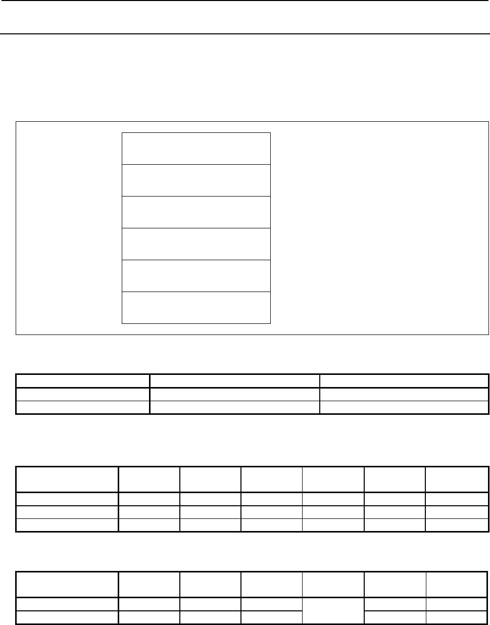
5.WINDOW FUNCTIONS
B-64513EN/03
- 594 -
5.4.2
Reading a Tool Offset (High-speed Response)
A tool offset value recorded in the CNC can be read.
Wear offset data, geometric offset data, cutter compensation data, and tool length offset data can be read
as a tool offset.
Input data structure
Top Address +0 (Function code)
13
+2 (Completion code)
-
(Need not to be set)
+4 (Data length L)
-
(Need not to be set)
+6 (Data number N)
Offset number
+8 (Data attribute M)
Offset type
+10
+41
(Data area)
-
(Need not to be set)
(a) Offset types (for machining centers)
Cutter Tool length
Wear 0 2
Geometric 1 3
If the type of tool offset need not be specified, enter 0.
(b) Offset types (for lathes)
X axis Z axis Tool tip R Virtual
tool tip Y axis B axis
(Reserved)
Wear 0 2 4 6 8 10
Geometric 1 3 5 7 9 11
2nd Geometric 12 13 14
(c) Offset types (for machining centers with the Tool offset for Milling and Turning function)
X axis Z axis Tool tip R Virtual
tool tip Y axis Corner R
Wear 1010 1012 1015 1019 1018 1024
Geometric 1009 1011 1014 1017 1023
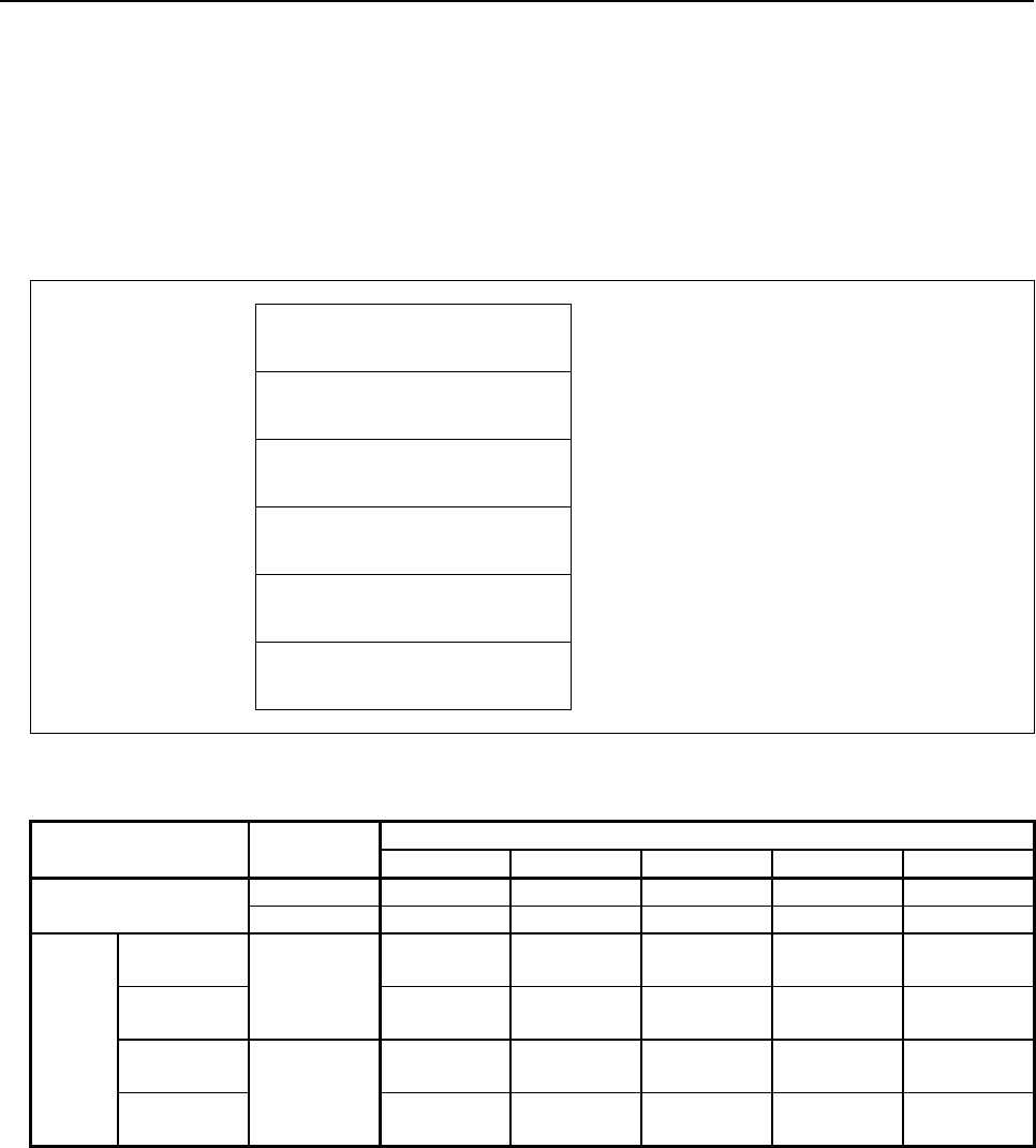
B-64513EN/03
5.WINDOW FUNCTIONS
- 595 -
Completion codes
0 The tool offset has been read normally.
3 The offset number specified for reading is invalid. (This completion code is returned when the
specified offset number data is not from 1 to the maximum number of offsets.)
4 There are mistakes in the data attribute that specifies the type of the offset to be read. (Some wrong
offset types do not result this completion code.)
Output data structure
Top Address +0 (Function code)
13
+2 (Completion code)
?
(See above description)
+4 (Data length L)
4
+6 (Data number N)
Offset number
(Same as input data)
+8 (Data attribute M)
Offset type
(Same as input data)
+10
+13
Tool offset value
(4bytes)
Signed binary (A negative value is represented in
2's complement.)
Upper 3 bytes are always "0" for virtual tool tip.
Output data unit
Input
system
Increment system
IS-A IS-B IS-C IS-D IS-E
Machining center
system
mm, deg 0.01 0.001 0.0001 0.00001 0.000001
inch 0.001 0.0001 0.00001 0.000001 0.0000001
Lathe
system
Radius
specification mm, deg
0.01 0.001 0.0001 0.00001 0.000001
Diameter
specification 0.01 0.001 0.0001 0.00001 0.000001
Radius
specification inch
0.001 0.0001 0.00001 0.000001 0.0000001
Diameter
specification 0.001 0.0001 0.00001 0.000001 0.0000001

5.WINDOW FUNCTIONS
B-64513EN/03
- 596 -
5.4.3
Writing a Tool Offset (Low-speed Response)
The tool offset value can be directly written into the CNC.
Wear offset data, geometric offset data, cutter compensation data, and tool length offset data can be
written as a tool offset.
WARNING
When you write some NC data using both this instruction in ladder program and
other applications, take care that you do not write to the same data area.
If some values are written to the same data area by two or more applications
including ladder program, unexpected value may be written. In this case, it may
cause an unexpected machine behavior and also tools, work pieces, and
machines may be damaged. As for details, refer to “SAFETY PRECAUTIONS”.
Input data structure
Top Address +0 (Function code)
14
+2 (Completion code)
-
(Need not to be set)
+4 (Data length L)
4
+6 (Data number N)
Offset number
+8 (Data attribute M)
Offset type
+10
+13
Tool offset value
Signed binary (A negative value is represented in
2's complement.)
Upper 3 bytes are always "0" for virtual tool tip.
(a) Offset types (for machining centers)
Cutter Tool length
Wear 0 2
Geometric 1 3
If the type of tool offset need not be specified, enter 0.
(b) Offset types (for lathes)
X axis Z axis Tool tip R Virtual
tool tip Y axis B axis
(Reserved)
Wear 0 2 4 6 8 10
Geometric 1 3 5 7 9 11
2nd Geometric 12 13 14
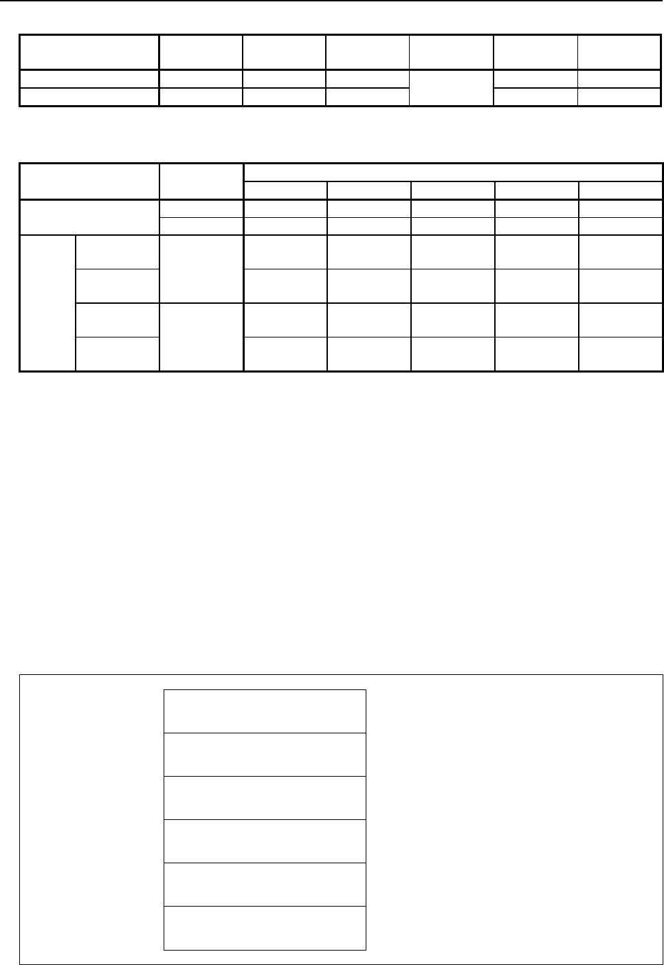
B-64513EN/03
5.WINDOW FUNCTIONS
- 597 -
(c) Offset types (for machining centers with the Tool offset for Milling and Turning function)
X axis Z axis Tool tip R Virtual
tool tip Y axis Corner R
Wear 1010 1012 1015 1019 1018 1024
Geometric 1009 1011 1014 1017 1023
Input data unit
Input
system
Increment system
IS-A IS-B IS-C IS-D IS-E
Machining center
system
mm, deg 0.01 0.001 0.0001 0.00001 0.000001
inch 0.001 0.0001 0.00001 0.000001 0.0000001
Lathe
system
Radius
specification mm, deg
0.01 0.001 0.0001 0.00001 0.000001
Diameter
specification 0.01 0.001 0.0001 0.00001 0.000001
Radius
specification inch
0.001 0.0001 0.00001 0.000001 0.0000001
Diameter
specification 0.001 0.0001 0.00001 0.000001 0.0000001
Completion codes
0 The tool offset has been written normally.
2 The data byte length for the tool offset specified for writing is invalid.
3 The offset number specified for writing is invalid. (This completion code is returned when the
specified offset number data is not from 1 to the maximum number of offsets.)
4 There are mistakes in the data attribute that specifies the type of the offset to be written. (Some
wrong offset types do not result this completion code.)
5 The tool offset value is out of the effective range.
6 For the offset number specified for writing, the additional tool offset number option is required, but
it is missing.
Also, the tool function option is not added that is necessary for the type of the offset specified for
writing.
116 The tool offset value is out of the effective range set by the wrong operation prevention function.
Output data structure
Top Address +0 (Function code)
14
+2 (Completion code)
?
(See above description)
+4 (Data length L)
4
(Same as input data)
+6 (Data number N)
Offset number
(Same as input data)
+8 (Data attribute M)
Offset type
(Same as input data)
+10
+13
Tool offset value
(Same as input data)
Signed binary (A negative value is represented in
2's complement.)

5.WINDOW FUNCTIONS
B-64513EN/03
- 598 -
5.4.4
Reading a Workpiece Origin Offset Value (High-speed
Response)
The workpiece origin offset recorded in the CNC can be read.
A workpiece origin offset is provided for each controlled axis (the 1st axis to the 32nd axis) in the CNC.
Either the workpiece origin offset for a specific axis can be read, or the workpiece origin offsets for all
axes can be read at one time. If the additional axis option is not provided, however, the workpiece origin
offset for the additional axis cannot be read.
Input data structure
Top Address +0 (Function code)
15
+2 (Completion code)
-
(Need not to be set)
+4 (Data length L)
-
(Need not to be set)
+6 (Data number N)
Offset group number
N=0: External workpiece origin offset
N=1: G54
: :
N=6: G59
With "addition of workpiece coordinate system pair"
N=7: G54.1 P1
: :
N=306: G54.1 P300
+8 (Data attribute M)
Axis number
M=1 to n: Workpiece origin offset number of a
specific axis. n is the axis number.
M=-1: Read for all axes.
+10
+41
(Data area)
-
(Need not to be set)
Completion codes
0 The workpiece origin offset has been read normally.
3 The specified offset number is invalid.
4 The specified axis number is invalid.
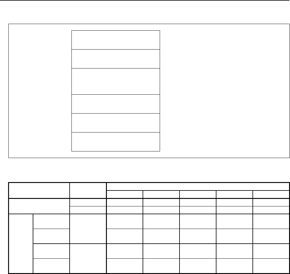
B-64513EN/03
5.WINDOW FUNCTIONS
- 599 -
Output data structure
Top Address +0 (Function code)
15
+2 (Completion code)
?
(See above description)
+4 (Data length L)
Byte length of the workpiece
origin offset value
L=4: The workpiece origin offset value for a specific
axis is read.
L=4×n: Workpiece origin offsets for all axes are
read.
+6 (Data number N)
Offset group number
(Same as input data)
+8 (Data attribute M)
Axis number
(Same as input data)
+10 Workpiece origin offset value
Signed binary number (A negative value is
represented in 2's complement.)
Output data unit
Input
system
Increment system
IS-A IS-B IS-C IS-D IS-E
Machining center
system
mm, deg 0.01 0.001 0.0001 0.00001 0.000001
inch 0.001 0.0001 0.00001 0.000001 0.0000001
Lathe
system
Radius
specification mm, deg
0.01 0.001 0.0001 0.00001 0.000001
Diameter
specification 0.01 0.001 0.0001 0.00001 0.000001
Radius
specification inch
0.001 0.0001 0.00001 0.000001 0.0000001
Diameter
specification 0.001 0.0001 0.00001 0.000001 0.0000001

5.WINDOW FUNCTIONS
B-64513EN/03
- 600 -
5.4.5
Writing a Workpiece Origin Offset Value (Low-speed
Response)
Data can be written directly as a workpiece origin offset value in the CNC.
A workpiece origin offset is provided for each controlled axis (the 1st axis to the 32nd axis) in the CNC.
Either the workpiece origin offset value for a specific axis can be written, or the workpiece origin offset
values for all axes can be written at one time. If the additional axis option is not provided, however, the
workpiece origin offset value for the additional axis cannot be written.
WARNING
When you write some NC data using both this instruction in ladder program and
other applications, take care that you do not write to the same data area.
If some values are written to the same data area by two or more applications
including ladder program, unexpected value may be written. In this case, it may
cause an unexpected machine behavior and also tools, work pieces, and
machines may be damaged. As for details, refer to “SAFETY PRECAUTIONS”.
Input data structure
Top Address +0 (Function code)
16
+2 (Completion code)
-
(Need not to be set)
+4 (Data length L)
Byte length of the workpiece
origin offset value
L=4: Workpiece origin offset value for a specific
axis is written.
L=4×n: Workpiece origin offset values for all axes
are written.
+6 (Data number N)
Offset group number
N=0: External workpiece origin offset
N=1: G54
: :
N=6: G59
With the option of adding Workpiece coordinate
systems.
N=7: G54.1 P1
: :
N=306: G54.1 P300
+8 (Data attribute M)
Axis number
M=1 to n: Workpiece origin offset number of a
specific axis. n is the axis number.
M=-1: Write for all.
+10 Workpiece origin offset value
Signed binary number (A negative value is
represented in 2's complement.)
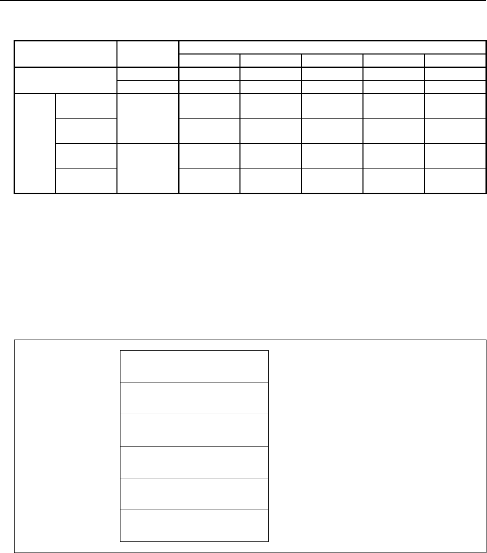
B-64513EN/03
5.WINDOW FUNCTIONS
- 601 -
Input data unit
Input
system
Increment system
IS-A IS-B IS-C IS-D IS-E
Machining center
system
mm, deg 0.01 0.001 0.0001 0.00001 0.000001
inch 0.001 0.0001 0.00001 0.000001 0.0000001
Lathe
system
Radius
specification mm, deg
0.01 0.001 0.0001 0.00001 0.000001
Diameter
specification 0.01 0.001 0.0001 0.00001 0.000001
Radius
specification inch
0.001 0.0001 0.00001 0.000001 0.0000001
Diameter
specification 0.001 0.0001 0.00001 0.000001 0.0000001
Completion codes
0 The workpiece origin offset has been written normally.
2 The specified data length is invalid.
3 The offset number is invalid.
4 The specified axis number is invalid.
5 The workpiece origin offset value is out of the effective range.
6 There is no workpiece coordinate shift option added.
Output data structure
Top Address +0 (Function code)
16
+2 (Completion code)
?
(See above description)
+4 (Data length L)
(Same as input data)
+6 (Data number N)
Offset group number
(Same as input data)
+8 (Data attribute M)
Axis number
(Same as input data)
+10 Workpiece origin offset value
(Same as input data)
Signed binary number (A negative value is
represented in 2's complement.)

5.WINDOW FUNCTIONS
B-64513EN/03
- 602 -
5.4.6
Reading a Parameter (High-speed Response)
The integer type parameter data of the CNC is read by directly accessing the CNC.
There are four types of the integer parameters in the CNC: Bit parameters having a definite meaning for
each bit, byte parameters holding 1-byte data, word parameters holding 2-byte data, and double word
parameters holding 4-byte data. Therefore, the length of the read data varies according to the parameter
number specified.
Note that bit parameters cannot be read in bit units. The eight bits (one byte) for a parameter number
must be read at a time.
For axis parameters, data for a specific axis can be read, or data for all axes can be read at a time.
For details of parameter data, refer to the “PARAMETER MANUAL”.
Input data structure
Top Address +0 (Function code)
17 or 154
+2 (Completion code)
-
(Need not to be set)
+4 (Data length L)
-
(Need not to be set)
+6 (Data number N)
Parameter number
+8 (Data attribute M)
Axis number
M=0: No axis
M=1 to n: A specific axis
M=-1: All axes
+10
+41
(Data area)
-
(Need not to be set)
Completion codes
0 Parameter data has been read normally.
3 The parameter number specified for reading is invalid.
4 The specified data attribute is invalid because it is neither 0, -1, nor a value 1 to n (n is the number of
axes).
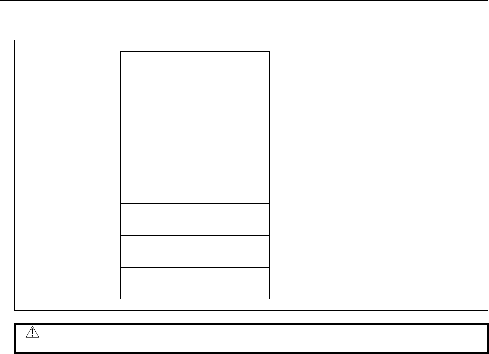
B-64513EN/03
5.WINDOW FUNCTIONS
- 603 -
Output data structure
Top Address +0 (Function code)
17 or 154
+2 (Completion code)
?
(See above description)
+4 (Data length L)
(L = 1, 2, 4, 1×n, 2×n, 4×n)
When no axis or one axis is specified
L=1: Bit or byte parameter
L=2: Word parameter
L=4: Double word parameter
When all axes are specified
L=1×n: Bit or byte parameter
L=2×n: Word parameter
L=4×n: Double word parameter
+6 (Data number N)
Parameter number
(Same as input data)
+8 (Data attribute M)
Axis number
(Same as input data)
+10 Parameter data
Parameter - dependent form
CAUTION
Macro executor parameters 9000 to 9011 cannot be read.

5.WINDOW FUNCTIONS
B-64513EN/03
- 604 -
5.4.7
Writing a Parameter (Low-speed Response)
Data can be written in an integer parameter in the CNC.
There are four types of the integer parameters in the CNC: Bit parameters having a definite meaning for
each bit, byte parameters holding 1-byte data, word parameters holding 2-byte data, and double word
parameters holding 4-byte data. Therefore, the length of the written data varies according to the
parameter specified.
Note that bit parameters cannot be written in bit units. The eight bits (one byte) for the parameter number
must be written at a time. This means that when a bit needs to be written, the whole data for the
corresponding parameter number shall be read first, modify the target bit in the read data, then the data
shall be rewritten.
For axis parameters, data for a specific axis can be read, or data for all axes can be read at a time.
For details of parameter data, refer to the “PARAMETER MANUAL”.
Some parameters cause a P/S alarm 000 when data is written. (The power must be turned off before
continuing operation.)
WARNING
When you write some NC data using both this instruction in ladder program and
other applications, take care that you do not write to the same data area.
If some values are written to the same data area by two or more applications
including ladder program, unexpected value may be written. In this case, it may
cause an unexpected machine behavior and also tools, work pieces, and
machines may be damaged. As for details, refer to “SAFETY PRECAUTIONS”.
Input data structure
Top Address +0 (Function code)
18
+2 (Completion code)
-
(Need not to be set)
+4 (Data length L)
(L = 1, 2, 4, 1×n, 2×n, 4×n)
When no axis or one axis is specified
L=1: Bit or byte parameter
L=2: Word parameter
L=4: Double word parameter
When all axes are specified
L=1×n: Bit or byte parameter
L=2×n: Word parameter
L=4×n: Double word parameter
+6 (Data number N)
Parameter number
+8 (Data attribute M)
Axis number
M=0: No axis
M=1 to n: A specific axis
M=-1: All axes
+10 Parameter data
Parameter - dependent form
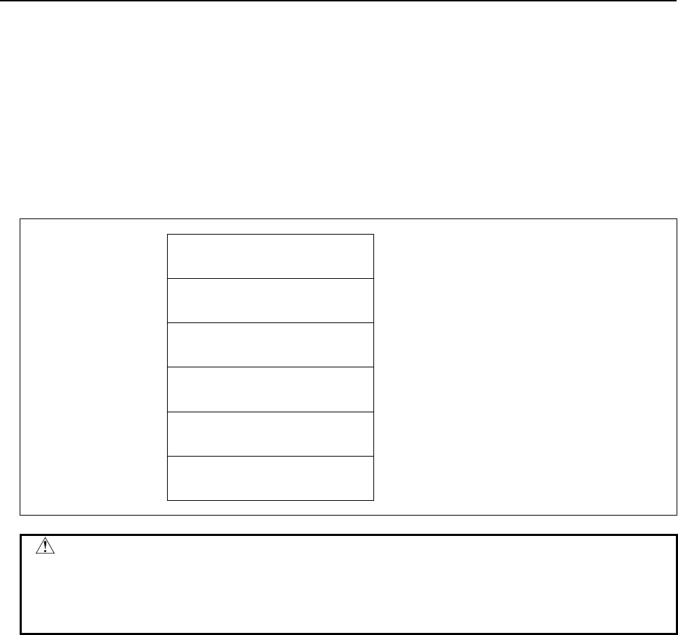
B-64513EN/03
5.WINDOW FUNCTIONS
- 605 -
Completion codes
0 Parameter data has been written normally.
2 The data byte length of the parameter specified for writing is invalid.
3 The parameter number specified for writing is invalid.
4 The specified data attribute is invalid because it is neither 0, -1, nor a value from 1 to n (n is the
number of axes).
6 The necessary option is not added.
113 The CNC status is that the writing the parameter cannot be allowed.
Output data structure
Top Address +0 (Function code)
18
+2 (Completion code)
?
(See above description)
+4 (Data length L)
(Same as input data)
+6 (Data number N)
Parameter number
(Same as input data)
+8 (Data attribute M)
Axis number
(Same as input data)
+10 Parameter data
(Same as input data)
Parameter - dependent form
CAUTION
1 Parameters may not become effective immediately depending on the parameter
numbers.
2 There is timing when it can't be written in some parameters. In this case '113' is
set to the completion code.

5.WINDOW FUNCTIONS
B-64513EN/03
- 606 -
5.4.8
Reading a Real Type Parameter (High-speed Response)
This function can read a real type CNC parameter.
For details of parameter data, refer to the “PARAMETER MANUAL”.
NOTE
This function cannot read integer type or bit type parameters. To read an integer
type or bit type parameter, use the function having function code 17 or 154.
Input data structure
(1) Reading the non-axis type parameter or the axis type parameter for one axis (M=n)
Top Address +0 (Function Code)
321
+2 (Completion code)
-
(Need not to be set)
+4 (Data length L)
-
(Need not to be set)
+6 (Data number N)
Parameter number
Set the parameter number with singed binary
format in four bytes length.
+10 (Data attribute M)
Axis number
M=0: Non-axis type parameter
M=1 to n: Axis number
+12 Decimal point position
(2 bytes)
Set the decimal point position of the parameter
value.
+14
+17
(Data area)
-
(Need not to be set)

B-64513EN/03
5.WINDOW FUNCTIONS
- 607 -
(2) Reading axis type parameters for all axes (M=-1, Example for 3 controlled-axes)
Top Address +0 (Function Code)
321
+2 (Completion code)
-
(Need not to be set)
+4 (Data length L)
-
(Need not to be set)
+6 (Data number N)
Parameter number
Set the parameter number with singed binary
format in four bytes length.
+10 (Data attribute M)
-1
All axes
+12 Decimal point position
(2 bytes)
Set the decimal point position of the parameter
value for the 1st axis.
+14 (Data area)
-
(Need not to be set)
+18 Decimal point position
(2 bytes)
Set the decimal point position of the parameter
value for the 2nd axis.
+20 (Data area)
-
(Need not to be set)
+24 Decimal point position
(2 bytes)
Set the decimal point position of the parameter
value for the 3rd axis.
+26
+29
(Data area)
-
(Need not to be set)
Completion codes
0 Normal completion
3 The data number is invalid.
4 The data attribute is invalid.
5 The decimal point position is invalid.

5.WINDOW FUNCTIONS
B-64513EN/03
- 608 -
Output data structure
(1) Reading the non-axis type parameter or the axis type parameter for one axis (M=n)
Top Address +0 (Function Code)
321
+2 (Completion code)
?
(See above description)
+4 (Data length L)
6
+6 (Data number N)
Parameter number
(Same as input data)
+10 (Data attribute M)
Axis number
(Same as input data)
+12 Decimal point position
(Same as input data)
+14
+17
Parameter value
(4 bytes)
The read parameter value is set with signed binary
format in four bytes length.
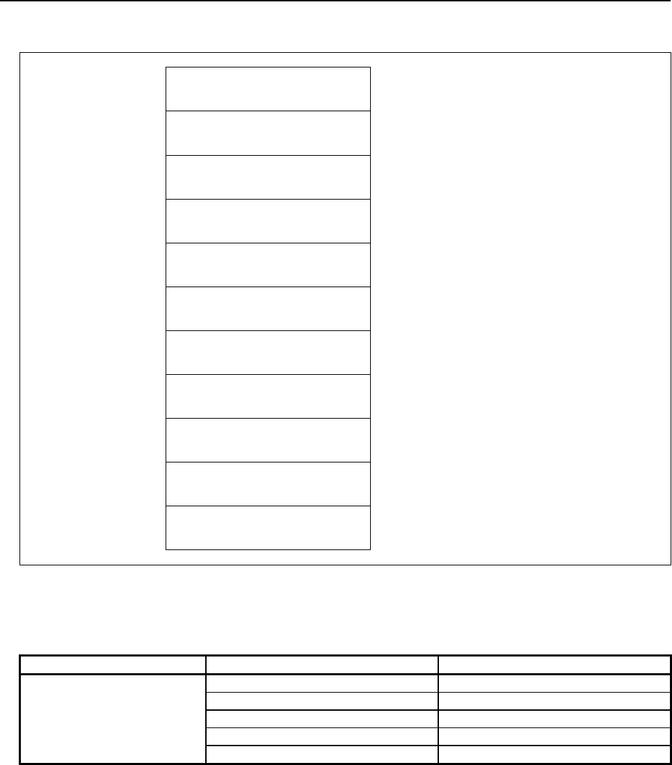
B-64513EN/03
5.WINDOW FUNCTIONS
- 609 -
(2) Reading axis type parameters for all axes (M=-1, Example for 3 controlled-axes)
Top Address +0 (Function Code)
321
+2 (Completion code)
?
(See above description)
+4 (Data length L)
18
(6 bytes * 3 axes)
+6 (Data number N)
Parameter number
(Same as input data)
+10 (Data attribute M)
-1
(Same as input data)
+12 Decimal point position
(Same as input data)
+14 Parameter value
(4 bytes)
The read parameter value for the 1st axis is set
with signed binary format in four bytes length.
+18 Decimal point position
(Same as input data)
+20 Parameter value
(4 bytes)
The read parameter value for the 2nd axis is set
with signed binary format in four bytes length.
+24 Decimal point position
(Same as input data)
+26
+29
Parameter value
(4 bytes)
The read parameter value for the 3rd axis is set
with signed binary format in four bytes length.
The read parameter value for each specified decimal point position is shown below.
(The read value) = (Parameter value) × 10 (Decimal point position)
Parameter value Decimal point position Read value
1.234
0 1
1 12
2 123
3 1234
4 12340

5.WINDOW FUNCTIONS
B-64513EN/03
- 610 -
5.4.9
Writing a Real Type Parameter (Low-speed Response)
This function can write a real type CNC parameter.
For details of parameter data, refer to the “PARAMETER MANUAL”.
WARNING
When you write some NC data using both this instruction in ladder program and
other applications, take care that you do not write to the same data area.
If some values are written to the same data area by two or more applications
including ladder program, unexpected value may be written. In this case, it may
cause an unexpected machine behavior and also tools, work pieces, and
machines may be damaged. As for details, refer to “SAFETY PRECAUTIONS”.
NOTE
This function cannot write integer type or bit type parameters. To write an
integer type or bit type parameter, use the function having function code 18.
Input data structure
(1) Writing the non-axis type parameter or the axis type parameter for one axis (M=n)
Top Address +0 (Function Code)
323
+2 (Completion code)
-
(Need not to be set)
+4 (Data length L)
6
Set the data length.
+6 (Data number N)
Parameter number
Set the parameter number with singed binary
format in four bytes length.
+10 (Data attribute M)
Axis number
M=0: Non-axis type parameter
M=1 to n: Axis number
+12 Decimal point position
(2 bytes)
Set the decimal point position of the parameter
value.
+14
+17
Parameter value
(4 bytes)
Set the parameter value with singed binary format
in four bytes length

B-64513EN/03
5.WINDOW FUNCTIONS
- 611 -
(2) Writing axis type parameters for all axes (M=-1, Example for 3 controlled-axes)
Top Address +0 (Function Code)
323
+2 (Completion code)
-
(Need not to be set)
+4 (Data length L)
18
(6bytes * 3axes)
Set the data length.
+6 (Data number N)
Parameter number
Set the parameter number with singed binary
format in four bytes length.
+10 (Data attribute M)
-1
All axes
+12 Decimal point position
(2 bytes)
Set the decimal point position of the parameter
value for the 1st axis.
+14 Parameter value
(4 bytes)
Set the parameter value for the 1st axis with singed
binary format in four bytes length
+18 Decimal point position
(2 bytes)
Set the decimal point position of the parameter
value for the 2nd axis.
+20 Parameter value
(4 bytes)
Set the parameter value for the 2nd axis with
singed binary format in four bytes length
+24 Decimal point position
(2 bytes)
Set the decimal point position of the parameter
value for the 3rd axis.
+26
+29
Parameter value
(4 bytes)
Set the parameter value for the 3rd axis with singed
binary format in four bytes length
Completion codes
0 Normal completion
2 The data length is invalid.
3 The data number is invalid.
4 The data attribute is invalid.
5 The decimal point position is invalid.
113 The CNC status is that the writing the parameter cannot be allowed.

5.WINDOW FUNCTIONS
B-64513EN/03
- 612 -
Output data structure
(1) Writing the non-axis type parameter or the axis type parameter for one controlled axis (M=n)
Top Address +0 (Function Code)
323
+2 (Completion code)
?
(See above description)
+4 (Data length L)
6
(Same as input data)
+6 (Data number N)
Parameter number
(Same as input data)
+10 (Data attribute M)
Axis number
(Same as input data)
+12 Decimal point position
(Same as input data)
+14
+17
Parameter value
(Same as input data)
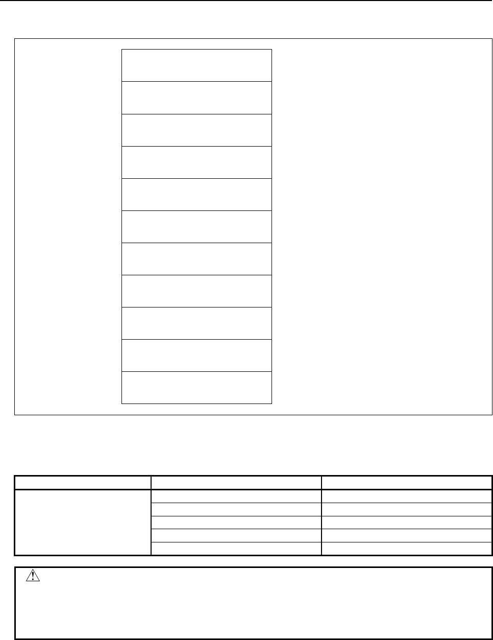
B-64513EN/03
5.WINDOW FUNCTIONS
- 613 -
(2) Reading axis type parameters for all axes (M=-1, Example for 3 controlled-axes)
Top Address +0 (Function Code)
323
+2 (Completion code)
?
(See above description)
+4 (Data length L)
18
(Same as input data)
+6 (Data number N)
Parameter number
(Same as input data)
+10 (Data attribute M)
-1
(Same as input data)
+12 Decimal point position
(Same as input data)
+14 Parameter value
(Same as input data)
+18 Decimal point position
(Same as input data)
+20 Parameter value
(Same as input data)
+24 Decimal point position
(Same as input data)
+26
+29
Parameter value
(Same as input data)
The parameter value for each specified decimal point position is shown below.
(Writing value) = (Parameter value) × 10 (Decimal point position)
Writing value Decimal point position Parameter value
1234
0 1234.000
1 123.400
2 12.240
3 1.234
4 0.123
CAUTION
1 Parameters may not become effective immediately depending on the parameter
numbers.
2 There is timing when it can't be written in some parameters. In this case '113' is
set to the completion code.

5.WINDOW FUNCTIONS
B-64513EN/03
- 614 -
5.4.10
Reading Setting Data (High-speed Response)
The data set in the CNC is read by directly accessing the CNC.
There are four types of setting data in the CNC: Bit setting data having a definite meaning for each bit,
byte setting data stored in bytes, word setting data stored in 2-byte units, and double-word setting data
stored in 4-byte units. Therefore, the length of the read data varies according to the setting data specified.
Note that bit setting data cannot be read in bit units. The eight bits (one byte) for the setting data number
must be read at a time.
For axis setting data, data for a specific axis can be read, or data for all axes can be read at a time.
For details of setting data, refer to the ”OPERATOR’S MANUAL”.
Input data structure
Top Address +0 (Function code)
19 or 155
+2 (Completion code)
-
(Need not to be set)
+4 (Data length L)
-
(Need not to be set)
+6 (Data number N)
Setting data number
+8 (Data attribute M)
Axis number
M=0: No axis
M=1 to n: A specific axis
M=-1: All axes
+10
+41
(Data area)
-
(Need not to be set)
Completion codes
0 Setting data has been read normally.
3 The setting number specified for reading is invalid.
4 The specified data attribute is invalid because it is neither 0, -1, nor a value from 1 to n (n is the
number of axes).

B-64513EN/03
5.WINDOW FUNCTIONS
- 615 -
Output data structure
Top Address +0 (Function code)
19 or 155
+2 (Completion code)
?
(See above description)
+4 (Data length L)
(L = 1, 2, 4, 1×n, 2×n, 4×n)
When no axis or one axis is specified
L=1: Bit or byte setting data
L=2: Word setting data
L=4: Double word setting data
When all axes are specified
L=1×n: Bit or byte setting data
L=2×n: Word setting data
L=4×n: Double word parameter
+6 (Data number N)
Parameter number
(Same as input data)
+8 (Data attribute M)
Axis number
(Same as input data)
+10 Setting data
Parameter - dependent form

5.WINDOW FUNCTIONS
B-64513EN/03
- 616 -
5.4.11
Writing Setting Data (Low-speed Response)
Data can be written as setting data in the CNC.
For details of setting data, refer to the ”OPERATOR’S MANUAL”.
WARNING
When you write some NC data using both this instruction in ladder program and
other applications, take care that you do not write to the same data area.
If some values are written to the same data area by two or more applications
including ladder program, unexpected value may be written. In this case, it may
cause an unexpected machine behavior and also tools, work pieces, and
machines may be damaged. As for details, refer to “SAFETY PRECAUTIONS”.
Input data structure
Top Address +0 (Function code)
20
+2 (Completion code)
-
(Need not to be set)
+4 (Data length L)
(L = 1, 2, 4, 1×n, 2×n, 4×n)
When no axis or one axis is specified
L=1: Bit or byte setting data
L=2: Word setting data
L=4: Double word setting data
When all axes are specified
L=1×n: Bit or byte setting data
L=2×n: Word setting data
L=4×n: Double word setting data
+6 (Data number N)
Setting data number
+8 (Data attribute M)
Axis number
M=0: No axis
M=1 to n: A specific axis
M=-1: All axes
+10 Setting data
Setting data - dependent form
Completion codes
0 Setting data has been written normally.
2 The byte length of the setting data specified for writing is invalid.
3 The setting data number specified for writing is invalid.
4 The specified data attribute is invalid because it is neither 0, -1, nor a value from 1 to n (n is the
number of axes).

B-64513EN/03
5.WINDOW FUNCTIONS
- 617 -
Output data structure
Top Address +0 (Function code)
20
+2 (Completion code)
?
(See above description)
+4 (Data length L)
(Same as input data)
+6 (Data number N)
Setting data number
(Same as input data)
+8 (Data attribute M)
Axis number
(Same as input data)
+10 Setting data
(Same as input data)
Setting data - dependent form
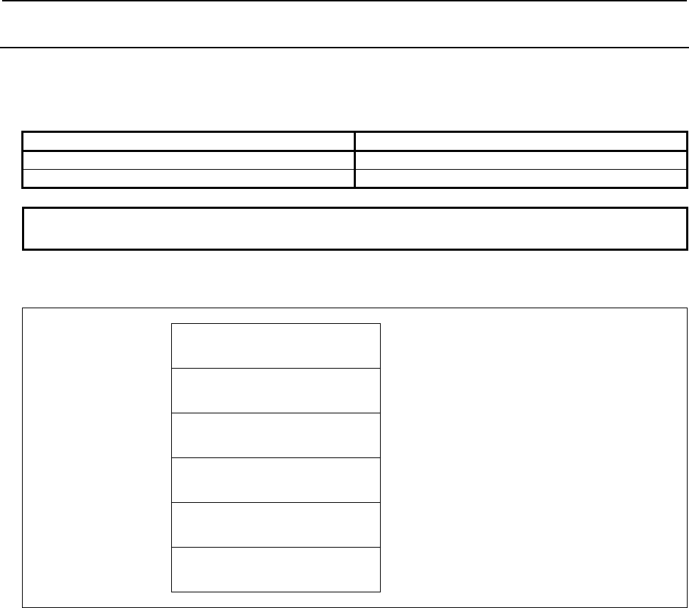
5.WINDOW FUNCTIONS
B-64513EN/03
- 618 -
5.4.12
Reading a Custom Macro Variable (High-speed Response)
Using this function, you can read a common variable of custom macro variables. You cannot read a local
variable and a system variable.
Table 5.4.12 (a) Common variables of custom macro
Custom macro common variable addition option Common variables
Not equipped #100~#149, #500~#549
Equipped #100~#199, #500~#999
NOTE
For details of the custom macro variables, refer to the "OPERATOR’S MANUAL ".
Input data structure
Top Address +0 (Function code)
21
+2 (Completion code)
-
(Need not to be set)
+4 (Data length L)
-
(Need not to be set)
+6 (Data number N)
Custom macro variable number
+8 (Data attribute M)
Number of decimal places
M=0: No specifying number of decimal places
M=1 to 8: Specifying number of decimal places
+10
+15
(Data area)
-
(Need not to be set)
Completion codes
0 Completed successfully
1 No option for custom macro variables
3 The data number is invalid.
4 The mantissa is out of range.
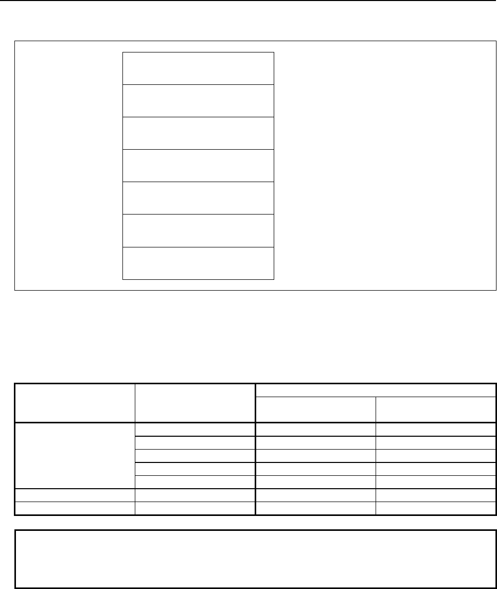
B-64513EN/03
5.WINDOW FUNCTIONS
- 619 -
Output data structure
Top Address +0 (Function code)
21
+2 (Completion code)
?
(See above description)
+4 (Data length L)
6
+6 (Data number N)
Custom macro variable number
(Same as input data)
+8 (Data attribute M)
Number of decimal places
(Same as input data)
+10 Mantissa(D1)
(4 bytes)
Signed binary format in 4 bytes length
+14
+15
Number of decimal places(D2)
(2 bytes)
Signed binary format in 2 bytes length
D2 = -1, 0 to 8
You can read D1 and D2 when the custom macro variable is expressed by the following formula.
[Custom macro variable] = D1 × 10 –D2
There is a "null" state on custom macro variables that means the value is not defined. When the custom
macro variable is "null", the D1=0 and the D2 = -1 are read in spite of the specified value of M.
Value of the custom
macro variable
Specified number of
decimal places (M)
Result data
Mantissa (D1) Number of decimal
places (D2)
1.234
0 1234 3
1 12 1
2 123 2
3 1234 3
4 12340 4
0 1 0 1
Null - 0 -1
NOTE
When you set 0 to number of decimal places M, the read value of D2 may
changes by the value of the macro variable and the setting of CNC system. So,
we recommend to set 1 to 8 to number of decimal places M.

5.WINDOW FUNCTIONS
B-64513EN/03
- 620 -
5.4.13
Writing a Custom Macro Variable (Low-speed Response)
Using this function, you can write value to a common variable of custom macro variables. You cannot
write to local variables or system variables.
WARNING
When you write some NC data using both this instruction in ladder program and
other applications, take care that you do not write to the same data area.
If some values are written to the same data area by two or more applications
including ladder program, unexpected value may be written. In this case, it may
cause an unexpected machine behavior and also tools, work pieces, and
machines may be damaged. As for details, refer to “SAFETY PRECAUTIONS”.
Table5.4.13 (a) Common variables of custom macro
Custom macro common variable addition option Common variables
Not equipped #100~#149, #500~#549
Equipped #100~#199, #500~#999
NOTE
For details of the custom macro variables, refer to the "OPERATOR’S MANUAL ".
Input data structure
Top Address +0 (Function code)
22
+2 (Completion code)
-
(Need not to be set)
+4 (Data length L)
6
+6 (Data number N)
Custom macro variable number
+8 (Data attribute M)
0
Set 0 to this field.
+10 Mantissa (D1)
(4 bytes)
Signed binary format in 4 bytes length
+14
+15
Number of decimal places (D2)
(2 bytes)
Signed binary format in 2 bytes length
D2 = -1, 0 to 8

B-64513EN/03
5.WINDOW FUNCTIONS
- 621 -
You should set values to D1 and D2 when the custom macro variable is expressed by the following
formula.
[Custom macro variable] = D1 × 10 –D2
There is a "null" state on custom macro variables that means the value is not defined. When you set D1=0
and D2= -1, the custom macro variable becomes "null" state.
Setting data Value of the custom macro
variable
(Result)
Mantissa (D1) Number of decimal places (D2)
1234 0 1234
1234 1 123.4
1234 2 12.34
1234 3 1.234
1234 4 0.1234
0 Except -1 0
0 -1 Null
Completion codes
0 Completed successfully
2 The data length is invalid.
3 The data number is invalid.
6 No option for custom macro variables
7 The variable is write-protected.
Output data structure
Top Address +0 (Function code)
22
+2 (Completion code)
?
(See above description)
+4 (Data length L)
6
(Same as input data)
+6 (Data number N)
Custom macro variable number
(Same as input data)
+8 (Data attribute M)
0
(Same as input data)
+10 Mantissa (D1)
(Same as input data)
+14
+15
Number of decimal places (D2)
(Same as input data)
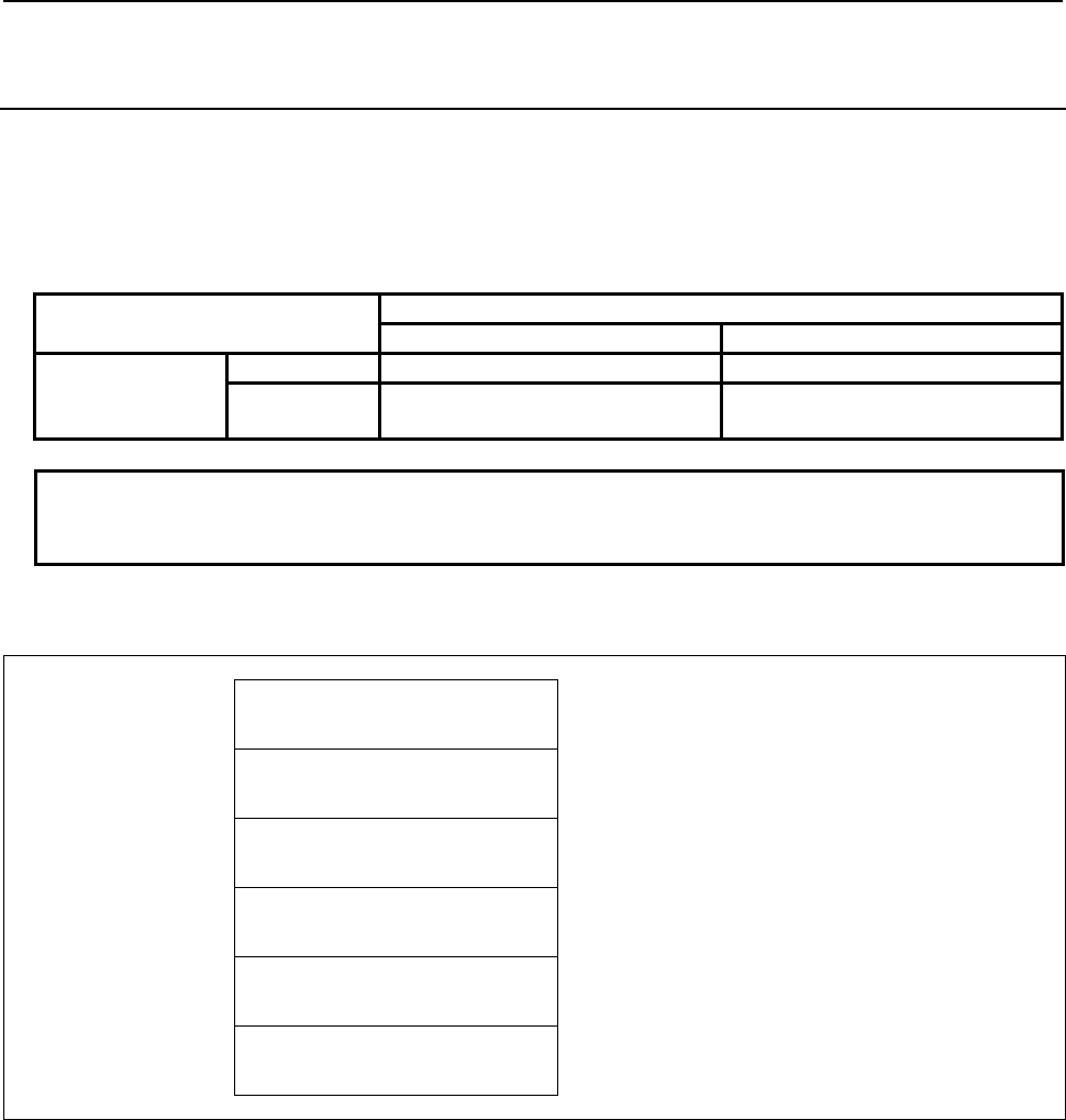
5.WINDOW FUNCTIONS
B-64513EN/03
- 622 -
5.4.14
Reading a Custom Macro Variable (Variable Number
Extension) (Low-speed Response)
Using this function, you can read a system variable and a common variable of custom macro variables.
You cannot read a local variable.
The readable common variable range is changed by some software option. About details, refer to the
following table.
Table5.4.14 (a) Range of common variables
Custom macro common variables addition option
Not equipped Equipped
Embedded macro
option
Not equipped #100~#149, #500~#549 #100~#199, #500~#999
Equipped #100~#149, #200~#499,
#500~#549
#100~#199, #200~#499,
#500~#999
NOTE
For details of the system variables and the common variables of the custom
macro, refer to the "OPERATOR’S MANUAL".
Input data structure
Top Address +0 (Function code)
437
+2 (Completion code)
-
(Need not to be set)
+4 (Data length L)
-
(Need not to be set)
+6 (Data number N)
Custom macro variable number
(4 bytes)
+10 (Data attribute M)
Number of decimal places
(2 bytes)
M=0 to 8: Specifying number of decimal places
+12
+17
(Data area)
-
(Need not to be set)
Completion codes
0 Completed successfully.
3 The data number is invalid.
5 The mantissa is out of range.
6 No option for custom macro variables.
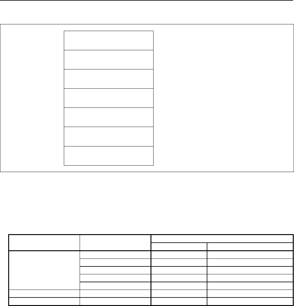
B-64513EN/03
5.WINDOW FUNCTIONS
- 623 -
Output data structure
Top Address +0 (Function code)
437
+2 (Completion code)
?
(See above description)
+4 (Data length L)
6
+6 (Data number N)
Custom macro variable number
(Same as input data)
+10 (Data attribute M)
Number of decimal places
(Same as input data)
+12 Mantissa(D1)
(4 bytes)
Signed binary format in 4 bytes length
+16
+17
Number of decimal places(D2)
(2 bytes)
Signed binary format in 2 bytes length
D2 = -1, 0 to 8
You can read D1 and D2 when the custom macro variable is expressed by the following formula.
[Custom macro variable] = D1 × 10 –D2
There is a "null" state on custom macro variables that means the value is not defined. When the custom
macro variable is "null", the D1=0 and the D2 = -1 are read in spite of the specified value of M.
Value of the custom
macro variable
Specified number of
decimal places (M)
Result data
Mantissa (D1) Number of decimal places (D2)
1.234
0 1 0
1 12 1
2 123 2
3 1234 3
4 12340 4
0 - 0 0
Null - 0 -1
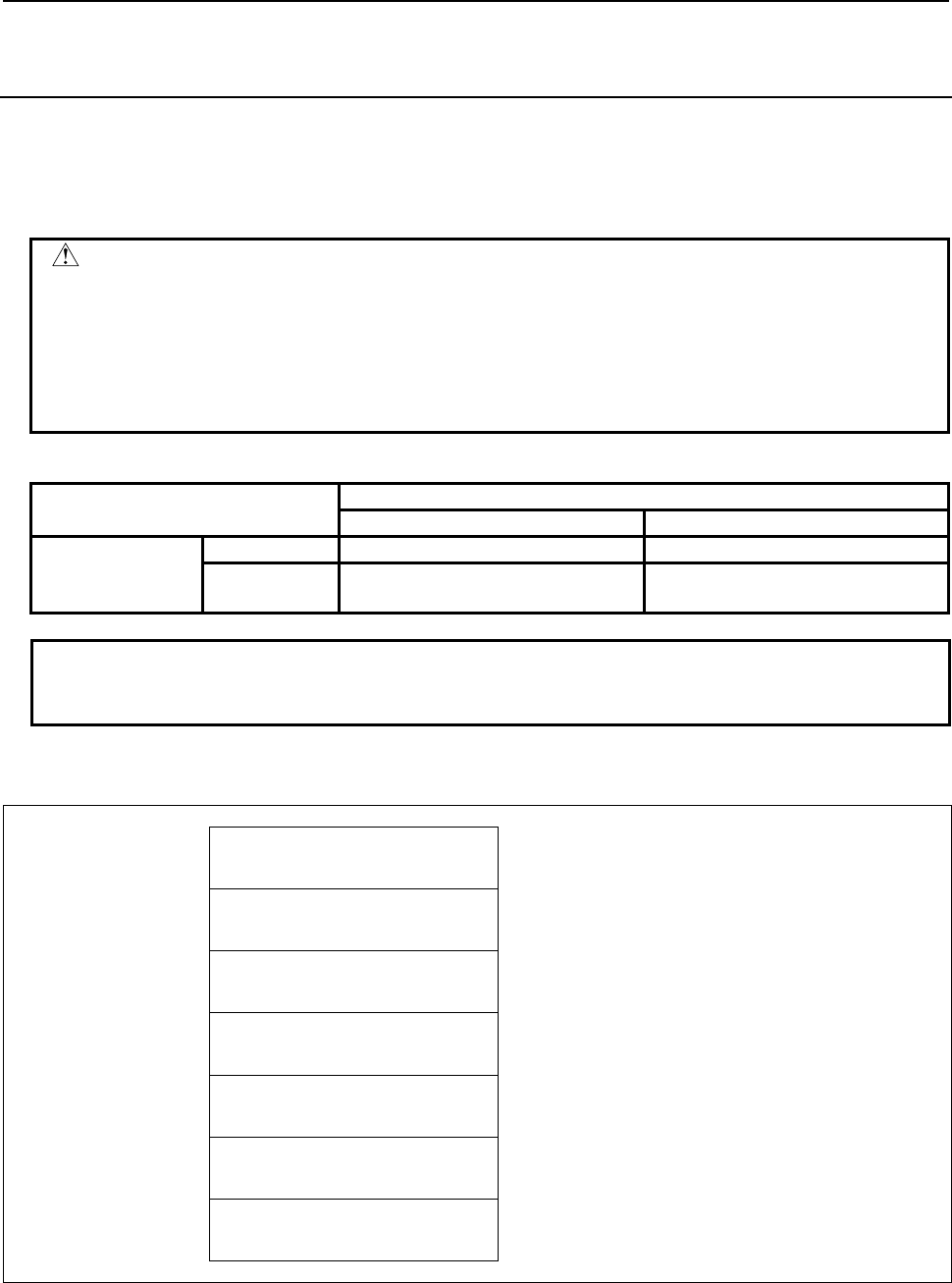
5.WINDOW FUNCTIONS
B-64513EN/03
- 624 -
5.4.15
Writing a Custom Macro Variable (Variable Number
Extension) (Low-speed Response)
Using this function, you can write a system variable and a common variable of custom macro variables.
You cannot write a local variable.
The writable common variable range is changed by some software option. About details, refer to the
following table.
WARNING
When you write some NC data using both this instruction in ladder program and
other applications, take care that you do not write to the same data area.
If some values are written to the same data area by two or more applications
including ladder program, unexpected value may be written. In this case, it may
cause an unexpected machine behavior and also tools, work pieces, and
machines may be damaged. As for details, refer to “SAFETY PRECAUTIONS”.
Table5.4.15 (a) Range of common variables
Custom macro common variables addition option
Not equipped Equipped
Embedded macro
option
Not equipped #100~#149, #500~#549 #100~#199, #500~#999
Equipped #100~#149, #200~#499,
#500~#549
#100~#199, #200~#499,
#500~#999
NOTE
For details of the system variables and the common variables of the custom
macro, refer to the "OPERATOR’S MANUAL".
Input data structure
Top Address +0 (Function code)
438
+2 (Completion code)
-
(Need not to be set)
+4 (Data length L)
6
+6 (Data number N)
Custom macro variable number
(4 bytes)
+10 (Data attribute M)
0
(2 bytes)
Set 0 to this field.
+12 Mantissa(D1)
(4 bytes)
Signed binary format in 4 bytes length
+16
+17
Number of decimal places(D2)
(2 bytes)
Signed binary format in 2 bytes length
D2 = -1, 0 to 8
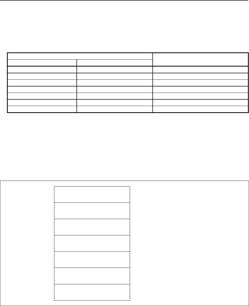
B-64513EN/03
5.WINDOW FUNCTIONS
- 625 -
You should set values to D1 and D2 when the custom macro variable is expressed by the following
formula.
[Custom macro variable] = D1 × 10 –D2
There is a "null" state on custom macro variables that means the value is not defined. When you set D1=0
and D2= -1, the custom macro variable becomes "null" state.
Setting data Value of the custom macro variable
(Result)
Mantissa (D1) Number of decimal places (D2)
1234 0 1234
1234 1 123.4
1234 2 12.34
1234 3 1.234
1234 4 0.1234
0 Except -1 0
0 -1 Null
Completion codes
0 Completed successfully.
2 The Data length is invalid.
3 The Data number is invalid.
6 No option for custom macro variables.
Output data structure
Top Address +0 (Function code)
438
+2 (Completion code)
?
(See above description)
+4 (Data length L)
6
(Same as input data)
+6 (Data number N)
Custom macro variable number
(Same as input data)
+10 (Data attribute M)
0
(Same as input data)
+12 Mantissa(D1)
(Same as input data)
+16
+17
Number of decimal places(D2)
(Same as input data)
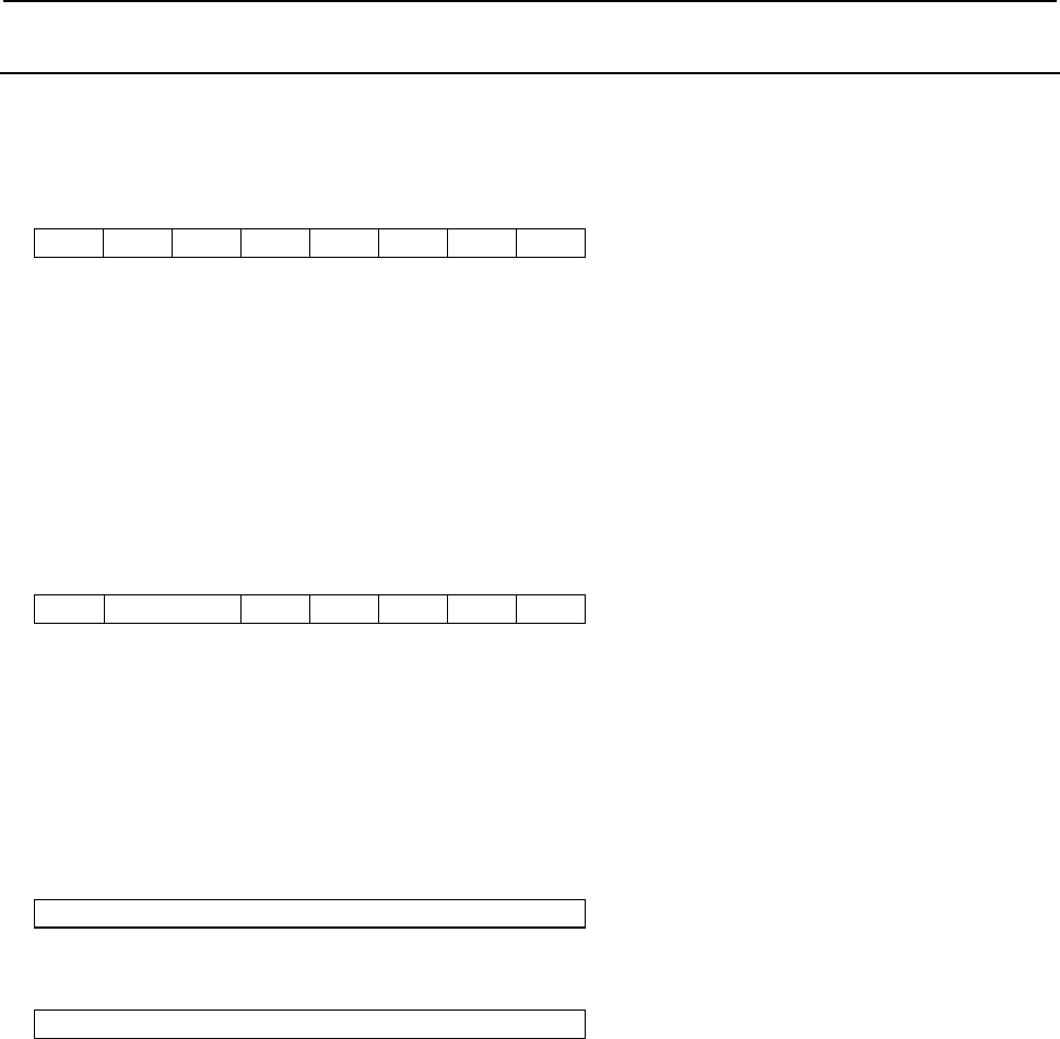
5.WINDOW FUNCTIONS
B-64513EN/03
- 626 -
5.4.16
Reading the CNC Alarm Status (High-speed Response)
When the CNC is in the alarm status, the alarm status data can be read. The following alarm status data
can be read:
(a) First byte of alarm status data
7 6 5 4 3 2 1 0
SR SV OH OT PS IO PW SW
SW : SW alarm (parameter writing alarm)
PW : PW alarm (alarm requiring power to be turned off)
IO : IO alarm (memory file alarm)
PS : PS alarm (program and operation alarm)
OT : OT alarm (overtravel alarm)
OH : OH alarm (overheat alarm)
SV : SV alarm (servo alarm)
SR : SR alarm (communication alarm)
(b) Second byte of alarm status data
7 6 5 4 3 2 1 0
EX (Reserved) BG IE DS SP MC
MC : MC alarm (macro alarm)
SP : SP alarm (spindle alarm)
DS : DS alarm (other alarm)
IE : IE alarm (malfunction prevention function alarm)
BG : BG alarm (background edit alarm)
EX : EX alarm (External alarm)
(c) Third byte of alarm status data
7 6 5 4 3 2 1 0
(Reserved)
(d) Fourth byte of alarm status data
7 6 5 4 3 2 1 0
(Reserved)

B-64513EN/03
5.WINDOW FUNCTIONS
- 627 -
Input data structure
Top Address +0 (Function code)
23
+2 (Completion code)
-
(Need not to be set)
+4 (Data length L)
-
(Need not to be set)
+6 (Data number N)
0
Set 0 to this field.
+8 (Data attribute M)
0
Set 0 to this field.
+10
+41
(Data area)
-
(Need not to be set)
Completion codes
0 Completed successfully.
Output data structure
Top Address +0 (Function code)
23
+2 (Completion code)
?
(See above description)
+4 (Data length L)
4
+6 (Data number N)
0
(Same as input data)
+8 (Data attribute M)
0
(Same as input data)
+10
+13
Alarm status
4 bytes bit type
CAUTION
In the previous CNC model (Series 16, 18, 21 etc.), the size of output data are 2
bytes. On this model, note that the size of output data is expanded to 4 bytes.

5.WINDOW FUNCTIONS
B-64513EN/03
- 628 -
5.4.17
Reading the Current Program Number (High-speed
Response)
The program number of a machining program being executed or selected on the CNC can be read.
When a subprogram is executed on the CNC, the program number of the main program can also be read.
Note that the program number that can be read is the first program number (first loop main program).
This function accepts only 4-digits program numbers. When the specification supports 8-digits program
numbers, specify function code 90 to read 8-digits program numbers.
Input data structure
Top Address +0 (Function code)
24
+2 (Completion code)
-
(Need not to be set)
+4 (Data length L)
-
(Need not to be set)
+6 (Data number N)
0
Set 0 to this field.
+8 (Data attribute M)
0
Set 0 to this field.
+10
+41
(Data area)
-
(Need not to be set)
Completion codes
0 The program number of the currently executing program was read successfully.
5 The program number exceeds 4-digits. (Use function code 90.)

B-64513EN/03
5.WINDOW FUNCTIONS
- 629 -
Output data structure
Top Address +0 (Function code)
24
+2 (Completion code)
?
(See above description)
+4 (Data length L)
4
+6 (Data number N)
0
(Same as input data)
+8 (Data attribute M)
0
(Same as input data)
+10 Current program number (ON)
Unsigned binary, 2 bytes long
+12
+13
Program number of main program
(OMN)
Unsigned binary, 2 bytes long
(a) Current program number (ON)
The program number of the program being executed is set.
(b) Program number of main program (OMN)
When the currently executing program is a subprogram, the program number of its main program
(first loop main program) is set. When the currently executing program is not a subprogram, 0 is set.

5.WINDOW FUNCTIONS
B-64513EN/03
- 630 -
5.4.18
Reading the Current Sequence Number (High-speed
Response)
The sequence number of a machining program being executed on the CNC can be read. If sequence
numbers are not assigned to all blocks of the machining program, the sequence number of the most
recently executed block is read.
Input data structure
Top Address +0 (Function code)
25
+2 (Completion code)
-
(Need not to be set)
+4 (Data length L)
-
(Need not to be set)
+6 (Data number N)
0
Set 0 to this field.
+8 (Data attribute M)
0
Set 0 to this field.
+10
+41
(Data area)
-
(Need not to be set)
Completion codes
0 The current sequence number has been read normally.
Output data structure
Top Address +0 (Function code)
25
+2 (Completion code)
?
(See above description)
+4 (Data length L)
4
Note that the data length must be set to 4 bytes
even though the current program number is 2 bytes
long (the sequence number is indicated by 5 digits).
+6 (Data number N)
0
(Same as input data)
+8 (Data attribute M)
0
(Same as input data)
+10
+13
Current sequence number
Unsigned binary

B-64513EN/03
5.WINDOW FUNCTIONS
- 631 -
5.4.19
Reading Modal Data (High-speed Response)
Using this function, you can read modal information of CNC.
(1) Reading modal information of G-function (Data number=0 to 33, -1)
Using this function, you can read modal information of G-function.
Input data structure
Top Address +0 (Function code)
32
+2 (Completion code)
-
(Need not to be set)
+4 (Data length L)
-
(Need not to be set)
+6 (Data number N)
Data type
N=0 to 33: Each data reading (See. Table 5.4.19 (a)
to (c))
N=-1: Collective reading (Group No.0 to 31)
+8 (Data attribute M)
Specified block
M=0: Current block
M=1: Next block
M=2: (reserved)
+10 (Data area)
-
(Need not to be set)
NOTE
1 The modal information for a block after the next block cannot be read.
2 When a collective reading, the read modal information of groups are from No. 0
to No.31. To read modal information of over No. 31 group, use the each data
reading by setting over 31 to the data number N.

5.WINDOW FUNCTIONS
B-64513EN/03
- 632 -
Table5.4.19 (a) Modal information of G-function (part 1)
Group
number
(Data type)
Machining center system Lathe system
G code Code in a
group
G code Code in a
group
A series B series C series
0 G00 0 G00 G00 G00 0
G01 1 G01 G01 G01 1
G02 2 G02 G02 G02 2
G02.1 27
G02.2 10 G02.2 G02.2 G02.2 20
G02.3 12 G02.3 G02.3 G02.3 22
G02.4 15 G02.4 G02.4 G02.4 18
G03 3 G03 G03 G03 3
G03.2 11 G03.2 G03.2 G03.2 21
G03.3 13 G03.3 G03.3 G03.3 23
G03.4 16 G03.4 G03.4 G03.4 19
G06.2 14 G06.2 G06.2 G06.2 17
G33 4 G32 G33 G33 4
G34 24 G34 G34 G34 9
G35 22 G35 G35 G35 14
G36 23 G36 G36 G36 15
G71.3 G71.3 G71.3 10
G72.3 G72.3 G72.3 11
G73.3 G73.3 G73.3 12
G74.3 G74.3 G74.3 13
G77 6 G90 G77 G20 5
G78 7 G92 G78 G21 6
G79 8 G94 G79 G24 7
1 G17 0 G96 G96 G96 1
G17.1P1 0 G97 G97 G97 0
G17.1P2 14
G17.1P3 18
G17.1P4 22
G17.1P5 26
G18 8
G19 4
2 G90 0 G90 G90 0
G91 1 G91 G91 1
3 G22 1 G68 G68 G68 1
G23 0 G69 G69 G69 0
4 G93 2 G93 G93 G93 2
G94 0 G98 G94 G94 0
G95 1 G99 G95 G95 1
5 G20(G70) 0 G20 G20 G70 0
G21(G71) 1 G21 G21 G71 1
6 G40 0 G40 G40 G40 0
G41 1 G41 G41 G41 1
G41.2 3 G41.2 G41.2 G41.2 3
G41.3 5 G41.3 G41.3 G41.3 5
G41.4 6 G41.4 G41.4 G41.4 6
G41.5 8 G41.5 G41.5 G41.5 8

B-64513EN/03
5.WINDOW FUNCTIONS
- 633 -
Table5.4.19 (b) Modal information of G-function (part 2)
Group
number
(Data type)
Machining center system Lathe system
G code Code in a
group
G code Code in a
group
A series B series C series
6 G41.6 10 G41.6 G41.6 G41.6 11
G42 2 G42 G42 G42 2
G42.2 4 G42.2 G42.2 G42.2 4
G42.4 7 G42.4 G42.4 G42.4 7
G42.5 9 G42.5 G42.5 G42.5 9
G42.6 11 G42.6 G42.6 G42.6 12
7 G43 1 G25 G25 G25 0
G43.1 3 G26 G26 G26 1
G43.3 7
G43.4 4
G43.5 5
G43.7 11
G43.8 9
G43.9 10
G44 2
G44.1 12
G49(G49.1) 0
8 G73 10 G22 G22 G22 1
G74 11 G23 G23 G23 0
G76 12
G80 0
G81 1
G82 2
G83 3
G84 4
G84.2 13
G84.3 14
G85 5
G86 6
G87 7
G88 8
G89 9
9 G98 0 G80 G80 G80 0
G99 1 G81 G81 G81 8
G82 G82 G82 9
G83 G83 G83 1
G83.1 G83.1 G83.1 10
G83.5 G83.5 G83.5 12
G83.6 G83.6 G83.6 14
G84 G84 G84 2
G84.2 G84.2 G84.2 11
G85 G85 G85 3
G87 G87 G87 5
G87.5 G87.5 G87.5 13
G87.6 G87.6 G87.6 15
G88 G88 G88 6
G89 G89 G89 7

5.WINDOW FUNCTIONS
B-64513EN/03
- 634 -
Table5.4.19 (c) Modal information of G-function (part 3)
Group
number
(Data type)
Machining center system Lathe system
G code Code in a
group
G code Code in a
group
A series B series C series
10 G50 0 G98 G98 0
G51 1 G99 G99 1
11 G66 1 G66 G66 G66 1
G66.1 2 G66.1 G66.1 G66.1 2
G67 0 G67 G67 G67 0
12 G96 1
G97 0
13 G54(G54.1) 0 G54(G54.1) G54(G54.1) G54(G54.1) 0
G55 1 G55 G55 G55 1
G56 2 G56 G56 G56 2
G57 3 G57 G57 G57 3
G58 4 G58 G58 G58 4
G59 5 G59 G59 G59 5
14 G61 1 G61 G61 G61 1
G62 2 G62 G62 G62 2
G63 3 G63 G63 G63 3
G64 0 G64 G64 G64 0
15 G68 1 G17 G17 G17 0
G68.2 2
G17.1 G17.1 G17.1 10 to 29
G68.3 3 G18 G18 G18 4
G68.4 4 G19 G19 G19 8
G69 0
16 G15 0 G68.1 G68.1 G68.1 1
G16 1 G68.2 G68.2 G68.2 2
G68.3 G68.3 G68.3 3
G68.4 G68.4 G68.4 4
G69.1 G69.1 G69.1 0
17 G40.1 0 G50 G50 0
G41.1 1 G51 G51 1
G42.1 2
18 G25 0
G40.1 G40.1 G40.1 0
G26 1
G41.1 G41.1 G41.1 1
G42.1 G42.1 G42.1 2
19 G50.2(G250) G50.2(G250) G50.2(G250) 0
G51.2(G251) G51.2(G251) G51.2(G251) 1
20 G12.1(G112) 1 G12.1(G112) G12.1(G112) G12.1(G112) 1
G13.1(G113) 0 G13.1(G113) G13.1(G113) G13.1(G113) 0
21 G50.1 0 G50.1 G50.1 G50.1 0
G51.1 1 G51.1 G51.1 G51.1 1
22 G54.2 0 to 8 G43 G43 G43 1
G43.1 G43.1 G43.1 3
G43.4 G43.4 G43.4 4
G43.5 G43.5 G43.5 5
G43.7(G44.7) G43.7(G44.7) G43.7(G44.7) 6
G44 G44 G44 2
G44.1 G44.1 G44.1 12
G49(G49.1) G49(G49.1) G49(G49.1) 0
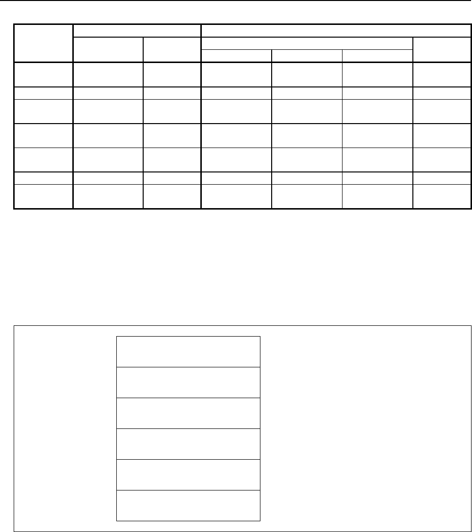
B-64513EN/03
5.WINDOW FUNCTIONS
- 635 -
Table5.4.19 (d) Modal information of G-function (part 4)
Group
number
(Data type)
Machining center system Lathe system
G code Code in a
group
G code Code in a
group
A series B series C series
23 G80.5 0 G15 G15 G15 0
G81.5 1 G16 G16 G16 1
25 G54.4 G54.4 G54.4 0
26 G44.9 1 G80.5 G80.5 G80.5 0
G49.9 0 G81.5 G81.5 G81.5 1
27 G80.4 G80.4 G80.4 0
G81.4 G81.4 G81.4 1
30 G50.2 0
G51.2 1
32 G54.4 0
33 G80.4 0
G81.4 1
Completion codes
0 Completed successfully
3 The data number is invalid
4 The data attribute is invalid
Output data structure
(1) Each data reading (Data number N=G code group number)
Top Address +0 (Function code)
32
+2 (Completion code)
?
(See above description)
+4 (Data length L)
2
+6 (Data number N)
Data type
(Same as input data)
+8 (Data attribute M)
Specified block
(Same as input data)
+10
+11
Modal information of G-function
(2 bytes)
See "Fig. 5.4.19 (a) Modal information of G-
function".
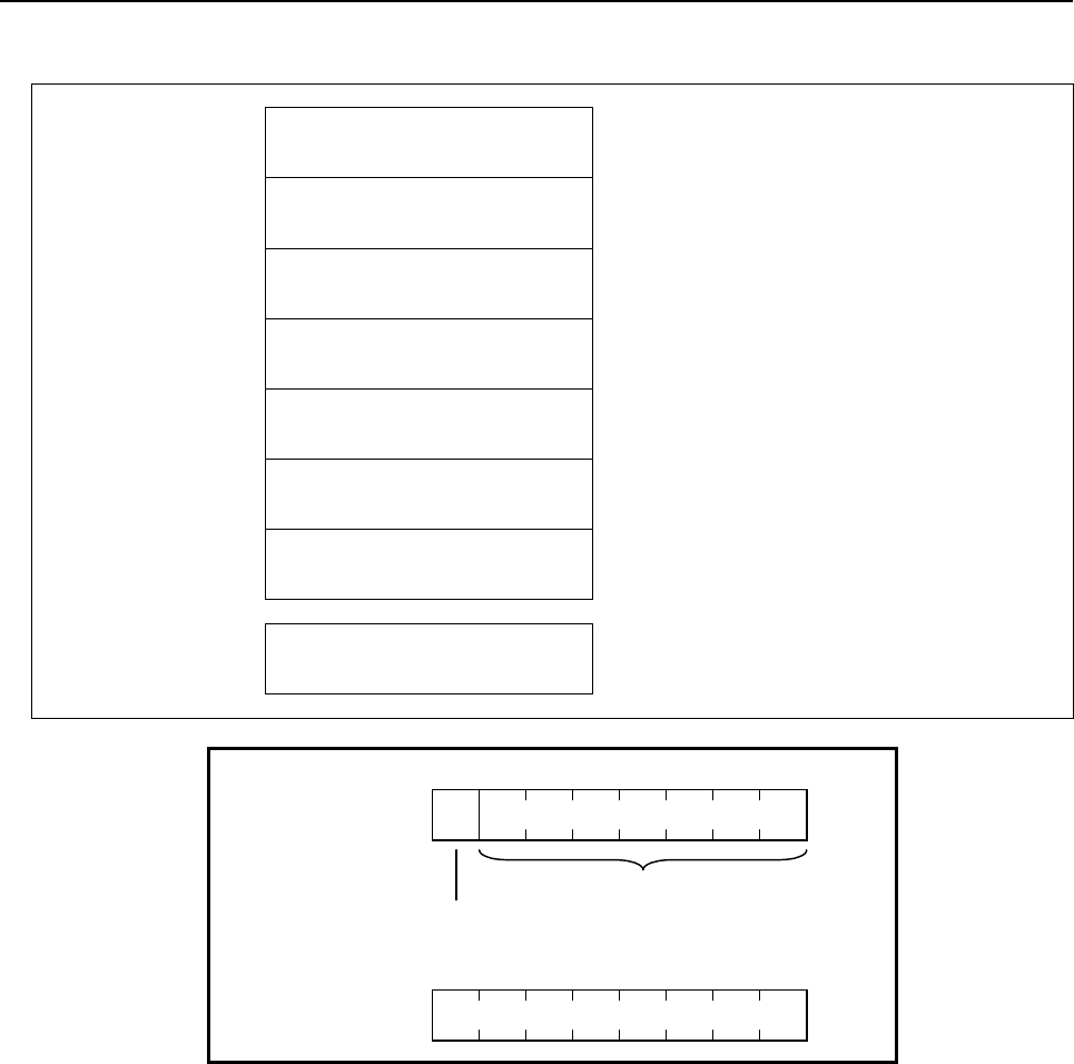
5.WINDOW FUNCTIONS
B-64513EN/03
- 636 -
(2) Corrective reading (Data number N=-1)
Top Address +0 (Function code)
32
+2 (Completion code)
?
(See above description)
+4 (Data length L)
2 * n
n=1 to 32: Effective number of G-function group.
+6 (Data number N)
-1
(Same as input data)
N=-1: Corrective reading
+8 (Data attribute M)
Specified block
(Same as input data)
+10 Modal information of G-function
group No.0
(2 bytes)
See "Fig. 5.4.19 (a) Modal information of G-
function".
+12 Modal information of G-function
group No.1
(2 bytes)
See "Fig. 5.4.19 (a) Modal information of G-
function".
~ ~
+72
+73
Modal information of G-function
group No.31
(2 bytes)
See "Fig. 5.4.19 (a) Modal information of G-
function".
Top Address +10
Code in a group
0 : Not specified in the group
1 : Specified in the group
75
6431
20
Top Address +11
75
6431
20
0
Fig. 5.4.19 (a) Modal information of g-function

B-64513EN/03
5.WINDOW FUNCTIONS
- 637 -
(2) Reading modal information of other than G-function (Data number=100 to 126, -2)
Using this function, you can read modal information of other than G-function.
Input data structure
Top Address +0 (Function code)
32
+2 (Completion code)
-
(Need not to be set)
+4 (Data length L)
-
(Need not to be set)
+6 (Data number N)
Data type
N=100 to 126: Each data reading (See Table 5.4.19(d))
N=-2: Collective read (No.100 to 126)
+8 (Data attribute M)
Specified block
M=0: Current block
M=1: Next block
M=2: (reserved)
+10 (Data area)
-
(Need not to be set)
NOTE
A modal information for a block after the next block cannot be read.

5.WINDOW FUNCTIONS
B-64513EN/03
- 638 -
Table5.4.19 (e) Modal information of other than G-function
Data type Specified Address Description
100 B Second auxiliary function
101 D
102 E (Reserved)
103 F
104 H
105 L
106 M
107 S
108 T
109 R
110 P
111 Q
112 A
113 C
114 I
115 J
116 K
117 N
118 O
119 U
120 V
121 W
122 X
123 Y
124 Z
125 M2
126 M3
Completion codes
0 Completed successfully
3 The data number is invalid
4 The data attribute is invalid

B-64513EN/03
5.WINDOW FUNCTIONS
- 639 -
Output data structure
(1) Each data reading (Data number N=See Table 5.4.19 (d))
Top Address +0 (Function code)
32
+2 (Completion code)
?
(See above description)
+4 (Data length L)
6
+6 (Data number N)
Data type
(Same as input data)
+8 (Data attribute M)
Specified block
(Same as input data)
+10
+15
Modal information
(6 bytes)
See "Fig. 5.4.19 (b) Modal information of other than
G-function".
(2) Corrective reading (Data number N=-2)
Top Address +0 (Function code)
32
+2 (Completion code)
?
(See above description)
+4 (Data length L)
174
+6 (Data number N)
Data type
(Same as input data)
+8 (Data attribute M)
Specified block
(Same as input data)
+10 Modal information of
Data type No.100
(6 bytes)
See "Fig. 5.4.19 (b) Modal information of other than
G-function".
+16 Modal information of
Data type No.101
(6 bytes)
See "Fig. 5.4.19 (b) Modal information of other than
G-function".
~ ~
+166 Modal information of
Data type No.126
(6 bytes)
See "Fig. 5.4.19 (b) Modal information of other than
G-function".
+172
+183
Reserved
(12 bytes)
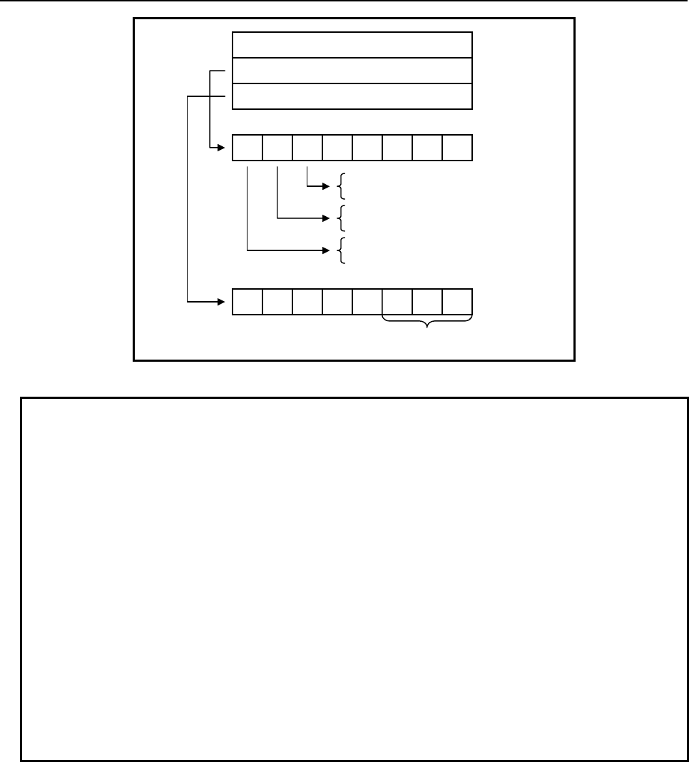
5.WINDOW FUNCTIONS
B-64513EN/03
- 640 -
7 5
6431
20
Data
FLAG1
FLAG2
4 bytes
1 byte
1 byte
0 : Positive
1 : Negative
0 : A decimal point not specified
1 : A decimal point specified
0 : Not specified in the current block
1 : Specified in the current block
7 5
6431
20
Number of decimal
p
laces
Fig. 5.4.19 (b) Modal information of other than G-function
NOTE
1 The specification of whether a decimal point is specified or not in FLAG1, and
the specification of the number of decimal places in FLAG2, are valid only for F
code. Even if a decimal point is not specified, the number of decimal places may
not be 0.
2 PMC-SB7 outputs the number of input digits to bits 0 to 3 of FLAG1, however
30i/31i/32i/35i-B, Power Motion i-A, 0i-F PMC does not. If you need to have the
number of input digits output as with the former specification, read the CNC
parameters of the following numbers, by using the window function for reading a
parameter (function code 17 or 154).
• For the M function:
No.3030(allowable number of digits of the M code)
• For the S function:
No.3031(allowable number of digits of the S code)
• For the T function:
No.3032(allowable number of digits of the T code)
• For the B function:
No.3033(allowable number of digits of the B code)

B-64513EN/03
5.WINDOW FUNCTIONS
- 641 -
5.4.20
Reading Diagnosis Data (Low-speed Response)
The information displayed on the diagnosis data screen is read by directly accessing the CNC.
Input data structure
Top Address +0 (Function code)
33
+2 (Completion code)
-
(Need not to be set)
+4 (Data length L)
-
(Need not to be set)
+6 (Data number N)
Diagnosis No.
+8 (Data attribute M)
Axis number
M=0: No axis
M=1 to n: axis number
M=-1: All axes
+10 (Data area)
-
(Need not to be set)
Completion codes
0 Diagnosis data has been read from the CNC normally.
3 The specified diagnosis data number is invalid.
4 The data specified as the data attribute is invalid because it is neither 0, -1, nor a value from 1 to n (n
is the number of axes).

5.WINDOW FUNCTIONS
B-64513EN/03
- 642 -
Output data structure
(1) In the case of bit, byte, word or double word type data
Top Address +0 (Function code)
33
+2 (Completion code)
?
(See above description)
+4 (Data length L)
L
(L = 1, 2, 4, 1×n, 2×n, 4×n)
When no axis or one axis is specified
L=1: Bit or byte data
L=2: Word data
L=4: Double word data
When all axes are specified
L=1×n: Bit or byte data
L=2×n: Word data
L=4×n: Double word data
+6 (Data number N)
Diagnosis No.
(Same as input data)
+8 (Data attribute M)
Axis number
(Same as input data)
+10 Diagnosis data
(1, 2, 4 bytes)
Data - dependent form
(2) In the case of Floating point type data
Top Address +0 (Function code)
33
+2 (Completion code)
?
(See above description)
+4 (Data length L)
L
(L = 6, 6×n)
When no axis or one axis is specified
L=6: Floating point type data
When all axes are specified
L=6×n: Floating point type data
+6 (Data number N)
Diagnosis No.
(Same as input data)
+8 (Data attribute M)
Axis number
(Same as input data)
+10 decimal point
(2 bytes)
+12
+15
Diagnosis data
(4 bytes)

B-64513EN/03
5.WINDOW FUNCTIONS
- 643 -
5.4.21
Reading Diagnosis Data (High-speed Response)
The specific data displayed on the diagnosis data screen can be read with high-speed response.
Supported numbers of diagnosis data are as follows.
Number Data
0 CNC internal state 1
308 Servo motor temperature
309 Pulsecoder temperature
403 Temperature of spindle motor
445 Spindle position data
712 Spindle warning state
720 Spindle diagnosis data 1 *Note2
722 Spindle diagnosis data 2 *Note2
750 OVC level
752 DC link voltage information
1580 Spindle duration time
1581 Spindle load max (Current)
4900 Total of current actual power consumption of all axes
NOTE
1 As for a type, a unit and a range of each data, refer to “1.3 DIAGNOSIS
FUNCTION” of the MAINTENANCE MANUAL and “13.1 DIAGNOSIS
FUNCTION” of the OPERATION AND MAINTENANCE HANDBOOK.
2 The contents of the diagnosis numbers 720 and 722 depend on the setting of
CNC parameter No.4532. For details, refer to the MAINTENANCE MANUAL and
the PARAMETER MANUAL of AC spindle motor.
Input data structure
Top Address +0 (Function code)
156
+2 (Completion code)
-
(Need not to be set)
+4 (Data length L)
-
(Need not to be set)
+6 (Data number N)
Diagnosis number
+8 (Data attribute M)
Axis number
M=0: No axis
M=1 to n: axis number
M=-1: All axes
+10 (Data area)
-
(Need not to be set)

5.WINDOW FUNCTIONS
B-64513EN/03
- 644 -
Completion codes
0 Diagnosis data has been read from the CNC normally.
3 The specified diagnosis data number is invalid.
4 The data specified as the data attribute is invalid because it is neither 0, -1, nor a value from 1 to n (n
is the number of axes).
Output data structure
(1) In the case of bit, byte, word or double word type data
Top Address +0 (Function code)
156
+2 (Completion code)
?
(See above description)
+4 (Data length L)
L
(L = 1, 2, 4, 1×n, 2×n, 4×n)
When no axis or one axis is specified
L=1: Bit or byte data
L=2: Word data
L=4: Double word data
When all axes are specified
L=1×n: Bit or byte data
L=2×n: Word data
L=4×n: Double word data
+6 (Data number N)
Diagnosis number
(Same as input data)
+8 (Data attribute M)
Axis number
(Same as input data)
+10 Diagnosis data
(1, 2, 4 bytes)
Data - dependent form
(2) In the case of Floating point type data
Top Address +0 (Function code)
156
+2 (Completion code)
?
(See above description)
+4 (Data length L)
L
(L = 6, 6×n)
When no axis or one axis is specified
L=6: Floating point type data
When all axes are specified
L=6×n: Floating point type data
+6 (Data number N)
Diagnosis number
(Same as input data)
+8 (Data attribute M)
Axis number
(Same as input data)
+10 Decimal point
(2 bytes)
+12
+15
Diagnosis data
(4 bytes)

B-64513EN/03
5.WINDOW FUNCTIONS
- 645 -
5.4.22
Reading a P-CODE Macro Variable (High-speed Response)
Using this function, you can read a P-CODE variable or an extended P-CODE variable for macro
executor.
Data type Number
P-CODE variables #10000 to #19999
Extended P-CODE variables #20000 to #89999
NOTE
For details of the P-CODE variables and extended P-CODE variables, refer to
the "Macro Executor PROGRAMMING MANUAL".
Input data structure
Top Address +0 (Function code)
59
+2 (Completion code)
-
(Need not to be set)
+4 (Data length L)
-
(Need not to be set)
+6 (Data number N)
P-CODE variable number
Signed binary format in 4 bytes length (note)
+10 (Data attribute M)
Number of decimal places
M=0: No specifying number of decimal places
M=1 to 8: Specifying number of decimal places
+12
+17
(Data area)
-
(Need not to be set)
NOTE
The data length is 4 bytes instead of 2 bytes.
Completion codes
0 Completed successfully
3 The data number is invalid.
4 The mantissa is out of range.

5.WINDOW FUNCTIONS
B-64513EN/03
- 646 -
Output data structure
Top Address +0 (Function code)
59
+2 (Completion code)
?
(See above description)
+4 (Data length L)
6
+6 (Data number N)
P-CODE variable number
(Same as input data)
+10 (Data attribute M)
Number of decimal places
(Same as input data)
+12 Mantissa (D1)
(4 bytes)
Signed binary format in 4 bytes length
+16
+17
Number of decimal places (D2)
(2 bytes)
Signed binary format in 2 bytes length
D2 = -1, 0 to 8 (Floating-point type)
D2 = 0 to 8 (Integer type)
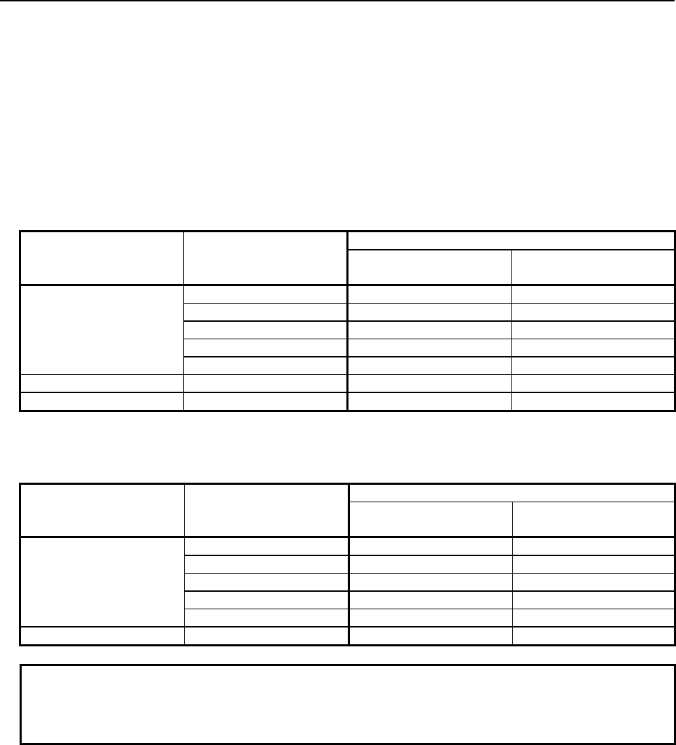
B-64513EN/03
5.WINDOW FUNCTIONS
- 647 -
You can read D1 and D2 when the P-CODE variable is expressed by the following formula.
[P-CODE variable] = D1 × 10 –D2
You can define the type of P-CODE variables as a floating-point type or an integer type by the setting of
CNC parameter No. 9033#3 and 9033#4.
(a) Floating-point type)
When P-CODE variables are floating-point type, there is a "null" state on P-CODE variables that
means the value is not defined. When the P-CODE variable is "null", the D1=0 and the D2 = -1 are
read in spite of the specified value of M.
Value of the P-CODE
variable
Specified number of
decimal places (M)
Result data
Mantissa (D1) Number of decimal
places (D2)
1.234
0 (Note) 1234 3
1 12 1
2 123 2
3 1234 3
4 12340 4
0 1 0 1
Null - 0 -1
(b) Integer type)
When P-CODE variables are integer type, there is no "null" state.
Value of the P-CODE
variable
Specified number of
decimal places (M)
Result data
Mantissa (D1) Number of decimal
places (D2)
1234
0 (Note) 1234000 3
1 12340 1
2 123400 2
3 1234000 3
4 12340000 4
0 1 0 1
NOTE
When you set 0 to number of decimal places M, the read value of D2 may
changes by the value of the macro variable and the setting of CNC system. So,
we recommend to set 1 to 8 to number of decimal places M.

5.WINDOW FUNCTIONS
B-64513EN/03
- 648 -
5.4.23
Writing a P-CODE Macro Variable (Low-speed Response)
Using this function, you can write value to a P-CODE variable or an extended P-CODE variable for
macro executor.
WARNING
When you write some NC data using both this instruction in ladder program and
other applications, take care that you do not write to the same data area.
If some values are written to the same data area by two or more applications
including ladder program, unexpected value may be written. In this case, it may
cause an unexpected machine behavior and also tools, work pieces, and
machines may be damaged. As for details, refer to “SAFETY PRECAUTIONS”.
Data type Number
P-CODE variables #10000 to #19999
Extended P-CODE variables #20000 to #89999
NOTE
For details of the P-CODE variables and extended P-CODE variables, refer to
the "Macro Executor PROGRAMMING MANUAL".
Input data structure
Top Address +0 (Function code)
60
+2 (Completion code)
-
(Need not to be set)
+4 (Data length L)
6
+6 (Data number N)
P-CODE variable number
Signed binary format in 4 bytes length (note)
+10 (Data attribute M)
0
Reserved
You should set 0 to this field.
+12 Mantissa (D1)
(4 bytes)
Signed binary format in 4 bytes length
+16
+17
Number of decimal places (D2)
(2 bytes)
Signed binary format in 2 bytes length
D2 = -1, 0 to 8 (Floating-point type)
D2 = 0 to 8 (Integer type)
NOTE
The data length is 4 bytes instead of 2 bytes.
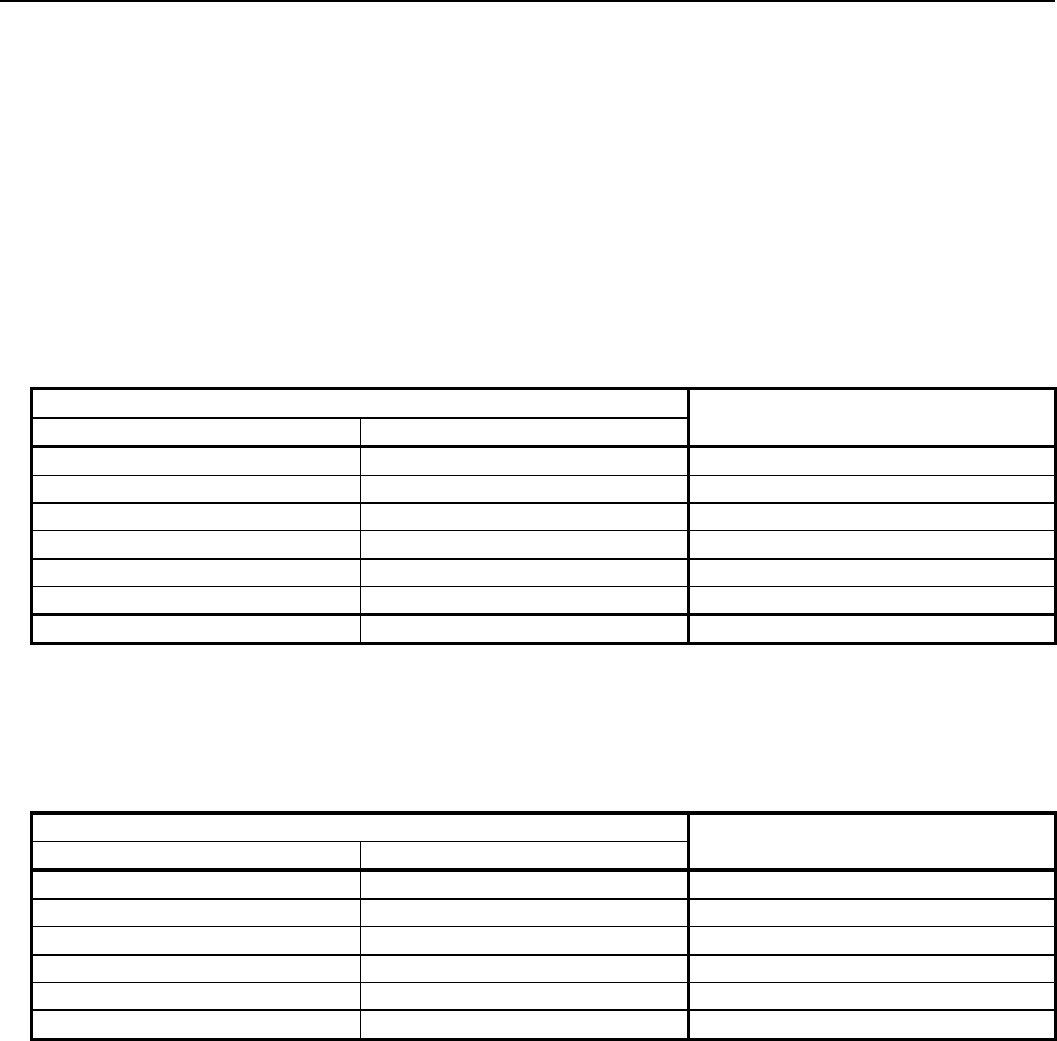
B-64513EN/03
5.WINDOW FUNCTIONS
- 649 -
You should set values to D1 and D2 when the custom macro variable is expressed by the following
formula.
[P-CODE variable] = D1 × 10 –D2
You can define the type of P-CODE variables as a floating-point type or an integer type by the setting of
CNC parameter No. 9033#3 and 9033#4.
(a) Floating-point type)
When P-CODE variables are floating-point type, there is a "null" state on P-CODE variables that
means the value is not defined. When you set D1=0 and D2= -1, the P-CODE variable becomes
"null" state.
Setting data Value of the P-CODE variable
(Floating-point)
Mantissa (D1) Number of decimal places (D2)
1234 0 1234
1234 1 123.4
1234 2 12.34
1234 3 1.234
1234 4 0.1234
0 Except -1 0
0 -1 Null
(b) Integer type)
When P-CODE variables are integer type, there is no "null" state. We recommend setting 0 to
number of decimal places D2 for writing to an integer type variable. When a negative value is set to
D2, the D2 is regarded as 0.
Setting data Value of the P-CODE variable
(Integer)
Mantissa (D1) Number of decimal places (D2)
1234 0 1234
1234 1 123
1234 2 12
1234 3 1
1234 4 0
0 Any 0

5.WINDOW FUNCTIONS
B-64513EN/03
- 650 -
Completion codes
0 Completed successfully
2 The data length is invalid.
3 The data number is invalid.
6 No option for macro executor
Output data structure
Top Address +0 (Function code)
60
+2 (Completion code)
?
(See above description)
+4 (Data length L)
6
(Same as input data)
+6 (Data number N)
P-CODE variable number
(Same as input data)
+10 (Data attribute M)
0
(Same as input data)
+12 Mantissa (D1)
(Same as input data)
+16
+17
Number of decimal places (D2)
(Same as input data)

B-64513EN/03
5.WINDOW FUNCTIONS
- 651 -
5.4.24
Reading CNC Status Information (High-speed Response)
Status information (status indication on the screen) can be read from the CNC.
The types of status information that can be read are as follows.
(1) Indication of which mode is selected, automatic or manual
(2) Status of automatic operation
(3) Status of movement along the axis and dwelling
(4) Status of M, S, T, and B functions
(5) Statuses of emergency stop and the reset signal
(6) Alarm status
(7) Status of program edits
Input data structure
Top Address +0 (Function code)
76
+2 (Completion code)
-
(Need not to be set)
+4 (Data length L)
-
(Need not to be set)
+6 (Data number N)
0
Set 0 to this field.
+8 (Data attribute M)
0
Set 0 to this field.
+10
+41
(Data area)
-
(Need not to be set)
Completion codes
0 CNC status information has been read normally.

5.WINDOW FUNCTIONS
B-64513EN/03
- 652 -
Output data structure
Top Address +0 (Function code)
76
+2 (Completion code)
?
(See above description)
+4 (Data length L)
14
+6 (Data number N)
0
(Same as input data)
+8 (Data attribute M)
0
(Same as input data)
+10 Indication of which mode is
currently selected, automatic or
manual (2 bytes)
0: MDI
1: MEMory
2: **** (Other state)
3: EDIT
4: HaNDle
5: JOG
6: Teach in JOG
7: Teach in HND
8: INC. feed
9: REFerence
10: ReMoTe
+12 Status of automatic operation
(2 bytes)
0: **** (Reset state)
1: STOP
2: HOLD
3: STaRT
+14 Status of movement along the
axis of dwelling
(2 bytes)
0: *** (Other state)
1: MoTioN
2: DWell
+16 Status of M, S, T, and B functions
(2 bytes)
0: *** (Other state)
1: FIN
+18 Status of emergency stop
(2 bytes)
0: (Releases the emergency stop state)
1: --EMerGency--
2: -RESET- (The reset signal is on)
+20 Alarm status
(2 bytes)
0: *** (Other state)
1: ALarM
2: BATtery low
+22
+23
Status of program edit
(2 bytes)
0: ******* (Non editing)
1: EDIT
2: SeaRCH
3: OUTPUT
4: INPUT
5: COMPARE
6: LabelSKip
7: OFST
8: WSFT
9: ReSTaRt

B-64513EN/03
5.WINDOW FUNCTIONS
- 653 -
5.4.25
Reading the Current Program Number (8-digits Program
Numbers) (High-speed Response)
This function reads CNC program numbers extended to 8 digits from the usual 4 digits.
Basically, this function is the same as function code 24 excluding the different data length of function
code 90.
Input data structure
Top Address +0 (Function code)
90
+2 (Completion code)
-
(Need not to be set)
+4 (Data length L)
-
(Need not to be set)
+6 (Data number N)
0
Set 0 to this field.
+8 (Data attribute M)
0
Set 0 to this field.
+10
+17
(Data area)
-
(Need not to be set)
Completion codes
0 The program number of the currently executing program has been read normally.

5.WINDOW FUNCTIONS
B-64513EN/03
- 654 -
Output data structure
Top Address +0 (Function code)
90
+2 (Completion code)
?
(See above description)
+4 (Data length L)
8
+6 (Data number N)
0
(Same as input data)
+8 (Data attribute M)
0
(Same as input data)
+10 Number of the program currently
being executed (ON)
(4bytes)
Unsigned binary format, 4-bytes length
+14
+17
Program number of the main
program (OMN)
(4bytes)
Unsigned binary format, 4-bytes length
(a) Number of the program currently being executed (ON)
The program number of the program currently being executed is set.
(b) Program number of the main program (OMN)
If the program currently being executed is a subprogram, the program number of its main program is
set.
If the program currently being executed is not a subprogram, 0 is set.

B-64513EN/03
5.WINDOW FUNCTIONS
- 655 -
5.4.26
Entering Data on the Program Check Screen (Low-speed
Response)
On the program check screen of the CNC, data can be entered for the spindle tool No. (HD.T) and the
next tool No. (NX.T).
This function is effective only when bit 2 of parameter 3108 is 1, and bit 1 of parameter 13200 is 1.
Input data structure
Top Address +0 (Function code)
150
+2 (Completion code)
-
(Need not to be set)
+4 (Data length L)
4
+6 (Data number N)
0, 1
N=0: Spindle tool No. (8 digits)
N=1: Next tool No. (8 digits)
+8 (Data attribute M)
0
Set 0 to this field.
+10
+13
Data for the spindle tool No.
or data for the next tool No.
(4 bytes)
Unsigned binary
Completion codes
0 Data has been entered on the program check screen normally.
2 The data length in bytes is invalid.
3 The data No. is invalid.
Output data structure
Top Address +0 (Function code)
150
+2 (Completion code)
?
(See above description)
+4 (Data length L)
4
(Same as input data)
+6 (Data number N)
(Same as input data)
N=0: Spindle tool No.
N=1: Next tool No.
+8 (Data attribute M)
0
(Same as input data)
+10
+13
Data for the spindle tool No. or
data for the next tool No.
(4 bytes)
Unsigned binary

5.WINDOW FUNCTIONS
B-64513EN/03
- 656 -
5.4.27
Reading Clock Data (Date and Time) (High-speed Response)
The current date (year, month, day) and time (hours, minutes, seconds) can be read from the clock built
into the CNC.
Input data structure
Top Address +0 (Function code)
151
+2 (Completion code)
-
(Need not to be set)
+4 (Data length L)
-
(Need not to be set)
+6 (Data number N)
-1, 0, 1
N=-1: Reads current date and time
N=0: Reads current date
N=1: Reads current time
+8 (Data attribute M)
0
Set 0 to this field.
+10 (Data area)
-
(Need not to be set)
Completion codes
0 Data of the clock built into the CNC has been read normally.
3 A value other than 0, 1, and -1 was specified for the data No.
Output data structure
(1) When reading the current date or the current time.
Top Address +0 (Function code)
151
+2 (Completion code)
?
(See above description)
+4 (Data length L)
6
+6 (Data number N)
(Same as input data)
+8 (Data attribute M)
0
(Same as input data)
+10 Current date (year)
or
Current time (hours)
Unsigned binary
+12 Current date (month)
or
Current time (minutes)
Unsigned binary
+14
+15
Current date (day)
or
Current time (seconds)
Unsigned binary
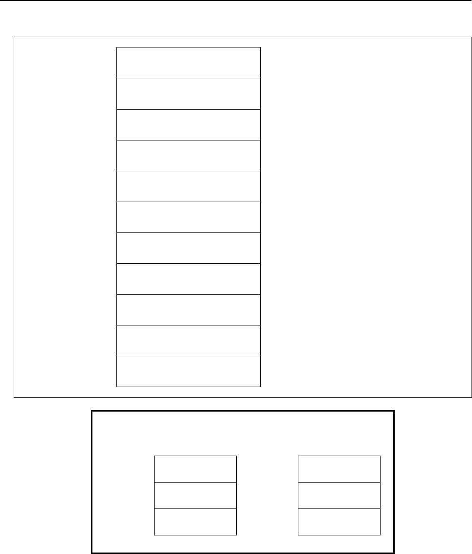
B-64513EN/03
5.WINDOW FUNCTIONS
- 657 -
(2) When both the current date and current time are specified to be read by entering [-1] for the data No.
Top Address +0 (Function code)
151
+2 (Completion code)
?
(See above description)
+4 (Data length L)
12
+6 (Data number N)
(Same as input data)
+8 (Data attribute M)
0
(Same as input data)
+10 Current date (year)
Unsigned binary
+12 Current date (month)
Unsigned binary
+14 Current date (day)
Unsigned binary
+16 Current time (hours)
Unsigned binary
+18 Current time (minutes)
Unsigned binary
+20
+21
Current time (seconds)
Unsigned binary
[Example] Sep. 10th, 1990
Data area
1990
+2
9
+4
10
[Example] 23:59:59
(hours:minutes:seconds)
Data area
23
+2
59
+4
59

5.WINDOW FUNCTIONS
B-64513EN/03
- 658 -
5.4.28
Writing Clock Data (Date and Time) (Low-speed Response)
The date (year, month, day) and the time (hours, minutes, seconds) can be written to the clock built into
the CNC.
Input data structure
(1) When writing the date or the time.
Top Address +0 (Function code)
139
+2 (Completion code)
-
(Need not to be set)
+4 (Data length L)
6
+6 (Data number N)
0 , 1
N=0: Writes date
N=1: Writes time
+8 (Data attribute M)
0
Set 0 to this field.
+10 Current date (year)
or
Current time (hours)
Signed binary in 2 bytes length.
Year: 2000 to 2096
Hours: 0 to 23
+12 Current date (month)
or
Current time (minutes)
Signed binary in 2 bytes length.
Month: 1 to 12
Minutes: 0 to 59
+14 Current date (day)
or
Current time (seconds)
Signed binary in 2 bytes length.
day: 1 to 31
seconds: 0 to 59

B-64513EN/03
5.WINDOW FUNCTIONS
- 659 -
(2) When writing the date and the time.
Top Address +0 (Function code)
139
+2 (Completion code)
-
(Need not to be set)
+4 (Data length L)
12
+6 (Data number N)
-1
N=-1: Writes date and time
+8 (Data attribute M)
0
Set 0 to this field.
+10
Current date (year)
Signed binary in 2 bytes length.
Year: 2000 to 2096
+12
Current date (month)
Signed binary in 2 bytes length.
Month: 1 to 12
+14
Current date (day)
Signed binary in 2 bytes length.
day: 1 to 31
+16
Current time (hours)
Signed binary in 2 bytes length.
Hours: 0 to 23
+18
Current time (minutes)
Signed binary in 2 bytes length.
Minutes: 0 to 59
+20
Current time (seconds)
Signed binary in 2 bytes length.
seconds: 0 to 59

5.WINDOW FUNCTIONS
B-64513EN/03
- 660 -
Completion codes
0 Completed successfully.
2 The data length is invalid.
3 The data number is invalid.
5 The specified year, month, day, hours, minutes or seconds are incorrect.
Example Date
“Nov. 8th, 2007”
Example Time
“23 hours 59 minutes 59 Seconds”
+0
139
+0
139
+2
0
+2
0
+4
6
+4
6
+6
0
+6
1
+8
0
+8
0
+10
2007
+10
23
+12
11
+12
59
+14
8
+14
59
Output data structure
(1) When writing the date or the time.
Top Address +0 (Function code)
139
+2 (Completion code)
?
(See above description)
+4 (Data length L)
6
+6 (Data number N)
(Same as input data)
+8 (Data attribute M)
0
(Same as input data)
+10 Current date (year)
or
Current time (hours)
+12 Current date (month)
or
Current time (minutes)
+14
+15
Current date (day)
or
Current time (seconds)

B-64513EN/03
5.WINDOW FUNCTIONS
- 661 -
(2) When writing both the date and time.
Top Address +0 (Function code)
139
+2 (Completion code)
?
(See above description)
+4 (Data length L)
12
+6 (Data number N)
(Same as input data)
+8 (Data attribute M)
0
(Same as input data)
+10 Current date (year)
+12 Current date (month)
+14 Current date (day)
+16 Current time (hours)
+18 Current time (minutes)
+20
+21
Current time (seconds)

5.WINDOW FUNCTIONS
B-64513EN/03
- 662 -
5.4.29
Reading the Pitch Error Compensation Value (High-speed
Response)
The pitch error compensation value in the CNC can be read.
Input data structure
Top Address +0 (Function code)
395
+2 (Completion code)
-
(Need not to be set)
+4 (Data length L)
-
(Need not to be set)
+6 (Data number N)
Pitch error compensation No.
+8 (Data attribute M)
0
Set 0 to this field.
+10
+41
(Data area)
-
(Need not to be set)
Completion codes
0 The pitch error compensation value has been read normally.
3 Illegal pitch error compensation number.
Output data structure
Top Address +0 (Function code)
395
+2 (Completion code)
?
(See above description)
+4 (Data length L)
1
+6 (Data number N)
Pitch error compensation No.
(Same as input data)
+8 (Data attribute M)
0
(Same as input data)
+10 Pitch error compensation value
(1 byte)

B-64513EN/03
5.WINDOW FUNCTIONS
- 663 -
5.4.30
Writing the Pitch Error Compensation Value (Low-speed
Response)
The pitch error compensation value can be written in the CNC.
WARNING
When you write some NC data using both this instruction in ladder program and
other applications, take care that you do not write to the same data area.
If some values are written to the same data area by two or more applications
including ladder program, unexpected value may be written. In this case, it may
cause an unexpected machine behavior and also tools, work pieces, and
machines may be damaged. As for details, refer to “SAFETY PRECAUTIONS”.
Input data structure
Top Address +0 (Function code)
396
+2 (Completion code)
-
(Need not to be set)
+4 (Data length L)
1
+6 (Data number N)
Pitch error compensation No.
+8 (Data attribute M)
0
Set 0 to this field.
+10 Pitch error compensation value
(1 byte)
Completion codes
0 The pitch error compensation value has been read normally.
2 Illegal data length.
3 Illegal pitch error compensation number.

5.WINDOW FUNCTIONS
B-64513EN/03
- 664 -
Output data structure
Top Address +0 (Function code)
396
+2 (Completion code)
?
(See above description)
+4 (Data length L)
1
(Same as input data)
+6 (Data number N)
Pitch error compensation No.
(Same as input data)
+8 (Data attribute M)
0
(Same as input data)
+10 Pitch error compensation value
(Same as input data)

B-64513EN/03
5.WINDOW FUNCTIONS
- 665 -
5.4.31
Tool Figure Making Instruction for 3D Interference Check
Function (Low-speed Response)
The tool compensation number is notified to make the tool figure to do the interference check by the
built-in 3D interference check function automatically. When this PMC window ends normally, the made
automatically tool figure becomes the object of the interference check.
Input data structure
Top Address +0 (Function code)
431
+2 (Completion code)
-
(Need not to be set)
+4 (Data length L)
2
+6 (Data number N)
0
Set 0 to this field.
+8 (Data attribute M)
0
Set 0 to this field.
+10
+11
Tool compensation number
(2 bytes)
Signed binary number(1 to)
M system: tool radius correction number
T system: tool figure correction number
Completion code
0 Normal end
1 This function is not supported.
2 invalid data block length(except 2)
5 When the mistake of the compensation number (smaller than one) or the compensation number is
correct, it is a failure of the tool figure making due to the mistake of undefined or the setting data of
the offset data of the correction number and the tool figure data.
6 Missing necessary option or parameter TDITL is set to one (No.10930#2).
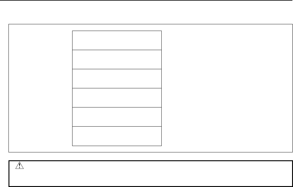
5.WINDOW FUNCTIONS
B-64513EN/03
- 666 -
Output data structure
Top Address +0 (Function code)
431
+2 (Completion code)
?
(See above description)
+4 (Data length L)
2
(Same as input data)
+6 (Data number N)
0
(Same as input data)
+8 (Data attribute M)
0
(Same as input data)
+10
+11
(correction number)
2 bytes
(Same as input data)
CAUTION
The 3D interference check function is not effective while executing this PMC
window.

B-64513EN/03
5.WINDOW FUNCTIONS
- 667 -
5.4.32
Reading Detailed Information of CNC Alarm
You can read detailed information of 30 CNC alarms in the maximum. Moreover, you can read detailed
information of CNC alarms selected by an alarm type of input data.
The detailed information of CNC alarm is as follows.
- Axis number
- Alarm type
- Alarm number
Input data structure
Top Address +0 (Function code)
433
+2 (Completion code)
-
(Need not to be set)
+4 (Data length L)
-
(Need not to be set)
+6 (Data number N)
Maximum number of alarms
N = 1 to 30
+8 (Data attribute M)
Alarm type number
-1: All alarm types
0- n: Alarm type
+10
+(12+8*(N-1)+7)
(Data)
-
(Need not to be set)
(1) Maximum number of alarms
You can set the number of alarms to read.
The maximum value is 30.
NOTE
The appropriate size of the data area corresponding to the maximum number of
alarms is necessary.
(2) Alarm type number
A correspondence table of the alarm type and the alarm type number is as follows.
Alarm type number Alarm type Alarm type number Alarm type
-1 All alarm 10 DS alarm
0 SW alarm 11 IE alarm
1 PW alarm 12 BG alarm
2 IO alarm 13 (Reserve)
3 PS alarm 14 (Reserve)
4 OT alarm 15 EX alarm
5 OH alarm 16 (Reserve)
6 SV alarm 17 (Reserve)
7 SR alarm 18 (Reserve)
8 MC alarm 19 (Reserve)
9 SP alarm 20 (Reserve)
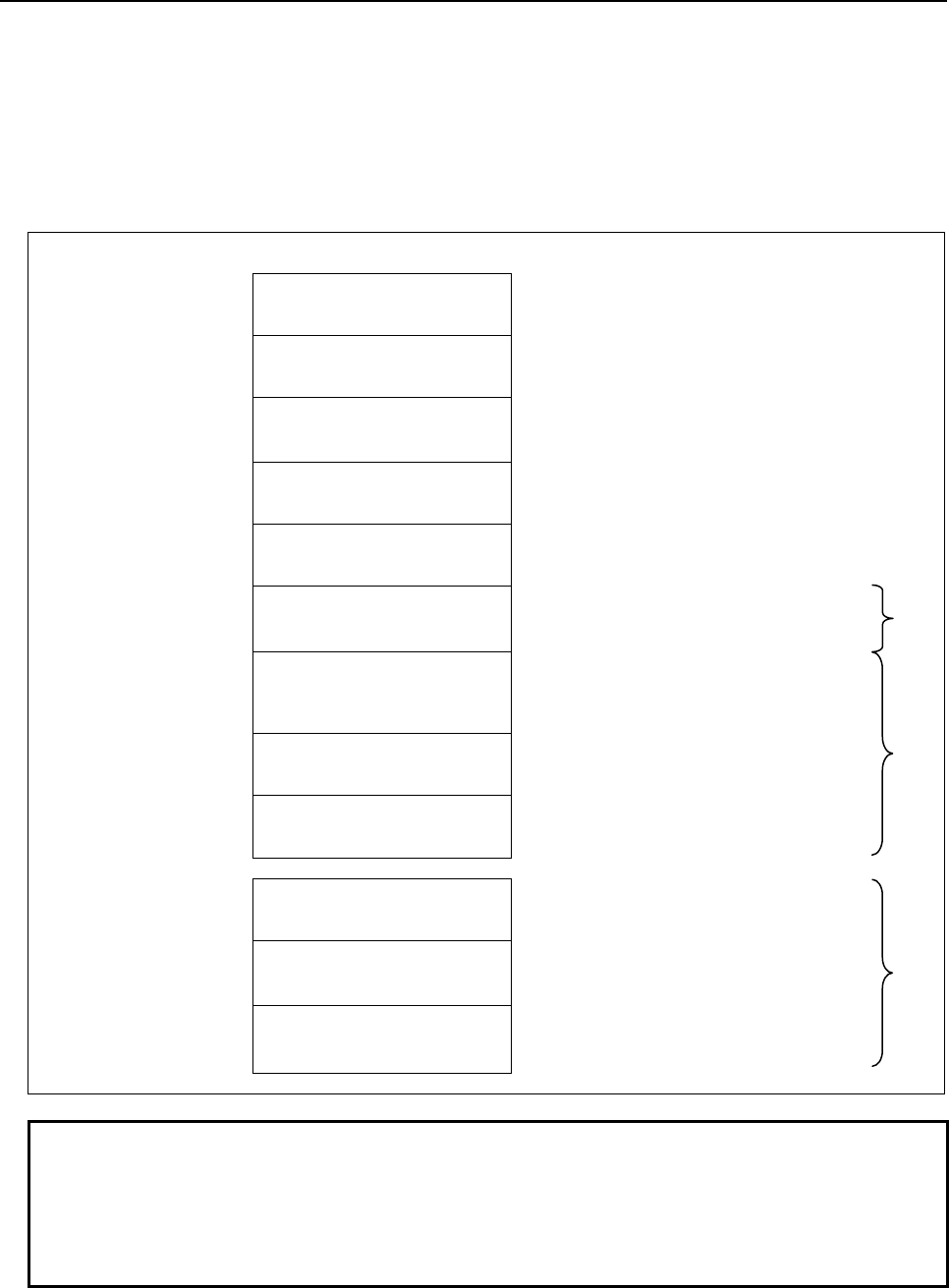
5.WINDOW FUNCTIONS
B-64513EN/03
- 668 -
Completion codes
0: Completed successfully
1: Not supported
3: The maximum number of alarms is invalid.
You should set the number 1 to 30.
4: Alarm type number is invalid.
Output data structure
Top Address +0 (Function code)
433
+2 (Completion code)
?
(See above description)
+4 (Data length L)
(L = 2 + 8 × N)
+6 (Data number N)
(Same as input data)
+8 (Data attribute M)
(Same as input data)
+10 Number of alarms
(2 bytes)
0 to 30
+12 Axis information
(4bytes)
Bit format in 4 bytes length
Refer to the "[Output data structure] (1)
Structure of detailed alarm information" for
details.
+16 Alarm type number
(2bytes)
Signed binary format in 2 bytes length
Refer to the "[Input data structure] (2)
Alarm type number" for details.
1st
+18 Alarm number
(2bytes)
Signed binary format in 2 bytes length
0 to 32767
~ ~
+(12+8×(N-1)) Axis information
(4bytes)
+(12+8×(N-1)+4) Alarm type number
(2bytes)
N th
+(12+8×(N-1)+6)
+(12+8×(N-1)+7)
Alarm number
(2bytes)
NOTE
1 When the "number of alarms" is less than "maximum number of alarms" that you
specify, the data at the position of "number of alarms" or after are set with 0 in
"axis information" and -1 in "alarm type number" and "alarm number".
2 You ought not to program as depended on output order of the alarm information
because this order may be changed.

B-64513EN/03
5.WINDOW FUNCTIONS
- 669 -
(1) Structure of detailed alarm information
When the occurrence alarm is axis type, the bit corresponding to the axis number is set to 1.
When the occurrence alarm is not axis type, all bits are set to 0.
Axis information (4bytes)
7 6 5 4 3 2 1 bit0
+12+8×(N-1)+0
8 7 6 5 4 3 2 1
+1
16 15 14 13 12 11 10 9
+2
24 23 22 21 20 19 18 17
+3
32 31 30 29 28 27 26 25
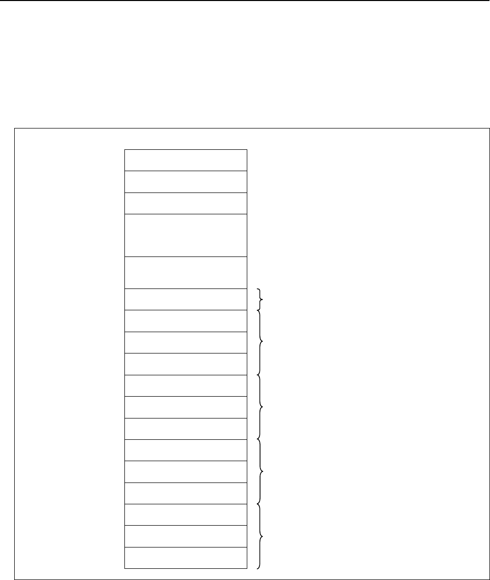
5.WINDOW FUNCTIONS
B-64513EN/03
- 670 -
[Example]
NC alarm : EX0005(Not axis type)
: SV0302(An alarm for the 1st axis.)
: OT0500(An alarm for the 3rd axis.)
When these alarms occur, the read data is as follows.
1. In case that all alarm types are read and the maximum number of alarms is set to 4.
Top Address +0 (Function code)
433
+2 (Completion code)
0
+4 (Data length)
34
+6 (Data number)
Maximum number of
alarms
4
+8 (Data attribute)
Alarm type number
-1
+10 Number of alarms
3
+12
Axis information
0
+16
Alarm type number
15 1 st
+18
Alarm number
5
+20
Axis information
1
+24
Alarm type number
6 2 nd
+26
Alarm number
302
+28
Axis information
4
+32
Alarm type number
4 3 rd
+34
Alarm number
500
+36
Axis information
0
+40
Alarm type number
-1 4 th
+42
+43
Alarm number
-1

B-64513EN/03
5.WINDOW FUNCTIONS
- 671 -
2. In case that OT alarm type is read and the maximum number of alarms is set to 4.
Top Address +0 (Function code)
433
+2 (Completion code)
0
+4 (Data length)
34
+6 (Data number)
Maximum number of
alarms
4
+8 (Data attribute)
Alarm type number
4
+10 Number of alarms
1
+12
Axis information
4
+16
Alarm type number
4 1 st
+18
Alarm number
500
+20
Axis information
0
+24
Alarm type number
-1 2 nd
+26
Alarm number
-1
+28
Axis information
0
+32
Alarm type number
-1 3 rd
+34
Alarm number
-1
+36
Axis information
0
+40
Alarm type number
-1 4 th
+42
+43
Alarm number
-1

5.WINDOW FUNCTIONS
B-64513EN/03
- 672 -
5.4.33
Command for Changing the Interference Object for 3D
Interference Check Function (Low-speed Response)
In built-in 3D interference check function, the interference object number and the valid figure number are
notified in order to change the interference object.
NOTE
The option for Built-in 3D interference is necessary to use this function.
Input data structure
Top Address +0 (Function code)
436
+2 (Completion code)
-
(Need not to be set)
+4 (Data length L)
2
+6 (Data number N)
Interference object number
Signed binary number. (1 to 6)
+8 (Data attribute M)
0
Set 0 to this field.
+10
Valid figure number
(2byte)
Signed binary number. (0 to 10)
Completion codes
0 Completed successfully.
1 The Function code is invalid.
2 The Data length is invalid.
3 The Interference object number is invalid.
5 The Valid figure number is invalid.
6 Necessary option missing.
Output data structure
Top Address +0 (Function code)
436
+2 (Completion code)
?
(See above description)
+4 (Data length L)
2
(Same as input data)
+6 (Data number N)
Interference object number
(Same as input data)
+8 (Data attribute M)
0
(Same as input data)
+10 Valid figure number
(Same as input data)

B-64513EN/03
5.WINDOW FUNCTIONS
- 673 -
5.4.34
Reading CNC ID Number (Low-speed Response)
CNC identification number 1 to 4 displayed on an ID-INF screen of CNC are read.
Input data structure
Top Address +0 (Function code)
447
+2 (Completion code)
-
(Need not to be set)
+4 (Data length L)
-
(Need not to be set)
+6 (Data number N)
0
Set 0 to this field.
+8 (Data attribute M)
0
Set 0 to this field.
+10
+25
(Data area)
-
(Need not to be set)
Completion codes
0 Completed successfully.
1 Not supported.
3 The data number is invalid.
4 The data attribute is invalid.
Output data structure
Top Address +0 (Function code)
447
+2 (Completion code)
?
(See above description)
+4 (Data length L)
16
(L = 4 bytes * 4)
+6 (Data number N)
0
(Same as input data)
+8 (Data attribute M)
0
(Same as input data)
+10 CNC ID number 1
(4 bytes)
Binary
+14 CNC ID number 2
(4 bytes)
Binary
+18 CNC ID number 3
(4 bytes)
Binary
+22
+25
CNC ID number 4
(4 bytes)
Binary
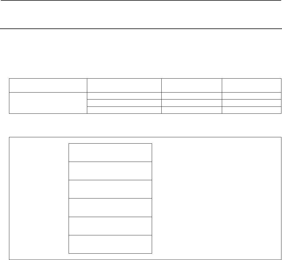
5.WINDOW FUNCTIONS
B-64513EN/03
- 674 -
5.4.35
Reading repetition count for subprogram calls / canned
cycle (High-speed Response)
When a subprogram is executed by specifying repetition count or a canned cycle is executed by
specifying repetition count in a NC program operation, specified repetition count and remaining repetition
count can be read.
Example of reading the repetition count:
The case that specified repetition count of subprogram call is 3.
Calling block of main program Calling order of executing
subprogram “P1000”
Remaining repetition
count
Specified repetition
count
M98P1000L3
First 3 3
Second 2 3
Third 1 3
Input data structure
Top Address +0 (Function code)
449
+2 (Completion code)
-
(Need not to be set)
+4 (Data length L)
-
(Need not to be set)
+6 (Data number N)
0
Set 0 to this field.
+8 (Data attribute M)
0
Set 0 to this field.
+10
+17
(Data area)
-
(Need not to be set)
Completion codes
0 Completed successfully.
1 This function is unsupported.
3 The data number is invalid.
4 The data attribute is invalid.

B-64513EN/03
5.WINDOW FUNCTIONS
- 675 -
Output data structure
Top Address +0 (Function code)
449
+2 (Completion code)
?
(See above description)
+4 (Data length L)
8
+6 (Data number N)
0
(Same as input data)
+8 (Data attribute M)
0
(Same as input data)
+10
Remaining repetition count
(4 bytes)
+14
+17
Specified repetition count
(4 bytes)
NOTE
1 When a subprogram is executed by specifying no repetition count or a canned
cycle is executed by specifying no repetition count, this window function can
read “0” as the remaining repetition count and the specified repetition count.
2 When a subprogram is not executed or a canned cycle is not executed, this
window function can read “-1” as the remaining repetition count and the specified
repetition count.

5.WINDOW FUNCTIONS
B-64513EN/03
- 676 -
5.5 AXIS INFORMATION
5.5.1 Reading the Actual Velocity of Controlled Axes (High-speed
Response)
The actual velocity of a movement on CNC-controlled axes can be read. Note that the read speed is the
composite velocity for the controlled axes. When movement involves only the basic three axes, the X, Y,
and Z axes, the composite velocity equals the actual velocity. When movement, however, involves the
fourth axis, such as a rotation axis or a parallel axis, as well as some of the basic three axes, the composite
velocity for all the relevant axes does not equal the actual velocity.
Input data structure
Top Address +0 (Function code)
26
+2 (Completion code)
-
(Need not to be set)
+4 (Data length L)
-
(Need not to be set)
+6 (Data number N)
0
Set 0 to this field.
+8 (Data attribute M)
0
Set 0 to this field.
+10
+41
(Data area)
-
(Need not to be set)
Completion codes
0 The actual velocity for the controlled axes has been read normally.
Output data structure
Top Address +0 (Function code)
26
+2 (Completion code)
?
(See above description)
+4 (Data length L)
4
+6 (Data number N)
0
(Same as input data)
+8 (Data attribute M)
0
(Same as input data)
+10
+13
Actual velocity for controlled axes
(4 bytes)
Unsigned binary
<Data increments>
• Input in mm : 1mm/min.
• Input in inches : 0.01 inch/min

B-64513EN/03
5.WINDOW FUNCTIONS
- 677 -
5.5.2
Reading the Absolute Position (Absolute Coordinates) of
Controlled Axes (High-speed Response)
The absolute coordinates of the CNC-controlled axes for movement can be read. According to the setting
of NC parameter No.3104#6 (DAL) and No.3104#7(DAC), the absolute coordinates can be read. The
values are the same as values displayed in the screen
Input data structure
Top Address +0 (Function code)
27
+2 (Completion code)
-
(Need not to be set)
+4 (Data length L)
-
(Need not to be set)
+6 (Data number N)
0
Set 0 to this field.
+8 (Data attribute M)
Axis number
M=1 to n: Absolute coordinate of a specific axis.
(n is the axis number.)
M=-1: Coordinates of all axes
+10
+41
(Data area)
-
(Need not to be set)
Completion codes
0 The absolute coordinates of the controlled axes have been read normally.
4 Data specified as the data attribute is invalid because it is neither -1 nor a value from 1 to n (n is the
number of axes). Alternatively, the specified axis number is greater than the number of controlled
axes.
Output data structure
(1) When reading a specified axis.
Top Address +0 (Function code)
27
+2 (Completion code)
?
(See above description)
+4 (Data length L)
4
+6 (Data number N)
0
(Same as input data)
+8 (Data attribute M)
Axis number
(Same as input data)
+10
+13
Absolute coordinate of the
controlled axis specified
(4 bytes)
Signed binary
(A negative value is represented in 2's
complement)
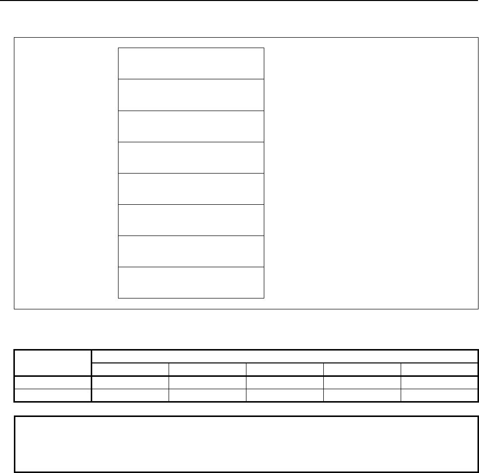
5.WINDOW FUNCTIONS
B-64513EN/03
- 678 -
(2) When reading all axes. (ex. number of controlled axes is 3)
Top Address +0 (Function code)
27
+2 (Completion code)
?
(See above description)
+4 (Data length L)
12
(4bytes * 3axes)
+6 (Data number N)
0
(Same as input data)
+8 (Data attribute M)
-1
(Same as input data)
M=-1: All axes.
+10 Absolute coordinate of the first
axis
(4 bytes)
Signed binary
(A negative value is represented in 2's
complement)
+14 Absolute coordinate of the second
axis
(4 bytes)
Signed binary
(A negative value is represented in 2's
complement)
+18
+21
Absolute coordinate of the third
axis
(4 bytes)
Signed binary
(A negative value is represented in 2's
complement)
Output data unit
Input system Increment system
IS-A IS-B IS-C IS-D IS-E
mm, deg 0.01 0.001 0.0001 0.00001 0.000001
inch 0.001 0.0001 0.00001 0.000001 0.0000001
NOTE
The reading position does not depend on the diameter or radius setting even
using the Diameter and Radius Setting Switching function but depends only on
the setting of the CNC parameter No. 1006#3 (DIAx).

B-64513EN/03
5.WINDOW FUNCTIONS
- 679 -
5.5.3
Reading the Machine Position (Machine Coordinates) of
Controlled Axes (High-speed Response)
The machine coordinates of CNC-controlled axes for movement can be read. The machine position is
read with the machine unit.
Input data structure
Top Address +0 (Function code)
28
+2 (Completion code)
-
(Need not to be set)
+4 (Data length L)
-
(Need not to be set)
+6 (Data number N)
0
Set 0 to this field.
+8 (Data attribute M)
Axis number
M=1 to n: Machine coordinate of a specific axis.
(n is the axis number.)
M=-1: Coordinates of all axes
+10
+41
(Data area)
-
(Need not to be set)
Completion codes
0 The machine coordinates of the controlled axes have been read normally.
4 Data specified as the data attribute is invalid because it is neither -1 nor a value from 1 to n (n is the
number of axes). Alternatively, the specified axis number is greater than the number of the
controlled axes.
Output data structure
(1) When reading a specified axis.
Top Address +0 (Function code)
28
+2 (Completion code)
?
(See above description)
+4 (Data length L)
4
+6 (Data number N)
0
(Same as input data)
+8 (Data attribute M)
Axis number
(Same as input data)
+10
+13
Machine coordinate of the
controlled axis specified
(4 bytes)
Signed binary
(A negative value is represented in 2's
complement)
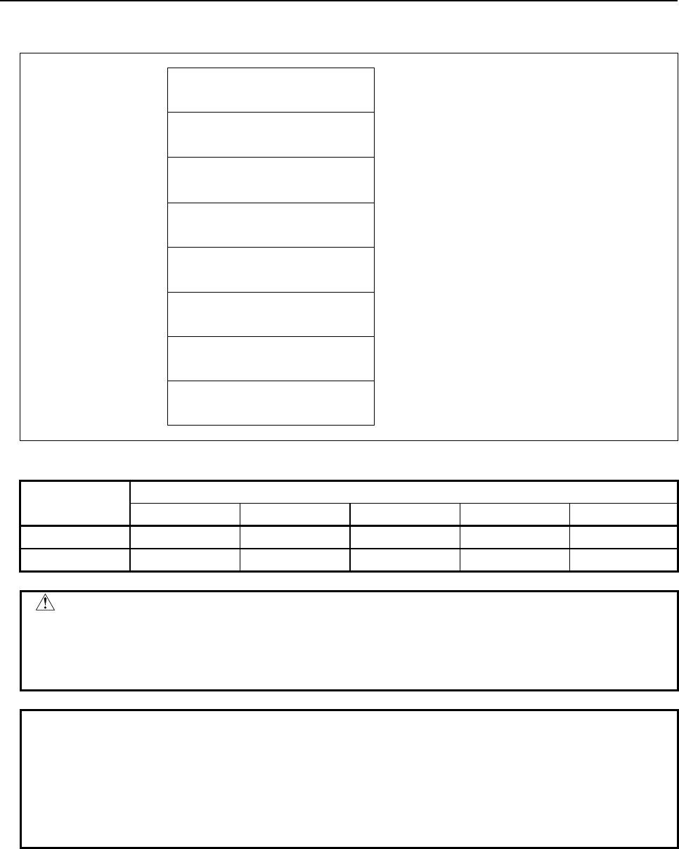
5.WINDOW FUNCTIONS
B-64513EN/03
- 680 -
(2) When reading all axes. (Ex. number of controlled axes is 3)
Top Address +0 (Function code)
28
+2 (Completion code)
?
(See above description)
+4 (Data length L)
12
(4bytes × 3axes)
+6 (Data number N)
0
(Same as input data)
+8 (Data attribute M)
-1
(Same as input data)
M=-1: All axes.
+10 Machine coordinate of the first
axis
(4 bytes)
Signed binary
(A negative value is represented in 2's
complement)
+14 Machine coordinate of the second
axis
(4 bytes)
Signed binary
(A negative value is represented in 2's
complement)
+18
+21
Machine coordinate of the third
axis
(4 bytes)
Signed binary
(A negative value is represented in 2's
complement)
Output data unit
Machine system Increment system
IS-A IS-B IS-C IS-D IS-E
mm, deg 0.01 0.001 0.0001 0.00001 0.000001
inch 0.001 0.0001 0.00001 0.000001 0.0000001
CAUTION
When an inch machine is used in metric input, or when a millimeter machine is
used in inch input, the machine position that is read with bit 0 of parameter No.
3104 set to 1 differs from the value indicated by the CNC. In this case,
therefore, the value read through the ladder must be calculated (converted).
NOTE
1 The reading position does not depend on the diameter or radius setting even
using the Diameter and Radius Setting Switching function but depends only on
the setting of the CNC parameter No. 1006#3 (DIAx).
2 Update cycle of the machine position becomes faster by setting 1 to the CNC
parameter No. 11300#5 (MPH). You should apply this setting only if necessary
because this setting may lower the performance of CNC a little.

B-64513EN/03
5.WINDOW FUNCTIONS
- 681 -
5.5.4
Reading a Skip Position (Stop Coordinates of Skip Operation
(G31)) of Controlled Axes (High-speed Response)
When a block of the skip operation (G31) is executed by the CNC and the skip signal goes on to stop the
machine, the absolute coordinates of the stop position on the axes of movement can be read.
Input data structure
Top Address +0 (Function code)
29
+2 (Completion code)
-
(Need not to be set)
+4 (Data length L)
-
(Need not to be set)
+6 (Data number N)
0
Set 0 to this field.
+8 (Data attribute M)
Axis number
M=1 to n: Skip coordinate on a specific axis.
(n is the axis number.)
M=-1: Coordinates on all axes
+10
+41
(Data area)
-
(Need not to be set)
Completion codes
0 The coordinates of the skip stop position for the controlled axes have been read normally.
4 Data specified for the data attribute is invalid because it is neither -1 nor a value from 1 to n (n is the
number of axes). Alternatively, the specified axis number is greater than the number of controlled
axes.
Output data structure
(1) When reading a specified axis.
Top Address +0 (Function code)
29
+2 (Completion code)
?
(See above description)
+4 (Data length L)
4
+6 (Data number N)
0
(Same as input data)
+8 (Data attribute M)
Axis number
(Same as input data)
+10
+13
Skip coordinate of the controlled
axis specified
(4 bytes)
Signed binary
(A negative value is represented in 2's
complement)
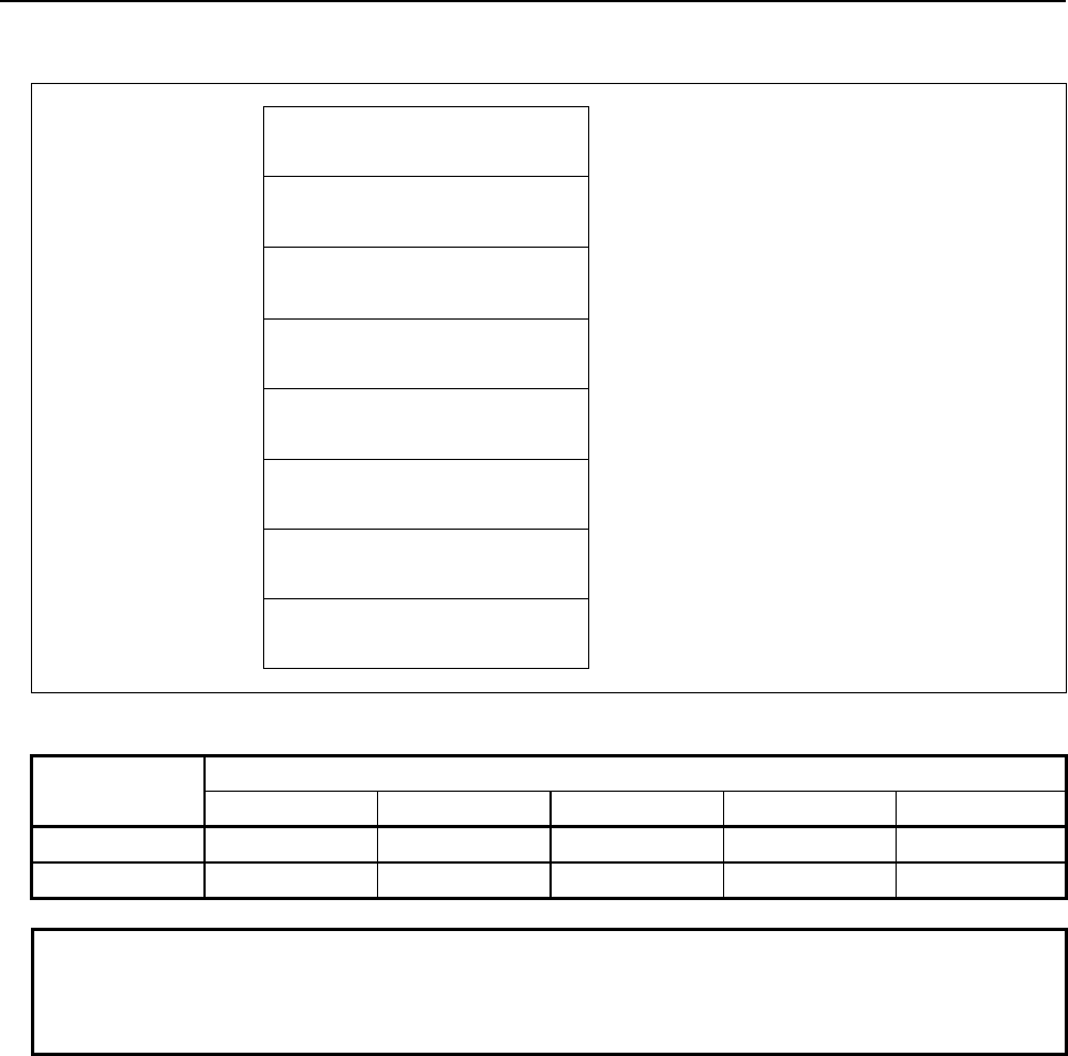
5.WINDOW FUNCTIONS
B-64513EN/03
- 682 -
(2) When reading all axes. (ex. number of controlled axes is 3)
Top Address +0 (Function code)
29
+2 (Completion code)
?
(See above description)
+4 (Data length L)
12
(4bytes × 3axes)
+6 (Data number N)
0
(Same as input data)
+8 (Data attribute M)
-1
(Same as input data)
M=-1: All axes.
+10 Skip coordinate of the first axis
(4 bytes)
Signed binary
(A negative value is represented in 2's
complement)
+14 Skip coordinate of the second axis
(4 bytes)
Signed binary
(A negative value is represented in 2's
complement)
+18
+21
Skip coordinate of the third axis
(4 bytes)
Signed binary
(A negative value is represented in 2's
complement)
Output data unit
Input system Increment system
IS-A IS-B IS-C IS-D IS-E
mm, deg 0.01 0.001 0.0001 0.00001 0.000001
inch 0.001 0.0001 0.00001 0.000001 0.0000001
NOTE
The reading position does not depend on the diameter or radius setting even
using the Diameter and Radius Setting Switching function but depends only on
the setting of the CNC parameter No. 1006#3 (DIAx).

B-64513EN/03
5.WINDOW FUNCTIONS
- 683 -
5.5.5
Reading the Servo Delay for Controlled Axes (High-speed
Response)
The servo delay, which is the difference between the specified coordinates of CNC-controlled axes and
the actual servo position, can be read.
Input data structure
Top Address +0 (Function code)
30
+2 (Completion code)
-
(Need not to be set)
+4 (Data length L)
-
(Need not to be set)
+6 (Data number N)
Unit
N=0: Read with Input unit
N=1: Read with Detection unit
+8 (Data attribute M)
Axis number
M=1 to n: Axis number
M=-1: All axes
+10
+n
(Data area)
-
(Need not to be set)
Completion codes
0 The servo delay for the controlled axes have been read normally.
3 The data number is invalid.
4 The data specified as the data attribute is invalid because it is neither -1 nor a value from 1 to n (n is
the number of axes). Alternatively, the specified axis number is greater than the number of
controlled axes.
Output data structure
(1) When reading a specified axis.
Top Address +0 (Function code)
30
+2 (Completion code)
?
(See above description)
+4 (Data length L)
4
+6 (Data number N)
Unit
(Same as input data)
+8 (Data attribute M)
Axis number
(Same as input data)
+10
+13
Servo delay
(4 bytes)
Signed binary format in 4 bytes length.

5.WINDOW FUNCTIONS
B-64513EN/03
- 684 -
(2) When reading all axes. (ex. number of controlled axes is 3)
Top Address +0 (Function code)
30
+2 (Completion code)
?
(See above description)
+4 (Data length L)
12
(4bytes× 3axes)
+6 (Data number N)
Unit
(Same as input data)
+8 (Data attribute M)
-1
(Same as input data)
M=-1: All axes.
+10 Servo delay of 1st axis
(4 bytes)
Signed binary format in 4 bytes length
+14 Servo delay of 2nd axis
(4 bytes)
Signed binary format in 4 bytes length
+18
+21
Servo delay of 3rd axis
(4 bytes)
Signed binary format in 4 bytes length
Output data unit
(1) In case of the data number N=0
Input system Increment system
IS-A IS-B IS-C IS-D IS-E
mm, deg 0.01 0.001 0.0001 0.00001 0.000001
inch 0.001 0.0001 0.00001 0.000001 0.0000001
(2) In case of the data number N=1
Detection unit
NOTE
The reading position does not depend on the diameter or radius setting even
using the Diameter and Radius Setting Switching function but depends only on
the setting of the CNC parameter No. 1006#3 (DIAx).

B-64513EN/03
5.WINDOW FUNCTIONS
- 685 -
5.5.6
Reading the Acceleration/Deceleration Delay on Controlled
Axes (High-speed Response)
The acceleration/deceleration delay, which is the difference between the coordinates of controlled axes
programmed in the CNC and the position after acceleration/deceleration is performed, can be read.
Input data structure
Top Address +0 (Function code)
31
+2 (Completion code)
-
(Need not to be set)
+4 (Data length L)
-
(Need not to be set)
+6 (Data number N)
Unit
N=0: Read with Input unit
N=1: Read with Detection unit
+8 (Data attribute M)
Axis number
M=1 to n: Axis number
M=-1: All axes
+10
+n
(Data area)
-
(Need not to be set)
Completion codes
0 The acceleration/deceleration delay for the control axis has been read normally.
3 The data number is invalid.
4 The data specified as the data attribute is invalid because it is neither -1 nor a value from 1 to n (n is
the number of axes). Alternatively, the specified axis number is greater than the number of
controlled axes.
Output data structure
(1) When reading a specified axis.
Top Address +0 (Function code)
31
+2 (Completion code)
?
(See above description)
+4 (Data length L)
4
+6 (Data number N)
Unit
(Same as input data)
+8 (Data attribute M)
Axis number
(Same as input data)
+10
+13
Acc./Dec. delay
(4 bytes)
Signed binary format in 4 bytes length.

5.WINDOW FUNCTIONS
B-64513EN/03
- 686 -
(2) When reading all axes. (ex. number of controlled axes is 3)
Top Address +0 (Function code)
31
+2 (Completion code)
?
(See above description)
+4 (Data length L)
12
(4bytes × 3axes)
+6 (Data number N)
Unit
(Same as input data)
+8 (Data attribute M)
-1
(Same as input data)
M=-1: All axes.
+10 ACC./Dec. delay of 1st axis
(4 bytes)
Signed binary format in 4 bytes length
+14 ACC./Dec. delay of 2nd axis
(4 bytes)
Signed binary format in 4 bytes length
+18
+21
ACC./Dec. delay of 3rd axis
(4 bytes)
Signed binary format in 4 bytes length
Output data unit
(1) In case of the data number N=0
Input system Increment system
IS-A IS-B IS-C IS-D IS-E
mm, deg 0.01 0.001 0.0001 0.00001 0.000001
inch 0.001 0.0001 0.00001 0.000001 0.0000001
(2) In case of the data number N=1
Detection unit
NOTE
The reading position does not depend on the diameter or radius setting even
using the Diameter and Radius Setting Switching function but depends only on
the setting of the CNC parameter No. 1006#3 (DIAx).

B-64513EN/03
5.WINDOW FUNCTIONS
- 687 -
5.5.7
Reading the Feed Motor Load Current Value (A/D Conversion
Data) (High-speed Response)
The digital value converted from the load current of the CNC-controlled axis can be read.
NOTE
The load current value of Cs-axis can not be read.
If you want to know the load information of Cs-axis, use the function code
No.153 (Reading load information of the spindle motor).
Input data structure
Top Address +0 (Function code)
34
+2 (Completion code)
-
(Need not to be set)
+4 (Data length L)
-
(Need not to be set)
+6 (Data number N)
2
Type of analog voltage
N=2: Load information for the CNC-controlled axes.
+8 (Data attribute M)
Axis number
M=1 to n ('n' is maximum axis number)
+10 (Data area)
-
(Need not to be set)
(a) Type of analog voltage (data number)
N Type of analog voltage
0 (reserved)
2 Load information for the CNC-controlled axes
NOTE
There is no analog input function on 30i/31i/32i/35i-B, Power Motion i-A, 0i-F. If
you need such a function, read A/D conversion data directly using the I/O Link
analog input module. For details, see “CONNECTION MANUAL (HARDWARE)”.
(b) Specifying a CNC-controlled axis (data attribute)
Specify a CNC-controlled axis number for which the voltage conversion data for the load current is
to be read.

5.WINDOW FUNCTIONS
B-64513EN/03
- 688 -
Completion codes
0 A/D conversion data has been read normally.
3 The data specified for the data number is invalid.
4 The data specified for the data attribute is invalid, or the specified axis number is greater than the
number of controlled axes.
Output data structure
Top Address +0 (Function code)
34
+2 (Completion code)
?
(See above description)
+4 (Data length L)
2
+6 (Data number N)
2
(Same as input data)
+8 (Data attribute M)
Axis number
(Same as input data)
+10
+11
A/D conversion data
(2 bytes)
Binary number from 0 to +/-6554
(a) A/D conversion data (AD) of CNC controlled axis load information
The load current for the specified CNC controlled axis is converted into analog voltage, the input to
the A/D converter to output a digital data.
The value actually set in the AD field is obtained from the following formula:
AD = A/D conversion data [Value read by the window function (±)]
N = Nominal current limit (Maximum current (Imax)) for the amplifier
corresponding to the motor
(AD) × = Load current [A
peak
]
N
6554
NOTE
For the nominal current limits (Maximum current (Imax)) of servo amplifier, see
the descriptions manual of the servo amplifier.

B-64513EN/03
5.WINDOW FUNCTIONS
- 689 -
5.5.8
Reading the Actual Spindle Speed (High-speed Response)
The actual speed of the spindle can be read from the CNC.
Input data structure
Top Address +0 (Function code)
50
+2 (Completion code)
-
(Need not to be set)
+4 (Data length L)
-
(Need not to be set)
+6 (Data number N)
0
Set 0 to this field.
+8 (Data attribute M)
0
Set 0 to this field.
+10
+41
(Data area)
-
(Need not to be set)
Completion codes
0 The actual speed of the spindle has been read normally.
Output data structure
Top Address +0 (Function code)
50
+2 (Completion code)
?
(See above description)
+4 (Data length L)
4
+6 (Data number N)
0
(Same as input data)
+8 (Data attribute M)
0
(Same as input data)
+10
+13
Actual spindle speed
Unsigned binary
<Data unit>
1/min

5.WINDOW FUNCTIONS
B-64513EN/03
- 690 -
5.5.9
Reading the Relative Position on a Controlled Axis (High-
speed Response)
The relative coordinates of the machine moving along an axis controlled by the CNC can be read.
According to the setting of NC parameter No.3104#4 (DRL) and No.3104#5 (DRC), the relative
coordinates can be read. The values are the same as values displayed in the screen
Input data structure
Top Address +0 (Function code)
74
+2 (Completion code)
-
(Need not to be set)
+4 (Data length L)
-
(Need not to be set)
+6 (Data number N)
0
Set 0 to this field.
+8 (Data attribute M)
Axis number
M=1 to n: Reads the relative coordinates of each
axis. (n is an axis No.)
M=-1: Reads the relative coordinates of all axes
+10
+41
(Data area)
-
(Need not to be set)
Completion codes
0 The relative coordinates on the controlled axis have been read normally.
4 The specified data attribute is invalid. That is, a value other than -1 and 1 to n (number of axes) was
specified, or the specified axis No. was greater than the number of controlled axes.
Output data structure
(1) When reading a specified axis.
Top Address +0 (Function code)
74
+2 (Completion code)
?
(See above description)
+4 (Data length L)
4
+6 (Data number N)
0
(Same as input data)
+8 (Data attribute M)
Axis number
(Same as input data)
+10
+13
Relative coordinates on the
specified controlled axis
(4 bytes)
Signed binary
(A negative value is represented in 2's
complement)
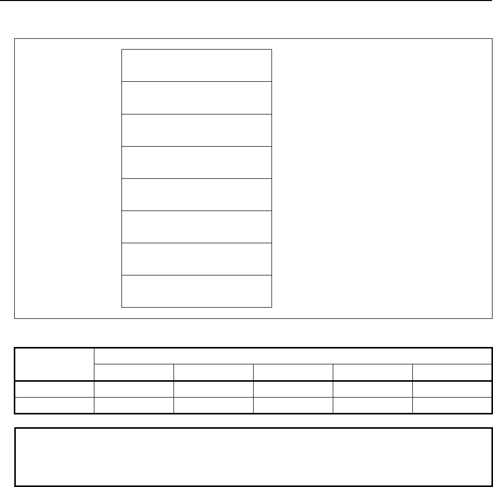
B-64513EN/03
5.WINDOW FUNCTIONS
- 691 -
(2) When reading all axes. (ex. number of controlled axes is 3)
Top Address +0 (Function code)
74
+2 (Completion code)
?
(See above description)
+4 (Data length L)
12
(4bytes * 3axes)
+6 (Data number N)
0
(Same as input data)
+8 (Data attribute M)
-1
(Same as input data)
M=-1: All axes.
+10 Relative coordinates on the first
axis
(4 bytes)
Signed binary
(A negative value is represented in 2's
complement)
+14 Relative coordinates on the
second axis
(4 bytes)
Signed binary
(A negative value is represented in 2's
complement)
+18
+21
Relative coordinates on the third
axis
(4 bytes)
Signed binary
(A negative value is represented in 2's
complement)
Output data unit
Input system Increment system
IS-A IS-B IS-C IS-D IS-E
mm, deg 0.01 0.001 0.0001 0.00001 0.000001
inch 0.001 0.0001 0.00001 0.000001 0.0000001
NOTE
The reading position does not depend on the diameter or radius setting even
using the Diameter and Radius Setting Switching function but depends only on
the setting of the CNC parameter No. 1006#3 (DIAx).

5.WINDOW FUNCTIONS
B-64513EN/03
- 692 -
5.5.10
Reading the Remaining Travel (High-speed Response)
The remaining travel of the machine along an axis controlled by the CNC can be read. The unit of the
read data is different whether the move command setting of the axis is radius specification or diameter
specification. When the move command setting of the axis is radius specification, the CNC parameter
No.1006#3 is “0”, the read data is double of the data that is displayed on a CNC position screen. When
the move command setting of the axis is diameter specification, the CNC parameter No.1006#3 is “1”, the
read data is the same as the data that is displayed on a CNC position screen.
Input data structure
Top Address +0 (Function code)
75
+2 (Completion code)
-
(Need not to be set)
+4 (Data length L)
-
(Need not to be set)
+6 (Data number N)
0
Set 0 to this field.
+8 (Data attribute M)
Axis number
M=1 to n: Reads the remaining travel along each
axis. (n is an axis No.)
M=-1: Reads the remaining travel along all axes
+10
+41
(Data area)
-
(Need not to be set)
Completion codes
0 The remaining travel along the controlled axis has been read normally.
4 The specified data attribute is invalid. That is, a value other than -1 and 1 to n (number of axes) was
specified, or the specified axis No. was greater than the number of controlled axes.
Output data structure
(1) When reading a specified axis.
Top Address +0 (Function code)
75
+2 (Completion code)
?
(See above description)
+4 (Data length L)
4
+6 (Data number N)
0
(Same as input data)
+8 (Data attribute M)
Axis number
(Same as input data)
+10
+13
Remaining travel along the
specified controlled axis
(4 bytes)
Signed binary
(A negative value is represented in 2's
complement)
B-64513EN/03
5.WINDOW FUNCTIONS
- 693 -
(2) When reading all axes. (ex. number of controlled axes is 3)
Top Address +0 (Function code)
75
+2 (Completion code)
?
(See above description)
+4 (Data length L)
12
(4bytes × 3axes)
+6 (Data number N)
0
(Same as input data)
+8 (Data attribute M)
-1
(Same as input data)
M=-1: All axes.
+10 Remaining travel along the first
axis
(4 bytes)
Signed binary
(A negative value is represented in 2's
complement)
+14 Remaining travel along the
second axis
(4 bytes)
Signed binary
(A negative value is represented in 2's
complement)
+18
+21
Remaining travel along the third
axis
(4 bytes)
Signed binary
(A negative value is represented in 2's
complement)
Output data unit
Setting of move command
(CNC parameter 1006#3)
Input
system
Increment system
IS-A IS-B IS-C IS-D ID-E
Radius specification
(1006#3=0)
mm deg 0.005 0.0005 0.00005 0.000005 0.0000005
inch 0.0005 0.00005 0.000005 0.0000005 0.00000005
Diameter specification
(1006#3=1)
mm deg 0.01 0.001 0.0001 0.00001 0.000001
inch 0.001 0.0001 0.00001 0.000001 0.0000001
NOTE
The reading position does not depend on the diameter or radius setting even
using the Diameter and Radius Setting Switching function but depends only on
the setting of the CNC parameter No. 1006#3 (DIAx).

5.WINDOW FUNCTIONS
B-64513EN/03
- 694 -
5.5.11
Reading the Actual Velocity of each Controlled Axis (High-
speed Response)
The actual velocity of each controlled axis can be read.
Input data structure
Top Address +0 (Function code)
91
+2 (Completion code)
-
(Need not to be set)
+4 (Data length L)
-
(Need not to be set)
+6 (Data number N)
0
Set 0 to this field.
+8 (Data attribute M)
Axis number
M=1 to n: Reads the actual velocity of each
controlled axis. (n is an axis No.)
M=-1: Reads the actual velocity of all controlled
axes.
+10
+41
(Data area)
-
(Need not to be set)
Completion codes
0 The actual velocity of the each controlled axis has been read normally.
4 The specified data attribute is invalid. That is, a value other than −1 and 1 to n (number of axes) was
specified, or the specified axis No. was greater than the number of controlled axes.
Output data structure
(1) When reading a specified axis.
Top Address +0 (Function code)
91
+2 (Completion code)
?
(See above description)
+4 (Data length L)
4
+6 (Data number N)
0
(Same as input data)
+8 (Data attribute M)
Axis number
(Same as input data)
+10
+13
Actual velocity of each controlled
axes
(4 bytes)
Signed binary(A negative value is represented in
2's complement)
B-64513EN/03
5.WINDOW FUNCTIONS
- 695 -
(2) When reading all axes. (ex. number of controlled axes is 3)
Top Address +0 (Function code)
91
+2 (Completion code)
?
(See above description)
+4 (Data length L)
12
(4bytes * 3axes)
+6 (Data number N)
0
(Same as input data)
+8 (Data attribute M)
-1
(Same as input data)
M=-1: All axes.
+10 Actual velocity of first axis
(4 bytes)
Signed binary
(A negative value is represented in 2's
complement)
+14 Actual velocity of second axis
(4 bytes)
Signed binary
(A negative value is represented in 2's
complement)
+18
+21
Actual velocity of third axis
(4 bytes)
Signed binary
(A negative value is represented in 2's
complement)
Output data unit
Increment system Data Increment
mm 1mm/min, 1deg/min
inch 0.01inch/min, 0.01deg/min

5.WINDOW FUNCTIONS
B-64513EN/03
- 696 -
5.5.12
Reading Actual Spindle Speeds (High-speed Response)
(1) Actual spindle speed
This function reads the actual speed of the serial spindles.
Input data structure
Top Address +0 (Function code)
138
+2 (Completion code)
-
(Need not to be set)
+4 (Data length L)
-
(Need not to be set)
+6 (Data number N)
0
Set 0 to this field.
+8 (Data attribute M)
Spindle number
M=1 to n: Read spindles on each axis. (n is the
spindle number)
M=-1: Read spindles on No.1 and No.2 axes
M=-2: Read spindles on No.1 to No.3 axes
M=-3: Read spindles on No.1 to No.4 axes
+10 (Data area)
-
(Need not to be set)
Completion codes
0 The actual spindle speed was read successfully.
4 The spindle speed in 'Data Attribute' has wrong values, that is, a value outside of the range -1 to -(n -
1) or 1 to n (n: number of spindles).
Output data structure
(1) When reading a specified spindle.
Top Address +0 (Function code)
138
+2 (Completion code)
?
(See above description)
+4 (Data length L)
4
+6 (Data number N)
0
(Same as input data)
+8 (Data attribute M)
Spindle number
(Same as input data)
+10
+13
Actual speed of specified spindle
(4bytes)
Signed binary
<Data unit>
1/min

B-64513EN/03
5.WINDOW FUNCTIONS
- 697 -
(2) When reading multiple spindles. (ex. 3 spindles)
Top Address +0 (Function code)
138
+2 (Completion code)
?
(See above description)
+4 (Data length L)
12
(4bytes × 3spindles)
+6 (Data number N)
0
(Same as input data)
+8 (Data attribute M)
-2
(Same as input data)
M=-2: Read spindles on No.1 to No.3 axes.
+10 Actual speed of No.1 spindle
(4 bytes)
Signed binary
<Data unit>
1/min
+14 Actual speed of No.2 spindle
(4 bytes)
Signed binary
<Data unit>
1/min
+18
+21
Actual speed of No.3 spindle
(4 bytes)
Signed binary
<Data unit>
1/min
(2) Position coder-less actual spindle speed
This function reads the actual spindle speed (position coder-less actual spindle speed) obtained by
calculating the spindle motor speed of the serial spindles.
Input data structure
Top Address +0 (Function code)
138
+2 (Completion code)
-
(Need not to be set)
+4 (Data length L)
-
(Need not to be set)
+6 (Data number N)
0
Set 0 to this field.
+8 (Data attribute M)
Spindle number(+10)
M=11 to (10 + n): Read spindles on each axis. (n is
the spindle number)
M=-11: Read spindles on No.1 and No.2 axes
M=-12: Read spindles on No.1 to No.3 axes
M=-13: Read spindles on No.1 to No.4 axes
+10 (Data area)
-
(Need not to be set)
Completion codes
0 The actual spindle speed was read successfully.
4 The spindle speed in 'Data Attribute' has wrong values, that is, a value outside of the range -11 to -(9
+ 1) or 11 to (10 + n) (n: number of spindles).

5.WINDOW FUNCTIONS
B-64513EN/03
- 698 -
Output data structure
(1) When reading a specified spindle.
Top Address +0 (Function code)
138
+2 (Completion code)
?
(See above description)
+4 (Data length L)
4
+6 (Data number N)
0
(Same as input data)
+8 (Data attribute M)
Spindle number(+10)
(Same as input data)
+10
+13
Position coder-less actual spindle
speed
(4bytes)
Signed binary
<Data unit>
1/min
(2) When reading multiple spindles. (Ex. 3 spindles)
Top Address +0 (Function code)
138
+2 (Completion code)
?
(See above description)
+4 (Data length L)
12
(4bytes × 3spindles)
+6 (Data number N)
0
(Same as input data)
+8 (Data attribute M)
-12
(Same as input data)
M=-12: Read spindles on No.1 to No.3 axes.
+10 Position coder-less actual No.1
spindle speed
(4bytes)
Signed binary
<Data unit>
1/min
+14 Position coder-less actual No.2
spindle speed
(4bytes)
Signed binary
<Data unit>
1/min
+18
+21
Position coder-less actual No.3
spindle speed
(4bytes)
Signed binary
<Data unit>
1/min

B-64513EN/03
5.WINDOW FUNCTIONS
- 699 -
5.5.13
Entering Torque Limit Data for the Digital Servo Motor (Low-
speed Response)
Torque limit values for the digital servo motor can be entered.
WARNING
When you write some NC data using both this instruction in ladder program and
other applications, take care that you do not write to the same data area.
If some values are written to the same data area by two or more applications
including ladder program, unexpected value may be written. In this case, it may
cause an unexpected machine behavior and also tools, work pieces, and
machines may be damaged. As for details, refer to “SAFETY PRECAUTIONS”.
Input data structure
Top Address +0 (Function code)
152
+2 (Completion code)
-
(Need not to be set)
+4 (Data length L)
2
+6 (Data number N)
0
Set 0 to this field.
+8 (Data attribute M)
Axis number
M=1 to n: Axis No.
+10
+11
Torque limit data (2 byte)
The high-order byte is
always set to 0
Unsigned binary
<Unit : %>
Values from 0 to 255 correspond to 0% to 100%
CAUTION
1 To use this function, you should set the CNC parameter No. 6286#0 to 1.
2 Calculate the torque limit data assuming that the value of CNC parameter
No.2060 is 100%.And, when using the standard parameter of servo motor, the
value of 100% means the maximum torque of it.
Completion codes
0: Torque limit data has been entered normally.
4: The specified data attribute is invalid. That is, a value other than 1 to n (number of axes) was
specified, or the specified axis No. was greater than the number of controlled axes.
113: The CNC status is that the writing data cannot be allowed. You should confirm that the CNC
parameter No. 6286#0 is set to 1.

5.WINDOW FUNCTIONS
B-64513EN/03
- 700 -
Output data structure
Top Address +0 (Function code)
152
+2 (Completion code)
?
(See above description)
+4 (Data length L)
2
(Same as input data)
+6 (Data number N)
0
(Same as input data)
+8 (Data attribute M)
Axis number
(Same as input data)
+10
+11
Torque limit data (2 byte)
(Input data)
The high-order byte is
always set to 0
Unsigned binary
<Unit : %>
Values from 0 to 255 correspond to 0% to 100%

B-64513EN/03
5.WINDOW FUNCTIONS
- 701 -
5.5.14
Reading Load Information of the Spindle Motor (Serial
Interface) (High-speed Response)
Load information of the serial spindle can be read.
The equation to normalize the load information is shown below
Load (%) = L ×λ
32767
L: Data read from the window
λ: The percentage of the maximum output of the motor to the continuous rated output of the motor
(When the maximum output is 180% and the continuous rated output is 100%, the percentage is
180.)
NOTE
The "λ" is equal to the value of parameter No. 4127.
Input data structure
Top Address +0 (Function code)
153
+2 (Completion code)
-
(Need not to be set)
+4 (Data length L)
-
(Need not to be set)
+6 (Data number N)
Spindle number
N=0: Read the load of the No.1 spindle
N=1: Read the load of the No.2 spindle
N=2: Read the load of the No.3 spindle
N=3: Read the load of the No.4 spindle
N=-1: Read the loads of the No.1 and No.2 spindle
N=-2: Read the loads of the No.1 to No.3 spindles
N=-3: Read the loads of the No.1 to No.4 spindles
+8 (Data attribute M)
0
Set 0 to this field.
+10
+41
(Data area)
-
(Need not to be set)
Completion codes
0 Load information of the serial spindle has been read normally.

5.WINDOW FUNCTIONS
B-64513EN/03
- 702 -
Output data structure
(1) When reading a specified spindle.
Top Address +0 (Function code)
153
+2 (Completion code)
?
(See above description)
+4 (Data length L)
2
+6 (Data number N)
Spindle number
(Same as input data)
+8 (Data attribute M)
0
(Same as input data)
+10
+11
Load information of the serial
spindle
Unsigned binary, 2 bytes long
(2) When reading multiple spindles. (Ex. 3 spindles)
Top Address +0 (Function code)
153
+2 (Completion code)
?
(See above description)
+4 (Data length L)
6
(2bytes × 3spindles)
+6 (Data number N)
-2
(Same as input data)
N=-2: Read the loads of the No.1 to No.3 spindles
+8 (Data attribute M)
0
(Same as input data)
+10 Load information of the 1st serial
spindle
Unsigned binary, 2 bytes long
+12 Load information of the 2nd serial
spindle
Unsigned binary, 2 bytes long
+14
+15
Load information of the 3rd serial
spindle
Unsigned binary, 2 bytes long

B-64513EN/03
5.WINDOW FUNCTIONS
- 703 -
5.5.15
Reading a Chopping Data (Low-speed Response)
Using this function, you can read the data (stroke count, real upper dead point, real lower dead point, and
current position) about a chopping function. And, stroke count data can be reset.
Input data structure
Top Address +0 (Function code)
206
+2 (Completion code)
-
(Need not be set)
+4 (Data length L)
-
(Need not be set)
+6 (Data number N)
0, 1, 2, 3, 4
Data type
N = 0 : Stroke count reset
N = 1 : Stroke count read
N = 2 : Real upper dead point read
N = 3 : Real lower dead point read
N = 4 : Current position read
+8 (Data attribute M)
-
(Need not be set)
+10 (Data area)
-
(Need not be set)
Completion codes
0: Completed successfully.
1: Not supported.
3: The data number is invalid.
6: No option for chopping function.

5.WINDOW FUNCTIONS
B-64513EN/03
- 704 -
Output data structure
(1) Reset a stroke count (Data type N=0)
Top Address +0 (Function code)
206
+2 (Completion code)
?
(See above description)
+4 (Data length L)
0
+6 (Data number N)
Data type
(Same as input data)
+8 (Data attribute M)
-
(2) Reading a stroke count (Data type N=1)
Top Address +0 (Function code)
206
+2 (Completion code)
?
(See above description)
+4 (Data length L)
2
+6 (Data number N)
Data type
(Same as input data)
+8 (Data attribute M)
-
+10 Stroke count
(2 Bytes)
Signed binary format in 2 bytes length.
Data = 0 to 32767

B-64513EN/03
5.WINDOW FUNCTIONS
- 705 -
(3) Reading a real upper dead point or real lower dead point (Data type N=2 or 3)
Top Address +0 (Function code)
206
+2 (Completion code)
?
(See above description)
+4 (Data length L)
4
+6 (Data number N)
Data type
(Same as input data)
+8 (Data attribute M)
-
+10 Real upper dead point or
real lower dead point
(4 Bytes)
Signed binary format in 4 bytes length.
(A negative value is represented in 2's
complement)
(4) Reading a current position (Data type N=4)
Top Address +0 (Function code)
206
+2 (Completion code)
?
(See above description)
+4 (Data length L)
4
+6 (Data number N)
Data type
(Same as input data)
+8 (Data attribute M)
-
+10 Current position
(4 Bytes)
Signed binary format in 4 bytes length.
(A negative value is represented in 2's
complement)

5.WINDOW FUNCTIONS
B-64513EN/03
- 706 -
5.5.16
Reading the Actual Speed of Servo Motor (High-speed
Response)
This function can read the following information of servo motor.
• Actual speed (rev / min)
• Thermal simulation data (OVC data)
• Torque command
(1) Reading the actual speed (Data number N = 11)
You can read the actual speed of servo motor.
The unit of the "Actual speed" are the "rev / min" for a rotary motor and the "cm / min" for a linear motor.
Input data structure
Top Address +0 (Function code)
207
+2 (Completion code)
-
(Need not to be set)
+4 (Data length L)
-
(Need not to be set)
+6 (Data number N)
11
N=11: Actual speed (rev / min)
+8 (Data attribute M)
Axis number
M=1 to n: Axis number
M=-1: All axes
+10 (Data area)
-
(Need not to be set)
Completion codes
0 Normal completion
3 The data number is invalid.
4 The data attribute is invalid.

B-64513EN/03
5.WINDOW FUNCTIONS
- 707 -
Output data structure
(1) When reading a specified axis.
Top Address +0 (Function code)
207
+2 (Completion code)
?
(See above description)
+4 (Data length L)
4
+6 (Data number N)
11
(Same as input data)
+8 (Data attribute M)
Axis number
(Same as input data)
+10
+13
Actual speed
(4 bytes)
Signed binary format in 4 bytes length
Data unit: "rev / min" for a rotary motor, "cm / min"
for a linear motor
(2) When reading all axes. (Ex. number of controlled axes is 3)
Top Address +0 (Function code)
207
+2 (Completion code)
?
(See above description)
+4 (Data length L)
12
(4bytes × 3axes)
+6 (Data number N)
11
(Same as input data)
+8 (Data attribute M)
-1
(Same as input data)
M=-1: All axes.
+10 Actual speed for 1st axis
(4 bytes)
Signed binary format in 4 bytes length
Data unit: "rev / min" for a rotary motor, "cm / min"
for a linear motor
+14 Actual speed for 2nd axis
(4 bytes)
Signed binary format in 4 bytes length
Data unit: "rev / min" for a rotary motor, "cm / min"
for a linear motor
+18
+21
Actual speed for 3rd axis
(4 bytes)
Signed binary format in 4 bytes length
Data unit: "rev / min" for a rotary motor, "cm / min"
for a linear motor

5.WINDOW FUNCTIONS
B-64513EN/03
- 708 -
(2) Reading the thermal simulation data (OVC data) (Data number N = 14)
You can read the thermal simulation data (OVC data) of servo motor.
Input data structure
Top Address +0 (Function code)
207
+2 (Completion code)
-
(Need not to be set)
+4 (Data length L)
-
(Need not to be set)
+6 (Data number N)
14
N=14: Thermal simulation data (OVC data).
+8 (Data attribute M)
Axis number
M=1 to n: Axis number
M=-1: All axes
+10 (Data area)
-
(Need not to be set)
Completion codes
0 Normal completion
3 The data number is invalid.
4 The data attribute is invalid.
Output data structure
(1) When reading a specified axis.
Top Address +0 (Function code)
207
+2 (Completion code)
?
(See above description)
+4 (Data length L)
2
+6 (Data number N)
14
(Same as input data)
+8 (Data attribute M)
Axis number
(Same as input data)
+10
+11
Thermal simulation data
(2 bytes)
Signed binary format in 2 bytes length
Data unit: %
The OVC alarm will happen when this value is
100 %.

B-64513EN/03
5.WINDOW FUNCTIONS
- 709 -
(2) When reading all axes. (ex. number of controlled axes is 3)
Top Address +0 (Function code)
207
+2 (Completion code)
?
(See above description)
+4 (Data length L)
6
(2bytes * 3axes)
+6 (Data number N)
14
(Same as input data)
+8 (Data attribute M)
-1
(Same as input data)
M=-1: All axes.
+10 Thermal simulation data for 1st
axis
(2 bytes)
Signed binary format in 2 bytes length
Data unit: %
The OVC alarm will happen when this value is
100 %.
+12 Thermal simulation data for 2nd
axis
(2 bytes)
Signed binary format in 2 bytes length
Data unit: %
The OVC alarm will happen when this value is
100 %.
+14
+15
Thermal simulation data for 3rd
axis
(2 bytes)
Signed binary format in 2 bytes length
Data unit: %
The OVC alarm will happen when this value is
100 %.
(3) Reading the torque command (Data number N = 15)
You can read the torque command of servo motor.
The read "Torque command" is normalized from -6554 to 6554. The value 6554 corresponds to the
maximum current of servo amplifier.
Applying the following formula to this value, you can determine the ratio of the torque command to the
maximum current of amplifier.
Ratio (%) = [data] × 100 / 6554
Applying the following formula, you can also determine the torque command (Apeak).
Torque command (Apeak) = [data] × [maximum current of amplifier] / 6554
Input data structure
Top Address +0 (Function code)
207
+2 (Completion code)
-
(Need not to be set)
+4 (Data length L)
-
(Need not to be set)
+6 (Data number N)
15
N=15: Torque command.
+8 (Data attribute M)
Axis number
M=1 to n: Axis number
M=-1: All axes
+10 (Data area)
-
(Need not to be set)

5.WINDOW FUNCTIONS
B-64513EN/03
- 710 -
Completion codes
0 Normal completion
3 The data number is invalid.
4 The data attribute is invalid.
Output data structure
(1) When reading a specified axis.
Top Address +0 (Function code)
207
+2 (Completion code)
?
(See above description)
+4 (Data length L)
2
+6 (Data number N)
15
(Same as input data)
+8 (Data attribute M)
Axis number
(Same as input data)
+10
+11
Torque command
(2 bytes)
Signed binary format in 2 bytes length
Data: This data is normalized from -6554 to 6554.
(2) When reading all axes. (Ex. number of controlled axes is 3)
Top Address +0 (Function code)
207
+2 (Completion code)
?
(See above description)
+4 (Data length L)
6
(2bytes * 3axes)
+6 (Data number N)
15
(Same as input data)
+8 (Data attribute M)
-1
M=-1: All axes.
+10 Torque command for 1st axis
(2 bytes)
Signed binary format in 2 bytes length
Data: This data is normalized from -6554 to 6554.
+12 Torque command for 2nd axis
(2 bytes)
Signed binary format in 2 bytes length
Data: This data is normalized from -6554 to 6554.
+14
+15
Torque command for 3rd axis
(2 bytes)
Signed binary format in 2 bytes length
Data: This data is normalized from -6554 to 6554.
B-64513EN/03
5.WINDOW FUNCTIONS
- 711 -
5.5.17
Reading the Estimate Disturbance Torque Data (High-speed
Response)
Using the abnormal load detection function, the CNC constantly calculates an estimated load torque.
Enabling the estimated load torque output function makes you able to read the data by using this function.
NOTE
The abnormal load detection function option is required. For detailed settings of
parameters and so forth, refer to the description of abnormal load detection in
the “CONNECTION MANUAL (FUNCTION)”.
(1) Servo axis (Data number N = 0)
This function can read the estimate disturbance torque data. The estimate disturbance torque data is the
load current data except a necessary current data for acceleration / deceleration of the servo motor. This
read value is normalized from –7282 to 7282. The value 7282 corresponds to the maximum current of
servo amplifier.
Applying the following formula to this value, you can determine the ratio of the estimate disturbance
current to the maximum current of amplifier.
Ratio (%) = [data] × 100 / 7282
Applying the following formula, you can also determine the estimate disturbance current (Apeak).
Estimate disturbance current (Apeak) = [data] × N / 7282
The value of N is following.
Parameter No.2165 N
less than 20 The value of No.2165
20 or more The value that is rounded down below the one's digit of the value of No.2165

5.WINDOW FUNCTIONS
B-64513EN/03
- 712 -
Input data structure
Top Address +0 (Function code)
211
+2 (Completion code)
-
(Need not to be set)
+4 (Data length L)
-
(Need not to be set)
+6 (Data number N)
0
Set 0 to this field.
+8 (Data attribute M)
Axis number
M=1 to n: Estimate disturbance torque data for
specific axis. ("n" is the axis number)
M=-1: Estimate disturbance torque data for all
axes.
+10 (Data area)
-
(Need not to be set)
Completion codes
0 The estimate disturbance torque data have been read normally.
4 The data specified as the data attribute is invalid because it is neither -1 nor a value from 1 to n (n is
the number of axes). Alternatively, the specified axis number is greater than the number of
controlled axes.
Output data structure
(1) When reading a specified axis.
Top Address +0 (Function code)
211
+2 (Completion code)
?
(See above description)
+4 (Data length L)
2
+6 (Data number N)
0
(Same as input data)
+8 (Data attribute M)
Axis number
(Same as input data)
+10
+11
Estimate disturbance torque data
for the controlled axis specified
(2 bytes)
(A negative value is represented in 2's
complement)

B-64513EN/03
5.WINDOW FUNCTIONS
- 713 -
(2) When reading all axes. (Ex. number of controlled axes is 3)
Top Address +0 (Function code)
211
+2 (Completion code)
?
(See above description)
+4 (Data length L)
6
(2bytes * 3axes)
+6 (Data number N)
0
(Same as input data)
+8 (Data attribute M)
-1
(Same as input data)
M=-1: All axes.
+10 Estimate disturbance torque data
for first axis
(2 bytes)
Signed binary(A negative value is represented in
2's complement)
+12 Estimate disturbance torque data
for second axis
(2 bytes)
Signed binary(A negative value is represented in
2's complement)
+14
+15
Estimate disturbance torque data
for third axis
(2 bytes)
Signed binary(A negative value is represented in
2's complement)
(2) Spindle axis (Data number N = 1)
This function can read the estimate disturbance torque data. The estimate disturbance torque data is the
load torque data except a necessary torque data for acceleration / deceleration of the spindle motor. This
read value is normalized from –16384 to 16384. The value 16384 corresponds to the maximum torque of
spindle motor.
Applying the following formula to this value, you can determine the ratio of the estimate disturbance
torque to the maximum torque of the spindle motor.
Ratio (%) = [data] ×100 / 16384
Applying the following formula, you can also determine the estimate disturbance torque (Nm). About the
30-min rated torque, refer to the specification document of the motor.
Estimate disturbance torque (Nm) = [data] ×N / 16384
N = [The 30-min rated torque of the motor] ×1.2 (In case of a SPINDLE MOTOR αi series.)

5.WINDOW FUNCTIONS
B-64513EN/03
- 714 -
Input data structure
Top Address +0 (Function code)
211
+2 (Completion code)
-
(Need not to be set)
+4 (Data length L)
-
(Need not to be set)
+6 (Data number N)
1
+8 (Data attribute M)
Spindle number
M=1 to n: Read the load of each spindle (n is the
spindle number)
M=-1: Read the loads of the No.1 and No.2
spindles
M=-2: Read the loads of the No.1 to No.3 spindles
M=-3: Read the loads of the No.1 to No.4 spindles
+10 (Data area)
-
(Need not to be set)
Completion codes
0 The estimate disturbance torque data have been read normally.
4 The data specified as the data attribute is invalid because it is neither a value from -1 to -(n-1) nor a
value from 1 to n (n is the number of axes). Alternatively, the specified axis number is greater than
the number of controlled axes.
Output data structure
(1) When reading a specified spindle.
Top Address +0 (Function code)
211
+2 (Completion code)
?
(See above description)
+4 (Data length L)
2
+6 (Data number N)
1
(Same as input data)
+8 (Data attribute M)
Spindle number
(Same as input data)
+10
+11
Estimate disturbance torque data
for the controlled axis specified
(2 bytes)
Signed binary
(A negative value is represented in 2's
complement)

B-64513EN/03
5.WINDOW FUNCTIONS
- 715 -
(2) When reading multiple spindles. (Ex. 3 spindles)
Top Address +0 (Function code)
211
+2 (Completion code)
?
(See above description)
+4 (Data length L)
6
(2bytes × 3spindles)
+6 (Data number N)
1
(Same as input data)
+8 (Data attribute M)
-2
(Same as input data)
-2: Read the loads of the No.1 to No.3 spindles
+10 Estimate disturbance torque data
for first axis
(2 bytes)
Signed binary
(A negative value is represented in 2's
complement)
+12 Estimate disturbance torque data
for second axis
(2 bytes)
Signed binary
(A negative value is represented in 2's
complement)
+14
+15
Estimate disturbance torque data
for third axis
(2 bytes)
Signed binary
(A negative value is represented in 2's
complement)

5.WINDOW FUNCTIONS
B-64513EN/03
- 716 -
5.5.18
Reading a Fine Torque Sensing Data (Statistical Calculation
Results) (High-speed Response)
You can read the statistical calculation results of the disturbance load torque, average value, maximum
value and distribution, for the fine torque sensing function.
The disturbance load torque is represented as a percentage against the rated torque of servo motor.
NOTE
1 The option of "Fine torque sensing" is necessary.
2 You should set the axis number to the CNC parameter No. 6360 to 6363 as
target axes for the fine torque sensing function.
- No. 6360 ... target axis No. 1
- No. 6361 ... target axis No. 2
- No. 6362 ... target axis No. 3
- No. 6363 ... target axis No. 4
In this window function, you should set above target axis number to the "Data
number" field.
Input data structure
Top Address +0 (Function code)
226
+2 (Completion code)
-
(Need not to be set)
+4 (Data length L)
-
(Need not to be set)
+6 (Data number N)
Target axis number
N=1 to n: Target axis number.
(n is the maximum target axis number)
N=-1: All axes
+8 (Data attribute M)
0
(2bytes)
Set 0 to this field.
+10 (Data area)
-
(Need not to be set)
Completion codes
0 Completed successfully.
1 Not supported.
3 The data number is invalid.
6 No option for fine torque sensing function. The CNC system software does not support this function.

B-64513EN/03
5.WINDOW FUNCTIONS
- 717 -
Output data structure
(1) When reading a specified axis.
Top Address +0 (Function code)
226
+2 (Completion code)
?
(See above description)
+4 (Data length L)
6
+6 (Data number N)
Target axis number
(Same as input data)
+8 (Data attribute M)
0
(Same as input data)
+10 Average value
Signed binary format in 2 bytes length
-32768 to 32767 (%)
+12 Maximum value
Signed binary format in 2 bytes length
-32768 to 32767 (%)
+14
+15
Distribution
Signed binary format in 2 bytes length
0 to 32767 (%)

5.WINDOW FUNCTIONS
B-64513EN/03
- 718 -
(2) When reading all axes. (Ex. number of target axes is 4)
Top Address +0 (Function code)
226
+2 (Completion code)
?
(See above description)
+4 (Data length L)
24
(6bytes × 4axes)
+6 (Data number N)
-1
(Same as input data)
-1: All axes.
+8 (Data attribute M)
0
(Same as input data)
+10 Average value of target axis 1
Signed binary format in 2 bytes length
-32768 to 32767 (%)
+12 Maximum value of target axis 1
Signed binary format in 2 bytes length
-32768 to 32767 (%)
+14 Distribution value of target axis 1
Signed binary format in 2 bytes length
0 to 32767 (%)
+16 Average value of target axis 2
Signed binary format in 2 bytes length
-32768 to 32767 (%)
+18 Maximum value of target axis 2
Signed binary format in 2 bytes length
-32768 to 32767 (%)
+20 Distribution value of target axis 2
Signed binary format in 2 bytes length
0 to 32767 (%)
+22 Average value of target axis 3
Signed binary format in 2 bytes length
-32768 to 32767 (%)
+24 Maximum value of target axis 3
Signed binary format in 2 bytes length
-32768 to 32767 (%)
+26 Distribution value of target axis 3
Signed binary format in 2 bytes length
0 to 32767 (%)
+28 Average value of target axis 4
Signed binary format in 2 bytes length
-32768 to 32767 (%)
+30 Maximum value of target axis 4
Signed binary format in 2 bytes length
-32768 to 32767 (%)
+32
+33
Distribution value of target axis 4
Signed binary format in 2 bytes length
0 to 32767 (%)

B-64513EN/03
5.WINDOW FUNCTIONS
- 719 -
5.5.19
Reading a Fine Torque Sensing Data (Store Data) (High-
speed Response)
According to the specifying of “Data number N”, you can read three types of data for the fine torque
sensing function.
NOTE
1 The option of "Fine torque sensing" is necessary.
2 You should set the axis number to the CNC parameter No. 6360 to 6363 as
target axes for the fine torque sensing function.
- No. 6360 ... target axis No. 1
- No. 6361 ... target axis No. 2
- No. 6362 ... target axis No. 3
- No. 6363 ... target axis No. 4
In this window function, you should set above target axis number to the "Data
number" field.
Reading a store counter (Data number N = 0)
You can read a store counter of stored data or sample data. The store counter indicates the number of data.
Input data structure
Top Address +0 (Function code)
232
+2 (Completion code)
-
(Need not to be set)
+4 (Data length L)
-
(Need not to be set)
+6 (Data number N)
0
N=0: Store counter
+8 (Data attribute M)
Data type
M=0: Stored data
M=1: Sample data
+10
+13
(Data area)
-
(Need not to be set)
Completion codes
0 Completed successfully.
1 Not supported.
3 The data number is invalid.
4 The data attribute is invalid.
6 No option for fine torque sensing function. The CNC system software does not support this function.

5.WINDOW FUNCTIONS
B-64513EN/03
- 720 -
Output data structure
Top Address +0 (Function code)
232
+2 (Completion code)
?
(See above description)
+4 (Data length L)
4
+6 (Data number N)
0
(Same as input data)
+8 (Data attribute M)
Data type
(Same as input data)
+10
+13
Store counter
Signed binary format in 4 bytes length.
(0 to 524288)
Reading the latest data (Data number N = 101 to 104)
You can read the latest disturbance load torque.
The disturbance load torque is represented as a percentage against the rated torque of servo motor.
When you set 1 to the data attribute M, you can read a disturbance load torque in sample data that
corresponds to the store counter of stored data.
Input data structure
Top Address +0 (Function code)
232
+2 (Completion code)
-
(Need not to be set)
+4 (Data length L)
-
(Need not to be set)
+6 (Data number N)
Target axis number(+100)
N=101 to (100+n): Target axis number + 100.
(n is the maximum target axis
number)
+8 (Data attribute M)
Data type
M=0: Stored data.
M=1: Sample data.
+10
+11
(Data area)
-
(Need not to be set)
Completion codes
0 Completed successfully.
1 Not supported.
3 The data number is invalid.
4 The data attribute is invalid.
6 No option for fine torque sensing function. The CNC system software does not support this function.
B-64513EN/03
5.WINDOW FUNCTIONS
- 721 -
Output data structure
Top Address +0 (Function code)
232
+2 (Completion code)
?
(See above description)
+4 (Data length L)
2 or 0
+6 (Data number N)
Target axis number(+100)
(Same as input data)
+8 (Data attribute M)
Data type
(Same as input data)
+10
+11
Latest data Signed binary format in 2 bytes length
(-32768 to 32767(%))
NOTE
When you set 1 to the "Data attribute M" and in the following condition, the data
is not output, but completion code 0 and data length 0 are output.
- The number of sampling data is less than the number of stored data.
- There is no stored data.
Reading stored torque data (any data) (Data number N = 1 to 4)
You can read any disturbance load torque in a stored data or in a sample data.
The disturbance load torque is represented as a percentage against the rated torque of servo motor.
The read data is selected by the "Start data number n" and the "Number of data items l". The valid "Start
data number n" and "Number of data items l" are follows.
(1) The valid "Start data number n"
Number of target axes Sample data preservation function
Disabled Enabled
1 0 to 524287 0 to 262143
2 0 to 262143 0 to 131071
3, 4 0 to 131071 0 to 65535
(2) The valid "Number of data items l"
Number of data items
1 to 120

5.WINDOW FUNCTIONS
B-64513EN/03
- 722 -
Input data structure
Top Address +0 (Function code)
232
+2 (Completion code)
-
(Need not to be set)
+4 (Data length L)
6
You should set 6 to this field.
+6 (Data number N)
Target axis number
N: 1 to n: Target axis number
(n is the maximum target axis number)
+8 (Data attribute M)
Data type
M=0: Stored data
M=1: Sample data
+10 (Start data number)
n
Signed binary format in 4 bytes length.
(n = 0 to 524287)
+14 (Number of data items)
l
Signed binary format in 2 bytes length.
(l = 1 to 120)
+16
+(17+((l-1)×2))
(Data area)
-
(Need not to be set)
Completion codes
0 Completed successfully.
1 Not supported.
2 The data length is invalid.
3 The data number is invalid.
4 The data attribute is invalid.
5 The "Start data number n" or the "Number of data items l" is invalid.
6 No option for fine torque sensing function. The CNC system software does not support this function.

B-64513EN/03
5.WINDOW FUNCTIONS
- 723 -
Output data structure
Top Address +0 (Function code)
232
+2 (Completion code)
?
(See above description)
+4 (Data length L)
(L=6+l×2)
+6 (Data number N)
Target axis number
(Same as input data)
+8 (Data attribute M)
Data type
(Same as input data)
+10 (Start data number)
n
(Same as input data)
+14 (Number of data items)
l
(Same as input data)
+16 Data of number n
Signed binary format in 2 bytes length
(-32768 to 32767(%))
+18 Data of number n+1
Signed binary format in 2 bytes length
(-32768 to 32767(%))
:
+(16+((l-1)×2))
+(17+((l-1)×2))
Data of number (n+l-1)
Signed binary format in 2 bytes length
(-32768 to 32767(%))
NOTE
1 When specified data range is larger than the data count of stored data, the valid
data is read and its size is returned as the "Data length L"
2 When specified data number is greater than the data count of stored data, the
data cannot be read, 6 is returned as the "Data length L" and 0 is returned as
"Completion code".

5.WINDOW FUNCTIONS
B-64513EN/03
- 724 -
5.5.20
Presetting the Relative Coordinate (Low-speed Response)
The preset data is set to the relative coordinate controlled by CNC. If 0 is set as preset data it becomes to
origin.
But it is impossible to write the value of preset data to the transferring axis. In the case of the preset of
relative coordinate of all axes is executed by using this function, if only one axis is transferring, the preset
of relative coordinate cannot be executed, neither.
WARNING
When you write some NC data using both this instruction in ladder program and
other applications, take care that you do not write to the same data area.
If some values are written to the same data area by two or more applications
including ladder program, unexpected value may be written. In this case, it may
cause an unexpected machine behavior and also tools, work pieces, and
machines may be damaged. As for details, refer to “SAFETY PRECAUTIONS”.
Input data structure
(1) When writing a specified axis.
Top Address +0 (Function code)
249
+2 (Completion code)
-
(Need not to be set)
+4 (Data length L)
4
+6 (Data number N)
0
Set 0 to this field.
+8 (Data attribute M)
Axis number
M=1 to n: Write data on each (n is the axis number)
+10
+13
Value of relative coordinate for the
controlled axis specified
(4 bytes)
Signed binary
(A negative value is represented in 2's
complement)
(2) When writing all axes. (Ex. number of controlled axes is 3)
Top Address +0 (Function code)
249
+2 (Completion code)
-
(Need not to be set)
+4 (Data length L)
12
(4bytes × 3axes)
+6 (Data number N)
0
Set 0 to this field.
+8 (Data attribute M)
-1
M=-1: All axes.
B-64513EN/03
5.WINDOW FUNCTIONS
- 725 -
+10 Value of relative coordinate for the
first axis
(4 bytes)
Signed binary
(A negative value is represented in 2's
complement)
+14 Value of relative coordinate for the
second axis
(4 bytes)
Signed binary
(A negative value is represented in 2's
complement)
+18
+21
Value of relative coordinate for the
third axis
(4 bytes)
Signed binary
(A negative value is represented in 2's
complement)
Input data unit
Input
system
Increment system
IS-A IS-B IS-C IS-D IS-E
Machining center system mm, deg 0.01 0.001 0.0001 0.00001 0.000001
inch 0.001 0.0001 0.00001 0.000001 0.0000001
Lathe
system
Radius specification mm, deg 0.01 0.001 0.0001 0.00001 0.000001
Diameter specification 0.01 0.001 0.0001 0.00001 0.000001
Radius specification inch 0.001 0.0001 0.00001 0.000001 0.0000001
Diameter specification 0.001 0.0001 0.00001 0.000001 0.0000001
Completion codes
0 Success to set the value of relative coordinate.
4 Data specified for the data attribute is invalid because it is neither -1 nor a value from 1 to n (n is the
number of axes). Alternatively, the specified axis number is greater than the number of controlled
axes.
5 Relative coordinate is out of range.
Output data structure
Top Address +0 (Function code)
249
+2 (Completion code)
?
(See above description)
+4 (Data length L)
(Same as input data)
+6 (Data number N)
0
(Same as input data)
+8 (Data attribute M)
Axis number
(Same as input data)
+10 Value of relative coordinate
(4×n bytes)

5.WINDOW FUNCTIONS
B-64513EN/03
- 726 -
5.5.21
Reading the Three-Dimensional Error Compensation Data
(Low-Speed Response)
This function can read the three-dimensional error compensation data corresponding to the specified
compensation point number and compensation axis number.
NOTE
About the details of the three-dimensional error compensation function and the
related CNC parameter, refer to the “CONNECTION MANUAL (FUNCTION) ”.
Input data structure
Top Address +0 (Function code)
413
+2 (Completion code)
-
(Need not to be set)
+4 (Data length L)
-
(Need not to be set)
+6 (Data number N)
Compensation point number
Set the compensation point number with signed
binary format in 2-bytes length.(From 1 to
maximum compensation point number)
+8 (Data attribute M)
Compensation axis number
Set the compensation axis number with signed
binary format in 2-bytes length.1 to 3:
compensation axis number-1: all compensation
axes
+10 (Data area)
-
(Need not to be set)
Completion codes
0 The processing has been executed normally.
1 This function is not available.
3 The specified compensation point number is invalid.
4 The specified compensation axis number is invalid.
6 The necessary option is not found.

B-64513EN/03
5.WINDOW FUNCTIONS
- 727 -
Output data structure
(1) When reading a specified axis.
Top Address +0 (Function code)
413
+2 (Completion code)
?
(See above description)
+4 (Data length L)
2
+6 (Data number N)
Compensation point number
(Same as input data)
+8 (Data attribute M)
Compensation axis number
(Same as input data)
+10
+11
Three-dimensional error
compensation data
(2bytes)
Signed binary format in 2-bytes length (from -128 to
127)
(2) When reading all axes. (Ex. number of controlled axes is 3)
Top Address +0 (Function code)
413
+2 (Completion code)
?
(See above description)
+4 (Data length L)
6
(2bytes × 3axes)
+6 (Data number N)
Compensation point number
(Same as input data)
+8 (Data attribute M)
-1
(Same as input data)
M=-1: All axes.
+10 Three-dimensional error
compensation data for the 1st
compensation axis
(2bytes)
Signed binary format in 2-bytes length
(from -128 to 127)
+12 Three-dimensional error
compensation data for the 2nd
compensation axis
(2bytes)
Signed binary format in 2-bytes length
(from -128 to 127)
+14
+15
Three-dimensional error
compensation data for the 3rd
compensation axis
(2bytes)
Signed binary format in 2-bytes length
(from -128 to 127)

5.WINDOW FUNCTIONS
B-64513EN/03
- 728 -
5.5.22
Writing the Three-Dimensional Error Compensation Data
(Low-Speed Response)
This function can write the three-dimensional error compensation data corresponding to the specified
compensation point number and compensation axis number.
WARNING
When you write some NC data using both this instruction in ladder program and
other applications, take care that you do not write to the same data area.
If some values are written to the same data area by two or more applications
including ladder program, unexpected value may be written. In this case, it may
cause an unexpected machine behavior and also tools, work pieces, and
machines may be damaged. As for details, refer to “SAFETY PRECAUTIONS”.
NOTE
About the details of the three-dimensional error compensation function and the
related CNC parameter, refer to the “CONNECTION MANUAL (FUNCTION)”.
Input data structure
(1) When writing a specified axis.
Top Address +0 (Function code)
414
+2 (Completion)
-
(Need not to be set)
+4 (Data length L)
2
+6 (Data number N)
Compensation point number
Set the compensation point number with signed
binary format in 2-bytes length. (from 1 to
maximum compensation point number)
+8 (Data attribute M)
Compensation axis number
Set the compensation axis number with signed
binary format in 2-bytes length. (1 to 3)
M=-1: All axes
+10
+11
Three-dimensional error
compensation data
(2bytes)
Set the three-dimensional error compensation data
with signed binary format in 2-bytes length. (from -
128 to 127)

B-64513EN/03
5.WINDOW FUNCTIONS
- 729 -
(2) When writing all axes. (Ex. number of controlled axes is 3)
Top Address +0 (Function code)
414
+2 (Completion code)
-
(Need not to be set)
+4 (Data length L)
6
(2bytes × 3axes)
+6 (Data number N)
Compensation point number
Set the compensation point number with signed
binary format in 2-bytes length. (from 1 to
maximum compensation point number)
+8 (Data attribute M)
-1
M=-1: All axes.
+10 Three-dimensional error
compensation data for the 1st
compensation axis(2bytes)
Set the three-dimensional error compensation data
for the 1st compensation axis with signed binary
format in 2-bytes length. (from -128 to 127)
+12 Three-dimensional error
compensation data for the 2nd
compensation axis(2bytes)
Set the three-dimensional error compensation data
for the 2nd compensation axis with signed binary
format in 2-bytes length. (from -128 to 127)
+14
+15
Three-dimensional error
compensation data for the 3rd
compensation axis(2bytes)
Set the three-dimensional error compensation data
for the 3rd compensation axis with signed binary
format in 2-bytes length. (from -128 to 127)
Completion codes
0 The processing has been executed normally.
1 This function is not available.
2 The specified data length is invalid.
3 The specified compensation point number is invalid.
4 The specified compensation axis number is invalid.
5 The specified three-dimensional error compensation data is invalid.
6 The necessary option is not found.

5.WINDOW FUNCTIONS
B-64513EN/03
- 730 -
Output data structure
(1) When writing a specified axis.
Top Address +0 (Function code)
414
+2 (Completion code)
?
(See above description)
+4 (Data length L)
2
(Same as input data)
+6 (Data number N)
Compensation point number
(Same as input data)
+8 (Data attribute M)
Compensation axis number
(Same as input data)
+10
+11
Three-dimensional error
compensation data
(Same as input data)
(2) When writing all axes. (Ex. number of controlled axes is 3)
Top Address +0 (Function code)
414
+2 (Completion code)
?
(See above description)
+4 (Data length L)
6
(Same as input data
+6 (Data number N)
Compensation point number
(Same as input data)
+8 (Data attribute M)
-1
(Same as input data)
+10 Three-dimensional error
compensation data for the 1st axis
(Same as input data)
+12 Three-dimensional error
compensation data for the 2nd
axis (Same as input data)
+14
+15
Three-dimensional error
compensation data for the 3rd
axis (Same as input data)

B-64513EN/03
5.WINDOW FUNCTIONS
- 731 -
5.5.23
Reading the Position of Controlled Axes
If you set following value to the data number N, following position or remaining travel can be read.
Data number N Read value
0 Machine position that servo delay and acceleration / deceleration delay is not applied
1 Machine position that servo delay and acceleration / deceleration delay is applied
2 Machine position that displayed on the current position display screen of the CNC.
3 Absolute position in workpiece coordinate system
4 Absolute position in feature coordinate system
5 Remaining travel in workpiece coordinate system
6 Remaining travel in feature coordinate system
5.5.23.1
Reading the machine position of controlled axes
You can read the machine position.
• If you set 0 to the data number N, you can read the machine position that servo delay and
acceleration / deceleration delay is not applied.
• If you set 1 to the data number N, you can read the machine position that servo delay and
acceleration / deceleration delay is applied.
• If you set 2 to the data number N, you can read the machine position that displayed on the current
position display screen of the CNC.
Input data structure
Top Address +0 (Function code)
428
+2 (Completion code)
-
(Need not to be set)
+4 (Data length L)
-
(Need not to be set)
+6 (Data number N)
Data type
0 : Machine position that servo delay and
acceleration/deceleration delay is not applied.
1 : Machine position that servo delay and
acceleration/deceleration delay is applied.
2 : Machine position that displayed on the current
position display screen of the CNC.
+8 (Data attribute M)
Axis number
1 to n (n is the number of axes in the CNC-path) :
Reads the value of a specified axis.
-1 : Reads the value of all axes in the CNC-path.
+10 (Data area)
-
(Need not to be set)
NOTE
1 To read a machine poison that servo delay and acceleration/deceleration delay
is applied, the following setting is required.
CNC parameter No.11313#7=1
2 When you set 1 to the data number N and "Actual position reading function with
absolute position detector" is available on a CNC series, you can read the
machine position by the function. Required setting is as follows.
CNC parameter No.1806#5=1, No.2224#4=1
For details of "Actual position reading function with absolute position detector",
refer to the CONNECTION MANUAL (FUNCTION) of the CNC series.

5.WINDOW FUNCTIONS
B-64513EN/03
- 732 -
Completion codes
0 Reading is successful.
3 The data specified as the data number is invalid.
4 The data specified as the data attribute is invalid because it is neither -1 nor a value from 1 to n (n is
the number of axes). Alternatively, the specified axis number is greater than the number of
controlled axes.
13 CNC is busy.
Output data structure
(1) When read a specified axis.
Top Address +0 (Function code)
428
+2 (Completion code)
?
(See above description)
+4 (Data length L)
4
+6 (Data number N)
Data type
(Same as input data)
+8 (Data attribute M)
Axis number
(Same as input data)
+10
+13
Machine position
(4 bytes)
Signed binary format in 4 bytes length.
(2) When read all axes. (Ex. number of controlled axes is 3)
Top Address +0 (Function code)
428
+2 (Completion code)
?
(See above description)
+4 (Data length L)
12
(4bytes * 3axes)
+6 (Data number N)
Data type
(Same as input data)
+8 (Data attribute M)
-1
(Same as input data)
M=-1: All axes.
+10 Machine position of 1st axis
(4 bytes)
Signed binary format in 4 bytes length
+14 Machine position of 2nd axis
(4 bytes)
Signed binary format in 4 bytes length
+18
+21
Machine position of 3rd axis
(4 bytes)
Signed binary format in 4 bytes length

B-64513EN/03
5.WINDOW FUNCTIONS
- 733 -
Output data unit
Machine system Increment system
IS-
A
IS-B IS-C IS-D IS-E
mm, deg 0.01 0.001 0.0001 0.00001 0.000001
inch 0.001 0.0001 0.00001 0.000001 0.0000001
NOTE
1 The read position does not depend on a status of "Diameter and Radius Setting
Switching function". The read position depends only on following setting.
CNC parameter No. 1006#3 (DIAx)
2 When you set 0 or 1 to the data number N, machine position in the machine unit
can be read.
3 When you set 0 to the data number N and following setting is applied, update
cycle of the machine position becomes faster.
CNC parameter No.11300#5 (MPH) = 1
You should apply this setting only if necessary because this setting may lower
the performance of CNC a little.
4 When you set 2 to the data number N, machine position in the input unit can be
read. Read position depends on following parameters setting.
CNC parameter No. 0#2, No.3104#0
5.5.23.2
Reading the absolute position of controlled axes
You can read the absolute position.
• If you set 3 to the data number N, you can read the absolute position in the work coordinate system.
• If you set 4 to the data number N, you can read the absolute position in the feature coordinate system.
NOTE
1 "3-dimensional coordinate system conversion", "Tilted working plane command"
or "Workpiece setting error compensation" option is necessary.
2 When a feature coordinate system is not defined, the absolute position in the
work coordinate system can be read even if you set 4 to the data number N.
Input data structure
Top Address +0 (Function code)
428
+2 (Completion code)
-
(Need not to be set)
+4 (Data length L)
-
(Need not to be set)
+6 (Data number N)
Data type
3 : Absolute position in the work coordinate system.
4 : Absolute position in the feature coordinate
system.
+8 (Data attribute M)
Axis number
1 to n (n is the number of axes in the CNC-path) :
Reads the value of a specified axis.
-1 : Reads the value of all axes in the CNC-path.
+10 (Data area)
-
(Need not to be set)

5.WINDOW FUNCTIONS
B-64513EN/03
- 734 -
Completion codes
0 Reading is successful.
1 PMC system software does not support this function or necessary option missing.
3 The data specified as the data number is invalid.
4 The data specified as the data attribute is invalid because it is neither -1 nor a value from 1 to n (n is
the number of axes). Alternatively, the specified axis number is greater than the number of
controlled axes.
13 CNC is busy.
Output data structure
(1) When read a specified axis.
Top Address +0 (Function code)
428
+2 (Completion code)
?
(See above description)
+4 (Data length L)
4
+6 (Data number N)
Data type
(Same as input data)
+8 (Data attribute M)
Axis number
(Same as input data)
+10
+13
Absolute position
(4 bytes)
Signed binary format in 4 bytes length.
(2) When read all axes. (Ex. number of controlled axes is 3)
Top Address +0 (Function code)
428
+2 (Completion code)
?
(See above description)
+4 (Data length L)
12
(4bytes * 3axes)
+6 (Data number N)
Data type
(Same as input data)
+8 (Data attribute M)
-1
(Same as input data)
M=-1: All axes.
+10 Absolute position of 1st axis
(4 bytes)
Signed binary format in 4 bytes length
+14 Absolute position of 2nd axis
(4 bytes)
Signed binary format in 4 bytes length
+18
+21
Absolute position of 3rd axis
(4 bytes)
Signed binary format in 4 bytes length

B-64513EN/03
5.WINDOW FUNCTIONS
- 735 -
Output data unit
Machine system Increment system
IS-
A
IS-B IS-C IS-D IS-E
mm, deg 0.01 0.001 0.0001 0.00001 0.000001
inch 0.001 0.0001 0.00001 0.000001 0.0000001
NOTE
The read position does not depend on a status of "Diameter and Radius Setting
Switching function". The read position depends only on following setting.
CNC parameter No. 1006#3 (DIAx)
5.5.23.3
Reading the remaining travel
You can read the remaining travel.
• If you set 5 to the data number N, you can read the remaining travel in the work coordinate system.
• If you set 6 to the data number N, you can read the remaining travel in the feature coordinate system.
NOTE
1 "3-dimensional coordinate system conversion", "Tilted working plane command"
or "Workpiece setting error compensation" option is necessary.
2 When a feature coordinate system is not defined, the remaining travel in the
work coordinate system can be read even if you set 6 to the data number N.
Input data structure
Top Address +0 (Function code)
428
+2 (Completion code)
-
(Need not to be set)
+4 (Data length L)
-
(Need not to be set)
+6 (Data number N)
Data type
5 : Remaining travel in the work coordinate system.
6 : Remaining travel in the feature coordinate
system.
+8 (Data attribute M)
Axis number
1 to n (n is the number of axes in the CNC-path) :
Reads the value of a specified axis.
-1 : Reads the value of all axes in the CNC-path.
+10 (Data area)
-
(Need not to be set)
Completion codes
0 Reading is successful.
1 PMC system software does not support this function or necessary option missing.
3 The data specified as the data number is invalid.
4 The data specified as the data attribute is invalid because it is neither -1 nor a value from 1 to n (n is
the number of axes). Alternatively, the specified axis number is greater than the number of
controlled axes.
13 CNC is busy.

5.WINDOW FUNCTIONS
B-64513EN/03
- 736 -
Output data structure
(1) When read a specified axis.
Top Address +0 (Function code)
428
+2 (Completion code)
?
(See above description)
+4 (Data length L)
4
+6 (Data number N)
Data type
(Same as input data)
+8 (Data attribute M)
Axis number
(Same as input data)
+10
+13
Remaining travel
(4 bytes)
Signed binary format in 4 bytes length.
(2) When read all axes. (Ex. number of controlled axes is 3)
Top Address +0 (Function code)
428
+2 (Completion code)
?
(See above description)
+4 (Data length L)
12
(4bytes * 3axes)
+6 (Data number N)
Data type
(Same as input data)
+8 (Data attribute M)
-1
(Same as input data)
M=-1: All axes.
+10 Remaining travel of 1st axis
(4 bytes)
Signed binary format in 4 bytes length
+14 Remaining travel of 2nd axis
(4 bytes)
Signed binary format in 4 bytes length
+18
+21
Remaining travel of 3rd axis
(4 bytes)
Signed binary format in 4 bytes length

B-64513EN/03
5.WINDOW FUNCTIONS
- 737 -
Output data unit
Machine system Increment system
IS-
A
IS-B IS-C IS-D IS-E
mm, deg 0.01 0.001 0.0001 0.00001 0.000001
inch 0.001 0.0001 0.00001 0.000001 0.0000001
NOTE
The read position does not depend on a status of "Diameter and Radius Setting
Switching function". The read position depends only on following setting.
CNC parameter No. 1006#3 (DIAx)
The read value is the same as remaining travel displayed on an actual position
display screen on CNC.

5.WINDOW FUNCTIONS
B-64513EN/03
- 738 -
5.5.24
Reading slider position of the Control function for link type
press (High-speed Response)
You can read the slider position of control function for link type press.
If all axes are specified, this window allows the concurrent data to be read.
Input data structure
Top Address +0 (Function code)
386
+2 (Completion code)
-
(Need not to be set)
+4 (Data length L)
-
(Need not to be set)
+6 (Data number N)
0
Set 0 to this field.
+8 (Data attribute M)
Axis number
M=1 to n: Target axis number.
(n is maximum axis number.)
M=-1: All axes
+10
(Data area)
-
(Need not to be set)
Completion codes
0 The slider position for the specified axis has been read normally.
1 No option for "Control function for link type press".
4 Data specified for the data attribute is invalid because it is neither -1 nor a value from 1 to n (n is the
number of axes). Specifically, the specified axis number is greater than the number of controlled
axes.
Note
The option for "Control function for link type press" is necessary to use this
function.

B-64513EN/03
5.WINDOW FUNCTIONS
- 739 -
Output data structure
(1) When reading a specified axis.
Top Address +0 (Function code)
386
+2 (Completion code)
?
(See above description)
+4 (Data length L)
4
+6 (Data number N)
0
(Same as input data)
+8 (Data attribute M)
Axis number
(Same as input data)
+10
+13
Slider position of the controlled
axis specified
(4 bytes)
Signed binary
(A negative value is represented in 2's
complement)
(2) When reading all axes. (Ex. number of controlled axes is 3)
Top Address +0 (Function code)
386
+2 (Completion code)
?
(See above description)
+4 (Data length L)
12
(4bytes * 3axes)
+6 (Data number N)
0
(Same as input data)
+8 (Data attribute M)
-1
(Same as input data)
M=-1: All axes.
+10 Slider position of the first axis
(4 bytes)
Signed binary
(A negative value is represented in 2's
complement)
+14 Slider position of the second axis
(4 bytes)
Signed binary
(A negative value is represented in 2's
complement)
+18
+21
Slider position of the third axis
(4 bytes)
Signed binary
(A negative value is represented in 2's
complement)
Output data unit
Input system Increment system
IS-A IS-B IS-C IS-D IS-E
mm, deg 0.01 0.001 0.0001 0.00001 0.000001
inch 0.001 0.0001 0.00001 0.000001 0.0000001

5.WINDOW FUNCTIONS
B-64513EN/03
- 740 -
5.5.25
Reading position of lower dead point of the Control function
for link type press (High-speed Response)
You can read the lower dead point of the slider position of Control function for link type press.
If all axes are specified, this window allows the concurrent data to be read.
Input data structure
Top Address +0 (Function code)
387
+2 (Completion code)
-
(Need not to be set)
+4 (Data length L)
-
(Need not to be set)
+6 (Data number N)
0
Set 0 to this field.
+8 (Data attribute M)
Axis number
M=1 to n: Target axis number.
(n is maximum axis number.)
M=-1: All axes
+10
(Data area)
-
(Need not to be set)
Completion codes
0 The position of the lower dead point for the specified axis has been read normally.
1 No option for "Control function for link type press".
4 Data specified for the data attribute is invalid because it is neither -1 nor a value from 1 to n (n is the
number of axes). Specifically, the specified axis number is greater than the number of controlled
axes.
Note
The option for "Control function for link type press" is necessary to use this
function.

B-64513EN/03
5.WINDOW FUNCTIONS
- 741 -
Output data structure
(1) When reading a specified axis.
Top Address +0 (Function code)
387
+2 (Completion code)
?
(See above description)
+4 (Data length L)
4
+6 (Data number N)
0
(Same as input data)
+8 (Data attribute M)
Axis number
(Same as input data)
+10
+13
Position of the lower dead point of
the controlled axis specified
(4 bytes)
Signed binary
(A negative value is represented in 2's
complement)
(2) When reading all axes. (Ex. number of controlled axes is 3)
Top Address +0 (Function code)
387
+2 (Completion code)
?
(See above description)
+4 (Data length L)
12
(4bytes * 3axes)
+6 (Data number N)
0
(Same as input data)
+8 (Data attribute M)
-1
(Same as input data)
M=-1: All axes.
+10 Position of the lower dead point of
the first axis
(4 bytes)
Signed binary
(A negative value is represented in 2's
complement)
+14 Position of the lower dead point of
the second axis
(4 bytes)
Signed binary
(A negative value is represented in 2's
complement)
+18
+21
Position of the lower dead point of
the third axis
(4 bytes)
Signed binary
(A negative value is represented in 2's
complement)
Output data unit
Input system Increment system
IS-A IS-B IS-C IS-D IS-E
mm, deg 0.01 0.001 0.0001 0.00001 0.000001
inch 0.001 0.0001 0.00001 0.000001 0.0000001

5.WINDOW FUNCTIONS
B-64513EN/03
- 742 -
5.5.26
Reading main gear angle of the Control function for link type
press (High-speed Response)
You can read the main gear angle of the Control function for link type press.
If all axes are specified, this window allows the concurrent data to be read.
Input data structure
Top Address +0 (Function code)
388
+2 (Completion code)
-
(Need not to be set)
+4 (Data length L)
-
(Need not to be set)
+6 (Data number N)
0
Set 0 to this field.
+8 (Data attribute M)
Axis number
M=1 to n: Target axis number.
(n is maximum axis number.)
M=-1: All axes
+10
(Data area)
-
(Need not to be set)
Completion codes
0 The main gear angle for the specified axis has been read normally.
1 No option for "Control function for link type press".
4 Data specified for the data attribute is invalid because it is neither -1 nor a value from 1 to n (n is the
number of axes). Specifically, the specified axis number is greater than the number of controlled
axes.
Note
The option for "Control function for link type press" is necessary to use this
function.

B-64513EN/03
5.WINDOW FUNCTIONS
- 743 -
Output data structure
(1) When reading a specified axis.
Top Address +0 (Function code)
388
+2 (Completion code)
?
(See above description)
+4 (Data length L)
4
+6 (Data number N)
0
(Same as input data)
+8 (Data attribute M)
Axis number
(Same as input data)
+10
+13
Main gear angle of the controlled
axis specified
(4 bytes)
Signed binary
(A negative value is represented in 2's
complement)
(2) When reading all axes. (Ex. number of controlled axes is 3)
Top Address +0 (Function code)
388
+2 (Completion code)
?
(See above description)
+4 (Data length L)
12
(4bytes * 3axes)
+6 (Data number N)
0
(Same as input data)
+8 (Data attribute M)
-1
(Same as input data)
M=-1: All axes.
+10 Main gear angle of the first axis
(4 bytes)
Signed binary
(A negative value is represented in 2's
complement)
+14 Main gear angle of the second
axis
(4 bytes)
Signed binary
(A negative value is represented in 2's
complement)
+18
+21
Main gear angle of the third axis
(4 bytes)
Signed binary
(A negative value is represented in 2's
complement)
Output data unit
Input system Increment system
IS-A IS-B IS-C IS-D IS-E
Rotation axis 0.01 0.01 0.01 0.01 0.01

5.WINDOW FUNCTIONS
B-64513EN/03
- 744 -
5.5.27
Reading analog monitor unit data (High-speed Response)
The analog current value from 0 to 25[mA] inputted into the analog monitor unit connected with CNC by
FSSB is read as digital data from 0 to 32767.
If all axes are specified, this window allows the concurrent data to be read.
Input data structure
Top Address +0 (Function code)
435
+2 (Completion code)
-
(Need not to be set)
+4 (Data length L)
-
(Need not to be set)
+6 (Data number N)
0
Set 0 to this field.
+8 (Data attribute M)
Axis number
M=1 to n: Target axis number.
(n is maximum axis number.)
M=-1: All axes
+10
(Data area)
-
(Need not to be set)
Completion codes
0 The analog monitor unit data has been read normally.
1 No option for "Control function for link type press" or "Pressure and position control function".
4 Data specified for the data attribute is invalid because it is neither -1 nor a value from 1 to n (n is the
number of axes). Specifically, the specified axis number is greater than the number of controlled
axes.
Note
The option for "Control function for link type press" and "Pressure and position
control function" are necessary to use this function.

B-64513EN/03
5.WINDOW FUNCTIONS
- 745 -
Output data structure
(1) When reading a specified axis.
Top Address +0 (Function code)
435
+2 (Completion code)
?
(See above description)
+4 (Data length L)
4
+6 (Data number N)
0
(Same as input data)
+8 (Data attribute M)
Axis number
(Same as input data)
+10
+13
Data of the controlled axis
specified
(4 bytes)
Signed binary
0 to 32767
(2) When reading all axes. (ex. number of controlled axes is 3)
Top Address +0 (Function code)
435
+2 (Completion code)
?
(See above description)
+4 (Data length L)
12
(4bytes * 3axes)
+6 (Data number N)
0
(Same as input data)
+8 (Data attribute M)
-1
(Same as input data)
M=-1: All axes.
+10 Data of the first axis
(4 bytes)
Signed binary
0 to 32767
+14 Data of the second axis
(4 bytes)
Signed binary
0 to 32767
+18
+21
Data of the third axis
(4 bytes)
Signed binary
0 to 32767

5.WINDOW FUNCTIONS
B-64513EN/03
- 746 -
5.5.28
Reading the Axes Command Value (High-speed Response)
You can read the axis command value.
Input data structure
Top Address +0 (Function code)
446
+2 (Completion code)
-
(Need not to be set)
+4 (Data length L)
-
(Need not to be set)
+6 (Data number N)
Axis number
1 to n (n is the number of axes in the CNC-path) :
Reads the value of a specified axis.
-1 : Reads the value of all axes in the CNC-path.
+8 (Data attribute M)
Specified block
M=0: Previous block
M=1: Active block
M=2: Next block
+10
(Data area)
-
(Need not to be set)
Completion codes
0 Normal completion.
3 The data number is invalid.
4 The data attribute is invalid.

B-64513EN/03
5.WINDOW FUNCTIONS
- 747 -
Output data structure
(1) When read a specified axis.
Top Address +0 (Function code)
446
+2 (Completion code)
?
(See above description)
+4 (Data length L)
12
+6 (Data number N)
Axis number
(Same as input data)
+8 (Data attribute M)
Specified block
(Same as input data)
+10
+21
Axis command value
(12 bytes)
See "Fig. 4.3 (a)".
(2) When read all axes. (Ex. number of controlled axes is 3)
Top Address +0 (Function code)
446
+2 (Completion code)
?
(See above description)
+4 (Data length L)
36
(12bytes * 3axes)
+6 (Data number N)
Axis number
(Same as input data)
+8 (Data attribute M)
Specified block
(Same as input data)
+10 Axis command value of
the first axis
(12 bytes)
See "Fig. 4.3 (a)".
+22 Axis command value of
the second axis
(12 bytes)
See "Fig. 4.3 (a)".
+34
+45
Axis command value of
the third axis
(12 bytes)
See "Fig. 4.3 (a)".
5.WINDOW FUNCTIONS
B-64513EN/03
- 748 -
Data structure of the axis command value is as follows.
Fig 4.3 (c) data structure of axis command value
NOTE
1 When 2nd or 3rd character of axis name is not defined, 0 can be read as 2nd or
3rd character.
2 Do not refer to undescribed bits of FLAG1 or FLAG2 because these statuses are
indefinite.
Example: When second axis is Y and Y50.0 is commanded, the following data are read.
Command value data = 500
Number of decimal places = 1
1st character of the axis name = 89 (ASCII code indicating the Y)
2nd character of the axis name = 0
3rd character of the axis name = 0
Calculation formula for the command value from the read value is as follows.
Command value = Command value data * 10-Number of decimal places
It is as follows when applying the read value of the example in the above calculation formula.
50.0 = 500 * 10-1
7 5
6 431
20
1st character of the axis name(ASCII
Number of decimal places
4 bytes
1 byte
7 5
6 431
20
0 : Positive
1 : Negative
0 : There is no command of a decimal point.
1 : There is a command of a decimal point.
0 : Not commanded in the block
1 : Commanded in the block
FLAG1
1 byte
Command value data
1 byte
1 byte
FLAG2
FLAG1
FLAG2
2nd character of the axis name(ASCII
3rd character of the axis name(ASCII
Reserved
1 byte
1 byte
2 bytes
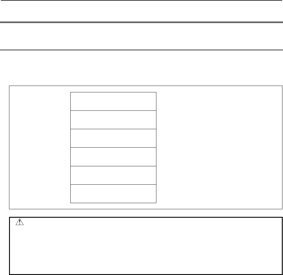
B-64513EN/03
5.WINDOW FUNCTIONS
- 749 -
5.6 TOOL LIFE MANAGEMENT FUNCTION
5.6.1 Reading The Tool Life Management Data
(Tool Group Number) (High-speed Response)
This function reads the tool group number in which the specified tool number is registered.
Input data structure
Top Address +0 (Function code)
38
+2 (Completion code)
-
(Need not to be set)
+4 (Data length L)
-
(Need not to be set)
+6 (Data number N)
0
Set 0 to this field.
+8 (Data attribute M)
Tool No.
+10
+137 (MAX)
(Data area)
-
(Need not to be set)
CAUTION
1 When the tool number is set to "0", the tool group number of the currently used
tool is read. If a tool group number is not specified after the power is turned ON,
tool group number "0" is read.
2 If the same tool belongs to two or more tool groups, 32 tool groups can be read
in the maximum. In this case, 128 bytes are required as the data area in the
maximum.
Completion codes
0 The tool group number is read successfully.
4 The tool number in 'Data Attribute' has a wrong value.
5 The tool number is not registered.
6 The tool life management option has not been added on.

5.WINDOW FUNCTIONS
B-64513EN/03
- 750 -
Output data structure
(1) When the specified tool is registered in only one group.
Top Address +0 (Function code)
38
+2 (Completion code)
?
(See above description)
+4 (Data length L)
4
+6 (Data number N)
0
(Same as input data)
+8 (Data attribute M)
Tool No.
(Same as input data)
+10
+13
Tool group No.
(4 bytes)
Unsigned binary
(2) When the specified tool is registered in multiple groups.
(ex. number of registered group is 3)
Top Address +0 (Function code)
38
+2 (Completion code)
?
(See above description)
+4 (Data length L)
12
(4bytes × n)
'n' is the number of tool groups to which the
specified tool belongs
+6 (Data number N)
0
(Same as input data)
+8 (Data attribute M)
Tool No.
(Same as input data)
+10 Tool group No.
(4 bytes)
Unsigned binary
+14 Tool group No.
(4 bytes)
Unsigned binary
+18
+21
Tool group No.
(4 bytes)
Unsigned binary
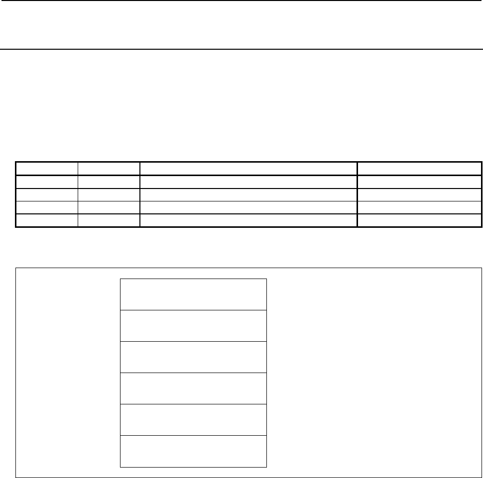
B-64513EN/03
5.WINDOW FUNCTIONS
- 751 -
5.6.2
Reading Tool Life Management Data
(Number of Tool Groups) (High-speed Response)
This function reads the number of tool groups in the tool life management data.
The maximum number of pairs of tool life management data in whole CNC system is 256 pairs (or 1024
pairs when extended).
The number of pairs assigned to the path is set to CNC parameter No.6813. The number of tool groups
that can be registered varies depending on the setting of parameter No.6800#0(GS1) and
No.6800#1(GS2) of the CNC, as indicated in the following table.
Parameter 6800
GS2 GS1 Number of tool groups Tools per group
0 0 1/8 of Max. pairs (No.6813) 32
0 1 1/4 of Max. pairs (No.6813) 16
1 0 1/2 of Max. pairs (No.6813) 8
1 1 Max. pairs (No.6813) 4
Input data structure
Top Address +0 (Function code)
39
+2 (Completion code)
-
(Need not to be set)
+4 (Data length L)
-
(Need not to be set)
+6 (Data number N)
0
Set 0 to this field.
+8 (Data attribute M)
0
Set 0 to this field.
+10
+41
(Data area)
-
(Need not to be set)
Completion codes
0 The number of tool group numbers has been read successfully.
6 No option for the tool life management.

5.WINDOW FUNCTIONS
B-64513EN/03
- 752 -
Output data structure
Top Address +0 (Function code)
39
+2 (Completion code)
?
(See above description)
+4 (Data length L)
4
+6 (Data number N)
0
(Same as input data)
+8 (Data attribute M)
0
(Same as input data)
+10
+13
Number of tool groups
(4 bytes)
Unsigned binary
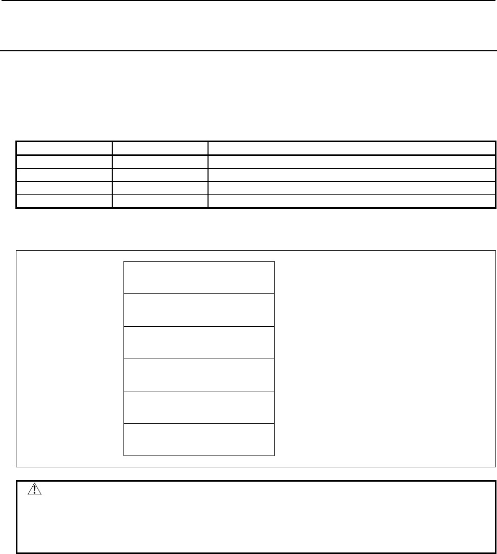
B-64513EN/03
5.WINDOW FUNCTIONS
- 753 -
5.6.3
Reading Tool Life Management Data
(Number of Tools) (High-speed Response)
This function reads the number of tools that belong to the tool group specified by tool group number,
from the tool life management data.
The number of tools that can be registered in each tool group varies depending on the setting of parameter
6800#0(GS1) and 6800#1(GS2) of the CNC, as indicated in the following table.
Parameter 6800
GS2 GS1 Number of tools in a tool group
0 0 1 to 32
0 1 1 to 16
1 0 1 to 8
1 1 1 to 4
Input data structure
Top Address +0 (Function code)
40
+2 (Completion code)
-
(Need not to be set)
+4 (Data length L)
-
(Need not to be set)
+6 (Data number N)
Tool group number
+8 (Data attribute M)
0
Set 0 to this field.
+10
+41
(Data area)
-
(Need not to be set)
CAUTION
Specifying "0" to the tool group number means the tool group that is currently
selected.
While no tool group is selected yet after power-on of CNC, "0" of the tool group
number results "0" of number of tools.

5.WINDOW FUNCTIONS
B-64513EN/03
- 754 -
Completion codes
0 The number of tools has been read successfully.
3 The specified tool group number is incorrect.
6 No option for the tool life management.
Output data structure
Top Address +0 (Function code)
40
+2 (Completion code)
?
(See above description)
+4 (Data length L)
4
+6 (Data number N)
Tool group number
(Same as input data)
+8 (Data attribute M)
0
(Same as input data)
+10
+13
Number of tools
(4 bytes)
Unsigned binary
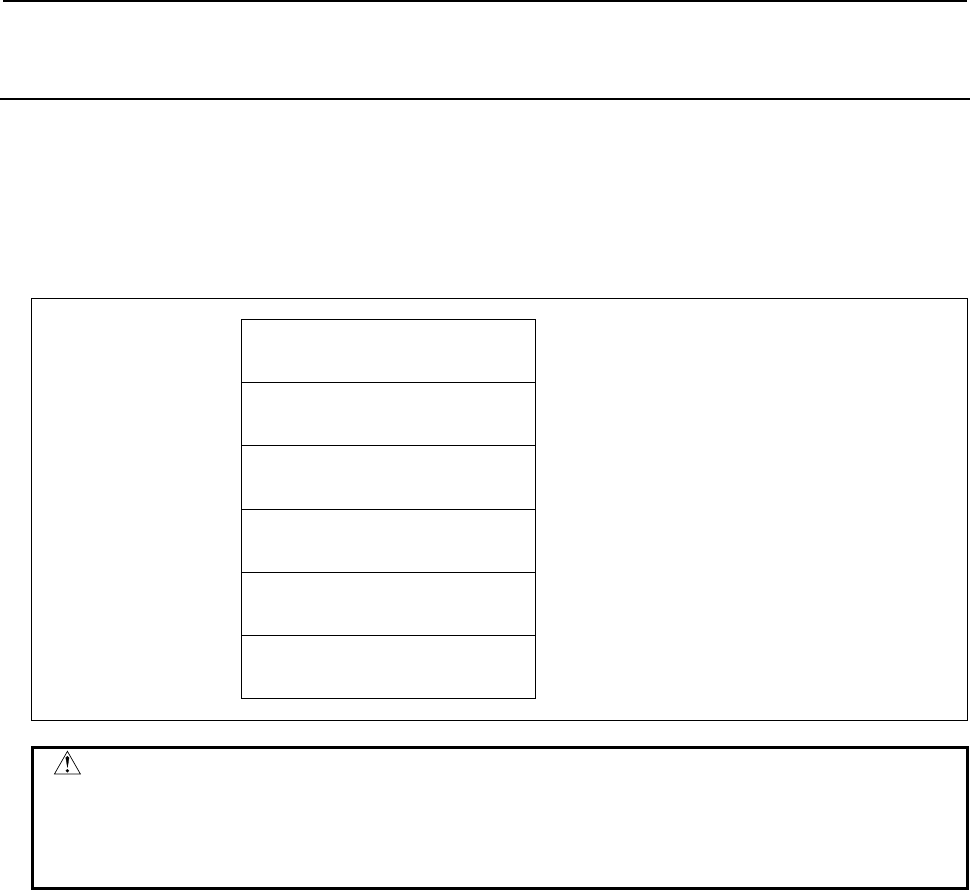
B-64513EN/03
5.WINDOW FUNCTIONS
- 755 -
5.6.4
Reading Tool Life Management Data (Tool Life)
(High-speed Response)
This function reads the tool life value of the tool group specified by tool group number, from the tool life
management data.
You can choose the method to manage tool lives by period of machining time or by the count of
machining cycles for each tool group.
Input data structure
Top Address +0 (Function code)
41
+2 (Completion code)
-
(Need not to be set)
+4 (Data length L)
-
(Need not to be set)
+6 (Data number N)
Tool group number
+8 (Data attribute M)
0
Set 0 to this field.
+10
+41
(Data area)
-
(Need not to be set)
CAUTION
Specifying "0" to the tool group number means the tool group that is currently
selected.
While no tool group is selected yet after power-on of CNC, "0" of the tool group
number results "0" of tool life value.
Completion codes
0 The tool life has been read successfully.
3 The specified tool group number is incorrect.
6 No option for the tool life management.

5.WINDOW FUNCTIONS
B-64513EN/03
- 756 -
Output data structure
Top Address +0 (Function code)
41
+2 (Completion code)
?
(See above description)
+4 (Data length L)
4
+6 (Data number N)
Tool group number
(Same as input data)
+8 (Data attribute M)
0
(Same as input data)
+10
+13
Tool life
(4 bytes)
Unsigned binary
Time or number or cycles
In case the tool group chooses machining time to manage the lives of the tools, CNC parameter
No.6805#0(FCO) determines the unit of the return value as below.
FCO Unit
0 1 minute
1 0.1 minute

B-64513EN/03
5.WINDOW FUNCTIONS
- 757 -
5.6.5
Reading Tool Life Management Data (Tool Life Counter)
(High-speed Response)
This function reads the tool life counter of the tool group specified by tool group number, from the tool
life management data.
Input data structure
Top Address +0 (Function code)
42
+2 (Completion code)
-
(Need not to be set)
+4 (Data length L)
-
(Need not to be set)
+6 (Data number N)
Tool group number
+8 (Data attribute M)
0
Set 0 to this field.
+10
+41
(Data area)
-
(Need not to be set)
CAUTION
Specifying "0" to the tool group number means the tool group that is currently
selected.
While no tool group is selected yet after power-on of CNC, "0" of the tool group
number results "0" of tool life counter.
Completion codes
0 The tool life has been read successfully.
3 The specified tool group number is incorrect.
6 No option for the tool life management.
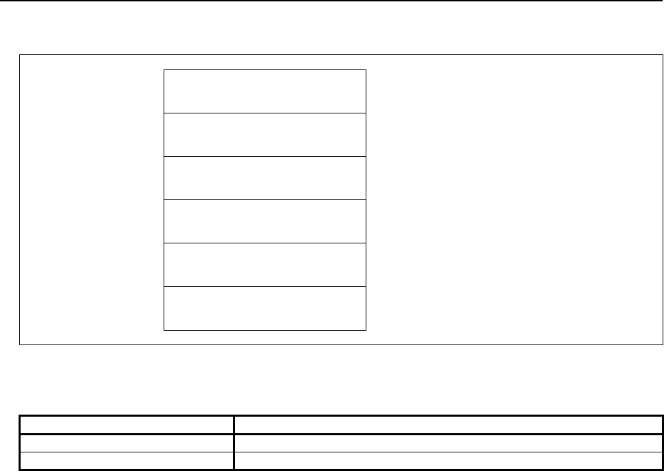
5.WINDOW FUNCTIONS
B-64513EN/03
- 758 -
Output data structure
Top Address +0 (Function code)
42
+2 (Completion code)
?
(See above description)
+4 (Data length L)
4
+6 (Data number N)
Tool group number
(Same as input data)
+8 (Data attribute M)
0
(Same as input data)
+10
+13
Tool life counter
(4 bytes)
Unsigned binary
Time or number or cycles
In case the tool group chooses machining time to manage the lives of the tools, CNC parameter
No.6805#0(FCO) determines the unit of the return value as below.
FCO Unit
0 1 minute
1 0.1 minute

B-64513EN/03
5.WINDOW FUNCTIONS
- 759 -
5.6.6
Reading Tool Life Management Data
(Tool Length Compensation Number (1): Tool Number)
(High-speed Response)
This function reads the tool length compensation number of the tool specified by tool group number and
tool number, from the tool life management data.
Input data structure
Top Address +0 (Function code)
43
+2 (Completion code)
-
(Need not to be set)
+4 (Data length L)
-
(Need not to be set)
+6 (Data number N)
Tool group number
+8 (Data attribute M)
Tool number
+10
+41
(Data area)
-
(Need not to be set)
CAUTION
Specifying "0" to the tool group number means the tool group that is currently
selected, and "0" to the tool number means the tool that is currently used in the
group.
While no tool group is selected yet after power-on of CNC, specifying the current
tool of the current group results "0" of tool length compensation number.
Completion codes
0 The tool length compensation number has been read successfully.
3 The specified tool group number is incorrect.
4 The specified tool number is incorrect.
5 The specified tool number is not found in the specified tool group.
6 No option for the tool life management.

5.WINDOW FUNCTIONS
B-64513EN/03
- 760 -
Output data structure
Top Address +0 (Function code)
43
+2 (Completion code)
?
(See above description)
+4 (Data length L)
4
+6 (Data number N)
Tool group number
(Same as input data)
+8 (Data attribute M)
Tool number
(Same as input data)
+10
+13
Tool length compensation number
(4 bytes)
Unsigned binary
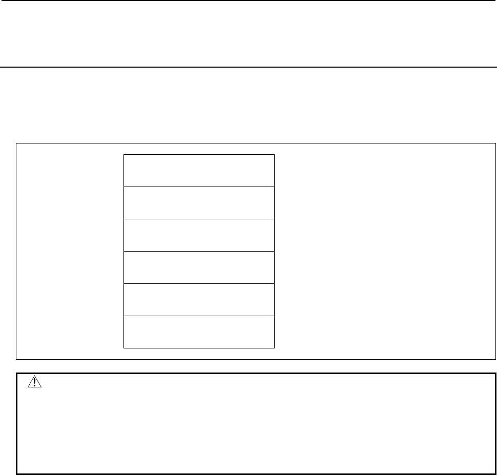
B-64513EN/03
5.WINDOW FUNCTIONS
- 761 -
5.6.7
Reading Tool Life Management Data (Tool Length
Compensation Number (2): Tool Order Number)
(High-speed Response)
This function reads the tool length compensation number of the tool specified by tool group number and
tool order number, from the tool life management data.
Input data structure
Top Address +0 (Function code)
44
+2 (Completion code)
-
(Need not to be set)
+4 (Data length L)
-
(Need not to be set)
+6 (Data number N)
Tool group number
+8 (Data attribute M)
Tool order number
+10
+41
(Data area)
-
(Need not to be set)
CAUTION
Specifying "0" to the tool group number means the tool group that is currently
selected. While no tool group is selected yet after power-on of CNC, specifying
the current group results "0" of tool length compensation number.
Specifying "0" to the tool order number means the tool that is currently used. If
the tool group has not ever been selected, tool order number "0" means the first
tool in the group instead.
Completion codes
0 The tool length compensation number has been read successfully.
3 The specified tool group number is incorrect.
4 The specified tool order number is incorrect.
5 The specified tool group has no tool in the specified tool order position.
6 No option for the tool life management.

5.WINDOW FUNCTIONS
B-64513EN/03
- 762 -
Output data structure
Top Address +0 (Function code)
44
+2 (Completion code)
?
(See above description)
+4 (Data length L)
4
+6 (Data number N)
Tool group number
(Same as input data)
+8 (Data attribute M)
Tool order number
(Same as input data)
+10
+13
Tool length compensation number
(4 bytes)
Unsigned binary

B-64513EN/03
5.WINDOW FUNCTIONS
- 763 -
5.6.8
Reading Tool Life Management Data (Cutter Radius
Compensation Number (1): Tool Number)
(High-speed Response)
This function reads the cutter radius compensation number of the tool specified by tool group number and
tool number, from the tool life management data.
Input data structure
Top Address +0 (Function code)
45
+2 (Completion code)
-
(Need not to be set)
+4 (Data length L)
-
(Need not to be set)
+6 (Data number N)
Tool group number
+8 (Data attribute M)
Tool number
+10
+41
(Data area)
-
(Need not to be set)
CAUTION
Specifying "0" to the tool group number means the tool group that is currently
selected, and "0" to the tool number means the tool that is currently used in the
group.
While no tool group is selected yet after power-on of CNC, specifying the current
tool of the current group results "0" of cutter radius compensation number.
Completion codes
0 The cutter radius compensation number has been read successfully.
3 The specified tool group number is incorrect.
4 The specified tool number is incorrect.
5 The specified tool number was not found in the specified tool group.
6 No option for the tool life management.

5.WINDOW FUNCTIONS
B-64513EN/03
- 764 -
Output data structure
Top Address +0 (Function code)
45
+2 (Completion code)
?
(See above description)
+4 (Data length L)
4
+6 (Data number N)
Tool group number
(Same as input data)
+8 (Data attribute M)
Tool number
(Same as input data)
+10
+13
Cutter compensation number
(4 bytes)
Unsigned binary

B-64513EN/03
5.WINDOW FUNCTIONS
- 765 -
5.6.9
Reading Tool Life Management Data (Cutter Radius
Compensation Number (2): Tool Order Number)
(High-speed Response)
This function reads the cutter radius compensation number of the tool specified by tool group number and
tool order number, from the tool life management data.
Input data structure
Top Address +0 (Function code)
46
+2 (Completion code)
-
(Need not to be set)
+4 (Data length L)
-
(Need not to be set)
+6 (Data number N)
Tool group number
+8 (Data attribute M)
Tool order number
+10
+41
(Data area)
-
(Need not to be set)
CAUTION
If 0 is specified for the tool group number, the tool group currently used is
referred. In this case, if any tool group has not been used since the power to the
CNC was turned on, 0 is read.
When 0 is specified for the tool order number, the data of the current tool in the
tool group is read if the group has already been used, or the data of the first tool
in the group is read if the group has not ever used.
Completion codes
0 The cutter radius compensation number has been read successfully.
3 The specified tool group number is incorrect.
4 The specified tool order number is incorrect.
5 The specified tool group has no tool in the specified tool order position.
6 No option for the tool life management.

5.WINDOW FUNCTIONS
B-64513EN/03
- 766 -
Output data structure
Top Address +0 (Function code)
46
+2 (Completion code)
?
(See above description)
+4 (Data length L)
4
+6 (Data number N)
Tool group number
(Same as input data)
+8 (Data attribute M)
Tool order number
(Same as input data)
+10
+13
Cutter compensation number
(4 bytes)
Unsigned binary
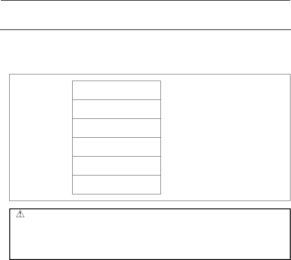
B-64513EN/03
5.WINDOW FUNCTIONS
- 767 -
5.6.10
Reading Tool Life Management Data
(Tool Information (1): Tool Number) (High-speed Response)
This function reads the status information of the tool specified by tool group number and tool number,
from the tool life management data.
Input data structure
Top Address +0 (Function code)
47
+2 (Completion code)
-
(Need not to be set)
+4 (Data length L)
-
(Need not to be set)
+6 (Data number N)
Tool group number
+8 (Data attribute M)
Tool number
+10
+41
(Data area)
-
(Need not to be set)
CAUTION
Specifying "0" to the tool group number means the tool group that is currently
selected, and "0" to the tool number means the tool that is currently used in the
group.
While no tool group is selected yet after power-on of CNC, specifying the current
tool of the current group results "0" of tool status information.
Completion codes
0 The tool status information has been read successfully.
3 The specified tool group number is incorrect.
4 The specified tool number is incorrect.
5 The specified tool number was not found in the specified tool group.
6 No option for the tool life management.

5.WINDOW FUNCTIONS
B-64513EN/03
- 768 -
Output data structure
Top Address +0 (Function code)
47
+2 (Completion code)
?
(See above description)
+4 (Data length L)
4
+6 (Data number N)
Tool group number
(Same as input data)
+8 (Data attribute M)
Tool number
(Same as input data)
+10
+13
Tool status information
(4 bytes)
0: See "CAUTION" on the previous page.
1: The tool is registered.
2: The tool has reached the end of its life.
3: The tool was skipped.
The three high-order bytes are fixed to 0.

B-64513EN/03
5.WINDOW FUNCTIONS
- 769 -
5.6.11
Reading Tool Life Management Data
(Tool Information (2): Tool Order Number)
(High-speed Response)
This function reads the status information of the tool specified by tool group number and tool order
number, from the tool life management data.
Input data structure
Top Address +0 (Function code)
48
+2 (Completion code)
-
(Need not to be set)
+4 (Data length L)
-
(Need not to be set)
+6 (Data number N)
Tool group number
+8 (Data attribute M)
Tool order number
+10
+41
(Data area)
-
(Need not to be set)
CAUTION
Specifying "0" to the tool group number means the tool group that is currently
selected. While no tool group is selected yet after power-on of CNC, specifying
the current group results "0" of tool status information.
Specifying "0" to the tool order number means the tool that is currently used. If
the tool group has not ever been selected, tool order number "0" means the first
tool in the group instead.
Completion codes
0 The tool status information has been read successfully.
3 The specified tool group number is incorrect.
4 The specified tool order number is incorrect.
5 The specified tool group has no tool in the specified tool order position.
6 No option for the tool life management.

5.WINDOW FUNCTIONS
B-64513EN/03
- 770 -
Output data structure
Top Address +0 (Function code)
48
+2 (Completion code)
?
(See above description)
+4 (Data length L)
4
+6 (Data number N)
Tool group number
(Same as input data)
+8 (Data attribute M)
Tool order number
(Same as input data)
+10
+13
Tool status information
(4 bytes)
0: See "CAUTION" on the previous page.
1: The tool is registered.
2: The tool has reached the end of its life.
3: The tool was skipped.
The three high-order bytes are fixed to 0.
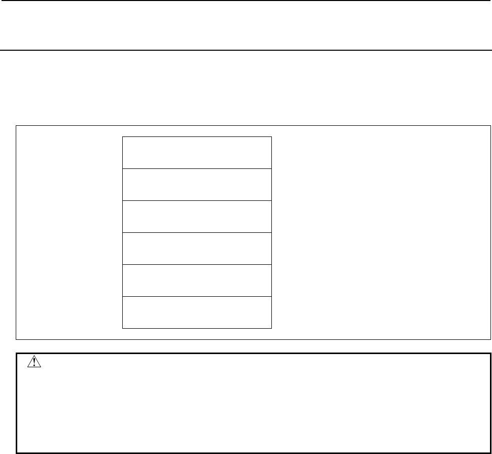
B-64513EN/03
5.WINDOW FUNCTIONS
- 771 -
5.6.12
Reading Tool Life Management Data (Tool Number)
(High-speed Response)
This function reads the tool number of the tool specified by tool group number and tool order number,
from the tool life management data.
Input data structure
Top Address +0 (Function code)
49
+2 (Completion code)
-
(Need not to be set)
+4 (Data length L)
-
(Need not to be set)
+6 (Data number N)
Tool group number
+8 (Data attribute M)
Tool order number
+10
+41
(Data area)
-
(Need not to be set)
CAUTION
Specifying "0" to the tool group number means the tool group that is currently
selected. While no tool group is selected yet after power-on of CNC, specifying
the current group results "0" of tool number.
Specifying "0" to the tool order number means the tool that is currently used. If
the tool group has not ever been selected, tool order number "0" means the first
tool in the group instead.
Completion codes
0 The tool number has been read successfully.
3 The specified tool group number is incorrect.
4 The specified tool order number is incorrect.
5 The specified tool group has no tool in the specified tool order position.
6 No option for the tool life management.

5.WINDOW FUNCTIONS
B-64513EN/03
- 772 -
Output data structure
Top Address +0 (Function code)
49
+2 (Completion code)
?
(See above description)
+4 (Data length L)
4
+6 (Data number N)
Tool group number
(Same as input data)
+8 (Data attribute M)
Tool order number
(Same as input data)
+10
+13
Tool number
(4 bytes)
Unsigned binary

B-64513EN/03
5.WINDOW FUNCTIONS
- 773 -
5.6.13
Reading the Tool Life Management Data
(Tool Life Counter Type) (High-speed Response)
This function reads the tool life counter type of the tool group specified by tool group number, from the
tool life management data.
Input data structure
Top Address +0 (Function code)
160
+2 (Completion code)
-
(Need not to be set)
+4 (Data length L)
-
(Need not to be set)
+6 (Data number N)
Tool group number
+8 (Data attribute M)
0
Set 0 to this field.
+10
+11
(Data area)
-
(Need not to be set)
CAUTION
Specifying "0" to the tool group number means the tool group that is currently
selected.
While no tool group is selected yet after power-on of CNC, "0" of the tool group
number results "0" of tool life counter type.
Completion codes
0 The tool life counter type has been read successfully.
3 The specified tool group number is incorrect.
6 No option for Tool life management.

5.WINDOW FUNCTIONS
B-64513EN/03
- 774 -
Output data structure
Top Address +0 (Function code)
160
+2 (Completion code)
?
(See above description)
+4 (Data length L)
2
+6 (Data number N)
Tool group number
(Same as input data)
+8 (Data attribute M)
0
(Same as input data)
+10
+11
Tool life counter type
(2 bytes)
0: No counter type
1: Frequency
2: Real time

B-64513EN/03
5.WINDOW FUNCTIONS
- 775 -
5.6.14
Registering Tool Life Management Data (Tool Group)
(Low-speed Response)
This function registers a tool group in the tool life management data, with tool number, length of life and
tool life counter type.
WARNING
When you write some NC data using both this instruction in ladder program and
other applications, take care that you do not write to the same data area.
If some values are written to the same data area by two or more applications
including ladder program, unexpected value may be written. In this case, it may
cause an unexpected machine behavior and also tools, work pieces, and
machines may be damaged. As for details, refer to “SAFETY PRECAUTIONS”.
Input data structure
Top Address +0 (Function code)
163
+2 (Completion code)
-
(Need not to be set)
+4 (Data length L)
8
+6 (Data number N)
0
Set 0 to this field.
+8 (Data attribute M)
Tool number
+10 Tool group number
(2 bytes)
Unsigned binary
1-1024
+12 Tool life counter type
(2 bytes)
1: Number of uses
2: Real time in minutes
+14
+17
Tool life
(4 bytes)
Unsigned binary
1-65535 times (Number of uses)
1-4300 minutes (Read time) Note
With the tool life management B function
1-99999999 times (Number of uses)
1-100000/60000 minutes (Real time) Note
NOTE
CNC parameter FCO(6805#0) decides the unit of tool life value of real time
counter type as follows:
6805#0 = 0 : 1 minute (1–4300)
6805#0 = 1 : 0.1 minute (1–43000)
With the tool life management B function, this parameter also decides the
effective region of life value as follows:
6805#0 = 0 : 100000 minutes (1–100000)
6805#0 = 1 : 60000 minutes (1–600000)

5.WINDOW FUNCTIONS
B-64513EN/03
- 776 -
Completion codes
0 Succeeded to register the tool group.
3 The specified tool group number is incorrect.
4 The tool number in 'Data attribute' has wrong value.
5 The length of tool life in 'Data area' is out of range.
6 No option for the tool life management.
Output data structure
Top Address +0 (Function code)
163
+2 (Completion code)
?
(See above description)
+4 (Data length L)
8
(Same as input data)
+6 (Data number N)
0
(Same as input data)
+8 (Data attribute M)
Tool number
(Same as input data)
+10 Tool group number
(2 bytes)
(Same as input data)
+12 Tool life counter type
(2 bytes)
(Same as input data)
+14
+17
Length of Tool life
(4 bytes)
(Same as input data)

B-64513EN/03
5.WINDOW FUNCTIONS
- 777 -
5.6.15
Writing Tool Life Management Data (Tool Life)
(Low-speed Response)
This function sets the length of tool life of the specified tool group in the tool life management data.
WARNING
When you write some NC data using both this instruction in ladder program and
other applications, take care that you do not write to the same data area.
If some values are written to the same data area by two or more applications
including ladder program, unexpected value may be written. In this case, it may
cause an unexpected machine behavior and also tools, work pieces, and
machines may be damaged. As for details, refer to “SAFETY PRECAUTIONS”.
Input data structure
Top Address +0 (Function code)
164
+2 (Completion code)
-
(Need not to be set)
+4 (Data length L)
4
+6 (Data number N)
Tool group number
+8 (Data attribute M)
0
Set 0 to this field.
+10
+13
Tool life
(4 bytes)
Unsigned binary
1-65535 times (Number of uses)
1-4300 minutes (Read time) Note
With the tool life management B function
1-99999999 times (Number of uses)
1-100000/60000 minutes (Real time) Note
NOTE
CNC parameter FCO(6805#0) decides the unit of tool life value of real time
counter type as follows:
6805#0 = 0 : 1 minute (1–4300)
6805#0 = 1 : 0.1 minute (1–43000)
With the tool life management B function, this parameter also decides the
effective region of life value as follows:
6805#0 = 0 : 100000 minutes (1–100000)
6805#0 = 1 : 60000 minutes (1–600000)
Completion codes
0 Succeeded to set the length of tool life.
3 The specified tool group number is incorrect.
5 The length of tool life is out of range.
6 No option for the tool life management.
13 The data of the currently selected tool group or the next tool group cannot be rewritten. An attempt
was made to rewrite the data of the currently selected tool group or the next group.

5.WINDOW FUNCTIONS
B-64513EN/03
- 778 -
Output data structure
Top Address +0 (Function code)
164
+2 (Completion code)
?
(See above description)
+4 (Data length L)
4
(Same as input data)
+6 (Data number N)
Tool group number
(Same as input data)
+8 (Data attribute M)
0
(Same as input data)
+10
+13
Length of Tool life
(4 bytes)
(Same as input data)

B-64513EN/03
5.WINDOW FUNCTIONS
- 779 -
5.6.16
Writing Tool Life Management Data (Tool Life Counter)
(Low-speed Response)
This function sets the tool life counter in the specified tool group in the tool life management data.
WARNING
When you write some NC data using both this instruction in ladder program and
other applications, take care that you do not write to the same data area.
If some values are written to the same data area by two or more applications
including ladder program, unexpected value may be written. In this case, it may
cause an unexpected machine behavior and also tools, work pieces, and
machines may be damaged. As for details, refer to “SAFETY PRECAUTIONS”.
Input data structure
Top Address +0 (Function code)
165
+2 (Completion code)
-
(Need not to be set)
+4 (Data length L)
4
+6 (Data number N)
Tool group number
+8 (Data attribute M)
0
Set 0 to this field.
+10
+13
Tool life counter
(4 bytes)
Unsigned binary
1-65535 times (Number of uses)
1-4300 minutes (Read time) Note
With the tool life management B function
1-99999999 times (Number of uses)
1-100000/60000 minutes (Real time) Note
NOTE
CNC parameter FCO(6805#0) decides the unit of tool life value of real time
counter type as follows:
6805#0 = 0 : 1 minute (1–4300)
6805#0 = 1 : 0.1 minute (1–43000)
With the tool life management B function, this parameter also decides the
effective region of life value as follows:
6805#0 = 0 : 100000 minutes (1–100000)
6805#0 = 1 : 60000 minutes (1–600000)
Completion codes
0 Succeeded to set the tool life counter.
3 The specified tool group number is incorrect.
5 The value for tool life counter is out of range.
6 No option for the tool life management.

5.WINDOW FUNCTIONS
B-64513EN/03
- 780 -
Output data structure
Top Address +0 (Function code)
165
+2 (Completion code)
?
(See above description)
+4 (Data length L)
4
(Same as input data)
+6 (Data number N)
Tool group number
(Same as input data)
+8 (Data attribute M)
0
(Same as input data)
+10
+13
Length of Tool life
(4 bytes)
(Same as input data)

B-64513EN/03
5.WINDOW FUNCTIONS
- 781 -
5.6.17
Writing Tool Life Management Data (Tool Life Counter Type)
(Low-speed Response)
This function sets the tool life counter type of specified tool group in the tool life management data.
WARNING
When you write some NC data using both this instruction in ladder program and
other applications, take care that you do not write to the same data area.
If some values are written to the same data area by two or more applications
including ladder program, unexpected value may be written. In this case, it may
cause an unexpected machine behavior and also tools, work pieces, and
machines may be damaged. As for details, refer to “SAFETY PRECAUTIONS”.
Input data structure
Top Address +0 (Function code)
166
+2 (Completion code)
-
(Need not to be set)
+4 (Data length L)
2
+6 (Data number N)
Tool group number
+8 (Data attribute M)
0
Set 0 to this field.
+10
+11
Tool life counter type
(2 bytes)
1: Number of uses
2: Real time in minutes
Completion codes
0 Succeeded to set the tool life counter type.
3 The specified tool group number is incorrect.
5 The value for tool life counter type is wrong.
6 No option for the tool life management.

5.WINDOW FUNCTIONS
B-64513EN/03
- 782 -
Output data structure
Top Address +0 (Function code)
166
+2 (Completion code)
?
(See above description)
+4 (Data length L)
2
(Same as input data)
+6 (Data number N)
Tool group number
(Same as input data)
+8 (Data attribute M)
0
(Same as input data)
+10
+11
Tool life counter type
(2 bytes)
(Same as input data)

B-64513EN/03
5.WINDOW FUNCTIONS
- 783 -
5.6.18
Writing Tool Life Management Data (Tool Length
Compensation Number (1): Tool Number)
(Low-speed Response)
This function sets the tool length compensation number of the specified tool group in the tool life
management data.
WARNING
When you write some NC data using both this instruction in ladder program and
other applications, take care that you do not write to the same data area.
If some values are written to the same data area by two or more applications
including ladder program, unexpected value may be written. In this case, it may
cause an unexpected machine behavior and also tools, work pieces, and
machines may be damaged. As for details, refer to “SAFETY PRECAUTIONS”.
Input data structure
Top Address +0 (Function code)
167
+2 (Completion code)
-
(Need not to be set)
+4 (Data length L)
4
+6 (Data number N)
Tool group number
+8 (Data attribute M)
Tool number
+10
+13
Tool length compensation number
(4 bytes)
Unsigned binary
1-255
Completion codes
0 Succeeded to set the tool length compensation number.
3 The specified tool group number is incorrect.
4 The tool number in 'Data attribute' has wrong value.
5 The tool number is not found in the tool group.
6 No option for the tool life management.

5.WINDOW FUNCTIONS
B-64513EN/03
- 784 -
Output data structure
Top Address +0 (Function code)
167
+2 (Completion code)
?
(See above description)
+4 (Data length L)
4
(Same as input data)
+6 (Data number N)
Tool group number
(Same as input data)
+8 (Data attribute M)
Tool number
(Same as input data)
+10
+13
Tool length compensation number
(4 bytes)
(Same as input data)
CAUTION
The effective value for tool length compensation number depends on tool
compensation number available on CNC.

B-64513EN/03
5.WINDOW FUNCTIONS
- 785 -
5.6.19
Writing Tool Life Management Data (Tool Length
Compensation Number (2): Tool Order Number)
(Low-speed Response)
This function sets the tool length compensation number of the tool of the specified tool order number in
the tool life management data.
WARNING
When you write some NC data using both this instruction in ladder program and
other applications, take care that you do not write to the same data area.
If some values are written to the same data area by two or more applications
including ladder program, unexpected value may be written. In this case, it may
cause an unexpected machine behavior and also tools, work pieces, and
machines may be damaged. As for details, refer to “SAFETY PRECAUTIONS”.
Input data structure
Top Address +0 (Function code)
168
+2 (Completion code)
-
(Need not to be set)
+4 (Data length L)
4
+6 (Data number N)
Tool group number
+8 (Data attribute M)
Tool order number
+10
+13
Tool length compensation number
(4 bytes)
Unsigned binary
1-255
Completion codes
0 Succeeded to set the tool length compensation number.
3 The specified tool group number is incorrect.
4 The tool order number is wrong.
6 No option for the tool life management.

5.WINDOW FUNCTIONS
B-64513EN/03
- 786 -
Output data structure
Top Address +0 (Function code)
168
+2 (Completion code)
?
(See above description)
+4 (Data length L)
4
(Same as input data)
+6 (Data number N)
Tool group number
(Same as input data)
+8 (Data attribute M)
Tool order number
(Same as input data)
+10
+13
Tool length compensation number
(4 bytes)
(Same as input data)
CAUTION
The effective value for tool length compensation number depends on tool
compensation number available on CNC.

B-64513EN/03
5.WINDOW FUNCTIONS
- 787 -
5.6.20
Writing Tool Life Management Data (Cutter Radius
Compensation Number (1): Tool Number)
(Low-speed Response)
This function sets the cutter radius compensation number of the specified tool group in the tool life
management data.
WARNING
When you write some NC data using both this instruction in ladder program and
other applications, take care that you do not write to the same data area.
If some values are written to the same data area by two or more applications
including ladder program, unexpected value may be written. In this case, it may
cause an unexpected machine behavior and also tools, work pieces, and
machines may be damaged. As for details, refer to “SAFETY PRECAUTIONS”.
Input data structure
Top Address +0 (Function code)
169
+2 (Completion code)
-
(Need not to be set)
+4 (Data length L)
4
+6 (Data number N)
Tool group number
+8 (Data attribute M)
Tool number
+10
+13
Cutter radius compensation
number
(4 bytes)
Unsigned binary
1-255
Completion codes
0 Succeeded to set the cutter radius compensation number.
3 The specified tool group number is incorrect.
4 The tool number in 'Data attribute' has wrong value.
5 The tool number is not found in the tool group.
6 No option for the tool life management.
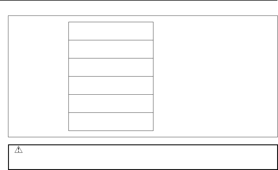
5.WINDOW FUNCTIONS
B-64513EN/03
- 788 -
Output data structure
Top Address +0 (Function code)
169
+2 (Completion code)
?
(See above description)
+4 (Data length L)
4
(Same as input data)
+6 (Data number N)
Tool group number
(Same as input data)
+8 (Data attribute M)
Tool number
(Same as input data)
+10
+13
Cutter radius compensation
number (4 bytes)
(Same as input data)
CAUTION
The effective value for Cutter radius compensation number depends on tool
compensation number available on CNC.

B-64513EN/03
5.WINDOW FUNCTIONS
- 789 -
5.6.21
Writing Tool Life Management Data (Cutter Radius
Compensation Number (2): Tool Order Number)
(Low-speed Response)
This function sets the cutter radius compensation number of the tool of the specified tool order number in
the tool life management data.
WARNING
When you write some NC data using both this instruction in ladder program and
other applications, take care that you do not write to the same data area.
If some values are written to the same data area by two or more applications
including ladder program, unexpected value may be written. In this case, it may
cause an unexpected machine behavior and also tools, work pieces, and
machines may be damaged. As for details, refer to “SAFETY PRECAUTIONS”.
Input data structure
Top Address +0 (Function code)
170
+2 (Completion code)
-
(Need not to be set)
+4 (Data length L)
4
+6 (Data number N)
Tool group number
+8 (Data attribute M)
Tool order number
+10
+13
Cutter radius compensation
number
(4 bytes)
Unsigned binary
1-255
Completion codes
0 Succeeded to set the cutter radius compensation number.
3 The specified tool group number is incorrect.
4 The tool order number is wrong.
6 No option for the tool life management.
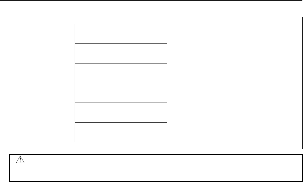
5.WINDOW FUNCTIONS
B-64513EN/03
- 790 -
Output data structure
Top Address +0 (Function code)
170
+2 (Completion code)
?
(See above description)
+4 (Data length L)
4
(Same as input data)
+6 (Data number N)
Tool group number
(Same as input data)
+8 (Data attribute M)
Tool order number
(Same as input data)
+10
+13
Cutter radius compensation
number (4 bytes)
(Same as input data)
CAUTION
The effective value for cutter radius compensation number depends on tool
compensation number available on CNC.

B-64513EN/03
5.WINDOW FUNCTIONS
- 791 -
5.6.22
Writing the Tool Life Management Data
(Tool Information (1): Tool Number) (Low-speed Response)
This function sets the Tool condition of the specified Tool group in the Tool life management data.
WARNING
When you write some NC data using both this instruction in ladder program and
other applications, take care that you do not write to the same data area.
If some values are written to the same data area by two or more applications
including ladder program, unexpected value may be written. In this case, it may
cause an unexpected machine behavior and also tools, work pieces, and
machines may be damaged. As for details, refer to “SAFETY PRECAUTIONS”.
Input data structure
Top Address +0 (Function code)
171
+2 (Completion code)
-
(Need not to be set)
+4 (Data length L)
2
+6 (Data number N)
Tool group number
+8 (Data attribute M)
Tool number
+10
+11
Tool information
(2 bytes)
1: Tool state clear
2: Tool state skip
Completion codes
0 The tool information is written successfully.
3 The tool group number exceeds maximum number of registered groups.
4 The specified tool number is incorrect.
5 The specified tool number is not registered to the specified tool group.
6 The tool life management option has not been added on.
5.WINDOW FUNCTIONS
B-64513EN/03
- 792 -
Output data structure
Top Address +0 (Function code)
171
+2 (Completion code)
?
(See above description)
+4 (Data length L)
2
(Same as input data)
+6 (Data number N)
Tool group number
(Same as input data)
+8 (Data attribute M)
Tool number
(Same as input data)
+10
+11
Tool information
(2 bytes)
(Same as input data)
This function changes tool condition as shown below.
Command Before call After call
clear
Skip ( # )
Skip ( )
Expired ( * )
Unused ( )
In use (@)
Unused ( )
skip
Unused ( )
In use (@)
Expired ( * )
Skip ( # )
Skip ( )
Skip ( # )
#
#

B-64513EN/03
5.WINDOW FUNCTIONS
- 793 -
5.6.23
Writing the Tool Management Data
(Tool Information (2): Tool Order Number)
(Low-speed Response)
This function changes the status of the tool specified by tool group number and tool order number, in the
tool life management data.
WARNING
When you write some NC data using both this instruction in ladder program and
other applications, take care that you do not write to the same data area.
If some values are written to the same data area by two or more applications
including ladder program, unexpected value may be written. In this case, it may
cause an unexpected machine behavior and also tools, work pieces, and
machines may be damaged. As for details, refer to “SAFETY PRECAUTIONS”.
Input data structure
Top Address +0 (Function code)
172
+2 (Completion code)
-
(Need not to be set)
+4 (Data length L)
2
+6 (Data number N)
Tool group number
+8 (Data attribute M)
Tool order number
+10
+11
Tool information
(2 bytes)
1: Tool state clear
2: Tool state skip
Completion codes
0 The tool information has been set successfully.
3 The specified tool group number is incorrect.
4 The tool order number is incorrect.
6 No option for Tool life management.
5.WINDOW FUNCTIONS
B-64513EN/03
- 794 -
Output data structure
Top Address +0 (Function code)
172
+2 (Completion code)
?
(See above description)
+4 (Data length L)
2
(Same as input data)
+6 (Data number N)
Tool group number
(Same as input data)
+8 (Data attribute M)
Tool order number
(Same as input data)
+10
+11
Tool information
(2 bytes)
(Same as input data)
This function changes tool condition as shown below.
Command Before call After call
clear
Skip ( # )
Skip ( )
Expired ( * )
Unused ( )
In use (@)
Unused ( )
skip
Unused ( )
In use (@)
Expired ( * )
Skip ( # )
Skip ( )
Skip ( # )
#
#

B-64513EN/03
5.WINDOW FUNCTIONS
- 795 -
5.6.24
Writing Tool Life Management Data (Tool Number)
(Low-speed Response)
This function registers a tool to the specified tool group in the tool life management data.
WARNING
When you write some NC data using both this instruction in ladder program and
other applications, take care that you do not write to the same data area.
If some values are written to the same data area by two or more applications
including ladder program, unexpected value may be written. In this case, it may
cause an unexpected machine behavior and also tools, work pieces, and
machines may be damaged. As for details, refer to “SAFETY PRECAUTIONS”.
Input data structure
Top Address +0 (Function code)
173
+2 (Completion code)
-
(Need not to be set)
+4 (Data length L)
4
+6 (Data number N)
Tool group number
+8 (Data attribute M)
Tool order number
+10
+13
Tool number
(4 bytes)
Unsigned binary
1-99999999
Completion codes
0 Succeeded to register the tool number.
3 The specified tool group number is incorrect.
4 The tool order number is wrong.
6 No option for the tool life management.

5.WINDOW FUNCTIONS
B-64513EN/03
- 796 -
Output data structure
Top Address +0 (Function code)
173
+2 (Completion code)
?
(See above description)
+4 (Data length L)
4
(Same as input data)
+6 (Data number N)
Tool group number
(Same as input data)
+8 (Data attribute M)
Tool order number
(Same as input data)
+10
+13
Tool number
(4 bytes)
(Same as input data)

B-64513EN/03
5.WINDOW FUNCTIONS
- 797 -
5.6.25
Reading The Tool Life Management Data
(Tool Group Number) (High-speed Response)
(8-digits Tool Number)
This function reads the tool group number in which the specified tool number is registered. This function
supports 8 digits tool number.
Input data structure
Top Address +0 (Function code)
200
+2 (Completion code)
-
(Need not to be set)
+4 (Data length L)
-
(Need not to be set)
+6 (Data number N)
0
Set 0 to this field.
+8 (Data attribute M)
Tool number
+12
+139 (MAX)
(Data area)
-
(Need not to be set)
NOTE
1 When the tool number is set to "0", the tool group number of the currently used
tool is read. If a tool group number is not specified after the power is turned ON,
tool group number "0" is read.
2 If the same tool belongs to two or more tool groups, 32 tool groups can be read
in the maximum. In this case, 128 bytes are required as the data area in the
maximum.
Completion codes
0 The tool group number is read successfully.
4 The tool number in 'Data Attribute' has a wrong value.
5 The tool number is not registered.
6 The tool life management option has not been added on.

5.WINDOW FUNCTIONS
B-64513EN/03
- 798 -
Output data structure
(1) When the specified tool is registered in only one group.
Top Address +0 (Function code)
200
+2 (Completion code)
?
(See above description)
+4 (Data length L)
4
+6 (Data number N)
0
(Same as input data)
+8 (Data attribute M)
Tool number
(Same as input data)
+12
+15
Tool group number
(4 bytes)
Unsigned binary
(2) When the specified tool is registered in multiple groups.
(Ex. The number of registered group is 3.)
Top Address +0 (Function code)
200
+2 (Completion code)
?
(See above description)
+4 (Data length L)
12
(4bytes× n)
'n' is the number of tool groups to which the
specified tool belongs
+6 (Data number N)
0
(Same as input data)
+8 (Data attribute M)
Tool number
(Same as input data)
+12 Tool group number
(4 bytes)
Unsigned binary
+16 Tool group number
(4 bytes)
Unsigned binary
+20
+23
Tool group number
(4 bytes)
Unsigned binary

B-64513EN/03
5.WINDOW FUNCTIONS
- 799 -
5.6.26
Reading Tool Life Management Data
(Tool Information (1): Tool Number) (High-speed Response)
(8-digits Tool Number)
This function reads the status information of the tool specified by tool group number and tool number,
from the tool life management data.
Input data structure
Top Address +0 (Function code)
201
+2 (Completion code)
-
(Need not to be set)
+4 (Data length L)
-
(Need not to be set)
+6 (Data number N)
Tool group number
+8 (Data attribute M)
Tool number
+12
+15
(Data area)
-
(Need not to be set)
CAUTION
Specifying "0" to the tool group number means the tool group that is currently
selected, and "0" to the tool number means the tool that is currently used in the
group.
While no tool group is selected yet after power-on of CNC, specifying the current
tool of the current group results "0" of tool status information.
Completion codes
0 The tool information was read successfully.
3 The specified tool group number is incorrect.
4 The specified tool number is incorrect.
5 The specified tool number is not registered to the specified tool group.
6 No option for the tool life management.

5.WINDOW FUNCTIONS
B-64513EN/03
- 800 -
Output data structure
Top Address +0 (Function code)
201
+2 (Completion code)
?
(See above description)
+4 (Data length L)
4
+6 (Data number N)
Tool group number
(Same as input data)
+8 (Data attribute M)
Tool number
(Same as input data)
+12
+15
Tool status information
(4 bytes)
0: See "CAUTION" on the previous page.
1: The tool is registered.
2: The tool has reached the end of its life.
3: The tool was skipped
The three high-order bytes are fixed to 0.

B-64513EN/03
5.WINDOW FUNCTIONS
- 801 -
5.6.27
Registering Tool Life Management Data
(Tool Group Number) (Low-speed Response)
(8-digits Tool Number)
This function registers the tool group number to tool life management data. Set the tool number, life
value and life counter type to the specified tool group.
WARNING
When you write some data using both this instruction in ladder program and
other applications, take care of duplication writing into the same data area. If
some values are written in the same data area by several applications,
unexpected value may be set and the machine may behave in an unexpected
working and tool, work piece, and the machine may also be damaged.
As for details, refer to “SAFETY PRECAUTIONS”.
Input data structure
Top Address +0 (Function code)
202
+2 (Completion code)
-
(Need not to be set)
+4 (Data length L)
8
+6 (Data number N)
0
Set 0 to this field.
+8 (Data attribute M)
Tool number
+12 Tool group number
(2 bytes)
Unsigned binary
1-1024
+14 Tool life counter type
(2 bytes)
1: Number of uses
2: Real time in minutes
+16
+19
Tool life
(4 bytes)
Unsigned binary
1-65535 times (Number or uses)
1-4300 minutes (Real time) Note
With the tool life management B function
1-99999999 times (Number or uses)
1-100000/60000 minutes (Real time) Note
NOTE
CNC parameter FCO(6805#0) decides the unit of tool life value of real time
counter type as follows:
6805#0 = 0 : 1 minute (1–4300)
6805#0 = 1 : 0.1 minute (1–43000)
With the tool life management B function, this parameter also decides the
effective region of life value as follows:
6805#0 = 0 : 100000 minutes (1–100000)
6805#0 = 1 : 60000 minutes (1–600000)

5.WINDOW FUNCTIONS
B-64513EN/03
- 802 -
Completion codes
0 The tool length was registered successfully.
3 The specified tool group number is incorrect.
4 The tool number in 'Data Attribute' has a wrong value.
5 The tool life value is out-of-range.
6 No option for the tool life management.
Output data structure
Top Address +0 (Function code)
202
+2 (Completion code)
?
(See above description)
+4 (Data length L)
8
(Same as input data)
+6 (Data number N)
0
(Same as input data)
+8 (Data attribute M)
Tool number
(Same as input data)
+12 Tool group number
(2 bytes)
(Same as input data)
+14 Tool life counter type
(2 bytes)
(Same as input data)
+16
+19
Tool life value
(4 bytes)
(Same as input data)

B-64513EN/03
5.WINDOW FUNCTIONS
- 803 -
5.6.28
Reading Tool Life Management Data
(Tool Length Compensation Number (1): Tool Number)
(High-speed Response) (8-digits Tool Number)
This function reads the tool length compensation number of the tool specified by tool group number and
tool number, from the tool life management data.
Input data structure
Top Address +0 (Function code)
227
+2 (Completion code)
-
(Need not to be set)
+4 (Data length L)
-
(Need not to be set)
+6 (Data number N)
Tool group number
+8 (Data attribute M)
Tool number
+12
+15
(Date area)
-
(Need not to be set)
CAUTION
Specifying "0" to the tool group number means the tool group that is currently
selected, and "0" to the tool number means the tool that is currently used in the
group.
While no tool group is selected yet after power-on of CNC, specifying the current
tool of the current group results "0" of tool length compensation number.
Completion codes
0 The tool length compensation number was read successfully.
3 The specified tool group number is incorrect.
4 The specified tool number is incorrect.
5 The specified tool number is not registered to the specified tool group.
6 No option for the tool life management.

5.WINDOW FUNCTIONS
B-64513EN/03
- 804 -
Output data structure
Top Address +0 (Function code)
227
+2 (Completion code)
?
(See above description)
+4 (Data length L)
4
+6 (Data number N)
Tool group number
(Same as input data)
+8 (Data attribute M)
Tool number
(Same as input data)
+12
+15
Tool length compensation number
(4 bytes)
Unsigned binary
B-64513EN/03
5.WINDOW FUNCTIONS
- 805 -
5.6.29
Reading Tool Life Management Data
(Cutter Radius Compensation Number (1): Tool Number)
(High-speed Response) (8-digits Tool Number)
This function reads the cutter radius compensation number of the tool specified by tool group number and
tool number, from the tool life management data.
Input data structure
Top Address +0 (Function code)
228
+2 (Completion code)
-
(Need not to be set)
+4 (Data length L)
-
(Need not to be set)
+6 (Data number N)
Tool group number
+8 (Data attribute M)
Tool number
+12
+15
(Date area)
-
(Need not to be set)
CAUTION
Specifying "0" to the tool group number means the tool group that is currently
selected, and "0" to the tool number means the tool that is currently used in the
group.
While no tool group is selected yet after power-on of CNC, specifying the current
tool of the current group results "0" of cutter radius compensation number.
Completion codes
0 The cutter radius compensation number was read successfully.
3 The specified tool group number is incorrect.
4 The specified tool number is incorrect.
5 The specified tool number is not registered to the specified tool group.
6 No option for the tool life management.

5.WINDOW FUNCTIONS
B-64513EN/03
- 806 -
Output data structure
Top Address +0 (Function code)
228
+2 (Completion code)
?
(See above description)
+4 (Data length L)
4
+6 (Data number N)
Tool group number
(Same as input data)
+8 (Data attribute M)
Tool number
(Same as input data)
+12
+15
Cutter radius compensation
number
(4 bytes)
Unsigned binary

B-64513EN/03
5.WINDOW FUNCTIONS
- 807 -
5.6.30
Writing Tool Life Management Data
(Tool Length Compensation Number (1): Tool Number)
(Low-speed Response) (8-digits Tool Number)
This function sets the tool length compensation number of a specified tool group in the tool life
management data.
WARNING
When you write some NC data using both this instruction in ladder program and
other applications, take care that you do not write to the same data area.
If some values are written to the same data area by two or more applications
including ladder program, unexpected value may be written. In this case, it may
cause an unexpected machine behavior and also tools, work pieces, and
machines may be damaged. As for details, refer to “SAFETY PRECAUTIONS”.
Input data structure
Top Address +0 (Function code)
229
+2 (Completion code)
-
(Need not to be set)
+4 (Data length L)
4
+6 (Data number N)
Tool group number
+8 (Data attribute M)
Tool number
+12
+15
Tool length compensation number
(4 bytes)
Unsigned binary
1-255
Completion codes
0 The tool length compensation number was written successfully.
3 The specified tool group number is incorrect.
4 The specified tool number is incorrect.
5 The specified tool number is not registered to the specified tool group.
6 No option for the tool life management.

5.WINDOW FUNCTIONS
B-64513EN/03
- 808 -
Output data structure
Top Address +0 (Function code)
229
+2 (Completion code)
?
(See above description)
+4 (Data length L)
4
(Same as input data)
+6 (Data number N)
Tool group number
(Same as input data)
+8 (Data attribute M)
Tool number
(Same as input data)
+12
+15
Tool length compensation number
(4 bytes)
(Same as input data)
CAUTION
The effective value for tool length compensation number depends on tool
compensation number available on CNC.

B-64513EN/03
5.WINDOW FUNCTIONS
- 809 -
5.6.31
Writing Tool Life Management Data
(Cutter Radius Compensation Number (1): Tool Number)
(Low-speed Response) (8-digits Tool Number)
This function sets the cutter radius compensation number of a tool belonging to a specified tool group in
the tool life management data.
WARNING
When you write some NC data using both this instruction in ladder program and
other applications, take care that you do not write to the same data area.
If some values are written to the same data area by two or more applications
including ladder program, unexpected value may be written. In this case, it may
cause an unexpected machine behavior and also tools, work pieces, and
machines may be damaged. As for details, refer to “SAFETY PRECAUTIONS”.
Input data structure
Top Address +0 (Function code)
230
+2 (Completion code)
-
(Need not to be set)
+4 (Data length L)
4
+6 (Data number N)
Tool group number
+8 (Data attribute M)
Tool number
+12
+15
cutter radius compensation
number
(4 bytes)
Unsigned binary
1-255
Completion codes
0 The cutter radius compensation number was written successfully.
3 The specified tool group number is incorrect.
4 The specified tool number is incorrect.
5 The specified tool number is not registered to the specified tool group.
6 No option for the tool life management.

5.WINDOW FUNCTIONS
B-64513EN/03
- 810 -
Output data structure
Top Address +0 (Function code)
230
+2 (Completion code)
?
(See above description)
+4 (Data length L)
4
(Same as input data)
+6 (Data number N)
Tool group number
(Same as input data)
+8 (Data attribute M)
Tool number
(Same as input data)
+12
+15
Cutter radius compensation
number (4 bytes)
(Same as input data)
CAUTION
The effective value for Cutter radius compensation number depends on tool
compensation number available on CNC.

B-64513EN/03
5.WINDOW FUNCTIONS
- 811 -
5.6.32
Writing the Tool Life Management Data
(Tool Information (1): Tool Number)
(Low-speed Response) (8-digits Tool Number)
This function sets the tool information of a tool belonging to a specified tool group in the tool life
management data. This function supports 8 digits tool number.
WARNING
When you write some NC data using both this instruction in ladder program and
other applications, take care that you do not write to the same data area.
If some values are written to the same data area by two or more applications
including ladder program, unexpected value may be written. In this case, it may
cause an unexpected machine behavior and also tools, work pieces, and
machines may be damaged. As for details, refer to “SAFETY PRECAUTIONS”.
Input data structure
Top Address +0 (Function code)
231
+2 (Completion code)
-
(Need not to be set)
+4 (Data length L)
2
+6 (Data number N)
Tool group number
+8 (Data attribute M)
Tool number
+12
+13
Tool information
(2 bytes)
1 : Clears tool status
2 : Skips tool status
Completion codes
0 The tool information is written successfully.
3 The tool group number exceeds maximum number of registered groups.
4 The specified tool number is incorrect.
5 The specified tool number is not registered to the specified tool group.
6 The tool life management option has not been added on.
5.WINDOW FUNCTIONS
B-64513EN/03
- 812 -
Output data structure
Top Address +0 (Function code)
231
+2 (Completion code)
?
(See above description)
+4 (Data length L)
2
(Same as input data)
+6 (Data number N)
Tool group number
(Same as input data)
+8 (Data attribute M)
Tool number
(Same as input data)
+12
+13
Tool information
(2 bytes)
(Same as input data)
This function changes tool condition as shown below.
Command Before call After call
clear
Skip ( # )
Skip ( )
Expired ( * )
Unused ( )
In use (@)
Unused ( )
skip
Unused ( )
In use (@)
Expired ( * )
Skip ( # )
Skip ( )
Skip ( # )
#
#

B-64513EN/03
5.WINDOW FUNCTIONS
- 813 -
5.6.33
Deleting Tool life Management Data (Tool Group)
(Low-speed Response)
This function deletes the specified tool group in the tool life management data. In other words, it makes
the tool group to be unregistered.
Input data structure
Top Address +0 (Function code)
324
+2 (Completion code)
-
(Need not to be set)
+4 (Data length L)
0
Set 0 to this field.
+6 (Data number N)
Tool group number
+8
+9
(Data attribute M)
0
Set 0 to this field.
Completion codes
0 Succeeded to delete the tool group number.
3 The specified tool group number is incorrect.
6 No option for the tool life management.
Output data structure
Top Address +0 (Function code)
324
+2 (Completion code)
?
(See above description)
+4 (Data length L)
0
(Same as input data)
+6 (Data number N)
Tool group number
(Same as input data)
+8
+9
(Data attribute M)
0
(Same as input data)

5.WINDOW FUNCTIONS
B-64513EN/03
- 814 -
5.6.34
Deleting Tool life Management Data (Tool Data)
(Low-speed Response)
This function deletes the tool data at the specified tool order number in the tool life management data.
Input data structure
Top Address +0 (Function code)
325
+2 (Completion code)
-
(Need not to be set)
+4 (Data length L)
0
Set 0 to this field.
+6 (Data number N)
Tool group number
+8
+9
(Data attribute M)
Tool order number
Completion codes
0 Succeeded to delete the tool group number.
3 The specified tool group number is incorrect.
4 The tool order number is wrong.
6 No option for the tool life management.
Output data structure
Top Address +0 (Function code)
325
+2 (Completion code)
?
(See above description)
+4 (Data length L)
0
(Same as input data)
+6 (Data number N)
Tool group number
(Same as input data)
+8
+9
(Data attribute M)
Tool order number
(Same as input data)

B-64513EN/03
5.WINDOW FUNCTIONS
- 815 -
5.6.35
Clearing Tool Life Management Data
(Tool Life Counter and Tool Information)
(Low-speed Response)
This function clears the tool life counter and all tool information of the specified tool group in the tool life
management data.
Input data structure
Top Address +0 (Function code)
326
+2 (Completion code)
-
(Need not to be set)
+4 (Data length L)
0
Set 0 to this field.
+6 (Data number N)
Tool group number
+8
+9
(Data attribute M)
0
Set 0 to this field.
Completion codes
0 Succeeded to clear the tool life counter and the tool information.
3 The specified tool group number is incorrect.
6 No option for the tool life management.
Output data structure
Top Address +0 (Function code)
326
+2 (Completion code)
?
(See above description)
+4 (Data length L)
0
(Same as input data)
+6 (Data number N)
Tool group number
(Same as input data)
+8
+9
(Data attribute M)
0
(Same as input data)

5.WINDOW FUNCTIONS
B-64513EN/03
- 816 -
5.6.36
Writing Tool Life Management Data (Arbitrary Group Number)
(Low-speed Response)
This function sets arbitrary group number of the specified tool group in the tool life management data.
WARNING
When you write some NC data using both this instruction in ladder program and
other applications, take care that you do not write to the same data area.
If some values are written to the same data area by two or more applications
including ladder program, unexpected value may be written. In this case, it may
cause an unexpected machine behavior and also tools, work pieces, and
machines may be damaged. As for details, refer to “SAFETY PRECAUTIONS”.
Input data structure
Top Address +0 (Function code)
327
+2 (Completion code)
-
(Need not to be set)
+4 (Data length L)
4
+6 (Data number N)
Tool group number
+8 (Data attribute M)
0
Set 0 to this field.
+10
+13
Arbitrary group number
(4 bytes)
NOTE
Writing the tool life Management Data (Arbitrary group number) is available for
tool life management B function.
Completion codes
0 Succeeded to set the arbitrary group number.
3 The specified tool group number is incorrect.
5 Arbitrary group number is out of range.
6 No option for the tool life management.

B-64513EN/03
5.WINDOW FUNCTIONS
- 817 -
Output data structure
Top Address +0 (Function code)
327
+2 (Completion code)
?
(See above description)
+4 (Data length L)
4
(Same as input data)
+6 (Data number N)
Tool group number
(Same as input data)
+8 (Data attribute M)
0
(Same as input data)
+10
+13
Arbitrary group number
(4 bytes)
(Same as input data)

5.WINDOW FUNCTIONS
B-64513EN/03
- 818 -
5.6.37
Writing Tool Life Management Data (Remaining Tool Life)
(Low-speed Response)
This function sets the length of remaining tool life of the specified tool group in the tool life management
data.
WARNING
When you write some NC data using both this instruction in ladder program and
other applications, take care that you do not write to the same data area.
If some values are written to the same data area by two or more applications
including ladder program, unexpected value may be written. In this case, it may
cause an unexpected machine behavior and also tools, work pieces, and
machines may be damaged. As for details, refer to “SAFETY PRECAUTIONS”.
Input data structure
Top Address +0 (Function code)
328
+2 (Completion code)
-
(Need not to be set)
+4 (Data length L)
4
+6 (Data number N)
Tool group number
+8 (Data attribute M)
0
Set 0 to this field.
+10
+13
Remaining tool life
(4 bytes)
NOTE
Writing the tool life Management Data (Remaining tool life) is available for tool
life management B function.
Completion codes
0 Succeeded to set the length of remaining tool life.
3 The specified tool group number is incorrect.
5 Remaining tool life is out of range.
6 No option for the tool life management.

B-64513EN/03
5.WINDOW FUNCTIONS
- 819 -
Output data structure
Top Address +0 (Function code)
328
+2 (Completion code)
?
(See above description)
+4 (Data length L)
4
(Same as input data)
+6 (Data number N)
Tool group number
(Same as input data)
+8 (Data attribute M)
0
(Same as input data)
+10
+13
Remaining tool life
(4 bytes)
(Same as input data)

5.WINDOW FUNCTIONS
B-64513EN/03
- 820 -
5.7 TOOL MANAGEMENT FUNCTIONS
Commands regarding the main axis position and standby position of a multi-
path system
In a multi-path system, the tool management data and the magazine data are shared by the paths.
Regarding the main axis position and standby position, by contrast, the system has separate data for each
individual path.
Therefore, when the PMC system issues a command regarding the main axis position or standby position,
the path number needs to be included in that command as well.
The specifiable command values are listed below.
Spindle position
1st 2nd 3rd 4th
Path 1 111 (11) 112 (12) 113 (13) 114 (14)
Path 2 211 212 213 214
Path 3 311 312 313 314
Path 4 411 412 413 414
Path 5 511 512 513 514
Path 6 611 612 613 614
Path 7 711 712 713 714
Path 8 811 812 813 814
Path 9 911 912 913 914
Path 10 1011 1012 1013 1014
Standby position
1st 2nd 3rd 4th
Path 1 121 (21) 122 (22) 123 (23) 124 (24)
Path 2 221 222 223 224
Path 3 321 322 323 324
Path 4 421 422 423 424
Path 5 521 522 523 524
Path 6 621 622 623 624
Path 7 721 722 723 724
Path 8 821 822 823 824
Path 9 921 922 923 924
Path 10 1021 1022 1023 1024
NOTE
1 The CNC can control a maximum of four axes per path.
2 When the maximum number of axes that can be controlled per path is four, the
CNC can control a maximum of eight axes for all the paths from path 1 to path
10.

B-64513EN/03
5.WINDOW FUNCTIONS
- 821 -
5.7.1
Exchanging Tool Management Data Numbers in a Magazine
Management Table (Low-speed Response)
The tool management data numbers of the two pot numbers of the specified magazine numbers are
exchanged.
When you specify the spindle position or the waiting position as the magazine number of the source and
the destination, specify 0 as the pot number.
When specifying the main axis position or standby position of the second or succeeding path of the CNC,
enter the path number in the position of the number of hundreds in the magazine number. For example,
when specifying the third main axis of path 2, enter 213 as the magazine number. When specifying path 1,
the number of hundreds can be omitted. For example, magazine number 122 may be entered as 22.
When using the function "Tool Management Function Tool storage position reservation", you can also
specify the "1" to the exchange type. If "1" is specified as an exchange type, you can exchange at once the
tool management data numbers in a magazine management table and origin position. Therefore, when
exchanging the tool by which the origin position is registered, the data of an origin position is also
exchanged.
NOTE
1 To use this window function, the option of “Tool pair for tool management
function: 64, 240 or 1000 pairs” is necessary.
2 To use the Tool Management Function Tool storage position reservation, the
option of "Tool management expansion B" is necessary. Moreover, set CNC
parameter TMP(No.13210#1) to 1 and TRF(No.13201#5) to 1.
3 To specify except zero as an exchange type, set CNC parameter
TEA(No.13208#4) to 1.
Input data structure
Top Address +0 (Function code)
329
+2 (Completion code)
-
(Need not to be set)
+4 (Data length L)
8
+6 (Data number N)
0
Set 0 to this field.
+8 (Data attribute M)
Exchange type
0 : Only the tool management data numbers in a
magazine management table is exchanged.
1 : Tool management data numbers in a magazine
management table and origin position are
exchanged at once.
+10 (Data number N2)
0
Set 0 to this field.
+12 (Detailed Completion code)
-
(Need not to be set)
+14 Magazine number 1
(2 bytes)
+16 Pot number 1
(2 bytes)

5.WINDOW FUNCTIONS
B-64513EN/03
- 822 -
+18 Magazine number 2
(2 bytes)
+20
+21
Pot number 2
(2 bytes)
Completion codes
0 The processing has been executed normally.
2 The data length is invalid.
3 The data number is invalid.
4 The exchange type is invalid.
5 (See the following detailed completion codes.)
6 The necessary option is not found.
Detailed completion codes
The detailed completion code is always 0 when the completion code is other than 5.
When the completion code is 5, the detailed completion code is one of the following values:
21 Cartridge number 1 is invalid.
22 Pot number 1 is invalid.
24 Cartridge number 2 is invalid.
25 Pot number 2 is invalid.
27 Interference with another tool or magazine frame
Output data structure
Top Address +0 (Function code)
329
+2 (Completion code)
?
(See above description)
+4 (Data length L)
8
(Same as input data)
+6 (Data number N)
0
(Same as input data)
+8 (Data attribute M)
0
(Same as input data)
+10 (Data number N2)
0
(Same as input data)
+12 (Detailed completion code)
?
(See above description)
+14 Magazine number 1
(2 bytes)
(Same as input data)
+16 Pot number 1
(2 bytes)
(Same as input data)
+18 Magazine number 2
(2 bytes)
(Same as input data)
+20
+21
Pot number 2
(2 bytes)
(Same as input data)

B-64513EN/03
5.WINDOW FUNCTIONS
- 823 -
5.7.2
Searching for a Free Pot (Low-speed Response)
Based on the pot position that is specified, the nearest free pot (Tool management number is 0) is
searched in the specified magazine or all the magazines. The position of spindle and standby are not
included into the free pot.
NOTE
To use this window function, the option of “Tool pair for tool management
function: 64, 240 or 1000 pairs” is necessary.
(a) Search direction
Search direction Direction
designation
Magazine that is searched
for
The search direction with
matrix type
0 Not specified Specified magazine Row
10 Not specified All magazine Row
20 Not specified Specified magazine Column
30 Not specified All magazine Column
1 Forward Specified magazine Row
11 Forward All magazine Row
-1 Backward Specified magazine Row
-11 Backward All magazine Row
2 Forward Specified magazine Column
12 Forward All magazine Column
-2 Backward Specified magazine Column
-12 Backward All magazine Column
In case that all magazine is specified to searching object, the search of free pot is performed in the
specified magazine. If free pot cannot be searched in the specified magazine, the search object is sifted to
the next magazine
Input data structure
Top Address +0 (Function code)
330
+2 (Completion code)
-
(Need not to be set)
+4 (Data length L)
-
(Need not to be set)
+6 (Data number N)
Magazine number
+8 (Data attribute M)
Search direction
+10 (Data number N2)
Pot number
+12 (Detailed Completion code)
-
(Need not to be set)
+14
+17
(Data area)
(4 bytes)
(Need not to be set)

5.WINDOW FUNCTIONS
B-64513EN/03
- 824 -
Completion codes
0 The processing has been executed normally.
3 (See the following detailed completion codes.)
4 The specified search direction is invalid.
6 The necessary option is not found.
8, 13 There is no free pot.
Detailed completion codes
The detailed completion code is always 0 when the completion code is other than 3.
When the completion code is 3, the detailed completion code is one of the following values:
21 The
magazine number is invalid.
22 The pot number is invalid.
Output data structure
Top Address +0 (Function code)
330
+2 (Completion code)
?
(See above description)
+4 (Data length L)
4
+6 (Data number N)
Magazine number
(Same as input data)
+8 (Data attribute M)
Search direction
(Same as input data)
+10 (Data number N2)
Pot number
(Same as input data)
+12 (Detailed completion code)
?
(See above description)
+14 Cartridge number
(2 bytes)
+16
+17
Pot number
(2 bytes)
When the search direction is not specified and free pots are found to the same distance in both forward
and backward directions, the pot found in the forward directions can be selected.

B-64513EN/03
5.WINDOW FUNCTIONS
- 825 -
5.7.3
Registering New Tool Management Data (Low-speed
Response)
A new tool is registered, based on the specified magazine number and pot number, or tool management
data number. The system searches for a free area, starting from the top of the memory space, and
registers the specified tool management data in the free area found. A free area refers to a location in the
memory space where the tool management data is disabled (bit 0 of the tool management data is set to 0).
Completion code 8 is returned if there is no free area.
If the specified magazine number or pot number does not correspond to a free pot (a tool management
data number is already assigned to it), completion code 13 is returned.
When using the function "Tool management function for oversize tools", you can also register the item
"Tool geometry number" to the tool management data. If you will register the tool management data that
causes an interference with another tool or magazine frame, completion code 5 and detailed completion
code 27 is returned.
When using the function "Tool management function tool storage position reservation", you can also
register the items "Origin magazine number" and "Origin pot number" to the tool management data. If
specified invalid magazine number and pot number as an origin position, completion code 5 and detailed
completion code 17 or 18 is returned and data aren’t registered. And registered origin position was
specified, completion code 5 and detailed completion code 104 is returned and data isn’t registered.
When using the function “Tool management function for multi-edge tools”, you can register the multi-
edge tools by setting 1-5 to the item “Number of edge positions”. If value specified to the number of edge
positions is other than 0-5, completion code 5 and detailed completion code 19 is returned. The multi-
edge tools can be registered up to 100. If 100 multi-edge tools have already been registered, completion
code 5 and detailed completion code 94 is returned.
When using the function "Tool management function multi-edge tools support", you can also register the
items "Edge group number" and "Edge number" to the tool management data using this Window function.
If you will register the tool management data that causes inconsistency such as duplication of an edge
number on an edge group, completion code 5 and detailed completion code 29 is returned.

5.WINDOW FUNCTIONS
B-64513EN/03
- 826 -
NOTE
1 To use this window function, the option of “Tool pair for tool management
function: 64, 240 or 1000 pairs” is necessary.
2 The data length differs depending on whether the "Tool management function
customized data extension (5 to 20)" or "Tool management function customized
data extension (5 to 40)" option is equipped or not.
3 To use the Tool management function tool storage position reservation, the
option of "Tool management expansion B" is necessary. Moreover, set CNC
parameter TMP(No.13210#1) to 1 and TRF(No.13201#5) to 1.
4 To use the Tool management function for oversize tools, the option of "Tool
management expansion B" is necessary. Moreover, set CNC parameter
TOT(No.13210#0) to 1.
5 Tool management function has two functions concerning the multi-edge tool,
which are “Tool management function for multi-edge tools” and “Tool
management function multi-edge tools support”. And, the usable items are
different respectively.
1) Tool management function for multi-edge tools
When “Tool management function for multi-edge tools” is used, the following
item is enabled.
- Number of edge positions
To use the “Tool management function for multi-edge tools”, the option of
"Tool management function for multi-edge tools" is necessary.
Moreover, set the parameter MEB (No.13210#3) to 1.
2) Tool management function multi-edge tools support
When “Tool management function multi-edge tools support” is used, the
following items are enabled.
- Edge group number
- Edge number
To use the Tool management function multi-edge tools support, set the
parameter TME (No.13201#3) to 1.
(a) Data length
76: When the option "Tool management function customized data extension" is not equipped.
140: When the option "Tool management function customized data extension (5 to 20)" is equipped.
220: When the option "Tool management function customized data extension (5 to 40)" is equipped.
Input data structure
Top Address +0 (Function code)
331
+2 (Completion code)
-
(Need not to be set)
+4 (Data length L)
76, 140, 220
+6 (Data number N)
Magazine number
If you want to specify the tool management data
number, set zero to this field.
+8 (Data attribute M)
0
Set 0 to this field.

B-64513EN/03
5.WINDOW FUNCTIONS
- 827 -
+10 (Data number N2)
Pot number or
tool management data number
+12 (Detailed Completion code)
-
(Need not to be set)
+14 Tool type number
(4 bytes)
+18 Tool life counter
(4 bytes)
+22 Maximum tool life
(4 bytes)
+26 Notice tool life
(4 bytes)
+30 Tool life status
(1 byte)
+31 Customized data 0
(1 byte)
+32 Tool information
(2 bytes)
+34 Tool length compensation number
H
(2 bytes)
* for milling or compound system
+36 Cutter compensation number
D
(2 bytes)
* for milling or compound system
+38 Spindle speed S
(4 bytes)
+42 Cutting feedrate F
(4 bytes)
+46 (unused)
0
(2 bytes)
Set 0 to this field.
+48 (unused)
0
(2 bytes)
Set 0 to this field.
+50 Tool geometric compensation
number G
(2 bytes)
* for lathe or compound system
+52 Tool wear compensation number
W
(2 bytes)
* for lathe or compound system
+54 Tool geometry number
GNO
(2 bytes)
* When the function "Tool management function for
oversize tools" is enabled.
+56 Edge group number
(2 bytes)
* When the function "Tool management function
multi-edge tools support" is enabled.
+58 Edge number
(2 bytes)
* When the function "Tool management function
multi-edge tools support" is enabled.
+60 Origin magazine number
(2 bytes)
* When the function "Tool management function
tool storage position reservation" is enabled.
+62 Origin pot number
(2 bytes)
* When the function "Tool management function
tool storage position reservation" is enabled.

5.WINDOW FUNCTIONS
B-64513EN/03
- 828 -
+64 Number of edge positions
(1 byte)
* When the function "Tool management function
multi-edge tools support" is enabled.
+65 (reserved)
0
(9 bytes)
Set 0 to this field.
+74 Customized data 1
(4 bytes)
~ ~
+86
+89
Customized data 4
(4 bytes)
This item is end of data when the data length is 76.
~ ~
+150
+153
Customized data 20
(4 bytes)
This item is end of data when the data length is
140.
~ ~
+230
+233
Customized data 40
(4 bytes)
This item is end of data when the data length is
220.
Completion codes
0 The processing has been executed normally.
2 The data length is invalid.
3 (See the following detailed completion codes.)
5 (See the following detailed completion codes.)
6 The necessary option is not found.
7 The area is protected.
8 There is no free area.
13 There is no free pot.
Detailed completion codes
The detailed completion code is always 0 when the completion code is other than 3 or 5.
When the completion code is 3, the detailed completion code is one of the following values:
21 The magazine number is invalid.
22 The pot number is invalid.
23 The tool management data number is invalid.
When the completion code is 5, the detailed completion code is one of the following values:
1 The specified tool type number is invalid.
2 The specified tool life counter is invalid.
3 The specified maximum tool life is invalid.
4 The specified notice tool life is invalid.
5 The specified tool life status is invalid.
7 The specified tool information is invalid.
8 The specified tool length compensation number (H) is invalid.
9 The specified cutter compensation number (D) is invalid.
10 The specified spindle speed (S) is invalid.
11 The specified cutting feedrate (F) is invalid.
12 The specified tool geometric compensation number (G) is invalid.
13 The specified tool wear compensation number (W) is invalid.
14 The specified tool geometry number (GNO) is invalid
15 The specified edge group number is invalid.
16 The specified edge number is invalid.
17 Origin magazine number is invalid.

B-64513EN/03
5.WINDOW FUNCTIONS
- 829 -
18 Origin pot number is invalid.
19 Number of edge positions is invalid.
27 Interference with another tool or magazine frame
29 Illegal multi edge tool data.
31 to 70 The specified customized data (1 to 40) is invalid.
94 Multi-edge tools have been full already.
104 Origin overlaps
Output data structure
Top Address +0 (Function code)
331
+2 (Completion code)
?
(See above description)
+4 (Data length L)
(Same as input data)
+6 (Data number N)
Magazine number
(Same as input data)
+8 (Data attribute M)
0
(Same as input data)
+10 (Data number N2)
Pot number or
tool management data number
(Same as input data)
+12 (Detailed completion code)
?
(See above description)
+14 Tool type number
(4 bytes)
(Same as input data)
+18 Tool life counter
(4 bytes)
(Same as input data)
~ ~
+86
+89
Customized data 4
(4 bytes)
(Same as input data)
This item is end of data when the data length is 76.
~ ~
+150
+153
Customized data 20
(4 bytes)
(Same as input data)
This item is end of data when the data length is
140.
~ ~
+230
+233
Customized data 40
(4 bytes)
(Same as input data)
This item is end of data when the data length is
220.

5.WINDOW FUNCTIONS
B-64513EN/03
- 830 -
5.7.4
Writing Tool Management Data (Low-speed Response)
The tool management data is changed based on the specified magazine number and pot number, or tool
management data number. In the case of a free pot (a tool management data number is not assigned),
completion code 9 is returned.
When using the function "Tool management function for oversize tools", you can also register the item
"Tool geometry number" to the tool management data. If you will register the tool management data that
causes an interference with another tool or magazine frame, completion code 5 and detailed completion
code 27 is returned.
When using the function "Tool management function tool storage position reservation", you can also
register the items "Origin magazine number" and "Origin pot number" to the tool management data. If
specified invalid magazine number and pot number as an origin position, completion code 5 and detailed
completion code 17 or 18 is returned and data aren’t registered. And registered origin position was
specified, completion code 5 and detailed completion code 104 is returned and data isn’t registered.
When using the function “Tool management function for multi-edge tools”, you can register the multi-
edge tools by setting 1-5 to the item “Number of edge positions”. If value specified to the number of edge
positions is other than 0-5, completion code 5 and detailed completion code 19 is returned. . The multi-
edge tools can be registered up to 100. If 100 multi-edge tools have already been registered, completion
code 5 and detailed completion code 94 is returned.
When using the function "Tool management function multi-edge tools support", you can also register the
items "Edge group number" and "Edge number" to the tool management data using this Window function.
If you will register the tool management data that causes inconsistency such as duplication of an edge
number on an edge group, completion code 5 and detailed completion code 29 is returned.
WARNING
When you write some NC data using both this instruction in ladder program and
other applications, take care that you do not write to the same data area.
If some values are written to the same data area by two or more applications
including ladder program, unexpected value may be written. In this case, it may
cause an unexpected machine behavior and also tools, work pieces, and
machines may be damaged. As for details, refer to “SAFETY PRECAUTIONS”.

B-64513EN/03
5.WINDOW FUNCTIONS
- 831 -
NOTE
1 To use this window function, the option of “Tool pair for tool management
function: 64, 240 or 1000 pairs” is necessary.
2 The data length differs depending on whether the "Tool management function
customized data extension (5 to 20)" or "Tool management function customized
data extension (5 to 40)" option is equipped or not.
3 To use the Tool management function tool storage position reservation, the
option of "Tool management expansion B" is necessary. Moreover, set CNC
parameter TMP(No.13210#1) to 1 and TRF(No.13201#5) to 1.
4 To use the Tool management function for oversize tools, the option of "Tool
management expansion B" is necessary. Moreover, set CNC parameter
TOT(No.13210#0) to 1.
5 Tool management function has two functions concerning the multi-edge tool,
which are “Tool management function for multi-edge tools” and “Tool
management function multi-edge tools support”. And, the usable items are
different respectively.
1) Tool management function for multi-edge tools
When “Tool management function for multi-edge tools” is used, the following
item is enabled.
- Number of edge positions
To use the “Tool management function for multi-edge tools”, the option of
"Tool management function for multi-edge tools" is necessary.
Moreover, set the parameter MEB (No.13210#3) to 1.
2) Tool management function multi-edge tools support
When “Tool management function multi-edge tools support” is used, the
following items are enabled.
- Edge group number
- Edge number
To use the Tool management function multi-edge tools support, set the
parameter TME (No.13201#3) to 1.
(a) Data length
76: When the option "Tool management function customized data extension" is not equipped.
140: When the option "Tool management function customized data extension (5 to 20)" is equipped.
220: When the option "Tool management function customized data extension (5 to 40)" is equipped.
Input data structure
Top Address +0 (Function code)
332
+2 (Completion code)
-
(Need not to be set)
+4 (Data length L)
76, 140, 220
+6 (Data number N)
Magazine number
If you want to specify the tool management data
number, set zero to this field.
+8 (Data attribute M)
0
Set 0 to this field.

5.WINDOW FUNCTIONS
B-64513EN/03
- 832 -
+10 (Data number N2)
Pot number or tool management
data number
+12 (Detailed Completion code)
-
(Need not to be set)
+14 Tool type number
(4 bytes)
+18 Tool life counter
(4 bytes)
+22 Maximum tool life
(4 bytes)
+26 Notice tool life
(4 bytes)
+30 Tool life status
(1 byte)
+31 Customized data 0
(1 byte)
+32 Tool information
(2 bytes)
+34 Tool length compensation number
H
(2 bytes)
* for milling or compound system
+36 Cutter compensation number
D
(2 bytes)
* for milling or compound system
+38 Spindle speed
S
(4 bytes)
+42 Cutting feedrate
F
(4 bytes)
+46 (unused)
0
(2 bytes)
Set 0 to this field.
+48 (unused)
0
(2 bytes)
Set 0 to this field.
+50 Tool geometric compensation
number G
(2 bytes)
* for lathe or compound system
+52 Tool wear compensation number
W
(2 bytes)
* for lathe or compound system
+54 Tool geometry number
GNO
(2 bytes)
* When the function "Tool management function for
oversize tools" is enabled
+56 Edge group number
(2 bytes)
* When the function "Tool management function
multi-edge tools support" is enabled.
+58 Edge number
(2 bytes)
* When the function "Tool management function
multi-edge tools support" is enabled.
+60 Origin magazine number
(2 bytes)
* When the function "Tool management function
tool storage position reservation " is enabled.
+62 Origin pot number
(2 bytes)
* When the function "Tool management function
tool storage position reservation " is enabled.

B-64513EN/03
5.WINDOW FUNCTIONS
- 833 -
+64 Number of edge positions
(1 byte)
* When the function " Tool management function
for multi-edge tools" is enabled.
+65 (reserved)
0
(9 bytes)
Set 0 to this field.
+74 Customized data 1
(4 bytes)
~ ~
+86
+89
Customized data 4
(4 bytes)
This item is end of data when the data length is 76.
~ ~
+150
+153
Customized data 20
(4 bytes)
This item is end of data when the data length is
140.
~ ~
+230
+233
Customized data 40
(4 bytes)
This item is end of data when the data length is
220.
Completion codes
0 The processing has been executed normally.
2 The data length is invalid.
3 (See the following detailed completion codes.)
5 (See the following detailed completion codes.)
6 The necessary option is not found.
7 The area is protected.
9 Free pot.
Detailed completion codes
The detailed completion code is always 0 when the completion code is other than 3 or 5.
When the completion code is 3, the detailed completion code is one of the following values:
21 The magazine number is invalid.
22 The pot number is invalid.
23 The tool management data number is invalid.
When the completion code is 5, the detailed completion code is one of the following values:
1 The specified tool type number is invalid.
2 The specified tool life counter is invalid.
3 The specified maximum tool life is invalid.
4 The specified notice tool life is invalid.
5 The specified tool life status is invalid.
7 The specified tool information is invalid.
8 The specified tool length compensation number (H) is invalid.
9 The specified cutter compensation number (D) is invalid.
10 The specified spindle speed (S) is invalid.
11 The specified cutting feedrate (F) is invalid.
12 The specified tool geometric compensation number (G) is invalid.
13 The specified tool wear compensation number (W) is invalid.
14 The specified tool geometry number (GNO) is invalid
15 The specified edge group number is invalid.
16 The specified edge number is invalid.
17 Origin magazine number is invalid.
18 Origin pot number is invalid.

5.WINDOW FUNCTIONS
B-64513EN/03
- 834 -
19 Number of edge positions is invalid.
27 Interference with another tool or magazine frame
29 Illegal multi edge tool data.
31 to 70 The specified customized data (1 to 40) is invalid.
94 Multi-edge tools have been full already.
104 Origin overlaps
Output data structure
Top Address +0 (Function code)
332
+2 (Completion code)
?
(See above description)
+4 (Data length L)
(Same as input data)
+6 (Data number N)
Magazine number
(Same as input data)
+8 (Data attribute M)
0
(Same as input data)
+10 (Data number N2)
Pot number or tool management
data number
(Same as input data)
+12 (Detailed completion code)
?
(See above description)
+14 Tool type number
(4 bytes)
(Same as input data)
+18 Tool life counter
(4 bytes)
(Same as input data)
~
+86
+89
Customized data 4
(4 bytes)
(Same as input data)
This item is end of data when the data length is 76.
~ ~
+150
+153
Customized data 20
(4 bytes)
(Same as input data)
This item is end of data when the data length is
140.
~ ~
+230
+233
Customized data 40
(4 bytes)
(Same as input data)
This item is end of data when the data length is
220.

B-64513EN/03
5.WINDOW FUNCTIONS
- 835 -
5.7.5
Deleting Tool Management Data (Low-speed Response)
The tool management data is deleted based on the specified magazine number and pot number, or tool
management data number.
In the case of a free pot (a tool management data number is not assigned), error code 9 is returned.
NOTE
1 To use this window function, the option of “Tool pair for tool management
function: 64, 240 or 1000 pairs” is necessary.
2 When the “Tool management function for multi-edge tools” is used, the tool
management data of the multi-edge tool can be deleted. In this time, the edge
data is deleted with the tool management data.
Input data structure
Top Address +0 (Function code)
333
+2 (Completion code)
-
(Need not to be set)
+4 (Data length L)
0
+6 (Data number N)
Magazine number
If you want to specify the tool management data
number, set zero to this field.
+8 (Data attribute M)
0
Set 0 to this field.
+10 (Data number N2)
Pot number or tool management
data number
+12
+13
(Detailed Completion code)
-
(Need not to be set)
Completion codes
0 The processing has been executed normally.
3 (See the following detailed completion codes.)
6 The necessary option is not found.
7 The area is protected.
9 Free pot.
Detailed completion codes
The detailed completion code is always 0 when the completion code is other than 3.
When the completion code is 3, the detailed completion code is one of the following values:
21 The
magazine number is invalid.
22 The pot number is invalid.
23 The tool management data number is invalid.

5.WINDOW FUNCTIONS
B-64513EN/03
- 836 -
Output data structure
Top Address +0 (Function code)
333
+2 (Completion code)
?
(See above description)
+4 (Data length L)
0
(Same as input data)
+6 (Data number N)
Magazine number
(Same as input data)
+8 (Data attribute M)
0
(Same as input data)
+10 (Data number N2)
Pot number or tool management
data number
(Same as input data)
+12
+13
(Detailed completion code)
?
(See above description)

B-64513EN/03
5.WINDOW FUNCTIONS
- 837 -
5.7.6
Reading Tool Management Data (Low-speed Response)
The tool management data is read based on the specified magazine number and pot number, or tool
management data number. In the case of a free pot (a tool management data number is not assigned),
completion code 9 is returned.
When using the function "Tool management function for oversize tools", you can also read the item "Tool
geometry number" from the tool management data.
When using the function "Tool management function tool storage position reservation", you can also read
the items "Origin magazine number" and "Origin pot number" from the tool management data.
When using the function “Tool management function for multi-edge tools”, you can also read the item
“Number of edge positions” from the tool management data.
When using the function "Tool management function multi-edge tools support", you can also read the
items "Edge group number" and "Edge number" from the tool management data using this Window
function.
NOTE
1 To use this window function, the option of “Tool pair for tool management
function: 64, 240 or 1000 pairs” is necessary.
2 Customized data 5 to 20 can be read when the "Tool management function
customized data extension (5 to 20)" option is equipped. Customized data 5 to
40 can be read when the "Tool management function customized data extension
(5 to 40)" option is equipped.
3 To use the Tool management function tool storage position reservation, the
option of "Tool management expansion B" is necessary. Moreover, set CNC
parameter TMP(No.13210#1) to 1 and TRF(No.13201#5) to 1.
4 To use the Tool management function for oversize tools, the option of "Tool
management expansion B" is necessary. Moreover, set CNC parameter
TOT(No.13210#0) to 1.
5 Tool management function has two functions concerning the multi-edge tool,
which are “Tool management function for multi-edge tools” and “Tool
management function multi-edge tools support”. And, the usable items are
different respectively.
1) Tool management function for multi-edge tools
When “Tool management function for multi-edge tools” is used, the following
item is enabled.
- Number of edge positions
To use the “Tool management function for multi-edge tools”, the option of
"Tool management function for multi-edge tools" is necessary.
Moreover, set the parameter MEB (No.13210#3) to 1.
2) Tool management function multi-edge tools support
When “Tool management function multi-edge tools support” is used, the
following items are enabled.
- Edge group number
- Edge number
To use the Tool management function multi-edge tools support, set the
parameter TME (No.13201#3) to 1.

5.WINDOW FUNCTIONS
B-64513EN/03
- 838 -
Input data structure
Top Address +0 (Function code)
334
+2 (Completion code)
-
(Need not to be set)
+4 (Data length L)
-
(Need not to be set)
+6 (Data number N)
Magazine number
If you want to specify the tool management data
number, set zero to this field.
+8 (Data attribute M)
0
Set 0 to this field.
+10 (Data number N2)
Pot number or tool management
data number
+12 (Detailed Completion code)
-
(Need not to be set)
+14
+89
(Data area 1)
(76 bytes)
(Need not to be set)
+90
+153
(Data area 2)
(64 bytes)
(Need not to be set)
Total 140 bytes data area is necessary when the
option "Tool management function customized data
extension (5 to 20)" is equipped.
+154
+233
(Data area 3)
(80 bytes)
(Need not to be set)
Total 220 bytes data area is necessary when the
option "Tool management function customized data
extension (5 to 40)" is equipped.
Completion codes
0 The processing has been executed normally.
3 (See the following detailed completion codes.)
6 The necessary option is not found.
7 The area is protected.
9 Free pot.
Detailed completion codes
The detailed completion code is always 0 when the completion code is other than 3.
When the completion code is 3, the detailed completion code is one of the following values:
21 The magazine number is invalid.
22 The pot number is invalid.
23 The tool management data number is invalid.

B-64513EN/03
5.WINDOW FUNCTIONS
- 839 -
Output data structure
Top Address +0 (Function code)
334
+2 (Completion code)
?
(See above description)
+4 (Data length L)
76, 140, 220
+6 (Data number N)
Magazine number
(Same as input data)
+8 (Data attribute M)
0
(Same as input data)
+10 (Data number N2)
Pot number or tool management
data number
(Same as input data)
+12 (Detailed completion code)
?
(See above description)
+14 Tool type number
(4 bytes)
+18 Tool life counter
(4 bytes)
+22 Maximum tool life
(4 bytes)
+26 Notice tool life
(4 bytes)
+30 Tool life status
(1 byte)
+31 Customized data 0
(1 byte)
+32 Tool information
(2 bytes)
+34 Tool length compensation number
H
(2 bytes)
* for milling or compound system
+36 Cutter compensation number D
(2 bytes)
* for milling or compound system
+38 Spindle speed S
(4 bytes)
+42 Cutting feedrate F
(4 bytes)
+46 0 or Magazine number
(2 bytes)
+48 Tool management data number or
pot number
(2 bytes)

5.WINDOW FUNCTIONS
B-64513EN/03
- 840 -
+50 Tool geometric compensation
number G
(2 bytes)
* for lathe or compound system
+52 Tool wear compensation number
W
(2 bytes)
* for lathe or compound system
+54 Tool geometry number GNO
(2 bytes)
* When the function "Tool management function for
oversize tools" is enabled
+56 Edge group number
(2 bytes)
* When the function "Tool management function
multi-edge tools support" is enabled.
+58 Edge number
(2 bytes)
* When the function "Tool management function
multi-edge tools support" is enabled.
+60 Origin magazine number
(2 bytes)
* When the function "Tool management function
tool storage position reservation" is enabled.
+62 Origin pot number
(2 bytes)
* When the function "Tool management function
tool storage position reservation " is enabled.
+64 Number of edge positions
(1 byte)
* When the function "Tool management function for
multi-edge tools" is enabled.
+65 (reserved)
0
(9 bytes)
Set 0 to this field.
+74 Customized data 1
(4 bytes)
~ ~
+86
+89
Customized data 4
(4 bytes)
This item is end of data when the data length is 76.
~ ~
+150
+153
Customized data 20
(4 bytes)
This item is end of data when the data length is
140.
~ ~
+230
+233
Customized data 40
(4 bytes)
This item is end of data when the data length is
220.

B-64513EN/03
5.WINDOW FUNCTIONS
- 841 -
5.7.7
Writing a Specified Type of Tool Management Data
(Low-speed Response)
This function changes a part of tool management data.
Enter the data type number to be change, as the data attribute.
The size of the required data area differs depending on the data type.
The following table shows the relationship between each data type number and its corresponding data and
required data area size.
WARNING
When you write some NC data using both this instruction in ladder program and
other applications, take care that you do not write to the same data area.
If some values are written to the same data area by two or more applications
including ladder program, unexpected value may be written. In this case, it may
cause an unexpected machine behavior and also tools, work pieces, and
machines may be damaged. As for details, refer to “SAFETY PRECAUTIONS”.
Table 5.7.7 (a) Data, data type number and data area size
Data type
number Data Data
area size Remarks
1 Tool type number 4 bytes
2 Tool life counter 4 bytes
3 Maximum tool life 4 bytes
4 Notice tool life 4 bytes
5 Tool life status 1 byte
6 Customized data 0 1 byte
7 Tool information 2 bytes
8 Tool length compensation number
(H)
2 bytes * for milling or compound system
9 Cutter compensation number (D) 2 bytes * for milling or compound system
10 Spindle speed (S) 4 bytes
11 Cutting feedrate (F) 4 bytes
12 Tool geometric compensation
number (G)
2 bytes * for lathe or compound system
13 Tool wear compensation number
(W)
2 bytes * for lathe or compound system
14 Tool geometry number (GNO) 2 bytes When the function "Tool management function for
oversize tools" is enabled.
15 Edge group number 2 bytes When the function "Tool management function multi-
edge tools support" is enabled.
16 Edge number 2 bytes When the function "Tool management function multi-
edge tools support" is enabled.
17 Origin magazine number 2 bytes When the function "Tool management function tool
storage position reservation" is enabled.
18 Origin pot number 2 bytes When the function "Tool management function tool
storage position reservation" is enabled.
19 Number of edge positions 1 byte When the function "Tool management function for
multi-edge tools" is enabled.
31 Customized data 1 4 bytes
~ ~ ~
34 Customized data 4 4 bytes
35 Customized data 5 4 bytes These data are available when the option "Tool
management function customized data extension (5
to 20)" or "Tool management function customized
data extension (5 to 40)" is equipped.
~ ~ ~
50 Customized data 20 4 bytes

5.WINDOW FUNCTIONS
B-64513EN/03
- 842 -
Table 5.7.7 (a) Data, data type number and data area size
Data type
number Data Data
area size Remarks
51 Customized data 21 4 bytes These data are available when the option "Tool
management function customized data extension (5
to 40)" is equipped.
~ ~ ~
70 Customized data 40 4 bytes
100 Registering of origin magazine
number and origin pot number
0 byte - When the function " Tool Management Function
Tool Return Function " is enabled.
- Data area is not used.
101 Deleting of origin magazine number
and origin pot number
0 byte
When using the function "Tool management function for oversize tools", you can also register the item
"Tool geometry number" to the tool management data. If you register the tool management data that
causes an interference with another tool or magazine frame, completion code 5 and detailed completion
code 27 is returned.
Using the function “Tool management function tool storage position reservation”, you can also register
the item “Origin magazine number” to the tool management data by specifying 17 as data type number,
and you can also register the item “Origin pot number” to the tool management data by specifying 18 as
data type number. If specified invalid magazine number and pot number as an origin position, completion
code 5 and detailed completion code 17 or 18 is returned and data aren’t registered. And registered origin
position was specified, completion code 5 and detailed completion code 104 is returned and data isn’t
registered.
By specifying 100 as data type number, specified magazine number and pot number are registered to
“Origin magazine number” and “Origin pot number" of tool management data assigned there.
By specifying 101 as data type number, “Origin magazine number” and “Origin pot number" of tool
management data assigned to the pot specified magazine number and pot number are deleted.
When you specified 100 or 101 as data type number, you should specify the tool management data by
magazine number and pot number. When you specify 100 or 101 as data type number and specify -1 as
pot number, ”Origin magazine number” and “Origin pot number" of all tool management data in specified
magazine will be updated with current magazine and pot number, or deleted.
When you specify 100 or 101 as data type number and specify -1 as magazine number, “Origin magazine
number” and “Origin pot number" of tool management data registered on all magazine except one in the
main axis position or in the standby position are registered or deleted.
If you specify invalid magazine number and pot number as an origin position, or if the target is specified
by tool management data number, completion code 3 and detailed completion code 21 or 22 is returned
and no data is updated. And origin position to be registered is already occupied by other tool, completion
code 5 and detailed completion code 104 is returned and no data is updated.
When you specify -1 as magazine number or pot number if no tool management data is registered, the
completion code 9 "Free pot" is returned. If an error occurs while registering or deleting multiple origin
positions at once, origin positions of tool management data after the pot with the error will not be updated.
When using the function “Tool management function for multi-edge tools”, you can register the multi-
edge tools by specifying 19 as data type number and setting 1-5 to the item “Number of edge positions”.
If value specified to the number of edge positions is other than 0-5, completion code 5 and detailed
completion code 19 is returned. . The multi-edge tools can be registered up to 100. If 100 multi-edge tools
have already been registered, completion code 5 and detailed completion code 94 is returned.
When using the function "Tool management function multi-edge tools support", you can also register the
items "Edge group number" and "Edge number" to the tool management data using this Window function.
If you register the tool management data that causes inconsistency such as duplication of an edge number
on an edge group, completion code 5 and detailed completion code 29 is returned.

B-64513EN/03
5.WINDOW FUNCTIONS
- 843 -
NOTE
1 To use this window function, the option of “Tool pair for tool management
function: 64, 240 or 1000 pairs” is necessary.
2 Customized data 5 to 20 can be read when the "Tool management function
customized data extension (5 to 20)" option is equipped. Customized data 5 to
40 can be read when the "Tool management function customized data extension
(5 to 40)" option is equipped.
3 To use the Tool management function tool storage position reservation, the
option of "Tool management expansion B" is necessary. Moreover, set CNC
parameter TMP(No.13210#1) to 1 and TRF(No.13201#5) to 1.
4 To use the Tool management function for oversize tools, the option of "Tool
management expansion B" is necessary. Moreover, set CNC parameter
TOT(No.13210#0) to 1.
5 Tool management function has two functions concerning the multi-edge tool,
which are “Tool management function for multi-edge tools” and “Tool
management function multi-edge tools support”. And, the usable items are
different respectively.
1) Tool management function for multi-edge tools
When “Tool management function for multi-edge tools” is used, the following
item is enabled.
- Number of edge positions
To use the “Tool management function for multi-edge tools”, the option of
"Tool management function for multi-edge tools" is necessary.
Moreover, set the parameter MEB (No.13210#3) to 1.
2) Tool management function multi-edge tools support
When “Tool management function multi-edge tools support” is used, the
following items are enabled.
- Edge group number
- Edge number
To use the Tool management function multi-edge tools support, set the
parameter TME (No.13201#3) to 1.
CAUTION
When you specify 100 or 101 as data type number and specified -1 as magazine
number or pot number and too many tool management data will be registered or
deleted, the completion of the window instruction will take some time, a few
seconds in the worst case. In the meantime, other window instruction of low-
speed response does not work. And then, the execution of application using
FOCAS2 functions and C language executor application may be delayed.
Therefore, when updating or deleting many origin positions at once, you should
take special care for the delay of the other window instruction of low-speed
response, application using FOCAS2 and C language executor application.

5.WINDOW FUNCTIONS
B-64513EN/03
- 844 -
Input data structure
Top Address +0 (Function code)
335
+2 (Completion code)
-
(Need not to be set)
+4 (Data length L)
0, 1, 2, 4
Set the length of data that you want to write.
+6 (Data number N)
Magazine number
If you want to specify the tool management data
number, set zero to this field.
+8 (Data attribute M)
Data type number
+10 (Data number N2)
Pot number or tool management
data number
+12 (Detailed Completion code)
-
(Need not to be set)
+14
+n
(Data area)
(0, 1, 2, 4 bytes)
Set the data that you want to write. The size of the
required data area differs depending on the data
type.
Completion codes
0 The processing has been executed normally.
2 The data length is invalid.
3 (See the following detailed completion codes.)
4 The specified data type is invalid.
5 (See the following detailed completion codes.)
6 The necessary option is not found.
7 The area is protected.
9 Free pot.
Detailed completion codes
The detailed completion code is always 0 when the completion code is other than 3 or 5.
When the completion code is 3, the detailed completion code is one of the following values:
21 The magazine number is invalid.
22 The pot number is invalid.
23 The tool management data number is invalid.
When the completion code is 5, the detailed completion code is one of the following values:
1 The specified tool type number is invalid.
2 The specified tool life counter is invalid.
3 The specified maximum tool life is invalid.
4 The specified notice tool life is invalid.
5 The specified tool life status is invalid.
6 The specified customized data 0 is invalid.
7 The specified tool information is invalid.
8 The specified tool length compensation number (H) is invalid.
9 The specified cutter compensation number (D) is invalid.
10 The specified spindle speed (S) is invalid.
11 The specified cutting feedrate (F) is invalid.
12 The specified tool geometric compensation number (G) is invalid.

B-64513EN/03
5.WINDOW FUNCTIONS
- 845 -
13 The specified tool wear compensation number (W) is invalid.
14 The specified tool geometry number (GNO) is invalid
15 The specified edge group number is invalid.
16 The specified edge number is invalid.
17 Origin magazine number is invalid.
18 Origin pot number is invalid.
19 Number of edge positions is invalid.
27 Interference with another tool or magazine frame
29 Illegal multi edge tool data.
31 to 70 The specified customized data (1 to 40) is invalid.
94 Multi-edge tools have been full already.
104 Origin overlaps
Output data structure
Top Address +0 (Function code)
335
+2 (Completion code)
?
(See above description)
+4 (Data length L)
(Same as input data)
+6 (Data number N)
Magazine number
(Same as input data)
+8 (Data attribute M)
Data type number
(Same as input data)
+10 (Data number N2)
Pot number or tool management
data number
(Same as input data)
+12 (Detailed completion code)
?
(See above description)
+14
+n
(Data area)
(0, 1, 2, 4 bytes)
(Same as input data)

5.WINDOW FUNCTIONS
B-64513EN/03
- 846 -
5.7.8
Searching for Tool Management Data (Low-speed Response)
Tool data is searched based on the customized data.
A search is conducted to see whether any tool data that matches the specified customized data is
registered in the magazine management table. The magazine number and pot number of the first tool data
found to match the customized data are returned.
NOTE
1 To use this window function, the option of “Tool pair for tool management
function: 64, 240 or 1000 pairs” is necessary.
2 When the “Tool management function for multi-edge tools” is used, the
customize data registered in the first edge is searched.
Input data structure
Top Address +0 (Function code)
366
+2 (Completion code)
-
(Need not to be set)
+4 (Data length L)
-
(Need not to be set)
+6 (Data number N)
Customized data number
+8 (Data attribute M)
Lower 2 bytes of the customized
data
Set lower 2 bytes of the customized data that you
want to search.
+10 (Data number N2)
Higher 2 bytes of the customized
data
Set higher 2 bytes of the customized data that you
want to search.
+12 (Detailed Completion code)
-
(Need not to be set)
+14
+17
(Data area)
(4 bytes)
(Need not to be set)
Completion codes
0 The processing has been executed normally.
3 (See the following detailed completion codes.)
6 The necessary option is not found.
Detailed completion codes
The detailed completion code is always 0 when the completion code is other than 3.
When the completion code is 3, the detailed completion code is one of the following values:
1 The specified customized data number is too small (a negative value is specified).
2 The specified customized data number is too large (the value is larger than 4, 20, or 40).
3 The specified customized data is not found.

B-64513EN/03
5.WINDOW FUNCTIONS
- 847 -
Output data structure
Top Address +0 (Function code)
366
+2 (Completion code)
?
(See above description)
+4 (Data length L)
4 or 0
+6 (Data number N)
Customized data number
(Same as input data)
+8 (Data attribute M)
Lower 2 bytes of the customized
data
(Same as input data)
+10 (Data number N2)
Higher 2 bytes of the customized
data
(Same as input data)
+12 (Detailed completion code)
?
(See above description)
+14 Magazine number
(2 bytes)
+16
+17
Pot number
(2 bytes)
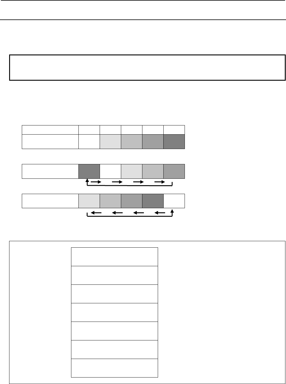
5.WINDOW FUNCTIONS
B-64513EN/03
- 848 -
5.7.9
Shifting Tool Management Data (Low-speed Response)
The pot numbers in the magazine management table are shifted.
In the case of a magazine with fixed pot numbers, the tool management data numbers registered for the
specified magazine are shifted by the specified shift count.
NOTE
To use this window function, the option of “Tool pair for tool management
function: 64, 240 or 1000 pairs” is necessary.
(a) Shift direction
1: Forward shift
-1: Backward shift
The example of shift operation is shown below.
Before shift)
Pot number 1 2 3 4 5
Tool management
data number 3 4 5 6 7
After one forward shift)
Tool management
data number 7 3 4 5 6
After one backward shift)
Tool management
data number 4 5 6 7 3
Input data structure
Top Address +0 (Function code)
367
+2 (Completion code)
-
(Need not to be set)
+4 (Data length L)
0
Set 0 to this field.
+6 (Data number N)
Magazine number
+8 (Data attribute M)
Shift direction
1: Forward, -1: Backward
+10 (Data number N2)
Shift count
+12
+13
(Detailed Completion code)
-
(Need not to be set)

B-64513EN/03
5.WINDOW FUNCTIONS
- 849 -
Completion codes
0 The processing has been executed normally.
3 (See the following Detailed completion codes.)
4 The specified shift direction is invalid.
6 The necessary option is not found.
Detailed completion codes
The detailed completion code is always 0 when the completion code is other than 3.
When the completion code is 3, the detailed completion code is one of the following values:
1 The specified
magazine number is invalid.
2 The specified shift count is invalid.
As the shift count, a value not greater than 0 or larger than the number of magazine data items is
specified.
Output data structure
Top Address +0 (Function code)
367
+2 (Completion code)
?
(See above description)
+4 (Data length L)
0
(Same as input data)
+6 (Data number N)
Magazine number
(Same as input data)
+8 (Data attribute M)
Shift direction
(Same as input data)
+10 (Data number N2)
Shift count
(Same as input data)
+12
+13
(Detailed completion code)
?
(See above description)

5.WINDOW FUNCTIONS
B-64513EN/03
- 850 -
5.7.10
Searching for a Free Pot (Oversize Tools Supported)
(Low-speed Response)
Based on the pot position that is specified, the free pot (Tool management number is 0) nearest and
oversize tool can be stored is searched in the specified magazine or all the magazines. The position of
spindle and standby isn’t included into the free pot.
NOTE
To use this window function, the option of “Tool pair for tool management
function: 64, 240 or 1000 pairs” and the option of "Tool management expansion
B" are necessary. Moreover, set CNC parameter TOT(No.13210#0) to 1.
(a) Search direction
Search direction Direction
designation
Magazine that is searched
for
The search direction with
matrix type
0 Not specified Specified magazine Row
10 Not specified All magazine Row
20 Not specified Specified magazine Column
30 Not specified All magazine Column
1 Forward Specified magazine Row
11 Forward All magazine Row
-1 Backward Specified magazine Row
-11 Backward All magazine Row
2 Forward Specified magazine Column
12 Forward All magazine Column
-2 Backward Specified magazine Column
-12 Backward All magazine Column
In case that all magazine is specified to searching object, the search of free pot is performed in the
specified magazine. If free pot cannot be searched in the specified magazine, the search object is sifted to
the next magazine

B-64513EN/03
5.WINDOW FUNCTIONS
- 851 -
Input data structure
Top Address +0 (Function code)
397
+2 (Completion code)
-
(Need not to be set)
+4 (Data length L)
-
(Need not to be set)
+6 (Data number N)
Magazine number
+8 (Data attribute M)
Search direction
+10 (Data number N2)
Pot number
+12 (Detailed Completion code)
-
(Need not to be set)
+14 (Data number N3)
Tool geometry number
+16
+19
(Data area)
(4 bytes)
(Need not to be set)
Completion codes
0 The processing has been executed normally.
3 (See the following Detailed completion codes.)
4 The specified search direction is invalid.
6 The necessary option is not found.
8, 13 There is no free pot.
Detailed completion codes
The detailed completion code is always 0 when the completion code is other than 3.
When the completion code is 3, the detailed completion code is one of the following values:
21 The
magazine number is invalid.
22 The pot number is invalid.
26 The tool geometry number is invalid.

5.WINDOW FUNCTIONS
B-64513EN/03
- 852 -
Output data structure
Top Address +0 (Function code)
397
+2 (Completion code)
?
(See above description)
+4 (Data length L)
4
+6 (Data number N)
Magazine number
(Same as input data)
+8 (Data attribute M)
Search direction
(Same as input data)
+10 (Data number N2)
Pot number
(Same as input data)
+12 (Detailed completion code)
?
(See above description)
+14 (Data number N3)
Tool geometry number
(Same as input data)
+16 Cartridge number
(2 bytes)
+18
+19
Pot number
(2 bytes)
When the search direction is not specified and free pots are found to the same distance in both forward
and backward directions, the pot found in the forward directions can be selected.

B-64513EN/03
5.WINDOW FUNCTIONS
- 853 -
5.7.11
Reading the Total Tool Life Data (Low-speed Response)
This function reads a total tool life data corresponding to the specified tool type number and the life count
type.
NOTE
1 To use this window function, the option of “Tool pair for tool management
function: 64, 240 or 1000 pairs” is necessary. Moreover, the option of "Tool
management expansion" or the option of "Tool management expansion" is
necessary.
2 When the “Tool management function for multi-edge tools” is used, the total tool
life data of the first edge is read. To read the total tool life data of second or
more, use the function code 442 “Reading total tool life data of edge”.
Input data structure
Top Address +0 (Function code)
409
+2 (Completion code)
-
(Need not to be set)
+4 (Data length L)
-
(Need not to be set)
+6 (Data number N)
Tool type number
Set the tool type number with signed binary format
in 4bytes length.
+10 (Data attribute M)
Life count type
Set the life count type with signed binary format in
2bytes length.
M=0: Count, 1: Time
+12 (Detailed Completion code)
-
(Need not to be set)
+14
+37
(Data area)
(24 bytes)
(Need not to be set)
Completion codes
0 The processing has been executed normally.
3 (See the following detailed completion codes.)
4 The specified tool count type is invalid.
6 The necessary option is not found.
Detailed completion codes
The detailed completion code is always 0 when the completion code is other than 3.
When the completion code is 3, the detailed completion code is one of the following values:
1 The tool type number is invalid. (Except for 1 through 99999999)
28 No specified tool type number

5.WINDOW FUNCTIONS
B-64513EN/03
- 854 -
Output data structure
Top Address +0 (Function code)
409
+2 (Completion code)
?
(See above description)
+4 (Data length L)
24
+6 (Data number N)
Tool type number
(Same as input data)
+10 (Data attribute M)
Life count type
(Same as input data)
+12 (Detailed completion code)
?
(See above description)
+14 Tool type number
(4bytes)
This is the same as "N: Data number" which you
specify.
+18 Total life counter
(4bytes)
The unit of this data is indicated by "+37: Life count
type".
+22 Total remaining life
(4bytes)
The unit of this data is indicated by "+37: Life count
type".
+26 Total maximum life
(4bytes)
The unit of this data is indicated by "+37: Life count
type".
+30 Total notice life
(4bytes)
The unit of this data is indicated by "+37: Life count
type".
+34 Tool count
(2bytes)
The tools, which have the specified tool type
number and tool life type, are counted.
+36 Total life status
(1byte)
0: Not noticed, 1: Noticed
+37 Life count type
(1byte)
0: Count, 1: Time (second), 2: Time (millisecond)

B-64513EN/03
5.WINDOW FUNCTIONS
- 855 -
5.7.12
Writing Tool Management Data by Specified Data (Low-speed
Response)
This function searches a tool management data for the specified search data and writes data to the
searched tool management data. If two or more tool management data match, the tool management data
that has smaller tool management data number is selected. If no tool management data matches,
completion code 3 and detailed completion code 103 is returned.
When using the function "Tool management function for oversize tools", you can also register the item
"Tool geometry number" to the tool management data. If you will register the tool management data that
causes an interference with another tool or magazine frame, completion code 5 and detailed completion
code 27 is returned.
When using the function "Tool management function tool storage position reservation", you can also
register the items "Origin magazine number" and "Origin pot number" to the tool management data. If
specified invalid magazine number and pot number as an origin position, completion code 5 and detailed
completion code 17 or 18 is returned and data aren’t registered. And registered origin position was
specified, completion code 5 and detailed completion code 104 is returned and data isn’t registered.
When using the function “Tool management function for multi-edge tools”, you can register the multi-
edge tools by setting 1-5 to the item “Number of edge positions”. If value specified to the number of edge
positions is other than 0-5, completion code 5 and detailed completion code 19 is returned. The multi-
edge tools can be registered up to 100. If 100 multi-edge tools have already been registered, completion
code 5 and detailed completion code 94 is returned.
When using the function "Tool management function multi-edge tools support ", you can also register the
items "Edge group number" and "Edge number" to the tool management data using this Window function.
If you will register the tool management data that causes inconsistency such as duplication of an edge
number on an edge group, completion code 5 and detailed completion code 29 is returned.
WARNING
When you write some NC data using both this instruction in ladder program and
other applications, take care that you do not write to the same data area.
If some values are written to the same data area by two or more applications
including ladder program, unexpected value may be written. In this case, it may
cause an unexpected machine behavior and also tools, work pieces, and
machines may be damaged. As for details, refer to “SAFETY PRECAUTIONS”.

5.WINDOW FUNCTIONS
B-64513EN/03
- 856 -
NOTE
1 To use this window function, the option of “Tool pair for tool management
function: 64, 240 or 1000 pairs” is necessary.
2 The data length differs depending on whether the "Tool management function
customized data extension (5 to 20)" or "Tool management function customized
data extension (5 to 40)" option is equipped or not.
3 To use the Tool management function tool storage position reservation, the
option of "Tool management expansion B" is necessary. Moreover, set CNC
parameter TMP(No.13210#1) to 1 and TRF(No.13201#5) to 1.
4 To use the Tool management function for oversize tools, the option of "Tool
management expansion B" is necessary. Moreover, set CNC parameter
TOT(No.13210#0) to 1.
5 Tool management function has two functions concerning the multi-edge tool,
which are “Tool management function for multi-edge tools”” and “Tool
management function multi-edge tools support”. And, the usable items are
different respectively.
1) Tool management function for multi-edge tools”
When “Tool management function for multi-edge tools”” is used, the following
item is enabled.
- Number of edge positions
To use the “Tool management function for multi-edge tools”, the option of
"Tool management function for multi-edge tools” is necessary.
Moreover, set the parameter MEB (No.13210#3) to 1.
2) Tool management function multi-edge tools support
When “Tool management function multi-edge tools support” is used, the
following items are enabled.
- Edge group number
- Edge number
To use the Tool management function multi-edge tools support, set the
parameter TME (No.13201#3) to 1.
(a) Data length
84: When the option "Tool management function customized data extension" is not equipped.
148: When the option "Tool management function customized data extension (5 to 20)" is equipped.
228: When the option "Tool management function customized data extension (5 to 40)" is equipped.
(b) Search kind number
You should set the search kind number that determines the kind of data to search.
Search kind number Search data 1 Search data 2
0 Magazine number Pot number
1 Tool management data number -
2 Tool type number Identifier
NOTE
When specifying '2' to the search kind number, the option of "Tool management
expansion B" is necessary and it is necessary to set a customize data number
that is used for the identifier to the CNC parameter No.13267.

B-64513EN/03
5.WINDOW FUNCTIONS
- 857 -
Input data structure
Top Address +0 (Function code)
419
+2 (Completion code)
-
(Need not to be set)
+4 (Data length L)
84, 148, 228
+6 (Data number N)
Search kind number
+8 (Data attribute M)
0
Set 0 to this field.
+10 (Data number N2)
0
Set 0 to this field.
+12 (Detailed Completion code)
-
(Need not to be set)
+14 Search data 1
(4 bytes)
+18 Search data 2
(4 bytes)
+22 Tool type number
(4 bytes)
+26 Tool life counter
(4 bytes)
+30 Maximum tool life
(4 bytes)
+34 Notice tool life
(4 bytes)
+38 Tool life status
(1 byte)
+39 Customized data 0
(1 byte)
+40 Tool information
(2 bytes)
+42 Tool length compensation number
H
(2 bytes)
* for milling or compound system
+44 Cutter compensation number D
(2 bytes)
* for milling or compound system
+46 Spindle speed S
(4 bytes)
+50 Cutting feedrate F
(4 bytes)
+54 (unused)
0
(2 bytes)
Set 0 to this field.

5.WINDOW FUNCTIONS
B-64513EN/03
- 858 -
+56 (unused)
0
(2 bytes)
Set 0 to this field.
+58 Tool geometric compensation
number G
(2 bytes)
* for lathe or compound system
+60 Tool wear compensation number
W
(2 bytes)
* for lathe or compound system
+62 Tool geometry number GNO
(2 bytes)
* When the function "Tool management function for
oversize tools" is enabled.
+64 Edge group number
(2 bytes)
* When "Tool management function multi-edge
tools support" is enabled.
+66 Edge number
(2 bytes)
* When "Tool management function multi-edge
tools support" is enabled.
+68 Origin magazine number
(2 bytes)
* When the function "Tool management function
tool storage position reservation" is enabled.
+70 Origin pot number
(2 bytes)
* When the function "Tool management function
tool storage position reservation" is enabled.
+72 Number of edge positions
(1 byte)
* When the function "Tool management function for
multi-edge tools" is enabled.
+73 (reserved)
0
(9 bytes)
Set 0 to this field.
+82 Customized data 1
(4 bytes)
~ ~
+94
+97
Customized data 4
(4 bytes)
This item is end of data when the data length is 84.
~ ~
+158
+161
Customized data 20
(4 bytes)
This item is end of data when the data length is
148.
~ ~
+238
+241
Customized data 40
(4 bytes)
This item is end of data when the data length is
228.
Completion codes
0 The processing has been executed normally.
2 The data length is invalid.
3 (See the following detailed completion codes.)
5 (See the following detailed completion codes.)
6 The necessary option is not found.
7 The area is protected.
9 Free pot.

B-64513EN/03
5.WINDOW FUNCTIONS
- 859 -
Detailed completion codes
The detailed completion code is always 0 when the completion code is other than 3 or 5.
When the completion code is 3, the detailed completion code is one of the following values:
100 The specified Search kind number is invalid.
101 The specified Search data 1 is invalid.
102 The specified Search data 2 is invalid.
103 The specified tool is not found.
When the completion code is 5, the detailed completion code is one of the following values:
1 The specified tool type number is invalid.
2 The specified tool life counter is invalid.
3 The specified maximum tool life is invalid.
4 The specified notice tool life is invalid.
5 The specified tool life status is invalid.
7 The specified tool information is invalid.
8 The specified tool length compensation number (H) is invalid.
9 The specified cutter compensation number (D) is invalid.
10 The specified spindle speed (S) is invalid.
11 The specified cutting feedrate (F) is invalid.
12 The specified tool geometric compensation number (G) is invalid.
13 The specified tool wear compensation number (W) is invalid.
14 The specified tool geometry number (GNO) is invalid
15 The specified edge group number is invalid.
16 The specified edge number is invalid.
17 Origin magazine number is invalid.
18 Origin pot number is invalid.
19 Number of edge positions is invalid.
27 Interference with another tool or magazine frame
29 Illegal multi edge tool data.
31 to 70 The specified customized data (1 to 40) is invalid.
94 Multi-edge tools have been full already.
104 Origin overlaps

5.WINDOW FUNCTIONS
B-64513EN/03
- 860 -
Output data structure
Top Address +0 (Function code)
419
+2 (Completion code)
?
(See above description)
+4 (Data length L)
(Same as input data)
+6 (Data number N)
Search kind number
(Same as input data)
+8 (Data attribute M)
0
(Same as input data)
+10 (Data number N2)
0
(Same as input data)
+12 (Detailed completion code)
?
(See above description)
+14 Search data 1
(4 bytes)
(Same as input data)
+18 Search data 2
(4 bytes)
(Same as input data)
~
+94
+97
Customized data 4
(4 bytes)
(Same as input data)
This item is end of data when the data length is 84.
~
+158
+161
Customized data 20
(4 bytes)
(Same as input data)
This item is end of data when the data length is
148.
~
+238
+241
Customized data 40
(4 bytes)
(Same as input data)
This item is end of data when the data length is
228.

B-64513EN/03
5.WINDOW FUNCTIONS
- 861 -
5.7.13
Deleting Tool Management Data by Specified Data
(Low-speed Response)
This function searches a tool management data for the specified search data and deletes the searched tool
management data. If two or more tool management data match, the tool management data that has smaller
tool management data number is selected. If no tool management data matches, completion code 3 and
detailed completion code 103 is returned.
(a) Search kind number and Search data
You should set the search kind number that determines the kind of data to search.
Search kind number Search data 1 Search data 2
0 Magazine number Pot number
1 Tool management data number
2 Tool type number Identifier
NOTE
1 To use this window function, the option of “Tool pair for tool management
function: 64, 240 or 1000 pairs” is necessary.
2 When specifying '2' to the search kind number, the option of "Tool management
expansion B" is necessary and it is necessary to set a customize data number
that is used for the identifier to the CNC parameter No.13267.
3 When the “Tool management function for multi-edge tools” is used, the tool
management data of the multi-edge tool can be deleted. In this time, the edge
data is deleted with the tool management data.
Input data structure
Top Address +0 (Function code)
420
+2 (Completion code)
-
(Need not to be set)
+4 (Data length L)
0
Set 0 to this field.
+6 (Data number N)
Search kind number
+8 (Data attribute M)
0
Set 0 to this field.
+10 (Data number N2)
0
Set 0 to this field.
+12 (Detailed Completion code)
-
(Need not to be set)
+14 Search data 1
(4 bytes)
+18
+21
Search data 2
(4 bytes)

5.WINDOW FUNCTIONS
B-64513EN/03
- 862 -
Completion codes
0 The processing has been executed normally.
3 (See the following detailed completion codes.)
6 The necessary option is not found.
7 The area is protected.
9 Free pot.
Detailed completion codes
The detailed completion code is always 0 when the completion code is other than 3.
When the completion code is 3, the detailed completion code is one of the following values:
100 The specified Search kind number is invalid.
101 The specified Search data 1 is invalid.
102 The specified Search data 2 is invalid.
103 The specified tool is not found.
Output data structure
Top Address +0 (Function code)
420
+2 (Completion code)
?
(See above description)
+4 (Data length L)
0
(Same as input data)
+6 (Data number N)
Search kind number
(Same as input data)
+8 (Data attribute M)
0
(Same as input data)
+10 (Data number N2)
0
(Same as input data)
+12 (Detailed completion code)
?
(See above description)
+14 Search data 1
(4 bytes)
(Same as input data)
+18
+21
Search data 2
(4 bytes)
(Same as input data)

B-64513EN/03
5.WINDOW FUNCTIONS
- 863 -
5.7.14
Reading Tool Management Data by Specified Data
(Low-speed Response)
This function searches a tool management data for the specified search data and reads data to the searched
tool management data. If two or more tool management data match, the tool management data that has
smaller tool management data number is selected. If no tool management data matches, completion code
3 and detailed completion code 103 is returned.
When using the function "Tool management function for oversize tools", you can also read the item "Tool
geometry number" from the tool management data.
When using the function "Tool management function tool storage position reservation", you can also read
the items "Origin magazine number" and "Origin pot number" from the tool management data.
When using the function “Tool management function for multi-edge tools”, you can also read the item
“Number of edge positions” from the tool management data.
When using the function " Tool management function multi-edge tools support ", you can also read the
item "Edge group number" and "Edge number" from the tool management data using this Window
function.

5.WINDOW FUNCTIONS
B-64513EN/03
- 864 -
NOTE
1 To use this window function, the option of “Tool pair for tool management
function: 64, 240 or 1000 pairs” is necessary.
2 Customized data 5 to 20 can be read when the "Tool management function
customized data extension (5 to 20)" option is equipped. Customized data 5 to
40 can be read when the "Tool management function customized data extension
(5 to 40)" option is equipped.
3 To use the Tool management function tool storage position reservation, the
option of "Tool management expansion B" is necessary. Moreover, set CNC
parameter TMP(No.13210#1) to 1 and TRF(No.13201#5) to 1.
4 To use the Tool management function for oversize tools, the option of "Tool
management expansion B" is necessary. Moreover, set CNC parameter
TOT(No.13210#0) to 1.
5 Tool management function has two functions concerning the multi-edge tool,
which are “Tool management function for multi-edge tools” and “Tool
management function multi-edge tools support”. And, the usable items are
different respectively.
1) Tool management function for multi-edge tools
When “Tool management function for multi-edge tools” is used, the following
item is enabled.
- Number of edge positions
To use the “Tool management function for multi-edge tools”, the option of
"Tool management function for multi-edge tools" is necessary.
Moreover, set the parameter MEB (No.13210#3) to 1.
2) Tool management function multi-edge tools support
When “Tool management function multi-edge tools support” is used, the
following items are enabled.
- Edge group number
- Edge number
To use the Tool management function multi-edge tools support, set the
parameter TME (No.13201#3) to 1.
(a) Search kind number and Search data
You should set the search kind number that determines the kind of data to search.
Search kind number Search data 1 Search data 2
0 Magazine number Pot number
1 Tool management data number
2 Tool type number Identifier
NOTE
When specifying '2' to the search kind number, the option of "Tool management
expansion B" is necessary and it is necessary to set a customize data number
that is used for the identifier to the CNC parameter No.13267.

B-64513EN/03
5.WINDOW FUNCTIONS
- 865 -
Input data structure
Top Address +0 (Function code)
421
+2 (Completion code)
-
(Need not to be set)
+4 (Data length L)
-
(Need not to be set)
+6 (Data number N)
Search kind number
+8 (Data attribute M)
0
Set 0 to this field.
+10 (Data number N2)
0
Set 0 to this field.
+12 (Detailed Completion code)
-
(Need not to be set)
+14 Search data 1
(4 bytes)
+18 Search data 2
(4 bytes)
+22
+97
(Data area 1)
(76 bytes)
(Need not to be set)
+98
+161
(Data area 2)
(64 bytes)
(Need not to be set)
Total 140 bytes data area is necessary when the
option "Tool management function customized data
extension (5 to 20)" is equipped.
+162
+241
(Data area 3)
(80 bytes)
(Need not to be set)
Total 220 bytes data area is necessary when the
option "Tool management function customized data
extension (5 to 40)" is equipped.
Completion codes
0 The processing has been executed normally.
3 (See the following detailed completion codes.)
6 The necessary option is not found.
7 The area is protected.
9 Free pot.
Detailed completion codes
The detailed completion code is always 0 when the completion code is other than 3.
When the completion code is 3, the detailed completion code is one of the following values:
100 The specified Search kind number is invalid.
101 The specified Search data 1 is invalid.
102 The specified Search data 2 is invalid.
103 The specified tool is not found.

5.WINDOW FUNCTIONS
B-64513EN/03
- 866 -
Output data structure
Top Address +0 (Function code)
421
+2 (Completion code)
?
(See above description)
+4 (Data length L)
84, 148, 228
+6 (Data number N)
Search kind number
(Same as input data)
+8 (Data attribute M)
0
(Same as input data)
+10 (Data number N2)
0
(Same as input data)
+12 (Detailed completion code)
?
(See above description)
+14 Search data 1
(4 bytes)
(Same as input data)
+18 Search data 2
(4 bytes)
(Same as input data)
+22 Tool type number
(4 bytes)
+26 Tool life counter
(4 bytes)
+30 Maximum tool life
(4 bytes)
+34 Notice tool life
(4 bytes)
+38 Tool life status
(1 byte)
+39 Customized data 0
(1 byte)
+41 Tool information
(2 bytes)
+42 Tool length compensation number
H
(2 bytes)
* for milling or compound system
+44 Cutter compensation number D
(2 bytes)
* for milling or compound system
+46 Spindle speed S
(4 bytes)
+50 Cutting feedrate F
(4 bytes)
+54 0 or Magazine number
(2 bytes)

B-64513EN/03
5.WINDOW FUNCTIONS
- 867 -
+56 Tool management data number or
Pot number
(2 bytes)
+58 Tool geometric compensation
number G
(2 bytes)
* for lathe or compound system
+60 Tool wear compensation number
W
(2 bytes)
* for lathe or compound system
+62 Tool geometry number GNO
(2 bytes)
* When the function "Tool management function for
oversize tools" is enabled.
+64 Edge group number
(2 bytes)
* When "Tool management function multi-edge
tools support" is enabled.
+66 Edge number
(2 bytes)
* When "Tool management function multi-edge
tools support" is enabled.
+68 Origin magazine number
(2 bytes)
* When the function "Tool management function
tool storage position reservation" is enabled.
+70 Origin pot number
(2 bytes)
* When the function "Tool management function
tool storage position reservation" is enabled.
+72 Number of edge positions
(1 byte)
* When the function " Tool management function
for multi-edge tools" is enabled.
+73 (reserved)
0
(9 bytes)
Set 0 to this field.
+82 Customized data 1
(4 bytes)
~ ~
+94
+97
Customized data 4
(4 bytes)
This item is end of data when the data length is 84.
~ ~
+158
+161
Customized data 20
(4 bytes)
This item is end of data when the data length is
148.
~ ~
+238
+241
Customized data 40
(4 bytes)
This item is end of data when the data length is
228.

5.WINDOW FUNCTIONS
B-64513EN/03
- 868 -
5.7.15
Writing Each Tool Management Data by Specified Data
(Low-speed Response)
This function searches a tool management data for the specified search data and writes data to the
searched tool management data. If two or more tool management data match, the tool management data
that has smaller tool management data number is selected. If no tool management data matches,
completion code 3 and detailed completion code 103 is returned.
Enter the data type number to be changed, as the data attribute.
The required size of the data area differs depending on the data type.
The following table shows the relationship between each data type number and its corresponding data and
required data area size.
WARNING
When you write some NC data using both this instruction in ladder program and
other applications, take care that you do not write to the same data area.
If some values are written to the same data area by two or more applications
including ladder program, unexpected value may be written. In this case, it may
cause an unexpected machine behavior and also tools, work pieces, and
machines may be damaged. As for details, refer to “SAFETY PRECAUTIONS”.
Table 5.7.15 (a) Data, data type number and data area size
Data type
number Data Data
area size Remarks
1 Tool type number 4 bytes
2 Tool life counter 4 bytes
3 Maximum tool life 4 bytes
4 Notice tool life 4 bytes
5 Tool life status 1 byte
6 Customized data 0 1 byte
7 Tool information 2 bytes
8 Tool length compensation number
(H)
2 bytes * for milling or compound system
9 Cutter compensation number (D) 2 bytes * for milling or compound system
10 Spindle speed (S) 4 bytes
11 Cutting feedrate (F) 4 bytes
12 Tool geometric compensation
number (G)
2 bytes * for lathe or compound system
13 Tool wear compensation number
(W)
2 bytes * for lathe or compound system
14 Tool geometry number (GNO) 2 bytes When the function "Tool management function for
oversize tools" is enabled.
15 Edge group number 2 bytes When "Tool management function multi-edge tools
support" is enabled.
16 Edge number 2 bytes When "Tool management function multi-edge tools
support" is enabled.
17 Origin magazine number 2 bytes When the function "Tool management function tool
storage position reservation" is enabled.
18 Origin pot number 2 bytes When the function "Tool management function tool
storage position reservation" is enabled.
19 Number of edge positions 1 byte When "Tool management function for multi-edge
tools “is enabled.
31 Customized data 1 4 bytes
~ ~ ~
34 Customized data 4 4 bytes

B-64513EN/03
5.WINDOW FUNCTIONS
- 869 -
Data type
number Data Data
area size Remarks
35 Customized data 5 4 bytes These data are available when the option "Tool
management function customized data extension (5
to 20)" or "Tool management function customized
data extension (5 to 40)" is equipped.
~ ~ ~
50 Customized data 20 4 bytes
51 Customized data 21 4 bytes These data are available when the option "Tool
management function customized data extension (5
to 40)" is equipped.
~ ~ ~
70 Customized data 40 4 bytes
100 Registering of origin magazine
number and origin pot number
0 byte - When the function "Tool management function
tool storage position reservation" is enabled.
- Search kind number (described later) must be 0.
- Data area is not used.
101 Deleting of origin magazine number
and origin pot number
0 byte
When using the function "Tool management function for oversize tools", you can also register the item
"Tool geometry number" to the tool management data. If you register the tool management data that
causes an interference with another tool or magazine frame, completion code 5 and detailed completion
code 27 is returned.
Using the function “Tool management function tool storage position reservation”, you can also register
the item “Origin magazine number” to the tool management data by specifying 17 as data type number,
and you can also register the item “Origin pot number” to the tool management data by specifying 18 as
data type number. If specified invalid magazine number and pot number as an origin position, completion
code 5 and detailed completion code 17 or 18 is returned and data aren’t registered. And registered origin
position was specified, completion code 5 and detailed completion code 104 is returned and data isn’t
registered.
When you specify 100 or 101 as data type number, search kind number (described later) must be 0.
By specifying 100 as data type number, specified magazine number and pot number are registered to
“Origin magazine number” and “Origin pot number" of tool management data assigned there.
By specifying 101 as data type number, “Origin magazine number” and “Origin pot number" of tool
management data assigned to the pot specified magazine number and pot number are deleted.
When you specify 100 or 101 as data type number and specify -1 as pot number, ”Origin magazine
number” and “Origin pot number" of all tool management data in specified magazine will be updated
with current magazine and pot number, or deleted. When you specify 100 or 101 as data type number and
specify -1 as magazine number, “Origin magazine number” and “Origin pot number" of tool management
data registered on all magazine except one in the main axis position or in the standby position are
registered or deleted.
If you specify invalid magazine number and pot number as an origin position, completion code 3 and
detailed completion code 101 or 102 is returned and no data is updated. And origin position to be
registered is already occupied by other tool, completion code 5 and detailed completion code 104 is
returned and no data is updated.
When you specify -1 as magazine number or pot number if no tool management data is registered, the
completion code 9 "Free pot" is returned. If an error occurs while registering or deleting multiple origin
positions at once, origin positions of tool management data after the pot with the error will not be updated.
When you specify 100 or 101 as data type number and specify any number except 0 as search kind
number, completion code 3 and detailed completion code 100 is returned and no data is registered.
When using the function “Tool management function for multi-edge tools”, you can register the multi-
edge tools by specifying 19 as data type number and setting 1-5 to the item “Number of edge positions”.
If value specified to the number of edge positions is other than 0-5, completion code 5 and detailed
completion code 19 is returned. The multi-edge tools can be registered up to 100. If 100 multi-edge tools
have already been registered, completion code 5 and detailed completion code 94 is returned.
When using the function "Tool management function multi-edge tools support ", you can also register the
item "Edge group number" and "Edge number" to the tool management data using this Window function.

5.WINDOW FUNCTIONS
B-64513EN/03
- 870 -
If you register the tool management data that causes inconsistency such as duplication of an edge number
on an edge group, completion code 5 and detailed completion code 29 is returned.
NOTE
1 To use this window function, the option of “Tool pair for tool management
function: 64, 240 or 1000 pairs” is necessary.
2 Customized data 5 to 20 can be read when the "Tool management function
customized data extension (5 to 20)" option is equipped. Customized data 5 to
40 can be read when the "Tool management function customized data extension
(5 to 40)" option is equipped.
3 To use the Tool management function tool storage position reservation, the
option of "Tool management expansion B" is necessary. Moreover, set CNC
parameter TMP(No.13210#1) to 1 and TRF(No.13201#5) to 1.
4 To use the Tool management function for oversize tools, the option of "Tool
management expansion B" is necessary. Moreover, set CNC parameter
TOT(No.13210#0) to 1.
5 Tool management function has two functions concerning the multi-edge tool,
which are “Tool management function for multi-edge tools” and “Tool
management function multi-edge tools support”. And, the usable items are
different respectively.
1) Tool management function for multi-edge tools
When “Tool management function multi-edge tools support” is used, the
following item is enabled.
- Number of edge positions
To use the “Tool management function for multi-edge tools”, the option of
"Tool management function for multi-edge tools" is necessary.
Moreover, set the parameter MEB (No.13210#3) to 1.
2) Tool management function multi-edge tools support
When “Tool management function multi-edge tools support” is used, the
following items are enabled.
- Edge group number
- Edge number
To use the Tool management function multi-edge tools support, set the
parameter TME (No.13201#3) to 1.
CAUTION
When you specify 100 or 101 as data type number and specified -1 as magazine
number or pot number and too many tool management data will be registered or
deleted, the completion of the window instruction will take some time, a few
seconds in the worst case. On the all times, other window instruction of low-
speed response does not work. And then, the execution of application using
FOCAS2 functions and C language executor application may be delayed.
Therefore, when updating or deleting a lot of data at once, you should take
special care for the delay of the other window instruction of low-speed response,
application using FOCAS2 and C language executor application.
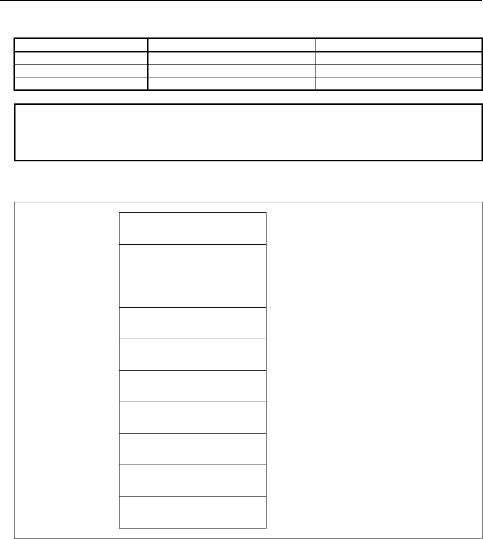
B-64513EN/03
5.WINDOW FUNCTIONS
- 871 -
(a) Search kind number and Search data
You should set the search kind number that determines the kind of data to search.
Search kind number Search data 1 Search data 2
0 Magazine number Pot number
1 Tool management data number -
2 Tool kind number Identifier
NOTE
When specifying '2' to the search kind number, the option of "Tool management
expansion B" is necessary and it is necessary to set a customize data number
that is used for the identifier to the CNC parameter No.13267.
Input data structure
Top Address +0 (Function code)
422
+2 (Completion code)
-
(Need not to be set)
+4 (Data length L)
0, 1, 2, 4
Set the length of data that you want to write.
+6 (Data number N)
Search kind number
+8 (Data attribute M)
Data type number
+10 (Data number N2)
0
Set 0 to this field.
+12 (Detailed Completion code)
-
(Need not to be set)
+14 Search data 1
(4 bytes)
+18 Search data 2
(4 bytes)
+22
+n
(Data area)
(0, 1, 2, 4 bytes)
Set the data that you want to write. The size of the
required data area differs depending on the data
type.
Completion codes
0 The processing has been executed normally.
2 The data length is invalid.
3 (See the following detailed completion codes.)
4 The specified data type is invalid.
5 (See the following detailed completion codes.)
6 The necessary option is not found.
7 The area is protected.
9 Free pot.

5.WINDOW FUNCTIONS
B-64513EN/03
- 872 -
Detailed completion codes
The detailed completion code is always 0 when the completion code is other than 3 or 5.
When the completion code is 3, the detailed completion code is one of the following values:
100 The specified Search kind number is invalid.
101 The specified Search data 1 is invalid.
102 The specified Search data 2 is invalid.
103 The specified tool is not found.
When the completion code is 5, the detailed completion code is one of the following values:
1 The specified tool type number is invalid.
2 The specified tool life counter is invalid.
3 The specified maximum tool life is invalid.
4 The specified notice tool life is invalid.
5 The specified tool life status is invalid.
6 The specified customized data 0 is invalid.
7 The specified tool information is invalid.
8 The specified tool length compensation number (H) is invalid.
9 The specified cutter compensation number (D) is invalid.
10 The specified spindle speed (S) is invalid.
11 The specified cutting feedrate (F) is invalid.
12 The specified tool geometric compensation number (G) is invalid.
13 The specified tool wear compensation number (W) is invalid.
14 The specified tool geometry number (GNO) is invalid
15 The specified edge group number is invalid.
16 The specified edge number is invalid.
17 Origin magazine number is invalid.
18 Origin pot number is invalid.
19 Number of edge positions is invalid.
27 Interference with another tool or magazine frame
29 Illegal multi edge tool data.
31 to 70 The specified customized data (1 to 40) is invalid.
94 Multi-edge tools have been full already.
104 Origin overlaps

B-64513EN/03
5.WINDOW FUNCTIONS
- 873 -
Output data structure
Top Address +0 (Function code)
422
+2 (Completion code)
?
(See above description)
+4 (Data length L)
(Same as input data)
+6 (Data number N)
Search kind number
(Same as input data)
+8 (Data attribute M)
Data type number
(Same as input data)
+10 (Data number N2)
0
(Same as input data)
+12 (Detailed completion code)
?
(See above description)
+14 Search data 1
(4 bytes)
(Same as input data)
+18 Search data 2
(4 bytes)
(Same as input data)
+22
+n
(Data area)
(0, 1, 2, 4 bytes)
(Same as input data)

5.WINDOW FUNCTIONS
B-64513EN/03
- 874 -
5.7.16
Writing Magazine Property Data (Low-speed Response)
This function writes magazine property data with specified magazine number.
WARNING
When you write some NC data using both this instruction in ladder program and
other applications, take care that you do not write to the same data area.
If some values are written to the same data area by two or more applications
including ladder program, unexpected value may be written. In this case, it may
cause an unexpected machine behavior and also tools, work pieces, and
machines may be damaged. As for details, refer to “SAFETY PRECAUTIONS”.
NOTE
To use this window function, the option of “Tool pair for tool management
function: 64, 240 or 1000 pairs” and the option of "Tool management expansion
B" are necessary. Moreover, set CNC parameter TMP(No.13210#1) to 1.
Input data structure
Top Address +0 (Function code)
423
+2 (Completion code)
-
(Need not to be set)
+4 (Data length L)
24
+6 (Data number N)
Magazine number
+8 (Data attribute M)
0
Set 0 to this field.
+10 (Data number N2)
0
Set 0 to this field.
+12 (Detailed completion code)
-
(Need not to be set)
+14 Magazine information
(1 byte)
+15 (Reserved)
0
(3 bytes)
Set 0 to this field.
+18 (unused)
0
(4 bytes)
Set 0 to this field.
+22 Customize data 1
(4 bytes)
+26 Customize data 2
(4 bytes)
+30 Customize data 3
(4 bytes)

B-64513EN/03
5.WINDOW FUNCTIONS
- 875 -
+34
+37
Customize data 4
(4 bytes)
Completion codes
0 The processing has been executed normally.
2 The data length is invalid.
3 (See the following detailed completion codes.)
5 (See the following detailed completion codes.)
6 The necessary option is not found.
Detailed completion codes
The detailed completion code is always 0 when the completion code is other than 3 or 5.
When the completion code is 3, the detailed completion code is one of the following values:
21 The specified magazine number is invalid.
When the completion code is 5, the detailed completion code is one of the following values:
1 The specified magazine number is invalid.
11 to 14 The specified customized data (1 to 4) is invalid.
Output data structure
Top Address +0 (Function code)
423
+2 (Completion code)
?
(See above description)
+4 (Data length L)
24
(Same as input data)
+6 (Data number N)
Magazine number
(Same as input data)
+8 (Data attribute M)
0
(Same as input data)
+10 (Data number N2)
0
(Same as input data)
+12 (Detailed completion code)
?
(See above description)
~ ~
+34
+37
Customized data 4
(4 bytes)
(Same as input data)

5.WINDOW FUNCTIONS
B-64513EN/03
- 876 -
5.7.17
Reading Magazine Property Data (Low-speed Response)
This function reads magazine property data with specified magazine number.
NOTE
To use this window function, the option of “Tool pair for tool management
function: 64, 240 or 1000 pairs” and the option of "Tool management expansion
B" are necessary. Moreover, set CNC parameter TMP(No.13210#1) to 1.
Input data structure
Top Address +0 (Function code)
424
+2 (Completion code)
-
(Need not to be set)
+4 (Data length L)
-
(Need not to be set)
+6 (Data number N)
Magazine number
+8 (Data attribute M)
0
Set 0 to this field.
+10 (Data number N2)
0
Set 0 to this field.
+12 (Detailed completion code)
-
(Need not to be set)
+14
+37
(Data area)
(24 bytes)
(Need not to be set)
Completion codes
0 The processing has been executed normally.
3 (See the following detailed completion codes.)
6 The necessary option is not found.
Detailed completion codes
The detailed completion code is always 0 when the completion code is other than 3.
When the completion code is 3, the detailed completion code is one of the following values:
21 The specified magazine number is invalid.

B-64513EN/03
5.WINDOW FUNCTIONS
- 877 -
Output data structure
Top Address +0 (Function code)
424
+2 (Completion code)
?
(See above description)
+4 (Data length L)
24
+6 (Data number N)
Magazine number
(Same as input data)
+8 (Data attribute M)
0
(Same as input data)
+10 (Data number N2)
0
(Same as input data)
+12 (Detailed completion code)
?
(See above description)
+14 Magazine information
(1 byte)
+15 (Reserved)
(3 bytes)
+18 Line of magazine
(2 bytes)
+20 Row of magazine
(2 bytes)
+22 Customize data 1
(4 bytes)
+26 Customize data 2
(4 bytes)
+30 Customize data 3
(4 bytes)
+34
+37
Customize data 4
(4 bytes)

5.WINDOW FUNCTIONS
B-64513EN/03
- 878 -
5.7.18
Writing Pot Property Data (Low-speed Response)
This function writes pot property data with specified magazine and pot number.
WARNING
When you write some NC data using both this instruction in ladder program and
other applications, take care that you do not write to the same data area.
If some values are written to the same data area by two or more applications
including ladder program, unexpected value may be written. In this case, it may
cause an unexpected machine behavior and also tools, work pieces, and
machines may be damaged. As for details, refer to “SAFETY PRECAUTIONS”.
NOTE
To use this window function, the option of “Tool pair for tool management
function: 64, 240 or 1000 pairs” and the option of "Tool management expansion
B" are necessary. Moreover, set CNC parameter TMP(No.13210#1) to 1.
Input data structure
Top Address +0 (Function code)
425
+2 (Completion code)
-
(Need not to be set)
+4 (Data length L)
48
+6 (Data number N)
Magazine number
+8 (Data attribute M)
Data type
0: Not change the tool management data number.
1: Change the tool management data number.
+10 (Data number N2)
Pot number
+12 (Detailed completion code)
-
(Need not to be set)
+14 Tool management data number
(2 bytes)
When you want to change the tool management
data number, set "1" to the "Data type".
+16 Pot type
(2 bytes)
+18 Pot information 1
(1 byte)
+19 Pot information 2
(1 byte)
+20 (Reserved)
0
(2 bytes)
Set 0 to this field.
+22 Customize data 1
(4 bytes)
~

B-64513EN/03
5.WINDOW FUNCTIONS
- 879 -
+58
+61
Customize data 10
(4 bytes)
Completion codes
0 The processing has been executed normally.
2 The data length is invalid.
3 (See the following detailed completion codes.)
4 The specified data type is invalid.
5 (See the following detailed completion codes.)
6 The necessary option is not found.
Detailed completion codes
The detailed completion code is always 0 when the completion code is other than 3 or 5.
When the completion code is 3, the detailed completion code is one of the following values:
21 The magazine number is invalid.
22 The pot number is invalid.
When the completion code is 5, the detailed completion code is one of the following values:
1 The specified tool management data number is invalid.
2 The specified pot type is invalid.
3 The specified pot information 1 is invalid.
4 The specified pot information 2 is invalid.
11 to 20 The specified customized data (1 to 10) is invalid.
Output data structure
Top Address +0 (Function code)
425
+2 (Completion code)
?
(See above description)
+4 (Data length L)
48
(Same as input data)
+6 (Data number N)
Magazine number
(Same as input data)
+8 (Data attribute M)
Data type
(Same as input data)
+10 (Data number N2)
Pot number
(Same as input data)
+12 (Detailed completion code)
?
(See above description)
~ ~
+58
+61
Customized data 10
(4 bytes)
(Same as input data)

5.WINDOW FUNCTIONS
B-64513EN/03
- 880 -
5.7.19
Reading Pot Property Data (Low-speed Response)
This function reads pot property data with specified magazine and pot number.
NOTE
To use this window function, the option of “Tool pair for tool management
function: 64, 240 or 1000 pairs” and the option of "Tool management expansion
B" are necessary. Moreover, set CNC parameter TMP(No.13210#1) to 1.
Input data structure
Top Address +0 (Function code)
426
+2 (Completion code)
-
(Need not to be set)
+4 (Data length L)
-
(Need not to be set)
+6 (Data number N)
Magazine number
+8 (Data attribute M)
0
Set 0 to this field.
+10 (Data number N2)
Pot number
+12 (Detailed completion code)
-
(Need not to be set)
+14
+61
(Data area)
(48 bytes)
(Need not to be set)
Completion codes
0 The processing has been executed normally.
3 (See the following detailed completion codes.)
6 The necessary option is not found.
Detailed completion codes
The detailed completion code is always 0 when the completion code is other than 3.
When the completion code is 3, the detailed completion code is one of the following values:
21 The magazine number is invalid.
22 The pot number is invalid.

B-64513EN/03
5.WINDOW FUNCTIONS
- 881 -
Output data structure
Top Address +0 (Function code)
426
+2 (Completion code)
?
(See above description)
+4 (Data length L)
48
+6 (Data number N)
Magazine number
(Same as input data)
+8 (Data attribute M)
0
(Same as input data)
+10 (Data number N2)
Pot number
(Same as input data)
+12 (Detailed completion code)
?
(See above description)
+14 Tool management data number
(2 bytes)
+16 Pot type
(2 bytes)
+18 Pot information 1
(1 byte)
+19 Pot information 2
(1 byte)
+20 (Reserved)
(2 bytes)
+22 Customize data 1
(4 bytes)
~ ~
+58
+61
Customize data 10
(4 bytes)

5.WINDOW FUNCTIONS
B-64513EN/03
- 882 -
5.7.20
Searching for a Free Pot by Specified Data
(Low-speed Response)
Based on the pot position that is specified, the nearest free pot(Tool management number is 0) that is
adopted to search kind number and searched data and that can be stored in the specified magazine or all
the magazines The position of spindle and standby aren't included into the free pot.
NOTE
To use this window function, the option of “Tool pair for tool management
function: 64, 240 or 1000 pairs” is necessary.
(a) Search kind number
The search kind number relates the search data to the data of following table.
Search kind number Search data Description
0 - Search for empty pot independent of search data
1 Tool geometry number
Search for empty pot in which specified tool geometry can be
stored.
2 Pot type Search for empty pot which has the specified pot type.
3 ~ 6
Magazine property
Customize data
1 ~ 4
Searching the free pot that has same data of specified
customize data of magazine property in the magazine
7 ~ 16
Pot property
Customize data
1 ~ 10
Searching the free pot that has same customize data of pot
property in the magazine
NOTE
1 When specifying '1' to the search kind number, the option of "Tool management
expansion B" is necessary. Moreover, set CNC parameter TOT(No.13210#0) to
1.
2 When specifying '2’ to ‘16' to the search kind number, the option of "Tool
management expansion B" is necessary. Moreover, set CNC parameter
TMP(No.13210#1) to 1.
(b) Search direction
Search direction Direction
designation
Magazine that is searched
for
The search direction with
matrix type
0 Not specified Specified magazine Row
10 Not specified All magazine Row
20 Not specified Specified magazine Column
30 Not specified All magazine Column
1 Forward Specified magazine Row
11 Forward All magazine Row
-1 Backward Specified magazine Row
-11 Backward All magazine Row
2 Forward Specified magazine Column
12 Forward All magazine Column
-2 Backward Specified magazine Column
-12 Backward All magazine Column
In case that “Direction designation” is “Not specified”, nearest free pot from the specified pot is selected.

B-64513EN/03
5.WINDOW FUNCTIONS
- 883 -
In case that all magazine is specified to searching object, the search of free pot is performed in the
specified magazine. If free pot cannot be searched in the specified magazine, the search object is sifted to
the next magazine
Input data structure
Top Address +0 (Function code)
427
+2 (Completion code)
-
(Need not to be set)
+4 (Data length L)
-
(Need not to be set)
+6 (Data number N)
Magazine number
+8 (Data attribute M)
Search direction
+10 (Data number N2)
Pot number
+12 (Detailed Completion code)
-
(Need not to be set)
+14 Search kind number
(2 bytes)
+16 (Reserved)
0
(2 bytes)
Set 0 to this field.
+18 Search data
(4 bytes)
+22 (Reserved)
0
(12 bytes)
Set 0 to this field.
+34
+37
(Data area)
(4 bytes)
(Need not to be set)
Completion codes
0 The processing has been executed normally.
3 (See the following detailed completion codes.)
4 The specified search direction is invalid.
6 The necessary option is not found.
13 There is no free pot.
Detailed completion codes
The detailed completion code is always 0 when the completion code is other than 3.
When the completion code is 3, the detailed completion code is one of the following values:
21 The magazine number is invalid.
22 The pot number is invalid.
100 The search kind number is invalid.
101 The search data is invalid.

5.WINDOW FUNCTIONS
B-64513EN/03
- 884 -
Output data structure
Top Address +0 (Function code)
427
+2 (Completion code)
?
(See above description)
+4 (Data length L)
4
+6 (Data number N)
Magazine number
(Same as input data)
+8 (Data attribute M)
Search direction
(Same as input data)
+10 (Data number N2)
Pot number
(Same as input data)
+12 (Detailed completion code)
?
(See above description)
+14 Search kind number
(2 bytes)
(Same as input data)
+16 (Reserved)
0
(Same as input data)
+18 Search data
(4 bytes)
(Same as input data)
+22 (Reserved)
0
(Same as input data)
+34 Magazine number
(2 bytes)
+36
+37
Pot number
(2 bytes)
The search direction is not specified and the free pot is found to the same distance of forward and
backward, the pot that is found in forward direction is priority.

B-64513EN/03
5.WINDOW FUNCTIONS
- 885 -
5.7.21
Reading a Tool Geometry Data (Low-speed Response)
This function reads a tool geometry data.
NOTE
To use this window function, the option of “Tool pair for tool management
function: 64, 240 or 1000 pairs” and the option of “Tool management expansion
B” are necessary. Moreover, set CNC parameter TOT(No.13210#0) to 1.
Input data structure
Top Address +0 (Function code)
429
+2 (Completion code)
-
(Need not to be set)
+4 (Data length L)
-
(Need not to be set)
+6 (Data number N)
Tool geometry data number
You should specify the tool geometry data number.
N = 1 to 20
+8 (Data attribute M)
0
(2bytes)
Set 0 to this field.
+10 (Data number N2)
0
(2bytes)
Set 0 to this field.
+12 (Detailed Completion code)
-
(Need not to be set)
+14
+18
(Data area)
(5bytes)
(Need not to be set)
Completion codes
0 Completed successfully
1 Not supported
3 The tool geometry data number is invalid.
6 No option

5.WINDOW FUNCTIONS
B-64513EN/03
- 886 -
Output data structure
Top Address +0 (Function code)
429
+2 (Completion code)
?
(See above description)
+4 (Data length L)
5
(2bytes)
+6 (Data number N)
Tool geometry data number
(Same as input data)
+8 (Data attribute M)
0
(Same as input data)
+10 (Data number N2)
0
(Same as input data)
+12 (Detailed completion code)
?
(See above description)
+14 The number of occupation pot
(left side)
(1byte)
Signed binary format in 1 byte length
0 to 4
+15 The number of occupation pot
(right side)
(1byte)
Signed binary format in 1 byte length
0 to 4
+16 The number of occupation pot
(upper side)
(1byte)
Signed binary format in 1 byte length
0 to 4
+17 The number of occupation pot
(lower side)
(1byte)
Signed binary format in 1 byte length
0 to 4
+18 Geometry
(1byte)
0: Geometry A
1: Geometry B

B-64513EN/03
5.WINDOW FUNCTIONS
- 887 -
5.7.22
Writing a Tool Geometry Data (Low-speed Response)
This function writes a tool geometry data.
But, the tool geometry data of the tool, that is stored in pot, cannot be written.
WARNING
When you write some NC data using both this instruction in ladder program and
other applications, take care that you do not write to the same data area.
If some values are written to the same data area by two or more applications
including ladder program, unexpected value may be written. In this case, it may
cause an unexpected machine behavior and also tools, work pieces, and
machines may be damaged. As for details, refer to “SAFETY PRECAUTIONS”.
NOTE
To use this function, the option of “Tool pair for tool management function: 64,
240 or 1000 pairs” and the option of “Tool management expansion B” are
necessary. Moreover, set CNC parameter TOT(No.13210#0) to 1.
Input data structure
Top Address +0 (Function code)
430
+2 (Completion code)
-
(Need not to be set)
+4 (Data length L)
5
(2bytes)
+6 (Data number N)
Tool geometry data number
You should specify the tool geometry data number.
N = 1 to 20
+8 (Data attribute M)
0
(2bytes)
Set 0 to this field.
+10 (Data number N2)
0
(2bytes)
Set 0 to this field.
+12 (Detailed Completion code)
-
(Need not to be set)
+14 The number of occupation pot
(left side)
(1byte)
Signed binary format in 1 byte length
0 to 4
+15 The number of occupation pot
(right side)
(1byte)
Signed binary format in 1 byte length
0 to 4
+16 The number of occupation pot
(upper side)
(1byte)
Signed binary format in 1 byte length
0 to 4
+17 The number of occupation pot
(lower side)
(1byte)
Signed binary format in 1 byte length
0 to 4
+18 Geometry
(1byte)
0 : Geometry A
1 : Geometry B

5.WINDOW FUNCTIONS
B-64513EN/03
- 888 -
Completion codes
0 Completed successfully
1 Not supported
3 The tool geometry data number is invalid.
5 (See the following detailed completion codes.)
6 No option
7 The tool is stored in a pot.
Detail Completion codes
This code is 0 except completion code is 5.
When completion code is 5
1 The left side occupation pot number is invalid.
You should set the number 0 to 4.
2 The right side occupation pot number is invalid.
You should set the number 0 to 4.
3 The upper side occupation pot number is invalid.
You should set the number 0 to 4.
4 The lower side occupation pot number is invalid.
You should set the number 0 to 4.
5 The geometry data is invalid.
You should set the number 0(Geometry A) or 1(Geometry B).
Output data structure
Top Address +0 (Function code)
430
+2 (Completion code)
?
(See above description)
+4 (Data length L)
5
(Same as input data)
+6 (Data number N)
Tool geometry data number
(Same as input data)
+8 (Data attribute M)
0
(Same as input data)
+10 (Data number N2)
0
(Same as input data)
+12 (Detailed completion code)
?
(See above description)
+14 The number of occupation pot
(left side)
(Same as input data)
Signed binary format in 1 byte length
0 to 4
+15 The number of occupation pot
(right side)
(Same as input data)
Signed binary format in 1 byte length
0 to 4
+16 The number of occupation pot
(upper side)
(Same as input data)
Signed binary format in 1 byte length
0 to 4
+17 The number of occupation pot
(lower side)
(Same as input data)
Signed binary format in 1 byte length
0 to 4
+18 Geometry
(Same as input data)
0: Geometry A
1: Geometry B

B-64513EN/03
5.WINDOW FUNCTIONS
- 889 -
5.7.23
Moving Tool Management Data Numbers in a Magazine
Management Table (Low-speed Response)
The tool management data number is moved specifying the magazine number and the pot number of the
source and the destination.
An empty pot is specified for the moving destination.
When you specify the spindle position or the waiting position as the magazine number of the source and
the destination, specify 0 as the pot number.
When Tool management function tool storage position reservation is valid, an empty pot or the origin
position registered into the tool which moves can be specified for the moving destination.
Moreover, when moving the tool by which the origin position is registered, the following data is changed
according to the specification of the source and the destination.
• When the tool is moved to other magazine or pot from the pot of the origin position registered into
the tool, the 2nd bit of the pot information 1 on the pot property of the origin position is set to 1.
• When the tool is returned to the origin position from magazine or pot other than the origin position
registered into the tool, the 2nd bit of the pot information 1 on the pot property of the origin position
is set to 0.
NOTE
1 To use this window function, the option of “Tool pair for tool management
function: 64, 240 or 1000 pairs” is necessary.
2 To use the tool management function tool storage position reservation, the
option of "Tool management expansion B" is necessary. Moreover, set CNC
parameter TMP(No.13210#1) to 1 and TRF(No.13201#5) to 1.

5.WINDOW FUNCTIONS
B-64513EN/03
- 890 -
Input data structure
Top Address +0 (Function code)
432
+2 (Completion code)
-
(Need not to be set)
+4 (Data length L)
8
(2bytes)
+6 (Data number N)
0
(2bytes)
Set 0 to this field.
+8 (Data attribute M)
0
(2bytes)
Set 0 to this field.
+10 (Data number N2)
0
(2bytes)
Set 0 to this field.
+12 (Detailed Completion code)
-
(Need not to be set)
+14 Magazine number of source
(2bytes)
+16 Pot number of source
(2bytes)
When you specify the spindle position or the
waiting position as the magazine number of the
source, set 0 to this field.
+18 Magazine number of destination
(2bytes)
+20
+21
Pot number of destination
(2bytes)
When you specify the spindle position or the
waiting position as the magazine number of the
destination, set 0 to this field.
Completion codes
0 The processing has been executed normally.
1 Not supported
5 (See the following detailed completion codes.)
6 The necessary option is not found.
7 The area is protected.
13 There is no free pot.
Detail Completion codes
The detailed completion code is always 0 when the completion code is other than 5.
When the completion code is 5, the detailed completion code is one of the following values:
1 Magazine number of source is invalid.
2 Pot number of source is invalid.
3 Tool is not found in the source magazine or pot.
4 Magazine number of destination is invalid.
5 Pot number of destination is invalid.
6 Tool is not found in the destination magazine or pot.

B-64513EN/03
5.WINDOW FUNCTIONS
- 891 -
Output data structure
Top Address +0 (Function code)
432
+2 (Completion code)
?
(See above description)
+4 (Data length L)
8
(Same as input data)
+6 (Data number N)
0
(Same as input data)
+8 (Data attribute M)
0
(Same as input data)
+10 (Data number N2)
0
(Same as input data)
+12 (Detailed Completion code)
?
(See above description)
+14 Magazine number of source
(2bytes)
(Same as input data)
+16 Pot number of source
(2bytes)
(Same as input data)
+18 Magazine number of destination
(2bytes)
(Same as input data)
+20
+21
Pot number of destination
(2bytes)
(Same as input data)

5.WINDOW FUNCTIONS
B-64513EN/03
- 892 -
5.7.24
Reading free number of Multi edge group / Tool offset
(High-speed Response)
This function reads the free number of Multi edge group / Tool offset.
NOTE
1 To use this window function, the option of “Tool pair for tool management
function: 64, 240 or 1000 pairs” is necessary. Moreover set CNC parameter
FNS(No.13210#7) to 1.
2 To use the edge group number, set the parameter TME (No.13201#3) to 1.
Input data structure
Top Address +0 (Function code)
434
+2 (Completion code)
-
(Need not be set)
+4 (Data length L)
-
(Need not be set)
+6
(Data number N)
0
Set 0 to this field.
+8
(Data attribute M)
0
Set 0 to this field.
+10
(Data number N2)
0
Set 0 to this field.
+12
(Detailed completion code)
-
(Need not be set)
+14
+29
(Data area)
(16byte)
(Need not be set)
Completion code
0 The processing has been executed normally.
6 The necessary option is not found.
NOTE
Completion code is 0 when the option of "Tool management function" (64, 240 or
1000 pairs) is set and CNC parameter FNS(No.13210 #7) is 0.

B-64513EN/03
5.WINDOW FUNCTIONS
- 893 -
Output data structure
Top Address +0 (Function code)
434
+2 (Completion code)
?
(See above description)
+4
(Data length L)
16
+6 (Data number N)
0
+8
(Data attribute M)
0
+10
(Data number N2)
0
+12
(Detailed completion code)
0
This field is 0 at all times.
+14
Free Multi edge group number (GRP)
(2byte)
Signed binary format in 2
bytes length.
1 to 99
+16
Free Tool length compensation number (H)
(2byte)
Signed binary format in 2
bytes length.
1 to n(n is the maximum
compensation number)
+18
Free Cutter compensation number (D)
(2byte)
Signed binary format in 2
bytes length.
1 to n(n is the maximum
compensation number)
+20
Free Tool geometric compensation number (TG)
(2byte)
Signed binary format in 2
bytes length.
1 to n(n is the maximum
compensation number)
+22
Free Tool wear compensation number (TW)
(2byte)
Signed binary format in 2
bytes length.
1 to n(n is the maximum
compensation number)
+24
Reserved 1
-2
(2byte)
+26
Reserved 2
-2
(2byte)
+28
+29
Reserved 3
-2
(2byte)
NOTE
1 When free numbers is not effective, free numbers "-1" is acquired.
2 When correspondence data is not effective, "-2" is acquired.
3 When CNC parameter No.13210#7 is 0, "-2" is acquired at all data area.
4 When the “Tool management function for multi-edge tools” is enabled, an edge
group number is not used. Therefore, the free multi-edge group number is “-2”.

5.WINDOW FUNCTIONS
B-64513EN/03
- 894 -
5.7.25
Writing Edge Data (Low-speed Response)
An edge data of multi-edge tools can be changed based on the specified magazine number, pot number,
and edge position. The tool management data number can be specified instead of magazine number and
pot number. If the tool except a multi-edge tool is specified, completion code 5 and detailed completion
code 95 is returned. In the case of a free pot (a tool management data number is not assigned), completion
code 9 is returned.
If zero is specified to edge position, the edge position stored in multi-edge tool is automatically selected.
If invalid edge position is specified, completion code 3 and detailed completion code 96 is returned.
WARNING
When you write some NC data using both this instruction in ladder program and
other applications, take care that you do not write to the same data area.
If some values are written to the same data area by two or more applications
including ladder program, unexpected value may be written. In this case, it may
cause an unexpected machine behavior and also tools, work pieces, and
machines may be damaged. As for details, refer to “SAFETY PRECAUTIONS”.
NOTE
To use this window function, the option of “Tool pair for tool management
function: 64, 240 or 1000 pairs” and the option of "Tool management function for
multi-edge tools" are necessary. Moreover, set the parameter MEB
(No.13210#3) to 1.
Input data structure
Top Address +0 (Function code)
439
+2 (Completion code)
-
(Need not to be set)
+4 (Data length L)
48
+6 (Data number N)
Magazine number
If you want to specify the tool management data
number, set zero to this field.
+8 (Data attribute M)
0
Set 0 to this field.
+10 (Data number N2)
Pot number or tool management
data number
+12 (Detailed Completion code)
-
(Need not to be set)
+14 Edge position
(4 bytes)
If you want to specify the edge position stored in a
multi-edge tool, set zero to this field.
+18 (Data area)
(4 bytes)
(Need not to be set)
+22 Tool life counter
(4 bytes)

B-64513EN/03
5.WINDOW FUNCTIONS
- 895 -
+26 Maximum tool life
(4 bytes)
+30 Notice tool life
(4 bytes)
+34 Tool life status
(1 byte)
+35 Customized data 0
(1 byte)
+36 (unused)
0
(2 bytes)
Set 0 to this field.
+38 Tool length compensation number
H
(2 bytes)
* for milling or compound system
+40 Cutter compensation number
D
(2 bytes)
* for milling or compound system
+42 Spindle speed
S
(4 bytes)
+46 Cutting feedrate
F
(4 bytes)
+50 Tool geometric compensation
number G
(2 bytes)
* for lathe or compound system
+52 Tool wear compensation number
W
(2 bytes)
* for lathe or compound system
+54 Customized data 1
(4 bytes)
~ ~
+66
+69
Customized data 4
(4 bytes)
Completion codes
0 The processing has been executed normally.
2 The data length is invalid.
3 (See the following detailed completion codes.)
5 (See the following detailed completion codes.)
6 The necessary option or parameter is not found.
7 The area is protected.
9 Free pot.
Detailed completion codes
The detailed completion code is always 0 when the completion code is other than 3 or 5.
When the completion code is 3, the detailed completion code is one of the following values:
21 The magazine number is invalid.
22 The pot number is invalid.
23 The tool management data number is invalid.
96 The edge position is invalid.

5.WINDOW FUNCTIONS
B-64513EN/03
- 896 -
When the completion code is 5, the detailed completion code is one of the following values:
2 The specified tool life counter is invalid.
3 The specified maximum tool life is invalid.
4 The specified notice tool life is invalid.
5 The specified tool life status is invalid.
8 The specified tool length compensation number (H) is invalid.
9 The specified cutter compensation number (D) is invalid.
10 The specified spindle speed (S) is invalid.
11 The specified cutting feedrate (F) is invalid.
12 The specified tool geometric compensation number (G) is invalid.
13 The specified tool wear compensation number (W) is invalid.
31 to 34 The specified customized data (1 to 4) is invalid.
95 The tool except a multi-edge tool is specified.
Output data structure
Top Address +0 (Function code)
439
+2 (Completion code)
?
(See above description)
+4 (Data length L)
48
(Same as input data)
+6 (Data number N)
Magazine number
(Same as input data)
+8 (Data attribute M)
0
(Same as input data)
+10 (Data number N2)
Pot number or tool management
data number
(Same as input data)
+12 (Detailed completion code)
?
(See above description)
+14 Edge position
(4 bytes)
(Same as input data)
+18 Written edge position
(4 bytes)
The same value as the edge position set to +14 is
read. However, when 0 is specified, the edge
position stored in the multi-edge tool is read.
+22 Tool life counter
(4 bytes)
(Same as input data)
+26 Maximum tool life
(4 bytes)
(Same as input data)
~
+66
+69
Customized data 4
(4 bytes)
(Same as input data)

B-64513EN/03
5.WINDOW FUNCTIONS
- 897 -
5.7.26
Reading Edge Data (Low-speed Response)
An edge data of multi-edge tools can be read based on the specified magazine number, pot number, and
edge position. The tool management data number can be specified instead of magazine number and pot
number. If the tool except a multi-edge tool is specified, completion code 5 and detailed completion code
95 is returned. In the case of a free pot (a tool management data number is not assigned), completion code
9 is returned.
If zero is specified to edge position, the edge position stored in multi-edge tool is automatically selected.
If invalid edge position is specified, completion code 3 and detailed completion code 96 is returned.
NOTE
To use this window function, the option of “Tool pair for tool management
function: 64, 240 or 1000 pairs” and the option of "Tool management function for
multi-edge tools" are necessary. Moreover, set the parameter MEB
(No.13210#3) to 1.
Input data structure
Top Address +0 (Function code)
440
+2 (Completion code)
-
(Need not to be set)
+4 (Data length L)
(Need not to be set)
+6 (Data number N)
Magazine number
If you want to specify the tool management data
number, set zero to this field.
+8 (Data attribute M)
0
Set 0 to this field.
+10 (Data number N2)
Pot number or tool management
data number
+12 (Detailed Completion code)
-
(Need not to be set)
+14 Edge position
(4 bytes)
If you want to specify the edge position stored in a
multi-edge tool, set zero to this field.
+18
+69
(Data area)
(52 bytes)
(Need not to be set)
Completion codes
0 The processing has been executed normally.
3 (See the following detailed completion codes.)
5 (See the following detailed completion codes.)
6 The necessary option or parameter is not found.
7 The area is protected.
9 Free pot.

5.WINDOW FUNCTIONS
B-64513EN/03
- 898 -
Detailed completion codes
The detailed completion code is always 0 when the completion code is other than 3 or 5.
When the completion code is 3, the detailed completion code is one of the following values:
21 The magazine number is invalid.
22 The pot number is invalid.
23 The tool management data number is invalid.
96 The edge position is invalid.
When the completion code is 5, the detailed completion code is one of the following values:
95 The tool except a multi-edge tool is specified.
Output data structure
Top Address +0 (Function code)
440
+2 (Completion code)
?
(See above description)
+4 (Data length L)
48
(Same as input data)
+6 (Data number N)
Magazine number
(Same as input data)
+8 (Data attribute M)
0
(Same as input data)
+10 (Data number N2)
Pot number or tool management
data number
(Same as input data)
+12 (Detailed completion code)
?
(See above description)
+14 Edge position
(4 bytes)
(Same as input data)
+18 Read edge position
(4 bytes)
The same value as the edge position set to +14 is
read. However, when 0 is specified, the edge
position stored in the multi-edge tool is read.
+22 Tool life counter
(4 bytes)
+26 Maximum tool life
(4 bytes)
+30 Notice tool life
(4 bytes)
+34 Tool life status
(1 byte)
+35 Customized data 0
(1 byte)
+36 (unused)
0
(2 bytes)
+38 Tool length compensation number
H
(2 bytes)
* for milling or compound system

B-64513EN/03
5.WINDOW FUNCTIONS
- 899 -
+40 Cutter compensation number
D
(2 bytes)
* for milling or compound system
+42 Spindle speed
S
(4 bytes)
+46 Cutting feedrate
F
(4 bytes)
+50 Tool geometric compensation
number G
(2 bytes)
* for lathe or compound system
+52 Tool wear compensation number
W
(2 bytes)
* for lathe or compound system
+54 Customized data 1
(4 bytes)
~ ~
+66
+69
Customized data 4
(4 bytes)
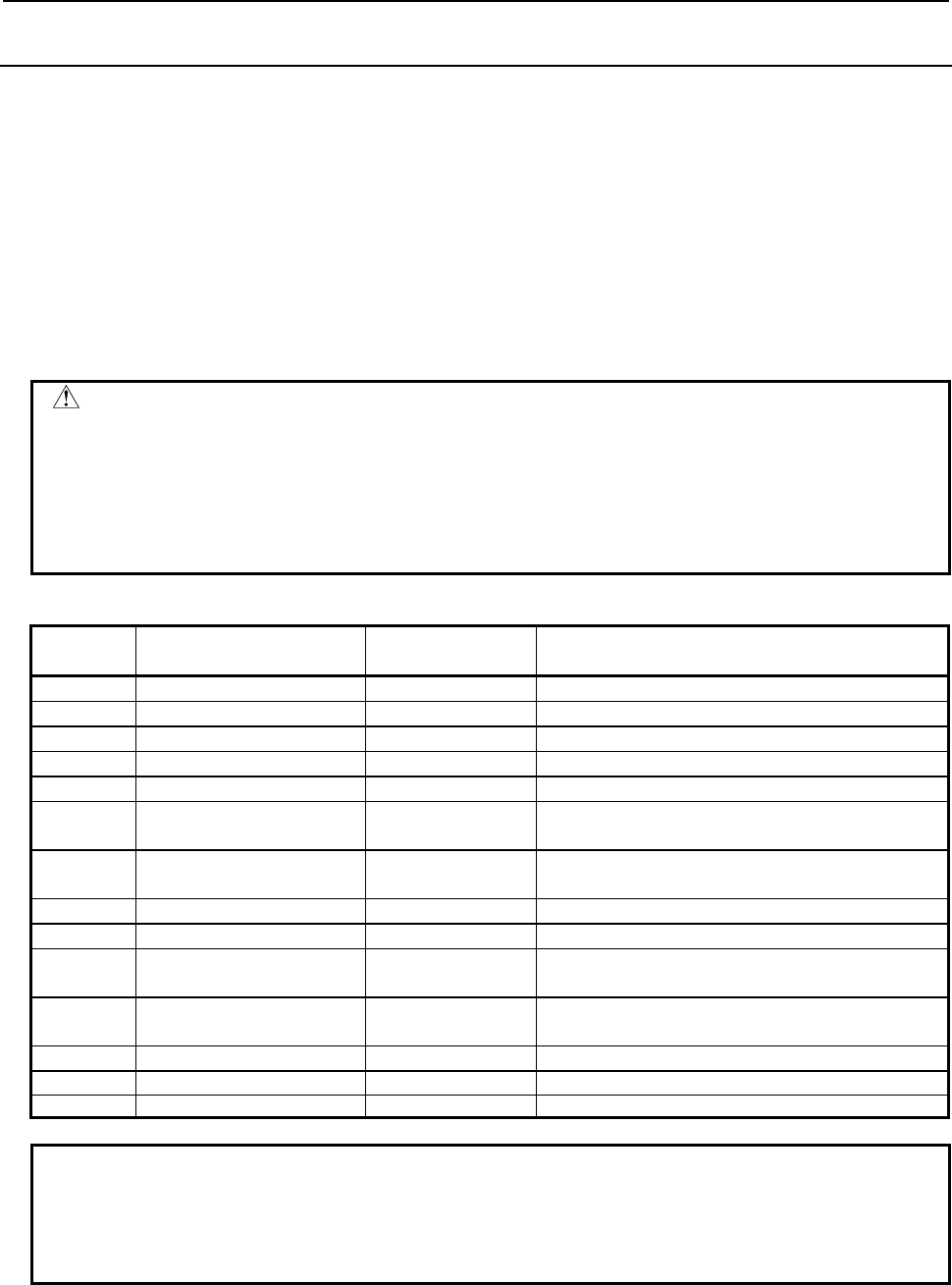
5.WINDOW FUNCTIONS
B-64513EN/03
- 900 -
5.7.27
Writing Each Edge Data (Low-speed Response)
A part of edge data can be changed based on the specified magazine number, pot number, and edge
position. The tool management data number can be specified instead of magazine number and pot number.
If the tool except a multi-edge tool is specified, completion code 5 and detailed completion code 95 is
returned. In the case of a free pot (a tool management data number is not assigned), completion code 9 is
returned.
If zero is specified to edge position, the edge position stored in multi-edge tool is automatically selected.
If invalid edge position is specified, completion code 3 and detailed completion code 96 is returned.
Enter the data type number to be change, as the data attribute.
The size of the required data area differs depending on the data type.
The following table shows the relationship between each data type number and its corresponding data and
required data area size.
WARNING
When you write some NC data using both this instruction in ladder program and
other applications, take care that you do not write to the same data area.
If some values are written to the same data area by two or more applications
including ladder program, unexpected value may be written. In this case, it may
cause an unexpected machine behavior and also tools, work pieces, and
machines may be damaged. As for details, refer to “SAFETY PRECAUTIONS”.
Table 5.7.27 (a) Data, data type number and data area size
Data type
number Data Data area size Remarks
2 Tool life counter 4 bytes
3 Maximum tool life 4 bytes
4 Notice tool life 4 bytes
5 Tool life status 1 byte
6 Customized data 0 1 byte
8 Tool length compensation
number (H) 2 bytes * for milling or compound system
9 Cutter compensation
number (D) 2 bytes * for milling or compound system
10 Spindle speed (S) 4 bytes
11 Cutting feedrate (F) 4 bytes
12 Tool geometric
compensation number (G) 2 bytes * for lathe or compound system
13 Tool wear compensation
number (W) 2 bytes * for lathe or compound system
31 Customized data 1 4 bytes
~ ~ ~
34 Customized data 4 4 bytes
NOTE
To use this window function, the option of “Tool pair for tool management
function: 64, 240 or 1000 pairs” and the option of "Tool management function for
multi-edge tools" are necessary. Moreover, set the parameter MEB
(No.13210#3) to 1.

B-64513EN/03
5.WINDOW FUNCTIONS
- 901 -
Input data structure
Top Address +0 (Function code)
441
+2 (Completion code)
-
(Need not to be set)
+4 (Data length L)
1, 2, 4
Set the length of data that you want to write.
+6 (Data number N)
Magazine number
If you want to specify the tool management data
number, set zero to this field.
+8 (Data attribute M)
Data type number
+10 (Data number N2)
Pot number or tool management
data number
+12 (Detailed Completion code)
-
(Need not to be set)
+14 Edge position
(4 bytes)
If you want to specify the edge position stored in a
multi-edge tool, set zero to this field.
+18 (Data area 1)
(4 bytes)
(Need not to be set)
+22
+n
(Data area 2)
(1, 2, 4 bytes)
Set the data that you want to write. The size of the
required data area differs depending on the data
type.
Completion codes
0 The processing has been executed normally.
2 The data length is invalid.
3 (See the following detailed completion codes.)
4 The specified data type is invalid.
5 (See the following detailed completion codes.)
6 The necessary option or parameter is not found.
7 The area is protected.
9 Free pot.
Detailed completion codes
The detailed completion code is always 0 when the completion code is other than 3 or 5.
When the completion code is 3, the detailed completion code is one of the following values:
21 The magazine number is invalid.
22 The pot number is invalid.
23 The tool management data number is invalid.
96 The edge position is invalid.
When the completion code is 5, the detailed completion code is one of the following values:
2 The specified tool life counter is invalid.
3 The specified maximum tool life is invalid.
4 The specified notice tool life is invalid.
5 The specified tool life status is invalid.
6 The specified customized data 0 is invalid.

5.WINDOW FUNCTIONS
B-64513EN/03
- 902 -
8 The specified tool length compensation number (H) is invalid.
9 The specified cutter compensation number (D) is invalid.
10 The specified spindle speed (S) is invalid.
11 The specified cutting feedrate (F) is invalid.
12 The specified tool geometric compensation number (G) is invalid.
13 The specified tool wear compensation number (W) is invalid.
31 to 34 The specified customized data (1 to 4) is invalid.
95 The tool except a multi-edge tool is specified.
Output data structure
Top Address +0 (Function code)
441
+2 (Completion code)
?
(See above description)
+4 (Data length L)
(Same as input data)
+6 (Data number N)
Magazine number
(Same as input data)
+8 (Data attribute M)
Data type number
(Same as input data)
+10 (Data number N2)
Pot number or tool management
data number
(Same as input data)
+12 (Detailed completion code)
?
(See above description)
+14 Edge position
(4 bytes)
(Same as input data)
+18 Written edge position
(4 bytes)
The same value as the edge position set to +14 is
read. However, when 0 is specified, the edge
position stored in the multi-edge tool is read.
+22 (Data area)
(1, 2, 4 bytes)
(Same as input data)

B-64513EN/03
5.WINDOW FUNCTIONS
- 903 -
5.7.28
Reading the Total Tool Life Data of an Edge (Low-speed
Response)
This function can read a total tool life data of multi-edge tools corresponding to the specified tool type
number, the life count type, and edge position.
If the tool except a multi-edge tool is specified, completion code 5 and detailed completion code 95 is
returned. And, if zero or invalid edge position is specified, completion code 3 and detailed completion
code 96 is returned.
NOTE
To use this window function, the option of “Tool pair for tool management
function: 64, 240 or 1000 pairs” and the option of "Tool management function for
multi-edge tools" are necessary. Moreover, set the parameter MEB
(No.13210#3) to 1.
Input data structure
Top Address +0 (Function code)
442
+2 (Completion code)
-
(Need not to be set)
+4 (Data length L)
-
(Need not to be set)
+6 (Data number N)
Tool type number
Set the tool type number with signed binary format
in 4bytes length.
+10 (Data attribute M)
Life count type
Set the life count type with signed binary format in
2bytes length.
M=0: Count, 1: Time
+12 (Detailed Completion code)
-
(Need not to be set)
+14 Edge position
(4 bytes)
+18 (Reserved)
(4 bytes)
Set zero to this field.
+22
+45
(Data area)
(24 bytes)
(Need not to be set)
Completion codes
0 The processing has been executed normally.
3 (See the following detailed completion codes.)
4 The specified tool count type is invalid.
3 (See the following detailed completion codes.)
6 The necessary option or parameter is not found.

5.WINDOW FUNCTIONS
B-64513EN/03
- 904 -
Detailed completion codes
The detailed completion code is always 0 when the completion code is other than 3 or 5.
When the completion code is 3, the detailed completion code is one of the following values:
1 The tool type number is invalid. (Except for 1 through 99999999)
28 No specified tool type number
96 The edge position is invalid.
When the completion code is 5, the detailed completion code is one of the following values:
95 The tool except a multi-edge tool is specified.
Output data structure
Top Address +0 (Function code)
442
+2 (Completion code)
?
(See above description)
+4 (Data length L)
24
+6 (Data number N)
Tool type number
(Same as input data)
+10 (Data attribute M)
Life count type
(Same as input data)
+12 (Detailed completion code)
?
(See above description)
+14 Edge position
(4 bytes)
(Same as input data)
+18 (Reserved)
0
(Same as input data)
+22 Tool type number
(4bytes)
This is the same as "N: Data number" which you
specify.
+26 Total life counter
(4bytes)
The unit of this data is indicated by "+45: Life count
type".
+30 Total remaining life
(4bytes)
The unit of this data is indicated by "+45: Life count
type".
+34 Total maximum life
(4bytes)
The unit of this data is indicated by "+45: Life count
type".
+38 Total notice life
(4bytes)
The unit of this data is indicated by "+45: Life count
type".
+42 Tool count
(2bytes)
The tools, which have the specified tool type
number and tool life type, are counted.
+44 Total life status
(1byte)
0: Not noticed, 1: Noticed
+45 Life count type
(1byte)
0: Count, 1: Time (second), 2: Time (millisecond)
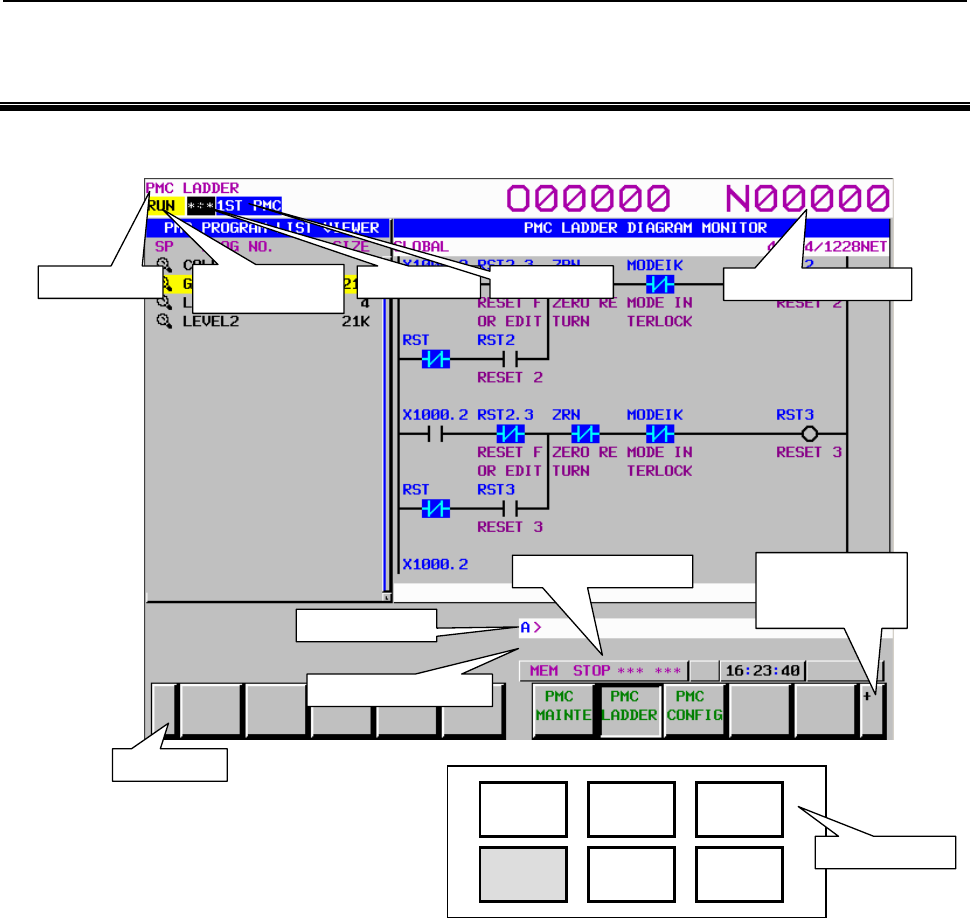
B-64513EN/03
6.OPERATING THE PMC SCREEN
- 905 -
6 OPERATING THE PMC SCREEN
The basic configuration of the PMC screen is described below.
Screen title
[+]
Soft key page
turning key
Return key
OFFSET
SETTING
SYSTEM
MESSAGE
GRAPH
POS PROG
Message display line
Key entry line
NC status indication
Ladder
execution status
PMC alarm
Function keys
NC program number
PMC
p
ath
• Screen title:
Displays the name of a specific submenu of the PMC.
• Ladder execution status:
Displays the execution status of the ladder program.
• PMC alarm:
Indicates whether any PMC alarm is occurring.
• PMC path:
Displays the currently selected PMC.
• NC program number:
Displays the currently selected NC program number.
• Key entry line:
Line for entering a numerical value or character key string.
• Message display line:
Displays an error or warning message.
• NC status indication:
Displays the NC mode, the execution status of the NC program, the currently selected NC path
number.

6.OPERATING THE PMC SCREEN
B-64513EN/03
- 906 -
• Return key:
Used to switch from the PMC operation menu to a specific PMC submenu or from a specific PMC
submenu to the main menu of the PMC.
• Soft key page turning key:
Used to turn soft key pages.
About the PMC screen
When you click the "SYSTEM" function key and then turn the soft key page by clicking the [+] soft key,
the main menu of the PMC is displayed.
The PMC main menu offers the following three types of submenus, which are respectively used for
specific purposes.
• PMC maintenance
• PMC ladder
• PMC configuration
Each of these PMC submenus is explained below.
(1) PMC maintenance menu
This menu displays the screens related to the maintenance of the PMC, such as those for PMC signal
status monitoring and traces and for PMC data display and editing.
(2) PMC ladder menu
This menu displays the screens related to the display and editing of the ladder program.
(3) PMC configuration menu
This menu displays the screens related to the display and editing of the data other than the ladder
constituting the sequence program, as well as the screen for setting the PMC functions.
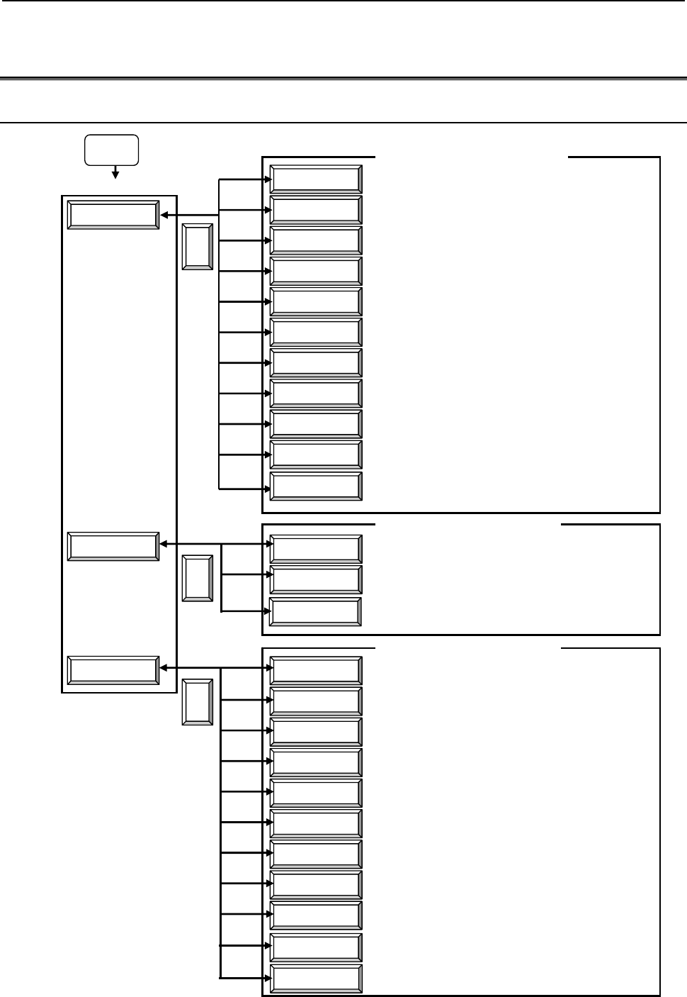
B-64513EN/03
6.OPERATING THE PMC SCREEN
- 907 -
6.1 OPERATION SCREENS OF THE PMC AND SOFT KEY
ORGANIZATION
6.1.1 Transition of the PMC Screens
SYSTEM
PMC MAINTE
STATUS
I/O DEVICE
PMC ALARM
I/O
TIMER
COUNTR
KEEP RELAY
DATA
TRACE
TRACE SETING
LIST
LADDER
TITLE
CONFIG PARAM
SETING
PMC STATUS
SYSTEM PARAM
MODULE
SYMBOL
MESAGE
ONLINE
PMC LADDER
PMC CONFIG
<
<
<
Signal status screen
I/O device monitor screen
PMC alarm screen
Data I/O screen
PMC parameter (timer) screen
PMC parameter (counter) screen
PMC parameter (keep relay)
screen
PMC parameter (data table) screen
Signal trace screen
Signal trace (parameter setting)
screen
Program list screen
Ladder display/editing screen
Title display/editing screen
Configuration parameter screen
PMC status screen (multi-PMC switch)
System parameter display/editing
screen
I/O module display/editing screen
Symbol and comment display/editing
screen
Message display/editing screen
Online monitoring parameter setting
screen
PMC main menu
PMC ladder submenu
PMC configuration submenu
PMC maintenance submenu
(See Section 7.1.)
(See Section 7.5.)
(See Section 7.2.)
(See Section 7.4.)
(See Subsection 7.3.1.)
(See Subsection 7.3.2.)
(See Subsection 7.3.3.)
(See Subsection 7.3.4.)
(See Subsection 7.6.1.)
(See Subsection 7.6.2.)
(See Section 8.1.)
(See Sections 8.2 to 8.5.)
(See Section 9.6.)
(See Section 9.1.)
(See Section 9.8.)
(See Section 9.4.)
(See Section 9.2.)
(See Section 9.3.)
(See Section 9.10.)
Setting screens (general, message shift,
I/O link assignment data selection,
override)
(See Section 9.5.)
(See Section 9.9.)
I/O DGN
I/O DIAGNOSIS screen (See Section 7.7.)
DUP. CHECK
Duplicate coil check screen (See Section 8.10.)
I/O Link i
I/O configuration viewer/editor screen
(I/O Link i assignment)
(See Section 9.7.)
(See Section 9.11.)
PROG LIST
PMC program list screen
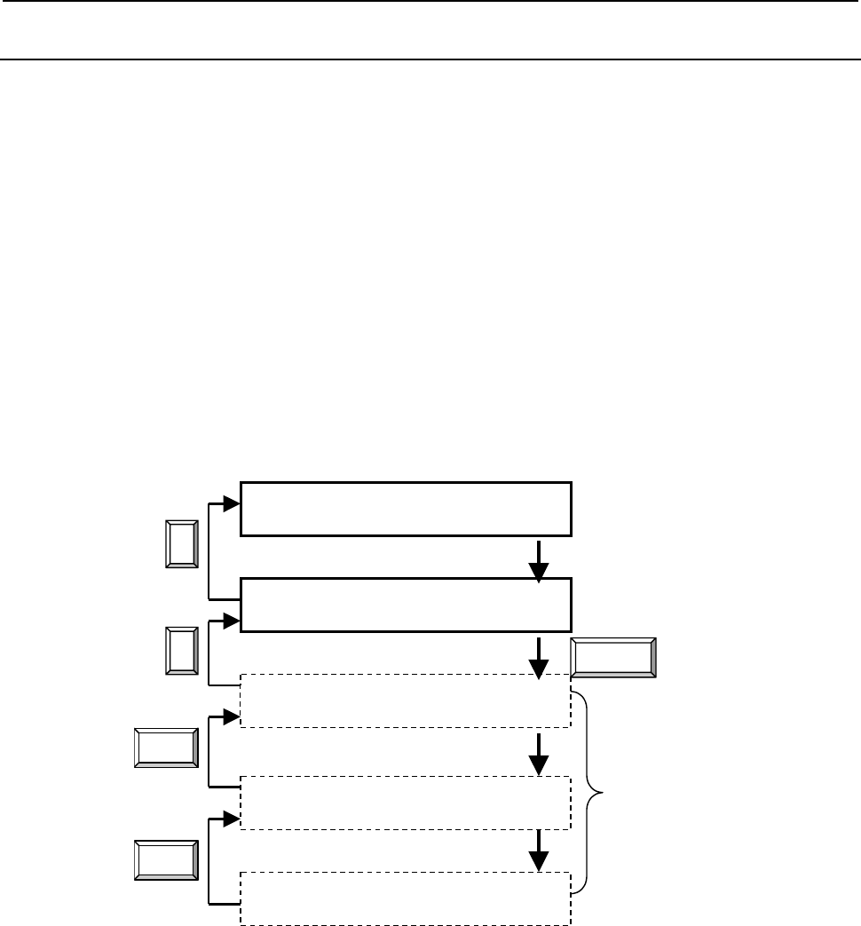
6.OPERATING THE PMC SCREEN
B-64513EN/03
- 908 -
6.1.2
Basic Screen Operations
Use the operation soft keys to operate the individual screens.
To switch to the operation soft keys, do the following:
• Click the [(OPRT)] soft key, which is one of the PMC submenu soft key.
• Enter a numerical value or character string.
To switch from the operation soft keys to a specific PMC submenu or to the PMC main menu, click the
[<] soft key.
No operation soft keys are displayed when the screen requires no operation. In that case, the [(OPRT)]
soft key is not displayed, either.
On the other hand, a screen that involves multiple different functions consists of two or more layers of
operation soft keys.
In that case, to return from the operation soft keys of one layer to those of the previous layer, click the
[EXIT] soft key.
A transition diagram for the PMC main menu soft keys, PMC submenu soft keys, and operation soft keys
is shown below.
PMC main menu soft keys
PMC submenu soft keys
Operation soft keys (1st layer)
Operation soft keys (2nd layer)
<
<
Operation soft keys (3rd layer)
EXIT
(OPRT)
The number of
operation soft key
layers differs for
each screen.
EXIT
Fig. 6.1.2 Transition diagram for the PMC soft keys
Example) Ladder display/editing screen
Operate the ladder display/editing screen by switching three layers of operation soft keys - ladder display
operation soft keys (1st layer), ladder editing operation soft keys (2nd layer), and ladder net editing
operation soft keys (3rd layer).
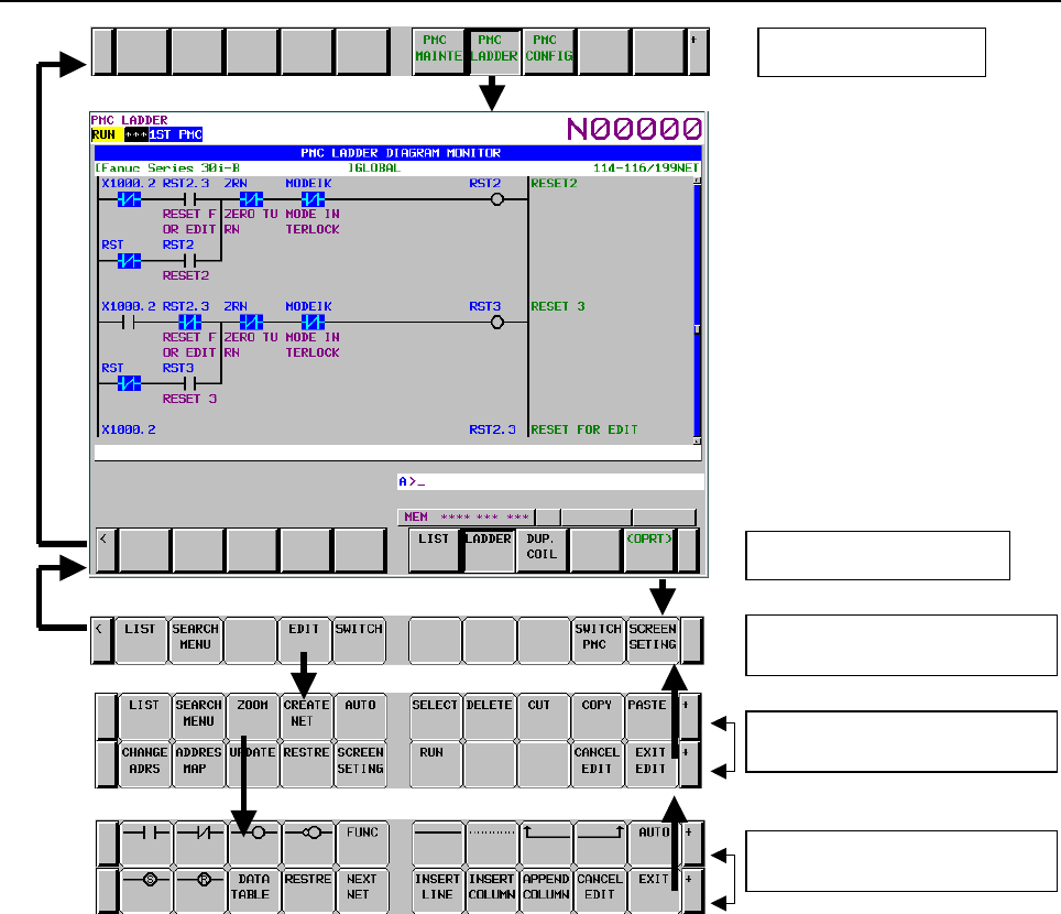
B-64513EN/03
6.OPERATING THE PMC SCREEN
- 909 -
PMC main menu
PMC ladder submenu
Ladder display operation soft keys
(1st layer)
Ladder editing operation soft keys
(2nd layer)
Ladder net editing operation soft keys
(3rd layer)

6.OPERATING THE PMC SCREEN
B-64513EN/03
- 910 -
6.2 DISPLAY AND OPERATION CONDITIONS FOR SCREENS
Several PMC screens can be protected from unauthorized attempts to display data or operate the screen,
based on preset conditions. This section describes such display and operation conditions.
There are two kinds of data protection for PMC. One is the Programmer Protection Function and another
is Protection of Data at 8 Levels.
The Programmer Protection Function is effective in standard. When the Protection of Data at 8 Levels is
added, the Programmer Protection Function becomes ineffective and the Protection of Data at 8 Levels
becomes effective.
6.2.1 Programmer Protection Function
CAUTION
This section contains important information for developers of application system
controlled by PMC. Improperly implemented application system may increase
possibility of defects in its safety. Careful examinations and considerations on
using and implementing with the functions explained especially in this section
are strongly required.
PMC system provides various embedded programmer functions such as edit, diagnosis and debugging
which help the programming and debugging of sequence program. To use these functions which may
even disable safety mechanism realized by sequence program, it is required that the operator of these
functions should be an expert who fully understands the sequence program and the operation of PMC. It
is also strongly recommended to the developer of machine that these functions should be protected from
careless use by ordinary operators after the machine is shipped into the field. Furthermore, if these
functions partly need to be used in the field for any purpose such as the maintenance or adjustment, the
developer of the machine should implement any means to enable these functions after forcing the
machine in safe mode or should let the operator know and strictly follow proper procedure to ensure the
safety.
The setting parameters described in this section are provided for the developer of machine to be able to
properly program the sequence or control the parameters for necessary conditions on which the operator
is allowed to use PMC programmer functions safely by eliminating careless operation which may cause
"stopping the ladder", "changing sequence program" or "changing important setting data".
These parameters can be set on the setting screen or in some system keep relays (K900 to 999).
NOTE
1 When using the ladder dividing management function, divided ladder programs
are protected in the same condition as main ladder program.
2 When using PMC memory shared mode in multi-path PMC function, the ladder
program in the path is protected in same condition as 1st path PMC.
PROGRAMMER ENABLE (K900.1)
If you set "PROGRAMMER ENABLE" to "YES", it enables the following functions as a supervisor
mode.
• Ladder editing screen
• Title data editing screen
• Symbol/comment data editing screen
• Message data editing screen
• I/O unit address setting screen
• Start/stop of ladder
• Forcing function

B-64513EN/03
6.OPERATING THE PMC SCREEN
- 911 -
• Override function (Note1)
• Setting of multi-language message display function
• Data I/O screen
• System parameter screen
• Parameter setting screen for online monitor
• Setting screen for the I/O Link assignment data selection function
• Setting screen for keep relay K900 or after
• Configuration parameter screen
• Sequence program input and output
• Data setting in the timer, counter, keep relay and data screen (Note2)
• PMC parameter input and output (Note3)
• Input and output of message data for multi-language display
• Saving of a sequence program to flash ROM
• Saving of message data for multi-language display to flash ROM
• I/O configuration viewer screen (I/O Link i assignment)
• I/O configuration editor screen (I/O Link i assignment)
• Input and Output of I/O configuration data
• Saving of I/O configuration data to flash ROM
• I/O configuration viewer screen (I/O Link i selectable I/O)
• Registration and deletion of I/O devices in I/O device monitor screen
NOTE
1 The override function also requires the setting of "OVERRIDE ENABLE" in the
setting parameters.
2 In order to change the data in each PMC parameter screen, particular
operations are necessity. For details, refer to subsection “6.2.2”.
3 In order to input/output the PMC parameters in the date I/O screen, particular
operations are necessity. For details, refer to subsection “6.2.2”.
WARNING
If the sequence program is stopped while the machine is operating, the machine
may cause unexpected operation. Before stopping the sequence program,
make sure that there is no one near the machine and that the tool will not collide
with the workpiece or machine. Operating the machine in any inappropriate
fashion can result in the death of or serious injury to the user. The tool,
workpiece, and/or machine can also be damaged.
CAUTION
Set this setting to "NO"(0) before shipment of the machine. If this setting is left
as "YES"(1), the operator may stop execution of the ladder program by mistake.
If you want to protect this setting, make a sequence that always writes 0 in this
bit by your ladder. Or control the machine to force to translate into safety state
by sequence program using the way described in Section 2.2.4 when the ladder
stops.

6.OPERATING THE PMC SCREEN
B-64513EN/03
- 912 -
HIDE PMC PROGRAM (K900.0)
If you set "HIDE PMC PROGRAM" to "YES", it disables the following functions which have the
sequence program display.
• Ladder monitor screen
• Ladder editing screen
• Title data screen
• Title data editor screen
• Symbol/comment data viewer screen
• Symbol/comment data editor screen
• Message data viewer screen
• Message data editor screen
• I/O module viewer screen
• I/O module editor screen
• Clear of PMC parameter
• System parameter viewer screen
• System parameter editor screen
• Output of sequence program
• Output of message data for multi-language display
• I/O configuration viewer screen (I/O Link i assignment)
• I/O configuration editor screen (I/O Link i assignment)
• Output of I/O configuration data
NOTE
Even if this parameter is set to "YES", these functions will not be hidden except
for Ladder monitor/editing screen if "PROGRAMMER ENABLE" is set to "YES".
EDIT ENABLE (K901.6)
If you set "EDIT ENABLE" to "YES", it enables the following functions which can edit the program.
• Ladder editing screen (Note1)
• Title data editing screen (Note1)
• Symbol/comment data editing screen (Note1) (Note2)
• Message data editing screen (Note1) (Note2)
• I/O unit address setting screen (Note1) (Note2)
• Clear of PMC parameter (Note1) (Note2)
• Setting of multi-language message display function
• System parameter screen (Note1)
• Setting screen for keep relay K900 or after
• Configuration parameter screen
• Sequence program input (Note2)
• Saving of a sequence program to flash ROM
• Input of message data for multi-language display (Note2)
• Saving of message data for multi-language display to flash ROM
NOTE
1 Even if this parameter is set to "YES", these functions, which display a part of
program, are not available if "HIDE PMC PROGRAM" is set to "YES".
2 These screens, which stop ladder program, also require the below setting
"ALLOW PMC STOP".

B-64513EN/03
6.OPERATING THE PMC SCREEN
- 913 -
CAUTION
Set this setting to "NO"(0) before shipment of the machine if you want to prohibit
operator form editing the program. If you want to protect this setting, make a
sequence that always writes 0 in this bit by your ladder.
ALLOW PMC STOP (K902.2)
If you set "ALLOW PMC STOP" to "YES", it enables the following functions which require stop/start of
ladder program. (Note1)
• Symbol/comment data editing screen (Note2)
• Message data editing screen (Note2)
• I/O unit address setting screen (Note2)
• Clear of PMC parameter (Note2)
• Start/stop of ladder
• System parameter screen (Note2)
• Input of sequence program (Note2)
• Input of message data for multi-language display (Note2)
NOTE
1 Even if this parameter is set to "YES", these functions, which display a part of
program, are not available if "HIDE PMC PROGRAM" is set to "YES".
2 These editing screens also require the above setting "EDIT ENABLE".
WARNING
If the sequence program is stopped while the machine is operating, the machine
may cause unexpected operation. Before stopping the sequence program,
make sure that there is no one near the machine and that the tool will not collide
with the workpiece or machine. Operating the machine in any inappropriate
fashion can result in the death of or serious injury to the user. The tool,
workpiece, and/or machine can also be damaged.
CAUTION
Set this setting to "NO"(0) before shipment of the machine. If this setting is left
as "YES"(1), the operator may stop execution of the ladder program by mistake.
If you want to protect this setting, make a sequence that always writes 0 in this
bit by your ladder. Or control the machine to force to translate into safety state
by sequence program using the way described in Section 2.2.4 when the ladder
stops.
RAM WRITE ENABLE (K900.4)
If you set "RAM WRITE ENABLE" to "YES", it enables the following functions, regardless of the other
protection.
• Forcing function
• Override function (Note)
• The change of the PMC parameters from the timer, counter, keep relay, and data screens is disabled.
• The input of the PMC parameters from the PMC I/O screen is disabled.

6.OPERATING THE PMC SCREEN
B-64513EN/03
- 914 -
NOTE
The override function also requires the setting of "OVERRIDE ENABLE" in the
setting parameters.
CAUTION
Set this setting to "NO"(0) before shipment of the machine. If this setting is left
as "YES"(1), the operator may modify PMC parameters or PMC signals by
mistake. If you want to protect this setting, make a sequence that always writes
0 in this bit by your ladder.
DATA TBL CNTL SCREEN (K900.7)
If you set "DATA TBL CNTL SCREEN" to "NO", the data table control screen is not displayed.
IO GROUP SELECTION (K906.1)
If you set "IO GROUP SELECTION " to "SHOW", it enables to use the following functions.
• Setting screen for the selectable I/O link assignment function
• I/O configuration viewer screen (I/O link i selectable assignment)
HIDE PMC PARAM (K902.6)
If you set "HIDE PMC PARAM" to "YES", functions that are related to the PMC parameters are
protected, as follows:
• The timer, counter, keep relay, and data screens cannot be displayed.
• The PMC I/O screen cannot output the PMC parameters.
CAUTION
1 To output the PMC parameters from the data I/O screen requires a special
operation. For information about how to enable the output of the PMC
parameters, see "Output from the data I/O screen" in Subsection 6.2.2.
2 Even if the parameter is set to “YES”, above function is not protected if the
"PROGRAMMER ENABLE" is set to "YES"
PROTECT PMC PARAM (K902.7)
If you set "PROTECT PMC PARAM" to "YES", functions that are related to the PMC parameters are
protected, as follows:
• The change of the PMC parameters from the timer, counter, keep relay, and data screens is disabled.
• The input of the PMC parameters from the PMC I/O screen is disabled.
CAUTION
1 To change the PMC parameters on an individual screen requires a special
operation. For information about how to enable the input of the PMC
parameters, see "Input from the PMC parameter screen" in Subsection 6.2.2.
2 To enter the PMC parameters from the data I/O screen requires a special
operation. For information about how to enable the input of the PMC
parameters, see "Input from the data I/O screen" in Subsection 6.2.2.
3 Even if the parameter is set to “YES”, above function is not protected if the
"PROGRAMMER ENABLE" is set to "YES"
KEEP RELAY (SYSTEM) (K906.6)
If you set " KEEP RELAY (SYSTEM)" to "SHOW", The KEEP RELAY for PMC system (after K900)
screen is enabled.

B-64513EN/03
6.OPERATING THE PMC SCREEN
- 915 -
I/O CONF EDIT ENABLE (K907.0)
If you set “I/O CONF EDIT ENABLE” to “YES”, it enables to use the following functions for editing of
I/O configuration data. In the multi-path PMC system, the setting of first path PMC is effective.
• I/O configuration editor screen (I/O Link i assignment)
• Input of I/O configuration data
• Saving of I/O configuration data to flash ROM
REGISTER I/O DEVICES (K935.1)
If you set “REGISTER I/O DEVICES” to “YES”, it enables to use the following function. In the multi-
path PMC system, the setting of first path PMC is effective.
• Registration / deletion of I/O devices configuration in the I/O device monitor screen
Example for setting parameters
(1) If you want to prohibit completely operator from accessing the sequence program;
• PROGRAMMER ENABLE (K900.1) "NO"
• HIDE PMC PROGRAM (K900.0) "YES"
• EDIT ENABLE (K901.6) "NO"
• ALLOW PMC STOP (K902.2) "NO"
(2) If you want to allow operator only monitoring the sequence program;
• PROGRAMMER ENABLE (K900.1) "NO"
• HIDE PMC PROGRAM (K900.0) "NO"
• EDIT ENABLE (K901.6) "NO"
• ALLOW PMC STOP (K902.2) "NO"
NOTE
Use the password function of sequence program to restrict the function to
particular operator. Refer to FANUC LADDER-III operator's manual B-66234EN
"5.4".
(3) If you want to allow operator monitoring and editing the sequence program;
• PROGRAMMER ENABLE (K900.1) "NO"
• HIDE PMC PROGRAM (K900.0) "NO"
• EDIT ENABLE (K901.6) "YES"
• ALLOW PMC STOP (K902.2) "NO"
NOTE
Use the password function of sequence program to restrict the function to
particular operator. Refer to FANUC LADDER-III operator's manual B-66234EN
"5.4".
(4) If you want to allow operator monitoring and editing the sequence program which requires stop of
ladder;
• PROGRAMMER ENABLE (K900.1) "NO"
• HIDE PMC PROGRAM (K900.0) "NO"
• EDIT ENABLE (K901.6) "YES"
• ALLOW PMC STOP (K902.2) "YES"
NOTE
Use the password function of sequence program to restrict the function to
particular operator. Refer to FANUC LADDER-III operator's manual B-66234EN
"5.4".

6.OPERATING THE PMC SCREEN
B-64513EN/03
- 916 -
WARNING
If a sequence program is stopped while the machine is operating, the machine
may behave unexpectedly. Before stopping the sequence program, make sure
that nobody is near the machine and that the tool cannot interfere with the work-
piece or machine. Incorrect operation of the machine presents an extreme risk of
death or serious injury to the user. Damage the tool, work-piece, and/or the
machine is also likely.
(5) The case that operator who familiar with the machine and the ladder sequence operate all the PMC
programmer functions;
• PROGRAMMER ENABLE (K900.1) "YES"
• HIDE PMC PROGRAM (K900.0) "NO"
WARNING
If a sequence program is stopped while the machine is operating, the machine
may behave unexpectedly. Before stopping the sequence program, make sure
that nobody is near the machine and that the tool cannot interfere with the work-
piece or machine. Incorrect operation of the machine presents an extreme risk
of death or serious injury to the user. Damage the tool, work-piece, and/or the
machine is also likely.
(6) If you want to prohibit the editing and input/output of the ladder and allow the input/output of the
PMC parameters:
• PROGRAMMER ENABLE (K900.1) "NO"
• RAM WRITE ENABLE (K900.4) "NO"
• HIDE PMC PROGRAM (K900.0) "YES"
• EDIT ENABLE (K901.6) "NO"
• ALLOW PMC STOP (K902.2) "NO"
• HIDE PMC PARAM (K902.6) "NO"
• PROTECT PMC PARAM (K902.7) "NO"
NOTE
1 To input the PMC parameters, place the NC in the emergency stop state and set
the PWE parameter, which is one of the NC parameters, to 1.
2 To output the PMC parameters, set the EDIT mode.

B-64513EN/03
6.OPERATING THE PMC SCREEN
- 917 -
6.2.2
PMC Parameter Input/Output Conditions
Input from the PMC parameter screen
Usually, no data can be entered for PMC parameters because they are protected. The following methods
can be used to make it possible to enter data for them.
(1) If the sequence program is running (RUN state) (usually, this method should be used when the
machine is operating.)
(a) Place the NC in MDI mode or bring it to an emergency stop. (Note1)
(b) Set "PWE" on the NC setting screen to 1 (see the following table).
(c) Alternatively, set the program protect signal (KEY4) to 1 (only if counters or data tables are
involved).
(d) The parameters are released from protection; so data can be entered for them (see the following
table).
PWE KEY4
Timer {
Counter { {
Keep relay {
Data table { {
(e) After entering data for the parameters, return "PWE" or the KEY4 signal to the previous state.
NOTE
1 Referenced NC mode is the mode of NC path to which is assigned the interface
between CNC and PMC “F/G0 to F/G767” of PMC path of present operating
screen. For details of the interface between CNC and PMC, see “1.6.2”.
(2) If the sequence program can be stopped (STOP state), for example, while it is being debugged
(a) Stop the sequence program.
(b) The parameter protection is released; so data can be entered for them.
WARNING
If a sequence program is stopped while the machine is operating, the machine
may behave unexpectedly. Before stopping the sequence program, make sure
that nobody is near the machine and that the tool cannot interfere with the
workpiece or machine. Incorrect operation of the machine presents an extreme
risk of death or serious injury to the user. Damage the tool, workpiece, and/or
the machine is also likely.
NOTE
1 These operations may be protected by the programmer protection function. For
details of the programmer protection function, see "PROTECT PMC PARAM" in
Subsection 6.2.1.
2 If you set "RAM WRITE ENABLE" to "YES", the change of the PMC parameters
is enabled, regardless of the above operations and the other protection. For the
details of "RAM WRITE ENABLE", see "RAM WRITE ENABLE" in “6.2.1”.
The guidance message displayed when protected PMC parameters are inputted on the PMC parameters
screen.
Guidance message Contents
MUST BE IN EMERGENCY STOP OR IN MDI MODE NC is not in edit mode and not in emergency stop mode.
PWE MUST BE ON PWE is 0.
EITHER PWE OR KEY4 MUST BE ON PWE is 0 and KEY4 signal is 0.
THIS FUNCTION IS PROTECTED This function is protected by the programmer protection
function or protection of data at 8 levels.
6.OPERATING THE PMC SCREEN
B-64513EN/03
- 918 -
Input from the data I/O screen
To enter the PMC parameters from the data I/O screen requires the operation described below. The
following methods can be used to enable the input of the PMC parameters.
(1) If the sequence program is running (RUN state) (Under normal circumstances, this method should
be used when the machine is operating.)
(a) Place the NC in the emergency stop state or the EDIT mode.
(b) Set "PWE" on the NC setting screen to "1".
(c) The protection of the parameters is canceled, making it possible to enter them.
(d) After entering the PMC parameters, reset "PWE" to its original state.
(2) If the sequence program is being debugged and can be stopped (STOP state)
(a) Place the sequence program in the stop state.
(b) The protection of the parameters is canceled, making it possible to enter them.
NOTE
1 These operations may be protected by the programmer protection function. For
details of the programmer protection function, see "PROTECT PMC PARAM" in
Subsection 6.2.1.
2 If you set "RAM WRITE ENABLE" to "YES", the input of the PMC parameters
from the PMC I/O screen is enabled, regardless of the above operations and the
other protection. For details "RAM WRITE ENABLE", see "RAM WRITE
ENABLE" in Subsection 6.2.1.
The guidance message displayed when protected PMC parameters are inputted on the I/O screen.
Guidance message Contents
MUST BE IN EMERGENCY STOP OR IN EDIT MODE CNC is not in emergency stop or EDIT mode.
PWE MUST BE ON PWE is 0.
THIS FUNCTION IS NOT ALLOWED This function is protected by the programmer protection
function or protection of data at 8 levels.

B-64513EN/03
6.OPERATING THE PMC SCREEN
- 919 -
Output from the data I/O screen
To output the PMC parameters from the data I/O screen requires the operation described below. The
following methods can be used to enable the output of the PMC parameters.
(1) If the sequence program is running (RUN state) (Under normal circumstances, this method should
be used when the machine is operating.)
(a) Place the CNC in the emergency stop state or the EDIT mode.
(b) The protection of the parameters is canceled, making it possible to enter them.
(2) If the sequence program is being debugged and can be stopped (STOP state)
(a) Place the sequence program in the stop state.
(b) The protection of the parameters is canceled, making it possible to enter them.
NOTE
These operations may be protected by the programmer protection function. For
details of the programmer protection function, see "PROTECT PMC PARAM" in
Subsection 6.2.1.
The guidance message displayed when protected PMC parameters is outputted on the I/O screen.
Guidance message Contents
MUST BE IN EMERGENCY STOP OR IN EDIT MODE CNC is not in emergency stop or EDIT mode.
THIS FUNCTION IS NOT ALLOWED This function is protected by the programmer protection
function or protection of data at 8 levels.

6.OPERATING THE PMC SCREEN
B-64513EN/03
- 920 -
6.2.3
Password Function for Ladder Program
The password function provides protection against unauthorized attempts to display or edit the content of
the ladder program. When the password function is in use, the ladder program cannot be displayed or
edited without entering the "password" that is preset with an offline programmer such as FANUC
LADDER-III.
(1) Types of password
There are two types of password.
• Display permission password
• Edit permission password
(2) Specifiable characters for password
For a character string to be specified as a password, it needs to meet the following conditions:
• 16 characters or less in length
• Alphabetic letters (uppercase only) and/or numbers
(3) Screens to be protected
The following screens are protected by the password:
• Ladder display screen
• Ladder editing screen
• Program list display screen
• Program list editing screen
(4) Display of the protection status
The protection status of the program can be checked using the program list display screen or
program list editing screen. For details, see (2) in Section 8.1.
(5) Release from password protection
When you attempt to switch to a password-protected screen, you are asked to enter the password. In
this process, you can release the protection by entering the "password strings" and then pressing the
input key.
NOTE
1 Once the password protection is released, you will not be asked to enter the
password until you either shut down the system and turn on its power again or
replace the ladder program using the I/O function or other.
2 When you turn on the power of CNC with "X" and "O" pressed simultaneously,
the sequence program can be cleared regardless of whether the password is set
or not.
3 When K903.2=1, you will not be asked to enter the password.
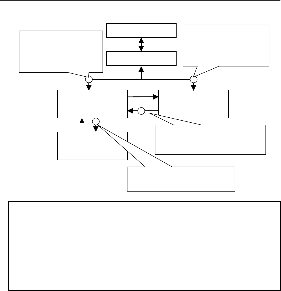
B-64513EN/03
6.OPERATING THE PMC SCREEN
- 921 -
Switching of the password-protected screens
PMC main menu
Ladder display screen Program list
display screen
Ladder editing
screen
PMC ladder menu
[ZOOM]
[LIST]
When the message appears
prompting you to enter the
password for displaying data,
enter the display permission
password or edit permission
password (*1).
When the message appears prompting you
to enter the password for displaying data,
enter the display permission password or
edit permission password (*1) (*2).
When the message appears prompting
you to enter the password for editing data,
enter the edit permission password.
[LIST]
[LADDER]
[PMC LADDER]
[EDIT][EXIT]
[<]
When the message appears
prompting you to enter the
password for displaying data,
enter the display permission
password or edit permission
password (*1).
NOTE
1 When only the display permission password is set, both the display and editing
functions are protected.
When only the edit permission password is set, the editing function is protected.
When both the display permission password and edit permission password are
set, both the display and editing functions are protected. In that case, you can
release the protection of the display and editing functions by using the edit
permission password.
2 Enter the password when you want to display the content of a program protected
by the partial protection function by using the [ZOOM] soft key. As for the partial
protection function, refer to “6.2.4”.
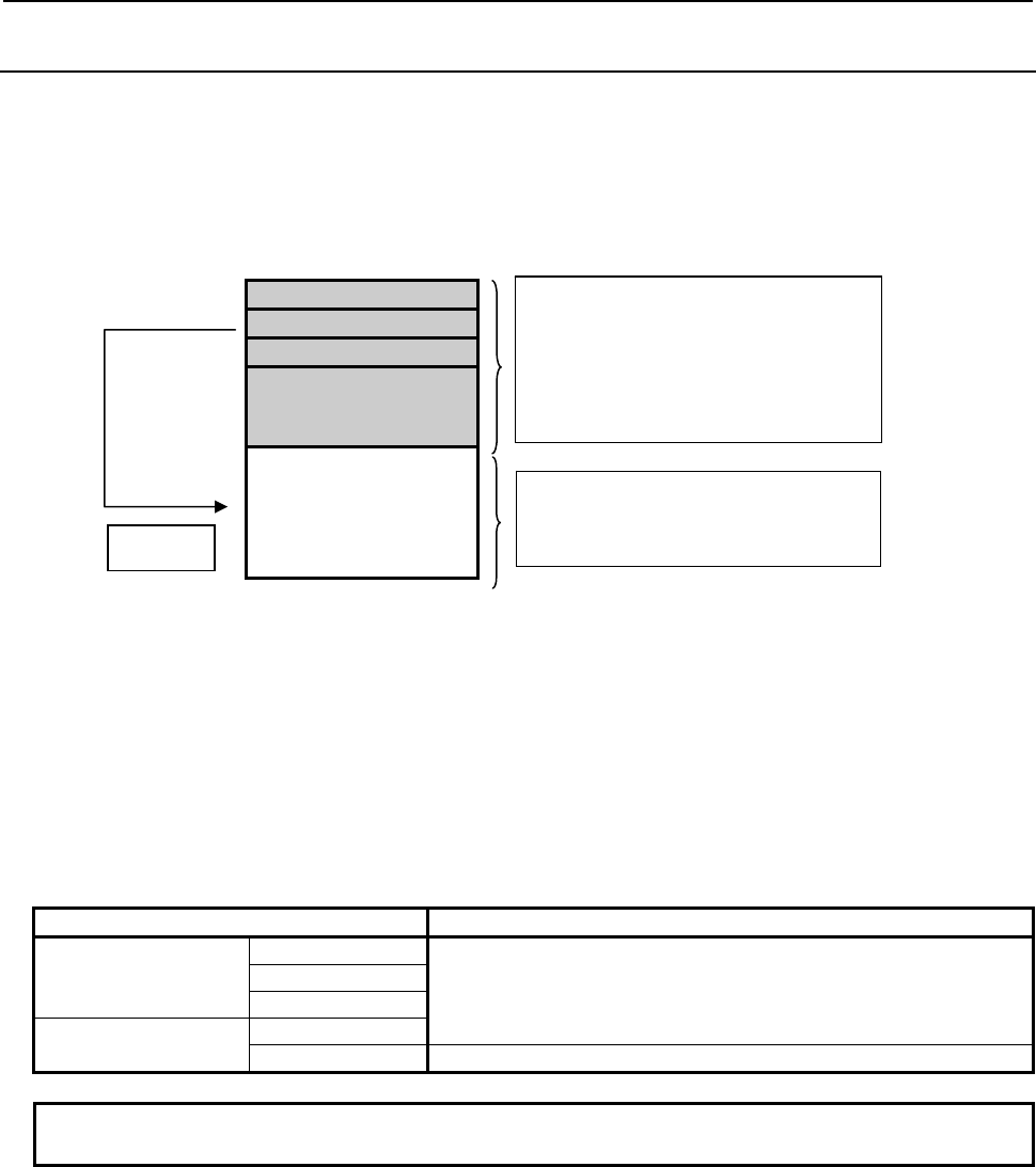
6.OPERATING THE PMC SCREEN
B-64513EN/03
- 922 -
6.2.4
Partial Protection Function for Ladder Program
This function classifies subprograms into two areas, edit protected area and unprotected area, and the
password protection affects only the edit protected area. As a result, it enables the partial edit protection
for ladder program.
Therefore, it enables for dealers or end users to customize the ladder program and protects the program of
machine tool builders.
Ladder program
Level 1
Level 2
Level 3
Subprogram
P1 to P1499
Subprogram
P1500 to P5000
Setting method
On FANUC LADDER-III, you should set the edit permission password which has “#” character at the
beginning of string (Up to 16 characters including “#”)
(Ex.) The edit permission password #1425
The subprograms from P1500 to P5000 can be edited regardless of the password protection. Even if you
set the display permission password, the display of subprograms from P1500 to P5000 is not protected
owing to this function.
Table 6.2.4 The protection status of each program for partial protection function
Program type Protected/not protected
Main programs
Level 1 The editing functions are protected by each password.
Level 2
Level 3
Sub programs P1 to P1499
P1500 to P5000 You can edit the subprograms without password.
NOTE
This function cannot be used for PMC memory A and DCSPMC.
Protected area:
Edit permission passwords can protect
the area from editing.
Machine tool builders can edit the
programs in this area
Unprotected area:
Dealers or end users can edit the
programs in this area.
CALL
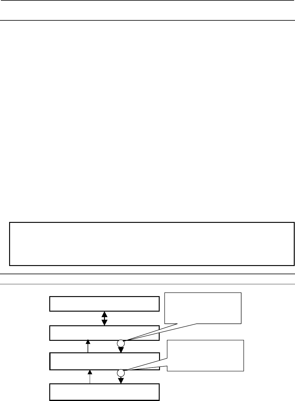
B-64513EN/03
6.OPERATING THE PMC SCREEN
- 923 -
6.2.5
Password Function for I/O Configuration Data
The password function provides protection against unauthorized attempts to display or edit of the I/O
configuration data. When using this password function, the I/O configuration data cannot be displayed or
edited without entering the "password" that is preset with an offline programmer such as FANUC
LADDER-III.
(1) Type of passwords
There are two types of password.
• Display permission password
• Edit permission password
(2) Specifiable characters for password
For a character string to be specified as a password, it needs to meet the following conditions:
• 16 characters or less in length
• Alphabetic letters (uppercase only) and/or numbers
(3) Screens to be protected
The following screens are protected by the password:
• I/O configuration viewer screen (I/O Link i assignment)
• I/O configuration editor screen (I/O Link i assignment)
(4) Display of the protection status
The protection status of I/O configuration data can be checked using the I/O configuration viewer
screen (I/O Link i assignment) or the I/O configuration editor screen (I/O Link i assignment).
(5) Release from password protection
When you attempt to switch to a password-protected screen, you are asked to enter the password. In
this process, you can release the protection by entering the "password strings" and then pressing the
input key.
It is unnecessary to turn the power off and on again
NOTE
1 Once the password protection is released, you will not be asked to enter the
password until you either shut down the system and turn on its power again or
replace the I/O Link i assignment data using the I/O function or other.
2 When K903.2=1, you will not be asked to enter the password.
Switching of the password-protecting screen
PMC Main menu
PMC Configuration menu
[I/O Link i]
[PMC CONFIG]
[EXIT]
[<]
I/O configuration viewer
(I/O Link i assignment)
“ENTER PASSWORD TO
READ” is displayed,
and enter the password
for viewer or editor. (Note
)
[EDIT]
I/O configuration editor
(I/O Link i assignment)
“ENTER PASSWORD TO
WRITE” is displayed,
and enter the password
for editor.

6.OPERATING THE PMC SCREEN
B-64513EN/03
- 924 -
NOTE
When only the display permission password is set, both the viewer and the editor
are protected.
When only the edit permission password is set, the editor is protected.
When both the display permission password and edit permission password are
set, both the viewer and editor are protected. In that case, you can release the
protection of the viewer and the editor by using the edit permission password.
6.2.6
Protection of Data at 8 Levels
The protection of data at 8 levels is a common function of CNC and PMC.
8 operation levels can be set for CNC and PMC operation, and 8 protection levels can be set for various
types of CNC and PMC data.
When various types of CNC and PMC data are changed or output externally, the system compares the
operation level with the protection level to determine whether change or external output is allowed.
NOTE
For the details of the protection of data at 8 levels on CNC, refer to the
Connection Manual (Function) of CNC. And, refer to the OPERATOR’S Manual
of CNC for the details of operation of setting the protection levels.
CAUTION
When the protection of data at 8 levels is added, programmer protection function
of section 6.2.1 and PMC parameter input/output conditions of section 6.2.2
become ineffective. But, the password function of PMC is available with the
protection of data at 8 levels at the same time.
WARNING
All protection levels of PMC item are level 0 in the initial condition. Namely, all
PMC data are not protected. Therefore, set the opportune level (value) to
prevent a miss operation.
Operation level
8 operation levels can be set for CNC and PMC operation.
Operation levels 0 to 3 are selected by the memory protection key signal. Operation levels 4 to 7 are
selected by password.
Operation level Setting method Sample classification
7 (High) Password --
6 Password MTB
5 Password Dealer, Integrator
4 Password End user
3 Memory protection key signal User level (Level1)
2 Memory protection key signal User level (Level2)
1 Memory protection key signal User level (Level3)
0 (Low) Memory protection key signal User level (Level4)
When operation level 4 to 7 is set, the operation level remains unchanged until the password is cleared.
(The operation level also remains unchanged if the power is turned off.)
Operation level 7 is reserved for CNC and PMC maintenance.

B-64513EN/03
6.OPERATING THE PMC SCREEN
- 925 -
Data protection level
A data protection level can be set for each of the following types of data.
There are two data protection levels as shown below.
- Change protection level
Protection level used for changing data.
- Output protection level
Protection level used for externally outputting data.
Protection levels 0 (low) to 7 (high) can be set.
There are common items and items of each path when using the multi-path PMC. The setting items of
each path can be set to different level for each PMC path.
Table 6.2.6 (a) Setting items and protected action
Setting item Protected action
Data type Function Screen Operation
CONFIGURATION
PARAMETER (Note1)
CHANGE Configuration parameter screen Change
SETTING (ONLINE)
(Note1)
CHANGE Parameters for online monitor screen Change
SETTING (EACH PATH) CHANGE Setting screen Change
SEQUENCE PROGRAM
(Note2)
CHANGE Ladder diagram screen Edit
Title screen Edit
System parameter screen Edit
I/O module screen Edit
Symbol and Comment screen Edit
Message screen Edit
PMC status screen Activate/Stop program
Data I/O screen Read program
Write program to Flash ROM
OUTPUT Data I/O screen Write program to external device
PMC PARAMETER CHANGE Data I/O screen Read PMC parameter
OUTPUT Data I/O screen Write PMC parameter
TIMER CHANGE Timer screen Change
COUNTER CHANGE Counter screen Change
KEEP RELAY CHANGE Keep relay screen (user area) Change
KEEP RELAY (SYSTEM) CHANGE Keep relay screen (system area) Change
DATA TABLE CHANGE Data table screen Change
DATA TABLE CONTROL CHANGE Data table control screen Change
PMC MEMORY CHANGE Signal status screen Forced I/O function
I/O CONFIGURATION
DATA (Note1)
CHANGE I/O configuration editor screen
(I/O Link i assignment)
Edit
Data I/O screen Read I/O configuration data
Write I/O configuration data to
flash ROM
OUTPUT Data I/O screen Write I/O configuration data to
external device
I/O LINK GROUP
SELECTION (Note1)
CHANGE I/O assignment data selection function
setting screen
Change
I/O configuration viewer screen
(I/O Link i assignment)
Change
REGISTRATION OF I/O
DEVICE
CHANGE I/O device monitor screen Change
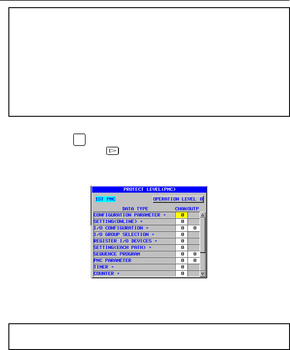
6.OPERATING THE PMC SCREEN
B-64513EN/03
- 926 -
NOTE
1 These items are common setting of all PMC paths when using multi-path PMC
function.
2 When using the ladder dividing management function, divided ladder programs
are protected in the same condition as main ladder program. However there are
invalid screens for divided ladder programs.
3 Some data types do not have an output function.
4 For data whose protection level is higher than the operation level, the protection
level cannot be changed.
5 The current data protection level cannot be changed to a protection level that is
higher than the current operation level.
6 The I/O protection level of message data for multi-language display is the same
as the I/O protection level of sequence programs.
Setting of PMC protection level
1 Press function key
OFFSET
SETTING
.
2 Press the continuous menu key several times until [PROTECT] is displayed.
3 Press soft key [PROTECT].
4 Press soft key [PMC LEVEL].
The PROTECT LEVEL (PMC) screen shown below is displayed.
Fig. 6.2.6 (a) PMC protection level setting screen
5 When using multi-path PMC function, press soft key [SWITCH PMC] to select the PMC path.
6 Move the cursor to “CHANGE” level or “OUTPUT” level of a desired data item.
7 Key in a new desired level, then press soft key [INPUT].
NOTE
Some setting items with which an asterisk is displayed after the data name are
the common data of all PMC paths when using multi-path PMC function.
B-64513EN/03
6.OPERATING THE PMC SCREEN
- 927 -
6.3 DISPLAY OF DIVIDED LADDER PROGRAM
When using the ladder dividing management function, the following PMC screens display specified
divided ladder program by pressing the [SWITCH PMC] soft key in each screen.
・Signal status screen (Note1)
・PMC parameter screen (Note1)
・I/O diagnosis screen (Note1)
・Program list screen
・Ladder display/editing screen
・Title display/editing screen
・Setting screens (Note1)
・System parameter display/editing screen
・I/O module display/editing screen (Note2)
・Symbol and comment display/editing screen
・Message display/editing screen (Note2)
・Duplicate coil check screen (Note1)
NOTE
1 To display symbol for signal address, the symbols, which are defined in specified
divided ladder program, are used.
2 These screens are displayed only in main ladder program.
The [SWITCH PMC] soft key works as follows.
Operation Behavior
Pressing the [SWITCH PMC] soft key only Switching to the next sequence program in order.
“PMC path number”+ the [SWITCH PMC] soft key Switching to the main ladder program in specified PMC path.
For example, inputting “3” and pressing this soft key selects the
main ladder program in the 3rd path
“PMC path number” - “Divided ladder program
number” + the [SWITCH PMC] soft key
Switching to the specified divided ladder program.
For example, inputting “3-2” and pressing this soft key selects
the ladder program of divided number 2 in the 3rd path.
NOTE
1 The [SWITCH PMC] soft key is displayed when using the ladder dividing
management function or the multi-path PMC function is effective.
2 There are some screens which do not have the [SWITCH PMC] soft key.
3 In 8 level data protection screen, only the PMC path is switched even if pressing
the [SWITCH PMC] soft key when using the ladder dividing management
function.
The number of the divided ladder program, which is selected, is displayed at the upper left of each PMC
screen.
(Example) The case of selecting the program of divided number 1 of 1st path PMC.
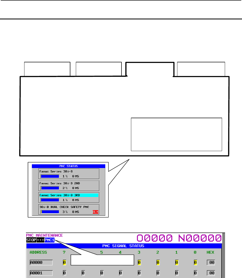
6.OPERATING THE PMC SCREEN
B-64513EN/03
- 928 -
6.4 MULTI-PMC DISPLAY
In the case of a multi-PMC system (maximum five paths), when you select a specific PMC on the PMC
status screen, each of the PMC screens listed below displays the information regarding that selected PMC.
The following figure is a case of the system of three paths PMC and dual check safety PMC.
By default, the PMC screens display the information regarding PMC1. For details of the PMC status
screen, see Section 9.6.
PMC1 PMC2 PMC3 Dual check safety
PMC
z
Signal status screen
z
PMC parameter screen
z
I/O diagnosis screen (address order / symbol order)
z
Program list screen
z
Ladder display/editing screen
z
Title display/editing screen
z
Setting screen
z
System parameter display/editing screen
z
I/O module display/editing screen
z
Symbol and comment display/editing screen
z
Message display/editing screen
The PMC status screen lets you switch
the PMC to be displayed or manipulated
on each screen. In this figure, PMC3 is
selected.
An indication of the currently selected PMC is displayed at the upper left corner of each PMC screen.
The current selected PMC

B-64513EN/03
6.OPERATING THE PMC SCREEN
- 929 -
The screens listed below display the information regarding all the PMC on the same screen space,
regardless of the switching of the PMC.
For details, see the sections describing the operation of the individual screens.
z PMC alarm screen
z I/O Link connection status screen
z Data I/O screen
z Signal trace screen
z I/O diagnosis screen (network order)
z Parameter setting screen for online monitoring
z I/O Configuration viewer/editor screen
z PMC Program list screen
Screens intended to display or manipulate all the PMCs
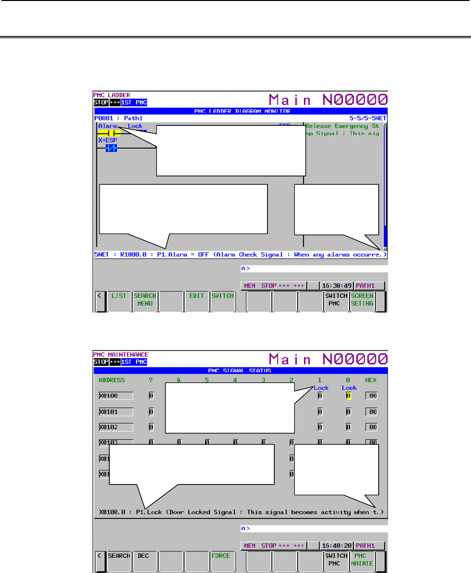
6.OPERATING THE PMC SCREEN
B-64513EN/03
- 930 -
6.5 DISPLAYING EXTENDED SYMBOL AND COMMENT
Extended symbol and comment is displayed on the PMC screen.
For details of Extended symbol and comment, see " SPECIFICATION OF EXTENDED SYMBOL AND
COMMENT " in Subsection 1.2.7.
Maximum 7 characters of a local symbol
are displayed on ladder diagram.
If no local symbol, a global symbol is
displayed.
Program No., Local symbol, value and
comment are displayed on the additional
information line.
If no local symbol, a global symbol is displayed.
A period is displayed on
the end of strings when
comment is over the
screen size.
Fig. 6.5 (a) Ladder diagram screen (extended symbol and comment)
Maximum 7 characters of a global
symbol are displayed on signal status
display area. If no global symbol, a
local symbol is displayed.
Program No., Local symbol and comment are
displayed on the additional information line.
If no local symbol, a global symbol is displayed.
A period is displayed on
the end of strings when
comment is over the
screen size.
Fig. 6.5 (b) Signal status screen (extended symbol and comment)

B-64513EN/03
6.OPERATING THE PMC SCREEN
- 931 -
When using extended symbol and comment, you can define local symbols in each sub-program.
Moreover, you can define multiple symbol and comment to one signal.
However, only one symbol and comment can to be displayed on PMC screen except I/O diagnosis screen
and symbol and comment screen, for a PMC address.
The priority of displaying symbol and comment, and range of search function is defined as follows.
Screen Displaying symbol and comment Searching symbol and comment
Ladder screen (except address map)
Program list screen
A symbol and comment is
displayed by following priority.
1 Local symbol and comment that
is defined in the displayed sub-
program.
2 Global symbol and comment.
3 Symbol undefined comment.
The following symbol and
comment can be searched.
-
Local symbol that is defined in
the displayed sub-program.
-
Global symbol.
Signal status screen
PMC parameter (timer) screen
PMC parameter (counter) screen
PMC parameter (keep relay) screen
PMC parameter (data table) screen
Signal trace screen
Signal trace (parameter setting) screen
Ladder (address map) screen
A symbol and comment is
displayed by following priority.
1 Global symbol and comment.
2 Local symbol and comment of
LEVEL1 to 3.
3 Local symbol and comment of
sub-program P1 to P5000.
4 Symbol undefined comment.
All symbols and comments can be
searched.
You can search a local symbol by
following format.
-
(program name).(symbol)
The program name is able to be
specified by sub-program number
or a symbol of P-address.
I/O diagnosis screen
Symbol and comment screen
All symbols and comments are
displayed.
All symbols and comments can be
searched. A symbol or comment
can be searched by partial string.
NOTE
When multiple symbols and comments are defined in one signal, you can search
each symbol name. On the other hand, the symbol displayed on PMC screen is
one of these symbol names. Therefore, if you search a symbol, displayed
symbol name on searched position may be different from searched word.
7.PMC DIAGNOSIS AND MAINTENANCE SCREENS ([PMC MAINTE])
B-64513EN/03
- 932 -
7 PMC DIAGNOSIS AND MAINTENANCE
SCREENS ([PMC MAINTE])
The PMC maintenance menu displays the screens related to PMC maintenance including PMC signal
status monitoring, trace, and PMC data display/editing.
In order to move to the PMC maintenance menu, press the SYSTEM key then select the [PMC MAINTE]
soft key as shown below.
SYSTEM
PMC main menu PMC maintenance submenu
PMC MAINTE STATUS
I/O DEVICE
PMC ALARM
I/O
TIMER
COUNTR
KEEP RELAY
DATA
TRACE
TRACE SETING
<
SIGNAL STATUS screen
I/O DEVICE MONITOR screen
A
LARM MESSAGE screen
DATA I/O screen
PMC PARAM (TIMER) screen
PMC PARAM (COUNTER) screen
PMC PARAM (KEEP RELAY) screen
PMC PARAM (DATA TABLE) screen
SIGNAL TRACE screen
SIGNAL TRACE (PARAMETER SETTING) screen
I/O DGN I/O DIAGNOSIS screen
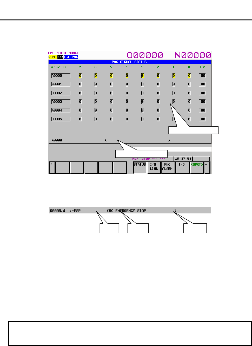
B-64513EN/03
7.PMC DIAGNOSIS AND MAINTENANCE SCREENS ([PMC MAINTE])
- 933 -
7.1 MONITORING PMC SIGNAL STATUS ([STATUS] SCREEN)
The SIGNAL STATUS screen displays the data at all addresses specified in the program. The data of
each address consists of a bit pattern (0s and/or 1s) and a hexadecimal or decimal number at the rightmost
position on a byte-by-byte basis.
The additional information line at the bottom of the screen displays the symbol and comment of the
address on which the cursor is placed. When the cursor is placed on a byte, the byte symbol and
comment are displayed.
Table contents
• ADDRESS: Address referenced by a sequence program
• 0 to 7: Data at each bit position
• HEX: Display of each byte in hexadecimal
• DEC: Display of each byte in decimal
Operation procedure
(1) Press the [STATUS] soft key. The screen shown above appears.
(2) Key in an address whose data to be displayed, and then press the [SEARCH] soft key.
(3) The data starting at the input address is displayed as a bit pattern.
(4) To display the data at another address, press the cursor keys, page keys, or [SEARCH] soft key.
(5) To modify the status of a signal, switch to the forced I/O screen by pressing the [FORCE] soft key.
NOTE
The [FORCE] soft key is displayed and usable when the forced I/O function is
enabled. For details, see Section 6.2.
Additional information line
Signal status display area
Address Symbol Comment
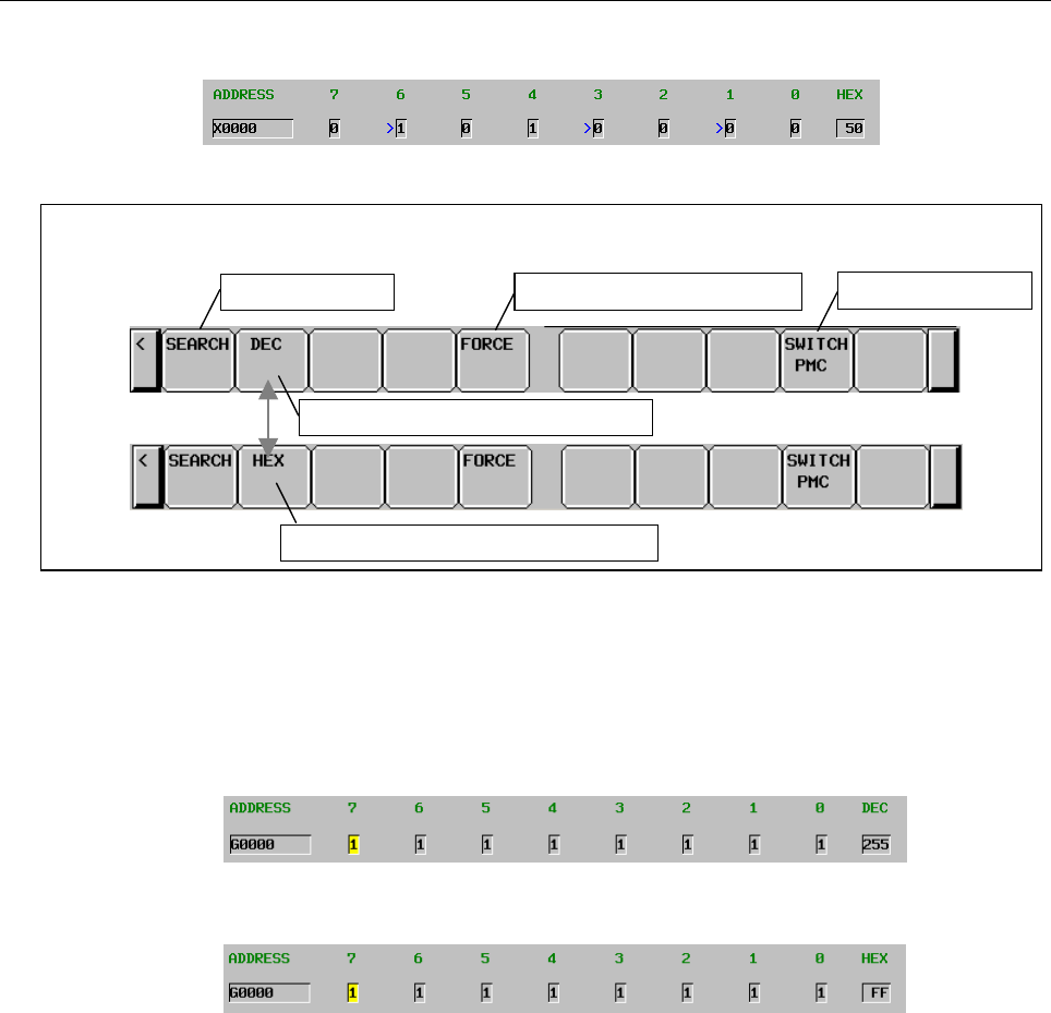
7.PMC DIAGNOSIS AND MAINTENANCE SCREENS ([PMC MAINTE])
B-64513EN/03
- 934 -
(6) On the forced I/O screen, an overridden X signal or Y signal is prefixed by a greater-than sign (>) to
indicate the setting of override.
Soft keys on the Signal Status screen
Switching to display in decimal
Switching to display in hexadecimal
A
ddress search PMC path switching
Switching to the forced I/O screen
Fig. 7.1.1 (a) Soft keys on the SIGNAL STATUS screen
Operations using soft keys
(1) [SEARCH] Search for an address
Searches for a byte address or bit address.
(2) [DEC] Switching to display in decimal
Displays the data of each byte in decimal.
This soft key is enabled only when hexadecimal display is selected.
(3) [HEX] Switching to display in hexadecimal
Displays the data of each byte in hexadecimal.
This soft key is enabled only when decimal display is selected.
(4) [FORCE] Switching to the forced I/O screen
Switches the screen display to the forced I/O screen.
(5) [SWITCH PMC] Switching PMC path or divided ladder programs
Switches PMC path or divided ladder program. For details of the operation, refer to “6.3”.
By setting keep relay K935.0 to 1, you can display PMC program list screen. For details, refer
to ”2.2.11”.
B-64513EN/03
7.PMC DIAGNOSIS AND MAINTENANCE SCREENS ([PMC MAINTE])
- 935 -
7.1.1
Forced I/O Function
The forced I/O function enables a value to be input forcibly for the signal at an arbitrary PMC address.
With this function, for example, a sequence program can be debugged without using an I/O device by
forced input to X, and the signal routing on the I/O device can be checked efficiently without using a
sequence program by forced output to Y.
Two input modes are available: the forced I/O mode and the override mode. Choose from the two modes
for each application.
WARNING
Special care must be exercised when modifying a signal with the forced
Input/output function. If the forced input/output function is used incorrectly, the
operation of the machine may be unpredictable. Never use this function when
people are near the machine.
CAUTION
1 The Override function is a special function for debugging the ladder program.
Therefore, when shipping the machine, disable the Override function invariably.
2 When using the Override function, the update cycle of input/output signals of I/O
Link is as follows with the 1st level execution cycle of ladder program. Do not
use the Override function when you debug the ladder program that is affected by
the changing of update cycle of I/O signals.
Update cycle of input/output signals
When the 1st level execution cycle is 4ms 4 ms
When the 1st level execution cycle is 1, 2 or 8ms 8 ms
3 The I/O setting values of the Override function are cleared when the power is
turned off. Therefore, Override settings for all signals are reset when cycling the
power of CNC.
4 The override function can be used in three paths PMC simultaneously. However,
the use in single-path is recommended because of the influence of scan time. If
you use this function by the setting above the maximum path number, the PMC
alarm “ER47 ILLEGAL OVERRIDE FUNCTION SETTING (TOO MANY PMC
PATHS)” occurs and the override mode is invalid in all PMC paths.
Number of the maximum path
When the 1st level execution cycle is 1 or 2ms 1
When the 1st level execution cycle is 4 or 8ms 3
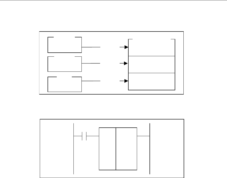
7.PMC DIAGNOSIS AND MAINTENANCE SCREENS ([PMC MAINTE])
B-64513EN/03
- 936 -
(1) Forced I/O mode
This mode is applicable to all PMC addresses.
Note, however, that a signal modified by forced I/O is overwritten by a sequence program or input
scanning, so that the result of modification by forced I/O is lost.
Example 1:
Forced I/O is performed for R0 in the following ladder program:
<1> The initial signal status is as follows:
X0.0 = off, K0 = 55H, R0 = 00H
<2> The FFh is forcibly input to the R0.
X0.0 = off, K0 = 55H, R0 = FFH
<3> When the X0.0 is turned on, the R0 assumes the result of output by the sequence program.
X0.0 = on, K0 = 55H, R0 = 55H
Machine
X
G,Y,R,T,K,C,D,E
I/O address
Overwrite
Overwrite
Overwrite
NC
Ladder
F
MOVE 1111
1111
K0
R0
X0.0
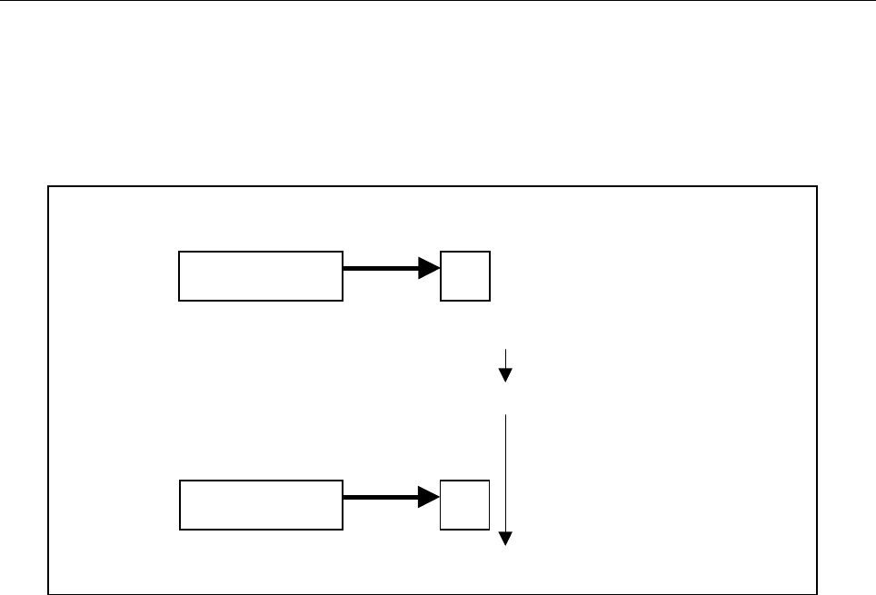
B-64513EN/03
7.PMC DIAGNOSIS AND MAINTENANCE SCREENS ([PMC MAINTE])
- 937 -
Example 2:
Forced I/O is performed for X0 in a configuration where the I/O Unit-MODEL A is connected to the
X0 via the I/O Link.
A value input from the I/O Unit-MODEL A is transferred to the X0 cyclically. Therefore, even if the
value of X0 is modified forcibly during a period, the X0 is overwritten in the next cycle by the value input
from the I/O Unit-MODEL A.
A value may be cyclically transferred even to an unallocated address. Therefore, the forced I/O function
for the X in the forced I/O mode must be used when a sequence program is debugged with no I/O device
connected or allocated.
When an I/O device is connected, use the override mode, described below, to debug a sequence program.
I/O Unit-MODEL A NC
X0 = FFh X0 = FFh
X0 = 00h
The value set by forced modification is
overwritten by the value input from the
machine.
I/O Unit-MODEL A
X0 = FFh
1. Inpu
t
from the machine
2. The value of X0 is forcibly modified to 00h.
3. Inpu
t
from the machine in the next cycle
NC
X0 = FFh
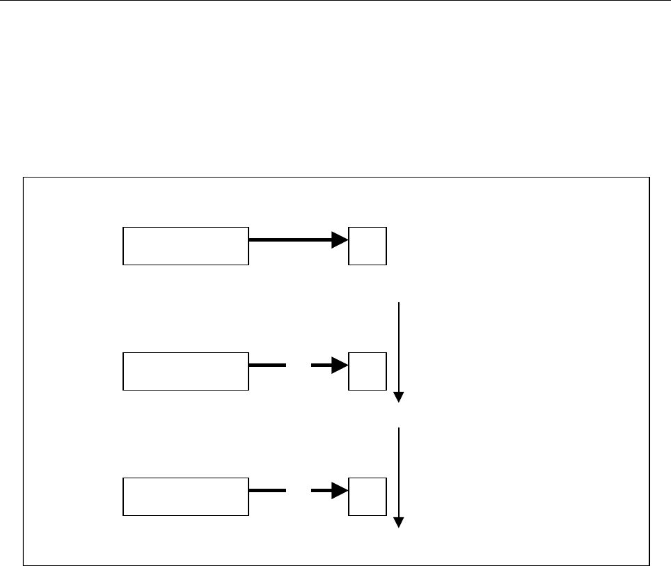
7.PMC DIAGNOSIS AND MAINTENANCE SCREENS ([PMC MAINTE])
B-64513EN/03
- 938 -
(2) Override mode
The state that disables a sequence program and machine signal from overwriting a value modified by
forced I/O is referred to as override. In the override mode, override can be set for arbitrary X and Y
signals. To the X and the Y addresses and other addresses for which override is not set, forced I/O is
applied.
Example:
Forced I/O is performed for the X0 in a configuration where the I/O Unit-MODEL A is connected to
the X0 via the I/O link.
In this way, the forced I/O function for the X in the override mode can also be used to debug a sequence
program when an I/O device is connected. If the override state is set for a Y address, a value after
modification by forced I/O is output to the I/O device.
I/O Unit-MODEL A
X0 = FFh X0 = FFh
3. The value of X0 is forcibly modified to 00h.
I/O Unit-MODEL A
X0 = FFh X0 = 00h
I/O Unit-MODEL A NC
X0 = FFh
Transfer from the I/O Unit-MODEL
A
is disabled.
×
×
NC
NC
X0 = FFh
1. Inpu
t
from the machine
2. Override is set for X0.
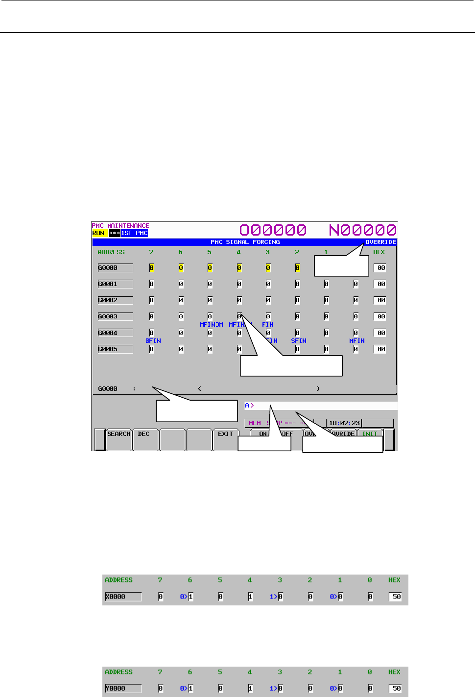
B-64513EN/03
7.PMC DIAGNOSIS AND MAINTENANCE SCREENS ([PMC MAINTE])
- 939 -
7.1.2
Forced I/O Screen
On the forced I/O screen, the value of an arbitrary signal can be modified forcibly.
The forced I/O screen can be used in one of two input modes: the forced I/O mode and the override mode.
To move to the forced I/O screen, press the [FORCE] soft key on the SIGNAL STATUS screen. On the
forced I/O screen, the following operations can be performed:
• Signal search [SEARCH]
• Switching to display/input in decimal [DEC]
• Switching to display/input in hexadecimal [HEX]
• Transition to the signal status screen [EXIT]
• Signal on [ON]
• Signal off [OFF]
• Override setting [OVRIDE SET]
• Override cancellation [OVRIDE RESET]
• Complete override cancellation [INIT]
In the input mode display area to the right of the title, "OVERRIDE" is displayed only when the forced
I/O mode is set to the override mode.
The signal status display area indicates the signal status of each address. The status shown below is
indicated for X and Y signal bits for which override is set.
(1) X signal
(Input signal from the I/O device) > (Input signal to the ladder)
The hexadecimal or decimal display field on the rightmost position of the screen displays the value
of the input signal to the ladder on the right side.
(2) Y signal
(Output signal from the ladder) > (Output signal to the I/O device)
The hexadecimal or decimal display field on the rightmost position of the screen displays the value
of the output signal to the I/O device on the left side.
Input mode
Signal status display area
Additional information
line
Message display line Key input line
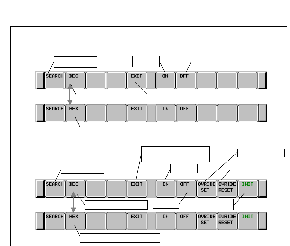
7.PMC DIAGNOSIS AND MAINTENANCE SCREENS ([PMC MAINTE])
B-64513EN/03
- 940 -
The message display line at the bottom of the screen displays an error message as required.
Fig. 7.1.2 (a) Soft keys on the forced I/O screen
Operations using the soft keys
(1) [SEARCH] Search for an address
Searches for a byte address or bit address.
(2) [DEC] Switching to decimal input
Displays and inputs the data of each byte in decimal.
This soft key is enabled only when display/input in hexadecimal is selected.
(3) [HEX] Switching to hexadecimal input
Displays and inputs the data of each byte in hexadecimal.
This soft key is enabled only when display/input in decimal is selected.
(4) [EXIT] Switching to the signal status display screen
Quits the forced I/O function.
(5) [ON] Signal on
Turns on the signal on which the cursor is placed. Depending on the cursor position, bit operation or
byte operation can be performed.
(6) [OFF] Signal off
Turns off the signal on which the cursor is placed. Depending on the cursor position, bit operation
or byte operation can be performed.
(7) [OVRIDE SET] Override setting
Sets the override state for the X or Y address on which the cursor is placed. Depending on the
cursor position, bit operation or byte operation can be performed.
This soft key is valid only in the override mode.
Soft keys on the forced I/O screen
Forced I/O
Override
Address search Signal off
Signal on
Switching to the signal status display screen
Switching to decimal input
Switching to hexadecimal input
Address search
Switching to the signal status
display screen
Switching to decimal input
Switching to hexadecimal input
Override setting
Complete override
cancellation
Signal off
Signal on Override cancellation

B-64513EN/03
7.PMC DIAGNOSIS AND MAINTENANCE SCREENS ([PMC MAINTE])
- 941 -
(8) [OVRIDE RESET] Override cancellation
Cancels the override state set for the X or Y address on which the cursor is placed. Depending on
the cursor position, bit operation or byte operation can be performed.
This soft key is valid only in the override mode.
(9) [INIT] Complete override cancellation
Cancels all override settings for X and Y addresses.
This soft key is valid only in the override mode.
Screen operations using other keys
(1) Input key
The input key is used to modify the signal status.
(a) Bit-by-bit setting
• Input 1 then press the input key to turn on the signal.
• Input 0 then press the input key to turn off the signal.
• Press the input key to toggle between the on and off statuses of the signal.
(b) Byte-by-byte setting
In the case of the byte cursor, input up to eight binary digits then press the input key. (When an
input value is shorter than eight digits, the value is input from bit 0.)
Example: When 100 is input, this value is input as follows:
Bit number 7 6 5 4 3 2 1 0
0 0 0 0 0 1 0 0
When the cursor is placed on the hexadecimal or decimal display field, hexadecimal input or
decimal input is enabled on a byte-by-byte basis.
(c) Successive data input
Data items can be input successively in a column. The cursor moves to the last input data item.
• As the data delimiter, ";" (EOB) is used.
Example: "1;0;1;" + Input key
• With ";=", the value of the immediately preceding data item is input.
Example: "1;=;=;0;=" + Input key inputs 1,1,1,0,0.
• With ";;", data items can be input, skipping an address.
Example: "1;;1" + Input key inputs no data for the second item.
• With "R;input-value;count", the same value can be input as many times as the specified
count.
Example: "R;1;200" + Input key inputs two hundred 1s in a column.
(2) Cursor keys
With the cursor keys, select a signal to be modified.
If you press the cursor key for moving left when the cursor is placed at bit 7 of an arbitrary address,
the cursor changes to a byte cursor.
If you press the cursor key for moving right when the cursor is placed on the hexadecimal or decimal
display field of an arbitrary address, the cursor changes to a byte cursor for the next one entire byte.
When the cursor is placed on the hexadecimal or decimal display field or the cursor is a byte cursor,
the one-byte signal data of the address can be modified.
(3) Page keys
The page keys can be used to select a page to be displayed.
Operation of the return key
On the forced I/O screen, the operation of the return key is disabled.
Use the [EXIT] soft key to cancel the forced I/O mode and return to the Signal Status screen.
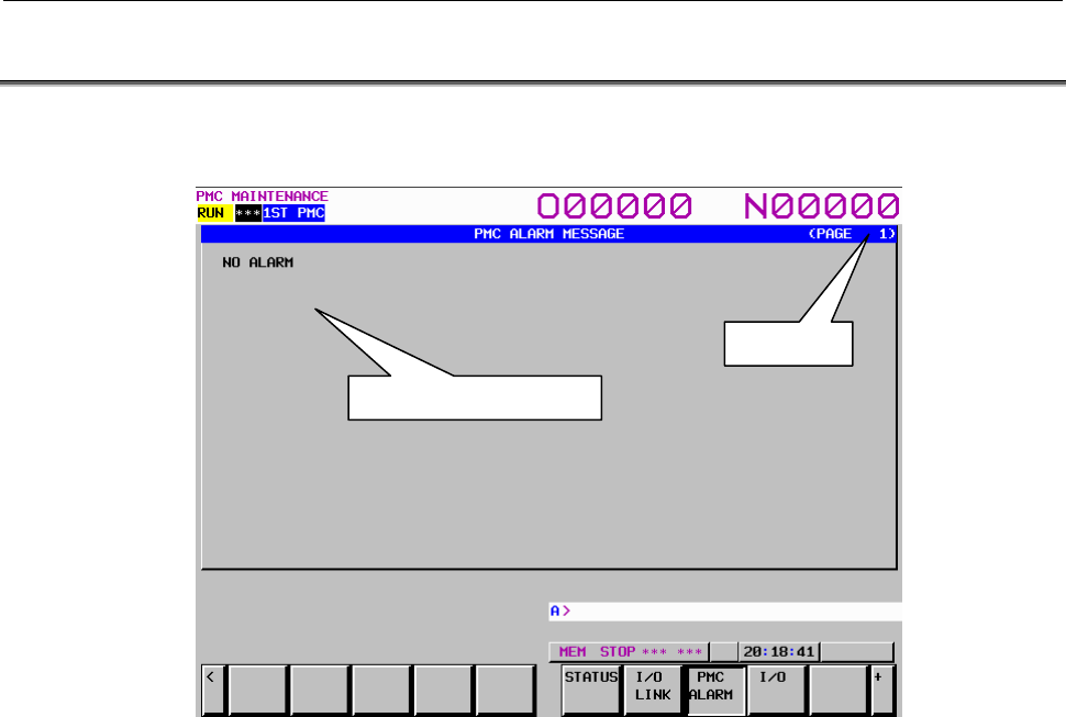
7.PMC DIAGNOSIS AND MAINTENANCE SCREENS ([PMC MAINTE])
B-64513EN/03
- 942 -
7.2 CHECKING PMC ALARMS ([PMC ALARM] SCREEN)
On this screen, an alarm message output from the PMC is displayed. To move to the PMC alarm screen,
press the [PMC ALARM] soft key.
In the alarm message display area, an alarm message output from the PMC is displayed. When many
alarm messages are output to two or more pages, the page keys can be used to switch from one page to
another.
In the page display area to the right of the title, the number of the page currently displaying messages is
indicated.
For information about messages displayed, see Section 12.1.
Alarm message display area
Page display

B-64513EN/03
7.PMC DIAGNOSIS AND MAINTENANCE SCREENS ([PMC MAINTE])
- 943 -
7.3 SETTING AND DISPLAYING PMC PARAMETERS
PMC parameters (timer, counter, keep relay, and data table) can be set and displayed on each screen.
Moreover, data items can be input successively. The cursor moves to the last data item successively input.
Method of input
(1) As the data delimiter, ";" (EOB) is used.
Example: "100;200;300;" + Input key
(2) With ";=", the value of the immediately preceding data item is input.
Example: "100;=;=;200;=" + Input key inputs 100,100,100,200,200.
(3) With ";;", data items can be input, skipping an address.
Example: "100;;100" + Input key inputs no data for the second item.
(4) With "R;input-value;count", the same value can be input as many times as the specified count.
Example: "R;100;200" + Input key inputs two hundred 100s in a column.
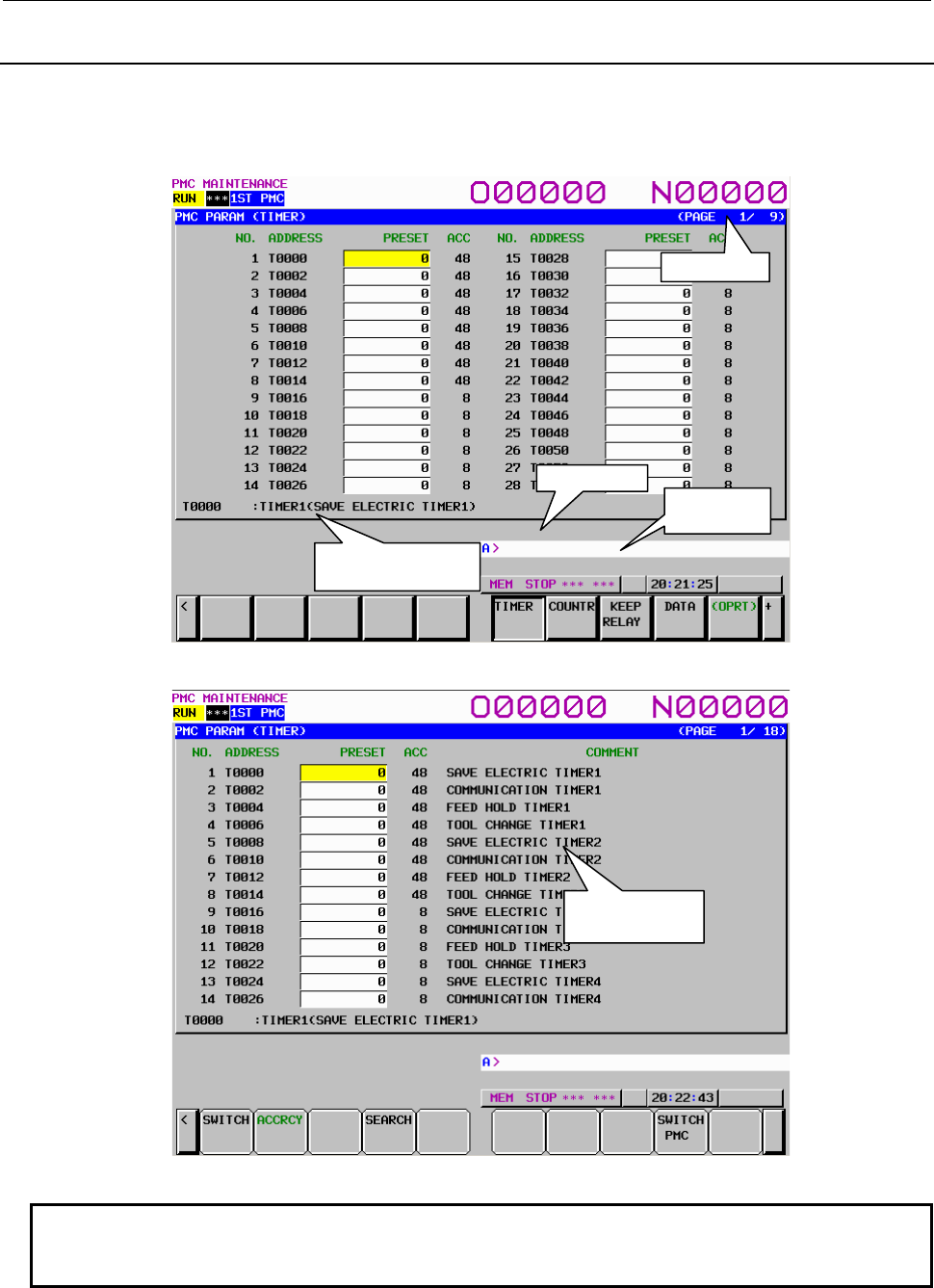
7.PMC DIAGNOSIS AND MAINTENANCE SCREENS ([PMC MAINTE])
B-64513EN/03
- 944 -
7.3.1
Setting and Displaying Timers ([TIMER] Screen)
This screen is used to set and display timer values for functional instruction on-delay timer (TMR:SUB 3).
This screen can be used in one of two modes: the simple display mode and the comment display mode.
To move to the TIMER screen, press the [TIMER] soft key.
Fig. 7.3.1 (a) Simple display mode
Fig. 7.3.1 (b) Comment display mode
NOTE
When using a display unit which has 7 soft keys, the comment display mode is
not available.
Page display
Key input line
Message
display line
Additional information
line
Comment display
area
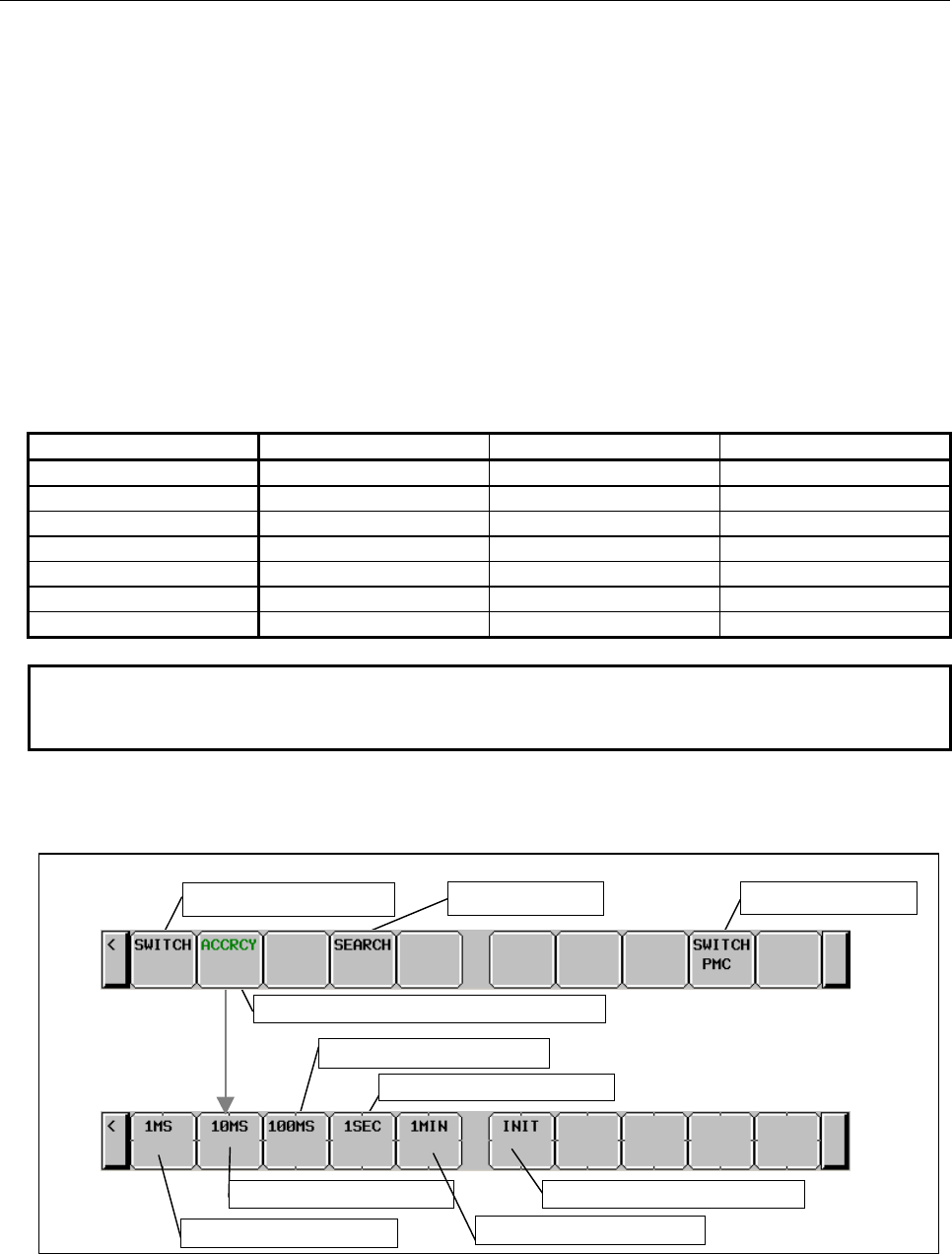
B-64513EN/03
7.PMC DIAGNOSIS AND MAINTENANCE SCREENS ([PMC MAINTE])
- 945 -
Table contents
• NO.: Timer number specified for a functional instruction timer.
• ADDRESS: Address referenced by a sequence program
• PRESET: Timer setting value
• ACC: Timer accuracy
• COMMENT: T address comment
In the PRESET column, timer setting values are displayed. When the timer accuracy is 8, 48, 1, 10, or
100 msec, only a numeric value is displayed. When the timer accuracy is the second or minute, a time
value is displayed using H, M, and S with the separator "_" used to delimit one unit from another as
follows:
aaH_bbM_ccS
In the ACC column, timer accuracy values are displayed. The table below indicates the time setting
values and notation of each accuracy value.
Timer No. Accuracy notation Minimum time setting Maximum time setting
1 to 8 48 (initial value) 48 msec 1572.8 seconds
9 to 250 8 (initial value) 8 msec 262.1 seconds
1 to 250 1 1 msec 32.7 seconds
1 to 250 10 10 msec 327.7 seconds
1 to 250 100 100 msec 54.6 minutes
1 to 250 S 1 second 546 minutes
1 to 250 M 1 minute 546 hours
NOTE
Above table is for PMC Memory-B. the timer number is 1 to 40 in PMC Memory-
A and DCSPMC, and 1 to 500 in PMC Memory-C/D.
The additional information line at the bottom of the screen displays the symbol and comment of the
address on which the cursor is placed.
Soft key
s on the
TIMER
screen
Setting accuracy to 10 msec
Switching
the
display
mode PMC path switching
T address
search
Switching
to the soft keys for accuracy setting
Setting accuracy to 100 msec
Setting accuracy to 1 second
Setting accuracy to 1 msec Setting accuracy to 1 minute
Setting accuracy to an initial
value
Fig. 7.3.1 (c) Soft keys on the TIMER screen

7.PMC DIAGNOSIS AND MAINTENANCE SCREENS ([PMC MAINTE])
B-64513EN/03
- 946 -
Operations using the soft keys
(1) [SWITCH] Switching the display mode
Switches the display mode.
NOTE
When using a display unit which has 7 soft keys, the soft key [SWITCH] is not
displayed.
(2) [ACCRCY] Switching to the soft keys for accuracy setting
Switches to the soft keys for timer accuracy setting.
(3) [SEARCH] T address search
Searches for an input T address or timer number.
(4) [SWITCH PMC] Switching PMC path or divided ladder programs
Switches PMC path or divided ladder program. For details of the operation, refer to “6.3”.
By setting keep relay K935.0 to 1, you can display PMC program list screen. For details, refer
to ”2.2.11”.
(5) [1MS] Setting accuracy to 1 msec
Sets timer accuracy to 1 msec.
(6) [10MS] Setting accuracy to 10 msec
Sets timer accuracy to 10 msec.
(7) [100MS] Setting accuracy to 100 msec
Sets timer accuracy to 100 msec.
(8) [1SEC] Setting accuracy to 1 second
Sets timer accuracy to 1 second.
(9) [1MIN] Setting accuracy to 1 minute
Sets timer accuracy to 1 minute.
(10) [INIT] Setting accuracy to an initial value
Sets the timer accuracy of the timer number on which the cursor is placed to an initial value (8 msec
or 48 msec).
Data input using the input key
When timer accuracy is set to 1 second or 1 minute, the unit is the second if S is specified at the end of an
input value; the unit is the minute if M is specified; the unit is the hour if H is specified.
Example:
When setting "2 hours, 46 minutes, 40 seconds" as the timer address for timer accuracy 1 second:
"2H46M40S"+ input key is inputted.
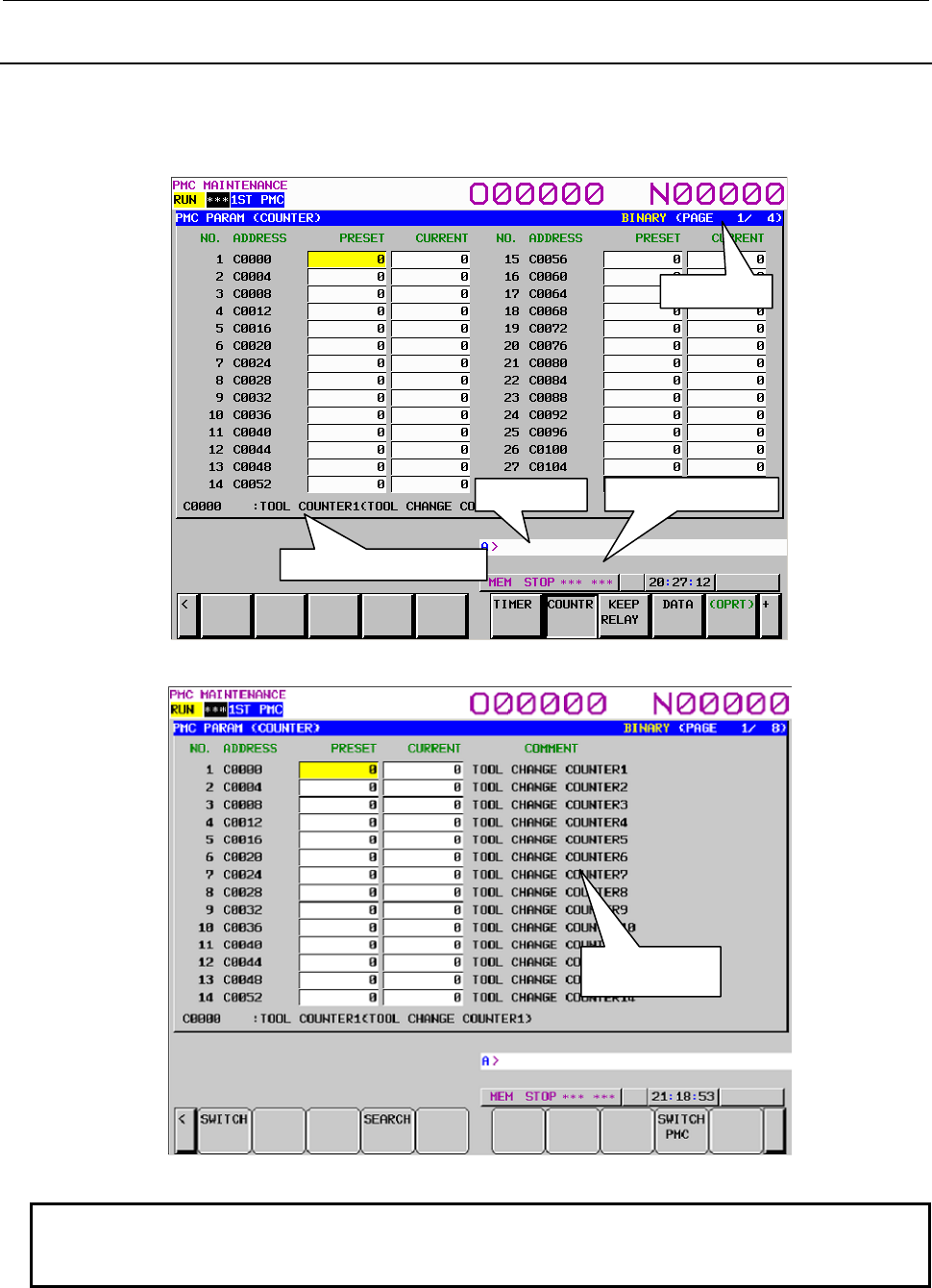
B-64513EN/03
7.PMC DIAGNOSIS AND MAINTENANCE SCREENS ([PMC MAINTE])
- 947 -
7.3.2
Setting and Displaying Counter Values ([COUNTR] Screen)
This screen is used to set and display the maximum and current counter values for functional instruction
counters (SUB 5). This screen can be used in one of two modes: the simple display mode and the
comment display mode. To move to the COUNTER screen, press the [COUNTR] soft key.
Fig. 7.3.2 (a) Simple display mode
Fig. 7.3.2 (b) Comment display mode
NOTE
When using a display unit which has 7 soft keys, the comment display mode is
not available.
Page display
Key input line
Additional information line
Message display line
Comment display
area
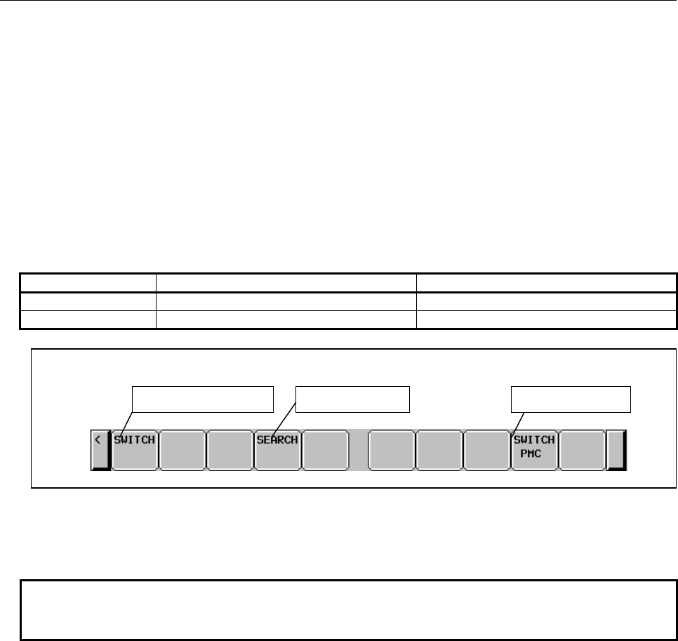
7.PMC DIAGNOSIS AND MAINTENANCE SCREENS ([PMC MAINTE])
B-64513EN/03
- 948 -
Table contents
• NO.: Counter number specified for a functional instruction counter
• ADDRESS: Address referenced by a sequence program
• PRESET: Maximum counter value (a minimum counter value is specified by a counter
instruction)
• CURRENT: Current counter value
• COMMENT: Comment on the C address of a setting value
The additional information line at the bottom of the screen displays the symbol and comment of the
address on which the cursor is placed. If the cursor is placed on a PRESET value, the symbol and
comment of the address of the PRESET value are displayed. If the cursor is placed on a CURRENT
value, the symbol and comment of the address of the CURRENT value are displayed.
Counter types and maximum values
Counter type PRESET maximum value CURRENT maximum value
BINARY 32767 32767
BCD 9999 9999
Fig. 7.3.2 (c) Soft keys on the COUNTER screen
Operations using the soft keys
(1) [SWITCH] Display mode switching
Switches the display mode.
NOTE
When using a display unit which has 7 soft keys, the soft key [SWITCH] is not
displayed.
(2) [SEARCH] C address search
Searches for an input C address or counter number.
(3) [SWITCH PMC] Switching PMC path or divided ladder programs
Switches PMC path or divided ladder program. For details of the operation, refer to “6.3”.
By setting keep relay K935.0 to 1, you can display PMC program list screen. For details, refer
to ”2.2.11”.
Soft keys on the COUNTER screen
Display mode switching C address search PMC path switching
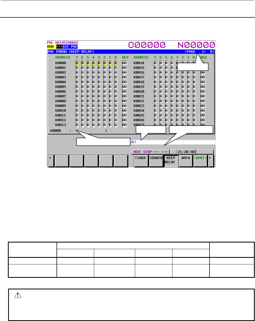
B-64513EN/03
7.PMC DIAGNOSIS AND MAINTENANCE SCREENS ([PMC MAINTE])
- 949 -
7.3.3
Setting and Displaying Keep Relays ([KEEP RELAY] Screen)
This screen is used for setting and displaying the Keep Relays. To move to the KEEP RELAY screen,
press the [KEEP RELAY] soft key.
Table contents
• ADDRESS: Address referred by sequence Program
• 0 to 7: Contents of each bit
• HEX: Value of the byte data in hexadecimal notation
The additional information line at the bottom of the screen displays the symbol and comment of the
address on which the cursor is placed. When the cursor is placed on a byte, the byte symbol and
comment are displayed.
Since Keep Relay is nonvolatile memory, the contents are not lost even if you turn off the power.
The Keep Relay area consists of parts as follows.
1st to 5th path PMC Dual check safety
PMC
PMC Memory-A PMC Memory-B PMC Memory-C PMC Memory-D
User area K0 to K19 K0 to K99 K0 to K199 K0 to K299 K0 to K19
Area for management
software K900 to K999 K900 to K999 K900 to K999 K900 to K999 K900 to K999
For details of the area for the PMC management software, see Subsection 2.2.11.
CAUTION
If the area for the PMC management software is protected by the programmer
protection function, the area is not displayed on the KEEP RELAY screen. For
details, see Section 6.2.
Page display
Additional information line
Key input line Message display line
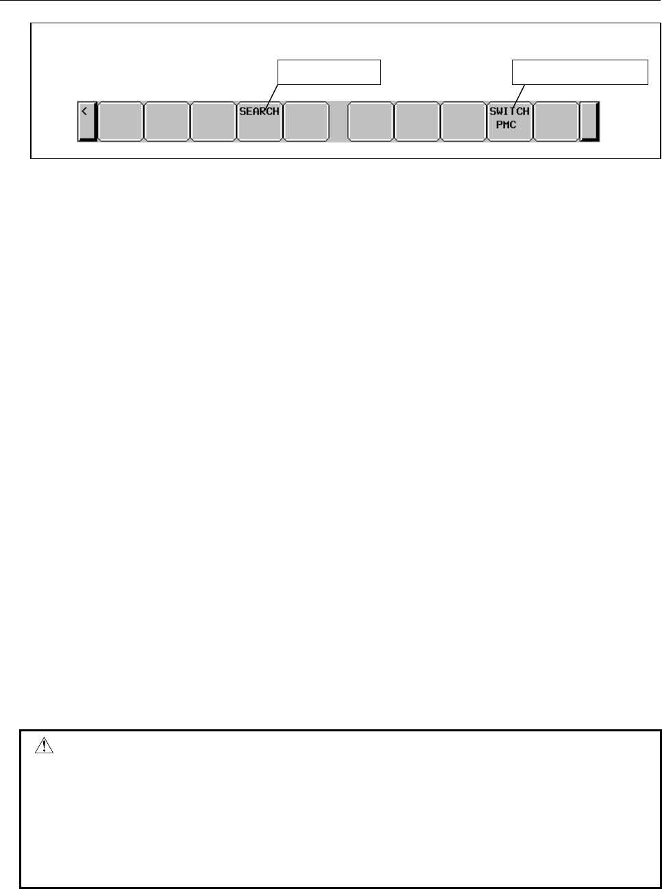
7.PMC DIAGNOSIS AND MAINTENANCE SCREENS ([PMC MAINTE])
B-64513EN/03
- 950 -
Fig. 7.3.3 Soft keys on the KEEP RELAY screen
Operations using the soft keys
(1) [SEARCH] K address search
Searches for an input K address.
(2) [SWITCH PMC] Switching PMC path or divided ladder programs
Switches PMC path or divided ladder program. For details of the operation, refer to “6.3”.
By setting keep relay K935.0 to 1, you can display PMC program list screen. For details, refer
to ”2.2.11”.
Data input using the input key
The input key is used to modify the signal status.
(1) Bit-by-bit setting
• Input 1 then press the input key to turn on the signal.
• Input 0 then press the input key to turn off the signal.
(2) Byte-by-byte setting
In the case of the byte cursor, input up to eight binary digits then press the input key. (When an
input value is shorter than eight digits, the value is input from bit 0.)
Example: When 100 is input, this value is input as follows:
Bit number 7 6 5 4 3 2 1 0
0 0 0 0 0 1 0 0
When the cursor is placed on the hexadecimal display field, hexadecimal input is enabled on a byte-
by-byte basis.
Cursor keys
With the cursor keys, select a signal to be modified.
If you press the cursor key for moving left when the cursor is placed at bit 7 of an arbitrary address, the
cursor changes to a byte cursor.
If you press the cursor key for moving right when the cursor is placed on the hexadecimal display field of
an arbitrary address, the cursor changes to a byte cursor for the next one entire byte.
When the cursor is on the hexadecimal display field or the cursor is a byte cursor, the one-byte signal data
of the address can be modified.
CAUTION
1 Do not use the area for PMC management software. This area is not same as
ordinary keep relays for ladder, because the relays in this area are reserved for
PMC system software use, and they affect behavior of the PMC software. Set
"0" to any relays that are not mentioned about their usage, to prevent
unexpected behavior of PMC.
2 Be sure to set the reserved portion of the area for the PMC management
software to 0.
Soft keys on the KEEP RELA
Y
screen
K address search PMC path switching
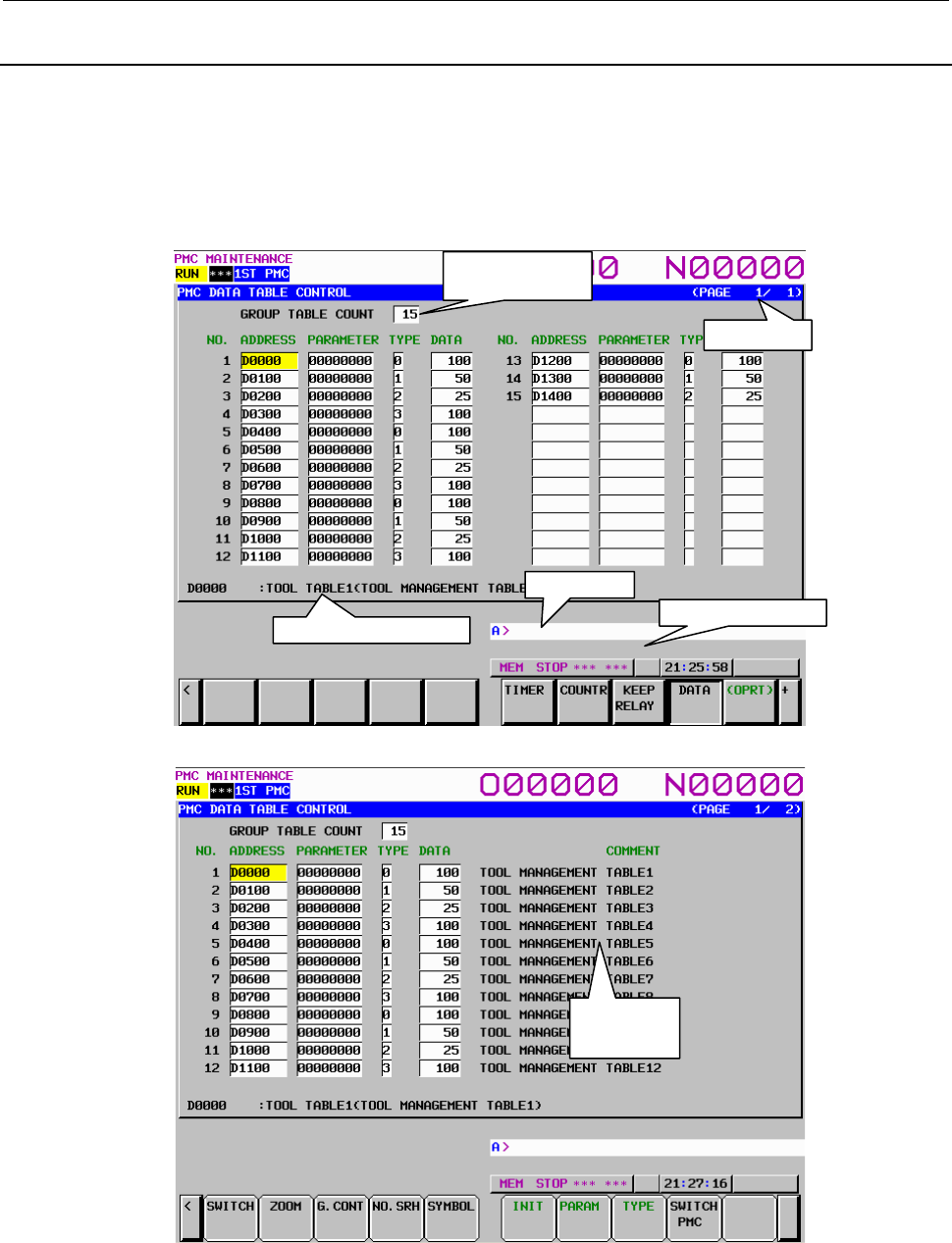
B-64513EN/03
7.PMC DIAGNOSIS AND MAINTENANCE SCREENS ([PMC MAINTE])
- 951 -
7.3.4
Setting and Displaying Data Tables ([DATA] Screen)
Data table has two related screens; DATA TABLE CONTROL and DATA TABLE. And similarly, extra
relay has two related screens; EXTRA RELAY CONTROL and EXTRA RELAY. These screens can be
switched to each other. To move to the data screen, press the [DATA] soft key.
DATA TABLE CONTROL screen ([LIST] screen)
Pressing the [DATA] soft key displays the DATA TABLE CONTROL screen for data table management.
This screen can be used in one of two modes: the simple display mode and the comment display mode.
Fig. 7.3.4 (a) Simple display mode
Fig. 7.3.4 (b) Comment display mode
Page display
Display of the
number of groups
Additional information line
Key input line
Message display line
Comment
display area
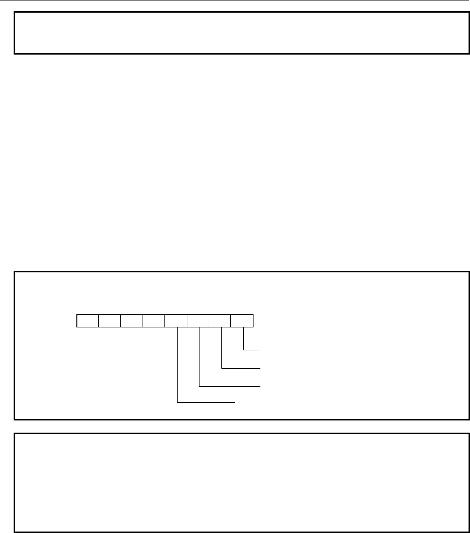
7.PMC DIAGNOSIS AND MAINTENANCE SCREENS ([PMC MAINTE])
B-64513EN/03
- 952 -
NOTE
When using a display unit which has 7 soft keys, the comment display mode is
not available.
Table contents
• GROUP TABLE COUNT: Number of data items in the data table
• NO.: Group number
• ADDRESS: Data table start address
• PARAMETER: Data table control parameter
• TYPE: Data length (0 = 1 byte, 1 = 2 bytes, 2 = 4 bytes, 3 = bit)
• DATA: Number of data items in each data table
• COMMENT: Comment on the start D address of each group
The additional information line at the bottom of the screen displays the symbol and comment of the
address on which the cursor is placed. When the cursor is placed on the PARAMETER, TYPE, or DATA
column, the current setting is displayed.
The ADDRESS column displays the start address of a data table. Multiple groups may share an address.
When the [SYMBOL] soft key is pressed, the symbol of the start address is displayed.
NOTE
The data table control parameters have the following meanings:
0: Binary format
1: BCD format (Bits 2 and 3 are invalid.)
0: Without input protection
1: With input protection
0: Binary or BCD format (Bit 0 is valid.)
1: Hexadecimal format (Bits 0 and 3 are invalid.)
0: Signed decimal (valid only when bits 0 and 2 are set to 0)
1: Unsigned decimal (valid only when bits 0 and 2 are set to 0)
#7 #6 #5 #4 #3 #2 #1 #0
NOTE
1 When data table control data is protected by the programmer protection function,
the data table control data screen is not displayed. For details, see Section 6.2.
2 When PMC parameters are output using the I/O screen (see Section 7.4), only
the data of an address D area set in the data table control data is output from the
data table screen. The data of an address D area not set in the data table
control data is not output.
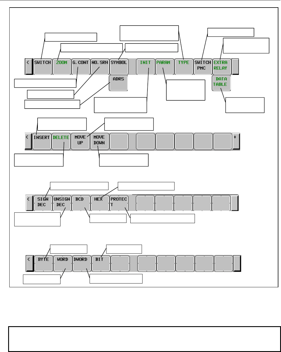
B-64513EN/03
7.PMC DIAGNOSIS AND MAINTENANCE SCREENS ([PMC MAINTE])
- 953 -
Soft keys on the DATA TABLE CONTROL screen
Display mode switching
Switching to the zoom screen
Input of the number of groups
Group number search
Symbol display switching
Address display switching Data table control data
initialization
Switching to the soft keys
for data size setting
Switching to the
soft keys for
parameter setting
PMC path switching
Switching to Extra
relay screen
Switching to Data
table screen
Soft keys for parameter setting
Soft keys for data size setting
Setting for signed decimal
Setting for unsigned
decimal
Setting for hexadecimal
Setting for BCD Protection state modification
Setting for byte
Setting for word
Setting for bit
Setting for double word
Data table control data
insertion
Data table control data
movement to up
Data table control data
deletion
Data table control data
movement to down
Fig. 7.3.4 (c) Soft keys on the DATA TABLE CONTROL screen
Operations using the soft keys
(1) [SWITCH] Display mode switching
Switches the display mode.
NOTE
When using a display unit which has 7 soft keys, the soft key [SWITCH] is not
displayed.
(2) [ZOOM] Switching to the zoom screen
Switches the screen display to the DATA TABLE screen.
(3) [G.CONT] Input of the number of groups
By pressing this soft key after inputting the number of groups, the number of groups on the data
table can be set. The maximum numbers of groups are 100.
(4) [NO.SRH] Group number search
By pressing this soft key after inputting a group number, the cursor can be moved to the specified
group.

7.PMC DIAGNOSIS AND MAINTENANCE SCREENS ([PMC MAINTE])
B-64513EN/03
- 954 -
(5) [SYMBOL] Symbol display switching
Displays the symbol of the start address of a data table in the ADDRESS column.
This soft key is valid only for address display.
(6) [ADRESS] Address display switching
Displays the start address of a data table in the ADDRESS column.
This soft key is valid for symbol display.
(7) [INIT] Data table control data initialization
Initializes the setting of data table control data.
NO.
1
ADDRESS
D0000
PARAMETER
00000000
TYPE
0
DATA
10000 (NOTE)
NOTE
1 When data table control data is initialized, the entire data area is set as a single
table. The start address is the start address of the D addresses. The control
parameters are set as follows: signed binary format, without input protection,
one-byte data size, and the number of data items set to the total number of bytes
in the entire D address area.
2 For the PMC Memory-A and DCSPMC, the initial number of data items is 3000.
For the PMC Memory-B, it is 10000. For the PMC Memory-C, it is 20000. For the
PMC Memory-D, it is 60000.
(8) [PARAM] Switching to the soft keys for parameter setting
Switches to the soft keys for setting the parameters of data table control data.
(9) [TYPE] Switching to the soft keys for data setting
Switches to the soft keys for data size setting.
(10) [EXTRA RELAY]/[DATA TABLE] Switching to Extra relay/Data Table control data
Switch the contents of the screen between the control data for Data table (D) and those for extra
relays (E).
To switch to extra relay control data, the system keep relay K909.5 needs to be 1.
(11) [SWITCH PMC] Switching PMC path or divided ladder programs
Switches PMC path or divided ladder program. For details of the operation, refer to “6.3”.
By setting keep relay K935.0 to 1, you can display PMC program list screen. For details, refer
to ”2.2.11”.
(12) [INSERT] Data table control data insertion
Inserts the new data table control data.
(13) [DELETE] Data table control data deletion
Delete the data table control data at the cursor position.
(14) [MOVE UP] Data table control data upward movement
Replaces the data table control data at the cursor position with upper line.
(15) [MOVE DOWN] Data table control data downward movement
Replaces the data table control data at the cursor position with lower line.
(16) [SIGN DEC] Setting for signed decimal
Sets signed decimal for the parameters of data table control data.
(17) [UNSIGN DEC] Setting for unsigned decimal
Sets unsigned decimal for the parameters of data table control data.
(18) [BCD] Setting for BCD
Sets BCD for the parameters of data table control data.
(19) [HEX] Setting for hexadecimal
Sets hexadecimal for the parameters of data table control data.
(20) [PROTECT] Protection state modification
Modifies the protection state of the parameters of data table control data.
(21) [BYTE] Setting for byte
Sets the data size to one byte.
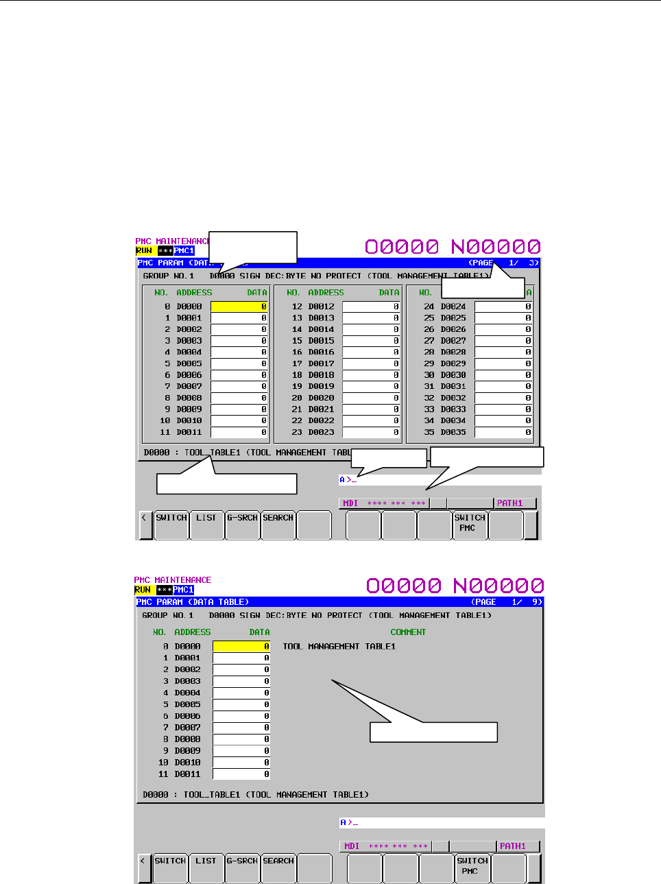
B-64513EN/03
7.PMC DIAGNOSIS AND MAINTENANCE SCREENS ([PMC MAINTE])
- 955 -
(22) [WORD] Setting for word
Sets the data size to two bytes.
(23) [DWORD] Setting for double word
Sets the data size to four bytes.
(24) [BIT] Setting for bit
Sets the data size to one bit.
When the data size is one bit, the unit for the number of data items is one byte.
DATA TABLE screen ([ZOOM] screen)
If the data table control data is specified, pressing the [ZOOM] soft key on the data table control data
screen displays the data table setting screen. This screen can be used in one of three modes: the
simple display mode, the comment display mode, and the bit display mode.
Fig. 7.3.4 (d) Simple display mode
Fig. 7.3.4 (e) Comment display mode
Group
information line
Page display
Additional information line
Key input line Message display line
Comment display area
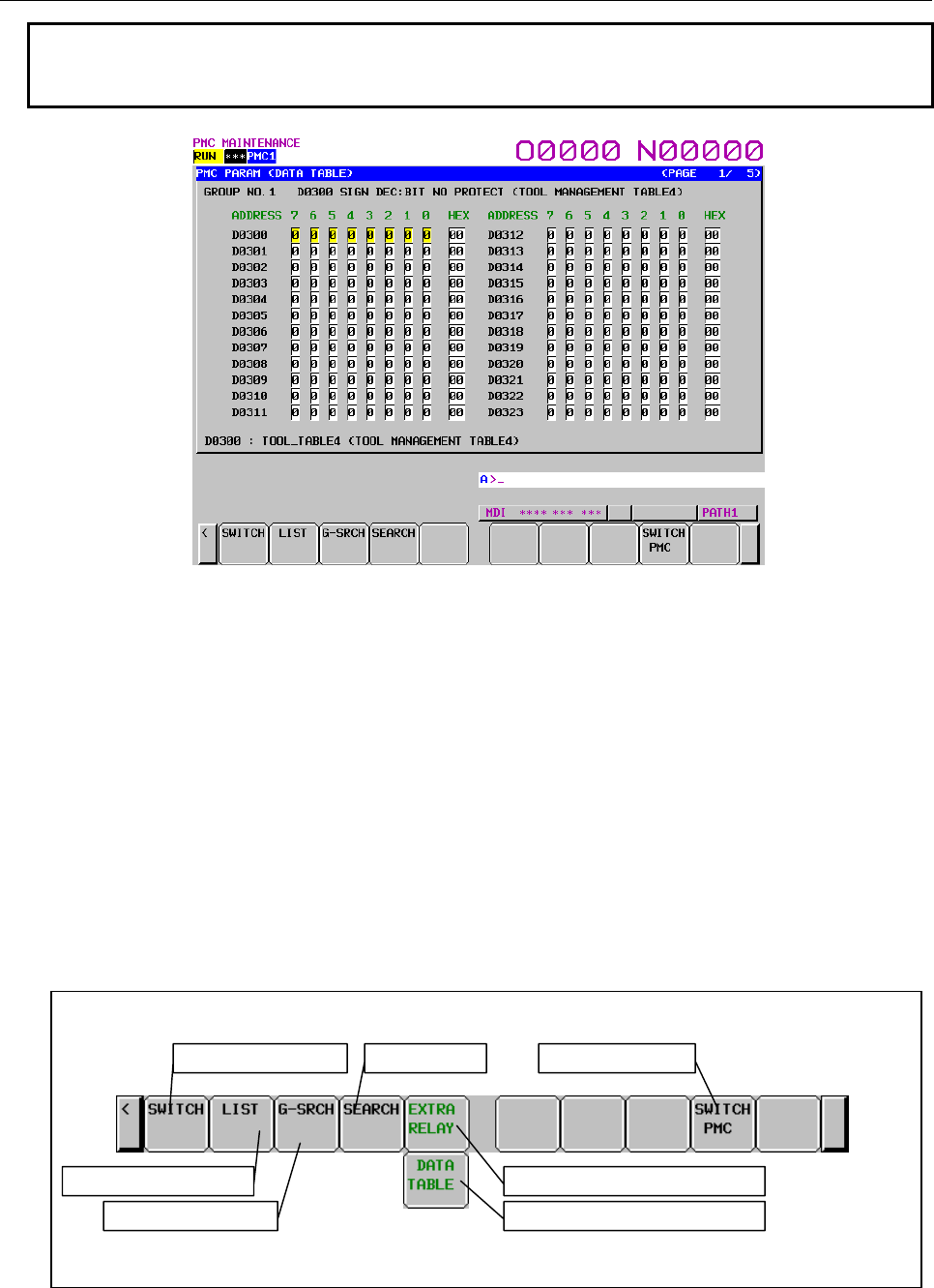
7.PMC DIAGNOSIS AND MAINTENANCE SCREENS ([PMC MAINTE])
B-64513EN/03
- 956 -
NOTE
When using a display unit which has 7 soft keys, the comment display mode is
not available.
Fig. 7.3.4 (f) Bit display mode
Table contents
• NO.
• ADDRESS: Address used by the sequence program
• DATA: Data value of data table
• COMMENT: Comment on the D address
• 0 to 7: Data of each bit
• HEX: Display of each byte in hexadecimal
The group information line at the top of the screen displays a group number, group start address, settings,
and comment on the start address.
The additional information line at the bottom of the screen displays the symbol and comment of the
address on which the cursor is placed. In the bit display mode, a bit symbol and comment, or a byte
symbol and comment are displayed, depending on the cursor position.
Soft keys on the DATA TABLE screen
Display mode switching
Switching to the list screen
Group number search
Address search
Switching to the Extra relay screen
Switching PMC path
Switching to the Data table screen
Fig. 7.3.4 (g) Soft keys on the DATA TABLE screen

B-64513EN/03
7.PMC DIAGNOSIS AND MAINTENANCE SCREENS ([PMC MAINTE])
- 957 -
Operations using the soft keys
(1) [SWITCH] Display mode switching
Switches the mode between the simple display mode and comment display mode when the data size
is one byte, two bytes, or four bytes. When the data size is one bit, this soft key switches the mode
between the simple display mode and bit display mode.
NOTE
When using a display unit which has 7 soft keys, the soft key [SWITCH] is not
displayed.
(2) [LIST] Switching to the list screen
Pressing this soft key switches to the data table control data screen.
(3) [G-SRCH] Group number search
After the entry of a group number for a data table to be searched in another group, pressing this key
moves the cursor to the beginning of that group.
(4) [SEARCH] Address search
After the entry of an address, pressing this key moves the cursor to the specified address within the
currently selected group. In the bit display mode, this soft key searches for a byte address or bit
address.
(5) [EXTRA RELAY]/[DATA TABLE] Switching to Extra relay/Data Table
Switch the contents of the screen between Data table (D) and extra relays (E).
To switch to extra relay, the system keep relay K909.5 needs to be 1.
(6) [SWITCH PMC] Switching PMC path or divided ladder programs
Switches PMC path or divided ladder program. For details of the operation, refer to “6.3”. This soft
key is not shown in EXTRA RELAY screen.
By setting keep relay K935.0 to 1, you can display PMC program list screen. For details, refer
to ”2.2.11”.
Screen operations in the bit display mode
In the bit display mode, the method of operation described below is used.
(1) Input key
The input key is used to modify the signal status.
(a) Bit-by-bit setting
• Input 1 then press the input key to turn on the signal.
• Input 0 then press the input key to turn off the signal.
(b) Byte-by-byte setting
In the case of the byte cursor, input up to eight binary digits then press the input key. (When an
input value is shorter than eight digits, the value is input from bit 0.)
Example: When 100 is input, this value is input as follows:
Bit number 7 6 5 4 3 2 1 0
0 0 0 0 0 1 0 0
When the cursor is placed on the hexadecimal display field, hexadecimal input is enabled on a
byte-by-byte basis.
(2) Cursor keys
With the cursor keys, select a signal to be modified.
If you press the cursor key for moving left when the cursor is placed at bit 7 of an arbitrary address,
the cursor changes to a byte cursor.
If you press the cursor key for moving right when the cursor is placed on the hexadecimal display
field of an arbitrary address, the cursor changes to a byte cursor for the next one entire byte.
When the cursor is placed on the hexadecimal display field, or the cursor is a byte cursor, the one-
byte signal data of the address can be modified.
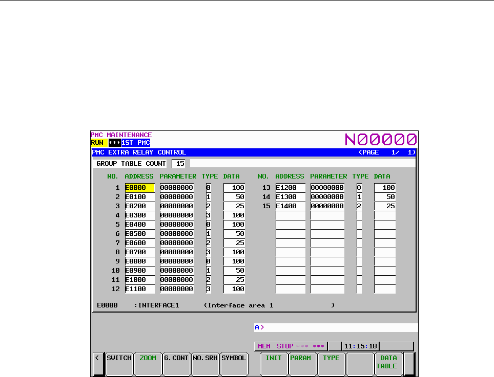
7.PMC DIAGNOSIS AND MAINTENANCE SCREENS ([PMC MAINTE])
B-64513EN/03
- 958 -
EXTRA RELAY CONTROL screen ([LIST] screen)
To switch to the EXTRA RELAY CONTROL screen in which you can manage the extra relay tables, use
[EXTRA RELAY] soft key in DATA TABLE CONTROL screen.
The operation of this screen is similar to the DATA TABLE CONTROL screen. See the “DATA TABLE
CONTROL screen ([LIST] screen)” for the detail of the operations.
To make it easy to distinguish the EXTRA RELAY CONTROL screen from DATA TABLE CONTROL
screen, the EXTRA RELAY CONTROL screen has white background at the line of “GROUP TABLE
COUNT”.
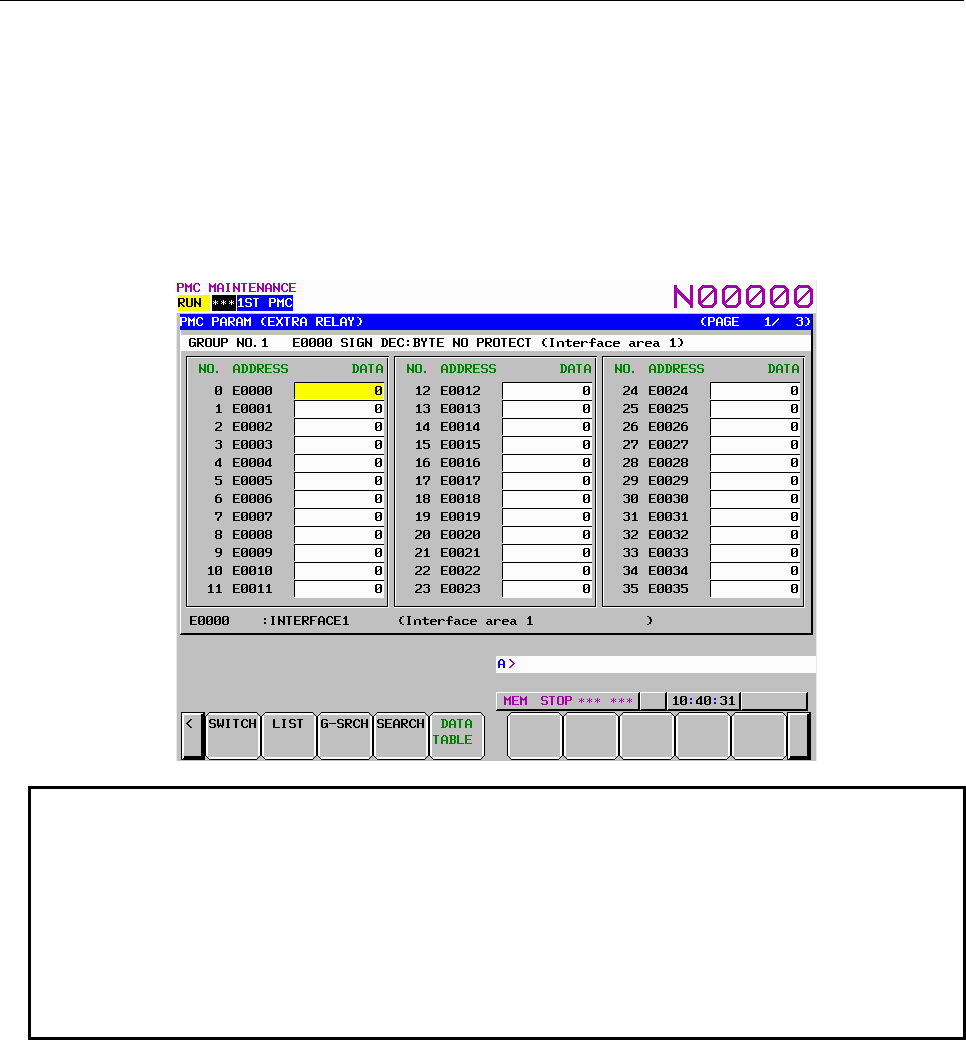
B-64513EN/03
7.PMC DIAGNOSIS AND MAINTENANCE SCREENS ([PMC MAINTE])
- 959 -
EXTRA RELAY screen ([ZOOM] screen)
When the extra relay control data are properly set, pressing [ZOOM] soft key at EXTRA RELAY
CONTROL screen leads you to the EXTRA RELAY screen. Similarly to the DATA TABLE screen, this
screen can show the contents of extra relays in three display modes; the simple display mode, the
comment display mode, and the bit display mode.
The operation of this screen is similar to the DATA TABLE screen. See the “DATA TABLE screen
([ZOOM] screen)” for the detail of the operations.
To make it easy to distinguish the EXTRA RELAY screen from the DATA TABLE screen, the
EXTRARELAY screen has white background at the line of the group information.
NOTE
1 Extra relays (E) can be included only in PMC parameter output from 1st PMC. If
you set 1 to the system keep relay K906.3, no information of extra relays is
included in PMC parameter output.
2 You have an option on the format of the extra relays when you include the extra
relays in the PMC parameter output. See “2.3.2 PMC Parameter Format” for the
detail of the format of the extra relays.
3 Even if the extra relays are not configured as non-volatile memory, their control
data are non-volatile.
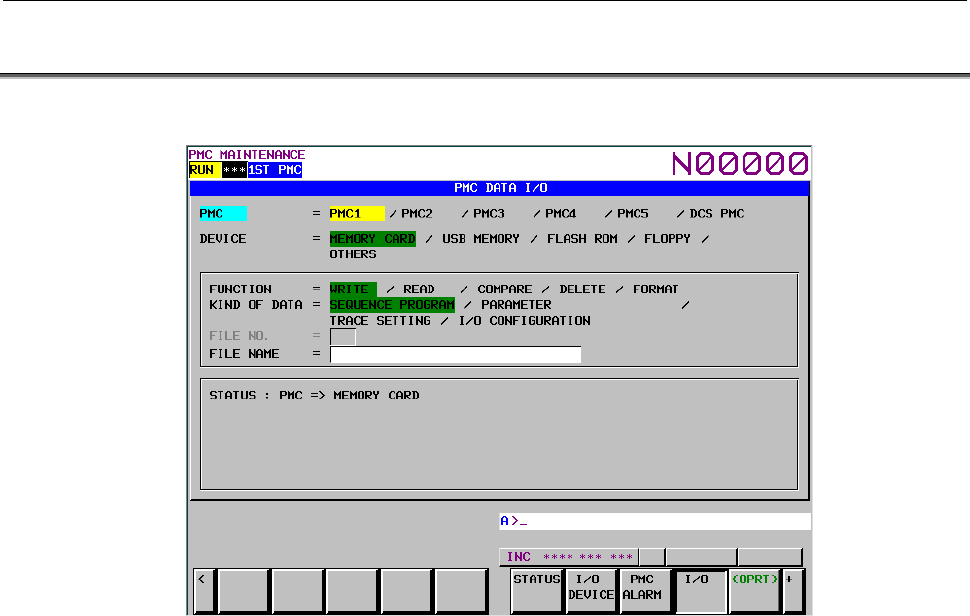
7.PMC DIAGNOSIS AND MAINTENANCE SCREENS ([PMC MAINTE])
B-64513EN/03
- 960 -
7.4 DATA INPUT/OUTPUT ([I/O] SCREEN)
To move to the I/O screen, press the [I/O] soft key.
On this screen, sequence programs, PMC parameters, PMC message data for multi-language display,
trace setting data and I/O configuration data can be written to the specified device, read from the device,
and compared. The query selection cursor, which moves vertically from one question to another, is
displayed, as is the option selection cursor, which moves horizontally from one option to another.
The following types of devices can be used for input/output. The desired device type can be selected by
positioning the query selection cursor to "DEVICE" and moving the option selection cursor to that type.
• MEMORY CARD: Data can be output to and input from a memory card.
• USB MEMORY: Data can be output to and input from a USB memory.
• FLASH ROM: Data can be output to and input from flash ROM.
• FLOPPY: Data can be output to and input from Handy File or Floppy Cassette.
• OTHERS: Data can be output to and input from other general-purpose RS-232C
input/output devices.
The multi-path PMC system enables an I/O target PMC to be selected. For details, see Section 7.4.4.
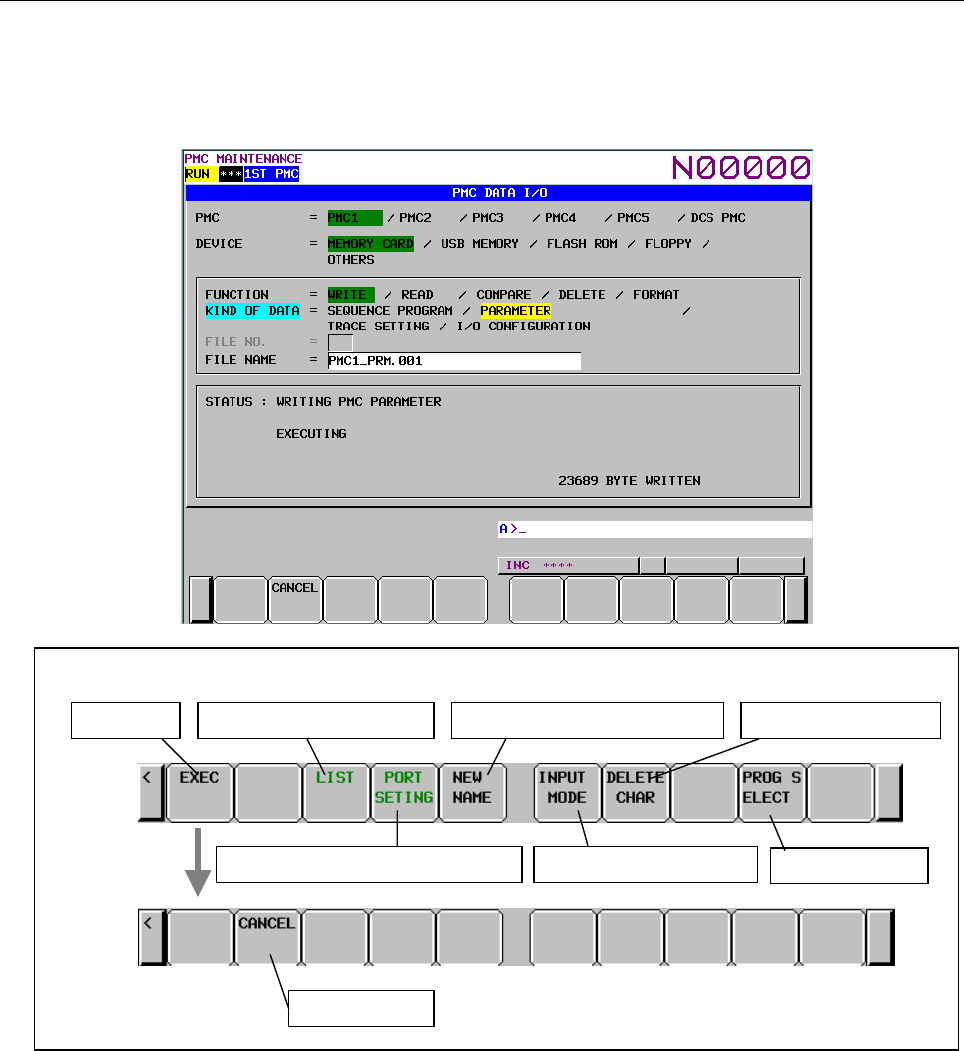
B-64513EN/03
7.PMC DIAGNOSIS AND MAINTENANCE SCREENS ([PMC MAINTE])
- 961 -
In STATUS in the lower part of the screen, a detailed explanation of execution and the execution status
are displayed. During write, read, and comparison, the size of the data already transferred is indicated as
the execution (intermediate) result.
The following gives a display example shown when PMC parameters are written to a memory card:
Soft keys on the I/O screen
Execution
Cancellation
Switch to the list screen
Switch to the
p
ort settin
g
screen Chan
g
e the in
p
ut mode
Delete a characterGeneratin
g
a new file name
Select pro
g
ram
Fig. 7.4 Soft keys on the I/O screen
Operations using the soft keys
(1) [EXEC] Execution
Executes a processing item selected for FUNCTION.
During execution, the [CANCEL] soft key is displayed.
(2) [LIST] Switching to the list screen
Switches the screen display to the file list screen.
This soft key is valid only when MEMORY CARD, USB MEMORY or FLOPPY is selected for
DEVICE.
(3) [PORT SETING] Switching to the port setting screen
Switches the screen display to the Port setting screen.
This soft key is valid only when FLOPPY or OTHERS is selected for DEVICE.

7.PMC DIAGNOSIS AND MAINTENANCE SCREENS ([PMC MAINTE])
B-64513EN/03
- 962 -
(4) [CANCEL] Cancellation
Cancels execution. Upon normal termination, the display of this soft key disappears.
(5) [NEW NAME] Generating a new file name
Unused new file name is generated by searching files on a memory card, a USB memory or a floppy
disk. This soft key is displayed when a writing function to memory card, to USB memory or to
floppy disk is selected.
New file name is generated with the following format.
• Data Name
The following data name is specified for each kind of data.
Kind of Data Data Name
Sequence program
(Main ladder program) (Note)
1st path PMC PMC1
2nd path PMC PMC2
3rd path PMC PMC3
4th path PMC PMC4
5th path PMC PMC5
DCSPMC PMCS
Sequence program
(Divided ladder program) (Note)
Divided ladder program No.1 of 1st path PMC L101PMC1
Divided ladder program No.2 of 1st path PMC L102PMC1
Divided ladder program No.3 of 1st path PMC L103PMC1
: :
Divided ladder program No.98 of 1st path PMC L198PMC1
Divided ladder program No.99 of 1st path PMC L199PMC1
Divided ladder program No.1 of 2nd path PMC L201PMC2
: :
Divided ladder program No.99 of 2nd path PMC L299PMC2
Divided ladder program No.1 of 3rd path PMC L301PMC3
: :
Divided ladder program No.99 of 3rd path PMC L399PMC3
Divided ladder program No.1 of 4th path PMC L401PMC4
: :
Divided ladder program No.99 of 4th path PMC L499PMC4
Divided ladder program No.1 of 5th path PMC L501PMC5
: :
Divided ladder program No.99 of 5th path PMC L599PMC5
PMC parameter 1st path PMC PMC1_PRM
2nd path PMC PMC2_PRM
3rd path PMC PMC3_PRM
4th path PMC PMC4_PRM
5th path PMC PMC5_PRM
DCSPMC PMCS_PRM
Message data for multi-language
display (Note)
1st path PMC M1PMCMSG
2nd path PMC M2PMCMSG
3rd path PMC M3PMCMSG
4th path PMC M4PMCMSG
5th path PMC M5PMCMSG
Trace setting data PMC_TRS
I/O configuration data (I/O Link i assignment data) (Note) IOCONF
Data Name Data Number
.xxx
B-64513EN/03
7.PMC DIAGNOSIS AND MAINTENANCE SCREENS ([PMC MAINTE])
- 963 -
NOTE
The data name is the same as the file name of flash ROM.
• Data number
The data number is the three digits number that begins at '000'. The next number of the
maximum data number of a file that exists on a memory card or floppy disk is set to the data
number. However, when a file that has a data number '999' exists on a memory card or floppy
disk, the '999' is set to the data number.
NOTE
1 When 128 or more files exist on a memory card or floppy disk, the "Generating
new file name" does not work correctly. You should only use this function when
127 or less files exist on the device.
2 You cannot input/output divided ladder program from/into floppy disk.
(6) [INPUT MODE] Changing the input mode
By pressing the [INPUT MODE] soft key, the input mode is changed in the following order. The
indicator "INSERT" that appears on the screen means insert mode. The indicator "ALTER" means
replace mode. The soft key [INPUT MODE] appears only when the cursor is on the FILE NAME
box.
Insert
mode
Replace
mode
Full-string
input
• Full-string input
An entire file name is selected by the cursor and the entire file name is replaced by input.
• Insert mode
Input characters are inserted at the cursor. If you press the INPUT key without no character,
one space character will be inserted.
• Replace mode
The characters on and after cursor are replaced by input characters. If you press the INPUT key
without no character, the character on the cursor will be replaced by space character.
(7) [DELETE CHAR] Deleting a character
Delete a character on the cursor. This soft key [DELETE CHAR] appears only when the cursor is on
the FILE NAME box and the input mode is "INSERT" or "ALTER".
NOTE
For the description of the error messages on the I/O screen, see Section 12.1.
(8) [PROG. SELECT] Selecting sequence program
You can select sequence program for inputting/outputting. This soft key is displayed when the
ladder dividing management function is effective.
The [PROG. SELECT] soft key works as follows.
Operation Behavior
Only [PROG. SELECT] Select main ladder program or divided ladder program in selected
PMC path in order.
7.PMC DIAGNOSIS AND MAINTENANCE SCREENS ([PMC MAINTE])
B-64513EN/03
- 964 -
Operation Behavior
“Divided ladder program number”
+ [PROG. SELECT]
Select divided ladder program of specified number in selected PMC
path.
For example, inputting “12” and pressing this soft key in “PMC2”
selects “PMC2-12”. In case of selecting main ladder program, input
“0”.
Selected divided ladder program is displayed in the status column.
Example: Writing the ladder program of divided number 1 of 1st path PMC to Memory card.

B-64513EN/03
7.PMC DIAGNOSIS AND MAINTENANCE SCREENS ([PMC MAINTE])
- 965 -
7.4.1
Memory Card and USB Memory
Memory card
The memory card, which is used for inputting/outputting the sequence program in the I/O screen, can also
be used to access to the programmer (FANUC LADDER-III).
As for the memory card, you need use the compact flash adapter, which is attached a compact flash card
(CF card) purchased from FANUC.
NOTE
If a CF card other than that purchased from FANUC is used, the operation is not
guaranteed.
For the details, refer to “APPENDIX E” in the “CONNECTION MANUAL (HARDWARE)” of each
CNC series.
USB memory
You can input/output some data to/from a USB memory with a USB port beside a display unit.
NOTE
It is not guaranteed that every commercially available USB memory can operate
normally. A USB memory with a security function does not operate. Some
commercially available USB memories may not be designed for the use in an FA
environment.
CAUTION
1 While the control unit is accessing the USB memory, do not turn off the power to
the control unit or do not remove the USB memory.
2 Close the cover of the USB port when no USB memory is inserted.
For the details, refer to section 5.6 in the “CONNECTION MANUAL (HARDWARE)” of each CNC
series. .
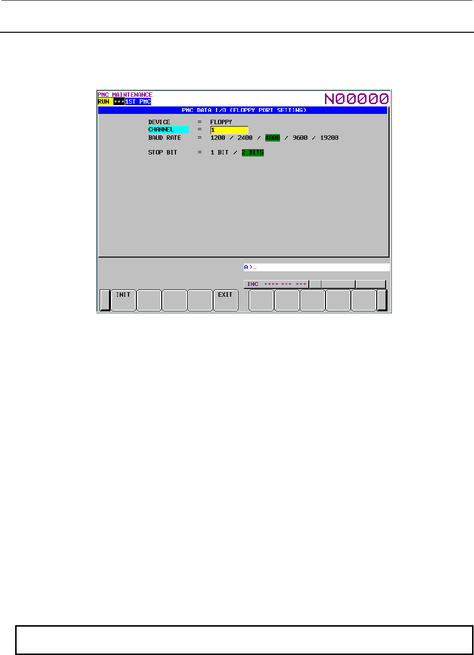
7.PMC DIAGNOSIS AND MAINTENANCE SCREENS ([PMC MAINTE])
B-64513EN/03
- 966 -
7.4.2
Setting the Communication Port ([PORT SETING] Screen)
When FLOPPY or OTHERS is selected for DEVICE on the I/O screen, the [PORT SETING] soft key is
displayed. When you press this soft key, the port setting screen appears. The screen below is a sample
screen displayed when FLOPPY is selected for DEVICE.
This screen allows the setting of the communication data required for communication using the RS-232C.
Communication data can be set for each of the two types of devices independently of the other.
Selected device type is displayed to "DEVICE" menu on screen.
Explanation of each question
• CHANNEL
Check that an RS-232C cable is connected to the main board of the control unit. Directly enter the
number corresponding to the connected connector.
1.......... JD56A
2.......... JD36A/JD54
• BAUD RATE
1200: Sets the baud rate to "1200".
2400: Sets the baud rate to "2400".
4800: Sets the baud rate to "4800".
9600: Sets the baud rate to "9600".
19200: Sets the baud rate to "19200".
• STOP BIT
1 BIT: Sets the number of stop bits to "1".
2 BITS: Sets the number of stop bits to "2".
• WRITE CODE
"WRITE CODE" is displayed when "OTHERS" is selected for "DEVICE".
ASCII: Sets the output code to "ASCII".
ISO: Sets the output code to "ISO".
NOTE
Parity is always "NONE".
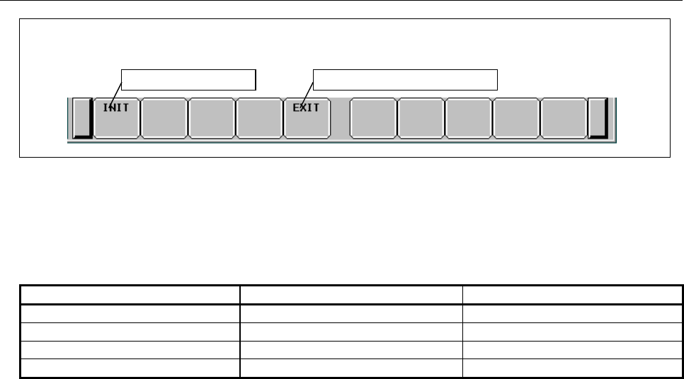
B-64513EN/03
7.PMC DIAGNOSIS AND MAINTENANCE SCREENS ([PMC MAINTE])
- 967 -
Fig. 7.4.2 Soft keys on the port setting screen
Operations using the soft keys
(1) [INIT] Setting initialization
Sets all the parameters to their initial values.
The table below indicates the initial value of each setting item.
Initial values
DEVICE DEVICE = FLOPPY DEVICE = OTHERS
CHANNEL 1 1
BAUD RATE 4800 4800
STOP BIT 2 BITS 2 BITS
WRITE CODE (NONE) ISO
(2) [EXIT] Switching to the I/O screen
Terminates the setting of the communication parameters and switches the screen display to the I/O
screen.
Operation of the return key
On the port setting screen, the operation of the return key is disabled.
Use the [EXIT] soft key to terminate the setting of the communication parameters and return to the I/O
screen.
Soft keys on the port setting screen
Setting initialization Goest to the I/O screen
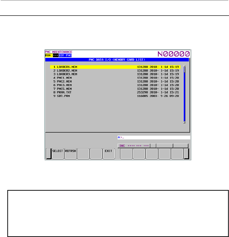
7.PMC DIAGNOSIS AND MAINTENANCE SCREENS ([PMC MAINTE])
B-64513EN/03
- 968 -
7.4.3
Displaying a File List ([LIST] Screen)
When MEMORY CARD, USB MEMORY or FLOPPY is selected for DEVICE on the I/O screen, the
[LIST] soft key is displayed. When you press this soft key, the file list screen appears. The contents of
the root directory of the selected device are displayed. The screen below is a sample screen displayed
when MEMORY CARD is selected for DEVICE.
If MEMORY CARD is selected for DEVICE, and a memory card holding files is inserted into the slot,
the contents of the memory card are displayed. If FLOPPY is selected for DEVICE, the contents of a
Floppy Cassette or Handy File are displayed.
NOTE
1 Up to 128 files can be displayed on this screen. When 129 or more files are
saved, the 129th and subsequent files are ignored.
2 In case of the USB memory, up to 32 characters of the file names can be
displayed. If a file has a name over 32 characters, the first 32 characters are
displayed. For a folder, the file size does not be displayed but “<FOLDER>” is
displayed.
When a file is selected on this screen, the screen display can be returned to the I/O screen. To select a file,
place the cursor at the name of the file, then press either the [SELECT] soft key or the INPUT key. After
the key entry, the screen display switches to the I/O screen automatically. In this case, the cursor is
positioned at READ on the FUNCTION menu, and the number and name of the file selected on the list
screen are indicated in the FILE NO. and FILE NAME fields, respectively. A display example is shown
below.
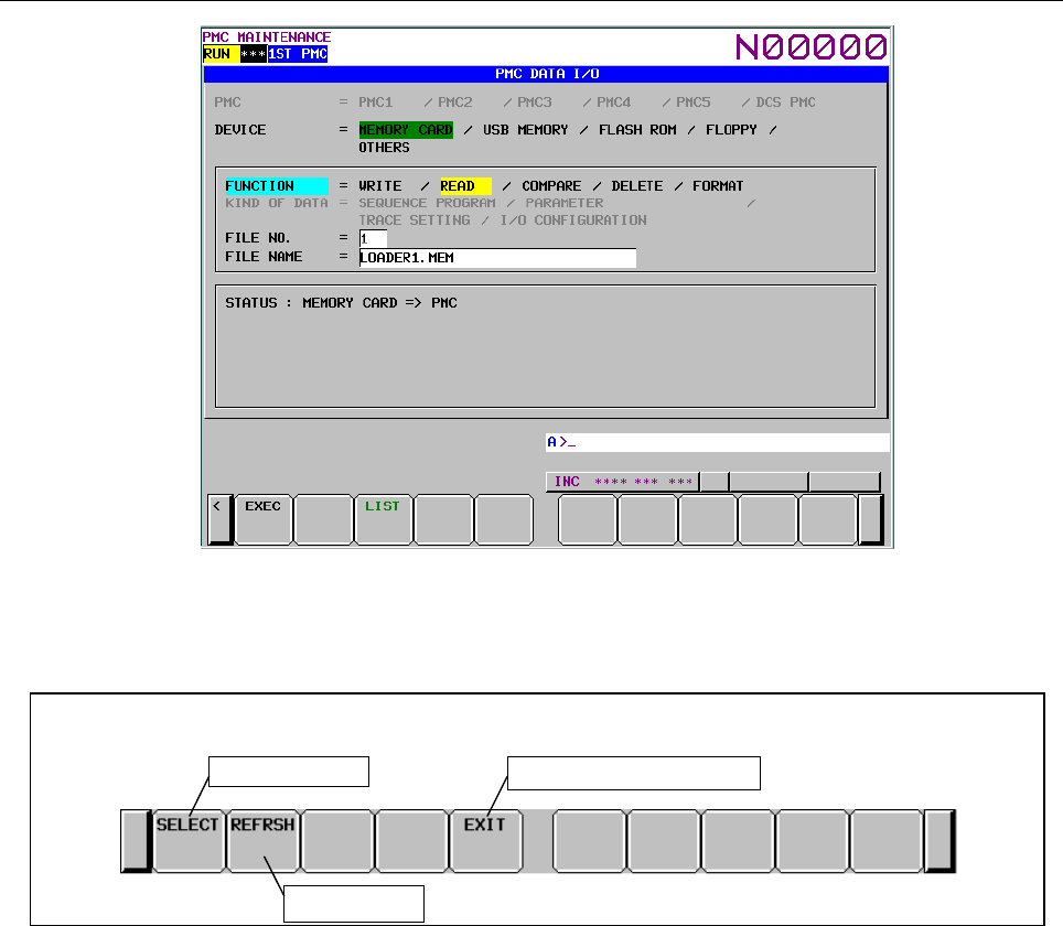
B-64513EN/03
7.PMC DIAGNOSIS AND MAINTENANCE SCREENS ([PMC MAINTE])
- 969 -
To return the screen display to the I/O screen without selecting a file, press the [EXIT] soft key. Even if
the memory card, the USB memory or the floppy disk in the floppy cassette, or the handy file is
exchanged while the file list screen is being displayed, the display data is not automatically updated. In
this case, press the [REFRSH] soft key. The contents of the new memory card are then displayed.
Fig. 7.4.3 Soft keys on the file list screen
Operations using the soft keys
(1) [SELECT] File selection
Selects a file, and returns the screen display to the I/O screen.
(2) [REFRSH] List updating
Redisplays the file list screen.
(3) [EXIT] Switching to the I/O screen
Switches the screen display to the I/O screen without selecting a file.
Operation of the return key
On the file list screen, the operation of the return key is disabled.
Use the [EXIT] soft key to return to the I/O screen without selecting a file.
Soft keys on the file list screen
File selection Goes to the I/O screen
List updating
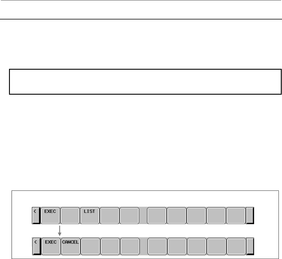
7.PMC DIAGNOSIS AND MAINTENANCE SCREENS ([PMC MAINTE])
B-64513EN/03
- 970 -
7.4.4
Setting an I/O Target PMC
The multi-path PMC system enables an I/O target PMC to be selected on the I/O screen.
Specification of a PMC in the item of PMC
Select PMC with the query selection cursor then select an I/O target PMC by moving the option selection
cursor.
NOTE
The PMC query may not be displayed, depending on the setting of each query.
For details, see the description of each operation procedure.
Nonexistent PMCs are not displayed as options.
Example: When PMC3, PMC4 and PMC5 do not exist
PMC = PMC1 / PMC2 / DCSPMC
When only PMC1 exists, the indication below is provided, so that no selection operation is required. In
this case, the query selection cursor does not move to PMC.
PMC = PMC1
Specification of a PMC when a sequence program is read
When the data of the I/O screen is read, the type of data is automatically identified. The procedure for
reading a sequence program is described below.
Soft keys for reading a sequence program
(1) Reading a sequence program including PMC information
(a) After setting a device on the I/O screen, select READ for FUNCTION, then press the [EXEC]
soft key.
(b) The following message is displayed:
"READING SEQUENCE PROGRAM (PMCx)"
(As PMCx, the PMC number embedded in the data is displayed. "DCSPMC" is displayed for a
program for dual check safety.)
(c) Press the [EXEC] soft key to continue the operation.
(d) Press the [CANCEL] soft key to stop the operation.
(2) Reading a sequence program for the conventional model
When the reading of the sequence program of the conventional model begins, the following message
is displayed, and the read operation is terminated abnormally:
"UNKNOWN FILE FORMAT"
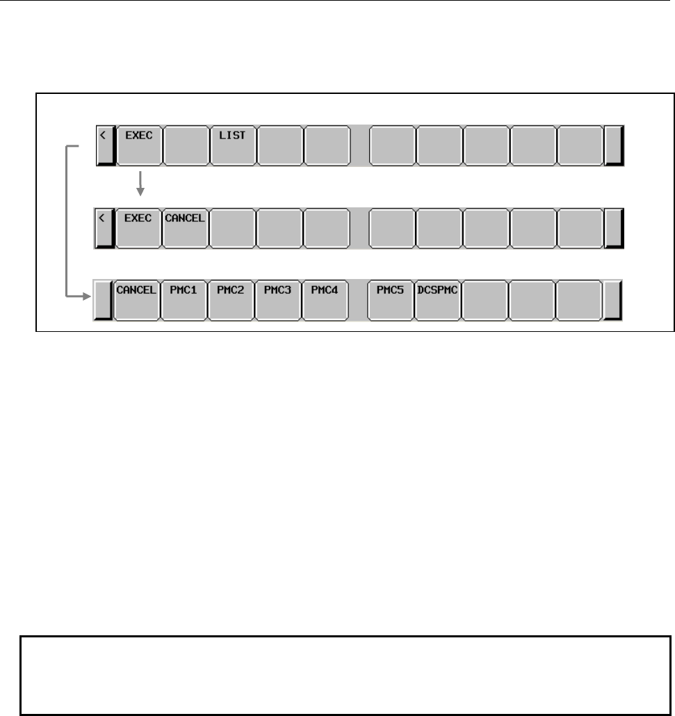
B-64513EN/03
7.PMC DIAGNOSIS AND MAINTENANCE SCREENS ([PMC MAINTE])
- 971 -
Specification of a PMC when PMC parameters are read
When the data of the I/O screen is read, the type of data is automatically identified. The procedure for
reading PMC parameters is described below.
(1) Reading PMC parameters including PMC information
(a) After setting a device, select READ for FUNCTION, then execute.
(b) The following message is displayed:
"READING PMC PARAMETER (PMCx)"
(As PMCx, the PMC number embedded in the data is displayed. "DCSPMC" is displayed for
parameters for dual check safety.)
(c) Press the [EXEC] soft key to continue the operation.
(d) Press the [CANCEL] soft key to stop the operation.
(2) Reading PMC parameters for the conventional model
(a) After setting a device, select READ for FUNCTION, then execute.
(b) The following message is displayed:
"READING PMC PARAMETER"
(c) Select a read source PMC with the corresponding soft key.
(d) Press the [CANCEL] soft key to stop processing.
NOTE
1 When only PMC1 exists, only the step for reading PMC parameters including
PMC information needs to be executed.
2 For a nonexistent PMC, no soft key is displayed.
When PMC parameters for the conventional model are read with the multi-PMC system
When PMC parameters including PMC information are read
Soft keys for reading PMC parameters

7.PMC DIAGNOSIS AND MAINTENANCE SCREENS ([PMC MAINTE])
B-64513EN/03
- 972 -
7.4.5
Note on Inputting of Sequence Program
When reading a sequence program during execution of the ladder program, there are the following
methods.
- The execution of the ladder program is stopped and new ladder program is read.
- The execution of the ladder program is not stopped. The ladder program is exchanged and running
continuously after the completion of reading of the ladder program.
For the way to read a sequence program without stopping the ladder, set the CNC parameter No. 11933#5
to 1. See “2.4.3 CNC Parameters Related to the PMCs” for details.
After understanding the following warning well, read a sequence program.
WARNING
1 When reading a ladder program, executed ladder program is stopped. Even If
the setting that a sequence program can be read without stopping the ladder is
chosen, executed ladder would be stopped when improper file is read or you
cancel the operation of reading during reading a sequence program. When the
ladder program is stopped, controls, safety features and monitoring by the ladder
program do not work. And it may cause an unexpected machine behavior.
Before reading a ladder program, make it sure that the machine is proper status
and nobody is near the machine.
2 If the setting that a sequence program can be read without stopping the ladder is
chosen, the ladder program is exchanged after the completion of reading of the
ladder program. When reading the ladder program that the assignment of signal
addresses is changed, it may cause an unexpected machine behavior. Before
reading a ladder program, make it sure that the machine is proper status and
nobody is near the machine.
3 When stopping executed ladder program, the terminate procedure of the ladder
program may not complete. In such a case, modify the ladder program referring
to Section 4.15.
B-64513EN/03
7.PMC DIAGNOSIS AND MAINTENANCE SCREENS ([PMC MAINTE])
- 973 -
7.4.6
Outputting a Sequence Program to the Memory Card or the
USB Memory
A sequence program can be output from a PMC to the memory card or the USB memory. To use this
function, perform the operation described below on the I/O screen.
NOTE
This operation can be performed only when the operation condition allows
sequence program output. For details, see Section 6.2.
(1) On the I/O screen, make the following settings with the query selection cursor and option selection
cursor:
Query Setting
PMC (Output target PMC)
DEVICE MEMORY CARD or USB MEMORY
FUNCTION WRITE
KIND OF DATA SEQUENCE PROGRAM
For the setting of an output target PMC, see Subsection 7.4.4.
(2) Move the query selection cursor to FILE NAME and enter a file name.
You should enter the file name with "8.3 format" that is constructed with base name, less than 8
characters, dot "." and extension, less than 3 characters. In case of the USB memory, a file name is
up to 32 characters.
Or, press the [NEW NAME] soft key to set a new file name.
(3) Press the [EXEC] soft key to output the sequence program.
Press the [CANCEL] soft key to stop the operation.
(4) If the specified file name already exists on a memory card or a USB memory, the following message
will be displayed. If you want to overwrite the file, press the [YES] soft key. And, if you want to
cancel the output, press the [NO] key.
"THIS FILE NAME IS ALREADY USED. OVERWRITE IT?"
NOTE
1 For the supported memory card/USB memory, see Subsection 7.4.1.
2 A folder cannot be specified for an output.
3 In case of the USB memory, “FORFANUC” cannot be used for the first 8
characters of the file name.

7.PMC DIAGNOSIS AND MAINTENANCE SCREENS ([PMC MAINTE])
B-64513EN/03
- 974 -
7.4.7
Inputting a Sequence Program from the Memory Card or the
USB Memory
A sequence program can be input from the memory card or the USB memory to a PMC. To use this
function, perform the operation described below on the I/O screen.
WARNING
When the sequence program being executed is updated to the sequence
program whose symbols are assigned to the different addresses, the signal state
may be unsuitable. If you activate the sequence program in this state, the
machine may behave in an unexpected way, and there is an extreme risk of
death or serious injury, as well as the likelihood of tools, work pieces and the
machine being damaged. Therefore, initialize the signals if needed before
starting the updated sequence program.
CAUTION
When editing FB definitions and FB instances by the offline editing function on
FANUC LADDER-III, the addresses assigned to the parameters and variables of
function block will be changed. Therefore, the parameters and variables of all
function blocks will be initialized by 0 when the sequence program is inputted
into CNC. (See “11.1.4 Assignment of FB variable” for details.)
NOTE
1 This operation can be performed only when the operation condition allows
sequence program input. For details, see Section 6.2.
2 In a sequence program which uses extended symbol and comment format, if
you edit the symbol / comment data of the sequence program by FANUC
LADDER-III and store it into CNC with K903.5=1, the address area for
automatically assignment will be initialized to 0.
(1) On the I/O screen, make the following settings with the query selection cursor and option selection
cursor:
Query Setting
DEVICE MEMORY CARD or USB MEMORY
FUNCTION READ
(2) Specify an input target sequence program by performing the following operations:
• Move the query selection cursor to FILE NO., then key in an input target file number. At this
time, the FILE NAME field displays the file name corresponding to the entered file number.
• Move the query selection cursor to FILE NAME, then key in the input target file name.
• Switch the screen display to the list screen, then select the input target file.
For the list screen, see Subsection 7.4.3.

B-64513EN/03
7.PMC DIAGNOSIS AND MAINTENANCE SCREENS ([PMC MAINTE])
- 975 -
NOTE
1 If a value is set in the FILE NO. field, and a file name not corresponding to the
file number is entered in the FILE NAME field when FILE NO. and FILE NAME
are displayed at the same time, the value set in the FILE NO. field is erased, and
the setting in the FILE NAME field becomes valid.
2 A folder cannot be specified for an input subject. When the specified FILE NO. is
a folder, the following message is displayed.
“FOLDER CANNOT BE SPECIFIED”.
(3) Press the [EXEC] soft key.
A warning message is displayed for the reading.
The reading starts when pressing the [EXEC] soft key again. The execution of the ladder program is
stopped automatically.
The ladder program can be read without stopping the ladder program. See 7.4.5 for details.
When pressing the [CANCEL] soft key, the reading processing is canceled.
WARNING
1 When reading a ladder program, executed ladder program is stopped. Even If
the setting that a sequence program can be read without stopping the ladder is
chosen, executed ladder would be stopped when improper file is read or you
cancel the operation of reading during reading a sequence program. When the
ladder program is stopped, controls, safety features and monitoring by the ladder
program do not work. And it may cause an unexpected machine behavior.
Before reading a ladder program, make it sure that the machine is proper status
and nobody is near the machine.
2 If the setting that a sequence program can be read without stopping the ladder is
chosen, the ladder program is exchanged after the completion of reading of the
ladder program. When reading the ladder program that the assignment of signal
addresses is changed, it may cause an unexpected machine behavior. Before
reading a ladder program, make it sure that the machine is proper status and
nobody is near the machine.
3 When stopping executed ladder program, the terminate procedure of the ladder
program may not complete. In such a case, modify the ladder program referring
to Section 4.15.
NOTE
1 For the supported memory card/USB memory, see Subsection 7.4.1.
2 When the format of a specified file cannot be recognized, the read operation is
terminated abnormally with the following message:
"UNKNOWN FILE FORMAT"
3 In case of the USB memory, “FORFANUC” cannot be used for the first 8
characters of the file name.

7.PMC DIAGNOSIS AND MAINTENANCE SCREENS ([PMC MAINTE])
B-64513EN/03
- 976 -
7.4.8
Comparing Sequence Programs with Memory Card Files or
USB Memory Files
A sequence program comparison can be made between the PMC and memory card or USB memory. To
use this function, perform the operation described below on the I/O screen.
NOTE
Compare operation can be performed only when the operation condition allows
sequence program output. For details, see Section 6.2.
(1) On the I/O screen, make the following settings with the query selection cursor and option selection
cursor:
Query Setting
DEVICE MEMORY CARD or USB MEMORY
FUNCTION COMPARE
(2) Specify a sequence program to be compared, by performing the following operations:
• Move the query selection cursor to FILE NO., then key in a compare target file number. At
this time, the FILE NAME field displays the file name corresponding to the entered file number.
• Move the query selection cursor to FILE NAME, then key in the compare target file name.
• Switch the screen display to the list screen, and then select the compare target file.
For the list screen, see Subsection 7.4.3.
NOTE
1 If a value is set in the FILE NO. field, and a file name not corresponding to the
file number is entered in the FILE NAME field when FILE NO. and FILE NAME
are displayed at the same time, the value set in the FILE NO. field is erased, and
the setting in the FILE NAME field becomes valid.
2 A folder cannot be specified for a compare subject. When the specified FILE NO.
is a folder, the following message is displayed.
“FOLDER CANNOT BE SPECIFIED”.
(3) Press the [EXEC] soft key to execute a sequence program comparison.
Press the [CANCEL] soft key to stop the operation.
NOTE
1 For the supported memory card/USB memory, see Subsection 7.4.1.
2 When the format of a specified file cannot be recognized, the compare operation
is terminated abnormally with the following message:
"UNKNOWN FILE FORMAT"
3 In case of the USB memory, “FORFANUC” cannot be used for the first 8
characters of the file name.
B-64513EN/03
7.PMC DIAGNOSIS AND MAINTENANCE SCREENS ([PMC MAINTE])
- 977 -
7.4.9
Saving Sequence Programs to the Flash ROM
Sequence programs can be saved from a PMC to the flash ROM. To use this function, perform the
operation described below on the I/O screen.
NOTE
This operation can be performed only when the operation condition allows
sequence program output. For details, see Section 6.2.
(1) On the I/O screen, make the following settings with the query selection cursor and option selection
cursor:
Query Setting
PMC (Output target PMC)
DEVICE FLASH ROM
FUNCTION WRITE
KIND OF DATA SEQUENCE PROGRAM
For the setting of an output target PMC, see Subsection 7.4.4.
(2) Press the [EXEC] soft key to save sequence programs.
When writing to the flash ROM is performed, the processing cannot be stopped.
NOTE
When programs are written, flash ROM initialization may consume some time.
During initialization, "INITIALIZING FLASH ROM." is displayed in the STATUS
display field.

7.PMC DIAGNOSIS AND MAINTENANCE SCREENS ([PMC MAINTE])
B-64513EN/03
- 978 -
7.4.10
Inputting Sequence Programs from the Flash ROM
Sequence programs can be inputted from the flash ROM to a PMC. To use this function, perform the
operation described below on the I/O screen.
WARNING
When the sequence program being executed is updated to the sequence
program whose symbols are assigned to the different addresses, the signal state
may be unsuitable. If you activate the sequence program in this state, the
machine may behave in an unexpected way, and there is an extreme risk of
death or serious injury, as well as the likelihood of tools, work pieces and the
machine being damaged. Therefore, initialize the signals if needed before
starting the updated sequence program.
CAUTION
When editing FB definitions and FB instances by the offline editing function on
FANUC LADDER-III, the addresses assigned to the parameters and variables of
function block will be changed. Therefore, the parameters and variables of all
function blocks will be initialized by 0 when the sequence program is inputted
into CNC. (See “11.1.4 Assignment of FB variable” for details.)
NOTE
1 This operation can be performed only when the operation condition allows
sequence program input. For details, see Section 6.2.
2 In a sequence program which uses extended symbol and comment format, if you
edit the symbol / comment data of the sequence program by FANUC LADDER-
III and store it into CNC with K903.5=1, the address area for automatically
assignment will be initialized to 0.
(1) On the I/O screen, make the following settings with the query selection cursor and option selection
cursor:
Query Setting
PMC (Input target PMC)
DEVICE FLASH ROM
FUNCTION READ
For the setting of an input target PMC, see Subsection 7.4.4.
(2) Press the [EXEC] soft key to input sequence programs.
A warning message is displayed for the reading.
The reading starts when pressing the [EXEC] soft key again. The execution of the ladder program is
stopped automatically.
The ladder program can be read without stopping the ladder program. See 7.4.5 for details.
The reading processing cannot be stopped during reading from the flash ROM,

B-64513EN/03
7.PMC DIAGNOSIS AND MAINTENANCE SCREENS ([PMC MAINTE])
- 979 -
WARNING
1 When reading a ladder program, executed ladder program is stopped. Even If
the setting that a sequence program can be read without stopping the ladder is
chosen, executed ladder would be stopped when improper file is read or you
cancel the operation of reading during reading a sequence program. When the
ladder program is stopped, controls, safety features and monitoring by the ladder
program do not work. And it may cause an unexpected machine behavior.
Before reading a ladder program, make it sure that the machine is proper status
and nobody is near the machine.
2 If the setting that a sequence program can be read without stopping the ladder is
chosen, the ladder program is exchanged after the completion of reading of the
ladder program. When reading the ladder program that the assignment of signal
addresses is changed, it may cause an unexpected machine behavior. Before
reading a ladder program, make it sure that the machine is proper status and
nobody is near the machine.
3 When stopping executed ladder program, the terminate procedure of the ladder
program may not complete. In such a case, modify the ladder program referring
to Section 4.15.
7.PMC DIAGNOSIS AND MAINTENANCE SCREENS ([PMC MAINTE])
B-64513EN/03
- 980 -
7.4.11
Comparing Sequence Programs with Flash ROM Files
A sequence program comparison can be made between the PMC and flash ROM. To use this function,
perform the operation described below on the I/O screen.
NOTE
Compare operation can be performed only when the operation condition allows
sequence program output. For details, see Section 6.2.
(1) On the I/O screen, make the following settings with the query selection cursor and option selection
cursor:
Query Setting
PMC (Compare target PMC)
DEVICE FLASH ROM
FUNCTION COMPARE
For the setting of a compare target PMC, see Subsection 7.4.4.
(2) Press the [EXEC] soft key to execute a sequence program comparison.
When a sequence program comparison with the flash ROM is performed, the processing cannot be
stopped.
7.4.12
Outputting a Sequence Program to the FLOPPY
A sequence program can be output from a PMC to a Floppy Cassette or Handy File connected via RS-
232C. To use this function, perform the operation described below on the I/O screen. To set the
communication parameters, display the port setting screen by pressing the [PORT SETING] soft key. For
the port setting screen, see Subsection 7.4.2.
NOTE
This operation can be performed only when the operation condition allows
sequence program output. For details, see Section 6.2.
(1) On the I/O screen, make the following settings with the query selection cursor and option selection
cursor:
Query Setting
PMC (Output target PMC)
DEVICE FLOPPY
FUNCTION WRITE
KIND OF DATA SEQUENCE PROGRAM
For the setting of an output target PMC, see Subsection 7.4.4.
(2) Move the query selection cursor to FILE NAME and enter a file name.
When using a MS-DOS formatted floppy disk, you should enter the file name with "8.3 format" that
is constructed with base name, less than 8 characters, dot "." and extension, less than 3 characters.
When using a FANUC formatted floppy disk, you should enter the file name with less than 17
characters.
Or, press the [NEW NAME] soft key to set a new file name.
(3) Press the [EXEC] soft key to output the sequence program.
Press the [CANCEL] soft key to stop the operation.

B-64513EN/03
7.PMC DIAGNOSIS AND MAINTENANCE SCREENS ([PMC MAINTE])
- 981 -
7.4.13
Inputting a Sequence Program from the FLOPPY
A sequence program can be input to a PMC from a Floppy Cassette or Handy File connected via RS-
232C. To use this function, perform the operation described below on the I/O screen. To set the
communication parameters, display the port setting screen by pressing the [PORT SETING] soft key. For
the port setting screen, see Subsection 7.4.2.
WARNING
When the sequence program being executed is updated to the sequence
program whose symbols are assigned to the different addresses, the signal state
may be unsuitable. If you activate the sequence program in this state, the
machine may behave in an unexpected way, and there is an extreme risk of
death or serious injury, as well as the likelihood of tools, work pieces and the
machine being damaged. Therefore, initialize the signals if needed before
starting the updated sequence program.
CAUTION
When editing FB definitions and FB instances by the offline editing function on
FANUC LADDER-III, the addresses assigned to the parameters and variables of
function block will be changed. Therefore, the parameters and variables of all
function blocks will be initialized by 0 when the sequence program is inputted
into CNC. (See “11.1.4 Assignment of FB variable” for details.)
NOTE
1 This operation can be performed only when the operation condition allows
sequence program input. For details, see Section 6.2.
2 In a sequence program which uses extended symbol and comment format, if you
edit the symbol / comment data of the sequence program by FANUC LADDER-
III and store it into CNC with K903.5=1, the address area for automatically
assignment will be initialized to 0.
(1) On the I/O screen, make the following settings with the query selection cursor and option selection
cursor:
Query Setting
DEVICE FLOPPY
FUNCTION READ
(2) Specify an input target sequence program by performing the following operations:
• Move the query selection cursor to FILE NO., then key in an input target file number. At this
time, the FILE NAME field displays the file name corresponding to the entered file number.
• Move the query selection cursor to FILE NAME, then key in the input target file name.
• Switch the screen display to the list screen, and then select the input target file.
For the list screen, see Subsection 7.4.3.
NOTE
If a value is set in the FILE NO. field, and a file name not corresponding to the
file number is entered in the FILE NAME field when FILE NO. and FILE NAME
are displayed at the same time, the value set in the FILE NO. field is erased, and
the setting in the FILE NAME field becomes valid.

7.PMC DIAGNOSIS AND MAINTENANCE SCREENS ([PMC MAINTE])
B-64513EN/03
- 982 -
(3) Press the [EXEC] soft key.
A warning message is displayed for the reading.
The reading starts when pressing the [EXEC] soft key again. The execution of the ladder program is
stopped automatically.
The ladder program can be read without stopping the ladder program. See 7.4.5 for details.
When pressing the [CANCEL] soft key, the reading processing is canceled.
WARNING
1 When reading a ladder program, executed ladder program is stopped. Even If
the setting that a sequence program can be read without stopping the ladder is
chosen, executed ladder would be stopped when improper file is read or you
cancel the operation of reading during reading a sequence program. When the
ladder program is stopped, controls, safety features and monitoring by the ladder
program do not work. And it may cause an unexpected machine behavior.
Before reading a ladder program, make it sure that the machine is proper status
and nobody is near the machine.
2 If the setting that a sequence program can be read without stopping the ladder is
chosen, the ladder program is exchanged after the completion of reading of the
ladder program. When reading the ladder program that the assignment of signal
addresses is changed, it may cause an unexpected machine behavior. Before
reading a ladder program, make it sure that the machine is proper status and
nobody is near the machine.
3 When stopping executed ladder program, the terminate procedure of the ladder
program may not complete. In such a case, modify the ladder program referring
to Section 4.15.
NOTE
1 When the format of a specified file cannot be recognized, the read operation is
terminated abnormally with the following message:
"UNKNOWN FILE FORMAT"
B-64513EN/03
7.PMC DIAGNOSIS AND MAINTENANCE SCREENS ([PMC MAINTE])
- 983 -
7.4.14
Comparing Sequence Programs with FLOPPY Files
A sequence program comparison can be made between the PMC and Floppy Cassette or Handy File
connected via RS-232C. To use this function, perform the operation described below on the I/O screen.
To set the communication parameters, display the port setting screen by pressing the [PORT SETING]
soft key. For the port setting screen, see Subsection 7.4.2.
NOTE
Compare operation can be performed only when the operation condition allows
sequence program output. For details, see Section 6.2.
(1) On the I/O screen, make the following settings with the query selection cursor and option selection
cursor:
Query Setting
DEVICE FLOPPY
FUNCTION COMPARE
(2) Specify a sequence program to be compared, by performing the following operations:
• Move the query selection cursor to FILE NO., then key in a compare target file number. At
this time, the FILE NAME field displays the file name corresponding to the entered file number.
• Move the query selection cursor to FILE NAME, then key in the compare target file name.
• Switch the screen display to the list screen, and then select the compare target file.
For the list screen, see Subsection 7.4.3.
NOTE
If a value is set in the FILE NO. field, and a file name not corresponding to the
file number is entered in the FILE NAME field when FILE NO. and FILE NAME
are displayed at the same time, the value set in the FILE NO. field is erased, and
the setting in the FILE NAME field becomes valid.
(3) Press the [EXEC] soft key to execute a sequence program comparison.
Press the [CANCEL] soft key to stop the operation.
NOTE
1 When the format of a specified file cannot be recognized, the compare operation
is terminated abnormally with the following message:
"UNKNOWN FILE FORMAT"

7.PMC DIAGNOSIS AND MAINTENANCE SCREENS ([PMC MAINTE])
B-64513EN/03
- 984 -
7.4.15
Outputting Sequence Programs to Other Devices
(via the RS-232C Port)
Sequence programs can be output from a PMC to another type of device connected via RS-232C. To use
this function, perform the operation described below on the I/O screen. To set the communication
parameters, display the port setting screen by pressing the [PORT SETING] soft key. For the port setting
screen, see Subsection 7.4.2.
NOTE
This operation can be performed only when the operation condition allows
sequence program output. For details, see Section 6.2.
(1) On the I/O screen, make the following settings with the query selection cursor and option selection
cursor:
Query Setting
PMC (Output target PMC)
DEVICE OTHERS
FUNCTION WRITE
KIND OF DATA SEQUENCE PROGRAM
For the setting of an output target PMC, see Subsection 7.4.4.
(2) Press the [EXEC] soft key to output sequence programs.
Press the [CANCEL] soft key to stop the operation.

B-64513EN/03
7.PMC DIAGNOSIS AND MAINTENANCE SCREENS ([PMC MAINTE])
- 985 -
7.4.16
Inputting Sequence Programs from Other Devices
(via the RS-232C Port)
Sequence programs can be input to a PMC from another type of device connected via RS-232C. To use
this function, perform the operation described below on the I/O screen. To set the communication
parameters, display the port setting screen by pressing the [PORT SETING] soft key. For the port setting
screen, see Subsection 7.4.2.
WARNING
When the sequence program being executed is updated to the sequence
program whose symbols are assigned to the different addresses, the signal state
may be unsuitable. If you activate the sequence program in this state, the
machine may behave in an unexpected way, and there is an extreme risk of
death or serious injury, as well as the likelihood of tools, work pieces and the
machine being damaged. Therefore, initialize the signals if needed before
starting the updated sequence program.
CAUTION
When editing FB definitions and FB instances by the offline editing function on
FANUC LADDER-III, the addresses assigned to the parameters and variables of
function block will be changed. Therefore, the parameters and variables of all
function blocks will be initialized by 0 when the sequence program is inputted
into CNC. (See “11.1.4 Assignment of FB variable” for details.)
NOTE
1 This operation can be performed only when the operation condition allows
sequence program input. For details, see Section 6.2.
2 In a sequence program which uses extended symbol and comment format, if you
edit the symbol / comment data of the sequence program by FANUC LADDER-
III and store it into CNC with K903.5=1, the address area for automatically
assignment will be initialized to 0.
(1) On the I/O screen, make the following settings with the query selection cursor and option selection
cursor:
Query Setting
DEVICE OTHERS
FUNCTION READ
(2) Press the [EXEC] soft key.
A warning message is displayed for the reading.
The reading starts when pressing the [EXEC] soft key again. The execution of the ladder program is
stopped automatically.
The ladder program can be read without stopping the ladder program. See 7.4.5 for details.
When pressing the [CANCEL] soft key, the reading processing is canceled.

7.PMC DIAGNOSIS AND MAINTENANCE SCREENS ([PMC MAINTE])
B-64513EN/03
- 986 -
WARNING
1 When reading a ladder program, executed ladder program is stopped. Even If
the setting that a sequence program can be read without stopping the ladder is
chosen, executed ladder would be stopped when improper file is read or you
cancel the operation of reading during reading a sequence program. When the
ladder program is stopped, controls, safety features and monitoring by the ladder
program do not work. And it may cause an unexpected machine behavior.
Before reading a ladder program, make it sure that the machine is proper status
and nobody is near the machine.
2 If the setting that a sequence program can be read without stopping the ladder is
chosen, the ladder program is exchanged after the completion of reading of the
ladder program. When reading the ladder program that the assignment of signal
addresses is changed, it may cause an unexpected machine behavior. Before
reading a ladder program, make it sure that the machine is proper status and
nobody is near the machine.
3 When stopping executed ladder program, the terminate procedure of the ladder
program may not complete. In such a case, modify the ladder program referring
to Section 4.15.
NOTE
1 When the format of a specified file cannot be recognized, the read operation is
terminated abnormally with the following message:
"UNKNOWN FILE FORMAT"
7.4.17
Comparing Sequence Programs with Files of Other Devices
(via the RS-232C Port)
A sequence program comparison can be made between the PMC and another type of device connected via
RS-232C. To use this function, perform the operation described below on the I/O screen. To set the
communication parameters, display the port setting screen by pressing the [PORT SETING] soft key. For
the port setting screen, see Subsection 7.4.2.
NOTE
Compare operation can be performed only when the operation condition allows
sequence program output. For details, see Section 6.2.
(1) On the I/O screen, make the following settings with the query selection cursor and option selection
cursor:
Query Setting
DEVICE OTHERS
FUNCTION COMPARE
(2) Press the [EXEC] soft key to execute a sequence program comparison.
Press the [CANCEL] soft key to stop the operation.
NOTE
1 When the format of a specified file cannot be recognized, the compare operation
is terminated abnormally with the following message:
"UNKNOWN FILE FORMAT"
B-64513EN/03
7.PMC DIAGNOSIS AND MAINTENANCE SCREENS ([PMC MAINTE])
- 987 -
7.4.18
Outputting PMC Parameters to the Memory Card or the USB
memory
PMC parameters can be output from a PMC to the memory card or the USB memory. To use this
function, perform the operation described below on the I/O screen.
NOTE
This operation can be performed only when the operation condition allows PMC
parameter output. For details, see Section 6.2.
(1) On the I/O screen, make the following settings with the query selection cursor and option selection
cursor:
Query Setting
PMC (Output target PMC)
DEVICE MEMORY CARD or USB MEMORY
FUNCTION WRITE
KIND OF DATA PARAMETER
For the setting of an output target PMC, see Subsection 7.4.4.
(2) Move the query selection cursor to FILE NAME and enter a file name.
You should enter the file name with "8.3 format" that is constructed with base name, less than 8
characters, dot "." and extension, less than 3 characters. In case of the USB memory, a file name is
up to 32 characters.
Or, press the [NEW NAME] soft key to set a new file name.
(3) Press the [EXEC] soft key to output PMC parameters.
Press the [CANCEL] soft key to stop the operation.
(4) If the specified file name already exists on a memory card or a USB memory, the following message
will be displayed.
If you want to overwrite the file, press the [YES] soft key. And, if you want to cancel the output,
press the [NO] key.
"THIS FILE NAME IS ALREADY USED. OVERWRITE IT?"
NOTE
1 For the supported memory card/USB memory, see Subsection 7.4.1.
2 A folder cannot be specified for an output subject.
3 In case of the USB memory, “FORFANUC” cannot be used for the first 8
characters of the file name.
4 When using the Common PMC Memory mode, the PMC Parameter is shared by
those PMC paths, too. The PMC Parameter can be inputted or outputted on
PMC1.
7.PMC DIAGNOSIS AND MAINTENANCE SCREENS ([PMC MAINTE])
B-64513EN/03
- 988 -
7.4.19
Inputting PMC Parameters from the Memory Card or the USB
Memory
PMC parameters can be input from the memory card or the USB memory to a PMC. To use this function,
perform the operation described below on the I/O screen.
NOTE
This operation can be performed only when the operation condition allows PMC
parameter input. For details, see Section 6.2.
(1) On the I/O screen, make the following settings with the query selection cursor and option selection
cursor:
Query Setting
DEVICE MEMORY CARD or USB MEMORY
FUNCTION READ
(2) Specify input target PMC parameters by performing the following operations:
• Move the query selection cursor to FILE NO., then key in an input target file number. At this
time, the FILE NAME field displays the file name corresponding to the entered file number.
• Move the query selection cursor to FILE NAME, then key in the input target file name.
• Switch the screen display to the list screen, and then select the input target file.
For the list screen, see Subsection 7.4.3.
NOTE
1 If a value is set in the FILE NO. field, and a file name not corresponding to the
file number is entered in the FILE NAME field when FILE NO. and FILE NAME
are displayed at the same time, the value set in the FILE NO. field is erased, and
the setting in the FILE NAME field becomes valid.
2 A folder cannot be specified for an input subject. When the specified FILE NO. is
a folder, the following message is displayed.
“FOLDER CANNOT BE SPECIFIED”.
(3) Press the [EXEC] soft key.
Before the reading of the file is started, the following message is displayed to check if read
processing may be executed:
"READING PMC PARAMETER (PMCx)"
(As PMCx, the PMC number embedded in the data is displayed. "DCSPMC" is displayed for
parameters for dual check safety.)
Press the [EXEC] soft key to continue the operation. When PMC parameters for the conventional
model are to be read with the multi-PMC system, select a read source PMC with soft key operation.
For PMC selection, see Subsection 7.4.4. Press the [CANCEL] soft key to stop the operation.
If the reading of PMC parameters is continued, the PMC parameters are rewritten even when a
ladder program is being executed.
WARNING
When PMC parameters are read, a modified parameter can exercise an
unexpected influence on ladder operation. Before reading PMC parameters,
make sure that the parameters to be read do not affect ladder operation.

B-64513EN/03
7.PMC DIAGNOSIS AND MAINTENANCE SCREENS ([PMC MAINTE])
- 989 -
NOTE
1 For the supported memory card/USB memory, see Subsection 7.4.1.
2 When the format of a specified file cannot be recognized, the read operation is
terminated abnormally with the following message:
"UNKNOWN FILE FORMAT"
3 In case of the USB memory, “FORFANUC” cannot be used for the first 8
characters of the file name.
4 When using the Common PMC Memory mode, the PMC Parameter is shared by
those PMC paths, too. The PMC Parameter can be inputted or outputted on
PMC1.

7.PMC DIAGNOSIS AND MAINTENANCE SCREENS ([PMC MAINTE])
B-64513EN/03
- 990 -
7.4.20
Comparing PMC Parameters with Memory Card Files or USB
Memory Files
A PMC parameter comparison can be made between the PMC and memory card or USB memory. To use
this function, perform the operation described below on the I/O screen.
NOTE
Compare operation can be performed only when the operation condition allows
PMC parameter output. For details, see Section 6.2.
(1) On the I/O screen, make the following settings with the query selection cursor and option selection
cursor:
Query Setting
DEVICE MEMORY CARD or USB MEMORY
FUNCTION COMPARE
(2) Specify PMC parameters to be compared, by performing the following operations:
• Move the query selection cursor to FILE NO., then key in a compare target file number. At
this time, the FILE NAME field displays the file name corresponding to the entered file number.
• Move the query selection cursor to FILE NAME, then key in the compare target file name.
• Switch the screen display to the list screen, and then select the compare target file.
For the list screen, see Subsection 7.4.3.
NOTE
1 If a value is set in the FILE NO. field, and a file name not corresponding to the
file number is entered in the FILE NAME field when FILE NO. and FILE NAME
are displayed at the same time, the value set in the FILE NO. field is erased, and
the setting in the FILE NAME field becomes valid.
2 A folder cannot be specified for a compare subject. When the specified FILE NO.
is a folder, the following message is displayed.
“FOLDER CANNOT BE SPECIFIED”.
(3) Press the [EXEC] soft key to execute a PMC parameter comparison.
When PMC parameters for the conventional model are to be read with the multi-PMC system, select
a read source PMC with soft key operation. For PMC selection, see Subsection 7.4.4. Press the
[CANCEL] soft key to stop the operation.
NOTE
1 For the supported memory card/USB memory, see Subsection 7.4.1.
2 When the format of a specified file cannot be recognized, the compare operation
is terminated abnormally with the following message:
"UNKNOWN FILE FORMAT"
3 In case of the USB memory, “FORFANUC” cannot be used for the first 8
characters of the file name.
4 When using the Common PMC Memory mode, the PMC Parameter is shared by
those PMC paths, too. The PMC Parameter can be inputted or outputted on
PMC1.
B-64513EN/03
7.PMC DIAGNOSIS AND MAINTENANCE SCREENS ([PMC MAINTE])
- 991 -
7.4.21
Outputting PMC Parameters to the FLOPPY
PMC parameters can be output from a PMC to a Floppy Cassette or Handy File connected via RS-232C.
To use this function, perform the operation described below on the I/O screen. To set the communication
parameters, display the port setting screen by pressing the [PORT SETING] soft key. For the port setting
screen, see Subsection 7.4.2.
NOTE
This operation can be performed only when the operation condition allows PMC
parameter output. For details, see Section 6.2.
(1) On the I/O screen, make the following settings with the query selection cursor and option selection
cursor:
Query Setting
PMC (Output target PMC)
DEVICE FLOPPY
FUNCTION WRITE
KIND OF DATA PARAMETER
For the setting of an output target PMC, see Subsection 7.4.4.
(2) Move the query selection cursor to FILE NAME and enter a file name.
When using a MS-DOS formatted floppy disk, you should enter the file name with "8.3 format" that
is constructed with base name, less than 8 characters, dot "." and extension, less than 3 characters.
When using a FANUC formatted floppy disk, you should enter the file name with less than 17
characters.
Or, press the [NEW NAME] soft key to set a new file name.
(3) Press the [EXEC] soft key to output the PMC parameters.
Press the [CANCEL] soft key to stop the operation.
NOTE
When using the Common PMC Memory mode, the PMC Parameter is shared by
those PMC paths, too. The PMC Parameter can be inputted or outputted on the
1st-path PMC.

7.PMC DIAGNOSIS AND MAINTENANCE SCREENS ([PMC MAINTE])
B-64513EN/03
- 992 -
7.4.22
Inputting PMC Parameters from the FLOPPY
PMC parameters can be input to a PMC from a Floppy Cassette or Handy File connected via RS-232C.
To use this function, perform the operation described below on the I/O screen. To set the communication
parameters, display the port setting screen by pressing the [PORT SETING] soft key. For the port setting
screen, see Subsection 7.4.2.
NOTE
This operation can be performed only when the operation condition allows PMC
parameter input. For details, see Section 6.2.
(1) On the I/O screen, make the following settings with the query selection cursor and option selection
cursor:
Query Setting
DEVICE FLOPPY
FUNCTION READ
(2) Specify input target PMC parameters by performing the following operations:
• Move the query selection cursor to FILE NO., then key in an input target file number. At this
time, the FILE NAME field displays the file name corresponding to the entered file number.
• Move the query selection cursor to FILE NAME, then key in the input target file name.
• Switch the screen display to the list screen, and then select the input target file.
For the list screen, see Subsection 7.4.3.
NOTE
If a value is set in the FILE NO. field, and a file name not corresponding to the
file number is entered in the FILE NAME field when FILE NO. and FILE NAME
are displayed at the same time, the value set in the FILE NO. field is erased, and
the setting in the FILE NAME field becomes valid.
(3) Press the [EXEC] soft key.
Before the reading of the file is started, the following message is displayed to check if read
processing may be executed:
"READING PMC PARAMETER (PMCx)"
(As PMCx, the PMC number embedded in the data is displayed. "DCSPMC" is displayed for
parameters for dual check safety.)
Press the [EXEC] soft key to continue the operation. When PMC parameters for the conventional
model are to be read with the multi-PMC system, select a read source PMC with soft key operation.
For PMC selection, see Subsection 7.4.4. Press the [CANCEL] soft key to stop the operation.
If the reading of PMC parameters is continued, the PMC parameters are rewritten even when a
ladder program is being executed.
NOTE
1 When the format of a specified file cannot be recognized, the read operation is
terminated abnormally with the following message:
"UNKNOWN FILE FORMAT"
2 When using the Common PMC Memory mode, the PMC Parameter is shared by
those PMC paths, too. The PMC Parameter can be inputted or outputted on
PMC1.

B-64513EN/03
7.PMC DIAGNOSIS AND MAINTENANCE SCREENS ([PMC MAINTE])
- 993 -
WARNING
When PMC parameters are read, a modified parameter can exercise an
unexpected influence on ladder operation. Before reading PMC parameters,
make sure that the parameters to be read do not affect ladder operation.
7.4.23
Comparing PMC Parameters with FLOPPY Files
A PMC parameter comparison can be made between the PMC and Floppy Cassette or Handy File
connected via RS-232C. To use this function, perform the operation described below on the I/O screen.
To set the communication parameters, display the port setting screen by pressing the [PORT SETING]
soft key. For the port setting screen, see Subsection 7.4.2.
NOTE
Compare operation can be performed only when the operation condition allows
PMC parameter output. For details, see Section 6.2.
(1) On the I/O screen, make the following settings with the query selection cursor and option selection
cursor:
Query Setting
DEVICE FLOPPY
FUNCTION COMPARE
(2) Specify PMC parameters to be compared, by performing the following operations:
• Move the query selection cursor to FILE NO., then key in a compare target file number. At
this time, the FILE NAME field displays the file name corresponding to the entered file number.
• Move the query selection cursor to FILE NAME, then key in the compare target file name.
• Switch the screen display to the list screen, and then select the compare target file.
For the list screen, see Subsection 7.4.3.
NOTE
If a value is set in the FILE NO. field, and a file name not corresponding to the
file number is entered in the FILE NAME field when FILE NO. and FILE NAME
are displayed at the same time, the value set in the FILE NO. field is erased, and
the setting in the FILE NAME field becomes valid.
(3) Press the [EXEC] soft key to execute a PMC parameter comparison.
When PMC parameters for the conventional model are to be read with the multi-PMC system, select
a read source PMC with soft key operation. For PMC selection, see Subsection 7.4.4. Press the
[CANCEL] soft key to stop the operation.
NOTE
1 When the format of a specified file cannot be recognized, the compare operation
is terminated abnormally with the following message:
"UNKNOWN FILE FORMAT"
2 When using the Common PMC Memory mode, the PMC Parameter is shared by
those PMC paths, too. The PMC Parameter can be inputted or outputted on
PMC1.

7.PMC DIAGNOSIS AND MAINTENANCE SCREENS ([PMC MAINTE])
B-64513EN/03
- 994 -
7.4.24
Outputting PMC Parameters to Other Devices
(via the RS-232C Port)
PMC parameters can be output from a PMC to another type of device connected via RS-232C. To use
this function, perform the operation described below on the I/O screen. To set the communication
parameters, display the port setting screen by pressing the [PORT SETING] soft key. For the port setting
screen, see Subsection 7.4.2.
NOTE
This operation can be performed only when the operation condition allows PMC
parameter output. For details, see Section 6.2.
(1) On the I/O screen, make the following settings with the query selection cursor and option selection
cursor:
Query Setting
PMC (Output target PMC)
DEVICE OTHERS
FUNCTION WRITE
KIND OF DATA PARAMETER
For the setting of an output target PMC, see Subsection 7.4.4.
(2) Press the [EXEC] soft key to output PMC parameters.
Press the [CANCEL] soft key to stop the operation.
NOTE
When using the Common PMC Memory mode, the PMC Parameter is shared by
those PMC paths, too. The PMC Parameter can be inputted or outputted on the
1st-path PMC.
B-64513EN/03
7.PMC DIAGNOSIS AND MAINTENANCE SCREENS ([PMC MAINTE])
- 995 -
7.4.25
Inputting PMC Parameters from Other Devices
(via the RS-232C Port)
PMC parameters can be input to a PMC from another type of device connected via RS-232C. To use this
function, perform the operation described below on the I/O screen. To set the communication parameters,
display the port setting screen by pressing the [PORT SETING] soft key. For the port setting screen, see
Subsection 7.4.2.
NOTE
This operation can be performed only when the operation condition allows PMC
parameter input. For details, see Section 6.2.
(1) On the I/O screen, make the following settings with the query selection cursor and option selection
cursor:
Query Setting
DEVICE OTHERS
FUNCTION READ
(2) Press the [EXEC] soft key.
Before the reading of a file is started, the following message is displayed to check if read processing
may be executed:
"READING PMC PARAMETER (PMCx)"
(As PMCx, the PMC number embedded in the data is displayed. "DCSPMC" is displayed for
parameters for dual check safety.)
Press the [EXEC] soft key to continue the operation. When PMC parameters for the conventional
model are to be read with the multi-PMC system, select a read source PMC with soft key operation.
For PMC selection, see Subsection 7.4.4. Press the [CANCEL] soft key to stop the operation.
If the reading of PMC parameters is continued, the PMC parameters are rewritten even when a
ladder program is being executed.
NOTE
1 When the format of a specified file cannot be recognized, the read operation is
terminated abnormally with the following message:
"UNKNOWN FILE FORMAT"
2 When using the Common PMC Memory mode, the PMC Parameter is shared by
those PMC paths, too. The PMC Parameter can be inputted or outputted on
PMC1.
WARNING
When PMC parameters are read, a modified parameter can exercise an
unexpected influence on ladder operation. Before reading PMC parameters,
make sure that the parameters to be read do not affect ladder operation.

7.PMC DIAGNOSIS AND MAINTENANCE SCREENS ([PMC MAINTE])
B-64513EN/03
- 996 -
7.4.26
Comparing PMC Parameters with Files of Other Devices
(via the RS-232C Port)
A PMC parameter comparison can be made between the PMC and another type of device connected via
RS-232C. To use this function, perform the operation described below on the I/O screen. To set the
communication parameters, display the port setting screen by pressing the [PORT SETING] soft key. For
the port setting screen, see Subsection 7.4.2.
NOTE
Compare operation can be performed only when the operation condition allows
PMC parameter output. For details, see Section 6.2.
(1) On the I/O screen, make the following settings with the query selection cursor and option selection
cursor:
Query Setting
DEVICE OTHERS
FUNCTION COMPARE
(2) Press the [EXEC] soft key to execute a PMC parameter comparison.
When PMC parameters for the conventional model are to be read with the multi-PMC system, select
a read source PMC with soft key operation. For PMC selection, see Subsection 7.4.4. Press the
[CANCEL] soft key to stop the operation.
NOTE
1 When the format of a specified file cannot be recognized, the compare operation
is terminated abnormally with the following message:
"UNKNOWN FILE FORMAT"
2 When using the Common PMC Memory mode, the PMC Parameter is shared by
those PMC paths, too. The PMC Parameter can be inputted or outputted on
PMC1.
B-64513EN/03
7.PMC DIAGNOSIS AND MAINTENANCE SCREENS ([PMC MAINTE])
- 997 -
7.4.27
Outputting Message Data for Multi-Language Display to the
Memory Card or the USB memory
A message data for multi-language display can be output from a PMC to the memory card or the USB
memory. To use this function, perform the operation described below on the I/O screen.
NOTE
This operation can be performed only when the operation condition allows
message data for multi-language display output. For details, see Section 6.2.
(1) On the I/O screen, make the following settings with the query selection cursor and option selection
cursor:
Query Setting
PMC (Output target PMC)
DEVICE MEMORY CARD or USB MEMORY
FUNCTION WRITE
KIND OF DATA MESSAGE
For the setting of an output target PMC, see Subsection 7.4.4.
(2) Move the query selection cursor to FILE NAME and enter a file name.
You should enter the file name with "8.3 format" that is constructed with base name, less than 8
characters, dot "." and extension, less than 3 characters. In case of the USB memory, a file name is
up to 32 characters.
Or, press the [NEW NAME] soft key to set a new file name.
(3) Press the [EXEC] soft key to output the message data for multi-language display.
Press the [CANCEL] soft key to stop the operation.
(4) If the specified file name already exists on a memory card or a USB memory, the following message
will be displayed.
If you want to overwrite the file, press the [YES] soft key. And, if you want to cancel the output,
press the [NO] key.
"THIS FILE NAME IS ALREADY USED. OVERWRITE IT?"
NOTE
1 For the supported memory card/USB memory, see Subsection 7.4.1.
2 A folder cannot be specified for an output subject.
3 In case of the USB memory, “FORFANUC” cannot be used for the first 8
characters of the file name.

7.PMC DIAGNOSIS AND MAINTENANCE SCREENS ([PMC MAINTE])
B-64513EN/03
- 998 -
7.4.28
Inputting Message Data for Multi-Language Display from the
Memory Card or the USB memory
A message data for multi-language display can be input from the memory card or the USB memory to a
PMC. To use this function, perform the operation described below on the I/O screen.
NOTE
This operation can be performed only when the operation condition allows
message data for multi-language display input. For details, see Section 6.2.
(1) On the I/O screen, make the following settings with the query selection cursor and option selection
cursor:
Query Setting
DEVICE MEMORY CARD or USB MEMORY
FUNCTION READ
(2) Specify an input target message data for multi-language display by performing the following
operations:
• Move the query selection cursor to FILE NO., then key in an input target file number. At this
time, the FILE NAME field displays the file name corresponding to the entered file number.
• Move the query selection cursor to FILE NAME, then key in the input target file name.
• Switch the screen display to the list screen, and then select the input target file.
For the list screen, see Subsection 7.4.3.
NOTE
1 If a value is set in the FILE NO. field, and a file name not corresponding to the
file number is entered in the FILE NAME field when FILE NO. and FILE NAME
are displayed at the same time, the value set in the FILE NO. field is erased, and
the setting in the FILE NAME field becomes valid.
2 A folder cannot be specified for an input subject. When the specified FILE NO. is
a folder, the following message is displayed.
“FOLDER CANNOT BE SPECIFIED”.
(3) Press the [EXEC] soft key.
Before the reading of the file is started, the following message is displayed to check if read
processing may be executed:
STATUS : READING MESSAGE DATA (PMC1)
<WARNING>
READING SEQUENCE PROGRAM OR PMC PARAMETER REQUIRES SPECIAL CARE.
* READING IMPROPER DATA MAY CAUSE UNEXPECTED MOVEMENT OF MACHINE.
* PROGRAM WILL BE STOPPED BY READING SEQUENCE PROGRAM.
ARE YOU SURE YOU WANT TO READ THIS FILE?
Press the [EXEC] soft key to continue the operation. Press the [CANCEL] soft key to stop the
operation.
If the reading of the message data for multi-language display is continued, the ladder program being
executed is automatically stopped.

B-64513EN/03
7.PMC DIAGNOSIS AND MAINTENANCE SCREENS ([PMC MAINTE])
- 999 -
WARNING
1 If a message data for multi-language display is read while ladder program is
being executed, the ladder program being executed is automatically stopped.
Take special care when stopping a ladder program. If a ladder program is
stopped at an inadequate timing or in an inadequate machine state, the machine
can make an unexpected movement. Moreover, when a ladder program is
stopped, the safety feature and monitoring based on the ladder program do not
function. Before stopping a ladder program, make sure that the machine state is
normal and that there is no person near the machine.
2 When an attempt is made to stop the ladder program being executed, the stop
processing may continue endlessly, depending on the ladder operation. In such
a case, modify the ladder program according to Section 4.15.
NOTE
1 For the supported memory card/USB memory, see Subsection 7.4.1.
2 When the format of a specified file cannot be recognized, the read operation is
terminated abnormally with the following message:
"UNKNOWN FILE FORMAT"
3 In case of the USB memory, “FORFANUC” cannot be used for the first 8
characters of the file name.

7.PMC DIAGNOSIS AND MAINTENANCE SCREENS ([PMC MAINTE])
B-64513EN/03
- 1000 -
7.4.29
Comparing Message Data for Multi-Language Display with
Memory Card Files or USB Memory Files
A message data for multi-language display comparison can be made between the PMC and memory card
or USB memory. To use this function, perform the operation described below on the I/O screen.
NOTE
Compare operation can be performed only when the operation condition allows
message data for multi-language display output. For details, see Section 6.2.
(1) On the I/O screen, make the following settings with the query selection cursor and option selection
cursor:
Query Setting
DEVICE MEMORY CARD or USB MEMORY
FUNCTION COMPARE
(2) Specify a message data for multi-language display to be compared, by performing the following
operations:
• Move the query selection cursor to FILE NO., then key in a compare target file number. At
this time, the FILE NAME field displays the file name corresponding to the entered file number.
• Move the query selection cursor to FILE NAME, then key in the compare target file name.
• Switch the screen display to the list screen, and then select the compare target file.
For the list screen, see Subsection 7.4.3.
NOTE
1 If a value is set in the FILE NO. field, and a file name not corresponding to the
file number is entered in the FILE NAME field when FILE NO. and FILE NAME
are displayed at the same time, the value set in the FILE NO. field is erased, and
the setting in the FILE NAME field becomes valid.
2 A folder cannot be specified for a compare subject. When the specified FILE NO.
is a folder, the following message is displayed.
“FOLDER CANNOT BE SPECIFIED”.
(3) Press the [EXEC] soft key to execute a message data for multi-language display comparison.
Press the [CANCEL] soft key to stop the operation.
NOTE
1 For the supported memory card/USB memory, see Subsection 7.4.1.
2 When the format of a specified file cannot be recognized, the compare operation
is terminated abnormally with the following message:
"UNKNOWN FILE FORMAT"
3 In case of the USB memory, “FORFANUC” cannot be used for the first 8
characters of the file name.
B-64513EN/03
7.PMC DIAGNOSIS AND MAINTENANCE SCREENS ([PMC MAINTE])
- 1001 -
7.4.30
Saving Message Data for Multi-Language Display to the Flash
ROM
A message data for multi-language display can be saved from a PMC to the flash ROM. To use this
function, perform the operation described below on the I/O screen.
NOTE
This operation can be performed only when the operation condition allows
message data for multi-language display output. For details, see Section 6.2.
(1) On the I/O screen, make the following settings with the query selection cursor and option selection
cursor:
Query Setting
PMC (Output target PMC)
DEVICE FLASH ROM
FUNCTION WRITE
KIND OF DATA MESSAGE
For the setting of an output target PMC, see Subsection 7.4.4.
(2) Press the [EXEC] soft key to save a message data for multi-language display.
When writing to the flash ROM is performed, the processing cannot be stopped.
NOTE
When programs are written, flash ROM initialization may consume some time.
During initialization, "INITIALIZING FLASH ROM." is displayed in the STATUS
display field.
7.PMC DIAGNOSIS AND MAINTENANCE SCREENS ([PMC MAINTE])
B-64513EN/03
- 1002 -
7.4.31
Inputting Message Data for Multi-Language Display from the
Flash ROM
A message data for multi-language display can be inputted from the flash ROM to a PMC. To use this
function, perform the operation described below on the I/O screen.
NOTE
This operation can be performed only when the operation condition allows
message data for multi-language display input. For details, see Section 6.2.
(1) On the I/O screen, make the following settings with the query selection cursor and option selection
cursor:
Query Setting
PMC (Input target PMC)
DEVICE FLASH ROM
FUNCTION READ
For the setting of an input target PMC, see Subsection 7.4.4.
(2) Press the [EXEC] soft key to input message data for multi-language display.
When reading from the flash ROM is performed, the processing cannot be stopped.
If the reading of message data for multi-language display is continued, the ladder program being
executed is automatically stopped.
WARNING
1 If a message data for multi-language display is read while ladder program is
being executed, the ladder program being executed is automatically stopped.
Take special care when stopping a ladder program. If a ladder program is
stopped at an inadequate timing or in an inadequate machine state, the machine
can make an unexpected movement. Moreover, when a ladder program is
stopped, the safety feature and monitoring based on the ladder program do not
function. Before stopping a ladder program, make sure that the machine state is
normal and that there is no person near the machine.
2 When an attempt is made to stop the ladder program being executed, the stop
processing may continue endlessly, depending on the ladder operation. In such
a case, modify the ladder program according to Section 4.15.

B-64513EN/03
7.PMC DIAGNOSIS AND MAINTENANCE SCREENS ([PMC MAINTE])
- 1003 -
7.4.32
Comparing Message Data for Multi-Language Display with
Flash ROM Files
A message data for multi-language display comparison can be made between the PMC and flash ROM.
To use this function, perform the operation described below on the I/O screen.
NOTE
Compare operation can be performed only when the operation condition allows
message data for multi-language display output. For details, see Section 6.2.
(1) On the I/O screen, make the following settings with the query selection cursor and option selection
cursor:
Query Setting
PMC (Compare target PMC)
DEVICE FLASH ROM
FUNCTION COMPARE
For the setting of a compare target PMC, see Subsection 7.4.4.
(2) Press the [EXEC] soft key to execute a message data for multi-language display comparison.
When a message data for multi-language display comparison with the flash ROM is performed, the
processing cannot be stopped.

7.PMC DIAGNOSIS AND MAINTENANCE SCREENS ([PMC MAINTE])
B-64513EN/03
- 1004 -
7.4.33
Outputting Trace setting data to the Memory Card or the USB
Memory
A trace setting data can be output from a PMC to the memory card or the USB memory. To use this
function, perform the operation described below on the I/O screen.
NOTE
This operation can be performed only when the operation condition allows trace
setting data output. For details, see Section 6.2.
(1) On the I/O screen, make the following settings with the query selection cursor and option selection
cursor:
Query Setting
DEVICE MEMORY CARD or USB MEMORY
FUNCTION WRITE
KIND OF DATA TRACE SETTING
(2) Move the query selection cursor to FILE NAME and enter a file name.
You should enter the file name with "8.3 format" that is constructed with base name, less than 8
characters, dot "." and extension, less than 3 characters. In case of the USB memory, a file name is
up to 32 characters.
Or, press the [NEW NAME] soft key to set a new file name.
(3) Press the [EXEC] soft key to output the trace setting data.
Press the [CANCEL] soft key to stop the operation.
(4) If the specified file name already exists on a memory card or a USB memory, the following message
will be displayed.
If you want to overwrite the file, press the [YES] soft key. And, if you want to cancel the output,
press the [NO] key.
"THIS FILE NAME IS ALREADY USED. OVERWRITE IT?"
NOTE
1 For the supported memory card/USB memory, see Subsection 7.4.1.
2 A folder cannot be specified for an output subject.
3 In case of the USB memory, “FORFANUC” cannot be used for the first 8
characters of the file name.

B-64513EN/03
7.PMC DIAGNOSIS AND MAINTENANCE SCREENS ([PMC MAINTE])
- 1005 -
7.4.34
Inputting Trace Setting Data from the Memory Card or the
USB Memory
A trace setting data can be input from the memory card or the USB memory to a PMC. To use this
function, perform the operation described below on the I/O screen.
NOTE
This operation can be performed only when the operation condition allows trace
setting data input. For details, see Section 6.2.
(1) On the I/O screen, make the following settings with the query selection cursor and option selection
cursor:
Query Setting
DEVICE MEMORY CARD or USB MEMORY
FUNCTION READ
(2) Specify an input trace setting data by performing the following operations:
• Move the query selection cursor to FILE NO., then key in an input target file number. At this
time, the FILE NAME field displays the file name corresponding to the entered file number.
• Move the query selection cursor to FILE NAME, then key in the input target file name.
• Switch the screen display to the list screen, and then select the input target file.
For the list screen, see Subsection 7.4.3.
NOTE
If a value is set in the FILE NO. field, and a file name not corresponding to the
file number is entered in the FILE NAME field when FILE NO. and FILE NAME
are displayed at the same time, the value set in the FILE NO. field is erased, and
the setting in the FILE NAME field becomes valid.
(3) Press the [EXEC] soft key.
Before the reading of the file is started, the following message is displayed to check if read
processing may be executed:
"READING TRACE SETTING"
*ARE YOU SURE YOU WANT TO READ THIS FILE?
Press the [EXEC] soft key to continue the operation. Press the [CANCEL] soft key to stop the
operation.
NOTE
1 For the supported memory card/USB memory, see Subsection 7.4.1.
2 When the format of a specified file cannot be recognized, the read operation is
terminated abnormally with the following message:
"UNKNOWN FILE FORMAT"
3 A folder cannot be specified for an input subject.
4 When the specified name is a folder name, the following message is display by
pressing the [EXEC] soft key.
“FOLDER NAME CANNOT BE SPECIFIED”
5 In case of the USB memory, “FORFANUC” cannot be used for the first 8
characters of the file name.
7.PMC DIAGNOSIS AND MAINTENANCE SCREENS ([PMC MAINTE])
B-64513EN/03
- 1006 -
7.4.35
Outputting I/O Configuration data to the Memory Card or USB
Memory
I/O configuration data (I/O Link i assignment data) can be output from a PMC to the memory card or the
USB memory. To use this function, perform the operation described below on the I/O screen.
NOTE
This operation can be performed only when the operation condition allows I/O
configuration data output. For details, see Section 6.2.
(1) On the I/O screen, make the following settings with the query selection cursor and option selection
cursor:
Query Setting
DEVICE MEMORY CARD or USB MEMORY
FUNCTION WRITE
KIND OF DATA I/O CONFIGURATION DATA
(2) Move the query selection cursor to FILE NAME and enter a file name.
You should enter the file name with "8.3 format" that is constructed with base name, less than 8
characters, dot "." and extension, less than 3 characters. In case of the USB memory, a file name is
up to 32 characters.
Or, press the [NEW NAME] soft key to set a new file name.
(3) Press the [EXEC] soft key to output the I/O configuration data.
Press the [CANCEL] soft key to stop the operation.
(4) If the specified file name already exists on a memory card or a USB memory, the following message
will be displayed. If you want to overwrite the file, press the [YES] soft key. And, if you want to
cancel the output, press the [NO] key.
"THIS FILE NAME IS ALREADY USED. OVERWRITE IT?"
NOTE
1 For the supported memory card/USB memory, see Subsection 7.4.1.
2 A folder cannot be specified for an output subject.
3 In case of the USB memory, “FORFANUC” cannot be used for the first 8
characters of the file name.

B-64513EN/03
7.PMC DIAGNOSIS AND MAINTENANCE SCREENS ([PMC MAINTE])
- 1007 -
7.4.36
Inputting I/O Configuration data from the Memory Card or
USB Memory
I/O configuration data (I/O Link i assignment data) can be input from the memory card or the USB
memory to a PMC. To use this function, perform the operation described below on the I/O screen.
NOTE
This operation can be performed only when the operation condition allows I/O
configuration data input. For details, see Section 6.2.
(1) On the I/O screen, make the following settings with the query selection cursor and option selection
cursor:
Query Setting
DEVICE MEMORY CARD or USB MEMORY
FUNCTION READ
(2) Specify an input target I/O configuration data by performing the following operations:
• Move the query selection cursor to FILE NO., then key in an input target file number. At this
time, the FILE NAME field displays the file name corresponding to the entered file number.
• Move the query selection cursor to FILE NAME, then key in the input target file name.
• Switch the screen display to the list screen, and then select the input target file.
For the list screen, see Subsection 7.4.3.
NOTE
If a value is set in the FILE NO. field, and a file name not corresponding to the
file number is entered in the FILE NAME field when FILE NO. and FILE NAME
are displayed at the same time, the value set in the FILE NO. field is erased, and
the setting in the FILE NAME field becomes valid.
(3) Press the [EXEC] soft key.
Before the reading of the file is started, the following message is displayed to check if read
processing may be executed:
"READING I/O CONFIGURATION DATA"
*ARE YOU SURE YOU WANT TO READ THIS FILE?
Press the [EXEC] soft key to continue the operation. Press the [CANCEL] soft key to stop the
operation.
NOTE
1 For the supported memory card/USB memory, see Subsection 7.4.1.
2 A folder cannot be specified for an input subject.
3 In case of the USB memory, “FORFANUC” cannot be used for the first 8
characters of the file name.
4 When the format of a specified file cannot be recognized, the read operation is
terminated abnormally with the following message:
"UNKNOWN FILE FORMAT"

7.PMC DIAGNOSIS AND MAINTENANCE SCREENS ([PMC MAINTE])
B-64513EN/03
- 1008 -
7.4.37
Comparing I/O Configuration data with Memory Card Files or
USB Memory Files
I/O configuration data (I/O Link i assignment data) comparison can be made between the PMC and
memory card or USB memory. To use this function, perform the operation described below on the I/O
screen.
NOTE
The compare operation can be performed only when the operation condition
allows the I/O configuration data output. For details, see Section 6.2.
(1) On the I/O screen, make the following settings with the query selection cursor and option selection
cursor:
Query Setting
DEVICE MEMORY CARD or USB MEMORY
FUNCTION COMPARE
(2) Specify I/O configuration data to be compared, by performing the following operations:
• Move the query selection cursor to FILE NO., then key in a compare target file number. At
this time, the FILE NAME field displays the file name corresponding to the entered file number.
• Move the query selection cursor to FILE NAME, then key in the compare target file name.
• Switch the screen display to the list screen, and then select the compare target file.
For the list screen, see Subsection 7.4.3.
NOTE
If a value is set in the FILE NO. field, and a file name not corresponding to the
file number is entered in the FILE NAME field when FILE NO. and FILE NAME
are displayed at the same time, the value set in the FILE NO. field is erased, and
the setting in the FILE NAME field becomes valid.
(3) Press the [EXEC] soft key to execute I/O configuration data comparison.
Press the [CANCEL] soft key to stop the operation.
NOTE
1 For the supported memory card/USB memory, see Subsection 7.4.1.
2 A folder cannot be specified for a compare subject.
3 In case of the USB memory, “FORFANUC” cannot be used for the first 8
characters of the file name.
4 When the format of a specified file cannot be recognized, the compare operation
is terminated abnormally with the following message:
"UNKNOWN FILE FORMAT"

B-64513EN/03
7.PMC DIAGNOSIS AND MAINTENANCE SCREENS ([PMC MAINTE])
- 1009 -
7.4.38
Saving I/O Configuration data to the Flash ROM
I/O configuration data (I/O Link i assignment data) can be saved from a PMC to the flash ROM. To use
this function, perform the operation described below on the I/O screen.
NOTE
This operation can be performed only when the operation condition allows I/O
configuration data output. For details, see Section 6.2.
(1) On the I/O screen, make the following settings with the query selection cursor and option selection
cursor:
Query Setting
DEVICE FLASH ROM
FUNCTION WRITE
KIND OF DATA I/O CONFIGURATION DATA
For the setting of an output target PMC, see Subsection 7.4.4.
(2) Press the [EXEC] soft key to save the I/O configuration data.
When writing to the flash ROM is performed, the processing cannot be stopped.
NOTE
When programs are written, flash ROM initialization may consume some time.
During initialization, "INITIALIZING FLASH ROM." is displayed in the STATUS
display field.
WARNING
If unsuitable I/O configuration data is used, the machine can make an
unexpected movement. Before saving an I/O configuration data, make sure that
the I/O configuration data is suitable.
7.PMC DIAGNOSIS AND MAINTENANCE SCREENS ([PMC MAINTE])
B-64513EN/03
- 1010 -
7.4.39
Inputting I/O Configuration data from the Flash ROM
I/O configuration data (I/O Link i assignment data) can be inputted from the flash ROM to a PMC. To
use this function, perform the operation described below on the I/O screen.
NOTE
1 This operation can be performed only when the operation condition allows I/O
configuration data input. For details, see Section 6.2.
(1) On the I/O screen, make the following settings with the query selection cursor and option selection
cursor:
Query Setting
DEVICE FLASH ROM
FUNCTION READ
For the setting of an input target PMC, see Subsection 7.4.4.
(2) Press the [EXEC] soft key to input the I/O configuration data programs.
When reading from the flash ROM is performed, the processing cannot be stopped.
7.4.40
Comparing I/O Configuration data with Flash ROM Files
I/O configuration data (I/O Link i assignment data) comparison can be made between the PMC and flash
ROM. To use this function, perform the operation described below on the I/O screen.
NOTE
Compare operation can be performed only when the operation condition allows
I/O configuration data output. For details, see Section 6.2.
(1) On the I/O screen, make the following settings with the query selection cursor and option selection
cursor:
Query Setting
DEVICE FLASH ROM
FUNCTION COMPARE
For the setting of a compare target PMC, see Subsection 7.4.4.
(2) Press the [EXEC] soft key to execute the I/O configuration data comparison.
When a sequence program comparison with the flash ROM is performed, the processing cannot be
stopped.
B-64513EN/03
7.PMC DIAGNOSIS AND MAINTENANCE SCREENS ([PMC MAINTE])
- 1011 -
7.4.41
Deleting Memory Card/USB memory Files or Formatting a
Memory Card
A file on a memory card or a USB memory can be deleted, or a memory card can be formatted. To use
this function, perform the operation described below on the I/O screen.
Deleting memory card files
(1) On the I/O screen, make the following settings with the query selection cursor and option selection
cursor:
Query Setting
DEVICE MEMORY CARD or USB MEMORY
FUNCTION DELETE
(2) Specify a file to be deleted, by performing the following operations:
• Move the query selection cursor to FILE NO., then key in the number of a file to be deleted.
At this time, the FILE NAME field displays the file name corresponding to the entered file
number.
• Move the query selection cursor to FILE NAME, then key in the name of the file to be deleted.
• Switch the screen display to the list screen, and then select the file to be deleted.
For the list screen, see Subsection 7.4.3.
NOTE
If a value is set in the FILE NO. field, and a file name not corresponding to the
file number is entered in the FILE NAME field when FILE NO. and FILE NAME
are displayed at the same time, the value set in the FILE NO. field is erased, and
the setting in the FILE NAME field becomes valid.
(3) Press the [EXEC] soft key to delete the file.
NOTE
1 No files can be deleted from a flash memory card.
2 A folder cannot be specified for a deletion subject.
Formatting a memory card
(1) On the I/O screen, make the following settings with the query selection cursor and option selection
cursor:
Query Setting
DEVICE MEMORY CARD
FUNCTION FORMAT
(2) Press the [EXEC] soft key to format the memory card.
CAUTION
When the formatting of a memory card is executed with FORMAT selected, all
data of the memory card is lost. Be careful when formatting a memory card.
NOTE
For the supported memory card/USB memory, see Subsection 7.4.1.
7.PMC DIAGNOSIS AND MAINTENANCE SCREENS ([PMC MAINTE])
B-64513EN/03
- 1012 -
7.4.42
Deleting One or All FLOPPY Files
A specified file or all files on a Floppy Cassette or Handy File connected via RS-232C can be deleted. To
use this function, perform the operation described below on the I/O screen. To set the communication
parameters, display the port setting screen by pressing the [PORT SETING] soft key. For details of the
port setting screen, see Subsection 7.4.2.
Deleting a specified file on the FLOPPY
(1) On the I/O screen, make the following settings with the query selection cursor and option selection
cursor:
Query Setting
DEVICE FLOPPY
FUNCTION DELETE
(2) Specify a file to be deleted, by performing the following operations:
• Move the query selection cursor to FILE NO., then key in the number of a file to be deleted.
At this time, the FILE NAME field displays the file name corresponding to the entered file
number.
• Move the query selection cursor to FILE NAME, then key in the name of the file to be deleted.
• Switch the screen display to the list screen, and then select the file to be deleted.
For the list screen, see Subsection 7.4.3.
NOTE
If a value is set in the FILE NO. field, and a file name not corresponding to the
file number is entered in the FILE NAME field when FILE NO. and FILE NAME
are displayed at the same time, the value set in the FILE NO. field is erased, and
the setting in the FILE NAME field becomes valid.
(3) Press the [EXEC] soft key to delete the file.
Deleting all files on the FLOPPY
(1) On the I/O screen, make the following settings with the query selection cursor and option selection
cursor:
Query Setting
DEVICE FLOPPY
FUNCTION DELETE ALL
(2) Press the [EXEC] soft key to delete all files.
NOTE
The following Floppy Cassette does not support the operation of FORMAT:
FLOPPY CASSETTE ADAPTER A13B-0131-B001
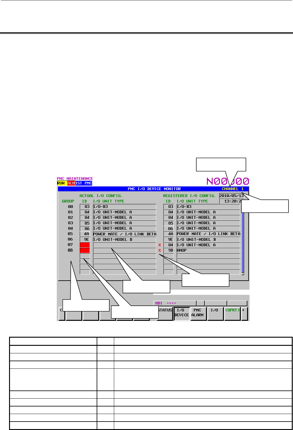
B-64513EN/03
7.PMC DIAGNOSIS AND MAINTENANCE SCREENS ([PMC MAINTE])
- 1013 -
7.5 DISPLAYING I/O DEVICES CONNECTION STATUS ([I/O
DEVICE] SCREEN)
I/O DEVICE MONITOR screen shows the types and the ID codes of I/O Units that are connected to I/O
Link in order of Group number. The screen displayed the difference between the group number of I/O
module allocation data and actually connected group number.
In case that you register configuration of I/O devices in this screen, the difference between the registered
groups and actually connected groups can be detected during the power on sequence of the system and the
groups are displayed in the screen. We recommend the registration of configuration of I/O devices when
shipping of the machine system. If you do not register configuration of I/O devices, difference check of
I/O devices is not performed.
The screen supports the following operations.
• Registration of configuration of I/O devices [REG.]
• Deletion of configuration of I/O devices [DELETE]
To switch the screen display to the I/O DEVICE MONITOR screen, press the [I/O DEVICE] soft key.
Table 7.5(a) Displayed type and actual type of I/O Units (for I/O Link)
Displayed I/O Unit ID Actual I/O Unit
CONNECTION UNIT 80 Connection Unit
OPERATOR PANEL 82 Connection Unit for Operators Panel
I/O-B3 83 I/O B3
IO UNIT-MODEL A 84
86
87
I/O Unit-MODEL A
POWER MATE / I/O LINK BETA 4A Power Mate or I/O Link Beta
SERIES 0 50 Series 0
OPERATOR I/F BOARD (MPG1) 53 Machine Operators Panel Interface
LINK CONNECTION UNIT 96 I/O Link Connecting Unit
I/O UNIT-MODEL B 9E I/O Unit-MODEL B
Registered date
Channel number
I/O Unit ID code
Group number
Difference mark
I/O Unit type

7.PMC DIAGNOSIS AND MAINTENANCE SCREENS ([PMC MAINTE])
B-64513EN/03
- 1014 -
Displayed I/O Unit ID Actual I/O Unit
R-J MATE 61 R-J Mate
CONNECTOR PANEL MODULE A9 I/O module for connector panel
OPERATOR PANEL A1 AA I/O module for operator's panel
OPERATOR I/F BOARD (MPG3) 6B Operator Interface (with MPG)
LOADER I/O AF I/O Board for Loader
FRC DIF B0 DIF Board for ROBOCUT
FRC MIF B1 MIF Board for ROBOCUT
I/O CARD B2 I/O board
ROBOSHOT I/O CARD A B3 I/O for ROBOSHOT
LOADER I/O (MATRIX) B4 I/O Board for Loader (Matrix)
PROCESS I/O FA B5 Process I/O for robot controller
PROCESS IO 89 Process I/O for robot controller
I/O LINK ADAPTER 8B I/O Link adapter
OPERATOR PANEL 95 I/O for Series 0
LASER OSCILLATOR 97 Laser Oscillator
FIXED I/O TYPE A 98 I/O for Robot Type A
FIXED I/O TYPE B 99 I/O for Robot Type B
AS-I CONVERTER 77 AS-i Converter
OPERATOR PANEL B A8 I/O Module (for Operator Panel 48/32)
MACHINE OPERATOR PANEL A A8 I/O Module (for Machine Operator Panel of 0 Type)
CONNECTION UNIT C1 (MPG) A8 Connection Unit C1 (with MPG)
MACHINE OPERATOR PANEL B A8 I/O Module (for Machine Operator Panel)
I/O MODULE WITH LCD A8 LCD display embedded I/O
I/O FOR CONNECTOR PANEL A8 I/O for connector panel
MACHINE OPERATORS PANEL A8 Machine operator’s panel
I/O FOR OPERATOR PANEL C1 A8 I/O module for operator's panel
SAFETY M.O.P.(PMC) A8 Safety machine operator’s panel (PMC)
SAFETY M.O.P.(DCS) A8 Safety machine operator’s panel (DCSPMC)
UNKNOWN UNIT - Unknown I/O Unit
NOTE
Some I/O units in above table may be displayed as “Unknown I/O unit”
according to the version of the system software. However, these I/O units would
work normally.
Table 7.5(b) Displayed type of I/O Units (for I/O Link i)
ID Displayed I/O Unit
01 OP. PANEL (CABINET) I/O B
04 MACHINE OPERATORS PANEL
08 DISPLAY FOR AUTOMOTIVE
0A I/O MODULE TYPE-2
0B I/O FOR PWR MAGNETICS CAB
0C FRC PIF
0D FRC DIF
0E FRC MIF
14 I/O BOARD SLAVE0
15 I/O BOARD SLAVE1
17 TERMINAL I/O MODULE
1E OPERATORS PANEL
21 MACHINE OPERATORS PANEL
26 I/O FOR OPERATOR PANEL C1
2C FRC PIF (DCS)
2D SMALL MACHINE OP. PANEL B

B-64513EN/03
7.PMC DIAGNOSIS AND MAINTENANCE SCREENS ([PMC MAINTE])
- 1015 -
ID Displayed I/O Unit
30 HANDY MACHINE OP. PANEL
32 SAFETY M.O.P.
3F Unit name same as name of previous group
(I/O device composed of plural groups)
4A I/O Link BETA
53 OPERATORS PANEL I/F BOARD
56 R-30iB
57 R-30iB Mate
6B OPERATORS PANEL I/F BOARD
77 I/O Link AS-i CONVERTER
82 OP. PANEL CONNECTION UNIT
96 CONNECTION UNIT
A9 I/O FOR CONNECTOR PANEL
AA I/O FOR OPERATOR PANEL A1
AB MULTISENSOR UNIT
AE I/O FOR OPERATOR PANEL A3
B2 I/O CARD
B8 LASER OSCILLATOR
C6 I/O FOR OP. PANEL (DCS)
C7 I/O FOR OP. PANEL (DCS)_S
C8 SAFETY IO UNIT
D0 I/O UNIT-MODEL A
D8 I/O UNIT-MODEL B
NOTE
Some I/O units in above table may be displayed as “Unknown I/O unit”
according to the version of the system software. However, these I/O units would
work normally.
(1) GROUP NUMBER
The group number, which is assigned in I/O module allocation data at the time of power on, is
displayed from “00”. Non-assigned group is not displayed.
NOTE
Even if I/O module allocation data is updated, the group number is never updated
before the power is turn off/on.
(2) ID of I/O UNIT
The ID of “ACTUAL I/O CONFIG.” shows the IDs of the actual connected I/O units. The ID of
“REGISTERED I/O CONFIG.” shows the IDs of registered I/O units.
When the PMC alarm “ER97” occurs, the ID of caused I/O unit is emphasized by red color.
NOTE
1 Even if I/O module allocation data is corrected during PMC alarm, emphasized
display is never cleared before the power is turn off/on.
2 The ID of I/O Link i is displayed by 4 digits. The ID of I/O Link is displayed by 2
digits.
3 Several I/O devices have same ID.
(3) I/O UNIT TYPE
I/O UNIT TYPE of “ACTUAL I/O CONFIG.” shows the I/O unit type of the actual connected I/O
units. I/O UNIT TYPE of “REGISTERED I/O CONFIG.” shows the IDs of registered I/O units.
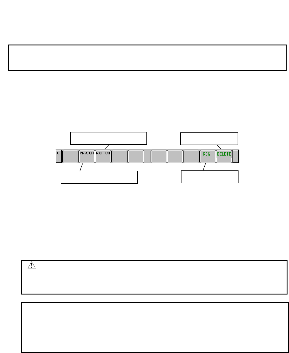
7.PMC DIAGNOSIS AND MAINTENANCE SCREENS ([PMC MAINTE])
B-64513EN/03
- 1016 -
(4) Difference mark
When registered I/O devices configuration is differ from actual I/O devices at the power on, the
difference mark is displayed.
NOTE
Even if registered configuration of I/O devices is updated by the operation of
[REG.] or [DELETE], the difference mark will not be updated immediately.
(5) REGISTRATION DATE
The date, at which the configuration of I/O devices is registered, is displayed.
(6) REGISTRATION TIME
The time, at which the configuration of I/O devices is registered, is displayed.
Soft keys
Displays connection status of
the
p
revious channel
Displays connection status of
the next channel
Registers I/O devices
confi
g
uration
Deletes I/O devices
confi
g
uration
(a) [PRV. CH] Displays connection status of the previous channel.
(b) [NXT. CH] Displays connection status of the next channel.
(c) [REG.] Registers actual I/O devices configuration.
When no I/O device is connected, the operation of this soft key is invalid.
Refer to 7.5.1 for details.
(d) [DELETE] Deletes registered I/O devices configuration.
When no I/O devices configuration is registered, this soft key is not
displayed.
CAUTION
When you clear the PMC parameter, like the power on operation with
pressing “O” and “Z”, registered I/O devices configuration is cleared.
Register again if necessary.
NOTE
1 The operations of [REG.] and [DELETE] can be protected by the programmer
protection function. In case of protecting, these soft-keys is not displayed.
2 The operations of [REG.] and [DELETE] can update the IDs, the unit types,
and the date and time of registration.
3 The operations of [REG.] and [DELETE] are performed in each channel.
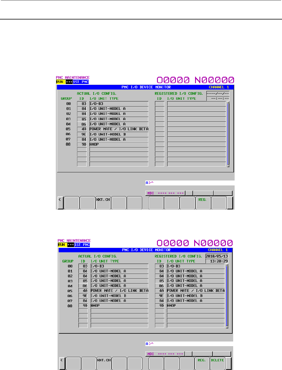
B-64513EN/03
7.PMC DIAGNOSIS AND MAINTENANCE SCREENS ([PMC MAINTE])
- 1017 -
7.5.1
Registration of I/O Devices Configuration
After you check whether the I/O devices configuration is correctly connecting, register the I/O devices
configuration by the soft key [REG.] in the I/O DEVICE MONITOR screen. As a result, the difference
between the registered I/O devices configuration and actual connected I/O devices configuration can be
checked during the power on sequence.
By deleting registered I/O devises configuration, the difference check between the registered I/O devices
configuration and actual connected I/O devices configuration is canceled.
Fig. 7.5.1 (a) No registration of I/O devices configuration
The following is an example of registration.
Fig. 7.5.1 (b) Registration of I/O devices configuration
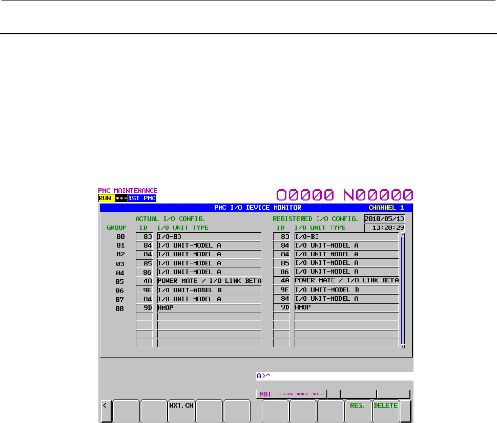
7.PMC DIAGNOSIS AND MAINTENANCE SCREENS ([PMC MAINTE])
B-64513EN/03
- 1018 -
7.5.2
Check of I/O Link Connection
When the I/O Link connection check function is effective (K906#2=0), the difference in the group
number between the group of the I/O module allocation data and the group of actual connected I/O
devices is checked.
For details of the I/O Link connection check function, refer to subsection “3.4”.
Moreover, when the configuration of I/O devices is registered in this screen, the difference between the
registered configuration of I/O devices and actually connected configuration of I/O devices is checked at
the time of power on.
In case of no alarm of I/O devices connection
The following is the case of no problem of I/O devices connection.
Fig. 7.5.2 (a) No alarm of I/O Link connection check
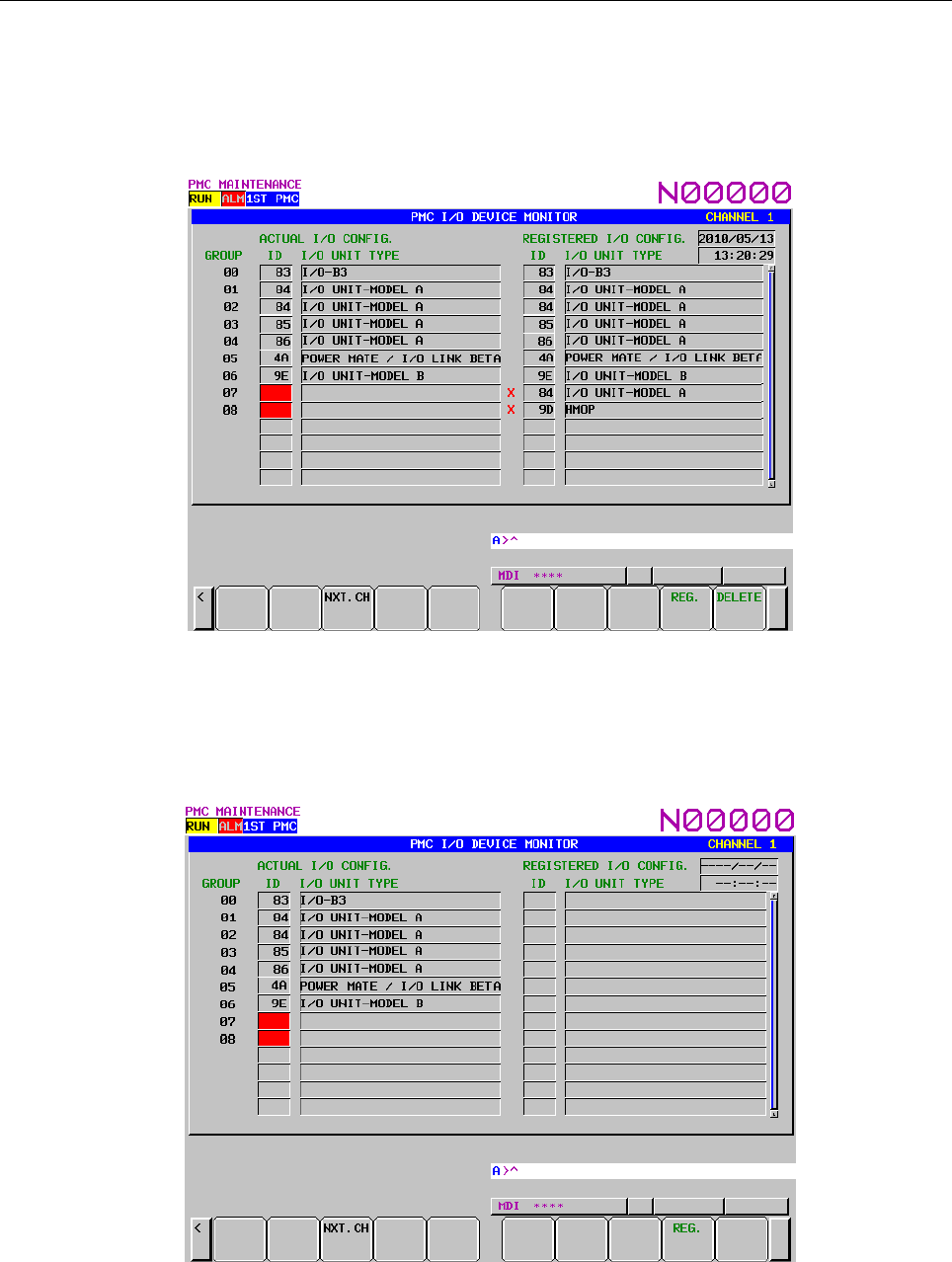
B-64513EN/03
7.PMC DIAGNOSIS AND MAINTENANCE SCREENS ([PMC MAINTE])
- 1019 -
In case of PMC alarm ER97
When the PMC alarm “ER97” occurs, the ID part of I/O unit of the group leading to the alarm in the
“ACTUAL I/O CONFIG.” is emphasized by red color.
And the difference between the registered configuration of I/O devices and actually connected
configuration of I/O devices is displayed with the difference mark.
Fig. 7.5.2 (b) Example of I/O Link connection check alarm
In case of above example, the cause is that the group number 7 or later cannot be recognized.
The issue can be specified by investigating the I/O device connected to group 7.
Even if I/O devises configuration is not registered, ID part of I/O unit in the “ACTUAL I/O CONFIG.” is
emphasized by red color.
Fig. 7.5.2 (c) Example of no registration of configuration of I/O devices
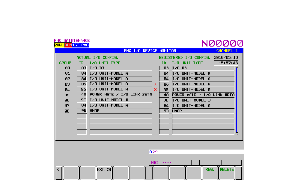
7.PMC DIAGNOSIS AND MAINTENANCE SCREENS ([PMC MAINTE])
B-64513EN/03
- 1020 -
In case of PMC alarm ER95
When the PMC alarm “ER95” occurs, the groups of I/O unit leading to the alarm are displayed with the
difference mark.
Fig. 7.5.2 (d) When configuration of I/O devices is different
In case of above example, the cause is the order of group 3 and 4 of the I/O devices.
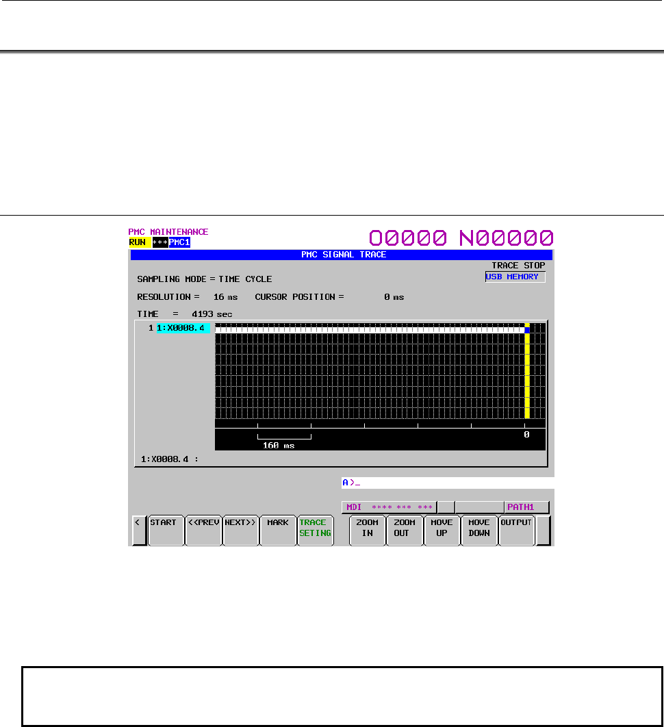
B-64513EN/03
7.PMC DIAGNOSIS AND MAINTENANCE SCREENS ([PMC MAINTE])
- 1021 -
7.6 TRACING AND DISPLAYING PMC SIGNAL STATUS
After setting a signal sampling condition on the trace parameter setting screen, PMC signal transitions can
be traced on the SIGNAL TRACE screen by executing the trace function.
To switch the screen display to the SIGNAL TRACE screen, press the [TRACE] soft key.
To switch the screen display to the trace parameter setting screen, press the [TRACE SETING] soft key.
With the multi-PMC system, the signals of all PMCs can be traced simultaneously.
7.6.1 Signal Trace Function ([TRACE] Screen)
SIGNAL TRACE screen
Before trace operation can be executed, the trace parameters must be set. Press the [TRACE SETING]
soft key to switch the screen display to the trace parameter setting screen.
By setting the PMC setting screen, the trace function can be automatically started after the power is
turned on. In this case as well, the trace parameters must be set beforehand.
NOTE
For the setting to automatically start the trace function after the power is turned
on, see Subsection 7.6.5.
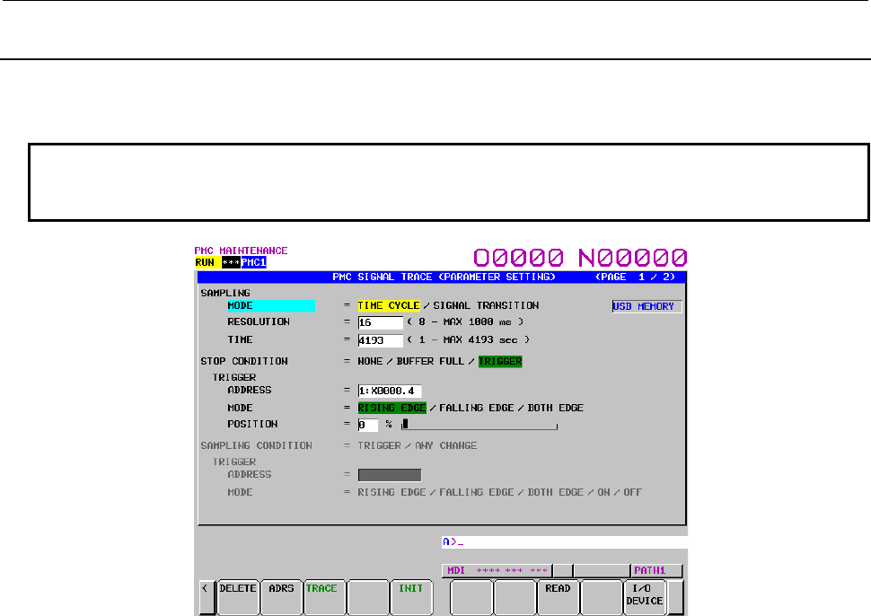
7.PMC DIAGNOSIS AND MAINTENANCE SCREENS ([PMC MAINTE])
B-64513EN/03
- 1022 -
7.6.2
Setting of Trace Parameter ([TRACE SETING] Screen)
On the trace parameter setting screen, a sampling condition can be set. The screen consists of two pages.
Use the page keys to switch between the pages.
NOTE
Even if you set a trace parameter during executing of trace, the modification of
the parameter does not influence the trace execution.
Trace parameter setting screen (first page)
(1) SAMPLING/ MODE
Determines the sampling mode.
• TIME CYCLE: Samples at every specified cycle time.
• SIGNAL TRANSITION: Monitors the signal at a set cycle and samples when the signal makes
a transition.
(2) SAMPLING/ RESOLUTION
The resolution of sampling is inputted. The default value is the minimum sampling resolution (msec),
which varies depending on the CNC.
Setting range: Minimum sampling resolution to 1000 (msec)
An input value is rounded off to a multiple of the minimum sampling resolution (msec) which is
closest to but not greater than the input value.
(3) SAMPLING/ TIME
This parameter is displayed when "TIME CYCLE" is set on "SAMPLING/ MODE". The execution
time of trace is inputted. The value of "SAMPLING/ RESOLUTION" or the number of specified
signal address changes the range of the value that is able to input. The range is displayed on the right
side.
(4) SAMPLING/ FRAME
This parameter is displayed when "SIGNAL TRANSITION" is set on SAMPLING/ MODE". The
number of sampling is inputted. The value of "SAMPLING/ RESOLUTION" or the number of
specified signal addresses changes the range of the value that is able to input. The range is displayed
on the right side.
(5) STOP CONDITION
Determines the condition to stop the trace.
• NONE: Does not stop the tracing automatically.
• BUFFER FULL: Stops the tracing when the buffer becomes full.
• TRIGGER: Stops the tracing by trigger.
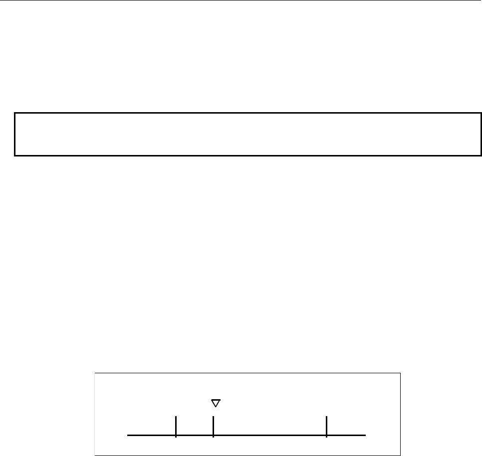
B-64513EN/03
7.PMC DIAGNOSIS AND MAINTENANCE SCREENS ([PMC MAINTE])
- 1023 -
(6) STOP CONDITION/ TRIGGER/ ADDRESS
When "TRIGGER" is set on "STOP CONDITION", this parameter is enabled. Input signal address
or symbol name as stop trigger.
A PMC number can be set for a trigger address by entering the PMC number at the time of address
setting.
Example: "2:R9200.1" + Input key
A setting can be made by entering "PMC number" + ":" + "address" as indicated above.
NOTE
1 For the PMC numbers, see Section 1.6.
2 If there is not “:” key on your keyboard, use “;” or “/” instead.
(7) STOP CONDITION/ TRIGGER/ MODE
When "TRIGGER" is set on "STOP CONDITION", this parameter is enabled. Determine the trigger
mode when the trace is stopped.
• RISING EDGE: Stops the tracing automatically by rising up of the trigger signal.
• FALLING EDGE: Stops the tracing automatically by falling down of the trigger signal.
• BOTH EDGE: Stops the tracing automatically by rising up or falling down of the trigger
signal.
(8) STOP CONDITION/ TRIGGER/ POSITION
When "TRIGGER" is set on "STOP CONDITION", this parameter is enabled. Input the ratio (%) of
the sampling time or number which specifies the position where specified trigger condition is on. If
you would like to examine the transitions of the signal before the trigger condition, you should set a
big value in this parameter. If you would like to examine the transitions of the signal after the trigger
condition, you should set a small value in this parameter.
Example:
The case that sampling time is 10 seconds and trigger position is set as "10%".
← 1 sec →← 9 sec →
Trigger position
(9) SAMPLING CONDITION
When "SIGNAL TRANSITION" is set on "TRACE MODE", this parameter is enabled.
Determine the sampling condition.
• TRIGGER: Samples the status of specified signals when the specified sampling
condition is on.
• ANY CHANGE: Samples the status of specified signals when the signals change.
(10) SAMPLING CONDITION/ TRIGGER/ ADDRESS
When "SIGNAL TRANSITION" is set on "TRACE MODE", and "TRIGGER" is set on
"SAMPLING CONDITION", this parameter is enabled. Input signal address or symbol name as
sampling trigger.
A PMC number can be set for a trigger address by entering the PMC number at the time of address
setting.
Example: "2:R9200.1" + Input key
A setting can be made by entering "PMC number" + ":" + "address" as indicated above.
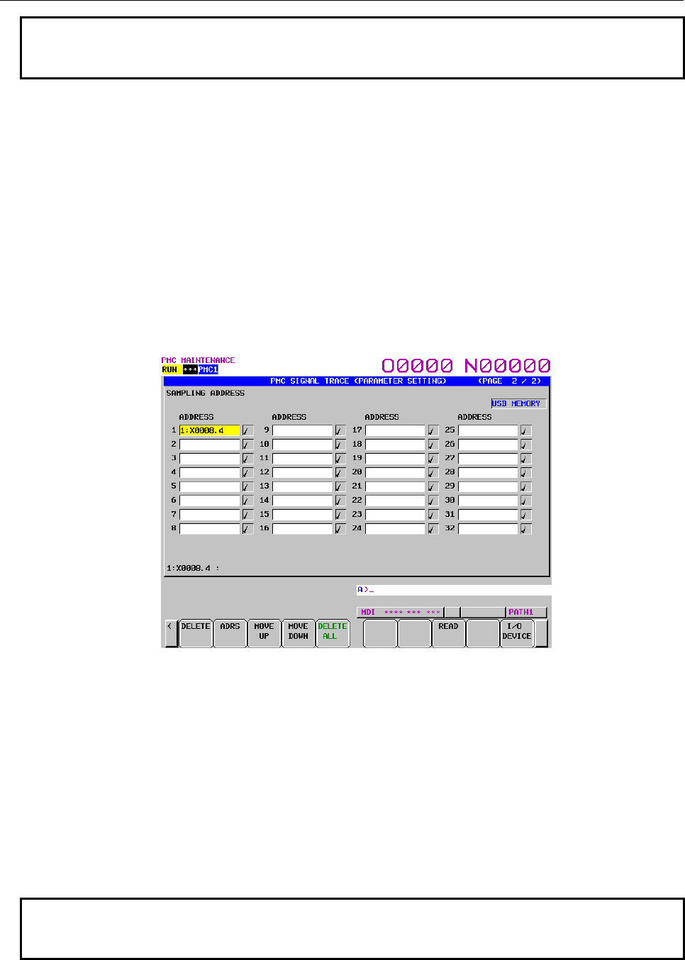
7.PMC DIAGNOSIS AND MAINTENANCE SCREENS ([PMC MAINTE])
B-64513EN/03
- 1024 -
NOTE
1 For the PMC numbers, see Section 1.6.
2 If there is not “:” key on your keyboard, use “;” or “/” instead.
(11) SAMPLING CONDITION/ TRIGGER/ MODE
When "SIGNAL TRANSITION" is set on "TRACE MODE", and "TRIGGER" is set on
"SAMPLING CONDITION", this parameter is enabled. Input trigger mode that determines the
condition of specified trigger.
• RISING EDGE: Samples the status of specified signals by rising up of the trigger signal.
• FALLING EDGE: Samples the status of specified signals by falling down of the trigger signal.
• BOTH EDGE: Samples the status of specified signals by rising up or falling down of the
trigger signal.
• ON: Samples the status of specified signals during the trigger signal is on.
• OFF: Samples the status of specified signals during the trigger signal is off.
Page 2 of the PARAMETER SETTING screen
You can set the addresses or symbols that should be sampled.
Trace parameter setting screen (second page)
(1) Setting addresses
In case of inputting discrete bit addresses, any bit address can be inputted.
Moreover, when you input byte address, all bits of the address (bits 0 to 7) are set automatically.
Maximum 32 points of signal address can be inputted.
With the multi-PMC system, an address can be set for a desired PMC by specifying its PMC number.
Example: 2:R9200.1 + Input key
A setting can be made by entering "PMC number" + ":" + "address" as indicated above.
In case of the DCSPMC, enter "S:"+"address".
When no PMC number is specified, the specification of the currently selected PMC is assumed. In
this case, "PMC number" + ":" is automatically prefixed to a specified address.
When only one PMC is used as in the standard PMC system, no PMC number needs to be specified.
NOTE
1 For the PMC numbers, see Section 1.6.
2 If there is not “:” key on your keyboard, use “;” or “/” instead.

B-64513EN/03
7.PMC DIAGNOSIS AND MAINTENANCE SCREENS ([PMC MAINTE])
- 1025 -
NOTE
3 Increasing the number of the signal address changes the capacity of
"SAMPLING/ TIME" or "SAMPLING/ FRAME" in page 1. If the capacity is
changed, the following warning message is displayed. (The "n" on the message
means the maximum value that is able to input.)
a) In case of "TIME CYCLE" mode
"SAMPLING TIME IS REDUCED TO n SEC."
b) In case of "SIGNAL TRANSITION" mode
"SAMPLING FRAME IS REDUCED TO n."
4 The signal trace for the DCSPMC is executed in the same timing as signals of
1st to 5th paths PMC.
CAUTION
The signal trace of the DCSPMC does not synchronize with the ladder execution
period of the DCSPMC. Therefore, when plural signals are traced, the timing of
tracing may not be accurate.
(2) Soft keys
Soft keys on the setting screen of sampling address are as follows
(a) [DELETE]
Clears the value of the edit box on the cursor.
(b) [SYMBOL]/[ADDRESS]
Changes the address display to the symbol display. However, display of the address that is not
defined the symbol does not change. This soft key also changes to "ADDRESS".
(c) [MOVE UP]
Exchanges the signal indicated the cursor for the signal above one line.
(d) [MOVE DOWN]
Exchanges the signal indicated the cursor for the signal below one line.
(e) [DELETE ALL]
Clears all of the value of the edit box.
(f) [READ]
Reads the trace setting file from the device displayed in the indicator window. There are two
kinds of the devices i.e. “memory card” and “USB memory”.
NOTE
When not specifying the file name, the file name of a trace setting data which
can be read is “PMC_TRS.000”. When specifying the file name, a trace setting
data of the file name can be read.
(g) [I/O DEVICE]
Selects input device of the trace setting file and output device of the trace result data. Pressing
the soft-key switches “memory card” or “USB memory” alternately. Selected device name is
displayed in the indicator window on the trace result screen and the trace setting screen.
NOTE
Selected device information is not initialized by the soft key [INIT] in the page 1 of
the trace parameter setting screen. The clearing operation of PMC parameter
(Power on with pressing “O” key and ”Z” key) initializes the information. The Initial
setting is “memory card”.

7.PMC DIAGNOSIS AND MAINTENANCE SCREENS ([PMC MAINTE])
B-64513EN/03
- 1026 -
(3) Trigger setting
When "SIGNAL TRANSITION" is set on "TRACE MODE" and "ANY CHANGE" is set on
"SAMPLING CONDITION", it can be set whether to use the setting address as the signals that
should trigger the sampling in the setting signals. As for the signal address where the trigger was set,
"9" is displayed right. Soft keys on the Trigger setting screen are as follows:
• TRGON: Sets the Trigger on.
• TRGOFF: Sets the Trigger off.
The default setting is trigger on for all signals.
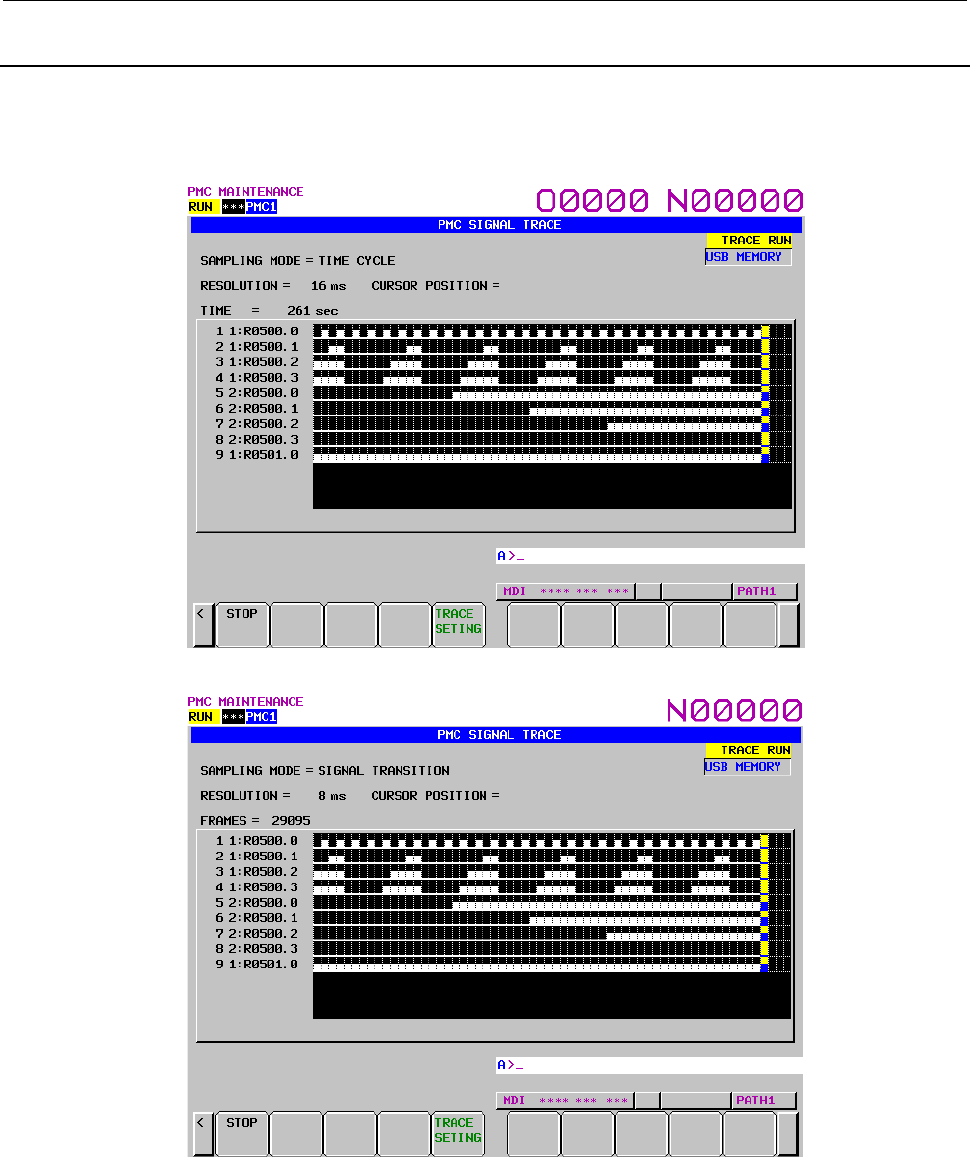
B-64513EN/03
7.PMC DIAGNOSIS AND MAINTENANCE SCREENS ([PMC MAINTE])
- 1027 -
7.6.3
Execution of Trace
After the trace parameters are set, a trace operation can be started by pressing the [(OPRT)] soft key and
the [START] soft key on the SIGNAL TRACE screen. The following is the screen examples of the trace
execution by "TIME CYCLE" mode and "SIGNAL TRANSITION" mode.
Trace execution screen (TIME CYCLE mode)
Trace execution screen (SIGNAL TRANSITION mode)
The result of trace is immediately displayed during execution of the trace.
When the stop conditions that is set in parameter setting screen is satisfied the execution is finished.
Pressing the [STOP] soft key aborts the execution. In "SIGNAL TRANSITION" mode, graphic display is
not refreshed until any signal for sampling trigger changes.
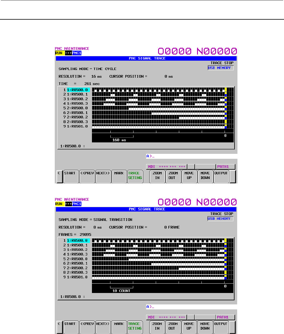
7.PMC DIAGNOSIS AND MAINTENANCE SCREENS ([PMC MAINTE])
B-64513EN/03
- 1028 -
7.6.4
Operation after Execution of Trace
When the execution is finished, the result of trace is displayed. The followings are the screen examples of
trace by "TIME CYCLE" and "SIGNAL TRANSITION" mode.
Trace result screen (TIME CYCLE mode)
Trace result screen (SIGNAL TRANSITION mode)
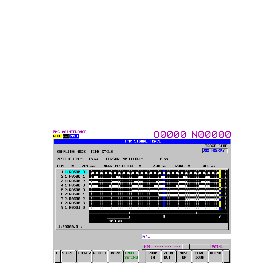
B-64513EN/03
7.PMC DIAGNOSIS AND MAINTENANCE SCREENS ([PMC MAINTE])
- 1029 -
The cursor indicating current position is initially displayed on the original point (0 point). The position of
the cursor is displayed in "CURSOR POSITION" in the upper of the screen. The cursor can move
horizontally with the <←> or <→> key. After the execution, following operation is enabled.
a) Scroll of screen
- Cursor up/down key and Page up/down key
Enables the vertical scroll for the specified signal
- Cursor right/left key, [NEXT>>] soft key and [<< PREV] soft key
Enables the horizontal scroll of the graph.
b) Automatic calculation of the selected range
Pressing the [MARK] soft key marks the current position and displays the mark cursor.
If the mark cursor duplicates with the current position cursor, the current position cursor has priority
of display. The "MARK POSITION" that shows the position of the mark cursor and "RANGE" that
shows the range between the mark cursor and the current position cursor are displayed in the upper
of screen.
Moving the current position cursor changes these values. Pressing the [MARK] soft key again
releases the select range mode.
Trace result screen (Mark cursor display)
c) Zoom in/Zoom out of waveform
Pressing the [ZOOM IN] soft key magnifies the display of chart. Pressing the [ZOOM OUT] soft
key reduces the display of chart. Pressing these soft keys also change the scale value of the
graduation on the graph. When trace is just finished, the default zooming level was the most
magnified level. In “ZOOM OUT” mode, "▓" is displayed as following screen example when the
transitions of signal cannot be expressed accurately enough. The limitation of “ZOOM OUT”
displays all of result of the trace in one page.
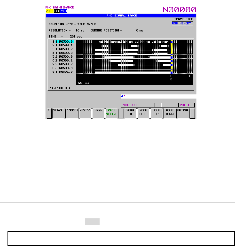
7.PMC DIAGNOSIS AND MAINTENANCE SCREENS ([PMC MAINTE])
B-64513EN/03
- 1030 -
Trace result screen (Zoom out display)
d) Exchange of sampling signal
Pressing the [MOVE UP] soft key exchanges the signal indicated by the signal cursor for the signal
one line above. Pressing the [MOVE DOWN] soft key exchanges the signal indicated by the signal
cursor for the signal one line below. The result of the operation is cancelled by the execution of trace
or putting the power off. If you want to maintain the order of displayed signals behind the re-
execution or the power off, set the order on "SAMPLING ADDRESS" screen.
e) Output of the trace result data
Pressing the [OUTPUT] soft key writes the trace result data to “memory card” or “USB memory”.
7.6.5
Automatic Start of Trace Setting
Trace execution is automatically started after power-on by setting a PMC setting data.
• TRACE START = MANUAL/AUTO
NOTE
For details of the method of setting PMC setting data, see Section 9.5.

B-64513EN/03
7.PMC DIAGNOSIS AND MAINTENANCE SCREENS ([PMC MAINTE])
- 1031 -
7.6.6
Trace Result Output
If trace result data is present when a trace operation has been executed, the data can be output to the
memory card or the USB memory. Output trace result data can be input to application software such as
spreadsheet software run on the personal computer. For the method of input, refer to the relevant manual
of application software.
(1) Operation
Press the [OUTPUT] soft key. The soft key display changes to [EXEC] and [CANCEL]. Press the
[EXEC] soft key to start output. Upon completion of output, the soft key display returns to the
initial status on the signal trace result screen.
(2) File name
The name of an output file is PMCTRACE.000. If a file with the same name exists on the memory
card, the extension is incremented to PMCTRACE.001, PMCTRACE.002, and so on (up to
PMCTRACE.999).
(3) Output format
Trace result data is output in the text format. Character string data items such as item names and
setting names are enclosed in quotation marks (').
Output data is divided into four major blocks: a header, data of the first parameter setting page, data
of the second parameter setting page, and trace result data.
(a) Header
At the start of data, an identifier representing the type of data and edition information are
output.
Identifier: ('PMC TRACE DATA')
Edition information: ('Edition', 1)
(b) Data of the first parameter setting page
identifier, , ,
setting-number, setting-item-name, setting, setting-character-string
setting-number, setting-item-name, setting, setting-character-string
setting-number, setting-item-name, setting, setting-character-string
setting-number, setting-item-name, setting, setting-character-string
:
:
• identifier Character string data
The character string 'Setting' is output.
• setting-number Numeric data
The numbers (starting with 1) assigned to setting items in ascending order are output.
• setting-item-name Character string data
The character string of each setting item is output.
• setting Numeric data
A value that is originally numeric, such as a resolution value, is directly output. Numbers
(starting with 1) are assigned from left to right to options from which a choice is to be
made, such as TIME CYCLE/SIGNAL TRANSITION, and the number assigned to a
selected option is output.

7.PMC DIAGNOSIS AND MAINTENANCE SCREENS ([PMC MAINTE])
B-64513EN/03
- 1032 -
• setting-character-string Character string data
For a setting that is numeric data, its unit, if used, is output.
For an option that is converted to a number in the item of "setting" mentioned above, the
original character string data is output. In other cases, a blank is output in this column.
Table of data of the first parameter setting page
Item Setting
number Setting item name Setting Setting character string
Sampling mode 1 'Sampling mode' 1 'TIME CYCLE'
2 'SIGNAL TRANSITION'
Sampling resolution 2 'Sampling resolution' Numeric value 'MSEC'
Sampling time 3 'Sampling time' Numeric value 'SEC'
Sampling frame 'Sampling frame'
1 'NONE'
Stop condition 4 'Stop condition' 2 'BUFFER FULL'
3 'TRIGGER'
Stop trigger address 5 'Stop trigger address' Address Symbol
1 'RISING EDGE'
Stop trigger mode 6 'Stop trigger mode' 2 'FALLING EDGE'
3 'BOTH EDGE'
Stop position 7 'Stop trigger position' Numeric value %
Sampling condition 8 'Sampling condition' 1 'TRIGGER'
2 'ANY CHANGE'
Sampling trigger address 9 'Sampling trigger address' Address Symbol
1 'RISING EDGE'
Sampling trigger mode 10 'Sampling trigger mode' 2 'FALLING EDGE'
3 'BOTH EDGE'
NOTE
1 For a setting item that is invalidated in combination with another setting, only a
setting number and setting item name are output, with a blank output in the
setting column and the setting character string column. (However, commas are
not omitted.)
2 For an item name that changes according to the setting of another item, the item
name displayed according to the setting is displayed. (Example: Sampling
time/Sampling frame dependent on the selection of a Sampling mode option)
3 For a sampling stop trigger address and sampling trigger address, an address is
output in the setting column, and a symbol is output in the setting character
string column. When no symbol is set, an address is output in the setting
character string column as well.
4 For a sampling stop trigger position (successful trigger position/sampling frame
count) is output after "%". (This is because a frame position is internally held, so
that an error can occur at the time of conversion to a percentage value.)

B-64513EN/03
7.PMC DIAGNOSIS AND MAINTENANCE SCREENS ([PMC MAINTE])
- 1033 -
(c) Data of the second parameter setting page
identifier-1, data-1, data-2, data-3, . . . . .
identifier-2, data-1, data-2, data-3, . . . . .
identifier-3, data-1, data-2, data-3, . . . . .
identifier-4, data-1, data-2, data-3, . . . . .
• identifier Character string data
'Address': Sampling address
'Symbol': Symbol defined for a sampling address
'Comment': Comment defined for a sampling address
'Check': Indicates whether a check is made to see if each signal is used to trigger
sampling when SAMPLING CONDITION = ANY CHANGE.
• data
'Address': Address character string
'Symbol': Symbol character string
'Comment': Comment character string
'Check': With check = 1/without check = 0
NOTE
1 Data is not output beyond set sampling addresses. This means that no blank is
output in the item of 'Address'.
2 For an address for which no symbol or no comment is set, no data is output, but
a blank is output in the column. Commas are not omitted but are output for up to
set sampling addresses.
(d) Trace result data
identifier, sampling-address-1, sampling-address-2, . . . . .
frame-count, data-1, data-2, data-3. . . . .
:
:
:
• identifier Character string data
The character string 'Data' is output.
• frame-count Numeric value
The position where the frame count is 0 is a position where triggering is performed
successfully. If triggering is unsuccessful, the frame count is 0 at the point where
sampling stopped.
• data Numeric data
The value 0 or 1 is output.
It is assumed that data is output until an EOF (end of file) appears. Information such as
data size is not set.
7.PMC DIAGNOSIS AND MAINTENANCE SCREENS ([PMC MAINTE])
B-64513EN/03
- 1034 -
(4) Example of trace result output (The contents of the following example is rearranged for easy
understanding. The actual may be different.)
'PMC TRACE DATA'
'Edition', 1
'Setting', , ,
1,'Sampling mode', 2, 'SIGNAL TRANSITION'
2,'Sampling resolution', 8, 'MSEC'
3,'Sampling time', 2000,
4,'Stop condition', 3, 'TRIGGER'
5,'Stop trigger address', 'X10.0', 'SYMBOL1'
6,'Stop trigger mode', 1, 'RISING EDGE'
7,'Stop trigger position', 50(1250/2500), '%'
8,'Sampling condition', 1, 'TRIGGER'
9,'Sampling trigger address', 'X10.1', 'SYMBOL2'
10,'Sampling trigger mode', 3, 'BOTH EDGE'
'Address','R0000.0', 'R0000.1', 'R0000.2', 'R0000.3', 'R0000.4', 'R0000.5', 'R0000.6', 'R0000.7',
'R0001.0', 'R0002.0'
'Symbol', 'ZRN_M' , , , '*SPA1' , '*SPA2', 'MX-RD','RSTN', 'RSTMA', 'MO1X', 'MO2X'
'Comment', 'ZRN MODE', 'TIME CNT.AUX1(MEM)' , , , , 'READ STROBE', 'NORMAL RESET PB',
'INIT_M&RSTM (RST->MACRO)', 'OPTIONAL STOP1','OPTIONAL STOP2'
'Check', 0, 1, 1, 1, 1, 1, 0, 1, 1, 1
'Data','R0000.0', 'R0000.1', 'R0000.2', 'R0000.3', 'R0000.4', 'R0000.5',
'R0000.6', 'R0000.7', 'R0001.0', 'R0002.0'
-6, 1,0,0,0,0,0,0,0,0,0
-5, 0,0,0,0,0,1,1,1,1,1
-4, 1,1,1,1,1,0,0,0,0,0
-3, 0,1,0,1,0,1,0,1,0,1
-2, 0,0,1,1,0,0,1,1,0,0
Note1
Note2,3
NOTE
1 With the multi-PMC system, this data is output in the format: "PMC number" + ":"
+ "address".
Example: '2:R0000.0'
2 In case of the extended symbol mode, a program name is added in front of the
local symbol.
Example: ‘1:P1.ZRN_M’ (PMC path=1, Local symbol in P1)
3 When using the ladder dividing management function, the symbols and
comments defined in the main ladder program are output to trace result and
setting data.

B-64513EN/03
7.PMC DIAGNOSIS AND MAINTENANCE SCREENS ([PMC MAINTE])
- 1035 -
7.7 MONITORING I/O DIAGNOSIS ([I/O DGN] SCREEN)
The I/O diagnosis screen shows the status of I/O variables, which are extracted from symbol data, and
configuration of network and the status of communication of I/O modules. The following items are listed
in this screen:
• The symbol and comment of the variable
• The status of the variable
• The address of the variable
• The type of I/O network device
• The type of I/O module of the network device
• The network address information of the network device
• The communication status of the network device
NOTE
Supported
types of I/O network device are PROFIBUS, I/O Link and I/O Link i.
There are two screens related to I/O diagnosis function.
(1) The I/O diagnosis screen
The I/O variables are listed in this screen. You can check the configuration of the I/O network
devices and the status of the communication with them.
You can select three ways of ordering the list by soft keys:
• Address order (Default)
The variables are displayed in the order of their actual addresses.
• Symbol order
The variables are displayed in the alphabetical order of their symbols.
• Network order
The variables are displayed in the order of their network addresses. Only the variables actually
associated with an I/O network appear in this mode.
NOTE
“Symbol order” is available only in case of the sequence program with extended
symbol and comment.
(2) The setting screen
You can configure the I/O diagnosis screen at the setting screen
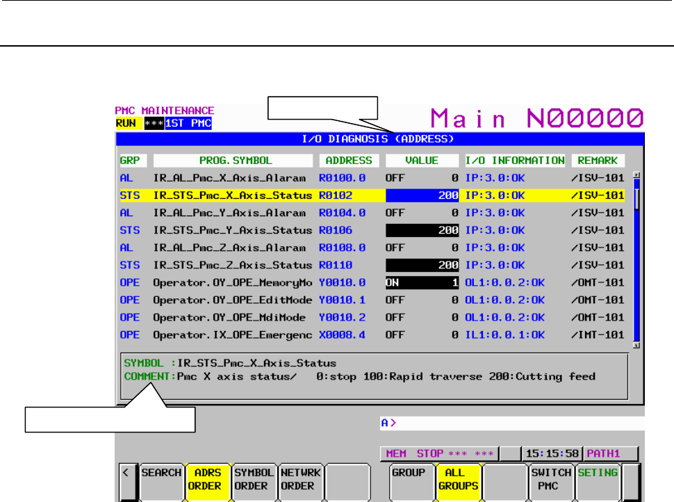
7.PMC DIAGNOSIS AND MAINTENANCE SCREENS ([PMC MAINTE])
B-64513EN/03
- 1036 -
7.7.1
I/O DIAGNOSIS Screen
In I/O Diagnosis screen, you can check the status of each I/O variable. You can also check the
configuration of I/O devices and the communication status with them.
(1) GRP (GROUP)
To include a specific string, which means a kind of signals in a part of symbol string, these signals
on I/O diagnosis screen are classified and you can easy to understand the status of signals.
The group names of the I/O variables are displayed, which are extracted (Max. 4 chars) out of their
symbol names as configured in “GROUP FORMAT” in the setting screen.
The groups to be displayed can be specified by soft key.
[ALL GROUPS] All groups are displayed.
[GROUP] The group entered by key or the group under the cursor is selected to be displayed.
(2) PROG.SYMBOL (SYMBOL)
The symbol names of the I/O variables are displayed.
The symbol names are displayed in the following formats according to the setting of the “SHOW
PROGRAM” on the Setting screen of I/O DIAGNOSIS.
<Program Symbol>.<Signal Symbol>
<Program Number>.<Signal Symbol>
<Signal Symbol>
For details of the setting of the “SHOW PROGRAM”, see to the description of “SHOW
PROGRAM” in Section 7.7.2
(3) ADDRESS
The actual locations of I/O variables are displayed.
Listing order
Additional information
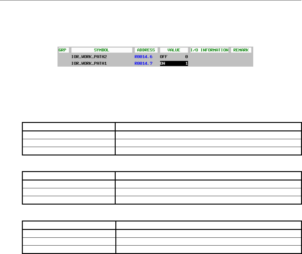
B-64513EN/03
7.PMC DIAGNOSIS AND MAINTENANCE SCREENS ([PMC MAINTE])
- 1037 -
(4) VALUE
The current values of I/O variables are displayed as signed decimal, according to the data type of
them (i.e. BOOL, BYTE, WORD, and DWORD). If the data type is BOOL, “ON” or “OFF” is also
displayed as follows.
(5) I/O INFORMATION
The information related to I/O network is displayed in the display format below:
<I/O type><Network type> : <Network address> : <status>
I/O type:
Module type Shown as
Input module I
Output module O
Other *
Network type:
Network type Shown as
PROFIBUS P
I/O Link Ln (n: channel number)
I/O Link i Ln (n: channel number)
Network address:
Network type Network address notation
PROFIBUS <Slave #>.<Slot #>
I/O Link <Group #>.<Base #>.<Slot #>
I/O Link i <Group #>.<Slot #>

7.PMC DIAGNOSIS AND MAINTENANCE SCREENS ([PMC MAINTE])
B-64513EN/03
- 1038 -
NOTE
This screen shows the I/O information according to the network setting that
became effective at the time of the last power-on.
The notes for each network device are as follows:
PROFIBUS
1. If you have changed some of the PROFIBUS parameters, you have to cycle
the power once to make the changes take effect.
I/O Link
1. Only the I/O Link assignments, which are made effective by the setting of
“Machine Signal Interface” in Configuration Parameter menu and the setting
of the “Communication method of I/O Link” in NC Parameter and the setting
of “Selectable I/O Link Assignment Function”, are displayed.
2. If you have changed the following parameters, you have to cycle the power
once to make them take effect:
• “I/O Link assignment data”
• “Machine signal interface” in PMC configuration parameter
• “Communication method of I/O Link” in NC Parameter
• Parameter of “Selectable I/O Link assignment function”
3 If you have stored new sequence program to PMC, its I/O Link assignment
data will not take effect until you write it into Flash-ROM and cycle the power
once.
I/O Link i
1. Only the I/O Link i assignments, which are made effective by the setting of
“Communication method of I/O Link” in NC Parameter and the setting of
“Selectable I/O Link i Assignment Function”, are displayed.
2. If you have changed the following parameters, you have to cycle the power
once to make them take effect:
• “I/O Link i assignment data”
• “Communication method of I/O Link” in NC Parameter
• Parameter of “Selectable I/O Link i assignment function”
3. If you have stored new I/O configuration data to PMC, its I/O Link i
assignment data will not take effect until you write it into Flash-ROM and
cycle the power once.
Status: the status of communication
“OK” or “NG” is displayed.
(6) REMARK
The remarks up to 8 characters extracted from comment data are displayed. To specify the remark at
this field, set “100” to the attribute value of the comment, which you want to show in this field, on
FANUC LADDER-III,
(7) Additional information window
In this window, symbol and comment of the I/O variable under the cursor are displayed.
To display comments depend on language, set a language attribute with FANUC LADDER-III.
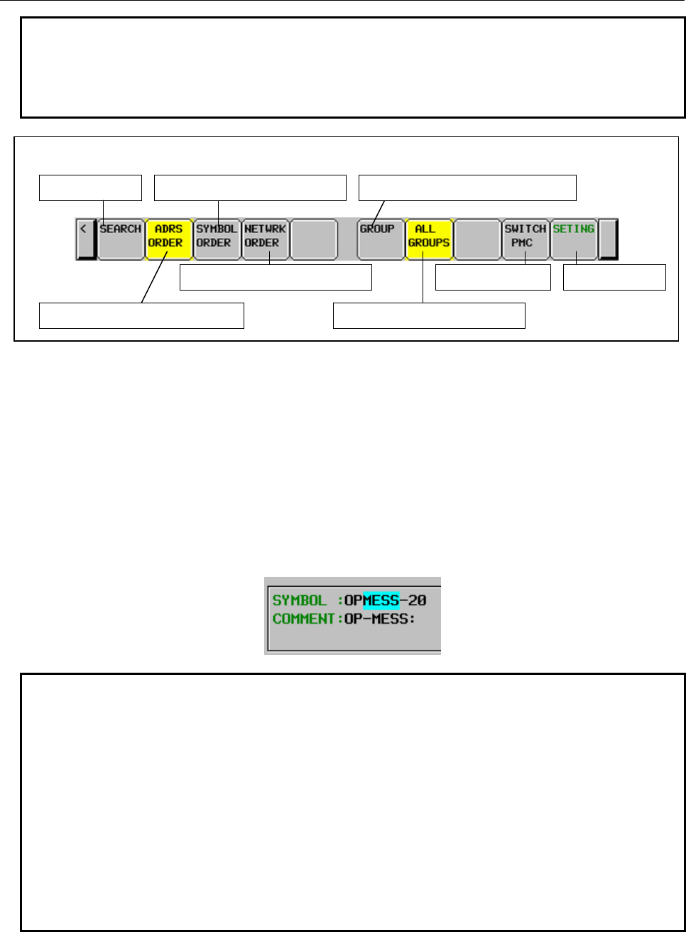
B-64513EN/03
7.PMC DIAGNOSIS AND MAINTENANCE SCREENS ([PMC MAINTE])
- 1039 -
NOTE
In case of the extended symbol and comment, the comments on the screen will
be
switched
dynamically to new language when the language setting of CNC
changes. For the language attribute, refer to "APPENDIX B. LANGUAGE ID
TABLE".
Switch to the address order display
Search for data Switch to the address order display
Screen settings Switch to the address order display
Softkeys on the I/O Diagnosis screen
Switch to the specified group display
Switch to the all group display
Switch PMC path
Operations using soft keys
(1) [SEARCH] Search symbol or address
Pressing [SEARCH] soft key after a string searches the string in the symbols and addresses, and
shows a symbol or an address that contains the string if found.
The search is performed toward bottom of the list. When it reaches the bottom of the list, it goes
back to the top and continues.
Pressing [SEARCH] alone repeats the last search.
When the search hits, the part of the searched string is highlighted by light blue background in the
Additional Information window.
Example:
The case of searching “MESS” to hit the symbol “OPMESS-20”
NOTE
1 When arrived back to the starting position where the first search operation hit by
repeated search of the same entry, the message “REACHED TO THE END OF
SYMBOL DATA.” appears.
2 If the setting “SHOW PROGRAM” is set to “SYMBOL” or “PROGRAM NO.”, the
symbol name is displayed in one of forms below:
<Program Symbol>.<Signal Symbol>
<Program Number>.<Signal Symbol>
In this case, search function will not hit in “Program Symbol” nor “Program
Number”.
3 On a symbol screen in network order a searching word is performed in address
order. When you search a part string and some word are hit, the searched
position (cursor position) may move to unexpected direction.
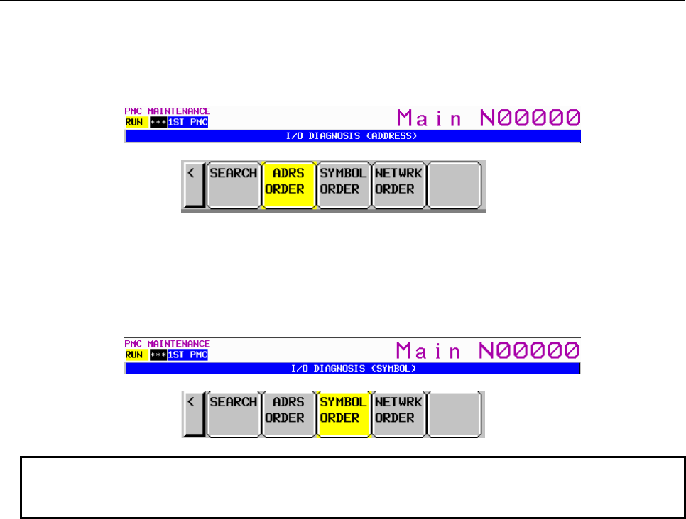
7.PMC DIAGNOSIS AND MAINTENANCE SCREENS ([PMC MAINTE])
B-64513EN/03
- 1040 -
(2) [ADRS ORDER] Sort by address order
Displays I/O variables in address order. (Default)
In this mode, the mark “(ADDRESS)” is appended in the title of this screen, and the [ADRS
ORDER] soft key is highlighted with yellow background.
(3) [SYMBOL ORDER] Sort by symbol order
Displays I/O variables in symbol order.
In this mode, the mark “(SYMBOL)” is appended in the title of this screen, and the [SYMBOL
ORDER] soft key is highlighted with yellow background.
NOTE
“
Symbol
order” is available only in case of the sequence program with extended
symbol and comment.
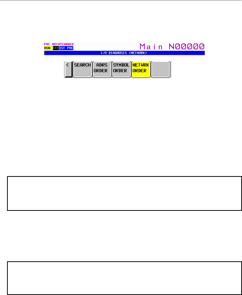
B-64513EN/03
7.PMC DIAGNOSIS AND MAINTENANCE SCREENS ([PMC MAINTE])
- 1041 -
(4) [NETWRK ORDER] Sort by network address order
Displays I/O variables in order of network address.
Only the I/O variables that is actually effective are displayed.
In this mode, the mark “(NETWORK)” is appended in the title of this screen, and the [NETWRK
ORDER] soft key is highlighted with yellow background.
The I/O variables are sorted by its network address. The sorting order is not affected by the type of
modules such as input or output. The order is determined according only to priority of network
address portion as following. For I/O Link and I/O Link i, the I/O variables of them are displayed
together by the channel order.
PROFIBUS: Slave Number, Slot Number
I/O Link: Channel, Group, Base, Slot
I/O Link i: Channel, Group, Slot
Example: In case that the channel 1 is I/O Link i and the channel 2 is I/O Link, I/O Link i is
displayed earlier.
IP:3.0:OK
IL1:0.1:OK
IL2:0.0.1:OK
NOTE
If while sorting the I/
O variables in “Network order” mode, the following messages may
appear:
SORTING DATA [PROFIBUS :
n
SLAVE]
SORTING DATA [I/
O LINK :
n
CH
m
GROUP]
(5) [GROUP] Filter by group
Choose a group to which the I/O variables to be displayed belong. Press this soft key following the
group name, or press it alone with the cursor placed on the group you want to specify.
The way to order the I/O variables will not change.
If the setting “GROUP FORMAT” is not specified, the soft key [GROUP] and [ALL GROUPS] are
not effective.
NOTE
If while extracting the I/O variables of specific group, the following messages may
appear:
SELECTING GROUP [PROFIBUS :
n
SLAVE]
SELECTING GROUP [I/O LINK :
n
CH
m
GROUP]
(6) [ALL GROUPS] Cancel group filter
Displays I/O variables of any group. (Default)
If the setting “GROUP FORMAT” is not specified, the soft key [GROUP] and [ALL GROUPS] are
not effective.
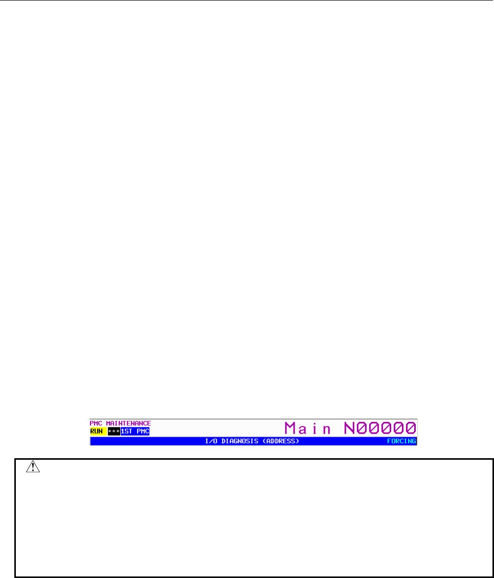
7.PMC DIAGNOSIS AND MAINTENANCE SCREENS ([PMC MAINTE])
B-64513EN/03
- 1042 -
(7) [SWITCH PMC] Switching PMC path or divided ladder programs
Switches PMC path or divided ladder program of which the I/O variables are to be shown. For
details of the operation, refer to “6.3”.
By setting keep relay K935.0 to 1, you can display PMC program list screen. For details, refer
to ”2.2.11”.
(8) [SETING] Configure the setting of this screen
Goes to the setting screen of I/O diagnosis.
Screen operation using other keys
(1) Cursor keys
Move cursor to change the I/O variable, whose information is displayed in Additional information
window, or to which the forcing function is performed. They scroll up and down the contents of the
screen if necessary.
(2) Page keys
Scroll up or down the contents of the screen by page.
(3) Input key
If the forcing function is available, you can change the status of I/O variables by Input key.
(a) Changing a bit signal
• “1” + Input key to turn on the signal.
• “0” + Input key to turn off the signal.
• Press Input key alone to toggle the signal
(b) Changing a byte, word, dword variable
Press Input key following signed decimal
If the setting item “FORCING ENABLE” is set to “YES” in the setting screen, you can change the
value of I/O variables as described above.
The mark “FORCING” at the right end of the screen title indicates the forcing function is enabled.
WARNING
1 You have to pay special attention to use Forced I/O function to change status of signals.
Inappropriate use of Forced I/O function may cause unexpected reaction of machine.
You have to make it sure that nobody is near the machine when you use this function.
2 As you use Forcing mode of Forced I/O function to change status of signal, however, the
signal may look proof against Forced I/O function, because LADDER program or I/O
device writes into the signal repeatedly. In this case, even if the signal looks unchanged,
actual signal may be changed in very short moment. You should be careful for the
reaction of machine to such signal changes.
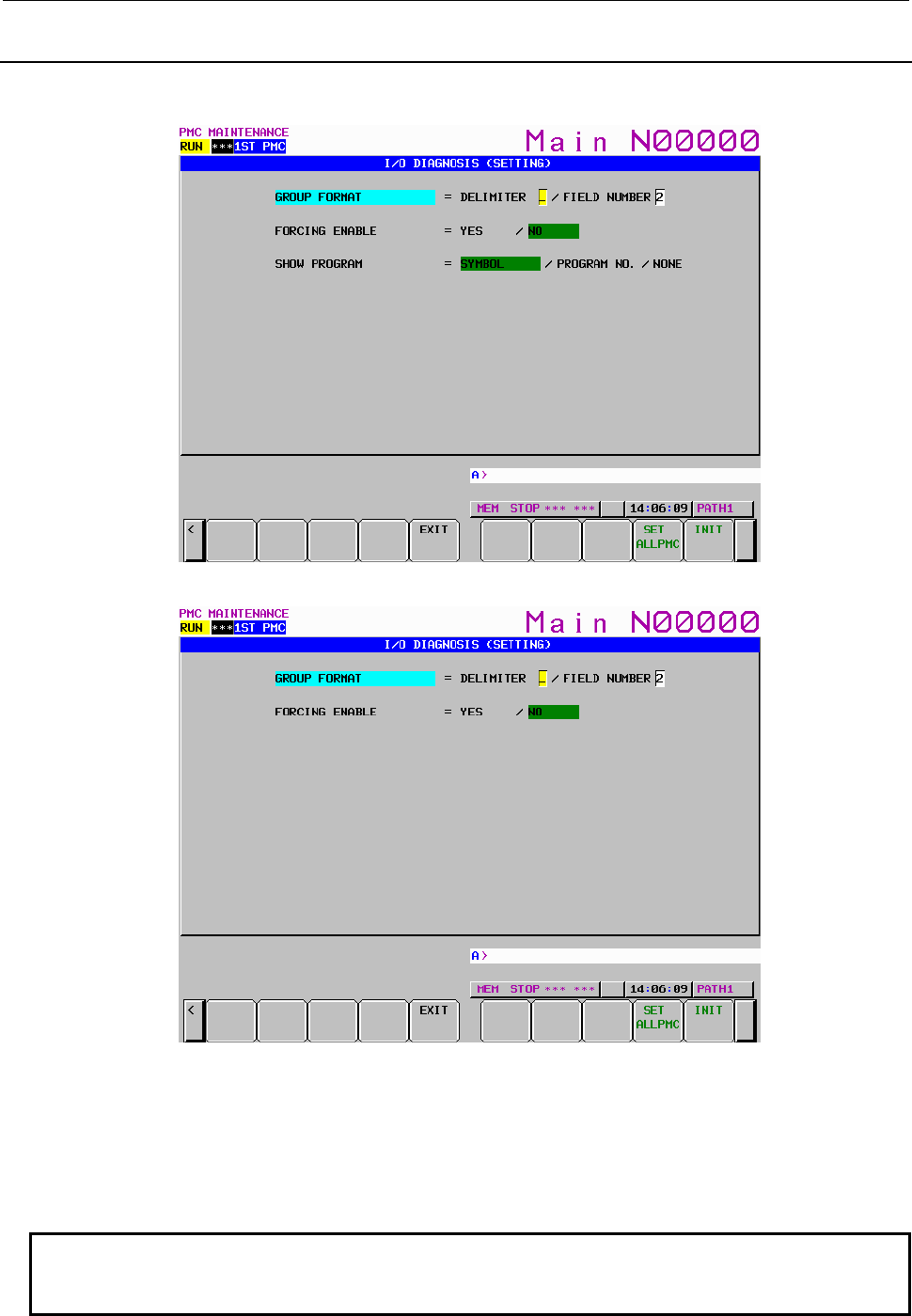
B-64513EN/03
7.PMC DIAGNOSIS AND MAINTENANCE SCREENS ([PMC MAINTE])
- 1043 -
7.7.2
SETTING Screen of I/O DIAGNOSIS
In “I/O DIAGNOSIS (SETTING)” screen, you can change the setting to configure the I/O diagnosis
screen
Fig. 7.7.2(a) Setting screen of the I/O diagnosis (for extended symbol and comment)
Fig. 7.7.2 (b) Setting screen of the I/O diagnosis (for former symbol and comment)
(1) GROUP FORMAT
The group names shown in I/O Diagnosis screen are strings extracted from their symbol names
according to this parameter.
• DELIMITER
Sets the character of delimiter for extraction. Every appearance of this character in a symbol
string cut the symbol into “fields”.
NOTE
If no character is given, the group feature of I/O Diagnosis screen is disabled.
In this case, the field number has no effect.

7.PMC DIAGNOSIS AND MAINTENANCE SCREENS ([PMC MAINTE])
B-64513EN/03
- 1044 -
• FIELD NUMBER
Sets the field number, which indicates the field to be a group name. If this number is 1, the
first field, which means the portion of each symbol name from the first character to the
character just before the first appearance of the delimiter character,
NOTE
If 0 is set, the group feature of I/O Diagnosis screen is disabled.
In this case, the delimiter has no effect.
Example: Case of “_” as delimiter, and group name at 2nd field
The symbol = I_AL_NC_WATCH_DOG_SIGNAL
DELIMITER = ‘_’
FIELD NUMBER = 2
As a result, “AL” is extracted as its group name
(2) FORCING ENABLE
Enables or disables the forcing function.
WARNING
1 You have to pay special attention to use Forced I/O function to change status of
signals. Inappropriate use of Forced I/O function may cause unexpected reaction
of machine. You have to make it sure that nobody is near the machine when you
use this function.
2 As you use Forcing mode of Forced I/O function to change status of signal,
however, the signal may look proof against Forced I/O function, because
LADDER program or I/O device writes into the signal repeatedly. In this case,
even if the signal looks unchanged, actual signal may be changed in very short
moment. You should be careful for the reaction of machine to such signal
changes.
NOTE
If the Forced I/O function is protected by the programmer protection function, this
setting is not effective.
The Forced I/O function will be protected in the condition as follows.
In case of Programmer Protection Function
• PROGRAMMER ENABLE (K900.1) "NO"
and
• RAM WRITE ENABLE (K900.4) "NO"
In case of Protection of Data at 8 Levels
• Operation level is less than CHANGE level of “PMC MEMORY”
.
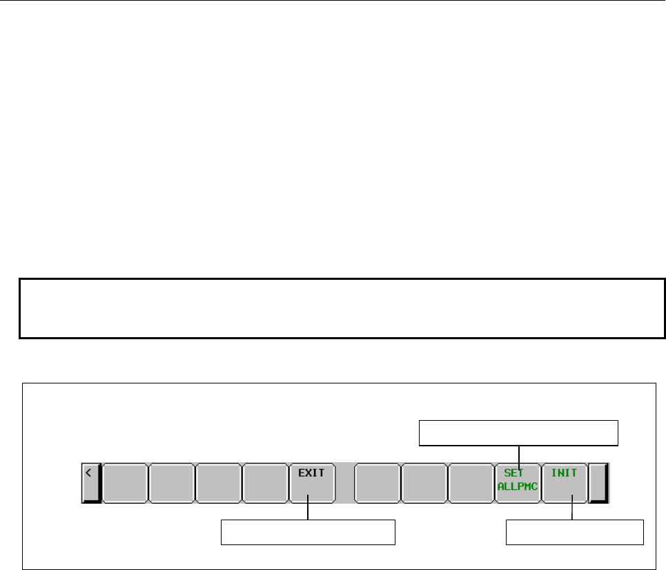
B-64513EN/03
7.PMC DIAGNOSIS AND MAINTENANCE SCREENS ([PMC MAINTE])
- 1045 -
(3) SHOW PROGRAM
Determines the form of symbol name in the I/O Diagnosis screen.
SYMBOL:
Symbol names are displayed in the form below:
<Program Symbol>.<Signal Symbol>
If symbol name is too long for the symbol field of the I/O Diagnosis screen, the tail of signal
symbol is cut to fit it.
PROGRAM NO.:
Symbol names are displayed in the form below:
<Program Number>.<Signal Symbol>
If symbol name is too long for the symbol field of the I/O Diagnosis screen, the tail of signal
symbol is cut to fit it.
NONE:
Program symbol nor program number is not displayed.
NOTE
These setting data are kept in the nonvolatile memory not to be lost even if the
power is turned off.
Operations using the soft keys
(1) [EXIT]
Goes to the I/O Diagnosis screen.
(2) [SET ALLPMC] Copies settings to all PMC paths
Copies current settings to all other PMC paths.
(3) [INIT] Initializes settings
All the settings are initialized to their initial values as follows:
GROUP FORMAT: DELIMITER = none
FIELD NUMBER = 0
FORCING ENABLE: NO
SHOW PROGRAM: SYMBOL
Initializes each itemsGoes to I/O Diagnosis screen
Softkeys on the I/O Diagnosis screen
Copy each itmes to all PMC path
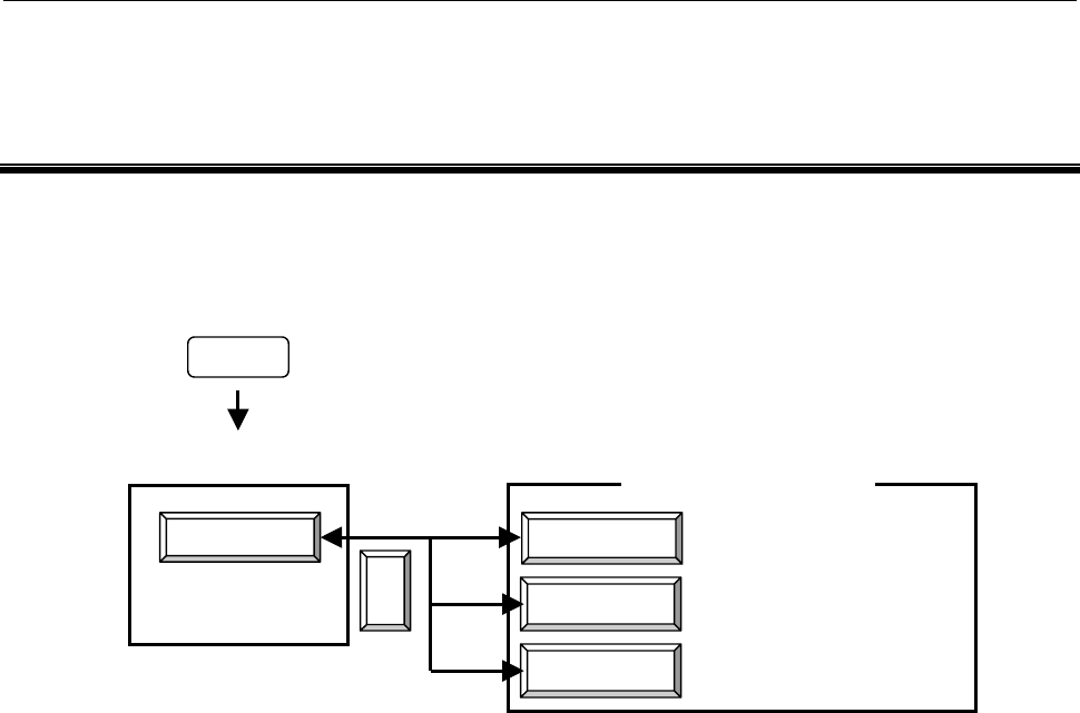
8.LADDER DIAGRAM MONITOR AND EDITOR SCREENS ([PMC LADDER])
B-64513EN/03
- 1046 -
8 LADDER DIAGRAM MONITOR AND
EDITOR SCREENS ([PMC LADDER])
The PMC LADDER menu contains the screens related to PMC Ladder diagrams, such as the PROGRAM
LIST screen and the LADDER DIAGRAM MONITOR/EDITOR screens.
You can switch to the PMC LADDER menu by operating on the "SYSTEM" key and then the [PMC
LADDER] soft key.
LIST
LADDER
PMC LADDER
<
Program list screen
Ladder diagram Monitor / Editor
screen
PMC LADDER menu
SYSTEM
DUP. CHECK Duplicate coil check screen
PMC main menu
Pressing the [LADDER] soft key causes the sequence program to be dynamically displayed, allowing you
to monitor operation. The editor screen allows you to make changes to relay and functional instructions
in the sequence program to change the operation of the sequence program.
The ladder diagram display/editor functions consist of the following screens:
(1) LADDER DIAGRAM MONITOR screen
Displays ladder diagrams to monitor the current states of relays, coils, and so on.
(2) COLLECTIVE MONITOR screen
Displays selected ladder net to monitor the current states of relays, coils, and so on.
(3) LADDER DIAGRAM EDITOR screen
Allows you to edit ladder diagram in units of net.
(4) NET EDITOR screen
Allows you to edit single net in a ladder diagram.
(5) PROGRAM LIST VIEWER screen
Allows you to select the subprogram to be displayed on the LADDER DIAGRAM MONITOR
screen.
(6) PROGRAM LIST EDITOR screen
Allows you to edit a ladder program in units of subprograms. Also allows you to select the
subprogram to be edited on the LADDER DIAGRAM EDITOR screen.
(7) FUNCTIONAL INSTRUCTION DATA TABLE VIEWER screen
Allows you to view the contents of the data table for functional instruction with data table.
(8) FUNCTIONAL INSTRUCTION DATA TABLE EDITOR screen
Allows you to edit the contents of the data table for functional instruction with data table.
(9) SUBPROGRAM LIST VIEWER screen
Displays the list of the called subprogram and the subprogram switching history.
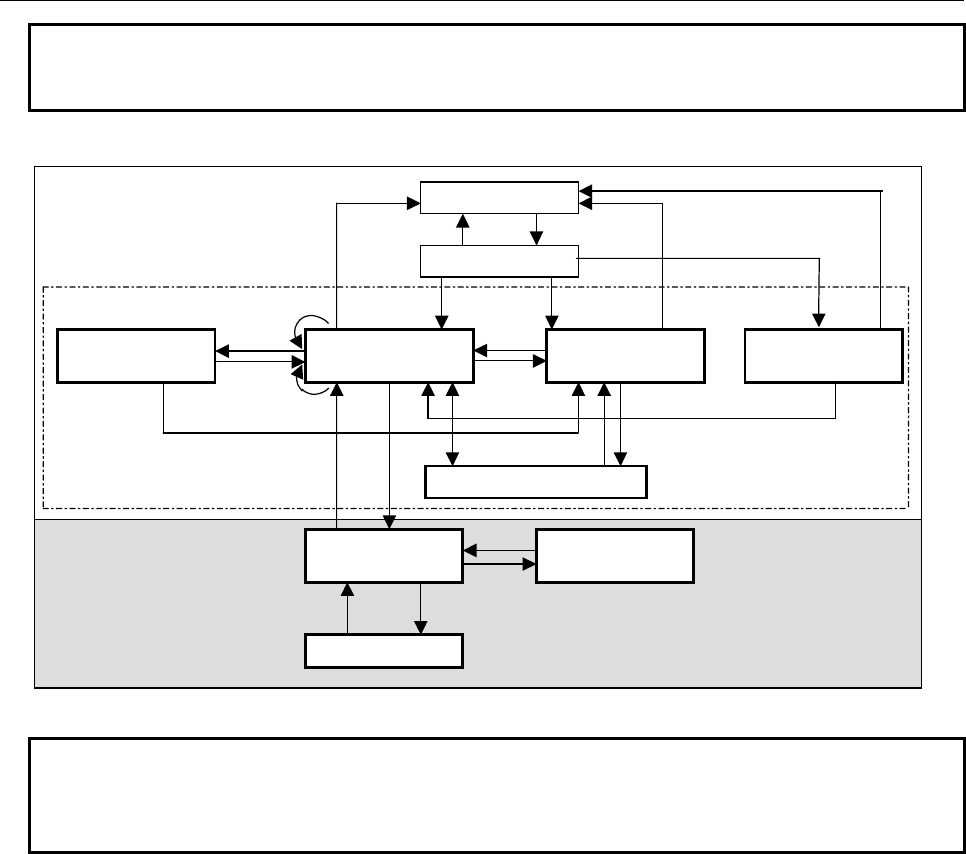
B-64513EN/03
8.LADDER DIAGRAM MONITOR AND EDITOR SCREENS ([PMC LADDER])
- 1047 -
NOTE
You can protect these screens by using the programmer protection function. For
details, see Section 6.2.
You can move among screens as shown in the figure below.
[SWITCH]
Edit Function
[LIST]
[EXIT] [ZOOM]
PROGRAM LIST
EDITOR screen
LADDER DIAGRAM
EDITOR screen
NET EDITOR screen
[CREATE NET]
[ZOOM]
[LIST]
[ZOOM]
[ZOOM]
[EDIT] COLLECTIVE MONITOR screen
[LIST][LADDER]
[<] [<]
[PMC LADDER][<]
PMC main menu
PMC LADDER menu
Display Function
(Monitor)
[EXIT EDIT]
[SPLIST]
[LADDER]
[LIST]
SUBPROGRAM LIST
VIEWER screen [LIST]
[BACK]
LADDER DIAGRAM
MONITOR screen
[BACK]
PROGRAM LIST
VIEWER screen
[ZOOM]
[BACK] [ZOOM]
Duplicate coil check
screen
[JUMP]
[DUP. CHECK] [<]
Fig. 8 Transition among screens
NOTE
The [EDIT] soft key on the LADDER DIAGRAM MONITOR screen is displayed
and becomes available if the programmer protection function enables to edit
ladder program. For details, see Section 6.2.
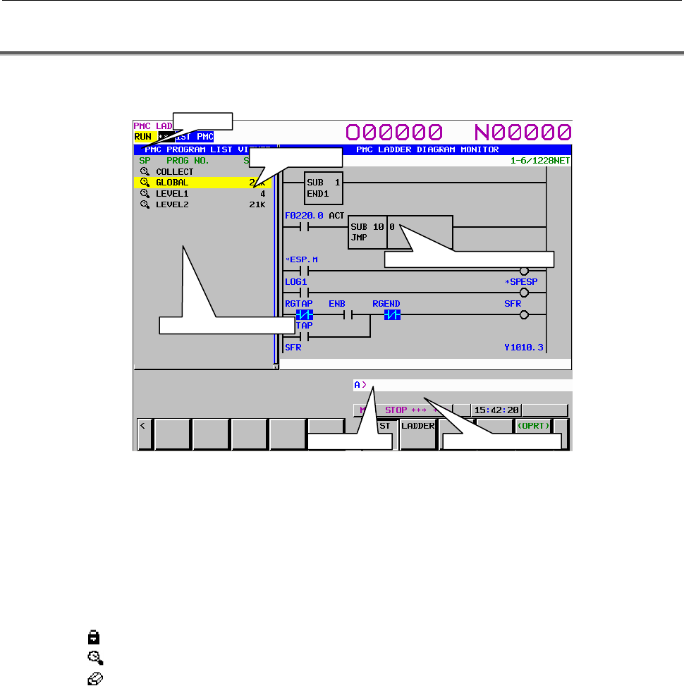
8.LADDER DIAGRAM MONITOR AND EDITOR SCREENS ([PMC LADDER])
B-64513EN/03
- 1048 -
8.1 DISPLAYING A PROGRAM LIST ([LIST] SCREEN)
The PROGRAM LIST VIEWER screen shows program information such as the program size.
(1) Screen structures
(a) A program list is displayed on the left side of the screen; on the right side, the ladder diagram
of the program currently indicated by the cursor on the program list is displayed.
(b) In the message line, error messages or inquiry messages will be displayed depending on the
situation.
(c) The program list displays up to 18 programs at a time in the list display area.
(2) Area of program list
(a) In the "SP area", the protect information for subprograms is displayed, so are their program
types.
(Lock): Unable to browse and edit (Global program)
(Magnifying glass): Ladder program which is able to browse but unable to edit
(Pencil): Ladder program which is able to browse and edit
(b) Program name is displayed in the "PROG NO." field for each program.
There are three kinds of program names.
COLLECT: means the collective monitor screen.
GLOBAL: means the whole program.
LEVELn (n = 1, 2, 3): means the Ladder level 1, 2 and 3.
Pm (m = subprogram number): means subprogram.
By changing the “ADDRESS NOTATION” item in the LADDER DIAGRAM MONITOR
Setting screen to “SYMBOL”, you can display symbols.
(c) The program size is displayed in the “SIZE” field for each program.
If the program size is not over 1024 byte, the unit is shown in byte.
If it is over 1024 byte, the unit is shown in kilo (1024) byte with “K”.
Ex.) The case that program size is not over 1024 byte.
1023 bytes: “1023” is shown.
Ex.) The case that program size is over 1024 byte.
20000 bytes: “19K” is shown.
(Sizes are rounded off to whole numbers before being displayed.)
Ladder preview display area
Message display line Key input line
Program number area
Size area
SP area
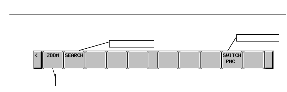
B-64513EN/03
8.LADDER DIAGRAM MONITOR AND EDITOR SCREENS ([PMC LADDER])
- 1049 -
(3) Operation with Soft keys
Soft key of PROGRAM LIST VIEWER screen
Display the contents
of program
Search for program
Switch PMC paths
(a) [ZOOM] Display the contents of program
Goes to LADDER DIAGRAM MONITOR screen. If you press [ZOOM] soft key without
strings, the program under the cursor is displayed at LADDER DIAGRAM MONITOR screen.
If you entered program name (See (a) in (5) for detail) or symbol before pressing [ZOOM] soft
key, the program according to the preceding string is searched and the program is displayed at
LADDER DIAGRAM MONITOR screen.
But, when the selected program is protected to monitor, you have to unlock the protection.
(b) [SEARCH] Search for program
Searches the program. If you entered program name (See (a) in (5) for detail) or symbol and
press [SEARCH] soft key, the program according to the preceding string is searched, the cursor
points the program.
(c) [SWITCH PMC] Switching PMC path or divided ladder programs
Switches PMC path or divided ladder program. For details of the operation, refer to “6.3”.
By setting keep relay K935.0 to 1, you can display PMC program list screen. For details, refer
to ”2.2.11”.
(4) Other operations
(a) Cursor move keys, Page change keys
You can move cursor by all cursor move keys and Page change keys.
(b) INPUT key
You can operate same as [ZOOM] soft key.
(5) Note of searching and zooming operations
(a) When you specify a subprogram to search for, or to zoom into, you can use following notation
for each program part:
GLOBAL: “0”(Zero) or “G”
LEVEL1, 2, 3: “L” + Number Ex.) “L1”, “L01”, etc
Pn: Number or “P2 + Number
Ex.) “1”, “P1”, “P01”
(b) Search function by [SEARCH] soft key tries to suppose the given word as an item to be
searched in following order.
(i) The string for GLOBAL or LEVEL: “0”(Zero), “G”,“L” + Number
The number for subprogram: Number
(ii) Symbol
(iii) The string for subprogram: “P” + Number
(6) Ladder preview
The subprogram indicated by the cursor in the program list is displayed in the ladder display area on
the right of the screen.
If you wish to operate on the ladder diagram, you must switch to the LADDER DIAGRAM
MONITOR screen by using the [ZOOM] soft key from the program list.
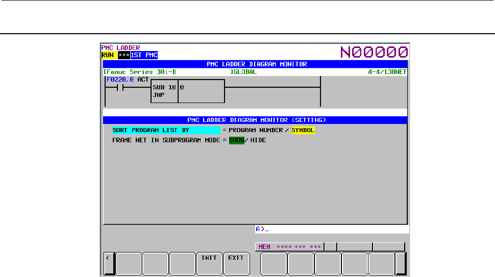
8.LADDER DIAGRAM MONITOR AND EDITOR SCREENS ([PMC LADDER])
B-64513EN/03
- 1050 -
8.1.1
Setting the Program List Screen
(1) Program list screen setting
To make settings on the program list screen, use the [SCREEN SETING] soft key on the ladder
screen.
Page 2 of the ladder setting screen contains the settings of the program list screen.
(2) Setting items
(a) SORT PROGRAM LIST BY
Specifies whether to display each subprograms on Program List display screen in order of
program numbers or symbols. When ADDRESS NOTATION is SYMBOL, programs without
symbols are displayed in order of program number after programs with the symbols.
COLLECT,GLOBAL, LEVEL1, LEVEL2, LEVEL3 are out of target of sort.
PROGRAM NUMBER (default)
Program List display screen in order of program numbers.
SYMBOL
Program List display screen in order of symbols.
(b) FRAME NET IN SUBPROGRAM MODE
Frame net means functional instruction END1, 2 and 3 on LEVEL1, 2, 3, and functional
instruction SP and SPE on subprogram.
It determines whether the frame net in the LADDER DIAGRAM MONITOR/EDITOR screen
are displayed or not, when you selected the program and press [ZOOM] soft key in the
PROGRAM LIST VIEWER/EDITOR screen.
SHOW (default)
The frame net is displayed in the LADDER DIAGRAM MONITOR/EDITOR screen.
HIDE
The frame net is not displayed in the LADDER DIAGRAM MONITOR/EDITOR screen.
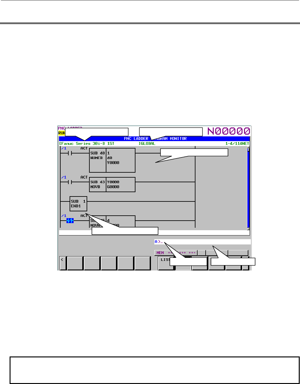
B-64513EN/03
8.LADDER DIAGRAM MONITOR AND EDITOR SCREENS ([PMC LADDER])
- 1051 -
8.2 MONITORING LADDER DIAGRAMS ([LADDER] SCREEN)
LADDER DIAGRAM MONITOR screen shows the on/off status of contacts and coils, and the contents
of address specified for parameter of functional instructions.
From the PMC LADDER menu, you can switch to the LADDER DIAGRAM MONITOR screen by using
the [LADDER] soft key. You can use following operation at this screen, including "Forced I/O function
(Forcing mode)", by which you can force the relay or the address parameters of functional instructions to
a new status or value.
• Switch subprogram to show [LIST]
• Search for address or others [SEARCH MENU]
• Show data table of functional instructions [DATA TABLE]
• Go to COLLECTIVE MONITOR Screen [SWITCH]
• Forced I/O function (Forcing mode) "number" + INPUT key
(1) Screen structures
(a) Title information (REMARKS) of the LADDER Program, the current subprogram, and the
current position information of the Diagram displayed in this screen, are displayed above the
LADDER Diagram.
When you select a subprogram to be displayed, range for search function is indicated at right of
the top line as "LOCAL" or "GLOBAL". In case of "LOCAL", the range for search function
is restricted within the current subprogram. In case of "GLOBAL", on the other hand, search
function searches whole of LADDER program, and switch current subprogram automatically
according to the result of searching.
NOTE
The range mark for search, “LOCAL” or “GLOBAL” does not be displayed in the
displays of 8.4 inch or 10.4 inch.
(b) In the additional information line near the bottom of the screen, the following information of
the address under the cursor is displayed when the cursor is shown.
• Net number of the net at the cursor
• Address and its symbol and comment information
• Current value
Key input line Message line
Additional
information
line
Area for LADDER Diagram
Title information (REMARKS)
Current
subprogram
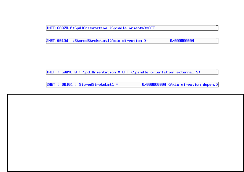
8.LADDER DIAGRAM MONITOR AND EDITOR SCREENS ([PMC LADDER])
B-64513EN/03
- 1052 -
Symbol and Comment are displayed with fixed length when using Basic type Symbol and
Comment data.
In case of the bit address under the cursor.
In case of the byte address under the cursor.(4 bytes parameter)
Left justified Symbol and Comment are displayed with flexible length when using Extended
type Symbol and Comment data.
In case of the bit address under the cursor.
In case of the byte address under the cursor.(4 bytes parameter)
NOTE
1 When you set K903.1 to 1 and using Basic type Symbol and Comment data, the
symbol and comment are displayed with flexible length on additional information
line, as same as when using Extended Symbol and Comment data.
2 Displayed comment characters on additional information line is shown below
when the symbol and comment are displayed with fixed length.
8.4 inch, 10.4 inch : 15 characters
15 inch, 19 inch : 30 characters
3 When symbol and comment on an additional information line are displayed with
flexible length and all the characters of comment cannot be displayed on the line,
a period is displayed at the end of comment string.
(c) In the message line, error messages or inquiry messages will be displayed depending on the
situation.
(d) In the area for LADDER diagrams, 9 × 8, 9 × 6, 9 × 4, 7 × 8, 7 × 6, and 7 × 4 relays can be
displayed (horizontally and vertically). For details, see Subsection 8.2.2.
(e) The gauge indicating the current display position in relation to the whole Ladder program is
displayed at the right end of the screen.
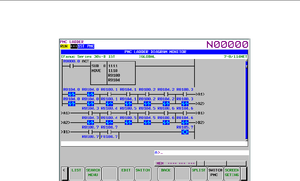
B-64513EN/03
8.LADDER DIAGRAM MONITOR AND EDITOR SCREENS ([PMC LADDER])
- 1053 -
(2) LADDER diagram
(a) Nets wider than the screen width are displayed as “Continuous Net” using continuous marks
(“>A1>”). Same continuous marks mean they are connected with each other.
(3) Monitor
(a) Contacts and coils change their colors and/or shapes according to the status of the signals.
The status of power flow is not displayed.
(b) Usually, the parameters of functional instructions are monitored and displayed. You can
suppress the monitor and display by an appropriate setting. For details, see Subsection 8.2.2.
(4) Displaying Symbols and Comments
(a) Usually, addresses are displayed above contacts and coils. For an address with a symbol
assigned, you can change the setting so that the symbol is displayed instead of the address.
You can add colors to addresses. For details, see Subsection 8.2.2.
(b) If the address of a contact has a comment attached, the comment is displayed below the contact.
You can change its display mode by changing the setting. You can add colors to comments.
For details, see Subsection 8.2.2.
(c) If the address used with coil has a comment string assigned, the comment strings will be
displayed at the right margin beside the coil. You can use this margin area to display an
additional relay instead of the comment string by setting: at this setting, one more relay can be
displayed in each diagram line. You can add colors to comments. For details, see
Subsection 8.2.2.
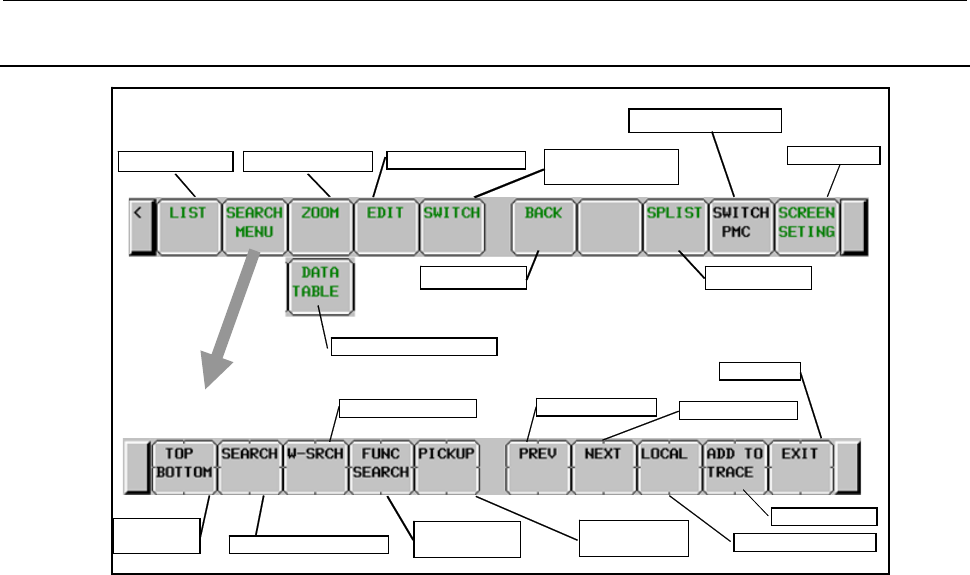
8.LADDER DIAGRAM MONITOR AND EDITOR SCREENS ([PMC LADDER])
B-64513EN/03
- 1054 -
8.2.1
Operating on the LADDER DIAGRAM MONITOR Screen
Main soft keys of LADDER Diagram Monitor screen
Program List
Display Data Table
Back previous
Switch to COLLECTIVE
MONITOR screen
LADDER Diagram Editor
Subprogram List
Screen Settings
Switch PMC paths
Display Subprogram
Search next
Search Write Coil Search previous
Search Address or Net
Search Functional
Instruction
Switch range
Search soft keys
Exit
Jump to
Top/Bottom
Adding to trace
Pick up a Ladder
Diagram net
(1) Operation with Soft keys
(a) [LIST] Go to PROGRAM LIST VIEWER screen
Goes to PROGRAM LIST VIEWER screen to choose subprogram to be displayed at LADDER
DIAGRAM MONITOR screen.
(b) [SEARCH MENU] Search & Jump
Change soft keys to “Search soft keys”. Use the [EXIT] soft key to return to the “Main soft
keys”.
“Search soft keys” consists of followings:
• [TOP BOTTOM] Jump to Top/Bottom
Jumps to the top of LADDER Program. If the top is displayed already, then jump to the
bottom.
• [SEARCH] Search Address/Net
Searches the PMC address or the net according to the preceding string. You can specify
both of bit address and byte address.
When digits are entered, the digits are supposed to be a net number and the screen will
jump to the net of the net number.
When a string other than digits is entered, the string is examined as a symbol for PMC
address at first. If the string is found to match a symbol, then the address that the symbol
means will be searched for.
If no symbol matches the string, then the string is examined as PMC address at next. If the
string indicates correct PMC address, then the address will be searched for.
When cursor is hidden, the net that has the specified net number or contains the specified
address will be shown at the top of the screen. When cursor is shown, the cursor moves to
the relay or the parameter to show the found address directly.
When target address is in a program protected by the partial protection function, it can be
skipped and moved to the next by pressing [SKIP] key.
• [W-SRCH] Search Write Coil
Searches for the write coils with the address that entered string means. Any contacts with
the address are ignored.

B-64513EN/03
8.LADDER DIAGRAM MONITOR AND EDITOR SCREENS ([PMC LADDER])
- 1055 -
• [FUNC SEARCH] Search Functional Instruction
Searches for the functional instructions by its SUB number or its mnemonic name such as
“TMR” or “END2”.
• [PICKUP] Pick up a ladder net and load it into the COLLECTIVE MONITOR screen
Picks up the ladder net to monitor and loads it into the COLLECTIVE MONITOR screen.
• [PREV] Search previous
Repeats to search the same thing backward (upward).
• [NEXT] Search next
Repeats to search the same thing forward (downward).
• [GLOBAL]/[LOCAL] Change range
Changes the range for searching between GLOBAL and LOCAL; GLOBAL means whole
of program, and LOCAL means within the displaying subprogram. Current range for
searching is indicated at right of the information line at top of screen.
• [ADD TO TRACE] Adding to trace
Adds the PMC address used for contact or coil into sampling address for signal trace.
• [EXIT] Exit from the search function
Exits from a search process and returns you to the main soft key display.
(c) [DATA TABLE] Go to FUNCTIONAL INSTRUCTION DATA TABLE VIEWER screen
Goes to FUNCTIONAL INSTRUCTION DATA TABLE VIEWER screen to examine contents
of Data Table of functional instructions such as COD (SUB 7) and CODB (SUB 27), which
have Data Table in themselves. This soft key appears only when the cursor is on a functional
instruction that has Data Table.
(d) [ZOOM] Display contents of subprogram
Placing the cursor on a CALL/CALLU/CM instruction, [ZOOM] soft key is displayed.
Pressing [ZOOM] soft key switches the subprogram on the screen to the one which the
instruction under the cursor calls. Each subprogram switching is recorded in the subprogram
history (Max. 16 records), and you can trace back the history by [BACK] soft key. You can see
the list of subprograms in the current history at the Subprogram List Display screen.
(e) [EDIT] Go to LADDER DIAGRAM EDITOR screen
Goes to LADDER DIAGRAM EDITOR screen. This soft key appears only when Programmer
function is enabled. And activating Online Monitor function disables this soft key.
If the ladder program is password-protected, you are asked to enter a password. Enter the
password required to edit the program.
(f) [SWITCH] Switch to COLLECTIVE MONITOR screen
Switches to COLLECTIVE MONITOR screen.
(g) [BACK] Show the preceding subprogram
Ladder Diagram Monitor screen manages the history of the subprograms which have been
displayed. You can use [BACK] soft key to trace back the history to recall the previous
subprogram. You can see the subprograms in the current history at the subprogram list screen.
(h) [SPLIST] Switch to the subprogram list screen
The subprogram list screen shows the list of the subprograms which are called by the current
subprogram. You can choose a subprogram from the list, which will be displayed on the screen.
On the other hand, the history of the displayed subprogram is displayed.
(i) [SWITCH PMC] Switching PMC path or divided ladder programs
Switches PMC path or divided ladder program. For details of the operation, refer to “6.3”.
By setting keep relay K935.0 to 1, you can display PMC program list screen. For details, refer
to ”2.2.11”.
(j) [SCREEN SETING] Screen settings
Goes to setting screen for LADDER DIAGRAM MONITOR screen. You can change various
settings for LADDER DIAGRAM MONITOR screen at the screen. Use “EXIT” soft key to
return to LADDER DIAGRAM MONITOR screen. See Subsection 8.2.2 for the detail.

8.LADDER DIAGRAM MONITOR AND EDITOR SCREENS ([PMC LADDER])
B-64513EN/03
- 1056 -
(2) Other operations
(a) Cursor move keys, Page change keys
With cursor hidden, you can move diagram in the screen by up/down Cursor move keys and
Page change keys.
PAGE
↑
← →
PAGE
↓
Move screen
Search backward
Search forward
Function of Cursor keys when cursor is hidden
With cursor displayed, you can move the cursor by all cursor move keys and Page change keys.
When cursor is placed on some relay or some address parameter of a functional instruction, the
information about the address under cursor is displayed at “Additional Information Line”.
(b) “number” + INPUT key
When cursor is shown, you can force the value of the address under cursor by entering new
value as “number” + INPUT key. In this screen, Forced I/O function is limited only to
Forcing mode. This Forced I/O function asks you to confirm your intention before it takes
effect. Once it is confirmed that you actually want to change value by this function, you can
change the value of the same relay or parameter without further confirmation. However, after
you move cursor or you operate other functions, you will be asked when you use the Forced I/O
function again.
WARNING
1 You have to pay special attention to use Forced I/O function to change status of
signals. Inappropriate use of Forced I/O function may cause unexpected
reaction of machine. You have to make it sure that nobody is near the machine
when you use this function.
2 As you use Forcing mode of Forced I/O function to change status of signal,
however, the signal may look proof against Forced I/O function, because
LADDER program or I/O device writes into the signal repeatedly. In this case,
even if the signal looks unchanged, actual signal may be changed in very short
moment. You should be careful for the reaction of machine to such signal
changes.
NOTE
1 If the forced I/O function is protected by the programmer protection function,
pressing the INPUT key has no effect. For details of protection conditions, and
the like, see Section 6.2.
2 Parameters of timer functional instructions, TMR and TMRB, which have special
monitor formats, are not supported by Forced I/O function. For details, see the
description of functional instructions of special monitor format in Subsection
8.2.3.

B-64513EN/03
8.LADDER DIAGRAM MONITOR AND EDITOR SCREENS ([PMC LADDER])
- 1057 -
(3) Notes for Search function
(a) The string followed by [SEARCH] is treated as symbol first. In case that the symbol “D0” is
assigned to the bit address “R0.0”, the operation “D0” + [SEARCH] will search the bit address
“R0.0”, instead of byte address “D0”.
(b) To search the symbol that consists of only digit characters, which will usually be treated as net
number, you can use leading space to specify explicitly the string is symbol. For example,
while “123” + [SEARCH] will search the 123rd net from top of the LADDER, “_123” +
[SEARCH] (“_” is space) will search address with symbol “123”.
(c) When the range for searching is GLOBAL, and the target is found in other than displaying
subprogram, the screen will automatically switch to the subprogram to which the found target
belongs. Searching GLOBAL net number that current subprogram does not contain, for
example, the subprogram that contains the net of the net number will appear in the screen,
displaying the net.
(4) Shortcuts
(a) When cursor is hidden, left/right cursor move keys without string act just like [PREV]/[NEXT]
soft keys.
(b) String followed by [SEARCH MENU] soft key in “Main soft keys” starts searching directly.
(c) [SEARCH] soft key in the search soft keys without string searches the address or the functional
instruction under cursor forward. If cursor is hidden, or cursor is placed neither on a relay nor
on a functional instruction, this operation just repeats the last successful search forward, just
like [NEXT] soft key.
(d) [W-SRCH] soft key without string searches forward a write coil of the same address with relay
under cursor. If cursor is hidden, or cursor is not placed on a relay, this operation will search
a write coil of the bit address that is searched at last successful search. If the last search was
not made with bit address, the last entered string for searching is used to determine what bit
address is to be searched for a write coil.
(e) [FUNC SEARCH] soft key without string searches forward the same functional instruction
with one under cursor. If cursor is hidden, or cursor is not placed on a functional instruction,
this operation will search a functional instruction that is searched at last successful search. If
the last search was not made for functional instruction, the last entered string for searching is
used to determine what functional instruction is to be searched.
(f) [LIST] soft key following string that indicates subprogram, switches subprogram on LADDER
DIAGRAM MONITOR screen. Examples for strings to specify subprogram are following:
“L1” Level 1
“P10”, “10” Subprogram “P10”
“0”(zero), “G” Whole of LADDER program (Global)
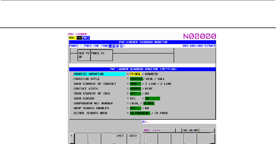
8.LADDER DIAGRAM MONITOR AND EDITOR SCREENS ([PMC LADDER])
B-64513EN/03
- 1058 -
8.2.2
Setting the Display Format of the LADDER DIAGRAM
MONITOR Screen
(1) Display screen
The LADDER DIAGRAM MONITOR screen is partially displayed on the screen.
The relays displayed here will change real-time by changing the setting.
(2) Setting items
LADDER DIAGRAM MONITOR (SETTING) screen contains the setting items below:
(a) ADDRESS NOTATION
Determines whether the bit and byte addresses in the LADDER Diagram are displayed as
corresponding symbols, or the addresses themselves.
SYMBOL (default)
Addresses that have a symbol are displayed by the symbols. Addresses without symbols
are displayed by the addresses themselves.
ADDRESS
All addresses are displayed as the addresses themselves even if they have a symbol.
(b) FUNCTION STYLE
Change the shape of functional instructions. There are three options as below. You have to
choose other than “COMPACT” to show the current values of address parameters of functional
instructions.
COMPACT (default)
Occupies least space in diagram. Monitors of current values of address parameters are
omitted.
WIDE
Extends the box horizontally to reserve spaces for the monitors of current values of
address parameters. The box becomes wider than COMPACT.
TALL
Extends the box vertically to reserve spaces for the monitors of current values of address
parameters. The box becomes taller than COMPACT.
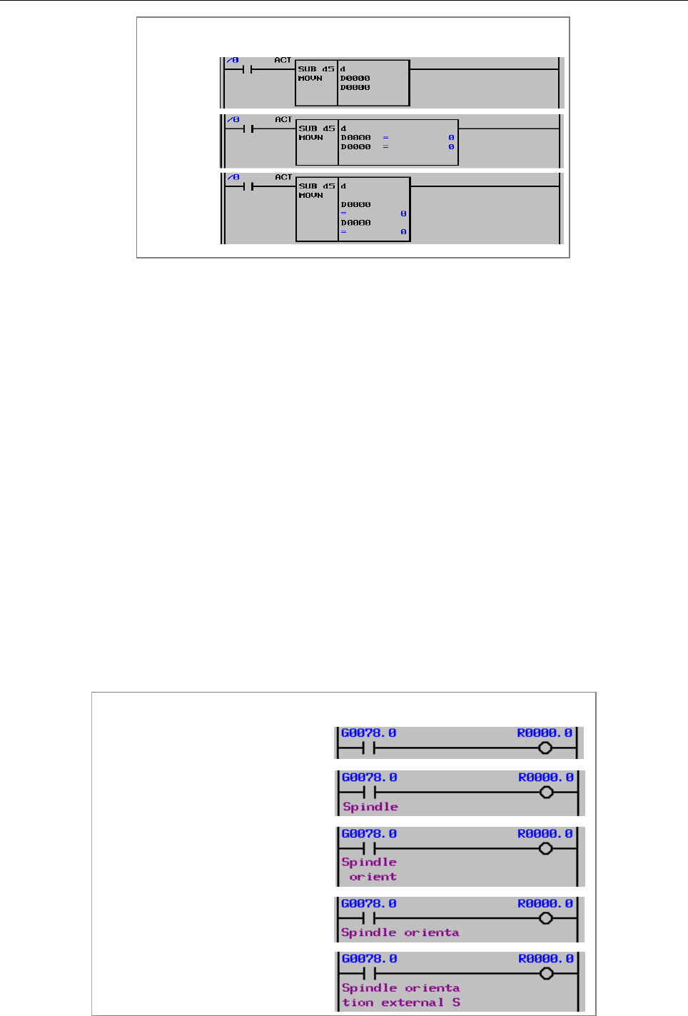
B-64513EN/03
8.LADDER DIAGRAM MONITOR AND EDITOR SCREENS ([PMC LADDER])
- 1059 -
Display styles of functional instructions
COMPACT
WIDE
TALL
The displays of current values of address parameters change their format according to each
parameter. See Subsection 8.2.3 for details.
When you place the cursor on an address parameter, its current value is displayed in the
“Additional Information Line” in both formats of binary decimal, and BCD (or hexadecimal
binary).
(c) SHOW COMMENT OF CONTACT
Set the style of relay comment. These are three options as below. When you display relay
comment, less ladder diagram circuits are shown.
NONE (default)
Relay comments are not displayed.
1 LINE
Relay comments are displayed in one line. Up to 15 characters (7 characters in Japanese)
of relay comment can be displayed when "WIDE" is selected for the "CONTACT
WIDTH" setting that is described below. Characters after 15th character will not be
displayed.
2 LINE
Relay comments are displayed in two lines. Up to 30 characters (14 characters in
Japanese) of relay comment can be displayed when "WIDE" is selected to the
"CONTACT WIDTH" setting that is described below. Up to 14 characters can be
displayed. Characters after 30th character will not be displayed.
Display styles of relay comment
CONTACT WIDTH = NORMAL
CONTACT WIDTH = NORMAL
CONTACT WIDTH = WIDE
CONTACT WIDTH = WIDE
SHOW COMMENT OF CONTACT = NONE
SHOW COMMENT OF CONTACT = 1 LINE
SHOW COMMENT OF CONTACT = 2 LINE
SHOW COMMENT OF CONTACT = 1 LINE
SHOW COMMENT OF CONTACT = 2 LINE
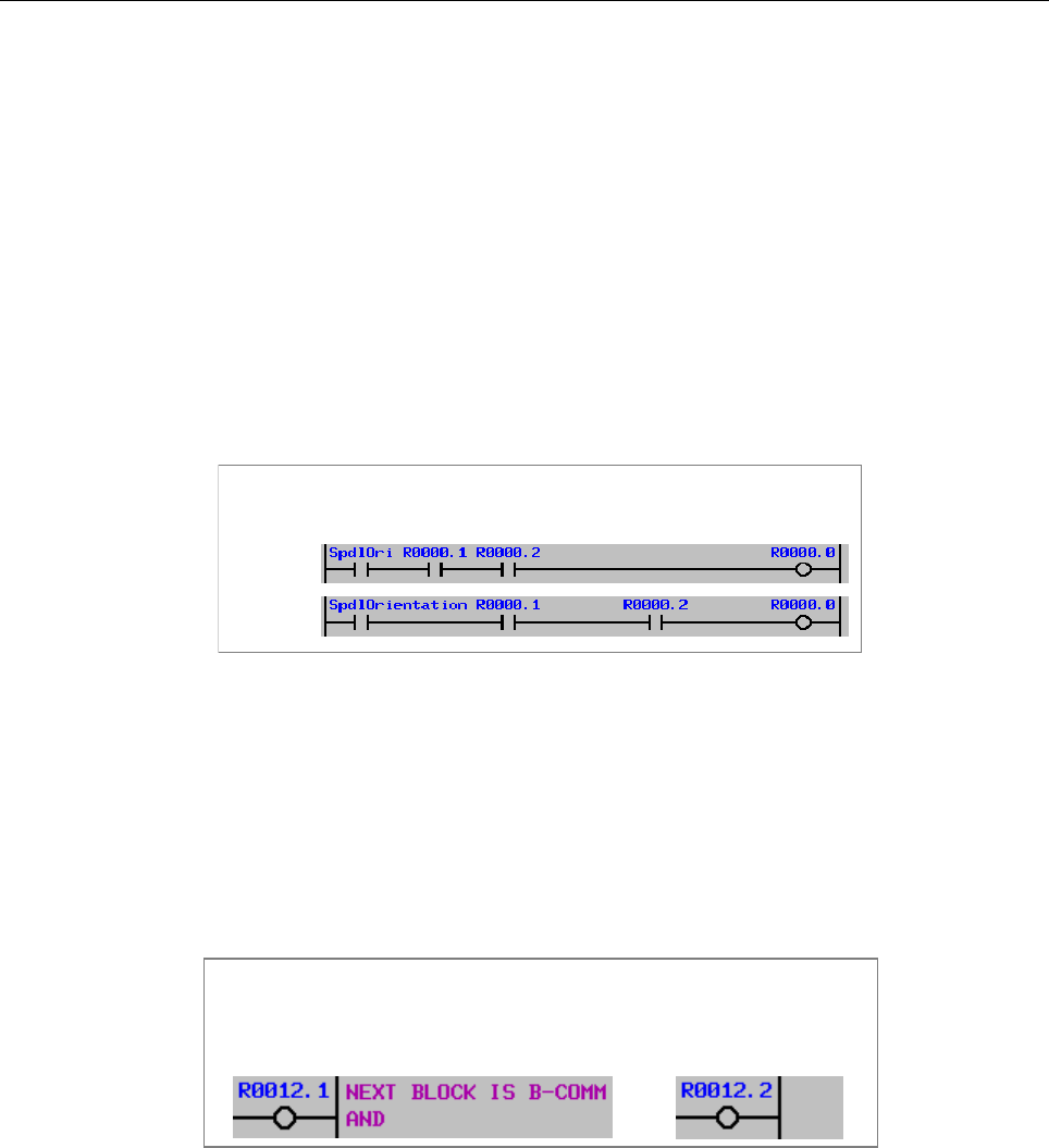
8.LADDER DIAGRAM MONITOR AND EDITOR SCREENS ([PMC LADDER])
B-64513EN/03
- 1060 -
(d) CONTACT WIDTH
Set the style of relay width. When "WIDE" is selected for the "CONTACT WIDTH" setting,
up to 15 characters of symbol on relay can be displayed. Moreover, when "1 LINE" is selected
for the "SHOW COMMENT OF CONTACT" setting, up to 15 characters of relay comment
can be displayed. When "2 LINE" is selected for the "SHOW COMMENT OF CONTACT"
setting, up to 30 characters of relay comment can be displayed. However, in these cases, fewer
contacts can be displayed.
NORMAL (default)
A relay is expressed with 8-character length.
Up to 7 characters of symbol can be displayed.
WIDE
A relay is expressed with 16-character length.
Up to 15 characters of symbol can be displayed.
Display styles of relay
NORMAL
WIDE
(e) SHOW COMMENT OF COIL
Determines whether to show coil comments.
YES (default)
Right margin of 2 lines of 15 characters is reserved for display of coil comments.
NO
Right margin is used to extend diagram by two more relays (15inch; one more relay),
instead of showing coil comment. The screen position bar is also displayed at the right
edge of the screen in this option.
Show Coil comment setting
YES NO
(f) SHOW CURSOR
Determines whether to show cursor.
YES (default)
Cursor is displayed. Cursor move keys will move the cursor. When the cursor is
placed on bit or byte addresses, the information of the address is displayed at "Additional
Information Line". When you search something with the cursor displayed, the cursor
goes directly where it is found. This option is recommended for search operation with
LADDER program that contains many large nets.
NO
Cursor is not displayed. Up/down cursor move keys will scroll the contents of screen
directly. When you search something with the cursor hidden, the net, which contains it,
will appear at the top of the screen.
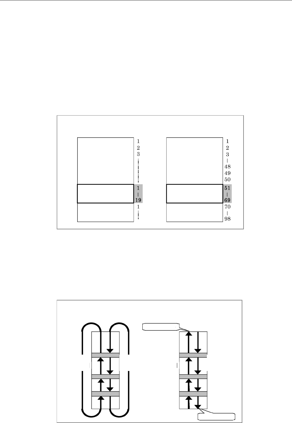
B-64513EN/03
8.LADDER DIAGRAM MONITOR AND EDITOR SCREENS ([PMC LADDER])
- 1061 -
(g) SUBPROGRAM NET NUMBER
Determines whether a net number is counted as "LOCAL" starting from the top of current
subprogram, or is counted as "GLOBAL" starting from the top of whole program. This
setting also affects the expression of net number at searching nets by number.
LOCAL
Net number starts from 1 at top of current subprogram. Net number is defined only
within current subprogram. The net number information at upper right of the screen is
displayed in the format "displaying range/nets in subprogram NET".
GLOBAL (default)
Net number starts from 1 at top of Level 1 program. Net number is defined identically at
whole of program. The net number information at upper right of the screen is displayed
in the format "displaying range/subprogram range NET".
Definition of net number
LOCAL GLOBAL
Current
Subprogram
Current
Subprogram
(h) WRAP SEARCH ENABLED
Allows search process to wrap from top/bottom to bottom/top to continue to search.
YES (default)
Downward search will continue to search from top of LADDER when reaches to bottom.
Upward search will also continue to search from bottom when reaches to top.
NO
Search process will fail when reached top or bottom, and displays an error message at
Message Line.
[NEXT] [PREV] [PREV] [NEXT]
YES NO
Wrap search
Not found
Not found
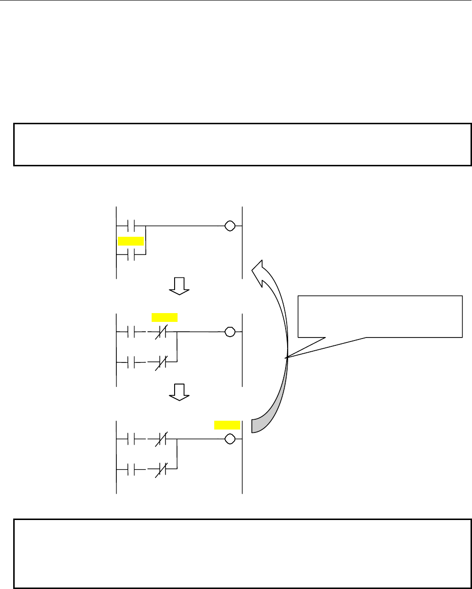
8.LADDER DIAGRAM MONITOR AND EDITOR SCREENS ([PMC LADDER])
B-64513EN/03
- 1062 -
(i) GLOBAL SEARCH AREA
Determines whether searching range is the displaying program or all programs in the PMC path
when using the ladder dividing management function.
IN PROGRAM (default)
Current displaying program is searching target.
IN PATH
All programs in current selected PMC path are searching target.
Note
When not using the ladder dividing management function (PRM 11931#5 = 0),
this item is not displayed.
Searching range and order
Main ladder
R 0000.1
R 0000.0
D 0000.0
R 0000.0
R 0000.1
D 0000.1
X0000.0
X0000.1
X0000.0
X0000.1
R 0000.1
X0000.3
X0000.2
Divided ladder 1
Divided ladder 2
Example of searching action in PMC path (searching PMC address R0000.1)
NOTE
When a search target is found in protected program by password in PMC path,
the action depends on keep relay K903.2.
K903.2=0: Asking for password.
K903.2=1: “PROGRAM IS PROTECTED.” is displayed.
(i) DIAGRAM APPEARANCE SETTING
Changes the appearance of LADDER diagram. Lines, relays, and functional instructions that
constitute LADDER diagram can be changed in the colors and the shapes.
When wrap search is enabled, search
target is changed from last ladder to top
ladder (main ladder).
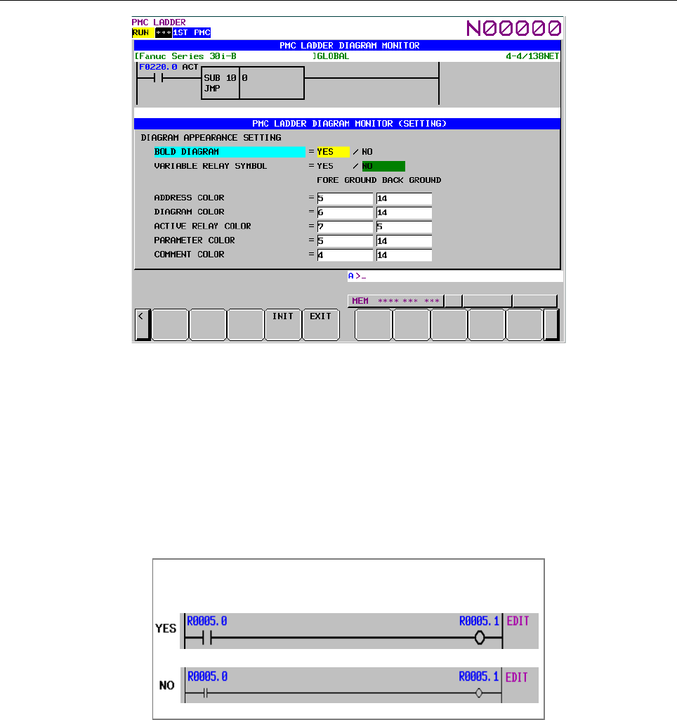
B-64513EN/03
8.LADDER DIAGRAM MONITOR AND EDITOR SCREENS ([PMC LADDER])
- 1063 -
・BOLD DIAGRAM
Sets thickness of diagram lines. This setting also affects shapes of relays.
YES (default)
Diagram is drawn with thick lines. Relays are drawn in more distinct shapes. You
have to choose this option to make following "VARIABLE RELAY SYMBOL"
setting effective.
NO
Diagram is drawn with thin lines. Relays are drawn in smaller shapes.
Bold Diagram setting
・VARIABLE RELAY SYMBOL
Determines whether to change the shapes of relays according to their on/off status, or to
fix their shapes. This setting is effective only when the setting "BOLD DIAGRAM" is
set to "YES".
YES
Shapes of relays change according to their on/off status. This option is effective
only when the setting "BOLD DIAGRAM" is set to "YES". If it is set to "NO",
shapes of relays will not change regardless of this setting.
NO (default)
Shapes of relays will not change.
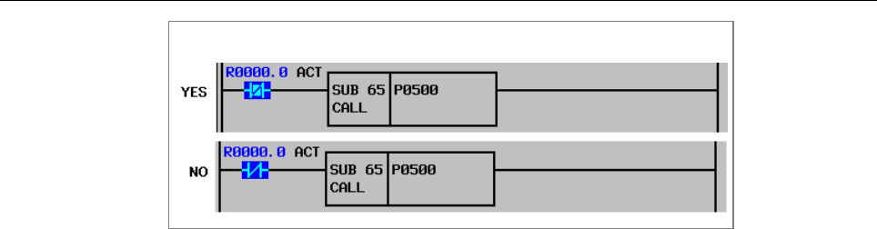
8.LADDER DIAGRAM MONITOR AND EDITOR SCREENS ([PMC LADDER])
B-64513EN/03
- 1064 -
Change of relay shapes at on/off status
・ADDRESS COLOR
Colors for the relay address are set. You can specify these colors by entering color
number. 15 colors (from No. 0 to No. 14) are available. Foreground color should be
different from background one.
・DIAGRAM COLOR
General color and its background color for LADDER Diagram. You can specify these
colors by entering color number, or by using right and left cursor move keys to change the
color number. You can use 15 numbers from 0 to 14; however, some different number
may correspond to the same color. You cannot specify the same number to the
foreground and the background colors.
・ACTIVE RELAY COLOR
Color setting for the active relay. When a contact allows power flow, and when a coil
receives power, they are active and are displayed with this color setting. When contacts
and coils are not active, they are displayed with "general color". You can specify these
colors in the same manner as color setting of DIAGRAM COLOR, etc.
・PARAMETER COLOR
Color setting for the monitor of functional instruction parameters. They are displayed
when functional instructions are displayed in the shape other than "COMPACT". You
can specify these colors in the same manner as color setting of DIAGRAM COLOR, etc.
・COMMENT COLOR
Colors for the relay comment are set. You can specify these colors by entering color
number, or by moving right and left cursor. 15 colors (from No. 0 to No. 14) are
available. Foreground color should be different from background one.
(3) Soft keys
LADDER DIAGRAM MONITOR (SETTING) screen has the soft keys of options and following:
(a) [INIT] Initialize all settings
All settings will be initialized to the default values.
(b) [EXIT] Switch to LADDER DIAGRAM MONITOR screen
Ends the LADDER DIAGRAM MONITOR (SETTING) screen and switches to LADDER
DIAGRAM MONIITOR screen.
(4) Settings on multi-path PMC system
On the multi-path PMC systems, the Ladder Diagram related configuration is common to all PMC
paths at first. To make it independent for each PMC path, set system keep relay K909.4 to 1.
For example, different color settings may make it easier to recognize the PMC path which the
Ladder Diagram on the screen belongs to.
When you set 1 to K909.4 at the first time, the first PMC path will inherit the old settings, and the
rest path will start with the initial settings.
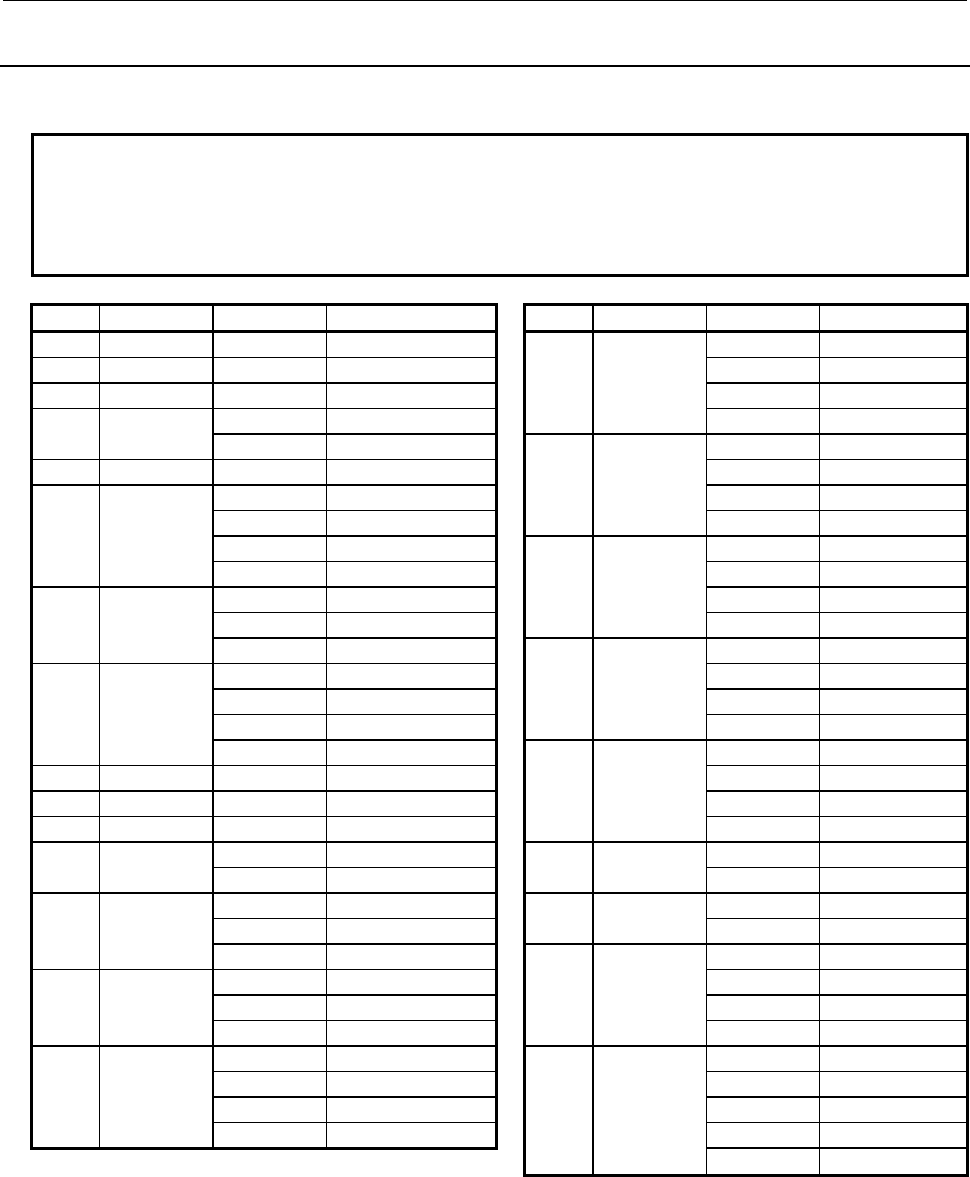
B-64513EN/03
8.LADDER DIAGRAM MONITOR AND EDITOR SCREENS ([PMC LADDER])
- 1065 -
8.2.3
Display Format for Parameters
The following table shows all monitor formats for each parameter of each functional instruction.
NOTE
1 "Variable" in "Monitor format" field means that this parameter changes its size
according to the other parameter. See the descriptions for each functional
instruction for detail.
2 Functional instruction with "*" mark has Data table.
No. Name Parameter Monitor format No. Name Parameter Monitor format
1 END1 − − 18 XMOV 1 constant
2 END2 − − 2 4-digit BCD
3 TMR 1 special 3 4-digit BCD
4 DEC 1 2-digit BCD 4 4-digit BCD
2 constant 19 ADD 1 constant
5 CTR 1 special 2 4-digit BCD
6 ROT 1 constant 3 4-digit BCD
2 4-digit BCD 4 4-digit BCD
3 4-digit BCD 20 SUB 1 constant
4 4-digit BCD 2 4-digit BCD
7 COD * 1 constant 3 4-digit BCD
2 2-digit BCD 4 4-digit BCD
3 4-digit BCD 21 MUL 1 constant
8 MOVE 1 constant 2 4-digit BCD
2 constant 3 4-digit BCD
3 2-digit HEX 4 4-digit BCD
4 2-digit HEX 22 DIV 1 constant
9 COM 1 constant 2 4-digit BCD
10 JMP 1 constant 3 4-digit BCD
11 PARI 1 1-byte binary 4 4-digit BCD
14 DCNV 1 no monitor 23 NUME 1 constant
2 no monitor 2 4-digit BCD
15 COMP 1 constant 24 TMRB 1 special
2 4-digit BCD 2 constant
3 4-digit BCD 25 DECB 1 constant
16 COIN 1 constant 2 variable binary
2 4-digit BCD 3 constant
3 4-digit BCD 4 2-digit HEX
17 DSCH 1 constant 26 ROTB 1 constant
2 4-digit BCD 2 variable binary
3 4-digit BCD 3 variable binary
4 4-digit BCD 4 variable binary
5 variable binary
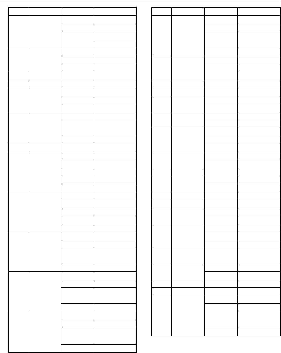
8.LADDER DIAGRAM MONITOR AND EDITOR SCREENS ([PMC LADDER])
B-64513EN/03
- 1066 -
No. Name Parameter Monitor format No. Name Parameter Monitor format
27 CODB * 1 constant 39 DIVB 1 constant
2 constant 2 variable binary
3 1-byte binary 3 constant or
variable binary
4 variable binary
28 MOVOR 1 2-digit HEX 4 variable binary
2 2-digit HEX 40 NUMEB 1 constant
3 2-digit HEX 2 constant
29 COME − − 3 variable binary
30 JMPE − − 41 DISPB 1 constant
31 DCNVB 1 constant 42 EXIN 1 8-digit HEX
2 no monitor 43 MOVB 1 1-byte binary
3 no monitor 2 1-byte binary
32 COMPB 1 constant 44 MOVW 1 2-byte binary
2 constant or
variable binary
2 2-byte binary
45 MOVN 1 constant
3 variable binary 2 4-byte binary
33 SFT 1 4-digit HEX 3 4-byte binary
34 DSCHB 1 constant 47 MOVD 1 4-byte binary
2 variable binary 2 4-byte binary
3 variable binary 48 END3 − −
4 variable binary 50 PSGNL 1 1-byte binary
5 variable binary 2 2-digit HEX
35 XMOVB 1 constant 51 WINDR 1 2-byte binary
2 variable binary 52 WINDW
1 2-byte binary
3 variable binary 53 AXCTL
1 constant
4 variable binary 2 8-digit HEX
5 variable binary 54 TMRC
1 constant
36 ADDB 1 constant 2 special
2 variable binary 3 special
3 constant or
variable binary
55 CTRC 1 2-byte binary
4 variable binary 56 CTRB
1 constant
37 SUBB 1 constant 2 special
2 variable binary 57 DIFU
1 constant
3 constant or
variable binary
58 DIFD 1 constant
59 EOR 1 constant
4 variable binary 2 variable HEX
38 MULB 1 constant 3 constant or
2 variable binary variable HEX
3 constant or 4 variable HEX
variable binary
4 variable binary

B-64513EN/03
8.LADDER DIAGRAM MONITOR AND EDITOR SCREENS ([PMC LADDER])
- 1067 -
No. Name Parameter Monitor format No. Name Parameter Monitor format
60 AND 1 constant 203 NEB 1 constant or
2 variable HEX 1-byte binary
3 constant or 2 constant or
variable HEX 1-byte binary
4 variable HEX 204 NEW 1 constant or
61 OR 1 constant 2-byte binary
2 variable HEX 2 constant or
3 constant or 2-byte binary
variable HEX 205 NED 1 constant or
4 variable HEX 4-byte binary
62 NOT 1 constant 2 constant or
2 variable HEX 4-byte binary
3 variable HEX 206 GTB 1 constant or
63 PSGN2 1 1-byte binary 1-byte binary
64 END − − 2 constant or
65 CALL 1 no monitor 1-byte binary
66 CALLU 1 no monitor 207 GTW 1 constant or
68 JMPB 1 no monitor 2-byte binary
69 LBL 1 no monitor 2 constant or
70 NOP 1 constant 2-byte binary
71 SP 1 no monitor 208 GTD 1 constant or
72 SPE − − 4-byte binary
73 JMPC 1 no monitor 2 constant or
74 CS 1 2-byte binary 4-byte binary
75 CM 1 no monitor 209 LTB 1 constant or
76 CE - − 1-byte binary
77 TMRBF 1 special 2 constant or
2
constant 1-byte binary
200 EQB 1 constant or 210 LTW 1 constant or
1-byte binary 2-byte binary
2 constant or 2 constant or
1-byte binary 2-byte binary
201 EQW 1 constant or 211 LTD 1 constant or
2-byte binary 4-byte binary
2 constant or 2 constant or
2-byte binary 4-byte binary
202 EQD 1 constant or 212 GEB 1 constant or
4-byte binary 1-byte binary
2 constant or 2 constant or
4-byte binary 1-byte binary
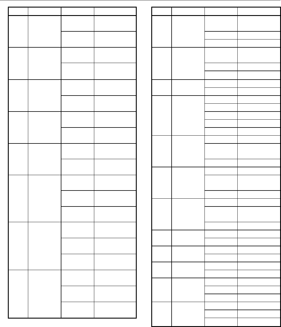
8.LADDER DIAGRAM MONITOR AND EDITOR SCREENS ([PMC LADDER])
B-64513EN/03
- 1068 -
No. Name Parameter Monitor format No. Name Parameter Monitor format
213 GEW 1 constant or 221 TMRST 1 Constant or
2-byte binary Special
2 constant or 2 Special
2-byte binary 3 No monitor
214 GED 1 constant or 222 TMRSS 1 Constant or
4-byte binary Special
2 constant or 2 Special
4-byte binary 3 No monitor
215 LEB 1 constant or 223 CTRD 1 4-byte binary
1-byte binary 2 4-byte binary
2 constant or 224 MOVBT 1 No monitor
1-byte binary 2 4-byte HEX
216 LEW 1 constant or 3 Constant
2-byte binary 4 4-byte HEX
2 constant or 5 Constant
2-byte binary 225 SETNB 1 No monitor
217 LED 1 constant or 2 Constant or
4-byte binary 1-byte binary
2 constant or 3 1-byte binary
4-byte binary 226 SETNW 1 No monitor
218 RNGB 1 constant or 2 Constant or
1-byte binary 2-byte binary
2 constant or 3 2-byte binary
1-byte binary 227 SETND 1 No monitor
3 constant or 2 Constant or
1-byte binary 4-byte binary
219 RNGW 1 constant or 3 4-byte binary
2-byte binary 228 XCHGB 1 1-byte binary
2 constant or 2 1-byte binary
2-byte binary 229 XCHGW 1 2-byte binary
3 constant or 2 2-byte binary
2-byte binary 230 XCHGD 1 4-byte binary
220 RNGD 1 constant or 2 4-byte binary
4-byte binary 231 SWAPW 1 No monitor
2 constant or 2 2-byte binary
4-byte binary 3 2-byte binary
3 constant or 232 SWAPD 1 No monitor
4-byte binary 2 4-byte binary
3 4-byte binary
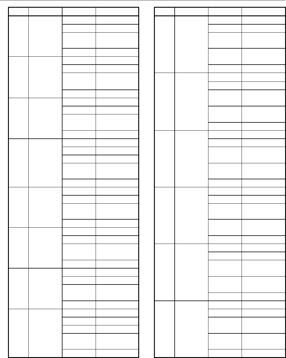
B-64513EN/03
8.LADDER DIAGRAM MONITOR AND EDITOR SCREENS ([PMC LADDER])
- 1069 -
No. Name Parameter Monitor format No. Name Parameter Monitor format
233 TBLRB 1 No monitor 241 DSEQB 1 No monitor
2 1-byte binary 2 1-byte binary
3 Constant or 3 Constant or
2-byte binary 2-byte binary
4 1-byte binary 4 Constant or
234 TBLRW 1 No monitor 1-byte binary
2 2-byte binary 5 2-byte binary
3 Constant or 242 DSEQW 1 No monitor
2-byte binary 2 2-byte binary
4 2-byte binary 3 Constant or
235 TBLRD 1 No monitor 2-byte binary
2 4-byte binary 4 Constant or
3 Constant or 2-byte binary
2-byte binary 5 2-byte binary
4 4-byte binary 243 DSEQD 1 No monitor
236 TBLRN 1 No monitor 2 4-byte binary
2 No monitor 3 Constant or
3 4-byte binary 2-byte binary
4 Constant or 4 Constant or
2-byte binary 4-byte binary
5 4-byte binary 5 2-byte binary
237 TBLWB 1 No monitor 244 DSNEB 1 No monitor
2 1-byte binary 2 1-byte binary
3 Constant or 3 Constant or
2-byte binary 2-byte binary
4 1-byte binary 4 Constant or
238 TBLWW 1 No monitor 1-byte binary
2 2-byte binary 5 2-byte binary
3 Constant or 245 DSNEW 1 No monitor
2-byte binary 2 2-byte binary
4 2-byte binary 3 Constant or
239 TBLWD 1 No monitor 2-byte binary
2 4-byte binary 4 Constant or
3 Constant or 2-byte binary
2-byte binary 5 2-byte binary
4 4-byte binary 246 DSNED 1 No monitor
240 TBLWN 1 No monitor 2 4-byte binary
2 No monitor 3 Constant or
3 4-byte binary 2-byte binary
4 Constant or 4 Constant or
2-byte binary 4-byte binary
5 4-byte binary 5 2-byte binary
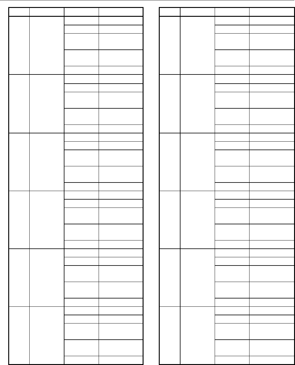
8.LADDER DIAGRAM MONITOR AND EDITOR SCREENS ([PMC LADDER])
B-64513EN/03
- 1070 -
No. Name Parameter Monitor format No. Name Parameter Monitor format
247 DSGTB 1 No monitor 253 DSGEB 1 No monitor
2 1-byte binary 2 1-byte binary
3 Constant or 3 Constant or
2-byte binary 2-byte binary
4 Constant or 4 Constant or
1-byte binary 1-byte binary
5 2-byte binary 5 2-byte binary
248 DSGTW 1 No monitor 254 DSGEW 1 No monitor
2 2-byte binary 2 2-byte binary
3 Constant or 3 Constant or
2-byte binary 2-byte binary
4 Constant or 4 Constant or
2-byte binary 2-byte binary
5 2-byte binary 5 2-byte binary
249 DSGTD 1 No monitor 255 DSGED 1 No monitor
2 4-byte binary 2 4-byte binary
3 Constant or 3 Constant or
2-byte binary 2-byte binary
4 Constant or 4 Constant or
4-byte binary 4-byte binary
5 2-byte binary 5 2-byte binary
250 DSLTB 1 No monitor 256 DSLEB 1 No monitor
2 1-byte binary 2 1-byte binary
3 Constant or 3 Constant or
2-byte binary 2-byte binary
4 Constant or 4 Constant or
1-byte binary 1-byte binary
5 2-byte binary 5 2-byte binary
251 DSLTW 1 No monitor 257 DSLEW 1 No monitor
2 2-byte binary 2 2-byte binary
3 Constant or 3 Constant or
2-byte binary 2-byte binary
4 Constant or 4 Constant or
2-byte binary 2-byte binary
5 2-byte binary 5 2-byte binary
252 DSLTD 1 No monitor 258 DSLED 1 No monitor
2 4-byte binary 2 4-byte binary
3 Constant or 3 Constant or
2-byte binary 2-byte binary
4 Constant or 4 Constant or
4-byte binary 4-byte binary
5 2-byte binary 5 2-byte binary
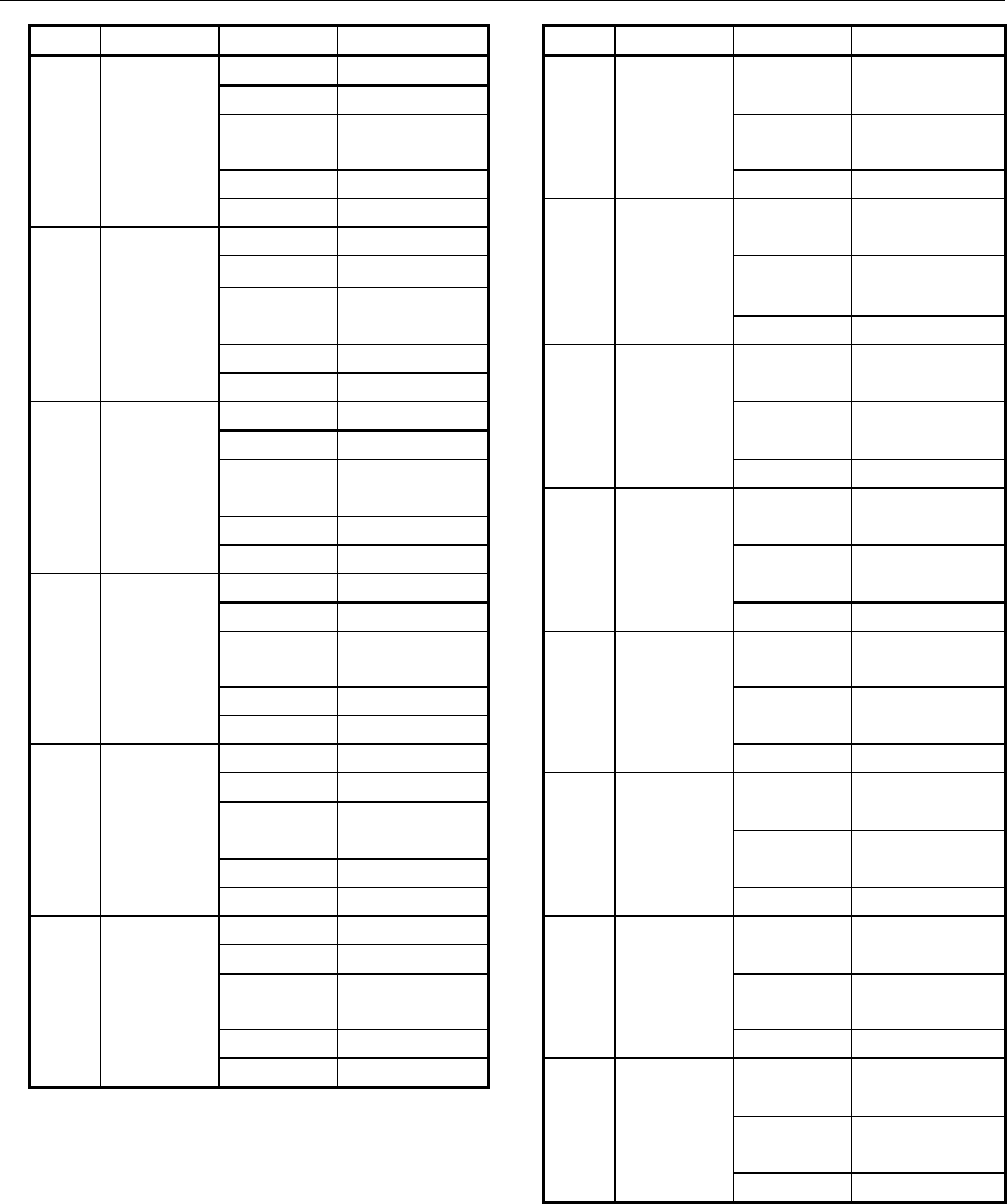
B-64513EN/03
8.LADDER DIAGRAM MONITOR AND EDITOR SCREENS ([PMC LADDER])
- 1071 -
No. Name Parameter Monitor format No. Name Parameter Monitor format
259 DMAXB 1 No monitor 265 EORB 1 Constant or
2 1-byte binary 1-byte HEX
3 Constant or 2 Constant or
2-byte binary 1-byte HEX
4 1-byte binary 3 1-byte HEX
5 2-byte binary 266 EORW 1 Constant or
260 DMAXW 1 No monitor 2-byte HEX
2 2-byte binary 2 Constant or
3 Constant or 2-byte HEX
2-byte binary 3 2-byte HEX
4 2-byte binary 267 EORD 1 Constant or
5 2-byte binary 4-byte HEX
261 DMAXD 1 No monitor 2 Constant or
2 4-byte binary 4-byte HEX
3 Constant or 3 4-byte HEX
2-byte binary 268 ANDB 1 Constant or
4 4-byte binary 1-byte HEX
5 2-byte binary 2 Constant or
262 DMINB 1 No monitor 1-byte HEX
2 1-byte binary 3 1-byte HEX
3 Constant or 269 ANDW 1 Constant or
2-byte binary 2-byte HEX
4 1-byte binary 2 Constant or
5 2-byte binary 2-byte HEX
263 DMINW 1 No monitor 3 2-byte HEX
2 2-byte binary 270 ANDD 1 Constant or
3 Constant or 4-byte HEX
2-byte binary 2 Constant or
4 2-byte binary 4-byte HEX
5 2-byte binary 3 4-byte HEX
264 DMIND 1 No monitor 271 ORB 1 Constant or
2 4-byte binary 1-byte HEX
3 Constant or 2 Constant or
2-byte binary 1-byte HEX
4 4-byte binary 3 1-byte HEX
5 2-byte binary 272 ORW 1 Constant or
2-byte HEX
2 Constant or
2-byte HEX
3 2-byte HEX

8.LADDER DIAGRAM MONITOR AND EDITOR SCREENS ([PMC LADDER])
B-64513EN/03
- 1072 -
No. Name Parameter Monitor format No. Name Parameter Monitor format
273 ORD 1 Constant or 282 SHRW 1 Constant or
4-byte HEX 2-byte HEX
2 Constant or 2 Constant or
4-byte HEX 2-byte binary
3 4-byte HEX 3 2-byte HEX
274 NOTB 1 Constant or 283 SHRD 1 Constant or
1-byte HEX 4-byte HEX
2 1-byte HEX 2 Constant or
275 NOTW 1 Constant or 4-byte binary
2-byte HEX 3 4-byte HEX
2 2-byte HEX 284 SHRN 1 No monitor
276 NOTD 1 Constant or 2 Constant or
4-byte HEX 4-byte HEX
2 4-byte HEX 3 Constant or
277 SHLB 1 Constant or 4-byte binary
1-byte HEX 4 4-byte HEX
2 Constant or 285 ROLB 1 Constant or
1-byte binary 1-byte HEX
3 1-byte HEX 2 Constant or
278 SHLW 1 Constant or 1-byte binary
2-byte HEX 3 1-byte HEX
2 Constant or 286 ROLW 1 Constant or
2-byte binary 2-byte HEX
3 2-byte HEX 2 Constant or
279 SHLD 1 Constant or 2-byte binary
4-byte HEX 3 2-byte HEX
2 Constant or 287 ROLD 1 Constant or
4-byte binary 4-byte HEX
3 4-byte HEX 2 Constant or
280 SHLN 1 No monitor 4-byte binary
2 Constant or 3 4-byte HEX
4-byteS HEX 288 ROLN 1 No monitor
3 Constant or 2 Constant or
4-byte binary 4-byte HEX
4 4-byte HEX 3 Constant or
281 SHRB 1 Constant or 4-byte binary
1-byte HEX 4 4-byte HEX
2 Constant or 289 RORB 1 Constant or
1-byte binary 1-byte HEX
3 1-byte HEX 2 Constant or
1-byte binary
3 1-byte HEX
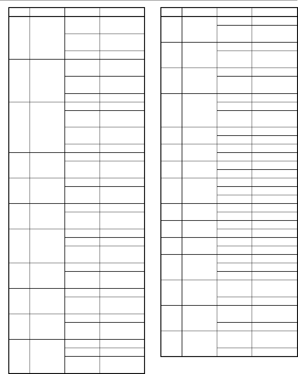
B-64513EN/03
8.LADDER DIAGRAM MONITOR AND EDITOR SCREENS ([PMC LADDER])
- 1073 -
No. Name Parameter Monitor format No. Name Parameter Monitor format
290 RORW 1 Constant or 301 BTSTB 1 1-byte HEX
2-byte HEX 2 Constant or
2 Constant or 1-byte binary
2-byte binary 302 BTSTW 1 2-byte HEX
3 2-byte HEX 2 Constant or
291 RORD 1 Constant or 2-byte binary
4-byte HEX 303 BTSTD 1 4-byte HEX
2 Constant or 2 Constant or
4-byte binary 4-byte binary
3 4-byte HEX 304 BTSTN 1 No monitor
292 RORN 1 No monitor 2 4-byte HEX
2 Constant or 3 Constant or
4-byte HEX 4-byte binary
3 Constant or 305 BPOSB 1 1-byte HEX
4-byte binary 2 1-byte binary
4 4-byte HEX 306 BPOSW 1 2-byte HEX
293 BSETB 1 1-byte HEX 2 2-byte binary
2 Constant or 307 BPOSD 1 4-byte HEX
1-byte binary 2 4-byte binary
294 BSETW 1 2-byte HEX 308 BPOSN 1 No monitor
2 Constant or 2 4-byte HEX
2-byte binary 3 4-byte binary
295 BSETD 1 4-byte HEX 309 BCNTB 1 1-byte HEX
2 Constant or 2 1-byte binary
4-byte binary 310 BCNTW 1 2-byte HEX
296 BSETN 1 No monitor 2 2-byte binary
2 4-byte HEX 311 BCNTD 1 4-byte HEX
3 Constant or 2 4-byte binary
4-byte binary 312 BCNTN 1 No monitor
297 BRSTB 1 1-byte HEX 2 4-byte HEX
2 Constant or 3 4-byte binary
1-byte binary 313 TBCDB 1 Constant or
298 BRSTW 1 2-byte HEX 1-byte binary
2 Constant or 2 1-byte HEX
2-byte binary 314 TBCDW 1 Constant or
299 BRSTD 1 4-byte HEX 2-byte binary
2 Constant or 2 2-byte HEX
4-byte binary 315 TBCDD 1 Constant or
300 BRSTN 1 No monitor 4-byte binary
2 4-byte HEX 2 4-byte HEX
3 Constant or
4-byte binary

8.LADDER DIAGRAM MONITOR AND EDITOR SCREENS ([PMC LADDER])
B-64513EN/03
- 1074 -
No. Name Parameter Monitor format No. Name Parameter Monitor format
316 FBCDB 1 Constant or 325 MULSB 1 Constant or
1-byte HEX 1-byte binary
2 1-byte binary 2 Constant or
317 FBCDW 1 Constant or 1-byte binary
2-byte HEX 3 1-byte binary
2 2-byte binary 326 MULSW 1 Constant or
318 FBCDD 1 Constant or 2-byte binary
4-byte HEX 2 Constant or
2 4-byte binary 2-byte binary
319 ADDSB 1 Constant or 3 2-byte binary
1-byte binary 327 MULSD 1 Constant or
2 Constant or 4-byte binary
1-byte binary 2 Constant or
3 1-byte binary 4-byte binary
320 ADDSW 1 Constant or 3 4-byte binary
2-byte binary 328 DIVSB 1 Constant or
2 Constant or 1-byte binary
2-byte binary 2 Constant or
3 2-byte binary 1-byte binary
321 ADDSD 1 Constant or 3 1-byte binary
4-byte binary 329 DIVSW 1 Constant or
2 Constant or 2-byte binary
4-byte binary 2 Constant or
3 4-byte binary 2-byte binary
322 SUBSB 1 Constant or 3 2-byte binary
1-byte binary 330 DIVSD 1 Constant or
2 Constant or 4-byte binary
1-byte binary 2 Constant or
3 1-byte binary 4-byte binary
323 SUBSW 1 Constant or 3 4-byte binary
2-byte binary 331 MODSB 1 Constant or
2 Constant or 1-byte binary
2-byte binary 2 Constant or
3 2-byte binary 1-byte binary
324 SUBSD 1 Constant or 3 1-byte binary
4-byte binary 332 MODSW 1 Constant or
2 Constant or 2-byte binary
4-byte binary 2 Constant or
3 4-byte binary 2-byte binary
3 2-byte binary

B-64513EN/03
8.LADDER DIAGRAM MONITOR AND EDITOR SCREENS ([PMC LADDER])
- 1075 -
No. Name Parameter Monitor format
333 MODSD 1 Constant or
4-byte binary
2 Constant or
4-byte binary
3 4-byte binary
334 INCSB 1 1-byte binary
335 INCSW 1 2-byte binary
336 INCSD 1 4-byte binary
337 DECSB 1 1-byte binary
338 DECSW 1 2-byte binary
339 DECSD 1 4-byte binary
340 ABSSB 1 Constant or
1-byte binary
2 1-byte binary
341 ABSSW 1 Constant or
2-byte binary
2 2-byte binary
342 ABSSD 1 Constant or
4-byte binary
2 4-byte binary
343 NEGSB 1 Constant or
1-byte binary
2 1-byte binary
344 NEGSW 1 Constant or
2-byte binary
2 2-byte binary
345 NEGSD 1 Constant or
4-byte binary
2 4-byte binary
• Functional instructions of special monitor format
TMR
Displays instructions in the following format:
Functional instructions Functional instruction
Vertical display horizontal display
Timer number = Current value Timer number
Preset value Current value
Preset value
The monitor display format of the preset values and the current values varies depending on the timer
precision, as given in the table below. For details of timer precision, see Subsection 7.3.1.
Precision Resolution Display format
0 8 msec/48 msec by second
1 1 msec by second
2 10 msec by second
3 100 msec by second
4 1 second HH:MM:SS
5 1 minute HH:MM:SS
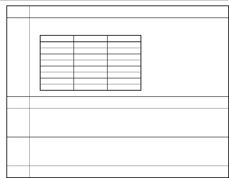
8.LADDER DIAGRAM MONITOR AND EDITOR SCREENS ([PMC LADDER])
B-64513EN/03
- 1076 -
TMRB
Displays current value by seconds (HH:MM:SS if 1 minute or more) (preset value is displayed by
milliseconds)
TMRC
The 2nd parameter shows preset value, and the 3rd parameter shows current value as their monitor
displays.
These two monitor displays changes their format according to the 1st parameter as below:
1st parameter Resolution Display format
0 8 msec by second
1 48 msec by second
2 1 second HH:MM:SS
3 10 seconds HH:MM:SS
4 1 minute HH:MM:SS
5 1 msec by second
6 10 msec by second
7 100 msec by second
TMRBF
Displays current value by seconds (HH:MM:SS if 1 minute or more) (preset value is displayed by
milliseconds)
TMRSS
By the setting time or the addition time, the monitor display format is changed as follows.
In the case of 59 minutes and less than 59 seconds:
MM:SS:xxx
When 1 hour is exceeded:
HHH: MM:SS
TMRST
By the setting time or the addition time, the monitor display format is changed as follows.
In the case of less than 10000 hours:
HHHH: MM:SS
When 10000 hours is exceeded:
It displays by 10 figures of signed decimal numbers.
CTR
Displays in "Current/Preset" format by binary or BCD according to the counter type setting in LADDER
Program.
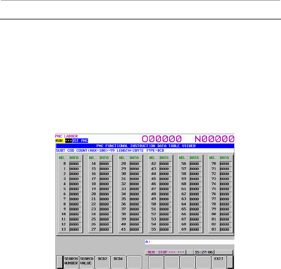
B-64513EN/03
8.LADDER DIAGRAM MONITOR AND EDITOR SCREENS ([PMC LADDER])
- 1077 -
8.2.4
FUNCTIONAL INSTRUCTION DATA TABLE VIEWER Screen
FUNCTIONAL INSTRUCTION DATA TABLE VIEWER screen shows the contents of following data
table that belongs to some functional instructions.
• Functional Instruction COD (SUB7)
• Functional Instruction CODB (SUB27)
To reach this screen, at LADDER DIAGRAM MONITOR screen, press [DATA TABLE] soft key that is
displayed when the cursor is on the following functional instructions which have a data table.
Following operations are available at this screen.
• Search for data table number. [SEARCH NUMBER]
• Search for data value. [SEARCH VALUE]
• Change the displaying data digits. [BCD2], [BCD4]
(These soft keys can be operated only at FUNCTIONAL INSTRUCTION DATA TABLE VIEWER
screen of functional instruction COD.)
• Switch to LADDER DIAGRAM MONITOR screen. [EXIT]
FUNCTIONAL INSTRUCTION DATA TABLE VIEWER screen of functional instruction COD
(1) Screen structures
(a) The functional instruction name, the number of data table, data length and data types are
displayed above the Data Table.
(b) In the message line, error messages or inquiry messages will be displayed depending on the
situation.
(c) In case of functional instruction COD, the data of 6 lines and 14 columns can be displayed in
the area for Data table.
In case of functional instruction CODB, the data of 4 lines and 14 columns can be displayed in
the area for Data table.
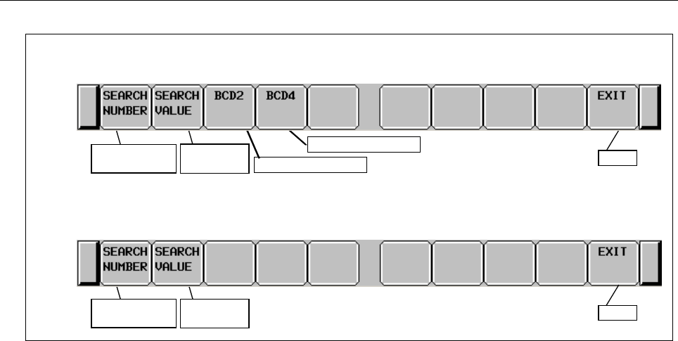
8.LADDER DIAGRAM MONITOR AND EDITOR SCREENS ([PMC LADDER])
B-64513EN/03
- 1078 -
(2) Operations
Soft keys of Functional Instruction Data Table Viewer screen of functional instruction COD
Search for data
table number
Search for
data value
Display BCD4 digits
Exit
Display BCD2 digits
Soft keys of Functional Instruction Data Table Viewer screen of functional instruction CODB
Search for data
table number
Search for
data value Exit
(a) [SEARCH NUMBER] Search for data table number
Searches the data table number which you specified.
Then the cursor is displayed on the data of the target number.
And the cursor is disappeared when you operate something.
(b) [SEARCH VALUE] Search for data value
Searches the data value which you specified.
Then the cursor is displayed on the target data.
And the cursor is disappeared when you operate something.
(c) [BCD2] Display BCD2 digits
Changes the display data type to 2 digits of BCD. This operation only switches the display
data type. So it does never edit the data on memory.
(d) [BCD4] Display BCD4 digits
Changes the display data type to 4 digits of BCD. This operation only switches the display
data type. So it does never edit the data on memory.
(e) [EXIT] Exit View
Ends the FUNCTIONAL INSTRUCTION DATA TABLE
VIEWER screen and switches to LADDER DIAGRAM MONITOR screen.
(f) Cursor move keys, Page change keys
You can scroll screen by right/left cursor move keys and Page change keys.
(g) Operation of the return key
On the FUNCTIONAL INSTRUCTION DATA TABLE VIEWER screen, the return key has
no effect.
After you have finished editing data, and want to return to the LADDER DIAGRAM
MONITOR screen, use the [EXIT] soft key.
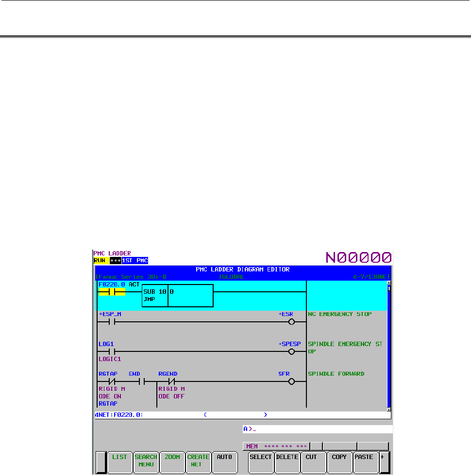
B-64513EN/03
8.LADDER DIAGRAM MONITOR AND EDITOR SCREENS ([PMC LADDER])
- 1079 -
8.3 EDITING LADDER PROGRAMS
At LADDER DIAGRAM EDITOR screen you can edit LADDER program to change its behavior.
To switch LADDER DIAGRAM EDITOR screen, press [EDIT] soft key at LADDER DIAGRAM
MONITOR screen.
Following operations are available at LADDER DIAGRAM EDITOR screen.
• Delete by net [DELETE]
• Move by net [CUT] & [PASTE]
• Copy by net [COPY] & [PASTE]
• Change address of contacts and coils "bit address" + INPUT key
• Change parameters of functional instructions "number" or "byte address" + INPUT key
• Add new net [CREATE NET]
• Change construction of net [ZOOM]
• Make changes effective [UPDATE]
• Abandon changes [RESTRE]
• Cancel edit [CANCEL EDIT]
LADDER DIAGRAM EDITOR screen

8.LADDER DIAGRAM MONITOR AND EDITOR SCREENS ([PMC LADDER])
B-64513EN/03
- 1080 -
CAUTION
1 You can edit ladder programs regardless of whether they are active or not. To
execute a ladder program with the results of editing being reflected, you must
update the ladder program. To do this, press the [UPDATE] soft key, or update
the program when exiting from the LADDER DIAGRAM EDITOR screen. For
details of the method of protecting editing, see Section 7.3.
2 After you have edited a sequence program, the results of editing will be lost if the
power is turned off without first writing the edited sequence program to flash ROM.
Write the sequence program to flash ROM on the I/O screen. If you set "WRITE
TO F-ROM(EDIT)" to "YES" on the general functions' setting parameter screen, a
confirmation message will be displayed, prompting you to ask whether to write a
sequence program to flash ROM after the end of editing. For details of this
setting, see Section 9.5.
(1) Screen structures
(a) It is basically same with LADDER DIAGRAM MONITOR screen, except that no monitor
displays of relays and parameters of functional instructions are displayed.
(b) At right side of LADDER Diagram area, a position bar is always displayed, which indicates
screen position within current subprogram: in LADDER DIAGRAM MONITOR screen, this
position bar is exclusively displayed with comments of write coil. Sometimes, this position
bar hides a part of write coil comments.
(2) LADDER Diagram
(a) Style of LADDER Diagram is basically same with LADDER DIAGRAM MONITOR screen,
except that functional instructions are drawn always in "COMPACT" format that has no
monitor displays.
(b) Cursor is shown always. And the net, which will be an object of following editing operations,
is emphasized in screen.
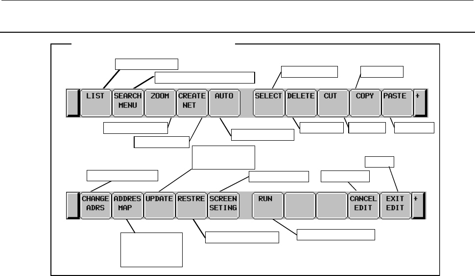
B-64513EN/03
8.LADDER DIAGRAM MONITOR AND EDITOR SCREENS ([PMC LADDER])
- 1081 -
8.3.1
Operating on the LADDER DIAGRAM EDITOR Screen
Abandon changes
Setting screen
Select net Copy net
Delete net Cut net Paste net
Add net
Edit new net
Change to Search soft keys
Cancel edit
Exit
Run/stop LADDER
Program List
Soft keys of LADDER Diagram Editor screen
Make changes
effective
Change address
Automatic input
Display address
map display
screen
Fig. 8.3.1 Soft keys of LADDER DIAGRAM EDITOR screen
(1) Operation with Soft keys
(a) [LIST] Go to PROGRAM LIST EDITOR screen
Goes to PROGRAM LIST EDITOR screen to choose which subprogram to be edited at
LADDER DIAGRAM EDITOR screen. The PROGRAM LIST EDITOR screen can also edit
subprograms.
(b) [SEARCH MENU] Search & Jump
Change soft keys to "Search soft keys". Use "EXIT" soft key to return to the "Main soft
keys".
"Search soft keys" are quite same with ones of LADDER DIAGRAM MONITOR screen.
(c) [ZOOM] Change construction of net
Goes to NET EDITOR screen to modify structure of the selected net.
You can select the net to be modified, either a net under the cursor or multiple nets near the
cursor by setting of "ZOOM MODE" on ladder diagram editor setting screen.
(d) [CREATE NET] Add new net
Create and add new net to cursor position. Pressing this soft key reaches NET EDITOR
screen, so that new net is constructed.
(e) [AUTO] Automatic input of unused address/parameter number
Executes the function for automatically inputting an unused address or parameter number.
For details of these functions, see Sections 8.7 and 8.8.
(f) [SELECT] Select multiple nets
Used to specify multiple nets before performing an editing operation such as [DELETE],
[CUT], and [COPY]. Press the [SELECT] soft key to select the start point of the range to be
selected, then use the cursor movement keys or the search function to specify the end point of
the selected range. After you have selected nets, edit them by pressing the appropriate editing
soft key. While the multiple nets are being selected, the information on the selected range is
displayed on the additional information line. And the [SELECT] soft key is highlighted with
yellow background .
(g) [DELETE] Delete net
Deletes selected nets. The nets deleted by [DELETE] soft key are lost. If you delete
wrong nets by the [DELETE] soft key, you have to abandon the all modifications you have
made, and restore LADDER program to the original one before editing operation by using the
[RESTRE] soft key.
8.LADDER DIAGRAM MONITOR AND EDITOR SCREENS ([PMC LADDER])
B-64513EN/03
- 1082 -
(h) [CUT] Cut nets
Cuts selected nets. The cut nets are preserved in Paste Buffer, and disappear from diagram.
The contents of Paste Buffer before [CUT] operation are lost.
[CUT] and [PASTE] soft keys are used to move nets.
The Paste Buffer can contain approx. 8000 steps maximum, and [CUT] may fail to cut nets of
over 8000 steps.
(i) [COPY] Copy nets
Copy selected nets into Paste Buffer. No change on diagram will be made. The contents of
Paste Buffer before [COPY] operation are lost.
[COPY] and [PASTE] soft keys are used to copy nets.
(j) [PASTE] Paste nets
Pastes nets at cursor position, which were stored into Paste Buffer by [CUT] or [COPY] soft
key.
Pressing [PASTE] soft key while selecting nets using [SELECT] soft key, alters the selected
nets with the nets in Paste Buffer.
The contents of Paste Buffer will remain until turning NC power off.
(k) [CHANGE ADRS] Change addresses
Switches to the mode in which the address alteration function is enabled.
(l) [ADDRES MAP] Display the address map display screen
Displays the address map display screen to view references of addresses in use.
(m) [UPDATE] Make changes effective
Reflects the results of the editing operations executed thus far in the ladder program under
execution. If it succeeds to update running LADDER, edited LADDER starts to run.
When there are some errors on the net, an error message is showed and the ladder program is
not updated.
WARNING
You have to pay special attention to modify running LADDER program. If you
modify LADDER program in wrong way, or update LADDER program with the
machine in improper status, it may cause unexpected reaction of the machine.
You have to make it sure that modifications you make on LADDER program is
appropriate, machine is in proper status, and nobody is near the machine, when
you update LADDER program.
(n) [RESTRE] Abandon changes
Abandons all changes, and restores LADDER program to the one at entering LADDER
DIAGRAM EDITOR screen, or last updated one using [UPDATE] soft key. This soft key is
useful when you make wrong modifications and hard to recover from them.
(o) [SCREEN SETING] Screen settings
Goes to setting screen for LADDER DIAGRAM EDITOR screen. You can change various
settings for LADDER DIAGRAM EDITOR screen at the screen. Use "EXIT" soft key to
return to LADDER DIAGRAM EDITOR screen.
(p) [RUN]/[STOP] Run and stop LADDER program
Controls LADDER program execution. [RUN] soft key makes LADDER run, and [STOP]
soft key makes LADDER stop. If changes are reflected normally, the LADDER program as
edited will be executed at that point.

B-64513EN/03
8.LADDER DIAGRAM MONITOR AND EDITOR SCREENS ([PMC LADDER])
- 1083 -
WARNING
You have to pay special attention to run/stop LADDER program.
Running/stopping LADDER program in a wrong timing, or with machine in
improper status, may cause unexpected reaction of machine. You have to make
it sure that machine is in proper status, and nobody is near the machine when you
run/stop LADDER program.
(q) [CANCEL EDIT] Abandon editing
Abandons all changes, and restores LADDER program to the one at entering LADDER
DIAGRAM EDITOR screen, or last updated one using [UPDATE] soft key. Switches to
LADDER DIAGRAM MONITOR screen.
(r) [EXIT EIDT] Exit Editor
Updates running LADDER program to edited LADDER program, so that the all modifications
will take effects, and exits the editor screen. When there are some errors on the net, an error
message is showed and the ladder program is not updated. The screen is not exited.
Even if you press function keys such as the SYSTEM key while editing a ladder diagram,
screen does not move to another screen.
WARNING
You have to pay special attention to modify running LADDER program. If you
modify LADDER program in wrong way, or update LADDER program with the
machine in improper status, may cause unexpected reaction of the machine.
You have to make it sure that modifications you make on LADDER program is
appropriate, machine is in proper status, and nobody is near the machine, when
you update LADDER program.
(2) Other operations
(a) Cursor move keys, Page change keys
Cursor move keys and Page change keys move cursor on screen. When cursor is placed on
some relay or some address parameter of a functional instruction, the information about the
address under cursor is displayed at "Additional Information Line".
(b) "bit address" + INPUT key
Changes bit address of relay under cursor.
(c) "number" or "byte address" + INPUT key
Changes parameter of functional instructions under cursor.
But, there are some parameters that can not change by this operation. If you see a message
that means that this parameter can not be changed, use NET EDITOR screen to change the
parameter.
(3) Shortcuts
(a) Same shortcut search operations with LADDER DIAGRAM MONITOR screen are available.
For their detail, see descriptions about shortcut operations of LADDER DIAGRAM
MONITOR screen.
(b) Same shortcut operations using [LIST] soft key with LADDER DIAGRAM MONITOR screen
are available.
(4) Operation of the return key
On the LADDER DIAGRAM EDITOR screen, the return key has no effect.
After you have finished editing ladder data, and want to return to the LADDER DIAGRAM
MONITOR screen, use the [EXIT] soft key.
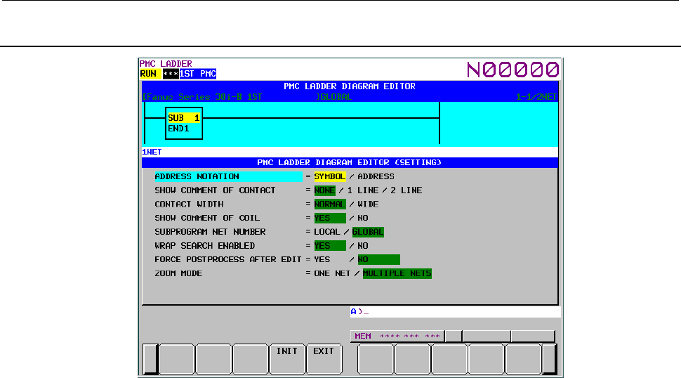
8.LADDER DIAGRAM MONITOR AND EDITOR SCREENS ([PMC LADDER])
B-64513EN/03
- 1084 -
8.3.2
Setting the LADDER DIAGRAM EDITOR Screen
Fig. 8.3.2 LADDER DIAGRAM EDITOR (SETTING) screen
(1) Display screen
The LADDER DIAGRAM EDITOR screen is partially displayed on the screen.
The relays displayed here will change real-time by changing the setting.
(2) Setting items
LADDER DIAGRAM EDITOR (SETTING) screen contains the setting items below:
(a) ADDRESS NOTATION
Determines whether the bit and byte addresses in the LADDER Diagram are displayed as
corresponding symbols, or the addresses themselves.
SYMBOL (default)
Addresses that have a symbol are displayed by the symbols. Addresses without symbols
are displayed by the addresses themselves.
ADDRESS
All addresses are displayed as the addresses themselves even if they have a symbol.
(b) SHOW COMMENT OF CONTACT
Set the style of relay comment. These are three options as below. When you display relay
comment, less ladder diagram circuits are shown.
NONE (default)
Relay comments are not displayed.
1 LINE
Relay comments are displayed in one line. Up to 15 characters (7 characters in Japanese)
of relay comment can be displayed when "WIDE" is selected for the "CONTACT
WIDTH" setting that is described below. Characters after 15th character will not be
displayed.
2 LINE
Relay comments are displayed in two lines. Up to 30 characters (14 characters in
Japanese) of relay comment can be displayed when "WIDE" is selected to the
"CONTACT WIDTH" setting that is described below. Up to 14 characters can be
displayed. Characters after 30th character will not be displayed.
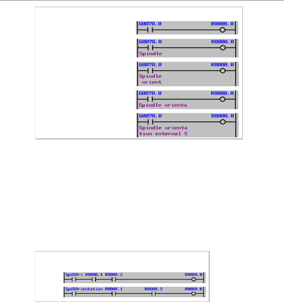
B-64513EN/03
8.LADDER DIAGRAM MONITOR AND EDITOR SCREENS ([PMC LADDER])
- 1085 -
Display styles of relay comment
CONTACT WIDTH = NORMAL
CONTACT WIDTH = NORMAL
CONTACT WIDTH = WIDE
CONTACT WIDTH = WIDE
SHOW COMMENT OF CONTACT = NONE
SHOW COMMENT OF CONTACT = 1 LINE
SHOW COMMENT OF CONTACT = 2 LINE
SHOW COMMENT OF CONTACT
= 1 LINE
SHOW COMMENT OF CONTACT = 2 LINE
(c) CONTACT WIDTH
Set the style of relay width. When "WIDE" is selected for the "CONTACT WIDTH" setting,
up to 15 characters of symbol on relay can be displayed. Moreover, when "1 LINE" is selected
for the "SHOW COMMENT OF CONTACT" setting, up to 15 characters of relay comment
can be displayed. When "2 LINE" is selected for the "SHOW COMMENT OF CONTACT"
setting, up to 30 characters of relay comment can be displayed. However, in these cases, fewer
contacts can be displayed.
NORMAL (default)
A relay is expressed with 8-character length.
Up to 7 characters of symbol can be displayed.
WIDE
A relay is expressed with 16-character length.
Up to 15 characters of symbol can be displayed.
Display styles of relay
NORMAL
WIDE
(d) SHOW COMMENT OF COIL
Determines whether to show coil comments. Unlike the LADDER DIAGRAM MONITOR
screen, the gage indicating the current display position is displayed at the right end of the
LADDER DIAGRAM EDITOR screen, regardless of this setting.
YES (default)
Right margin of 2 lines of 15 characters is reserved for display of coil comments.
NO
Right margin is used to extend diagram by one more relay, instead of showing coil
comment.
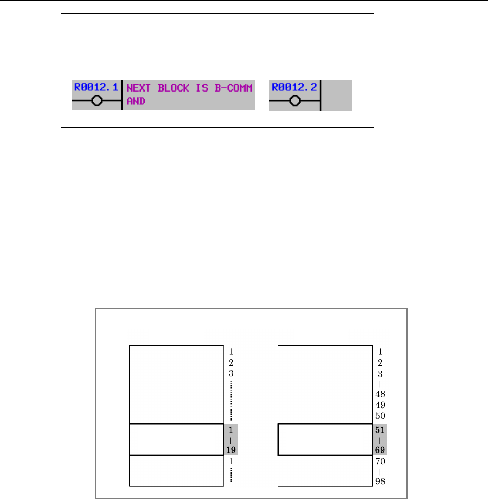
8.LADDER DIAGRAM MONITOR AND EDITOR SCREENS ([PMC LADDER])
B-64513EN/03
- 1086 -
Show Coil comment setting
YES NO
(e) SUBPROGRAM NET NUMBER
Determines whether a net number is counted as "LOCAL" starting from the top of current
subprogram, or is counted as "GLOBAL" starting from the top of whole program. This
setting also affects the expression of net number at searching nets by number.
LOCAL
Net number starts from 1 at top of current subprogram. Net number is defined only
within current subprogram. The net number information at upper right of the screen is
displayed in the format "displaying range / nets in subprogram NET".
GLOBAL (default)
Net number starts from 1 at top of Level 1 program. Net number is defined identically at
whole of program. The net number information at upper right of the screen is displayed
in the format "displaying range / subprogram range NET".
Definition of net number
LOCAL GLOBAL
Current
Subprogram
Current
Subprogram
(f) WRAP SEARCH ENABLED
Allows search process to wrap from top/bottom to bottom/top to continue to search.
YES (default)
Downward search will continue to search from top of LADDER when reaches to bottom.
Upward search will also continue to search from bottom when reaches to top.
NO
Search process will fail when reached top or bottom, and displays an error message at
Message Line.
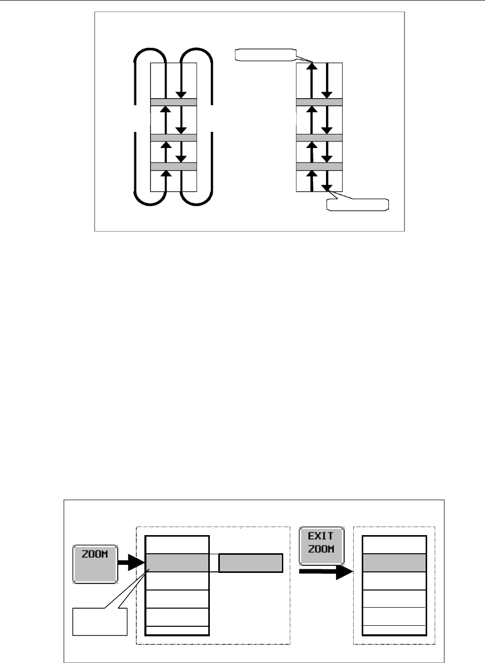
B-64513EN/03
8.LADDER DIAGRAM MONITOR AND EDITOR SCREENS ([PMC LADDER])
- 1087 -
[NEXT][PREV] [PREV] [NEXT]
YES NO
Wrap search
Not found
Not found
(g) FORCE POSTPROCESS AFTER EDIT
Allows you to specify whether to always perform the postprocessing necessary to operate a
ladder program or perform it only if the ladder program has been changed.
YES (default)
Postprocessing is always performed when you exit from the LADDER DIAGRAM
EDITOR screen. The postprocessing checks the contents of the ladder diagram. This
means that merely by entering the LADDER DIAGRAM EDITOR screen and then exiting
from it, the contents of the ladder diagram is checked again.
NO
Postprocessing is performed only if the ladder program has been changed. No
postprocessing will be performed when you enter the LADDER DIAGRAM EDITOR
screen and then exiting from it. This means that you can exit from the LADDER
DIAGRAM EDITOR screen even if the ladder program contains an error.
(h) ZOOM MODE
When going to NET EDITOR screen by [ZOOM] soft key on ladder editor screen, you can
select the net to be modified, either a net under the cursor or multiple nets near the cursor.
ONE NET (default)
You can modify a net under the cursor.
A
ction in modifying an existing net when "ZOOM MODE" is "ONE NET".
Editing
Net 2a
Net 1
Net 3
:
:
Net 2a
Net 1
Net 3
:
:
Net 2
Cursor
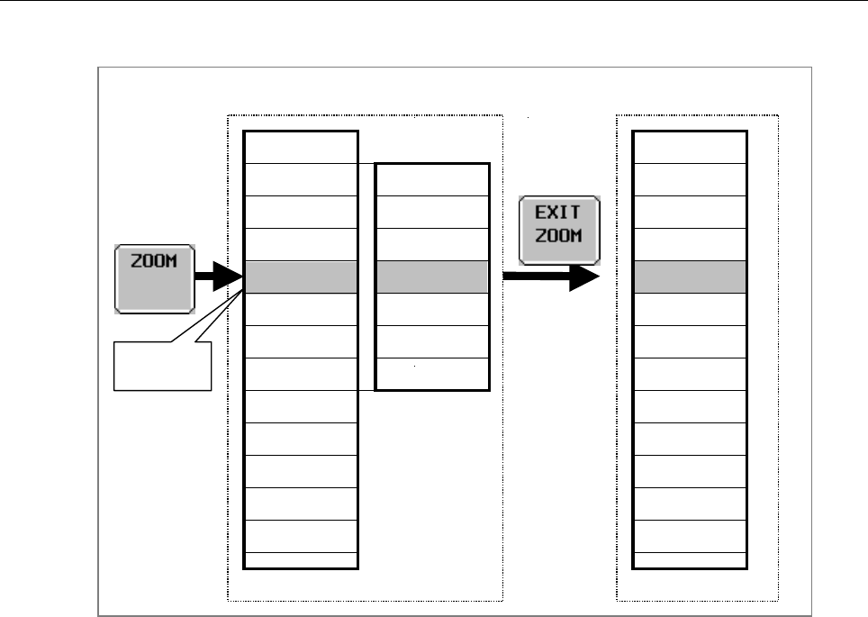
8.LADDER DIAGRAM MONITOR AND EDITOR SCREENS ([PMC LADDER])
B-64513EN/03
- 1088 -
MULTIPLE NETS
You can modify multiple nets near the cursor.
A
ction in modifying an existing net when “ZOOM MODE” is “MULTIPLE NETS”.
Net 1
Net 2
Net 3
Net 6
Net 7
Net 8
Net 9
Net 4
Net 10
Net 11
Net 5
:
:
Net 2a
Net 3a
Net 4a
Net 5a
Net 6a
Net 7a
Net 8a
Editing
Net 1
Net 2a
Net 3a
Net 6a
Net 7a
Net 9
Net 4a
Net 10
Net 11
Net 5a
Net 8a
:
:
Cursor
Page 3 of the setting screen
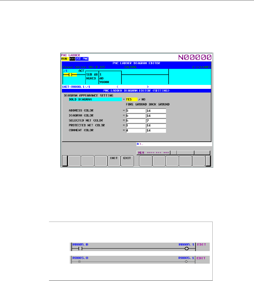
B-64513EN/03
8.LADDER DIAGRAM MONITOR AND EDITOR SCREENS ([PMC LADDER])
- 1089 -
(i) DIAGRAM APPEARANCE SETTING
Changes the appearance of LADDER diagram. Lines, relays, and functional instructions that
constitute LADDER diagram can be changed in the colors and the shapes. You can set colors
by entering their numbers. You can set 16 colors from 0 to 15. (Different numbers may
correspond to the same color.) You cannot set the same color number for the display and
background colors of the same portion.
・BOLD DIAGRAM
Sets thickness of diagram lines. This setting also affects shapes of relays.
YES (default)
Diagram is drawn with thick lines. Relays are drawn in more distinct shapes.
NO
Diagram is drawn with thin lines. Relays are drawn in smaller shapes.
Bold Diagram setting
Y
ES
NO
・ADDRESS COLOR
Colors for the relay address are set. You can specify these colors by entering color
number. 16 colors (from No. 0 to No. 15) are available. Foreground color should be
different from background one.
・DIAGRAM COLOR
General color and its background color for LADDER Diagram.
・SELECTED NET COLOR
Color setting for a selected net. The net subject to the editing operation will be displayed
in this color.

8.LADDER DIAGRAM MONITOR AND EDITOR SCREENS ([PMC LADDER])
B-64513EN/03
- 1090 -
・PROTECTED NET COLOR
Color setting for a net protected from an editing operation. The protected net will not be
selected as an object of editing. When a subprogram is displayed, those nets that contain
the following functional instructions are protected so that they cannot be deleted or
entered.
END1 END3 SP
END2 SPE
・COMMENT COLOR
Colors for the relay comment are set. You can specify these colors by entering color
number. 16 colors (from No. 0 to No. 15) are available. Foreground color should be
different from background one.
(3) Soft keys
LADDER DIAGRAM EDITOR (SETTING) screen has the soft keys of options and following:
• [INIT] Initialize all settings
All settings will be initialized to the default values.
• [EXIT] Switch to the LADDER DIAGRAM EDITOR screen
Ends the LADDER DIAGRAM EDITOR (SETTING) screen and switches to the LADDER
DIAGRAM EDITOR screen.
(4) Settings on multi-path PMC system
On the multi-path PMC systems, the Ladder Diagram related configuration is common to all PMC
paths at first. To make it independent for each PMC path, set system keep relay K909.4 to 1.
For example, different color settings may make it easier to recognize the PMC path which the
Ladder Diagram on the screen belongs to.
When you set 1 to K909.4 at the first time, the first PMC path will inherit the old settings, and the
rest path will start with the initial settings.
8.3.3
NET EDITOR Screen
At the NET EDITOR screen, you can create new net, and modify existing net.
• Changing existing nets
If you move a net with the [ZOOM] soft key, you will enter a mode (Modify mode) in which you
can change the net.
You can select the net to be modified, either a net under the cursor or multiple nets near the cursor
by setting of "ZOOM MODE" on ladder diagram editor setting screen.
• Adding a new net
When [CREATE NET] soft key is used, this screen is in "New mode" to create new net from
nothing.
Following operations are available at this screen:
• Place new contacts and coils "bit address" + [ ], [ ], etc.
• Change type of contacts and coils [ ], [ ], etc.
• Place new functional instructions [FUNC]
• Change type of functional instructions [FUNC]
• Erase contacts, coils, and functional instructions [ ]
• Draw/erase connecting lines [ ]/[ ], [ ], [ ]
• Edit data table of functional instructions [DATA TABLE]
• Insert line/column [INSERT LINE], [INSERT COLUMN],
[APPEND COLUMN]
• Change address of contacts and coils "bit address" + INPUT key
• Change parameters of functional instructions "number" or "byte address" + INPUT key
• Abandon modifications [CANCEL EDIT]
• Restore the net to the state it was before editing [RESTRE]
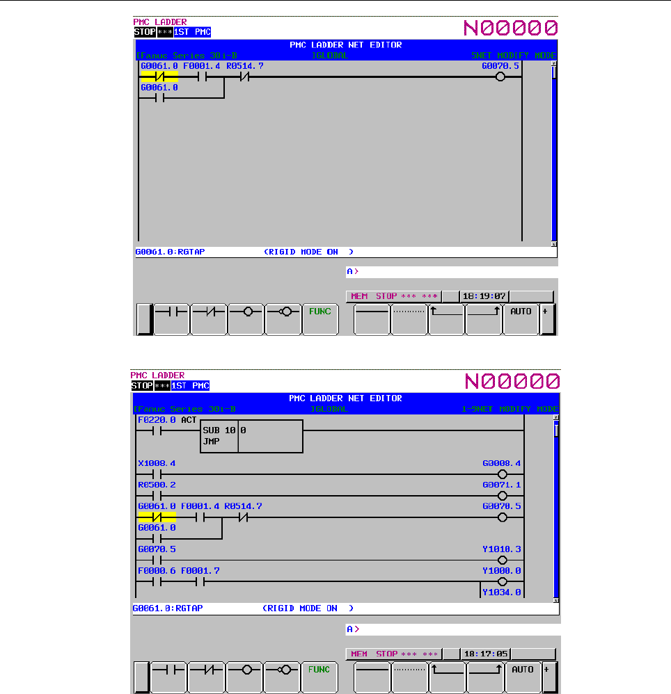
B-64513EN/03
8.LADDER DIAGRAM MONITOR AND EDITOR SCREENS ([PMC LADDER])
- 1091 -
Fig. 8.3.3 (a) Structure of the NET EDITOR screen (ONE NET)
Fig. 8.3.3 (b) Structure of the NET EDITOR screen (MULTIPLE NETS)
(1) Screen structures
(a) It is basically same with the LADDER DIAGRAM EDITOR screen.
(b) The gage indicating the current display position in relation to the edit area is displayed at the
right end of the screen.
(c) Current edit mode is indicated at right of the top line as "NEW MODE" or "MODFY MODE".
When [ZOOM] soft key at the LADDER DIAGRAM EDITOR screen is used to reach NET
EDITOR screen, the screen is in Modify mode, and when [CREATE NET] soft key is used, it
is in New mode.
(d) Current net number is displayed at right of the top line. The net number is same with the net
number in previous the LADDER DIAGRAM EDITOR screen.
(e) NET EDITOR screen expands image of net horizontally for a wider net according to its width,
while LADDER DIAGRAM MONITOR/EDITOR screen folds nets wider than screen width.
When net width is expanded over screen width, attempt to move cursor out of screen will scroll
net image to the direction.

8.LADDER DIAGRAM MONITOR AND EDITOR SCREENS ([PMC LADDER])
B-64513EN/03
- 1092 -
The net of maximum size occupies area of 1024 elements, but actually available area may be
little less for internal use according to the internal condition: "element" means the space that is
occupied by single relay.
(f) The maximum size of edit area occupies the area for 1024 elements when you modify and add
multiple nets.
If "ZOOM MODE" is "MULTIPLE NETS" on ladder diagram editor setting screen, the half of
edit area is filled with modified net when going to the NET EDITOR screen by [ZOOM] soft
key on the ladder editor screen.
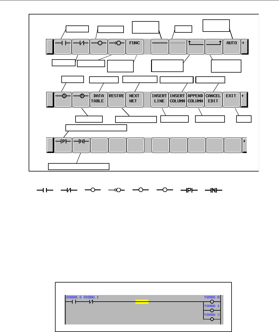
B-64513EN/03
8.LADDER DIAGRAM MONITOR AND EDITOR SCREENS ([PMC LADDER])
- 1093 -
(2) Operation with Soft keys
Soft keys of Net Editor screen
Edit next net
Abandon changes
Delete
B contact Inverted coil
Right vertical
connection
A contact Normal coil
Horizontal
connection
Functional
instructions
Left vertical
connection
Data table Insert column
Reset coil
Insert line Add column
Cancel edit
Exit
Set coil
Automatic
input
Positive transition contact
Negative transition contact
Fig. 8.3.3 (b) Soft keys of NET EDITOR screen
(a) [ ], [ ], [ ], [ ], [ S], [ R], [ ], [ ]
Place relays (contacts and coils), or change type of existing relays.
When one of these relay soft keys is pressed at cursor on blank place, new relay of the soft key
is placed under the
cursor. When the soft key follows a string that means a bit address, the bit address is assigned
to the newly placed relay.
If no bit address is given, last entered bit address is automatically used for the new relay. If no
bit address has been entered yet, the new relay will have no address assigned to it. Contacts can
be placed at other than rightmost column, and coils can be placed at rightmost column only.
Moving cursor onto an existing relay, pressing a relay soft key of different type changes the
type of relay under the cursor. But, changing coil to contact, and changing contact to coil are
forbidden.
Sample of contacts and coils
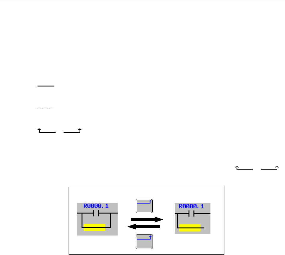
8.LADDER DIAGRAM MONITOR AND EDITOR SCREENS ([PMC LADDER])
B-64513EN/03
- 1094 -
(b) [FUNC] Enter and change functional instruction
Places functional instruction, or changes type of existing functional instruction.
When [FUNC] soft key is pressed at cursor on blank place, new functional instruction will be
placed under the cursor: list of available functional instructions is displayed, then choose type
of functional instruction to be entered. When [FUNC] soft key follows a string that means
number or name of a functional instruction, the specified functional instruction is entered
directly, without the list screen.
Moving cursor onto an existing functional instruction, pressing [FUNC] soft key changes the
type of functional instruction under the cursor.
(c) [ ] Draw horizontal connection
Draws horizontal connection line. Or alters an existing relay to horizontal line.
(d) [ ] Erase relays and functional instructions
Erases relays and functional instructions under cursor.
(e) [ ], [ ] Draw and erase vertical connection
Draw vertical connection line upward from right or left edge of relay or horizontal line under
cursor. Or erase existing vertical lines.
If the relay or line under the cursor has no vertical line upward, these soft keys have solid
arrows, and indicate that pressing them means drawing lines. On the other hand, if a vertical
line already exists under the cursor, arrows in these soft keys become pale ([ ], [ ]),
and indicate that pressing them means erasing lines.
Drawing and erasing vertical connection line
(f) [AUTO] Automatic input of unused address/parameter number
Executes the function for automatically inputting an unused address or parameter number.
For details of these functions, see Sections 8.7 and 8.8.
(g) [DATA TABLE] Edit data table
Reaches FUNCTIONAL INSTRUCTION DATA TABLE EDITOR screen to edit data table of
functional instruction under cursor. This soft key appears only when cursor is on a functional
instruction that has data table with it.
For detail of editing operation of data table, see descriptions of FUNCTIONAL
INSTRUCTION DATA TABLE EDITOR screen.
(h) [RESTRE] Restore net
Restores the currently edited net to the state it was before the start of editing. If you called the
NET EDITOR screen with the [CREATE NET] soft key from the LADDER DIAGRAM
EDITOR screen, the net will be restored to the state in which it contains nothing; if you called
the NET EDITOR screen with the [ZOOM] soft key, the net will be restored to the state it was
before the changes.
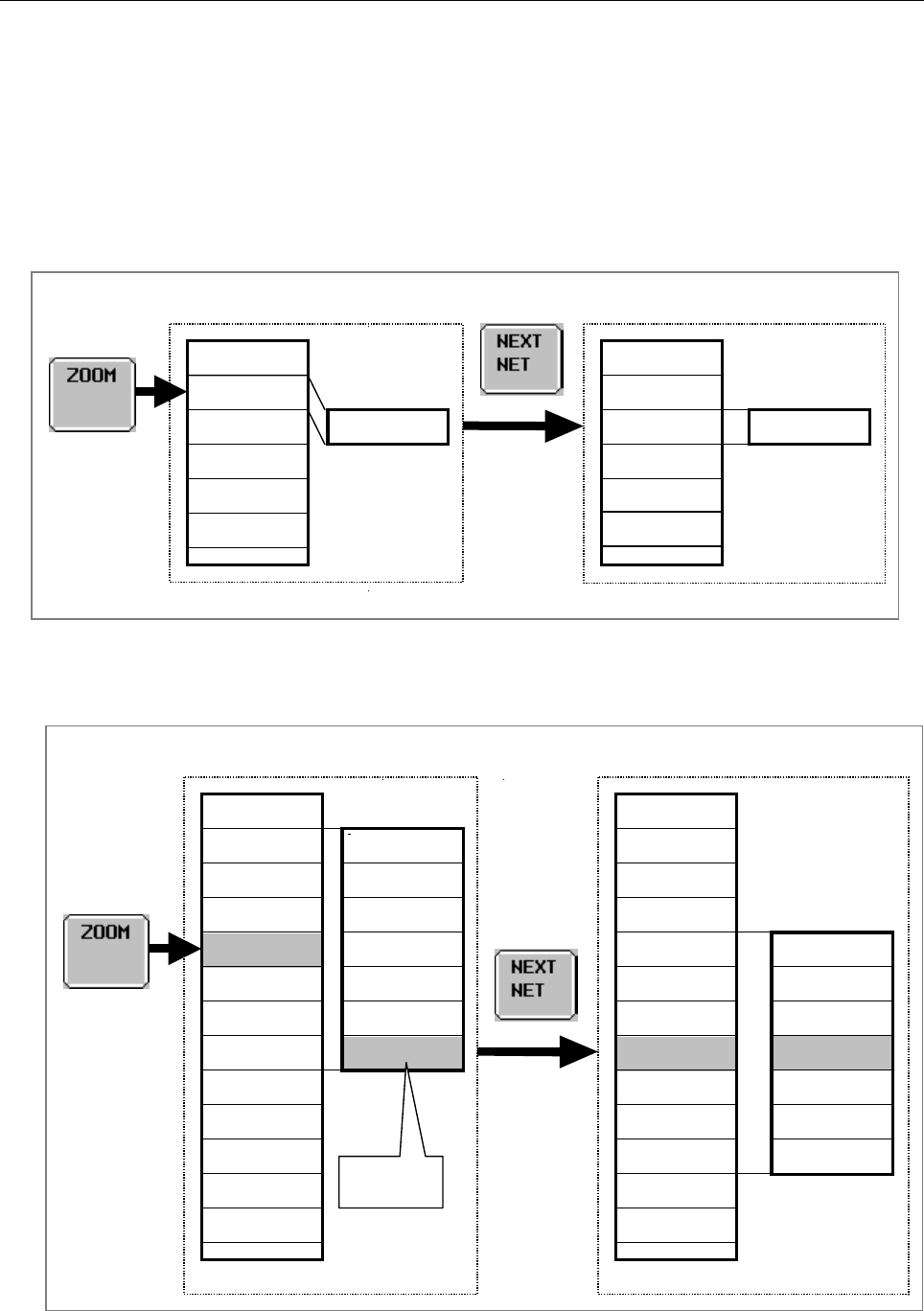
B-64513EN/03
8.LADDER DIAGRAM MONITOR AND EDITOR SCREENS ([PMC LADDER])
- 1095 -
(i) [NEXT NET] Go to next net
If [ZOOM] soft key at LADDER DIAGRAM EDITOR screen is used to reach NET EDITOR
screen, the [NEXT NET] soft key acts on setting of "ZOOM MODE" on ladder diagram editor
setting screen.
In case of "ZOOM MODE" is "ONE NET"
Finishes editing current net, and goes to next net.
If [ZOOM] soft key at LADDER DIAGRAM EDITOR screen is used to reach NET
EDITOR screen, [NEXT NET] will finish modifying current net, and the next net will be
an object of further editing operation.
In case of "ZOOM MODE" is " MULTIPLE NETS"
Finishes editing current net, change multiple nets to be modified by centering the cursor,
on the editing area.
Action of [NEXT NET] soft key in modifying an existing net when "ZOOM MODE" is "MULTIPLE NETS".
Net 1
Net 2
Net 3
Net 6
Net 7
Net 8
Net 9
Net 4
Net 10
Net 11
Net 5
:
:
Net 2a
Net 3a
Net 4a
Net 5a
Net 6a
Net 7a
Net 8a
Editing
Net 1
Net 2a
Net 3a
Net 6a
Net 7a
Net 9
Net 4a
Net 10
Net 11
Net 5a
Net 8a
:
:
Net 5b
Net 6b
Net 7b
Net 8b
Net 9a
Net 10a
Net 11a
Editing
Cursor
Action of [NEXT NET] soft key in modifying an existing net when "ZOOM MODE" is "ONE NET".
Net 1
Net 3
Net 4
:
:
Net 2a
Editing
Net 1
Net 2a
Net 3
Net 4
:
:
Net 2
Net 3a

8.LADDER DIAGRAM MONITOR AND EDITOR SCREENS ([PMC LADDER]) B-64513EN/03
- 1096 -
If [CREATE NET] soft key at LADDER DIAGRAM EDITOR screen is used to reach
NET EDITOR screen, [NEXT NET] will finish creating current net, insert it into the
LADDER program, and start with blank to create another new net to be inserted next to
the current net.
Action of [NEXT NET] soft key in adding a new net
Net 1
Net 2
Editing
Net 3
Net A
Net 4
:
:
Net 1
Net 2a
Editing
Net A
Net B
Net 3
Net 4
:
(j) [INSERT LINE] Insert line
Inserts one blank line at cursor position. Diagram elements at or below vertical cursor
position will be shifted downward by one line. Inserting line at middle of functional
instruction box will expand the box vertically to make a space between the input conditions.
Action of inserting line
(k) [INSERT COLUMN] Insert column before cursor
Inserts one blank column at cursor position. Diagram elements at or on right of horizontal
cursor position will be shifted to right by one column. And if there is no room to shift the
elements, a new column is added and the Diagram area will be expanded to right.
Action of inserting column
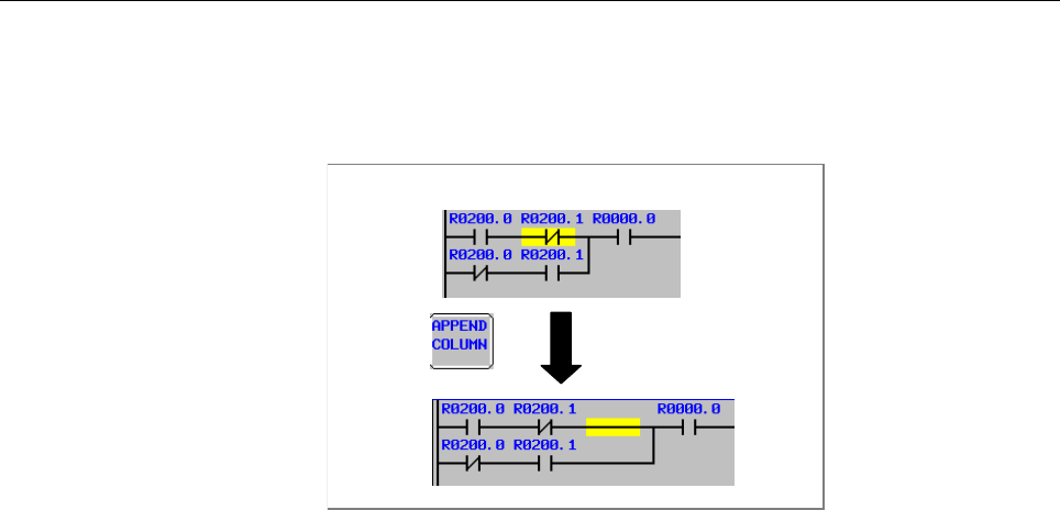
B-64513EN/03
8.LADDER DIAGRAM MONITOR AND EDITOR SCREENS ([PMC LADDER])
- 1097 -
(l) [APPEND COLUMN] Insert column after cursor
Inserts one blank column at right of cursor position. Diagram elements on right of horizontal
cursor position will be shifted to right by one column. And if necessary, net will be expanded
to right.
Action of appending column
(m) [CANCEL EDIT] Abandon changes
Restores the currently edited net to the state it was before the start of editing and moves you to
the LADDER DIAGRAM MONITOR screen. If [CREATE NET] soft key at LADDER
DIAGRAM EDITOR screen is used to reach NET EDITOR screen, it will be back to blank net,
and if [ZOOM] soft key is used, it will be back to the old net before modifications in this
screen.
(n) [EXIT] Exit editor screen
Analyzes current editing net, and store it into LADDER program.
If some error is found in the net, it still remains NET EDITOR screen, and an error message
will be displayed. According to a kind of error, cursor may indicate where the error is
detected.
(3) Other operations
(a) Cursor move keys, Page change keys
Cursor move keys and Page change keys move cursor on screen.
The NET EDITOR screen expands image of net horizontally for a wider net according to its
width, while LADDER DIAGRAM MONITOR/EDITOR screen folds nets wider than screen
width. When net width is expanded over screen width, attempt to move cursor out of screen
will scroll net image to the direction. The net of maximum size occupies area of 1024
elements, but actually available area may be little less for internal use according to the internal
condition: "element" means the space that is occupied by single relay.
(b) "bit address" + INPUT key
Changes bit address of relay under cursor.
(c) "number" / "byte address" + INPUT key
Changes parameter of functional instructions under cursor.
(4) Operation of the return key
On the LADDER NET EDITOR screen, the return key has no effect.
After you have finished editing ladder net data, and want to return to the LADDER DIAGRAM
EDITOR screen, use the [EXIT] soft key.

8.LADDER DIAGRAM MONITOR AND EDITOR SCREENS ([PMC LADDER])
B-64513EN/03
- 1098 -
(5) Displaying extended symbol and comment
When using extended symbol and comment, you can define local symbols in each sub-program.
On the NET EDITOR screen, the priority of displaying symbol and comment by setting of "ZOOM
MODE" on ladder diagram editor setting screen and by selected program is defined as follows.
ZOOM MODE Program Displaying symbol and comment
ONE NET
The whole program,
LEVEL 1 to 3,
Sub-program P1 to P5000.
A symbol and comment is displayed by following priority.
1 Local symbol and comment that defined to displaying
sub-program.
2 Global symbol and comment.
3 Symbol undefined comment.
MULTIPLE
NETS
The whole program Global symbol and comment.
LEVEL 1 to 3,
Sub-program P1 to P5000.
A symbol and comment is displayed by following priority.
1 Local symbol and comment that defined to displaying
sub-program.
2 Global symbol and comment.
3 Symbol undefined comment.
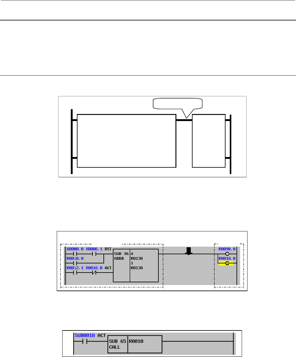
B-64513EN/03
8.LADDER DIAGRAM MONITOR AND EDITOR SCREENS ([PMC LADDER])
- 1099 -
8.3.4
Structure of Valid Net
There are the standard type and the extended type of the structures of ladder net. On the Extended PMC
Ladder Instruction Function, structure of standard type net and structure of extended type net can be
intermingled. Structure of extended type net includes structure of standard type net. And complicated
logic can be expressed in one net.
8.3.4.1
Structure of standard type net
Valid net must have following structure:
Input section
Output
section
Convergence point
Structure of valid net
"Input section" consists of contacts and functional instruction, and the result of operations of input section
is led to "Convergence point". After the convergence point, there is "Output section" that consists of
coils only. The "Convergence point" is the nearest point to right power line, where all connections join
with each other to gather into single connection.
Output
section
Convergence
point
Input section
Sample of valid net
Input section contains at least one relay or functional instruction, however, output section may contain
nothing.
Example of net with no output section
Valid net is also restricted in following rules:
• Only one functional instruction is available for a net.
• Functional instruction can be placed only at last (rightmost) of input section.
• Only coils can be contained in output section.
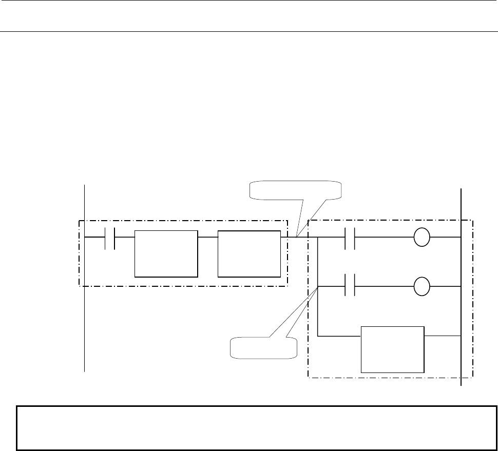
8.LADDER DIAGRAM MONITOR AND EDITOR SCREENS ([PMC LADDER])
B-64513EN/03
- 1100 -
8.3.4.2
Structure of extended type net
If the structure of extended type net is used, a more complicated circuit can be made compared with the
structure of standard type net.
As for the structure of extended type net, the following points are extended to the structure of standard
type net.
• Two or more functional instructions can be used for one net.
• A relay or other functional instructions are connectable with the output of a functional instruction.
• In the output section, not only a coil (coil, negative coil, set coil, reset coil) but also a relay and the
functional instruction can be located.
Sample of valid net
NOTE
The functional instruction, which can be used with the structure of extended type
net, has restriction. For details, refer to Table 8.3.4.2.
Functional
instruction
Functional
instruction
Functional
instruction
Conver
g
ence
p
oint
Output section
Branch point
Input section

B-64513EN/03
8.LADDER DIAGRAM MONITOR AND EDITOR SCREENS ([PMC LADDER])
- 1101 -
The functional instruction, which can be used in the structure of extended
type net.
Table 8.3.4.2
Instruction Name SUB Number Usable in Extended type net
END1 1 No
END2 2 No
TMR 3 Yes
DEC 4 Yes
CTR 5 No
ROT 6 No
COD 7 No
MOVE 8 No
COM 9 No
JMP 10 No
PARI 11 No
DCNV 14 No
COMP 15 No
COIN 16 No
DSCH 17 No
XMOV 18 No
ADD 19 No
SUB 20 No
MUL 21 No
DIV 22 No
NUME 23 No
TMRB 24 Yes
DECB 25 No
ROTB 26 No
CODB 27 No
MOVOR 28 No
COME 29 No
JMPE 30 No
DCNVB 31 No
COMPB 32 No
SFT 33 No
DSCHB 34 No
XMOVB 35 No
ADDB 36 No
SUBB 37 No
MULB 38 No
DIVB 39 No
NUMEB 40 No
DISPB 41 No
EXIN 42 No
MOVB 43 Yes (Note)
MOVW 44 Yes (Note)
MOVN 45 Yes (Note)
MOVD 47 Yes (Note)
END3 48 No
PSGNL 50 No
WINDR 51 No
WINDW 52 No
AXCTL 53 No
TMRC 54 Yes
CTRC 55 No

8.LADDER DIAGRAM MONITOR AND EDITOR SCREENS ([PMC LADDER])
B-64513EN/03
- 1102 -
Instruction Name SUB Number Usable in Extended type net
CTRB 56 No
DIFU 57 Yes
DIFD 58 Yes
EOR 59 No
AND 60 No
OR 61 No
NOT 62 No
PSGN2 63 No
END 64 No
CALL 65 No
CALLU 66 No
JMPB 68 No
LBL 69 No
NOP 70 No
SP 71 No
SPE 72 No
JMPC 73 No
CS 74 No
CM 75 No
CE 76 No
TMRBF 77 Yes
EQB 200 Yes
EQW 201 Yes
EQD 202 Yes
NEB 203 Yes
NEW 204 Yes
NED 205 Yes
GTB 206 Yes
GTW 207 Yes
GTD 208 Yes
LTB 209 Yes
LTW 210 Yes
LTD 211 Yes
GEB 212 Yes
GEW 213 Yes
GED 214 Yes
LEB 215 Yes
LEW 216 Yes
LED 217 Yes
RNGB 218 Yes
RNGW 219 Yes
RNGD 220 Yes
TMRST 221 No
TMRSS 222 No
CTRD 223 No
MOVBT 224 Yes
SETNB 225 Yes
SETNW 226 Yes
SETND 227 Yes
XCHGB 228 Yes
XCHGW 229 Yes
XCHGD 230 Yes
SWAPW 231 Yes
SWAPD 232 Yes

B-64513EN/03
8.LADDER DIAGRAM MONITOR AND EDITOR SCREENS ([PMC LADDER])
- 1103 -
Instruction Name SUB Number Usable in Extended type net
TBLRB 233 Yes
TBLRW 234 Yes
TBLRD 235 Yes
TBLRN 236 Yes
TBLWB 237 Yes
TBLWW 238 Yes
TBLWD 239 Yes
TBLWN 240 Yes
DSEQB 241 Yes
DSEQW 242 Yes
DSEQD 243 Yes
DSNEB 244 Yes
DSNEW 245 Yes
DSNED 246 Yes
DSGTB 247 Yes
DSGTW 248 Yes
DSGTD 249 Yes
DSLTB 250 Yes
DSLTW 251 Yes
DSLTD 252 Yes
DSGEB 253 Yes
DSGEW 254 Yes
DSGED 255 Yes
DSLEB 256 Yes
DSLEW 257 Yes
DSLED 258 Yes
DMAXB 259 Yes
DMAXW 260 Yes
DMAXD 261 Yes
DMINB 262 Yes
DMINW 263 Yes
DMIND 264 Yes
EORB 265 Yes
EORW 266 Yes
EORD 267 Yes
ANDB 268 Yes
ANDW 269 Yes
ANDD 270 Yes
ORB 271 Yes
ORW 272 Yes
ORD 273 Yes
NOTB 274 Yes
NOTW 275 Yes
NOTD 276 Yes
SHLB 277 Yes
SHLW 278 Yes
SHLD 279 Yes
SHLN 280 Yes
SHRB 281 Yes
SHRW 282 Yes
SHRD 283 Yes
SHRN 284 Yes
ROLB 285 Yes
ROLW 286 Yes

8.LADDER DIAGRAM MONITOR AND EDITOR SCREENS ([PMC LADDER])
B-64513EN/03
- 1104 -
Instruction Name SUB Number Usable in Extended type net
ROLD 287 Yes
ROLN 288 Yes
RORB 289 Yes
RORW 290 Yes
RORD 291 Yes
RORN 292 Yes
BSETB 293 Yes
BSETW 294 Yes
BSETD 295 Yes
BSETN 296 Yes
BRSTB 297 Yes
BRSTW 298 Yes
BRSTD 299 Yes
BRSTN 300 Yes
BTSTB 301 Yes
BTSTW 302 Yes
BTSTD 303 Yes
BTSTN 304 Yes
BPOSB 305 Yes
BPOSW 306 Yes
BPOSD 307 Yes
BPOSN 308 Yes
BCNTB 309 Yes
BCNTW 310 Yes
BCNTD 311 Yes
BCNTN 312 Yes
TBCDB 313 Yes
TBCDW 314 Yes
TBCDD 315 Yes
FBCDB 316 Yes
FBCDW 317 Yes
FBCDD 318 Yes
ADDSB 319 Yes
ADDSW 320 Yes
ADDSD 321 Yes
SUBSB 322 Yes
SUBSW 323 Yes
SUBSD 324 Yes
MULSB 325 Yes
MULSW 326 Yes
MULSD 327 Yes
DIVSB 328 Yes
DIVSW 329 Yes
DIVSD 330 Yes
MODSB 331 Yes
MODSW 332 Yes
MODSD 333 Yes
INCSB 334 Yes
INCSW 335 Yes
INCSD 336 Yes
DECSB 337 Yes
DECSW 338 Yes
DECSD 339 Yes
ABSSB 340 Yes
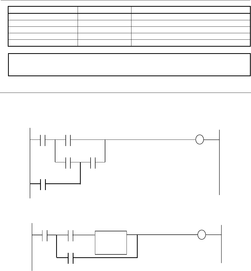
B-64513EN/03
8.LADDER DIAGRAM MONITOR AND EDITOR SCREENS ([PMC LADDER])
- 1105 -
Instruction Name SUB Number Usable in Extended type net
ABSSW 341 Yes
ABSSD 342 Yes
NEGSB 343 Yes
NEGSW 344 Yes
NEGSD 345 Yes
NOTE
When using these instructions in the structure of extended type net, it is possible
either to output a result of operation to a coil or to omit a coil.
8.3.4.3
Ladder that is not programmable
The following ladder diagrams are not programmable.
(1) Perform an OR operation in the middle of operation.
(2) A loop circuit is placed before and after of functional instruction.
Functional
instruction
A B C
D E
F
A B
C
D
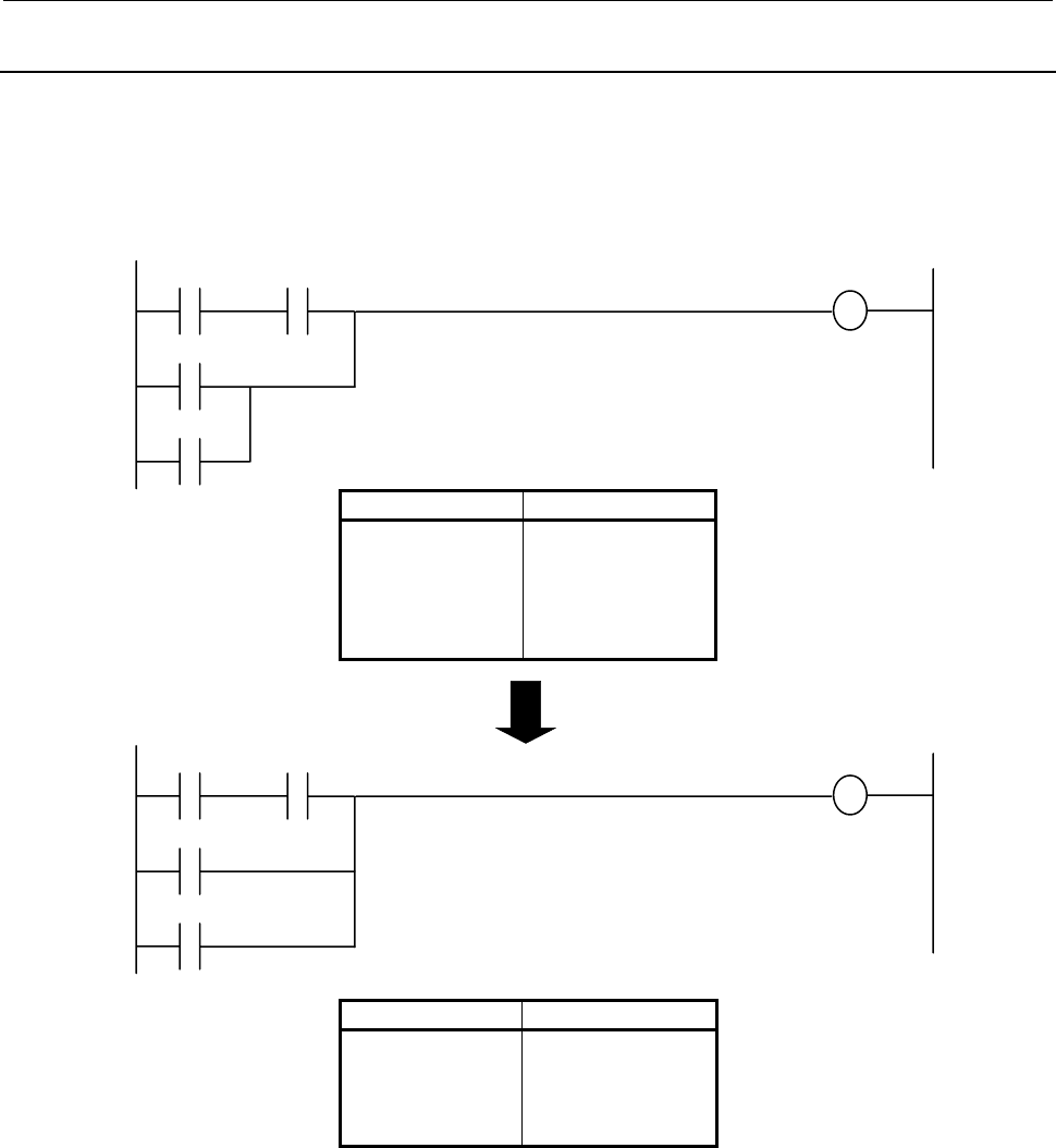
8.LADDER DIAGRAM MONITOR AND EDITOR SCREENS ([PMC LADDER])
B-64513EN/03
- 1106 -
8.3.5
Optimization
In order to generate the always same object from the inputted ladder diagram, the optimization which
deletes bit stack manipulation omissible by changing an operation order, makes smaller the object
generated, and makes execution speed quick is performed. However, the optimization which changes an
access order to each bit address is not performed.
Mnemonic Stack consumption
RD A
AND B
RD.STK C
OR D
OR.STK
WRT E
0
0
1
1
0
0
Mnemonic Stack consumption
RD A
AND B
OR C
OR D
WRT E
0
0
0
0
0
Inputted ladder diagram
Optimized ladder diagram
A B
C
D
E
A B
C
D
E
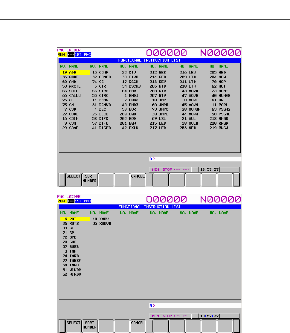
B-64513EN/03
8.LADDER DIAGRAM MONITOR AND EDITOR SCREENS ([PMC LADDER])
- 1107 -
8.3.6
FUNCTIONAL INSTRUCTION LIST Screen
Pressing [FUNC] soft key at the NET EDITOR screen reaches FUNCTIONAL INSTRUCTION LIST
screen at which you can choose a functional instruction to be entered from the list of all available
functional instructions.
Fig. 8.3.6 FUNCTIONAL INSTRUCTION LIST screen
Operations at this screen are below:
(1) Operation with soft keys
(a) [SELECT] Select a functional instruction
Selects a functional instruction. The functional instruction is entered into the editing net.
(b) [SORT NUMBER], [SORT NAME] Rearrange functional instructions list
Rearrange functional instructions list in two ways. [SORT NUMBER] soft key arranges the
list in numerical order with their identifying numbers, on the other hand, [SORT NAME] soft
key arranges it in alphabetical order with their names.
(c) [CANCEL] Quit selecting
Quits selecting functional instruction, and return to the NET EDITOR screen.

8.LADDER DIAGRAM MONITOR AND EDITOR SCREENS ([PMC LADDER])
B-64513EN/03
- 1108 -
(2) Other operations
(a) Cursor move keys
Cursor move keys move cursor on screen. According to the cursor position, the functional
instruction to be selected changes.
(b) INPUT key
Act just like [SELECT] soft key.
(3) Shortcuts
(a) [SELECT] soft key and INPUT key following number or name of a functional instruction will
select the specified functional instruction directly, instead of the one under cursor.
(b) When [FUNC] soft key in the NET EDITOR screen is pressed following a string that means
number or name of a functional instruction, the specified functional instruction is entered
directly, without displaying FUNCTIONAL INSTRUCTION LIST screen.
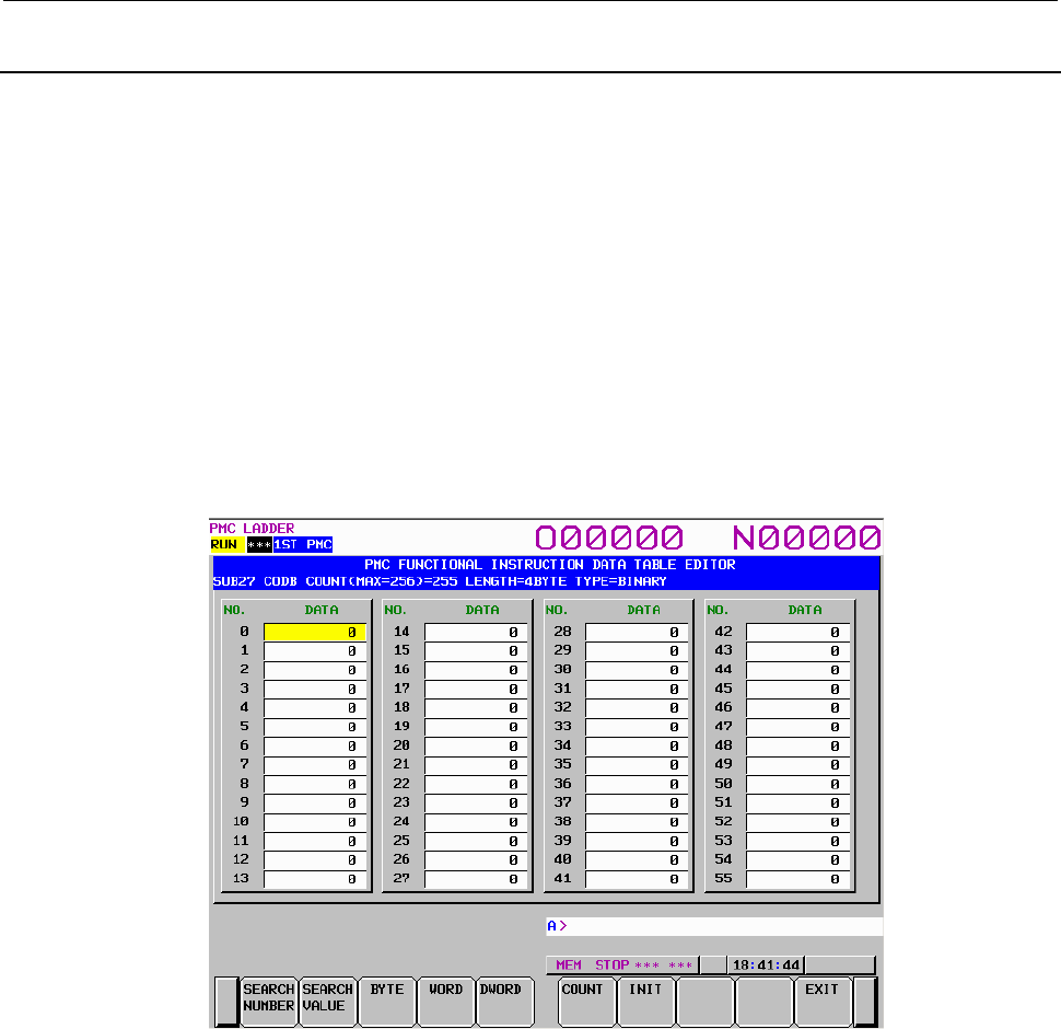
B-64513EN/03
8.LADDER DIAGRAM MONITOR AND EDITOR SCREENS ([PMC LADDER])
- 1109 -
8.3.7
FUNCTIONAL INSTRUCTION DATA TABLE EDITOR Screen
At FUNCTIONAL INSTRUCTION DATA TABLE EDITOR screen, you can edit the contents of data
table that belongs to some functional instructions.
To reach this screen, at NET EDITOR screen, press [DATA TABLE] soft key that is displayed when the
cursor is on the following functional instructions which have a data table.
• Functional Instruction COD (SUB7)
• Functional Instruction CODB (SUB27)
The following edit operations are available at this screen.
• Change the data table value "number" + INPUT key
• Change the data length [BYTE], [WORD], [DWORD]
(These soft keys can be operated only at FUNCTIONAL INSTRUCTION DATA TABLE EDITOR
screen of Functional Instruction CODB.)
• Change the number of data [COUNT]
• Initialize all of data [INIT]
• Switch to LADDER DIAGRAM EDITOR screen [EXIT]
Fig. 8.3.7 FUNCTIONAL INSTRUCTION DATA TABLE EDITOR screen
(1) Screen structures
It is same with the FUNCTIONAL INSTRUCTION DATA TABLE VIEWER screen.
(2) Display data
The cursor is shown always. You can edit the data that is pointed by the cursor.
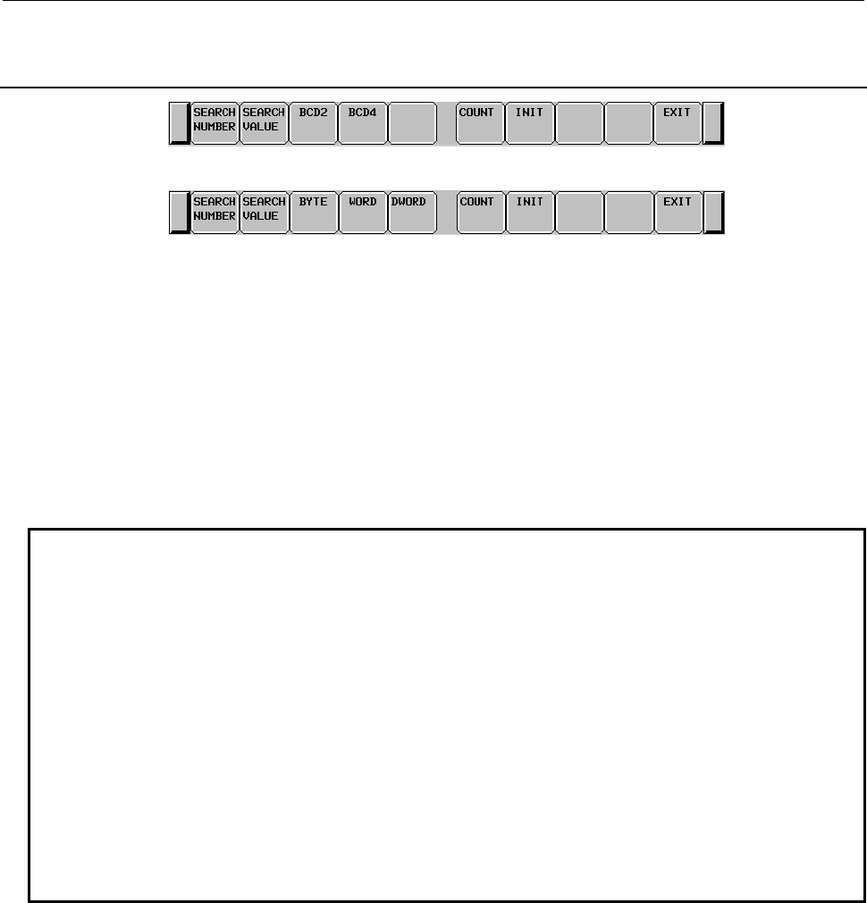
8.LADDER DIAGRAM MONITOR AND EDITOR SCREENS ([PMC LADDER])
B-64513EN/03
- 1110 -
8.3.8
Operating on the FUNCTIONAL INSTRUCTION DATA TABLE
EDITOR Screen
Soft keys of FUNCTIONAL INSTRUCTION DATA TABLE EDITOR screen of functional instruction COD
Soft keys of FUNCTIONAL INSTRUCTION DATA TABLE EDITOR screen of functional instruction CODB
(1) [SEARCH NUMBER] Search for data table number
Searches the data table number which you specified.
(2) [SEARCH VALUE] Search for data value
Searches the data value which you specified.
(3) [BCD2] Display BCD2 digits
Changes the display data type to 2 digits of BCD. This operation only switches the display data
type. So it does never edit the data on memory.
(4) [BCD4] Display BCD4 digits
Changes the display data type to 4 digits of BCD. This operation only switches the display data type.
So it does never edit the data on memory.
NOTE
In the functional instruction COD (SUB7), the data type of the data table can
dynamically be changed either BCD2 or BCD4 by "BYT" which is one of input
condition. So the data type of the data table is decided when the functional
instruction COD is executed. Decide the display data digit according to the status
of "BYT" by pressing either [BCD2] soft key or [BCD4] soft key. After turning the
power on, the default displaying data type is BCD4 digits. But if you change data
type by pressing [BCD2] soft key or [BCD4] soft key, the data type is kept until you
change again.
The data table of functional instruction COD is stored in the memory as BCD4
digits type. If you change the data type from BCD4 digits to BCD2 digits, the data
is displayed without higher 2-digits. But the data of higher 2-digits is kept in the
memory. So you return the data type from BCD2 digits to BCD4 digits, the
former BCD4 digits is recovered. The input range of the data obeys the current
data type.
(5) [BYTE] Change to the BYTE length
Changes data length to 1 byte. If overflowed data is found, the cursor points it, and this operation
aborts. Then, correct it and press [BYTE] soft key again.
(6) [WORD] Change to the 2 BYTE length
Changes data length to 2 bytes. If overflowed data is found, the cursor points it, and this operation
aborts. Then, correct it and press [WORD] soft key again.
(7) [DWORD] Change to the 4 BYTE length
Changes data length to 4 bytes.

B-64513EN/03
8.LADDER DIAGRAM MONITOR AND EDITOR SCREENS ([PMC LADDER])
- 1111 -
NOTE
On functional instruction CODB, the data type is decided by the first parameter of
it. So, if you change data type, the first parameter is changed too.
When you added functional instruction CODB to ladder program, the default data
type is BYTE.
(8) [COUNT] Change the number of data
Changes the number of data. If you expanded the number of data, "0" is set to expanded data as
default.
NOTE
In case of functional instruction COD, the number of data is decided by the first
parameter of it. In case of functional instruction CODB, the number of data is
decided by the second parameter of it. If you change the number of data, these
parameters are also changed.
(9) [INIT] Initialize all of data
Initializes all of data to "0". The number of data is not changed.
(10) [EXIT] Exit Editor
Ends the FUNCTIONAL INSTRUCTION DATA TABLE EDITOR screen and switches to NET
EDITOR screen.
(11) Cursor move keys, page change keys
You can move the cursor by all cursor move keys and page change keys.
(12) Operation of the return key
On the FUNCTIONAL INSTRUCTION DATA TABLE EDITOR screen, the return key has no
effect.
After you have finished editing ladder net data, and want to return to the LADDER DIAGRAM
EDITOR screen, use the [EXIT] soft key.
(13) "number" + INPUT key
Changes the data that is pointed by the cursor.
The input range of the data obeys the data length and the display data type.
Ex.) The case of functional instruction COD and displaying BCD2 digits
The available data range: 0 to 99
Ex.) The case of functional instruction CODB and length of 2 BYTE
The available data range: -32768 to 32767
And you can input multiple numbers by the following methods.
(a) ";"(EOB) is used for separating data.
(Ex.) Press the INPUT key after typing "100;200;300;"
(b) ";=" is used for inputting the same value as preceding data.
(Ex.) Press the INPUT key after typing "100;=;=;200;=", and it becomes
"100,100,100,200,200".
(c) ";;" is used for skipping an input address.
(Ex.) Press the INPUT key after typing "100;;100". The second data is not inputted.
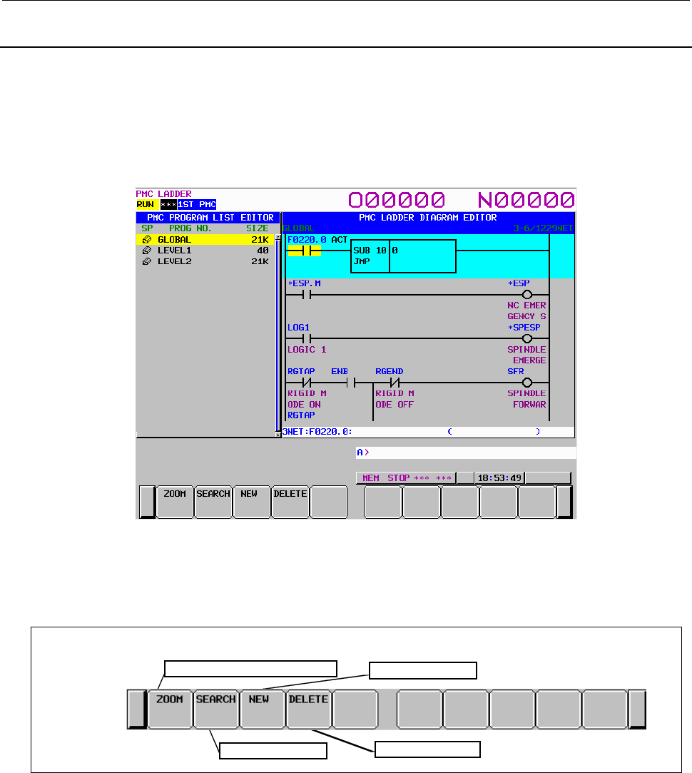
8.LADDER DIAGRAM MONITOR AND EDITOR SCREENS ([PMC LADDER])
B-64513EN/03
- 1112 -
8.3.9
PROGRAM LIST EDITOR Screen
At the PROGRAM LIST EDITOR screen you can create new program and delete a program in addition
to the function of PROGRAM LIST VIEWER screen. To reach this screen, press [LIST] soft key at the
LADDER DIAGRAM EDITOR screen. Following operations are available at the PROGRAM LIST
EDITOR screen. For more detail of these operations, see the descriptions of each key to operate.
• Create new program [NEW]
• Delete a program [DELETE]
Fig. 8.3.9 PROGRAM LIST EDITOR screen
On the PROGRAM LIST EDITOR screen, a preview of the editor screen for the ladder program currently
positioned by the cursor on the program list is displayed on the right of the screen.
(1) Operations using the soft keys
Display the contents of program Add new program
Search fo
r
p
ro
g
ram Delete a program
Soft keys of Program List Editor screen
Soft keys of PROGRAM LIST EDITOR screen
(a) [ZOOM] Display the contents of program
Goes to LADDER DIAGRAM EDITOR screen.

B-64513EN/03
8.LADDER DIAGRAM MONITOR AND EDITOR SCREENS ([PMC LADDER])
- 1113 -
(b) [SEARCH] Search for program
Searches for a program. Pressing the [SEARCH] soft key after entering a program name or
symbol name searches for program corresponding to the input character string and moves the
cursor to the program.
(c) [NEW] Create new program
If you entered program name or symbol and press the [NEW] soft key, the program will be
checked its existence. If such program is not found, new program will be created. The created
program is inserted automatically into the program list and the cursor points it. The following
ladder nets are created automatically according to the type of created program by this
operation.
LEVEL1: Functional instruction END1
LEVEL2: Functional instruction END2
LEVEL3: Functional instruction END3
Subprogram: Functional instruction SP, SPE
If the status of protection of the program is enabled to edit, this operation is available.
(d) [DELETE] Delete a program
Deletes a program. If you entered no strings and press the [DELETE] soft key, the program
under the cursor is deleted. If you entered program name or symbol and press the [DELETE]
soft key, the program will be checked its existence, and will be deleted if such program is
found.
But, GLOBAL, LEVEL1 and LEVEL2 should always exist on program list. If you delete
these programs, the contents of program are abandoned. But these programs do not disappear
on program list.
If the status of protection of the program is enabled to edit, this operation is available.
But this operation is disabled in case of the step sequence program.
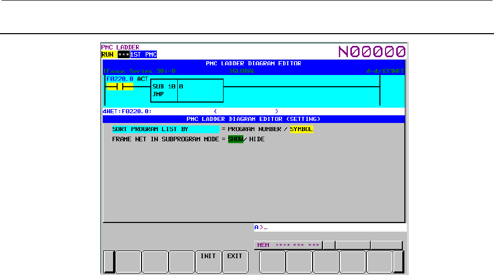
8.LADDER DIAGRAM MONITOR AND EDITOR SCREENS ([PMC LADDER])
B-64513EN/03
- 1114 -
8.3.10
Setting the PROGRAM LIST EDITOR Screen
Fig. 8.3.10 PROGRAM LIST EDITOR (SETTING) screen
(1) Program list screen setting
To set the program list screen, use the [SCREEN SETING] soft key on the Ladder screen.
Page 2 of the ladder setting screen, contains the setting items for the program list screen.
(a) SORT PROGRAM LIST BY
Specifies whether to display each subprogram on Program List editor screen in order of
program numbers or symbols. When ADDRESS NOTATION is SYMBOL, programs without
symbols are displayed in order of program number after programs with the symbols. GLOBAL,
LEVEL1, LEVEL2, LEVEL3 are out of target of sort.
PROGRAM NUMBER (default)
Program List display screen in order of program numbers.
SYMBOL
Program List display screen in order of symbols.
(b) FRAME NET IN SUBPROGRAM MODE
Frame nets refer to the functional instructions END1, END2, END3 at LEVEL1, LEVEL2, and
LEVEL3 and function instructions SP and SPE in subprograms. When you display the contents
of a program with the [ZOOM] soft key from the PROGRAM LIST VIEWER/EDITOR
screens, specify whether or not to display these frame nets.
SHOW (default)
Displays frame nets on the LADDER DIAGRAM MONITOR/EDITOR screens.
HIDE
Hides frame nets from the LADDER DIAGRAM MONITOR/EDITOR screens.
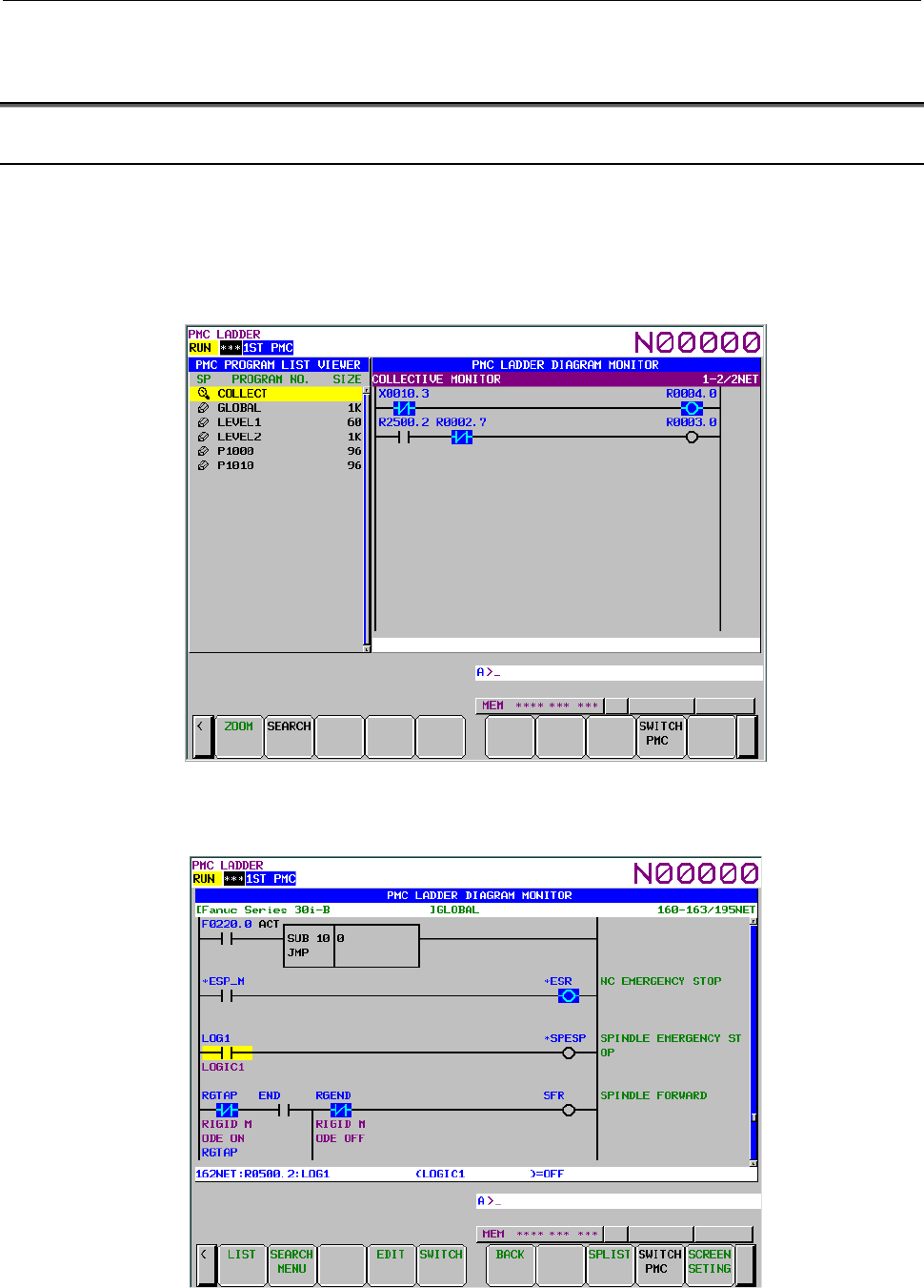
B-64513EN/03
8.LADDER DIAGRAM MONITOR AND EDITOR SCREENS ([PMC LADDER])
- 1115 -
8.4 SELECTING AND DISPLAYING THE NECESSARY
LADDER NET ([SWITCH] SCREEN])
8.4.1 Collective Monitor Function
The COLLECTIVE MONITOR screen allows you to specify ladder nets to be monitored, so that you can
monitor only the necessary ladder net.
The COLLECTIVE MONITOR screen can be called in either of the following ways:
(1) Calling from the PROGRAM LIST VIEWER screen
On the program list screen, move the cursor to the "COLLECT" program position, then press the
[ZOOM] soft key.
Fig. 8.4.1 (a) PROGRAM LIST VIEWER screen
(2) Calling from the LADDER DIAGRAM MONITOR screen
On the LADDER DIAGRAM MONITOR screen, press the [SWITCH] soft key.
Fig. 8.4.1 (b) LADDER DIAGRAM MONITOR screen
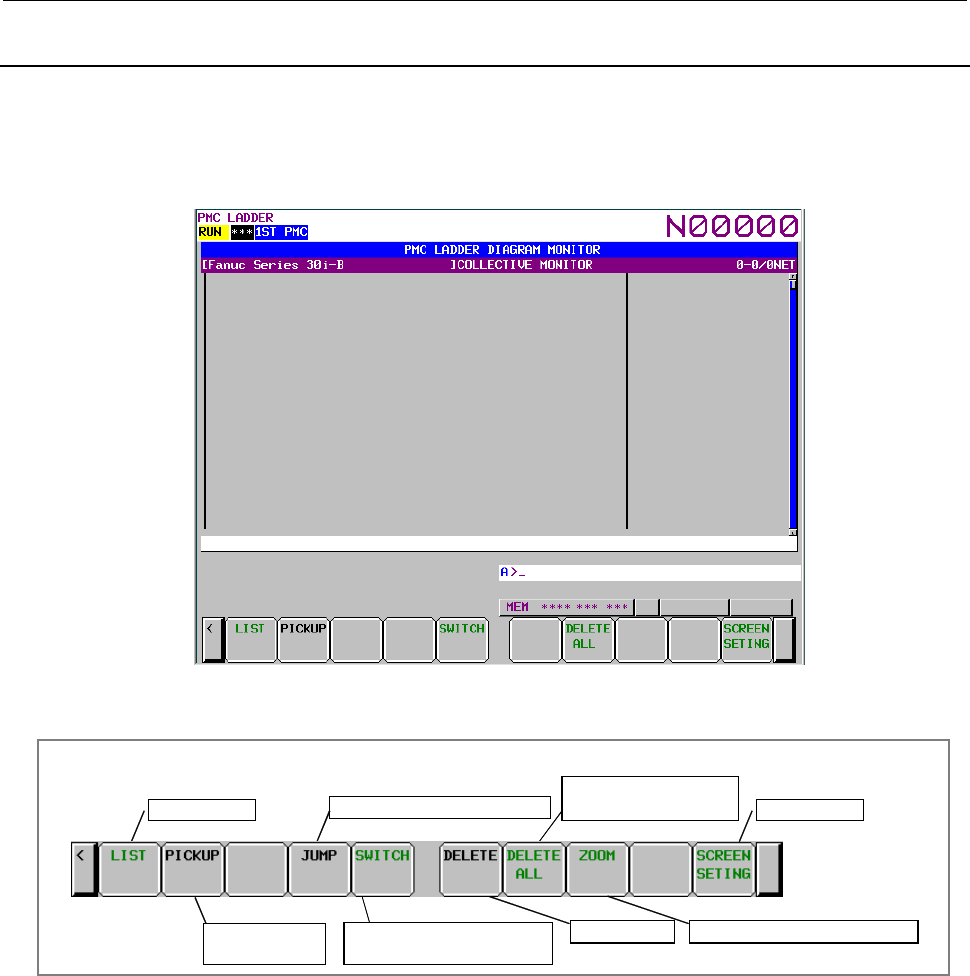
8.LADDER DIAGRAM MONITOR AND EDITOR SCREENS ([PMC LADDER])
B-64513EN/03
- 1116 -
8.4.2
Collective Monitor Screen
The COLLECTIVE MONITOR screen is such as that shown below. At first, it does not display any
ladder diagram. Ladder nets will be added to this screen as they are selected with coil search and pickup
operations. Up to 128 nets can be added to the COLLECTIVE MONITOR screen. If an attempt is
made to add more, the most recently added 128 nets will be displayed.
Fig. 8.4.2 (a) COLLECTIVE MONITOR screen (initial screen)
(1) Operations using the soft keys
Soft keys of Collective Monitor screen
Program List Jump to the ladder dia
g
ram net
Initialization of
COLLECTIVE MONITOR
Switches to LADDER
DIAGRAM MONITOR screen
Pick up a ladder
diagram net
Delete a net
Screen setting
Display a content of subprogram
Fig. 8.4.2 (b) Soft keys of COLLECTIVE MONITOR screen
(a) [LIST] Calling PROGRAM LIST VIEWER screen.
Calls the PROGRAM LIST VIEWER screen. On PROGRAM LIST VIEWER screen, you
can switch subprograms to be displayed on LADDER DIAGRAM MONITOR screen.
(b) [PICKUP] Picking up ladder nets.
Picks up ladder nets with coil which you want to monitor, on COLLECTIVE MONITOR
screen.
(c) [JUMP] Jump to a ladder net.
On LADDER DIAGRAM MONITOR screen, search the ladder net at a cursor position on the
COLLECTIVE MONITOR screen and jumps to the ladder net.
(d) [SWITCH] Switches to LADDER DIAGRAM MONITOR screen.
Switches to the LADDER DIAGRAM MONITOR screen.

B-64513EN/03
8.LADDER DIAGRAM MONITOR AND EDITOR SCREENS ([PMC LADDER])
- 1117 -
(e) [DELETE] Quits to display a ladder diagram net on the screen. (1 net)
Quits to display a ladder diagram net (only 1 net) which is picked up on the COLLECTIVE
MONITOR screen. This soft key appears by setting "SHOW CURSOR" to "YES" on the
setting screen.
(f) [DELETE ALL] Erases to display a ladder diagram net on the screen. (all nets)
Erases to display ladder diagram nets (all net) which is picked up on the COLLECTIVE
MONITOR screen.
(g) [ZOOM] Display contents of subprogram.
Placing the cursor on a CALL/CALLU/CM instruction and pressing [ZOOM] soft key displays
the target subprogram.
(g) [SCREEN SETING] Screen settings.
Calling the setting screen for the COLLECTIVE MONITOR screen. You can change each
settings of a ladder diagram display. Return to COLLECTIVE MONITOR screen by pressing
the [EXIT] soft key.
(2) Specifying the ladder diagram to monitor
The operation for picking up ladder nets which you want to monitor on COLLECTIVE MONITOR
screen is as follows.
(a) Specification of ladder nets on the COLLECTIVE MONITOR screen
• Specify the address by key input
Pick up a ladder net by keying in the address used by a coil.
• Indication from a ladder net on the COLLECTIVE MONITOR screen
Indicate a relay on an already picked up ladder net, with the cursor, to pick up the net that
uses the relay address for the coil.
(b) Specifying a ladder net from the LADDER DIAGRAM MONITOR screen
Specify a net from the LADDER DIAGRAM MONITOR screen to pick it and load it into the
COLLECTIVE MONITOR screen.
(3) Picking up a ladder net on the COLLECTIVE MONITOR screen
You can pick up a ladder net from the COLLECTIVE MONITOR screen. The procedure for
picking up a ladder net is as described below.
(a) Address specification
(i) Enter the address to monitor (for example, R10.1).
(ii) Press the [PICKUP] soft key.
(iii) The net in which a coil uses the address specified in (i) will be picked up and loaded at the
beginning of the screen.
(b) Specification of an address from a ladder net on the screen
(i) Move the cursor to a relay on the ladder net that uses the address you want to monitor.
(ii) Press the [PICKUP] soft key.
(iii) The net in which a coil uses the address specified in (i) will be picked up and loaded at the
beginning of the screen, and the cursor moves to the specified coil position.
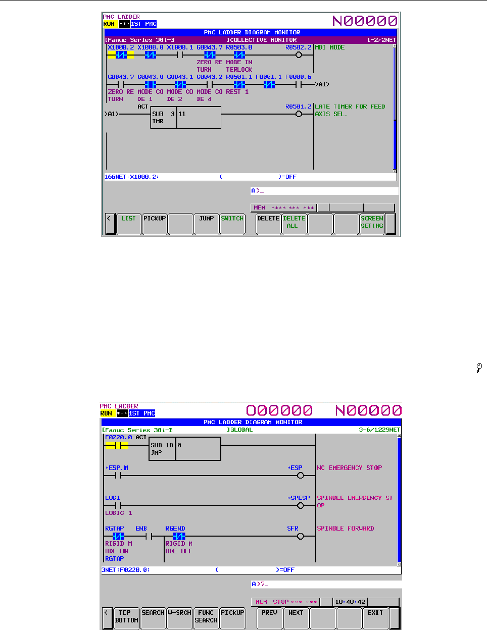
8.LADDER DIAGRAM MONITOR AND EDITOR SCREENS ([PMC LADDER])
B-64513EN/03
- 1118 -
Fig. 8.4.2 (c) COLLECTIVE MONITOR screen
(4) Picking up a ladder net from the LADDER DIAGRAM MONITOR screen
You can pick up a ladder net from the LADDER DIAGRAM MONITOR screen. The procedure
for picking up a ladder net is as described below.
(a) From the LADDER DIAGRAM MONITOR screen, press the [SEARCH] soft key to display
the soft keys for search.
(b) Move the cursor to the ladder net to pick up.
(c) Press the [PICKUP] soft key to pick up and load the net specified in (b) at the beginning of the
COLLECTIVE MONITOR screen.
(d) For the ladder net picked up and loaded into the COLLECTIVE MONITOR screen, the " "
mark is displayed at the left end of the net.
Fig. 8.4.2 (d) LADDER DIAGRAM MONITOR screen (search soft keys)
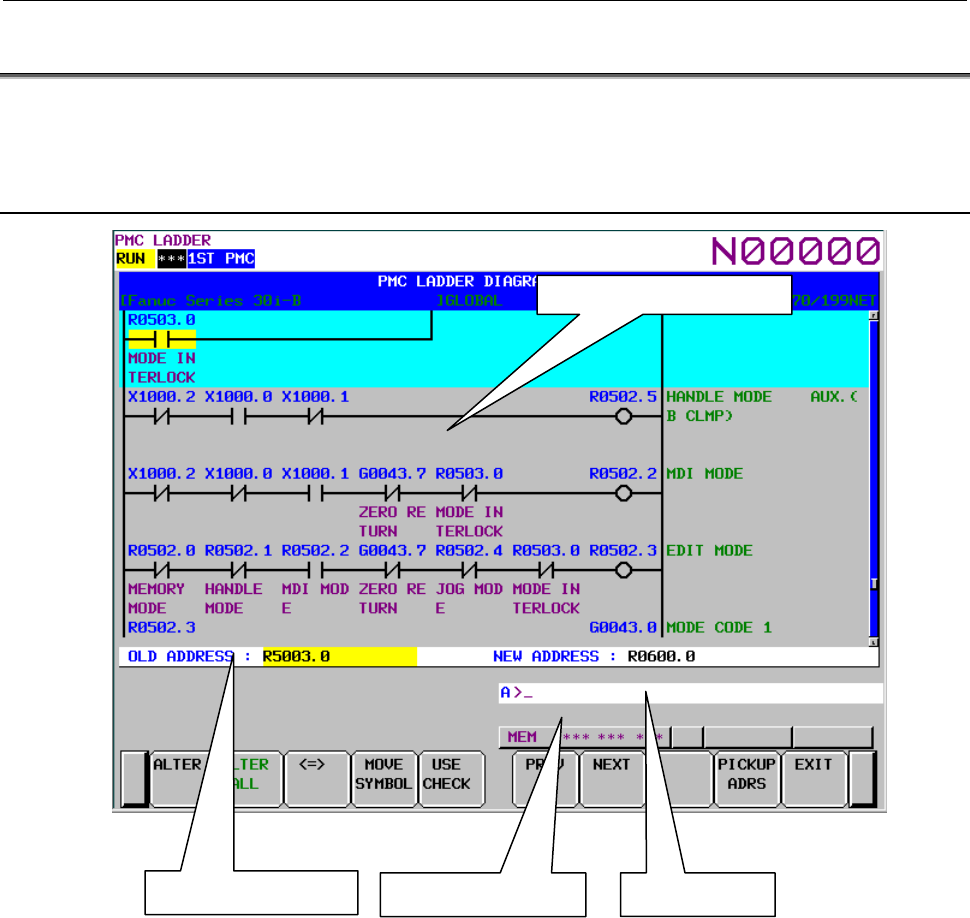
B-64513EN/03
8.LADDER DIAGRAM MONITOR AND EDITOR SCREENS ([PMC LADDER])
- 1119 -
8.5 ADDRESS ALTERATION FUNCTION
You can alter the address used in a ladder program with another address.
To perform address change, press the [CHANGE ADRS] soft key to switch to address change mode.
8.5.1 Screen Structures
(1) Key input line
Area in which data is displayed as it is keyed in.
(2) Message display line
Area in which confirmation and error messages are displayed.
(3) Address input line
Enter the address used in the ladder program in the "OLD ADDRESS" field and a new address into
the "NEW ADDRESS" field.
You can enter either PMC addresses or symbols as addresses.
Key input line
Message display line
Address input line
LADDER diagram display area
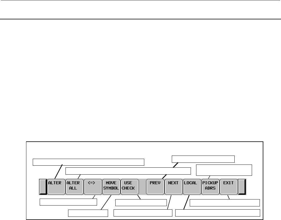
8.LADDER DIAGRAM MONITOR AND EDITOR SCREENS ([PMC LADDER])
B-64513EN/03
- 1120 -
8.5.2
Operating on the Screen
(1) Entering an address
You can enter an address by entering a "character string" and pressing the [INPUT] key.
• Address specification using a wildcard
You can use a wildcard (*) in the bit portion of a bit address.
Example: X100.*, which represents X100.0 to X100.7
The following input examples result in errors (invalid input).
(a) Use of a wildcard in a symbol
Example: ALWYS*
(b) Use of a wildcard in a portion other than the bit portion of a bit address
Example: X10*.0, X10*.*
(c) Use of a wildcard in a byte address
Example: X10*
(2) Operation with soft keys
Check the address to use
Search in the backward direction
Acquire the address
indicated by the cursor
Search in the forward direction Specify the area subject to search and alteration
Exit from the address alteration function
Move a symbol
Switch the cursor position
A
lter to the address s
p
ecified in the NEW ADDRESS field
A
ddress alteration function soft keys
A
lter to the address specified in the NEW ADDRESS field at once
Address alteration function soft keys
(a) [ALTER] Alter to the address specified in the NEW ADDRESS field
Alters the address indicated by the cursor in the ladder diagram display area to the address
specified in the "NEW ADDRESS" field.
This soft key is not displayed if the cursor in the ladder diagram does not indicate an address
that can be altered.
(b) [ALTER ALL] Alter to the address specified in the NEW ADDRESS field at once
Alters all instances of the address specified in the "OLD ADDRESS" field to the address
specified in the "NEW ADDRESS" field at once. If a whole program is selected, alteration
will take place globally. If a local program is selected, alteration will take place locally.
The following messages are displayed at the start and end of alteration.
(Confirmation message before alteration)
DO YOU ALTER ALL OLD ADDRESS IN GLOBAL?
(At the end of alteration)
ADDRESSES WERE ALTERED INTO "XXXXX" IN THE GLOBAL.
(c) [<=>] Switch the cursor position
Switches the cursor position between "OLD ADDRESS" and "NEW ADDRESS" alternately.

B-64513EN/03
8.LADDER DIAGRAM MONITOR AND EDITOR SCREENS ([PMC LADDER])
- 1121 -
(d) [MOVE SYMBOL] Move a symbol
Deletes the symbol of the address in the "OLD ADDRESS" field and redefines it for the
address in the "NEW ADDRESS" field.
The following messages are displayed at the start and end of alteration.
(Confirmation message before alteration)
ARE YOU SURE YOU WANT TO MOVE THE SYMBOL?
(At the end of alteration)
THE SYMBOL WAS MOVED.
(e) [USE CHECK] Check the address to use
Checks to see if the address specified in the "NEW ADDRESS" field is in use by searching for
the address through the ladder diagram.
When the address is used, the following messages are displayed.
・The case that selected program uses the address.
”xxxxx” IS USED.
・The case that selected program uses the address (extended symbol/comment format)
THE ADDRESS IS USED.
・The case that other divided program uses the address.
THE ADDRESS IS USED IN OTHER PROGRAM.
(f) [PREV] Search in the backward direction
Searches for the address specified in the "OLD ADDRESS" field through the ladder diagram in
the backward direction.
(g) [NEXT] Search in the forward direction
Searches for the address specified in the "OLD ADDRESS" field through the ladder diagram in
the forward direction.
(h) [GLOBAL/LOCAL] Specify the area subject to search and alteration
Used to specify either the entire program (global) or the subprogram (local) as the area subject
to search and alteration in the ladder diagram.
This soft key is displayed when a local program is selected in the program list screen.
(i) [PICKUP ADRS] Acquire the address indicated by the cursor
Used to pick up and load the address indicated by the cursor in the ladder diagram into the
"OLD ADDRESS" or "NEW ADDRESS" field.
(j) [EXIT] Exits from the address alternation function
Exits from the address alteration function and returns you to the ladder edit functions.
To use the address alteration function again, press the [CHANGE ADRS] soft key while the
ladder edit functions are displayed.
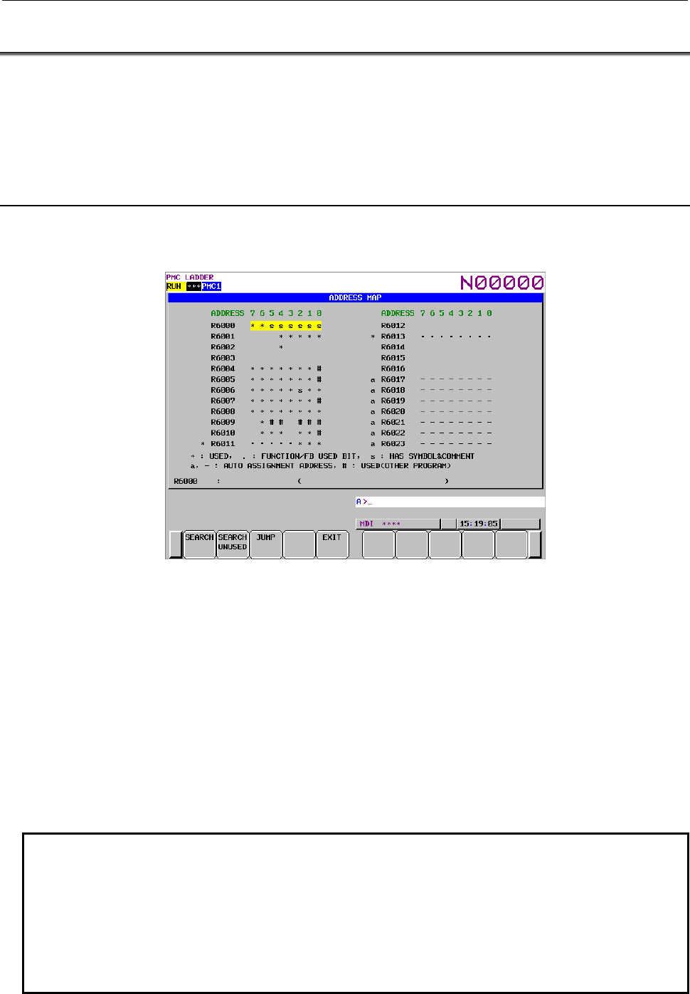
8.LADDER DIAGRAM MONITOR AND EDITOR SCREENS ([PMC LADDER])
B-64513EN/03
- 1122 -
8.6 FUNCTION TO REFERENCE ADDRESSES IN USE
You can switch the LADDER DIAGRAM EDITOR screen to the address map display screen where you
can view a list of addresses in use.
The address map display screen displays 24-byte bit map starting at any address.
Those "addresses not referenced in ladder diagrams that have symbols/comments defined" are also
displayed.
8.6.1 Address Map Display Screen
When pressing the [ADDRESS MAP] soft key on the ladder editor screen, the address map display screen
appears.
(1) Address representation
By representing each bit as described below, the status of PMC addresses in use are indicated.
Blank: Address bit not in use
*: Address bit in use (When a byte is used, an asterisk (*) is displayed to the left of the address
representation.)
*R100 • • • • • • • •: R100 is byte reference.
R101 ∗ ∗ ∗ ∗ ∗ ∗ ∗ ∗: R101.0 to R101.7 are bit reference, respectively.
*R102 ∗ ∗ ∗ ∗ ∗ ∗ ∗ ∗: Both byte and bit reference
S: Bit not referenced in the ladder diagram but that has a symbol/comment defined.
a: Automatic assignment address (byte) (Note)
-: Automatic assignment address (bit) (Note)
#: Address which is used in other program of same PMC path (ladder divided management
function)
NOTE
1 When same address is used in both selected program and another program, the
status for selected program is displayed.
2 The mark of addresses used in other program is displayed in bit position.
3 When there are some addresses used in other program, the following statuses
are showed as “#”
*(used as bit or byte), S(symbol/comment is defined), a,- (Automatic assignment
address)
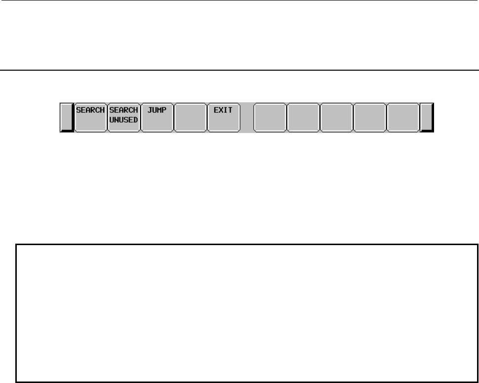
B-64513EN/03
8.LADDER DIAGRAM MONITOR AND EDITOR SCREENS ([PMC LADDER])
- 1123 -
(2) Additional display line
Any symbol/comment of the address at the cursor position is displayed in the additional display line.
8.6.2
Operating on the Screen
(1) Operation with soft keys
(a) [SEARCH] Search for an address
Searches for the specified address and displays it as the start address of the address map
display.
(b) [SEARCH UNUSED] Search for unused address
Displays an address map centering on the unused address with the smallest number found from
the specified address (if not specified, the address at which the cursor is currently located) and
containing the preceding and succeeding 12 bytes, 24 bytes in total.
NOTE
1 Parameters of functional instructions are handled as addresses in use with a
length of one byte, regardless of the data length of the parameters.
2 The range of the addresses to be searched for is determined by the specified
address.
Example: When R100.0 is specified, R100.0 to R7999.7 are searched for.
(Memory-B)
3 The following addresses are not subject to unused address search: (Memory-B)
X/Y1000 to X/Y1127, R9000 to R9499, T0 to T499, T9000 to T9499, C0 to C399,
C5000 to C5199, K900 to K999, A9000 to A9249, P1 to P5000, and L1 to L9999
(c) [JUMP]
Moves to the net in which the address at the cursor is in use. At this time, lap search is executed
in whole ladder program, regardless of the ladder screen settings. Addresses, which are showed
as “*” mark of bit or byte, can be jumped.
(d) [EXIT]
Switches the screen to the LADDER DIAGRAM EDITOR screen. At this time, the
LADDER DIAGRAM EDITOR screen displays the ladder net that it displayed before the
switch to this screen.
(2) Other operations with keys
You can use the page switch keys to switch between pages.
You cannot scroll with the cursor movement keys.

8.LADDER DIAGRAM MONITOR AND EDITOR SCREENS ([PMC LADDER])
B-64513EN/03
- 1124 -
8.7 FUNCTION TO AUTOMATICALLY INPUT UNUSED
ADDRESSES
This function automatically inputs unused R, D, and E addresses during ladder editing.
Specifying an unused start address
Enter any R, D, or E address and press the [AUTO] soft key.
The system searches for an unused bit through a list of addresses in the ascending order, starting at that
address, inputs the unused address of the unused bit and places that address at the top of the list of unused
addresses. If you repeat this operation, the unused start address will be updated. This address is not
displayed on the screen. Upon the completion of editing, the stored unused start address is abandoned.
Automatic input of R, D, or E address
After you have specified an unused start address, entering a single address character "R", "D", or "E" and
pressing the [AUTO] soft key causes an unused bit address subsequent to the specified unused address to
be automatically input.
For the R address, a simpler operation is available: Merely pressing the [AUTO] soft key enables
automatic input.
If you perform this operation without specifying an unused start address, the system searches for unused
bit, starting at the first address of the specified address type.
If an address used by a functional instruction parameter before a search for an unused address is found,
the following message will be displayed and the search for an unused bit will be stopped to avoid the
simultaneous uses of the address.
NO FREE ADDRESS IS FOUND BEFORE Xxxxx.
NOTE
This operation is available to bit addresses only.
You cannot automatically input byte addresses.

B-64513EN/03
8.LADDER DIAGRAM MONITOR AND EDITOR SCREENS ([PMC LADDER])
- 1125 -
8.8 AUTOMATICALLY INPUTTING UNUSED PARAMETER
NUMBERS
This function automatically inputs the unused numbers for the parameters of functional instructions
during ladder editing.
Operation
This function is applicable to the first parameters of the following functional instructions.
SUB3 (TMR)
SUB5 (CTR)
SUB24 (TMRB)
SUB56 (CTRB)
SUB57 (DIFU)
SUB58 (DIFD)
SUB77 (TMRBF)
Moving the cursor to one of these parameters and pressing the [AUTO] soft key causes an unused
parameter number to be input.
NOTE
Special specifications apply to SUB3 (TMR) and SUB5 (CTR). For details, see
"Automatic input of the TMR parameter of a functional instruction" and "Automatic
input of the CTR parameter of a functional instruction", described later.
If you perform this operation with a parameter number already input, an unused parameter number
subsequent to that number will be set.
If an attempt is made to perform this operation on a function instruction to which this operation is not
applicable, the following error message will be displayed.
CANNOT PERFORM "AUTO" ON THE INSTRUCTION.
If no unused numbers for parameters are found, the following error message will be displayed.
NO UNUSED PARAMETER NUMBER.
Automatic input of the TMR parameter of a functional instruction
When inputting the TMR parameter, you must consider precision.
(1) Range of parameter numbers subject to this automatic input
Timer numbers with their precision default setting being 8 msec (timer number 9 and subsequent
numbers) are assumed to be subject to this automatic input.
(2) Display of setting and precision of an input timer number
The setting and precision of an input timer number are displayed in the additional display line in the
following format:
TMR-number xx: setting xxxxxxxxxx precision xxMS
Automatic input of the CTR parameter of a functional instruction
(1) Display of the setting and current value of an input counter number
The setting and current-value of an input counter number are displayed in the additional display line
in the following format:
CTR-number xx: setting xxxxxxxxxx current-value xxxxxxx

8.LADDER DIAGRAM MONITOR AND EDITOR SCREENS ([PMC LADDER])
B-64513EN/03
- 1126 -
8.9 DUPLICATION DETECTION IN LADDER EDITING
8.9.1 DETECTION OF DOUBLE COILS
This function automatically detects double coils when you edit WRT coils with ladder editing operations.
Time to check
When you edit coils, this function always detects double coils.
When the check makes a hit, the following message is displayed:
- The case of detecting double coil in selected program
xxxxx.x IS USED IN NET xxxxx AS COIL.
- The case of detecting double coil in other program of same PMC path
USED IN OTHER PROG. AS COIL(xxxxx.x).
Example)
R0100.0 IS USED IN NET 100 AS COIL.
The coil editing refers to the following:
• Creation of a new WRT coil and change of a coil to a WRT coil
• Creation of a new WRT.NOT coil and change of a coil to a WRT.NOT coil
• Creation of a new SET/RST coil and change of a coil to a SET/RST coil
Objects of the check
Only coils are the objects of this check.
Thus, the following are not the object of this check:
• Output parameters of functional instructions
8.9.2
DUPLICATION DETECTION OF PARAMETER NUMBER OF
FUNCTIONAL INSTRUCTIONS
This function automatically detects duplication when you edit parameter number of functional
instructions.
Timing to check
When you edit parameter number of functional instructions, this function always detects duplication.
When the check makes a hit, the following message is displayed:
- The case of detecting duplication of parameter number of functional instructions in selected program
“INSTRUCTION” NUMBER IS USED(NET xxxx).
- The case of detecting duplication of parameter number of functional instructions in other program of
same PMC path
“Instruction name” NUMBER IS USED IN OTHER PROGRAM.
Example)
CTR NUMBER IS USED(NET 100).
The parameter number editing refers to the following:
• Creation of a new functional instruction (including the selection from functional instruction list
screen)
• Change of a parameter number of functional instruction

B-64513EN/03
8.LADDER DIAGRAM MONITOR AND EDITOR SCREENS ([PMC LADDER])
- 1127 -
Objects of the check
Only parameter number (first parameter) of the following functional instructions is the objects of this
check.
SUB3 (TMR), SUB5 (CTR), SUB24 (TMRB), SUB77 (TMRBF), SUB56 (CTRB), SUB57 (DIFU),
SUB58 (DIFD)
There are two area in which above functional instructions should check. One is that checking in whole
program of the PMC path and another is that checking in selected program only.
Whole program of the PMC path: SUB3 (TMR), SUB5 (CTR), SUB56 (CTRB)
Selected program: SUB24 (TMRB), SUB77 (TMRBF), SUB57 (DIFU), SUB58 (DIFD)
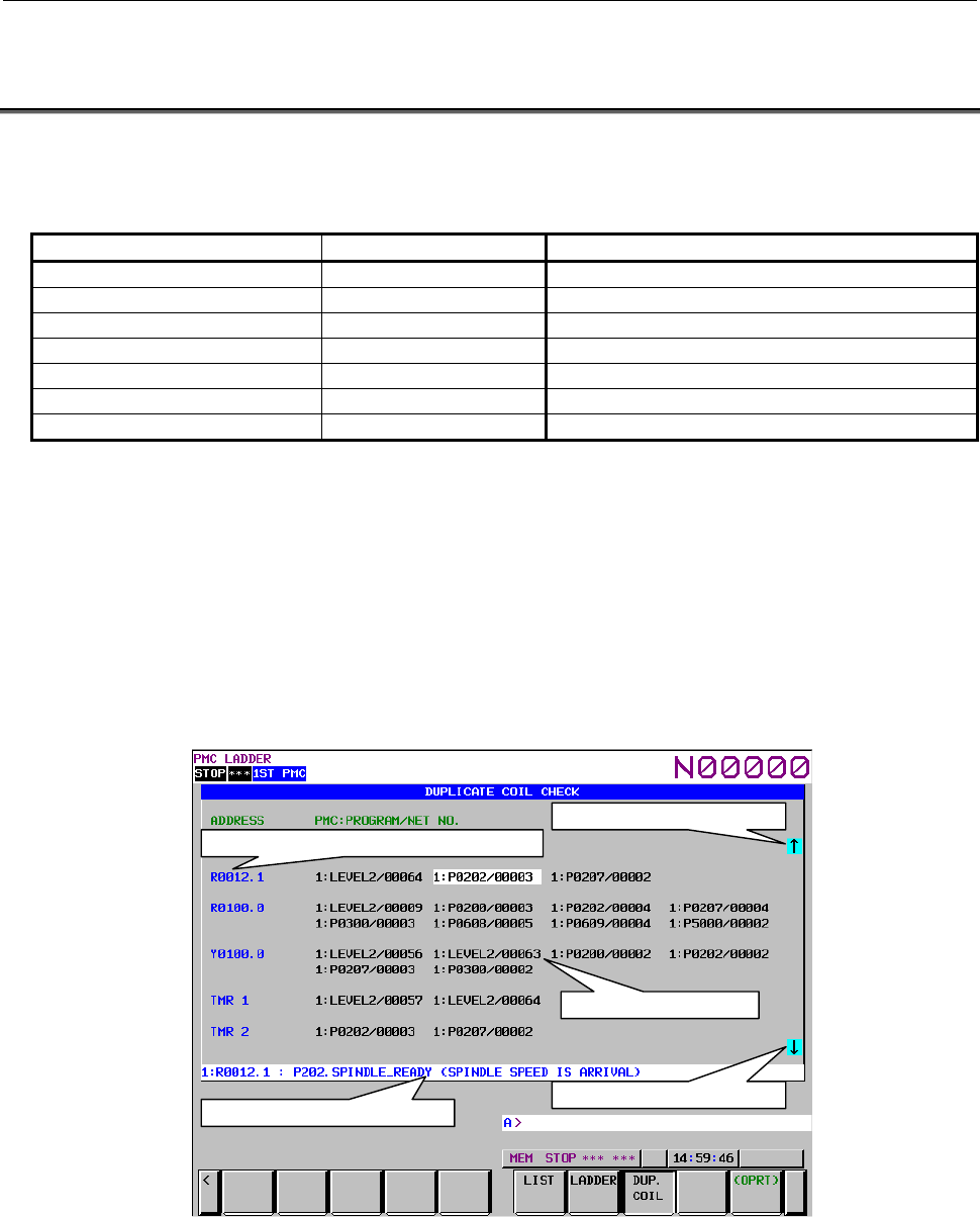
8.LADDER DIAGRAM MONITOR AND EDITOR SCREENS ([PMC LADDER])
B-64513EN/03
- 1128 -
8.10 CHECKING OF DUPLICATE COIL ([DUP. CHECK]
SCREEN)
On the Duplicate Coil Check screen, you can check the overwriting of a PMC address from some coil
instructions. And, you can check the multiple use of instruction number of the following numbered
functional instructions.
Instruction name SUB number Function
TMR 3 Timer
TMRB 24 Fixed Timer
TMRBF 77 Off Delay Fixed Timer
CTR 5 Counter
CTRB 56 Fixed Counter
DIFU 57 Rising Edge Detection
DIFD 58 Falling Edge Detection
Moreover, you can check the overwriting for plural sequence programs.
- When using the ladder dividing management function, they are checked among main ladder program
and divided ladder programs.
- Common memories (E address) for two or more PMC paths are checked when using a multiple PMC
paths system.
- When using memory shared mode in the multi-path PMC, all of shared PMC memories and
instruction numbers are checked.
The result of check is displayed with a list of net numbers of a program that is using duplicated data.
You can display a selected ladder net by moving the cursor and pressing the [JUMP] soft key.
A
ddress and Instruction number display area
Net number display area
Data continuation mark (lower)
A
dditional information display line
Data continuation mark (upper)
Fig. 8.10 (a) Duplicate coil check screen
Screen structures
(1) ADDRESS
Duplicated PMC address of coil and Functional instruction's name and number are displayed. You
can also display it by symbol instead of PMC address by pressing the [SYMBOL] soft key.
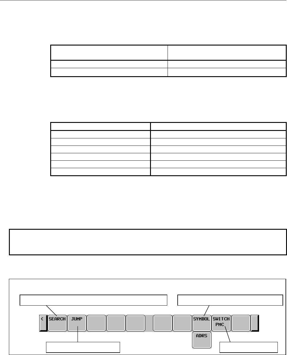
B-64513EN/03
8.LADDER DIAGRAM MONITOR AND EDITOR SCREENS ([PMC LADDER])
- 1129 -
(2) NET NO.
Some net numbers using the same coil or instruction number are displayed. The net number is
displayed in the following format by the configuration of PMC and the setting of the Ladder diagram
screen.
Setting of Ladder screen
(SUBPROGRAM NET NUMBER)
Net number display format
Global PMC:NET NO.
Local PMC:PROGRAM/NET NO.
In the “PMC” field of the format above, PMC path number and divided ladder program number are
displayed.
In case of main ladder program, the following PMC path numbers are displayed. In case of divided
ladder program, the divided number is also displayed after PMC path number + “-“.
PMC path Display number
1st path PMC 1
2nd path PMC 2
3rd path PMC 3
4th path PMC 4
5th path PMC 5
DCSPMC S
(3) Data continuation mark
This mark is displayed when the data continues to the pointed direction.
(4) Additional information display line
Symbol and comment of the cursor focused data are displayed
NOTE
In the address area and the additional information display line, symbols of current
sequence program are displayed.
Operations using soft keys
Soft keys on the Duplicate coil check screen
Searchin
g
of a PMC address or a Functional instruction
Jum
p
to a du
p
lication net Switches PMC
p
ath
Switches PMC address dis
p
la
y
mode
Fig. 8.10 (b) Soft keys on the Duplicate coil check screen
(1) [SEARCH] Searches a PMC address or a Functional instruction
This searches a PMC address or a Functional instruction. If specified PMC address or Functional
instruction is not duplicated, the following message is displayed, and duplications that found after it
are displayed.
When searching a PMC address :
"THE ADDRESS IS NOT FOUND"

8.LADDER DIAGRAM MONITOR AND EDITOR SCREENS ([PMC LADDER])
B-64513EN/03
- 1130 -
When searching a Functional instruction:
"THE FUNCTIONAL INSTRUCTION IS NOT FOUND"
When you cancel the searching, the check result display area is cleared. Operate the search function
again to re-display it.
The following letters can be used for searching PMC address.
• Bit address (ex. "R100.1" + [SEARCH])
• Byte address (ex. "R200" + [SEARCH])
• PMC memory type (ex. "R" + [SEARCH])
The following letters can be used for searching functional instruction.
Functional instruction Operation
TMR (Timer : SUB 3) "TMR" + [SEARCH]
"3" + [SEARCH]
TMRB (Fixed Timer : SUB 24)
and
TMRBF (Off delay fixed Timer : SUB 77)
"TMRB" + [SEARCH]
"24" + [SEARCH]
"TMRBF" + [SEARCH]
"77"
CTR (Counter : SUB 5) "CTR" + [SEARCH]
"5" + [SEARCH]
CTRB (Fixed Counter : SUB 56) "CTRB" + [SEARCH]
"56"
DIFU (Rising Edge Detection : SUB 57)
and
DIFD (Falling Edge Detection : SUB58)
"DIFU" + [SEARCH]
"57" + [SEARCH]
"DIFD" + [SEARCH]
"58" + [SEARCH]
(2) [JUMP] Jump to a duplication net
Change to the Ladder diagram screen and display the selected net. This soft key is displayed when
any duplication is detected.
(3) [SYMBOL] / [ADRS] Switches PMC address display mode
By pressing the [SYMBOL] soft key, you can change PMC addresses to symbol on the check result
display area. And, you can change to the original PMC address by pressing the [ADRS] soft key.
(4) [SWITCH PMC] Switching PMC path or divided ladder programs
Switches PMC path or divided ladder program. For details of the operation, refer to “6.3”.
By setting keep relay K935.0 to 1, you can display PMC program list screen. For details, refer
to ”2.2.11”.
Operations using other keys
(1) Cursor keys
Move the cursor displayed on a net number. You can display any Ladder net selected with the cursor,
by pressing the [JUMP] soft key.
When the cursor is on the top or bottom line of the screen, pressing the cursor key of the same
direction scrolls the contents of the screen.
(2) Page keys
Scroll up or down the contests of the screen by page.
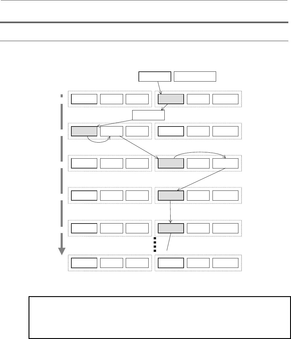
B-64513EN/03
8.LADDER DIAGRAM MONITOR AND EDITOR SCREENS ([PMC LADDER])
- 1131 -
8.11 DISPLAYING A SUBPROGRAM LIST ([SPLIST] SCREEN)
8.11.1 Display history of a Subprogram
To record the switching history of subprogram display in the LADDER DIAGRAM DISPLAY screen
and STEP SEQUENCE DISPLAY screen, you can trace back the history by [BACK] soft key.
Step Sequence Display Ladder Diagram Display
Subprogram List
State Display
Step Screen
Subprogram List
Ladder Screen
Collective Monitor
Subprogram List
Ladder Screen
Collective Monitor
History 1
History
n
History 2
Subprogram List
State Display
Step Screen
Program List
Program List
Subprogram List
Ladder Screen
Collective Monitor
State Display(Global)
[ZOOM]
[ZOOM]
[LIST]
History 4
[SWITCH]
History 3
[ZOOM]
[JUMP]
[SPLIST]
Subprogram List
Ladder Screen
Collective Monitor
Subprogram List
Ladder Screen
Collective Monitor
Subprogram List
State Display
Step Screen
Subprogram List
State Display
Step Screen
Subprogram List
State Display
Step Screen
Subprogram List
Ladder Screen
Collective Monitor
History 5
Subprogram List
State Display
Step Screen
[SEARCH]
Fig. 8.11.1 (a) Display history of a Subprogram
NOTE
When current program is switched from main program to divided program
with searching operation, the display history is recorded. However,
switching from divided program to other divided program clears recorded
display history.
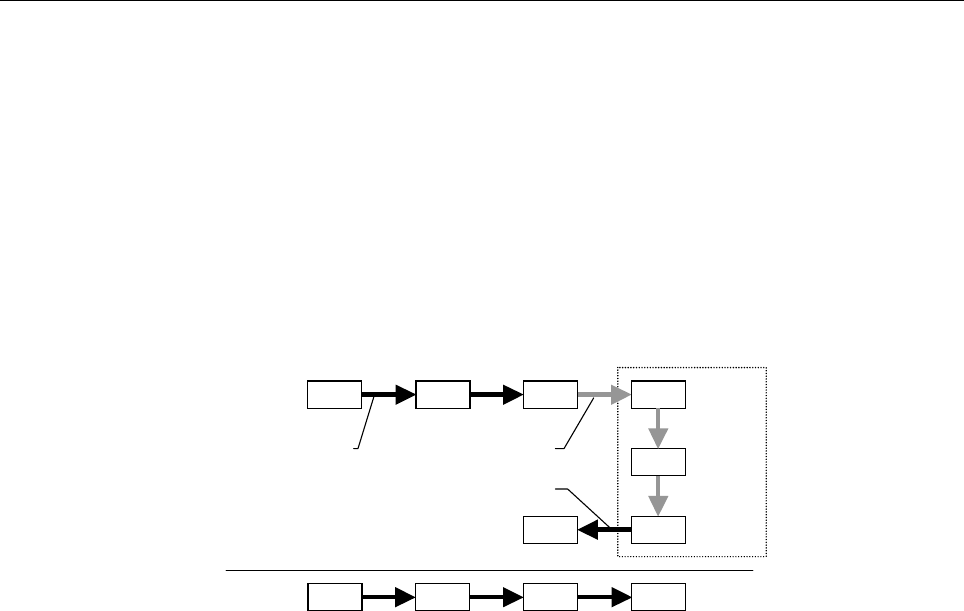
8.LADDER DIAGRAM MONITOR AND EDITOR SCREENS ([PMC LADDER])
B-64513EN/03
- 1132 -
Management of history information
Max.16 records are recorded in the history information. When subprogram is switched more than 16
times, the old history information is deleted in turn.
Jump within the same subprogram is not recorded.
When changing the sequence program by the PMC data I/O screen or FANUC LADDER-III, all the
display history of the subprogram is deleted.
The display history is not deleted even if the program is changed by the LADDER DIAGRAM EDITOR
screen. When deleting a subprogram, the deleted subprogram is removed from the history. And the
history information is not recorded by switching the subprogram in the LADDER DIAGRAM EDITOR
screen. When the subprogram A which is displayed just before starting the editing operation is different
from the subprogram B which is displayed just after editing, it is switched from B to A by the [BACK]
operation.
P1 P101
P202
P203P203
P1 P101 P201 P203
P201
History
Move Start Editing
P201
Finish Editing
Operation
Edit
Fig. 8.11.1 (b) Management of historical information
Display of the history in the subprogram list screen
The display history of subprograms and the list of calling subprogram are displayed together.
The display history of subprograms is displayed as the history number in the program type section. The
oldest history number is 1 and as it becomes newer, the number becomes larger.
You can move the cursor to the subprogram in the list of the history.
When the cursor is positioned on a subprogram in the history and it is zoomed, you can back to the older
subprogram of history directly.
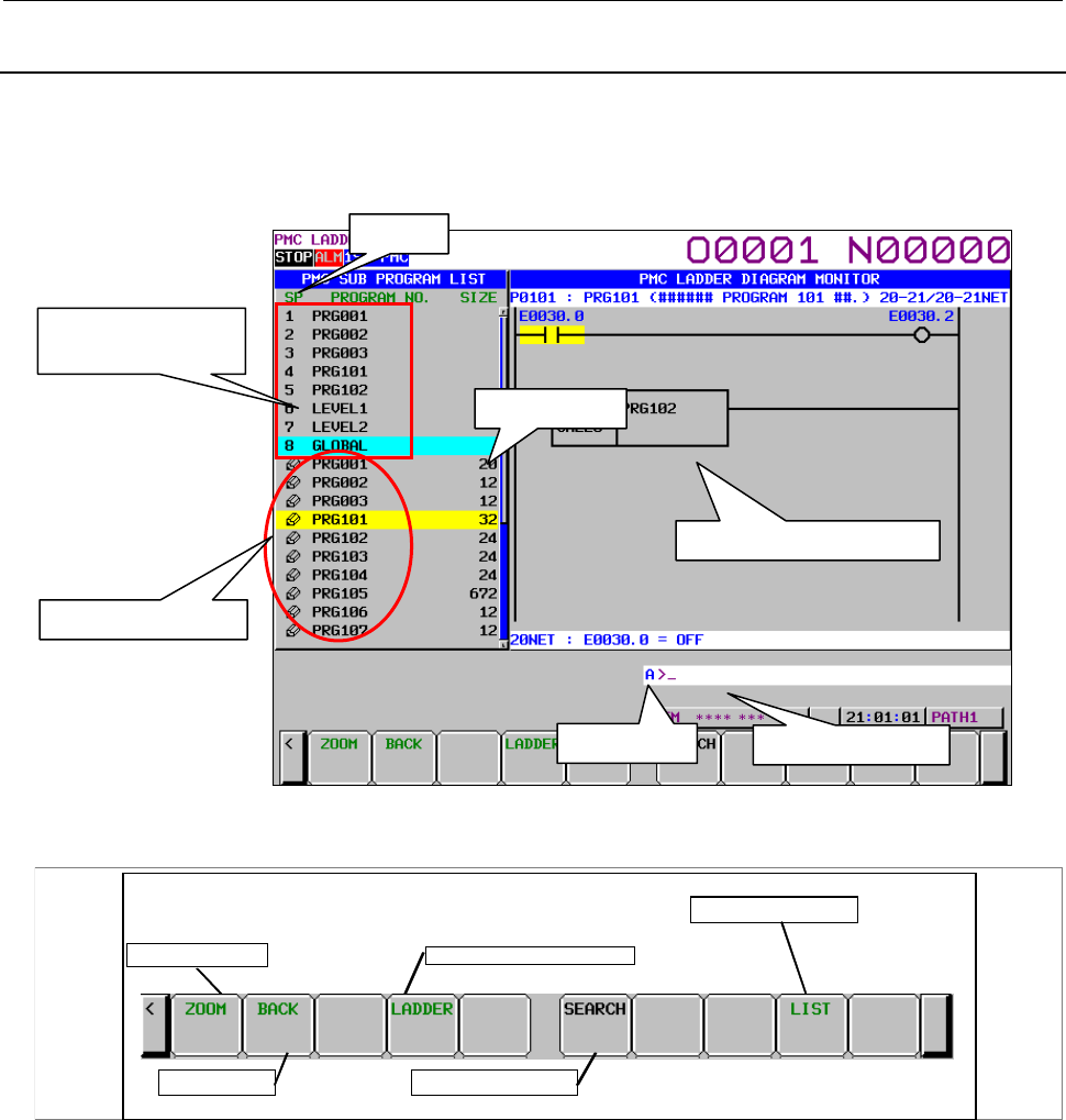
B-64513EN/03
8.LADDER DIAGRAM MONITOR AND EDITOR SCREENS ([PMC LADDER])
- 1133 -
8.11.2
Subprogram List Display Screen
The Subprogram List Display screen shows the list of the subprograms which are called by the current
subprogram. You can choose a subprogram from the list, which will be displayed on the screen. On the
other hand, the history of the displayed subprogram is also displayed.
Fig. 8.11.2 (a) Subprogram List Display Screen
(1) Operation with Soft keys
Main soft keys of Subprogram list screen
Back previous
Display current subprogram
Display Program List
Display Subprogram
Search for subprogram
(a) [ZOOM] Display specified subprogram
Switches the screen display to the ladder diagram display screen. When you press the [ZOOM]
soft key without entering a character string, the ladder diagram display screen is displayed with
subprogram under the cursor. When you press the [ZOOM] soft key after entering a program
name or symbol name, the subprogram corresponding to the entered character string is
displayed. If the subprogram is protected, the password needs to be released.
(b) [BACK] Switch to the program list screen or the previous history
When the display history is one, it returns to the program list display screen. When the display
history is two or more, it returns to the previous history.
(c) [LADDER] Switch to the ladder diagram monitor screen
Switches the screen display to the ladder diagram monitor screen which displays the current
subprogram.
Size area
SP area
Ladder preview display area
Key input line Message display line
Calling subprogram
History of the
displayed subprogram

8.LADDER DIAGRAM MONITOR AND EDITOR SCREENS ([PMC LADDER])
B-64513EN/03
- 1134 -
(d) [SEARCH] Subprogram search
Searches for a subprogram. When you press the [SEARCH] soft key after entering a
subprogram name or symbol name, the subprogram corresponding to the entered character
string is searched for.
(e) [LIST] Go to PROGRAM LIST VIEWER screen
Displays the program list screen.
(2) Others
For details of screen structures and operation, see Section 8.1, "DISPLAYING A PROGRAM LIST
([LIST] SCREEN)".
8.11.3
Setting Subprogram List Screen
The setting the subprogram list display screen is shared with the program list display screen.
For details of the setting screen, see Subsection 8.1.1, "Setting Program List Screen".

B-64513EN/03
8.LADDER DIAGRAM MONITOR AND EDITOR SCREENS ([PMC LADDER])
- 1135 -
8.12 OPERATION BY TOUCH PANEL
A CNC with a touch panel enables you to operate several functions of the following screens by touching
the screen.
- Ladder diagram monitor screen
- Ladder diagram editor screen
- Net editor screen
- Program list viewer screen
- Program list editor screen
- Subprogram list display screen
- Collective monitor screen
You can operate with two ways of touching the screen.
-Touch
“Touch” means to press a point on the screen momentarily.
- Long touch
“Long touch” means that a point on the screen is kept pressed for a second or longer and then a
pointer is released from same point on the screen.
Furthermore, you can operate a soft key using a touch panel on all screens.
CAUTION
When a point on the screen is kept pressed for a second or longer, "Long touch"
comes into effect. If CNC parameter 3192#2 is set to 1 and CNC parameter
3197, which means detection time of continuous pressing on touch panel, is set
to a short time, NC alarm " SR5303 TOUCH PANEL ERROR " might occur on
"Long touch".
When NC alarm occurred, operation of CNC is stopped.
When NC alarm occurred, adjust CNC parameter 3192#2 and 3197.
NOTE
1 To use a touch panel function, the “Touch panel control” or the “FANUC
PICTURE function” option is necessary.
2 An operation of touch panel is not recorded to the operation history.
3 See “8.12.1 Operation list of the touch panel” for available operations of touch
panel.
4 When display of the virtual MDI key overlaps with PMC screen, this function is
disabled because of taking precedence the virtual MDI key.
See "USER’S MANUAL of each CNC series for the virtual MDI key function
details.
5 When the one-touch menu displays on 10.4" display unit, this function is disabled
because of taking precedence the one-touch menu.
6 This function can be controlled using keep relay.
K931.0.
0: Enables the touch panel operation of PMC screens. (Initial value)
1: Disables the touch panel operation of PMC screens.
7 On series 30i/31i/32i/35i-B or Power Motion i-A, 0i-F with Personal Computer,
this function is not supported.

8.LADDER DIAGRAM MONITOR AND EDITOR SCREENS ([PMC LADDER])
B-64513EN/03
- 1136 -
8.12.1
Operation List of the Touch Panel
Table8.12.1 (a) Operation list of the touch panel
Screen Operation Detail
Program list viewer Cursor move A Cursor moves to a touched point on the screen.
Page change When either end of a scroll bar is touched, the screen
is scrolled up or down one page.
Zoom When a cursor is long touched, a program under the
cursor is displayed.
Ladder diagram monitor (note) Cursor move A Cursor moves to a touched point on the screen.
Page change When either end of a scroll bar is touched, the screen
is scrolled up or down one page.
Search coil When a cursor is long touched, a address under a
cursor is searched for the coil.
Zoom When a cursor is long touched, a subprogram, which
is specified at FB, CALL, CALLU and CM instruction's
parameter under the cursor, is displayed.
Ladder diagram editor Cursor move A Cursor moves to a touched point on the screen.
Page change When either end of a scroll bar is touched, the screen
is scrolled up or down one page.
Net editor Cursor move A Cursor moves to a touched point on the screen.
Program list editor Cursor move A Cursor moves to a touched point on the screen.
Page change When either end of a scroll bar is touched, the screen
is scrolled up or down one page.
Zoom When a cursor is long touched, a program under the
cursor is displayed.
Collective monitor (note) Cursor move A Cursor moves to a touched point on the screen.
Page change When either end of a scroll bar is touched, the screen
is scrolled up or down one page.
Pick up When a cursor is long touched, a ladder net including
a coil with a address under the cursor is picked up.
Zoom When a cursor is long touched, a subprogram, which
is specified at FB, CALL, CALLU and CM instruction's
parameter under the cursor, is displayed.
Subprogram list display Cursor move A Cursor moves to a touched point on the screen.
Page change When either end of a scroll bar is touched, the screen
is scrolled up or down one page.
Zoom When a cursor is long touched, a program under the
cursor is displayed.
NOTE
When you operate using touch panel on the ladder diagram screen and the
collective monitor screen, set "SHOW CURSOR" to "YES" on the ladder diagram
monitor screen (setting). If "SHOW CURSOR" is "NO", you can operate only the
page change on these screens.
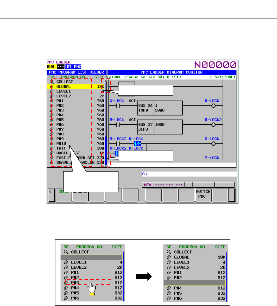
B-64513EN/03
8.LADDER DIAGRAM MONITOR AND EDITOR SCREENS ([PMC LADDER])
- 1137 -
8.12.2
Operation of Program List Viewer Screen
You can operate the following operations using the touch panel on the Program list viewer screen.
- Cursor move
- Page change
- Display the contents of subprogram [ZOOM]
Fig.8.12.2 (a) Operation of Program list viewer screen
(1) Cursor move
When you touch SP area and program number area, the cursor moves to the touched point.
Touch
Fig.8.12.2 (b) Cursor move
(2) Page change
When upper end of the scroll bar is touched, the screen is scrolled up one page.
When lower end of a scroll bar is touched, the screen is scrolled down one page.
When the page up/down area is touched, the scroll bar is displayed with yellow color.
Touch : Cursor move
Long touch : Zoom
Touch : Page up
Touch : Page down
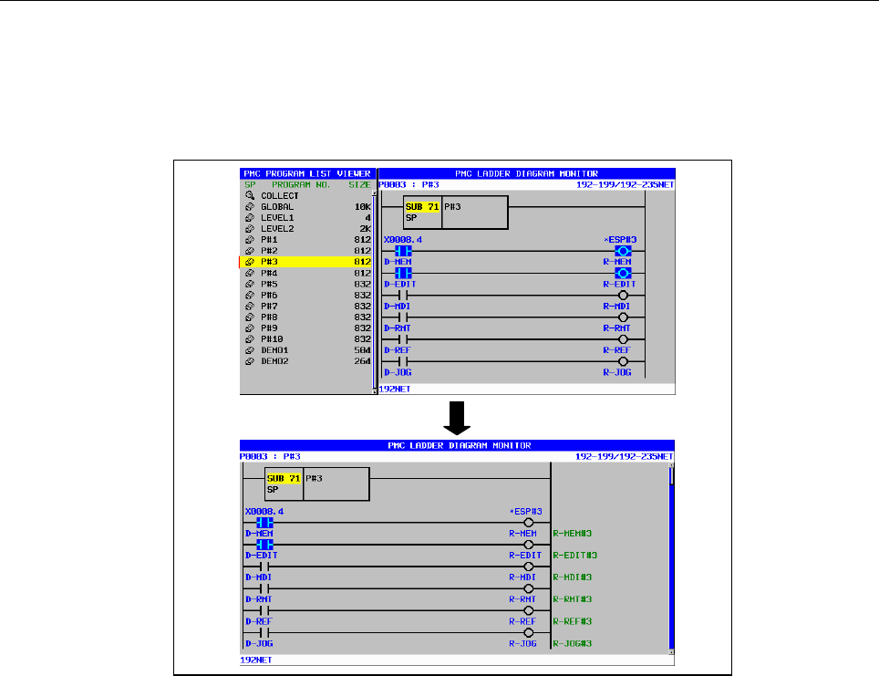
8.LADDER DIAGRAM MONITOR AND EDITOR SCREENS ([PMC LADDER])
B-64513EN/03
- 1138 -
(3) Display the contents of subprogram [ZOOM]
When you long touch the program number, the cursor color becomes red and touched program is
displayed on ladder diagram monitor screen. If you want to cancel "zoom" operation, move the
touched point after the cursor color is red. By the way, when the selected program is protected to
monitor, you have to unlock the protection.
Long touch
Fig.8.12.2 (c) Display the contents of subprogram
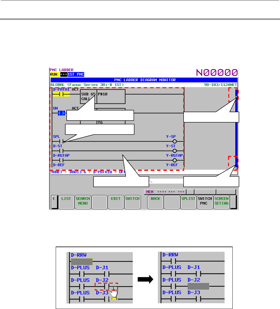
B-64513EN/03
8.LADDER DIAGRAM MONITOR AND EDITOR SCREENS ([PMC LADDER])
- 1139 -
8.12.3
Operation of Ladder Diagram Monitor Screen
You can operate the following operations using the touch panel on the ladder diagram monitor screen.
- Cursor move
- Page change
- Search coil [W-SRCH]
- Display the contents of subprogram/function block [ZOOM]
Fig.8.12.3 (a) Operation of ladder diagram monitor screen
(1) Cursor move
When you touch the ladder diagram area, the cursor goes to the touched point.
Touch
Fig.8.12.3 (b) Cursor move
(2) Page change
When upper end of the scroll bar is touched, the screen is scrolled up one page.
When lower end of the scroll bar is touched, the screen is scrolled down one page.
When the page up/down area is touched, the scroll bar is displayed with yellow color.
Touch : Cursor move
Touch : Page up
Touch : Page down
Long touch : Zoom
Long touch : Coil search
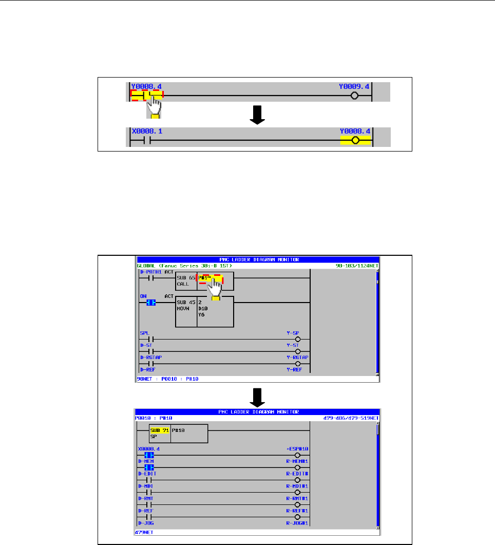
8.LADDER DIAGRAM MONITOR AND EDITOR SCREENS ([PMC LADDER])
B-64513EN/03
- 1140 -
(3) Search coil [W-SRCH]
When you long touch the bit address, the cursor color becomes red and the coil with the touched bit
address is searched. If you want to cancel "coil search" operation, move the touched point after the
cursor color is red.
Long touch
Fig.8.12.3 (c) Search coil
(4) Display the contents of subprogram/function block [ZOOM]
When you long touch CALL, CALLU and CM instruction and instance of the function block, the
cursor color becomes red and the subprogram or the FB body program is displayed. If you want to
cancel "zoom" operation, move the touched point after the cursor color is red. By the way, when the
selected subprogram or the function block is protected to monitor, you have to unlock the protection.
Long touch
Fig.8.12.3 (d) Display the contents of subprogram/function block

B-64513EN/03
8.LADDER DIAGRAM MONITOR AND EDITOR SCREENS ([PMC LADDER])
- 1141 -
On the instance of function block, long touch is available at "FB instance", "FB definition name","
Input parameter", "Output parameter", "Input/Output parameter" or "Instance monitor".
Fig.8.12.3 (e) Available cursor positions of zooming in a function block
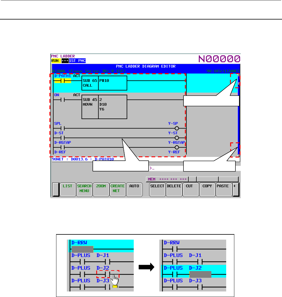
8.LADDER DIAGRAM MONITOR AND EDITOR SCREENS ([PMC LADDER])
B-64513EN/03
- 1142 -
8.12.4
Operation of Ladder Diagram Editor Screen
You can operate the following operations using the touch panel on the ladder diagram editor screen.
- Cursor move
- Page change
Fig.8.12.4 (a) Operation of ladder diagram editor screen
(1) Cursor move
When you touch the ladder diagram area, the cursor goes to the touched point.
Touch
Fig.8.12.4 (b) Cursor move
(2) Page change
When upper end of the scroll bar is touched, the screen is scrolled up one page.
When lower end of the scroll bar is touched, the screen is scrolled down one page.
When the page up/down area is touched, the scroll bar is displayed with yellow color.
Touch : Cursor move
Touch : Page up
Touch : Page down
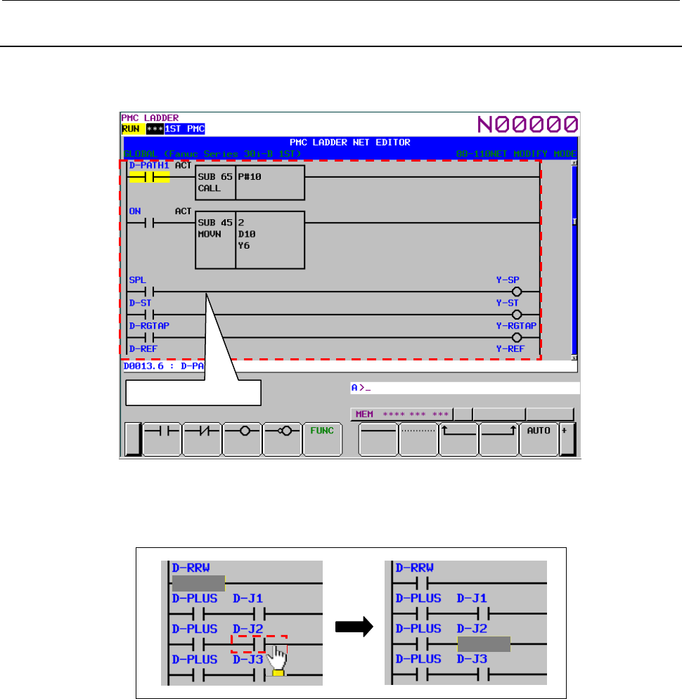
B-64513EN/03
8.LADDER DIAGRAM MONITOR AND EDITOR SCREENS ([PMC LADDER])
- 1143 -
8.12.5
Operation of Net Editor Screen
You can operate the following operations using the touch panel on the net editor screen.
- Cursor move
Fig.8.12.5 (a) Operation of Net editor screen
(1) Cursor move
When you touch the ladder diagram area, the cursor goes to the touched point.
Touch
Fig.8.12.5 (b) Cursor move
Touch : Cursor move
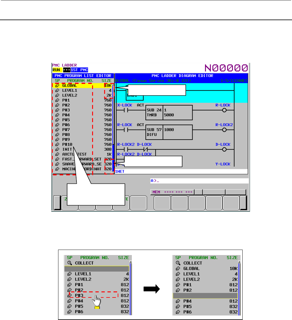
8.LADDER DIAGRAM MONITOR AND EDITOR SCREENS ([PMC LADDER])
B-64513EN/03
- 1144 -
8.12.6
Operation of Program List Editor Screen
You can operate the following operations using the touch panel on the program list editor screen.
- Cursor move
- Page change
- Display the contents of subprogram [ZOOM]
Fig.8.12.6 (a) Operation of program list editor screen
(1) Cursor move
When you touch the SP area and the program number area, the cursor goes to the touched point.
Touch
Fig.8.12.6 (b) Cursor move
(2) Page change
When upper end of the scroll bar is touched, the screen is scrolled up one page.
When lower end of the scroll bar is touched, the screen is scrolled down one page.
When the page up/down area is touched, the scroll bar is displayed with yellow color.
Touch : Cursor move
Long touch : Zoom
Touch : Page up
Touch : Page down
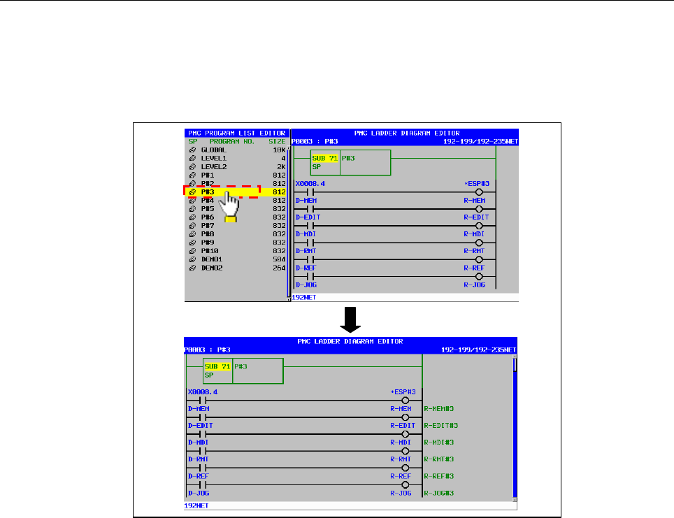
B-64513EN/03
8.LADDER DIAGRAM MONITOR AND EDITOR SCREENS ([PMC LADDER])
- 1145 -
(3) Display the contents of subprogram [ZOOM]
When you long touch the program number, the cursor color becomes red and touched program is
displayed on ladder diagram editor screen. If you want to cancel "zoom" operation, move the
touched point after the cursor color is red. By the way, when the selected program is protected to
edit, you have to unlock the protection.
Long touch
Fig.8.12.6 (c) Display the contents of subprogram
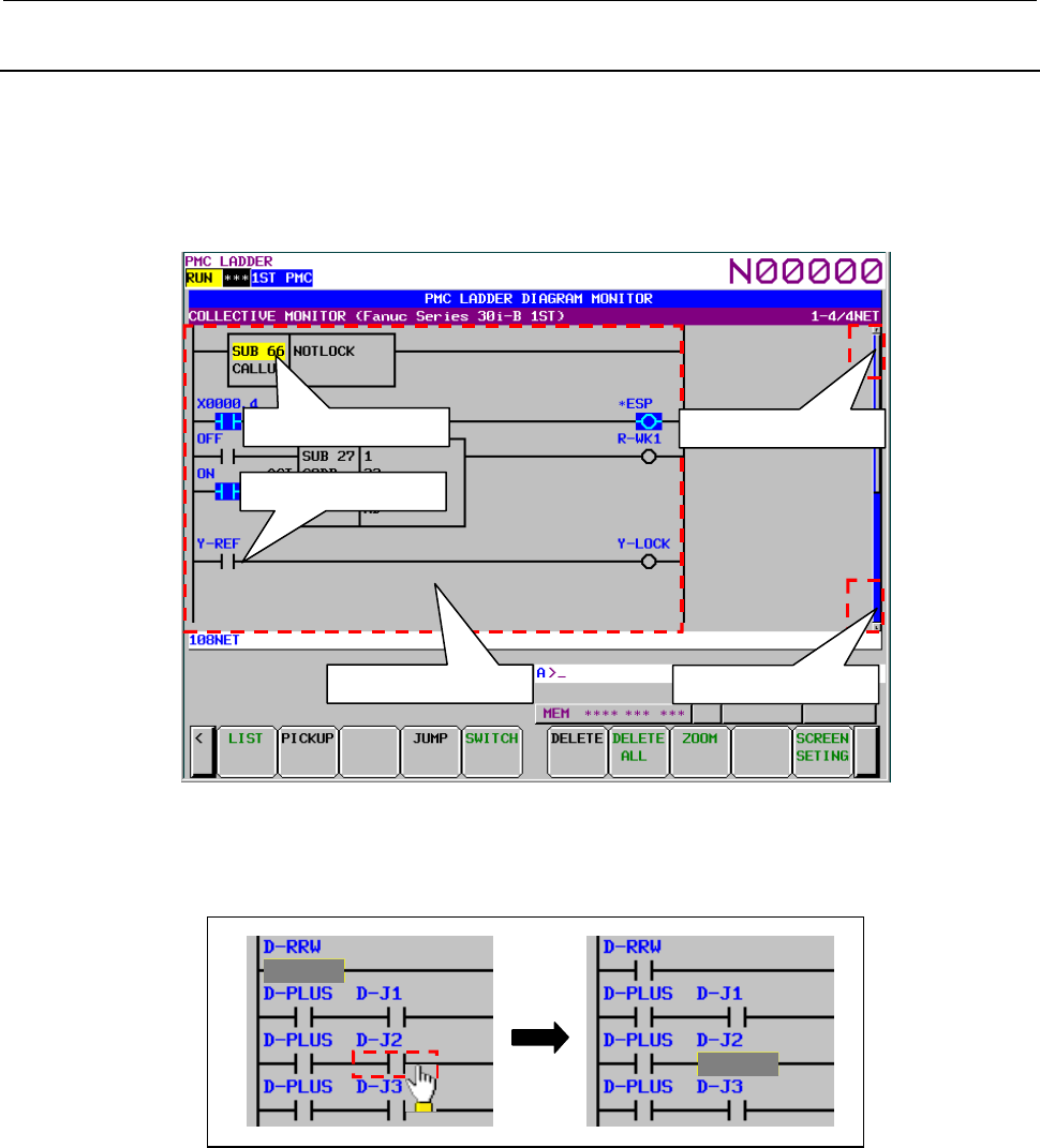
8.LADDER DIAGRAM MONITOR AND EDITOR SCREENS ([PMC LADDER])
B-64513EN/03
- 1146 -
8.12.7
Operation of Collective Monitor Screen
You can operate the following operations using the touch panel on the collective monitor screen.
- Cursor move
- Page change
- Pick up ladder net [PICKUP]
- Display the contents of subprogram/function block [ZOOM]
Fig.8.12.7 (a) Operation of collective monitor screen
(1) Cursor move
When you touch the ladder diagram area, the cursor goes to the touched point.
Touch
Fig.8.12.7 (b) Cursor move
(2) Page change
When upper end of the scroll bar is touched, the screen is scrolled up one page.
When lower end of the scroll bar is touched, the screen is scrolled down one page.
When the page up/down area is touched, the scroll bar is displayed with yellow color.
Touch : Cursor move
Touch : Page up
Touch : Page down
Long touch : Zoom
Long touch : Pick up
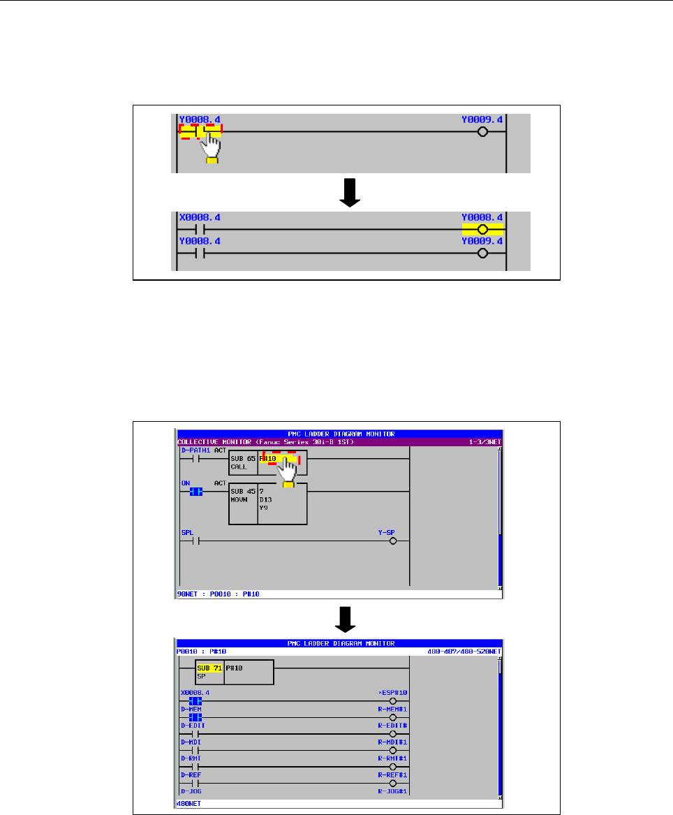
B-64513EN/03
8.LADDER DIAGRAM MONITOR AND EDITOR SCREENS ([PMC LADDER])
- 1147 -
(3) Pick up ladder net [PICKUP]
When you long touch the bit address, the cursor color becomes red and the ladder net including the
coil with the touched bit address is picked up. If you want to cancel "pick up" operation, move the
touched point after the cursor color is red.
Long touch
Fig.8.12.7 (c) Pick up ladder net
(4) Display the contents of subprogram/function block [ZOOM]
When you long touch CALL, CALLU and CM instruction and instance of the function block, the
cursor color becomes red and the subprogram or the FB body program is displayed. If you want to
cancel "zoom" operation, move the touched point after the cursor color is red. By the way, when the
selected subprogram or the function block is protected to monitor, you have to unlock the protection.
Long touch
Fig.8.12.7 (d) Display the contents of subprogram/function block

8.LADDER DIAGRAM MONITOR AND EDITOR SCREENS ([PMC LADDER])
B-64513EN/03
- 1148 -
On the instance of function block, long touch is available at "FB instance", "FB definition name",
"Input parameter", "Output parameter", "Input/Output parameter" or "Instance monitor".
Fig.8.12.7 (e) Available cursor positions of zooming in a function block
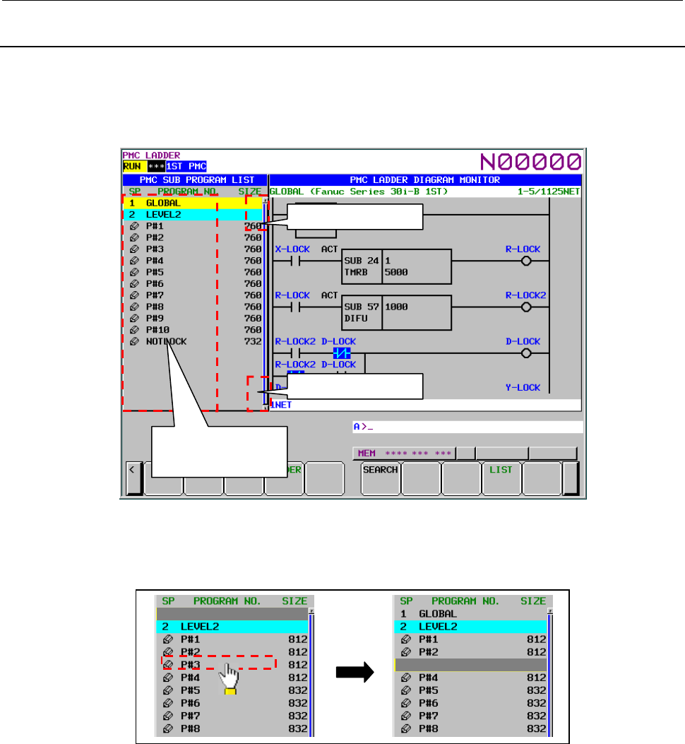
B-64513EN/03
8.LADDER DIAGRAM MONITOR AND EDITOR SCREENS ([PMC LADDER])
- 1149 -
8.12.8
Operation of Subprogram List Display Screen
You can operate the following operations using the touch panel on the subprogram list display screen.
- Cursor move
- Page change
- Display the contents of subprogram/function block [ZOOM]
Fig.8.12.8 (a) Operation of subprogram list display screen
(1) Cursor move
When you touch the SP area and the program number area, the cursor goes to a touched point.
Touch
Fig.8.12.8 (b) Cursor move
(2) Page change
When upper end of the scroll bar is touched, the screen is scrolled up one page.
When lower end of the scroll bar is touched, the screen is scrolled down one page.
When the page up/down area is touched, the scroll bar is displayed with yellow color.
Touch : Cursor move
Long touch : Zoom
Touch : Page up
Touch : Page down
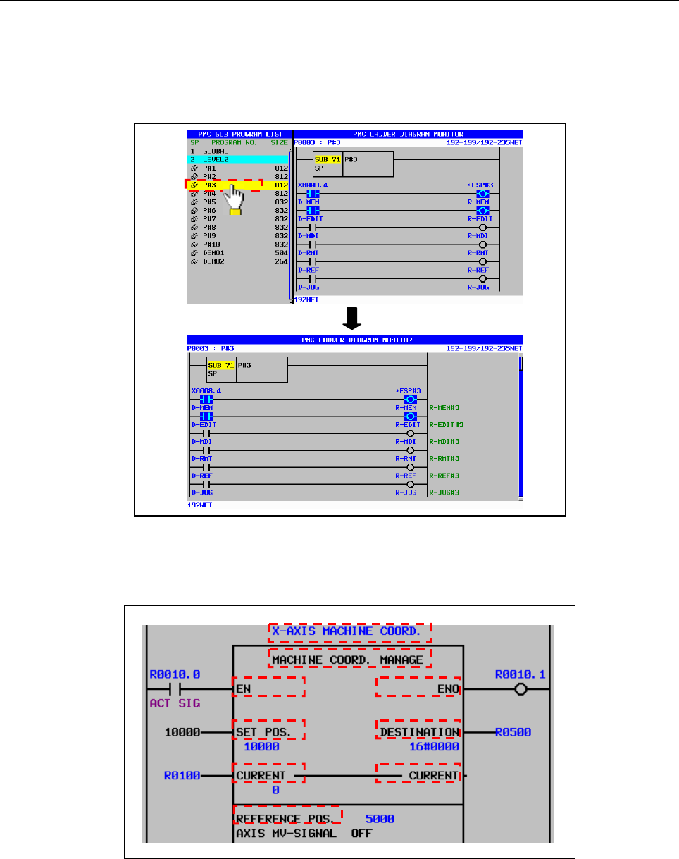
8.LADDER DIAGRAM MONITOR AND EDITOR SCREENS ([PMC LADDER])
B-64513EN/03
- 1150 -
(3) Display the contents of subprogram/function block [ZOOM]
When you long touch CALL, CALLU and CM instruction and instance of the function block, the
cursor color becomes red and the subprogram or the FB body program is displayed. If you want to
cancel "zoom" operation, move the touched point after the cursor color is red. By the way, when the
selected subprogram or the function block is protected to monitor, you have to unlock the protection.
Long touch
Fig.8.12.8 (c) Display the contents of subprogram/function block
On the instance of function block, long touch is available at "FB instance", "FB definition name",
"Input parameter", "Output parameter", "Input/Output parameter" or "Instance monitor".
Fig.8.12.8 (d) Available cursor positions of zooming in a function block
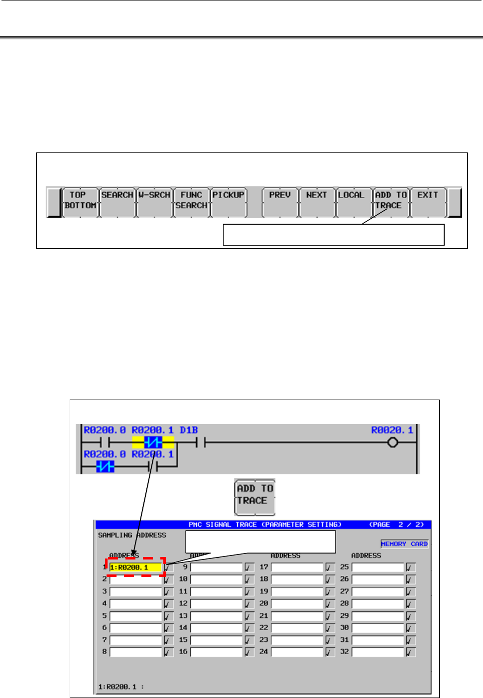
B-64513EN/03
8.LADDER DIAGRAM MONITOR AND EDITOR SCREENS ([PMC LADDER])
- 1151 -
8.13 Adding of Sampling Address of Signal Trace
You can add PMC addresses used in ladder program on the ladder monitoring screen into sampling
addresses for signal trace.
Operation
Pressing the [ADD TO TRACE] soft key adds the PMC address used for contact or coil into sampling
address for signal trace.
When adding, the message “ADDED TO TRACE SAMPLING ADDRESS.” is displayed.
Search soft keys in LADDER DIAGRAM MONITOR SCREEN
Adding of sampling address for signal trace
There are two operation ways for adding of sampling address.
(1) Adding of PMC address on cursor.
You select the following instructions or PMC address by the cursor and press the [ADD TO
TRACE] soft key.
・ Coils
・ Contacts
・ FB parameters
・ FB instance monitor
Selected PMC address is added to sampling address.
Added to sampling address
Operation procedure of adding sampling address
Pressing

8.LADDER DIAGRAM MONITOR AND EDITOR SCREENS ([PMC LADDER])
B-64513EN/03
- 1152 -
(2) Adding of entered PMC address
Enter a symbol or PMC address and press the [ADD TO TRACE] soft key.
Example: “R200.1” + [ADD TO TRACE] soft key
Entered symbol or PMC address is added to sampling address.
NOTE
1. When there is a contact or a coil on cursor and pressing [ADD TO TRACE] after
entering PMC address, the PMC address is added to sampling address. PMC
address of the contact or the coil on the cursor is not added to sampling address.
2 PMC address to add to sampling address is only bit address. Byte address cannot
be added.
3 When cursor is located on the position on which the PMC address cannot be
added and press the [ADD TO TRACE], there is no reaction.
4 When entered strings are not correct symbol or PMC address, the error message
“INPUT INVALID” is displayed.
Result of adding
PMC address, which is added in ladder diagram monitor screen, is registered at the top of sampling
addresses.
The sampling addresses, which have already set, are moved down one step. When sampling addresses
exceeds the maximum number, last sampling address is deleted.
You can confirm the added address in the trace parameter setting screen.
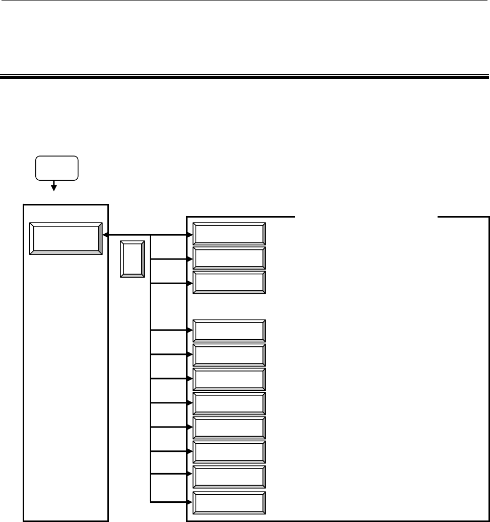
B-64513EN/03
9.PMC CONFIGURATION DATA SETTING SCREENS ([PMC CONFIG])
- 1153 -
9 PMC CONFIGURATION DATA SETTING
SCREENS ([PMC CONFIG])
The PMC configuration menu is used to display screens related to PMC configuration data that change
the target PMC, and display and edit PMC data.
You can move to the PMC configuration menu by pressing the [SYSTEM] key, then the [PMC CONFIG]
soft key.
SYSTEM
PMC CONFIG
PMC main menu
TITLE
CONFIG PARAM
SETING
PMC STATUS
SYSTEM PARAM
MODULE
SYMBOL
MESAGE
ONLINE
<
Title display/edit screens
Configuration parameter screens
PMC status screen
System parameter display/edit screens
I/O module display/edit screens
Symbol and comment display/edit screens
Message display/edit screens
Online monitor parameter setting screen
PMC configuration menu
Setting screens
(for general functions, multi-language message
function, selectable I/O Link assignment function,
and override
mode)
PMC submenu
I/O Link i
I/O configuration viewer/editor screen
(I/O Link i assignment)
PROG LIST
PMC program list screen
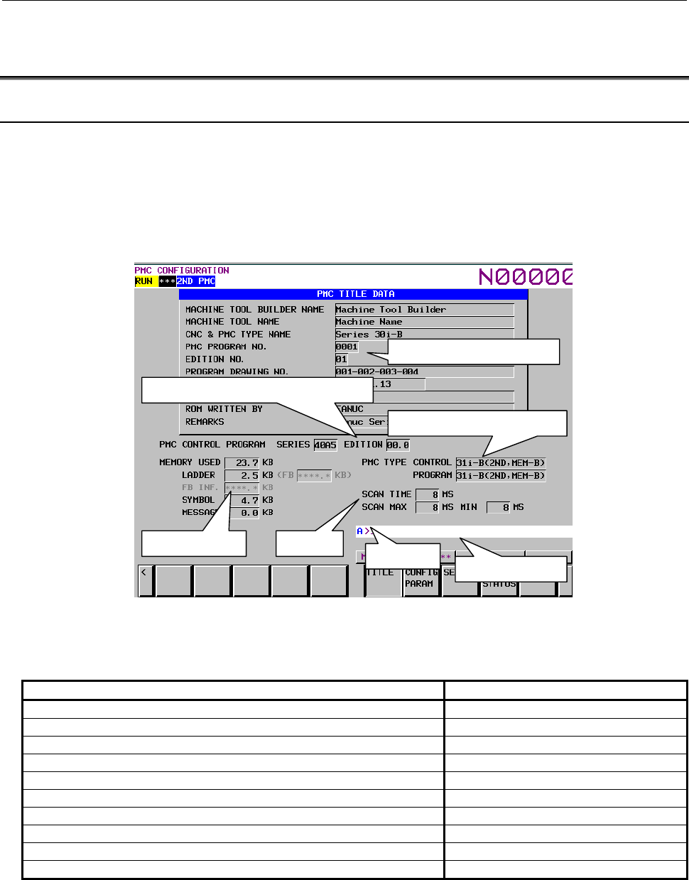
9.PMC CONFIGURATION DATA SETTING SCREENS ([PMC CONFIG])
B-64513EN/03
- 1154 -
9.1 DISPLAYING AND EDITING TITLE DATA ([TITLE]
SCREENS)
9.1.1 Displaying Title Data
On the TITLE DATA screen, you can check the title data items and some ladder information items. To
switch to the TITLE DATA screen, press the [TITLE] soft key.
Besides, the following operation is available in the TITLE DATA screen.
• Moving to the TITLE DATA EDITOR screen [EDIT]
• Moving to the TITLE DATA (MESSAGE) screen [MESAGE TITLE]
Title data of sequence program
Series and edition of PMC system software
PMC type and PMC Memory type
Used memory size
Message display line
Scan time
Key input line
(1) Title data
The following title data that is set in the sequence program is displayed.
Item Max. characters
MACHINE TOOL BUILDER NAME 32
MACHINE TOOL NAME 32
CNC & PMC NAME 32
PMC PROGRAM NO. 4
EDITION NO. 2
PROGRAM DRAWING NO. 32
DATA OF PROGRAMMING 16
PROGRAM DESIGNED BY 32
ROM WRITTEN BY 32
REMARKS 32
(2) PMC control program
The series and edition of PMC system software is displayed.
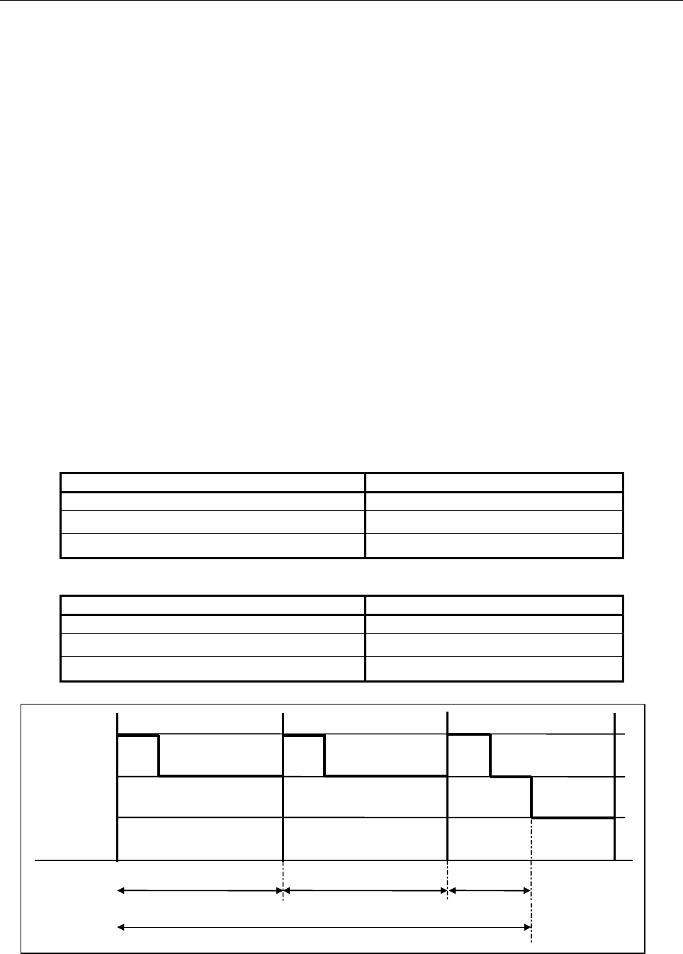
B-64513EN/03
9.PMC CONFIGURATION DATA SETTING SCREENS ([PMC CONFIG])
- 1155 -
(3) Used memory
Using memory size for each data are displayed. The following information is displayed.
• All program size
• Ladder program size
• Symbol & Comment data size
• Message data size
(4) PMC type
The PMC type and PMC Memory Type of PMC system software is displayed. And, the PMC type
and PMC Memory Type of sequence program is displayed.
(5) Scan time
The scan time of sequence program is displayed. The following information is displayed.
• Current scan time
• Maximum scan time
• Minimum scan time
You can switch the display of scan time by operating a soft key.
The detailed display of scan time is an execution period of 2nd level ladder, which is represented by
percentage (%). The 100% means the assigned time for execution of ladder for each PMC paths in
every ladder execution cycle.
The relation between the scan time and the detailed display of scan time is as follows.
Table 9.1.1(a) Ladder execution cycle (4 ms)
Detailed display of scan time Scan Time
100% or less 4
From 101 to 200% 8
From 201 to 300% 12
Table 9.1.1(b) Ladder execution cycle (8 ms)
Detailed display of scan time Scan Time
100% or less 8
From 101 to 200% 16
From 201 to 300% 24
1st level
Ladder execution cycle (4msec/8msec)
100% 100% 50%
250%
1st level processing
2nd level processing
(Division 1)
2nd level
3rd level
2nd level processing
(Division 2)
2nd level processing
(Division 3)
1st level processing 1st level processing
3rd level
processing
Ladder execution cycle (4msec/8msec) Ladder execution cycle (4msec/8msec)
Fig. 9.1.1(a) Detailed display of scan time (the case of 250%)
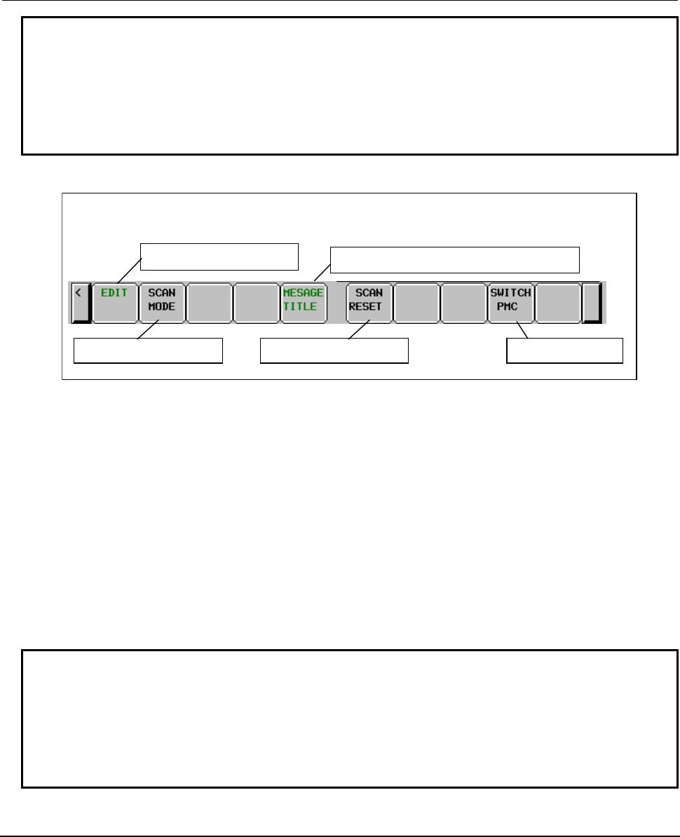
9.PMC CONFIGURATION DATA SETTING SCREENS ([PMC CONFIG])
B-64513EN/03
- 1156 -
NOTE
1 When the ladder is stopped, the maximum/minimum of scan time is cleared.
2 When the scan time exceeds 4-digit, "****" is displayed.
3 When the execution time at the 1st level of the ladder exceeds the time allocated
in each PMC paths, a detailed display of scan time is not displayed correctly.
4 When using the 1st level execution cycle in 1ms, 2ms, the detailed scan time
may be dramatically changed by the execution timing of the 1st level.
Screen operations
Soft keys on the PMC Title Data screen
Switch to the editor screen
Switch to the TITLE DATA (MESSAGE) screen
Change the scan mode
Reset the scan time Switch PMC path
Fig. 9.1.1(b) Soft keys on the TITLE DATA screen
(1) Operations using the soft keys
(a) [EDIT] Switch to the editor screen
Switches to the TITLE DATA EDITOR screen.
(b) [SCAN MODE] Change the display of scan time
Switches the display of the scan time between the scan time by milliseconds and detailed
displays of scan time.
(c) [MESAGE TITLE] Switch to the TITLE DATA (MESSAGE) screen
Switches to the TITLE DATA (MESSAGE) screen.
(d) [SCAN RESET] Reset the maximum/minimum of scan time
Resets the maximum/minimum of scan time.
(e) [SWICTH PMC] Change the PMC
Switches the PMC path.
NOTE
1 The [EDIT] soft key appears when the Programmer Protection is released, and it
becomes effective.
2 The operation of changing scan time display by [SCAN MODE] is applied to all
PMC paths.
3 The operation of resetting maximum / minimum scan time display by [SCAN
RESET] is applied to each PMC path.
9.1.2
Editing Title Data
On the TITLE DATA EDITOR screen, you can edit title data items. To switch to the TITLE DATA
EDITOR screen, press the [EDIT] soft key on the TITLE DATA screen.
On the TITLE DATA EDITOR screen, you can perform the following operations:
• Changing the input mode [INPUT MODE]
• Deleting title data [DELETE]
• Moving to the TITLE DATA screen [EXIT EDIT]
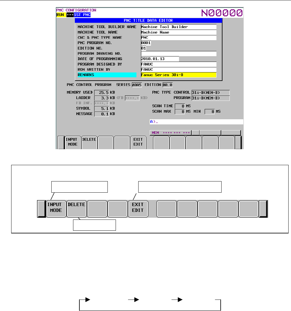
B-64513EN/03
9.PMC CONFIGURATION DATA SETTING SCREENS ([PMC CONFIG])
- 1157 -
Screen operations
Soft keys on the PMC Title Data Editor screen
Change the input mode Move to the PMC Title Data screen
Delete title data
Fig. 9.1.2 Soft keys on the TITLE DATA EDITOR screen
(1) Operations using the soft keys
(a) [INPUT MODE] Change the input mode
Pressing the [INPUT MODE] soft key changes the input mode. The selection cycles in the
following order. In the insert mode, "INSERT" appears on the screen; in the replace mode,
"ALTER" appears.
Insert
mode
Replace
mode
Full-string
input
• Full-string input
The entire string at the cursor is selected and replaced with an input string.
• Insert mode
Input characters are inserted at the cursor. Pressing the INPUT key with inputting no
characters inserts one space.
• Replace mode
Input characters replace characters at and after the cursor. Pressing the INPUT key with
inputting no characters replaces the character at the cursor with a space.
(b) [DELETE] Delete characters
Deletes selected characters.
(c) [EXIT EDIT] Switch to the TITLE DATA screen
Terminates editing of title data and moves to the TITLE DATA screen.

9.PMC CONFIGURATION DATA SETTING SCREENS ([PMC CONFIG])
B-64513EN/03
- 1158 -
(2) Screen operation using other keys
Use cursor keys to select characters to be edited.
(3) RETURN key operation
On the TITLE DATA EDITOR screen, the return key operation is disabled.
To terminate title editing and return to the TITLE DATA screen, use the [EXIT EDIT] soft key.
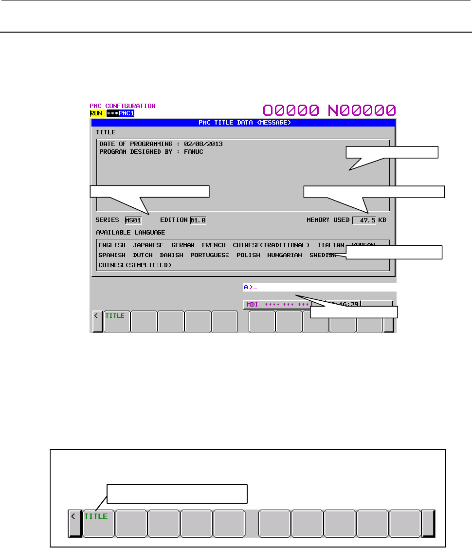
B-64513EN/03
9.PMC CONFIGURATION DATA SETTING SCREENS ([PMC CONFIG])
- 1159 -
9.1.3
Displaying Title Data (Message)
On the TITLE DATA (MESSAGE) screen, message data for multi-language display can be checked. To
switch to the TITLE DATA (MESSAGE) screen, press the [MESAGE TITLE] soft key. On the TITLE
DATA (MESSAGE) screen, the operation described below can be performed.
• Moving to the TITLE DATA screen [TITLE]
In this screen, the following items are displayed for message data for multi-language display.
• TITLE: Title information of the message data
• SERIES: Series of the title data
• EDITION: Edition of the title data
• MEMORY USED: Memory used status
• AVILABLE LANGUAGE: List of language IDs
Screen Operation
Soft key on the TITLE DATA (MESSAGE) screen
Swit ch to the TITLE DA TA screen
(1) Operation using the soft key
(a) [TITLE] Switch to the TITLE DATA screen
Switches to the TITLE DATA screen.
Series/Edition of message data
Message display line
Memory used status for message data
List of usable languages
Title data display area
9.PMC CONFIGURATION DATA SETTING SCREENS ([PMC CONFIG])
B-64513EN/03
- 1160 -
Setting and Displaying of Series/Edition
The message data for multi-language display can be created with FANUC LADDER-III.
You can specify series/edition directive line in the title information of the data. Therefore, the
series/edition can be display in the TITLE DATA (MESSAGE) screen.
NOTE
This manual describes the procedure for displaying series/edition in the screen.
As for details for creating of message data for multi-language display, refer to
“FANUC LADDER-III OPERATOR’S MANUAL (B-66234EN)”.
Specification method of series/edition
・ The followings are the format of series/edition directive line. These directives can be specified with
both capital and small letters.
Series directive line
.SERIES=xxxx .series=xxxx
Edition directive line
.EDITION=xxxx .edition=xxxx
・ Specify the series/edition directive line from the beginning of a line in title information enclosed in
double quotation marks.
・ To display the “xxxx” in the screen, specify a string within four characters.
Usable characters are half-width capital alphabet, digit characters, space and dot.
Useable characters
A to Z, 0 to 9, Space, . (dot)
Example)
The case of displaying “SERIES MS01” and “EDITION 01.0” in the TITLE DATA (MESSAGE)
screen
Specify “(2) Series directive line” and “(3) Edition directive line” in the title information of message
source file for multi-language display.
Message source file for multi-language display
Convert the message source file for multi-language display to memory card format file and load the
file into CNC. Therefore, the series/edition directive line is not displayed in the title column and
specified strings are displayed in the series/edition column.
%@4-D
”DATE OF PROGRAMMING : 02/08/2013
PROGRAM DESIGNED BY : FANUC
.SERIES=MS01
.EDITION=01.0”
$0 ALM1001 1001 FUSE IS BLOWN (SURGE KILLER)
$1 ALM1001 1001 ヒューズ切れ(サージキラー)
$2 ALM1001 1001 FUSE IS BLOWN (SURGE KILLER)
%
Identification code
Identification code
Message data
・
English
・
Japanese
・
German
(
2
)
Series directive line
(
3
)
Edition directive line
(
1
)
Title data
Title information
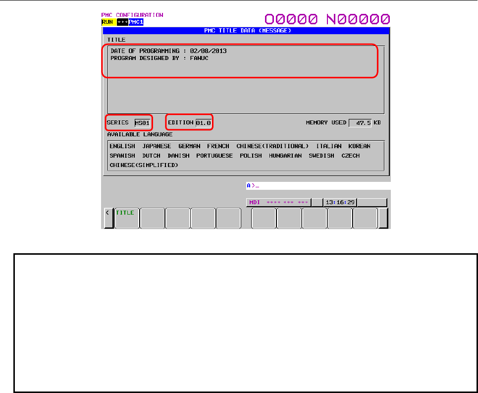
B-64513EN/03
9.PMC CONFIGURATION DATA SETTING SCREENS ([PMC CONFIG])
- 1161 -
TITLE DATA (MESSAGE) screen
NOTE
1 When no series/edition directive line is specified in the message source file of
multi-language message data, the column of series/edition of the screen
becomes blank.
2 When specifying characters which can not be used for string of series/edition,
space characters are displayed in the column of series/edition of the screen.
3 When loading the message data for multi-language display with series/edition
directive into CNC system which is not applied to this function, the series/edition
directive line is displayed in the title column as the string typed in the message
source file.
(
1
)
(
2
)
(
3
)
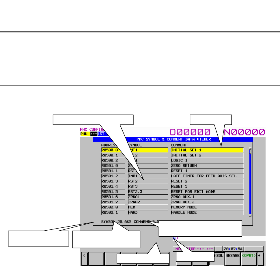
9.PMC CONFIGURATION DATA SETTING SCREENS ([PMC CONFIG])
B-64513EN/03
- 1162 -
9.2 DISPLAYING AND EDITING SYMBOL AND COMMENT
DATA ([SYMBOL] SCREENS)
The display and operation of symbol and comment screen differs in former type from extended type.
For details of former type symbol and comment screen, see Subsection 9.2.1 to 9.2.4.
For details of extended type symbol and comment screen, see Subsection 9.2.5 to 9.2.7.
9.2.1 Displaying Symbol and Comment Data
On the SYMBOL & COMMENT DATA VIEWER screen, you can check symbol and comment data
items defined for each address byte or bit used by a ladder program.
ADDRESS: Displays the byte or bit addresses for which a symbol or comment is registered.
SYMBOL: Displays the symbol for each address (16 characters).
COMMENT: Displays the comment for the address (30 characters).
Scroll bar: Indicates the position of the current displayed data.
Amount of occupied memory:
The amounts of memory occupied by symbol data and of that occupied by comment data,
and total amount of memory occupied by symbol and comment data are displayed under
the symbol and comment display.
Symbol and comment display area Scroll bar
Amount of memory
occupied by symbol data
Amount of memory occupied
by comment data
Total amount of memory occupied
by symbol and comment data
Message display line Key input line
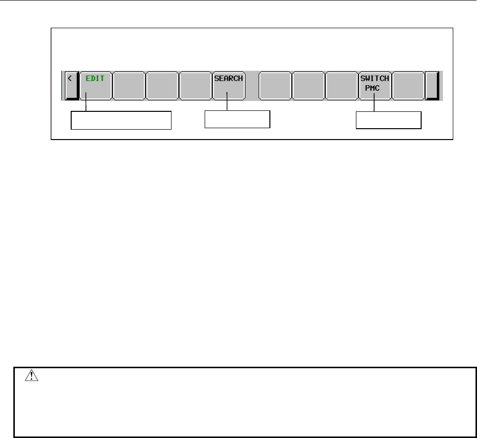
B-64513EN/03
9.PMC CONFIGURATION DATA SETTING SCREENS ([PMC CONFIG])
- 1163 -
Screen operations
Soft keys on the SYMBOL & COMMENT DATA VIEWER screen
Search for data
Switch to the editor screen
Switch PMC path
Fig. 9.2.1 Soft keys on the SYMBOL & COMMENT DATA VIEWER screen
(1) Operations using the soft keys
(a) [EDIT] Switch to the editor screen
Moves to the SYMBOL & COMMENT DATA EDITOR screen.
(b) [SEARCH] Search for data
Searches for the address corresponding to the input string or an address for which symbol or
comment data containing the input string is defined and displays it on the screen. Both bit and
byte addresses can be searched for.
(c) [SWITCH PMC] Switching PMC path or divided ladder programs
Switches PMC path or divided ladder program. For details of the operation, refer to “6.3”.
By setting keep relay K935.0 to 1, you can display PMC program list screen. For details, refer
to ”2.2.11”.
(2) Screen operations using other keys
Cursor keys: Move the cursor.
Page keys: Scroll the screen up or down one page.
CAUTION
When the programmer protection function is enabled, the [EDIT] soft key
appears and is available. When the online monitor function is enabled, you
cannot move to the SYMBOL & COMMENT DATA EDITOR screen.
For details, see Section 6.2.
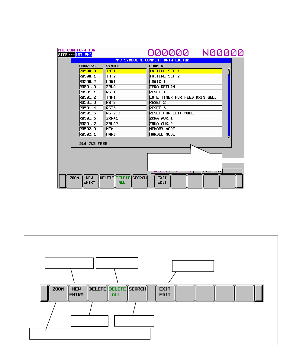
9.PMC CONFIGURATION DATA SETTING SCREENS ([PMC CONFIG])
B-64513EN/03
- 1164 -
9.2.2
Editing Symbol and Comment Data
On the SYMBOL & COMMENT DATA EDITOR screen, you can define a symbol for a desired address
byte or bit and add a comment. You can also change already defined symbol and comment data.
Amount of unused memory
The amount of unused memory for editing symbol and comment data is displayed under the symbol and
comment display.
Screen operations
Change data or register changed data as a new entry
Register a new entry
Delete data
Delete all data Terminate editing
Soft keys on the SYMBOL & COMMENT DATA EDITOR screen
Search for data
Fig. 9.2.2 Soft keys on the SYMBOL & COMMENT DATA EDITOR screen
(1) Operations using the soft keys
(a) [ZOOM] Change data or register changed data as a new entry
Switches to the screen for changing data of the entry at the cursor or registering the changed
data as a new entry.
(b) [NEW ENTRY] Register a new entry
Switches to the screen for registering a new entry.
(c) [DELETE] Delete data
Deletes symbol and comment data at the cursor.
Amount of unused memory for
symbol and comment data

B-64513EN/03
9.PMC CONFIGURATION DATA SETTING SCREENS ([PMC CONFIG])
- 1165 -
(d) [DELETE ALL] Delete all data
Deletes all symbol and comment data.
(e) [SEARCH] Search for data
Searches for the address corresponding to the input string or an address for which symbol or
comment data containing the input string is defined and displays it on the screen. Both bit and
byte addresses can be searched for.
(f) [EXIT EDIT] Terminate editing
Switches to the SYMBOL & COMMENT DATA VIEWER screen.
(2) Editing a set of symbol and comment data at a time
An address, symbol, and comment are input at a time.
Enter a symbol and comment following an address with delimiting them by non-alphanumeric
characters as shown below and press the INPUT key. Symbol or comment data can be omitted.
address/symbol/comment/ INPUT key ("/" is a non-alphanumeric character.)
Example 1:
Inputs an address, symbol, and comment. A slash “/” is used as a delimiter.
G0.4/*EMG/EMERGENCYSW/INPUT key
Example 2:
Omits a comment. A slash “/” is used as a delimiter.
G0.4/*EMG// INPUT key
G0.4/*EMG/ INPUT key
G0.4/*EMG INPUT key
To update symbol or comment data for an existing address, move the cursor to the target address and
enter symbol or comment data with omitting the address.
Example 3:
Omits an address and inputs symbol and comment data. A slash “/” is used as a delimiter.
/*EMG/EMERGENCYSW/INPUT key
In this case, when symbol or comment data is omitted, the displayed data is not changed.
(3) Screen operations using other keys
Cursor keys: Move the cursor.
Page keys: Scroll the screen up or down one page.
(4) RETURN key operation
On the SYMBOL & COMMENT DATA EDITOR screen, the return key operation is disabled.
To terminate editing of symbol and comment data and return to the SYMBOL & COMMENT
DATA VIEWER screen, use the [EXIT EDIT] soft key.
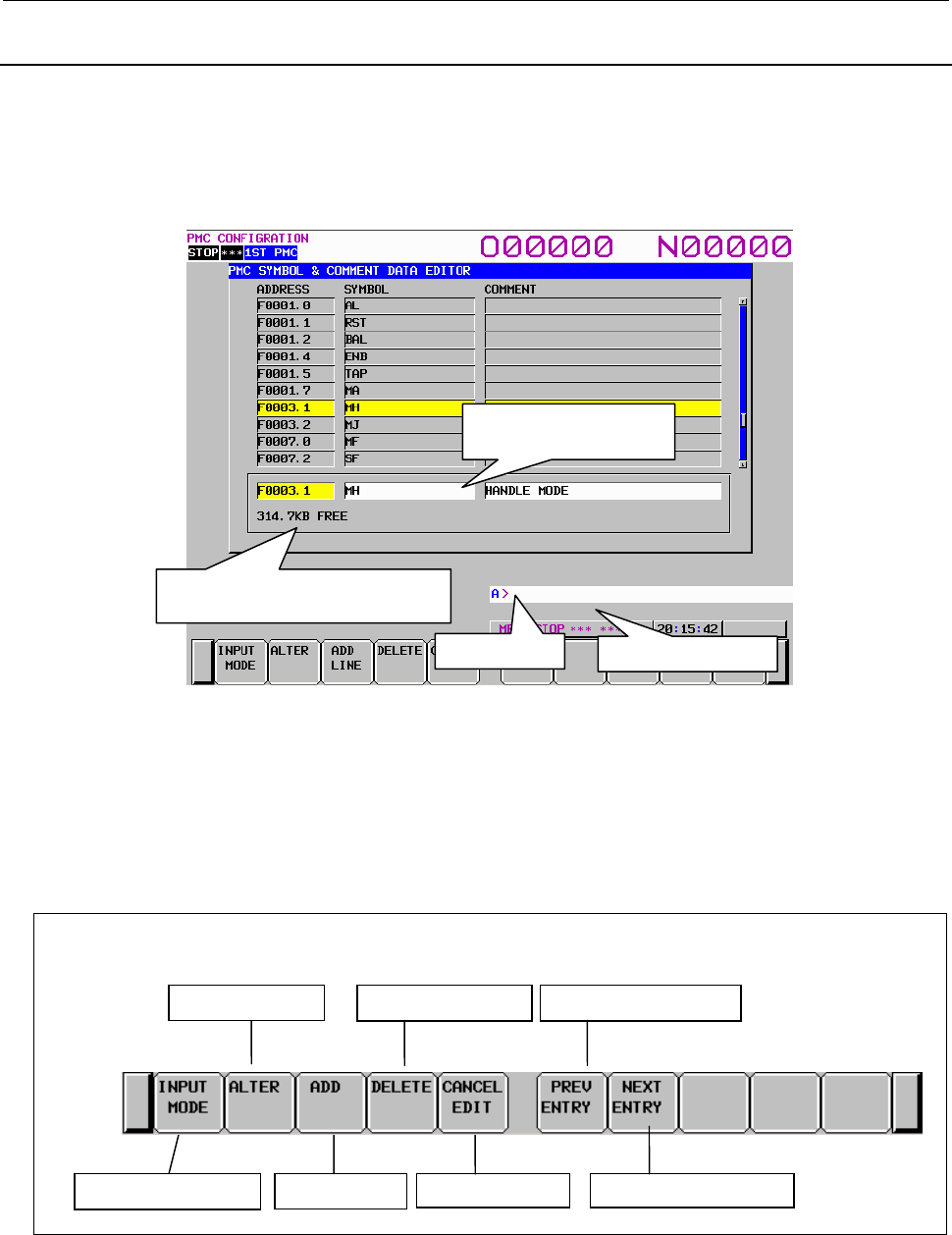
9.PMC CONFIGURATION DATA SETTING SCREENS ([PMC CONFIG])
B-64513EN/03
- 1166 -
9.2.3
Partially Changing Symbol and Comment Data
On the SYMBOL & COMMENT DATA EDITOR screen, pressing the [ZOOM] soft key displays the
following screen. At the bottom of the screen, the area for editing a symbol and comment data entry
appears. You can define a symbol for a desired address byte or bit and add a comment. You can also
change already defined symbol and comment data.
For a registered data entry, you can edit the address, symbol, and comment in character units.
Amount of unused memory:
The amount of unused memory for editing symbol and comment data is displayed.
Area for editing a symbol and comment data entry:
Enter an address, symbol data, and comment data.
Screen operations
Cancel edits
Change the input mode
Replace an entry
New entry
Delete characters
Soft keys on the symbol & comment data entry editor screen
Editing previous entry
Editing next entry
Fig. 9.2.3 Soft keys on the symbol & comment data entry editor screen
Amount of unused memory for
symbol and comment data
Area for editing a symbol
and comment data entry
Message display line
Key input line

B-64513EN/03
9.PMC CONFIGURATION DATA SETTING SCREENS ([PMC CONFIG])
- 1167 -
(1) Operations using the soft keys
(a) [INPUT MODE] Change the input mode
Pressing the [INPUT MODE] soft key changes the input mode. The selection cycles in the
following order. In the insert mode, "INSERT" appears on the screen; in the replace mode,
"ALTER" appears.
Insert
mode
Replace
mode
Full-string
input
• Full-string input
The entire string at the cursor is selected and replaced with an input string.
• Insert mode
Input characters are inserted at the cursor. Pressing the INPUT key with inputting no
characters inserts one space.
• Replace mode
Input characters replace characters at and after the cursor. Pressing the INPUT key with
inputting no characters replaces the character at the cursor with a space.
(b) [ALTER] Replace an entry
Replaces the target entry with edit data. When the data in the address field is updated and the
address is a new one, the original data corresponding to the old address is deleted and the edit
data is registered as a new entry. If an address to be registered as a new one is already
registered, a confirmation message appears, which asks you if you are sure to overwrite the old
data.
(c) [ADD LINE] New entry
Registers input data as a new entry. If the address of the new entry is already registered, a
confirmation message appears, which asks you if you are sure to overwrite the old data.
(d) [DELETE] Delete characters
Performs either of the following deletions:
• In the full-string input mode
Deletes the string at the cursor.
• In the insert or replace mode
Deletes one character at the cursor.
(e) [CANCEL EDIT] Cancel edits
Cancels edits and switches to the SYMBOL & COMMENT DATA EDITOR screen. The data
is not updated.
(f) [PREV ENTRY] Editing previous entry
You can edit a symbol and comment on previous entry without leaving from editing mode.
(g) [NEXT ENTRY] Editing next entry
You can edit a symbol and comment on next entry without leaving from editing screen.
(2) RETURN key operation
On the symbol & comment data entry editor screen, the return key operation is disabled. To
terminate editing of a symbol and comment data entry and return to the SYMBOL & COMMENT
DATA EDITOR screen, use the [ALTER], [ADD LINE], or [CANCEL EDIT] soft key.
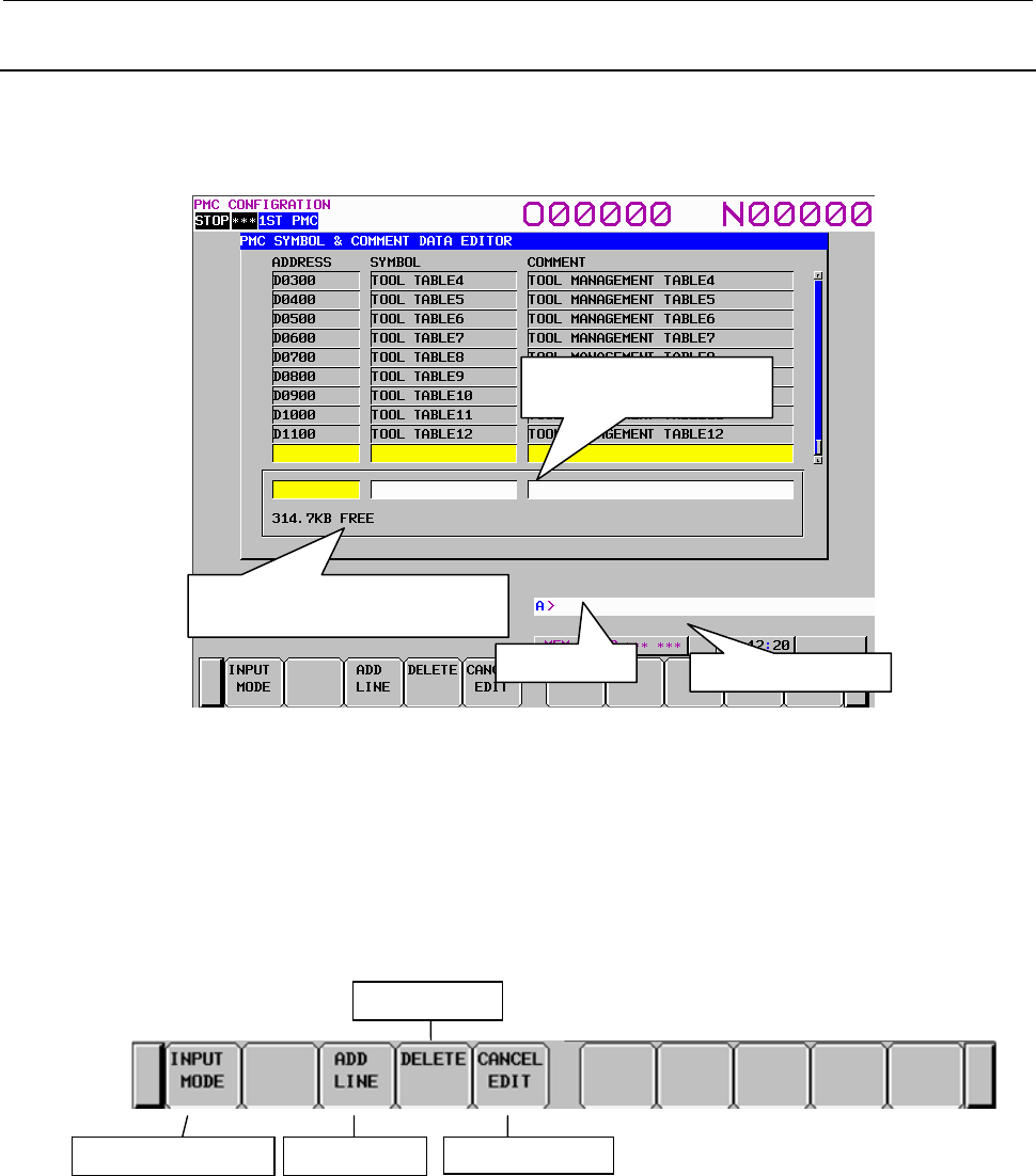
9.PMC CONFIGURATION DATA SETTING SCREENS ([PMC CONFIG])
B-64513EN/03
- 1168 -
9.2.4
Registering New Symbol and Comment Data
On the SYMBOL & COMMENT DATA EDITOR screen, pressing the [NEW ENTRY] soft key displays
the following screen. At the bottom of the screen, the area for editing a symbol and comment data entry
appears. You can register new entry data.
Amount of unused memory:
The amount of unused memory for editing symbol and comment data is displayed.
Area for editing a symbol and comment data entry:
Enter an address, symbol data, and comment data.
Screen operations
Cancel edits
Change the input mode New entry
Delete characters
Symbol & comment data entry editor screen
Fig. 9.2.4 Soft keys on the symbol & comment data entry editor screen
Amount of unused memory for
symbol and comment data
Area for editing a symbol
and comment data entry
Key input line Message display line

B-64513EN/03
9.PMC CONFIGURATION DATA SETTING SCREENS ([PMC CONFIG])
- 1169 -
(1) Operations using the soft keys
(a) [INPUT MODE] Change the input mode
Pressing the [INPUT MODE] soft key changes the input mode. The selection cycles in the
following order. In the insert mode, "INSERT" appears on the screen; in the replace mode,
"ALTER" appears.
Insert
mode
Replace
mode
Full-string
input
• Full-string input
The entire string at the cursor is selected and replaced with an input string.
• Insert mode
Input characters are inserted at the cursor. Pressing the INPUT key with inputting no
characters inserts one space.
• Replace mode
Input characters replace characters at and after the cursor. Pressing the INPUT key with
inputting no characters replaces the character at the cursor with a space.
(b) [ADD LINE] Register new entry data
Registers input data as a new entry. If the address of the new entry is already registered, a
confirmation message appears, which asks you if you are sure to overwrite the old data.
(c) [DELETE] Delete entry data
Performs either of the following deletions:
• In the full-string input mode
It deletes the string at the cursor.
• In the insert or replace mode
It deletes one character at the cursor.
(d) [CANCEL EDIT] Cancel edits
Cancels edits and switches to the SYMBOL & COMMENT DATA EDITOR screen. The data
is not updated.
(2) Screen operation using other keys
Cursor keys: Move the cursor.
(3) RETURN key operation
On the symbol & comment data entry editor screen, the return key operation is disabled. To
terminate editing of a symbol and comment data entry and return to the SYMBOL & COMMENT
DATA EDITOR screen, use the [ADD LINE] or [CANCEL EDIT] soft key.
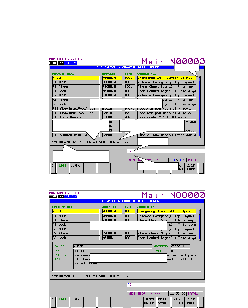
9.PMC CONFIGURATION DATA SETTING SCREENS ([PMC CONFIG])
B-64513EN/03
- 1170 -
9.2.5
Displaying Extended Symbol and Comment
Pressing the [SYMBOL] soft key, screen changes to symbol and comment displaying screen. In this
screen, you can see all defined symbols and comments.
There are two displaying modes. One is “Outline mode” and another is “Details mode”. You can change
this mode each other by pressing the [DISP MODE] soft key.
Scroll bar
Symbol and comment list display area
Amount of memory occupied
by symbol data
Total amount of memory occupied
by symbol and comment data
Amount of memory occupied
by comment data
Messa
g
e displa
y
line
Key input line
Fig. 9.2.5(a) Extended symbol and comment displaying screen (Outline mode, Symbol order)
Symbol and comment list display area
Symbol and Comment detail display area
Fig. 9.2.5(b) Extended symbol and comment displaying screen (Details mode, Symbol order)
Pressing the [ADRS ORDER] or [SYMBOL ORDER] soft key, you can sort entries by address or
characters of symbol.
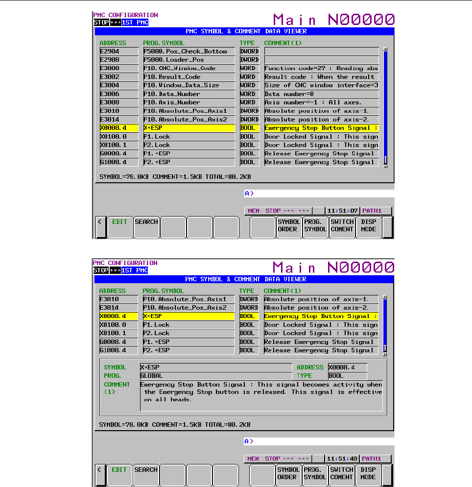
B-64513EN/03
9.PMC CONFIGURATION DATA SETTING SCREENS ([PMC CONFIG])
- 1171 -
Fig. 9.2.5(c) Extended symbol and comment displaying screen (Outline mode, Address order)
Fig. 9.2.5(d) Extended symbol and comment displaying screen (Details mode, Address order)
PROG.SYMBOL: Symbol is displayed. When a symbol is local symbol, this symbol is displayed as the
form “[PROGRAM NAME].[SYMBOL]”
ADDRESS: Address is displayed.
TYPE: Data type is displayed.
COMMENT: Comment is displayed. When multi comments are defined, you can see each
comment by pressing the soft key [SWITCH COMENT].
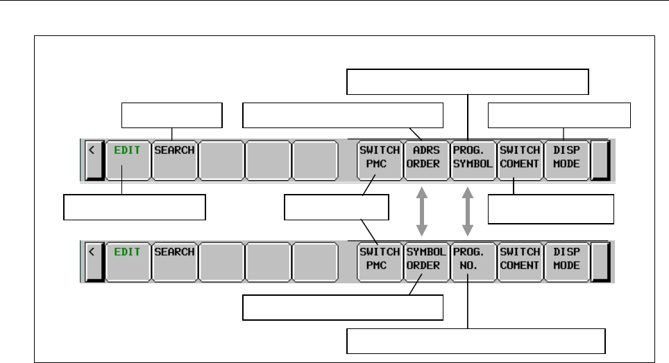
9.PMC CONFIGURATION DATA SETTING SCREENS ([PMC CONFIG])
B-64513EN/03
- 1172 -
Operation
Soft keys on the SYMBOL & COMMENT DATA VIEWER screen
Switch to the editor screen
Search for data
Change the displayed
comment
Change the display mode
Switch the program name to symbol notation
Switch to the address order display
Switch the program name to program number
Switch to the symbol order display
Switch PMC path
Fig. 9.2.5(e) Soft key layout in extended symbol and comment displaying screen
(1) Operation by soft key
(a) [EDIT] Changing to editing screen
Pressing the [EDIT] soft key, the screen is changed to “extended symbol and comment editing
screen”
(b) [SEARCH] Searching word
You can search entry by address expression, part characters of symbol or part characters of
comment.
(c) [ADRS ORDER] / [SYMBOL ORDER] Changing a displaying order
You can change the displaying order. Pressing the [ADRS ORDER] soft key, all entries are
sorted by address. Pressing the [SYMBOL ORDER] soft key, entries are sorted by character of
symbols in each sub programs.
(d) [PROG. SYMBOL] / [PROG. NO.] Changing a display of program name
Pressing the [PROG.SYMBOL] soft key, all symbols defined to addresses P are displayed as a
name of sub program. When pressing the [PROG. ADRS] soft key, the addresses P are
displayed as a name of subprogram.
(e) [SWITCH COMENT] Changing a display of comment set.
Pressing the [SWITCH COMENT] soft key, current displaying comment set is changed to next
comment set.
(f) [DISP MODE] Changing the displaying mode
There are two displaying modes. One is “Outline mode” and another is “Details mode”. You
can change this mode each other by pressing the [DISP MODE] soft key.
(g) [SWITCH PMC] Switching PMC path or divided ladder programs
Switches PMC path or divided ladder program. For details of the operation, refer to “6.3”.
By setting keep relay K935.0 to 1, you can display PMC program list screen. For details, refer
to ”2.2.11”.
(2) Operation by other keys
CURSOR KEY: Moving cursor
PAGE KEY: Paging up or down.
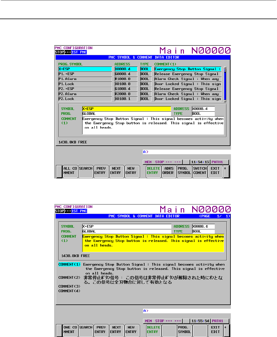
B-64513EN/03
9.PMC CONFIGURATION DATA SETTING SCREENS ([PMC CONFIG])
- 1173 -
9.2.6
Editing Extended Symbol and Comment
In symbol and comment editing screen, you can change, add or delete symbol and comment. To change
screen to the symbol and comment editing screen, press the [EDIT] soft key in the symbol and comment
display screen.
Fig. 9.2.6(a) Extended symbol and comment editing screen (One comment display)
Pressing the [ALL COMENT] soft key changes a screen to the “All comment display” screen. In the “All
comment display” screen, you can refer to other comment sets in editing.
Fig. 9.2.6 (b) Extended symbol and comment editing screen (All comment display)
FREE:
Free memory size to store symbol and comment is shown. Editing various data such as sequence
program and message will change this free size.
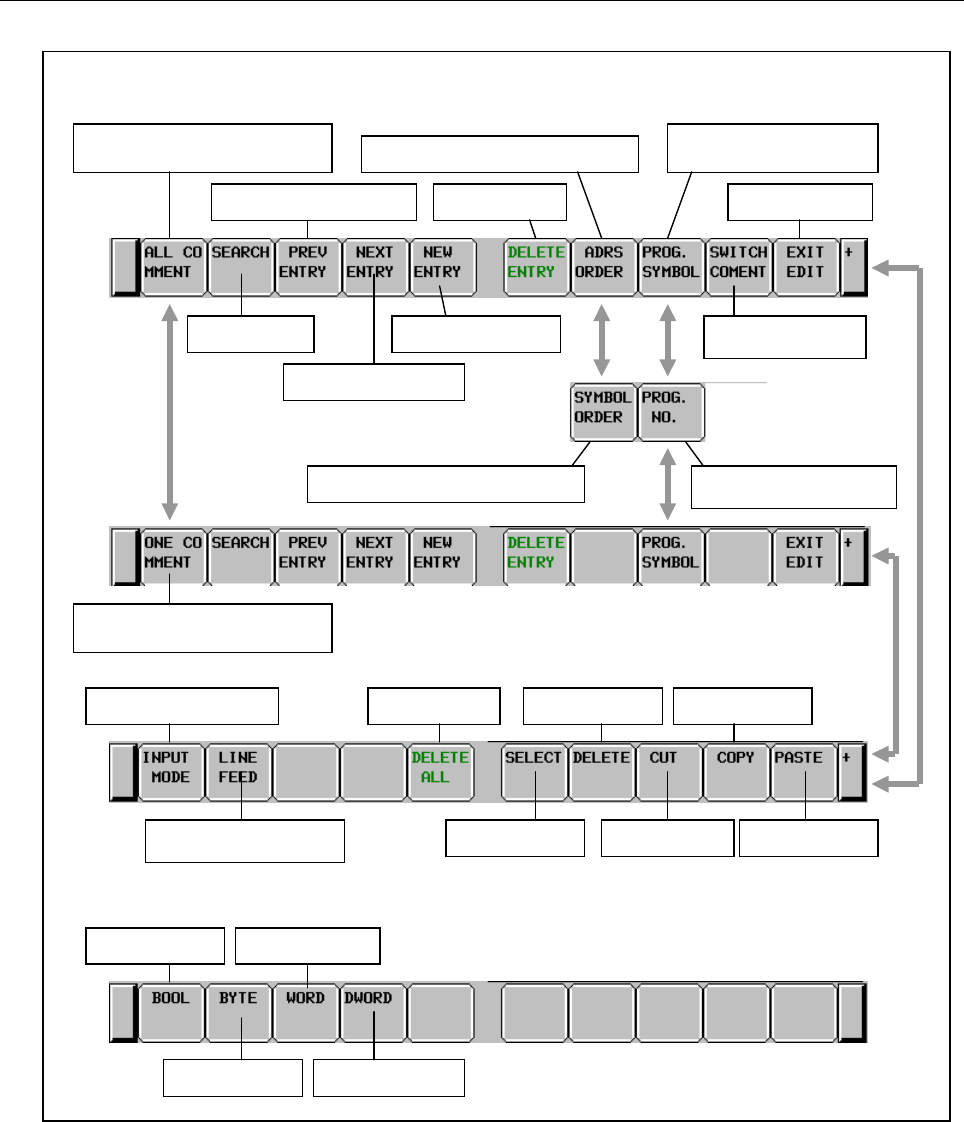
9.PMC CONFIGURATION DATA SETTING SCREENS ([PMC CONFIG])
B-64513EN/03
- 1174 -
Operation
Soft keys on the SYMBOL & COMMENT DATA EDITOR screen
Soft keys for the data type inputting edit-box
Change to the all comment
displayed screen
Change displaying
comment
Create a new entry
Display the next entry
Search for data
Display the previous entry End of editing
Switch the program name to
symbol notation
Delete entry
Switch to the address order display
Change to the one comment
displayed screen
Delete all data
Input the line feed code
(for comment)
Change the input mode
Paste characters
Copy characters
Cut characters
Delete characters
Select characters
Set to WORD Set to BOOL
Set to DWORDSet to BYTE
Switch the program name
to program number
Switch to the symbol order display
Fig. 9.2.6 (c) Soft key layout in extended symbol and comment editing screen

B-64513EN/03
9.PMC CONFIGURATION DATA SETTING SCREENS ([PMC CONFIG])
- 1175 -
(1) Operation by soft key
(a) [ALL COMMENT] / [ONE COMMENT] Changing the comment display mode
This soft key allows you to change the comment display mode. One mode is “All comment
display”. Another is “One comment display”. In the “All comment display” mode, you can edit
all comments in the same screen. In the “One comment display” mode, you can refer to another
symbol and comment.
(b) [SEARCH] Searching word
You can search entry by address expression, part characters of symbol or part characters of
comment.
(c) [PREV ENTRY] Editing previous entry
You can edit a symbol and comment on previous entry without leaving from editing mode.
(d) [NEXT ENTRY] Editing next entry
You can edit a symbol and comment on next entry without leaving from editing screen.
(e) [NEW ENTRY] Adding a new entry
You can add a new symbol and comment entry.
(f) [DELETE ENTRY] Deleting entry
You can delete a symbol and comment entry.
(g) [ADRS ORDER] / [SYMBOL ORDER] Changing a displaying order
You can change the displaying order. Pressing the [ADRS ORDER] soft key, all entries are
sorted by address. Pressing the [SYMBOL ORDER] soft key, entries are sorted by character of
symbols in each sub programs.
(h) [PROG. SYMBOL] / [PROG. NO.] Changing a display of program name
Pressing the [PROG.SYMBOL] soft key, all symbols defined to addresses P are displayed as a
name of sub program. When pressing the [PROG. NO.] soft key, addresses P are displayed as a
name of subprogram.
(i) [SWITCH COMENT] Changing a display of comment set.
Pressing the [SWITCH COMENT] soft key, current displaying comment set is changed to next
comment set.
(j) [EXIT EDIT] Terminating editing
Pressing the [EXIT EDIT] soft key, editing of symbol and comment is terminated. A screen is
changed to symbol and comment display screen.
(k) [INPUT MODE] Changing an input mode
Pressing the [INPUT MODE] soft key, input mode is changed as following. Current input
mode is displayed on right top of the screen.
INSERT
ALTER
WHOLE
• WHOLE
This mode is whole editing mode. Whole characters on the cursor are replaced.
• INSERT
The input characters are inserted before the cursor. On comment editing box, pressing the
INPUT key with no character inserts one white space before the cursor.
• ALTER
The characters on and after cursor are overwritten by input characters. On comment
editing box, pressing the INPUT key with no character overwrites a character on the
cursor by one white space.
(l) [LINE FEED] Inserting a new line code
On comment editing box, pressing the [LINE FEED] soft key inserts a new line code. When
you print a sequence program on FANUC LADDER-III, comment string starts new line at the
inserted new line code. New line code is only available in comment string.
(m) [DELETE ALL] Deleting all symbols and comments
Pressing the [DELETE ALL] soft key deletes all symbols and comments.

9.PMC CONFIGURATION DATA SETTING SCREENS ([PMC CONFIG])
B-64513EN/03
- 1176 -
(n) [SELECT] Selecting
Pressing the [SELECT] soft key starts selecting and after that moving the cursor selects some
characters for deleting, overwriting, copying or cutting. To input characters with selecting some
characters can overwrites selecting characters by the input characters.
(o) [DELETE] Deleting characters
To press the [DELETE] soft key with selecting some characters deletes them.
(p) [CUT] Cutting characters
To press the [CUT] soft key with selecting some characters cuts them and sends them to
pasting buffer. Previous contents of the pasting buffer are lost and new contents are stored. To
move some characters, use the [SELECT], [CUT] and [PASTE] soft key.
(q) [COPY] Copying characters
To press the [COPY] soft key with selecting some characters send them to pasting buffer.
Previous contents of the pasting buffer are lost and new contents are stored. To copy some
characters, use the [SELECT], [COPY] and [PASTE] soft key.
(r) [PASTE] Pasting characters
To press the [PASTE] soft key pastes the contents of pasting buffer. In the “WHOLE” mode,
pasted characters overwrite whole characters on the cursor. In the “INSERT” mode, pasted
characters are inserted at before the cursor. In the “ALTER” mode, pasted characters overwrite
characters on the cursor. Pasting operation does not delete the contents of pasting buffer. So
you can paste repeatedly.
(2) Operation by other keys
CURSOR KEY: Moving cursor
PAGE KEY: Paging up or down.
(3) Operation by “RETURN” key
On the symbol and comment editing screen, the “RETURN” key is not available. To terminate
symbol and comment editing, press the [EXIT EDIT] soft key.
NOTE
1 The character which can be inputted from CNC screen are the alphabetic
character, number, and sign of ASCII. Refer to "1.2.7 (7) Available characters"
for the character which can be used.
2 Create the data of Japanese comment and multi-language comment (simplified
Chinese character, Korean, etc.) using FANUC LADDER-III.
3 The character which cannot be displayed on CNC screen is converted to a
space character, when compiled by FANUC LADDER-III.
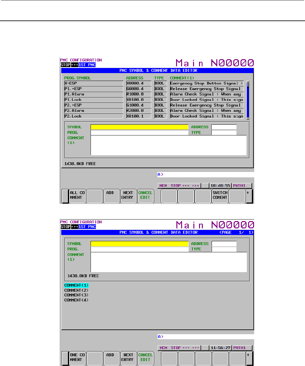
B-64513EN/03
9.PMC CONFIGURATION DATA SETTING SCREENS ([PMC CONFIG])
- 1177 -
9.2.7
Adding an Extended Symbol and Comment
To add a new entry of symbol and comment, press the [NEW ENTRY] soft key. In this situation, you can
also change the comment displaying mode. One is the “one comment displaying mode” and another is
“all comments displaying mode”.
Fig. 9.2.7 (a) Adding new entry of symbol and comment screen (One comment display)
Fig. 9.2.7 (b) Adding new entry of symbol and comment screen (All comment display)
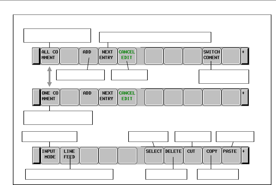
9.PMC CONFIGURATION DATA SETTING SCREENS ([PMC CONFIG])
B-64513EN/03
- 1178 -
Operation
Soft keys on the SYMBOL & COMMENT DATA EDITOR screen (New entry mode)
Change to the all comment
displayed screen
Switch displaying
comment
Cancel edits
Registering the current entry and create a new entry
Registering the entry
Change to the one comment
displayed screen
Change the input mode
Insert the line feed code (for comment)
Paste characters
Copy characters
Select characters Cut characters
Delete characters
Fig. 9.2.7 (c) Soft key layout in adding new entry of symbol and comment screen
(1) Operation by soft key
(a) [ADD] Registering new entry
Pressing the [ADD] soft key registers new entry of symbol and comment.
(b) [NEXT ENTRY] Creating new entry
You can create a new symbol and comment entry without leaving from editing mode.
(c) [CANCEL EDIT] Discarding the new entry
Pressing the [CANCEL EDIT] soft key discards current new entry.
As for the explanation of other soft keys, refer to "9.2.6 Editing Extended Symbol and Comment".
(2) Operation by other keys
CURSOR KEY: Moving cursor
PAGE KEY: Paging up or down.
(3) Operation by “RETURN” key
On the symbol and comment editing screen, the “RETURN” key is not available. To terminate
symbol and comment editing, press the [ADD] or [CANCEL EDIT] soft key.
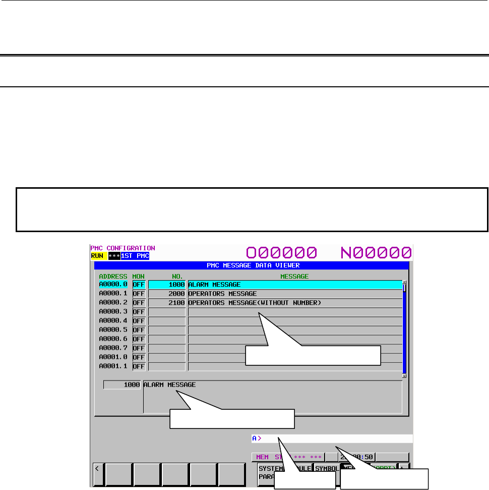
B-64513EN/03
9.PMC CONFIGURATION DATA SETTING SCREENS ([PMC CONFIG])
- 1179 -
9.3 DISPLAYING AND EDITING MESSAGE DATA ([MESAGE]
SCREENS)
9.3.1
Displaying Message Data
On the MESSAGE DATA VIEWER screen, you can check each external message data item output to the
NC screen by functional instruction DISPB.
To display the MESSAGE DATA VIEWER screen, press the [MESAGE] soft key. On the MESSAGE
DATA VIEWER screen, you can perform the following operations:
• Moving to the MESSAGE DATA EDITOR screen [EDIT]
• Searching for message data [SEARCH]
• Previewing message data [PREVIEW]
NOTE
Multi-language message data are not displayed on this screen. When you create
or edit the data, use FANUC LADDER-III.
Description of items in the table
• ADDRESS: Message address
• MON: Current status of the message requests (A addresses)
• NO.: Message number
• MESSAGE: Message data
Screen configuration
(1) On the screen, message addresses, message requesting monitors, message numbers, and message
data are displayed from left to right. A message requesting monitor indicates the status of the signal
(A addresses) of the message address. In the simple message data display area, the first line of data
is displayed.
(2) In the detailed message data display at the bottom of the screen, message data at the cursor is all
displayed.
(3) On the message display line at the bottom of the screen, an error message appears when issued.
Message display line
Key input line
Simple message data display area
Detailed message data display
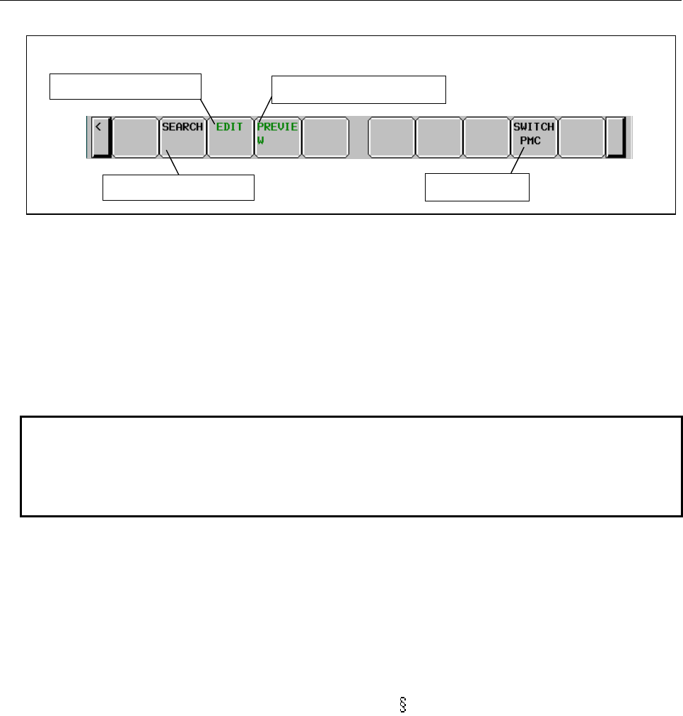
9.PMC CONFIGURATION DATA SETTING SCREENS ([PMC CONFIG])
B-64513EN/03
- 1180 -
Screen operations
Soft keys on the PMC Message Data Viewer screen
Soft keys on the PMC Message Data Viewer screen
Switch to the editor screen
Previewing message
data
Search for message data
Switch PMC path
Fig. 9.3.1 Soft keys on the MESSAGE DATA VIEWER screen
(1) Operations using the soft keys
(a) [SEARCH] Search for message data
It searches for the address for which message data containing an address, message number, or
string corresponding to the input string is set and displays the message data on the screen.
When a byte address is searched for, a bit 0 address is found.
Example)
When A2 is searched for, the cursor moves to A2.0.
(b) [EDIT] Switch to the editor screen
Moves to the MESSAGE DATA EDITOR screen.
NOTE
When the programmer protection function is enabled, the [EDIT] soft key
appears and is available. When the online monitor function is enabled, you
cannot move to the MESSAGE DATA EDITOR screen. For details, see Section
6.2.
(c) [PREVIEW] Previewing message data
Displays a character code enclosed by at signs (@) with the corresponding character actually
displayed.
Example)
Japanese1: ”@B6C532@” →”カナ 2”
Japanese2: ”@0248733E6F44643B5F01@100”→”非常停止 100”
European character type 1: UNZUL@0DC101@SSIGE → "UNZULÄSSIGE"
European character type 2: C@0EA501@MBO@0EA801@ → "CИMBOЛ"
European character type 3: @05ED01@123 → " 123"
To terminate preview display, press the [EXIT] soft key.
(d) [SWITCH PMC] Switching PMC path or divided ladder programs
Switches PMC path or divided ladder program. For details of the operation, refer to “6.3”.
By setting keep relay K935.0 to 1, you can display PMC program list screen. For details, refer
to ”2.2.11”.
(2) Screen operation using other keys
Use cursor and page keys to change the message data in the detailed message data display.
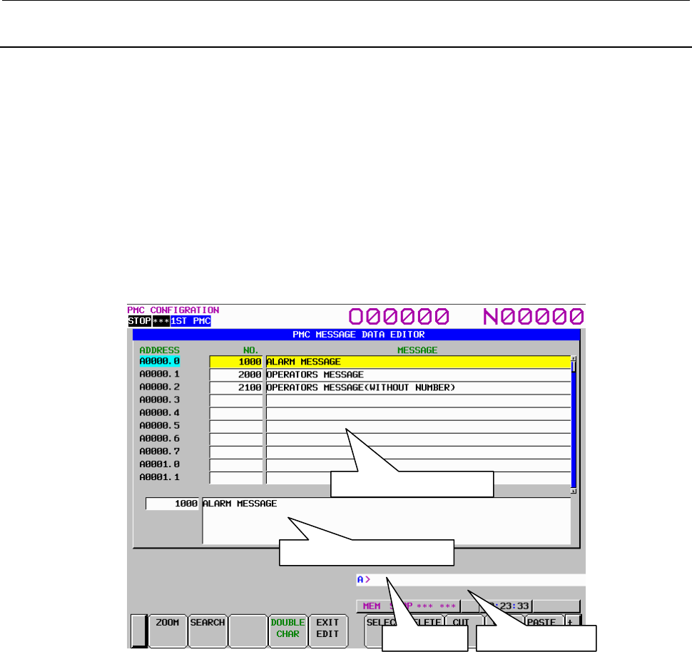
B-64513EN/03
9.PMC CONFIGURATION DATA SETTING SCREENS ([PMC CONFIG])
- 1181 -
9.3.2
Editing Message Data
On the MESSAGE DATA EDITOR screen, you can edit message data items.
To move to the MESSAGE DATA EDITOR screen, press the [EDIT] soft key on the MESSAGE DATA
VIEWER screen. On the MESSAGE DATA EDITOR screen, you can perform the following operations:
• Moving to the message data entry editor screen [ZOOM]
• Searching for message data [SEARCH]
• Previewing message data [PREVIEW]
• Moving to the MESSAGE DATA VIEWER screen [EXIT EDIT]
• Selecting multiple entries [SELECT]
• Deleting an entry [DELETE]
• Moving an entry [CUT] and [PASTE]
• Copying an entry [COPY] and [PASTE]
• Deleting all entries [DELETE ALL]
Screen configuration
(1) On the screen, message addresses, message numbers, and message data are displayed from left to
right. In the message data edit area, the first line of data is displayed.
(2) In the detailed message data display at the bottom of the screen, message data at the cursor is all
displayed.
(3) On the message display line at the bottom of the screen, an error message appears when issued.
Messa
g
e dis
p
la
y
line
Ke
y
in
p
ut line
Messa
g
e data edit area
Detailed messa
g
e data dis
p
la
y
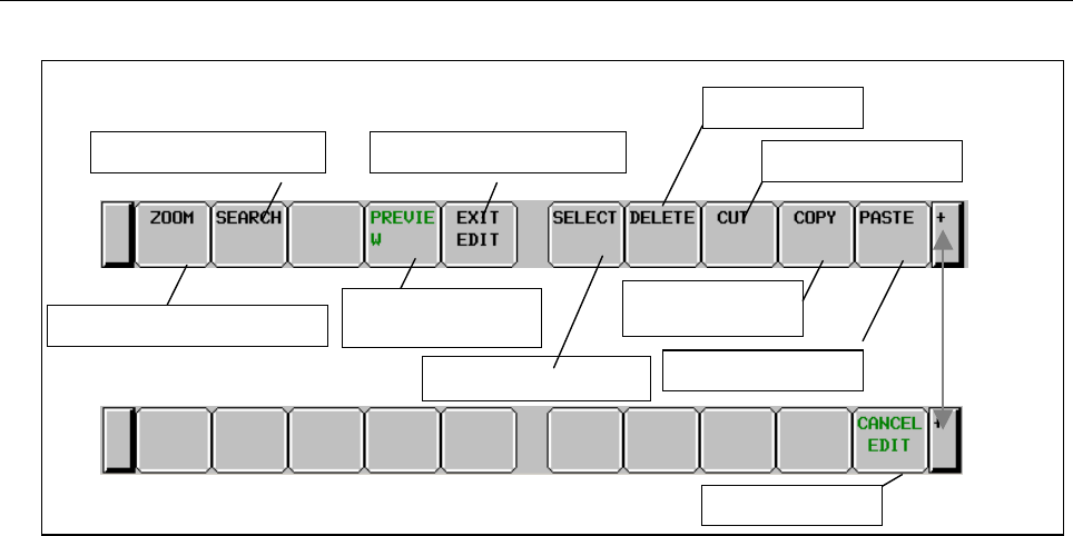
9.PMC CONFIGURATION DATA SETTING SCREENS ([PMC CONFIG])
B-64513EN/03
- 1182 -
Screen operations
Soft keys on the PMC Message Data Editor screen
Switch to the display screen
Select multiple entries
Previewing message
data characters
Display the entry editor screen
Search for message data
Delete all entries
Delete an entry
Cut an entry
Copy an entry
Paste an entry
Fig. 9.3.2 Soft keys on the MESSAGE DATA EDITOR screen
(1) Operations using the soft keys
(a) [ZOOM] Switch to the entry editor screen
Moves to the entry editor screen for message data to edit entry data at the cursor.
(b) [SEARCH] Search for message data
Searches for an address, message number, or message data string. The operation method
conforms to that for [SEARCH] on the MESSAGE DATA VIEWER screen. For details, see
"Screen operations" for the MESSAGE DATA VIEWER screen.
(c) [PREVIEW] Previewing message data
Displays a character code enclosed by at signs (@) with the corresponding character actually
displayed.
The operation method conforms to that for [PREVIEW] on the MESSAGE DATA VIEWER
screen. For details, see "Screen operations" for the MESSAGE DATA VIEWER screen.
(d) [EXIT EDIT] Switch to the display screen
Terminates editing of message data and moves to the MESSAGE DATA VIEWER screen.
(e) [SELECT] Select multiple entries
Use this key to specify multiple entries to be edited with a soft key such as [DELETE].
Pressing this soft key puts the screen into the mode for selecting multiple entries starting from
the entry being edited at that time. Move the cursor and use the search function so that the
entries to be edited are selected. After the entries to be edited are selected, edit them by
pressing each edit soft key. When you want to delete, move, or copy multiple entries, use this
soft key to select multiple entries.
(f) [DELETE] Delete an entry
Deletes a selected entry.
(g) [CUT] Cut an entry
Cuts a selected entry. The cut data is transferred to the pasting buffer and deleted from message
data. The contents of the pasting buffer before the data is transferred are erased. When you want
to move data from an entry to another, use this soft key together with the [PASTE] soft key.
(h) [COPY] Copy an entry
Transfers a selected entry to the pasting buffer. The message data is not changed. The contents
of the pasting buffer before the data is transferred are erased. When you want to copy data in
an entry to another, use this soft key together with the [PASTE] soft key.

B-64513EN/03
9.PMC CONFIGURATION DATA SETTING SCREENS ([PMC CONFIG])
- 1183 -
(i) [PASTE] Paste an entry
Replaces data at the cursor with the entry transferred to the pasting buffer by the [CUT] or
[COPY] soft key. When the contents of the pasting buffer are pasted by pressing the [PASTE]
soft key, they are not erased. The contents of the pasting buffer are retained until the power to
the NC is turned off.
(j) [DELETE ALL] Delete all entries
Deletes all message data.
(2) Editing message data for an entry at a time
Message data for an entry is input at a time.
(a) Standard specification
Enter a message string following a message number with delimiting them by a semicolon (;) as
shown below and press the INPUT key.
message-number;message-string
Example: 2001; ABCDEFG INPUT key
(b) Extended specification
Enter a message string following a message number in the extended specification format as
shown below and press the INPUT key.
message-number;message-string
Example: AL1+000= ABCDEFG INPUT key
OP1+999= ABCDEFG INPUT key
NOTE
For details of the extended specification of message number, see the description
of Extended specification in Subsection 4.11.1.(iv)
(3) Screen operation using other keys
Use cursor and page keys to change the message data in the detailed message data display.
(4) RETURN key operation
On the MESSAGE DATA EDITOR screen, the return key operation is disabled. To terminate editing
of message data and return to the MESSAGE DATA VIEWER screen, use the [EXIT EDIT] soft key.
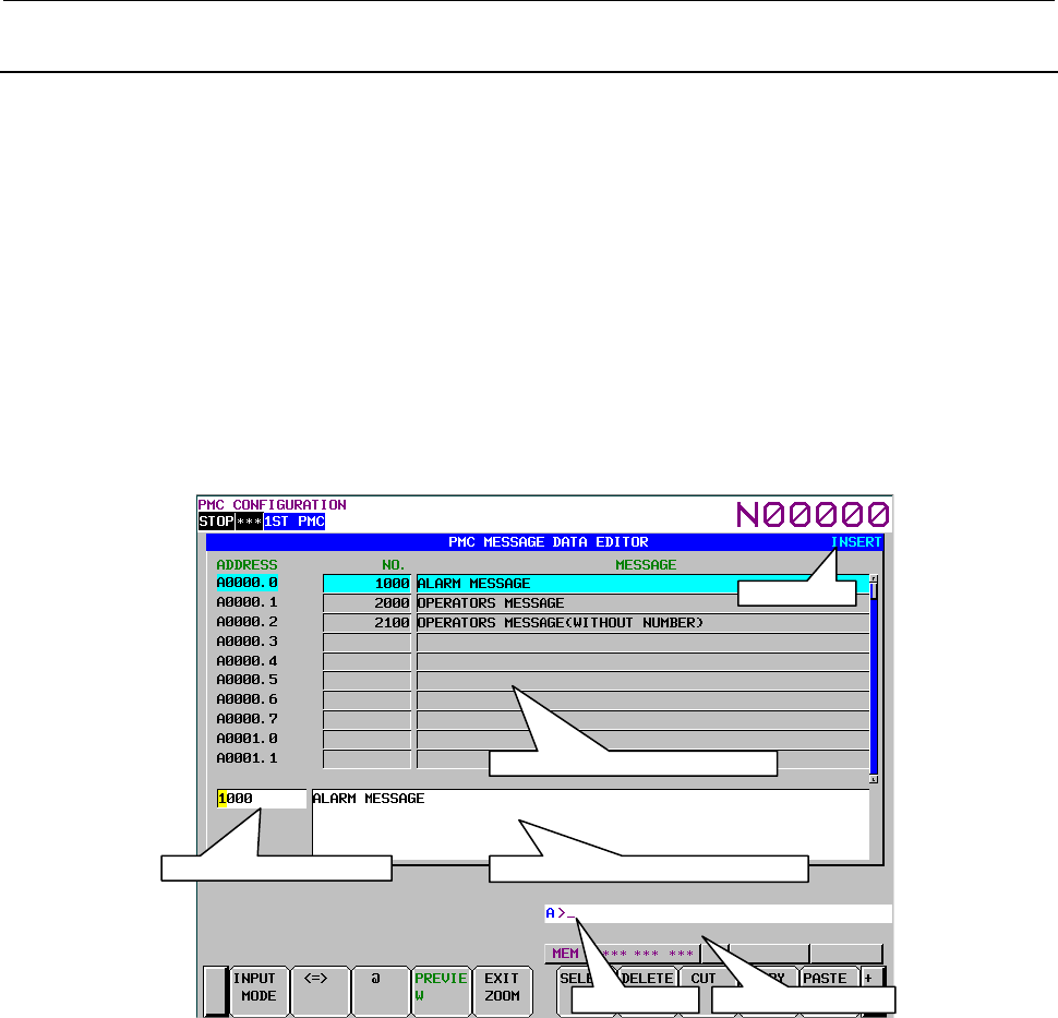
9.PMC CONFIGURATION DATA SETTING SCREENS ([PMC CONFIG])
B-64513EN/03
- 1184 -
9.3.3
Editing Desired Message Data
On the message data entry editor screen, you can edit desired message data. To move to the message data
entry editor screen, press the [ZOOM] soft key on the MESSAGE DATA EDITOR screen. On the
message data entry editor screen, you can perform the following operations:
• Changing the input mode [INPUT MODE]
• Changing data to be edited [<=>]
• Inserting an at sign (@) [@]
• Previewing message data [PREVIEW]
• Moving to the MESSAGE DATA EDITOR screen [EXIT]
• Selecting a string [SELECT]
• Deleting a string [DELETE]
• Moving a string [CUT] and [PASTE]
• Copying a string [COPY] and [PASTE]
• Canceling edits [CANCEL EDIT]
Screen configuration
(1) On the screen, message addresses, message numbers, and message data are displayed from left to
right. In the simple message data display area, the first line of data is displayed.
(2) The message number edit area and area for editing a message data string at the bottom of the screen
are used to edit the message number and data.
(3) On the message display line at the bottom of the screen, an error message appears when issued.
Message display line
Key input line
Simple message data display area
Area for editing a message data string
Input mode
Message number edit area
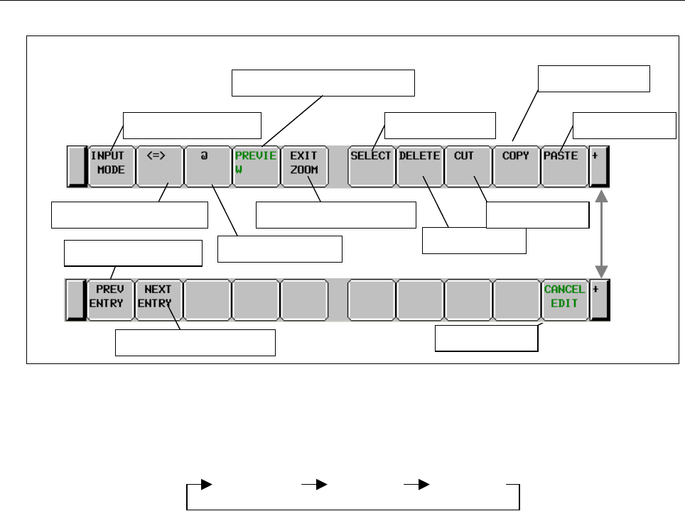
B-64513EN/03
9.PMC CONFIGURATION DATA SETTING SCREENS ([PMC CONFIG])
- 1185 -
Screen operations
Cancel edits
Soft keys on the message data entry editor screen
Switch to the editor screen
Select characters
Previewing message data
Change the input mode
Delete characters
Cut characters
Copy characters
Paste characters
Change data to be edited
Input an at sign (@)
Editing next entry
Editing previous entry
Fig. 9.3.3 Soft keys on the message data entry editor screen
(1) Operations using the soft keys
(a) [INPUT MODE] Change the input mode
Pressing [INPUT MODE] changes the input mode. The selection cycles in the following order.
In the insert mode, "INSERT" appears on the screen; in the replace mode, "ALTER" appears.
Insert
mode
Replace
mode
Full-string
input
• Full-string input
The entire string at the cursor is selected and replaced with an input string.
• Insert mode
Input characters are inserted at the cursor. Pressing the INPUT key with inputting no
characters inserts one space.
• Replace mode
Input characters replace characters at and after the cursor. Pressing the INPUT key with
inputting no characters replaces the character at the cursor with a space.
(b) [<=>] Change data to be edited
Use this soft key to move the cursor between the message number edit area and area for editing
a message string. You can check the cursor position to know which data is currently being
edited.
(c) [@] Input of an at sign (@)
To display Japanese, or special character, the character code of the character is enclosed by at
signs (@). To simplify the input of an at sign (@), this soft key adds an at sign (@) to the
string in the key input line. This soft key is enabled when the input mode is insert or replace.
In the full-string input mode, this soft key is not displayed.
(d) [PREVIEW] Previewing message data
Displays a character code enclosed by at signs (@) with the corresponding character actually
displayed.
The operation method conforms to that for [PREVIEW] on the MESSAGE DATA VIEWER
screen. For details, see "Screen operations" for the MESSAGE DATA VIEWER screen.
(e) [EXIT ZOOM] Switch to the editor screen
Terminates entry editing of message data and moves to the MESSAGE DATA EDITOR screen.
(f) [SELECT] Select characters
Use this key to specify multiple characters to be edited with a soft key such as [DELETE].
Pressing this soft key puts the screen into the mode for selecting multiple characters starting

9.PMC CONFIGURATION DATA SETTING SCREENS ([PMC CONFIG])
B-64513EN/03
- 1186 -
from the character being edited at that time. Move the cursor so that the characters to be edited
are selected. After the characters to be edited are selected, operate each edit soft key or enter
characters. This soft key is enabled when the input mode is insert or replace. In the full-string
input mode, this soft key is not displayed.
(g) [DELETE] Delete characters
Deletes selected characters.
(h) [CUT] Cut characters
Cuts selected characters. The cut characters are transferred to the pasting buffer and deleted
from message data. The contents of the pasting buffer before the characters are transferred are
erased. When you want to move characters, use this soft key together with the [PASTE] soft
key.
(i) [COPY] Copy characters
Transfers selected characters to the pasting buffer. The message data is not changed. The
contents of the pasting buffer before the characters are transferred are erased. When you want
to copy characters, use this soft key together with the [PASTE] soft key.
(j) [PASTE] Paste characters
Inserts the characters transferred to the pasting buffer by the [CUT] or [COPY] soft key at the
cursor in the insert input mode or replaces the data at the cursor with the characters in other
input modes. When the contents of the pasting buffer are pasted by pressing the [PASTE] soft
key, they are not erased. The contents of the pasting buffer are retained until the power to the
NC is turned off.
(k) [PREV ENTRY] Editing previous entry
You can edit a symbol and comment on previous entry without leaving from editing mode. And
the up cursor move key acts just like [PREV ENTRY] soft key.
(l) [NEXT ENTRY] Editing next entry
You can edit a symbol and comment on next entry without leaving from editing mode. And the
down cursor move key acts just like [NEXT ENTRY] soft key.
(m) [CANCEL EDIT] Cancel edits
Cancels edits made on this screen.
(2) Screen operation using other keys
Use cursor keys to change the character to be edited.
(3) RETURN key operation
On the message data entry editor screen, the return key operation is disabled. To terminate entry
editing of message data and return to the MESSAGE DATA EDITOR screen, use the [EXIT] soft
key.
NOTE
1 For details of the input format for kanji and other special character strings, see
Subsection 4.11.1.
2 For details of the extended specification of message number, see the description
of Extended specification in Subsection 4.11.1.(iv)
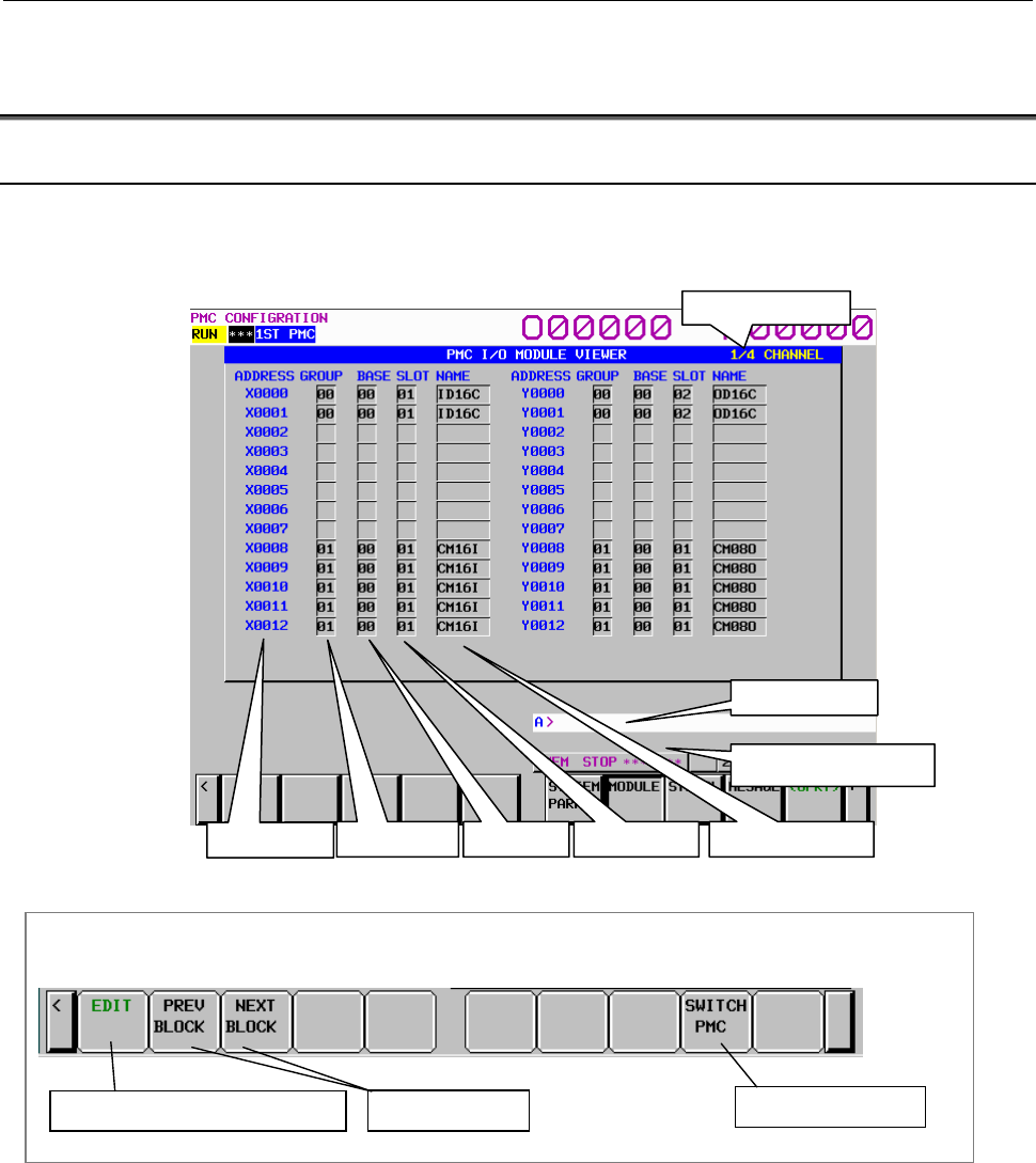
B-64513EN/03
9.PMC CONFIGURATION DATA SETTING SCREENS ([PMC CONFIG])
- 1187 -
9.4 DISPLAYING AND EDITING I/O MODULE ALLOCATION
DATA ([MODULE] SCREENS)
9.4.1 Displaying I/O Module Allocation Data
The I/O MODULE VIEWER screen displays data of allocation of I/O modules to X and Y addresses.
Check that I/O modules are allocated correctly.
To switch to the I/O MODULE VIEWER screen, press the [MODULE] soft key.
Screen operations
Change the channel
Soft keys on the I/O MODULE VIEWER screen
Switch to the allocation editor screen Switch the PMC path
Fig. 9.4.1 Soft keys on the I/O MODULE VIEWER screen
(1) Operations using the soft keys
(a) [EDIT] Switch to the I/O MODULE EDITOR screen
(b) [PRV.CH] Display I/O module allocation data for the previous channel
(c) [NXT.CH] Display I/O module allocation data for the next channel
(d) [SWITCH PMC] Switching PMC path or divided ladder programs
Switches PMC path or divided ladder program. For details of the operation, refer to “6.3”.
By setting keep relay K935.0 to 1, you can display PMC program list screen. For details, refer
to ”2.2.11”.
Address Grou
p
Base Slot Allocation name
Channel numbe
r
Ke
y
in
p
ut line
Message display line
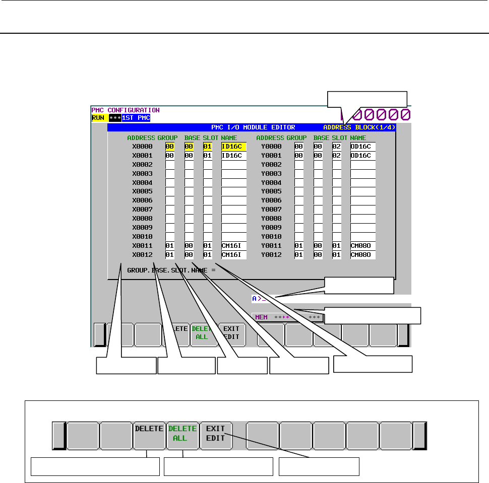
9.PMC CONFIGURATION DATA SETTING SCREENS ([PMC CONFIG])
B-64513EN/03
- 1188 -
9.4.2
Editing I/O Module Allocation Data
On the I/O MODULE EDITOR screen, you can edit data of allocation of I/O modules to X and Y
addresses.
To switch to the I/O MODULE EDITOR screen, press the [EDIT] soft key on the I/O MODULE
VIEWER screen.
Screen operations
Delete all allocation Delete allocation at cursor position Terminate editing
Soft keys in I/O MODULE EDITOR screen
(1) Operations using the soft keys
(a) [DELETE] Delete allocation data
Deletes allocation data at the cursor.
(b) [DELETE ALL] Delete all allocation data
When this soft key is pressed, the following confirmation message appears:
"DO YOU DELETE ALL ALLOCATION DATA?"
The [YES] and [NO] soft keys appear. Press [NO] to cancel deletion or [YES] to execute
deletion.
(c) [EXIT EDIT] Switch to the I/O MODULE VIEWER screen
(2) Allocation of I/O Units to X and Y addresses
(a) Set the cursor at address to which you will allocate new I/O Unit.
(b) Type "Group. Base. Slot. I/O-module-name" and press INPUT key.
Ex) In case you allocate "Group = 1, Base = 0, Slot = 5, Name = ID16C" to X10, set the cursor
at X10 and enter "1.0.5.ID16C" + INPUT key
Address Group Base Slot Allocation name
Block number
Key input line
Message display line
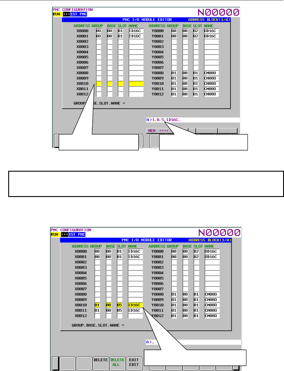
B-64513EN/03
9.PMC CONFIGURATION DATA SETTING SCREENS ([PMC CONFIG])
- 1189 -
NOTE
As to the allocation name of I/O Unit, see Tables 3.2.3 (a) to 3.2.3 (c) in section
“3.2.3”.
(c) The I/O Unit is allocated to address of the cursor position for the I/O Unit size.
In case of above example (b), I/O Unit is allocated at X10 and X11 like as follows.
(a) Set the cursor at X10 (b) 1.0.5.ID16C + INPUT key
(c) I/O Unit is allocated at X10 and X11

9.PMC CONFIGURATION DATA SETTING SCREENS ([PMC CONFIG])
B-64513EN/03
- 1190 -
NOTE
1 To make the allocation effective, after storing the Ladder program in the flash
ROM, turn the power to the CNC and all slave I/O devices off, then on again.
2 The Ladder program is not stopped automatically when you open I/O MODULE
VIEWER screen or EDITOR screen.
(3) Delete allocation
(a) Set the cursor at allocation, which you will delete, and press ”the [DELETE] soft key”.
(b) The allocation is deleted.
(4) Delete all allocation
(a) Press the [DELETE ALL] soft key.
(b) "DO YOU DELETE ALL ALLOCATION DATA?" is displayed.
(c) Press the [YES] soft key.
(d) Allocation data of X and Y are all deleted.
(5) RETURN key operation
On the I/O MODULE EDITOR screen, the return key operation is disabled. To terminate editing of
allocation data and return to the I/O MODULE VIEWER screen, use the [EXIT EDIT] soft key.
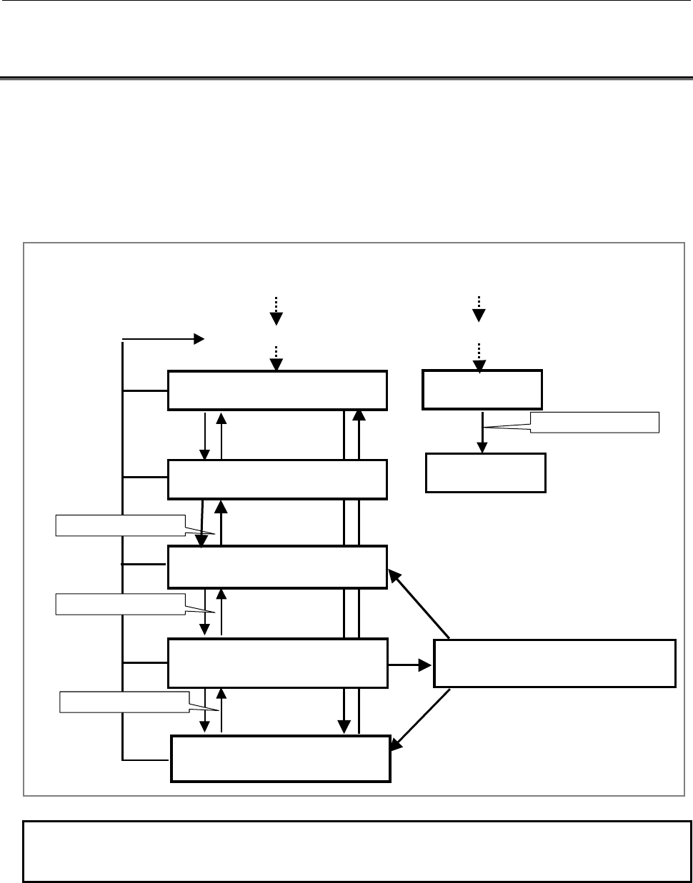
B-64513EN/03
9.PMC CONFIGURATION DATA SETTING SCREENS ([PMC CONFIG])
- 1191 -
9.5 DISPLAYING AND CHANGING PMC SETTINGS ([SETING]
SCREENS)
There are following setting parameter screens.
• PMC SETTING (GENERAL) screen
• PMC SETTING (MESSGE SHIFT) screen
• PMC SETTING (SELECTABLE I/O) screen
• PMC SETTING (OVERRIDE) screen
Use the [NEXT] and [PREV] soft keys to switch from a setting screen to another as shown in the figure
below.
PMC SETTING (GENERAL) screen
Page1
[<]
PMC SETTING (WARN
SELECTABLE I/O) screen
PMC SETTING (MESSAGE SHIFT)
screen
[NEXT]
[PREV]
[PMC CONIG]
[NEXT]
[PREV]
PMC SETTING (OVERRIDE) screen
[NEXT]
[PREV]
PMC SETTING (SELECTABLE I/O) screen
EFFECTIVE GROUP SELECTION
[NEXT]
[PREV]
[YES]
The screen protection
[KEEP RELAY]
Keep Relay
(K0-K99)
Keep Relay
(K900-K919)
Page Down
The screen protection
The screen protection
The screen protection
[SETING]
[PMC MAINTE]
PMC SETTING (GENERAL) screen
Page2
[NEXT]
[PREV]
NOTE
You can also use the keep relay screen (for K900 and after) to set these setting
parameters.
Setting screen of multi-language display function, selectable I/O link assignment function and
OVERRIDE mode of the forced input/output function and System Keep Relay screen can be protected by
programmer protection function.
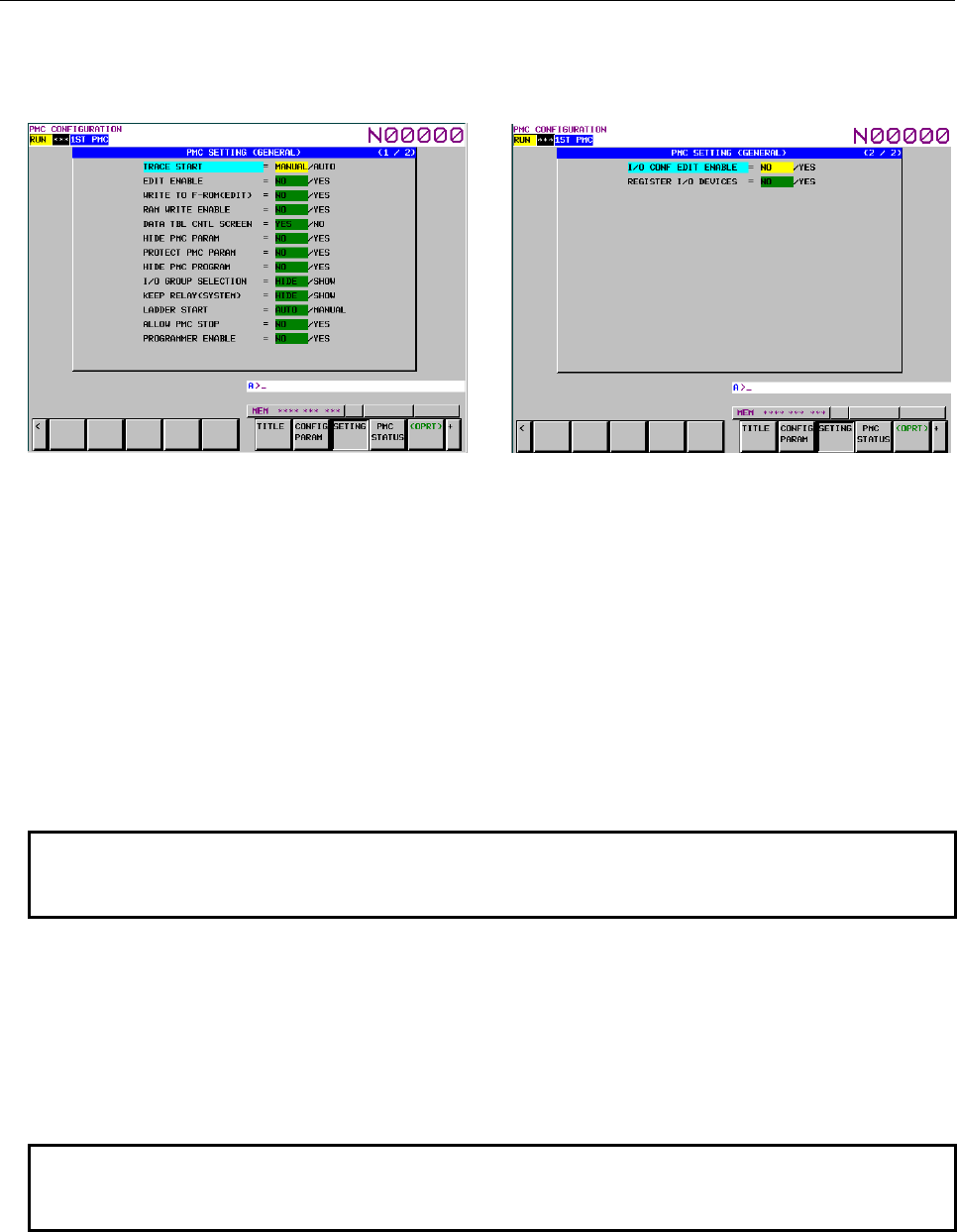
9.PMC CONFIGURATION DATA SETTING SCREENS ([PMC CONFIG])
B-64513EN/03
- 1192 -
(1) PMC SETTING GENERAL screen
On the PMC SETTING (GENERAL) screen, set parameters that specify the use condition of each
PMC function.
Page1 Page2
Use the [↑] and [↓] keys to move the item cursor.
Use the [←] and [→] keys to move the setting cursor and set the parameter.
Use the page keys to switch to another page.
(a) TRACE START (K906.5) (only 1st PMC path)
MANUAL: Executes the trace function by operating the corresponding soft key on the trace
screen.
AUTO: Automatically executes the trace function after power-on.
(b) EDIT ENABLE (K901.6)
NO: Prevents editing of the sequence program.
YES: Allows editing of the sequence program.
NOTE
This setting effects some PMC functions.
For details, see Section 6.2.
(c) WRITE TO F-ROM (EDIT) (K902.0)
NO: Does not write to flash ROM automatically after editing of sequence program.
YES: Writes to flash ROM automatically after editing of sequence program.
(d) RAM WRITE ENABLE (K900.4)
NO: Prevents forcing function.
YES: Allows forcing function.
NOTE
This setting effects some PMC functions.
For details, see Section 6.2.
(e) DATA TBL CNTL SCREEN (K900.7)
YES: Displays PMC parameter data table control screen.
NO: Does not display PMC parameter data table control screen.

B-64513EN/03
9.PMC CONFIGURATION DATA SETTING SCREENS ([PMC CONFIG])
- 1193 -
(f) HIDE PMC PARAM (K902.6)
NO: Allows PMC parameter display.
YES: Prevents PMC parameter display.
NOTE
This setting effects some PMC functions.
For details, see Section 6.2.
(g) PROTECT PMC PARAM (K902.7)
NO: Allows PMC parameter editing.
YES: Prevents PMC parameter editing.
(h) HIDE PMC PROGRAM (K900.0)
NO: Allows sequence program display.
YES: Prevents sequence program display.
NOTE
This setting effects some PMC functions.
For details, see Section 6.2.
(i) I/O GROUP SELECTION (K906.1)
HIDE: The PMC SETTING (SELECTABLE I/O) screen is not displayed.
SHOW: The PMC SETTING (SELECTABLE I/O) screen is displayed.
(j) KEEP RELAY (SYSTEM) (K906.6)
HIDE: The KEEP RELAY (K900-K999) screen is not displayed.
SHOW: The KEEP RELAY (K900-K999) screen is displayed.
(k) LADDER START (K900.2)
AUTO: Executes the sequence program automatically after the power turns on.
MANUAL: Executes the sequence program by [RUN] soft-key.
(l) ALLOW PMC STOP (K902.2)
NO: Prevents run/stop operation of the sequence program.
YES: Allows run/stop operation of the sequence program.
NOTE
This setting effects some PMC functions.
For details, see Section 6.2.
(m) PROGRAMMER ENABLE (K900.1)
NO: Disables embedded programmer.
YES: Enables embedded programmer.
NOTE
This setting effects some PMC functions.
For details, see Section 6.2.
(n) I/O CONF EDIT ENABLE (K907.0) (only 1st PMC path)
NO: Disables editing of I/O configuration data (I/O Link i assignment data).
YES: Enables editing of I/O configuration data (I/O Link i assignment data).
NOTE
This setting effects some PMC functions.
For details, see Section 6.2.
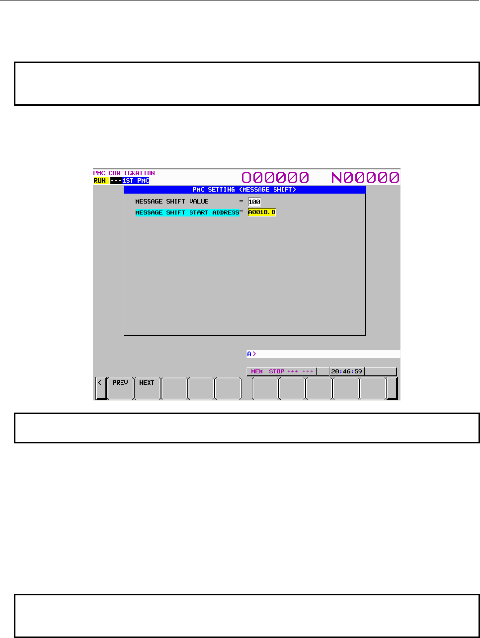
9.PMC CONFIGURATION DATA SETTING SCREENS ([PMC CONFIG])
B-64513EN/03
- 1194 -
(o) REGISTER I/O DEVICES (K935.1) (only 1st PMC path)
NO: Disables register/delete of I/O device configuration.
YES: Enables register/delete of I/O device configuration.
NOTE
This setting effects some PMC functions.
For details, see Section 6.2.
(2) PMC SETTING (MESSAGE SHIFT) screen
On the PMC SETTING (MESSAGE SHIFT) screen, set the parameters for the message shift
function by functional instruction DISPB.
NOTE
For details of the display condition for this screen, see Section 6.2.
(a) MESSAGE SHIFT VALUE (K918, K919)
Enter the amount by which the message display request bit is to be shifted.
The valid data range is between 0 and 1999. The initial value is 0.
After entering a value, press the INPUT key to set the value.
The input data is also retained after power-off.
(b) MESSAGE SHIFT START ADDRESS (K916, K917)
Enter the start bit address of the area for the message display request bit to be shifted.
The specified address must be within the A address area. The initial value is A0.0.
The input data is also retained after power-off.
NOTE
Data set for "MESSAGE SHIFT START ADDRESS" is valid only when the value
set for "MESSAGE SHIFT VALUE" is other than 0.

B-64513EN/03
9.PMC CONFIGURATION DATA SETTING SCREENS ([PMC CONFIG])
- 1195 -
(3) Setting screens for the selectable I/O Link assignment function
(a) PMC SETTING (WARN SELECTABLE I/O) screen
This caution screen is displayed for the operator's attention when the operator is switching to
the PMC SETTING (SELECTABLE I/O) screen.
Read the displayed caution carefully.
When you are sure to set parameters after reading the caution, press the [YES] soft key.
This soft key switches to the PMC SETTING (SELECTABLE I/O) screen.
NOTE
For details of the display condition for this screen, see Section 6.2.
WARNING
If you modify this setting parameter without care, the I/O assignment data may
not match I/O devices and turning on the power may result in unexpected
malfunctions of machine. Therefore, it is required that the operator of this
function should be an expert who fully understands the sequence program and
the operation of PMC. It is also strongly recommended to the developer of
machine that this setting screen should be protected from careless use by
ordinary operators after the machine is shipped into the field.
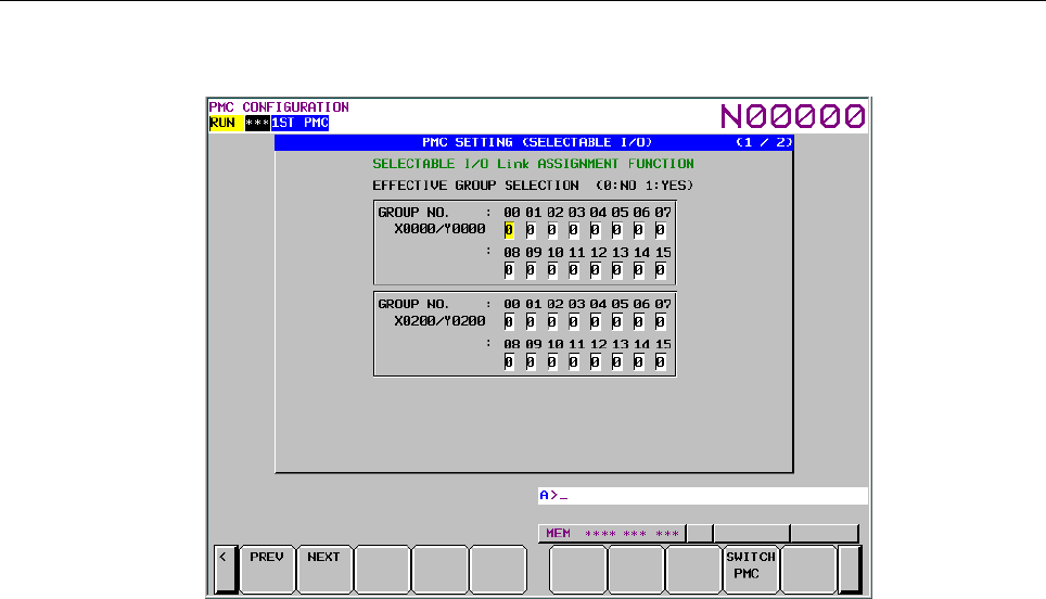
9.PMC CONFIGURATION DATA SETTING SCREENS ([PMC CONFIG])
B-64513EN/03
- 1196 -
(b) PMC SETTING (SELECTABLE I/O) screen
You can set the group of optional I/O device that is connected with each machine.
The maximum number of X/Y address blocks of I/O Link per PMC is 4.
You can set these parameters of available X/Y address blocks of I/O Link.
To switch to another page, use the page keys.
EFFECTIVE GROUP SELECTION
(X/Y0: K920 and K921, X/Y200: K922 and K923, X/Y400: K924 and K925, X/Y600: K926
and K927)
You can select effective I/O group in I/O link assignment data.
1: I/O group is effective.
0: I/O group is no effective.
The "*" mark means that the group is set as the basic part by the parameter "BASIC GROUP
COUNT" on the SYSTEM PARAMETER screen. The value cannot be set into these parts.
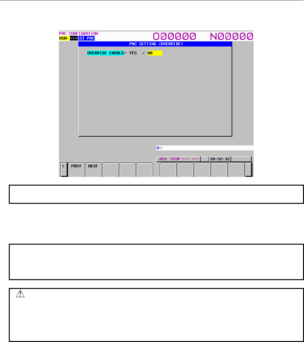
B-64513EN/03
9.PMC CONFIGURATION DATA SETTING SCREENS ([PMC CONFIG])
- 1197 -
(4) PMC SETTING (OVERRIDE) screen
On this screen, specify whether to enable the override function.
NOTE
For details of the display condition for this screen, see Section 6.2.
OVERRIDE ENABLE (K906.0)
YES: Enables the override function.
NO: Disables the override function.
NOTE
The change to this parameter setting is made effective at the next power-on.
After changing the setting of this parameter, be sure to turn the power off, then
on again.
WARNING
Special care must be exercised when using the Override function. If the Override
function is used incorrectly, the operation of the machine may be unpredictable.
Therefore, use the Override function after understood "7.1.1 Forced I/O function"
sufficiently. Moreover, When shipping the machine, disable the Override function
invariably.
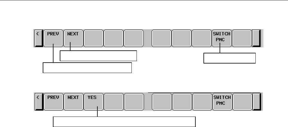
9.PMC CONFIGURATION DATA SETTING SCREENS ([PMC CONFIG])
B-64513EN/03
- 1198 -
(5) Operations using the soft keys
Soft keys common to the setting parameter screens
Soft keys on the PMC SETTING (WARN SELECTABLE I/O) screen
(a) [PREV] Switch to the previous page
(b) [NEXT] Switch to the next page
(c) [YES] Switch to the PMC SETTING (SELECTABLE I/O) screen
(d) [SWITCH PMC] Switching PMC path or divided ladder programs
Switches PMC path or divided ladder program. For details of the operation, refer to “6.3”.
By setting keep relay K935.0 to 1, you can display PMC program list screen. For details, refer
to ”2.2.11”.
Move to the previous setting screen
Move to the next setting screen
Move to the PMC SETTING (SELECTABLE I/O) screen
Switch PMC path
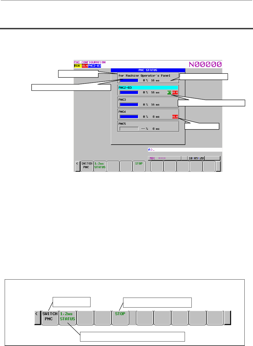
B-64513EN/03
9.PMC CONFIGURATION DATA SETTING SCREENS ([PMC CONFIG])
- 1199 -
9.6 DISPLAYING THE STATUS OF PMCS AND CHANGING
THE TARGET PMC ([PMC STATUS] SCREENS)
On the PMC STATUS screen, you can display the status of each existing PMC and change the target
PMC for display and operation on each screen. To switch to the PMC STATUS screen, press the [PMC
STATUS] soft key.
This screen displays the status of up to five PMCs and dual check safety.
The status display for each PMC shows title information (REMARKS), ladder execution performance
monitor, current execution time of the ladder program, sequence program number, divided ladder
program number and edition corresponding to the title data, and alarm mark.
The ladder execution performance monitor shows the ratio of the execution of the level-1 and level-2
sequence sections of the ladder program on the monitor bar. The ratio of the execution of the level-1
sequence section of the ladder program is displayed with a numeric value next to the monitor bar. When
the ladder program is stopped, the monitor bar is not displayed.
When using the ladder dividing management function, the divided ladder program number is displayed.
No number is displayed when main ladder program is selected.
The alarm mark is displayed only when an alarm is issued on the PMC. Nothing is displayed when no
alarm is issued.
On this screen, you can start and stop a ladder program.
Fig. 9.6 Soft keys on the PMC STATUS screen
Title information
Ladder execution performance monitor
Ladder execution time
Alarm mark
Divided Ladder program number
Change the PMC
Start and stop a ladder program
Switch to the PMC STATUS(1,2ms LADDER) screen
Soft keys on the PMC STATUS screen

9.PMC CONFIGURATION DATA SETTING SCREENS ([PMC CONFIG])
B-64513EN/03
- 1200 -
Operation using the soft key
(1) [SWITCH PMC] Switching PMC path or divided ladder programs
Switches PMC path or divided ladder program. For details of the operation, refer to “6.3”.
You can check the position of the cursor displayed at the title information of each PMC to know the
current target PMC.
By setting keep relay K935.0 to 1, you can display PMC program list screen. For details, refer
to ”2.2.11”.
(2) [1, 2ms STATUS] Switch to the PMC STATUS(1,2ms LADDER) screen
This soft key switches to the PMC STATUS(1,2ms LADDER) screen. This soft key is displayed
when using the 1st level execution cycle in 1ms, 2ms.
About a PMC STATUS(1, 2ms LADDER) screen, refer to "3.9.1 Displaying the status of the 1st
level execution cycles in 1ms/2ms ([PMC status (1,2ms ladder)] screen)" of this document for
details.
(3) [RUN]/[STOP] Start and stop a ladder program
For details of these operations, see Subsection 9.6.1.
CAUTION
When the programmer protection function is enabled, the [RUN]/[STOP] soft key
appears and is available. For details, see Section 6.2.
9.6.1
Starting and Stopping Sequence Programs
On this screen, you can start or stop a sequence program. NC parameter No.11931#0 determines whether
multi-path PMC shall start/stop individually, or they shall synchronize.
(1) Starting a sequence program ([RUN])
When a program is stopped, pressing the [RUN] soft key causes the system to display the inquiry
message "ARE YOU SURE YOU WANT TO RUN PROGRAM?". Pressing the [YES] soft key in
response to this message causes the program to start. The status line display changes to "RUN".
The sequence program starts from the beginning. The soft key changes to [STOP].
(2) Stopping a sequence program ([STOP])
When a program is running, pressing the [STOP] soft key causes the system to display the inquiry
message "ARE YOU SURE YOU WANT TO STOP PROGRAM?". Pressing the [YES] soft key in
response to this message causes the program to stop. The status line display changes to "STOP".
The soft key changes to [RUN].
WARNING
If the sequence program is stopped while the machine is operating, the machine
may behave in an unexpected way. Before stopping the sequence program,
ensure that there are no people near the machine and that the tool cannot
collide with the work piece or the machine.
Otherwise, there is an extreme risk of death or serious injury, as well as the
likelihood of the tool, the work piece, and the machine being damaged.
(3) Automatic operation of a sequence program
When LADDER START is set to AUTO (bit 2 of the keep relay K900 = 0) on the setting screen, a
sequence program can be executed automatically when the power is turned on.
And the inquiry message “ARE YOU SURE YOU WANT TO RUN PROGRAM?” is displayed
after editing the following data. Pressing the [YES] soft key in response to this message causes the
program to start. The status line display changes to "RUN".
• Symbol comment data
• Message data
• System parameter
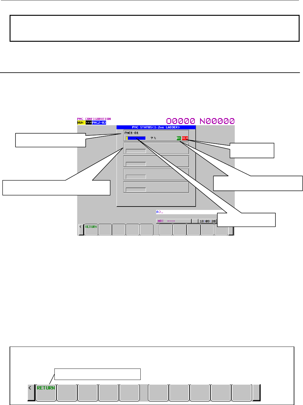
B-64513EN/03
9.PMC CONFIGURATION DATA SETTING SCREENS ([PMC CONFIG])
- 1201 -
NOTE
In case of a fatal PMC alarm that prevents the program to start, even if you
press "YES" soft key, the program will not start.
9.6.2
Displaying the status of the 1st level execution cycle in
1ms/2ms ([PMC STATUS(1,2ms LADDER)] screen)
The PMC STATUS(1,2ms LADDER) screen displays the execution status of the 1st level of ladder
program which 1ms or 2ms is set to the execution cycle of the 1st level.
This screen is displayed by pressing the [1,2ms STATUS] soft key of PMC status screen. [1 or 2ms
status] soft key is displayed when 1ms or 2ms are set to the execution cycle of the 1st level.
Fig.9.6.2 (a) PMC STATUS(1,2ms LADDER) screen
The ladder execution performance monitor shows the execution time ratio of the 1st level of execution
cycle in 1ms or 2ms. The maximum execution time is 100%. In case of 1ms of the execution cycle, the
maximum execution time is 0.5ms. In case of 2ms of the execution cycle, the maximum execution time is
1ms.
The information of the ladder program of the 1st level of ladder execution cycle in 1ms, 2ms is displayed
on the title information and divided ladder program number. And the alarm status of the PMC path of the
1st level execution cycle in 1ms, 2ms is displayed at the alarm mark.
In the PMC path in which 1ms or 2ms is not set to execution cycle of the 1st level, this information is
displayed as blank.
Operation using the soft key
Fig. 9.6.2 (b) Soft keys on the PMC STATUS(1,2ms LADDER) screen
(1) [RETURN] Switch to the PMC STATUS screen
Switches to the PMC STATUS screen.
Title information
Ladder execution performance monitor
Divided Ladder program number
Alarm mark
monitor bar
Soft keys on the PMC STATUS(1,2ms LADDER) screen
Switch to the PMC STATUS screen
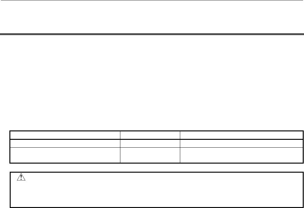
9.PMC CONFIGURATION DATA SETTING SCREENS ([PMC CONFIG])
B-64513EN/03
- 1202 -
9.7 DISPLAYING AND SETTING PARAMETERS FOR THE
ONLINE FUNCTION ([ONLINE] SCREEN)
The online function allows PMC data to be displayed and edited on a personal computer when the PMC is
connected to FANUC LADDER-III or Ladder Editing Package.
Following functions are available in the online function.
• Ladder monitor display
• Online ladder editing
• PMC parameter display and editing
• Signal state monitor
• Input/output to and from the PMC (loading from the PMC, storing to the PMC)
• Writing to flash ROM
For detailed explanation of the online function, refer to the following manuals:
Manual name Drawing number Description
FANUC LADDER-III Operator's Manual B-66234EN Online function by FANUC LADDER-III
Ladder Editing Package (Windows)
Operator's Manual
B-63484EN Online function by Ladder Editing Package
CAUTION
When the online function is used with RS-232C, the selected channel is
occupied by the PMC system. To use other functions with RS-232C, specify
other channel setting than the one used by online function.
Even while you are monitoring signals, ladder program and PMC parameters, and editing PMC
parameters using the online function, you can monitor them also on following PMC screen.
• The LADDER DIAGRAM VIEWER screen
• The PROGRAM LIST VIEWER screen
• The TITLE DATA VIEWER screen
• The SYSTEM PARAMETER VIEWER screen
• The I/O MODULE VIEWER screen
• The SYMBOL & COMMENT DATA EDITOR screen
• The MESSAGE DATA EDITOR screen
• The I/O DIAGNOSIS screen

B-64513EN/03
9.PMC CONFIGURATION DATA SETTING SCREENS ([PMC CONFIG])
- 1203 -
On these screens, if you start editing the sequence program by online edit or storing another sequence
program from FANUC LADDER-III or Ladder Editing Package to PMC, PMC will stop monitoring the
sequence program. When updating the sequence program is completed, PMC will start monitoring the
new program again.
However, on the following PMC screens, even if you start storing another sequence program from
FANUC LADDER-III or Ladder Editing Package to PMC, symbol and comment data displayed in the
screen will not be updated automatically.
When symbol and comment data are displayed again by page up/down key, etc, the updated symbol and
comment data will be displayed.
• The SIGNAL STATUS screen
• The PMC PARAMETER (TIMER) screen
• The PMC PARAMETER (COUNTER) screen
• The PMC PARAMETER (KEEP RELAY) screen
• The PMC PARAMETER (DATA TABLE CONTROL DATA) screen
• The PMC PARAMETER (DATA TABLE) screen
• The SIGNAL TRACE screen
CAUTION
1 While communicating with online function, you can not move to following PMC
editor screens and an attempt will result in an error message "PROGRAM IS
BEING MODIFIED".
On the other hand, while one of the following PMC screens is displayed, a
demand to make connection with the online function of FANUC LADDER-III or
Ladder Editing Package will be rejected, and will issue a communication error
instead and you can not use online function.
Use the online function on the screen except following PMC screens.
- LADDER DIAGRAM EDITOR screen
- PROGRAM LIST EDITOR screen
- TITLE DATA EDITOR screen
- SYSTEM PARAMETER EDITOR screen
- I/O MODULE EDITOR screen
- SYMBOL & COMMENT DATA EDITOR screen
- MESSAGE DATA EDITOR screen
- PMC PARAMETER (DATA TABLE) screen (write enable)
(When data table control data is protected, the data table control data can not
be modified on the screen. For details, see section 6.2.1 and 6.2.2)
2 If you start storing a PMC parameter from FANUC LADDER-III or Ladder Editing
Package to PMC, while the PMC PARAMETER (DATA TABLE) screen is
displayed, data table is displayed according to the old data table control data
until you once exit and re-enter PMC PARAMETER (DATA TABLE) screen.
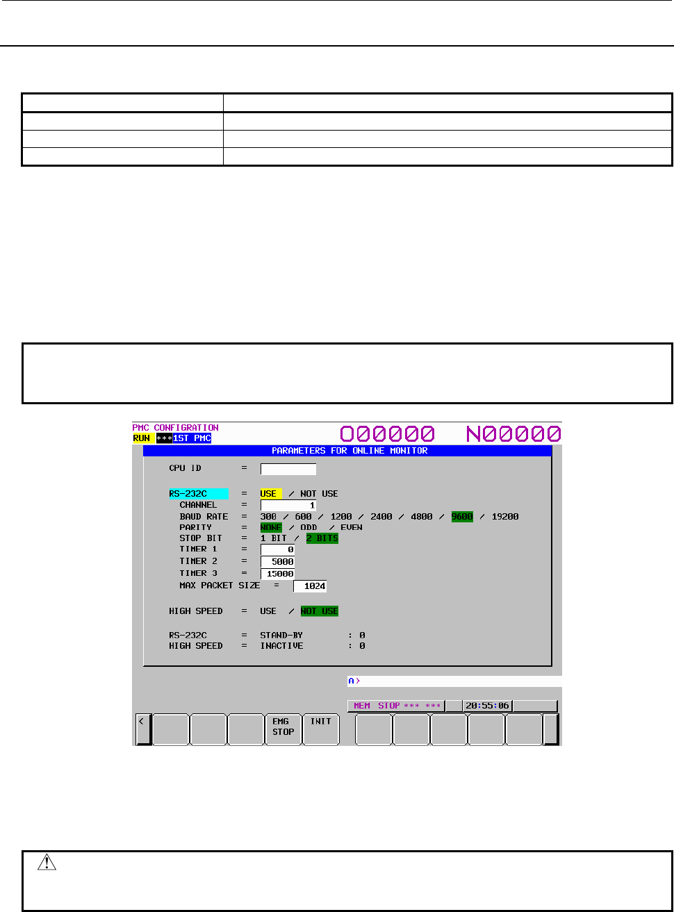
9.PMC CONFIGURATION DATA SETTING SCREENS ([PMC CONFIG])
B-64513EN/03
- 1204 -
9.7.1
Setting Parameters for the Online Function
The online function can be connected using one of the following three methods.
Connection method Applicable software
Ethernet FANUC LADDER-III and Ladder Editing Package
RS-232C FANUC LADDER-III
HSSB Ladder Editing Package
Before using the online function, put the online function into the connection waiting state on the PMC.
To put the PMC into the connection waiting state, use the PARAMETERS FOR ONLINE MONITOR
screen or relevant CNC parameter.
To use Ethernet for connecting the online function, set Ethernet communication parameters. For details
of the Ethernet communication parameters, see Subsection 9.7.3.
(1) Setting of online connection using the PARAMETERS FOR ONLINE MONITOR screen
Press the [ONLINE] soft key to display the PARAMETERS FOR ONLINE MONITOR screen.
NOTE
When the programmer protection function is enabled, the online setting screen is
available. For details, see Section 6.2.
Fig. 9.7.1 PARAMETERS FOR ONLINE MONITOR screen
EMG STOP: Terminates communication forcibly. Use this key if communication becomes
abnormal and the connection cannot be terminated normally.
INIT: Initializes the parameters to their default values.
CAUTION
In case of configuration of CNC with which neither Ethernet nor HSSB is
available, the item of "HIGH SPEED " is not displayed.

B-64513EN/03
9.PMC CONFIGURATION DATA SETTING SCREENS ([PMC CONFIG])
- 1205 -
(a) Case of connection by RS-232C (FANUC LADDER-III)
(i) Check that "NOT USE" is selected at the "RS-232C" item.
(ii) Set the parameter of "CHANNEL" and "BAUD RATE".
(iii) Move the cursor to the "RS-232C" item with Up or Down Cursor key.
(iv) Select "USE" with Left or Right Cursor key.
(b) Case of connection by Ethernet (FANUC LADDER-III, Ladder Editing Package)
(i) Move the cursor to the "HIGH SPEED" item with Up or Down Cursor key.
(ii) Select "USE" with Left or Right Cursor key.
(c) Case of connection by HSSB (Ladder Editing Package)
(i) Move the cursor to the "HIGH SPEED" item with Up or Down Cursor key.
(ii) Select "USE" with Left or Right Cursor key.
NOTE
1 When both "RS-232C = USE" and "HIGH SPEED = USE" are selected, the PMC
system will communicate with the application which is connected first. If PMC
system is already connecting with an application, it can not connect with other
applications.
2 When you use the online function by Ethernet, setting Ethernet parameters of
CNC is necessary in advance.
(2) Setting of online connection by NC parameter
You can enable and disable the online connection for Ethernet, HSSB and RS-232C by NC
parameter No.24 without setting on the PMC online setting screen.
For details of the parameter, see Subsection 2.4.3.
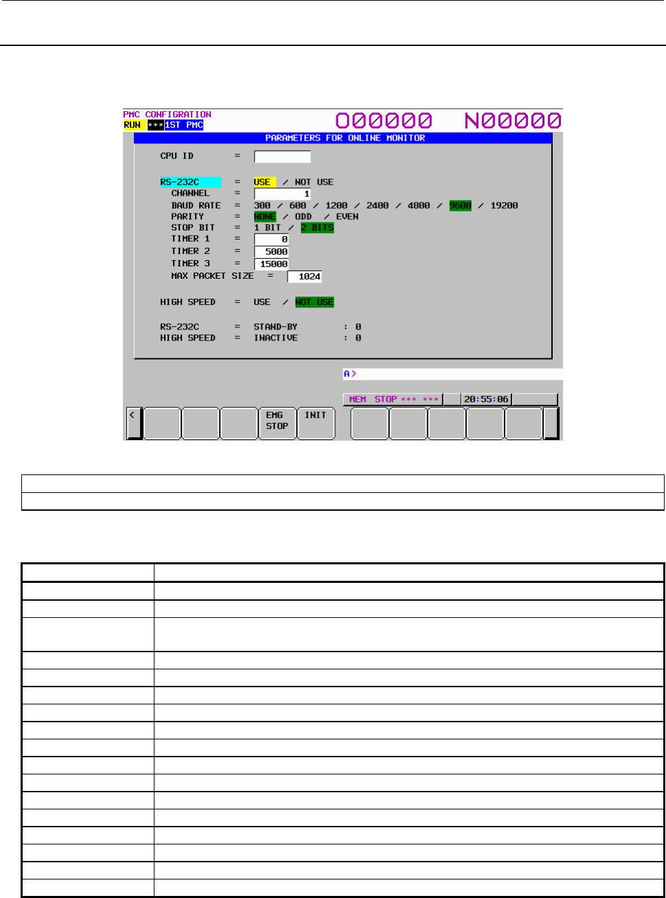
9.PMC CONFIGURATION DATA SETTING SCREENS ([PMC CONFIG])
B-64513EN/03
- 1206 -
9.7.2
Communication Status
The communication status of RS-232C and HIGH SPEED are displayed at the online monitor screen
during the online communication.
Fig. 9.7.2 Communication status of online setting screen
RS-232C : The communication condition of RS-232C is displayed.
HIGH SPEED : The communication condition of high-speed I/F (HSSB or Ethernet) is displayed.
The display messages and the meanings are shown in the table of below.
Displayed messages Meanings
INACTIVE The communication is inactive.
STOPPING The communication is being stopped.(Wait for the termination of communication)
STARTING The communication is being started.(Wait for the termination of communication over
another communication path)
STAND-BY The communication is in standby mode.
CONNECTED The communication is being connected.
NO OPTION The port can be not opened because there is not option of RS-232C.
BAD PARAMETER Invalid RS-232C parameters are specified.
TIMEOUT ERROR A time-out has occurred and communication is aborted.
TIMEOUT(K) ERROR A time-out has occurred and communication is aborted.
BCC ERROR Invalid Block Check Code (packet parity) is specified.
PARITY ERROR A parity error has occurred.
OVER-RUN ERROR A reception overrun has occurred.
SEQUENCE ERROR Packets have been received in invalid sequence.
DATA ERROR Incorrect packet has been received.
QUEUE OVERFLOW The transmit/receive queue has overflowed.
DISCONNECTED Communication has been terminated successfully.
NO CONNECTION The cable is disconnected.
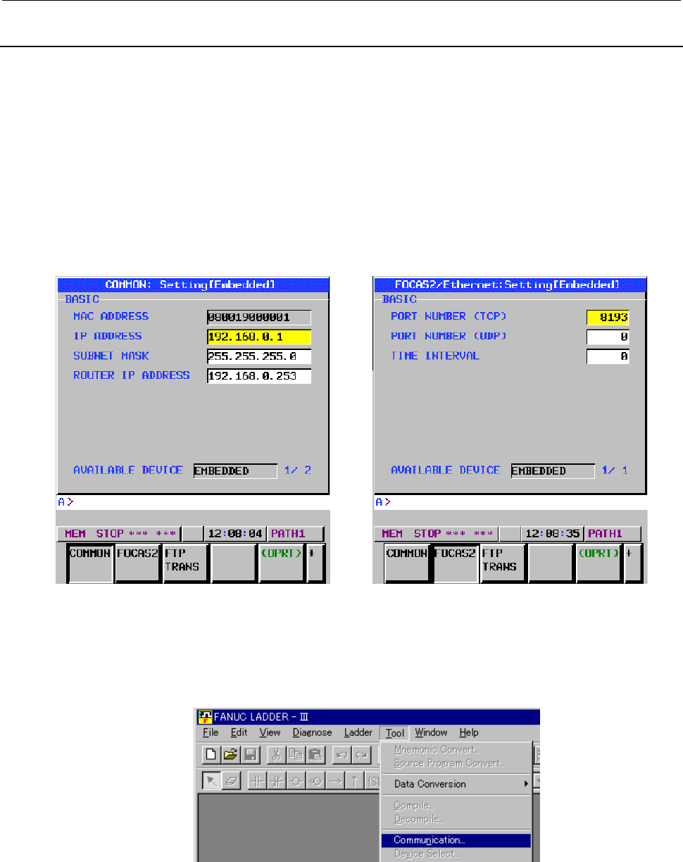
B-64513EN/03
9.PMC CONFIGURATION DATA SETTING SCREENS ([PMC CONFIG])
- 1207 -
9.7.3
About Ethernet Communication Parameters
(1) Setting of Ethernet parameters
When you try to connect FANUC LADDER-III or Ladder Editing Package with CNC by Ethernet, it
is necessary to set some Ethernet parameters. The setting of Ethernet parameters can be set in the
following Ethernet parameter screen of CNC. Refer to the section "EMBEDDED ETHERNET
FUNCTION” of CONNECTION MANUAL (FUNCTION) about the detail of the setting screen and
setting parameters.
The setting item necessary for Ethernet connection for PMC online function is as follows.
• IP ADDRESS (Set the IP address of CNC. 192.168.0.1 etc.)
• SUBNET MASK (Set the mask address of the IP address. 255.255.255.0 etc.)
• ROUTER IP ADDRESS (If you use the router, set the Router IP Address.)
• PORT NUMBER (TCP) (8193 etc.)
Fig. 9.7.3 Ethernet parameter setting screen
(2) Starting online communication by offline programmer (Ethernet connection)
The procedures for online connection with PMC and the offline programmer (FANUC LADDER-III,
Ladder Editing Package) by Ethernet are as follows. (Example: FANUC LADDER-III)
(a) Start up FANUC LADDER-III, and click the [Communication] on [Tool] menu.
(b) Select the [Network Address] tab and push the <Add Host> button. Input the "IP Address" and
"Port No." inputted in (1) of this subsection.
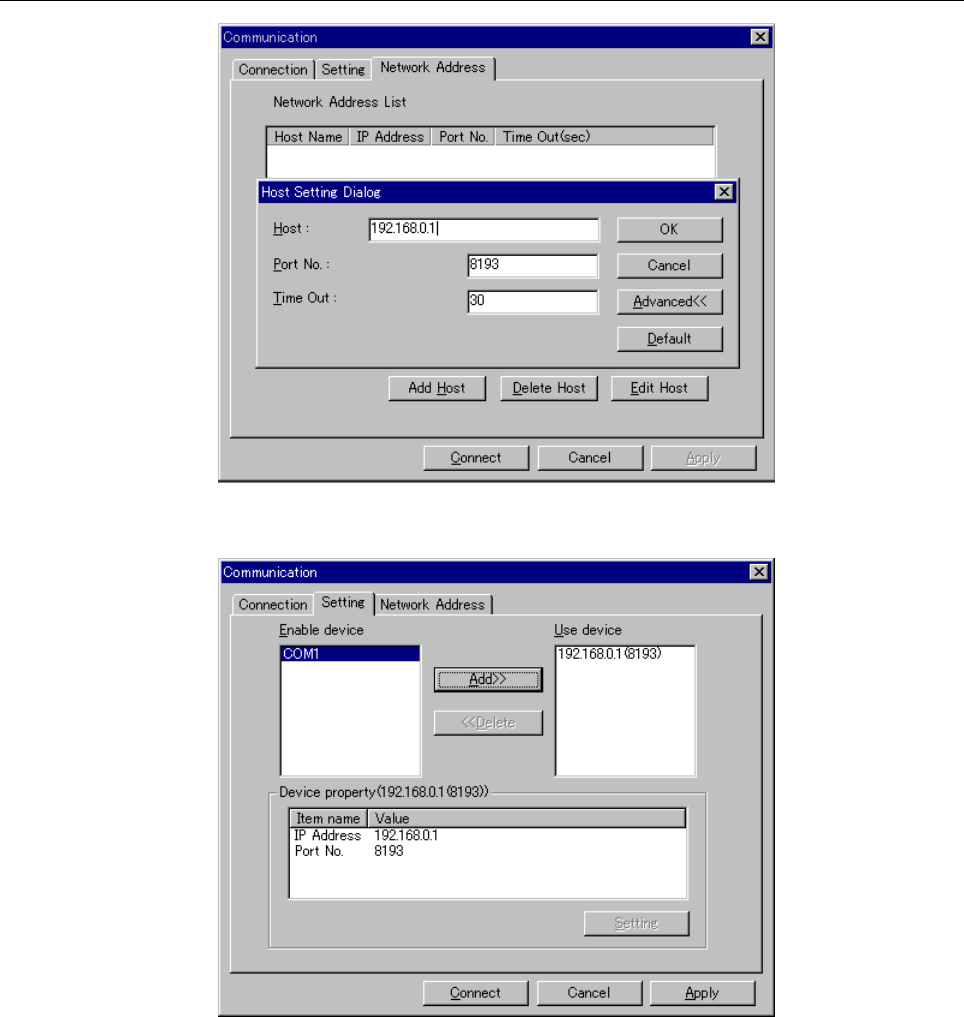
9.PMC CONFIGURATION DATA SETTING SCREENS ([PMC CONFIG])
B-64513EN/03
- 1208 -
(c) Select the [Setting] tab, and add the IP Address to "Use device".
(d) Press the <Connect> button for start of the communication.
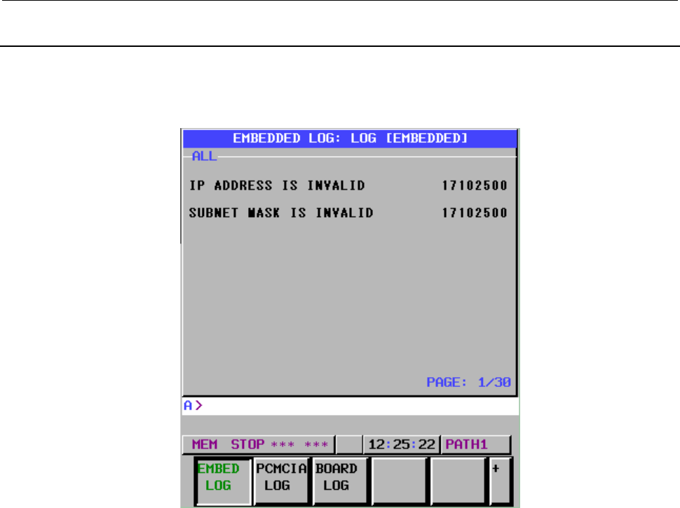
B-64513EN/03
9.PMC CONFIGURATION DATA SETTING SCREENS ([PMC CONFIG])
- 1209 -
9.7.4
About Connection Log of Ethernet
If any errors have occurred during Ethernet connection, the contents of the errors are displayed at
"EMBEDDED LOG" screen of CNC.
Refer to this screen when the communication does not start.
Fig. 9.7.4 The log screen of embedded Ethernet

9.PMC CONFIGURATION DATA SETTING SCREENS ([PMC CONFIG])
B-64513EN/03
- 1210 -
Connection log Meanings and countermeasures
Cat6Err: PDU =
m, n,
[
x
]
date time
Cat6Err: PDU =
n,
[
x
]
date time
Cat6Err: TaskTimeOut[
x
]
date time
An error has occurred during the online communication.
m, n
: Online communication information that is internal information of a
system.
x: Error information
6001 PMC does not support the Ethernet.
Confirm the Series/Edition of PMC software.
6003 Unsupported command data was received. Confirm the Series/Edition
of Ethernet board software.
6004 There was an error in command data.
Confirm the Series/Edition of Ethernet board software.
6005 PMC does not receive command data.
Confirm the communication status at the online setting screen of PMC.
6010 PMC does not receive command data.
Confirm if "HIGH SPEED = USE" is selected and other application is
not connected at the online setting screen of PMC.
6011 Time-out error occurred at PMC.
Increase the value of "Time Out" in [Network Address] of
[Communication] menu for FANUC LADDER-III or Ladder Editing
Package.
6012 PMC does not receive command data because it is busy for
processing.
Confirm the communication status at the online setting screen of PMC.
6013 Time-out error occurred at PMC.
Increase the value of "Time Out" in [Network Address] of
[Communication] menu for FANUC LADDER-III or Ladder Editing
Package.
6101 PMC received an unsupported function code.
Confirm the Series/Edition of PMC software.
date time
: The time when the error occurred.
Ex.) "0323" means March 23rd.
"1858" means 6:58 PM.
"21161714" means 21st 4:17 PM 14 seconds.
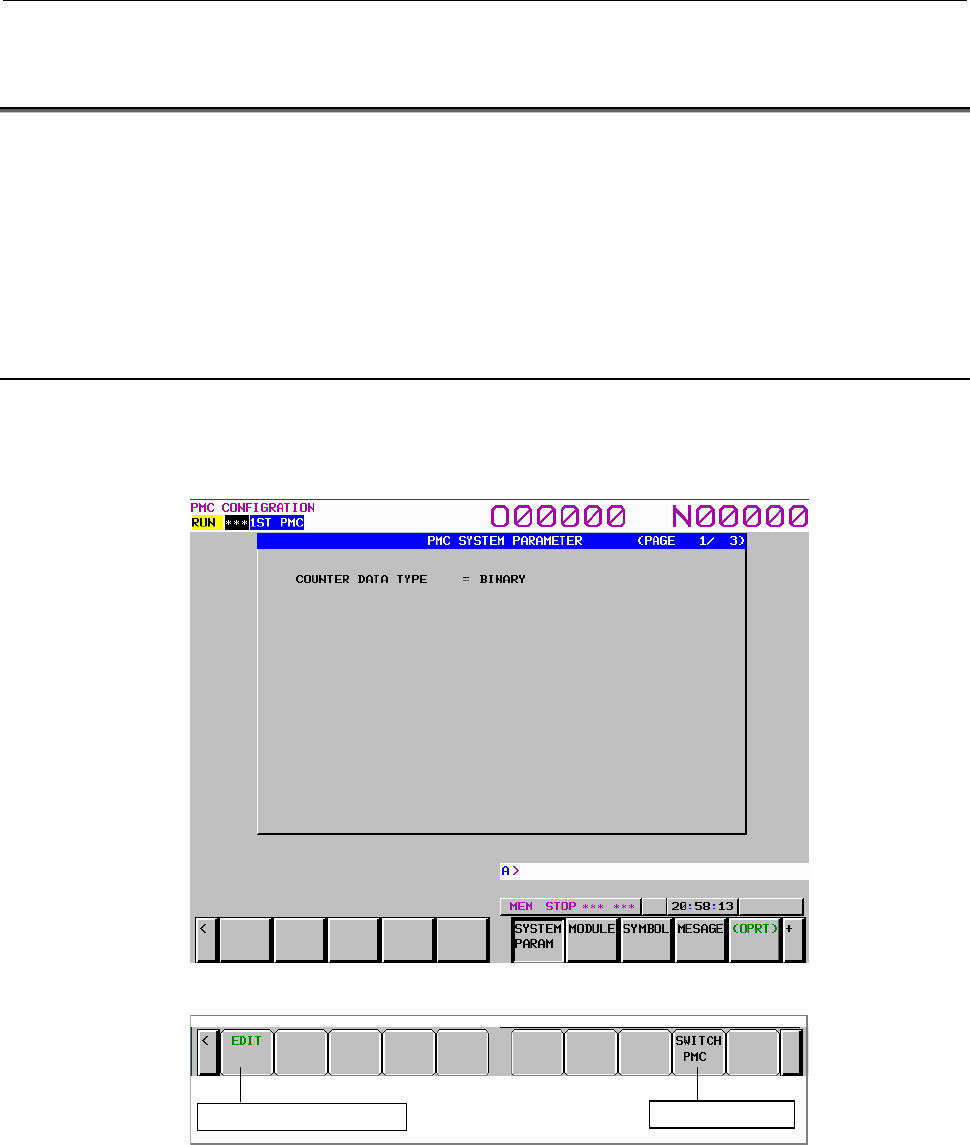
B-64513EN/03
9.PMC CONFIGURATION DATA SETTING SCREENS ([PMC CONFIG])
- 1211 -
9.8 DISPLAYING AND SETTING SYSTEM PARAMETERS
([SYSTEM PARAM] SCREENS)
On the SYSTEM PARAMETER screen, you can display and set the following data items:
• Counter data type
• Parameters for an FS0 operator's panel
• Parameters for the selectable I/O Link assignment function
To switch to each data display/setting screen, use the page keys.
9.8.1 Displaying and Setting the Counter Data Type
Display and set the type of counter data used by the functional instruction counter.
Set the BINARY or the BCD.
Display screen
Screen operation
Switch to the edit screen Switch PMC path
(1) Operation using the soft key
[EDIT] Switch to the edit screen
Switches to the system parameter edit screen.
[SWITCH PMC] Switching PMC path or divided ladder programs
Switches PMC path or divided ladder program. For details of the operation, refer to “6.3”.
By setting keep relay K935.0 to 1, you can display PMC program list screen. For details, refer
to ”2.2.11”.
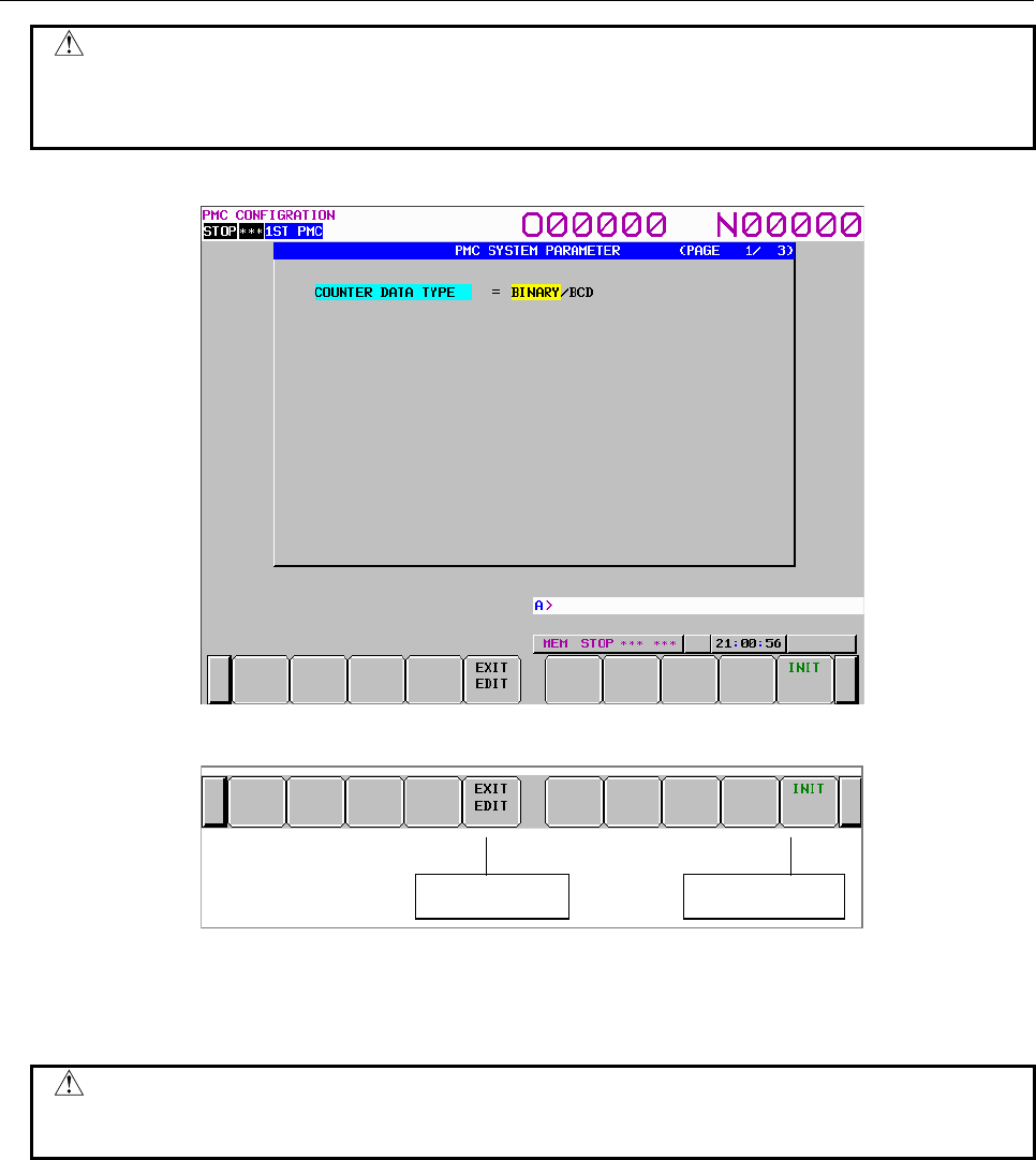
9.PMC CONFIGURATION DATA SETTING SCREENS ([PMC CONFIG])
B-64513EN/03
- 1212 -
CAUTION
When the programmer protection function is enabled, the [EDIT] soft key
appears and is available. When the online monitor function is enabled, you
cannot move to the system parameter edit screen. For details, see Section 6.2.
Setting screen
Screen operation
Initialize settingsTerminate setting
(1) Operation using the soft key
(a) [EXIT EDIT] Terminate setting
Switches to the system parameter display screen.
CAUTION
After changing the data type, set the counter value again.
See Subsection 7.3.2.
(b) [INIT] Initialize settings
Initializes all system parameters.
(2) Screen operation using other keys
Use cursor keys to switch between BINARY and BCD.
(3) RETURN key operation
On the system parameter edit screen, the return key operation is disabled. To terminate system
parameter editing and return to the system parameter display screen, use the [EXIT EDIT] soft key.
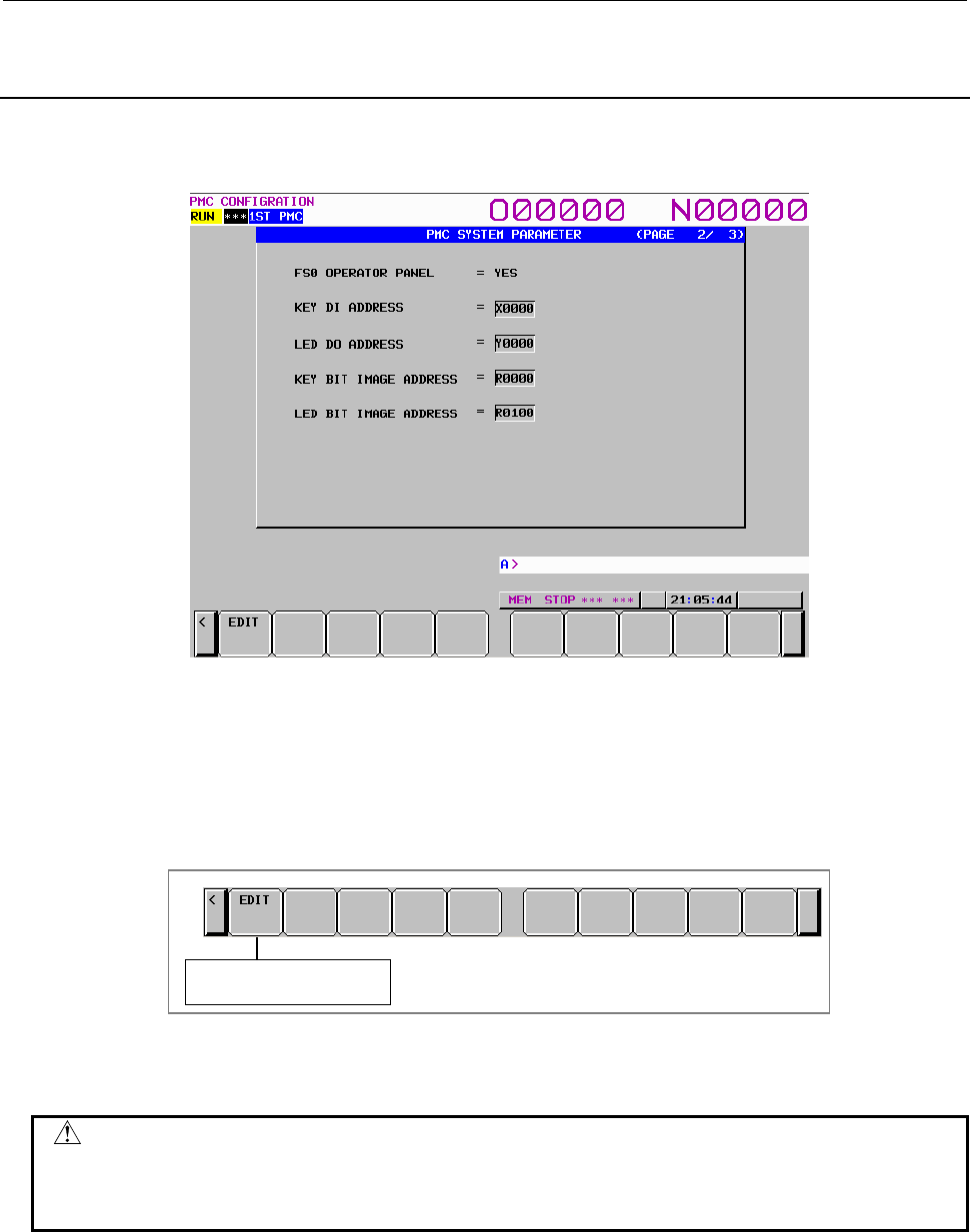
B-64513EN/03
9.PMC CONFIGURATION DATA SETTING SCREENS ([PMC CONFIG])
- 1213 -
9.8.2
Displaying and Setting Parameters for an FS0 Operator's
Panel
Display and set parameters for using an FS0 operator's panel.
Display screen
• FS0 OPERATOR PANEL Whether to use an FS0 operator's panel
• KEY DI ADDRESS Start address of actually connected external DI
• LED DO ADDRESS Start address of actually connected external DO
• KEY BIT IMAGE ADDRESS Start address of the key image referenced by user programs
• LED BIT IMAGE ADDRESS Start address of the LED image generated by user programs
Screen operation
Move to the edit screen
(1) Operation using the soft key
[EDIT] Switch to the edit screen
Switches to the system parameter edit screen.
CAUTION
When the programmer protection function is enabled, the [EDIT] soft key
appears and is available. When the online monitor function is enabled, you
cannot move to the system parameter edit screen. For details, see Section 6.2.
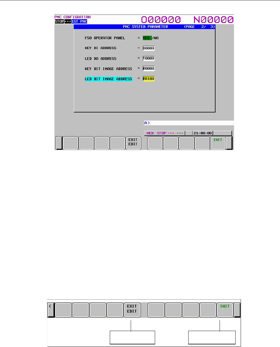
9.PMC CONFIGURATION DATA SETTING SCREENS ([PMC CONFIG])
B-64513EN/03
- 1214 -
Setting screen
• FS0 OPERATOR PANEL
Specify whether to connect an FS0 operator's panel. When setting this item to YES, set the
addresses of the actual DI and DO connected to the operator's panel, address of the key image
transferred from the operator's panel, and address of the LED image transferred to the operator's
panel.
• KEY DI ADDRESS
Set the start address of the actually connected external DI with a PMC address (X0 to X127, X200 to
X327, X400 to X527, or X600 to X727).
• LED DO ADDRESS
Set the start address of the actually connected external DO with a PMC address (Y0 to Y127, Y200
to Y327, Y400 to Y527, or Y600 to Y727).
• KEY BIT IMAGE ADDRESS
Set the start address of the key image referenced by user programs with a PMC address. Normally,
set an internal relay (R) area.
• LED BIT IMAGE ADDRESS
Set the start address of the LED image generated by user programs with a PMC address. Normally,
set an internal relay (R) area.
Screen operation
Initialize settingsTerminate setting
(1) Operation using the soft key
(a) [EXIT EDIT] Terminate setting
Switches to the system parameter display screen.
(b) [INIT] Initialize settings
Initializes all system parameters.

B-64513EN/03
9.PMC CONFIGURATION DATA SETTING SCREENS ([PMC CONFIG])
- 1215 -
(2) Screen operations using other keys
Use the [↑] and [↓] cursor keys to change the item to be edited.
Use the [←] and [→] cursor keys to change the setting.
(3) RETURN key operation
On the system parameter edit screen, the return key operation is disabled. To terminate system
parameter editing and return to the system parameter display screen, use the [EXIT EDIT] soft key.
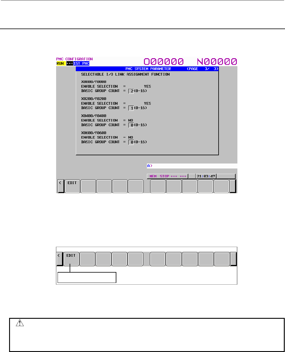
9.PMC CONFIGURATION DATA SETTING SCREENS ([PMC CONFIG])
B-64513EN/03
- 1216 -
9.8.3
Displaying and Setting Parameters for the Selectable I/O Link
Assignment Function
Display and set parameters for using the selectable I/O Link assignment function.
Display screen
• ENABLE SELECTION
Whether to enable or disable the selectable I/O Link assignment function
• BASIC GROUP COUNT
Number of groups always enabled for any machine configuration
Screen operation
Move to the edit screen
(1) Operation using the soft key
(a) [EDIT] Switch to the edit screen
Switches to the system parameter edit screen.
CAUTION
When the programmer protection function is enabled, the [EDIT] soft key
appears and is available. When the online monitor function is enabled, the
system parameter edit screen cannot be displayed. For details, see Section 6.2.
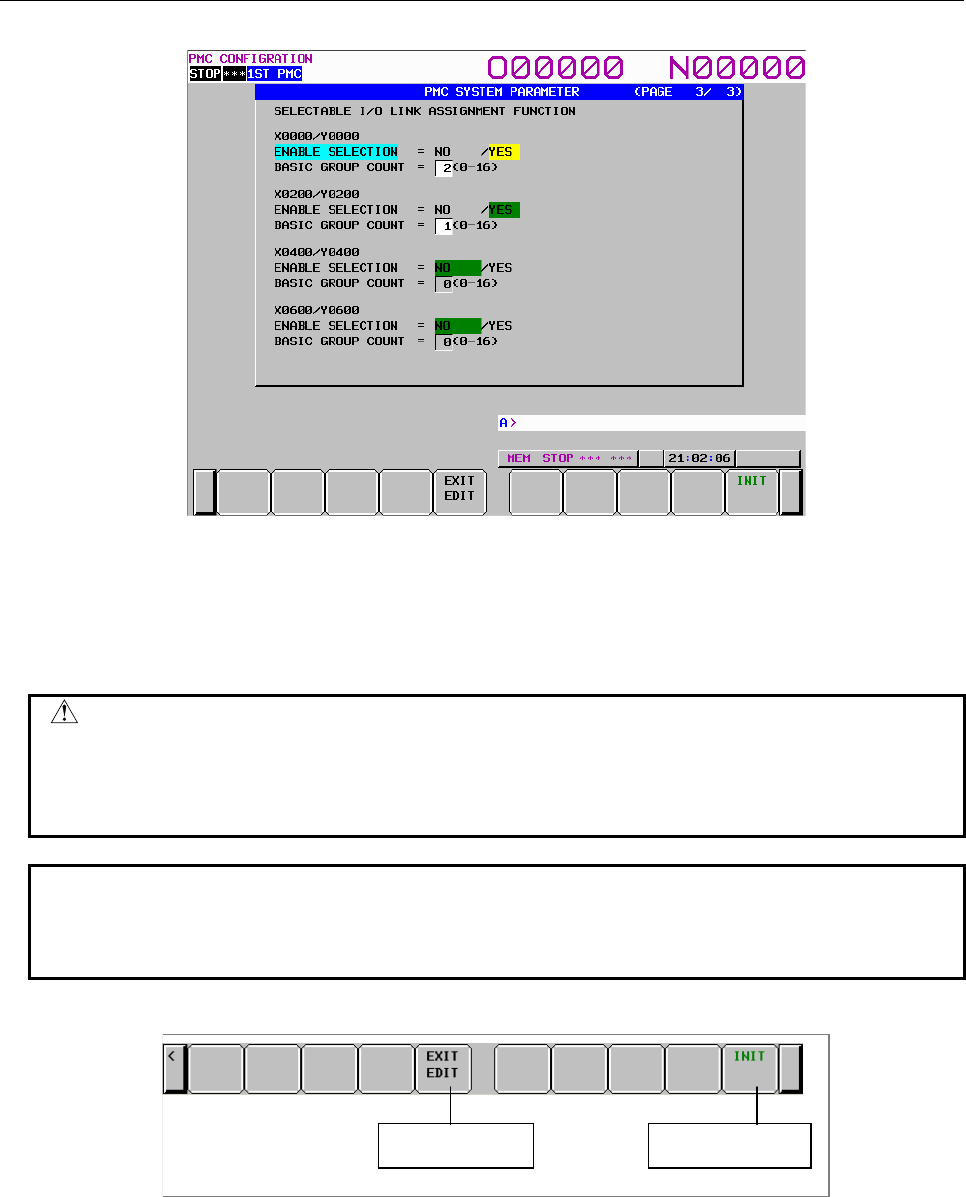
B-64513EN/03
9.PMC CONFIGURATION DATA SETTING SCREENS ([PMC CONFIG])
- 1217 -
Setting screen
• ENABLE SELECTION
Specify whether to enable or disable the selectable I/O Link assignment function with YES or NO.
The initial setting is NO (disabled).
• BASIC GROUP COUNT
Set the number of groups always enabled for any machine configuration.
CAUTION
When enabling this function, set the setting parameters (K920 to K927 described
below) properly according to the actually connected I/O devices. If this function
is enabled, but the DI/DO area is not assigned to a hardware channel, the
function does not operate.
NOTE
The parameters can be set only for available channels according to the I/O Link
configuration. For a channel for which the parameters cannot be set, the BASIC
GROUP COUNT field is left blank.
Screen operation
Initialize settingsTerminate setting
(1) Operation using the soft key
(a) [EXIT EDIT] Terminate setting
Switches to the system parameter display screen.
(b) [INIT] Initialize settings
Initializes all system parameters.

9.PMC CONFIGURATION DATA SETTING SCREENS ([PMC CONFIG])
B-64513EN/03
- 1218 -
(2) Screen operations using other keys
Use the [↑] and [↓] cursor keys to change the item to be edited.
Use the [←] and [→] cursor keys to change the setting.
(3) RETURN key operation
On the system parameter edit screen, the return key operation is disabled. To terminate system
parameter editing and return to the system parameter display screen, use the [EXIT EDIT] soft key.
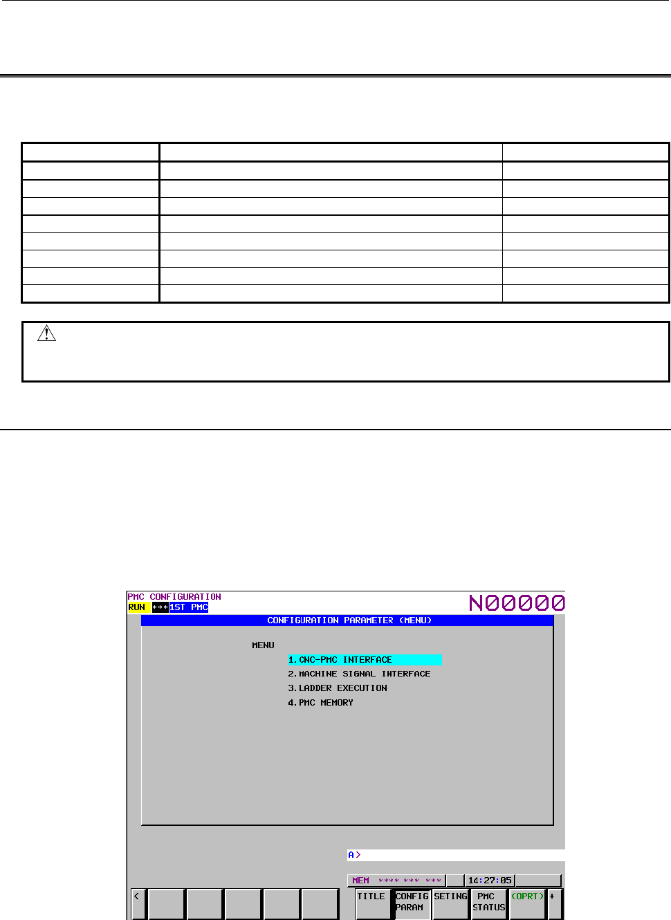
B-64513EN/03
9.PMC CONFIGURATION DATA SETTING SCREENS ([PMC CONFIG])
- 1219 -
9.9 DISPLAYING AND SETTING CONFIGURATION
PARAMETERS ([CONFIG PARAM] SCREENS)
Configuration parameter setting screens display the following NC parameters related to PMCs in an easy-
to-understand manner and facilitate setting.
No. Settings Remarks
11900 to 11904 Execution priorities of multiple PMCs LADDER EXEC screen
11905 to 11909 Execution ratios of multiple PMCs LADDER EXEC screen
11910 to 11912 Input/output addresses of the I/O Link MACHINE I/F screen
11915 to 11917 Input/output address of dual assignment of I/O Link channel MACHINE I/F screen
11920 to 11929 G/F addresses of the CNC interface CNC I/F screen
11930 Level-1 execution cycle LADDER EXEC screen
11931 Start/stop mode of multiple PMCs LADDER EXEC screen
11940 to 11944 PMC Memory type PMC MEMORY screen
CAUTION
1 For details of each NC parameter, see Subsection 2.4.3.
2 After setting these NC parameters, turn the power off, then on again.
9.9.1
Menu for Setting Configuration Parameters
There are the following PMC configuration parameter setting screens.
• The MENU screen
• The CNC-PMC INTERFACE screen
• The MACHINE SIGNAL INTERFACE screen
• The LADDER EXECUTION screen
• The PMC MEMORY screen
Move to each setting screen from the MENU screen.
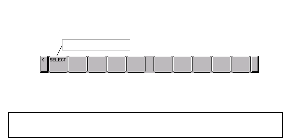
9.PMC CONFIGURATION DATA SETTING SCREENS ([PMC CONFIG])
B-64513EN/03
- 1220 -
Soft key on the PMC CONFIGRATION PARAMETER (MENU) screen
Switch to each settin
g
screen
Fig. 9.9.1 Soft key on the PMC CONFIGRATION PARAMETER (MENU) screen
(1) Operation using the soft key
(a) [SELECT] Switch to each setting screen
NOTE
Each setting screen can be protected using the programmer protection function.
If a setting screen is protected, the [SELECT] soft key is not displayed.
(2) Screen operation using other keys
Use cursor keys to switch to a desired setting item.
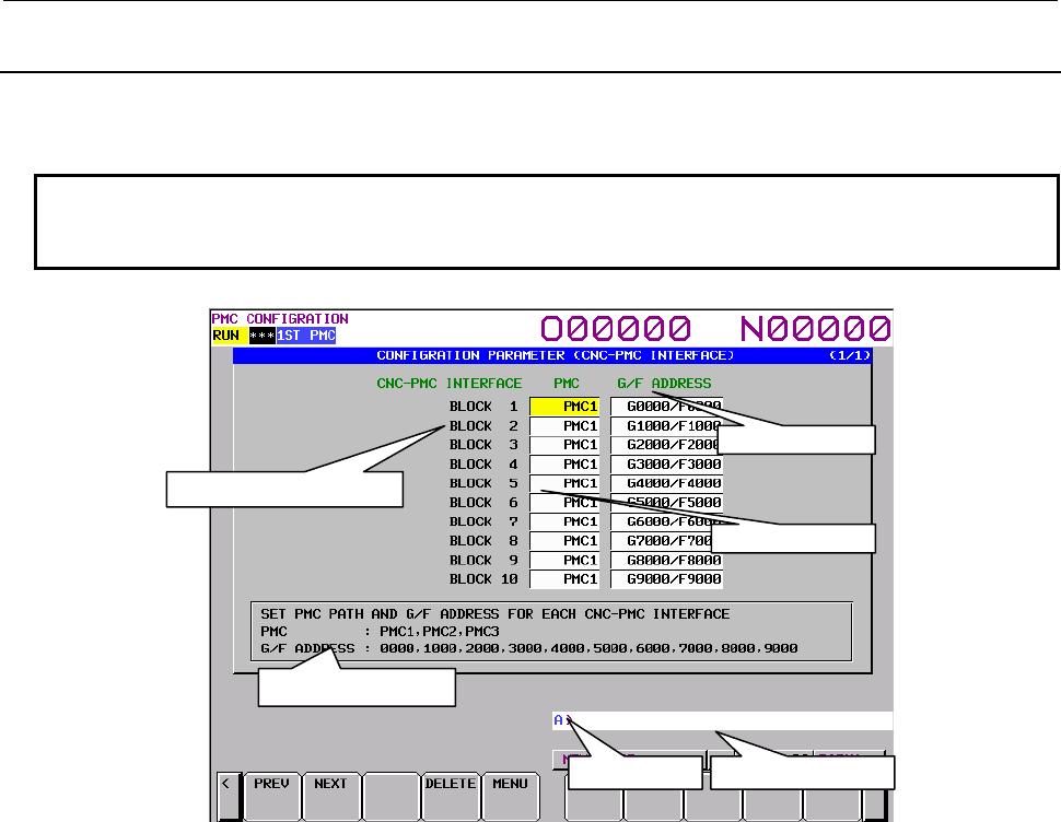
B-64513EN/03
9.PMC CONFIGURATION DATA SETTING SCREENS ([PMC CONFIG])
- 1221 -
9.9.2
Setting the CNC-PMC Interface
On the PMC CONFIGRATION PARAMETER (CNC-PMC INTERFACE) screen, set a correspondence
between the G/F addresses of each PMC and CNC-PMC interface.
NOTE
For details of the CNC-PMC interface, see the description of the CNC-PMC
interface in Subsection 2.4.3.
PMC CONFIGRATION PARAMETER (CNC-PMC INTERFACE) screen
(1) CNC-PMC INTERFACE
Displays the number of each CNC-PMC interface block.
BLOCK 1: G0000 to G0768/F0000 to F0768 viewed from the CNC
BLOCK 2: G1000 to G1768/F1000 to F1768 viewed from the CNC
BLOCK 3: G2000 to G2768/F2000 to F2768 viewed from the CNC
BLOCK 4: G3000 to G3768/F3000 to F3768 viewed from the CNC
BLOCK 5: G4000 to G4768/F4000 to F4768 viewed from the CNC
BLOCK 6: G5000 to G5768/F5000 to F5768 viewed from the CNC
BLOCK 7: G6000 to G6768/F6000 to F6768 viewed from the CNC
BLOCK 8: G7000 to G7768/F7000 to F7768 viewed from the CNC
BLOCK 9: G8000 to G8768/F8000 to F8768 viewed from the CNC
BLOCK 10: G9000 to G9768/F9000 to F9768 viewed from the CNC
(2) PMC
Assign a PMC to each CNC-PMC interface block.
PMC1: First PMC
PMC2: Second PMC
PMC3: Third PMC
PMC4: Forth PMC
PMC5: Fifth PMC
(3) G/F ADDRESS
Set the start G/F addresses.
G/F addresses
PMC
CNC-PMC interface blocks
Help message
Key input line Message display line
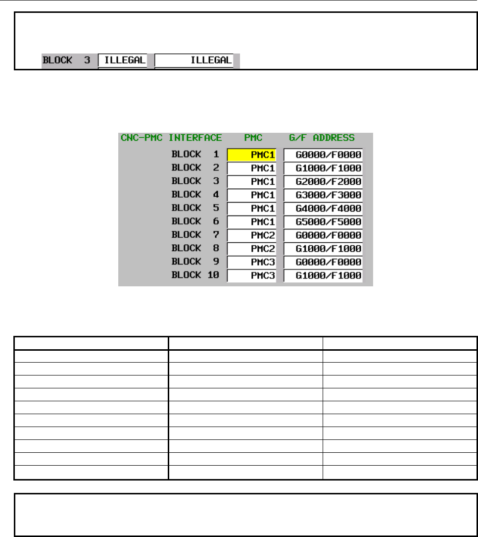
9.PMC CONFIGURATION DATA SETTING SCREENS ([PMC CONFIG])
B-64513EN/03
- 1222 -
NOTE
If an invalid value is set for the NC parameter, "ILLEGAL" is displayed as shown
below:
(4) Help message
A help message for operation is displayed.
(5) Example of screen setting and corresponding NC parameter settings
When values are set on the screen as shown in the figure above, the following settings are input for
the corresponding NC parameters:
Block number NC parameter number Setting
1 11920 100
2 11921 101
3 11922 102
4 11923 103
5 11924 104
6 11925 105
7 11926 200
8 11927 201
9 11928 300
10 11929 301
NOTE
This screen can be protected from editing using the programmer protection
function.
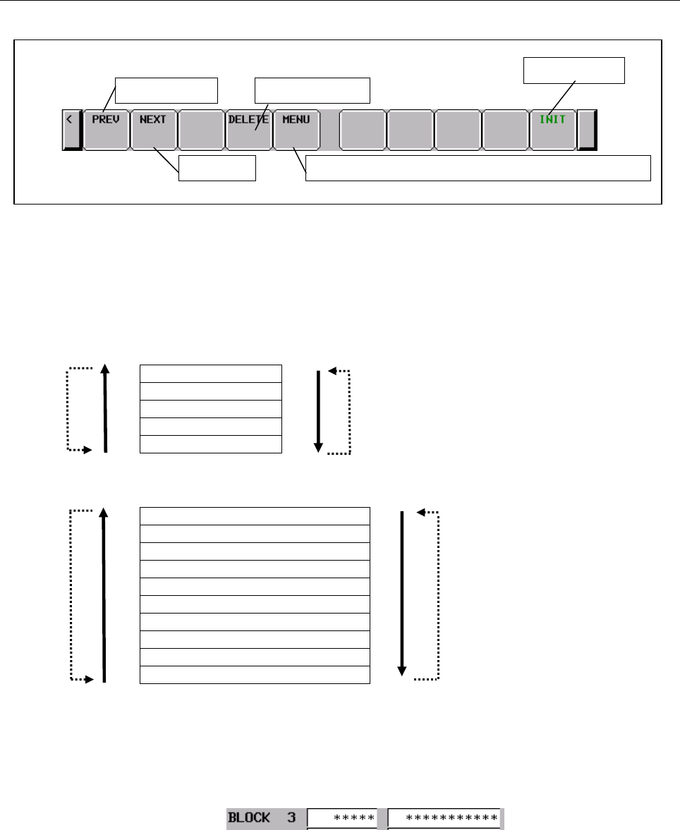
B-64513EN/03
9.PMC CONFIGURATION DATA SETTING SCREENS ([PMC CONFIG])
- 1223 -
Screen operation
Fig. 9.9.2 Soft keys on the CNC-PMC INTERFACE screen
(1) Operations using the soft keys
(a) [PREV] Previous choice
[NEXT] Next choice
Inputs the value of the previous or next choice for the item at the cursor like a toggle switch.
To select a PMC
PMC1
PMC2
PMC3
PMC4
PMC5
To select G/F addresses
G0000 to G0768/F0000 to F0768
G1000 to G1768/F1000 to F1768
G2000 to G2768/F2000 to F2768
G3000 to G3768/F3000 to F3768
G4000 to G4768/F4000 to F4768
G5000 to G5768/F5000 to F5768
G6000 to G6768/F6000 to F6768
G7000 to G7768/F7000 to F7768
G8000 to G8768/F8000 to F8768
G9000 to G9768/F9000 to F9768
This soft key is displayed and can be operated only when editing is allowed.
(b) [DELETE] Delete the setting
Deletes the setting of the item at the cursor.
After data is deleted, "*****" is displayed as shown below:
This soft key is displayed and can be operated only when editing is allowed.
Soft keys on the CNC I/F screen
Previous choice
Move to the PMC CONFIGRATION PARAMETER (MENU) screenNext choice
Delete the setting
Initialize settings
PREV NEXT
PREV NEXT
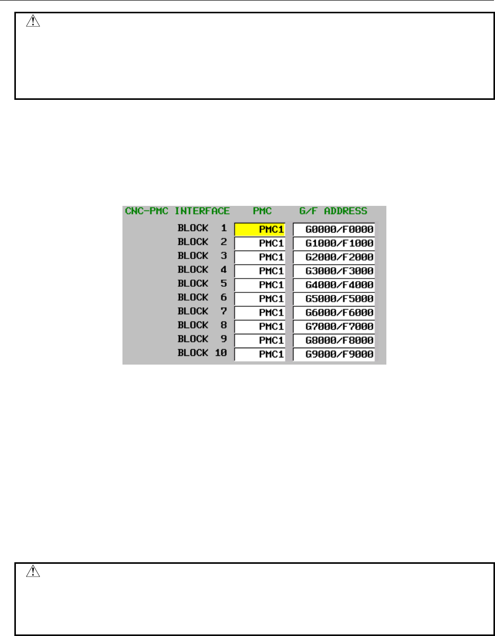
9.PMC CONFIGURATION DATA SETTING SCREENS ([PMC CONFIG])
B-64513EN/03
- 1224 -
CAUTION
When the NC parameters are all set to 0, the initial status (for the initial status,
see (d)) is set. Deleting all items with this operation is equivalent to setting the
initial status. For this reason, if an attempt is made to delete the last item, the
following message appears and the item cannot be deleted:
"LAST SETTING DATA CAN NOT BE DELETED."
(c) [MENU] Switch to the MENU screen
Switches to the MENU screen.
(d) [INIT] Initialize settings
Initializes the interface settings.
This soft key is displayed and can be operated only when editing is allowed.
The initial settings are as follows:
(2) Screen operations using other keys
Cursor keys
Use them to change the CNC-PMC interface block to be set.
INPUT key
You can also set an item by entering a numeric value or string and pressing the INPUT key.
To set a PMC
• Enter PMC1, PMC2, PMC3, PMC4 or PMC5.
• Enter a numeric value 1, 2, 3, 4 or 5.
To set G/F addresses
• Enter a displayed string such as G0000/F0000.
• Enter a start address such as 0, 1000, or 2000.
CAUTION
1 You can set an item on this screen regardless of the NC mode.
2 If data is duplicate, the data is displayed in red and the following message
appears:
"DUPLICATE G/F ADDRESS"
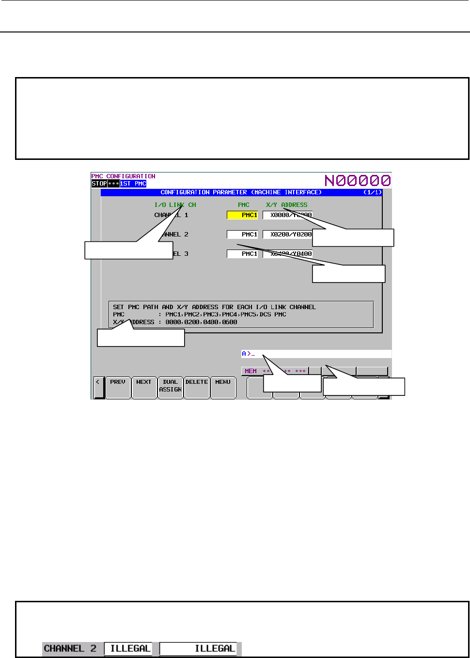
B-64513EN/03
9.PMC CONFIGURATION DATA SETTING SCREENS ([PMC CONFIG])
- 1225 -
9.9.3
Setting the Machine Signal Interface
On the PMC CONFIGRATION PARAMETER (MACHINE INTERFACE) screen, set the input/output
addresses of the I/O Link.
NOTE
1 For details of input/output addresses of the I/O Link, see the description of
input/output addresses of the I/O Link in Subsection 2.4.3.
2 For details of input/output addresses for virtual channels of the I/O Link channel
split function, see the description of Input/output addresses of dual assignment
of I/O Link channel in Subsection 2.4.3.
PMC CONFIGRATION PARAMETER (MACHINE INTERFACE) screen
(1) I/O Link CH
Displays I/O Link channel numbers.
(2) PMC
Displays each PMC.
PMC1: First PMC
PMC2: Second PMC
PMC3: Third PMC
PMC4: Forth PMC
PMC5: Fifth PMC
DCSPMC: Dual check safety ladder
(3) X/Y ADDRESS
Set the start X/Y addresses.
NOTE
If an invalid value is set for the NC parameter, "ILLEGAL" is displayed as shown
below:
X/Y addresses
PMC
I/O Link channels
Hel
p
messa
g
e
Ke
y
in
p
ut line Messa
g
e dis
p
la
y
line
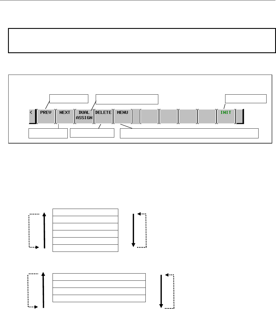
9.PMC CONFIGURATION DATA SETTING SCREENS ([PMC CONFIG])
B-64513EN/03
- 1226 -
(4) Help message
A help message for operation is displayed.
NOTE
This screen can be protected from editing using the programmer protection
function.
Screen operation
Fig. 9.9.3 Soft keys on the MACHINE SIGNAL INTERFACE screen
(1) Operations using the soft keys
(a) [PREV] Previous choice
[NEXT] Next choice
Inputs the value of the previous or next choice for the item at the cursor like a toggle switch.
To select a PMC
PMC1
PMC2
PMC3
PMC4
PMC5
PMCDCS
To select X/Y addresses
X0000 to X0127/Y0000 to Y0127
X0200 to X0327/Y0200 to Y0327
X0400 to X0527/Y0400 to Y0527
X0600 to X0727/Y0600 to Y0727
This soft key is displayed and can be operated only when editing is allowed.
Soft keys on the MACHINE SIGNAL INTERFACE screen
Previous choice Initialize settings
Move to the PMC CONFIGRATION PARAMETER (MENU) screen
Next choice Delete the setting
Display dual assignment
NEXTPREV
PREV NEXT
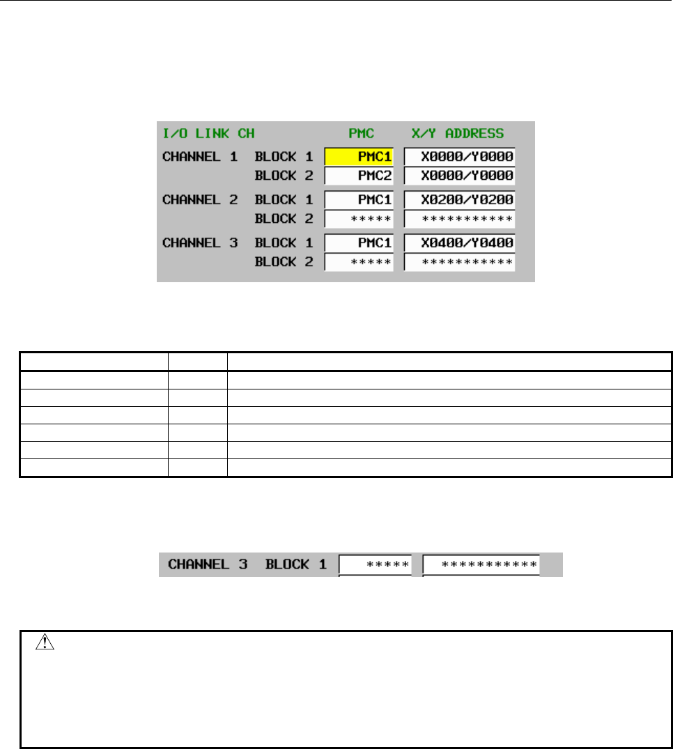
B-64513EN/03
9.PMC CONFIGURATION DATA SETTING SCREENS ([PMC CONFIG])
- 1227 -
(b) [DUAL ASSIGN] Display of dual assignment
Setting items (BLOCK 2) of dual assignment of I/O link channel are displayed. They are
already displayed when they have been set. This soft key is displayed and can be operated only
when editing is allowed.
Example : Set the second block of channel 1
Setting of dual assignment of I/O link channel
These settings reflect NC parameters of "I/O link input/output address" and "input/output address of
dual assignment of I/O link channel" as follows.
NC parameter number Setting Meaning
11910 100 Assign X/Y0 to X/Y127 of the first PMC to the first block of channel 1.
11915 200 Assign X/Y0 to X/Y127 of the second PMC to the second block of channel 1.
11911 101 Assign X/Y200 to X/Y327 of the first PMC to channel 2.
11916 0 Second block is not used in channel 2.
11912 102 Assign X/Y400 to X/Y527 of the first PMC to channel 3.
11917 0 Second block is not used in channel 3.
(c) [DELETE] Delete the setting
Deletes the setting of the item at the cursor.
After data is deleted, "*****" is displayed as shown below:
This soft key is displayed and can be operated only when editing is allowed.
CAUTION
When the NC parameters are all set to 0, the initial status (for the initial status,
see (e)) is set. Deleting all items with this operation is equivalent to setting the
initial status. For this reason, if an attempt is made to delete the last item, the
following message appears and the item cannot be deleted:
"LAST SETTING DATA CAN NOT BE DELETED."
(d) [MENU] Switch to the MENU screen
Switches to the MENU screen.
(e) [INIT] Initialize settings
Initializes the interface settings.
This soft key is displayed and can be operated only when editing is allowed.
The initial settings are as follows:
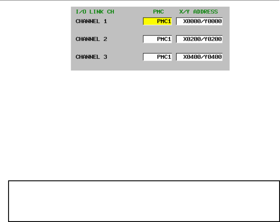
9.PMC CONFIGURATION DATA SETTING SCREENS ([PMC CONFIG])
B-64513EN/03
- 1228 -
(2) Screen operations using other keys
Cursor keys
Use them to change the I/O Link channel to be set.
INPUT key
You can also set an item by entering a numeric value or string and pressing the INPUT key.
To set a PMC
• Enter PMC1, PMC2, PMC3, PMC4, PMC5 or DCSPMC.
• Enter a numeric value 1, 2, 3, 4, 5 or S.
To set X/Y addresses
• Enter a displayed string such as X0000/Y0000.
• Enter a start address such as 0, 200,400 or 600.
NOTE
1 You can set an item on this screen regardless of the NC mode.
2 If data is duplicate, the data is displayed in red and the following message
appears:
"DUPLICATE X/Y ADDRESS"
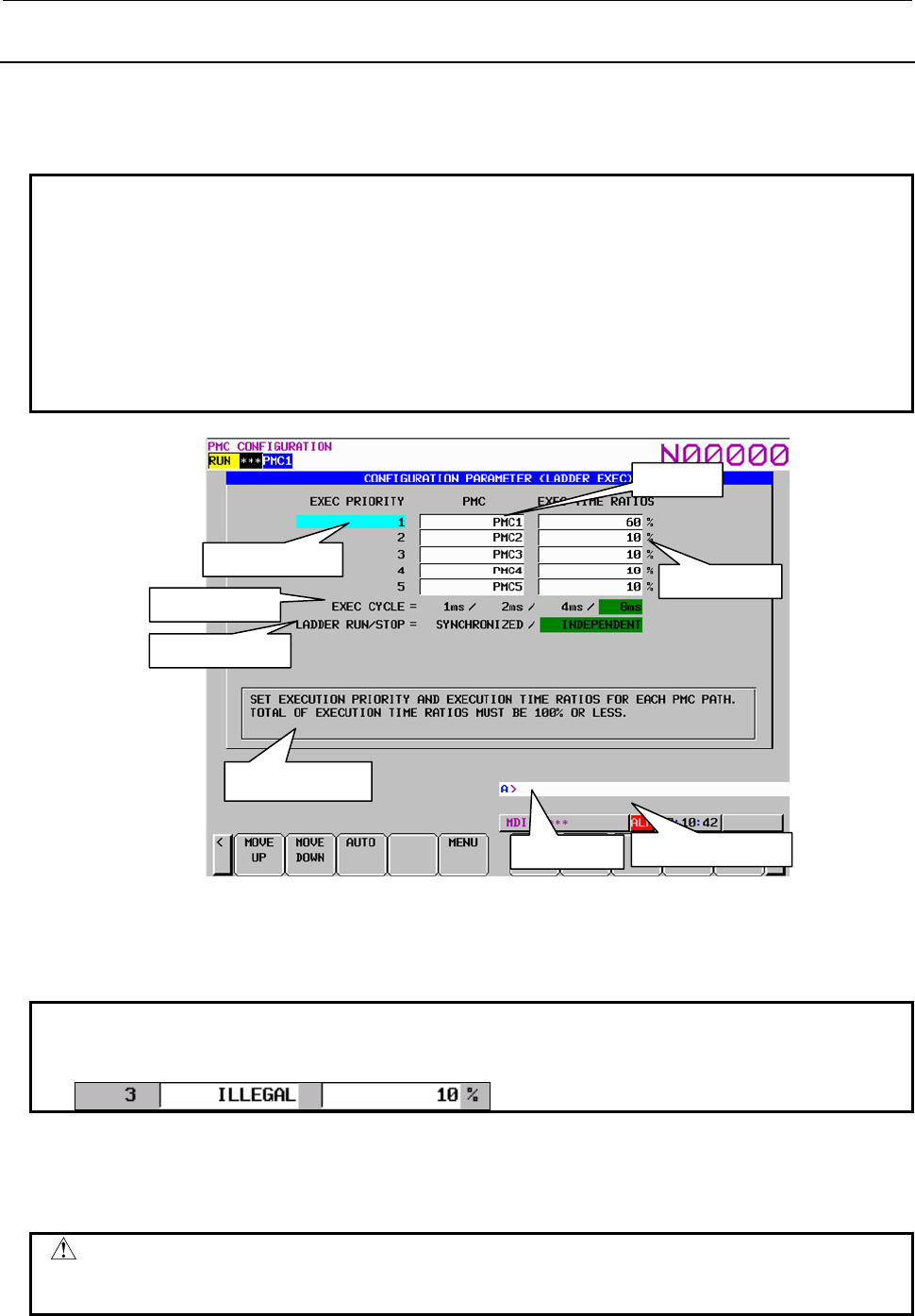
B-64513EN/03
9.PMC CONFIGURATION DATA SETTING SCREENS ([PMC CONFIG])
- 1229 -
9.9.4
Setting the Parameters Related to Ladder Execution
On the PMC CONFIGRATION PARAMETER (LADDER EXEC) screen, set the execution priorities of
multiple PMCs, execution ratios of multiple PMCs, level-1 execution cycle, and start/stop control of
multiple PMCs.
NOTE
1 For details of execution priorities of multiple PMCs, see the description of
execution priorities of multiple PMCs in Subsection 2.4.3.
2 For details of execution ratios of multiple PMCs, see the description of execution
ratios of multiple PMCs in Subsection 2.4.3.
3 For details of the level-1 execution cycle, see the description of level-1 execution
cycle in Subsection 2.4.3.
4 For details of the start/stop mode of multiple PMCs, see the description of
start/stop control of multiple PMCs in Subsection 2.4.3.
Key input line Message display line
Help message
Execution time
PMC
Execution priority
Execution cycle
Ladder start/stop
(1) EXEC PRIORITY PMC EXEC TIME RATIOS
Displays and sets the execution priority of each PMC. Also displays and sets the execution time
ratio of each PMC.
NOTE
If an invalid value is set for the NC parameter, "ILLEGAL" is displayed as shown
below:
(2) EXEC CYCLE
Set the PMC execution cycle.
PMC execution cycle is different by PMC type.
CAUTION
If an invalid value is set for the NC parameter, the cursor is not displayed. Press
the [INIT] soft key to release the invalid state.
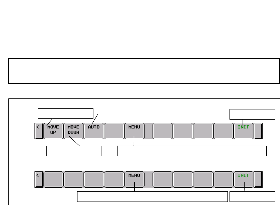
9.PMC CONFIGURATION DATA SETTING SCREENS ([PMC CONFIG])
B-64513EN/03
- 1230 -
(3) LADDER RUN/STOP
Specify whether to start/stop the ladder programs of multiple PMCs synchronously or control the
start/stop of the ladder program of each PMC independently.
(4) Help message
A help message for operation is displayed.
NOTE
This screen can be protected from editing using the programmer protection
function.
Screen operation
Fig. 9.9.4 Soft keys on the LADDER EXECUTION screen
(1) Operations using the soft keys
(a) [MOVE UP] Move the execution priority up
Moves a PMC set under EXEC PRIORITY and changes its execution priority.
The execution time ratio is not changed with this operation because it is determined by the
execution sequence.
This soft key is displayed only when the execution priority is to be set.
(b) [MOVE DOWN] Move the execution priority down
Moves a PMC set under EXEC PRIORITY and changes its execution priority.
The execution time ratio is not changed with this operation because it is determined by the
execution sequence.
This soft key is displayed only when the execution priority is to be set.
(c) [AUTO] Set the execution time ratios automatically
Automatically sets the execution time ratios according to the actual number of steps in the
ladder programs.
This soft key is displayed only when the execution priority is to be set.
Example: When PMC1 = 15000 steps, PMC2 = 6000steps, PMC3 = 5000steps, PMC4 = 1500
steps, PMC5 = 1500steps
PMC1 = 15000 / (15000 + 6000 + 6000 + 1500 + 1500) = 50%
PMC2 = 6000 / (15000 + 6000 + 6000 + 1500 + 1500) = 20%
PMC3 = 6000 / (15000 + 6000 + 6000 + 1500 + 1500) = 20%
PMC4 = 1500 / (15000 + 6000 + 6000 + 1500 + 1500) = 5%
PMC5 = 1500 / (15000 + 6000 + 6000 + 1500 + 1500) = 5%
Soft keys for setting of “EXEC CYCLE” and “LADDER RUN/STOP”
Move the priority down
Set the execution ratios automatically
Initialize settings
Move to the PMC CONFIGRATION PARAMETER (MENU) screen
Move to the PMC CONFIGRATION PARAMETER (MENU) screen
Initialize settings
Move the priority up
Soft keys for setting of ”EXEC PRIORITY”
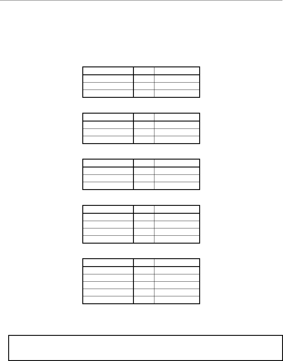
B-64513EN/03
9.PMC CONFIGURATION DATA SETTING SCREENS ([PMC CONFIG])
- 1231 -
(d) [MENU] Switch to the MENU screen
Switches to the MENU screen.
(e) [INIT] Initialize settings
It initializes the settings.
• EXEC PRIORITY: Set to the default setting.
When the values are all set to 0, the following default setting is used.
When only the first PMC is used
EXEC PRIORITY PMC EXEC RATIOS
1 PMC1 100%
2
−
0%
3
−
0%
When the first and second PMCs are used
EXEC PRIORITY PMC EXEC RATIOS
1 PMC1 85%
2 PMC2 15%
3
−
0%
When the first, second, and third PMCs are used
EXEC PRIORITY PMC EXEC RATIOS
1 PMC1 75%
2 PMC2 15%
3 PMC3 10%
When the first, second, third and forth PMCs are used
EXEC PRIORITY PMC EXEC RATIOS
1 PMC1 70%
2 PMC2 10%
3 PMC3 10%
4 PMC4 10%
When the first, second, third, forth and fifth PMCs are used
EXEC PRIORITY PMC EXEC RATIOS
1 PMC1 60%
2 PMC2 10%
3 PMC3 10%
4 PMC4 10%
5 PMC5 10%
• EXEC CYCLE : 8msec
• LADDER RUN/STOP : INDEPENDENT
NOTE
If an invalid value is set for the NC parameter, press the [INIT] soft key to
release the invalid state.
(2) Screen operations using other keys
Cursor keys
Use them to set an item for EXEC CYCLE and LADDER RUN/STOP.
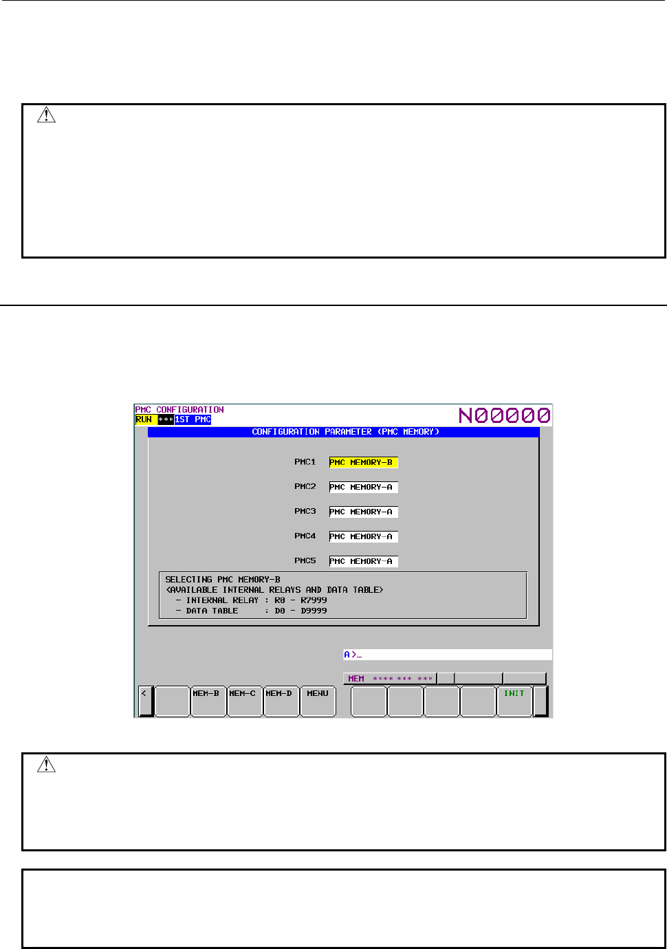
9.PMC CONFIGURATION DATA SETTING SCREENS ([PMC CONFIG])
B-64513EN/03
- 1232 -
INPUT key
Use this key to input the execution time ratio in units of 1%.
If the total of values set for the PMCs exceeds 100%, the following error message appears:
"TOTAL OF EXEC RATIO IS OVER 100%."
CAUTION
1 You can set an item on this screen regardless of the NC mode.
2 When the NC parameters are all set to 0, the initial status (for the initial status,
see (e) in (1)) is set. Setting all execution time ratios to 0 with this operation is
equivalent to setting the initial status. For this reason, if an attempt is made to
set the last item to 0, the following message appears and the item cannot be set
to 0:
"CANNOT SET 0% TO ALL EXECUTION TIME RATIOS."
9.9.5
Setting the PMC Memory Type
On the PMC CONFIGURATION PARAMETER(PMC MEMORY) screen, you can change the PMC
Memory Type of each PMC path.
The setting is saved to the CNC parameter and becomes effective after rebooting CNC. See the "2.4.3
CNC Parameters Related to the PMCs" for the details of the CNC parameter.
Fig. 9.9.5 (a) PMC CONFIGURATION PARAMETER (PMC MEMORY) screen
CAUTION
PMC nonvolatile memory must be initialized after changing PMC Memory Type.
Therefore, make a backup of PMC parameter before changing PMC Memory
Type. See "2.8 BATTERY BACKUP DATA" about the operation of initializing
PMC nonvolatile memory.
NOTE
1 The item of the menu differs by the constitution of software options.
2 Selectable PMC Memory Type differs for each PMC path. See the "2.1.3
Determination of PMC Memory Type" for the details of selectable types.
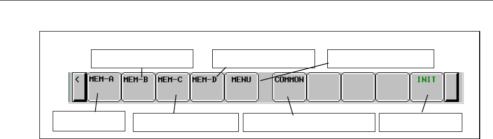
B-64513EN/03
9.PMC CONFIGURATION DATA SETTING SCREENS ([PMC CONFIG])
- 1233 -
Screen operations
Fig. 9.9.5 (b) Soft keys on the PMC CONFIGURATION PARAMETER (PMC MEMORY) screen
(1) Operation with soft keys
(a) [MEM-A] Select the PMC Memory-A.
Selects the PMC Memory-A for the cursor focused PMC path. This soft key is displayed when
the PMC Memory-A is selectable at focused PMC path.
(b) [MEM-B] Select the PMC Memory-B.
Selects the PMC Memory-B for the cursor focused PMC path. This soft key is displayed when
the PMC Memory-B is selectable at focused PMC path.
(c) [MEM-C] Select the PMC Memory-C.
Selects the PMC Memory-C for the cursor focused PMC path. This soft key is displayed when
the PMC Memory-C is selectable at focused PMC path.
(d) [MEM-D] Select the PMC Memory-D.
Selects the PMC Memory-D for the cursor focused PMC path. This soft key is displayed when
the PMC Memory-D is selectable at focused PMC path.
(e) [COMMON] Select the Common PMC Memory mode.
Selects the Common PMC Memory mode to the cursor focused PMC path. This soft key is
displayed when the Common PMC Memory mode is selectable at focused PMC path.
(f) [MENU] Switch to the menu screen.
Switches to the CONFIGURATION PARAMETER (MENU) screen.
(g) [INIT] Initialize all settings
Reset all PMC Memory Type of each PMC paths to the default setting.
Soft keys on the PMC CONFIGURATION PARAMETER (PMC MEMORY) screen
Select the PMC
Memory-A
Select the PMC Memor
y
-D
Select the PMC Memor
y
-C Initialize all settin
g
s
Switch to the menu screen
Select the Common PMC Memor
y
Select the PMC Memor
y
-B
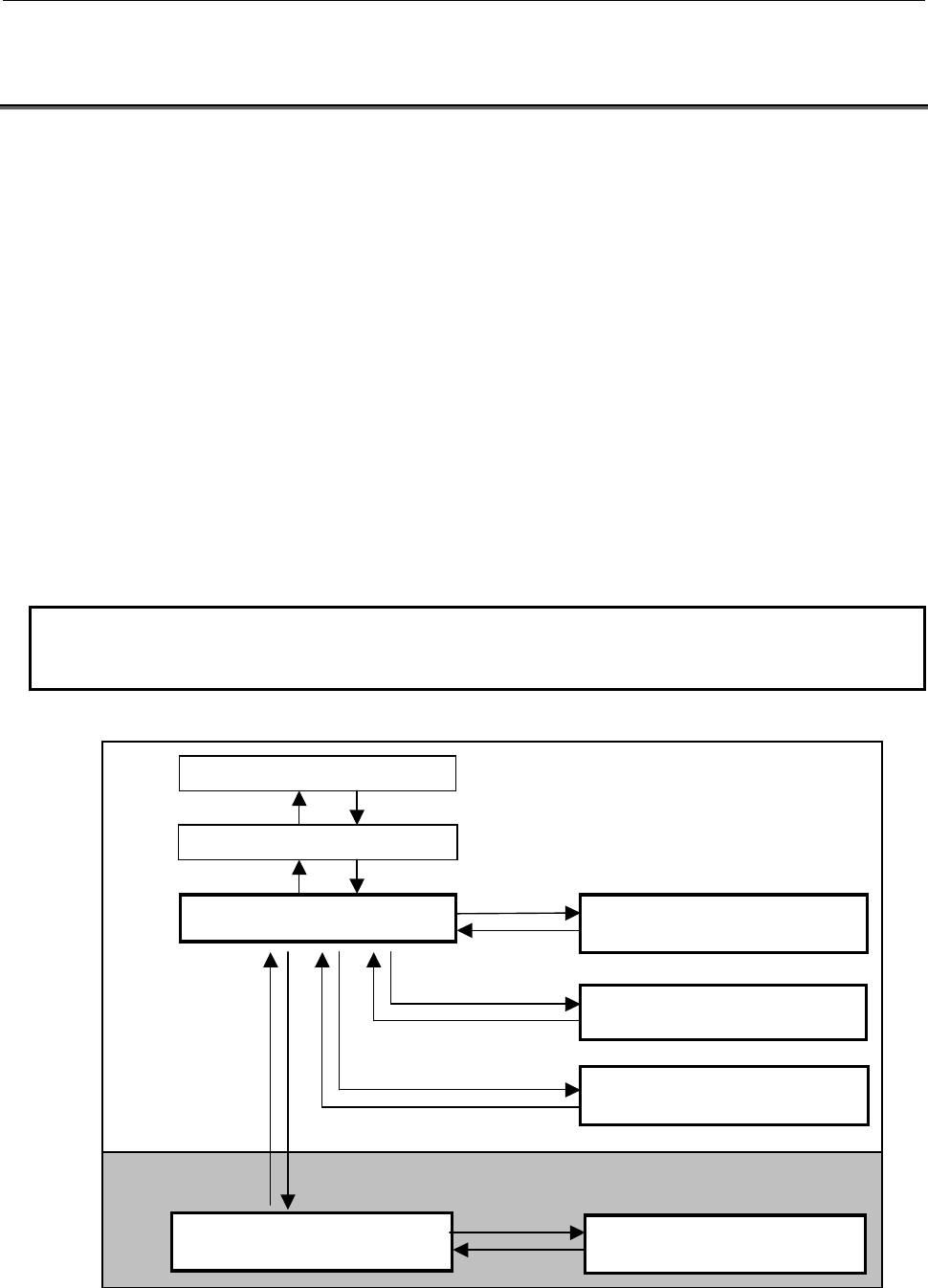
9.PMC CONFIGURATION DATA SETTING SCREENS ([PMC CONFIG])
B-64513EN/03
- 1234 -
9.10 DISPLAYING AND EDITING OF I/O Link i ASSIGNMENT
([I/O LINK I] SCREEN)
Pressing the [I/O Link i] soft key shows I/O Link i assignment data and you can confirm the contents of
the I/O devices assignment. In the editing screen, you can edit the I/O Link i assignment data and change
the assignment of I/O devices.
I/O Link i assignment data is stored in I/O configuration data.
The display/edit screens of the I/O Link i assignment data are as follows.
(1) I/O CONFIGURATION VIEWER (I/O Link i GROUP SETTING) Screen
It displays the group setting of I/O Link i assignment data.
(2) I/O CONFIGURATION VIEWER (I/O Link i SLOT SETTING) Screen
It displays the slot setting of I/O Link i assignment data.
(3) I/O CONFIGURATION VIEWER (I/O Link i TITLE) Screen
It displays the tile of I/O Link i assignment data.
(4) I/O CONFIGURATION VIEWER (SELECTABLE I/O Link i ASSIGNMENT) Screen
It selects the I/O devices groups which are required for each machine.
(5) I/O CONFIGURATION EDITOR (I/O Link i GROUP SETTING) Screen
It edits the group setting of I/O Link i assignment data.
(6) I/O CONFIGURATION EDITOR (I/O Link i SLOT SETTING) Screen
It edits the slot setting of I/O Link i assignment data.
NOTE
You are able to protect these screens by the programmer protection function.
For details, refer to subsection “6.2.1”.
The flow chart of each screen is as follows:
[<]
[<]
[I/O Link i]
[PMC CONFIG]
[EDIT END] [EDIT]
Monitor Function
Editor function
[TITLE]
I/O CONFIGURATION VIEWER
(I/O Link i SLOT SETTING) SCREEN
I/O CONFIGURATION VIEWER
(
I/O Link i GROUP SETTING
)
SCREEN
I/O CONFIGURATION VIEWER
(I/O Link i SELECTABLE I/O) SCREEN
I/O CONFIGURATION VIEWER
(I/O Link i TITLE) SCREEN
I/O CONFIGURATION EDITOR
(I/O Link i GROUP SETTING) SCREEN
I/O CONFIGURATION EDITOR
(I/O Link i SLOT SETTING) SCREEN
PMC MAIN MENU
PMC CONFIGURATION MANU
[ZOOM]
[ZOOM]
[EXIT ZOOM]
[EXIT]
[SELECT ASSIGN]
[EXIT ZOOM]
[EXIT]
Fig. 9.10 Flow chart of the screens
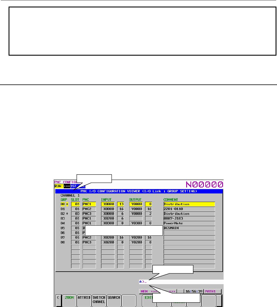
B-64513EN/03
9.PMC CONFIGURATION DATA SETTING SCREENS ([PMC CONFIG])
- 1235 -
NOTE
The [EDIT] soft key is available when the setting of “I/O CONF EDIT ENABLE” is
“YES” in the programmer protection function. The [SELECT ASSIGN] soft key is
available when the setting of “REGISTER I/O DEVICES” is “YES” in the
programmer protection function and the selectable assignment function is
enabled. For the details, refer to subsection “6.2.1” and “9.10.5”.
9.10.1
Displaying of Group Information of I/O Link i Assignment
Data
In the I/O CONFIGRATION VIEWER (I/O Link i GROUP SETTING) screen, you can confirm the
contents of the group setting of the I/O Link i assignment data. Pressing the [I/O Link i] soft key shows
this screen. The following operations can be performed in this screen.
• Go to the VIEWER (I/O Link i SLOT SETTING) screen [ZOOM]
• Switch display mode [COMENT],[ATTRIB]
• Switch the channel [SWITCH CHANEL]
• Search for an address [SEARCH]
• Go to the EDITOR (I/O Link i group setting) screen [EDIT]
• Go to the VIEWER (I/O Link i title) screen [TITLE]
• Go to the VIEWER (I/O Link i SELECT ASSIGN) screen [SELECT ASSIGN]
Group information display area
Channel display
Message display line
Key input line
Fig. 9.10.1(a) I/O CONFIGRATION VIEWER (I/O Link i GROUP SETTING) screen (Comment display mode)
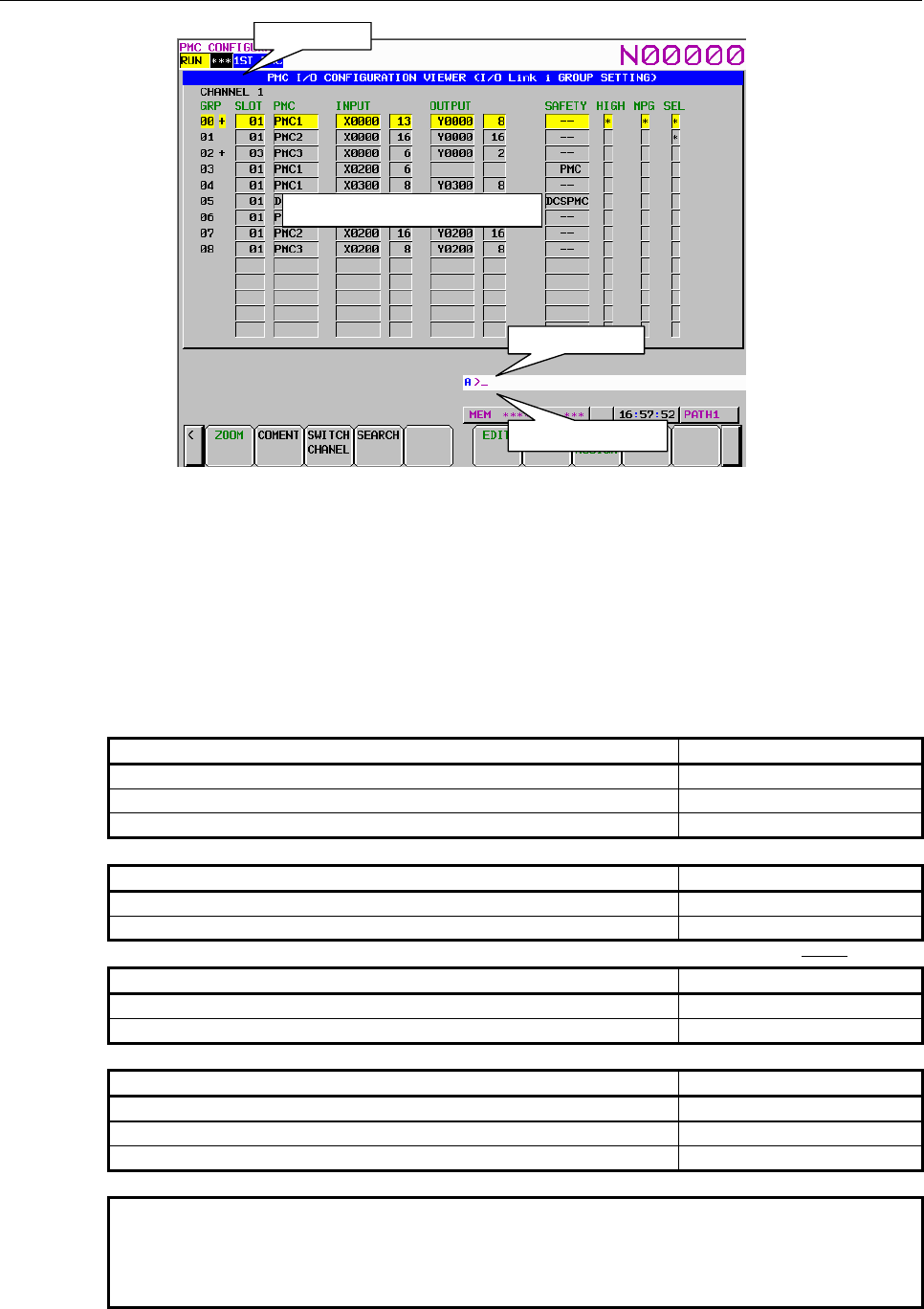
9.PMC CONFIGURATION DATA SETTING SCREENS ([PMC CONFIG])
B-64513EN/03
- 1236 -
Group information display area
Channel display
Message display line
Key input line
Fig. 9.10.1(b) I/O CONFIGRATION VIEWER (I/O Link i GROUP SETTING) screen (Attribute display mode)
Contents of the table
GRP: Displays the group number of assignment location. When plural slots are defined in
the group, ”+” is displayed at the right side of the group number.
SLOT: Displays the slot number of the top slot.
PMC: Displays the PMC path of the top slot.
INPUT: Displays the X address and data length (byte) of the top slot.
OUTPUT: Displays the Y address and data length (byte) of the top slot.
COMMENT: Displays the comment as for the top slot.
SAFETY: Displays the contents for the safety I/O mode.
Safety I/O mode
Remark
Normal I/O (Default)
--
Safety I/O for DCSPMC
DCSPMC
Safety I/O for PMC1
~
PMC5
PMC
HIGH: Displays the update cycle for each group.
Update cycle
Remark
Normal mode (2ms) (Default)
(space)
High-speed mode (0.5ms)
*
MPG: Displays existence/non-existence of the manual pulse module foe each every group.
Manual pulse module
Remark
Not use of the manual pulse module (Default) (space)
Use of the manual pulse module *
SEL: Displays effective groups.
Selectable status of groups
Remark
Invalid group (Default) (space)
Effective group
レ
Basic group *
NOTE
The data of “SEL” are displayed when the selectable assignment
function is enabled in the I/O CONFIGURATION EDITOR (I/O Link i
GROUP SETTING) screen.
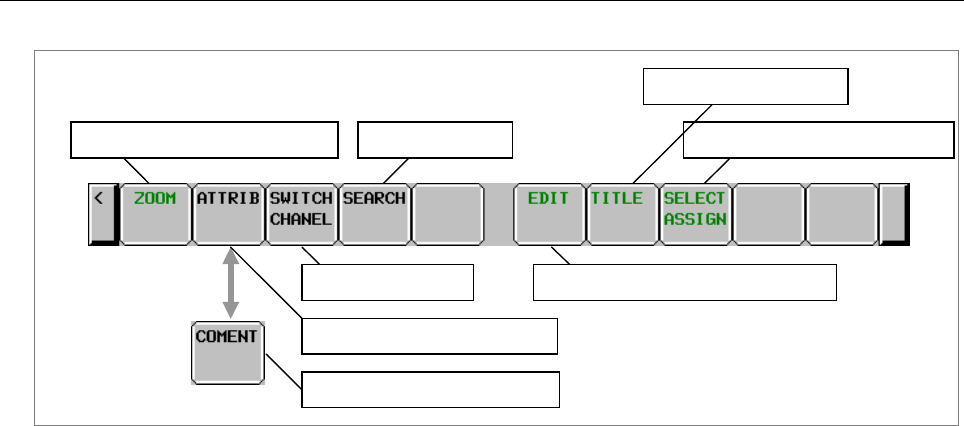
B-64513EN/03
9.PMC CONFIGURATION DATA SETTING SCREENS ([PMC CONFIG])
- 1237 -
Screen operations
I/O CONFIGRATION VIEWER (I/O Link iGROUP SETTING) screen
Display the SELECT ASSIGN screen
Change to comment display mode
Switching of channel
Display the SLOT SETTING screen
Display the EDIT(group setting) screen
Display the TITLE screen
Search for address
Change to attribute display mode
Fig. 9.10.1 (c) Soft keys on I/O CONFIGRATION VIEWER (I/O Link i GROUP SETTING) screen
(1) Operations using the soft keys
(a) [ZOOM] Display the SLOT SETTING screen
Moves to the I/O CONFIGRATION VIEWER (I/O Link i SLOT SETTING) screen.
(b) [ATTRIB] Change to attribute display mode
Changes the display mode to the attribute display mode. This soft key appears in the comment
display mode.
(c) [COMENT] Change to comment display mode
Changes the display mode to the comment display mode. This soft key appears in the attribute
display mode.
(d) [SWITCH CHANEL] Switching of channel
Switches the channel to display in order.
(e) [SEARCH] Search for address
Searches for address corresponding to the input character string and displays a group that
includes the address. In the message line, the detail information of slot is displayed. The range
for search is all of slots in whole channels.
(f) [EDIT] Display the EDIT screen
Moves to the I/O CONFIGRATION EDITOR (I/O Link i GROUP SETTING) screen. This soft
key appears when the programmer function enables. The password is required when the I/O
Link i assignment data is protected by password function. Enter the password required in order
to edit.
(g) [TITLE] Display the TITLE screen
Moves to the I/O CONFIGRATION VIEWER (I/O Link i TITLE) screen.
(h) [SELECT ASSIGN] Display the SELECTABLE ASSIGNMET screen
Moves to the I/O CONFIGRATION VIEWER (I/O Link i SELECTABLE ASSIGNMET)
screen.
(2) Operations using other keys
Cursor move key: Moves the cursor.
Page change key: Scrolls a page of display data.
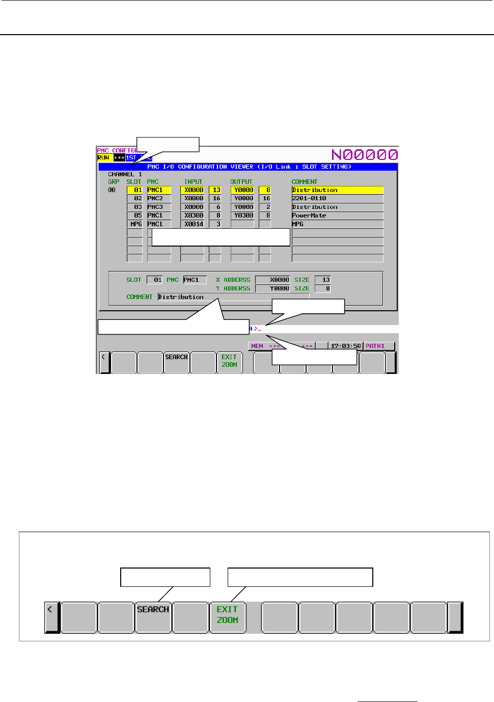
9.PMC CONFIGURATION DATA SETTING SCREENS ([PMC CONFIG])
B-64513EN/03
- 1238 -
9.10.2
Displaying of Slot Information of I/O Link i Assignment Data
In the I/O CONFIGURATION VIEWER (I/O Link i SLOT SETTING) screen, you can confirm the
contents of each slot setting in specified group of the I/O Link i assignment data. Pressing the [ZOOM]
soft key in the GROUP SETTING screen shows this screen. The following operations can be performed
in this screen.
• Search for an address [SEARCH]
• Go to the VIEWER (I/O Link i GROUP SETTING) screen [EXIT ZOOM]
Detailed displa
y
area of slot information
Slot information list display area
Channel display
Message display line
Key input line
Fig. 9.10.2(a) I/O CONFIGRATION VIEWER (I/O Link i SLOT SETTING) screen
Contents of the table
GRP: Displays the group number.
SLOT: Displays the slot number. When the “manual pulse module” is set, the “MPG” is
displayed
PMC: Displays the PMC path..
INPUT: Displays the X address and data length (byte) for each I/O device.
OUTPUT: Displays the Y address and data length (byte) for each I/O device.
COMMENT: Displays the comment as for the I/O device
Screen operations
I/O CONFIGRATION VIEWER (I/O Link iSLOT SETTING) screen
Search for address Display the GROUP SETTING screen
Fig. 9.10.2 (b) soft keys of I/O CONFIGRATION VIEWER (I/O Link i SLOT SETTING) screen
(1) Operations using the soft keys
(a) [SEARCH] Search for address
Searches for address corresponding to the input character string input address and displays on
the screen. The range for search are all of slots in whole channels.
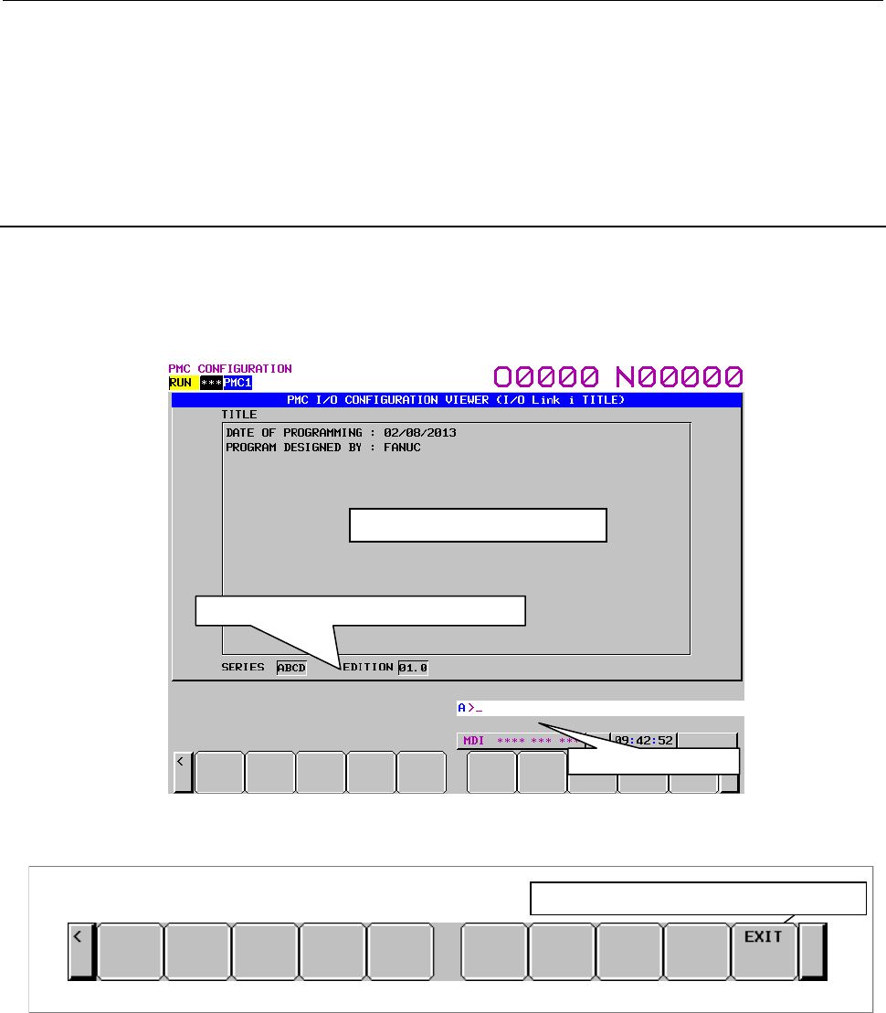
B-64513EN/03
9.PMC CONFIGURATION DATA SETTING SCREENS ([PMC CONFIG])
- 1239 -
(b) [EXIT ZOOM] Display the I/O Link i GROUP SETTING screen
Moves to the I/O CONFIGRATION VIEWER (I/O Link i GROUP SETTING) screen.
(2) Operations using other keys
Cursor move key: Moves the cursor.
Page change key: Scrolls a page of display data.
9.10.3
Displaying of Title Information of I/O Link i Assignment Data
In the I/O CONFIGURATION VIEWER (I/O Link i TITLE) screen, you can confirm the title
information for the I/O Link i assignment data. Pressing the [TITLE] soft key in the GROUP SETTING
screen shows this screen. The following operations can be performed in this screen.
• Go to the VIEWER (I/O Link i GROUP SETTING) screen [EXIT]
Screen operations
I/O CONFIGRATION VIEWER (I/O Link iTITLE) screen
Display the VIEWER (GROUP SETTING)screen
(1) Operations using the soft keys
[EXIT] Goes to the I/O CONFIGURATION VIEWER (I/O Link i GROUP SETTING) screen
Setting and Displaying of Series/Edition
I/O Link i assignment data can be created with FANUC LADDER-III.
You can specify series/edition directive line in the title information of the I/O Link i assignment data.
Therefore, the series/edition can be display in the I/O CONFIGURATION VIEWER (I/O Link i TITLE)
screen.
Series/Edition of I/O Link
i
assignment data
Message display line
Title information display area
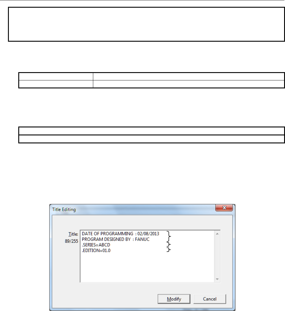
9.PMC CONFIGURATION DATA SETTING SCREENS ([PMC CONFIG])
B-64513EN/03
- 1240 -
NOTE
This manual describes the procedure for displaying series/edition in the screen.
As for details for creating of I/O Link i assignment data, refer to “FANUC
LADDER-III OPERATOR’S MANUAL (B-66234EN)”.
Specification method of series/edition
・ The followings are the format of series/edition directive line. These directives can be specified with
both capital and small letters.
Series directive line
.SERIES=xxxx .series=xxxx
Edition directive line
.EDITION=xxxx .edition=xxxx
・ Specify the series/edition directive line from the beginning of a line.
・ To display the “xxxx” in the screen, specify a string within four characters.
Usable characters are half-width capital alphabet, digit characters, space and dot.
Useable characters
A to Z, 0 to 9, Space, . (dot)
Example)
The case of displaying “SERIES ABCD” and “EDITION 01.0” in the I/O CONFIGURATION
VIEWER (I/O Link i TITLE) screen
Specify “(2) Series directive line” and “(3) Edition directive line” in the title in I/O Link i editing
screen of FANUC LADDER-III.
I/O Link i Editing screen (Title Editing) of FANUC LADDER-III
Compile the I/O Link i assignment data to memory card format file and load the file into CNC.
Therefore, the series/edition directive line is not displayed in the title column and specified strings
are displayed in the series/edition column.
(2) Series directive line
(3) Edition directive line
(1) Title data
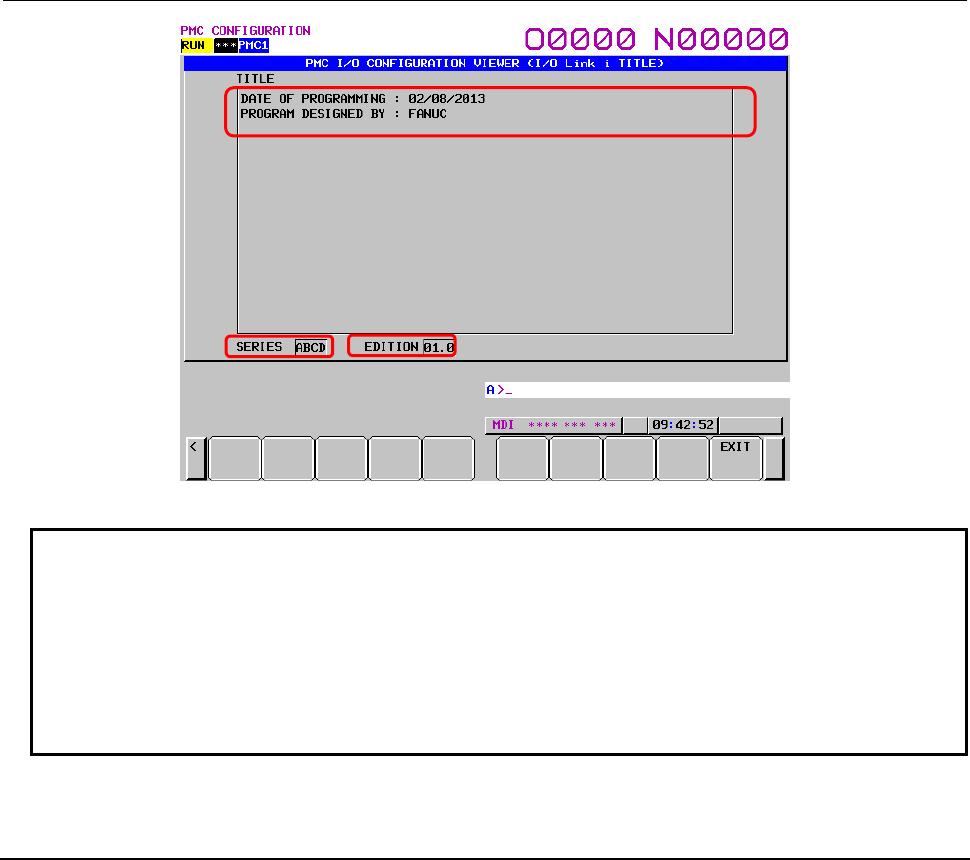
B-64513EN/03
9.PMC CONFIGURATION DATA SETTING SCREENS ([PMC CONFIG])
- 1241 -
I/O CONFIGURATION VIEWER (I/O Link i TITLE) screen
NOTE
1 When no series/edition directive line is specified in the I/O Link i assignment
data, the column of series/edition of the screen becomes blank.
2 When specifying characters which can not be used for string of series/edition,
space characters are displayed in the column of series/edition of the screen.
3 When loading the I/O Link i assignment data with series/edition directive into
CNC system which is not applied to this function, the series/edition directive line
is displayed in the title column as the string typed in FANUC LADDER-III.
9.10.4
Setting of Effective Group of I/O Link i Assignment Data
(Selectable Assignment Function)
In the I/O CONFIGRATION VIEWER (I/O Link i SELECTABLE I/O) screen, you can select the I/O
Link i groups which are required for each machine. Pressing the [SELECT ASSIGN] soft key shows this
screen. The following operations can be performed in this screen.
• Switch the channel [SWITCH CHANEL]
• Search for an address [SEARCH]
• Setting of the effective group [ENABLE],[DISABL]
• Go to the VIEWER (I/O Link i GROUP SETTING) screen [EXIT]
(
2
)
(3)
(
1
)
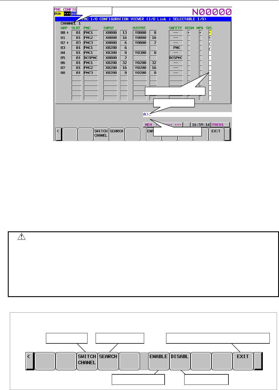
9.PMC CONFIGURATION DATA SETTING SCREENS ([PMC CONFIG])
B-64513EN/03
- 1242 -
Effective group selection
Channel display
Message display line
Key input line
Fig. 9.10.4(a) I/O CONFIGRATION VIEWER (I/O Link i SELECTABLE I/O) screen
Setting of the effective group
(Channel 1: K928 to K930, Channel 2: K932 to K934)
You can select the effective group of I/O Link i assignment data.
“✓”: The assignment is enabled.
(space): The assignment is disabled
The “*” mark is displayed on the basic group which is set by pressing the [BASIC GROUP] soft key in
the I/O CONFIGURAITON EDITOR (I/O Link i GROUP SETTING) screen. This operation cannot be
performed on the basic group.
WARNING
If you modify this setting without care, the I/O assignment data may not match
I/O devices and turning on the power may result in unexpected malfunctions of
machine. So, it is required that the operator of this function should be an expert
who fully understands the sequence program and the operation of PMC. It is
also strongly recommended to the developer of machine that this setting screen
should be protected from careless use by ordinary operators after the machine is
shipped into the field.
Screen operations
I/O CONFIGRATION EDITOR (I/O Link iSELECTABLE I/O) screen
Switch channel
Set to invalid group
Display the VIEWER (GROUP SETTING) screen
Set to effective group
Search for address
Fig. 9.10.4 (b) Soft keys of I/O CONFIGRATION VIEWER (I/O Link i SELECTABLE I/O) screen

B-64513EN/03
9.PMC CONFIGURATION DATA SETTING SCREENS ([PMC CONFIG])
- 1243 -
(1) Operations using the soft keys
(d) [SWITCH CHANEL] Switching of channel
Switches the channels to display in order.
(e) [SEARCH] Search for address
Searches for address corresponding to the input character string input address and displays a
group that includes the address. In the message line, the detail information of slot is displayed.
The range for search are all of slots in whole channels.
(c) [ENABLE] Set to effective group
The assignment of the group is enabled.
(d) [DISABL] Set to invalid group
The assignment of the group is disabled.
(e) [EXIT] Display the GROUP SETTING screen
Moves to the I/O CONFIGRATION VIEWER (I/O Link i GROUP SETTING) screen.
(2) Operations using other keys
Cursor move key: Moves the cursor.
Page change key: Scrolls a page of display data.
Input key: The “1” + input key enables the assignment data.
The “0” + input key disables the assignment data.
Only input key switches disable/enable of the assignment data.
9.10.5
Editing of Group Information of I/O Link i Assignment Data
In the I/O CONFIGRATION EDITOR (I/O Link i GROUP SETTING) screen, you can edit the contents
of the group setting of the I/O Link i assignment data. Pressing the [EDIT] soft key in the I/O
CONFIGRATION VIEWER (I/O Link i GROUP SETTING) screen shows this screen. The following
operations can be performed in this screen.
• Go to the EDITOR (I/O Link i SLOT SETTING) screen [ZOOM]
• Switch display mode [COMENT],[ATTRIB]
• Switch the channel [SWITCH CHANEL]
• Search for an address [SEARCH]
• Change the assignment data [CHANGE]
• Delete the assignment data [DELETE]
• Add new group [NEW]
• Exchange group order [MOVE UP]、[MOVE DOWN]
• Delete the group [DELETE GROUP]
• Exit editor [EXIT EDIT]
• Enable selectable assignment function [ENABLE SELECT]
• Setting of basic group [BASIC GROUP]
• Delete all data [DELETE ALL]
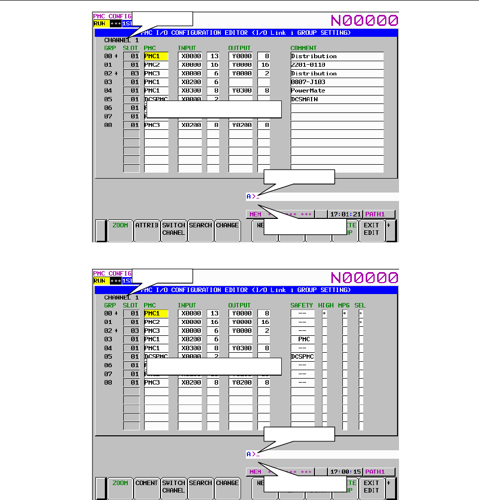
9.PMC CONFIGURATION DATA SETTING SCREENS ([PMC CONFIG])
B-64513EN/03
- 1244 -
Group information editing area
Channel display
Message display line
Key input line
Fig. 9.10.5(a) I/O CONFIGRATION EDITOR (I/O Link i GROUP SETTING) screen (Comment display mode)
Group information editing area
Channel display
Message display line
Key input line
Fig. 9.10.5(b) I/O CONFIGRATION EDITOR (I/O Link i GROUP SETTING) screen (Attribute display mode)
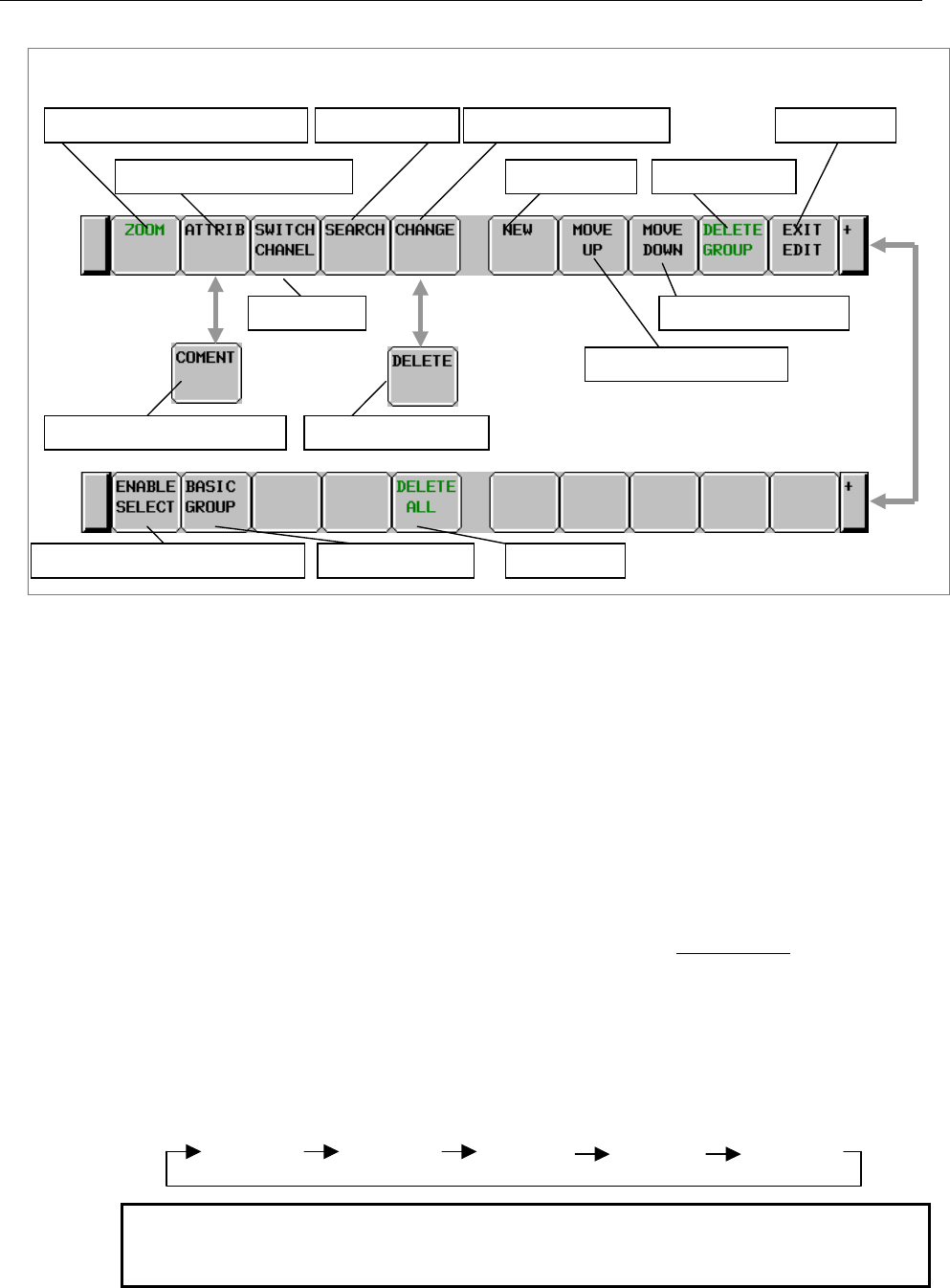
B-64513EN/03
9.PMC CONFIGURATION DATA SETTING SCREENS ([PMC CONFIG])
- 1245 -
Screen operations
I/O CONFIGRATION EDITOR (I/O Link i GROUP SETTING) screen
Enable selectable assignment function
Change to comment display mode
Switch channel
Display the SLOT SETTING screen Exit editor
Setting of basic group
Add new group Delete the group
Delete all data
Exchange to lower group
Change the assignment data
Delete assignment data
Search for address
Exchange to upper group
Change to attribute display mode
Fig. 9.10.5 (c) Soft keys of I/O CONFIGRATION EDITOR (I/O Link i GROUP SETTING) screen
(1) Operations using the soft keys
(a) [ZOOM] Display the SLOT SETTING screen
Moves to the I/O CONFIGRATION EDITOR (I/O Link i SLOT SETTING) screen.
(b) [ATTRIB] Change to attribute display mode
Changes the display mode to the attribute display mode. This soft key appears in the comment
display mode.
(c) [COMENT] Change to comment display mode
Changes the display mode to the comment display mode. This soft key appears in the attribute
display mode.
(d) [SWITCH CHANEL] Switching of channel
Switches the channel to display in order.
(e) [SEARCH] Search for address
Searches for address corresponding to the input character string input address and displays a
group that includes the address. In the message line, the detail information of slot is displayed.
The range for search are all of slots in whole channels.
(f) [CHANGE] Change the assignment data
This soft key appears when the cursor is on some items which are “PMC”, “SAFETY”,
“HIGH” and “MPG”. Changes the each item of the assignment data at the cursor as follows:
• PMC
Changes the PMC path in order.
PMC2 PMC3
PMC1 PMC4 PMC5
NOTE
When the safety I/O mode is “DCSPMC”, the PMC path is set to
“DCSPMC” and pressing this key is invalid .
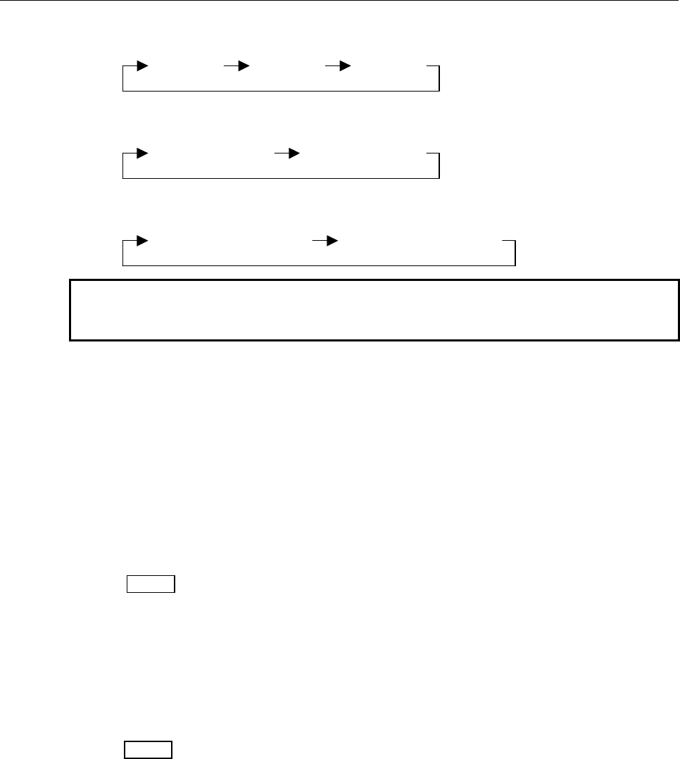
9.PMC CONFIGURATION DATA SETTING SCREENS ([PMC CONFIG])
B-64513EN/03
- 1246 -
• SAFETY
Changes the safety I/O mode in order.
PMC
DCSPMCNormal I/O
• HIGH
Changes the update cycle in order.
Normal (2ms)
High-speed (0.5ms)
• MPG
Changes existence/non-existence of manual pulse module.
Non-existence of MPG
Existence of MPG
NOTE
When changing to “Non-existence of MPG”, the “MPG” in SLOT
disappears.
(g) [DELETE] Delete the assignment data
This soft key appears when the cursor is on some items which are “INPUT”, “OUTPUT” and
“COMMENT”. The assignment data on the cursor is deleted.
(h) [NEW] Add new group
New group is inserted on the cursor. The numbers of the groups after added group are shifted.
The slot information is linked to shifted groups but the effect group information “SEL” is not
linked.
Example:
Before the editing:
GRP Group information Slot information SEL
01 GA SA ✓
02 GB SB ✓
03 GC SC (space)
Operation:
Pressing [NEW] when the cursor is on “GRP 02”.
After the editing:
GRP Group information Slot information SEL
01 GA SA ✓
02 (space) (space) ✓
03 GB SB (space)
04 GC SC (space)
(i) [MOVE UP] Exchange to upper group
The group on the cursor is exchanged to the upper group.
(j) [MOVE DOWN] Exchange to lower group
The group on the cursor is exchanged to the lower group.
(k) [DELETE GROUP] Delete the group
The group on the cursor is deleted. The numbers of the groups after deleted group are shifted.
The slot information is linked to shifted groups but the effect group information “SEL” is not
linked.

B-64513EN/03
9.PMC CONFIGURATION DATA SETTING SCREENS ([PMC CONFIG])
- 1247 -
Example:
Before the editing:
GRP Group information Slot information SEL
01 GA SA ✓
02 GB SB ✓
03 GC SC (space)
Operation:
Pressing [DELETE] when the cursor is on “GRP 02”.
After the editing:
GRP Group information Slot information SEL
01 GA SA ✓
02 GC SC ✓
NOTE
The operation of the group deletion deletes all of slot information which
belongs to the group.
(l) [EXIT EDIT] Exit editor
Exits the editor and moves to the I/O CONFIGURATION VIEWER (I/O Link i GROUP
SETTING) screen.
(m) [ENABLE SELECT] Enable selectable assignment function
Enables or disables the selectable assignment function for this channel.
(n) [BASIC GROUP] Setting of basic group
Sets the basic group. You can input the number 0 to 24 and press this soft key. This key is
displayed when the selectable assignment function for this channel is enabled.
(o) [DELETE ALL] Delete all data
All of information for this channel is deleted.
NOTE
The operation of [DELETE ALL] deletes all of group information and slot
information. And the selectable assignment function is disabled.
(2) Operations using other keys
Cursor move key: Moves the cursor.
Page change key: Scrolls a page of display data.
Input key:
When the cursor is on the “PMC”:
“Numeric” + “Input key” means “PMC1”, “PMC2”, “PMC3”, “PMC4” and “PMC5”.
Only “Input key” changes PMC path by turns.
When the cursor is on the “SAFETY”:
Only “Input key” changes the safety I/O mode by turns.
When the cursor is on the “MPG”:
Only “Input key” changes the setting by turns.
NOTE
When changing to “Non-existence of MPG”, the “MPG” in SLOT
disappears.
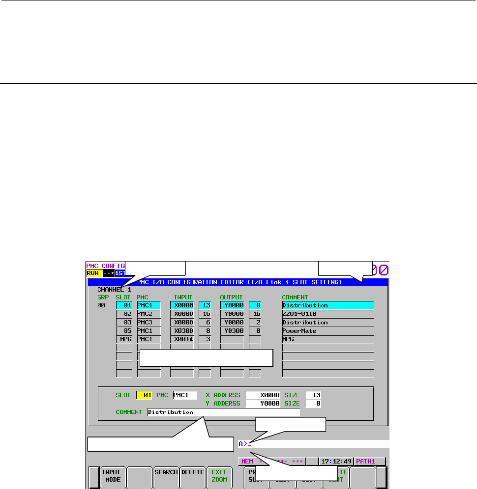
9.PMC CONFIGURATION DATA SETTING SCREENS ([PMC CONFIG])
B-64513EN/03
- 1248 -
(3) Operations using return key
The return key is invalid in this screen. To return the I/O CONFIGURATION VIEWER (I/O Link i
GROUP SETTING) screen, press the [EXIT EDIT] soft key.
9.10.6
Changing of Slot Information of I/O Link i Assignment Data
In the I/O CONFIGRATION EDITOR (I/O Link i SLOT SETTING) screen, you can edit the contents of
the slot setting of specified group. Pressing the [ZOOM] soft key in the I/O CONFIGRATION EDITOR
(I/O Link i GROUP SETTING) screen shows this screen. The following operations can be performed in
this screen.
• Switch input mode [INPUT MODE]
• Automatic setting of free address [AUTO]
• Search for an address [SEARCH]
• Delete the data [DELETE]
• Exit the slot editor [EXIT ZOOM]
• Change display slot [PREV. SLOT], [NEXT SLOT]
• Add new slot [NEW SLOT]
• Delete slot [DELETE SLOT]
Input mode
Detailed displa
y
area of slot information
Slot information list display area
Channel display
Message display line
Key input line
Fig. 9.10.6(a) I/O CONFIGRATION EDITOR (I/O Link i SLOT SETTING) screen
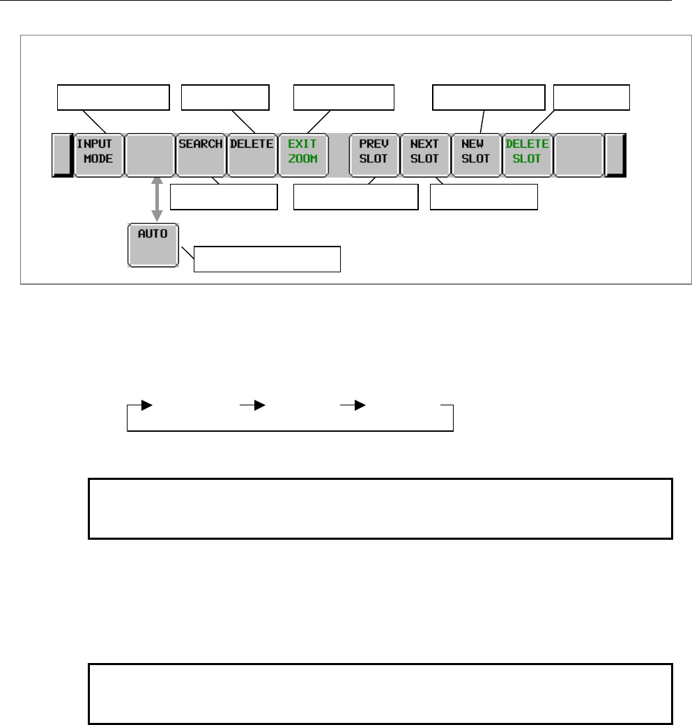
B-64513EN/03
9.PMC CONFIGURATION DATA SETTING SCREENS ([PMC CONFIG])
- 1249 -
Screen operations
I/O CONFIGRATION EDITOR (I/O Link
i
SLOT SETTING) screen
Automatic address setting
Search for address
Exit the slot editor
Move to next slot
Add new slot Delete slotSwitch input mode
Move to previous slot
Delete the data
Fig. 9.10.6 (b) Soft keys of I/O CONFIGRATION EDITOR (I/O Link i SLOT SETTING) screen
(1) Operations using the soft keys
(a) [INPUT MODE] Switch input mode
Pressing the [INPU MODE] soft key, the input mode for the comment is changed as follows.
Current input mode is displayed on the screen.
INSERT ALTERWHOLE
For the detail of the input mode, refer to subsection “9.2.6”.
NOTE
This key is valid for the comment data. For other data, this key is
invalid and input mode becomes the “WHOLE” mode.
(b) [AUTO] Automatic address setting
This key is displayed when the cursor is on the “X ADDRESS” and “Y ADDRESS”. An
address having the input “SIZE” is searched from each free area. For example, when “X0020”
is set in the “INPUT”, pressing this key searched a free address within the range of X0020 to
X0127.
NOTE
If once a free address is set by pressing this key, other address is
never searched by pressing this key again.
(c) [SEARCH] Search for address
Searches input address and displayed a group that includes the address. The range for search is
all of slots in whole channels.
(d) [DELETE] Delete the data
Deletes selected data.
(e) [EXIT ZOOM] Exit the slot editor
Moves to I/O CONFIGURATION EDITOR (I/O Link i GROUP SETTING) screen.
(f) [PREV. SLOT] Move to previous slot
Selects the slot displayed on upper line of the cursor in the slot list.
(g) [NEXT SLOT] Move to next slot
Selects the slot displayed on lower line of the cursor in the slot list.
(h) [NEW SLOT] Add new slot
Adds a new slot.
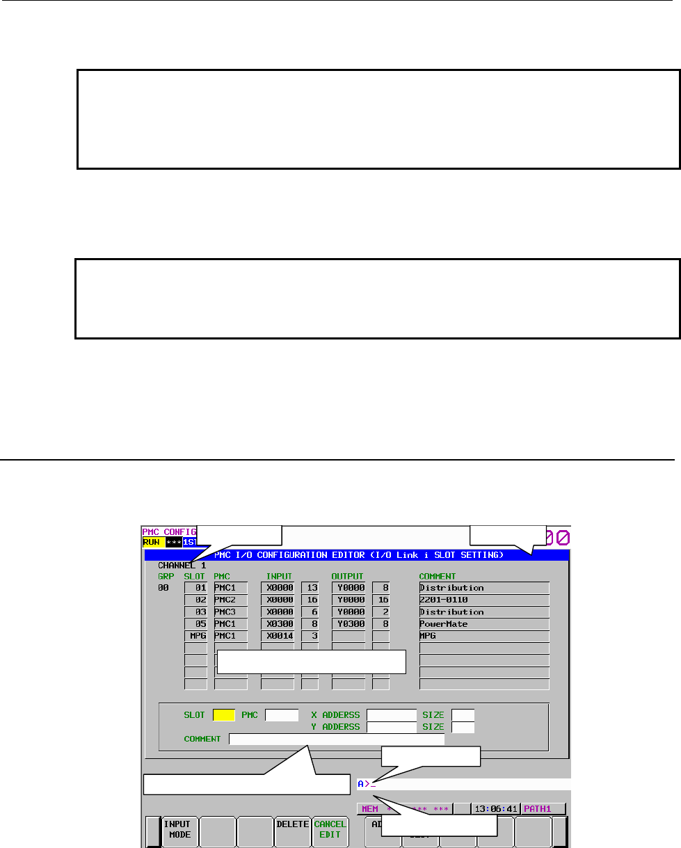
9.PMC CONFIGURATION DATA SETTING SCREENS ([PMC CONFIG])
B-64513EN/03
- 1250 -
(i) [DELETE SLOT] Delete slot
Deletes a slot.
NOTE
The operation of the [DELETE SLOT] soft key never deletes the slot of
the “MPG”. When you want to delete the slot of the “MPG”, set the “MPG”
off in the I/O CONFIGURATION EDITOR (I/O Link i GROUP SETTING)
screen.
(2) Operations using other keys
Cursor move key: Moves the cursor.
Page change key: Scrolls a page of display data.
NOTE
When you set the “SAFETY” I/O mode to the “DCSPMC” for a group in the
I/O CONFIGURATION EDITOR (I/O Link i GROUP SETTING) screen,
you cannot change to the PMC path in the “PMC” item of the group.
(3) Operations using return key
The return key is invalid in this screen. To return the I/O CONFIGURATION VIEWER (I/O Link i
GROUP SETTING) screen, press the [EXIT EDIT] soft key.
9.10.7
Adding of Slot Information of I/O Link i Assignment Data
Pressing the [NEW SLOT] soft key creates a new slot in the I/O CONFIGURATION EDITOR (I/O Link
i SLOT SETTING) screen.
Input mode
Detailed displa
y
area of slot information
Slot information list display area
Channel display
Message display line
Key input line
Fig. 9.10.7(a) I/O CONFIGRATION EDITOR (I/O Link i SLOT SETTING) screen (NEW SLOT)
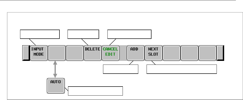
B-64513EN/03
9.PMC CONFIGURATION DATA SETTING SCREENS ([PMC CONFIG])
- 1251 -
Screen operations
I/O CONFIGRATION EDITOR (I/O Link
i
SLOT SETTING) screen (NEW SLOT)
Register the slot
Cancel the edit
Register the slot and add next slot
Switch input mode Delete the data
Automatic address setting
Fig. 9.10.7 (b) I/O CONFIGRATION EDITOR (I/O Link i SLOT SETTING) screen (NEW SLOT)
(1) Operations using the soft keys
(a) [CANCEL EDIT] Cancel the edit
New created slot is aborted.
(b) [ADD] Register the slot
Registers new created slot.
(c) [NEXT SLOT] Register the slot and add next slot
Registers current editing slot and creates new slot.
For details of other soft keys, refer to subsection “9.10.6”.
(2) Operations using other keys
Cursor move key: Moves the cursor.
(3) Operations using return key
The return key is invalid in this screen. To return the I/O CONFIGURATION VIEWER (I/O Link i
SLOT SETTING) screen, press the [ADD] or [CANCEL EDIT] soft key.
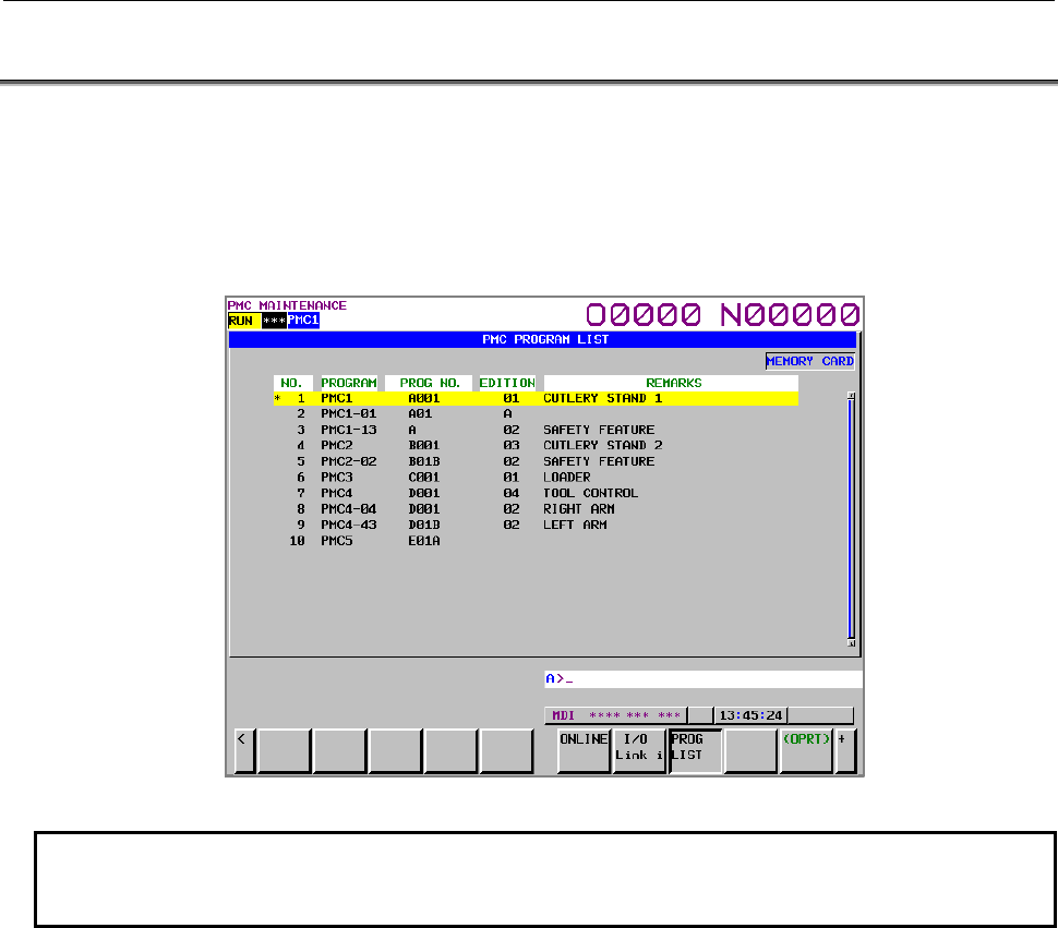
9.PMC CONFIGURATION DATA SETTING SCREENS ([PMC CONFIG])
B-64513EN/03
- 1252 -
9.11 PMC Program List Screen
In case of using multi-path PMC or ladder dividing management function, you can confirm the
information of main ladder programs or divided ladder programs for all PMC paths installed in CNC
system.
In PMC program list screen, you can confirm all main programs and divided programs of all PMC paths.
By selecting a program in the list, displayed program can be switched. PMC program list screen appears
by pressing the [PROG LIST] soft key or pressing the [SWITCH PMC] soft key in each PMC screen.
Fig.9.11 (a) PMC PROGRAM LIST screen
NOTE
Set keep relay K935.0 to 1 in order to display this screen by pressing [SWICH
PMC] in each PMC screen.
Displayed program information
Program on selecting: asterisk “*” is displayed on the left end of the program.
NO: List number
PROGRAM: In case of main ladder program, PMC path name is displayed. In case of divided
ladder program, divided number with PMC path name and hyphen “-“ is
displayed.
PROGRAM NO.: The program No., which is set in title data of the sequence program, is displayed.
EDITION: The edition, which is set in title data of the sequence program, is displayed.
REMAERKS: The remarks, which is set in title data of the sequence program, is displayed.
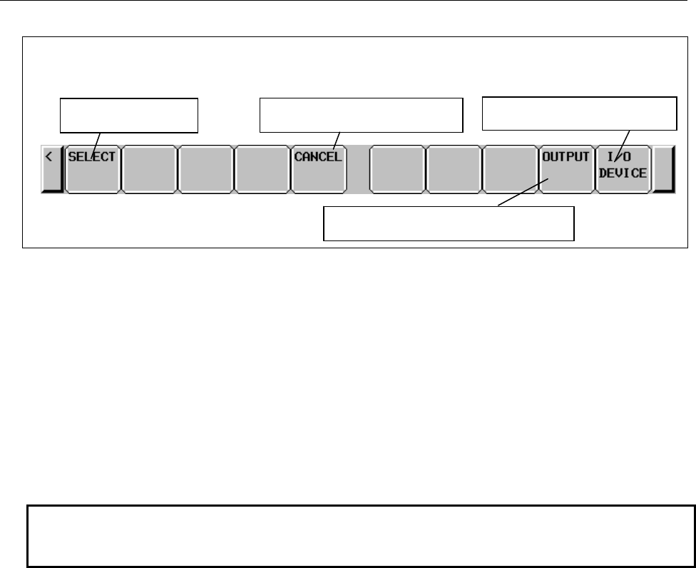
B-64513EN/03
9.PMC CONFIGURATION DATA SETTING SCREENS ([PMC CONFIG])
- 1253 -
Operations using the soft keys
Fig.9.11 (b) Soft keys on PMC program list screen
(1) [SELECT] Program selection
This key switches selected program.
According to kind of soft key to display this screen, switching action is as follows.
・The case that the screen is displayed by the [PROG LIST] soft key
Selected program is switched.
・The case that the screen is displayed by the [SWITCH PMC] soft key
Selected program is switched and return to previous screen.
(2) [CANCEL] Canceling of program selection.
This key cancels program selection and return to previous screen.
NOTE
[CANCEL] soft key is displayed only when the screen is displayed by [SWITCH
PMC] soft key.
(3) [OUTPUT] Output of program list information file
This key outputs program list information file. As for the contents of the output file, refer to “9.11.1”.
(4) [IO DEVICE] Switching of output device
This key selects output device (USB memory or memory card) of program list information file. By
pressing this key, “memory card” or “USB memory” switches alternately. Selected device name is
displayed in the indicator window.
Soft keys on PMC program list screen
Canceling of program selection
Program selection Switching of output device
Output program list information file

9.PMC CONFIGURATION DATA SETTING SCREENS ([PMC CONFIG])
B-64513EN/03
- 1254 -
9.11.1
Output of program list information file
You can output program list information file by pressing the [OUTPUT] soft key.
For maintenance of machines, there are cases where you want to get the information of ladder programs
installed in CNC system. In case of using multi-path PMC or ladder dividing management function, you
can confirm the information on the PMC program list screen. You can get the information of the screen as
a bitmap file. To use this function, however, you can output a text file of the screen information. The text
file is output as “CSV” format. Therefore, you can manage it using application software such as EXCEL
on PC.
When pressing this soft key, [EXEC] and [CANCEL] soft keys appear. To output the file, press the
[EXEC] soft key.
You can select output device by the [IO DEVICE] soft key.
(1) File name
The output file name is “PMC_LIST.000”. If the same file name exists on the device, the extension
is incremented to “001”, “002” and so on.(Maximum “999”)
(2) Output format
The file is output with the “CSV” format. Character string data such as program and remarks are
enclosed in double quotation marks (“ ”).
Output contents are as follows.
(a) Header
At the top of data, an identifier representing the file information is output.
Identifier: (“PMC PROGRAM LIST”)
Edition information: (“Edition”, 1)
(b) Data
Program information, which are displayed on program list screen, are output.
Program information: Number, “Program”, “Program No.”, “Edition”, “Remarks”
Example of program list information
(For view comfort, tabs are inserted in several places. In actual data, however, no tab is inserted.)
“PMC PROGRAM LIST”
“Edition”, 1
1, “PMC1”, ”A001”, ”01”, ”CUTLERY STAND1”
2, “PMC1-01”, ”A01B”, ”01”,
3, “PMC1-02”, ”A01C”, ”02”, ”SAFETY FEATURE”
4, “PMC2”, ”B001”, ”03”, ”CUTLERY STAND2”
5, “PMC2-01”, ”B01B”, ”02”, ” SAFETY FEATURE”
6, “PMC3”, ”C001”, ”01”, ”LOADER”
7, “PMC4”, , ,
8, “PMC4-01”, ”D01A”, ”02”, ”RIGHIT ARM”
9, “PMC4-02”, ”D01B”, ”01”, ”LEFT ARM”
10, “PMC5”, ”E01A”, ,
Header
Data
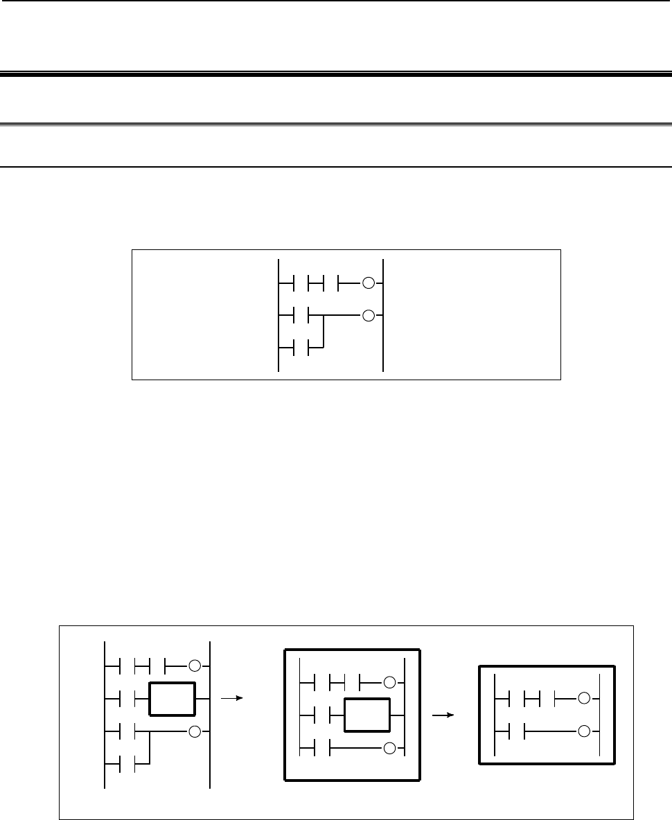
B-64513EN/03
10.STEP SEQUENCE FUNCTION
- 1255 -
10 STEP SEQUENCE FUNCTION
10.1 OVERVIEW
10.1.1 Step Sequence Method
The ladder method is most often used for programming the sequence control governed by a
programmable controller. This method, shown in Fig.10.1.1(a), was derived from relay-panel control
circuits. Since it has been in use for years, many sequence control engineers are already familiar with it.
This method is also used in PMC sequence programming.
Fig. 10.1.1(a) Ladder method
The greater the number of functions implemented by the PMC for a CNC system, the larger and the more
complicated the sequence program becomes. A large-scale system requires a larger program and a greater
number of processes, making it hard for the ladder method to control the overall process. This is because
the ladder method does not describe the order of control. While the ladder method is suitable for
describing partial control, it is hard to apply it to the description of the flow of control overall.
To overcome this problem, structured programming has been introduced into sequence control. A PMC
that supports the subprogram function enables the use of modular programs. As shown in Fig.10.1.1(b), a
large-scale program is divided into subprograms for each function, simplifying the unit of processing.
Since the programmer determines how to divide the main program into subprograms and the control flow
used to call the subprograms, however, the programs are not necessarily easy-to-understand by other
programmers.
CALL
CALL
Subprogram
Subprogram
Fig. 10.1.1(b) Module method
Given these conditions, a step sequence method has been created to describe programs structurally. It is
well-suited to the control of entire processes and provides an easy-to-understand visualized flow of the
process. The step sequence programming features the direct representation of the control flow on a flow
chart, as shown in Fig. 10.1.1(c).
Each block of processing is described as a subprogram, using the ladder method. The entire program is
then created by combining these subprograms.
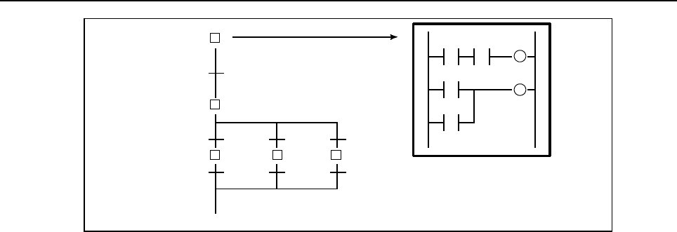
10.STEP SEQUENCE FUNCTION
B-64513EN/03
- 1256 -
Transition
Step 1
Step 2
Subprogram of ladder diagram
Drawing flow
Fig. 10.1.1(c) Step sequence method
The step sequence method has the following features:
(1) Increased programming efficiency
• Since the flow of processes can be programmed directly, simple, correct programming is
enabled, reducing the time required for programming.
• Even for complicated control, programming proceeds from the main flow to detailed flow in
each process, creating a structured, top-down program, which is easy-to-understand by persons
other than the original creator.
• Structured modules can be used again easily.
(2) Easy debugging and maintenance
• Graphical display enables the operator to easily understand the execution state of a program
visually.
• Erroneous steps in a program can be found easily.
• A part of a program can be easily modified.
(3) High-speed program
• Since only the subprograms required for a certain process are executed, the cycle time is
reduced.
(4) Transition from ladder programs
• Since steps and transitions consist of conventional ladder programs, conventional ladder
programs can be converted to new step sequence programs, without discarding ladder-program
resources.
In step sequence programming, a sequence control program is divided into two types of subprograms,
steps and transitions. Steps describe processes. Transitions connect steps and determine whether the
transition conditions from one step to another evaluate true. As shown in Fig. 10.1.1(d), a step sequence
program is described using graphical symbols.

B-64513EN/03
10.STEP SEQUENCE FUNCTION
- 1257 -
[ ]
Step A
Transition B
Starts execution. Waits for machining request.
(Process 1)
Machining request?
→ When machining is requested
Holds a workpiece on the pallet. (Process 2)
Step C
Transition D Loading completed?
→ Once loading has been completed
Machines the workpiece. (Process 3)Step E
Transition F Machining completed?
→ Once machining has been completed
Unloads the workpiece to the pallet. (Process 4)
Step G
Transition H Unloading completed?
→ Once unloading has been completed
Moves the pallet. (Process 5)
Step I
Fig. 10.1.1(d) Example of machining the workpiece
As shown in this example, the program flow from process 1 through process 5 is expressed visually.
Detailed programs related to the movements performed as part of each process, and the signals used for
determining whether transition conditions for proceeding to the next step are satisfied, are not described
here. To program complicated control flows, many other functions are supported, such as divergence,
jump, and nesting functions. The details of these functions are described later.
Step sequence programming is suitable for creating programs which control processes sequentially.
Programs used for controlling a unit which operates according to a certain sequence, such as a loader,
ATC, and other peripheral units, are best suited to step sequence programming. For programs which
control units with no particular sequence, such as that of the operator’s panel which is always monitoring
the emergency stop signal or mode signals, however, are not well-suited to step sequence programming.
The PMC supports the advantages of both methods, ladder and step sequence programming, by calling
subprograms written according to a step sequence and those written as a ladder, from the main program.
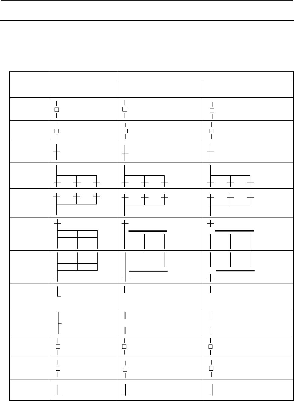
10.STEP SEQUENCE FUNCTION
B-64513EN/03
- 1258 -
10.1.2
Graphical Symbols
This manual uses the graphical symbols listed in Table 10.1.2 to describe step sequence flowcharts.
Depending on the character font being used, the actually displayed symbols may differ slightly from those
listed here.
These graphical symbols are described in the subsequent chapters.
Table 10.1.2 List of graphical symbols
Contents Display of programming
manual
Display
CNC Device Personal Computer
FANUC LADDER-III
Step
Sn
Sn
Sn
Initial Step
[ ] Sn
[ ] Sn
[ ] Sn
Transition
Pn
Pn
Pn
Divergence of
Selective
Sequence
Convergence
of Selective
Sequence
Divergence of
Simultaneous
Sequence
Convergence
of
Simultaneous
Sequence
Jump
→Ln
-> Ln
-> Ln
Label
←Ln
<- Ln
<- Ln
Block Step
] Sn
] Sn
] Sn
Initial Block
Step
[ ] Sn
[ ] Sn [ ] Sn
End of Block
Step
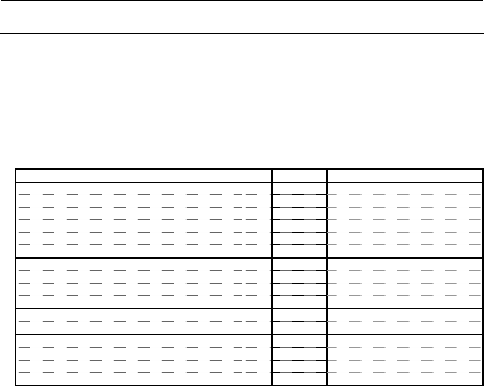
B-64513EN/03
10.STEP SEQUENCE FUNCTION
- 1259 -
10.1.3
Editing and Debugging Step Sequence Programs
The personal computer programmer "FANUC LADDER-III" is used to edit a step sequence program.
For details of transferring and writing a step sequence program to the PMC, see Subsection 1.3.4,
"Transferring and Writing a Step Sequence Program to the PMC".
A step sequence program is executed and debugged on the CNC.
For details of debugging a step sequence program, see Subsection 1.3.5, "Checking a Sequence Program".
Table 10.1.3 indicates the step sequence functions usable on FANUC LADDER-III and the CNC.
Table 10.1.3 Step sequence functions
PMC FANUC LADDER-III
Display and edit of a program
• Display of subprogram list { {
• Create a new subprogram { {
• Delete a subprogram {
• Edit a subprogram of Step Sequence form {
• Edit a subprogram of ladder diagram { {
Input and output
• Input and output with a memory card/USB memory { {
• Input and output with RS232C { {
• Write to a Flash ROM { {
Execution of program
• Execution of a ladder diagram { {
Diagnosis and debugging
• Diagnosis of Step Sequence program {
• Diagnosis of a ladder diagram { {
• Set and display a monitoring timer {
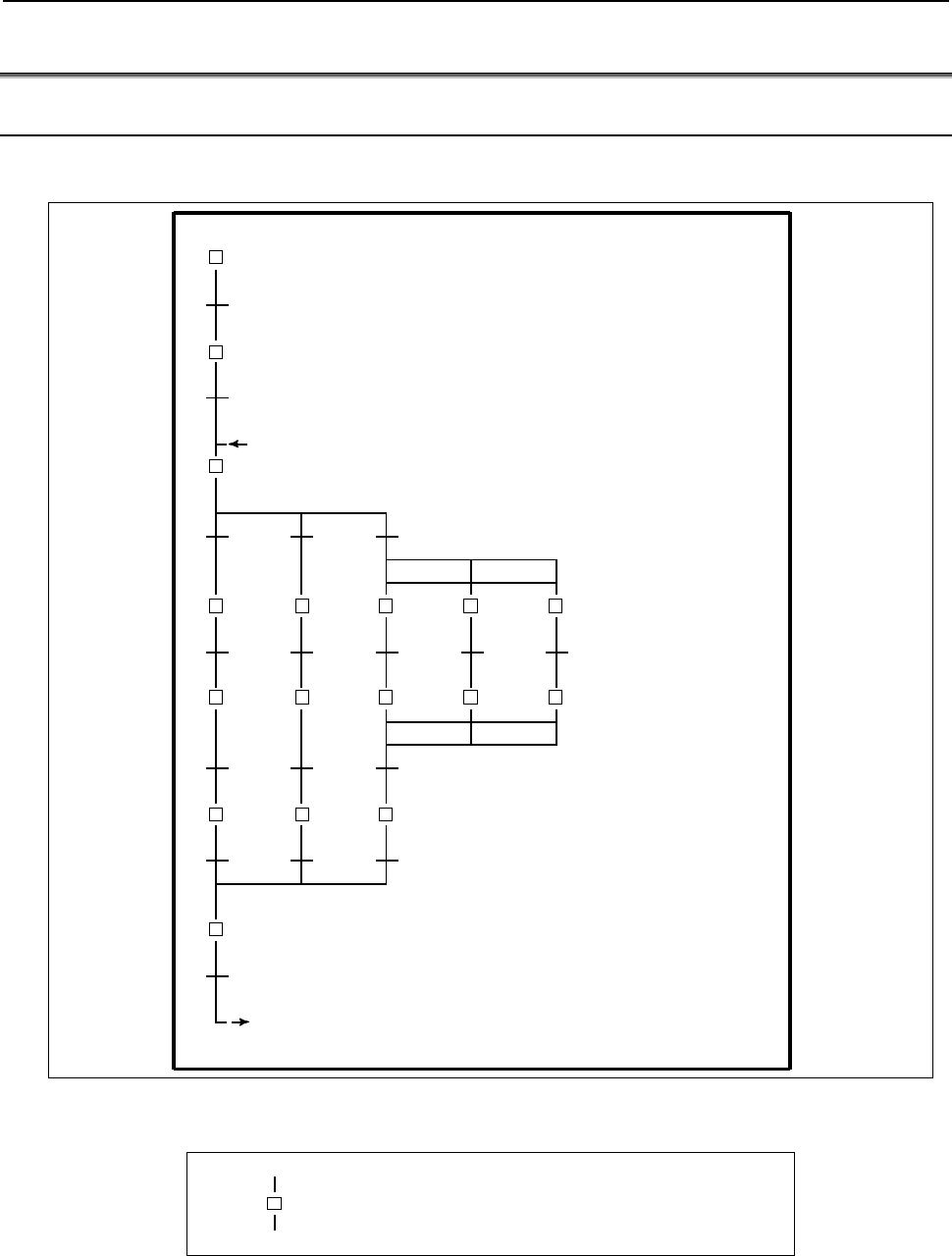
10.STEP SEQUENCE FUNCTION
B-64513EN/03
- 1260 -
10.2 STEP SEQUENCE BASICS
10.2.1 Terminology
A step sequence program is created using a variety of graphical symbols, as shown in Fig. 10.2.1(a). The
main terms used in the step sequence are described below.
L1 (Jump)
(Block)
[ ] S1 (Initial Step)
L1 (Label)
P100 (Transition)
S2 (Step)
P101 (Transition)
S3
(Divergence of Selective
(Divergence of Simultaneous
Sequence)
(Convergence of
Simultaneous Sequence)
(Convergence of Selective Sequence)
] S10 (Block Step)
Fig. 10.2.1(a) Step sequence elements
(1) Step
Sn
(Pm)
A step indicates a process, which is the basic processing unit in a step sequence program. In a step,
specify the S address (Sn), which is a step number, and P address (Pm), which indicates a
subprogram (action program) specifying the details of processing in each step.
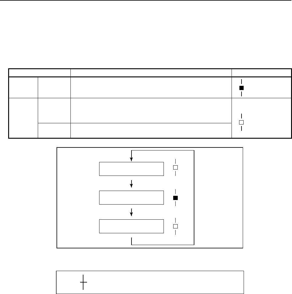
B-64513EN/03
10.STEP SEQUENCE FUNCTION
- 1261 -
(2) Step state transition
When a step sequence program is executed, the process proceeds as program processing advances,
the state of each step changes accordingly. Each step can assume any of the logical states listed in
Table 10.2.1, its state changes as shown in Fig. 10.2.1(b). Activation refers to the changing of a step
from the inactive state to the active state.
Inactivation refers to the changing of a step from the active state to the inactive state.
Table 10.2.1 Step state
State Processing Display
Active Execution Activated step.
The action program (subprogram) is being executed.
Sn
Inactive Transition
to halt
Transition from execution to halt.
The action program (subprogram) is executed once only, then the
step automatically transits to halt.
Sn
Halt Not activated state.
The action program (subprogram) has not yet been executed.
Inactivate (halt status)
Activate (active status)
Inactivate (transition to halt)
Fig. 10.2.1(b) Step state transition
(3) Transition
Pn
A transition denotes the transition conditions. When these evaluate true, the step of the
corresponding state changes from the inactive to active state or vice the reverse. Specify the P
address (Pn), which indicates a subprogram describing the transition conditions in detail.
As shown in Fig. 10.2.1(c), step S2 changes its state from inactive to active when the conditions
described in transition P10 evaluate true, while step S2 changes its state from active to inactive when
the conditions described in transition P20 evaluate true.
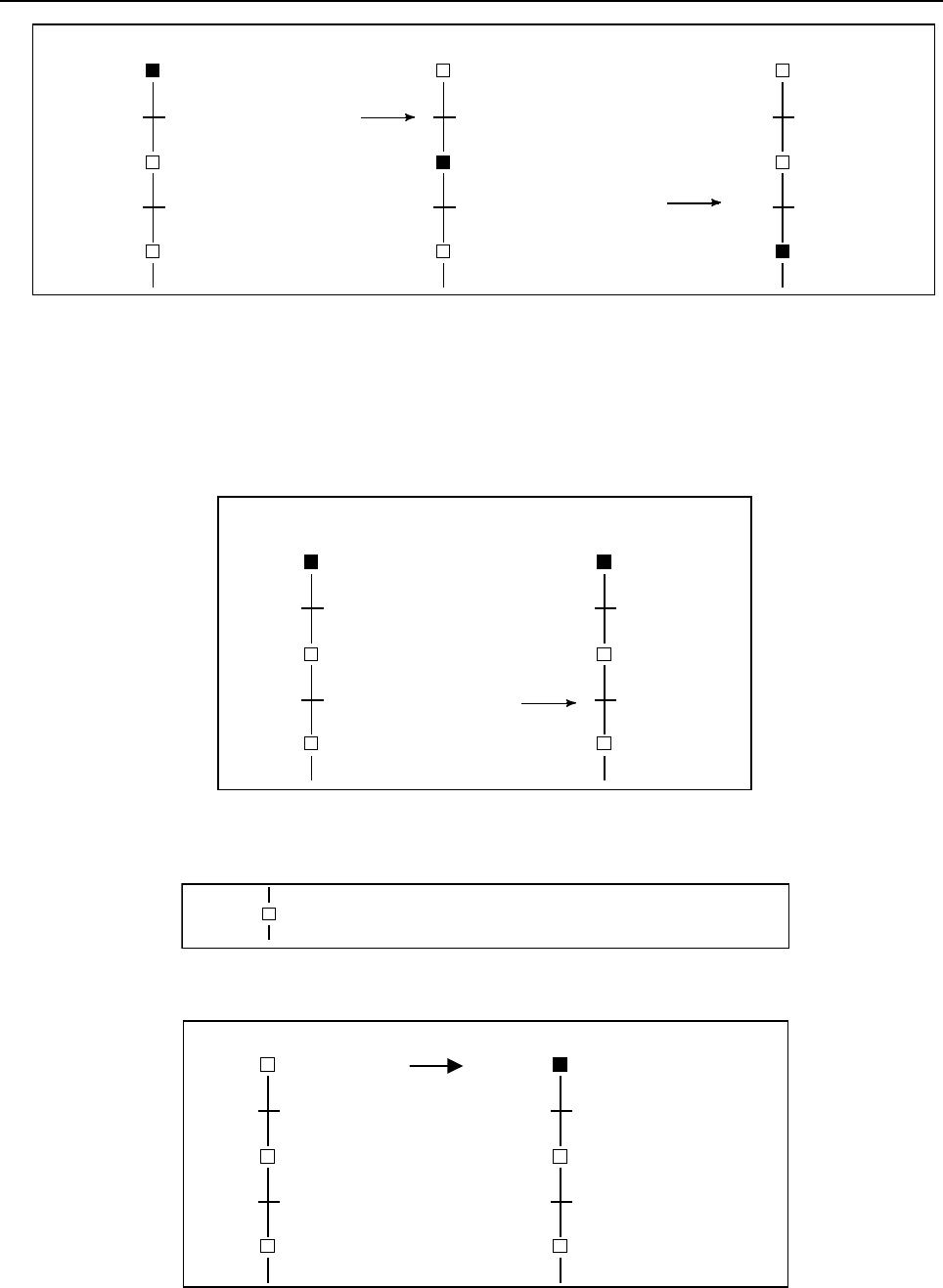
10.STEP SEQUENCE FUNCTION
B-64513EN/03
- 1262 -
Executing step1 Executing step2 Executing step3
S1 (step 1) S1 (step 1) S1 (step 1)
P10 (Condition is true)
S2 (step2)
P20 P20 (Condition is true)
S3 (step3)
P10
S2 (step2)
S3 (step3)
P20
P10
S2 (step2)
S3 (step3)
Fig. 10.2.1(c) Transition of step state by the transition
Note that the step immediately before a transition must be active in order to switch the next step
from inactive to active when the conditions specified in the transition evaluate true. As shown in Fig.
10.2.1(d), step S3 does not change to the active state, even when transition P20 evaluates true, if step
S1 is active and step S2 is inactive. An active state passes from a certain step to the next step when
the corresponding transition conditions evaluate true, the execution of the step sequence program
advancing one step.
Executing step1 Executing step1
S1 (step1) S1 (step1)
P10
S2 (step2)
P20 (Condition is true) P20
S3 (step2)
P10
S2 (step2)
S3 (step2)
S1 (step 1)
Fig. 10.2.1(d) Transition of step state by transition
(4) Initial Step
[ ]
Sn
(Pm)
While a normal step can be activated by a transition, the initial step is activated automatically when
execution of the program starts, as shown in Fig. 10.2.1(e).
Stopping program (STOP) Executing program (RUN)
S1 (step1) S1 (step1)
P10
S2 (step2)
P20 P20
S3 (step3)
P10
S2 (step2)
S3 (step3)
[ ]
[ ]
Fig. 10.2.1(e) Activate of initial step
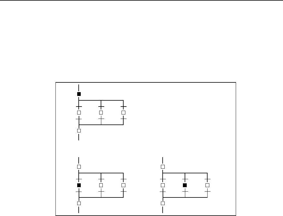
B-64513EN/03
10.STEP SEQUENCE FUNCTION
- 1263 -
Although the initial step, which is usually executed first, is often placed at the top of a program, it
can also be specified at some point within a program. It is always activated first. After being
deactivated once, it can be subsequently be activated again. In this case, it acts in the same way as a
normal step.
(5) Divergence and Convergence of Selective Sequence
To
describe a complicated sequence, selective sequences can be used.
A selective sequence offers multiple choices, from among which the condition becomes true first
activates the corresponding step, as shown in Fig. 10.2.1(f). The divergent paths join to generate the
main sequence.
S1
(Divergence of selective sequence)
P23
P21 P22
S21 S22 S23
(Convergence of selective sequence)
When transition P21 evaluates true
↓
When transition P22 evaluates true.
S1
(true)
S21 S22 S23
S2
(true)
S21 S22 S23
↓
S1 (step1)
Fig. 10.2.1(f) Selective sequence
(6) Divergence and Convergence of Simultaneous Sequence
A Simultaneous sequence can be used to execute multiple processes simultaneously. In a
Simultaneous sequence, as shown in Fig. 10.2.1(g), one transition activates multiple steps. The
activated multiple steps are executed independently. Once all steps along the multiple paths have
been completed, the divergent paths join to generate the main sequence.
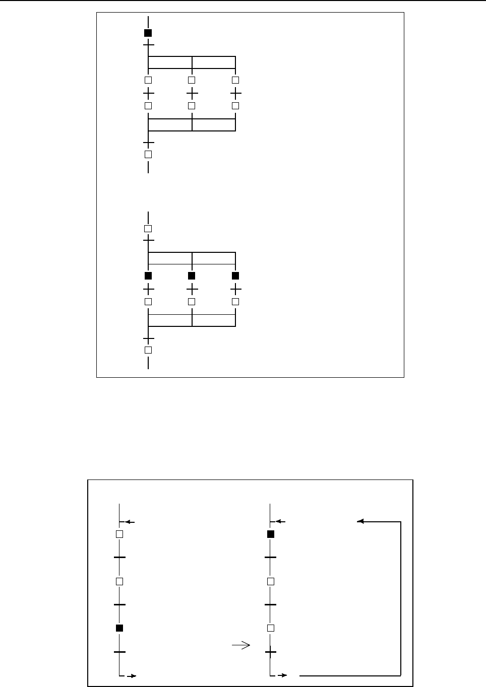
10.STEP SEQUENCE FUNCTION
B-64513EN/03
- 1264 -
(Divergence of simultaneous sequence)
(Convergence of simultaneous sequence)
S21 S22 S23
S31 S32 S33
S4
P10
S1
When transition P10 evaluates true
↓
S21 S22 S23
S31 S32 S33
S4
P10 (true)
S1
Fig. 10.2.1(g) Simultaneous sequence
(7) Jump and Label
The jump function is used to describe a non–serial sequence, such as a repeated loop. As shown in
Fig. 10.2.1(h), when a jump designation is activated, the sequence jumps to the step having the
corresponding jump destination label, after which that step is activated. To specify a label number,
the L address is used in the same way as a jump instruction in ladder programming. A jump can be
made to a previous or subsequent step.
Executing step3 Executing step1
P10 P10
P20 P20
L1 (Jump)
L1 L1 (Label)
S1 (step1)
P30 (Condition is true) P30
L1
S1 (step1)
S2 (step2) S2 (step2)
S3 (step3) S3 (step3)
Fig. 10.2.1(h) Jump and Label
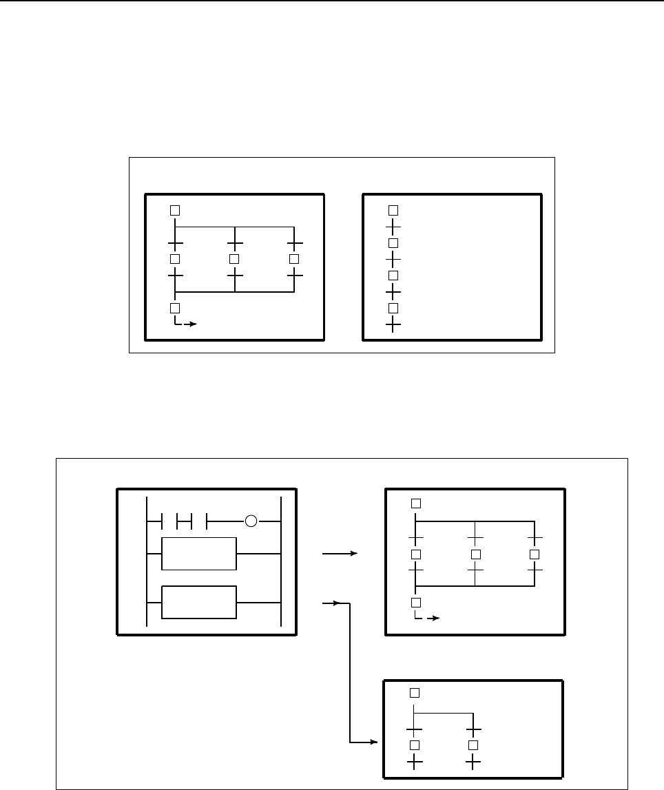
B-64513EN/03
10.STEP SEQUENCE FUNCTION
- 1265 -
(8) Block
A block refers to a group of consecutive steps and transitions. A block can be a step sequence
program. The more complicated the sequence becomes, the larger and more complex the block is. A
program can be divided into multiple blocks in the same way as for subprograms in ladder
programming, based on the concept of modular programming. Each block is identified by a P
address, which corresponds to the subprogram number in ladder programming.
A block is executed as the main program in a step sequence, or called from another step sequence
program as a subprogram.
Block 1(P1) Block 2 (P2)
[ ]
[ ]
Fig. 10.2.1(i) Block
(9) Calling block
To execute a block as the main program in a step sequence, call the block with the CALLU (SUB
66) or CALL (SUB65) instruction in the same way as for ladder subprogram calling from the second
level ladder program.
CALLU P2
CALLU P3
[ ]
[ ]
Ladder (Second level) Block2 (P2)
Block3 (P3)
Fig. 10.2.1(j) Calling block
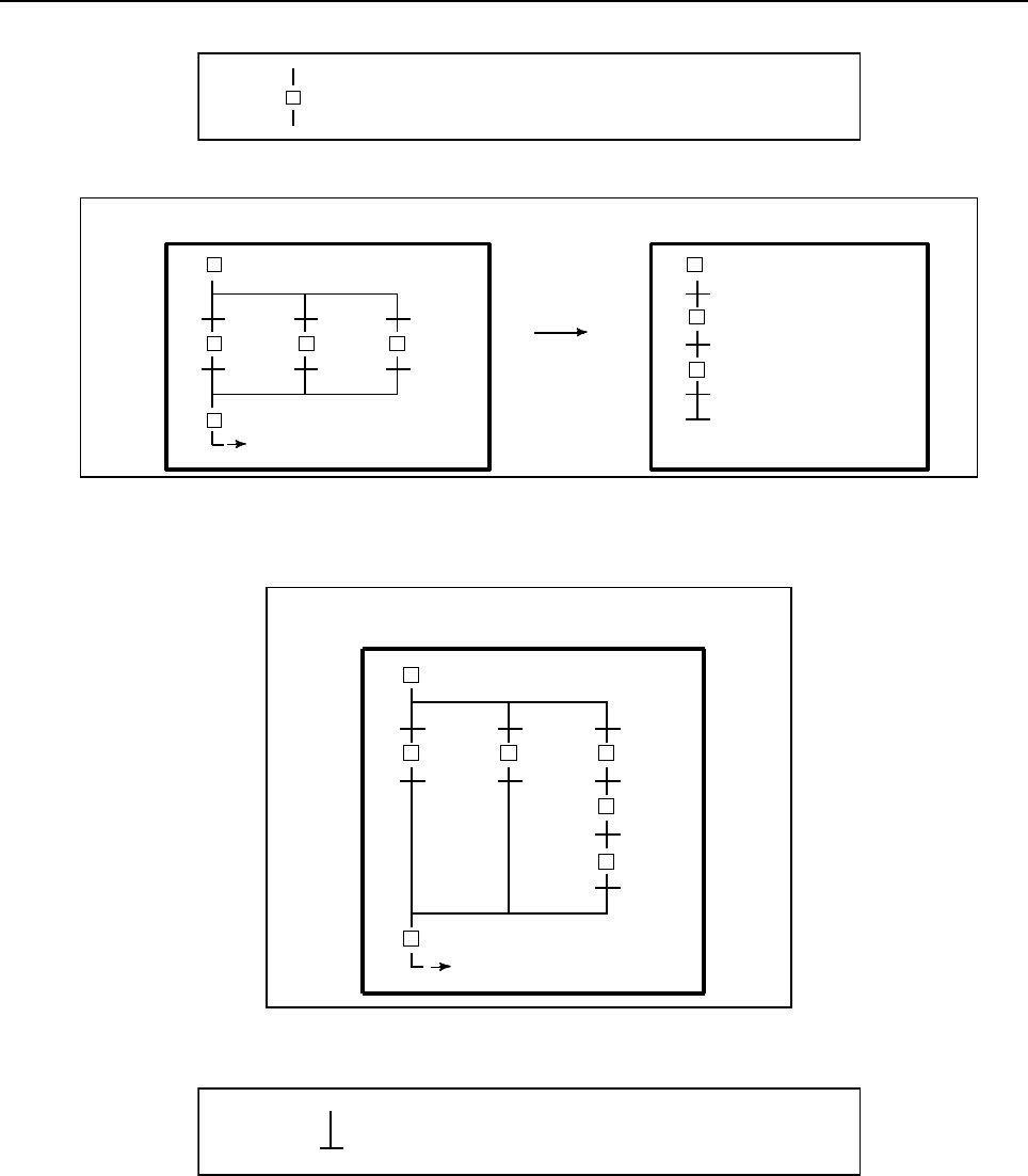
10.STEP SEQUENCE FUNCTION
B-64513EN/03
- 1266 -
(10) Block step (calling step sequence program)
Sn
( Pm )
To call a block from the step sequence program as a subprogram, specify a block step in the step
sequence program which calls the block, as shown in Fig. 10.2.1 (k). This is called bloc nesting.
(P2)
S231
S232
S233
Block 1 (P1) Block 2 (P2)
[
]
] S23
[ ]
S1
S21 S22
S3
Fig. 10.2.1(k) Block nesting
The program shown in Fig. 10.2.1(k) is equivalent to in Fig. 10.2.1(l) which does not use a block
step.
S1
S21
S232
S233
S3
Block (P1)
[ ]
S22 S231
Fig. 10.2.1(l) Program without block step
(11) End of block step
Use an end block step to terminate nested–block–step calling and to return to the calling sequence.
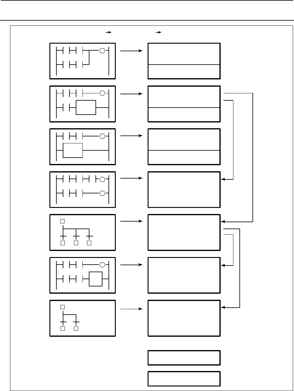
B-64513EN/03
10.STEP SEQUENCE FUNCTION
- 1267 -
10.2.2
Execution of Step Sequence
First level
(Ladder diagram)
Second level
(Ladder diagram)
CALL
Third level
(Ladder diagram)
END1 (SUB 1) function
CALL
END2 (SUB 2) function
END3 (SUB 48) function
Subprogram P1
(Ladder diagram)
Subprogram P2
(Step sequence)
Subprogram P3
(Ladder diagram)
Subprogram P4
(Step sequence)
[ ]
[ ]
Subprogram Pn
END (SUB 64) function
Editing
(source program) Compile Executing
(Object format program)
Fig. 10.2.2(a) Structure of program
In the step sequence method, a program is created (edited) in units of subprograms. The edited source
program is compiled and converted to an executable ROM–format program, then linked, as shown in Fig.
10.2.2(a).
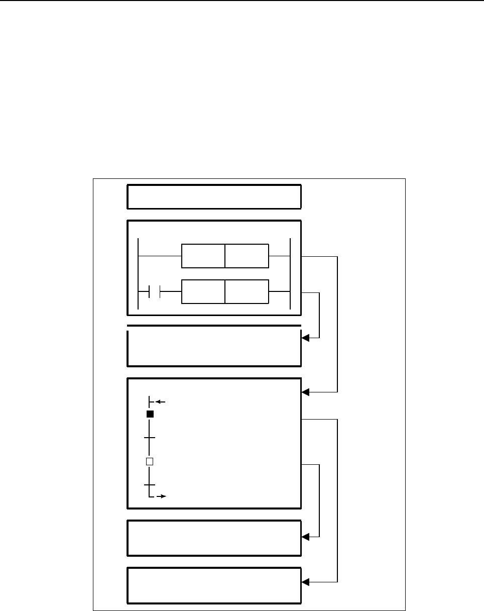
10.STEP SEQUENCE FUNCTION
B-64513EN/03
- 1268 -
A ROM–format program is a kind of a modular program, created using conventional subprograms. A step
sequence block is also a type of a subprogram. Step sequence blocks are linked to the end of the first level
to third level ladder programs, together with other ladder subprograms.
In the same way as in the ladder method, a program is activated at certain intervals.
Refer to section 1.4.3 “Processing Priority (1st Level, 2nd Level, and 3rd Level) “ for details
All subprograms, created using either the ladder or step sequence method, are called from the second
level ladder. Hence, the execution time of the second level ladder includes those of ladder subprograms,
step sequence programs (blocks), steps, and transitions. Since only the activated step and the transition
which checks the transition condition from the step to the next step are executed in a step sequence
program, the second level ladder is executed much more frequently than may be expected from the total
number of steps.
P4
P6
R0. 0
LEVEL1 (Ladder diagram)
LEVEL2 (Ladder diagram)
CALLU P2
CALL P1
P1 (Ladder diagram)
P2 (Step sequence)
L1
S1 (P3)
S2 (P5)
P4 (Ladder diagram)
P3 (Ladder diagram)
[ ]
L1
Fig. 10.2.2(b) Execution of step sequence
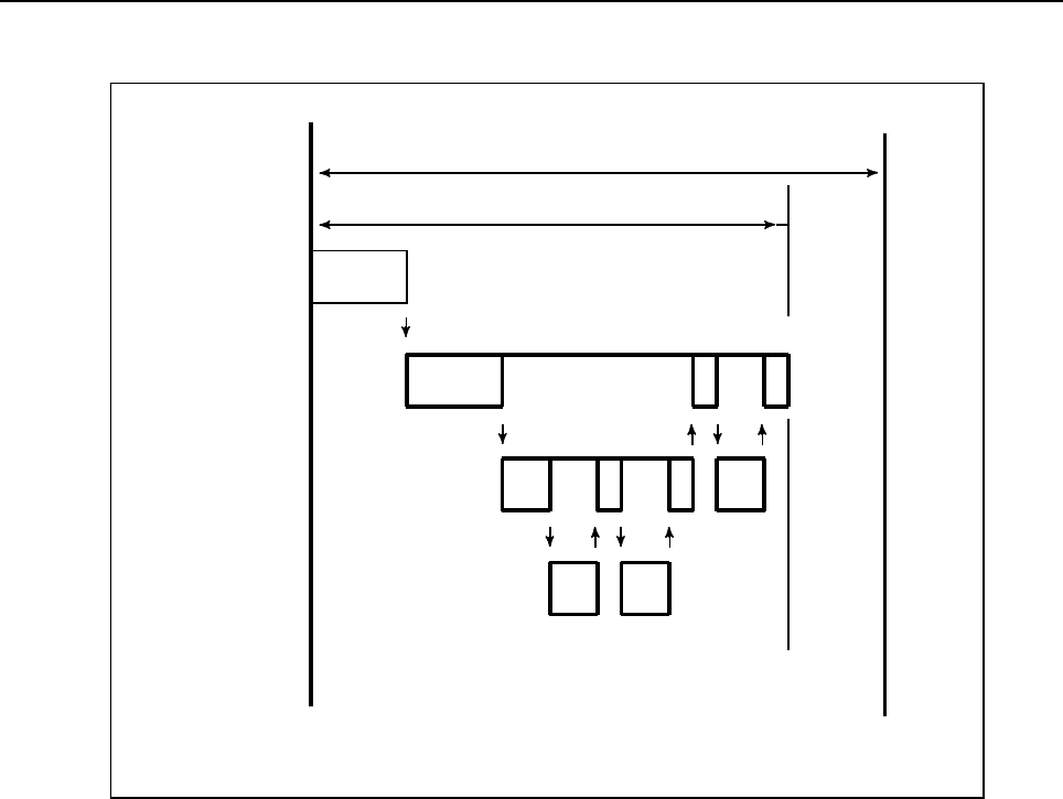
B-64513EN/03
10.STEP SEQUENCE FUNCTION
- 1269 -
In the step sequence program shown in Fig. 10.2.2(b), when step S1 is activated, subprograms are
executed according to the timing illustrated in Fig. 10.2.2(c).
Subprogram
8 msec or 4 msec
1st PMC execution time
LEVEL1
LEVEL2
Transition
First level
Second level
Step
P2 P1
P3 P4
Fig. 10.2.2(c) Timing of execution of step sequence program
In this case, step sequence program P2, step P3, transition P4, and ladder subprogram P1 are executed.
Step P5 and transition P6 are not executed.
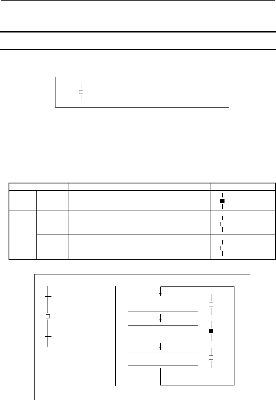
10.STEP SEQUENCE FUNCTION
B-64513EN/03
- 1270 -
10.3 CONFIGURATION AND OPERATION OF
STEP–SEQUENCE PROGRAMS
10.3.1 Step
A step is a unit of processing in a program.
Display
Sn
(Pm)
Contents
• Define a step number (Sn), necessary for controlling execution, and subprogram number (Pm)
specifying actual processing, for a step.
• Assign a step number to a step.
• The same step number cannot be used twice in a program.
• A step has three logical states: the execution, transition to halt, and halt states. The execution state is
also called the active state. The transition to halt and halt states are collectively called the inactive
state.
State Contents of operation Display Sn.0
Activate Execution Activated step.
The action program (subprogram) is being executed.
Sn
1
Inactivate
Transition to
halt
Transition from execution to halt.
The action program (subprogram) is executed once only,
then the step automatically transits to halt.
Sn
0
Stop
Not activated state.
The action program (subprogram) has not yet been
executed.
Sn
0
Example) State transition of Step B
Transition A
Inactivate (halt state)
Step B Transition A
Transition C
A
ctivate (execution state)
Transition C
Inactivate (transition to halt)
(Execute one time)
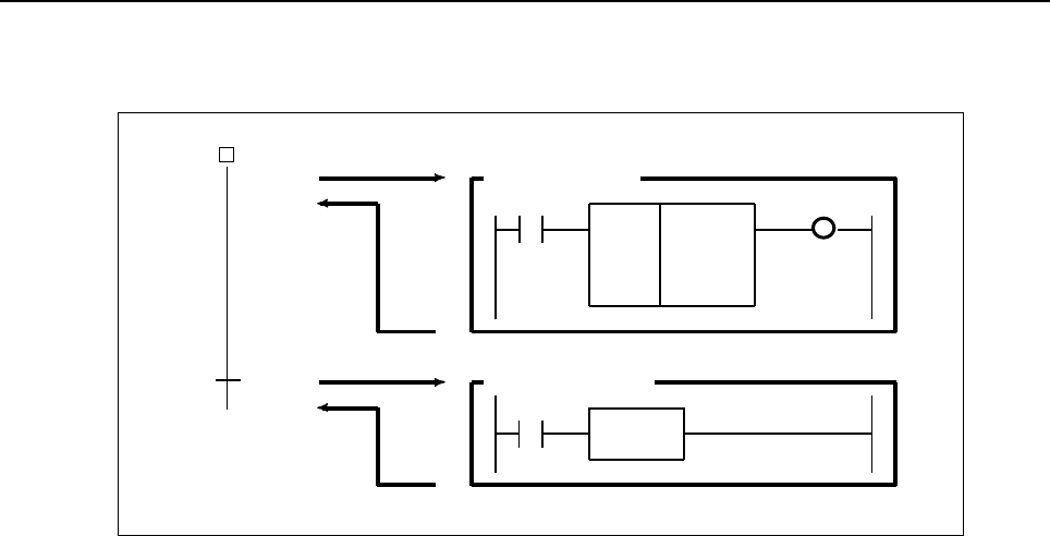
B-64513EN/03
10.STEP SEQUENCE FUNCTION
- 1271 -
Example
After the M7 code is decoded, control is transferred to the next step using a DEC functional
instruction.
DEC F0
711
F7.0
S1
(P1) Subprogram P1
MF R0.0
P101 Subprogram P101
R0.0
TRSET
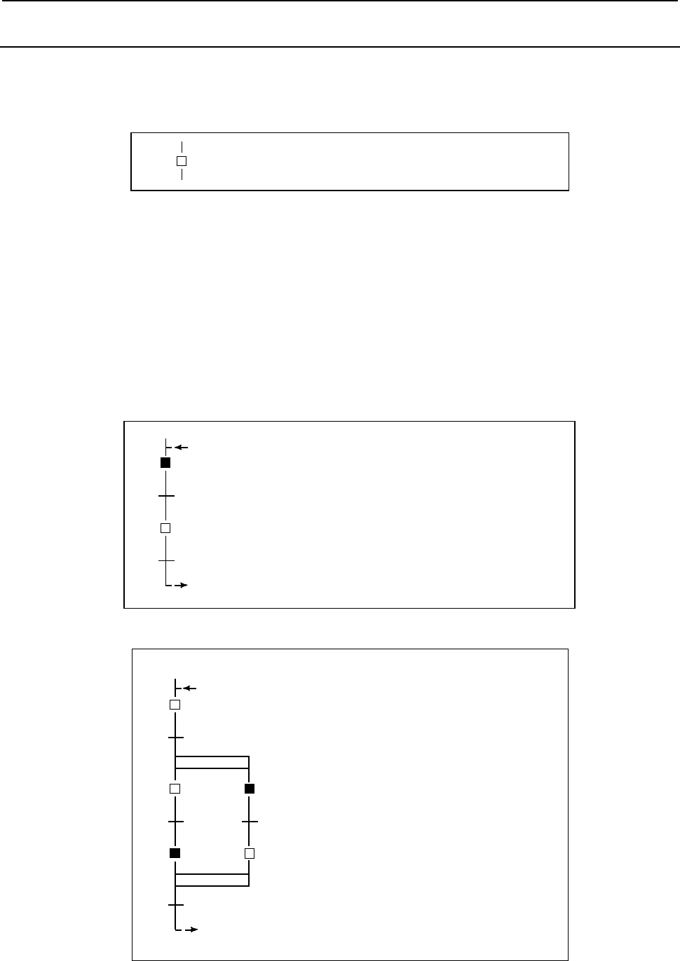
10.STEP SEQUENCE FUNCTION
B-64513EN/03
- 1272 -
10.3.2
Initial Step
An initial step is automatically activated when execution of the program starts. Once it has been activated,
it operates in the same way as a normal step. The program can be returned to this step through other steps.
Display
[ ]
Sn
(Pm)
Contents
• Define a step number (Sn), necessary for controlling execution, and subprogram number (Pm)
specifying the actual processing, for an initial step.
• All initial steps are activated when the other steps are not activated.
• Each block must contain at least one initial step. No limit is applied to the number of initial steps
contained in a block.
• A block having no initial step cannot be executed if called.
• Assign a step number to an initial step.
• The same step number cannot be used more than once in a program.
• In parallel branch, one initial step is required for each path. (See example 2.)
Example 1
[ ]
L1
S1
P101
S2
P102
L1
When a program is executed, step P1, specified by an
initial step, is activated first.
Initial step S1 is executed in the same way as normal
step once S1 has been executed.
Example 2
[ ]
L1
S4
P110
L1
When a program is executed, steps S3 and S4,
specified by an initial step, are activated first.
Once steps S3 and S4 have been executed, initial
steps S3 and S4 are executed in the same way as
normal step when the program starts from step S1.
S1
P101
S2
P102
[ ]
S5
S3
P103
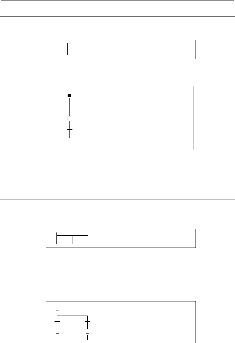
B-64513EN/03
10.STEP SEQUENCE FUNCTION
- 1273 -
10.3.3
Transition
A transition specifies the conditions governing the transition from the step to the next step.
Display
Pn
Contents
• Only one transition is required between steps.
• Transition between steps is performed as described below.
S1
P102
P101
S2
While S1 is activate, only S1 and P101 are
executed.
Other steps and transition are not executed.
When the transition P102 evaluates true unless
S2 is not being executed, the state is ignored.
When the transition P101 evaluates true, control
passes fro S1 to S2. In this case, when the
condition is true, S1 is terminated regardless of
the state of S1, and S2 is activated.
• When a signal is set to 1 in a transition, it remains the state even if the control is transferred to the
subsequent step. To set the signal to 0, use another subprogram to do so.
Example
Refer an example described on the Step function (Sub sec. 10.3.1).
10.3.4
Divergence of Selective Sequence
A selective sequence branches to two or more sequences. When the transition evaluates true, the
corresponding step is activated.
Display
Contents
• Transitions are placed after a divergence of selective sequence.
• The step connected to the transition for which the conditions are true is first activated.
• When the conditions for any transition are true simultaneously, the leftmost step is activated.
• A selective sequence can create up to 16 paths.
Example
[ ] S1
P100
S2
P101
S3
When the conditions for P101 are satisfied
earlier than those of P102, step S3 is
activated.
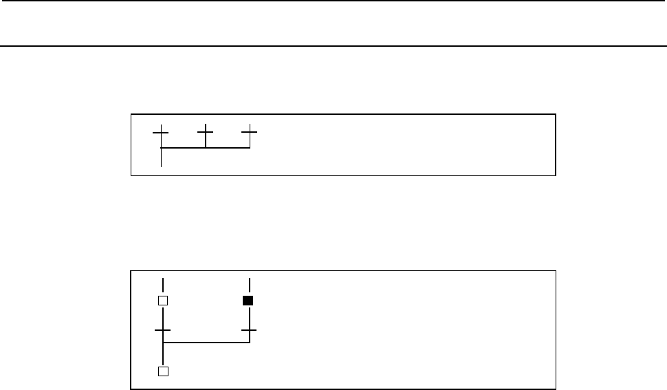
10.STEP SEQUENCE FUNCTION
B-64513EN/03
- 1274 -
10.3.5
Convergence of Selective Sequence
It combines two or more divergent paths to the main sequence.
Display
Contents
The number of divergent paths must match that of the convergent paths.
Example
S2
P102
S4
P103
S3 S3 While step S3 is executed, the transition
P103 evaluates true, thus step S4 is activated.
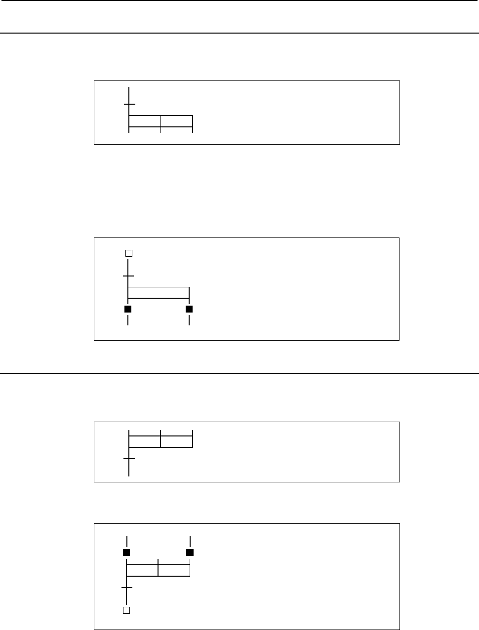
B-64513EN/03
10.STEP SEQUENCE FUNCTION
- 1275 -
10.3.6
Divergence of Simultaneous Sequence
A simultaneous sequence branches to two or more sequences, and all steps are activated simultaneously.
Display
Contents
• A transition must be placed before a divergence of simultaneous sequence.
• All branched steps are activated simultaneously, then executed.
• A simultaneous sequence can create up to 32 paths.
Example
[ ]
S1
P101
S2 S3
When the transition P101 evaluates true, step
S2 and S3 are activated simultaneously.
10.3.7
Convergence of Simultaneous Sequence
It combines two or more divergent paths to the main sequence.
Display
Contents
• A convergence of simultaneous sequence is processed as follows.
S10
P120
S21
When the transition P120 evaluates true,
step S10 and S20 are terminated and step
S21 is activated.
S20
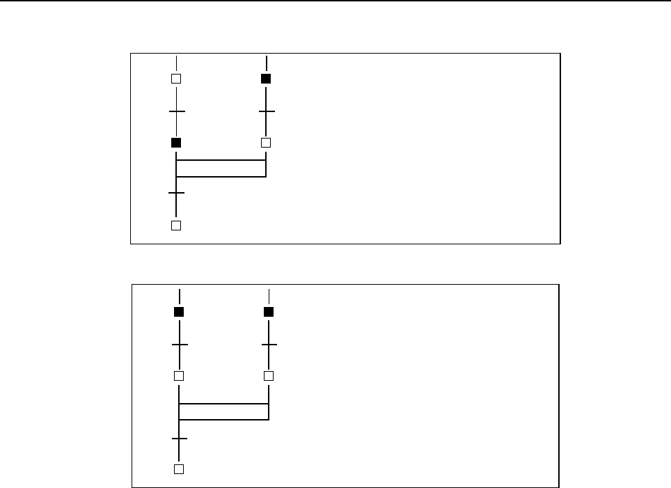
10.STEP SEQUENCE FUNCTION
B-64513EN/03
- 1276 -
• Wait processing is processed as follows.
Case 1)
S10
P109
S20
When the transition P109 evaluates true
unless both of step S11 and S16 are
active, control does not pass to step S20.
When the transition P109 evaluates true
while both of S11 and S16 are active, S11
and S16 are terminated and S20 is
activated. In the case, P109 provides the
termination conditions for both S11 and
S16.
P110
S11
S15
P115
S16
Case 2)
S11
P110
S20
To specify the termination conditions for
S11 and S16 separately, place the
conditions in P111 and P116 and specify
two dummy steps, S12 and S17, as
shown
A
dummy step also requires a step
number and subprogram number. Also
specify a dummy transition condition,
which becomes always true, in P110.
P111
S12
(dummy)
S16
P116
S17
(dummy)
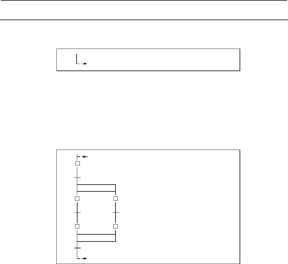
B-64513EN/03
10.STEP SEQUENCE FUNCTION
- 1277 -
10.3.8
Jump
A jump controls the execution of steps non–sequentially, together with a transition.
Display
Ln
Contents
• Specify a jump destination label (Ln).
• The step to which control is transferred (jumped) is activated.
• The jump destination must be within the same program.
• A jump cannot be performed from outside a simultaneous sequence to within the simultaneous
sequence, or from within a simultaneous sequence to outside.
• A jump cannot be performed between parallel–branched paths.
Example
[ ]
S1
P101
S2
When steps S4 and S5 are executed and the
transition P110 evaluates true, the program is
repeated from initial step S1.
L1
P102
S4
P110
L1
S3
P103
S5

10.STEP SEQUENCE FUNCTION
B-64513EN/03
- 1278 -
10.3.9
Label
A label specifies the jump destination.
Display
Ln
Contents
Specify the jump destination label (Ln).
Example
Refer to an example described on the jump function (Subsec. 10.3.8).
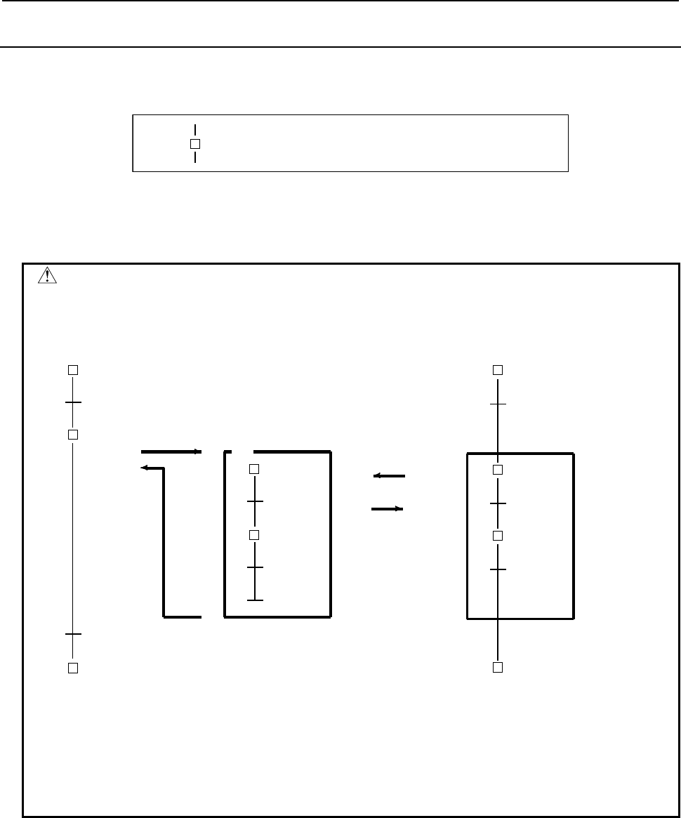
B-64513EN/03
10.STEP SEQUENCE FUNCTION
- 1279 -
10.3.10
Block Step
A block step specifies the step sequence subprogram to be executed.
Display
] Sn
(Pm)
Contents
Define a step number (Sn), which controls the execution of a block step, and a subprogram (Pm)
specifying the actual process, for a block step.
CAUTION
1 Assign a step number to a block step.
2 The same step number cannot be used twice in a program.
3 A transition must be placed after a block step.
Example)
]
S1
P101
S2
(P2)
P102
S3
P2
S20
P120
S21
P121
equal
S1
S3
S20
P120
S21
P121
P101
4 Transition P102 cannot be omitted due to the syntax of the step sequence
method. Specify a dummy transition, which becomes always true, for transition
P102.
5 Transition P121 must specify the transition condition for the termination of the
step S21.
6 When the conditions of transitions P102 and P121 are switched, step S21 will
not be correctly executed.
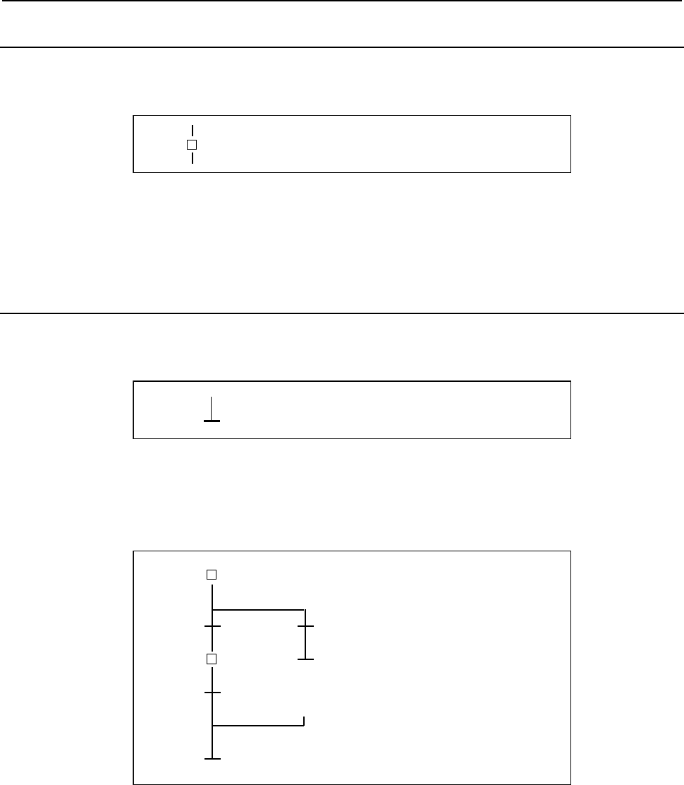
10.STEP SEQUENCE FUNCTION
B-64513EN/03
- 1280 -
10.3.11
Initial Block Step
This is an initial step on the block step.
Display
[ ] Sn
(
Pm
)
Contents
• Define a step number (Sn), necessary for controlling execution, and subprogram number (Pm)
specifying the actual processing, for an initial step.
• This step has the same function and graphical symbol as an initial step.
10.3.12
End Of Block Step
This terminates a block step.
Display
Contents
• Use this step to terminate a block step.
• Each block requires at least one end block step. No limit is applied to the number of end block steps.
Example
P103P100
P102
S2
[ ]
S1
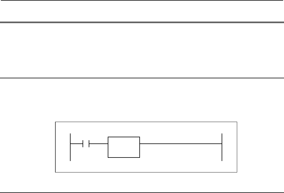
B-64513EN/03
10.STEP SEQUENCE FUNCTION
- 1281 -
10.4 EXTENDED LADDER INSTRUCTIONS
To enable the specification of steps and transitions, the components of a step sequence program, by
means of the ladder method, the following signals and functional instructions are provided. These signals
and instructions can only be used in subprograms in which step sequence step and transitions are
specified.
10.4.1 Functional Instruction TRSET
Function
This instruction describes that the conditions for a transition have been true.
This instruction is used in a subprogram which is called from a transition.
Format
TRSET
(SUB122)
A
CT
10.4.2
PMC Address (S Address)
Contents
• An S address is created to end block step processing.
• The meaning of each bit of the step number (S address) is shown in the following.
Sn.0 0: Transition to halt state, or halt state
1: Execution state
Sn.4 0: Transition to halt state, or halt state, or the scanning execute for the first time.
1: Execution state (Turns ON 1 scan delayed from Sn.0)
• This address allows any subprogram to reference the state of any step.
• When 0 is written in the S address with byte size, the Execution State of step that is specified can be
initialized. When LADDER was stopped, or the step which is no longer being called while in the
activated state, etc, the step sequence program can be execute from the beginning when it is
activated next time. The initialization of Execution State of step should be carried out with state that
step sequence program which contains this step isn’t called (ACT=0). To initialize a step sequence
program, writes 0 in all the S addresses included within the program.
• A ladder for the TRSET transition instruction can be programmed using each bits of S address.
Referring to S address, however, adversely affects the portability and comprehensibility. Use this
feature sparingly.
Example 1
This address is used to reference the activation states of steps in a step in which this address has been
specified, and performs complicated wait processing in a program including a simultaneous
sequence.
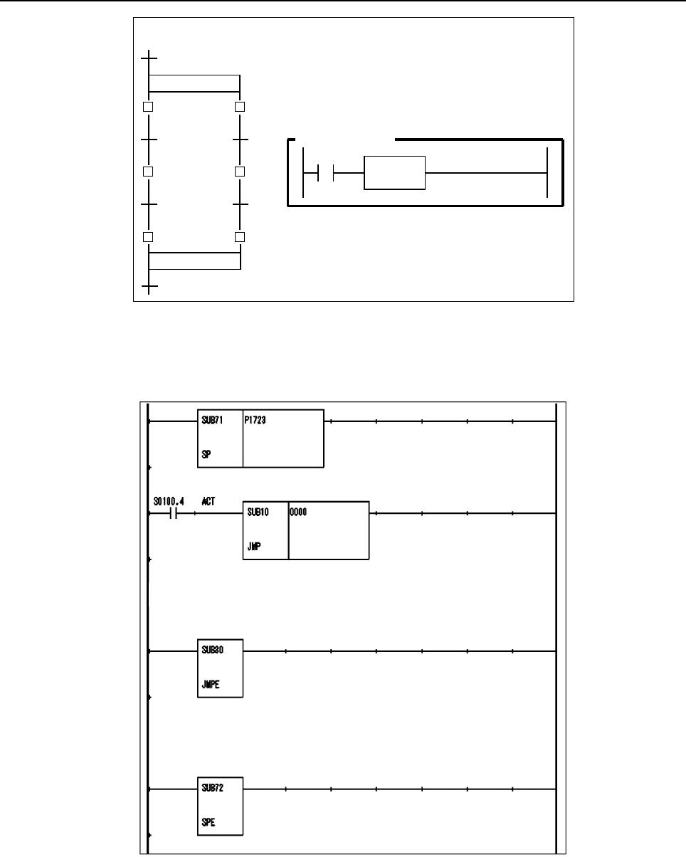
10.STEP SEQUENCE FUNCTION
B-64513EN/03
- 1282 -
P1 P4
P2 P1
Subprogram P1
S2.0
S2 TRSET
S5
S1 S4
S3 S6
In case of synchronizing the executing of S2 and S6
Example 2
The section between JMP and JMPE in the following example is executed only once after the
specific step (The following example is in the case of S100.) transits in the activated state from the
inactivated state.
[Processing to execute only once after the transition, here.]
[Processing to execute only every scanning, here.]
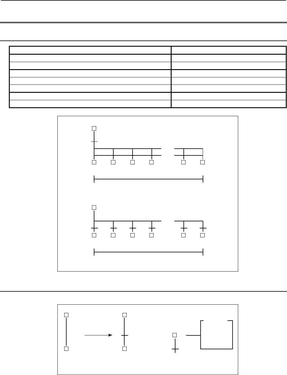
B-64513EN/03
10.STEP SEQUENCE FUNCTION
- 1283 -
10.5 SPECIFICATION OF STEP SEQUENCE
10.5.1 Specification
Item Description
Number of subprogram Up to 5000 (P1 to P5000)
Number of step Up to 2000 (S1 to S2000)
Number of label Up to 9999 (L1 to L9999)
Maximum number of jumps per block Up to 256
Nesting depth of block step Up to 8 levels
Size of block 192 lines × 48 columns
Number of paths Up to 32 paths
. . . .
Up to 32 paths
. . . .
. . . .
Up to 32 paths
. . . .
. . . .
10.5.2
General Rules
• One transition must exist between step and step.
S1
(P10) Subprogram
CALL P10
CALL P11
Correct
S2
(P11)
S1
(P10)
S2
(P11)
P1 or S1
The step S1 calls
subprogram P10, P11.
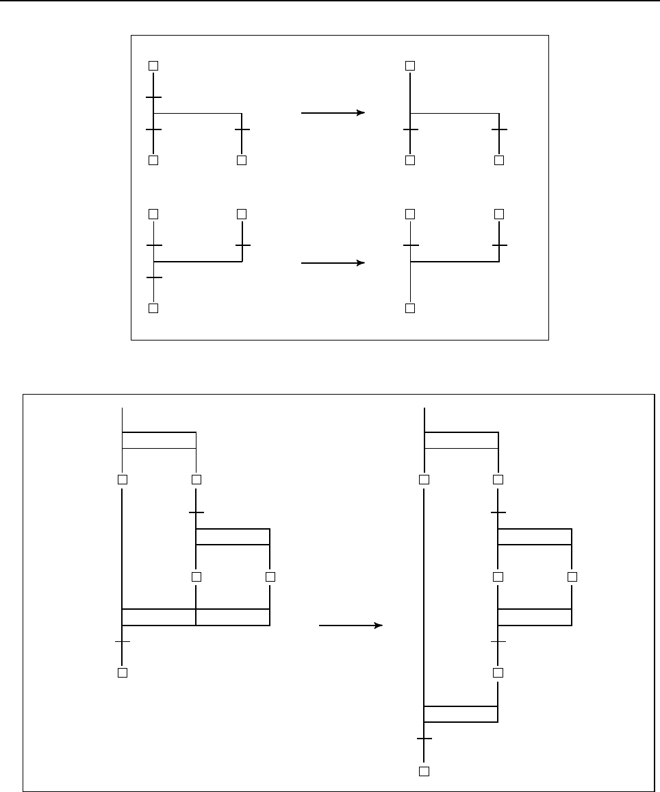
10.STEP SEQUENCE FUNCTION
B-64513EN/03
- 1284 -
• The transition shall never be repeated even at the point of the divergence and the convergence.
Correct
P10 P2 P1
P11 P2 P2
P12
S12
S2
S3
P1
S1
P10
P11
S10
S10
S1
S3
S2
S12
P10
S10
Correct
• When a simultaneous sequence is specified in another simultaneous sequence, one convergence must not
be used for each sequence.
Correct
S5 S5
(dummy)
P1 P3
P2 P2
S3
P1
S3
S2
S4
S1
S1 S2
S4
S6
Correct
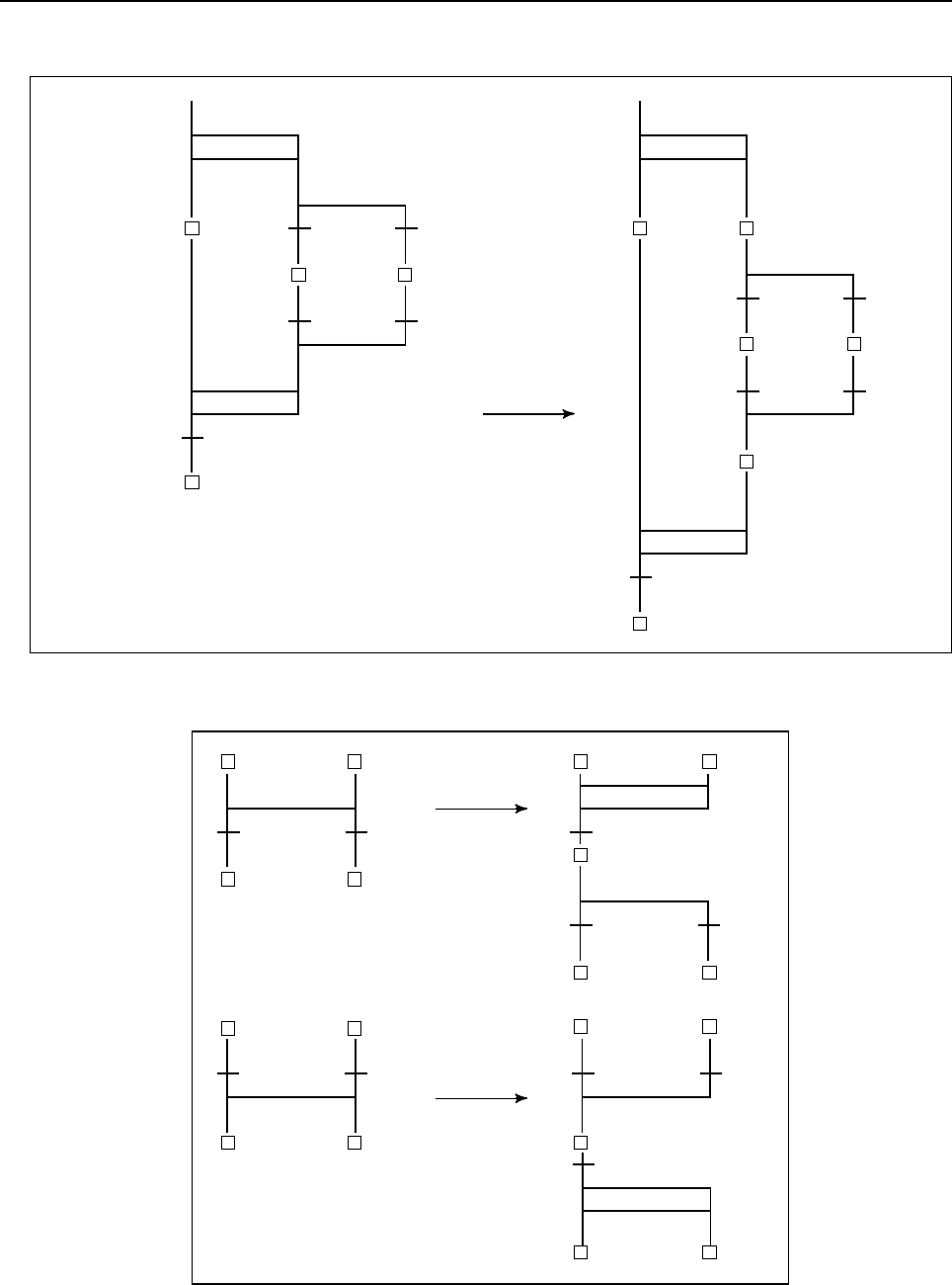
B-64513EN/03
10.STEP SEQUENCE FUNCTION
- 1285 -
• When a selective sequence is specified in a simultaneous sequence, dummy steps must be required
both after the divergence and before convergence.
Correct
S4
P1
P2
P3
S1
S2
P4
P5
S3
S6
P1
S1
P2
P3
S3
P4
P5
S4
S2 (dummy)
S5 (dummy)
• In case of branching again immediately after the convergence, a step/transition is required between
the divergence and convergence.
P2
P10
P10 P100 (dummy)
P1
S1 S2
S3 S10
Correct
S100 (dummy)
S10
S3
S2
S1
P11
P2 P2
P100 (dummy)
S10 S2
S100 (dummy)
S2
S12
P11
S10
S13
S13 S12
Correct
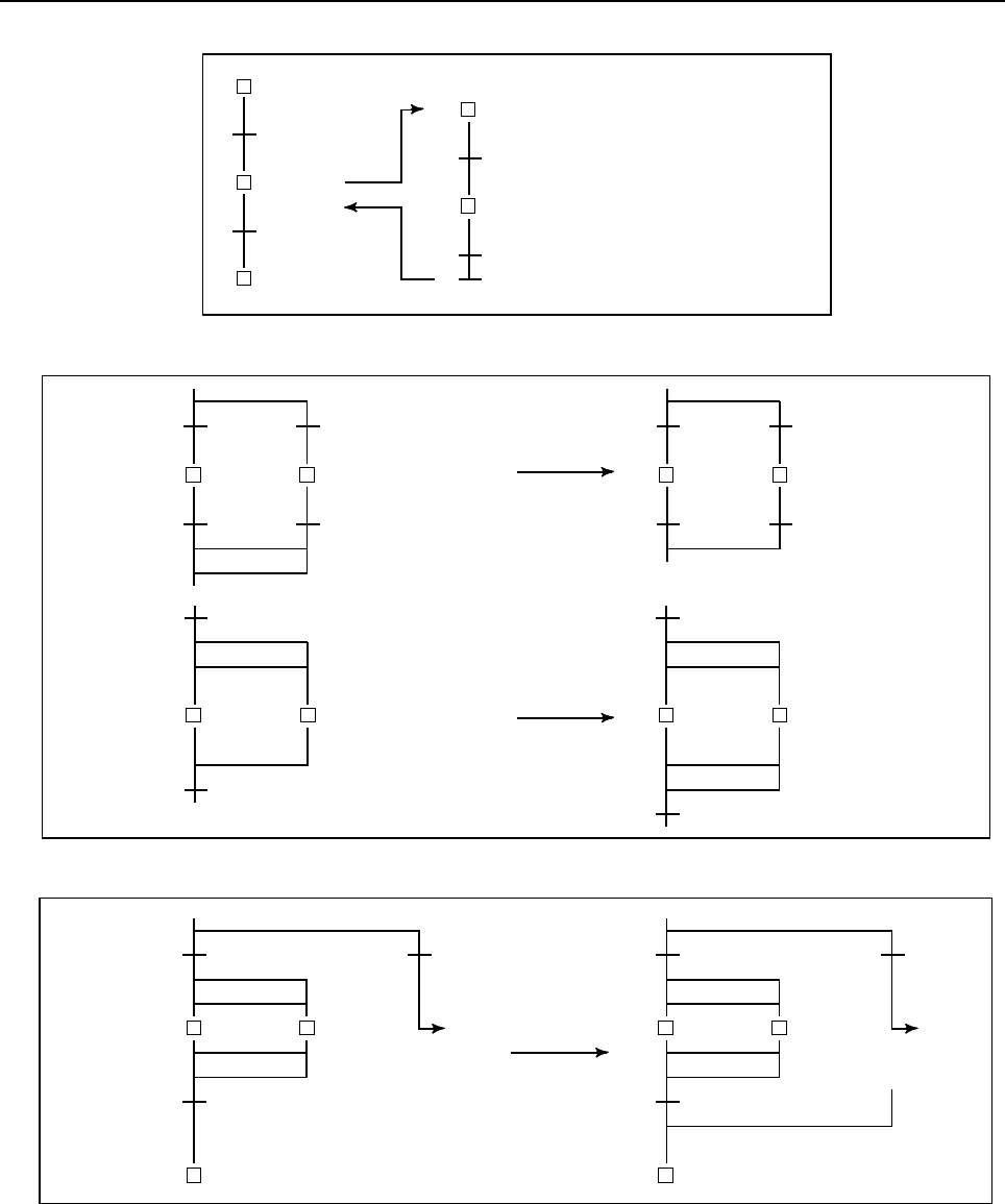
10.STEP SEQUENCE FUNCTION
B-64513EN/03
- 1286 -
• Immediately after the block step, a dummy transition which is always true is needed.
P10
P10 When block step S11 is used,
transition P11 and P101 cannot be
omitted
Note) P11 is a dummy transition.
The transition condition of
P11 must always be true.
P11
S100
S11
S101
S12
]
S10
[ ]
P100
P101
• The divergence must be terminated with the same type of convergence.
P2
P3
S2
P4
P5
S3
P2
P3
S2
P4
P5
S3
P2
P3
S2 S3
P2
P3
S2 S3
Correct
Correct
• The number of convergences must match that of divergences.
Correct
S2
S4
P3
P1
S3
P2
L1 S2
S4
P3
P1
S3
P2
L1
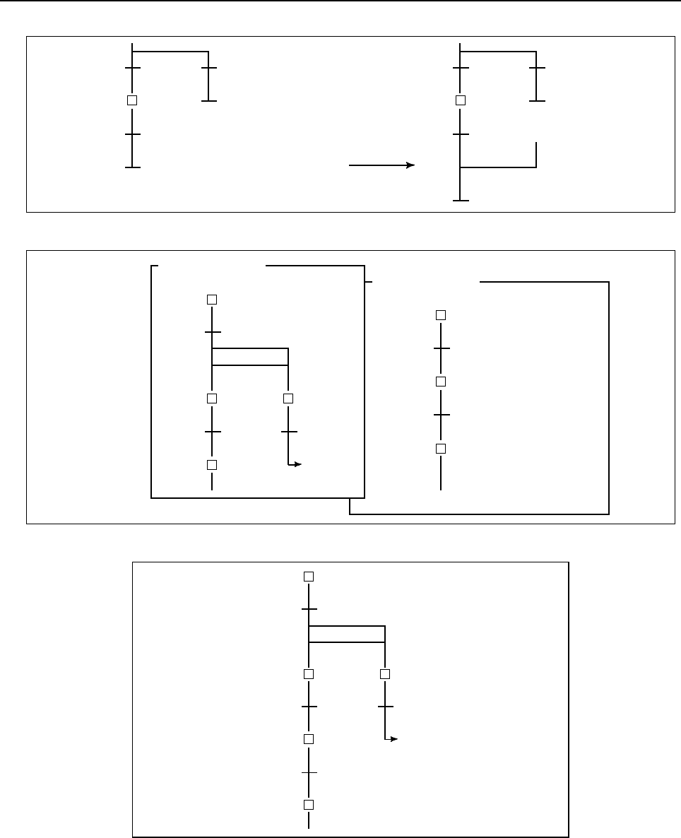
B-64513EN/03
10.STEP SEQUENCE FUNCTION
- 1287 -
• The number of convergences must match that of divergences, even at the end of a block step.
Correct
S2
P3
P1 P2
S2
P3
P1 P2
• It is not possible to jump to the other subprogram.
P100
← L1
P101
P11
S10
S100
P10
Subprogram P1
Subprogram P2
S101
S11
S102
S12
P20
S20
L1
• It is not possible to jump from a simultaneous sequence to another simultaneous sequence.
S1
P1
S2
P2
S3
P3
S4
← L1
S10
P10
L1
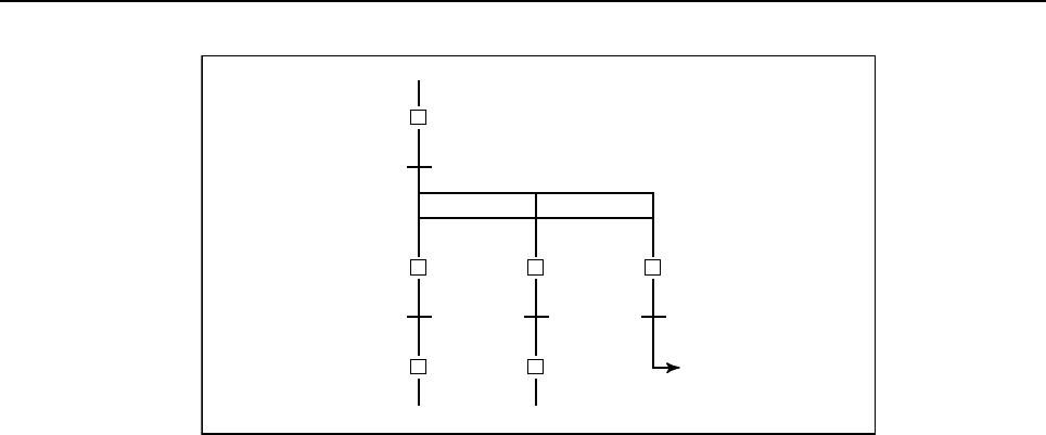
10.STEP SEQUENCE FUNCTION
B-64513EN/03
- 1288 -
• It is not allowed to jump from inside of the simultaneous sequence to outside.
L1
← L1
S1
P1
S2
P2
S3
S10
P10
S11
S20
P20
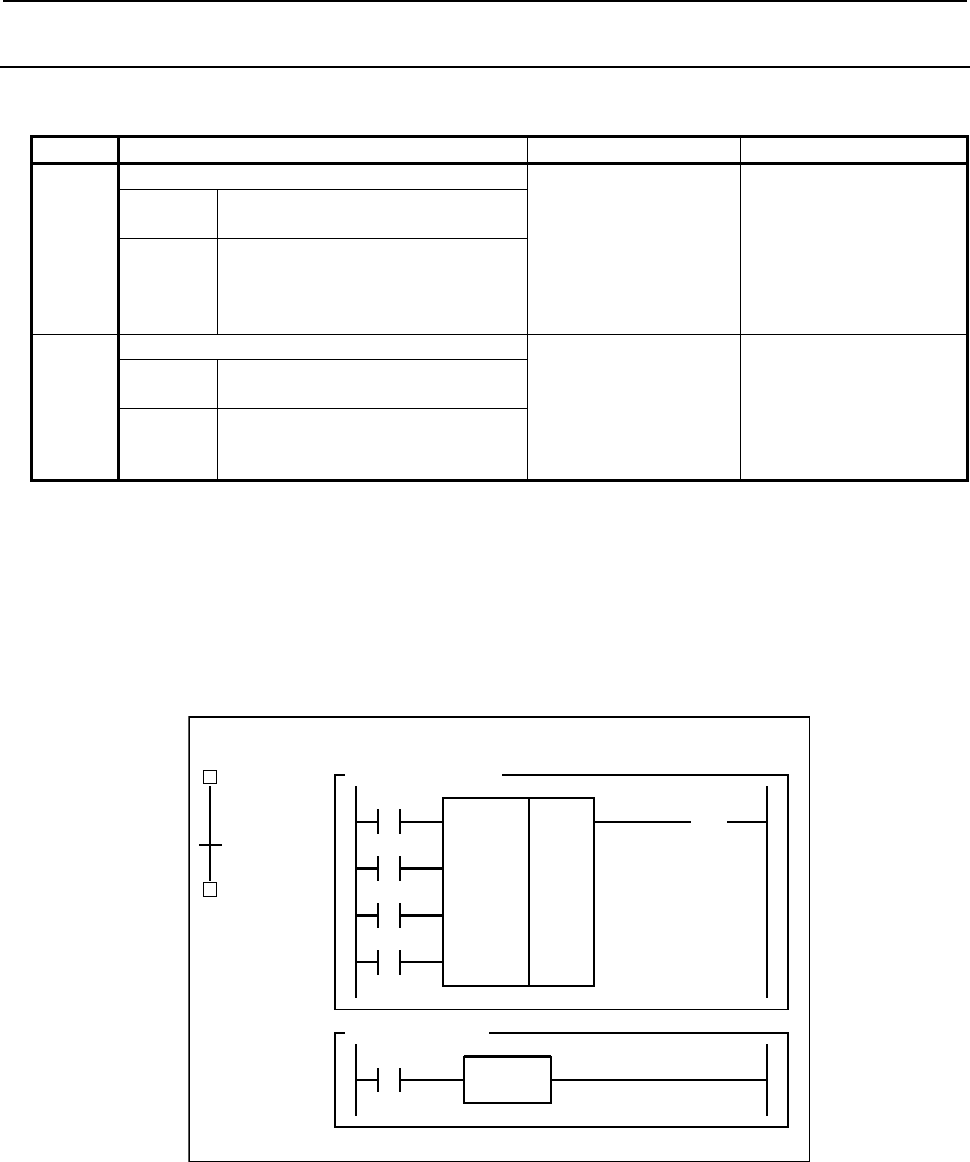
B-64513EN/03
10.STEP SEQUENCE FUNCTION
- 1289 -
10.5.3
Exclusive Control for Functional Instructions
The use of the following basic/functional instructions is restricted in steps and transitions.
Group Description Basic instructions Functional instructions
A The instructions operate when a signal changes. RDPT
ANDPT
ORPT
RDPT.STK
RDNT
ANDNT
ORNT
RDNT.STK
CTR (SUB5)
CTRC (SUB60)
TMR (SUB3)
TMRB (SUB24)
TMRC (SUB54)
DIFU (SUB57)
DIFD (SUB58)
Condition Multiple functional instructions
having the same number are used.
Problem Not activated.
Correct operation cannot be
guaranteed.
B Restriction due to the interface.
-
WINDR (SUB51)
WINDW (SUB52)
DISP (SUB49)
DISPB (SUB41)
EXIN (SUB40)
AXCTL (SUB53)
Condition Data is input or output by using two
subprograms.
Problem Invalid return value.
Not terminated.
(1) Basic/functional instructions of group A
Since these functional instructions operate when the corresponding signals change, they may not
operate correctly when called from multiple steps.
Example
While multiple CTR functional instructions are used, when control passes from S1 to S2 with
ACT of CTR not set to off, CTR is not counted when called from step S2.
CTR 1
S1
(P100)
Subprogram P100
R0.0
( )
S2
(P100)
X1.0
Subprogram P1
X1.0
TRSET
P1
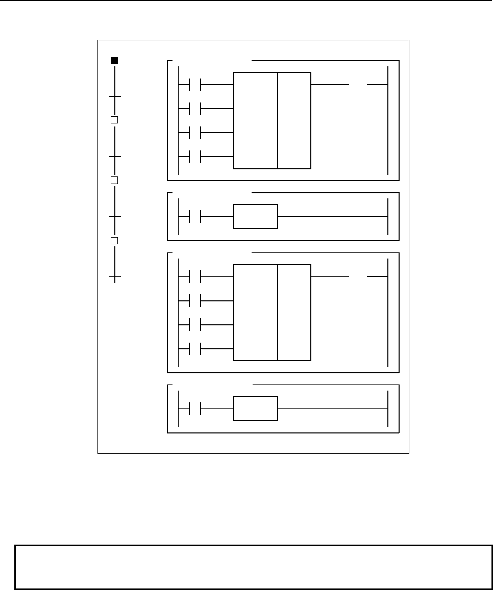
10.STEP SEQUENCE FUNCTION
B-64513EN/03
- 1290 -
Correct program
Divide the subprogram so that ACT of CTR is called after it is set to off.
CTR 1
CTR 1
S1
(P100)
Subprogram P100
R0.0
( )
S2
(P102)
X1.0
S3
(
P100
)
Subprogram P101
X1.0
TRSET
S4
(P102) Subprogram P102
R9091.0
Subprogram P103
R9091.1
TRSET
P101
P103
P103
P101
R0.0
( )
(2) Functional instructions of group B
While an instruction is being executed through the interface with the NC, other same instructions
cannot be executed. PMC control software does not receive the process when the instruction is not at
a same position (net).
If ACT is set to on and off in different instructions (or subprograms), these processes are not
terminated.
NOTE
Only the window instructions (WINDR and WINDW) which work as
low–speed–type belong to the group B.
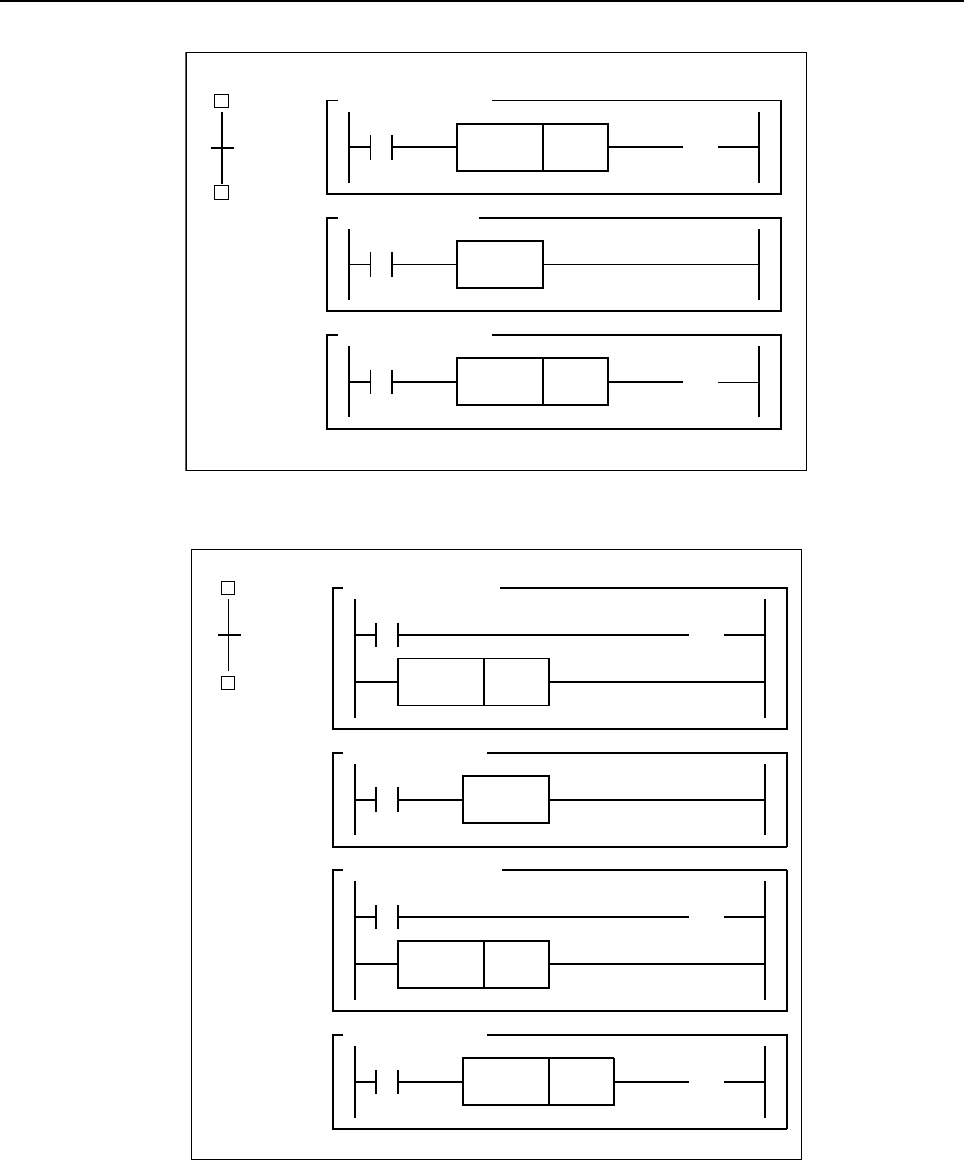
B-64513EN/03
10.STEP SEQUENCE FUNCTION
- 1291 -
Example
S2
(P101)
P1
S1
(P100)
Sub
p
ro
g
ram P100
R9091.1 WINDR R10
Subprogram P1
R0.0
TRSET
Subprogram P101
R9091.0
WINDR R10
R0.0
( )
R0.0
( )
Correct program
Correct the program so that ACT is set to on and off within one subprogram.
S2
(
P101
)
P1
S1
(P100)
Subprogram P100
R9091.1
CALLU P2
Subprogram P1
R0.0
TRSET
Subprogram P101
R9091.0
CALLU P2
Subprogram P2
R0.1
WINDR R10
R0.1
( )
R0.1
( )
R0.0
( )
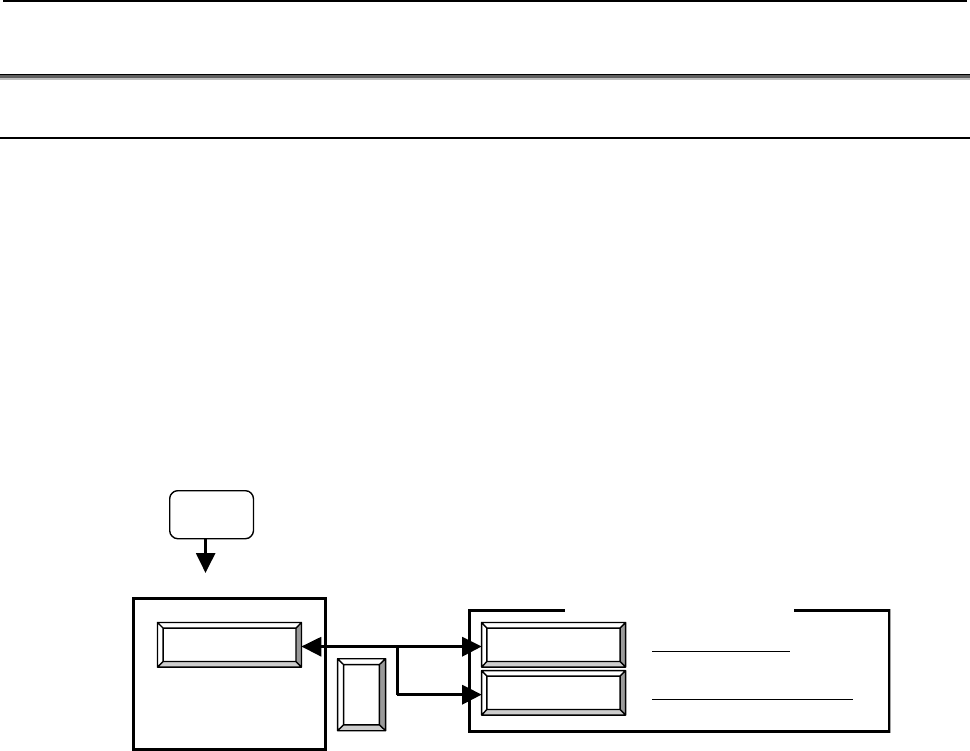
10.STEP SEQUENCE FUNCTION
B-64513EN/03
- 1292 -
10.6 STEP SEQUENCE SCREEN OPERATION
10.6.1 Displaying a Step Sequence Diagram
The following operations are supported to enable the diagnosis and debugging of a step sequence
program.
• Displaying a step sequence and editing a ladder
• Displaying the execution state of a step sequence
• Monitoring the run time of the step sequence program
A step sequence can be operated using the PMC ladder menu.
The PMC ladder menu is used to display PMC ladder related screens such as a program list screen and
ladder diagram display/editor screen.
The screen display can be switched to the PMC ladder menu by operating the <SYSTEM> key then the
[PMC LADDER] soft key as shown below.
PMC main menu
LIST
LADDER
PMC LADDER
<
Program list screen
Ladder display/editor screen
PMC ladder menu
SYSTEM
Pressing the [LADDER] soft key displays a sequence program dynamically to enable operation
monitoring. On the editor screen, modifications can be made to relays and function instructions of a
sequence program to change the operation of the sequence program.
The ladder diagram display/edit function consists of the following screens:
(1) Ladder diagram display screen (ladder diagram monitor screen)
Displays a ladder diagram and monitors the current state of relays/coils.
(2) Selection monitor screen
Displays a selected ladder net only and monitors the current state of relays/coils.
(3) Ladder diagram editor screen
Used to edit a ladder on a net-by-net basis.
(4) Net editor screen
Used to edit the contents of a net in a ladder.
(5) Program list display screen
Used to select a subprogram to be displayed on the ladder diagram display screen.
(6) Program list editor screen
Used to edit a ladder program on a subprogram-by-subprogram basis and select a subprogram to be
edited on the ladder diagram editor screen.
(7) Function instruction data table display screen
Enables the data table of a function instruction to be referenced.
(8) Function instruction data table editor screen
Enables the data table of a function instruction to be edited.
(9) Step sequence display screen
Displays a step sequence diagram and monitors the current step/transition state.
(10) Subprogram list display screen
Used to select a subprogram used with a step sequence.
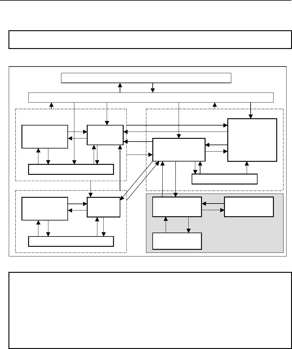
B-64513EN/03
10.STEP SEQUENCE FUNCTION
- 1293 -
(11) Step sequence state display screen
Displays the execution state of each step of a step sequence.
NOTE
These screens can be protected using the programmer protection function.
The screens make transactions as shown below.
[SPLIST]
Editing functions
[LIST]
[EXIT] [ZOOM]
Program list
editor screen
Ladder diagram
editor screen
Net editor screen
[CREATE NET]
[ZOOM]
[LIST]
[ZOOM]
[LIST]
[EDIT]
Program list editor
screen
Subprogram list display screen
Ladder diagram
monitor screen
[SPLIST]
[EXIT]
[<]
[PMC LADDER] [<]
PMC main menu
PMC ladder menu
Display function (monitor)
Ste
p
se
q
uence
state display
screen
Step sequence state
display screen (Sub)
Subprogram list display screen
[ZOOM]
[LIST]
[STEP]
[SPLIST] [STATE]
[STEP]
[STATE]
[LIST] (Note2) [LADDER] (Note 1)
[BACK] [ZOOM]
[ZOOM]
[BACK]
[BACK]
[ZOOM]
[SPLIST]
Step sequence
state display
screen
Step sequence state
display screen (Sub)
Subprogram list display screen
[STEP]
[SPLIST] [STATE]
[STEP]
[STATE]
[<]
[LADDER] (Note 1) [LIST] (Note2)
[BACK]
Fig. 10.6.1 Transition of step sequence display and ladder display/editing screen
NOTE
1 Pressing the [PMC LADDER] soft key displays one of the ladder diagram display
screen, selection monitor screen, step sequence display screen or the program
list display screen which was displayed most recently.
2 The [EDIT] soft key on the ladder diagram display screen is displayed only when
the programmer function is enabled. (To enable the programmer function, set
the setting item "PROGRAMMER ENABLE" on the PMC parameter setting
screen to "Yes" or set K900.1 to 1.) Alternatively, set "EDIT ENABLE" to "Yes" or
set K901.6 to 1.
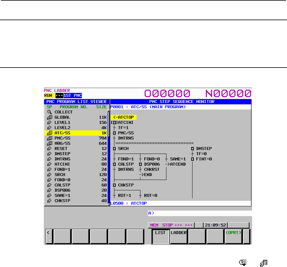
10.STEP SEQUENCE FUNCTION
B-64513EN/03
- 1294 -
10.6.2
History of Display
The history of transition of subprogram display in the ladder program display screen or the step sequence
program display screen is recorded. The history records are displayed in the subprogram list display
screen. As for details, refer to 8.11.1.
10.6.3
Program List Display Screen
To display the step sequence diagram display screen first after the power is turned on, select a
subprogram of the step sequence on the program list display screen.
Program list display screen (step sequence)
On the program list display screen, a subprogram of a step sequence is marked with or in the
"SP" display area. Pressing the [ZOOM] soft key when the cursor is placed on a subprogram, the screen
display switches to the step sequence display screen.
For details of the program list display screen, see Section 8.1, "DISPLAYING THE PROGRAM LIST
("LIST" SCREEN)".
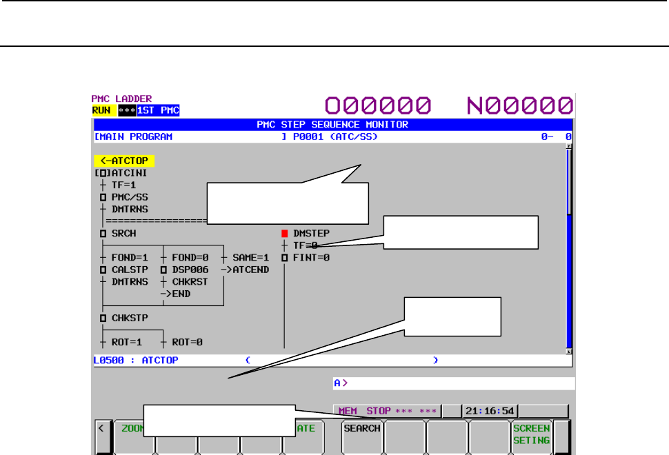
B-64513EN/03
10.STEP SEQUENCE FUNCTION
- 1295 -
10.6.4
Step Sequence Display Screen
Pressing the [ZOOM] soft key when the cursor is placed on a step sequence on the program list display
screen, subprogram list display screen, or step sequence display screen displays the step sequence display
screen.
Fig. 10.6.4 Step sequence display screen
(1) Screen configuration
(a) At the top of the screen, information (“[comment] program number (symbol)”) on the
subprogram for which a sequence diagram is currently displayed is displayed together with the
coordinates of the cursor position.
(b) The message display line displays a message such as an error message and inquiry, depending
on the situation.
(c) The additional information line displays detail information on the step sequence diagram
element where the cursor is placed.
When the cursor is placed on a step, the information displayed changes according to the setting of
"STEP NOTATION" described in Subsection 10.6.5, "Setting the Step Sequence Diagram Screen".
• When "S-ADDRESS" is set in "STEP NOTATION"
[P-address] S-address: symbol information of the S-address (comment information of the
S-address)
• When "P-ADDRESS" is set in "STEP NOTATION"
[S-address] P-address: symbol information of the P-address (comment information of the
P-address)
When the cursor is placed on a transition, jump, or label, detail information is displayed in the
following format:
Address : Symbol information (Comment information)
When a step sequence diagram is displayed, the screen can display 16 elements vertically and 8
elements horizontally.
Subprogram displayed
Activated step
Additional
information
Message display line
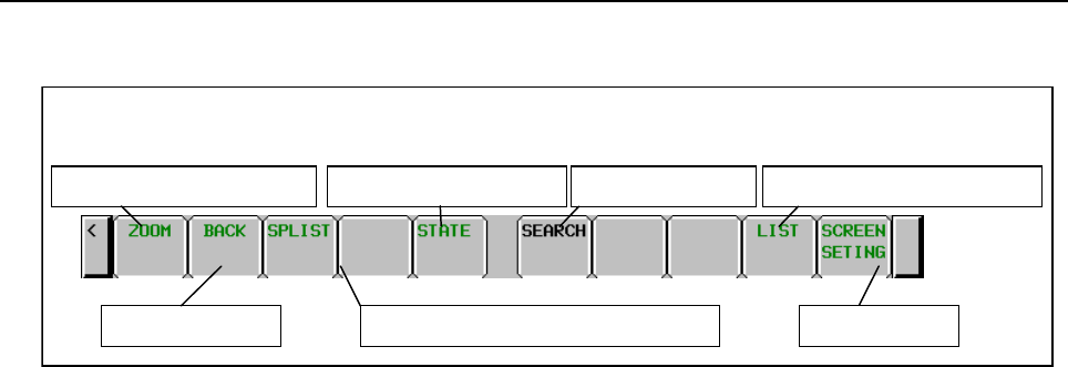
10.STEP SEQUENCE FUNCTION
B-64513EN/03
- 1296 -
(2) Operations using soft keys
(a) [ZOOM] Display specified subprogram
Switches the screen display to the ladder diagram display screen or the step sequence display
screen.
When you press the [ZOOM] soft key without entering a character string, the ladder diagram
display screen is displayed if the cursor is placed on a ladder, or the step sequence display
screen is displayed if the cursor is placed on a step sequence.
When you press the [ZOOM] soft key after entering a subprogram name or symbol name, the
subprogram (ladder diagram display screen or step sequence display screen) corresponding to
the entered character string is displayed. If the subprogram is protected, the password needs to
be released.
(b) [BACK] Show the preceding subprogram
Traces back the history to recall the previous displayed subprogram.
(c) [SPLIST] Switch to the subprogram list screen
Switches the screen display to the subprogram list display screen.
(d) [STATE] Switch to the state display screen
Switches the screen display to the step sequence state display screen.
(e) [SEARCH] Search symbol/address
Searches the symbol or the PMC address according to the preceding string.
(f) [LIST] Go to PROGRAM LIST VIEWER screen
Displays the program list screen.
(g) [SCREEN SETTING] Display setting
Switches the screen display to the step sequence display setting screen.
(h) [<]
Switches the screen display to the PMC ladder menu.
(3) Screen operations using other keys
(a) Cursor keys, page keys
The cursor can be moved using the up/down/left/right cursor keys and the page keys.
By pressing the down cursor key after entering a program name or symbol name, you can
search for the program.
(b) INPUT key
With the INPUT key, operations equivalent to those enabled by the [ZOOM] soft key can be
performed.
Soft keys for step sequence display screen
Display specified subprogram
Switch to state display screen
To previous level Display setting Switch to subprogram list screen
Subprogram search Switch to program list screen
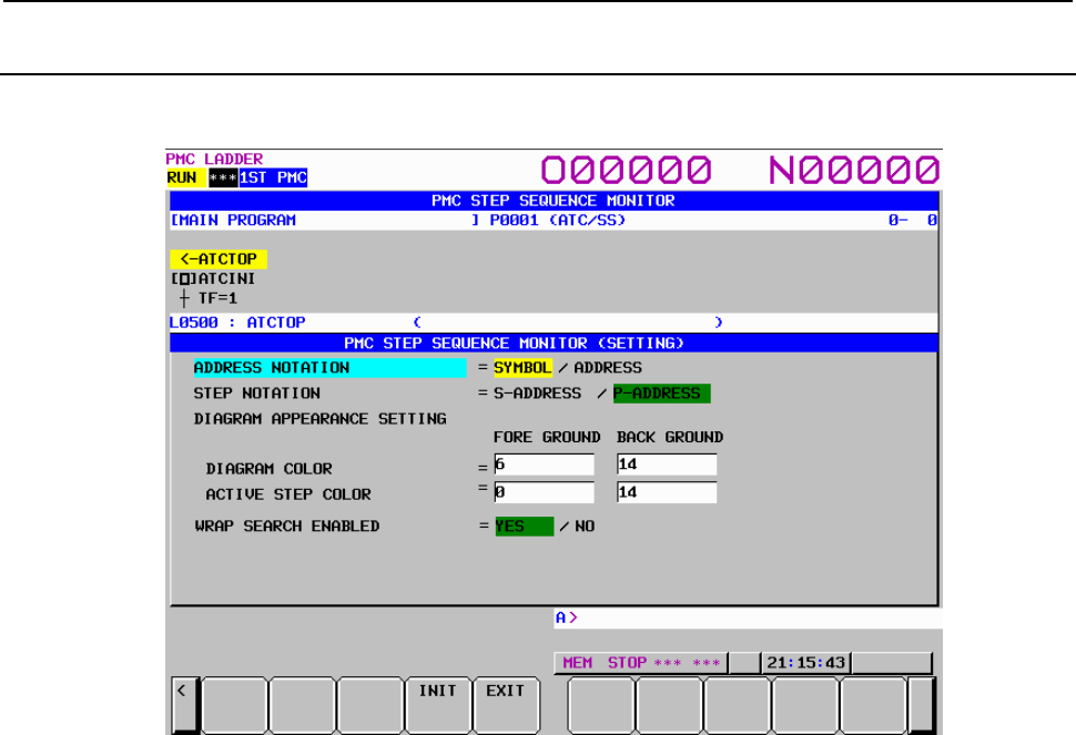
B-64513EN/03
10.STEP SEQUENCE FUNCTION
- 1297 -
10.6.5
Setting the Step Sequence Diagram Screen
Set the display format for the step sequence display screen.
To set each item, use the left/right cursor keys or soft keys.
Fig. 10.6.5 Step sequence display screen
(1) Setting items
(a) ADDRESS NOTATION
Set whether to use an address or symbol when a subprogram is to be displayed on the step
sequence display screen.
SYMBOL (default)
An address for which a symbol is defined is displayed using the symbol. An address for
which no symbol is defined is displayed using the address.
ADDRESS
An address for which a symbol is defined is displayed using the address at all times.
(b) STEP NOTATION
Set whether to use an S-address or P-address when the subprogram of each step is to be
displayed on the step sequence display screen. This setting is valid for steps only.
S-ADDRESS
When “ADDRESS NOTATION” is “ADDRESS”, each step is displayed using an
S-address (step number). When “ADDRESS NOTATION” is “SYMBOL”, the symbol
set for the S-address is displayed.
P-ADDRESS (default)
When “ADDRESS NOTATION” is “ADDRESS”, each step is displayed using a
P-address (subprogram number). When “ADDRESS NOTATION” is “SYMBOL”, the
symbol set for the P-address is displayed.
(c) DIAGRAM COLOR
Set the display color of an entire sequence diagram except the activation state mark of each step
on the step sequence display screen.
The display color can be changed by entering a numeric value or the left/right cursor keys. One
of 15 color numbers, 0 to 14, can be set.
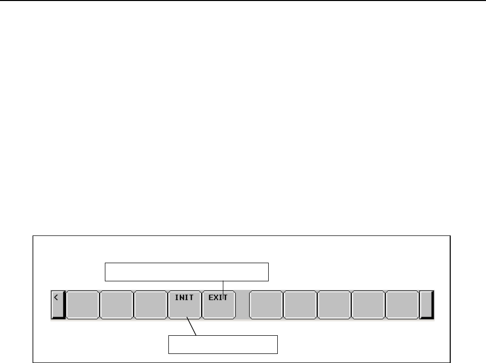
10.STEP SEQUENCE FUNCTION
B-64513EN/03
- 1298 -
(d) ACTIVE STEP COLOR
Set the display color of the activation state mark of each step on the step sequence display
screen.
The setting method and settable colors are the same as for the display color of a sequence
diagram.
(e) WRAP SEARCH ENABLED
Set whether to perform continued search operation from the start when search processing has
reached the end of the step sequence program.
YES (default)
When search processing has reached the end of the step sequence program, it goes to the
top of the program to continue to perform the search operation.
NO
When search processing has reached the end of a step sequence program, it ends with
failure.
(2) Operations using soft keys
(a) [INIT]
Initializes all settings.
(b) [EXIT]
Returns the screen display to the step sequence display screen.
Soft keys on step sequence display setting screen
Switch to step sequence display screen
Initialization of setting

B-64513EN/03
10.STEP SEQUENCE FUNCTION
- 1299 -
10.6.6
Subprogram List Display Screen
When you press the [SPLIST] soft key on the step sequence display screen, a list of the subprograms that
are being used with the step sequence currently displayed is displayed. On the other hand, the history of
the displayed subprogram is also displayed.
There are the following operations related to step sequence.
• On the subprogram list display screen, the subprogram of the step sequence is marked with or
in the "SP" display area. Pressing the [ZOOM] soft key when the cursor is placed on a
subprogram, the screen display switches to the step sequence display screen.
• Pressing the [STEP] soft key, switches the screen display to the step sequence display screen.
• Pressing the [STATE] soft key, switches the screen display to the step sequence state display screen.
For details of the subprogram list display screen, see Section 8.11, " DISPLAYING A SUBPROGRAM
LIST ([SPLIST] SCREEN)".
10.6.7
Setting Subprogram List Screen
The method of setting the subprogram list display screen is the same as for the program list display
screen.
For details of the setting screen, see Subsection 8.1.1, "Setting Program List Screen".
10.6.8
Ladder Diagram Monitor Screen
The ladder diagram display screen is displayed by pressing the [ZOOM] soft key when the cursor is
placed on a ladder subprogram on the program list screen, subprogram list screen, or step sequence
display screen.
This screen is the same as the screen described in Section 8.2, "MONITORING LADDER DIAGRAMS
([LADDER] SCREEN) ". For details of the screen, see Section 8.2.
10.6.9
Collective Monitor Screen
This screen is the same as the screen described in Subsection 8.4.2, "COLLECTIVE MONITOR
Function". For details of the screen, see Subsection 8.4.2.
If you use the function for jumping to a ladder net with the [JUMP] soft key on the selection monitor
screen, step sequence display hierarchy information is lost.
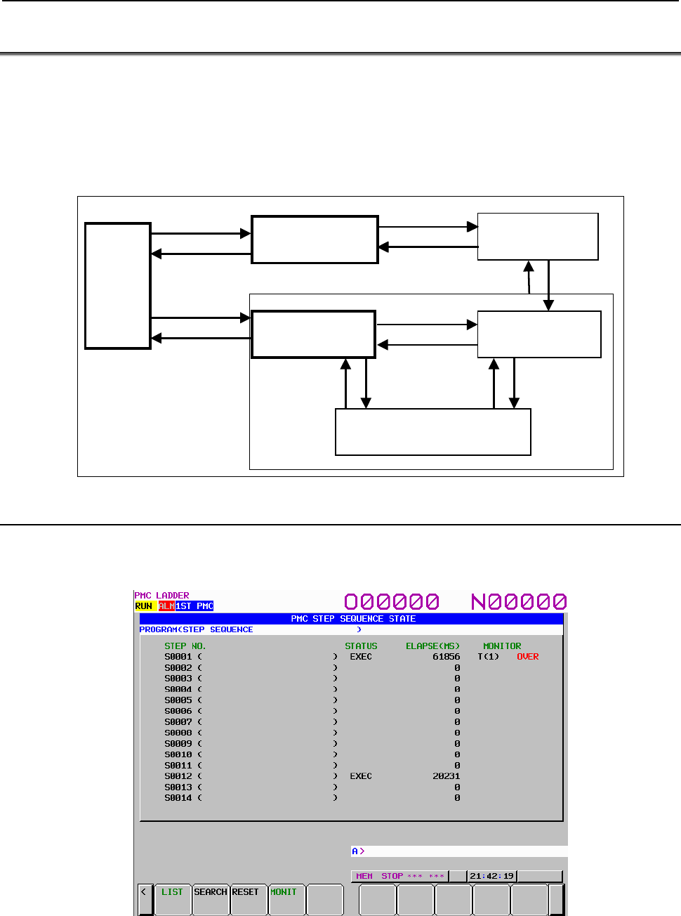
10.STEP SEQUENCE FUNCTION
B-64513EN/03
- 1300 -
10.7 EXECUTION STATE DISPLAY
The execution state of each step of a step sequence is displayed.
• Step sequence state display screen (global)
• Step sequence state display screen (subprogram)
• Time monitor setting screen
The screen configuration is shown below.
Program list display
screen
[STEP]
[STATE]
[ZOOM]
[LIST]
Step sequence
display screen
Step sequence state
display screen
(global)
Subprogram list display screen
Step sequence
state display screen
(subprogram)
Time
monitor
setting
screen
[SPLIST] [SPLIST]
[STATE] [STEP]
[MONIT]
[STATE]
[MONIT]
[LIST]
[STATE]
[STATE]
10.7.1
Step Sequence State Display Screen (Global)
Pressing the [STATE] soft key on the program list screen displays the step sequence state display screen
(global).
This screen displays the execution state and the elapsed time of operation of an entire step sequence.
Fig. 10.7.1 Step sequence state display screen (global)
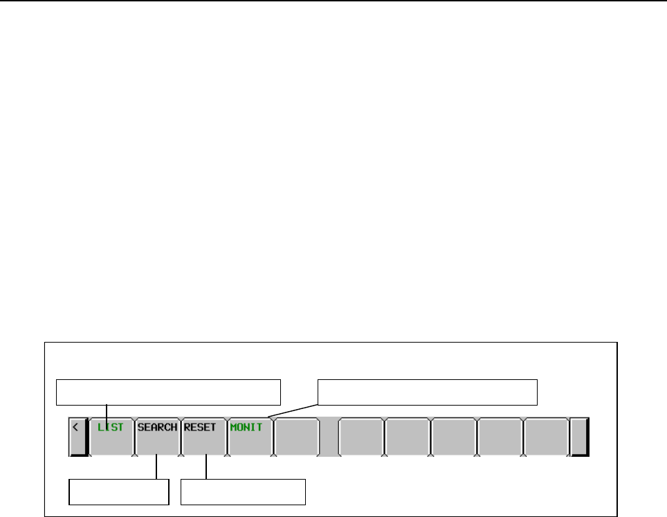
B-64513EN/03
10.STEP SEQUENCE FUNCTION
- 1301 -
(1) Screen configuration
(a) STEP NO.
Displays a step number. In parentheses, the symbol of the address of a step number is
displayed.
(b) STATUS
When "EXEC" is displayed, it means the active state. When "EXEC" is not displayed, it means
the inactive state.
(c) ELAPSE(MS)
Indicates the period of time of the active state. In the active state, the time indication changes.
(d) MONITOR
Shows assigned time monitor information.
• T(x) : Timer number for monitoring
• OVER : Monitor time exceeded
The message display line displays a message such as an error message and inquiry, depending on the
situation.
(2) Operations using soft keys
(a) [LIST] Switch to the program list display screen
Switches the screen display to the program list display screen.
(b) [SEARCH] Step search
Searches for a step. When you press the [SEARCH] soft key after entering a step number or
symbol name, the step corresponding to the entered character string is found, and the display is
updated so that the found step is placed at the start.
(c) [RESET] Abnormal state reset
Resets abnormal states that have occurred in all time monitoring operations.
For individual resetting, reset a desired monitoring operation on the time monitor setting
screen.
(d) [MONIT] Switch to the time monitor setting screen
Switches the screen display to the time monitor setting screen.
(e) [<]
Switches the screen display to the PMC ladder menu.
(3) Screen operations using other keys
Page keys
The page keys can be used to switch from one display page to another. A program can be
searched using the down cursor key following the step number or symbol name entered.
Soft keys for step sequence state display screen (global)
Switch to program list screen Switch to time monitor setting screen
Step search
A
bnormal state reset
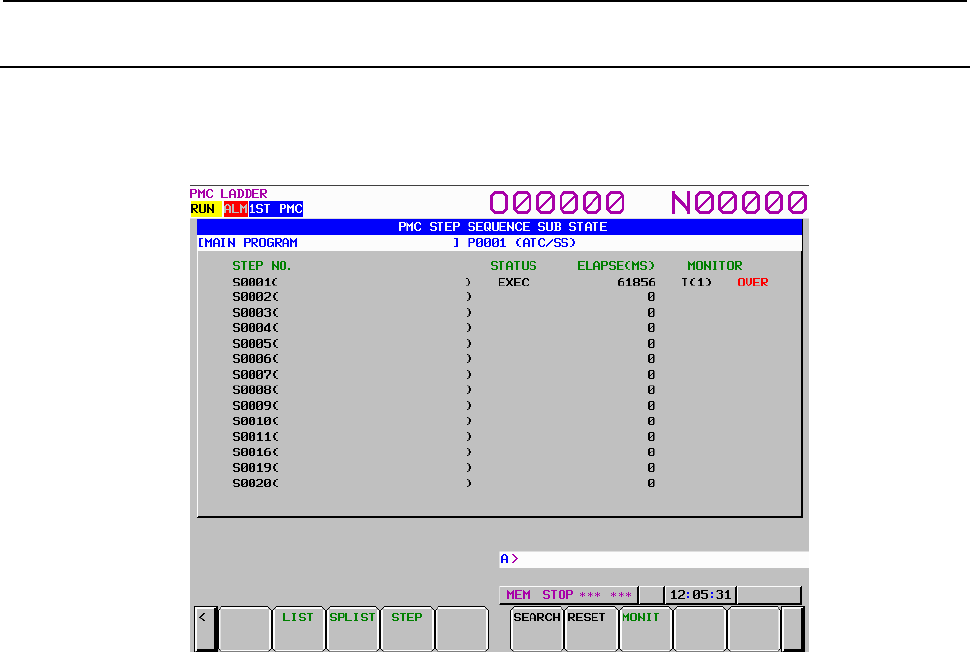
10.STEP SEQUENCE FUNCTION
B-64513EN/03
- 1302 -
10.7.2
Step Sequence State Display Screen (Subprogram)
Pressing the [STATE] soft key on the subprogram list screen or the step sequence display screen displays
the step sequence state display screen (subprogram).
This screen displays the execution state and the elapsed time of operation of each step used in the
currently selected step sequence.
Fig. 10.7.2 Step sequence state display screen (subprogram)
(1) Screen configuration
(a) STEP NO.
Displays a step number. In parentheses, the symbol of the address of a step number is
displayed.
(b) STATUS
When "EXEC" is displayed, it means the active state. When "EXEC" is not displayed, it means
the inactive state.
(c) ELAPSE(MS)
Indicates the period of time of the active state. In the active state, the time indication changes.
(d) MONITOR
Shows assigned time monitor information.
• T(x) : Timer number for monitoring
• OVER : Monitor time exceeded
The message display line displays a message such as an error message and inquiry, depending on the
situation.
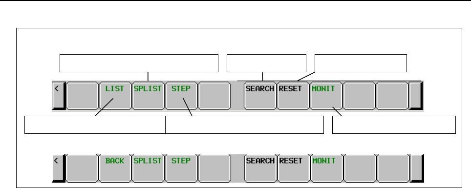
B-64513EN/03
10.STEP SEQUENCE FUNCTION
- 1303 -
(2) Operations using soft keys
Soft keys for step sequence state display screen
(a) [LIST] or [BACK] Switch to the program list screen or one level higher
Switches the screen display to the step sequence display screen one level higher. If one of
these soft keys is pressed on the step sequence display screen on the first level, the screen
display returns to the program list display screen.
(b) [SPLIST] Switch to the subprogram list screen
Switches the screen display to the subprogram list display screen.
(c) [STEP] Switch to the step sequence display screen
Switches the screen display to the step sequence display screen.
(d) [SEARCH] Step search
Searches for a step. When you press the [SEARCH] soft key after entering a step number or
symbol name, the step corresponding to the entered character string is found, and the display is
updated so that the found step is placed at the start.
(e) [RESET] Abnormal state reset
Resets abnormal states that have occurred in all time monitoring operations.
For individual resetting, reset a desired monitoring operation on the time monitor setting
screen.
(f) [MONIT] Switch to the time monitor setting screen
Switches the screen display to the time monitor setting screen.
(g) [<]
Switches the screen display to the PMC main menu.
(3) Screen operations using other keys
(a) Page keys
The page keys can be used to switch from one display page to another. A program can be
searched using the down cursor key following the step number or symbol name entered.
Soft keys for subprogram list display screen
For 1
st
level
Switch to time monitor setting
Switch to subprogram list screen
Switch to program list screen
For 2
nd
level and after
Switch to step sequence display screen
Program search Abnormal state reset

10.STEP SEQUENCE FUNCTION
B-64513EN/03
- 1304 -
10.8 TIME MONITOR FUNCTION
The time monitor function reports an error if a step sequence continues to be active for more than a
specified monitor time. For each of up to eight steps, a monitor time can be set.
If the active state of a step lasts for more than a specified time, the processing described below is
performed.
On the step sequence execution state display screen, "OVER" is indicated for a step number whose
monitor time has been exceeded.
The ladder just continues running.
(1) The bit of R9118 or Z118 corresponding to a monitor timer number is turned on. By monitoring
R9118 or Z118 with the ladder program, error processing can be programmed.
Timer No. Corresponding bit
1 R9118.0 or Z118.0
2 R9118.1 or Z118.1
3 R9118.2 or Z118.2
4 R9118.3 or Z118.3
5 R9118.4 or Z118.4
6 R9118.5 or Z118.5
7 R9118.6 or Z118.6
8 R9118.7 or Z118.7
(2) The PMC alarm screen displays the following message:
"ER48 STEP SEQUENCE TIME OVER(xxH)"
xx represents the value of R9118 or Z118 in hexadecimal.
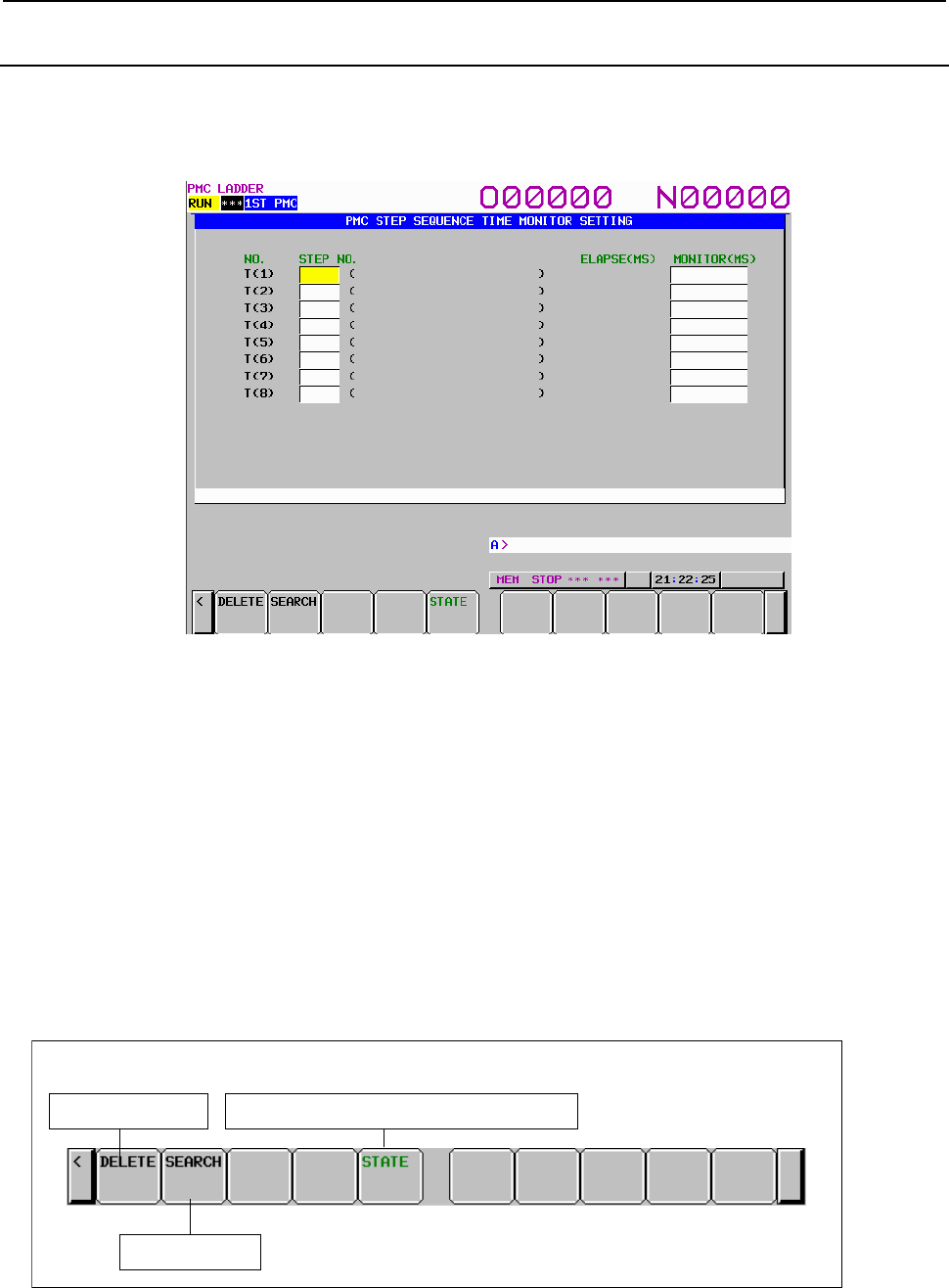
B-64513EN/03
10.STEP SEQUENCE FUNCTION
- 1305 -
10.8.1
Time Monitor Setting Screen
Pressing the [MONIT] soft key on the step sequence state display screen displays the time monitor setting
screen. The time monitor setting screen is used to set the time monitor function. Enter a step number or
monitor time after moving the cursor with the cursor up/down/left/right keys to the input field then press
the INPUT key for setting.
Fig. 10.8.1(a) Time monitor setting screen
(1) Screen configuration
(a) NO.
Monitor timer number. T(1): Uses Monitor timer 1.
(b) STEP NO.
Step number and symbol
S0001: Step number
The symbol of the step number is displayed in the parentheses at right.
(c) ELAPSE(MS)
Elapsed time (in msec). In the active state, the time indication changes.
(d) MONITOR(MS)
Time (in msec) set with the timer for monitoring
(2) Operations using soft keys
(a) [DELETE] Deletion of setting
Deletes the setting of a specified monitor number. Move the cursor to a number whose setting
is to be deleted then press the [DELETE] soft key.
Soft keys on time monitor setting screen
Deletion of setting Switch to step sequence state display screen
Step sarch
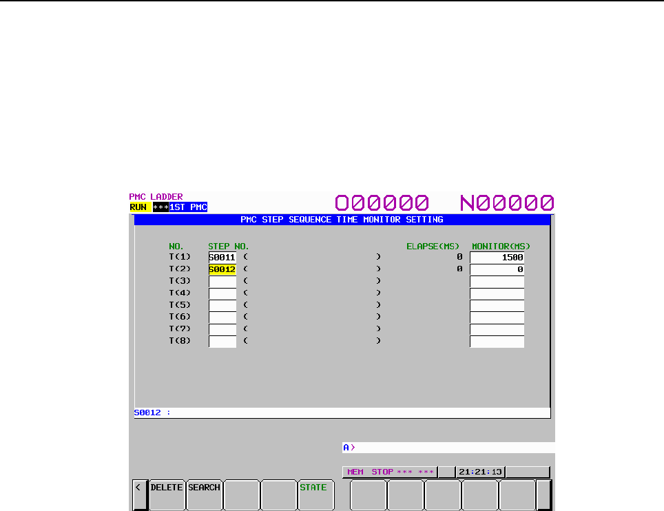
10.STEP SEQUENCE FUNCTION
B-64513EN/03
- 1306 -
(b) [SEARCH] Step search
Searches for a step. When you press the [SEARCH] soft key after entering a step number or
symbol name, the cursor will move onto the monitor item with the corresponding step assigned
if found.
(c) [STATE] Switch to the step sequence state display screen
Switches to the step sequence state display screen.
(d) [<]
Returns the display screen to the step sequence state display screen.
(3) Setting of monitoring
Fig. 10.8.1(b) Entering a step number
(a) Move the cursor to an input field then enter a step number (or symbol) to set.
Type "S12" then press the INPUT key.
(b) Move the cursor to the corresponding input field then set the monitor time.
• Up to eight monitor time values can be set.
• The cursor can be moved to a step number field and monitor time field.
• The maximum settable monitor time is 214748367 msec. If a greater value is entered, an
error occurs.
• If a monitor time is entered when the corresponding step number is not entered, an error
occurs.
• The same step number must not be set more than once.
(4) Canceling a setting of monitoring
Move the cursor to a field whose setting is to be deleted then press the [DELETE] soft key.
The setting of a monitor number is deleted, regardless of which field (step number or monitor time)
the cursor is placed on.
(5) Modifying a setting of monitoring
Move the cursor to a field then enter a new value.
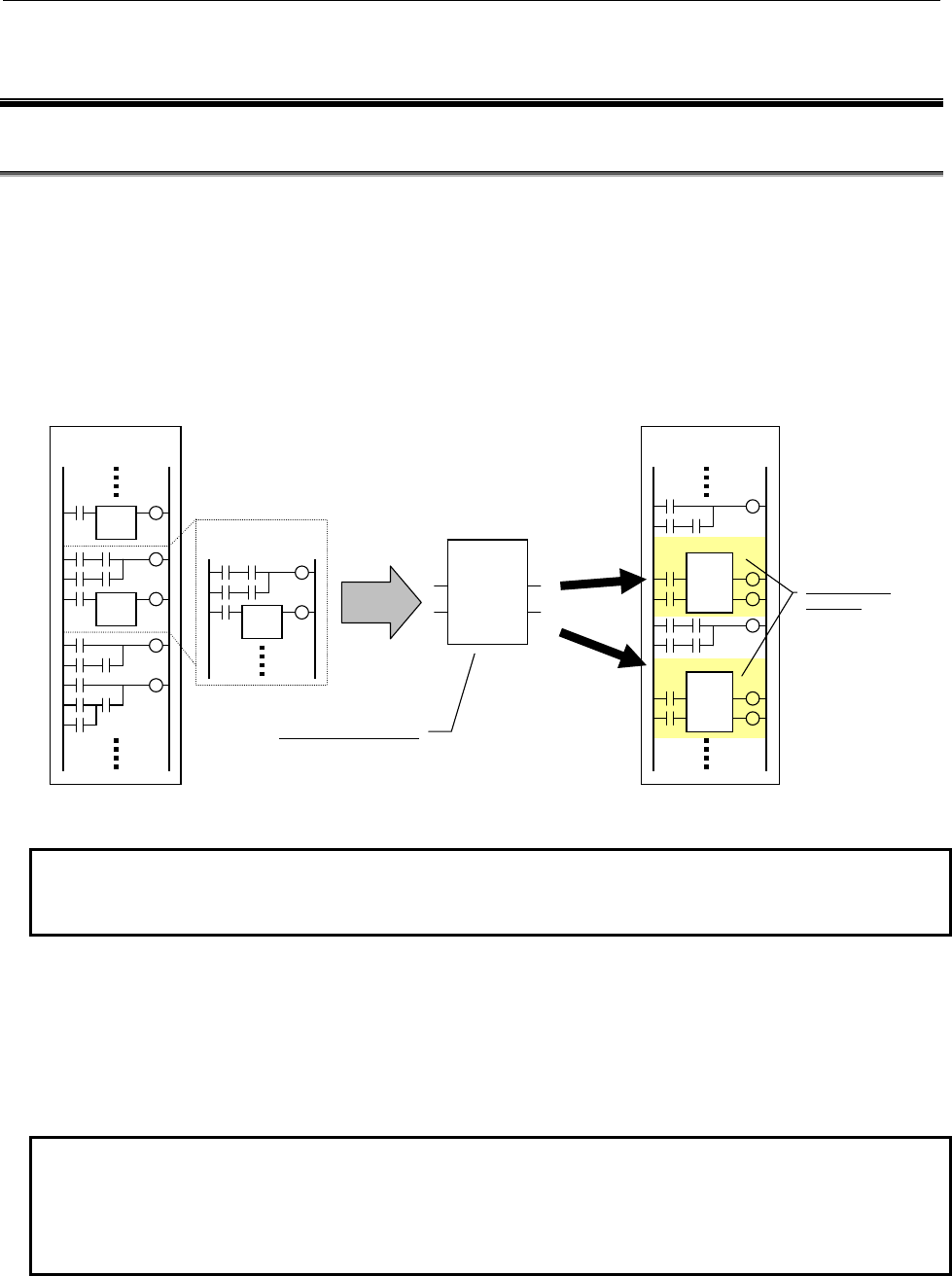
B-64513EN/03
11.FUNCTION BLOCK FUNCTION
- 1307 -
11 FUNCTION BLOCK FUNCTION
11.1 OVERVIEW
A “function block” is a block of a ladder program defined in advance that implements a particular process
(function).
You can place a defined function block in other ladder program and set required input/output parameters
to execute the function.
By defining a frequently used function as a function block, you can reuse the function easily, and can
reduce the time required for programming and increase the development efficiency.
In addition, program diagnosis can be performed without displaying the detailed program in the function
block, which is also effective to decreases the amount of the printed maintenance ladder diagram.
Ladder program
Often used processing
Ladder program
FUNC
IN1 OUT1
IN2 OUT2
Function
block
Function block definition
Function block
instances
Reuse
FUNC1
FUNC
IN1 OUT1
IN2 OUT2
FUNC2
FUNC
IN1 OUT1
IN2 OUT2
Fig. 11.1 (a) Reusing a program using a function block
NOTE
To use the Function Block function on the series 30i/31i/32i/35i-B or the Power
Motion i-A, its option is necessary.
Definition and instance
To create a function block, you need ladder program to implement the function and the input and output
signals for the program. These are called as “function block definition.” You can paste the defined
function block into an actual program and specify the input and output signals to call and execute the
function. Each function block pasted into a program is called a “function block instance.” You can create
more than one instances of the same function block in a program.
NOTE
Programming using function blocks requires FANUC LADDER-III, a PMC
programmer that runs on PC. You can also use PMC screens built into the CNC
to display the function block monitor and to change addresses and other items that
are set as parameters.
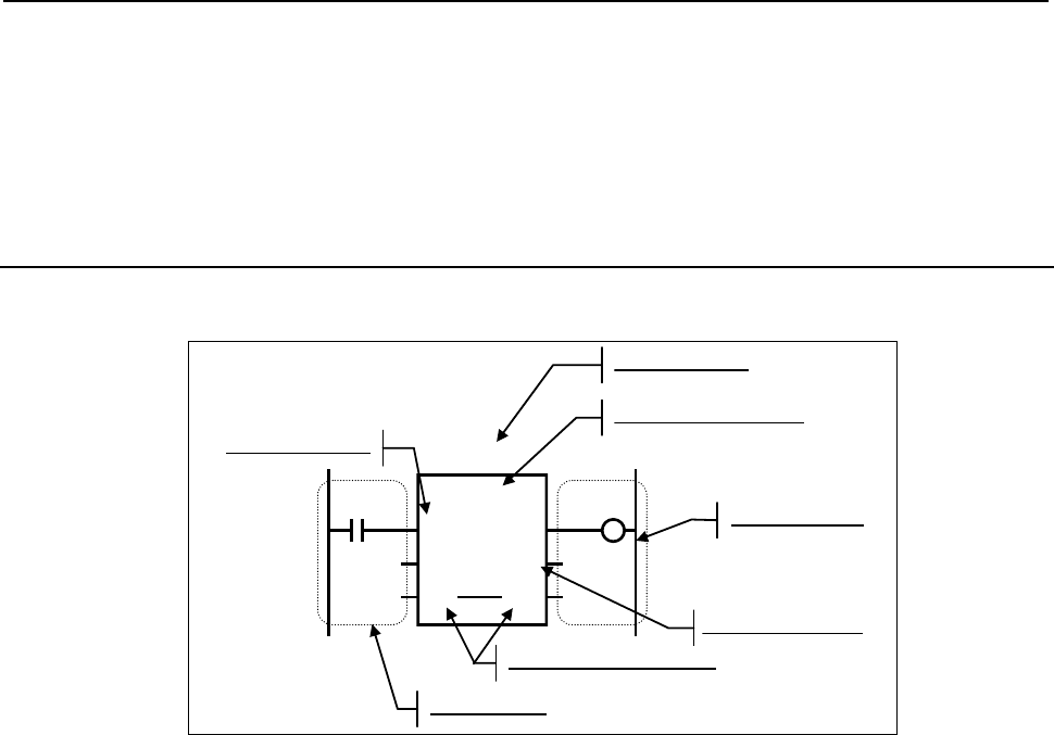
11.FUNCTION BLOCK FUNCTION B-64513EN/03
- 1308 -
Assignment of addresses to parameters and variables
Program a ladder program in a function block definition using variables (symbols) to which specific
addresses are not assigned (symbol programming). When a program containing a function block instance
is compiled, specific addresses are assigned to the parameters and variables used in the program in the
function block. Different addresses are assigned to different function block instances and individual
instances operate independently.
11.1.1 Item Names
A function block is represented by a rectangle as shown below.
FUNC
IN1 OUT1
IN2 OUT2
IO1 IO1
FUNC1
R10
0
100
R0.0
Instance name
Function block name
Output parameter
Input/output parameter
Input parameter
Input section
Output section
Y0.0
X0.0
Fig. 11.1.1 (a) Function block
An “instance name” is a name that uniquely identifies each instance of a function block. Each instance
has different name with each other.
A “function block name” is the name of the source function block definition of each instance. The
instances that call the same function block have the same function block name.
“Input parameters” receive input signals to a function block. Specify the value passed to each input
parameter with an address or constant in the “input section”. For a bit signal, specify its address on the
relevant contact.
“Output parameters” are output signals from a function block. In the “output section”, specify the
address for receiving each output parameter value to fetch the output of the function block. For a bit
signal, specify its address on the relevant coil.
“Input/output parameters” functions as both input and output of a function block. It is represented as
the two same parameter names in the input and output parameter positions connected by a line.

B-64513EN/03
11.FUNCTION BLOCK FUNCTION
- 1309 -
11.1.2
Overview of Specifications
(1) Function block definition
Item Specification Remarks
Function block name Identifier consisting of up to 40 characters Conforms to IEC61131-3.
Comment Character string consisting of up to 255
characters x 4 (Japanese characters
available)
Can be displayed on NC
screens.
Parameter Up to 64 parameters in total of input and
output
Data protection For each function block, “editing protection”
or “browsing and editing protection” using a
password can be specified.
Other information Version information
(2) Parameter specifications
Item Specification Remarks
Types of parameters Input parameter
Input/output parameter (NOTE 1)
Output parameter
The EN input and ENO
output are also
supported.
Maximum number of parameters 64 parameters in total
Name (symbol) Identifier consisting of up to 40 characters Conforms to IEC61131-3.
Comment Character string consisting of up to 255
characters x 4 (Japanese characters
available)
Can be displayed on NC
screens.
Data types BOOL
SINT, USINT, INT, UINT, DINT, UDINT
BYTE, WORD, DWORD
Conforms to IEC61131-3.
Count specification (NOTE 2) 1 to 32 Integer parameters other
than BOOL only
Displaying Internal and External Variables
in the Monitor (FB Instance Monitor
Display)
BOOL
SINT, USINT, INT, UINT, DINT, UDINT
BYTE, WORD, DWORD
8-bit bit string, 16-bit bit string
Can be specified up to 16
parameters in each
function block.
CAUTION
When editing FB definitions and FB instances by the offline editing function on
FANUC LADDER-III, the addresses assigned to the parameters and variables of
function block will be changed. Therefore, the parameters and variables of all
function blocks will be initialized by 0 when the sequence program is inputted into
CNC. (See “11.1.4 Assignment of FB variable” for details.)
NOTE
1 While the data of input/output parameters are passed by reference, the data of
other parameters are passed by value.
2 A value of 2 or larger can be specified to pass multiple contiguous data items of
the same data type.

11.FUNCTION BLOCK FUNCTION
B-64513EN/03
- 1310 -
(3) Variable specifications
Item Specification Remarks
Types of variables Internal variable
External variable
Maximum number of variables 1024 in total
Name (symbol) Identifier consisting of up to 40 characters Conforms to IEC61131-3.
Comment Character string consisting of up to 255
characters x 4 (Japanese characters
available)
Can be displayed on NC
screens.
Data types BOOL
SINT, USINT, INT, UINT, DINT, UDINT
BYTE, WORD, DWORD
Conforms to IEC61131-3.
Count specification (NOTE 1) 1 to 1000 Can be specified only for
non-bool internal
variables.
Nonvolatile memory type specification Available Can be specified only for
internal variables.
Memory allocation of internal variables Contiguously allocated in the order in which
they are defined.
Divided into nonvolatile
and volatile types and
arranged in different
areas.
Displaying Internal and External Variables
in the Monitor (FB Instance Monitor
Display)
BOOL
SINT, USINT, INT, UINT, DINT, UDINT
BYTE, WORD, DWORD
8-bit bit string, 16-bit bit string
Can be specified up to 16
variables in each function
block.
CAUTION
When editing FB definitions and FB instances by the offline editing function on
FANUC LADDER-III, the addresses assigned to the parameters and variables of
function block will be changed. Therefore, the parameters and variables of all
function blocks will be initialized by 0 when the sequence program is inputted into
CNC. (See “11.1.4 Assignment of FB variable” for details.)
NOTE
1 A value of 2 or larger can be specified to allocate contiguous areas for multiple
data items of the same data type.

B-64513EN/03
11.FUNCTION BLOCK FUNCTION
- 1311 -
(4) Program in a function block(FB body program)
Item Specification Remarks
Programming language Ladder language can call another function
block (up to 4 nested levels).
Maximum number of steps 8000 steps per function block
Available addresses Defined parameters, and internal and
external variables (NOTE 1)
Fixed PMC addresses (NOTE 2)
Available instructions Basic and functional instructions available
with the PMC for 30i/31i/32i/35i-B, Power
Motion i-A or 0i-F. The following instructions
cannot be used, however:
END1, END2, END3, END
SP, SPE, CALL, CALLU, JMPC
CS, CM, CE
The following instructions cannot be used in
any function block for which more than one
instance is to be created:
TMR
CTR, CTRB
For the following instructions, the automatic
number assignment function must be used:
TMRB, TMRBF
DIFU, DIFD
Call of another function block Other function block can be called up to 4
levels deep.
NOTE
1 They are programmed not with actual addresses, but with symbols.
2 Any addresses (including X, Y, F, G, R, D, and so on) available in the ladder
language of the PMC for 30i/31i/32i/35i-B, Power Motion i-A or 0i-F can be
directly specified.
(5) Function block call
Item Specification Remarks
Instance name Identifier consisting of up to 40 characters Conforms to IEC61131-3.
Comment Character string consisting of up to 255
characters x 4 (Japanese characters
available)
Can be displayed on NC
screens.
Parameter specification For a BOOL parameter, connect basic
instructions.
For an integer parameter, specify an
address or constant.
For an integer input/output parameter,
specify an address only.
Program level to call function block Can be called from level 1 to 3 or
subprogram.
Placed as a net in ladder program.
Number of function block calls Up to 1024 types of function blocks
Up to 5000 calls (instances) (NOTE)
Function block instance
called from a function
block also included

11.FUNCTION BLOCK FUNCTION
B-64513EN/03
- 1312 -
NOTE
In PMC Memory-B/C/D up to 5000 instances can be used. In PMC Memory-A,
and DCS PMC up to 512 instances can be used.
(6) PMC screen display and operations
Item Specification Remarks
Monitor display The signal status and values of parameters
can be monitored.
Internal and external variable monitor
(FB instance monitor display)
Up to 16 internal and external variables can
be monitored.
Setting to show/hide the monitor is
available.
To add and change the
Internal and external
variable monitor, FANUC
LADDER-III is required.
Variable monitor by bit-
string form is available
only in the FB instance
monitor display.
Function block zoom The program in a function block can be
zoomed.
You can also go back to
the previous function
block screen after
zooming.
Operation available during monitor display Forcibly turning the signal on or off
Diagnosis functions Trace function which displays signal
changes in graph form
Collective Monitor function which calls up
the coil from a contact
Function block editing
(editing function built into the PMC)
Only input and output sections for
parameters can be changed. The ladder
circuit of the FB body program cannot be
changed.
To change the FB body
program, FANUC
LADDER-III is required.

B-64513EN/03
11.FUNCTION BLOCK FUNCTION
- 1313 -
11.1.3
Memory Usage Related to Function Blocks
The following table lists memory usage related to programming using function blocks.
Table11.1.3 (a) Memory usage related to function blocks
Category Item Memory usage (NOTE 1)
Function block definition information
(NOTE 2)
One function block (including name and
comment character string)
55 to 148 bytes
One parameter information item (including
symbol and comment character string)
14 to 91 bytes
Program section Varies depending on the
program (NOTE 3)
Function block call (instance) One call 76 bytes
BOOL type parameter 12 bytes + Input/Output
circuit(NOTE 5)
Parameter other than BOOL type 24 bytes (NOTE 5)
FB body program section
(NOTE 4)
Equivalent to a conventional
ladder program(NOTE 6)
Symbol and comment (Extended
function format)
One definition 16 to 23 bytes (NOTE 8)
One symbol character 1 byte
One comment character
(single-byte character)
1 byte (NOTE 7)
One function block (NOTE 9) 8 bytes
NOTES
1 In addition to the memory usage listed in the table, some amount of memory may
be used to adjust the memory allocation.
2 These items are required for each type of function block used in the program.
3 To enable function block definitions to be restored at decompilation, include the
function block definition data in the object. In this case, the memory usage varies
depending on the contents of the function block definition. Generally the memory
usage of a function block consisting of 8000 steps may be about 7K to 10K bytes.
4 The size of FB body program is added for each instance.
5 The memory usage in following cases is 8 bytes.
- Case of input side of input/output parameter
- Case of omitted output side of output parameter and input/output parameter.
6 The size of FB body program is calculated in the same way as for conventional
ladder programs as the memory usage listed in the table below.
Type of instruction Memory usage
Basic instruction 4 bytes
Functional instruction 4 bytes
Functional instruction parameter 4 bytes
See “2.1.4” for details.
7 One double-byte character uses 2 bytes.
8 One definition of symbol and comment data uses 16 to 23 bytes of memory. In
addition, memory is used based on the lengths of the symbol and comment
character strings.
9 This memory is required for each function block call.

11.FUNCTION BLOCK FUNCTION
B-64513EN/03
- 1314 -
11.1.4 Assignment of FB Variable
An address of FB variable is assigned at compiling on FANUC LADDER-III and the assigned address
depends on the arrangement of FB instance in the ladder program. Therefore, when FB definition and FB
instance are edited, the assignment of address may be changed.
When the sequence program being executed is updated to the sequence program whose FB variables are
assigned to the different addresses, value of the variables may be unsuitable. For this reason, when
updating sequence program to the one whose FB variables are assigned to the different addresses, the
PMC system software will initialize FB variable area by 0. Therefore, you should design your function
block to operate safety when updating sequence program to the one whose FB variables are assigned to
the different addresses. The initialization range of FB variable area is not only actually assigned address
for variables but all addresses specified by setting of “Assignment Address of FB” on FANUC LADDER-
III
When updating sequence program to the one by the following operations, FB variable area will be
initialized.
(a) When changing a FB definition (except for editing FB body program only)
(b) When adding / deleting / moving a FB instance
(c) When changing an address of input / output parameter
(d) When changing a symbol / comment data referred as an external variable
(e) When changing the setting of “Assignment Address of FB” in the system parameter
NOTE
1 Depending on how you modify the sequence program, the updated sequence
program may run safety without initializing FB variable area.
2 By setting 1 to K903.4 of system keep relay, you can choose not initialize FB
variable area when changing the address of FB variable. (See “2.2.11 System
Keep Relay Addresses (K)” for details)

B-64513EN/03
11.FUNCTION BLOCK FUNCTION
- 1315 -
11.2 FUNCTION BLOCK DEFINITION
The definition section of a function block consists of the following information:
• Function block name
• Information of variables (including parameters and internal variables)
• FB body program
• Other information
The following sections explain the above items.
11.2.1 Function Block Name
A function block name is a character string used to identify a function block.
A character string consisting of the following characters (identifier conforming to IEC61131-3) can be
used as the name of a function block:
• Alphabetic characters (A to Z)
• Numeric characters (0 to 9)
• Underscore (_)
NOTE
1 A function block name must not begin with a numeric character. When an
underscore is specified as the first character, it must be followed by an
alphanumeric character.
2 A name character string can consist of up to 40 characters.
In addition to the name, you can define an arbitrary character string as a comment for a function block.

11.FUNCTION BLOCK FUNCTION
B-64513EN/03
- 1316 -
11.2.2
Variable Information
Variables used in the FB body program must be declared in advance.
The following types of variables are available in the program:
• Parameter
• Internal variable
• External variable
CAUTION
When editing FB definitions and FB instances by the offline editing function on
FANUC LADDER-III, the addresses assigned to the parameters and variables of
function block will be changed. Therefore, the parameters and variables of all
function blocks will be initialized by 0 when the sequence program is inputted
into CNC. (See “11.1.4 Assignment of FB variable” for details.)
The following table lists the maximum number of variables of each type that can be used in a function
block.
Type Maximum number
Parameter 64 in total
Internal and external variables 1024 in total
NOTE
1 Different addresses are assigned for parameters and internal variables in
different function block instances.
2 You can directly specify an actual address in the FB body program. In this case,
the address has an effect equivalent to an external variable. The address is not
included in the above number because it is not assumed to be an external
variable.
Each type of variable definition consists of the following information. Each variable type has its features
and restrictions. For details, see the explanation of each type of variable.
(a) Symbol
Each variable is identified by a symbol represented by a character string consisting of the following
characters (identifier conforming to IEC61131-3):
• Alphabetic characters (A to Z)
• Numeric characters (0 to 9)
• Underscore (_)
NOTE
1 A symbol must not begin with a numeric character. When an underscore is
specified as the first character, it must be followed by an alphanumeric character.
2 A symbol character string can consist of up to 40 characters.
3 The following symbols are reserved and not available for other purpose:
• EN
• ENO
For details of these symbols, see “(1) EN input and ENO output”.
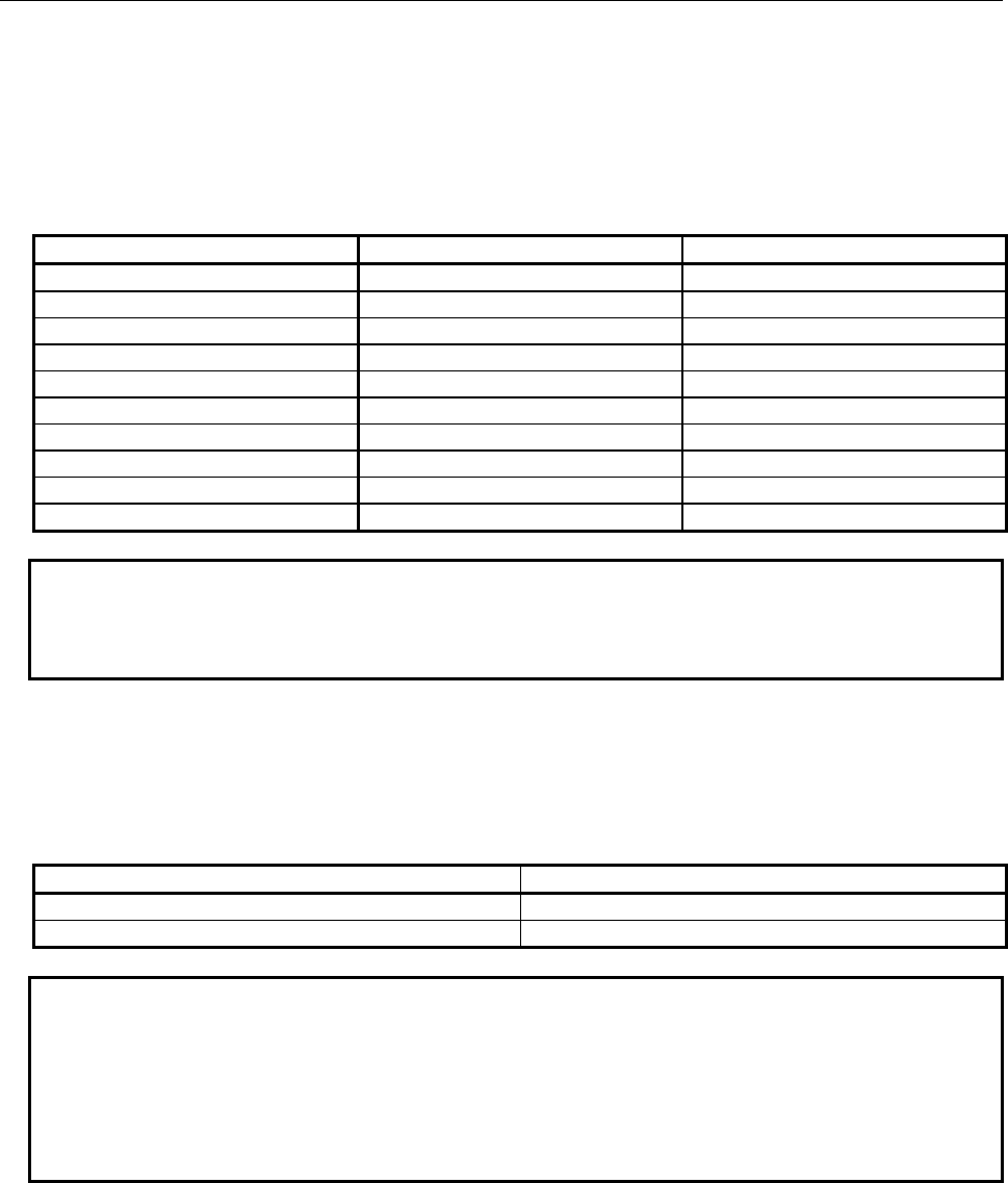
B-64513EN/03
11.FUNCTION BLOCK FUNCTION
- 1317 -
In addition to the symbol, you can define an arbitrary character string as a comment for each
variable.
You cannot use the same symbol for more than one variable in a function block definition.
(b) Basic data type
A defined variable must have one of the following data types conforming to IEC61131-3.
Type name Data type Monitor format
BOOL 1-bit bool value ON/OFF
SINT 8-bit signed integer value Signed decimal number
USINT 8-bit unsigned integer value Unsigned decimal number
INT 16-bit signed integer value Signed decimal number
UINT 16-bit unsigned integer value Unsigned decimal number
DINT 32-bit signed integer value Signed decimal number
UDINT 32-bit unsigned integer value Unsigned decimal number
BYTE 8-bit bit string Hexadecimal number
WORD 16-bit bit string Hexadecimal number
DWORD 32-bit bit string Hexadecimal number
NOTE
1 A constant is also displayed in the monitor format listed above if given to an input
parameter.
2 BCD data is correctly displayed in hexadecimal notation.
(c) Count specification
For input and output parameters and internal variables of the data types that occupy 1 byte or more
such as INT, you can specify the number of data items to allocate their area. For example, when you
specify 3 for the number of an INT internal variable, 6-byte area is allocated as the area for the
variable.
Type of variable Count specification range
Input or output parameter 1 to 32
Internal variable 1 to 1000
NOTE
The larger value is specified as the number of input or output parameters, the
larger amount of data must be copied during the execution of each relevant
function block instance, resulting in worse performance. In this case, memory
allocated for each instance is also increased. If you require input or output
parameters that use a large amount of PMC memory (R, D), you can use
input/output parameters to efficiently pass the large data.
Parameter
Parameters are variables used to exchange values between a function block and the circuit outside the
function block.
Parameters are divided into the following types:
• Input parameter
• Output parameter
• Input/output parameter
In addition, there are the following two special parameters:
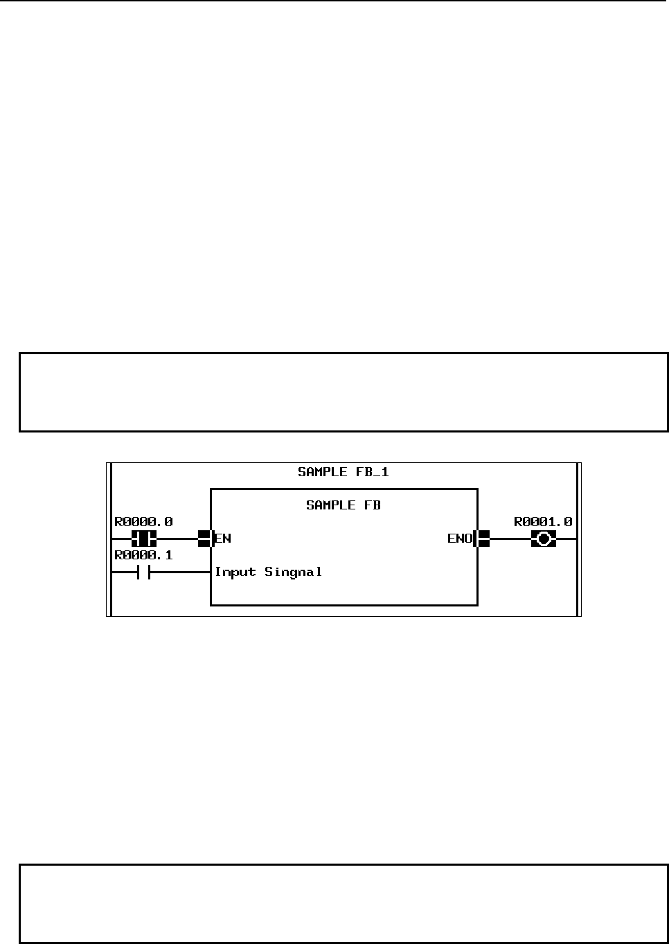
11.FUNCTION BLOCK FUNCTION
B-64513EN/03
- 1318 -
• EN input
• ENO output
The EN input and ENO output are special input and output parameters that control the execution of the
function block. For details, see “(1) EN input and ENO output” below.
For each parameter, specify an address for exchanging a value or a constant. While a constant or address
can be specified for an input parameter, only an address can be specified for an input/output parameter or
output parameter.
Each type of parameter is explained below.
(1) EN input and ENO output
The EN input is an input parameter which controls execution of the function block itself. The ENO
output is an output parameter which indicates whether the function block terminates normally when
the execution of the function block itself is completed.
The EN input and ENO output may or may not be specified. When defining a function block, specify
whether to use each of the EN input and ENO output.
NOTE
A parameter having the name of EN or ENO is always treated as the EN input or
ENO output. You cannot define a parameter or variable other than the EN input
or ENO output with the name of EN or ENO.
Fig.11.2.2 (a) EN input and ENO output
(a) EN input
The EN input controls whether to execute the function block. It functions as follows:
• When the EN input is ON, the FB body program is executed. When the FB has ENO
output, the ENO is set to ON before the program is executed.
• When the EN input is OFF, the FB body program is not executed and control is passed to
the execution of the subsequent program with the status at that point kept. When the FB
has ENO output, the ENO is set to OFF.
When the FB has no EN input, the FB body program is executed in the same way as when it is
ON.
NOTE
You can also use common line control (COM instruction) to control execution,
which is similar to using the EN input. Common line control is also valid for a
function block for without EN input.
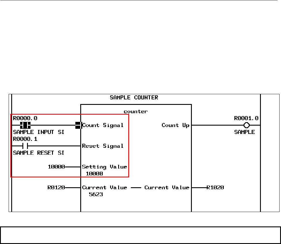
B-64513EN/03
11.FUNCTION BLOCK FUNCTION
- 1319 -
(b) ENO output
The ENO output indicates whether operation of a function block terminates normally. The
value of the ENO output is set to ON before the FB body program is executed. If an error
occurs in the FB body program and the output is invalid, the ENO output should be set to OFF.
When the EN input is OFF or when ACT of common line control (COM instruction) is OFF,
the ENO output is automatically set to OFF.
(2) Input parameter
An input parameter is a variable which receives the input to the FB body program. It is read only in
the FB body program. The EN input is a kind of input parameter.
Input parameters are displayed at the left side of a function block instance.
Fig.11.2.2 (b) Input parameters and input section
NOTE
You cannot write to an input parameter in the FB body program.
(3) Output parameter
An output parameter is a variable to pass the output from the FB body program. A value should be
set to it by the FB body program. The ENO output is a kind of output parameter.
If you do not have to fetch any output value, you can leave an output section without specifying an
address.
Output parameters are displayed at the right side of a function block instance in the output section.
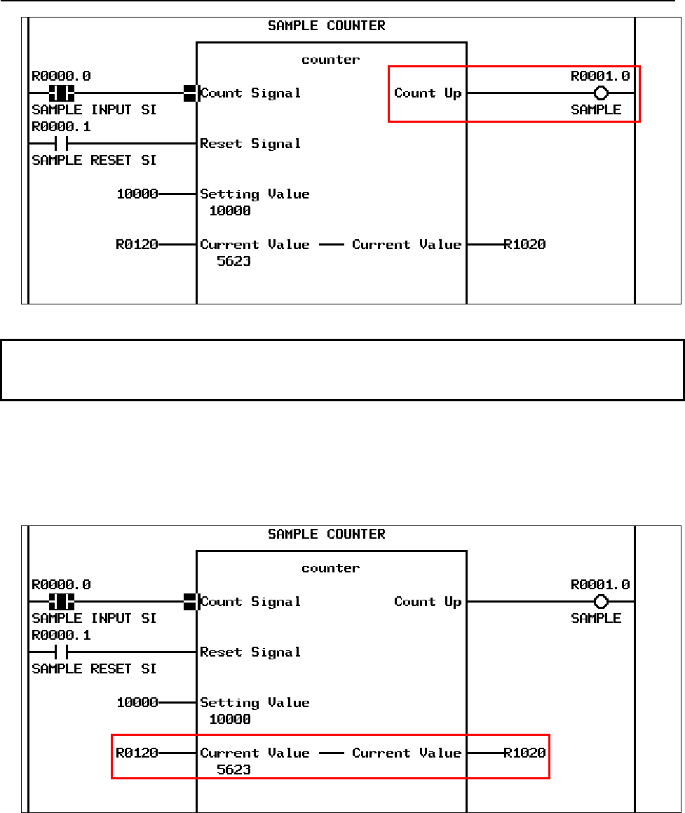
11.FUNCTION BLOCK FUNCTION
B-64513EN/03
- 1320 -
Fig.11.2.2 (c) Output parameters and output section
NOTE
If a value is not set for an output parameter in the FB body program, the previous
value is remained.
(4) Input/output parameter
An input/output parameter is handled as a variable which receives the input to the FB body program
and of which value can be changed by the FB body program.
It can be read and written by the FB body program without restrictions.
An input/output parameter is displayed at both sides of a function block connected by a line.
Fig.11.2.2 (d) Input/output parameter display
For an input/output parameter, you can specify an address in each of the left input and right output
sections. You can omit an address in the output section, but cannot omit one in the input section.
When an input/output parameter is accessed in the FB body program, the address specified in the
input section is referenced directly. The value of the input/output parameter is copied to the address
specified in the output section after function block processing terminates.
For input/output parameter “Current Value” in the figure above, the address specified in the input
section is “R0120” and that specified in the output section is “R1020.”

B-64513EN/03
11.FUNCTION BLOCK FUNCTION
- 1321 -
(a) Feature of input/output parameters
For an input parameter, the given constant or the value at the specified address is stored in the
variable assigned as the input parameter before the start of FB body program processing. For an
output parameter, the value of the output parameter is written at the specified address after the
termination of function block processing.
In contrast, for an input/output parameter, the program in the function block directly accesses
the address specified in the input section. Therefore, writing an input/output parameter by the
FB body program means directly writing a value at the address specified in the input section for
that input/output parameter.
You can use this feature of input/output parameters when the order to access signals must
strictly be controlled in a function block or when a large amount of data such as table data
needs to be passed.
(b) Notes on input/output parameters
Note the following points when using input/output parameters:
• No constant can be specified for an input/output parameter.
• The value of an input/output parameter may change during the execution of the FB body
program.
• The address assigned in the input section for an input/output parameter cannot be changed
by the online editing function or on the PMC ladder diagram editor screen.
• When the same address is set to different input/output parameters of a function block, or
when an address used as an external variable in the function block is set for an
input/output parameter of the function block, a correct symbol may not be displayed for
the address in the FB body program when displayed.
Internal variables
An internal variable is used only in the function block.
(1) Nonvolatile memory type
The nonvolatile memory type can be specified for an internal variable. In this case, the variable is
allocated in the nonvolatile memory type area (D address).
(2) Arrangement
Internal variables are arranged in contiguous memory areas in the order in which they are defined.
Nonvolatile and volatile variables are arranged in different areas.

11.FUNCTION BLOCK FUNCTION
B-64513EN/03
- 1322 -
NOTE
1 When internal variables of different data types are arranged, any variable of a
data type such as INT or DWORD that occupies at least 2 bytes is not aligned
based on the data type, but is arranged on a byte boundary. To avoid affect
performance, try to adjust the order of variable definitions so that variables of
these data types are arranged at even addresses. (The start of an internal
variable is always arranged at an even address.)
2 When a non-BOOL variable is arranged following a BOOL variable, any unused
bit address is not assigned to other BOOL variable after that. For example,
BOOL, SINT, BOOL, and SINT variables defined in this order use 4 byte area. A
used memory can be reduced to define the BOOL variables contiguously.
#7 #6 #5 #4 #3 #2 #1 #0
Unused BOOL uses 1 bit.
SINT uses 1 byte.
Unused BOOL uses 1 bit.
SINT uses 1 byte.
(3) Input parameter
When a function block is displayed on the screen, any internal variable is not displayed on that
screen. If you want to display and monitor the value of an internal variable in the function block, you
can specify the “monitor display” attribute with FANUC LADDER-III to display and monitor the
value of the variable in the function block. For details of monitor display of internal variables,
Subsection 11.5.3, " DISPLAYING INTERNAL AND EXTERNAL VARIABLES IN THE
MONITOR (FB INSTANCE MONITOR DISPLAY)".

B-64513EN/03
11.FUNCTION BLOCK FUNCTION
- 1323 -
External variables
An external variable is used in a function block to refer a symbol defined in advance in ladder program
outside the function block. The entity (address) to be accessed is the same even from different function
block instances.
If a symbol definition of the same name as an external variable is not found during compilation, an error
occurs.
NOTE
1 Details (including the real address) of an external variable are defined not by an
external variable declaration in the function block definition, but by symbol data of
the used ladder program. An external variable declaration in a function block
definition is used for referencing a variable defined in the ladder program.
2 The name of an external variable is an identifier conforming to IEC61131-3, so
only a symbol defined as an identifier conforming to IEC61131-3 can be
referenced. For details of a variable name, see Section 11.2.2, “Variable
Information”
3 The symbol and data type of a declared external variable must be consistent
within the whole program. For example, if a program registers symbol “ABC” of
the bit type, and a function block declares “ABC” as a byte external variable, a
compilation error occurs because the data type of the variable indicated by
symbol “ABC” is inconsistent.
4 A fixed address can be referenced by writing not a symbol, but a specific address
directly in the FB body program. In this case, the address does not need to be
counted as an external variable.
(1) Monitor display
The “monitor display” attribute can be specified for an external variable like an internal variable.
Specifying this attribute with FANUC LADDER-III will display and monitor an external variable,
which is normally not displayed in the function block.
For details of monitor display of internal variables, see Subsection 11.5.3, "Displaying Internal and
External Variables in the Monitor (FB Instance Monitor Display)".

11.FUNCTION BLOCK FUNCTION
B-64513EN/03
- 1324 -
11.2.3
FB Body Program
The function of each function block is defined by ladder program programmed using symbols. All
symbols that appear in the program must be declared as variables in advance. You can also specify an
address directly in a program to always access a fixed address.
NOTE
Creating more than one instance of a function block which writes data at a fixed
address causes duplicate writing.
(1) Levels of nested function block calls
From the FB body program, other function block can be called. Calling function block can be nested
up to 4 levels deep. If calling function block is nested more than 4 levels deep, a compilation error
occurs on FANUC LADDER-III.
NOTE
1 An ordinary subprogram cannot be called from a function block.
2 A function block call is independent of the nesting of subprogram call using the
CALL or CALLU instruction in the ladder language. Therefore, you do not have to
count a function block call in the number of nested subprogram call levels, or a
subprogram call in the number of nested function block call levels.
3 The depth of nested function block calls is not determined based on not the
number of nested function blocks actually called during execution, but the number
of nested function block calls defined in the program. That is, a function block call
that is programmed not to call actually is also counted. Therefore, any function
block cannot be called recursively.
4 For each of function block calls (instances) in a function block, a number is
automatically added to its instance name during compilation on FANUC
LADDER-III so that they have different names.
(2) Restrictions
There are some restrictions at creating the FB body program comparing with an ordinary ladder
program.
(a) Functional instructions
There are restrictions and notes on some functional instructions.
The following functional instructions cannot be used in the FB body program:
• END1, END2, END3, END
• SP, SPE
• CALL, CALLU
• JMPC
• CS, CM, CE
Do not use the following functional instructions in a function block of which more than one
instance is to be created because they cannot perform independent operations for different
function block instances:
• TMR
• CTR, CTRB
When the following functional instructions are used in a function block, set 0 to the timer
number, and rising and falling numbers with FANUC LADDER-III so that the automatic
number assignment function assigns different numbers for different function block instances:

B-64513EN/03
11.FUNCTION BLOCK FUNCTION
- 1325 -
• TMRB, TMRBF
• DIFU, DIFD
NOTE
If these functional instructions are used in a program without using the automatic
number assignment function, these instructions may not work correctly because
more than one functional instruction having the same number may operate
simultaneously.
When the following functional instructions are used in a FB body program, time is integrated
only while the FB body program is called:
• TMRST, TMRSS
The following functional instructions are executed in plural ladder scans. Do not cancel calling
a FB body program when the status of instruction is not completed (executing). Executing of
instruction means that from the execution start (ACT) is set to 1 and transfer completion (coil)
becomes 1 until the ACT is set to 0 and the coil becomes 0:
• DISPB
• EXIN
• WINDR (low-speed type only)
• WINDW (low-speed type only)
• AXCTL
NOTE
1 When the FB body program call is canceled in executing one of the above
functional instructions, other EXIN, WINDR, WINDW and AXCTL may not work
correctly. Operation of instruction is not also guaranteed.
2 As for AXCTL instruction, use the reset request(RST) = 0 normally. Do not cancel
the FB body program call when the reset request(RST) = 1. When canceled,
other AXCTL may not work correctly and operation of instruction is not
guaranteed.
For the example, see Subsection 1.4.4.3, " Notes on using subroutines".
(b) Other restrictions
In addition, the following restrictions apply on the FB body program:
• A value cannot be written to an input parameter.
• The JMP and JMPE instructions and the COM and COME instructions must be paired
within a function block.
• The JMPB instruction can jump only to the LBL instruction within the function block.
• A program consisting of up to 8000 steps can be created in a function block.
• Because a FB body program is not executed when the EN input is OFF, it is referred as
always ON in the case of it is used in the FB body program. So, the EN input can not be
used as the input signal of DIFU/DIFD, -|P|-, -|N|- and counter instructions to catch rising
and falling edge.

11.FUNCTION BLOCK FUNCTION
B-64513EN/03
- 1326 -
11.2.4
Other Information
A function block definition also contains the following information:
• Version information
• Protection information
The following explains the above information.
(1) Version information
The following information is included as version information in a function block definition:
• Character string indicating the user definition version (character string consisting of up to 16
desired characters)
• Last update time stamp
These information items are used for managing the function block in a library. They are also used as
criteria at an identity check function for function blocks during recompilation on FANUC
LADDER-III.
NOTE
FANUC LADDER-III automatically records the last update time stamp. You do not
need specific setting or operation.
(2) Protection information
Protection information is used to protect a function block definition from editing or browsing with a
password.
After a password for protection is set, the password is required when the function block definition is
to be edited or the FB body program is to be browsed (displayed in the monitor).
Protection information set in a function block definition is inherited to each function block instance
generated from the function block definition.
There are the following two types of password protection:
• Editing protection
• Browsing and editing protection
Select editing or browsing and editing protection and set a password to protect the function block
definition. You can use a character string consisting of up to any 16 desired characters for the
password.
According to the selected type of protection, the relevant operations are prohibited as listed in the
table below.
Type of protection Browsing Editing
No protection ○ Enabled ○ Enabled
Editing protection ○ Enabled × Disabled
Browsing and editing protection × Disabled × Disabled

B-64513EN/03
11.FUNCTION BLOCK FUNCTION
- 1327 -
Each protection setting prohibits the following operations.
Type of protection Example of prohibited operation
Editing protection Editing of the function block definition (Deletion of the function
block definition itself is possible.)
Browsing and editing protection Display and monitor display of the FB body program
NOTE
The FB body program can be displayed and monitored on both the PMC screens
and FANUC LADDER-III, but can be edited only on FANUC LADDER-III in the
offline mode.
Protection with a password can be released by entering the password to enable the relevant operation
temporarily.

11.FUNCTION BLOCK FUNCTION
B-64513EN/03
- 1328 -
11.3 FUNCTION BLOCK CALL
To use a defined function block actually, insert an instruction (instance) which calls the function block in
a program and set signals and other items in the input and output section to complete the calling section.
An object code which calls the specified function block processing is generated based on the information
at compilation on FANUC LADDER-III.
CAUTION
When editing FB definitions and FB instances by the offline editing function on
FANUC LADDER-III, the addresses assigned to the parameters and variables of
function block will be changed. Therefore, the parameters and variables of all
function blocks will be initialized by 0 when the sequence program is inputted into
CNC. (See “11.1.4 Assignment of FB variable” for details.)
11.3.1
Function Block Call Positions
This section explains about difference by the positions of function block call.
(1) Program levels
A function block can be called from any position in level 1 to 3 ladder programs and subprograms.
(2) Common line control
When the ACT condition of the COM instruction is OFF, a function block call between COM and
COME is not called and the processing in the function block is not executed.
This is the same effect as when the EN input is set to OFF. For a function block without EN input,
you can use common line control to control a conditional function block call, which is similar to
using the EN input.
11.3.2
Creating a Function Block Call Section
Follow the procedure below to create a function block call section:
1. Enable the reference to the definition of a function block to be called.
2. Choose the function block definition and create a function block call section in the program.
3. Assign a name (instance name) to the function block call section.
4. Set a value, address, or symbol for each parameter.
NOTE
A total of function block instance which can be created in a program is as follows.
• Up to 5000, in the case of PMC Memory-B,C and D
• Up to 512, in the case of PMC Memory-A, DCS PMC
This number includes function blocks called from other function blocks.
The following explains the above procedure in detail.
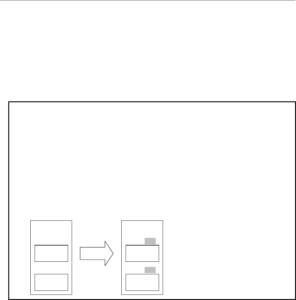
B-64513EN/03
11.FUNCTION BLOCK FUNCTION
- 1329 -
(1) Name of a function block instance
To insert an instruction which calls a function block in a ladder program, a name must be assigned to
the instance to be created at that time. Instance names are assigned to distinguish individual
instances when the same function block is called plurally in a program. The same name cannot be
assigned to more than one instance.
For the name of a function block instance, specify a character string consisting of the following
characters (identifier conforming to IEC61131-3):
• Alphabetic characters (A to Z)
• Numeric characters (0 to 9)
• Underscore (_)
NOTE
1 A function block instance name must not begin with a numeric character. When
an underscore is specified as the first character, it must be followed by an
alphanumeric character.
2 A name character string can consists of up to 40 characters.
3 When a function block contains a function block call instance, underscore (_) +
4-digit number is automatically added to the instance name in the function block
definition during compilation on FANUC LADDER-III so that the name uniquely
identifies the instance. For this reason, 5 characters (“_
nnnn
”) are added to a
function block instance name in a function block definition and the maximum
number of characters of the instance name becomes 35. If a name to which a
number is added is the name of another symbol, a compilation error occurs. Do
not use any similar symbols.
PARENT_FB
FB definition containing FB calls
CHILD_FB
CHILD_FB
CHILD1
CHILD2
PARENT_FB
PARENT1
CHILD_FB
CHILD_FB
CHILD1_0001
CHILD2_0002 Instantiation
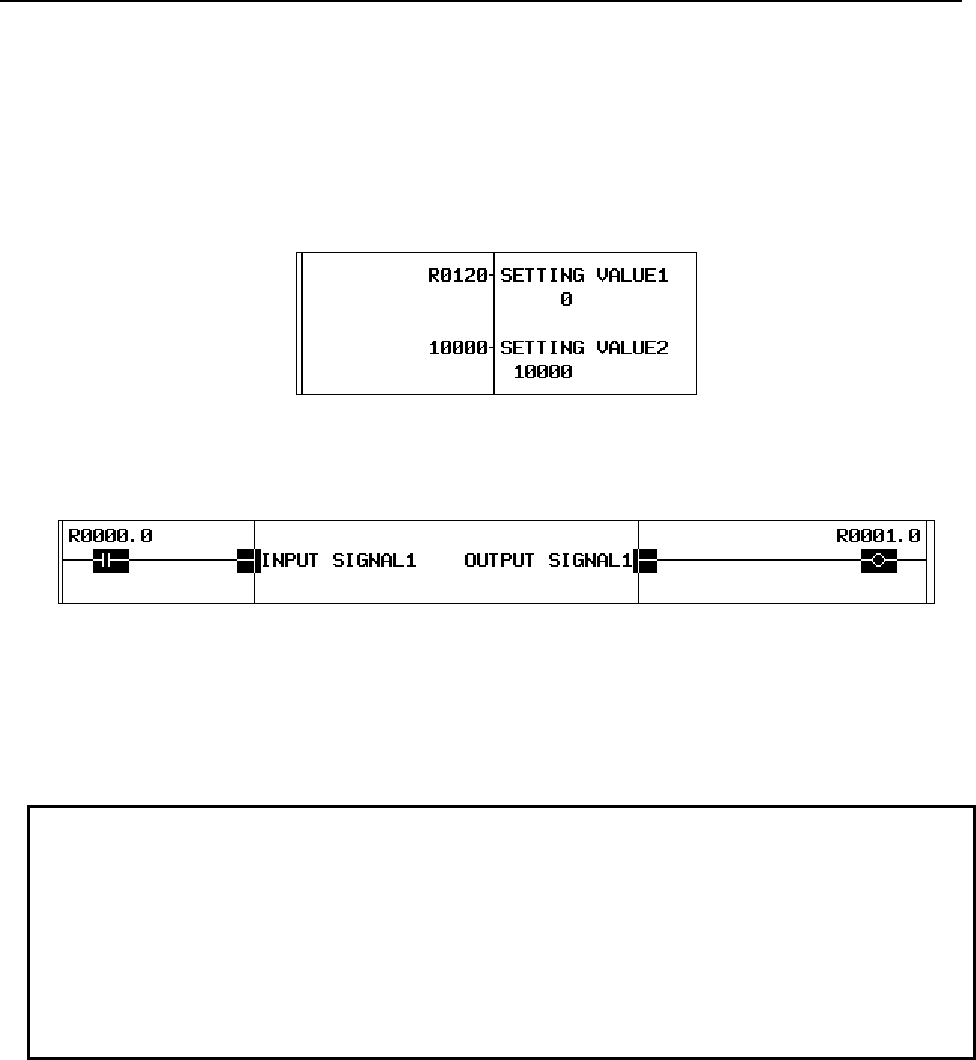
11.FUNCTION BLOCK FUNCTION
B-64513EN/03
- 1330 -
(2) Setting data in the input and output section
After inputting a function block instance, set a numeric value or address to each parameter of the
function block in the input or output section.
The available range differs depending on the type of parameter. For details, see “Parameter” in
Subsection 11.2.2.
For a non-BOOL parameter, specify an address to the right or left side of the parameter name. For an
input parameter, you can also specify a constant.
Fig.11.3.2 (a) Specifying an address (upper) and a constant (lower) for parameters
For a BOOL parameter, a contact is displayed in the input section. Specify an address on the contact.
And, you can add coils, contacts and connection lines if needed.
Fig.11.3.2 (b) Specifying a contact and a coil for BOOL parameters
For an input/output parameter, no contact is displayed in the input section even when the data type is
BOOL. Directly specify an address in the same way as for other data types of parameters.
For the output section for an output parameter or input/output parameter, you can omit the address
specification if the output value does not need to be saved.
NOTE
The consistency of the data type between the symbol set to the parameter and the
parameter itself is basically not checked. Combination of the BOOL and non-
BOOL types causes an error. Any combination of a numeric type (such as INT or
DINT) and a bit set type (such as BYTE) is available.
When a symbol of a different type is set for an input or output parameter, data of
the size which suites to the type of parameter is actually input or output. Note that
if data is input and output in different sizes, the program may not work as
expected.
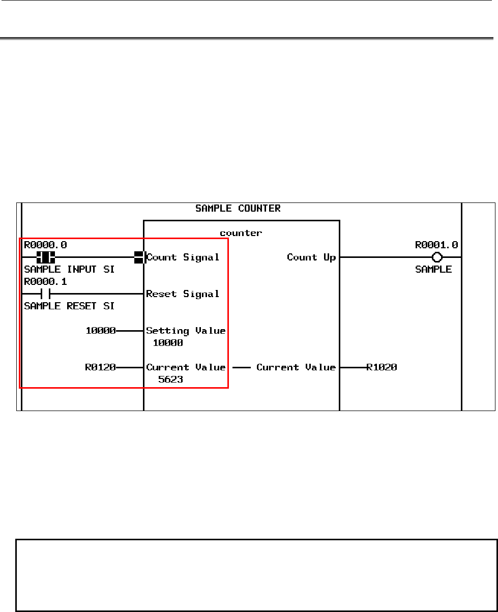
B-64513EN/03
11.FUNCTION BLOCK FUNCTION
- 1331 -
11.4 EXECUTING A FUNCTION BLOCK
A function block call section is executed in the following three steps:
1. Input process
2. Execution of the FB body program
3. Output process
The following explains the processing performed in each step in detail.
(1) Input process
In input process, given signals and numeric values are set to input parameters. The values are
sequentially set for the input parameters from the top to the bottom.
Fig.11.4 (a) Input process
In the example in this figure, input process will be performed as follows:
1. The signal status of R0000.0 is copied into input parameter “count signal”.
2. The signal status of R0000.1 is copied into input parameter “reset signal”.
3. The value 10000 is copied into input parameter “setting value”.
The address of input/output parameter “current value” itself will be R0120 and the value is not
copied.
NOTE
When a function block to be executed has the EN input and the EN input is OFF,
value is set for the subsequent input parameters but the subsequent execution
step of the FB body program is skipped. For details of the EN input, see Section
11.2.2, “Variable Information”.
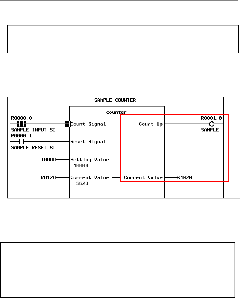
11.FUNCTION BLOCK FUNCTION
B-64513EN/03
- 1332 -
(2) Execution of the FB body program
After values are set to all input parameters by input process, the FB body program is executed.
NOTE
When a function block to be executed has the EN input and the EN input is OFF,
the FB body program is not executed. For details of the EN input, see Section
11.2.2, “Variable Information”.
(3) Output process
After the FB body program has been executed, output process is performed.
In output processing, the values of the output parameters are set to the addresses connected to these
output parameters. The values of the output parameters are sequentially set from the top to the
bottom.
Fig.11.4 (b) Output process
In the example in this figure, output process will be performed as follows:
1. The signal status of output parameter “count up” is copied into R0001.0.
2. The value of input/output parameter “current value” is copied into R1020.
NOTE
1 Output process is performed in the order in which parameters are arranged. When
the order in which values are set is important, change the order of parameters or
use input/output parameters to adjust the timing to set values.
2 When a value is set to an input/output parameter in the FB body program, the
value is set directly to the address specified in the input section of the input/output
parameter. Then the value of output and input/output parameter is set to an
address in the output section at output process.
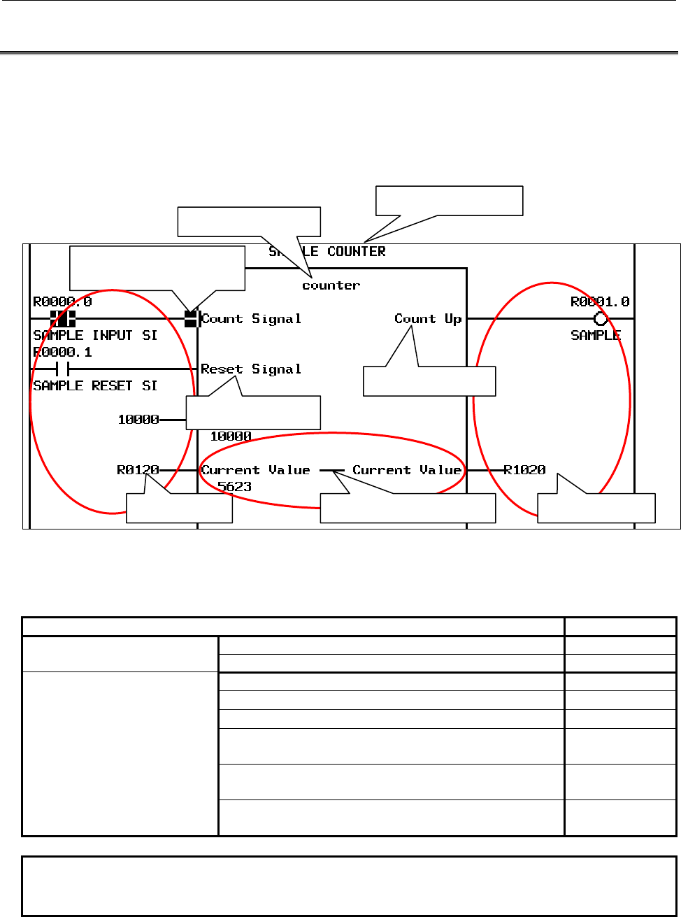
B-64513EN/03
11.FUNCTION BLOCK FUNCTION
- 1333 -
11.5 DISPLAYING AND EDITING A FUNCTION BLOCK
A function block in a ladder program is displayed on the ladder diagram monitor screen. The displayed
items include the function block definition name, instance name, and defined input, output, and
input/output signals. You can also monitor the active/inactive state of the function block, the value of
each parameter, and input and output values during the execution of the ladder.
In addition, you can use the editing function to change addresses and values set in the input and output
sections of the function block.
Fig.11.5 (a) Display of the function block
The following table lists whether each PMC function related to function blocks is available.
Table11.5 (a) List of functions
PMC functions related to function block PMC screen
Displaying and editing a function
block
・Displaying a list of function blocks ×
・Creating and editing a new function block ×
Displaying and editing the
function block instance
・Displaying the function block instance ○
・Creating and copying the function block instance ×
・Deleting the function block instance ○
・Changing data in the input and output sections of the
function block instance
○(NOTE)
・Displaying the ladder program in the function block
instance
○
・Modifying the ladder program in the function block
instance
×
NOTE
Any address in the input section assigned to an input/output parameter cannot be
changed.
FB instance name
FB definition name
Active/inactive state of the
input parameter
Input section Output section
Input parameter
Output parameter
Input/output parameter
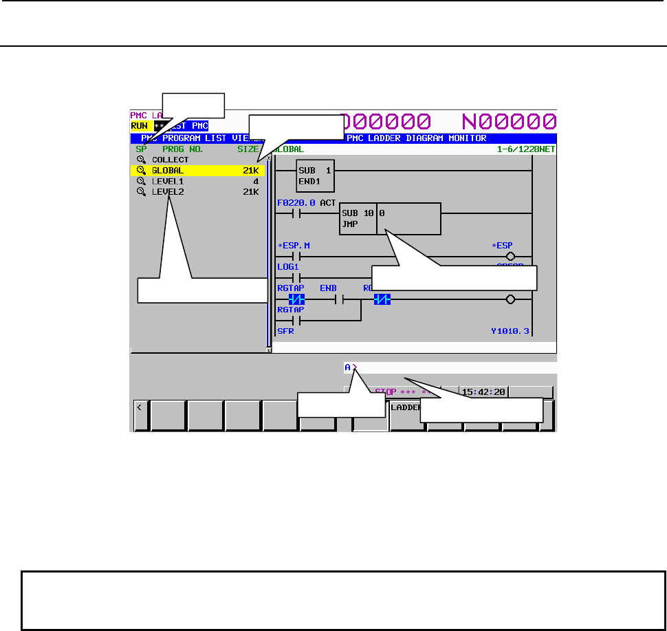
11.FUNCTION BLOCK FUNCTION
B-64513EN/03
- 1334 -
11.5.1
Program List Display Screen
The PROGRAM LIST VIEWER screen shows program information such as the program size.
Fig.11.5.1 (a) Program List Display Screen
Any function block is not displayed in the program list of this screen.
When pressing the [ZOOM] soft key after inputting the function block instance name, the screen display
switches to the FB body program of the specified function block instance.
For details of the screen, see Section 8.1, "DISPLAYING A PROGRAM LIST ([LIST] SCREEN)".
NOTE
The size of FB body program is not included in the program size of GLOBAL and
each subprogram displayed in the list.
Size area
SP area
Ladder preview display area
Key input line Message display
Program number area
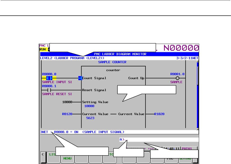
B-64513EN/03
11.FUNCTION BLOCK FUNCTION
- 1335 -
11.5.2
LADDER DIAGRAM MONITOR Screen
A function block in a ladder program is displayed on the ladder diagram monitor screen. You can also
monitor the active/inactive state of the function block, the value of each parameter, and input and output
values during the execution of the ladder.
Fig.11.5.2 (a) Function block displayed on the ladder diagram monitor screen
(1) Screen structures
(a) At the top of the screen, the title information (REMARKS) and current subprogram information
(“[comment] program number (symbol)”) are displayed together with the ladder position which
is displayed on the screen.
(b) The message display line displays a message such as an error message and inquiry, depending
on the situation.
(c) The additional information line displays the information of the function block when the cursor
is placed on the function block instance.
Key input line Message display line
Additional information line
Area for LADDER Diagram
Title information (REMARKS) and current subprogram
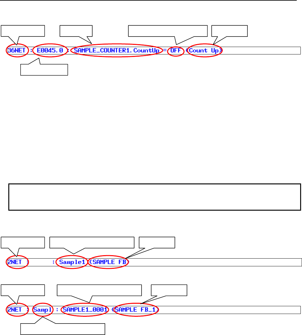
11.FUNCTION BLOCK FUNCTION
B-64513EN/03
- 1336 -
When the cursor position is on the function block parameter.
• Net number
Number of the net at the cursor position
• PMC address
4-digit byte address + bit address
• Symbol
Symbol set for the function block parameter
• Comment
Comment set for the function block parameter
• Value
Value of the parameter at the cursor position according to its data type
• When the type is BOOL: “ON” or “OFF”
• When the type is not BOOL: Decimal or hexadecimal number
NOTE
When the cursor is positioned on a constant or an omitted parameter in the output
section, only the net number is displayed.
When the cursor position is on the function block definition name or instance name.
• Function block definition name
• Function block instance name
Net number
PMC address
Symbol Value (INT/HEX or BOOL) Comment
Net number Function block definition name Comment
Net number
Function block definition name
Function block instance name Comment
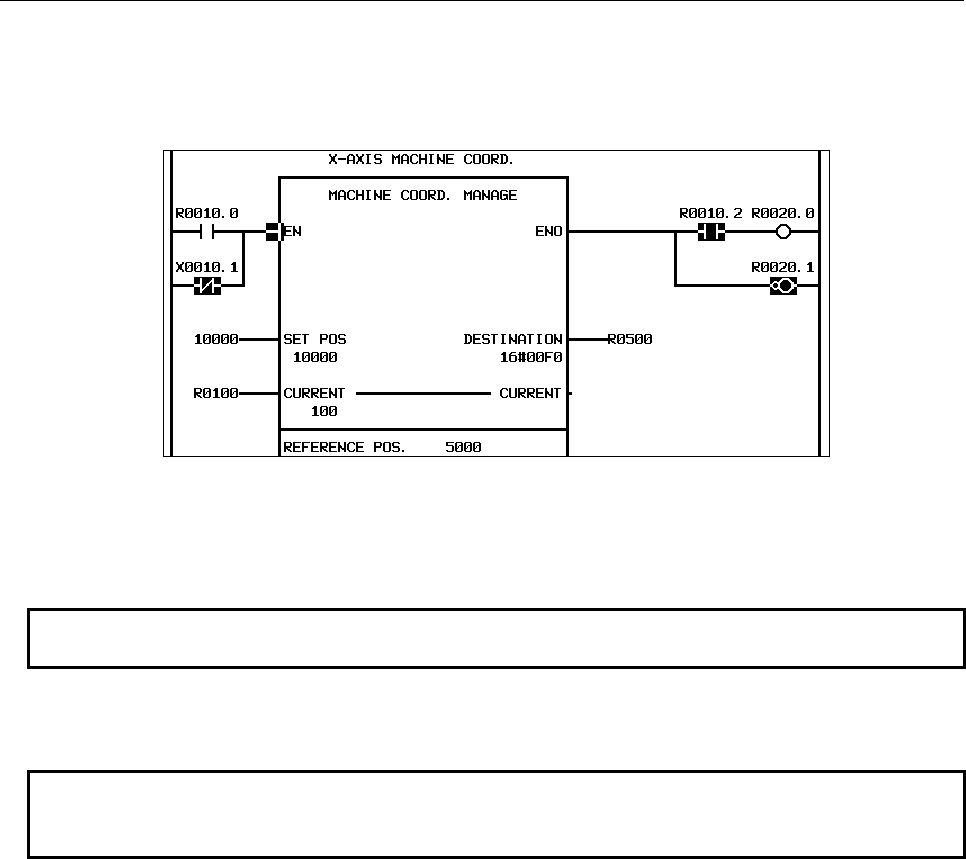
B-64513EN/03
11.FUNCTION BLOCK FUNCTION
- 1337 -
(2) Function block display
On the ladder diagram monitor screen, you can monitor the signal status and current value of each
parameter of a function block in the ladder program being executed. The parameter is displayed in
the format corresponding to its data type.
Fig.11.5.2 (b) Sample of a function block monitor
Each item in Fig. 11.5.2 (b) is explained below.
1. For a BOOL parameter in the input section, contact instructions are connected.
NOTE
No constant can be set for a BOOL parameter.
2. Displays the numeric value set to the input parameter as a constant.
3. Displays the PMC address set of the input/output parameter.
NOTE
For an input/output parameter, no constant can be set in the input section. Set a
PMC address.
4. For a BOOL parameter in the output section, coil instructions are connected. And, you can
connect a contact instruction before the coil instruction.
5. Displays the PMC address defined as the copy destination of the output parameter.
6. Displays a blank when output section for a parameter is omitted.
1
2
3
4
5
6
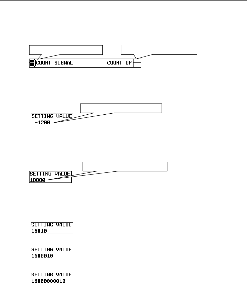
11.FUNCTION BLOCK FUNCTION
B-64513EN/03
- 1338 -
(3) Monitor display screen
• BOOL
The status is displayed at border between the input section and input parameter, and between
the output parameter and output section which indicates the active/inactive state of the
parameter.
• SINT, INT, DINT
The value of the input parameter, output parameter and input/output parameter is displayed
with a signed decimal number.
• USINT, UINT, UDINT
The value of the input parameter, output parameter and input/output parameter is displayed
with an unsigned decimal number.
• BYTE, WORD, DWORD
The value of the input parameter, output parameter and input/output parameter is displayed
with a hexadecimal number.
The number of displayed digits differs depending on the data type.
- BYTE
- WORD
- DWORD
When the input parameter is on When the output parameter is off
When the parameter value is -1200
When the parameter value is 10000
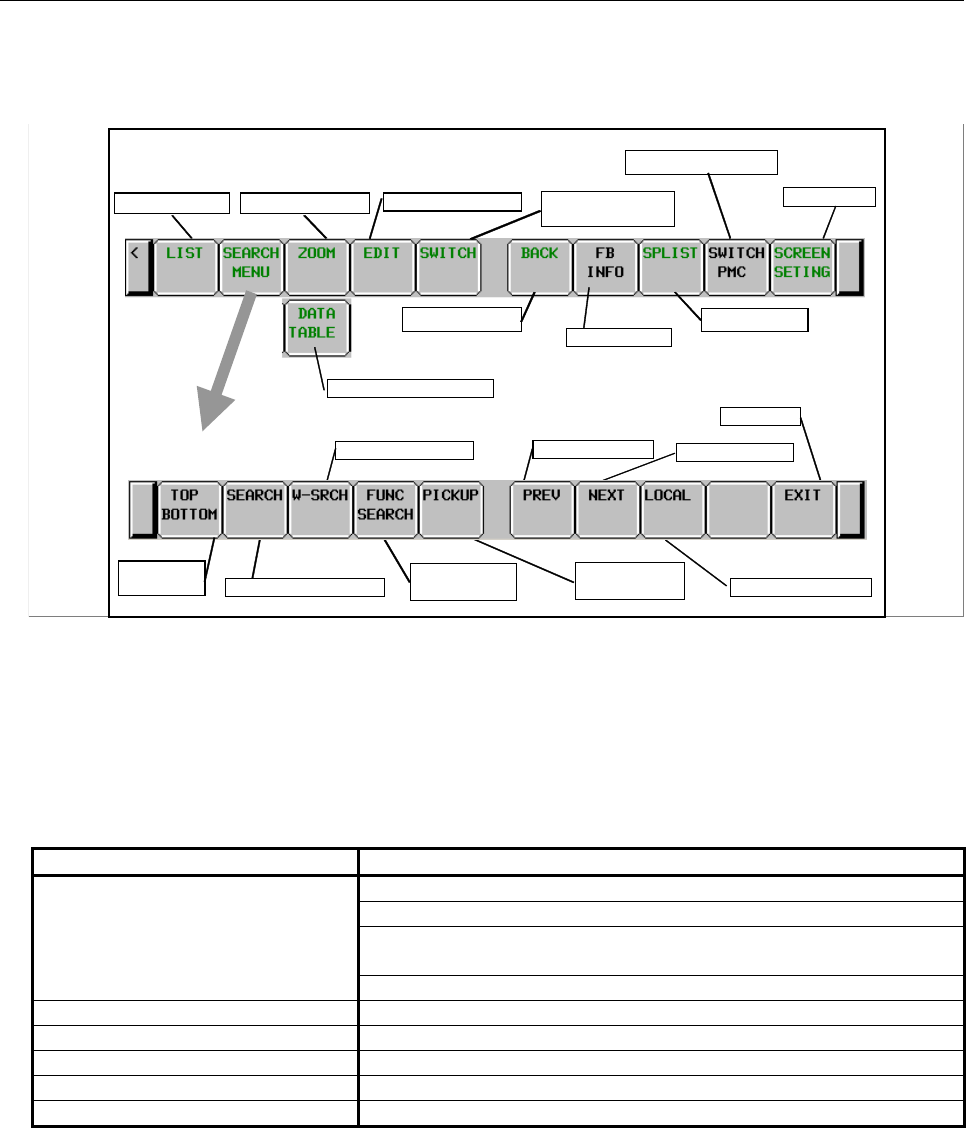
B-64513EN/03
11.FUNCTION BLOCK FUNCTION
- 1339 -
(4) Operation with Soft keys
The soft key operations to function block are described below. About the other operation with soft
keys, see Subsection 8.2.1, "Operating on the LADDER DIAGRAM MONITOR Screen".
Main soft keys of LADDER Diagram Monitor screen
Program List
Display Data Table
Back to previous
Switch to COLLECTIVE
MONITOR screen
LADDER Diagram Editor
FB Information
Subprogram List
Screen Settings
Switch PMC paths
Display Subprogram
Search next
Search Write Coil Search previous
Search Address or Net
Search Functional
Instruction
Pick up a Ladder
Diagram net
Switch range
Search soft keys
Exit
Jump to
Top/Bottom
(a) [LIST] Go to PROGRAM LIST VIEWER screen
Displays the program list screen. Specifying a function block instance name and pressing the
[LIST] soft key can zoom in the FB body program.
(b) [SEARCH MENU] Search & Jump
Change soft keys to “Search soft keys”. There are the following search functions related to
function blocks.
Table11.5.2 (a) Search functions
Function name Searched item related to function blocks
Search PMC address used in the input or output section of a function block
PMC address used for a function block parameter
An internal or external variable (PMC address) which the FB instance
monitor is set
Function block instance name
Coil search BOOL parameter in the output section of a function block
Functional instruction search Function block definition name
Pick up Pick up the function block net and net in the FB body program
Previous Search target
Next Search target

11.FUNCTION BLOCK FUNCTION
B-64513EN/03
- 1340 -
NOTE
1 When search function find the target and attempt to zoom in a function block for
which browsing and editing protection is set, you are asked to enter the
password. When pressing the [SKIP] key in this case, the target address is
skipped and the next target is searched.
2 When a GLOBAL program is displayed and you search for an internal variable of
a function block, the FB body program is displayed and the cursor moves to the
target address.
3 When a subprogram is displayed and you search for an internal variable of a
function block in the global search mode, the cursor also moves to the target
address in the FB body program.
(c) [DATA TABLE] Go to FUNCTIONAL INSTRUCTION DATA TABLE VIEWER screen
Goes to FUNCTIONAL INSTRUCTION DATA TABLE VIEWER screen to examine contents
of Data Table of functional instructions such as COD (SUB 7) and CODB (SUB 27), which
have Data Table in themselves. This soft key appears only when the cursor is on a functional
instruction that has Data Table.
(d) [ZOOM] Display contents of subprogram/function block
When positioning the cursor on a CALL/CALLU/CM instruction or a function block instance,
the [ZOOM] soft key is displayed. Pressing the [ZOOM] soft key displays the subprogram and
FB body program. When you attempt to zoom in a password-protected subprogram or function
block, you are asked to enter the password.
NOTE
1 The FB body program is not included in the GLOBAL program. To display an FB
body program, zoom in the function block from the section in which the relevant
function block instance is used.
2 When K903.2=1, you will not be asked to enter the password.
(e) [EDIT] Go to LADDER DIAGRAM EDITOR screen
Goes to LADDER DIAGRAM EDITOR screen. Even if the [EDIT] soft key is pressed, an
error message is displayed and edit operation is disabled when an FB body program is
displayed.
(f) [SWITCH] Switch to COLLECTIVE MONITOR screen
Switches to COLLECTIVE MONITOR screen.
(g) [BACK] Show the preceding subprogram/function block
Traces back the history to recall the previous displayed subprogram and function block.
(h) [FB INFO] Function block information display
Displays information (version, date, and protection status) on the function block at the cursor
position at the message display line. This soft key is displayed only when the cursor is
positioned on a function block.
Example)
Version Date Protection status
01 2007/09/03 PROT = P
Protection status
P : browsing and editing protection
R : editing protection

B-64513EN/03
11.FUNCTION BLOCK FUNCTION
- 1341 -
(i) [SPLIST] Switch to the subprogram list screen
Switches the screen display to the subprogram list display screen.
(j) [SWITCH PMC] Switching PMC path or divided ladder programs
Switches PMC path or divided ladder program. For details of the operation, refer to “6.3”.
By setting keep relay K935.0 to 1, you can display PMC program list screen. For details, refer
to ”2.2.11”.
(k) [SCREEN SETING] Screen settings
Goes to setting screen for LADDER DIAGRAM MONITOR screen.
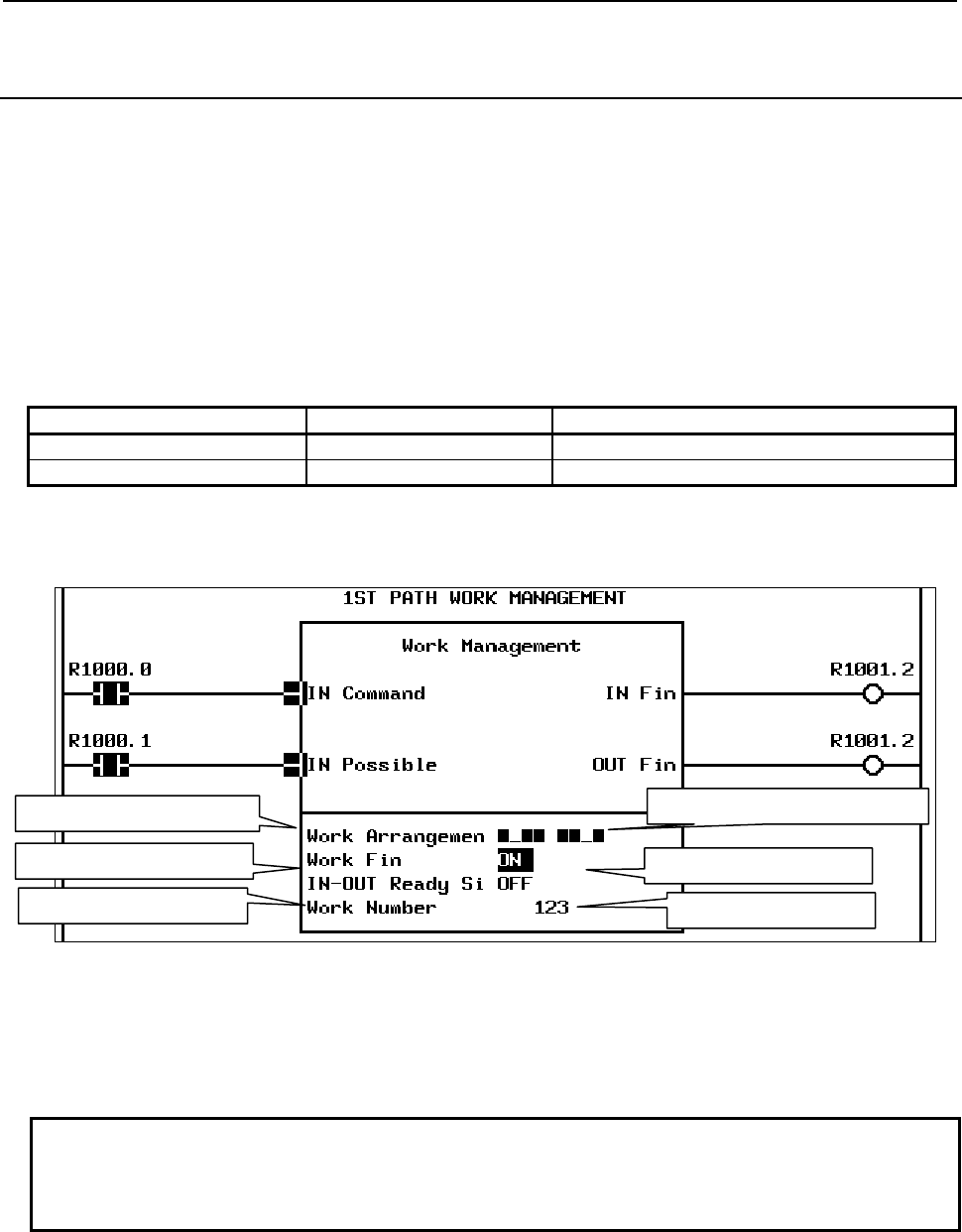
11.FUNCTION BLOCK FUNCTION
B-64513EN/03
- 1342 -
11.5.3
Displaying Internal and External Variables in the Monitor (FB
Instance Monitor Display)
Normally, when a function block is displayed on the ladder diagram monitor screen, the signal status and
current value of each parameter is displayed in the monitor, but the internal and external variables used in
the function block are not displayed.
However, you can specify the “monitor display” attribute for specific internal or external variables that
you can monitor their values in the same way as for parameters, which provide a clue for the internal
status of the function block. This monitor display is called “FB instance monitor”.
The monitor display attribute can be specified for up to 16 internal and external variables in one function
block.
For FB instance monitor display, you can specify the following monitor formats in addition to the
ordinary monitor formats.
Internal and external variables with the monitor display attribute are listed under the monitor display of
parameters. You can also change the value of each variable displayed in the monitor.
Fig.11.5.3 (a) FB instance monitor display
You can display or hide the FB instance monitor by the screen setting. See Subsection 11.5.5 " Setting the
Display Format of the LADDER DIAGRAM MONITOR Screen".
The variables to be displayed in the FB instance monitor can be defined in the function block definition
on FANUC LADDER-III.
NOTE
1 You can monitor variables in the bit string display of BYTE and WORD only in the
FB instance monitor.
2 The 32-bit bit string monitor format is not available.
Type name Data type Monitor format
BYTE (bit) 8-bit bit string Bit string display
WORD (bit) 16-bit bit string Bit string display
INT variable comment
BOOL variable comment
BYTE variable comment BYTE variable bit string monitor
BOOL variable monitor
INT variable monitor
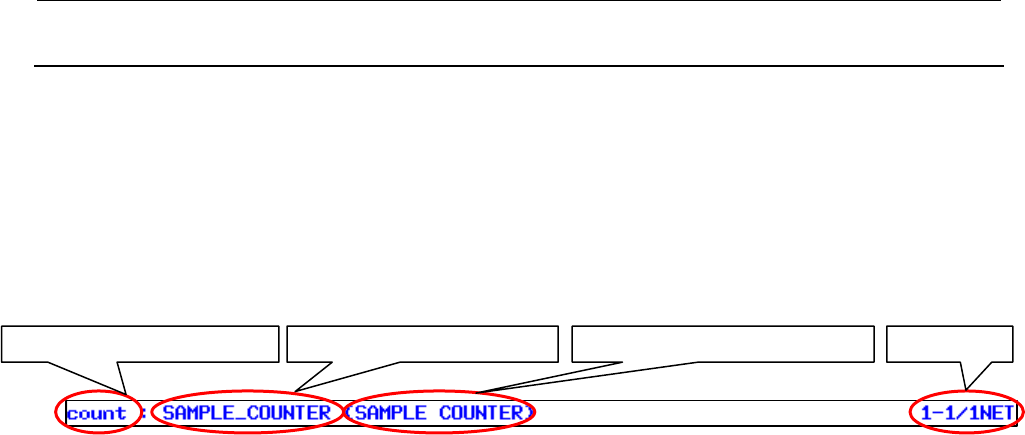
B-64513EN/03
11.FUNCTION BLOCK FUNCTION
- 1343 -
11.5.4
Displaying the FB Body Program
To move the cursor to the function block on the ladder diagram monitor screen and press the [ZOOM]
soft key, you can display the ladder circuit in the function block in the monitor.
You can also press the [BACK] soft key to return the screen to the display the function block monitor
display mode.
(1) Items displayed at the top of the screen
The following function block information is displayed at the top of the screen when a FB body
program is displayed.
• Function block definition name
Name of the function block definition
• Function block instance name
Symbol registered as the function block instance name
• Function block instance comment
The comment set for the function block instance
• Net number
Local net number in the function block
Function block instance name Net numberFunction block definition name Function block instance comment
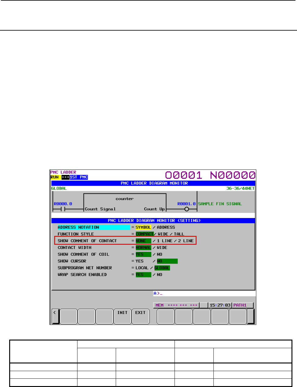
11.FUNCTION BLOCK FUNCTION
B-64513EN/03
- 1344 -
11.5.5
Setting the Display Format of the LADDER DIAGRAM
MONITOR Screen
You can set the display format of the LADDER DIAGRAM MONITOR screen. The settings mainly
related to the display format of function block instance are as follows.
• SHOW COMMENT OF CONTACT
• ADDRESS NOTATION IN FB
• SHOW FB INSTANCE MONITOR
• FB PARAMETER NAME
• DIAGRAM APPEARANCE SETTING (COLOR)
About other settings, see Subsection 8.2.2 "Setting the Display Format of the LADDER DIAGRAM
MONITOR Screen".
(1) SHOW COMMENT OF CONTACT
The display line of comment of contact, the display line of parameter name, and the presence of
monitor display on the function block instance vary according to the setting of “SHOW COMMENT
OF CONTACT”.
Fig.11.5.5 (a) Setting of “SHOW COMMENT OF CONTACT”
Setting of “SHOW
COMMENT OF
CONTACT”
Parameter Comment in the input and output sections
Name Non-BOOL monitor BOOL (relay) Non-BOOL (byte address)
2 line 2 lines Displayed 2 lines 2 lines
1 line 2 lines Displayed 1 line 1 line
None (default) 2 lines Not displayed Not displayed Not displayed
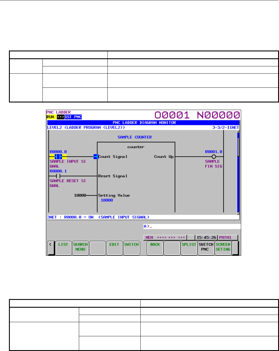
B-64513EN/03
11.FUNCTION BLOCK FUNCTION
- 1345 -
The display format in each setting value is shown below.
(a) “2 LINE” for “SHOW COMMENT OF CONTACT”
The display format when setting “2 LINE” for “SHOW COMMENT OF CONTACT” is as
follows.
Display item Description
Parameter Name Comment or symbol (15 single-byte characters x 2 lines)
Non-BOOL monitor Displayed
Input/output
sections
BOOL Address or symbol (15 single-byte characters x 1 line)
Comment (15 single-byte characters x 2 lines)
Non-BOOL Address or symbol (15 single-byte characters x 2 lines)
Comment (15 single-byte characters x 2 lines)
Fig.11.5.5 (b) Display screen of “SHOW COMMENT OF CONTACT = 2 LINE”
(b) “1 LINE” for “SHOW COMMENT OF CONTACT”
The display format when setting “1 LINE” for “SHOW COMMENT OF CONTACT” is as
follows.
Display item Description
Parameter Parameter name Comment or symbol (15 single-byte characters x 2 lines)
Non-BOOL monitor Displayed
Input/output sections
BOOL Address or symbol (15 single-byte characters x 1 line)
Comment (15 single-byte characters x 1 lines)
Non-BOOL Address or symbol (15 single-byte characters x 2 lines)
Comment (15 single-byte characters x 1 lines)
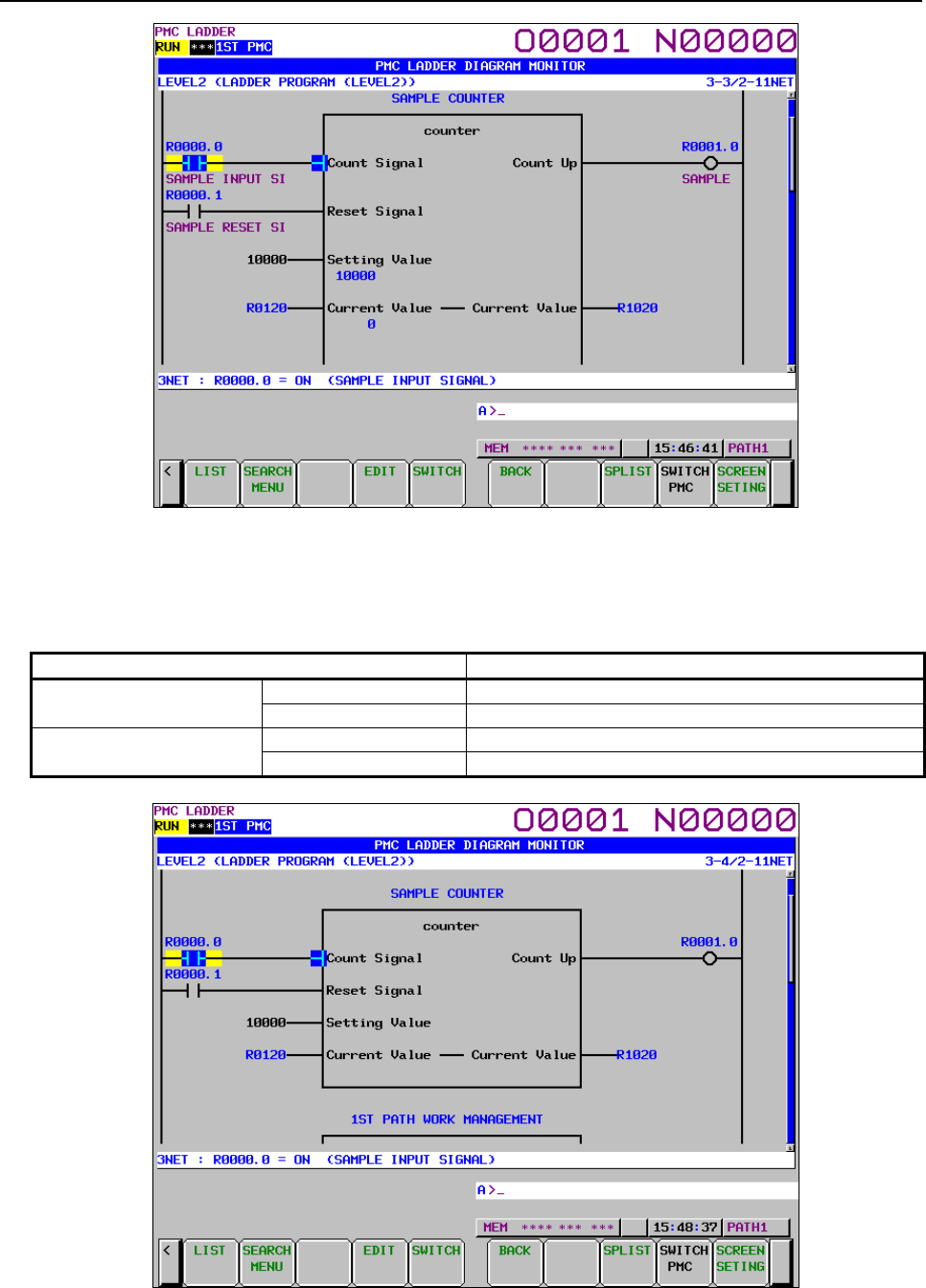
11.FUNCTION BLOCK FUNCTION
B-64513EN/03
- 1346 -
Fig.11.5.5 (c) Display screen of “SHOW COMMENT OF CONTACT = 1 LINE”
(c) “NONE” for “SHOW COMMENT OF CONTACT”
The display format when setting “NONE” for “SHOW COMMENT OF CONTACT” is as
follows.
Display item Description
Parameter Parameter name Comment or symbol (15 single-byte characters x 2 lines)
Non-BOOL monitor Not displayed
Input/output sections BOOL Address or symbol (15 single-byte characters x 1 line)
Non-BOOL Address or symbol (15 single-byte characters x 2 lines)
Fig.11.5.5 (d) Display screen of “SHOW COMMENT OF CONTACT = NONE”
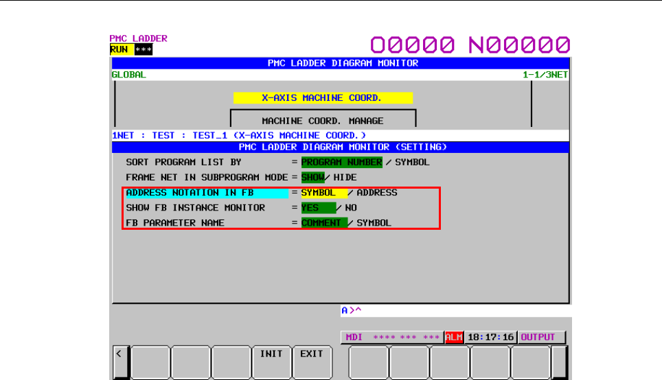
B-64513EN/03
11.FUNCTION BLOCK FUNCTION
- 1347 -
(2) ADDRESS NOTATION IN FB
Fig.11.5.5 (e) Display settings of the function block
Determines whether the bit / byte address in FB body program is displayed in a corresponding
symbol or it is always displayed in an address.
SYMBOL (default)
The address with a symbol is displayed by the symbol. The address with no symbol is
displayed by the address.
ADDRESS
The address with a symbol is also displayed by the address.
(3) SHOW FB INSTANCE MONITOR
Determines whether to show FB instance monitor display.
YES (default)
FB instance monitor is displayed.
NO
FB instance monitor is not displayed.
(4) FB PARAMETER NAME
Determines whether the parameter name of function block instance is displayed as corresponding
symbol or comment.
COMMENT (default)
Parameter name of function block is displayed by its comment.
SYMBOL
Parameter name of function block is displayed by its symbol.

11.FUNCTION BLOCK FUNCTION
B-64513EN/03
- 1348 -
(5) DIAGRAM APPEARANCE SETTING (COLOR)
The display color of each element of function block instance is determined by a color setting on the
ladder diagram monitor setting screen. The correspondence of the display color in each element and
the setting item is as follows.
Table11.5.5 (a) Display color settings related to function block
Element Setting item
Function block instance name ADDRESS COLOR
Function block definition name DIAGRAM COLOR
Function block instance frame DIAGRAM COLOR
PMC address (in the input or output section) ADDRESS COLOR
Constant (in the input section) DIAGRAM COLOR
Parameter name (parameter) DIAGRAM COLOR
Monitor value (parameter) PARAMETER COLOR
Active/inactive state (parameter) ACTIVE RELAY COLOR
Variable name
(in the FB instance monitor)
DIAGRAM COLOR
Variable monitor value:
Numeric
(in the FB instance monitor)
PARAMETER COLOR
Variable monitor value:
BOOL
(in the FB instance monitor)
ON:ACTIVE RELAY COLOR
OFF:DIAGRAM COLOR
Variable monitor value:
Bit string
(in the FB instance monitor)
ACTIVE RELAY COLOR
(BACK GROUND)
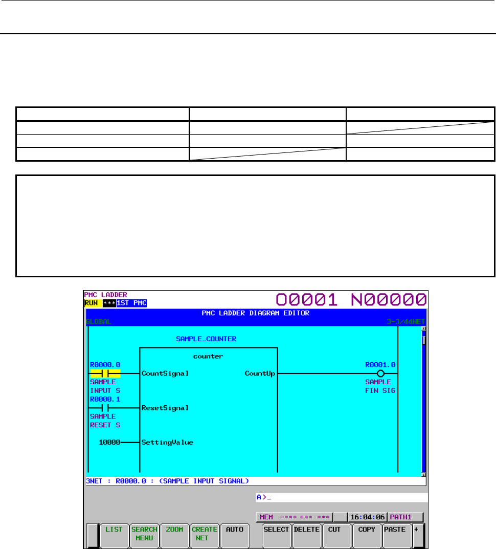
B-64513EN/03
11.FUNCTION BLOCK FUNCTION
- 1349 -
11.5.6
LADDER DIAGRAM EDITOR Screen
You can edit PMC addresses and constants set in the input and output sections of a function block. You
cannot change any parameter defined in the function block. The input section for an input/output
parameter can not be changed, however.
Table11.5.6 (a) Whether the input and output sections can be edited
Input section Output section
Input parameter Can be edited. (NOTE)
Input/output parameter Cannot be edited. Can be edited. (NOTE)
Output parameter Can be edited. (NOTE)
NOTE
The following operations are not possible in the LADDER DIAGRAM EDITOR
Screen. Use the NET EDITOR Screen instead.
• Adding or deleting a contact or a coil in the input section or the output section
of BOOL type parameter.
• Omitting the address set in the output section.
• Setting the address in the output section which is omitted.
Fig.11.5.6 (a) Function block displayed on the ladder diagram editor screen
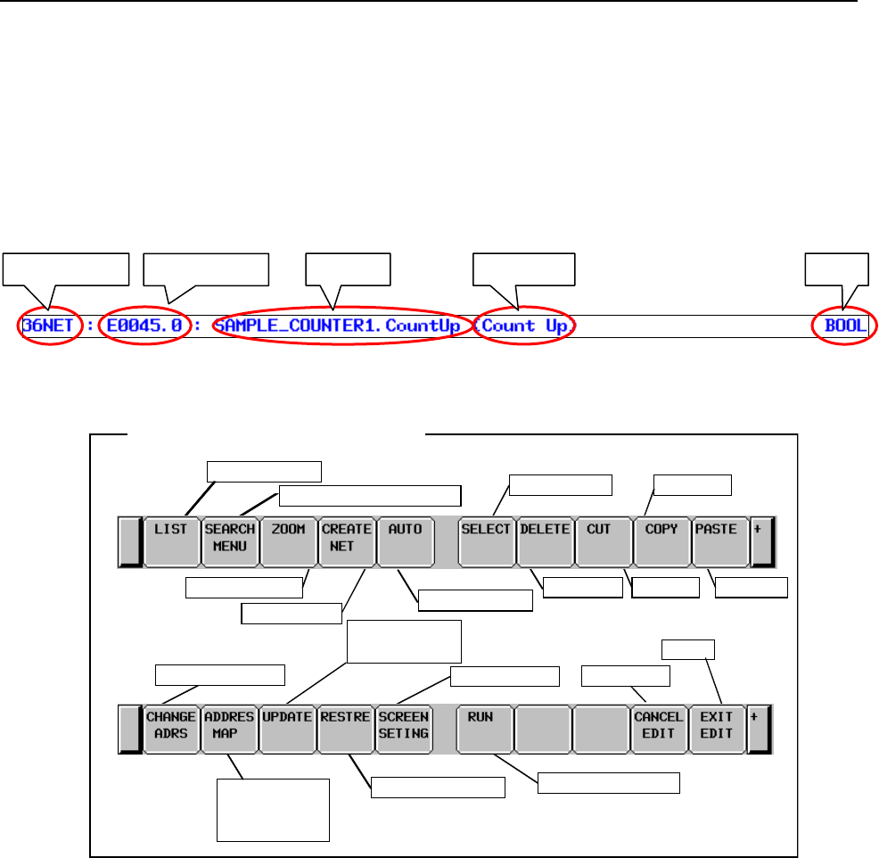
11.FUNCTION BLOCK FUNCTION
B-64513EN/03
- 1350 -
(1) Screen structures
(a) It is basically same with LADDER DIAGRAM MONITOR screen. It displays a function block
like the ladder diagram monitor screen. The parameter or FB instance monitor is not displayed,
however.
(b) Items displayed in the additional information display line on the ladder diagram editor screen
are almost the same as in the line on the ladder diagram monitor screen. When the cursor is
positioned on the input or output parameter or input/output parameter of the function block,
however, the type of that parameter is displayed at the rightmost position in the additional
information display line.
(2) Operation with Soft keys
Abandon changes
Setting screen
Select net Copy net
Delete net Cut net Paste net
Add net
Edit new net
Change to Search soft keys
Cancel edit
Exit
Run/stop LADDER
Program List
Soft keys of LADDER Diagram Editor screen
Make changes
effective
Change address
Automatic input
Display address
map display
screen
Fig.11.5.6 (b) Soft keys of LADDER DIAGRAM EDITOR screen
(a) [LIST] Go to PROGRAM LIST EDITOR screen
Goes to PROGRAM LIST EDITOR screen to choose which subprogram to be edited at
LADDER DIAGRAM EDITOR screen. The PROGRAM LIST EDITOR screen can also edit
subprograms. Inputting a function block instance name and pressing the [LIST] soft key
appears the message “CANNOT EDIT FUNCTION BLOCK” in the message line.
(b) [SEARCH MENU] Search & Jump
The way of using the search soft keys is the same as in the ladder diagram monitor screen. If a
PMC address etc. in the FB body program is searched for in the global search mode, the
message “CANNOT EDIT FUNCTION BLOCK” appears in the message line.
(c) [ZOOM] Change construction of net
Calls the net editor screen to modify the net structure. You can position the cursor on a function
block instance and press the [ZOOM] soft key to edit the net of the function block instance.
(d) [CREATE NET] Add new net
Create and add new net to cursor position. Pressing this soft key reaches NET EDITOR screen,
so that new net is constructed.
(e) [AUTO] Automatic input of unused address/parameter number
Net number PMC address TypeSymbol Comment

B-64513EN/03
11.FUNCTION BLOCK FUNCTION
- 1351 -
Executes the function to automatically input an unused address or parameter number. The range
of specified PMC addresses of the "Assignment Address of FB" and "Automatic Assignment
Address" in the FANUC LADDER-III are excluded from the target of the automatic input.
(f) [SELECT] Select multiple nets
Used to specify multiple nets before performing an editing operation such as [DELETE],
[CUT], and [COPY] soft key.
(g) [DELETE] Delete net
Deletes the selected net. You can delete a net containing a function block.
NOTE
Even if a net of function block instance is deleted, the FB body program
remains. To delete unused FB body program, you have to delete a net of FB
instance by the offline editing function on FANUC LADDER-III.
(h) [CUT] Cut nets
Cuts selected nets. If a net containing a function block is selected, an error message appears and
the net cannot be removed.
(i) [COPY] Copy nets
Copies the selected net. If a net containing a function block is selected, an error message
appears and the net cannot be copied.
(j) [PASTE] Paste nets
Pastes nets at cursor position, which were stored into Paste Buffer by [CUT] or [COPY] soft
key.
(k) [CHANGE ADRS] Change addresses
Displays the address conversion soft keys to use the address conversion function. You can
change a PMC address set in the input or output section of a function block.
(l) [ADDRES MAP] Display the address map display screen
Displays the address map display screen to view references of addresses in use.
(m) [UPDATE] Make changes effective
Updates the ladder program with the results of the editing operations and make it ready to be
actually executed. If it succeeds to update running LADDER, edited LADDER starts to run.
(n) [RESTRE] Abandon changes
Abandons all changes, and restores LADDER program to the one at entering LADDER
DIAGRAM EDITOR screen, or last updated one using [UPDATE] soft key.
(o) [SCREEN SETING] Screen settings
Goes to setting screen for LADDER DIAGRAM EDITOR screen.
(p) [RUN]/[STOP] Run and stop LADDER program
Controls LADDER program execution. [RUN] soft key makes LADDER run, and [STOP] soft
key makes LADDER stop. If changes are applied normally, the LADDER program as edited
will be executed at that point.
(q) [CANCEL EDIT] Abandon editing
Abandons all changes, and restores LADDER program to the one at entering LADDER
DIAGRAM EDITOR screen, or last updated one using [UPDATE] soft key. Switches to
LADDER DIAGRAM MONITOR screen.
(r) [EXIT EIDT] Exit Editor
Updates running LADDER program to edited LADDER program, so that the all modifications
will take effects, and exits the editor screen.
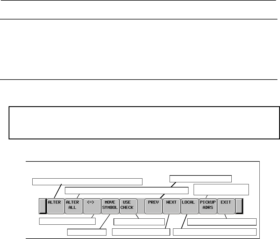
11.FUNCTION BLOCK FUNCTION
B-64513EN/03
- 1352 -
11.5.7
NET EDITOR Screen
At NET EDITOR screen, you can create new net, and modify existing net. You can edit the net of input
and output sections of a function block instance which is selected in the LADDER DIAGRAM EDITOR
screen. You can also set an address in the omitted output section or delete and omit it in the output section.
This screen is the same as the screen described in Subsection 8.3.3, "NET EDITOR Screen". For details
of the screen, see Subsection 8.3.3.
11.5.8
Address Alteration Function
To perform address change, press the [CHANGE ADRS] soft key from the LADDER DIAGRAM
EDITOR screen to switch to the address change mode.
NOTE
The input and output parameters of a function block instance and the PMC
address used in the FB body program cannot be changed by this function. To
change these addresses, use FANUC LADDER-III.
(1) Operation with soft keys
Check the address usage
Search in the backward direction
Acquire the address
indicated by the cursor
Search in the forward direction
Specify the area subject to search and alteration
Exit from the address alteration function
Move a symbol
Switch the cursor position
A
lter to the address s
p
ecified in the NEW ADDRESS field
A
ddress alteration function soft keys
A
lter to the address specified in the NEW ADDRESS field at once
Fig.11.5.8 (a) Address alteration function soft keys
PMC addresses used in the input and output section of the function block can be changed. The
following explains address conversion function operations related to function blocks. For details, see
Section 8.5, "ADDRESS ALTERATION FUNCTION".
• [ALTER]
You can position the cursor on an address in the input or output section of a function block,
enter a desired PMC address for “Alter address”, and press the [ALTER] soft key to replace a
PMC address.
• [ALTER ALL]
You can set a PMC address set in the input or output section of a function block for “OLD
ADDRESS” and a PMC address after conversion for “NEW ADDRESS”, and press the
[ALTER ALL] soft key to convert the address in the input and output sections of the function
block that is set for “OLD ADDRESS”.
• [USE CHECK]
Checks to see if the address specified in the "NEW ADDRESS" field is in use by searching for
the address through the ladder diagram. The address used in the function block instance and FB
body program is the subject of the use check, too.

B-64513EN/03
11.FUNCTION BLOCK FUNCTION
- 1353 -
• [PICKUP ADRS]
You can fetch a PMC address set in the input or output or input/output section of a function
block for “OLD ADDRESS” or “NEW ADDRESS”.
NOTE
When trying to alter an address assigned in the input section for an
input/output parameter, the following error message is displayed.
"CANNOT EDIT INPUT/OUTPUT PARAM ADDRESS"
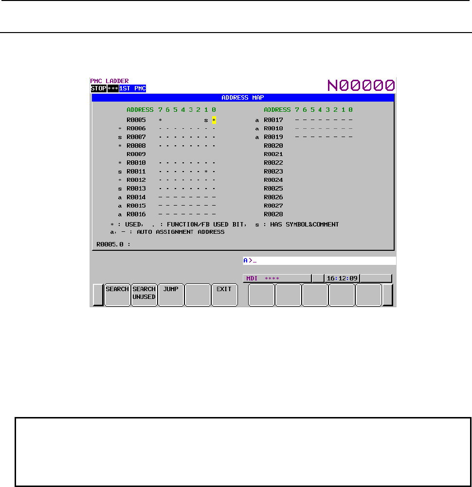
11.FUNCTION BLOCK FUNCTION
B-64513EN/03
- 1354 -
11.5.9
Address Map Display Screen
Pressing the [ADDRESS MAP] soft key on the ladder editor screen causes that screen to switch to the
address map display screen.
Fig.11.5.9 (a) Address Map Display Screen
An asterisk (*) is marked also to the address which is used in the FB body program and function block
instance when using a function block function.
Symbol and comment (s) is marked to the address of internal and external variables that are not used
actually in the FB body program and function block instance but defined in function block.
The “a” mark (for byte) and the “-“ mark (for bit) is marked for the automatic assignment address.
NOTE
1 Non-BOOL parameters of function block are handled as addresses in use with a
length of one byte, regardless of the data length of the parameters.
2 It does not jump to the address used in the FB body program because it cannot
be edited.
For details of the Address Map Display Screen, see Subsection 8.6.1, "Address Map Display Screen".
B-64513EN/03
11.FUNCTION BLOCK FUNCTION
- 1355 -
11.5.10
Duplicate Coil Check Screen
On the Duplicate Coil Check screen, you can check the overwriting of a PMC address by multiple coil
instructions. And, you can also check the multiple use of instruction number of the following functional
instructions.
Instruction name SUB number Function
TMR 3 Timer
TMRB 24 Fixed Timer
TMRBF 77 Off Delay Fixed Timer
CTR 5 Counter
CTRB 56 Fixed Counter
DIFU 57 Rising Edge Detection
DIFD 58 Falling Edge Detection
The target of multiple use check related to function block is as follows.
• A coil in the FB body program
• The instruction number of the above functional instructions in the FB body program
• A coil in the output section of a function block instance
• A BOOL input parameter of a function block instance
For details of the Duplicate Coil Check, see Section 8.10, "CHECKING OF DUPLICATE COIL ([DUP.
CHECK] SCREEN)".
NOTE
Do not delete the symbol for the function block instance name on the symbol and
comment editor screen. When it is deleted, jump function for FB body program
become unavailable.
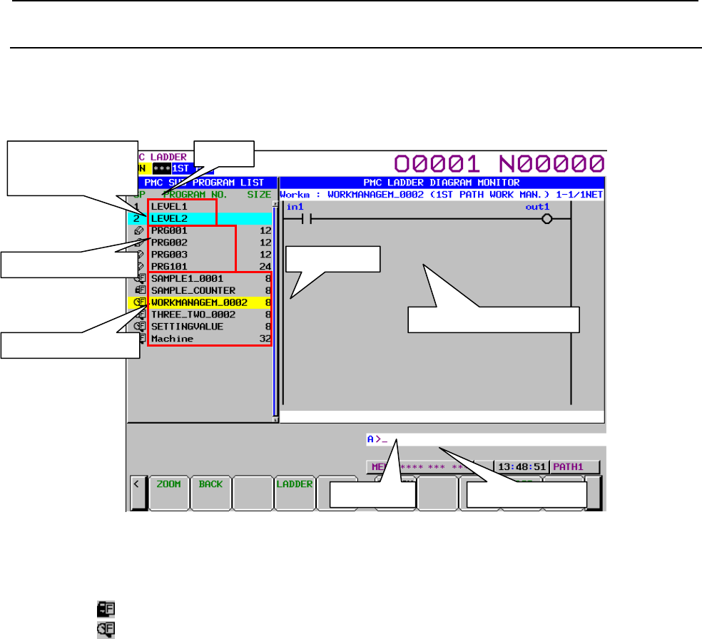
11.FUNCTION BLOCK FUNCTION
B-64513EN/03
- 1356 -
11.5.11
Subprogram List Display Screen
The Sub Program List Viewer screen shows the list of the subprograms and function blocks called by the
current subprogram. On the other hand, the history of the displayed subprogram and function block is
displayed.
Fig.11.5.11 (a) Subprogram List Display Screen
There are the following operations related to function blocks.
(1) Area of subprogram list
In the "SP area", the program types of function block are displayed.
(Lock) : Unable to browse and edit
(Magnifying glass): Able to browse but unable to edit
Ladder
p
review dis
p
la
y
area
Messa
g
e dis
p
la
y
line Ke
y
in
p
ut line
Called FB bod
y
p
ro
g
ram
Size area
SP area
Called sub
p
ro
g
ram
History of the
displayed subprogram
and function block
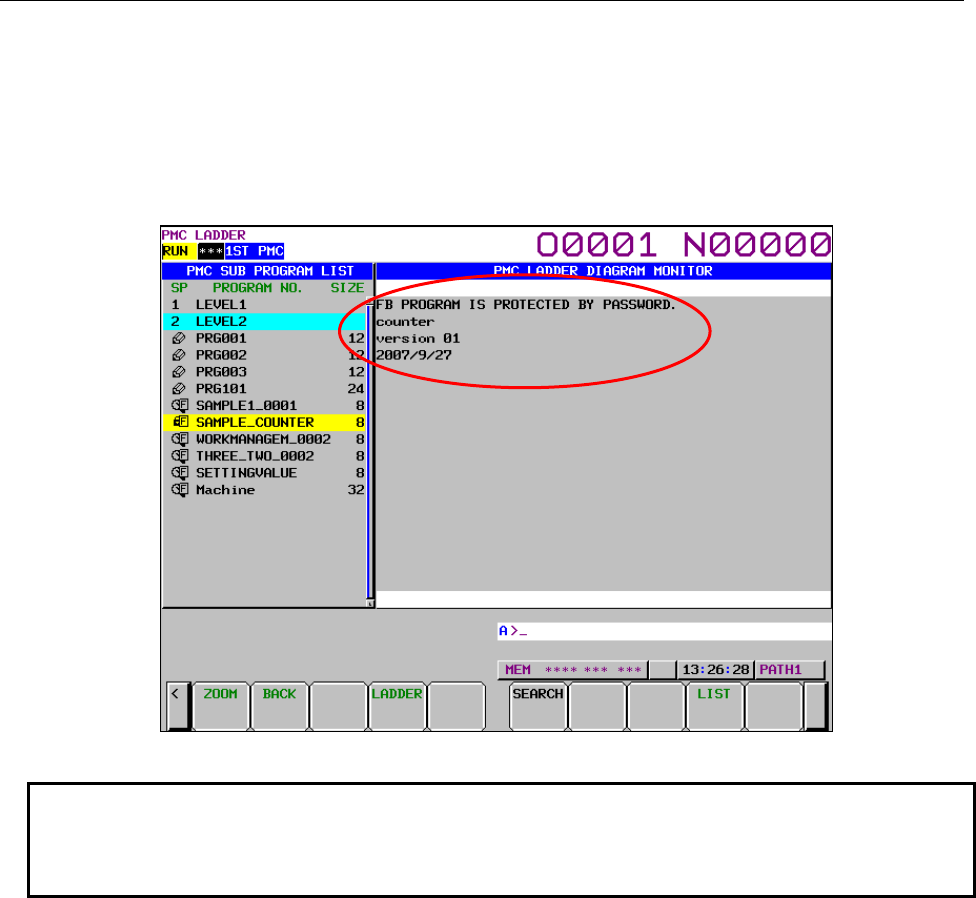
B-64513EN/03
11.FUNCTION BLOCK FUNCTION
- 1357 -
(2) Function block display of browsing and editing protection
When you preview a FB body program for which browsing and editing protection is set, the
following contents are displayed.
FB PROGRAM IS PROTECTED BY PASSWORD.
Comment of function block
Version
Date
Fig.11.5.11 (b) Preview display when FB program is protected
NOTE
Do not delete the symbol for the function block instance name on the symbol and
comment editor screen. When it is deleted, displaying the screen in order of
symbols may not work correctly.
For details of the Subprogram List Display Screen, see Section 8.11, "DISPLAYING A SUBPROGRAM
LIST ([SPLIST] SCREEN)".
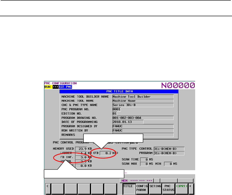
11.FUNCTION BLOCK FUNCTION
B-64513EN/03
- 1358 -
11.5.12
Title Screen
On the TITLE DATA screen, you can check the title data items and some ladder information items. The
following items are displayed when using the function block function.
• The size of function block
Memory size used for the part of FB body program of function block. And, memory size used for
ladder also includes FB body program size.
• The size of function block information
Data size for the function block information as for the function block definition etc.
Fig.11.5.12 (a) Title Screen
For details of the Title Screen, see Section 9.1, "DISPLAYING AND EDITING TITLE DATA ([TITLE]
SCREENS)".
The size of function block
The size of function block information
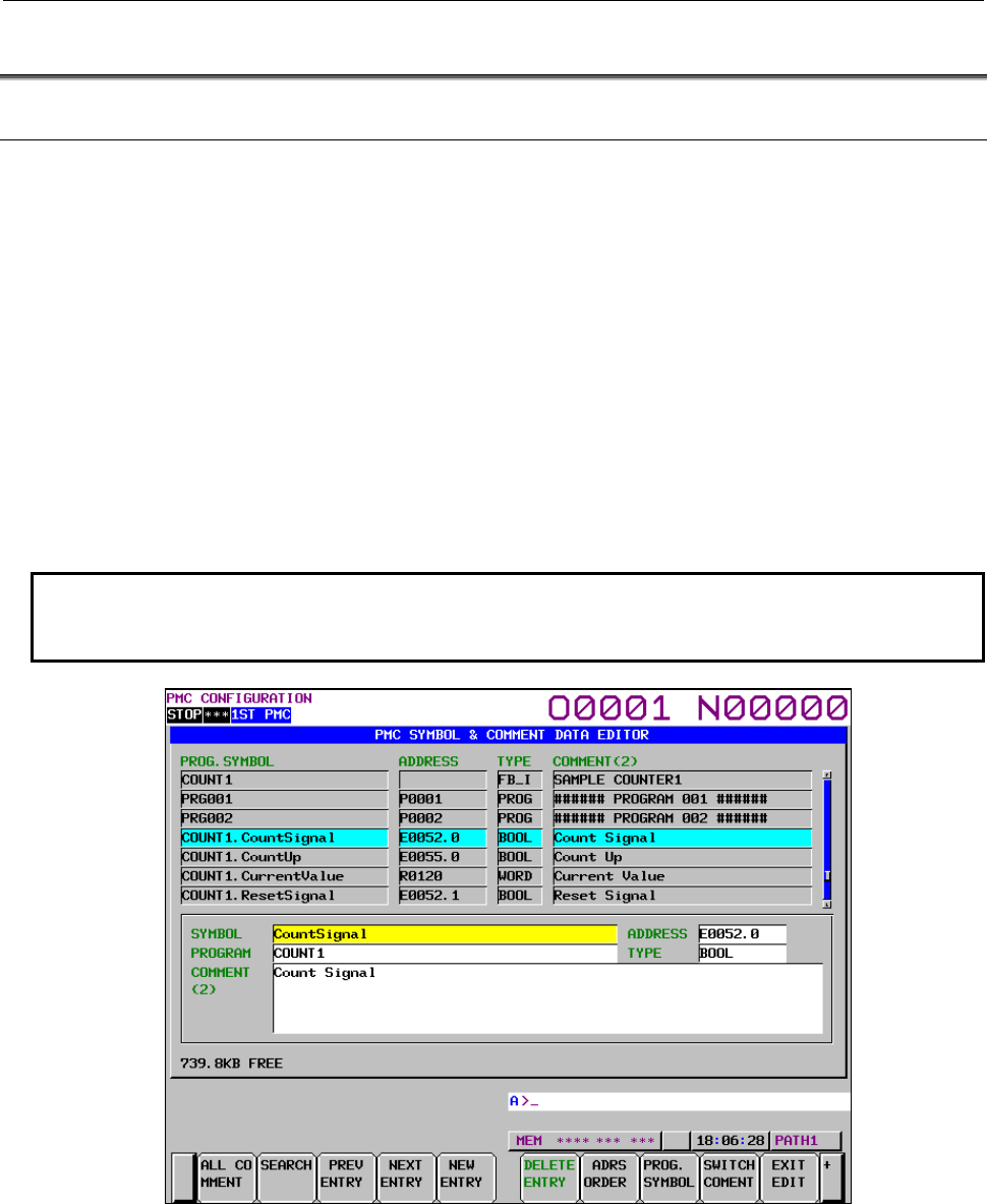
B-64513EN/03
11.FUNCTION BLOCK FUNCTION
- 1359 -
11.6 DISPLAYING AND EDITING SYMBOL AND COMMENT
11.6.1 Extended Symbol and Comment Screen
This screen is the same as the screen described in Subsection 9.2.5, "Displaying Extended Symbol and
Comment". For details of the screen, see Subsection 9.2.5.
There are the following symbol and comment data definitions related to function block.
(1) Symbol and comment definition of function block instance name
PROG.SYMBOL: Displayed as the form “[PROGRAM NAME].[SYMBOL]”
ADDRESS: This column is blank.
TYPE: “FB_I” is displayed.
(2) Symbol and comment definition of internal and external variables in the function block
PROG.SYMBOL: Local symbol to the function block
• When a symbol is defined for the function block instance:
“function-block-instance-name.symbol”
• When a symbol is not defined for the function block instance:
“function-block-definition-name.symbol”
NOTE
The symbol for a function block cannot be changed or added. Available
operations are line deletion in entry units and all deletion only.
Fig.11.6.1 (a) Extended Symbol and Comment Screen

11.FUNCTION BLOCK FUNCTION
B-64513EN/03
- 1360 -
11.6.2
Displaying Extended Symbol and Comment
The following table lists how symbols and comments are displayed and searched for on each screen.
Screen Displaying symbol and comment Searching symbol and comment
Ladder screen (except address
map)
Program list screen
Subprogram list screen
A symbol and comment is displayed
by following priority.
1 Local symbol and comment that
defined to displayed
subprogram or function block.
2 Global symbol and comment.
3 Comment without symbol.
The following symbol and comment
can be searched.
- Local symbol that defined to
displayed subprogram or
function block.
- Global symbol.
Signal status screen
PMC parameter (timer) screen
PMC parameter (counter) screen
PMC parameter (keep relay) screen
PMC parameter (data table) screen
Signal trace screen
Signal trace (parameter setting)
screen
Ladder (address map) screen
A symbol and comment is displayed
by following priority.
1 Global symbol and comment.
2 Local symbol and comment of
LEVEL1 to 3.
3 Local symbol and comment of
sub-program P1 to P5000.
4 Local symbol and comment for
the function block
5 Comment without symbol.
All symbols and comments can be
searched.
You can search a local symbol by
following format.
- (program name).(symbol)
The program name is able to be
specified by sub-program number or
a symbol of P-address. For a
function block, specify it with a
function block instance name.
I/O diagnosis screen
Symbol and comment screen
All symbols and comments are
displayed.
All symbols and comments can be
searched. A symbol or comment
can be searched by partial string.
NOTE
When multiple symbol and comment are defined to the same address, you can
search it by each symbol name. On the other hand the symbol displayed for the
address on PMC screen is one of these symbol names. So if you search such a
symbol, displayed symbol name on searched position may be different from the
symbol searched.

B-64513EN/03
12.PMC ALARM MESSAGES AND ACTIONS TO TAKE
- 1361 -
12 PMC ALARM MESSAGES AND ACTIONS
TO TAKE
12.1 ALARM MESSAGE LIST
12.1.1 Messages That May Be Displayed on the PMC Alarm Screen
The following table lists the PMC alarm messages that may be displayed on the PMC alarm screen.
Alarm number Faulty location/corrective action Contents
ER01 PROGRAM DATA
ERROR
<1> Enter the sequence program again.
<2> If this error recurs even after you have
entered the sequence program again, the
error may be due to a hardware fault. In
that case, contact us.
The sequence program is invalid.
ER02 PROGRAM SIZE
OVER
<1> Reduce the size of the sequence program.
<2> Contact us, and specify a ladder step
count option that allows you to set a larger
program size.
The sequence program is too
large to load into the save area.
The sequence program is invalid.
ER03 PROGRAM SIZE
ERROR(OPTION)
<1> Reduce the size of the sequence program.
<2> Contact us, and specify a ladder step
count option that allows you to set a larger
program size.
The sequence program exceeds
the size specified by the ladder
step count option.
ER04 PMC TYPE UNMATCH Change the sequence program so that it
specifies the adequate PMC type, by using the
programmer.
The PMC type specified in the
sequence program does not
match the type of the PMC
actually in use.
ER08 OBJECT UNMATCH Contact us. An unsupported function is used
in the sequence program.
ER09 PMC LABEL CHECK
ERROR. PLEASE TURN ON
POWER AGAIN WITH
PRESSING 'O'&'Z'. (CLEAR
PMC SRAM)
<1> Turn on the power of the CNC again, by
holding down the 'O' and 'Z' keys at the
same time.
<2> Replace the backup batteries.
The nonvolatile memory of the
PMC system needs to be
initialized in such cases as when
you have changed the PMC
model.
ER17 PROGRAM PARITY <1> Enter the sequence program again.
<2> If this error recurs even after you have
entered the sequence program again, the
error may be due to a hardware fault. In
that case, contact us.
The parity of the sequence
program is invalid.
ER18 PROGRAM DATA
ERROR BY I/O
Enter the sequence program again. Reading sequence program was
interrupted.
ER19 LADDER DATA
ERROR
Display the LADDER DIAGRAM EDITOR
screen again, and terminate the editing
operation by pressing the [EXIT] soft key.
During editing the ladder, the
screen display is switched to a
CNC screen by the operation of a
function key.
ER22 NO PROGRAM Enter the sequence program again. The sequence program is empty.
ER27 LADDER FUNC. PRM
IS OUT OF RANGE
Correct the sequence program; change the
parameter number specified in a functional
instruction to a value that is within the allowable
range.
An out-of-range parameter
number is specified in the TMR,
TMRB, TMRBF, CTR, CTRB,
DIFU, or DIFD functional
instruction.

12.PMC ALARM MESSAGES AND ACTIONS TO TAKE
B-64513EN/03
- 1362 -
Alarm number Faulty location/corrective action Contents
ER33 I/O Link ERROR(CHn)
(Note3)
Contact us; replace the faulty hardware. The LSI for the I/O Link is faulty.
ER34 I/O Link ERROR (CHn
Gxx)
(Note1)(Note3)
<1> Check the cable connections to the
devices of group xx.
<2> Check whether the power of each I/O
device has been turned on before the
CNC.
<3> Replace any device of group xx in which
the PMC control module is embedded.
An I/O device communication
error occurred on the slave side of
group xx.
ER35 TOO MUCH OUTPUT
DATA IN GROUP(CHn Gxx)
(Note1)(Note3)
Reduce the output data count of group xx. The output data count of I/O Link
group xx exceeds the upper limit
(33 bytes).
Or the output data count of I/O
Link i group “xx” exceeds the
upper limit (65 bytes for the
normal I/O, 29 bytes for the safety
I/O).
The superfluous data is regarded
as invalid.
ER36 TOO MUCH INPUT
DATA IN GROUP(CHn Gxx)
(Note1)(Note3)
Reduce the input data count of group xx. The input data count of I/O Link
group xx exceeds the upper limit
(33 bytes).
Or the input data count of I/O Link
i group “xx” exceeds the upper
limit (65 bytes for the normal I/O,
29 bytes for the safety I/O). The
superfluous data is regarded as
invalid.
ER37 TOO MUCH SLOT IN
BASE(CHn)
(Note3)
Correct the slot number to a value of 10 or less. The slot number for the I/O Link
exceed the upper limit (10). The
slot number larger than 11 is
regarded as invalid.
ER38 MAX SETTING
OUTPUT DATA OVER(CHn
Gxx)
(Note1)(Note3)
<1> In case of I/O Link, reduce the total amount
of output data of all groups to 128 bytes or
less.
<2> In case of I/O Link i, reduce the total
amount of output data of all groups to 256
bytes or less.
The I/O area for the I/O Link is
insufficient.
(The area allocated to the group
“xx” and later on the output side is
regarded as invalid.)
In case of I/O Link i, The I/O area
is insufficient in the normal update
cycle mode.
ER39 MAX SETTING INPUT
DATA OVER(CHn xx)
(Note1)(Note3)
<1> In case of I/O Link, reduce the total amount
of input data of all groups to 128 bytes or
less.
<2> In case of I/O Link i, reduce the total
amount of input data of all groups to 256
bytes or less.
The I/O area for the I/O Link is
insufficient.
(The area allocated to the group
“xx” and later on the input side is
regarded as invalid.)
In case of I/O Link i, The I/O area
is insufficient in the normal update
cycle mode.
ER43 PROGRAM DATA
ERROR(PT/NT)
<1> Store sequence program which is compiled
again after recompilations using FANUC
LADDER-III.
<2> If you see the same alarm again after <1>,
contact us.
The sequence program is invalid.
ER45 NO OPTION
(FUNCTION BLOCK)
Add a required function block option. No function block option is
specified.

B-64513EN/03
12.PMC ALARM MESSAGES AND ACTIONS TO TAKE
- 1363 -
Alarm number Faulty location/corrective action Contents
ER46 MESSAGE DATA
UPDATE ERROR.
PLEASE TRUN OFF POWER
AFTER SAVING DATA.
Save the corrected sequence program or
message data for multi-language display to F-
ROM. Moreover, turn the power off/on.
The message data in the
sequence program or the
message data for multi-language
display cannot be updated. It is
necessary to turn off/on the
power. The ladder program
cannot be executed when this
alarm occurs.
ER47 ILLEGAL OVERRIDE
FUNCTION SETTING (TOO
MANY PMC PATHS)
The override mode of the force I/O function is
available in 3 or less PMC paths in same time.
In some PMC paths, make the function invalid.
Moreover, turn the power off/on.
The override function is enabled in
four or more PMC paths.
ER48 STEP SEQUENCE
TIME OVER(xxH)
Remove the setting of exceeding setting time
on the STEP SEQUENCE TIME MONITOR
SETTING screen.
The activated condition of step
sequence exceeds the time limit,
which is set on the STEP
SEQUENCE TIME MONITOR
SETTING screen.
ER49 POSITIVE/NEGATIVE
TRANSITION (PT/NT)
INSTRUCTION INITIALIZE
ERROR. PLEASE TRUN OFF
POWER AFTER SAVING
PROGRAM.
Modify the sequence program and save the
program to flash ROM. Then, reboot the CNC.
The work memory of positive /
negative transition (PT/NT)
instruction cannot be initialized.
It is necessary to reboot the CNC.
The ladder program stops when
this alarm occurs.
ER50 PMC EXECUTION
ORDER ERROR
Check CNC parameter Nos. 11900 to 11904. The execution order setting of the
multi-PMC function is invalid.
ER51 PMC EXECUTION
PERCENTAGE ERROR
Check CNC parameter Nos. 11905 to 11909. The execution percentage setting
of the multi-PMC function is
invalid.
ER52 I/O Link CHANNEL
ASSIGNMENT ERROR
(Note3)
Check CNC parameter Nos. 11910 to 11912. The I/O Link channel assignment
to the PMC system is invalid.
ER54 NC-PMC I/F
ASSIGNMENT ERROR
Check CNC parameter Nos. 11920 to 11929. The interface assignment between
NC and PMC is invalid.
ER55 LADDER EXECUTION
CYCLE SETTING ERROR
Check the CNC parameter, No.11930, 11945,
and 11946.
Setting of the execution cycle of
the ladder 1st level (CNC
parameter No.11930) is incorrect.
Or, a setting of the ladder 1st level
execution cycle in 1ms or 2ms
(CNC parameter No.11945,
11946) is incorrect.
ER57 MULTI-PATH PMC I/F
ASSIGNMENT ERROR
Check CNC parameter No. 11932. The assignment of multi-path
PMC interface is invalid.
ER58 PMC MEMORY TYPE
SETTING ERROR
Check CNC parameter No.11940 to No.11944. The setting of PMC Memory Type
is invalid.
ER60 I/O Link i ERROR(CHn)
(Note3)
Contact us. Exchange of the hardware. The LSI for I/O Link i is faulty.
ER61 I/O Link i ERROR(CHn
Gxx)
(Note1) (Note3)
<1> Check the cable connected to the device
of group “xx”.
<2> Check the power supply of the I/O device
if the power is turned on earlier than the
power of CNC.
<3> Exchange the I/O device in group “xx” in
which PMC control module is built.
<4> Check the assignment data of handy
machine operator’s panel if it is used in
group “xx”.
The connection error occurred in
the slave of group “xx”.

12.PMC ALARM MESSAGES AND ACTIONS TO TAKE
B-64513EN/03
- 1364 -
Alarm number Faulty location/corrective action Contents
ER62 I/O Link i DCS ERROR
(Note3)
Contact us. Exchange of the hardware. The LSI for I/O Link i DCS is
faulty.
ER63 I/O Link CHANNEL
SETTING ERROR
(Note3)
<1> Change the channel configuration in order
to reduce the I/O points. As for the
communication method for each channel,
specify the CNC parameter No. 11933#0
and 1.
Total I/O points are over
4096/4096 points in system.
For the I/O Link, the I/O points are
1024/1024 points for one channel.
For the I/O Link i, 2048/2048
points for one channel.
ER64 I/O Link i TOO MANY
CONNECTED
GROUPS(CHn)
(Note3)
Reduce the number of connected I/O modules
in channel “n”.
257 or more I/O modules are
connected with channel “n”.
(Note 4)
ER65 I/O Link i TOO MANY
SLOTS(CHn)
(Note3)
Reduce the number of connected I/O modules
to 256 or less.
257 or more of I/O modules are
connected in channel “n”.
ER66 I/O Link i PMC
ADDRESS OVERLAPPED
(PMCm X(Y)nnnn)
(Note3)
Enter the PMC address or size again so that
any address is not used by multiple PMCs that
share PMC memory.
The address X(Y)”nnnn” assigned
in PMC path “m” is assigned to
another PMC path that is shared
the common memory with PMC
path “m”.
ER67 I/O Link i TOO MANY
SAFETY I/O GROUPS
(Note3)
Reduce the group number of safety I/O.
The total group number of safety
I/O in PMC paths exceed 4 or the
total group number of safety I/O in
DSCPMC exceed 4 for I /O Link i.
ER68 I/O Link i TOO MANY
ASSIGNMENTS IN HIGH
SPEED MODE (CHn,Gyy)
(Note1) (Note3)
When there are some groups which is set to
high-speed update cycle mode in I/O Link i,
Correct the transmission timing. Refer to
subsection “3.3.3”.
In the channel n, the transmission
size exceeds the limit of high-
speed mode for I/O Link i. The
assignment of group “yy” or later
cannot be performed.
ER69 I/O Link i
ASSIGNMENT ADDRESS
INVALID(CHn Gyy)
(Note2)(Note3)
Correct the assignment data of I/O Link i. The address of false PMC path is
assigned in group “yy” of channel
“n” of I/O Link i assignment data.
ER70 PMC ADDRESS
BLOCK OVERLAPPED
BETWEEN I/O Link AND I/O
Link i(PMCm X(Y)nnnn)
(Note3)
<1> Delete the assignment data for I/O Link i or
correct the assignment address.
<2> Correct the X/Y address block of the I/O
Link channel. (The setting of Machine
signal interface of PMC configuration
parameter)
<3> Check the communication method of I/O
Link. (NC parameter 11933#0,#1)
<4> Check the setting of the selectable
assignment data function for I/O Link i.
There is a PMC address block
which is assigned in both I/O Link
and I/O Link i.
ER71 I/O Link i STATUS
ALARM LENGTH OVER IN
GROUP(CHn Gxx)
(Note1)(Note3)
Correct the configuration of I/O devices and
reduce the total of the status alarms to 64bytes
or less.
The total of the status alarms for
I/O devices connected with group
“xx” of channel “n” exceeds 64
bytes
ER89 EDITING I/O
CONFIGURATION DATA IS
NOT COMPLETED
Finish the edit of I/O configuration data.
I/O configuration data is invalid
because that the editing of the I/O
configuration data is in the midst.
ER90 TOO LARGE I/O
CONFIGURATION DATA
(Note3)
Reduce the I/O configuration data file. I/O configuration data is larger
than the save area or invalid.
ER91 I/O CONFIGURATION
DATA PARITY
(Note3)
<1> Input I/O configuration data file again.
<2> When re-input cannot solve this error, the
hardware may be failure. Contact us.
The parity of I/O configuration
data is invalid.

B-64513EN/03
12.PMC ALARM MESSAGES AND ACTIONS TO TAKE
- 1365 -
Alarm number Faulty location/corrective action Contents
ER92 I/O CONFIGURATION
DATA ERROR BY I/O
Input I/O configuration data file again. Reading of I/O configuration file is
interrupted.
ER93 UNSUPPORTED I/O
CONFIGURATION DATA
(Note3)
Correct the type of I/O configuration data and
input again.
The type of I/O configuration data
is invalid.
ER94 I/O CONFIGURATION
DATA ERROR
(Note3)
Re-compile the I/O configuration data by FL-III.
Moreover, input again.
Data configuration of I/O
configuration data is abnormal.
ER95 I/O DEVICE
MISMATCH(CHn)
(Note3)
When this alarm occurs on a well-worked
machine, the causes may be following:
<1> Disconnection of communication cable or
contact fault.
<2> The power of an I/O device is turned off.
Or the power on is delayed.
<3> The failure of an I/O device.
<4> The power of some I/O devices remain
when the power of CNC is turned off/on.
Turn the power all of I/O devices off/on
when the power of CNC is turned off/on.
When this alarm occurs during a debugging of
sequence program, the following causes also
come up.
<5> The configuration (type, order or number)
of the I/O devices is wrong.
<6> Invalid I/O configuration data is registered.
You can confirm the error I/O device in the “I/O
Device Monitor” screen.
This alarm occurs when actual I/O
devices connected to CNC differ
from the I/O configuration data
registered in the “I/O Device
Monitor” screen. The ladder
program runs regardless of the
occurrence of this alarm.
ER96 I/O Link MAX GROUP
OVER(CHn)
(Note3)
<1> Check the PMC paths and addresses of
first and second blocks of n channel on
configuration parameter setting screen.
<2> Check the total groups of first and second
block on I/O module assignment.
<3> Check the parameter setting of
"Selectable I/O Link assignment function".
When dual assignment of I/O Link
channel is used, total groups of
first and second block exceeds 16
groups.
The ladder program runs
regardless of the occurrence of
this alarm.

12.PMC ALARM MESSAGES AND ACTIONS TO TAKE
B-64513EN/03
- 1366 -
Alarm number Faulty location/corrective action Contents
ER97 I/O Link FAILURE(CHn
Gxx)
(Note1) (Note3)
When this alarm occurs on a well-worked
machine, the cause may be following.
<1> The failure of the cable or contact from
group (“xx” – 1) to “xx”.
<2> The power of an I/O device of group “xx” or
later is turned off. Or the power on is
delayed.
<3> The failure of an I/O device of group “xx” or
(“xx” – 1).
<4> The power of some I/O devices remain
when the power of CNC is turned off/on.
Turn the power all of I/O devices off/on
when the power of CNC is turned off/on.
If this alarm occurs during a debugging of
sequence program, the following causes also
come up.
<5> The group number of I/O device is invalid.
<6> The mistake of the assignment setting of
I/O modules.
<7> The mistake of the parameter setting of
"Selectable I/O Link assignment function"
<8> The mistake of the machine signal
interface setting.
You can confirm the details of the error in the
“I/O Device Monitor” screen.
This alarm occurs when less I/O
devices are connected.
This alarm occurs when a total
group count of the I/O module
assignment are different with one
of connected device count.
The ladder program runs
regardless of the occurrence of
this alarm.
WN02 OPERATE PANEL
ADDRESS
ERROR
Correct the Series 0 operator's panel address
that is set in the PMC system parameter.
The Series 0 operator's panel
address that is set in the PMC
system parameter is invalid.
WN03 ABORT
WINDOW/EXIN
Modify the ladder program and turn on the
power of the CNC again. Refer to subsection
“4.15” for details.
The ladder program was stopped
while communication was in
progress between CNC and PMC.
This alarm may cause the
WINDR, WINDW, EXIN, and
DISPB functional instructions to
malfunction.
WN07 LADDER SP
ERROR(STACK)
Correct the sequence program so that the
subprogram has eight or fewer levels of
nesting.
There are too many levels of
nesting (levels more than 8) for
the CALL or CALLU functional
instruction to call the subprogram.
WN09 SEQUENCE
PROGRAM IS NOT
WRITTEN TO FLASH ROM
If you want to use the current sequence
program next time you power on the system,
write the sequence program to flash ROM. If
you have made any unwanted change to the
sequence program by mistake, read the original
sequence program from flash ROM.
You have changed the sequence
program using the LADDER
DIAGRAM EDITOR screen or
DATA I/O screen, but you have
not yet written the changed
sequence program to flash ROM.
If you shut down the system
without writing the changed
sequence program to flash ROM,
the changes you have made will
be lost next time you turn on the
power.
WN10 NO OPTION(STEP
SEQUENCE)
<1> Add the step sequence option.
<2> Arrange so that the step sequence
subprogram will not be called.
No step sequence option was
found when the system attempted
to execute a step sequence.

B-64513EN/03
12.PMC ALARM MESSAGES AND ACTIONS TO TAKE
- 1367 -
Alarm number Faulty location/corrective action Contents
WN57 OVERRIDE
FUNCTION IS ACTIVE
The Override function is for debugging only.
So, disable the function when shipping the
machine.
The Override function is activated.
WN58 UNSUPPORTED
FUNCTION
Correct the sequence program with Ladder
editing function on PMC screen.
An unsupported functional
instruction is used in the
sequence program. The functional
instruction was skipped.
WN59 MESSAGE FILE
SYMBOL UNDEFINED
Correct the error in the message file for multi-
language display.
In the message file for multi-
language display, a symbol that
does not exist in the ladder is
defined.
WN60 MESSAGE FILE
SYMBOL INVALID
Correct the error in the message file for multi-
language display.
In the message file for multi-
language display, a symbol other
than an A address is defined.
WN61 MESSAGE FILE
ADDRESS DUPLICATE
Correct the error in the message file for multi-
language display.
The A address area has a
duplicate definition between a
symbol and address or between
symbols.
WN62 MESSAGE FILE
NUMBER ERROR
Correct the error in the message file for multi-
language display.
A message number differs
between the ladder and message
file for multi-language display at
the same A address.
WN63 MESSAGE FILE IS
NOT WRITTEN TO FLASH
ROM
If you want to use the current message file for
multi-language display next time you power on
the system, write the message file to flash
ROM.
You have changed the message
data for multi-language display
using DATA I/O screen, but you
have not yet written the changed
message data to flash ROM. If
you shut down the system without
writing the changed message data
to flash ROM, the changes you
have made will be nowhere next
time you turn on the power.
WN64 MESSAGE FILE SIZE
OVER
<1> Reduce the size of the message file for
multi-language display.
<2> Contact us and specify an option for a
larger size.
The message file for multi-
language display is too large to
load into the save area.
The message file for multi-
language display is invalid.
WN65 MESSAGE FILE
MISMATCH
Contact us. An unsupported function is used
in the message file for multi-
language display.
WN66 MESSAGE FILE
PARITY
<1> Enter the message file for multi-language
display again.
<2> If this error recurs even after you have
entered the message file for multi-
language display again, the error may be
due to a hardware fault. In that case,
contact us.
The parity of the message file for
multi-language display is invalid.
WN67 MESSAGE FILE
ERROR BY I/O
Enter the message file for multi-language
display again.
Reading the message file for
multi-language display was
interrupted.

12.PMC ALARM MESSAGES AND ACTIONS TO TAKE
B-64513EN/03
- 1368 -
Alarm number Faulty location/corrective action Contents
WN68 I/O CONFIGURATION
DATA IS NOT WRITTEN TO
FLASH ROM
If you want to make updated I/O configuration
data effective, write the data to Flash ROM.
The I/O configuration data was
updated in the I/O configuration
editor screen or data I/O screen
but the data has not been written
to Flash ROM yet. The data will
be lost if the save operation is not
performed.
WN69 I/O Link i DO ALARM
(CHn Gxx Syy zz : PMCm
Ybbb = **H )
(Note1)
Check DO of the relevant device.
For the details of the alarm of I/O devices, refer
to the “CONNECTION MANUAL
(HARDWARE)” of each CNC series.
The DO alarm (ex. a short circuit
with the ground) occurs at byte
“zz” of slot “yy” of group “xx” in
channel “n”.
Y “bbbb” of PMC path ”m” is the
address at which the alarm
occurred.
DCSPMC Y”bbbb” is the address
for DCSPMC.
Display of “PMC*Y****” is the case
of occurrence of unassigned
address.
The “**H” shows some bits at
which the alarm occurs by
hexadecimal.
(Ex. “PMC1Y115=28H” shows the
alarm occurs at Y115.3 and
Y115.5 in PMC1. “28H” means
“00101000” in binary. )
WN70 I/O Link i STATUS
ALARM (CHn Gxx Syy zz =
**H)
(Note1)
Check the alarm information of applied I/O
device.
For the details of the alarm of I/O devices, refer
to the “CONNECTION MANUAL
(HARDWARE)” of each CNC series
The status alarm except for the
DO alarm occurs at byte “zz” of
slot “yy” of group “xx” in channel
“n”.
The “**H” shows some bits at
which the alarm occurs by
hexadecimal.
NOTE
1 The displayed group number in ER34, ER35, ER36, ER38, ER39, ER61, ER68,
ER71, ER97, WN69 and WN70 is wiring number of I/O device.
2 The group number displayed in ER69 is the number of I/O Link i assignment
data.
3 When some PMC alarms related to I/O Link and I/O Link i occur, all of I/O
devices in all of channels do not be liked with the CNC.
4 This alarm may occur even if 256 or less I/O modules are connected with the
channel. It depends on situation of composition of I/O devices.

B-64513EN/03
12.PMC ALARM MESSAGES AND ACTIONS TO TAKE
- 1369 -
12.1.2
PMC System Alarm Messages
Error Messages when SYS_ALM199 (PMC General)
Alarm number Faulty location/corrective action Contents
PC004 CPU INVALID INSTRUCTION
-----< ERROR POSITION >-----
MAIN BOARD
-----------------------------------------
This alarm may be due to a main
board fault.
A CPU error occurred in the PMC
system.
PC006 CPU INVALID SLOT
INSTRUCTION
-----< ERROR POSITION >-----
MAIN BOARD
-----------------------------------------
PC009 CPU ADDRESS ERROR
-----< ERROR POSITION >-----
MAIN BOARD
-----------------------------------------
PC010 DMA ADDRESS ERROR
-----< ERROR POSITION >-----
MAIN BOARD
-----------------------------------------
PC012 CPU USER BREAK
EXCEPTION
-----< ERROR POSITION >-----
MAIN BOARD
-----------------------------------------
PC030 RAM PARITY
PC030 S-RAM PARITY
-----< ERROR POSITION >-----
MAIN BOARD
-----------------------------------------
A RAM parity error occurred in
the PMC system.
PC060 BUS ERROR
-----< ERROR POSITION >-----
MAIN BOARD
-----------------------------------------
A bus error occurred in the PMC
system.
PC070 ILLEGAL LADDER SPE (PMCn)
PC070 LADDER SPE(PMCm)
-----< ERROR POSITION >-----
MAIN BOARD
-----------------------------------------
A stack error occurred with the
SPE functional instruction of the
ladder program of n path.
PC071 ILLEGAL LADDER FBE (PMCn)
-----< ERROR POSITION >-----
MAIN BOARD
-----------------------------------------
A stack error occurred with the
FBE functional instruction of the
ladder program of path n.
PC072 STACK OVERFLOW (TASK:xx)
PC072 STACK OVERFLOW (INT:xx)
-----< ERROR POSITION >-----
MAIN BOARD
-----------------------------------------
A stack error occurred. (detected
by the software).
PC080 SYSTEM EMERGENCY
-----< ERROR POSITION >-----
MAIN BOARD
-----------------------------------------
System emergency state of the
PMC LSI.

12.PMC ALARM MESSAGES AND ACTIONS TO TAKE
B-64513EN/03
- 1370 -
Alarm number Faulty location/corrective action Contents
PC090 SYSTEM EMERGENCY
(SOFTWARE)
PC090 NON MASKABLE INTERRUPT
(SOFTWARE)
PC090 NON MASKABLE INTERRUPT
(UNKNOWN)
-----< ERROR POSITION >-----
MAIN BOARD
-----------------------------------------
CPU error (unexpected NMI)
occurs in PMC control software.
PC093 UNEXPECTED INTERRUPT
(xx)
-----< ERROR POSITION >-----
MAIN BOARD
-----------------------------------------
PC094 UNEXPECTED TRAP
EXCEPTION (xx)
-----< ERROR POSITION >-----
MAIN BOARD
-----------------------------------------
A trap exception of unknown
cause occurred with the PMC
control software.
PC095 MESSAGE CRC ERROR
(PMCn)
-----< ERROR POSITION >-----
MAIN BOARD
-----------------------------------------
RAM check error occurred.
PC096 LADDER CODE ERROR (___)
-----< ERROR POSITION >-----
MAIN BOARD
-----------------------------------------
PC097 LADDER CRC ERROR (PMCm)
-----< ERROR POSITION >-----
MAIN BOARD
-----------------------------------------
PC098 PMC SOFTWARE CRC ERROR
PC098 PMC SOFTWARE ECC ERROR
(_____:_)
-----< ERROR POSITION >-----
MAIN BOARD
-----------------------------------------
PC501 CNC/PMC INTERFACE ERROR
(PATHn)
-----< ERROR POSITION >-----
MAIN BOARD
-----------------------------------------
The read or write operation
between CNC and PMC failed

B-64513EN/03
12.PMC ALARM MESSAGES AND ACTIONS TO TAKE
- 1371 -
Error Messages when SYS_ALM197 (PMC General)
Alarm number Faulty location/corrective action Contents
PC070 ILLEGAL LADDER SPE
(DCSPMC)
-----< ERROR POSITION >-----
CPU CARD
-----------------------------------------
This alarm may be due to a CPU
card fault.
A stack error occurred with the
SPE functional instruction of the
ladder program of DCSPMC.
PC071 ILLEGAL LADDER FBE
(DCSPMC)
-----< ERROR POSITION >-----
CPU CARD
-----------------------------------------
A stack error occurred with the
FBE functional instruction of the
ladder program of DCSPMC.
PC095 MESSAGE CRC ERROR
(DCSPMC)
-----< ERROR POSITION >-----
CPU CARD
-----------------------------------------
RAM check error occurred.
PC097 LADDER PARITY ERR
(DCSPMC)
-----< ERROR POSITION >-----
CPU CARD
-----------------------------------------
Error Messages when SYS_ALM196 (PMC Watch Dog)
Alarm number Faulty location/corrective action Contents
PC073 WATCH-DOG ALARM(CNC<-
>PMC)
-----< ERROR POSITION >-----
MAIN BOARD
-----------------------------------------
This alarm may be due to a main
board fault.
The PMC CPU is not running.
Error Messages when SYS_ALM195 (I/O Link)
Alarm number Faulty location/corrective action Contents
PC050 I/O Link ER1 CHn:GRxx:yy
COMMUNICATION ALARM AT CHn :
GROUP xx
-----< ERROR POSITION>-----
CHn / GROUPxx
----------------------------------------
<1> Check the I/O device of group
“xx” in channel “n”
– Instantaneous power failure
– Unstable power line
<2> Check the I/O Link cable
between JD1B of group “xx”
and JD1A of group “xx-1”
– faulty wiring
– incomplete contact
<3> The I/O Link device of group
“xx” in channel “n” is faulty.
An I/O Link communication error
occurred.
“n” is a channel number (1 to 3).
“xx” is a group number (0 to 15).
“yy” is a internal error code.
This error occurs when the
communication with the device of
group “xx” in channel “n” is
stopped.
The causes are as follows:
– Instantaneous power failure,
unstable voltage or unstable
power line of the device
– Faulty wiring or incomplete
contact of communication cable
– Faulty device
Please note that It may not show
an accurate group number with
some conditions of the problem.

12.PMC ALARM MESSAGES AND ACTIONS TO TAKE
B-64513EN/03
- 1372 -
Alarm number Faulty location/corrective action Contents
PC051 I/O Link ER2 CHn:yy:xx:ww:vv
COMMUNICATION ALARM AT CHn
-----< ERROR POSITION>-----
CHn
----------------------------------------
<1> When you use an I/O Unit-
Model A, no base extension
unit is connected corresponding
to an I/O assignment data.
Check connection of I/O
devices and I/O assignment
data.
<2> When you use Power Mate as
I/O Link slave device and/or
Servo Motor Beta series I/O
Link option, some system alarm
occurs in such devices.
<3> A Communication may be
influenced by noise. Check the
ground wire and the shield of
the communication cables.
<4> The output of the I/O Link
devices is short-circuited.
<5> The power of the I/O Link
master and/or slave devices is
faulty.
– Instantaneous power failure
– Unstable power line
<6> Incomplete contact of the
communication cable
<7> Faulty wiring of the
communication cable
<8> Check the grounding of the
shield wire of the earth terminal
or the communication cable of
I/O devices.
<9> I/O Link devices are faulty.
<10>I/O Link master is faulty.
n=1,2: main board
n=3: CPU card
An I/O Link communication error
occurred.
“n” is a channel number (1 to 3).
“yy”, “xx”, “ww” and “vv” are
internal error code.
There are various causes as for
this error.
Error Messages when SYS_ALM194 (I/O Link i)
Alarm number Faulty location/corrective action Contents
PC049 HMOP DISTRIBUTED LINK
HMOP DISTRIBUTED LINK ERROR
-----< ERROR POSITION >---------------
CHn / UNITy(GROUPx) :
HANDY MACHINE OP. PANEL
HANDY MACHINE OP. PANEL I/F
UNIT
----------------------------------------------------
Check whether any noise is inserted
and check the ground status of the
unit.
Check whether there is
disconnection or incomplete contact
for the cable between the interface
unit and the DI/DO unit.
Check the power supply of the unit.
Change the unit.
A communication error occurred
between interface unit of handy
machine operation panel and
handy machine operation panel of
“y”th unit (group x) of channel “n”.
PC052 I/O Link I
PMC LSI RAM PARITY ERROR
-----< ERROR POSITION>----------------
MAIN BOARD
---------------------------------------------------
Change the main board. A RAM parity error occurred in
PMC LSI on the main board.

B-64513EN/03
12.PMC ALARM MESSAGES AND ACTIONS TO TAKE
- 1373 -
Alarm number Faulty location/corrective action Contents
PC053 I/O Link I
SLAVE LSI RAM PARITY ERROR
-----< ERROR POSITION>----------------
CHn / UNITy(GROUPx) : “Unit name”
(Note1)
---------------------------------------------------
Change the I/O device of the unit. A RAM parity error occurred in
“y”th unit (group “x”) of channel
“n”.
PC054 I/O Link I
ABNORMAL POWER SUPPLY
-----< ERROR POSITION>----------------
CHn / UNITy(GROUPx) : “Unit name”
(Note)
---------------------------------------------------
Check the power supply of the I/O
unit.
A power disconnection alarm
occurred in the “y”th unit (group
“x”) of channel “n”.
PC055 I/O Link I
I/O Link I SENDING DATA FAILURE
-----< ERROR POSITION>----------------
CHn / CNC <-> UNIT1(GROUP0)
CNC : MAIN BOARD
UNIT1 : “Unit name” (Note1)
---------------------------------------------------
Check whether any noise is inserted
between the CNC and 1st unit.
Check the ground status of the
slave device and the contact of the
connection cable.
A communication error occurred
between the CNC and 1st unit
(group 0) of channel “n”.
PC055 I/O Link I
I/O Link I SENDING DATA FAILURE
-----< ERROR POSITION>----------------
CHn / UNITy-1(GROUPx-1) <->
UNITy(GROUPx)
UNITy –1 : “Unit name” (Note1)
UNITy : “Unit name” (Note1)
---------------------------------------------------
Check whether there any noise is
inserted between the “y-1”th unit
(group “x-1”) and “y”th unit (group
“x”). Check the ground status of the
slave device and the contact of the
connection cable.
A communication error occurred
between the “y-1”th unit (group “x-
1”) and the “y”th unit (group “x”) of
channel “n”.
PC056 I/O Link I
I/O Link I DISCONNECTION
-----< ERROR POSITION>----------------
CHn / CNC <-> UNIT1(GROUP0)
CNC : MAIN BOARD
UNITy : “Unit name” (Note1)
---------------------------------------------------
Check whether there is
disconnection or incomplete contact
for the cable between the CNC and
1st unit (group 0).
Connection error occurred
between the CNC and 1st unit
(group 0) of channel “n”.
PC056 I/O Link I
I/O Link I DISCONNECTION
-----< ERROR POSITION>----------------
CHn / UNITy-1(GROUPx-1)<->
UNITy(GROUPx)
UNITy –1 : “Unit name” (Note1)
UNITy : “Unit name” (Note1)
---------------------------------------------------
Check whether there is
disconnection or incomplete contact
of the cable between the “y-1”th unit
(group “x-1”) and “y”th unit (group
“x”).
Connection error occurred
between the “y-1”th unit (group “x-
1”) and “y”th unit (group “x”) of
channel “n”.
PC057 I/O Link I
SAFETY I/O ALARM
-----< ERROR POSITION >-----
UNITy : “unit name” (Note 1)
-----------------------------------------
Change the I/O device of the unit. If
the error still occurs, change the
main board.
A hardware failure of the safety
I/O occurred between the CNC
and the “y”th unit.
PC058 I/O Link I
SLAVE LSI EXTERNAL ALARM
-----< ERROR POSITION>----------------
CHn / UNITy(GROUPx) : “Unit name”
(Note1)
---------------------------------------------------
Change the I/O device of the unit. A hardware failure occurred on
the “y”th unit (group “x”) of
channel “n”.

12.PMC ALARM MESSAGES AND ACTIONS TO TAKE
B-64513EN/03
- 1374 -
Alarm number Faulty location/corrective action Contents
PC059 I/O UNIT-MODEL B
DISTRIBUTED LINK
I/O UNIT-MODEL B DISTRIBUTED
LINK ERROR
-----< ERROR POSITION >---------------
CHn / UNITy(GROUPx) :
I/O UNIT-MODEL B DI/DO UNIT
I/O UNIT-MODEL B I/F UNIT
---------------------------------------------------
Check whether any noise is inserted
and check the ground status of the
unit.
Check whether there is
disconnection or incomplete contact
for the cable between the interface
unit and the DI/DO unit.
Check the power supply of the unit.
Change the unit.
A communication error occurred
between interface unit of I/O Unit-
MODEL B and DI/DO unit of “y”th
unit (group x) of channel “n”.
NOTE
1 When an unknown unit is connected, the hardware ID is displayed.
2 For some I/O devices, one unit such as a safety I/O unit may consist of two
groups. If a connection failure occurs between groups containing units of the
same type, PC058 instead of PC056 indicating a connection failure occurs as a
unit failure.
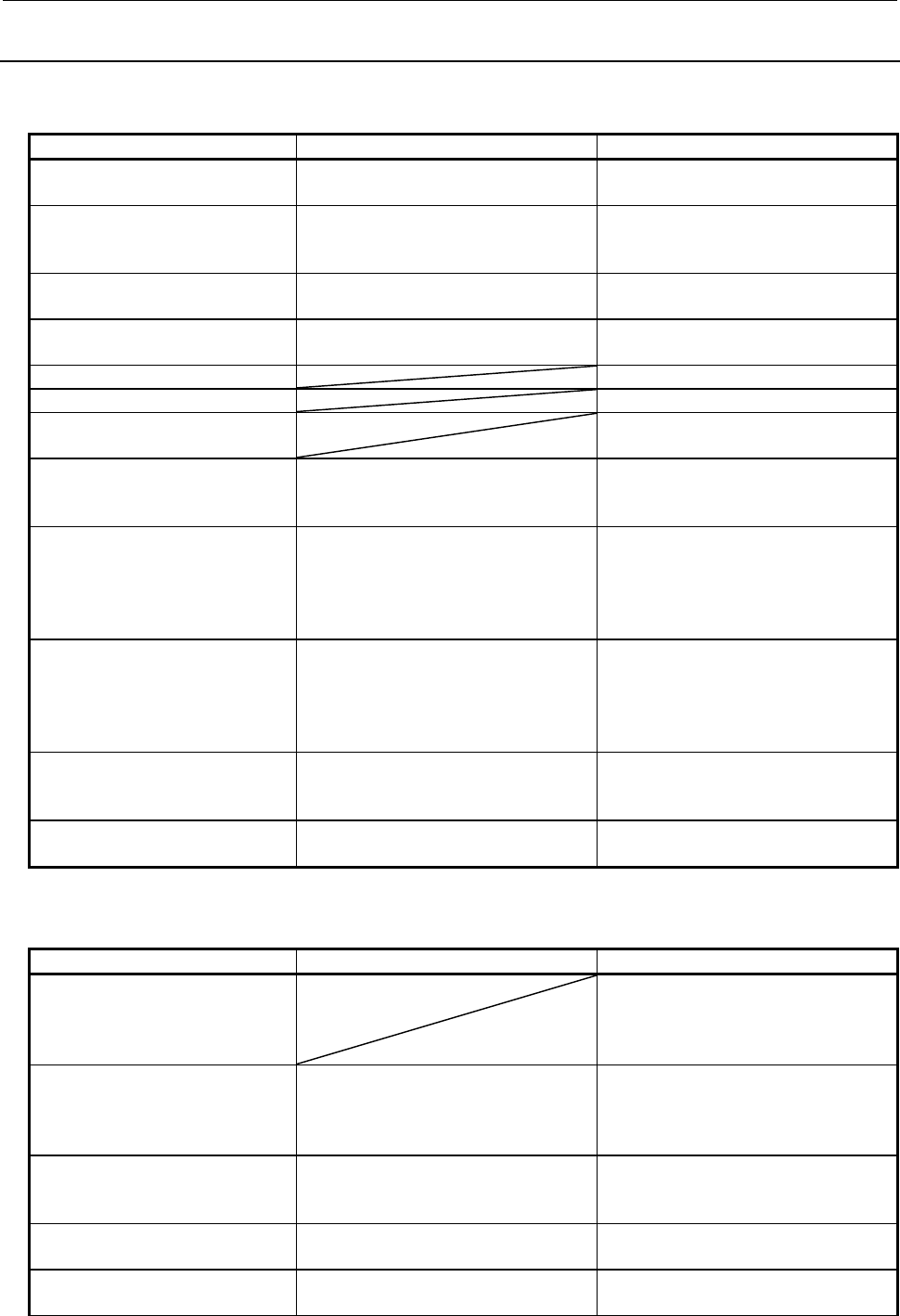
B-64513EN/03
12.PMC ALARM MESSAGES AND ACTIONS TO TAKE
- 1375 -
12.1.3
Operation Errors
Error messages that may be displayed on the PMC LADDER DIAGRAM
VIEWER screen
Message Faulty location/corrective action Contents
INPUT INVALID Input a valid address or numeric value. The input address or numeric value is
invalid.
LADDER PROGRAM IS
PROTECTED BY PASSWORD
Enter the password. The screen cannot be displayed
because the program is protected by
the password.
ILLEGAL SUBPROGRAM NAME Input a existent subprogram number or
symbol.
A nonexistent subprogram number or
symbol is specified.
SYMBOL UNDEFINED Input a defined symbol or bit address. An undefined symbol character string
is specified.
THE NET IS NOT FOUND The specified net is not found.
THE ADDRESS IS NOT FOUND The specified address is not found.
THE FUNCTIONAL
INSTRUCTION IS NOT FOUND
The specified functional instruction is
not found.
WRITE COIL NEEDS BIT
ADDRESS
Specify a bit address for the write coil
search.
You entered a byte address when
specifying an address used for the
write coil search.
SOME NETS ARE DISCARDED The system cannot pick up all the nets.
Choose the nets to pick up, by using
the LADDER DIAGRAM VIEWER
display screen, and then perform the
net pickup operation manually.
The system failed to pick up all the
nets because there were 128 nets or
more to be picked up.
PROGRAM IS BEING MODIFIED Disconnect the online communication
with FANUC LADDER-III. Stop other
applications from accessing the ladder
data.
The ladder data cannot be displayed
because online communication with
FANUC LADDER-III is in progress or
another application is accessing the
ladder data.
THIS FUNCTION IS
PROTECTED
Cancel the protection by the
programmer protection function or 8-
level protection function.
This function is protected by the
programmer protection function or 8-
level protection function.
CANNOT EDIT FUNCTION
BLOCK
Use FANUC LADDER-III to edit
function block.
You tried to edit the FB body program.
Error messages that may be displayed on the PMC LADDER DIAGRAM
EDITOR screen
Message Faulty location/corrective action Contents
THIS NET IS PROTECTED When you are editing data on a per-
subprogram basis, you cannot edit the
subprogram frame nets (END1, END2,
END3, SP, and SPE).
TOO LARGE DATA TO COPY Reduce the range of data to copy.
Perform the copy operation several
times, copying a smaller range of data
at a time.
The selected range of data exceeds
the size of the copy buffer.
TOO LARGE DATA TO PASTE Reduce the size of data to paste. An attempt was made to paste data
whose size exceeded the free space of
the sequence program.
BIT ADDRESS IS REQUIRED Make sure that the address types
match for the alteration operation.
An attempt was made to alter a bit
address to a byte address.
BYTE ADDRESS IS REQUIRED Make sure that the address types
match for the alteration operation.
An attempt was made to alter a byte
address to a bit address.

12.PMC ALARM MESSAGES AND ACTIONS TO TAKE
B-64513EN/03
- 1376 -
Message Faulty location/corrective action Contents
ILLEGAL PMC ADDRESS Check the address to be input, and
then enter it correctly.
• A character string was entered that
was unacceptable as a PMC
address.
• A wildcard (*) was specified in an
inappropriate manner.
• Either "OLD ADDRESS" or "NEW
ADDRESS" was not entered.
THIS ADDRESS IS READ-ONLY Enter a write-permitted address. • An attempt was made to alter a write
coil address to a write-prohibited bit
address.
• An attempt was made to alter an
address set in an output parameter
of a functional instruction to a write-
prohibited bit address.
THE ADDRESS TYPES ARE
MISMATCHED
Check the types of the address in
"OLD ADDRESS" and "NEW
ADDRESS" and, if necessary, enter
the correct address or addresses.
The type of the addresses in "OLD
ADDRESS" does not match that in
"NEW ADDRESS".
***** DOSE NOT HAVE SYMBOL Define symbol data in "OLD
ADDRESS".
No symbol data is defined for "OLD
ADDRESS".
***** ALREADY HAS SYMBOL Make sure that the address types
match for the alteration operation.
Symbol data is already defined for
"NEW ADDRESS".
CANNOT CUT FUNCTION
BLOCK
Use FANUC LADDER-III to edit
function block.
Cut nets which do not include any
function block.
You tried to cut the net including the
function block.
CANNOT COPY FUNCTION
BLOCK
Use FANUC LADDER-III to edit
function block.
Copy nets which do not include any
function block.
You tried to copy the net including the
function block.
CANNOT EDIT FUNCTION
BLOCK
Use FANUC LADDER-III to edit
function block.
You tried to edit the FB body program.
CANNOT INPUT AT THIS
SCREEN
Use NET EDITOR screen. You tried to set an address in the
output section that is omitted in the
function block.
CANNOT EDIT INPUT/OUTPUT
PARAM ADDRESS
An address in the input section of an
input/output parameter in the function
block cannot be changed.
NO CONSTANT TO
PARAMETER OF PLURAL TYPE
When the input parameter of the
function block is plural data type, any
constant cannot be set.
Error messages that may be displayed on the PMC LADDER DIAGRAM
EDITOR screen (when updating)
Message Faulty location/corrective action Contents
OVERLAPPED COM If COME is missing, add it in proper
position. If the COM is unnecessary,
remove it.
There is no COME that corresponds to
this COM.
END IN COM
END1 IN COM
END2 IN COM
END3 IN COM
If COME is missing, add it in proper
position. If COM is unnecessary, remove
it.
END,END1,END2, or END3 is found
between COM and COME.

B-64513EN/03
12.PMC ALARM MESSAGES AND ACTIONS TO TAKE
- 1377 -
Message Faulty location/corrective action Contents
JMPE IN COM JMPE and corresponding JMP must
have same COM/COME status. Review
JMP range and COM range, to adjust not
to overlap with each other: it is possible
that one range includes the other
completely.
JMPE is found between COM and
COME, and JMP and corresponding
JMPE have different COM/COME
status.
SP/SPE IN COM If COME is missing, add it in proper
position. If the COM is unnecessary,
remove it.
SP or SPE is found between COM and
COME.
COME WITHOUT COM If COM is missing, add it in proper
position. If the COME is unnecessary,
remove it.
There is no COM that corresponds to
this COME.
COME NOT FOUND AFTER
COM
If COME is missing, add it in proper
position. If the COM is unnecessary,
remove it.
There is no COME that corresponds to
this COM.
DUPLICATE CTR NUMBER
(WARN)
If some of them are unnecessary,
remove them. If all of them are
necessary, assign other number to
parameter of them to make them unique.
(If two or more instructions with same
parameter number will never be active
simultaneously at one time, the Ladder
program has a possibility to work
correctly, however, it is recommended
from safety and maintenance points of
view, that all these instructions should
have different parameter number with
each other.)
Plural CTRs have the same number as
their parameter. (This is warning.)
ILLEGAL CTR NUMBER If unnecessary, remove it. Assign correct
number not to exceed the maximum
number defined by each PMC model.
CTR has parameter number that is out
of range.
DUPLICATE DIFU/DIFD
NUMBER
(WARN)
If some of them are unnecessary,
remove them. If all of them are
necessary, assign other number to
parameter of them to make them unique.
(If two or more instructions with same
parameter number will never be active
simultaneously at one time, the Ladder
program has a possibility to work
correctly, however, it is recommended
from safety and maintenance points of
view, that all these instructions should
have different parameter number with
each other.)
Plural DIFUs or DIFDs have the same
number as their parameter. (This is
warning.)
ILLEGAL DIFU/DIFD NUMBER If unnecessary, remove it. Assign correct
number not to exceed the maximum
number defined by each PMC model.
DIFU or DIFD has parameter number
that is out of range.
NO END1
NO END2
NO END3
Add END1, END2 or END3 in proper
position.
END1, END2 or END3 is not found.
DUPLICATE END1
DUPLICATE END2
DUPLICATE END3
Remove extra END1, END2 or END3. Multiple END1, END2 or END3 are
found.
GARBAGE AFTER END
GARBAGE AFTER END2
GARBAGE AFTER END3
Remove unnecessary nets, and move
necessary nets to proper position so that
they will be executed.
There are some nets after END, END2
or END3, which will not be executed.

12.PMC ALARM MESSAGES AND ACTIONS TO TAKE
B-64513EN/03
- 1378 -
Message Faulty location/corrective action Contents
OVERLAPPED JMP If JMPE is missing, add it in proper
position. If the JMP is unnecessary,
remove it.
There is no JMPE that corresponds to
this JMP.
JMP/JMPE TO BAD COM
LEVEL
JMP and corresponding JMPE must
have same COM/COME status. Review
JMP range and COM range, to adjust not
to overlap with each other: it is possible
that one range includes the other
completely.
JMP and corresponding JMPE have
different COM/COME status.
COME IN JMP COME and corresponding COM must
have same JMP/JMPE status. Review
COM range and JMP range, to adjust not
to overlap with each other: it is possible
that one range includes the other
completely.
COME is found between JMP and
JMPE, and COM and corresponding
COME have different JMP/JMPE
status.
END IN JMP
END1 IN JMP
END2 IN JMP
END3 IN JMP
If JMPE is missing, add it in proper
position. If JMP is unnecessary, remove
it.
END,END1,END2, or END3 is found
between JMP and JMPE.
SP/SPE IN JMP If JMPE is missing, add it in proper
position. If the JMP is unnecessary,
remove it.
SP or SPE is found between JMP and
JMPE.
JMPB OVER COM BORDER JMPB and its destination must have
same COM/COME status. Review range
of JMPB and COM range, to adjust not to
overlap with each other: it is possible that
one range includes the other completely.
JMPB and its destination differ in
COM/COME status.
JMPB OVER LEVEL JMPB can only jump to the same
program level, or within a subprogram. If
the JMPB is unnecessary, remove it. If
LBL for the JMPB is missing, add it in
proper position. If it should be JMPC,
correct it.
JMPB jumps to different program level.
LBL FOR JMPB NOT FOUND If JMPB is unnecessary, remove it. If LBL
is missing, add it in proper position.
Can not find proper LBL for JMPB.
JMPC IN BAD LEVEL JMPC is used to jump from a
subprogram to level 2. If the JMPC is
unnecessary, remove it. If it should be
JMPB or JMP, correct it.
JMPC is used in other than
subprogram.
LBL FOR JMPC NOT FOUND If JMPC is unnecessary, remove it. If LBL
is missing, add it in proper position:
JMPC jumps into level 2.
Can not find proper LBL for JMPC.
LBL FOR JMPC IN BAD LEVEL JMPC is used to jump from a
subprogram to level 2. If the JMPC is
unnecessary, remove it. If another LBL of
same L-address that the JMPC is
intended to jump exists in the
subprogram, assign different L-address
to these two LBLs. If it should be JMPB
or JMP, correct it.
Destination of JMPC is not level 2.
JMPC INTO COM LBL for JMPC must be located out of any
COM and COME pair. If the JMPC is
unnecessary, remove it. If the LBL is
located wrong, move it to correct
position. If the L-address of JMPC is
wrong, correct it.
JMPC jumps to LBL between COM
and COME.

B-64513EN/03
12.PMC ALARM MESSAGES AND ACTIONS TO TAKE
- 1379 -
Message Faulty location/corrective action Contents
JMPE WITHOUT JMP If JMP is missing, add it in proper
position. If the JMPE is unnecessary,
remove it.
There is no JMP that corresponds to
this JMPE.
JMPE NOT FOUND AFTER
JMP
If JMPE is missing, add it in proper
position. If the JMP is unnecessary,
remove it.
There is no JMPE that corresponds to
this JMP.
TOO MANY LBL Remove unnecessary LBLs. If this error
still occurs, adjust the construction of
program to use less LBLs.
There are too many LBLs.
DUPLICATE LBL If some of these LBLs are unnecessary,
remove them. If all of these LBLs is
necessary, assign other L-addresses to
them to make all LBLs unique.
Same L-address is used in plural
LBLs.
OVERLAPPED SP If SPE is missing, add it in proper
position. If the SP is unnecessary,
remove it.
There is no SPE that corresponds to
this SP.
SPE WITHOUT SP If SP is missing, add it in proper position.
If the SPE is unnecessary, remove it.
There is no SP that corresponds to this
SPE.
SPE NOT FOUND AFTER SP If SPE is missing, add it in proper
position. If the SP is unnecessary,
remove it.
There is no SPE that corresponds to
this SP.
END IN SP If SPE is missing, add it in proper
position. If END is in wrong place, move
it to proper position.
END is found between SP and SPE.
DUPLICATE P ADDRESS If some of these SPs are unnecessary,
remove them. If all of these SPs is
necessary, assign other P-addresses to
them to make all SPs unique.
Same P-address is used in plural SPs.
DUPLICATE TMRB/TMRBF
NUMBER
(WARN)
If some of them are unnecessary,
remove them. If all of them are
necessary, assign other number to
parameter of them to make them unique.
(If two or more instructions with same
parameter number will never be active
simultaneously at one time, the Ladder
program has a possibility to work
correctly, however, it is recommended
from safety and maintenance points of
view, that all these instructions should
have different parameter number with
each other.)
Plural TMRBs/TMRBFs have the same
number as their parameter. (This is
warning.)
ILLEGAL TMRB/TMRBF
NUMBER
If unnecessary, remove it. Assign correct
number not to exceed the maximum
number defined by each PMC model.
TMRB/TMRBF has parameter number
that is out of range.

12.PMC ALARM MESSAGES AND ACTIONS TO TAKE
B-64513EN/03
- 1380 -
Message Faulty location/corrective action Contents
DUPLICATE TMR NUMBER
(WARN)
If some of them are unnecessary,
remove them. If all of them are
necessary, assign other number to
parameter of them to make them unique.
(If two or more instructions with same
parameter number will never be active
simultaneously at one time, the Ladder
program has a possibility to work
correctly, however, it is recommended
from safety and maintenance points of
view, that all these instructions should
have different parameter number with
each other.)
Plural TMRs have the same number
as their parameter. (This is warning.)
ILLEGAL TMR NUMBER If unnecessary, remove it. Assign correct
number not to exceed the maximum
number defined by each PMC model.
TMR has parameter number that is out
of range.
NO SUCH SUBPROGRAM If it calls wrong subprogram, correct it. If
the subprogram is missing, create it.
Subprogram that is called by
CALL/CALLU is not found.
UNAVAILABLE INSTRUCTION Confirm that this ladder program is
correct one. If this program is correct
one, all these unsupported instructions
have to be removed.
Unsupported instruction for this PMC
model is found.
SP IN BAD LEVEL SP can be used at top of a subprogram.
Correct it so that no SP exists in other
place.
SP is found in wrong place.
LADDER PROGRAM IS
BROKEN
This ladder program must be all cleared
once, and remake ladder program.
Ladder program may be broken by
some reason.
NO WRITE COIL Add proper write coil. Write coil is necessary, but is not
found.
CALL/CALLU IN BAD LEVEL CALL/CALLU must be used in Level 2 or
in subprograms. Do not use any other
places.
CALL/CALLU is used in wrong place.
SP IN LEVEL3 If END3 is located wrong, move it to
correct position. If the SP is
unnecessary, remove it.
SP is found in level 3.
CS/CM/CE IN COM If COME is missing, add it in proper
position. If the COM is unnecessary,
remove it.
CS,CM or CE is found between COM
and COME.
CS/CM/CE IN BAD LEVEL CS, CM or CE must be used in Level 2 or
in subprograms. Do not use any other
places.
CS,CM, or CE is used in wrong place.
CM/CE WITHOUT CS If CS is missing, add it in proper position.
If the CM or CE is unnecessary, remove
it.
There is no CS that corresponds to
this CM or CE.
INSTRUCTION EXCEPT CM IN
CS
If CE is missing, add it in proper position.
If the instruction other than CM is
unnecessary, remove it.
Instruction except CM is found
between CS and CE.
OVERLAPPED CS If CE is missing, add it in proper position.
If the CS is unnecessary, remove it.
There is no CE that corresponds to
this CS.
New ladder needs reboot to run
(PT/NT)
To execute the program, once stop it and
save it to flash ROM. Then, reboot the
CNC.
If you want to enable the added
positive / negative transition (PT/NT)
instruction, it is necessary to reboot
the CNC.
FB BODY PROGRAM IS
BLOKEN
The ladder program must be deleted and
remake it.
FB body program is broken.

B-64513EN/03
12.PMC ALARM MESSAGES AND ACTIONS TO TAKE
- 1381 -
Error messages that may be displayed on the PMC NET EDITOR screen
Message Faulty location/corrective action Contents
ILLEGAL FUNCTIONAL
INSTRUCTION NAME
Specify the name of an available
functional instruction.
The entered name of functional
instruction is invalid.
TOO MANY FUNCTION IN ONE
NET
Only one functional instruction is
allowed to constitute a net. If
necessary, divide the net into plural
nets.
Too many functional instructions are in
one net.
TOO LARGE NET Divide the net into plural nets so that
step number in a net may become
small.
Net is too large. When a net is
converted into the object, the net
exceeds 256 steps.
NO INPUT FOR OPERATION Coil without input, or coil connected to
output of functional instruction that has
no output, causes this error. If coil is
not necessary, remove it. If necessary,
connect it to meaningful input.
No signal is provided for logical
operation.
OPERATION AFTER FUNCTION
IS FORBIDDEN
Output of functional instruction can not
be connected to a contact, nor to
conjunction with other signal that will
be implemented by logical-or
operation.
No logical operation with functional
instruction output is permitted, except
write coils.
WRITE COIL IS EXPECTED Write coil is not found even if it is
expected. Add proper write coil to the
net.
Write coil is expected, but not found.
BAD COIL LOCATION Coil can be located only at rightmost
column. Any coil located at other place
must be erased once, and place
necessary coils in correct place.
Coil is located in bad position.
SHORT CIRCUIT Find contact with terminals connected
by short circuit, and correct
connections.
Some contacts are connected with
short circuit. CTR has a parameter
number that is out of the range.
FUNCTION AFTER
DIVERGENCE IS FORBIDDEN
Functional instruction can not be used
in output section of net. If necessary,
divide the net into plural nets.
Functional instruction is used in output
section of net.
ALL COIL MUST HAVE SAME
INPUT
Left terminals of all coils in a net must
be connected to same input point.
When a net contains more than one
coil, the coils should not have any
contact beside them affects only of the
coils.
BAD CONDITION INPUT Check the connection of all condition
inputs of the functional instruction.
Especially for functional instruction that
has more than one condition input,
check if connections to condition
inputs interfere with each other.
Some condition input of functional
instruction is not connected correctly.
NET IS TOO COMPLICATED Examine every connection, and find
unnecessarily bending connection, or
coils that are connected to different
point.
Net is too complicated to analyze.
PARAMETER IS NOT SUPPLIED Enter all of the relay addresses, and
parameters of functional instructions.
Relay with blank address, or blank
parameter of functional instruction, is
found.
TOO LARGE DATA FOR NET-
EDITOR
Change for being to modify net by
[NEXT NET] soft key.
The net data in net editor screen is too
large.
TOO MANY FUNCTIONS FOR
NET-EDITOR
Change for being to modify net by
[NEXT NET] soft key.
There are too many functional
instructions in net editor screen.

12.PMC ALARM MESSAGES AND ACTIONS TO TAKE
B-64513EN/03
- 1382 -
Message Faulty location/corrective action Contents
BAD DIAGRAM STRUCTURE Examine every connection, and find
the error of connection of relay or
functional instruction.
Circuit is too complicated to analyze.
NOT SUPPORT ENHANCED
LADDER DIAGRAM
Replace other functional instruction
which supports Structure of extended
type net.
Or, change the ladder net construction
not to be Structure of extended type
net.
The ladder net Structure of extended
type net contains a functional
instruction which does not support
Structure of extended type net.
TOO COMPLICATED CIRCUIT
AROUND FUNCTION
The circuit lines branched from a
conditional input for some functional
instruction must reach the right power
line without joining the output line from
the functional instruction.
Refer to 8.3.4.3.
The circuit construction around
functional
instruction is too complicated.
CONNECT OUTPUT TO COIL
DIRECTLY
Connect the output of the functional
instruction directly to a coil.
The output of the functional instruction
is not
connected directly to a coil.
SINGLE COIL IS EXPECTED This functional instruction must have
single coil directly connected to the
output.
A functional instruction has multiple
coils
connected to its output which are
prohibited.
INVALID CIRCUIT FOR FB
PARAMETER
Specify the name of contact and coil
for the parameter of function block.
The functional instruction is connected
to the parameter of function block.
NO CONNECTION Connect the broken connection. The connection is broken.
PARAMETER IS NOT SUPPLIED Specify an address. The address is not assigned to the
input section and the coil of output
section of a function block.
CAN NOT PLACE FB AND
FUNCTION IN ONE NET
Delete the functional instruction placed
on the same net as the function block.
A functional instruction is placed on
the same net as the function block.
NO ASSIGNMENT TO FB
CONTACT
Specify a contact. The contact is not assigned in the
input section for a BOOL type of the
function block.
Error messages that may be displayed on the TITLE DATA EDITOR screen
Message Faulty location/corrective action Contents
TOO MANY
CHARACTERS
Make sure that the entered character string
is within the allowable input length.
The number of characters in the entered
character string exceeds the allowable
input length. Some of the characters are
discarded.
PROGRAM IS BEING
MODIFIED
Disconnect the online communication with
FANUC LADDER-III. Stop other
applications from accessing the title data.
The title data cannot be displayed
because online communication with
FANUC LADDER-III is in progress or
another application is accessing the title
data.
THIS FUNCTION IS
PROTECTED
Cancel the protection by the programmer
protection function or 8-level protection
function.
This function is protected by the
programmer protection function or 8-level
protection function.

B-64513EN/03
12.PMC ALARM MESSAGES AND ACTIONS TO TAKE
- 1383 -
Error messages that may be displayed on the SYMBOL & COMMENT DATA
EDITOR screen
Message Faulty location/corrective action Contents
TOO MANY
CHARACTERS
Make sure that the entered address is
within the allowable input length.
The number of characters in the entered
address exceeds the allowable address
input length.
ADDRESS IS REQUIRED Enter data in a batch correctly, as instructed
in "Editing a set of symbol and comment
data" in Subsection 9.2.2.
No address was entered during the batch
input of address, symbol, and comment
data using the SYMBOL & COMMENT
EDITOR screen.
ILLEGAL PMC ADDRESS Enter an address correctly. The specified address is invalid, or the
entered address character string contains
a space or spaces.
THE ADDRESS
ALREADY HAS AN
ENTRY
Specify another address. An already registered address was
entered.
THE SYMBOL NAME IS
ALREADY USED
Specify another symbol. An already registered symbol was
entered.
PMC ADDRESS MUST
BE ENTERED
Enter a PMC address in the ADDRESS
field.
No PMC address was entered when new
symbol/comment data is registered.
TOO LONG COMMENT
STRING
Make sure that the comment consists of 30
characters or less.
The entered comment exceeds the
specified number of characters.
THE STRING IS NOT
FOUND
Specify another character string for the
search.
The search was done for the specified
character string but did not find it.
OUT OF SPACE Create free space for the sequence
program, by deleting unnecessary ladder or
message data.
The symbol/comment editing area has no
free space.
PROGRAM IS BEING
MODIFIED
Disconnect the online communication with
FANUC LADDER-III. Stop other
applications from accessing the
symbol/comment data.
The symbol/comment data cannot be
displayed because online communication
with FANUC LADDER-III is in progress or
another application is accessing the
symbol/comment data.
THIS FUNCTION IS
PROTECTED
Cancel the protection by the programmer
protection function or 8-level protection
function.
This function is protected by the
programmer protection function or 8-level
protection function.
BAD SYMBOL NAME Change the symbol name. The symbol name is invalid.
CANNOT EDIT
ADDRESS AUTO
ASSIGNED SYMBOL
Use FANUC LADDER-III to change the
symbol.
The symbol whose PMC address is
assigned automatically by compiling
FANUC LADDER-III, can not edit.
ILLEGAL DATA TYPE Enter a correct data type. The specified data type is invalid.
ILLEGAL PROGRAM
NAME
Enter a correct program name. The specified program is invalid.
LINE FEED IS NOT
AVAILABLE IN THIS
DATA
Line feed code can be entered in comment
data only. Do not enter it in other data.
Line feed code cannot be entered in this
data.
LINE FEED IS NOT
AVAILABLE IN THIS
MODE
Enter Line feed code in the insert or
overwrite mode.
Line feed code cannot be entered in this
mode.
NO SYMBOL. PROGRAM
SETTING IS IGNORED
Symbol name is required for local symbol. The specified program is ignored because
no symbol is specified.
NOTHING TO PASTE You need to copy or cut character strings
before you paste them.
You try to paste character strings without
copying or cutting ones.
TOO LARGE DATA TO
PASTE Shorten the character string to copy or cut. The character strings is too long to copy
or cut.
UNAVAILABLE
CHARACTERS WAS
OMITTED.
Do not copy or cut characters which cannot
be used at pasted position.
The characters which can not be used at
pasted position, were omitted.

12.PMC ALARM MESSAGES AND ACTIONS TO TAKE
B-64513EN/03
- 1384 -
Error messages that may be displayed on the MESSAGE DATA EDITOR
screen
Message Faulty location/corrective action Contents
INPUT INVALID Correct the message number.
Enter ";" in the 5th digit position in the
batch message input process.
The format of the message number is
invalid, or the delimiter code -
semicolon (;) - was not entered in the
batch message input process.
ILLEGAL NUMBER Enter a four-digit number as the
message number.
The entered message number
contains any nonnumeric character, or
a number shorter than four digits was
entered.
THE NUMBER IS OUT OF
RANGE
Enter the number in the range from 0
to 4095 for the message number of the
format with path number, and 1000 to
9999 for the message number of other
format.
The entered message number is out of
range.
CLOSING "@" IS NOT FOUND When entering kana or other Japanese
characters, make sure that they are
enclosed within a pair of @ signs.
One of the @ sign pair is missing.
BAD NUMBER OF
CHARACTERS IN "@-@"
Enter a character string correctly
between a pair of @ signs.
The number of characters entered
between the pair of @ signs is not
even.
ILLEGAL CHARACTER IN "@-@" Enter a character string correctly
between a pair of @ signs.
One or more invalid character codes
exist between the pair of @ signs.
BAD NUMBER OF
CHARACTERS FOR 2-BYTE
CODE
Enter a two-byte code correctly
between @02 and 01@.
The number of characters in the two-
byte code (characters entered
between @02 and 01@) is not a
multiple of four.
ILLEGAL 2-BYTE CODE Enter a two-byte code correctly
between @02 and 01@.
The two-byte code (characters entered
between @02 and 01@) contains one
or more characters other than the JIS
codes.
CLOSING CONTROL CODE "01"
IS NOT FOUND
Enter the closing control code. The two-byte code (characters entered
between @02 and 01@) lacks the
closing control code (01).
CONTROL CODE "XX" IS
REPEATED
Remove any repeated control code. The starting control code (02), closing
control code (01), and/or umlaut code
(0D) is repeated.
CLOSING "]" IS NOT FOUND Make sure that the "[" and "]" codes
are entered in pairs.
The delimiter codes for numerical data
are not entered in pairs.
BAD NUMERICAL DATA
FORMAT
Specify the numerical data correctly. The format of the numerical data is
invalid.
BAD PMC ADDRESS FOR
NUMERIAL DATA
Enter an available address. The address section of the numerical
data is invalid.
PROGRAM IS BEING MODIFIED Disconnect the online communication
with FANUC LADDER-III. Stop other
applications from accessing the
message data.
The message data cannot be
displayed because online
communication with FANUC LADDER-
III is in progress or another application
is accessing the message data.
THIS FUNCTION IS
PROTECTED
Cancel the protection by the
programmer protection function or 8-
level protection function.
This function is protected by the
programmer protection function or 8-
level protection function.

B-64513EN/03
12.PMC ALARM MESSAGES AND ACTIONS TO TAKE
- 1385 -
Error messages that may be displayed on the I/O MODULE EDITOR screen
Message Faulty location/corrective action Contents
GROUP NUMBER IS TOO
LARGE
Specify 15 or a smaller value as the
group number.
The entered group number is too
large.
BASE NUMBER IS TOO LARGE Specify base number 0 for I/O Unit-B
(##, #1 - #10).
The entered base number is too
large.
SLOT NUMBER IS TOO LARGE Specify 30 or a smaller value as the slot
number for I/O Unit-B (##, #1 - #10).
For other I/O units, specify 10 or a
smaller value.
The entered slot number is too large.
SLOT NUMBER IS TOO SMALL Specify 0 or a large value as the slot
number for I/O Unit-B (##, #1 - #10).
For other I/O units, specify 1 or a larger
value.
The entered slot number is too small.
I/O UNIT NAME MISMATCH Check the I/O unit name or address. The input I/O unit is assigned to the
Y address, or the output I/O unit is
assigned to the X address.
ILLEGAL I/O UNIT NAME Enter an I/O unit that is listed in Tables
3.2 (a) to 3.2 (c) in Chapter 3.
The entered I/O unit name is invalid.
NOT ENOUGH SPACE Enter the data again after creating free
space by deleting the data allocated
behind the current cursor position or by
other adequate means.
There is not enough free address
space for the size of the I/O unit you
are going to assign.
This error also occurs if you attempt
to assign the I/O unit to an already
allocated address space.
PROGRAM IS BEING MODIFIED Disconnect the online communication
with FANUC LADDER-III. Stop other
applications from accessing the I/O
module data.
The I/O module data cannot be
displayed because online
communication with FANUC
LADDER-III is in progress or another
application is accessing the I/O
module data.
THIS FUNCTION IS
PROTECTED
Cancel the protection by the
programmer protection function or 8-
level protection function.
This function is protected by the
programmer protection function or 8-
level protection function.
Error messages that may be displayed on the I/O CONFIGURATION EDITOR
screen
Message Faulty location/corrective action Contents
TOO MANY GROUPS (CHx) Delete any unnecessary group, then
create a new group.
A new group cannot be created
because the maximum number of
groups per channel is exceeded.
TOO MANY SLOTS (CHx) Delete any unnecessary slot, then
create a new slot.
A new slot cannot be created
because the maximum number of
slots per channel (256 slots) is
exceeded.
TOO MANY SLOTS IN A GROUP
(CHx, Gyy)
Delete any unnecessary slot, then
create a new slot.
A new slot cannot be created
because the maximum number of
slots per channel (32 slots) is
exceeded.
NO SLOT(Gxx) Add a slot. There is no slot in group Gxx.
SLOT NUMBER IS REQUIRED Enter a slot number. No slot number is entered for a slot.
SLOT NUMBER DUPLICATE Change the slot number used more
than once.
More than one slot data item having
the same slot number is found in the
same group.
CAN NOT DELETE MPG SLOT Turn the MPG flag off in the group
setting screen.
No MPG slot can be deleted in the
slot setting screen.

12.PMC ALARM MESSAGES AND ACTIONS TO TAKE
B-64513EN/03
- 1386 -
Message Faulty location/corrective action Contents
ILLEGAL SLOT NUMBER Enter a slot number not greater than
32.
The entered slot number is greater
than 32.
ILLEGAL PMC ADDRESS Enter a correct PMC address again. The entered PMC address is invalid.
Alternatively, no PMC address is
entered.
ILLEGAL SIZE Enter a correct size again. The entered size is outside the PMC
address range.
Alternatively, a value of 0 is entered
as the size.
SLOT HAS NO ASSIGNMENT Enter a PMC address and size. For a slot, a PMC address or size is
not entered for both DI and DO.
ILLEGAL COMMENT Enter a correct comment again. An entered comment does not
conform to the extended symbol and
comment format.
PMC ADDRESS OVERLAPPED
(PMCm X(Y)nnnn)
Enter the PMC address or size so
that it is set only once.
Address PMCm X(Y)nnnn is also
assigned to another slot in I/O Link i
assignment data.
TOO MANY OUTPUT POINTS (CHx,
Gyy)
Reduce the number of output points
of the group.
The number of output points of the
I/O Link i group set for Gyy of CHx
exceeds the upper limit (65 bytes by
default or 29 bytes for the safety I/O
device).
TOO MANY INPUT POINTS (CHx,
Gyy)
Reduce the number of input points
of the group.
The number of input points of the
I/O Link i group set for Gyy of CHx
exceeds the upper limit (65 bytes by
default or 29 bytes for the safety I/O
device).
TOO MANY OUTPUT POINTS (CHx) Reduce the number of output points
in the channel.
Warning message. The number of
I/O Link i output points set in CHx
exceeds the upper limit.
TOO MANY INPUT POINTS (CHx) Reduce the number of input points
in the channel.
Warning message. The number of
I/O Link i input points set in CHx
exceeds the upper limit.
TOO MANY CHARACTERS Enter a comment within the input
field.
The number of characters in an
entered comment exceeds the input
width.
THE ADDRESS IS NOT FOUND The specified address is not found.
INPUT INVALID Enter a correct numeric value. A numeric value is invalid.
I/O CONFIG DATA IS BROKEN Enter an I/O configuration file again. I/O Link i assignment data is invalid.
TOO MANY SAFETY I/O GROUPS Reduce the number of I/O Link i
safety I/O groups.
Warning message. More than four
I/O Link i safety I/O groups are
specified either on the PMC or DCS
side in the entire system.
TOO MANY ASSIGNMENTS
(H.SPEED)(CHn,Gyy)
When a group in the high-speed
transfer cycle mode is connected to
I/O Link i, correct assignment so
that the assignment for each group
is performed within the quartered
transfer timing with referencing
Subsection 3.6.4 “Transfer Cycle”.
Warning message. In CHn, group yy
and following exceed the transfer
capacity limit in transfer timing
assignment processing when the
high-speed mode of I/O Link i is
used.
BASIC GROUP INVALID Correct the number of basic groups
for the I/O assignment selection
function of I/O Link i.(0 to 24)
The number of basic groups for the
I/O assignment selection function of
I/O Link i is invalid.

B-64513EN/03
12.PMC ALARM MESSAGES AND ACTIONS TO TAKE
- 1387 -
Message Faulty location/corrective action Contents
UNAVAILABLE ADDRESS FOR
DCSPMC
Use addresses X0/Y0 and following. Addresses X200/Y200, X400/Y400,
or X600/Y600 and following are
assigned to a group for which
DCSPMC is specified for the PMC
path.
THIS DATA IS BEING MODIFIED Disconnect the online
communication with FANUC
LADDER-III. Stop other applications
from accessing the I/O configuration
data.
I/O configuration data cannot be
displayed because online
communication with FANUC
LADDER-III is in progress or
another application is accessing the
I/O configuration data.
INTERNAL ERROR(0xCxxxxxxx) Contact us, and report the displayed
message correctly.
This error occurs due to an internal
factor. An error code is indicated in
parentheses.
Error messages that may be displayed on the SYSTEM PARAMETER screen
Message Faulty location/corrective action Contents
INPUT INVALID Enter a numerical value correctly, as
instructed in Section 9.8.
The entered numerical value or its
input format is invalid.
SYMBOL UNDEFINED Enter a defined symbol or bit address. An undefined symbol character string
was entered.
PROGRAM IS BEING MODIFIED Disconnect the online communication
with FANUC LADDER-III. Stop other
applications from accessing the
system parameter data.
The system parameter data cannot be
displayed because online
communication with FANUC LADDER-
III is in progress or another application
is accessing the system parameter
data.
THIS FUNCTION IS
PROTECTED
Cancel the protection by the
programmer protection function or 8-
level protection function.
This function is protected by the
programmer protection function or 8-
level protection function.
Error messages that may be displayed on the SIGNAL STATUS screen
Message Faulty location/corrective action Contents
INPUT INVALID Enter a numerical value correctly, as
instructed in "Screen operations using
other keys" in Subsection 7.1.2.
The entered numerical value or its
input format is invalid.
SYMBOL UNDEFINED Enter a defined symbol or bit address. An undefined symbol character string
was entered.
THIS FUNCTION IS
PROTECTED
Cancel the protection by the
programmer protection function or 8-
level protection function.
This function is protected by the
programmer protection function or 8-
level protection function.
Error messages that may be displayed on the PMC PARAM screen
Message Faulty location/corrective action Contents
INPUT INVALID Enter a numerical value correctly, as
instructed in Section 7.3.
The entered numerical value or its
input format is invalid.
MUST BE IN EMERGENCY
STOP OR IN MDI MODE
Set a mode to MDI or emergency stop. The status of NC is not MDI mode or
emergency stop.
PWE MUST BE ON Set the “PWE” to ”1” in NC setting
screen.
The “PWE” in NC setting screen is ”0”.
EITHER PWE OR KEY4 MUST
BE ON
Set the “PWE” to ”1” in NC setting
screen or set the key “KEY4” to “1”.
The “PWE” in NC setting screen is ”0”
or the program protect key “KEY4”
is ”0”.

12.PMC ALARM MESSAGES AND ACTIONS TO TAKE
B-64513EN/03
- 1388 -
Message Faulty location/corrective action Contents
THIS FUNCTION IS
PROTECTED
Cancel the protection by the
programmer protection function or 8-
level protection function.
This function is protected by the
programmer protection function or 8-
level protection function.
Error messages that may be displayed on the SIGNAL TRACE screen
Message Faulty location/corrective action Contents
TRACE FUNCTION IS ALREADY
IN USE
Wait until FANUC LADDER-III or some
other application finishes using the
trace function before executing it.
FANUC LADDER-III or some other
application is currently using the trace
function.
NO SAMPLING ADDRESS Specify a bit address as a sampling
address in the trace parameter.
No sampling address is specified in
the trace parameter.
NO STOP TRIGGER ADDRESS Specify a bit address as the stop
trigger address in the trace parameter.
The stop trigger address is not
specified in the trace parameter.
NO SAMPLING TRIGGER
ADDRESS
Specify a bit address as the sampling
trigger address in the trace parameter.
The sampling trigger address is not
specified in the trace parameter.
USB MEMORY IS USED BY
OTHER FUNCTION.
Terminate another function that is
using the USB memory, then perform
operation again.
The USB memory is being used by
another function.
USB MEMORY IS NOT READY. Check whether a USB memory is
inserted.
No USB memory is inserted.
USB MEMORY IS FULL. Delete any unnecessary files and
allocate a required capacity.
The USB memory is full.
USB MEMORY HAS BEEN
REMOVED
Insert the USB memory, then execute
input/output operation again.
A USB memory is removed while it is
being accessed.
USB MEMORY IS NOT
FORMATTED
Replace the USB memory with another
one.
The inserted USB memory cannot be
recognized.
USB HARDWARE ERROR
(xxxxxxxxxx)
Replace the USB memory with another
one. If this error still occurs after
replacement, contact us, and report
the displayed message correctly.
This error occurs due to a USB
hardware failure. An error code is
indicated in parentheses.
INTERNAL ERROR (xxxxxxxxxx) Contact us, and report the displayed
message correctly.
This error occurs due to an internal
factor. An error code is indicated in
parentheses.
Error messages that may be displayed on the trace setting screen
Message Faulty location/corrective action Contents
INPUT INVALID Enter a numerical value that is within
the specified data range of the relevant
trace parameter.
A nonnumeric value or an out-of-range
parameter value was entered.
SYMBOL UNDEFINED Enter a defined symbol or bit address. An undefined symbol character string
was entered.
BIT ADDRESS IS REQUIRED Specify a bit address as the stop or
sampling trigger address.
A byte address was specified as the
stop or sampling trigger address.
INVALID STOP TRIGGER
ADDRESS
Enter a PMC signal address that can
be used as the stop trigger address.
The bit address entered as the stop
trigger address is invalid.
INVALID SAMPLING TRIGGER
ADDRESS
Enter a PMC signal address that can
be used as the sampling trigger
address.
The bit address entered as the
sampling trigger address is invalid.
UNSUPPORTED TRACE
SETTING FILE
This file cannot be handled. Set data in
the TRACE SETING screen.
Unsupported trace setting file was
read.
INVALID SETTING VALUE (LINE
n)
Output the trance setting file again.
Alternatively, set data in the TRACE
SETING screen.
An invalid setting was found.
The file may be broken.

B-64513EN/03
12.PMC ALARM MESSAGES AND ACTIONS TO TAKE
- 1389 -
Message Faulty location/corrective action Contents
SAMPLING TIME/FRAME WAS
ADJUSTED
Check the data on the TRACE
SETING screen.
The values were adjusted according to
the read data. (This is warning.)
UNKNOWN SETTING WAS
SKIPPED(LINE n)
Check the read trace data. An unknown trace setting item was
found and ignored. (This is warning.)
INVALID SAMPLING ADDRESS
WAS FOUND
Check the read trace data. An invalid sampling address was
found. (This is warning.)
TOO MANY SAMPLING
ADDRESSES
Check the read trace data. The number of sampling addresses
exceeds the upper limit. (This is
warning.)
THE FILE IS NOT TRACE
SETTING FILE
This file cannot be read. Specify a
correct file.
An attempt was made to read a file
which was not a trace setting file.
FILE NAME CONTAINS
RESERVED WORD.
Correct file name. “FORFANUC” cannot be used in the
top of the file name.
USB MEMORY IS USED BY
OTHER FUNCTION.
Terminate another function that is
using the USB memory, then perform
operation again.
The USB memory is being used by
another function.
Another function is formatting the USB
memory.
USB MEMORY IS NOT READY. Check whether a USB memory is
inserted.
No USB memory is inserted.
USB MEMORY HAS BEEN
REMOVED
Insert the USB memory, then execute
input/output operation again.
A USB memory is removed while it is
being accessed.
USB MEMORY IS NOT
FORMATTED
Replace the USB memory with another
one.
The inserted USB memory cannot be
recognized.
FILE NAME IS INVALID. Correct the file name. An invalid character was found in a file
name.
FOLDER NAME CANNOT BE
SPECIFIED.
A folder name is specified. Specify an
appropriate file name.
An attempt was made to read or write
a folder.
USB HARDWARE ERROR
(xxxxxxxxxx)
Replace the USB memory with another
one. If this error still occurs after
replacement, contact the FANUC
service center, and report the
displayed message correctly.
This error occurs due to a USB
hardware failure. An error code is
indicated in parentheses.
INTERNAL ERROR (xxxxxxxxxx) Contact us, and report the displayed
message correctly.
This error occurs due to an internal
factor. An error code is indicated in
parentheses.
Error messages that may be displayed on the I/O Diagnosis screen
Message Faulty location/corrective action Contents
ENTER STRING TO SEARCH. Enter a string before starting a
search.
No search string is specified.
I/O DIAGNOSIS FUNCTION IS NOT
SUPPORTED
To use the I/O diagnosis function,
update the PMC system software.
The I/O diagnosis function cannot
be used because the PMC system
software is an older version.
INPUT INVALID Check the entered string. The entered string is invalid.
LADDER PROGRAM IS BROKEN Check the information displayed on
the PMC alarm screen and reload
the program.
The program is broken.
NO GROUP FORMAT. Use [GROUP] on the I/O diagnosis
(setting) screen.
No group display is set.
PROGRAM IS BEING MODIFIED. Retry after completing the function
that is using the program.
The program cannot be referenced
because it is being used by another
function.

12.PMC ALARM MESSAGES AND ACTIONS TO TAKE
B-64513EN/03
- 1390 -
Message Faulty location/corrective action Contents
REACHED TO THE END OF
SYMBOL DATA.
To make another search, specify a
string again.
The search has been completed
until the end of the data has been
reached.
SYMBOL ORDER IS NOT
AVAILABLE.
Use the FANUC LADDER-III to
convert the program to one with the
extended symbol & comment
function.
The format of this program does not
allow sorting and display in symbol
order.
THE GROUP IS NOT FOUND Check the specified group. The specified group is not found.
FORCING IS PROTECTED ON
THIS PATH. Disable the programmer protection
function.
The forced input/output function is
currently protected on the selected
PMC path.
THE STRING IS NOT FOUND Check the specified string. The specified string is not found.
12.1.4
I/O Communication Error Messages
The error messages that may appear on the I/O screen and their meanings and actions are listed below.
Error messages displayed during memory card I/O operation
Message Faulty location/corrective action Contents
MEMORY CARD IS NOT READY Check whether a memory card is
installed.
No memory card is installed.
MEMORYCARD IS FULL Delete files to create available space. There is no available space in the
memory card.
MEMORYCARD IS WRITE
PROTECTED
Release the write protection of the
memory card.
The memory card is write-protected.
MEMORYCARD IS NOT
FORMATTED
Format the memory card. The memory card cannot be
recognized.
TOO MANY FILES IN
MEMORYCARD
Delete unnecessary files to reduce the
number of files.
There are too many files.
FILE NOT FOUND On the list screen, check the file name
or file number.
The specified file cannot be found.
FILE IS READ-ONLY Check the attributes of the file. Write to the specified file is not
permitted.
FILE NAME IS INVALID Specify the file name in MS-DOS form. The file name is illegal.
CAN NOT FORMAT MEMORY
CARD
The NC cannot format this memory
card. Use another unit such as a
personal computer to format the
memory card.
The memory card cannot be formatted.
UNSUPPORTED MEMORYCARD Replace the memory card with another
one.
This memory card is not supported.
CAN NOT DELETE FILE Check the attributes of the file. An error occurred when a file was
deleted from the memory card.
MEMORYCARD BATTERY
ALARM
Replace the battery of the memory
card.
The battery of the memory card has
become weak.
THIS FILE NAME IS ALREADY
USED
Change the file name to another one. The file name is already used.
MEMORYCARD ACCESS
ERROR
Replace the memory card with another
one.
The memory card cannot be accessed.
DIFFERENCE FOUND File comparison detected a mismatch.
MEMORY CARD HEADER ROM
DATA ID IS ILLEGAL
This file cannot be read. Check the
type of the file.
An attempt was made to read a file,
but its ROM data ID was illegal.

B-64513EN/03
12.PMC ALARM MESSAGES AND ACTIONS TO TAKE
- 1391 -
Message Faulty location/corrective action Contents
FILE NUMBER CAN NOT
SELECTED
If the file does not exist, the key entry
is invalid. If this error occurs even
when the cursor is placed at a file
name, contact the FANUC service
center.
The file number cannot be selected.
THE FILE NUMBER DOES NOT
EXIST
Check the total number of files on the
list screen.
The entered file number is not present.
The entered number exceeds the total
number of files.
FILE NUMBER IS RESTRICTED
TO "128"
Enter a numeric value not exceeding
128.
A value up to 128 can be entered as
the file number.
MEMORY CARD IS USED BY
OTHER FUNCTION
Retry after terminating the other
function that is currently using the
memory card.
Some other function is currently using
the memory card.
MEMORY CARD IS WRITE
PROTECTED
Cancel the write protection of the
memory card, or use another memory
card that is not write protected.
The memory card is write protected.
UNSUPPORTED MEMORY
CARD
Use another memory card. This is an unsupported type of memory
card.
COULD NOT DELETE FILE Check the read/write permission
attribute of the file.
The file cannot be deleted.
UNSUPPORTED TRACE
SETTING FILE
This file is Invalid. Set data in the
TRACE SETING screen.
Unsupported trace setting file was
read.
INVALID SETTING VALUE (LINE
n)
Output the trance setting file again.
Alternatively, set data in the TRACE
SETING screen.
Invalid setting value was found.
The file may be broken.
SAMPLING TIME/FRAME WAS
ADJUSTED
Check the data on trace setting
screen.
It was adjusted according to the
contents. (This is warning.)
UNKNOWN SETTING WAS
SKIPPED(LINE n)
Check the read trace data. An unknown trace setting item was
found and ignored. (This is warning.)
INVALID SAMPLING ADDRESS
WAS FOUND
Check the read trace data. An invalid sampling address was
found. (This is warning.)
TOO MANY SAMPLING
ADDRESSES
Check the read trace data. The number of sampling addresses
exceeds the upper limit. (This is
warning.)
INTERNAL ERROR (xxxxxxxxxx) Contact us, and report the displayed
message correctly.
An error due to an internal factor
occurred. Details on the error are
displayed in parentheses.
Error messages displayed during USB memory I/O operation
Message Faulty location/corrective action Contents
FILE NAME CONTAINS RESERVED
WORD.
Correct file name. The string “FORFANUC” cannot be
used in the top of the file name.
USB MEMORY HAS BEEN REMOVED Insert the USB memory, then
execute input/output operation again.
A USB memory is removed while it
is being accessed.
USB MEMORY IS NOT READY. Check whether a USB memory is
inserted.
No USB memory is inserted.
USB MEMORY IS USED BY OTHER
FUNCTION.
Terminate another function that is
using the USB memory, then perform
operation again.
The USB memory is being used by
another function.
THIS FILE NAME IS ALREADY USED.
OVERWRITE IT?
Follow the message, and overwrite
the file or specify another file name
to write data.
An existing file name is specified as
the write destination.
FILE NOT FOUND Check the file name or number on
the file list screen.
The specified file was not found.

12.PMC ALARM MESSAGES AND ACTIONS TO TAKE
B-64513EN/03
- 1392 -
Message Faulty location/corrective action Contents
USB MEMORY IS FULL. Delete any unnecessary files and
allocate a required capacity.
The USB memory is full.
FILE IS READ-ONLY. Specify another file or check the file
attribute and delete the read-only
attribute.
The specified file is read-only.
USB MEMORY IS NOT FORMATTED Replace the USB memory with
another one.
The inserted USB memory cannot
be recognized.
FILE NAME IS INVALID. Correct the file name. An invalid character was found in a
file name.
DIFFERENCE FOUND File comparison detected a
mismatch.
THE FILE NUMBER DOES NOT
EXIST
Check the total number of files on
the list screen.
The entered file number is not
found. The entered number is
greater than the total number of
files.
FILE NUMBER IS RESTRICTED TO
"128"
Enter a numeric value not greater
than 128.
A value up to 128 can be entered
as the file number.
FOLDER CANNOT BE SPECIFIED. <1> The specified number indicates
a folder. Enter an appropriate
number.
<2> No folder can be selected in the
file list screen.
<1> The specified number indicates
a folder.
<2> An attempt was made to select
a folder in the file list screen.
THIS FILE CANNOT BE SPECIFIED. <1> The file name corresponding to
the specified file number consists
of more than 32 characters. Enter
an appropriate number.
<2> No file having a file name
consisting of more than 32
characters can be selected in the
file list screen.
<1> The file name corresponding to
the specified file number consists
of more than 32 characters.
<2> An attempt was made to select
a file having a file name
consisting of more than 32
characters.
USB HARDWARE ERROR
(xxxxxxxxxx)
Replace the USB memory with
another one. If this error still occurs
after replacement, contact us, and
report the displayed message
correctly.
This error occurs due to a USB
hardware failure. An error code is
indicated in parentheses.
INTERNAL ERROR (xxxxxxxxxx) Contact us, and report the displayed
message correctly.
This error occurs due to an internal
factor. An error code is indicated in
parentheses.
Error messages displayed during flash ROM I/O operation
Message Faulty location/corrective action Contents
NOT IN EMG STOP MODE Place the system in the emergency
stop state.
The system is not in the emergency
stop state.
DIFFERENCE FOUND A file comparison detected a
mismatch.
FLASH ROM IS USED BY
OTHER FUNCTION
Retry after ending another function
that uses flash ROM.
Flash ROM is in use by another
function.
INTERNAL ERROR (xxxxxxxxxx) Contact us, and report the displayed
message correctly.
An error due to an internal factor
occurred. Details on the error are
displayed in parentheses.

B-64513EN/03
12.PMC ALARM MESSAGES AND ACTIONS TO TAKE
- 1393 -
Error messages displayed during FLOPPY or other input/output device I/O
operation.
Message Faulty location/corrective action Contents
ILLEGAL PMC PARAMETER
FORMAT
Specify a file of the PMC parameter
format. Also, check the specified file
to see whether its content is not
disrupted.
The specified file is not of the PMC
parameter format.
ILLEGAL HANDY FILE FORMAT Specify a file of the handy file format.
Also, check the specified file to see
whether its content is not disrupted.
The specified file is not of the handy
file format.
UNKNOWN FILE FORMAT Specify file of recognizable format
such as PMC parameter format, or
check the contents of the file.
Cannot recognize the format of
specified file.
FILE NAME OR FILE NUMBER IS
REQUIRED
Specify file name or file number for the
operation.
Need file name or file number to
identify file to read, compare, or delete.
I/O DEVICE IS NOT ATTACHED
OR IN ERROR STATUS
Check the power of I/O device is ON.
Check the I/O device is connected.
Check the cable that connects I/O
device with PMC is correct one. If
some error has occurred in I/O device,
solve it.
Any I/O device is not connected, or
some error has occurred in it.
RECEIVED BAD DATA: CHECK
THE COMMUNICATION
PARAMETERS
Check the PMC's communication
parameters such as baud rate match
the ones of I/O device.
Invalid data has been received.
RECEIVED DATA HAS
OVERRUN
Check the communication parameters
about flow control.
Too many data have received at once.
OTHER FUNCTION IS USING
THIS CHANNEL
Use the other channel, or stop the
function.
Others function is using this channel.
BAD COMMUNICATION
PARAMETER
Check the communication parameters
such as baud rate.
Setting parameters of communication
are not correct.
I/O FUNCTION IS USED BY
OTHER FUNCTION
Wait until function that using I/O
function do finish, or stop the function.
Another function such as FANUC
LADDER-III is using I/O function.
UNKNOWN HANDY FILE
FORMAT DATA
Check the file. The received data is not a program of
the PMC system or is a program of
some other incompatible type.
ILLEGAL BAUD RATE SETTING Set a valid baud rate. The set baud rate is invalid.
ILLEGAL CHANNEL NUMBER Set a valid channel number. The set channel number is invalid.
ILLEGAL PARITY BIT SETTING Set a valid parity bit. The set parity bit is invalid.
ILLEGAL STOP BIT SETTING Set a valid stop bit. The set stop bit is invalid.
ILLEGAL WRITE CODE
SETTING
Set a valid output code. The set output code is invalid.
SEQUENCE PROGRAM IS IN
USE BY ONLINE FUNCTION
Wait until On-line function, do finish
the using I/O function. In general, both
of I/O function and On-line function
should not be used at the same time.
Can not input/output of sequence
program, because On-line function is
using sequence program.
Common error messages that may be displayed on individual devices during
the I/O operations
Message Faulty location/corrective action Contents
ERROR OCCURS IN
SEQUENCE PROGRAM
Check the PMC alarm screen and
correct the indicated program error
accordingly.
Data cannot be output because there
is an error in the ladder program.
MUST BE IN EMERGENCY
STOP
Set to emergency stop. The status of NC is not emergency
stop when reading PMC parameter.

12.PMC ALARM MESSAGES AND ACTIONS TO TAKE
B-64513EN/03
- 1394 -
Message Faulty location/corrective action Contents
PWE MUST BE ON Set the “PWE” to ”1” in NC setting
screen.
The “PWE” in NC setting screen is ”0”
when reading PMC parameter.
MUST BE IN EDIT MODE Set to the EDIT mode. The mode is not EDIT when reading
PMC parameter.
THIS FUNCTION IS NOT
ALLOWED
Check the related settings. There are not all the settings that are
needed to use this function.
PMC PARAMETER IS USED BY
OTHER FUNCTION
Retry after terminating the other
function that is currently using the
PMC parameter.
The PMC parameter is currently used
by some other function and cannot be
referenced by this function.
TOO LARGE SEQUENCE
PROGRAM
Check the file. Or, change to a step
number option that allows you to set a
larger program size.
The ladder program is too large to
read.
SEQUENCE PROGRAM IS
USED BY OTHER FUNCTION
Retry after terminating the other
function that is currently displaying the
ladder program.
The ladder program is currently used
by some other function and cannot be
referenced by this function.
INVALID I/O CONFIGURATION
DATA
Read correct I/O configuration file. Invalid I/O configuration data was read
and any of the following operations
was performed:
- Writing it to the memory card
- Comparing it with a memory card file
USB
- Writing it to flash ROM
-Comparing it with flash ROM
TOO LARGE I/O
CONFIGURATION DATA
Check the I/O configuration file. The I/O configuration file is too large to
read.
I/O CONFIGURATION DATA IS
USED BY OTHER FUNCTION
Terminate another function that is
using the I/O configuration data, then
execute operation again.
I/O configuration data is being used by
another function (such as FANUC
LADDER-III).

B-64513EN/03
12.PMC ALARM MESSAGES AND ACTIONS TO TAKE
- 1395 -
12.2 I/O Link COMMUNICATION ERRORS AND ACTIONS TO
TAKE
If an I/O Link communication error occurs, the system generates a system alarm, displaying an error
message of the following format.
PC050 I/O Link CHn GRa:bb
In this message format, CHn (where n is 1 or a higher number) represents the number of the channel that
has caused the communication error. “GRa” represents a group number in which a problem may occur.
“bb” means internal code.
However, correct group number may not be shown depend on cause or condition of the communication
error. Please note that it is difficult to identify the cause of the error or the location of the fault with these
values alone, for the following reasons.
(1) If the communication error has resulted from a hardware fault or noise, these register values
themselves may not be correct.
(2) Different register values may be presented for the same cause depending on the timing of the error
occurrence.
Therefore, it is important to consider other circumstantial factors in addition to this displaying.

12.PMC ALARM MESSAGES AND ACTIONS TO TAKE
B-64513EN/03
- 1396 -
12.2.1
Causes of Communication Errors
An I/O Link communication error can stem from various types of causes such as those described below.
(1) Improper cable type, disconnection, or inadequate connection
Several different types of I/O Link electrical cables are used, as listed below. Check that the cable
of the proper type is connected to each device. Also, check the connection of each cable, based on
"Connection Manual (Hardware)". Pay particular attention to those signals to be carried over a
twisted-pair cable. Make sure that the SIN signal is paired with the *SIN signal and that the SOUT
signal is paired with the *SOUT signal. If any of these signals is paired with the wrong signal, the
cable will become more susceptible to noise. Do not connect any unnecessary cable. Since the
system has the +24V and +5V power cables, connecting an unnecessary cable can lead to a failure or
malfunction.
• K1X: Used to connect groups.
• K2X: Used for base extension.
• K3X: Used to connect an optical I/O Link adapter or I/O Link dummy unit.
(2) Connection to the wrong connector
The output end of a cable between I/O Link groups is connected to "JD1A" and its input end is
connected to "JD1B". Check each cable to see whether it is not connected to the wrong connector.
(3) Loose connector connection
Check each cable to see whether it is firmly connected to the relevant connector. The cable may be
connected loosely.
(4) Assignment data mismatch
If the actual link configuration does not match the assignment data, a communication error may
result. For example, if base extensions (bases 1 to 3) are assigned but if those bases are not
connected, a system alarm is generated when the CNC is started.
(5) Noise
Take necessary counter-noise measures, as instructed in "Connection Manual (Hardware)". If the
communication cables are bundled together with the power cables, noise may be introduced to the
communication cables. To avoid such noise, install the communication cables and the power cables
in separate bundles. Also, connect the shield of the communication cable to the ground plate using a
cable clamp. (Refer to "Connection Manual (Hardware)".)
(6) DO connection to ground
With some types of operator's panel, a communication alarm occurs if the DO terminal is connected
to ground or to another DO terminal due to inadequate cable connection, module malfunction or
failure, or other cause.
(7) Insufficient power capacity or drop in voltage
Check whether the power capacity is insufficient. While the machine had a sufficient power
capacity when originally designed, it may be suffering a power shortage due to such factors as
subsequent modifications to the machine design and/or the factory facilities. Also, even if there is
no problem under normal operating conditions, certain operations may result in a drop in voltage.
(8) Loose power connection
Check that the power cable is connected firmly. Several cases have been identified in which
intermittent errors occur at an extremely low incidence because the power cable is loosely connected
to the power unit precluding the stable supply of power to the slave.
(9) Power unit malfunction or failure
A communication error may result from an instantaneous interruption of power supply due to a
malfunction or failure of the power unit.

B-64513EN/03
12.PMC ALARM MESSAGES AND ACTIONS TO TAKE
- 1397 -
(10) Restart of the slave at the time of the CNC restart
When the master I/O Link device is restarted, the slave needs to be restarted as well. Particular care
must be exercised about intelligent-type slaves (those that exert standalone control independently,
such as FS0-C, Power Mate,
β
amplifier, and spindle monitor unit) because, when the power of the
master is turned off, a system alarm is generated in the slave. If the CNC alone is restarted in this
situation, the system alarm in the slave causes another system alarm to be generated in the master.
(11) System alarm in the slave
In cases where intelligent-type slaves are used, if a system alarm occurs in any of the slaves, the
master also generates a system alarm. Similarly, if a system alarm occurs in the master, the slave
generates a system alarm as well. Therefore, when such slaves are used, it is important to know
which device (master or slave) has generated a system alarm first.
If only the master is experiencing a system alarm while no such alarm is occurring in the slave, the
likely cause is that the power of the slave was turned off instantaneously, causing a system alarm in
the master, and then the slave was restarted.
(12) Failure to connect the optical I/O Link adapter to ground
The optical I/O Link adapter, which accomplishes conversion between electrical cable and optical
cable, uses its own case as a grounding body. Therefore, the case of the adapter must be connected
to ground.
(13) CNC or I/O device malfunction or failure
A communication error may stem from a hardware malfunction or failure. Try replacing boards
having an I/O Link connector (master PCB and PMC boards), the PMC control module (which may
be attached directly to the master PCB in some PMC types), back panel, individual slaves, or other
adequate components.
(14) Operation mistake
If the error has occurred only once, it may be due to an operation mistake, such as turning off the
power of the slave inadvertently.

12.PMC ALARM MESSAGES AND ACTIONS TO TAKE
B-64513EN/03
- 1398 -
12.2.2
Check Items
Check the following items individually to make a judgment as to whether any of the causes described in
the preceding subsection is present.
(1) Operation records
"Had the machine been operating normally before the error occurred?"
If the machine suddenly starts to experience problems while it has been operating normally all along,
one potential cause of those problems is noise, loose connector connection, or insufficient power
capacity due to such factors as modifications to machine design and/or the factory facilities.
Another highly likely cause is a hardware failure.
If the machine is still in the startup phase and has no operation records, you need to begin your
investigation by checking the assignment data and hardware connections.
(2) Configuration and assignment data
"How are the I/O Link devices configured?"
Examine the actual I/O Link configuration (types of the master and slaves and their connections) and
the assignment data.
Based on "Connection Manual (Hardware)", check whether the assignment data matches the actual
I/O Link configuration, whether the I/O Link point count is within the limit, whether terminal
resistors and other connectors are properly connected, whether a power cable is properly connected
to each master and slave, whether the power-on or power-off procedure has been performed
normally, and so on.
(3) Timing
"What did you do when the error occurred?"
If the error occurs when you turn on the power, first check whether each cable connector is
connected to the appropriate device, as well as the assignment data. A system alarm occurs when
the power is turned on, if bases 1 to 3 are assigned while bases 1 to 3 are actually not connected.
Also, when the master is restarted, the slave needs to be restarted as well. Check that the power of
the slave is off before turning off the power of the master.
If the error repeats every time you carry out a certain operation, the likely cause is that an inadequate
voltage is applied to the machine because of loose connector connection, noise, insufficient power
capacity, or DO connection to ground that is caused by that particular operation.
(4) Operation
"
Does
the error occur every time you carry out the same operation?"
If the error occurs every time you carry out the same operation, you can locate the faulty part by
removing the slaves sequentially starting with the one having the largest group number. Note that
removing certain types of slaves (e.g., operator's panel) leaves you unable to manipulate the machine.
Take necessary precautions for safety before removing such slaves.
If an error is unrepeatable and occurs with low frequency, its cause is difficult to identify. In that
case, there is no option but to take every possible measure and see if the error will be corrected.
Such measures include replacing hardware components (masters, slaves, cables, etc.), strengthening
the power supply (using an independent power source not shared with other devices), enhancing the
earth grounding system, shielding the cables, and installing the PMC cables and other cables in
separate bundles.

B-64513EN/03
12.PMC ALARM MESSAGES AND ACTIONS TO TAKE
- 1399 -
(5) Phenomenon
"Does the error cause the same phenomenon every time?"
Each time the same error occurs, check the system alarm message (register values), the LEDs on the
slave, and the system alarm message displayed by the slave. As described earlier, these indications
may vary depending on certain conditions. If the status denoted by these indications changes every
time, the information given by the register values and LEDs is not reliable.
(6) Alarm history/system alarm history
"Is there any other alarm?"
The communication error may be due to another alarm event that occurred before the I/O Link
system alarm. Check the alarm history and system alarm history records for any such alarm.
If the slave also has alarm history and system alarm history data, check those history records as well.
(7) Register values
"What kind of alarm is occurring?"
If the same register values are displayed every time the system alarm occurs, those register values
may help you identify the location or cause of the error. However, as described earlier, these
register values are not always valid.
(8) Retry counters
"Isn't the communication unstable?"
In response to an error that has occurred singly, the I/O Link attempts to retransmit data. If the error
cannot be avoided by this retransmission attempt, then a system alarm is generated.
Every time such a retransmission takes place, one of the register values is incremented by 1. The
addresses of these registers are the same regardless of the type of the PMC system.
Meaning of the register PMC address Size
Retry counter of channel 1 R9051 1 byte
Retry counter of channel 2 R9057 1 byte
Retry counter of channel 3 R9165 1 byte
By checking these register values, you can know whether the communication had been unstable all
along or a communication error occurred suddenly after a reasonable period of stable operation.
In cases where a communication error repeats intermittently and the values of these registers are
frequently updated, try replacing adequate hardware components. If the register values come to stay
unchanged after you replace a certain hardware component, then you can tell that particular
hardware component is the cause of the error.
These registers are volatile memory, and their values are cleared to 0 at the time of powering on.
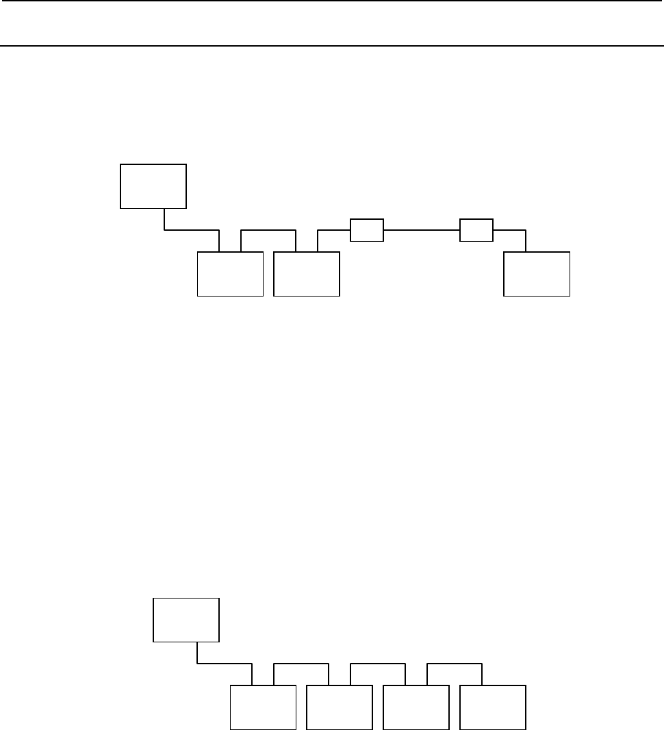
12.PMC ALARM MESSAGES AND ACTIONS TO TAKE
B-64513EN/03
- 1400 -
12.2.3
Sample Cases
A system alarm occurs once a day.
<Category>
Improper cable type, cable cut, or inadequate connection
<Configuration>
NC
Operator's
panel I/O
Group 0
Connector
panel I/O
Group 1
I/O Unit-A
Group 2
Optical I/O link
adapter
Optical I/O link
adapter
Optical cable
<Cause>
Groups 0 and 1 were connected using a cable to which a +5 V power wire was attached.
<Explanation>
The cable to which a +5V power wire is attached is intended to connect optical I/O Link adapters.
When not using optical I/O Link adapters, use a cable to which a +5V power wire is not attached.
Note that, when this troubleshooting work (replacing the cable) was done, the operator's panel I/O
module was replaced as well. Therefore, the direct cause of the error might have been the operator's
panel I/O module.
A system alarm occurs two or three times a day.
<Category>
Improper cable type, cable cut, or inadequate connection
<Configuration>
NC
Operator's
panel I/O
Grou
p
0
β
amplifier
Grou
p
1
β
amplifier
Grou
p
2
Connector
panel I/O
Grou
p
3
<Cause>
The cable between groups 2 and 3 had a short circuit inside it.
<Explanation>
Because the alarm had been occurring with relatively high frequency (two or three times a day), the
cause of the error was located by removing the salve devices sequentially starting with the one
having the largest group number.
B-64513EN/03
12.PMC ALARM MESSAGES AND ACTIONS TO TAKE
- 1401 -
A system alarm occurs if you execute "I/O Link startup" after storing the
ladder program using the online monitor.
<Category>
Assignment data mismatch
<Register>
83:41
<Configuration>
NC
I/O Unit-A
Group 0
I/O Unit-A
Group 1
I/O Unit-A
Group 2
<Cause>
The groups and bases had been set mistakenly.
(Correct) (Wrong)
Group Base Slot Module name Group Base Slot Module name
0 0
n Module 1
0 0
n Module 1
1 0
n Module 2
0 1
n Module 2
2 0
n Module 3
0 2
n Module 3
<Explanation>
If the base numbers are mistakenly assigned, the error almost always occurs when the power of the
CNC is turned on.
A system alarm is prone to occur when the feeder starts to operate after the
machining process.
<Category>
Noise
<Configuration>
NC
I/O Unit-A
Grou
p
0
Operator's
panel
Grou
p
1
Power
Mate-D
Grou
p
2
12.PMC ALARM MESSAGES AND ACTIONS TO TAKE
B-64513EN/03
- 1402 -
<Cause>
None of the masters, slaves, or communication cables were properly grounded to earth.
<Explanation>
If a system alarm is prone to occur in response to a specific operation, it is highly likely that a drop
in voltage, noise interference, loose cable connection, or short circuit results from that operation.
A system alarm occurs almost every time the automatic operation begins.
<Category>
Noise
<Configuration>
NC
I/O Unit-A
Group 0
Operator's
panel
Group 1
<Cause>
The communication cables and power cables were installed in the same bundle.
<Explanation>
The error no longer occurred after the communication cables and power cables were installed in
separate bundles. In this case, too, noise is considered to be the cause of the error. Note, however,
that such noise-caused errors do not necessarily occur in response to one specific operation. In
many cases, they emerge as intermittent errors that occur with extremely low frequency and it is
difficult to identify any particular condition for them to arise. Therefore, if an error is occurring
intermittently and if you have potential error factors, such as any hardware component not connected
to ground, poor grounding, and cables installed near a noise source, you need to take necessary
measures for each of those error factors and see if the error will be corrected.
A system alarm occurs at a cycle start.
<Category>
DO connection to ground
<Configuration>
NC
I/O Unit-A
Group 0
Connection
unit
Group 1
I/O Unit-A
Group 2
I/O Unit-A
Group 3
Operator's
panel I/O
Group 4
<Cause>
DO was short-circuited due to a wiring mistake on the operator's panel.
B-64513EN/03
12.PMC ALARM MESSAGES AND ACTIONS TO TAKE
- 1403 -
<Explanation>
Some operator's panel I/O modules cause a system alarm if the DO output is connected to ground.
In this case, we were able to identify the faulty component by checking the signal which is turned on
at a cycle start on the operator's panel.
A system alarm occurs once every five times the feeder is moved.
<Category>
Insufficient power capacity or drop in voltage
<Configuration>
NC
I/O Unit-A
Group 0
<Cause>
The power voltage of the slave dropped from 24 volts to 17 volts when the feeder was moved.
<Explanation>
If a system alarm is prone to occur in response to a specific operation, it is highly likely that a drop
in voltage, noise interference, or loose cable connection results from that operation.
A system alarm occurs every time an external alarm is displayed.
<Category>
Insufficient power capacity or drop in voltage
<Configuration>
NC
β
amplifier
Group 0
I/O Unit-A
Group 1
<Cause>
A flashing lamp was lit when an alarm occurred, which caused the power voltage of the slave to
drop from 24 volts to 10 volts.
<Explanation>
We checked the LED of group 0 (
β
amplifier) and found that an NMI had occurred. As a result of
examining the power supply of the
β
amplifier, we were able to confirm that its voltage would drop
when its flashing lamp was lit.
12.PMC ALARM MESSAGES AND ACTIONS TO TAKE
B-64513EN/03
- 1404 -
A system alarm occurs intermittently.
<Category>
Loose power connection
<Configuration>
NC
I/O Unit-A
Group 0
Spindle
monitor unit
Group 1
I/O Unit-A
Group 2
I/O Unit-A
Group 3
<Cause>
The cable was loosely connected to the terminal block of the slave power unit; it was merely in
touch of the block. We conducted a voltage measurement and found that the voltage of the slave
sometimes dropped from the 24-volt level.
<Explanation>
At the time when this measurement was conducted, the voltage of the slave dropped only by 2 volts
or so and no system alarm occurred. However, when the voltage level is unstable, any instantaneous
yet substantial change in voltage can lead to an error. To prevent this, check that each cable is
connected firmly, replace the power supply unit, or use a stable power supply.
A system alarm sometimes occurs at powering on.
<Category>
Restart of the slave at the time of the CNC restart
<Configuration>
(Unknown)
<Cause>
Due to a wiring mistake, some slaves did not turn off their power even when the power of the CNC
was turned off.
<Explanation>
When the master I/O Link device is restarted, all the slaves need to be restarted as well. The error
occurred intermittently because only the CNC power was turned on or off rather than turning on or
off the main power.
A system alarm occurs when data is written using the BOOT screen.
<Category>
Restart of the slave at the time of the CNC restart
<Configuration>
(Unknown)
<Cause>
When a macro was to be written using the BOOT screen, only the power of the CNC was turned off
and then on while the power of the slaves remained on.
<Explanation>
When the master I/O Link device is restarted, all the slaves need to be restarted as well.

B-64513EN/03
12.PMC ALARM MESSAGES AND ACTIONS TO TAKE
- 1405 -
A system alarm occurs every time the power is turned on.
<Category>
System down of in the slave
<Configuration>
NC
Operator's
panel
connection unit
Group 0
I/O Unit-A
Group 1
Power
Mate-E
Group 2
Power
Mate-E
Group 3
<Cause>
A RAM parity error had occurred in Power Mate-E of group 2.
<Explanation>
Since group 2 was Power Mate-E, we checked the alarm using the DPL and MDI and confirmed that
a RAM parity error had occurred in the device.
System alarms began to occur after the machine had been in operation for
about one year.
<Category>
Failure to connect the optical I/O Link adapter to ground
<Configuration>
(Unknown)
<Cause>
The connection between the optical I/O Link adapter case and the inside of the optical I/O Link
adapter was loose.
<Explanation>
The case of the optical I/O Link adapter is not painted and serves as a grounding body as well.
Therefore, the optical I/O Link adapter must be connected to ground. In this case, the adapter was
properly grounded but, because it was installed in a position subject to vibration, the connection
between the adapter case and the inside of the adapter had been lost.
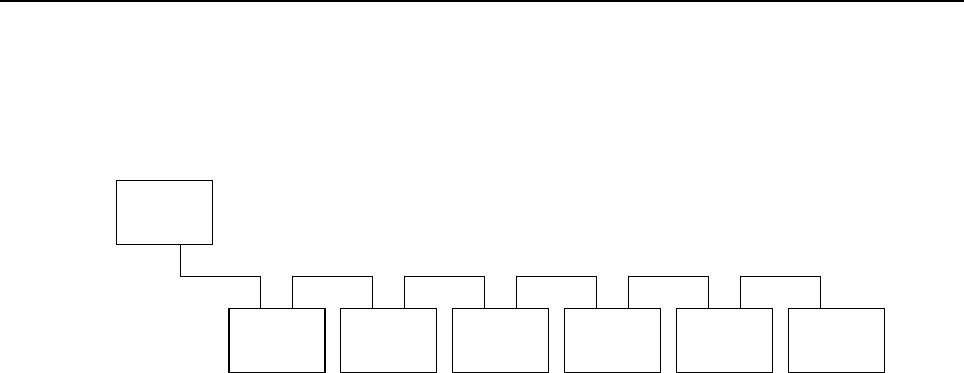
12.PMC ALARM MESSAGES AND ACTIONS TO TAKE
B-64513EN/03
- 1406 -
A system alarm occurs every time the power is turned on.
<Category>
CNC or I/O device malfunction or failure
<Configuration>
NC
Operator's
panel I/O
Group 0
Spindle
monitor unit
Group 1
Connector
panel I/O
Group 2
Connector
panel I/O
Group 3
Connector
panel I/O
Group 4
Connector
panel I/O
Group 5
<Cause>
The basic connector panel I/O module of group 5 was faulty.
<Explanation>
Since the alarm had occurred every time the power was turned on, we removed the devices
sequentially, starting with the one having the largest group number, and checked whether an alarm
would arise. As a result, we found out that the system would start normally when group 5 was
removed. We then conducted a test with the basic module of group 5 attached to another CNC and
discovered that the error was due to the malfunction of that individual module.
APPENDIX

B-64513EN/03
APPENDIX
A.CHARACTER CODE TABLE
- 1409 -
A CHARACTER CODE TABLE
A.1 Simplified chinese character code table (GB2312 code)
+0 +1 +2 +3 +4 +5 +6 +7 +8 +9 +A +B +C +D +E +F
A1A0 、 。 · ˉˇ¨〃々— ~ ‖ … ‘ ’
A1B0 “ ”〔 〕 〈 〉《》「」『 』 〖 〗 【 】
A1C0 ± ×÷ ∶ ∧ ∨∑∏∪∩∈ ∷ √ ⊥ ∥ ∠
A1D0 ⌒ ⊙∫ ∮ ≡ ≌≈∽∝≠≮ ≯ ≤ ≥ ∞ ∵
A1E0 ∴ ♂♀ ° ′ ″℃$¤¢£ ‰ § № ☆ ★
A1F0 ○ ●◎ ◇ ◆ □■△▲※→ ← ↑ ↓ 〓
A2A0
A2B0 ⒈⒉ ⒊ ⒋ ⒌⒍⒎⒏⒐⒑ ⒒ ⒓ ⒔ ⒕ ⒖
A2C0 ⒗ ⒘⒙ ⒚ ⒛ ⑴⑵⑶⑷⑸⑹ ⑺ ⑻ ⑼ ⑽ ⑾
A2D0 ⑿ ⒀⒁ ⒂ ⒃ ⒄⒅⒆⒇①② ③ ④ ⑤ ⑥ ⑦
A2E0 ⑧ ⑨⑩ ㈠㈡㈢㈣㈤㈥ ㈦ ㈧ ㈨ ㈩
A2F0 ⅠⅡ Ⅲ Ⅳ ⅤⅥⅦⅧⅨⅩ Ⅺ Ⅻ
A3A0 !" # ¥ %&'()* + , - . /
A3B0 0 12 3 4 56789:;<= > ?
A3C0 @ AB C D EFGHIJ K L M N O
A3D0 P QR S T UVWXYZ [ \ ] ^ _
A3E0 ` ab c d efghij k l m n o
A3F0 p qr s t uvwxyz { | }  ̄
A4A0 ぁあ ぃ い ぅうぇえぉお か が き ぎ く
A4B0 ぐ けげ こ ご さざしじすず せ ぜ そ ぞ た
A4C0 だ ちぢ っ つ づてでとどな に ぬ ね の は
A4D0 ば ぱひ び ぴ ふぶぷへべぺ ほ ぼ ぽ ま み
A4E0 む めも ゃ や ゅゆょよらり る れ ろ ゎ わ
A4F0 ゐ ゑ を ん
A5A0 ァア ィ イ ゥウェエォオ カ ガ キ ギ ク
A5B0 グ ケゲ コ ゴ サザシジスズ セ ゼ ソ ゾ タ
A5C0 ダ チヂ ッ ツ ヅテデトドナ ニ ヌ ネ ノ ハ
A5D0 バ パヒ ビ ピ フブプヘベペ ホ ボ ポ マ ミ
A5E0 ム メモ ャ ヤ ュユョヨラリ ル レ ロ ヮ ワ
A5F0 ヰ ヱ ヲ ン ヴ ヵ ヶ

A.CHARACTER CODE TABLE APPENDIX
B-64513EN/03
- 1410 -
+0 +1 +2 +3 +4 +5 +6 +7 +8 +9 +A +B +C +D +E +F
A6A0 ΑΒ Γ Δ ΕΖΗΘΙΚ Λ Μ Ν Ξ Ο
A6B0 Π ΡΣ Τ Υ ΦΧΨΩ
A6C0 αβ γ δ εζηθικ λ μ ν ξ ο
A6D0 π ρσ τ υ φχψω
A6E0
A6F0
A7A0 АБ В Г ДЕЁЖЗИ Й К Л М Н
A7B0 О ПР С Т УФХЦЧШ Щ Ъ Ы Ь Э
A7C0 Ю Я
A7D0 аб в г деёжзи й к л м н
A7E0 о пр с т уфхцчш щ ъ ы ь э
A7F0 ю я
A8A0 ā á ǎ à ē é ě è ī í ǐ ì ō ó ǒ
A8B0 ò ū ú ǔ ù ǖǘǚǜ üê
A8C0 ㄅㄆㄇㄈㄉㄊ ㄋ ㄌ ㄍ ㄎ ㄏ
A8D0 ㄐ ㄑㄒ ㄓ ㄔ ㄕㄖㄗㄘㄙㄚ ㄛ ㄜ ㄝ ㄞ ㄟ
A8E0 ㄠ ㄡㄢ ㄣ ㄤ ㄥㄦㄧㄨㄩ
A8F0
A9A0 ─ ━│┃┄┅┆ ┇ ┈ ┉ ┊ ┋
A9B0 ┌ ┍┎ ┏ ┐ ┑┒┓└┕┖ ┗ ┘ ┙ ┚ ┛
A9C0 ├ ┝┞ ┟ ┠ ┡┢┣┤┥┦ ┧ ┨ ┩ ┪ ┫
A9D0 ┬ ┭┮ ┯ ┰ ┱┲┳┴┵┶ ┷ ┸ ┹ ┺ ┻
A9E0 ┼ ┽┾ ┿ ╀ ╁╂╃╄╅╆ ╇ ╈ ╉ ╊ ╋
A9F0
B0A0 啊阿 埃 挨 哎唉哀皑癌蔼 矮 艾 碍 爱 隘
B0B0 鞍 氨安 俺 按 暗岸胺案肮昂 盎 凹 敖 熬 翱
B0C0 袄 傲奥 懊 澳 芭捌扒叭吧笆 八 疤 巴 拔 跋
B0D0 靶 把耙 坝 霸 罢爸白柏百摆 佰 败 拜 稗 斑
B0E0 班 搬扳 般 颁 板版扮拌伴瓣 半 办 绊 邦 帮
B0F0 梆 榜膀 绑 棒 磅蚌镑傍谤苞 胞 包 褒 剥
B1A0 薄雹 保 堡 饱宝抱报暴豹 鲍 爆 杯 碑 悲
B1B0 卑 北辈 背 贝 钡倍狈备惫焙 被 奔 苯 本 笨
B1C0 崩 绷甭 泵 蹦 迸逼鼻比鄙笔 彼 碧 蓖 蔽 毕
B1D0 毙 毖币 庇 痹 闭敝弊必辟壁 臂 避 陛 鞭 边
B1E0 编 贬扁 便 变 卞辨辩辫遍标 彪 膘 表 鳖 憋

B-64513EN/03
APPENDIX
A.CHARACTER CODE TABLE
- 1411 -
+0 +1 +2 +3 +4 +5 +6 +7 +8 +9 +A +B +C +D +E +F
B1F0 别 瘪彬 斌 濒 滨宾摈兵冰柄 丙 秉 饼 炳
B2A0 病并 玻 菠 播拨钵波博勃 搏 铂 箔 伯 帛
B2B0 舶 脖膊 渤 泊 驳捕卜哺补埠 不 布 步 簿 部
B2C0 怖 擦猜 裁 材 才财睬踩采彩 菜 蔡 餐 参 蚕
B2D0 残 惭惨 灿 苍 舱仓沧藏操糙 槽 曹 草 厕 策
B2E0 侧 册测 层 蹭 插叉茬茶查碴 搽 察 岔 差 诧
B2F0 拆 柴豺 搀 掺 蝉馋谗缠铲产 阐 颤 昌 猖
B3A0 场尝 常 长 偿肠厂敞畅唱 倡 超 抄 钞 朝
B3B0 嘲 潮巢 吵 炒 车扯撤掣彻澈 郴 臣 辰 尘 晨
B3C0 忱 沉陈 趁 衬 撑称城橙成呈 乘 程 惩 澄 诚
B3D0 承 逞骋 秤 吃 痴持匙池迟弛 驰 耻 齿 侈 尺
B3E0 赤 翅斥 炽 充 冲虫崇宠抽酬 畴 踌 稠 愁 筹
B3F0 仇 绸瞅 丑 臭 初出橱厨躇锄 雏 滁 除 楚
B4A0 础储 矗 搐 触处揣川穿椽 传 船 喘 串 疮
B4B0 窗 幢床 闯 创 吹炊捶锤垂春 椿 醇 唇 淳 纯
B4C0 蠢 戳绰 疵 茨 磁雌辞慈瓷词 此 刺 赐 次 聪
B4D0 葱 囱匆 从 丛 凑粗醋簇促蹿 篡 窜 摧 崔 催
B4E0 脆 瘁粹 淬 翠 村存寸磋撮搓 措 挫 错 搭 达
B4F0 答 瘩打 大 呆 歹傣戴带殆代 贷 袋 待 逮
B5A0 怠耽 担 丹 单郸掸胆旦氮 但 惮 淡 诞 弹
B5B0 蛋 当挡 党 荡 档刀捣蹈倒岛 祷 导 到 稻 悼
B5C0 道 盗德 得 的 蹬灯登等瞪凳 邓 堤 低 滴 迪
B5D0 敌 笛狄 涤 翟 嫡抵底地蒂第 帝 弟 递 缔 颠
B5E0 掂 滇碘 点 典 靛垫电佃甸店 惦 奠 淀 殿 碉
B5F0 叼 雕凋 刁 掉 吊钓调跌爹碟 蝶 迭 谍 叠
B6A0 丁盯 叮 钉 顶鼎锭定订丢 东 冬 董 懂 动
B6B0 栋 侗恫 冻 洞 兜抖斗陡豆逗 痘 都 督 毒 犊
B6C0 独 读堵 睹 赌 杜镀肚度渡妒 端 短 锻 段 断
B6D0 缎 堆兑 队 对 墩吨蹲敦顿囤 钝 盾 遁 掇 哆
B6E0 多 夺垛 躲 朵 跺舵剁惰堕蛾 峨 鹅 俄 额 讹
B6F0 娥 恶厄 扼 遏 鄂饿恩而儿耳 尔 饵 洱 二
B7A0 贰发 罚 筏 伐乏阀法珐藩 帆 番 翻 樊 矾
B7B0 钒 繁凡 烦 反 返范贩犯饭泛 坊 芳 方 肪 房
B7C0 防 妨仿 访 纺 放菲非啡飞肥 匪 诽 吠 肺 废
B7D0 沸 费芬 酚 吩 氛分纷坟焚汾 粉 奋 份 忿 愤

A.CHARACTER CODE TABLE APPENDIX
B-64513EN/03
- 1412 -
+0 +1 +2 +3 +4 +5 +6 +7 +8 +9 +A +B +C +D +E +F
B7E0 粪 丰封 枫 蜂 峰锋风疯烽逢 冯 缝 讽 奉 凤
B7F0 佛 否夫 敷 肤 孵扶拂辐幅氟 符 伏 俘 服
B8A0 浮涪 福 袱 弗甫抚辅俯釜 斧 脯 腑 府 腐
B8B0 赴 副覆 赋 复 傅付阜父腹负 富 讣 附 妇 缚
B8C0 咐 噶嘎 该 改 概钙盖溉干甘 杆 柑 竿 肝 赶
B8D0 感 秆敢 赣 冈 刚钢缸肛纲岗 港 杠 篙 皋 高
B8E0 膏 羔糕 搞 镐 稿告哥歌搁戈 鸽 胳 疙 割 革
B8F0 葛 格蛤 阁 隔 铬个各给根跟 耕 更 庚 羹
B9A0 埂耿 梗 工 攻功恭龚供躬 公 宫 弓 巩 汞
B9B0 拱 贡共 钩 勾 沟苟狗垢构购 够 辜 菇 咕 箍
B9C0 估 沽孤 姑 鼓 古蛊骨谷股故 顾 固 雇 刮 瓜
B9D0 剐 寡挂 褂 乖 拐怪棺关官冠 观 管 馆 罐 惯
B9E0 灌 贯光 广 逛 瑰规圭硅归龟 闺 轨 鬼 诡 癸
B9F0 桂 柜跪 贵 刽 辊滚棍锅郭国 果 裹 过 哈
BAA0 骸孩 海 氦 亥害骇酣憨邯 韩 含 涵 寒 函
BAB0 喊 罕翰 撼 捍 旱憾悍焊汗汉夯 杭 航 壕 嚎
BAC0 豪 毫郝 好 耗 号浩呵喝荷菏 核 禾 和 何 合
BAD0 盒 貉阂 河 涸 赫褐鹤贺嘿黑 痕 很 狠 恨 哼
BAE0 亨 横衡 恒 轰 哄烘虹鸿洪宏弘 红 喉 侯 猴
BAF0 吼 厚候 后 呼 乎忽瑚壶葫胡 蝴 狐 糊 湖
BBA0 弧虎 唬 护 互沪户花哗华 猾 滑 画 划 化
BBB0 话 槐徊 怀 淮 坏欢环桓还缓换 患 唤 痪 豢
BBC0 焕 涣宦 幻 荒 慌黄磺蝗簧皇 凰 惶 煌 晃 幌
BBD0 恍 谎灰 挥 辉 徽恢蛔回毁悔 慧 卉 惠 晦 贿
BBE0 秽 会烩 汇 讳 诲绘荤昏婚魂浑 混 豁 活 伙
BBF0 火 获或 惑 霍 货祸击圾基机 畸 稽 积 箕
BCA0 肌饥 迹 激 讥鸡姬绩缉吉 极 棘 辑 籍 集
BCB0 及 急疾 汲 即 嫉级挤几脊己 蓟 技 冀 季 伎
BCC0 祭 剂悸 济 寄 寂计记既忌际 妓 继 纪 嘉 枷
BCD0 夹 佳家 加 荚 颊贾甲钾假稼 价 架 驾 嫁 歼
BCE0 监 坚尖 笺 间 煎兼肩艰奸缄 茧 检 柬 碱 硷
BCF0 拣 捡简 俭 剪 减荐槛鉴践贱 见 键 箭 件
BDA0 健舰 剑 饯 渐溅涧建僵姜 将 浆 江 疆 蒋
BDB0 桨 奖讲 匠 酱 降蕉椒礁焦胶 交 郊 浇 骄 娇
BDC0 嚼 搅铰 矫 侥 脚狡角饺缴绞 剿 教 酵 轿 较

B-64513EN/03
APPENDIX
A.CHARACTER CODE TABLE
- 1413 -
+0 +1 +2 +3 +4 +5 +6 +7 +8 +9 +A +B +C +D +E +F
BDD0 叫 窖揭 接 皆 秸街阶截劫节 桔 杰 捷 睫 竭
BDE0 洁 结解 姐 戒 藉芥界借介疥 诫 届 巾 筋 斤
BDF0 金 今津 襟 紧 锦仅谨进靳晋 禁 近 烬 浸
BEA0 尽劲 荆 兢 茎睛晶鲸京惊 精 粳 经 井 警
BEB0 景 颈静 境 敬 镜径痉靖竟竞净 炯 窘 揪 究
BEC0 纠 玖韭 久 灸 九酒厩救旧臼 舅 咎 就 疚 鞠
BED0 拘 狙疽 居 驹 菊局咀矩举沮 聚 拒 据 巨 具
BEE0 距 踞锯 俱 句 惧炬剧捐鹃娟倦 眷 卷 绢 撅
BEF0 攫 抉掘 倔 爵 觉决诀绝均菌 钧 军 君 峻
BFA0 俊竣 浚 郡 骏喀咖卡咯开 揩 楷 凯 慨 刊
BFB0 堪 勘坎 砍 看 康慷糠扛抗亢 炕 考 拷 烤 靠
BFC0 坷 苛柯 棵 磕 颗科壳咳可渴 克 刻 客 课 肯
BFD0 啃 垦恳 坑 吭 空恐孔控抠口 扣 寇 枯 哭 窟
BFE0 苦 酷库 裤 夸 垮挎跨胯块筷 侩 快 宽 款 匡
BFF0 筐 狂框 矿 眶 旷况亏盔岿窥葵 奎 魁 傀
C0A0 馈愧 溃 坤 昆捆困括扩廓 阔 垃 拉 喇 蜡
C0B0 腊 辣啦 莱 来 赖蓝婪栏拦篮 阑 兰 澜 谰 揽
C0C0 览 懒缆 烂 滥 琅榔狼廊郎朗浪 捞 劳 牢 老
C0D0 佬 姥酪 烙 涝 勒乐雷镭蕾磊累 儡 垒 擂 肋
C0E0 类 泪棱 楞 冷 厘梨犁黎篱狸 离 漓 理 李 里
C0F0 鲤 礼莉 荔 吏 栗丽厉励砾历 利 傈 例 俐
C1A0 痢立 粒 沥 隶力璃哩俩联 莲 连 镰 廉 怜
C1B0 涟 帘敛 脸 链 恋炼练粮凉梁 粱 良 两 辆 量
C1C0 晾 亮谅 撩 聊 僚疗燎寥辽潦了 撂 镣 廖 料
C1D0 列 裂烈 劣 猎 琳林磷霖临邻鳞 淋 凛 赁 吝
C1E0 拎 玲菱 零 龄 铃伶羚凌灵陵 岭 领 另 令 溜
C1F0 琉 榴硫 馏 留 刘瘤流柳六龙 聋 咙 笼 窿
C2A0 隆垄 拢 陇 楼娄搂篓漏陋 芦 卢 颅 庐 炉
C2B0 掳 卤虏 鲁 麓 碌露路赂鹿潞 禄 录 陆 戮 驴
C2C0 吕 铝侣 旅 履 屡缕虑氯律率滤 绿 峦 挛 孪
C2D0 滦 卵乱 掠 略 抡轮伦仑沦纶论 萝 螺 罗 逻
C2E0 锣 箩骡 裸 落 洛骆络妈麻玛 码 蚂 马 骂 嘛
C2F0 吗 埋买 麦 卖 迈脉瞒馒蛮满 蔓 曼 慢 漫
C3A0 谩芒 茫 盲 氓忙莽猫茅锚 毛 矛 铆 卯 茂
C3B0 冒 帽貌 贸 么 玫枚梅酶霉煤 没 眉 媒 镁 每

A.CHARACTER CODE TABLE APPENDIX
B-64513EN/03
- 1414 -
+0 +1 +2 +3 +4 +5 +6 +7 +8 +9 +A +B +C +D +E +F
C3C0 美 昧寐 妹 媚 门闷们萌蒙檬盟 锰 猛 梦 孟
C3D0 眯 醚靡 糜 迷 谜弥米秘觅泌蜜 密 幂 棉 眠
C3E0 绵 冕免 勉 娩 缅面苗描瞄藐 秒 渺 庙 妙 蔑
C3F0 灭 民抿 皿 敏 悯闽明螟鸣铭 名 命 谬 摸
C4A0 摹蘑 模 膜 磨摩魔抹末莫 墨 默 沫 漠 寞
C4B0 陌 谋牟 某 拇 牡亩姆母墓暮 幕 募 慕 木 目
C4C0 睦 牧穆 拿 哪 呐钠那娜纳氖乃 奶 耐 奈 南
C4D0 男 难囊 挠 脑 恼闹淖呢馁内嫩 能 妮 霓 倪
C4E0 泥 尼拟 你 匿 腻逆溺蔫拈年 碾 撵 捻 念 娘
C4F0 酿 鸟尿 捏 聂 孽啮镊镍涅您 柠 狞 凝 宁
C5A0 拧泞 牛 扭 钮纽脓浓农弄 奴 努 怒 女 暖
C5B0 虐 疟挪 懦 糯 诺哦欧鸥殴藕 呕 偶 沤 啪 趴
C5C0 爬 帕怕 琶 拍 排牌徘湃派攀潘 盘 磐 盼 畔
C5D0 判 叛乓 庞 旁 耪胖抛咆刨炮袍 跑 泡 呸 胚
C5E0 培 裴赔 陪 配 佩沛喷盆砰抨 烹 澎 彭 蓬 棚
C5F0 硼 篷膨 朋 鹏 捧碰坯砒霹批 披 劈 琵 毗
C6A0 啤脾 疲 皮 匹痞僻屁譬篇 偏 片 骗 飘 漂
C6B0 瓢 票撇 瞥 拼 频贫品聘乒坪 苹 萍 平 凭 瓶
C6C0 评 屏坡 泼 颇 婆破魄迫粕剖扑 铺 仆 莆 葡
C6D0 菩 蒲埔 朴 圃 普浦谱曝瀑期欺 栖 戚 妻 七
C6E0 凄 漆柒 沏 其 棋奇歧畦崎脐 齐 旗 祈 祁 骑
C6F0 起 岂乞 企 启 契砌器气迄弃 汽 泣 讫 掐
C7A0 恰洽 牵 扦 钎铅千迁签仟 谦 乾 黔 钱 钳
C7B0 前 潜遣 浅 谴 堑嵌欠歉枪呛 腔 羌 墙 蔷 强
C7C0 抢 橇锹 敲 悄 桥瞧乔侨巧鞘撬 翘 峭 俏 窍
C7D0 切 茄且 怯 窃 钦侵亲秦琴勤芹 擒 禽 寝 沁
C7E0 青 轻氢 倾 卿 清擎晴氰情顷 请 庆 琼 穷 秋
C7F0 丘 邱球 求 囚 酋泅趋区蛆曲 躯 屈 驱 渠
C8A0 取娶 龋 趣 去圈颧权醛泉 全 痊 拳 犬 券
C8B0 劝 缺炔 瘸 却 鹊榷确雀裙群 然 燃 冉 染 瓤
C8C0 壤 攘嚷 让 饶 扰绕惹热壬仁人 忍 韧 任 认
C8D0 刃 妊纫 扔 仍 日戎茸蓉荣融熔 溶 容 绒 冗
C8E0 揉 柔肉 茹 蠕 儒孺如辱乳汝 入 褥 软 阮 蕊
C8F0 瑞 锐闰 润 若 弱撒洒萨腮鳃 塞 赛 三 叁
C9A0 伞散 桑 嗓 丧搔骚扫嫂瑟 色 涩 森 僧 莎

B-64513EN/03
APPENDIX
A.CHARACTER CODE TABLE
- 1415 -
+0 +1 +2 +3 +4 +5 +6 +7 +8 +9 +A +B +C +D +E +F
C9B0 砂 杀刹 沙 纱 傻啥煞筛晒珊 苫 杉 山 删 煽
C9C0 衫 闪陕 擅 赡 膳善汕扇缮墒伤 商 赏 晌 上
C9D0 尚 裳梢 捎 稍 烧芍勺韶少哨邵 绍 奢 赊 蛇
C9E0 舌 舍赦 摄 射 慑涉社设砷申 呻 伸 身 深 娠
C9F0 绅 神沈 审 婶 甚肾慎渗声生 甥 牲 升 绳
CAA0 省盛 剩 胜 圣师失狮施湿 诗 尸 虱 十 石
CAB0 拾 时什 食 蚀 实识史矢使屎 驶 始 式 示 士
CAC0 世 柿事 拭 誓 逝势是嗜噬适 仕 侍 释 饰 氏
CAD0 市 恃室 视 试 收手首守寿授 售 受 瘦 兽 蔬
CAE0 枢 梳殊 抒 输 叔舒淑疏书赎 孰 熟 薯 暑 曙
CAF0 署 蜀黍 鼠 属 术述树束戍竖 墅 庶 数 漱
CBA0 恕刷 耍 摔 衰甩帅栓拴霜 双 爽 谁 水 睡
CBB0 税 吮瞬 顺 舜 说硕朔烁斯撕 嘶 思 私 司 丝
CBC0 死 肆寺 嗣 四 伺似饲巳松耸 怂 颂 送 宋 讼
CBD0 诵 搜艘 擞 嗽 苏酥俗素速粟 僳 塑 溯 宿 诉
CBE0 肃 酸蒜 算 虽 隋随绥髓碎岁 穗 遂 隧 祟 孙
CBF0 损 笋蓑 梭 唆 缩琐索锁所塌 他 它 她 塔
CCA0 獭挞 蹋 踏 胎苔抬台泰酞 太 态 汰 坍 摊
CCB0 贪 瘫滩 坛 檀 痰潭谭谈坦毯 袒 碳 探 叹 炭
CCC0 汤 塘搪 堂 棠 膛唐糖倘躺淌 趟 烫 掏 涛 滔
CCD0 绦 萄桃 逃 淘 陶讨套特藤腾 疼 誊 梯 剔 踢
CCE0 锑 提题 蹄 啼 体替嚏惕涕剃 屉 天 添 填 田
CCF0 甜 恬舔 腆 挑 条迢眺跳贴铁 帖 厅 听 烃
CDA0 汀廷 停 亭 庭挺艇通桐酮 瞳 同 铜 彤 童
CDB0 桶 捅筒 统 痛 偷投头透凸秃 突 图 徒 途 涂
CDC0 屠 土吐 兔 湍 团推颓腿蜕褪 退 吞 屯 臀 拖
CDD0 托 脱鸵 陀 驮 驼椭妥拓唾挖 哇 蛙 洼 娃 瓦
CDE0 袜 歪外 豌 弯 湾玩顽丸烷完 碗 挽 晚 皖 惋
CDF0 宛 婉万 腕 汪 王亡枉网往旺 望 忘 妄 威
CEA0 巍微 危 韦 违桅围唯惟为 潍 维 苇 萎 委
CEB0 伟 伪尾 纬 未 蔚味畏胃喂魏 位 渭 谓 尉 慰
CEC0 卫 瘟温 蚊 文 闻纹吻稳紊问 嗡 翁 瓮 挝 蜗
CED0 涡 窝我 斡 卧 握沃巫呜钨乌 污 诬 屋 无 芜
CEE0 梧 吾吴 毋 武 五捂午舞伍侮 坞 戊 雾 晤 物
CEF0 勿 务悟 误 昔 熙析西硒矽晰 嘻 吸 锡 牺

A.CHARACTER CODE TABLE APPENDIX
B-64513EN/03
- 1416 -
+0 +1 +2 +3 +4 +5 +6 +7 +8 +9 +A +B +C +D +E +F
CFA0 稀息 希 悉 膝夕惜熄烯溪 汐 犀 檄 袭 席
CFB0 习 媳喜 铣 洗 系隙戏细瞎虾匣 霞 辖 暇 峡
CFC0 侠 狭下 厦 夏 吓掀锨先仙鲜 纤 咸 贤 衔 舷
CFD0 闲 涎弦 嫌 显 险现献县腺馅 羡 宪 陷 限 线
CFE0 相 厢镶 香 箱 襄湘乡翔祥详想 响 享 项 巷
CFF0 橡 像向 象 萧 硝霄削哮嚣销 消 宵 淆 晓
D0A0 小孝 校 肖 啸笑效楔些歇 蝎 鞋 协 挟 携
D0B0 邪 斜胁 谐 写 械卸蟹懈泄泻 谢 屑 薪 芯 锌
D0C0 欣 辛新 忻 心 信衅星腥猩惺兴 刑 型 形 邢
D0D0 行 醒幸 杏 性 姓兄凶胸匈汹雄 熊 休 修 羞
D0E0 朽 嗅锈 秀 袖 绣墟戌需虚嘘 须 徐 许 蓄 酗
D0F0 叙 旭序 畜 恤 絮婿绪续轩喧 宣 悬 旋 玄
D1A0 选癣 眩 绚 靴薛学穴雪血 勋 熏 循 旬 询
D1B0 寻 驯巡 殉 汛 训讯逊迅压押 鸦 鸭 呀 丫 芽
D1C0 牙 蚜崖 衙 涯 雅哑亚讶焉咽阉 烟 淹 盐 严
D1D0 研 蜒岩 延 言 颜阎炎沿奄掩眼 衍 演 艳 堰
D1E0 燕 厌砚 雁 唁 彦焰宴谚验殃 央 鸯 秧 杨 扬
D1F0 佯 疡羊 洋 阳 氧仰痒养样漾 邀 腰 妖 瑶
D2A0 摇尧 遥 窑 谣姚咬舀药要 耀 椰 噎 耶 爷
D2B0 野 冶也 页 掖 业叶曳腋夜液 一 壹 医 揖 铱
D2C0 依 伊衣 颐 夷 遗移仪胰疑沂宜 姨 彝 椅 蚁
D2D0 倚 已乙 矣 以 艺抑易邑屹亿役 臆 逸 肄 疫
D2E0 亦 裔意 毅 忆 义益溢诣议谊 译 异 翼 翌 绎
D2F0 茵 荫因 殷 音 阴姻吟银淫寅 饮 尹 引 隐
D3A0 印英 樱 婴 鹰应缨莹萤营 荧 蝇 迎 赢 盈
D3B0 影 颖硬 映 哟 拥佣臃痈庸雍 踊 蛹 咏 泳 涌
D3C0 永 恿勇 用 幽 优悠忧尤由邮铀 犹 油 游 酉
D3D0 有 友右 佑 釉 诱又幼迂淤于盂 榆 虞 愚 舆
D3E0 余 俞逾 鱼 愉 渝渔隅予娱雨 与 屿 禹 宇 语
D3F0 羽 玉域 芋 郁 吁遇喻峪御愈 欲 狱 育 誉
D4A0 浴寓 裕 预 豫驭鸳渊冤元 垣 袁 原 援 辕
D4B0 园 员圆 猿 源 缘远苑愿怨院 曰 约 越 跃 钥
D4C0 岳 粤月 悦 阅 耘云郧匀陨允运 蕴 酝 晕 韵
D4D0 孕 匝砸 杂 栽 哉灾宰载再在咱 攒 暂 赞 赃
D4E0 脏 葬遭 糟 凿 藻枣早澡蚤躁 噪 造 皂 灶 燥

B-64513EN/03
APPENDIX
A.CHARACTER CODE TABLE
- 1417 -
+0 +1 +2 +3 +4 +5 +6 +7 +8 +9 +A +B +C +D +E +F
D4F0 责 择则 泽 贼 怎增憎曾赠扎 喳 渣 札 轧
D5A0 铡闸 眨 栅 榨咋乍炸诈摘 斋 宅 窄 债 寨
D5B0 瞻 毡詹 粘 沾 盏斩辗崭展蘸 栈 占 战 站 湛
D5C0 绽 樟章 彰 漳 张掌涨杖丈帐账 仗 胀 瘴 障
D5D0 招 昭找 沼 赵 照罩兆肇召遮折 哲 蛰 辙 者
D5E0 锗 蔗这 浙 珍 斟真甄砧臻贞 针 侦 枕 疹 诊
D5F0 震 振镇 阵 蒸 挣睁征狰争怔 整 拯 正 政
D6A0 帧症 郑 证 芝枝支吱蜘知 肢 脂 汁 之 织
D6B0 职 直植 殖 执 值侄址指止趾 只 旨 纸 志 挚
D6C0 掷 至致 置 帜 峙制智秩稚质炙 痔 滞 治 窒
D6D0 中 盅忠 钟 衷 终种肿重仲众舟 周 州 洲 诌
D6E0 粥 轴肘 帚 咒 皱宙昼骤珠株 蛛 朱 猪 诸 诛
D6F0 逐 竹烛 煮 拄 瞩嘱主著柱助 蛀 贮 铸 筑
D7A0 住注 祝 驻 抓爪拽专砖转 撰 赚 篆 桩 庄
D7B0 装 妆撞 壮 状 椎锥追赘坠缀 谆 准 捉 拙 卓
D7C0 桌 琢茁 酌 啄 着灼浊兹咨资姿 滋 淄 孜 紫
D7D0 仔 籽滓 子 自 渍字鬃棕踪宗综 总 纵 邹 走
D7E0 奏 揍租 足 卒 族祖诅阻组钻 纂 嘴 醉 最 罪
D7F0 尊 遵昨 左 佐 柞做作坐座
D8A0 亍丌 兀 丐 廿卅丕亘丞鬲 孬 噩 丨 禺 丿
D8B0 匕 乇夭 爻 卮 氐囟胤馗毓睾 鼗 丶 亟 鼐 乜
D8C0 乩 亓芈 孛 啬 嘏仄厍厝厣厥厮 靥 赝 匚 叵
D8D0 匦 匮匾 赜 卦 卣刂刈刎刭刳刿 剀 剌 剞 剡
D8E0 剜 蒯剽 劂 劁 劐劓冂罔亻仃 仉 仂 仨 仡 仫
D8F0 仞 伛仳 伢 佤 仵伥伧伉伫佞 佧 攸 佚 佝
D9A0 佟佗 伲 伽 佶佴侑侉侃侏 佾 佻 侪 佼 侬
D9B0 侔 俦俨 俪 俅 俚俣俜俑俟俸 倩 偌 俳 倬 倏
D9C0 倮 倭俾 倜 倌 倥倨偾偃偕偈偎 偬 偻 傥 傧
D9D0 傩 傺僖 儆 僭 僬僦僮儇儋仝氽 佘 佥 俎 龠
D9E0 汆 籴兮 巽 黉 馘冁夔勹匍訇 匐 凫 夙 兕 亠
D9F0 兖 亳衮 袤 亵 脔裒禀嬴蠃羸 冫 冱 冽 冼
DAA0 凇冖 冢 冥 讠讦讧讪讴讵 讷 诂 诃 诋 诏
DAB0 诎 诒诓 诔 诖 诘诙诜诟诠诤 诨 诩 诮 诰 诳
DAC0 诶 诹诼 诿 谀 谂谄谇谌谏谑 谒 谔 谕 谖 谙
DAD0 谛 谘谝 谟 谠 谡谥谧谪谫谮 谯 谲 谳 谵 谶

A.CHARACTER CODE TABLE APPENDIX
B-64513EN/03
- 1418 -
+0 +1 +2 +3 +4 +5 +6 +7 +8 +9 +A +B +C +D +E +F
DAE0 卩 卺阝 阢 阡 阱阪阽阼陂陉 陔 陟 陧 陬 陲
DAF0 陴 隈隍 隗 隰 邗邛邝邙邬邡 邴 邳 邶 邺
DBA0 邸邰 郏 郅 邾郐郄郇郓郦 郢 郜 郗 郛 郫
DBB0 郯 郾鄄 鄢 鄞 鄣鄱鄯鄹酃酆 刍 奂 劢 劬 劭
DBC0 劾 哿勐 勖 勰 叟燮矍廴凵凼 鬯 厶 弁 畚 巯
DBD0 坌 垩垡 塾 墼 壅壑圩圬圪圳 圹 圮 圯 坜 圻
DBE0 坂 坩垅 坫 垆 坼坻坨坭坶坳 垭 垤 垌 垲 埏
DBF0 垧 垴垓 垠 埕 埘埚埙埒垸埴 埯 埸 埤 埝
DCA0 堋堍 埽 埭 堀堞堙塄堠塥 塬 墁 墉 墚 墀
DCB0 馨 鼙懿 艹 艽 艿芏芊芨芄芎 芑 芗 芙 芫 芸
DCC0 芾 芰苈 苊 苣 芘芷芮苋苌苁 芩 芴 芡 芪 芟
DCD0 苄 苎芤 苡 茉 苷苤茏茇苜苴 苒 苘 茌 苻 苓
DCE0 茑 茚茆 茔 茕 苠苕茜荑荛荜 茈 莒 茼 茴 茱
DCF0 莛 荞茯 荏 荇 荃荟荀茗荠茭 茺 茳 荦 荥
DDA0 荨茛 荩 荬 荪荭荮莰荸莳 莴 莠 莪 莓 莜
DDB0 莅 荼莶 莩 荽 莸荻莘莞莨莺 莼 菁 萁 菥 菘
DDC0 堇 萘萋 菝 菽 菖萜萸萑萆菔 菟 萏 萃 菸 菹
DDD0 菪 菅菀 萦 菰 菡葜葑葚葙葳 蒇 蒈 葺 蒉 葸
DDE0 萼 葆葩 葶 蒌 蒎萱葭蓁蓍蓐 蓦 蒽 蓓 蓊 蒿
DDF0 蒺 蓠蒡 蒹 蒴 蒗蓥蓣蔌甍蔸 蓰 蔹 蔟 蔺
DEA0 蕖蔻 蓿 蓼 蕙蕈蕨蕤蕞蕺 瞢 蕃 蕲 蕻 薤
DEB0 薨 薇薏 蕹 薮 薜薅薹薷薰藓 藁 藜 藿 蘧 蘅
DEC0 蘩 蘖蘼 廾 弈 夼奁耷奕奚奘 匏 尢 尥 尬 尴
DED0 扌 扪抟 抻 拊 拚拗拮挢拶挹 捋 捃 掭 揶 捱
DEE0 捺 掎掴 捭 掬 掊捩掮掼揲揸 揠 揿 揄 揞 揎
DEF0 摒 揆掾 摅 摁 搋搛搠搌搦搡 摞 撄 摭 撖
DFA0 摺撷 撸 撙 撺擀擐擗擤擢 攉 攥 攮 弋 忒
DFB0 甙 弑卟 叱 叽 叩叨叻吒吖吆呋 呒 呓 呔 呖
DFC0 呃 吡呗 呙 吣 吲咂咔呷呱呤 咚 咛 咄 呶 呦
DFD0 咝 哐咭 哂 咴 哒咧咦哓哔呲 咣 哕 咻 咿 哌
DFE0 哙 哚哜 咩 咪 咤哝哏哞唛哧唠 哽 唔 哳 唢
DFF0 唣 唏唑 唧 唪 啧喏喵啉啭啁 啕 唿 啐 唼
E0A0 唷啖 啵 啶 啷唳唰啜喋嗒 喃 喱 喹 喈 喁
E0B0 喟 啾嗖 喑 啻 嗟喽喾喔喙嗪 嗷 嗉 嘟 嗑 嗫
E0C0 嗬 嗔嗦 嗝 嗄 嗯嗥嗲嗳嗌嗍 嗨 嗵 嗤 辔 嘞

B-64513EN/03
APPENDIX
A.CHARACTER CODE TABLE
- 1419 -
+0 +1 +2 +3 +4 +5 +6 +7 +8 +9 +A +B +C +D +E +F
E0D0 嘈 嘌嘁 嘤 嘣 嗾嘀嘧嘭噘嘹 噗 嘬 噍 噢 噙
E0E0 噜 噌噔 嚆 噤 噱噫噻噼嚅嚓 嚯 囔 囗 囝 囡
E0F0 囵 囫囹 囿 圄 圊圉圜帏帙帔 帑 帱 帻 帼
E1A0 帷幄 幔 幛 幞幡岌屺岍岐 岖 岈 岘 岙 岑
E1B0 岚 岜岵 岢 岽 岬岫岱岣峁岷 峄 峒 峤 峋 峥
E1C0 崂 崃崧 崦 崮 崤崞崆崛嵘崾 崴 崽 嵬 嵛 嵯
E1D0 嵝 嵫嵋 嵊 嵩 嵴嶂嶙嶝豳嶷 巅 彳 彷 徂 徇
E1E0 徉 後徕 徙 徜 徨徭徵徼衢彡 犭 犰 犴 犷 犸
E1F0 狃 狁狎 狍 狒 狨狯狩狲狴狷 猁 狳 猃 狺
E2A0 狻猗 猓 猡 猊猞猝猕猢猹 猥 猬 猸 猱 獐
E2B0 獍 獗獠 獬 獯 獾舛夥飧夤夂 饣 饧 饨 饩 饪
E2C0 饫 饬饴 饷 饽 馀馄馇馊馍馐 馑 馓 馔 馕 庀
E2D0 庑 庋庖 庥 庠 庹庵庾庳赓廒 廑 廛 廨 廪 膺
E2E0 忄 忉忖 忏 怃 忮怄忡忤忾怅 怆 忪 忭 忸 怙
E2F0 怵 怦怛 怏 怍 怩怫怊怿怡恸 恹 恻 恺 恂
E3A0 恪恽 悖 悚 悭悝悃悒悌悛 惬 悻 悱 惝 惘
E3B0 惆 惚悴 愠 愦 愕愣惴愀愎愫 慊 慵 憬 憔 憧
E3C0 憷 懔懵 忝 隳 闩闫闱闳闵闶 闼 闾 阃 阄 阆
E3D0 阈 阊阋 阌 阍 阏阒阕阖阗阙 阚 丬 爿 戕 氵
E3E0 汔 汜汊 沣 沅 沐沔沌汨汩汴 汶 沆 沩 泐 泔
E3F0 沭 泷泸 泱 泗 沲泠泖泺泫泮 沱 泓 泯 泾
E4A0 洹洧 洌 浃 浈洇洄洙洎洫 浍 洮 洵 洚 浏
E4B0 浒 浔洳 涑 浯 涞涠浞涓涔浜 浠 浼 浣 渚 淇
E4C0 淅 淞渎 涿 淠 渑淦淝淙渖涫 渌 涮 渫 湮 湎
E4D0 湫 溲湟 溆 湓 湔渲渥湄滟溱 溘 滠 漭 滢 溥
E4E0 溧 溽溻 溷 滗 溴滏溏滂溟潢 潆 潇 漤 漕 滹
E4F0 漯 漶潋 潴 漪 漉漩澉澍澌潸 潲 潼 潺 濑
E5A0 濉澧 澹 澶 濂濡濮濞濠濯 瀚 瀣 瀛 瀹 瀵
E5B0 灏 灞宀 宄 宕 宓宥宸甯骞搴 寤 寮 褰 寰 蹇
E5C0 謇 辶迓 迕 迥 迮迤迩迦迳迨 逅 逄 逋 逦 逑
E5D0 逍 逖逡 逵 逶 逭逯遄遑遒遐 遨 遘 遢 遛 暹
E5E0 遴 遽邂 邈 邃 邋彐彗彖彘尻 咫 屐 屙 孱 屣
E5F0 屦 羼弪 弩 弭 艴弼鬻屮妁妃 妍 妩 妪 妣
E6A0 妗姊 妫 妞 妤姒妲妯姗妾 娅 娆 姝 娈 姣
E6B0 姘 姹娌 娉 娲 娴娑娣娓婀婧 婊 婕 娼 婢 婵

A.CHARACTER CODE TABLE APPENDIX
B-64513EN/03
- 1420 -
+0 +1 +2 +3 +4 +5 +6 +7 +8 +9 +A +B +C +D +E +F
E6C0 胬 媪媛 婷 婺 媾嫫媲嫒嫔媸 嫠 嫣 嫱 嫖 嫦
E6D0 嫘 嫜嬉 嬗 嬖 嬲嬷孀尕尜孚 孥 孳 孑 孓 孢
E6E0 驵 驷驸 驺 驿 驽骀骁骅骈骊 骐 骒 骓 骖 骘
E6F0 骛 骜骝 骟 骠 骢骣骥骧纟纡 纣 纥 纨 纩
E7A0 纭纰 纾 绀 绁绂绉绋绌绐 绔 绗 绛 绠 绡
E7B0 绨 绫绮 绯 绱 绲缍绶绺绻绾 缁 缂 缃 缇 缈
E7C0 缋 缌缏 缑 缒 缗缙缜缛缟缡 缢 缣 缤 缥 缦
E7D0 缧 缪缫 缬 缭 缯缰缱缲缳缵 幺 畿 巛 甾 邕
E7E0 玎 玑玮 玢 玟 珏珂珑玷玳珀 珉 珈 珥 珙 顼
E7F0 琊 珩珧 珞 玺 珲琏琪瑛琦琥 琨 琰 琮 琬
E8A0 琛琚 瑁 瑜 瑗瑕瑙瑷瑭瑾 璜 璎 璀 璁 璇
E8B0 璋 璞璨 璩 璐 璧瓒璺韪韫韬 杌 杓 杞 杈 杩
E8C0 枥 枇杪 杳 枘 枧杵枨枞枭枋 杷 杼 柰 栉 柘
E8D0 栊 柩枰 栌 柙 枵柚枳柝栀柃 枸 柢 栎 柁 柽
E8E0 栲 栳桠 桡 桎 桢桄桤梃栝桕 桦 桁 桧 桀 栾
E8F0 桊 桉栩 梵 梏 桴桷梓桫棂楮 棼 椟 椠 棹
E9A0 椤棰 椋 椁 楗棣椐楱椹楠 楂 楝 榄 楫 榀
E9B0 榘 楸椴 槌 榇 榈槎榉楦楣楹 榛 榧 榻 榫 榭
E9C0 槔 榱槁 槊 槟 榕槠榍槿樯槭 樗 樘 橥 槲 橄
E9D0 樾 檠橐 橛 樵 檎橹樽樨橘橼 檑 檐 檩 檗 檫
E9E0 猷 獒殁 殂 殇 殄殒殓殍殚殛 殡 殪 轫 轭 轱
E9F0 轲 轳轵 轶 轸 轷轹轺轼轾辁 辂 辄 辇 辋
EAA0 辍辎 辏 辘 辚軎戋戗戛戟 戢 戡 戥 戤 戬
EAB0 臧 瓯瓴 瓿 甏 甑甓攴旮旯旰昊 昙 杲 昃 昕
EAC0 昀 炅曷 昝 昴 昱昶昵耆晟晔 晁 晏 晖 晡 晗
EAD0 晷 暄暌 暧 暝 暾曛曜曦曩贲 贳 贶 贻 贽 赀
EAE0 赅 赆赈 赉 赇 赍赕赙觇觊觋觌 觎 觏 觐 觑
EAF0 牮 犟牝 牦 牯 牾牿犄犋犍犏 犒 挈 挲 掰
EBA0 搿擘 耄 毪 毳毽毵毹氅氇 氆 氍 氕 氘 氙
EBB0 氚 氡氩 氤 氪 氲攵敕敫牍牒牖 爰 虢 刖 肟
EBC0 肜 肓肼 朊 肽 肱肫肭肴肷胧 胨 胩 胪 胛 胂
EBD0 胄 胙胍 胗 朐 胝胫胱胴胭脍 脎 胲 胼 朕 脒
EBE0 豚 脶脞 脬 脘 脲腈腌腓腴腙腚 腱 腠 腩 腼
EBF0 腽 腭腧 塍 媵 膈膂膑滕膣膪 臌 朦 臊 膻
ECA0 臁膦 欤 欷 欹歃歆歙飑飒 飓 飕 飙 飚 殳

B-64513EN/03
APPENDIX
A.CHARACTER CODE TABLE
- 1421 -
+0 +1 +2 +3 +4 +5 +6 +7 +8 +9 +A +B +C +D +E +F
ECB0 彀 毂觳 斐 齑 斓於旆旄旃旌 旎 旒 旖 炀 炜
ECC0 炖 炝炻 烀 炷 炫炱烨烊焐焓 焖 焯 焱 煳 煜
ECD0 煨 煅煲 煊 煸 煺熘熳熵熨熠 燠 燔 燧 燹 爝
ECE0 爨 灬焘 煦 熹 戾戽扃扈扉礻 祀 祆 祉 祛 祜
ECF0 祓 祚祢 祗 祠 祯祧祺禅禊禚 禧 禳 忑 忐
EDA0 怼恝 恚 恧 恁恙恣悫愆愍 慝 憩 憝 懋 懑
EDB0 戆 肀聿 沓 泶 淼矶矸砀砉砗 砘 砑 斫 砭 砜
EDC0 砝 砹砺 砻 砟 砼砥砬砣砩硎 硭 硖 硗 砦 硐
EDD0 硇 硌硪 碛 碓 碚碇碜碡碣碲 碹 碥 磔 磙 磉
EDE0 磬 磲礅 磴 礓 礤礞礴龛黹黻 黼 盱 眄 眍 盹
EDF0 眇 眈眚 眢 眙 眭眦眵眸睐睑 睇 睃 睚 睨
EEA0 睢睥 睿 瞍 睽瞀瞌瞑瞟瞠 瞰 瞵 瞽 町 畀
EEB0 畎 畋畈 畛 畲 畹疃罘罡罟詈罨 罴 罱 罹 羁
EEC0 罾 盍盥 蠲 钅 钆钇钋钊钌钍 钏 钐 钔 钗 钕
EED0 钚 钛钜 钣 钤 钫钪钭钬钯钰 钲 钴 钶 钷 钸
EEE0 钹 钺钼 钽 钿 铄铈铉铊铋铌铍 铎 铐 铑 铒
EEF0 铕 铖铗 铙 铘 铛铞铟铠铢铤 铥 铧 铨 铪
EFA0 铩铫 铮 铯 铳铴铵铷铹铼 铽 铿 锃 锂 锆
EFB0 锇 锉锊 锍 锎 锏锒锓锔锕锖 锘 锛 锝 锞 锟
EFC0 锢 锪锫 锩 锬 锱锲锴锶锷锸 锼 锾 锿 镂 锵
EFD0 镄 镅镆 镉 镌 镎镏镒镓镔镖 镗 镘 镙 镛 镞
EFE0 镟 镝镡 镢 镤 镥镦镧镨镩镪 镫 镬 镯 镱 镲
EFF0 镳 锺矧 矬 雉 秕秭秣秫稆嵇稃 稂 稞 稔
F0A0 稹稷 穑 黏 馥穰皈皎皓皙 皤 瓞 瓠 甬 鸠
F0B0 鸢 鸨鸩 鸪 鸫 鸬鸲鸱鸶鸸鸷 鸹 鸺 鸾 鹁 鹂
F0C0 鹄 鹆鹇 鹈 鹉 鹋鹌鹎鹑鹕鹗 鹚 鹛 鹜 鹞 鹣
F0D0 鹦 鹧鹨 鹩 鹪 鹫鹬鹱鹭鹳疒 疔 疖 疠 疝 疬
F0E0 疣 疳疴 疸 痄 疱疰痃痂痖痍 痣 痨 痦 痤 痫
F0F0 痧 瘃痱 痼 痿 瘐瘀瘅瘌瘗瘊 瘥 瘘 瘕 瘙
F1A0 瘛瘼 瘢 瘠 癀瘭瘰瘿瘵癃 瘾 瘳 癍 癞 癔
F1B0 癜 癖癫 癯 翊 竦穸穹窀窆窈 窕 窦 窠 窬 窨
F1C0 窭 窳衤 衩 衲 衽衿袂袢裆袷 袼 裉 裢 裎 裣
F1D0 裥 裱褚 裼 裨 裾裰褡褙褓褛 褊 褴 褫 褶 襁
F1E0 襦 襻疋 胥 皲 皴矜耒耔耖耜 耠 耢 耥 耦 耧
F1F0 耩 耨耱 耋 耵 聃聆聍聒聩聱 覃 顸 颀 颃

A.CHARACTER CODE TABLE APPENDIX
B-64513EN/03
- 1422 -
+0 +1 +2 +3 +4 +5 +6 +7 +8 +9 +A +B +C +D +E +F
F2A0 颉颌 颍 颏 颔颚颛颞颟颡 颢 颥 颦 虍 虔
F2B0 虬 虮虿 虺 虼 虻蚨蚍蚋蚬蚝 蚧 蚣 蚪 蚓 蚩
F2C0 蚶 蛄蚵 蛎 蚰 蚺蚱蚯蛉蛏蚴 蛩 蛱 蛲 蛭 蛳
F2D0 蛐 蜓蛞 蛴 蛟 蛘蛑蜃蜇蛸蜈 蜊 蜍 蜉 蜣 蜻
F2E0 蜞 蜥蜮 蜚 蜾 蝈蜴蜱蜩蜷蜿 螂 蜢 蝽 蝾 蝻
F2F0 蝠 蝰蝌 蝮 螋 蝓蝣蝼蝤蝙蝥 螓 螯 螨 蟒
F3A0 蟆螈 螅 螭 螗螃螫蟥螬螵 螳 蟋 蟓 螽 蟑
F3B0 蟀 蟊蟛 蟪 蟠 蟮蠖蠓蟾蠊蠛 蠡 蠹 蠼 缶 罂
F3C0 罄 罅舐 竺 竽 笈笃笄笕笊笫 笏 筇 笸 笪 笙
F3D0 笮 笱笠 笥 笤 笳笾笞筘筚筅 筵 筌 筝 筠 筮
F3E0 筻 筢筲 筱 箐 箦箧箸箬箝箨 箅 箪 箜 箢 箫
F3F0 箴 篑篁 篌 篝 篚篥篦篪簌篾 篼 簏 簖 簋
F4A0 簟簪 簦 簸 籁籀臾舁舂舄 臬 衄 舡 舢 舣
F4B0 舭 舯舨 舫 舸 舻舳舴舾艄艉 艋 艏 艚 艟 艨
F4C0 衾 袅袈 裘 裟 襞羝羟羧羯羰 羲 籼 敉 粑 粝
F4D0 粜 粞粢 粲 粼 粽糁糇糌糍糈 糅 糗 糨 艮 暨
F4E0 羿 翎翕 翥 翡 翦翩翮翳糸絷 綦 綮 繇 纛 麸
F4F0 麴 赳趄 趔 趑 趱赧赭豇豉酊 酐 酎 酏 酤
F5A0 酢酡 酰 酩 酯酽酾酲酴酹 醌 醅 醐 醍 醑
F5B0 醢 醣醪 醭 醮 醯醵醴醺豕鹾 趸 跫 踅 蹙 蹩
F5C0 趵 趿趼 趺 跄 跖跗跚跞跎跏 跛 跆 跬 跷 跸
F5D0 跣 跹跻 跤 踉 跽踔踝踟踬踮 踣 踯 踺 蹀 踹
F5E0 踵 踽踱 蹉 蹁 蹂蹑蹒蹊蹰蹶 蹼 蹯 蹴 躅 躏
F5F0 躔 躐躜 躞 豸 貂貊貅貘貔斛 觖 觞 觚 觜
F6A0 觥觫 觯 訾 謦靓雩雳雯霆 霁 霈 霏 霎 霪
F6B0 霭 霰霾 龀 龃 龅龆龇龈龉龊 龌 黾 鼋 鼍 隹
F6C0 隼 隽雎 雒 瞿 雠銎銮鋈錾鍪 鏊 鎏 鐾 鑫 鱿
F6D0 鲂 鲅鲆 鲇 鲈 稣鲋鲎鲐鲑鲒 鲔 鲕 鲚 鲛 鲞
F6E0 鲟 鲠鲡 鲢 鲣 鲥鲦鲧鲨鲩鲫 鲭 鲮 鲰 鲱 鲲
F6F0 鲳 鲴鲵 鲶 鲷 鲺鲻鲼鲽鳄鳅 鳆 鳇 鳊 鳋
F7A0 鳌鳍 鳎 鳏 鳐鳓鳔鳕鳗鳘 鳙 鳜 鳝 鳟 鳢
F7B0 靼 鞅鞑 鞒 鞔 鞯鞫鞣鞲鞴骱 骰 骷 鹘 骶 骺
F7C0 骼 髁髀 髅 髂 髋髌髑魅魃魇 魉 魈 魍 魑 飨
F7D0 餍 餮饕 饔 髟 髡髦髯髫髻髭 髹 鬈 鬏 鬓 鬟
F7E0 鬣 麽麾 縻 麂 麇麈麋麒鏖麝 麟 黛 黜 黝 黠

B-64513EN/03
APPENDIX
A.CHARACTER CODE TABLE
- 1423 -
+0 +1 +2 +3 +4 +5 +6 +7 +8 +9 +A +B +C +D +E +F
F7F0 黟 黢黩 黧 黥 黪黯鼢鼬鼯鼹 鼷 鼽 鼾 齄

A.CHARACTER CODE TABLE APPENDIX
B-64513EN/03
- 1424 -
A.2 Korean character code table
Unicode Character
Unicode Character Unicode Character
Unicode Character
AC00 가 ACE0 고 ADF8 그 B0AE 낮
AC01 각 ACE1 곡 ADF9 극 B0B4 내
AC04 간 ACE4 곤 ADFC 근 B0B5 낵
AC08 갈 ACE8 골 AE00 글 B0C4 냄
AC10 감 ACF0 곰 AE08 금 B0C9 냉
AC11 갑 ACF3 곳 AE09 급 B0CE 냎
AC12 값 ACF5 공 AE30 기 B108 너
AC15 강 ACFC 과 AE38 길 B10C 넌
AC16 갖 ACFD 곽 AE4A 깊 B113 넓
AC19 같 AD00 관 AE4C 까 B118 넘
AC1C 개 AD04 괄 AE4D 깍 B123 넣
AC1D 객 AD11 광 AE4E 깎 B124 네
AC2D 갭 AD18 괘 AE5D 깝 B125 넥
AC31 갱 AD38 괸 AE65 깥 B137 넷
AC70 거 AD50 교 AE68 깨 B140 녀
AC74 건 AD6C 구 AED8 께 B144 년
AC78 걸 AD6D 국 AF3C 꼼 B150 념
AC80 검 AD70 군 AF3F 꼿 B178 노
AC81 겁 AD74 굴 AFB8 꾸 B179 녹
AC83 것 AD75 굵 B048 끈 B17C 논
AC8C 게 AD7C 굼 B04A 끊 B180 놀
ACA8 겨 AD7D 굽 B05D 끝 B189 놉
ACA9 격 AD82 궂 B098 나 B18B 놋
ACAC 견 AD88 궈 B099 낙 B18D 농
ACB0 결 AD8C 권 B09C 난 B192 높
ACB8 겸 ADA4 궤 B0A0 날 B193 놓
ACB9 겹 ADC0 귀 B0A8 남 B204 누
ACBD 경 ADDC 규 B0A9 납 B205 눅
ACC4 계 ADE0 균 B0AD 낭 B208 눈

B-64513EN/03
APPENDIX
A.CHARACTER CODE TABLE
- 1425 -
Unicode Character
Unicode Character Unicode Character
Unicode Character
B214 눔 B36E 덮 B51C 딜 B7F0 런
B217 눗 B370 데 B524 딤 B7FD 럽
B274 뉴 B371 덱 B525 딥 B807 렇
B284 늄 B3C4 도 B530 따 B808 레
B290 느 B3C5 독 B531 딱 B824 려
B294 는 B3C8 돈 B534 딴 B825 력
B298 늘 B3CC 돌 B54C 때 B828 련
B2A0 늠 B3D7 돗 B5A0 떠 B834 렴
B2A5 능 B3D9 동 B5A4 떤 B839 령
B2A6 늦 B418 되 B5B0 떰 B85C 로
B2C8 니 B41C 된 B5BB 떻 B85D 록
B2D8 님 B420 될 B5C0 뗀 B860 론
B2D9 닙 B428 됨 B5C4 뗄 B871 롱
B2E4 다 B429 됩 B610 또 B8B0 뢰
B2E6 닦 B450 두 B69C 뚜 B8CC 료
B2E8 단 B451 둑 B6AB 뚫 B8E8 루
B2EB 닫 B454 둔 B6F0 뛰 B8F9 룹
B2EC 달 B458 둘 B700 뜀 B958 류
B2EE 닮 B461 둡 B728 뜨 B960 률
B2F4 담 B465 둥 B738 뜸 B974 르
B2F5 답 B4A4 뒤 B744 띄 B978 른
B2F9 당 B4B7 뒷 B77C 라 B97C 를
B2FF 닿 B4DC 드 B77D 락 B984 름
B300 대 B4DD 득 B780 란 B9AC 리
B308 댈 B4E0 든 B78C 람 B9AD 릭
B310 댐 B4E3 듣 B791 랑 B9B0 린
B311 댑 B4E4 들 B798 래 B9BC 림
B315 댕 B4F1 등 B7A8 램 B9BD 립
B354 더 B4F8 듸 B7B5 략 B9C1 링
B35F 덟 B514 디 B7C9 량 B9C6 맆
B365 덥 B518 딘 B7EC 러 B9C8 마

A.CHARACTER CODE TABLE APPENDIX
B-64513EN/03
- 1426 -
Unicode Character
Unicode Character Unicode Character
Unicode Character
B9C9 막 BB34 무 BC8C 벌 BFD0 뿐
B9CC 만 BB35 묵 BC94 범 C0AC 사
B9CE 많 BB38 문 BC95 법 C0AD 삭
B9D0 말 BB3C 물 BC97 벗 C0B0 산
B9DD 망 BB3D 묽 BCA0 베 C0B4 살
B9DE 맞 BB44 뭄 BCA8 벨 C0BC 삼
B9E1 맡 BB49 뭉 BCBC 벼 C0BD 삽
B9E4 매 BBC0 므 BCBD 벽 C0C1 상
B9EC 맬 BBC4 믄 BCC0 변 C0C8 새
B9F9 맹 BBD0 믐 BCC4 별 C0C9 색
BA38 머 BBF8 미 BCD1 병 C0D8 샘
BA39 먹 BBF9 믹 BCF4 보 C0DD 생
BA3C 먼 BBFC 민 BCF5 복 C11C 서
BA48 멈 BBFF 믿 BCF8 본 C11D 석
BA4D 멍 BC00 밀 BCFC 볼 C11E 섞
BA4E 멎 BC0D 밍 BD09 봉 C120 선
BA54 메 BC0F 및 BD80 부 C124 설
BA70 며 BC11 밑 BD81 북 C12C 섬
BA74 면 BC14 바 BD84 분 C12D 섭
BA78 멸 BC15 박 BD88 불 C131 성
BA85 명 BC16 밖 BD93 붓 C138 세
BA87 몇 BC18 반 BD99 붙 C13C 센
BAA8 모 BC1B 받 BE0C 브 C140 셀
BAA9 목 BC1C 발 BE14 블 C148 셈
BAAB 몫 BC1D 밝 BE44 비 C14B 셋
BAB0 몰 BC24 밤 BE54 빔 C154 셔
BAB9 몹 BC29 방 BE57 빗 C15B 셛
BABB 못 BC30 배 BE60 빠 C18C 소
BABD 몽 BC31 백 BE68 빨 C18D 속
BAFC 뫼 BC84 버 BE7C 빼 C190 손
BB18 묘 BC88 번 BFCC 뿌 C194 솔

B-64513EN/03
APPENDIX
A.CHARACTER CODE TABLE
- 1427 -
Unicode Character
Unicode Character Unicode Character
Unicode Character
C19C 솜 C42C 쐬 C5B9 얹 C655 왕
C19F 솟 C464 쑤 C5BB 얻 C65C 왜
C1A1 송 C4F0 쓰 C5BC 얼 C678 외
C1E0 쇠 C4F4 쓴 C5C4 엄 C67C 왼
C218 수 C500 씀 C5C5 업 C694 요
C219 숙 C50C 씌 C5C6 없 C6A9 용
C21C 순 C528 씨 C5C8 었 C6B0 우
C220 술 C529 씩 C5CA 엊 C6B1 욱
C22B 숫 C53B 씻 C5D0 에 C6B4 운
C26C 쉬 C544 아 C5D4 엔 C6B8 울
C270 쉰 C545 악 C5EC 여 C6C5 웅
C2A4 스 C548 안 C5ED 역 C6CC 워
C2A8 슨 C549 앉 C5F0 연 C6D0 원
C2B5 습 C54A 않 C5F4 열 C6D4 월
C2B7 슷 C54C 알 C5FC 염 C6DC 웜
C2B9 승 C554 암 C5FD 엽 C704 위
C2DC 시 C555 압 C600 였 C717 윗
C2DD 식 C558 았 C601 영 C720 유
C2E0 신 C559 앙 C605 옅 C721 육
C2E4 실 C55E 앞 C606 옆 C724 윤
C2EB 싫 C560 애 C624 오 C728 율
C2EC 심 C561 액 C625 옥 C735 융
C2ED 십 C57C 야 C628 온 C73C 으
C2F8 싸 C57D 약 C62C 올 C740 은
C308 쌈 C580 얀 C633 옳 C744 을
C30D 쌍 C587 얇 C634 옴 C74C 음
C368 써 C591 양 C635 옵 C751 응
C36C 썬 C595 얕 C637 옷 C758 의
C37C 썼 C5B4 어 C640 와 C774 이
C3D8 쏘 C5B5 억 C644 완 C775 익
C410 쐐 C5B8 언 C654 왔 C778 인

A.CHARACTER CODE TABLE APPENDIX
B-64513EN/03
- 1428 -
Unicode Character
Unicode Character Unicode Character
Unicode Character
C77C 일 C878 졸 CC3B 찻 CE69 칩
C77D 읽 C880 좀 CC3D 창 CE6D 칭
C783 잃 C881 좁 CC3F 찿 CE74 카
C784 임 C885 종 CC44 채 CE78 칸
C785 입 C88B 좋 CC45 책 CE90 캐
C788 있 C88C 좌 CC54 챔 CE94 캔
C78A 잊 C8FC 주 CC98 처 CEA0 캠
C78E 잎 C900 준 CC99 척 CEE4 커
C790 자 C904 줄 CC9C 천 CEF4 컴
C791 작 C911 중 CCA0 철 CEF5 컵
C794 잔 C99D 증 CCAB 첫 CF00 케
C798 잘 C9C0 지 CCAD 청 CF1C 켜
C7A0 잠 C9C1 직 CCB4 체 CF54 코
C7A1 잡 C9C4 진 CCD0 쳐 CFE0 쿠
C7A5 장 C9C8 질 CD08 초 CFE1 쿡
C7AC 재 C9D0 짐 CD09 촉 D034 퀴
C7AD 잭 C9D1 집 CD0C 촌 D06C 크
C7C1 쟁 C9D3 짓 CD1D 총 D070 큰
C800 저 C9D9 짙 CD5C 최 D074 클
C801 적 C9DC 짜 CD94 추 D07C 큼
C804 전 C9DD 짝 CD95 축 D07D 큽
C808 절 C9E7 짧 CD9C 출 D0A4 키
C810 점 C9F8 째 CDA5 춥 D0A5 킥
C811 접 CABD 쪽 CDA9 충 D0B5 킵
C814 젔 CB10 쬐 CDE8 취 D0C0 타
C815 정 CBE4 쯤 CE21 측 D0C1 탁
C81C 제 CC28 차 CE35 층 D0C4 탄
C838 져 CC29 착 CE58 치 D0C8 탈
C870 조 CC2C 찬 CE59 칙 D0D5 탕
C871 족 CC30 찰 CE5C 친 D0DC 태
C874 존 CC38 참 CE68 침 D0DD 택

B-64513EN/03
APPENDIX
A.CHARACTER CODE TABLE
- 1429 -
Unicode Character
Unicode Character Unicode Character
Unicode Character
D0ED 탭 D3B8 편 D5D8 험 D76C 희
D0F6 탶 D3C9 평 D5DD 헝 D770 흰
D130 터 D3D0 폐 D5E4 헤 D788 히
D131 턱 D3EC 포 D601 혁 D798 힘
D134 턴 D3ED 폭 D604 현
D14C 테 D3FC 폼 D611 협
D1A0 토 D45C 표 D615 형
D1A4 톤 D478 푸 D638 호
D1B1 톱 D480 풀 D639 혹
D1B5 통 D488 품 D63C 혼
D1F4 퇴 D48D 풍 D648 홈
D22C 투 D4E8 퓨 D64D 홍
D2B8 트 D504 프 D654 화
D2B9 특 D53C 피 D655 확
D2BC 튼 D544 필 D658 환
D2C0 틀 D54D 핍 D65C 활
D2C8 틈 D558 하 D669 황
D2F0 티 D559 학 D68C 회
D300 팀 D55C 한 D69F 횟
D301 팁 D560 할 D6A1 횡
D305 팅 D568 함 D6A8 효
D30C 파 D569 합 D6C4 후
D310 판 D56D 항 D6C5 훅
D314 팔 D574 해 D6C8 훈
D328 패 D575 핵 D718 휘
D380 펀 D588 했 D734 휴
D384 펄 D589 행 D751 흑
D38C 펌 D5A5 향 D754 흔
D398 페 D5C8 허 D758 흘
D39C 펜 D5C9 헉 D760 흠
D3B4 펴 D5CC 헌 D765 흥

A.CHARACTER CODE TABLE APPENDIX
B-64513EN/03
- 1430 -
A.3 Russian (Cyrillic) character code table
Code Character Code Character Code Character Code Character
0xC0 А 0xC8 И 0xD1 С 0xDA Ъ
0xC1 Б 0xC9 Й 0xD2 Т 0xDB Ы
0xC2 В 0xCA К 0xD3 У 0xDC Ь
0xC3 Г 0xCB Л 0xD4 Ф 0xDD Э
0xC4 Д 0xCC М 0xD5 Х 0xDE Ю
0xC5 Е 0xCD Н 0xD6 Ц 0xDF Я
0xA8 Ё 0xCE О 0xD7 Ч
0xC6 Ж 0xCF П 0xD8 Ш
0xC7 З 0xD0 Р 0xD9 Щ

B-64513EN/03
APPENDIX
A.CHARACTER CODE TABLE
- 1431 -
A.4 Turkish character code table
Unicode Character
Unicode Character Unicode Character
Unicode Character
0x60 ` 0x7A z 0xCA Ê 0xE5 å
0x61 a 0x7B { 0xCB Ë 0xE6 æ
0x62 b 0x7C : 0xCC Ì 0xE7 ç
0x63 c 0x7D } 0xCD Í 0xE8 è
0x64 d 0x8A Š 0xCE Î 0xE9 é
0x65 e 0x8B < 0xCF Ï 0xEA ê
0x66 f 0x8C Œ 0xD0 Ğ 0xEB ë
0x67 g 0x98 ~ 0xD1 Ñ 0xEC ì
0x68 h 0x9A š 0xD2 Ò 0xED í
0x69 i 0x9B > 0xD3 Ó 0xEE î
0x6A j 0x9C œ 0xD4 Ô 0xEF ï
0x6B k 0x9F Ÿ 0xD5 Õ 0xF0 ğ
0x6C l 0xA1 ¡ 0xD6 Ö 0xF1 ñ
0x6D m 0xA5 \ 0xD8 Ø 0xF2 ò
0x6E n 0xB5 µ 0xD9 Ù 0xF3 ó
0x6F o 0xBF ¿ 0xDA Ú 0xF4 ô
0x70 p 0xC0 À 0xDB Û 0xF5 õ
0x71 q 0xC1 Á 0xDC Ü 0xF6 ö
0x72 r 0xC2 Â 0xDD İ 0xF8 ø
0x73 s 0xC3 Ã 0xDE Ş 0xF9 ù
0x74 t 0xC4 Ä 0xDF ß 0xFA ú
0x75 u 0xC5 Å 0xE0 à 0xFB û
0x76 v 0xC6 Æ 0xE1 á 0xFC ü
0x77 w 0xC7 Ç 0xE2 â 0xFD ı
0x78 x 0xC8 È 0xE3 ã 0xFE ş
0x79 y 0xC9 É 0xE4 ä 0xFF ÿ

APPENDIX
B-64513EN/03
- 1432 -
B. LIST OF CNC FUNCTIONS
USING PMC SIGNALS
OTHER THAN G/F ADDRESS
B LANGUAGE ID TABLE
Language ID used for Extended symbol and comment function and PMC message multi-language display
function is as follows.
Language ID Language
0 English
1 Japanese
2 German
3 French
4 Chinese (Traditional)
5 Italian
6 Korean
7 Spanish
8 Dutch
9 Danish
10 Portuguese
11 Polish
12 Hungarian
13 Swedish
14 Czech
15 Chinese (Simplified)
16 Russian
17 Turkish
18 Bulgarian
19 Rumanian
20 Slovak
21 Finnish
22 Hindi
23 Vietnamese

B-64513EN/03
APPENDIX
- 1433 -
C.LIST OF CNC FUNCTIONS
USING PMC SIGNALS OTHER
THAN G/F ADDRESS
C LIST OF CNC FUNCTIONS USING PMC
SIGNALS OTHER THAN G/F ADDRESS
CNC Functions using PMC signals other than G/F address in addition to the function to create
applications and the communication function that are listed in “SAFETY PRECAUTIONS” are as
follows. For details, refer to “CONNECTION MANUAL (FUNCTION)” of each CNC series.
CNC function name Signal
types
Access
types to
signal
Related CNC
parameter
numbers
CONNECTION MANUAL
(FUNCTION)
Reference item
High-Speed Position Switch Y Write HPF(No.8501#0)
No.8565
High-Speed Position Switch
Direction-Sensitive High-Speed
Position Switch
Y Write HPF(No.8501#0)
No.8565
Direction-Sensitive High-Speed
Position Switch
Flexible Path Axis Assignment R Write No.11554 Outputting States of Individual
Axes
Flexible Path Axis Assignment R Read CSG(No.11563#0)
No.11553
Signal Type of Flexible Path Axis
Assignment
Stored Stroke Limit Range
Switching Function by Signal
D Read No.1313 Stored Stroke Limit Range
Switching Function by Signal
Manual Linear/Circular
Interpolation
R Read
Write
MRI(No.7106#3)
MRO(No.7106#4)
No.13541
No.13542
Manual Linear/Circular
Interpolation
Manual Reference Position
Return
X Read GDC(No.3006#0)
XSG(No.3008#2)
No.3013
No.3014
Manual Reference Position
Return
Spindle Speed Command
Clamp
R Read No.3773 Spindle Speed Command
Clamp
Custom Macro R Write IFR(No.6020#2)
No.6094
Custom Macro
High-Speed Cycle Machining
Operation Information Output
Function
R Write HIF(No.7504#1)
No.7526
High-Speed Cycle Machining
Operation Information Output
Function
Energy Saving Level Selecting
Function
X,Y,A,R,
T,K,C,D
Read Set signals on the
display
Energy Saving Level Selecting
Function
Machine operation menu
function
R Read
Write
Set signals on the
tool
Machine operation menu
function
Machine operation menu making
tool
Automatic Tool Length
Measurement (M Series)
/Automatic Tool Offset
(T Series)
X Read XSG(No.3008#2)
No.3019
Automatic Tool Length
Measurement (M Series)
/Automatic Tool Offset
(T Series)
Skip Function X Read XSG(No.3008#2)
No.3012
Skip Function
Multi-Step Skip X Read XSG(No.3008#2)
No.3012
Multi-Step Skip
Direct Input of Offset Value
Measured B (for Lathe System)
X Read XSG(No.3008#2)
No.3019
Direct Input of Offset Value
Measured B (for Lathe System)

APPENDIX
B-64513EN/03
- 1434 -
C. LIST OF CNC FUNCTIONS
USING PMC SIGNALS
OTHER THAN G/F ADDRESS
CNC function name Signal
types
Access
types to
signal
Related CNC
parameter
numbers
CONNECTION MANUAL
(FUNCTION)
Reference item
PMC Axis Control X Read XSG(No.3008#2)
No.3019
SKE(No.8001#7)
PMC Axis Control
Extended External Machine
Zero Point Shift
R Read EMS(No.1203#0)
No.1280
Extended External Machine Zero
Point Shift
Communication Retry
Monitoring Function
R9051
(Z51)
R9057
(Z57)
R9165
(Z165)
Read Fixed signals Communication Retry Monitoring
Function

B-64513EN/03
INDEX
i-1
INDEX
<Number>
1st LEVEL EXECUTION CYCLE of LADDER in
1ms/2ms ..................................................................... 59
<A>
About Connection Log of Ethernet ............................ 1209
About Ethernet Communication Parameters .............. 1207
ABSSB (Absolute Value (1 Byte Length) SUB 340)
ABSSW (Absolute Value (2 Bytes Length) SUB 341)
ABSSD (Absolute Value (4 Bytes Length) SUB 342)
.................................................................................. 501
ADD (BCD Addition SUB 19) .................................... 476
ADDB (Binary Addition SUB 36) ............................... 468
Adding an Extended Symbol and Comment .............. 1177
Adding of Sampling Address of Signal Trace ............ 1151
Adding of Slot Information of I/O Link i Assignment
Data ........................................................................ 1250
Adding/Updating/Deleting Divided Ladder Program .... 45
Address Alteration Function ...................................... 1352
ADDRESS ALTERATION FUNCTION ................... 1119
Address Map Display Screen ........................... 1122, 1354
Addresses for Multi-path PMC Interface (M, N) ......... 118
Addresses for Signals Between the PMC and CNC
(F, G) .......................................................................... 92
Addresses of Signals Between the PMC and Machine
(X, Y) ......................................................................... 93
ADDSB (Addition (1 Byte Length) SUB 319) ADDSW
(Addition (2 Bytes Length) SUB 320) ADDSD
(Addition (4 Bytes Length) SUB 321) ...................... 487
ALARM MESSAGE LIST ........................................ 1361
AND (Logical AND SUB 60) ...................................... 382
AND Instruction ........................................................... 240
AND.NOT Instruction .................................................. 241
AND.STK Instruction .................................................. 246
ANDB (Logical AND (1 Byte Length) SUB 268)
ANDW (Logical AND (2 Bytes Length) SUB 269)
ANDD (Logical AND (4 Bytes Length) SUB 270) .. 395
ANDNT Instruction ..................................................... 258
ANDPT Instruction ...................................................... 253
Assignment Method ............................................. 178, 206
Assignment Method for a Handy Machine Operator's
Panel ......................................................................... 195
Assignment Method for an AS-i Converter Unit .......... 196
Assignment Method for Distribution I/O Connection
Panel I/O Modules and Distribution I/O Operator's
Panel I/O Modules .................................................... 187
Assignment Method for I/O Link Connection Units .... 193
Assignment Method for I/O Unit-MODEL A .............. 183
Assignment Method for I/O Unit-MODEL B .............. 185
Assignment Method for the Power Mate ...................... 192
Assignment Method of I/O Link i ................................ 225
Assignment of FB Variable ........................................ 1314
ASSIGNMENT OF NETWORK DEVICES TO X/Y
ADDRESS ................................................................ 231
Automatic Start of Trace Setting ............................... 1030
AUTOMATICALLY INPUTTING UNUSED
PARAMETER NUMBERS ................................... 1125
AXCTL (Axis Control by PMC SUB 53) .................... 530
AXIS INFORMATION ............................................... 676
<B>
Basic Configuration of PMC ........................................... 1
Basic Instructions .......................................................... 78
BASIC INSTRUCTIONS ............................................ 232
Basic Screen Operations .............................................. 908
Basic Specifications ....................................................... 68
BATTERY BACKUP DATA ...................................... 171
BCNTB (Bit Count (1 Byte Length) SUB 309) BCNTW
(Bit Count (2 Bytes Length) SUB 310) BCNTD (Bit
Count (4 Bytes Length) SUB 311) ........................... 443
BCNTN (Bit Count
(Arbitrary Bytes Length) SUB 312) ......................... 445
BIT OPERATION ....................................................... 374
Block Step ................................................................. 1279
BPOSB (Bit Search (1 Byte Length) SUB 305) BPOSW
(Bit Search (2 Bytes Length) SUB 306) BPOSD (Bit
Search (4 Bytes Length) SUB 307) .......................... 439
BPOSN (Bit Search
(Arbitrary Bytes Length) SUB 308) ......................... 441
BRSTB (Bit Reset (1 Byte Length) SUB 297) BRSTW
(Bit Reset (2 Bytes Length) SUB 298) BRSTD (Bit
Reset (4 Bytes Length) SUB 299) ............................ 431
BRSTN (Bit Reset (Arbitrary Bytes Length) SUB 300)433
BSETB (Bit Set (1 Byte Length) SUB 293) BSETW
(Bit Set (2 Bytes Length) SUB 294) BSETD (Bit Set
(4 Bytes Length) SUB 295) ..................................... 427
BSETN (Bit Set (Arbitrary Bytes Length) SUB 296) .. 429
BTSTB (Bit Test (1 Byte Length) SUB 301) BTSTW
(Bit Test (2 Bytes Length) SUB 302) BTSTD (Bit
Test (4 Bytes Length) SUB 303) .............................. 435
BTSTN (Bit Test (Arbitrary Bytes Length) SUB 304) 437
<C>
CALL (Conditional Subprogram Call SUB 65) .......... 559
CALLU (Unconditional Subprogram Call SUB 66) .... 560
Causes of Communication Errors .............................. 1396
Cautions for Reading from/Writing to Nonvolatile
Memory ................................................................... 120
CE (End of Case Call SUB 76) .................................... 568
Changing of Slot Information of I/O Link i Assignment
Data ........................................................................ 1248
CHARACTER CODE TABLE ................................. 1409
Check Items ............................................................... 1398
Check of I/O Link Connection .................................. 1018
CHECKING OF DUPLICATE COIL ([DUP. CHECK]
SCREEN) ............................................................... 1128
CHECKING PMC ALARMS ([PMC ALARM]
SCREEN) ................................................................. 942
Checking Sequence Program ......................................... 13

INDEX
B-64513EN/03
i-2
Clearing Tool Life Management Data (Tool Life
Counter and Tool Information) (Low-speed
Response) ................................................................. 815
CM (Sub Program Call in Case Call SUB 75) ............. 567
CNC INFORMATION ................................................. 592
CNC Parameters Related to the PMCs ......................... 132
COD (Code Conversion SUB 7) .................................. 448
CODB (Binary Code Conversion SUB 27) .................. 451
CODE CONVERSION ................................................ 447
COIN (Coincidence Check SUB 16) ............................ 372
Collective Monitor Function ...................................... 1115
Collective Monitor Screen ............................... 1116, 1299
COM (Common Line Control SUB 9) ......................... 547
COME (Common Line Control End SUB 29) ............. 550
Command for Changing the Interference Object for 3D
Interference Check Function (Low-speed Response)672
Comment .......................................................................... 6
Common PMC Memory mode of Multi-path PMC...... 519
Common PMC Memory Mode of Multi-Path PMC ....... 53
COMMUNICATION METHOD for EXTERNAL I/O
DEVICE ..................................................................... 55
Communication Status ............................................... 1206
COMMUNICATION WITH I/O DEVICE .................. 174
COMP (Comparison SUB 15) ...................................... 370
Comparing I/O Configuration data with Flash ROM
Files ........................................................................ 1010
Comparing I/O Configuration data with Memory Card
Files or USB Memory Files .................................... 1008
Comparing Message Data for Multi-Language Display
with Flash ROM Files ............................................ 1003
Comparing Message Data for Multi-Language Display
with Memory Card Files or USB Memory Files .... 1000
Comparing PMC Parameters with Files of Other
Devices (via the RS-232C Port) .............................. 996
Comparing PMC Parameters with FLOPPY Files ....... 993
Comparing PMC Parameters with Memory Card Files
or USB Memory Files .............................................. 990
Comparing Sequence Programs with Files of Other
Devices (via the RS-232C Port) ............................... 986
Comparing Sequence Programs with Flash ROM Files980
Comparing Sequence Programs with FLOPPY Files ... 983
Comparing Sequence Programs with Memory Card
Files or USB Memory Files ...................................... 976
COMPARISON ............................................................ 352
Compatibility between 0i-D DCSPMC and
30i/31i/32i/35i-B DCSPMC ..................................... 156
Compatibility between 0i-F DCSPMC and
30i/31i/32i/35i-B DCSPMC ..................................... 161
Compatibility between 0i-F PMC and 30i/31i/32i/35i-B
PMC ......................................................................... 161
Compatibility between 30i/31i/32i-A DCSPMC and
30i/31i/32i/35i-B, 0i-F DCSPMC ............................. 153
Compatibility between 35i-B PMC and PMC-SB5/SB6
for Power Mate i-D ................................................... 157
COMPATIBILITY BETWEEN PMC MEMORY
TYPE ........................................................................ 150
Compatibility between PMC Memory-A and PMC
Memory-B ................................................................ 150
Compatibility between PMC Memory-B and PMC
Memory-C/D ............................................................ 150
Compatibility between Power Motion i-A PMC and
PMC-SB5/SB6 for Power Mate i-H ......................... 159
Compatibility with Conventional Models .................... 589
COMPATIBILITY WITH CONVENTIONAL
MODELS ................................................................. 152
Compatibility with PMC Memory-C and PMC
Memory-D ............................................................... 151
Compatibility with series 0i-D PMC ........................... 156
Compatibility with Series 30i/31i/32i-A PMC ............ 152
Compatibility with the PMCs for the 15i-A/B ............. 155
Compatibility with the PMCs for the 16i/18i/21i-B .... 153
COMPB (Comparison Between Binary Data SUB 32) 367
CONFIGURATION AND OPERATION OF
STEP–SEQUENCE PROGRAMS ......................... 1270
Configuration of an I/O Link ....................................... 176
Configuration of I/O Link i.......................................... 218
Convergence of Selective Sequence .......................... 1274
Convergence of Simultaneous Sequence ................... 1275
COUNTER .................................................................. 281
Counter Addresses (C) ................................................. 107
Creating a Function Block Call Section .................... 1328
Creating Ladder Diagram .............................................. 11
CS (Case Call SUB 74) ............................................... 564
CTR (Counter SUB 5) ................................................. 282
CTRB (Fixed Counter SUB 56) ................................... 288
CTRC (Counter SUB 55) ............................................. 290
CTRD (Counter (4 Bytes Length) SUB 223) .............. 292
<D>
DATA INPUT/OUTPUT ([I/O] SCREEN) ................ 960
Data Table Addresses (D) ............................................ 115
DATA TRANSFER ..................................................... 295
DCNV (Data Conversion SUB 14) .............................. 454
DCNVB (Extended Data Conversion SUB 31) ........... 456
DEC (Decode SUB 4) .................................................. 458
DECB (Binary Decoding SUB 25) .............................. 460
DECSB (Decrement (1 Byte Length) SUB 337)
DECSW (Decrement (2 Bytes Length) SUB 338)
DECSD (Decrement (4 Bytes Length) SUB 339) .... 499
Defining characters not found in the CNC MDI keys . 512
Deleting Memory Card/USB memory Files or
Formatting a Memory Card ................................... 1011
Deleting One or All FLOPPY Files ........................... 1012
Deleting Tool life Management Data (Tool Data)
(Low-speed Response) ............................................. 814
Deleting Tool life Management Data (Tool Group)
(Low-speed Response) ............................................. 813
Deleting Tool Management Data (Low-speed
Response) ................................................................. 835
Deleting Tool Management Data by Specified Data
(Low-speed Response) ............................................. 861
Details of the Basic Instructions .................................. 234
DETECTION OF DOUBLE COILS ......................... 1126
Determination of PMC Memory Type ........................... 72
Determining Specification ............................................. 11
DIFD (Falling Edge Detection SUB 58) ...................... 378

B-64513EN/03
INDEX
i-3
Difference Between Relay Sequence Circuit and
Ladder Sequence Program ............................................ 7
DIFU (Rising Edge Detection SUB 57) ....................... 376
Directions for Use of I/O Link i in Dual Check Safety
Function .................................................................... 228
DISPB (Display Message SUB 41) .............................. 506
DISPLAY AND OPERATION CONDITIONS FOR
SCREENS ................................................................ 910
Display Format for Parameters................................... 1065
Display history of a Subprogram ............................... 1131
DISPLAY OF DIVIDED LADDER PROGRAM ........ 927
Display of European Characters ................................... 168
Display of Simplified Chinese and Korean (Hangul
Characters) ............................................................... 169
Displaying a File List ([LIST] Screen) ......................... 968
DISPLAYING A PROGRAM LIST
([LIST] SCREEN) .................................................. 1048
Displaying a Step Sequence Diagram ........................ 1292
DISPLAYING A SUBPROGRAM LIST ([SPLIST]
SCREEN) ............................................................... 1131
DISPLAYING AND CHANGING PMC SETTINGS
([SETING] SCREENS) .......................................... 1191
DISPLAYING AND EDITING A FUNCTION
BLOCK .................................................................. 1333
DISPLAYING AND EDITING I/O MODULE
ALLOCATION DATA ([MODULE] SCREENS) . 1187
DISPLAYING AND EDITING MESSAGE DATA
([MESAGE] SCREENS) ........................................ 1179
DISPLAYING AND EDITING OF I/O Link i
ASSIGNMENT ([I/O LINK I] SCREEN) .............. 1234
DISPLAYING AND EDITING SYMBOL AND
COMMENT ............................................................ 1359
DISPLAYING AND EDITING SYMBOL AND
COMMENT DATA ([SYMBOL] SCREENS) ....... 1162
DISPLAYING AND EDITING TITLE DATA
([TITLE] SCREENS) ............................................. 1154
DISPLAYING AND SETTING CONFIGURATION
PARAMETERS ([CONFIG PARAM] SCREENS) 1219
Displaying and Setting Parameters for an FS0
Operator's Panel ...................................................... 1213
DISPLAYING AND SETTING PARAMETERS FOR
THE ONLINE FUNCTION ([ONLINE] SCREEN)1202
Displaying and Setting Parameters for the Selectable
I/O Link Assignment Function ............................... 1216
DISPLAYING AND SETTING SYSTEM
PARAMETERS ([SYSTEM PARAM] SCREENS)1211
Displaying and Setting the Counter Data Type .......... 1211
Displaying Extended Symbol and Comment ... 1170, 1360
DISPLAYING EXTENDED SYMBOL AND
COMMENT .............................................................. 930
DISPLAYING I/O DEVICES CONNECTION
STATUS ([I/O DEVICE] SCREEN) ...................... 1013
Displaying I/O Module Allocation Data .................... 1187
Displaying Internal and External Variables in the
Monitor (FB Instance Monitor Display) ................. 1342
Displaying Message Data ........................................... 1179
Displaying of Group Information of I/O Link i
Assignment Data .................................................... 1235
Displaying of Slot Information of I/O Link i
Assignment Data .................................................... 1238
Displaying of Title Information of I/O Link i
Assignment Data .................................................... 1239
Displaying Symbol and Comment Data .................... 1162
Displaying the FB Body Program .............................. 1343
DISPLAYING THE STATUS OF PMCS AND
CHANGING THE TARGET PMC ([PMC STATUS]
SCREENS) ............................................................ 1199
Displaying the status of the 1st level execution cycle in
1ms/2ms
([PMC STATUS(1,2ms LADDER)] screen) ......... 1201
Displaying Title Data ................................................ 1154
Displaying Title Data (Message) ............................... 1159
DIV (BCD Division SUB 22) ...................................... 482
DIVB (Binary Division SUB 39) ................................. 474
Divergence of Selective Sequence ............................. 1273
Divergence of Simultaneous Sequence ...................... 1275
Divided Ladder Program ............................................... 37
DIVSB (Division (1 Byte Length) SUB 328) DIVSW
(Division (2 Bytes Length) SUB 329) DIVSD
(Division (4 Bytes Length) SUB 330) ..................... 493
DMAXB (Maximum Data (1 Byte Length) SUB 259)
DMAXW (Maximum Data (2 Bytes Length) SUB
260) DMAXD (Maximum Data (4 Bytes Length)
SUB 261) ................................................................. 346
DMINB (Minimum Data (1 Byte Length) SUB 262)
DMINW (Minimum Data (2 Bytes Length) SUB 263)
DMIND (Minimum Data
(4 Bytes Length) SUB 264) ..................................... 349
DSCH (Data Search SUB 17) ...................................... 327
DSCHB (Binary Data Search SUB 34) ....................... 324
DSEQB(Searching Data from Table(=)(1 Byte Length)
SUB 241) DSEQW(Searching Data from Table(=)(2
Bytes Length) SUB 242) DSEQD(Searching Data
from Table(=)(4 Bytes Length) SUB 243)
DSNEB(Searching Data from Table(≠)(1 Byte
Length) SUB 244) DSNEW(Searching D ................ 342
Dual Assignment of I/O Link Channel ........................ 206
Duplicate Coil Check Screen ..................................... 1355
DUPLICATION DETECTION IN LADDER
EDITING ............................................................... 1126
DUPLICATION DETECTION OF PARAMETER
NUMBER OF FUNCTIONAL INSTRUCTIONS . 1126
<E>
Editing and Debugging Step Sequence Programs ...... 1259
Editing Desired Message Data ................................... 1184
Editing Extended Symbol and Comment ................... 1173
Editing I/O Module Allocation Data ......................... 1188
EDITING LADDER PROGRAMS ........................... 1079
Editing Message Data ................................................ 1181
Editing of Group Information of I/O Link i Assignment
Data ........................................................................ 1243
Editing Sequence Program ............................................ 11
Editing Symbol and Comment Data .......................... 1164
Editing Title Data ...................................................... 1156
END (End of a Ladder Program SUB 64) ................... 564

INDEX
B-64513EN/03
i-4
End Of Block Step ..................................................... 1280
END1 (1st Level Sequence Program End SUB 1) ....... 562
END2 (2nd Level Sequence Program End SUB 2) ...... 563
END3 (3rd Level Sequence Program End SUB 48) ..... 563
Entering Data on the Program Check Screen
(Low-speed Response) ............................................. 655
Entering Torque Limit Data for the Digital Servo Motor
(Low-speed Response) ............................................. 699
EOR (Exclusive OR SUB 59) ...................................... 380
EORB (Exclusive OR (1 Byte Length) SUB 265)
EORW (Exclusive OR (2 Bytes Length) SUB 266)
EORD (Exclusive OR (4 Bytes Length) SUB 267) .. 392
Example ....................................................................... 212
Exchanging Tool Management Data Numbers in a
Magazine Management Table (Low-speed
Response) ................................................................. 821
Exclusive Control for Functional Instructions ............ 1289
EXECUTING A FUNCTION BLOCK ...................... 1331
Execution cycle of a ladder ............................................ 59
EXECUTION OF SEQUENCE PROGRAM ................. 14
Execution of Step Sequence ....................................... 1267
Execution of Trace ..................................................... 1027
Execution Order and Execution Time Percentage .......... 49
Execution Procedure of Sequence Program ................... 15
EXECUTION STATE DISPLAY .............................. 1300
EXIN (External Data Input SUB 42)............................ 521
EXTENDED LADDER INSTRUCTIONS ................ 1281
Extended Symbol and Comment Screen .................... 1359
Extra Relay Addresses (E) ........................................... 104
<F>
FB Body Program ...................................................... 1324
FBCDB (BCD to Binary Conversion (1 Byte Length)
SUB 313) FBCDW (BCD to Binary Conversion (2
Bytes Length) SUB 314) FBCDD (BCD to Binary
Conversion (4 Bytes Length) SUB 315) ................... 465
File Name of Flash ROM related to PMC .................... 173
Forced I/O Function ..................................................... 935
Forced I/O Screen ........................................................ 939
Format of the Functional Instructions .......................... 262
FORMATS OF CONTROL DATA ............................. 579
FS0 Operator's Panel .................................................... 197
FUNCTION BLOCK CALL ...................................... 1328
Function Block Call Positions .................................... 1328
FUNCTION BLOCK DEFINITION .......................... 1315
FUNCTION BLOCK FUNCTION ............................ 1307
Function Block Name ................................................ 1315
FUNCTION TO AUTOMATICALLY INPUT
UNUSED ADDRESSES ........................................ 1124
FUNCTION TO REFERENCE ADDRESSES IN USE1122
FUNCTIONAL INSTRUCTION DATA TABLE
EDITOR Screen ..................................................... 1109
FUNCTIONAL INSTRUCTION DATA TABLE
VIEWER Screen ..................................................... 1077
FUNCTIONAL INSTRUCTION LIST Screen .......... 1107
Functional Instruction TRSET ................................... 1281
FUNCTIONAL INSTRUCTIONS ............................... 262
Functional Instructions
(Arranged in Sequence of Instruction Group) ............ 79
Functional Instructions
(Arranged in Sequence of SUB No.) .......................... 86
<G>
General Rules ............................................................ 1283
Graphic Symbols of Relays and Coils ............................. 6
Graphical Symbols .................................................... 1258
<H>
History of Display ..................................................... 1294
<I>
I/O Communication Error Messages ......................... 1390
I/O DIAGNOSIS Screen ............................................ 1036
I/O Link / I/O Link i CONNECTION CHECK
FUNCTION ............................................................. 230
I/O Link COMMUNICATION ERRORS AND
ACTIONS TO TAKE ............................................ 1395
I/O Link i and I/O Link .......................................... 55, 174
I/O Link i Selectable Assignment Data Function ........ 223
I/O Signals of PMC ......................................................... 1
Implementation .............................................................. 19
INCSB (Increment (1 Byte Length) SUB 334) INCSW
(Increment (2 Bytes Length) SUB 335) INCSD
(Increment (4 Bytes Length) SUB 336) ................... 497
Initial Block Step ....................................................... 1280
Initial Step ................................................................. 1272
Input / Output Points .................................................... 219
Input/Output of All Divided Ladder Programs .............. 45
Inputting a Sequence Program from the FLOPPY ....... 981
Inputting a Sequence Program from the Memory Card
or the USB Memory ................................................. 974
Inputting I/O Configuration data from the Flash ROM1010
Inputting I/O Configuration data from the Memory
Card or USB Memory ............................................ 1007
Inputting Message Data for Multi-Language Display
from the Flash ROM .............................................. 1002
Inputting Message Data for Multi-Language Display
from the Memory Card or the USB memory ........... 998
Inputting PMC Parameters from Other Devices (via the
RS-232C Port) .......................................................... 995
Inputting PMC Parameters from the FLOPPY ............ 992
Inputting PMC Parameters from the Memory Card or
the USB Memory ..................................................... 988
Inputting Sequence Programs from Other Devices (via
the RS-232C Port) .................................................... 985
Inputting Sequence Programs from the Flash ROM .... 978
Inputting Trace Setting Data from the Memory Card or
the USB Memory ................................................... 1005
INSTRUCTIONS RELATED TO CNC FUNCTIONS 505
Interface Between CNC and PMC ................................. 51
Interlock ......................................................................... 34
Internal Relay Addresses (R) ......................................... 95
INVALID INSTRUCTIONS ....................................... 576
Item Names ................................................................ 1308

B-64513EN/03
INDEX
i-5
<J>
JMP (Jump SUB 10) .................................................... 551
JMPB (Label Jump 1 SUB 68) ..................................... 554
JMPC (Label Jump 2 SUB 73) ..................................... 556
JMPE (Jump End SUB 30) ........................................... 553
Jump ........................................................................... 1277
<K>
Keep Relay Addresses (K) ........................................... 107
Korean character code table ....................................... 1424
<L>
Label .......................................................................... 1278
Label Number Addresses (L) ....................................... 118
LADDER DIAGRAM EDITOR Screen .................... 1349
Ladder Diagram Format ................................................... 5
LADDER DIAGRAM MONITOR AND EDITOR
SCREENS ([PMC LADDER]) ............................... 1046
Ladder Diagram Monitor Screen ................................ 1299
LADDER DIAGRAM MONITOR Screen ................ 1335
Ladder dividing management function ......................... 519
LADDER DIVIDING MANAGEMENT FUNCTION .. 36
LADDER LANGUAGE............................................... 232
Ladder that is not programmable ................................ 1105
LANGUAGE ID TABLE ........................................... 1432
LBL (Label SUB 69) .................................................... 558
Line Number and Net Number ......................................... 6
LIST OF CNC FUNCTIONS USING PMC SIGNALS
OTHER THAN G/F ADDRESS............................. 1433
LIST OF WINDOW FUNCTIONS .............................. 582
List of Window Functions (Function Code Order) ....... 586
List of Window Functions (Function Group Order) ..... 582
LOW-SPEED RESPONSE AND HIGH-SPEED
RESPONSE .............................................................. 580
<M>
Making Method of Divided Ladder Program ................. 44
Maximum execution time ............................................... 62
Maximum Number of Message .................................... 167
Memory Card and USB Memory ................................. 965
Memory Usage Related to Function Blocks ............... 1313
Menu for Setting Configuration Parameters ............... 1219
Message Display Addresses (A) ................................... 106
Message Display Function (DISPB instruction) when
Using Ladder Dividing Management Function .......... 43
Message shift function ................................................. 516
Messages That May Be Displayed on the PMC Alarm
Screen ..................................................................... 1361
MODSB (Remainder (1 Byte Length) SUB 331)
MODSW (Remainder (2 Bytes Length) SUB 332)
MODSD (Remainder (4 Bytes Length) SUB 333) ... 495
MONITORING I/O DIAGNOSIS ([I/O DGN]
SCREEN) ............................................................... 1035
MONITORING LADDER DIAGRAMS ([LADDER]
SCREEN) ............................................................... 1051
MONITORING PMC SIGNAL STATUS ([STATUS]
SCREEN) ................................................................. 933
MOVB (Transfer of 1 Byte SUB 43) ........................... 296
MOVBT (Bit Transfer SUB 224) ................................ 314
MOVD (Transfer of 4 Bytes SUB 47) ......................... 298
MOVE (Logical Product Transfer SUB 8) .................. 301
Moving Tool Management Data Numbers in a
Magazine Management Table
(Low-speed Response) ............................................. 889
MOVN (Transfer of an Arbitrary Number of Bytes
SUB 45) ................................................................... 299
MOVOR (Data Transfer After Logical Sum SUB 28) 303
MOVW (Transfer of 2 Bytes SUB 44) ........................ 297
MUL (BCD Multiplication SUB 21) ........................... 480
MULB (Binary Multiplication SUB 38) ...................... 472
MULSB (Multiplication (1 Byte Length) SUB 325)
MULSW (Multiplication (2 Bytes Length) SUB 326)
MULSD (Multiplication (4 Bytes Length) SUB 327)491
Multi-Language Display .............................................. 166
MULTI-PATH PMC FUNCTION ................................ 47
Multi-Path PMC Interface ............................................. 52
MULTI-PMC DISPLAY ............................................. 928
<N>
NEGSB (Sign Inversion (1 Byte Length) SUB 343)
NEGSW (Sign Inversion (2 Bytes Length) SUB 344)
NEGSD (Sign Inversion (4 Bytes Length) SUB 345)503
NET EDITOR Screen ...................................... 1090, 1352
Nonvolatile Memory Control Address (K) .................. 107
NOP (No Operation SUB 70) ...................................... 564
NOT (Logical NOT SUB 62) ...................................... 386
NOTB (Logical NOT (1 Byte Length) SUB 274)
NOTW (Logical NOT (2 Bytes Length) SUB 275)
NOTD (Logical NOT (4 Bytes Length) SUB 276) .. 401
Note on Inputting of Sequence Program ...................... 972
NOTE ON PROGRAMMING ..................................... 577
Note on the Programming of a Low-speed Response
Window Instruction ................................................. 581
Notes ............................................................................ 216
Notes on I/O Signals Updated by Other Than PMC ...... 34
Notes on using subroutines ............................................ 28
Notes when this functional instruction is used in
subroutine ................................................................ 516
Notice in programming of the 1st level ......................... 63
Numbers of Input Points and of Output Points of the I/O
Link .......................................................................... 177
NUME (BCD Definition of Constant SUB 23) ........... 486
NUMEB (Definition of Binary Constants SUB 40) .... 484
Numerical data display ................................................ 511
<O>
Operating on the FUNCTIONAL INSTRUCTION
DATA TABLE EDITOR Screen ........................... 1110
Operating on the LADDER DIAGRAM EDITOR
Screen .................................................................... 1081
Operating on the LADDER DIAGRAM MONITOR
Screen .................................................................... 1054
Operating on the Screen .................................. 1120, 1123
OPERATING THE PMC SCREEN ............................ 905
Operation after Execution of Trace ........................... 1028
OPERATION BY TOUCH PANEL .......................... 1135

INDEX
B-64513EN/03
i-6
Operation Errors ......................................................... 1375
OPERATION INSTRUCTION .................................... 467
Operation List of the Touch Panel ............................. 1136
Operation of Collective Monitor Screen .................... 1146
Operation of Ladder Diagram Editor Screen .............. 1142
Operation of Ladder Diagram Monitor Screen ........... 1139
Operation of Net Editor Screen .................................. 1143
Operation of Program List Editor Screen ................... 1144
Operation of Program List Viewer Screen ................. 1137
Operation of Subprogram List Display Screen ........... 1149
OPERATION SCREENS OF THE PMC AND SOFT
KEY ORGANIZATION ........................................... 907
Operation when using the Ladder Dividing
Management Function ................................................ 64
Operation when using the Multi-path PMC Function .... 66
Optimization ............................................................... 1106
OR (Logical OR SUB 61) ............................................ 384
OR Instruction .............................................................. 242
OR.NOT Instruction ..................................................... 243
OR.STK Instruction ..................................................... 247
ORB (Logical OR (1 Byte Length) SUB 271) ORW
(Logical OR (2 Bytes Length) SUB 272) ORD
(Logical OR (4 Bytes Length) SUB 273) ................. 398
ORNT Instruction ......................................................... 259
ORPT Instruction ......................................................... 254
Other Information ....................................................... 1326
Outline .................................................................. 205, 210
Output of program list information file ...................... 1254
Outputting a Sequence Program to the FLOPPY ......... 980
Outputting a Sequence Program to the Memory Card or
the USB Memory ...................................................... 973
Outputting I/O Configuration data to the Memory Card
or USB Memory ..................................................... 1006
Outputting Message Data for Multi-Language Display
to the Memory Card or the USB memory ................ 997
Outputting PMC Parameters to Other Devices (via the
RS-232C Port) .......................................................... 994
Outputting PMC Parameters to the FLOPPY ............... 991
Outputting PMC Parameters to the Memory Card or the
USB memory ............................................................ 987
Outputting Sequence Programs to Other Devices (via
the RS-232C Port) .................................................... 984
Outputting Trace setting data to the Memory Card or the
USB Memory ......................................................... 1004
OVERVIEW .................................................... 1255, 1307
OVERVIEW OF PMC ..................................................... 1
Overview of Specifications ........................................ 1309
<P>
PARAMETERS FOR THE PMC SYSTEM ................ 129
PARI (Parity Check SUB 11) ....................................... 388
Partial Protection Function for Ladder Program .......... 922
Partially Changing Symbol and Comment Data......... 1166
Password Function for I/O Configuration Data ............ 923
Password Function for Ladder Program ....................... 920
PMC Address (S Address) ......................................... 1281
PMC Addresses .............................................................. 76
PMC ALARM MESSAGES AND ACTIONS TO
TAKE ..................................................................... 1361
PMC CONFIGURATION DATA SETTING
SCREENS ([PMC CONFIG]) ................................ 1153
PMC DIAGNOSIS AND MAINTENANCE SCREENS
([PMC MAINTE]) ................................................... 932
PMC Memory when Using Ladder Dividing
Management .............................................................. 41
PMC message multi-language display function ........... 519
PMC MESSAGE MULTI-LANGUAGE DISPLAY
FUNCTION ............................................................. 164
PMC Parameter Format ............................................... 121
PMC Parameter Input/Output Conditions .................... 917
PMC PARAMETERS ................................................. 119
PMC Program List Screen ......................................... 1252
PMC Signal Addresses .................................................... 2
PMC SIGNAL ADDRESSES........................................ 92
PMC SPECIFICATIONS .............................................. 68
PMC System Alarm Messages .................................. 1369
PMC System Parameters ............................................. 131
Presetting the Relative Coordinate (Low-speed
Response) ................................................................. 724
Processing Priority (1st Level, 2nd Level, and 3rd
Level) ......................................................................... 16
Program Capacity .......................................................... 73
PROGRAM CONTROL .............................................. 546
Program Execution when Using Ladder Dividing
Management .............................................................. 38
Program List Display Screen ........................... 1294, 1334
PROGRAM LIST EDITOR Screen ........................... 1112
Programmer Protection Function ................................. 910
Protection of Data at 8 Levels ..................................... 924
PSGN2 (Position Signal SUB 63)................................ 536
PSGNL (Position Signal SUB 50) ............................... 540
PUSH Instruction / POP Instruction ............................ 261
<R>
RD Instruction ............................................................. 236
RD.NOT Instruction .................................................... 237
RD.STK Instruction ..................................................... 244
RD.STK.NOT Instruction ............................................ 245
RDNT Instruction ........................................................ 256
RDNT.STK Instruction................................................ 260
RDPT Instruction ......................................................... 251
RDPT.STK Instruction ................................................ 255
Reading repetition count for subprogram calls / canned
cycle (High-speed Response) ................................... 674
Reading a Chopping Data (Low-speed Response)....... 703
Reading a Custom Macro Variable
(High-speed Response) ............................................ 618
Reading a Custom Macro Variable (Variable Number
Extension) (Low-speed Response) ........................... 622
Reading a Fine Torque Sensing Data (Statistical
Calculation Results) (High-speed Response) ........... 716
Reading a Fine Torque Sensing Data (Store Data)
(High-speed Response) ............................................ 719
Reading a Parameter (High-speed Response) .............. 602

B-64513EN/03
INDEX
i-7
Reading a P-CODE Macro Variable
(High-speed Response) ............................................. 645
Reading a Real Type Parameter
(High-speed Response) ............................................. 606
Reading a Skip Position (Stop Coordinates of Skip
Operation (G31)) of Controlled Axes
(High-speed Response) ............................................. 681
Reading a Tool Geometry Data (Low-speed Response)885
Reading a Tool Offset (High-speed Response) ............ 594
Reading a Workpiece Origin Offset Value
(High-speed Response) ............................................. 598
Reading Actual Spindle Speeds
(High-speed Response) ............................................. 696
Reading analog monitor unit data
(High-speed Response) ............................................. 744
Reading Clock Data (Date and Time)
(High-speed Response) ............................................. 656
Reading CNC ID Number (Low-speed Response) ....... 673
Reading CNC Status Information
(High-speed Response) ............................................. 651
Reading CNC System Information
(High-speed Response) ............................................. 592
Reading Detailed Information of CNC Alarm ............. 667
Reading Diagnosis Data (High-speed Response) ......... 643
Reading Diagnosis Data (Low-speed Response) .......... 641
Reading Edge Data (Low-speed Response) ................. 897
Reading free number of Multi edge group / Tool offset
(High-speed Response) ............................................. 892
Reading Load Information of the Spindle Motor (Serial
Interface) (High-speed Response) ............................ 701
Reading Magazine Property Data
(Low-speed Response) ............................................. 876
Reading main gear angle of the Control function for link
type press (High-speed Response) ............................ 742
Reading Modal Data (High-speed Response) .............. 631
Reading position of lower dead point of the Control
function for link type press (High-speed Response) . 740
Reading Pot Property Data (Low-speed Response)...... 880
Reading Setting Data (High-speed Response) .............. 614
Reading slider position of the Control function for link
type press (High-speed Response) ............................ 738
Reading the Absolute Position (Absolute Coordinates)
of Controlled Axes (High-speed Response) ............. 677
Reading the absolute position of controlled axes ......... 733
Reading the Acceleration/Deceleration Delay on
Controlled Axes (High-speed Response) .................. 685
Reading the Actual Speed of Servo Motor
(High-speed Response) ............................................. 706
Reading the Actual Spindle Speed
(High-speed Response) ............................................. 689
Reading the Actual Velocity of Controlled Axes
(High-speed Response) ............................................. 676
Reading the Actual Velocity of each Controlled Axis
(High-speed Response) ............................................. 694
Reading the Axes Command Value
(High-speed Response) ............................................. 746
Reading the CNC Alarm Status
(High-speed Response) ............................................. 626
Reading the Current Program Number (8-digits
Program Numbers) (High-speed Response) ............. 653
Reading the Current Program Number
(High-speed Response) ............................................ 628
Reading the Current Sequence Number
(High-speed Response) ............................................ 630
Reading the Estimate Disturbance Torque Data
(High-speed Response) ............................................ 711
Reading the Feed Motor Load Current Value (A/D
Conversion Data) (High-speed Response) ............... 687
Reading the Machine Position (Machine Coordinates)
of Controlled Axes (High-speed Response) ............. 679
Reading the machine position of controlled axes ........ 731
Reading the Pitch Error Compensation Value
(High-speed Response) ............................................ 662
Reading the Position of Controlled Axes ..................... 731
Reading the Relative Position on a Controlled Axis
(High-speed Response) ............................................ 690
Reading the remaining travel ....................................... 735
Reading the Remaining Travel (High-speed Response)692
Reading the Servo Delay for Controlled Axes
(High-speed Response) ............................................ 683
Reading the Three-Dimensional Error Compensation
Data (Low-Speed Response) .................................... 726
Reading The Tool Life Management Data (Tool Group
Number) (High-speed Response) ............................. 749
Reading The Tool Life Management Data (Tool Group
Number) (High-speed Response) (8-digits Tool
Number) ................................................................... 797
Reading the Tool Life Management Data (Tool Life
Counter Type) (High-speed Response) .................... 773
Reading the Total Tool Life Data (Low-speed
Response) ................................................................. 853
Reading the Total Tool Life Data of an Edge
(Low-speed Response) ............................................. 903
Reading Tool Life Management Data (Cutter Radius
Compensation Number (1) Tool Number)
(High-speed Response) (8-digits Tool Number) ...... 805
Reading Tool Life Management Data (Number of Tool
Groups) (High-speed Response) .............................. 751
Reading Tool Life Management Data
(Number of Tools) (High-speed Response) ............. 753
Reading Tool Life Management Data
(Tool Information (1) Tool Number)
(High-speed Response) ............................................ 767
Tool Number) (High-speed Response)
(8-digits Tool Number) ............................................ 799
Reading Tool Life Management Data
(Tool Information (2) Tool Order Number)
(High-speed Response) ............................................ 769
Reading Tool Life Management Data
(Tool Length Compensation Number (1) Tool
Number) (High-speed Response) ............................ 759
Tool Number) (High-speed Response)
(8-digits Tool Number) ............................................ 803
Reading Tool Life Management Data (Cutter Radius
Compensation Number (1) Tool Number)
(High-speed Response) ............................................ 763

INDEX
B-64513EN/03
i-8
Reading Tool Life Management Data (Cutter Radius
Compensation Number (2) Tool Order Number)
(High-speed Response) ............................................. 765
Reading Tool Life Management Data (Tool Length
Compensation Number (2) Tool Order Number)
(High-speed Response) ............................................. 761
Reading Tool Life Management Data (Tool Life
Counter) (High-speed Response) .............................. 757
Reading Tool Life Management Data (Tool Life)
(High-speed Response) ............................................. 755
Reading Tool Life Management Data (Tool Number)
(High-speed Response) ............................................. 771
Reading Tool Management Data (Low-speed
Response) ................................................................. 837
Reading Tool Management Data by Specified Data
(Low-speed Response) ............................................. 863
Registering New Symbol and Comment Data ............ 1168
Registering New Tool Management Data (Low-speed
Response) ................................................................. 825
Registering Tool Life Management Data (Tool Group
Number) (Low-speed Response) (8-digits Tool
Number) ................................................................... 801
Registering Tool Life Management Data (Tool Group)
(Low-speed Response) ............................................. 775
Registration of I/O Devices Configuration ................. 1017
Repetitive Operation ...................................................... 16
ROLB (Bit Rotation Left (1 Byte Length) SUB 285)
ROLW (Bit Rotation Left (2 Bytes Length) SUB 286)
ROLD (Bit Rotation Left (4 Bytes Length) SUB 287)
.................................................................................. 415
ROLN (Bit Rotation Left (Arbitrary Bytes Length)
SUB 288) .................................................................. 418
RORB (Bit Rotation Right (1 Byte Length) SUB 289)
RORW (Bit Rotation Right (2 Bytes Length) SUB
290) RORD (Bit Rotation Right (4 Bytes Length)
SUB 291) .................................................................. 421
RORN (Bit Rotation Right (Arbitrary Bytes Length)
SUB 292) .................................................................. 424
ROT (Rotation Control SUB 6) .................................... 570
ROTATION CONTROL .............................................. 569
ROTB (Binary Rotation Control SUB 26) ................... 573
RST Instruction ............................................................ 250
Russian (Cyrillic) character code table ...................... 1430
<S>
Safety I/O ..................................................................... 222
Sample Cases ............................................................. 1400
Saving I/O Configuration data to the Flash ROM ...... 1009
Saving Message Data for Multi-Language Display to
the Flash ROM ....................................................... 1001
Saving Sequence Programs to the Flash ROM ............. 977
Screen Structures ........................................................ 1119
Searching for a Free Pot (Low-speed Response) .......... 823
Searching for a Free Pot (Oversize Tools Supported)
(Low-speed Response) ............................................. 850
Searching for a Free Pot by Specified Data
(Low-speed Response) ............................................. 882
Searching for Tool Management Data (Low-speed
Response) ................................................................. 846
Selectable I/O Link Assignment Function ................... 210
SELECTING AND DISPLAYING THE NECESSARY
LADDER NET ([SWITCH] SCREEN]) ................ 1115
SEQUENCE PROGRAM CREATION PROCEDURE 11
SET Instruction ............................................................ 249
SETNB (Data Setting (1 Byte Length) SUB 225)
SETNW (Data Setting (2 Bytes Length) SUB 226)
SETND (Data Setting (4 Bytes Length) SUB 227) .. 317
Setting an I/O Target PMC .......................................... 970
Setting and Displaying Counter Values ([COUNTR]
Screen) ..................................................................... 947
Setting and Displaying Data Tables ([DATA] Screen) 951
Setting and Displaying Keep Relays ([KEEP RELAY]
Screen) ..................................................................... 949
SETTING AND DISPLAYING PMC PARAMETERS943
Setting and Displaying Timers ([TIMER] Screen) ...... 944
Setting I/O Address for I/O Link ................................... 57
Setting I/O Address For I/O Link Channel .................. 205
Setting I/O Address for I/O Link i ................................. 56
Setting of Effective Group of I/O Link i Assignment
Data (Selectable Assignment Function) ................. 1241
Setting of Trace Parameter ([TRACE SETING] Screen)
............................................................................... 1022
Setting Parameters ....................................................... 129
Setting Parameters for the Online Function ............... 1204
SETTING Screen of I/O DIAGNOSIS ...................... 1043
Setting Subprogram List Screen ...................... 1134, 1299
Setting the CNC-PMC Interface ................................ 1221
Setting the Communication Port ([PORT SETING]
Screen) ..................................................................... 966
Setting the Display Format of the LADDER
DIAGRAM MONITOR Screen ................... 1058, 1344
Setting the LADDER DIAGRAM EDITOR Screen .. 1084
Setting the Machine Signal Interface ......................... 1225
Setting the Parameters Related to Ladder Execution . 1229
Setting the PMC Memory Type ................................. 1232
Setting the PROGRAM LIST EDITOR Screen ......... 1114
Setting the Program List Screen ................................ 1050
Setting the Step Sequence Diagram Screen ............... 1297
SFT (Shift Register SUB 33) ....................................... 390
Shifting Tool Management Data
(Low-speed Response) ............................................. 848
SHLB (Bit Shift Left (1 Byte Length) SUB 277) SHLW
(Bit Shift Left (2 Bytes Length) SUB 278) SHLD (Bit
Shift Left (4 Bytes Length) SUB 279) ..................... 403
SHLN (Bit Shift Left (Arbitrary Bytes Length)
SUB 280) ................................................................. 406
SHRB (Bit Shift Right (1 Byte Length) SUB 281)
SHRW (Bit Shift Right (2 Bytes Length) SUB 282)
SHRD (Bit Shift Right (4 Bytes Length) SUB 283) 409
SHRN (Bit Shift Right (Arbitrary Bytes Length)
SUB 284) ................................................................. 412
Signal Name (Symbol Name) .......................................... 5
Signal Trace Function ([TRACE] Screen) ................. 1021

B-64513EN/03
INDEX
i-9
Signed Binary Comparison (() GEB (1 Byte Length
SUB 212) GEW (2 Bytes Length SUB 213) GED (4
Bytes Length SUB 214) ............................................ 361
Signed Binary Comparison (() LEB (1 Byte Length
SUB 215) LEW (2 Bytes Length SUB 216) LED (4
Bytes Length SUB 217) ............................................ 363
Signed Binary Comparison (() NEB (1 Byte Length
SUB 203) NEW (2 Bytes Length SUB 204) NED (4
Bytes Length SUB 205) ............................................ 355
Signed Binary Comparison (<) LTB (1 Byte Length
SUB 209) LTW (2 Bytes Length SUB 210) LTD (4
Bytes Length SUB 211) ............................................ 359
Signed Binary Comparison (=) EQB (1 Byte Length
SUB 200) EQW (2 Bytes Length SUB 201) EQD (4
Bytes Length SUB 202) ............................................ 353
Signed Binary Comparison (>) GTB (1 Byte Length
SUB 206) GTW (2 Bytes Length SUB 207) GTD (4
Bytes Length SUB 208) ............................................ 357
Signed Binary Comparison (Range) RNGB (1 Byte
Length SUB 218) RNGW (2 Bytes Length SUB 219)
RNGD (4 Bytes Length SUB 220) ........................... 365
Simplified chinese character code table (GB2312 code)1409
SP (Subprogram SUB 71) ............................................ 561
SPE (End of a Subprogram SUB 72) ........................... 562
Specification............................................................... 1283
Specification of Extended Symbol and Comment ............ 8
SPECIFICATION OF STEP SEQUENCE ................ 1283
SPECIFICATIONS ........................................................ 68
Starting and Stopping Sequence Programs ................. 1200
Step ............................................................................ 1270
STEP SEQUENCE BASICS ...................................... 1260
Step Sequence Display Screen ................................... 1295
STEP SEQUENCE FUNCTION ................................ 1255
Step Sequence Method ............................................... 1255
STEP SEQUENCE SCREEN OPERATION ............. 1292
Step Sequence State Display Screen (Global) ............ 1300
Step Sequence State Display Screen (Subprogram) ... 1302
Storage and Management of Sequence Program ............ 13
Structure of extended type net .................................... 1100
Structure of standard type net..................................... 1099
Structure of Valid Net ................................................ 1099
Structured Sequence Program ........................................ 19
SUB (BCD Subtraction SUB 20) ................................. 478
Sub Program in Divided Ladder ..................................... 42
Sub programming and nesting ........................................ 24
SUBB (Binary Subtraction SUB 37) ............................ 470
Subprogram List Display Screen ............ 1133, 1299, 1356
Subprogram Number Addresses (P) ............................. 118
SUBSB (Subtraction (1 Byte Length) SUB 322)
SUBSW (Subtraction (2 Bytes Length) SUB 323)
SUBSD (Subtraction (4 Bytes Length) SUB 324) .... 489
SWAPW (Data Swap (2 Bytes Length) SUB 231)
SWAPD (Data Swap (4 Bytes Length) SUB 232) .... 321
Synchronization Processing of I/O Signals .................... 30
System Keep Relay Addresses (K) .............................. 108
System Relay Addresses (R9000, Z0) ............................ 95
<T>
TABLE DATA ............................................................ 329
TBCDB (Binary to BCD Conversion (1 Byte Length)
SUB 313) TBCDW (Binary to BCD Conversion (2
Bytes Length) SUB 314) TBCDD (Binary to BCD
Conversion (4 Bytes Length) SUB 315) .................. 463
TBLRB (Reading Data from Table (1 Byte Length)
SUB 233) TBLRW (Reading Data from Table (2
Bytes Length) SUB 234) TBLRD (Reading Data
from Table (4 Bytes Length) SUB 235) ................... 330
TBLRN (Reading Data from Table (Arbitrary Bytes
Length) SUB 236) .................................................... 333
TBLWB (Writing Data to Table (1 Byte Length) SUB
237) TBLWW (Writing Data to Table (2 Bytes
Length) SUB 238) TBLWD (Writing Data to Table
(4 Bytes Length) SUB 239) ..................................... 336
TBLWN (Writing Data to Table (Arbitrary Bytes
Length) SUB 240) .................................................... 339
Terminology .............................................................. 1260
The Convert Method of Source Program Using FANUC
LADDER-III ............................................................ 162
TIME MONITOR FUNCTION ................................. 1304
Time Monitor Setting Screen ..................................... 1305
TIMER ......................................................................... 267
Timer Addresses (T) .................................................... 106
Title Screen ................................................................ 1358
TMR (On-delay Timer SUB 3) .................................... 268
TMRB (Fixed On-delay Timer SUB 24) ..................... 270
TMRBF (Fixed Off-delay Timer SUB 77) .................. 272
TMRC (On-delay Timer SUB 54) ............................... 274
TMRST (Stop Watch Timer (1ms Accuracy) SUB 221)
TMRSS (Stop Watch Timer (1sec Accuracy) SUB
222) .......................................................................... 277
Tool Figure Making Instruction for 3D Interference
Check Function (Low-speed Response) ................... 665
TOOL LIFE MANAGEMENT FUNCTION ............... 749
TOOL MANAGEMENT FUNCTIONS ...................... 820
Total Ladder Steps of Multi-path PMC ......................... 70
Trace Result Output ................................................... 1031
TRACING AND DISPLAYING PMC SIGNAL
STATUS ................................................................ 1021
Transferring and Writing Sequence Program to PMC ... 12
Transition ................................................................... 1273
Transition of the PMC Screens .................................... 907
Turkish character code table ...................................... 1431
<U>
Update Cycle of Signals .............................................. 220
Usage of PMC Message Multi-Language Display
Function ................................................................... 164
Used Memory Size of Sequence Program ..................... 75
<V>
Variable Information ................................................. 1316
<W>
WHAT IS I/O Link i ? ................................................. 217
WHAT IS LADDER LANGUAGE? ............................... 5

INDEX
B-64513EN/03
i-10
WHAT IS PMC? .............................................................. 1
WHAT IS THE I/O LINK? .......................................... 175
WINDOW FUNCTIONS ............................................. 578
WINDR (Reading CNC Window Data SUB 51) ......... 526
WINDW (Writing CNC Window Data SUB 52) ......... 528
Writing a Custom Macro Variable (Low-speed
Response) ................................................................. 620
Writing a Custom Macro Variable (Variable Number
Extension) (Low-speed Response) ........................... 624
Writing a Parameter (Low-speed Response) ................ 604
Writing a P-CODE Macro Variable (Low-speed
Response) ................................................................. 648
Writing a Real Type Parameter (Low-speed Response)610
Writing a Specified Type of Tool Management Data
(Low-speed Response) ............................................. 841
Writing a Tool Geometry Data (Low-speed Response)887
Writing a Tool Offset (Low-speed Response) .............. 596
Writing a Workpiece Origin Offset Value (Low-speed
Response) ................................................................. 600
Writing Clock Data (Date and Time) (Low-speed
Response) ................................................................. 658
Writing Each Edge Data (Low-speed Response) ......... 900
Writing Each Tool Management Data by Specified Data
(Low-speed Response) ............................................. 868
Writing Edge Data (Low-speed Response) .................. 894
Writing Magazine Property Data (Low-speed
Response) ................................................................. 874
Writing Pot Property Data (Low-speed Response) ...... 878
Writing Setting Data (Low-speed Response) ............... 616
Writing the Pitch Error Compensation Value
(Low-speed Response) ............................................. 663
Writing the Three-Dimensional Error Compensation
Data (Low-Speed Response) .................................... 728
Writing the Tool Life Management Data (Tool
Information (1) Tool Number) (Low-speed
Response) (8-digits Tool Number) ........................... 811
Tool Number) (Low-speed Response) ......................... 791
Writing the Tool Management Data (Tool Information
(2)
Tool Order Number) (Low-speed Response) .............. 793
Writing Tool Life Management Data (Cutter Radius
Compensation Number (1)
Tool Number) (Low-speed Response) (8-digits Tool
Number) ................................................................... 809
Writing Tool Life Management Data (Tool Length
Compensation Number (1)
Tool Number) (Low-speed Response) (8-digits Tool
Number) ................................................................... 807
Writing Tool Life Management Data (Arbitrary Group
Number) (Low-speed Response) .............................. 816
Writing Tool Life Management Data (Cutter Radius
Compensation Number (1)
Tool Number) (Low-speed Response) ......................... 787
Writing Tool Life Management Data (Cutter Radius
Compensation Number (2)
Tool Order Number) (Low-speed Response) ............... 789
Writing Tool Life Management Data (Remaining Tool
Life) (Low-speed Response) .................................... 818
Writing Tool Life Management Data (Tool Length
Compensation Number (1)
Tool Number) (Low-speed Response) ......................... 783
Writing Tool Life Management Data (Tool Length
Compensation Number (2)
Tool Order Number) (Low-speed Response) ............... 785
Writing Tool Life Management Data (Tool Life
Counter Type) (Low-speed Response) ..................... 781
Writing Tool Life Management Data (Tool Life
Counter) (Low-speed Response) .............................. 779
Writing Tool Life Management Data (Tool Life)
(Low-speed Response) ............................................. 777
Writing Tool Life Management Data (Tool Number)
(Low-speed Response) ............................................. 795
Writing Tool Management Data (Low-speed Response)
................................................................................. 830
Writing Tool Management Data by Specified Data
(Low-speed Response) ............................................. 855
WRT Instruction .......................................................... 238
WRT.NOT Instruction ................................................. 239
<X>
XCHGB (Data Exchange (1 Byte Length) SUB 228)
XCHGW (Data Exchange (2 Bytes Length) SUB
229) XCHGD (Data Exchange (4 Bytes Length) SUB
230) .......................................................................... 319
XMOV (Indexed Data Transfer SUB 18) .................... 312
XMOVB (Binary Index Modifier Data Transfer SUB
35) ............................................................................ 304

B-64513EN/03
REVISION RECORD
r-1
REVISION RECORD
Edition Date Contents
03 Nov., 2014
• PMC function for 0i
-MODEL F
• Improvement of Window function
• Displaying series/edition of I/O link i assignment data and Multi-language PMC message
• Correction of errors
02 Jul., 2013
• Ladder Dividing Management Function
• Modification of file names in PMC [I/O] screen
• PMC function for Power Motion i
-MODEL A
• PSGN2/PSGNL functional instruction using actual machine position
• The 1st level execution cycle 1ms/2ms of ladder
• Improvement of Data Table Control Data Screen
• Assignment of network devices to X/Y address
• Multi-language display of signal comment
• Setting of sampling address for PMC signal trace on the PMC Ladder monitor screen
• Improvement of Window function
• Correction of errors
01
Jul., 2010

FANUC Series 30i/31i/32i/35i-MODEL B
FANUC Power Motion i-MODEL A
FANUC Series 0i-MODEL F
PMC Supplemental Programming Manual
Type of applied technical documents
Name
FANUC Series 30i/31i/32i/35i-MODEL B
FANUC Power Motion i-MODEL A
FANUC Series 0i-MODEL F
PMC Programming Manual
Spec. No. /Ed.
B-64513EN/03
Summary of Change
Group Name/Outline New, Add,
Correct, Delete
Applied Date
Basic Function ・ PMC window functions has been improved.
Add Dec. 2014
Optional
Function
Unit
Maintenance
Parts
Notice
Correction
Another
FANUC Series 30i/31i/32i/35i -MODEL B
FANUC Power Motion i -MODEL A
FANUC Series 0i -MODEL F
PMC Supplemental Programming Manual
01 2014.12.25 M.Ichijou New registration DRAW. NO. : B-64513EN/03-1
EDIT. DATE DESIG. DESCRIPTION 1 / 15

FANUC Series 30i/31i/32i/35i -MODEL B
Power Motion i -MODEL A
FANUC Series 0i -MODEL F
PMC Supplemental Programming Manual
Contents
1 SUMMARY ···················································································································· 3
2 APPLIED SOFTWARE ····································································································· 3
3 WINDOW FUNCTIONS ···································································································· 3
3.1 Reading Modal Data (High-speed Response) ······································································ 4
4 APPENDIX B LANGUAGE ID TABLE ············································································ 15
FANUC Series 30i/31i/32i/35i -MODEL B
FANUC Power Motion i -MODEL A
FANUC Series 0i -MODEL F
PMC Supplemental Programming Manual
01 2014.12.25 M.Ichijou New registration DRAW. NO. : B-64513EN/03-1
EDIT. DATE DESIG. DESCRIPTION 2 / 15
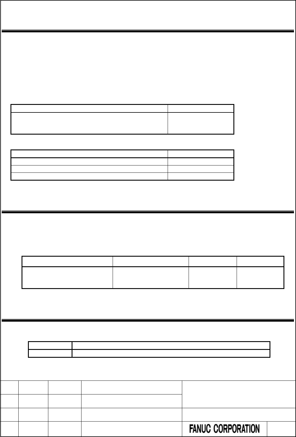
1 SUMMARY
The following function has been improved.
● The following window function has been improved.
- No.32 Reading modal data
This document is a supplemental manual for above.
Specifications and operations about PMC for FANUC Series 30i/31i/32i/35i-MODEL B, FANUC Power
Motion i-MODEL A, FANUC Series 0i-MODEL F are described in the following manual.
Manual
Spec.
FANUC Series 30
i
/31
i
/32
i
/35
i
-MODEL B
FANUC Power Motion i-MODEL A
FANUC Series 0i-MODEL F PMC Programming Manual
B-64513EN / 03
In this document, the following abbreviations are used.
Name
Abbreviation
FANUC Series 30i/31i/32i/35i-MODEL B
30i/31i/32i/35i -B
FANUC Power Motion i-MODEL A
Power Motion i-A
FANUC Series 0i-MODEL F
0i -F
2 APPLIED SOFTWARE
The new features will be applied to the following software.
● Improvement of 'No.32 Reading modal data'
PMC System software
PMC Drawing number Series Edition
Series 30i/31i/32i-B
Series 35i-B
Power Motion i-A
A02B-0323-H580#40A5
A02B-0333-H580#40A5
A02B-0334-H580#40A5
40A5 19 or later
3 WINDOW FUNCTIONS
The following window function has been improved.
Function code
Description
32
Reading modal data
FANUC Series 30i/31i/32i/35i -MODEL B
FANUC Power Motion i -MODEL A
FANUC Series 0i -MODEL F
PMC Supplemental Programming Manual
01 2014.12.25 M.Ichijou New registration DRAW. NO. : B-64513EN/03-1
EDIT. DATE DESIG. DESCRIPTION 3 / 15

3.1 Reading Modal Data (High-speed Response)
Change "5.4.19 Reading modal data(High-speed Response)" as follows.
Using this function, you can read modal information of CNC.
(1) Reading modal information of G-function (Data number=0 to 33, -1, -3)
Using this function, you can read modal information of G-function.
Input data structure
Top Address +0
(Function code)
32
+2
(Completion code)
-
(Need not to be set)
+4
(Data length L)
-
(Need not to be set)
+6
(Data number N)
Data type
N=0 to 33: Reading each data (See. Table 3.1 (a) to
(d))
N=-1: Reading 32 groups (Group No.0 to 31)
N=-3: Reading all groups
+8
(Data attribute M)
Specified block
M=0: Current block
M=1: Next block
M=2: (reserved)
+10
(Data area)
-
(Need not to be set)
NOTE
1 The modal information for a block after the next block cannot be read.
2 When reading 32 groups, the read modal information of groups are from No. 0 to
No.31. To read modal information of over No. 31 group, set over 31 to the data
number N or set “-3 (reading 32 all groups)” to the data number N.
3 When reading all groups, the modal information of 50 groups can be read
including some reserve groups. In the reserve group, the value “0” is set.
CAUTION
When using “N=-3” (reading all groups), ensure 100 byte area for the data area,
that is 110 bytes area for the input data area. If the data area is insufficient, a new
group data would be written to non-secured area when CNC new features will be
added in the future. As a result, the sequence program is not executed correctly
and the machine may behave an unexpected working.
FANUC Series 30i/31i/32i/35i -MODEL B
FANUC Power Motion i -MODEL A
FANUC Series 0i -MODEL F
PMC Supplemental Programming Manual
01 2014.12.25 M.Ichijou New registration DRAW. NO. : B-64513EN/03-1
EDIT. DATE DESIG. DESCRIPTION 4 / 15

Table3.1 (a) Modal information of G-function (part 1)
Group
number
(Data type)
Machining center system
Lathe system
G code Code in a
group
G code
Code in a
group
A series
B series
C series
0
G00
0
G00
G00
G00
0
G01
1
G01
G01
G01
1
G02
2
G02
G02
G02
2
G02.1
27
G02.2
10
G02.2
G02.2
G02.2
20
G02.3
12
G02.3
G02.3
G02.3
22
G02.4
15
G02.4
G02.4
G02.4
18
G03
3
G03
G03
G03
3
G03.2
11
G03.2
G03.2
G03.2
21
G03.3
13
G03.3
G03.3
G03.3
23
G03.4
16
G03.4
G03.4
G03.4
19
G06.2
14
G06.2
G06.2
G06.2
17
G33
4
G32
G33
G33
4
G34
24
G34
G34
G34
9
G35
22
G35
G35
G35
14
G36
23
G36
G36
G36
15
G71.3
G71.3
G71.3
10
G72.3
G72.3
G72.3
11
G73.3
G73.3
G73.3
12
G74.3
G74.3
G74.3
13
G77
6
G90
G77
G20
5
G78
7
G92
G78
G21
6
G79
8
G94
G79
G24
7
1
G17
0
G96
G96
G96
1
G17.1P1
0
G97
G97
G97
0
G17.1P2
14
G17.1P3
18
G17.1P4
22
G17.1P5
26
G18
8
G19
4
2
G90
0
G90
G90
0
G91
1
G91
G91
1
3
G22
1
G68
G68
G68
1
G23
0
G69
G69
G69
0
4
G93
2
G93
G93
G93
2
G94
0
G98
G94
G94
0
G95
1
G99
G95
G95
1
5
G20(G70)
0
G20
G20
G70
0
G21(G71)
1
G21
G21
G71
1
6
G40
0
G40
G40
G40
0
G41
1
G41
G41
G41
1
G41.2
3
G41.2
G41.2
G41.2
3
G41.3
5
G41.3
G41.3
G41.3
5
G41.4
6
G41.4
G41.4
G41.4
6
G41.5
8
G41.5
G41.5
G41.5
8
FANUC Series 30i/31i/32i/35i -MODEL B
FANUC Power Motion i -MODEL A
FANUC Series 0i -MODEL F
PMC Supplemental Programming Manual
01 2014.12.25 M.Ichijou New registration DRAW. NO. : B-64513EN/03-1
EDIT. DATE DESIG. DESCRIPTION 5 / 15

Table3.1 (b) Modal information of G-function (part 2)
Group
number
(Data type)
Machining center system
Lathe system
G code Code in a
group
G code
Code in a
group
A series
B series
C series
6
G41.6
10
G41.6
G41.6
G41.6
11
G42
2
G42
G42
G42
2
G42.2
4
G42.2
G42.2
G42.2
4
G42.4
7
G42.4
G42.4
G42.4
7
G42.5
9
G42.5
G42.5
G42.5
9
G42.6
11
G42.6
G42.6
G42.6
12
7
G43
1
G25
G25
G25
0
G43.1
3
G26
G26
G26
1
G43.3
7
G43.4
4
G43.5
5
G43.7
11
G43.8
9
G43.9
10
G44
2
G44.1
12
G49(G49.1)
0
8
G73
10
G22
G22
G22
1
G74
11
G23
G23
G23
0
G76
12
G80
0
G81
1
G82
2
G83
3
G84
4
G84.2
13
G84.3
14
G85
5
G86
6
G87
7
G88
8
G89
9
9
G98
0
G80
G80
G80
0
G99
1
G81
G81
G81
8
G82
G82
G82
9
G83
G83
G83
1
G83.1
G83.1
G83.1
10
G83.5
G83.5
G83.5
12
G83.6
G83.6
G83.6
14
G84
G84
G84
2
G84.2
G84.2
G84.2
11
G85
G85
G85
3
G87
G87
G87
5
G87.5
G87.5
G87.5
13
G87.6
G87.6
G87.6
15
G88
G88
G88
6
G89
G89
G89
7
FANUC Series 30i/31i/32i/35i -MODEL B
FANUC Power Motion i -MODEL A
FANUC Series 0i -MODEL F
PMC Supplemental Programming Manual
01 2014.12.25 M.Ichijou New registration DRAW. NO. : B-64513EN/03-1
EDIT. DATE DESIG. DESCRIPTION 6 / 15

Table3.1 (c) Modal information of G-function (part 3)
Group
number
(Data type)
Machining center system
Lathe system
G code Code in a
group
G code
Code in a
group
A series
B series
C series
10
G50
0
G98
G98
0
G51
1
G99
G99
1
11
G66
1
G66
G66
G66
1
G66.1
2
G66.1
G66.1
G66.1
2
G67
0
G67
G67
G67
0
12
G96
1
G97
0
13
G54(G54.1)
0
G54(G54.1)
G54(G54.1)
G54(G54.1)
0
G55
1
G55
G55
G55
1
G56
2
G56
G56
G56
2
G57
3
G57
G57
G57
3
G58
4
G58
G58
G58
4
G59
5
G59
G59
G59
5
14
G61
1
G61
G61
G61
1
G62
2
G62
G62
G62
2
G63
3
G63
G63
G63
3
G64
0
G64
G64
G64
0
15
G68
1
G17
G17
G17
0
G68.2
2
G17.1
G17.1
G17.1
10 to 29
G68.3
3
G18
G18
G18
4
G68.4
4
G19
G19
G19
8
G69
0
16
G15
0
G68.1
G68.1
G68.1
1
G16
1
G68.2
G68.2
G68.2
2
G68.3
G68.3
G68.3
3
G68.4
G68.4
G68.4
4
G69.1
G69.1
G69.1
0
17
G40.1
0
G50
G50
0
G41.1
1
G51
G51
1
G42.1
2
18
G25
0
G40.1
G40.1
G40.1
0
G26
1
G41.1
G41.1
G41.1
1
G42.1
G42.1
G42.1
2
19
G50.2(G250)
G50.2(G250)
G50.2(G250)
0
G51.2(G251)
G51.2(G251)
G51.2(G251)
1
20
G12.1(G112)
1
G12.1(G112)
G12.1(G112)
G12.1(G112)
1
G13.1(G113)
0
G13.1(G113)
G13.1(G113)
G13.1(G113)
0
21
G50.1
0
G50.1
G50.1
G50.1
0
G51.1
1
G51.1
G51.1
G51.1
1
22
G54.2
0 to 8
G43
G43
G43
1
G43.1
G43.1
G43.1
3
G43.4
G43.4
G43.4
4
G43.5
G43.5
G43.5
5
G43.7(G44.7)
G43.7(G44.7)
G43.7(G44.7)
6
G44
G44
G44
2
G44.1
G44.1
G44.1
12
G49(G49.1)
G49(G49.1)
G49(G49.1)
0
FANUC Series 30i/31i/32i/35i -MODEL B
FANUC Power Motion i -MODEL A
FANUC Series 0i -MODEL F
PMC Supplemental Programming Manual
01 2014.12.25 M.Ichijou New registration DRAW. NO. : B-64513EN/03-1
EDIT. DATE DESIG. DESCRIPTION 7 / 15

Table3.1 (d) Modal information of G-function (part 4)
Group
number
(Data type)
Machining center system
Lathe system
G code Code in a
group
G code
Code in a
group
A series
B series
C series
23
G80.5
0
G15
G15
G15
0
G81.5
1
G16
G16
G16
1
25
G54.4
G54.4
G54.4
0
26
G44.9
1
G80.5
G80.5
G80.5
0
G49.9
0
G81.5
G81.5
G81.5
1
27
G80.4
G80.4
G80.4
0
G81.4
G81.4
G81.4
1
30
G50.2
0
G51.2
1
32
G54.4
0
33
G80.4
0
G81.4
1
Completion codes
0 Completed successfully
3 The data number is invalid
4 The data attribute is invalid
Output data structure
(1) Reading each data (Data number N=G code group number)
Top Address +0
(Function code)
32
+2
(Completion code)
?
(See above description)
+4
(Data length L)
2
+6
(Data number N)
Data type
(Same as input data)
+8
(Data attribute M)
Specified block
(Same as input data)
+10
+11
Modal information of G-function
(2 bytes)
See "Fig. 3.1 (a) Modal information of G-function".
FANUC Series 30i/31i/32i/35i -MODEL B
FANUC Power Motion i -MODEL A
FANUC Series 0i -MODEL F
PMC Supplemental Programming Manual
01 2014.12.25 M.Ichijou New registration DRAW. NO. : B-64513EN/03-1
EDIT. DATE DESIG. DESCRIPTION 8 / 15
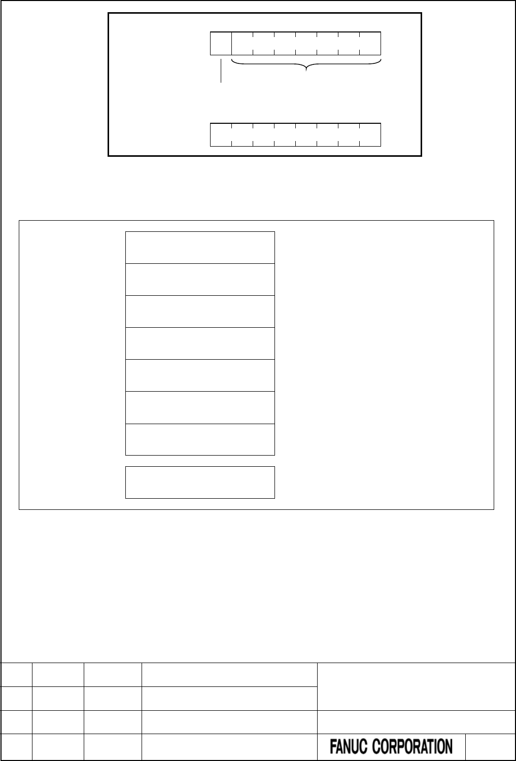
Top Address +10
Code in a group
0 : Not specified in the group
1 : Specified in the group
7
5
6
4
3
1
2
0
Top Address +11
7
5
6
4
3
1
2
0
0
Fig. 3.1 (a) Modal information of g-function
(2) Reading 32 groups (Data number N=-1)
Top Address +0
(Function code)
32
+2
(Completion code)
?
(See above description)
+4
(Data length L)
64
+6
(Data number N)
-1
(Same as input data)
+8
(Data attribute M)
Specified block
(Same as input data)
+10
Modal information of G-function
group No.0
(2 bytes)
See "Fig. 3.1 (a) Modal information of G-function".
+12
Modal information of G-function
group No.1
(2 bytes)
See "Fig. 3.1 (a) Modal information of G-function".
~
~
+72
+73
Modal information of G-function
group No.31
(2 bytes)
See "Fig. 3.1 (a) Modal information of G-function".
FANUC Series 30i/31i/32i/35i -MODEL B
FANUC Power Motion i -MODEL A
FANUC Series 0i -MODEL F
PMC Supplemental Programming Manual
01 2014.12.25 M.Ichijou New registration DRAW. NO. : B-64513EN/03-1
EDIT. DATE DESIG. DESCRIPTION 9 / 15

(3) Reading all groups (Data number N=-3)
Top Address +0
(Function code)
32
+2
(Completion code)
?
(See above description)
+4
(Data length L)
100
+6
(Data number N)
-3
(Same as input data)
+8
(Data attribute M)
Specified block
(Same as input data)
+10
Modal information of G-function
group No.0
(2 bytes)
See "Fig. 3.1 (a) Modal information of G-function".
+12
Modal information of G-function
group No.1
(2 bytes)
See "Fig. 3.1 (a) Modal information of G-function".
~
~
+108
+109
Modal information of G-function
group No.49
(2 bytes)
NOTE
The modal information of 50 groups can be read including some reserve groups.
In the reserve group, the value “0” is set.
FANUC Series 30i/31i/32i/35i -MODEL B
FANUC Power Motion i -MODEL A
FANUC Series 0i -MODEL F
PMC Supplemental Programming Manual
01 2014.12.25 M.Ichijou New registration DRAW. NO. : B-64513EN/03-1
EDIT. DATE DESIG. DESCRIPTION 10 / 15

(2) Reading modal information of other than G-function (Data number=100 to 126, -2)
Using this function, you can read modal information of other than G-function.
Input data structure
Top Address +0
(Function code)
32
+2
(Completion code)
-
(Need not to be set)
+4
(Data length L)
-
(Need not to be set)
+6
(Data number N)
Data type
N=100 to 126: Each data reading (See Table 3.1(e))
N=-2: Collective read (No.100 to 126)
+8
(Data attribute M)
Specified block
M=0: Current block
M=1: Next block
M=2: (reserved)
+10
(Data area)
-
(Need not to be set)
NOTE
A modal information for a block after the next block cannot be read.
FANUC Series 30i/31i/32i/35i -MODEL B
FANUC Power Motion i -MODEL A
FANUC Series 0i -MODEL F
PMC Supplemental Programming Manual
01 2014.12.25 M.Ichijou New registration DRAW. NO. : B-64513EN/03-1
EDIT. DATE DESIG. DESCRIPTION 11 / 15

Table3.1 (e) Modal information of other than G-function
Data type
Specified Address
Description
100
B
Second auxiliary function
101
D
102
E
(Reserved)
103
F
104
H
105
L
106
M
107
S
108
T
109
R
110
P
111
Q
112
A
113
C
114
I
115
J
116
K
117
N
118
O
119
U
120
V
121
W
122
X
123
Y
124
Z
125
M2
126
M3
Completion codes
0 Completed successfully
3 The data number is invalid
4 The data attribute is invalid
FANUC Series 30i/31i/32i/35i -MODEL B
FANUC Power Motion i -MODEL A
FANUC Series 0i -MODEL F
PMC Supplemental Programming Manual
01 2014.12.25 M.Ichijou New registration DRAW. NO. : B-64513EN/03-1
EDIT. DATE DESIG. DESCRIPTION 12 / 15

Output data structure
(1) Each data reading (Data number N=See Table 3.1 (e))
Top Address +0
(Function code)
32
+2
(Completion code)
?
(See above description)
+4
(Data length L)
6
+6
(Data number N)
Data type
(Same as input data)
+8
(Data attribute M)
Specified block
(Same as input data)
+10
+15
Modal information
(6 bytes)
See "Fig. 3.1 (b) Modal information of other than
G-function".
(2) Corrective reading (Data number N=-2)
Top Address +0
(Function code)
32
+2
(Completion code)
?
(See above description)
+4
(Data length L)
174
+6
(Data number N)
Data type
(Same as input data)
+8
(Data attribute M)
Specified block
(Same as input data)
+10
Modal information of
Data type No.100
(6 bytes)
See "Fig. 3.1 (b) Modal information of other than
G-function".
+16
Modal information of
Data type No.101
(6 bytes)
See "Fig. 3.1 (b) Modal information of other than
G-function".
~
~
+166
Modal information of
Data type No.126
(6 bytes)
See "Fig. 3.1 (b) Modal information of other than
G-function".
+172
+183
Reserved
(12 bytes)
FANUC Series 30i/31i/32i/35i -MODEL B
FANUC Power Motion i -MODEL A
FANUC Series 0i -MODEL F
PMC Supplemental Programming Manual
01 2014.12.25 M.Ichijou New registration DRAW. NO. : B-64513EN/03-1
EDIT. DATE DESIG. DESCRIPTION 13 / 15
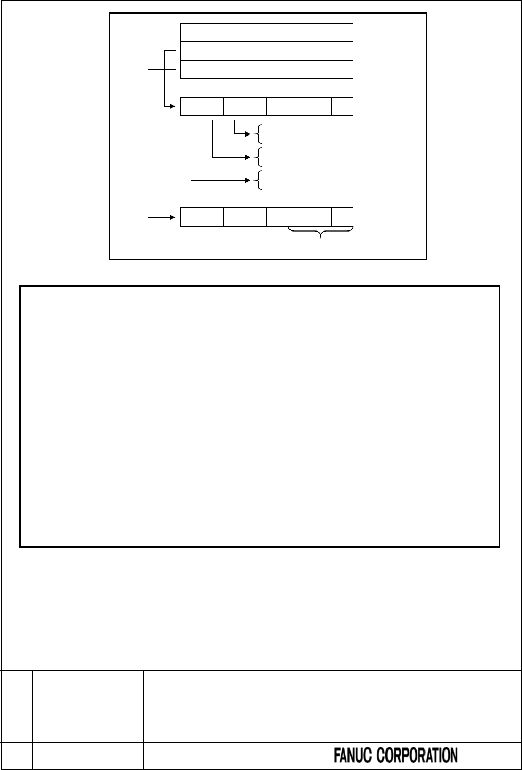
7
5
6
4
3
1
2
0
Data
FLAG1
FLAG2
4 bytes
1 byte
1 byte
0 : Positive
1 : Negative
0 : A decimal point not specified
1 : A decimal point specified
0 : Not specified in the current block
1 : Specified in the current block
7
5
6
4
3
1
2
0
Number of decimal places
Fig. 3.1 (b) Modal information of other than G-function
NOTE
1 The specification of whether a decimal point is specified or not in FLAG1, and the
specification of the number of decimal places in FLAG2, are valid only for F code.
Even if a decimal point is not specified, the number of decimal places may not be
0.
2 PMC-SB7 outputs the number of input digits to bits 0 to 3 of FLAG1, however
30i/31i/32i/35i-B, Power Motion i-A, 0i-F PMC does not. If you need to have the
number of input digits output as with the former specification, read the CNC
parameters of the following numbers, by using the window function for reading a
parameter (function code 17 or 154).
• For the M function:
No.3030(allowable number of digits of the M code)
• For the S function:
No.3031(allowable number of digits of the S code)
• For the T function:
No.3032(allowable number of digits of the T code)
• For the B function:
No.3033(allowable number of digits of the B code)
FANUC Series 30i/31i/32i/35i -MODEL B
FANUC Power Motion i -MODEL A
FANUC Series 0i -MODEL F
PMC Supplemental Programming Manual
01 2014.12.25 M.Ichijou New registration DRAW. NO. : B-64513EN/03-1
EDIT. DATE DESIG. DESCRIPTION 14 / 15

4 APPENDIX B LANGUAGE ID TABLE
Change "APPENDIX-B LANGUAGE ID TABLE " as follows.
Language ID used for Extended symbol and comment function and PMC message multi-language display
function is as follows.
Language ID
Language
0
English
1
Japanese
2
German
3
French
4
Chinese (Traditional)
5
Italian
6
Korean
7
Spanish
8
Dutch
9
Danish
10
Portuguese
11
Polish
12
Hungarian
13
Swedish
14
Czech
15
Chinese (Simplified)
16
Russian
17
Turkish
18
Bulgarian
19
Rumanian
20
Slovak
21
Finnish
22
(reserved)
23
Vietnamese
24
Indonesian
FANUC Series 30i/31i/32i/35i -MODEL B
FANUC Power Motion i -MODEL A
FANUC Series 0i -MODEL F
PMC Supplemental Programming Manual
01 2014.12.25 M.Ichijou New registration DRAW. NO. : B-64513EN/03-1
EDIT. DATE DESIG. DESCRIPTION 15 / 15

FANUC Series 30i/31i/32i/35i-MODEL B
FANUC Power Motion i-MODEL A
FANUC Series 0i-MODEL F
PMC Supplemental Programming Manual
Type of applied technical documents
Name
FANUC Series 30i/31i/32i/35i-MODEL B
FANUC Power Motion i-MODEL A
FANUC Series 0i-MODEL F
PMC Programming Manual
Spec. No. /Ed.
B-64513EN/03
Summary of Change
Group Name/Outline New, Add,
Correct, Delete
Applied Date
Basic Function
・
Addition of 0i-F PMC/L.
・ Addition of PMC Memory Type-E.
・ Addition of PID control instruction.
・ Expansion of PMC PROGRAM NO. and
EDITION NO. of title data.
Add Apr. 2015
Optional
Function
Unit
Maintenance
Parts
Notice
Correction
Another Addition of notes.
FANUC Series 30i/31i/32i/35i-MODEL B
FANUC Power Motion i-MODEL A
FANUC Series 0i-MODEL F
PMC Supplemental Programming Manual
01 2015.4.16 H.Yonekura New registration DRAW. NO. : B-64513EN/03-2
EDIT. DATE DESIG. DESCRIPTION 1 / 88

FANUC Series 30i/31i/32i/35i-MODEL B
FANUC Power Motion i-MODEL A
FANUC Series 0i-MODEL F
PMC Supplemental Programming Manual
Contents
1 SUMMARY ···················································································································· 4
2 APPLIED SOFTWARE ····································································································· 5
3 OVERVIEW OF PMC ······································································································· 7
3.1 LADDER DIVIDING MANAGEMENT FUNCTION ··································································· 7
3.2 MULTI-PATH PMC FUNCTION ··························································································· 7
3.2.1 Interface between CNC and PMC ··············································································· 7
4 PMC SPECIFICATIONS ································································································· 10
4.1 SPECIFICATIONS ··········································································································· 10
4.1.1 Basic Specifications ································································································· 10
4.1.2 Total Ladder Steps of Multi-path PMC ······································································· 14
4.1.3 Determination of PMC Memory Type ········································································· 15
4.1.4 Program Capacity ··································································································· 16
4.1.5 Used Memory Size of Sequence Program ···································································· 17
4.1.6 PMC Addresses ······································································································· 19
4.1.7 Basic Instructions ··································································································· 23
4.1.8 Functional Instructions (Arranged in Sequence of Instruction Group) ····························· 24
4.1.9 Functional Instructions (Arranged in Sequence of SUB No.) ·········································· 32
4.2 PMC SIGNAL ADDRESSES ······························································································ 39
4.2.1 Addresses for Signals Between the PMC and CNC (F, G) ·············································· 39
4.2.2 Addresses of Signals Between the PMC and Machine (X, Y) ·········································· 40
4.2.3 Internal Relay Addresses (R) ···················································································· 41
4.2.4 System Relay Addresses (R9000, Z0) ·········································································· 41
4.2.5 Extra Relay Addresses (E) ························································································ 42
4.2.6 Message Display Addresses (A) ················································································· 42
4.2.7 Timer Addresses (T) ································································································ 43
4.2.8 Counter Addresses (C) ····························································································· 43
4.2.9 Keep Relay Addresses (K) ························································································· 44
4.2.10 System Keep Relay Addresses (K) ·············································································· 44
4.2.11 Data Table Addresses (D) ························································································· 45
4.2.12 Addresses for Multi-path PMC Interface (M, N) ··························································· 46
4.2.13 Subprogram Number Addresses (P) ··········································································· 46
4.2.14 Label Number Addresses (L) ····················································································· 47
4.3 PMC PARAMETERS ········································································································ 48
4.3.1 PMC Parameter Format ··························································································· 48
4.4 PARAMETERS FOR THE PMC SYSTEM ············································································· 53
4.4.1 CNC Parameters Related to the PMCs ······································································· 53
4.5 COMPATIBILITY BETWEEN PMC MEMORY TYPE ······························································· 66
4.5.1 Compatibility between PMC Memory-D and PMC Memory-E ········································ 66
4.6 COMPATIBILITY WITH CONVENTIONAL MODELS ······························································ 67
FANUC Series 30i/31i/32i/35i-MODEL B
FANUC Power Motion i-MODEL A
FANUC Series 0i-MODEL F
PMC Supplemental Programming Manual
01 2015.4.16 H.Yonekura New registration DRAW. NO. : B-64513EN/03-2
EDIT. DATE DESIG. DESCRIPTION 2 / 88

4.6.1 Compatibility between 0i/0i Mate-D PMC/L and 0i-F PMC/L ········································· 67
5 COMMUNICATION WITH I/O DEVICE ·············································································· 68
5.1 I/O Link i and I/O Link ····································································································· 68
5.2 WHAT IS I/O Link i ? ······································································································· 70
6 LADDER LANGUAGE ··································································································· 71
6.1 OPERATION INSTRUCTION ····························································································· 71
6.1.1 PID (PID Control : SUB 460) ···················································································· 72
7 PMC DIAGNOSIS AND MAINTENANCE SCREENS ([PMC MAINTE]) ··································· 79
7.1 DATA INPUT/OUTPUT ([I/O] SCREEN) ··············································································· 79
7.1.1 7.4.1 Memory Card and USB Memory ········································································ 79
8 LADDER DIAGRAM MONITOR AND EDITOR SCREEN ([PMC LADDER]) ····························· 80
8.1 MONITORING LADDER DIAGRAMS ([LADDER] SCREEN) ···················································· 80
8.1.1 Display Format for Parameters ················································································· 80
8.2 EDITING LADDER PROGRAMS ······················································································ 80
8.2.1 Structure of Valid Net ······························································································ 80
9 PMC CONFIGURATION DATA SETTING SCREEN ([PMC CONFIG]) ····································· 81
9.1 DISPLAYING AND EDITING TITLE DATA ([TITLE] SCREENS) ················································ 81
9.1.1 Displaying Title Data ······························································································ 81
9.1.2 Editing Title Data ··································································································· 83
9.2 DISPLAYING AND SETTING CONFIGURATION PARAMETERS ([CONFIG PARAM] SCREEN) ····· 84
9.2.1 Setting the PMC memory type ·················································································· 84
9.3 PMC Program List Screen ······························································································· 86
9.3.1 Output of program list information file ······································································· 87
10 PMC ALARM MESSAGE AND ACTIONS TO TAKE ···························································· 88
10.1 ALARM MESSAGE LIST ·································································································· 88
10.1.1 Message that May Be Displayed on the PMC Alarm Screen ··········································· 88
10.1.2 Operation Errors ····································································································· 88
FANUC Series 30i/31i/32i/35i-MODEL B
FANUC Power Motion i-MODEL A
FANUC Series 0i-MODEL F
PMC Supplemental Programming Manual
01 2015.4.16 H.Yonekura New registration DRAW. NO. : B-64513EN/03-2
EDIT. DATE DESIG. DESCRIPTION 3 / 88
1 SUMMARY
The following function has been added or been improved.
(1) Addition of 0i-F PMC/L.
PMC/L function for Type 3 or Type 5 of FANUC Series 0i-MODEL F has been added.
About this function, refer to the following chapters.
● 4. PMC SPECIFICATIONS
● 5. COMMUNICATION WITH I/O DEVICE
● 10. PMC ALARM MESSAGE AND ACTIONS TO TAKE
(2) Addition of PMC Memory Type-E.
PMC Memory Type-E which is used for multi path or multi axes CNC has been added.
About this function, refer to the following chapters.
● 3. OVERVIEW OF PMC
● 4. PMC SPECIFICATIONS
● 9. PMC CONFIGURATION DATA SETTING SCREEN ([PMC CONFIG])
NOTE
PMC Memory Type-E is enabled only on a special series of CNC software.
(3) Addition of PID control instruction.
Functional instruction for PID control that is used at temperature control etc has been added.
About this function, refer to the following chapters.
● 4. PMC SPECIFICATIONS
● 6. LADDER LANGUAGE
● 8. LADDER DIAGRAM MONITOR AND EDITOR SCREEN ([PMC LADDER])
(4) Expansion of PMC PROGRAM NO. and EDITION NO. of title data.
At title data, PMC PROGRAM NO. has been expanded to 8 characters from 4 characters, and EDITION
NO. has been expanded to 8 characters from 2 characters.
About this function, refer to the following chapter.
● 9. PMC CONFIGURATION DATA SETTING SCREEN ([PMC CONFIG])
This document is a supplemental manual for above.
Please refer to the following manual about existing functions and operations.
Manual
Spec.
FANUC Series 30i/31i/32i/35i-MODEL B
FANUC Power Motion i-MODEL A
FANUC Series 0i-MODEL F
PMC Programming Manual
B-64513EN / 03
In this document, the following abbreviations are used.
Name
Abbreviation
FANUC Series 30i/31i/32i/35i-MODEL B
30i/31i/32i/35i-B
FANUC Power Motion i-MODEL A
Power Motion i-A
FANUC Series 0i-MODEL F
0i-F
FANUC Series 30i/31i/32i/35i-MODEL B
FANUC Power Motion i-MODEL A
FANUC Series 0i-MODEL F
PMC Supplemental Programming Manual
01 2015.4.16 H.Yonekura New registration DRAW. NO. : B-64513EN/03-2
EDIT. DATE DESIG. DESCRIPTION 4 / 88
2 APPLIED SOFTWARE
The new features will be applied to the following software.
(1) Addition of PMC/L
● PMC System software
PMC Drawing number Series Edition
Series 0i-MODEL F PMC/L
A02B-0339-H580#40B2
40B2
03 or later
● CNC System software
PMC Drawing number Series Edition
Series 0i-MODEL TF
Series 0i-MODEL MF
A02B-0339-H501#D6G1
A02B-0340-H501#D4G1
D6G1
D4G1
07 or later
(2) Addition of PMC Memory Type-E
● PMC System software
PMC
Drawing number
Series
Edition
Series 30i-MODEL B PMC
A02B-0323-H580#40A5
40A5
20 or later
● CNC System software
PMC Drawing number Series Edition
Series 30i-MODEL B
(Now developing)
FANUC Series 30i/31i/32i/35i-MODEL B
FANUC Power Motion i-MODEL A
FANUC Series 0i-MODEL F
PMC Supplemental Programming Manual
01 2015.4.16 H.Yonekura New registration DRAW. NO. : B-64513EN/03-2
EDIT. DATE DESIG. DESCRIPTION 5 / 88

(3) Addition of PID control instruction
● PMC System software
PMC Drawing number Series Edition
Series 30
i
/31
i
/32
i
/35
i
-MODEL B PMC
Power Motion i-MODEL A PMC
A02B-0323-H580#40A5 40A5 20 or later
Series 0i-MODEL F PMC
A02B-0339-H580#40B2
40B2
03 or later
● CNC System software
PMC Drawing number Series Edition
Series 30i-MODEL B
A02B-0323-H501#G301
G311
G321
G301
G311
G321
69 or later
Series 31i-MODEL B5 A02B-0326-H501#G421
G431
G421
G431
69 or later
Series 31i-MODEL B A02B-0327-H501#G401
G411
G401
G411
69 or later
Series 32i-MODEL B
A02B-0328-H501#G501
G501
69 or later
Series 35i-MODEL B A02B-0333-H501#G601
G611
G601
G611
23 or later
(Scheduled)
Power Motion i-MODEL A
A02B-0334-H501#88H0
88H0
20 or later
Series 0
i
-MODEL TF
Series 0i-MODEL MF
A02B-0339-H501#D6G1
A02B-0340-H501#D4G1
D6G1
D4G1
07 or later
(4) Expansion of “PMC PROGRAM NO.” and “EDITION NO.” of title data.
Same as ‘(3) Addition of PID control instruction’.
FANUC Series 30i/31i/32i/35i-MODEL B
FANUC Power Motion i-MODEL A
FANUC Series 0i-MODEL F
PMC Supplemental Programming Manual
01 2015.4.16 H.Yonekura New registration DRAW. NO. : B-64513EN/03-2
EDIT. DATE DESIG. DESCRIPTION 6 / 88

3 OVERVIEW OF PMC
3.1 LADDER DIVIDING MANAGEMENT FUNCTION
Add the following note into “1.5 LADDER DIVIDING MANAGEMENT FUNCTION”.
NOTE
To enable the ladder dividing management function, set 1 to the NC parameter
11931#5. For details, refer to “2.4.3”
3.2 MULTI-PATH PMC FUNCTION
3.2.1 Interface between CNC and PMC
Change “1.6.2 Interface between CNC and PMC” as follows.
When using PMC Memory Type-A, B, C, or D
The PMC path that controls the CNC-PMC interfaces, and the PMC addresses (F/G addresses) of the
interfaces, can be configured by CNC parameters.
These parameter settings enable you to configure the interface control system; configuration that all
CNC-PMC interfaces of the CNC are controlled by single PMC, or configuration that the CNC-PMC
interfaces are controlled by multiple PMCs.
The CNC-PMC interface is a memory block consisting of DI/DO areas of 768-byte each. There are 10
CNC-PMC interfaces at CNC side, and also 10 interfaces for each PMC path at PMC side, and you can
configure their connections as you like.
If all of these parameters are not set (0 is set to all), it is treated as the initial settings; all the F/G addresses of
the CNC side are assigned to the F/G addresses of the first PMC as described below.
FANUC Series 30i/31i/32i/35i-MODEL B
FANUC Power Motion i-MODEL A
FANUC Series 0i-MODEL F
PMC Supplemental Programming Manual
01 2015.4.16 H.Yonekura New registration DRAW. NO. : B-64513EN/03-2
EDIT. DATE DESIG. DESCRIPTION 7 / 88
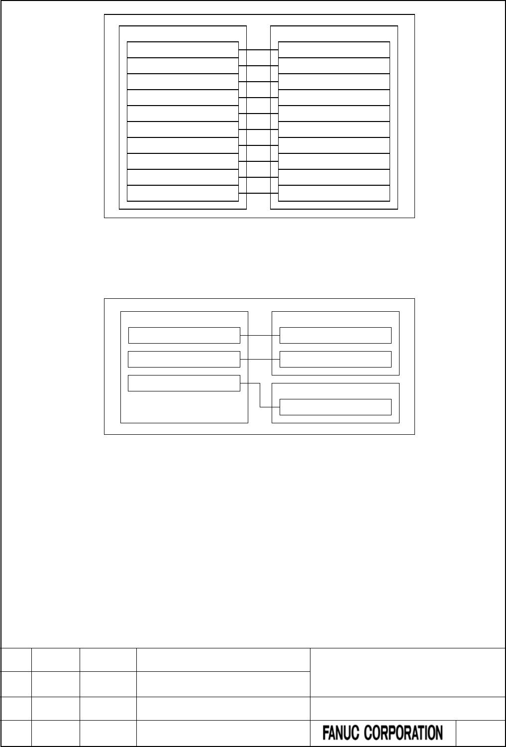
CNC
1st PMC
F/G0 to F/G767 of CNC
F/G1000 to F/G1767 of CNC
F/G2000 to F/G2767 of CNC
F/G3000 to F/G3767 of CNC
F/G4000 to F/G4767 of CNC
F/G5000 to F/G5767 of CNC
F/G6000 to F/G6767 of CNC
F/G7000 to F/G7767 of CNC
F/G8000 to F/G8767 of CNC
F/G9000 to F/G9767 of CNC
F/G0 to F/G767 of 1st PMC
F/G1000 to F/G1767 of 1st PMC
F/G2000 to F/G2767 of 1st PMC
F/G3000 to F/G3767 of 1st PMC
F/G4000 to F/G4767 of 1st PMC
F/G5000 to F/G5767 of 1st PMC
F/G6000 to F/G6767 of 1st PMC
F/G7000 to F/G7767 of 1st PMC
F/G8000 to F/G8767 of 1st PMC
F/G9000 to F/G9767 of 1st PMC
Fig. 3.2.1 (a) Initial settings for CNC-PMC interface
In the following example, F/G0 to F/G767 and F/G1000 to F/G1767 of the CNC are assigned to F/G0 to
F/G767 and F/G1000 to F/G1767 of the first PMC, and F/G2000 to F/G2767 of the CNC are assigned to
F/G0 to F/G767 of the second PMC:
CNC
1st PMC
F/G0 to F/G767 of CNC
F/G0 to F/G767 of 1st PMC
2nd PMC
F/G0 to F/G767 of 2nd PMC
F/G1000 to F/G1767 of 1st PMC
F/G1000 to F/G1767 of CNC
F/G2000 to F/G2767 of CNC
Fig. 3.2.1 (b) Setting example for CNC-PMC interface
For details of parameter setting, see Subsection 2.4.3.
When using PMC Memory Type-E
When using PMC Memory Type-E, the CNC-PMC interfaces are assigned as follows.
(F/G address of CNC = F/G address of 1st PMC)
This configuration of the interfaces is fixed and cannot be changed.
FANUC Series 30i/31i/32i/35i-MODEL B
FANUC Power Motion i-MODEL A
FANUC Series 0i-MODEL F
PMC Supplemental Programming Manual
01 2015.4.16 H.Yonekura New registration DRAW. NO. : B-64513EN/03-2
EDIT. DATE DESIG. DESCRIPTION 8 / 88
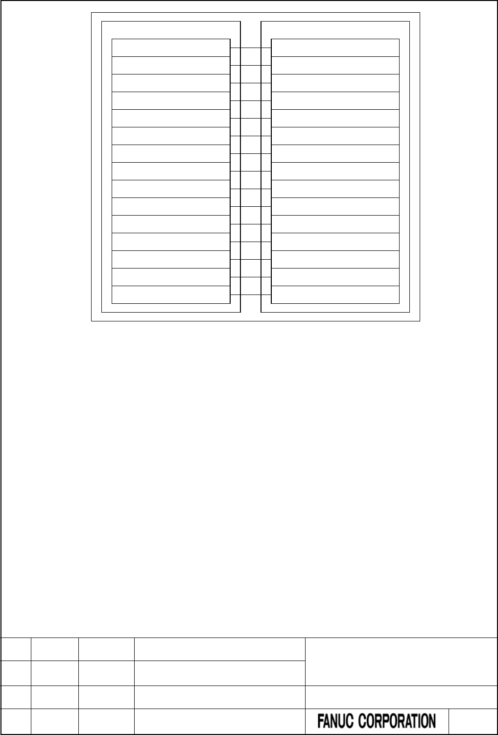
CNC
F/G0 to F/G767 of CNC
F/G1000 to F/G1767 of CNC
F/G2000 to F/G2767 of CNC
F/G3000 to F/G3767 of CNC
F/G4000 to F/G4767 of CNC
F/G5000 to F/G5767 of CNC
F/G6000 to F/G6767 of CNC
F/G7000 to F/G7767 of CNC
F/G8000 to F/G8767 of CNC
F/G9000 to F/G9767 of CNC
F/G10000 to F/G10767 of CNC
F/G11000 to F/G11767 of CNC
F/G12000 to F/G12767 of CNC
F/G13000 to F/G13767 of CNC
F/G14000 to F/G14767 of CNC
1st PMC
F/G0 to F/G767 of 1st PMC
F/G1000 to F/G1767 of 1st PMC
F/G2000 to F/G2767 of 1st PMC
F/G3000 to F/G3767 of 1st PMC
F/G4000 to F/G4767 of 1st PMC
F/G5000 to F/G5767 of 1st PMC
F/G6000 to F/G6767 of 1st PMC
F/G7000 to F/G7767 of 1st PMC
F/G8000 to F/G8767 of 1st PMC
F/G9000 to F/G9767 of 1st PMC
F/G10000 to F/G10767 of 1st PMC
F/G11000 to F/G11767 of 1st PMC
F/G12000 to F/G12767 of 1st PMC
F/G13000 to F/G13767 of 1st PMC
F/G14000 to F/G14767 of 1st PMC
Fig. 3.2.1 (c) CNC-PMC interface of PMC memory type-E
FANUC Series 30i/31i/32i/35i-MODEL B
FANUC Power Motion i-MODEL A
FANUC Series 0i-MODEL F
PMC Supplemental Programming Manual
01 2015.4.16 H.Yonekura New registration DRAW. NO. : B-64513EN/03-2
EDIT. DATE DESIG. DESCRIPTION 9 / 88

4 PMC SPECIFICATIONS
4.1 SPECIFICATIONS
4.1.1 Basic Specifications
Change “2.1.1 Basic Specifications” as follows.
Table 4.1.1 (a) Basic specifications of each PMC path
Function 1st to 5th path PMC 0i-F PMC/L DCSPMC
(Note1)
Reference
Multi-Path PMC function Maximum 5 paths
(0i-F:Maximum 3 paths)
- - 1.6
PMC Memory Type 1st PMC
PMC Memory-B, C, D, E(Note2)
2nd to 5th PMC
PMC Memory-A, B, C
Common PMC Memory with 1st PMC
- - 2.1.3
Programming language Ladder
Step sequence(Note3)
Function block
Ladder
Function block
Ladder
Function block
4
10
11
Divided ladder program
- Number of programs
- File number
40(0i-F:16)
1 to 99
6
1 to 99
None 2.1.4
Number of ladder levels
3
2 (Note4)
2 (Note4)
1.4.3
Level 1 execution period 1ms, 2ms, 4ms or 8ms
(0i-F:4ms or 8ms)
8ms 8ms 1.8, 2.4.3
Processing power
- Basic instruction
processing speed
(transition contact)
9.1ns/step
(0i-F:18.2ns/step)
1µs/step
1µs/step
-
Program capacity
- Ladder
- Symbol & Comment
- Message
Up to about 300,000 steps
(0i-F:100,000steps)
At least 1KB
At least 8KB
Up to about
24,000 steps
At least 1KB
At least 8KB
Up to about
5,000 steps
At least 1KB
At least 8KB
2.1.2, 2.1.4
Instructions
- Basic instructions
- Functional instructions
24
219
24
217
24
210
2.1.7
2.1.8, 2.1.9
CNC interface
2.2.1
- Inputs (F)
768 bytes * 15
768 bytes * 2
768 bytes
- Outputs (G)
768 bytes * 15
768 bytes * 2
768 bytes
FANUC Series 30i/31i/32i/35i-MODEL B
FANUC Power Motion i-MODEL A
FANUC Series 0i-MODEL F
PMC Supplemental Programming Manual
01 2015.4.16 H.Yonekura New registration DRAW. NO. : B-64513EN/03-2
EDIT. DATE DESIG. DESCRIPTION 10 / 88

Function 1st to 5th path PMC 0i-F PMC/L DCSPMC
(Note1)
Reference
DI/DO
2.2.2, 3
- Inputs (X) Up to 4,096 points
(0i-F:2,048 points)
Up to 1,024
points
Up to 896 points
- Outputs(Y)
Up to 4,096 points
(0i-F:2,048 points)
Up to 1,024
points
Up to 896 points
Symbol & Comment
1.2.7, 2.1.5
- Number of symbol
characters
40
40
40
- Number of comment
characters
255 * 4 255 * 4 255 * 4
Program storage area
(Flash ROM)
Max. 5MB
(0i-F:Max. 2MB)
Max. 768KB 128 KB 2.1.4
NOTE
1 This PMC is used for Dual Check Safety function (option) and handles the safety
related signals.
2 PMC Memory Type-E is enabled only on a special series of CNC software.
3 The Step Sequence is available in the main ladder of 1st PMC.
4 A program can be created on level 3 to maintain source-level compatibility with
programs for other models, but it is not executed.
FANUC Series 30i/31i/32i/35i-MODEL B
FANUC Power Motion i-MODEL A
FANUC Series 0i-MODEL F
PMC Supplemental Programming Manual
01 2015.4.16 H.Yonekura New registration DRAW. NO. : B-64513EN/03-2
EDIT. DATE DESIG. DESCRIPTION 11 / 88

Table 4.1.1 (b) Basic specifications of each PMC Memory Type
Function
1st to 5th PMC
0i-F
PMC/L DCSPMC
(Note 1)
PMC
Memory-A PMC
Memory-B PMC
Memory-C
PMC
Memory-D
PMC
Memory-E
(Note2)
PMC Memory
• Internal relay (R)
1,500 bytes
8,000 bytes
16,000 bytes
60,000 bytes
1,500 bytes
1,500 bytes
•
System Relay
(R9000 or Z0)
500 bytes 500 bytes 500 bytes 500 bytes 500 bytes 500 bytes
• Extra relay (E) (Note3)
10,000 bytes
10,000 bytes
10,000 bytes
10,000 bytes
10,000 bytes
(Note 4)
• Message display (A)
⋅ Display requests
2,000 points
2,000 points
4,000 points
6,000 points
2,000 points
(Note 5)
⋅ Status displays
2,000 points
2,000 points
4,000 points
6,000 points
2,000 points
(Note 5)
• Nonvolatile memory
• Timer (T)
⋅ Variable timer 80 bytes
(40 pieces)
500 bytes
(250 pieces)
1,000 bytes
(500 pieces)
1,000 bytes
(500 pieces)
80 bytes
(40 pieces)
80 bytes
(40 pieces)
⋅ Variable timer
precision
80 bytes
(40 pieces)
500 bytes
(250 pieces)
1,000 bytes
(500 pieces)
1,000 bytes
(500 pieces)
80 bytes
(40 pieces)
80 bytes
(40 pieces)
• Counter (C)
⋅ Variable counter
80 bytes
(20 pieces)
400 bytes
(100 pieces)
800 bytes
(200 pieces)
1200 bytes
(300 pieces)
80 bytes
(20 pieces)
80 bytes
(20 pieces)
⋅ Fixed counter
40 bytes
(20 pieces)
200 bytes
(100 pieces)
400 bytes
(200 pieces)
600 bytes
(300 pieces)
40 bytes
(20 pieces)
40 bytes
(20 pieces)
• Keep relay (K)
⋅ User area
20 bytes
100 bytes
200 bytes
300 bytes
100 bytes
20 bytes
⋅ System area
100 bytes
100 bytes
100 bytes
100 bytes
100 bytes
100 bytes
• Data table (D)
3,000 bytes
10,000 bytes
20,000 bytes
(Note 6)
60,000 bytes
(Note 6)
3,000 bytes
3,000 bytes
• Step sequence
⋅ Step number (S)
(None)
2,000 bytes
2,000 bytes
2,000 bytes
(None)
(None)
Functional instructions
• Variable timers (TMR)
40 pieces
250 pieces
500 pieces
500 pieces
40 pieces
40 pieces
• Fixed timers
(TMRB/TMRBF)
100 pieces
500 pieces
1,000 pieces
1,500 pieces
100 pieces
100 pieces
•
Variable counters
(CTR)
20 pieces 100 pieces 200 pieces 300 pieces 20 pieces 20 pieces
• Fixed counters
(CTRB)
20 pieces
100 pieces
200 pieces
300 pieces
20 pieces
20 pieces
•
Rising/Falling edge
detection (DIFU/DIFD)
256 pieces 1,000 pieces 2,000 pieces 3,000 pieces 256 pieces 256 pieces
• Labels (LBL)
9,999 pieces
9,999 pieces
9,999 pieces
9,999 pieces
9,999 pieces
9,999 pieces
• Subprograms (SP)
512 pieces
5,000 pieces
5,000 pieces
5,000 pieces
512 pieces
512 pieces
FANUC Series 30i/31i/32i/35i-MODEL B
FANUC Power Motion i-MODEL A
FANUC Series 0i-MODEL F
PMC Supplemental Programming Manual
01 2015.4.16 H.Yonekura New registration DRAW. NO. : B-64513EN/03-2
EDIT. DATE DESIG. DESCRIPTION 12 / 88

NOTE
1 This PMC is used for Dual Check Safety function (option).
2 PMC Memory Type-E is enabled only on a special series of CNC software.
3 The extra relay is common memory for the multi-PMC function. This means that
its size covers all of PMCs. Moreover, It is possible to use the extra relay as
nonvolatile memory by the option. (Exclude 0i-F PMC/L)
4 No extra relay is available for DCSPMC.
5 The message display relay is ineffective in DCSPMC because the message
display function is unavailable in it.
6 Under the configuration having two or more paths of PMC Memory-C or one path
of PMC Memory-D or E, specify the “Nonvolatile PMC data table area expansion
40KB” option. If this option is not added, the expanded data table area (D10000~)
is not kept after rebooting CNC. Refer to subsection 2.1.3 for details.
FANUC Series 30i/31i/32i/35i-MODEL B
FANUC Power Motion i-MODEL A
FANUC Series 0i-MODEL F
PMC Supplemental Programming Manual
01 2015.4.16 H.Yonekura New registration DRAW. NO. : B-64513EN/03-2
EDIT. DATE DESIG. DESCRIPTION 13 / 88

4.1.2 Total Ladder Steps of Multi-path PMC
Change part of “2.1.2 Total Ladder Steps of Multi-path PMC” as follows.
For the multi-path PMC system, you can specify a ladder step option by the total step of all of PMCs.
Table 4.1.2 (a) Ladder step options of 30i/31i/32i/35i-B, Power Motion i-A, 0i-F PMC
Option name
Specification
Maximum ladder size
PMC Ladder Function 24,000 Steps
Basic
102 KB
PMC Ladder Function 32,000 Steps
H990#32K
136 KB
PMC Ladder Function 64,000 Steps
H990#64K
272 KB
PMC Ladder Function 100,000 Steps
H990#100K
425 KB
PMC Ladder Function 300,000 Steps (Note)
H990#300K
1,275 KB
NOTE
The option is not supported for the Series 0i-F.
Table 4.1.2 (b) Ladder step options of 0i-F PMC/L
Option name
Specification
Maximum ladder size
PMC Ladder Function 5,000 Steps
Basic
21.25 KB
PMC Ladder Function 8,000 Steps
H990#8K
34 KB
PMC Ladder Function 24,000 Steps
H990#24K
102 KB
*** omitted below ***
FANUC Series 30i/31i/32i/35i-MODEL B
FANUC Power Motion i-MODEL A
FANUC Series 0i-MODEL F
PMC Supplemental Programming Manual
01 2015.4.16 H.Yonekura New registration DRAW. NO. : B-64513EN/03-2
EDIT. DATE DESIG. DESCRIPTION 14 / 88

4.1.3 Determination of PMC Memory Type
Change “2.1.3 Determination of PMC Memory Type” as follows.
PMC memory type
There are five PMC memory types i.e. memory-A, memory-B, memory-C, memory-D and memory-E. These
memory types differ in the size of PMC address. For the 2nd to 5th path PMC, the PMC memory can be also
shared with the 1st path PMC. The 0i-F PMC/L and the DCSPMC do not have plural PMC memory types.
For the details of the PMC memory type, refer to subsection “2.1.1”. As for the CNC parameter for the PMC
memory type, refer to subsection “2.4.3”.
The following is the selectable PMC memory types in each PMC path.
1st path PMC
2nd to 5th path PMC
Remark
PMC-memory B (default)
PMC-memory C
PMC-memory A (default)
PMC-memory B
PMC-memory C
Shared with 1st path PMC
You can specify up to three paths both of
PMC-memory B and C in total.
PMC-memory D
PMC-memory E (NOTE)
Shared with 1st path PMC
NOTE
PMC Memory Type-E is enabled only on a special series of CNC software.
Nonvolatile area of the data table in each PMC memory type
The following table is the data table number and basic nonvolatile area of each PMC memory type.
Table 4.1.3 (a) Data table number of each PMC memory type
PMC memory type
Data Table
Basic nonvolatile area
PMC memory-A
3,000 bytes
3,000 bytes
PMC memory-B
10,000 bytes
10,000 bytes
PMC memory-C 20,000 bytes 20,000 bytes (In case of using one path of PMC-memory C)
10,000 bytes (In case of using two or more paths of PMC-memory C)
PMC memory-D
PMC memory-E
60,000 bytes 10,000 bytes
NOTE
To use two or more paths of PMC memory-C or one path of PMC memory-D or E,
specify the option “Nonvolatile PMC data table area expansion (40KB)”. If this
option is not specified, the data at D10000 and subsequent addresses is not
saved.
FANUC Series 30i/31i/32i/35i-MODEL B
FANUC Power Motion i-MODEL A
FANUC Series 0i-MODEL F
PMC Supplemental Programming Manual
01 2015.4.16 H.Yonekura New registration DRAW. NO. : B-64513EN/03-2
EDIT. DATE DESIG. DESCRIPTION 15 / 88
4.1.4 Program Capacity
Change part of “2.1.4 Program Capacity” as follows.
All of the memory size, to which save the sequence program and multi-language PMC message data for all
PMC paths, is specified as the combination of the following two options. The size of each data is calculated
per 128KB.
Minimum unit of the size of divided ladder program is also 128KB. You can make up to 40(Note1) programs
of main ladder and divided ladder within specified total memory size.
(1) PMC Ladder step option (30i/31i/32i/35i-B, Power Motion i-A, 0i-F PMC)
Option name
Memory size
PMC Ladder Function 24,000 Steps (Basic)
256 KB
PMC Ladder Function 32,000 Steps
384 KB
PMC Ladder Function 64,000 Steps
768 KB
PMC Ladder Function 100,000 Steps
1 MB (1,024 KB)
PMC Ladder Function 300,000 Steps (Note2)
3 MB (3,072 KB)
(2) PMC Ladder step option (0i-F PMC/L)
Option name
Memory size
PMC Ladder Function 5,000 Steps (Basic)
128 KB
PMC Ladder Function 8,000 Steps
128 KB
PMC Ladder Function 24,000 Steps
256 KB
(3) PMC Symbol, Comment and Message capacity expansion option (30i/31i/32i/35i-B, Power Motion i-A,
0i-F PMC)
Option name
Memory size
PMC Symbol, Comment and Message capacity expansion (512KB)
512 KB
PMC Symbol, Comment and Message capacity expansion (1MB)
1MB (1,024 KB)
PMC Symbol, Comment and Message capacity expansion (2MB) (Note2)
2MB (2,048 KB)
(4) PMC Symbol, Comment and Message capacity expansion option (0i-F PMC/L)
Option name
Memory size
PMC Symbol, Comment and Message capacity expansion (512KB)
512 KB
CAUTION
When using 0i-F PMC/L, create message data in sequence program and
message data for multi-language display, so that total size of those data
becomes less than 128KB. If total size exceeds 128KB, PMC alarm "ER59
MESSAGE DATA SIZE OVER" occurs, and the sequence program does not
start.
NOTE
1 Up to 16 programs are available for 0i-F PMC. And, up to 6 programs are
available for 0i-F PMC/L.
2 These options are not supported by the Series 0i-F.
*** omitted below ***
FANUC Series 30i/31i/32i/35i-MODEL B
FANUC Power Motion i-MODEL A
FANUC Series 0i-MODEL F
PMC Supplemental Programming Manual
01 2015.4.16 H.Yonekura New registration DRAW. NO. : B-64513EN/03-2
EDIT. DATE DESIG. DESCRIPTION 16 / 88

4.1.5 Used Memory Size of Sequence Program
Change “2.1.5 Used Memory Size of Sequence Program” as follows.
The following table lists the memory capacity used by sequence programs. When creating the sequence
programs, keep their total size within this memory capacity.
Table 4.1.5 (a) Used memory size for each data
Category
Item
Required memory size (Note 1)
Ladder (Note 2)
Basic instruction
Refer to table 2.1.8.
Functional instruction
Refer to table 2.1.9 and table2.1.10.
Functional instruction parameter
4 bytes
Symbol/comment
conventional type (Note 2)
One definition of symbol/comment
(Including symbol string)
24 bytes
One comment character
1 byte (Note 3)
Symbol/comment
extended
type (Note 2)
One definition of symbol/comment
16 - 23 bytes (Note 5)
One symbol character
1 byte
One comment character
1 byte (Note 3)
One sub-program
8 bytes (Note 6)
Message (Note 2) One message character (alphanumeric
characters)
1 byte (Note 4)
Others Area used by the system About 16K bytes
(PMC Memory-A, B, DCS PMC)
About 24K bytes (Note 7)
(PMC Memory-C)
About 32K bytes (Note 7)
(PMC Memory-D, E)
FANUC Series 30i/31i/32i/35i-MODEL B
FANUC Power Motion i-MODEL A
FANUC Series 0i-MODEL F
PMC Supplemental Programming Manual
01 2015.4.16 H.Yonekura New registration DRAW. NO. : B-64513EN/03-2
EDIT. DATE DESIG. DESCRIPTION 17 / 88

NOTE
1 The total sequence program size (including all items such as ladders,
symbols/comments, and messages) cannot exceed the sequence program
memory storage capacity. If a ladder, symbol/ comment, or message is large,
the size of other categories may be limited.
2 The PMC programmer may adjust arrangement of these items in the sequence
program memory to improve processing efficiency. As a result, up to 1K byte
(1024 bytes) may be added to the sum of the sizes of individual items.
3 Each full-size character takes a memory capacity of 2 bytes.
4 For Japanese and special characters, each character in a character code
notation (including leading and trailing “@” characters) takes a memory capacity
of one byte. See descriptions about the DISPB function instructions for the
character input code notation.
5 One definition of extended symbol and comment takes 16-23 bytes plus the
memory according to the length of symbol and comment.
6 8 bytes are taken for a sub-program when local symbols are defined in the
sub-program.
7 In the PMC Memory-C, the system area is expanded by about 8KB from PMC
Memory-A or B. In the PMC Memory-D or E, the area is expanded by about 16KB
from PMC Memory-A or B. Therefore, available memory size for Symbol,
Comment and Message data is smaller than PMC Memory-A and B. If the
program overflowed by converting PMC Memory Type, decrease the Symbol,
Comment or Message data, or upgrade the Ladder step option to larger size.
FANUC Series 30i/31i/32i/35i-MODEL B
FANUC Power Motion i-MODEL A
FANUC Series 0i-MODEL F
PMC Supplemental Programming Manual
01 2015.4.16 H.Yonekura New registration DRAW. NO. : B-64513EN/03-2
EDIT. DATE DESIG. DESCRIPTION 18 / 88

4.1.6 PMC Addresses
Change “2.1.6 PMC Address” as follows.
Table 4.1.6 (a) PMC Address list(30i/31i/32i/35i-B, Power Motion i-A, 0i-F PMC) (1)
Signals Symbol
1st to 5th path PMC
PMC Memory-A PMC Memory-B PMC Memory-C
PMC Memory-D
PMC Memory-E
(Note 2)
Input signal to the PMC
from the machine
X X0 ~ X127
X200 ~ X327
X400 ~ X527
X600 ~ X727
X0 ~ X127
X200 ~ X327
X400 ~ X527
X600 ~ X727
X0 ~ X127
X200 ~ X327
X400 ~ X527
X600 ~ X727
X0 ~ X127
X200 ~ X327
X400 ~ X527
X600 ~ X727
X1000 ~ X1127
(Note 3)
X1000 ~ X1127
(Note 3)
X1000 ~ X1127
(Note 3)
X1000 ~ X1127
(Note 3)
Output signal from the
PMC to the machine
Y Y0 ~ Y127
Y200 ~ Y327
Y400 ~ Y527
Y600 ~ Y727
Y0 ~ Y127
Y200 ~ Y327
Y400 ~ Y527
Y600 ~ Y727
Y0 ~ Y127
Y200 ~ Y327
Y400 ~ Y527
Y600 ~ Y727
Y0 ~ Y127
Y200 ~ Y327
Y400 ~ Y527
Y600 ~ Y727
Y1000 ~ Y1127
(Note 3)
Y1000 ~ Y1127
(Note 3)
Y1000 ~ Y1127
(Note 3)
Y1000 ~ Y1127
(Note 3)
Input signal to the PMC
from the CNC
F
F0 ~ F767
F1000 ~ F1767
F2000 ~ F2767
F3000 ~ F3767
F4000 ~ F4767
F5000 ~ F5767
F6000 ~ F6767
F7000 ~ F7767
F8000 ~ F8767
F9000 ~ F9767
F0 ~ F767
F1000 ~ F1767
F2000 ~ F2767
F3000 ~ F3767
F4000 ~ F4767
F5000 ~ F5767
F6000 ~ F6767
F7000 ~ F7767
F8000 ~ F8767
F9000 ~ F9767
F0 ~ F767
F1000 ~ F1767
F2000 ~ F2767
F3000 ~ F3767
F4000 ~ F4767
F5000 ~ F5767
F6000 ~ F6767
F7000 ~ F7767
F8000 ~ F8767
F9000 ~ F9767
F0 ~ F767
F1000 ~ F1767
F2000 ~ F2767
F3000 ~ F3767
F4000 ~ F4767
F5000 ~ F5767
F6000 ~ F6767
F7000 ~ F7767
F8000 ~ F8767
F9000 ~ F9767
Below is only for
PMC Memory-E
F10000 ~ F10767
F11000 ~ F11767
F12000 ~ F12767
F13000 ~ F13767
F14000 ~ F14767
FANUC Series 30i/31i/32i/35i-MODEL B
FANUC Power Motion i-MODEL A
FANUC Series 0i-MODEL F
PMC Supplemental Programming Manual
01 2015.4.16 H.Yonekura New registration DRAW. NO. : B-64513EN/03-2
EDIT. DATE DESIG. DESCRIPTION 19 / 88

Table 4.1.6 (b) PMC Address list(30i/31i/32i/35i-B, Power Motion i-A, 0i-F PMC) (2)
Signals Symbol
1st to 5th path PMC
PMC Memory-A PMC Memory-B PMC Memory-C
PMC Memory-D
PMC Memory-E
(Note 2)
Output signal from the
PMC to the CNC
G
G0 ~ G767
G1000 ~ G1767
G2000 ~ G2767
G3000 ~ G3767
G4000 ~ G4767
G5000 ~ G5767
G6000 ~ G6767
G7000 ~ G7767
G8000 ~ G8767
G9000 ~ G9767
G0 ~ G767
G1000 ~ G1767
G2000 ~ G2767
G3000 ~ G3767
G4000 ~ G4767
G5000 ~ G5767
G6000 ~ G6767
G7000 ~ G7767
G8000 ~ G8767
G9000 ~ G9767
G0 ~ G767
G1000 ~ G1767
G2000 ~ G2767
G3000 ~ G3767
G4000 ~ G4767
G5000 ~ G5767
G6000 ~ G6767
G7000 ~ G7767
G8000 ~ G8767
G9000 ~ G9767
G0 ~ G767
G1000 ~ G1767
G2000 ~ G2767
G3000 ~ G3767
G4000 ~ G4767
G5000 ~ G5767
G6000 ~ G6767
G7000 ~ G7767
G8000 ~ G8767
G9000 ~ G9767
Below is only for
PMC Memory-E
G10000 ~ G10767
G11000 ~ G11767
G12000 ~ G12767
G13000 ~ G13767
G14000 ~ G14767
Input signal from other
PMC path
M
M0 ~ M767
(Note 4)
M0 ~ M767
(Note 4)
M0 ~ M767
(Note 4)
M0 ~ M767
(Note 4)
Output signal to other
PMC path
N N0 ~ N767
(Note 4)
N0 ~ N767
(Note 4)
N0 ~ N767
(Note 4)
N0 ~ N767
(Note 4)
Internal relay
R
R0 ~ R1499
R0 ~ R7999
R0 ~ R15999
R0 ~ R59999
System relay
R / Z
R9000 ~ R9499
R9000 ~ R9499
Z0 ~ Z499
Z0 ~ Z499
Extra relay
E
E0 ~ E9999
(Note 5)
E0 ~ E9999
(Note 5)
E0 ~ E9999
(Note 5)
E0 ~ E9999
(Note 5)
Message display
・Display request
・
Display status
A
A0 ~ A249
A9000 ~ A9249
A0 ~ A249
A9000 ~ A9249
A0 ~ A499
A9000 ~ A9499
A0 ~ A749
A9000 ~ A9749
Timer
T
T0 ~ T79
T9000 ~ T9076
T0 ~ T499
T9000 ~ T9499
T0 ~ T999
T9000 ~ T9999
T0 ~ T999
T9000 ~ T9999
・
Variable timer
・Variable timer precision
(Note 7)
Counter
C
C0 ~ C79
C5000 ~ C5039
C0 ~ C399
C5000 ~ C5199
C0 ~ C799
C5000 ~ C5399
C0~C1199
C5000~C5599
・
Variable counter
・
Fixed counter
Keep relay
K
K0 ~ K19
K900 ~ K999
K0 ~ K99
K900 ~ K999
K0 ~ K199
K900 ~ K999
K0 ~ K299
K900 ~ K999
・
User area
・
System area
Data table D D0 ~ D2999 D0 ~ D9999 D0 ~ D19999
(Note 8)
D0 ~ D59999
(Note 8)
Label
L
L1 ~ L9999
L1 ~ L9999
L1 ~ L9999
L1 ~ L9999
Subprogram
P
P1 ~ P512
P1 ~ P5000
P1 ~ P5000
P1 ~ P5000
Step number
(Step sequence)
S
(none)
S1 ~ S2000
S1 ~ S2000
S1 ~ S2000
FANUC Series 30i/31i/32i/35i-MODEL B
FANUC Power Motion i-MODEL A
FANUC Series 0i-MODEL F
PMC Supplemental Programming Manual
01 2015.4.16 H.Yonekura New registration DRAW. NO. : B-64513EN/03-2
EDIT. DATE DESIG. DESCRIPTION 20 / 88

Table 4.1.6 (c) PMC Address list(0i-F PMC/L, DCSPMC)
Signals Symbol 0i-F PMC/L DCSPMC
(Note 1)
Input signal to the PMC
from the machine
X X0 ~ X127 X0 ~ X127
Output signal from the
PMC to the machine
Y Y0 ~ Y127 Y0 ~ Y127
Input signal to the PMC
from the CNC
F
F0 ~ F767
F1000 ~ F1767
F0 ~ F767
Output signal from the
PMC to the CNC
G
G0 ~ G767
G1000 ~ G1767
G0 ~ G767
Input signal from other
PMC path
M - -
Output signal to other
PMC path
N - -
Internal relay
R
R0 ~ R1499
R0 ~ R1499
System relay
R / Z
R9000 ~ R9499
R9000 ~ R9499
Extra relay
E
E0 ~ E9999
(Note 6)
Message display
・Display request
・
Display status
A
A0 ~ A249
A9000 ~ A9249
-
Timer
T
T0 ~ T79
T9000 ~ T9079
T0 ~ T79
T9000 ~ T9079
・
Variable timer
・Variable timer precision
(Note 7)
Counter
C
C0 ~ C79
C5000 ~ C5039
C0 ~ C79
C5000 ~ C5039
・
Variable counter
・
Fixed counter
Keep relay
K
K0 ~ K99
K900 ~ K999
K0 ~ K19
K900 ~ K999
・
User area
・
System area
Data table
D
D0 ~ D2999
D0 ~ D2999
Label
L
L1 ~ L9999
L1 ~ L9999
Subprogram
P
P1 ~ P512
P1 ~ P512
Step number
(Step sequence)
S (none) (none)
FANUC Series 30i/31i/32i/35i-MODEL B
FANUC Power Motion i-MODEL A
FANUC Series 0i-MODEL F
PMC Supplemental Programming Manual
01 2015.4.16 H.Yonekura New registration DRAW. NO. : B-64513EN/03-2
EDIT. DATE DESIG. DESCRIPTION 21 / 88

NOTE
1 This PMC is used for Dual Check Safety function (option).
2 PMC Memory Type-E is enabled only on a special series of CNC software.
3 This area is reserved for PMC management software. Do not use it in user
programs.
4 The M/N addresses cannot be used in 4th and 5th path PMC.
5 This area is common memory for the multi-path PMC function. Each program can
write and read the same value in the area.
6 No extra relay is available for the Dual Check Safety PMC.
7 This area is used to specify the precision of a variable timer.
- Don't modify the value of active timer and its precision except for writing same
value.
- Don't set the value other than the following range.
- If above rules are violated, the behavior of the timer is not guaranteed.
The value of precision
0: Default (8 msec or 48 msec)
1: 1 msec
2: 10 msec
3: 100 msec
4: 1 sec
5: 1 min
8 To save all area of the data table, the “Nonvolatile PMC data table area expansion
(40KB)” option may be necessary. See “2.1.3 Determination of PMC Memory
Type” for details.
FANUC Series 30i/31i/32i/35i-MODEL B
FANUC Power Motion i-MODEL A
FANUC Series 0i-MODEL F
PMC Supplemental Programming Manual
01 2015.4.16 H.Yonekura New registration DRAW. NO. : B-64513EN/03-2
EDIT. DATE DESIG. DESCRIPTION 22 / 88

4.1.7 Basic Instructions
Change “2.1.7 Basic Instructions” as follows.
Instruction name Required memory
size
1st to 5th path PMC 0i-F PMC/L DCSPMC (Note)
RD
4 bytes
RD.NOT
4 bytes
WRT
4 bytes
WRT.NOT
4 bytes
AND
4 bytes
AND.NOT
4 bytes
OR
4 bytes
OR.NOT
4 bytes
RD.STK
4 bytes
RD.NOT.STK
4 bytes
AND.STK
4 bytes
OR.STK
4 bytes
SET
4 bytes
RST
4 bytes
RDPT
12 bytes
●
●
●
ANDPT
12 bytes
●
●
●
ORPT
12 bytes
●
●
●
RDPT.STK
12 bytes
●
●
●
RDNT
12 bytes
●
●
●
ANDNT
12 bytes
●
●
●
ORNT
12 bytes
●
●
●
RDNT.STK
12 bytes
●
●
●
PUSH
4 bytes
●
●
●
POP
4 bytes
●
●
●
(: Usable. ●: The Extended PMC Ladder Instruction Function. ×: Unusable.)
NOTE
This PMC is used for Dual Check Safety function (option). See “Dual Check
Safety Connection Manual” of each CNC series for details.
FANUC Series 30i/31i/32i/35i-MODEL B
FANUC Power Motion i-MODEL A
FANUC Series 0i-MODEL F
PMC Supplemental Programming Manual
01 2015.4.16 H.Yonekura New registration DRAW. NO. : B-64513EN/03-2
EDIT. DATE DESIG. DESCRIPTION 23 / 88
4.1.8 Functional Instructions (Arranged in Sequence of Instruction
Group)
Change “2.1.8 Functional Instructions (Arranged in Sequence of Instruction Group)” as follows.
Table 4.1.8 (a) Functional instruction list (arranged in sequence of instruction group) (1)
Instruction
group
Instruction
name
SUB
No. Processing
Required
memory
size
(byte)
1st to
5th
PMC
0i-F
PMC/L
DCS
PMC
(Note1)
Timer
1
TMR
3
On-delay timer
8
2
TMRB
24
Fixed on-delay timer
12
3
TMRBF
77
Fixed off-delay timer
12
4
TMRC
54
On-delay timer
16
5
TMRST
221
Stop watch timer (1 ms accuracy)
20
●
●
●
6
TMRSS
222
Stop watch timer (1 sec accuracy)
20
●
●
●
Counter
1
CTR
5
Counter processing
8
2
CTRB
56
Counter processing
12
3
CTRC
55
Counter processing
12
4
CTRD
223
Counter processing (4 byte length)
12
●
●
●
Data
1
MOVB
43
1-byte transfer
12
transfer
2
MOVW
44
2-byte transfer
12
3
MOVD
47
4-byte transfer
12
4
MOVN
45
Transfer of arbitrary number of bytes
16
5
MOVE
8
Data transfer after logical product
20
6
MOVOR
28
Data transfer after logical sum
16
7
XMOVB
35
Index modification binary data transfer
24
8
XMOV
18
Index modification data transfer
20
9
MOVBT
224
Bit transfer
24
●
●
●
10
SETNB
225
Data setting (1 byte length)
20
●
●
●
11
SETNW
226
Data setting (2 byte length)
20
●
●
●
12
SETND
227
Data setting (4 byte length)
20
●
●
●
13
XCHGB
228
Data exchange (1 byte length)
12
●
●
●
14
XCHGW
229
Data exchange (2 byte length)
12
●
●
●
15
XCHGD
230
Data exchange (4 byte length)
12
●
●
●
16
SWAPW
231
Data swap (2 byte length)
16
●
●
●
17
SWAPD
232
Data swap (4 byte length)
16
●
●
●
18
DSCHB
34
Binary data search
24
19
DSCH
17
Data search
20
(: Usable, ●: The Extended PMC Ladder Instruction Function, ∆: Executed as NOP instruction (Note 2), ×: Unusable.)
FANUC Series 30i/31i/32i/35i-MODEL B
FANUC Power Motion i-MODEL A
FANUC Series 0i-MODEL F
PMC Supplemental Programming Manual
01 2015.4.16 H.Yonekura New registration DRAW. NO. : B-64513EN/03-2
EDIT. DATE DESIG. DESCRIPTION 24 / 88

Table 4.1.8 (b) Functional instruction list (arranged in sequence of instruction group) (2)
Instruction
group
Instruction
name
SUB
No. Processing
Required
memory
size
(byte)
1st to
5th
PMC
0i-F
PMC/L
DCS
PMC
(Note1)
Table
1
TBLRB
233
Reading data from table (1 byte length)
24
●
●
●
Data
2
TBLRW
234
Reading data from table (2 byte length)
24
●
●
●
3
TBLRD
235
Reading data from table (4 byte length)
24
●
●
●
4
TBLRN
236
Reading data from table (Arbitrary byte length)
28
●
●
●
5
TBLWB
237
Writing data to table (1 byte length)
24
●
●
●
6
TBLWW
238
Writing data to table (2 byte length)
24
●
●
●
7
TBLWD
239
Writing data to table (4 byte length)
24
●
●
●
8
TBLWN
240
Writing data to table (Arbitrary byte length)
28
●
●
●
9
DSEQB
241
Searching data from table (=) (1 byte length)
28
●
●
●
10
DSEQW
242
Searching data from table (=) (2 byte length)
28
●
●
●
11
DSEQD
243
Searching data from table (=) (4 byte length)
28
●
●
●
12
DSNEB
244
Searching data from table (≠) (1 byte length)
28
●
●
●
13
DSNEW
245
Searching data from table (≠) (2 byte length)
28
●
●
●
14
DSNED
246
Searching data from table (≠) (4 byte length)
28
●
●
●
15
DSGTB
247
Searching data from table (>) (1 byte length)
28
●
●
●
16
DSGTW
248
Searching data from table (>) (2 byte length)
28
●
●
●
17
DSGTD
249
Searching data from table (>) (4 byte length)
28
●
●
●
18
DSLTB
250
Searching data from table (<) (1 byte length)
28
●
●
●
19
DSLTW
251
Searching data from table (<) (2 byte length)
28
●
●
●
20
DSLTD
252
Searching data from table (<) (4 byte length)
28
●
●
●
21
DSGEB
253
Searching data from table (
≧
) (1 byte length)
28
●
●
●
22
DSGEW
254
Searching data from table (
≧
) (2 byte length)
28
●
●
●
23
DSGED
255
Searching data from table (
≧
) (4 byte length)
28
●
●
●
24
DSLEB
256
Searching data from table (
≦
) (1 byte length)
28
●
●
●
25
DSLEW
257
Searching data from table (
≦
) (2 byte length)
28
●
●
●
26
DSLED
258
Searching data from table (
≦
) (4 byte length)
28
●
●
●
27
DMAXB
259
Maximum data (1 byte length)
28
●
●
●
28
DMAXW
260
Maximum data (2 byte length)
28
●
●
●
29
DMAXD
261
Maximum data (4 byte length)
28
●
●
●
30
DMINB
262
Minimum data (1 byte length)
28
●
●
●
31
DMINW
263
Minimum data (2 byte length)
28
●
●
●
32
DMIND
264
Minimum data (4 byte length)
28
●
●
●
(: Usable, ●: The Extended PMC Ladder Instruction Function, ∆: Executed as NOP instruction (Note 2), ×: Unusable.)
FANUC Series 30i/31i/32i/35i-MODEL B
FANUC Power Motion i-MODEL A
FANUC Series 0i-MODEL F
PMC Supplemental Programming Manual
01 2015.4.16 H.Yonekura New registration DRAW. NO. : B-64513EN/03-2
EDIT. DATE DESIG. DESCRIPTION 25 / 88

Table 4.1.8 (c) Functional instruction list (arranged in sequence of instruction group) (3)
Instruction
group
Instruction
name
SUB
No. Processing
Required
memory
size
(byte)
1st to
5th
PMC
0i-F
PMC/L
DCS
PMC
(Note1)
Comparison
1
EQB
200
Signed Binary Comparison (=) (1 byte length)
16
2
EQW
201
Signed Binary Comparison (=) (2 byte length)
16
3
EQD
202
Signed Binary Comparison (=) (4 byte length)
16
4
NEB
203
Signed Binary Comparison (≠) (1 byte length)
16
5
NEW
204
Signed Binary Comparison (≠) (2 byte length)
16
6
NED
205
Signed Binary Comparison (≠) (4 byte length)
16
7
GTB
206
Signed Binary Comparison (>) (1 byte length)
16
8
GTW
207
Signed Binary Comparison (>) (2 byte length)
16
9
GTD
208
Signed Binary Comparison (>) (4 byte length)
16
10
LTB
209
Signed Binary Comparison (<) (1 byte length)
16
11
LTW
210
Signed Binary Comparison (<) (2 byte length)
16
12
LTD
211
Signed Binary Comparison (<) (4 byte length)
16
13
GEB
212
Signed Binary Comparison (
≧
) (1 byte length)
16
14
GEW
213
Signed Binary Comparison (
≧
) (2 byte length)
16
15
GED
214
Signed Binary Comparison (
≧
) (4 byte length)
16
16
LEB
215
Signed Binary Comparison (
≦
) (1 byte length)
16
17
LEW
216
Signed Binary Comparison (
≦
) (2 byte length)
16
18
LED
217
Signed Binary Comparison (
≦
) (4 byte length)
16
19
RNGB
218
Signed Binary Comparison (range) (1 byte length)
20
20
RNGW
219
Signed Binary Comparison (range) (2 byte length)
20
21
RNGD
220
Signed Binary Comparison (range) (4 byte length)
20
22
COMPB
32
Comparison between binary data
20
23
COMP
15
Comparison
16
24
COIN
16
Coincidence check
16
(: Usable, ●: The Extended PMC Ladder Instruction Function, ∆: Executed as NOP instruction (Note 2), ×: Unusable.)
FANUC Series 30i/31i/32i/35i-MODEL B
FANUC Power Motion i-MODEL A
FANUC Series 0i-MODEL F
PMC Supplemental Programming Manual
01 2015.4.16 H.Yonekura New registration DRAW. NO. : B-64513EN/03-2
EDIT. DATE DESIG. DESCRIPTION 26 / 88

Table 4.1.8 (d) Functional instruction list (arranged in sequence of instruction group) (4)
Instruction
group
Instruction
name
SUB
No. Processing
Requir
ed
memory
size
(byte)
1st to
5th
PMC
0i-F
PMC/L
DCS
PMC
(Note1)
Bit
1
DIFU
57
Rising-edge detection
8
operation
2
DIFD
58
Falling-edge detection
8
3
EOR
59
Exclusive OR
20
4
AND
60
Logical AND
20
5
OR
61
Logical OR
20
6
NOT
62
Logical NOT
16
7
PARI
11
Parity check
8
8
SFT
33
Shift register
8
9
EORB
265
Exclusive OR (1 byte length)
20
●
●
●
10
EORW
266
Exclusive OR (2 byte length)
20
●
●
●
11
EORD
267
Exclusive OR (4 byte length)
20
●
●
●
12
ANDB
268
Logical AND (1 byte length)
20
●
●
●
13
ANDW
269
Logical AND (2 byte length)
20
●
●
●
14
ANDD
270
Logical AND (4 byte length)
20
●
●
●
15
ORB
271
Logical OR (1 byte length)
20
●
●
●
16
ORW
272
Logical OR (2 byte length)
20
●
●
●
17
ORD
273
Logical OR (4 byte length)
20
●
●
●
18
NOTB
274
Logical NOT (1 byte length)
16
●
●
●
19
NOTW
275
Logical NOT (2 byte length)
16
●
●
●
20
NOTD
276
Logical NOT (4 byte length)
16
●
●
●
21
SHLB
277
Bit shift left (1 byte length)
20
●
●
●
22
SHLW
278
Bit shift left (2 byte length)
20
●
●
●
23
SHLD
279
Bit shift left (4 byte length)
20
●
●
●
24
SHLN
280
Bit shift left (Arbitrary byte length)
24
●
●
●
25
SHRB
281
Bit shift right (1 byte length)
20
●
●
●
26
SHRW
282
Bit shift right (2 byte length)
20
●
●
●
27
SHRD
283
Bit shift right (4 byte length)
20
●
●
●
28
SHRN
284
Bit shift right (Arbitrary byte length)
24
●
●
●
29
ROLB
285
Bit rotation left (1 byte length)
20
●
●
●
30
ROLW
286
Bit rotation left (2 byte length)
20
●
●
●
31
ROLD
287
Bit rotation left (4 byte length)
20
●
●
●
32
ROLN
288
Bit rotation left (Arbitrary byte length)
24
●
●
●
33
RORB
289
Bit rotation right (1 byte length)
20
●
●
●
34
RORW
290
Bit rotation right (2 byte length)
20
●
●
●
35
RORD
291
Bit rotation right (4 byte length)
20
●
●
●
36
RORN
292
Bit rotation right (Arbitrary byte length)
24
●
●
●
37
BSETB
293
Bit set (1 byte length)
16
●
●
●
38
BSETW
294
Bit set (2 byte length)
16
●
●
●
39
BSETD
295
Bit set (4 byte length)
16
●
●
●
40
BSETN
296
Bit set (Arbitrary byte length)
20
●
●
●
(: Usable, ●: The Extended PMC Ladder Instruction Function, ∆: Executed as NOP instruction (Note 2), ×: Unusable.)
FANUC Series 30i/31i/32i/35i-MODEL B
FANUC Power Motion i-MODEL A
FANUC Series 0i-MODEL F
PMC Supplemental Programming Manual
01 2015.4.16 H.Yonekura New registration DRAW. NO. : B-64513EN/03-2
EDIT. DATE DESIG. DESCRIPTION 27 / 88

Table 4.1.8 (e) Functional instruction list (arranged in sequence of instruction group) (5)
Instruction
group
Instruction
name
SUB
No. Processing
Required
memory
size
(byte)
1st to
5th
PMC
0i-F
PMC/L
DCS
PMC
(Note1)
Bit
41
BRSTB
297
Bit reset (1 byte length)
16
●
●
●
operation
42
BRSTW
298
Bit reset (2 byte length)
16
●
●
●
43
BRSTD
299
Bit reset (4 byte length)
16
●
●
●
44
BRSTN
300
Bit reset (Arbitrary byte length)
20
●
●
●
45
BTSTB
301
Bit test (1 byte length)
16
●
●
●
46
BTSTW
302
Bit test (2 byte length)
16
●
●
●
47
BTSTD
303
Bit test (4 byte length)
16
●
●
●
48
BTSTN
304
Bit test (Arbitrary byte length)
20
●
●
●
49
BPOSB
305
Bit search (1 byte length)
12
●
●
●
50
BPOSW
306
Bit search (2 byte length)
12
●
●
●
51
BPOSD
307
Bit search (4 byte length)
12
●
●
●
52
BPOSN
308
Bit search (Arbitrary byte length)
16
●
●
●
53
BCNTB
309
Bit count (1 byte length)
12
●
●
●
54
BCNTW
310
Bit count (2 byte length)
12
●
●
●
55
BCNTD
311
Bit count (4 byte length)
12
●
●
●
56
BCNTN
312
Bit count (Arbitrary byte length)
16
●
●
●
Code
conversion
1 COD 7 Code conversion 16+n
(Note5)
2 CODB 27 Binary code conversion 20+n
(Note5)
3
DCNV
14
Data conversion
12
4
DCNVB
31
Extended data conversion
16
5
DEC
4
Decoding
12
6
DECB
25
Binary decoding
20
7
TBCDB
313
Binary to BCD conversion (1 byte length)
16
●
●
●
8
TBCDW
314
Binary to BCD conversion (2 byte length)
16
●
●
●
9
TBCDD
315
Binary to BCD conversion (4 byte length)
16
●
●
●
10
FBCDB
316
BCD to Binary conversion (1 byte length)
16
●
●
●
11
FBCDW
317
BCD to Binary conversion (2 byte length)
16
●
●
●
12
FBCDD
318
BCD to Binary conversion (4 byte length)
16
●
●
●
(: Usable, ●: The Extended PMC Ladder Instruction Function, ∆: Executed as NOP instruction (Note 2), ×: Unusable.)
FANUC Series 30i/31i/32i/35i-MODEL B
FANUC Power Motion i-MODEL A
FANUC Series 0i-MODEL F
PMC Supplemental Programming Manual
01 2015.4.16 H.Yonekura New registration DRAW. NO. : B-64513EN/03-2
EDIT. DATE DESIG. DESCRIPTION 28 / 88

Table 4.1.8 (f) Functional instruction list (arranged in sequence of instruction group) (6)
Instruction
group
Instruction
name
SUB
No. Processing
Required
memory
size
(byte)
1st to
5th
PMC
0i-F
PMC/L
DCS
PMC
(Note1)
Operation
1
ADDB
36
Binary addition
20
2
SUBB
37
Binary subtraction
20
3
MULB
38
Binary multiplication
20
4
DIVB
39
Binary division
20
5
ADD
19
BCD addition
20
6
SUB
20
BCD subtraction
20
7
MUL
21
BCD multiplication
20
8
DIV
22
BCD division
20
9
NUMEB
40
Binary constant definition
16
10
NUME
23
BCD-constant definition
12
11
ADDSB
319
Addition (1 byte length)
20
●
●
●
12
ADDSW
320
Addition (2 byte length)
20
●
●
●
13
ADDSD
321
Addition (4 byte length)
20
●
●
●
14
SUBSB
322
Subtraction (1 byte length)
20
●
●
●
15
SUBSW
323
Subtraction (2 byte length)
20
●
●
●
16
SUBSD
324
Subtraction (3 byte length)
20
●
●
●
17
MULSB
325
Multiplication (1 byte length)
20
●
●
●
18
MULSW
326
Multiplication (2 byte length)
20
●
●
●
19
MULSD
327
Multiplication (4 byte length)
20
●
●
●
20
DIVSB
328
Division (1 byte length)
20
●
●
●
21
DIVSW
329
Division (2 byte length)
20
●
●
●
22
DIVSD
330
Division (4 byte length)
20
●
●
●
23
MODSB
331
Remainder (1 byte length)
20
●
●
●
24
MODSW
332
Remainder (2 byte length)
20
●
●
●
25
MODSD
333
Remainder (4 byte length)
20
●
●
●
26
INCSB
334
Increment (1 byte length)
8
●
●
●
27
INCSW
335
Increment (2 byte length)
8
●
●
●
28
INCSD
336
Increment (4 byte length)
8
●
●
●
29
DECSB
337
Decrement (1 byte length)
8
●
●
●
30
DECSW
338
Decrement (2 byte length)
8
●
●
●
31
DECSD
339
Decrement (4 byte length)
8
●
●
●
32
ABSSB
340
Absolute value (1 byte length)
16
●
●
●
33
ABSSW
341
Absolute value (2 byte length)
16
●
●
●
34
ABSSD
342
Absolute value (4 byte length)
16
●
●
●
35
NEGSB
343
Sign inversion (1 byte length)
16
●
●
●
36
NEGSW
344
Sign inversion (2 byte length)
16
●
●
●
37
NEGSD
345
Sign inversion (4 byte length)
16
●
●
●
38
PID
460
PID control (Note6)
28
●
×
×
(: Usable, ●: The Extended PMC Ladder Instruction Function, ∆: Executed as NOP instruction (Note 2), ×: Unusable.)
FANUC Series 30i/31i/32i/35i-MODEL B
FANUC Power Motion i-MODEL A
FANUC Series 0i-MODEL F
PMC Supplemental Programming Manual
01 2015.4.16 H.Yonekura New registration DRAW. NO. : B-64513EN/03-2
EDIT. DATE DESIG. DESCRIPTION 29 / 88
Table 4.1.8 (g) Functional instruction list (arranged in sequence of instruction group) (7)
Instruction
group
Instruction
name
SUB
No. Processing
Required
memory
size
(byte)
1st to
5th
PMC
0i-F
PMC/L
DCS
PMC
(Note1)
CNC
1
DISPB
41
Message display
8
∆
Function
2
EXIN
42
External data input
8
∆
3
WINDR
51
CNC window data read
8
∆
4
WINDW
52
CNC window data write
8
∆
5
AXCTL
53
PMC axis control
12
∆
6
PSGN2
63
Position signal
8
∆
7
PSGNL
50
Position signal
12
∆
Program
1
COM
9
Common line control
8
control
2
COME
29
End of common line control
4
3
JMP
10
Jump
12
4
JMPE
30
End of jump
4
5
JMPB
68
Label jump 1
16
6
JMPC
73
Label jump 2
16
7
LBL
69
Label
12
8
CALL
65
Conditional subprogram call
12
9
CALLU
66
Unconditional subprogram call
12
10
SP
71
Subprogram
8
11
SPE
72
End of subprogram
4
12
END1
1
End of first-level program
4
13
END2
2
End of second-level program
4
14
END3
48
End of third-level program
4
(Note3)
∆
(Note4)
∆
(Note4)
15
END
64
End of ladder program
4
16
NOP
70
No operation
8
17
CS
74
Case call
8
18
CM
75
Sub program call in case call
12
19
CE
76
End of case call
4
Rotation
1
ROT
6
Rotation control
20
control
2
ROTB
26
Binary rotation control
24
Invalid
1
SPCNT
46
Spindle control
16
∆
∆
∆
instruction 2 DISP 49 Message display 16+n
(Note5)
∆ ∆ ∆
3
MMCWR
98
MMC window data read
12
∆
∆
∆
4
MMCWW
99
MMC window data write
12
∆
∆
∆
5
FNC90
90
Arbitrary-function instruction 1
8
∆
∆
∆
6
FNC91
91
Arbitrary-function instruction 2
8
∆
∆
∆
7
FNC92
92
Arbitrary-function instruction 3
8
∆
∆
∆
8
FNC93
93
Arbitrary-function instruction 4
8
∆
∆
∆
9
FNC94
94
Arbitrary-function instruction 5
8
∆
∆
∆
10
FNC95
95
Arbitrary-function instruction 6
8
∆
∆
∆
11
FNC96
96
Arbitrary-function instruction 7
8
∆
∆
∆
12
FNC97
97
Arbitrary-function instruction 8
8
∆
∆
∆
(: Usable, ●: The Extended PMC Ladder Instruction Function, ∆: Executed as NOP instruction (Note 2), ×: Unusable.)
FANUC Series 30i/31i/32i/35i-MODEL B
FANUC Power Motion i-MODEL A
FANUC Series 0i-MODEL F
PMC Supplemental Programming Manual
01 2015.4.16 H.Yonekura New registration DRAW. NO. : B-64513EN/03-2
EDIT. DATE DESIG. DESCRIPTION 30 / 88

NOTE
1 This term stands for the Dual Check Safety PMC (option).
2 These instructions are intended to maintain source-level compatibility with programs
for conventional models. They are treated as a NOP instruction (instruction that
performs no operation).
3 The 3rd level sequence part is available for the compatibility with programs for
conventional models. However, the execution cycle period for processing the 3rd level
sequence part is not guaranteed. See Section 1.4.3 “Processing priority”.
4 This instruction is available only for source-level compatibility with programs for other
models. A program can be created on level 3, but it is not executed.
5 Memory size increases according to the number of data tables to be used. In the
COD instruction, CODB instruction (1 byte length), CODB instruction (2 byte length),
or DISP instruction, 2 bytes are added for each data. And, when the number of data
is odd, extra 2 bytes are added. In the CODB instruction, 4 bytes are added for each
data.
6 This instruction cannot be used in some version of PMC software. Executing this
instruction on the unsupported version of PMC software will raise the warning “WN58
UNSUPPORTED FUNCTION” on PMC alarm screen, and the ladder program is
executed excluding this instruction.
FANUC Series 30i/31i/32i/35i-MODEL B
FANUC Power Motion i-MODEL A
FANUC Series 0i-MODEL F
PMC Supplemental Programming Manual
01 2015.4.16 H.Yonekura New registration DRAW. NO. : B-64513EN/03-2
EDIT. DATE DESIG. DESCRIPTION 31 / 88

4.1.9 Functional Instructions (Arranged in Sequence of SUB No.)
Change “2.1.9 Functional Instructions (Arranged in Sequence of SUB No.)” as follows.
Table 4.1.9 (a) Functional instruction list (arranged in sequence of SUB No.) (1)
Instruction
name SUB
No. Processing Required
memory
size (byte)
1st to
5th
PMC
0i-F
PMC/L
DCS
PMC
(Note1)
END1
1
End of first-level program
4
END2
2
End of second-level program
4
TMR
3
Timer processing
8
DEC
4
Decoding
12
CTR
5
Counter processing
8
ROT
6
Rotation control
20
COD 7 Code conversion 16+n
(Note5)
MOVE
8
Data transfer after logical product
20
COM
9
Common line control
8
JMP
10
Jump
12
PARI
11
Parity check
8
DCNV
14
Data conversion
12
COMP
15
Comparison
16
COIN
16
Coincidence check
16
DSCH
17
Data search
20
XMOV
18
Index modification data transfer
20
ADD
19
Addition
20
SUB
20
Subtraction
20
MUL
21
Multiplication
20
DIV
22
Division
20
NUME
23
Constant definition
12
TMRB
24
Fixed-timer processing
12
DECB
25
Binary decoding
20
ROTB
26
Binary rotation control
24
CODB 27 Binary code conversion 20+n
(Note5)
MOVOR
28
Data transfer after logical sum
16
COME
29
End of common line control
4
JMPE
30
End of jump
4
DCNVB
31
Extended data conversion
16
COMPB
32
Binary comparison
20
SFT
33
Shift register
8
DSCHB
34
Binary data search
24
XMOVB
35
Index modification binary data transfer
24
ADDB
36
Binary addition
20
SUBB
37
Binary subtraction
20
MULB
38
Binary multiplication
20
DIVB
39
Binary division
20
(: Usable, ●: The Extended PMC Ladder Instruction Function, ∆: Executed as NOP instruction (Note 2), ×: Unusable.)
FANUC Series 30i/31i/32i/35i-MODEL B
FANUC Power Motion i-MODEL A
FANUC Series 0i-MODEL F
PMC Supplemental Programming Manual
01 2015.4.16 H.Yonekura New registration DRAW. NO. : B-64513EN/03-2
EDIT. DATE DESIG. DESCRIPTION 32 / 88

Table 4.1.9 (b) Functional instruction list (arranged in sequence of SUB No.) (2)
Instruction
name SUB
No. Processing Required
memory
size (byte)
1st to
5th
PMC
0i-F
PMC/L
DCS
PMC
(Note1)
NUMEB
40
Binary constant definition
16
DISPB
41
Message display
8
∆
EXIN
42
External data input
8
∆
MOVB
43
1-byte transfer
12
MOVW
44
2-byte transfer
12
MOVN
45
Transfer of arbitrary number of bytes
16
SPCNT
46
Spindle control
16
∆
∆
∆
MOVD
47
4-byte transfer
12
END3
48
End of third-level program
4
(Note3)
∆
(Note4)
∆
(Note4)
DISP 49 Message display 16+n
(Note5)
∆ ∆ ∆
PSGNL
50
Position signal
12
∆
WINDR
51
CNC window data read
8
∆
WINDW
52
CNC window data write
8
∆
AXCTL
53
PMC axis control
12
∆
TMRC
54
Timer processing
16
CTRC
55
Counter processing
12
CTRB
56
Counter processing
12
DIFU
57
Rising-edge detection
8
DIFD
58
Falling-edge detection
8
EOR
59
Exclusive OR
20
AND
60
Logical AND
20
OR
61
Logical OR
20
NOT
62
Logical NOT
16
PSGN2
63
Position signal
8
∆
END
64
End of ladder program
4
CALL
65
Conditional subprogram call
12
CALLU
66
Unconditional subprogram call
12
JMPB
68
Label jump 1
16
LBL
69
Label
12
NOP
70
No operation
8
SP
71
Subprogram
8
SPE
72
End of subprogram
4
JMPC
73
Label jump 2
16
CS
74
Case call
8
CM
75
Sub program call in case call
12
CE
76
End of case call
4
TMRBF
77
Fixed off-delay timer
12
FNC90
90
Arbitrary-function instruction 1
8
∆
∆
∆
FNC91
91
Arbitrary-function instruction 2
8
∆
∆
∆
FNC92
92
Arbitrary-function instruction 3
8
∆
∆
∆
FNC93
93
Arbitrary-function instruction 4
8
∆
∆
∆
(: Usable, ●: The Extended PMC Ladder Instruction Function, ∆: Executed as NOP instruction (Note 2), ×: Unusable.)
FANUC Series 30i/31i/32i/35i-MODEL B
FANUC Power Motion i-MODEL A
FANUC Series 0i-MODEL F
PMC Supplemental Programming Manual
01 2015.4.16 H.Yonekura New registration DRAW. NO. : B-64513EN/03-2
EDIT. DATE DESIG. DESCRIPTION 33 / 88

Table 4.1.9 (c) Functional instruction list (arranged in sequence of SUB No.) (3)
Instruction
name SUB
No. Processing Required
memory
size (byte)
1st to
5th
PMC
0i-F
PMC/L
DCS
PMC
(Note1)
FNC94
94
Arbitrary-function instruction 5
8
∆
∆
∆
FNC95
95
Arbitrary-function instruction 6
8
∆
∆
∆
FNC96
96
Arbitrary-function instruction 7
8
∆
∆
∆
FNC97
97
Arbitrary-function instruction 8
8
∆
∆
∆
MMCWR
98
MMC window data read
12
∆
∆
∆
MMCWW
99
MMC window data write
12
∆
∆
∆
GTB
206
Signed Binary Comparison (>)(1 byte length)
16
GTW
207
Signed Binary Comparison (>)(2 byte length)
16
GTD
208
Signed Binary Comparison (>)(4 byte length)
16
LTB
209
Signed Binary Comparison (<)(1 byte length)
16
LTW
210
Signed Binary Comparison (<)(2 byte length)
16
LTD
211
Signed Binary Comparison (<)(4 byte length)
16
GEB
212
Signed Binary Comparison (
≧
)(1 byte length)
16
GEW
213
Signed Binary Comparison (
≧
)(2 byte length)
16
GED
214
Signed Binary Comparison (
≧
)(4 byte length)
16
LEB
215
Signed Binary Comparison (
≦
)(1 byte length)
16
LEW
216
Signed Binary Comparison (
≦
)(2 byte length)
16
LED
217
Signed Binary Comparison (
≦
)(4 byte length)
16
RNGB
218
Signed Binary Comparison (range)(1 byte length)
20
RNGW
219
Signed Binary Comparison (range)(2 byte length)
20
RNGB
220
Signed Binary Comparison (range)(4 byte length)
20
TMRST
221
Stop watch timer (1 ms accuracy)
20
●
●
●
TMRSS
222
Stop watch timer (1 sec accuracy)
20
●
●
●
CTRD
223
Counter processing (4 byte length)
12
●
●
●
MOVBT
224
Bit transfer
24
●
●
●
SETNB
225
Data setting (1 byte length)
20
●
●
●
SETNW
226
Data setting (2 byte length)
20
●
●
●
SETND
227
Data setting (4 byte length)
20
●
●
●
XCHGB
228
Data exchange (1 byte length)
12
●
●
●
XCHGW
229
Data exchange (2 byte length)
12
●
●
●
XCHGD
230
Data exchange (4 byte length)
12
●
●
●
SWAPW
231
Data swap (2 byte length)
16
●
●
●
SWAPD
232
Data swap (4 byte length)
16
●
●
●
TBLRB
233
Reading data from table (1 byte length)
24
●
●
●
TBLRW
234
Reading data from table (2 byte length)
24
●
●
●
TBLRD
235
Reading data from table (4 byte length)
24
●
●
●
TBLRN
236
Reading data from table (Arbitrary byte length)
28
●
●
●
TBLWB
237
Writing data to table (1 byte length)
24
●
●
●
TBLWW
238
Writing data to table (2 byte length)
24
●
●
●
TBLWD
239
Writing data to table (4 byte length)
24
●
●
●
TBLWN
240
Writing data to table (Arbitrary byte length)
28
●
●
●
(: Usable, ●: The Extended PMC Ladder Instruction Function, ∆: Executed as NOP instruction (Note 2), ×: Unusable.)
FANUC Series 30i/31i/32i/35i-MODEL B
FANUC Power Motion i-MODEL A
FANUC Series 0i-MODEL F
PMC Supplemental Programming Manual
01 2015.4.16 H.Yonekura New registration DRAW. NO. : B-64513EN/03-2
EDIT. DATE DESIG. DESCRIPTION 34 / 88

Table 4.1.9 (d) Functional instruction list (arranged in sequence of SUB No.) (4)
Instruction
name SUB
No. Processing Required
memory
size (byte)
1st to
5th
PMC
0i-F
PMC/L
DCS
PMC
(Note1)
DSEQB
241
Searching data from table (=)(1 byte length)
28
●
●
●
DSEQW
242
Searching data from table (=)(2 byte length)
28
●
●
●
DSEQD
243
Searching data from table (=)(4 byte length)
28
●
●
●
DSNEB
244
Searching data from table (≠)(1 byte length)
28
●
●
●
DSNEW
245
Searching data from table (≠)(2 byte length)
28
●
●
●
DSNED
246
Searching data from table (≠)(4 byte length)
28
●
●
●
DSGTB
247
Searching data from table (>)(1 byte length)
28
●
●
●
DSGTW
248
Searching data from table (>)(2 byte length)
28
●
●
●
DSGTD
249
Searching data from table (>)(4 byte length)
28
●
●
●
DSLTB
250
Searching data from table (<)(1 byte length)
28
●
●
●
DSLTW
251
Searching data from table (<)(2 byte length)
28
●
●
●
DSLTD
252
Searching data from table (<)(4 byte length)
28
●
●
●
DSGEB
253
Searching data from table (
≧
)(1 byte length)
28
●
●
●
DSGEW
254
Searching data from table (
≧
)(2 byte length)
28
●
●
●
DSGED
255
Searching data from table (
≧
)(4 byte length)
28
●
●
●
DSLEB
256
Searching data from table (
≦
)(1 byte length)
28
●
●
●
DSLEW
257
Searching data from table (
≦
)(2 byte length)
28
●
●
●
DSLED
258
Searching data from table (
≦
)(4 byte length)
28
●
●
●
DMAXB
259
Maximum data (1 byte length)
28
●
●
●
DMAXW
260
Maximum data (2 byte length)
28
●
●
●
DMAXD
261
Maximum data (4 byte length)
28
●
●
●
DMINB
262
Minimum data (1 byte length)
28
●
●
●
DMINW
263
Minimum data (2 byte length)
28
●
●
●
DMIND
264
Minimum data (4 byte length)
28
●
●
●
EORB
265
Exclusive OR (1 byte length)
20
●
●
●
EORW
266
Exclusive OR (2 byte length)
20
●
●
●
EORD
267
Exclusive OR (4 byte length)
20
●
●
●
ANDB
268
Logical AND (1 byte length)
20
●
●
●
ANDW
269
Logical AND (2 byte length)
20
●
●
●
ANDD
270
Logical AND (4 byte length)
20
●
●
●
ORB
271
Logical OR (1 byte length)
20
●
●
●
ORW
272
Logical OR (2 byte length)
20
●
●
●
ORD
273
Logical OR (4 byte length)
20
●
●
●
NOTB
274
Logical NOT (1 byte length)
16
●
●
●
NOTW
275
Logical NOT (2 byte length)
16
●
●
●
NOTD
276
Logical NOT (4 byte length)
16
●
●
●
SHLB
277
Bit shift left (1 byte length)
20
●
●
●
SHLW
278
Bit shift left (2 byte length)
20
●
●
●
SHLD
279
Bit shift left (4 byte length)
20
●
●
●
SHLN
280
Bit shift left (Arbitrary byte length)
24
●
●
●
(: Usable, ●: The Extended PMC Ladder Instruction Function, ∆: Executed as NOP instruction (Note 2), ×: Unusable.)
FANUC Series 30i/31i/32i/35i-MODEL B
FANUC Power Motion i-MODEL A
FANUC Series 0i-MODEL F
PMC Supplemental Programming Manual
01 2015.4.16 H.Yonekura New registration DRAW. NO. : B-64513EN/03-2
EDIT. DATE DESIG. DESCRIPTION 35 / 88

Table 4.1.9 (e) Functional instruction list (arranged in sequence of SUB No.) (5)
Instruction
name SUB
No. Processing Required
memory
size (byte)
1st to
5th
PMC
0i-F
PMC/L
DCS
PMC
(Note1)
SHRB
281
Bit shift right (1 byte length)
20
●
●
●
SHRW
282
Bit shift right (2 byte length)
20
●
●
●
SHRD
283
Bit shift right (4 byte length)
20
●
●
●
SHRN
284
Bit shift right (Arbitrary byte length)
24
●
●
●
ROLB
285
Bit rotation left (1 byte length)
20
●
●
●
ROLW
286
Bit rotation left (2 byte length)
20
●
●
●
ROLD
287
Bit rotation left (4 byte length)
20
●
●
●
ROLN
288
Bit rotation left (Arbitrary byte length)
24
●
●
●
RORB
289
Bit rotation right (1 byte length)
20
●
●
●
RORW
290
Bit rotation right (2 byte length)
20
●
●
●
RORD
291
Bit rotation right (4 byte length)
20
●
●
●
RORN
292
Bit rotation right (Arbitrary byte length)
24
●
●
●
BSETB
293
Bit set (1 byte length)
16
●
●
●
BSETW
294
Bit set (2 byte length)
16
●
●
●
BSETD
295
Bit set (4 byte length)
16
●
●
●
BSETN
296
Bit set (Arbitrary byte length)
20
●
●
●
BRSTB
297
Bit reset (1 byte length)
16
●
●
●
BRSTW
298
Bit reset (2 byte length)
16
●
●
●
BRSTD
299
Bit reset (4 byte length)
16
●
●
●
BRSTN
300
Bit reset (Arbitrary byte length)
20
●
●
●
BTSTB
301
Bit test (1 byte length)
16
●
●
●
BTSTW
302
Bit test (2 byte length)
16
●
●
●
BTSTD
303
Bit test (4 byte length)
16
●
●
●
BTSTN
304
Bit test (Arbitrary byte length)
20
●
●
●
BPOSB
305
Bit search (1 byte length)
12
●
●
●
BPOSW
306
Bit search (2 byte length)
12
●
●
●
BPOSD
307
Bit search (4 byte length)
12
●
●
●
BPOSN
308
Bit search (Arbitrary byte length)
16
●
●
●
BCNTB
309
Bit count (1 byte length)
12
●
●
●
BCNTW
310
Bit count (2 byte length)
12
●
●
●
BCNTD
311
Bit count (4 byte length)
12
●
●
●
BCNTN
312
Bit count (Arbitrary byte length)
16
●
●
●
TBCDB
313
Binary to BCD conversion (1 byte length)
16
●
●
●
TBCDW
314
Binary to BCD conversion (2 byte length)
16
●
●
●
TBCDD
315
Binary to BCD conversion (4 byte length)
16
●
●
●
FBCDB
316
BCD to Binary conversion (1 byte length)
16
●
●
●
FBCDW
317
BCD to Binary conversion (2 byte length)
16
●
●
●
FBCDD
318
BCD to Binary conversion (4 byte length)
16
●
●
●
ADDSB
319
Addition (1 byte length)
20
●
●
●
ADDSW
320
Addition (2 byte length)
20
●
●
●
ADDSD
321
Addition (4 byte length)
20
●
●
●
(: Usable, ●: The Extended PMC Ladder Instruction Function, ∆: Executed as NOP instruction (Note 2), ×: Unusable.)
FANUC Series 30i/31i/32i/35i-MODEL B
FANUC Power Motion i-MODEL A
FANUC Series 0i-MODEL F
PMC Supplemental Programming Manual
01 2015.4.16 H.Yonekura New registration DRAW. NO. : B-64513EN/03-2
EDIT. DATE DESIG. DESCRIPTION 36 / 88

Table 4.1.9 (f) Functional instruction list (arranged in sequence of SUB No.) (6)
Instruction
name SUB
No. Processing Required
memory
size (byte)
1st to
5th
PMC
0i-F
PMC/L
DCS
PMC
(Note1)
SUBSB
322
Subtraction (1 byte length)
20
●
●
●
SUBSW
323
Subtraction (2 byte length)
20
●
●
●
SUBSD
324
Subtraction (3 byte length)
20
●
●
●
MULSB
325
Multiplication (1 byte length)
20
●
●
●
MULSW
326
Multiplication (2 byte length)
20
●
●
●
MULSD
327
Multiplication (4 byte length)
20
●
●
●
DIVSB
328
Division (1 byte length)
20
●
●
●
DIVSW
329
Division (2 byte length)
20
●
●
●
DIVSD
330
Division (4 byte length)
20
●
●
●
MODSB
331
Remainder (1 byte length)
20
●
●
●
MODSW
332
Remainder (2 byte length)
20
●
●
●
MODSD
333
Remainder (4 byte length)
20
●
●
●
INCSB
334
Increment (1 byte length)
8
●
●
●
INCSW
335
Increment (2 byte length)
8
●
●
●
INCSD
336
Increment (4 byte length)
8
●
●
●
DECSB
337
Decrement (1 byte length)
8
●
●
●
DECSW
338
Decrement (2 byte length)
8
●
●
●
DECSD
339
Decrement (4 byte length)
8
●
●
●
ABSSB
340
Absolute value (1 byte length)
16
●
●
●
ABSSW
341
Absolute value (2 byte length)
16
●
●
●
ABSSD
342
Absolute value (4 byte length)
16
●
●
●
NEGSB
343
Sign inversion (1 byte length)
16
●
●
●
NEGSW
344
Sign inversion (2 byte length)
16
●
●
●
NEGSD
345
Sign inversion (4 byte length)
16
●
●
●
PID
460
PID control (Note6)
28
●
×
×
(: Usable, ●: The Extended PMC Ladder Instruction Function, ∆: Executed as NOP instruction (Note 2), ×: Unusable.)
FANUC Series 30i/31i/32i/35i-MODEL B
FANUC Power Motion i-MODEL A
FANUC Series 0i-MODEL F
PMC Supplemental Programming Manual
01 2015.4.16 H.Yonekura New registration DRAW. NO. : B-64513EN/03-2
EDIT. DATE DESIG. DESCRIPTION 37 / 88

NOTE
1 This term stands for the Dual Check Safety PMC (option).
2 These instructions are intended to maintain source-level compatibility with programs
for conventional models. They are treated as a NOP instruction (instruction that
performs no operation).
3 The 3rd level sequence part is available for the compatibility with programs for
conventional models. However, the execution cycle period for processing the 3rd level
sequence part is not guaranteed. See Section 1.4.3 “Processing priority”.
4 This instruction is intended to maintain source-level compatibility with programs for
other models. A program can be created on level 3, but it is not executed.
5 Memory size increases by the number of data tables to be used. In the COD
instruction, CODB instruction (1byte length), CODB instruction (2byte length), or DISP
instruction, 2 bytes are added for each data. And, when the number of data is odd, 2
bytes are added moreover. In the CODB instruction, 4 bytes are added for each data.
6 This instruction cannot be used in some version of PMC software. Executing this
instruction on the unsupported version of PMC software will raise the warning “WN58
UNSUPPORTED FUNCTION” on PMC alarm screen, and the ladder program is
executed excluding this instruction.
FANUC Series 30i/31i/32i/35i-MODEL B
FANUC Power Motion i-MODEL A
FANUC Series 0i-MODEL F
PMC Supplemental Programming Manual
01 2015.4.16 H.Yonekura New registration DRAW. NO. : B-64513EN/03-2
EDIT. DATE DESIG. DESCRIPTION 38 / 88

4.2 PMC SIGNAL ADDRESSES
4.2.1 Addresses for Signals Between the PMC and CNC (F, G)
Change “2.2.1 Addresses for Signals Between the PMC and CNC (F, G)” as follows.
These addresses are interface areas between PMC and CNC. Refer to the applicable CNC connection manual
for details.
(1) Signals from the CNC to the PMC
1st to 5th path PMC
0i-F PMC/L DCSPMC
PMC Memory-A, B, C, D
PMC Memory-E
F0 ~ F767
F1000 ~ F1767
F2000 ~ F2767
F3000 ~ F3767
F4000 ~ F4767
F5000 ~ F5767
F6000 ~ F6767
F7000 ~ F7767
F8000 ~ F8767
F9000 ~ F9767
F0 ~ F767
F1000 ~ F1767
F2000 ~ F2767
F3000 ~ F3767
F4000 ~ F4767
F5000 ~ F5767
F6000 ~ F6767
F7000 ~ F7767
F8000 ~ F8767
F9000 ~ F9767
F10000 ~ F10767
F11000 ~ F11767
F12000 ~ F12767
F13000 ~ F13767
F14000 ~ F14767
F0 ~ F767
F1000 ~ F1767
F0 ~ F767
(2) Signals from the PMC to the CNC
1st to 5th path PMC
0i-F PMC/L DCSPMC
PMC Memory-A, B, C, D
PMC Memory-E
G0 ~ G767
G1000 ~ G1767
G2000 ~ G2767
G3000 ~ G3767
G4000 ~ G4767
G5000 ~ G5767
G6000 ~ G6767
G7000 ~ G7767
G8000 ~ G8767
G9000 ~ G9767
G0 ~ G767
G1000 ~ G1767
G2000 ~ G2767
G3000 ~ G3767
G4000 ~ G4767
G5000 ~ G5767
G6000 ~ G6767
G7000 ~ G7767
G8000 ~ G8767
G9000 ~ G9767
G10000 ~ G10767
G11000 ~ G11767
G12000 ~ G12767
G13000 ~ G13767
G14000 ~ G14767
G0 ~ G767
G1000 ~ G1767
G0 ~ G767
FANUC Series 30i/31i/32i/35i-MODEL B
FANUC Power Motion i-MODEL A
FANUC Series 0i-MODEL F
PMC Supplemental Programming Manual
01 2015.4.16 H.Yonekura New registration DRAW. NO. : B-64513EN/03-2
EDIT. DATE DESIG. DESCRIPTION 39 / 88
NOTE
The PMC paths corresponding to each CNC path to be controlled can be set. As for
details, refer to “CNC Parameters Related to the PMCs” in subsection “2.4.3”.
4.2.2 Addresses of Signals Between the PMC and Machine (X, Y)
Change part of “2.2.2 Addresses of Signals Between the PMC and Machine (X, Y)” as follows.
These addresses are interface areas between PMC and machines.
(1) Assignment of the FANUC I/O Link / I/O Link i
(a) Signals input from the machine to the PMC
PMC
PMC address
I/O Link
I/O Link i
1st to 5th PMC
X0
~
X127
X200~X327
X400~X527
X600
~
X727
Assign an address area to each
channel. (Note1)
Assign PMC address to each I/O
device. (Note2)
0i-F PMC/L
X0
~
X127
Channel 1.
DCSPMC
X0
~
X127
Assign to Channel 3. (Note1)
(b) Signals output from the PMC to the machine
PMC
PMC address
I/O Link
I/O Link i
1st to 5th PMC Y0~Y127
Y200~Y327
Y400~Y527
Y600
~
Y727
Assign an address area to each
channel. (Note1)
Assign PMC address to each I/O
device. (Note2)
0i-F PMC/L
Y0
~
Y127
Channel 1.
DCSPMC
Y0
~
Y127
Assign to Channel 3. (Note1)
NOTE
1 See "I/O Link input/output addresses" in subsection "2.4.3" for details.
2 See subsection "3.3.6" for details.
3 X/Y addresses can be also used for network devices. As for details, refer to “The
input/output address used by network device” in subsection "2.4.3".
*** omitted below ***
FANUC Series 30i/31i/32i/35i-MODEL B
FANUC Power Motion i-MODEL A
FANUC Series 0i-MODEL F
PMC Supplemental Programming Manual
01 2015.4.16 H.Yonekura New registration DRAW. NO. : B-64513EN/03-2
EDIT. DATE DESIG. DESCRIPTION 40 / 88
4.2.3 Internal Relay Addresses (R)
Change “2.2.3 Internal Relay Address (R)” as follows.
These addresses are a work area used in sequence programs.
Signals that interface with other control units can be assigned to these bytes over the FA network. It can also
be used as the interface with the C language executor and FOCAS2 functions.
Turning on the power clears these areas to 0.
NOTE
This address is not synchronized in the 2nd level ladder. A value of a signal in
this address may change during the execution of 2nd level ladder same as 1st
and 3rd level ladder when it is written by other program (Ex. Network function, C
language executor).
Table 4.2.3 Address of Internal Relay
Data kind
1st to 5th path PMC
0i-F PMC/L DCSPMC
PMC
Memory-A
PMC
Memory-B
PMC
Memory-C
PMC
Memory-D, E
User area
R0 to R1499
R0 to R7999
R0 to R15999
R0 to R59999
R0 to R1499
R0 to R1499
4.2.4 System Relay Addresses (R9000, Z0)
Change part of “2.2.4 System Relay Address (R9000, Z0)” as follows.
These addresses are a system information area. The area cannot be written from sequence programs.
Table 4.2.4 Address of System Relay
Data kind
1st to 5th path PMC
0i-F PMC/L DCSPMC
PMC
Memory-A
PMC
Memory-B
PMC
Memory-C
PMC
Memory-D, E
System relays
R9000 to
R9499
R9000 to
R9499
Z0 to Z499 Z0 to Z499 R9000 to
R9499
R9000 to
R9499
NOTE
1 The address conversion of the System Relays is necessary when a Sequence
Program is changed between PMC Memory-A/B and PMC Memory-C/D/E.
*** Omitted below ***
FANUC Series 30i/31i/32i/35i-MODEL B
FANUC Power Motion i-MODEL A
FANUC Series 0i-MODEL F
PMC Supplemental Programming Manual
01 2015.4.16 H.Yonekura New registration DRAW. NO. : B-64513EN/03-2
EDIT. DATE DESIG. DESCRIPTION 41 / 88

4.2.5 Extra Relay Addresses (E)
Change part of “2.2.5 Extra Relay Address (E)” as follows.
These addresses are a work area used in sequence programs. When using the multi-path PMC function, the
area becomes a common memory. The same value can be read and written in sequence programs of each
PMC path.
Extra relays can be used in the same manner as for internal relays.
Signals that interface with other control units can be assigned to these bytes over the FA network. It can also
be used as the interface with the C language executor and FOCAS2 functions.
Turning on the power clears this area to 0. (Note2)
NOTE
1 These addresses are not synchronized in the 2nd level ladder. A value of a signal
in these addresses may change during the execution of 2nd level ladder same as
1st and 3rd level ladder when it is written in other program (Ex. Network function,
C language executor).
2 The extra relay addresses (E) can be optionally configured as nonvolatile.
When they are nonvolatile, turning off the power does not erase the memory
contents. (exclude 0i-F PMC/L)
Table 4.2.5 Address of Extra Relay
Data kind
1st to 5th path PMC
0i-F PMC/L DCSPMC
PMC
Memory-A
PMC
Memory-B
PMC
Memory-C
PMC
Memory-D, E
Extra relays
E0 to E9999
E0 to E9999
E0 to E9999
E0 to E9999
E0 to E9999
-
*** Omitted below ***
4.2.6 Message Display Addresses (A)
Change “2.2.6 Message Display Address (A)” as follows.
These addresses are areas used for requesting a message display and outputting a message status.
See descriptions about the DISPB functional instruction in Chapter 4 for explanations about how to use this
area.
Turning on the power clears this area to 0.
Table 4.2.6 Address of Message display
Data kind
1st to 5th path PMC
0i-F PMC/L DCSPMC
PMC
Memory-A
PMC
Memory-B
PMC
Memory-C
PMC
Memory-D, E
Message display
request (points)
A0 to A249
(2,000 points)
A0 to A249
(2,000 points)
A0 to A499
(4,000 points)
A0 to A749
(6,000 points)
A0 to A249
(2,000 points)
-
Message display
status
A9000 to
A9249
A9000 to
A9249
A9000 to
A9499
A9000 to
A9749
A9000 to
A9249
-
FANUC Series 30i/31i/32i/35i-MODEL B
FANUC Power Motion i-MODEL A
FANUC Series 0i-MODEL F
PMC Supplemental Programming Manual
01 2015.4.16 H.Yonekura New registration DRAW. NO. : B-64513EN/03-2
EDIT. DATE DESIG. DESCRIPTION 42 / 88
4.2.7 Timer Addresses (T)
Change “2.2.7 Timer Addresses (T)” as follows.
These addresses are areas for setting values and the precision of variable timers (the TMR instruction).
The memory contents are kept even if turning off the power.
Table 4.2.7 Address of variable timer
Data kind
1st to 5th path PMC
0i-F PMC/L DCSPMC
PMC
Memory-A
PMC
Memory-B
PMC
Memory-C
PMC
Memory-D, E
Variable timer
(Number of timers)
T0 to T79
(40 pieces)
T0 to 499
(250 pieces)
T0 to T999
(500 pieces)
T0 to T999
(500 pieces)
T0 to T79
(40 pieces)
T0 to T79
(40 pieces)
precision
T9000 to
T9079
T9000 to 9499
T0 to T9999 T0 to T9999 T9000 to
T9079
T9000 to
T9079
4.2.8 Counter Addresses (C)
Change “2.2.8 Counter Addresses (C)” as follows.
These addresses are areas used for variable counters (the CTR instruction) and fixed counters (the CTRB
instruction).
The memory contents are kept even if turning off the power.
Table 4.2.8 Address of counters
Data kind
1st to 5th path PMC
0i-F PMC/L DCSPMC
PMC
Memory-A
PMC
Memory-B
PMC
Memory-C
PMC
Memory-D, E
Variable counter
(Number of counters)
C0 to C79
(20 pieces)
C0 to C399
(100 pieces)
C0 to C799
(200 pieces)
C0 to C1199
(300 pieces)
C0 to C79
(20 pieces)
C0 to C79
(20 pieces)
Fixed counter
(
Number of counters)
C5000 to
C5039
(20 pieces)
C5000 to
C5199
(100 pieces)
C5000 to
C5399
(200 pieces)
C5000 to
C5599
(300 pieces)
C5000 to
C5039
(20 pieces)
C5000 to
C5039
(20 pieces)
FANUC Series 30i/31i/32i/35i-MODEL B
FANUC Power Motion i-MODEL A
FANUC Series 0i-MODEL F
PMC Supplemental Programming Manual
01 2015.4.16 H.Yonekura New registration DRAW. NO. : B-64513EN/03-2
EDIT. DATE DESIG. DESCRIPTION 43 / 88
4.2.9 Keep Relay Addresses (K)
Change “2.2.9 Keep Relay Addresses (K)” as follows.
These addresses are a work area in which data are kept even if turning the power off.
Table 4.2.9 Address of keep relays
Data kind
1st to 5th path PMC
0i-F PMC/L DCSPMC
PMC
Memory-A
PMC
Memory-B
PMC
Memory-C
PMC
Memory-D, E
Keep relays
K0 to K19
K0 to K99
K0 to K199
K0 to K299
K0 to K99
K0 to K19
4.2.10 System Keep Relay Addresses (K)
Change part of “2.2.11 System Keep Relay Addresses (K)” as follows.
These addresses are an area for the setting of PMC system.
The memory contents are kept even if turning off the power.
Table 4.2.10 Address of System keep relay
Data kind
1st to 5th path PMC
0i-F PMC/L DCSPMC
PMC
Memory-A
PMC
Memory-B
PMC
Memory-C
PMC
Memory-D, E
System keep relays
K900 to K999
K900 to K999
K900 to K999
K900 to K999
K900 to K999
K900 to K999
*** Omitted below ***
FANUC Series 30i/31i/32i/35i-MODEL B
FANUC Power Motion i-MODEL A
FANUC Series 0i-MODEL F
PMC Supplemental Programming Manual
01 2015.4.16 H.Yonekura New registration DRAW. NO. : B-64513EN/03-2
EDIT. DATE DESIG. DESCRIPTION 44 / 88

4.2.11 Data Table Addresses (D)
Change part of “2.2.12 Data Table Addresses (D)” as follows.
These addresses are work areas in which data are kept even if turning the power off.
PMC sequence control sometimes requires a sizable amount of numeric data (hereinafter referred to as data
table). If the contents of a data table can be set or read freely, they can be used as various PMC sequence
control data, such as tool numbers of tools on the ATC magazine.
Each table can have an arbitrary size as long as it fits the data table memory, and 1-, 2-, and 4-byte binary and
BCD data can be used for each table separately; so it is possible to configure efficient, easy-to-use tables.
Data in a data table can be set or displayed on the DATA TABLE screen.
Data set in data tables can also be easily read and written with the sequence program using functional
instructions such as data search (DSCHB) and index modification data transfer (XMOVB).
The following table lists the number of bytes that can be used.
Signals that interface with other control units can be assigned to these bytes over the FA network. It can also
be used as the interface with the C language executor and FOCAS2 functions.
NOTE
These addresses are not synchronized in the 2nd level ladder. A value of a signal
in these addresses may change during the execution of 2nd level ladder same as
1st and 3rd level ladder when it is written in other program (Ex. Network function,
C language executor).
Table 4.2.11 Address of Data table
Data kind
1st to 5th path PMC
0i-F PMC/L DCSPMC
PMC
Memory-A
PMC
Memory-B
PMC
Memory-C
PMC
Memory-D, E
Data table
D0 to D2999
D0 to D9999
D0 to D19999
D0 to D59999
D0 to D2999
D0 to D2999
NOTE
The basic nonvolatile area is 10,000bytes. To make a nonvolatile area of D10000
or more, you should specify the option “Nonvolatile PMC Data Table Area
Expansion (40KB)”. Refer to subsection “2.1.3” for details.
*** Omitted below ***
FANUC Series 30i/31i/32i/35i-MODEL B
FANUC Power Motion i-MODEL A
FANUC Series 0i-MODEL F
PMC Supplemental Programming Manual
01 2015.4.16 H.Yonekura New registration DRAW. NO. : B-64513EN/03-2
EDIT. DATE DESIG. DESCRIPTION 45 / 88
4.2.12 Addresses for Multi-path PMC Interface (M, N)
Change “2.2.13 Addresses for Multi-path PMC Interface (M, N)” as follows.
These addresses are used to the Multi-path PMC interface area.
(1) Input signals from another PMC path
Table 4.2.12 Input signals from another PMC path
Data kind
1st to 3rd path PMC
0i-F PMC/L DCSPMC
PMC
Memory-A
PMC
Memory-B
PMC
Memory-C
PMC
Memory-D, E
Input signals
M0 to M767
M0 to M767
M0 to M767
M0 to M767
(unavailable)
(unavailable)
(2) Output signals to another PMC path
Table 4.2.12 Input signals from another PMC path
Data kind
1st to 3rd path PMC
0i-F PMC/L DCSPMC
PMC
Memory-A
PMC
Memory-B
PMC
Memory-C
PMC
Memory-D, E
Output signals
N0 to N767
N0 to N767
N0 to N767
N0 to N767
(unavailable)
(unavailable)
NOTE
These interfaces cannot be used in 4th and 5th path PMC.
4.2.13 Subprogram Number Addresses (P)
Change “2.2.14 Subprogram Number Addresses (P)” as follows.
These addresses are subprogram number for specifying the subprogram.
The subprogram number is used in the CALL, CALLU and CM instructions and applied subprogram is
called.
Table 4.2.13 Address of Subprogram number
Data kind
1st to 5th path PMC
0i-F PMC/L DCSPMC
PMC
Memory-A
PMC
Memory-B
PMC
Memory-C
PMC
Memory-D, E
Subprogram number
P1 to P512
P1 to P5000
P1 to P5000
P1 to P5000
P1 to P512
P1 to P512
FANUC Series 30i/31i/32i/35i-MODEL B
FANUC Power Motion i-MODEL A
FANUC Series 0i-MODEL F
PMC Supplemental Programming Manual
01 2015.4.16 H.Yonekura New registration DRAW. NO. : B-64513EN/03-2
EDIT. DATE DESIG. DESCRIPTION 46 / 88

4.2.14 Label Number Addresses (L)
Change “2.2.15 Label Number Addresses (L)” as follows.
These addresses are label number for specifying the label (LBL instruction).
The label number is used in the JMPB and JMPC instructions and jumps to applied LBL instruction.
The same label number can be specified for different instructions as long as the instructions are not within the
same program unit (main program or subprogram).
Table 4.2.14 Address of Label number
Data kind
1st to 5th path PMC
0i-F PMC/L DCSPMC
PMC
Memory-A
PMC
Memory-B
PMC
Memory-C
PMC
Memory-D, E
Label number
L1 to L9999
L1 to L9999
L1 to L9999
L1 to L9999
L1 to L9999
L1 to L9999
FANUC Series 30i/31i/32i/35i-MODEL B
FANUC Power Motion i-MODEL A
FANUC Series 0i-MODEL F
PMC Supplemental Programming Manual
01 2015.4.16 H.Yonekura New registration DRAW. NO. : B-64513EN/03-2
EDIT. DATE DESIG. DESCRIPTION 47 / 88
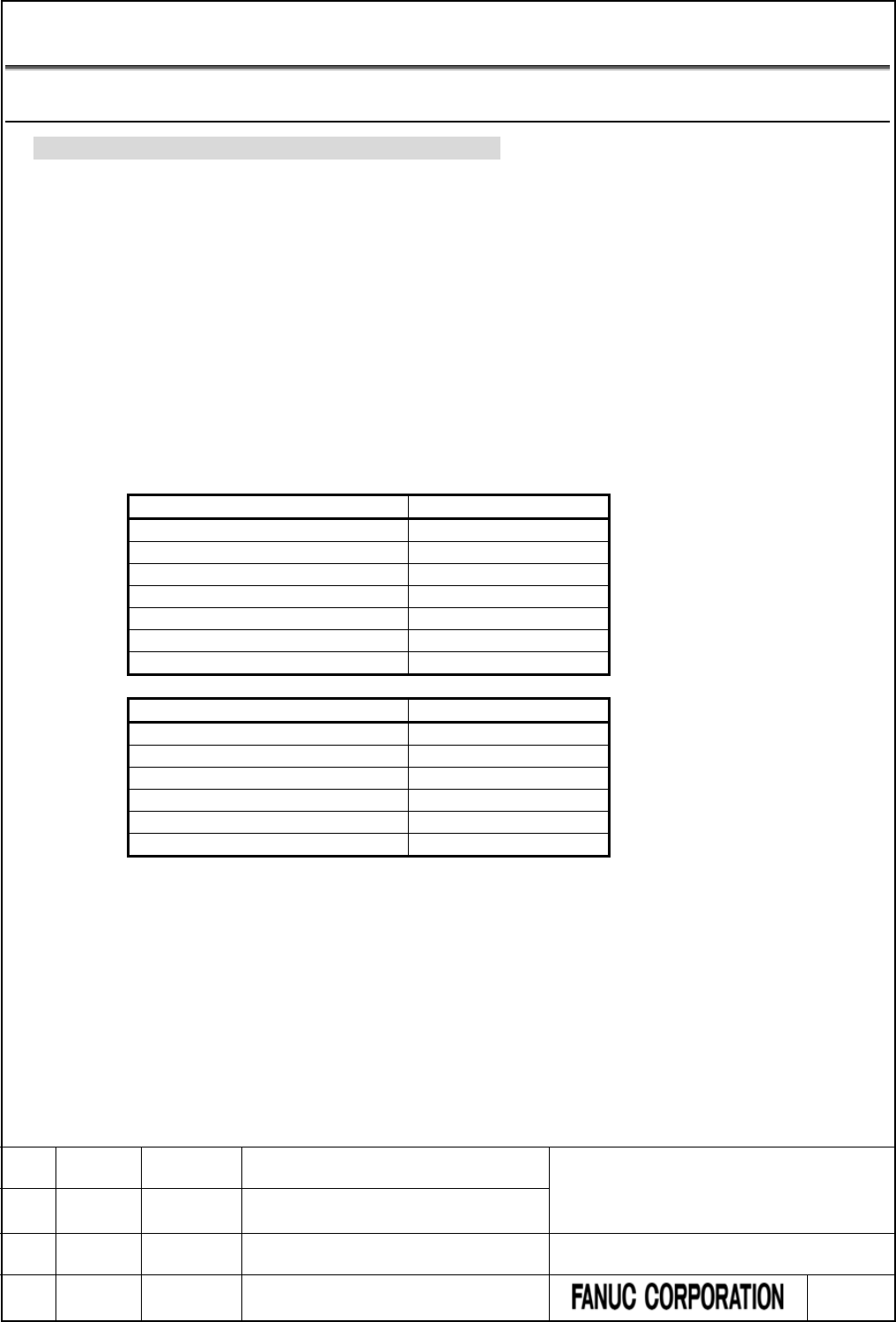
4.3 PMC PARAMETERS
4.3.1 PMC Parameter Format
Change part of “2.3.2 PMC Parameter Format” as follows.
This subsection describes the format used in outputting the contents of the PMC parameter to an external
device. As for the operation of output, refer to section 7 “sequence program and PMC parameter I/O”.
(1) Header information
The data begins with header information. Its format is as follows:
[Format]
%
(PMC = xxx, MSID = n)
PMC = xxx “xxx” is the model name of the PMC.
MSID = n “n” is ID information.
The following table lists values that can be set as “xxx” or “n”.
PMC Series
“xxx”
30i-B PMC
30I-B
31i-B PMC
31I-B
32i-B PMC
32I-B
35i-B PMC
35I-B
Power Motion i-A PMC
PMI-A
0i-F PMC
0I-F
0i-F PMC/L
0I-F-L
PMC Path
“n”
1st path PMC(include 0i-F PMC/L)
1
2nd path PMC
2
3rd path PMC
3
4th path PMC
4
5th path PMC
5
DCSPMC
9
FANUC Series 30i/31i/32i/35i-MODEL B
FANUC Power Motion i-MODEL A
FANUC Series 0i-MODEL F
PMC Supplemental Programming Manual
01 2015.4.16 H.Yonekura New registration DRAW. NO. : B-64513EN/03-2
EDIT. DATE DESIG. DESCRIPTION 48 / 88
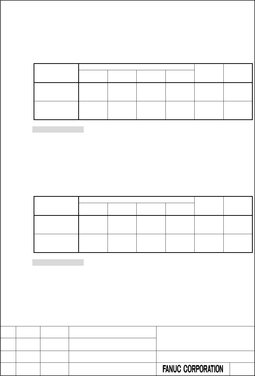
(2) Timer (T)
[Format]
N60xxxx Pnnnnn;
N600xxxx Pnnnnn;
[Data Contents]
N60xxxx or N600xxxx : parameter number
Specify the sum of the timer address (T) offset and 600000 or 6000000. The number in the
following table can be used.
1st to 5th path PMC
0i-F PMC/L DCSPMC
PMC
Memory-A
PMC
Memory-B
PMC
Memory-C
PMC
Memory-D, E
Timer setting value N600000
to
N600078
N600000
to
N600498
N600000
to
N600998
N6000000
to
N6000998
N600000
to
N600078
N600000
to
N600078
Timer accuracy N609000
to
N609078
N609000
to
N609498
N609000
to
N609998
N6009000
to
N6009998
N609000
to
N609078
N609000
to
N609078
*** Omitted below ***
(3) Counter (C)
[Format]
N61xxxx Pnnnnn;
N610xxxx Pnnnnn;
[Data Contents]
N61xxxx or N610xxxx; parameter number
Specify the sum of the counter address (C) offset and 610000 or 6100000. The number in the
following table can be used.
1st to 5th path PMC
0i-F PMC/L DCSPMC
PMC
Memory-A
PMC
Memory-B
PMC
Memory-C
PMC
Memory-D, E
Variable counter
(CTR)
N610000
to
N610078
N610000
to
N610398
N610000
to
N610798
N6100000
to
N6101198
N610000
to
N610078
N610000
to
N610078
Fixed counter
(CTRB)
N615000
to
N615038
N615000
to
N615198
N615000
to
N615398
N6105000
to
N6105598
N615000
to
N615038
N615000
to
N615038
*** Omitted below ***
FANUC Series 30i/31i/32i/35i-MODEL B
FANUC Power Motion i-MODEL A
FANUC Series 0i-MODEL F
PMC Supplemental Programming Manual
01 2015.4.16 H.Yonekura New registration DRAW. NO. : B-64513EN/03-2
EDIT. DATE DESIG. DESCRIPTION 49 / 88

(4) Keep relay (K)
[Format]
N62xxxx Pnnnnnnnn;
N620xxxx Pnnnnnnnn;
[Data Contents]
N62xxxx or N620xxxx Parameter number
Specify the sum of the keep relay address (K) offset and 620000 or 6200000. The number in
the following table can be used.
1st to 5th path PMC
0i-F PMC/L DCSPMC
PMC
Memory-A
PMC
Memory-B
PMC
Memory-C
PMC
Memory-D, E
User area N620000
to
N620019
N620000
to
N620099
N620000
to
N620199
N6200000
to
N6200299
N620000
to
N620099
N620000
to
N620019
System area N620900
to
N620999
N620900
to
N620999
N620900
to
N620999
N6200900
to
N6200999
N620900
to
N620999
N620900
to
N620999
*** Omitted below ***
FANUC Series 30i/31i/32i/35i-MODEL B
FANUC Power Motion i-MODEL A
FANUC Series 0i-MODEL F
PMC Supplemental Programming Manual
01 2015.4.16 H.Yonekura New registration DRAW. NO. : B-64513EN/03-2
EDIT. DATE DESIG. DESCRIPTION 50 / 88
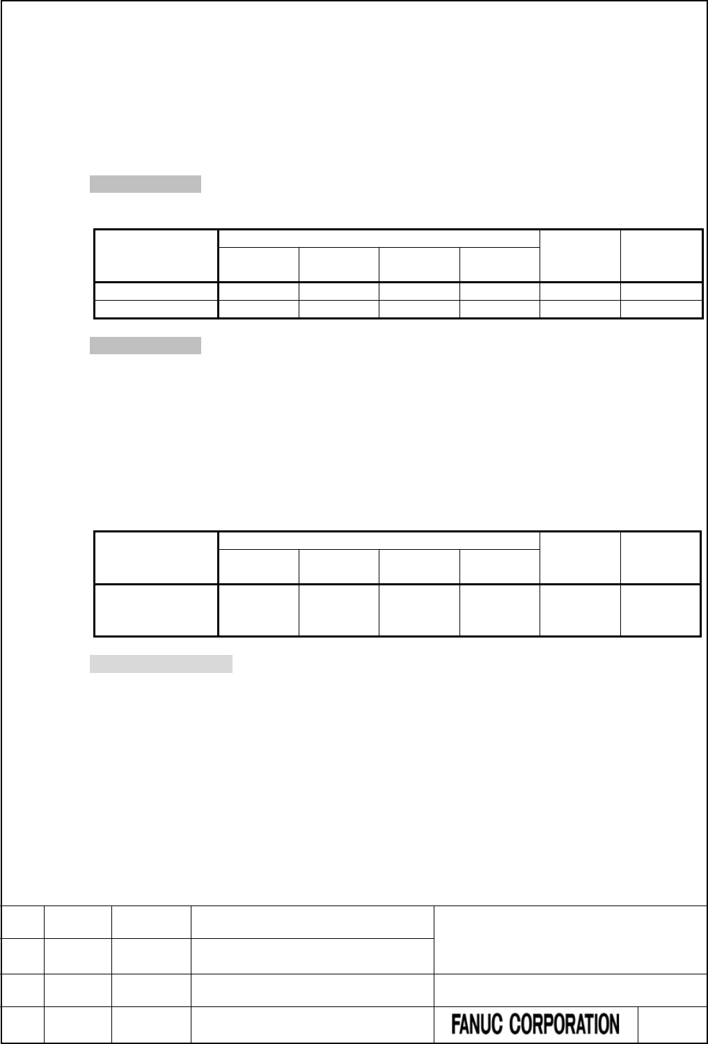
(5) Data (D)
(a) Data table control
[Format]
N630xxx Pnnnnn;
N6300xxx Pnnnnn;
[Data Contents]
*** Omission ***
The range of “Data size” and “Start address” is as follows.
1st to 5th path PMC
0i-F PMC/L DCSPMC
PMC
Memory-A
PMC
Memory-B
PMC
Memory-C
PMC
Memory-D, E
Data Size
1 to 3000
1 to 10000
1 to 20000
1 to 60000
1 to 3000
1 to 3000
Start address
0 to 2999
0 to 9999
0 to 19999
0 to 59999
0 to 2999
0 to 2999
*** Omission ***
(b) Data table
[Format]
N64xxxx Pnnnnn;
N64xxxxx Pnnnnn;
[Data Contents]
N64xxxx or N64xxxxx Parameter number
Specify the sum of the data table address (D) offset and 640000 or 6400000. The number in
the following table can be used.
1st to 5th path PMC
0i-F PMC/L DCSPMC
PMC
Memory-A
PMC
Memory-B
PMC
Memory-C
PMC
Memory-D, E
Data table N640000
to
N642999
N640000
to
N649999
N640000
to
N659999
N6400000
to
N6459999
N640000
to
N642999
N640000
to
N642999
*** Omitted below ***
FANUC Series 30i/31i/32i/35i-MODEL B
FANUC Power Motion i-MODEL A
FANUC Series 0i-MODEL F
PMC Supplemental Programming Manual
01 2015.4.16 H.Yonekura New registration DRAW. NO. : B-64513EN/03-2
EDIT. DATE DESIG. DESCRIPTION 51 / 88
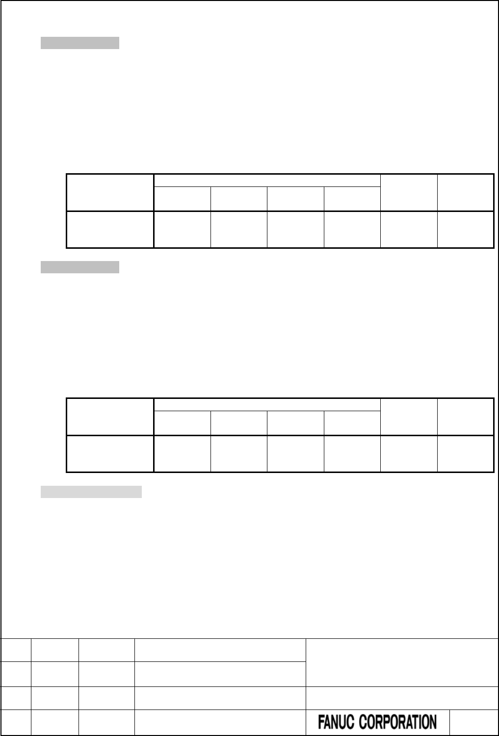
(6) Extra memory (E)
*** Omission ***
(a) Byte format
[Format]
N69xxxx Pnnnnn;
N690xxxx Pnnnnn;
[Data Contents]
N69xxxx or N690xxxx Parameter number
Specify the sum of the offset number of the extra relay and 690000 or 6900000. The number
in the following table can be used.
1st to 5th path PMC
0i-F PMC/L DCSPMC
PMC
Memory-A
PMC
Memory-B
PMC
Memory-C
PMC
Memory-D, E
Extra relay N690000
to
N699999
N690000
to
N699999
N690000
to
N699999
N6900000
to
N6909999
N690000
to
N699999
N690000
to
N699999
*** Omission ***
(c) Table format (Extra relay part)
[Format]
N69xxxx Pnnnnn;
N690xxxx Pnnnnn;
[Data Contents]
N69xxxx or N690xxxx Parameter Number
Specify the sum of the offset number of the extra relay and 690000 or 6900000. The number
in the following table can be used.
1st to 5th path PMC
0i-F PMC/L DCSPMC
PMC
Memory-A
PMC
Memory-B
PMC
Memory-C
PMC
Memory-D, E
Data table N690000
to
N699999
N690000
to
N699999
N690000
to
N699999
N6900000
to
N6909999
N690000
to
N699999
N690000
to
N699999
*** Omitted below ***
FANUC Series 30i/31i/32i/35i-MODEL B
FANUC Power Motion i-MODEL A
FANUC Series 0i-MODEL F
PMC Supplemental Programming Manual
01 2015.4.16 H.Yonekura New registration DRAW. NO. : B-64513EN/03-2
EDIT. DATE DESIG. DESCRIPTION 52 / 88

4.4 PARAMETERS FOR THE PMC SYSTEM
4.4.1 CNC Parameters Related to the PMCs
Change part of “2.4.3 CNC Parameters Related to the PMCs” as follows.
The CNC parameters related to the PMCs can be divided into those for controlling communication with
FANUC LADDER-III and ladder editing package and those for setting up the PMCs.
The following table summaries the CNC parameters related to the PMCs.
Table 4.4.1 (a) Summary of the CNC parameters related to the PMC
No.
Use
Remarks
24
Setting up communication with ladder development tools
PMC online connection function
11900 to 11904
Execution sequence for multiple PMCs
1st to 5th path PMC (Note2)
11905 to 11909
Percent execution time for multiple PMCs
1st to 5th path PMC (Note2)
11910 to 11912
I/O Link input/output address
Channels 1 to 3 (Note2)
11914 2nd, 3rd level execution cycle of ladder Common to 1st to 5th path PMC
(Note1, Note2)
11915 to 11917 Input/output address of dual assignment of I/O Link
channel
Second Block of Channels 1 to 3
(Note2)
11920 to 11929
CNC interface control address
CNC 10 paths (Note2)
11930 Ladder 1st level execution period Common to 1st to 5th path PMC
(Note2)
11931#0
Run/stop of Ladder
1st to 5th path PMC (Note2)
11931#1 The display number of external alarms/operator
messages
External data input, External
message
11931#5
Ladder dividing management function
Common to 1st to 5th path PMC
11931#7
Clearing of PMC nonvolatile memory
11932
Multi path PMC interface
(Note2)
11933#0,#1
I/O Link communication method
Channel 1, 2
11933#5
Running/stopping of ladder program when updating
11936
The number of PMC paths
(Note2)
11937 to 11939
The input / output address used by network devices
1st to 5th path PMC, X/Y0 to 727
11940 to 11944
PMC Memory Type
1st to 5th path PMC (Note2)
11945 The PMC path that the 1st level execution cycle in 1ms or
2ms is applied when using multi-path PMC function.
1st to 5th path PMC
(Note1, Note2)
11946 The divided ladder that the 1st level execution cycle in
1ms or 2ms is applied when using ladder dividing
management function.
Divided ladder program 1 to 99
(Note1, Note2)
NOTE
1 These parameters are unavailable for 0i-F PMC.
2 These parameters are unavailable for 0i-F PMC/L.
*** Omitted below ***
FANUC Series 30i/31i/32i/35i-MODEL B
FANUC Power Motion i-MODEL A
FANUC Series 0i-MODEL F
PMC Supplemental Programming Manual
01 2015.4.16 H.Yonekura New registration DRAW. NO. : B-64513EN/03-2
EDIT. DATE DESIG. DESCRIPTION 53 / 88
PMC setup parameters
Execution sequence for multiple PMCs
11900
PMC having the first priority in execution sequence
11901
PMC having the second priority in execution sequence
11902
PMC having the third priority in execution sequence
11903
PMC having the fourth priority in execution sequence
11904
PMC having the fifth priority in execution sequence
NOTE
1 Once any of these parameters is re-set, it is necessary to turn the
power off and on again.
2 This parameter is unavailable for 0i-F PMC/L.
*** Omitted below ***
Percent execution time for multiple PMCs
11905 Percent execution time for the PMC having the first priority in execution sequence
11906 Percent execution time for the PMC having the second priority in execution sequence
11907 Percent execution time for the PMC having the third priority in execution sequence
11908 Percent execution time for the PMC having the fourth priority in execution sequence
11909 Percent execution time for the PMC having the fifth priority in execution sequence
NOTE
1 Once any of these parameters is re-set, it is necessary to turn the
power off and on again.
2 This parameter is unavailable for 0i-F PMC/L.
*** Omitted below ***
FANUC Series 30i/31i/32i/35i-MODEL B
FANUC Power Motion i-MODEL A
FANUC Series 0i-MODEL F
PMC Supplemental Programming Manual
01 2015.4.16 H.Yonekura New registration DRAW. NO. : B-64513EN/03-2
EDIT. DATE DESIG. DESCRIPTION 54 / 88
I/O Link input/output addresses
11910
I/O Link channel 1 input/output addresses
11911
I/O Link channel 2 input/output addresses
11912
I/O Link channel 3 input/output addresses
NOTE
1 Once any of these parameters is re-set, it is necessary to turn the
power off and on again.
2 This parameter is unavailable for 0i-F PMC/L.
*** Omitted below ***
2nd, 3rd level execution cycle
11914
2nd / 3rd level execution cycle of ladder
NOTE
1 Once this parameter is set, it is necessary to turn off and on the
power.
2 This parameter is unavailable for 0i-F PMC and 0i-F PMC/L.
*** Omitted below ***
Input/output addresses of dual assignment of I/O Link channel
11915
Input/output addresses of the second block of I/O Link channel 1
11916
Input/output addresses of the second block of I/O Link channel 2
11917
Input/output addresses of the second block of I/O Link channel 3
NOTE
1 Once any of these parameters is re-set, it is necessary to turn the
power off and on again.
2 This parameter is unavailable for 0i-F PMC/L.
*** Omitted below ***
FANUC Series 30i/31i/32i/35i-MODEL B
FANUC Power Motion i-MODEL A
FANUC Series 0i-MODEL F
PMC Supplemental Programming Manual
01 2015.4.16 H.Yonekura New registration DRAW. NO. : B-64513EN/03-2
EDIT. DATE DESIG. DESCRIPTION 55 / 88
CNC-PMC interface
11920
CNC-PMC interface 1 input/output address
11921
CNC-PMC interface 2 input/output address
11922
CNC-PMC interface 3 input/output address
11923
CNC-PMC interface 4 input/output address
11924
CNC-PMC interface 5 input/output address
11925
CNC-PMC interface 6 input/output address
11926
CNC-PMC interface 7 input/output address
11927
CNC-PMC interface 8 input/output address
11928
CNC-PMC interface 9 input/output address
11929
CNC-PMC interface 10 input/output address
NOTE
1 Once any of these parameters is re-set, it is necessary to turn the
power off and on again.
2 This parameter is unavailable on the following composition. In this
case, F/G address of PMC is the same as F/G address of CNC.
● 0i-F PMC/L
● PMC Memory Type-E
[Input type] Parameter input
[Data type] Word
[Valid data range] 0, 100 to 109, 200 to 209, 300 to 309, 400 to 409, 500 to 509
This item assigns a PMC F/G address to a CNC F/G address.
CNC
First PMC
CNC F/G address
First-PMC F/G address
Second PMC
Second-PMC F/G address
Third PMC
Third-PMC F/G address
Fig. 4.4.1 (d) CNC-PMC interface assignment concept
FANUC Series 30i/31i/32i/35i-MODEL B
FANUC Power Motion i-MODEL A
FANUC Series 0i-MODEL F
PMC Supplemental Programming Manual
01 2015.4.16 H.Yonekura New registration DRAW. NO. : B-64513EN/03-2
EDIT. DATE DESIG. DESCRIPTION 56 / 88

Table 4.4.1 (b) CNC-PMC interface input/output address
Setting
Input/output address
0
Standard setting (see below)
100
F0 to 767/G0 to G767 for the 1st PMC
101
F1000 to F1767/G1000 to G1767 for the 1st PMC
102
F2000 to F2767/G2000 to G2767 for the 1st PMC
103
F3000 to F3767/G3000 to G3767 for the 1st PMC
104
F4000 to F4767/G4000 to G4767 for the 1st PMC
105
F5000 to F5767/G5000 to G5767 for the 1st PMC
106
F6000 to F6767/G6000 to G6767 for the 1st PMC
107
F7000 to F7767/G7000 to G7767 for the 1st PMC
108
F8000 to F8767/G8000 to G8767 for the 1st PMC
109
F9000 to F9767/G9000 to G9767 for the 1st PMC
200
F0 to F767/G0 to G767 for the 2nd PMC
201
F1000 to F1767/G1000 to G1767 for the 2nd PMC
202
F2000 to F2767/G2000 to G2767 for the 2nd PMC
203
F3000 to F3767/G3000 to G3767 for the 2nd PMC
204
F4000 to F4767/G4000 to G4767 for the 2nd PMC
205
F5000 to F5767/G5000 to G5767 for the 2nd PMC
206
F6000 to F6767/G6000 to G6767 for the 2nd PMC
207
F7000 to F7767/G7000 to G7767 for the 2nd PMC
208
F8000 to F8767/G8000 to G8767 for the 2nd PMC
209
F9000 to F9767/G9000 to G9767 for the 2nd PMC
300
F0 to F767/G0 to G767 for the 3rd PMC
301
F1000 to F1767/G1000 to G1767 for the 3rd PMC
302
F2000 to F2767/G2000 to G2767 for the 3rd PMC
303
F3000 to F3767/G3000 to G3767 for the 3rd PMC
304
F4000 to F4767/G4000 to G4767 for the 3rd PMC
305
F5000 to F5767/G5000 to G5767 for the 3rd PMC
306
F6000 to F6767/G6000 to G6767 for the 3rd PMC
307
F7000 to F7767/G7000 to G7767 for the 3rd PMC
308
F8000 to F8767/G8000 to G8767 for the 3rd PMC
309
F9000 to F9767/G9000 to G9767 for the 3rd PMC
400
F0 to F767/G0 to G767 for the 4th PMC
401
F1000 to F1767/G1000 to G1767 for the 4th PMC
402
F2000 to F2767/G2000 to G2767 for the 4th PMC
403
F3000 to F3767/G3000 to G3767 for the 4th PMC
404
F4000 to F4767/G4000 to G4767 for the 4th PMC
405
F5000 to F5767/G5000 to G5767 for the 4th PMC
406
F6000 to F6767/G6000 to G6767 for the 4th PMC
407
F7000 to F7767/G7000 to G7767 for the 4th PMC
408
F8000 to F8767/G8000 to G8767 for the 4th PMC
409
F9000 to F9767/G9000 to G9767 for the 4th PMC
500
F0 to F767/G0 to G767 for the 5th PMC
501
F1000 to F1767/G1000 to G1767 for the 5th PMC
502
F2000 to F2767/G2000 to G2767 for the 5th PMC
503
F3000 to F3767/G3000 to G3767 for the 5th PMC
504
F4000 to F4767/G4000 to G4767 for the 5th PMC
505
F5000 to F5767/G5000 to G5767 for the 5th PMC
FANUC Series 30i/31i/32i/35i-MODEL B
FANUC Power Motion i-MODEL A
FANUC Series 0i-MODEL F
PMC Supplemental Programming Manual
01 2015.4.16 H.Yonekura New registration DRAW. NO. : B-64513EN/03-2
EDIT. DATE DESIG. DESCRIPTION 57 / 88
Setting
Input/output address
506
F6000 to F6767/G6000 to G6767 for the 5th PMC
507
F7000 to F7767/G7000 to G7767 for the 5th PMC
508
F8000 to F8767/G8000 to G8767 for the 5th PMC
509
F9000 to F9767/G9000 to G9767 for the 5th PMC
If all these parameters are 0, the standard setting is used, that is, “CNC F/G address = 1st
PMC F/G address” is satisfied.
CNC
First PMC
F/G0 to F/G767 for the CNC
F/G1000 to F/G1767 for the CNC
F/G2000 to F/G2767 for the CNC
F/G3000 to F/G3767 for the CNC
F/G4000 to F/G4767 for the CNC
F/G5000 to F/G5767 for the CNC
F/G6000 to F/G6767 for the CNC
F/G7000 to F/G7767 for the CNC
F/G8000 to F/G8767 for the CNC
F/G9000 to F/G9767 for the CNC
F/G0 to F/G767 for the first PMC
F/G1000 to F/G1767 for the first PMC
F/G2000 to F/G2767 for the first PMC
F/G3000 to F/G3767 for the first PMC
F/G4000 to F/G4767 for the first PMC
F/G5000 to F/G5767 for the first PMC
F/G6000 to F/G6767 for the first PMC
F/G7000 to F/G7767 for the first PMC
F/G8000 to F/G8767 for the first PMC
F/G9000 to F/G9767 for the first PMC
Fig. 4.4.1 (e) CNC-PMC interface initial settings
CAUTION
1 If any of these parameters is nonzero, a duplicate number results in
the PMC alarm “ER54 NC-PMC I/F ASSIGNMENT ERROR”, thus
disabling all the PMCs from starting.
2 If these parameters are not set up in part, it is impossible to assign a
PMC address to the related CNC F/G address.
FANUC Series 30i/31i/32i/35i-MODEL B
FANUC Power Motion i-MODEL A
FANUC Series 0i-MODEL F
PMC Supplemental Programming Manual
01 2015.4.16 H.Yonekura New registration DRAW. NO. : B-64513EN/03-2
EDIT. DATE DESIG. DESCRIPTION 58 / 88
Level 1 execution period
11930
Ladder level execution period
NOTE
1 Once this parameter is re-set, it is necessary to turn the power off
and on again.
2 This parameter is unavailable for 0i-F PMC/L.
[Input type] Byte input
[Data type] Byte
[Valid data range] 0, 1, 2, 4, 8
This item specifies an execution period for ladder level 1.
Setting
Meaning
1 (Note2,3)
Executed at a 1ms cycle.
2 (Note2,3)
Executed at a 2ms cycle.
4
Executed at a 4-msec interval.
0, 8
Executed at an 8-msec interval.
NOTE
1 The level 1 execution period cannot be set for each PMC path
independently.
2 Refer to “1.8” when this parameter is set to a value “1” or “2”.
3 These values are unavailable for 0i-F PMC.
CAUTION
1 Setting this parameter to an unsupported value results in the PMC
alarm “ER55 LEVEL1 EXECUTION CYCLE ERROR”, and all PMCs
are not executed.
*** Omitted below ***
FANUC Series 30i/31i/32i/35i-MODEL B
FANUC Power Motion i-MODEL A
FANUC Series 0i-MODEL F
PMC Supplemental Programming Manual
01 2015.4.16 H.Yonekura New registration DRAW. NO. : B-64513EN/03-2
EDIT. DATE DESIG. DESCRIPTION 59 / 88
Start or stop of the ladder
#7
#6
#5
#4
#3
#2
#1
#0
11931
NMC
LDV
M16
PCC
[Data type] Bit
#0 PCC This item specifies start or stop of the ladder as follows:
0 : The ladder is started or stopped independently for each PMC.
1 : The ladders in all PMCs are started or stopped together.
NOTE
1 Once this parameter is re-set, it is necessary to turn the power off
and on again.
2 When using the Common PMC Memory mode, those programs are
started or stopped together regardless of this parameter.
3 This parameter is unavailable for 0i-F PMC/L.
*** Omitted below ***
Multi-path PMC interface
11932
Multi-path PMC interface
NOTE
1 Once this parameter is re-set, it is necessary to turn the power off
and on again.
2 This parameter is unavailable for 0i-F PMC/L.
*** Omitted below ***
FANUC Series 30i/31i/32i/35i-MODEL B
FANUC Power Motion i-MODEL A
FANUC Series 0i-MODEL F
PMC Supplemental Programming Manual
01 2015.4.16 H.Yonekura New registration DRAW. NO. : B-64513EN/03-2
EDIT. DATE DESIG. DESCRIPTION 60 / 88
Communication method with I/O device
Running/stopping of ladder program when updating
#7
#6
#5
#4
#3
#2
#1
#0
11933
SRL
C2T
C1T
[Input type] Parameter input
[Data type] Bit
NOTE
Once these parameters are re-set, it is necessary to turn the power
off and on again.
#0 C1T Specifies the communication method of channel 1.
0 : I/O Link is used.
1 : I/O Link i is used.
#1 C2T Specifies the communication method of channel 2.
0 : I/O Link is used.
1 : I/O Link i is used.
NOTE
1 When you set the channel to “use I/O Link”, set the parameter
no.11910 to 11912, also.
2 On 0i-F PMC and 0i-F PMC/L, the default value of these
parameters is “1”.
3 The parameter C2T(No.11933#1) is unavailable for 0i-F PMC/L.
*** Omitted below ***
The number of PMC paths
11936
The number of PMC paths
NOTE
1 Once this parameter is re-set, it is necessary to turn the power off
and on again.
2 This parameter is unavailable for 0i-F PMC/L.
*** Omitted below ***
FANUC Series 30i/31i/32i/35i-MODEL B
FANUC Power Motion i-MODEL A
FANUC Series 0i-MODEL F
PMC Supplemental Programming Manual
01 2015.4.16 H.Yonekura New registration DRAW. NO. : B-64513EN/03-2
EDIT. DATE DESIG. DESCRIPTION 61 / 88

The input / output address used by network device
#7
#6
#5
#4
#3
#2
#1
#0
11937
P24
P23
P22
P21
P14
P13
P12
P11
*** Omitted below ***
NOTE
1 Once these parameters are set, it is necessary to turn off and on the power.
2 For 0i-F PMC, P11 and P12 and P21 and P22 and P31 and P32(No.11937#0, #1,
#4, #5, No.11938#0, #1) are available only.
3 For 0i-F PMC/L, P11(No.11937#0) is available only.
4 This parameter should be set only for the X /Y address area to which the network
device is assigned, because this parameter may affect the ladder execution
performance.
5 Network devices cannot be assigned to the X/Y address area to which any I/O
Link and I/O Link i are assigned.
6 In case of using I/O Link i, assign network devices to the X/Y address area to
which any I/O Link i devices are not assigned, then set this parameter for
corresponding area.
7 In case of using I/O Link and the parameter No.11910-11912 are set to 0 (default
setting), I/O Link devices are assigned to X0-X127/Y0-Y127,
X200-X327/Y200-Y327 and X400-X527/Y400-Y527 area of 1st PMC path. In this
case for 1st PMC path, network devices can only be assigned to
X600-X727/Y600-Y727 area.
If all parameters are not set to 0, network devices can be assigned to the X/Y
address area to which any I/O Link channels are not assigned, and set this
parameter for corresponding area accordingly.
Example) When I/O Link channel 1 is assigned to X0-X127/Y0-Y127 of 1st PMC
path, and network device can be assigned to X200-327/Y200-327,
set the parameter No.11910=100, No.11911=0, No.11912=0, No.11937#1=1.
FANUC Series 30i/31i/32i/35i-MODEL B
FANUC Power Motion i-MODEL A
FANUC Series 0i-MODEL F
PMC Supplemental Programming Manual
01 2015.4.16 H.Yonekura New registration DRAW. NO. : B-64513EN/03-2
EDIT. DATE DESIG. DESCRIPTION 62 / 88
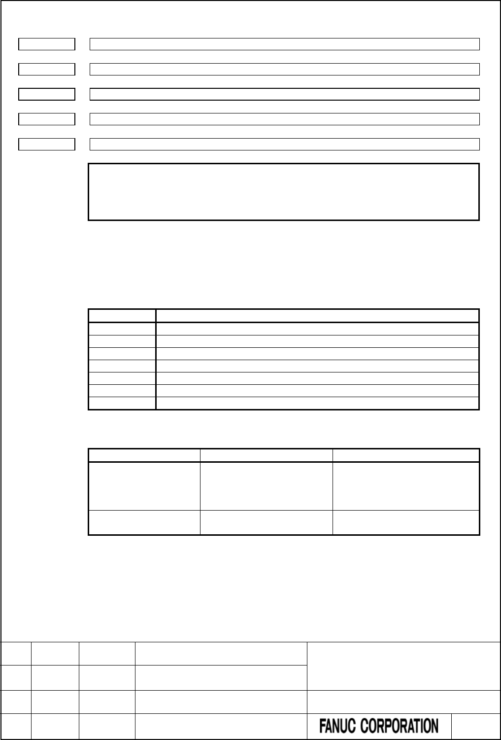
PMC Memory Type
11940
PMC Memory Type of 1st PMC
11941
PMC Memory Type of 2nd PMC
11942
PMC Memory Type of 3rd PMC
11943
PMC Memory Type of 4th PMC
11944
PMC Memory Type of 5th PMC
NOTE
1 Once this parameters is re-set, it is necessary to turn the power off
and on again.
2 This parameter is unavailable for 0i-F PMC/L.
[Input type] Parameter input
[Data type] Integer
[Valid data range] -1, 0, 1, 2, 3, 4, 5
Select a PMC Memory Type of each PMC path. Refer to “Table 2.1.1 Basic specification of
each PMC Memory Type” for details of each PMC Memory Type.
Setting
Meaning
0
Use standard setting of PMC Memory Type.
1
Use PMC Memory-A.
2
Use PMC Memory-B.
3
Use PMC Memory-C.
4
Use PMC Memory-D.
5
Use PMC Memory-E.(Note1)
-1
The 2nd to 5th paths PMC share the PMC Memory with 1st path PMC.
The following is the selectable PMC memory types in each PMC path.
1st path PMC
2nd to 5th path PMC
Remark
PMC-memory B (default)
PMC-memory C (note2)
PMC-memory A (default)
PMC-memory B
PMC-memory C (note2)
Shared with 1st path PMC
You can specify up to three paths
both of PMC-
memory B and C in
total.
PMC-memory D (note2)
PMC-memory E (note2)
Shared with 1st path PMC
FANUC Series 30i/31i/32i/35i-MODEL B
FANUC Power Motion i-MODEL A
FANUC Series 0i-MODEL F
PMC Supplemental Programming Manual
01 2015.4.16 H.Yonekura New registration DRAW. NO. : B-64513EN/03-2
EDIT. DATE DESIG. DESCRIPTION 63 / 88

CAUTION
1 Setting an invalid value to this parameter results in the PMC alarm
“ER58 PMC MEMORY TYPE SETTING ERROR” and all sequence
programs for each PMC will not be started.
2 PMC nonvolatile memory must be initialized after changing PMC
Memory Type. Therefore, make a backup of PMC parameter before
changing PMC Memory Type. Refer to the “2.7 DATA BACKED UP
BY THE BATTERY” of PMC Programming Manual about the
operation of initializing PMC nonvolatile memory.
NOTE
1 PMC Memory Type-E is enabled only on a special series of CNC
software.
2 To use all data table area as nonvolatile memory with PMC
Memory-C/D/E, specify the option “Nonvolatile PMC data table area
expansion (40KB)”. If this option does not be specified, the
expanded data table area (D10000 or more) does not keep the
memory after rebooting CNC.
FANUC Series 30i/31i/32i/35i-MODEL B
FANUC Power Motion i-MODEL A
FANUC Series 0i-MODEL F
PMC Supplemental Programming Manual
01 2015.4.16 H.Yonekura New registration DRAW. NO. : B-64513EN/03-2
EDIT. DATE DESIG. DESCRIPTION 64 / 88
The PMC path that the 1st level execution cycle in 1ms or 2ms is applied when using
multi-path PMC function
11945
The PMC path that the 1st level execution cycle in 1ms or 2ms is applied
when using multi-path PMC function
NOTE
1 Once this parameter is set, it is necessary to turn off and on the
power.
2 This parameter is unavailable for 0i-F PMC and 0i-F PMC/L..
*** Omitted below ***
The divided ladder that the 1st level execution cycle in 1ms or 2ms is applied when
using ladder dividing management function
11946
The divided ladder that the 1st level execution cycle in 1ms or 2ms is applied
when using ladder dividing management function
NOTE
1 Once this parameter is set, it is necessary to turn off and on the
power.
2 This parameter is unavailable for 0i-F PMC and 0i-F PMC/L..
*** Omitted below ***
FANUC Series 30i/31i/32i/35i-MODEL B
FANUC Power Motion i-MODEL A
FANUC Series 0i-MODEL F
PMC Supplemental Programming Manual
01 2015.4.16 H.Yonekura New registration DRAW. NO. : B-64513EN/03-2
EDIT. DATE DESIG. DESCRIPTION 65 / 88

4.5 COMPATIBILITY BETWEEN PMC MEMORY TYPE
4.5.1 Compatibility between PMC Memory-D and PMC Memory-E
Add the following after “2.5.3 Compatibility between PMC Memory-C and PMC Memory-D”.
The sequence program for the PMC Memory-E has highly compatibility of the source program with the one
for the PMC Memory-D.
You can convert a sequence program for the PMC Memory-D to one for the PMC Memory-E by using the
conversion function of FANUC LADDER-III.
WARNING
A little difference of execution timing may exist between PMC Memory Types.
Therefore, you should check again whether the program works correctly after
changing the PMC Memory Types even if the program worked fine before
changing the PMC Memory Type.
PMC parameter compatibility
PMC parameters outputted from on the PMC Memory-D can be loaded into the PMC Memory-E without any
modification.
When loading PMC parameters outputted on the PMC Memory-E to the PMC Memory-D without any
modification.
FANUC Series 30i/31i/32i/35i-MODEL B
FANUC Power Motion i-MODEL A
FANUC Series 0i-MODEL F
PMC Supplemental Programming Manual
01 2015.4.16 H.Yonekura New registration DRAW. NO. : B-64513EN/03-2
EDIT. DATE DESIG. DESCRIPTION 66 / 88

4.6 COMPATIBILITY WITH CONVENTIONAL MODELS
4.6.1 Compatibility between 0i/0i Mate-D PMC/L and 0i-F PMC/L
Add the following after “2.6.5 Compatibility with series 0i-D PMC”.
Ladder program compatibility
The series 0i-F PMC/L is highly compatible with the series 0i/0i Mate i-D PMC on the source level.
You can use the sequence program of the series 0i/0i Mate-D PMC/L on the series 0i-F PMC/L by changing
the PMC model using FANUC LADDER-III.
Transporting programs require modification because the specifications of the following functions have been
changed.
(1) The following items about execution timing may be changed.
- The execution cycle of both first and second level of ladder
- The timing of the execution cycle of first level of ladder according to the partition of second level
ladder
- The timing between ladder execution and I/O transfer or F,G signals
(2) The execution timing between the CNC processing and the ladder execution may be changed.
(3) When setting an illegal value, that is not written in the programming manual, into parameters of
functional instructions, the result may be different from the series 0i/0i Mate-D PMC/L.
PMC parameter compatibility
PMC parameters outputted from the series 0i/0i Mate-D PMC/L can be loaded into the series 0i-F PMC/L
without any modification.
File names in PMC [I/O] screen
In 0i-F PMC/L, PMC file names, which are created in PMC [I/O] screen, are different from the names in 0i/0i
Mate-D PMC/L.
Kind of data
File name of 0i/0i Mate-D PMC/L
File name of 0i-F PMC/L
Sequence program
PMC1_LAD.xxx
PMC1.xxx
Message data for multi-language
display
PMC1_MSG.xxx M1PMCMSG.xxx
(xxx:Data number in three-digit)
FANUC Series 30i/31i/32i/35i-MODEL B
FANUC Power Motion i-MODEL A
FANUC Series 0i-MODEL F
PMC Supplemental Programming Manual
01 2015.4.16 H.Yonekura New registration DRAW. NO. : B-64513EN/03-2
EDIT. DATE DESIG. DESCRIPTION 67 / 88
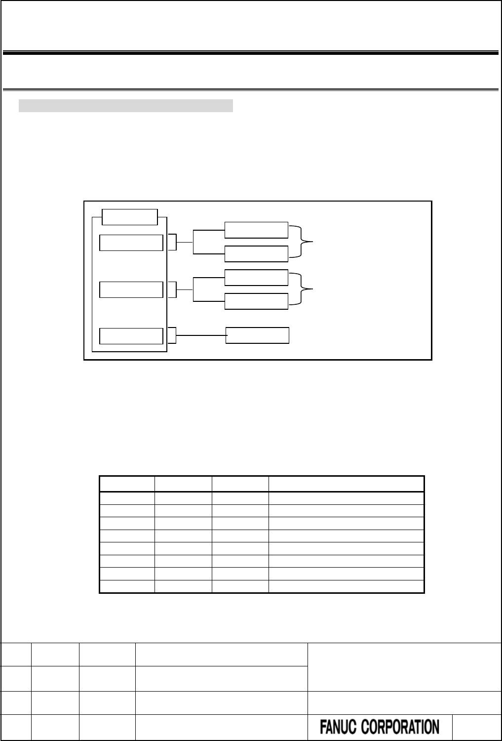
5 COMMUNICATION WITH I/O DEVICE
5.1 I/O Link i and I/O Link
Change “3.1 I/O Link i and I/O Link” as follows.
There are two communication methods for the high-speed serial interface which transmits input/output
signals between the PMC and I/O devices. They are the FANUC I/O Link i and the FANUC I/O Link.
You can use up to three channels for the serial interface. The communication method for channel 1 and
channel 2 can be specified by the CNC parameter. The channel 3 can be used only for the I/O Link.
For the details of the setting of the CNC parameter, see subsection “2.4.3”.
Channel 1
Channel 2
Channel 3
I/O Link
I/O Link i
I/O Link
I/O Link i
I/O Link
Switched by CNC parameter
11933#0
CNC
Switched by CNC parameter
11933#1
Fig. 5.1 Setting of communication method for each channel
The maximum I/O points of the I/O Link i are 2048 poins/2048 points for each channel. The maximum I/O
points of the I/O Link are 1024 points/1024 points for each channel. The maximum I/O points for a PMC
system are 4096 points/4096 points (0i-F: 2048 points/2048 points, 0i-F PMC/L: 1024 points/1024 points).
You can use one or more channels of the I/O Link i and the I/O Link however the total points cannot exceed
the maximum points of the PMC system.
[Example of the selectable case of the I/O Link i and the I/O Link]
Channel 1
Channel 2
Channel 3
Total points (DI / DO)
I/O Link i
I/O Link i
-
4096 / 4096 (Note1, Note2)
I/O Link i
I/O Link
I/O Link
4096 / 4096 (Note1, Note2)
I/O Link i
I/O Link
-
3072 / 3072 (Note1, Note2)
I/O Link
I/O Link
I/O Link
3072 / 3072 (Note1, Note2)
I/O Link i
-
-
2048 / 2048 (Note2)
I/O Link
I/O Link
-
2048 / 2048 (Note2)
I/O Link
-
I/O Link
2048 / 2048 (Note2)
I/O Link
-
-
1024 / 1024
FANUC Series 30i/31i/32i/35i-MODEL B
FANUC Power Motion i-MODEL A
FANUC Series 0i-MODEL F
PMC Supplemental Programming Manual
01 2015.4.16 H.Yonekura New registration DRAW. NO. : B-64513EN/03-2
EDIT. DATE DESIG. DESCRIPTION 68 / 88

NOTE
1 For 0i-F PMC, the total points (DI/DO) are 2048/2048 points.
2 For 0i-F PMC/L, the total points (DI/DO) are 1024/1024 points.
For the multi-path PMC, the DI/DO of one channel can be assigned to plural PMC paths efficiently using the
I/O Link i. The connect position of I/O devices can be defined as group/slot number.
As for the transmission cycle of the signals from the I/O Link i, there are two modes of the normal mode
(2msec) and the high-speed mode (0.5msec). You can specify the mode for each group of I/O devices.
For details, refer to subsection “3.3.3”.
CAUTION
1 For an I/O Link i channel, You should use I/O devices applied to the I/O Link i. Or
for an I/O Link channel, you should use I/O devices applied to the I/O Link. If you
use an inadaptable I/O device, all of I/O devices after the device cannot be
connected.
2 In case of using the dual check safety function, you can build the system by using
only devices of the I/O Link i or only devices of the I/O Link. You cannot build the
system by using both the I/O Link i and the I/O Link. If you use I/O Link, I/O
devices for DCSPMC must be connected to channel 3.
FANUC Series 30i/31i/32i/35i-MODEL B
FANUC Power Motion i-MODEL A
FANUC Series 0i-MODEL F
PMC Supplemental Programming Manual
01 2015.4.16 H.Yonekura New registration DRAW. NO. : B-64513EN/03-2
EDIT. DATE DESIG. DESCRIPTION 69 / 88

5.2 WHAT IS I/O Link i ?
Change “3.3 WHAT IS I/O LINK i ?” as follows.
The FANUC I/O Link i is one of the serial interfaces which transmits input/output signals at a high speed
between the PMC and I/O devices.
Available channels are two channels and for each channel, up to 2048 DI points and up to 2048 DO points
can be connected and controlled from the PMC.
As for the transmission cycle of the signals from I/O Link i, there are two modes of the normal mode (2msec)
and the high-speed mode (0.5msec). You can specify the mode for each group of I/O devices.
Fig. 5.2 Outline of specification of I/O Link i
Item
I/O Link i
I/O Link
Normal mode
High-speed mode
Transmit speed
12Mbps
1.5Mbps
Update cycle(Note 2)
2ms
0.5ms
2ms
I/O points for one channel
(Note 3)
2048 / 2048 512 / 512 1024 / 1024
(64 / 64)
I/O points for one group
(Note 3)
512 / 512
(224 / 224)
256 / 256
Maximum groups for one channel
(Note 3, Note4)
24
(4)
5
(4)
16
PMC control address
1st path PMC to 5th path PMC
DI:
X0
~
X127, X200
~
X327, X400
~
X527, X600
~
X727
DO:
Y0
~
Y127, Y200
~
Y327, Y400
~
Y527, Y600
~
Y727
Selection of effective group
I/O link selectable assignment data function
NOTE
1 You can select a communication method from either the I/O Link i or the I/O Link
for each channel by setting the CNC parameter “Communication method of I/O
Device”. The default setting is the I/O Link mode (0i-F: I/O Link i mode). For
details of the parameter, refer to subsection “2.4.3”. For example, you can use
the channel 1 as the I/O Link i, and the channel 2 as the I/O Link. In this case, the
total I/O points are 3072 points / 3072 points (0i-F: 2048 points / 2048 points, 0i-F
PMC/L: 1024 points /1024 points).
2 You can select an update cycle mode from either the normal mode or the
high-speed mode for each group. You can make use of two modes in one
channel. For details, refer to subsection “3.3.3”.
3 The Inside of “( )” is the specification of dual check safety.
4 If you build the dual check safety system using the I/O Link i, you can make use
of up to 4 groups for DCSPMC. If you use two channels of the I/O Link i, the
maximum number of available groups is 4 groups. For details of the directions for
the dual check safety of I/O Link i, refer to subsection “3.3.7”.
FANUC Series 30i/31i/32i/35i-MODEL B
FANUC Power Motion i-MODEL A
FANUC Series 0i-MODEL F
PMC Supplemental Programming Manual
01 2015.4.16 H.Yonekura New registration DRAW. NO. : B-64513EN/03-2
EDIT. DATE DESIG. DESCRIPTION 70 / 88

6 LADDER LANGUAGE
6.1 OPERATION INSTRUCTION
Change “4.10 OPERATION INSTRUCTION” as follows.
The following types of operation instruction are available. Use any of these instructions as appropriate for
your purpose.
Instruction name
Sub number
Processing
1
ADDB
36
Binary addition
2
SUBB
37
Binary subtraction
3
MULB
38
Binary multiplication
4
DIVB
39
Binary division
5
ADD
19
BCD addition
6
SUB
20
BCD subtraction
7
MUL
21
BCD multiplication
8
DIV
22
BCD division
9
NUMEB
40
Definition of binary constants
10
NUME
23
Definition of BCD constants
11
ADDSB
319
Addition (1 byte length)
12
ADDSW
320
Addition (2 bytes length)
13
ADDSD
321
Addition (4 bytes length)
14
SUBSB
322
Subtraction (1 byte length)
15
SUBSW
323
Subtraction (2 bytes length)
16
SUBSD
324
Subtraction (3 byte length)
17
MULSB
325
Multiplication (1 byte length)
18
MULSW
326
Multiplication (2 bytes length)
19
MULSD
327
Multiplication (4 bytes length)
20
DIVSB
328
Division (1 byte length)
21
DIVSW
329
Division (2 bytes length)
22
DIVSD
330
Division (4 bytes length)
23
MODSB
331
Remainder (1 byte length)
24
MODSW
332
Remainder (2 bytes length)
25
MODSD
333
Remainder (4 bytes length)
26
INCSB
334
Increment (1 byte length)
27
INCSW
335
Increment (2 bytes length)
28
INCSD
336
Increment (4 bytes length)
29
DECSB
337
Decrement (1 byte length)
30
DECSW
338
Decrement (2 bytes length)
31
DECSD
339
Decrement (4 bytes length)
32
ABSSB
340
Absolute value (1 byte length)
33
ABSSW
341
Absolute value (2 bytes length)
34
ABSSD
342
Absolute value (4 bytes length)
35
NEGSB
343
Sign inversion (1 byte length)
36
NEGSW
344
Sign inversion (2 bytes length)
37
NEGSD
345
Sign inversion (4 bytes length)
38
PID
460
PID control
FANUC Series 30i/31i/32i/35i-MODEL B
FANUC Power Motion i-MODEL A
FANUC Series 0i-MODEL F
PMC Supplemental Programming Manual
01 2015.4.16 H.Yonekura New registration DRAW. NO. : B-64513EN/03-2
EDIT. DATE DESIG. DESCRIPTION 71 / 88
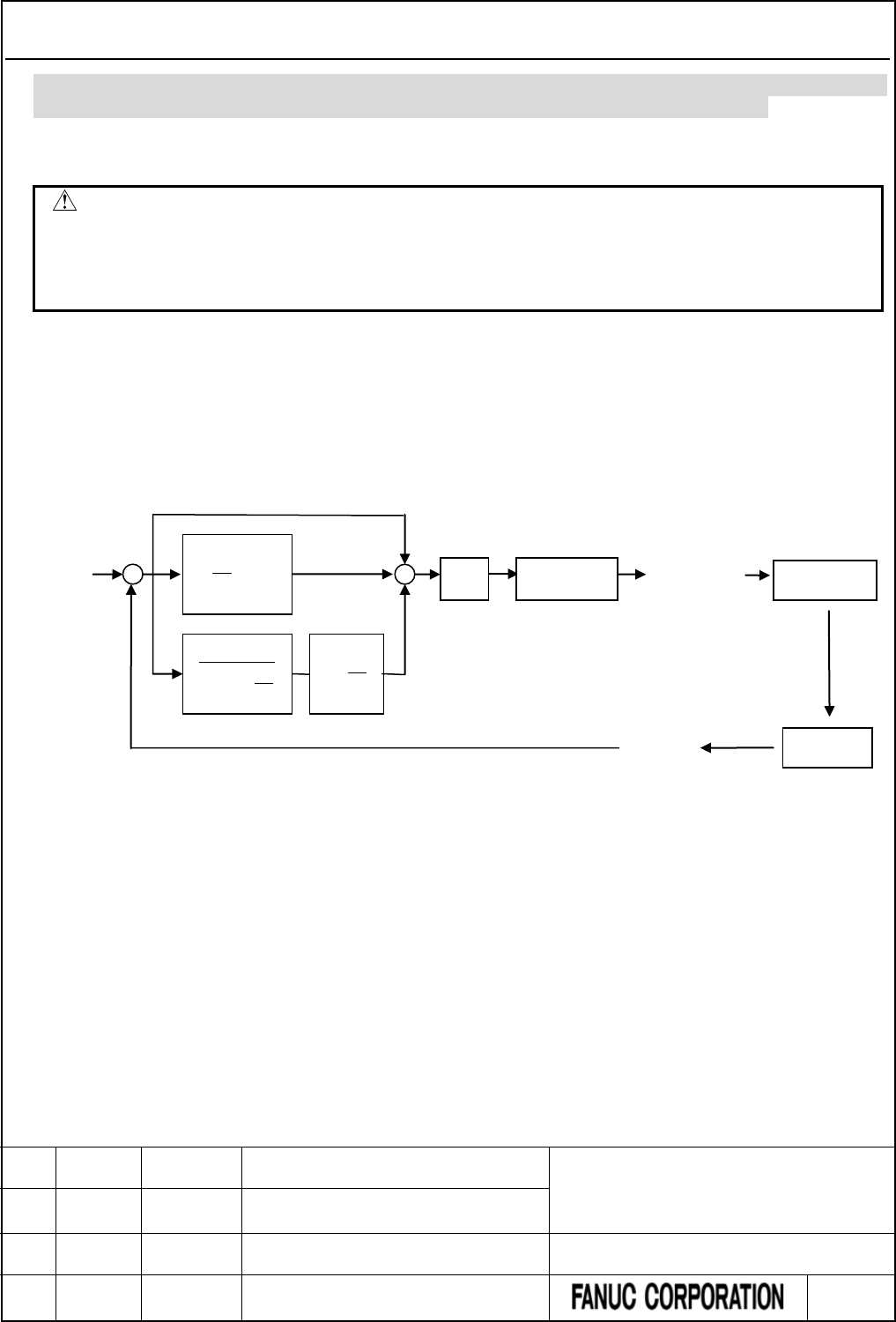
6.1.1 PID (PID Control : SUB 460)
Add the following after “4.10.19 NEGSB (Sign Inversion (1 Byte Length) : SUB 343), NEGSW (Sign
Inversion (2 Bytes Length) : SUB 344), NEGSD (Sign Inversion (4 Bytes Length) : SUB 345)”.
This instruction executes PID operation.
WARNING
This instruction cannot be used in some version of PMC software. Executing this
instruction on the unsupported version of PMC software will raise the warning
“WN58 UNSUPPORTED FUNCTION” on PMC alarm screen, and the ladder
program is executed excluding this instruction.
PID control
The PID control calculates the manipulated value to operate the controlled object from the preset setting
value and the process variable which are measured by sensors and so on. This control method is used for
controlling temperature, pressure, flow rate, and so on. By combining a proportional action (P), an integral
action (I), and a derivative action (D), it calculates the manipulated value to make the process variable agree
with the preset setting value soon and precisely.
Fig.6.1.1 (a) Block diagram of PID control
Preset
setting
value
∫edt
TI
1
Sensor
+
-
dt
de
T
D
1
1
η+
dt
de
TD
P
K
+
+
+
Manipulated
value limit
Controlled
object
Process
variable
Manipulated
value
FANUC Series 30i/31i/32i/35i-MODEL B
FANUC Power Motion i-MODEL A
FANUC Series 0i-MODEL F
PMC Supplemental Programming Manual
01 2015.4.16 H.Yonekura New registration DRAW. NO. : B-64513EN/03-2
EDIT. DATE DESIG. DESCRIPTION 72 / 88

Operation formula of PID control
The operation formula of the PID control is an additive synthesis of a proportional action (P), an integral
action (I), and a derivative action (D).
)
1
11
(dt
de
T
dt
de
K
T
edt
T
eKMV D
D
D
I
P∫+
++=
Proportional
action
Integral
action
Derivative action
MV :
Manipulated value
e :
Deviation
- Positive action
Process variable (PV) - Preset setting value (SV)
- Reverse action
Preset setting value (SV) - Process variable (PV)
Kp :
Proportional gain
TI :
Integral time
t :
Sampling period
TD :
Derivative time
KD :
Derivative gain
FANUC Series 30i/31i/32i/35i-MODEL B
FANUC Power Motion i-MODEL A
FANUC Series 0i-MODEL F
PMC Supplemental Programming Manual
01 2015.4.16 H.Yonekura New registration DRAW. NO. : B-64513EN/03-2
EDIT. DATE DESIG. DESCRIPTION 73 / 88
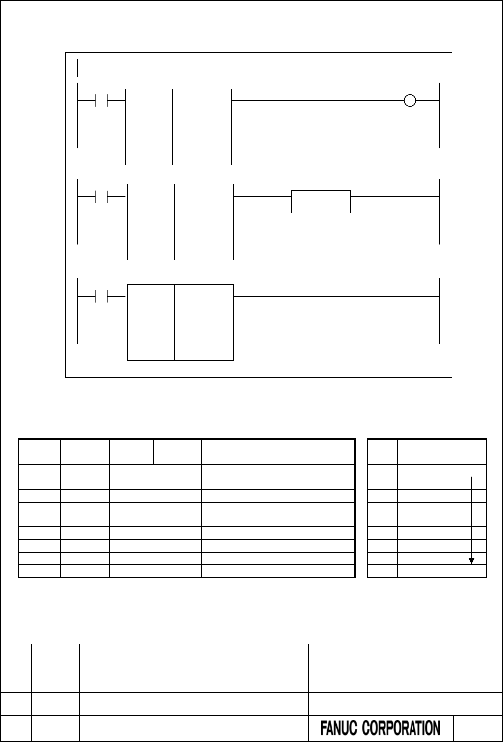
Format
Fig. 6.1.1 (b) shows the ladder format and Table 6.1.1 (a) shows the mnemonic format.
Fig. 6.1.1 (b) Format of PID control instruction
Table 6.1.1 (a) Mnemonic of PID control instruction
Mnemonic format Memory status of control
condition
Step
number
Instruction
Address
No.
Bit No. Remarks ST3 ST2 ST1 ST0
1
RD
○○○○
.
○
ACT
ACT
2
SUB
460
SUB No. (PID control instruction)
3
(PRM)
○○○○
PID control data address
4 (PRM) ○○○○
Preset setting value (address or
constant)
5
(PRM)
○○○○
Process variable input address
6
(PRM)
○○○○
Manipulated value output address
7
(PRM)
○○○○
Work memory address
8
WRT
○○○○
.
○
W1 Output
W1
PID control instruction
ACT
SUB 460
PID
○○○○
○○○○
○○○○
○○○○
○○○○
W1
ACT
ACT
Functional
instruction
ACT2
SUB 460
PID
○○○○
○○○○
○○○○
○○○○
○○○○
SUB 460
PID
○○○○
○○○○
○○○○
○○○○
○○○○
PID control data address
Preset setting value (address or constant)
Process variable input address
Manipulated value output address
Work memory address
FANUC Series 30i/31i/32i/35i-MODEL B
FANUC Power Motion i-MODEL A
FANUC Series 0i-MODEL F
PMC Supplemental Programming Manual
01 2015.4.16 H.Yonekura New registration DRAW. NO. : B-64513EN/03-2
EDIT. DATE DESIG. DESCRIPTION 74 / 88

Control condition
(a) Input signal (ACT)
ACT = 0 : Do not execute the PID control instruction.
ACT = 1 : Execute the PID control instruction.
Parameters
(a) PID control data address
You set the following PID control data in the area of 18 bytes length and specify the top address to this
parameter.
You can set and modify the values in the area under the condition of ACT = 0.
Contents
Setting range
Remarks
CTL+0
Proportional gain (KP)
1 to 32767
Unit
:
0.01
+2
Integral time (
TI) 0 to 32767 Unit:100 ms
If this value is 0, Integral action (I) does not work.
+4
Derivative time (
TD) 0 to 32767
Unit
:
10 ms
If this value is 0 or integral time (TI) is 0 (Integral action
does not work), and Derivative action (D) does not
work.
+6
Derivative gain (
KD) 0 to 32767
Unit
:
0.01
Set value between 8.00 and 10.00 normally; the actual
value between 800 and 1000. If the setting is 0, the
Derivative action (D) becomes exact differential.
+8
Sampling period (t)
1 to 32767
Unit
:
10 ms
If this value is shorter than ladder execution period, the
sampling period will be same as the ladder execution
period. For details, refer to “Sampling period” below.
+10
Positive action
/
Reverse action
0:Positive
1
:
Reverse
Specify the direction of PID control. For details, refer to
“Positive action / reverse action”.
+12 Manipulated value limit
0
:
No limit
1
:
Limit
When you want to restrict the range of the manipulated
value, specify “1”.
+14 Maximum manipulated
value
-32768 to 32767 Specify the maximum value of the manipulated value
when the manipulated value limit is set to 1.
If the operation result of the manipulated value
exceeds this value, the manipulated value will be this
value.
+16 Minimum manipulated
value
-32768 to 32767 Specify the minimum value of the manipulated value
when the manipulated value limit is set to 1.
If the operation result of the manipulated value is less
than this value, the manipulated value will be this
value.
+18
CAUTION
If you change the PID control data while ACT = 1, the operation result may be
incorrect.
FANUC Series 30i/31i/32i/35i-MODEL B
FANUC Power Motion i-MODEL A
FANUC Series 0i-MODEL F
PMC Supplemental Programming Manual
01 2015.4.16 H.Yonekura New registration DRAW. NO. : B-64513EN/03-2
EDIT. DATE DESIG. DESCRIPTION 75 / 88

NOTE
When the manipulated value limit is set to 1(enable limit), set the maximum and
the minimum manipulated values defined as “minimum < maximum”. If these
values do not satisfy the relation, the operation will not be executed and W1 will
be 0.
(b) Preset setting value
Specify the Preset setting value (SV), either by a constant or a PMC memory address for storing the
data.
(c) Process variable input address
Specify PMC memory address where the 2 byte data of the process variable is stored.
(d) Manipulated value output address
Specify PMC memory address where the 2 byte data of the manipulated value is stored.
NOTE
When the result of PID operation is out of the range of the manipulated value
output address, output the maximum value or the minimum value which can be
stored in the address.
(e) Work memory address
Specify a work memory address of 14 bytes length which is used for PID operation. R address will be
used typically.
The work memory is used for preserving the progress data of the PID operation. If you specify a
nonvolatile memory for the work memory, you have to initialize the area to 0 before the initial execution
of the instruction.
CAUTION
1 If the instruction starts working with the work memory that is not initialized to
“0”, the result of the PID operation will be incorrect.
2 Do not modify the contents of the work memory while the instruction is active.
3 If you change the work memory address by ladder editor, the new work memory
has to be initialized before starting the PID operation. In this case, the PID
operation starts from the initial state.
OUTPUT (W1)
W1=1: The operation works normally.
W1=0: The operation is not executed (ACT=0).
Some of the PID control data is out of range.
Or, the relation of “minimum manipulated value ≥ maximum manipulated value” is not satisfied
when the manipulated value limit is “1”.
Or, invalid data is found in the work memory.
FANUC Series 30i/31i/32i/35i-MODEL B
FANUC Power Motion i-MODEL A
FANUC Series 0i-MODEL F
PMC Supplemental Programming Manual
01 2015.4.16 H.Yonekura New registration DRAW. NO. : B-64513EN/03-2
EDIT. DATE DESIG. DESCRIPTION 76 / 88
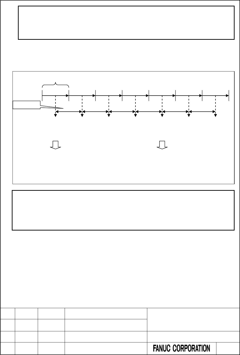
NOTE
1 When W1=0, the value in the manipulated value output address is preserved.
2 W1 can be omitted. Or it can be also connected to another functional instruction
instead of a coil.
3 This instruction does not use the operation output registers (R9000, Z0).
Sampling period
Specify the execution period of the PID operation by 10 ms unit.
Example) The scan time of the ladder program = 16 ms; the sampling period = 50 ms;
NOTE
1 The PID operation is processed at the timing of execution of PID control
instruction. Therefore, the processing timing of the operation may have a time lag
up to one scan time of the ladder program.
2 If the scan time of the ladder program is longer than the sampling period, the PID
operation is processed every scan of the ladder.
One scan of the sequence program
PID control
execution
16ms
16ms
16ms
16ms
16ms
PID operation
0ms
16ms
16+16=32ms
32+16=48ms
48+16=64ms
64-50=14
14+16=30ms
16ms
30+16=48ms
Sampling time
Scan time
Every time the PID control instruction is executed, it adds up each scan time. The PID operation is processed
when the
total of scan time reaches the sampling period. The excess of scan time total over the
sampling
period will be
carried over into the next scan time total.
PID control
execution
PID control
execution
PID control
execution
PID control
execution
PID control
execution
PID control
execution
PID operation
FANUC Series 30i/31i/32i/35i-MODEL B
FANUC Power Motion i-MODEL A
FANUC Series 0i-MODEL F
PMC Supplemental Programming Manual
01 2015.4.16 H.Yonekura New registration DRAW. NO. : B-64513EN/03-2
EDIT. DATE DESIG. DESCRIPTION 77 / 88
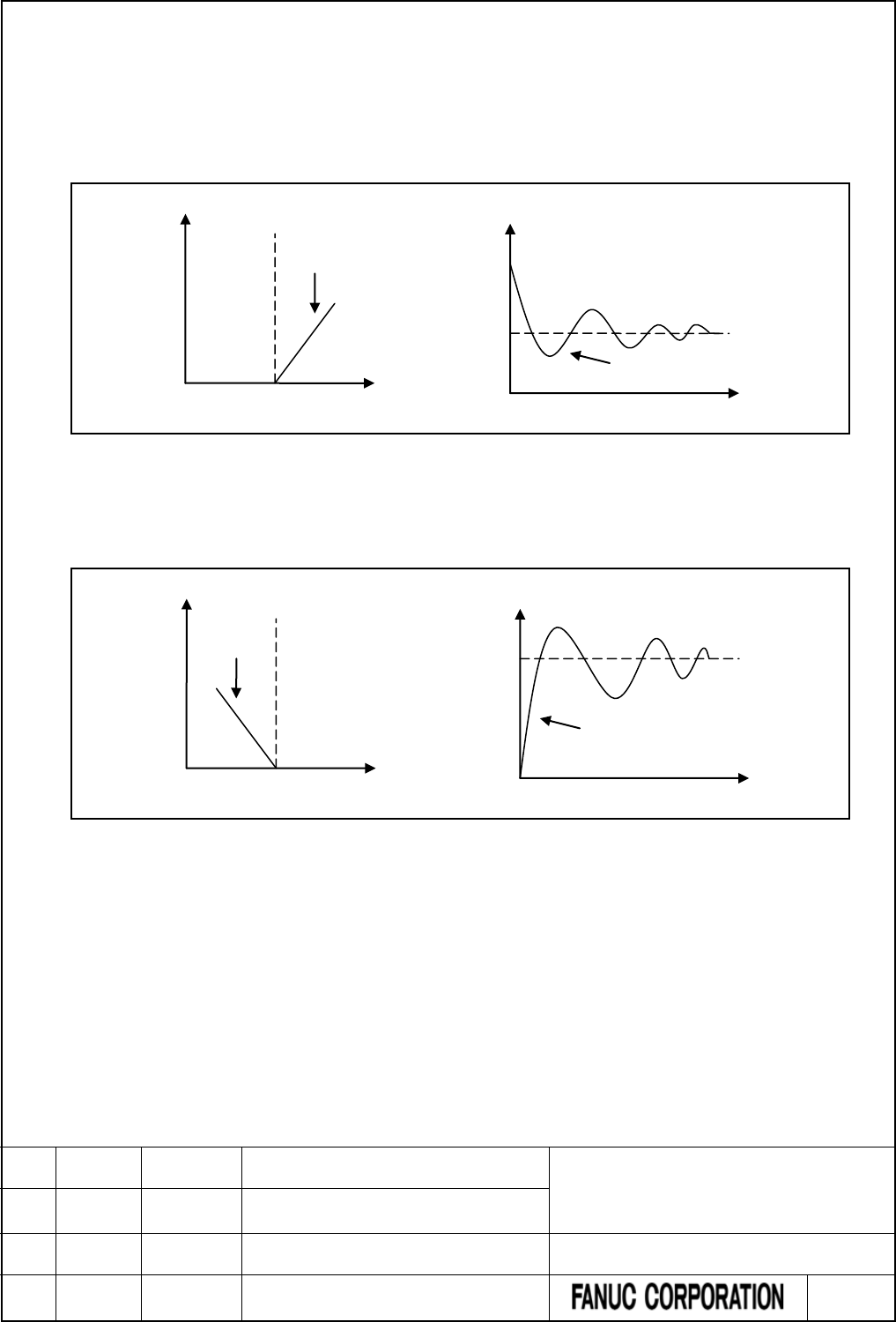
Positive action / Reverse action
The following control direction can be selected in the PID control instruction.
(1) Positive action
This action makes the Manipulated value increase when the Process variable is larger than the Preset
setting value. The following figure is an example of relationship diagram of manipulated value, Process
variable, and Preset setting value, and an example of temperature control in case of the positive action.
Fig.6.1.1 (c) Example of relationship diagram of MV, PV, and SV, and temperature control
(2) Reverse action
This action makes the Manipulated value increase when the Process variable is smaller than the Preset
setting value. The following figure is an example of relationship diagram of Manipulated value, Process
variable, and Preset setting value, and an example of temperature control in case of the reverse action.
Fig.6.1.1 (d) Example of relationship diagram of MV, PV and SV and temperature control
Example of heating
Manipulated
value (MV)
Process variable (PV)
Preset setting value (SV)
Reverse action
Temperature
Time
Preset
s
etting
value (SV)
Process
variable (PV)
Process variable (PV)
Manipulated
value (MV)
Preset setting value (SV)
Positive action
Preset
s
etting
value (SV)
Time
Temperature
Process variable (PV)
Example of air-conditioning
FANUC Series 30i/31i/32i/35i-MODEL B
FANUC Power Motion i-MODEL A
FANUC Series 0i-MODEL F
PMC Supplemental Programming Manual
01 2015.4.16 H.Yonekura New registration DRAW. NO. : B-64513EN/03-2
EDIT. DATE DESIG. DESCRIPTION 78 / 88

7 PMC DIAGNOSIS AND MAINTENANCE
SCREENS ([PMC MAINTE])
7.1 DATA INPUT/OUTPUT ([I/O] SCREEN)
7.1.1 7.4.1 Memory Card and USB Memory
Add the following to "7.4.1 Memory Card and USB Memory".
Memory card
The memory card, which is used for inputting/outputting the sequence program in the I/O screen, can also be
used to access to the programmer (FANUC LADDER-III).
As for the memory card, you need use the compact flash adapter, which is attached a compact flash card (CF
card) purchased from FANUC.
NOTE
If a CF card other than that purchased from FANUC is used, the operation is not
guaranteed.
For the details, refer to "APPENDIX E" in the "CONNECTION MANUAL (HARDWARE)" of each CNC
series.
USB memory
You can input/output some data to/from a USB memory with a USB port beside a display unit.
CAUTION
1 While the control unit is accessing the USB memory, do not turn off the power to the
control unit or do not remove the USB memory.
2 Close the cover of the USB port when no USB memory is inserted.
NOTE
1 It is not guaranteed that every commercially available USB memory can operate
normally. A USB memory with a security function does not operate. Some
commercially available USB memories may not be designed for the use in an FA
environment.
2 To use the USB slot of iPendant with a PMC screen, set bit 0 (PCM) of parameter
No. 300 to 1 and select MEMORY card to the device.
For the details, refer to section 5.6 in the "CONNECTION MANUAL (HARDWARE)" of each CNC series.
FANUC Series 30i/31i/32i/35i-MODEL B
FANUC Power Motion i-MODEL A
FANUC Series 0i-MODEL F
PMC Supplemental Programming Manual
01 2015.4.16 H.Yonekura New registration DRAW. NO. : B-64513EN/03-2
EDIT. DATE DESIG. DESCRIPTION 79 / 88
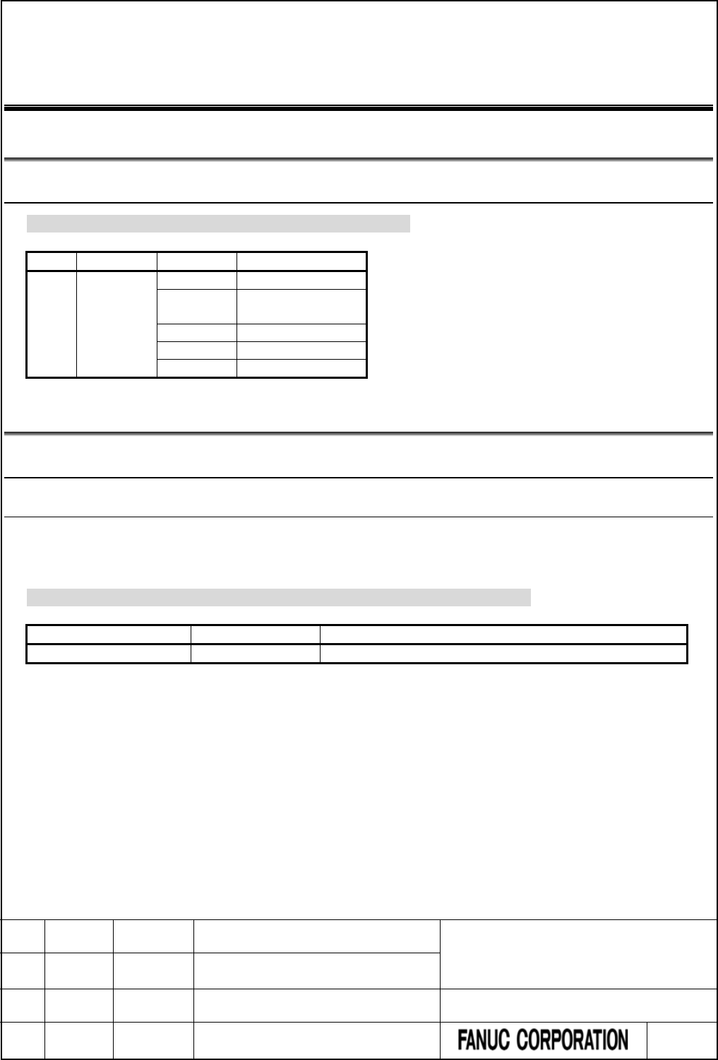
8 LADDER DIAGRAM MONITOR AND EDITOR
SCREEN ([PMC LADDER])
8.1 MONITORING LADDER DIAGRAMS ([LADDER] SCREEN)
8.1.1 Display Format for Parameters
Add the following to “8.2.3 Display Format for Parameters”.
No.
Name
Parameter
Monitor format
460
PID
1
2-byte binary
2
Constant or
2-byte binary
3
2-byte binary
4
2-byte binary
5
No monitor
8.2 EDITING LADDER PROGRAMS
8.2.1 Structure of Valid Net
8.2.1.1 Structure of extended type net
The functional instruction, which can be used in the structure of extended type
net
Add the following to the table 8.3.4.2 of “8.3.4.2 Structure of extended type net”.
Instruction name
SUB Number
Usable in Extended type net
PID
460
Yes
FANUC Series 30i/31i/32i/35i-MODEL B
FANUC Power Motion i-MODEL A
FANUC Series 0i-MODEL F
PMC Supplemental Programming Manual
01 2015.4.16 H.Yonekura New registration DRAW. NO. : B-64513EN/03-2
EDIT. DATE DESIG. DESCRIPTION 80 / 88
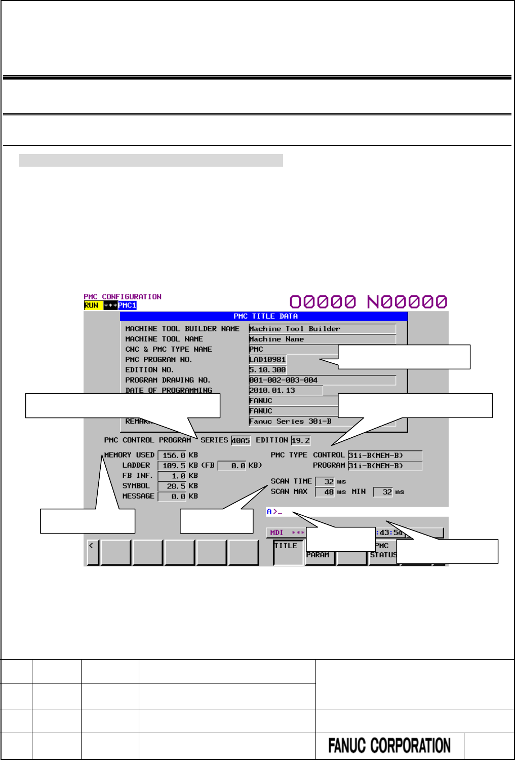
9 PMC CONFIGURATION DATA SETTING
SCREEN ([PMC CONFIG])
9.1 DISPLAYING AND EDITING TITLE DATA ([TITLE] SCREENS)
9.1.1 Displaying Title Data
Change a part of “9.1.1 Displaying Title Data” as follows.
On the TITLE DATA screen, you can check the title data items and some ladder information items.
To switch to the TITLE DATA screen, press the [TITLE] soft key.
Besides, the following operation is available in the TITLE DATA screen.
• Moving to the TITLE DATA EDITOR screen [EDIT]
• Moving to the TITLE DATA (MESSAGE) screen [MESAGE TITLE]
Title data of sequence
Series and edition of PMC system software PMC type and PMC memory type
Used memory size
Key input line
Message display line
Scan time
FANUC Series 30i/31i/32i/35i-MODEL B
FANUC Power Motion i-MODEL A
FANUC Series 0i-MODEL F
PMC Supplemental Programming Manual
01 2015.4.16 H.Yonekura New registration DRAW. NO. : B-64513EN/03-2
EDIT. DATE DESIG. DESCRIPTION 81 / 88

(1) Title data
The following title data that is set in the sequence program is displayed.
Item
Max. characters
MACHINE TOOL BUILDER NAME
32
MACHINE TOOL NAME
32
CNC & PMC NAME
32
PMC PROGRAM NO.
8
EDITION NO.
8
PROGRAM DRAWING NO.
32
DATA OF PROGRAMMING
16
PROGRAM DESIGNED BY
32
ROM WRITTEN BY
32
REMARKS
32
*** Omitted below ***
FANUC Series 30i/31i/32i/35i-MODEL B
FANUC Power Motion i-MODEL A
FANUC Series 0i-MODEL F
PMC Supplemental Programming Manual
01 2015.4.16 H.Yonekura New registration DRAW. NO. : B-64513EN/03-2
EDIT. DATE DESIG. DESCRIPTION 82 / 88
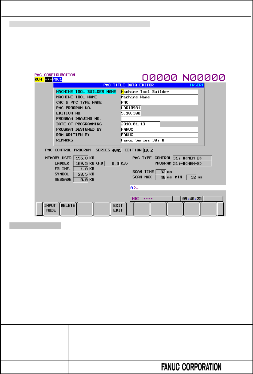
9.1.2 Editing Title Data
Change a part of a part of “9.1.2 Editing Tile Data” as follows.
On the TITLE DATA EDITOR screen, you can edit title data items. To switch to the TITLE DATA
EDITOR screen, press the [EDIT] soft key on the TITLE DATA screen.
On the TITLE DATA EDITOR screen, you can perform the following operations:
• Changing the input mode [INPUT MODE]
• Deleting title data [DELETE]
• Moving to the TITLE DATA screen [EXIT EDIT]
*** Omitted below ***
FANUC Series 30i/31i/32i/35i-MODEL B
FANUC Power Motion i-MODEL A
FANUC Series 0i-MODEL F
PMC Supplemental Programming Manual
01 2015.4.16 H.Yonekura New registration DRAW. NO. : B-64513EN/03-2
EDIT. DATE DESIG. DESCRIPTION 83 / 88
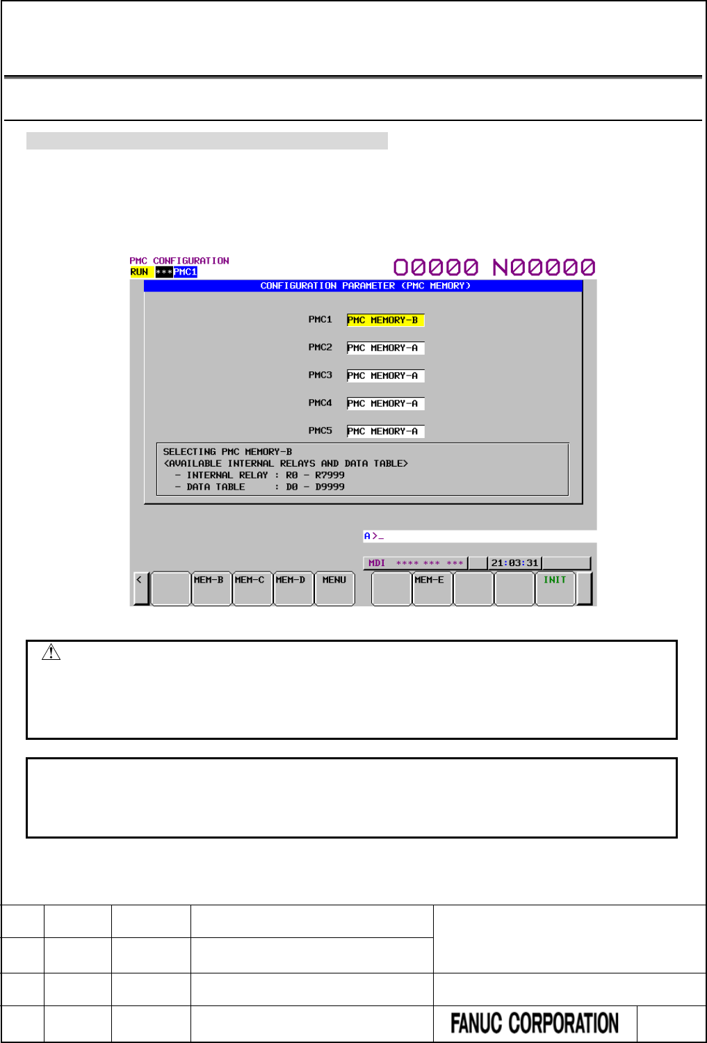
9.2 DISPLAYING AND SETTING CONFIGURATION
PARAMETERS ([CONFIG PARAM] SCREEN)
9.2.1 Setting the PMC memory type
Change “9.9.5 Setting the PMC Memory Type” as follows.
On the PMC CONFIGURATION PARAMETER (PMC MEMORY) screen, you can change the PMC
Memory Type of each PMC path.
The setting is saved to the CNC parameter and becomes effective after rebooting CNC. See the “2.4.3 CNC
Parameters Related to the PMCs” for the details of the CNC parameter.
Fig. 9.2.1 (a) PMC CONFIGURATION PARAMETER (PMC MEMORY) screen
CAUTION
PMC nonvolatile memory must be initialized after changing PMC Memory Type.
Therefore, make a backup of PMC parameter before changing PMC Memory
Type. See “2.8 BATTERY BACKUP DATA” about the operation of initializing
PMC nonvolatile memory.
NOTE
1 Selectable PMC Memory Type differs for each PMC path. See the “2.1.3
Determination of PMC Memory Type” for the details of selectable types.
2 The soft-key [MEM-E] is displayed only on a special series of CNC software.
FANUC Series 30i/31i/32i/35i-MODEL B
FANUC Power Motion i-MODEL A
FANUC Series 0i-MODEL F
PMC Supplemental Programming Manual
01 2015.4.16 H.Yonekura New registration DRAW. NO. : B-64513EN/03-2
EDIT. DATE DESIG. DESCRIPTION 84 / 88
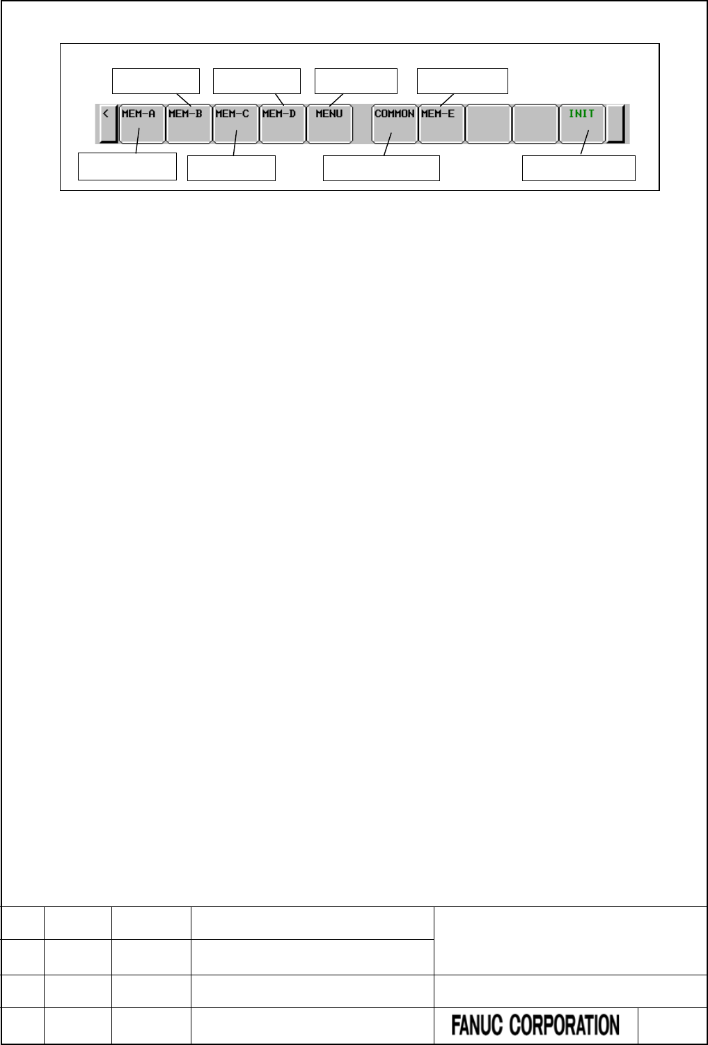
Screen operations
Fig. 9.2.1 (b) Soft keys on the PMC CONFIGURATION PARAMETER (PMC MEMORY) screen
(1) Operation with soft keys
(a) [MEM-A] Select the PMC Memory-A.
Selects the PMC Memory-A for the cursor focused PMC path. This soft key is displayed when the
PMC Memory-A is selectable at focused PMC path.
(b) [MEM-B] Select the PMC Memory-B.
Selects the PMC Memory-B for the cursor focused PMC path. This soft key is displayed when the
PMC Memory-B is selectable at focused PMC path.
(c) [MEM-C] Select the PMC Memory-C.
Selects the PMC Memory-C for the cursor focused PMC path. This soft key is displayed when the
PMC Memory-C is selectable at focused PMC path.
(d) [MEM-D] Select the PMC Memory-D.
Selects the PMC Memory-D for the cursor focused PMC path. This soft key is displayed when the
PMC Memory-D is selectable at focused PMC path.
(e) [MEM-E] Select the PMC Memory-E.
Selects the PMC Memory-E for the cursor focused PMC path. This soft key is displayed when the
PMC Memory-E is selectable CNC series and PMC path.
(f) [COMMON] Select the Common PMC Memory mode.
Selects the Common PMC Memory mode to the cursor focused PMC path. This soft key is
displayed when the Common PMC Memory mode is selectable at focused PMC path.
(g) [MENU] Switch to the menu screen.
Switches to the CONFIGURATION PARAMETER (MENU) screen.
(h) [INIT] Initialize all settings
Reset all PMC Memory Type of each PMC paths to the default setting.
Soft keys on the PMC CONFIGURATION PARAMETER (PMC MEMORY) screen
Select the PMC
Memory-A
Select the PMC
Memory-D
Select the PMC
Memory-C
Initialize all settings
Switch to the
menu screen
Select the Common
PMC Memory
Select the PMC
Memory-B
Select the PMC
Memory-E
FANUC Series 30i/31i/32i/35i-MODEL B
FANUC Power Motion i-MODEL A
FANUC Series 0i-MODEL F
PMC Supplemental Programming Manual
01 2015.4.16 H.Yonekura New registration DRAW. NO. : B-64513EN/03-2
EDIT. DATE DESIG. DESCRIPTION 85 / 88
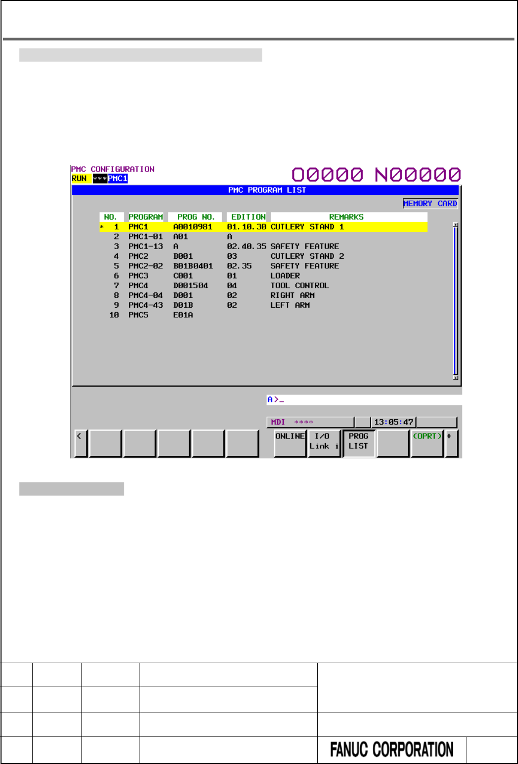
9.3 PMC Program List Screen
Change “9.11 PMC Program List Screen” as follows.
In case of using multi-path PMC or ladder dividing management function, you can confirm the information of
main ladder programs or divided ladder programs for all PMC paths installed in CNC system.
In PMC program list screen, you can confirm all main programs and divided programs of all PMC paths.
By selecting a program in the list, displayed program can be switched. PMC program list screen appears by
pressing the [PROG LIST] soft key or pressing the [SWITCH PMC] soft key in each PMC screen.
Fig.9.3 (a) PMCPROGRAM LIST screen
*** Omitted below ***
FANUC Series 30i/31i/32i/35i-MODEL B
FANUC Power Motion i-MODEL A
FANUC Series 0i-MODEL F
PMC Supplemental Programming Manual
01 2015.4.16 H.Yonekura New registration DRAW. NO. : B-64513EN/03-2
EDIT. DATE DESIG. DESCRIPTION 86 / 88
9.3.1 Output of program list information file
Change “9.11.1 Output of program list information file” as follows.
For maintenance of machines, there are cases where you want to get the information of ladder programs
installed in CNC system. In case of using multi-path PMC or ladder dividing management function, you can
confirm the information on the PMC program list screen. You can get the information of the screen as a
bitmap file. To use this function, however, you can output a text file of the screen information. The text file is
output as “CSV” format. Therefore, you can manage it using application software such as EXCEL on PC.
When pressing this soft key, [EXEC] and [CANCEL] soft keys appear. To output the file, press the [EXEC]
soft key.
You can select output device by the [IO DEVICE] soft key.
(1) File name
The output file name is “PMC_LIST.000”. If the same file name exists on the device, the extension is
incremented to “001”, “002” and so on. (Maximum “999”)
(2) Output format
The file is output with the “CSV” format. Character string data such as program and remarks are
enclosed in double quotation marks (" ").
Output contents are as follows.
(a) Header
At the top of data, an identifier representing the file information is output.
Identifier: ("PMC PROGRAM LIST")
Edition information: ("Edition", 1)
(b) Data
Program information, which is displayed on program list screen, is output.
Program information: Number, “Program”, “Program No.”, “Edition”, “Remarks”
Example of program list information
NOTE
For view comfort, tabs are inserted in several places. In actual data, however, no tab
is inserted.
"PMC PROGRAM LIST"
"Edition",
1
1,
"PMC1",
"A0010981",
"01.10.30",
"CUTLERY STAND1"
2,
"PMC1-01",
"A01B",
"01",
3,
"PMC1-02",
"A01C",
"02.40.35",
"SAFETY FEATURE"
4,
"PMC2",
"B001",
"03",
"CUTLERY STAND2"
5,
"PMC2-01",
"B01B0401",
"02.35",
"SAFETY FEATURE"
6,
"PMC3",
"C001",
"01",
"LOADER"
7,
"PMC4",
,
,
8,
"PMC4-01",
"D01A",
"02",
"RIGHIT ARM"
9,
"PMC4-02",
"D01B",
"01",
"LEFT ARM"
10,
"PMC5",
"E01A",
,
Header
Data
FANUC Series 30i/31i/32i/35i-MODEL B
FANUC Power Motion i-MODEL A
FANUC Series 0i-MODEL F
PMC Supplemental Programming Manual
01 2015.4.16 H.Yonekura New registration DRAW. NO. : B-64513EN/03-2
EDIT. DATE DESIG. DESCRIPTION 87 / 88

10 PMC ALARM MESSAGE AND ACTIONS TO
TAKE
10.1 ALARM MESSAGE LIST
10.1.1 Message that May Be Displayed on the PMC Alarm Screen
Add the following to "12.1.1 Messages That May Be Displayed on the PMC Alarm Screen".
Alarm number
Faulty location/corrective action
Contents
ER59 MESSAGE DATA SIZE OVER Reduce the size of message data in
sequence program or message file
for multi-language display.
The message data exceeds the
maximum message data size.
(Only 0i-F PMC/L)
10.1.2 Operation Errors
Add the following to "12.1.3 Operation Errors".
Error messages that may be displayed on the PMC LADDER DIAGRAM VIEWER
screen
Message
Faulty location/corrective action
Contents
NET IS TOO COMPLICATED Divide the net that is not displayed
into some smaller nets with FANUC
LADDER-III.
There is a net exceeding the limit
size for displaying on ladder diagram
monitor screen.
FANUC Series 30i/31i/32i/35i-MODEL B
FANUC Power Motion i-MODEL A
FANUC Series 0i-MODEL F
PMC Supplemental Programming Manual
01 2015.4.16 H.Yonekura New registration DRAW. NO. : B-64513EN/03-2
EDIT. DATE DESIG. DESCRIPTION 88 / 88
