Quectel Low Power Design User Guide V1.3
User Manual: Pdf
Open the PDF directly: View PDF ![]() .
.
Page Count: 27
- About the Document
- Contents
- Table Index
- Figure Index
- 1 Introduction
- 2 Low Power Consumption Solutions
- 3 Measures for Reducing Power Consumption
- 4 AT Command for Low Power Consumption
- 5 Appendix A Reference

Low Power Design
User Guide
GSM/GPRS Module Series
Rev. Low_Power_Design_User_Guide_V1.3
Date: 2015-04-11
www.quectel.com
GSM/GPRS Module Series
Low Power Design User Guide
Low_Power_Design _User_Guide Confidential / Released 1 / 26
Our aim is to provide customers with timely and comprehensive service. For any
assistance, please contact our company headquarters:
Quectel Wireless Solutions Co., Ltd.
Office 501, Building 13, No.99, Tianzhou Road, Shanghai, China, 200233
Tel: +86 21 5108 6236
Mail: info@quectel.com
Or our local office, for more information, please visit:
http://www.quectel.com/support/salesupport.aspx
For technical support, to report documentation errors, please visit:
http://www.quectel.com/support/techsupport.aspx
Or Email: Support@quectel.com
GENERAL NOTES
QUECTEL OFFERS THIS INFORMATION AS A SERVICE TO ITS CUSTOMERS. THE INFORMATION
PROVIDED IS BASED UPON CUSTOMERS’ REQUIREMENTS. QUECTEL MAKES EVERY EFFORT
TO ENSURE THE QUALITY OF THE INFORMATION IT MAKES AVAILABLE. QUECTEL DOES NOT
MAKE ANY WARRANTY AS TO THE INFORMATION CONTAINED HEREIN, AND DOES NOT ACCEPT
ANY LIABILITY FOR ANY INJURY, LOSS OR DAMAGE OF ANY KIND INCURRED BY USE OF OR
RELIANCE UPON THE INFORMATION. ALL INFORMATION SUPPLIED HEREIN IS SUBJECT TO
CHANGE WITHOUT PRIOR NOTICE.
COPYRIGHT
THIS INFORMATION CONTAINED HERE IS PROPRIETARY TECHNICAL INFORMATION OF
QUECTEL CO., LTD. TRANSMITTABLE, REPRODUCTION, DISSEMINATION AND EDITING OF THIS
DOCUMENT AS WELL AS UTILIZATION OF THIS CONTENTS ARE FORBIDDEN WITHOUT
PERMISSION. OFFENDERS WILL BE HELD LIABLE FOR PAYMENT OF DAMAGES. ALL RIGHTS
ARE RESERVED IN THE EVENT OF A PATENT GRANT OR REGISTRATION OF A UTILITY MODEL
OR DESIGN.
Copyright © Quectel Wireless Solutions Co., Ltd. 2015. All rights reserved.
Quectel
Confidential
GSM/GPRS Module Series
Low Power Design User Guide
Low_Power_Design _User_Guide Confidential / Released 2 / 26
About the Document
History
Revision
Date
Author
Description
1.0
2012-09-06
Layne YE
Initial
1.1
2014-02-28
Layne YE
1. Added battery test.
2. Added DC/DC convertor reference design.
3. Added power consumption of GSM module.
4. Added battery capacity assessment.
1.2
2014-08-28
Layne YE
1. Added energy battery pack in Table 1.
2. Added battery testing result and comparison.
3. Rectified the reference design.
1.3
2015-04-11
Layne YE
Added applicable modules
Quectel
Confidential

GSM/GPRS Module Series
Low Power Design User Guide
Low_Power_Design _User_Guide Confidential / Released 3 / 26
Contents
About the Document ................................................................................................................................... 2
Contents ....................................................................................................................................................... 3
Table Index ................................................................................................................................................... 4
Figure Index ................................................................................................................................................. 5
1 Introduction .......................................................................................................................................... 6
2 Low Power Consumption Solutions .................................................................................................. 7
2.1. Power Supply Solution ............................................................................................................ 7
2.1.1. Battery Type ..................................................................................................................... 7
2.1.2. Battery Test ...................................................................................................................... 8
2.1.2.1. Continuous Current Load Test ........................................................................... 8
2.1.2.2. Pulse Current Load Test .................................................................................... 9
2.1.2.3. Pulse Current Load Test with Capacitor .......................................................... 11
2.1.3. Battery Comparison and Selection ................................................................................ 12
2.2. Application Reference Design ............................................................................................... 13
2.2.1. Reference Design of Single Battery ES-341550-W ....................................................... 14
2.2.2. Reference Design of Single Battery ER34615M ........................................................... 15
2.2.3. Reference Design of Two Battery Packs ....................................................................... 16
2.3. DC/DC Step Down Convertor ................................................................................................ 17
2.3.1. DC/DC Convertor Design ............................................................................................... 17
2.3.2. DC/DC Layout Guideline ................................................................................................ 17
2.4. Power Consumption of GSM/GPRS Module ........................................................................ 18
2.5. Battery Capacity Requirement Assessment .......................................................................... 20
3 Measures for Reducing Power Consumption ................................................................................. 21
4 AT Command for Low Power Consumption ................................................................................... 22
4.1. AT+CDETXPW TX Power Control ...................................................................................... 22
4.2. Example of Reducing TX Power for GPRS Data Transmission............................................ 23
4.3. Example of Reducing TX Power for SMS Data Transmission .............................................. 25
5 Appendix A Reference ....................................................................................................................... 26
Quectel
Confidential

GSM/GPRS Module Series
Low Power Design User Guide
Low_Power_Design _User_Guide Confidential / Released 4 / 26
Table Index
TABLE 1: COMPARISON OF BATTERY PERFORMANCE PARAMETER ........................................................ 8
TABLE 2: PULSE CURRENT TEST CONDITION AND RESULT ....................................................................... 9
TABLE 3: PULSE CURRENT LOAD TEST WITH CAPACITOR ........................................................................ 11
TABLE 4: REFERENCE PRICE OF BATTERY ................................................................................................. 13
TABLE 5: TEST CONDITION IN DIFFERENT MODE ...................................................................................... 18
TABLE 6: EXAMPLE OF AVERAGE POWER CONSUMPTION IN DIFFERENT MODE ................................. 20
TABLE 7: REFERENCE DOCUMENT .............................................................................................................. 26
Quectel
Confidential

GSM/GPRS Module Series
Low Power Design User Guide
Low_Power_Design _User_Guide Confidential / Released 5 / 26
Figure Index
FIGURE 1: DISCHARGE CURVE CHART OF CONTINUOUS LOAD ............................................................... 8
FIGURE 2: THE DROP VOLTAGE OF ER34615 ................................................................................................ 9
FIGURE 3: THE DROP VOLTAGE OF ER34615M ........................................................................................... 10
FIGURE 4: THE DROP VOLTAGE OF ES-34341550-W .................................................................................. 10
FIGURE 5: THE DROP VOLTAGE OF TLP-83111A/SM .................................................................................... 11
FIGURE 6: THE DROP VOLTAGE OF ER34615M WITH CAPACITOR ........................................................... 12
FIGURE 7: REFERENCE DESIGN OF SINGLE BATTERY ES-341550-W ...................................................... 14
FIGURE 8: REFERENCE DESIGN OF SINGLE BATTERY ER34615M .......................................................... 15
FIGURE 9: REFERENCE DESIGN OF TWO BATTERY PACKS OF ES-341550-W ....................................... 16
FIGURE 10: REFERENCE CIRCUIT OF TPS54331 ........................................................................................ 17
FIGURE 11: CURRENT CONSUMPTION OF GPRS DATA TRANSMISSION ................................................. 19
FIGURE 12: CURRENT CONSUMPTION OF SMS TRANSMISSION ............................................................. 19
Quectel
Confidential

GSM/GPRS Module Series
Low Power Design User Guide
Low_Power_Design _User_Guide Confidential / Released 6 / 26
1 Introduction
This document mainly introduces the comprehensive solution and measure for reducing power
consumption of GSM/GPRS module in lower power application, including the battery selection and
relative reference design.
This document is applicable to all Quectel GSM modules.
Quectel
Confidential

GSM/GPRS Module Series
Low Power Design User Guide
Low_Power_Design _User_Guide Confidential / Released 7 / 26
2 Low Power Consumption Solutions
This solution is only applied for wireless data transmission terminals which can meet the following
requirements:
- Lithium-thionyl chloride (Li-SOCl2) is used for main power of the system
- The battery is a non-rechargeable battery and its lifecycle is up to one year or much longer
- Wireless data transmission terminals with less work time in application.
2.1. Power Supply Solution
Terminal device has to operate for a long time without AC mains supply. Hence device system needs
super capacity batteries to supply power. The power supply range of the GSM/GPRS module is 3.3~4.6V,
and the power for MCU is 3.3V or lower voltage. Since the battery is used as power source for device,
battery capacity selection and power circuit design play an important role in reducing power consumption
of whole system.
2.1.1. Battery Type
Considering the long-term effective working of the battery, super capacity Lithium-thionyl chloride
(Li-SOCl2) is needed. Lithium-thionyl chloride (Li-SOCl2) can not only provide the maximum energy ratio
and voltage, but also have preferable discharge characteristic and little self-discharge.
Generally, super capacity Lithium-thionyl chloride (Li-SOCl2) can be classified into power type and
energy type. For energy type battery, its capacity is high (e.g. ER34615 3.6V/19Ah), but maximum
continuous discharge current is quite lower. And power type battery can output larger current (e.g.
ER34615M 3.6V/13Ah). Besides these two typical batteries, there is another battery pack (e.g.
ES-341550-W 3.6V/19Ah) which is composed of an energy battery ER34615 and a super pulse capacitor
SPC1550. This battery pack can overcome the defect of energy type that cannot provide high pulse
current.
The comparison of the related parameters between these three types is shown as below:
Quectel
Confidential
GSM/GPRS Module Series
Low Power Design User Guide
Low_Power_Design _User_Guide Confidential / Released 8 / 26
Table 1: Comparison of Battery Performance Parameter
1. You can get more information of battery from EVE: http://www.evebattery.com/en2/index02.aspx.
2. There is another special battery pack from Israel. The part type is Trdiran TLP-83111/A/SM
(3.9V/16Ah) that consists of a power type battery TL6930 and a super capacitor HLC-1550A.
2.1.2. Battery Test
2.1.2.1. Continuous Current Load Test
The battery ER34615, ER34615M, ES-341550-W and TLP-83111A/SM are tested in different continuous
current load, the voltage drops much with the current increasing.
Figure 1: Discharge Curve Chart of Continuous Load
Performance
Parameter
Power Type
(ER34615M)
Energy Type
(ER34615)
Energy Battery Pack
(ES-341550-W)
Nominal Capacity
13Ah @5mA,to 2V
19Ah @2mA,to 2V
19Ah @2mA,to 2V
Nominal Voltage
3.6V
3.6V
3.6V
Maximum Continuous
Discharge Current
2000mA
230mA
Maximum Pulse Current
4000mA @0.1s
400mA @0.1s
3000mA @1s
Temperature Range
-60˚C ~ +85˚C
-60˚C ~ +85˚C
-40˚C ~ +85˚C
NOTES
Quectel
Confidential
GSM/GPRS Module Series
Low Power Design User Guide
Low_Power_Design _User_Guide Confidential / Released 9 / 26
From the above discharge curve chart, we can see that the voltage of battery ER34615 drops to lower
than 3.2V when the current load is up to 230mA, so this type cannot provide sufficient current for
GSM/GPRS module. And the power type battery ER34615M can support higher current than the energy
type battery ER34615. As to other two battery packs, their super capacitor can afford much higher current
load that can maintain high voltage on high current load.
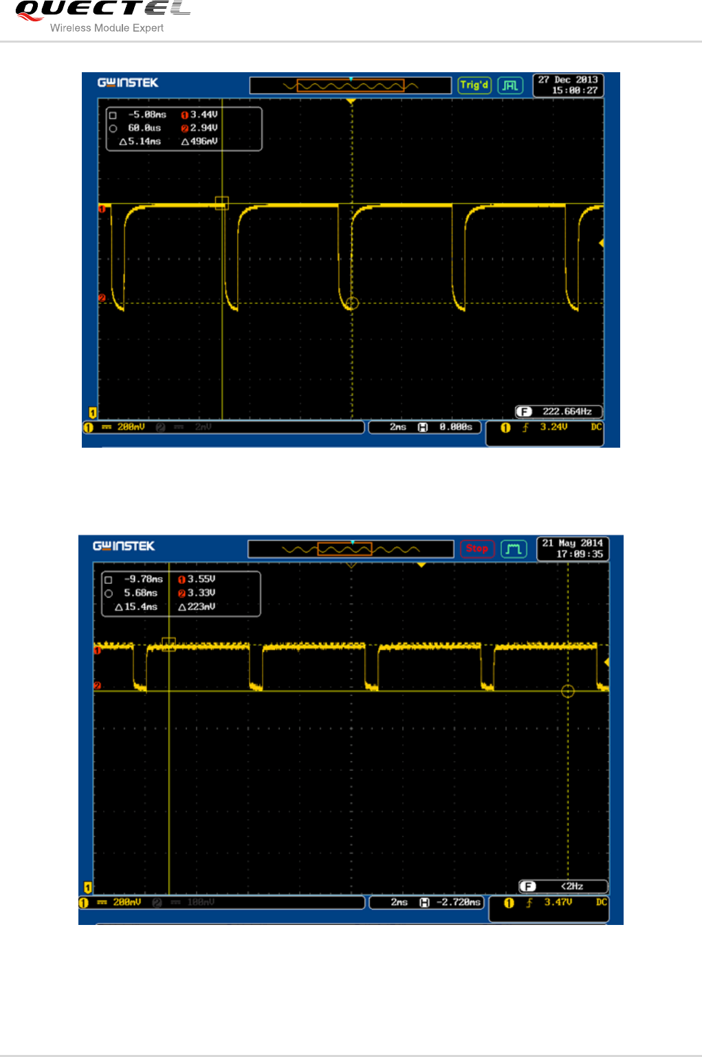
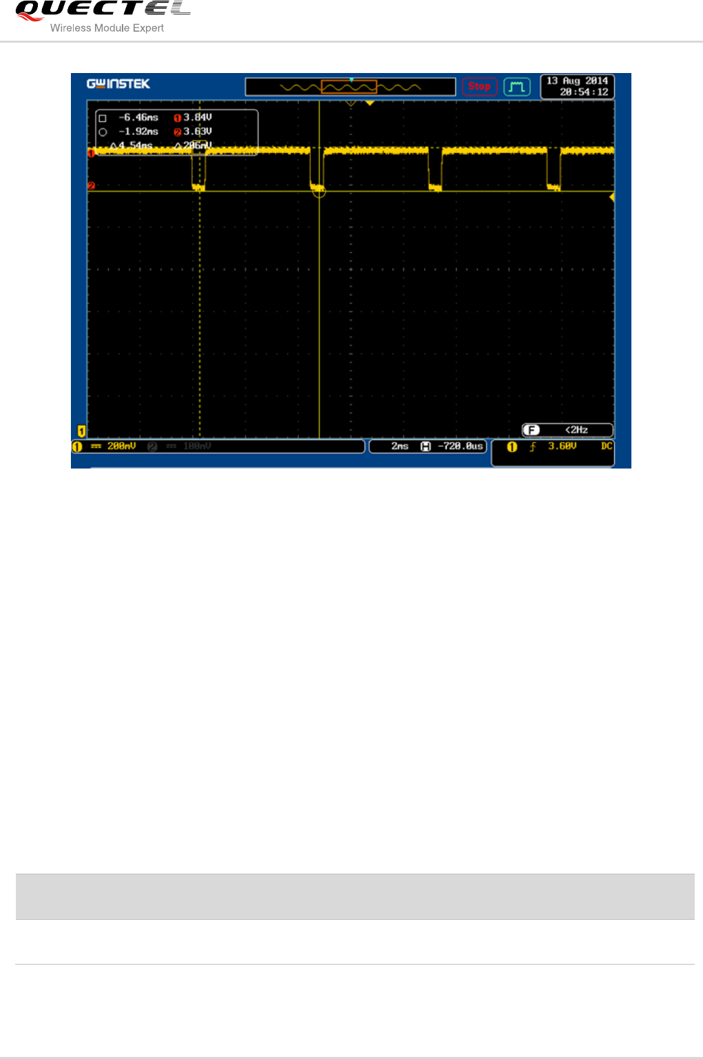
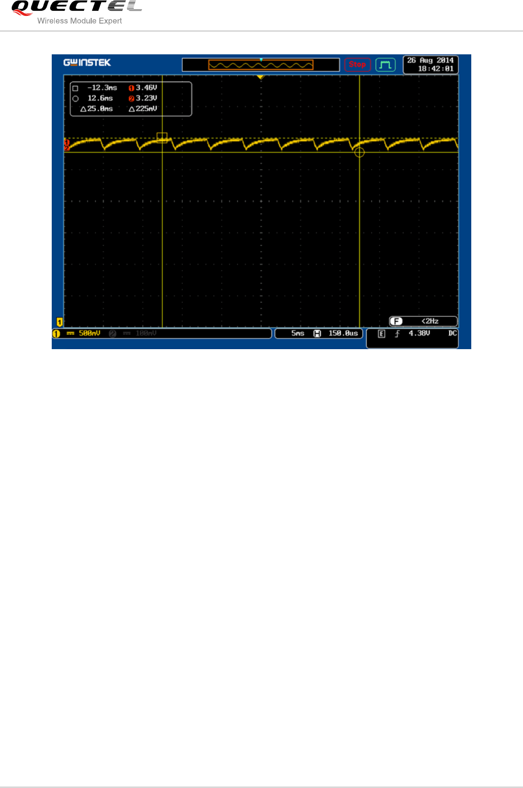
2.1.2.2. Pulse Current Load Test
The battery ER34615, ER34615M, ES-341550-W and TLP-83111A/SM are tested in pulse current load
that simulates burst time cycle of GSM transmitting. The test result is shown in following table.
Table 2: Pulse Current Test Condition and Result
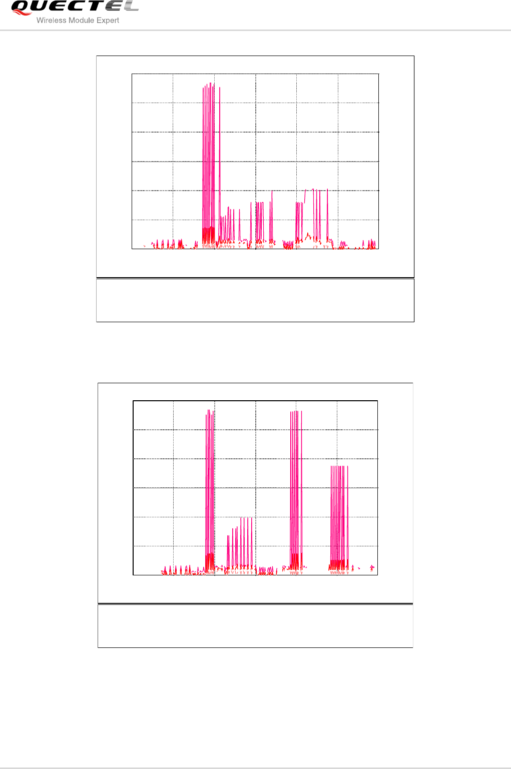
Figure 2: The Drop Voltage of ER34615
Battery Type
Pulse Current
Setting
Average
Current
Max.
Voltage
Min.
Voltage
Drop Voltage
Waveform
ER34615
150mA/4.037ms
1800mA/0.577ms
333mA
3.25V
1.14V
FIGURE 2
ER34615M
333mA
3.44V
2.91V
FIGURE 3
ES-341550-W
333mA
3.56V
3.32V
FIGURE 4
TLP-83111A/SM
333mA
3.84V
3.63V
FIGURE 5
Quectel
Confidential
GSM/GPRS Module Series
Low Power Design User Guide
Low_Power_Design _User_Guide Confidential / Released 10 / 26
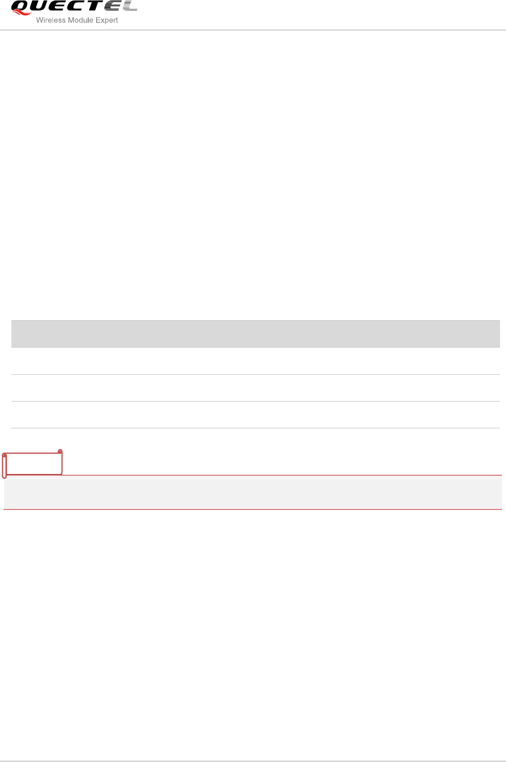
Figure 3: The Drop Voltage of ER34615M
Figure 4: The Drop Voltage of ES-34341550-W
Quectel
Confidential
GSM/GPRS Module Series
Low Power Design User Guide
Low_Power_Design _User_Guide Confidential / Released 11 / 26
Figure 5: The Drop Voltage of TLP-83111A/SM
From the above pulse testing result, we know that voltage of ER34615 battery drops so much and the
max voltage is only 3.25V which cannot satisfy the power requirements for GSM module, so the ER34615
is not suitable for GSM/GRPS module application. The battery ES-34341550-W and TLP-83111A/SM are
suitable for the GSM/GRPS module application, because the voltage drops less and can be sustained
higher than 3.3V when the peak current occurs.
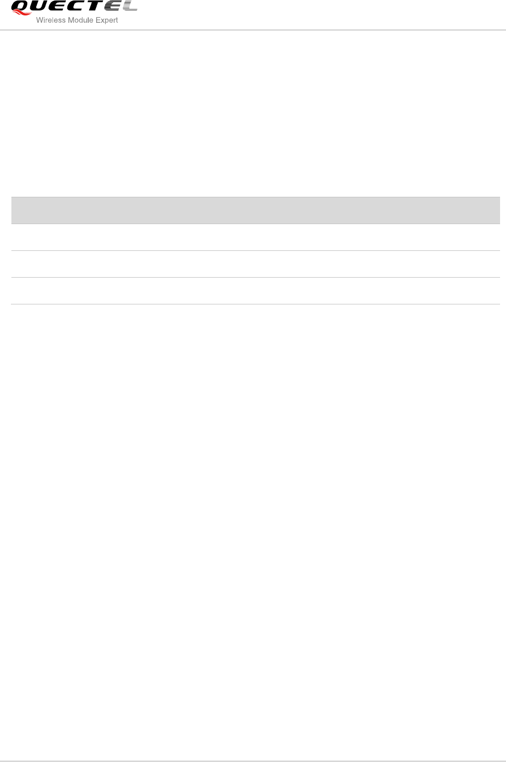
2.1.2.3. Pulse Current Load Test with Capacitor
In circuit design, the battery with high capacitance capacitor (4400uF) in parallel is used as power supply
for device system. The pulse current setting is same as above testing, the following table and figure show
the result of voltage drops of ER34615M with 4400uF capacitor.
Table 3: Pulse Current Load Test with Capacitor
Battery Type
Pulse Current
Setting
Average
Current
Max.
Voltage
Min.
Voltage
Drop Voltage
Waveform
ER34615M+4400uF
150mA/4.037ms
1800mA/0.577ms
333mA
3.46V
3.26V
FIGURE 6
Quectel
Confidential
GSM/GPRS Module Series
Low Power Design User Guide
Low_Power_Design _User_Guide Confidential / Released 12 / 26
Figure 6: The Drop Voltage of ER34615M with Capacitor
Compared to the voltage waveform in figure 3, the voltage drops less when the capacitor is added in
circuit. Although the max power is lower than the battery ES-341550-W and TLP-83111A/SM, in practical
test, the GSM/GRPS module supplied with this power supply works normally in short-term application. But
it is difficult to keep the battery voltage higher than 3.3V in long-term effective work.
2.1.3. Battery Comparison and Selection
According to GSM/GPRS power supply requirement of GSM/GPRS module, from the above different load
mode testing, we can conclude that the battery ER34615M, ES-341550-W and TLP-83111A/SM can be
used as power supply for GSM/GPRS module in lower power consumption application system. But we
also should consider other aspects of requirement.
In terms of safe use, in general, these three types of battery are safe. But the ER34615M is power type
battery, in order to provide high pulse current, the special internal structure of power type battery is
different from the energy type battery. In some high temperature environment, and the battery discharges
with high current, it may lead to explode. So the power type battery is forbidden to use in high temperature
and flammable and explosive circumstance.
As we know, the Li-SOCl2 battery has a defect of voltage hysteresis. The battery voltage drops to much
lower voltage after the battery being discharged in extremely current or stored a long period of time. As to
battery pack with super capacitor, for example, ES-341550-W, this type battery can effective overcome
Quectel
Confidential
GSM/GPRS Module Series
Low Power Design User Guide
Low_Power_Design _User_Guide Confidential / Released 13 / 26
the defect of voltage hysteresis. But for ER34615M battery without super capacitor, in real application
system, this defect can be overcome by discharge in high pulse current periodically.
From the aspect of price, the battery TLP-83111A/SM is a special customized voltage (3.9V) battery for
GSM/GPRS module, so the price is very expensive. The following table shows the reference price for
these three type battery.
Table 4: Reference Price of Battery
In sum, all these three type battery can be used as power supply. According to the battery performance,
the battery TLP-83111A/SM is an optimal choice. But, considering to the price requirement, the battery
ES-341550-W is more suitable.
2.2. Application Reference Design
The power supply range of the module is 3.3V~ 4.3V. The voltage drop occurs during the transmitting
burst time. As to the module, the power supply should not drop less than 3.3V because of the power
supply protection function, or else the module will be shutdown automatically. In order to ensure the
module working normally with low power supply, so the low power voltage shutdown and low power
voltage warning function should be disabled. You can use the AT+QVBATT command to set or disable
low voltage protection. Please refer to the document [2] for more details. For example:
AT+QVBATT=0,3500,0 Disable the low power voltage warning
AT+QVBATT=1,3300,0 Disable the low power voltage shutdown
AT+QVBATT=1,3000,1 Set the shutdown voltage to 3.0V
For GSM/GPRS module, only when the power for VBAT is higher than 3.2V can module be started from
shutdown mode, so make sure that the power supply meets the start voltage requirement of module.
In the low power system, power supply and interface circuit have a great influence on low power
consumption. Here are some reference designs with power supply and interface circuit as below.
Battery Type
Price (1K pcs)
ER34615M
45 RMB
ES-341550-W
60 RMB
TLP-83111A/SM
360 RMB
Quectel
Confidential
GSM/GPRS Module Series
Low Power Design User Guide
Low_Power_Design _User_Guide Confidential / Released 14 / 26
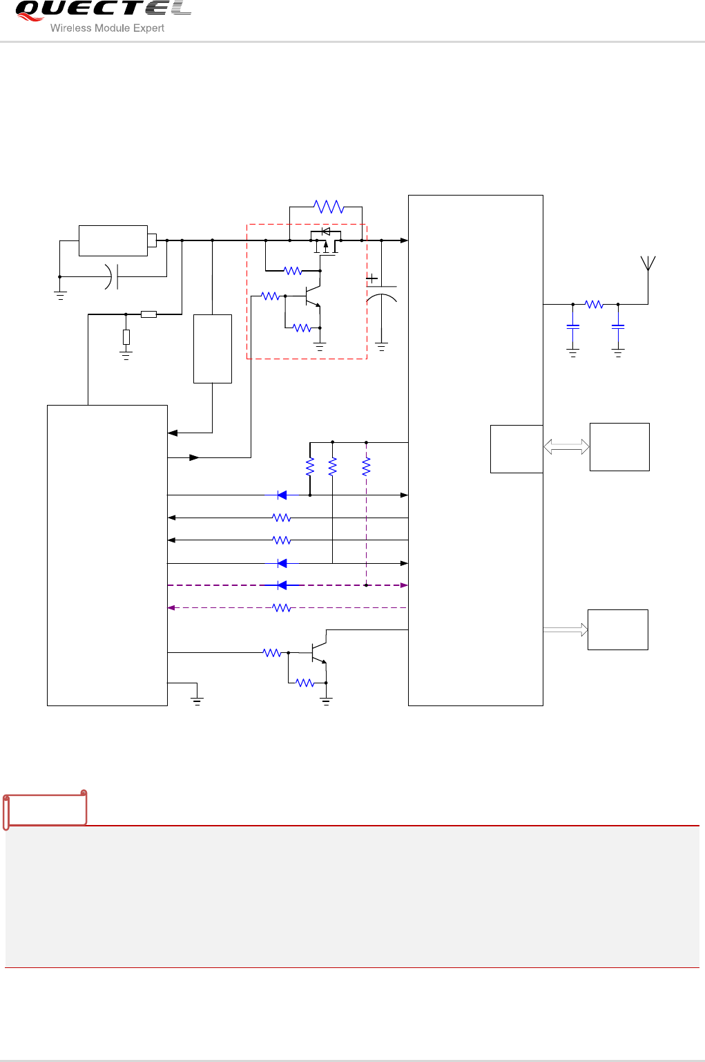
2.2.1. Reference Design of Single Battery ES-341550-W
The following figure shows the reference design with a single battery ES-341550-W used as power supply.
It is recommended to use this battery in your device.
G
S
D
0R_NM
100K
4.7K
47K
MCU
GSM/GPRS
VBAT
/TXD
/RXD TXD
RXD
1K
VCC
4.7K
47K
PWRKEY
GPIO2
1K
EINT0 RI
VDD_EXT
10K
/RTS
/CTS
10K
1K
RTS
CTS
10K
GPIO1 DTR
SIM card
NC NC
0R
GPIO3
RF_ANT
SIM
Interface
ADC
GND
ES-341550-W
IN
OUT
1000uF
LDO
Output
Indicator
470uF
Figure 7: Reference Design of Single Battery ES-341550-W
1. The dotted line circuit in purple is optional, you can remove this part circuit if do not need hardware
flow control in practical application.
2. Diode circuit on the interface is used to avoid current flowing into the module. It can reduce the power
consumption of MCU. It is recommended to use schottky diode with forward voltage less than 0.3V.
3. The circuit in red dotted rectangle can be removed when the GSM module need not shutdown the
power supply.
NOTE
Quectel
Confidential
GSM/GPRS Module Series
Low Power Design User Guide
Low_Power_Design _User_Guide Confidential / Released 15 / 26
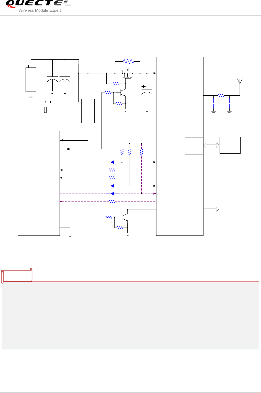
2.2.2. Reference Design of Single Battery ER34615M
The following figure shows the reference design with a single battery ER34615M used as power supply.
G
S
D
0R_NM
100K
4.7K
47K
MCU
GSM/GPRS
VBAT
/TXD
/RXD TXD
RXD
1K
VCC
4.7K
47K
PWRKEY
GPIO2
1K
EINT0 RI
VDD_EXT
10K
/RTS
/CTS
10K
1K
RTS
CTS
10K
GPIO1 DTR
SIM card
NC NC
0R
GPIO3
RF_ANT
SIM
Interface
ADC
GND
ER34615M
IN
OUT
1000uF
Output
Indicator
2200uF
2200uF
LDO
Figure 8: Reference Design of Single Battery ER34615M
1. The dotted line circuit in purple is alternative, you can use it or not according to whether you need
hardware flow control in practical application.
2. Diode circuit on the interface is used to avoid current flowing into the module. It can reduce the power
consumption of MCU. It is recommended to use schottky diode with forward voltage less than 0.3V.
3. The circuit in red dotted rectangle can be removed when the GSM module need not shutdown the
power supply.
4. The battery ER34615M is forbidden to use in high temperature, or flammable and explosive
circumstance. For example, Gas meter.
NOTE
Quectel
Confidential
GSM/GPRS Module Series
Low Power Design User Guide
Low_Power_Design _User_Guide Confidential / Released 16 / 26
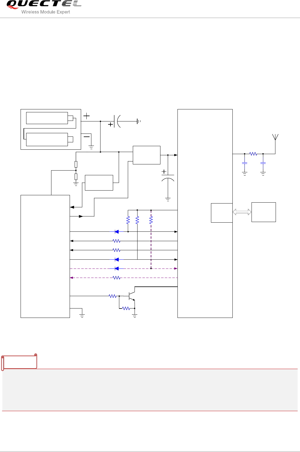
2.2.3. Reference Design of Two Battery Packs
In order to achieve much longer usage time, the battery pack composes of same two high capacity
batteries in series can be used as power supply. The output voltage is higher than the requirement of
power supply of MCU and GSM/GPRS module, thus, the output voltage should be regulated to meet the
requirements of power for GSM module and MCU. In order to increase the power conversion efficiency, it
is better to use DC/DC convertor instead of LDO regulator.
MCU
GSM/GPRS
VBAT
/TXD
/RXD TXD
RXD
1K
VCC
4.7K
47K
PWRKEY
GPIO2
1K
EINT0 RI
VDD_EXT
10K
/RTS
/CTS
10K
1K
RTS
CTS
10K
GPIO1 DTR
SIM card
NC NC
0R
GPIO3
RF_ANT
SIM
Interface
TPS54331
EN
IN OUT
TPS62240
IN
OUT
Battery Pack
ADC
GND
470uF
1000uF
ES-341550-W
ES-341550-W
Figure 9: Reference Design of Two Battery Packs of ES-341550-W
1. The dotted line circuit in purple is alternative, you can use it or not according to whether you need
hardware flow control in practical application.
2. Diode circuit on the interface is used to avoid current flowing into the module. It can reduce the power
consumption of MCU. It is recommended to use schottky diode with forward voltage less than 0.3V.
NOTE
Quectel
Confidential
GSM/GPRS Module Series
Low Power Design User Guide
Low_Power_Design _User_Guide Confidential / Released 17 / 26
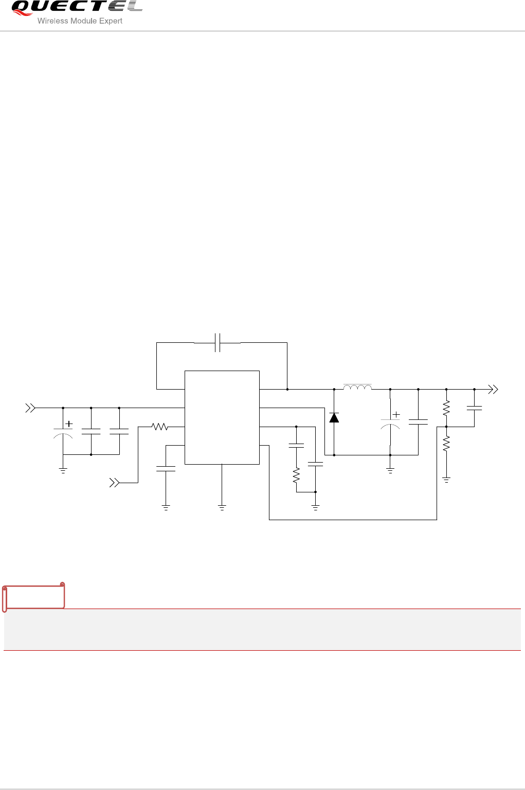
2.3. DC/DC Step Down Convertor
2.3.1. DC/DC Convertor Design
For the low power consumption application, as to the DC/DC convertor power supply for GSM/GPRS
module, the DC/DC step down convertor selection should be complied with following rules.
- The input voltage range of DC/DC convertor should be wider than the output voltage range of battery.
- The max output current is up to 2.5A at least, and high efficiency at light loads.
- The switching frequency of convertor should not be very high and very low. It is about 500 KHz. The
high switching frequency causes high switching loss that decreases the conversion efficiency. The
low switching frequency of convertor needs a big size external inductor.
- Keep low current consumption in shutdown mode.
The recommended DC/DC convertor is TPS54331 from TI. The reference circuit of TPS54331 for
GSM/GPRS module is as below:
EN
VIN
BOOT
SS
PH
GND
COMP
VSENSE
GND
1
2
3
4 5
6
7
8
9
TPS54331DDRU1
C1
330uF
C2 C3
10uF 100nF
C5 100nF
C6
C7
33pF
6.8pF
R3
R1
330K
BATT_IN
MCU_ON/OFF
1K
6.8uH
L1
D1 C8 C9
R4
R5
SS34B330uF
2.4K
10K NM
VBAT_4V
100nF
C10
15nF
C4
Figure 10: Reference Circuit of TPS54331
The capacitor C7 and C6 and resistor R3 are frequency compensation components. The capacitance and
resistance are calculated according to the specification of TPS54331.
2.3.2. DC/DC Layout Guideline
The DC/DC convertor requires a handful of external components, such as a power inductor, a catch diode,
feedback resistors, and so on. Even with every external component properly selected, the converter’s
performance can still be compromised with a poor layout. A poor layout can result in a converter with
NOTE
Quectel
Confidential

GSM/GPRS Module Series
Low Power Design User Guide
Low_Power_Design _User_Guide Confidential / Released 18 / 26
excessive output ripple voltage, poor load regulation, a poor dynamic load response, or a converter that
radiates excessive electromagnetic interference (EMI). So the following layout guideline must be
complied with.
- The VIN pin of TPS54331 should be bypassed to ground with a low ESR ceramic bypass capacitor.
The capacitor should be closed to the VIN pin.
- Since the PH pin connection is the switching node, the catch diode and output inductor should be
located very close to the PH pin, and the area of the PCB conductor is minimized to prevent
excessive capacitive coupling. The trace from the PH pin to inductor should be isolated from other
traces by the ground.
- Place the catch diode close to the PH pin to avoid long route, and keep the catch diode with good
grounding.
- Place the feedback resistors close to the VSENSE pin. The feedback sampled point should be routed
from the output of bypass capacitor. The feedback trace is noise-sensitive trace, so keep the
feedback trace away from the inductor flux.
- For operation at full rated load, the top side ground area must provide adequate heat dissipating area,
keep the bottom GND pad connected to the adequate ground area.
- The output voltage trace to the module should be wide enough to ensure that there is not too much
voltage drop occurring during transmitting burst, so the trace width should be no less than 2mm.
2.4. Power Consumption of GSM/GPRS Module
In order to choose an appropriate capacity of battery in lower power design application, it is needed to
evaluate the power consumption of GSM/GPRS module in normal working environment. In real
GSM/GPRS network, the current consumptions of module in transmission mode and SMS mode are
shown in following figures. It is a reference average current value. The power consumption is varied with
different signal strength and other environment.
The work process of module in the test is as follows:
Start moduleSearching networkRegister to the networkConnect to network successfullyTransmit
1KB data in GRPS mode or send 472B in SMS modeSucceed to transmitShut down module
Table 5: Test Condition in Different Mode
Mode
CSQ
GPRS Class
Data Size
Average Current
GPRS Data Transmission
29
Class 8
1024B
69.2mA
SMS Mode
29
472B
74.4mA
Quectel
Confidential
GSM/GPRS Module Series
Low Power Design User Guide
Low_Power_Design _User_Guide Confidential / Released 19 / 26
Data Log Display
Run Time
0.00 msec 5.00 sec 10.00 sec 15.00 sec 20.00 sec 25.00 sec 30.00 sec
Current Drain(A)
14.41m
336.12m
657.84m
979.56m
1.30
1.62
1.94
Av erage Minimum Maximum
Current 69.259mA 14.522mA 1.856A
Figure 11: Current Consumption of GPRS Data Transmission
Data Log Display
Run Time
0.00 msec 5.00 sec 10.00 sec 15.00 sec 20.00 sec 25.00 sec 30.00 sec
Current Drain(A)
14.20m
335.81m
657.41m
979.01m
1.30
1.62
1.94
Av erage Minimum Maximum
Current 74.447mA 14.950mA 1.851A
Figure 12: Current Consumption of SMS Transmission
As the above condition, the whole process will be finished in 30s, and under same external environment,
and the data size is small, the current consumption of SMS transmission is higher than that of GPRS data
module.
Quectel
Confidential
GSM/GPRS Module Series
Low Power Design User Guide
Low_Power_Design _User_Guide Confidential / Released 20 / 26
2.5. Battery Capacity Requirement Assessment
In practice, it is important to choose a suitable capacity of battery for low consumption device; also, it is
difficult to calculate the exact requirement for battery capacity. It can be estimated by following ways.
The power consumption of the device can be calculated in two modes: sleep mode and working mode.
No matter which mode the device works, the power consumption of device can be divided into four parts:
MCU control system, GSM/GPRS module system, self-discharge of battery and other external controlled
target (e.g. valves).
Here is an example showing a calculation method of power consumption as follows, assume the device
with 6 years of working time.
Table 6: Example of Average Power Consumption in Different Mode
All values of power consumption in different mode are not actual values.
The device works one time a day, the power consumption of 6 years is:
(16+130+40)(mA) × 30s × 1(times) × 365(days) × 6(years)/3600=3394.5mAh;
In sleep mode, the power consumption of 6 years is:
(5+1+4)(uA) × 24(hours) × 365(days) × 6(years)/1000=525.6mAh
The self-discharge rate of ER34615M is 3% after a year, so self-discharge of 6 years is:
13000mAh × 3% × 6(years)=2340mAh
So, the total power capacity requirement is : 3394.5+525.6+2340mAh=6260.1mAh
But in fact, to assure the battery can provide sufficient life time for the device, the capacity of battery
adopted is always about twice that of theoretical calculation.
System Unit
Sleep Mode
Work Mode (30s Every Time)
MCU Control System
5uA
16mA
GSM Module System
1uA (DC/DC is shut down)
130mA
External Controlled Target
4uA
40mA
NOTE
Quectel
Confidential

GSM/GPRS Module Series
Low Power Design User Guide
Low_Power_Design _User_Guide Confidential / Released 21 / 26
3 Measures for Reducing Power
Consumption
In order to reduce the power consumption, when the device does not need data transmission, the MCU
can switch off the power supply to the GSM/GPRS module. By this way, the current consumption of
GSM/GPRS system is only the shutdown quiescent current of DC/DC convertor.
If the module cannot be shutdown in application, the module should enter into sleep mode when it does
not work. In sleep mode, the power consumption can be reduced to 0.9mA~1.3mA. For the current
consumption in sleep mode, please refer to the document [1]. By this way, the external MCU can also
enter into sleep mode in idle to reduce the current consumption of MCU system.
The following ways can greatly improve power consumption of whole device.
- When the module is in sleep mode, the following methods can wake up the module.
1) Pull DTR pin in the low level to wake up the module
2) Receiving an SMS from network wakes up the module
- When MCU is in sleep mode, the following methods can wake up the module.
1) Set a timer to wake up MCU automatically
2) Wake up MCU through RI pin
- Use AT+QGPCLASS=8 to let the module enter into low power mode in the GPRS data transmitting.
In this transmitting mode, the module has the lowest power consumption, normally 200mA. For
details, please refer to the document [1].
- Cut off the power supply of module when it does not work in idle time. The module will not cause
power consumption.
- The better the load characteristic matches with the antenna port, the lower power consumption the
module has. It is strongly recommended that the RF interface has an impedance of 50ohm. Keep the
antenna in a place with stronger signal.
- The placement of the battery influences its discharge capacity. It is strongly recommended to place
the battery vertically.
- For the MCU system, in order to reduce the wastage of battery in the long-term working time, try to
use the low voltage MCU chip (such as the minimum voltage to 2V) or micro power consumption
chipset.
- To alleviate battery passivation, it is recommended that the battery should not be discharged in very
low current for long period. The device should discharge in high pulse current periodically by waking
up and turning on GSM/GPRS module periodically.
Quectel
Confidential
GSM/GPRS Module Series
Low Power Design User Guide
Low_Power_Design _User_Guide Confidential / Released 22 / 26
4 AT Command for Low Power
Consumption
You can use AT+CDETXPW command to reduce TX power. The following shows how to use this
command in detail.
4.1. AT+CDETXPW TX Power Control
AT+CDETXPW is used to decrease the transmission power of module which can decrease the current
consumption when module in GPRS data transferring.
Parameter
AT+CDETXPW TX Power Control
Test Command
AT+CDETXPW=?
Response
+CDETXPW:
<rf_band>(850,900,1800,1900),<tx_slots>(1,2,3,4),<PCLx>
,<dBmValue>
OK
Write Command
AT+CDETXPW=<rf_band>,<tx_slots>,
<PCLx>,<dBmValue>
Response
OK
If error is related to ME functionality:
ERROR
Reference
<rf_band> Select band
850 GSM 850
900 GSM 900
1800 DCS 1800
1900 PCS 1900
<tx_slots> Select GPRS uplink slot
1 GPRS uplink 1 slot
2 GPRS uplink 2 slots
Quectel
Confidential
GSM/GPRS Module Series
Low Power Design User Guide
Low_Power_Design _User_Guide Confidential / Released 23 / 26
Example
AT+CDETXPW=900,1,255,2 //Reduce 2dB on GSM900 band, apply to all PCLs.
OK
AT+CDETXPW=900,1,255,0 //Restore default value on GSM900 band, apply to all PCLs.
OK
4.2. Example of Reducing TX Power for GPRS Data Transmission
Following example describes how to reduce TX power when TCP data is transferring. Please refer to
GSM_TCPIP_AN.pdf and Mxx_AT_Command_Manual.pdf for more details of TCP function.
Example
RDY //Power on, automatically report URC.
+CFUN: 1
+CPIN: READY
Call Ready
AT+CREG?;+CGREG? //Query the case of attached network.
+CREG: 0,1
+CGREG: 0,1
OK
3 GPRS uplink 3 slots
4 GPRS uplink 4 slots
<PCLx> Power Control Level
GSM850/GSM900: 5~19
DCS1800/PCS1900: 0~15
All PCLs: 255
<power_rollbk> Set power rollback value
0 Restore default value
1~12 Reduce 1dB~12dB
The configuration of AT+CDETXPW command can be stored in NVRAM automatically.
NOTE
Quectel
Confidential

GSM/GPRS Module Series
Low Power Design User Guide
Low_Power_Design _User_Guide Confidential / Released 24 / 26
AT+QIFGCNT=0 //Set context 0 as the FGCNT.
OK
AT+QICSGP=1,“CMNET” //Set the APN as “CMNET”.
OK
AT+QIMUX=0 //Disable MUXIP.
OK
AT+QIMODE=0 //Set the session mode as non-transparent.
OK
AT+QIDNSIP=0 //Use IP address to establish TCP/UDP session.
OK
AT+QGPCLASS=8 //Set GPRS multi-slot class8.
OK
AT+CDETXPW=900,1,255,2 //Reduce 2dB on GSM900/ GPRS uplink 1 slot apply all PCLs.
OK
AT+QIOPEN=“TCP”, “124.74.41.170”,5111
//Visit the remote TCP server. And the address of the remote server is
an IP address.
OK
CONNECT OK //CONNECT OK means the module successfully connected to the
remote TCP server.
AT+QISEND=12 //Send 10bytes data to remote server
>start0123end //‘>’ from the UART to indicate the following input data is considered as
data to send.
SEND OK
AT+QISACK //Query the total size of the data sent and acknowledged.
+QISACK: 36, 24, 12 //The total size of the data sent is 36, the total size of the data
acknowledged is 24, the length of the data unacknowledged is 12.
OK
AT+QISACK //The data have been sent successfully.
+QISACK: 36, 36, 0
OK
AT+CDETXPW=900,1,255,0 //Restore default value on GSM900 band, apply to all PCLs.
OK
//Power off
Quectel
Confidential

GSM/GPRS Module Series
Low Power Design User Guide
Low_Power_Design _User_Guide Confidential / Released 25 / 26
4.3. Example of Reducing TX Power for SMS Data Transmission
Following example describes how to reduce TX power when SMS is transferring. Please refer to
GSM_SMS_AN.pdf and Mxx_AT_Command_Manual.pdf for more details of SMS function.
Example
RDY //Power on, automatically report URC.
+CFUN: 1
+CPIN: READY
Call Ready
AT+CREG? //Query the case of attached network.
+CREG: 0,1
OK
AT+CMGF=1 //Set the short message mode as TEXT mode.
OK
AT+CSMP=17,71,0,0 //Set the related parameters for sending short message in text mode.
OK
AT+CSCS=“GSM” //Set the character mode as GSM mode.
OK
AT+CDETXPW=900,1,255,4 //Reduce 4dB on GSM900/ GPRS uplink 1 slot apply all PCLs.
OK
AT+CMGS=“13817620516” //Send message to <da>“13817620516”.
>test<Ctrl+Z>
+CMGS: 250
OK
AT+CDETXPW=900,1,255,0 //Restore default value on GSM900 band, apply to all PCLs
OK
//Power off
Quectel
Confidential
GSM/GPRS Module Series
Low Power Design User Guide
Low_Power_Design _User_Guide Confidential / Released 26 / 26
5 Appendix A Reference
Table 7: Reference Document
NO.
Document Name
Remark
[1]
Mxx_Hardware_Design
Mxx Hardware Design
[2]
Mxx_AT_Commands_Manual
Mxx AT Commands Manual
[3]
GSM_TCPIP_AN
GSM TCPIP application note
[4]
GSM_SMS_AN
GSM SMS application note
Quectel
Confidential
