Quick Start Guide
QuickStartGuide
QuickStartGuide
QuickStartGuide
QuickStartGuide
QuickStartGuide
User Manual: Pdf
Open the PDF directly: View PDF ![]() .
.
Page Count: 12
SabreCSG Quick Start Guide
What is SabreCSG?
SabreCSG is a set of brush based level design tools for building levels inside Unity. SabreCSG
works by allowing you to build complex levels by adding and subtracting simple 3D shapes,
together, called brushes. For example, by adding a rectangular brush you can create a wall, by
then subtracting some more brushes you can create doorways and windows. This method allows
you to create very complex levels quickly and easily, allowing you to focus on creating great
gameplay spaces.
This guide will get you up and running with SabreCSG. Please note you can find complete
documentation, including video tutorials online at the dedicated SabreCSG Learn website.
Create Your First Brush
To begin using the SabreCSG tools in Unity, once you have imported SabreCSG from the Asset
Store, you will need to create a CSG model in your scene.
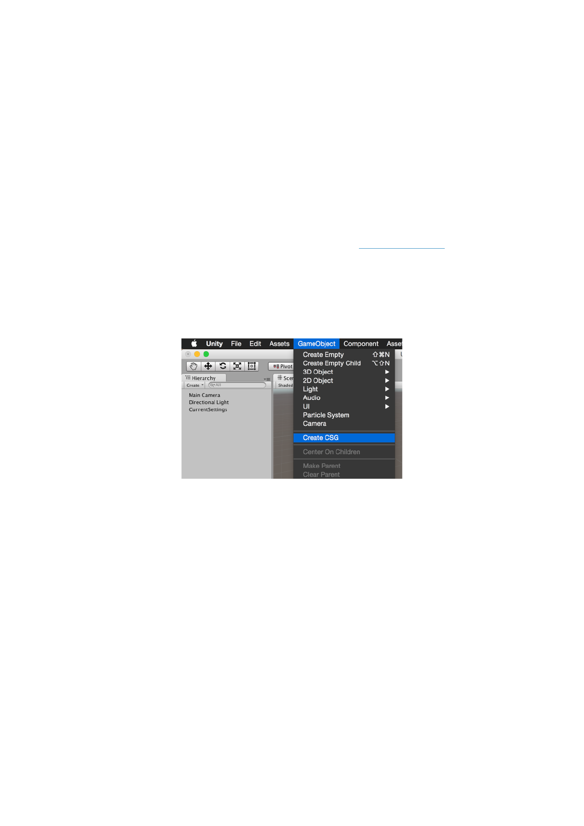
To do this, from the menu bar select GameObject -> Create CSG. This will add a blue volume to
the center of your scene. Once you hit the Rebuild button, the brush will be converted into your
level’s geometry. Brushes, which are primitive 3D volumes, are the building blocks for your level in
SabreCSG.
You’ll see a new interface has now overlayed the scene view. At the top there is a series of
different brush tools, which allow you to change how you are interacting with the brushes and
geometry.
At the bottom there is a toolbar which allows you to change settings on the current brush and also
change how SabreCSG is currently configured (such as snapping settings).
Next, to build this brush into level geometry click the Rebuild button on the toolbar.
You can now see that the transparent brush has been converted into a solid 3D mesh. Built
geometry by default uses an orange checkered material to give you a sense of scale as you build
levels.
Creating More Brushes
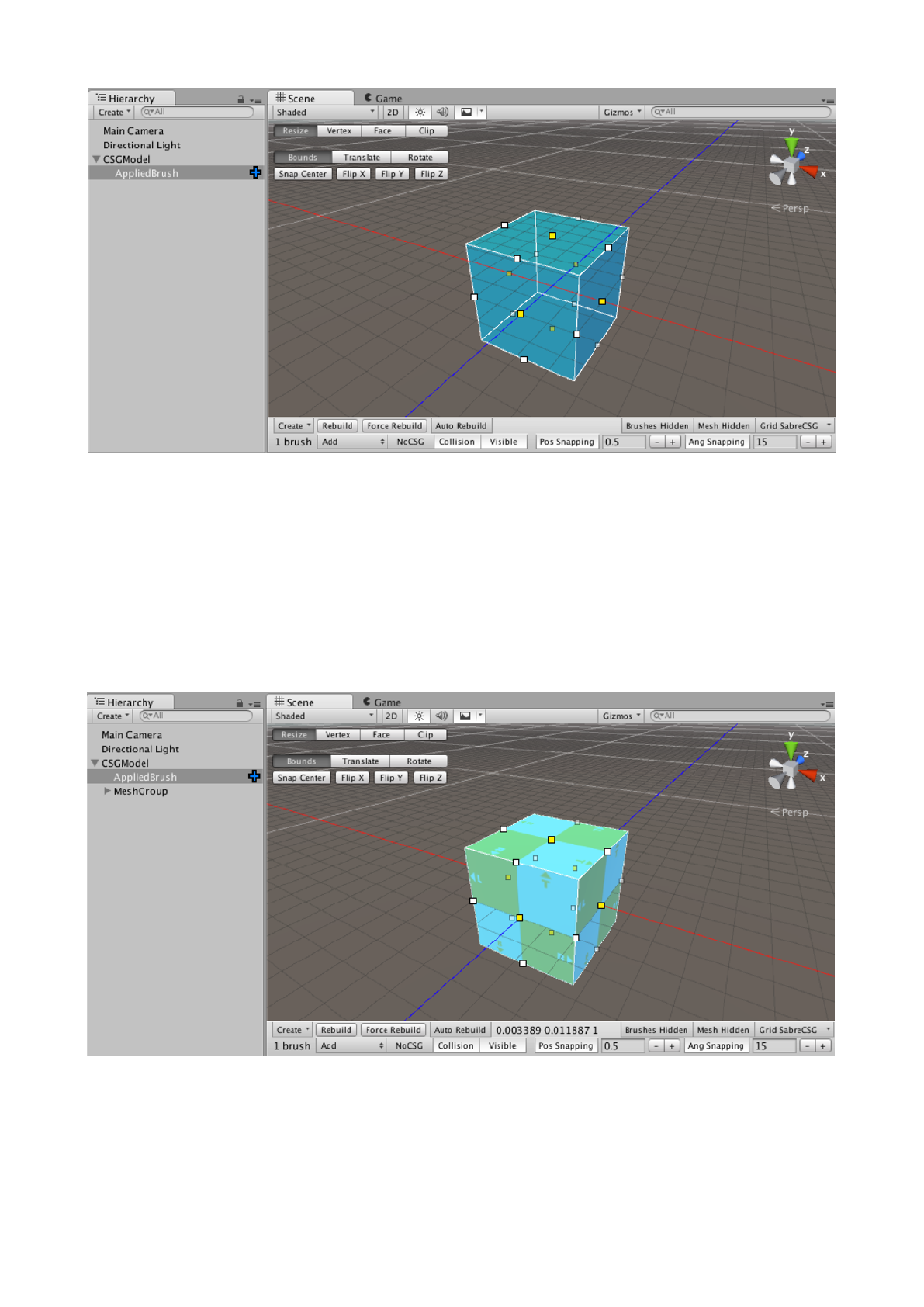
You can create more brushes by duplicating the existing brush (the keyboard shortcut is CTRL+D
or CMD+D on OSX) and then moving the new brush by clicking and dragging on one of the sides
of the brush bounds to translate it. In the following image you can see a duplicated brush that has
been moved:
Additive and Subtractive Brushes
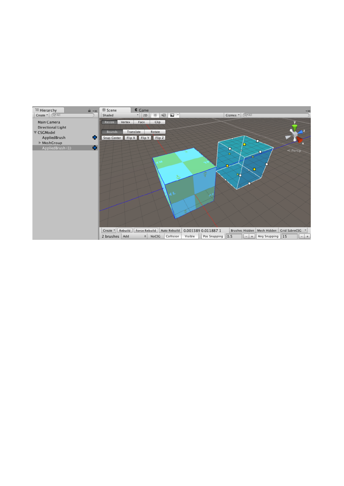
Brushes can be set as additive or subtractive volumes. By default, brushes are additive. When
using SabreCSG’s Resize, Clip, or Vertex tools, additive brushes are blue and subtractive brushes
are yellow.
Think of additive brushes like a solid block of clay. You can change the level geometry by creating
more additive brushes, much as you could change the block of clay by adding more clay. You can
also shape the level geometry using the Clip and Vertex modes. Subtractive brushes are another
way of shaping the level geometry that you have already created. Like the clay, however, you can’t
subtract from what doesn’t exist, so if you want to build most of your level’s geometry in a
subtractive way, it is best to make your first brush a large additive volume. This will give you a large
space to subtract within.
To change a brush to subtract mode press the S key with a brush selected, or alternatively change
the dropdown next to the brush count at the bottom left of the toolbar to “Subtract”. To change a
subtract brush back to additive either press A or change the dropdown to “Add”.
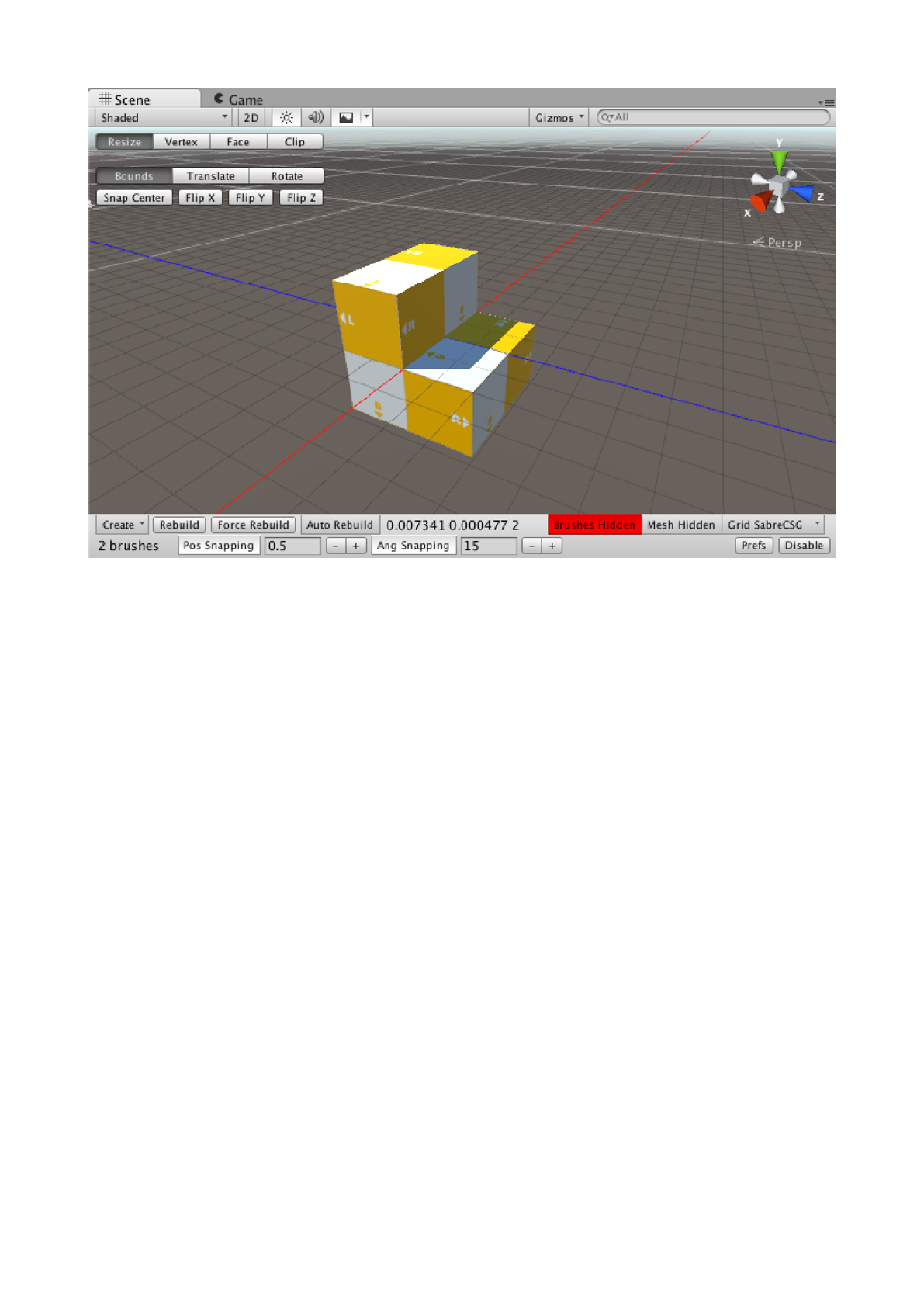
Subtractive brushes are shown in orange, while additive brushes are shown in blue. Note in the
image that the subtraction overlaps the add brush.
Brushes are different from level geometry. You have to rebuild to convert brushes into the playable
level geometry.
Every time you create a new brush, it goes to the end of the Unity Hierarchy, so you can create an
additive brush within a subtractive brush, so long as the addition is after the subtraction in the
Hierarchy. (If the addition comes first in the Hierarchy, then it will be subtracted from by the
subtractive brushes that follows it.)
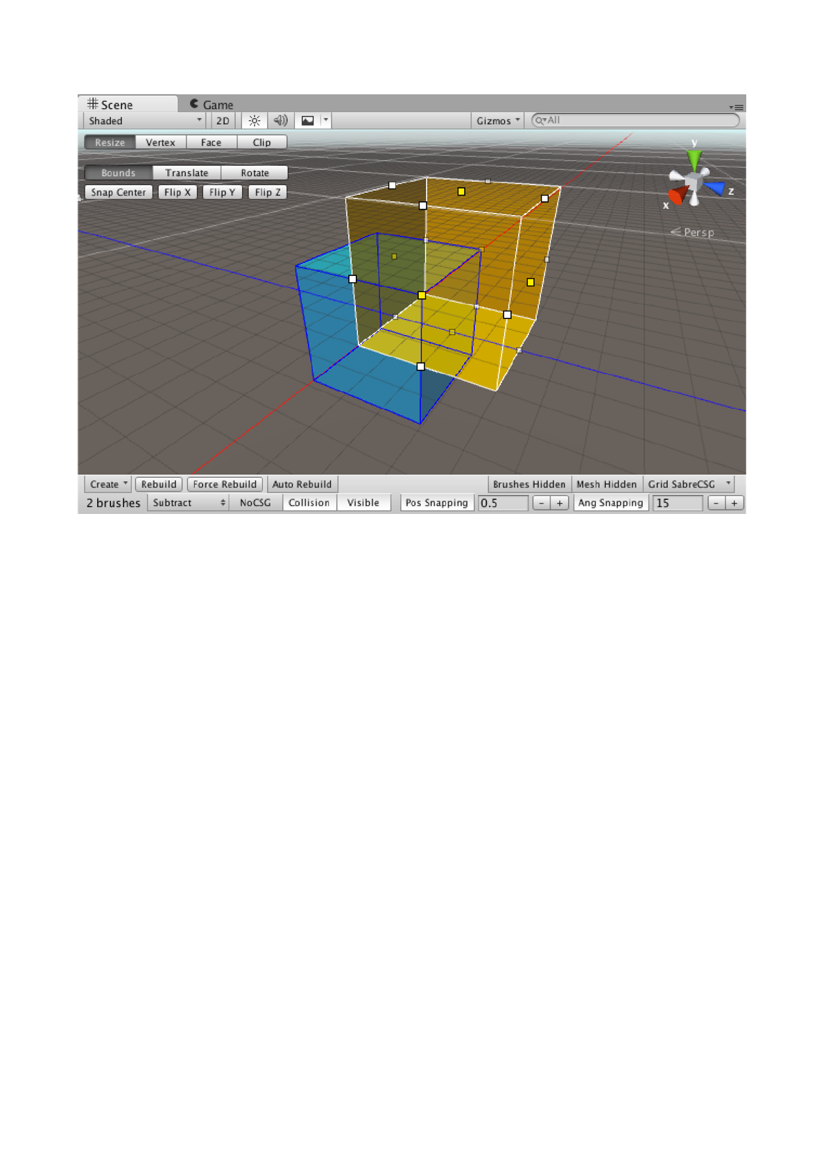
Now if you hit Rebuild (they keyboard shortcut is Ctrl+Shift+R on Windows, Cmd+Shift+R on
OSX) you’ll see that the resulting geometry is the additive volume minus the subtractive volume. In
this image I have hidden the brushes by switching from Resize mode to Free (which disables brush
interaction).
You can also subtract from additions within subtractions as much as you want. For example, you
could create a building in a cavern, and then create rooms within that building. It is best practice to
build the whole level in a series of passes, from the most generic shapes to the smallest details.
Completing a room’s details before completing the whole layout make it difficult to adjust the level
because of the way order matters for subtractive level design. For example, if your level has
several caverns, you would want to create these first, then create the buildings in the caverns, and
then create the rooms within the buildings. Creating one cavern and its buildings before creating
the other caverns (or creating one building and its rooms before creating the other buildings)
makes it more difficult to revise a layout.
You may find it useful to think of brushes in the Hierarchy as a series of instructions for the level
geometry. Creating a brush does not directly affect the level geometry, but it changes the
instructions that SabreCSG follows when you click Rebuild.
Resizing, Deleting and Rotating a Brush
Making sure the active tool at the top of the scene view is set to Resize, you can also resize tools
by clicking and dragging the square handles when a brush is selected.
As you resize the brush you’ll see the active axis displayed in green and also the current bounds of
the brush overlayed.
You can also delete brushes by pressing the delete key (or CMD+Backspace on OSX).
To rotate a brush simply hold CTRL before clicking and dragging one of the square handles. This
will initiate a rotation instead of a resize action.
Other Brush Tools
Vertex Tools
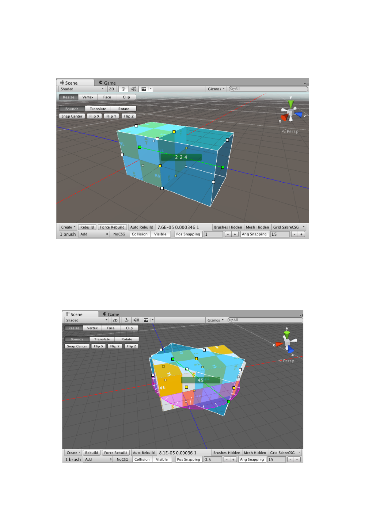
If you switch the tool at the top to Vertex you can manipulate individual brush vertices.
Where Resize mode is about moving brushes within a scene, Vertex mode is about moving the
parts of a brush. There is some overlap between Vertex mode and Resize mode, but Vertex mode
offers more options, like creating sloped surfaces and other complex geometry.
Most interesting level geometry has more angles to it than are possible with Resize mode alone,
which is why most of the work on a level past the earliest blocking phase will rely on Vertex mode.
In Vertex mode, with a brush selected, you can select multiple vertices by clicking on the circular
dots (hold Shift for multiselect). With vertices selected a movement handle will appear allowing you
to move the selected vertices. You can also click and drag a marquee to select several vertices in a
rectangular area.
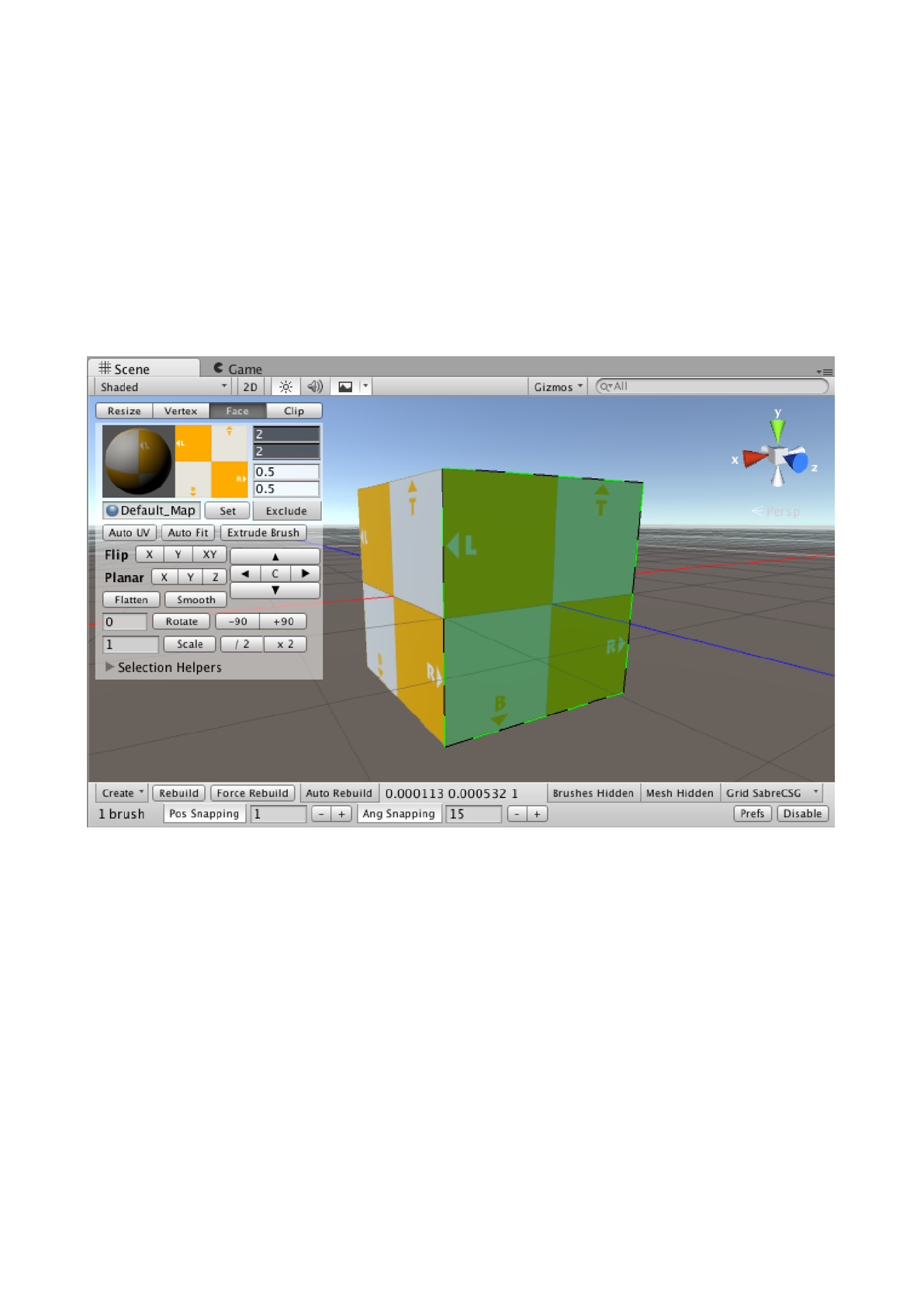
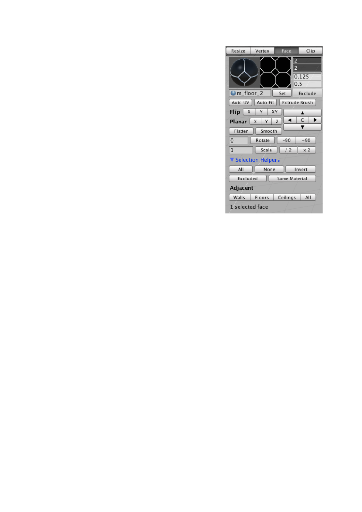
Face Tools
The Face tool lets you apply and adjust materials on built geometry. Because you interact with the
built geometry in this mode, brushes are hidden.
Selecting and Deselecting
Instead of selecting brushes, in Face mode you select each face independently from its brush. To
select multiple faces, hold Shift and click. To remove a face from the selected group, hold Ctrl and
click. It is often best to select a group of similar faces, and perform the edits (such as rotating or
translating UVs and applying materials) once.
Applying Materials
Once you have at least one face selected, you can apply a material by dragging one from the
Assets window to the field to the left of the Set button. Alternatively, you can click the Set button
and pick a material from the window that appears. These approaches require multiple precise
mouse clicks, so if you are going to apply a material on many faces, it is fastest to apply materials
to groups of selected faces.
Often, it is useful to have placeholder materials that distinguish walls from floors and ceilings. In
the Project window, there is a folder for examples with a folder of materials inside. When working
on a large, unlit level, it can be easy to mistake one kind of surface for another; having placeholder
materials helps.
Materials and UVs also persist in other brush editing modes.
If you apply a material to a brush’s built geometry, duplicate
the brush, and then rebuild, then both brushes will have the
same materials and UVs. The default brush has the same
material on the sides, top, and bottom, so if you apply a
different material to the sides with this first brush, and then
use it to create the rest of your level geometry, it can save
time with placeholder materials. This persistence is also
useful with complicated detail geometry, such as the trim of
an arch. By aligning the materials once, you can then
duplicate the brushes without needing to align the materials
again.
Translating UVs
Once you have selected a face, a white dot will appear. This
reflects the mouse position when you click and drag the face.
Like moving brushes, the UVs of a face snap to the grid.
Simply click and drag on one of the selected faces to
translate it. To increase or decrease the grid size, go to the
SabreCSG settings. You can also use the keyboard shortcuts
“,” and “.” to decrease and increase the grid size.
Rotating UVs
To rotate a selected face’s UVs, hold Ctrl and then click and drag. This will snap based on the
angular snapping, which you can change in the SabreCSG settings. If you want more precision
when you rotate, there is also an option below the SabreCSG tool selection bar, left of the Rotate
button. Here, you can specify the amount of rotation in degrees, positive or negative, and then
perform it by clicking Rotate. This more precise method is useful for recurring angles. For example,
the trim of a staircase should have a rise to run ratio of 1 to 2, which is 26.565 degrees. Trying to
snap to this angle would be impossible, and trying to rotate with snapping disabled would be
inaccurate, so it is best to use precise rotation.
Rotation in SabreCSG occurs around the center of the face, so if you need to perform a precise
rotation and translation, it is best to rotate first.
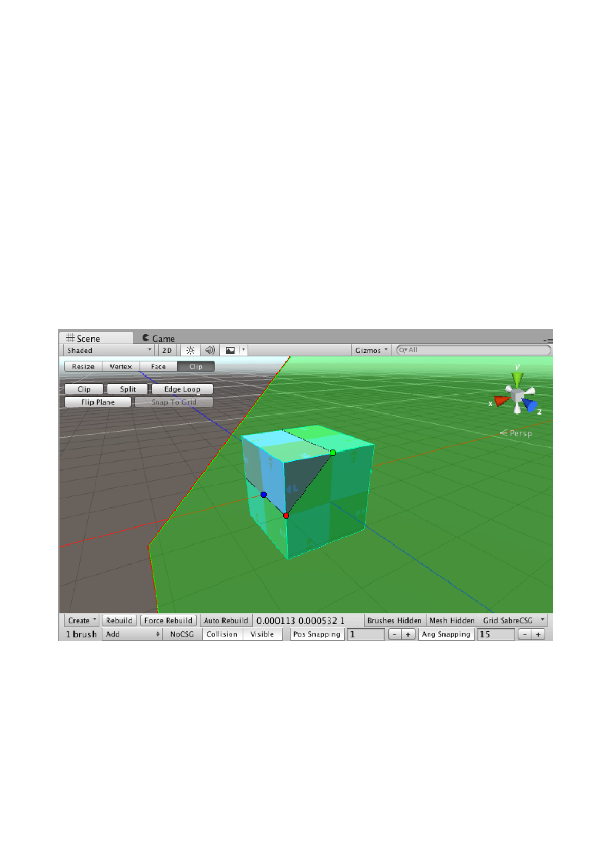
Clip Tool
With the Clip tool, it is possible to increase or decrease the number of vertices a brush has by
cutting off corners or splitting the brush into parts. You do this by drawing a clip plane, where
everything on one side of the plane is deleted or split from the original brush. This allows you to
quickly bevel a brush for example.
Selecting a Brush
Selecting a brush with the Clip tool is the same as in Resize mode.
Drawing the Clip Plane
When you have a brush selected, a red handle will appear near your mouse cursor, but unlike your
cursor the handle will be snapped to the grid. This red handle is the start point of the clip plane. By
clicking and dragging, a green handle and a blue handle will appear. The green dot is the end point
for the clip plane.
In a 3D perspective, the part of the brush that is visible through the clip plane’s green side will be
saved after clipping. The part of the brush that is visible through the clip plane’s red side will be
deleted. From an isometric, axis aligned camera perspective, the clip plane will look like a red line
next to a green line. As with a 3D view, the part of the brush that is on the green side of the line will
remain, while the part on the red side will be destroyed.
You can adjust the clip plane by clicking the red, blue, or green handles, and moving them. By
default, the blue handle will appear alongside the red handle, but once you have drawn the clip
plane, you can move it or the red dot to make more complicated cuts with the plane.
Clipping, Splitting, and Flipping
Once you have drawn the clip plane, you can click the Clip, Split, or Flip Plane buttons beneath the
SabreCSG tool selection bar. The Clip button performs the clip you have drawn, deleting one side
of the brush. If clipping would remove the wrong side of the brush, you can click Flip to reverse
which side the clip will remove. You can also click Split, which will create a new brush from the
clipped part, effectively splitting the brush in two. This allows you to manually modify or delete
parts that were previously a whole brush, which can be especially useful for creating concave
geometry.
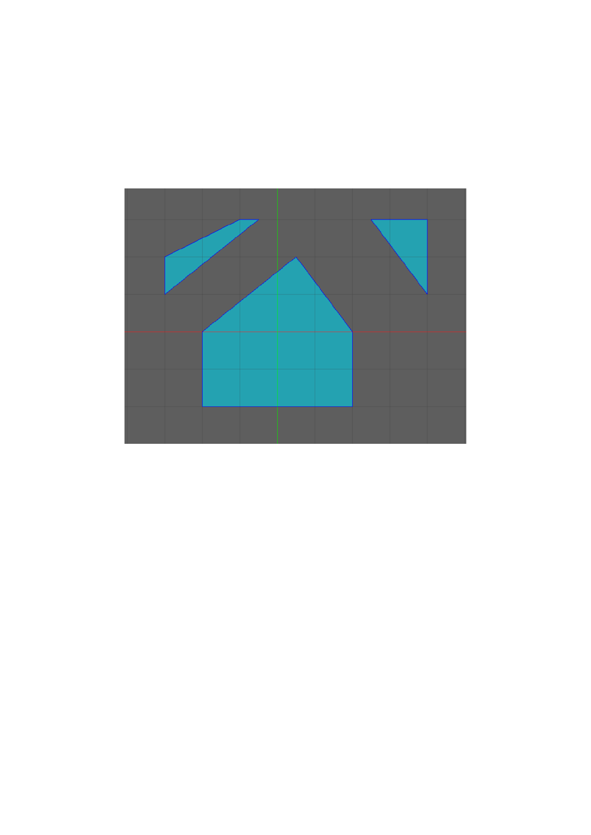
Some clips will decrease the number of faces and vertices that a brush has, while other clips will
increase it. These functions are the main reason for using the Clip tool, since they are not options
with other tools. For example, clipping can let you quickly bevel a corner, create a hexagonal prism
from a cuboid, or create a triangular prism for a ramp.
Since clipping a brush usually requires adjusting the camera position and drawing the clip plane, it
is often best to create some geometry that you can then quickly select and duplicate throughout
the level. For example, if your level will have ramps, it is best to create one archetype ramp, place
it off to the side in the world or in its own group in the hierarchy, and duplicate it throughout the
level.