RC5 Real Time Controller RC5User Manual R6860
User Manual: Pdf
Open the PDF directly: View PDF ![]() .
.
Page Count: 78
- Conventions
- Safety information
- About this Manual
- Introduction
- Instrument overview
- Installation Guide
- DIO ports
- High Speed Digital Inputs
- High Speed Digital Outputs
- Clock
- Upgrades and replacements
- Example: Nanonis SPM Control System, Tramea and OC4.5-S
- Software Installation Guide
- Troubleshooting
- Specifications
- Legal Information
- Index

Real-Time Controller
RC5
User Manual
November 2016 (R6860)


RC5 Real-Time Controller Index
•
iii
Contents
Conventions 6
Safety information 7
About this Manual 8
Introduction 9
Instrument overview 10
Block diagram .................................................................................................................... 10
Front panel ......................................................................................................................... 11
Rear panel .......................................................................................................................... 12
Installation Guide 14
Content of delivery ............................................................................................................ 14
Setup .................................................................................................................................. 15
Connection to SC5 ............................................................................................................. 15
Single SC5 ........................................................................................................... 16
Multiple SC5s ...................................................................................................... 17
Connection to OC4 ............................................................................................................ 19
Single OC4 .......................................................................................................... 19
Multiple OC4s ..................................................................................................... 20
Connection to host computer ............................................................................................. 21
Connection to computer screen .......................................................................................... 22
Powering ............................................................................................................................ 24
DIO ports 25
DIO ports connection ......................................................................................................... 25
DIO ports schematic and connector pin layout .................................................................. 26
Specifications (DIO ports) ................................................................................................. 27
High Speed Digital Inputs 28
High speed digital inputs connection ................................................................................. 28
High speed digital inputs schematic ................................................................................... 28
Specifications (high speed digital inputs) .......................................................................... 29
High Speed Digital Outputs 30
High speed digital outputs connection ............................................................................... 30
High speed digital outputs schematic ................................................................................. 30
Specifications (high speed digital outputs) ........................................................................ 31
Clock 32
Clocking options ................................................................................................................ 32
Clock ports connection ...................................................................................................... 33
Clock ports schematic ........................................................................................................ 33
Optional OCXO clock mounting instructions .................................................................... 34
Specifications (clock) ......................................................................................................... 37
Upgrades and replacements 38
Firmware update ................................................................................................................ 38

Real-time unit replacement ................................................................................................ 40
FPGA card replacement ..................................................................................................... 42
Example: Nanonis SPM Control System, Tramea and OC4.5-S 43
SPM Control System: Connections on the rear side of the instruments ............................. 43
Nanonis Tramea: Connections on the rear side of the instruments .................................... 45
OC4.5-S: Connections on the rear side of the instruments ................................................ 46
Software Installation Guide 47
Host computer requirements .............................................................................................. 47
Host computer network configuration ............................................................................... 48
Windows XP ........................................................................................................ 48
Windows Vista .................................................................................................... 50
Windows 7 and later ............................................................................................ 51
Nanonis software installation ............................................................................................. 56
License files ......................................................................................................... 58
First time startup .................................................................................................. 59
Real-time software update ................................................................................... 61
Troubleshooting 64
Network and software issues .............................................................................................. 64
License file issues .............................................................................................................. 65
Instrument doesn’t power up correctly .............................................................................. 66
Instrument is overheating ................................................................................................... 67
Clock issues ....................................................................................................................... 69
Specifications 70
General ............................................................................................................................... 70
DIO ports specifications .................................................................................................... 70
High speed digital inputs specifications ............................................................................. 71
High speed digital outputs specifications ........................................................................... 71
Clock specifications ........................................................................................................... 71
Operating conditions .......................................................................................................... 72
Storage and transportation conditions ................................................................................ 72
Legal Information 73
Warranty ............................................................................................................................ 73
Copyright ........................................................................................................................... 73
Trademarks ........................................................................................................................ 73
Declaration of Conformity ................................................................................................. 74
Index 77

RC5 Real-Time Controller Conventions
•
5
RC5 Real-Time Controller Conventions
•
6
Conventions
The following signal words and symbols appear in this manual:
Danger: Indicates a hazardous situation which, if not avoided, will result
in death or major
injury.
Warning: Indicates a hazardous situation which, if not avoided, could result in death or major
injury.
Caution: Indicates a hazardous situation which, if not avoided, could result in minor or moderate
injury.
High voltage: Risk of electric shock. Lethal voltages present.
Hot surface: Indicates that the surface of the instrument might become hot. Avoid coming into
contact with the hot surface.
Static sensitive devices: Observe precautions for handling electrostatic sensitive devices.
Note: Indicates a situation which, if not avoided, could result in damage or a malfunction of the
instrument.
Refer to instruction manual: The instruction manual mentioned in the text must be read before
operating the instrument.
Disconnect mains plug from electrical outlet: The mains plug must be disconnected from the
electrical outlet before proceeding.
Italic Commands, programs, menu items, functions, field names and product names are shown in italic
characters.
RC5 Real-Time Controller Safety information
•
7
Safety information
• Carefully read this manual and all related documents before installing and using the instrument.
• The safety notes and warnings have to be obeyed at all times.
• The RC5 may only be installed and used by authorized and instructed personnel who have read this manual.
• The RC5 is designed for indoors dry laboratory use only.
• The RC5 may only be used as specified in this manual, otherwise it may not fulfill safety requirements.
• Do not install substitute parts or perform modifications to this instrument. No user serviceable parts inside.
• Do not operate the RC5 if it is damaged or not functioning properly. Never use damaged accessories.
• Do not operate the instrument during electrical storms in order to avoid damaging the instrument.
• Never use corrosive or abrasive cleaning agents or polishes. If necessary, clean the instrument with a soft and
dry cloth, and make sure that it is completely dry and free from contaminants before returning it to service.
Warning: Lethal voltages are present inside the instrument. Disconnect the mains plug from the
electrical outlet before opening the instrument

RC5 Real-Time Controller About this Manual
•
8
About this Manual
This manual is intended as a reference tool for users of the Nanonis RC5 Real-time controller. It covers the
functionality of the instrument and explains its installation and operation.
This manual is not a service manual for the RC5.
Revision history
November 2016 (R6860) Updated release of the RC5 manual:
- Updated conformity declaration
August 2016 (R6641) Updated release of the RC5 manual:
- Added or updated information and pictures for NI PXIe-8840 embedded controller
- Updated to software V5
- Updated host computer requirements
May 2013 (R3800) Initial release of the RC5 manual
The SPECS order number for this manual is: 2078000363
RC5 Real-Time Controller Introduction
•
9
Introduction
The Nanonis Real-Time Controller RC5 is the central data processing unit of a Nanonis System. The RC5 provides
connectivity to other instruments in the Nanonis family, FPGA processing for high-speed calculations, CPU power
for slower time-deterministic processes, and a TCP/IP connection to the host computer running the Nanonis
software.
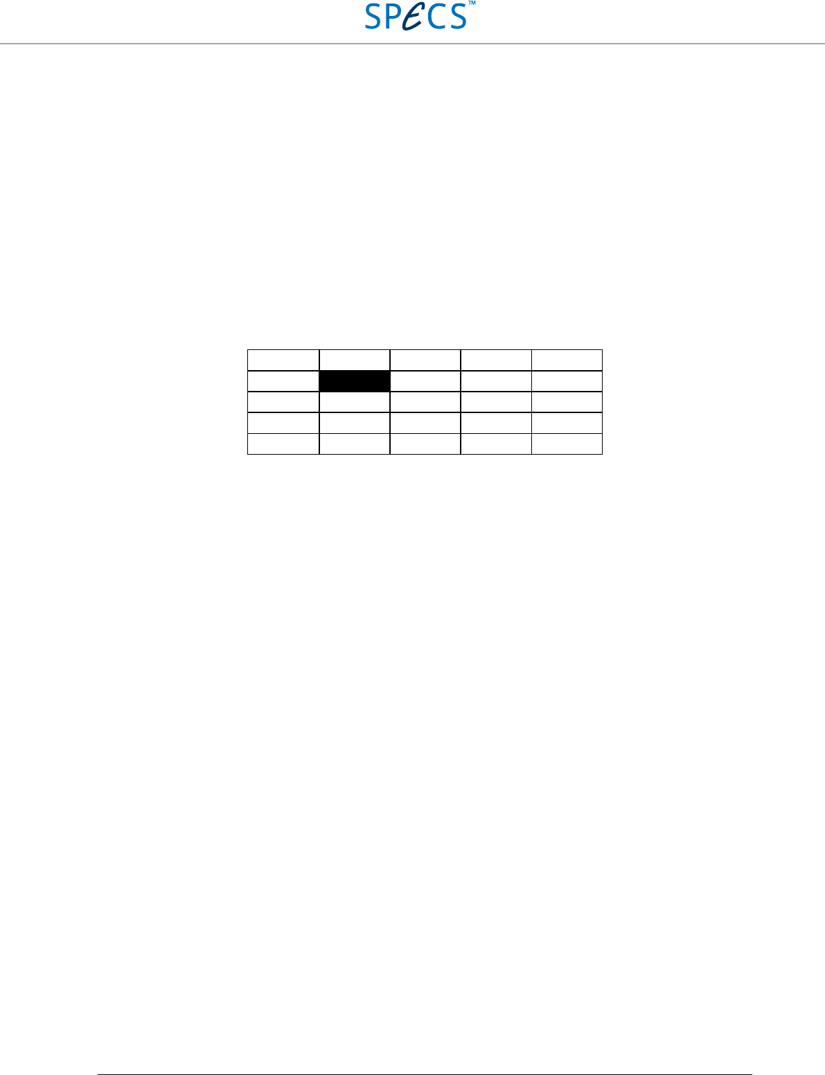
The RC5 is equipped with six device ports for connecting the Nanonis SC5 or OC4. Up to three instruments of each
type can be connected, with a maximum total of four instruments being supported in the software. The
configurations are shown in the table below.
No SC5 One SC5 Two SC5s Three SC5s
No OC4
One OC4
Two OC4s ()
Three OC4s () ()
The RC5 also provides four digital ports (DIO ports) with eight digital lines each, for digital control and readout of
other Nanonis or third-party instruments. All four ports are bidirectional and allow data rates of up to 500 kHz. For
faster data rates, four additional high speed digital inputs and outputs can be used e.g. for counting purposes (inputs),
or fast pulse generation (outputs). These lines allow data rates of up to 200 MHz.
Note: Under Version 4.5 of the Nanonis software, only two digital ports can be used, and the high speed digital
outputs are disabled.
The RC5 allows for a flexible clock management, making it possible to change or upgrade the clock source
depending on experimental requirements. The clock source can be either the low phase-noise internal clock, an
optional oven-controlled crystal oscillator (OCXO) which can be fitted to the RC5, the OCXO of a Nanonis OC4, or
an external clock source. The clock source is chosen automatically based on a priority list.
The RC5 is connected to the host computer running the control software using a single Ethernet cable. No other
connections are required for operation and installation of software and operating system upgrades.
RC5 Real-Time Controller Instrument overview
•
10
Instrument overview
Block diagram
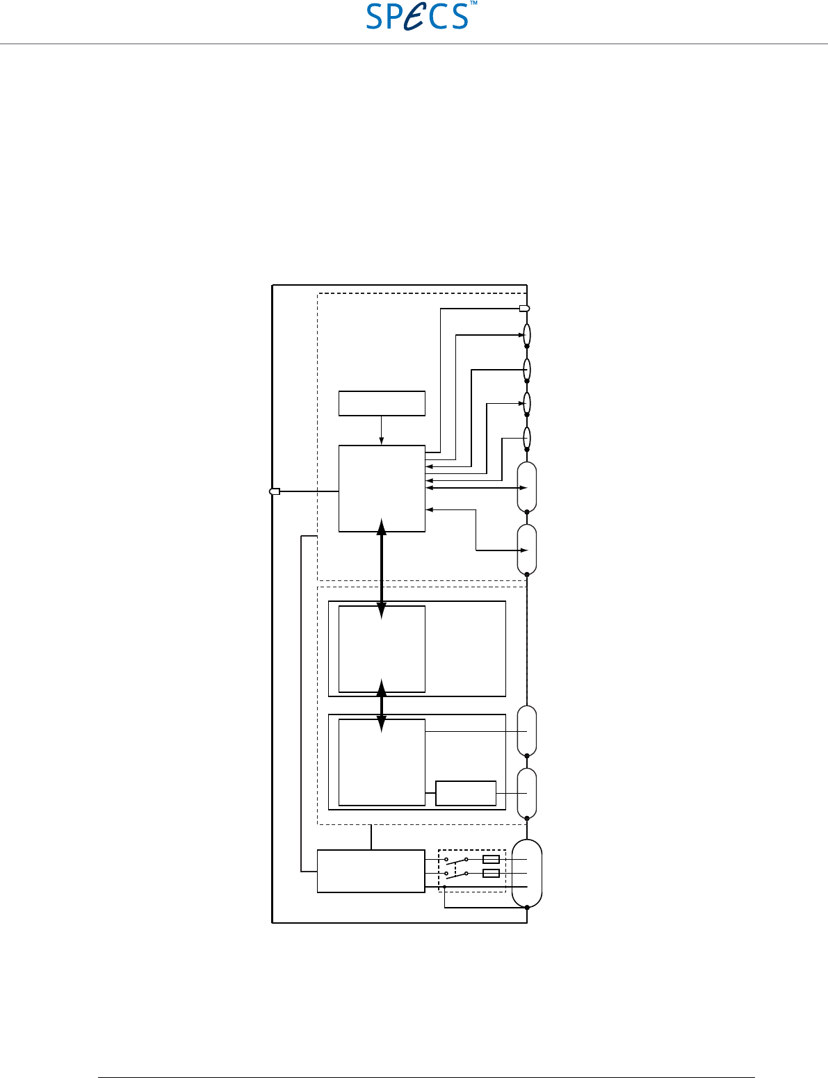
The block diagram of the RC5 is shown in the picture below.
Figure 1: Block diagram of the Nanonis RC5.
The main functional units of the RC5 are the real-time system, the FPGA, and the signal and clock distribution unit.
These units are powered by a medical grade ATX power supply and actively cooled by a fan placed at the bottom of
the RC5 enclosure.
Fuses
TCP/IP
communication
Real-time system
Intel Core i5 processor
LabVIEW RT OS
NI PXIe-8840 or
NI PXIe-8115
Virtex-5 FPGANI PXIe-7965R
AC INPUT
Line filter
ATX power supply
PXIe Bus
200 MHz
data transfer
Power
switch
ETHERNET
PORT
DISPLAY
PORT
DEVICE
PORTS
SC/OC 01-03
DIO PORTS
A-D
HI SPEED
DIGITAL
IN OUT
CLOCK
IN OUT
Signal distribution
Clock distribution
Optional OCXO Clock
Clock source LEDs
Power LED
RC5 Real-Time Controller Instrument overview
•
11
The real-time system unit is a NI PXIe-8840 (RC5 serial number 17517 and higher) or NI PXIe-8115 embedded
controller. It is based around an Intel Core i5-4400E processor running at 2.7 GHz (3.3 GHz in turbo mode) with 4
GB of RAM (NI PXIe-8840) or Intel Core i5-2510E processor running at 2.5 GHz (3.1 GHz in turbo mode) with 2
GB of RAM (NI PXIe-8115). It provides processing power for all time-critical loops, scan and sweep generation,
and for data acquisition. It also takes care of the TCP/IP communication with the host computer over its ethernet
connection. The complete real-time unit can be easily removed from the RC5, if necessary. For status information, a
computer screen can be connected to one of the two DisplayPort connectors.
The FPGA card is a NI PXIe-7965R FlexRIO card, connected to the real-time unit over a PXIe-bus. The Virtex-5
SX95T FPGA offers high processing power and speed for all fast data processing tasks, including PLLs, lock-in
amplifiers, digital filters, oversampling, PI controllers, and hrDAC™ modulation. The FPGA is clocked through the
signal and clock distribution unit.
The signal and clock distribution unit is connected over a 200 MHz data bus to the FPGA, and provides connectivity
to the measurement instruments of the Nanonis range. It also addresses the four digital ports (DIO ports, 500 kHz
maximum frequency), the eight high speed digital ports (200 MHz maximum frequency), and manages the clock
sources. The optional OCXO clock is also plugged to the electronic board of the signal and clock distribution unit.
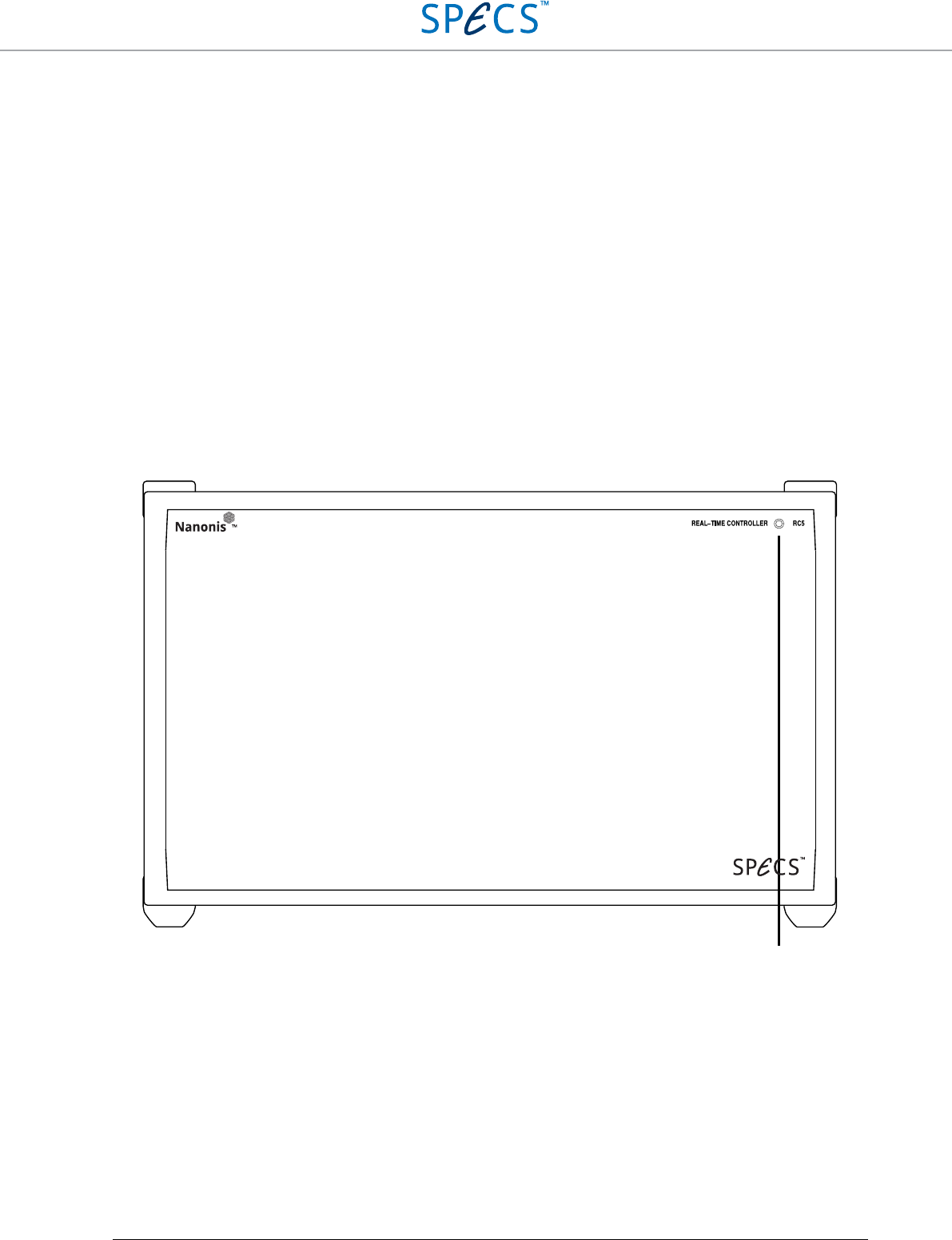
Front panel
Figure 2: RC5 front panel.
1. Power LED (blue): Indicates that the instrument is powered up
1
RC5 Real-Time Controller Instrument overview
•
12
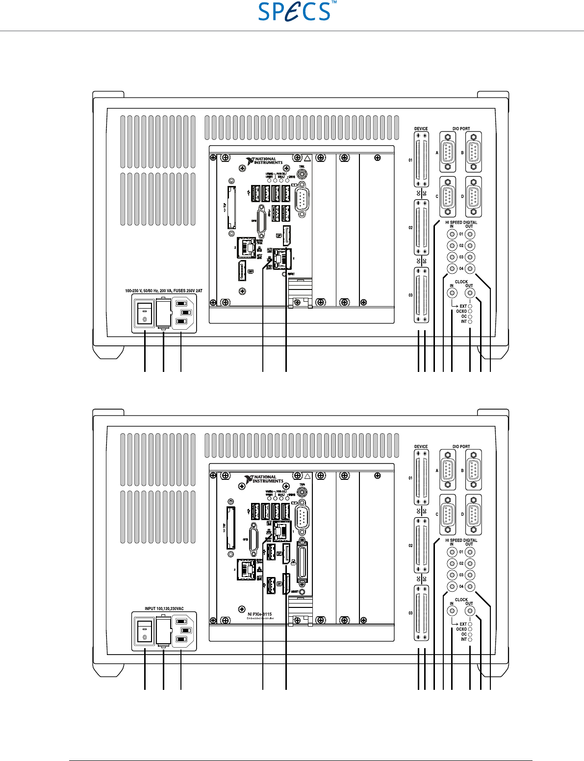
Rear panel
Figure 3: RC5 rear panel (NI PXIe-8840 version).
Figure 4: Figure 3: RC5 rear panel (NI PXIe-8115 version).
2 3 4 5 6 7 8 9 10 11 12 13 14
NI PXIe-8840
Embedded Controller
2 3 4 5 6 7 8 9 10 11 12 13 14
RC5 Real-Time Controller Instrument overview
•
13
2. Power switch: Turns the RC5 on and off.
3. Fuse holder: Contains two identical slow blowing fuses. Slow blowing 2A fuses (2AT, rated 250 VAC, 5×20
mm) should be used independently from the line voltage.
4. IEC power socket.
5. Ethernet connector: This connector is used for TCP/IP communication with the host computer. The other
ethernet port available should not be used. Please refer to the Connection to host computer section for details.
6. DisplayPort connector: This connector is used for connecting a computer display to the RC5. The screen
displays the status information of the instrument. Please refer to the Connection to computer screen section for
details.
7. OC4 device connectors: The Nanonis OC4 is connected to these connectors using the DEVICE RDIO cable
supplied with the OC4. Do not connect a Nanonis SC5 to these connectors. Please refer to the Connection to
OC4 section for details.
8. SC5 device connectors: The Nanonis SC5 is connected to these connectors using the DEVICE RDIO cable
supplied with the SC5. Do not connect a Nanonis OC4 to these connectors. Please refer to the Connection to
SC5 section for details.
9. DIO Ports A-D: These four D-sub9 female connectors are used for communication and control of other
Nanonis instruments, as well as third party equipment. Please refer to the DIO Ports section for details.
10. High Speed Digital Input connectors: These four SMB connectors provide four inputs for high speed digital
communication. Please refer to the High Speed Digital Inputs section for details.
11. Clock input: This SMB connector accepts a clock signal from an external 10 MHz clock source. Please refer to
the Clock section for details.
12. Clock source LEDs (green): Indicate that the corresponding clock source is selected and that the RC5 digital
circuits are locked to that clock signal. Please refer to the Clock section for details.
13. Clock output: This SMB connector outputs the 10 MHz clock signal of the clock source indicated by the Clock
source LEDs (12). For details, please refer to the Clock section.
14. High Speed Digital Output connectors: These four SMB connectors provide four outputs for high speed
digital communication. Please refer to the High Speed Digital Outputs section for details.
Symbols:
Earth
Protection Earth
RC5 Real-Time Controller Installation Guide
•
14
Installation Guide
This installation guide shows how to prepare and power up the RC5. Following these instructions ensures that the
instrument is working correctly, and that it can be connected to other instruments. Further steps will be explained in
detail in the chapters following this guide.
Please carefully read the manuals of the instruments to be connected to the RC5 before proceeding.
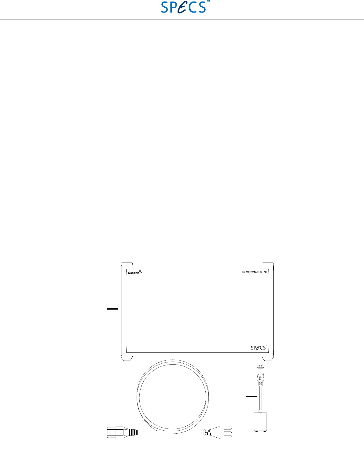
Content of delivery
When first unpacking the RC5, please check for the following items:
1. Nanonis RC5
2. Power cord
3. DisplayPort to VGA adapter
4. Test protocol
5. User manual
6. NI Real-time deployment license
These items are shown in the picture below. Note that the power cord appearance will depend on the country where
the RC5 is used (type J power cord shown).
Figure 5: These items are delivered with the RC5.
1
2 3
RC5 Real-Time Controller Installation Guide
•
15
Setup
To properly set up the instrument, a square space of at least 40 cm × 50 cm × 25 cm (W × D × H) is required.
Additional Nanonis instruments require an additional height of 10 cm for each instrument. The RC5 weighs
approximately 7.8 kg, and stability of its supporting table must be guaranteed. It must be possible to access the
hardware from the front and the rear in order to connect all necessary cables. The space has to be dry and kept within
the specified temperature range.
Note: Make sure that the power cord is accessible at all times. It must be possible to disconnect the
power cord immediately in case of emergency.
The RC5 is actively cooled, and the air intake is placed at the bottom of the instrument. The four plastic feet
supporting the instrument must not be removed, and no items should be placed between the supporting table and the
bottom of the instrument.
The RC5 requires one power socket (120 VA typical, 200 VA max at 100-230 V ±10%, 50/60 Hz ±5%) with proper
grounding. A complete Nanonis SPM Control System can require up to eight power sockets, with a total power
consumption of about 600 VA maximum.
Note: The power cord must be connected to a properly wired and earthed socket.
Note:
Use only the provided power cord or power cords conforming to IEC60227 with a connector
conforming to IEC60320.
Note: Make sure that the air intake at
the bottom of the instrument is not obstructed, otherwise the
RC5 might exceed its maximum operating temperature and shut down.
Connection to SC5
Only one single cable, supplied with the SC5, is needed as a connection between the SC5 and the real-time controller
RC5. The DEVICE RDIO cable is labelled as SHC68 – 68 – RDIO. Place the SC5 and RC5 at the desired location,
and make sure that the space requirements listed in the previous section are fulfilled.
RC5 Real-Time Controller Installation Guide
•
16
Note: Please carefully read the SC5 user manual delivered with the Nanonis SC5 before proceeding!
Note: Do not connect a Nanonis SC4 to the RC5. Doing this might result in damage to the RC5.
Note: Only use the supplied DEVICE RDIO cable for the connection between the SC5 and RC5. Do
not use cables labelled as SHC68 – 68 – RMIO or the SC5 will not function.
Single SC5
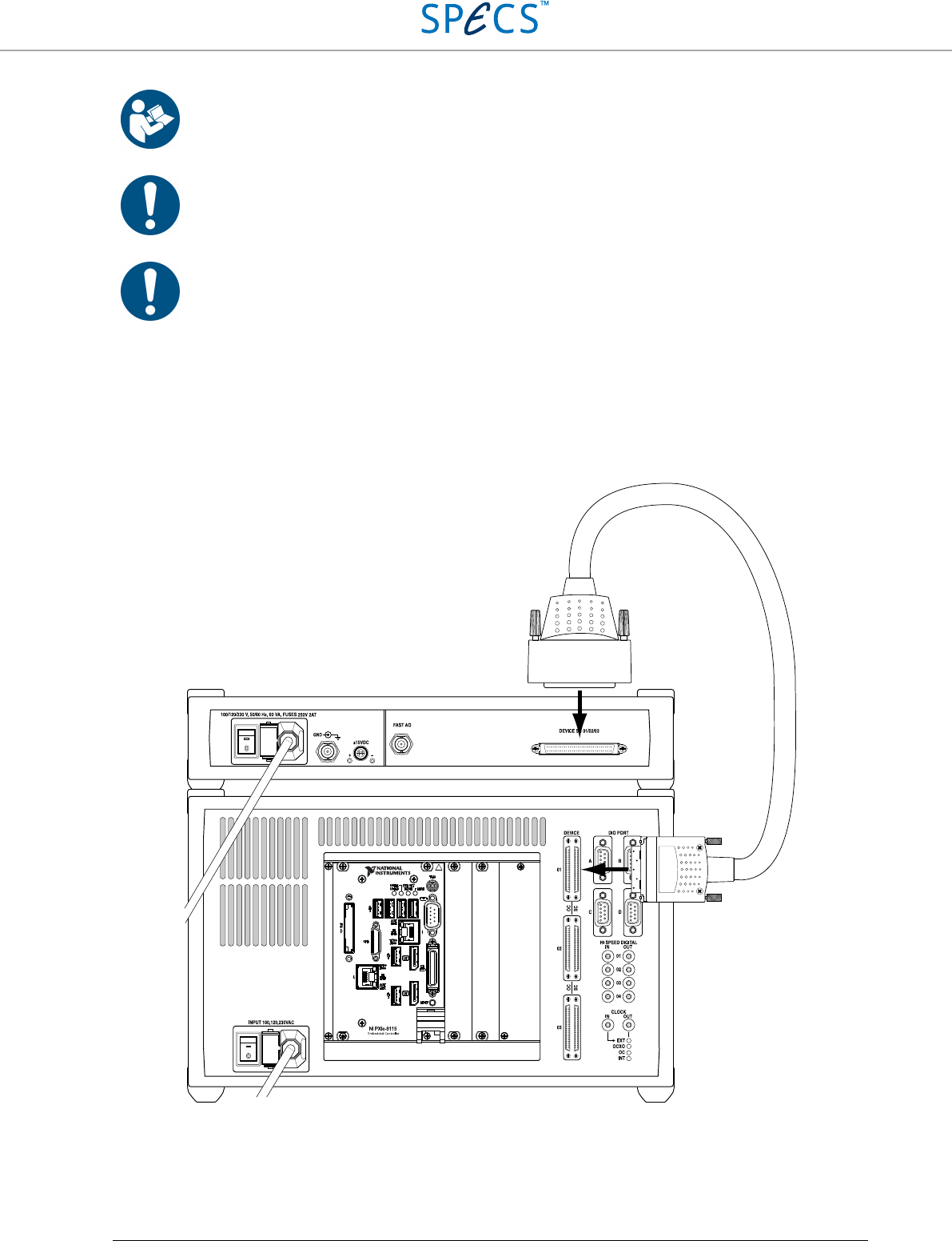
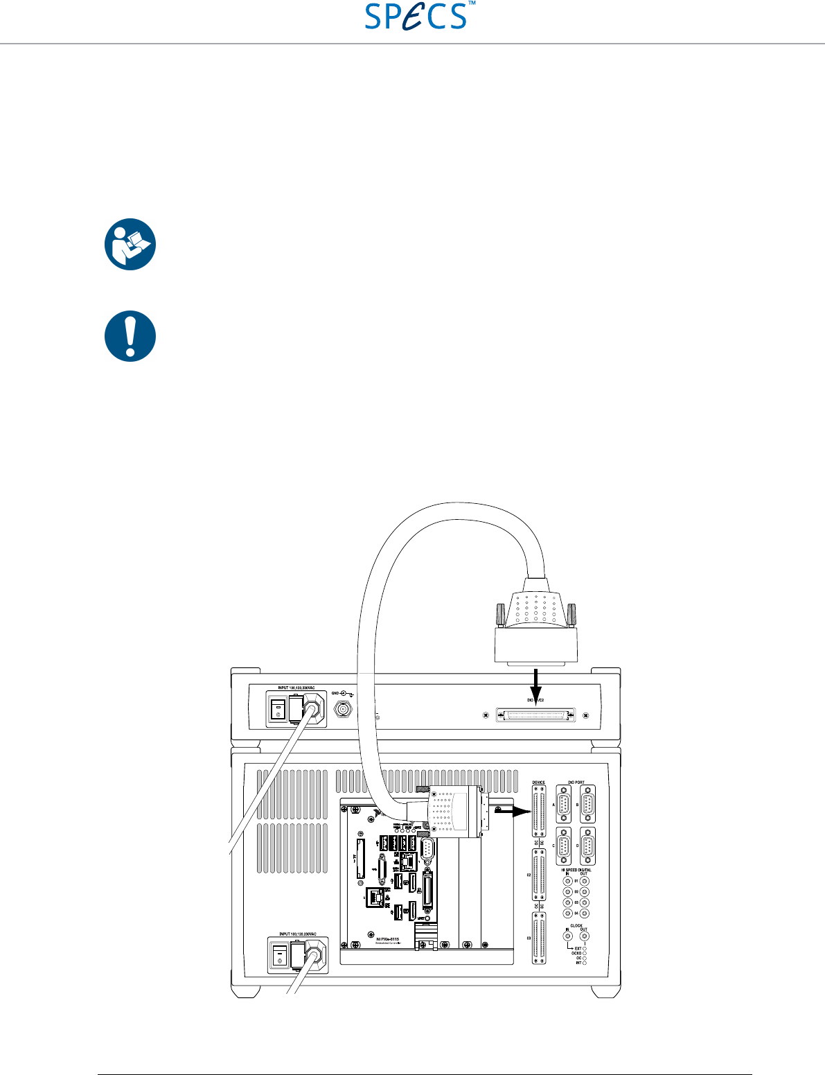
Make sure that both the SC5 and the RC5 are switched off, but connected to the mains. Connect the DEVICE RDIO
cable delivered with the SC5 to the DEVICE SC 01/02/03 port of the SC5 first, then to the SC 01 port (8) at the back
of the RC5, as shown in the figure below. Always tighten the screws on either side of the connectors.
Figure 6: Connection of one SC5 to the RC5. The power cords of both instruments have to be connected to the mains first.
RC5 Real-Time Controller Installation Guide
•
17
Note: Connect both the SC5 and the RC5 to the mains using the supplied power cords before
connecting the instruments together!
Note: Make sure that the screws of the DEVICE RDIO cable connectors are tightened, otherwise the
connectors might be damaged. Do not overtighten the screws!
Note: If a single SC5 is connected to the RC5, it must be connected to the SC 01 port at the back of the
RC5. Do not connect it to the SC 02 or SC 03 ports.
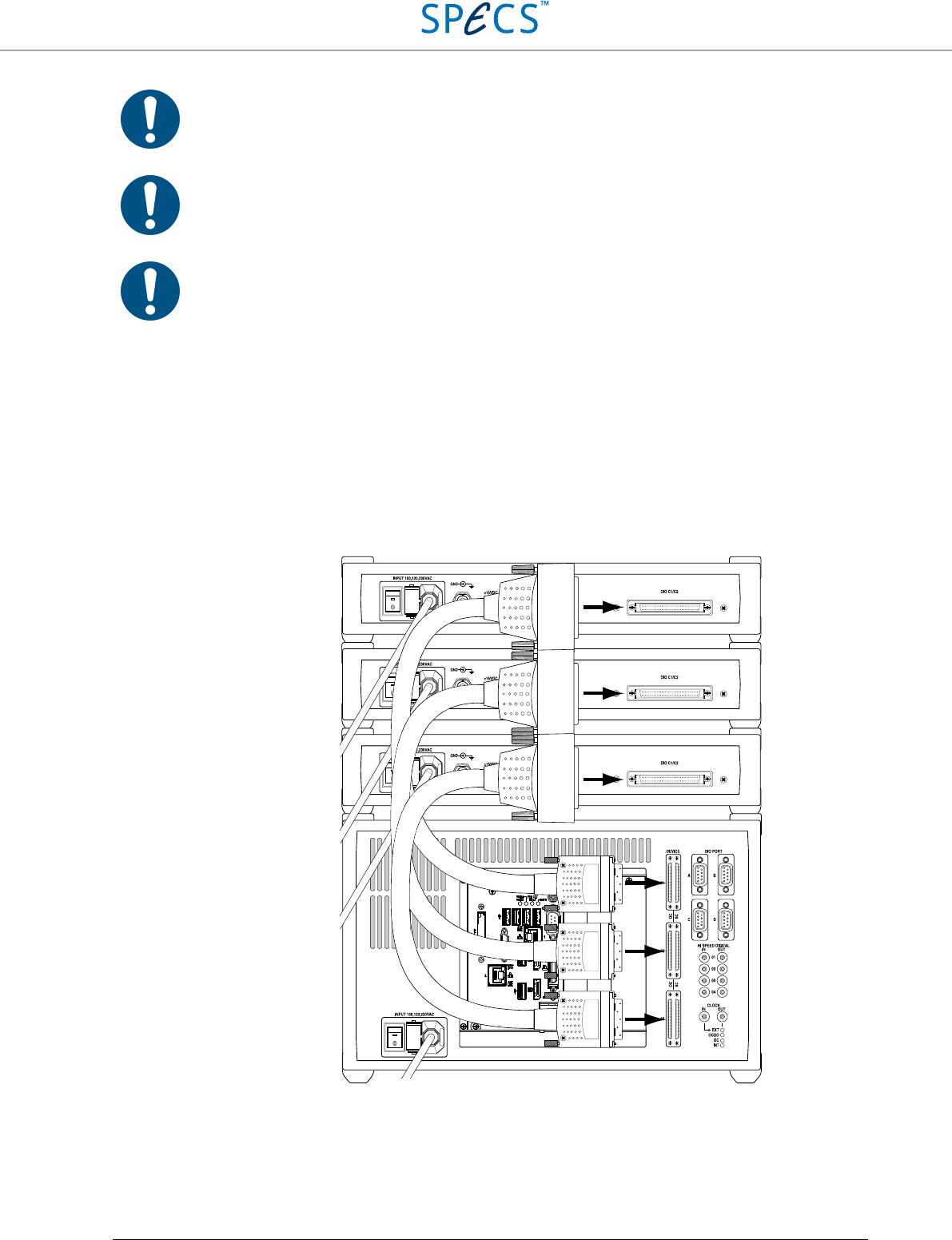
Multiple SC5s
Up to three Nanonis SC5s can be connected to a single RC5. Follow the instructions given in the previous section for
the connection of the additional SC5 units.
Since the different SC5s are addressed by their port number in the Nanonis software, make sure to label the
instruments on the front panel in order to recognize which instrument is connected to which port. The figure below
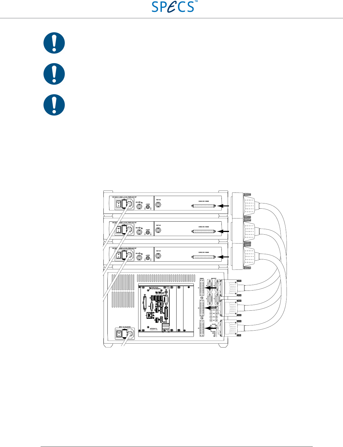
shows the maximum configuration with three SC5s connected to the RC5.
Figure 7: Connection of three SC5s to a RC5. The SC5s are shown placed above the RC5, but they can be also placed
below the RC5. Note that this arrangement is recommended only with an external source of forced cooling for the SC5s.
Otherwise a mixed arrangement (below and above the RC5) is recommended.
SC5 #1
SC5 #2
SC5 #3
RC5 Real-Time Controller Installation Guide
•
18
Note: If two SC5s are connected to the RC5, they must be connected to the SC 01 and SC 02 ports at
the back of the RC5. Do not connect the second SC5 to the SC 03 port.
Note: The SC5 must be able to dissipate a large amount of heat. It is not recommended to stack three
SC5s on top of the RC5 unless an external source of forced cooling provides a stream of air towards
the SC5 enclosures. It is recommended to use a mixed arrangement with SC5s placed below and above
the RC5.
Caution: Avoid touching the instrument and the BNC connectors if multiple SC5s are stacked on top
of each other since the surface of the instruments and the connectors may become very hot. Switch off
the instrument and let it cool down before touching it.
RC5 Real-Time Controller Installation Guide
•
19
Connection to OC4
Only one single cable, supplied with the OC4, is needed as a connection between the OC4 and the real-time
controller RC5. The DEVICE RDIO cable is labelled as SHC68 – 68 – RDIO, and is identical to the cable used for
connecting the SC5. Place the OC4 and RC5 at the desired location, and make sure that the space requirements listed
in the previous section are fulfilled.
Note: Please carefully read the OC4 user manual delivered with the Nanonis OC4 before proceeding!
Note: Only use the supplied DEVICE RDIO cable for the connection between the OC4 and RC5. Do
not use cables labelled as SHC68 – 68 – RMIO or the OC4 will not function.
Single OC4
Make sure that both the OC4 and the RC5 are switched off, but connected to the mains. Connect the DEVICE RDIO
cable delivered with the OC4 to the DIO C1/C2 port of the OC4 first, then to the OC 01 port (8) at the back of the
RC5, as shown in the figure below. Always tighten the screws on either side of the connectors.
Figure 8: Connection of one OC4 to the RC5. The power cords of both instruments have to be connected to the mains
first.
RC5 Real-Time Controller Installation Guide
•
20
Note: Connect both the OC4 and the RC5 to the mains using the supplied power cords before
connecting the instruments together!
Note: Make sure that the screws of the DEVICE RDIO cable connectors are tightened, otherwise the
connectors might be damaged. Do not overtighten the screws!
Note: If a single OC4 is connected to the RC5, it must be connected to the OC 01 port at the back of
the RC5. Do not connect it to the OC 02 or OC 03 ports.
Multiple OC4s
Up to three Nanonis OC4s can be connected to a single RC5. Follow the instructions given in the previous section
for the connection of the additional OC4 units.
Since the different OC4s are addressed by their port number in the Nanonis software, make sure to label the
instruments on the front panel in order to recognize which instrument is connected to which port. The figure below
shows the maximum configuration with three OC4s connected to the RC5.
Figure 9: Connection of three OC4s to a RC5. The OC4s are shown placed above the RC5, but they can be also placed
below the RC5.
OC4 #1
OC4 #2
OC4 #3
RC5 Real-Time Controller Installation Guide
•
21
Note: If two OC4s are connected to the RC5, they must be connected to the OC 01 and OC 02 ports at
the back of the RC5. Do not connect the second OC4 to the OC 03 port.
Note:
The OCXO of the OC4 can be used as a clock reference for the RC5 and all instruments
connected to it. Only port OC 01 accepts the clock of the OC4 as a reference, therefore the OC4
providing the clock reference must be connected to this port.
Connection to host computer
The host computer running the control software is connected to the RC5 over a single Gigabit-Ethernet cable. A
crossed cable should be used if the RC5 is connected directly to the host computer, while a normal cable should be
used if the RC5 is connected over a switch. In both cases Cat-5e or Cat-6 cables should be used.
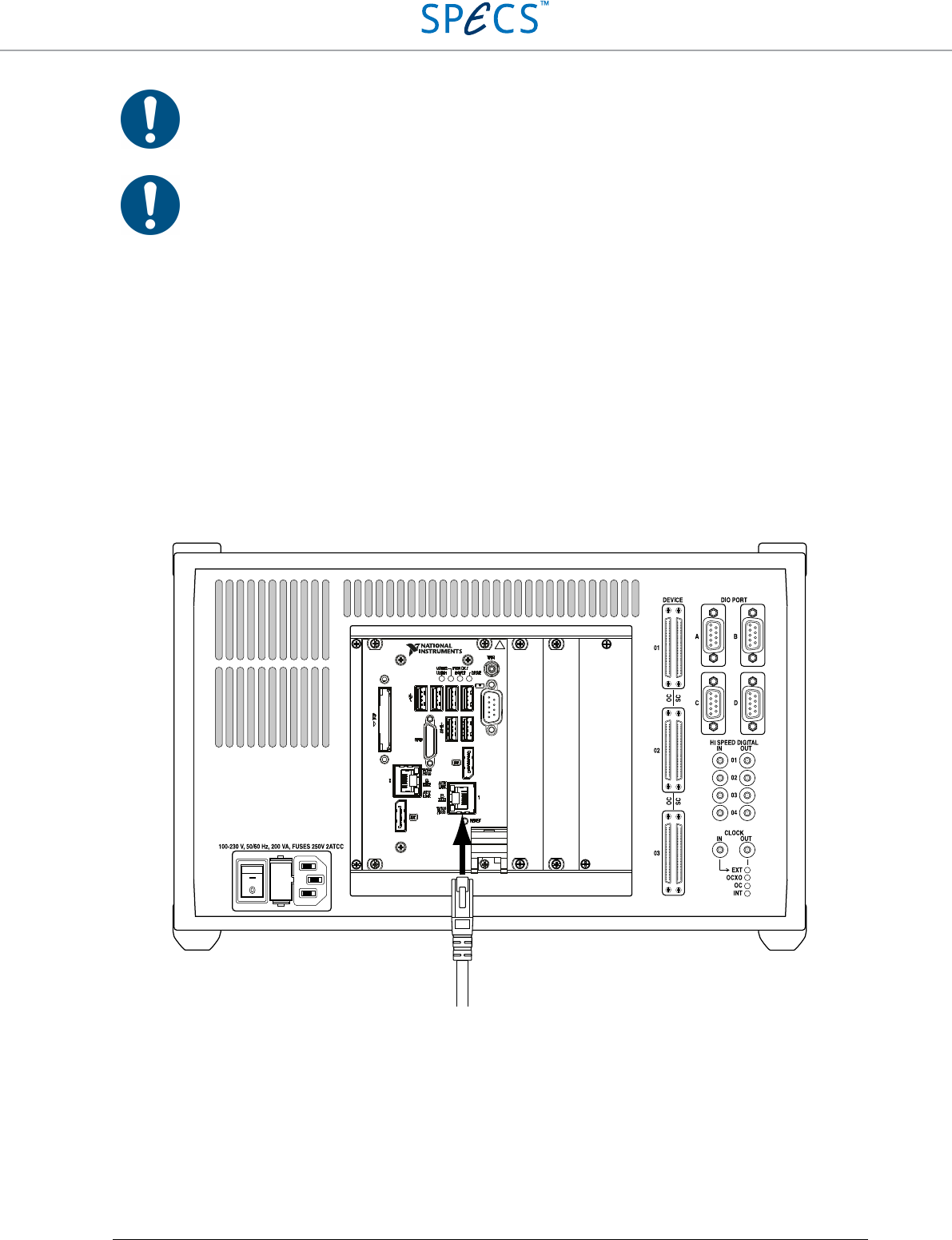
The cable should be connected to Ethernet connector 1 (5) at the back of the RC5, as shown in the picture below.
Ethernet connector 2 is disabled and should not be used.
For information about how to set-up the network adapter of the host computer, please refer to the Nanonis SPM
Control System section below.
Figure 10: RC5 with NI PXIe-8840 real-time controller: The Ethernet cable for the connection of the RC5 with the host
computer should be plugged in Ethernet connector 1 as shown above.
NI PXIe-8840
Embedded Controller
CRS
RC5 Real-Time Controller Installation Guide
•
22
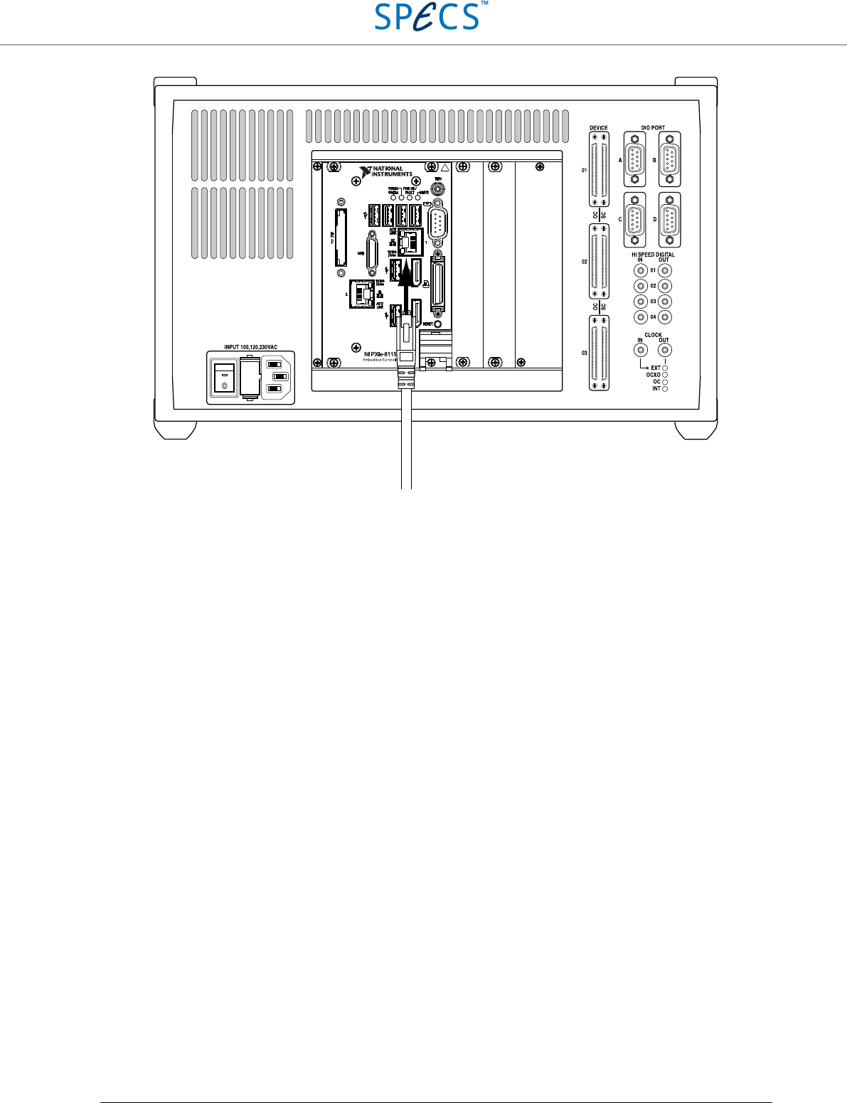
Figure 11: RC5 with NI PXIe-8115 real-time controller: The Ethernet cable for the connection of the RC5 with the host
computer should be plugged in Ethernet connector 1 as shown above.
Connection to computer screen
A computer screen connected to the DisplayPort connector (6) of the RC5 displays status information about the
instrument. Connecting a computer screen to the RC5 is not necessary during normal operation, but it can help to
trace a fault in case one of the following issues should occur:
• A connection between host computer and RC5 cannot be established and the RC5 does not respond to a “ping”
request.
• The software does not detect the RC5
• A Warning indicates a wrong real-time operating system release, and the update fails
• A real-time operating system update fails
• None of the instruments connected to the RC5 seems to be responding
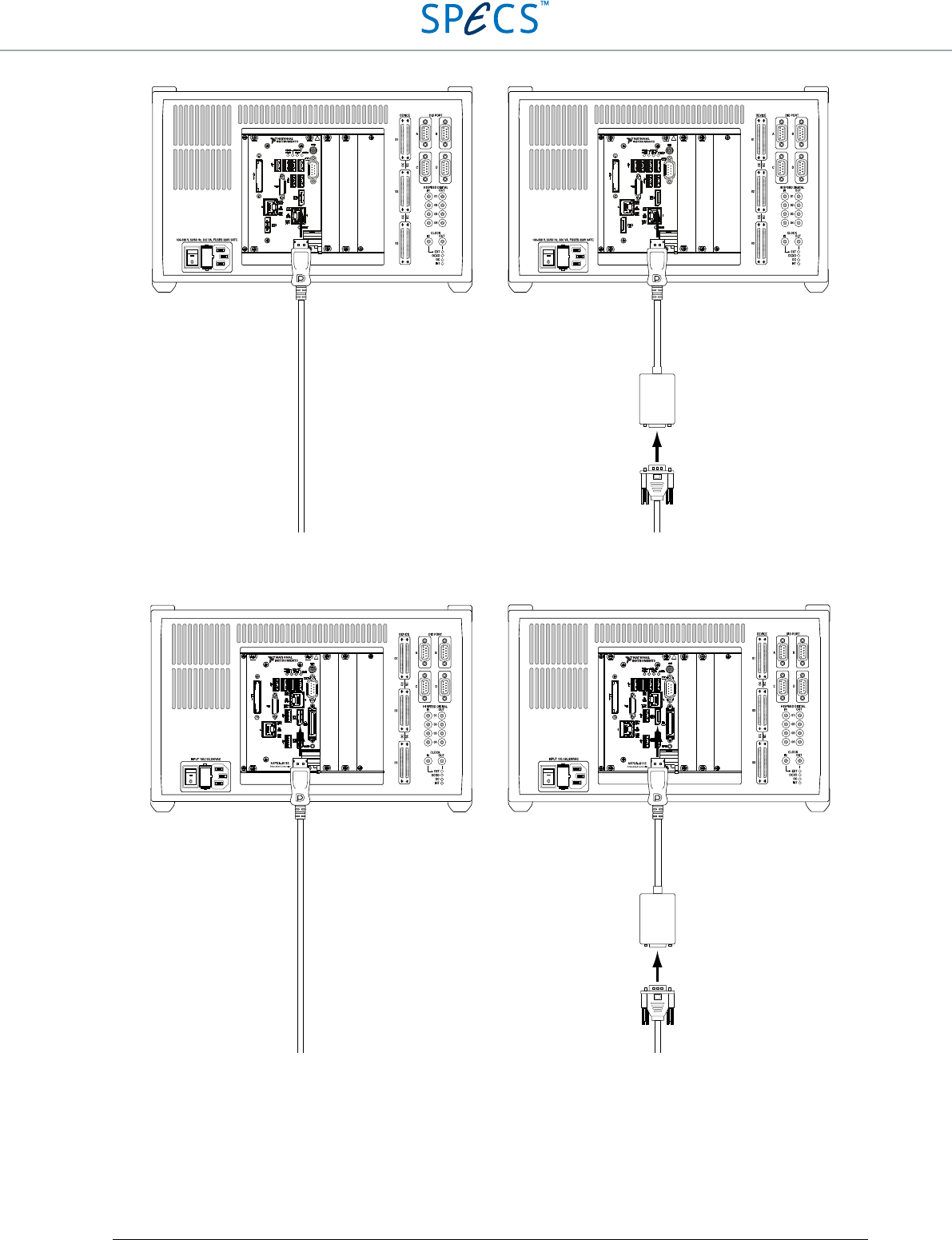
A computer screen is connected using a DisplayPort cable as indicated in the figure below on the left. For computer
screens using a VGA input, the supplied DisplayPort to VGA adapter should be used, as shown below on the right.
For computer screens using DVI inputs, a DisplayPort to DVI adapter (not supplied) should be used.
Note: Certain computer screens connected over the DisplayPort to VGA adapter might not be recognized if plugged
when the RC5 is already running. If nothing appears on the screen connected to the RC5, although the RC5 is
running, it is necessary to restart the RC5 by switching it off and then on again.
CRS
RC5 Real-Time Controller Installation Guide
•
23
Figure 12: Connection of a computer screen to the DisplayPort connector of the RC5 (with NI PXIe-8840 real-time
controller) using a DisplayPort cable (left). Connection to a computer screen using the supplied DisplayPort to VGA
adapter (right). An adapter to DVI (not supplied) must be used for computer screens with DVI input only.
Figure 13: Connection of a computer screen to the DisplayPort connector of the RC5 (with NI PXIe-8115 real-time
controller) using a DisplayPort cable (left). Connection to a computer screen using the supplied DisplayPort to VGA
adapter (right). An adapter to DVI (not supplied) must be used for computer screens with DVI input only.
NI PXIe-8840
Embedded Controller
NI PXIe-8840
Embedded Controller
RC5 Real-Time Controller Installation Guide
•
24
Powering
Before powering the RC5, make sure that:
• All SC5s and OC4s are connected to the RC5.
• If an external clock source is used as the clock reference, this source is connected and active.
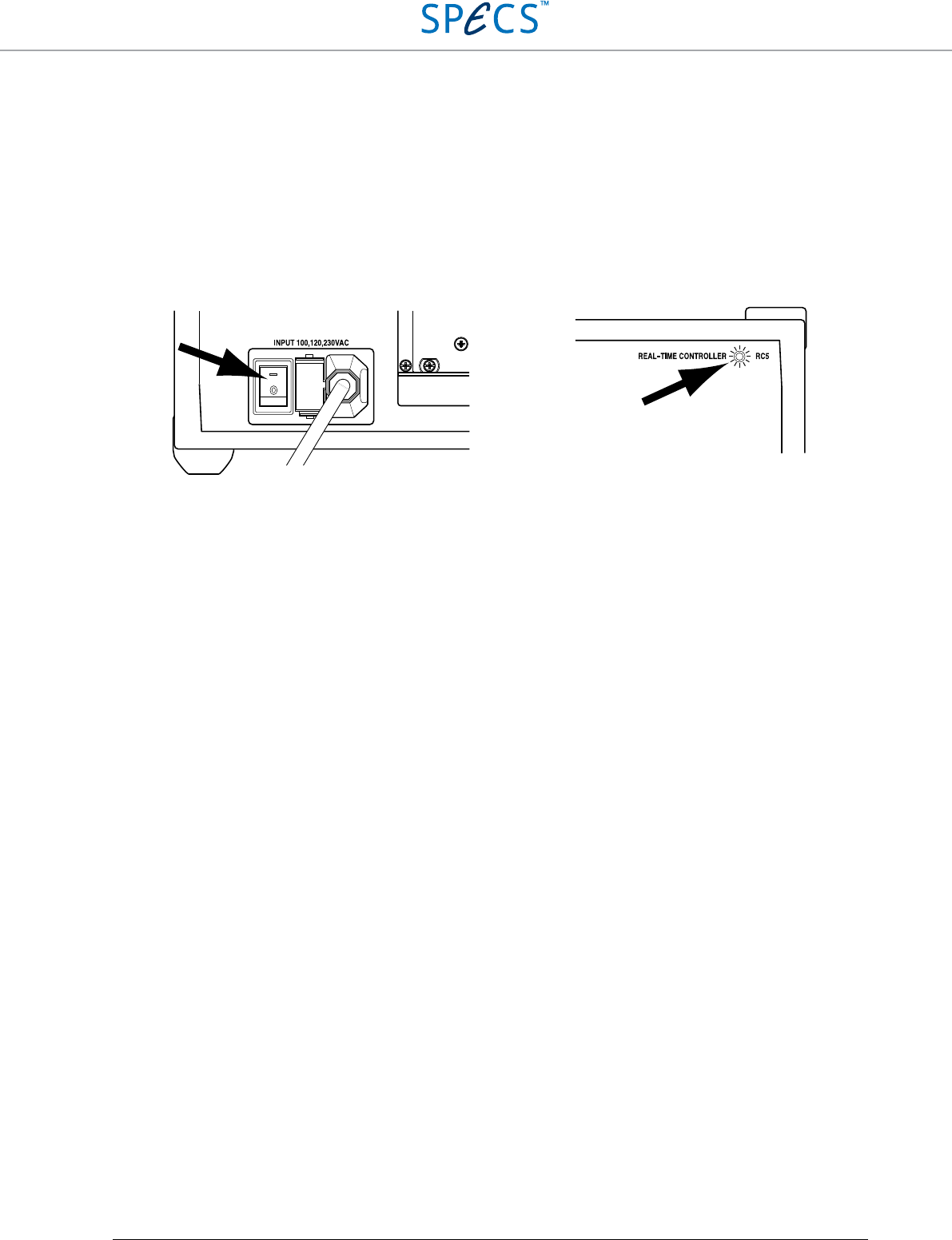
Then turn on the RC5 with the power switch (2) located at the back of the unit (see picture below). The power LED
(1) will turn on.
Figure 14: Powering up the RC5. Left side: Location of the power switch at the back of the RC5. Right side: LED which
will turn on after powering the unit.
The RC5 is now ready for use. Should the RC5 not turn on as described above, please refer to the Troubleshooting
section before proceeding. If a solution to the unexpected behavior is not listed there, please contact SPECS before
taking any further action.
How to proceed
• Make sure that all SC5s and OC4s which will be operated are connected to the RC5, as explained in the
Connection to SC5 and Connection to OC4 sections
• Connect an active external clock source to the Clock input connector (11) (only if the internal clock sources are
not used), as explained in the Clock section
• Connect the instruments requiring digital communication to the DIO ports (9), as explained in the DIO ports
section
• Connect the instruments requiring high-speed digital signals to the High Speed Digital Input (10) and Output
(14) connectors as explained in the High Speed Digital Inputs and High Speed Digital Outputs sections
• Turn on the OC4s
• Turn on the SC5s
• Turn on the RC5
RC5 Real-Time Controller DIO ports
•
25
DIO ports
The four DIO ports (DIO: Digital Input Output) of the RC5 are independent bidirectional digital interfaces with eight
signal lines each with a TTL signal level of 3.3 V. Each port uses a D-sub9 female connector, with one pin used for
digital ground. The maximum current in output mode is 25 mA for each pin, and the maximum bandwidth of the
signal lines is 500 kHz. The ports can therefore also be used for controlling external instruments over a Serial
Peripheral Interface bus (SPI). The DIO ports should not be used for pulse counting purposes. The High Speed
Digital Inputs should be used instead.
Nanonis instruments requiring control over a digital interface like the Nanonis PMD4 and PD5 have to be connected
to these ports.
DIO ports connection
A connection to the DIO ports has to be made using cables fitted with a D-sub9 male connector. A conventional D-
sub9 1:1 cable can be used for this purpose. All Nanonis instruments requiring a connection to a DIO port (Nanonis
PMD4, PD5, HVA4, as well as all adaptation kits) are delivered with a suitable double-shielded cable. For these
instruments, do not replace the double-shielded cable with a conventional cable.
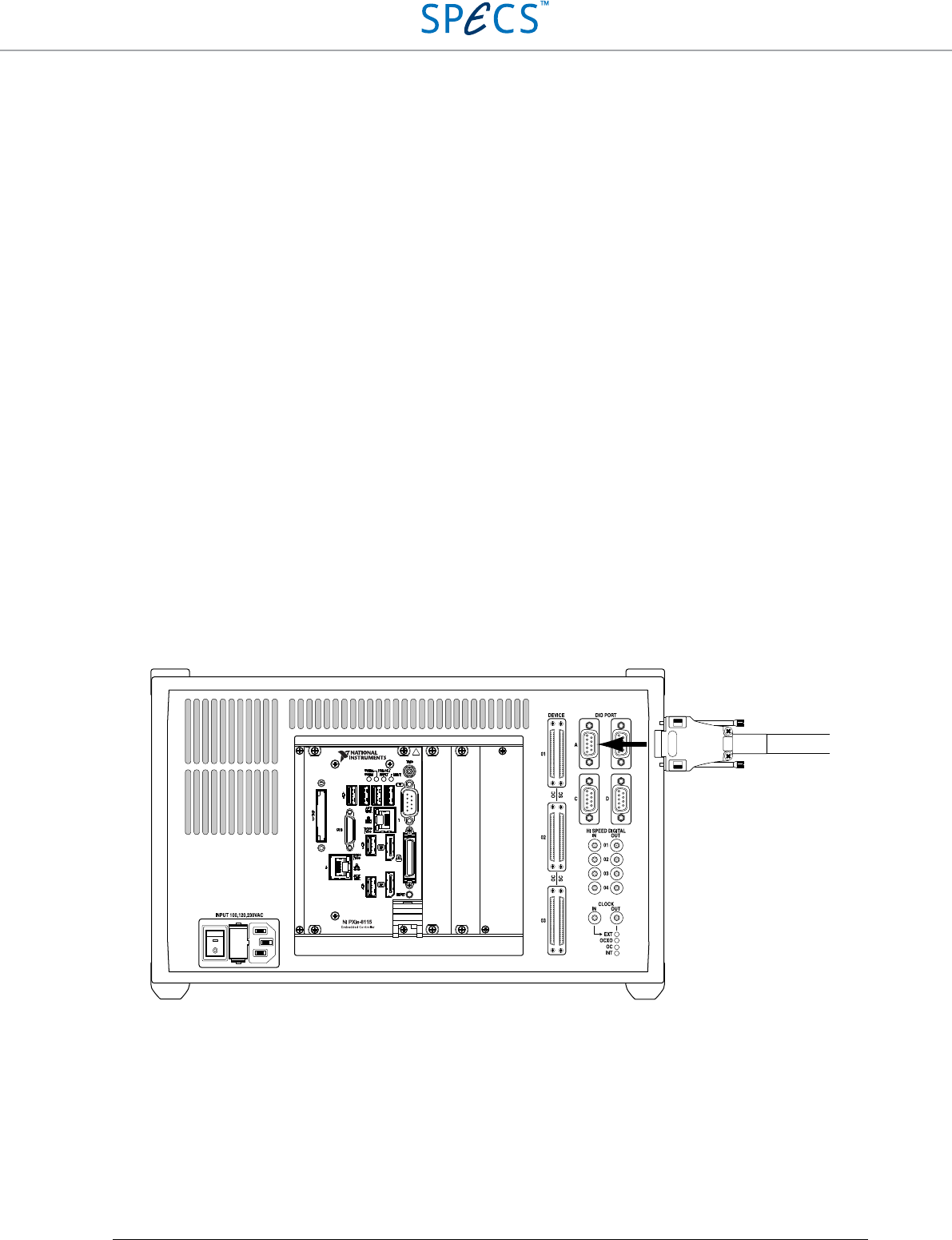
For all Nanonis products requiring a connection to a DIO port, as well as for many third-party instruments, the DIO
port to be used is specified within the license file of the Nanonis system. Please make sure to connect the instrument
to the correct DIO port. The picture below shows the connection to DIO port A.
Figure 15: Connection of a digital cable to a DIO port of the RC5 (DIO port A shown).
RC5 Real-Time Controller DIO ports
•
26
DIO ports schematic and connector pin layout
The DIO ports are connected to the signal distribution unit over a general purpose input output (GPIO) expander,
which provides electrical protection and isolation. The ground line of the DIO ports is connected to digital ground of
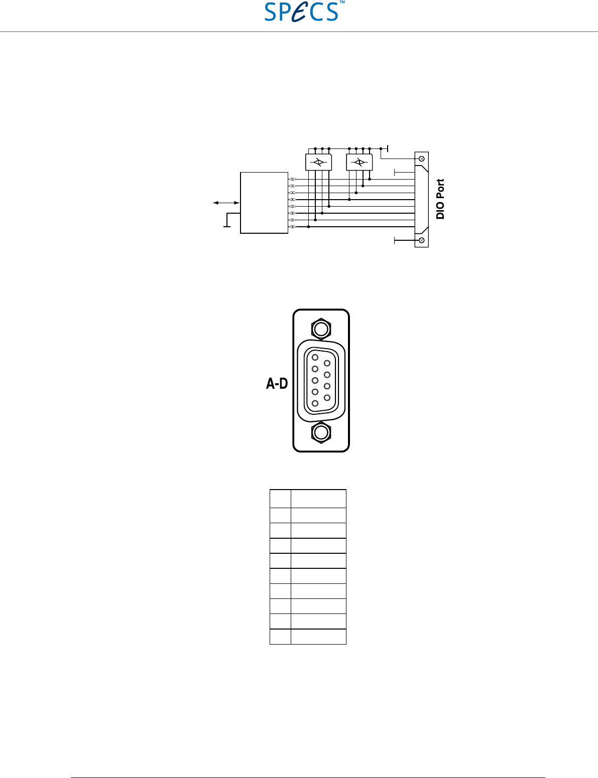
the RC5. All four ports use D-sub9 female connectors. The following picture shows the schematic of one of the
ports. All four ports are identical.
Figure 16: DIO ports schematic. All four DIO ports have the same electrical configuration.
For the pin assignment of the DIO ports, see the figure and table below.
Figure 17: DIO port pin configuration. The pin configuration is valid for all four DIO ports A to D.
PIN
Digital line
1 DGND
2 DIO1
3 DIO3
4 DIO5
5 DIO7
6 DIO0
7 DIO2
8 DIO4
9 DIO6
Table 1: Signal assignment of the DIO port of the RC5.
1
6
2
7
3
8
4
9
5
D-sub 9
FEMALE
GND
GND
To/from signal
distribution
GPIO
expander
PE
PE
1
2
3
4
5
6
7
8
9

RC5 Real-Time Controller DIO ports
•
27
Specifications (DIO ports)
Lines set to input
Pull-up resistance 100 kΩ ±40%
Low input threshold < 0.8 V
High input threshold > 2.0 V
Maximum input voltage 5.5 V
Input capacitance < 10 pF
Input leakage current ±10 µA
Lines set to output
Nominal output level 3.3 V
High output voltage > 2.6 V (@ 8 mA load)
Low output voltage < 0.5 V (@ 8 mA load)
Maximum current per line 25 mA (max. 100 mA per connector)
Timing
Maximum sampling frequency 500 kHz
RC5 Real-Time Controller High Speed Digital Inputs
•
28
High Speed Digital Inputs
The four high speed digital inputs of the RC5 offer a high-speed input interface typically used for pulse-counting
purposes. In contrast to the DIO ports, which are designed for frequencies up to 500 kHz, the high speed digital
inputs can accept input signals with frequencies up to 200 MHz. Each input uses a SMB male connector, with the
shield connected to digital ground.
High speed digital inputs connection
Connection to the high speed digital inputs has to be made using a cable fitted with female SMB connectors. The
connectors can be straight or angled. The connection of SMB cables is shown in the picture below.
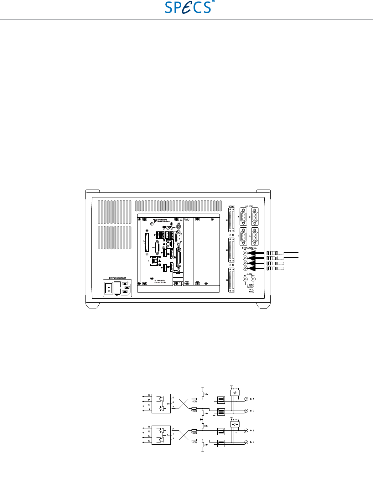
Figure 18: Connection of SMB cables to the high speed digital inputs.
High speed digital inputs schematic
The signal applied to the High Speed Digital Inputs is converted to a LVDS signal after passing protection and level
matching circuits. The shield of the SMB connector is connected to digital ground of the RC5. All four inputs use
SMB male connectors. The following picture shows the schematic of the four high speed digital inputs.
Figure 19: Schematic of the High Speed Digital Inputs.
GND
GND
GND
GND
GND
PE
PE
GND
GND
SE to LVDS
converters
To signal
distribution
To signal
distribution

RC5 Real-Time Controller High Speed Digital Inputs
•
29
Specifications (high speed digital inputs)
Electrical parameters
Nominal high input level 3.3 V (5 V TTL tolerant)
Low input threshold < 0.8 V
High input threshold > 2 V
Maximum input voltage 6 V
Input capacitance < 10 pF
Timing
Maximum sampling frequency 200 MHz
RC5 Real-Time Controller High Speed Digital Outputs
•
30
High Speed Digital Outputs
The four High Speed Digital Outputs of the RC5 offer a high-speed output interface typically used for fast pulse-
generation purposes. As for the High Speed Digital Inputs, in contrast to the DIO ports, which are designed for
frequencies up to 500 kHz, the high speed digital outputs can generate signals with frequencies up to 200 MHz. Each
output uses a SMB male connector, with the shield connected to digital ground.
High speed digital outputs connection
Connection to the high speed digital outputs has to be made using a cable fitted with female SMB connectors. The
connectors can be straight or angled. The connection of SMB cables is shown in the picture below.
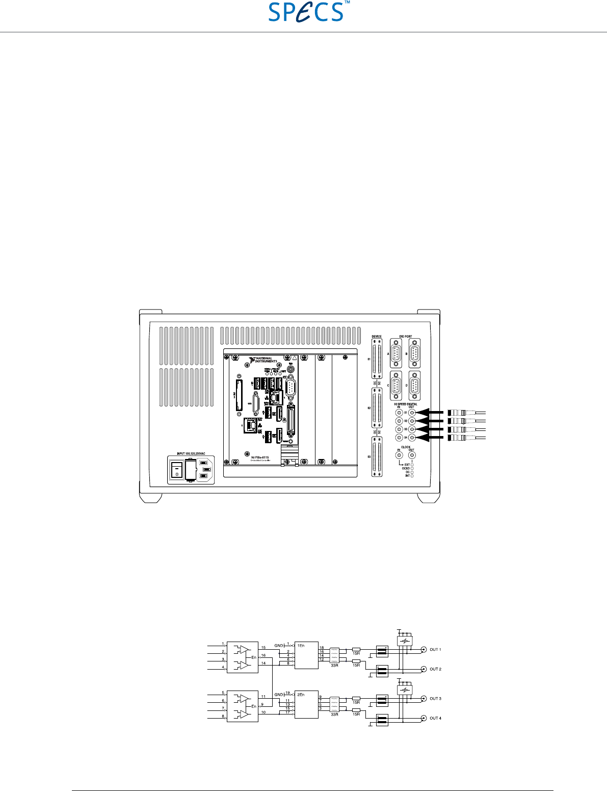
Figure 20: Connection of SMB cables to the high speed digital outputs.
High speed digital outputs schematic
The high speed digital outputs are driven by high speed signal drivers with paralleled outputs, which can drive long
cables. The shield of the SMB connector is connected to digital ground of the RC5. All four outputs use SMB male
connectors. The following picture shows the schematic of the four high speed digital outputs.
Figure 21: Schematic of the high speed digital outputs.
GND
GND
PE
PE
GND
GND
From signal
distribution
From signal
distribution
LVDS to SE
converters
High-speed
drivers

RC5 Real-Time Controller High Speed Digital Outputs
•
31
Specifications (high speed digital outputs)
Electrical parameters
Nominal output level 3.3 V
Output impedance ≅ 50 Ω
High output voltage > 2.0 V @ 33 mA load
Low output voltage < 0.4 V @ 33 mA load
Maximum current per line 33 mA
Timing
Maximum sampling frequency 200 MHz
RC5 Real-Time Controller Clock
•
32
Clock
Clocking options
The RC5 can accept four different clock sources, which are selected automatically when the RC5 is powered on
based on a priority list. The clock source can be either the low phase-noise clock of the FPGA, an optional oven-
controlled crystal oscillator (OCXO) which can be fitted to the RC5, the OCXO of a Nanonis OC4, or an external
clock 10 MHz source. Only one clock source will be used, while clock sources at a lower priority will be ignored.
The clock signal is used as a clock reference for all instruments connected to the RC5. The clock signal from the
selected clock source is then available at the CLOCK OUT connector (13).
The clock source is selected during power-up of the RC5 according to the following priority list:
• First priority: External 10 MHz clock source, e.g. atomic clock. As soon as a valid clock signal is applied to
the CLOCK IN connector (11) it is used as a clock reference for the RC5 and all instruments connected to it.
The internal optional OCXO, the OCXO clock signal of the attached OC4, as well as the internal FPGA clock
signals are ignored.
• Second priority: Optional internal OCXO. If the optional OCXO is installed, and no valid clock signal is
applied to the CLOCK IN connector (11), its signal is used as a clock reference for the RC5 and all instruments
connected to it. The OCXO clock signal of the attached OC4, as well as the internal FPGA clock signals are
ignored.
• Third priority: OCXO of a Nanonis OC4. If a Nanonis OC4 is connected to the RC5, its clock signal is used
as a clock reference for the RC5 and all instruments connected to it, if no valid clock signal is applied to the
CLOCK IN connector (11), and the optional internal OCXO is not installed. The internal FPGA clock signal is
ignored. The OC4 providing the clock source must be connected to the OC 01 port.
• Fourth priority: Internal FPGA clock. If none of the other clock sources are available, the internal FPGA
clock is used as a clock reference for the RC5 and all instruments connected to it.
Note: Before connecting an external clock source, make sure that its frequency is 10 MHz and that the
signal level is 3.3 V.
The Clock Source LEDs (12) indicate which clock source is active, and therefore which clock source is available at
the CLOCK OUT connector (13). Only one source can be active at one time, therefore only one LED can be lit at
one time. The picture below shows the situation for an active external clock source.
If an external clock source is connected to the CLOCK IN connector but the EXT LED does not light up, then the
external clock signal does not comply with the frequency and amplitude requirements. Please check the Clock ports
specifications section and make sure that the external clock source provides a compatible clock signal.
RC5 Real-Time Controller Clock
•
33
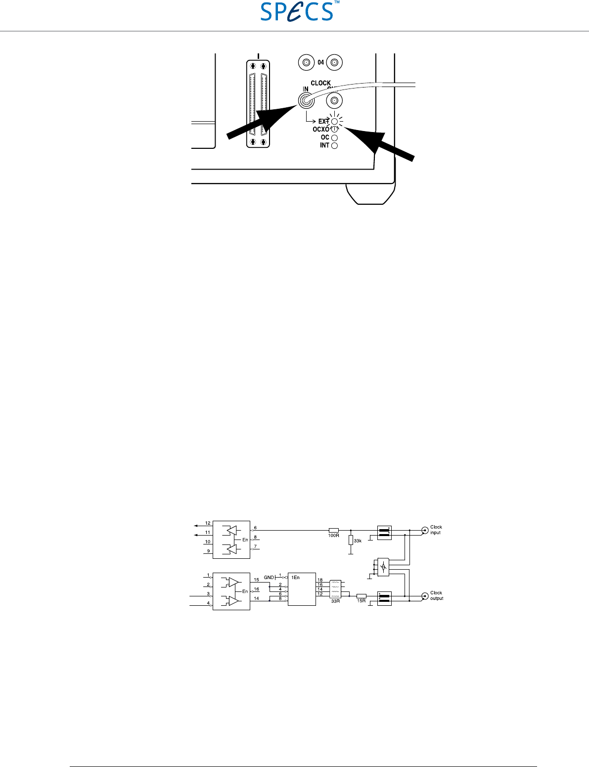
Figure 22: Function of the Clock Source LEDs: In this case, an external clock source is connected to the CLOCK IN
connector. The EXT LED lights up, indicating that the external clock is chosen as reference clock, and that the CLOCK
OUT connector outputs this clock signal.
Clock ports connection
Connection to the Clock ports (11,13) has to be made using a cable fitted with female SMB connectors. The
connectors can be straight or angled. An example for the connection of an external clock source is shown in the
figure above.
A connection to the clock ports is required only if:
• The clock reference of external instruments has to be synchronized with the clock reference of the RC5. In this
case the signal available on the CLOCK OUT connector (13) has to be connected to the reference clock input of
the external instrument.
• The RC5 and all instruments connected to it have to be synchronized with an external clock reference, e.g. an
atomic clock. In this case the external reference should be connected to the CLOCK IN connector (11).
Clock ports schematic
The clock input and output circuits are identical to those of the High Speed Digital Inputs and Outputs. The
schematic is shown in the picture below.
Figure 23: Schematic of the clock input and output.
GND
PE
To clock
distribution
GND
GND
PE
From clock
distribution
SE to LVDS
converter
LVDS to SE
converter
High-speed
driver
RC5 Real-Time Controller Clock
•
34
Optional OCXO clock mounting instructions
The optional OCXO is user-installable and can also be fitted to the RC5 after purchase of the instrument. The
oscillator is delivered without other components, and needs to be inserted into a dedicated socket on the signal
distribution board inside the RC5.
In order to install the OCXO, the RC5 needs to be opened. The following tools are required:
• 3 mm hex screwdriver
Note: Installation of the optional OCXO requires the RC5 to be opened, and requires the placement of
a relatively small object close to electronic components sensitive to electrostatic discharge (ESD).
Make sure to follow all directives for handling ESD sensitive components before proceeding. A wrist
strap connected to ground must be worn when performing the modification. Please send the RC5 back
to SPECS for the modification if there is any doubt about how the modification should be performed.
Before proceeding with the installation of the optional OCXO, please make sure that:
• All instruments (SC5s and OC4s) are disconnected from the RC5
• All DIO, High Speed Digital Input and Output, as well as Clock input and Output cables are disconnected from
the RC5
• The RC5 is disconnected from the mains.
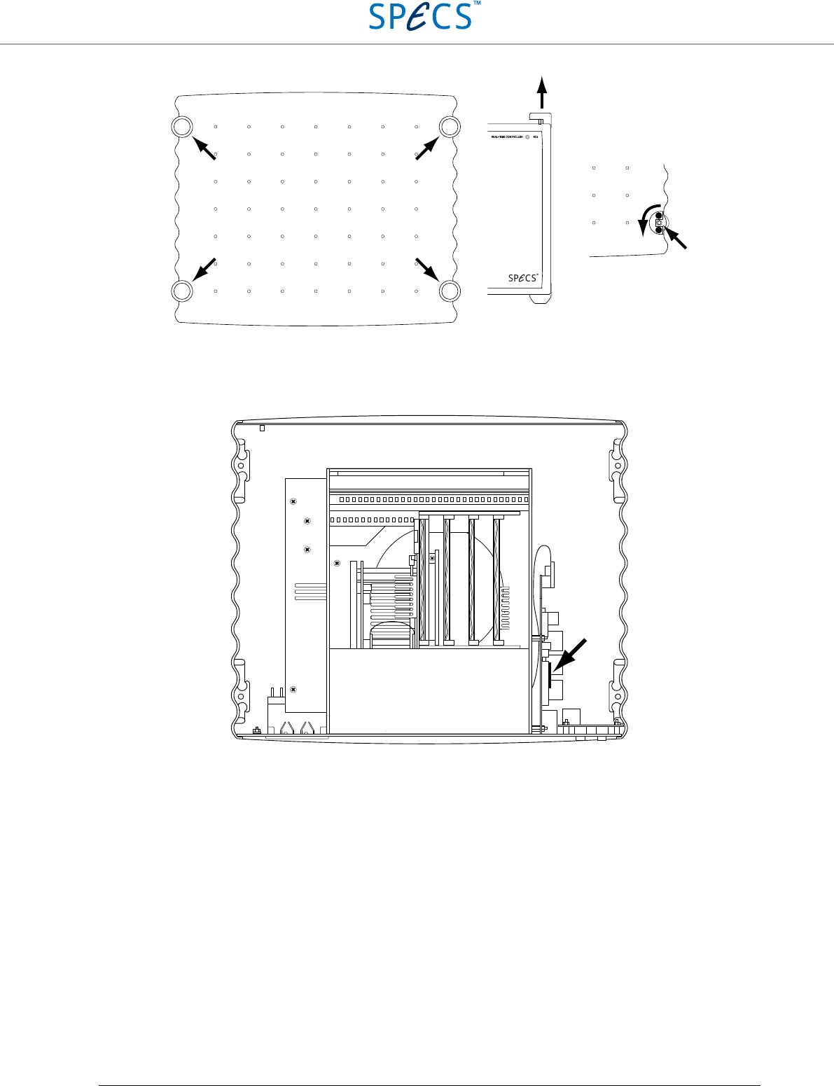
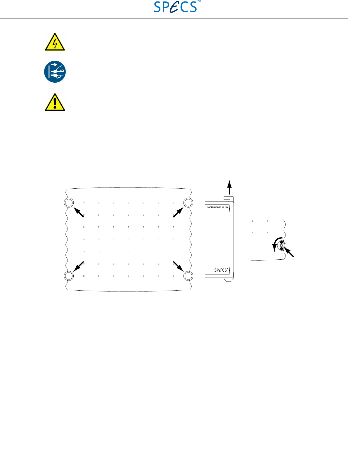
Once the above criteria are fulfilled, put the RC5 on a stable and sufficiently large surface. Remove the four plastic
caps covering the screws which hold the top cover of the instrument as shown in the figure below, and remove the
screws by turning them CCW using the 3 mm hex screwdriver. Make sure not to lose the lock washers placed below
the screws. The top cover can now be carefully lifted, and should be put on the side of the instrument. Note that there
is a grounding wire connecting the top cover with the rest of the instrument. This prevents the top cover being
completely separated from the unit but allows the top cover to be lifted by approx. 10 cm to facilitate removal.
Warning: Lethal voltages are present inside the RC5.
Note: Before installing the optional OCXO, make sure that the RC5 is disconnected from the mains.
Caution: The inner frame of the RC5 and the printed circuit boards have sharp edges. Proceed with
care in order to avoid injury.
RC5 Real-Time Controller Clock
•
35
Figure 24: Removing the top cover of the RC5: First remove the four plastic caps covering the screws by lifting them, then
remove the four screws by turning CCW with a 3 mm hex screwdriver.
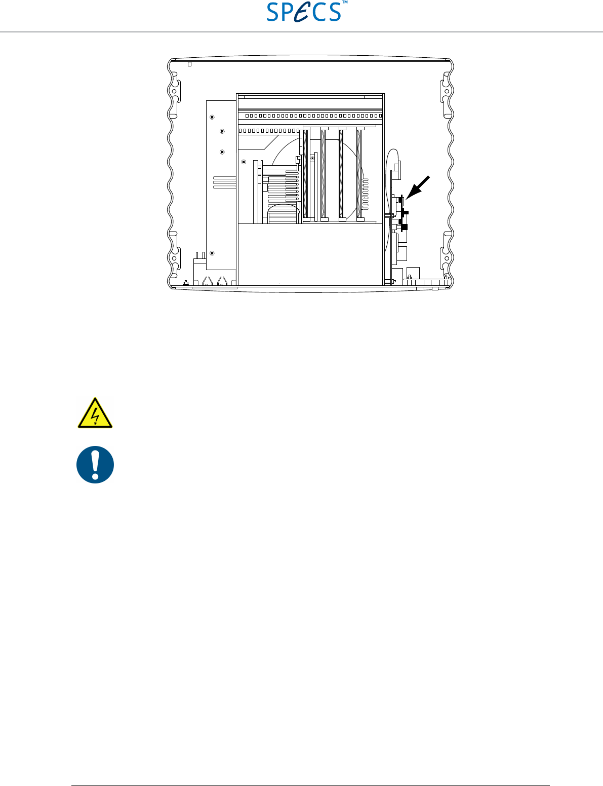
After removal of the top cover, face the rear panel of the instrument. The optional OCXO needs to be installed in a
dedicated socket located on the printed circuit board in the right part of the instrument as shown below.
Figure 25: Internal view of the RC5. The location of the optional OCXO socket is indicated by the arrow.
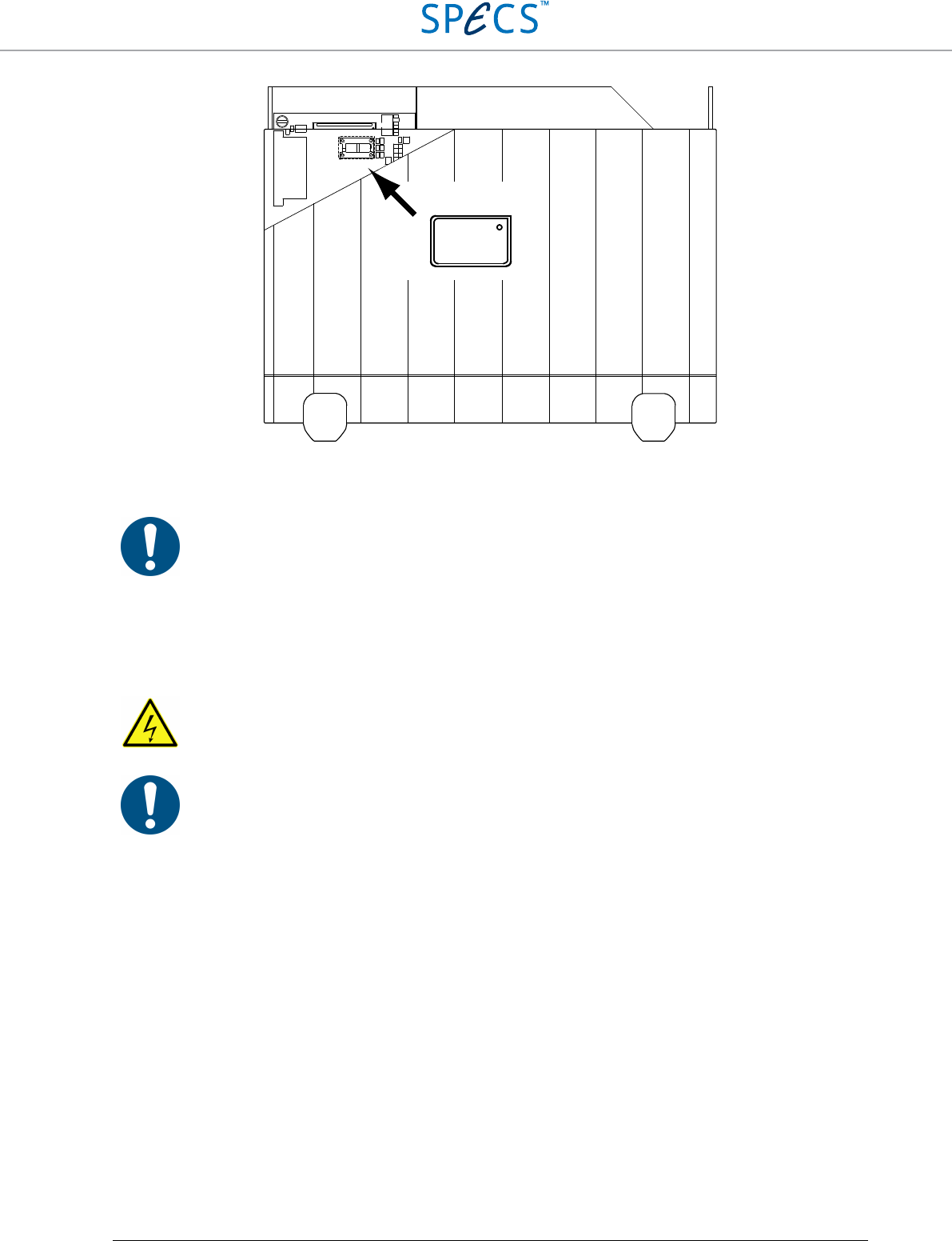
The figure below shows the correct orientation of the optional OCXO.
RC5 Real-Time Controller Clock
•
36
Figure 26: Mounting position and orientation of the optional OCXO (side view, in reality the components are behind the
side panel). Pin 1 has to be positioned on the upper right. Note that a ribbon cable covers the OCXO socket, and needs to
be lifted. Do not remove the ribbon cable.
Note: Make sure to install the optional OCXO as shown in the picture above. Installing it in the wrong
orientation might lead to damage of the OCXO and malfunctioning of the RC5.
Once the optional OCXO is correctly installed, the RC5 will use it as its clock source, as long as no external source
is connected to the CLOCK IN connector (11).
Warning: Avoid any physical contact with or modification of the areas of the instrument marked by
the high voltage warning sign, as this might impair the safety of the instrument.
Note: Make sure that the grounding wire is still firmly connected to the top cover and to rear panel
before closing the instrument. A loose grounding wire will impair safety of the instrument. Also make
sure that no OCXO, screws, tools, or other objects have been dropped or forgotten inside the
instrument. Any object left inside the instrument might impair its safety.
Orientation:

RC5 Real-Time Controller Clock
•
37
Specifications (clock)
Internal Clock and optional OCXO specifications
Internal Clock
Accuracy ±50 ppm
Maximum jitter 5 ps RMS phase jitter (10 Hz – 1 MHz range)
Optional OCXO
Accuracy ±4 ppm
Maximum jitter 5 ps RMS phase jitter (10 Hz – 1 kHz range)
Phase noise (bandwidth = 1 Hz) -70 dBc/Hz @ 1 Hz
-100 dBc/Hz @ 10 Hz
-130 dBc/Hz @ 100 Hz
-140 dBc/Hz @ 1 kHz
Short term stability < 5E-10 (0.1 s to 30 s), 5E-11 typical @ 1 s
Frequency stability over temperature ±0.075 ppm (0.15 ppm p-p) 0 to 60°C
Frequency stability over time First year: < ±0.7 ppm
After 10 Years: < ±4.0 ppm
Clock ports specifications
Electrical parameters (input)
Nominal high input level 3.3 V (5 V TTL tolerant)
Low input thresold < 0.8 V
High input thresold > 2 V
Maximum input voltage 6 V
Input capacitance < 10 pF
Timing requirements (input clock)
Required clock frequency 10 MHz
Signal rise and fall time requirement < 5 ns
Duty cycle range 40% - 60%
Electrical parameters (output)
Nominal output level 3.3 V
Output impedance ≅50 Ω
High output voltage > 2.0 V @ 33 mA load
Low output voltage < 0.4 V @ 33 mA load
Maximum current 33 mA
Timing (output)
Clock frequency 10 MHz
RC5 Real-Time Controller Upgrades and replacements
•
38
Upgrades and replacements
Firmware update
The RC5 is delivered with a firmware which defines all functionality and enables connection with all instruments
described in this manual. Changes to these parameters might require a firmware update.
Note:
Perform a firmware update only if instructed to do so by SPECS. An update of the firmware
without being advised to do so by SPECS voids the RC5 warranty.
Note: Firmware upgrades should not be confused with real-time software upgrades. The latter is performed
automatically from the Nanonis software when required. A firmware upgrade is only necessary when hardware-
related changes require new or modified functions of the signal and clock distribution unit.
Updating the firmware is a simple procedure, which only requires replacing a small printed circuit board (PCB)
inside the RC5. There is no software operation required, and the RC5 does not need to be connected to the host PC.
The board is shipped by postal mail if required. Please ship the old firmware PCB back to SPECS once the new one
has been installed.
In order to replace the firmware PCB, the RC5 needs to be opened. The following tools are required:
• 3 mm hex screwdriver
Note:
A replacement of the firmware PCB requires the RC5 to be opened, and requires to place a
relatively small object close to electronic components sensitive to electrostatic discharge (ESD). Make
sure to follow all directives for handling ESD sensitive components before proceeding. A wrist strap
connected to ground must be worn when performing the modification. Please send the RC5 back to
SPECS for the replacement if there is any doubt about how the modification should be done.
Before proceeding with the replacement of the firmware PCB, please make sure that:
• All instruments (SC5s and OC4s) are disconnected from the RC5
• All DIO, High Speed Digital Input and Output, as well as Clock input and Output cables are disconnected from
the RC5
• The RC5 is disconnected from the mains.
RC5 Real-Time Controller Upgrades and replacements
•
39
Once the above criteria are fulfilled, put the RC5 on a stable and sufficiently large surface. Remove the four plastic
caps covering the screws which hold the top cover of the instrument as shown in the figure below, and remove the
screws by turning them CCW using the 3 mm hex screwdriver. Make sure not to lose the lock washers placed below
the screws. The top cover can now be carefully lifted, and should be put on the side of the instrument. Note that there
is a grounding wire connecting the top cover with the rest of the instrument. This prevents the top cover being
completely separated from the unit but allows the top cover to be lifted by approx. 10 cm to facilitate removal.
Figure 27: Removing the top cover of the RC5: First remove the four plastic caps covering the screws by lifting them, then
remove the four screws by turning CCW with a 3 mm hex screwdriver.
The figure below shows the location of the firmware PCB.
Warning: Lethal voltages are present inside the RC5.
Note: Before replacing the firmware PCB, make sure that the RC5 is disconnected from the mains.
Caution: The inner frame of the RC5 and the printed circuit boards have sharp edges. Proceed with
care in order to avoid injury.
RC5 Real-Time Controller Upgrades and replacements
•
40
Figure 28: Internal view of the RC5. The location of the firmware PCB is indicated by the arrow.
In order to remove the firmware PCB, the board needs to be removed from its sockets by pulling to the right when
the RC5 is oriented as shown in the picture above. The new firmware PCB is inserted by pushing it into the socket
left empty after removing the old one. Removing the firmware PCB might require some force to be applied. Make
sure to keep the main printed circuit board (onto which the firmware PCB is plugged) in place when removing the
firmware PCB by holding it tightly. Do not use pliers for this purpose, as the board could be damaged.
Warning: Avoid any physical contact with or modification of the areas of the instrument marked by
the high voltage warning sign, as this might impair the safety of the instrument.
Note: Make sure that the grounding wire is still firmly connected to the top cover and to rear panel
before closing the instrument. A loose grounding wire will impair safety of the instrument. Also make
sure that no firmware board, screws, tools, or other objects have been dropped or forgotten inside the
instrument. Any object left inside the instrument might impair its safety.
Real-time unit replacement
A replacement of the real-time unit is necessary only in the following cases:
• Malfunction of the unit (see the troubleshooting section for details).
• Increased CPU-load from future revisions of the software requires more CPU processing power, which might be
available with future models of the real-time unit.
• Any other reason for which more CPU processing power than available with the originally delivered real-time
unit might be necessary.
RC5 Real-Time Controller Upgrades and replacements
•
41
Note: Please contact SPECS before replacing the real-time unit, if not instructed to do so by SPECS.
Not all PXIe real-
time units might be compatible with the Nanonis software. Any unsolicited
replacement of the real-time unit is done at own risk and voids the RC5 warranty.
Note: By replacing the real-
time unit, the MAC address of the network adapter also changes. The
software license files are therefore not valid anymore, and the control software will not start with the
replacement real-time unit. Please contact SPECS in order to obtain a new license file, and provide the
network adapter MAC address of the new real-time unit.
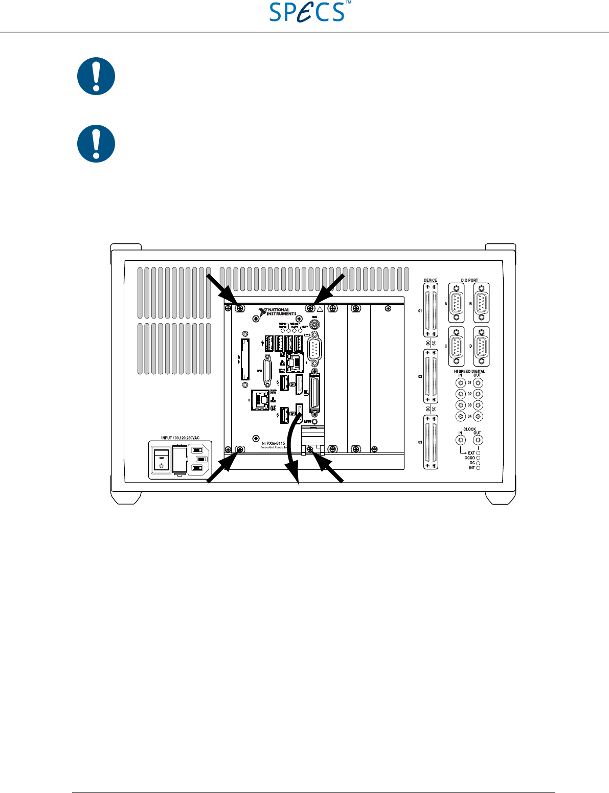
In order to replace the real-time unit, loosen the four screws marked by the arrows in the figure below. Then, push
down the the lever at the lower right, and pull-out the complete RT-unit from the RC5 enclosure.
Figure 29: Removal of the real-time-unit: After loosening the four screws marked by the arrows, the lever at the lower
right can be pushed down, and the RT-unit pulled out of the RC5 enclosure.
The new real-time unit is inserted by repeating the above procedure in the inverse order. Make sure to carefully align
the real-time unit with the guiding rails inside the RC5, or the unit cannot be inserted corretly into its slot.
RC5 Real-Time Controller Upgrades and replacements
•
42
FPGA card replacement
A replacement of the FPGA card is necessary only in the following cases:
• Malfunction of the FPGA card.
• Future software revisions require the change of the FPGA card. Users who might require a change of the card
will be contacted by SPECS.
Warning:
Only the FPGA card delivered inside the RC5, or FPGA cards which SPECS explicitly
recommends as a replacement are compatible with the Nanonis software. Other PXIe FPGA cards will
not work. Any unsolicited replacement of the FPGA card voids the RC5 warranty.
Caution:
Replacement of the FPGA card requires disconnecting a connector, which could be easily
damaged if not extracted with great care. Please send the RC5 back to SPECS for the replacement if
there is any doubt about how the modification should be done.
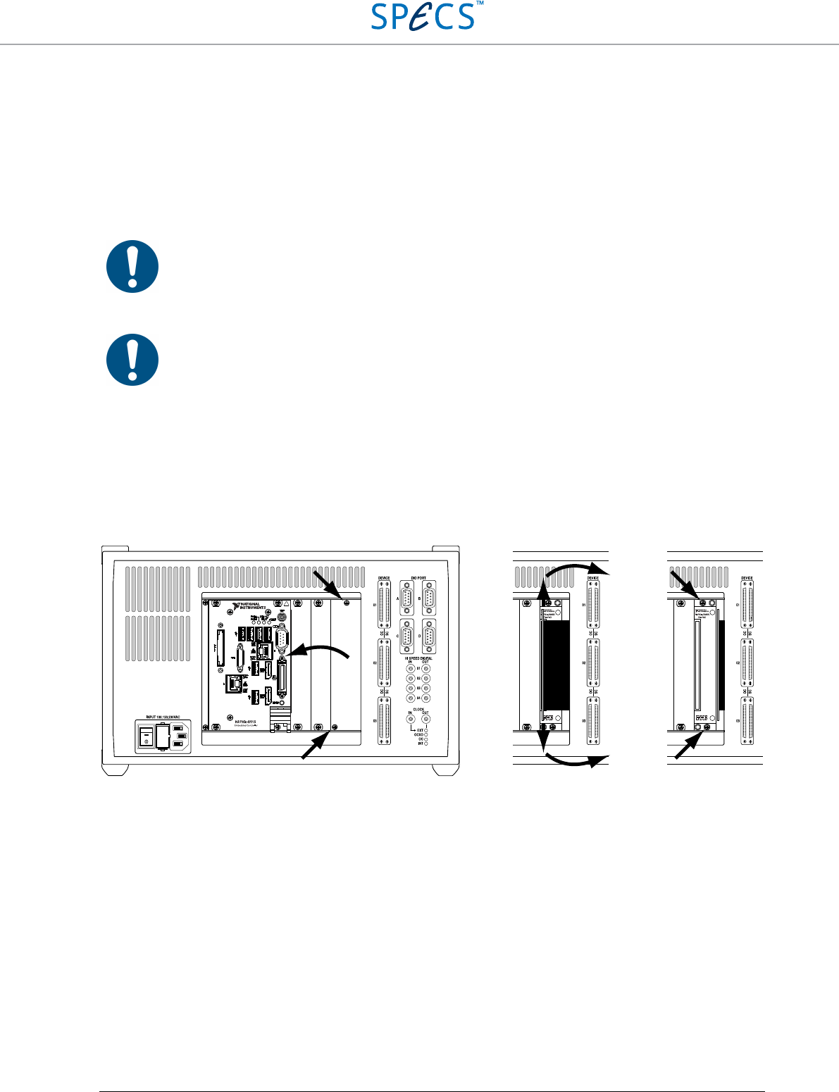
In order to replace the FPGA card, loosen the two screws marked by the arrows in the leftmost figure below. Then,
remove the metallic cover in order to reveal the connector to the FPGA card as shown in the center. Very carefully
extract the connector, making sure not to apply any force on the flexible flat-cable, and place it on the right of the
FPGA card slot, so that the card can be extracted. In order to extract the FPGA card, loosen the two screws marked
by arrows in the rightmost figure below, and pull the FPGA card out of the RC5 enclosure.
Figure 30: Removal of the FPGA card. Left: after loosening the two screws marked by the arrows, the metallic cover can
be removed. Center: The FPGA connector can be extracted by pulling on both the upper and lower edges of the green
printed circuit board, as marked by the arrows. Care should be taken not to pull on the flexible flat-cable at the right of
the connector. The connector can be placed at the right, in order to allow the FPGA card to be taken out. Right: The two
screws marked by the arrow need to be untightened, then the FPGA card can be removed by pulling on the screws, which
are anchored to the card.
The new FPGA card is inserted by repeating the above procedure in the inverse order. Make sure to carefully align
the FPGA card with the guiding rails inside the RC5, and make sure to insert the connector perpendicularly to the
rear panel, without applying any lateral forces.

RC5 Real-Time Controller Example: Nanonis SPM Control System, Tramea and OC4.5-S
•
43
Example: Nanonis SPM Control
System, Tramea and OC4.5-S
This chapter describes how the RC5 is connected to and used with a typical Nanonis SPM Control System or
Nanonis Tramea™ configuration, and how the host computer has to be configured. Please make sure that you have
read and understood the sections above before proceeding. All safety warnings are also valid for this section. For
more information about the other instruments shown in the following paragraphs, please refer to the corresponding
user manuals.
SPM Control System: Connections on the rear side of
the instruments
In a typical SPM controller configuration, the following instruments are connected to the RC5:
• Nanonis SC5 and OC4. Connected to the Device Connectors (7, 8).
• Nanonis HVA4, PMD4, PD5, all Nanonis adaptation kits, as well as third-party instruments e.g.
preamplifiers or piezo motor drivers. Connected to the DIO ports (9).
• Host PC. Connected to the Ethernet port (5).
• Additional instruments, clock source. Connected to the High Speed Digital Inputs and Outputs (10, 14), or the
clock ports (11, 13).
The following picture shows a Nanonis SPM control system with two SC5s, two OC4s, one HVA4, and one PMD4a.
Cables other than those connected or related to the RC5 have been omitted. This is a rather complex configuration.
The simplest configuration is the Nanonis SPM Base Package, which includes the RC5 and one SC5.
RC5 Real-Time Controller Example: Nanonis SPM Control System, Tramea and OC4.5-S
•
44
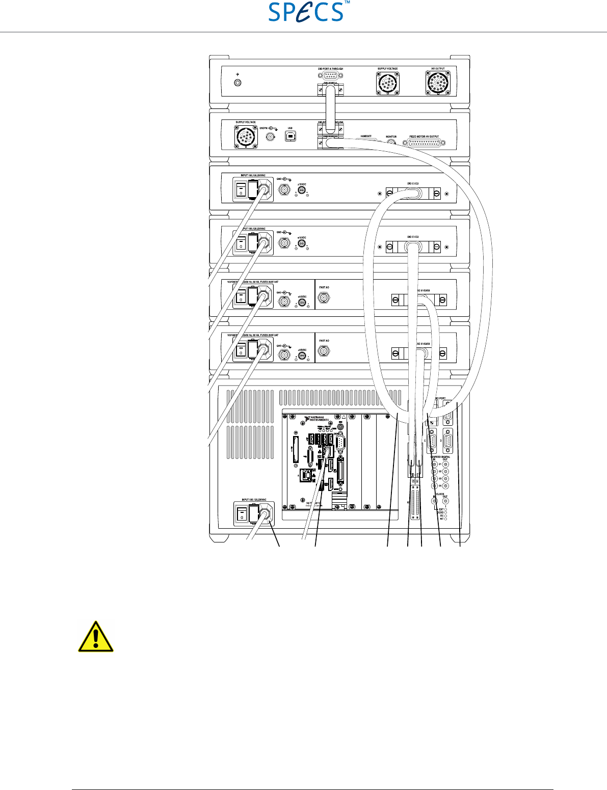
Figure 31: Rear panel of a Nanonis SPM system showing the connections used for the operation of the RC5. 1: Power
cord, 2: Ethernet cable, 3: DEVICE RDIO cable to the first OC4, 4: DEVICE RDIO cable to the second OC4, 5: DEVICE
RDIO cable to the second SC5, 6: DEVICE RDIO cable to the first SC5, 7: DIO cable to PMD4 and HVA4. Note: The
devices can be stacked in a different order, the picture above is an example.
Caution:
Nanonis systems including a RC5 and many other instruments can become very tall if all
instruments are stacked on top of each other. Make sure that the supporting table is stable enough, or
place the instruments in two different stacks (e.g. low voltage and high voltage instruments in different
stacks).
HVA4
PMD4a
OC4 #1
OC4 #2
SC5 #1
SC5 #2
1 2 3 4 5 6 7
RC5 Real-Time Controller Example: Nanonis SPM Control System, Tramea and OC4.5-S
•
45
Nanonis Tramea: Connections on the rear side of the
instruments
The following picture shows the configuration of a Nanonis Tramea™ with 8 I/Os, consisting of a RC5 and one
SC5. This configuration corresponds to the Nanonis SPM Base Package in terms of hardware.
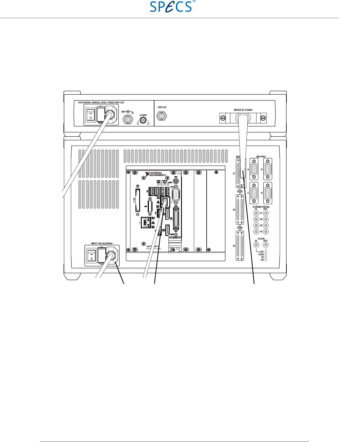
Figure 32: Rear panel of a Nanonis Tramea™ with single SC5. 1: Power cord, 2: Ethernet cable, 3: DEVICE RDIO cable
to SC5 connected to SC5 device connector 01.
1 2 3
RC5 Real-Time Controller Example: Nanonis SPM Control System, Tramea and OC4.5-S
•
46
OC4.5-S: Connections on the rear side of the
instruments
The following picture shows the configuration of a Nanonis OC4.5-S, consisting of a RC5 and one OC4.
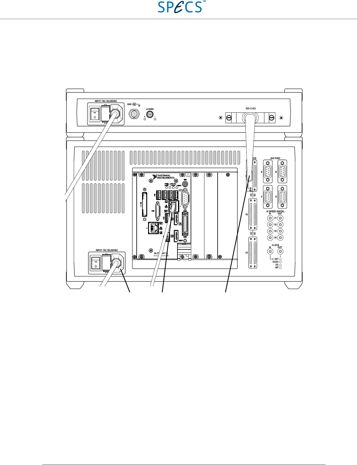
Figure 33: Rear panel of a Nanonis OC4.5-S. 1: Power cord, 2: Ethernet cable, 3: DEVICE RDIO cable to OC4 connected
to OC4 device connector 01.
1 2 3

RC5 Real-Time Controller Software Installation Guide
•
47
Software Installation Guide
Host computer requirements
The software running on the host computer is the control and visualization interface of a Nanonis system. The host
computer must therefore be able to handle and visualize all data transferred to/from the Nanonis system, translating
into the following basic requirements:
• There should be sufficient screen space for the software modules and for data visualization. The use of two
screens is highly recommended.
• CPU power should be sufficient for handling data transfers, processing data, and allowing a smooth user
interface operation.
• There should be sufficient disk space for saving acquired data.
All real-time data processing is done on the RC5 CPU, meaning that it is not necessary to use the fastest computer
hardware available. However, using obsolete hardware might result in poor user interface performance, TCP
timeouts, or data losses.
The requirements for the host PC hardware are listed in the table below.
Parameter
Minimum requirements Ideal configuration
CPU Intel Core i3-4XXX 3 GHz or equivalent
or better
Intel Core i5-4XXX 3 GHz or equivalent
or better
RAM 4 GB 8 GB or better
Hard Drive 500 GB 2 TB 7200 rpm
Graphics card Dual-head graphic card with digital
output (DVI or DisplayPort)
(no 3D acceleration required)
Dual-head graphic card with digital
output (DVI or DisplayPort)
(no 3D acceleration required)
Network adapter Gbit Ethernet Gbit Ethernet
Screens One screen:
21” 4:3, resolution 1600 × 1200
24”, 16:10, resolution 1920 × 1200
Two screens:
19” 5:4, resolution: 1280 × 1024
22” 16:10, resolution: 1680 × 1050
Two screens:
21” or 22” 4:3, resolution 1600 × 1200
24”, 16:10, resolution 1920 × 1200
Operating System Windows 7 32-bit or higher Windows 7 64-bit or higher
Note: Data streaming to disk into a database requires relatively high data transfer speeds. If this option is used, it is
recommended to use a dedicated hard drive for data storage (7200 rpm with large cache or SSD) and 16 GB RAM or
more.
Note: The number of software installations is not limited, meaning that the software can be installed in parallel on
different computers. However, only one software instance can connect to the RC5 at a time. If there are multiple
RC5 in use, the license file determines to which of the instruments the software will connect.
Note: The software runs under both 32-bit and 64-bit Windows operating systems. 64-bit operating systems are
recommended, since the software can allocate 2 GB of non-fragmented memory if sufficient RAM is installed (4 GB
or more).
RC5 Real-Time Controller Software Installation Guide
•
48
Note: A Laptop can be used for running the control software. However, due to limited screen resolution and physical
screen size only a limited number of software modules can be visible at the same time, and the workflow will be
considerably impaired.
Note: If an internet connection is necessary, two network adapters must be installed in the host computer, one for the
internet connection, and one for the connection to the RC5.
Host computer network configuration
This section describes how to configure the network adapter of the host computer. It is necessary to be logged on
with administrator rights, or at least to have a valid administrator password.
Configure the Network adapter of the host computer (the one connected to the RC5) using the following settings:
IP address: 192.168.236.X
Subnet mask: 255.255.255.0
With X being 1-99 and 111-255. Do not use IP addresses between 192.168.236.100 and 192.168.236.110, since
these IP addresses are reserved for the RC5. Do not use IP addresses already in use by other instruments, since this
will lead to an IP address conflict. In case the IP address of the RC5 needs to be changed (e.g. if the second network
adapter is in the same subnet), please contact SPECS. The following sections explain in detail the configuration for
each operating system. Please note that the appearance of dialog windows might be slightly different than shown in
the pictures below. The instructions refer to the Nanonis SPM Control System software, but the same procedures
apply also to the Nanonis Tramea™ software.
Windows XP
Note: Support and updates for Windows XP from Microsoft are not available anymore.
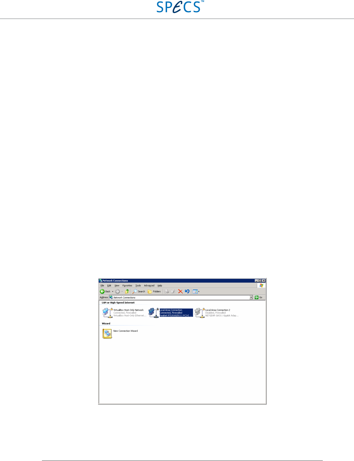
In the Start menu, open Settings, then Control Panel and choose Network Connections. Right-click on the network
adapter to which the RC5 is connected, and select Properties.
Select Internet Protocol (TCP/IP) and click on the Properties tab.
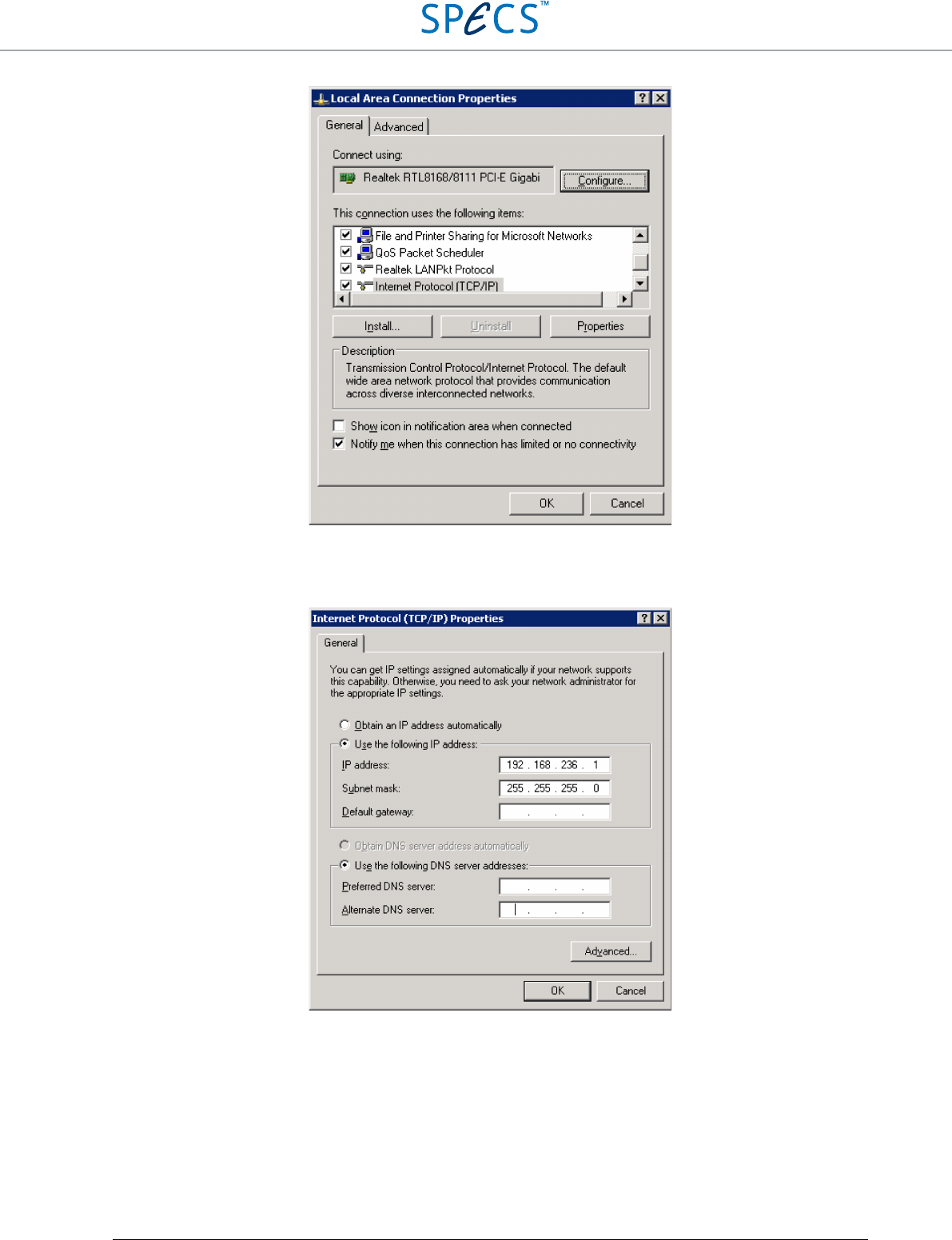
RC5 Real-Time Controller Software Installation Guide
•
49
In the configuration window, select Use the following IP address, and set the IP address to 192.168.236.X and the
subnet mask to 255.255.255.0, as shown below.
Click OK, then click OK again on the Local Area Network Properties window to close the window and apply the
new setting.
RC5 Real-Time Controller Software Installation Guide
•
50
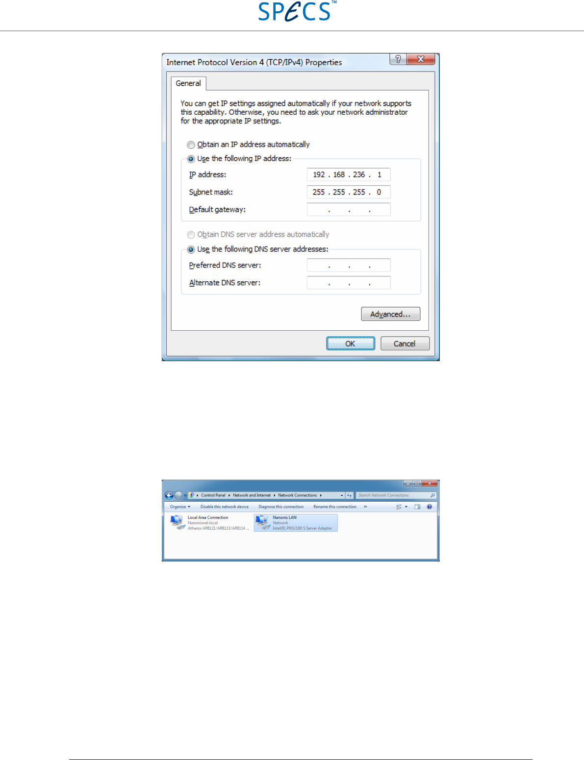
Windows Vista
In the Start menu, open Control Panel and choose Network and sharing center (in classic view) or View network
status and tasks (normal view). Then select Manage network connections. Right click on the network adapter to
which the RC5 is connected and select Properties.
Select Internet Protocol Version 4 (TCP/IPv4) and click on the Properties tab.
In the configuration window, select Use the following IP address, and set the IP address to 192.168.236.X and the
Subnet mask to 255.255.255.0, as shown below.
RC5 Real-Time Controller Software Installation Guide
•
51
Click OK, then click OK again on the Local Area Network Properties window to close the window and apply the
new setting.
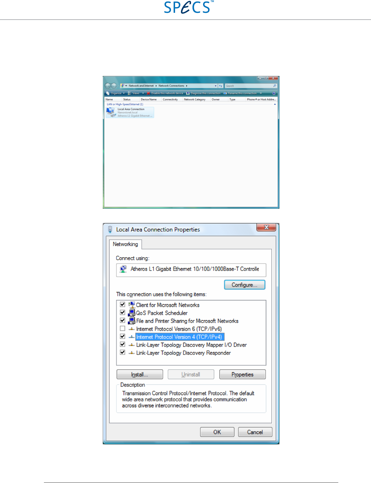
Windows 7 and later
Note: The procedure for Windows 7 is also valid for Windows 8 and Windows 10
In the Start menu, open Control Panel and choose Network and sharing center (in classic view) or View network
status and tasks (normal view). Then select Change adapter settings.
Right click on the network adapter to which the RC5 is connected (renamed to Nanonis LAN in this guide) and select
Properties.
Select Internet Protocol Version 4 (TCP/IPv4) and click on the Properties tab.
RC5 Real-Time Controller Software Installation Guide
•
52
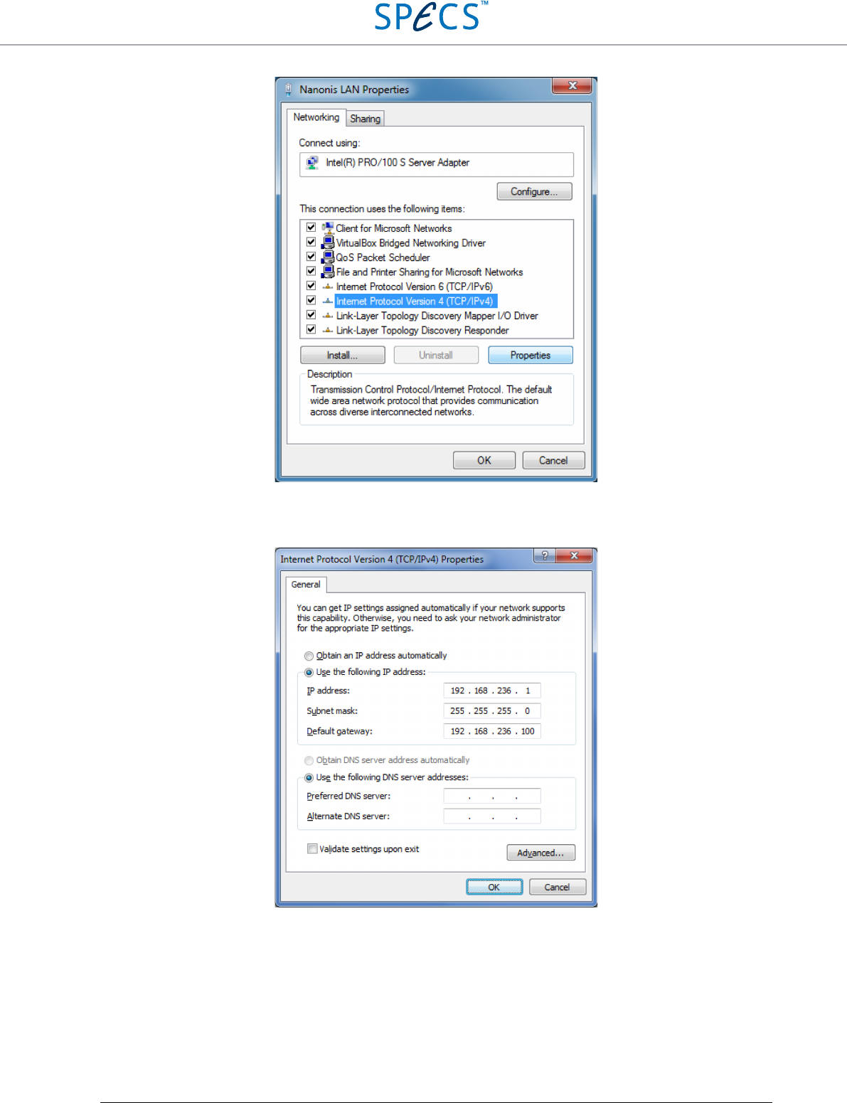
In the configuration window, select Use the following IP address, and set the IP address to 192.168.236.X, the
Subnet mask to 255.255.255.0, and the Default gateway to 192.168.236.100 (the IP address of the RC5), as shown
below.
Click OK, then click OK again on the Nanonis LAN Properties window to close the window and apply the new
setting.
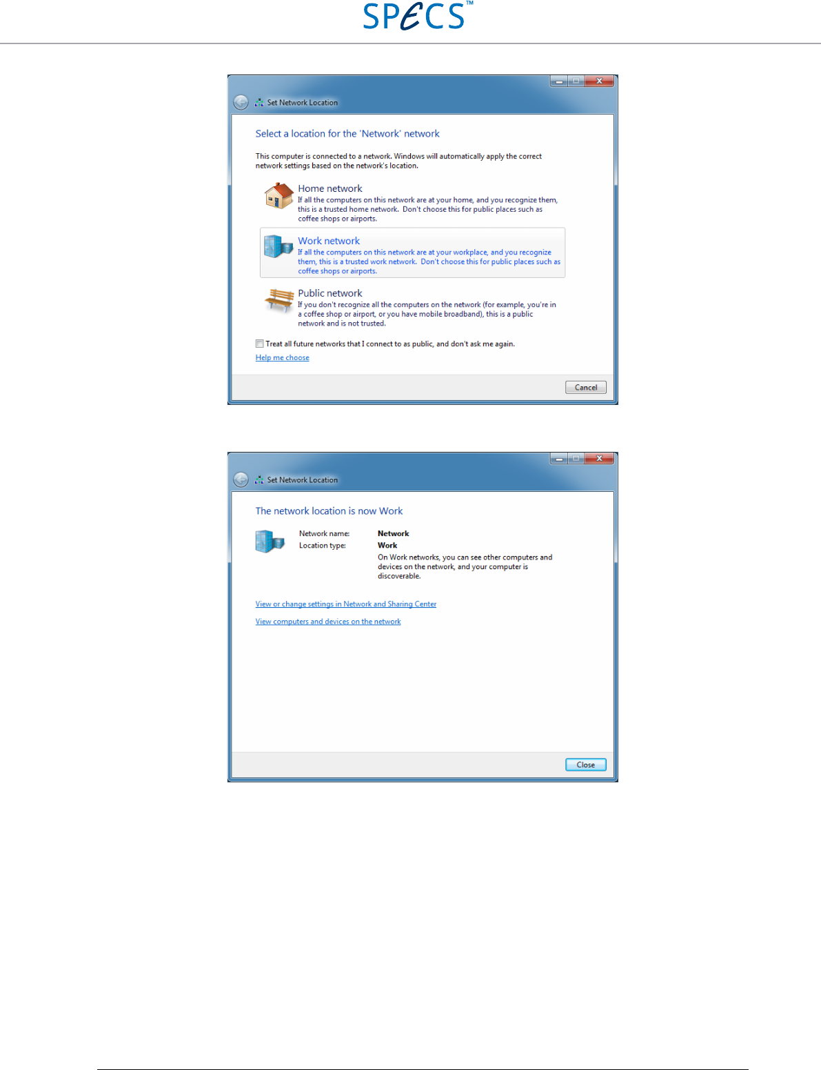
Make sure that the RC5 is switched on, and connect it to the host computer with a crossover Ethernet cable. Make
sure that it is connected to the correct network adapter! After connecting, the RC5 should be recognized, and the
following window will appear.
RC5 Real-Time Controller Software Installation Guide
•
53
Select Work network. Do not select Public network! The communication between RC5 and host PC might be
blocked if Public network is selected.
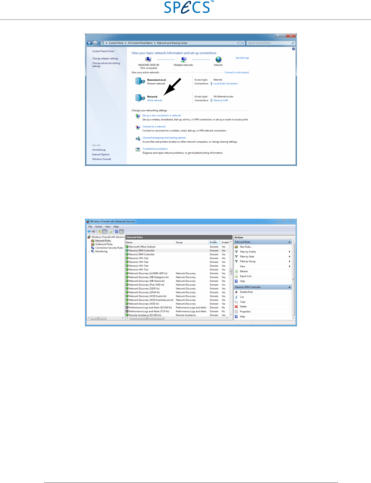
If you are not prompted to select the network location, it can be accessed from the Network and sharing center, as
shown below.
RC5 Real-Time Controller Software Installation Guide
•
54
Firewall configuration
In the Start menu, open Control Panel and choose Windows Firewall (in classic view) or System and Security and
then Windows Firewall (normal view). Then select Advanced settings, and select Inbound rules for the Nanonis SPM
controller.
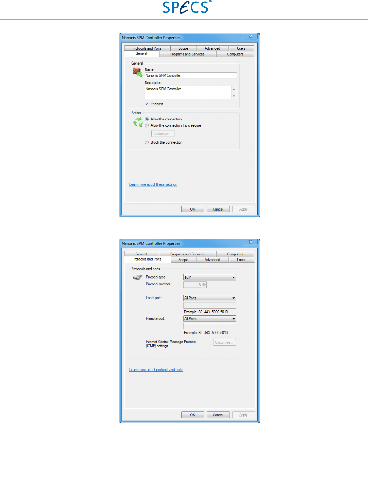
Double-click on both Nanonis SPM Controller items, and make sure that the connection is enabled and allowed for
both items, as shown below.
RC5 Real-Time Controller Software Installation Guide
•
55
Switch to the Protocol and Ports tab for both Nanonis SPM Controller items and make sure that All ports is selected
for both the TCP and UDP tab (TCP shown below).
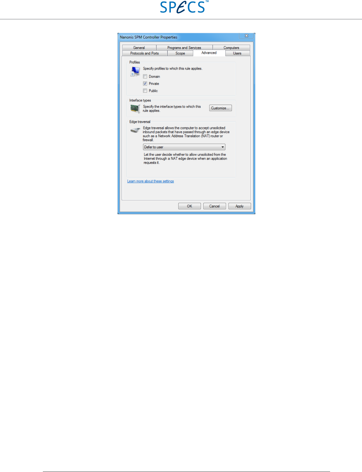
Switch to the Advanced tab, and verify that Private is checked.
RC5 Real-Time Controller Software Installation Guide
•
56
Note: As an alternative the firewall for the network adapter used by the Nanonis System can be disabled.
Nanonis software installation
Installation of the Nanonis software requires two files:
• Nanonis SPM Controller Installer V5 RXXXX or Nanonis Tramea Installer V5 RXXXX
• Nanonis license file
The Installer file has to be downloaded from the SPECS extranet website:
http://www.specs-zurich.com/en/extranetlogin.html
under the Software V5 SPM or Software V5 QT tab. The login credentials are provided by SPECS, and sent by email
after purchasing a Nanonis system.
The license file is also provided by SPECS. Make sure to have both files ready before starting the installation of the
Nanonis software.
Note: The license file determines which modules of the Nanonis software will be available once the software is
installed.
Note: The installer for Nanonis Tramea™ software found in the Software V5 QT tab does not contain any SPM
functionality. Therefore it is not possible to start the Nanonis Tramea™ software with a license file intended for a
Nanonis SPM Control System, or a Nanonis OC4.5-S. The installer for the Nanonis SPM Control System found in
the Software V5 SPM tab, on the other hand, contains both functionalities, meaning that it is possible to start the
Nanonis SPM Control System software with a Nanonis Tramea™ license file. Only quantum transport functionality
will be enabled in that case.
Note: The installation procedure described below is valid for both a first installation of the software, as well as for
an upgrade to a higher release.
Note: The appearance of dialog windows might be slightly different to those shown in the pictures below.
RC5 Real-Time Controller Software Installation Guide
•
57
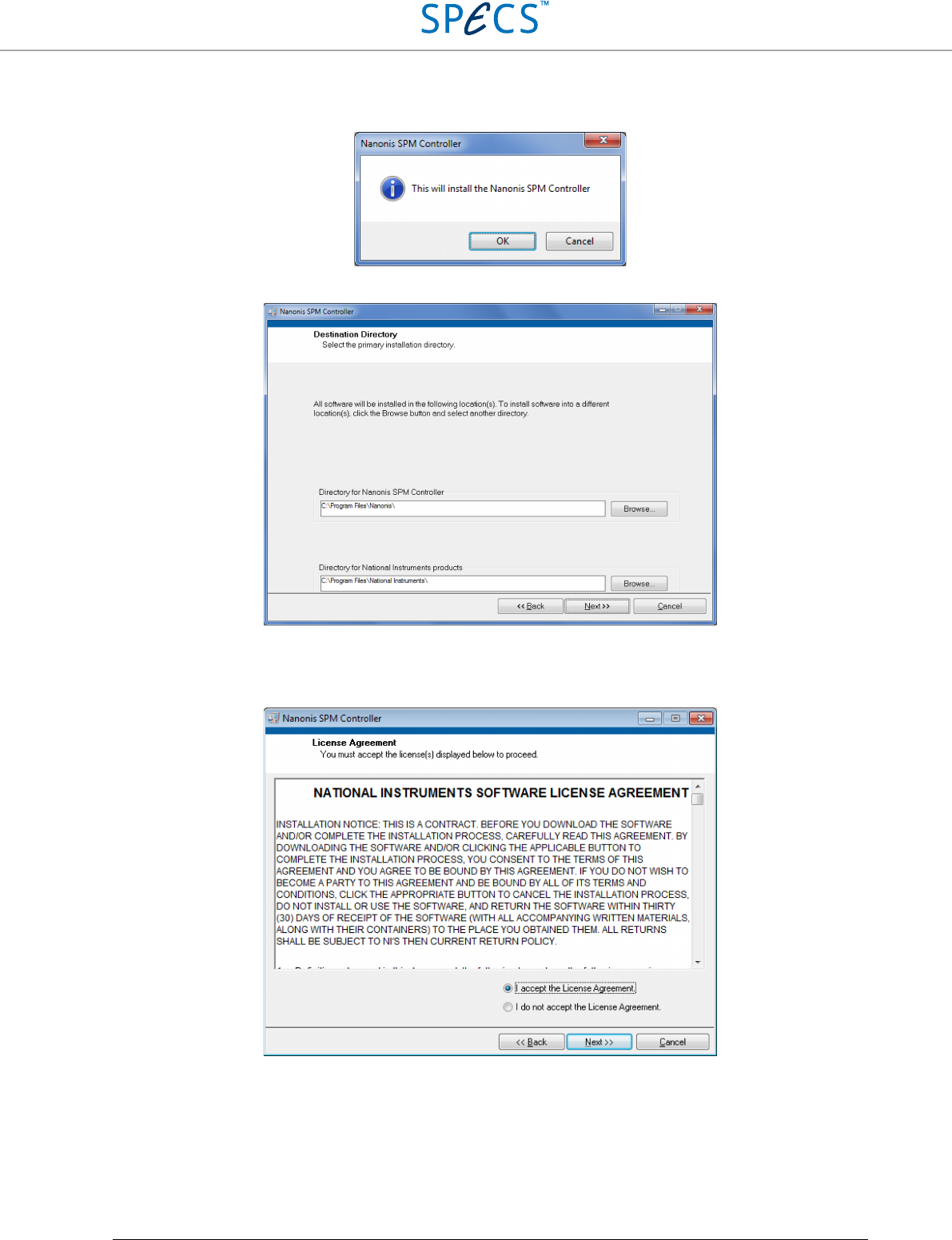
For starting the installation process, double-click on the Nanonis SPM Controller Installer V5 RXXXX or Nanonis
Tramea Installer V5 RXXXX.exe file. The following message will appear:
Press OK to start the installation. After the installer has initialized, the following dialog window will appear:
If different installation directories compared to the ones shown are preferred, indicate a different directory in the
corresponding field. Otherwise press Next >>.
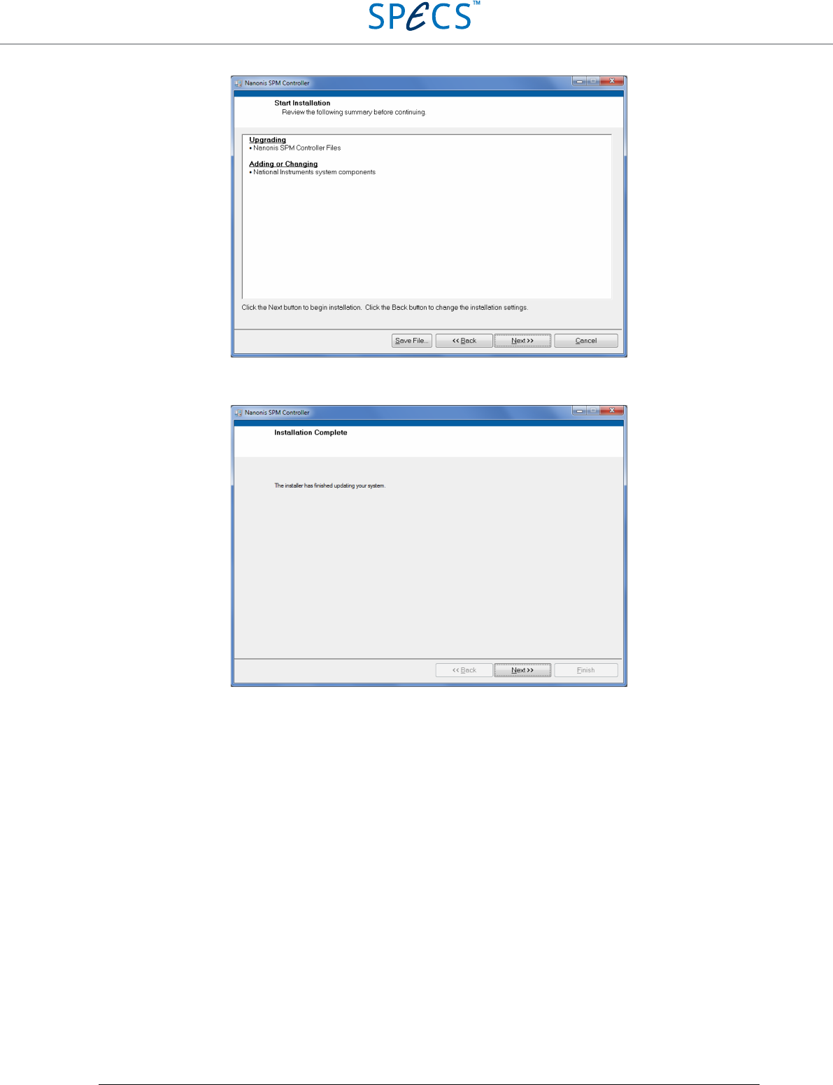
Read the license agreement and select I accept the License Agreement, then click Next >>. The following window
will appear. Depending on the installation type (first installation or upgrade), a different summary will be displayed.
The following picture is for an upgrade installation.
RC5 Real-Time Controller Software Installation Guide
•
58
Press Next >>, and the installation will start. Once the installation is finished, the following dialog window will
appear:
Press Next >> to finish the installation.
License files
Each RC5 is delivered with a license file. The license file is usually sent by email, together with the login credentials
to the extranet website http://www.specs-zurich.com/en/extranetlogin.html, and is required for the correct
functioning of the Nanonis hardware and software. The main functions of the license file are:
• Ensure that the hardware is configured properly, according to the system configuration
• Manage the software modules loaded when starting the Nanonis software
The license file is bound to the MAC address of the network adapter of the RC5, therefore each license file is
specific to a given RC5, and can’t be used with a different one. The license files are protected, meaning that by
changing entries, the license files become unusable.
Always keep the license file at a known location so it can be retrieved quickly. When contacting SPECS by email,
please always send the license file since this can contribute to speeding up the troubleshooting processes or facilitate
the addition of hardware and software modules.
Note that the license file needs to be changed if the real-time unit is replaced.
RC5 Real-Time Controller Software Installation Guide
•
59
First time startup
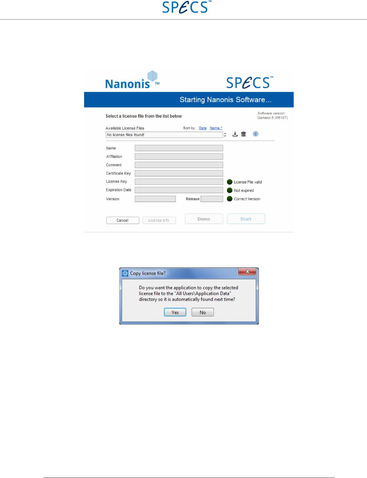
In order to start the Nanonis software, double-click on the Nanonis software icon, or select the Nanonis software
from the Start Menu. The following startup screen appears:
Click on the “No license file found!” drop-down list and select “Browse…”. A dialog window appears, asking to
specify the license file to be used and its location. Select the correct license file (see the next section for details) and
click “OK”. Another dialog will appear, asking if the file should be copied into a directory where the software can
find it automatically, see below.
It is recommended to click “Yes”, since the license file will then be automatically selected at the next start of the
software. Note that it is possible to copy multiple license files to the Application Data directory. The files can then
be accessed directly from the software startup screen shown above, by clicking on the “Available license files” drop-
down list.
After clicking “Yes” the license file appears in the “Available license files” drop-down list, as shown below.
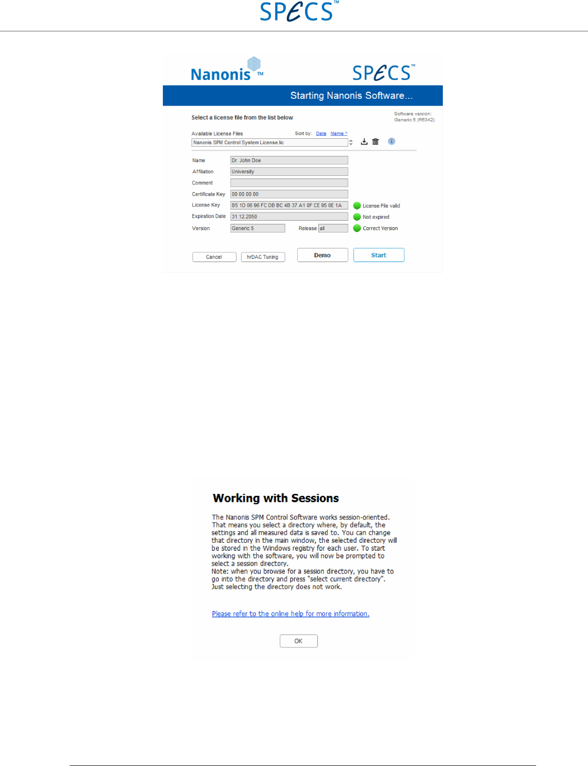
RC5 Real-Time Controller Software Installation Guide
•
60
All three indicators next to the License File, Expiration Date, and software version should be green to indicate no
errors occurred.
Note that the file can be saved to a different location by clicking on the save icon, or can be deleted from the list by
clicking on the trash icon. The Information icon provides information on the file when hovering the mouse over it.
In order to start the software for normal operation, click on the “Start” button.
Note: At this point a Windows Firewall warning might pop up, informing that the Firewall has blocked some
features of the program. Depending on the operating system, click on “Unblock” or “Allow access” in order to
proceed. This requires administrator privileges. If a different firewall is used, make sure that also that firewall does
not prevent the Nanonis software from running. Antivirus software might also interfere with the startup process of
the Nanonis software. Please make sure that all antivirus software is deactivated at the first start of the Nanonis
software. The software then needs to be configured in such a way, that the Nanonis software is not recognized as a
threat to the computer.
After clicking on the “Start” button, the software will load the modules specified by the license file. However, if the
real-time software is outdated, it might be necessary to update it by following the on-screen instructions explained in
the following section. After that, the following information appears:
Read the text, and if necessary click on “Refer to the online help for more information” in order to access the online
help (does not require an internet connection). Then click on “OK”. In the next dialog window, browse for a
directory to be used as a session directory, then click on “select current directory” at the bottom right of the window.
Note that it is not possible to select “cancel”.
The software is then ready to use.
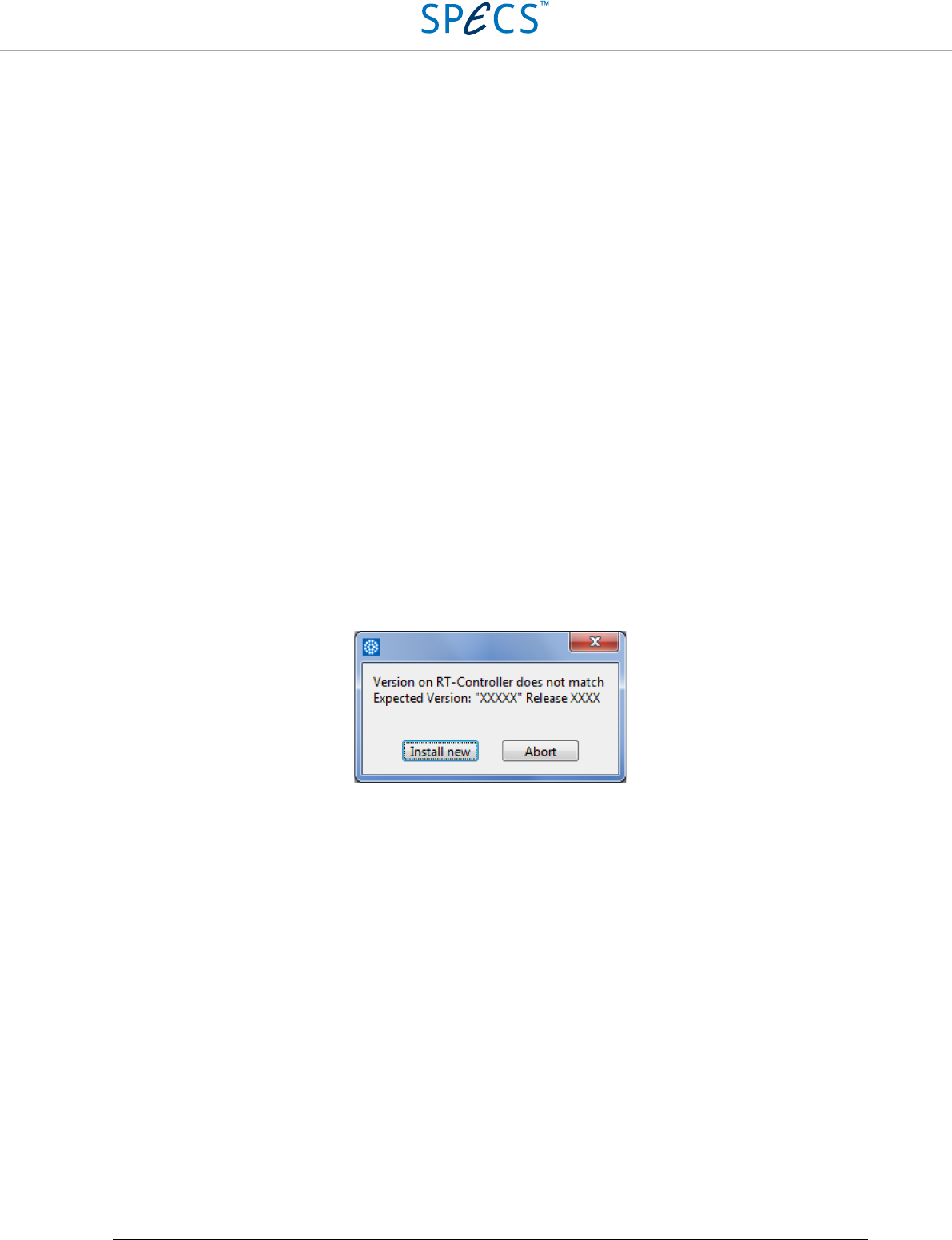
RC5 Real-Time Controller Software Installation Guide
•
61
Note: This procedure is necessary only during first time startup of the software or when using a new license file.
Otherwise the software automatically selects the last used session directory.
If the software should not start as described above, please refer to the Troubleshooting section.
There are three other options available in the startup screen: Cancel, hrDAC tuning, and Demo.
Cancel closes the startup screen without starting the software.
hrDAC tuning starts the hrDAC™ calibration procedure. Note that during calibration the analog outputs are
internally connected to the analog inputs. This means that output and input connectors will be electrically floating.
For more information about hrDAC™ and the calibration procedure, please refer to the SC5 user manual.
Demo starts the software in simulation mode. This means that the software will not connect to the hardware, but will
only start the host application. The simulation mode can be used for familiarization with the software without the
risk of damaging samples, or for testing and debugging measurement routines written in the Programming Interface.
Only the modules licensed in the license file will be loaded, and a license file is necessary for starting the software in
simulation mode. It is not necessary to have the hardware connected to the host computer.
Real-time software update
The Nanonis software running on the host computer requires a specific release of the real-time software installed on
the RC5. If the latter is older than the required release, a real-time software update is necessary. This is the case
when:
• The Nanonis software has been updated between testing of the RC5 at SPECS and delivery of the instrument
• A newer release of the Nanonis software has been downloaded and installed
If the update is necessary, a dialog window appears automatically after pressing the “Start” button in the startup
screen:
Press “Install new” in order to install an updated release of the real-time software. The following information
window is displayed:
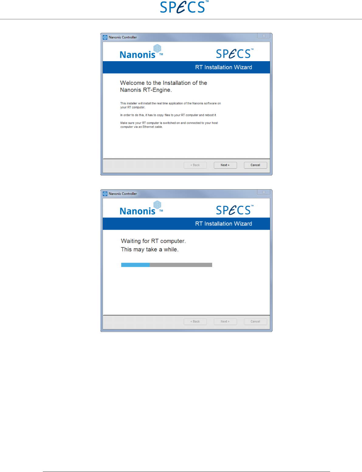
RC5 Real-Time Controller Software Installation Guide
•
62
Click “Next” in order to start the installation. The following two progress windows are displayed:
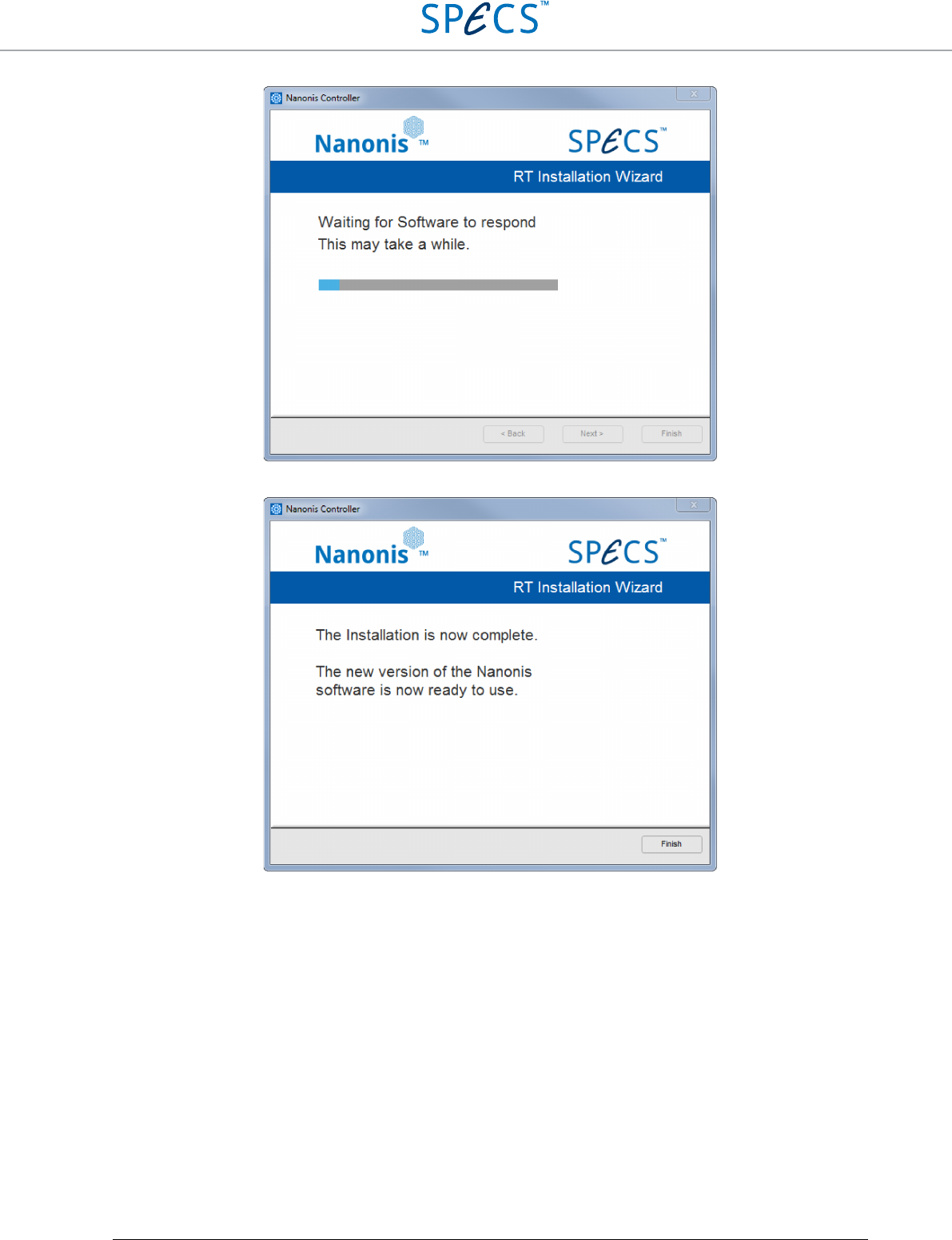
RC5 Real-Time Controller Software Installation Guide
•
63
The procedure takes approximately 2 minutes. Once the update process is completed, the following window appears:
Press “Finish” to end the real-time update. The startup screen appears again, and the software can now be started
normally. If the update process should stop, please refer to the Troubleshooting section.
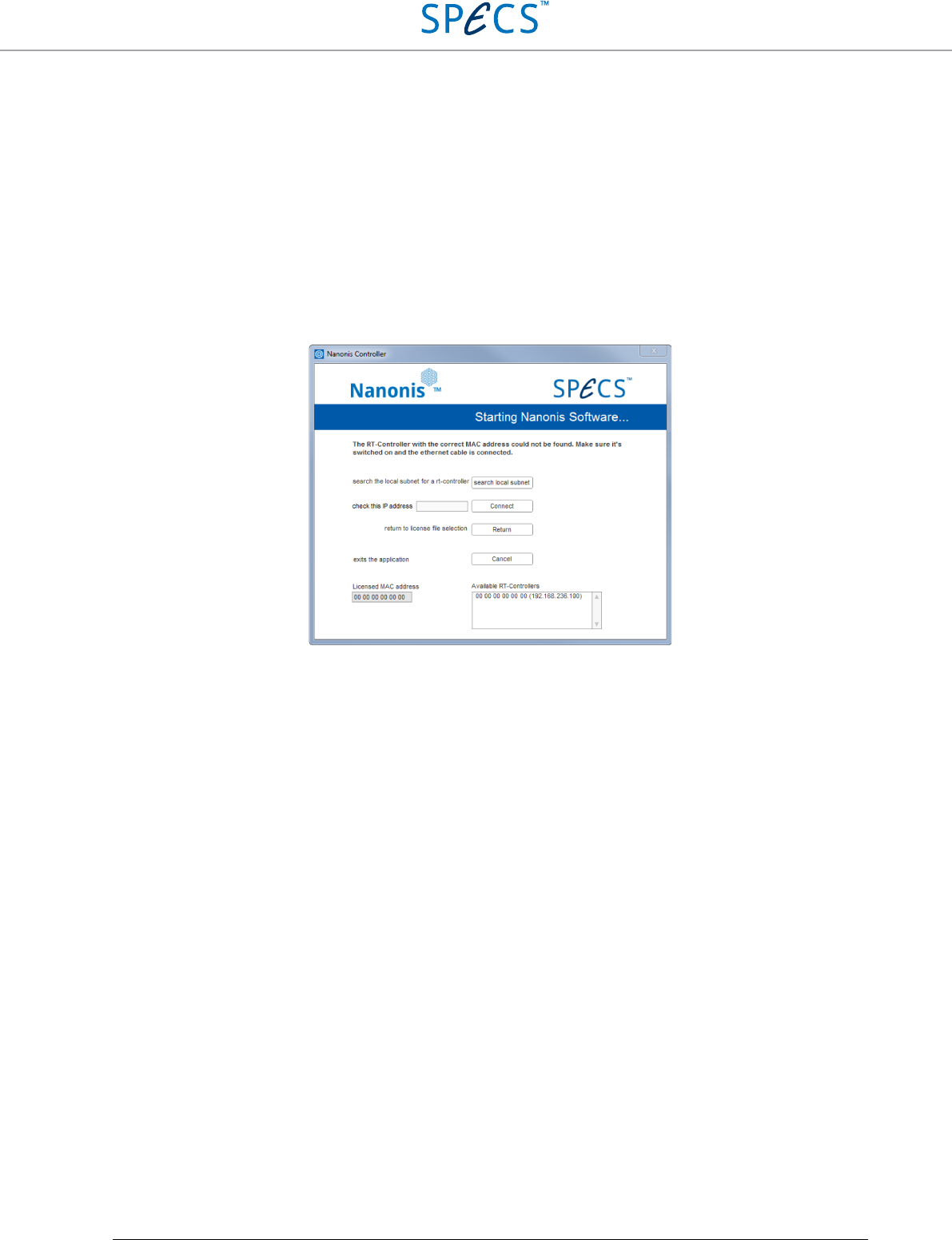
RC5 Real-Time Controller Troubleshooting
•
64
Troubleshooting
Network and software issues
SYMPTOM: The instrument turns on, but does not respond when starting the software. There is no
indication of faults. The following window appears after starting the software.
Figure 34: This error window appears if no communication between the RC5 and the host computer is possible.
REASON: The real-time controller has not finished booting.
SOLUTION: Wait about 20 seconds and try again. It takes about 30 seconds for the RC5 to finish its boot
process.
REASON: Missing Ethernet cable. In this case there is no entry in the “Available RT-Controllers” field.
SOLUTION: Make sure that an Ethernet cable is connected to both the correct Ethernet connector (5) of the
RC5, and the correctly configured Ethernet port of the host computer.
REASON: Wrong Ethernet cable. In this case there might be no entry in the “Available RT-Controllers” field.
SOLUTION: Make sure that the RC5 is connected to the host computer with a crossed Ethernet cable. A crossed
cable is not necessary if the RC5 is connected to the host computer over a switch, hub, or router.
REASON: The RC5 is connected to the host computer over a router with incorrect configuration. In this case
there is no entry in the “Available RT-Controllers” field.
SOLUTION: Make sure that the router is not acting as a DHCP server. The RC5 has a fixed IP address. Also
make sure that all devices connected to the router have IP addresses in the range 192.168.236.X,
with X being 1-99 or 111-255. The IP addresses from 192.168.236.100 to 192.168.236.110 should
not be used. Please contact SPECS if the IP address of the RC5 needs to be changed.
REASON: Firewall or antivirus software is blocking the communication between RC5 and host computer.
SOLUTION: Disable the Windows firewall, or any other active firewall. If the RC5 is connected directly to the
host computer, a firewall is not necessary. Disable any active antivirus software installed on the
host computer. If this solves the issue, enable the antivirus software, but make sure to configure it
so that the communication is not blocked. Note that system dialog windows requesting an
authorization for connecting to the RC5 or for a firewall exception might be displayed behind
another window. Please make sure that no authorization request is pending.
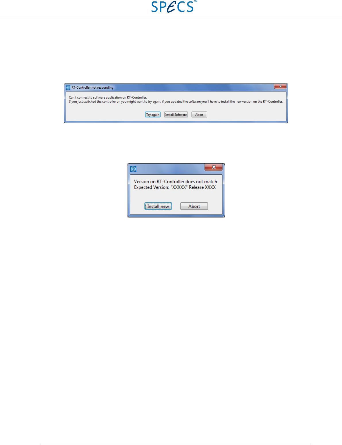
RC5 Real-Time Controller Troubleshooting
•
65
NOTE: Connection issues related to firewalls, or operating system TCP/IP issues can be solved by
entering the IP address of the RC5 (192.168.236.100, if it has not been previously changed
from the default value, otherwise the changed IP address) in the “check this IP address”
field, and then click “Connect”. If a connection is still not possible, please check all possible
reasons listed here.
REASON: No software or corrupted software installed on real-time controller. A dialog window appears,
informing that the RT-Controller did not respond.
Figure 35: Dialog window informing that no connection to the real-time software is possible.
SOLUTION: Click on “Install Software” to reinstall the real-time controller software. If the software has been
started less than 60 seconds before the RC5 has been powered on, please click on “Try again” first.
REASON: Outdated software installed on real-time controller. The following dialog window appears.
Figure 36: Dialog window informing that the software installed on the real-time controller needs to be updated.
SOLUTION: Please follow the instructions given in the Real-time software update section above.
REASON: Wrong license file. The MAC addresses in the field “Licensed MAC address” and “Available RT-
Controllers” (see above) are different.
SOLUTION: Make sure that the correct license file has been selected. The license files are bound to a specific
RC5, therefore license files for other RC5s will not work.
License file issues
SYMPTOM: The “License file valid” LED in the startup screen of the software is dark.
REASON: The license file has been tampered with, or has been generated incorrectly.
SOLUTION: Retrieve the original license file and try again. If this does not solve the issue, please contact
SPECS.
SYMPTOM: The “Not Expired” LED in the startup screen of the software is dark.
REASON: The license file has expired. This is the case for time-limited licenses.
SOLUTION: Use a license file with no time limitation. If not available, please contact SPECS.
SYMPTOM: The “Correct Version” LED in the startup screen of the software is dark.
REASON: The license file is intended for a different version of the software.
SOLUTION: Use the license file sent with the RC5. If the file cannot be found, please contact SPECS.
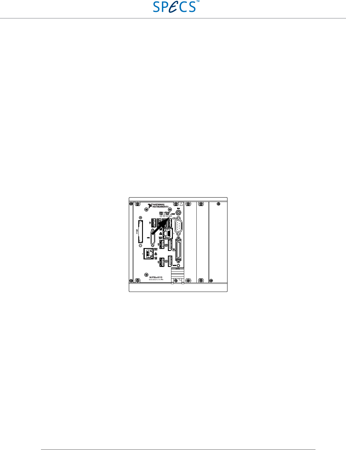
RC5 Real-Time Controller Troubleshooting
•
66
Instrument doesn’t power up correctly
SYMPTOM: The Power LED (1) does not light up.
REASON: Fuses blown.
SOLUTION: Disconnect the RC5 from the mains. Remove and check the fuses (3). If the fuses are blown,
replace them with fuses of the same rating (T2A), and try powering up the RC5. Should the fuses
blow again, please contact SPECS.
REASON: RC5 damaged.
SOLUTION: Disconnect the RC5 from the mains. Remove and check the fuses (3). If the fuses are intact, but the
unit is still not working, please contact SPECS.
SYMPTOM: The instrument turns on, but does not respond when starting the software. The “DRIVE”
LED (see picture below) at the back of the RT-unit does not light when powering the RC5.
REASON: Hard drive failure.
SOLUTION: A hard drive failure is very unlikely, but cannot be ruled out. In the case of a hard drive failure, the
“DRIVE” LED at the back of the RT-unit does not light up when powering the RC5 (see picture
below for the location of the LED). Please note that during normal operation the LED is always
off, therefore a hard drive failure can only be detected by observing the LED when powering the
RC5. If the hard drive has failed, please contact SPECS.
Figure 37: Location of the "DRIVE" LED indicating normal functioning of the hard drive during start-up of the RC5.
SYMPTOM: The instrument turns on, but does not respond when starting the software. There is no
indication of faults.
REASON: Corrupt file system, or network-related issue (see above).
SOLUTION: Connect a computer screen to the DisplayPort connector as explained in the Connection to
computer screen section. The status information shown on the screen should appear as shown in
the picture below. If the displayed information should be different, please take a picture of the
screen and contact SPECS.
RC5 Real-Time Controller Troubleshooting
•
67
Figure 38: Status screen of the RC5 during normal operation (NI PXIe-8840 version). CPU load might be different than
shown in the picture.
Figure 39: Status screen of the RC5 during normal operation (NI PXIe-8115 version). CPU load might be different than
shown in the picture.
Instrument is overheating
SYMPTOM: Response of the software user interface is sluggish. TCP communication breaks down or
error messages appear.
REASON: Ventilation is insufficient or the environment temperature is above specified operating conditions.
SOLUTION: Relocate the RC5 to an open space, if it was previously put in a rack or at a location with poor
ventilation. Make sure that the cooling-air exhaust at the back of the unit is not obstructed, and that
warm air is not redirected to the cooling-air intake at the bottom of the RC5. If the environment
temperature exceeds the specified operating conditions, turn on air conditioning, if available.
REASON: Air intake at the bottom of the RC5 is obstructed.
CPU# Total Load ISRs Timed Structures Other Threads
CPU 0: 82% 0% |−−−−−−−−| 75% |−−−−−−−−| 5% |−−−−−−−−|
Dev Op M Link Driver MAC Address IP Address /Mask Adapter Mode
* 1 Int U R i1000e XXXXXXXXXXXX 192.168.236.X /24 TCP/IP (static)
2 Int - i1000e XXXXXXXXXXXX - - Disabled
LabVIEW Real-Time Executive
Build Time: Month X YYYY hr:min:sec
(C) Copyright 2002-2016 National Instruments Corporation
MAX system identification name: RC5-XXXXX
LabVIEW Real-Time Single-Core Kernel
Initializing network...
System Web Server started
NI-RIO Server 15.1.0b4 started successfully.
Welcome to LabVIEW Real-Time 15.X.X
NI_VISA Server 15.0 started successfully.
Starting Nanonis RT Engine
MAC Address is XX:XX:XX:XX:XX:XX
loading FPGA...Version: Generic 5, RT Release: XXXX, RT Type: V5
is running now
connected to 192.168.236.Y
CPU# Total Load ISRs Timed Structures Other Threads
CPU 0: 82% 0% |−−−−−−−−|75% |−−−−−−−−|5% |−−−−−−−−|
Build Time: Month X YYYY hr:min:sec
(C) Copyright 2002-2012 National Instruments Corporation
MAX system identification name: RC5-XXX
LabVIEW Real-Time Single-Core Kernel
Initializing network...
Device 1 - MAC addr: XX:XX:XX:XX:XX:XX - 192.168.236.X /24 (primary - static)
Device 2 - MAC addr: XX:XX:XX:XX:XX:XX - disabled
System Web Server started
Startup Application: c:\ startup.rtexe
NI-RIO Server 4.1 started successfully.
NI_VISA Server 5.1 started successfully.
Welcome to LabVIEW Real-Time 11.X.X
Starting Nanonis RT Engine
MAC Address is XX:XX:XX:XX:XX:XX
loading FPGA...Version: Generic 4,RT Release: XXXX,RT Type: V45
is running now
connected to 192.168.236.Y
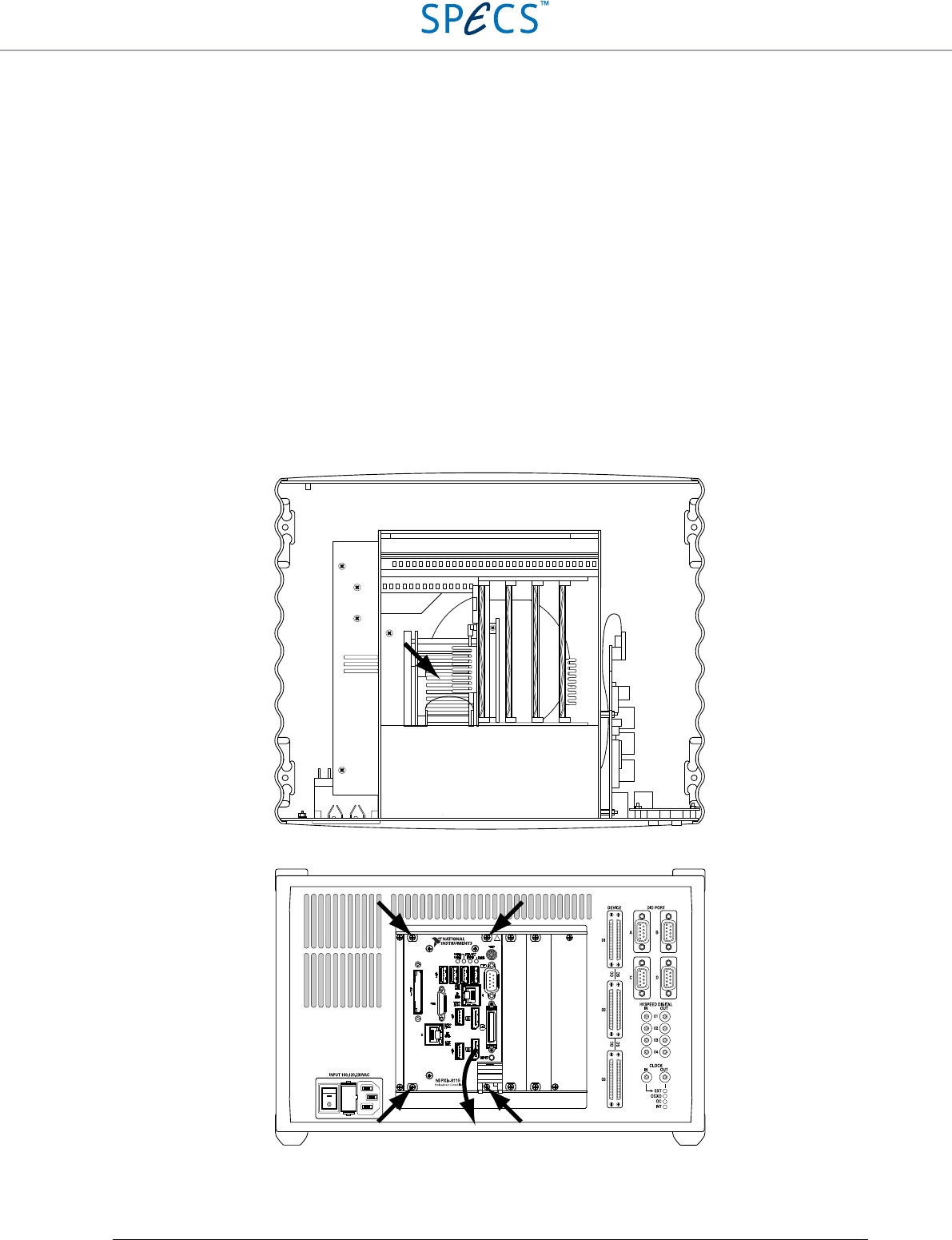
RC5 Real-Time Controller Troubleshooting
•
68
SOLUTION: Make sure that the air intake at the bottom of the unit is not covered by any object, and that there is
no object placed anywhere between the RC5 bottom panel and supporting table. Make sure that the
plastic feet supporting the instrument have not been removed.
REASON: Air intake at the bottom of the RC5 is obstructed by dust.
SOLUTION: Make sure that there is no dust covering the air intake at the bottom of the RC5. If there is dust on
the intake cover, remove the dust carefully with a dry cloth. Take measures to avoid that dust can
reach the air intake.
REASON: Cooling fins of the CPU heatsink are filled with dust. The top cover of the instrument needs to be
removed in order to verify this. Instructions for how to remove the cover are given in the Optional
OCXO clock mounting instructions section.
SOLUTION: Remove the instrument top cover as explained in the Optional OCXO clock mounting instructions
section. The location of the heatsink is shown in the figure below. Remove the dust with a plastic
tool. Do not use a cloth (electrostatic discharge!) or a vacuum cleaner for this purpose. Note that, if
dust has accumulated inside the CPU heatsink, it is highly probable that the air intake cover at the
bottom of the RC5 is also obstructed by dust. Clean that air intake as explained above, and take
measures to avoid that dust can reach the air intake.
Alternatively, remove the complete RT-unit as shown below, in order to facilitate the removal of
the dust.
Figure 40: Location of the RC5 CPU heatsink.
Figure 41: Removal of the RT-unit: After loosening the four screws marked by the arrows, the lever at the lower right can
be pushed down, and the RT-unit pulled out of the RC5 enclosure.

RC5 Real-Time Controller Troubleshooting
•
69
Clock issues
SYMPTOM: The instrument turns on, but does not respond when starting the software. An external clock
source is used and none of the Clock source LEDs (12) is on.
REASON: The clock signal generated by the external clock source does not have the correct frequency or
amplitude, its rise time is too slow, or the duty cycle is different than 50% by a too large amount.
The RC5 recognizes that a signal is applied to the CLOCK IN connector (12), but is not able to
lock on it.
SOLUTION: Make sure that the clock signal complies with the frequency, amplitude, rise time, and duty cycle
specifications given in the Clock ports specifications section above. If the source does not comply,
either use the internal clock or a different clock source. If the source does comply, but the RC5
does not lock on the clock signal, please switch off the RC5 and switch it on again. If the clock
signal is still not recognized, please contact SPECS.
SYMPTOM: A Nanonis OC4 is connected to the RC5, but the INT Clock source LED (12) is on instead of
the OC LED.
REASON: The OC4 is not connected to OC4 device connector 01 (7).
SOLUTION: Make sure that the OC4 is connected to the OC4 device connector 01 (7). Only the OC4 connected
to this connector can be used as a clock source for the RC5.
REASON: The OCXO inside the OC4 is disabled, or the OC4 is configured for the use of an external clock.
SOLUTION: Please contact SPECS for instructions on how to change the clock settings of the OC4.
SYMPTOM: An OCXO has been installed in the RC5, but the INT Clock source LED (12) is on instead of
the OCXO LED.
REASON: Incorrect frequency or voltage specifications of the OCXO.
SOLUTION: Please make sure that the OCXO has a frequency of 10 MHz and operates with a voltage of 3.3 V.
REASON: The OCXO has been mounted upside down.
SOLUTION: Please check that the OCXO has been mounted as described in the Optional OCXO clock mounting
instructions section. The sharp edge of the OCXO marked by a dot must show towards the rear
panel of the RC5.

RC5 Real-Time Controller Specifications
•
70
Specifications
General
Casing Wavetronics, stackable
Power Internal power supply
Power consumption Approx. 120 VA typical, 200 VA maximum
Power supply 100-230 V ±10%, 50/60 Hz ±5%, Fuses 250 V 2AT
Device connectors 6 (3×SC5, 3×OC4, maximum 4 devices)
DIO ports 4 ports, 8 bidirectional lines per port
High speed digital ports 4 inputs, 4 outputs
Clock I/O 1 input (autoselect), 1 output (active clock source)
Isolation between GND and PE 30 V peak, limited by ESD suppressors
EMC-Protection According to EN61326-1, Table-1, for cable length < 3 m
Operating temperature +5 ˚C to +35 ˚C
Dimensions 33.0 × 26.5 × 20.7 cm (W×D×H)
Weight Approx. 7.8 kg
DIO ports specifications
Lines set to input
Pull-up resistance 100 kΩ ±40%
Low input threshold < 0.8 V
High input threshold > 2.0 V
Maximum input voltage 5.5 V
Input capacitance < 10 pF
Input leakage current ±10 µA
Lines set to output
Nominal output level 3.3 V
High output voltage > 2.6 V (@ 8 mA load)
Low output voltage < 0.5 V (@ 8 mA load)
Maximum current per line 25 mA (max. 100 mA per connector)
Timing
Maximum sampling frequency 500 kHz

RC5 Real-Time Controller Specifications
•
71
High speed digital inputs specifications
Electrical parameters
Nominal high input level 3.3 V (5 V TTL tolerant)
Low input threshold < 0.8 V
High input threshold > 2 V
Maximum input voltage 6 V
Input capacitance < 10 pF
Timing
Maximum sampling frequency 200 MHz
High speed digital outputs specifications
Electrical parameters
Nominal output level 3.3 V
Output impedance ≅ 50 Ω
High output voltage > 2.0 V @ 33 mA load
Low output voltage < 0.4 V @ 33 mA load
Maximum current per line 33 mA
Timing
Maximum sampling frequency 200 MHz
Clock specifications
Internal Clock
Accuracy ±50 ppm
Maximum jitter 5 ps RMS phase jitter (10 Hz – 1 MHz range)
Optional OCXO
Accuracy ±4 ppm
Maximum jitter 5 ps RMS phase jitter (10 Hz – 1 kHz range)
Phase noise (bandwidth = 1 Hz) -70 dBc/Hz @ 1 Hz
-100 dBc/Hz @ 10 Hz
-130 dBc/Hz @ 100 Hz
-140 dBc/Hz @ 1 kHz
Short term stability < 5E-10 (0.1 s to 30 s), 5E-11 typical @ 1 s
Frequency stability over temperature ±0.075 ppm (0.15 ppm p-p) 0 to 60°C
Frequency stability over time First year: < ±0.7 ppm
After 10 Years: < ±4.0 ppm

RC5 Real-Time Controller Specifications
•
72
Electrical parameters (input)
Nominal high input level 3.3 V (5 V TTL tolerant)
Low input thresold < 0.8 V
High input thresold > 2 V
Maximum input voltage 6 V
Input capacitance < 10 pF
Timing requirements (input clock)
Required clock frequency 10 MHz
Signal rise and fall time requirement < 5 ns
Duty cycle range 40% - 60% minimum
Electrical parameters (output)
Nominal output level 3.3 V
Output impedance ≅50 Ω
High output voltage > 2.0 V @ 33 mA load
Low output voltage < 0.4 V @ 33 mA load
Maximum current 33 mA
Timing (output)
Clock frequency 10 MHz
Operating conditions
Environment The RC5 is designed for indoors dry laboratory use only
Ambient temperature 5 ˚C to 35 ˚C
in accordance with IEC-60068-2-1 and IEC-60068-2-2
Humidity 10-50% relative humidity, non-condensing
in accordance with IEC-60068-2-56
Maximum altitude 2000 m
Pollution degree 2 (indoor use only)
Installation category II
Mains supply voltage fluctuations Are not to exceed ±10% of nominal supply voltage
Storage and transportation conditions
Ambient temperature -20 ˚C to 70 ˚C
in accordance with IEC-60068-2-1 and IEC-60068-2-2
Humidity 5-95% relative humidity, non condensing
in accordance with IEC-60068-2-56
Pollution degree 2 (indoor use only)

RC5 Real-Time Controller Legal Information
•
73
Legal Information
Warranty
SPECS acknowledges a warranty period of 12 months (EU: 24 months) from the date of delivery (if not otherwise
stated) on parts and labour, excluding explicitly any software and consumables.
EXCEPT AS SPECIFIED HEREIN, SPECS MAKES NO WARRANTIES, EXPRESS OR IMPLIED, AND
SPECIFICALLY DISCLAIMS ANY WARRANTY OF MERCHANTABILITY OR FITNESS FOR A
PARTICULAR PURPOSE. CUSTOMER’S RIGHT TO RECOVER DAMAGES CAUSED BY FAULT OR
NEGLIGENCE ON THE PART OF SPECS SHALL BE LIMITED TO THE AMOUNT THERETOFORE PAID
BY THE CUSTOMER. SPECS WILL NOT BE LIABLE FOR DAMAGES RESULTING FROM LOSS OF DATA,
PROFITS, USE OF PRODUCTS, OR INCIDENTAL OR CONSEQUENTIAL DAMAGES, EVEN IF ADVISED
OF THE POSSIBILITY THEREOF.
This limitation of the liability of SPECS will apply regardless of the form of action, whether in contract or tort,
including negligence. Any action against SPECS must be brought within one year after the cause of action accrues.
SPECS shall not be liable for any delay in performance due to causes beyond its reasonable control. The warranty
provided herein does not cover damages, defects, malfunctions, or service failures caused by owner’s failure to
follow the SPECS installation, operation, or maintenance instructions; owner’s modification of the product; owner’s
abuse, misuse, or negligent acts; and power failure or surges, fire, flood, accident, actions of third parties, or other
events outside reasonable control.
Copyright
Under the copyright laws, this publication may not be reproduced or transmitted in any form, electronic or
mechanical, including photocopying, recording, storing in an information retrieval system, or translating, in whole or
in part, without the prior written consent of SPECS GmbH.
Trademarks
SPECS® is a registered trademark of SPECS Surface Nano Analysis GmbH. Nanonis® is a registered trademark of
SPECS Zurich GmbH. Product and company names mentioned herein are trademarks or trade names of their
respective owners.
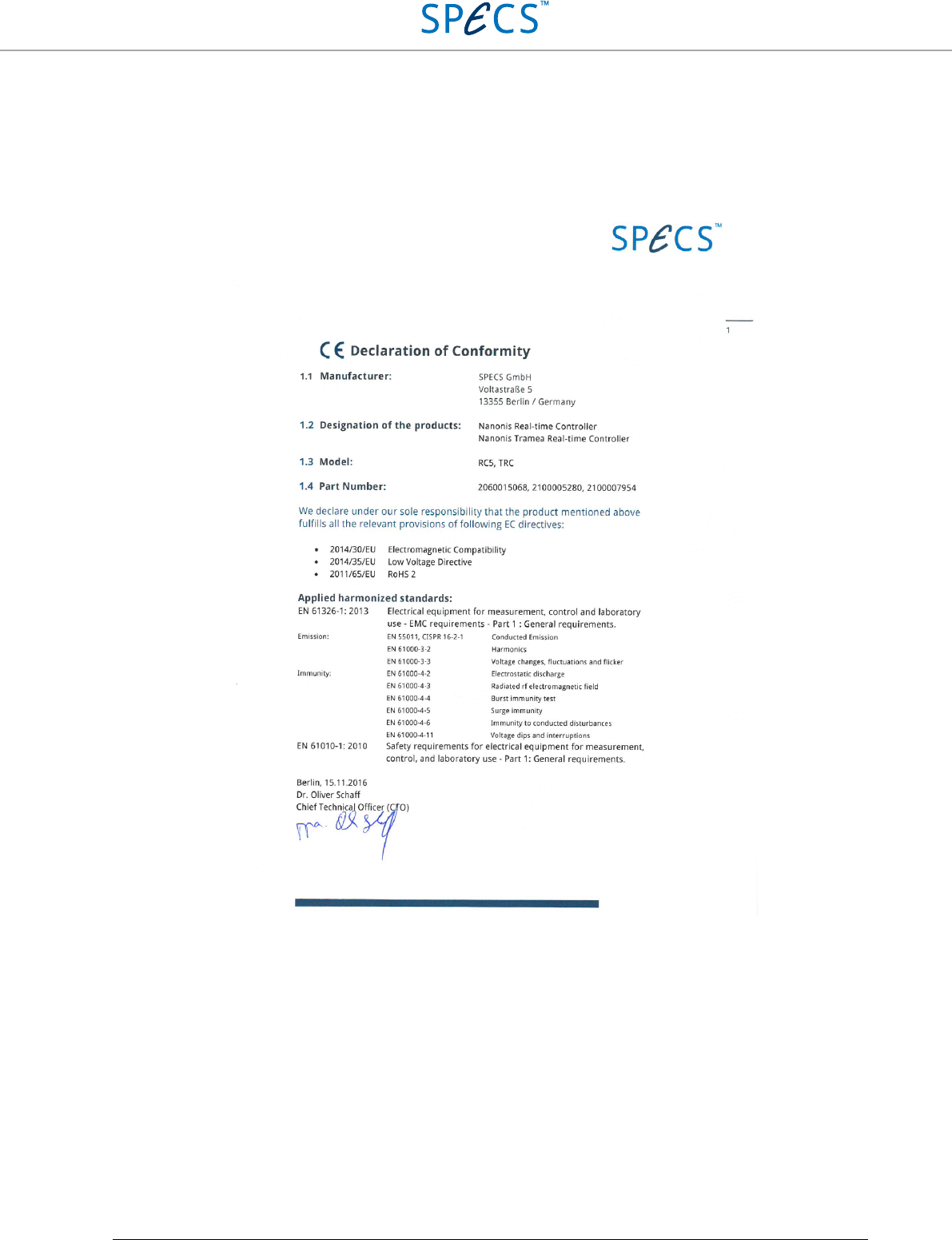
RC5 Real-Time Controller Legal Information
•
74
Declaration of Conformity

RC5 Real-Time Controller Legal Information
•
75

RC5 Real-Time Controller Index
•
77
Index
A
Atomic clock 32
C
CPU 47
D
DEVICE RDIO cable 12, 15, 19
disk space 47
E
Electrostatic discharge 34, 38
ethernet cable 51
extranet website 56
F
firewall 51, 59
firmware PCB 38
G
graphics card 47
H
hard drive 47
I
IP address 48, 50, 51
L
License file 25
login credentials 56, 58
N
Nanonis adaptation kits 25, 43
Nanonis HVA4 25
Nanonis OC4.5-S 46, 56
Nanonis PD5 25
Nanonis PMD4 25
Nanonis SC4 15
Nanonis SPM base package 43
Nanonis SPM Control System 56
Nanonis Tramea™ 45
network adapter 47, 48, 50, 51
O
OCXO 9, 32, 34
P
phase noise 9, 32
pulse counter 9
pulse generator 9
R
RAM memory 47
S
simulation mode 59
W
Wrist strap 34, 38

