RECO User Guide
User Manual: Pdf
Open the PDF directly: View PDF ![]() .
.
Page Count: 44

Table of Contents
Abstract
1. Introduction
1.1. Architecture Overview
1.2. Dynamic Linking Framework for RECO MME
1.2.1. RECO MME
1.2.2. Dynamic Linking Framework
2. Environment Setup
2.1. Core Network
2.1.1. Setup IP Architecture
2.1.1.1. Network Sockets and NICs
2.1.1.2. NICs and Virtual NICs
2.1.1.3. Virtual NICs and NICs in VMs
2.1.1.4. NICs in VMs and IPs
2.1.2. Auto Installation Script
2.1.2.1. MME
2.1.2.1.1. Download RECO and Other Tools
2.1.2.1.2. Run The Script
2.1.2.1.3. Run The MME
2.1.2.2. HSS
2.1.2.2.1. Download RECO and Other Tools
2.1.2.2.2. Run The Script
2.1.2.2.3. Run The HSS
2.1.2.3. S/P-GW
2.1.2.3.1. Download RECO and Other Tools
2.1.2.3.2. Run The Script
2.1.2.3.3. Run The S/P-GW
2.1.3. Manual Installation
2.1.3.1. MME
2.1.3.1.1. Update
2.1.3.1.2. Download RECO and Other Tools
2.1.3.1.3. Copy Configuration Files
2.1.3.1.4. File Settings
2.1.3.1.5. Install libgtpnl
2.1.3.1.6. Build The MME
2.1.3.1.7. Check The Certification
2.1.3.1.8. Install Packet python-tk
2.1.3.1.9. Run The MME
2.1.3.2. HSS
2.1.3.2.1. Update
2.1.3.2.2. Download RECO and Other Tools
2.1.3.2.3. Copy Configuration Files
2.1.3.2.4. File Settings
2.1.3.2.5. Database Import
2.1.3.2.6. Check The Certification
2.1.3.2.7. Build The HSS
2.1.3.2.8. Run The HSS
1

2.1.3.2.9. Phpmyadmin
2.1.3.3. S/P-GW
2.1.3.3.1. Update
2.1.3.3.2. Download RECO and Other Tools
2.1.3.3.3. Copy Configuration Files
2.1.3.3.4. File Settings
2.1.3.3.5. Build The SPGW
2.1.3.3.6. Run The SPGW
2.1.4 Example of IP Settings
2.1.4.1 Architecture Overview with IPs
2.1.4.2 IP Settings of HSS
2.1.4.2.1 Network Interface Settings
2.1.4.3 IP Settings of MME
2.1.4.3.1 Network Interface Settings
2.1.4.3.2 Configuration File Settings
2.1.4.4 IP Settings of S/P-GW
2.1.4.4.1 Network Interface Settings
2.1.4.4.2 Configuration File Settings
2.2. RAN
2.2.1. SIM Card
2.2.2. eNodeB
2.2.2.1. Commercial eNodeB - Wistron NeWeb OSQ4G-01E2
2.2.2.2. OAI eNodeB
2.2.2.2.1. USRP B210
2.2.2.2.1.1. USRP driver installation
2.2.2.2.1.2. Build OAI executables from source
2.2.2.2.1.3. Start the eNodeB with USRP B210
2.2.2.2.2. ExpressMimo2
2.2.2.2.2.1. ExpressMimo2 card setup
2.2.2.2.2.2. Building OAI executables from source
2.2.2.2.2.3. Start the eNodeB with ExpressMimo2
3. Conclusion
2

Abstract
It is envisioned in the future that not only smartphones will connect to cellular
networks, but also all kinds of different wearable devices, sensors, vehicles, home
appliances, VR headsets, and robots etc. However, since the characteristics of these
different devices differ largely, people argue that future 5G communication systems
should be designed to elastically accommodate these different scenarios. We propose
a reconfigurable core network called RECO that demonstrates how to implement
customized virtual network entities efficiently to suit for different types of users with
different characteristics. We then implement a reconfigurable MME called RECO
MME which verifies our proposed RECO architecture. Besides, we particularly
focuses on the dynamic linking framework used in our RECO MME.
1. Introduction
1.1. Architecture Overview
Reconfigurable Core (RECO)
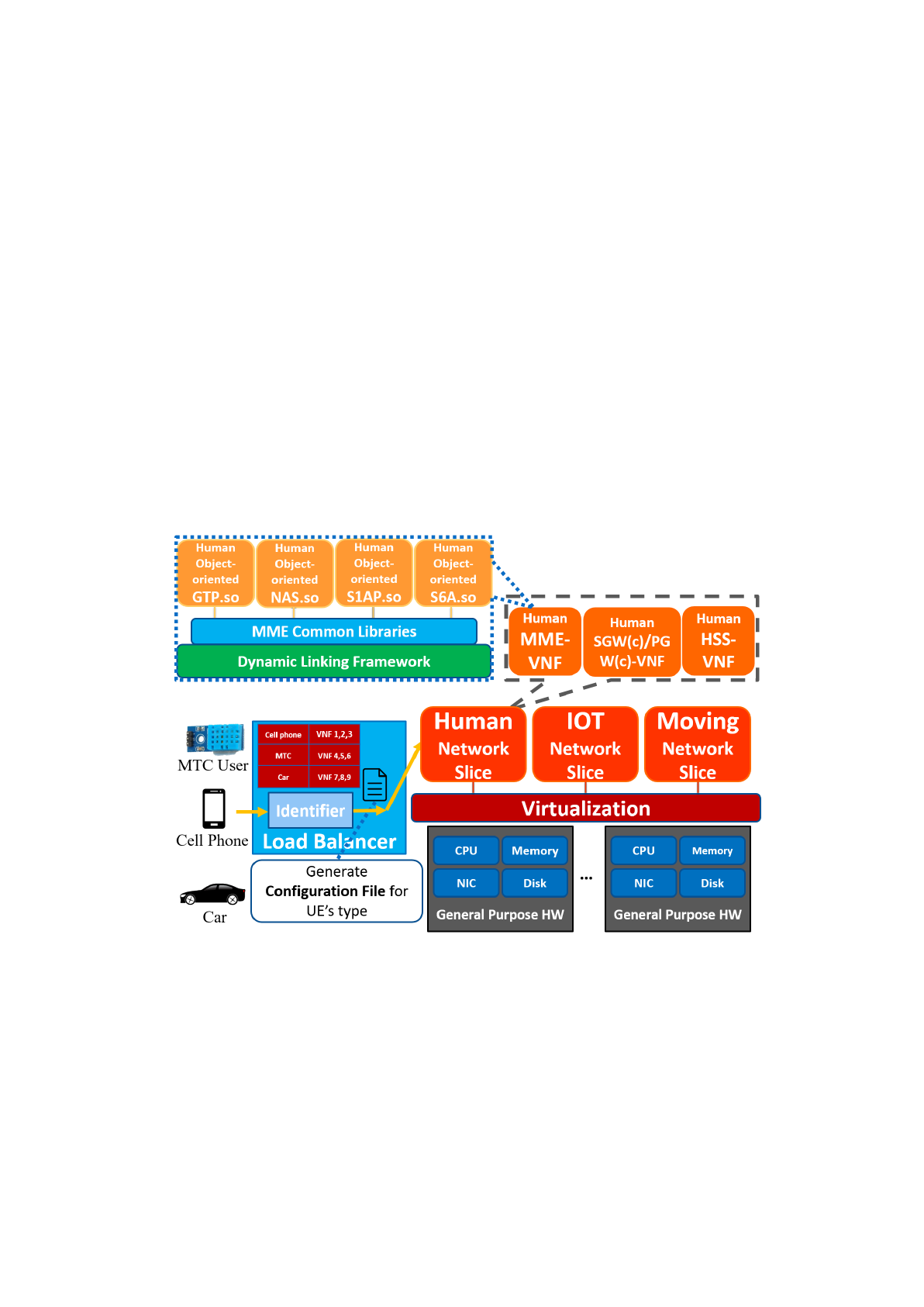
Figure 1 shows the architecture to build a flexible 5G core efficiently, and we
call it Reconfigurable Core (RECO). RECO has three key components:
Modularized virtual network entities (VNFs) designed by object-oriented
programming language:
Inside each virtual network entity or so-called virtual network function (VNF),
we split the code into modules and compile them into shared libraries (.so). We
then separate the modules into two groups: (i) common
modules
which are the
same among different types of users, and (ii) customized
modules
which differ
between different types of users. As shown in Figure 1, the MME common
libraries are the common modules and GTP.so, NAS.so, S1AP.so, and S6A.so are
the customized modules. The common modules can be implemented in any
programming language since they are only treated as libraries for customized
modules. Also, different types of customized VNFs share the same copy of
common modules. For example, the human MME VNF, the IOT MME VNF and
the vehicle MME VNF all use the same copy of common modules stored inside
memory and disk. On the other hand, customized modules differ between
different user types and should be implemented in object-oriented programming
languages. The major benefit of implementing customized modules like this is
that it can highly reuse already written code and enhance the process of creating a
new customized VNF. For example, suppose we have already implemented a
human MME VNF. To implement a high-mobility vehicle MME VNF, we can
directly inherit most of the classes within the human MME VNF and just override
particular mobility related member functions to build a high-mobility vehicle
MME VNF.
Dynamic linking framework which links customized modules during
run-time:
For each virtual network entity, there is a dynamic linking framework inside it.
The framework's major job is to link customized modules during run-time
according to the configuration file the identifier provides to form a customized
virtual network entity. The reason we choose to use dynamic linking is because it
highly increases the flexibility to create a new network slice. When needing to
3
form a new virtual network entity, all we need to do is to create new
corresponding customized modules for the particular type of user and the
dynamic linking framework will then compose everything together to form a new
network entity. This is somewhat similar to adding a plugin into the Chrome
browser to generate a customized browser.
An identifier which generates a configuration file for a particular network
slice:
When a new user first tries to attach to the core network, the identifier inside
the load balancer will try to identify the user’s type by parsing some “user type
tag” in the attach request packet. If this kind of user type has never attached to the
core network before, the identifier will generate a configuration
file
including
information about what customized modules it needs to form a particular network
slice and pass it to the dynamic linking framework. Then the dynamic linking
framework will compose these modules together and form customized virtual
network entities to serve the user. The identifier also records a hash
table
with
user types as the key and which VNFs are for that particular user type as the
value. In this way, subsequent packets of the same user type can go through the
hash table and find out which VNFs it should route its packets to.
Figure 1. Reconfigurable Core
1.2. Dynamic Linking Framework for RECO MME
We choose first to implement the MME entity so that we can verify that our
reconfigurable architecture is feasible and has the benefits we expect. In the
following subsections, we first give an overview of our reconfigurable virtual
MME (RECO MME) and show its architecture, then we focus on how the
dynamic linking framework is implemented in RECO MME.
4

1.2.1. RECO MME
We built a reconfigurable virtual MME to demonstrate the proposed
reconfigurable architecture. It is mainly modified from the MME inside
openair-cn, a simple core network developed by EURECOM. We followed the
code architecture of openair-cn but to separate the highly bundled mme
executable linked with many static libraries into a dynamic linking framework
linked with shared libraries. Figure 3 shows the architecture of our RECO MME.
It is composed of four main components listed below:
Common modules
We recompiled the static libraries used in openair-cn’s MME into two kinds of
shared libraries: (i) load-time dynamic linking shared libraries which share
among different types of users, and (ii) run-time dynamic linking shared libraries
which differ between different types of users. The load-time dynamic linking
shared libraries
are common modules which can be shared among different
customized MME. When the mme executable (the dynamic linking framework)
is executed and loaded into memory, these common modules will also be loaded
into memory. We purposely built these common modules into load-time dynamic
linking shared libraries
because when there are tons of different customized
MMEs (human MME, eHealth MME, high mobility MME etc.) serving different
types of users simultaneously on a machine, the storage and memory device will
only need to store one copy of these common modules. This highly reduces disk
space and memory usage.
In practice, we compiled the static libraries (.a) 3GPP_TYPES, BSTR,
CN_UTILS, HASHTABLE, SECU_CN, UDP_SERVER, SCTP_SERVER,
GTPV2C, ITTI inside openair-cn into load-time dynamic linking shared libraries
for our RECO MME to get the benefits of saving storage and memory space.
Customized Object-oriented modules
We refactored MME_APP, NAS, S1AP, S11_MME and S6A inside
openair-cn from C-based static libraries into C++ based run-time dynamic
linking shared libraries
. Building these customized modules into run-time
dynamic linking shared libraries
enables the MME to load and unload shared
libraries during run-time. By doing so, the dynamic linking framework can load
different customized modules according to a configuration file and form a
customized MME. For example, to form a high-security MME that serves
eHealth users, the dynamic linking framework would load customized
high-security modules according to the configuration file during run-time and
link them into a customized high-security MME used particularly by eHealth
users.
In addition, the source code inside these five modules (MME_APP, NAS,
S1AP, S11_MME and S6A) are all refactored by C++ object-oriented
programming language. This was done by composing related functions and
variables inside each module into classes. By doing so, when a programmer
wants to customize an already written module (base module) into a totally new
module (such as a high-security module or a high-mobility module), he/she does
not need to rewrite the whole module again. Instead, he/she can inherit classes
inside the base module and override particular member functions with new
functionalities into a new customized module. This highly reuses already written
5

code and increases the development process.
Pseudo Identifier
Currently, we simply implemented a checkbox list shown in Figure 3. The
checkbox list enables the programmer to manually choose particular modules for
a type of user and then generate the corresponding configuration file and pass it
to the dynamic linking framework.
The configuration file generated by the pseudo identifier is shown in Figure 2.
We can see that for a human user, we should choose MME_APP, NAS,
S11_MME , S1AP and S6A as the customized modules to be loaded by the
dynamic linking framework. And for a high-mobility user such as a user taking
the high-speed rail, we should choose high-mobility modules HMB_MME_APP,
HMB_NAS and HMB_S11_MME with customized high mobility classes
implemented inside these modules and S1AP and S6A which are the same
modules as the human users since these modules do not differ from a human
user. As for an eHealth user which requires special high-security authentication
methods, we should choose high-security modules HS_NAS and HS_S6A which
are implemented with new security algorithms and the other three modules the
same as a human user.
Figure 2. Configuration file for RECO MME
Dynamic linking framework
The dynamic linking framework is used for linking customized modules at
run-time according to the configuration file the pseudo identifier provides to
form a customized MME. Its main functionalities include provide an interface
for customized modules, parse the configuration file, load and initialize
corresponding modules according to the configuration file, and help resolve
dependency relationships among customized modules. We will describe each of
these functionalities clearly in the next subsection.
6
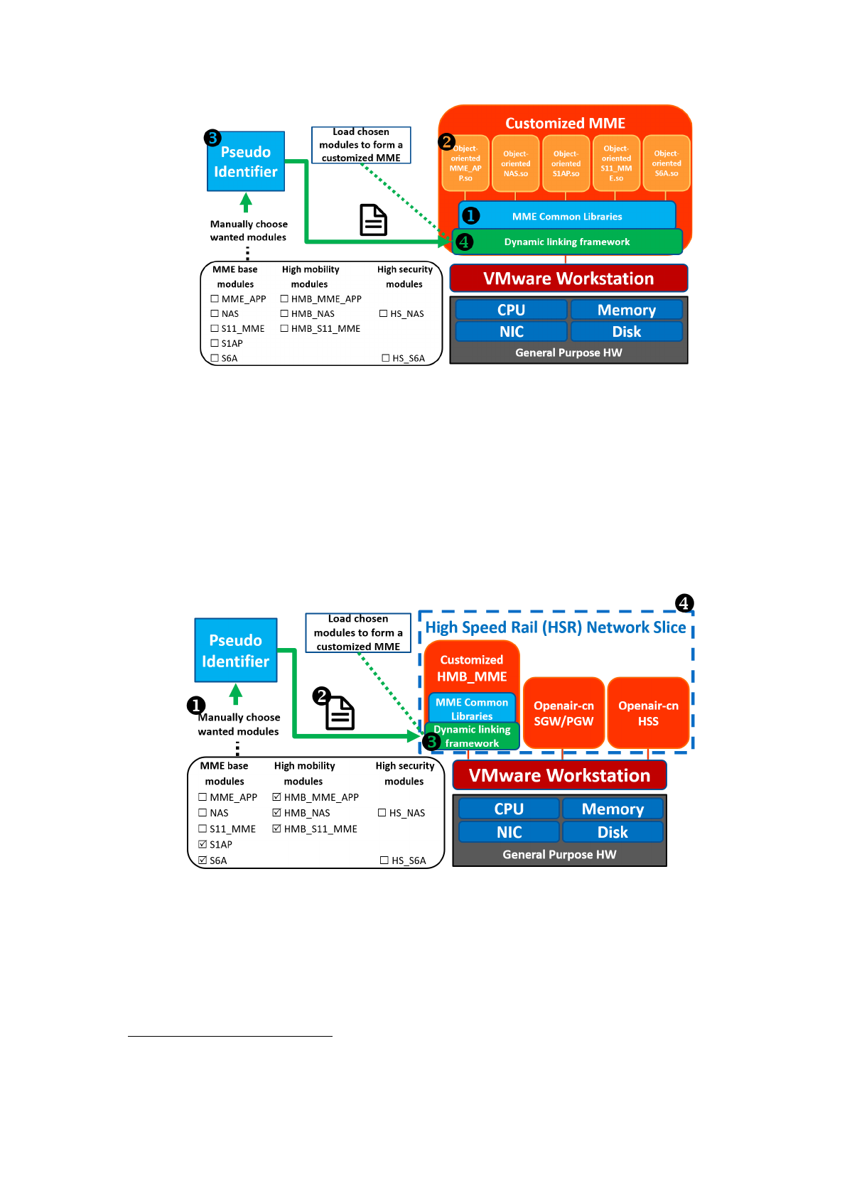
Figure 3. RECO MME Architecture
Figure 4 illustrates an example to form a high-speed rail (HSR) high-mobility
MME inside our RECO MME. (1) We manually choose the high mobility
modules HMB_MME_APP, HMB_NAS and HMB_S11_MME and base
1
modules S1AP and S6A. (2) The pseudo identifier will generate a corresponding
configuration file for the dynamic linking framework. (3) The framework will
load and initialize the corresponding modules to form a customized MME for
HSR. (4) The MME for HSR along with other core network entities form a HSR
network slice.
Figure 4. High mobility MME example
1.2.2. Dynamic Linking Framework
In this subsection, we describe how the dynamic linking framework is
implemented in our RECO MME. The framework has four main functionalities,
(1) provide an interface for customized modules (2) parse the configuration file (3)
load and initialize corresponding modules according to the configuration file, and
1Note that we did not modify the source code for mobility related modules. We just renamed these
modules’ names to HMB_MME_APP, HMB_NAS and HMB_S11_MME to demonstrate our
reconfigurable concept. The same is for high security modules.
7
(4) help resolve dependency relationships among customized modules.
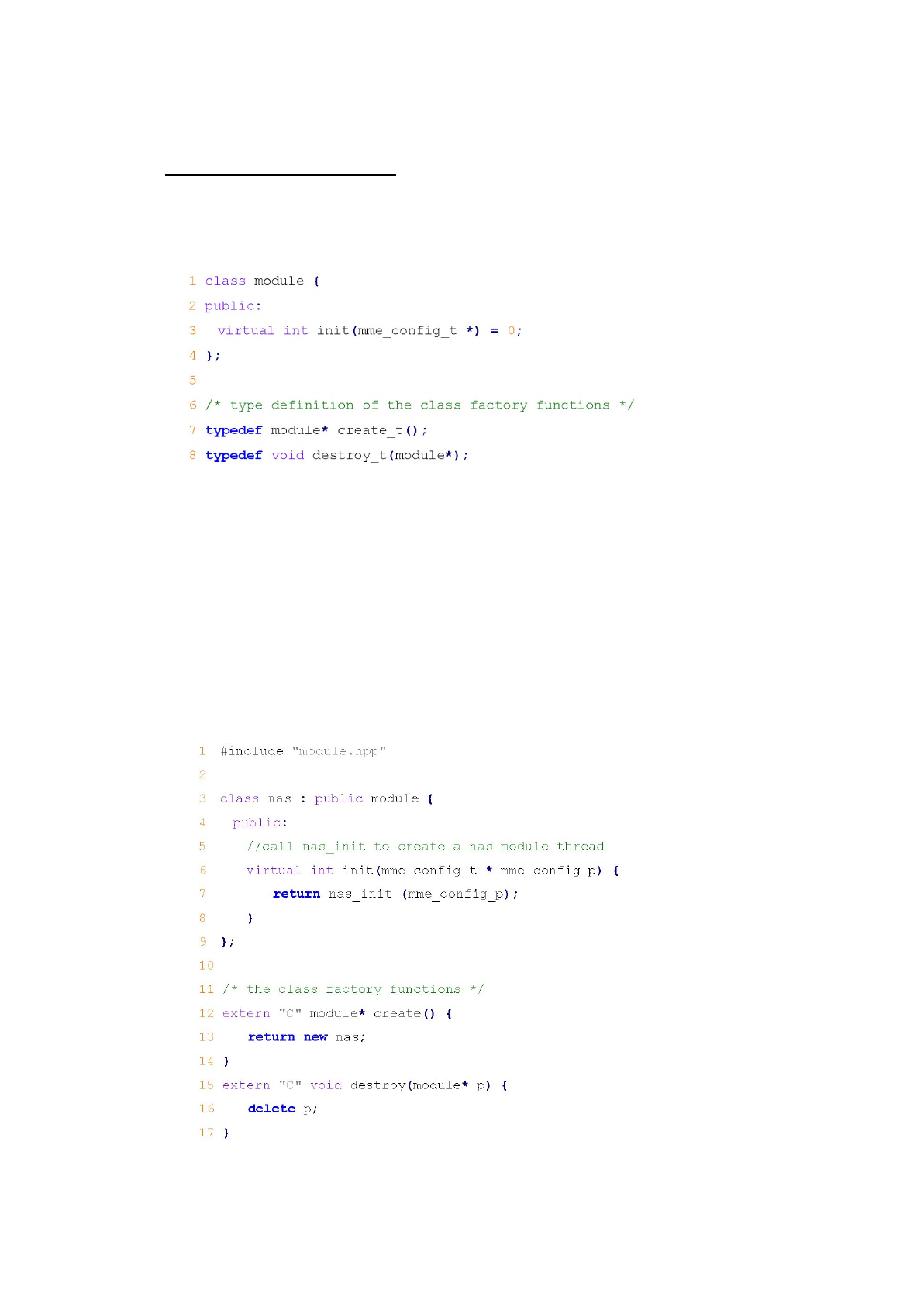
Module-framework interface
First, we provide an interface class named module
inside the dynamic linking
framework shown in Figure 5. This interface class includes a pure virtual function
named init
which forces every class that inherits module
to implement its own
initialization function.
Figure 5. Interface class “module” in the dynamic linking framework
Next, in every customized module, we implement a class named after its
module name and inherits the “module” interface class. Besides, we create two
class
factory
functions
which helps the module to create/destroy an instance of its
own. For example, Figure 6 shows the implementation of a class named nas
inside
the NAS.so module. We can see that class nas
inherits interface module
and
implements the init
virtual function. In addition, it implements two class factory
functions named create
and destroy
. Function create
helps create a nas
instance,
and function destroy
frees the created nas
instance. The dynamic linking
framework will use dlsym
to access the symbol address of create
and destroy
and
use these addresses to create or destroy the nas
instance.
Figure 6. nas.cpp
8

Parse configuration file
The dynamic linking framework is also responsible for parsing the
configuration file for the MME. The configuration file includes a module list
which lists the customized modules that the framework should load and link
during run-time as listed in Figure 2. Line 10 in Figure 7 shows the function called
to parse the configuration file. After parsing the configuration file, the framework
will store the list of customized modules in a global variable named mod_list
shown in line 5 in Figure 7. This variable will be used later for loading and
initializing customized modules.
Load and initialize customized modules
We can see in line 18 ~ line 34 in Figure 7 that how the dynamic linking
framework loads and initializes customized modules. It uses a for
loop to iterate
through the mod_list.
Moreover, for every customized module, the framework
uses dlopen
to load the customized modules into memory and then uses dlsym
to
access the symbol address of the class factory function create
and calls it to create
an instance of that module. Later in line 32, it calls the init
function of every
module to initialize that module.
Resolve dependency relationships among customized modules
Note that in line 20 in Figure 7, we set the RTLD_GLOBAL
flag in dlopen
.
This flag tells the dynamic linker to merge the symbol table of each module into a
global symbol table which enables subsequently loaded shared libraries to access
symbols defined in previously loaded shared libraries. In other words, by setting
RTLD_GLOBAL,
customized modules can access symbols defined in other
modules easily as if they were defined in their own module.
9

Figure 7. “main” function for the dynamic linking framework
10
2. Environment Setup
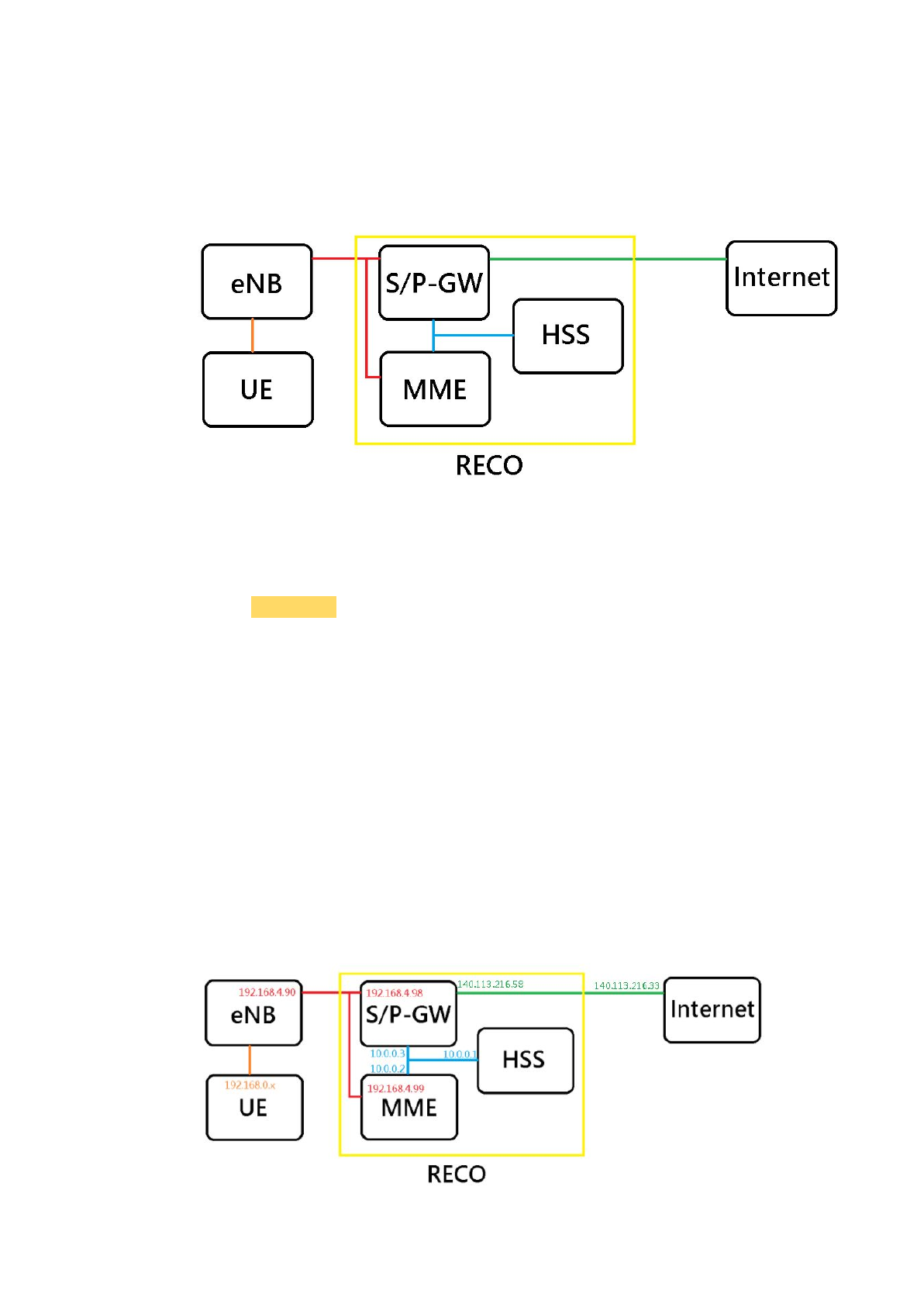
The example of network architecture is like the picture below. We can follow
it when setting IP addresses to run the RECO. And there is an example of how
to set IP addresses in chapter 2.1.1.
Notice that:
HSS and MME still need the Internet when installing some application tools.
And there are some particular colors to show different meanings:
Commands
Items
Important points
2.1. Core Network
Notice that:
The S/P-GW require a Linux kernel version equal to 3.19 or greater than 4.7.
2.1.1. Setup IP Architecture
We use ubuntu 16.04 with VMware Workstation 12.5.7 for example.
Notice that:
We have to snapshot the VMs before shutdown. Then we have to load the
snapshot every time to avoid the problems occurred when rebooting.
The architecture is like the picture below.
11
Notice that:
We need at least two NICs (Network Interface Card) on the host device.
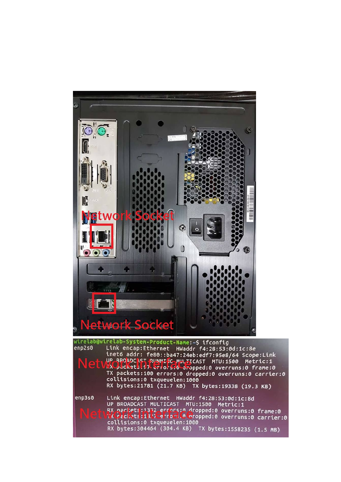
2.1.1.1. Network Sockets and NICs
We have to know the relationship between network sockets and NICs.
This step is on the host device.
12
The simplest way to ensure the relationship is that attach one of the network
socket to the Internet through an Internet wire.
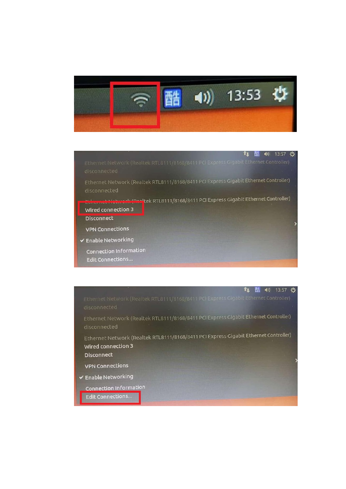
After that, click the Internet settings at the upper right corner.
There will be a 'wired connect', remember this wired connection.
Then click the 'Edit connections'.
13
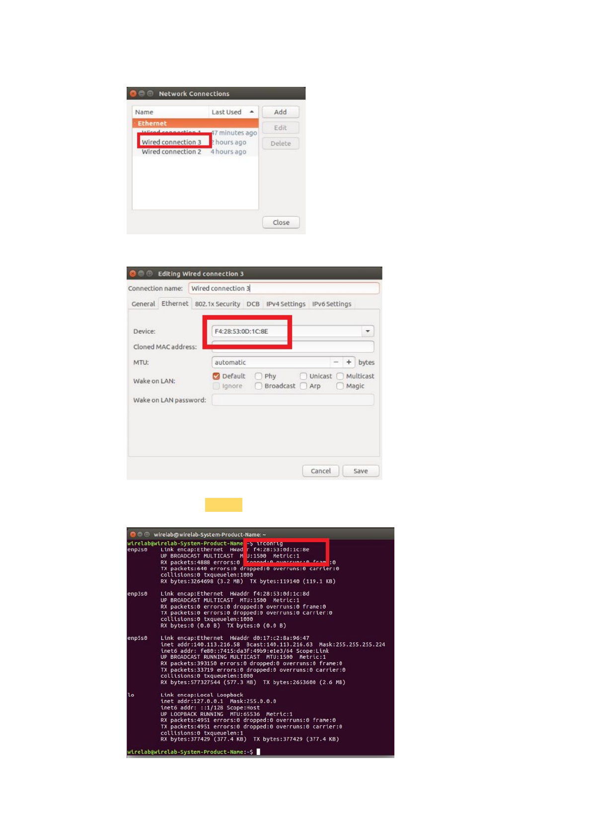
Click the wired connection we find in the previous step.
See the 'Ethernet' page, remember the device address.
Then command 'ifconfig', find the NIC which has the same physical address,
that is the one the network socket mapped.
14
Finally, set the internet well.
So, in this step, we know the relationship between NICs and network sockets!
2.1.1.2. NICs and Virtual NICs
We have to know the relationship between NICs and virtual NICs.
This step is between the host device and VMware.
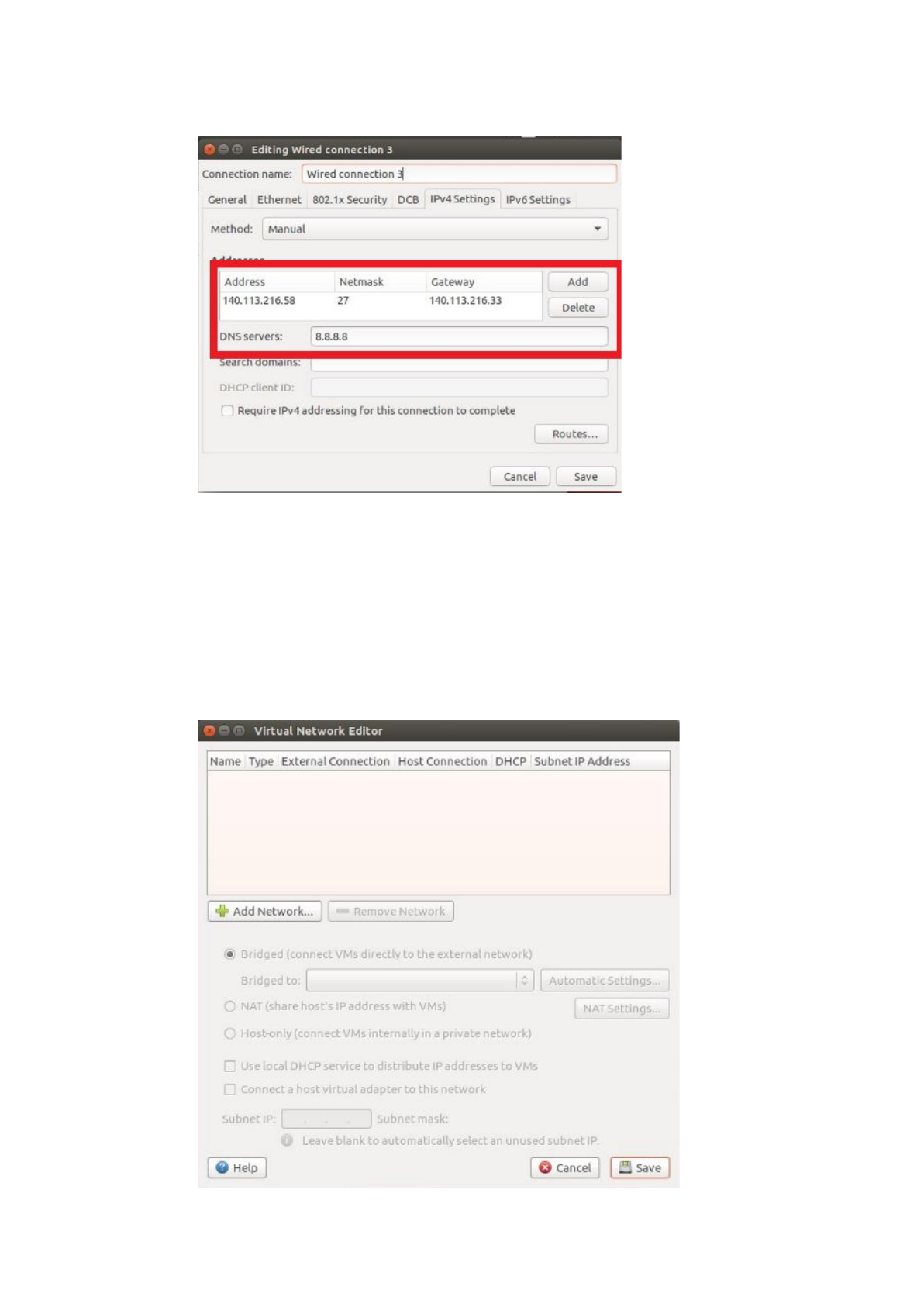
To use the custom mode in the VMware, we have to bridge NICs to virtual
NICs. Choose Edit -> Virtual Network Editor -> key in the host password ->
remove all settings.
15
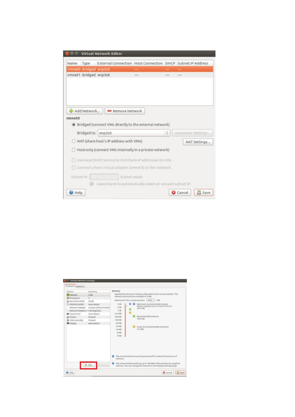
Then Add Network -> choose bridge mode -> Add -> select the particular NIC
to bridge, and that is the NIC we bridge to the virtual NIC.
So, in this step, we know the relationship between NICs and virtual NICs!
2.1.1.3. Virtual NICs and NICs in VMs
We have to know the relationship between virtual NICs and NICs in VMs.
This step is between VMs and VMware.
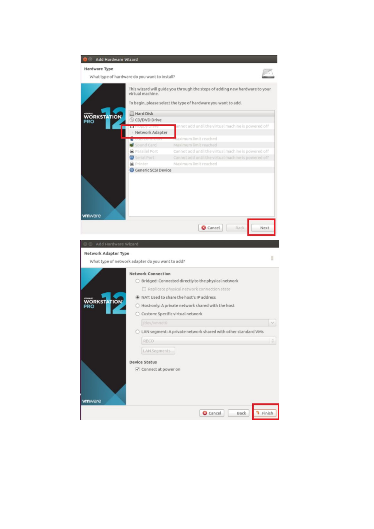
To bridge NICs in the VM to the particular host NICs, we have to use the
custom mode. Right-click the VM -> Settings -> Add -> Network Adapter ->
Next -> Finish , that is the way to add a NIC into the VM. Use this method to
fit the request of each VM.
16
HSS requires two NICs in the VM.
Choose the first NIC in the VM to connect to the Internet, and it needs the real
IP because we use the custom mode. Right-click the VM -> Settings -> click
the first NIC in the VM-> Custom mode -> choose virtual NIC (Which one
17
maps the host NIC that can attach the Internet) -> Save.
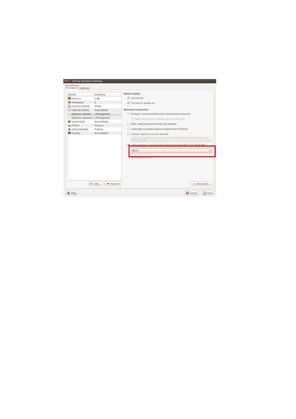
Choose the second NIC in the VM as the LAN interface, and set it at the first
time. Right-click the VM -> Settings -> Click the second NIC in the VM->
LAN mode -> (for the first time we set LAN: Add -> Rename it as you want
(For example is RECO) -> Close -> click the choose list ->) Save.
Notice that:
If we only have one or two real IPs can be used, we have to remove it after all
the HSS installation process.
The way to remove it is that right click the VM -> Settings -> click the first
(which one connect to the Internet) NIC in the VM -> Remove -> Save.
MME requires three NICs in the VM.
Choose the first NIC in the VM to connect to Internet, and it needs the real IP
because we use the custom mode. Right-click the VM -> Settings -> click the
first NIC in the VM -> Custom mode -> choose virtual NIC (Which one map
the host NIC that can attach the Internet) -> Save.
Choose the second NIC in the VM as the LAN interface, and set it at the first
time. Right-click the VM -> Settings -> Click the second NIC in the VM ->
LAN mode -> (for the first time we set LAN: Add -> Rename it as you want
(For example is RECO) -> Close -> click the choose list ->)Save.
Choose the third NIC in the VM to connect to the eNB. Right-click the VM ->
Settings -> click the third NIC in the VM -> Custom mode -> choose virtual
NIC (Which one map the host NIC that can attach the eNB) -> Save.
18

Notice that:
If we only have one or two real IPs can be used, we have to remove the NIC in
the VM after all the HSS installation process.
The way to remove it is that: right-click the VM -> Settings -> click the first
(which one connect to the Internet) NIC in the VM -> Remove -> Save.
S/P-GW requires three NICs in the VM.
Choose the first NIC in the VM to connect to Internet, and it needs the real IP
because we use the custom mode. Right-click the VM -> Settings -> click the
first NIC in the VM -> Custom mode -> choose virtual NIC (Which one map
the host NIC that can attach the Internet) -> Save.
Choose the second NIC in the VM as the LAN interface, and set it at the first
time. Right-click the VM -> Settings -> Click the second NIC in the VM ->
LAN mode -> (for the first time we set LAN: Add -> Rename it as you want
(For example is RECO) -> Close -> click the choose list ->) Save.
Choose the third NIC in the VM to connect to the eNB. Right-click the VM ->
Settings -> click the third NIC in the VM-> Custom mode -> choose virtual
NIC (Which one map the host NIC that can attach the eNB) -> Save.
2.1.1.4. NICs in VMs and IPs
We have to know the relationship between NICs in VMs and IPs.
This step is at VMs.
The relationship between NICs in the VM and settings of the VM will follow
the same order. In other words, the first NIC in the VM maps to the first VM
interface, the second NIC in the VM maps to the second VM interface.
19
After that, it is not a problem to set the IP now. Set the real IP to the VM
interface that finally connects to the network socket which attaches to the
Internet. Set the IP to eNB to the VM interface that finally connects to the
network socket which attaches to the eNB, and set the IP to the LAN we
defined.
The problem now is that what is the command to set the IP to the VM
interface? The command is that:
$ sudo ifconfig <VM interface> <IP you want to set to it>
Notice that:
We have to stop the auto connection because it will remove IPs we have set.
Edit connections -> Wired connection x -> General -> delete the check of
“Automatically connect to this network when it is available” -> Save.
20
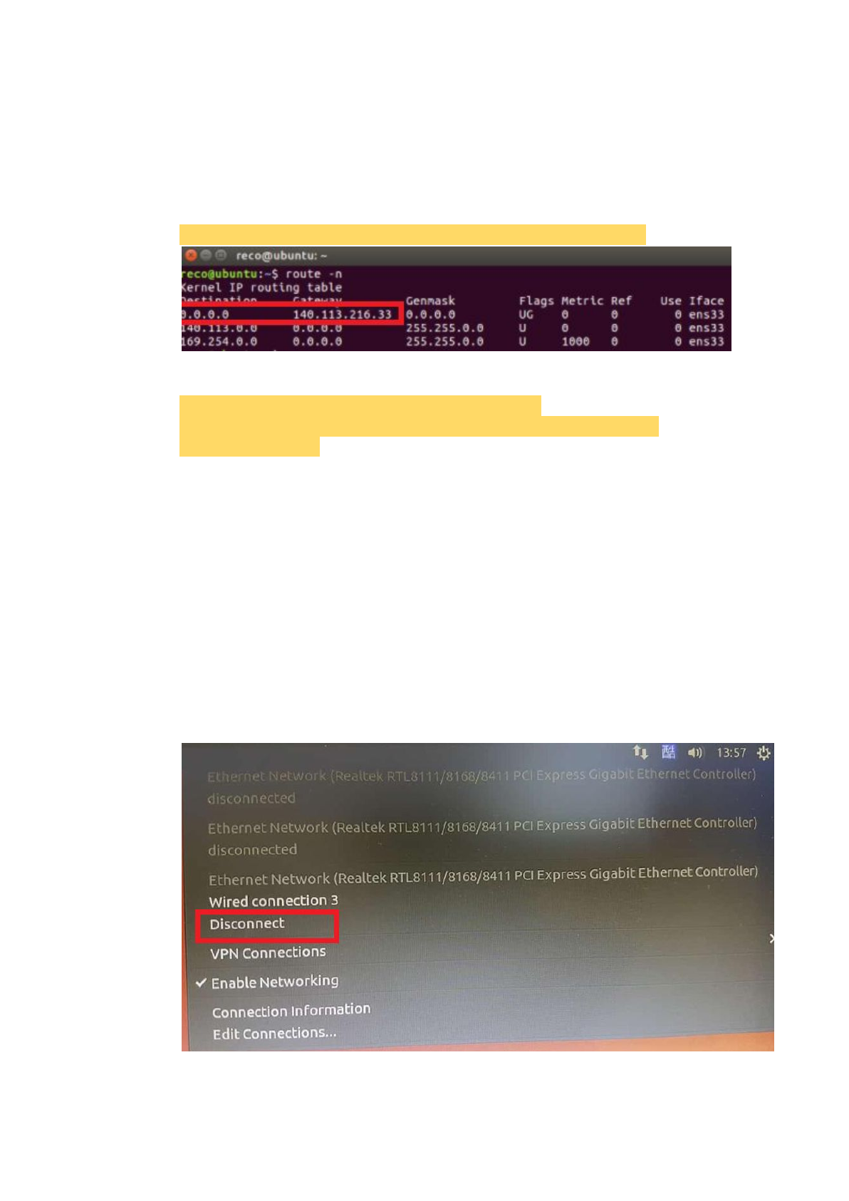
The final problem is that: Why we do not connect to the Internet even we have
set the IP to the VM interface? It is because we have to set more things like
the default gateway and the DNS server.
The command to set the default gateway is that:
$ sudo route add -net 0.0.0.0 netmask 0.0.0.0 gw <default gateway>.
The command to set the DNS server is that:
$ sudo chmod 777 /etc/resolvconf/resolv.conf.d/base
$ sudo echo "nameserver 8.8.8.8" > /etc/resolvconf/resolv.conf.d/base
$ sudo resolvconf -u
It should connect to the Internet now!
Notice that:
If the LAN mode NIC in VMs not work, reboot all the VMs.
2.1.2. Auto Installation Script
Notice that:
If we can not install RECO by this script successfully, we can follow the
manual installation steps in the later chapters to install RECO.
Notice that:
If we use the same real IP between the host device and the VM, please
disconnect the Internet at the host side to ensure the quality of installation.
21

2.1.2.1. MME
2.1.2.1.1. Download RECO and Other Tools
Download the git tool to download RECO.
$ sudo apt-get update -y
$ sudo apt-get install subversion git -y
Then download RECO.
$ git clone https://github.com/RECONet/RECO.git
2.1.2.1.2. Run The Script
Get into the scripts file.
$ cd ./RECO/SCRIPTS
Run the auto installation script.
$ sudo ./install_RECO MME
Key in the IP architecture. (We use the example IP architecture for example)
For the connection to eNB
NIC name of MME: ens38
IP address of MME (with mask): 192.168.4.99/24
For the connection to SPGW
NIC name of MME: ens37
IP address of MME (with mask): 10.0.0.2/8
IP address of SPGW (with mask): 10.0.0.3/8
For the connection to HSS
IP address of HSS (without mask): 10.0.0.1
Then press 'Enter' to go to the next state.
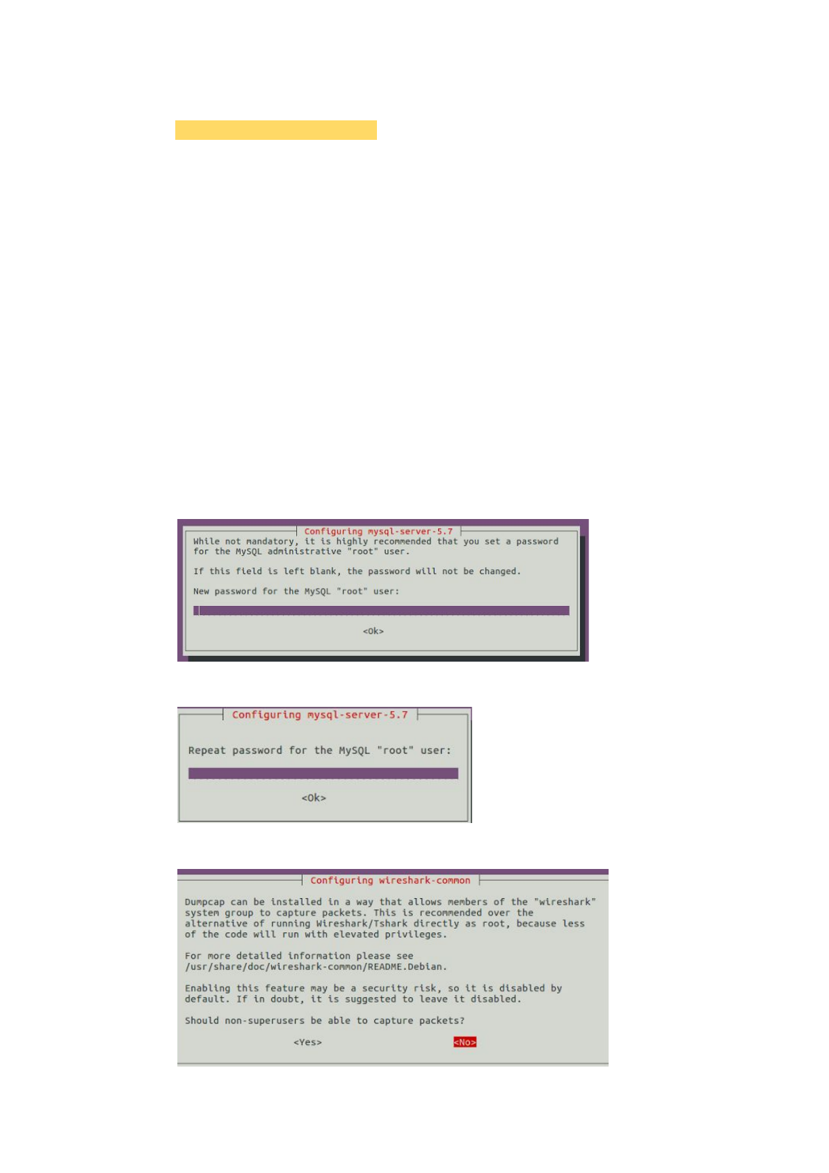
Key in the MySQL password, but it is useless in MME.
Key in the password again.
22
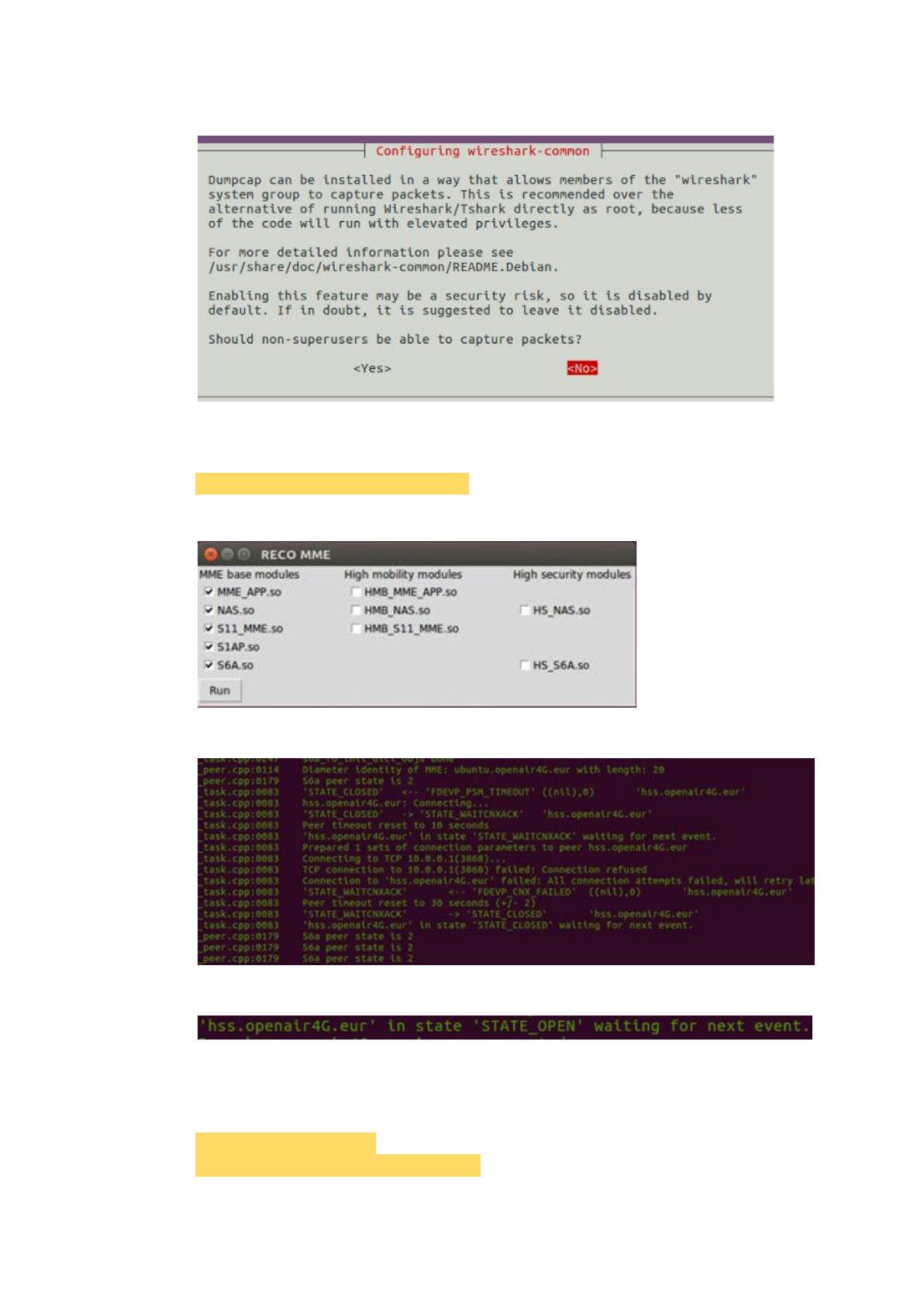
Should non-superusers be able to capture packets? Yes
2.1.2.1.3. Run The MME
Run the pseudo identifier to start the MME.
$ sudo python ./pseudo_identifier.py
Check the items in the first column as below and click ‘run’.
Then the MME is running! Congratulations!
If the MME connects to the active HSS, there will be a log as below.
2.1.2.2. HSS
2.1.2.2.1. Download RECO and Other Tools
Download the git tool to download RECO.
$ sudo apt-get update -y
$ sudo apt-get install subversion git -y
23
Then download RECO.
$ git clone https://github.com/RECONet/RECO.git
2.1.2.2.2. Run The Script
Get into the scripts file.
$ cd ./RECO/SCRIPTS
Run the auto installation script.
$ sudo ./install_RECO HSS
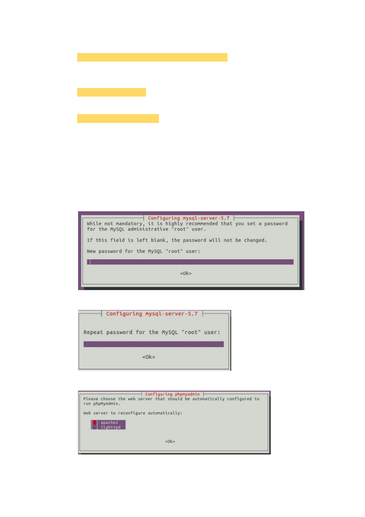
Key in the MySQL password you want to use. (We use ‘123’ for example)
For MySQL database
Password: 123
Then press 'Enter' to go to the next state.
Key in the MySQL password as same as the previous one (‘123’ for example).
This password is important in HSS.
Key in the password again.
Select the web server: apache2
24
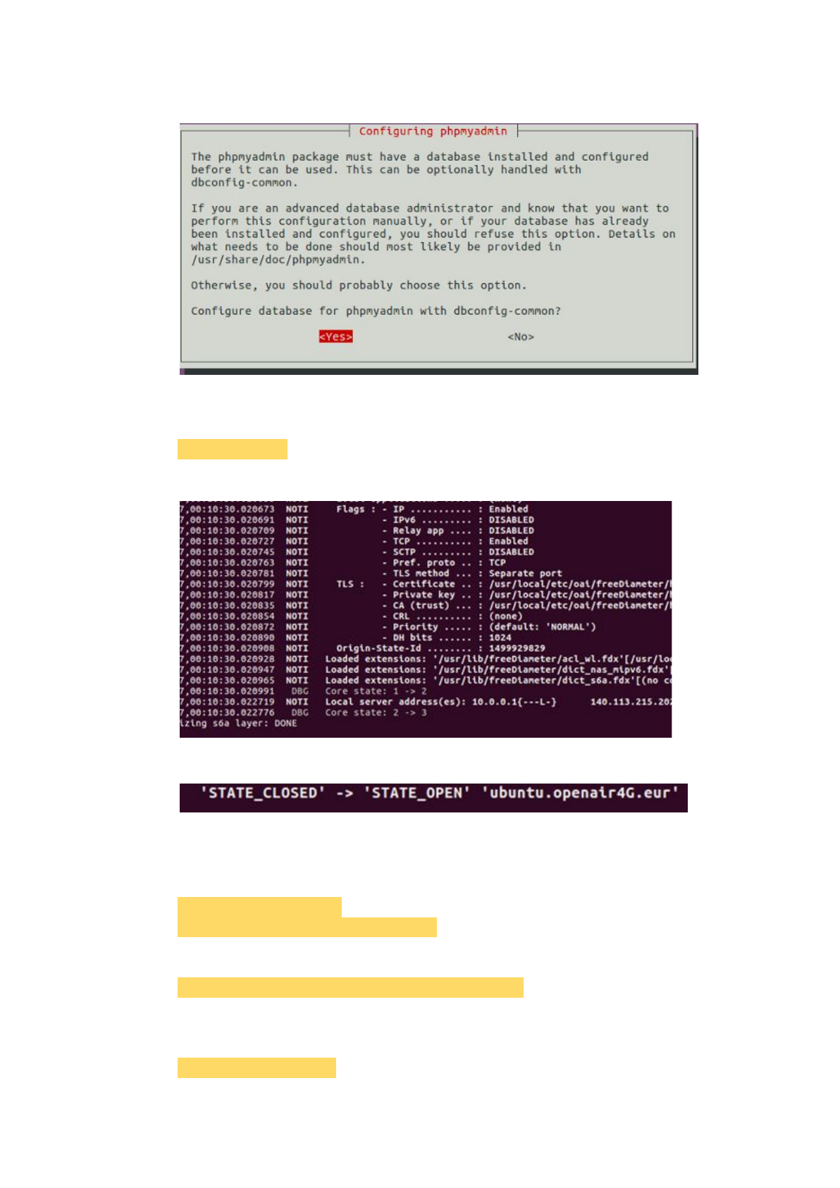
Configure the database with dbconfig-common? No
2.1.2.2.3. Run The HSS
Run the script to start the HSS.
$ sudo ./run_hss
Then the HSS is running! Congratulations!
If the HSS connect to the active MME, there will be a log.
2.1.2.3. S/P-GW
2.1.2.3.1. Download RECO and Other Tools
Download the git tool to download RECO.
$ sudo apt-get update -y
$ sudo apt-get install subversion git -y
Then download RECO.
$ git clone https://github.com/RECONet/RECO.git
2.1.2.3.2. Run The Script
Get into the scripts file.
$ cd ./RECO/SCRIPTS
25
Run the auto installation script.
$ sudo ./install_RECO SPGW
Key in the IP architecture. (We use the example IP architecture for example)
For the connection to MME
NIC name of SPGW: ens37
IP address of SPGW (with mask): 10.0.0.3/8
For the connection to eNB
NIC name of SPGW: ens38
IP address of SPGW (with mask): 192.168.4.98/24
For the connection to Internet
NIC name of SPGW: ens33
For UE
IP address of UE (with mask): 192.168.0.0/16
Then press 'Enter' to go to the next state.
Key in the MySQL password, but it is useless in SPGW.
Key in the password again.
Should non-superusers be able to capture packets? Yes
26

2.1.2.3.3. Run The S/P-GW
Run the script to start the S/P-GW.
$ sudo ./run_spgw
There seems to have some problems, press <control + c> to stop it.
$ <control+c>
Then rerun the script.
The S/P-GW is running! Congratulations!
2.1.3. Manual Installation
2.1.3.1. MME
2.1.3.1.1. Update
$ sudo apt-get update
$ sudo apt-get upgrade
2.1.3.1.2. Download RECO and Other Tools
Download RECO source code from 'github'.
$ git clone https://github.com/RECONet/RECO.git
Download some tools will be used later.
$ cd ./RECO/SCRIPTS
$ sudo ./build_hss -i
$ sudo ./build_mme -i
27
Notice that:
If there is any asking during the process, choose 'yes' for safety.
2.1.3.1.3 Copy configuration files
Copy configuration files to the particular locations.
$ cd ..
$ cd ./ETC
$ sudo cp mme.conf /usr/local/etc/oai
$ sudo cp mme_fd.conf /usr/local/etc/oai/freeDiameter
$ sudo chmod 777 /usr/local/etc/oai/mme.conf
$ sudo chmod 777 /usr/local/etc/oai/freeDiameter/mme_fd.conf
2.1.3.1.4. File settings
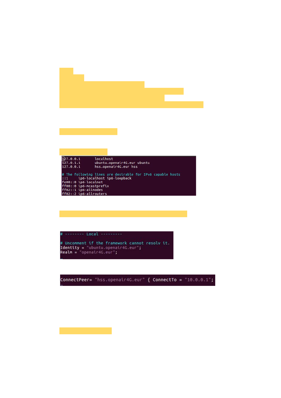
Modify the hostname to 'ubuntu'.
$ sudo vim /etc/hostname
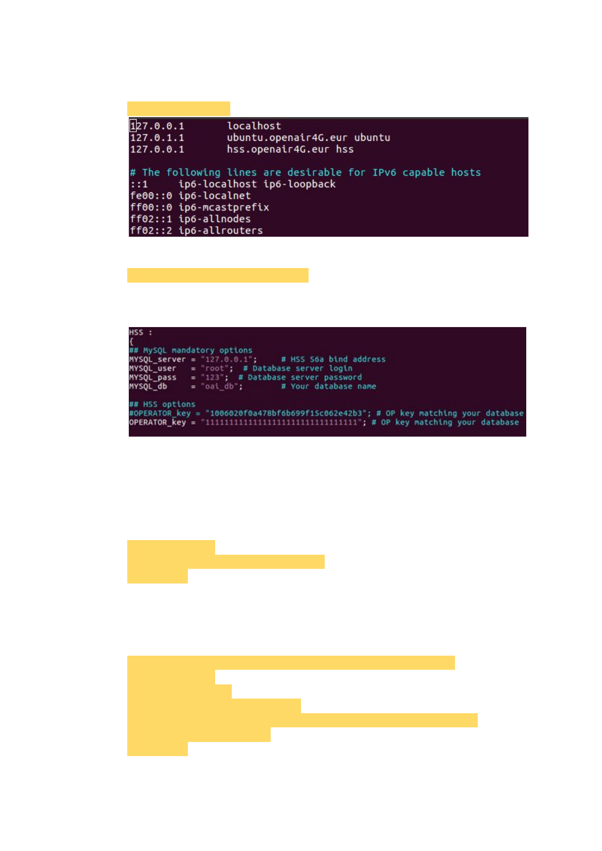
Modify hosts as the picture below.
$ sudo vim /etc/hosts
Set the 'mme_fd.conf' file.
$ sudo vim /usr/local/etc/oai/freeDiameter/mme_fd.conf
Set 'ubuntu.openair4G.eur' to 'Identity'.
Set 'ConnectTo' as the IP of HSS.
Notice that:
If we have no idea about how to set the IP addresses, see the example in
chapter 2.1.4.
Set the 'mme.conf' file.
$ sudo vim ./mme.conf
Notice that:
This file will be copied to '/usr/local/etc/oai' by running 'pseudo_identifier.py'.
28
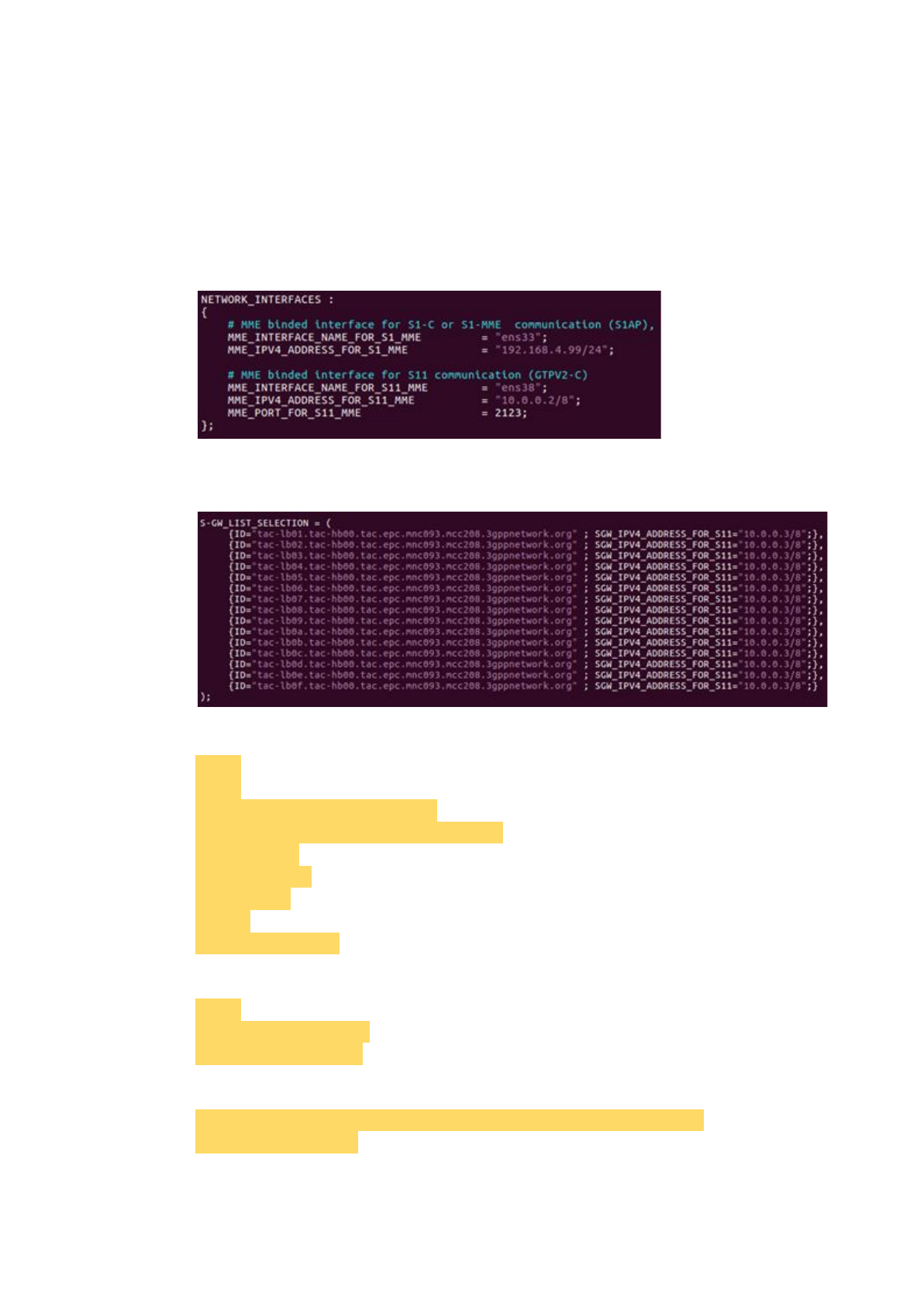
Set 'MME_INTERFACE_NAME_FOR_S1_MME', which is the network
interface that MME used to connect to the eNB, and set
'MME_IPV4_ADDRESS_FOR_S1_MME', which is the IP with the mask of
the network interface.
Set 'MME_INTERFACE_NAME_FOR_S11_MME', which is the network
interface that MME used to connect to the S/P-GW, and set
'MME_IPV4_ADDRESS_FOR_S11_MME', which is the IP with the mask of
the network interface.
Set 'SGW_IPV4_ADDRESS_FOR_S11', which is the IP with the mask of
S/P-GW.
2.1.3.1.5. Install libgtpnl
$ cd ..
$ cd ..
$ sudo apt-get install libmnl-dev
$ git clone git://git.osmocom.org/libgtpnl
$ cd ./libgtpnl
$ autoreconf -fi
$ ./configure
$ make
$ sudo make install
2.1.3.1.6. Build the MME
$ cd ..
$ cd ./RECO/SCRIPTS
$ sudo ./build_mme -c
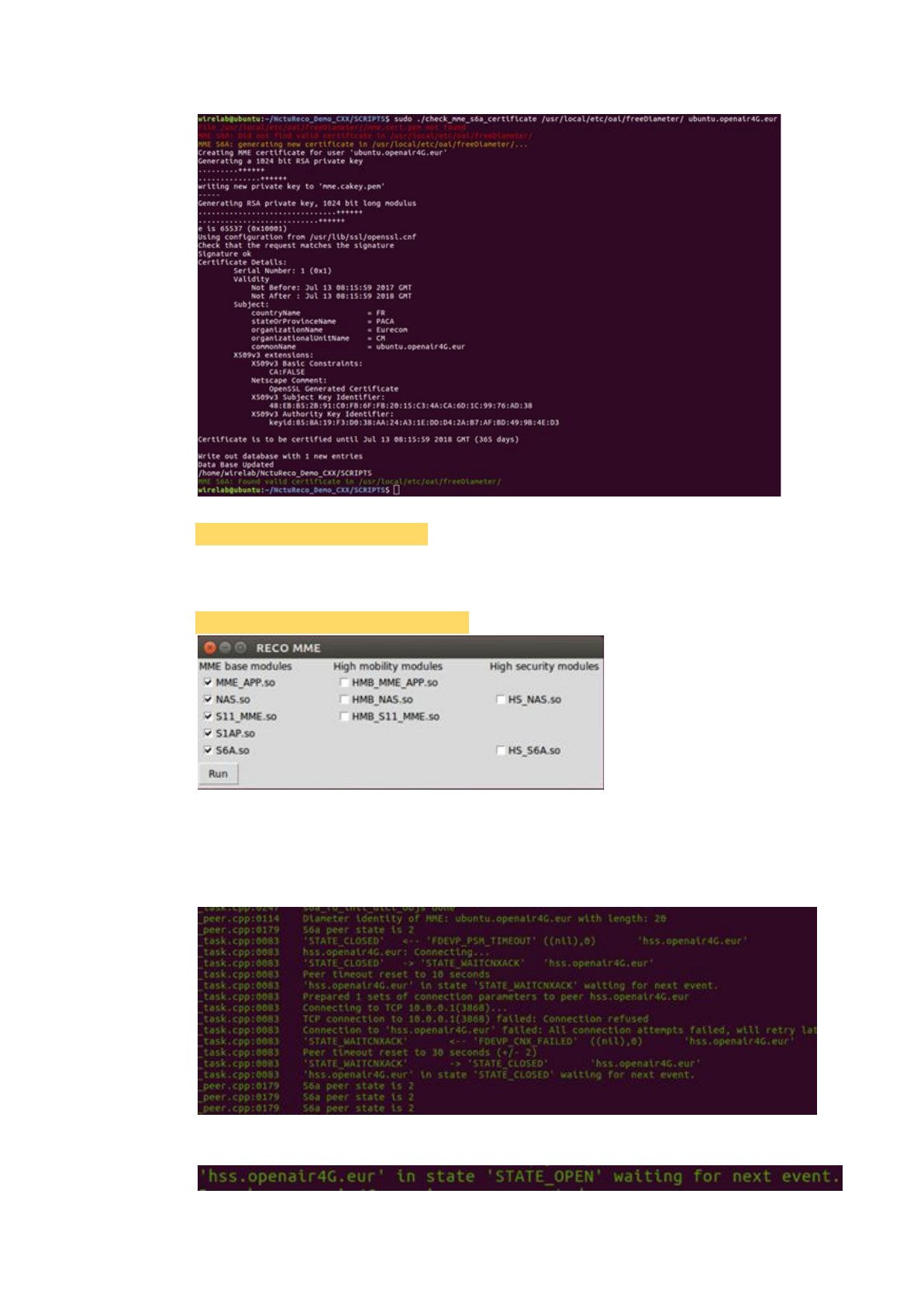
2.1.3.1.7. Check the certification
$ sudo ./check_mme_s6a_certificate /usr/local/etc/oai/freeDiameter/
ubuntu.openair4G.eur
29
2.1.3.1.8. Install packet python-tk
$ sudo apt-get install python-tk
2.1.3.1.9. Run the MME
Run the script to simulate the identifier to perform dynamic linking.
$ sudo python ./pseudo_identifier.py
Notice that:
In the latest version, we suggest checking the items in the first column.
Click 'Run' to start the MME.
When the MME connects to the HSS, there will be a log.
30

Notice that:
The HSS must be active to connect to the MME.
Notice that:
If we want to rerun the MME, type commands below to release sources.
Find the 'pid' of the process. It is '59457' in the picture below for example.
$ ps aux | grep python
Then kill the process with the 'pid' we have found.
$ sudo kill -9 <pid>
2.1.3.2. HSS
2.1.3.2.1. Update
$ sudo apt-get update
$ sudo apt-get upgrade
2.1.3.2.2. Download RECO and other tools
Download RECO source code from 'github'.
$ git clone https://github.com/RECONet/RECO.git
Download some tools will be used later.
$ cd ./RECO/SCRIPTS
$ sudo ./build_hss -i
Notice that:
The password we set when running the 'build_hss -i' at the first time will be
used to log in the MySQL database, and we set '123' to it for example.
Notice that:
If there is any asking during the process, choose 'yes' for safety.
2.1.3.2.3 Copy configuration files
Copy configuration files to the particular locations.
$ cd ..
$ cd ./ETC
$ sudo cp hss.conf /usr/local/etc/oai
$ sudo cp hss_fd.conf /usr/local/etc/oai/freeDiameter
$ sudo cp acl.conf /usr/local/etc/oai/freeDiameter
$ sudo chmod 777 /usr/local/etc/oai/hss.conf
$ sudo chmod 777 /usr/local/etc/oai/freeDiameter/hss_fd.conf
$ sudo chmod 777 /usr/local/etc/oai/freeDiameter/acl.conf
2.1.3.2.4 File settings
Modify the hostname to 'ubuntu'.
$ sudo vim /etc/hostname
31
Modify hosts as the picture below.
$ sudo vim /etc/hosts
Set the 'hss.conf' file.
$ sudo vim /usr/local/etc/oai/hss.conf
Set 'MYSQL_user' and 'MYSQL_pass' as same as the database.
Set serial '1's to 'OPERATOR_key'.
Notice that:
The 'MYSQL_user' is 'root', and the 'MYSQL_pass' is the password we set in
the previous step, for example, that is '123'.
2.1.3.2.5 Database import
Create database 'oai_db'.
$ mysql -u root -p
mysql > CREATE DATABASE oai_db;
mysql > exit
Notice that:
The password is the one we set in the previous step, for example is '123'.
Import data to 'oai_db'.
$ mysql -u root -p oai_db < ~/RECO/SRC/OAI_HSS/db/oai_db.sql
$ mysql -u root -p
mysql > USE oai_db;
mysql > select * from mmeidentity;
mysql > UPDATE mmeidentity SET mmehost = 'ubuntu.openair4G.eur'
WHERE idmmeidentity = '4';
mysql > exit
32
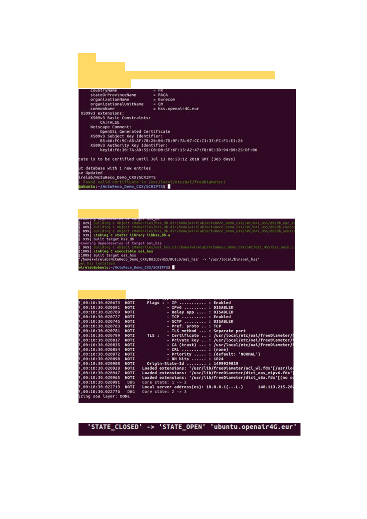
2.1.3.2.6 Check the certification
$ cd ..
$ cd ./SCRIPTS
$ sudo ./check_hss_s6a_certificate /usr/local/etc/oai/freeDiameter/
hss.openair4G.eur
2.1.3.2.7 Build the HSS
$ sudo ./build_hss -c
2.1.3.2.8 Run the HSS
$ sudo ./run_hss
When the HSS connect to the MME, there will be a log.
Notice that:
MME must be active to connect to HSS.
33
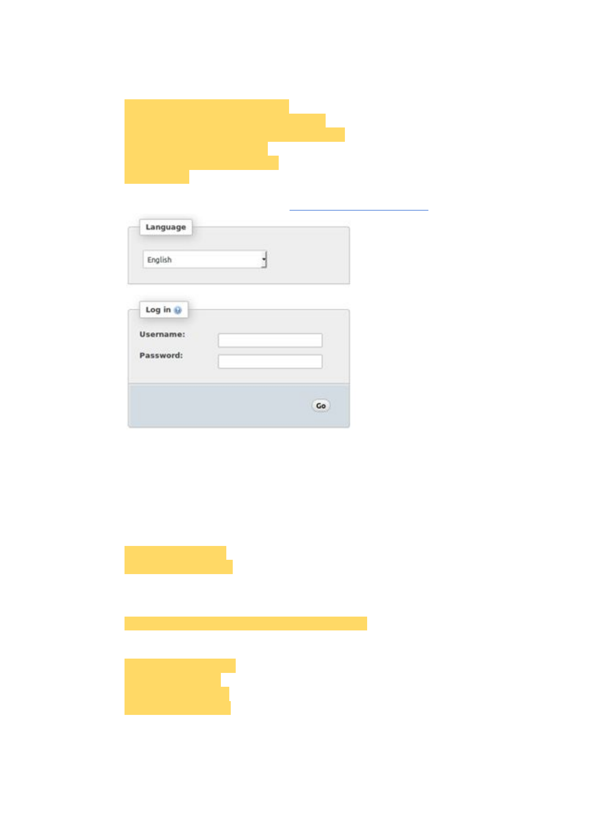
2.1.3.2.9 Phpmyadmin
It provides the GUI for database operations.
$ sudo apt-get install phpmyadmin
$ sudo ln -s /etc/phpmyadmin/apache.conf
/etc/apache2/conf-available/phpmyadmin.conf
$ sudo a2enconf phpmyadmin
$ sudo /etc/init.d/apache2 reload
$ sudo reboot
We can operate data by accessing 'http://127.0.0.1/phpmyadmin'.
Insert data of the SIM card into the database 'oai_db'.
Notice that:
If we do not insert SIM card data, we will fail to connect to the Internet.
2.1.3.3. S/P-GW
2.1.3.3.1. Update
$ sudo apt-get update
$ sudo apt-get upgrade
2.1.3.3.2. Download RECO and other tools
Download RECO source code from 'github'.
$ git clone https://github.com/RECONet/RECO.git
Download some tools will be used later.
$ cd ./RECO/SCRIPTS
$ sudo ./build_hss -i
$ sudo ./build_mme -i
$ sudo ./build_spgw -i
Notice that:
If there is any asking during the process, choose 'yes' for safety.
34

2.1.3.3.3 Copy configuration files
Copy configuration files to the particular locations.
$ cd ..
$ cd ./ETC
$ sudo cp spgw.conf /usr/local/etc/oai
$ sudo chmod 777 /usr/local/etc/oai/spgw.conf
2.1.3.3.4 File settings
Set the 'spgw.conf' file.
$ sudo vim /usr/local/etc/oai/spgw.conf
Set 'SGW_INTERFACE_NAME_FOR_S11', which is the network interface
S/P-GW used to connect to the MME and set
'SGW_IPV4_ADDRESS_FOR_S11', which is the IP with the mask of the
network interface.
Set 'SGW_INTERFACE_NAME_FOR_S1U_S12_S4_UP', which is the
network interface S/P-GW used to connect to the eNB and set
'SGW_IPV4_ADDRESS_FOR_S1U_S12_S4_UP', which is the IP with the
mask of the network interface.
Notice that:
If we have no idea about how to set the IP addresses, see the example in
chapter 2.1.4.
Set 'PGW_INTERFACE_NAME_FOR_SGI', which is the network interface
S/P-GW used to connect to the internet.
Set 'yes' to 'PGW_MASQUERADE_SGI' and 'UE_TCP_MSS_CLAMPING'
to avoid failure.
Set 'IPV4_LIST', which is a scope of IPs distributed to UEs connecting to the
S/P-GW.
35
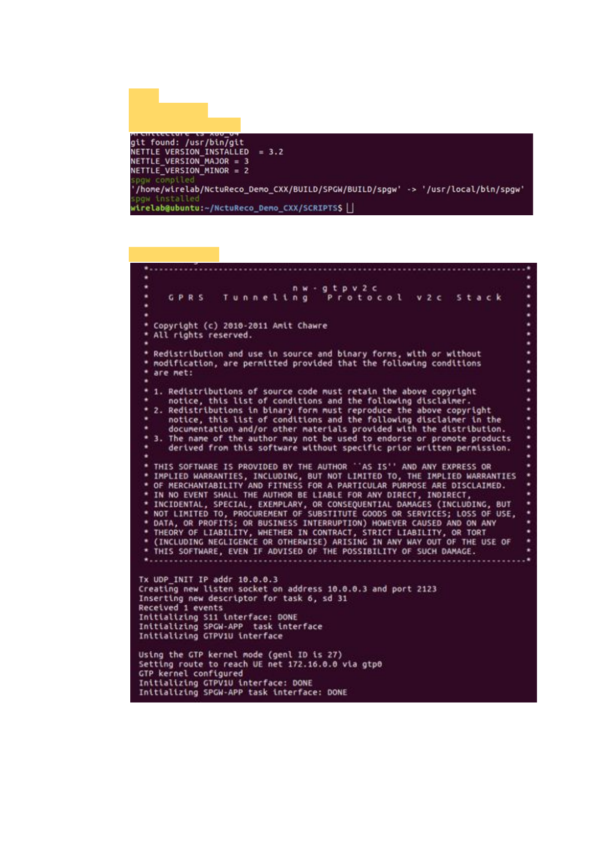
2.1.3.3.5 Build the SPGW
$ cd ..
$ cd ./SCRIPTS
$ sudo ./build_spgw -c
2.1.3.3.6 Run the SPGW
$ sudo ./run_spgw
36
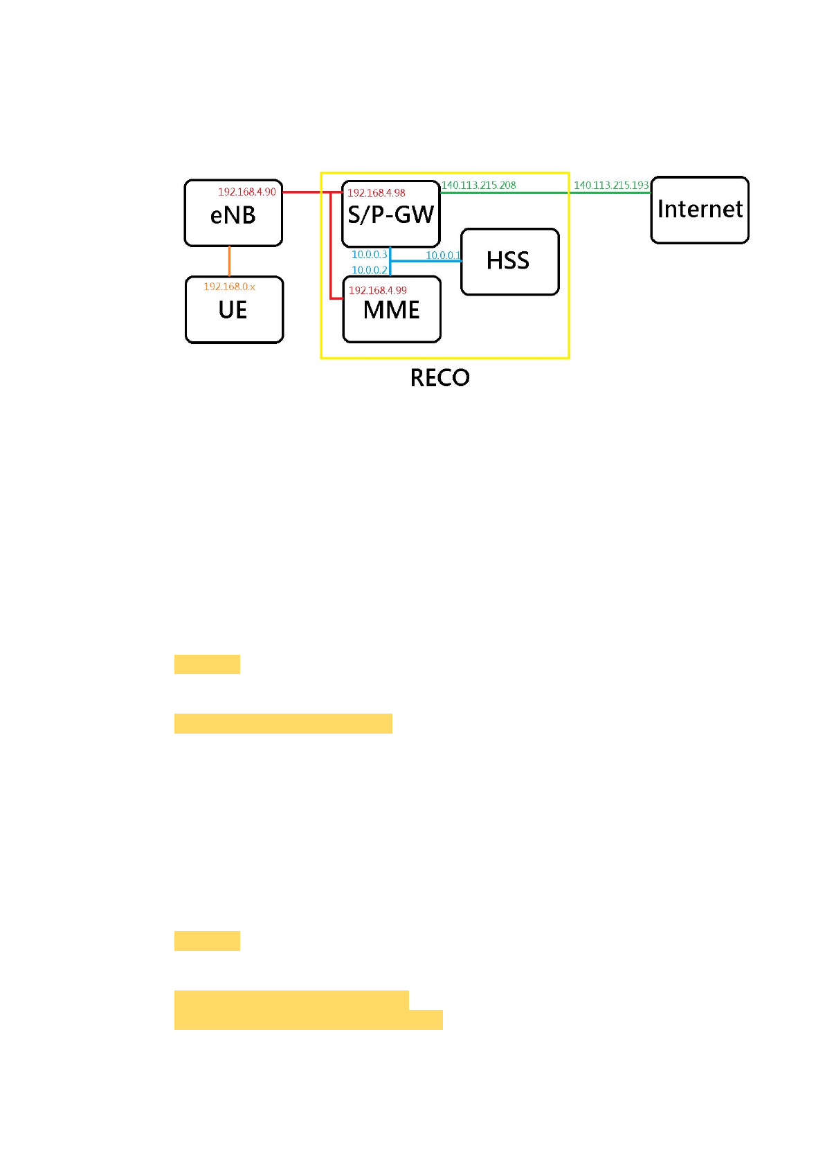
2.1.4. Example of IP Settings
2.1.4.1. Architecture Overview with IPs
Notice that:
'140.113.215.193' is the IP address of the default gateway.
Notice that:
The IPs may be different from the IP architecture at the chapter 2.1.1.
2.1.4.2. IP Settings of HSS
2.1.4.2.1. Network Interface Settings
Notice that:
We need at least one network interface card (NIC).
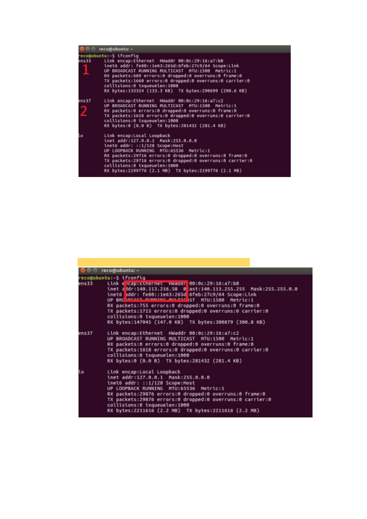
Find the name of the NIC.
$ ifconfig
Set IP Address to the NIC.
$ sudo ifconfig <name> 10.0.0.1
Notice that:
<name> is the name of the NIC.
2.1.4.3. IP Settings of MME
2.1.4.3.1. Network Interface Settings
Notice that:
We need at least two network interface cards (NICs).
Find the names of the NICs.
$ ifconfig
Set IP Addresses to the NICs.
$ sudo ifconfig <name_1> 10.0.0.2
$ sudo ifconfig <name_2> 192.168.4.99
37

Notice that:
<name_1> is the name of the first NIC.
<name_2> is the name of the second NIC.
2.1.4.3.2. Configuration File Settings
mme_fd.conf:
ConnectTo = "10.0.0.1"
mme.conf:
MME_INTERFACE_NAME_FOR_S1_MME = "<name_2>"
MME_IPV4_ADDRESS_FOR_S1_MME = "192.168.4.99/24"
MME_INTERFACE_NAME_FOR_S11_MME = "<name_1>"
MME_IPV4_ADDRESS_FOR_S11_MME = "10.0.0.2/8"
SGW_IPV4_ADDRESS_FOR_S11 = "10.0.0.3/8"
Notice that:
Here we only set the part of IPs and NICs names. As for other settings, please
follow the previous chapters.
2.1.4.4. IP Settings of S/P-GW
2.1.4.4.1. Network Interface Settings
Notice that:
We need at least three network interface cards (NICs).
Find the names of the NICs.
$ ifconfig
Set IP Addresses to the NICs.
$ sudo ifconfig <name_1> 10.0.0.3
$ sudo ifconfig <name_2> 192.168.4.98
$ sudo ifconfig <name_3> 140.113.215.2083
Notice that:
<name_1> is the name of the first NIC.
<name_2> is the name of the second NIC.
<name_2> is the name of the third NIC.
Notice that:
If ping google.com failed, type commands below to connect to the Internet.
$ sudo route add -net 0.0.0.0 netmask 0.0.0.0 gw 140.113.215.193
$ sudo chmod 777 /etc/resolvconf/resolv.conf.d/base
$ sudo echo "nameserver 8.8.8.8" >> /etc/resolvconf/resolv.conf.d/base
$ sudo resolvconf -u
Notice that:
'140.113.215.193' is the IP address of the default gateway.
38

2.1.4.4.2. Configuration File Settings
spgw.conf:
SGW_INTERFACE_NAME_FOR_S11 = "<name_1>"
SGW_IPV4_ADDRESS_FOR_S11 = "10.0.0.3/8"
SGW_INTERFACE_NAME_FOR_S1U_S12_S4_UP = "<name_2>"
SGW_IPV4_ADDRESS_FOR_S1U_S12_S4_UP = "192.168.4.98/24"
PGW_INTERFACE_NAME_FOR_SGI = "<name_3>"
IPV4_LIST = "192.168.0.0/16"
Notice that:
Here we only set the part of IPs and NICs names. As for other settings, please
follow the previous chapters.
2.2. Radio Access Network
2.2.1. SIM Card
The SIM card we use: sysmoUSIM-SJS1 (with ADM keys)
You can buy it at the following link:
http://shop.sysmocom.de/products/sysmousim-sjs1
We can use PySIM to program the SIM card.
Install packages:
$ sudo apt-get install pcscd pcsc-tools libccid python-dev swig
python-setuptools python-pip libpcsclite-dev
$ sudo pip install pycrypto
Download PySIM from git:
$ git clone git://git.osmocom.org/pysim.git
Also need Pyscard:
Download from
https://sourceforge.net/projects/pyscard/files/pyscard/pyscard%201.9.5/pyscar
d-1.9.5.tar.gz/download
Install command:
$ cd <pyscard-path>
$ sudo /usr/bin/python setup.py build_ext install
Use the following command to check whether card reader is ready:
$ sudo pcsc_scan
If you see this picture, you are ready to program the SIM card:
39
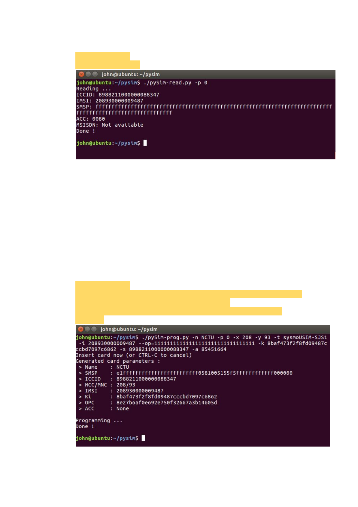
Read SIM card information:
$ cd <pysim-path>
$ ./pySim-read.py -p 0
Program SIM card:
You need to prepare the following information:
-x MCC :Mobile Country Code, the first 3 letter of IMSI
-y MNC:Mobile Network Code, the 4th and 5th letter of IMSI
-i IMSI:International Mobile Subscriber Identity, presented as a 15 digit
number
op OP:Operator Code, presented as a 32 digit number
-k KI:Subscriber Authentication Key, presented as a 32 digit number
-s ICCID:Integrated Circuit Card Identifier, presented as a 20 digit number
-a ADM1:The password uses to programming SIM card, presented as a 8
digit number
Programming commands:
$ cd <pysim-path>
$ ./pySim-prog.py -p 0 -x 466 -y 86 -t sysmoUSIM-SJS1 -i 466862054321003
--op=97A167DED889B6DFA92D985D77E5C088 -k
808182888485868788898A8B8C8D8E8F -s 8988211000000088313 -a
23605945
40
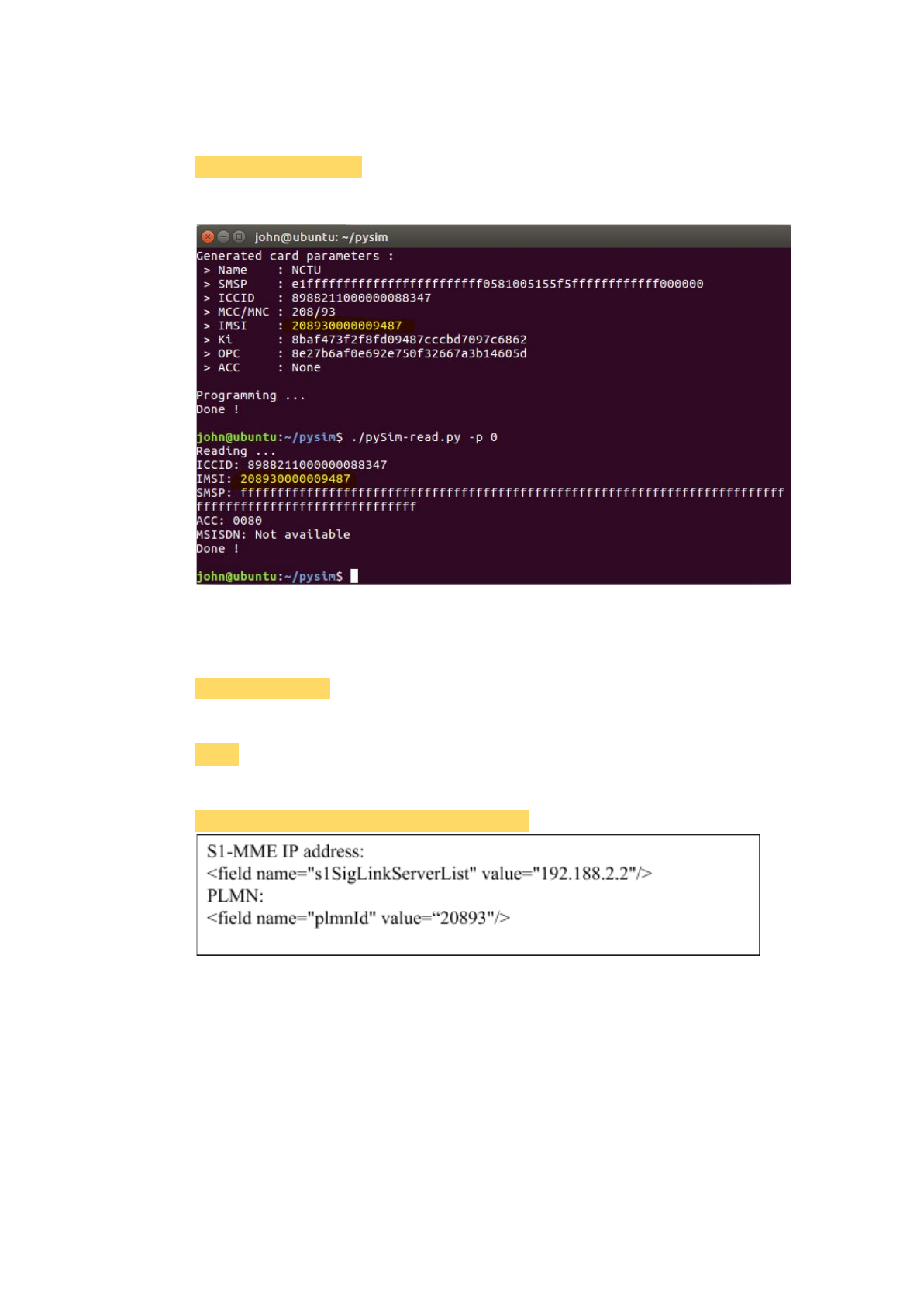
Verification:
$ ./pySim-read.py -p 0
If the IMSI changed, done!
2.2.2. eNodeB
2.2.2.1. Commercial eNodeB - Wistron NeWeb OSQ4G-01E2
First, connect to the eNB from the MME.
$ telnet <eNB IP>
Then log in the eNB as a root user.
$ root
Edit the configuration file. (Here are the examples)
$ vi /mnt/flash/etc/fsm/xml/provisioning.xml
→ After rebooting the eNodeB, it can connect to MME through WAN port.
Notice that:
The 's1SigLinkServerList' is the IP of MME used to connect to the eNB.
Notice that:
The 'plmnId' is the same value as the PLMN ID of the SIM card.
2.2.2.2. OAI eNodeB
2.2.2.2.1. USRP B210
41

※It is recommend to use the USB3.0 port.
2.2.2.2.1.1. USRP driver installation
◎UHD binary installation
$ sudo add-apt-repository ppa:ettusresearch/uhd
$ sudo apt-get update
$ sudo apt-get install libuhd-dev libuhd003 uhd-host
◎Building and Installing UHD from source
$ sudo apt-get install libboost-all-dev libusb-1.0-0-dev python-mako doxygen
python-docutils cmake build-essential
$ git clone --recursive git://github.com/EttusResearch/uhd.git
$ cd <uhd-repo-path>/host
$ mkdir build
$ cd build
$ cmake ../
$ make
$ make test
$ sudo make install
$ sudo ldconfig
2.2.2.2.1.2. Building OAI executables from source
$ git clone https://gitlab.eurecom.fr/oai/openairinterface5g.git
$ cd YOUR_openairinterface5g_DIRECTORY
$ source oaienv # Very important. It sets the correct environment variables
$ cd cmake_targets
$ ./build_oai -I -w USRP # Package installation + USRP Driver installation
$ ./build_oai --eNB -c -w USRP
2.2.2.2.1.3. Start the eNodeB with USRP B210
Here we use the configuration file: enb.band7.tm1.usrpb210.conf
(Remember to check the configuration of PLMN ID and the interface between
MME and eNodeB.)
$ cd $OPENAIR_DIR/cmake_targets/lte_build_oai/build
$ sudo -E ./lte-softmodem -O
$OPENAIR_DIR/targets/PROJECT/GENERIC-LTE-EPC/CONF/enb.band7.t
m1.usrpb210.conf
You can see some messages of s1ap_setup on your MME machine after the
connection established.
2.2.2.2.2. ExpressMimo2
2.2.2.2.2.1. ExpressMimo2 card setup
Initialize express MIMO card
$ cd openairinterface5g
$ . oaienv
$ cd cmake_targets/tools/
42

$ . init_exmimo2
You should see the following output on the console
loading openair_rf
Using firware version 10
Running “dmesg”, you should see something ending with
[782979.116663] [openair][IOCTL] ok asked Leon to set stack and start execution
(addr 0x40000000, stackptr 43fffff0)
[782979.116782] [LEON card0]: FWINIT: Will start execution @ 40000000, stack
@ 43fffff0
[782979.228844] [LEON card0]: pcie_initialize_interface_bot(): firmware_block_ptr
3200100, printk_buffer_ptr 3240100, pci_interface_ptr 3240500, exmimo_id_ptr
3240700
[782979.229321] [LEON card0]: System Info:
[782979.229464] [LEON card0]: Bitstream: SVN Revision: 5307, Build date
(GMT): Wed 2014-03-19 15:55:01, User ID: 0x0001
[782979.229600] [LEON card0]: Software: SVN Revision: 5541, Build date
(GMT): Wed 2014-03-19 08:45:08
[782979.229691] [LEON card0]: ExpressMIMO-2 SDR! (Built on Nov 7 2014
15:14:44)
[782979.229819] [LEON card0]: Initialized LIME.
[782979.229935] [LEON card0]: Initializing RF Front end chain0 (to TVWS_TDD).
[782979.230209] [LEON card0]: ready.
2.2.2.2.2.2. Building OAI executables from source
$ git clone https://gitlab.eurecom.fr/oai/openairinterface5g.git
$ cd YOUR_openairinterface5g_DIRECTORY
$ source oaienv # Very important. It sets the correct environment variables.
$ cd cmake_targets
$ ./build_oai -I # Package installation + EXMIMO Driver installation
$ ./build_oai --eNB -w EXMIMO -c -s # eNodeB + EXMIMO + test
2.2.2.2.2.3. Start the eNodeB with ExpressMimo2
Here we use the configuration file: enb.band7.tm1. exmimo2.conf
(Remember to check the configuration of PLMN ID and the interface between
MME and eNodeB.)
$ cd $OPENAIR_DIR/cmake_targets/lte_build_oai/build
$ sudo -E ./lte-softmodem -O
$OPENAIR_DIR/targets/PROJECT/GENERIC-LTE-EPC/CONF/enb.band7.t
m1.exmimo2.conf
You can see some messages of s1ap_setup on your MME machine after the
connection established.
43

3. Conclusion
We have presented a reconfigurable core network architecture called RECO to
efficiently implement customized core network entities for a heterogeneous 5G
environment. We also built a reconfigurable MME (RECO MME) to verify our
RECO concept. We specifically introduced the implementation of how the dynamic
linking framework is implemented in RECO MME and show that our RECO MME
has the benefits of (1) reduce disk space and memory usage (2) easy to update and
deploy (3) flexibility to link certain modules to form a customized MME (4)
Object-oriented code structure which allows programmers to reuse code when
forming a customized MME. Finally, we expect and hope the research community
would like to join us in this research project.
44
