REV Blinkin LED Driver User's Manual
User Manual: Pdf
Open the PDF directly: View PDF ![]() .
.
Page Count: 16
REV-11-1105-UM-0 Copyright © 2018 REV Robotics, LLC 1
fg
BLINKIN LED DRIVER
USER'S MANUAL

REV-11-1105-UM-0 Copyright © 2018 REV Robotics, LLC 2
TABLE OF CONTENTS
1 OVERVIEW ............................................................................................................................................................................... 3
1.1 CONNECTIONS .............................................................................................................................................................. 3
1.2 KIT CONTENTS .............................................................................................................................................................. 3
1.3 ELECTRICAL RATINGS .................................................................................................................................................. 3
1.4 SUPPORTED LED STRIP TYPES .................................................................................................................................... 4
2 SETUP AND CONFIGURATION ............................................................................................................................................... 5
2.1 GETTING STARTED ....................................................................................................................................................... 5
2.2 SETUP MODE ................................................................................................................................................................. 6
2.3 PWM CONTROL ............................................................................................................................................................. 7
2.4 FIRST ROBOTICS PROGRAMMING EXAMPLE ............................................................................................................. 8
2.5 PATTERN ADUSTMENTS .............................................................................................................................................. 9
2.6 FACTORY RESET ............................................................................................................................................................ 9
3 EXAMPLE APPLICATIONS ................................................................................................................................................... 10
3.1 FIRST ROBOTICS COMPETITION ................................................................................................................................ 10
3.2 FIRST TECH CHALLENGE ............................................................................................................................................ 11
3.3 STAND-ALONE WIRING ............................................................................................................................................... 12
3.4 COMPETITION ROBOTICS APPLICATION IDEAS ...................................................................................................... 12
4 PHYSICAL DIMENSIONS ...................................................................................................................................................... 13
5 LED PATTERN TABLE .......................................................................................................................................................... 14
LIST OF FIGURES
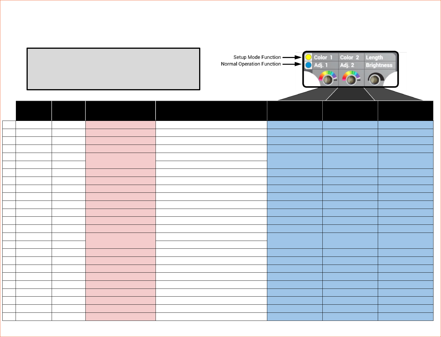
Figure 1: Blinkin Connections and Indicators ............................................................................................................................... 3
LIST OF TABLES
Table 1: Kit Contents ...................................................................................................................................................................... 3
Table 2: Status LED Blink Codes ................................................................................................................................................... 5
Table 3: WPI Motor Control Output PWM Range .......................................................................................................................... 8
Table 4: Example SPARK Control Values based on Table 5 ........................................................................................................ 8
Table 5: Excerpt from Section 6 LED Pattern List ........................................................................................................................ 8
Table 6: Blinkin Factory Default Values ........................................................................................................................................ 9
REV-11-1105-UM-0 Copyright © 2018 REV Robotics, LLC 3
1 OVERVIEW
The Blinkin is designed to make it straight forward to add controllable LEDs to a robot, cart, or any other project which
would benefit from some extra lumens without needing any specialized programming. The Blinkin is a compact, all-in-one
solution which can control LEDs in a stand-alone mode with just a 12V power source or in a dynamic mode, changing
patterns by supplying a standard servo-style PWM signal.
1.1 CONNECTIONS
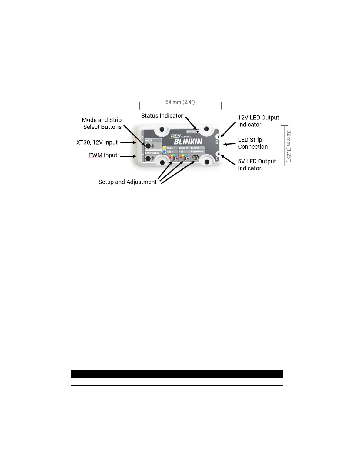
Figure 1: Blinkin Connections and Indicators
Mode/Up Button – Switch between normal running mode and set-up mode.
Strip Select/Down Button – Switch which kind of LED strip is being controlled.
XT30 Power Input – Connect to a 12V nominal battery or other equivalent power source.
PWM Input – Provide a standard servo-style PWM signal to control the LED output pattern/color.
Status Indicator – RGB LED mode indicator. See Table 2 for colors and meanings.
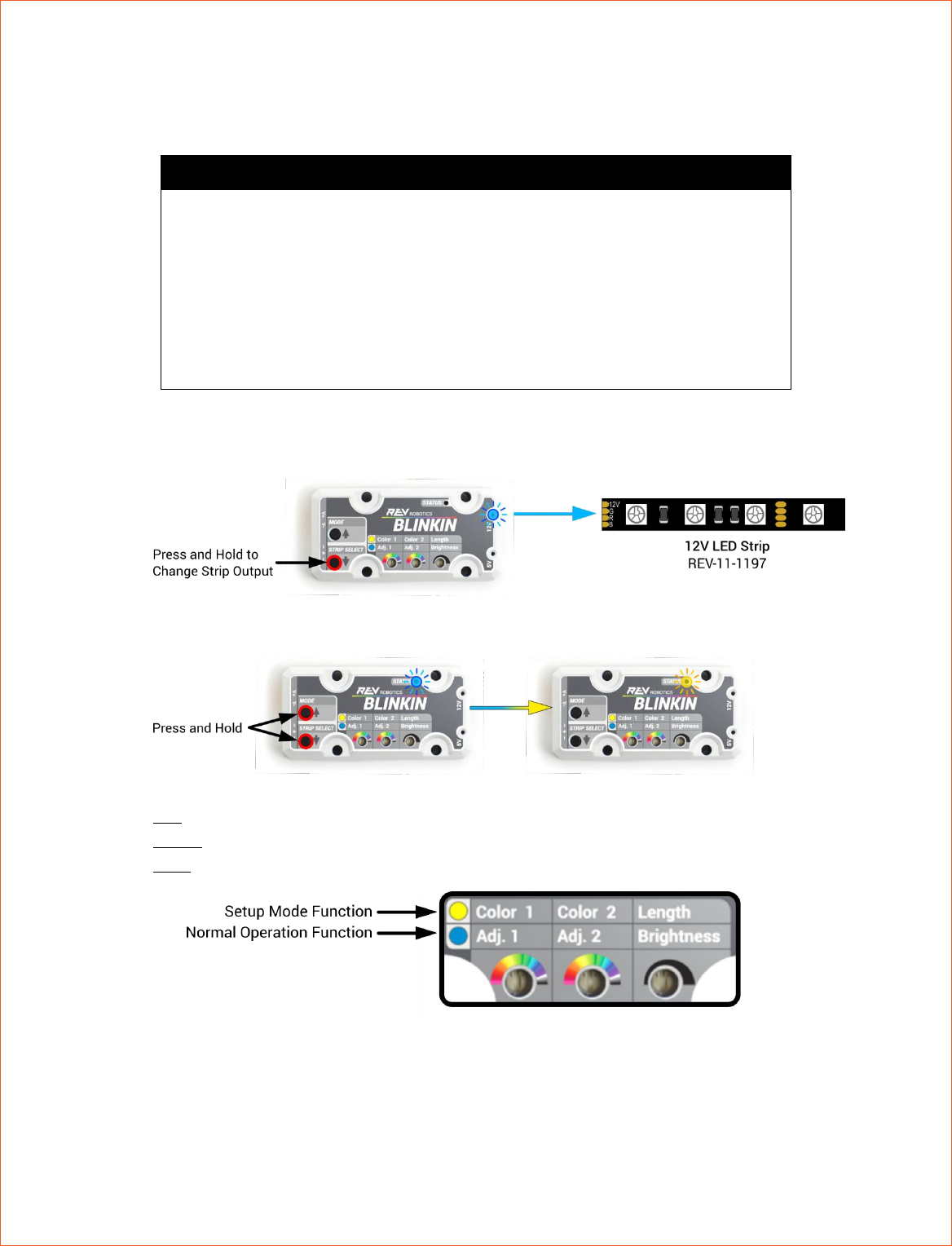
Setup and Adjustment – Three potentiometers are used to set customer color palette colors and addressable
strip length in set-up mode (Section 2.2), and are used to adjust brightness and other pattern properties like speed
and pattern density during normal operation (Section 2.5).
5V/12V LED Indicators – Indicate which kind of strip is currently selected as the output type (Section 2.1).
LED Strip Connection – Use the included JST PH, 7-pin to JST SM pigtail connector to connect to LED strip(s).
1.2 KIT CONTENTS
Table 1: Kit Contents
QTY
Part Number
Contents
1
REV-11-1105
REV-11-1105 Blinkin LED Driver
1
REV-11-1130*
PWM Cable
1
REV-31-1394*
XT30 Adapter Cable (Female Connector Only)
1
REV-11-1196
LED Adapter Cable
1
Small Screw Driver for Adjustment
* Exact part included may vary, but is functionally equivalent to listed part number
1.3 ELECTRICAL RATINGS
REV-11-1105-UM-0 Copyright © 2018 REV Robotics, LLC 4
12V Input
Recommended input operating voltage is from 5.5V to 13.5V. Absolute input
voltage range is 5.2V- 25V—use caution before exceeding the recommended
input range to prevent damage.
Minimum start-up operation for the 5V LEDs is 7V.
12V LEDs output is driven directly off this input voltage therefore lower or
significantly higher input voltage may not allow for proper operation and may
result in damage.
12V LED Output
Maximum of 12A output. Supports a minimum of 300 LEDs in series, or up to
two strings of 300 in parallel. * Equivalent to 10m of LEDs on 60 LED/m
strips.
5V LED Output
Maximum of 5A output. Supports up to 240 LEDs for more patterns and
brightness. * Equivalent to 5m of LEDs on 60LED/m strips.
* If LEDs near the end of a strip are dimmer, off color or behaving erratically either the strip current is exceeding
the current capability of the Blinkin or there is too much voltage drop over the strip length.
Problem: LEDs near the end of a strip are dimmer, off color, or behaving erratically.
Possible Cause: LEDs are exceeding Blinkin current supply.
Solution: Turn down the strip brightness, shorten the strip, or use a pattern with less LEDs lit at the same time.
Possible Cause: There is too much voltage drop over the length of the strip so LEDs near the end don’t have
enough voltage to operate properly.
Solution: Shorten the LED strip or if more LEDs are needed shorten the strip and run the remaining strip in parallel
to the other strip
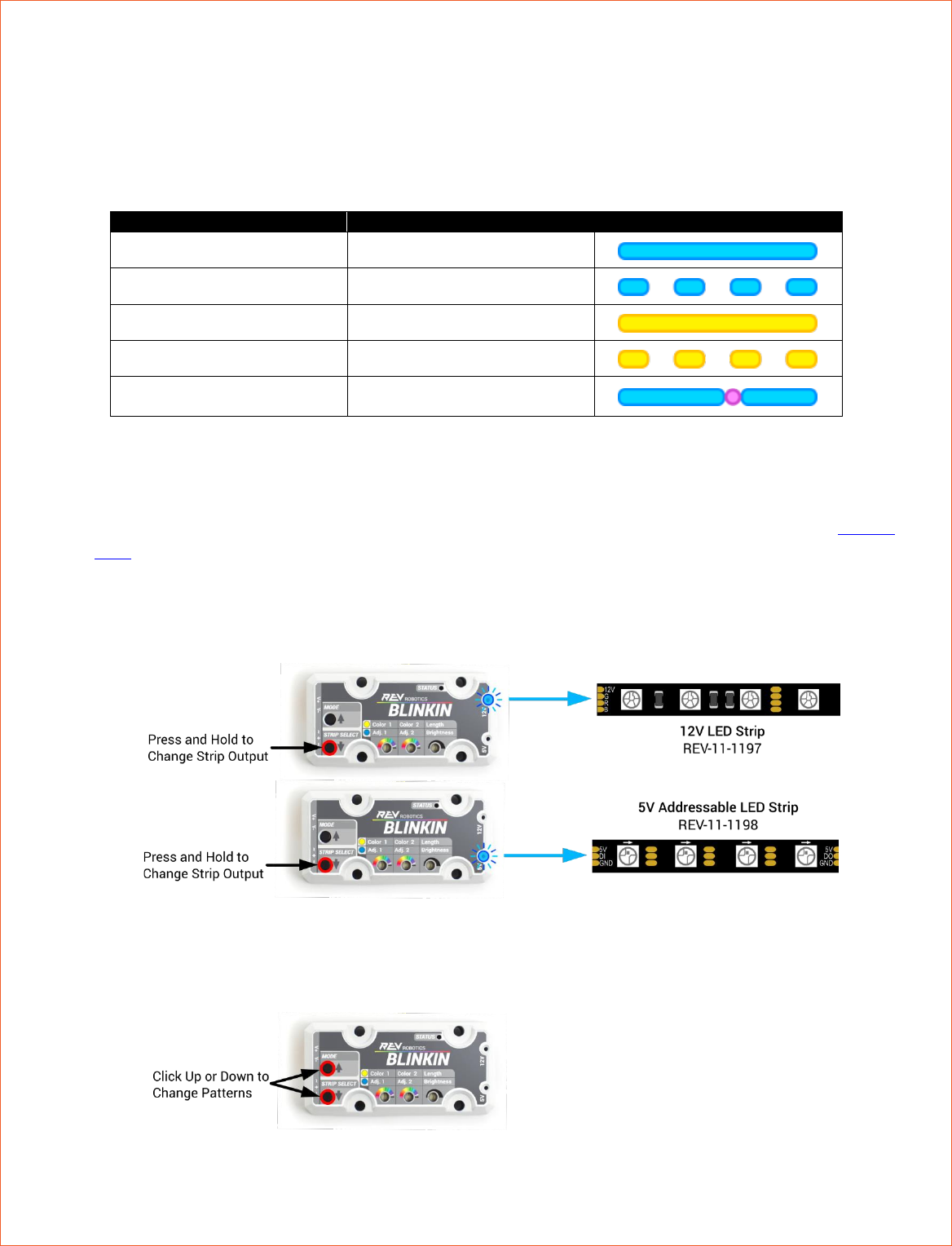
1.4 SUPPORTED LED STRIP TYPES
The BLINKIN can drive either 12V RGB LEDs or 5V Individual addressable LED strips. Each strip type has its own benefits
and drawbacks depending on what type of light display is desired.
12V LEDs
These LEDs are all connected together so the strip will always be all the same solid color,
but this kind of LED strip is generally cheaper than the 5V kind. BLINKIN is designed for 12V
Common Anode LEDs such as REV-11-1197. These strips have a four-wire interface and can
be cut to length every three LEDs.
5V LEDs
BLINKIN can control the WS2812 5V individually addressable LED type strips such as REV-
11-1198. This kind of strip is more expensive than the 12V type, but each individual LED can
be a different color and brightness to create very colorful animations. These strips have a 3-
wire interface and can be cut to length between each LED.
REV-11-1105-UM-0 Copyright © 2018 REV Robotics, LLC 5
2 SETUP AND CONFIGURATION
The Blinkin operates in two modes, normal runtime operation and set-up mode. The Status LED will also indicate whether
the Blinkin is currently measuring a valid PWM signal. See Table 2 for details.
Table 2: Status LED Blink Codes
State
PWM Measured
Status LED
Normal Operation
Valid PWM Input Detected
Normal Operation
No PWM Input Detected
Setup Mode
Valid PWM Input Detected
Setup Mode
No PWM Input Detected
Command Signal Detected—
see Section 1 for details
2.1 GETTING STARTED
1. Connect 12V power to the Blinkin using the yellow XT30
2. Select either a 12V or 5V Addressable LED strip and connect it to the Blinkin via the LED cable adapter (REV-11-
1196)
3. If the LED output indicator for the 12V/5V strip which is connected is not lit, press and hold the Strip Select
button until the corresponding strip indicator LED is lit. Your LED strip should now be displaying the default
pattern (29 – Color Waves, Party Palette), or the user programmed default pattern.
4. With no input PWM active (blue blinking Status LED), clicking (short press) the Up (Mode) and Down (Strip
Select) buttons will change the pattern being displayed (See Section 5 for complete pattern list). This pattern will
reset to the default after a power cycle unless the default is changed using the setup mode.
REV-11-1105-UM-0 Copyright © 2018 REV Robotics, LLC 6
2.2 SETUP MODE
In addition to the pre-programmed fixed color palette patterns the Blinkin can be customized to use user selected colors
and strip length to create more custom look. These settings can be saved in to permanent memory so they persist
through power cycles.
Customizable Features
• Addressable Strip Length
Up to 240 WS2812 LEDs
• Team Color 1 and Team Color 2
Select two of 22 different color options to represent your team colors
• Default No Signal Pattern
Select which pattern is displayed with there is not PWM input
(e.g. a disabled FRC robot)
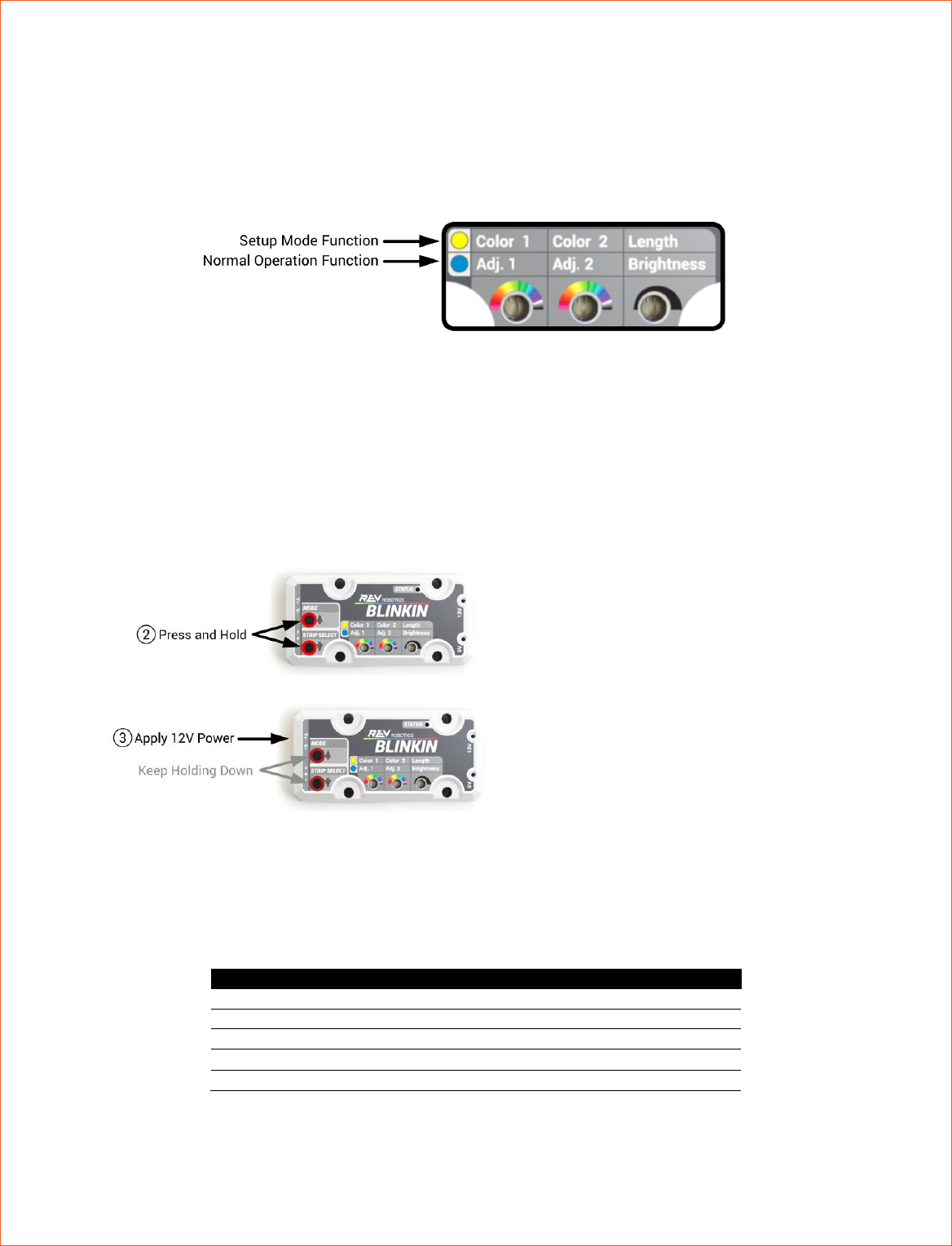
1. Power up the Blinkin as described in Section 2.1. The LED strip selected cannot be changed during setup mode,
so ensure that the desired strip is connected and running before continuing.
2. To enter Setup Mode, press and hold the Mode button for ~6 seconds, the Status LED will change from blue to
yellow. The LED strip will automatically display pattern 75 which uses Color 1 and Color 2 to aid in configuration.
3. Use the included small screwdriver to adjust the three adjustment potentiometers
• Left: Color 1 – Primary Pattern Color
• Middle: Color 2 – Secondary Pattern Color
• Right: Addressable Strip Number of LEDs (1-240)
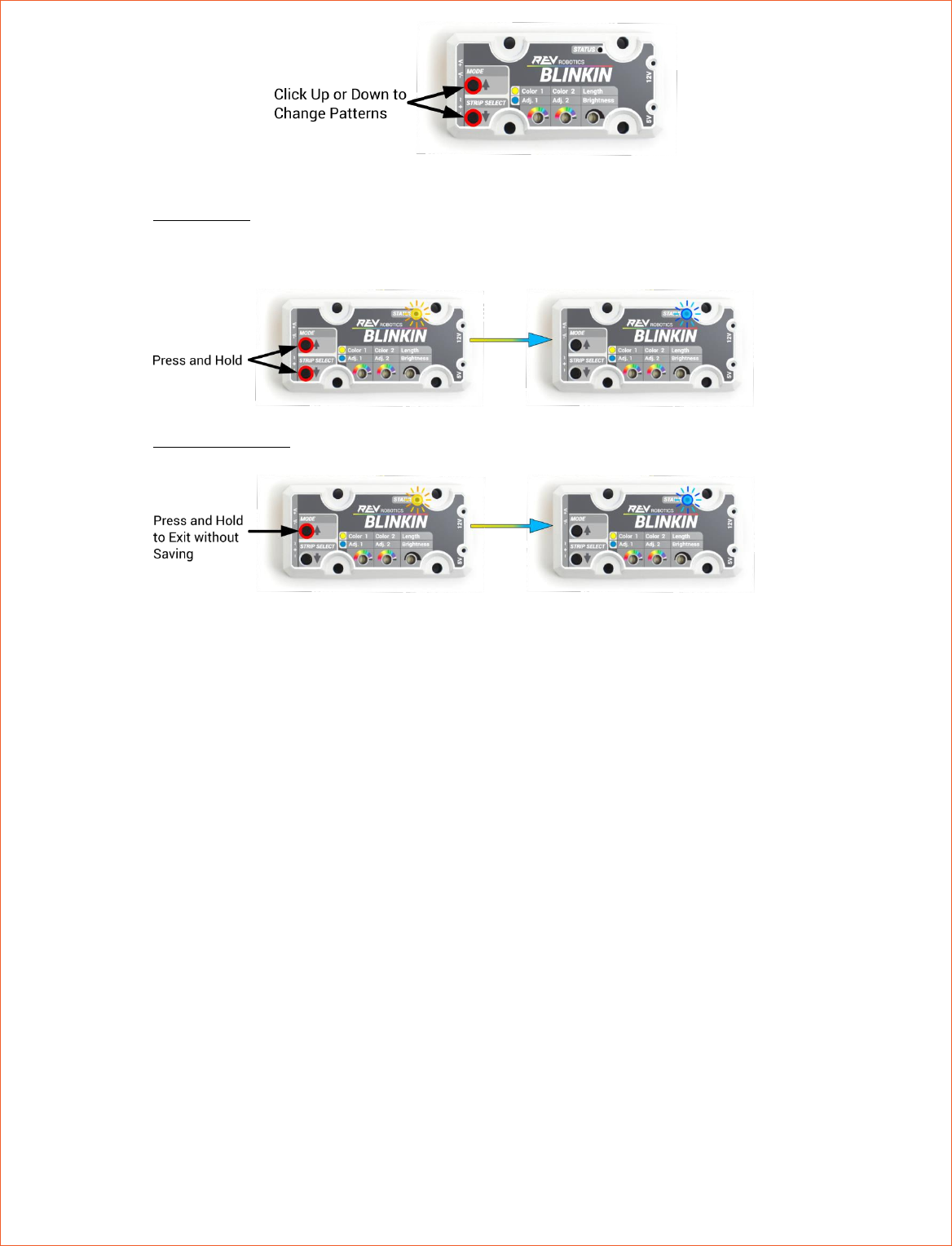
4. With no input PWM signal (yellow blinking Status LED), select the default no signal pattern by clicking (short
press) the Up (Mode) and Down (Strip Select) buttons until the desired pattern is displayed. Leave the displayed
pattern on the test pattern (75) on exit to leave the default no signal pattern unchanged.
REV-11-1105-UM-0 Copyright © 2018 REV Robotics, LLC 7
5. To Exit Setup mode:
• Save and Exit: Press and hold the Mode and Strip Select buttons for ~6 seconds. colors, strip length and
new default no signal pattern values are permanently saved in EEPROM and will persist between power
cycles.
• Exit without Saving: press and hold the Mode button. Nothing is saved and Blinkin will return to its
previously saved state after power cycle.
6. The Status LED will return to blue when Setup Mode has been exited
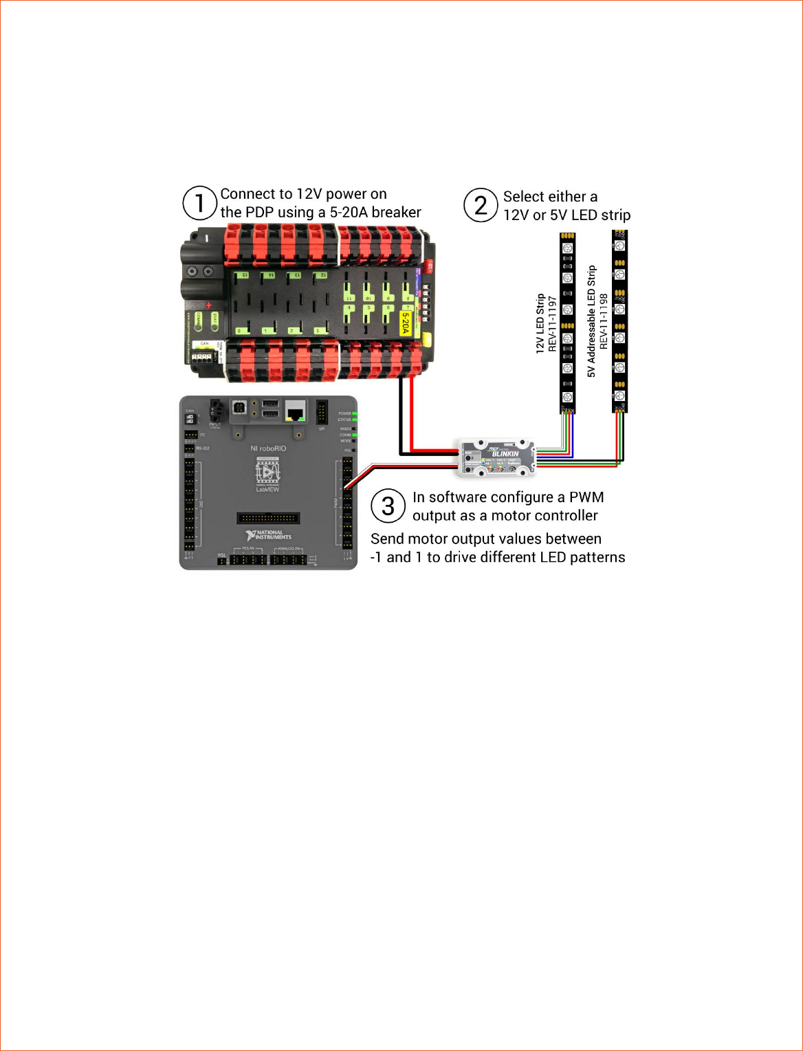
2.3 PWM CONTROL
The Blinkin can be controlled via software using a standard servo-style PWM signal. The Blinkin measures the width of the
incoming pulse from the PWM signal, and then based on that value selects a pattern from a corresponding pattern table.
Valid input pulse widths are from 1000us to 2000us.
1. Connect the Blinkin to a PWM control port on the roboRIO (or other controller) using a standard PWM cable.
2. Using the programming language of your choice, generate a PWM signal.
• For use with the FRC, create a motor of type SPARK. (Other Motor and Servo types will work, but might
change the values associated with specific patterns)
3. In your main robot code where motor (or servo) output power is normally updated, set your output power to the
value corresponding to the pattern desired (see Section 5). The output pattern can be changed during a match by
updating the motor output power (in FRC, from -1 to 1). This can be tied to a button pressed by the driver, or
automated based on sensor input or other events.
REV-11-1105-UM-0 Copyright © 2018 REV Robotics, LLC 8
2.4 FIRST ROBOTICS PROGRAMMING EXAMPLE
In the FRC control system, motor outputs range varies depending on which type of motor controller is initialized. The
output pulse range is scaled from the user requested output power of -1 to 1 to the range defined for each type of Motor
controller.
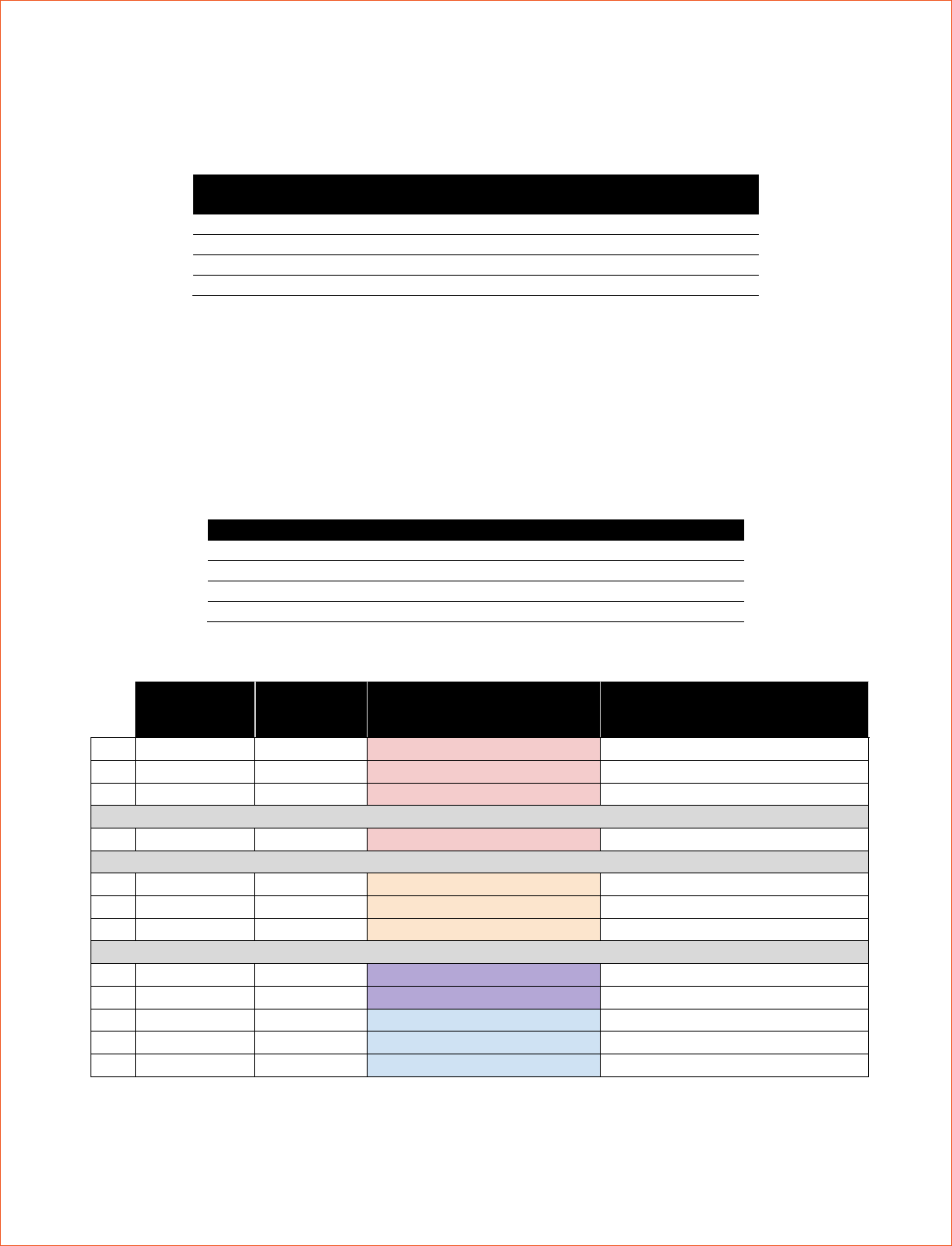
Table 3: WPI Motor Control Output PWM Range
WPI Motor Control
Open Type
Minimum Pulse
Width Output (us)
Maximum Pulse
Width Output (us)
SPARK
1000
2000
SRX
997
2004
Talon SR
989
2037
Jaguar
697
2322
From Table 3, the SPARK motor controller type output directly matches the input to the Blinkin, which makes the math to
convert the -1 to 1 code range to the 1000-2000us Blinkin input range the simplest. Other control types, including servo,
from the roboRIO can also be used, but the user will need to scale input range correctly to ensure they are sending only a
valid PWM range and that they can select the desired LED pattern.
As an example, referencing Table 5 includes an excerpt from the Section 5 LED PATTERN TABLE, and includes the correct
SPARK motor output value for each pattern Table 4 lists motor control values associated with specific patterns:
Table 4: Example SPARK Control Values based on Table 5
LED Color/Pattern
Motor Output Value
Ocean Colored Rainbow
-0.95
Larson Scanner (Similar to a Cylon)
-0.35
Fast Heartbeat in User Selected Team Color 1
0.07
Solid Blue
0.87
Table 5: Excerpt from Section 5 LED Pattern List
Pulse Width
(us)
roboRIO
SPARK
Value
Pattern Type
5V Strip Pattern
1
1005
-0.99
Fixed Palette Pattern
Rainbow, Rainbow Palette
2
1015
-0.97
Fixed Palette Pattern
Rainbow, Party Palette
3
1025
-0.95
Fixed Palette Pattern
Rainbow, Ocean Palette
...
33
1325
-0.35
Fixed Palette Pattern
Larson Scanner, Red
...
52
1515
0.03
Color 1 Pattern
Heartbeat Slow
53
1525
0.05
Color 1 Pattern
Heartbeat Medium
54
1535
0.07
Color 1 Pattern
Heartbeat Fast
...
77
1765
0.53
Color 1 and 2 Pattern
Color Waves, Color 1 and 2
94
1935
0.87
Solid Colors
Blue
95
1945
0.89
Solid Colors
Blue Violet
96
1955
0.91
Solid Colors
Violet
REV-11-1105-UM-0 Copyright © 2018 REV Robotics, LLC 9
2.5 PATTERN ADUSTMENTS
All of the LED strips and patterns can have their overall brightness adjusted and many of the patterns can be adjusted to
change the pattern density and speed. Section 5 details what patterns have which adjustments.
1. In Normal Mode (Not in Setup Mode) select a pattern which is adjustable
2. Using the small included screwdriver and change Adj.1 Adj.2 and brightness to change the pattern behavior
2.6 FACTORY RESET
The Blinkin can store custom user setting in EEPROM so that it persists through power cycles, see Section 2.2 for details.
Restore the Blinkin to factory default settings using the following procedure:
1. Power off the Blinkin
2. Press and hold the Mode and Strip Select buttons
3. Power on the Blinkin
4. Wait for ~2 Seconds
5. Release the Mode and Strip Select buttons
After completing the factory reset the default values found in Table 6 will be reloaded into permanent memory.
Table 6: Blinkin Factory Default Values
Variable
Default Value
Color 1
Sky Blue – 0x0080FF
Color 2
Gold – 0xFFEA00
Strip Length
60 LEDs
No Signal Pattern
29 – Color Waves, Party Palette
Strip Select
5V
REV-11-1105-UM-0 Copyright © 2018 REV Robotics, LLC 10
3 EXAMPLE APPLICATIONS
3.1 FIRST ROBOTICS COMPETITION
Always be sure to read the relevant rules and use appropriate gauge wiring before using anything on your competition
robot.
After wiring you Blinkin into your robot, follow the setup instructions in Section 2.2 and follow the instructions on PWM
control in Section 2.3 as desired.
REV-11-1105-UM-0 Copyright © 2018 REV Robotics, LLC 11
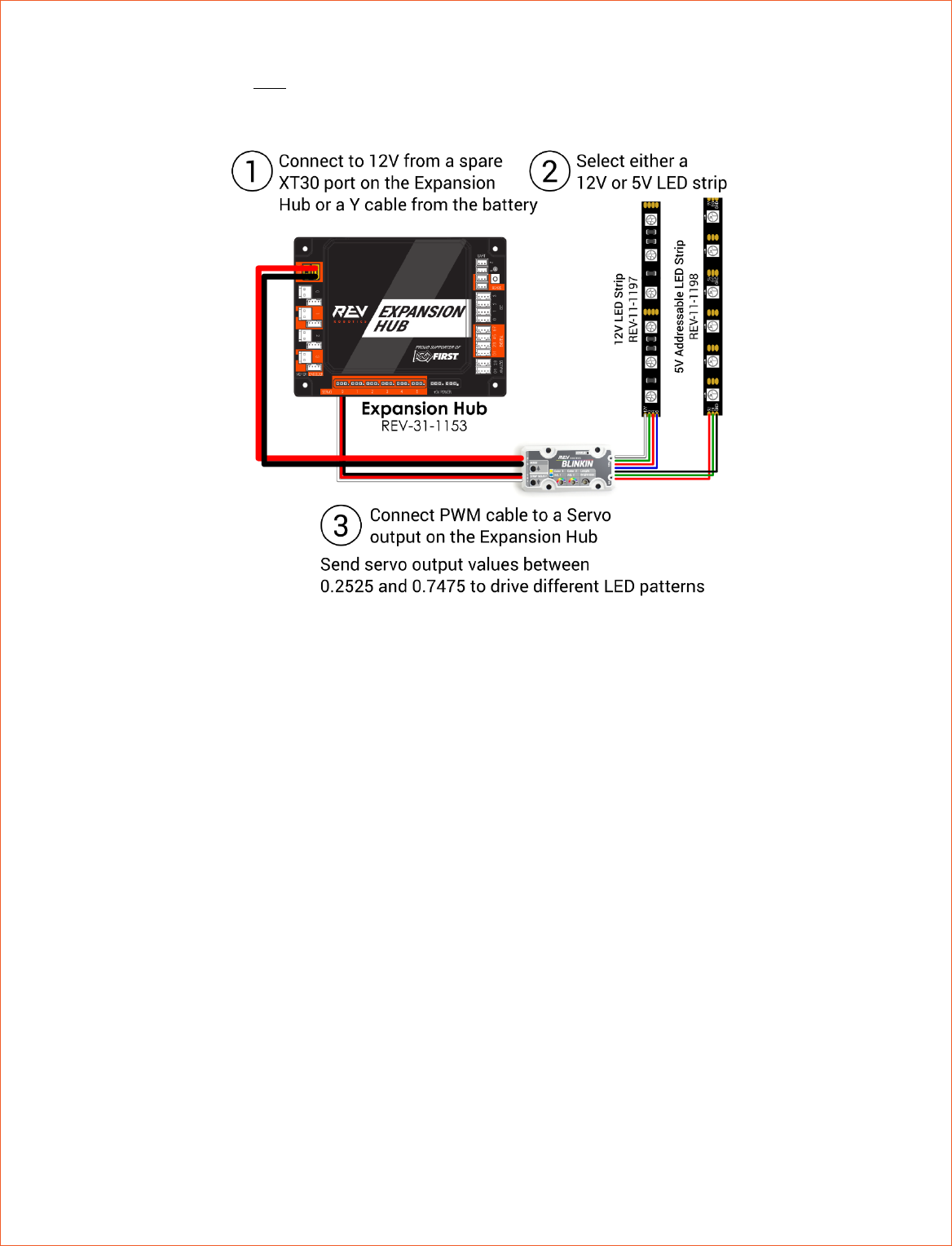
3.2 FIRST TECH CHALLENGE
Please note that the Blinkin is NOT competition legal for the 2017-2018 FTC season. The following wiring information is
for adding LEDs for demonstrations and unofficial events.
REV-11-1105-UM-0 Copyright © 2018 REV Robotics, LLC 12
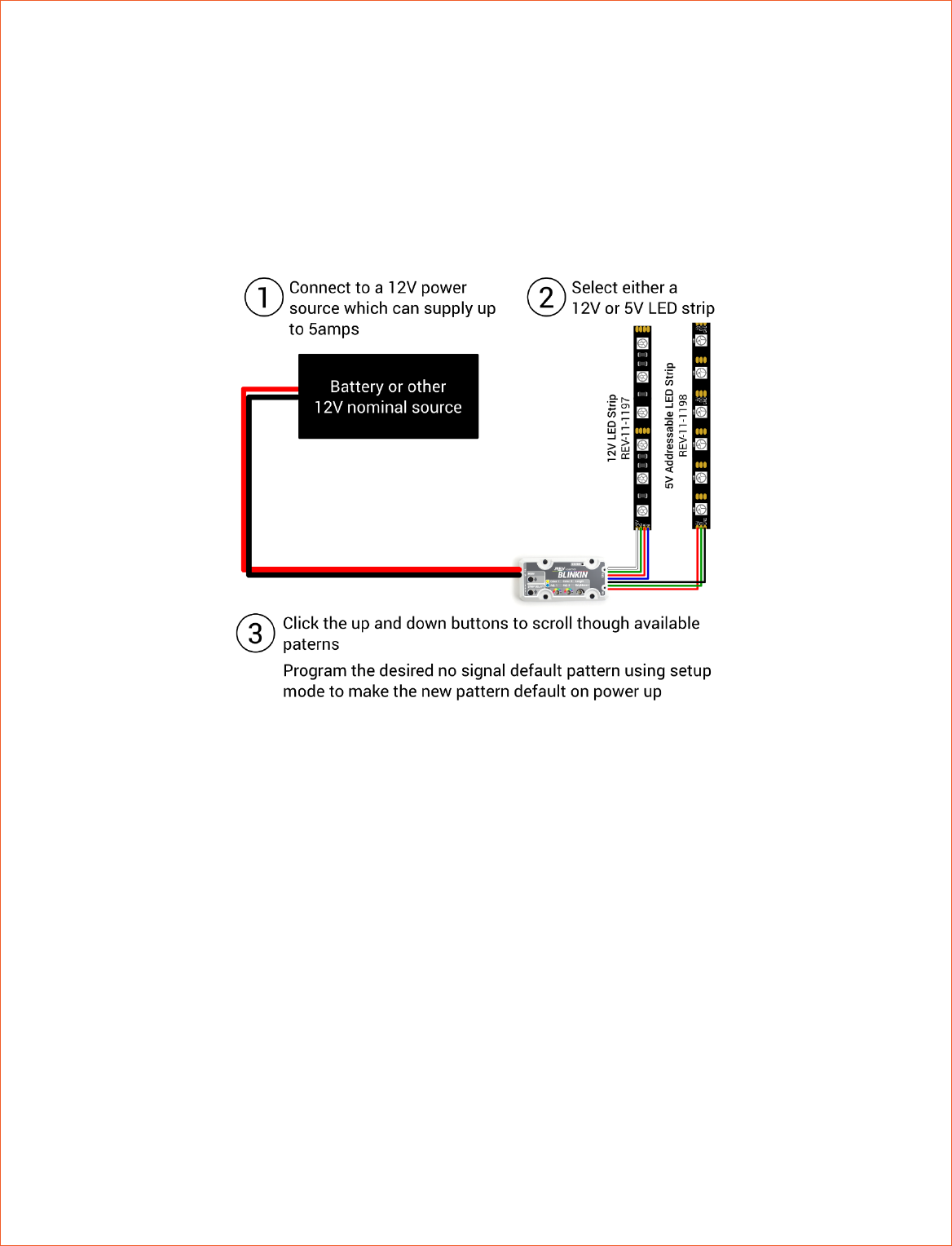
3.3 STAND-ALONE WIRING
The Blinkin can run in a stand-alone operation mode when there is no way to generate a PWM signal, or a single output
pattern is all that is needed. In this mode the Blinkin will be operating in Normal Mode with no input signal (blue blinking
LED) and will default to the programmed no input signal pattern (factory setting is pattern 29 – Color Waves, Party
Palette).
The currently displayed pattern can be changed at any time by pressing the up and down buttons to scroll through the
pattern list (Section 5). Unless a new default no signal test pattern is saved in memory by completing the setup mode
process, the Blinkin will default back to the last saved pattern after a power cycle.
3.4 COMPETITION ROBOTICS APPLICATION IDEAS
Adding LEDs to your robot (or other project) can do more than just make them look cool, you can use LEDs to provide
critical visual feedback. Here are some examples:
• Program a controller button to change the LED output pattern (e.g. 85 – Solid Yellow) and the drive can use the
LEDs to communicate to the human player at a portal station across the field that the robot is ready to receive a
game object.
• If the driver has poor visibility to see if the robot has acquired a game object, add a sensor to the intake and the
LED strip can be programmed to automatically display a new pattern when the object is acquired. The driver never
has to take their eyes off the robot to check the dashboard because the robot will clearly display its status.
• Using the match time value available in software, the LEDs can be changes to a time warning pattern (e.g. – Solid
Red) with X seconds left in a match.
• The robot can display a different pattern when enabled vs disabled which provides a more visible indicator of the
state of the robot than the RSL.
REV-11-1105-UM-0 Copyright © 2018 REV Robotics, LLC 13
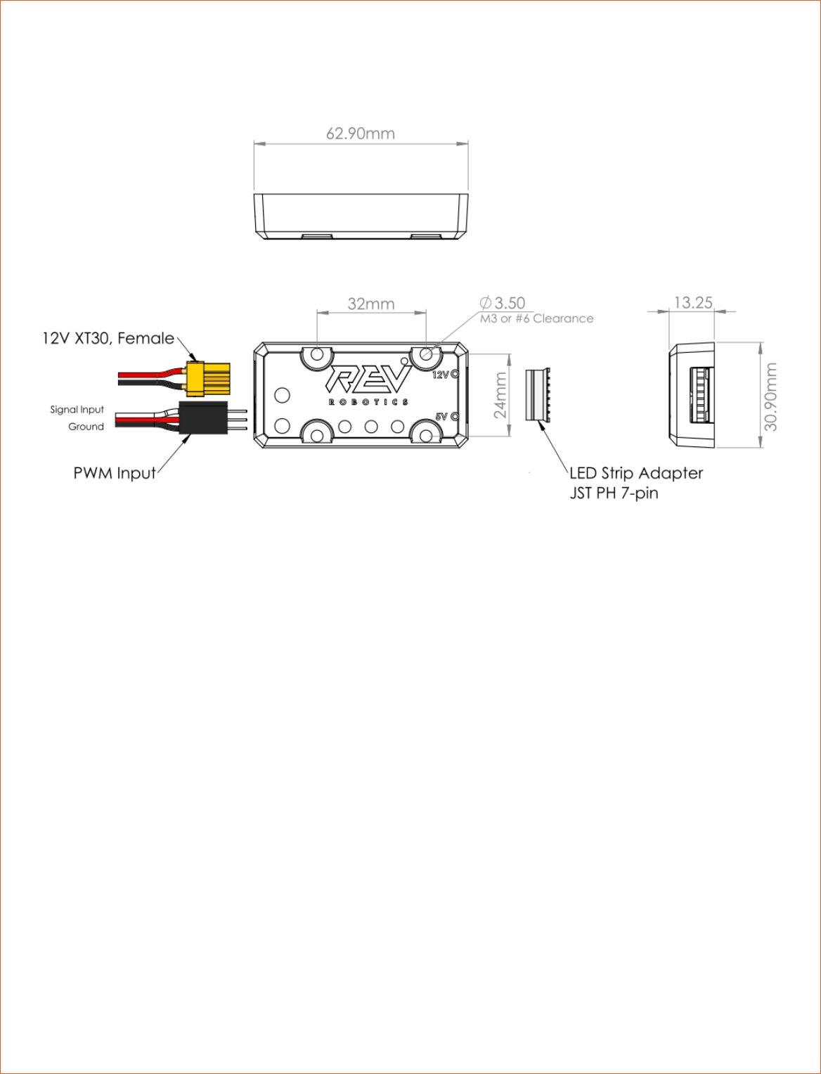
4 PHYSICAL DIMENSIONS
REV-11-1105-UM-0 Copyright © 2018 REV Robotics, LLC 14
5 LED PATTERN TABLE
Pulse Width
(us)
roboRIO
SPARK
Value
Pattern Type
5V Strip Pattern
Normal Operation
Adjustment 1
Normal Operation
Adjustment 2
Normal Operation
Brightness
1
1005
-0.99
Fixed Palette Pattern
Rainbow, Rainbow Palette
Pattern Density
Speed
Brightness
2
1015
-0.97
Fixed Palette Pattern
Rainbow, Party Palette
Pattern Density
Speed
Brightness
3
1025
-0.95
Fixed Palette Pattern
Rainbow, Ocean Palette
Pattern Density
Speed
Brightness
4
1035
-0.93
Fixed Palette Pattern
Rainbow, Lave Palette
Pattern Density
Speed
Brightness
5
1045
-0.91
Fixed Palette Pattern
Rainbow, Forest Palette
Pattern Density
Speed
Brightness
6
1055
-0.89
Fixed Palette Pattern
Rainbow with Glitter
Pattern Density
Speed
Brightness
7
1065
-0.87
Fixed Palette Pattern
Confetti
Pattern Density
Speed
Brightness
8
1075
-0.85
Fixed Palette Pattern
Shot, Red
-
-
Brightness
9
1085
-0.83
Fixed Palette Pattern
Shot, Blue
-
-
Brightness
10
1095
-0.81
Fixed Palette Pattern
Shot, White
-
-
Brightness
11
1105
-0.79
Fixed Palette Pattern
Sinelon, Rainbow Palette
Pattern Density
Speed
Brightness
12
1115
-0.77
Fixed Palette Pattern
Sinelon, Party Palette
Pattern Density
Speed
Brightness
13
1125
-0.75
Fixed Palette Pattern
Sinelon, Ocean Palette
Pattern Density
Speed
Brightness
14
1135
-0.73
Fixed Palette Pattern
Sinelon, Lava Palette
Pattern Density
Speed
Brightness
15
1145
-0.71
Fixed Palette Pattern
Sinelon, Forest Palette
Pattern Density
Speed
Brightness
16
1155
-0.69
Fixed Palette Pattern
Beats per Minute, Rainbow Palette
Pattern Density
Speed
Brightness
17
1165
-0.67
Fixed Palette Pattern
Beats per Minute, Party Palette
Pattern Density
Speed
Brightness
18
1175
-0.65
Fixed Palette Pattern
Beats per Minute, Ocean Palette
Pattern Density
Speed
Brightness
19
1185
-0.63
Fixed Palette Pattern
Beats per Minute, Lava Palette
Pattern Density
Speed
Brightness
20
1195
-0.61
Fixed Palette Pattern
Beats per Minute, Forest Palette
Pattern Density
Speed
Brightness
21
1205
-0.59
Fixed Palette Pattern
Fire, Medium
-
-
Brightness
22
1215
-0.57
Fixed Palette Pattern
Fire, Large
-
-
Brightness
23
1225
-0.55
Fixed Palette Pattern
Twinkles, Rainbow Palette
-
-
Brightness
24
1235
-0.53
Fixed Palette Pattern
Twinkles, Party Palette
-
-
Brightness
25
1245
-0.51
Fixed Palette Pattern
Twinkles, Ocean Palette
-
-
Brightness
This table primarily describes the behavior of the 5V addressable LEDs
as they are capable of more complicated patterns. 12V LEDs will all
show patterns with the same color palette as the pattern selected and
the speed can be adjusted as indicated for the selected pattern.
REV-11-1105-UM-0 Copyright © 2018 REV Robotics, LLC 15
26
1255
-0.49
Fixed Palette Pattern
Twinkles, Lava Palette
-
-
Brightness
27
1265
-0.47
Fixed Palette Pattern
Twinkles, Forest Palette
-
-
Brightness
28
1275
-0.45
Fixed Palette Pattern
Color Waves, Rainbow Palette
-
-
Brightness
29
1285
-0.43
Fixed Palette Pattern
Color Waves, Party Palette
-
-
Brightness
30
1295
-0.41
Fixed Palette Pattern
Color Waves, Ocean Palette
-
-
Brightness
31
1305
-0.39
Fixed Palette Pattern
Color Waves, Lava Palette
-
-
Brightness
32
1315
-0.37
Fixed Palette Pattern
Color Waves, Forest Palette
-
-
Brightness
33
1325
-0.35
Fixed Palette Pattern
Larson Scanner, Red
Pattern Width
Speed
Brightness
34
1335
-0.33
Fixed Palette Pattern
Larson Scanner, Gray
Pattern Width
Speed
Brightness
35
1345
-0.31
Fixed Palette Pattern
Light Chase, Red
Dimming
Speed
Brightness
36
1355
-0.29
Fixed Palette Pattern
Light Chase, Blue
Dimming
Speed
Brightness
37
1365
-0.27
Fixed Palette Pattern
Light Chase, Gray
Dimming
Speed
Brightness
38
1375
-0.25
Fixed Palette Pattern
Heartbeat, Red
-
-
Brightness
39
1385
-0.23
Fixed Palette Pattern
Heartbeat, Blue
-
-
Brightness
40
1395
-0.21
Fixed Palette Pattern
Heartbeat, White
-
-
Brightness
41
1405
-0.19
Fixed Palette Pattern
Heartbeat, Gray
-
-
Brightness
42
1415
-0.17
Fixed Palette Pattern
Breath, Red
-
-
Brightness
43
1425
-0.15
Fixed Palette Pattern
Breath, Blue
-
-
Brightness
44
1435
-0.13
Fixed Palette Pattern
Breath, Gray
-
-
Brightness
45
1445
-0.11
Fixed Palette Pattern
Strobe, Red
-
-
Brightness
46
1455
-0.09
Fixed Palette Pattern
Strobe, Blue
-
-
Brightness
47
1465
-0.07
Fixed Palette Pattern
Strobe, Gold
-
-
Brightness
48
1475
-0.05
Fixed Palette Pattern
Strobe, White
-
-
Brightness
49
1485
-0.03
Color 1 Pattern
End to End Blend to Black
-
-
Brightness
50
1495
-0.01
Color 1 Pattern
Larson Scanner
Pattern Width
Speed
Brightness
51
1505
0.01
Color 1 Pattern
Light Chase
Dimming
Speed
Brightness
52
1515
0.03
Color 1 Pattern
Heartbeat Slow
-
-
Brightness
53
1525
0.05
Color 1 Pattern
Heartbeat Medium
-
-
Brightness
54
1535
0.07
Color 1 Pattern
Heartbeat Fast
-
-
Brightness
55
1545
0.09
Color 1 Pattern
Breath Slow
-
-
Brightness
56
1555
0.11
Color 1 Pattern
Breath Fast
-
-
Brightness
57
1565
0.13
Color 1 Pattern
Shot
-
-
Brightness
58
1575
0.15
Color 1 Pattern
Strobe
-
-
Brightness
59
1585
0.17
Color 2 Pattern
End to End Blend to Black
-
-
Brightness
60
1595
0.19
Color 2 Pattern
Larson Scanner
Pattern Width
Speed
Brightness
61
1605
0.21
Color 2 Pattern
Light Chase
Dimming
Speed
Brightness
62
1615
0.23
Color 2 Pattern
Heartbeat Slow
-
-
Brightness
63
1625
0.25
Color 2 Pattern
Heartbeat Medium
-
-
Brightness
REV-11-1105-UM-0 Copyright © 2018 REV Robotics, LLC 16
64
1635
0.27
Color 2 Pattern
Heartbeat Fast
-
-
Brightness
65
1645
0.29
Color 2 Pattern
Breath Slow
-
-
Brightness
66
1655
0.31
Color 2 Pattern
Breath Fast
-
-
Brightness
67
1665
0.33
Color 2 Pattern
Shot
-
-
Brightness
68
1675
0.35
Color 2 Pattern
Strobe
-
-
Brightness
69
1685
0.37
Color 1 and 2 Pattern
Sparkle, Color 1 on Color 2
-
-
Brightness
70
1695
0.39
Color 1 and 2 Pattern
Sparkle, Color 2 on Color 1
-
-
Brightness
71
1705
0.41
Color 1 and 2 Pattern
Color Gradient, Color 1 and 2
-
-
Brightness
72
1715
0.43
Color 1 and 2 Pattern
Beats per Minute, Color 1 and 2
Pattern Density
Speed
Brightness
73
1725
0.45
Color 1 and 2 Pattern
End to End Blend, Color 1 to 2
-
-
Brightness
74
1735
0.47
Color 1 and 2 Pattern
End to End Blend
-
-
Brightness
75
1745
0.49
Color 1 and 2 Pattern
Color 1 and Color 2 no blending (Setup
Pattern)
-
-
Brightness
76
1755
0.51
Color 1 and 2 Pattern
Twinkles, Color 1 and 2
-
-
Brightness
77
1765
0.53
Color 1 and 2 Pattern
Color Waves, Color 1 and 2
-
-
Brightness
78
1775
0.55
Color 1 and 2 Pattern
Sinelon, Color 1 and 2
Pattern Density
Speed
Brightness
79
1785
0.57
Solid Colors
Hot Pink
-
-
Brightness
80
1795
0.59
Solid Colors
Dark red
-
-
Brightness
81
1805
0.61
Solid Colors
Red
-
-
Brightness
82
1815
0.63
Solid Colors
Red Orange
-
-
Brightness
83
1825
0.65
Solid Colors
Orange
-
-
Brightness
84
1835
0.67
Solid Colors
Gold
-
-
Brightness
85
1845
0.69
Solid Colors
Yellow
-
-
Brightness
86
1855
0.71
Solid Colors
Lawn Green
-
-
Brightness
87
1865
0.73
Solid Colors
Lime
-
-
Brightness
88
1875
0.75
Solid Colors
Dark Green
-
-
Brightness
89
1885
0.77
Solid Colors
Green
-
-
Brightness
90
1895
0.79
Solid Colors
Blue Green
-
-
Brightness
91
1905
0.81
Solid Colors
Aqua
-
-
Brightness
92
1915
0.83
Solid Colors
Sky Blue
-
-
Brightness
93
1925
0.85
Solid Colors
Dark Blue
-
-
Brightness
94
1935
0.87
Solid Colors
Blue
-
-
Brightness
95
1945
0.89
Solid Colors
Blue Violet
-
-
Brightness
96
1955
0.91
Solid Colors
Violet
-
-
Brightness
97
1965
0.93
Solid Colors
White
-
-
Brightness
98
1975
0.95
Solid Colors
Gray
-
-
Brightness
99
1985
0.97
Solid Colors
Dark Gray
-
-
Brightness
100
1995
0.99
Solid Colors
Black
-
-
Brightness
