Ray Marine Tiller Drive Installation Instructions 87061 2 EN
User Manual: Pdf
Open the PDF directly:
View PDF
.
Page Count: 18
56937
Installation Guide
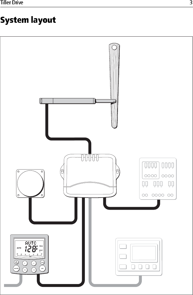
System layout
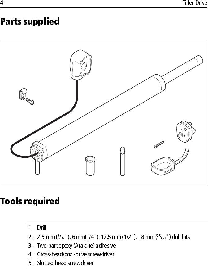
Parts supplied
Tools required
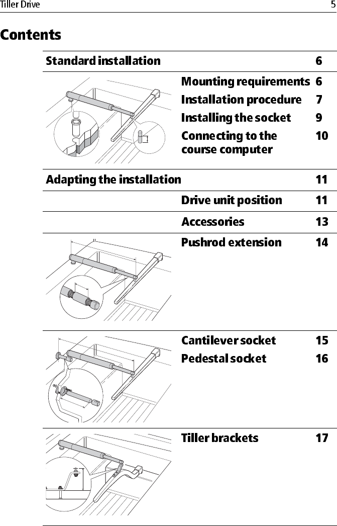
Contents
6
11
Cantilever socket
Tiller brackets
17
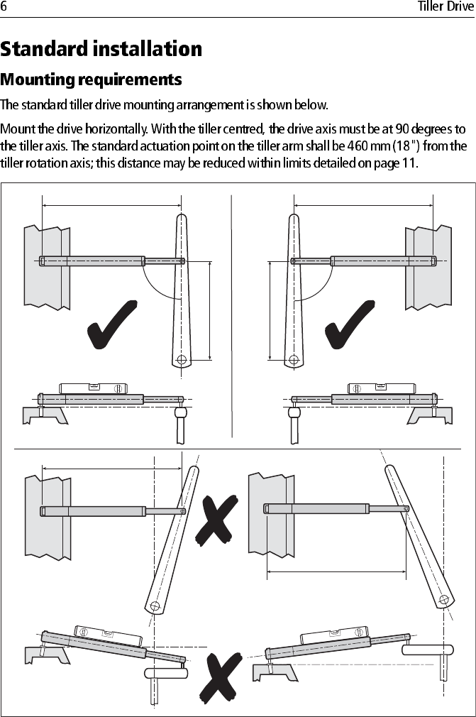
Standard installation
Mounting requirements
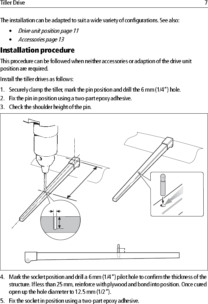
Installation procedure
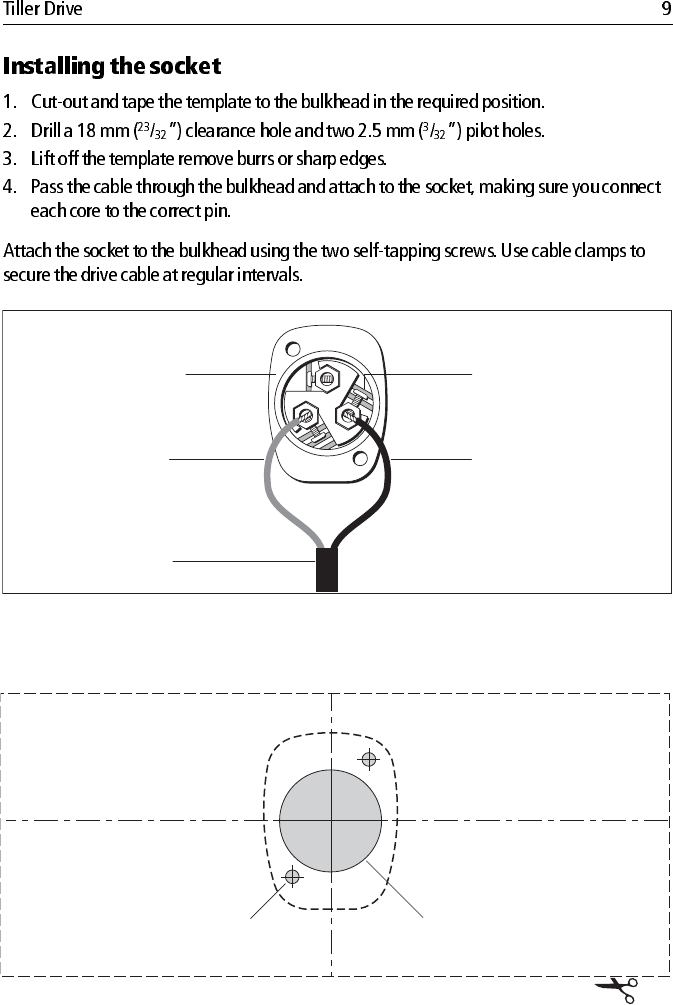
Installing the socket
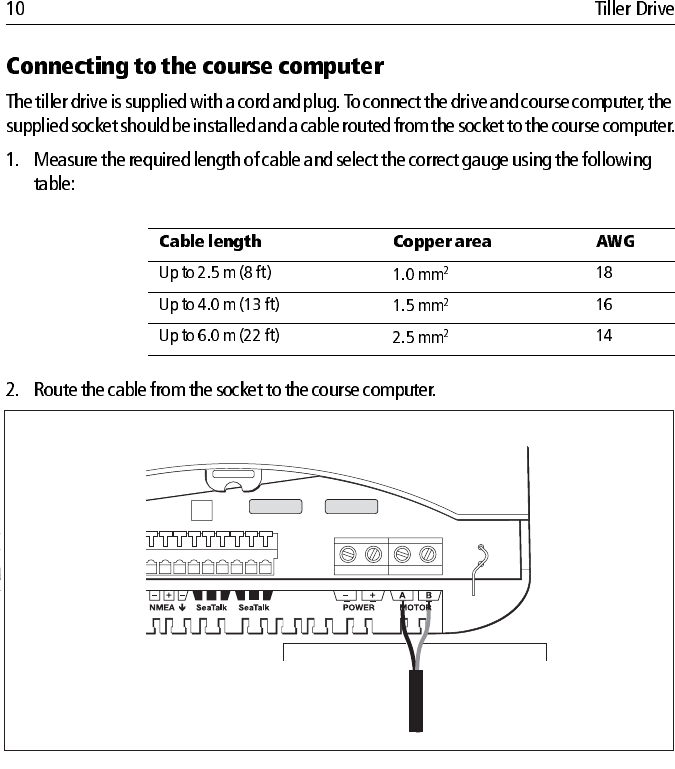
Connecting to the course computer
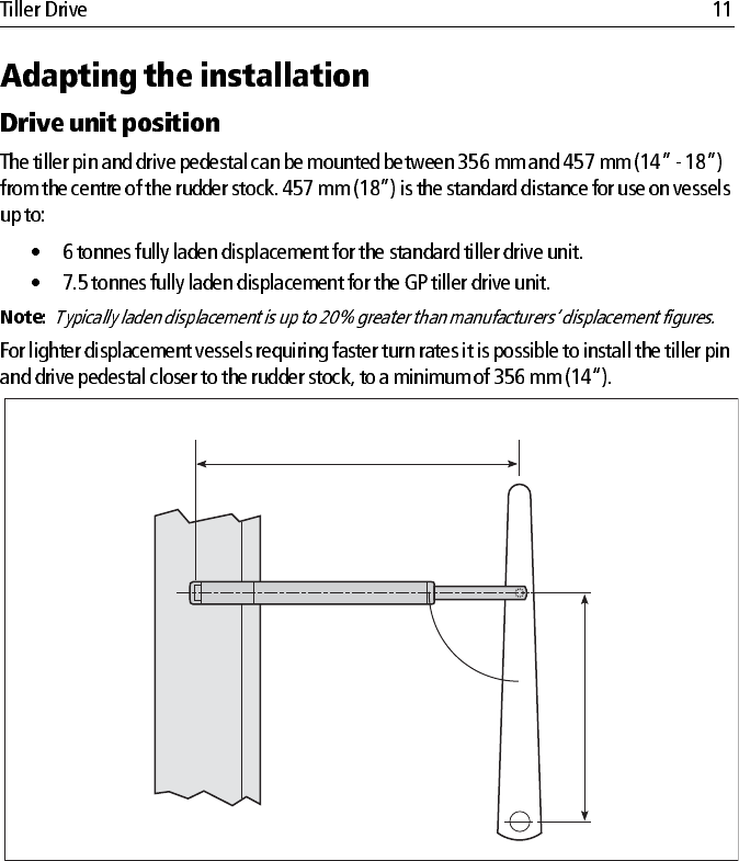
Adapting the installation
Drive unit position
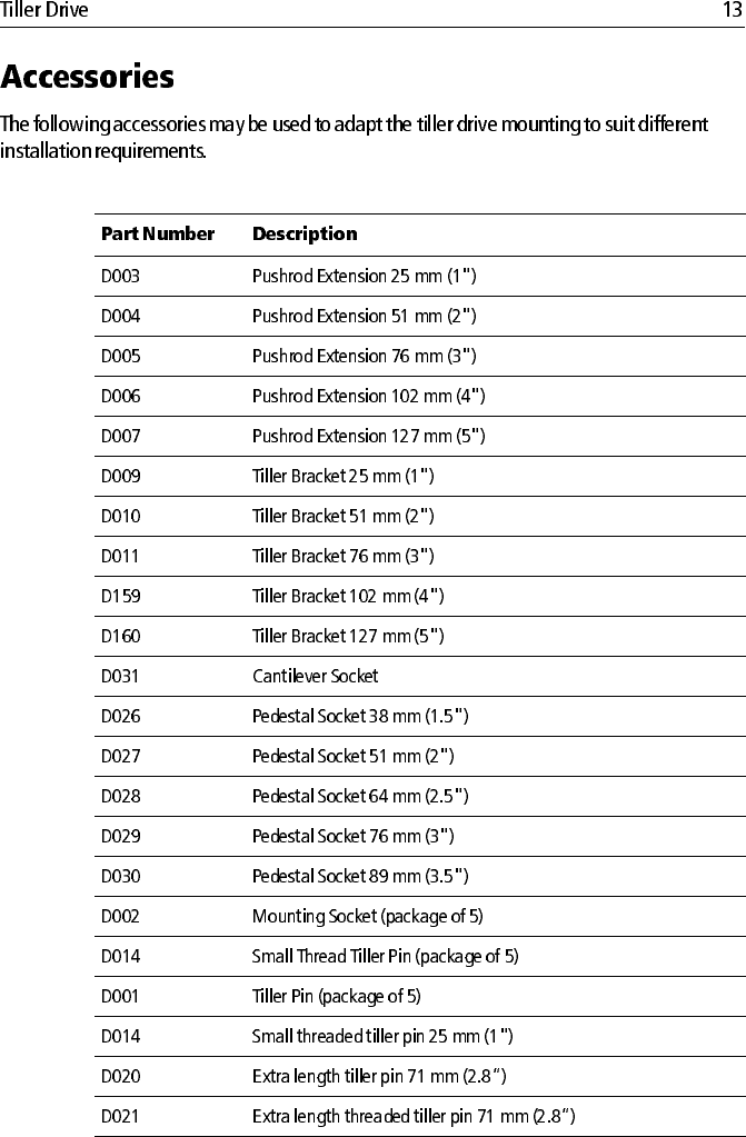
Accessories
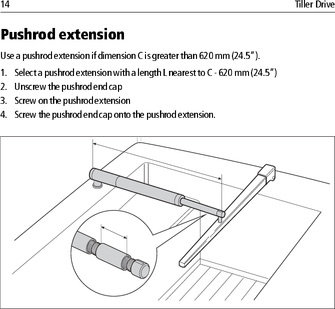
Pushrod extension
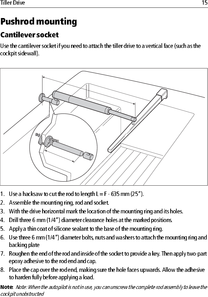
Pushrod mounting
Cantilever socket
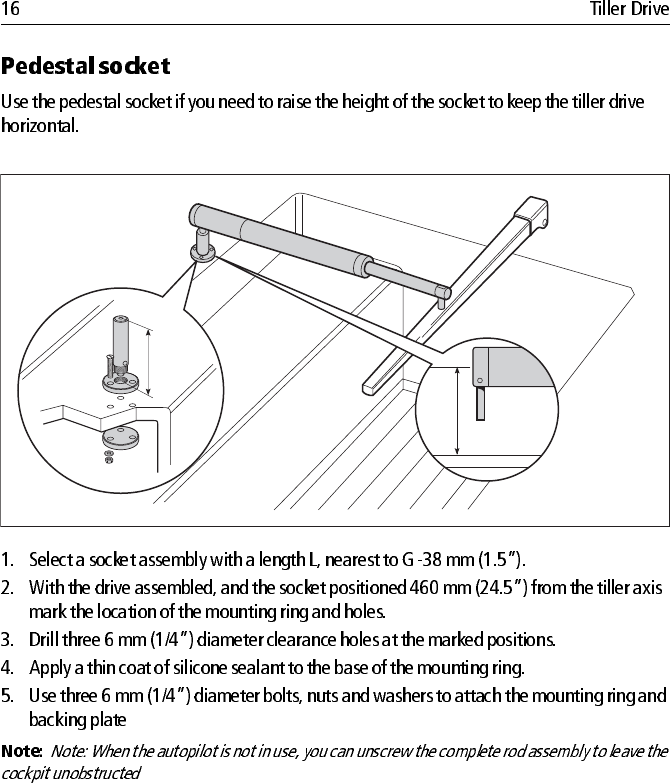
Pedestal socket
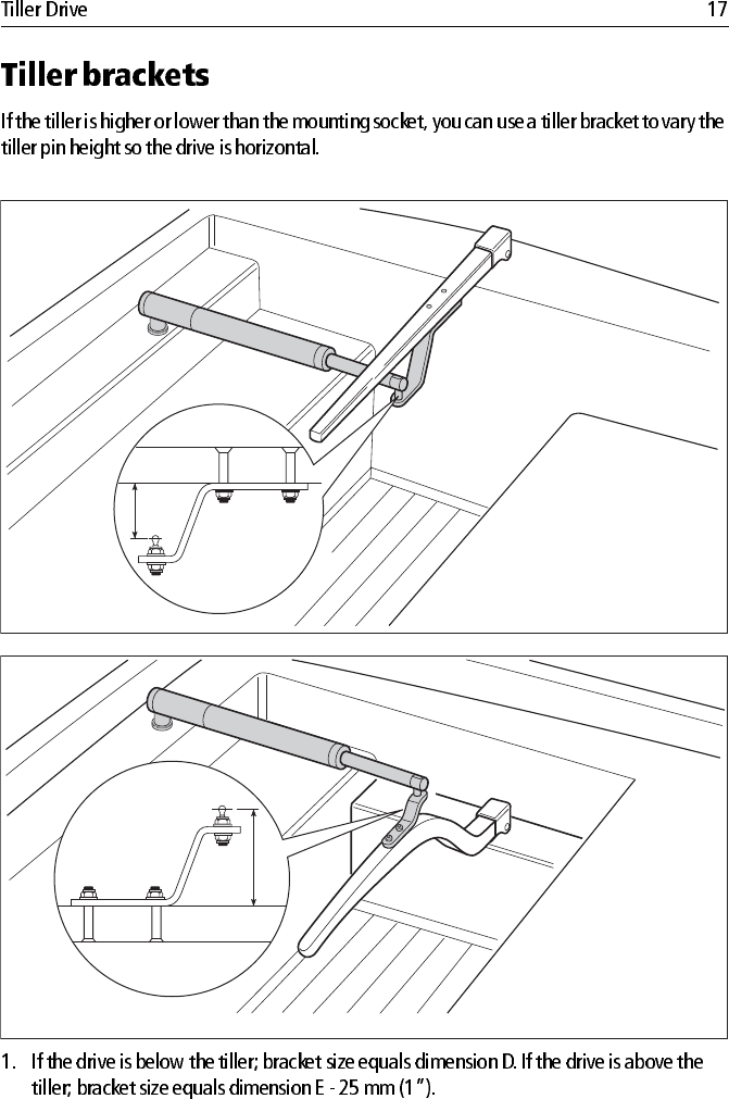
Tiller brackets
Boat's electrical
distribution panel
Control unit
Fluxgate compass
NMEA
instrument
or navigator
D8922-1
Course computer
Tiller drive
D5437-2
Mounting
sock
et
T
iller
pin
Sock
et
Plug
Sock
et screw
No 4 x 3/4 in (x2)
T
iller drive
Tiller drive parts
Cable clip
and screw
,
No 6 x 1/2 in
Mounting socket
12.5 mm
(0.5 in)
Tiller pin
L
C
L
F
E
620mm (24.5")
620mm (24.5")
D8819_2
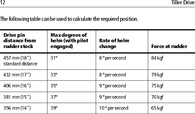
457 mm (18 in)
457 mm (18 in)
90
o
90
o
620mm (24.5")
620mm (24.5")
D8818-2
12.5 mm
(0.5 in)
6 mm
(0.25 in)
12.5 mm
(0.5 in)
T
wo part
epoxy
adhesive
to fix tiller
pin in
place
1. 2.
3.
Allow epoxy to fully harden
before applying load.
457 mm (18 in)
25mm
(1.0 in)
D8831_2
620 mm (24.5 in)
4.
5.
6.
12.5 mm
(1/2 in)
T
wo part
epoxy adhesive
to fix mounting
sock
et in place
457 mm (18 in)
D8840-1
Drive (brown)
2 stripe terminal
Drive (blue)
3 stripe terminal
To the
control unit
Terminal
identification
stripes
Rear of sock
et
Drill 2.5 mm (3/32 inch)
diameter hole (2 positions)
Drill 18 mm (23/32 inch)
diameter hole
Tiller drive - socket template
D5411-2
Brown
Blue
D9446-1
RF GND
POWER IN
SEA
TALK
Course computer
D9291_1
356 mm to 457 mm (14 in to 18 in)
90˚
620mm (24.5")
Tiller Drive Unit Position Range
L
C
D8812_1
L
F
D
8
8
1
6_
1
G
D8817_!
L
D8813_1
D
E
D8814_1
D8815_2
90 degrees
457 mm (18 in)