Red Hat OpenStack Platform 10 Networking Guide Open Stack En US
User Manual: Pdf
Open the PDF directly: View PDF ![]() .
.
Page Count: 137 [warning: Documents this large are best viewed by clicking the View PDF Link!]
- Table of Contents
- PREFACE
- CHAPTER 1. NETWORKING OVERVIEW
- CHAPTER 2. OPENSTACK NETWORKING CONCEPTS
- PART I. COMMON TASKS
- CHAPTER 3. COMMON ADMINISTRATIVE TASKS
- 3.1. Create a network
- 3.2. Create an advanced network
- 3.3. Add network routing
- 3.4. Delete a network
- 3.5. Purge a tenant’s networking
- 3.6. Create a subnet
- 3.7. Delete a subnet
- 3.8. Add a router
- 3.9. Delete a router
- 3.10. Add an interface
- 3.11. Delete an interface
- 3.12. Configure IP addressing
- 3.13. Create multiple floating IP pools
- 3.14. Bridge the physical network
- CHAPTER 4. PLANNING IP ADDRESS USAGE
- CHAPTER 5. REVIEW OPENSTACK NETWORKING ROUTER PORTS
- CHAPTER 6. TROUBLESHOOT PROVIDER NETWORKS
- CHAPTER 7. CONNECT AN INSTANCE TO THE PHYSICAL NETWORK
- CHAPTER 8. CONFIGURE PHYSICAL SWITCHES FOR OPENSTACK NETWORKING
- 8.1. Planning your physical network environment
- 8.2. Configure a Cisco Catalyst switch
- 8.3. Configure a Cisco Nexus switch
- 8.4. Configure a Cumulus Linux switch
- 8.5. Configure an Extreme Networks EXOS switch
- 8.6. Configure a Juniper EX Series switch
- PART II. ADVANCED CONFIGURATION
- CHAPTER 9. CONFIGURE MTU SETTINGS
- CHAPTER 10. CONFIGURE QUALITY-OF-SERVICE (QOS)
- CHAPTER 11. CONFIGURE BRIDGE MAPPINGS
- CHAPTER 12. CONFIGURE RBAC
- CHAPTER 13. CONFIGURE DISTRIBUTED VIRTUAL ROUTING (DVR)
- CHAPTER 14. CONFIGURE LOAD BALANCING-AS-A-SERVICE (LBAAS)
- CHAPTER 15. TENANT NETWORKING WITH IPV6
- CHAPTER 16. MANAGE TENANT QUOTAS
- CHAPTER 17. CONFIGURE FIREWALL-AS-A-SERVICE (FWAAS)
- CHAPTER 18. CONFIGURE ALLOWED-ADDRESS-PAIRS
- CHAPTER 19. CONFIGURE LAYER 3 HIGH AVAILABILITY
- CHAPTER 20. USE TAGGING FOR VIRTUAL DEVICE IDENTIFICATION
- CHAPTER 21. SR-IOV SUPPORT FOR VIRTUAL NETWORKING
- 21.1. Configure SR-IOV in your Red Hat OpenStack Platform deployment
- 21.2. Create Virtual Functions on the Compute node
- 21.3. Configure SR-IOV on the Network Node
- 21.4. Configure SR-IOV on the Controller Node
- 21.5. Configure SR-IOV in Compute
- 21.6. Enable the OpenStack Networking SR-IOV agent
- 21.7. Configure an instance to use the SR-IOV port
- 21.8. Review the allow_unsafe_interrupts setting
- 21.9. Add a Physical Function to an Instance
- 21.10. Additional considerations

Red Hat OpenStack Platform 10
Networking Guide
An Advanced Guide to OpenStack Networking
Last Updated: 2018-01-05


Red Hat OpenStack Platform 10 Networking Guide
An Advanced Guide to OpenStack Networking
OpenStack Team
rhos-docs@redhat.com

Legal Notice
Copyright © 2018 Red Hat, Inc.
The text of and illustrations in this document are licensed by Red Hat under a Creative Commons
Attribution–Share Alike 3.0 Unported license ("CC-BY-SA"). An explanation of CC-BY-SA is
available at
http://creativecommons.org/licenses/by-sa/3.0/
. In accordance with CC-BY-SA, if you distribute this document or an adaptation of it, you must
provide the URL for the original version.
Red Hat, as the licensor of this document, waives the right to enforce, and agrees not to assert,
Section 4d of CC-BY-SA to the fullest extent permitted by applicable law.
Red Hat, Red Hat Enterprise Linux, the Shadowman logo, JBoss, OpenShift, Fedora, the Infinity
logo, and RHCE are trademarks of Red Hat, Inc., registered in the United States and other
countries.
Linux ® is the registered trademark of Linus Torvalds in the United States and other countries.
Java ® is a registered trademark of Oracle and/or its affiliates.
XFS ® is a trademark of Silicon Graphics International Corp. or its subsidiaries in the United
States and/or other countries.
MySQL ® is a registered trademark of MySQL AB in the United States, the European Union and
other countries.
Node.js ® is an official trademark of Joyent. Red Hat Software Collections is not formally related
to or endorsed by the official Joyent Node.js open source or commercial project.
The OpenStack ® Word Mark and OpenStack logo are either registered trademarks/service marks
or trademarks/service marks of the OpenStack Foundation, in the United States and other
countries and are used with the OpenStack Foundation's permission. We are not affiliated with,
endorsed or sponsored by the OpenStack Foundation, or the OpenStack community.
All other trademarks are the property of their respective owners.
Abstract
A Cookbook for Common OpenStack Networking Tasks.

. . . . . . . . . . . . . . . . . . . . . . . . . . . . . . . . . . . . . . . . . . . . . . . . . . . . . . . . . . . . . . . . . . . . . . . . . . . . . . . . . . . . . . . . . . . . . . . . . . . . . . . . . . . . . . . . . . . . . . . . . . . . . . . . . . . . . . . . . . . . . . . . . . . . . . . . . . . . . . . . . . . . . . . . . . . . . . . . . . . . . . . . . . . . . . . . . . . . . . . . . . . . . . . . . . . . . . . . . . . . . . . . . . . . . . . . . . . . . . . . . . . . . . . . . . . . . . . . . . . . . . . . . . . . . . . . . . . . . . . .
. . . . . . . . . . . . . . . . . . . . . . . . . . . . . . . . . . . . . . . . . . . . . . . . . . . . . . . . . . . . . . . . . . . . . . . . . . . . . . . . . . . . . . . . . . . . . . . . . . . . . . . . . . . . . . . . . . . . . . . . . . . . . . . . . . . . . . . . . . . . . . . . . . . . . . . . . . . . . . . . . . . . . . . . . . . . . . . . . . . . . . . . . . . . . . . . . . . . . . . . . . . . . . . . . . . . . . . . . . . . . . . . . . . . . . . . . . . . . . . . . . . . . . . . . . . . . . . . . . . . . . . . . . . . . . . . . . . . . . . .
. . . . . . . . . . . . . . . . . . . . . . . . . . . . . . . . . . . . . . . . . . . . . . . . . . . . . . . . . . . . . . . . . . . . . . . . . . . . . . . . . . . . . . . . . . . . . . . . . . . . . . . . . . . . . . . . . . . . . . . . . . . . . . . . . . . . . . . . . . . . . . . . . . . . . . . . . . . . . . . . . . . . . . . . . . . . . . . . . . . . . . . . . . . . . . . . . . . . . . . . . . . . . . . . . . . . . . . . . . . . . . . . . . . . . . . . . . . . . . . . . . . . . . . . . . . . . . . . . . . . . . . . . . . . . . . . . . . . . . . .
. . . . . . . . . . . . . . . . . . . . . . . . . . . . . . . . . . . . . . . . . . . . . . . . . . . . . . . . . . . . . . . . . . . . . . . . . . . . . . . . . . . . . . . . . . . . . . . . . . . . . . . . . . . . . . . . . . . . . . . . . . . . . . . . . . . . . . . . . . . . . . . . . . . . . . . . . . . . . . . . . . . . . . . . . . . . . . . . . . . . . . . . . . . . . . . . . . . . . . . . . . . . . . . . . . . . . . . . . . . . . . . . . . . . . . . . . . . . . . . . . . . . . . . . . . . . . . . . . . . . . . . . . . . . . . . . . . . . . . . .
. . . . . . . . . . . . . . . . . . . . . . . . . . . . . . . . . . . . . . . . . . . . . . . . . . . . . . . . . . . . . . . . . . . . . . . . . . . . . . . . . . . . . . . . . . . . . . . . . . . . . . . . . . . . . . . . . . . . . . . . . . . . . . . . . . . . . . . . . . . . . . . . . . . . . . . . . . . . . . . . . . . . . . . . . . . . . . . . . . . . . . . . . . . . . . . . . . . . . . . . . . . . . . . . . . . . . . . . . . . . . . . . . . . . . . . . . . . . . . . . . . . . . . . . . . . . . . . . . . . . . . . . . . . . . . . . . . . . . . . .
Table of Contents
PREFACE
1. OPENSTACK NETWORKING AND SDN
1.1. Topics covered in this book
2. THE POLITICS OF VIRTUAL NETWORKS
CHAPTER 1. NETWORKING OVERVIEW
1.1. How Networking Works
1.1.1. VLANs
1.2. Connecting two LANs together
1.2.1. Firewalls
1.3. OpenStack Networking (neutron)
1.4. Using CIDR format
CHAPTER 2. OPENSTACK NETWORKING CONCEPTS
2.1. Installing OpenStack Networking (neutron)
2.1.1. Supported installation
2.2. OpenStack Networking diagram
2.3. Security Groups
2.4. Open vSwitch
2.5. Modular Layer 2 (ML2)
2.5.1. The reasoning behind ML2
2.5.2. ML2 network types
2.5.3. ML2 Mechanism Drivers
2.6. L2 Population
2.7. OpenStack Networking Services
2.7.1. L3 Agent
2.7.2. DHCP Agent
2.7.3. Open vSwitch Agent
2.8. Tenant and Provider networks
2.8.1. Tenant networks
2.8.2. Provider networks
2.8.2.1. Flat provider networks
2.8.2.2. Configure controller nodes
2.8.2.3. Configure the Network and Compute nodes
2.8.2.4. Configure the network node
2.9. Layer 2 and layer 3 networking
2.9.1. Use switching where possible
PART I. COMMON TASKS
CHAPTER 3. COMMON ADMINISTRATIVE TASKS
3.1. Create a network
3.2. Create an advanced network
3.3. Add network routing
3.4. Delete a network
3.5. Purge a tenant’s networking
3.6. Create a subnet
3.6.1. Create a new subnet
3.7. Delete a subnet
3.8. Add a router
3.9. Delete a router
3.10. Add an interface
7
7
7
7
9
9
9
9
10
10
10
12
12
12
12
13
13
14
14
14
14
15
15
16
16
16
16
16
17
17
17
18
18
19
20
22
23
23
25
25
26
26
27
27
29
29
29
29
Table of Contents
1

. . . . . . . . . . . . . . . . . . . . . . . . . . . . . . . . . . . . . . . . . . . . . . . . . . . . . . . . . . . . . . . . . . . . . . . . . . . . . . . . . . . . . . . . . . . . . . . . . . . . . . . . . . . . . . . . . . . . . . . . . . . . . . . . . . . . . . . . . . . . . . . . . . . . . . . . . . . . . . . . . . . . . . . . . . . . . . . . . . . . . . . . . . . . . . . . . . . . . . . . . . . . . . . . . . . . . . . . . . . . . . . . . . . . . . . . . . . . . . . . . . . . . . . . . . . . . . . . . . . . . . . . . . . . . . . . . . . . . . . .
. . . . . . . . . . . . . . . . . . . . . . . . . . . . . . . . . . . . . . . . . . . . . . . . . . . . . . . . . . . . . . . . . . . . . . . . . . . . . . . . . . . . . . . . . . . . . . . . . . . . . . . . . . . . . . . . . . . . . . . . . . . . . . . . . . . . . . . . . . . . . . . . . . . . . . . . . . . . . . . . . . . . . . . . . . . . . . . . . . . . . . . . . . . . . . . . . . . . . . . . . . . . . . . . . . . . . . . . . . . . . . . . . . . . . . . . . . . . . . . . . . . . . . . . . . . . . . . . . . . . . . . . . . . . . . . . . . . . . . . .
. . . . . . . . . . . . . . . . . . . . . . . . . . . . . . . . . . . . . . . . . . . . . . . . . . . . . . . . . . . . . . . . . . . . . . . . . . . . . . . . . . . . . . . . . . . . . . . . . . . . . . . . . . . . . . . . . . . . . . . . . . . . . . . . . . . . . . . . . . . . . . . . . . . . . . . . . . . . . . . . . . . . . . . . . . . . . . . . . . . . . . . . . . . . . . . . . . . . . . . . . . . . . . . . . . . . . . . . . . . . . . . . . . . . . . . . . . . . . . . . . . . . . . . . . . . . . . . . . . . . . . . . . . . . . . . . . . . . . . . .
. . . . . . . . . . . . . . . . . . . . . . . . . . . . . . . . . . . . . . . . . . . . . . . . . . . . . . . . . . . . . . . . . . . . . . . . . . . . . . . . . . . . . . . . . . . . . . . . . . . . . . . . . . . . . . . . . . . . . . . . . . . . . . . . . . . . . . . . . . . . . . . . . . . . . . . . . . . . . . . . . . . . . . . . . . . . . . . . . . . . . . . . . . . . . . . . . . . . . . . . . . . . . . . . . . . . . . . . . . . . . . . . . . . . . . . . . . . . . . . . . . . . . . . . . . . . . . . . . . . . . . . . . . . . . . . . . . . . . . . .
. . . . . . . . . . . . . . . . . . . . . . . . . . . . . . . . . . . . . . . . . . . . . . . . . . . . . . . . . . . . . . . . . . . . . . . . . . . . . . . . . . . . . . . . . . . . . . . . . . . . . . . . . . . . . . . . . . . . . . . . . . . . . . . . . . . . . . . . . . . . . . . . . . . . . . . . . . . . . . . . . . . . . . . . . . . . . . . . . . . . . . . . . . . . . . . . . . . . . . . . . . . . . . . . . . . . . . . . . . . . . . . . . . . . . . . . . . . . . . . . . . . . . . . . . . . . . . . . . . . . . . . . . . . . . . . . . . . . . . . .
3.11. Delete an interface
3.12. Configure IP addressing
3.12.1. Create floating IP pools
3.12.2. Assign a specific floating IP
3.12.3. Assign a random floating IP
3.13. Create multiple floating IP pools
3.14. Bridge the physical network
CHAPTER 4. PLANNING IP ADDRESS USAGE
4.1. Using multiple VLANs
4.2. Isolating VLAN traffic
4.3. IP address consumption
4.4. Virtual Networking
4.5. Example network plan
CHAPTER 5. REVIEW OPENSTACK NETWORKING ROUTER PORTS
5.1. View current port status
CHAPTER 6. TROUBLESHOOT PROVIDER NETWORKS
6.1. Topics covered
6.2. Basic ping testing
6.3. Troubleshooting VLAN networks
6.3.1. Review the VLAN configuration and log files
6.4. Troubleshooting from within tenant networks
6.4.1. Perform advanced ICMP testing within the namespace
CHAPTER 7. CONNECT AN INSTANCE TO THE PHYSICAL NETWORK
7.1. Using Flat Provider Networks
7.1.1. The flow of outgoing traffic
7.1.2. The flow of incoming traffic
7.1.3. Troubleshooting
7.2. Using VLAN provider networks
7.2.1. The flow of outgoing traffic
7.2.2. The flow of incoming traffic
7.2.3. Troubleshooting
7.3. Enable Compute metadata access
7.4. Floating IP addresses
CHAPTER 8. CONFIGURE PHYSICAL SWITCHES FOR OPENSTACK NETWORKING
8.1. Planning your physical network environment
8.2. Configure a Cisco Catalyst switch
8.2.1. Configure trunk ports
8.2.1.1. Configure trunk ports for a Cisco Catalyst switch
8.2.2. Configure access ports
8.2.2.1. Configure access ports for a Cisco Catalyst switch
8.2.3. Configure LACP port aggregation
8.2.3.1. Configure LACP on the physical NIC
8.2.3.2. Configure LACP on a Cisco Catalyst switch
8.2.4. Configure MTU settings
8.2.4.1. Configure MTU settings on a Cisco Catalyst switch
8.2.5. Configure LLDP discovery
8.2.5.1. Configure LLDP on a Cisco Catalyst switch
8.3. Configure a Cisco Nexus switch
8.3.1. Configure trunk ports
30
30
30
31
31
32
32
33
33
33
35
35
35
37
37
39
39
39
41
41
42
43
45
45
48
50
51
53
55
58
59
60
60
61
61
62
62
62
63
63
64
64
65
66
66
67
67
67
67
Red Hat OpenStack Platform 10 Networking Guide
2

. . . . . . . . . . . . . . . . . . . . . . . . . . . . . . . . . . . . . . . . . . . . . . . . . . . . . . . . . . . . . . . . . . . . . . . . . . . . . . . . . . . . . . . . . . . . . . . . . . . . . . . . . . . . . . . . . . . . . . . . . . . . . . . . . . . . . . . . . . . . . . . . . . . . . . . . . . . . . . . . . . . . . . . . . . . . . . . . . . . . . . . . . . . . . . . . . . . . . . . . . . . . . . . . . . . . . . . . . . . . . . . . . . . . . . . . . . . . . . . . . . . . . . . . . . . . . . . . . . . . . . . . . . . . . . . . . . . . . . . .
. . . . . . . . . . . . . . . . . . . . . . . . . . . . . . . . . . . . . . . . . . . . . . . . . . . . . . . . . . . . . . . . . . . . . . . . . . . . . . . . . . . . . . . . . . . . . . . . . . . . . . . . . . . . . . . . . . . . . . . . . . . . . . . . . . . . . . . . . . . . . . . . . . . . . . . . . . . . . . . . . . . . . . . . . . . . . . . . . . . . . . . . . . . . . . . . . . . . . . . . . . . . . . . . . . . . . . . . . . . . . . . . . . . . . . . . . . . . . . . . . . . . . . . . . . . . . . . . . . . . . . . . . . . . . . . . . . . . . . . .
8.3.1.1. Configure trunk ports for a Cisco Nexus switch
8.3.2. Configure access ports
8.3.2.1. Configure access ports for a Cisco Nexus switch
8.3.3. Configure LACP port aggregation
8.3.3.1. Configure LACP on the physical NIC
8.3.3.2. Configure LACP on a Cisco Nexus switch
8.3.4. Configure MTU settings
8.3.4.1. Configure MTU settings on a Cisco Nexus 7000 switch
8.3.5. Configure LLDP discovery
8.3.5.1. Configure LLDP on a Cisco Nexus 7000 switch
8.4. Configure a Cumulus Linux switch
8.4.1. Configure trunk ports
8.4.1.1. Configure trunk ports for a Cumulus Linux switch
8.4.2. Configure access ports
8.4.2.1. Configuring access ports for a Cumulus Linux switch
8.4.3. Configure LACP port aggregation
8.4.3.1. Configure LACP on the physical NIC
8.4.3.2. Configure LACP on a Cumulus Linux switch
8.4.4. Configure MTU settings
8.4.4.1. Configure MTU settings on a Cumulus Linux switch
8.4.5. Configure LLDP discovery
8.5. Configure an Extreme Networks EXOS switch
8.5.1. Configure trunk ports
8.5.1.1. Configure trunk ports on an Extreme Networks EXOS switch
8.5.2. Configure access ports
8.5.2.1. Configure access ports for an Extreme Networks EXOS switch
8.5.3. Configure LACP port aggregation
8.5.3.1. Configure LACP on the physical NIC
8.5.3.2. Configure LACP on an Extreme Networks EXOS switch
8.5.4. Configure MTU settings
8.5.4.1. Configure MTU settings on an Extreme Networks EXOS switch
8.5.5. Configure LLDP discovery
8.5.5.1. Configure LLDP settings on an Extreme Networks EXOS switch
8.6. Configure a Juniper EX Series switch
8.6.1. Configure trunk ports
8.6.1.1. Configure trunk ports on the Juniper EX Series switch
8.6.2. Configure access ports
8.6.2.1. Configure access ports for a Juniper EX Series switch
8.6.3. Configure LACP port aggregation
8.6.3.1. Configure LACP on the physical NIC
8.6.3.2. Configure LACP on a Juniper EX Series switch
8.6.4. Configure MTU settings
8.6.4.1. Configure MTU settings on a Juniper EX Series switch
8.6.5. Configure LLDP discovery
8.6.5.1. Configure LLDP on a Juniper EX Series switch
PART II. ADVANCED CONFIGURATION
CHAPTER 9. CONFIGURE MTU SETTINGS
9.1. MTU overview
9.1.1. Configure MTU advertisement
9.1.2. Configure tenant networks
9.1.3. Configure MTU Settings in Director
68
68
68
68
69
69
70
70
70
70
70
70
71
71
71
72
72
72
72
72
73
73
73
73
73
73
74
74
75
75
75
75
75
76
76
76
76
76
77
77
78
79
79
80
80
81
82
82
83
83
83
Table of Contents
3

. . . . . . . . . . . . . . . . . . . . . . . . . . . . . . . . . . . . . . . . . . . . . . . . . . . . . . . . . . . . . . . . . . . . . . . . . . . . . . . . . . . . . . . . . . . . . . . . . . . . . . . . . . . . . . . . . . . . . . . . . . . . . . . . . . . . . . . . . . . . . . . . . . . . . . . . . . . . . . . . . . . . . . . . . . . . . . . . . . . . . . . . . . . . . . . . . . . . . . . . . . . . . . . . . . . . . . . . . . . . . . . . . . . . . . . . . . . . . . . . . . . . . . . . . . . . . . . . . . . . . . . . . . . . . . . . . . . . . . . .
. . . . . . . . . . . . . . . . . . . . . . . . . . . . . . . . . . . . . . . . . . . . . . . . . . . . . . . . . . . . . . . . . . . . . . . . . . . . . . . . . . . . . . . . . . . . . . . . . . . . . . . . . . . . . . . . . . . . . . . . . . . . . . . . . . . . . . . . . . . . . . . . . . . . . . . . . . . . . . . . . . . . . . . . . . . . . . . . . . . . . . . . . . . . . . . . . . . . . . . . . . . . . . . . . . . . . . . . . . . . . . . . . . . . . . . . . . . . . . . . . . . . . . . . . . . . . . . . . . . . . . . . . . . . . . . . . . . . . . . .
. . . . . . . . . . . . . . . . . . . . . . . . . . . . . . . . . . . . . . . . . . . . . . . . . . . . . . . . . . . . . . . . . . . . . . . . . . . . . . . . . . . . . . . . . . . . . . . . . . . . . . . . . . . . . . . . . . . . . . . . . . . . . . . . . . . . . . . . . . . . . . . . . . . . . . . . . . . . . . . . . . . . . . . . . . . . . . . . . . . . . . . . . . . . . . . . . . . . . . . . . . . . . . . . . . . . . . . . . . . . . . . . . . . . . . . . . . . . . . . . . . . . . . . . . . . . . . . . . . . . . . . . . . . . . . . . . . . . . . . .
. . . . . . . . . . . . . . . . . . . . . . . . . . . . . . . . . . . . . . . . . . . . . . . . . . . . . . . . . . . . . . . . . . . . . . . . . . . . . . . . . . . . . . . . . . . . . . . . . . . . . . . . . . . . . . . . . . . . . . . . . . . . . . . . . . . . . . . . . . . . . . . . . . . . . . . . . . . . . . . . . . . . . . . . . . . . . . . . . . . . . . . . . . . . . . . . . . . . . . . . . . . . . . . . . . . . . . . . . . . . . . . . . . . . . . . . . . . . . . . . . . . . . . . . . . . . . . . . . . . . . . . . . . . . . . . . . . . . . . . .
. . . . . . . . . . . . . . . . . . . . . . . . . . . . . . . . . . . . . . . . . . . . . . . . . . . . . . . . . . . . . . . . . . . . . . . . . . . . . . . . . . . . . . . . . . . . . . . . . . . . . . . . . . . . . . . . . . . . . . . . . . . . . . . . . . . . . . . . . . . . . . . . . . . . . . . . . . . . . . . . . . . . . . . . . . . . . . . . . . . . . . . . . . . . . . . . . . . . . . . . . . . . . . . . . . . . . . . . . . . . . . . . . . . . . . . . . . . . . . . . . . . . . . . . . . . . . . . . . . . . . . . . . . . . . . . . . . . . . . . .
. . . . . . . . . . . . . . . . . . . . . . . . . . . . . . . . . . . . . . . . . . . . . . . . . . . . . . . . . . . . . . . . . . . . . . . . . . . . . . . . . . . . . . . . . . . . . . . . . . . . . . . . . . . . . . . . . . . . . . . . . . . . . . . . . . . . . . . . . . . . . . . . . . . . . . . . . . . . . . . . . . . . . . . . . . . . . . . . . . . . . . . . . . . . . . . . . . . . . . . . . . . . . . . . . . . . . . . . . . . . . . . . . . . . . . . . . . . . . . . . . . . . . . . . . . . . . . . . . . . . . . . . . . . . . . . . . . . . . . . .
. . . . . . . . . . . . . . . . . . . . . . . . . . . . . . . . . . . . . . . . . . . . . . . . . . . . . . . . . . . . . . . . . . . . . . . . . . . . . . . . . . . . . . . . . . . . . . . . . . . . . . . . . . . . . . . . . . . . . . . . . . . . . . . . . . . . . . . . . . . . . . . . . . . . . . . . . . . . . . . . . . . . . . . . . . . . . . . . . . . . . . . . . . . . . . . . . . . . . . . . . . . . . . . . . . . . . . . . . . . . . . . . . . . . . . . . . . . . . . . . . . . . . . . . . . . . . . . . . . . . . . . . . . . . . . . . . . . . . . . .
9.1.4. Review the resulting MTU calculation
CHAPTER 10. CONFIGURE QUALITY-OF-SERVICE (QOS)
10.1. QoS Policy Scope
10.2. QoS Policy Management
10.3. DSCP Marking for Egress Traffic
10.4. RBAC for QoS Policies
CHAPTER 11. CONFIGURE BRIDGE MAPPINGS
11.1. What are bridge mappings used for?
11.1.1. Configure bridge mappings
11.1.2. Configure the controller node
11.1.3. Traffic flow
11.2. Maintaining Bridge Mappings
11.2.1. Manual port cleanup
11.2.2. Automated port cleanup using ‘neutron-ovs-cleanup’
11.2.2.1. Example usage of neutron-ovs-cleanup:
11.3. VLAN-Aware Instances
11.3.1. Overview
11.3.2. Review the Trunk Plugin
11.3.3. Create a Trunk Connection
11.3.4. Add Subports to the Trunk
11.4. Configure an Instance to use a Trunk
CHAPTER 12. CONFIGURE RBAC
12.1. Create a new RBAC policy
12.2. Review your configured RBAC policies
12.3. Delete a RBAC policy
12.4. RBAC for external networks
CHAPTER 13. CONFIGURE DISTRIBUTED VIRTUAL ROUTING (DVR)
13.1. Overview of Layer 3 Routing
13.1.1. Routing Flows
13.1.2. Centralized Routing
13.2. DVR Overview
13.3. Known Issues and Caveats
13.4. Supported Routing Architectures
13.5. Deploying DVR
13.6. Migrate Centralized Routers to Distributed Routing
CHAPTER 14. CONFIGURE LOAD BALANCING-AS-A-SERVICE (LBAAS)
14.1. OpenStack Networking and LBaaS Topology
14.1.1. Support Status of LBaaS
14.1.2. Service Placement
14.2. Configure LBaaS
CHAPTER 15. TENANT NETWORKING WITH IPV6
15.1. IPv6 subnet options
15.1.1. Create an IPv6 subnet using Stateful DHCPv6
CHAPTER 16. MANAGE TENANT QUOTAS
16.1. L3 quota options
16.2. Firewall quota options
16.3. Security group quota options
16.4. Management quota options
84
85
85
85
86
87
88
88
88
88
88
89
89
89
90
90
90
91
91
93
95
98
98
99
99
100
101
101
101
101
102
102
103
103
104
106
107
107
107
108
110
110
111
114
114
114
114
114
Red Hat OpenStack Platform 10 Networking Guide
4

. . . . . . . . . . . . . . . . . . . . . . . . . . . . . . . . . . . . . . . . . . . . . . . . . . . . . . . . . . . . . . . . . . . . . . . . . . . . . . . . . . . . . . . . . . . . . . . . . . . . . . . . . . . . . . . . . . . . . . . . . . . . . . . . . . . . . . . . . . . . . . . . . . . . . . . . . . . . . . . . . . . . . . . . . . . . . . . . . . . . . . . . . . . . . . . . . . . . . . . . . . . . . . . . . . . . . . . . . . . . . . . . . . . . . . . . . . . . . . . . . . . . . . . . . . . . . . . . . . . . . . . . . . . . . . . . . . . . . . . .
. . . . . . . . . . . . . . . . . . . . . . . . . . . . . . . . . . . . . . . . . . . . . . . . . . . . . . . . . . . . . . . . . . . . . . . . . . . . . . . . . . . . . . . . . . . . . . . . . . . . . . . . . . . . . . . . . . . . . . . . . . . . . . . . . . . . . . . . . . . . . . . . . . . . . . . . . . . . . . . . . . . . . . . . . . . . . . . . . . . . . . . . . . . . . . . . . . . . . . . . . . . . . . . . . . . . . . . . . . . . . . . . . . . . . . . . . . . . . . . . . . . . . . . . . . . . . . . . . . . . . . . . . . . . . . . . . . . . . . . .
. . . . . . . . . . . . . . . . . . . . . . . . . . . . . . . . . . . . . . . . . . . . . . . . . . . . . . . . . . . . . . . . . . . . . . . . . . . . . . . . . . . . . . . . . . . . . . . . . . . . . . . . . . . . . . . . . . . . . . . . . . . . . . . . . . . . . . . . . . . . . . . . . . . . . . . . . . . . . . . . . . . . . . . . . . . . . . . . . . . . . . . . . . . . . . . . . . . . . . . . . . . . . . . . . . . . . . . . . . . . . . . . . . . . . . . . . . . . . . . . . . . . . . . . . . . . . . . . . . . . . . . . . . . . . . . . . . . . . . . .
. . . . . . . . . . . . . . . . . . . . . . . . . . . . . . . . . . . . . . . . . . . . . . . . . . . . . . . . . . . . . . . . . . . . . . . . . . . . . . . . . . . . . . . . . . . . . . . . . . . . . . . . . . . . . . . . . . . . . . . . . . . . . . . . . . . . . . . . . . . . . . . . . . . . . . . . . . . . . . . . . . . . . . . . . . . . . . . . . . . . . . . . . . . . . . . . . . . . . . . . . . . . . . . . . . . . . . . . . . . . . . . . . . . . . . . . . . . . . . . . . . . . . . . . . . . . . . . . . . . . . . . . . . . . . . . . . . . . . . . .
. . . . . . . . . . . . . . . . . . . . . . . . . . . . . . . . . . . . . . . . . . . . . . . . . . . . . . . . . . . . . . . . . . . . . . . . . . . . . . . . . . . . . . . . . . . . . . . . . . . . . . . . . . . . . . . . . . . . . . . . . . . . . . . . . . . . . . . . . . . . . . . . . . . . . . . . . . . . . . . . . . . . . . . . . . . . . . . . . . . . . . . . . . . . . . . . . . . . . . . . . . . . . . . . . . . . . . . . . . . . . . . . . . . . . . . . . . . . . . . . . . . . . . . . . . . . . . . . . . . . . . . . . . . . . . . . . . . . . . . .
CHAPTER 17. CONFIGURE FIREWALL-AS-A-SERVICE (FWAAS)
17.1. Enable FWaaS
17.2. Configure FWaaS
17.3. Create a firewall
CHAPTER 18. CONFIGURE ALLOWED-ADDRESS-PAIRS
18.1. Basic allowed-address-pairs operations
18.2. Adding allowed-address-pairs
CHAPTER 19. CONFIGURE LAYER 3 HIGH AVAILABILITY
19.1. OpenStack Networking without HA
19.2. Overview of Layer 3 High Availability
19.2.1. Failover conditions
19.3. Tenant considerations
19.4. Background changes
19.4.1. Changes to neutron-server
19.4.2. Changes to L3 agent
19.5. Configuration Steps
19.5.1. Configure the OpenStack Networking node
19.5.2. Review your configuration
CHAPTER 20. USE TAGGING FOR VIRTUAL DEVICE IDENTIFICATION
CHAPTER 21. SR-IOV SUPPORT FOR VIRTUAL NETWORKING
21.1. Configure SR-IOV in your Red Hat OpenStack Platform deployment
21.2. Create Virtual Functions on the Compute node
21.3. Configure SR-IOV on the Network Node
21.4. Configure SR-IOV on the Controller Node
21.5. Configure SR-IOV in Compute
21.6. Enable the OpenStack Networking SR-IOV agent
21.7. Configure an instance to use the SR-IOV port
21.8. Review the allow_unsafe_interrupts setting
21.9. Add a Physical Function to an Instance
21.9.1. Configure Compute for Physical Functions
21.9.2. Configure Physical Functions
21.10. Additional considerations
115
115
116
116
117
117
117
118
118
118
118
119
119
119
119
119
119
120
121
123
123
123
127
128
128
129
129
132
132
132
132
133
Table of Contents
5

Red Hat OpenStack Platform 10 Networking Guide
6

PREFACE
OpenStack Networking (codename neutron) is the software-defined networking component of Red Hat
OpenStack Platform 10.
1. OPENSTACK NETWORKING AND SDN
Software-defined networking (SDN) is an approach to computer networking that allows network
administrators to manage network services through abstraction of lower-level functionality. While
server workloads have been migrated into virtual environments, they’re still just servers looking for a
network connection to let them send and receive data. SDN meets this need by moving networking
equipment (such as routers and switches) into the same virtualized space. If you’re already familiar
with basic networking concepts, then it’s not much of a leap to consider that they’ve now been
virtualized just like the servers they’re connecting.
This book intends to give administrators an understanding of basic administration and troubleshooting
tasks in Part 1, and explores the advanced capabilities of OpenStack Networking in a cookbook style in
Part 2. If you’re already comfortable with general networking concepts, then the content of this book
should be accessible to you (someone less familiar with networking might benefit from the general
networking overview in Part 1).
1.1. Topics covered in this book
Preface - Describes the political landscape of SDN in large organizations, and offers a short
introduction to general networking concepts.
Part 1 - Covers common administrative tasks and basic troubleshooting steps:
Adding and removing network resources
Basic network troubleshooting
Tenant network troubleshooting
Part 2 - Contains cookbook-style scenarios for advanced OpenStack Networking features,
including:
Configure Layer 3 High Availability for virtual routers
Configure SR-IOV, and DVR, and other Neutron features
2. THE POLITICS OF VIRTUAL NETWORKS
Software-defined networking (SDN) allows engineers to deploy virtual routers and switches in their
virtualization environment, be it OpenStack or RHEV-based. SDN also shifts the business of moving
data packets between computers into an unfamiliar space. These routers and switches were previously
physical devices with all kinds of cabling running through them, but with SDN they can be deployed and
operational just by clicking a few buttons.
In many large virtualization environments, the adoption of software-defined networking (SDN) can
result in political tensions within the organisation. Virtualization engineers who may not be familiar
with advanced networking concepts are expected to suddenly manage the virtual routers and switches
of their cloud deployment, and need to think sensibly about IP address allocation, VLAN isolation, and
subnetting. And while this is going on, the network engineers are watching this other team discuss
technologies that used to be their exclusive domain, resulting in agitation and perhaps job security
PREFACE
7

concerns. This demarcation can also greatly complicate troubleshooting: When systems are down and
can’t connect to each other, are the virtualization engineers expected to handover the troubleshooting
efforts to the network engineers the moment they see the packets reaching the physical switch?
This tension can be more easily mitigated if you think of your virtual network as an extension of your
physical network. All of the same concepts of default gateways, routers, and subnets still apply, and it
all still runs using TCP/IP.
However you choose to manage this politically, there are also technical measures available to address
this. For example, Cisco’s Nexus product enables OpenStack operators to deploy a virtual router that
runs the familiar Cisco NX-OS. This allows network engineers to login and manage network ports the
way they already do with their existing physical Cisco networking equipment. Alternatively, if the
network engineers are not going to manage the virtual network, it would still be sensible to involve
them from the very beginning. Physical networking infrastructure will still be required for the
OpenStack nodes, IP addresses will still need to be allocated, VLANs will need to be trunked, and
switch ports will need to be configured to trunk the VLANs. Aside from troubleshooting, there are
times when extensive co-operation will be expected from both teams. For example, when adjusting the
MTU size for a VM, this will need to be done from end-to-end, including all virtual and physical switches
and routers, requiring a carefully choreographed change between both teams.
Network engineers remain a critical part of your virtualization deployment, even more so after the
introduction of SDN. The additional complexity will certainly need to draw on their skills, especially
when things go wrong and their sage wisdom is needed.
Red Hat OpenStack Platform 10 Networking Guide
8

CHAPTER 1. NETWORKING OVERVIEW
1.1. How Networking Works
The term Networking refers to the act of moving information from one computer to another. At the
most basic level, this is performed by running a cable between two machines, each with network
interface cards (NICs) installed.
NOTE
If you’ve ever studied the OSI networking model, this would be layer 1.
Now, if you want more than two computers to get involved in the conversation, you would need to
scale out this configuration by adding a device called a switch. Enterprise switches resemble pizza
boxes with multiple Ethernet ports for you to plug in additional machines. By the time you’ve done all
this, you have on your hands something that’s called a Local Area Network (LAN).
Switches move us up the OSI model to layer two, and apply a bit more intelligence than the lower layer
1: Each NIC has a unique MAC address number assigned to the hardware, and it’s this number that lets
machines plugged into the same switch find each other. The switch maintains a list of which MAC
addresses are plugged into which ports, so that when one computer attempts to send data to another,
the switch will know where they’re both situated, and will adjust entries in the CAM (Content
Addressable Memory), which keeps track of MAC-address-to-port mappings.
1.1.1. VLANs
VLANs allow you to segment network traffic for computers running on the same switch. In other
words, you can logically carve up your switch by configuring the ports to be members of different
networks — they are basically mini-LANs that allow you to separate traffic for security reasons. For
example, if your switch has 24 ports in total, you can say that ports 1-6 belong to VLAN200, and ports
7-18 belong to VLAN201. As a result, computers plugged into VLAN200 are completely separate from
those on VLAN201; they can no longer communicate directly, and if they wanted to, the traffic would
have to pass through a router as if they were two separate physical switches (which would be a useful
way to think of them). This is where firewalls can also be useful for governing which VLANs can
communicate with each other.
1.2. Connecting two LANs together
Imagine that you have two LANs running on two separate switches, and now you’d like them to share
information with each other. You have two options for configuring this:
First option: Use 802.1Q VLAN tagging to configure a single VLAN that spans across both
physical switches. For this to work, you take a network cable and plug one end into a port on
each switch, then you configure these ports as 802.1Q tagged ports (sometimes known as
trunk ports). Basically you’ve now configured these two switches to act as one big logical
switch, and the connected computers can now successfully find each other. The downside to
this option is scalability, you can only daisy-chain so many switches until overhead becomes an
issue.
Second option: Buy a device called a router and plug in cables from each switch. As a result,
the router will be aware of the networks configured on both switches. Each end plugged into
the switch will be assigned an IP address, known as the default gateway for that network. The
"default" in default gateway defines the destination where traffic will be sent if is clear that the
destined machine is not on the same LAN as you. By setting this default gateway on each of
CHAPTER 1. NETWORKING OVERVIEW
9

your computers, they don’t need to be aware of all the other computers on the other networks
in order to send traffic to them. Now they just send it on to the default gateway and let the
router handle it from there. And since the router is aware of which networks reside on which
interface, it should have no trouble sending the packets on to their intended destinations.
Routing works at layer 3 of the OSI model, and is where the familiar concepts like IP addresses
and subnets do their work.
NOTE
This concept is how the internet itself works. Lots of separate networks run by different
organizations are all interconnected using switches and routers. Keep following the
right default gateways and your traffic will eventually get to where it needs to be.
1.2.1. Firewalls
Firewalls can filter traffic across multiple OSI layers, including layer 7 (for inspecting actual content).
They are often situated in the same network segments as routers, where they govern the traffic
moving between all the networks. Firewalls refer to a pre-defined set of rules that prescribe which
traffic may or may not enter a network. These rules can become very granular, for example:
"Servers on VLAN200 may only communicate with computers on VLAN201, and only on a Thursday
afternoon, and only if they are sending encrypted web traffic (HTTPS) in one direction".
To help enforce these rules, some firewalls also perform Deep Packet Inspection (DPI) at layers 5-7,
whereby they examine the contents of packets to ensure they actually are whatever they claim to be.
Hackers are known to exfiltrate data by having the traffic masquerade as something it’s not, so DPI is
one of the means that can help mitigate that threat.
1.3. OpenStack Networking (neutron)
These same networking concepts apply in OpenStack, where they are known as Software-Defined
Networking (SDN). The OpenStack Networking (neutron) component provides the API for virtual
networking capabilities, and includes switches, routers, and firewalls. The virtual network
infrastructure allows your instances to communicate with each other and also externally using the
physical network. The Open vSwitch bridge allocates virtual ports to instances, and can span across to
the physical network for incoming and outgoing traffic.
1.4. Using CIDR format
IP addresses are generally first allocated in blocks of subnets. For example, the IP address range
192.168.100.0 - 192.168.100.255 with a subnet mask of 255.555.255.0 allows for 254 IP
addresses (the first and last addresses are reserved).
These subnets can be represented in a number of ways:
Common usage: Subnet addresses are traditionally displayed using the network address
accompanied by the subnet mask. For example:
Network Address: 192.168.100.0
Subnet mask: 255.255.255.0
Using CIDR format: This format shortens the subnet mask into its total number of active bits.
For example, in 192.168.100.0/24 the /24 is a shortened representation of
255.255.255.0, and is a total of the number of flipped bits when converted to binary. For
Red Hat OpenStack Platform 10 Networking Guide
10

example, CIDR format can be used in ifcfg-xxx scripts instead of the NETMASK value:
#NETMASK=255.255.255.0
PREFIX=24
CHAPTER 1. NETWORKING OVERVIEW
11

CHAPTER 2. OPENSTACK NETWORKING CONCEPTS
OpenStack Networking has system services to manage core services such as routing, DHCP, and
metadata. Together, these services are included in the concept of the controller node, which is a
conceptual role assigned to a physical server. A physical server is typically assigned the role of Network
node, keeping it dedicated to the task of managing Layer 3 routing for network traffic to and from
instances. In OpenStack Networking, you can have multiple physical hosts performing this role,
allowing for redundant service in the event of hardware failure. For more information, see the chapter
on Layer 3 High Availability.
NOTE
Red Hat OpenStack Platform 10 added support for composable roles, allowing you to
separate network services into a custom role. However, for simplicity, this guide
assumes that a deployment uses the default controller role.
2.1. Installing OpenStack Networking (neutron)
2.1.1. Supported installation
The OpenStack Networking component is installed as part of a Red Hat OpenStack Platform director
deployment. Refer to the Red Hat OpenStack Platform director installation guide for more information.
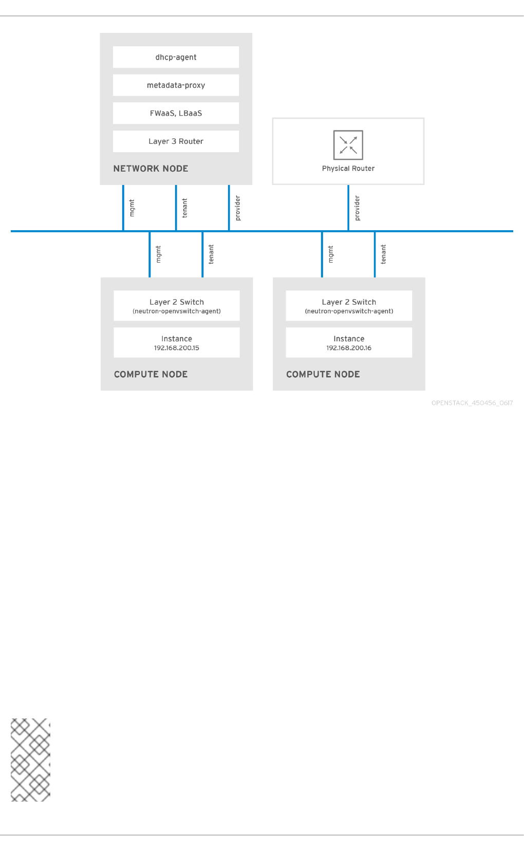
2.2. OpenStack Networking diagram
This diagram depicts a sample OpenStack Networking deployment, with a dedicated OpenStack
Networking node performing L3 routing and DHCP, and running the advanced services FWaaS and
LBaaS. Two Compute nodes run the Open vSwitch ( openvswitch-agent) and have two physical network
cards each, one for tenant traffic, and another for management connectivity. The OpenStack
Networking node has a third network card specifically for provider traffic:
Red Hat OpenStack Platform 10 Networking Guide
12
2.3. Security Groups
Security groups and rules filter the type and direction of network traffic sent to (and received from) a
given neutron port. This provides an additional layer of security to complement any firewall rules
present on the Compute instance. The security group is a container object with one or more security
rules. A single security group can manage traffic to multiple compute instances. Ports created for
floating IP addresses, OpenStack Networking LBaaS VIPs, and instances are associated with a security
group. If none is specified, then the port is associated with the default security group. By default, this
group will drop all inbound traffic and allow all outbound traffic. Additional security rules can be added
to the default security group to modify its behavior or new security groups can be created as
necessary.
2.4. Open vSwitch
Open vSwitch (OVS) is a software-defined networking (SDN) virtual switch similar to the Linux
software bridge. OVS provides switching services to virtualized networks with support for industry
standard NetFlow, OpenFlow, and sFlow. Open vSwitch is also able to integrate with physical switches
using layer 2 features, such as STP, LACP, and 802.1Q VLAN tagging. Tunneling with VXLAN and GRE is
supported with Open vSwitch version 1.11.0-1.el6 or later.
NOTE
Do not use LACP with OVS-based bonds, as this configuration is problematic and
unsupported. Instead, consider using bond_mode=balance-slb as a replacement for
this functionality. In addition, you can still use LACP with Linux bonding. For the
technical details behind this requirement, see BZ#1267291.
CHAPTER 2. OPENSTACK NETWORKING CONCEPTS
13

NOTE
To mitigate the risk of network loops in Open vSwitch, only a single interface or a single
bond may be a member of a given bridge. If you require multiple bonds or interfaces, you
can configure multiple bridges.
2.5. Modular Layer 2 (ML2)
ML2 is the OpenStack Networking core plug-in introduced in OpenStack’s Havana release.
Superseding the previous model of monolithic plug-ins, ML2’s modular design enables the concurrent
operation of mixed network technologies. The monolithic Open vSwitch and Linux Bridge plug-ins have
been deprecated and removed; their functionality has instead been reimplemented as ML2 mechanism
drivers.
NOTE
ML2 is the default OpenStack Networking plug-in, with Open vSwitch configured as the
default mechanism driver.
2.5.1. The reasoning behind ML2
Previously, OpenStack Networking deployments were only able to use the plug-in that had been
selected at implementation time. For example, a deployment running the Open vSwitch plug-in was
only able to use Open vSwitch exclusively; it wasn’t possible to simultaneously run another plug-in such
as linuxbridge. This was found to be a limitation in environments with heterogeneous requirements.
2.5.2. ML2 network types
Multiple network segment types can be operated concurrently. In addition, these network segments
can interconnect using ML2’s support for multi-segmented networks. Ports are automatically bound to
the segment with connectivity; it is not necessary to bind them to a specific segment. Depending on
the mechanism driver, ML2 supports the following network segment types:
flat
GRE
local
VLAN
VXLAN
The various Type drivers are enabled in the ML2 section of the ml2_conf.ini file:
[ml2]
type_drivers = local,flat,vlan,gre,vxlan
2.5.3. ML2 Mechanism Drivers
Plug-ins have been reimplemented as mechanisms with a common code base. This approach enables
code reuse and eliminates much of the complexity around code maintenance and testing.
Red Hat OpenStack Platform 10 Networking Guide
14

NOTE
Refer to the Release Notes for the list of supported mechanism drivers.
The various mechanism drivers are enabled in the ML2 section of the ml2_conf.ini file. For example:
[ml2]
mechanism_drivers = openvswitch,linuxbridge,l2population
NOTE
If your deployment uses Red Hat OpenStack Platform director, then these settings are
managed by director and should not be changed manually.
2.6. L2 Population
The L2 Population driver enables broadcast, multicast, and unicast traffic to scale out on large overlay
networks. By default, Open vSwitch GRE and VXLAN replicate broadcasts to every agent, including
those that do not host the destination network. This design requires the acceptance of significant
network and processing overhead. The alternative design introduced by the L2 Population driver
implements a partial mesh for ARP resolution and MAC learning traffic; it also creates tunnels for a
particular network only between the nodes that host the network. This traffic is sent only to the
necessary agent by encapsulating it as a targeted unicast.
1. Enable the L2 population driver by adding it to the list of mechanism drivers. You also need to have
at least one tunneling driver enabled; either GRE, VXLAN, or both. Add the appropriate configuration
options to the ml2_conf.ini file:
[ml2]
type_drivers = local,flat,vlan,gre,vxlan
mechanism_drivers = openvswitch,linuxbridge,l2population
2. Enable L2 population in the openvswitch_agent.ini file. This must be enabled on each node running
the L2 agent:
[agent]
l2_population = True
NOTE
To install ARP reply flows, you will need to configure the arp_responder flag. For
example:
[agent]
l2_population = True
arp_responder = True
2.7. OpenStack Networking Services
By default, Red Hat OpenStack Platform includes components that integrate with the ML2 and Open
vSwitch plugin to provide networking functionality in your deployment:
CHAPTER 2. OPENSTACK NETWORKING CONCEPTS
15
2.7.1. L3 Agent
The L3 agent is part of the openstack-neutron package. Network namespaces are used to provide each
project with its own isolated layer 3 routers, which direct traffic and provide gateway services for the
layer 2 networks; the L3 agent assists with managing these routers. The nodes on which the L3 agent
is to be hosted must not have a manually-configured IP address on a network interface that is
connected to an external network. Instead there must be a range of IP addresses from the external
network that are available for use by OpenStack Networking. These IP addresses will be assigned to
the routers that provide the link between the internal and external networks. The range selected must
be large enough to provide a unique IP address for each router in the deployment as well as each
desired floating IP.
2.7.2. DHCP Agent
The OpenStack Networking DHCP agent manages the network namespaces that are spawned for each
project subnet to act as DHCP server. Each namespace is running a dnsmasq process that is capable of
allocating IP addresses to virtual machines running on the network. If the agent is enabled and running
when a subnet is created then by default that subnet has DHCP enabled.
2.7.3. Open vSwitch Agent
The Open vSwitch (OVS) neutron plug-in uses its own agent, which runs on each node and manages the
OVS bridges. The ML2 plugin integrates with a dedicated agent to manage L2 networks. By default,
Red Hat OpenStack Platform uses ovs-agent, which builds overlay networks using OVS bridges.
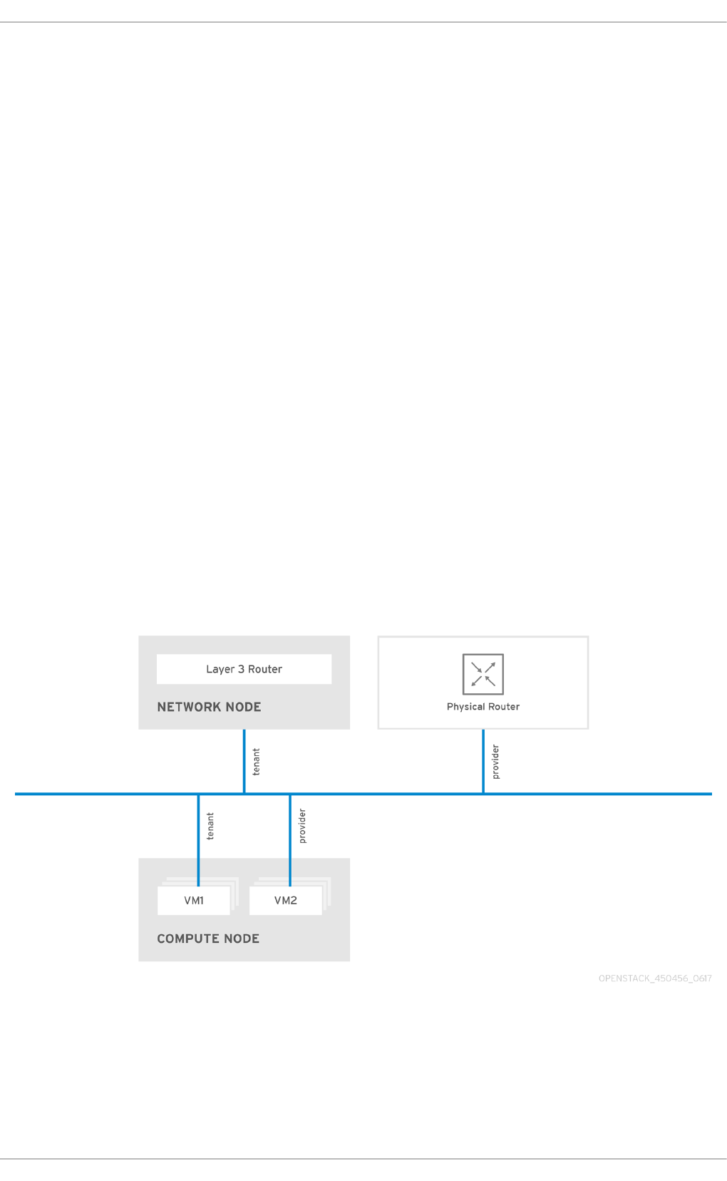
2.8. Tenant and Provider networks
The following diagram presents an overview of the tenant and provider network types, and illustrates
how they interact within the overall OpenStack Networking topology:
2.8.1. Tenant networks
Tenant networks are created by users for connectivity within projects. They are fully isolated by
default and are not shared with other projects. OpenStack Networking supports a range of tenant
network types:
Red Hat OpenStack Platform 10 Networking Guide
16

Flat - All instances reside on the same network, which can also be shared with the hosts. No
VLAN tagging or other network segregation takes place.
VLAN - OpenStack Networking allows users to create multiple provider or tenant networks
using VLAN IDs (802.1Q tagged) that correspond to VLANs present in the physical network.
This allows instances to communicate with each other across the environment. They can also
communicate with dedicated servers, firewalls, load balancers and other network
infrastructure on the same layer 2 VLAN.
VXLAN and GRE tunnels - VXLAN and GRE use network overlays to support private
communication between instances. An OpenStack Networking router is required to enable
traffic to traverse outside of the GRE or VXLAN tenant network. A router is also required to
connect directly-connected tenant networks with external networks, including the Internet;
the router provides the ability to connect to instances directly from an external network using
floating IP addresses.
NOTE
You can configure QoS policies for tenant networks. For more information, see
Chapter 10, Configure Quality-of-Service (QoS).
2.8.2. Provider networks
Provider networks are created by the OpenStack administrator and map directly to an existing
physical network in the data center. Useful network types in this category are flat (untagged) and
VLAN (802.1Q tagged). It is possible to allow provider networks to be shared among tenants as part of
the network creation process.
2.8.2.1. Flat provider networks
You can use flat provider networks to connect instances directly to the external network. This is useful
if you have multiple physical networks (for example, physnet1 and physnet2) and separate physical
interfaces (eth0 → physnet1 and eth1 → physnet2), and intend to connect each Compute and Network
node to those external networks. If you would like to use multiple vlan-tagged interfaces on a single
interface to connect to multiple provider networks, please refer to Section 7.2, “Using VLAN provider
networks”.
2.8.2.2. Configure controller nodes
1. Edit /etc/neutron/plugin.ini (symbolic link to /etc/neutron/plugins/ml2/ml2_conf.ini) and add flat to
the existing list of values, and set flat_networks to *. For example:
type_drivers = vxlan,flat
flat_networks =*
2. Create an external network as a flat network and associate it with the configured physical_network.
Configuring it as a shared network (using --shared) will let other users create instances directly
connected to it.
neutron net-create public01 --provider:network_type flat --
provider:physical_network physnet1 --router:external=True --shared
3. Create a subnet using neutron subnet-create, or the dashboard. For example:
CHAPTER 2. OPENSTACK NETWORKING CONCEPTS
17

# neutron subnet-create --name public_subnet --enable_dhcp=False --
allocation_pool start=192.168.100.20,end=192.168.100.100 --
gateway=192.168.100.1 public01 192.168.100.0/24
4. Restart the neutron-server service to apply the change:
systemctl restart neutron-server
2.8.2.3. Configure the Network and Compute nodes
Perform these steps on the network node and compute nodes. This will connect the nodes to the
external network, and allow instances to communicate directly with the external network.
1. Create an external network bridge (br-ex) and add an associated port (eth1) to it:
Create the external bridge in /etc/sysconfig/network-scripts/ifcfg-br-ex:
DEVICE=br-ex
TYPE=OVSBridge
DEVICETYPE=ovs
ONBOOT=yes
NM_CONTROLLED=no
BOOTPROTO=none
In /etc/sysconfig/network-scripts/ifcfg-eth1, configure eth1 to connect to br-ex:
DEVICE=eth1
TYPE=OVSPort
DEVICETYPE=ovs
OVS_BRIDGE=br-ex
ONBOOT=yes
NM_CONTROLLED=no
BOOTPROTO=none
Reboot the node or restart the network service for the changes to take effect.
2. Configure physical networks in /etc/neutron/plugins/ml2/openvswitch_agent.ini and map bridges to
the physical network:
bridge_mappings = physnet1:br-ex
NOTE
For more information on bridge mappings, see Chapter 11, Configure Bridge Mappings.
3. Restart the neutron-openvswitch-agent service on both the network and compute nodes for the
changes to take effect:
systemctl restart neutron-openvswitch-agent
2.8.2.4. Configure the network node
Red Hat OpenStack Platform 10 Networking Guide
18

1. Set external_network_bridge = to an empty value in /etc/neutron/l3_agent.ini:
Previously, OpenStack Networking used external_network_bridge when only a single bridge was
used for connecting to an external network. This value may now be set to a blank string, which allows
multiple external network bridges. OpenStack Networking will then create a patch from each bridge to
br-int.
# Name of bridge used for external network traffic. This should be set to
# empty value for the linux bridge
external_network_bridge =
2. Restart neutron-l3-agent for the changes to take effect.
systemctl restart neutron-l3-agent
NOTE
If there are multiple flat provider networks, then each of them should have a separate
physical interface and bridge to connect them to the external network. You will need to
configure the ifcfg-* scripts appropriately and use a comma-separated list for each
network when specifying the mappings in the bridge_mappings option. For more
information on bridge mappings, see Chapter 11, Configure Bridge Mappings.
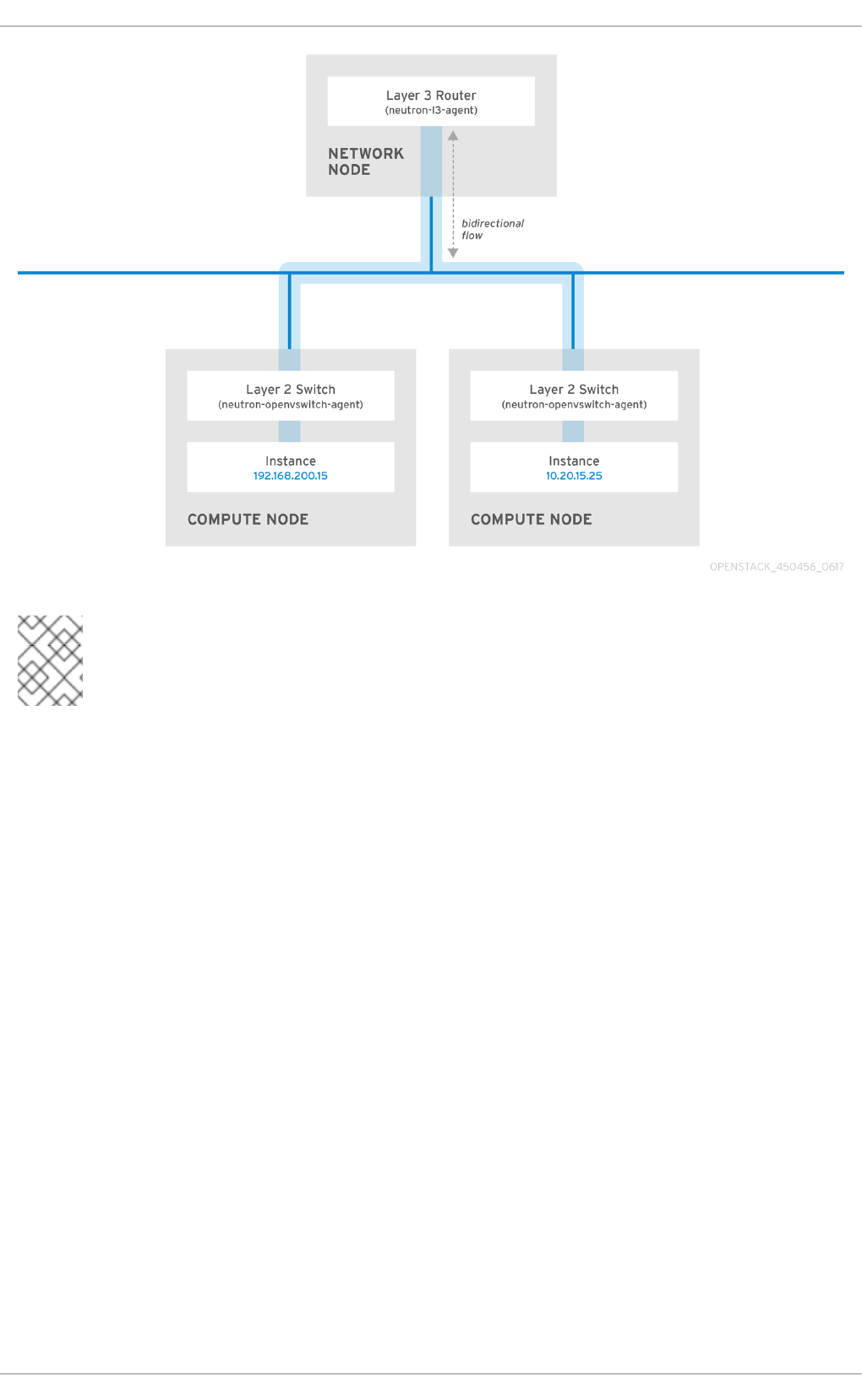
2.9. Layer 2 and layer 3 networking
When designing your virtual network, you will need to anticipate where the majority of traffic is going
to be sent. Network traffic moves faster within the same logical network, rather than between
networks. This is because traffic between logical networks (using different subnets) needs to pass
through a router, resulting in additional latency.
Consider the diagram below which has network traffic flowing between instances on separate VLANs:
CHAPTER 2. OPENSTACK NETWORKING CONCEPTS
19
NOTE
Even a high performance hardware router is still going to add some latency to this
configuration.
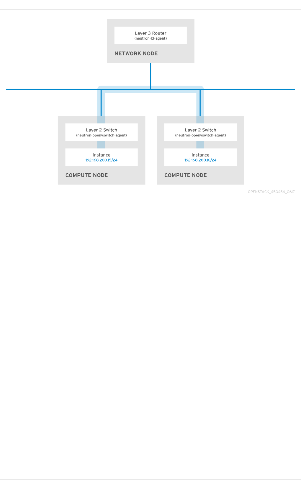
2.9.1. Use switching where possible
Switching occurs at a lower level of the network (layer 2), so can function much quicker than the
routing that occurs at layer 3. The preference should be to have as few hops as possible between
systems that frequently communicate. For example, this diagram depicts a switched network that
spans two physical nodes, allowing the two instances to directly communicate without using a router
for navigation first. You’ll notice that the instances now share the same subnet, to indicate that they’re
on the same logical network:
Red Hat OpenStack Platform 10 Networking Guide
20
In order to allow instances on separate nodes to communicate as if they’re on the same logical
network, you’ll need to use an encapsulation tunnel such as VXLAN or GRE. It is recommended you
consider adjusting the MTU size from end-to-end in order to accommodate the additional bits required
for the tunnel header, otherwise network performance can be negatively impacted as a result of
fragmentation. For more information, see Configure MTU Settings.
You can further improve the performance of VXLAN tunneling by using supported hardware that
features VXLAN offload capabilities. The full list is available here:
https://access.redhat.com/articles/1390483
CHAPTER 2. OPENSTACK NETWORKING CONCEPTS
21

PART I. COMMON TASKS
Covers common administrative tasks and basic troubleshooting steps.
Red Hat OpenStack Platform 10 Networking Guide
22

CHAPTER 3. COMMON ADMINISTRATIVE TASKS
OpenStack Networking (neutron) is the software-defined networking component of Red Hat
OpenStack Platform. The virtual network infrastructure enables connectivity between instances and
the physical external network.
This section describes common administration tasks, such as adding and removing subnets and
routers to suit your Red Hat OpenStack Platform deployment.
3.1. Create a network
Create a network to give your instances a place to communicate with each other and receive IP
addresses using DHCP. A network can also be integrated with external networks in your Red Hat
OpenStack Platform deployment or elsewhere, such as the physical network. This integration allows
your instances to communicate with outside systems. For more information, see Bridge the physical
network.
When creating networks, it is important to know that networks can host multiple subnets. This is useful
if you intend to host distinctly different systems in the same network, and would prefer a measure of
isolation between them. For example, you can designate that only webserver traffic is present on one
subnet, while database traffic traverse another. Subnets are isolated from each other, and any instance
that wishes to communicate with another subnet must have their traffic directed by a router. Consider
placing systems that will require a high volume of traffic amongst themselves in the same subnet, so
that they don’t require routing, and avoid the subsequent latency and load.
1. In the dashboard, select Project > Network > Networks .
2. Click +Create Network and specify the following:
Field Description
Network Name Descriptive name, based on the role that the
network will perform. If you are integrating the
network with an external VLAN, consider appending
the VLAN ID number to the name. For example,
webservers_122, if you are hosting HTTP web
servers in this subnet, and your VLAN tag is 122. Or
you might use internal-only if you intend to
keep the network traffic private, and not integrate it
with an external network.
Admin State Controls whether the network is immediately
available. This field allows you to create the network
but still keep it in a Down state, where it is logically
present but still inactive. This is useful if you do not
intend to enter the network into production right
away.
3. Click the Next button, and specify the following in the Subnet tab:
CHAPTER 3. COMMON ADMINISTRATIVE TASKS
23

Field Description
Create Subnet Determines whether a subnet is created. For
example, you might not want to create a subnet if
you intend to keep this network as a placeholder
without network connectivity.
Subnet Name Enter a descriptive name for the subnet.
Network Address Enter the address in CIDR format, which contains the
IP address range and subnet mask in one value. To
determine the address, calculate the number of bits
masked in the subnet mask and append that value to
the IP address range. For example, the subnet mask
255.255.255.0 has 24 masked bits. To use this mask
with the IPv4 address range 192.168.122.0, specify
the address 192.168.122.0/24.
IP Version Specifies the internet protocol version, where valid
types are IPv4 or IPv6. The IP address range in the
Network Address field must match whichever version
you select.
Gateway IP IP address of the router interface for your default
gateway. This address is the next hop for routing any
traffic destined for an external location, and must be
within the range specified in the Network Address
field. For example, if your CIDR network address is
192.168.122.0/24, then your default gateway is
likely to be 192.168.122.1.
Disable Gateway Disables forwarding and keeps the subnet isolated.
4. Click Next to specify DHCP options:
Enable DHCP - Enables DHCP services for this subnet. DHCP allows you to automate the
distribution of IP settings to your instances.
IPv6 Address -Configuration Modes If creating an IPv6 network, specifies how IPv6 addresses
and additional information are allocated:
No Options Specified - Select this option if IP addresses are set manually, or a non
OpenStack-aware method is used for address allocation.
SLAAC (Stateless Address Autoconfiguration) - Instances generate IPv6 addresses
based on Router Advertisement (RA) messages sent from the OpenStack Networking
router. This configuration results in an OpenStack Networking subnet created with
ra_mode set to slaac and address_mode set to slaac.
DHCPv6 stateful - Instances receive IPv6 addresses as well as additional options (for
example, DNS) from OpenStack Networking DHCPv6 service. This configuration results in
Red Hat OpenStack Platform 10 Networking Guide
24

a subnet created with ra_mode set to dhcpv6-stateful and address_mode set to dhcpv6-
stateful.
DHCPv6 stateless - Instances generate IPv6 addresses based on Router Advertisement
(RA) messages sent from the OpenStack Networking router. Additional options (for
example, DNS) are allocated from the OpenStack Networking DHCPv6 service. This
configuration results in a subnet created with ra_mode set to dhcpv6-stateless and
address_mode set to dhcpv6-stateless.
Allocation Pools - Range of IP addresses you would like DHCP to assign. For example, the
value 192.168.22.100,192.168.22.100 considers all up addresses in that range as available for
allocation.
DNS Name Servers - IP addresses of the DNS servers available on the network. DHCP
distributes these addresses to the instances for name resolution.
Host Routes - Static host routes. First specify the destination network in CIDR format,
followed by the next hop that should be used for routing. For example: 192.168.23.0/24,
10.1.31.1 Provide this value if you need to distribute static routes to instances.
5. Click Create.
The completed network is available for viewing in the Networks tab. You can also click Edit to change
any options as needed. Now when you create instances, you can configure them now to use its subnet,
and they will subsequently receive any specified DHCP options.
3.2. Create an advanced network
Advanced network options are available for administrators, when creating a network from the Admin
view. These options define the network type to use, and allow tenants to be specified:
1. In the dashboard, select Admin > Networks > Create Network > Project . Select a destination project
to host the new network using Project.
2. Review the options in Provider Network Type :
Local - Traffic remains on the local Compute host and is effectively isolated from any external
networks.
Flat - Traffic remains on a single network and can also be shared with the host. No VLAN
tagging or other network segregation takes place.
VLAN - Create a network using a VLAN ID that corresponds to a VLAN present in the physical
network. Allows instances to communicate with systems on the same layer 2 VLAN.
GRE - Use a network overlay that spans multiple nodes for private communication between
instances. Traffic egressing the overlay must be routed.
VXLAN - Similar to GRE, and uses a network overlay to span multiple nodes for private
communication between instances. Traffic egressing the overlay must be routed.
Click Create Network, and review the Project’s Network Topology to validate that the network has
been successfully created.
3.3. Add network routing
CHAPTER 3. COMMON ADMINISTRATIVE TASKS
25

To allow traffic to be routed to and from your new network, you must add its subnet as an interface to
an existing virtual router:
1. In the dashboard, select Project > Network > Routers .
2. Click on your virtual router’s name in the Routers list, and click +Add Interface. In the Subnet list,
select the name of your new subnet. You can optionally specify an IP address for the interface in this
field.
3. Click Add Interface .
Instances on your network are now able to communicate with systems outside the subnet.
3.4. Delete a network
There are occasions where it becomes necessary to delete a network that was previously created,
perhaps as housekeeping or as part of a decommissioning process. In order to successfully delete a
network, you must first remove or detach any interfaces where it is still in use. The following procedure
provides the steps for deleting a network in your project, together with any dependent interfaces.
1. In the dashboard, select Project > Network > Networks . Remove all router interfaces associated
with the target network’s subnets. To remove an interface: Find the ID number of the network you
would like to delete by clicking on your target network in the Networks list, and looking at the its ID
field. All the network’s associated subnets will share this value in their Network ID field.
2. Select Project > Network > Routers , click on your virtual router’s name in the Routers list, and
locate the interface attached to the subnet you would like to delete. You can distinguish it from the
others by the IP address that would have served as the gateway IP. In addition, you can further validate
the distinction by ensuring that the interface’s network ID matches the ID you noted in the previous
step.
3. Click the interface’s Delete Interface button.
Select Project > Network > Networks, and click the name of your network. Click the target subnet’s
Delete Subnet button.
NOTE
If you are still unable to remove the subnet at this point, ensure it is not already being
used by any instances.
4. Select Project > Network > Networks , and select the network you would like to delete.
5. Click Delete Networks.
3.5. Purge a tenant’s networking
In a previous release, after deleting a project, you might have noticed the presence of stale resources
that were once allocated to the project. This included networks, routers, and ports. Previously, these
stale resources had to be been manually deleted, while also being mindful of deleting them in the
correct order. This has been addressed in Red Hat OpenStack Platform 10, where you can instead use
the neutron purge command to delete all the neutron resources that once belonged to a particular
project.
For example, to purge the neutron resources of test-project prior to deletion:
Red Hat OpenStack Platform 10 Networking Guide
26

# openstack project list
+----------------------------------+--------------+
| ID | Name |
+----------------------------------+--------------+
| 02e501908c5b438dbc73536c10c9aac0 | test-project |
| 519e6344f82e4c079c8e2eabb690023b | services |
| 80bf5732752a41128e612fe615c886c6 | demo |
| 98a2f53c20ce4d50a40dac4a38016c69 | admin |
+----------------------------------+--------------+
# neutron purge 02e501908c5b438dbc73536c10c9aac0
Purging resources: 100% complete.
Deleted 1 security_group, 1 router, 1 port, 1 network.
# openstack project delete 02e501908c5b438dbc73536c10c9aac0
3.6. Create a subnet
Subnets are the means by which instances are granted network connectivity. Each instance is
assigned to a subnet as part of the instance creation process, therefore it’s important to consider
proper placement of instances to best accommodate their connectivity requirements. Subnets are
created in pre-existing networks. Remember that tenant networks in OpenStack Networking can host
multiple subnets. This is useful if you intend to host distinctly different systems in the same network,
and would prefer a measure of isolation between them. For example, you can designate that only
webserver traffic is present on one subnet, while database traffic traverse another. Subnets are
isolated from each other, and any instance that wishes to communicate with another subnet must have
their traffic directed by a router. Consider placing systems that will require a high volume of traffic
amongst themselves in the same subnet, so that they don’t require routing, and avoid the subsequent
latency and load.
3.6.1. Create a new subnet
In the dashboard, select Project > Network > Networks , and click your network’s name in the
Networks view.
1. Click Create Subnet, and specify the following.
Field Description
Subnet Name Descriptive subnet name.
Network Address Address in CIDR format, which contains the IP
address range and subnet mask in one value. To
determine the address, calculate the number of bits
masked in the subnet mask and append that value to
the IP address range. For example, the subnet mask
255.255.255.0 has 24 masked bits. To use this mask
with the IPv4 address range 192.168.122.0, specify
the address 192.168.122.0/24.
CHAPTER 3. COMMON ADMINISTRATIVE TASKS
27

IP Version Internet protocol version, where valid types are IPv4
or IPv6. The IP address range in the Network
Address field must match whichever version you
select.
Gateway IP IP address of the router interface for your default
gateway. This address is the next hop for routing any
traffic destined for an external location, and must be
within the range specified in the Network Address
field. For example, if your CIDR network address is
192.168.122.0/24, then your default gateway is
likely to be 192.168.122.1.
Disable Gateway Disables forwarding and keeps the subnet isolated.
Field Description
2. Click Next to specify DHCP options:
Enable DHCP - Enables DHCP services for this subnet. DHCP allows you to automate the
distribution of IP settings to your instances.
IPv6 Address -Configuration Modes If creating an IPv6 network, specifies how IPv6 addresses
and additional information are allocated:
No Options Specified - Select this option if IP addresses are set manually, or a non
OpenStack-aware method is used for address allocation.
SLAAC (Stateless Address Autoconfiguration) - Instances generate IPv6 addresses
based on Router Advertisement (RA) messages sent from the OpenStack Networking
router. This configuration results in an OpenStack Networking subnet created with
ra_mode set to slaac and address_mode set to slaac.
DHCPv6 stateful - Instances receive IPv6 addresses as well as additional options (for
example, DNS) from OpenStack Networking DHCPv6 service. This configuration results in
a subnet created with ra_mode set to dhcpv6-stateful and address_mode set to dhcpv6-
stateful.
DHCPv6 stateless - Instances generate IPv6 addresses based on Router Advertisement
(RA) messages sent from the OpenStack Networking router. Additional options (for
example, DNS) are allocated from the OpenStack Networking DHCPv6 service. This
configuration results in a subnet created with ra_mode set to dhcpv6-stateless and
address_mode set to dhcpv6-stateless.
Allocation Pools - Range of IP addresses you would like DHCP to assign. For example, the
value 192.168.22.100,192.168.22.100 considers all up addresses in that range as available for
allocation.
DNS Name Servers - IP addresses of the DNS servers available on the network. DHCP
distributes these addresses to the instances for name resolution.
Host Routes - Static host routes. First specify the destination network in CIDR format,
followed by the next hop that should be used for routing. For example: 192.168.23.0/24,
10.1.31.1 Provide this value if you need to distribute static routes to instances.
Red Hat OpenStack Platform 10 Networking Guide
28

3. Click Create.
The new subnet is available for viewing in your network’s Subnets list. You can also click Edit to change
any options as needed. When you create instances, you can configure them now to use this subnet, and
they will subsequently receive any specified DHCP options.
3.7. Delete a subnet
You can delete a subnet if it is no longer in use. However, if any instances are still configured to use the
subnet, the deletion attempt fails and the dashboard displays an error message. This procedure
demonstrates how to delete a specific subnet in a network:
In the dashboard, select Project > Network > Networks , and click the name of your network. Select
the target subnet and click Delete Subnets.
3.8. Add a router
OpenStack Networking provides routing services using an SDN-based virtual router. Routers are a
requirement for your instances to communicate with external subnets, including those out in the
physical network. Routers and subnets connect using interfaces, with each subnet requiring its own
interface to the router. A router’s default gateway defines the next hop for any traffic received by the
router. Its network is typically configured to route traffic to the external physical network using a
virtual bridge.
1. In the dashboard, select Project > Network > Routers , and click +Create Router.
2. Enter a descriptive name for the new router, and click Create router.
3. Click Set Gateway next to the new router’s entry in the Routers list.
4. In the External Network list, specify the network that will receive traffic destined for an external
location.
5. Click Set Gateway. After adding a router, the next step is to configure any subnets you have created
to send traffic using this router. You do this by creating interfaces between the subnet and the router.
3.9. Delete a router
You can delete a router if it has no connected interfaces. This procedure describes the steps needed to
first remove a router’s interfaces, and then the router itself.
1. In the dashboard, select Project > Network > Routers , and click on the name of the router you would
like to delete.
2. Select the interfaces of type Internal Interface. Click Delete Interfaces.
3. From the Routers list, select the target router and click Delete Routers.
3.10. Add an interface
Interfaces allow you to interconnect routers with subnets. As a result, the router can direct any traffic
that instances send to destinations outside of their intermediate subnet. This procedure adds a router
interface and connects it to a subnet. The procedure uses the Network Topology feature, which
displays a graphical representation of all your virtual router and networks and enables you to perform
network management tasks.
CHAPTER 3. COMMON ADMINISTRATIVE TASKS
29

1. In the dashboard, select Project > Network > Network Topology .
2. Locate the router you wish to manage, hover your mouse over it, and click Add Interface.
3. Specify the Subnet to which you would like to connect the router. You have the option of specifying
an IP Address. The address is useful for testing and troubleshooting purposes, since a successful ping
to this interface indicates that the traffic is routing as expected.
4. Click Add interface.
The Network Topology diagram automatically updates to reflect the new interface connection
between the router and subnet.
3.11. Delete an interface
You can remove an interface to a subnet if you no longer require the router to direct its traffic. This
procedure demonstrates the steps required for deleting an interface:
1. In the dashboard, select Project > Network > Routers .
2. Click on the name of the router that hosts the interface you would like to delete.
3. Select the interface (will be of type Internal Interface), and click Delete Interfaces.
3.12. Configure IP addressing
You can use procedures in this section to manage your IP address allocation in OpenStack Networking.
3.12.1. Create floating IP pools
Floating IP addresses allow you to direct ingress network traffic to your OpenStack instances. You
begin by defining a pool of validly routable external IP addresses, which can then be dynamically
assigned to an instance. OpenStack Networking then knows to route all incoming traffic destined for
that floating IP to the instance to which it has been assigned.
NOTE
OpenStack Networking allocates floating IP addresses to all projects (tenants) from the
same IP ranges/CIDRs. Meaning that every subnet of floating IPs is consumable by any
and all projects. You can manage this behavior using quotas for specific projects. For
example, you can set the default to 10 for ProjectA and ProjectB, while setting ProjectC's
quota to 0.
The Floating IP allocation pool is defined when you create an external subnet. If the subnet only hosts
floating IP addresses, consider disabling DHCP allocation with the enable_dhcp=False option:
# neutron subnet-create --name SUBNET_NAME --enable_dhcp=False --
allocation_pool start=IP_ADDRESS,end=IP_ADDRESS --gateway=IP_ADDRESS
NETWORK_NAME CIDR
For example:
# neutron subnet-create --name public_subnet --enable_dhcp=False --
allocation_pool start=192.168.100.20,end=192.168.100.100 --
gateway=192.168.100.1 public 192.168.100.0/24
Red Hat OpenStack Platform 10 Networking Guide
30

3.12.2. Assign a specific floating IP
You can assign a specific floating IP address to an instance using the nova command (or through the
dashboard; see section “Update an Instance (Actions menu)”).
# nova floating-ip-associate INSTANCE_NAME IP_ADDRESS
In this example, a floating IP address is allocated to an instance named corp-vm-01:
# nova floating-ip-associate corp-vm-01 192.168.100.20
3.12.3. Assign a random floating IP
Floating IP addresses can be dynamically allocated to instances. You do not select a particular IP
address, but instead request that OpenStack Networking allocates one from the pool. Allocate a
floating IP from the previously created pool:
# neutron floatingip-create public
+---------------------+--------------------------------------+
| Field | Value |
+---------------------+--------------------------------------+
| fixed_ip_address | |
| floating_ip_address | 192.168.100.20 |
| floating_network_id | 7a03e6bc-234d-402b-9fb2-0af06c85a8a3 |
| id | 9d7e2603482d |
| port_id | |
| router_id | |
| status | ACTIVE |
| tenant_id | 9e67d44eab334f07bf82fa1b17d824b6 |
+---------------------+--------------------------------------+
With the IP address allocated, you can assign it to a particular instance. Locate the ID of the port
associated with your instance (this will match the fixed IP address allocated to the instance). This port
ID is used in the following step to associate the instance’s port ID with the floating IP address ID. You
can further distinguish the correct port ID by ensuring the MAC address in the third column matches
the one on the instance.
# neutron port-list
+--------+------+-------------+----------------------------------------
----------------+
| id | name | mac_address | fixed_ips
|
+--------+------+-------------+----------------------------------------
----------------+
| ce8320 | | 3e:37:09:4b | {"subnet_id": "361f27", "ip_address":
"192.168.100.2"} |
| d88926 | | 3e:1d:ea:31 | {"subnet_id": "361f27", "ip_address":
"192.168.100.5"} |
| 8190ab | | 3e:a3:3d:2f | {"subnet_id": "b74dbb", "ip_address":
"10.10.1.25"}|
+--------+------+-------------+----------------------------------------
----------------+
CHAPTER 3. COMMON ADMINISTRATIVE TASKS
31

Use the neutron command to associate the floating IP address with the desired port ID of an instance:
# neutron floatingip-associate 9d7e2603482d 8190ab
3.13. Create multiple floating IP pools
OpenStack Networking supports one floating IP pool per L3 agent. Therefore, scaling out your L3
agents allows you to create additional floating IP pools.
NOTE
Ensure that handle_internal_only_routers in /etc/neutron/neutron.conf is configured to
True for only one L3 agent in your environment. This option configures the L3 agent to
manage only non-external routers.
3.14. Bridge the physical network
The procedure below enables you to bridge your virtual network to the physical network to enable
connectivity to and from virtual instances. In this procedure, the example physical eth0 interface is
mapped to the br-ex bridge; the virtual bridge acts as the intermediary between the physical network
and any virtual networks. As a result, all traffic traversing eth0 uses the configured Open vSwitch to
reach instances. Map a physical NIC to the virtual Open vSwitch bridge (for more information, see
Chapter 11, Configure Bridge Mappings):
NOTE
IPADDR, NETMASK GATEWAY, and DNS1 (name server) must be updated to match
your network.
# vi /etc/sysconfig/network-scripts/ifcfg-eth0
DEVICE=eth0
TYPE=OVSPort
DEVICETYPE=ovs
OVS_BRIDGE=br-ex
ONBOOT=yes
Configure the virtual bridge with the IP address details that were previously allocated to eth0:
# vi /etc/sysconfig/network-scripts/ifcfg-br-ex
DEVICE=br-ex
DEVICETYPE=ovs
TYPE=OVSBridge
BOOTPROTO=static
IPADDR=192.168.120.10
NETMASK=255.255.255.0
GATEWAY=192.168.120.1
DNS1=192.168.120.1
ONBOOT=yes
You can now assign floating IP addresses to instances and make them available to the physical
network.
Red Hat OpenStack Platform 10 Networking Guide
32
CHAPTER 4. PLANNING IP ADDRESS USAGE
An OpenStack deployment can consume a larger number of IP addresses than might be expected. This
section aims to help with correctly anticipating the quantity of addresses required, and explains where
they will be used.
NOTE
VIPs (also known as Virtual IP Addresses) - VIP addresses host HA services, and are
basically an IP address shared between multiple controller nodes.
4.1. Using multiple VLANs
When planning your OpenStack deployment, you might begin with a number of these subnets, from
which you would be expected to allocate how the individual addresses will be used. Having multiple
subnets allows you to segregate traffic between systems into VLANs. For example, you would not
generally want management or API traffic to share the same network as systems serving web traffic.
Traffic between VLANs will also need to traverse through a router, which represents an opportunity to
have firewalls in place to further govern traffic flow.
4.2. Isolating VLAN traffic
You would typically allocate separate VLANs for the different types of network traffic you will host. For
example, you could have separate VLANs for each of these types of networks. Of these, only the
External network needs to be routable to the external physical network. In this release, DHCP services
are provided by the director.
NOTE
Not all of the isolated VLANs in this section will be required for every OpenStack
deployment. For example, if your cloud users don’t need to create ad hoc virtual
networks on demand, then you may not require a tenant network; if you just need each
VM to connect directly to the same switch as any other physical system, then you
probably just need to connect your Compute nodes directly to a provider network and
have your instances use that provider network directly.
Provisioning network - This VLAN is dedicated to deploying new nodes using director over
PXE boot. OpenStack Orchestration (heat) installs OpenStack onto the overcloud bare metal
servers; these are attached to the physical network to receive the platform installation image
from the undercloud infrastructure.
Internal API network - The Internal API network is used for communication between the
OpenStack services, and covers API communication, RPC messages, and database
communication. In addition, this network is used for operational messages between controller
nodes. When planning your IP address allocation, note that each API service requires its own IP
address. Specifically, an IP address is required for each of these services:
vip-msg (ampq)
vip-keystone-int
vip-glance-int
vip-cinder-int
CHAPTER 4. PLANNING IP ADDRESS USAGE
33

vip-nova-int
vip-neutron-int
vip-horizon-int
vip-heat-int
vip-ceilometer-int
vip-swift-int
vip-keystone-pub
vip-glance-pub
vip-cinder-pub
vip-nova-pub
vip-neutron-pub
vip-horizon-pub
vip-heat-pub
vip-ceilometer-pub
vip-swift-pub
NOTE
When using High Availability, Pacemaker expects to be able to move the VIP addresses
between the physical nodes.
Storage - Block Storage, NFS, iSCSI, among others. Ideally, this would be isolated to separate
physical Ethernet links for performance reasons.
Storage Management - OpenStack Object Storage (swift) uses this network to synchronise
data objects between participating replica nodes. The proxy service acts as the intermediary
interface between user requests and the underlying storage layer. The proxy receives
incoming requests and locates the necessary replica to retrieve the requested data. Services
that use a Ceph back-end connect over the Storage Management network, since they do not
interact with Ceph directly but rather use the front-end service. Note that the RBD driver is an
exception; this traffic connects directly to Ceph.
Tenant networks - Neutron provides each tenant with their own networks using either VLAN
segregation (where each tenant network is a network VLAN), or tunneling via VXLAN or GRE.
Network traffic is isolated within each tenant network. Each tenant network has an IP subnet
associated with it, and multiple tenant networks may use the same addresses.
External - The External network hosts the public API endpoints and connections to the
Dashboard (horizon). You can also optionally use this same network for SNAT, but this is not a
requirement. In a production deployment, you will likely use a separate network for floating IP
addresses and NAT.
Provider networks - These networks allows instances to be attached to existing network
Red Hat OpenStack Platform 10 Networking Guide
34

infrastructure. You can use provider networks to map directly to an existing physical network
in the data center, using flat networking or VLAN tags. This allows an instance to share the
same layer-2 network as a system external to the OpenStack Networking infrastructure.
4.3. IP address consumption
The following systems will consume IP addresses from your allocated range:
Physical nodes - Each physical NIC will require one IP address; it is common practice to
dedicate physical NICs to specific functions. For example, management and NFS traffic would
each be allocated their own physical NICs (sometimes with multiple NICs connecting across to
different switches for redundancy purposes).
Virtual IPs (VIPs) for High Availability - You can expect to allocate around 1 to 3 for each
network shared between controller nodes.
4.4. Virtual Networking
These virtual resources consume IP addresses in OpenStack Networking. These are considered local to
the cloud infrastructure, and do not need to be reachable by systems in the external physical network:
Tenant networks - Each tenant network will require a subnet from which it will allocate IP
addresses to instances.
Virtual routers - Each router interface plugging into a subnet will require one IP address (with
an additional address required if DHCP is enabled).
Instances - Each instance will require an address from the tenant subnet they are hosted in. If
ingress traffic is needed, an additional floating IP address will need to be allocated from the
designated external network.
Management traffic - Includes OpenStack Services and API traffic. In Red Hat OpenStack
Platform 10, requirements for virtual IP addresses have been reduced; all services will instead
share a small number of VIPs. API, RPC and database services will communicate on the
internal API VIP.
4.5. Example network plan
This example shows a number of networks that accommodate multiple subnets, with each subnet being
assigned a range of IP addresses:
Table 4.1. Example subnet plan
Subnet name Address range Number of addresses Subnet Mask
Provisioning network 192.168.100.1 -
192.168.100.250
250 255.255.255.0
Internal API network 172.16.1.10 - 172.16.1.250 241 255.255.255.0
Storage 172.16.2.10 -
172.16.2.250
241 255.255.255.0
CHAPTER 4. PLANNING IP ADDRESS USAGE
35

Storage Management 172.16.3.10 -
172.16.3.250
241 255.255.255.0
Tenant network
(GRE/VXLAN)
172.19.4.10 -
172.16.4.250
241 255.255.255.0
External network (incl.
floating IPs)
10.1.2.10 - 10.1.3.222 469 255.255.254.0
Provider network
(infrastructure)
10.10.3.10 - 10.10.3.250 241 255.255.252.0
Subnet name Address range Number of addresses Subnet Mask
Red Hat OpenStack Platform 10 Networking Guide
36

CHAPTER 5. REVIEW OPENSTACK NETWORKING ROUTER
PORTS
Virtual routers in OpenStack Networking use ports to interconnect with subnets. You can review the
state of these ports to determine whether they’re connecting as expected.
5.1. View current port status
This procedure lists all the ports attached to a particular router, then demonstrates how to retrieve a
port’s state (DOWN or ACTIVE).
1. View all the ports attached to the router named r1:
# neutron router-port-list r1
Example result:
+--------------------------------------+------+-------------------+----
----------------------------------------------------------------------
------------+
| id | name | mac_address |
fixed_ips
|
+--------------------------------------+------+-------------------+----
----------------------------------------------------------------------
------------+
| b58d26f0-cc03-43c1-ab23-ccdb1018252a | | fa:16:3e:94:a7:df |
{"subnet_id": "a592fdba-babd-48e0-96e8-2dd9117614d3", "ip_address":
"192.168.200.1"} |
| c45e998d-98a1-4b23-bb41-5d24797a12a4 | | fa:16:3e:ee:6a:f7 |
{"subnet_id": "43f8f625-c773-4f18-a691-fd4ebfb3be54", "ip_address":
"172.24.4.225"} |
+--------------------------------------+------+-------------------+----
----------------------------------------------------------------------
------------+
2. View the details of each port by running this command against its ID (the value in the left column).
The result includes the port’s status, indicated in the following example as having an ACTIVE state:
# neutron port-show b58d26f0-cc03-43c1-ab23-ccdb1018252a
Example result:
+-----------------------+---------------------------------------------
-----------------------------------------+
| Field | Value
|
+-----------------------+---------------------------------------------
-----------------------------------------+
| admin_state_up | True
|
| allowed_address_pairs |
|
| binding:host_id | node.example.com
CHAPTER 5. REVIEW OPENSTACK NETWORKING ROUTER PORTS
37

|
| binding:profile | {}
|
| binding:vif_details | {"port_filter": true, "ovs_hybrid_plug": true}
|
| binding:vif_type | ovs
|
| binding:vnic_type | normal
|
| device_id | 49c6ebdc-0e62-49ad-a9ca-58cea464472f
|
| device_owner | network:router_interface
|
| extra_dhcp_opts |
|
| fixed_ips | {"subnet_id": "a592fdba-babd-48e0-96e8-
2dd9117614d3", "ip_address": "192.168.200.1"} |
| id | b58d26f0-cc03-43c1-ab23-ccdb1018252a
|
| mac_address | fa:16:3e:94:a7:df
|
| name |
|
| network_id | 63c24160-47ac-4140-903d-8f9a670b0ca4
|
| security_groups |
|
| status | ACTIVE
|
| tenant_id | d588d1112e0f496fb6cac22f9be45d49
|
+-----------------------+---------------------------------------------
-----------------------------------------+
Perform this step for each port to retrieve its status.
Red Hat OpenStack Platform 10 Networking Guide
38

CHAPTER 6. TROUBLESHOOT PROVIDER NETWORKS
A deployment of virtual routers and switches, also known as software-defined networking (SDN), may
seem to introduce complexity at first glance. However, the diagnostic process of troubleshooting
network connectivity in OpenStack Networking is similar to that of physical networks. If using VLANs,
the virtual infrastructure can be considered a trunked extension of the physical network, rather than a
wholly separate environment.
6.1. Topics covered
Basic ping testing
Troubleshooting VLAN networks
Troubleshooting from within tenant networks
6.2. Basic ping testing
The ping command is a useful tool for analyzing network connectivity problems. The results serve as a
basic indicator of network connectivity, but might not entirely exclude all connectivity issues, such as a
firewall blocking the actual application traffic. The ping command works by sending traffic to specified
destinations, and then reports back whether the attempts were successful.
NOTE
The ping command expects that ICMP traffic is allowed to traverse any intermediary
firewalls.
Ping tests are most useful when run from the machine experiencing network issues, so it may be
necessary to connect to the command line via the VNC management console if the machine seems to
be completely offline.
For example, the ping test command below needs to validate multiple layers of network infrastructure
in order to succeed; name resolution, IP routing, and network switching will all need to be functioning
correctly:
$ ping www.redhat.com
PING e1890.b.akamaiedge.net (125.56.247.214) 56(84) bytes of data.
64 bytes from a125-56.247-214.deploy.akamaitechnologies.com
(125.56.247.214): icmp_seq=1 ttl=54 time=13.4 ms
64 bytes from a125-56.247-214.deploy.akamaitechnologies.com
(125.56.247.214): icmp_seq=2 ttl=54 time=13.5 ms
64 bytes from a125-56.247-214.deploy.akamaitechnologies.com
(125.56.247.214): icmp_seq=3 ttl=54 time=13.4 ms
^C
You can terminate the ping command with Ctrl-c, after which a summary of the results is presented.
Zero packet loss indicates that the connection was timeous and stable:
--- e1890.b.akamaiedge.net ping statistics ---
3 packets transmitted, 3 received, 0% packet loss, time 2003ms
rtt min/avg/max/mdev = 13.461/13.498/13.541/0.100 ms
CHAPTER 6. TROUBLESHOOT PROVIDER NETWORKS
39
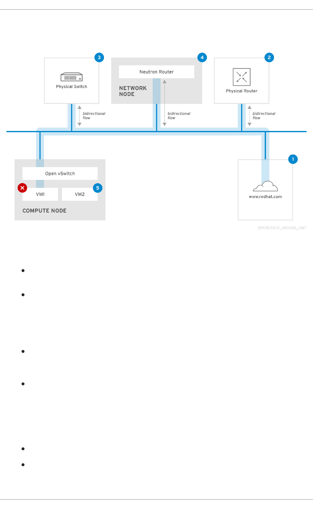
In addition, the results of a ping test can be very revealing, depending on which destination gets tested.
For example, in the following diagram VM1 is experiencing some form of connectivity issue. The
possible destinations are numbered in blue, and the conclusions drawn from a successful or failed
result are presented:
1. The internet - a common first step is to send a ping test to an internet location, such as
www.redhat.com.
Success: This test indicates that all the various network points in between are working as
expected. This includes the virtual and physical network infrastructure.
Failure: There are various ways in which a ping test to a distant internet location can fail. If
other machines on your network are able to successfully ping the internet, that proves the
internet connection is working, and it’s time to bring the troubleshooting closer to home.
2. Physical router - This is the router interface designated by the network administrator to direct
traffic onward to external destinations.
Success: Ping tests to the physical router can determine whether the local network and
underlying switches are functioning. These packets don’t traverse the router, so they do not
prove whether there is a routing issue present on the default gateway.
Failure: This indicates that the problem lies between VM1 and the default gateway. The
router/switches might be down, or you may be using an incorrect default gateway. Compare
the configuration with that on another server that is known to be working. Try pinging another
server on the local network.
3. Neutron router - This is the virtual SDN (Software-defined Networking) router used by Red Hat
OpenStack Platform to direct the traffic of virtual machines.
Success: Firewall is allowing ICMP traffic, the Networking node is online.
Failure: Confirm whether ICMP traffic is permitted in the instance’s security group. Check that
the Networking node is online, confirm that all the required services are running, and review
the L3 agent log (/var/log/neutron/l3-agent.log).
Red Hat OpenStack Platform 10 Networking Guide
40

4. Physical switch - The physical switch’s role is to manage traffic between nodes on the same
physical network.
Success: Traffic sent by a VM to the physical switch will need to pass through the virtual
network infrastructure, indicating that this segment is functioning as expected.
Failure: Is the physical switch port configured to trunk the required VLANs?
5. VM2 - Attempt to ping a VM on the same subnet, on the same Compute node.
Success: The NIC driver and basic IP configuration on VM1 are functional.
Failure: Validate the network configuration on VM1. Or, VM2’s firewall might simply be blocking
ping traffic. In addition, confirm that the virtual switching is set up correctly, and review the
Open vSwitch (or Linux Bridge) log files.
6.3. Troubleshooting VLAN networks
OpenStack Networking is able to trunk VLAN networks through to the SDN switches. Support for
VLAN-tagged provider networks means that virtual instances are able to integrate with server subnets
in the physical network.
To troubleshoot connectivity to a VLAN Provider network, attempt to ping the gateway IP designated
when the network was created. For example, if you created the network with these commands:
# neutron net-create provider --provider:network_type=vlan --
provider:physical_network=phy-eno1 --provider:segmentation_id=120
# neutron subnet-create "provider" --allocation-pool
start=192.168.120.1,end=192.168.120.253 --disable-dhcp --gateway
192.168.120.254 192.168.120.0/24
Then you’ll want to attempt to ping the defined gateway IP of 192.168.120.254
If that fails, confirm that you have network flow for the associated VLAN (as defined during network
creation). In the example above, OpenStack Networking is configured to trunk VLAN 120 to the
provider network. This option is set using the parameter --provider:segmentation_id=120.
Confirm the VLAN flow on the bridge interface, in this case it’s named br-ex:
# ovs-ofctl dump-flows br-ex
NXST_FLOW reply (xid=0x4):
cookie=0x0, duration=987.521s, table=0, n_packets=67897,
n_bytes=14065247, idle_age=0, priority=1 actions=NORMAL
cookie=0x0, duration=986.979s, table=0, n_packets=8, n_bytes=648,
idle_age=977, priority=2,in_port=12 actions=drop
6.3.1. Review the VLAN configuration and log files
OpenStack Networking (neutron) agents - Use the neutron command to verify that all agents
are up and registered with the correct names:
# neutron agent-list
+--------------------------------------+--------------------+---------
--------------+-------+----------------+
CHAPTER 6. TROUBLESHOOT PROVIDER NETWORKS
41

| id | agent_type | host
| alive | admin_state_up |
+--------------------------------------+--------------------+---------
--------------+-------+----------------+
| a08397a8-6600-437d-9013-b2c5b3730c0c | Metadata agent |
rhelosp.example.com | :-) | True |
| a5153cd2-5881-4fc8-b0ad-be0c97734e6a | L3 agent |
rhelosp.example.com | :-) | True |
| b54f0be7-c555-43da-ad19-5593a075ddf0 | DHCP agent |
rhelosp.example.com | :-) | True |
| d2be3cb0-4010-4458-b459-c5eb0d4d354b | Open vSwitch agent |
rhelosp.example.com | :-) | True |
+--------------------------------------+--------------------+---------
--------------+-------+----------------+
Review /var/log/neutron/openvswitch-agent.log - this log should provide confirmation that
the creation process used the ovs-ofctl command to configure VLAN trunking.
Validate external_network_bridge in the /etc/neutron/l3_agent.ini file. A hardcoded value
here won’t allow you to use a provider network via the L3-agent, and won’t create the
necessary flows. As a result, this value should look like this: external_network_bridge =
""
Check network_vlan_ranges in the /etc/neutron/plugin.ini file. You don’t need to specify the
numeric VLAN ID if it’s a provider network. The only time you need to specify the ID(s) here is
if you’re using VLAN isolated tenant networks.
Validate the OVS agent configuration file bridge mappings, confirm that the bridge mapped to
phy-eno1 exists and is properly connected to eno1.
6.4. Troubleshooting from within tenant networks
In OpenStack Networking, all tenant traffic is contained within network namespaces. This allows
tenants to configure networks without interfering with each other. For example, network namespaces
allow different tenants to have the same subnet range of 192.168.1.1/24 without resulting in any
interference between them.
To begin troubleshooting a tenant network, first determine which network namespace contains the
network:
1. List all the tenant networks using the neutron command:
# neutron net-list
+--------------------------------------+-------------+----------------
---------------------------------------+
| id | name | subnets
|
+--------------------------------------+-------------+----------------
---------------------------------------+
| 9cb32fe0-d7fb-432c-b116-f483c6497b08 | web-servers | 453d6769-fcde-4796-
a205-66ee01680bba 192.168.212.0/24 |
| a0cc8cdd-575f-4788-a3e3-5df8c6d0dd81 | private | c1e58160-707f-44a7-
bf94-8694f29e74d3 10.0.0.0/24 |
| baadd774-87e9-4e97-a055-326bb422b29b | private | 340c58e1-7fe7-4cf2-
96a7-96a0a4ff3231 192.168.200.0/24 |
| 24ba3a36-5645-4f46-be47-f6af2a7d8af2 | public | 35f3d2cb-6e4b-4527-
Red Hat OpenStack Platform 10 Networking Guide
42

a932-952a395c4bb3 172.24.4.224/28 |
+--------------------------------------+-------------+----------------
---------------------------------------+
In this example, we’ll be examining the web-servers network. Make a note of the id value in the web-
server row (in this case, its 9cb32fe0-d7fb-432c-b116-f483c6497b08). This value is appended to the
network namespace, which will help you identify in the next step.
2. List all the network namespaces using the ip command:
# ip netns list
qdhcp-9cb32fe0-d7fb-432c-b116-f483c6497b08
qrouter-31680a1c-9b3e-4906-bd69-cb39ed5faa01
qrouter-62ed467e-abae-4ab4-87f4-13a9937fbd6b
qdhcp-a0cc8cdd-575f-4788-a3e3-5df8c6d0dd81
qrouter-e9281608-52a6-4576-86a6-92955df46f56
In the result there is a namespace that matches the web-server network id. In this example it’s
presented as qdhcp-9cb32fe0-d7fb-432c-b116-f483c6497b08.
3. Examine the configuration of the web-servers network by running commands within the
namespace. This is done by prefixing the troubleshooting commands with ip netns exec (namespace) .
For example:
a) View the routing table of the web-servers network:
# ip netns exec qrouter-62ed467e-abae-4ab4-87f4-13a9937fbd6b route -n
Kernel IP routing table
Destination Gateway Genmask Flags Metric Ref Use
Iface
0.0.0.0 172.24.4.225 0.0.0.0 UG 0 0 0
qg-8d128f89-87
172.24.4.224 0.0.0.0 255.255.255.240 U 0 0 0
qg-8d128f89-87
192.168.200.0 0.0.0.0 255.255.255.0 U 0 0 0
qr-8efd6357-96
b) View the routing table of the web-servers network:
# ip netns exec qrouter-62ed467e-abae-4ab4-87f4-13a9937fbd6b route -n
Kernel IP routing table
Destination Gateway Genmask Flags Metric Ref Use
Iface
0.0.0.0 172.24.4.225 0.0.0.0 UG 0 0 0
qg-8d128f89-87
172.24.4.224 0.0.0.0 255.255.255.240 U 0 0 0
qg-8d128f89-87
192.168.200.0 0.0.0.0 255.255.255.0 U 0 0 0
qr-8efd6357-96
6.4.1. Perform advanced ICMP testing within the namespace
1. Capture ICMP traffic using the tcpdump command.
CHAPTER 6. TROUBLESHOOT PROVIDER NETWORKS
43

# ip netns exec qrouter-62ed467e-abae-4ab4-87f4-13a9937fbd6b tcpdump -
qnntpi any icmp
There may not be any output until you perform the next step:
2. In a separate command line window, perform a ping test to an external network:
# ip netns exec qrouter-62ed467e-abae-4ab4-87f4-13a9937fbd6b ping
www.redhat.com
3. In the terminal running the tcpdump session, you will observe detailed results of the ping test.
tcpdump: listening on any, link-type LINUX_SLL (Linux cooked), capture
size 65535 bytes
IP (tos 0xc0, ttl 64, id 55447, offset 0, flags [none], proto ICMP (1),
length 88)
172.24.4.228 > 172.24.4.228: ICMP host 192.168.200.20 unreachable,
length 68
IP (tos 0x0, ttl 64, id 22976, offset 0, flags [DF], proto UDP (17),
length 60)
172.24.4.228.40278 > 192.168.200.21: [bad udp cksum 0xfa7b -> 0xe235!]
UDP, length 32
NOTE
When performing a tcpdump analysis of traffic, you might observe the responding
packets heading to the router interface rather than the instance. This is expected
behaviour, as the qrouter performs DNAT on the return packets.
Red Hat OpenStack Platform 10 Networking Guide
44

CHAPTER 7. CONNECT AN INSTANCE TO THE PHYSICAL
NETWORK
This chapter explains how to use provider networks to connect instances directly to an external
network.
Overview of the OpenStack Networking topology:
OpenStack Networking (neutron) has two categories of services distributed across a number of node
types.
Neutron server - This service runs the OpenStack Networking API server, which provides the
API for end-users and services to interact with OpenStack Networking. This server also
integrates with the underlying database to store and retrieve tenant network, router, and
loadbalancer details, among others.
Neutron agents - These are the services that perform the network functions for OpenStack
Networking:
neutron-dhcp-agent - manages DHCP IP addressing for tenant private networks.
neutron-l3-agent - performs layer 3 routing between tenant private networks, the
external network, and others.
neutron-lbaas-agent - provisions the LBaaS routers created by tenants.
Compute node - This node hosts the hypervisor that runs the virtual machines, also known as
instances. A Compute node must be wired directly to the network in order to provide external
connectivity for instances. This node is typically where the l2 agents run, such as neutron-
openvswitch-agent.
Service placement:
The OpenStack Networking services can either run together on the same physical server, or on
separate dedicated servers, which are named according to their roles:
Controller node - The server that runs API service.
Network node - The server that runs the OpenStack Networking agents.
Compute node - The hypervisor server that hosts the instances.
The steps in this chapter assume that your environment has deployed these three node types. If your
deployment has both the Controller and Network node roles on the same physical node, then the steps
from both sections must be performed on that server. This also applies for a High Availability (HA)
environment, where all three nodes might be running the Controller node and Network node services
with HA. As a result, sections applicable to Controller and Network nodes will need to be performed on
all three nodes.
7.1. Using Flat Provider Networks
This procedure creates flat provider networks that can connect instances directly to external
networks. You would do this if you have multiple physical networks (for example, physnet1,
physnet2) and separate physical interfaces ( eth0 -> physnet1, and eth1 -> physnet2), and
you need to connect each Compute node and Network node to those external networks.
CHAPTER 7. CONNECT AN INSTANCE TO THE PHYSICAL NETWORK
45

NOTE
If you want to connect multiple VLAN-tagged interfaces (on a single NIC) to multiple
provider networks, please refer to Section 7.2, “Using VLAN provider networks” .
Configure the Controller nodes:
1. Edit /etc/neutron/plugin.ini (which is symlinked to
/etc/neutron/plugins/ml2/ml2_conf.ini) and add flat to the existing list of values, and set
flat_networks to *:
type_drivers = vxlan,flat
flat_networks =*
2. Create a flat external network and associate it with the configured physical_network. Creating it
as a shared network will allow other users to connect their instances directly to it:
neutron net-create public01 --provider:network_type flat --
provider:physical_network physnet1 --router:external=True --shared
3. Create a subnet within this external network using neutron subnet-create, or the OpenStack
Dashboard. For example:
neutron subnet-create --name public_subnet --enable_dhcp=False --
allocation_pool start=192.168.100.20,end=192.168.100.100 --
gateway=192.168.100.1 public01 192.168.100.0/24
4. Restart the neutron-server service to apply this change:
# systemctl restart neutron-server.service
Configure the Network node and Compute nodes:
These steps must be completed on the Network node and the Compute nodes. As a result, the nodes
will connect to the external network, and will allow instances to communicate directly with the
external network.
1. Create the Open vSwitch bridge and port. This step creates the external network bridge ( br-ex) and
adds a corresponding port (eth1):
i. Edit /etc/sysconfig/network-scripts/ifcfg-eth1:
DEVICE=eth1
TYPE=OVSPort
DEVICETYPE=ovs
OVS_BRIDGE=br-ex
ONBOOT=yes
NM_CONTROLLED=no
BOOTPROTO=none
ii. Edit /etc/sysconfig/network-scripts/ifcfg-br-ex:
DEVICE=br-ex
TYPE=OVSBridge
Red Hat OpenStack Platform 10 Networking Guide
46

DEVICETYPE=ovs
ONBOOT=yes
NM_CONTROLLED=no
BOOTPROTO=none
2. Restart the network service for the changes to take effect:
# systemctl restart network.service
3. Configure the physical networks in /etc/neutron/plugins/ml2/openvswitch_agent.ini
and map the bridge to the physical network:
NOTE
For more information on configuring bridge_mappings, see Chapter 11, Configure
Bridge Mappings.
bridge_mappings = physnet1:br-ex
4. Restart the neutron-openvswitch-agent service on the Network and Compute nodes for the
changes to take effect:
systemctl restart neutron-openvswitch-agent
Configure the Network node:
1. Set external_network_bridge = to an empty value in /etc/neutron/l3_agent.ini. This
enables the use of external provider networks.
# Name of bridge used for external network traffic. This should be set to
# empty value for the linux bridge
external_network_bridge =
2. Restart neutron-l3-agent for the changes to take effect:
systemctl restart neutron-l3-agent.service
NOTE
If there are multiple flat provider networks, each of them should have separate physical
interface and bridge to connect them to external network. Please configure the ifcfg-*
scripts appropriately and use comma-separated list for each network when specifying
them in bridge_mappings. For more information on configuring bridge_mappings,
see Chapter 11, Configure Bridge Mappings.
Connect an instance to the external network:
With the network created, you can now connect an instance to it and test connectivity:
1. Create a new instance.
CHAPTER 7. CONNECT AN INSTANCE TO THE PHYSICAL NETWORK
47
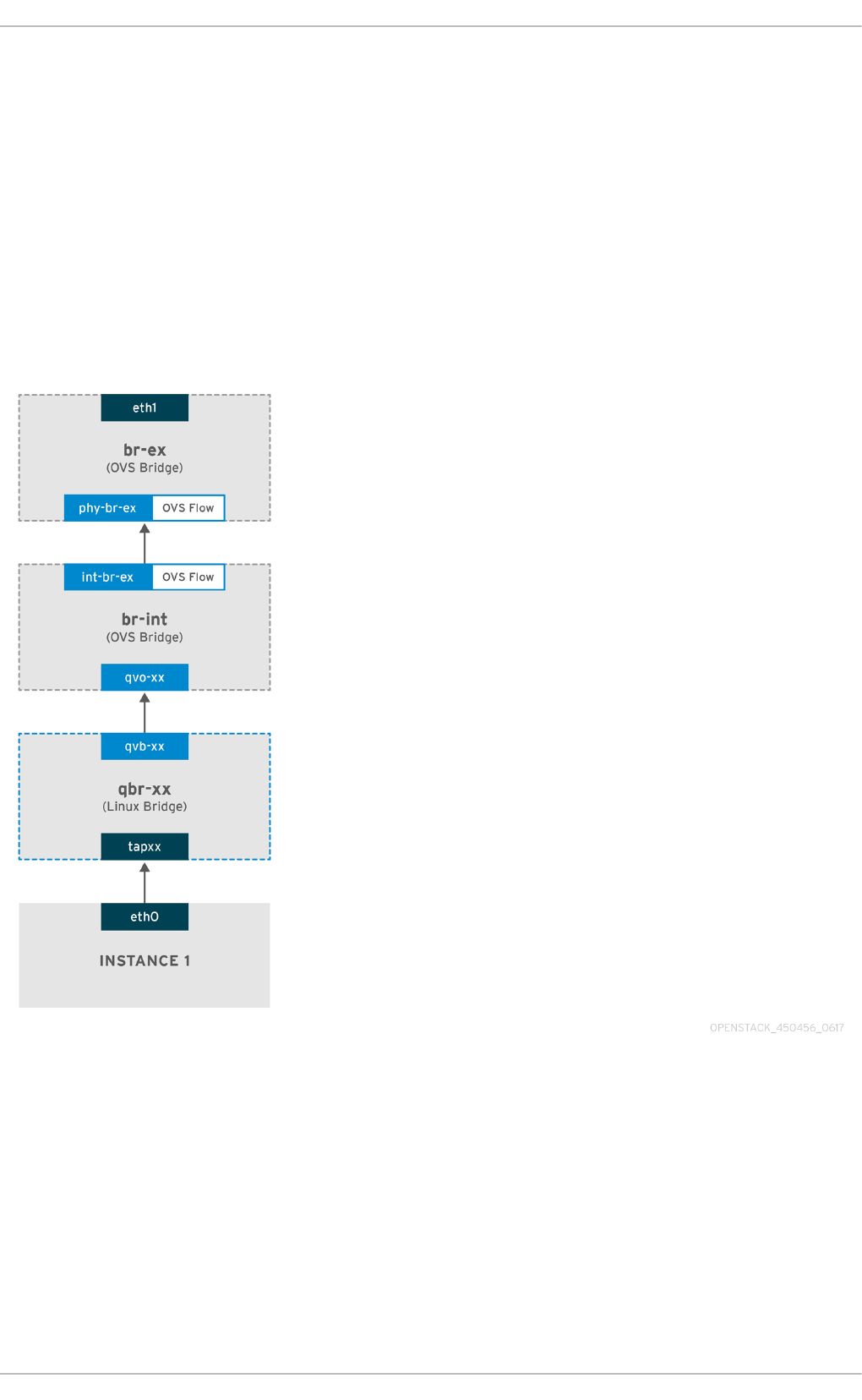
2. Use the Networking tab in the dashboard to add the new instance directly to the newly-created
external network.
How does the packet flow work?
With flat provider networking configured, this section describes in detail how traffic flows to and from
an instance.
7.1.1. The flow of outgoing traffic
The packet flow for traffic leaving an instance and arriving directly at an external network: Once you
configure br-ex, add the physical interface, and spawn an instance to a Compute node, your resulting
interfaces and bridges will be similar to those in the diagram below (if using the iptables_hybrid
firewall driver):
1. Packets leaving the eth0 interface of the instance will first arrive at the linux bridge qbr-xx.
2. Bridge qbr-xx is connected to br-int using veth pair qvb-xx <-> qvo-xxx. This is because the
bridge is used to apply the inbound/outbound firewall rules defined by the security group.
3. Interface qvbxx is connected to the qbr-xx linux bridge, and qvoxx is connected to the br-int
Open vSwitch (OVS) bridge.
The configuration of qbr-xx on the Linux bridge:
Red Hat OpenStack Platform 10 Networking Guide
48

qbr269d4d73-e7 8000.061943266ebb no qvb269d4d73-e7
tap269d4d73-e7
The configuration of qvoxx on br-int:
Bridge br-int
fail_mode: secure
Interface "qvof63599ba-8f"
Port "qvo269d4d73-e7"
tag: 5
Interface "qvo269d4d73-e7"
NOTE
Port qvoxx is tagged with the internal VLAN tag associated with the flat provider
network. In this example, the VLAN tag is 5. Once the packet reaches qvoxx, the VLAN
tag is appended to the packet header.
The packet is then moved to the br-ex OVS bridge using the patch-peer int-br-ex <-> phy-br-
ex.
Example configuration of the patch-peer on br-int:
Bridge br-int
fail_mode: secure
Port int-br-ex
Interface int-br-ex
type: patch
options: {peer=phy-br-ex}
Example configuration of the patch-peer on br-ex:
Bridge br-ex
Port phy-br-ex
Interface phy-br-ex
type: patch
options: {peer=int-br-ex}
Port br-ex
Interface br-ex
type: internal
When this packet reaches phy-br-ex on br-ex, an OVS flow inside br-ex strips the VLAN tag (5)
and forwards it to the physical interface.
In the example below, the output shows the port number of phy-br-ex as 2.
# ovs-ofctl show br-ex
OFPT_FEATURES_REPLY (xid=0x2): dpid:00003440b5c90dc6
n_tables:254, n_buffers:256
capabilities: FLOW_STATS TABLE_STATS PORT_STATS QUEUE_STATS ARP_MATCH_IP
actions: OUTPUT SET_VLAN_VID SET_VLAN_PCP STRIP_VLAN SET_DL_SRC SET_DL_DST
SET_NW_SRC SET_NW_DST SET_NW_TOS SET_TP_SRC SET_TP_DST ENQUEUE
CHAPTER 7. CONNECT AN INSTANCE TO THE PHYSICAL NETWORK
49
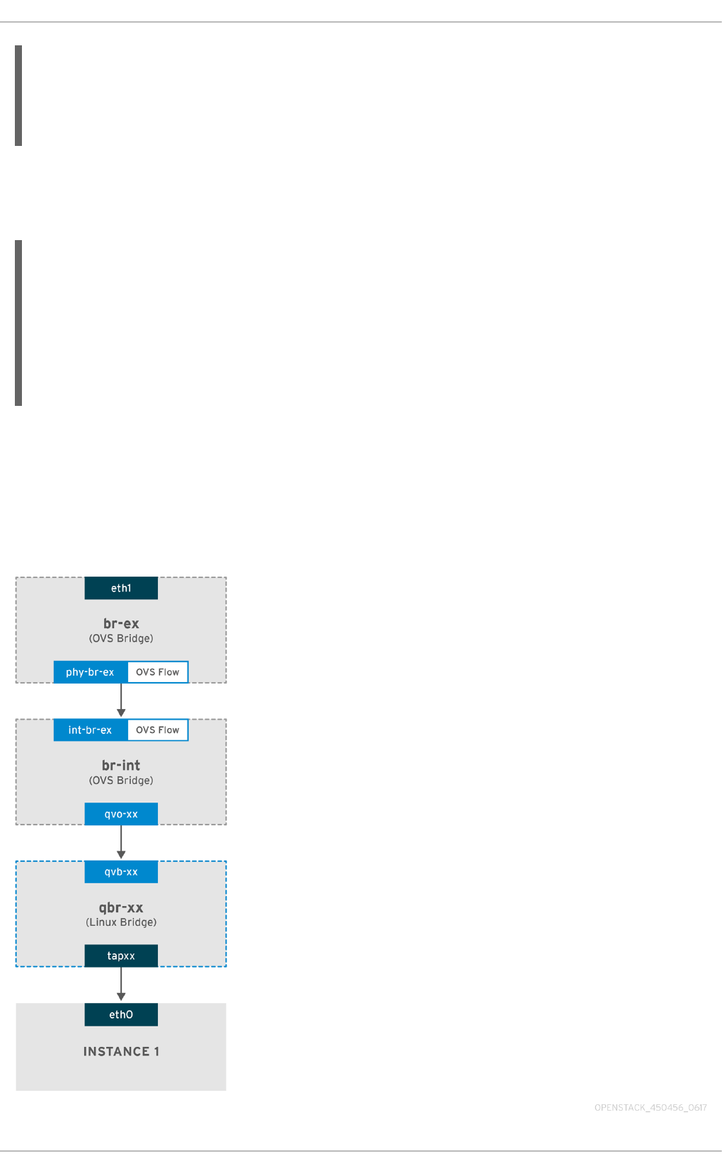
2(phy-br-ex): addr:ba:b5:7b:ae:5c:a2
config: 0
state: 0
speed: 0 Mbps now, 0 Mbps max
The output below shows any packet that arrives on phy-br-ex (in_port=2) with a VLAN tag of 5
(dl_vlan=5). In addition, the VLAN tag is stripped away and the packet is forwarded
(actions=strip_vlan,NORMAL).
# ovs-ofctl dump-flows br-ex
NXST_FLOW reply (xid=0x4):
cookie=0x0, duration=4703.491s, table=0, n_packets=3620, n_bytes=333744,
idle_age=0, priority=1 actions=NORMAL
cookie=0x0, duration=3890.038s, table=0, n_packets=13, n_bytes=1714,
idle_age=3764, priority=4,in_port=2,dl_vlan=5 actions=strip_vlan,NORMAL
cookie=0x0, duration=4702.644s, table=0, n_packets=10650, n_bytes=447632,
idle_age=0, priority=2,in_port=2 actions=drop
This packet is then forwarded to the physical interface. If the physical interface is another VLAN-
tagged interface, then the interface will add the tag to the packet.
7.1.2. The flow of incoming traffic
This section describes the flow of incoming traffic from the external network until it arrives at the
instance’s interface.
Red Hat OpenStack Platform 10 Networking Guide
50

1. Incoming traffic first arrives at eth1 on the physical node.
2. The packet is then passed to the br-ex bridge.
3. The packet then moves to br-int using the patch-peer phy-br-ex <--> int-br-ex.
In the example below, int-br-ex uses port number 15. See the entry containing 15(int-br-ex):
ovs-ofctl show br-int
OFPT_FEATURES_REPLY (xid=0x2): dpid:00004e67212f644d
n_tables:254, n_buffers:256
capabilities: FLOW_STATS TABLE_STATS PORT_STATS QUEUE_STATS ARP_MATCH_IP
actions: OUTPUT SET_VLAN_VID SET_VLAN_PCP STRIP_VLAN SET_DL_SRC SET_DL_DST
SET_NW_SRC SET_NW_DST SET_NW_TOS SET_TP_SRC SET_TP_DST ENQUEUE
15(int-br-ex): addr:12:4e:44:a9:50:f4
config: 0
state: 0
speed: 0 Mbps now, 0 Mbps max
Observing the traffic flow on br-int
1. When the packet arrives at int-br-ex, an OVS flow rule within the br-int bridge amends the
packet to add the internal VLAN tag 5. See the entry for actions=mod_vlan_vid:5:
# ovs-ofctl dump-flows br-int
NXST_FLOW reply (xid=0x4):
cookie=0x0, duration=5351.536s, table=0, n_packets=12118, n_bytes=510456,
idle_age=0, priority=1 actions=NORMAL
cookie=0x0, duration=4537.553s, table=0, n_packets=3489, n_bytes=321696,
idle_age=0, priority=3,in_port=15,vlan_tci=0x0000
actions=mod_vlan_vid:5,NORMAL
cookie=0x0, duration=5350.365s, table=0, n_packets=628, n_bytes=57892,
idle_age=4538, priority=2,in_port=15 actions=drop
cookie=0x0, duration=5351.432s, table=23, n_packets=0, n_bytes=0,
idle_age=5351, priority=0 actions=drop
2. The second rule manages packets that arrive on int-br-ex (in_port=15) with no VLAN tag
(vlan_tci=0x0000): It adds VLAN tag 5 to the packet (actions=mod_vlan_vid:5,NORMAL) and
forwards it on to qvoxxx.
3. qvoxxx accepts the packet and forwards to qvbxx, after stripping the away the VLAN tag.
4. The packet then reaches the instance.
NOTE
VLAN tag 5 is an example VLAN that was used on a test Compute node with a flat
provider network; this value was assigned automatically by neutron-openvswitch-
agent. This value may be different for your own flat provider network, and it can differ
for the same network on two separate Compute nodes.
7.1.3. Troubleshooting
CHAPTER 7. CONNECT AN INSTANCE TO THE PHYSICAL NETWORK
51

The output provided in the section above - How does the packet flow work? - provides sufficient
debugging information for troubleshooting a flat provider network, should anything go wrong. The
steps below would further assist with the troubleshooting process.
1. Review bridge_mappings:
Verify that physical network name used (for example, physnet1) is consistent with the contents of the
bridge_mapping configuration. For example:
# grep bridge_mapping /etc/neutron/plugins/ml2/openvswitch_agent.ini
bridge_mappings = physnet1:br-ex
# neutron net-show provider-flat
...
| provider:physical_network | physnet1
...
2. Review the network configuration:
Confirm that the network is created as external, and uses the flat type:
# neutron net-show provider-flat
...
| provider:network_type | flat |
| router:external | True |
...
3. Review the patch-peer:
Run ovs-vsctl show, and verify that br-int and br-ex is connected using a patch-peer int-br-
ex <--> phy-br-ex.
This connection is created when the neutron-openvswitch-agent service is restarted. But only if
bridge_mapping is correctly configured in
/etc/neutron/plugins/ml2/openvswitch_agent.ini. Re-check the bridge_mapping setting
if this is not created, even after restarting the service.
NOTE
For more information on configuring bridge_mappings, see Chapter 11, Configure
Bridge Mappings.
4. Review the network flows:
Run ovs-ofctl dump-flows br-ex and ovs-ofctl dump-flows br-int and review whether
the flows strip the internal VLAN IDs for outgoing packets, and add VLAN IDs for incoming packets.
This flow is first added when you spawn an instance to this network on a specific Compute node.
If this flow is not created after spawning the instance, verify that the network is created as
flat, is external, and that the physical_network name is correct. In addition, review the
bridge_mapping settings.
Red Hat OpenStack Platform 10 Networking Guide
52

Finally, review the ifcfg-br-ex and ifcfg-ethx configuration. Make sure that ethX is
definitely added as a port within br-ex, and that both of them have UP flag in the output of ip
a.
For example, the output below shows eth1 is a port in br-ex:
Bridge br-ex
Port phy-br-ex
Interface phy-br-ex
type: patch
options: {peer=int-br-ex}
Port "eth1"
Interface "eth1"
The example below demonstrates that eth1 is configured as an OVS port, and that the kernel knows
to transfer all packets from the interface, and send them to the OVS bridge br-ex. This can be
observed in the entry: master ovs-system.
# ip a
5: eth1: <BROADCAST,MULTICAST,UP,LOWER_UP> mtu 1500 qdisc mq master ovs-
system state UP qlen 1000
7.2. Using VLAN provider networks
This procedure creates VLAN provider networks that can connect instances directly to external
networks. You would do this if you want to connect multiple VLAN-tagged interfaces (on a single NIC)
to multiple provider networks. This example uses a physical network called physnet1, with a range of
VLANs (171-172). The network nodes and compute nodes are connected to the physical network
using a physical interface on them called eth1. The switch ports to which these interfaces are
connected must be configured to trunk the required VLAN ranges.
The following procedures configure the VLAN provider networks using the example VLAN IDs and
names given above.
Configure the Controller nodes:
1. Enable the vlan mechanism driver by editing /etc/neutron/plugin.ini (symlinked to
/etc/neutron/plugins/ml2/ml2_conf.ini), and add vlan to the existing list of values. For
example:
[ml2]
type_drivers = vxlan,flat,vlan
2. Configure the network_vlan_ranges setting to reflect the physical network and VLAN ranges in
use. For example:
[ml2_type_vlan]
network_vlan_ranges=physnet1:171:172
3. Restart the neutron-server service to apply the changes:
systemctl restart neutron-server
CHAPTER 7. CONNECT AN INSTANCE TO THE PHYSICAL NETWORK
53

4. Create the external networks as a vlan-type, and associate them to the configured
physical_network. Create it as a --shared network to let other users directly connect instances.
This example creates two networks: one for VLAN 171, and another for VLAN 172:
neutron net-create provider-vlan171 \
--provider:network_type vlan \
--router:external true \
--provider:physical_network physnet1 \
--provider:segmentation_id 171 --shared
neutron net-create provider-vlan172 \
--provider:network_type vlan \
--router:external true \
--provider:physical_network physnet1 \
--provider:segmentation_id 172 --shared
5. Create a number of subnets and configure them to use the external network. This is done using
either neutron subnet-create or the dashboard. You will want to make certain that the external
subnet details you have received from your network administrator are correctly associated with each
VLAN. In this example, VLAN 171 uses subnet 10.65.217.0/24 and VLAN 172 uses 10.65.218.0/24:
neutron subnet-create \
--name subnet-provider-171 provider-171 10.65.217.0/24 \
--enable-dhcp \
--gateway 10.65.217.254 \
neutron subnet-create \
--name subnet-provider-172 provider-172 10.65.218.0/24 \
--enable-dhcp \
--gateway 10.65.218.254 \
Configure the Network nodes and Compute nodes:
These steps must be performed on the Network node and Compute nodes. As a result, this will connect
the nodes to the external network, and permit instances to communicate directly with the external
network.
1. Create an external network bridge ( br-ex), and associate a port ( eth1) with it:
This example configures eth1 to use br-ex:
/etc/sysconfig/network-scripts/ifcfg-eth1
DEVICE=eth1
TYPE=OVSPort
DEVICETYPE=ovs
OVS_BRIDGE=br-ex
ONBOOT=yes
NM_CONTROLLED=no
BOOTPROTO=none
This example configures the br-ex bridge:
/etc/sysconfig/network-scripts/ifcfg-br-ex:
Red Hat OpenStack Platform 10 Networking Guide
54

DEVICE=br-ex
TYPE=OVSBridge
DEVICETYPE=ovs
ONBOOT=yes
NM_CONTROLLED=no
BOOTPROTO=none
2. Reboot the node, or restart the network service for the networking changes to take effect. For
example:
# systemctl restart network
3. Configure the physical networks in /etc/neutron/plugins/ml2/openvswitch_agent.ini
and map bridges according to the physical network:
bridge_mappings = physnet1:br-ex
NOTE
For more information on configuring bridge_mappings, see Chapter 11, Configure
Bridge Mappings.
4. Restart the neutron-openvswitch-agent service on the network nodes and compute nodes for
the changes to take effect:
systemctl restart neutron-openvswitch-agent
Configure the Network node:
1. Set external_network_bridge = to an empty value in /etc/neutron/l3_agent.ini. This is
required to use provider external networks, not bridge based external network where we will add
external_network_bridge = br-ex:
# Name of bridge used for external network traffic. This should be set to
# empty value for the linux bridge
external_network_bridge =
2. Restart neutron-l3-agent for the changes to take effect.
systemctl restart neutron-l3-agent
3. Create a new instance and use the Networking tab in the dashboard to add the new instance
directly to the newly-created external network.
How does the packet flow work?
With VLAN provider networking configured, this section describes in detail how traffic flows to and
from an instance:
7.2.1. The flow of outgoing traffic
This section describes the packet flow for traffic leaving an instance and arriving directly to a VLAN
provider external network. This example uses two instances attached to the two VLAN networks (171
CHAPTER 7. CONNECT AN INSTANCE TO THE PHYSICAL NETWORK
55
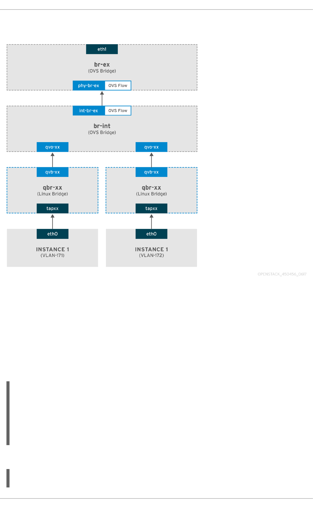
and 172). Once you configure br-ex, add a physical interface to it, and spawn an instance to a Compute
node, your resulting interfaces and bridges will be similar to those in the diagram below:
1. As illustrated above, packets leaving the instance’s eth0 first arrive at the linux bridge qbr-xx
connected to the instance.
2. qbr-xx is connected to br-int using veth pair qvbxx <→ qvoxxx.
3. qvbxx is connected to the linux bridge qbr-xx and qvoxx is connected to the Open vSwitch bridge br-
int.
Below is the configuration of qbr-xx on the Linux bridge.
Since there are two instances, there would two linux bridges:
# brctl show
bridge name bridge id STP enabled interfaces
qbr84878b78-63 8000.e6b3df9451e0 no qvb84878b78-63
tap84878b78-63
qbr86257b61-5d 8000.3a3c888eeae6 no qvb86257b61-5d
tap86257b61-5d
The configuration of qvoxx on br-int:
options: {peer=phy-br-ex}
Red Hat OpenStack Platform 10 Networking Guide
56

Port "qvo86257b61-5d"
tag: 3
Interface "qvo86257b61-5d"
Port "qvo84878b78-63"
tag: 2
Interface "qvo84878b78-63"
qvoxx is tagged with the internal VLAN tag associated with the VLAN provider network. In
this example, the internal VLAN tag 2 is associated with the VLAN provider network
provider-171 and VLAN tag 3 is associated with VLAN provider network provider-172.
Once the packet reaches qvoxx, the packet header will get this VLAN tag added to it.
The packet is then moved to the br-ex OVS bridge using patch-peer int-br-ex <→ phy-br-
ex. Example patch-peer on br-int:
Bridge br-int
fail_mode: secure
Port int-br-ex
Interface int-br-ex
type: patch
options: {peer=phy-br-ex}
Example configuration of the patch peer on br-ex:
Bridge br-ex
Port phy-br-ex
Interface phy-br-ex
type: patch
options: {peer=int-br-ex}
Port br-ex
Interface br-ex
type: internal
When this packet reaches phy-br-ex on br-ex, an OVS flow inside br-ex replaces the internal
VLAN tag with the actual VLAN tag associated with the VLAN provider network.
The output of the following command shows that the port number of phy-br-ex is 4:
# ovs-ofctl show br-ex
4(phy-br-ex): addr:32:e7:a1:6b:90:3e
config: 0
state: 0
speed: 0 Mbps now, 0 Mbps max
The below command displays any packet that arrives on phy-br-ex (in_port=4) which has VLAN tag 2
(dl_vlan=2). Open vSwitch replaces the VLAN tag with 171
(actions=mod_vlan_vid:171,NORMAL) and forwards the packet on. It also shows any packet that
arrives on phy-br-ex (in_port=4) which has VLAN tag 3 ( dl_vlan=3). Open vSwitch replaces the
VLAN tag with 172 (actions=mod_vlan_vid:172,NORMAL) and forwards the packet on. These rules
are automatically added by neutron-openvswitch-agent.
# ovs-ofctl dump-flows br-ex
NXST_FLOW reply (xid=0x4):
CHAPTER 7. CONNECT AN INSTANCE TO THE PHYSICAL NETWORK
57

NXST_FLOW reply (xid=0x4):
cookie=0x0, duration=6527.527s, table=0, n_packets=29211,
n_bytes=2725576, idle_age=0, priority=1 actions=NORMAL
cookie=0x0, duration=2939.172s, table=0, n_packets=117, n_bytes=8296,
idle_age=58, priority=4,in_port=4,dl_vlan=3
actions=mod_vlan_vid:172,NORMAL
cookie=0x0, duration=6111.389s, table=0, n_packets=145, n_bytes=9368,
idle_age=98, priority=4,in_port=4,dl_vlan=2
actions=mod_vlan_vid:171,NORMAL
cookie=0x0, duration=6526.675s, table=0, n_packets=82, n_bytes=6700,
idle_age=2462, priority=2,in_port=4 actions=drop
This packet is then forwarded to physical interface eth1.
7.2.2. The flow of incoming traffic
An incoming packet for the instance from external network first reaches eth1, then arrives at
br-ex.
From br-ex, the packet is moved to br-int via patch-peer phy-br-ex <-> int-br-ex.
The below command shows int-br-ex with port number 18:
# ovs-ofctl show br-int
18(int-br-ex): addr:fe:b7:cb:03:c5:c1
config: 0
state: 0
speed: 0 Mbps now, 0 Mbps max
When the packet arrives on int-br-ex, an OVS flow rule inside br-int adds internal VLAN tag 2
for provider-171 and VLAN tag 3 for provider-172 to the packet:
# ovs-ofctl dump-flows br-int
NXST_FLOW reply (xid=0x4):
cookie=0x0, duration=6770.572s, table=0, n_packets=1239, n_bytes=127795,
idle_age=106, priority=1 actions=NORMAL
cookie=0x0, duration=3181.679s, table=0, n_packets=2605, n_bytes=246456,
idle_age=0, priority=3,in_port=18,dl_vlan=172
actions=mod_vlan_vid:3,NORMAL
cookie=0x0, duration=6353.898s, table=0, n_packets=5077, n_bytes=482582,
idle_age=0, priority=3,in_port=18,dl_vlan=171
actions=mod_vlan_vid:2,NORMAL
cookie=0x0, duration=6769.391s, table=0, n_packets=22301,
n_bytes=2013101, idle_age=0, priority=2,in_port=18 actions=drop
cookie=0x0, duration=6770.463s, table=23, n_packets=0, n_bytes=0,
idle_age=6770, priority=0 actions=drop
The second rule says a packet that arrives on int-br-ex (in_port=18) which has VLAN tag 172 in it
(dl_vlan=172), replace VLAN tag with 3 ( actions=mod_vlan_vid:3,NORMAL) and forward. The
third rule says a packet that arrives on int-br-ex (in_port=18) which has VLAN tag 171 in it
(dl_vlan=171), replace VLAN tag with 2 ( actions=mod_vlan_vid:2,NORMAL) and forward.
With the internal VLAN tag added to the packet, qvoxxx accepts it and forwards it on to qvbxx
(after stripping the VLAN tag), after which the packet then reaches the instance.
Red Hat OpenStack Platform 10 Networking Guide
58

Note that the VLAN tag 2 and 3 is an example that was used on a test Compute node for the VLAN
provider networks (provider-171 and provider-172). The required configuration may be different for
your VLAN provider network, and can also be different for the same network on two different
Compute nodes.
7.2.3. Troubleshooting
Refer to the packet flow described in the section above when troubleshooting connectivity in a VLAN
provider network. In addition, review the following configuration options:
1. Verify that physical network name is used consistently. In this example, physnet1 is used
consistently while creating the network, and within the bridge_mapping configuration:
# grep bridge_mapping /etc/neutron/plugins/ml2/openvswitch_agent.ini
bridge_mappings = physnet1:br-ex
# neutron net-show provider-vlan171
...
| provider:physical_network | physnet1
...
2. Confirm that the network was created as external, is type vlan, and uses the correct
segmentation_id value:
# neutron net-show provider-vlan171
...
| provider:network_type | vlan |
| provider:physical_network | physnet1 |
| provider:segmentation_id | 171 |
...
3. Run ovs-vsctl show and verify that br-int and br-ex are connected using the patch-peer int-br-
ex <→ phy-br-ex.
This connection is created while restarting neutron-openvswitch-agent, provided that the
bridge_mapping is correctly configured in
/etc/neutron/plugins/ml2/openvswitch_agent.ini.
Recheck the bridge_mapping setting if this is not created even after restarting the service.
4. To review the flow of outgoing packets, run ovs-ofctl dump-flows br-ex and ovs-ofctl
dump-flows br-int, and verify that the flows map the internal VLAN IDs to the external VLAN ID
(segmentation_id). For incoming packets, map the external VLAN ID to the internal VLAN ID.
This flow is added by the neutron OVS agent when you spawn an instance to this network for the first
time. If this flow is not created after spawning the instance, make sure that the network is created as
vlan, is external, and that the physical_network name is correct. In addition, re-check the
bridge_mapping settings.
5. Finally, re-check the ifcfg-br-ex and ifcfg-ethx configuration. Make sure that ethX is added as a port
inside br-ex, and that both of them have UP flag in the output of the ip a command.
For example, the output below shows that eth1 is a port in br-ex.
Bridge br-ex
Port phy-br-ex
Interface phy-br-ex
type: patch
CHAPTER 7. CONNECT AN INSTANCE TO THE PHYSICAL NETWORK
59

options: {peer=int-br-ex}
Port "eth1"
Interface "eth1"
The command below shows that eth1 has been added as a port, and that the kernel is aware to move all
packets from the interface to the OVS bridge br-ex. This is demonstrated by the entry: master ovs-
system.
# ip a
5: eth1: <BROADCAST,MULTICAST,UP,LOWER_UP> mtu 1500 qdisc mq master ovs-
system state UP qlen 1000
7.3. Enable Compute metadata access
Instances connected in this way are directly attached to the provider external networks, and have
external routers configured as their default gateway; no OpenStack Networking (neutron) routers are
used. This means that neutron routers cannot be used to proxy metadata requests from instances to
the nova-metadata server, which may result in failures while running cloud-init. However, this issue can
be resolved by configuring the dhcp agent to proxy metadata requests. You can enable this
functionality in /etc/neutron/dhcp_agent.ini. For example:
enable_isolated_metadata = True
7.4. Floating IP addresses
Note that the same network can be used to allocate floating IP addresses to instances, even if they
have been added to private networks at the same time. The addresses allocated as floating IPs from
this network will be bound to the qrouter-xxx namespace on the Network node, and will perform DNAT-
SNAT to the associated private IP address. In contrast, the IP addresses allocated for direct external
network access will be bound directly inside the instance, and allow the instance to communicate
directly with external network.
Red Hat OpenStack Platform 10 Networking Guide
60

CHAPTER 8. CONFIGURE PHYSICAL SWITCHES FOR
OPENSTACK NETWORKING
This chapter documents the common physical switch configuration steps required for OpenStack
Networking. Vendor-specific configuration is included for the following switches:
Cisco Catalyst
Cisco Nexus
Cumulus Linux
Extreme Networks EXOS
Juniper EX Series
8.1. Planning your physical network environment
The physical network adapters in your OpenStack nodes can be expected to carry different types of
network traffic, such as instance traffic, storage data, or authentication requests. The type of traffic
these NICs will carry affects how their ports are configured on the physical switch.
As a first step, you will need to decide which physical NICs on your Compute node will carry which
types of traffic. Then, when the NIC is cabled to a physical switch port, that switch port will need to be
specially configured to allow trunked or general traffic.
For example, this diagram depicts a Compute node with two NICs, eth0 and eth1. Each NIC is cabled to
a Gigabit Ethernet port on a physical switch, with eth0 carrying instance traffic, and eth1 providing
connectivity for OpenStack services:
Sample network layout
NOTE
This diagram does not include any additional redundant NICs required for fault
tolerance.
CHAPTER 8. CONFIGURE PHYSICAL SWITCHES FOR OPENSTACK NETWORKING
61

8.2. Configure a Cisco Catalyst switch
8.2.1. Configure trunk ports
OpenStack Networking allows instances to connect to the VLANs that already exist on your physical
network. The term trunk is used to describe a port that allows multiple VLANs to traverse through the
same port. As a result, VLANs can span across multiple switches, including virtual switches. For
example, traffic tagged as VLAN110 in the physical network can arrive at the Compute node, where
the 8021q module will direct the tagged traffic to the appropriate VLAN on the vSwitch.
8.2.1.1. Configure trunk ports for a Cisco Catalyst switch
If using a Cisco Catalyst switch running Cisco IOS, you might use the following configuration syntax to
allow traffic for VLANs 110 and 111 to pass through to your instances. This configuration assumes that
your physical node has an ethernet cable connected to interface GigabitEthernet1/0/12 on the
physical switch.
NOTE
These values are examples only. Simply copying and pasting into your switch
configuration without adjusting the values first will likely result in an unexpected
outage.
interface GigabitEthernet1/0/12
description Trunk to Compute Node
spanning-tree portfast trunk
switchport trunk encapsulation dot1q
switchport mode trunk
switchport trunk native vlan 2
switchport trunk allowed vlan 2,110,111
These settings are described below:
Field Description
interface GigabitEthernet1/0/12 The switch port that the node’s NIC is plugged into.
This is just an example, so it is important to first
verify that you are configuring the correct port here.
You can use the show interface command to view a
list of ports.
description Trunk to Compute Node The description that appears when listing all
interfaces using the show interface command.
Should be descriptive enough to let someone
understand which system is plugged into this port,
and what the connection’s intended function is.
spanning-tree portfast trunk Assuming your environment uses STP, tells Port
Fast that this port is used to trunk traffic.
Red Hat OpenStack Platform 10 Networking Guide
62

switchport trunk encapsulation
dot1q
Enables the 802.1q trunking standard (rather than
ISL). This will vary depending on what your switch
supports.
switchport mode trunk Configures this port as a trunk port, rather than an
access port, meaning that it will allow VLAN traffic
to pass through to the virtual switches.
switchport trunk native vlan 2 Setting a native VLAN tells the switch where to send
untagged (non-VLAN) traffic.
switchport trunk allowed vlan
2,110,111
Defines which VLANs are allowed through the trunk.
Field Description
8.2.2. Configure access ports
Not all NICs on your Compute node will carry instance traffic, and so do not need to be configured to
allow multiple VLANs to pass through. These ports require only one VLAN to be configured, and might
fulfill other operational requirements, such as transporting management traffic or Block Storage data.
These ports are commonly known as access ports and usually require a simpler configuration than
trunk ports.
8.2.2.1. Configure access ports for a Cisco Catalyst switch
Using the example from the Sample network layout diagram, GigabitEthernet1/0/13 (on a Cisco
Catalyst switch) is configured as an access port for eth1. This configuration assumes that your physical
node has an ethernet cable connected to interface GigabitEthernet1/0/12 on the physical switch.
NOTE
These values are examples only. Simply copying and pasting into your switch
configuration without adjusting the values first will likely result in an unexpected
outage.
interface GigabitEthernet1/0/13
description Access port for Compute Node
switchport mode access
switchport access vlan 200
spanning-tree portfast
These settings are described below:
Field Description
CHAPTER 8. CONFIGURE PHYSICAL SWITCHES FOR OPENSTACK NETWORKING
63

interface GigabitEthernet1/0/13 The switch port that the node’s NIC is plugged into.
The interface value is just an example, so it is
important to first verify that you are configuring the
correct port here. You can use the show interface
command to view a list of ports.
description Access port for Compute
Node
The description that appears when listing all
interfaces using the show interface command.
Should be descriptive enough to let someone
understand which system is plugged into this port,
and what the connection’s intended function is.
switchport mode access Configures this port as an access port, rather than a
trunk port.
switchport access vlan 200 Configures the port to allow traffic on VLAN 200.
Your Compute node should also be configured with
an IP address from this VLAN.
spanning-tree portfast If using STP, this tells STP not to attempt to initialize
this as a trunk, allowing for quicker port handshakes
during initial connections (such as server reboot).
Field Description
8.2.3. Configure LACP port aggregation
LACP allows you to bundle multiple physical NICs together to form a single logical channel. Also known
as 802.3ad (or bonding mode 4 in Linux), LACP creates a dynamic bond for load-balancing and fault
tolerance. LACP must be configured at both physical ends: on the physical NICs, and on the physical
switch ports.
8.2.3.1. Configure LACP on the physical NIC
1. Edit the /home/stack/network-environment.yaml file:
- type: linux_bond
name: bond1
mtu: 9000
bonding_options:{get_param: BondInterfaceOvsOptions};
members:
- type: interface
name: nic3
mtu: 9000
primary: true
- type: interface
name: nic4
mtu: 9000
2. Configure the Open vSwitch bridge to use LACP:
Red Hat OpenStack Platform 10 Networking Guide
64

BondInterfaceOvsOptions:
"mode=802.3ad"
For information on configuring network bonds, see the Advanced Overcloud Customization guide.
8.2.3.2. Configure LACP on a Cisco Catalyst switch
In this example, the Compute node has two NICs using VLAN 100:
1. Physically connect the Compute node’s two NICs to the switch (for example, ports 12 and 13).
2. Create the LACP port channel:
interface port-channel1
switchport access vlan 100
switchport mode access
spanning-tree guard root
3. Configure switch ports 12 (Gi1/0/12) and 13 (Gi1/0/13):
sw01# config t
Enter configuration commands, one per line. End with CNTL/Z.
sw01(config) interface GigabitEthernet1/0/12
switchport access vlan 100
switchport mode access
speed 1000
duplex full
channel-group 10 mode active
channel-protocol lacp
interface GigabitEthernet1/0/13
switchport access vlan 100
switchport mode access
speed 1000
duplex full
channel-group 10 mode active
channel-protocol lacp
4. Review your new port channel. The resulting output lists the new port-channel Po1, with member
ports Gi1/0/12 and Gi1/0/13:
sw01# show etherchannel summary
<snip>
Number of channel-groups in use: 1
Number of aggregators: 1
Group Port-channel Protocol Ports
------+-------------+-----------+-------------------------------------
----------
1 Po1(SD) LACP Gi1/0/12(D) Gi1/0/13(D)
CHAPTER 8. CONFIGURE PHYSICAL SWITCHES FOR OPENSTACK NETWORKING
65

NOTE
Remember to apply your changes by copying the running-config to the startup-config:
copy running-config startup-config.
8.2.4. Configure MTU settings
Certain types of network traffic might require that you adjust your MTU size. For example, jumbo
frames (9000 bytes) might be suggested for certain NFS or iSCSI traffic.
NOTE
MTU settings must be changed from end-to-end (on all hops that the traffic is expected
to pass through), including any virtual switches. For information on changing the MTU in
your OpenStack environment, see Chapter 9, Configure MTU Settings.
8.2.4.1. Configure MTU settings on a Cisco Catalyst switch
This example enables jumbo frames on your Cisco Catalyst 3750 switch.
1. Review the current MTU settings:
sw01# show system mtu
System MTU size is 1600 bytes
System Jumbo MTU size is 1600 bytes
System Alternate MTU size is 1600 bytes
Routing MTU size is 1600 bytes
2. MTU settings are changed switch-wide on 3750 switches, and not for individual interfaces. This
command configures the switch to use jumbo frames of 9000 bytes. If your switch supports it, you
might prefer to configure the MTU settings for individual interfaces.
sw01# config t
Enter configuration commands, one per line. End with CNTL/Z.
sw01(config)# system mtu jumbo 9000
Changes to the system jumbo MTU will not take effect until the next reload
is done
NOTE
Remember to save your changes by copying the running-config to the startup-config:
copy running-config startup-config.
3. When possible, reload the switch to apply the change. This will result in a network outage for any
devices that are dependent on the switch.
sw01# reload
Proceed with reload? [confirm]
Red Hat OpenStack Platform 10 Networking Guide
66

4. When the switch has completed its reload operation, confirm the new jumbo MTU size. The exact
output may differ depending on your switch model, where System MTU might apply to non-Gigabit
interfaces, and Jumbo MTU might describe all Gigabit interfaces.
sw01# show system mtu
System MTU size is 1600 bytes
System Jumbo MTU size is 9000 bytes
System Alternate MTU size is 1600 bytes
Routing MTU size is 1600 bytes
8.2.5. Configure LLDP discovery
The ironic-python-agent service listens for LLDP packets from connected switches. The collected
information can include the switch name, port details, and available VLANs. Similar to Cisco Discovery
Protocol (CDP), LLDP assists with the discovery of physical hardware during director’s
introspection process.
8.2.5.1. Configure LLDP on a Cisco Catalyst switch
1. Use lldp run to enable LLDP globally on your Cisco Catalyst switch:
sw01# config t
Enter configuration commands, one per line. End with CNTL/Z.
sw01(config)# lldp run
2. View any neighboring LLDP-compatible devices:
sw01# show lldp neighbor
Capability codes:
(R) Router, (B) Bridge, (T) Telephone, (C) DOCSIS Cable Device
(W) WLAN Access Point, (P) Repeater, (S) Station, (O) Other
Device ID Local Intf Hold-time Capability Port ID
DEP42037061562G3 Gi1/0/11 180 B,T
422037061562G3:P1
Total entries displayed: 1
NOTE
Remember to save your changes by copying the running-config to the startup-config:
copy running-config startup-config.
8.3. Configure a Cisco Nexus switch
8.3.1. Configure trunk ports
OpenStack Networking allows instances to connect to the VLANs that already exist on your physical
network. The term trunk is used to describe a port that allows multiple VLANs to traverse through the
same port. As a result, VLANs can span across multiple switches, including virtual switches. For
CHAPTER 8. CONFIGURE PHYSICAL SWITCHES FOR OPENSTACK NETWORKING
67

example, traffic tagged as VLAN110 in the physical network can arrive at the Compute node, where
the 8021q module will direct the tagged traffic to the appropriate VLAN on the vSwitch.
8.3.1.1. Configure trunk ports for a Cisco Nexus switch
If using a Cisco Nexus you might use the following configuration syntax to allow traffic for VLANs 110
and 111 to pass through to your instances. This configuration assumes that your physical node has an
ethernet cable connected to interface Ethernet1/12 on the physical switch.
NOTE
These values are examples only. Simply copying and pasting into your switch
configuration without adjusting the values first will likely result in an unexpected
outage.
interface Ethernet1/12
description Trunk to Compute Node
switchport mode trunk
switchport trunk allowed vlan 2,110,111
switchport trunk native vlan 2
end
8.3.2. Configure access ports
Not all NICs on your Compute node will carry instance traffic, and so do not need to be configured to
allow multiple VLANs to pass through. These ports require only one VLAN to be configured, and might
fulfill other operational requirements, such as transporting management traffic or Block Storage data.
These ports are commonly known as access ports and usually require a simpler configuration than
trunk ports.
8.3.2.1. Configure access ports for a Cisco Nexus switch
Using the example from the Sample network layout diagram, Ethernet1/13 (on a Cisco Nexus switch) is
configured as an access port for eth1. This configuration assumes that your physical node has an
ethernet cable connected to interface Ethernet1/13 on the physical switch.
NOTE
These values are examples only. Simply copying and pasting into your switch
configuration without adjusting the values first will likely result in an unexpected
outage.
interface Ethernet1/13
description Access port for Compute Node
switchport mode access
switchport access vlan 200
8.3.3. Configure LACP port aggregation
LACP allows you to bundle multiple physical NICs together to form a single logical channel. Also known
as 802.3ad (or bonding mode 4 in Linux), LACP creates a dynamic bond for load-balancing and fault
tolerance. LACP must be configured at both physical ends: on the physical NICs, and on the physical
Red Hat OpenStack Platform 10 Networking Guide
68

switch ports.
8.3.3.1. Configure LACP on the physical NIC
1. Edit the /home/stack/network-environment.yaml file:
- type: linux_bond
name: bond1
mtu: 9000
bonding_options:{get_param: BondInterfaceOvsOptions};
members:
- type: interface
name: nic3
mtu: 9000
primary: true
- type: interface
name: nic4
mtu: 9000
2. Configure the Open vSwitch bridge to use LACP:
BondInterfaceOvsOptions:
"mode=802.3ad"
For information on configuring network bonds, see the Advanced Overcloud Customization guide.
8.3.3.2. Configure LACP on a Cisco Nexus switch
In this example, the Compute node has two NICs using VLAN 100:
1. Physically connect the Compute node’s two NICs to the switch (for example, ports 12 and 13).
2. Confirm that LACP is enabled:
(config)# show feature | include lacp
lacp 1 enabled
3. Configure ports 1/12 and 1/13 as access ports, and as members of a channel group. Depending on
your deployment, you might deploy to use trunk interfaces rather than access interfaces. For example,
for Cisco UCI the NICs are virtual interfaces, so you might prefer to set up all access ports. In addition,
there will likely be VLAN tagging configured on the interfaces.
interface Ethernet1/13
description Access port for Compute Node
switchport mode access
switchport access vlan 200
channel-group 10 mode active
interface Ethernet1/13
description Access port for Compute Node
switchport mode access
switchport access vlan 200
channel-group 10 mode active
CHAPTER 8. CONFIGURE PHYSICAL SWITCHES FOR OPENSTACK NETWORKING
69

8.3.4. Configure MTU settings
Certain types of network traffic might require that you adjust your MTU size. For example, jumbo
frames (9000 bytes) might be suggested for certain NFS or iSCSI traffic.
NOTE
MTU settings must be changed from end-to-end (on all hops that the traffic is expected
to pass through), including any virtual switches. For information on changing the MTU in
your OpenStack environment, see Chapter 9, Configure MTU Settings.
8.3.4.1. Configure MTU settings on a Cisco Nexus 7000 switch
MTU settings can be applied to a single interface on 7000-series switches. These commands configure
interface 1/12 to use jumbo frames of 9000 bytes:
interface ethernet 1/12
mtu 9216
exit
8.3.5. Configure LLDP discovery
The ironic-python-agent service listens for LLDP packets from connected switches. The collected
information can include the switch name, port details, and available VLANs. Similar to Cisco Discovery
Protocol (CDP), LLDP assists with the discovery of physical hardware during director’s
introspection process.
8.3.5.1. Configure LLDP on a Cisco Nexus 7000 switch
LLDP can be enabled for individual interfaces on Cisco Nexus 7000-series switches:
interface ethernet 1/12
lldp transmit
lldp receive
no lacp suspend-individual
no lacp graceful-convergence
interface ethernet 1/13
lldp transmit
lldp receive
no lacp suspend-individual
no lacp graceful-convergence
NOTE
Remember to save your changes by copying the running-config to the startup-config:
copy running-config startup-config.
8.4. Configure a Cumulus Linux switch
8.4.1. Configure trunk ports
OpenStack Networking allows instances to connect to the VLANs that already exist on your physical
Red Hat OpenStack Platform 10 Networking Guide
70

network. The term trunk is used to describe a port that allows multiple VLANs to traverse through the
same port. As a result, VLANs can span across multiple switches, including virtual switches. For
example, traffic tagged as VLAN110 in the physical network can arrive at the Compute node, where
the 8021q module will direct the tagged traffic to the appropriate VLAN on the vSwitch.
8.4.1.1. Configure trunk ports for a Cumulus Linux switch
If using a Cumulus Linux switch, you might use the following configuration syntax to allow traffic for
VLANs 100 and 200 to pass through to your instances. This configuration assumes that your physical
node has transceivers connected to switch ports swp1 and swp2 on the physical switch.
NOTE
These values are examples only. Simply copying and pasting into your switch
configuration without adjusting the values first will likely result in an unexpected
outage.
auto bridge
iface bridge
bridge-vlan-aware yes
bridge-ports glob swp1-2
bridge-vids 100 200
8.4.2. Configure access ports
Not all NICs on your Compute node will carry instance traffic, and so do not need to be configured to
allow multiple VLANs to pass through. These ports require only one VLAN to be configured, and might
fulfill other operational requirements, such as transporting management traffic or Block Storage data.
These ports are commonly known as access ports and usually require a simpler configuration than
trunk ports.
8.4.2.1. Configuring access ports for a Cumulus Linux switch
Using the example from the Sample network layout diagram, swp1 (on a Cumulus Linux switch) is
configured as an access port. This configuration assumes that your physical node has an ethernet
cable connected to the interface on the physical switch. Cumulus Linux switches use eth for
management interfaces and swp for access/trunk ports.
NOTE
These values are examples only. Simply copying and pasting into your switch
configuration without adjusting the values first will likely result in an unexpected
outage.
auto bridge
iface bridge
bridge-vlan-aware yes
bridge-ports glob swp1-2
bridge-vids 100 200
auto swp1
iface swp1
CHAPTER 8. CONFIGURE PHYSICAL SWITCHES FOR OPENSTACK NETWORKING
71

bridge-access 100
auto swp2
iface swp2
bridge-access 200
8.4.3. Configure LACP port aggregation
LACP allows you to bundle multiple physical NICs together to form a single logical channel. Also known
as 802.3ad (or bonding mode 4 in Linux), LACP creates a dynamic bond for load-balancing and fault
tolerance. LACP must be configured at both physical ends: on the physical NICs, and on the physical
switch ports.
8.4.3.1. Configure LACP on the physical NIC
There is no need to configure the physical NIC in Cumulus Linux.
8.4.3.2. Configure LACP on a Cumulus Linux switch
To configure the bond, edit /etc/network/interfaces and add a stanza for bond0:
auto bond0
iface bond0
address 10.0.0.1/30
bond-slaves swp1 swp2 swp3 swp4
NOTE
Remember to apply your changes by reloading the updated configuration: sudo
ifreload -a
8.4.4. Configure MTU settings
Certain types of network traffic might require that you adjust your MTU size. For example, jumbo
frames (9000 bytes) might be suggested for certain NFS or iSCSI traffic.
NOTE
MTU settings must be changed from end-to-end (on all hops that the traffic is expected
to pass through), including any virtual switches. For information on changing the MTU in
your OpenStack environment, see Chapter 9, Configure MTU Settings.
8.4.4.1. Configure MTU settings on a Cumulus Linux switch
This example enables jumbo frames on your Cumulus Linux switch.
auto swp1
iface swp1
mtu 9000
Remember to apply your changes by reloading the updated configuration: sudo ifreload -a
Red Hat OpenStack Platform 10 Networking Guide
72

8.4.5. Configure LLDP discovery
By default, the LLDP service, lldpd, runs as a daemon and starts when the switch boots.
To view all LLDP neighbors on all ports/interfaces:
cumulus@switch$ netshow lldp
Local Port Speed Mode Remote Port Remote Host Summary
---------- --- --------- ----- ----- ----------- --------
eth0 10G Mgmt ==== swp6 mgmt-sw IP:
10.0.1.11/24
swp51 10G Interface/L3 ==== swp1 spine01 IP:
10.0.0.11/32
swp52 10G Interface/L ==== swp1 spine02 IP:
10.0.0.11/32
8.5. Configure an Extreme Networks EXOS switch
8.5.1. Configure trunk ports
OpenStack Networking allows instances to connect to the VLANs that already exist on your physical
network. The term trunk is used to describe a port that allows multiple VLANs to traverse through the
same port. As a result, VLANs can span across multiple switches, including virtual switches. For
example, traffic tagged as VLAN110 in the physical network can arrive at the Compute node, where
the 8021q module will direct the tagged traffic to the appropriate VLAN on the vSwitch.
8.5.1.1. Configure trunk ports on an Extreme Networks EXOS switch
If using an X-670 series switch, you might refer to the following example to allow traffic for VLANs 110
and 111 to pass through to your instances. This configuration assumes that your physical node has an
ethernet cable connected to interface 24 on the physical switch. In this example, DATA and MNGT are
the VLAN names.
NOTE
These values are examples only. Simply copying and pasting into your switch
configuration without adjusting the values first will likely result in an unexpected
outage.
#create vlan DATA tag 110
#create vlan MNGT tag 111
#configure vlan DATA add ports 24 tagged
#configure vlan MNGT add ports 24 tagged
8.5.2. Configure access ports
Not all NICs on your Compute node will carry instance traffic, and so do not need to be configured to
allow multiple VLANs to pass through. These ports require only one VLAN to be configured, and might
fulfill other operational requirements, such as transporting management traffic or Block Storage data.
These ports are commonly known as access ports and usually require a simpler configuration than
trunk ports.
8.5.2.1. Configure access ports for an Extreme Networks EXOS switch
CHAPTER 8. CONFIGURE PHYSICAL SWITCHES FOR OPENSTACK NETWORKING
73

To continue the example from the diagram above, this example configures 10 (on a Extreme Networks
X-670 series switch) as an access port for eth1. you might use the following configuration to allow
traffic for VLANs 110 and 111 to pass through to your instances. This configuration assumes that your
physical node has an ethernet cable connected to interface 10 on the physical switch.
NOTE
These values are examples only. Simply copying and pasting into your switch
configuration without adjusting the values first will likely result in an unexpected
outage.
create vlan VLANNAME tag NUMBER
configure vlan Default delete ports PORTSTRING
configure vlan VLANNAME add ports PORTSTRING untagged
For example:
#create vlan DATA tag 110
#configure vlan Default delete ports 10
#configure vlan DATA add ports 10 untagged
8.5.3. Configure LACP port aggregation
LACP allows you to bundle multiple physical NICs together to form a single logical channel. Also known
as 802.3ad (or bonding mode 4 in Linux), LACP creates a dynamic bond for load-balancing and fault
tolerance. LACP must be configured at both physical ends: on the physical NICs, and on the physical
switch ports.
8.5.3.1. Configure LACP on the physical NIC
1. Edit the /home/stack/network-environment.yaml file:
- type: linux_bond
name: bond1
mtu: 9000
bonding_options:{get_param: BondInterfaceOvsOptions};
members:
- type: interface
name: nic3
mtu: 9000
primary: true
- type: interface
name: nic4
mtu: 9000
2. Configure the Open vSwitch bridge to use LACP:
BondInterfaceOvsOptions:
"mode=802.3ad"
For information on configuring network bonds, see the Advanced Overcloud Customization guide.
Red Hat OpenStack Platform 10 Networking Guide
74

8.5.3.2. Configure LACP on an Extreme Networks EXOS switch
In this example, the Compute node has two NICs using VLAN 100:
enable sharing MASTERPORT grouping ALL_LAG_PORTS lacp
configure vlan VLANNAME add ports PORTSTRING tagged
For example:
#enable sharing 11 grouping 11,12 lacp
#configure vlan DATA add port 11 untagged
NOTE
You might need to adjust the timeout period in the LACP negotiation script. For more
information, see
https://gtacknowledge.extremenetworks.com/articles/How_To/LACP-configured-
ports-interfere-with-PXE-DHCP-on-servers
8.5.4. Configure MTU settings
Certain types of network traffic might require that you adjust your MTU size. For example, jumbo
frames (9000 bytes) might be suggested for certain NFS or iSCSI traffic.
NOTE
MTU settings must be changed from end-to-end (on all hops that the traffic is expected
to pass through), including any virtual switches. For information on changing the MTU in
your OpenStack environment, see Chapter 9, Configure MTU Settings.
8.5.4.1. Configure MTU settings on an Extreme Networks EXOS switch
The example enables jumbo frames on any Extreme Networks EXOS switch, and supports forwarding IP
packets with 9000 bytes:
enable jumbo-frame ports PORTSTRING
configure ip-mtu 9000 vlan VLANNAME
For example:
# enable jumbo-frame ports 11
# configure ip-mtu 9000 vlan DATA
8.5.5. Configure LLDP discovery
The ironic-python-agent service listens for LLDP packets from connected switches. The collected
information can include the switch name, port details, and available VLANs. Similar to Cisco Discovery
Protocol (CDP), LLDP assists with the discovery of physical hardware during director’s
introspection process.
8.5.5.1. Configure LLDP settings on an Extreme Networks EXOS switch
CHAPTER 8. CONFIGURE PHYSICAL SWITCHES FOR OPENSTACK NETWORKING
75

The example allows configuring LLDP settings on any Extreme Networks EXOS switch. In this example,
11 represents the port string:
enable lldp ports 11
8.6. Configure a Juniper EX Series switch
8.6.1. Configure trunk ports
OpenStack Networking allows instances to connect to the VLANs that already exist on your physical
network. The term trunk is used to describe a port that allows multiple VLANs to traverse through the
same port. As a result, VLANs can span across multiple switches, including virtual switches. For
example, traffic tagged as VLAN110 in the physical network can arrive at the Compute node, where
the 8021q module will direct the tagged traffic to the appropriate VLAN on the vSwitch.
8.6.1.1. Configure trunk ports on the Juniper EX Series switch
If using a Juniper EX series switch running Juniper JunOS, you might use the following configuration to
allow traffic for VLANs 110 and 111 to pass through to your instances. This configuration assumes
that your physical node has an ethernet cable connected to interface ge-1/0/12 on the physical
switch.
NOTE
These values are examples only. Simply copying and pasting into your switch
configuration without adjusting the values first will likely result in an unexpected
outage.
ge-1/0/12 {
description Trunk to Compute Node;
unit 0 {
family ethernet-switching {
port-mode trunk;
vlan {
members [110 111];
}
native-vlan-id 2;
}
}
}
8.6.2. Configure access ports
Not all NICs on your Compute node will carry instance traffic, and so do not need to be configured to
allow multiple VLANs to pass through. These ports require only one VLAN to be configured, and might
fulfill other operational requirements, such as transporting management traffic or Block Storage data.
These ports are commonly known as access ports and usually require a simpler configuration than
trunk ports.
8.6.2.1. Configure access ports for a Juniper EX Series switch
Red Hat OpenStack Platform 10 Networking Guide
76

To continue the example from the diagram above, this example configures ge-1/0/13 (on a Juniper EX
series switch) as an access port for eth1. This configuration assumes that your physical node has an
ethernet cable connected to interface ge-1/0/13 on the physical switch.
NOTE
These values are examples only. Simply copying and pasting into your switch
configuration without adjusting the values first will likely result in an unexpected
outage.
ge-1/0/13 {
description Access port for Compute Node
unit 0 {
family ethernet-switching {
port-mode access;
vlan {
members 200;
}
native-vlan-id 2;
}
}
}
8.6.3. Configure LACP port aggregation
LACP allows you to bundle multiple physical NICs together to form a single logical channel. Also known
as 802.3ad (or bonding mode 4 in Linux), LACP creates a dynamic bond for load-balancing and fault
tolerance. LACP must be configured at both physical ends: on the physical NICs, and on the physical
switch ports.
8.6.3.1. Configure LACP on the physical NIC
1. Edit the /home/stack/network-environment.yaml file:
- type: linux_bond
name: bond1
mtu: 9000
bonding_options:{get_param: BondInterfaceOvsOptions};
members:
- type: interface
name: nic3
mtu: 9000
primary: true
- type: interface
name: nic4
mtu: 9000
2. Configure the Open vSwitch bridge to use LACP:
BondInterfaceOvsOptions:
"mode=802.3ad"
For information on configuring network bonds, see the Advanced Overcloud Customization guide.
CHAPTER 8. CONFIGURE PHYSICAL SWITCHES FOR OPENSTACK NETWORKING
77

8.6.3.2. Configure LACP on a Juniper EX Series switch
In this example, the Compute node has two NICs using VLAN 100:
1. Physically connect the Compute node’s two NICs to the switch (for example, ports 12 and 13).
2. Create the port aggregate:
chassis {
aggregated-devices {
ethernet {
device-count 1;
}
}
}
3. Configure switch ports 12 (ge-1/0/12) and 13 (ge-1/0/13) to join the port aggregate ae1:
interfaces {
ge-1/0/12 {
gigether-options {
802.3ad ae1;
}
}
ge-1/0/13 {
gigether-options {
802.3ad ae1;
}
}
}
NOTE
For Red Hat OpenStack Platform director deployments, in order to PXE boot from the
bond, you need to set one of the bond members as lacp force-up. This will ensure
that one bond member only comes up during introspection and first boot. The bond
member set with lacp force-up should be the same bond member that has the MAC
address in instackenv.json (the MAC address known to ironic must be the same MAC
address configured with force-up).
4. Enable LACP on port aggregate ae1:
interfaces {
ae1 {
aggregated-ether-options {
lacp {
active;
}
}
}
}
5. Add aggregate ae1 to VLAN 100:
Red Hat OpenStack Platform 10 Networking Guide
78

interfaces {
ae1 {
vlan-tagging;
native-vlan-id 2;
unit 100 {
vlan-id 100;
}
}
}
6. Review your new port channel. The resulting output lists the new port aggregate ae1 with member
ports ge-1/0/12 and ge-1/0/13:
> show lacp statistics interfaces ae1
Aggregated interface: ae1
LACP Statistics: LACP Rx LACP Tx Unknown Rx Illegal Rx
ge-1/0/12 0 0 0 0
ge-1/0/13 0 0 0 0
NOTE
Remember to apply your changes by running the commit command.
8.6.4. Configure MTU settings
Certain types of network traffic might require that you adjust your MTU size. For example, jumbo
frames (9000 bytes) might be suggested for certain NFS or iSCSI traffic.
NOTE
MTU settings must be changed from end-to-end (on all hops that the traffic is expected
to pass through), including any virtual switches. For information on changing the MTU in
your OpenStack environment, see Chapter 9, Configure MTU Settings.
8.6.4.1. Configure MTU settings on a Juniper EX Series switch
This example enables jumbo frames on your Juniper EX4200 switch.
NOTE
The MTU value is calculated differently depending on whether you are using Juniper or
Cisco devices. For example, 9216 on Juniper would equal to 9202 for Cisco. The extra
bytes are used for L2 headers, where Cisco adds this automatically to the MTU value
specified, but the usable MTU will be 14 bytes smaller than specified when using Juniper.
So in order to support an MTU of 9000 on the VLANs, the MTU of 9014 would have to be
configured on Juniper.
1. For Juniper EX series switches, MTU settings are set for individual interfaces. These commands
configure jumbo frames on the ge-1/0/14 and ge-1/0/15 ports:
set interfaces ge-1/0/14 mtu 9216
set interfaces ge-1/0/15 mtu 9216
CHAPTER 8. CONFIGURE PHYSICAL SWITCHES FOR OPENSTACK NETWORKING
79

NOTE
Remember to save your changes by running the commit command.
2. If using a LACP aggregate, you will need to set the MTU size there, and not on the member NICs. For
example, this setting configures the MTU size for the ae1 aggregate:
set interfaces ae1 mtu 9216
8.6.5. Configure LLDP discovery
The ironic-python-agent service listens for LLDP packets from connected switches. The collected
information can include the switch name, port details, and available VLANs. Similar to Cisco Discovery
Protocol (CDP), LLDP assists with the discovery of physical hardware during director’s
introspection process.
8.6.5.1. Configure LLDP on a Juniper EX Series switch
You can enable LLDP globally for all interfaces, or just for individual ones:
1. For example, to enable LLDP globally on your Juniper EX 4200 switch:
lldp {
interface all{
enable;
}
}
}
2. Or, enable LLDP just for the single interface ge-1/0/14:
lldp {
interface ge-1/0/14{
enable;
}
}
}
NOTE
Remember to apply your changes by running the commit command.
Red Hat OpenStack Platform 10 Networking Guide
80

PART II. ADVANCED CONFIGURATION
Contains cookbook-style scenarios for advanced OpenStack Networking features.
PART II. ADVANCED CONFIGURATION
81
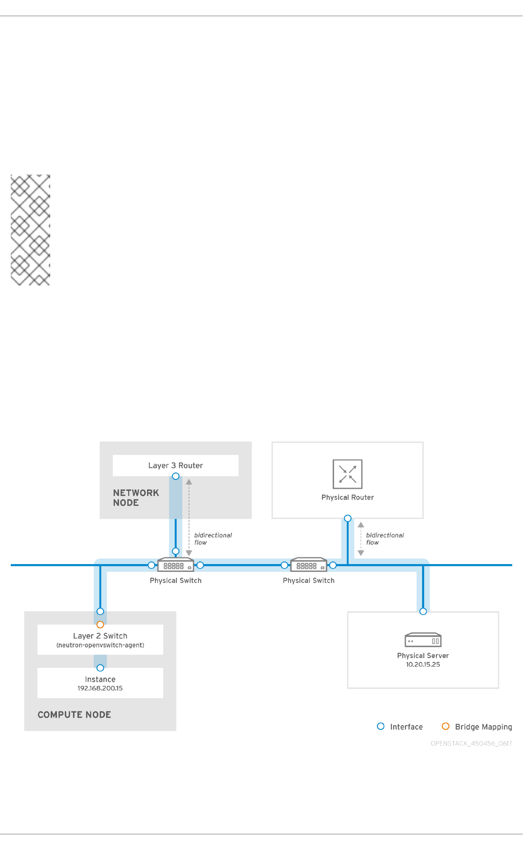
CHAPTER 9. CONFIGURE MTU SETTINGS
9.1. MTU overview
OpenStack Networking has the ability to calculate the largest possible MTU size that can safely be
applied to instances. The MTU value specifies the maximum amount of data a single network packet is
able to transfer; this number is variable depending on the most appropriate size for the application. For
example, NFS shares might require a different MTU size to that of a VoIP application.
NOTE
OpenStack Networking is able to calculate the largest possible MTU value, which can
then be viewed using the neutron net-show command. net-mtu is a neutron API
extension, so it may be not present in some implementations. The required MTU value
can be advertised to DHCPv4 clients for automatic configuration, if supported by the
instance, as well as to IPv6 clients through Router Advertisement (RA) packets. Note
that for Router Advertisements to be sent, the network should be attached to a router.
MTU settings need to be set consistently from end-to-end in order to work properly. This means that
the MTU setting needs to be the same size at every point the packet passes through, including the VM
itself, the virtual network infrastructure, the physical network, and the destination server itself.
For example, the circles in the following diagram indicate the various points where an MTU value would
need to be adjusted for traffic between an instance and a physical server. Every interface that handles
network traffic will need to have its MTU value changed to accommodate packets of a particular MTU
size. This will be required if traffic is expected to travel from the instance 192.168.200.15 through to the
physical server 10.20.15.25:
Inconsistent MTU values can result in several network issues, the most common being random packet
loss that results in connection drops and slow network performance. Such issues are problematic to
troubleshoot, since every possible network point needs to be identified and examined to ensure it has
Red Hat OpenStack Platform 10 Networking Guide
82

the correct MTU value set.
9.1.1. Configure MTU advertisement
MTU advertisement eases the MTU configuration process by moving MTU settings into the realm of
automated DHCP configuration and/or IPv6 RA configuration. As a result, the optimal MTU size is then
advertised to instances using DHCPv4 or IPv6 RA.
MTU advertisement is enabled in /etc/neutron/neutron.conf:
advertise_mtu = True
Note that this option is enabled by default in Mitaka, has been deprecated in Newton, and is likely to be
removed in a future release. When set, the tenant network’s configured MTU option is advertised to
instances using DHCPv4 and IPv6 RAs.
NOTE
Not all DHCPv4 clients support the automatic configuration of MTU values.
9.1.2. Configure tenant networks
With Red Hat OpenStack Platform 10 director, you can use a single parameter in the network
environment file to define the default MTU for all tenant networks. This will make it easier to align your
configuration with the physical MTU:
NeutronTenantMtu - Configures the base MTU that reflects physical network capabilities.
Neutron then uses this base value to calculate MTUs for networks it manages. For example, for
VLAN and flat networks, the value is used as-is, but for VLXAN and GRE networks, they get
lower MTUs to make room for the tunnel header overhead. If using VXLAN/GRE tunneling,
then this should be equal to the MTU operating on the physical network.
9.1.3. Configure MTU Settings in Director
This example demonstrates how to set the MTU using the NIC config templates. The MTU needs to be
set on the bridge, bond (if applicable), interface(s), and VLAN(s):
-
type: ovs_bridge
name: br-isolated
use_dhcp: false
mtu: 9000 # <--- Set MTU
members:
-
type: ovs_bond
name: bond1
mtu: 9000 # <--- Set MTU
ovs_options: {get_param: BondInterfaceOvsOptions}
members:
-
type: interface
name: ens15f0
mtu: 9000 # <--- Set MTU
primary: true
-
CHAPTER 9. CONFIGURE MTU SETTINGS
83

type: interface
name: enp131s0f0
mtu: 9000 # <--- Set MTU
-
type: vlan
device: bond1
vlan_id: {get_param: InternalApiNetworkVlanID}
mtu: 9000 # <--- Set MTU
addresses:
-
ip_netmask: {get_param: InternalApiIpSubnet}
-
type: vlan
device: bond1
mtu: 9000 # <--- Set MTU
vlan_id: {get_param: TenantNetworkVlanID}
addresses:
-
ip_netmask: {get_param: TenantIpSubnet}
9.1.4. Review the resulting MTU calculation
View the calculated MTU value. This result is the calculation of the largest possible MTU value that can
be used by instances. You can then proceed by configuring this value on all interfaces involved in the
path of network traffic.
# neutron net-show <network>
Red Hat OpenStack Platform 10 Networking Guide
84

CHAPTER 10. CONFIGURE QUALITY-OF-SERVICE (QOS)
Red Hat OpenStack Platform 10 introduces support for network quality-of-service (QoS) policies.
These policies allow OpenStack administrators to offer varying service levels by applying rate limits to
egress traffic for instances. As a result of implementing a QoS policy, any traffic that exceeds the
specified rate is consequently dropped.
10.1. QoS Policy Scope
QoS policies are applied to individual ports, or to a particular tenant network, where ports with no
specific policy attached will inherit the policy.
10.2. QoS Policy Management
QoS policies can be dynamically applied, modified, or removed. This example manually creates a
bandwidth limiting rule and applies it to a port.
1. Review the list of tenants and determine the id of where you need to create QoS policy:
# openstack project list
+----------------------------------+----------+
| ID | Name |
+----------------------------------+----------+
| 4b0b98f8c6c040f38ba4f7146e8680f5 | auditors |
| 519e6344f82e4c079c8e2eabb690023b | services |
| 80bf5732752a41128e612fe615c886c6 | demo |
| 98a2f53c20ce4d50a40dac4a38016c69 | admin |
+----------------------------------+----------+
2. Create a QoS policy named bw-limiter in the admin tenant:
# neutron qos-policy-create 'bw-limiter' --tenant-id
98a2f53c20ce4d50a40dac4a38016c69
3. Configure the policing rules for the bw-limiter policy:
# neutron qos-bandwidth-limit-rule-create bw-limiter --max_kbps 3000
--max_burst_kbps 3000
4. Configure a neutron port to apply the bw-limiter policy:
# neutron port-update <port id> --qos-policy bw-limiter
5. Review the QoS rule. For example:
# neutron qos-rule-show 9be535c3-daa2-4d7b-88ea-e8de16
+-------------------+---------------------------------+
| Field | Value |
+-------------------+---------------------------------+
| id | 9be535c3-daa2-4d7b-88ea-e8de16 |
| rule_type | bandwidth_limit |
| description | |
CHAPTER 10. CONFIGURE QUALITY-OF-SERVICE (QOS)
85

| max_kbps | 3000 |
| max_burst_kbps | 300 |
+-------------------+---------------------------------+
These values allow you to configure the policing algorithm accordingly:
max_kbps - the maximum rate (in Kbps) that the instance is allowed to send.
max_burst_kbps - the maximum amount of data (in kbits) that the port could send in a
instant if the token buffer was full. The token buffer is replenished at a "max_kbps" rate.
10.3. DSCP Marking for Egress Traffic
Differentiated Services Code Point (DSCP) allows you to to implement QoS on your network by
embedding relevant values in the IP headers. OpenStack Networking (neutron) QoS policies can now
use DSCP marking to manage egress traffic on neutron ports and networks. At present, DSCP is only
available for VLAN and flat provider networks using Open vSwitch (OVS); support for VXLAN is
expected to follow.
In this implementation, a policy is first created, then DSCP rules are defined and applied to the policy.
These rules use the --dscp-mark parameter, which specifies the decimal value of a DSCP mark. For
example:
1. Create a new QoS policy:
neutron qos-policy-create qos-web-servers --tenant-id
98a2f53c20ce4d50a40dac4a38016c69
2. Create a DSCP rule and apply it to the qos-web-servers policy, using DSCP mark 18:
neutron qos-dscp-marking-rule-create qos-web-servers --dscp-mark 18
Created a new dscp_marking_rule:
+-----------+--------------------------------------+
| Field | Value |
+-----------+--------------------------------------+
| dscp_mark | 18 |
| id | d7f976ec-7fab-4e60-af70-f59bf88198e6 |
+-----------+--------------------------------------+
3. View the DSCP rules for QoS policy qos-web-servers:
neutron qos-dscp-marking-rule-list qos-web-servers
+-----------+--------------------------------------+
| dscp_mark | id |
+-----------+--------------------------------------+
| 18 | d7f976ec-7fab-4e60-af70-f59bf88198e6 |
+-----------+--------------------------------------+
4. View the details of the DSCP rule assigned to policy qos-web-servers:
neutron qos-dscp-marking-rule-show d7f976ec-7fab-4e60-af70-f59bf88198e6
qos-web-servers
+-----------+--------------------------------------+
| Field | Value |
Red Hat OpenStack Platform 10 Networking Guide
86

+-----------+--------------------------------------+
| dscp_mark | 18 |
| id | d7f976ec-7fab-4e60-af70-f59bf88198e6 |
+-----------+--------------------------------------+
5. Change the DSCP value assigned to a rule:
neutron qos-dscp-marking-rule-update d7f976ec-7fab-4e60-af70-f59bf88198e6
qos-web-servers --dscp-mark 22
Updated dscp_marking_rule: d7f976ec-7fab-4e60-af70-f59bf88198e6
6. Delete a DSCP rule:
neutron qos-dscp-marking-rule-delete d7f976ec-7fab-4e60-af70-f59bf88198e6
qos-web-servers
Deleted dscp_marking_rule(s): d7f976ec-7fab-4e60-af70-f59bf88198e6
10.4. RBAC for QoS Policies
Red Hat OpenStack Platform 10 adds Role-based Access Control (RBAC) for QoS policies. As a result,
you can now make QoS policies available to certain projects.
For example, you can now create a QoS policy that allows for lower-priority network traffic, and have it
only apply to certain projects. In the following command below, the bw-limiter policy created previously
is assigned to the demo tenant:
# neutron rbac-create 'bw-limiter' --type qos-policy --target-tenant
80bf5732752a41128e612fe615c886c6 --action access_as_shared
CHAPTER 10. CONFIGURE QUALITY-OF-SERVICE (QOS)
87

CHAPTER 11. CONFIGURE BRIDGE MAPPINGS
This chapter describes how to configure bridge mappings in Red Hat OpenStack Platform.
11.1. What are bridge mappings used for?
Bridge mappings allow provider network traffic to reach the physical network. Traffic leaves the
provider network from the router’s qg-xxx interface and arrives at br-int. A patch port between br-int
and br-ex then allows the traffic to pass through the bridge of the provider network and out to the
physical network.
11.1.1. Configure bridge mappings
Below is an example of a patch-peer between br-int and br-ex:
int-br-ex <-> phy-br-ex
This connection is configured in the bridge_mappings setting. For example:
bridge_mappings = physnet1:br-ex,physnet2:br-ex2
NOTE
If the bridge_mapping entry is missing, no network connection exists, and
communication to physical networks will not work.
This configuration’s first entry creates a connection between br-int and br-ex using patch peer cable.
The second entry creates a patch peer for br-ex2.
11.1.2. Configure the controller node
The bridge_mappings configuration must correlate with that of the network_vlan_ranges option on
the controller node. For the example given above, the controller node is configured as follows:
network_vlan_ranges = physnet1:10:20,physnet2:21:25
These values create the provider networks that represent the corresponding external networks; the
external networks are then connected to the tenant networks via router interfaces. As a result, it is
necessary to configure bridge_mappings on the network node on which the router is scheduled. This
means that the router traffic is able to egress using the correct physical network, as represented by
the provider network (for example: physnet1).
11.1.3. Traffic flow
In addition to creating the connection, this setting also configures the OVS flow in br-int and br-ex to
allow the network traffic to traverse to and from the external network. Each external network is
represented by an internal VLAN id, which is tagged to the router’s qg-xxx port. When a packet
reaches phy-br-ex, the br-ex port strips the VLAN tag and moves the packet to the physical interface
and then to the external network. The return packet from external network arrives on br-ex and is
moved to br-int using phy-br-ex <→ int-br-ex . When the packet reaches int-br-ex, another flow in
br-int adds internal vlan tag to the packet. This allows the packet to be accepted by qg-xxx.
Red Hat OpenStack Platform 10 Networking Guide
88

11.2. Maintaining Bridge Mappings
After removing any mappings, a subsequent patch-port cleanup is required. This action ensures that
the bridge configuration is cleared of erroneous entries, with two options available for performing this
task:
Manual port cleanup - requires careful removal of the superfluous ports. No outage is required
to network connectivity.
Automated port cleanup using neutron-ovs-cleanup - performs an automated cleanup, but
requires an outage, and requires that the necessary mappings be re-added. Choose this option
if you don’t mind having an outage to network connectivity.
Examples are given below for each of these two options:
11.2.1. Manual port cleanup
The manual port cleanup process removes unneeded ports, and doesn’t require a system outage. You
can identify these ports by their naming convention: in br-$external_bridge they are named as "phy-
"$external_bridge and in br-int they are named "int-"$external_bridge.
This example procedure removes a bridge from bridge_mappings, and cleans up the corresponding
ports. 1. Edit openvswitch_agent.ini and remove the entry for physnet2:br-ex2 from
bridge_mappings:
bridge_mappings = physnet1:br-ex,physnet2:br-ex2
Remove the entry for physnet2:br-ex2. The resulting bridge_mappings resembles this:
bridge_mappings = physnet1:br-ex
2. Use ovs-vsctl to remove the patch ports associated with the removed physnet2:br-ex2 entry:
# ovs-vsctl del-port br-ex2 phy-br-ex2
# ovs-vsctl del-port br-int int-br-ex2
NOTE
If the entire bridge_mappings entry is removed or commented out, cleanup commands
will need to be run for each entry,
3. Restart neutron-openvswitch-agent:
# service neutron-openvswitch-agent restart
11.2.2. Automated port cleanup using ‘neutron-ovs-cleanup’
This action is performed using the neutron-ovs-cleanup command combined with the --ovs_all_ports
flag. Restart the neutron services or the entire node to then restore the bridges back to their normal
working state. This process requires a total networking outage.
The neutron-ovs-cleanup command unplugs all ports (instances, qdhcp/qrouter, among others) from
all OVS bridges. Using the flag --ovs_all_ports results in removing all ports from br-int, cleaning up
CHAPTER 11. CONFIGURE BRIDGE MAPPINGS
89

tunnel ends from br-tun, and patch ports from bridge to bridge. In addition, the physical interfaces
(such as eth0, eth1) are removed from the bridges (such as br-ex, br-ex2). This will result in lost
connectivity to instances until the ports are manually re-added using ovs-vsctl:
# ovs-vsctl add-port br-ex eth1
11.2.2.1. Example usage of neutron-ovs-cleanup:
1. Make a backup of your bridge_mapping entries as found in openvswitch_agent.ini.
2. Run neutron-ovs-cleanup with the --ovs_all_ports flag. Note that this step will result in a total
networking outage.
# /usr/bin/neutron-ovs-cleanup
--config-file /etc/neutron/plugins/ml2/openvswitch_agent.ini
--log-file /var/log/neutron/ovs-cleanup.log --ovs_all_ports
3. Restart these OpenStack Networking services:
# systemctl restart neutron-openvswitch-agent
# systemctl restart neutron-l3-agent.service
# systemctl restart neutron-dhcp-agent.service
4. Restore connectivity by re-adding the bridge_mapping entries to openvswitch_agent.ini.
5. Restart the neutron-openvswitch-agent service:
# systemctl restart neutron-openvswitch-agent
NOTE
When the OVS agent restarts, it doesn’t touch any connections which are not present in
bridge_mappings. So if you have br-int connected to br-ex2, and br-ex2 has some
flows on it, removing it from the bridge_mappings configuration (or commenting it out
entirely) won’t disconnect the two bridges, no matter what you do (whether restarting
the service, or the node).
11.3. VLAN-Aware Instances
11.3.1. Overview
Instances can now send and receive VLAN-tagged traffic over a single vNIC. This ability is particularly
useful for NFV applications (VNFs) that expect VLAN-tagged traffic, allowing multiple
customers/services to be served by a single vNIC.
For example, the tenant data network can use VLANs, or tunneling (VXLAN/GRE) segmentation, while
the instances will see the traffic tagged with VLAN IDs. As a result, network packets are tagged just
before they are injected to the instance; they don’t need to be tagged throughout the entire network.
To implement this, start by creating a parent port and attaching it to an existing neutron network.
Doing so will add a trunk connection to the parent port you created. Next, create subports. These
subports are the ports that connect VLANs to instances, thereby allowing connectivity to the trunk.
Red Hat OpenStack Platform 10 Networking Guide
90

Within the instance operating system, you need to create a sub-interface that tags traffic for the VLAN
associated with the subport.
11.3.2. Review the Trunk Plugin
In a director-based deployment, the trunk plugin is turned on by default. You can review the
configuration on the controller nodes:
1.On the controller node, confirm that the trunk plugin is enabled in /etc/neutron/neutron.conf. For
example:
service_plugins=router,metering,qos,trunk
11.3.3. Create a Trunk Connection
1. Identify the network that requires the trunk port connection. This would be the network that will
contain the instance that requires access to the trunked VLANs. In this example, this is the public
network:
openstack network list
+--------------------------------------+---------+--------------------
------------------+
| ID | Name | Subnets
|
+--------------------------------------+---------+--------------------
------------------+
| 82845092-4701-4004-add7-838837837621 | private | 434c7982-cd96-4c41-
a8c9-b93adbdcb197 |
| 8d8bc6d6-5b28-4e00-b99e-157516ff0050 | public | 3fd811b4-c104-44b5-
8ff8-7a86af5e332c |
+--------------------------------------+---------+--------------------
------------------+
2. Create the parent trunk port, and attach it to the network that the instance will be connected to. In
this example, a neutron port named parent-trunk-port is created on the public network. This trunk
will be considered the parent port, as you can use it to create subports.
openstack port create --network public parent-trunk-port
+-----------------------+---------------------------------------------
--------------------------------+
| Field | Value
|
+-----------------------+---------------------------------------------
--------------------------------+
| admin_state_up | UP
|
| allowed_address_pairs |
|
| binding_host_id |
|
| binding_profile |
|
| binding_vif_details |
|
CHAPTER 11. CONFIGURE BRIDGE MAPPINGS
91

| binding_vif_type | unbound
|
| binding_vnic_type | normal
|
| created_at | 2016-10-20T02:02:33Z
|
| description |
|
| device_id |
|
| device_owner |
|
| extra_dhcp_opts |
|
| fixed_ips | ip_address='172.24.4.230', subnet_id='dc608964-
9af3-4fed-9f06-6d3844fb9b9b' |
| headers |
|
| id | 20b6fdf8-0d43-475a-a0f1-ec8f757a4a39
|
| mac_address | fa:16:3e:33:c4:75
|
| name | parent-trunk-port
|
| network_id | 871a6bd8-4193-45d7-a300-dcb2420e7cc3
|
| project_id | 745d33000ac74d30a77539f8920555e7
|
| project_id | 745d33000ac74d30a77539f8920555e7
|
| revision_number | 4
|
| security_groups | 59e2af18-93c6-4201-861b-19a8a8b79b23
|
| status | DOWN
|
| updated_at | 2016-10-20T02:02:33Z
|
+-----------------------+---------------------------------------------
--------------------------------+
4. Create a trunk using the port you just created. In this example the trunk is named parent-trunk.
openstack network trunk create --parent-port parent-trunk-port parent-
trunk
+-----------------+--------------------------------------+
| Field | Value |
+-----------------+--------------------------------------+
| admin_state_up | UP |
| created_at | 2016-10-20T02:05:17Z |
| description | |
| id | 0e4263e2-5761-4cf6-ab6d-b22884a0fa88 |
| name | parent-trunk |
| port_id | 20b6fdf8-0d43-475a-a0f1-ec8f757a4a39 |
| revision_number | 1 |
| status | DOWN |
Red Hat OpenStack Platform 10 Networking Guide
92

| sub_ports | |
| tenant_id | 745d33000ac74d30a77539f8920555e7 |
| updated_at | 2016-10-20T02:05:17Z |
+-----------------+--------------------------------------+
5. View the trunk connection:
openstack network trunk list
+--------------------------------------+--------------+---------------
-----------------------+-------------+
| ID | Name | Parent Port
| Description |
+--------------------------------------+--------------+---------------
-----------------------+-------------+
| 0e4263e2-5761-4cf6-ab6d-b22884a0fa88 | parent-trunk | 20b6fdf8-0d43-
475a-a0f1-ec8f757a4a39 | |
+--------------------------------------+--------------+---------------
-----------------------+-------------+
View the details of the trunk connection:
openstack network trunk show parent-trunk
+-----------------+--------------------------------------+
| Field | Value |
+-----------------+--------------------------------------+
| admin_state_up | UP |
| created_at | 2016-10-20T02:05:17Z |
| description | |
| id | 0e4263e2-5761-4cf6-ab6d-b22884a0fa88 |
| name | parent-trunk |
| port_id | 20b6fdf8-0d43-475a-a0f1-ec8f757a4a39 |
| revision_number | 1 |
| status | DOWN |
| sub_ports | |
| tenant_id | 745d33000ac74d30a77539f8920555e7 |
| updated_at | 2016-10-20T02:05:17Z |
+-----------------+--------------------------------------+
11.3.4. Add Subports to the Trunk
1. Create a neutron port. This port will be used as a subport connection to the trunk. You must also
specify the MAC address that was assigned to the parent port:
openstack port create --network private --mac-address fa:16:3e:33:c4:75
subport-trunk-port
+-----------------------+---------------------------------------------
-----------------------------+
| Field | Value
|
+-----------------------+---------------------------------------------
-----------------------------+
| admin_state_up | UP
|
| allowed_address_pairs |
|
CHAPTER 11. CONFIGURE BRIDGE MAPPINGS
93

| binding_host_id |
|
| binding_profile |
|
| binding_vif_details |
|
| binding_vif_type | unbound
|
| binding_vnic_type | normal
|
| created_at | 2016-10-20T02:08:14Z
|
| description |
|
| device_id |
|
| device_owner |
|
| extra_dhcp_opts |
|
| fixed_ips | ip_address='10.0.0.11', subnet_id='1a299780-
56df-4c0b-a4c0-c5a612cef2e8' |
| headers |
|
| id | 479d742e-dd00-4c24-8dd6-b7297fab3ee9
|
| mac_address | fa:16:3e:33:c4:75
|
| name | subport-trunk-port
|
| network_id | 3fe6b758-8613-4b17-901e-9ba30a7c4b51
|
| project_id | 745d33000ac74d30a77539f8920555e7
|
| project_id | 745d33000ac74d30a77539f8920555e7
|
| revision_number | 4
|
| security_groups | 59e2af18-93c6-4201-861b-19a8a8b79b23
|
| status | DOWN
|
| updated_at | 2016-10-20T02:08:15Z
|
+-----------------------+---------------------------------------------
-----------------------------+
NOTE
If you receive the error HttpException: Conflict, confirm that you are creating the
subport on a different network to the one that has the parent trunk port. This example
uses the public network for the parent trunk port, and private for the subport.
2. Associate the port with the trunk ( parent-trunk), and specify the VLAN ID ( 55):
Red Hat OpenStack Platform 10 Networking Guide
94

openstack network trunk set --subport port=subport-trunk-
port,segmentation-type=vlan,segmentation-id=55 parent-trunk
11.4. Configure an Instance to use a Trunk
The instance operating system must be configured to use the MAC address that neutron assigned to
the subport. You can also configure the subport to use a specific MAC address during the subport
creation step.
1. Review the configuration of your network trunk:
$ openstack network trunk list
+--------------------------------------+--------------+---------------
-----------------------+-------------+
| ID | Name | Parent Port
| Description |
+--------------------------------------+--------------+---------------
-----------------------+-------------+
| 0e4263e2-5761-4cf6-ab6d-b22884a0fa88 | parent-trunk | 20b6fdf8-0d43-
475a-a0f1-ec8f757a4a39 | |
+--------------------------------------+--------------+---------------
-----------------------+-------------+
$ openstack network trunk show parent-trunk
+-----------------+---------------------------------------------------
---------------------------------------------+
| Field | Value
|
+-----------------+---------------------------------------------------
---------------------------------------------+
| admin_state_up | UP
|
| created_at | 2016-10-20T02:05:17Z
|
| description |
|
| id | 0e4263e2-5761-4cf6-ab6d-b22884a0fa88
|
| name | parent-trunk
|
| port_id | 20b6fdf8-0d43-475a-a0f1-ec8f757a4a39
|
| revision_number | 2
|
| status | DOWN
|
| sub_ports | port_id='479d742e-dd00-4c24-8dd6-b7297fab3ee9',
segmentation_id='55', segmentation_type='vlan' |
| tenant_id | 745d33000ac74d30a77539f8920555e7
|
| updated_at | 2016-10-20T02:10:06Z
|
+-----------------+---------------------------------------------------
---------------------------------------------+
CHAPTER 11. CONFIGURE BRIDGE MAPPINGS
95

2. Create an instance that uses the parent port id as its vNIC:
nova boot --image cirros --flavor m1.tiny testInstance --security-groups
default --key-name sshaccess --nic port-id=20b6fdf8-0d43-475a-a0f1-
ec8f757a4a39
+--------------------------------------+------------------------------
-----------------+
| Property | Value
|
+--------------------------------------+------------------------------
-----------------+
| OS-DCF:diskConfig | MANUAL
|
| OS-EXT-AZ:availability_zone |
|
| OS-EXT-SRV-ATTR:host | -
|
| OS-EXT-SRV-ATTR:hostname | testinstance
|
| OS-EXT-SRV-ATTR:hypervisor_hostname | -
|
| OS-EXT-SRV-ATTR:instance_name |
|
| OS-EXT-SRV-ATTR:kernel_id |
|
| OS-EXT-SRV-ATTR:launch_index | 0
|
| OS-EXT-SRV-ATTR:ramdisk_id |
|
| OS-EXT-SRV-ATTR:reservation_id | r-juqco0el
|
| OS-EXT-SRV-ATTR:root_device_name | -
|
| OS-EXT-SRV-ATTR:user_data | -
|
| OS-EXT-STS:power_state | 0
|
| OS-EXT-STS:task_state | scheduling
|
| OS-EXT-STS:vm_state | building
|
| OS-SRV-USG:launched_at | -
|
| OS-SRV-USG:terminated_at | -
|
| accessIPv4 |
|
| accessIPv6 |
|
| adminPass | uMyL8PnZRBwQ
|
| config_drive |
|
| created | 2016-10-20T03:02:51Z
Red Hat OpenStack Platform 10 Networking Guide
96

|
| description | -
|
| flavor | m1.tiny (1)
|
| hostId |
|
| host_status |
|
| id | 88b7aede-1305-4d91-a180-
67e7eac8b70d |
| image | cirros (568372f7-15df-4e61-
a05f-10954f79a3c4) |
| key_name | sshaccess
|
| locked | False
|
| metadata | {}
|
| name | testInstance
|
| os-extended-volumes:volumes_attached | []
|
| progress | 0
|
| security_groups | default
|
| status | BUILD
|
| tags | []
|
| tenant_id | 745d33000ac74d30a77539f8920555e7
|
| updated | 2016-10-20T03:02:51Z
|
| user_id |
8c4aea738d774967b4ef388eb41fef5e |
+--------------------------------------+------------------------------
-----------------+
CHAPTER 11. CONFIGURE BRIDGE MAPPINGS
97

CHAPTER 12. CONFIGURE RBAC
Role-based Access Control (RBAC) policies in OpenStack Networking allows granular control over
shared neutron networks. Previously, networks were shared either with all tenants, or not at all.
OpenStack Networking now uses a RBAC table to control sharing of neutron networks among tenants,
allowing an administrator to control which tenants are granted permission to attach instances to a
network.
As a result, cloud administrators can remove the ability for some tenants to create networks and can
instead allow them to attach to pre-existing networks that correspond to their project.
12.1. Create a new RBAC policy
This example procedure demonstrates how to use a RBAC policy to grant a tenant access to a shared
network.
1. View the list of available networks:
# neutron net-list
+--------------------------------------+-------------+-----------
--------------------------------------------+
| id | name | subnets
|
+--------------------------------------+-------------+-----------
--------------------------------------------+
| fa9bb72f-b81a-4572-9c7f-7237e5fcabd3 | web-servers | 20512ffe-
ad56-4bb4-b064-2cb18fecc923 192.168.200.0/24 |
| bcc16b34-e33e-445b-9fde-dd491817a48a | private | 7fe4a05a-
4b81-4a59-8c47-82c965b0e050 10.0.0.0/24 |
| 9b2f4feb-fee8-43da-bb99-032e4aaf3f85 | public | 2318dc3b-
cff0-43fc-9489-7d4cf48aaab9 172.24.4.224/28 |
+--------------------------------------+-------------+-----------
--------------------------------------------+
2. View the list of tenants:
# openstack project list
+----------------------------------+----------+
| ID | Name |
+----------------------------------+----------+
| 4b0b98f8c6c040f38ba4f7146e8680f5 | auditors |
| 519e6344f82e4c079c8e2eabb690023b | services |
| 80bf5732752a41128e612fe615c886c6 | demo |
| 98a2f53c20ce4d50a40dac4a38016c69 | admin |
+----------------------------------+----------+
3. Create a RBAC entry for the web-servers network that grants access to the auditors tenant
(4b0b98f8c6c040f38ba4f7146e8680f5):
# neutron rbac-create fa9bb72f-b81a-4572-9c7f-7237e5fcabd3 --type
network --target-tenant 4b0b98f8c6c040f38ba4f7146e8680f5 --action
access_as_shared
Created a new rbac_policy:
+---------------+--------------------------------------+
| Field | Value |
+---------------+--------------------------------------+
Red Hat OpenStack Platform 10 Networking Guide
98

| action | access_as_shared |
| id | 314004d0-2261-4d5e-bda7-0181fcf40709 |
| object_id | fa9bb72f-b81a-4572-9c7f-7237e5fcabd3 |
| object_type | network |
| target_tenant | 4b0b98f8c6c040f38ba4f7146e8680f5 |
| tenant_id | 98a2f53c20ce4d50a40dac4a38016c69 |
+---------------+--------------------------------------+
As a result, users in the auditors project are able to connect instances to the web-servers network.
12.2. Review your configured RBAC policies
1. Use neutron rbac-list to retrieve the ID of your existing RBAC policies:
# neutron rbac-list
+--------------------------------------+-------------+-----------
---------------------------+
| id | object_type | object_id
|
+--------------------------------------+-------------+-----------
---------------------------+
| 314004d0-2261-4d5e-bda7-0181fcf40709 | network | fa9bb72f-
b81a-4572-9c7f-7237e5fcabd3 |
| bbab1cf9-edc5-47f9-aee3-a413bd582c0a | network | 9b2f4feb-
fee8-43da-bb99-032e4aaf3f85 |
+--------------------------------------+-------------+-----------
---------------------------+
2. Use neutron rbac-show to view the details of a specific RBAC entry:
# neutron rbac-show 314004d0-2261-4d5e-bda7-0181fcf40709
+---------------+--------------------------------------+
| Field | Value |
+---------------+--------------------------------------+
| action | access_as_shared |
| id | 314004d0-2261-4d5e-bda7-0181fcf40709 |
| object_id | fa9bb72f-b81a-4572-9c7f-7237e5fcabd3 |
| object_type | network |
| target_tenant | 4b0b98f8c6c040f38ba4f7146e8680f5 |
| tenant_id | 98a2f53c20ce4d50a40dac4a38016c69 |
+---------------+--------------------------------------+
12.3. Delete a RBAC policy
1. Use neutron rbac-list to retrieve the ID of your existing RBACs:
# neutron rbac-list
+--------------------------------------+-------------+-----------
---------------------------+
| id | object_type | object_id
|
+--------------------------------------+-------------+-----------
---------------------------+
| 314004d0-2261-4d5e-bda7-0181fcf40709 | network | fa9bb72f-
CHAPTER 12. CONFIGURE RBAC
99

b81a-4572-9c7f-7237e5fcabd3 |
| bbab1cf9-edc5-47f9-aee3-a413bd582c0a | network | 9b2f4feb-
fee8-43da-bb99-032e4aaf3f85 |
+--------------------------------------+-------------+-----------
---------------------------+
2. Use neutron rbac-delete to delete the RBAC, using its ID value:
# neutron rbac-delete 314004d0-2261-4d5e-bda7-0181fcf40709
Deleted rbac_policy: 314004d0-2261-4d5e-bda7-0181fcf40709
12.4. RBAC for external networks
You can grant RBAC access to external networks (networks with gateway interfaces attached) using
the --action access_as_external parameter
For example, this procedure creates a RBAC for the web-servers network and grants access to the
engineering tenant (c717f263785d4679b16a122516247deb):
1. Create a new RBAC policy using --action access_as_external:
# neutron rbac-create 6e437ff0-d20f-4483-b627-c3749399bdca --type network
--target-tenant c717f263785d4679b16a122516247deb --action
access_as_external
Created a new rbac_policy:
+---------------+--------------------------------------+
| Field | Value |
+---------------+--------------------------------------+
| action | access_as_external |
| id | ddef112a-c092-4ac1-8914-c714a3d3ba08 |
| object_id | 6e437ff0-d20f-4483-b627-c3749399bdca |
| object_type | network |
| target_tenant | c717f263785d4679b16a122516247deb |
| tenant_id | c717f263785d4679b16a122516247deb |
+---------------+--------------------------------------+
2. As a result, users in the Engineering tenant are able to view the network or connect instances to it:
$ neutron net-list
+--------------------------------------+-------------+----------------
--------------------------------------+
| id | name | subnets
|
+--------------------------------------+-------------+----------------
--------------------------------------+
| 6e437ff0-d20f-4483-b627-c3749399bdca | web-servers | fa273245-1eff-4830-
b40c-57eaeac9b904 192.168.10.0/24 |
+--------------------------------------+-------------+----------------
--------------------------------------+
Red Hat OpenStack Platform 10 Networking Guide
100

CHAPTER 13. CONFIGURE DISTRIBUTED VIRTUAL ROUTING
(DVR)
Customers deploying Red Hat OpenStack Platform 10 have the option to choose between a centralized
routing model or DVR for their Red Hat OpenStack Platform deployment. While DVR is fully supported
and available as a configuration option, Red Hat OpenStack Platform 10 director still defaults to
centralized routing.
It is important to note that both centralized routing and DVR are valid routing models, and each has its
own set of advantages and disadvantages. Customers are advised to use this document to carefully
plan whether centralized routing or DVR will better suit their needs.
13.1. Overview of Layer 3 Routing
OpenStack Networking (neutron) provides routing services for project networks. Without a router,
instances in a project network are only able to communicate with one another over a shared L2
broadcast domain. Creating a router and assigning it to a tenant network allows the instances in that
network to communicate with other project networks or upstream (if an external gateway is defined
for the router).
13.1.1. Routing Flows
Routing services in OpenStack can be categorized into three main flows:
East-West routing - routing of traffic between different networks in the same tenant. This
traffic does not leave the OpenStack deployment. This definition applies to both IPv4 and IPv6
subnets.
North-South routing with floating IPs - Floating IP addressing can be best described as a one-
to-one NAT that can be modified and floats between instances. While floating IPs are modeled
as a one-to-one association between the floating IP and a neutron port, they are implemented
by association with a neutron router that performs the NAT translation. The floating IPs
themselves are taken from the uplink network that is providing the router with its external
connectivity. As a result, instances can communicate with external resources (such as
endpoints in the internet) or the other way around. Floating IPs are an IPv4 concept and do not
apply to IPv6. It is assumed that the IPv6 addressing used by projects uses Global Unicast
Addresses (GUAs) with no overlap across the projects, and therefore can be routed without
NAT.
North-South routing without floating IPs (also known as SNAT) - Neutron offers a default
port address translation (PAT) service for instances that have not been allocated floating IPs.
With this service, instances can communicate with external endpoints through the router, but
not the other way around. For example, an instance can browse a website in the internet, but a
web browser outside could not browse a website hosted within the instance. SNAT is applied
for IPv4 traffic only. In addition, neutron project networks that are assigned GUAs prefixes do
not require NAT on the neutron router external gateway port to access the outside world.
13.1.2. Centralized Routing
Originally, neutron was designed with a centralized routing model where a project’s virtual routers,
managed by the neutron L3 agent, are all deployed in a dedicated node or cluster of nodes (referred to
as the Network node, or Controller node). This means that each time a routing function is required
(east/west, floating IPs or SNAT), traffic would traverse through a dedicated node in the topology. This
introduced multiple challenges and resulted in sub-optimal traffic flows. For example:
CHAPTER 13. CONFIGURE DISTRIBUTED VIRTUAL ROUTING (DVR)
101

Traffic between instances flows through a Controller node - when two instances need to
communicate with each other using L3, traffic has to hit the Controller node. Even if the
instances are scheduled on the same Compute node, traffic still has to leave the Compute
node, flow through the Controller, and route back to the Compute node. This negatively
impacts performance.
Instances with floating IPs receive and send packets through the Controller node - the
external network gateway interface is available only at the Controller node, so whether the
traffic is originating from an instance, or destined to an instance from the external network, it
has to flow through the Controller node. Consequently, in large environments the Controller
node is subject to heavy traffic load. This would affect performance and scalability, and also
requires careful planning to accommodate enough bandwidth in the external network gateway
interface. The same requirement applies for SNAT traffic.
To better scale the L3 agent, neutron can use the L3 HA feature, which distributes the virtual routers
across multiple nodes. In the event that a Controller node is lost, the HA router will failover to a
standby on another node and there will be packet loss until the HA router failover completes. The
feature is available starting with Red Hat Enterprise Linux OpenStack Platform 6 and is enabled by
default.
13.2. DVR Overview
Distributed Virtual Routing (DVR) offers an alternative routing design, which is now fully supported
with Red Hat OpenStack Platform 10. It intends to isolate the failure domain of the Controller node and
optimize network traffic by deploying the L3 agent and schedule routers on every Compute node.
When using DVR:
East-West traffic is routed directly on the Compute nodes in a distributed fashion.
North-South traffic with floating IP is distributed and routed on the Compute nodes. This
requires the external network to be connected to each and every Compute node.
North-South traffic without floating IP is not distributed and still requires a dedicated
Controller node.
The L3 agent on the Controller node is configured with a new dvr_snat mode so that only
SNAT traffic is served by the node.
The neutron metadata agent is distributed and deployed on all Compute nodes. The metadata
proxy service is hosted on all the distributed routers.
13.3. Known Issues and Caveats
NOTE
For Red Hat OpenStack Platform 10, do not use DVR unless your kernel version is at
least kernel-3.10.0-514.1.1.el7
Support for DVR is limited to the ML2 core plug-in and the Open vSwitch (OVS) mechanism
driver. Other back ends are not supported.
SNAT traffic is not distributed, even when DVR is enabled. SNAT does work, but all
ingress/egress traffic must traverse through the centralized Controller node.
Red Hat OpenStack Platform 10 Networking Guide
102

IPv6 traffic is not distributed, even when DVR is enabled. IPv6 routing does work, but all
ingress/egress traffic must traverse through the centralized Controller node. Customers that
are extensively using IPv6 routing are advised not to use DVR at this time.
DVR is not supported in conjunction with L3 HA. With Red Hat OpenStack Platform 10 director,
if DVR is used, L3 HA is turned off. That means that routers are still going to be scheduled on
the Network nodes (and load-shared between the L3 agents), but if one agent fails, all routers
hosted by this agent will fail as well. This only affects SNAT traffic. The
allow_automatic_l3agent_failover feature is recommended in such cases, so that if
one network node fails, the routers will be rescheduled to a different node.
DHCP servers, which are managed by the neutron DHCP agent, are not distributed and are still
deployed on the Controller node. With Red Hat OpenStack Platform, the DHCP agent is
deployed in a highly available configuration on the Controller nodes, regardless of the routing
design (centralized or DVR).
For floating IPs, each Compute node requires an interface on the External network. In addition,
each Compute node now requires one additional IP address. This is due to the implementation
of the external gateway port and the floating IP network namespace.
VLAN, GRE, and VXLAN are all supported for project data separation. When GRE or VXLAN are
used, the L2 Population feature must be turned on. With Red Hat OpenStack Platform 10
director, this is enforced during installation.
13.4. Supported Routing Architectures
Red Hat Enterprise Linux OpenStack Platform 5 through to Red Hat OpenStack Platform 10 for
centralized, HA routing.
Red Hat OpenStack Platform 10 with distributed routing.
Upgrading from a Red Hat OpenStack Platform 9 deployment running centralized HA routing
to Red Hat OpenStack Platform 10 with only distributed routing.
13.5. Deploying DVR
The neutron-ovs-dvr.yaml environment file configures the required DVR-specific parameters.
Configuring DVR for arbitrary deployment configuration requires additional consideration. The
requirements are:
(a) The interface connected to the physical network for external network traffic must be configured on
both the Compute and Controller nodes.
(b) A bridge must be created on Compute and Controller nodes, with an interface for external network
traffic.
(c) Neutron must be configured to allow this bridge to be used.
The host networking configuration (a and b) are controlled by Heat templates that pass configuration
to the Heat-managed nodes for consumption by the os-net-config process. This is essentially
automation of provisioning host networking. Neutron must also be configured (c) to match the
provisioned networking environment. The defaults are not expected to work in production
environments. For example, a proof-of-concept environment using the typical defaults might be similar
to the following:
1. Verify that the value for OS::TripleO::Compute::Net::SoftwareConfig in
CHAPTER 13. CONFIGURE DISTRIBUTED VIRTUAL ROUTING (DVR)
103

environments/neutron-ovs-dvr.yaml is the same as the
OS::TripleO::Controller::Net::SoftwareConfig value in use. This can normally be found in
the network environment file in use when deploying the overcloud, for example, environments/net-
multiple-nics.yaml. This will create the appropriate external network bridge for the Compute node’s L3
agent.
NOTE
If customizations have been made to the Compute node’s network configuration, it may
be necessary to add the appropriate configuration to those files instead.
2. Configure a neutron port for the Compute node on the external network by modifying
OS::TripleO::Compute::Ports::ExternalPort to an appropriate value, such as
OS::TripleO::Compute::Ports::ExternalPort: ../network/ports/external.yaml
3. Include environments/neutron-ovs-dvr.yaml as an environment file when deploying the overcloud. For
example:
$ openstack overcloud deploy --templates -e /usr/share/openstack-tripleo-
heat-templates/environments/neutron-ovs-dvr.yaml
4. Verify that L3 HA is disabled.
For production environments (or test environments that require special customization, for example,
involving network isolation, dedicated NICs, among others) the example environments can be used as a
guide. Particular attention should be give to the bridge mapping type parameters used by the L2
agents (for example, OVS) and any reference to external facing bridges for other agents (such as the
L3 agent).
NOTE
The external bridge configuration for the L3 agent, while currently still provided, is
deprecated and will be removed in the future.
13.6. Migrate Centralized Routers to Distributed Routing
This section describes the upgrade path to distributed routing for Red Hat OpenStack Platform 9
deployments that use L3 HA centralized routing.
1. Upgrade your deployment from Red Hat OpenStack Platform 9 to 10, and validate that it is working
correctly.
2. Run the director stack update to configure DVR, as described in Deploying DVR.
3. Confirm that routing still works through the existing routers.
4. You will not be able to directly transition a L3 HA router to distributed. Instead, for each router, turn
off the L3 HA option, and then turn on the distributed option:
4a. Move the router out of the admin state:
$ neutron router-update --admin-state-up=False
4b. Convert the router to the legacy type:
Red Hat OpenStack Platform 10 Networking Guide
104

$ neutron router-update --ha=False
4c. Configure the router to use DVR:
$ neutron router-update --distributed=True
4d. Move the router into the admin state:
$ neutron router-update --admin-state-up=True
4e. Confirm that routing still works, and is now distributed.
CHAPTER 13. CONFIGURE DISTRIBUTED VIRTUAL ROUTING (DVR)
105

CHAPTER 14. CONFIGURE LOAD BALANCING-AS-A-SERVICE
(LBAAS)
Load Balancing-as-a-Service (LBaaS) enables OpenStack Networking to distribute incoming requests
evenly between designated instances. This step-by-step guide configures OpenStack Networking to
use LBaaS with the Open vSwitch (OVS) plug-in.
Introduced in Red Hat OpenStack Platform 5, Load Balancing-as-a-Service (LBaaS) enables OpenStack
Networking to distribute incoming requests evenly between designated instances. This ensures the
workload is shared predictably among instances, and allows more effective use of system resources.
Incoming requests are distributed using one of these load balancing methods:
Round robin - Rotates requests evenly between multiple instances.
Source IP - Requests from a unique source IP address are consistently directed to the same
instance.
Least connections - Allocates requests to the instance with the least number of active
connections.
Table 1: LBaaS features
Table 14.1. LBaaS features
Feature Description
Monitors LBaaS provides availability monitoring with the ping,
TCP, HTTP and HTTPS GET methods. Monitors are
implemented to determine whether pool members
are available to handle requests.
Management LBaaS is managed using a variety of tool sets. The
REST API is available for programmatic
administration and scripting. Users perform
administrative management of load balancers
through either the CLI (neutron) or the OpenStack
dashboard.
Connection limits Ingress traffic can be shaped with connection limits.
This feature allows workload control and can also
assist with mitigating DoS (Denial of Service)
attacks.
Session persistence LBaaS supports session persistence by ensuring
incoming requests are routed to the same instance
within a pool of multiple instances. LBaaS supports
routing decisions based on cookies and source IP
address.
NOTE
LBaaS is currently supported only with IPv4 addressing.
Red Hat OpenStack Platform 10 Networking Guide
106
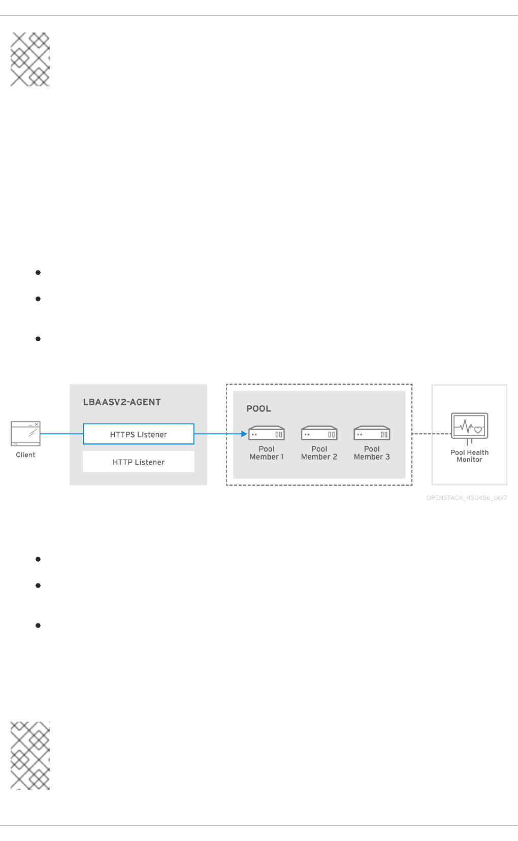
NOTE
LBaaSv1 has been removed in Red Hat OpenStack Platform 10 (Newton), and replaced
with LBaaSv2.
14.1. OpenStack Networking and LBaaS Topology
OpenStack Networking (neutron) services can be broadly classified into two categories.
1. - Neutron API server - This service runs the OpenStack Networking API server, which has the main
responsibility of providing an API for end users and services to interact with OpenStack Networking.
This server also has the responsibility of interacting with the underlying database to store and retrieve
tenant network, router, and loadbalancer details, among others.
2. - Neutron Agents - These are the services that deliver various network functionality for OpenStack
Networking.
neutron-dhcp-agent - manages DHCP IP addressing for tenant private networks.
neutron-l3-agent - facilitates layer 3 routing between tenant private networks, the external
network, and others.
neutron-lbaasv2-agent - provisions the LBaaS routers created by tenants.
The following diagram describes the flow of HTTPS traffic through to a pool member:
14.1.1. Support Status of LBaaS
LBaaS v1 API was deprecated in Red Hat OpenStack Platform 9 and removed in version 10.
LBaaS v2 API was introduced in Red Hat OpenStack Platform 7, and is the only available
LBaaS API as of version 10.
LBaaS deployment is not currently supported in Red Hat OpenStack Platform director.
14.1.2. Service Placement
The OpenStack Networking services can either run together on the same physical server, or on
separate dedicated servers.
NOTE
Red Hat OpenStack Platform 10 added support for composable roles, allowing you to
separate network services into a custom role. However, for simplicity, this guide
assumes that a deployment uses the default controller role.
CHAPTER 14. CONFIGURE LOAD BALANCING-AS-A-SERVICE (LBAAS)
107

The server that runs API server is usually called the Controller node, whereas the server that runs the
OpenStack Networking agents is called the Network node. An ideal production environment would
separate these components to their own dedicated nodes for performance and scalability reasons, but
a testing or PoC deployment might have them all running on the same node. This chapter covers both
of these scenarios; the section under Controller node configuration need to be performed on the API
server, whereas the section on Network node is performed on the server that runs the LBaaS agent.
NOTE
If both the Controller and Network roles are on the same physical node, then the steps
must be performed on that server.
14.2. Configure LBaaS
This procedure configures OpenStack Networking (neutron) to use LBaaS with the Open vSwitch
(OVS) plug-in.
NOTE
Perform these steps on nodes running the neutron-server service:
On the Controller node (API Server):
1. Install HAProxy:
# yum install haproxy
2. Add the LBaaS tables to the neutron database:
$ neutron-db-manage --subproject neutron-lbaas --config-file
/etc/neutron/neutron.conf --config-file
/etc/neutron/plugins/ml2/ml2_conf.ini upgrade head
3. Change the service provider in /etc/neutron/neutron_lbaas.conf. In the [service
providers] section, comment out ( #) all entries except for:
service_provider=LOADBALANCERV2:Haproxy:neutron_lbaas.drivers.haprox
y.plugin_driver.HaproxyOnHostPluginDriver:default
4. In /etc/neutron/neutron.conf, confirm that you have the LBaaS v2 plugin configured in
service_plugins:
service_plugins=neutron_lbaas.services.loadbalancer.plugin.LoadBalan
cerPluginv2
You can also expect to see any other plugins you have previously added.
NOTE
If you have lbaasv1 configured, replace it with the above setting for lbaasv2.
5. In /etc/neutron/lbaas_agent.ini, add the following to the [DEFAULT] section:
Red Hat OpenStack Platform 10 Networking Guide
108

ovs_use_veth = False
interface_driver =neutron.agent.linux.interface.OVSInterfaceDriver
6. In /etc/neutron/services_lbaas.conf, add the following to the [haproxy] section:
user_group = haproxy
a. Comment out any other device driver entries.
NOTE
If the l3-agent is in a failed mode, see the l3_agent log files. You may
need to edit /etc/neutron/neutron.conf and comment out certain
values in [DEFAULT], and uncomment the corresponding values in
oslo_messaging_rabbit, as described in the log file.
7. Configure the LbaaS services, and review their status:
a. Stop the lbaasv1 services and start lbaasv2:
# systemctl disable neutron-lbaas-agent.service
# systemctl stop neutron-lbaas-agent.service
# systemctl mask neutron-lbaas-agent.service
# systemctl enable neutron-lbaasv2-agent.service
# systemctl start neutron-lbaasv2-agent.service
b. Review the status of lbaasv2:
# systemctl status neutron-lbaasv2-agent.service
c. Restart neutron-server and check the status:
# systemctl restart neutron-server.service
# systemctl status neutron-server.service
d. Check the Loadbalancerv2 agent:
$ neutron agent-list
CHAPTER 14. CONFIGURE LOAD BALANCING-AS-A-SERVICE (LBAAS)
109

CHAPTER 15. TENANT NETWORKING WITH IPV6
This chapter describes how to implement IPv6 subnets in a tenant network. In addition to tenant
networking, as of director 7.3, IPv6-native deployments can be configured for the overcloud nodes.
Red Hat OpenStack Platform 6 added support for IPv6 in tenant networks. IPv6 subnets are created
within existing tenant networks, and support a number of address assignment modes: Stateless
Address Autoconfiguration (SLAAC), Stateful DHCPv6, and Stateless DHCPv6. This chapter describes
the IPv6 subnet creation options, and provides an example procedure that runs through these steps.
15.1. IPv6 subnet options
IPv6 subnets are created using the neutron subnet-create command. In addition, you can optionally
specify the address mode and the Router Advertisement mode. The possible combinations of these
options are explained below:
RA Mode Address Mode Result
ipv6_ra_mode=not set ipv6-address-mode=slaac The instance receives an IPv6
address from the external router
(not managed by OpenStack
Networking) using SLAAC.
ipv6_ra_mode=not set ipv6-address-mode=dhcpv6-
stateful
The instance receives an IPv6
address and optional information
from OpenStack Networking
(dnsmasq) using DHCPv6
stateful.
ipv6_ra_mode=not set ipv6-address-mode=dhcpv6-
stateless
The instance receives an IPv6
address from the external router
using SLAAC, and optional
information from OpenStack
Networking (dnsmasq) using
DHCPv6 stateless.
ipv6_ra_mode=slaac ipv6-address-mode=not-set The instance uses SLAAC to
receive an IPv6 address from
OpenStack Networking (radvd).
ipv6_ra_mode=dhcpv6-stateful ipv6-address-mode=not-set The instance receives an IPv6
address and optional information
from an external DHCPv6 server
using DHCPv6 stateful.
ipv6_ra_mode=dhcpv6-stateless ipv6-address-mode=not-set The instance receives an IPv6
address from OpenStack
Networking (radvd) using SLAAC,
and optional information from an
external DHCPv6 server using
DHCPv6 stateless.
Red Hat OpenStack Platform 10 Networking Guide
110

ipv6_ra_mode=slaac ipv6-address-mode=slaac The instance receives an IPv6
address from OpenStack
Networking (radvd) using
SLAAC.
ipv6_ra_mode=dhcpv6-stateful ipv6-address-mode=dhcpv6-
stateful
The instance receives an IPv6
address from OpenStack
Networking (dnsmasq) using
DHCPv6 stateful, and optional
information from OpenStack
Networking (dnsmasq) using
DHCPv6 stateful.
ipv6_ra_mode=dhcpv6-stateless ipv6-address-mode=dhcpv6-
stateless
The instance receives an IPv6
address from OpenStack
Networking (radvd) using
SLAAC, and optional information
from OpenStack Networking
(dnsmasq) using DHCPv6
stateless.
RA Mode Address Mode Result
15.1.1. Create an IPv6 subnet using Stateful DHCPv6
This procedure makes use of the settings explained above to create an IPv6 subnet in a tenant
network. The initial steps gather the necessary tenant and network information, then use this to
construct a subnet creation command.
NOTE
OpenStack Networking only supports EUI-64 IPv6 address assignment for SLAAC. This
allows for simplified IPv6 networking, as hosts will self-assign addresses based on the
base 64-bits plus MAC address. Attempts to create subnets with a different netmask
and address_assign_type of SLAAC will fail.
1. Retrieve the tenant id of the Project where you want to create the IPv6 subnet. These values are
unique between OpenStack deployments, so your value will differ from the one supplied. In this
example, the QA tenant will receive the IPv6 subnet.
# openstack project list
+----------------------------------+----------+
| ID | Name |
+----------------------------------+----------+
| 25837c567ed5458fbb441d39862e1399 | QA |
| f59f631a77264a8eb0defc898cb836af | admin |
| 4e2e1951e70643b5af7ed52f3ff36539 | demo |
| 8561dff8310e4cd8be4b6fd03dc8acf5 | services |
+----------------------------------+----------+
CHAPTER 15. TENANT NETWORKING WITH IPV6
111

2. Retrieve a list of all networks present in OpenStack Networking (neutron), and note the name of the
network that will host the IPv6 subnet. In this example, database-servers will be used.
# neutron net-list
+--------------------------------------+------------------+-----------
--------------------------------------------------+
| id | name | subnets
|
+--------------------------------------+------------------+-----------
--------------------------------------------------+
| 8357062a-0dc2-4146-8a7f-d2575165e363 | private | c17f74c4-db41-
4538-af40-48670069af70 10.0.0.0/24 |
| 31d61f7d-287e-4ada-ac29-ed7017a54542 | public | 303ced03-6019-
4e79-a21c-1942a460b920 172.24.4.224/28 |
| 6aff6826-4278-4a35-b74d-b0ca0cbba340 | database-servers |
|
+--------------------------------------+------------------+-----------
--------------------------------------------------+
3. Use the QA tenant-id (25837c567ed5458fbb441d39862e1399) from the above steps to
construct the network creation command. Another requirement is the name of the destination network
that will host the IPv6 subnet. In this example, the database-servers network is used:
# neutron subnet-create --ip-version 6 --ipv6_address_mode=dhcpv6-stateful
--tenant-id 25837c567ed5458fbb441d39862e1399 database-servers
fdf8:f53b:82e4::53/125
Created a new subnet:
+-------------------+-------------------------------------------------
-------------+
| Field | Value
|
+-------------------+-------------------------------------------------
-------------+
| allocation_pools | {"start": "fdf8:f53b:82e4::52", "end":
"fdf8:f53b:82e4::56"} |
| cidr | fdf8:f53b:82e4::53/125
|
| dns_nameservers |
|
| enable_dhcp | True
|
| gateway_ip | fdf8:f53b:82e4::51
|
| host_routes |
|
| id | cdfc3398-997b-46eb-9db1-ebbd88f7de05
|
| ip_version | 6
|
| ipv6_address_mode | dhcpv6-stateful
|
| ipv6_ra_mode |
|
| name |
|
Red Hat OpenStack Platform 10 Networking Guide
112

| network_id | 6aff6826-4278-4a35-b74d-b0ca0cbba340
|
| tenant_id | 25837c567ed5458fbb441d39862e1399
|
+-------------------+-------------------------------------------------
-------------+
4. Validate this configuration by reviewing the network list. Note that the entry for database-servers
now reflects the newly created IPv6 subnet:
# neutron net-list
+--------------------------------------+------------------+-----------
--------------------------------------------------+
| id | name | subnets
|
+--------------------------------------+------------------+-----------
--------------------------------------------------+
| 6aff6826-4278-4a35-b74d-b0ca0cbba340 | database-servers | cdfc3398-997b-
46eb-9db1-ebbd88f7de05 fdf8:f53b:82e4::50/125 |
| 8357062a-0dc2-4146-8a7f-d2575165e363 | private | c17f74c4-db41-
4538-af40-48670069af70 10.0.0.0/24 |
| 31d61f7d-287e-4ada-ac29-ed7017a54542 | public | 303ced03-6019-
4e79-a21c-1942a460b920 172.24.4.224/28 |
+--------------------------------------+------------------+-----------
--------------------------------------------------+
As a result of this configuration, instances created by the QA tenant are able to receive a DHCP IPv6
address when added to the database-servers subnet:
# nova list
+--------------------------------------+------------+--------+---------
---+-------------+-------------------------------------+
| ID | Name | Status | Task
State | Power State | Networks |
+--------------------------------------+------------+--------+---------
---+-------------+-------------------------------------+
| fad04b7a-75b5-4f96-aed9-b40654b56e03 | corp-vm-01 | ACTIVE | -
| Running | database-servers=fdf8:f53b:82e4::52 |
+--------------------------------------+------------+--------+---------
---+-------------+-------------------------------------+
CHAPTER 15. TENANT NETWORKING WITH IPV6
113

CHAPTER 16. MANAGE TENANT QUOTAS
This chapter explains the management of Tenant/Project quotas for OpenStack Networking
components.
OpenStack Networking (neutron) supports the use of quotas to constrain the number of resources
created by tenants/projects. For example, you can limit the number of routers a tenant can create by
changing the quota_router value in the neutron.conf file:
quota_router = 10
This configuration limits each tenant to a maximum of 10 routers.
Further quota settings are available for the various network components:
16.1. L3 quota options
Quota options available for L3 networking: quota_floatingip - Number of floating IPs allowed per
tenant. quota_network - Number of networks allowed per tenant. quota_port - Number of ports
allowed per tenant. quota_router - Number of routers allowed per tenant. quota_subnet - Number of
subnets allowed per tenant. quota_vip - Number of vips allowed per tenant.
16.2. Firewall quota options
Quota options governing firewall management: quota_firewall - Number of firewalls allowed per
tenant. quota_firewall_policy - Number of firewall policies allowed per tenant. quota_firewall_rule -
Number of firewall rules allowed per tenant.
16.3. Security group quota options
Quota options for managing the permitted number of security groups: quota_security_group -
Number of security groups allowed per tenant. quota_security_group_rule - Number of security group
rules allowed per tenant.
16.4. Management quota options
Quota options for administrators to consider: default_quota - Default number of resource allowed per
tenant. quota_health_monitor - Number of health monitors allowed per tenant. Health monitors do not
consume resources, however the quota option is available due to the OpenStack Networking back end
handling members as resource consumers. quota_member - Number of pool members allowed per
tenant. Members do not consume resources, however the quota option is available due to the
OpenStack Networking back end handling members as resource consumers. quota_pool - Number of
pools allowed per tenant.
Red Hat OpenStack Platform 10 Networking Guide
114

CHAPTER 17. CONFIGURE FIREWALL-AS-A-SERVICE (FWAAS)
The Firewall-as-a-Service (FWaaS) plug-in adds perimeter firewall management to OpenStack
Networking (neutron). FWaaS uses iptables to apply firewall policy to all virtual routers within a project,
and supports one firewall policy and logical firewall instance per project.
FWaaS operates at the perimeter by filtering traffic at the OpenStack Networking (neutron) router.
This distinguishes it from security groups, which operate at the instance level.
NOTE
FWaaS is currently in Technology Preview; untested operation is not recommended.
The example diagram below illustrates the flow of ingress and egress traffic for the VM2 instance:
Figure 1. FWaaS architecture
17.1. Enable FWaaS
1. Install the FWaaS packages:
# yum install openstack-neutron-fwaas python-neutron-fwaas
2. Enable the FWaaS plugin in the neutron.conf file:
service_plugins = neutron.services.firewall.fwaas_plugin.FirewallPlugin
CHAPTER 17. CONFIGURE FIREWALL-AS-A-SERVICE (FWAAS)
115

3. Configure FWaaS in the fwaas_driver.ini file:
[fwaas]
driver =
neutron.services.firewall.drivers.linux.iptables_fwaas.IptablesFwaasDriver
enabled = True
[service_providers]
service_provider =
LOADBALANCER:Haproxy:neutron_lbaas.services.loadbalancer.drivers.haproxy.p
lugin_driver.HaproxyOnHostPluginDriver:default
4. FWaaS management options are available in OpenStack dashboard. Enable this option in the
local_settings.py file, usually located on the Controller node:
/usr/share/openstack-dashboard/openstack_dashboard/local/local_settings.py
'enable_firewall' = True
5. Restart neutron-server to apply the changes.
# systemctl restart neutron-server
17.2. Configure FWaaS
First create the firewall rules and create a policy to contain them, then create a firewall and apply the
policy:
1. Create a firewall rule:
$ neutron firewall-rule-create --protocol <tcp|udp|icmp|any> --
destination-port <port-range> --action <allow|deny>
The CLI requires a protocol value. If the rule is protocol agnostic, the any value can be used.
2. Create a firewall policy:
$ neutron firewall-policy-create --firewall-rules "<firewall-rule IDs or
names separated by space>" myfirewallpolicy
The order of the rules specified above is important. You can create an empty firewall policy and add
rules later, either with the update operation (when adding multiple rules) or with the insert-rule
operations (when adding a single rule).
Note: FWaaS always adds a default deny all rule at the lowest precedence of each policy. Consequently,
a firewall policy with no rules blocks all traffic by default.
17.3. Create a firewall
$ neutron firewall-create <firewall-policy-uuid>
The firewall remains in PENDING_CREATE state until an OpenStack Networking router is created, and
an interface is attached.
Red Hat OpenStack Platform 10 Networking Guide
116

CHAPTER 18. CONFIGURE ALLOWED-ADDRESS-PAIRS
Allowed-address-pairs allow you to specify mac_address/ip_address (CIDR) pairs that pass through a
port regardless of subnet. This enables the use of protocols such as VRRP, which floats an IP address
between two instances to enable fast data plane failover.
NOTE
The allowed-address-pairs extension is currently only supported by these plug-ins: ML2,
Open vSwitch, and VMware NSX.
18.1. Basic allowed-address-pairs operations
Create a port and allow one address pair:
# neutron port-create net1 --allowed-address-pairs type=dict list=true
mac_address=<mac_address>,ip_address=<ip_cidr>
18.2. Adding allowed-address-pairs
# neutron port-update <port-uuid> --allowed-address-pairs type=dict
list=true mac_address=<mac_address>,ip_address=<ip_cidr>
NOTE
OpenStack Networking prevents setting an allowed-address-pair that matches the
mac_address and ip_address of a port. This is because such a setting would have no
effect since traffic matching the mac_address and ip_address is already allowed to
pass through the port.
CHAPTER 18. CONFIGURE ALLOWED-ADDRESS-PAIRS
117
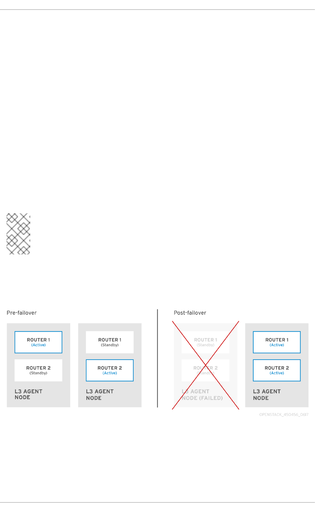
CHAPTER 19. CONFIGURE LAYER 3 HIGH AVAILABILITY
This chapter explains the role of Layer 3 High Availability in an OpenStack Networking deployment and
includes implementation steps for protecting your network’s virtual routers.
19.1. OpenStack Networking without HA
An OpenStack Networking deployment without any high availability features is going to be vulnerable
to physical node failures.
In a typical deployment, tenants create virtual routers, which are scheduled to run on physical L3 agent
nodes. This becomes an issue when you lose a L3 agent node and the dependent virtual machines
subsequently lose connectivity to external networks. Any floating IP addresses will also be unavailable.
In addition, connectivity is also lost between any networks hosted by the router.
19.2. Overview of Layer 3 High Availability
This active/passive high availability configuration uses the industry standard VRRP (as defined in RFC
3768) to protect tenant routers and floating IP addresses. A virtual router is randomly scheduled
across multiple OpenStack Networking nodes, with one designated as the active, and the remainder
serving in a standby role.
NOTE
A successful deployment of Layer 3 High Availability requires that the redundant
OpenStack Networking nodes maintain similar configurations, including floating IP
ranges and access to external networks.
In the diagram below, the active Router1 and Router2 are running on separate physical L3 agent nodes.
Layer 3 High Availability has scheduled backup virtual routers on the corresponding nodes, ready to
resume service in the case of a physical node failure. When the L3 agent node fails, Layer 3 High
Availability reschedules the affected virtual router and floating IP addresses to a working node:
During a failover event, instance TCP sessions through floating IPs remain unaffected, and will migrate
to the new L3 node without disruption. Only SNAT traffic is affected by failover events.
The L3 agent itself is further protected when in an active/active HA mode.
19.2.1. Failover conditions
Red Hat OpenStack Platform 10 Networking Guide
118

Layer 3 High Availability will automatically reschedule protected resources in the following events:
The L3 agent node shuts down or otherwise loses power due to hardware failure.
L3 agent node becomes isolated from the physical network and loses connectivity.
NOTE
Manually stopping the L3 agent service does not induce a failover event.
19.3. Tenant considerations
Layer 3 High Availability configuration occurs in the back end and is invisible to the tenant. They can
continue to create and manage their virtual routers as usual, however there are some limitations to be
aware of when designing your Layer 3 High Availability implementation:
Layer 3 High Availability supports up to 255 virtual routers per tenant.
Internal VRRP messages are transported within a separate internal network, created
automatically for each project. This process occurs transparently to the user.
19.4. Background changes
The Neutron API has been updated to allow administrators to set the --ha=True/False flag when
creating a router, which overrides the (Default) configuration of l3_ha in neutron.conf. See the next
section for the necessary configuration steps.
19.4.1. Changes to neutron-server
Layer 3 High Availability assigns the active role randomly, regardless of the scheduler used by
OpenStack Networking (whether random or leastrouter).
The database schema has been modified to handle allocation of VIPs to virtual routers.
A transport network is created to direct Layer 3 High Availability traffic as described above.
19.4.2. Changes to L3 agent
A new keepalived manager has been added, providing load-balancing and HA capabilities.
IP addresses are converted to VIPs.
19.5. Configuration Steps
This procedure enables Layer 3 High Availability on the OpenStack Networking and L3 agent nodes.
19.5.1. Configure the OpenStack Networking node
1. Configure Layer 3 High Availability in the neutron.conf file by enabling L3 HA and defining the
number of L3 agent nodes that should protect each virtual router:
l3_ha = True
max_l3_agents_per_router = 2
min_l3_agents_per_router = 2
CHAPTER 19. CONFIGURE LAYER 3 HIGH AVAILABILITY
119

These settings are explained below:
l3_ha - When set to True, all virtual routers created from this point onwards will default to HA
(and not legacy) routers. Administrators can override the value for each router using:
# neutron router-create --ha=<True | False> routerName
max_l3_agents_per_router - Set this to a value between the minimum and total number of
network nodes in your deployment. For example, if you deploy four OpenStack Networking
nodes but set max to 2, only two L3 agents will protect each HA virtual router: One active, and
one standby. In addition, each time a new L3 agent node is deployed, additional standby
versions of the virtual routers are scheduled until the max_l3_agents_per_router limit is
reached. As a result, you can scale out the number of standby routers by adding new L3
agents.
min_l3_agents_per_router - The min setting ensures that the HA rules remain enforced. This
setting is validated during the virtual router creation process to ensure a sufficient number of
L3 Agent nodes are available to provide HA. For example, if you have two network nodes and
one becomes unavailable, no new routers can be created during that time, as you need at least
min active L3 agents when creating a HA router.
2. Restart the neutron-server service for the change to take effect:
# systemctl restart neutron-server.service
19.5.2. Review your configuration
Running the ip address command within the virtual router namespace will now return a HA device in
the result, prefixed with ha-.
# ip netns exec qrouter-b30064f9-414e-4c98-ab42-646197c74020 ip address
<snip>
2794: ha-45249562-ec: <BROADCAST,MULTICAST,UP,LOWER_UP> mtu 1500 qdisc
noqueue state DOWN group default
link/ether 12:34:56:78:2b:5d brd ff:ff:ff:ff:ff:ff
inet 169.254.0.2/24 brd 169.254.0.255 scope global ha-54b92d86-4f
With Layer 3 High Availability now enabled, virtual routers and floating IP addresses are protected
against individual node failure.
Red Hat OpenStack Platform 10 Networking Guide
120

CHAPTER 20. USE TAGGING FOR VIRTUAL DEVICE
IDENTIFICATION
NOTE
Virtual device tagging was added in version 2.32 of the nova API for both block devices
and network ports, however:
For block devices: this capability only works in 2.32.
For network interface tagging: this capability only works in versions 2.32 to
2.36. Network interface tagging does not work under 2.37.
An update is available for python-novaclient (not openstackclient) that is
intended to work around this issue. As a result, the issue should not occur when using
novaclient, except when using both block device tagging and the automatic network
feature introduced in 2.37. Attempting to use both of these features together will result
in an error. Those capabilities will remain mutually exclusive for Red Hat OpenStack
Platform 10.
These issues do not affect Red Hat OpenStack Platform 11, which uses version
2.42 and allows the concurrent use of both block device tagging and network
interface tagging.
To apply this update, see https://access.redhat.com/errata/RHSA-2017:1595
If an instance is started with multiple network interfaces or block devices, you can use device tagging
to communicate the intended role of each device to the instance operating system. Tags are assigned
to devices at instance boot time, and are made available to the instance operating system through the
metadata API and the config drive (if enabled).
The tags are set using the following parameters:
--block-device tag=device metadata
--nic tag=device metadata
For example, this command creates an instance using the tag parameters for --block-device and -
-nic:
$ nova boot test-vm --flavor m1.tiny --image cirros \
--nic net-id=55411ca3-83dd-4036-9158-bf4a6b8fb5ce,tag=nfv1 \
--block-device id=b8c9bef7-aa1d-4bf4-a14d-
17674b370e13,bus=virtio,tag=database-server NFVappServer
The resulting tags are added to the existing instance metadata and are made available through both
the metadata API, and on the configuration drive. In the above example, the following devices section
will appear in the metadata:
Sample meta_data.json:
{
"devices": [
{
CHAPTER 20. USE TAGGING FOR VIRTUAL DEVICE IDENTIFICATION
121

"type": "nic",
"bus": "pci",
"address": "0030:00:02.0",
"mac": "aa:00:00:00:01",
"tags": ["nfv1"]
},
{
"type": "disk",
"bus": "pci",
"address": "0030:00:07.0",
"serial": "disk-vol-227",
"tags": ["database-server"]
}
]
}
The device tag metadata is available as GET /openstack/latest/meta_data.json from the
metadata API. If the configuration drive is enabled, and mounted under /configdrive in the instance
operating system, the metadata is also present in /configdrive/openstack/latest/meta_data.json.
Red Hat OpenStack Platform 10 Networking Guide
122

CHAPTER 21. SR-IOV SUPPORT FOR VIRTUAL NETWORKING
First introduced in RHEL OpenStack Platform 6, single root I/O virtualization (SR-IOV) support was
extended to virtual machine networking. SR-IOV enables OpenStack to put aside the previous
requirement for virtual bridges, and instead extends the physical NIC’s capabilities directly through to
the instance. In addition, support for IEEE 802.1br allows virtual NICs to integrate with, and be
managed by, the physical switch.
NOTE
For information on Network Function Virtualization (NFV), see the NFV Configuration
Guide.
21.1. Configure SR-IOV in your Red Hat OpenStack Platform deployment
SR-IOV adds support for the concept of a virtual function which, while presented as a PCI device on the
hardware, is a virtual interface that is provided by the physical function.
This chapter contains procedures for configuring SR-IOV to pass a physical NIC through to a virtual
instance. These steps assume a deployment using a Controller node, an OpenStack Networking
(neutron) node, and multiple Compute (nova) nodes.
Note: Virtual machine instances using SR-IOV virtual function (VF) ports and virtual machine
instances using regular ports (for example, linked to Open vSwitch bridge), can communicate with
each other across the network assuming that the appropriate L2 configuration (flat, VLAN) is in place.
At present, there is a limitation where instances using SR-IOV ports and instances using regular
vSwitch ports which reside on the same Compute node cannot communicate with each other if they
are sharing the same Physical Function (PF) on the network adapter.
21.2. Create Virtual Functions on the Compute node
Perform these steps on all Compute nodes with supported hardware.
Note: Please refer to this article for details on supported drivers.
This procedure configures a system to passthrough an Intel 82576 network device. Virtual Functions
are also created, which can then be used by instances for SR-IOV access to the device.
1. Ensure that Intel VT-d or AMD IOMMU are enabled in the system’s BIOS. Refer to the machine’s
BIOS configuration menu, or other means available from the manufacturer.
2. Ensure that Intel VT-d or AMD IOMMU are enabled in the operating system:
For Intel VT-d systems, refer to the procedure here.
For AMD IOMMU systems, refer to the procedure here.
3. Run the lspci command to ensure the network device is recognized by the system:
[root@compute ~]# lspci | grep 82576
The network device is included in the results:
03:00.0 Ethernet controller: Intel Corporation 82576 Gigabit Network
Connection (rev 01)
CHAPTER 21. SR-IOV SUPPORT FOR VIRTUAL NETWORKING
123

03:00.1 Ethernet controller: Intel Corporation 82576 Gigabit Network
Connection (rev 01)
4. Perform these steps to activate Virtual Functions on the Compute node:
4a. Remove the kernel module. This will allow it to be configured in the next step:
[root@compute ~]# modprobe -r igb
Note: The module used by the SRIOV-supported NIC should be used in step 4 , rather than igb for
other NICs (for example, ixgbe or mlx4_core). Confirm the driver by running the ethtool command.
In this example, em1 is the PF to use:
[root@compute ~]# ethtool -i em1 | grep ^driver
4b. Start the module with max_vfs set to 7 (or up to the maximum supported).
[root@compute ~]# modprobe igb max_vfs=7
4c. Make the Virtual Functions persistent:
[root@compute ~]# echo "options igb max_vfs=7" >>/etc/modprobe.d/igb.conf
Note: For Red Hat Enterprise Linux 7, to make the aforementioned changes persistent, rebuild the
initial ramdisk image after completing step 4.
Note: Regarding the persistence of the settings in steps 4c. and 4d.: The modprobe command enables
Virtual Functions on all NICs that use the same kernel module, and makes the change persist through
system reboots. It is possible to enable VFs for only a specific NIC, however there are some possible
issues that can result. For example, this command enables VFs for the enp4s0f1 interface:
# echo 7 > /sys/class/net/enp4s0f1/device/sriov_numvfs
However, this setting will not persist after a reboot. A possible workaround is to add this to rc.local, but
this has its own limitation, as described in the note below:
# chmod +x /etc/rc.d/rc.local
# echo "echo 7 > /sys/class/net/enp4s0f1/device/sriov_numvfs" >>
/etc/rc.local
Note: Since the addition of systemd, Red Hat Enterprise Linux starts services in parallel, rather than in
series. This means that rc.local no longer executes at a predictable point in the boot process. As a
result, unexpected behavior can occur, and this configuration is not recommended.
4d. Activate Intel VT-d in the kernel by appending the intel_iommu=pt and igb.max_vfs=7 parameters to
the kernel command line. You can either change your current settings if you are going to always boot
the kernel this way, or you can create a custom menu entry with these parameters, in which case your
system will boot with these parameters by default, but you will also be able to boot the kernel without
these parameters if need be.
• To change your current kernel command line parameters, run the following command:
Red Hat OpenStack Platform 10 Networking Guide
124

[root@compute ~]# grubby --update-kernel=ALL --args="intel_iommu=pt
igb.max_vfs=7"
For more information on using grubby, see Configuring GRUB 2 Using the grubby Tool in the System
Administrator’s Guide.
Note: If using a Dell Power Edge R630 node, you will need to use intel_iommu=on instead of
intel_iommu=pt. You can enable this using grubby:
# grubby --update-kernel=ALL --args="intel_iommu=on"
• To create a custom menu entry:
i. Find the default entry in grub:
[root@compute ~]# grub2-editenv list
saved_entry=Red Hat Enterprise Linux Server (3.10.0-123.9.2.el7.x86_64)
7.0 (Maipo)
ii. a. Copy the desired menuentry starting with the value of saved_entry from /boot/grub2/grub.cfg to
/etc/grub.d/40_custom. The entry begins with the line starting with "menuentry" and ends with a line
containing "}" b. Change the title after menuentry c. Add intel_iommu=pt igb.max_vfs=7 to the end of
the line starting with linux16.
For example:
menuentry 'Red Hat Enterprise Linux Server, with Linux 3.10.0-
123.el7.x86_64 - SRIOV' --class red --class gnu-linux --class gnu --class
os --unrestricted $menuentry_id_option 'gnulinux-3.10.0-123.el7.x86_64-
advanced-4718717c-73ad-4f5f-800f-f415adfccd01' {
load_video
set gfxpayload=keep
insmod gzio
insmod part_msdos
insmod ext2
set root='hd0,msdos2'
if [ x$feature_platform_search_hint = xy ]; then
search --no-floppy --fs-uuid --set=root --hint-bios=hd0,msdos2 --
hint-efi=hd0,msdos2 --hint-baremetal=ahci0,msdos2 --hint='hd0,msdos2'
5edd1db4-1ebc-465c-8212-552a9c97456e
else
search --no-floppy --fs-uuid --set=root 5edd1db4-1ebc-465c-8212-
552a9c97456e
fi
linux16 /vmlinuz-3.10.0-123.el7.x86_64 root=UUID=4718717c-73ad-4f5f-
800f-f415adfccd01 ro vconsole.font=latarcyrheb-sun16 biosdevname=0
crashkernel=auto vconsole.keymap=us nofb console=ttyS0,115200
LANG=en_US.UTF-8 intel_iommu=pt igb.max_vfs=7
initrd16 /initramfs-3.10.0-123.el7.x86_64.img
}
iii. Update grub.cfg to apply the change config file:
[root@compute ~]# grub2-mkconfig -o /boot/grub2/grub.cfg
CHAPTER 21. SR-IOV SUPPORT FOR VIRTUAL NETWORKING
125

iv. Change the default entry:
[root@compute ~]# grub2-set-default 'Red Hat Enterprise Linux Server, with
Linux 3.10.0-123.el7.x86_64 - SRIOV'
v. Create the dist.conf configuration file.
Note: Before performing this step, review the section describing the effects of
allow_unsafe_interrupts: Review the allow_unsafe_interrupts setting.
[root@compute ~]# echo "options vfio_iommu_type1
allow_unsafe_interrupts=1" > /etc/modprobe.d/dist.conf
5. Reboot the server to apply the new kernel parameters:
[root@compute ~]# systemctl reboot
6. Review the SR-IOV kernel module on the Compute node. Confirm that the module has been loaded
by running lsmod:
[root@compute ~]# lsmod |grep igb
The filtered results will include the necessary module:
igb 87592 0
dca 6708 1 igb
7. Review the PCI vendor ID Make a note of the PCI vendor ID (in vendor_id:product_id format) of your
network adapter. Extract this from the output of the lspci command using the -nn flag. For example:
[root@compute ~]# lspci -nn | grep -i 82576
05:00.0 Ethernet controller [0200]: Intel Corporation 82576 Gigabit
Network Connection [8086:10c9] (rev 01)
05:00.1 Ethernet controller [0200]: Intel Corporation 82576 Gigabit
Network Connection [8086:10c9] (rev 01)
05:10.0 Ethernet controller [0200]: Intel Corporation 82576 Virtual
Function [8086:10ca] (rev 01)
Note: This parameter may differ depending on your network adapter hardware.
8. Review the new Virtual Functions Use lspci to list the newly-created VFs:
[root@compute ~]# lspci | grep 82576
The results will now include the device plus the Virtual Functions:
0b:00.0 Ethernet controller: Intel Corporation 82576 Gigabit Network
Connection (rev 01)
0b:00.1 Ethernet controller: Intel Corporation 82576 Gigabit Network
Connection(rev 01)
0b:10.0 Ethernet controller: Intel Corporation 82576 Virtual Function (rev
01)
0b:10.1 Ethernet controller: Intel Corporation 82576 Virtual Function (rev
Red Hat OpenStack Platform 10 Networking Guide
126

01)
0b:10.2 Ethernet controller: Intel Corporation 82576 Virtual Function (rev
01)
0b:10.3 Ethernet controller: Intel Corporation 82576 Virtual Function (rev
01)
0b:10.4 Ethernet controller: Intel Corporation 82576 Virtual Function (rev
01)
0b:10.5 Ethernet controller: Intel Corporation 82576 Virtual Function (rev
01)
0b:10.6 Ethernet controller: Intel Corporation 82576 Virtual Function (rev
01)
0b:10.7 Ethernet controller: Intel Corporation 82576 Virtual Function (rev
01)
0b:11.0 Ethernet controller: Intel Corporation 82576 Virtual Function (rev
01)
0b:11.1 Ethernet controller: Intel Corporation 82576 Virtual Function (rev
01)
0b:11.2 Ethernet controller: Intel Corporation 82576 Virtual Function (rev
01)
0b:11.3 Ethernet controller: Intel Corporation 82576 Virtual Function (rev
01)
0b:11.4 Ethernet controller: Intel Corporation 82576 Virtual Function (rev
01)
0b:11.5 Ethernet controller: Intel Corporation 82576 Virtual Function (rev
01)
21.3. Configure SR-IOV on the Network Node
OpenStack Networking (neutron) uses a ML2 mechanism driver to support SR-IOV. Perform these
steps on the Network node to configure the SR-IOV driver. In this procedure, you add the mechanism
driver, ensure that vlan is among the enabled drivers, and then define the VLAN ranges:
1. Enable sriovnicswitch in the /etc/neutron/plugins/ml2/ml2_conf.ini file. For example, this configuration
enables the SR-IOV mechanism driver alongside Open vSwitch.
Note: sriovnicswitch does not support the current interface drivers for DHCP Agent, so openvswitch (or
other mechanism driver with VLAN support) is a requirement when using sriovnicswitch.
[ml2]
tenant_network_types = vlan
type_drivers = vlan
mechanism_drivers = openvswitch, sriovnicswitch
[ml2_type_vlan]
network_vlan_ranges = physnet1:15:20
network_vlan_ranges - In this example, physnet1 is used as the network label, followed by the
specified VLAN range of 15-20.
Note: The mechanism driver sriovnicswitch currently supports only the flat and vlan drivers.
However, enabling sriovnicswitch does not limit you to only having flat or vlan tenant networks.
VXLAN and GRE, among others, can still be used for instances that are not using SR-IOV ports.
2. Optional - The supported vendor_id/product_id couples are 15b3:1004, 8086:10ca. Specify your NIC
vendor’s product ID if it differs from these. In addition, you will need to modify this list if PF
passthrough is being used. For example:
CHAPTER 21. SR-IOV SUPPORT FOR VIRTUAL NETWORKING
127

[ml2_sriov]
supported_pci_vendor_devs = 15b3:1004,8086:10ca
3. Restart the neutron-server service to apply the configuration:
[root@network ~]# systemctl restart neutron-server.service
21.4. Configure SR-IOV on the Controller Node
1. To allow proper scheduling of SR-IOV devices, the Compute scheduler needs to use FilterScheduler
with the PciPassthroughFilter filter. Apply this configuration in the nova.conf file on the Controller node.
For example:
scheduler_available_filters=nova.scheduler.filters.all_filters
scheduler_default_filters=RetryFilter,AvailabilityZoneFilter,RamFilter,Com
puteFilter,ComputeCapabilitiesFilter,ImagePropertiesFilter,CoreFilter,
PciPassthroughFilter
2. Restart the Compute scheduler to apply the change:
[root@compute ~]# systemctl restart openstack-nova-scheduler.service
21.5. Configure SR-IOV in Compute
On all Compute nodes, associate the available VFs with each physical network:
1. Define the entries in the nova.conf file. This example adds the VF network matching enp5s0f1, and
tags physical_network as physnet1, the network label previously configured in network_vlan_ranges.
pci_passthrough_whitelist={"devname": "enp5s0f1",
"physical_network":"physnet1"}
This example adds the PF network matching vendor ID 8086, and tags physical_network as physnet1: ~
pci_passthrough_whitelist = \{"vendor_id": "8086","product_id": "10ac",
"physical_network":"physnet1"} ~
PCI passthrough whitelist entries use the following syntax:
["device_id": "<id>",] ["product_id": "<id>",]
["address": "[[[[<domain>]:]<bus>]:][<slot>][.[<function>]]" |
"devname": "Ethernet Interface Name",]
"physical_network":"Network label string"
id - The id setting accepts the * wildcard value, or a valid device/product id. You can use lspci to
list the valid device names.
address - The address value uses the same syntax as displayed by lspci using the -s switch.
devname - The devname is a valid PCI device name. You can list the available names using
ifconfig -a. This entry must correspond to either a PF or VF value that is associated with a vNIC.
If the device defined by the address or devname corresponds to a SR-IOV PF, all the VFs under
the PF will match the entry. It is possible to associate 0 or more tags with an entry.
Red Hat OpenStack Platform 10 Networking Guide
128

physical_network - When using SR-IOV networking, "physical_network" is used to define the
physical network that devices are attached to.
You can configure multiple whitelist entries per host. The fields device_id, product_id, and address or
devname will be matched against PCI devices that are returned as a result of querying libvirt.
2. Apply the changes by restarting the nova-compute service:
[root@compute ~]# systemctl restart openstack-nova-compute
21.6. Enable the OpenStack Networking SR-IOV agent
1. Install the sriov-nic-agent package in order to complete the following steps:
[root@compute ~]# yum install openstack-neutron-sriov-nic-agent
2. Enable NoopFirewallDriver in the /etc/neutron/plugins/ml2/openvswitch_agent.ini file:
[root@compute ~]# openstack-config --set
/etc/neutron/plugins/ml2/openvswitch_agent.ini securitygroup
firewall_driver neutron.agent.firewall.NoopFirewallDriver
3. Add mappings to the /etc/neutron/plugins/ml2/sriov_agent.ini file. In this example, physnet1 is the
physical network, and enp4s0f1 is the physical function. Leave exclude_devices blank to allow the agent
to manage all associated VFs.
[sriov_nic]
physical_device_mappings = physnet1:enp4s0f1
exclude_devices =
4. Optional - Exclude VFs To exclude specific VFs from agent configuration, list them in the sriov_nic
section. For example:
exclude_devices = eth1:0000:07:00.2; 0000:07:00.3, eth2:0000:05:00.1;
0000:05:00.2
5. Start the OpenStack Networking SR-IOV agent:
[root@compute ~]# systemctl enable neutron-sriov-nic-agent.service
[root@compute ~]# systemctl start neutron-sriov-nic-agent.service
21.7. Configure an instance to use the SR-IOV port
Overview of SR-IOV functions
Using SR-IOV, you can give an instance direct access to a NIC by using Physical Functions (PFs) and
Virtual Functions (VFs). PFs use VFs to allow multiple instances to have direct access to the same PCI
card. As a result, the PCI card can be thought of as being logically partitioned into VFs for use by
multiple instances. SR-IOV is thereby different to PCI passthrough, which only allows one instance to
have exclusive access to the PCI device.
CHAPTER 21. SR-IOV SUPPORT FOR VIRTUAL NETWORKING
129

NOTE
SR-IOV NICs cannot concurrently bind to instances when using both PFs and VFs. Due
to memory address protection, an instance should not have control of the PF if other
instances are using VFs. In other words, unless a single instance is using the card by
binding directly to the PF (almost equivalent to PCI passthrough), in most cases neutron
will pass VFs to instances and let the host control the PF.
Limitations of Virtual Functions
Physical Function passthrough might be more appropriate for certain use cases. For example:
Residential vCPE
BNG/BRAS (IPoE or PPPoE)
PE for VPLS or VLL
VPN L3 (using multiple VLANs by port)
Other use cases where specific traffic handling is required, depending on level 2
encapsulation. For example, QinQ encapsulation for MAN networks.
When using VFs, your server NIC port may end up blocking traffic. This is expected behavior
that helps mitigate spoofing attacks from instances sharing VFs from the same NIC. As a result,
your NIC vendor might recommend allowing promiscuous unicast, disabling antispoofing, and
disabling ingress VLAN filtering.
A NIC should be configured to use either physical functions or virtual functions; not both at the
same time.
Example configuration
In this example, the SR-IOV port is added to the web network.
1. Retrieve the list of available networks:
[root@network ~]# neutron net-list
+--------------------------------------+---------+--------------------
----------------------------------+
| id | name | subnets
|
+--------------------------------------+---------+--------------------
----------------------------------+
| 3c97eb09-957d-4ed7-b80e-6f052082b0f9 | corp | 78328449-796b-49cc-
96a8-1daba7a910be 172.24.4.224/28 |
| 721d555e-c2e8-4988-a66f-f7cbe493afdb | web | 140e936e-0081-4412-
a5ef-d05bacf3d1d7 10.0.0.0/24 |
+--------------------------------------+---------+--------------------
----------------------------------+
The result lists the networks that have been created in OpenStack Networking, and includes subnet
details.
2. Create the port inside the web network:
Red Hat OpenStack Platform 10 Networking Guide
130

[root@network ~]# neutron port-create web --name sr-iov --binding:vnic-
type direct
Created a new port:
+-----------------------+---------------------------------------------
------------------------------------+
| Field | Value
|
+-----------------------+---------------------------------------------
------------------------------------+
| admin_state_up | True
|
| allowed_address_pairs |
|
| binding:host_id |
|
| binding:profile | {}
|
| binding:vif_details | {}
|
| binding:vif_type | unbound
|
| binding:vnic_type | normal
|
| device_id |
|
| device_owner |
|
| fixed_ips | {"subnet_id": "140e936e-0081-4412-a5ef-
d05bacf3d1d7", "ip_address": "10.0.0.2"} |
| id | a2122b4d-c9a9-4a40-9b67-ca514ea10a1b
|
| mac_address | fa:16:3e:b1:53:b3
|
| name | sr-iov
|
| network_id | 721d555e-c2e8-4988-a66f-f7cbe493afdb
|
| security_groups | 3f06b19d-ec28-427b-8ec7-db2699c63e3d
|
| status | DOWN
|
| tenant_id | 7981849293f24ed48ed19f3f30e69690
|
+-----------------------+---------------------------------------------
------------------------------------+
3. Create an instance using the new port.
Create a new instance named webserver01, and configure it to use the new port, using the port ID from
the previous output in the id field:
Note: You can retrieve a list of available images and their UUIDs using the glance image-list command.
[root@compute ~]# nova boot --flavor m1.tiny --image 59a66200-45d2-4b21-
982b-d06bc26ff2d0 --nic port-id=a2122b4d-c9a9-4a40-9b67-ca514ea10a1b
webserver01
CHAPTER 21. SR-IOV SUPPORT FOR VIRTUAL NETWORKING
131

Your new instance webserver01 has been created and configured to use the SR-IOV port.
21.8. Review the allow_unsafe_interrupts setting
Platform support for interrupt remapping is required to fully isolate a guest with assigned devices from
the host. Without such support, the host may be vulnerable to interrupt injection attacks from a
malicious guest. In an environment where guests are trusted, the admin may opt-in to still allow PCI
device assignment using the allow_unsafe_interrupts option. Review whether you need to enable
allow_unsafe_interrupts on your host. If the IOMMU on the host supports interrupt remapping, then
there is no need to enable this feature.
1. Use dmesg to confirm whether your host supports IOMMU interrupt remapping:
[root@compute ~]# dmesg |grep ecap
If bit 3 of the ecap (0xf020ff → …1111) is 1 , this indicates that the IOMMU supports interrupt remapping.
2. Confirm whether IRQ remapping is enabled:
[root@compute ~]# dmesg |grep "Enabled IRQ"
[ 0.033413] Enabled IRQ remapping in x2apic mode
Note: "IRQ remapping" can be disabled manually by adding intremap=off to grub.conf.
3. If the host’s IOMMU does not support interrupt remapping, you will need to enable
allow_unsafe_assigned_interrupts=1 in the kvm module.
21.9. Add a Physical Function to an Instance
You can configure Compute to expose Physical Functions (PFs) to instances. This use case helps NFV
applications by granting instances full control over the physical port, allowing them to use some of the
functionality not available to Virtual Functions (VF). These instances can then bypass some of the
limitations certain cards impose on VFs, or can exclusively use the full bandwidth of the port.
Compute can allow the assignment of a free PF to instances, in the event none of the child VFs are
assigned to instances. Once a PF is assigned, then none of its VFs will be available. The VFs will be
available again once the instance is shutdown and the PF becomes free. This also works in reverse:
Compute will prevent a PF from being assigned if one of its VFs is already assigned.
21.9.1. Configure Compute for Physical Functions
Expose the physical functions by adding device_type: type-PF to your nova.conf whitelist. For
example:
pci_passthrough_whitelist={"product_id":"10ed", "vendor_id":"8086",
"physical_network":"physnet1",'device_type': 'type-PF}
21.9.2. Configure Physical Functions
You can manage SR-IOV PFs as if they were neutron ports. Neutron supports a new vnic_type of
direct-physical; the resulting vNIC is then used by nova to select a PF on a host (and perform
passthrough to a guest) using the new VIF type. As a result, nova will update the neutron port with the
MAC address of the selected PF on the host.
Red Hat OpenStack Platform 10 Networking Guide
132

For example, to create a PF on a network called Network1:
$ neutron port-create Network1 --name pf-port --binding:vnic_type direct-
physical
You can then attach the resulting port to an instance for PF access.
21.10. Additional considerations
When selecting a vNIC type, note that vnic_type=macvtap is not currently supported.
VM migration with SR-IOV attached instances is not supported.
Security Groups can not currently be used with SR-IOV enabled ports.
CHAPTER 21. SR-IOV SUPPORT FOR VIRTUAL NETWORKING
133
