Certificate No: (release)L181654L082
2016-04-11
: Pdf (Release)L181654L082 (release)L181654L082 CertsReports 525466 ProductFiles
Open the PDF directly: View PDF ![]() .
.
Page Count: 67
Certificate No:L181654L082
SPORTON LAB.
CERTIFICATE
EQUIPMENT:
300N Wireless LAN Broadband Router
MODEL NO. :
BR-6428GN; GR-428GN; 3G-6408GN; 3G-408GN;
3G-6408n; LT-6408n
APPLICANT:
EDIMAX TECHNOLOGY CO., LTD.
No.3,Wu-Chuan 3rd Road,Wu-Ku Industrial Park, New
Taipei City, Taiwan
CERTIFY THAT:
THE MEASUREMENTS SHOWN IN THIS TEST REPORT WERE MADE IN
ACCORDANCE WITH THE PROCEDURES GIVEN IN EUROPEAN COUNCIL
DIRECTIVE 2006/95/EC. THE EQUIPMENT PASSED THE TEST
PERFORMED ACCORDING TO
European Standard:
IEC 60950-1: 2005 (2nd Edition)
EN60950-1: 2006+A11:2009
This evaluation was carried out to the best of our knowledge and ability, and our
responsibility is limited to the exercise of reasonable care. This certification is not
intended to relieve the sellers from their contractual obligations.
THE CERTIFICATE WAS CARRIED OUT ON May 28, 2012 AT SPORTON
INTERNATIONAL INC. LAB.
Hans Hsieh
Director
SPORTON INTERNATIONAL INC. EMC & SAFETY GROUP
14 Fl-2, No. 186, Jianyi Road, Zhonghe District, New Taipei City, Taiwan.
Page 1 of 39 Report No.:L181654L082
Fi
Sporton International Inc.
LOW VOLTAGE DIRECTIVE TEST REPORT
IEC 60950-1: 2005 (2nd Edition) and/or EN 60950-1: 2006
Information technology equipment – Safety –
Part 1: General requirements
Report Reference No. ....................... :
L181654L082
Compiled by (+ signature) ................. :
Nancy Shi
Engineer
Approved by (+ signature) ................. :
Peter Hsu
Reviewer
Date of Issue ..................................... :
May 28, 2012
Testing laboratory .............................. :
Sporton International Inc.
Address .............................................. :
14 Fl-2, No. 186, Jianyi Road, Zhonghe District, New Taipei City, Taiwan.
Testing location ................................. :
Taiwan
Applicant ............................................ :
EDIMAX TECHNOLOGY CO., LTD.
Address .............................................. :
No.3,Wu-Chuan 3rd Road,Wu-Ku Industrial Park, New Taipei City,
Taiwan
Standard ............................................ :
IEC 60950-1: 2005 (2nd Edition) and/or
EN60950-1: 2006+A11:2009
Test Report Form No. ....................... :
LVD 60950-1
Test procedure ................................. :
Sporton LVD type test approval
Procedure deviation ........................... :
N/A
Non-standard test method ................. :
N/A
Type of test object ............................. :
300N Wireless LAN Broadband Router
Trademark ......................................... :
EDIMAX
Model/type reference ......................... :
BR-6428GN; GR-428GN; 3G-6408GN; 3G-408GN; 3G-6408n;
LT-6408n
Manufacturer ..................................... :
EDIMAX TECHNOLOGY CO., LTD.
No.3,Wu-Chuan 3rd Road,Wu-Ku Industrial Park, New Taipei City,
Taiwan
Rating ................................................. :
DC 5 V, 1A
Page 2 of 39 Report No.:L181654L082
Fi
Sporton International Inc.
Test item particulars:
Equipment mobility .................................................... :
[X] movable [] hand-held [] transportable
[] stationary [] for building-in [] direct plug-in
Connection to the mains ............................................ :
[] pluggable equipment [] type A [] type B
[] permanent connection
[] detachable power supply cord
[] non-detachable power supply cord
[X] not directly connected to the mains
Operating condition ...................................................... :
[X] continuous
[] rated operating / resting time:
Access location ........................................................... :
[X] operator accessible
[] restricted access location
Over voltage category (OVC) ..................................... :
[] OVC I [] OVC II [] OVC III [] OVC IV
[X] other: N/A
Mains supply tolerance (%) or absolute mains supply
values .......................................................................... :
Not directly connected to the mains
Tested for IT power systems ...................................... :
[] Yes [X] No
IT testing, phase-phase voltage (V) ........................... :
N/A
Class of equipment ..................................................... :
[] Class I [] Class II [X] Class III
[] Not classified
Considered current rating (A) ..................................... :
N/A
Pollution degree (PD) ................................................. :
[] PD 1 [X] PD 2 [] PD 3
IP protection class ...................................................... :
IPX0
Altitude during operation (m) ...................................... :
Up to 2000 m
Altitude of test laboratory (m) ..................................... :
Not over 2000 m
Mass of equipment (kg) .............................................. :
Approx. 0.216g (Type 1), 0.196g (Type 2), 0.232g
(Type 3), 0.240g (Type 4)
Test case verdicts
Test case does not apply to the test object ................... :
N (N.A.)
Test item does meet the requirement ........................... :
P (Pass)
Test item does not meet the requirement ..................... :
F (Fail)
Testing:
- Date of receipt of test item .......................................... :
2012-03-20
- Date(s) of performance of test .................................... :
2012-03-21
General remarks:
The test result presented in this report relate only to the object(s) tested.
This report shall not be reproduced, except in full, without the written approval of the Issuing testing laboratory.
"(see appended table)" refers to a table appended to the report.
Throughout this report a comma (point) is used as the decimal separator.

Page 3 of 39 Report No.:L181654L082
Fi
Sporton International Inc.
Comments:
The test results are true for the test sample(s) only.
A part of this test report or certificate should not be duplicated in any way; however, the duplication of the whole
document is allowed.
This test-report includes the following documents:
Test report - ( 39 pages)
Photo - ( 27 pages)
General product information:
-The equipment is a 300N Wireless LAN Broadband Router, intended for used with information technology
equipment.
-The external power adaptor is approved product and complied with the requirements of sub-clause 2.5 as a
limited power source, see appended table 1.5.1 for detail.
-There are two type of enclosure for used and plastic enclosure was secured together by screws
- A) Overall dimensions of the equipment were approximate 157.4 by 105.9 by 29.3 mm. (see appendix photo of
type 1 and 2, that are different of USB optional provided and wireless antenna type )
- B) Overall dimensions of the equipment were approximate 180.6 by 111.6 by 25.7 mm. (see appendix photo of
type 3)
-Except heating /abnormal test were conducted on type 2 and 3, all test were conducted on type 2 replace to
others.
-All models are identical except for model designation for marketing purpose only
-The equipment was evaluated for use in a maximum air ambient of 40ºC.
-The test sample is pre-production without serial number.
-Instructions and equipment marking related to safety is applied in the language that is acceptable in the
country in which the equipment is to be sold.
Page 4 of 39 Report No.:L181654L082
Fi
Sporton International Inc.
Clause
Requirement - Test
Result - Remark
Verdict
1
GENERAL
Pass
1.5
Components
Pass
1.5.1
Comply with IEC 60950 or relevant component
standard
Components, which were found to
affect safety aspects, comply with
the requirements of this standard
or with the safety aspects of the
relevant IEC/EN component
standards.
Pass
1.5.2
Evaluation and testing of components
Components, which are certified to
IEC/EN and/or national standards,
are used correctly within their
ratings or have been evaluated
during this approval.
Pass
1.5.3
Thermal controls
N.A.
1.5.4
Transformers
N.A.
1.5.5
Interconnecting cables
N.A.
1.5.6
Capacitors bridging insulation
N.A.
1.5.7
Resistors bridging insulation
N.A.
1.5.7.1
Resistors bridging functional, basic
or supplementary insulation
N.A.
1.5.7.2
Resistors bridging double or reinforced insulation
between a.c. mains and other circuits
N.A.
1.5.7.3
Resistors bridging double or reinforced insulation
between a.c. mains and antenna or coaxial cable
N.A.
1.5.8
Components in equipment for IT power systems
N.A.
1.5.9
Surge suppressors
N.A.
1.5.9.1
General
N.A.
1.5.9.2
Protection of VDRs
N.A.
1.5.9.3
Bridging of functional insulation by a VDR
N.A.
1.5.9.4
Bridging of basic insulation by a VDR
N.A.
1.5.9.5
Bridging of supplementary, double or reinforced
insulation by a VDR
N.A.
1.6
Power interface
Pass
1.6.1
AC power distribution systems .............................. :
N.A.
1.6.2
Input current
See appended table 1.6.2
Pass
1.6.3
Voltage limit of hand-held equipment
.
N.A.

Page 5 of 39 Report No.:L181654L082
Fi
Sporton International Inc.
1.6.4
Neutral conductor
N.A.
1.7
Marking and instructions
Pass
1.7.1
Power rating
See below
Pass
Rated voltage(s) or voltage range(s) (V) ............. :
The unit does not directly connect to
Mains supply.
(Rated voltage DC 5.0V is optional
marked)
N.A.
Symbol for nature of supply, for d.c. only ...............:
no direct connection to the mains
supply (DC symbol is optional marked)
N.A.
Rated frequency or rated frequency range (Hz) .....:
DC input
N.A.
Rated current (mA or A) ..........................................:
The unit does not directly connect to
Mains supply.
(Rated current 1.0 A is optional
marked)
N.A.
Manufacturer’s name or trade-mark or
identification mark ...................................................:
See page 1.
Pass
Type/model or type reference …................
See page 1.
Pass
Symbol for Class II equipment only ........................:
Class III equipment.
N.A.
Other symbols ..........................................................:
Additional symbols or marking do not
give rise to misunderstandings.
Pass
1.7.2
Safety instructions and marking
See below.
Pass
1.7.2.1
General
Operation/installation instruction is
provided with each unit.
Pass
1.7.2.2
Disconnect devices
N.A.
1.7.2.3
Overcurrent protective device
N.A.
1.7.2.4
IT power distribution systems
N.A.
1.7.2.5
Operator access with a tool
N.A.
1.7.2.6
Ozone
N.A.
1.7.3
Short duty cycles
N.A..
1.7.4
Supply voltage adjustment .....................................:
N.A.
Methods and means of adjustment; reference to
installation instructions
N.A.
1.7.5
Power outlets on the equipment ............................:
N.A.
1.7.6
Fuse identification (marking, special fusing
characteristics, cross-reference) ..........................:
N.A.
1.7.7
Wiring terminals
N.A.
1.7.7.1
Protective earthing and bonding terminals
N.A.
1.7.7.2
Terminal for a.c. mains supply conductors
N.A.
1.7.7.3
Terminals for d.c. mains supply conductors
N.A.
Page 6 of 39 Report No.:L181654L082
Fi
Sporton International Inc.
1.7.8
Controls and indicators
N.A.
1.7.8.1
Identification, location and marking ........................:
N.A.
1.7.8.2
Colours ..................................................................:
N.A.
1.7.8.3
Symbols according to IEC 60417 ............................:
N.A.
1.7.8.4
Markings using figures ..........................................:
N.A.
1.7.9
Isolation of multiple power sources ........................:
N.A.
1.7.10
Thermostats and other regulating devices
N.A.
1.7.11
Durability
N.A.
1.7.12
Removable parts .................................................... :
No markings placed on removable
parts.
Pass
1.7.13
Replaceable batteries
N.A.
Language(s)
1.7.14
Equipment for restricted access locations
Not intended for use in restricted
access locations.
N.A.
2
PROTECTION FROM HAZARDS
Pass
2.1
Protection from electric shock and energy hazards
Pass
2.1.1
Protection in operator access areas
See below
Pass
2.1.1.1
Access to energized parts
The unit is supplied from approved
power supply that provides SELV.
Only SELV circuit inside the unit.
No electrical shock or energy hazards.
Pass
Test by inspection ..................................................:
N.A.
Test with test finger (Figure 2A) ............................ :
N.A.
Test with test pin (Figure 2B) .................................... :
N.A.
Test with test probe (Figure 2C) ........................... :
N.A.
2.1.1.2
Battery compartments .............................................. :
N.A.
2.1.1.3
Access to ELV wiring
N.A.
Working voltage (Vpeak or Vrms); minimum
distance through insulation (mm)
2.1.1.4
Access to hazardous voltage circuit wiring
N.A.
2.1.1.5
Energy hazards ...................................................... :
No energy hazard in operator access
area. The connectors of the equipment
below 240VA.
Pass
2.1.1.6
Manual controls
N.A.
2.1.1.7
Discharge of capacitors in equipment
N.A.
Time-constant (s); measured voltage (V) ................:
2.1.1.8
Energy hazards – d.c. mains supplies
N.A.
Page 7 of 39 Report No.:L181654L082
Fi
Sporton International Inc.
a) Capacitor connected to the d.c. mains supply ... :
N.A.
b) Internal battery connected to the d.c. mains
supply ...................................................................... :
N.A.
2.1.1.9
Audio amplifiers
N.A.
2.1.2
Protection in service access areas
N.A.
2.1.3
Protection in restricted access locations
N.A.
2.2
SELV circuits
Pass
2.2.1
General requirements
See below
Pass
2.2.2
Voltages under normal conditions (V) .....................:
Between any SELV circuits 42.4 V
peak and 60 Vdc are not exceeded.
Pass
2.2.3
Voltages under fault conditions (V) ..........................:
Single fault did not cause excessive
voltage in accessible SELV circuits.
Limits of 71V peak and 120Vd.c. were
not exceeded within 0.2s and limits
42.4V peak and 60Vd.c. were not
exceeded for longer than 0.2s.
Pass
2.2.4
Connection of SELV circuits to other circuits ..........:
SELV circuit only connected to SELV
Pass
2.3
TNV circuits
N.A.
2.3.1
Limits
N.A.
Type of TNV circuits .................................................:
2.3.2
Separation from others circuits and from
accessible parts
N.A.
2.3.2.1
General requirements
N.A.
2.3.2.2
Protection by basic insulation
N.A.
2.3.2.3
Protection by earthing
N.A.
2.3.2.4
Protection by other constructions ............................ :
N.A.
2.3.3
Separation from hazardous voltages
N.A.
Insulation employed .................................................:
2.3.4
Connection of TNV circuits to other circuits
N.A.
Insulation employed .................................................:
2.3.5
Test for operating voltages generated externally
N.A.
2.4
Limited current circuits
N.A.
2.4.1
General requirements
N.A.
2.4.2
Limit values
N.A.
Frequency (Hz) ...................................................... :
Measured current (mA) .......................................... :
Page 8 of 39 Report No.:L181654L082
Fi
Sporton International Inc.
Measured voltage (V) :
Measured capacitance (µF) ................................... :
2.4.3
Connection of limited current circuits to other
circuits
N.A.
2.5
Limited power sources
Pass
a) Inherently limited output
For data port
Pass
b) Impedance limited output
N.A.
c) Regulating network limited output under normal
operating and single fault condition
USB circuit design from 5V output of
adaptor directly. Which compliance with
LPS. No test was conducted on USB
port.
Pass
d) Overcurrent protective device limited output
N.A.
Max. output voltage (V), max. output current (A),
max. apparent power (VA)
See appended table 2.5
Current rating of overcurrent protective device
(A)
2.6
Provisions for earthing and bonding
N.A.
2.6.1
Protective earthing
Class III equipment.
N.A.
2.6.2
Functional earthing
N.A.
2.6.3
Protective earthing conductors and protective
bonding conductors
N.A.
2.6.3.1
General
N.A.
2.6.3.2
Size of protective earthing conductors
N.A.
Rated current (A), cross-sectional area (mm2),
AWG ......................................................................... :
2.6.3.3
Size of protective bonding conductors
N.A.
Rated current (A), cross-sectional area (mm2),
AWG ......................................................................... :
Protective current rating (A), cross-sectional area
(mm2), AWG
N.A.
2.6.3.4
Resistance of earthing conductors and their
terminations; resistance (), voltage drop (V),
test current (A), duration (min) ..................................
N.A.
2.6.3.5
Colour of insulation .................................................. :
N.A.
2.6.4
Terminals
N.A.
2.6.4.1
General
N.A.
2.6.4.2
Protective earthing and bonding terminals
N.A.
Rated current (A), type and nominal thread
diameter (mm) ......................................................... :
Page 9 of 39 Report No.:L181654L082
Fi
Sporton International Inc.
2.6.4.3
Separation of the protective earthing conductor
from protective bonding conductors
N.A.
2.6.5
Integrity of protective earthing
N.A.
2.6.5.1
Interconnection of equipment
N.A.
2.6.5.2
Components in protective earthing conductors
and protective bonding conductors
N.A.
2.6.5.3
Disconnection of protective earth
N.A.
2.6.5.4
Parts that can be removed by an operator
N.A.
2.6.5.5
Parts removed during servicing
N.A.
2.6.5.6
Corrosion resistance
N.A.
2.6.5.7
Screws for protective bonding
N.A.
2.6.5.8
Reliance on telecommunication network or cable
distribution system
N.A.
2.7
Overcurrent and earth fault protection in primary circuits
N.A.
2.7.1
Basic requirements
Class III equipment.
N.A.
Instructions when protection relies on building
installation.
N.A.
2.7.2
Faults not simulated in 5.3.7
N.A.
2.7.3
Short-circuit backup protection
N.A.
2.7.4
Number and location of protective devices .......... :
N.A.
2.7.5
Protection by several devices
N.A.
2.7.6
Warning to service personnel .................................. :
N.A.
2.8
Safety interlocks
N.A.
2.8.1
General principles
N.A.
2.8.2
Protection requirements
N.A.
2.8.3
Inadvertent reactivation
N.A.
2.8.4
Fail-safe operation
N.A.
2.8.5
Moving parts
N.A.
2.8.6
Overriding
N.A.
2.8.7
Switches and relays
N.A.
2.8.7.1
Contact gaps (mm) ................................................ :
N.A.
2.8.7.2
Overload test
N.A.
2.8.7.3
Endurance test
N.A.
2.8.7.4
Electric strength test
N.A.
2.8.8
Mechanical actuators
N.A.
Page 10 of 39 Report No.:L181654L082
Fi
Sporton International Inc.
2.9
Electrical insulation
Pass
2.9.1
Properties of insulating materials
Pass
2.9.2
Humidity conditioning
N.A.
Humidity (%),Temperature (℃)
2.9.3
Grade of insulation
The unit supply by SELV, only
Functional insulation in the unit.
See Clause 5.3.4.
Pass
2.9.4
Separation from hazardous voltages
N.A.
Method(s) used ....................................................... :
2.10
Clearances, creepage distances and distances through insulation
Pass
2.10.1
General
Functional insulation only.
See Clause 5.3.4.
Pass
2.10.1.1
Frequency ................................................................ :
N.A.
2.10.1.2
Pollution degrees ..................................................... :
N.A.
2.10.1.3
Reduced values for functional insulation
N.A.
2.10.1.4
Intervening unconnected conductive parts
N.A.
2.10.1.5
Insulation with varying dimensions
N.A.
2.10.1.6
Special separation requirements
N.A.
2.10.1.7
Insulation in circuits generating starting pulses
N.A.
2.10.2
Determination of working voltage
N.A.
2.10.2.1
General
N.A.
2.10.2.2
RMS working voltage
N.A.
2.10.2.3
Peak working voltage
N.A.
2.10.3
Clearances
N.A.
2.10.3.1
General
N.A.
2.10.3.2
Mains transient voltages
N.A.
a) AC mains supply ................................................. :
N.A.
b) Earthed d.c. mains supplies ............................... :
N.A.
c) Unearthed d.c. mains supplies ........................... :
N.A.
d) Battery operation ................................................. :
N.A.
2.10.3.3
Clearances in primary circuits
N.A.
2.10.3.4
Clearances in secondary circuits
N.A.
2.10.3.5
Clearances in circuits having starting pulses
N.A.
2.10.3.6
Transients from a.c. mains supply .......................... :
N.A.
2.10.3.7
Transients from d.c. mains supply .......................... :
N.A.
2.10.3.8
Transients from telecommunication networks
and cable distribution systems ................................ :
N.A.

Page 11 of 39 Report No.:L181654L082
Fi
Sporton International Inc.
2.10.3.9
Measurement of transient voltage levels
N.A.
a) Transients from a mains supply
N.A.
For an a.c. mains supply ......................................... :
N.A.
For a d.c. mains supply ........................................... :
N.A.
b) Transients from a telecommunication network .... :
N.A.
2.10.4
Creepage distances
N.A.
2.10.4.1
General
N.A.
2.10.4.2
Material group and comparative tracking index
N.A.
CTI tests .....................................................................:
N.A.
2.10.4.3
Minimum creepage distances
N.A.
2.10.5
Solid insulation
N.A.
2.10.5.1
General
N.A.
2.10.5.2
Distances through insulation
N.A.
2.10.5.3
Insulating compound as solid insulation
N.A.
2.10.5.4
Semiconductor devices
N.A.
2.10.5.5.
Cemented joints
N.A.
2.10.5.6
Thin sheet material – General
N.A.
2.10.5.7
Separable thin sheet material
N.A.
Number of layers (pcs)……………………………..
2.10.5.8
Non-separable thin sheet material
N.A.
2.10.5.9
Thin sheet material – standard test procedure
N.A.
Electric strength test
2.10.5.10
Thin sheet material – alternative test procedure
N.A.
Electric strength test
2.10.5.11
Insulation in wound components
N.A.
2.10.5.12
Wire in wound components
N.A.
Working voltage ...................................................... :
N.A.
a) Basic insulation not under stress ........................ :
N.A.
b) Basic, supplementary, reinforced insulation ....... :
N.A.
c) Compliance with Annex U ................................... :
N.A.
Two wires in contact inside wound component;
angle between 45 and 90 ..................................... :
N.A.
2.10.5.13
Wire with solvent-based enamel in wound
components
N.A.
Electric strength test
Routine test
N.A.
2.10.5.14
Additional insulation in wound components
N.A.
Working voltage ...................................................... :
N.A.
Page 12 of 39 Report No.:L181654L082
Fi
Sporton International Inc.
- Basic insulation not under stress .......................... :
N.A.
- Supplementary, reinforced insulation ....................:
N.A.
2.10.6
Construction of printed boards
N.A.
2.10.6.1
Uncoated printed boards
N.A.
2.10.6.2
Coated printed boards
N.A.
2.10.6.3
Insulation between conductors on the same inner
surface of a printed board
N.A.
2.10.6.4
Insulation between conductors on different layers
of a printed board
N.A.
Distance through insulation
N.A.
Number of insulation layers (pcs) ............................:
N.A.
2.10.7
Component external terminations
N.A.
2.10.8
Tests on coated printed boards and coated
components
N.A.
2.10.8.1
Sample preparation and preliminary inspection
N.A.
2.10.8.2
Thermal conditioning (℃)
N.A.
2.10.8.3
Electric strength test
2.10.8.4
Abrasion resistance test
N.A.
2.10.9
Thermal cycling
N.A.
2.10.10
Test for Pollution Degree 1 environment and
insulating compound
N.A.
2.10.11
Tests for semiconductor devices and cemented
joints
N.A.
2.10.12
Enclosed and sealed parts
N.A.
3
WIRING, CONNECTIONS AND SUPPLY
Pass
3.1
General
Pass
3.1.1
Current rating and overcurrent protection
All wires/conductors possess adequate
cross-sectional areas for their intended
application and Internal wiring are
adequately insulated.
Pass
3.1.2
Protection against mechanical damage
The wires are well routed away from
sharp edges, etc. and are adequately
fixed to prevent excessive strain on
wire and terminals.
Pass
3.1.3
Securing of internal wiring
The wires are positioned in such a
manner that prevents excessive strain,
loosening of terminal connections and
damage of conductor insulation.
Pass
3.1.4
Insulation of conductors
N.A.
3.1.5
Beads and ceramic insulators
N.A.
Page 13 of 39 Report No.:L181654L082
Fi
Sporton International Inc.
3.1.6
Screws for electrical contact pressure
N.A.
3.1.7
Insulation materials in electrical connections
N.A.
3.1.8
Self-tapping and spaced thread screws
N.A.
3.1.9
Termination of conductors
N.A.
10 N pull test
N.A.
3.1.10
Sleeving on wiring
N.A.
3.2
Connection to a mains supply
N.A.
3.2.1
Means of connection
Class III equipment.
N.A.
3.2.1.1
Connection to an a.c. mains supply
N.A.
3.2.1.2
Connection to a d.c. mains supply
N.A.
3.2.2
Multiple supply connections
N.A.
3.2.3
Permanently connected equipment
N.A.
Number of conductors, diameter (mm) of cable
and conduits ........................................................ :
3.2.4
Appliance inlets
N.A.
3.2.5
Power supply cords
N.A.
3.2.5.1
AC Power supply cords
N.A.
Type.......................................................................... :
Rated current (A), cross-sectional area (mm2),
AWG ......................................................................... :
3.2.5.2
DC power supply cords
N.A.
3.2.6
Cord anchorages and strain relief
N.A.
Mass of equipment (kg), pull (N) .......................... :
Longitudinal displacement (mm) ............................ :
3.2.7
Protection against mechanical damage
N.A.
3.2.8
Cord guards
N.A.
Diameter or minor dimension D (mm); test mass
(g) .......................................................................... :
Radius of curvature of cord (mm) ............................ :
3.2.9
Supply wiring space
N.A.
3.3
Wiring terminals for connection of external conductors
N.A.
3.3.1
Wiring terminals
No wiring terminals
N.A.
3.3.2
Connection of non-detachable power supply
cords
N.A.
3.3.3
Screw terminals
N.A.
3.3.4
Conductor sizes to be connected
N.A.
Page 14 of 39 Report No.:L181654L082
Fi
Sporton International Inc.
Rated current (A), cord/cable type,
cross-sectional area (mm2) ...................................... :
3.3.5
Wiring terminal sizes
N.A.
Rated current (A), type and nominal thread
diameter (mm) ......................................................... :
3.3.6
Wiring terminals design
N.A.
3.3.7
Grouping of wiring terminals
N.A.
3.3.8
Stranded wire
N.A.
3.4
Disconnection from the mains supply
N.A.
3.4.1
General requirement
Class III equipment.
N.A.
3.4.2
Disconnect devices
N.A.
3.4.3
Permanently connected equipment
N.A.
3.4.4
Parts which remain energized
N.A.
3.4.5
Switches in flexible cords
N.A.
3.4.6
Number of poles – single-phase and d.c.
equipment
N.A.
3.4.7
Number of poles – three-phase equipment
N.A.
3.4.8
Switches as disconnect devices
N.A.
3.4.9
Plugs as disconnect devices
N.A.
3.4.10
Interconnected equipment
N.A.
3.4.11
Multiple power sources
N.A.
3.5
Interconnection of equipment
Pass
3.5.1
General requirements
See below.
Pass
3.5.2
Types of interconnection circuits .............................:
Interconnection circuits of SELV
through the connectors.
Pass
3.5.3
ELV circuits as interconnection circuits
N.A.
3.5.4
Data ports for additional equipments
See appended table 2.5
Pass
4
PHYSICAL REQUIREMENTS
Pass
4.1
Stability
N.A.
Angle of 10
< 7 kg.
N.A.
Test: force (N) ..........................................................:
N.A.
4.2
Mechanical strength
N.A.
4.2.1
General
N.A.

Page 15 of 39 Report No.:L181654L082
Fi
Sporton International Inc.
4.2.2
Steady force test, 10 N
N.A.
4.2.3
Steady force test, 30 N
N.A.
4.2.4
Steady force test, 250 N
N.A.
4.2.5
Impact test
N.A.
Fall test
N.A.
Swing test
N.A.
4.2.6
Drop test; height (mm)
N.A.
4.2.7
Stress relief test
N.A.
4.2.8
Cathode ray tubes
N.A.
Picture tube separately certified ............................ :
N.A.
4.2.9
High pressure lamps
N.A.
4.2.10
Wall or ceiling mounted equipment; force (N) ..... :
N.A.
4.3
Design and construction
Pass
4.3.1
Edges and corners
All edges and corners are rounded
or smoothed
Pass
4.3.2
Handles and manual controls; force (N) ............... :
N.A.
4.3.3
Adjustable controls
N.A.
4.3.5
Connection of plugs and sockets
N.A.
4.3.6
Direct plug-in equipment
N.A.
Dimensions (mm) of mains plug for direct
plug-in …............................................................:
N.A.
Torque and pull test of mains plug for direct
plug-in; torque
(Nm);pull(N) …............................:
N.A.
4.3.7
Heating elements in earthed equipment
N.A.
4.3.8
Batteries
N.A.
- Overcharging of a rechargeable battery
N.A.
- Unintentional charging of a non-rechargeable
battery
N.A.
- Reverse charging of a rechargeable battery
N.A.
- Excessive discharging rate for any battery
N.A.
4.3.9
Oil and grease
N.A.
4.3.10
Dust, powders, liquids and gases
N.A.
4.3.11
Containers for liquids or gases
N.A.
4.3.12
Flammable liquids ....................................................:
N.A.
Quantity of liquid (l) ..................................................:
N.A.
Flash point (C) ........................................................:
N.A.
4.3.13
Radiation; type of radiation …............................
See below.
Pass
Page 16 of 39 Report No.:L181654L082
Fi
Sporton International Inc.
4.3.13.1
General
See below.
Pass
4.3.13.2
Ionizing radiation
N.A.
Measured radiation (pA/kg) ....................................:
Measured high-voltage (kV) ....................................:
Measured focus voltage (kV) ..................................:
CRT markings .........................................................:
4.3.13.3
Effect of ultraviolet (UV) radiation on materials
N.A.
Part, property, retention after test, flammability
classification ...........................................................:
N.A.
4.3.13.4
Human exposure to ultraviolet (UV) radiation .......:
N.A.
4.3.13.5
Laser (including LEDs)
For LED user as indicating lights
Indicating LED used.
Pass
Laser class .............................................................:
4.3.13.6
Other types .............................................................:
N.A.
4.4
Protection against hazardous moving parts
N.A.
4.4.1
General
N.A.
4.4.2
Protection in operator access areas
N.A.
4.4.3
Protection in restricted access locations
N.A.
4.4.4
Protection in service access areas
N.A.
4.5
Thermal requirements
Pass
4.5.1
General
See below
Pass
4.5.2
Temperature tests
See appended table 4.5
Pass
Normal load condition per Annex L ......................... :
See appended table 1.6.2
4.5.3
Temperature limits for materials
See appended table 4.5
Pass
4.5.4
Touch temperature limits
See appended table 4.5
Pass
4.5.5
Resistance to abnormal heat ................................... :
N.A.
4.6
Openings in enclosures
Pass
4.6.1
Top and side openings
See below
Pass
Dimensions (mm) ................................................ :
See appended table 4.6.1.
4.6.2
Bottoms of fire enclosures
Fire enclosure is not required,
reference only
N.A.
Construction of the bottom, dimensions (mm) ........ :
See appended table 4.6.1.
4.6.3
Doors or covers in fire enclosures
N.A.
4.6.4
Openings in transportable equipment
N.A.
4.6.4.1
Constructional design measures
N.A.
Page 17 of 39 Report No.:L181654L082
Fi
Sporton International Inc.
Dimensions (mm) ..................................................... :
4.6.4.2
Evaluation measures for larger openings
N.A.
4.6.4.3
Use of metallized parts
N.A.
4.6.5
Adhesives for constructional purposes
N.A.
Conditioning temperature (℃)/time (weeks)
4.7
Resistance to fire
Pass
4.7.1
Reducing the risk of ignition and spread of flame
See below.
Pass
Method 1, selection and application of
components wiring and materials
Use of materials with the required
flammability classes.
Pass
Method 2, application of all of simulated fault
condition tests
N.A.
4.7.2
Conditions for a fire enclosure
See below.
Pass
4.7.2.1
Parts requiring a fire enclosure
N.A.
4.7.2.2
Parts not requiring a fire enclosure
With having the following parts :
- Components in secondary
(supplied by LPS).
- Components mounted on
material of flammability Class
V-1.
The fire enclosure is not required.
Pass
4.7.3
Materials
See below.
Pass
4.7.3.1
General
See appended table 1.5.1 for PCB
Pass
4.7.3.2
Materials for fire enclosures
N.A.
4.7.3.3
Materials for components and other parts outside
fire enclosures
N.A.
4.7.3.4
Materials for components and other parts inside
fire enclosures
N.A.
4.7.3.5
Materials for air filter assemblies
N.A.
4.7.3.6
Materials used in high-voltage components
N.A.
5
ELECTRICAL REQUIREMENTS AND SIMULATED ABNORMAL CONDITIONS
Pass
5.1
Touch current and protective conductor current
N.A.
5.1.1
General
Class III equipment.
N.A.
5.1.2
Equipment under test (EUT)
N.A.
5.1.2.1
Single connection to an a.c. mains supply
N.A.
5.1.2.2
Redundant multiple connections to an a.c. mains
supply
N.A.
5.1.2.3
Simultaneous multiple connections to an a.c.
mains supply
N.A.
Page 18 of 39 Report No.:L181654L082
Fi
Sporton International Inc.
5.1.3
Test circuit
N.A.
5.1.4
Application of measuring instrument
N.A.
5.1.5
Test procedure
N.A.
5.1.6
Test measurements
N.A.
Supply voltage (V) ............................................... :
Measured touch current (mA) ................................ :
Max. allowed touch current (mA) ........................... :
Measured protective conductor current (mA) ...... :
Max. allowed protective conductor current (mA)... :
N.A.
5.1.7
Equipment with touch current exceeding 3.5 mA
................................................................................. :
N.A.
5.1.7.1
General ..................................................................... :
N.A.
5.1.7.2
Simultaneous multiple connections to the supply
N.A.
5.1.8
Touch currents to and from telecommunication
networks and cable distribution systems and
from telecommunication networks
N.A.
5.1.8.1
Limitation of the touch current to a
telecommunication network and a cable
distribution system
N.A.
Supply voltage (V) .................................................. :
Measured touch current (mA)) .............................. :
Max. allowed touch current (mA) ............................. :
5.1.8.2
Summation of touch currents from
telecommunication networks ................................... :
N.A.
a) EUT with earthed telecommunication ports ........ :
N.A.
b) EUT whose telecommunication ports have no
reference to protective earth
N.A.
5.2
Electric strength
N.A.
5.2.1
General
N.A.
5.2.2
Test procedure
N.A.
5.3
Abnormal operating and fault conditions
Pass
5.3.1
Protection against overload and abnormal
operation
See below.
Pass
5.3.2
Motors
N.A.
5.3.3
Transformers
N.A.
5.3.4
Functional insulation ............................................. :
Complied with the requirements c).
Pass
5.3.5
Electromechanical components
N.A.
5.3.6
Audio amplifiers in ITE
N.A.
Page 19 of 39 Report No.:L181654L082
Fi
Sporton International Inc.
5.3.7
Simulation of faults
See appended table 5.3
Pass
5.3.8
Unattended equipment
N.A.
5.3.9
Compliance criteria for abnormal operating and
fault conditions
See below.
Pass
5.3.9.1
During the tests
Neither fire the equipment nor molten
metal was emitted.
Pass
5.3.9.2
After the tests
N.A.
6
CONNECTION TO TELECOMMUNICATION NETWORKS
N.A.
6.1
Protection of telecommunication network service personnel, and users of other
equipment connected to the network, from hazards in the equipment
N.A.
6.1.1
Protection from hazardous voltages
N.A.
6.1.2
Separation of the telecommunication network from earth
N.A.
6.1.2.1
Requirements
N.A.
Supply voltage (V) ............................................... :
Current in the test circuit (mA) ............................ :
6.1.2.2
Exclusions ................................................................ :
N.A.
6.2
Protection of equipment users from overvoltages on telecommunication networks
N.A.
6.2.1
Separation requirements
N.A.
6.2.2
Electric strength test procedure
N.A.
6.2.2.1
Impulse test
N.A.
6.2.2.2
Steady-state test
N.A.
6.2.2.3
Compliance criteria
N.A.
6.3
Protection of telecommunication wiring system from overheating
N.A.
Max. output current (A) ......................................... :
Current limiting method ........................................... :
7
CONNECTION TO CABLE DISTRIBUTION SYSTEMS
N.A.
7.1
General
N.A.
7.2
Protection of cable distribution system service
persons, and users of other equipment
connected to the system, from hazardous
voltages in the equipment
N.A.
7.3
Protection of equipment users from overvoltages
on the cable distribution system
N.A.
Page 20 of 39 Report No.:L181654L082
Fi
Sporton International Inc.
7.4
Insulation between primary circuits and cable
distribution systems
N.A.
7.4.1
General
N.A.
7.4.2
Voltage surge test
N.A.
7.4.3
Impulse test
N.A.
Page 21 of 39 Report No.:L181654L082
Fi
Sporton International Inc.
A
ANNEX A, TESTS FOR RESISTANCE TO HEAT AND FIRE
N.A.
A.1
Flammability test for fire enclosures of movable equipment having a total mass exceeding
18 kg, and of stationary equipment (see 4.7.3.2)
N.A.
A.1.1
Samples
Wall thickness (mm) ............................................ :
A.1.2
Conditioning of samples; temperature (C) ............ :
N.A.
A.1.3
Mounting of samples .............................................. :
N.A.
A.1.4
Test flame (see IEC 60695-11-3)
N.A.
Flame A, B, C or D ................................................... :
N.A.
A.1.5
Test procedure
N.A.
A.1.6
Compliance criteria
N.A.
Sample 1 burning time (s) ................................... :
Sample 2 burning time (s) ...................................... :
Sample 3 burning time (s) ...................................... :
A.2
Flammability test for fire enclosures of movable equipment having a total mass not
exceeding 18 kg, and for material and components located inside fire enclosures (see
4.7.3.2 and 4.7.3.4)
N.A.
A.2.1
Samples, material
Wall thickness (mm) ............................................... :
A.2.2
Conditioning of samples; temperature (°C) ............. :
N.A.
A.2.3
Mounting of samples .............................................. :
N.A.
A.2.4
Test flame (see IEC 60695-11-4)
N.A.
Flame A, B or C ....................................................... :
A.2.5
Test procedure
N.A.
A.2.6
Compliance criteria
N.A.
Sample 1 burning time (s) ...................................... :
Sample 2 burning time (s) ...................................... :
Sample 3 burning time (s) ...................................... :
A.2.7
Alternative test acc. To IEC 60695-11-5, cl. 5 and
9
N.A.
Sample 1 burning time (s) ...................................... :
Sample 2 burning time (s) ...................................... :
Sample 3 burning time (s) ...................................... :
A.3
Hot flaming oil test (see 4.6.2)
N.A.
A.3.1
Mounting of samples .............................................. :
N.A.
A.3.2
Test procedure
N.A.
A.3.3
Compliance criterion ............................................... :
N.A.
Page 22 of 39 Report No.:L181654L082
Fi
Sporton International Inc.
B
ANNEX B, MOTOR TESTS UNDER ABNORMAL CONDITIONS (see 4.7.2.2 and 5.3.2)
N.A.
B.1
General requirements
N.A.
Position ............................................................... :
Manufacturer .......................................................... :
Type ....................................................................... :
Rated values ....................................................... :
B.2
Test conditions
N.A.
B.3
Maximum temperatures
N.A.
B.4
Running overload test
N.A.
B.5
Locked-rotor overload test
N.A.
Test duration (days) .............................................. :
Electric strength test: test voltage (V) ................ :
B.6
Running overload test for DC motors in
secondary circuits
N.A.
B.6.1
General
N.A.
B.6.2
Test procedure
N.A.
B.6.3
Alternative test procedure
N.A.
B.6.4
Electric strength test; test voltage (V) ...................... :
N.A.
B.7
Locked-rotor overload test for DC motors in
secondary circuits
N.A.
B.7.1
General
N.A.
B.7.2
Test procedure
N.A.
B.7.3
Alternative test procedure; ....................................... :
N.A.
B.7.4
Electric strength test; test voltage (V)
N.A.
B.8
Test for motors with capacitors
N.A.
B.9
Test for three-phase motors
N.A.
B.10
Test for series motors
N.A.
Operating voltage (V) ............................................ :
C
ANNEX C, TRANSFORMERS (see 1.5.4 and 5.3.3)
N.A.
Position .................................................................. :
Manufacturer ......................................................... :
Type ...................................................................... :
Rated values ....................................................... :
Method of protection ..............................................
C.1
Overload test
N.A.
Page 23 of 39 Report No.:L181654L082
Fi
Sporton International Inc.
C.2
Insulation
N.A.
Protection from displacement of windings
N.A.
D
ANNEX D, MEASURING INSTRUMENTS FOR TOUCH-CURRENT TESTS
N.A.
D.1
Measuring instrument
N.A.
D.2
Alternative measuring instrument
N.A.
E
ANNEX E, TEMPERATURE RISE OF A WINDING (see 1.4.13)
N.A.
F
ANNEX F, MEASUREMENT OF CLEARANCES AND CREEPAGE DISTANCES
(see 2.10)
N.A.
G
ANNEX G, ALTERNATIVE METHOD FOR DETERMINING MINIMUM CLEARANCES
N.A.
G.1
Clearances
N.A.
G.1.1
General
N.A.
G.1.2
Summary of the procedure for determining
minimum clearances
N.A.
G.2
Determination of mains transient voltage (V) .......:
N.A.
G.2.1
AC mains supply
N.A.
G.2.2
Earthed d.c. mains supplies
N.A.
G.2.3
Unearthed d.c. mains supplies ................................ :
N.A.
G.2.4
Battery operation ...................................................... :
N.A.
G.3
Determination of telecommunication network
transient voltage (V) ................................................ :
N.A.
G.4
Determination of required withstand voltage (V) .... :
N.A.
G.4.1
Mains transients and internal repetitive peaks ........ :
N.A.
G.4.2
Transients from telecommunication networks ........ :
N.A.
G.4.3
Combination of transients
N.A.
G.4.4
Transients from cable distribution systems
N.A.
G.5
Measurement of transient levels (V) ...................... :
N.A.
a) Transients from a mains supply
N.A.
For an a.c. mains supply
N.A.
For a d.c. mains supply
N.A.
b) Transients from a telecommunication network
N.A.
G.6
Determination of minimum clearances .................. :
N.A.
H
ANNEX H, IONIZING RADIATION (see 4.3.13)
N.A.
Page 24 of 39 Report No.:L181654L082
Fi
Sporton International Inc.
J
ANNEX J, TABLE OF ELECTROCHEMICAL POTENTIALS (see 2.6.5.6)
N.A.
Metal used .............................................................. :
K
ANNEX K, THERMAL CONTROLS (see 1.5.3 and 5.3.8)
N.A.
K.1
Making and breaking capacity
N.A.
K.2
Thermostat reliability; operating voltage (V) ......... :
N.A.
K.3
Thermostat endurance test; operating voltage
(V) ........................................................................... :
N.A.
K.4
Temperature limiter endurance; operating
voltage (V) .............................................................. :
N.A.
K.5
Thermal cut-out reliability
N.A.
K.6
Stability of operation
N.A.
L
ANNEX L, NORMAL LOAD CONDITIONS FOR SOME TYPES OF ELECTRICAL
BUSINESS EQUIPMENT (see 1.2.2.1 and 4.5.2)
Pass
L.1
Typewriters
N.A.
L.2
Adding machines and cash registers
N.A.
L.3
Erasers
N.A.
L.4
Pencil sharpeners
N.A.
L.5
Duplicators and copy machines
N.A.
L.6
Motor-operated files
N.A.
L.7
Other business equipment
Pass
M
ANNEX M, CRITERIA FOR TELEPHONE RINGING SIGNALS (see 2.3.1)
N.A.
M.1
Introduction
N.A.
M.2
Method A
N.A.
M.3
Method B
N.A.
M.3.1
Ringing signal
N.A.
M.3.1.1
Frequency (Hz) ..................................................... :
M.3.1.2
Voltage (V) ............................................................. :
M.3.1.3
Cadence; time (s), voltage (V) ............................... :
M.3.1.4
Single fault current (mA) .......................................... :
M.3.2
Tripping device and monitoring voltage .................. :
N.A.
M.3.2.1
Conditions for use of a tripping device or a
monitoring voltage
N.A.
M.3.2.2
Tripping device
N.A.
M.3.2.3
Monitoring voltage (V) .............................................. :
N.A.
Page 25 of 39 Report No.:L181654L082
Sporton International Inc.
N
ANNEX N, IMPULSE TEST GENERATORS (see 1.5.7.2, 1.5.7.3, 2.10.3.9, 6.2.2.1, 7.3.2,
7.4.3 and Clause G.5)
N.A.
N.1
ITU-T impulse test generators
N.A.
N.2
IEC 60065 impulse test generator
N.A.
P
ANNEX P, NORMATIVE REFERENCES
Pass
Q
ANNEX Q, Voltage dependent resistors (VDRs) (see 1.5.9.1)
N.A.
a) Preferred climatic categories ............................... :
N.A.
b) Maximum continuous voltage .............................. :
N.A.
c) Pulse current ........................................................ :
N.A.
R
ANNEX R, EXAMPLES OF REQUIREMENTS FOR QUALITY CONTROL
PROGRAMMES
N.A.
R.1
Minimum separation distances for unpopulated
coated printed boards (see 2.10.6.2)
N.A.
R.2
Reduced clearances (see 2.10.3)
N.A.
S
ANNEX S, PROCEDURE FOR IMPULSE TESTING (see 6.2.2.3)
N.A.
S.1
Test equipment
N.A.
S.2
Test procedure
N.A.
S.3
Examples of waveforms during impulse testing
N.A.
T
ANNEX T, GUIDANCE ON PROTECTION AGAINST INGRESS OF WATER (see 1.1.2)
N.A.
U
ANNEX U, INSULATED WINDING WIRES FOR USE WITHOUT INTERLEAVED
INSULATION (see 2.10.5.4).
N.A.
V
ANNEX V, AC POWER DISTRIBUTION SYSTEMAS (see 1.6.1)
N.A.
V.1
Introduction
N.A.
V.2
TN power distribution systems
N.A.
W
ANNEX W, SUMMATION OF TOUCH CURRENTS
N.A.
W.1
Touch current from electronic circuits
N.A.
W.1.1
Floating circuits
N.A.
W.1.2
Earthed circuits
N.A.
Page 26 of 39 Report No.:L181654L082
Sporton International Inc.
W.2
Interconnection of several equipments
N.A.
W.2.1
Isolation
N.A.
W.2.2
Common return, isolated from earth
N.A.
W.2.3
Common return, connected to protective earth
N.A.
X
ANNEX X, MAXIMUM HEATING EFFECT IN TRANSFORMER TESTS (see clause C.1)
N.A.
X.1
Determination of maximum input current
N.A.
X.2
Overload test procedure
N.A.
Y
ANNEX Y, ULTRAVIOLET LIGHT CONDITIONING TEST (see 4.3.13.3)
N.A.
Y.1
Test apparatus
N.A.
Y.2
Mounting of test samples
N.A.
Y.3
Carbon-arc light-exposure apparatus
N.A.
Y.4
Xenon-arc light-exposure apparatus
N.A.
Z
ANNEX Z, OVERVOLTAGE CATEGORIES
(see 2.10.3.2 and Clause G.2)
N.A.
AA
ANNEX AA, MANDREL TEST (see 2.10.5.8)
N.A.
BB
ANNEX BB, CHANGES IN THE SECOND
EDITION
Page 27 of 39 Report No.:L181654L082
Sporton International Inc.
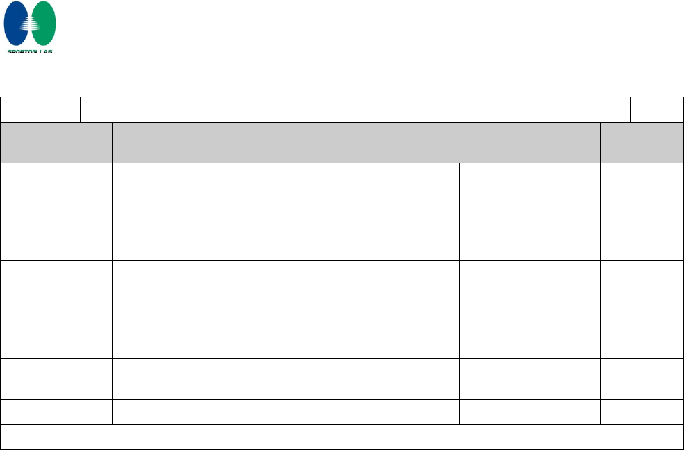
1.5.1
TABLE: list of critical components
Pass
object/part No.
manufacturer/
trademark
type/model
technical data
standard
mark(s) of
conformity
Adaptor
Dee Van
Enterprise
Co., Ltd.
DSC-6PFA-05
FEU 050100
I/p: 100-240 Vac,
50/60 Hz. 0.2 A;
o/p : 5Vdc, 1.0A.
Class II, 50 C,
L.P.S.
EN 60950-1:
2006+A11+A1
TUV Rh
(Certificate
No.: S1
50148464
006)
Dee Van
Enterprise
Co., Ltd.
DSA-12PFA-05
FEU-050200
I/p: 100-240 Vac,
50/60 Hz, 0.5A;
o/p : 5Vdc, 2.0A.
Class II, 40 C,
L.P.S.
EN 60950-1:
2006+A11+A1
TUV Rh
(Certificate
No.: S1
50195500)
PCB
--
--
Min. V-1, Min. 105
°C
UL 796
UL
Plastic Enclosure
--
--
HB min.
UL 94
UL
* Additional testing and evaluation may be required based on auditing agency’s discretion.
Page 28 of 39 Report No.:L181654L082
Sporton International Inc.
1.6.2
TABLE: electrical data (in normal conditions)
Pass
fuse #
Irated (A)
U (V)
P (W)
I (A)
Ifuse (A)
condition/status
--
1.0
5 Vdc
3.350
0.67
--
Max. Normal load.
Comments:
Maximum Normal Load: The equipment continuous communicated to other device via wireless, LAN ports and
WAN port and With each USB port loaded 2.5 W.
2.1.1.5
TABLE: max. V, A, VA test
N.A.
Voltage (rated)
(V)
Current (rated)
(A)
Voltage
(max.)
(V)
Current (max.)
(A)
VA (max.)
(VA)
Note(s)
2.1.1.7
TABLE: discharge test
N.A.
Condition
τ
calculated
(s)
τmeasured
(s)
tu → 0V
(s)
Comments
Note(s)
2.2.2
TABLE: Hazardous voltage measurement
N.A.
Transformer
Location
max. Voltage
Voltage Limitation
Componet
V peak
V d.c.
Note(s)
2.2.3
TABLE: SEL voltage measurement
N.A.
Location
Voltage measured (V)
Comments
Note(s)
2.4.2
TABLE: limited current circuit measurement
N.A.
Location
Voltage
(V)
Current
(mA)
Freq.
(kHz)
Limit
(mA)
Comments
Page 29 of 39 Report No.:L181654L082
Sporton International Inc.
Note(s)
2.5
TABLE: limited power source measurement
Pass
Limits
Measured
Verdict
For LAN port 1~4
According to Table 2B ( normal condition), Pin 1~8, Uoc =0 V
current (in A)
8
0
Pass
Apparent power (in VA)
100
0
Pass
For WAN port
According to Table 2B ( normal condition), Pin 1~8, Uoc = 0 V
current (in A)
8
0
Pass
Apparent power (in VA)
100
0
Pass
2.6.3.4
TABLE: ground continue test
N.A.
Location
Resistance measured(mΩ)
Comments
Note(s)
2.10.2
TABLE: working voltage measurement
N.A.
Location
RMS voltage (V)
Peak voltage (V)
Comments
Note(s)
2.10.3 and
2.10.4
TABLE: clearance and creepage distance measurements
N.A.
clearance cl and creepage
distance dcr at/of:
Up
(V)
U r.m.s. (V)
required cl
(mm)
cl (mm)
required dcr
(mm)
dcr
(mm)
Notes: Functional insulation only.
2.10.5
TABLE: distance through insulation measurements
N.A.
distance through insulation di at/of:
U r.m.s. (V)
test
voltage
(V)
required di
(mm)
di (mm)
Page 30 of 39 Report No.:L181654L082
Sporton International Inc.
Note(s)
4.3.8
TABLE: Batteries
N.A.
The tests of 4.3.8 are applicable only when appropriate battery
data is not available
--
N.A.
Is it possible to install the battery in a reverse polarity position?
--
--
Non-rechargeable batteries
Rechargeable batteries
Discharging
Un-intentiona
l charging
Charging
Discharging
Reversed charging
Meas.
Current
Manuf.
Specs.
Meas.
Current
Manuf.
Specs.
Meas.
Current
Manuf.
Specs.
Meas.
Current
Manuf.
Specs.
Max.
current
during
normal
condition
--
--
--
--
--
--
--
--
--
Max.
current
during
fault
condition
--
--
--
--
--
--
--
--
--
Test results:
Verdict
- Chemical leaks
N.A.
- Explosion of the battery
N.A.
- Emission of flame or expulsion of molten metal
N.A.
- Electric strength tests of equipment after completion of tests
N.A.
Supplementary information:
4.5
TABLE: maximum temperatures
Pass
test voltage (V) ...................................................... :
5Vdc
5Vdc
tamb1 (ºC) ................................................................ :
--
--
tamb2 (ºC) ................................................................ :
--
--
temperature rise dT of part/at:
T (ºC)
allowed Tmax
(ºC)
Test Sample
Type 2
Type 3
--
PCB near U17
51.2
56.3
105
PCB near U11
47.4
51.6
105
PCB near IC(RTL8192CE)
57.4
61.8
105
C255 body
45.1
47.4
105
L134 body
45.6
48.0
105
Plastic enclosure inside near IC (RTL8192CE)
46.2
50.6
--
Page 31 of 39 Report No.:L181654L082
Sporton International Inc.
Plastic enclosure outside near IC
(RTL8192CE)
44.2
47.9
95
Ambient
40.0(22.8)
40.0(22.9)
--
temperature T of winding:
R1 ()
R2 ()
dT (ºK)
allowed
Tmax (ºC)
insulation class
Supplementary information:
1) All values for T (ºC) are re-calculated from Tamb respectively.
2) The maximum ambient temperature specified by manufacturer is 40 ºC (Tma)
4.5.5
TABLE: ball pressure test of thermoplastics parts
N.A.
Allowed impression diameter (mm):
2 mm
part:
test temperature
(ºC)
impression diameter
(mm)
Note(s)
4.6.1, 4.6.2
TABLE: Enclosure openings
Pass
Location
Size(mm)
Comments
Type A enclosure
Top
10.8 x 0.2 max.
Numbers rectangle openings.
Side
11.1 x 1.2 max.
Numbers rectangle openings.
Bottom
7.6 x 0.2 max.
Numbers rectangle openings.
Type B enclosure
Side
5.2 x 1.1 max.
Numbers rectangle openings.
Bottom
17.5 x 1.6 max.
Numbers rectangle openings.
Note(s):
4.7
Table: Resistance to fire
N.A.
Part
Manufacturer of
material
Type of material
Thickness
(mm)
Flammability
class
Evidence
Note(s):
5.1.6
TABLE: touch current measurement
N.A.
Condition
L→terminal A
(mA)
N→terminal A
(mA)
Limit
Comments
Page 32 of 39 Report No.:L181654L082
Sporton International Inc.
Note(s)
5.2
TABLE: electric strength tests, impulse tests and voltage surge tests
N.A.
test voltage applied between:
Voltage shape (AC,
DC, impulse, surge
test voltage (V)
breakdown
Note(s)
5.3
TABLE: fault condition tests
Pass
ambient temperature (ºC) ..................................... :
See below.
model/type of power supply .................................. :
See appended table 1.5.1
manufacturer of power supply .............................. :
See appended table 1.5.1
rated markings of power supply ........................... :
See appended table 1.5.1
No.
component
No.
fault
test voltage
(V)
test time
fuse
No.
fuse current
(A)
result
1.
Ventilation
Openings
(Type 2)
Blocked
5Vdc
5 hr
--
--
Unit normal operation. No
hazardous. No damaged.
Max temperature:
PCB near IC(RTL8192)= 45.5ºC
Ambient =22.9ºC
2.
Ventilation
Openings
(Type 3)
Blocked
5Vdc
3 hr
--
--
Unit normal operation. No
hazardous. No damaged.
Max temperature:
PCB near IC(RTL8192)= 47.9ºC
Ambient =22.5ºC
Note(s)
Page 33 of 39 Report No.:L181654L082
Sporton International Inc.
EN 60950-1:2006 – CENELEC COMMON MODIFICATIONS
Contents
Add the following annexes:
Annex ZA (normative) Normative references to international publications with their
corresponding European publications
Annex ZB (normative) Special national conditions
Annex ZC (informative) A-deviations
Pass
General
Delete all the “country” notes in the reference document according to the following list:
1.4.8 Note 2 1.5.1 Note 2 & 3 1.5.7.1 Note
1.5.8 Note 2 1.5.9.4 Note 1.7.2.1 Note 4, 5 & 6
2.2.3 Note 2.2.4 Note 2.3.2 Note
2.3.2.1 Note 2 2.3.4 Note 2 2.6.3.3 Note 2 & 3
2.7.1 Note 2.10.3.2 Note 2 2.10.5.13 Note 3
3.2.1.1 Note 3.2.4 Note 3. 2.5.1 Note 2
4.3.6 Note 1 & 2 4.7 Note 4 4.7.2.2 Note
4.7.3.1 Note 2 5.1.7.1 Note 3 & 4 5.3.7 Note 1
6 Note 2 & 5 6.1.2.1 Note 2 6.1.2.2 Note
6.2.2 Note 6. 2.2.1 Note 2 6.2.2.2 Note
7.1 Note 3 7.2 Note 7.3 Note 1 & 2
G.2.1 Note 2 Annex H Note 2
Pass
1.3.Z1
Add the following subclause:
1.3.Z1 Exposure to excessive sound pressure
The apparatus shall be so designed and constructed as to present no danger when used
for its intended purpose, either in normal operating conditions or under fault conditions,
particularly providing protection against exposure to excessive sound pressures from
headphones or earphones.
NOTE Z1 A new method of measurement is described in EN 50332-1, Sound system equipment:
Headphones and earphones associated with portable audio equipment - Maximum sound pressure
level measurement methodology and limit considerations - Part 1: General method for “one
package equipment”, and in EN 50332-2, Sound system equipment: Headphones and earphones
associated with portable audio equipment - Maximum sound pressure level measurement
methodology and limit considerations - Part 2: Guidelines to associate sets with headphones
coming from different manufacturers.
N.A.

Page 34 of 39 Report No.:L181654L082
Sporton International Inc.
1.5.1
Add the following NOTE:
NOTE Z1 The use of certain substances in electrical and electronic equipment is restricted within
the EU: see Directive 2002/95/EC
N.A.
1.7.2.1
Add the following NOTE:
NOTE Z1 In addition, the instructions shall include, as far as applicable, a warning that excessive
sound pressure from earphones and headphones can cause hearing loss
N.A.
2.7.1
Replace the subclause as follows:
Basic requirements
To protect against excessive current, short-circuits and earth faults in PRIMARY
CIRCUITS, protective devices shall be included either as integral parts of the equipment
or as parts of the building installation, subject to the following, a), b) and c):
a) except as detailed in b) and c), protective devices necessary to comply with the
requirements of 5.3 shall be included as parts of the equipment;
b) for components in series with the mains input to the equipment such as the supply cord,
appliance coupler, r.f.i. filter and switch, short-circuit and earth fault protection may be
provided by protective devices in the building installation;
c) it is permitted for PLUGGABLE EQUIPMENT TYPE B or PERMANENTLY
CONNECTED EQUIPMENT, to rely on dedicated overcurrent and short-circuit protection
in the building installation, provided that the means of protection, e.g. fuses or circuit
breakers, is fully specified in the installation instructions.
If reliance is placed on protection in the building installation, the installation instructions
shall so state, except that for PLUGGABLE EQUIPMENT TYPE A the building installation
shall be regarded as providing protection in accordance with the rating of the wall socket
outlet.
N.A.
2.7.2
This subclause has been declared ‘void’.
N.A.
3.2.3
Delete the NOTE in Table 3A, and delete also in this table the conduit sizes in
parentheses.
N.A.
3.2.5.1
Replace “60245 IEC 53” by “H05 RR-F”;
“60227 IEC 52” by “H03 VV-F or H03 VVH2-F”;
“60227 IEC 53” by “H05 VV-F or H05 VVH2-F2”.
In Table 3B, replace the first four lines by the following:
| Up to and including 6 | 0,75 a) |
| Over 6 up to and including 10 | 0,75 b) 1,0 |
| Over 10 up to and including 16 | 1,0 c) 1,5 |
In the conditions applicable to Table 3B delete the words “in some countries” in condition
a).
In NOTE 1, applicable to Table 3B, delete the second sentence.
N.A.
3.3.4
In table 3D, delete the fourth line: conductor sizes for 10 to 13 A, and replace with the
following:
| Over 10 up to and including 16 | 1,5 to 2,5 | 1,5 to 4 |
Delete the fifth line – conductor sizes for 13 to 16 A.
N.A.
4.3.13.6
Add the following NOTE:
NOTE Z1 Attention is drawn to 1999/519/EC: Council Recommendation on the limitation of
exposure of the general public to electromagnetic fields 0 Hz to 300 GHz. Standards taking into
account this Recommendation which demonstrate compliance with the applicable EU Directive are
indicated in the OJEC.
N.A.

Page 35 of 39 Report No.:L181654L082
Sporton International Inc.
Annex H
Replace the last paragraph of this annex by:
At any point 10 cm from the surface of the OPERATOR ACCESS AREA, the dose rate
shall not exceed 1 μSv/h (0,1 mR/h) (see NOTE). Account is taken of the background
level.
Replace the notes as follows:
NOTE These values appear in Directive 96/29/Euratom.
Delete NOTE 2.
N.A.
Biblio-grap
hy
Additional EN standards.
ZA
NORMATIVE REFERENCES TO INTERNATIONAL PUBLICATIONS WITH THEIR
CORRESPONDING EUROPEAN PUBLICATIONS
N.A.
ZB
SPECIAL NATIONAL CONDITIONS
N.A.
1.2.4.1
In Denmark, certain types of Class I appliances
(see 3.2.1.1) may be provided with a plug not
establishing earthing conditions when inserted
into Danish socket-outlets.
N.A.
1.5.7.1
In Finland, Norway and Sweden, resistors bridging BASIC INSULATION in CLASS I
PLUGGABLE EQUIPMENT TYPE A must comply with the requirements in 1.5.7.2.
N.A.
1.5.8
In Norway, due to the IT power system used (see annex V, Figure V.7), capacitors are
required to be rated for the applicable line-to-line voltage (230 V).
N.A.
1.5.9.4
In Finland, Norway and Sweden, the third dashed sentence is applicable only to
equipment as defined in 6.1.2.2 of this annex.
N.A.
1.7.2.1
In Finland, Norway and Sweden, CLASS I PLUGGABLE EQUIPMENT TYPE A intended
for connection to other equipment or a network shall, if safety relies on connection to
protective earth or if surge suppressors are connected between the network terminals and
accessible parts, have a marking stating that the equipment must be connected to an
earthed mains socket-outlet.
The marking text in the applicable countries shall be as follows:
In Finland: "Laite on liitettävä suojamaadoituskoskettimilla varustettuun pistorasiaan"
In Norway: “Apparatet må tilkoples jordet stikkontakt”
In Sweden: “Apparaten skall anslutas till jordat uttag”
N.A.
1.7.5
In Denmark, socket-outlets for providing power to other equipment shall be in accordance
with the Heavy Current Regulations, Section 107-2-D1, Standard Sheet DK 1-3a, DK 1-5a
or DK 1-7a, when used on Class I equipment. For STATIONARY EQUIPMENT the
socket-outlet shall be in accordance with Standard Sheet DK 1-1b or DK 1-5a.
N.A.
2.2.4
In Norway, for requirements see 1.7.2.1, 6.1.2.1 and 6.1.2.2 of this annex.
N.A.
2.3.2
In Finland, Norway and Sweden there are additional requirements for the insulation. See
6.1.2.1 and 6.1.2.2 of this annex.
N.A.
2.3.4
In Norway, for requirements see 1.7.2.1, 6.1.2.1 and 6.1.2.2 of this annex.
N.A.
2.6.3.3
In the United Kingdom, the current rating of the circuit shall be taken as 13 A, not 16 A.
N.A.
2.7.1
In the United Kingdom, to protect against excessive currents and short-circuits in the
PRIMARY CIRCUIT of DIRECT PLUG-IN EQUIPMENT, tests according to 5.3 shall be
conducted, using an external protective device rated 30 A or 32 A. If these tests fail,
suitable protective devices shall be included as integral parts of the DIRECT PLUG-IN
EQUIPMENT, so that the requirements of 5.3 are met.
N.A.

Page 36 of 39 Report No.:L181654L082
Sporton International Inc.
2.10.5.13
In Finland, Norway and Sweden, there are additional requirements for the insulation, see
6.1.2.1 and 6.1.2.2 of this annex.
N.A.
3.2.1.1
In Switzerland, supply cords of equipment having a RATED CURRENT not exceeding 10
A shall be provided with a plug complying with SEV 1011 or IEC 60884-1 and one of the
following dimension sheets:
SEV 6532-2.1991 Plug Type 15 3P+N+PE 250/400 V, 10 A
SEV 6533-2.1991 Plug Type 11 L+N 250 V, 10 A
SEV 6534-2.1991 Plug Type 12 L+N+PE 250 V, 10 A
In general, EN 60309 applies for plugs for currents exceeding 10 A. However, a 16 A plug
and socket-outlet system is being introduced in Switzerland, the plugs of which are
according to the following dimension sheets, published in February 1998:
SEV 5932-2.1998 Plug Type 25 3L+N+PE 230/400 V, 16 A
SEV 5933-2.1998 Plug Type 21 L+N 250 V, 16 A
SEV 5934-2.1998 Plug Type 23 L+N+PE 250 V, 16 A
N.A.
3.2.1.1
In Denmark, supply cords of single-phase equipment having a rated current not
exceeding13 A shall be provided with a plug according to the Heavy Current Regulations,
Section 107-2-D1.
CLASS I EQUIPMENT provided with socket-outlets with earth contacts or which are
intended to be used in locations where protection against indirect contact is required
according to the wiring rules shall be provided with a plug in accordance with standard
sheet DK 2-1a or DK 2-5a.
If poly-phase equipment and single-phase equipment having a RATED CURRENT
exceeding 13 A is provided with a supply cord with a plug, this plug shall be in accordance
with the Heavy Current Regulations, Section 107-2-D1 or EN 60309-2.
N.A.
3.2.1.1
In Spain, supply cords of single-phase equipment having a rated current not exceeding 10
A shall be provided with a plug according to UNE 20315:1994.
Supply cords of single-phase equipment having a rated current not exceeding 2,5 A shall
be provided with a plug according to UNE-EN 50075:1993.
CLASS I EQUIPMENT provided with socket-outlets with earth contacts or which are
intended to be used in locations where protection against indirect contact is required
according to the wiring rules, shall be provided with a plug in accordance with standard
UNE 20315:1994.
If poly-phase equipment is provided with a supply cord with a plug, this plug shall be in
accordance with UNE-EN 60309-2.
N.A.
3.2.1.1
In the United Kingdom, apparatus which is fitted with a flexible cable or cord and is
designed to be connected to a mains socket conforming to BS 1363 by means of that
flexible cable or cord and plug, shall be fitted with a ‘standard plug’ in accordance with
Statutory Instrument 1768:1994 - The Plugs and Sockets etc. (Safety) Regulations 1994,
unless exempted by those regulations.
NOTE ‘Standard plug’ is defined in SI 1768:1994 and essentially means an approved plug
conforming to BS 1363 or an approved conversion plug.
N.A.
3.2.1.1
In Ireland, apparatus which is fitted with a flexible cable or cord and is designed to be
connected to a mains socket conforming to I.S. 411 by means of that flexible cable or cord
and plug, shall be fitted with a 13 A plug in accordance with Statutory Instrument 525:1997
- National Standards Authority of Ireland (section 28) (13 A Plugs and Conversion
Adaptors for Domestic Use) Regulations 1997.
N.A.
3.2.4
In Switzerland, for requirements see 3.2.1.1 of this annex.
N.A.
3.2.5.1
In the United Kingdom, a power supply cord with conductor of 1,25 mm2 is allowed for
equipment with a rated current over 10 A and up to and including 13 A.
N.A.

Page 37 of 39 Report No.:L181654L082
Sporton International Inc.
3.3.4
In the United Kingdom, the range of conductor sizes of flexible cords to be accepted by
terminals for equipment with a RATED CURRENT of over 10 A up to and including 13 A
is:
• 1,25 mm2 to 1,5 mm2 nominal cross-sectional area.
N.A.
4.3.6
In the United Kingdom, the torque test is performed using a socket outlet complying with
BS 1363 part 1:1995, including Amendment 1:1997 and Amendment 2:2003 and the plug
part of DIRECT PLUG-IN EQUIPMENT shall be assessed to BS 1363: Part 1, 12.1, 12.2,
12.3, 12.9, 12.11, 12.12, 12.13, 12.16 and 12.17, except that the test of 12.17 is
performed at not less than 125 °C. Where the metal earth pin is replaced by an Insulated
Shutter Opening Device (ISOD), the requirements of clauses 22.2 and 23 also apply.
N.A.
4.3.6
In Ireland, DIRECT PLUG-IN EQUIPMENT is known as plug similar devices. Such
devices shall comply with Statutory Instrument 526:1997 - National Standards Authority of
Ireland (Section 28) (Electrical plugs, plug similar devices and sockets for domestic use)
Regulations, 1997.
N.A.
5.1.7.1
In Finland, Norway and Sweden TOUCH CURRENT measurement results exceeding
3,5 mA r.m.s. are permitted only for the following equipment:
• STATIONARY PLUGGABLE EQUIPMENT TYPE A that
- is intended to be used in a RESTRICTED ACCESS LOCATION where
equipotential bonding has been applied, for example, in a telecommunication
centre; and
- has provision for a permanently connected PROTECTIVE EARTHING
CONDUCTOR; and
- is provided with instructions for the installation of that conductor by a
SERVICE PERSON;
• STATIONARY PLUGGABLE EQUIPMENT TYPE B;
• STATIONARY PERMANENTLY CONNECTED EQUIPMENT.
N.A.

Page 38 of 39 Report No.:L181654L082
Sporton International Inc.
6.1.2.1
In Finland, Norway and Sweden, add the following text between the first and second
paragraph of the compliance clause:
If this insulation is solid, including insulation forming part of a component, it shall at least
consist of either
- two layers of thin sheet material, each of
which shall pass the electric
strength test below, or
- one layer having a distance through
insulation of at least 0,4 mm, which shall pass the electric strength test
below.
If this insulation forms part of a semiconductor component (e.g. an optocoupler), there is
no distance through insulation requirement for the insulation consisting of an insulating
compound completely filling the casing, so that CLEARANCES and CREEPAGE
DISTANCES do not exist, if the component passes the electric strength test in accordance
with the compliance clause below and in addition
-passes the tests and inspection criteria of 2.10.11 with an electric strength
test of 1,5 kV multiplied by 1,6 (the electric strength test of 2.10.10 shall be
performed using 1,5 kV), and
-is subject to ROUTINE TESTING for electric strength during manufacturing,
using a test voltage of 1,5 kV.It is permitted to bridge this insulation with a capacitor
complying with EN 132400:1994, subclass Y2.
A capacitor classified Y3 according to EN 132400:1994, may bridge this insulation under
the following conditions:
-the insulation requirements are satisfied by having a capacitor classified Y3
as defined by EN 132400, which in addition to the Y3 testing, is tested with
an impulse test of 2,5 kV defined in EN 60950-1:2006, 6.2.2.1;
-the additional testing shall be performed on all the test specimens as
described in EN 132400;
-the impulse test of 2,5 kV is to be performed before the endurance test in EN 132400, in
the sequence of tests as described in EN 132400.
N.A.
6.1.2.2
In Finland, Norway and Sweden, the exclusions are applicable for PERMANENTLY
CONNECTED EQUIPMENT, PLUGGABLE EQUIPMENT TYPE B and equipment
intended to be used in a RESTRICTED ACCESS LOCATION where equipotential bonding
has been applied, e.g. in a telecommunication centre, and which has provision for a
permanently connected PROTECTIVE EARTHING CONDUCTOR and is provided with
instructions for the installation of that conductor by a SERVICE PERSON.
N.A.
7.2
In Finland, Norway and Sweden, for requirements see 6.1.2.1 and 6.1.2.2 of this annex.
The term TELECOMMUNICATION NETWORK in 6.1.2 being replaced by the term
CABLE DISTRIBUTION SYSTEM.
N.A.
7.3
In Norway and Sweden, there are many buildings where the screen of the coaxial cable
is normally not connected to the earth in the building installation.
N.A.
7.3
In Norway, for installation conditions see EN 60728-11:2005.
N.A.
ZC
A-DEVIATIONS (informative)
N.A.
1.5.1
Sweden (Ordinance 1990:944)
Add the following:
NOTE In Sweden, switches containing mercury are not permitted.
N.A.
Page 39 of 39 Report No.:L181654L082
Sporton International Inc.
1.5.1
Switzerland (Ordinance on environmentally hazardous substances SR 814.081, Annex
1.7, Mercury - Annex 1.7 of SR 814.81 applies for mercury.)
Add the following:
NOTE In Switzerland, switches containing mercury such as thermostats, relays and level controllers
are not allowed.
N.A.
1.7.2.1
Denmark (Heavy Current Regulations)
Supply cords of CLASS I EQUIPMENT, which is delivered without a plug, must be
provided with a visible tag with the following text:
Vigtigt!
Lederen med grøn/gul isolation
må kun tilsluttes en klemme mæ rket
eller
If essential for the safety of the equipment, the tag must in addition be provided with a
diagram, which shows the connection of the other conductors, or be provided with the
following text:
“For tilslutning af de øvrige ledere, se medfølgende installationsvejledning.”
N.A.
1.7.2.1
Germany (Gesetz über technische Arbeitsmittel und Verbraucherprodukte (Geräte- und
Produktsicherheitsgesetz – GPSG) [Law on technical labour equipment and consumer
products], of 6th January 2004, Section 2, Article 4, Clause (4), Item 2).
If for the assurance of safety and health certain rules during use, amending or
maintenance of a technical labour equipment or readymade consumer product are to be
followed, a manual in German language has to be delivered when placing the product on
the market.
Of this requirement, rules for use even only by SERVICE PERSONS are not exempted.
N.A.
1.7.5
Denmark (Heavy Current Regulations)
With the exception of CLASS II EQUIPMENT provided with a socket outlet in accordance
with the Heavy Current Regulations, Section 107-2-D1, Standard Sheet DK 1-4a, CLASS
II EQUIPMENT shall not be fitted with socket-outlets for providing power to other
equipment.
N.A.
1.7.13
Switzerland (Ordinance on chemical hazardous risk reduction SR 814.81, Annex 2.15
Batteries)
Annex 2.15 of SR 814.81 applies for batteries.
N.A.
5.1.7.1
Denmark (Heavy Current Regulations, Chapter 707, clause 707.4)
TOUCH CURRENT measurement results exceeding 3,5 mA r.m.s. are permitted only for
PERMANENTLY CONNECTED EQUIPMENT and PLUGGABLE EQUIPMENT TYPE B.
N.A.
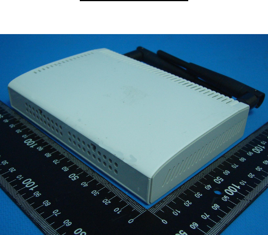
Page 1 Report No.: L181654L082
Sporton International Inc.
Appendix – Photo
Type 1
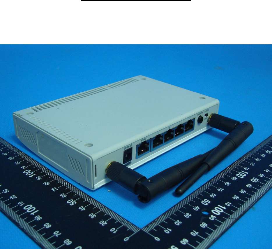
Page 2 Report No.: L181654L082
Sporton International Inc.
Appendix – Photo

Page 3 Report No.: L181654L082
Sporton International Inc.
Appendix – Photo
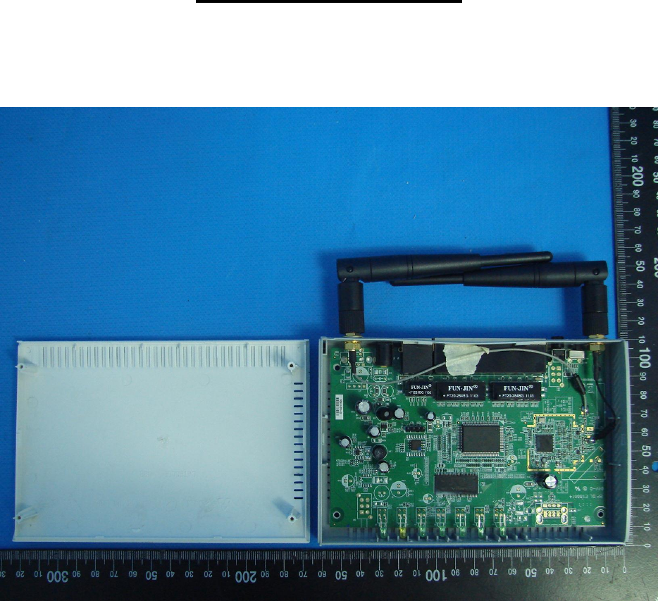
Page 4 Report No.: L181654L082
Sporton International Inc.
Appendix – Photo
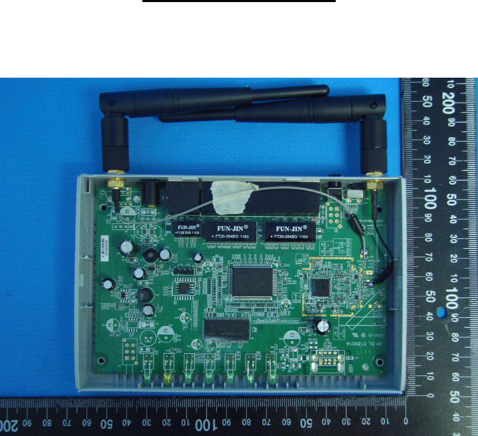
Page 5 Report No.: L181654L082
Sporton International Inc.
Appendix – Photo
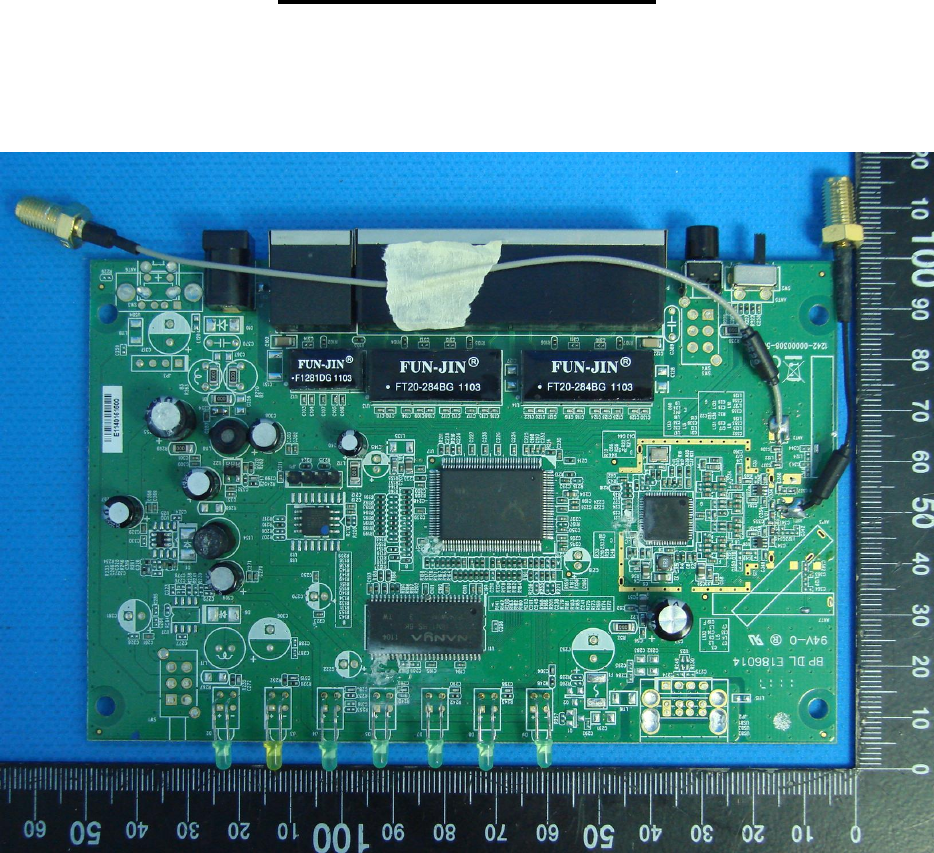
Page 6 Report No.: L181654L082
Sporton International Inc.
Appendix – Photo
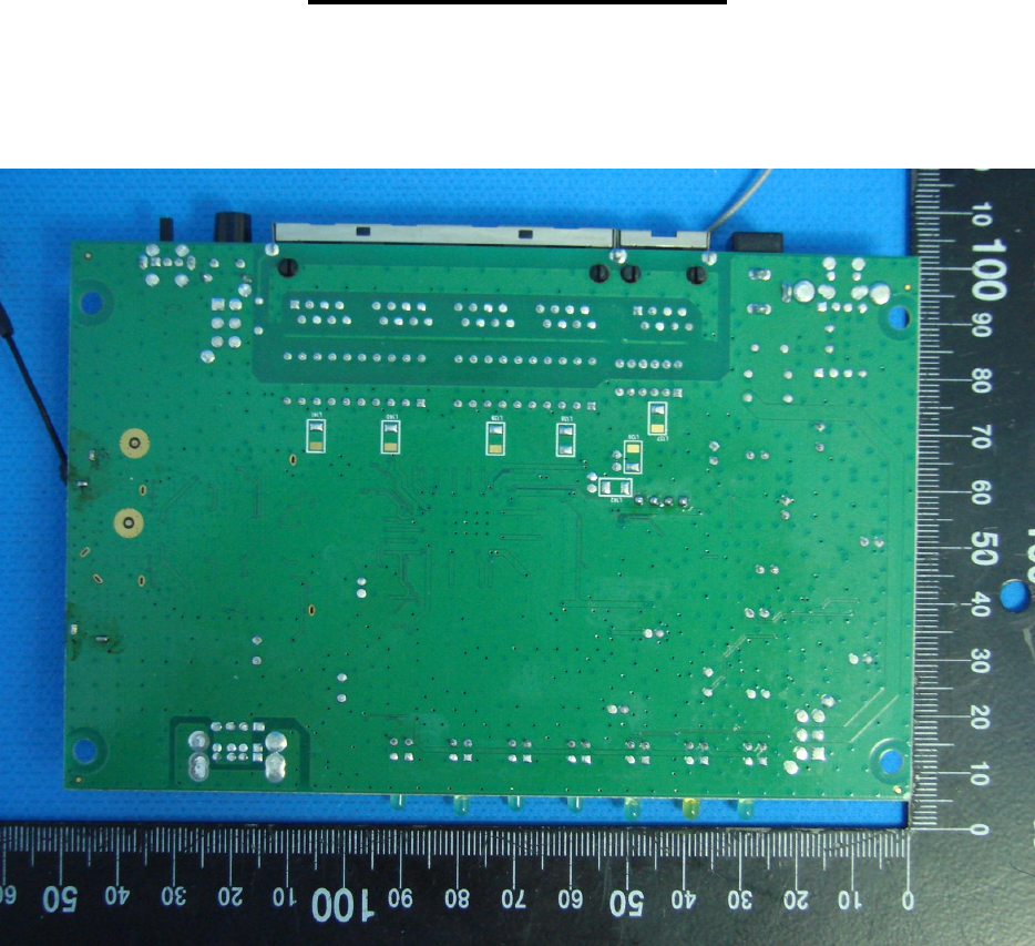
Page 7 Report No.: L181654L082
Sporton International Inc.
Appendix – Photo
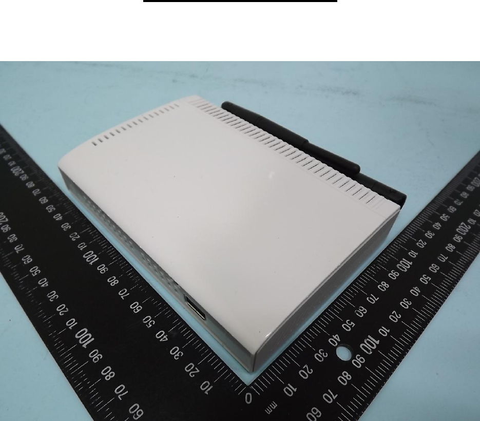
Page 8 Report No.: L181654L082
Sporton International Inc.
Appendix – Photo
Type 2
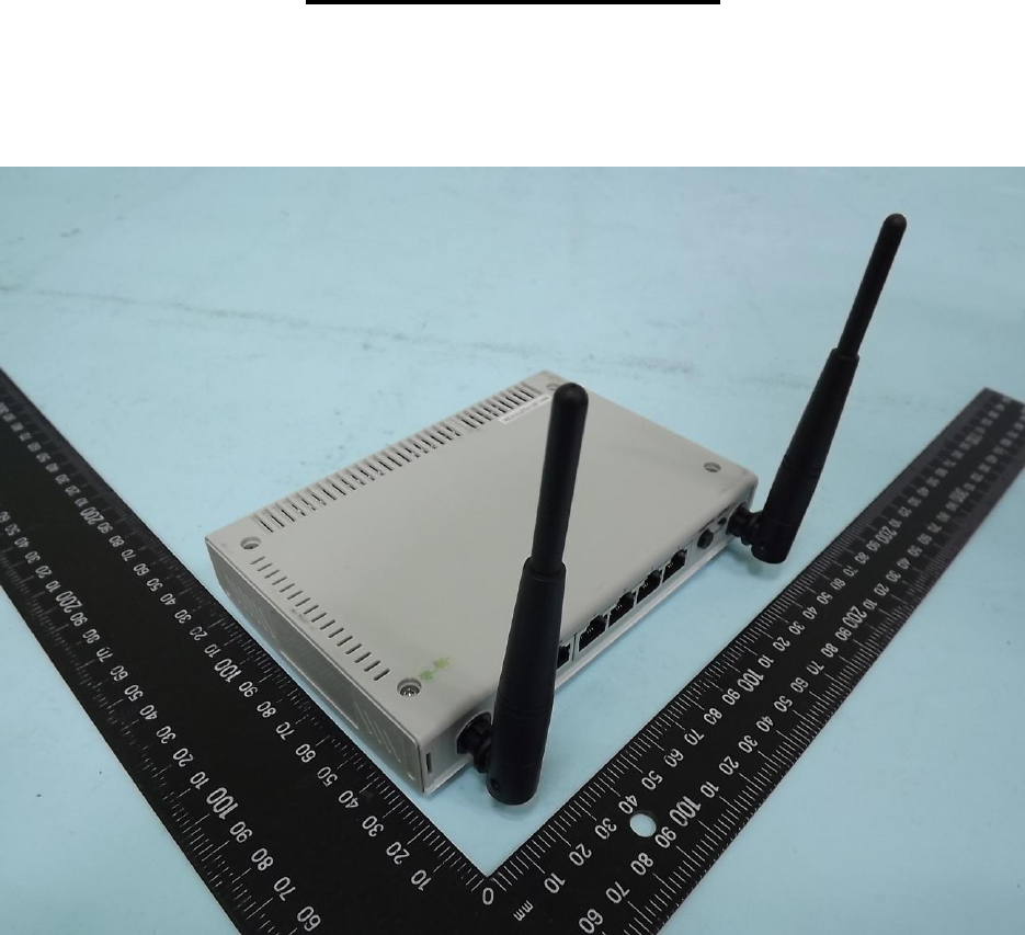
Page 9 Report No.: L181654L082
Sporton International Inc.
Appendix – Photo
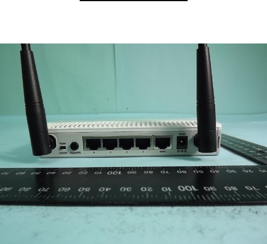
Page 10 Report No.: L181654L082
Sporton International Inc.
Appendix – Photo
Page 11 Report No.: L181654L082
Sporton International Inc.
Appendix – Photo
Page 12 Report No.: L181654L082
Sporton International Inc.
Appendix – Photo
Page 13 Report No.: L181654L082
Sporton International Inc.
Appendix – Photo
Page 14 Report No.: L181654L082
Sporton International Inc.
Appendix – Photo
Type 2 (different antenna)
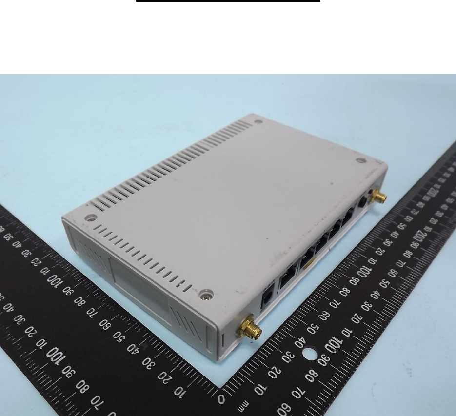
Page 15 Report No.: L181654L082
Sporton International Inc.
Appendix – Photo
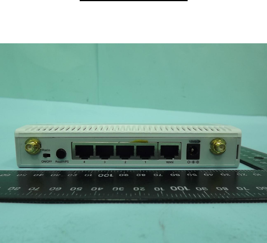
Page 16 Report No.: L181654L082
Sporton International Inc.
Appendix – Photo
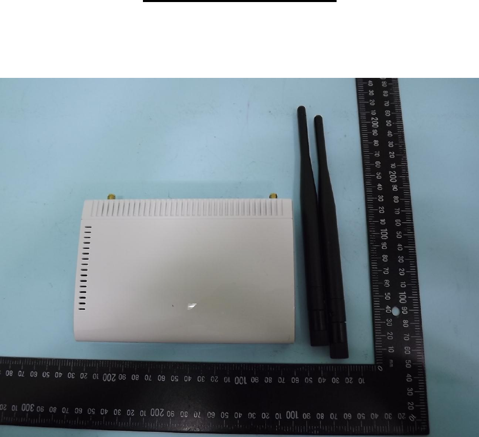
Page 17 Report No.: L181654L082
Sporton International Inc.
Appendix – Photo

Page 18 Report No.: L181654L082
Sporton International Inc.
Appendix – Photo
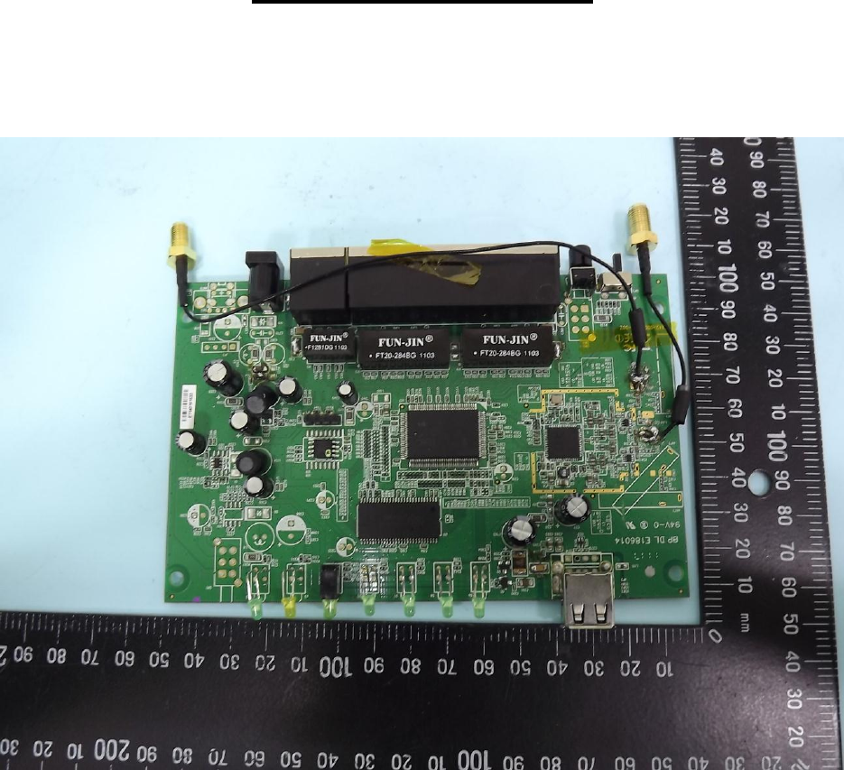
Page 19 Report No.: L181654L082
Sporton International Inc.
Appendix – Photo
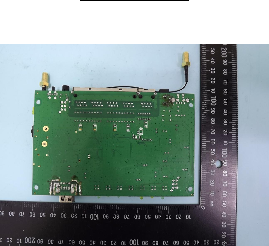
Page 20 Report No.: L181654L082
Sporton International Inc.
Appendix – Photo

Page 21 Report No.: L181654L082
Sporton International Inc.
Appendix – Photo
Type 3
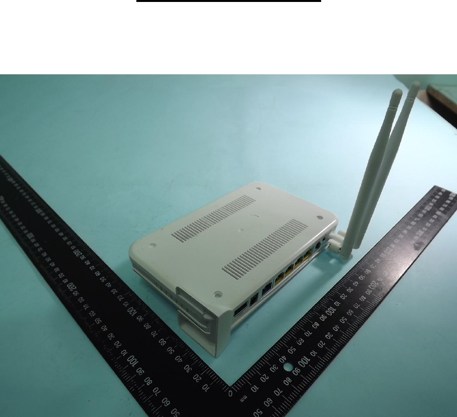
Page 22 Report No.: L181654L082
Sporton International Inc.
Appendix – Photo
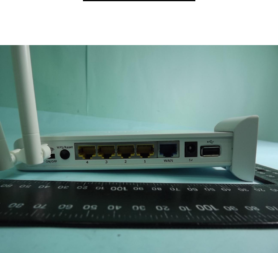
Page 23 Report No.: L181654L082
Sporton International Inc.
Appendix – Photo
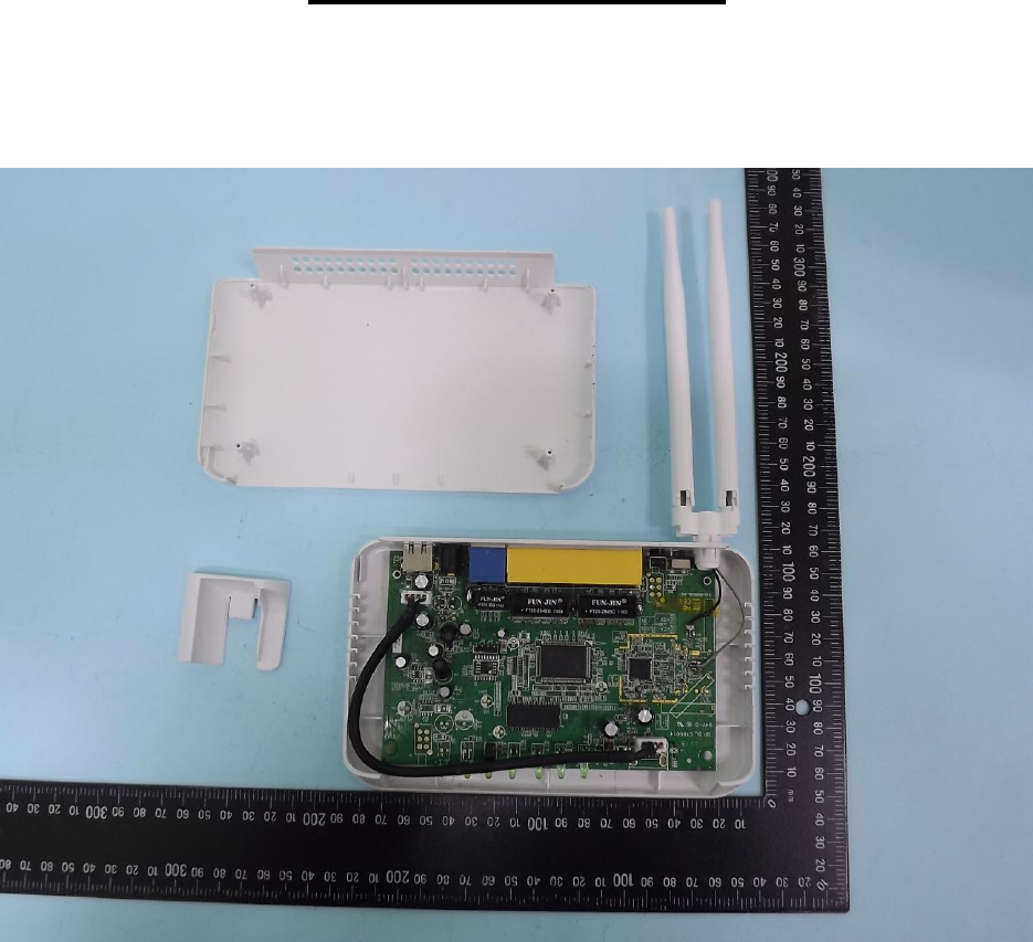
Page 24 Report No.: L181654L082
Sporton International Inc.
Appendix – Photo
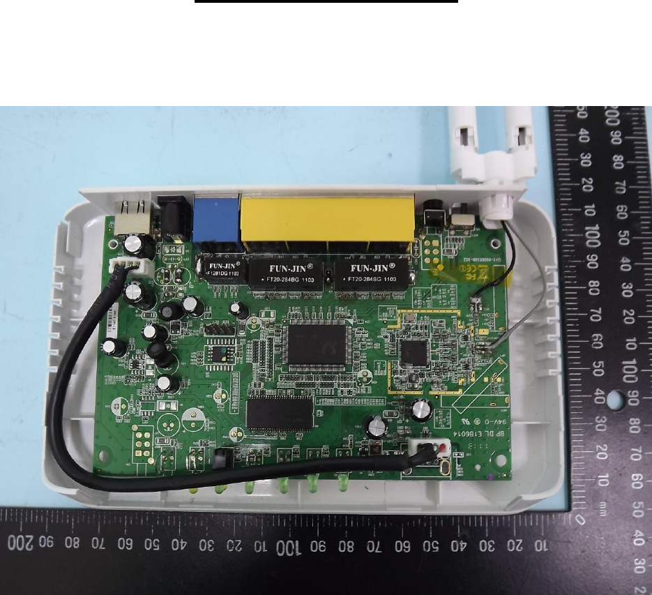
Page 25 Report No.: L181654L082
Sporton International Inc.
Appendix – Photo
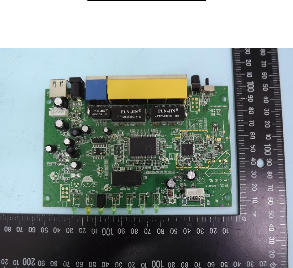
Page 26 Report No.: L181654L082
Sporton International Inc.
Appendix – Photo
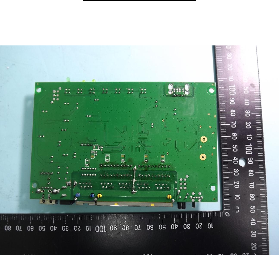
Page 27 Report No.: L181654L082
Sporton International Inc.
Appendix – Photo
