Robot Studio Guide Matlab Control
User Manual: Pdf
Open the PDF directly: View PDF ![]() .
.
Page Count: 28

1
Guide for ABB RobotStudio
This guide explains step-by-step the process of setting up a robot cell in RobotStudio that can be controlled
from Matlab
by
Michael Natapon Hansson
Department of Mechanical and Manufacturing Engineering, Aalborg University
January 2016

2
Content
Setting Up and Controlling a Robot in RobotStudio from Matlab ..................................................................... 3
Setting Up RobotStudio Controller to Enable TCP/IP Connection ................................................................. 3
Setting Up a Server in RobotStudio ................................................................................................................ 5
Setting Up a Client in Matlab ....................................................................................................................... 15
Using the Matlab Client to Control a Robot in RobotStudio ........................................................................ 16
Setting Up and Controlling a Gripper in RobotStudio from Matlab ................................................................ 19
Setting up and using a camera in RobotStudio from Matlab ........................................................................... 23
3
Setting Up and Controlling a Robot in RobotStudio from Matlab
This guide will show how to enable and use Matlab to control a robot system in RobotStudio through a
TCP/IP connection. This guide will have its outset in some already developed components for both Matlab
and RobotStudio, which consist of a client class for Matlab and a collection of Rapid modules that together
will serve as a server in RobotStudio.
Setting Up RobotStudio Controller to Enable TCP/IP Connection
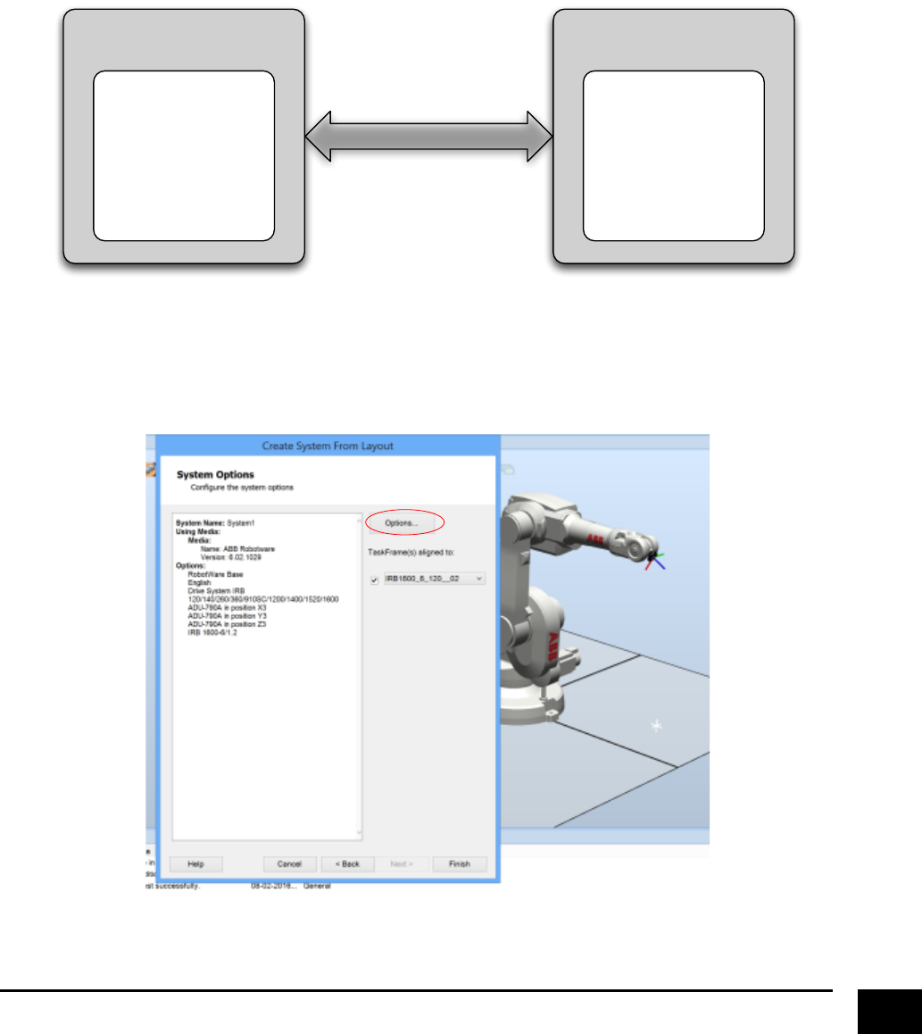
The first thing we need to do is to setup a robot controller in RobotStudio to allow a connection through
TCP/IP. When importing a robot and creating a system, go to the “Options” panel.
RobotStudioConnector
Matlab
Cl ass
CommandHandler
ConnectionHandler
FunctionHandler
InitParameters
RobotStudio
Rapid Modules
ServerClient
TCP/ IP Socket
4
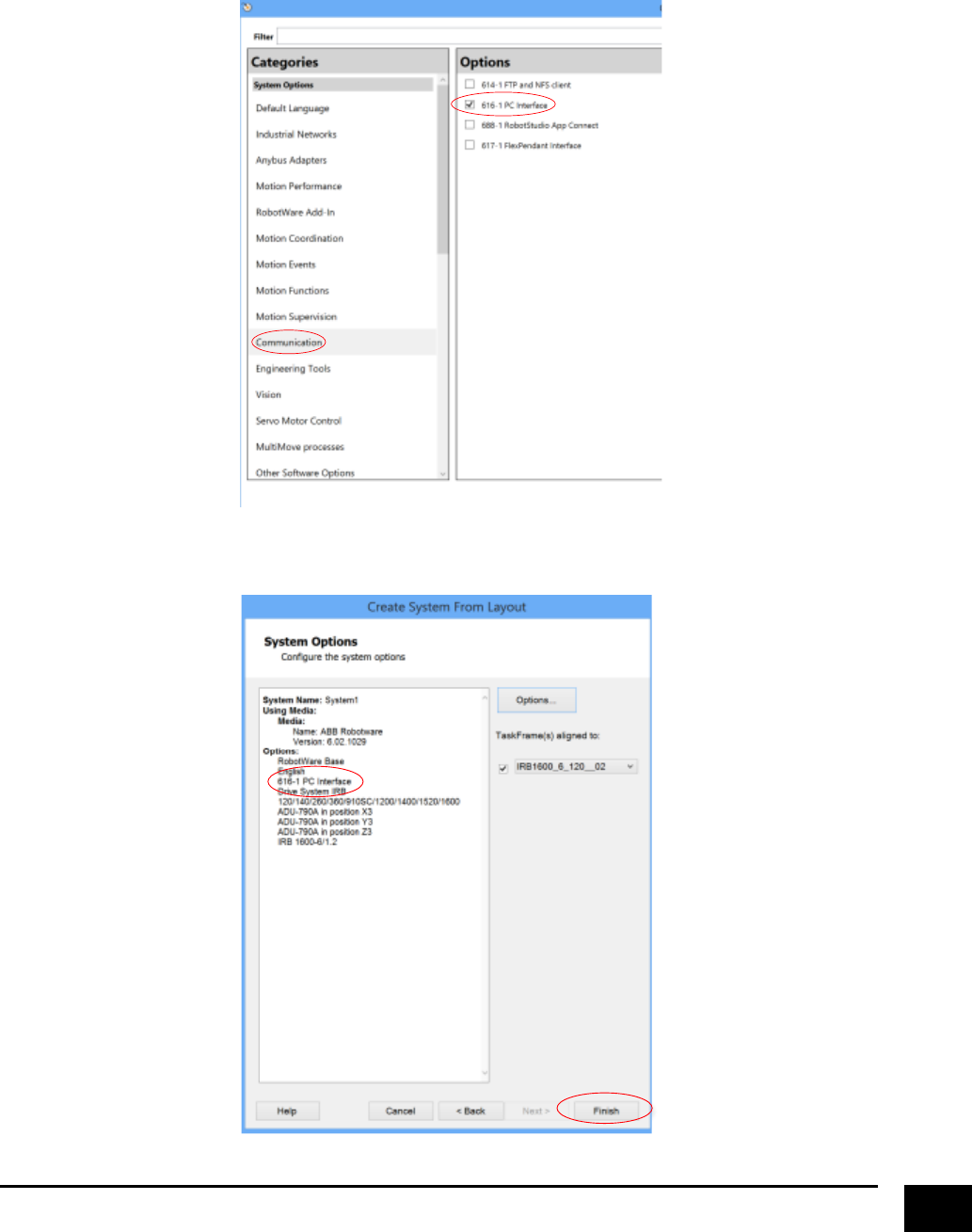
Next, go to “Communication” and select “PC-Interface”, which will enable a PC application (e.g. Matlab) to
communicate with a robot controller over an Ethernet network.
After clicking “Close”, you should be able to see that “PC-Interface” is added as part of the system. You are
now able to connect to the controller trough TCP/IP, so just click “Finish”.
5
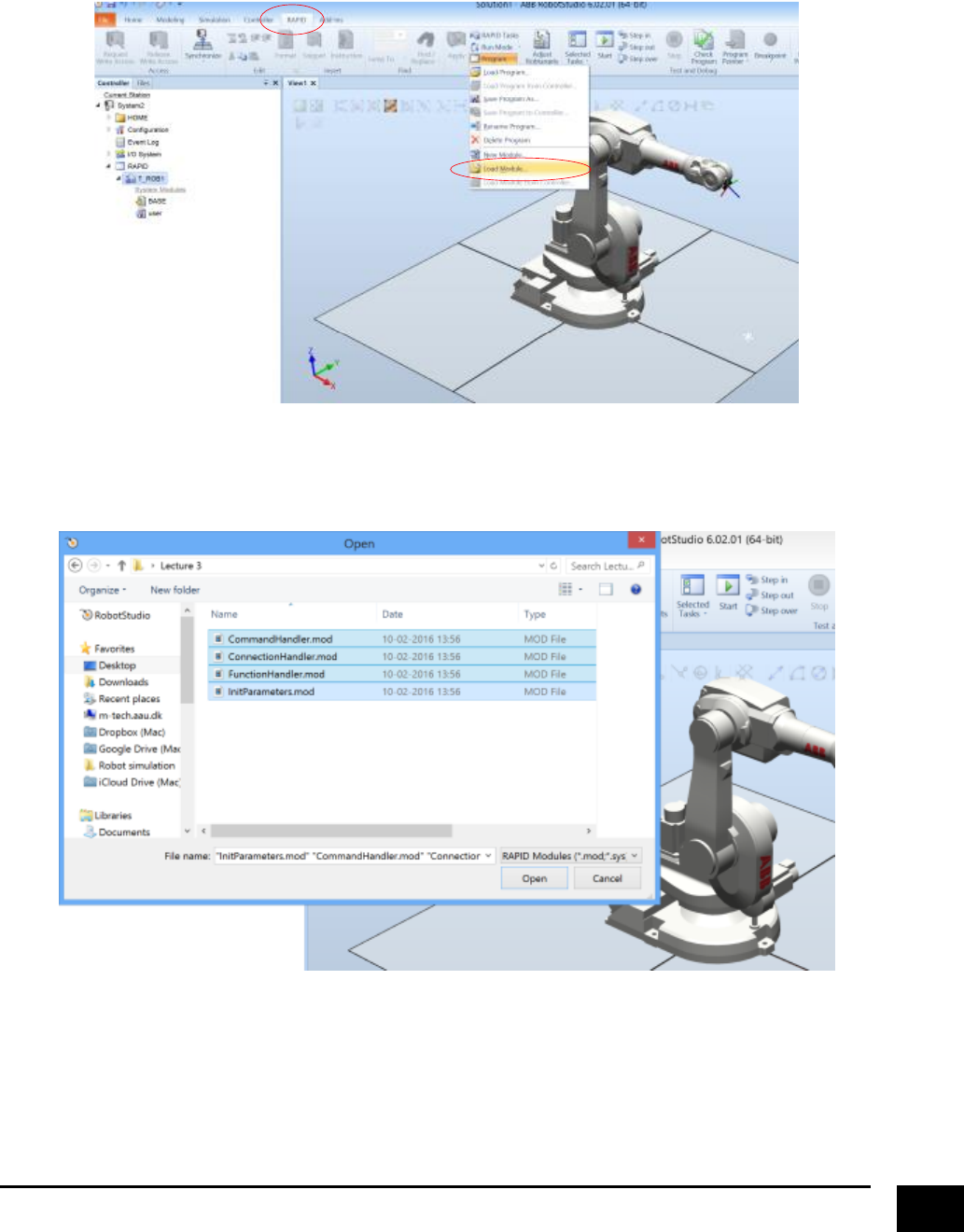
Setting Up a Server in RobotStudio
As mentioned earlier, we will make use of some already defined modules that contains the functionality
needed to create a server. So go to the “RAPID” tab, click on “Program” and select “Load Module”.
Locate and load the four modules “CommandHandler”, “ConnectionHandler”, “FunctionHandler” and
“InitParameters”. From this point this collection of modules we be referred to as “server modules”.
6
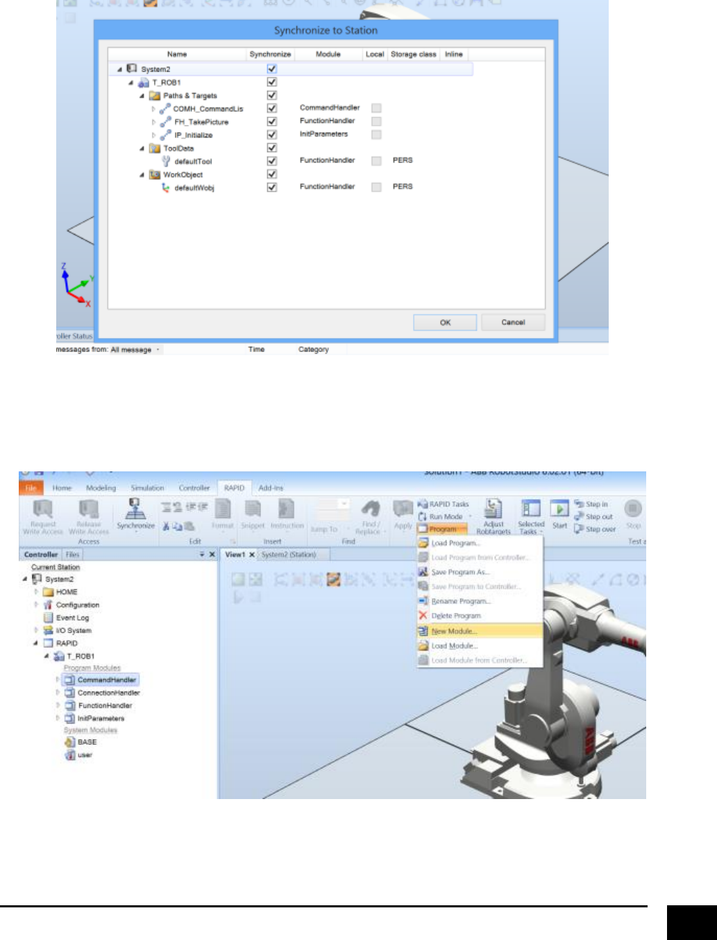
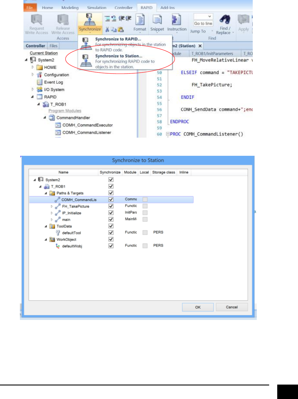
Afterwards you will be asked if you want to synchronise the server modules with the station. Mark all and
click “OK”.
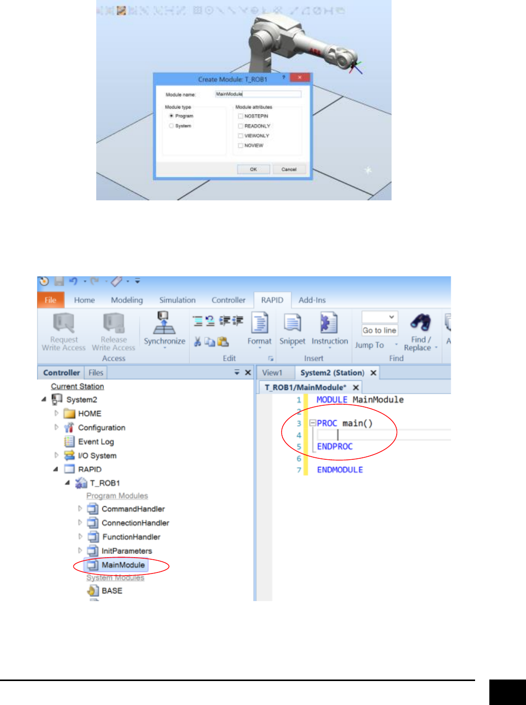
The next thing to do is to make use of the server modules, since they only contain the necessary
functionality to create a server, but not actually doing anything yet. So click on “Program” again and select
“New Module”.
7
Give the new module whatever name you like.
The purpose of the created module is to contain a program that will function as a “main” program, which
will be the entry point when running the system. So double click on the created module and make a
program called “main” (or whatever you like).
8
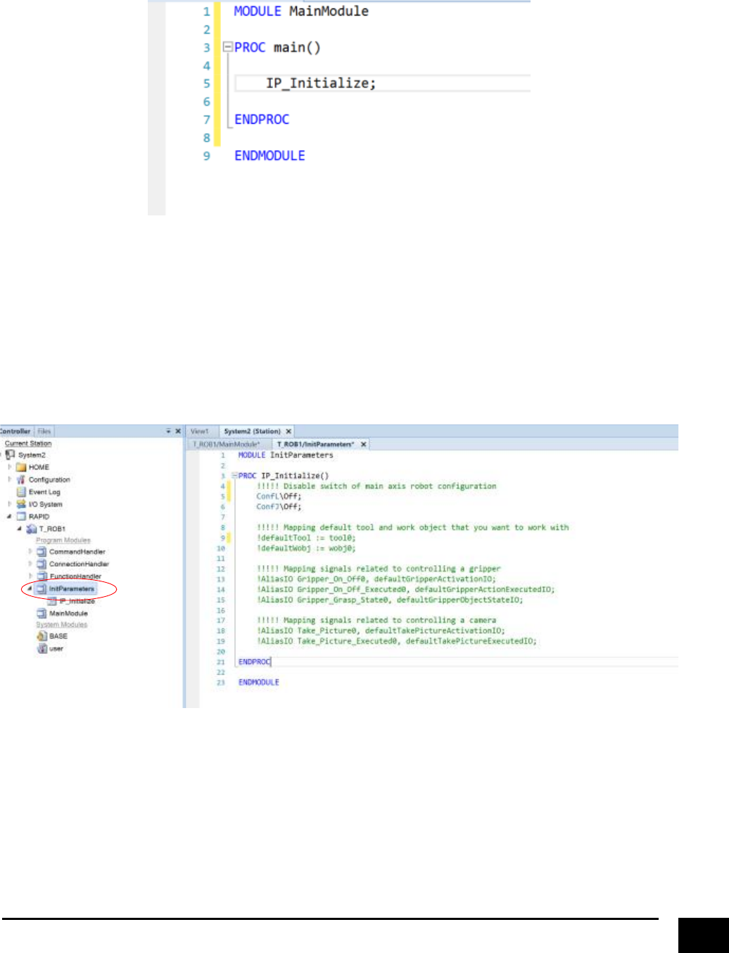
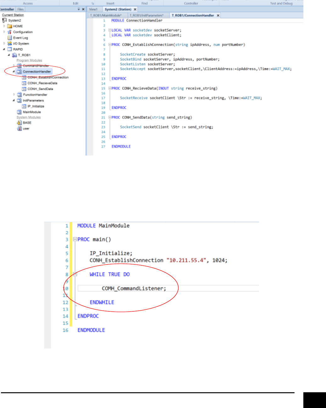
The first functionality we will make use of from the server modules is from the “InitParameters” module. So
write the following in the “main” program.
Double click on “InitParameters” to take a closer look at the “IP_Initialize” program. As you can see the
purpose of “IP_Initialize” is to set up parameters such as disabling switching of main axis configuration
during linear or joint movement, specifying which tool- and work object that will be our frame references,
and mapping signals to control a gripper and controlling a camera. Setting up and controlling a gripper and
a camera will be explained later in this guide, since we right now only focuses on the robot. For controlling
the robot, we need to specify the tool and work object that we want to work with.
9
So modify “IP_Initialize” to look like this (removing the exclamation marks), where “tool0” and “wobj0” are
referring to the default TCP point and base frame of the robot we imported. If you make a custom work
object that you want to use instead, remember to specify that in “IP_Initialize”.
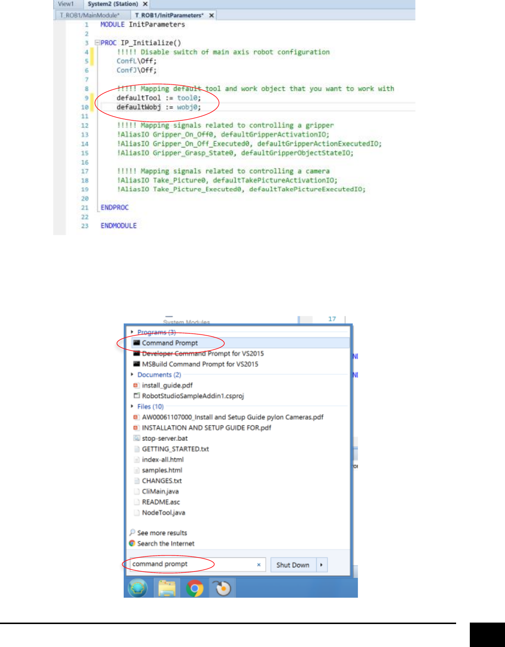
The next thing we want to do is to configure and launch a TCP/IP server in RobotStudio, but before we can
do that we need to know what specific IP address our computer has been given. Open the windows
“Command Prompt”
10
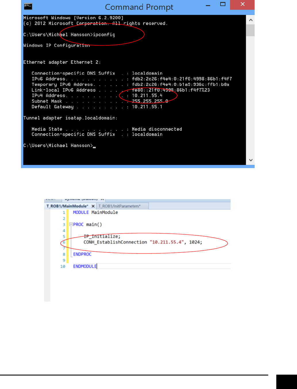
In the command prompt write “ipconfig” and hit enter/return. In this case, the IP address that has been
given to the computer is 10.211.55.4.
Go back to the “main” program and write the following.
IP address port number
11
Double click on “ConnectionHandler” and take a closer look at “CONH_EstablishConnection”. As you can
see the “CONH_EstablishConnection” program is responsible for setting up a TCP/IP server and wait to just
wait until a client connects to the server. The other programs included in the “ConnectionHandler” module
is to read and send messages between the server and a client.
The last thing we need to do before the server is set up to enable controlling a robot, is to insert a listener
that translates messages into actions that is to be executed. Furthermore, we want the listener to run in a
loop so that the program keeps running. So go back to “main” program and write the following.
12
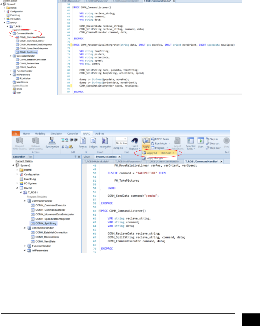
Double click on “CommandHandler” and take a closer look at “COMH_CommandListener”. As you can see,
the “COMH_CommandListener” is reading the messages send by a client, extracting the command and the
associated data to the command, and finally calling “COMH_CommandExecutor”, which initiates the action
related to the command.
Since we did make some changes to the programs we need to save these changes, so click on “Apply” and
select “Apply All”.
13
Remember to synchronise to station
14
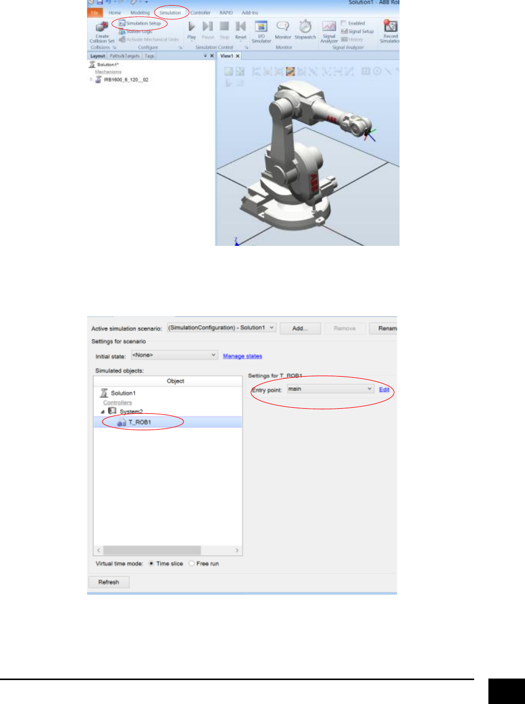
Go to the “Simulation” tab and click on “Simulation Setup”.
Make sure that the “Entry Point” is to the “main” program that has been created. This concludes setting up
the RobotStudio server for now.
15
Setting Up a Client in Matlab
As for RobotStudio, a client class has already been made that’s able to communicate with the server
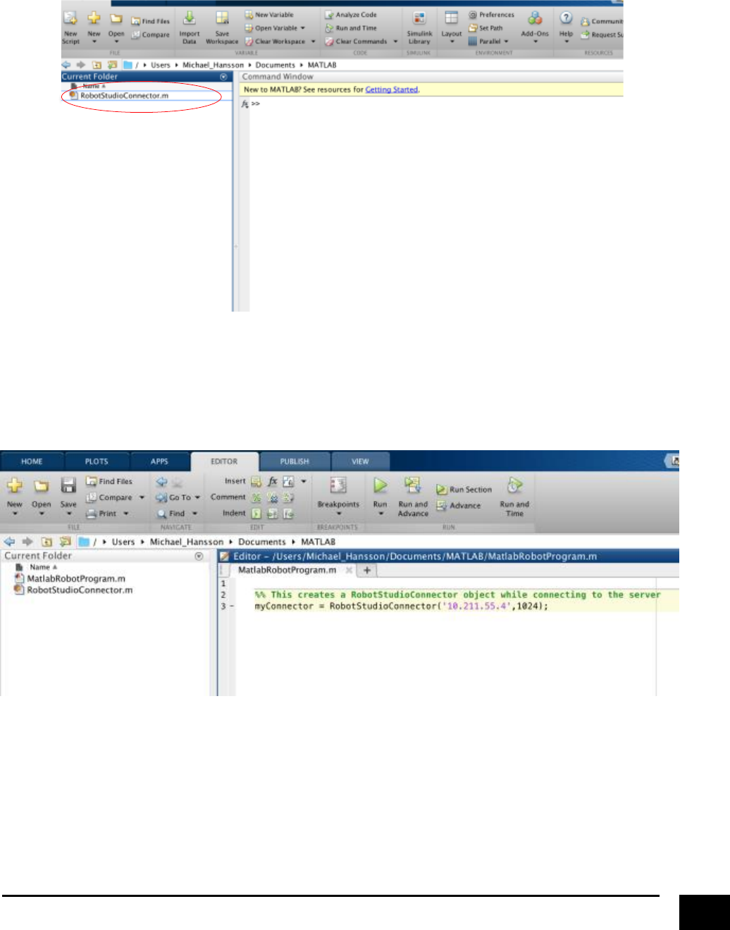
modules. So place “RobotStudioConnector.m” in your work folder.
Create a new script and create a “RobotStudioConnector” object. As you can see, “RobotStudioConnector”
requires to be given arguments in the form of IP address and port number, so that it knows where the
location of the server is. Not much had to be done, but the Matlab client is now set up to communicate
with the server.
16
Using the Matlab Client to Control a Robot in RobotStudio
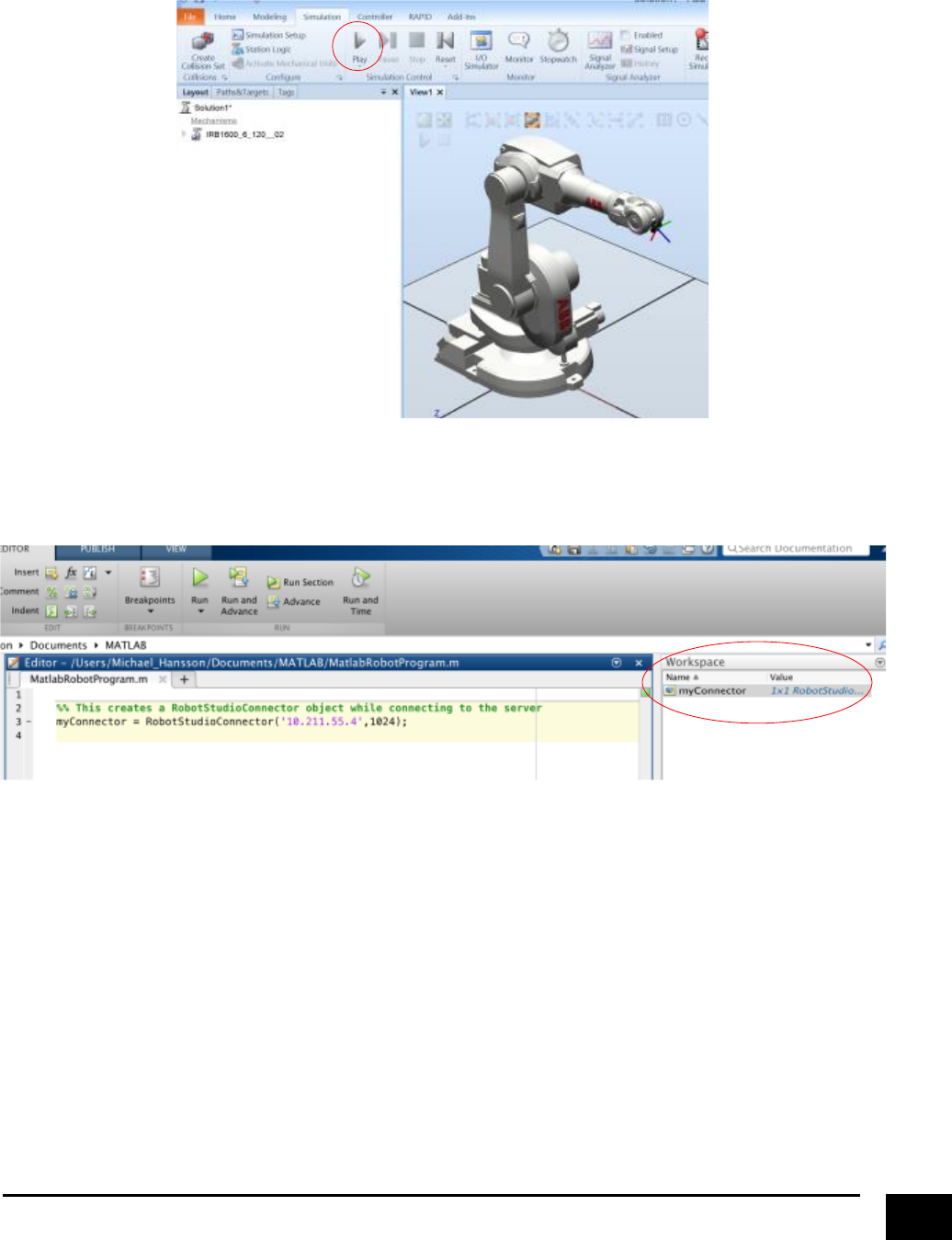
The first thing we need to do is to run the simulation in RobotStudio, which will start the server.
Next, execute the creation of a “RobotStudioConnector” object (This can be done by clicking ctrl+enter for
windows user or cmd+enter for mac users).
17
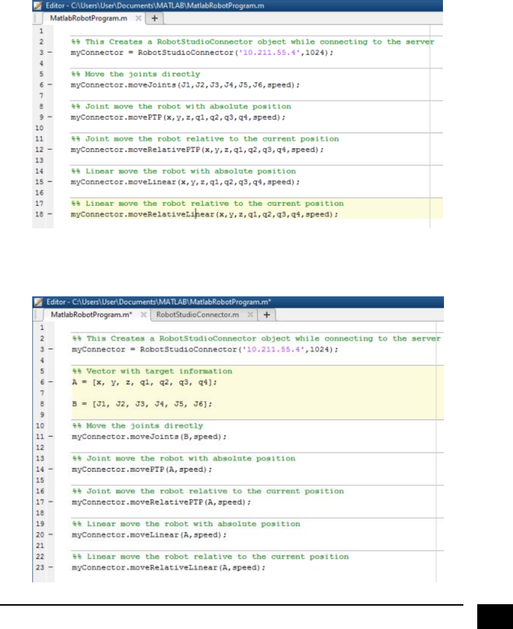
Now it is possible to move the robot using five commands; “moveJoints”, “movePTP”, “moveRelativeP2P”,
“moveLinear” or “moveRelativeLinear”. All of the commands, except “moveJoints”, takes as input the
position and orientation of a target, whereas “moveJoints” takes the values of the joints as input. In
addition, it is required to specify the speed that robot should move with. The speed should be specified in
form of a string that uses the RobotStudio standard, eg. “v100”.
You can alternatively also use the commands where the target information is represented in the form of a
vector.
18
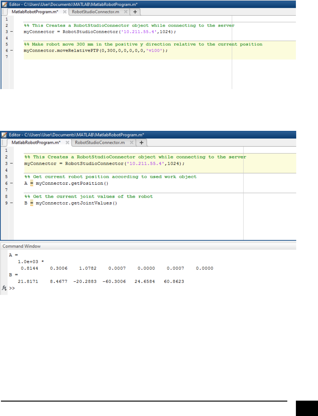
Let’s try to make the robot move using the “moveRelativeJoint” command. Write and execute the
following, and you should be able to see the robot moving in RobotStudio.
The final command that can be used in relation to the robot is the “getPosition” command, which returns
the current position of the robot in form of a vector.
19
Setting Up and Controlling a Gripper in RobotStudio from Matlab
This guide will show how to set up and control a gripper and has its outset in using the Schunk WSG
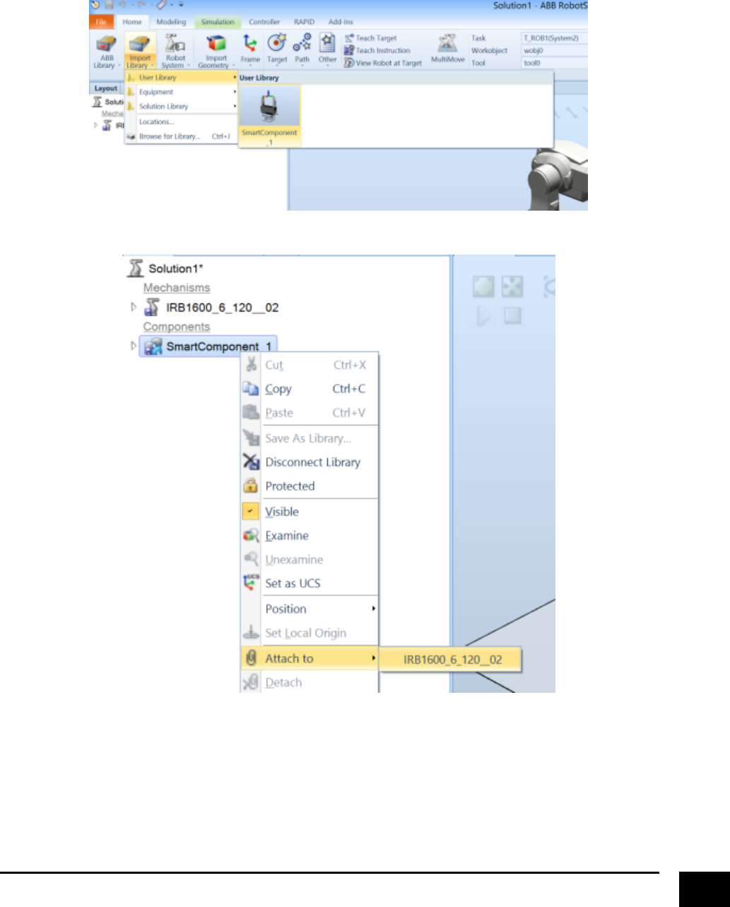
Gripper, which was created in the guide “RobotStudio_Guide_Tool_Design”. The first thing to do is to load
the gripper into the scene and attach it to the robot.
20
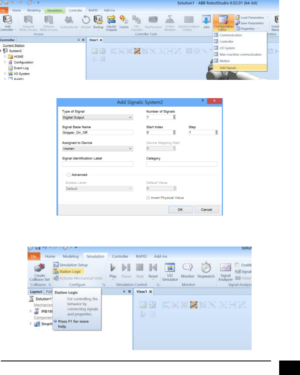
Next we want to set up the I/O signals in the virtual controller to control the gripper. Create three signals;
“Gripper_On_Off” is a digital output, “Gripper_On_Off_Executed” is a digital input, and
“Gripper_Grasp_State” is a digital input. You can call the signals whatever you want, as long as you have
created two digital inputs and one digital output. Remember to restart the system afterwards.
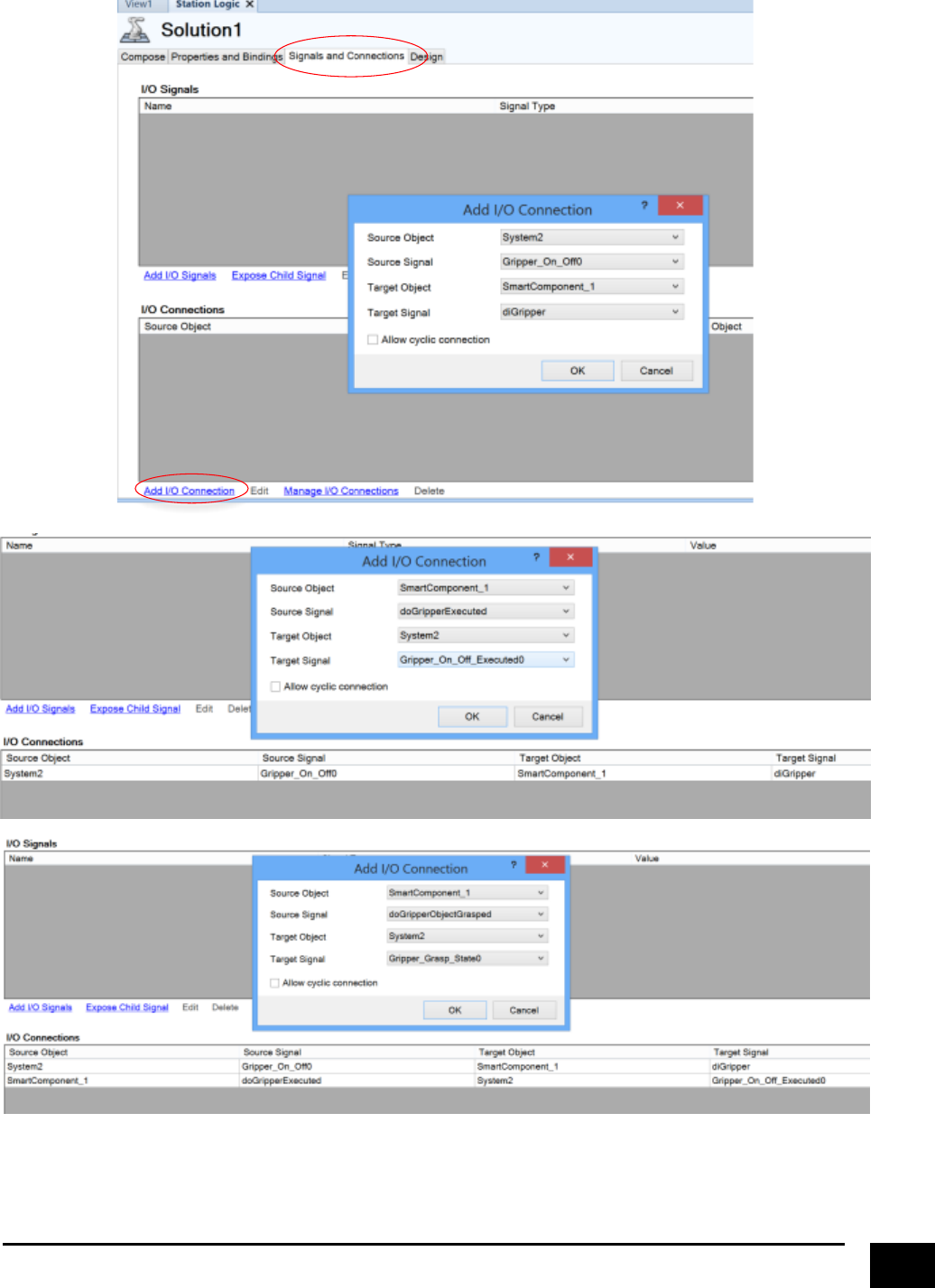
Go to “Station Logic” and setup the I/O’s to the gripper.
21
22
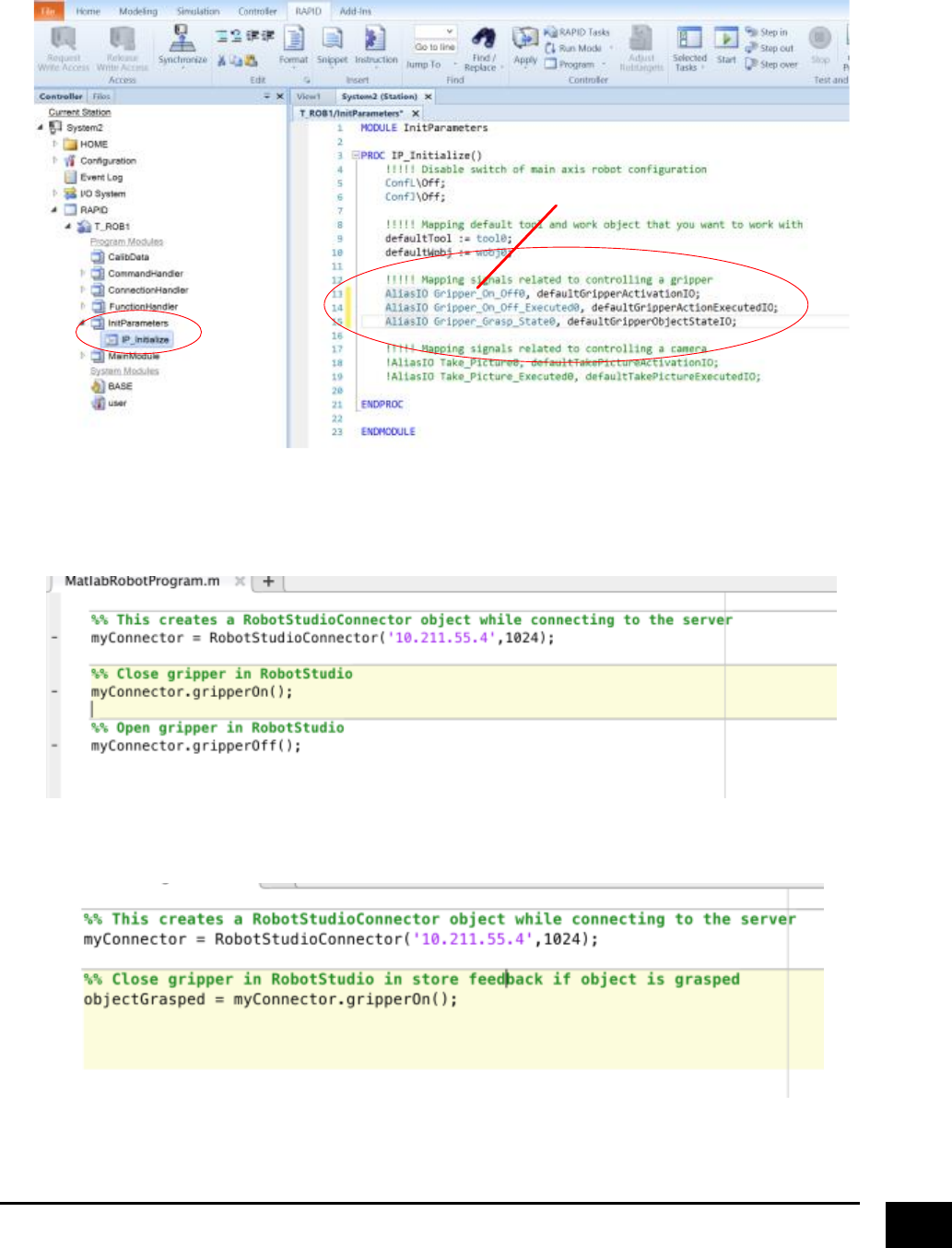
Go to the “RAPID” tap and modify “IP_Initialize”. Remember to apply the changes and synchronise to the
station.
Next, run the simulation and go to Matlab. There are two commands related to controlling the gripper;
“gripperOn” and “gripperOff”. Try to use them after connecting the client to the server.
You can also use the “gripperOn” command to save the state regarding if an object has been grasped. “1”
indicates that an object is grasped, “0” indicates that no object has been grasped.
Signal Names
23
Setting up and using a camera in RobotStudio from Matlab
This guide will show how to set up and control a camera. Since a controllable camera component is not
available by default in RobotStudio, this guide will take its outset in a custom made smart component that
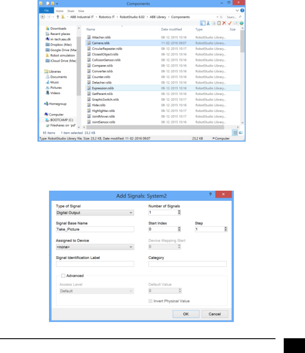
will enable saving images of the scene. So the first thing to do, is to place the smart component “Camera”
in “C:\Program Files (x86)\ABB Industrial IT\Robotics IT\RobotStudio 6.02\ABB Library\Components” (or
wherever you have chosen to install RobotStudio). This will make “Camera” available in the smart
component selection menu.
Next, we want to add some I/O signals to control the camera functionality. Create two signals;
“Take_Picture” is a digital output, and “Take_Picture_Executed” is a digital input. Remember to restart the
system afterwards.
24
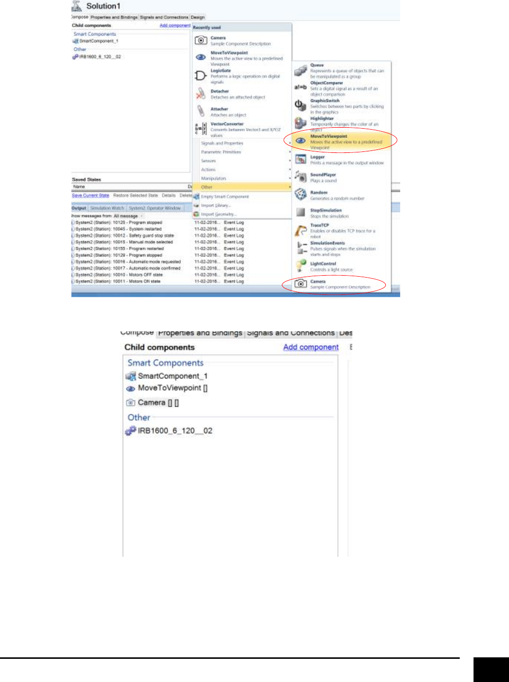
Go to “Station Logic” and add two smart components
You should end up with something like this
25
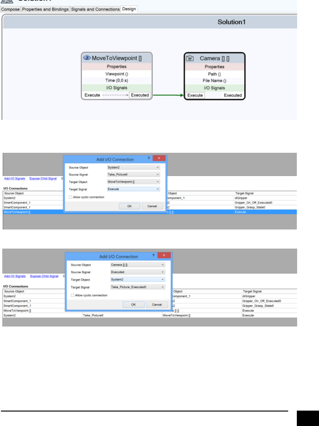
Go to “Design” under “Station Logic” and connect “MoveToViewpoint” and “Camera” like this.
Setup the I/O for the camera (go to “Signals and Connection” in “Station Logic”).
26
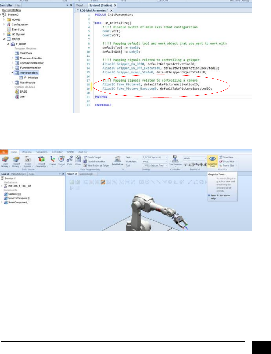
Go to the “RAPID” tap and modify “IP_Initialize”. Remember to apply the changes and synchronise to the
station.
The last thing we need to do before being able to call the take picture functionality is to configure the
camera viewpoint and where to save the image file. First go to the “Home” tap and select “Graphics Tools”.
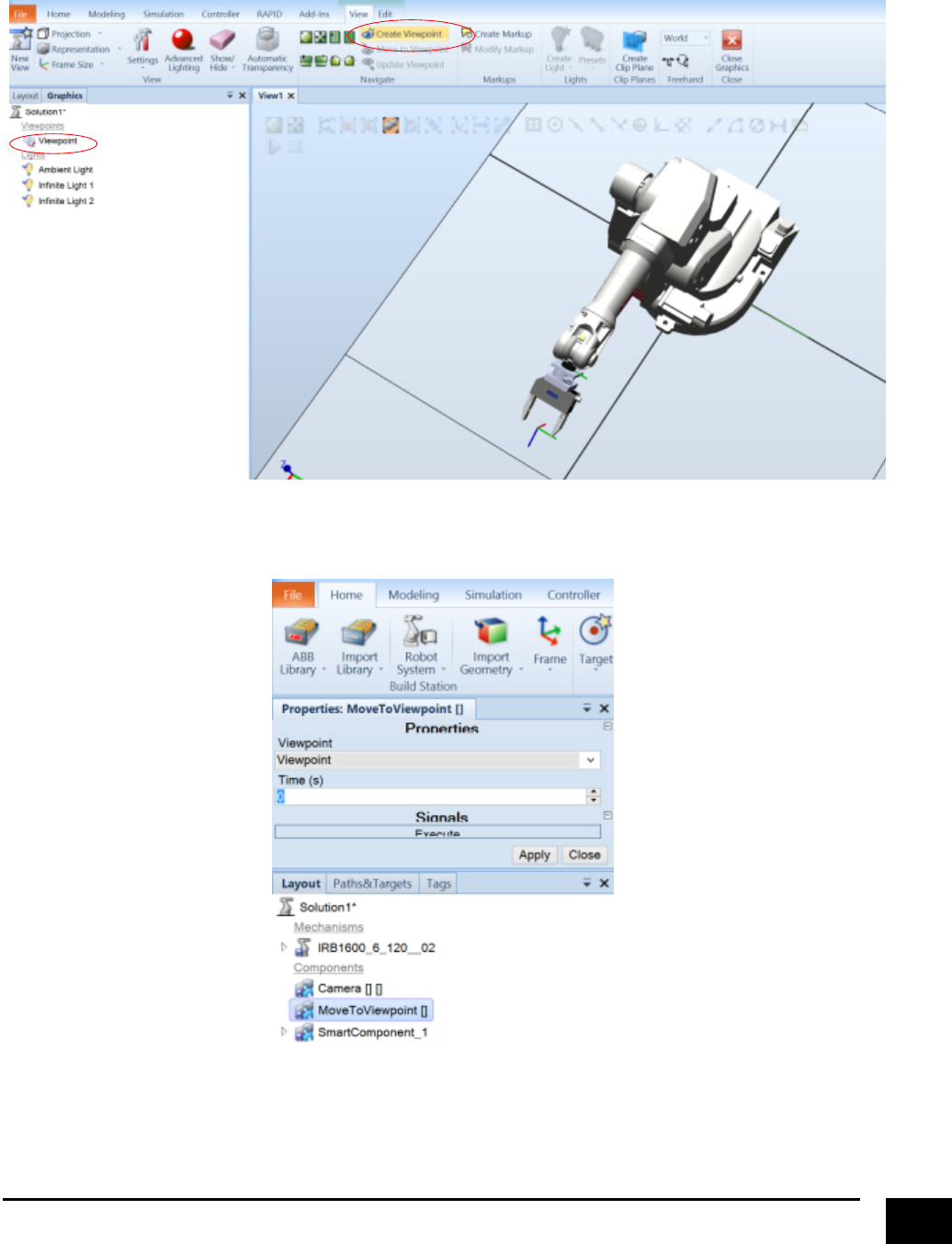
27
Find a “spot” of the scene that you want a picture of. Then press “Create Viewpoint”, and a viewpoint
object should appear in the panel.
Set up the properties for the “MoveToViewpoint” to use the created viewpoint.
28
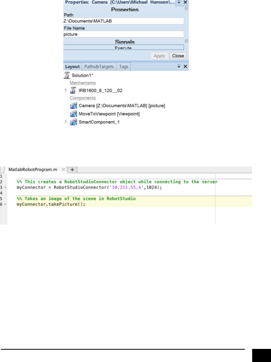
Finally set up the properties for “Camera”, with a path and a name for where you want to save the image.
Next, run the simulation and go to Matlab. There is only one command for the camera, and that’s
“takePicture”.
fin …
