SH 2 Reference Manual V1.2
SH-2-Reference-Manual-v1.2
User Manual: Pdf
Open the PDF directly: View PDF ![]() .
.
Page Count: 83

Hillcrest Laboratories, Inc. 15245 Shady Grove Road, Suite 400 Rockville, MD 20850
Copyright © 2017 Hillcrest Labs, Inc. All rights reserved.
SH-2 Reference Manual
Document Number:
1000-3625
Document Revision:
1.2
Date:
05/19/2017
Copyright © 2017 Hillcrest Laboratories, Inc. All rights reserved. 1
Table of Contents
LIST OF FIGURES ............................................................................................................... 4
1.0 INTRODUCTION ....................................................................................................... 7
1.1 Intended Audience ................................................................................................................. 7
1.2 Scope ..................................................................................................................................... 7
1.3 Revision History ..................................................................................................................... 7
2.0 SENSOR USAGE ..................................................................................................... 8
3.0 HOST INTERFACES ............................................................................................... 10
3.1 UART Interface..................................................................................................................... 10
3.1.1 S-format Output Packet .................................................................................................... 10
3.1.2 L-format Output Packet .................................................................................................... 10
3.1.3 H-format Output Packet.................................................................................................... 11
4.0 CONFIGURATION .................................................................................................. 13
4.1 Flash Storage ....................................................................................................................... 13
4.2 RAM Storage ........................................................................................................................ 13
4.3 Records ................................................................................................................................ 13
4.3.1 Static Calibration .............................................................................................................. 13
4.3.2 Dynamic Calibration ......................................................................................................... 13
4.3.3 MotionEngine Power Management and Stability Classifier ............................................. 14
4.3.4 Sensor Orientation ........................................................................................................... 14
4.3.5 AR/VR Stabilization .......................................................................................................... 15
4.3.6 Significant Motion Detector Configuration ........................................................................ 16
4.3.7 Shake Detector Configuration .......................................................................................... 16
4.3.8 Serial Number .................................................................................................................. 17
4.3.9 Maximum Fusion Period .................................................................................................. 17
4.3.10 Environmental Sensor Calibration ............................................................................. 17
4.3.11 Ambient Light Sensor (ALS) Calibration .................................................................... 18
4.3.12 Proximity Sensor Calibration ...................................................................................... 18
4.3.13 Flip Detector Configuration ........................................................................................ 19
4.3.14 Pickup Detector Configuration ................................................................................... 20
4.3.15 Stability Detector Configuration ................................................................................. 22
4.3.16 Activity Tracker Configuration .................................................................................... 22
4.3.17 Sleep Detector Configuration ..................................................................................... 22
4.3.18 Tilt Detector Configuration ......................................................................................... 23
4.3.19 Pocket Detector Configuration ................................................................................... 23
4.3.20 Circle Detector Configuration ..................................................................................... 24
4.3.21 User Record ............................................................................................................... 25
4.3.22 MotionEngine Time Source Selection ........................................................................ 25
4.3.23 UART Output Format Selection ................................................................................. 25
4.3.24 Gyro-Integrated Rotation Vector ................................................................................ 25
4.3.25 Fusion Control Record ............................................................................................... 27
4.3.26 Configuration Records Summary ............................................................................... 27
4.3.27 Version Information .................................................................................................... 28
5.0 OPERATION ........................................................................................................... 29
5.1 Sensor Metadata .................................................................................................................. 29
5.1.1 Sensor-Specific Metadata ................................................................................................ 32

1000-3625 SH-2 Reference Manual
Copyright © 2017 Hillcrest Laboratories, Inc. All rights reserved. 2
5.2 Input Reports ........................................................................................................................ 32
5.3 Output Reports ..................................................................................................................... 33
5.4 Feature Reports ................................................................................................................... 33
5.4.1 Rate Control ..................................................................................................................... 33
5.4.2 Threshold Control ............................................................................................................. 33
5.4.3 Batch Operation ............................................................................................................... 33
5.5 Sensor Triggering ................................................................................................................. 34
6.0 REPORT DESCRIPTIONS ...................................................................................... 36
6.1 Report ID Convention ........................................................................................................... 36
6.2 Summary .............................................................................................................................. 36
6.3 Configuration Reports .......................................................................................................... 37
6.3.1 Product ID Request (0xF9) .............................................................................................. 37
6.3.2 Product ID Response (0xF8) ............................................................................................ 37
6.3.3 FRS Write Request (0xF7) ............................................................................................... 38
6.3.4 FRS Write Data Request (0xF6) ...................................................................................... 38
6.3.5 FRS Write Response (0xF5) ............................................................................................ 39
6.3.6 FRS Read Request (0xF4) ............................................................................................... 40
6.3.7 FRS Read Response (0xF3) ............................................................................................ 40
6.3.8 Command Request (0xF2) ............................................................................................... 41
6.3.9 Command Response (0xF1) ............................................................................................ 41
6.4 Commands ........................................................................................................................... 42
6.4.1 Report Errors (0x01)......................................................................................................... 43
6.4.2 Perform Self-Test ............................................................................................................. 44
6.4.3 Counter Commands (0x02) .............................................................................................. 44
6.4.4 Tare (0x03) ....................................................................................................................... 45
6.4.5 Initialization (0x04) ........................................................................................................... 47
6.4.6 Save DCD (0x06) ............................................................................................................. 49
6.4.7 ME Calibration Commands (0x07) ................................................................................... 50
6.4.8 Configure Periodic DCD Save (0x09) .............................................................................. 51
6.4.9 Get Oscillator Type (0x0A) ............................................................................................... 52
6.4.10 Clear DCD and Reset (0x0B) ..................................................................................... 53
6.5 Sensor Reports .................................................................................................................... 53
6.5.1 Common Fields ................................................................................................................ 54
6.5.2 Common Dynamic Feature Report .................................................................................. 55
6.5.3 Get Feature Request (0xFE) ............................................................................................ 55
6.5.4 Set Feature Command (0xFD) ......................................................................................... 55
6.5.5 Get Feature Response (0xFC) ......................................................................................... 56
6.5.6 Force Sensor Flush (0xF0) .............................................................................................. 56
6.5.7 Flush Completed (0xEF) .................................................................................................. 57
6.5.8 Raw Accelerometer (0x14) ............................................................................................... 57
6.5.9 Accelerometer (0x01) ....................................................................................................... 58
6.5.10 Linear Acceleration (0x04) ......................................................................................... 58
6.5.11 Gravity (0x06) ............................................................................................................. 59
6.5.12 Raw Gyroscope (0x15) .............................................................................................. 59
6.5.13 Gyroscope Calibrated (0x02) ..................................................................................... 60
6.5.14 Gyroscope Uncalibrated (0x07) ................................................................................. 60
6.5.15 Raw Magnetometer (0x16) ........................................................................................ 61
6.5.16 Magnetic Field Calibrated (0x03) ............................................................................... 62
6.5.17 Magnetic Field Uncalibrated (0x0F) ........................................................................... 62
6.5.18 Rotation Vector (0x05) ............................................................................................... 63
6.5.19 Game Rotation Vector (0x08) .................................................................................... 63
6.5.20 Geomagnetic Rotation Vector (0x09)......................................................................... 64
6.5.21 Pressure (0x0A) ......................................................................................................... 65
6.5.22 Ambient Light (0x0B) ................................................................................................. 65

1000-3625 SH-2 Reference Manual
Copyright © 2017 Hillcrest Laboratories, Inc. All rights reserved. 3
6.5.23 Humidity (0x0C) ......................................................................................................... 65
6.5.24 Proximity (0x0D)......................................................................................................... 66
6.5.25 Temperature (0x0E) ................................................................................................... 66
6.5.26 Reserved (0x17)......................................................................................................... 67
6.5.27 Tap Detector (0x10) ................................................................................................... 67
6.5.28 Step Detector (0x18) .................................................................................................. 67
6.5.29 Step Counter (0x11) ................................................................................................... 68
6.5.30 Significant Motion (0x12) ........................................................................................... 69
6.5.31 Stability Classifier (0x13) ........................................................................................... 69
6.5.32 Shake Detector (0x19) ............................................................................................... 70
6.5.33 Flip Detector (0x1A) ................................................................................................... 70
6.5.34 Pickup Detector (0x1B) .............................................................................................. 71
6.5.35 Stability Detector (0x1C) ............................................................................................ 71
6.5.36 Personal Activity Classifier (0x1E) ............................................................................. 72
6.5.37 Sleep Detector (0x1F) ................................................................................................ 74
6.5.38 Tilt Detector (0x20) .................................................................................................... 74
6.5.39 Pocket Detector (0x21) .............................................................................................. 75
6.5.40 Circle Detector (0x22) ................................................................................................ 75
6.5.41 Heart Rate Monitor (0x23) ......................................................................................... 76
6.5.42 ARVR-Stabilized Rotation Vector (0x28) ................................................................... 76
6.5.43 ARVR-Stabilized Game Rotation Vector (0x29) ........................................................ 77
6.5.44 Gyro-Integrated Rotation Vector (0x2A) .................................................................... 77
7.0 BATCHING ............................................................................................................. 79
7.1 Batch queues ....................................................................................................................... 79
7.2 Batch timestamps ................................................................................................................. 79
7.2.1 Base Timestamp Reference (0xFB) ................................................................................. 79
7.2.2 Timestamp Rebase (0xFA) .............................................................................................. 80
8.0 REFERENCES ........................................................................................................ 81
9.0 NOTICES ................................................................................................................ 82

1000-3625 SH-2 Reference Manual
Copyright © 2017 Hillcrest Laboratories, Inc. All rights reserved. 4
List of Figures
Figure 1: Document History .............................................................................................. 7
Figure 2: Sensor Usage ..................................................................................................... 9
Figure 3: S-format Output Packet Definition ................................................................... 10
Figure 4: L-format Output Packet Definition ................................................................... 11
Figure 5: H-format Output Packet Definition ................................................................... 12
Figure 6: MotionEngine Power Management and Stability Classifier Record ............. 14
Figure 7: Sensor Orientation Record .............................................................................. 14
Figure 8: AR/VR Stabilization Record ............................................................................. 15
Figure 9: Significant Motion Detector Configuration Record ........................................ 16
Figure 10: Shake Detector Configuration Record .......................................................... 16
Figure 11: Serial Number Record .................................................................................... 17
Figure 12: Maximum Fusion Period Record ................................................................... 17
Figure 13: Environmental Sensor Calibration Record ................................................... 17
Figure 14: ALS Calibration Record ................................................................................. 18
Figure 15: Proximity Sensor Calibration Record ........................................................... 18
Figure 16: Flip Detector Configuration Record .............................................................. 19
Figure 17: Pickup Detector Configuration Record ......................................................... 20
Figure 18: Stability Detector Configuration Record ...................................................... 22
Figure 19: Sleep Detector Configuration Record ........................................................... 22
Figure 20: Tilt Detector Configuration Record ............................................................... 23
Figure 21: Pocket Detector Configuration Record ......................................................... 23
Figure 22: Circle Detector Configuration Record .......................................................... 24
Figure 23: User Record .................................................................................................... 25
Figure 24: Time Source Record ...................................................................................... 25
Figure 25: UART Output Format Selection Record ......................................................... 25
Figure 26: Gyro-Integrated Rotation Vector Configuration Record ............................... 26
Figure 27: Fusion Control Record .................................................................................. 27
Figure 28: Configuration Records .................................................................................. 28
Figure 29: Metadata Records .......................................................................................... 30
Figure 30: Metadata Record Format – Revision 3 .......................................................... 30
Figure 31: Metadata Record Format – Revision 4 .......................................................... 31
Figure 32: Personal Activity Classifier Sensor-Specific Metadata. .............................. 32
Figure 33: Sensor Trigger Modes ................................................................................... 35
Figure 34: Report ID List ................................................................................................. 37
Figure 35: Product ID Request ........................................................................................ 37
Figure 36: Product ID Response ..................................................................................... 38
Figure 37: FRS Write Request ......................................................................................... 38
Figure 38: FRS Write Data Request ................................................................................ 39
Figure 39: FRS Write Response ...................................................................................... 39
Figure 40: FRS Read Request ......................................................................................... 40
Figure 41: FRS Read Response ...................................................................................... 40
Figure 42: Command Request ........................................................................................ 41
Figure 43: Command Response ...................................................................................... 42
Figure 44: Command Identifiers ...................................................................................... 43
Figure 45: Report Errors Command................................................................................ 43
Figure 46: Report Errors Response ................................................................................ 44
Figure 47: Get Counts Command ................................................................................... 44
Figure 48: Get Counts Response .................................................................................... 45

1000-3625 SH-2 Reference Manual
Copyright © 2017 Hillcrest Laboratories, Inc. All rights reserved. 5
Figure 49: Clear Counts Command ................................................................................ 45
Figure 50: Tare Now Command ....................................................................................... 46
Figure 51: Persist Tare Command .................................................................................. 47
Figure 52: Set Reorientation Command ......................................................................... 47
Figure 53: Initialize Command......................................................................................... 48
Figure 54: Initialize Command Subsystems ................................................................... 48
Figure 55: Initialize Response ......................................................................................... 48
Figure 56: Save DCD Command ...................................................................................... 49
Figure 57: Save DCD Response ...................................................................................... 49
Figure 58: Configure ME Calibration Command ............................................................ 50
Figure 59: Get ME Calibration Command ....................................................................... 50
Figure 60: Configure ME Calibration Response............................................................. 51
Figure 61: Configure Periodic Save DCD Command ..................................................... 52
Figure 62: Get Oscillator Type Command ....................................................................... 52
Figure 63: Get Oscillator Type Response ...................................................................... 53
Figure 64: Clear DCD and Reset Command .................................................................... 53
Figure 65: Common Report Fields .................................................................................. 54
Figure 66: Common Feature Report ............................................................................... 55
Figure 67: Get Feature Request (0xFE) .......................................................................... 55
Figure 68: Set Feature Command (0xFD) ....................................................................... 56
Figure 69: Get Feature Response (0xFC) ....................................................................... 56
Figure 70: Force Sensor Flush (0xF0) ............................................................................ 57
Figure 71: Flush Completed (0xEF) ................................................................................ 57
Figure 72: Raw Accelerometer Input Report .................................................................. 57
Figure 73: Accelerometer Input Report .......................................................................... 58
Figure 74: Linear Acceleration Input Report .................................................................. 58
Figure 75: Gravity Input Report ....................................................................................... 59
Figure 76: Raw Gyroscope Input Report ........................................................................ 60
Figure 77: Gyroscope Calibrated Input Report .............................................................. 60
Figure 78: Gyroscope Uncalibrated Input Report .......................................................... 61
Figure 79: Raw Magnetometer Input Report .................................................................. 61
Figure 80: Magnetic Field Calibrated Input Report ........................................................ 62
Figure 81: Magnetic Field Uncalibrated Input Report .................................................... 63
Figure 82: Rotation Vector Input Report ........................................................................ 63
Figure 83: Game Rotation Vector Input Report .............................................................. 64
Figure 84: Geomagnetic Rotation Vector Input Report ................................................. 64
Figure 85: Pressure Sensor Input Report ....................................................................... 65
Figure 86: Ambient Light Sensor Input Report .............................................................. 65
Figure 87: Humidity Sensor Input Report ....................................................................... 66
Figure 88: Proximity Sensor Input Report ...................................................................... 66
Figure 89: Temperature Sensor Input Report ................................................................ 66
Figure 90: Tap Detector Input Report ............................................................................. 67
Figure 91: Step Detector Input Report ............................................................................ 68
Figure 92: Step Counter Input Report ............................................................................. 68
Figure 93: Significant Motion Input Report .................................................................... 69
Figure 94: Stability Classifier Input Report .................................................................... 69
Figure 95: Shake Detector Input Report ......................................................................... 70
Figure 96: Flip Detector Input Report ............................................................................. 71
Figure 97: Pickup Detector Input Report ........................................................................ 71
Figure 98: Stability Detector Input Report ...................................................................... 72
Figure 99: Personal Activity Classifier Feature Report. ................................................ 72

1000-3625 SH-2 Reference Manual
Copyright © 2017 Hillcrest Laboratories, Inc. All rights reserved. 6
Figure 100: Personal Activity Classifier Report ............................................................. 73
Figure 101: Activity Classification States ...................................................................... 74
Figure 102: Sleep Detector Input Report ........................................................................ 74
Figure 103: Tilt Detector Input Report ............................................................................ 74
Figure 104: Pocket Detector Input Report ...................................................................... 75
Figure 105: Circle Detector Input Report ........................................................................ 75
Figure 106: Heart Rate Monitor Input Report ................................................................. 76
Figure 107: ARVR-Stabilized Rotation Vector Input Report .......................................... 77
Figure 108: ARVR-Stabilized Game Rotation Vector Input Report ............................... 77
Figure 109: Gyro-Integrated Rotation Vector Input Report ........................................... 78
Figure 110: Timestamp Dependencies ........................................................................... 79
Figure 111: Base Timestamp Reference Record ........................................................... 80
Figure 112: Timestamp Rebase Record ......................................................................... 80

1000-3625 SH-2 Reference Manual
Copyright © 2017 Hillcrest Laboratories, Inc. All rights reserved. 7
1.0 Introduction
The SH-2 is Hillcrest’s turnkey sensor hub software solution. The SH-2 connects to various
motion and environmental sensors, collects data from them, processes that data and provides
the results to a host processor.
1.1 Intended Audience
This document is intended for application developers implementing products that use the SH-2.
1.2 Scope
This document describes the features of the SH-2, how they work, how to use them and the
application programming interface (API) for the SH-2. This document assumes the reader is
already familiar with Hillcrest’s MotionEngine.
1.3 Revision History
Revision
Date
Description
1.2
05/19/2017
Clarified Tare command usage, added description of Tare
application to AR/VR Stabilized Rotation Vectors and Gyro-
Integrated Rotation Vector. Clarified FRS Read “BUSY” status
behavior. Fix bad references. Added language clarifying
interaction between Gyro-Integrated Rotation Vector and other
fusion outputs. Clarified SHTP channels in 6.2.
1.1
02/16/2017
Update the default value of AR/VR Stabilization FRS record.
Remove unused reference.
1.0
02/06/2017
Initial issue
Figure 1: Document History

1000-3625 SH-2 Reference Manual
Copyright © 2017 Hillcrest Laboratories, Inc. All rights reserved. 8
2.0 Sensor Usage
The SH-2 connects to and manages a variety of physical sensors. It processes the outputs of
the physical sensors to produce virtual sensors. Virtual sensors require data from one or more
physical sensors. Figure 2 indicates which physical sensors are required for which virtual
sensors. The number of physical sensors in use at any one time impacts the power consumed
by the device. Using more physical sensors means consuming more power.

1000-3625 SH-2 Reference Manual
Copyright © 2017 Hillcrest Laboratories, Inc. All rights reserved. 9
Physical Sensors
Virtual Sensors
accelerometer
gyroscope
magnetometer
pressure
ambient light
humidity
proximity
temperature
HRM
Raw accelerometer
X
Acceleration
X
Linear acceleration
X
Gravity
X
Raw gyroscope
X
Gyroscope calibrated
X
X
Gyroscope uncalibrated
X
X
Raw magnetometer
X
Magnetic field calibrated
X
X
Magnetic field uncalibrated
X
X
Rotation vector
X
X
X
Game rotation vector
X
X
Geomagnetic rotation vector
X
X
Pressure
X
Ambient light
X
Humidity
X
Proximity
X
Temperature
X
Tap detector
X
Step detector
X
Step counter
X
Significant motion
X
Stability classifier
X
X
Shake detector
X
Flip detector
X
Pickup detector
X
Stability detector
X
Personal Activity classifier
X
Sleep detector
X
Tilt detector
X
Pocket detector
X
X
X
Circle detector
X
Heart rate monitor
X
X
AR/VR Stabilized Rotation
Vector
X
X
X
AR/VR Stabilized Game
Rotation Vector
X
X
Gyro-Integrated Rotation
Vector
X
X
X1
Figure 2: Sensor Usage
1
Magnetometer is not required when Gyro-Integrated Rotation Vector is configured with the Game
Rotation Vector as its Reference Data Type (see 4.3.24).

1000-3625 SH-2 Reference Manual
Copyright © 2017 Hillcrest Laboratories, Inc. All rights reserved. 10
3.0 Host Interfaces
The SH-2 communicates to the host processor through Hillcrest’s Sensor Hub Transport
Protocol. See [1] for details of the SHTP protocol. See [2] for details of how SH-2 uses SHTP.
3.1 UART Interface
Certain SH-2 products support a UART interface with special output formats. There are two
such output formats available.
3.1.1 S-format Output Packet
The S-format is the default output packet format for the UART mode. This output packet
provides heading information. Below is a description of the output packet layout:
Byte
Description
0
Header = 0xAA
1
Reserved = 0x00
2
Sequence Number
3
Angle LSB
4
Angle MSB
5
Checksum
Figure 3: S-format Output Packet Definition
Header
Packet header byte, always equal to 0xAA.
Reserved
Reserved byte, always equal to 0x00.
Sequence Number
Sequence number of the packet. The first packet sent after
startup will have a sequence number of 0. After the 256th packet
is sent the sequence number rolls over back to 0.
Angle
16-bit heading value expressed in units of centidegrees (degrees
x100). This value has a range of -18000 to 18000 centidegrees.
Checksum
Checksum of the packet, equal to the XOR of the sequence
number and angle bytes of the packet.
3.1.2 L-format Output Packet
The L-format packet is an alternate output packet format for the UART mode. This output packet
format needs to be selected using an FRS record – see 4.3.23 for more information on the FRS
record. Below is a description of the output packet layout.
Byte
Description
0
Header LSB = 0xAC
1
Header MSB = 0xAC
2
Sequence Number
3
Angle LSB
4
Angle MSB
5
Angular velocity LSB
6
Angular velocity MSB
7
X-axis acceleration LSB
8
X-axis acceleration MSB

1000-3625 SH-2 Reference Manual
Copyright © 2017 Hillcrest Laboratories, Inc. All rights reserved. 11
Byte
Description
9
Y-axis acceleration LSB
10
Y-axis acceleration MSB
11
Z-axis acceleration LSB
12
Z-axis acceleration MSB
13
Reserved
14
Checksum
Figure 4: L-format Output Packet Definition
Header
16-bit packet header, always equal to 0xACAC.
Sequence Number
Sequence number of the packet. The first packet sent after
startup will have a sequence number of 0. After the 256th packet
is sent the sequence number rolls over back to 0.
Angle
16-bit heading value expressed in units of decidegrees (degrees
x10). This value has a range of -1800 to 1800 decidegrees.
Angular velocity
16-bit angular velocity value expressed in units of decidegrees
per second (degrees per second x10).
X-axis acceleration
16-bit acceleration value expressed in milli-gravities (gravitational
constant x1000) representing the acceleration of the device in the
X-direction.
Y-axis acceleration
16-bit acceleration value expressed in milli-gravities (gravitational
constant x1000) representing the acceleration of the device in the
Y-direction.
Z-axis acceleration
16-bit acceleration value expressed in milli-gravities (gravitational
constant x1000) representing the acceleration of the device in the
Z-direction.
Reserved
Reserved byte, always equal to 0x00.
Checksum
Checksum of the packet, equal to the sum of the sequence
number, angle, angular velocity, and acceleration bytes of the
packet.
3.1.3 H-format Output Packet
The H-format packet is another alternate output packet format for the UART mode. This output
packet provides Euler angles and acceleration values. This output packet format needs to be
selected using an FRS record – see 4.3.23 for more information on the FRS record. Below is a
description of the output packet layout.
Byte
Description
0
Header LSB = 0xAA
1
Header MSB = 0xAA
2
Sequence Number
3
Yaw LSB
4
Yaw MSB
5
Pitch LSB

1000-3625 SH-2 Reference Manual
Copyright © 2017 Hillcrest Laboratories, Inc. All rights reserved. 12
Byte
Description
6
Pitch MSB
7
Roll LSB
8
Roll MSB
9
X-axis acceleration LSB
10
X-axis acceleration MSB
11
Y-axis acceleration LSB
12
Y-axis acceleration MSB
13
Z-axis acceleration LSB
14
Z-axis acceleration MSB
15
Reserved
16
Reserved
17
Reserved
18
Checksum
Figure 5: H-format Output Packet Definition
Header
16-bit packet header, always equal to 0xAAAA.
Sequence Number
Sequence number of the packet. The first packet sent after
startup will have a sequence number of 0. After the 256th packet
is sent the sequence number rolls over back to 0.
Yaw
16-bit angular yaw value expressed in units of centidegrees
(degrees x100).
Pitch
16-bit angular pitch value expressed in units of centidegrees
(degrees x100).
Roll
16-bit angular roll value expressed in units of centidegrees
(degrees x100).
X-axis acceleration
16-bit acceleration value expressed in milli-gravities (gravitational
constant x1000) representing the acceleration of the device in the
X-direction.
Y-axis acceleration
16-bit acceleration value expressed in milli-gravities (gravitational
constant x1000) representing the acceleration of the device in the
Y-direction.
Z-axis acceleration
16-bit acceleration value expressed in milli-gravities (gravitational
constant x1000) representing the acceleration of the device in the
Z-direction.
Reserved
Reserved bytes, always equal to 0x00.
Checksum
Checksum of the packet, equal to the sum of the sequence
number, yaw, pitch, roll, acceleration and reserved bytes of the
packet.

1000-3625 SH-2 Reference Manual
Copyright © 2017 Hillcrest Laboratories, Inc. All rights reserved. 13
4.0 Configuration
The SH-2 has a number of configurable options that control the overall behavior of the hub.
These configuration options are stored as records in either flash or RAM. Only one record of
each configuration options may be stored. Access to the configuration records is provided
through reports described in section 6.3.
4.1 Flash Storage
The SH-2 can be implemented on processors with flash memory. On these systems the
configuration records persist through power cycles. The configuration options may be changed
at any time; however, the SH-2 must be restarted for changes to take effect. The SH-2 has a
very simple flash record system (FRS) that manages reading, writing and erasing these records.
The FRS implements wear leveling to reduce wear on the flash memory.
4.2 RAM Storage
The SH-2 can also be implemented on processors without flash. In these systems the
configuration records are stored in RAM. They must be downloaded each time the SH-2 is
started. To change configuration options, restart the SH-2 and download new options.
4.3 Records
4.3.1 Static Calibration
Static calibration data is produced by the manufacturing process for per device calibration and
stored on the SH-2. There are two per device calibration records – one for the accelerometer,
gyroscope and magnetometer (AGM) sensor set and one for the screen rotation accelerometer
(SRA). The SH-2 uses a nominal calibration if static calibration data is not configured. The
nominal calibration is built-in to the SH-2 sensor drivers. There are two nominal calibration
records – one for the AGM sensor set and one for the SRA. The per device records are
read/write. The nominal records are read only. The data format is proprietary to Hillcrest Labs.
4.3.2 Dynamic Calibration
Dynamic calibration is produced by MotionEngine during operation. Dynamic calibration may be
stored for use following a restart to enhance MotionEngine’s startup performance. The data
format is proprietary to Hillcrest Labs.

1000-3625 SH-2 Reference Manual
Copyright © 2017 Hillcrest Laboratories, Inc. All rights reserved. 14
4.3.3 MotionEngine Power Management and Stability Classifier
The MotionEngine power management record controls the thresholds MotionEngine uses to
determine when the device is at rest and when it is in motion. The format of a MotionEngine
Power Management record is shown in Figure 6. This record also configures the thresholds use
by the stability classifier.
Description
Word
Byte 3
Byte 2
Byte 1
Byte 0
0
Delta orientation
1
Stable threshold
2
Reserved
Delta acceleration
Stable duration
Figure 6: MotionEngine Power Management and Stability Classifier Record
Delta orientation
Once a device has been determined to be not moving based
on the generation of ON_TABLE or IS_STABLE, delta
orientation is the amount of change in device orientation
required to recognize that the device is in motion. The units
are radians. The delta orientation value is a signed, 2’s-
complement fixed point number with a Q point of 28. The
default value is 0.2.
Stable threshold
The gyro output must be below this limit for the stable duration
in order for an IS_STABLE notification to be generated. The
units are radians per second. The stable threshold value is a
signed, 2’s-complement fixed point number with a Q point of
25. The default value is 1.0.
Stable duration
The amount of time in seconds that motion must be below the
stable threshold before an IS_STABLE notification is
generated. The default value is 3.
Delta acceleration
When using wake-on-motion, this is the amount of
acceleration required for the accelerometer to determine that
motion has occurred. The units are mg. The delta acceleration
value is unsigned. The default value is 0.
4.3.4 Sensor Orientation
The sensor orientation record controls the rotation of the MotionEngine output coordinate
system relative to the sensor’s coordinate system. The rotation vector is a signed, 2’s-
complement fixed point number with a Q point of 30. The format of a sensor orientation record is
shown in Figure 7. If the rotation vector is set to all 0’s then no rotation is applied. The default
values are 0 for all for values. In addition, each accelerometer, gyroscope and magnetometer
has its own sensor orientation record. The sensor specific records are used to align the
orientation of sensors to the system when not using per device static calibration data.
Word
Description
0
Rotation quaternion X
1
Rotation quaternion Y
2
Rotation quaternion Z
3
Rotation quaternion W
Figure 7: Sensor Orientation Record
1000-3625 SH-2 Reference Manual
Copyright © 2017 Hillcrest Laboratories, Inc. All rights reserved. 15
4.3.5 AR/VR Stabilization
During large, fast motions the angular position output may sometimes become misaligned with
the actual angular position. When the device slows or stops, angular position can be determined
accurately and the angular position output updated accordingly. However, step updates to the
output are undesirable in some applications. AR/VR stabilization addresses this issue by
correcting angular position errors only when the device is moving.
The AR/VR stabilization record controls the thresholds MotionEngine uses to stabilize angular
position. The format of an AR/VR stabilization record is shown in Figure 8. The AR/VR
stabilization parameters are all unsigned, fixed point numbers. There are separate AR/VR
stabilization records for the rotation vector and game rotation vector. If a record is not
programmed then default values of 0 are used for all parameters.
Word
Description
0
Scaling
1
Max rotation
2
Max error
3
Stability magnitude
Figure 8: AR/VR Stabilization Record
Scaling
Scaling controls what fraction of the angular velocity can be
used to correct angular position errors. The range for this
parameter is 0 to 1.0. This parameter is dimensionless. The Q
point is 30. A typical value is 0.2.
Max rotation
Max rotation is the maximum amount of angular correction
that can be used to correct angular position errors. The
settings for scaling and max rotation determine how
aggressively angular errors are corrected. The range is 0 to
PI. The units are radians. The Q point is 29. A typical value is
7.3 degrees or 0.127 radians.
Max error
Max error is the maximum angular error allowed to
accumulate before the angular position output is updated in a
single step. The units are radians. The range is 0 to PI. The Q
point is 29. A typical value is 45 degrees or 0.785 radians.
Stability magnitude
Stability magnitude controls the amount of change in angular
position that must occur before the angular position output is
updated with a new value. The units are radians. The Q point
is 29. A typical value is 0.0 degrees or 0.0 radians.

1000-3625 SH-2 Reference Manual
Copyright © 2017 Hillcrest Laboratories, Inc. All rights reserved. 16
4.3.6 Significant Motion Detector Configuration
The significant motion detector has several parameters that must be configured. The
configuration parameters are 32-bit integers or 32-bit signed fixed point numbers. If this record
is not programmed then default values are used.
Word
Description
0
Acceleration threshold
1
Step threshold
Figure 9: Significant Motion Detector Configuration Record
Acceleration threshold
The acceleration threshold to trigger significant motion. The
default value is 10.0 m/s^2. The Q point is 24.
Step threshold
The number of steps required to trigger significant motion. The
default value is 5. This is an unsigned integer.
4.3.7 Shake Detector Configuration
The shake detector has several parameters that must be configured. The configuration
parameters are 32-bit signed integers, 32-bit signed fixed point numbers or bit fields. If this
record is not programmed then default values are used.
Word
Description
0
Minimum time
1
Maximum time
2
Threshold
3
Shake count
4
Enable flags
Figure 10: Shake Detector Configuration Record
Minimum time
The minimum time in microseconds between direction
changes. The default value is 50,000us.
Maximum time
The maximum time in microseconds between direction
changes. The default value is 400,000us.
Threshold
The threshold in m/s^2 that must be exceeded to count as a
direction change. The default value is 8.0m/s^2. The Q point is
26.
Shake count
The number of direction changes to count as a shake. The
default value is 3.
Enable flags
Enable flags for shake detection on the X, Y and Z axes. 0 –
disable, 1 – enable. X, Y, and Z axes are enabled by default.
Bit 0 – X axis
Bit 1 – Y axis
Bit 2 – Z axis
Bit 3:7 - reserved

1000-3625 SH-2 Reference Manual
Copyright © 2017 Hillcrest Laboratories, Inc. All rights reserved. 17
4.3.8 Serial Number
The serial number record stores a 32-bit number used to identify an individual device. The
format of a serial number record is shown in Figure 11.
Word
Description
0
32-bit serial number
Figure 11: Serial Number Record
4.3.9 Maximum Fusion Period
The maximum fusion period record stores the maximum fusion period allowed. The units are
microseconds. If a fusion period larger than this maximum is requested then the fusion period
will be set to this maximum. The fusion period check can be disabled by clearing this record or
by setting the maximum to 0.
Word
Description
0
Max fusion period
Figure 12: Maximum Fusion Period Record
4.3.10 Environmental Sensor Calibration
Each environmental sensor may require calibration. The calibration parameters for the
environmental sensors are offset and scale. Offset accounts for a fixed difference between the
output of the sensor and the actual value. Scale accounts for the difference between how much
the output of the sensor changes and how much the actual value changes. Offset and scale are
both signed fixed point numbers. The Q point is different for each type of sensor. If the
calibration record for a particular sensor is not programmed then default values of offset = 0 and
scale = 1 are used.
Word
Description
0
Offset
1
Scale
Figure 13: Environmental Sensor Calibration Record
Offset
The offset value is added to the output of the sensor. The Q
points are:
Pressure: 20
Temperature: 7
Humidity: 8
Ambient Light: 8
Proximity: 4
Scale
The output of the sensor is multiplied by the scale. The Q
points are:
Pressure: 15
Temperature: 15
Humidity: 15
Ambient Light: 15
Proximity: 15

1000-3625 SH-2 Reference Manual
Copyright © 2017 Hillcrest Laboratories, Inc. All rights reserved. 18
4.3.11 Ambient Light Sensor (ALS) Calibration
The ALS may require additional calibration parameters beyond the simple scale and offset
provided to all environmental sensors. These parameters are device specific and are stored in
the ALS Calibration Record.
Word
Description
0
Sensor GUID
1
Bits 7:0 – Length
Bits 31:8 - Reserved
1..N
Parameters
Figure 14: ALS Calibration Record
Sensor GUID
An ID that uniquely identifies the sensor for which the
calibration record was created.
Length
Length in words of the parameters section of the record.
Parameters
The calibration parameters applicable for a specific sensor.
Contact Hillcrest Labs for details.
4.3.12 Proximity Sensor Calibration
The proximity sensor may require additional calibration parameters beyond the simple scale and
offset provided to all environmental sensors. These parameters are device specific and are
stored in the Proximity Sensor Calibration Record.
Word
Description
0
Sensor GUID
1
Bits 7:0 – Length
Bits 31:8 - Reserved
1..N
Parameters
Figure 15: Proximity Sensor Calibration Record
Sensor GUID
An ID that uniquely identifies the sensor for which the
calibration record was created.
Length
Length in words of the parameters section of the record.
Parameters
The calibration parameters applicable for a specific sensor.
Contact Hillcrest Labs for details.
1000-3625 SH-2 Reference Manual
Copyright © 2017 Hillcrest Laboratories, Inc. All rights reserved. 19
4.3.13 Flip Detector Configuration
The flip detector has several parameters that must be configured. The configuration parameters
are 32-bit signed fixed point numbers. If this record is not programmed then default values are
used.
Word
Description
0
Time constant
1
Angular threshold
2
Angular hysteresis
Figure 16: Flip Detector Configuration Record
Time constant
The time constant used for filtering input data. The default
value is 0.4. The Q point is 20.
Angular threshold
The angle in radians, measured from a downward pointing line
(i.e. line pointing toward earth) defining the maximum range to
be in the down state. The default value is pi/4 (45 degrees).
The Q point is 29.
Angular hysteresis
The angle in radians defining the amount of hysteresis to
apply. The hysteresis region is angular threshold ± (angular
hysteresis / 2). The default value is pi/90 (2 degrees). The Q
point is 29.

1000-3625 SH-2 Reference Manual
Copyright © 2017 Hillcrest Laboratories, Inc. All rights reserved. 20
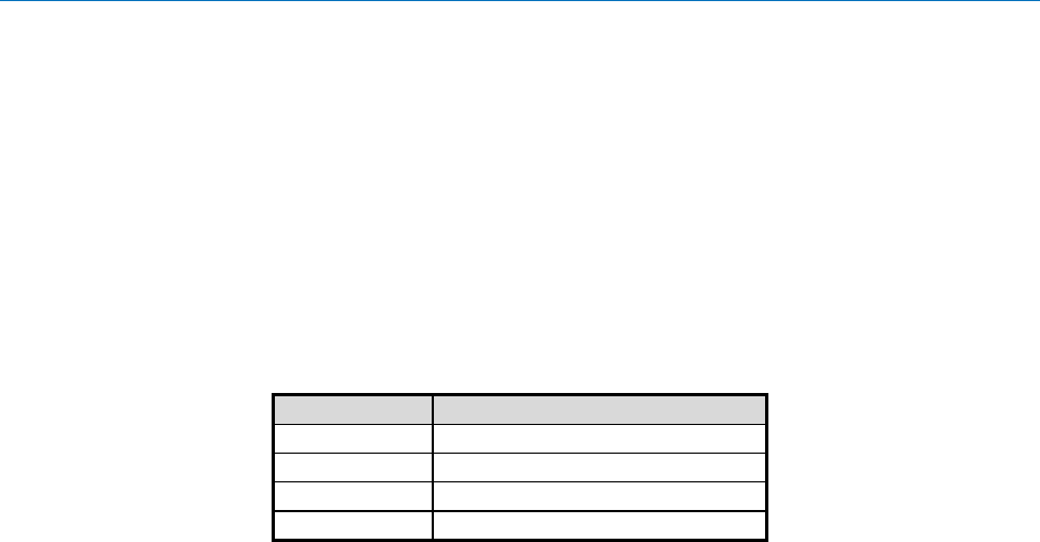
4.3.14 Pickup Detector Configuration
The pickup detector has several parameters that must be configured. The configuration
parameters are 32-bit signed fixed point numbers. If this record is not programmed then default
values are used.
The pickup detector can be operated in three different modes. The first mode, “Level-to-not-
level” (LNL) reports a pick-up event when the sensor hub moves from a level position to a non-
level position. The second mode, “Stopped within Tilt Region” (SWTR) reports a pick-up event
when the sensor hub is rotated to a given angular position and held there. The third mode
reports a pick-up event when either the LNL or SWTR conditions are satisfied.
These detectors are configured independently. In Figure 17, fields are identified as belonging to
the “Level-to-Not-Level” (LNL) detector or the “Stopped Within Tilt Region” (SWTR) detector.
Word
Description
MSB
LSB
0
Enabled detectors
1
LNL Orientation Y
LNL Orientation X
2
LNL Orientation W
LNL Orientation Z
3
LNL Group Delay
4
LNL Angular Deviation
5
LNL Angular Hysteresis
6
SWTR Orientation Y
SWTR Orientation X
7
SWTR Orientation W
SWTR Orientation Z
8
SWTR Group Delay
9
SWTR Roll Minimum
10
SWTR Roll Maximum
11
SWTR Pitch Minimum
12
SWTR Pitch Maximum
13
SWTR Stable Acceleration
14
SWTR Motion Acceleration
15
SWTR Motion to Stable Duration
Figure 17: Pickup Detector Configuration Record
Enabled Detectors
A bitmap of enabled detectors. LNL and SWTR detectors are
enabled by default.
Bit 0 – LNL detector
Bit 1 – SWTR detector
Bit 2:31 – reserved
LNL Orientation
A rotation quaternion that is applied to the input before
computing what is "level". The default value is the identity
quaternion. The Q point is 14.
LNL Group delay
The desired group delay in seconds. The default value is 0.4
seconds. The Q point is 20.
LNL Angular Deviation
The angle (in radians) defining much tilt there can be and still
consider the device "level". The default value is pi/4 radians
(45 degrees). The Q point is 29.

1000-3625 SH-2 Reference Manual
Copyright © 2017 Hillcrest Laboratories, Inc. All rights reserved. 21
LNL Angular Hysteresis
The angle (in radians) defining the amount of hysteresis to
apply. The entry point for level will be: angDeviation -
angHysteresis/2. The exit point from level will be:
angDeviation + angHysteresis/2. The default value is pi/90
radians (2 degrees). The Q point is 29.
SWTR Orientation
A rotation quaternion that is applied to the input before
decomposing into roll and pitch. The default value is (0.7071,
0, 0, 0.7071) for (W,X,Y,Z). The Q point is 14.
SWTR Group Delay
The desired group delay in seconds. The default value is
0.125 seconds. The Q point is 20.
SWTR Roll Minimum
The minimum roll value (in rads) when stopped to trigger a
detection. The default value is –pi/18 radians (-10 degrees).
The Q point is 29.
SWTR Roll Maximum
The maximum roll value (in rads) when stopped to trigger a
detection. The default value is 2.96706 radians (170 degrees).
The Q point is 29.
SWTR Pitch Minimum
The minimum pitch value (in rads) when stopped to trigger a
detection. The default value is –pi/3 radians (-60 degrees).
The Q point is 29.
SWTR Pitch Maximum
The maximum pitch value (in rads) when stopped to trigger a
detection. The default value is pi/3 radians (60 degrees). The
Q point is 29.
SWTR Stable Acceleration
The largest acceleration (in m/s^2) that is allowed to indicated
stopped. The default value is 1.0 m/s^2. The Q point is 24.
SWTR Motion Acceleration
The smallest acceleration (in m/s^2) that will trigger motion.
The default value is 4.0 m/s^2. The Q point is 24.
SWTR Motion to Stable
Duration
The amount of time allowed (in seconds) between the last
detected motion and when the device is stopped. The Q point
is 20. The default value is 1.0 seconds.
1000-3625 SH-2 Reference Manual
Copyright © 2017 Hillcrest Laboratories, Inc. All rights reserved. 22
4.3.15 Stability Detector Configuration
The stability detector has several parameters that must be configured. The configuration
parameters are 32-bit fixed point numbers. If this record is not programmed then default values
are used.
Word
Description
0
Acceleration threshold
1
Duration
Figure 18: Stability Detector Configuration Record
Acceleration threshold
The acceleration in m/s^2 that must be exceeded to trigger not
stable. The default value is 0.784 m/s^2. The Q point is 24.
This value is signed.
Duration
The duration in microseconds that acceleration must remain
below the acceleration threshold in order to declare that the
device is stable. The default value is 500,000us. The Q point
is 0. This value is unsigned.
4.3.16 Activity Tracker Configuration
The data format of the Activity Tracker Configuration is proprietary to Hillcrest Labs.
4.3.17 Sleep Detector Configuration
The sleep detector has several parameters that must be configured. The configuration
parameters are 32-bit unsigned fixed point numbers. If this record is not programmed then
default values are used.
Word
Description
0
Filter coefficient
1
Processing window
2
Categorization window
3
Calibration constant
Figure 19: Sleep Detector Configuration Record
Filter coefficient
A coefficient used to clamp low acceleration values to 0. The
default value is 0.035. The Q point is 29.
Processing window
The processing window size in seconds. The default value is
10. The Q point is 0.
Categorization window
The categorization window size in number of processing
windows. The default value is 6. The Q point is 0.
Calibration constant
A unitless calibration constant that tunes how small a
movement triggers a hard wake. It should be tuned
experimentally. The default value is 0.45. The Q point is 29.

1000-3625 SH-2 Reference Manual
Copyright © 2017 Hillcrest Laboratories, Inc. All rights reserved. 23
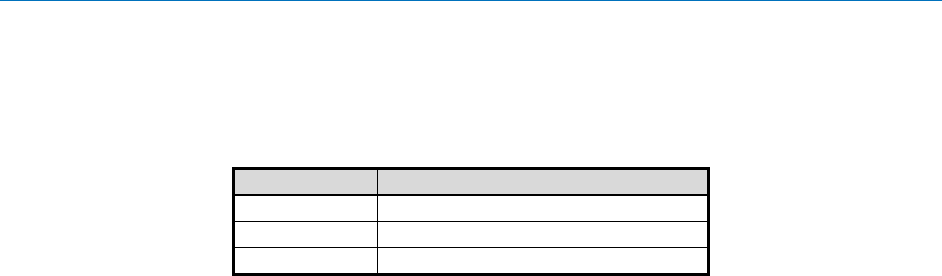
4.3.18 Tilt Detector Configuration
The tilt detector has several parameters that must be configured. The configuration parameters
are 32-bit signed fixed point numbers. If this record is not programmed then default values are
used.
Word
Description
0
Processing window
1
Angular threshold
Figure 20: Tilt Detector Configuration Record
Processing window
The processing window size in seconds. The default value is
2. The Q point is 27.
Angular threshold
The cosine of the angle that defines a tilt. The default value is
cos(35 degrees) = 0.81915… The Q point is 30.
4.3.19 Pocket Detector Configuration
The pocket detector has several parameters that must be configured. The configuration
parameters are 32-bit signed fixed point numbers. If this record is not programmed then default
values are used.
Word
Description
MSB
LSB
0
Orientation Y
Orientation X
1
Orientation W
Orientation Z
2
Orientation Group Delay
3
Angular Ghost Group Delay
4
Near threshold
5
Dark threshold
6
Level threshold
7
Inverted threshold
8
Straight threshold
9
Linear motion threshold
10
Angular motion threshold
11
Motion timeout
12
Opaque adjacency debounce time
Figure 21: Pocket Detector Configuration Record
Orientation
A rotation quaternion that is applied to the input before pocket
determination. The default value is the identity quaternion.
The Q point is 14.
Orientation Group Delay
The desired group delay of the orientation filter in seconds.
The Q point is 20.
Angular Ghost Group
Delay
The desired group delay of the angular ghost filter in seconds.
The Q point is 20.

1000-3625 SH-2 Reference Manual
Copyright © 2017 Hillcrest Laboratories, Inc. All rights reserved. 24
Near Threshold
The threshold below which values are considered near. The
default value is 3 cm. The Q point is 0.
Dark Threshold
The threshold below which values are considered dark. The
default value is 10 lux. The Q point is 0.
Level Threshold
The threshold at which a “level” state is determined. The
default value is cos(15 degrees). The Q point is 29.
Inverted Threshold
The threshold at which a “inverted” state is determined. The
default value is cos(100 degrees). The Q point is 29.
Straight Threshold
The threshold at which a “straight” state is determined The
default value is sin(10 degrees). The Q point is 29.
Linear Motion Threshold
The threshold at which linear motion is considered. The
default value is 2 m/s^2. The Q point is 26.
Angular Motion Threshold
The threshold at which angular motion is considered. The
default value is pi/3 rad/s. The Q point is 28.
Motion Timeout
The timeout for determining motion consideration. The default
value is 1 second. The Q point is 20.
Opaque Adjacency
Debounce Time
The debounce time for determining opaque adjacency (a near
and dark state). The default value is 1 second. The Q point is
20.
4.3.20 Circle Detector Configuration
The circle detector has several parameters that must be configured. The configuration
parameters are 32-bit signed fixed point numbers. If this record is not programmed then default
values are used.
Word
Description
0
Acceleration threshold
1
Angular threshold
2
Revolution threshold
Figure 22: Circle Detector Configuration Record
Acceleration threshold
The threshold of acceleration change from gravity to be
considered circle motion. The default value is 4 m/s^2. The Q
point is 24.
Angular threshold
The threshold of angle between rotation axes. The default
value is 0. The Q point is 30.
Revolution threshold
The threshold for revolutions in radians. The default value is
3pi. The Q point is 25.
1000-3625 SH-2 Reference Manual
Copyright © 2017 Hillcrest Laboratories, Inc. All rights reserved. 25
4.3.21 User Record
There is a record available for the user to store data. The data must be stored as words. The
user record should be limited to 64 words.
Word
Description
0
User defined
…
n
Figure 23: User Record
4.3.22 MotionEngine Time Source Selection
MotionEngine needs to know how to determine the amount of time between two samples from
gyroscope. There are two methods for determining the sample time. The first method is to use
the period that the gyroscope is set to. The second method is to use the sample timestamps
provided by the system clock from the chip on which the sensor hub library is operating. If the
system clock is based on a crystal or an accurate oscillator (±2%) then use time stamps;
otherwise use the gyroscope period.
Word
Description
0
Time source
Figure 24: Time Source Record
Time source
0 – use gyroscope period
1 – use timestamps
others – reserved
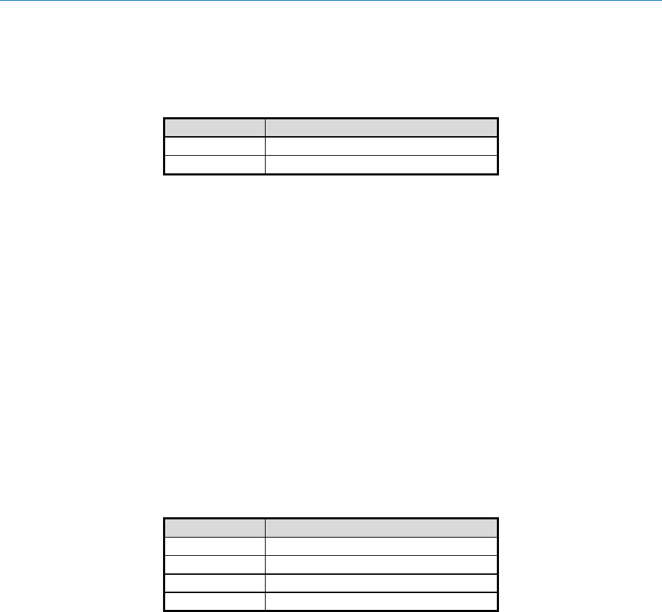
4.3.23 UART Output Format Selection
Some SH-2 products support UART output. There are multiple output formats available for
products operating in UART mode. This FRS record is used to select which output format to
use. If this record is not present in a system, the S-format output is used by default.
Word
Description
0
UART Output Format Selection
Figure 25: UART Output Format Selection Record
UART Output Format
Selection
0 – S-format Output
1 – L-format Output
2 – H-format Output
others – reserved
4.3.24 Gyro-Integrated Rotation Vector
The Gyro-Integrated Rotation Vector provides high-rate, low-latency rotation vector output. It
can be configured to use several different sources as a reference vector, and prediction can
optionally be enabled and tuned.
Word
Description
MSB
LSB
0
Reserved
Reference Data Type
1
Synchronization Interval
1000-3625 SH-2 Reference Manual
Copyright © 2017 Hillcrest Laboratories, Inc. All rights reserved. 26
Word
Description
MSB
LSB
2
Maximum Error
3
Prediction Amount
4
Alpha
5
Beta
6
Gamma
Figure 26: Gyro-Integrated Rotation Vector Configuration Record
Reference Data Type
The slower fused result which is used to provide periodic
corrections to the fast gyro integration process. Acceptable
values are 0x0207 (6-axis Game Rotation Vector) and 0x0204
(9-axis Absolute Rotation Vector). Default value is 6-axis
Game Rotation Vector (0x0207).
Reserved
Set to 0.
Synchronization Interval
Duration, in microseconds, desired between outputs of
reference data type. The units are microseconds. The default
value is 10000 (equivalent to 100 Hz).
Maximum Error
Maximum discrepancy, in radians, between the gyro-
integrated rotation vector and the reference vector that can be
used for smooth corrections. If the reference vector diverges
from the gyro-integrated rotation vector by more than this
amount, the gyro-integrated rotation vector will be updated in
a single discontinuous step to match the reference.
The units are radians. The Q-point is 29. The default value is
π/6 (equivalent to 30 degrees).
Prediction amount
Amount forward in time at which prediction will be performed.
The units are seconds. The Q-point is 10. Default value is 0.
Set this to 0 to disable prediction.
Alpha
Unitless position prediction parameter. The Q-point is 20.
Default value is 0.303072543909142
Beta
Unitless velocity prediction parameter. The Q-point is 20.
Default value is 0.113295896384921
Gamma
Unitless acceleration prediction parameter. The Q-point is 20.
Default value is 0.002776219713054

1000-3625 SH-2 Reference Manual
Copyright © 2017 Hillcrest Laboratories, Inc. All rights reserved. 27
4.3.25 Fusion Control Record
MotionEngine needs to know if the Game Rotation Vector is to use the magnetometer for
stabilization. This is a bit oriented flag word.
Word
Description
0
Flags
Figure 27: Fusion Control Record
Bit 0 - Enable Mag
Stabilized Game Rotation
Vector
0 – False
1 – True
others – reserved
4.3.26 Configuration Records Summary
A list of all the configuration records is shown in Figure 28.
Record ID
Description
0x7979
Static calibration – AGM
0x4D4D
Nominal calibration – AGM
0x8A8A
Static calibration – SRA
0x4E4E
Nominal calibration - SRA
0x1F1F
Dynamic calibration
0xD3E2
MotionEngine power management
0x2D3E
System orientation
0x2D41
Primary accelerometer orientation
0x2D43
Screen rotation accelerometer orientation
0x2D46
Gyroscope orientation
0x2D4C
Magnetometer orientation
0x3E2D
AR/VR stabilization – rotation vector
0x3E2E
AR/VR stabilization – game rotation vector
0xC274
Significant Motion detector configuration
0x7D7D
Shake detector configuration
0xD7D7
Maximum fusion period
0x4B4B
Serial number
0x39AF
Environmental sensor - Pressure calibration
0x4D20
Environmental sensor - Temperature calibration
0x1AC9
Environmental sensor - Humidity calibration
0x39B1
Environmental sensor - Ambient light calibration
0x4DA2
Environmental sensor - Proximity calibration
0xD401
ALS Calibration
0xD402
Proximity Sensor Calibration
0x1B2A
Pickup detector configuration
0xFC94
Flip detector configuration
0xED85
Stability detector configuration
0xED88
Activity Tracker configuration
0xED87
Sleep detector configuration
0xED89
Tilt detector configuration

1000-3625 SH-2 Reference Manual
Copyright © 2017 Hillcrest Laboratories, Inc. All rights reserved. 28
Record ID
Description
0xEF27
Pocket detector configuration
0xEE51
Circle detector configuration
0x74B4
User record
0xD403
MotionEngine Time Source Selection
0xA1A1
UART Output Format Selection
0xA1A2
Gyro-Integrated Rotation Vector configuration
0xA1A3
Fusion Control Flags
Figure 28: Configuration Records
4.3.27 Version Information
Version information is retrieved by using the HCOMM Product ID Request message.

1000-3625 SH-2 Reference Manual
Copyright © 2017 Hillcrest Laboratories, Inc. All rights reserved. 29
5.0 Operation
5.1 Sensor Metadata
Each sensor has a set of static metadata associated with it. This metadata provides information
about the sensor’s capabilities and limitations. The metadata available for each sensor is
Vendor ID
Sensor driver version
Sensor-specific metadata
Name string
Maximum range
Minimum period
Batch buffer reserved count
Maximum batch buffer count
Resolution
Power
Bytes used in batch buffer for one sample
Q point 1 – applies to sensor output
Q point 2 – applies to sensor bias or sensor accuracy unless otherwise noted.
The metadata for each sensor is retrieved by performing an FRS read operation. The FRS
record ID for each sensor is listed in Figure 29.
Record ID
Description
0xE301
Raw accelerometer
0xE302
Accelerometer
0xE303
Linear acceleration
0xE304
Gravity
0xE305
Raw gyroscope
0xE306
Gyroscope calibrated
0xE307
Gyroscope uncalibrated
0xE308
Raw magnetometer
0xE309
Magnetic field calibrated
0xE30A
Magnetic field uncalibrated
0xE30B
Rotation vector
0xE30C
Game rotation vector
0xE30D
Geomagnetic rotation vector
0xE30E
Pressure
0xE30F
Ambient light
0xE310
Humidity
0xE311
Proximity
0xE312
Temperature
0xE313
Tap detector
0xE314
Step detector
0xE315
Step counter
0xE316
Significant motion
0xE317
Stability classifier
0xE318
Shake detector
0xE319
Flip detector
0xE31A
Pickup detector

1000-3625 SH-2 Reference Manual
Copyright © 2017 Hillcrest Laboratories, Inc. All rights reserved. 30
Record ID
Description
0xE31B
Stability detector
0xE31C
Personal Activity classifier
0xE31D
Sleep detector
0xE31E
Tilt detector
0xE31F
Pocket detector
0xE320
Circle detector
0xE321
Heart Rate Monitor
0xE322
ARVR Stabilized Rotation Vector
0xE323
ARVR Stabilized Game Rotation Vector
0xE324
Gyro-integrated Rotation Vector
Figure 29: Metadata Records
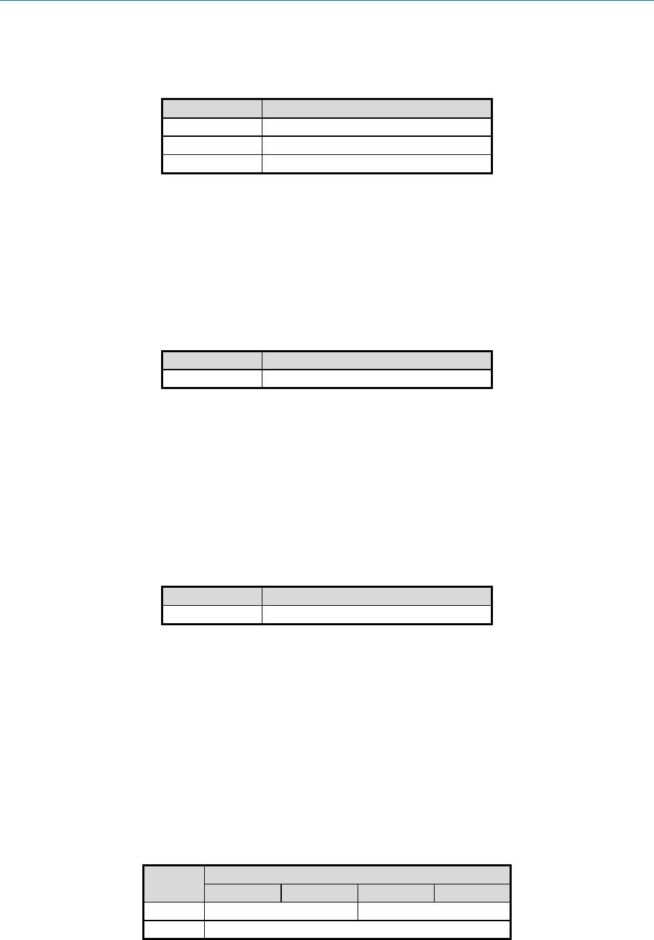
The format of the metadata records is shown in Figure 30 and Figure 26.
Word
Description
MSB
LSB
0
Version
1
Range
2
Resolution
3
Revision = 3
Power
4
Minimum period
5
FIFO reserved count
FIFO max count
6
Vendor ID length
Batch buffer bytes
7
Q point 2
Q point 1
8
Q point 3
Sensor-Specific
Metadata Length
9
Sensor-Specific metadata
…
…
9 +
Sensor-
Specific
Metadata
Length
Vendor ID
…
…
N
Vendor ID
Figure 30: Metadata Record Format – Revision 3
Word
Description
MSB
LSB
0
Version
1
Range
2
Resolution
3
Revision = 4
Power
4
Minimum period
5
FIFO reserved count
FIFO max count
6
Vendor ID length
Batch buffer bytes
7
Q point 2
Q point 1
8
Q point 3
Sensor-Specific
Metadata Length

1000-3625 SH-2 Reference Manual
Copyright © 2017 Hillcrest Laboratories, Inc. All rights reserved. 31
Word
Description
MSB
LSB
9
Maximum period
10
Sensor-Specific metadata
…
…
10 +
Sensor-
Specific
Metadata
Length
Vendor ID
…
…
N
Vendor ID
Figure 31: Metadata Record Format – Revision 4
Version
Identifies the physical sensor/driver/fusion versions for a given
sensor. The elements within this field are updated when a
component changes in a manner that affects the output of the
sensor.
LSB – ME version
Byte 1 – MH version
Byte 2 – SH version
MSB – 0x00
Range
The range of the sensor. The format is unsigned fixed point. The
units and Q point are the same as those used in the sensor’s
input report.
Resolution
The resolution of the sensor. The format is unsigned fixed point.
The units and Q point are the same as those used in the sensor’s
input report.
Power
The power used by the sensor in mA when operating. The format
is unsigned fixed point. The Q point is 10.
Revision
Indicates the revision of the metadata record.
Minimum period
An unsigned integer indicating the minimum operating period in
microseconds of the sensor.
FIFO max count
The maximum number of samples that can be stored in the batch
buffer.
FIFO reserved
count
The number entries reserved in the batch FIFO for this sensor
Batch buffer bytes
The number of bytes used in the batch buffer to store one entry.
Vendor ID length
The length of the vendor ID in bytes.
Q point 1
A signed 16-bit integer indicating the Q point of the sensor data
fields.
Q point 2
A signed 16-bit integer indicating the Q point of the sensor bias

1000-3625 SH-2 Reference Manual
Copyright © 2017 Hillcrest Laboratories, Inc. All rights reserved. 32
or accuracy fields. This field is applicable only to sensors that
have bias or accuracy outputs as well as data outputs.
Sensor-Specific
Metadata length
An unsigned 16-bit integer indicating how many bytes are used
for sensor-specific metadata. 0 if there is no additional metadata.
This value must be a multiple of four.
Q point 3
A signed 16-bit integer indicating the Q point of the sensor data
change sensitivity.
Maximum period
An unsigned integer indicating the maximum operating period in
microseconds of the sensor.
Sensor-Specific
Metadata
Some sensors expose additional information (e.g. Personal
activity classifier exposes a bitmap representing the set of
supported classification states). This area is used for such
information. This field is padded with zeroes if the length is not a
multiple of four.
Vendor ID
The vendor ID is a character string that lists the vendor name
and part number. It is null terminated. The first byte starts in the
LSB of the first word. This field is padded with zeroes if the length
of the vendor ID is not a multiple of four.
5.1.1 Sensor-Specific Metadata
Sensors may need to expose more detailed information than the basic set of fields above. The
format of these sensors’ Sensor-specific Metadata is described here.
5.1.1.1 Personal Activity Classifier Metadata (0xE31C)
The sensor-specific metadata length is 4.
The sensor-specific metadata is structured as shown in Figure 32.
Description
Byte
Bit 7
Bit 6
Bit 5
Bit 4
Bit 3
Bit 2
Bit 1
Bit 0
0
…
…
…
…
…
…
Classification
1 supported
Classification
0 supported
1
…
…
…
…
…
…
…
…
2
…
…
…
…
…
…
…
…
3
Reserved
Classification
30 supported
…
…
…
…
…
…
Figure 32: Personal Activity Classifier Sensor-Specific Metadata.
5.2 Input Reports
The SH-2 returns sensor data to the host via input reports. Each sensor has its own input report.
Input reports are sent at a rate specified by the host. This rate may either be synchronous to the
sensor’s operating rate or asynchronous. Input reports may also be requested by the host at

1000-3625 SH-2 Reference Manual
Copyright © 2017 Hillcrest Laboratories, Inc. All rights reserved. 33
any time. The SH-2may also be configured to send input reports only if thresholds are
exceeded. Each sensor has its own set of thresholds. If a threshold is configured then the SH-2
will send reports at the requested rate only if the sensor output exceeds the threshold.
Sensor data is sent to the host on either the “Wakeup” SHTP channel or the “Normal” SHTP
channel, depending on whether a sensor has been configured as a wakeup sensor or not (see
[2]).
The Gyro-integrated Rotation Vector is reported on a separate “gyroRV” SHTP channel to
facilitate traffic prioritization and other optimizations.
Input reports are also used to send configuration responses to the host. Configuration input
reports will be sent on the SHTP “control” channel (see [2]).
5.3 Output Reports
Output reports are used to send configuration information to the SH-2.
5.4 Feature Reports
Sensor operation is controlled through feature reports. Setting a feature report for a sensor
causes operation of that sensor to change to comply with the settings in the feature report.
Getting a feature report returns the current operation configuration of the sensor. The operations
that can be controlled by feature reports are described in the following sections. These
descriptions provide an overview of how to control sensor operation. In cases where specific
field in feature reports are mentioned see section 6.0 for detailed information about those fields.
5.4.1 Rate Control
Sensor operating rate is controlled through the report interval field. When set to zero the sensor
is off. When set to a non-zero value the sensor generates reports at that interval or more
frequently. If the sensor cannot operate as quickly as requested, it will operate at its minimum
interval, if possible. Input reports are generated at the operating rate of the sensors.
Please note that while active, the Gyro-Integrated Rotation Vector (6.5.44) may cause a
reduction in both the nominal and actual reporting periods for fusion outputs for given requested
periods. For example, a 400 Hz Game Rotation Vector may drop to 100 Hz to permit full-speed
operation of the Gyro-Integrated Rotation Vector.
5.4.2 Threshold Control
Each sensor has a configurable reporting threshold used to determine if an input report should
be sent or not. The reporting threshold is set using the change sensitivity field. Change
sensitivities are either absolute or relative. Absolute sensitivities are evaluated to determine if
the current output values exceed the change sensitivity. Relative sensitivities are evaluated to
determine if the current output has changed relative to the previous output by an amount that
exceeds the change sensitivity.
5.4.3 Batch Operation
Batching causes the sensor to buffer its input reports until they can be sent. There are two batch
buffers. The first buffer is a circular buffer. When the SH-2 in on, reports are sent based on a
delay interval or when the buffer is full. When the SH-2 is asleep, reports are queued in the
buffer until the buffer is full. New sensor reports then overwrite the oldest reports in the buffer.
When the SH-2 is turned on the reports in the buffer are sent.

1000-3625 SH-2 Reference Manual
Copyright © 2017 Hillcrest Laboratories, Inc. All rights reserved. 34
The second buffer is a wake-on-full buffer. When the SH-2 is on or asleep, reports are sent
based on a delay interval or when the buffer is full. When the SH-2 is asleep, reports are
queued in the buffer until the buffer is full. When the buffer is full, the SH-2 wakes the AP and
sends the reports.
In cases where reports are sent when the buffer is full, they are sent soon enough to prevent the
buffer from actually overflowing. Thus, no reports are lost.
5.5 Sensor Triggering
Sensors report events based on trigger modes. The trigger modes are:
Continuous – events are reported continuously at the report interval
On-change – events are reported only if the sensor’s output has changed. In addition,
events are reported no more frequently than once every report interval
One-shot – a single event is reported and then the sensor turns off
Special – reporting requirements are explained in the section on that sensor’s report
Wake-up – When the sensor has a report to send, it can wake the host in order to send
the report. i.e. it can cause the system to exit sleep mode.
Always-on – The sensor remains on, even during periods of sleep
The trigger mode for each sensor, except the significant motion detector, can be configured as
continuous, on-change or special. The trigger mode for the significant motion detector is always
one-shot. In addition, sensors can be configured to wake up the application processor. The
trigger mode and wake-up capability for each sensor when configured for an Android system is
shown in Figure 33.
Note the interaction between “wake-up” and “always-on.” A sensor may be configured as
always-on, but not wakeup. In this mode, the sensor will continue to run and log data to the non-
wakeup batch buffer while the hub is asleep. When a (different) wakeup sensor triggers, the
buffered data from all sensors is delivered. Thus, the host will get the data from the wakeup
sensor and then the backlog of data from the non-wakeup, but always-on sensors. It is generally
not useful to configure a sensor as “wake-up” but not “always-on.”

1000-3625 SH-2 Reference Manual
Copyright © 2017 Hillcrest Laboratories, Inc. All rights reserved. 35
Output
continuous
on-change
one-shot
special
wake-up
always-on
Raw accelerometer
X
Acceleration
X
Linear acceleration
X
Gravity
X
Raw gyroscope
X
Gyroscope calibrated
X
Gyroscope uncalibrated
X
Raw magnetometer
X
Magnetic field calibrated
X
Magnetic field uncalibrated
X
Rotation vector
X
Game rotation vector
X
Geomagnetic rotation vector
X
ARVR-Stabilized Rotation vector
X
ARVR-Stabilized Game rotation vector
X
Pressure
X
Ambient light
X
Humidity
X
Proximity
X
X
Temperature
X
SAR
Tap detector
X
Step detector
X
Step counter
X
X
Significant motion
X
X
Stability classifier
X
Shake detector
X
X
Flip detector
X
X
Pickup detector
X
X
Stability detector
X
Personal Activity Classifier
X
Sleep detector
X
X
Tilt detector
X
X
Pocket Detector
X
X
Circle detector
X
X
Figure 33: Sensor Trigger Modes

1000-3625 SH-2 Reference Manual
Copyright © 2017 Hillcrest Laboratories, Inc. All rights reserved. 36
6.0 Report Descriptions
6.1 Report ID Convention
The report ID is shown as byte 0 in the reports defined throughout the following sections.
6.2 Summary
The following table summarizes all the reports in use with SH-2. Direction is relative to the host
(e.g. “write” indicates transmission of data from host to hub).
SHTP Channel
Direction
Report
ID
Description
SH-2 Control
W
0xFE
Get Feature Request
SH-2 Control
W
0xFD
Set Feature Command
SH-2 Control
W
0xFC
Get Feature Response
Wakeup/Normal
R
0xFB
Base Timestamp
Wakeup/Normal
R
0xFA
Timestamp Rebase
SH-2 Control
W
0xF9
Product ID Request
SH-2 Control
R
0xF8
Product ID Response
SH-2 Control
W
0xF7
FRS Write Request
SH-2 Control
W
0xF6
FRS Write Data
SH-2 Control
W
0xF5
FRS Write Response
SH-2 Control
W
0xF4
FRS Read Request
SH-2 Control
R
0xF3
FRS Read Response
SH-2 Control
W
0xF2
Command Request
SH-2 Control
R
0xF1
Command Response
Wakeup/Normal
R
0x01
Accelerometer
Wakeup/Normal
R
0x02
Gyroscope
Wakeup/Normal
R
0x03
Magnetic Field
Wakeup/Normal
R
0x04
Linear Acceleration
Wakeup/Normal
R
0x05
Rotation Vector
Wakeup/Normal
R
0x06
Gravity
Wakeup/Normal
R
0x07
Uncalibrated Gyroscope
Wakeup/Normal
R
0x08
Game Rotation Vector
Wakeup/Normal
R
0x09
Geomagnetic Rotation Vector
Wakeup/Normal
R
0x0A
Pressure
Wakeup/Normal
R
0x0B
Ambient Light
Wakeup/Normal
R
0x0C
Humidity
Wakeup/Normal
R
0x0D
Proximity
Wakeup/Normal
R
0x0E
Temperature
Wakeup/Normal
R
0x0F
Uncalibrated Magnetic Field
Wakeup/Normal
R
0x10
Tap Detector
Wakeup/Normal
R
0x11
Step Counter
Wakeup/Normal
R
0x12
Significant Motion
Wakeup/Normal
R
0x13
Stability Classifier
Wakeup/Normal
R
0x14
Raw Accelerometer
Wakeup/Normal
R
0x15
Raw Gyroscope
Wakeup/Normal
R
0x16
Raw Magnetometer
Wakeup/Normal
R
0x17
SAR
Wakeup/Normal
R
0x18
Step Detector

1000-3625 SH-2 Reference Manual
Copyright © 2017 Hillcrest Laboratories, Inc. All rights reserved. 37
SHTP Channel
Direction
Report
ID
Description
Wakeup/Normal
R
0x19
Shake Detector
Wakeup/Normal
R
0x1A
Flip Detector
Wakeup/Normal
R
0x1B
Pickup Detector
Wakeup/Normal
R
0x1C
Stability Detector
Wakeup/Normal
R
0x1E
Personal Activity Classifier
Wakeup/Normal
R
0x1F
Sleep Detector
Wakeup/Normal
R
0x20
Tilt Detector
Wakeup/Normal
R
0x21
Pocket Detector
Wakeup/Normal
R
0x22
Circle Detector
Wakeup/Normal
R
0x23
Heart Rate Monitor
Wakeup/Normal
R
0x28
ARVR-Stabilized Rotation Vector
Wakeup/Normal
R
0x29
ARVR-Stabilized Game Rotation Vector
Figure 34: Report ID List
6.3 Configuration Reports
Configuration reports are read and written using messages. These messages are described in
the following sections. Some configuration reports are used to collect information. Some
configuration reports are used to read and write configuration records.
6.3.1 Product ID Request (0xF9)
The product ID request is used to request product ID information from the FSP3xx.
Byte
Description
0
Report ID = 0xF9
1
Reserved
Figure 35: Product ID Request
6.3.2 Product ID Response (0xF8)
The product ID response returns product ID information about the FSP3xx.
Byte
Description
0
Report ID = 0xF8
1
Reset Cause
2
SW Version Major
3
SW Version Minor
4
SW Part Number LSB
5
SW Part Number …
6
SW Part Number …
7
SW Part Number MSB
8
SW Build Number LSB
9
SW Build Number …
10
SW Build Number …
11
SW Build Number MSB
12
SW Version Patch LSB

1000-3625 SH-2 Reference Manual
Copyright © 2017 Hillcrest Laboratories, Inc. All rights reserved. 38
Byte
Description
13
SW Version Patch MSB
14
Reserved
15
Reserved
Figure 36: Product ID Response
Reset Cause
The last cause of the processor reset. Only reported for the
overall system ID. Subsystem Product IDs will report Not
Applicable.
0 – Not Applicable
1 – Power On Reset
2 – Internal System Reset
3 – Watchdog Timeout
4 – External Reset
5 – Other
SW Version:
software version major (8 bits).minor (8 bits).patch (16 bits)
SW Part Number:
32-bit value representing the software part number
SW Build Number:
32-bit software build number
6.3.3 FRS Write Request (0xF7)
The FRS write request is used to initiate writing an FRS record.
Byte
Description
0
Report ID = 0xF7
1
Reserved
2
Length LSB
3
Length MSB
4
FRS Type LSB
5
FRS Type MSB
Figure 37: FRS Write Request
Length:
length in 32-bit words of the record to be written. If the length is set
to 0 then the record is erased.
FRS Type:
FRS record type (see Figure 28)
6.3.4 FRS Write Data Request (0xF6)
The FRS write data request is sent to write data to the record indicated by a previous write
request. Only one FRS operation may be in progress at any one time.
Byte
Description
0
Report ID = 0xF6
1
Reserved
2
Offset LSB
3
Offset MSB
4
Data0 LSB
5
Data0 …

1000-3625 SH-2 Reference Manual
Copyright © 2017 Hillcrest Laboratories, Inc. All rights reserved. 39
Byte
Description
6
Data0 …
7
Data0 MSB
8
Data1 LSB
9
Data1 …
10
Data1 …
11
Data1 MSB
Figure 38: FRS Write Data Request
Offset:
offset, in 32-bit words, from the beginning of the record indicating
where in the record the data is to be written
Data0/1:
32-bit words of data to be written to the FRS record
The offset field is used to detect missing or put of order write data requests. When writing a
record, the write data requests must be supplied in order, with both data0 and data1 fields used.
If the record contains an odd number of words then the final write data request must use data0.
6.3.5 FRS Write Response (0xF5)
The write response report indicates the status of a write operation.
Byte
Description
0
Report ID = 0xF5
1
Status/Error
2
Word Offset LSB
3
Word Offset MSB
Figure 39: FRS Write Response
Status/Error:
0 – word(s) received
1 – unrecognized FRS type
2 – busy
3 – write completed
4 – write mode entered or ready
5 – write failed
6 – data received while not in write mode
7 – invalid length
8 – record valid (the complete record passed internal validation
checks)
9 – record invalid (the complete record failed internal validation
checks)
10 – device error (DFU flash memory device unavailable)
11 – record is read only
12-255 – reserved
Word Offset:
the number of words offset from the beginning of the record for the
most recently received write data request
An FRS write response is generated for each write request or write data request.

1000-3625 SH-2 Reference Manual
Copyright © 2017 Hillcrest Laboratories, Inc. All rights reserved. 40
6.3.6 FRS Read Request (0xF4)
The FRS read request is used to retrieve an FRS record from the FSP3xx. Only one FRS
operation may be in progress at a time. If a Read Request is issued before the first read
operation is complete, it will be responded to with a Read Response indicating BUSY and then it
will complete the already in-progress read operation.
Byte
Description
0
Report ID = 0xF4
1
Reserved
2
Read Offset LSB
3
Read Offset MSB
4
FRS Type LSB
5
FRS Type MSB
6
Block Size LSB
7
Block Size MSB
Figure 40: FRS Read Request
Read Offset:
offset, in 32-bit words, from the beginning of the FRS record at which
to begin the read operation. The first word in an FRS record is word 0.
FRS Type:
FRS record type to read (see Figure 28)
Block Size:
number of 32-bit words to read. If the block size is zero then the entire
record beginning at the read offset is returned
6.3.7 FRS Read Response (0xF3)
The FRS read response report is used to return the contents of an FRS record. Once a read
request has been received, the FSP3xx generates read responses until the request record or
portion of a record is returned. Only one FRS operation may be in progress at a time.
Byte
Description
0
Report ID = 0xF3
1
Data Length (bits 7:4)
Status (bits 3:0)
2
Word Offset LSB
3
Word Offset MSB
4
Data0 LSB
5
Data0 …
6
Data0 …
7
Data0 MSB
8
Data1 LSB
9
Data1 …
10
Data1 …
11
Data1 MSB
12
FRS Type LSB
13
FRS Type MSB
14
Reserved
15
Reserved
Figure 41: FRS Read Response
Data Length:
the number of data words contained within the message.

1000-3625 SH-2 Reference Manual
Copyright © 2017 Hillcrest Laboratories, Inc. All rights reserved. 41
Status:
0 – no error
1 – unrecognized FRS type
2 – busy
3 – read record completed
4 – offset out of range
5 – record empty
6 – read block completed (if block size requested)
7 – read block completed and read record completed (if block size
requested)
8 – device error (DFU flash memory device unavailable)
9-15 – reserved
Word Offset:
the number of words offset from the beginning of the record
Data0/1:
between 0 and 2 32-bit words of data from and FRS record. If only 1
word is present then it will be in the data0 field.
FRS Type:
indicates to which type of FRS record the data belongs (see
Section 4.0)
6.3.8 Command Request (0xF2)
The command request is used to ask the SH-2 to perform some special operation or report
some special data that is not part of normal sensor operation.
Byte
Description
0
Report ID = 0xF2
1
Sequence number
2
Command
3
P0
4
P1
5
P2
6
P3
7
P4
8
P5
9
P6
10
P7
11
P8
Figure 42: Command Request
Sequence
number
A monotonically incrementing uint8_t that rolls over. It is used to detect
missing commands and to synchronize responses
Command
A unit8_t in the range of 1-127 indicating the command. 0 and 128-255
are reserved.
P0 – P9
A set of command-specific parameters. The interpretation of these
parameters is defined for each command.
6.3.9 Command Response (0xF1)
The command response is used to report the results of some special operation or some special
data that is not part of normal sensor operation.

1000-3625 SH-2 Reference Manual
Copyright © 2017 Hillcrest Laboratories, Inc. All rights reserved. 42
Byte
Description
0
Report ID = 0xF1
1
Sequence number
2
Command
3
Command sequence number
4
Response sequence number
5
R0
6
R1
7
R2
8
R3
9
R4
10
R5
11
R6
12
R7
13
R8
14
R9
15
R10
Figure 43: Command Response
Sequence
number
A monotonically incrementing uint8_t that rolls over. It is used to detect
missing responses
Command
A unit8_t indicating the command being responded to. A value of with
the most significant bit set indicates that the response was
autonomously generated and is not associated with a command
request. Bits 6-0 indicate the command that the response corresponds
to. That is, bits 6-0 identify how to interpret the response.
Command
sequence
number
The sequence number from the command request for which the
response was returned. It is used to synchronize commands and
responses. This field is set to 0 for unsolicited responses.
Response
sequence
number
Some commands may require multiple responses. This is a
monotonically incrementing uint8_t that counts responses within a
group of responses to a single request. It may rollover. It restarts at 0
with each new response group. A response group may consist of only
one response.
R0 – R10
A set of response values. The interpretation of these values is specific
to the response for each command.
6.4 Commands
A set of commands has been defined to support a variety of operations on the sensor hub. For
each command id, a Command Message and associated Response message are usually
defined. (A few cases define only a command or only a response.) The definitions of the
command and response formats for each command id are defined in the following sections.
The following table summarizes the command identifiers defined to date:
Id
Name
Description
1
Errors
Command and Response to access error queue. See section 6.4.1
2
Counter
Command and Response to access counters. See section 6.4.3

1000-3625 SH-2 Reference Manual
Copyright © 2017 Hillcrest Laboratories, Inc. All rights reserved. 43
Id
Name
Description
3
Tare
Command and Response to operate on tare. See section 6.4.4
4
Initialize
Reinitialize sensor hub components. See section 6.4.5
5
Reserved
ID 5 is not currently in use. It is reserved for future use.
6
DCD
Command to save DCD. See section 6.4.6
7
ME CAL
Command and Response to configure ME Calibration. See section 6.4.7
8
Reserved
Deprecated.
9
DCD Save
Command to configure periodic saving of DCD. See section 6.4.6
10
Oscillator
Command to retrieve the oscillator type used in the clock system.
11
Clear DCD
and Reset
Command to clear the in-memory DCD state and perform a chip reset. See
section
Figure 44: Command Identifiers
6.4.1 Report Errors (0x01)
The SH-2 maintains a queue of errors. The report error command is used to retrieve values
from this queue. The usage of parameters and response values is shown below. The report
error command may generate multiple responses. The SH-2 will send as many responses as
necessary to send all the errors in its queue. Every error response ends with a response with
the error source set to 255, indicating that there are no more errors to report.
Byte
Name
Description
0
Report ID
0xF2 – Command Request
1
Sequence
Number
See section 6.3.8.
2
Command
0x01 – report all errors in the error queue
3
P0
The severity of errors to report. Errors of this severity and higher will be
reported. 0 – highest priority.
4
P1
Reserved
5
P2
Reserved
6
P3
Reserved
7
P4
Reserved
8
P5
Reserved
9
P6
Reserved
10
P7
Reserved
11
P8
Reserved
Figure 45: Report Errors Command
Byte
Name
Description
0
Report ID
0xF1- Command Response
1
Sequence
Number
See Section 6.3.9
2
Command
0x01 – report all errors in the error queue
3
Command
Sequence
Number
See Section 6.3.9
4
Response
Sequence
Number
See Section 6.3.9
5
R0
Severity – the severity of the error currently being reported

1000-3625 SH-2 Reference Manual
Copyright © 2017 Hillcrest Laboratories, Inc. All rights reserved. 44
Byte
Name
Description
6
R1
Error sequence number. A monotonically incrementing uin8_t that counts all
the errors generated for the reported severity. It may rollover.
7
R2
Error source. 0 – reserved, 1 – MotionEngine, 2 – MotionHub, 3 – SensorHub,
4 – Chip level executable, 5-254 reserved. 255 – no error to report.
8
R3
Error. See library API
9
R4
Error module. See library API
10
R5
Error code. See library API
11
R6
Reserved
12
R7
Reserved
13
R8
Reserved
14
R9
Reserved
15
R10
Reserved
Figure 46: Report Errors Response
6.4.2 Perform Self-Test
TBD
6.4.3 Counter Commands (0x02)
Counter commands are specified with a command byte of 2. Sub-commands are specified by
the P0 byte.
6.4.3.1 Get Counts (0x00)
Retrieve the number of times a specified sensor has produced samples, and what has been
done with those samples.
Offered = Number of samples produced by underlying data source.
On = Number of “Offered” samples while this sensor was requested by host.
Accepted = Number of “On” samples that passed decimation filter.
Attempted = Number of “Accepted” samples that passed threshold requirements and had
transmission to the host attempted.
Byte
Name
Description
0
Report ID
0xF2 – Command Request
1
Sequence
Number
See Section 6.3.8.
2
Command
0x02 – Counter command
3
P0
0x00 – Sub-command: get counts
4
P1
Sensor ID
5
P2
Reserved
6
P3
Reserved
7
P4
Reserved
8
P5
Reserved
9
P6
Reserved
10
P7
Reserved
11
P8
Reserved
Figure 47: Get Counts Command

1000-3625 SH-2 Reference Manual
Copyright © 2017 Hillcrest Laboratories, Inc. All rights reserved. 45
These counts are returned in a pair of responses. The response sequence number (0 or 1)
indicates the types of counts it contains.
Byte
Name
Description
0
Report ID
0xF1- Command Response
1
Sequence
Number
See Section 6.3.9
2
Command
0x02 – Counter command
3
Command
Sequence
Number
See 6.3.9
4
Response
Sequence
Number
See 6.3.9
5
R0
Sensor ID
6
R1
Status (0= invalid sensor requested, 1=valid sensor requested)
7
R2
Reserved
8
R3
Count Offered (Sequence Number=0) Count On (Sequence Number=1) LSB
9
R4
Count Offered (SN=0) Count On (SN=1) …
10
R5
Count Offered (SN=0) Count On (SN=1) ….
11
R6
Count Offered (SN=0) Count On (SN=1) MSB
12
R7
Count Accepted (SN=0) Count Attempted (SN=1) LSB
13
R8
Count Accepted (SN=0) Count Attempted (SN=1) …
14
R9
Count Accepted (SN=0) Count Attempted (SN=1) ….
15
R10
Count Accepted (SN=0) Count Attempted (SN=1) MSB
Figure 48: Get Counts Response
6.4.3.2 Clear Counts (0x01)
Clear all counters for a given sensor to 0.
Byte
Name
Description
0
Report ID
0xF2 – Command Request
1
Sequence
Number
See Section 6.3.8.
2
Command
0x02 – Counter command
3
P0
0x01 – Sub-command: clear counts
4
P1
Sensor ID
5
P2
Reserved
6
P3
Reserved
7
P4
Reserved
8
P5
Reserved
9
P6
Reserved
10
P7
Reserved
11
P8
Reserved
Figure 49: Clear Counts Command
6.4.4 Tare (0x03)
Tare commands are specified with a Command byte of 3. Sub-commands are specified by the
P0 byte.

1000-3625 SH-2 Reference Manual
Copyright © 2017 Hillcrest Laboratories, Inc. All rights reserved. 46
6.4.4.1 Tare Now (0x00)
This command instructs SH-2 to perform a tare operation along one or more axis. Currently the
following axes are supported:
P1 = 0x07: (X,Y, Z). This tares with rotation around all axes. This will reorient all motion
outputs (e.g. accelerometer, gyroscope, magnetometer, rotation vectors).
P1 = 0x04: (Z): This will tare with a rotation around Z, which changes the heading, but not the
tilt. The Z axis will be defined by the current reorientation.
If P2 is 0 (Rotation Vector) or 2 (Geomagnetic Rotation Vector), then this will reorient all motion
outputs.
If P2 is 1 (Gaming Rotation Vector), then this will only tare the Gaming Rotation Vector. A Z-
axis Gaming Rotation tare cannot be persistent, because the Gaming Rotation Vector has no
absolute reference for heading.
If P2 is 3, 4, or 5 (Gyro-Integrated Rotation Vector, ARVR-Stabilized Rotation Vector, ARVR-
Stabilized Game Rotation Vector), then the tare will be performed on the underlying rotation
vector (Rotation Vector or Game Rotation Vector). The derived vector will be immediately
updated to match the value of the underlying rotation vector at this time.
Byte
Name
Description
0
Report ID
0xF2 – Command Request
1
Sequence
Number
See Section 6.3.8.
2
Command
0x03 – Tare command
3
P0
0x00 – Subcommand: Perform Tare now
4
P1
Bitmap of axes to tare: Bit 0= X, Bit 1= Y, Bit 2= Z
5
P2
Rotation Vector to use as basis for tare.
0: Rotation Vector
1: Gaming Rotation Vector
2: Geomagnetic Rotation Vector
3: Gyro-Integrated Rotation Vector
4: ARVR-Stabilized Rotation Vector
5: ARVR-Stabilized Game Rotation Vector
6
P3
Reserved
7
P4
Reserved
8
P5
Reserved
9
P6
Reserved
10
P7
Reserved
11
P8
Reserved
Figure 50: Tare Now Command
6.4.4.2 Persist Tare (0x01)
This command instructs SH-2 to persist the results of the last tare operation to flash for use at
the next system restart. These results are stored in the master Sensor Orientation configuration
record, individual sensor orientation records are not modified. Note that this only persists the
tare applied to rotation vector and geomagnetic rotation vector.
Byte
Name
Description
0
Report ID
0xF2 – Command Request

1000-3625 SH-2 Reference Manual
Copyright © 2017 Hillcrest Laboratories, Inc. All rights reserved. 47
Byte
Name
Description
1
Sequence
Number
See Section 6.3.8.
2
Command
0x03 – Tare command
3
P0
0x01 – Persist Tare
4
P1
Reserved
5
P2
Reserved
6
P3
Reserved
7
P4
Reserved
8
P5
Reserved
9
P6
Reserved
10
P7
Reserved
11
P8
Reserved
Figure 51: Persist Tare Command
6.4.4.3 Set Reorientation (0x02)
This command instructs SH-2 to set the current run-time sensor reorientation. Note that this
does not replace any persistent tare settings in the master Sensor Orientation configuration
record. Persistent tare settings must be cleared by deleting the Sensor Orientation configuration
record.
To clear the current tare, set P1-P8 to 0x00.
The rotation vector is a signed, 16-bit 2’s-complement fixed point number with a Q-point of 14.
Byte
Name
Description
0
Report ID
0xF2 – Command Request
1
Sequence
Number
See Section 6.3.8.
2
Command
0x03 – Tare Command
3
P0
0x02 – Set Reorientation
4
P1
Rotation quaternion X LSB
5
P2
Rotation quaternion X MSB
6
P3
Rotation quaternion Y LSB
7
P4
Rotation quaternion Y MSB
8
P5
Rotation quaternion Z LSB
9
P6
Rotation quaternion Z MSB
10
P7
Rotation quaternion W LSB
11
P8
Rotation quaternion W MSB
Figure 52: Set Reorientation Command
6.4.5 Initialization (0x04)
The initialize command requests that the sensor hub reinitialize itself or one of its subsystems.
The response is sent unsolicited if the sensor hub itself resets.
6.4.5.1 Initialize Command
This command is sent by the host to re-initialize the sensor hub (or one of its subsystems.)
Byte
Name
Description
0
Report ID
0xF2 – Command Request

1000-3625 SH-2 Reference Manual
Copyright © 2017 Hillcrest Laboratories, Inc. All rights reserved. 48
Byte
Name
Description
1
Sequence
Number
See Section 6.3.8.
2
Command
0x04 – Initialize command
3
P0
Subsystem
4
P1
Reserved
5
P2
Reserved
6
P3
Reserved
7
P4
Reserved
8
P5
Reserved
9
P6
Reserved
10
P7
Reserved
11
P8
Reserved
Figure 53: Initialize Command
The subsystem field indicates which component of the sensor hub should be reinitialized:
Value
Subsystem
Description
0
None
No Operation.
1
SensorHub
Reinitialize the entire sensor hub.
Others
Reserved
Reserved
Figure 54: Initialize Command Subsystems
6.4.5.2 Initialize Response
The sensor hub responds to the Initialize command with an Initialize Response. In the case
where the sensor hub reinitializes itself, this response is unsolicited. An unsolicited response is
also generated after startup.
Byte
Name
Description
0
Report ID
0xF1- Command Response
1
Sequence
Number
See Section 6.3.9
2
Command
0x04 – Initialize, 0x84 – Initialize (unsolicited)
3
Command
Sequence
Number
See 6.3.9
4
Response
Sequence
Number
See 6.3.9
5
R0
Status (0 – successful. 1 – Operation failed)
6
R1
Subsystem
7
R2
Reserved
8
R3
Reserved
9
R4
Reserved
10
R5
Reserved
11
R6
Reserved
12
R7
Reserved
13
R8
Reserved
14
R9
Reserved
15
R10
Reserved
Figure 55: Initialize Response

1000-3625 SH-2 Reference Manual
Copyright © 2017 Hillcrest Laboratories, Inc. All rights reserved. 49
6.4.6 Save DCD (0x06)
The Save DCD command requests that the sensor hub save the current DCD. Upon
completion, a Save DCD Response will be sent.
6.4.6.1 Save DCD Command
This command is sent by the host to save the DCD.
Byte
Name
Description
0
Report ID
0xF2 – Command Request
1
Sequence
Number
See Section 6.3.8.
2
Command
0x06 – Save DCD Command
3
P0
Reserved
4
P1
Reserved
5
P2
Reserved
6
P3
Reserved
7
P4
Reserved
8
P5
Reserved
9
P6
Reserved
10
P7
Reserved
11
P8
Reserved
Figure 56: Save DCD Command
6.4.6.2 Save DCD Response
The sensor hub responds to the Save DCD command with a Save DCD Response containing a
success/failure status.
Byte
Name
Description
0
Report ID
0xF1- Command Response
1
Sequence
Number
See Section 6.3.9
2
Command
0x06 – Save DCD
3
Command
Sequence
Number
See 6.3.9
4
Response
Sequence
Number
See 6.3.9
5
R0
Status (0 – success. Non Zero – Operation failed)
6
R1
Reserved
7
R2
Reserved
8
R3
Reserved
9
R4
Reserved
10
R5
Reserved
11
R6
Reserved
12
R7
Reserved
13
R8
Reserved
14
R9
Reserved
15
R10
Reserved
Figure 57: Save DCD Response

1000-3625 SH-2 Reference Manual
Copyright © 2017 Hillcrest Laboratories, Inc. All rights reserved. 50
6.4.7 ME Calibration Commands (0x07)
The ME Calibration command requests tell the sensor hub to enable/disable the accelerometer,
gyro and magnetometer calibration routines and can read back the enable/disable state of each
of these routines.
6.4.7.1 Configure ME Calibration Command
This command is sent by the host to configure the ME calibration of the accelerometer, gyro and
magnetometer giving the host the ability to control when calibration is performed.
Byte
Name
Description
0
Report ID
0xF2 – Command Request
1
Sequence
Number
See Section 6.3.8.
2
Command
0x07 – ME Calibration Command
3
P0
Accel Cal Enable (1 – enabled, 0 – disabled)
4
P1
Gyro Cal Enable (1 – enabled, 0 – disabled)
5
P2
Mag Cal Enable (1 – enabled, 0 – disabled)
6
P3
0x00 – Subcommand: Configure ME Calibration
7
P4
Planar Accel Cal Enable (1 – enabled, 0 – disabled)
8
P5
Reserved
9
P6
Reserved
10
P7
Reserved
11
P8
Reserved
Figure 58: Configure ME Calibration Command
6.4.7.2 Get ME Calibration Command
This command is sent by the host to request the enable/disable state of the accelerometer, gyro
and magnetometer calibration routines.
Byte
Name
Description
0
Report ID
0xF2 – Command Request
1
Sequence
Number
See Section 6.3.8.
2
Command
0x07 – ME Calibration Command
3
P0
Reserved
4
P1
Reserved
5
P2
Reserved
6
P3
0x01 – Subcommand: Get ME Calibration
7
P4
Reserved
8
P5
Reserved
9
P6
Reserved
10
P7
Reserved
11
P8
Reserved
Figure 59: Get ME Calibration Command

1000-3625 SH-2 Reference Manual
Copyright © 2017 Hillcrest Laboratories, Inc. All rights reserved. 51
6.4.7.3 ME Calibration Response
The sensor hub responds to the Configure ME Calibration command with a Configure ME
Calibration Response containing a success/failure status and the enable/disable state of the
accelerometer, gyro and magnetometer calibration routines.
Byte
Name
Description
0
Report ID
0xF1- Command Response
1
Sequence
Number
See Section 6.3.9
2
Command
0x07 – Configure ME Calibration
3
Command
Sequence
Number
See 6.3.9
4
Response
Sequence
Number
See 6.3.9
5
R0
Status (0 – success. Non Zero – Operation failed)
6
R1
Accel Cal Enable (1 – enabled, 0 – disabled)
7
R2
Gyro Cal Enable (1 – enabled, 0 – disabled)
8
R3
Mag Cal Enable (1 – enabled, 0 – disabled)
9
R4
Planar Accel Cal Enable (1 – enabled, 0 – disabled)
10
R5
Reserved
11
R6
Reserved
12
R7
Reserved
13
R8
Reserved
14
R9
Reserved
15
R10
Reserved
Figure 60: Configure ME Calibration Response
6.4.8 Configure Periodic DCD Save (0x09)
The Configure Periodic DCD Save command configures the automatic saving of DCD. There is
no response to this command. This command does not inhibit the Save DCD command.
6.4.8.1 Configure Periodic DCD Save Command
This command is sent by the host to enable or disable the saving of DCD on a periodic basis.
Byte
Name
Description
0
Report ID
0xF2 – Command Request
1
Sequence
Number
See Section 6.3.8.
2
Command
0x09– Configure DCD Save Command
3
P0
0x00 – Enable Periodic DCD Save
0x01 – Disable Periodic DCD Save
4
P1
Reserved
5
P2
Reserved
6
P3
Reserved
7
P4
Reserved
8
P5
Reserved
9
P6
Reserved
10
P7
Reserved
11
P8
Reserved

1000-3625 SH-2 Reference Manual
Copyright © 2017 Hillcrest Laboratories, Inc. All rights reserved. 52
Figure 61: Configure Periodic Save DCD Command
6.4.9 Get Oscillator Type (0x0A)
The Get Oscillator Type command is used to get information about the oscillator type used in
the clock system of the SH-2.
6.4.9.1 Get Oscillator Type Command
This command is sent by the host to request information about the clock system of the SH-2.
Byte
Name
Description
0
Report ID
0xF2 – Command Request
1
Sequence
Number
See Section 6.3.8.
2
Command
0x0A – Get Oscillator Type Command
3
P0
Reserved
4
P1
Reserved
5
P2
Reserved
6
P3
Reserved
7
P4
Reserved
8
P5
Reserved
9
P6
Reserved
10
P7
Reserved
11
P8
Reserved
Figure 62: Get Oscillator Type Command
6.4.9.2 Get Oscillator Type Response
The sensor hub responds to the Get Oscillator Type command with a Get Oscillator Type
Response containing the oscillator type used by the SH-2 clock system.
Byte
Name
Description
0
Report ID
0xF1- Command Response
1
Sequence
Number
See Section 6.3.9
2
Command
0x0A – Get Oscillator Type Command
3
Command
Sequence
Number
See 6.3.9
4
Response
Sequence
Number
See 6.3.9
5
R0
Oscillator Type (0 – internal Oscillator, 1 – external crystal, 2 – external clock )
6
R1
Reserved
7
R2
Reserved
8
R3
Reserved
9
R4
Reserved
10
R5
Reserved
11
R6
Reserved
12
R7
Reserved
13
R8
Reserved

1000-3625 SH-2 Reference Manual
Copyright © 2017 Hillcrest Laboratories, Inc. All rights reserved. 53
Byte
Name
Description
14
R9
Reserved
15
R10
Reserved
Figure 63: Get Oscillator Type Response
6.4.10 Clear DCD and Reset (0x0B)
The sensor hub stores updated Dynamic Calibration Data to RAM frequently. At non-power-up
reset, the hub will persist the last-stored DCD from RAM to FRS. In order to prevent this from
happening (e.g. if one desires to fully clear DCD state), this command performs an atomic clear-
DCD (from RAM) and system reset.
The recommended sequence for completely resetting DCD state is:
1. Reset hub (via pin toggle, reset command, or Clear DCD and Reset Command)
2. Delete flash copy of DCD via FRS: see 6.3.3.
3. Issue Clear DCD and Reset Command.
6.4.10.1 Clear DCD and Reset Command
Clear any copy of DCD stored in RAM and perform a chip reset immediately. No response is
sent for this command, though the hub will report an unsolicited Initialization Response as in a
standard reset (see 6.4.5.2).
Byte
Name
Description
0
Report ID
0xF2 – Command Request
1
Sequence
Number
See Section 6.3.8.
2
Command
0x0B – Clear DCD and Reset
3
P0
Reserved
4
P1
Reserved
5
P2
Reserved
6
P3
Reserved
7
P4
Reserved
8
P5
Reserved
9
P6
Reserved
10
P7
Reserved
11
P8
Reserved
Figure 64: Clear DCD and Reset Command
6.5 Sensor Reports
Sensor feature reports are used to control and configure sensors, and to retrieve sensor
configuration. Sensor input reports are used to send sensor data to the host.
The sensor input reports use fixed point formats for their data fields. Some sensors report both
the sensor data output and either the sensor bias or the sensor accuracy. For sensors that have
both types of outputs, the Q point of each type of output may be different. The default Q point
for each type is provided in the following sections about the reports for each sensor. For SH-2
systems using revision 1 or later of the sensor metadata record, the Q points are provided in the

1000-3625 SH-2 Reference Manual
Copyright © 2017 Hillcrest Laboratories, Inc. All rights reserved. 54
metadata record. If there is a difference between the Q point listed below and that of the
metadata record, the metadata record takes precedence.
6.5.1 Common Fields
The sensor feature and input reports have a number of fields in common across many sensors.
These common fields and their meaning are listed in Figure 65. Fields that are specific to a
sensor are explained in that sensors report.
Field
Description
Report ID
Report ID
Sequence number
8-bit unsigned integer used to track reports. The
sequence number increments once for each report sent.
Gaps in the sequence numbers indicate missing or
dropped reports.
Report Interval
32-bit unsigned integer representing the interval in
microseconds between asynchronous input reports
Batch Interval
32-bit unsigned integer controlling the maximum delay (in
microseconds) between the time that a sensor is sampled
and the time that its data can be reported. The value 0 is
reserved for “do not delay” and the value 0xFFFFFFFF is
reserved for “never trigger delivery on the basis of
elapsed time”
Feature flags
A bit field that enables various features for a sensor.
Bit 0: change sensitivity type.
0 – absolute
1 – relative
Bit 1: change sensitivity enable
0 – disabled
1 – enabled
Bit 2: wake-up enable
0 – disabled
1 – enabled
Bit 3: always-on enable (run sensor while hub is in “sleep”
mode)
0 – disabled
1 – enabled
Bit 4: reserved
Bit 5: reserved
Bit 6: reserved
Bit 7: reserved
Change sensitivity absolute
16-bit signed fixed point integer representing the value a
sensor output must exceed in order to trigger another
input report.
Change sensitivity relative
16-bit signed fixed point integer representing the amount
by which a sensor output must change from the previous
input report in order to trigger another input report.
Sensor-Specific
Configuration word
32-bit field available for use by sensors requiring
additional configuration options.
Status
Bits 1:0 – indicate the status of a sensor.
0 – Unreliable
1 – Accuracy low
2 – Accuracy medium
3 – Accuracy high
Bits 7:2 – Delay upper bits: 6 most-significant bits of
report delay. See blow.
Delay LSB
8 least-significant bits of report delay. Units are 100 us.
Figure 65: Common Report Fields

1000-3625 SH-2 Reference Manual
Copyright © 2017 Hillcrest Laboratories, Inc. All rights reserved. 55
6.5.2 Common Dynamic Feature Report
All sensors use the same format for a feature report. This format is shown in Figure 66.
Byte
Description
Read/Write
0
Feature Report ID
R
1
Feature flags
R/W
2
Change sensitivity [absolute | relative] LSB
R/W
3
Change sensitivity [absolute | relative] MSB
R/W
4
Report Interval LSB
R/W
5
Report Interval
R/W
6
Report Interval
R/W
7
Report Interval MSB
R/W
8
Batch Interval LSB
R/W
9
Batch Interval
R/W
10
Batch Interval
R/W
11
Batch Interval MSB
R/W
12
Sensor-specific configuration word LSB
R/W
13
Sensor-specific configuration word
R/W
14
Sensor-specific configuration word
R/W
15
Sensor-specific configuration word MSB
R/W
Figure 66: Common Feature Report
The type of change sensitivity may be either absolute or relative. The units of change sensitivity
are normally the same as that of the input reports. The Q point of the change sensitivity is
normally the same as that of the input reports. Any variations from this normal arrangement are
explained in the individual sensor’s report section. For some sensors the change sensitivity is
redefined to have a meaning that is applicable to that particular sensor. In these cases use of
the change sensitivity field is explained in the feature report section for that sensor.
6.5.3 Get Feature Request (0xFE)
Get-Feature requests are issued by sending the following report to SH-2. These are sent on the
SH-2 control channel from host to hub.
Byte
Description
0
Report ID=0xFE
1
Feature Report ID
Figure 67: Get Feature Request (0xFE)
“Feature Report ID” is set to the ID of the feature report that is to be obtained. For example, to
request the Raw Accelerometer feature report, the bytes 0xFE 0x14 would be sent to SH-2. SH-
2 will respond by sending a Get Feature Response (6.5.5) at some point in the future.
6.5.4 Set Feature Command (0xFD)
Set-Feature commands are issued by prefixing the full feature report with 0xFD. These are sent
on the SH-2 control channel from host to hub.
Byte
Description
0
Report ID = 0xFD
1
Feature Report ID
2
Feature flags
3
Change sensitivity [absolute | relative] LSB

1000-3625 SH-2 Reference Manual
Copyright © 2017 Hillcrest Laboratories, Inc. All rights reserved. 56
Byte
Description
4
Change sensitivity [absolute | relative] MSB
5
Report Interval LSB
6
Report Interval
7
Report Interval
8
Report Interval MSB
9
Batch Interval LSB
10
Batch Interval
11
Batch Interval
12
Batch Interval MSB
13
Sensor-specific configuration word LSB
14
Sensor-specific configuration word
15
Sensor-specific configuration word
16
Sensor-specific configuration word MSB
Figure 68: Set Feature Command (0xFD)
6.5.5 Get Feature Response (0xFC)
SH-2 will respond to Get Feature Requests (6.5.3) by sending a Get Feature Response on the
control channel. These are the full feature report that was requested, prefixed with 0xFC.
Note that SH-2 protocol version 1.0.1 and higher will send Get Feature Response messages
unsolicited if a sensor’s rate changes (e.g. due to change in the rate of a related sensor).
Byte
Description
0
Report ID = 0xFC
1
Feature Report ID
2
Feature flags
3
Change sensitivity [absolute | relative] LSB
4
Change sensitivity [absolute | relative] MSB
5
Report Interval LSB
6
Report Interval
7
Report Interval
8
Report Interval MSB
9
Batch Interval LSB
10
Batch Interval
11
Batch Interval
12
Batch Interval MSB
13
Sensor-specific configuration word LSB
14
Sensor-specific configuration word
15
Sensor-specific configuration word
16
Sensor-specific configuration word MSB
Figure 69: Get Feature Response (0xFC)
6.5.6 Force Sensor Flush (0xF0)
This is sent from the host to the hub to trigger a flush of outstanding data from a given sensor
(e.g. before its batch settings would require it). The hub may report data for other sensors as

1000-3625 SH-2 Reference Manual
Copyright © 2017 Hillcrest Laboratories, Inc. All rights reserved. 57
well. Each of these will result in the transmission of a corresponding Flush Complete report
(6.5.7) to the host.
Byte
Description
0
Report ID=0xF0
1
Sensor ID
Figure 70: Force Sensor Flush (0xF0)
6.5.7 Flush Completed (0xEF)
Report that all data from a given sensor, as of the corresponding Force Sensor flush () has been
transmitted.
Byte
Description
0
Report ID=0xEF
1
Sensor ID
Figure 71: Flush Completed (0xEF)
6.5.8 Raw Accelerometer (0x14)
The accelerometer sensor reports raw readings from the physical accelerometer MEMS sensor.
The units are ADCs. Interpretation of the reported values is sensor dependent. The report ID is
0x14.
6.5.8.1 Feature Report
The change sensitivity is applied to each axis independently.
6.5.8.2 Input Report
Byte
Description
0
Report ID = 0x14
1
Sequence number
2
Status
3
Delay
4
Accelerometer Axis X LSB
5
Accelerometer Axis X MSB
6
Accelerometer Axis Y LSB
7
Accelerometer Axis Y MSB
8
Accelerometer Axis Z LSB
9
Accelerometer Axis Z MSB
10
Reserved
11
Reserved
12
Timestamp LSB
13
…
14
…
15
Timestamp MSB
Figure 72: Raw Accelerometer Input Report
The timestamp field is a uint32_t. It is the time that the sample was taken as measured by a
timer running on the hub. The units are microseconds.

1000-3625 SH-2 Reference Manual
Copyright © 2017 Hillcrest Laboratories, Inc. All rights reserved. 58
6.5.9 Accelerometer (0x01)
The accelerometer sensor reports the total acceleration of the device. The units are m/s^2. The
Q point is 8. The report ID is 0x01.
6.5.9.1 Feature Report
The change sensitivity is applied to each axis independently.
6.5.9.2 Input Report
Byte
Description
0
Report ID = 0x01
1
Sequence number
2
Status
3
Delay
4
Accelerometer Axis X LSB
5
Accelerometer Axis X MSB
6
Accelerometer Axis Y LSB
7
Accelerometer Axis Y MSB
8
Accelerometer Axis Z LSB
9
Accelerometer Axis Z MSB
Figure 73: Accelerometer Input Report
6.5.10 Linear Acceleration (0x04)
The linear acceleration sensor reports the acceleration of the device minus gravity. The units
are m/s^2. The Q point is 8. The report ID is 0x04.
6.5.10.1 Feature Report
The change sensitivity is applied to each axis independently.
6.5.10.2 Input Report
Byte
Description
0
Report ID = 0x04
1
Sequence number
2
Status
3
Delay
4
Linear acceleration Axis X LSB
5
Linear acceleration Axis X MSB
6
Linear acceleration Axis Y LSB
7
Linear acceleration Axis Y MSB
8
Linear acceleration Axis Z LSB
9
Linear acceleration Axis Z MSB
Figure 74: Linear Acceleration Input Report

1000-3625 SH-2 Reference Manual
Copyright © 2017 Hillcrest Laboratories, Inc. All rights reserved. 59
6.5.11 Gravity (0x06)
The gravity sensor reports gravity in the device’s coordinate frame. The units are m/s^2. The Q
point is 8. The report ID is 0x06.
6.5.11.1 Feature Report
The change sensitivity is applied to each axis independently.
6.5.11.2 Input Report
Byte
Description
0
Report ID = 0x06
1
Sequence number
2
Status
3
Delay
4
Gravity Axis X LSB
5
Gravity Axis X MSB
6
Gravity Axis Y LSB
7
Gravity Axis Y MSB
8
Gravity Axis Z LSB
9
Gravity Axis Z MSB
Figure 75: Gravity Input Report
6.5.12 Raw Gyroscope (0x15)
The gyroscope sensor reports raw readings from the physical gyroscope MEMS sensor. The
units are ADCs. Interpretation of the reported values is sensor dependent. The report ID is
0x15.
6.5.12.1 Feature Report
The change sensitivity is applied to each axis independently.
6.5.12.2 Input Report
Byte
Description
0
Report ID = 0x15
1
Sequence number
2
Status
3
Delay
4
Gyroscope Axis X LSB
5
Gyroscope Axis X MSB
6
Gyroscope Axis Y LSB
7
Gyroscope Axis Y MSB
8
Gyroscope Axis Z LSB
9
Gyroscope Axis Z MSB
10
Gyroscope temperature LSB
11
Gyroscope temperature MSB
12
Timestamp LSB
13
…

1000-3625 SH-2 Reference Manual
Copyright © 2017 Hillcrest Laboratories, Inc. All rights reserved. 60
Byte
Description
14
…
15
Timestamp MSB
Figure 76: Raw Gyroscope Input Report
The timestamp field is a uint32_t. It is the time that the sample was taken as measured by a
timer running on the hub. The units are microseconds.
6.5.13 Gyroscope Calibrated (0x02)
The gyroscope calibrated sensor reports drift-compensated rotational velocity. The units are
rad/s. The Q point is 9. The report ID is 0x02.
6.5.13.1 Feature Report
The change sensitivity is applied to each axis independently.
6.5.13.2 Input Report
Byte
Description
0
Report ID = 0x02
1
Sequence number
2
Status
3
Delay
4
Gyroscope calibrated Axis X LSB
5
Gyroscope calibrated Axis X MSB
6
Gyroscope calibrated Axis Y LSB
7
Gyroscope calibrated Axis Y MSB
8
Gyroscope calibrated Axis Z LSB
9
Gyroscope calibrated Axis Z MSB
Figure 77: Gyroscope Calibrated Input Report
6.5.14 Gyroscope Uncalibrated (0x07)
The gyroscope uncalibrated sensor reports rotational velocity without drift compensation. An
estimate of drift is also reported. The units for both values are rad/s. The Q point for both values
is 9. The report ID is 0x07.
6.5.14.1 Feature Report
The change sensitivity is applied to each uncalibrated axis independently. The change
sensitivity does not apply to the bias fields.
6.5.14.2 Input Report
Byte
Description
0
Report ID = 0x07
1
Sequence number
2
Status
3
Delay
4
Gyroscope uncalibrated Axis X LSB

1000-3625 SH-2 Reference Manual
Copyright © 2017 Hillcrest Laboratories, Inc. All rights reserved. 61
Byte
Description
5
Gyroscope uncalibrated Axis X MSB
6
Gyroscope uncalibrated Axis Y LSB
7
Gyroscope uncalibrated Axis Y MSB
8
Gyroscope uncalibrated Axis Z LSB
9
Gyroscope uncalibrated Axis Z MSB
10
Gyroscope uncalibrated bias Axis X LSB
11
Gyroscope uncalibrated bias Axis X MSB
12
Gyroscope uncalibrated bias Axis Y LSB
13
Gyroscope uncalibrated bias Axis Y MSB
14
Gyroscope uncalibrated bias Axis Z LSB
15
Gyroscope uncalibrated bias Axis Z MSB
Figure 78: Gyroscope Uncalibrated Input Report
6.5.15 Raw Magnetometer (0x16)
The magnetometer sensor reports raw readings from the physical magnetometer sensor. The
units are ADCs. Interpretation of the reported values is sensor dependent. The report ID is
0x16.
6.5.15.1 Feature Report
The change sensitivity is applied to each axis independently.
6.5.15.2 Input Report
Byte
Description
0
Report ID = 0x16
1
Sequence number
2
Status
3
Delay
4
Magnetometer Axis X LSB
5
Magnetometer Axis X MSB
6
Magnetometer Axis Y LSB
7
Magnetometer Axis Y MSB
8
Magnetometer Axis Z LSB
9
Magnetometer Axis Z MSB
10
Reserved
11
Reserved
12
Timestamp LSB
13
…
14
…
15
Timestamp MSB
Figure 79: Raw Magnetometer Input Report
The timestamp field is a uint32_t. It is the time that the sample was taken as measured by a
timer running on the hub. The units are microseconds.

1000-3625 SH-2 Reference Manual
Copyright © 2017 Hillcrest Laboratories, Inc. All rights reserved. 62
6.5.16 Magnetic Field Calibrated (0x03)
The magnetic field calibrated sensor reports the geomagnetic field calibrated for hard and soft
iron effects such that the vector is aligned with the declination and heading of Earth’s magnetic
field. The units are uTesla. The Q point is 4. The report ID is 0x03.
6.5.16.1 Feature Report
The change sensitivity is applied to each axis independently.
6.5.16.2 Input Report
Byte
Description
0
Report ID = 0x03
1
Sequence number
2
Status
3
Delay
4
Magnetic Field calibrated Axis X LSB
5
Magnetic Field calibrated Axis X MSB
6
Magnetic Field calibrated Axis Y LSB
7
Magnetic Field calibrated Axis Y MSB
8
Magnetic Field calibrated Axis Z LSB
9
Magnetic Field calibrated Axis Z MSB
Figure 80: Magnetic Field Calibrated Input Report
6.5.17 Magnetic Field Uncalibrated (0x0F)
The magnetic field uncalibrated sensor reports the geomagnetic field calibrated for soft iron
effects only. Estimates for the hard iron bias are also reported. The units for both values are
uTesla. The Q point for both values is 4. The report ID is 0x0F.
6.5.17.1 Feature Report
The change sensitivity is applied to each uncalibrated axis independently. The change
sensitivity does not apply to the hard iron bias fields.
6.5.17.2 Input Report
Byte
Description
0
Report ID = 0x0F
1
Sequence number
2
Status
3
Delay
4
Magnetic Field uncalibrated Axis X LSB
5
Magnetic Field uncalibrated Axis X MSB
6
Magnetic Field uncalibrated Axis Y LSB
7
Magnetic Field uncalibrated Axis Y MSB
6
Magnetic Field uncalibrated Axis Z LSB
9
Magnetic Field uncalibrated Axis Z MSB
10
Magnetic Field uncalibrated hard iron bias Axis X LSB
11
Magnetic Field uncalibrated hard iron bias Axis X MSB

1000-3625 SH-2 Reference Manual
Copyright © 2017 Hillcrest Laboratories, Inc. All rights reserved. 63
Byte
Description
12
Magnetic Field uncalibrated hard iron bias Axis Y LSB
13
Magnetic Field uncalibrated hard iron bias Axis Y MSB
14
Magnetic Field uncalibrated hard iron bias Axis Z LSB
15
Magnetic Field uncalibrated hard iron bias Axis Z MSB
Figure 81: Magnetic Field Uncalibrated Input Report
6.5.18 Rotation Vector (0x05)
The rotation vector sensor reports the orientation of the device. The format of the rotation vector
is a unit quaternion. The Q point is 14. In addition an estimate of the heading accuracy is
reported. The units for the accuracy estimate are radians. The Q point is 12. The report ID is
0x05.
6.5.18.1 Feature Report
The change sensitivity is applied to the angular difference between two rotation vectors. The
units for change sensitivity are radians. The change sensitivity is unsigned and the Q point is
13.
6.5.18.2 Input Report
Byte
Description
0
Report ID = 0x05
1
Sequence number
2
Status
3
Delay
4
Unit quaternion i component LSB
5
Unit quaternion i component MSB
6
Unit quaternion j component LSB
7
Unit quaternion j component MSB
8
Unit quaternion k component LSB
9
Unit quaternion k component MSB
10
Unit quaternion real component LSB
11
Unit quaternion real component MSB
12
Accuracy estimate LSB
13
Accuracy estimate MSB
Figure 82: Rotation Vector Input Report
6.5.19 Game Rotation Vector (0x08)
The rotation vector sensor reports the orientation of the device. The format of the rotation vector
is a unit quaternion. The Q point is 14. The report ID is 0x08.
6.5.19.1 Feature Report
The change sensitivity is applied to the angular difference between two rotation vectors. The
units for change sensitivity are radians. The change sensitivity is unsigned and the Q point is
13.

1000-3625 SH-2 Reference Manual
Copyright © 2017 Hillcrest Laboratories, Inc. All rights reserved. 64
6.5.19.2 Input Report
Byte
Description
0
Report ID = 0x08
1
Sequence number
2
Status
3
Delay
4
Unit quaternion i component LSB
5
Unit quaternion i component MSB
6
Unit quaternion j component LSB
7
Unit quaternion j component MSB
8
Unit quaternion k component LSB
9
Unit quaternion k component MSB
10
Unit quaternion real component LSB
11
Unit quaternion real component MSB
Figure 83: Game Rotation Vector Input Report
6.5.20 Geomagnetic Rotation Vector (0x09)
The geomagnetic rotation vector sensor reports the orientation of the device. The format of the
rotation vector is a unit quaternion. The Q point is 14. In addition an estimate of the heading
accuracy is reported. The units for the accuracy estimate are radians. The Q point is 12. The
report ID is 0x09.
6.5.20.1 Feature Report
The change sensitivity is applied to the angular difference between two rotation vectors. The
units for change sensitivity are radians. The change sensitivity is unsigned and the Q point is
13.
6.5.20.2 Input Report
Byte
Description
0
Report ID = 0x09
1
Sequence number
2
Status
3
Delay
4
Unit quaternion i component LSB
5
Unit quaternion i component MSB
6
Unit quaternion j component LSB
7
Unit quaternion j component MSB
8
Unit quaternion k component LSB
9
Unit quaternion k component MSB
10
Unit quaternion real component LSB
11
Unit quaternion real component MSB
12
Accuracy estimate LSB
13
Accuracy estimate MSB
Figure 84: Geomagnetic Rotation Vector Input Report

1000-3625 SH-2 Reference Manual
Copyright © 2017 Hillcrest Laboratories, Inc. All rights reserved. 65
6.5.21 Pressure (0x0A)
The pressures sensor reports atmospheric pressure. The units are hectopascals. The Q point is
20. The report ID is 0x0A.
6.5.21.1 Feature Report
The Q point of the change sensitivity is 6.
6.5.21.2 Input Report
Byte
Description
0
Report ID = 0x0A
1
Sequence number
2
Status
3
Delay
4
Atmospheric pressure LSB
6
…
6
…
7
Atmospheric pressure MSB
Figure 85: Pressure Sensor Input Report
6.5.22 Ambient Light (0x0B)
The ambient light sensor reports the measures the amount of light entering the sensor. The
units are lux. The Q point is 8. The report ID is 0x0B.
6.5.22.1 Feature Report
The Q point of the change sensitivity is 6.
6.5.22.2 Input Report
Byte
Description
0
Report ID = 0x0B
1
Sequence number
2
Status
3
Delay
4
Ambient light LSB
5
…
6
…
7
Ambient light MSB
Figure 86: Ambient Light Sensor Input Report
6.5.23 Humidity (0x0C)
The humidity sensor reports relative humidity in the ambient air. The units are percent. The Q
point is 8. The report ID is 0x0C.
6.5.23.1 Feature Report
No special remarks.

1000-3625 SH-2 Reference Manual
Copyright © 2017 Hillcrest Laboratories, Inc. All rights reserved. 66
6.5.23.2 Input Report
Byte
Description
0
Report ID = 0x0C
1
Sequence number
2
Status
3
Delay
4
Relative humidity LSB
5
Relative humidity MSB
Figure 87: Humidity Sensor Input Report
6.5.24 Proximity (0x0D)
The proximity sensor reports distance from the device. The units are centimeters. The Q point is
4. The report ID is 0x0D.
6.5.24.1 Feature Report
The change sensitivity is applied to each axis independently.
6.5.24.2 Input Report
Byte
Description
0
Report ID = 0x0D
1
Sequence number
2
Status
3
Delay
4
Distance LSB
5
Distance MSB
Figure 88: Proximity Sensor Input Report
6.5.25 Temperature (0x0E)
The temperature sensor reports ambient temperature. The units are °C. The Q point is 7. The
report ID is 0x0E.
6.5.25.1 Feature Report
No special remarks.
6.5.25.2 Input Report
Byte
Description
0
Report ID = 0x0E
1
Sequence number
2
Status
3
Delay
4
Temperature LSB
5
Temperature MSB
Figure 89: Temperature Sensor Input Report

1000-3625 SH-2 Reference Manual
Copyright © 2017 Hillcrest Laboratories, Inc. All rights reserved. 67
6.5.26 Reserved (0x17)
6.5.27 Tap Detector (0x10)
The tap detector reports single and double taps. The report ID is 0x10.
6.5.27.1 Feature Report
The change sensitivity should be set to 0 for the tap detector.
6.5.27.2 Input Report
Byte
Description
0
Report ID = 0x10
1
Sequence number
2
Status
3
Delay
4
Taps detected
Figure 90: Tap Detector Input Report
Taps detected
Bit field.
Indicates single and double taps along each axis. The direction
flag is not valid if a tap was not detected along the associated
axis. The direction flag means that if a tap was detected and the
direction flag is set then the tap was along the positive given axis
towards the origin. For example, if the positive Z axis is pointing
out of the face of a device and the user taps on the face of the
device then the Z axis tap and direction flags will both be set. If a
tap is detected, it may be either a single or a double tap.
Bit 0 – X axis tap.
Bit 1 – X axis positive tap
Bit 2 – Y axis tap
Bit 3 – Y axis positive tap
Bit 4 – Z axis tap
Bit 5 – Z axis positive tap
Bit 6 – double tap
Bit 7 – reserved
6.5.28 Step Detector (0x18)
The step detector reports steps detected. Each report indicates a single step. The report ID is
0x18.
6.5.28.1 Feature Report
The change sensitivity should be set to 0 for the step detector.
6.5.28.2 Input Report

1000-3625 SH-2 Reference Manual
Copyright © 2017 Hillcrest Laboratories, Inc. All rights reserved. 68
Byte
Description
0
Report ID = 0x18
1
Sequence number
2
Status
3
Delay
4
Detect latency LSB
5
…
6
…
7
Detect latency MSB
Figure 91: Step Detector Input Report
Detect latency
The delay in microseconds from The time from when the step
occurred until the time the step was detected and reported.
6.5.29 Step Counter (0x11)
The step counter reports steps counted. The units are steps. The value is unsigned. The Q point
is 0. The report ID is 0x11. The step counter will wake the host at least once before the steps
field wraps around to a previously reported value.
6.5.29.1 Feature Report
No special remarks.
6.5.29.2 Input Report
Byte
Description
0
Report ID = 0x11
1
Sequence number
2
Status
3
Delay
4
Detect latency LSB
5
…
6
…
7
Detect latency MSB
8
Steps LSB
9
Steps MSB
10
Reserved
11
Reserved
Figure 92: Step Counter Input Report
Detect latency
The delay in microseconds from The time from when the last
step being counted occurred until the time the step count was
reported.
Steps
The number of steps counted. This is a normally incrementing
count of the number of steps taken by the user. This field may
decrement of motions previously reported as steps are
determined not to be steps. This field rolls over.

1000-3625 SH-2 Reference Manual
Copyright © 2017 Hillcrest Laboratories, Inc. All rights reserved. 69
6.5.30 Significant Motion (0x12)
The significant motion detector sends a single report when it detects significant motion. It
automatically turns itself off after sending its single report. The report ID is 0x12.
6.5.30.1 Feature Report
The change sensitivity should be set to 0 for the significant motion detector.
6.5.30.2 Input Report
Byte
Description
0
Report ID = 0x12
1
Sequence number
2
Status
3
Delay
4
Motion LSB
5
Motion MSB
Figure 93: Significant Motion Input Report
Motion
Indicates motion being reported.
1 – significant motion detected
All other values are reserved.
6.5.31 Stability Classifier (0x13)
The stability classifier sensor reports the type of stability detected. The report ID is 0x13.
6.5.31.1 Feature Report
The change sensitivity should be set to 0 for the stability classifier sensor.
6.5.31.2 Input Report
Byte
Description
0
Report ID = 0x13
1
Sequence number
2
Status
3
Delay
4
Stability classification
5
Reserved
Figure 94: Stability Classifier Input Report
Stability
Classification
Stability classification is the state of the device based on its
movement.
0 – unknown
1 – on table. The hub is at rest on a stable surface with very little
vibration.
2 – stationary. The hub’s motion is below the stable threshold but
the stable duration requirement has not been met. This output is

1000-3625 SH-2 Reference Manual
Copyright © 2017 Hillcrest Laboratories, Inc. All rights reserved. 70
only available when gyro calibration is enabled. See section
6.4.7 for details about enabling gyro calibration. When gyro
calibration is disabled, only states 0, 1, 3 and 4 are output.
3 – stable. The hub’s motion has met the stable threshold and
duration requirements.
4 – motion. The hub is moving.
5 – 255 Reserved
6.5.32 Shake Detector (0x19)
The shake detector sends a report each time it detects a shake. The report ID is 0x19.
6.5.32.1 Feature Report
The change sensitivity should be set to 0 for the shake detector.
6.5.32.2 Input Report
Byte
Description
0
Report ID = 0x19
1
Sequence number
2
Status
3
Delay
4
Shake LSB
5
Shake MSB
Figure 95: Shake Detector Input Report
Shake
A bit field that indicates the axis along which that a shake was
detected.
Bit 0 – X axis shake.
Bit 1 – Y axis shake
Bit 2 – Z axis shake
Bits 3-15 – Reserved
6.5.33 Flip Detector (0x1A)
The flip detector sends a report each time it detects a flip. The report ID is 0x1A.
6.5.33.1 Feature Report
The change sensitivity should be set to 0 for the flip detector.
6.5.33.2 Input Report
Byte
Description
0
Report ID = 0x1A
1
Sequence number
2
Status

1000-3625 SH-2 Reference Manual
Copyright © 2017 Hillcrest Laboratories, Inc. All rights reserved. 71
Byte
Description
3
Delay
4
Flip LSB
5
Flip MSB
Figure 96: Flip Detector Input Report
Flip
Indicates that a flip was detected.
1 – flip detected
All other values are reserved
6.5.34 Pickup Detector (0x1B)
The pickup detector sends a report each time it detects a pickup. The report ID is 0x1B.
6.5.34.1 Feature Report
The change sensitivity should be set to 0 for the pickup detector.
6.5.34.2 Input Report
Byte
Description
0
Report ID = 0x1B
1
Sequence number
2
Status
3
Delay
4
Pickup LSB
5
Pickup MSB
Figure 97: Pickup Detector Input Report
Pickup
Indicates that a pickup was detected.
1 – level to not level detected
2 – stopped within tilt region detected
3 – both level to not level and stopped within tilt region detected
All other values are reserved
6.5.35 Stability Detector (0x1C)
The stability detector sends a report each time it detects entry in or exit from a stable state. The
report ID is 0x1C.
6.5.35.1 Feature Report
The change sensitivity should be set to 0 for the stability detector.
6.5.35.2 Input Report
Byte
Description
0
Report ID = 0x1C
1
Sequence number

1000-3625 SH-2 Reference Manual
Copyright © 2017 Hillcrest Laboratories, Inc. All rights reserved. 72
Byte
Description
2
Status
3
Delay
4
Stability LSB
5
Stability MSB
Figure 98: Stability Detector Input Report
Stability
Bit field.
Indicates stability detector events. A value of 1 means the event
was detected.
Bit 0 – stable state entered
Bit 1 – stable state exited
All other bits are reserved
6.5.36 Personal Activity Classifier (0x1E)
6.5.36.1 Feature Report
The lower 31 bits of Sensor-Specific Configuration Word indicate which classifications are
requested (bit indices correspond with the classification states enumerated in Figure 101:
Activity Classification States). For example, to enable still (4), walking (6) and running (7), the
host would set bits 4, 6, and 7, supplying 0x000000D0 as the Sensor-Specific Configuration
Word. If any classifications are requested, the “Unknown” classification (0) will automatically be
requested.
Change sensitivity is specified in percent (0-100), and is applied to the confidence of each
classification. A report will be produced if any requested classification’s confidence change
since the last transmitted input report exceeds the specified threshold. Note that this change is
not relative to the value of the confidence. For example, a 10% change threshold, when applied
to a classification having original confidence of 80%, will trigger at 90% and 70%, not 88% and
72%.
The most significant bit of Sensor-Specific Configuration Word imposes the additional constraint
that the most-likely-state must differ from the last reported most-likely state when set.
Description
Byte
Bit 7
Bit 6
Bit 5
Bit 4
Bit 3
Bit 2
Bit 1
Bit 0
0
…
…
…
…
…
…
Classification
1 enable
Classification
0 enable
1
…
…
…
…
…
…
…
…
2
…
…
…
…
…
…
…
…
3
MLS
Change
Classification
30 enable
…
…
…
…
…
…
Figure 99: Personal Activity Classifier Feature Report.
6.5.36.2 Input Report

1000-3625 SH-2 Reference Manual
Copyright © 2017 Hillcrest Laboratories, Inc. All rights reserved. 73
Byte
Description
0
Report ID = 0x1E
1
Sequence number
2
Status
3
Delay
4
Page Number + EOS
5
Most likely state
6
Classification (10 x Page Number) confidence
7
Classification (10 x Page Number) + 1 confidence
8
Classification (10 x Page Number) + 2 confidence
9
Classification (10 x Page Number) + 3 confidence
10
Classification (10 x Page Number) + 4 confidence
11
Classification (10 x Page Number) + 5 confidence
12
Classification (10 x Page Number) + 6 confidence
13
Classification (10 x Page Number) + 7 confidence
14
Classification (10 x Page Number) + 8 confidence
15
Classification (10 x Page Number) + 9 confidence
Figure 100: Personal Activity Classifier Report
Page Number +
EOS
MSB is set if this is the last input report for a set of classification
results, MSB is clear if more input reports follow this one.
7 least-significant bits indicate page number in the event that
classifications are added that exceed the length of a single input
report. Results will be reported in multiple pages of no more than
10 confidence levels per page.
Most likely state
Indicates most likely current state, per Figure 101: Activity
Classification States.
Classification n
confidence
Confidence that the current state is (Page Number x 10) + n.
Confidences range from 0 to 100, but do not add up to 100 (as
activities are not mutually exclusive).
Note that the classifier may not be able to be configured to provide exactly the set of
classifications requested. In this case, confidence reports for unwanted classifications may be
masked (set to 0) internally by SH-2.
Note that if the personal activity classifier supports more than 10 classifications, all pages will be
reported (even if no classifications were requested on that page or no confidence levels on that
page exceeded the change threshold).
ID
Description
0
Unknown
1
In-Vehicle
2
On-Bicycle
3
On-Foot
4
Still
5
Tilting
6
Walking
7
Running
8
OnStairs

1000-3625 SH-2 Reference Manual
Copyright © 2017 Hillcrest Laboratories, Inc. All rights reserved. 74
Figure 101: Activity Classification States
6.5.37 Sleep Detector (0x1F)
The sleep detector sends a report each time it detects a change in sleep state. The report ID is
0x1F.
6.5.37.1 Feature Report
The change sensitivity should be set to 0 for the sleep detector.
6.5.37.2 Input Report
Byte
Description
0
Report ID = 0x1F
1
Sequence number
2
Status
3
Delay
4
Sleep state
5
Reserved
Figure 102: Sleep Detector Input Report
Sleep state
Indicates the users current sleep state.
0 – hard wake
1 – soft wake
2 – light sleep
3 – deep sleep
4 – unknown
All other values are reserved
6.5.38 Tilt Detector (0x20)
The tilt detector sends a report each time it detects a tilt. The report ID is 0x20.
6.5.38.1 Feature Report
The change sensitivity should be set to 0 for the tilt detector.
6.5.38.2 Input Report
Byte
Description
0
Report ID = 0x20
1
Sequence number
2
Status
3
Delay
4
Tilt LSB
5
Tilt MSB
Figure 103: Tilt Detector Input Report
Tilt
Indicates that a tilt was detected.

1000-3625 SH-2 Reference Manual
Copyright © 2017 Hillcrest Laboratories, Inc. All rights reserved. 75
1 – tilt detected
All other values are reserved
6.5.39 Pocket Detector (0x21)
The pocket detector sends a report each time it detects entry in or exit from a pocket state. The
report ID is 0x21.
6.5.39.1 Feature Report
The change sensitivity should be set to 0 for the pocket detector.
6.5.39.2 Input Report
Byte
Description
0
Report ID = 0x21
1
Sequence number
2
Status
3
Delay
4
Pocket LSB
5
Pocket MSB
Figure 104: Pocket Detector Input Report
Pocket State
Bit field.
Indicates pocket detector events. A value of 1 means the event
was detected.
Bit 0 – entered in pocket state
Bit 1 – entered out of pocket state
All other bits are reserved
6.5.40 Circle Detector (0x22)
The circle detector sends a report each time it detects a double circle gesture. The report ID is
0x22.
6.5.40.1 Feature Report
The change sensitivity should be set to 0 for the circle detector.
6.5.40.2 Input Report
Byte
Description
0
Report ID = 0x22
1
Sequence number
2
Status
3
Delay
4
Circle LSB
5
Circle MSB
Figure 105: Circle Detector Input Report

1000-3625 SH-2 Reference Manual
Copyright © 2017 Hillcrest Laboratories, Inc. All rights reserved. 76
Circle
Indicates that a circle was detected.
1 – circle gesture detected
All other values are reserved
6.5.41 Heart Rate Monitor (0x23)
The heart rate monitor measures the user’s heart rate. The report ID is 0x23. Heart rate is an
unsigned 16-bit integer reported in beats per minute (bpm).
6.5.41.1 Feature Report
No special remarks.
6.5.41.2 Input Report
Byte
Description
0
Report ID = 0x23
1
Sequence number
2
Status
3
Delay
4
Heart rate LSB
5
Heart rate MSB
Figure 106: Heart Rate Monitor Input Report
6.5.42 ARVR-Stabilized Rotation Vector (0x28)
The ARVR-stabilized rotation vector sensor reports the orientation of the device. Accumulated
errors are corrected while the device is in motion, which limits the appearance of discontinuities
or jumps in data. The format of the rotation vector is a unit quaternion. The Q point is 14. In
addition an estimate of the heading accuracy is reported. The units for the accuracy estimate
are radians. The Q point is 12. The report ID is 0x28.
6.5.42.1 Feature Report
The change sensitivity is applied to the angular difference between two rotation vectors. The
units for change sensitivity are radians. The change sensitivity is unsigned and the Q point is
13.
6.5.42.2 Input Report
Byte
Description
0
Report ID = 0x28
1
Sequence number
2
Status
3
Delay
4
Unit quaternion i component LSB
5
Unit quaternion i component MSB
6
Unit quaternion j component LSB
7
Unit quaternion j component MSB
8
Unit quaternion k component LSB

1000-3625 SH-2 Reference Manual
Copyright © 2017 Hillcrest Laboratories, Inc. All rights reserved. 77
Byte
Description
9
Unit quaternion k component MSB
10
Unit quaternion real component LSB
11
Unit quaternion real component MSB
12
Accuracy estimate LSB
13
Accuracy estimate MSB
Figure 107: ARVR-Stabilized Rotation Vector Input Report
6.5.43 ARVR-Stabilized Game Rotation Vector (0x29)
The ARVR-Stabilized game rotation vector sensor reports the orientation of the device.
Accumulated errors are corrected while the device is in motion, which limits the appearance of
discontinuities or jumps in data. The format of the rotation vector is a unit quaternion. The Q
point is 14. The report ID is 0x29.
6.5.43.1 Feature Report
The change sensitivity is applied to the angular difference between two rotation vectors. The
units for change sensitivity are radians. The change sensitivity is unsigned and the Q point is
13.
6.5.43.2 Input Report
Byte
Description
0
Report ID = 0x29
1
Sequence number
2
Status
3
Delay
4
Unit quaternion i component LSB
5
Unit quaternion i component MSB
6
Unit quaternion j component LSB
7
Unit quaternion j component MSB
8
Unit quaternion k component LSB
9
Unit quaternion k component MSB
10
Unit quaternion real component LSB
11
Unit quaternion real component MSB
Figure 108: ARVR-Stabilized Game Rotation Vector Input Report
6.5.44 Gyro-Integrated Rotation Vector (0x2A)
The Gyro-Integrated Rotation Vector sensor reports the absolute orientation of the device as
determined by integrating gyroscope data at every gyroscope sample and correcting to the
more-accurate Rotation Vector periodically. This sensor can support higher data rates than the
more-accurate Rotation Vector can. The format of the output report is a unit quaternion and
calibrated gyroscope data. The Q point of the angular position is 14 and angular velocity is 10.
The report ID is 0x2A.
6.5.44.1 Feature Report
This feature supports neither on-change nor batched operation.

1000-3625 SH-2 Reference Manual
Copyright © 2017 Hillcrest Laboratories, Inc. All rights reserved. 78
While this virtual sensor is controlled (via set-feature reports) with report ID 0x2A on the
common control channel, its data is delivered on the “inputGyroRv” SHTP channel, not the
standard input report channels.
6.5.44.2 Input Report
Byte
Description
0
Unit quaternion i component LSB
1
Unit quaternion i component MSB
2
Unit quaternion j component LSB
3
Unit quaternion j component MSB
4
Unit quaternion k component LSB
5
Unit quaternion k component MSB
6
Unit quaternion real component LSB
7
Unit quaternion real component MSB
8
Angular velocity x component LSB
9
Angular velocity x component MSB
10
Angular velocity y component LSB
11
Angular velocity y component MSB
12
Angular velocity z component LSB
13
Angular velocity z component MSB
Figure 109: Gyro-Integrated Rotation Vector Input Report
Note that this input report *DOES NOT* contain a report ID field. This is the only type of report
delivered on the “inputGyroRV” SHTP channel, so it is omitted to save transmission time.

1000-3625 SH-2 Reference Manual
Copyright © 2017 Hillcrest Laboratories, Inc. All rights reserved. 79
7.0 Batching
Under SH-2, all input reports on the inputNormal and inputWakeup channels are delivered in
batch format. The batch interval setting in the Common Dynamic Feature Report (6.5.2) dictates
how many microseconds are allowed to elapse between the point in time where a sensor
measurement is obtained and the time that it is provided to the host. A lower value results in
lower data latency but higher system power consumption.
In order to comply with the Android L requirements [3], we separate wakeup sensor data from
non-wakeup sensor data. Any time that a delivery is triggered, we deliver the data from the
wakeup queue first before sending the data from the non-wakeup queue.
7.1 Batch queues
SH-2 maintains two batch queues, one for wake-up sensor data, the other for non-wake-up
sensor data. These are sized independently and do not share memory.
Sensors are configured as wake-up by setting the wake-up bit in the “Feature Flags” field of the
Common Dynamic Feature Report (6.5.2).
7.2 Batch timestamps
In order to balance the needs of transmitting high-frequency data (with low timestamp overhead)
and low-frequency data (with large batch delay values), we combine the sensor report’s 14-bit
delay field with two additional record types: a Base Timestamp Reference and Timestamp
Rebase.
1. A “Base Timestamp Reference” record is inserted at the start of each batch, giving a
shared time reference between the host and the sensor hub.
2. A “Timestamp Rebase” record is inserted to extend the delay for blocks of reports which
are too far from the batch’s Base Timestamp Reference to be represented with the 14-bit
report delay field.
Figure 110 graphically displays the relationship between the various sources of timing data.
Transport
Reference
(e.g. HINT)
Base
Reference Report Report Timestamp
Rebase Report Report
Figure 110: Timestamp Dependencies
7.2.1 Base Timestamp Reference (0xFB)
The Base Timestamp Reference provides a delta from the transport-protocol-defined reference
point (the HINT assert for SHTP) and some arbitrary point in time.

1000-3625 SH-2 Reference Manual
Copyright © 2017 Hillcrest Laboratories, Inc. All rights reserved. 80
Byte
Description
0
Report ID=0xFB
1
Base Delta LSB: relative to transport-defined reference
point. Signed. Units are 100 microsecond ticks.
2
Base Delta
3
Base Delta
4
Base Delta MSB
Figure 111: Base Timestamp Reference Record
For example, if HINT occurs at some time t and the Base Timestamp Reference record has a
value for delta of 10, the timestamps in a given batch will be relative to t – 1 ms.
The value 0x7FFFFFFF is reserved to indicate that Base Delta exceeded the maximum value
that could be represented in 32 bits.
7.2.2 Timestamp Rebase (0xFA)
The 14-bit delay field of sensor input reports can represent up to 16383 100-microsecond ticks,
or up to 1.64 seconds. Low frequency, batched sensor data can easily span ranges of time on
the order of seconds or minutes. The Timestamp Rebase record is added to the batch’s Base
Timestamp Reference to derive a new base for sensor reports. Note that Rebase Delta is
signed.
Byte
Description
0
Report ID=0xFA
1
Rebase Delta LSB: relative to Base Timestamp
Reference. Signed. Units are 100 microsecond ticks.
2
Rebase Delta
3
Rebase Delta
4
Rebase Delta MSB
Figure 112: Timestamp Rebase Record
For example, if HINT occurs at time 5.0 seconds and the batch’s Base Timestamp Base Delta is
4.0 seconds, this establishes a shared base timestamp at 1.0 seconds. If a timestamp rebase is
encountered having delta 1.5 seconds, then the basis to which subsequent report delays are
applied will be 2.5 (e.g. a sensor report having delay = 1.0 seconds would be timestamped as
occurring at t=3.5).

1000-3625 SH-2 Reference Manual
Copyright © 2017 Hillcrest Laboratories, Inc. All rights reserved. 81
8.0 References
1. Hillcrest Laboratories, 1000-3535 Sensor Hub Transport Protocol
2. Hillcrest Laboratories, 1000-3600 SH-2 SHTP Reference Manual
3. Batching: http://source.android.com/devices/sensors/batching.html

1000-3625 SH-2 Reference Manual
Copyright © 2017 Hillcrest Laboratories, Inc. All rights reserved. 82
9.0 Notices
Information furnished by Hillcrest Laboratories, Inc. (Hillcrest) is believed to be accurate and
reliable. However, Hillcrest assumes no responsibility for its use, nor for any infringement of
patents or other rights of third parties that may result from its use.
Hillcrest reserves the right to make changes, corrections, modifications or improvements to this
document at any time without notice. Information in this document supersedes and replaces all
information previously supplied. Hillcrest makes no warranties, express or implied, regarding
the information contained in this document.
Information in this document is provided solely to enable the use of Hillcrest products. “Typical”
and default parameters provided by Hillcrest are not guaranteed, and can vary between
applications and over time.
The product is designed primarily for use in consumer electronics and has not been evaluated
for use in products or systems where failure or malfunction may result in personal injury, death,
severe property damage or environmental damage, such as aerospace, lifesaving, life
sustaining or military applications. Hillcrest assumes no liability for any claims or damages
arising from information contained in this document, or from the use of products and services
detailed herein. This exclusion includes, but is not limited to, claims or damages based on the
infringement of patents, trademarks, copyrights and/or any other intellectual property rights.
The product is provided by Hillcrest “As Is.” Hillcrest makes no representations or warranties
regarding the product express or implied, including without limitation any implied warranties as
to title, noninfringement, merchantability, or fitness for a particular purpose.
Freespace is a registered trademark of Hillcrest Laboratories, Inc. The Hillcrest Labs logo is a
trademark of Hillcrest Laboratories, Inc. All other trademarks and copyrights are the property of
their respective owners.
Third party notices are available on our website at: http://hillcrestlabs.com/legal/third-party-
attributions/
Copyright © 2017 Hillcrest Laboratories, Inc. All rights reserved.
