T2000/Smart TRAC AVL/Smart AVL Tait Specific User Guide Smart
User Manual: Pdf T2000/SmartTRAC AVL/SmartTRAC AVL Tait specific user guide
Open the PDF directly: View PDF ![]() .
.
Page Count: 20

TAIT
CONFIGURATION
GUIDE
&
SMARTTRAC
WORKSTATION
USER REFERNCE MANUAL
For MPT 1327 Trunked and Conventional(PMR) Installations

TAIT CONFIGURATION GUIDE
V 1.0 February 2003 Page 2
INTRODUCTION ........................................................................................................................................................ 3
ARCHITECTURE........................................................................................................................................................ 3
INSTALLATION.......................................................................................................................................................... 3
SECTION 1 CONVENTIONAL (PMR) INSTALLATION ..................................................................................... 4
OVERVIEW................................................................................................................................................................... 4
SETTING UP THE BASE:................................................................................................................................................. 4
PROGRAMMING THE T2000-A75: ................................................................................................................................ 4
SETTING UP THE VEHICLE:........................................................................................................................................... 5
PROGRAMMING THE T2000-A76: ................................................................................................................................ 5
ADDING MOBILE UNITS TO SMARTTRAC................................................................................................................... 6
SECTION 2 MPT1327 TRUNKING INSTALLATIONS......................................................................................... 9
OVERVIEW................................................................................................................................................................... 9
SETTING UP THE BASE:................................................................................................................................................. 9
SETTING UP THE VEHICLE:........................................................................................................................................... 9
ADDING MOBILE UNITS............................................................................................................................................. 10
POLLING NPD OR SST .............................................................................................................................................. 11
SECTION 3 SMARTTRAC FEATURES................................................................................................................. 12
CONNECTING THE BASE RADIO TO THE PC ................................................................................................. 12
MAPS........................................................................................................................................................................... 13
STARTING SMARTTRAC AUTOMATICALLY.................................................................................................. 13
HOUSEKEEPING (ARCHIVING THE DATABASE)...........................................................................................14
NETWORKING ......................................................................................................................................................... 15
BEFORE YOU BEGIN .................................................................................................................................................. 15
INSTALLING SMARTTRAC ........................................................................................................................................ 15
SHIFTING DATABASE FILES TO THE NETWORK.......................................................................................................... 15
SETTING EACH CLIENT MACHINE TO USE THE SHARED DATABASE........................................................................... 15
DIAGNOSTICS .......................................................................................................................................................... 16
VEHICLE POLL STATUS.............................................................................................................................................. 16
DISPLAYING THE MAP27 ANALYSER ......................................................................................................................... 16
APPENDIX.................................................................................................................................................................. 17
GPS WIRING DETAILS ................................................................................................................................................ 17
MPT 1327 RADIO PROGRAMMING ............................................................................................................................ 18

TAIT CONFIGURATION GUIDE
V 1.0 February 2003 Page 3
INTRODUCTION
This manual contains information relevant to setting up a SmartTRAC AVL (Automatic Vehicle
Location) package with equipment from Tait electronics LTD. It is broken into three sections,
section one deals with MPT1327 installations, section two deals with conventional installations and
section three deals with components that are common to both Conventional and MPT1327
versions of SmartTRAC.
ARCHITECTURE
A typical AVL installation consists of SmartTRAC base pc software, a base radio connected to the
pc via a serial lead, a communications system and a vehicle fitted with an AVL capable Tait radio
with a GPS receiver plugged into the radio.
The components differ slightly between Conventional (PMR) and MPT1327 trunked systems
INSTALLATION
To install the Tait SmartTRAC version, insert the CD into the CD-rom and the installation process
will start automatically. Follow the on screen prompts until a screen labelled “Setup Type” is
displayed. For most instances select “Single User Installation”.
Other options relate to networking SmartTRAC, see the networking section.
When the MapInfo installation starts you will be asked to fill in user details. When a prompt
appears asking for a serial number, enter in any number to proceed, as this field is not used.
Wait until the “Setup Finished” box is displayed and then restart your computer.

TAIT CONFIGURATION GUIDE
V 1.0 February 2003 Page 4
SECTION 1 CONVENTIONAL (PMR) INSTALLATION
Overview
A conventional installation consists of;
• Base:
PC installed with SmartTRAC software,
A T2010 or T2015 base radio fitted with a T2000-A75 1200/2400 Baud modem
Power supply for the T2000 mobile radio
Serial lead connecting the Radio to the PC
• Vehicle:
A T2010 or T2015 mobile radio fitted with a T2000-A76 AVL modem
A GPS receiver
• Base station equipment:
The system can work without a base station (Simplex operation), however for coverage, a base station such
as the Tait T800 range is normally used.
Setting up the base:
• Install SmartTRAC as per the above instructions.
• Install the T2000-A75 AVL modem into the base T2010 or T2015 following the instructions supplied with
the T2000-A75
• Program the A75 (Please see T2000-A75 programming section).
• Program the T2000 for the frequencies and subtones that you wish to use, using the T2000 PGM tool and the
T2000 programming lead connected to the microphone socket of the T2000.
• Fit the radio to the power supply and antenna.
• Connect the radio to the PC comm Port via a 9way serial cable.
Programming the T2000-A75:
After installing the T2000-A75 modem programmer, start the programmer from the
[
Start
]Æ[
Programs
]Æ[Tait Programming applications]Æ[
A75 modem programmer
]
Connect a 9 way serial lead from the PC comm. Port to the 9-way connector on the back of the T2000. Turn the
T2000 on.
Program the T2000-A75 with the values shown below. If the T2000-A75 has not been programmed before, select
“Send Escape” and wait unit application responds with an OK message before reading or programming the modem.
This enables programming of the modem when the transparent mode auto start option has been enabled (The factory
default).
The value “lead in delay” is the only parameter that may need to be changed. If there is a long delay between the time
that the base station keys up and the receive signal (often due to subtone decode) is heard then this value should be
increased accordingly, otherwise the data message will be clipped.

TAIT CONFIGURATION GUIDE
V 1.0 February 2003 Page 5
Setting up the Vehicle:
• Install the T2000-A76 in the T2010 or T2015.
• A power wire must be run from the logic board of the T2000 to the 9-way connector of the T2000-A76/A78
to provide power to the GPS receiver.
• If using a T2002-A00 GPS receiver, install a wire from S14 pin1 (13.8V) to pin 6 of the 9 way connector
• If using a T2003-A00 GPS receiver, install a wire from S14 pin2 (5.0 V) to pin 4 of the 9 way connector
• Program the T2000-A76 according to the T2000-A76 programming section.
• Program the T2000 for the frequencies and subtones that you wish to use, using the T2000 PGM tool and the
T2000 programming lead connected to the microphone socket of the T2000.
Programming the T2000-A76:
• Plug a 9 way serial lead from the PC comm port into the A76 connector on the back of the T2000.
• Ensure that pins 4 and 6 of the 9-way lead are isolated to prevent the power feed from the radio
damaging the PC comm port.
• Power up the T2000.
• Program the T2000-A76 using the programming tool,

TAIT CONFIGURATION GUIDE
V 1.0 February 2003 Page 6
• Baud rate: Specifies the baud rate of the GPS receiver, by default this should be 4800 Baud.
• PTT ANI: If this box is checked, an AVL string will be sent each time the PTT is pressed/released.
• On air board rate: This specifies the over-air data rate, this can either be 1200 or 2400. This setting must
match the programming of the T2000-A75.
• Tone blank: If this option is checked, the receiving audio will be muted when AVL data is being sent on the
channel.
• Aux control inhibit: Not used for SmartTRAC
• Emergency enable: Enables an emergency AVL poll to be sent when pin 7 of the T2000-A76 9-way is
grounded.
• PTT ANI format: If this option and the PTT ANI option are checked, an AVL string will be sent on PTT
release. If this option is not checked, an AVL string will be sent on PTT press.
• AVL Report delay time: This is how long before an individual poll request is received and a response is
sent.
• Lead in delay: This is how long the radio transmits for before sending data, this value should be increased if
there is a significant delay through the repeater system.
• Power up channel: if the radio has been enabled for BCD channel change, a power up channel can be
specified.
• Radio ID: this should be different for each vehicle. This is the number that SmartTRAC uses to poll the
Radio fitted with an A76.
• Emergency AVL report count: specifies how many Emergency AVL reports are sent
• Emergency AVL report Period: Specifies how long before each report is sent.
• Group poll Idle delay time: Not used for SmartTRAC.
• AVL despatcher address: should match the parameter programmed into the A75. This is the Ident where
AVL responses will be sent to.
Adding Mobile Units to SmartTRAC
To enter a new vehicle, open SmartTRAC [
Start
]Æ[
Programs
]Æ[SmartTRAC]Æ[
SmartTRAC
explorer
]

TAIT CONFIGURATION GUIDE
V 1.0 February 2003 Page 7
Right click in the vehicles window
Choose [
new mobile unit
]
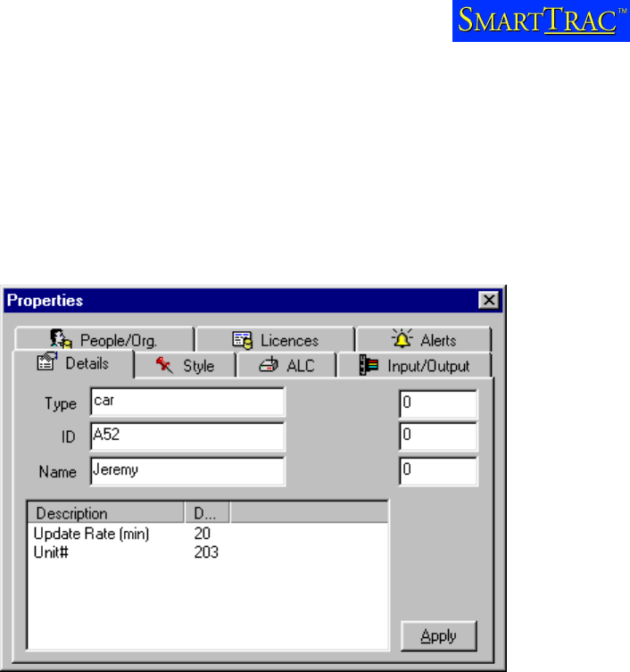
A properties box will appear with different options as shown below:
Click on each of the following Tabs and then fill out the information
Details
Type car, truck, van etc. The units will be grouped according to their type in the
filter window.
ID any ID that is used for the vehicle. This field is not compulsory.
Name this will be displayed next to the vehicle.
Style
The Icon, colour, size and track of the vehicle can all be changed according to user preference.
ALC

TAIT CONFIGURATION GUIDE
V 1.0 February 2003 Page 8
Report Position to:
• Base Determines the automatic polling rate. The vehicle will be polled automatically
every 15 minutes in the example above and a latitude/longitude placed in the database. Limits
are often set by Network Providers for the minimum automatic poll duration.
• Unit number This is the number that was programmed into the T2000-A76, this will be
different for every Vehicle.
No other fields are required.

TAIT CONFIGURATION GUIDE
V 1.0 February 2003 Page 9
SECTION 2 MPT1327 TRUNKING INSTALLATIONS
Overview
A MPT1327 installation consists of;
• Base:
PC installed with SmartTRAC software,
A Map 27 capable T2030 / T2035 / T2040 (T2040 preferred, LCD display provides good feedback on call
success and fail)
Power supply for the T2000 mobile radio
Serial lead connecting the Radio to the PC (supplied with SmartTRAC purchase)
• Vehicle:
A T2030/T2035/T2040 mobile radio with AVL firmware
A single port UART (T2000-A66) fitted to the radio
A GPS receiver
• MPT system:
AVL will generally work on any type of MPT system, Tait or Third party.
Setting up the base:
• Install SmartTRAC as per the above instructions.
• Install the Single port UART if the radio has not had one fitted
• Program the radio for the specified MPT system and using the parameters detailed in the appendix
• Fit the radio to the power supply and antenna.
• Connect the radio to the PC comm Port via a 9way serial cable.
Setting up the Vehicle:
• Install the Single port UART to the radio.
• A power wire must be run from the logic board of the T2000 to the 9-way connector of the T2000-A76/A78
to provide power to the GPS receiver.
o If using a T2002-A00 GPS receiver, install a wire from S14 pin1 (13.8V) to pin 6 of the 9 way
connector
o If using a T2003-A00 GPS receiver, install a wire from S14 pin2 (5.0 V) to pin 4 of the 9 way
connector
• Download direct connect firmware into the radio.
• Program the radio for the specified MPT system and using the parameters detailed in the appendix
NB Radios can be ordered from Tait pre-configured for AVL
TAIT CONFIGURATION GUIDE
V 1.0 February 2003 Page 10
Adding Mobile Units
To enter a new vehicle, open SmartTRAC [
Start
]Æ[
Programs
]Æ[SmartTRAC]Æ[
SmartTRAC
explorer
]
Right click in the vehicles window
Choose [
new mobile unit
]
A properties box will appear with different options as shown below:
Click on each of the following Tabs and then fill out the information
Details
Type car, truck, van etc. The units will be grouped according to their type in the
filter window.
ID any ID that is used for the vehicle. This field is not compulsory.
Name this will be displayed next to the vehicle.
Style
The Icon, colour, size and track of the vehicle can all be changed according to user preference.
ALC

TAIT CONFIGURATION GUIDE
V 1.0 February 2003 Page 11
Report Position to:
Base Determines the automatic polling rate. The vehicle will be polled automatically every 20
minutes in the example above and a latitude/longitude placed in the database. Limits are often set
by Network Providers for the minimum automatic poll duration.
Unit number If the mobiles are within the same fleet, enter in the 2 or 3 digit 1343 number of
the radio.
Pfix The prefix and ident fields are only needed if vehicles are in multiple fleets. The prefix and
Ident are in MPT 1327 format. To convert a MPT 1343 address to 1327 use the following steps.
Example 1343 number 203 4260 202
Subtract 200 from the MPT 1343 prefix to give the MPT 1327 prefix
Eg: 203 – 200 = 3
Subtract 2000 from the fleet individual number
Eg: 4260 – 2000 = 2260
Multiply this result by 2
Eg: 2260 * 2 = 4520 (A)
Subtract 200 (3 digit) or 20 (2 digit) from the unit number
Eg: 202 – 200 = 2
Add above result to (A)
Eg: 4520 + 2 = 4522
MPT 1327 number = 3,4522
No other fields are required.
Polling NPD or SST
SmartTRAC can be set up to poll vehicles using a Non Prescribed Data poll on a traffic channel or
using a Single Segment Transaction on a control channel.
There are different instances when one is more appropriate than the other.
Generally NPD polling is preferred, especially if SmartTRAC is being operated on a busy public
network.
TAIT CONFIGURATION GUIDE
V 1.0 February 2003 Page 12
SECTION 3 SMARTTRAC FEATURES
CONNECTING THE BASE RADIO TO THE PC
Connect the 9-way connector on the rear of the radio to a spare COM port on the PC using the 9-
way cable supplied. The cable is a standard computer 9 way male to 9 way female with 1-1 wiring.
Once the radio is connected and switched on, for MPT 1327 radios make sure that the radio has
network service. Indicated by a steady “svc” icon or LED.
Place a call on the radio and make sure that the received audio at the remote radio is clear.
To specify which COM port the base radio is connected to choose
[
Tools
]Æ[
Communications Properties
]
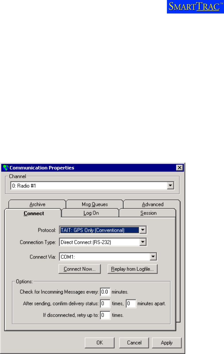
A communications properties box should be displayed as below:
For conventional systems, the protocol must be set to “TAIT:GPS only (conventional)”
For MPT Trunking systems, the protocol can be set to either “TAIT: GPS only (SST)” for polling on
the control channel or “TAIT: GPS only (NPD)” for polling on the traffic channel.
When [
Tools
]Æ[
Communications Properties
] is selected, SmartTRAC server will also start running.
SmartTRAC server must ALWAYS run in the background to process poll requests. An icon will
appear in the toolbar if communication to the base radio fails.

TAIT CONFIGURATION GUIDE
V 1.0 February 2003 Page 13
Choose the COM port that the base radio is connected to and select [
Connect Now
]. If the
operation is successful a system tray icon (bottom right hand side of the screen) will appear then
disappear. You are now ready to poll vehicles.
System tray Icon
If the operation was unsuccessful check that:
Your radio is turned on
The programming information and firmware versions are correct
The serial cable is connected between the UART and the correct COM port
Once the COM port has been set up once it will not need to be done again, however SmartTRAC
server always needs to be running each time SmartTRAC is started. This is achieved by selecting
[
Tools
]Æ[
Connect now
].
MAPS
SmartTRAC uses MapInfo format maps. Any MapInfo workspace with a .wor extension can be
opened by either selecting [
File
]Æ[
open
] and selecting the workspace from SmartTRAC or by
double clicking the workspace from windows explorer. SmartTRAC will start automatically.
STARTING SMARTTRAC AUTOMATICALLY
If SmartTRAC is running on a stand alone PC, it is a good idea to add the map workspace (.wor)
and SmartTRAC server to the windows StartUp menu.
This will automatically open the map and run the server whenever the PC is restarted.
First find the directory where SmartTRAC was installed (usually c:\program files\SmartTRAC) and
add the file DbLink.exe to windows StartUp.
Do the same for the workspace of the map you are using.
To find information on adding programs to windows StartUp, please consult Windows Help.

TAIT CONFIGURATION GUIDE
V 1.0 February 2003 Page 14
HOUSEKEEPING (ARCHIVING THE DATABASE)
All position reports and unit status, type and names are stored in a Microsoft Access
database. This database will grow as new polls are received. To keep the data secure and to
keep the database to a manageable size, it is recommended to archive the database every
two months, or more frequently if desired.
To archive a Database, a copy of a compression tool such as WinZip or Power Archiver is
valuable. A “zipped” database will usually fit on a 3.5 “ floppy which is useful if the PC is not
connected to a network.
To archive the database and exchange with another, first locate the database. Often it will be
located under c:\program Files\SmartTRAC and called StSample.mdb.
The next step assumes that a clean database was archived when the package was installed.
Zip StSample.mdb and copy to a safe place. This database will contain two months of position
information for your vehicles. When zipping the database it is useful to give the zip file a
meaningful name such as june01.zip. This will also help prevent existing archived databases being
overwritten if the same name is used.
Unzip the clean copy of the database and pace back into the folder where the original database
was copied from. SmartTRAC now needs to know which database to use. Use the following
procedure to point SmartTRAC to the correct database:
1. Run [
Start
] Æ [
Programs
] Æ [
SmartTRAC
] Æ [
ODBC Configuration
]
2. Select the “SmartTRAC” User Datasource and click [
Configure
]
3. Click the [
Select
] button
4. Locate the “StSample” database file (your database file may be named differently) on
the networl fileserver and click [
OK
]
5. Click [
OK
] to close the remaining dialogs
If an error message “ODBC Microsoft Access Driver Login Failed” – Could not find the file
‘c:\program files\SmartTRAC\stsample.mdb occurs, the clean database has been installed into the
wrong folder or has been renamed. Repeat the above process making sure you are using the
correct database.

TAIT CONFIGURATION GUIDE
V 1.0 February 2003 Page 15
NETWORKING
SmartTRAC Workstation machines can be configured to work with a shared Microsoft Access
database in a LAN environment. Such configurations are recommended for small workgroups with
1-5 users.
Before You Begin
This process assumes that you are familiar with Microsoft Access database files, network
connections and file sharing issues.
Installing SmartTRAC
When installing SmartTRAC Workstation in a multi-user site run the following setup types:
1. Single User Installation on the machine that is physically connected to the base radio.
Only one machine may have this setup type.
2. Multi-User Installation - Workstation on all other machines that will become part of
the SmartTRAC workgroup.
Shifting Database Files to the Network
During Installation SmartTRAC places two database files in the installation directory. These are:
• STBLANK.MDB : The template database
• STSAMPLE.MDB : The sample database
Copy both files to a location on a network file server that is accessible to all machines in the
workgroup.
Setting Each Client Machine to use the Shared Database
1. Run [
Start
]Æ[
Programs
]Æ[
SmartTRAC
]Æ[
ODBC Configuration
]
2. Select the “SmartTRAC” User Datasource and click [
Configure
]
3. Click the [
Select
] button
4. Locate the “StSample” database file on the network fileserver and click [
OK
]
5. Click [OK] to close the remaining dialogs
If you should encounter any difficulties during this procedure please refer to our on-line
troubleshooting guide at: www.absolute.co.nz/SmartTRAC/help.htm

TAIT CONFIGURATION GUIDE
V 1.0 February 2003 Page 16
DIAGNOSTICS
Vehicle Poll Status
SmartTRAC will display a unit status next to each vehicle. If this cannot be seen, right click in the
vehicles window, then select [
View
]Æ[
Details
].
There are four possible states that are displayed next to each vehicle:
On – Normal The vehicle is being polled successfully, a valid position fix is being
returned.
On – No GPS coverage The radio is responding but the GPS unit cannot obtain a
valid position. The vehicle could be in a garage or in a position where the GPS receiver
does not have a clear view of the sky.
On - GPS Disconnected The radio is responding but there is no information to the
radio from the GPS. The GPS receiver is either unplugged from the radio or not
functioning correctly.
Off / Not Home The radio cannot be reached. The radio is either switched off, or out of
system coverage.
These states are logged into the database. If problems occur when vehicles are polled, the
database can be zipped up and sent away for analysis. See Housekeeping for Details on how to
zip and replace a database.
Displaying the Map27 analyser
SmartTRAC MPT versions have a Map27 packet analyser available. This will show the Map27
commands between the radio and the PC.
Map27 is the data protocol used for MPT1327 radios.
To enable the packet analyser;
Choose
[tools
]Æ[
Communications Properties
]
Click on the “log on” tab and under username type “log”.
Click apply and the analyser will appear.
To copy a view of the analyser to another application, select “alt-print scrn” to copy it to the
clipboard.

TAIT CONFIGURATION GUIDE
V 1.0 February 2003 Page 17
APPENDIX
GPS wiring details
The T2002-A00 and T2003-A00 receivers come complete with a moulded 9 way male connector.
If the moulded plug needs to be cut for any reason, wiring details are:
T2002-A00
Scout GPS DB-9 (Male) Function
Pin 5 Shield(Gnd) Signal Gnd
Pin 6 Red + ve 13.8 V
Pin 3 White GPS Tx Data
Pin 2 Yellow GPS Rx Data
T2003-A00
GPS DB-9 (Male) Function
Pin 5 Black Signal Gnd
Pin 4 Red + ve 5 V
Pin 3 White GPS Tx Data
Pin 2 Green GPS Rx Data
TAIT CONFIGURATION GUIDE
V 1.0 February 2003 Page 18
MPT 1327 Radio Programming
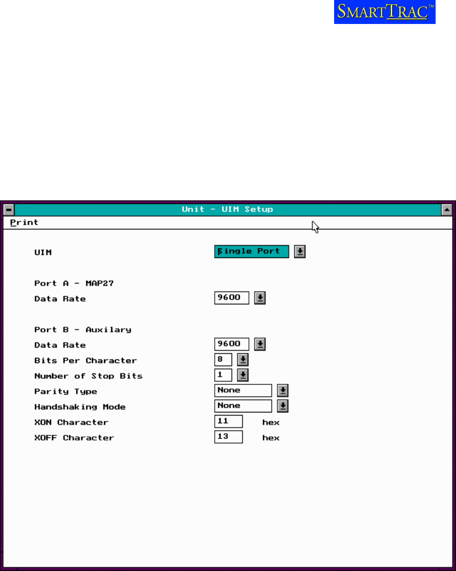
Ensure that the UART is enabled in the radio programming datafile, with settings as per the
sample below. Note that MAP27 has to be enabled under edit / specifications / MAP27 before the
UART settings can be edited.
UART Setup
TAIT CONFIGURATION GUIDE
V 1.0 February 2003 Page 19
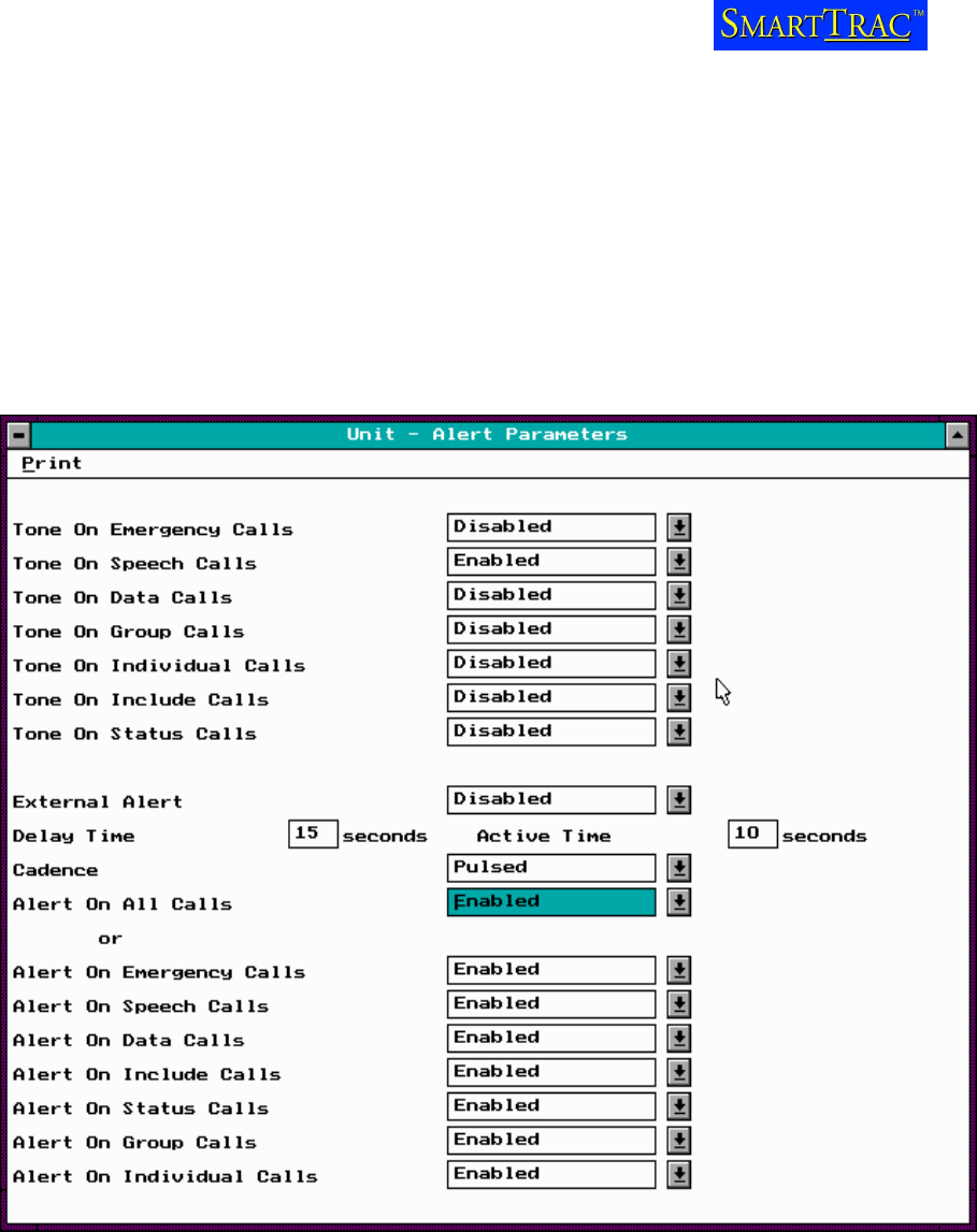
Alert tones
Check with the customer whether or not the radio should make a sound (beep) when a GPS poll is
made to the vehicle.
If not, ensure that in the Unit Alert screen of the radio database that Tone On Speech Calls is
Enabled and ALL of other Tone Alert fields are disabled (See below).
If an external alert is fitted, then ensure that all fields except the specific call type required are
disabled.
TAIT CONFIGURATION GUIDE
V 1.0 February 2003 Page 20
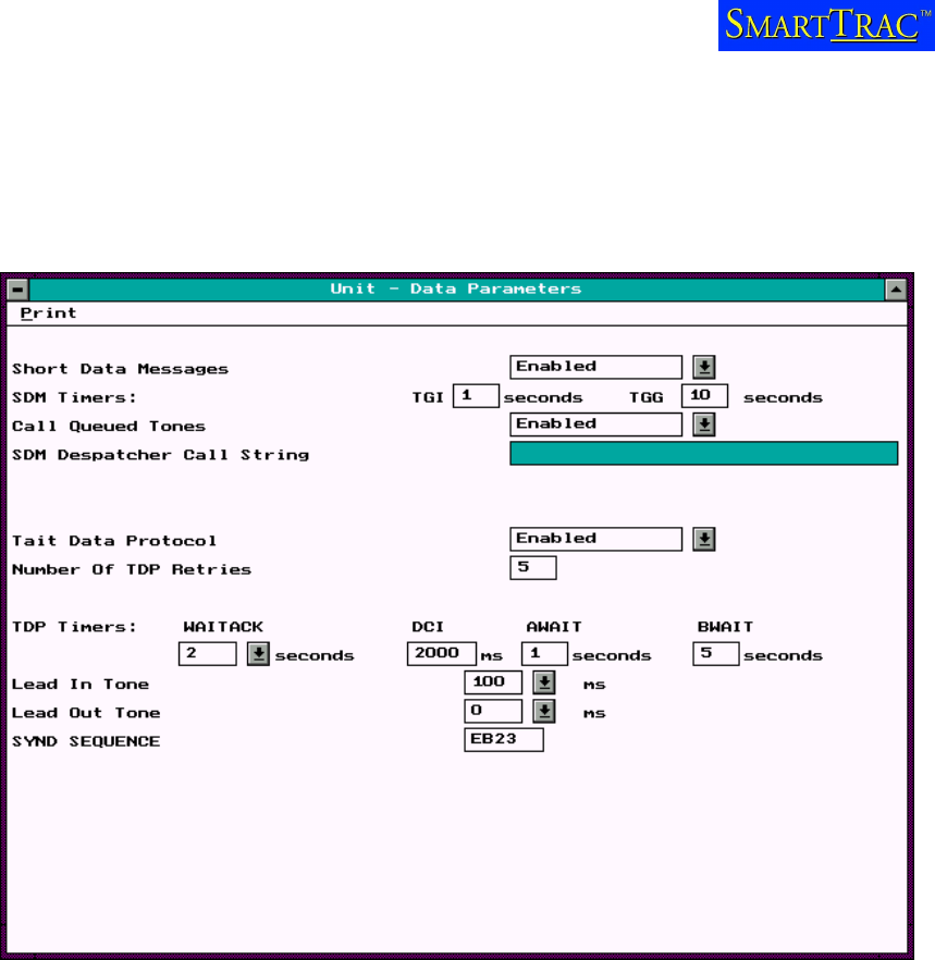
Data Settings
These setting should provide reliable data transfer, however some networks prefer to use different
settings than shown below:
