Solarflare Server Adapter User Guide (2013) SF 103837 CD 10 Issue
User Manual: Pdf
Open the PDF directly: View PDF ![]() .
.
Page Count: 389 [warning: Documents this large are best viewed by clicking the View PDF Link!]
- Table of Contents
- Chapter 1: Introduction
- Chapter 2: Installation
- 2.1 Solarflare Network Adapter Products
- 2.2 Fitting a Full Height Bracket (optional)
- 2.3 Inserting the Adapter in a PCI Express (PCIe) Slot
- 2.4 Attaching a Cable (RJ-45)
- 2.5 Attaching a Cable (SFP+)
- 2.6 Supported SFP+ Cables
- 2.7 Supported SFP+ 10G SR Optical Transceivers
- 2.8 Supported SFP+ 10G LR Optical Transceivers
- 2.9 Supported SFP 1000BASE-T Transceivers
- 2.10 Supported 1G Optical Transceivers
- 2.11 Supported Speed and Mode
- 2.12 LED States
- 2.13 Solarflare Mezzanine Adapter: SFN5802K
- 2.14 Solarflare Mezzanine Adapters: SFN5812H and SFN5814H
- 2.15 Solarflare Mezzanine Adapter SFN6832F-C61
- 2.16 Solarflare Mezzanine Adapter SFN6832F-C62
- 2.17 Solarflare Precision Time Synchronization Adapters
- 2.18 Solarflare SFA6902F ApplicationOnload™ Engine
- Chapter 3: Solarflare Adapters on Linux
- 3.1 System Requirements
- 3.2 Linux Platform Feature Set
- 3.3 Solarflare RPMs
- 3.4 Installing Solarflare Drivers and Utilities on Linux
- 3.5 Red Hat Enterprise Linux Distributions
- 3.6 SUSE Linux Enterprise Server Distributions
- 3.7 Unattended Installations
- 3.8 Unattended Installation - Red Hat Enterprise Linux
- 3.9 Unattended Installation - SUSE Linux Enterprise Server
- 3.10 Hardware Timestamps
- 3.11 Configuring the Solarflare Adapter
- 3.12 Setting Up VLANs
- 3.13 Setting Up Teams
- 3.14 Running Adapter Diagnostics
- 3.15 Running Cable Diagnostics
- 3.16 Linux Utilities RPM
- 3.17 Configuring the Boot ROM with sfboot
- 3.18 Upgrading Adapter Firmware with Sfupdate
- 3.19 License Install with sfkey
- 3.20 Performance Tuning on Linux
- 3.21 Module Parameters
- 3.22 Linux ethtool Statistics
- Chapter 4: Solarflare Adapters on Windows
- 4.1 System Requirements
- 4.2 Windows Feature Set
- 4.3 Installing the Solarflare Driver Package on Windows
- 4.4 Adapter Drivers Only Installation
- 4.5 Full Solarflare Package Installation
- 4.6 Install Drivers and Options From a Windows Command Prompt
- 4.7 Unattended Installation - Windows Server 2008, 2008 R2, Windows 7 and Windows Server 2012
- 4.8 Unattended Installation - Windows Server 2003
- 4.9 Managing Adapters with SAM
- 4.10 Managing Adapters Remotely with SAM
- 4.11 Using SAM
- 4.12 Using SAM to Configure Adapter Features
- 4.13 Segmentation Offload
- 4.14 Using SAM to Configure Teams and VLANs
- 4.15 Using SAM to View Statistics and State Information
- 4.16 Using SAM to Run Adapter and Cable Diagnostics
- 4.17 Using SAM for Boot ROM Configuration
- 4.18 Managing Firmware with SAM
- 4.19 Configuring Network Adapter Properties in Windows
- 4.20 Windows Command Line Tools
- 4.21 Sfboot: Boot ROM Configuration Tool
- 4.22 Sfupdate: Firmware Update Tool
- 4.23 Sfteam: Adapter Teaming and VLAN Tool
- 4.24 Sfcable: Cable Diagnostics Tool
- 4.25 Sfnet
- 4.26 Completion codes (%errorlevel%)
- 4.27 Teaming and VLANs
- 4.28 Performance Tuning on Windows
- 4.29 Windows Event Log Error Messages
- Chapter 5: Solarflare Adapters on VMware
- Chapter 6: Solarflare Adapters on Solaris
- 6.1 System Requirements
- 6.2 Solaris Platform Feature Set
- 6.3 Installing Solarflare Drivers
- 6.4 Unattended Installation Solaris 10
- 6.5 Unattended Installation Solaris 11
- 6.6 Configuring the Solarflare Adapter
- 6.7 Setting Up VLANs
- 6.8 Solaris Utilities Package
- 6.9 Configuring the Boot ROM with sfboot
- 6.10 Upgrading Adapter Firmware with Sfupdate
- 6.11 Performance Tuning on Solaris
- 6.12 Module Parameters
- 6.13 Kernel and Network Adapter Statistics
- Chapter 7: SR-IOV Virtualization Using KVM
- Chapter 8: SR-IOV Virtualization for XenServer
- Chapter 9: Solarflare Adapters on Mac 0S X
- Chapter 10: Solarflare Boot ROM Agent
- Index

Issue 10 © Solarflare Communications 2013 i
Solarflare Server Adapter
User Guide
Solarflare® Server Adapter User Guide
• Introduction...Page 1
• Installation...Page 19
• Solarflare Adapters on Linux...Page 39
• Solarflare Adapters on Windows...Page 107
• Solarflare Adapters on VMware...Page 252
• Solarflare Adapters on Solaris...Page 279
• SR-IOV Virtualization Using KVM...Page 323
• SR-IOV Virtualization for XenServer...Page 340
• Solarflare Adapters on Mac 0S X...Page 350
• Solarflare Boot ROM Agent...Page 360
Information in this document is subject to change without notice.
© 2008-2013 Solarflare Communications Inc. All rights reserved.
Trademarks used in this text are registered trademarks of Solarflare Communications Inc; Adobe is
a trademark of Adobe Systems. Microsoft and Windows are registered trademarks of Microsoft
Corporation.
Linux® is the registered trademark of Linus Torvalds in the U.S. and other countries.
Other trademarks and trade names may be used in this document to refer to either the entities
claiming the marks and names or their products. Solarflare Communications Inc. disclaims any
proprietary interest in trademarks and trade names other than its own.
SF-103837-CD
Last revised: December 2013
Issue 10

Issue 10 © Solarflare Communications 2013 ii
Solarflare Server Adapter
User Guide
Table of Contents
Table of Contents. . . . . . . . . . . . . . . . . . . . . . . . . . . . . . . . . . . . . . . . . . . . . . . . . . . . . . . . . . ii
Chapter 1: Introduction . . . . . . . . . . . . . . . . . . . . . . . . . . . . . . . . . . . . . . . . . . . . . . . . . . . . . 1
1.1 Virtual NIC Interface . . . . . . . . . . . . . . . . . . . . . . . . . . . . . . . . . . . . . . . . . . . . . . . . . . . 1
1.2 Product Specifications. . . . . . . . . . . . . . . . . . . . . . . . . . . . . . . . . . . . . . . . . . . . . . . . . . 4
1.3 Software Driver Support . . . . . . . . . . . . . . . . . . . . . . . . . . . . . . . . . . . . . . . . . . . . . . . 13
1.4 Solarflare AppFlex™ Technology Licensing.. . . . . . . . . . . . . . . . . . . . . . . . . . . . . . . . 13
1.5 Open Source Licenses . . . . . . . . . . . . . . . . . . . . . . . . . . . . . . . . . . . . . . . . . . . . . . . . . 14
1.6 Support and Download . . . . . . . . . . . . . . . . . . . . . . . . . . . . . . . . . . . . . . . . . . . . . . . . 15
1.7 Regulatory Information. . . . . . . . . . . . . . . . . . . . . . . . . . . . . . . . . . . . . . . . . . . . . . . . 15
1.8 Regulatory Approval . . . . . . . . . . . . . . . . . . . . . . . . . . . . . . . . . . . . . . . . . . . . . . . . . . 16
Chapter 2: Installation . . . . . . . . . . . . . . . . . . . . . . . . . . . . . . . . . . . . . . . . . . . . . . . . . . . . . 19
2.1 Solarflare Network Adapter Products . . . . . . . . . . . . . . . . . . . . . . . . . . . . . . . . . . . . 20
2.2 Fitting a Full Height Bracket (optional) . . . . . . . . . . . . . . . . . . . . . . . . . . . . . . . . . . 21
2.3 Inserting the Adapter in a PCI Express (PCIe) Slot . . . . . . . . . . . . . . . . . . . . . . . . . . 22
2.4 Attaching a Cable (RJ-45) . . . . . . . . . . . . . . . . . . . . . . . . . . . . . . . . . . . . . . . . . . . . . . 23
2.5 Attaching a Cable (SFP+) . . . . . . . . . . . . . . . . . . . . . . . . . . . . . . . . . . . . . . . . . . . . . . . 24
2.6 Supported SFP+ Cables . . . . . . . . . . . . . . . . . . . . . . . . . . . . . . . . . . . . . . . . . . . . . . . . 26
2.7 Supported SFP+ 10G SR Optical Transceivers . . . . . . . . . . . . . . . . . . . . . . . . . . . . . . 27
2.8 Supported SFP+ 10G LR Optical Transceivers . . . . . . . . . . . . . . . . . . . . . . . . . . . . . . 28
2.9 Supported SFP 1000BASE-T Transceivers . . . . . . . . . . . . . . . . . . . . . . . . . . . . . . . . . 28
2.10 Supported 1G Optical Transceivers . . . . . . . . . . . . . . . . . . . . . . . . . . . . . . . . . . . . . 29
2.11 Supported Speed and Mode. . . . . . . . . . . . . . . . . . . . . . . . . . . . . . . . . . . . . . . . . . . 29
2.12 LED States. . . . . . . . . . . . . . . . . . . . . . . . . . . . . . . . . . . . . . . . . . . . . . . . . . . . . . . . . . 31
2.13 Solarflare Mezzanine Adapter: SFN5802K. . . . . . . . . . . . . . . . . . . . . . . . . . . . . . . . 32
2.14 Solarflare Mezzanine Adapters: SFN5812H and SFN5814H. . . . . . . . . . . . . . . . . . 34
2.15 Solarflare Mezzanine Adapter SFN6832F-C61 . . . . . . . . . . . . . . . . . . . . . . . . . . . . 35
2.16 Solarflare Mezzanine Adapter SFN6832F-C62 . . . . . . . . . . . . . . . . . . . . . . . . . . . . 37
2.17 Solarflare Precision Time Synchronization Adapters . . . . . . . . . . . . . . . . . . . . . . . 38
2.18 Solarflare SFA6902F ApplicationOnload™ Engine . . . . . . . . . . . . . . . . . . . . . . . . . 38
Chapter 3: Solarflare Adapters on Linux . . . . . . . . . . . . . . . . . . . . . . . . . . . . . . . . . . . . . . 39
3.1 System Requirements . . . . . . . . . . . . . . . . . . . . . . . . . . . . . . . . . . . . . . . . . . . . . . . . . 39
3.2 Linux Platform Feature Set . . . . . . . . . . . . . . . . . . . . . . . . . . . . . . . . . . . . . . . . . . . . . 40
3.3 Solarflare RPMs . . . . . . . . . . . . . . . . . . . . . . . . . . . . . . . . . . . . . . . . . . . . . . . . . . . . . . 41
3.4 Installing Solarflare Drivers and Utilities on Linux . . . . . . . . . . . . . . . . . . . . . . . . . . 43
3.5 Red Hat Enterprise Linux Distributions . . . . . . . . . . . . . . . . . . . . . . . . . . . . . . . . . . . 43
3.6 SUSE Linux Enterprise Server Distributions. . . . . . . . . . . . . . . . . . . . . . . . . . . . . . . . 44
3.7 Unattended Installations . . . . . . . . . . . . . . . . . . . . . . . . . . . . . . . . . . . . . . . . . . . . . . 45
3.8 Unattended Installation - Red Hat Enterprise Linux . . . . . . . . . . . . . . . . . . . . . . . . . 47
3.9 Unattended Installation - SUSE Linux Enterprise Server . . . . . . . . . . . . . . . . . . . . . 48

Issue 10 © Solarflare Communications 2013 iii
Solarflare Server Adapter
User Guide
3.10 Hardware Timestamps . . . . . . . . . . . . . . . . . . . . . . . . . . . . . . . . . . . . . . . . . . . . . . . 49
3.11 Configuring the Solarflare Adapter . . . . . . . . . . . . . . . . . . . . . . . . . . . . . . . . . . . . . 49
3.12 Setting Up VLANs. . . . . . . . . . . . . . . . . . . . . . . . . . . . . . . . . . . . . . . . . . . . . . . . . . . . 51
3.13 Setting Up Teams. . . . . . . . . . . . . . . . . . . . . . . . . . . . . . . . . . . . . . . . . . . . . . . . . . . . 52
3.14 Running Adapter Diagnostics . . . . . . . . . . . . . . . . . . . . . . . . . . . . . . . . . . . . . . . . . . 53
3.15 Running Cable Diagnostics . . . . . . . . . . . . . . . . . . . . . . . . . . . . . . . . . . . . . . . . . . . . 54
3.16 Linux Utilities RPM . . . . . . . . . . . . . . . . . . . . . . . . . . . . . . . . . . . . . . . . . . . . . . . . . . 55
3.17 Configuring the Boot ROM with sfboot . . . . . . . . . . . . . . . . . . . . . . . . . . . . . . . . . . 56
3.18 Upgrading Adapter Firmware with Sfupdate . . . . . . . . . . . . . . . . . . . . . . . . . . . . . 70
3.19 License Install with sfkey . . . . . . . . . . . . . . . . . . . . . . . . . . . . . . . . . . . . . . . . . . . . . 75
3.20 Performance Tuning on Linux. . . . . . . . . . . . . . . . . . . . . . . . . . . . . . . . . . . . . . . . . . 77
3.21 Module Parameters. . . . . . . . . . . . . . . . . . . . . . . . . . . . . . . . . . . . . . . . . . . . . . . . . . 97
3.22 Linux ethtool Statistics . . . . . . . . . . . . . . . . . . . . . . . . . . . . . . . . . . . . . . . . . . . . . . . 99
Chapter 4: Solarflare Adapters on Windows . . . . . . . . . . . . . . . . . . . . . . . . . . . . . . . . . . 107
4.1 System Requirements . . . . . . . . . . . . . . . . . . . . . . . . . . . . . . . . . . . . . . . . . . . . . . . . 107
4.2 Windows Feature Set . . . . . . . . . . . . . . . . . . . . . . . . . . . . . . . . . . . . . . . . . . . . . . . . 108
4.3 Installing the Solarflare Driver Package on Windows. . . . . . . . . . . . . . . . . . . . . . . 110
4.4 Adapter Drivers Only Installation. . . . . . . . . . . . . . . . . . . . . . . . . . . . . . . . . . . . . . . 111
4.5 Full Solarflare Package Installation . . . . . . . . . . . . . . . . . . . . . . . . . . . . . . . . . . . . . 113
4.6 Install Drivers and Options From a Windows Command Prompt . . . . . . . . . . . . . 121
4.7 Unattended Installation - Windows Server 2008, 2008 R2, Windows 7 and Windows
Server 2012 . . . . . . . . . . . . . . . . . . . . . . . . . . . . . . . . . . . . . . . . . . . . . . . . . . . . . . . . . . . . . . . . . 126
4.8 Unattended Installation - Windows Server 2003 . . . . . . . . . . . . . . . . . . . . . . . . . . 131
4.9 Managing Adapters with SAM . . . . . . . . . . . . . . . . . . . . . . . . . . . . . . . . . . . . . . . . . 139
4.10 Managing Adapters Remotely with SAM. . . . . . . . . . . . . . . . . . . . . . . . . . . . . . . . 141
4.11 Using SAM . . . . . . . . . . . . . . . . . . . . . . . . . . . . . . . . . . . . . . . . . . . . . . . . . . . . . . . . 141
4.12 Using SAM to Configure Adapter Features . . . . . . . . . . . . . . . . . . . . . . . . . . . . . . 146
4.13 Segmentation Offload. . . . . . . . . . . . . . . . . . . . . . . . . . . . . . . . . . . . . . . . . . . . . . . 153
4.14 Using SAM to Configure Teams and VLANs. . . . . . . . . . . . . . . . . . . . . . . . . . . . . . 158
4.15 Using SAM to View Statistics and State Information . . . . . . . . . . . . . . . . . . . . . . 167
4.16 Using SAM to Run Adapter and Cable Diagnostics . . . . . . . . . . . . . . . . . . . . . . . . 168
4.17 Using SAM for Boot ROM Configuration . . . . . . . . . . . . . . . . . . . . . . . . . . . . . . . . 173
4.18 Managing Firmware with SAM. . . . . . . . . . . . . . . . . . . . . . . . . . . . . . . . . . . . . . . . 179
4.19 Configuring Network Adapter Properties in Windows. . . . . . . . . . . . . . . . . . . . . 180
4.20 Windows Command Line Tools . . . . . . . . . . . . . . . . . . . . . . . . . . . . . . . . . . . . . . . 186
4.21 Sfboot: Boot ROM Configuration Tool. . . . . . . . . . . . . . . . . . . . . . . . . . . . . . . . . . 188
4.22 Sfupdate: Firmware Update Tool. . . . . . . . . . . . . . . . . . . . . . . . . . . . . . . . . . . . . . 202
4.23 Sfteam: Adapter Teaming and VLAN Tool . . . . . . . . . . . . . . . . . . . . . . . . . . . . . . . 206
4.24 Sfcable: Cable Diagnostics Tool . . . . . . . . . . . . . . . . . . . . . . . . . . . . . . . . . . . . . . . 213
4.25 Sfnet . . . . . . . . . . . . . . . . . . . . . . . . . . . . . . . . . . . . . . . . . . . . . . . . . . . . . . . . . . . . . 216
4.26 Completion codes (%errorlevel%) . . . . . . . . . . . . . . . . . . . . . . . . . . . . . . . . . . . . . 221
4.27 Teaming and VLANs. . . . . . . . . . . . . . . . . . . . . . . . . . . . . . . . . . . . . . . . . . . . . . . . . 223
4.28 Performance Tuning on Windows . . . . . . . . . . . . . . . . . . . . . . . . . . . . . . . . . . . . . 236

Issue 10 © Solarflare Communications 2013 iv
Solarflare Server Adapter
User Guide
4.29 Windows Event Log Error Messages . . . . . . . . . . . . . . . . . . . . . . . . . . . . . . . . . . . 249
Chapter 5: Solarflare Adapters on VMware . . . . . . . . . . . . . . . . . . . . . . . . . . . . . . . . . . . 252
5.1 System Requirements . . . . . . . . . . . . . . . . . . . . . . . . . . . . . . . . . . . . . . . . . . . . . . . . 252
5.2 VMware Feature Set . . . . . . . . . . . . . . . . . . . . . . . . . . . . . . . . . . . . . . . . . . . . . . . . . 253
5.3 Installing Solarflare Drivers and Utilities on VMware. . . . . . . . . . . . . . . . . . . . . . . 254
5.4 Configuring Teams. . . . . . . . . . . . . . . . . . . . . . . . . . . . . . . . . . . . . . . . . . . . . . . . . . . 255
5.5 Configuring VLANs . . . . . . . . . . . . . . . . . . . . . . . . . . . . . . . . . . . . . . . . . . . . . . . . . . . 255
5.6 Running Adapter Diagnostics . . . . . . . . . . . . . . . . . . . . . . . . . . . . . . . . . . . . . . . . . . 257
5.7 Configuring the Boot ROM with Sfboot. . . . . . . . . . . . . . . . . . . . . . . . . . . . . . . . . . 258
5.8 Upgrading Adapter Firmware with Sfupdate . . . . . . . . . . . . . . . . . . . . . . . . . . . . . 268
5.9 Performance Tuning on VMware . . . . . . . . . . . . . . . . . . . . . . . . . . . . . . . . . . . . . . . 271
Chapter 6: Solarflare Adapters on Solaris . . . . . . . . . . . . . . . . . . . . . . . . . . . . . . . . . . . . 279
6.1 System Requirements . . . . . . . . . . . . . . . . . . . . . . . . . . . . . . . . . . . . . . . . . . . . . . . . 279
6.2 Solaris Platform Feature Set . . . . . . . . . . . . . . . . . . . . . . . . . . . . . . . . . . . . . . . . . . . 280
6.3 Installing Solarflare Drivers. . . . . . . . . . . . . . . . . . . . . . . . . . . . . . . . . . . . . . . . . . . . 281
6.4 Unattended Installation Solaris 10. . . . . . . . . . . . . . . . . . . . . . . . . . . . . . . . . . . . . . 282
6.5 Unattended Installation Solaris 11. . . . . . . . . . . . . . . . . . . . . . . . . . . . . . . . . . . . . . 283
6.6 Configuring the Solarflare Adapter . . . . . . . . . . . . . . . . . . . . . . . . . . . . . . . . . . . . . 284
6.7 Setting Up VLANs. . . . . . . . . . . . . . . . . . . . . . . . . . . . . . . . . . . . . . . . . . . . . . . . . . . . 286
6.8 Solaris Utilities Package . . . . . . . . . . . . . . . . . . . . . . . . . . . . . . . . . . . . . . . . . . . . . . 286
6.9 Configuring the Boot ROM with sfboot . . . . . . . . . . . . . . . . . . . . . . . . . . . . . . . . . . 286
6.10 Upgrading Adapter Firmware with Sfupdate . . . . . . . . . . . . . . . . . . . . . . . . . . . . 297
6.11 Performance Tuning on Solaris . . . . . . . . . . . . . . . . . . . . . . . . . . . . . . . . . . . . . . . 300
6.12 Module Parameters. . . . . . . . . . . . . . . . . . . . . . . . . . . . . . . . . . . . . . . . . . . . . . . . . 308
6.13 Kernel and Network Adapter Statistics . . . . . . . . . . . . . . . . . . . . . . . . . . . . . . . . . 310
Chapter 7: SR-IOV Virtualization Using KVM . . . . . . . . . . . . . . . . . . . . . . . . . . . . . . . . . . 323
7.1 Supported Platforms and Adapters . . . . . . . . . . . . . . . . . . . . . . . . . . . . . . . . . . . . . 323
7.2 Linux KVM SR-IOV . . . . . . . . . . . . . . . . . . . . . . . . . . . . . . . . . . . . . . . . . . . . . . . . . . . 324
7.3 Installation . . . . . . . . . . . . . . . . . . . . . . . . . . . . . . . . . . . . . . . . . . . . . . . . . . . . . . . . . 327
7.4 Configuration Red Hat 6.1 . . . . . . . . . . . . . . . . . . . . . . . . . . . . . . . . . . . . . . . . . . . . 330
7.5 Configuration Red Hat 6.2 . . . . . . . . . . . . . . . . . . . . . . . . . . . . . . . . . . . . . . . . . . . . 333
7.6 Performance Tuning . . . . . . . . . . . . . . . . . . . . . . . . . . . . . . . . . . . . . . . . . . . . . . . . . 336
7.7 Migration . . . . . . . . . . . . . . . . . . . . . . . . . . . . . . . . . . . . . . . . . . . . . . . . . . . . . . . . . . 338
Chapter 8: SR-IOV Virtualization for XenServer. . . . . . . . . . . . . . . . . . . . . . . . . . . . . . . . 340
8.1 Supported Platforms and Adapters . . . . . . . . . . . . . . . . . . . . . . . . . . . . . . . . . . . . . 340
8.2 XenServer6 SR-IOV . . . . . . . . . . . . . . . . . . . . . . . . . . . . . . . . . . . . . . . . . . . . . . . . . . 341
8.3 Installation . . . . . . . . . . . . . . . . . . . . . . . . . . . . . . . . . . . . . . . . . . . . . . . . . . . . . . . . . 344
8.4 Configuration . . . . . . . . . . . . . . . . . . . . . . . . . . . . . . . . . . . . . . . . . . . . . . . . . . . . . . . 345
8.5 Performance Tuning . . . . . . . . . . . . . . . . . . . . . . . . . . . . . . . . . . . . . . . . . . . . . . . . . 346

Issue 10 © Solarflare Communications 2013 v
Solarflare Server Adapter
User Guide
Chapter 9: Solarflare Adapters on Mac 0S X . . . . . . . . . . . . . . . . . . . . . . . . . . . . . . . . . . 350
9.1 System Requirements . . . . . . . . . . . . . . . . . . . . . . . . . . . . . . . . . . . . . . . . . . . . . . . . 350
9.2 Supported Hardware Platforms . . . . . . . . . . . . . . . . . . . . . . . . . . . . . . . . . . . . . . . . 350
9.3 Mac 0S X Platform Feature Set. . . . . . . . . . . . . . . . . . . . . . . . . . . . . . . . . . . . . . . . . 351
9.4 Thunderbolt . . . . . . . . . . . . . . . . . . . . . . . . . . . . . . . . . . . . . . . . . . . . . . . . . . . . . . . . 351
9.5 Driver Install. . . . . . . . . . . . . . . . . . . . . . . . . . . . . . . . . . . . . . . . . . . . . . . . . . . . . . . . 351
9.6 Interface Configuration. . . . . . . . . . . . . . . . . . . . . . . . . . . . . . . . . . . . . . . . . . . . . . . 354
9.7 Tuning. . . . . . . . . . . . . . . . . . . . . . . . . . . . . . . . . . . . . . . . . . . . . . . . . . . . . . . . . . . . . 355
9.8 Driver Properties via sysctl . . . . . . . . . . . . . . . . . . . . . . . . . . . . . . . . . . . . . . . . . . . . 355
9.9 Firmware Update. . . . . . . . . . . . . . . . . . . . . . . . . . . . . . . . . . . . . . . . . . . . . . . . . . . . 356
9.10 Performance . . . . . . . . . . . . . . . . . . . . . . . . . . . . . . . . . . . . . . . . . . . . . . . . . . . . . . 358
Chapter 10: Solarflare Boot ROM Agent . . . . . . . . . . . . . . . . . . . . . . . . . . . . . . . . . . . . . 360
10.1 Configuring the Solarflare Boot ROM Agent . . . . . . . . . . . . . . . . . . . . . . . . . . . . . 360
10.2 PXE Support . . . . . . . . . . . . . . . . . . . . . . . . . . . . . . . . . . . . . . . . . . . . . . . . . . . . . . . 361
10.3 iSCSI Boot . . . . . . . . . . . . . . . . . . . . . . . . . . . . . . . . . . . . . . . . . . . . . . . . . . . . . . . . . 364
10.4 Configuring the iSCSI Target . . . . . . . . . . . . . . . . . . . . . . . . . . . . . . . . . . . . . . . . . . 364
10.5 Configuring the Boot ROM . . . . . . . . . . . . . . . . . . . . . . . . . . . . . . . . . . . . . . . . . . . 364
10.6 DHCP Server Setup . . . . . . . . . . . . . . . . . . . . . . . . . . . . . . . . . . . . . . . . . . . . . . . . . 370
10.7 Installing an Operating System to an iSCSI target. . . . . . . . . . . . . . . . . . . . . . . . . 372
10.8 Default Adapter Settings. . . . . . . . . . . . . . . . . . . . . . . . . . . . . . . . . . . . . . . . . . . . . 381
Index . . . . . . . . . . . . . . . . . . . . . . . . . . . . . . . . . . . . . . . . . . . . . . . . . . . . . . . . . . . . . . . . . . 382

Issue 10 © Solarflare Communications 2013 1
Solarflare Server Adapter
User Guide
Chapter 1: Introduction
This is the User Guide for Solarflare® Server Adapters. This chapter covers the following topics:
• Virtual NIC Interface...Page 1
• Advanced Features and Benefits...Page 2
• Product Specifications...Page 4
• Software Driver Support on page 13
• Solarflare AppFlex™ Technology Licensing....Page 13
• Open Source Licenses...Page 14
• Support and Download...Page 15
• Regulatory Information...Page 15
• Regulatory Approval...Page 16
1.1 Virtual NIC Interface
Solarflare’s VNIC architecture provides the key to efficient server I/O and is flexible enough to be
applied to multiple server deployment scenarios. These deployment scenarios include:
•Kernel Driver – This deployment uses an instance of a VNIC per CPU core for standard operating
system drivers. This allows network processing to continue over multiple CPU cores in parallel.
The virtual interface provides a performance-optimized path for the kernel TCP/IP stack and
contention-free access from the driver, resulting in extremely low latency and reduced CPU
utilization.
•Accelerated Virtual I/O – The second deployment scenario greatly improves I/O for virtualized
platforms. The VNIC architecture can provide a VNIC per Virtual Machine, giving over a
thousand protected interfaces to the host system, granting any virtualized (guest) operating
system direct access to the network hardware. Solarflare's hybrid SR-IOV technology, unique to
Solarflare Ethernet controllers, is the only way to provide bare-metal I/O performance to
virtualized guest operating systems whilst retaining the ability to live migrate virtual machines.
•OpenOnload™ – The third deployment scenario aims to leverage the host CPU(s) to full
capacity, minimizing software overheads by using a VNIC per application to provide a kernel
bypass solution. Solarflare has created both an open-source and Enterprise class high-
performance application accelerator that delivers lower and more predictable latency and
higher message rates for TCP and UDP-based applications, all with no need to modify
applications or change the network infrastructure. To learn more about the open source
NOTE: Throughout this guide the term Onload refers to both OpenOnload® and EnterpriseOnload®
unless otherwise stated. Users of Onload should refer to the Onload User Guide, SF-104474-CD,
which describes procedures for download and installation of the Onload distribution, accelerating
and tuning the application using Onload to achieve minimum latency and maximum throughput.

Issue 10 © Solarflare Communications 2013 2
Solarflare Server Adapter
User Guide
OpenOnload project or EnterpriseOnload, download the Onload user guide (SF-104474-CD) or
contact your reseller.
Advanced Features and Benefits
Virtual NIC support The core of Solarflare technology. Protected VNIC interfaces can
be instantiated for each running guest operating system or
application, giving it a direct pipeline to the Ethernet network.
This architecture provides the most efficient way to maximize
network and CPU efficiency. The Solarflare Ethernet controller
supports up to 1024 vNIC interfaces per port.
On IBM System p servers equipped with Solarflare adapters,
each adapter is assigned to a single Logical Partition (LPAR)
where all VNICS are available to the LPAR.
PCI Express Implements PCI Express 3.0.
High Performance Support for 40G Ethernet interfaces and a new internal
datapath micro architecture.
Hardware Switch Fabric Full hardware switch fabric in silicon capable of steering any
flow based on Layer 2, Layer 3 or application level protocols
between physical and virtual interfaces. Supporting an open
software defined network control plane with full PCI-IOV
virtualization acceleration for high performance guest operating
systems and virtual applications.
Improved flow processing The addition of dedicated parsing, filtering, traffic shaping and
flow steering engines which are capable of operating flexibly
and with an optimal combination of a full hardware data plane
with software based control plane.
TX PIO Transmit Programmed input/output is the direct transfer of data
to the adapter without CPU involvement. As an alternative to
the usual bus master DMA method, TX PIO improves latency
and is especially useful for smaller packets.
Multicast Replication Received multicast packets are replicated in hardware and
delivered to multiple receive queues.
Sideband management NCSI RMII interface for base board management integration.
SMBus interface for legacy base board management integration.

Issue 10 © Solarflare Communications 2013 3
Solarflare Server Adapter
User Guide
PCI Single-Root-IOV, SR-IOV,
capable
127 Virtual functions per port.
Flexible deployment of 1024 channels between Virtual and
Physical Functions.
Support Alternate Routing ID (ARI).
SR-IOV is not supported for Solarflare adapters on IBM System p
servers.
10-gigabit Ethernet Supports the ability to design a cost effective, high performance
10 Gigabit Ethernet solution.
Receive Side Scaling (RSS) IPv4 and IPv6 RSS raises the utilization levels of multi-core
servers dramatically by distributing I/O load across all CPUs and
cores.
Stateless offloads Through the addition of hardware based TCP segmentation and
reassembly offloads, VLAN, VxLAN and FCOE offloads.
Transmit rate pacing (per
queue)
Provides a mechanism for enforcing bandwidth quotas across all
guest operating systems. Software re-programmable on the fly
to allow for adjustment as congestion increases on the network.
Jumbo frame support Support for up to 9216 byte jumbo frames.
MSI-X support 1024 MSI-X interrupt support enables higher levels of
performance.
Can also work with MSI or legacy line based interrupts.
Ultra low latency Cut through architecture. < 7s end to end latency with
standard kernel drivers, < 3s with Onload drivers.
Remote boot Support for PXE boot 2.1 and iSCSI Boot provides flexibility in
cluster design and diskless servers (see Solarflare Boot ROM
Agent on page 360).
Network boot is not supported for Solarflare adapters on IBM
System p servers.
MAC address filtering Enables the hardware to steer packets based on the MAC
address to a VNIC.
Hardware timestamps The Solarflare Flareon™ SFN7000 series adapters can support
hardware timestamping for all received network packets -
including PTP.
The SFN5322F and SFN6322F adapters can generate hardware
timestamps of PTP packets.

Issue 10 © Solarflare Communications 2013 4
Solarflare Server Adapter
User Guide
1.2 Product Specifications
Solarflare Flareon™ Network Adapters
Solarflare Flareon™ Ultra SFN7322F Dual-Port 10GbE PCIe 3.0 Server I/O Adapter
Solarflare Flareon™ Ultra SFN7122F Dual-Port 10GbE PCIe 3.0 Server I/O Adapter
Part number SFN7322F
Controller silicon SFC9120
Power 5.9W typical
PCI Express 8 lanes Gen 3 (8.0GT/s), 127 SR-IOV virtual functions per port
Virtual NIC support 1024 vNIC interfaces per port
Supports OpenOnload Yes (factory enabled)
PTP and hardware timestamps Yes (factory enabled)
1PPS Optional bracket and cable assembly - not factory installed.
SR-IOV Yes
Network ports 2 x SFP+ (10G/1G)
Part number SFN7122F
Controller silicon SFC9120
Power 5.9W typical
PCI Express 8 lanes Gen 3 (8.0GT/s), 127 SR-IOV virtual functions per port
Virtual NIC support 1024 vNIC interfaces per port
Supports OpenOnload Yes (factory enabled)
PTP and hardware timestamps AppFlex™ license required
1PPS Optional bracket and cable assembly - not factory installed.
SR-IOV Yes
Network ports 2 x SFP+ (10G/1G)

Issue 10 © Solarflare Communications 2013 5
Solarflare Server Adapter
User Guide
Solarflare Flareon™ SFN7022F Dual-Port 10GbE PCIe 3.0 Server I/O Adapter
Part number SFN7022F
Controller silicon SFC9120
Power 5.9W typical
PCI Express 8 lanes Gen 3 (8.0GT/s), 127 SR-IOV virtual functions per port
Virtual NIC support 1024 vNIC interfaces per port
Supports OpenOnload AppFlex™ license required
PTP and hardware timestamps AppFlex™ license required
1PPS Optional bracket and cable assembly - not factory installed.
SR-IOV Yes
Network ports 2 x SFP+ (10G/1G)

Issue 10 © Solarflare Communications 2013 6
Solarflare Server Adapter
User Guide
Solarflare Onload Network Adapters
Solarflare SFN5121T Dual-Port 10GBASE-T Server Adapter
Solarflare SFN5122F Dual-Port 10G SFP+ Server Adapter
Solarflare SFN4112F Single-Port SFP+ Server Adapter
Part number SFN5121T
Controller silicon SFL9021
Power 12.9W typical
PCI Express 8 lanes Gen2 (5.0GT/s), 127 SR-IOV virtual functions per port
Virtual NIC support 1024 vNIC interfaces per port
Supports OpenOnload Yes
SR-IOV Yes
Network ports 2 x 10GBASE-T (10G/1G/100M)
Part number SFN5122F
Controller silicon SFC9020
Power 4.9W typical
PCI Express 8 lanes Gen2 (5.0GT/s), 127 SR-IOV virtual functions per port
Virtual NIC support 1024 vNIC interfaces per port
Supports OpenOnload Yes
SR-IOV Yes
Network ports 2 x SFP+ (10G/1G)
Part number SFN4112F
Controller silicon SFC4000
Power < 4.5W typical, <5.2W max (with direct attach module)
< 5.3W typical, <6.1W max (with 10GBASE-SR SFP+ module)
PCI Express 8 lanes Gen1 (2.5GT/s)
Virtual NIC support 1024 vNIC interfaces
Supports OpenOnload Yes

Issue 10 © Solarflare Communications 2013 7
Solarflare Server Adapter
User Guide
Solarflare SFN5322F Dual-Port 10GbE Precision Time Stamping Server Adapter
Solarflare SFN6122F Dual-Port 10GbE SFP+ Server Adapter
1. SR-IOV is not supported for Solarflare adapters on IBM System p servers.
SR-IOV No
Network ports 1 x SFP+ (10G)
Part number SFN5322F
Controller silicon SFC9020
Power 4.9W typical
PCI Express 8 lanes Gen2 (5.0GT/s), 127 SR-IOV virtual functions per port
Virtual NIC support 1024 vNIC interfaces per port
Supports OpenOnload Yes
SR-IOV Yes
Network ports 2 x SFP+ (10G/1G)
Part number SFN6122F
Controller silicon SFC9020
Power 5.9W typical
PCI Express 8 lanes Gen2 (5.0GT/s), 127 SR-IOV virtual functions per port
Virtual NIC support 1024 vNIC interfaces per port
Supports OpenOnload Yes
SR-IOV Yes1
Network ports 2 x SFP+ (10G/1G)
Regulatory Product Code S6102

Issue 10 © Solarflare Communications 2013 8
Solarflare Server Adapter
User Guide
Solarflare SFN6322F Dual-Port 10GbE SFP+ Server Adapter
Solarflare SFA6902F Dual-Port 10GbE SFP+ ApplicationOnload™ Engine
Part number SFN6122F
Controller silicon SFC9020
Power 5.9W typical
PCI Express 8 lanes Gen2 (5.0GT/s), 127 SR-IOV virtual functions per port
Virtual NIC support 1024 vNIC interfaces per port
Supports OpenOnload Yes
SR-IOV Yes
Network ports 2 x SFP+ (10G/1G)
Part number SFA6902F
Controller silicon SFC9020
Power 25W typical
PCI Express 8 lanes Gen2 (5.0GT/s), 127 SR-IOV virtual functions per port
Virtual NIC support 1024 vNIC interfaces per port
Supports OpenOnload Yes
SR-IOV Yes
Network ports 2 x SFP+ (10G/1G)

Issue 10 © Solarflare Communications 2013 9
Solarflare Server Adapter
User Guide
Solarflare Performant Network Adapters
Solarflare SFN5161T Dual-Port 10GBASE-T Server Adapter
Solarflare SFN5151T Single-Port 10GBASE-T Server Adapter
Solarflare SFN5162F Dual-Port 10G SFP+ Server Adapter
Part number SFN5161T
Controller silicon SFL9021
Power 12.9W typical
PCI Express 8 lanes Gen2 (5.0GT/s)
Virtual NIC support 1024 vNIC interfaces per port
Supports OpenOnload No
SR-IOV Yes
Network ports 2 x 10GBASE-T (10G/1G/100M)
Part number SFN5151T
Controller silicon SFL9021
Power 7.9W typical
PCI Express 8 lanes Gen2 (5.0GT/s)
Virtual NIC support 1024 vNIC interfaces
Supports OpenOnload No
SR-IOV Yes
Network ports 1 x 10GBASE-T (10G/1G/100M)
Part number SFN5162F
Controller silicon SFC9020
Power 4.9W typical
PCI Express 8 lanes Gen2 (5.0GT/s)
Virtual NIC support 1024 vNIC interfaces per port
Supports OpenOnload No
SR-IOV Yes1

Issue 10 © Solarflare Communications 2013 10
Solarflare Server Adapter
User Guide
Solarflare SFN5152F Single-Port 10G SFP+ Server Adapter
1. SR-IOV is not supported for Solarflare adapters on IBM System p servers.
Network ports 2 x SFP+ (10G/1G)
Part number SFN5152F
Controller silicon SFC9020
Power 4.0W typical
PCI Express 8 lanes Gen2 (5.0GT/s)
Virtual NIC support 1024 vNIC interfaces
Supports OpenOnload No
SR-IOV Yes
Network ports 1 x SFP+ (10G/1G)

Issue 10 © Solarflare Communications 2013 11
Solarflare Server Adapter
User Guide
Solarflare Mezzanine Adapters
Solarflare SFN5812H Dual-Port 10G Ethernet Mezzanine Adapter
Solarflare SFN5814H Quad-Port 10G Ethernet Mezzanine Adapter
Solarflare SFN5802K Dual-Port 10G Ethernet Mezzanine Adapter
Part number SFN5812H
Controller silicon SFC9020
Power 3.9W typical
PCI Express 8 lanes Gen2 (5.0GT/s), 127 SR-IOV virtual functions per port
Virtual NIC support 1024 vNIC interfaces per port
Supports OpenOnload Yes
SR-IOV Yes
Ports 2 x 10GBASE-KX4 backplane transmission
Part number SFN5814H
Controller silicon 2 x SFC9020
Power 7.9W typical
PCI Express 8 lanes Gen2 (5.0GT/s), 127 SR-IOV virtual functions per port
Virtual NIC support 1024 vNIC interfaces per port
Supports OpenOnload Yes
SR-IOV Yes
Ports 4 x 10GBASE-KX4 backplane transmission
Part number SFN5802K
Controller silicon SFC9020
Power 7.8W typical
PCI Express 8 lanes Gen2 (5.0GT/s), 127 SR-IOV virtual functions per port
Virtual NIC support 1024 vNIC interfaces per port
Supports OpenOnload Yes
SR-IOV Yes

Issue 10 © Solarflare Communications 2013 12
Solarflare Server Adapter
User Guide
Solarflare SFN6832F Dual-Port 10GbE SFP+ Mezzanine Adapter
Solarflare SFN6822F Dual-Port 10GbE SFP+ FlexibleLOM Onload Server Adapter
Ports 2 x 10GBASE-KR backplane transmission
Part number SFN6832F-C61 for DELL PowerEdge C6100 series
SFN6832F-C62 for DELL PowerEdge C6200 series
Controller silicon SFC9020
Power 5.9W typical
PCI Express 8 lanes Gen2 (5.0GT/s), 127 SR-IOV virtual functions per port
Virtual NIC support 1024 vNIC interfaces per port
Supports OpenOnload Yes
SR-IOV Yes
Ports 2 x SFP+ (10G/1G)
Regulatory Product Code S6930
Part number SFN6822F
Controller silicon SFC9020
Power 5.9W typical
PCI Express 8 lanes Gen2 (5.0GT/s), 127 SR-IOV virtual functions per port
Virtual NIC support 1024 vNIC interfaces per port
Supports OpenOnload Yes
SR-IOV Yes
Ports 2 x SFP+ (10G/1G)

Issue 10 © Solarflare Communications 2013 13
Solarflare Server Adapter
User Guide
1.3 Software Driver Support
• Windows® Server 2003 (32 bit and 64 bit).
• Windows® Server 2008 (32 bit and 64 bit) - including R2 release.
• Windows® Server 2012.
• Windows® 7 (32 bit and 64 bit).
• Windows® XP (32 bit and 64 bit).
• Microsoft® Hyper-V™ Server 2008 R2.
• Linux® 2.6 and 3.x Kernels (32 bit and 64 bit) for the following distributions: RHEL 5, 6 and MRG.
SLES 10, 11 and SLERT.
• VMware® ESX™ 5.0 and ESXi™ 5.1, vSphere™ 4.0 and vSphere™ 4.1.
• Citrix XenServer™ 5.6, 6.0 and Direct Guest Access.
• Linux® KVM.
• Solaris™ 10 updates 8, 9 and 10 and Solaris™ 11 (GLDv3).
• Mac OS X Snow Leopard 10.6.8 (32 bit and 64 bit), OS X Lion 10.7.0 and later releases, OS X
Mountain Lion 10.8.0 and later, OS X Mavericks 10.9.
Solarflare SFN5162F and SFN6122F adapters are supported on the IBM POWER architecture (PPC64)
running RHEL 6.4 on IBM System p servers.
Drivers supporting the SFN7000 series adapters are currently only available for Linux platforms.
The Solarflare accelerated network middleware, OpenOnload and EnterpriseOnload, is supported
on all Linux variants listed above, and is available for all Solarflare Onload network adapters.
Solarflare are not aware of any issues preventing OpenOnload installation on other Linux variants
such as Ubuntu, Gentoo, Fedora and Debian variants.
1.4 Solarflare AppFlex™ Technology Licensing.
Solarflare AppFlex technology allows Solarflare server adapters to be selectively configured to
enable on-board applications. AppFlex licenses are required to enable selected functionality on the
Solarflare Flareon™ adapters and the AOE ApplicationOnload™ Engine.
Customers can obtain access to AppFlex applications via their Solarflare sales channel by obtaining
the corresponding AppFlex authorization code. The authorization code allows the customer to
generate licenses at the MyAppFlex page at https://support.solarflare.com/myappflex.
The sfkey utility application is used to install the generated license key file on selected adapters. For
detailed instructions for sfkey and license installation refer to License Install with sfkey on page 75.

Issue 10 © Solarflare Communications 2013 14
Solarflare Server Adapter
User Guide
1.5 Open Source Licenses
1.4.1 Solarflare Boot Manager
The Solarflare Boot Manager is installed in the adapter's flash memory. This program is free
software; you can redistribute it and/or modify it under the terms of the GNU General Public License
as published by the Free Software Foundation; either version 2 of the License, or (at your option)
any later version.
This program is distributed in the hope that it will be useful, but WITHOUT ANY WARRANTY; without
even the implied warranty of MERCHANTABILITY or FITNESS FOR A PARTICULAR PURPOSE. See the
GNU General Public License for more details.
The latest source code for the Solarflare Boot Manager can be download from https://
support.solarflare.com/. If you require an earlier version of the source code, please e-mail
support@solarflare.com.
1.4.2 Controller Firmware
The firmware running on the SFC9xxx controller includes a modified version of libcoroutine. This
software is free software published under a BSD license reproduced below:
Copyright (c) 2002, 2003 Steve Dekorte
All rights reserved.
Redistribution and use in source and binary forms, with or without modification, are permitted
provided that the following conditions are met:
Redistributions of source code must retain the above copyright notice, this list of conditions and the
following disclaimer.
Redistributions in binary form must reproduce the above copyright notice, this list of conditions and
the following disclaimer in the documentation and/or other materials provided with the
distribution.
Neither the name of the author nor the names of other contributors may be used to endorse or
promote products derived from this software without specific prior written permission.
THIS SOFTWARE IS PROVIDED BY THE COPYRIGHT HOLDERS AND CONTRIBUTORS "AS IS" AND ANY
EXPRESS OR IMPLIED WARRANTIES, INCLUDING, BUT NOT LIMITED TO, THE IMPLIED WARRANTIES
OF MERCHANTABILITY AND FITNESS FOR A PARTICULAR PURPOSE ARE DISCLAIMED. IN NO EVENT
SHALL THE REGENTS OR CONTRIBUTORS BE LIABLE FOR ANY DIRECT, INDIRECT, INCIDENTAL,
SPECIAL, EXEMPLARY, OR CONSEQUENTIAL DAMAGES (INCLUDING, BUT NOT LIMITED TO,
PROCUREMENT OF SUBSTITUTE GOODS OR SERVICES; LOSS OF USE, DATA, OR PROFITS; OR
BUSINESS INTERRUPTION) HOWEVER CAUSED AND ON ANY THEORY OF LIABILITY, WHETHER IN
CONTRACT, STRICT LIABILITY, OR TORT (INCLUDING NEGLIGENCE OR OTHERWISE) ARISING IN ANY
WAY OUT OF THE USE OF THIS SOFTWARE, EVEN IF ADVISED OF THE POSSIBILITY OF SUCH DAMAGE.

Issue 10 © Solarflare Communications 2013 15
Solarflare Server Adapter
User Guide
1.6 Support and Download
Solarflare network drivers, RPM packages and documentation are available for download from
https://support.solarflare.com/.
Software and documentation for OpenOnload is available from www.openonload.org.
1.7 Regulatory Information
Warnings
Do not install the Solarflare network adapter in hazardous areas where highly combustible or
explosive products are stored or used without taking additional safety precautions. Do not expose
the Solarflare network adapter to rain or moisture.
The Solarflare network adapter is a Class III SELV product intended only to be powered by a certified
limited power source.
The equipment has been tested and found to comply with the limits for a Class B digital device,
pursuant to Part 15 of the FCC Rules. These limits are designed to provide reasonable protection
against harmful interference in a residential installation. The equipment generates, uses and can
radiate radio frequency energy and, if not installed and used in accordance with the instructions,
may cause harmful interference to radio communications. However, there is no guarantee that
interference will not occur in a particular installation.
If the equipment does cause harmful interference to radio or television reception, which can be
determined by turning the equipment off and on, the user is encouraged to try to correct the
interference by one or more of the following measures:
• Reorient or relocate the receiving antenna.
• Increase the separation between the equipment and receiver.
• Connect the equipment into an outlet on a circuit different from that to which the receiver is
connected.
• Consult the dealer or an experienced radio/TV technician for help.
Changes or modifications not expressly approved by Solarflare Communications, the party
responsible for FCC compliance, could void the user's authority to operate the equipment.
This Class B digital apparatus complies with Canadian ICES-003.
Cet appareil numérique de la classe B est conforme à la norme NMB-003 du Canada.
Underwriters Laboratory Inc ('UL') has not tested the performance or reliability of the security or
signaling aspects of this product. UL has only tested for fire, shock or casualty hazards as outlined in
the UL's Standard for Safety UL 60950-1. UL Certification does not cover the performance or
reliability of the security or signaling aspects of this product. UL makes no representations,
warranties or certifications whatsoever regarding the performance or reliability of any security or
signaling related functions of this product.
Issue 10 © Solarflare Communications 2013 16
Solarflare Server Adapter
User Guide
Laser Devices
The laser safety of the equipment has been verified using the following certified laser device module
(LDM):
When installed in a 10Gb ETHERNET NETWORK INTERFACE CARD FROM THE Solarflare SFN5000,
SFN6000 or SFN7000 SERIES, the laser emission levels remain under Class I limits as specified in the
FDA regulations for lasers, 21 CFR Part 1040.
The decision on what LDMs to use is made by the installer. For example, equipment may use one of
a multiple of different LDMs depending on path length of the laser communication signal. This
equipment is not basic consumer ITE.
The equipment is installed and maintained by qualified staff from the end user communications
company or subcontractor of the end user organization. The end product user and/or installer are
solely responsible for ensuring that the correct devices are utilized in the equipment and the
equipment with LDMs installed complies with applicable laser safety requirements.
1.8 Regulatory Approval
The information in this section is applicable to SFN5121T, SFN5151T, SFN5161T, SFN5152F and
SFN5162F Solarflare network adapters:
Additional Regulatory Information for SFN5122F, SFN5322F, SFN6122F, SFN6322F
, SFA6902F, SFN7022F,SFN7122F and SFN7322F adapters.
ሶቯቒ㍔⫀⑵䚕孔函䷘榊㽱椫⹂呹尞Ⓟ◣巿↩᧤9&&,᧥ቑ㲨䄥⪉ቈሲኌኖ $ ㍔⫀㔏
嫢孔函ቊሼᇭሶቑ孔函ት⹅ㄼ䜿⬒ቊ∎䞷ሼቮቋ榊㽱ⰷ⹂ትㆤሰ怆ሶሼሶቋሯሥቭቡሼᇭ
ቀቑቫሩቍ椫⹂ሯ䤉䞮ሺቂ椪ᇬ∎䞷劔ቒ拸⒖ቍ⺍㉫ሯ㉔尐ቋቍቮ⫃⚗ሯሥቭቡሼ
Manufactuer Model CDRH Accession
No
Mark of
conformity File No
Avago Technologies AFBR-703SDZ 9720151-072 TUV R72071411
Finisar Corporation FTLX8571D3BCL 9210176-094 TUV R72080250
Category Specification Details
EMC
Europe BS EN 55022:2006
BS EN 55024:1998 +A1:2001 +A2:2003
US FCC Part 15 Class B
Canada ICES 003/NMB-003 Class B
Safety1
1. The safety assessment has been concluded on this product as a component/sub-assem-
bly only.
Europe BS EN 60950-1:2006 +A11:2009
US UL 60950-1 2nd Ed.
Canada CSA C22.2 60950-1-07 2nd Ed.
CB IEC 60950-1:2005 2nd Ed.
RoHS Europe Complies with EU directive 2002/95/EC

Issue 10 © Solarflare Communications 2013 17
Solarflare Server Adapter
User Guide
巵⛙∎䞷劔᧶
抨㢾䟁櫭䤓彖岙䞱❐᧨⦷⻔⇞䤓䜿⬒₼∎䞷㣑᧨♾厌㦒抯㒟⺓櫊㞍᧨⦷抨䲽㍔㽐ₚ᧨∎
䞷劔㦒嬺尐㻑㘰♥㩟K拸䠅䤓⺜䷥
$ 鞾韥韥 꽺ꓩ끞ꗞꭖ뭪겕韥韥 넩韥韥鱉꽺ꓩ끞 $ 鞾 냱ꈑ놹녅볁놶뼞麦ꈒ냹뼑
韥韥넩꿙鱽 볅ꎙ녅 鿅鱉 ꩡ끞녅鱉 넩 뇅냹 늱넍뼍겑韥 ꗉꄱꐥ 閵뇊뀭넍 덵꾢꾅 ꩡ끞뼍鱉
阸냹ꑞ놶냱ꈑ뼞鱽鲙
Additional Regulatory Information for SFN5812H, SFN5814H SFN5802K and
SFN6832F adapters.
ሶቯቒ㍔⫀⑵䚕孔函䷘榊㽱椫⹂呹尞Ⓟ◣巿↩᧤9&&,᧥ቑ㲨䄥⪉ቈሲኌኖ $ ㍔⫀㔏
嫢孔函ቊሼᇭሶቑ孔函ት⹅ㄼ䜿⬒ቊ∎䞷ሼቮቋ榊㽱ⰷ⹂ትㆤሰ怆ሶሼሶቋሯሥቭቡሼᇭ
ቀቑቫሩቍ椫⹂ሯ䤉䞮ሺቂ椪ᇬ∎䞷劔ቒ拸⒖ቍ⺍㉫ሯ㉔尐ቋቍቮ⫃⚗ሯሥቭቡሼ
巵⛙∎䞷劔᧶
抨㢾䟁櫭䤓彖岙䞱❐᧨⦷⻔⇞䤓䜿⬒₼∎䞷㣑᧨♾厌㦒抯㒟⺓櫊㞍᧨⦷抨䲽㍔㽐ₚ᧨∎
䞷劔㦒嬺尐㻑㘰♥㩟K拸䠅䤓⺜䷥
Category Specification Details
EMC
Europe BS EN 55022:2010 + A1:2007
BS EN 55024:1998 +A1:2001 +A2:2003
US FCC Part 15 Class B
Canada ICES 003/NMB-003 Class B
Taiwan CNS 13438:2006 Class B
Japan VCCI Regulations V-3:2010 Class B
South Korea KCC KN-22, KN-24
Australia AS/NZS CISPR 22:2009
Safety1
1. The safety assessment has been concluded on this product as a component/sub-assem-
bly only.
Europe BS EN 60950-1:2006 +A11:2009
US UL 60950-1 2nd Ed.
Canada CSA C22.2 60950-1-07 2nd Ed.
CB IEC 60950-1:2005 2nd Ed.
RoHS Europe Complies with EU directive 2011/65/EU
Issue 10 © Solarflare Communications 2013 18
Solarflare Server Adapter
User Guide
Category Specification Details
EMC
Europe BS EN 55022:2006
BS EN 55024:1998 +A1:2001 +A2:2003
US FCC Part 15 Class B
Canada ICES 003/NMB-003 Class B
Taiwan CNS 13438:2006 Class A
Japan VCCI Regulations V-3:2010 Class A
Australia AS/NZS CISPR 22:2009
Safety1
1. The safety assessment has been concluded on this product as a component/sub-assem-
bly only.
Europe BS EN 60950-1:2006 +A11:2009
US UL 60950-1 2nd Ed.
Canada CSA C22.2 60950-1-07 2nd Ed.
CB IEC 60950-1:2005 2nd Ed.
RoHS Europe Complies with EU directive 2002/95/EC

Issue 10 © Solarflare Communications 2013 19
Solarflare Server Adapter
User Guide
Chapter 2: Installation
This chapter covers the following topics:
• Solarflare Network Adapter Products...Page 20
• Fitting a Full Height Bracket (optional)...Page 21
• Inserting the Adapter in a PCI Express (PCIe) Slot...Page 22
• Attaching a Cable (RJ-45)...Page 23
• Attaching a Cable (SFP+)...Page 24
• Supported SFP+ Cables...Page 26
• Supported SFP+ 10G SR Optical Transceivers...Page 27
• Supported SFP+ 10G LR Optical Transceivers on page 28
• Supported SFP 1000BASE-T Transceivers...Page 28
• Supported 1G Optical Transceivers...Page 29
• Supported Speed and Mode...Page 29
• LED States...Page 31
• Solarflare Mezzanine Adapter: SFN5802K...Page 32
• Solarflare Mezzanine Adapters: SFN5812H and SFN5814H...Page 34
• Solarflare Mezzanine Adapter SFN6832F-C61...Page 35
• Solarflare Mezzanine Adapter SFN6832F-C62...Page 37
• Solarflare Precision Time Synchronization Adapters...Page 38
• Solarflare SFA6902F ApplicationOnload™ Engine...Page 38
CAUTION: Servers contain high voltage electrical components. Before removing the server cover,
disconnect the mains power supply to avoid the risk of electrocution.
Static electricity can damage computer components. Before handling computer components,
discharge static electricity from yourself by touching a metal surface, or wear a correctly fitted anti-
static wrist band.

Issue 10 © Solarflare Communications 2013 20
Solarflare Server Adapter
User Guide
2.1 Solarflare Network Adapter Products
Solarflare Flareon™ adapters
- Solarflare Flareon Ultra SFN7322F Dual-Port 10GbE PCIe 3.0 Server I/O Adapter
- Solarflare Flareon Ultra SFN7122F Dual-Port 10GbE PCIe 3.0 Server I/O Adapter
- Solarflare Flareon SFN7022F Dual-Port 10GbE PCIe 3.0 Server I/O Adapter
Solarflare Onload adapters
- Solarflare SFN6322F Dual-Port 10GbE Precision Time Stamping Server Adapter
- Solarflare SFN6122F Dual-Port 10GbE SFP+ Server Adapter
- Solarflare SFA6902F Dual-Port 10GbE ApplicationOnload™ Engine
- Solarflare SFN5322F Dual-Port 10GbE Precision Time Stamping Server Adapter
- Solarflare SFN5122F Dual-Port 10G SFP+ Server Adapter
- Solarflare SFN5121T Dual-Port 10GBASE-T Server Adapter
- Solarflare SFN4112F Single-Port SFP+ Server Adapter
Solarflare Performant network adapters
- Solarflare SFN5161T Dual-Port 10GBASE-T Server Adapter
- Solarflare SFN5151T Single-Port10GBASE-T Server Adapter
- Solarflare SFN5162F Dual-Port 10G SFP+ Server Adapter
- Solarflare SFN5152F Single-Port 10G SFP+ Server Adapter
Solarflare Mezzanine adapters
- Solarflare SFN5802K Dual-Port 10G Ethernet Mezzanine Adapter for HP BladeSystem c-Class
- Solarflare SFN5812H Dual-Port 10G Ethernet Mezzanine Adapter for IBM BladeCenter
- Solarflare SFN5814H Quad-Port 10G Ethernet Mezzanine Adapter for IBM BladeCenter
- Solarflare SFN6832F-C61 Dual-Port 10GbE SFP+ Mezzanine Adapter for DELL PowerEdge
C6100 series servers.
- Solarflare SFN6832F-C62 Dual-Port 10GbE SFP+ Mezzanine Adapter for DELL PowerEdge
C6200 series servers.
- Solarflare SFN6822F Dual-Port 10GbE SFP+ FlexibleLOM Onload Server Adapter
Solarflare network adapters can be installed on Intel/AMD x86 based 32 bit or 64 bit servers. The
network adapter must be inserted into a PCIe x8 OR PCIe x 16 slot for maximum performance. Refer
to PCI Express Lane Configurations on page 241 for details.
Solarflare SFN5162F and SFN6122F adapters are supported on the IBM POWER architecture (PPC64)
running RHEL 6.4 on IBM System p servers.
Issue 10 © Solarflare Communications 2013 21
Solarflare Server Adapter
User Guide
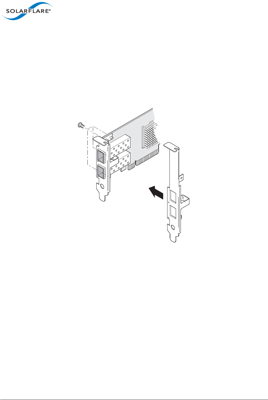
2.2 Fitting a Full Height Bracket (optional)
Solarflare adapters are supplied with a low-profile bracket fitted to the adapter. A full height bracket
has also been supplied for PCIe slots that require this type of bracket.
To fit a full height bracket to the Solarflare adapter:
1From the back of the adapter, remove the screws securing the bracket.
2Slide the bracket away from the adapter.
3Taking care not the overtighten the screws, attach the full height bracket to the adapter.
Issue 10 © Solarflare Communications 2013 22
Solarflare Server Adapter
User Guide
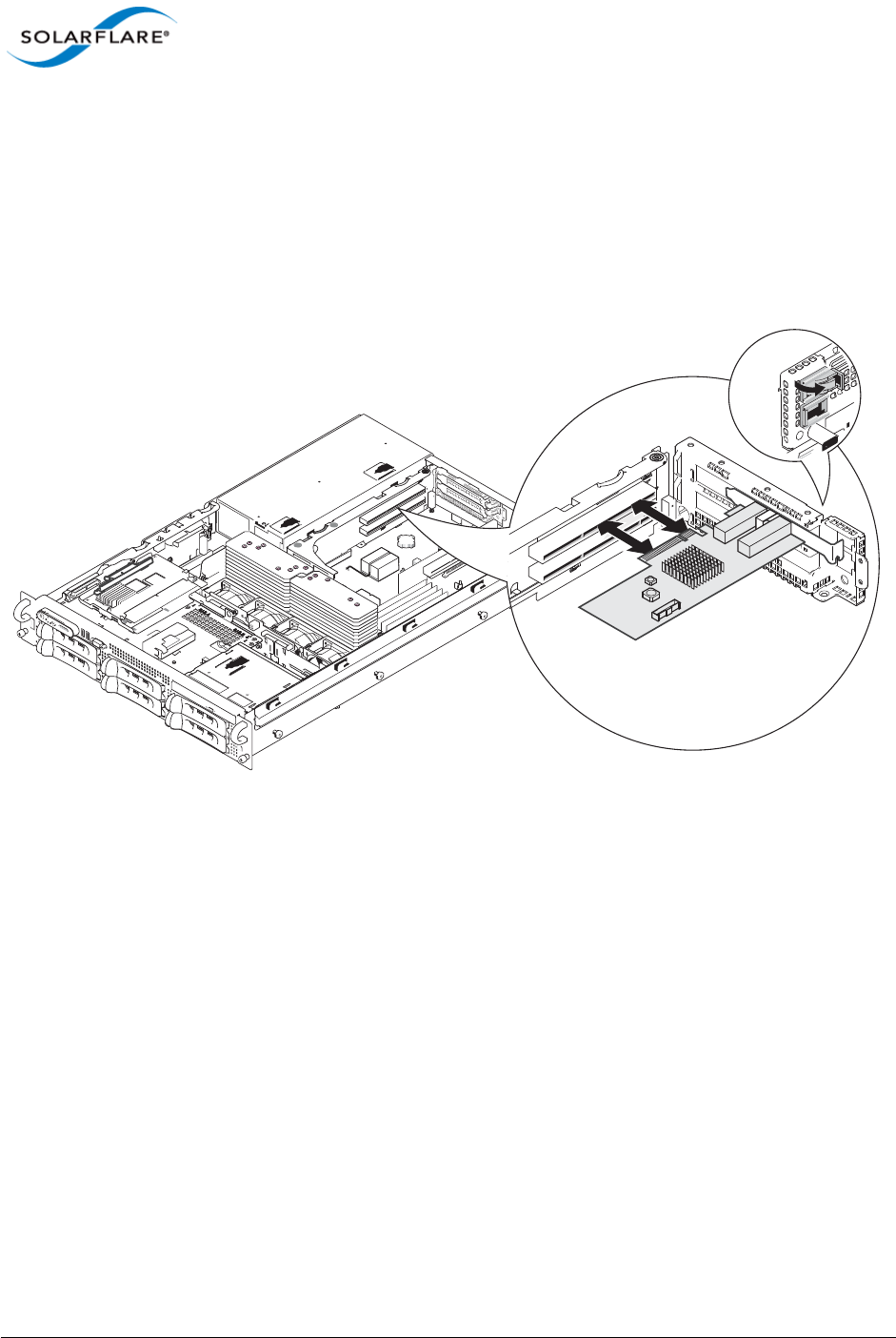
2.3 Inserting the Adapter in a PCI Express (PCIe) Slot
1Shut down the server and unplug it from the mains. Remove the server cover to access the
PCIe slots in the server.
2Locate an 8-lane or 16-lane PCIe slot (refer to the server manual if necessary) and insert the
Solarflare card.
3Secure the adapter bracket in the slot.
4Replace the cover and restart the server.
5After restarting the server, the host operating system may prompt you to install drivers for the
new hardware. Click Cancel or abort the installation and refer to the relevant chapter in this
manual for how to install the Solarflare adapter drivers for your operating system.
Issue 10 © Solarflare Communications 2013 23
Solarflare Server Adapter
User Guide
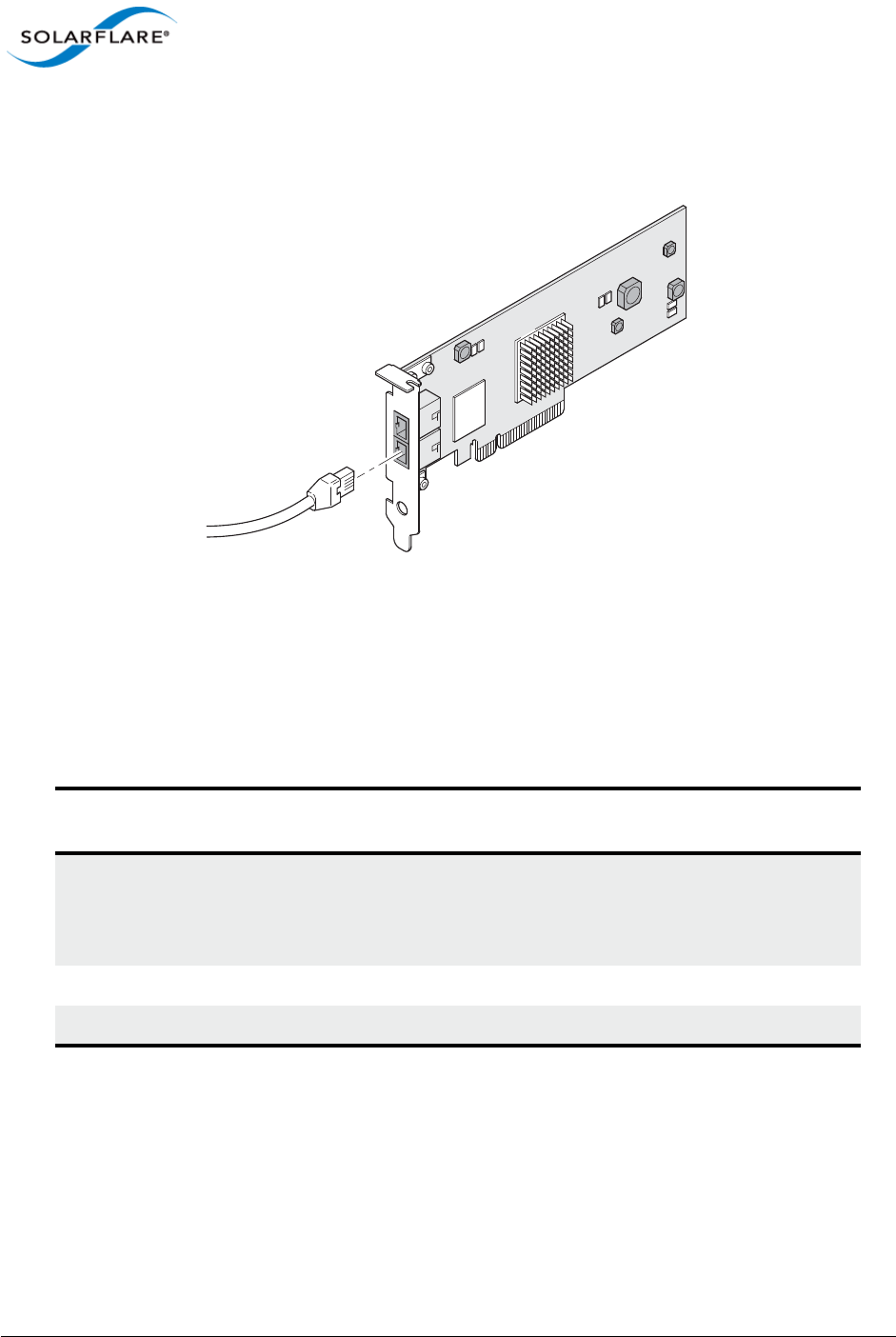
2.4 Attaching a Cable (RJ-45)
The Solarflare SFN5121T 10GBASE-T Server Adapter connects to the Ethernet network using a
copper cable fitted with an RJ-45 connector (shown below).
RJ-45 Cable Specifications
Table 1 below lists the recommended cable specifications for various Ethernet port types.
Depending on the intended use, attach a suitable cable. For example, to achieve 10 Gb/s
performance, use a Category 6 cable. To achieve the desired performance, the adapter must be
connected to a compliant link partner, such as an IEEE 802.3an-compliant gigabit switch.
Table 1: RJ-45 Cable Specification
Port type Connector Media Type Maximum
Distance
10GBASE-T RJ-45 Category 6A
Category 6 unshielded twisted pairs (UTP)
Category 5E
100m (328 ft.)
55m (180 ft.)
55m (180 ft.)
1000BASE-T RJ-45 Category 5E, 6, 6A UTP 100m (328 ft.)
100BASE-TX RJ-45 Category 5E, 6, 6A UTP 100m (328 ft.)
Issue 10 © Solarflare Communications 2013 24
Solarflare Server Adapter
User Guide
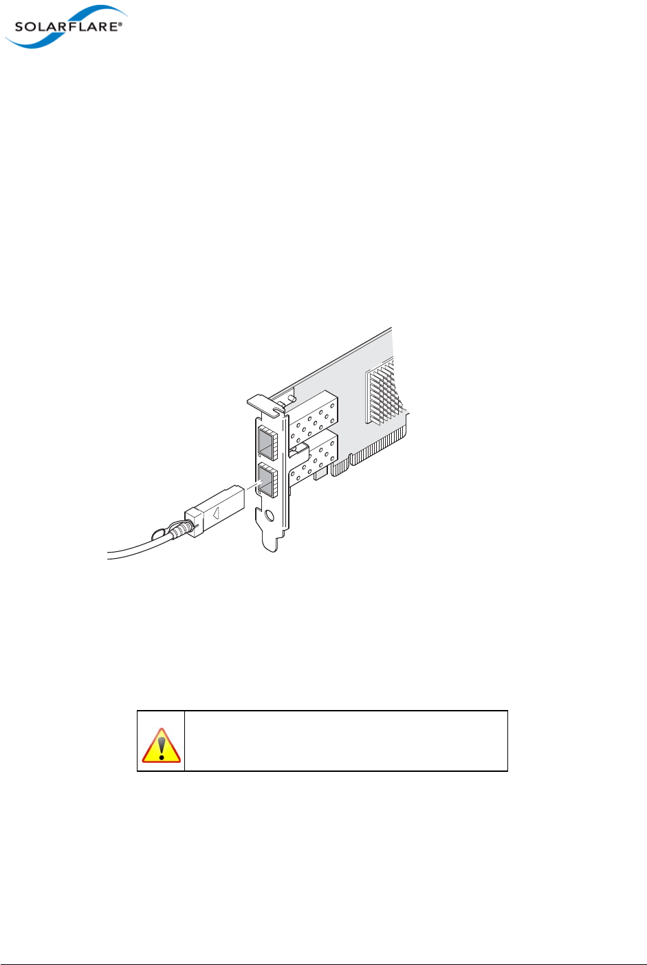
2.5 Attaching a Cable (SFP+)
The Solarflare SFP+ Server Adapters can be connected to the network using either an SFP+ Direct
Attach cable or a fiber optic cable.
Attaching the SFP+ Direct Attach Cable:
1Turn the cable so that the connector retention tab and gold fingers are on the same side as the
network adapter retention clip.
Push the cable connector straight in to the adapter socket until it clicks into place.
Removing the SFP+ Direct Attach Cable:
1Pull straight back on the release ring to release the cable retention tab. Alternatively, you can
lift the retention clip on the adapter to free the cable if necessary.
2Slide the cable free from the adapter socket.
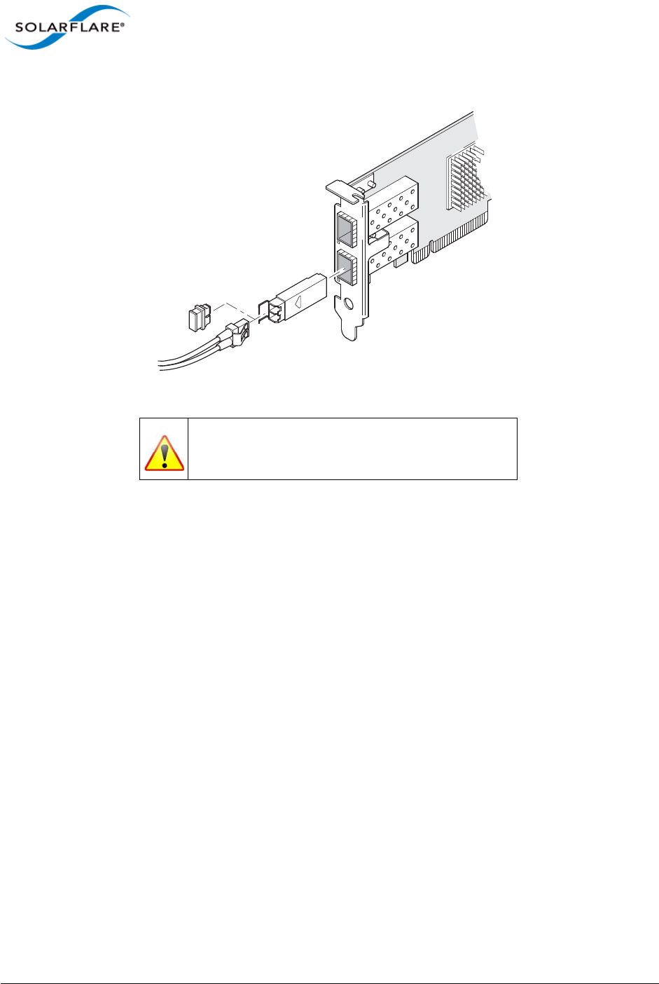
Attaching a fiber optic cable:
1Remove and save the fiber optic connector cover.
2Insert a fiber optic cable into the ports on the network adapter bracket as shown. Most
connectors and ports are keyed for proper orientation. If the cable you are using is not keyed,
WARNING
Do not look directly into the fiber transceiver or cables
as the laser beams can damage your eyesight.
Issue 10 © Solarflare Communications 2013 25
Solarflare Server Adapter
User Guide
check to be sure the connector is oriented properly (transmit port connected to receive port
on the link partner, and vice versa).
Removing a fiber optic cable:
1Remove the cable from the adapter bracket and replace the fiber optic connector cover.
2Pull the plastic or wire tab to release the adapter bracket.
3Hold the main body of the adapter bracket and remove it from the adapter.
WARNING
Do not look directly into the fiber transceiver or cables
as the laser beams can damage your eyesight.

Issue 10 © Solarflare Communications 2013 26
Solarflare Server Adapter
User Guide
2.6 Supported SFP+ Cables
Table 2 is a list of supported SFP+ cables that have been tested by Solarflare. Solarflare is not aware
of any issues preventing the use of other brands of SFP+ cables (of up to 5m in length) with Solarflare
network adapters. However, only cables in the table below have been fully verified and are therefore
supported.
Table 2: Supported SFP+ Direct Attach Cables
Manufacturer Product Code Cable Length Notes
Arista CAB-SFP-SFP-1M 1m
Arista CAB-SFP-SFP-3M 3m
Cisco SFP-H10GB-CU1M 1m
Cisco SFP-H10GB-CU3M 3m
Cisco SFP-H10GB-CU5M 5m
HP J9283A/B Procurve 3m
Juniper EX-SFP-10GE-DAC-1m 1m
Juniper EX-SFP-10GE-DAC-3m 3m
Molex 74752-1101 1m Not supported on SFN4112F
adapters – due to cable being
non-compliant with the SFP+
spec with respect to I2C.
Molex 74752-2301 3m
Molex 74752-3501 5m
Molex 74752-9093 1m 37-0960-01 / 0K585N
Molex 74752-9094 3m 37-0961-01 / 0J564N
Molex 74752-9096 5m 37-0962-01 / 0H603N
Panduit PSF1PXA1M 1m
Panduit PSF1PXA3M 3m
Panduit PSF1PXD5MBU 5m
Siemon SFPP30-01 1m
Siemon SFPP30-02 2m
Siemon SFPP30-03 3m
Siemon SFPP24-05 5m

Issue 10 © Solarflare Communications 2013 27
Solarflare Server Adapter
User Guide
The Solarflare SFA6902F adapter has been tested and certified with direct attach cables up to 3m in
length.
2.7 Supported SFP+ 10G SR Optical Transceivers
Table 3 is a list of supported SFP+10G SR optical transceivers that have been tested by Solarflare.
Solarflare is not aware of any issues preventing the use of other brands of 10G SR transceivers with
Solarflare network adapters. However, only transceivers in the table below have been fully verified
and are therefore supported.
Tyco 2032237-2 D 1m
Tyco 2032237-4 3m
Table 3: Supported SFP+ 10G Optical SR Transceivers
Manufacturer Product Code Notes
Avago AFBR-703SDZ 10G
Avago AFBR-703SDDZ Dual speed 1G/10G optic. Not
supported on SFN4112F adapters.
Avago AFBR-703SMZ 10G
Arista SFP-10G-SR 10G
Finisar FTLX8571D3BCL 10G
Finisar FTLX8571D3BCV Dual speed 1G/10G optic. Not
supported on SFN4112F adapters.
HP 456096-001 Also labelled as 455883-B21 and
455885-001
Intel AFBR-703SDZ 10G
JDSU PLRXPL-SC-S43-22-N 10G
Juniper AFBR-700SDZ-JU1 10G
MergeOptics TRX10GVP2010 10G
Solarflare SFM-10G-SR 10G
Table 2: Supported SFP+ Direct Attach Cables
Manufacturer Product Code Cable Length Notes
Issue 10 © Solarflare Communications 2013 28
Solarflare Server Adapter
User Guide
2.8 Supported SFP+ 10G LR Optical Transceivers
Table 4 is a list of supported SFP+10G LR optical transceivers that have been tested by Solarflare.
Solarflare is not aware of any issues preventing the use of other brands of 10G LR transceivers with
Solarflare network adapters. However, only transceivers in the table below have been fully verified
and are therefore supported.
2.9 Supported SFP 1000BASE-T Transceivers
Table 5 is a list of supported SFP 1000BASE-T transceivers that have been tested by Solarflare.
Solarflare is not aware of any issues preventing the use of other brands of 1000BASE-T transceivers
with the Solarflare network adapters. However, only transceivers in the table below have been fully
verified and are therefore supported.
Table 4: Supported SFP+ 10G LR Optical Transceivers
Manufacturer Product Code Notes
Avago AFCT-701SDZ 10G single mode fiber
Finisar FTLX1471D3BCL 10G single mode fiber
NOTE: 1000BASE-T transceivers are not supported on the SFN4112F SFP+ server network adapter.
Table 5: Supported SFP 1000BASE-T Transceivers
Manufacturer Product Code
Arista SFP-1G-BT
Avago ABCU-5710RZ
Cisco 30-1410-03
Dell FCMJ-8521-3-(DL)
Finisar FCLF-8521-3
Finisar FCMJ-8521-3
HP 453156-001
453154-B21
3COM 3CSFP93

Issue 10 © Solarflare Communications 2013 29
Solarflare Server Adapter
User Guide
2.10 Supported 1G Optical Transceivers
Table 6 is a list of supported 1G transceivers that have been tested by Solarflare. Solarflare is not
aware of any issues preventing the use of other brands of 1G transceivers with Solarflare network
adapters. However, only transceivers in the table below have been fully verified and are therefore
supported.
2.11 Supported Speed and Mode
Solarflare network adapters support either SFP/SFP+ or Base-T standards.
On Base-T adapters three speeds are supported 100Mbps, 1Gbps and 10Gbps. The adapters use
auto negotiation to automatically select the highest speed supported in common with the link
partner.
On SFP+ adapters the currently inserted SFP module (transceiver) determines the supported speeds,
typically SFP modules only support a single speed. Some Solarflare SFP+ adapters support dual
speed optical modules that can operate at either 1Gbps or 10Gbps. However, these modules do not
auto-negotiate link speed and operate at the maximum (10G) link speed unless explicitly configured
to operate at a lower speed (1G).
NOTE: 1G optical transceivers are not supported on the SFN4112F SFP+ server network adapter.
Table 6: Supported 1G Transceivers
Manufacturer Product Code Type
Avago AFBR-5710PZ 1000Base-SX
Cisco GLC-LH-SM 1000Base-LX/LH
Finisar FTLF8519P2BCL 1000Base-SX
Finisar FTLF8519P3BNL 1000Base-SX
Finisar FTLF1318P2BCL 1000Base-LX
Finisar FTLF1318P3BTL 1000Base-LX
HP 453153-001
453151-B21
1000Base-SX

Issue 10 © Solarflare Communications 2013 30
Solarflare Server Adapter
User Guide
The tables below summarizes the speeds supported by Solarflare network adapters.
Table 7: SFN4112F SFP+ Adapter
Supported Modes Auto neg speed Speed Comment
SFP+ direct attach cable No 10G
SFP+ optical module (10G) No 10G
Table 8: SFN5xxx,SFN6xxx and SFN7xxx SFP+ Adapters
Supported Modes Auto neg speed Speed Comment
SFP+ direct attach cable No 10G
SFP+ optical module (10G) No 10G
SFP optical module (1G) No 1G
SFP+ optical module (10G/1G) No 10G or 1G Dual speed modules run at
the maximum speed (10G)
unless explicitly configured to
the lower speed (1G)
SFP 1000BASE-T module No 1G These modules support only
1G and will not link up at
100Mbps
Table 9: SFN5121T, SFN5151T, SFN5161T 10GBASE-T Adapters
Supported Modes Auto neg speed Speed Comment
100Base-T Yes 100Mbps Typically the interface is set
to auto negotiation speed
and automatically selects the
highest speed supported in
common with it’s link partner.
If the link partner is set to
100Mbps, with no autoneg,
the adapter will use “parallel
detection” to detect and
select 100Mbps speed. If
needed any of the three
speeds can be explicitly
configured
1000Base-TX Yes 1Gbps
10GBase-T Yes 10Gbps

Issue 10 © Solarflare Communications 2013 31
Solarflare Server Adapter
User Guide
100Base-T in a Solarflare adapter back-to-back (no intervening switch) configuration will not work
and is not supported.
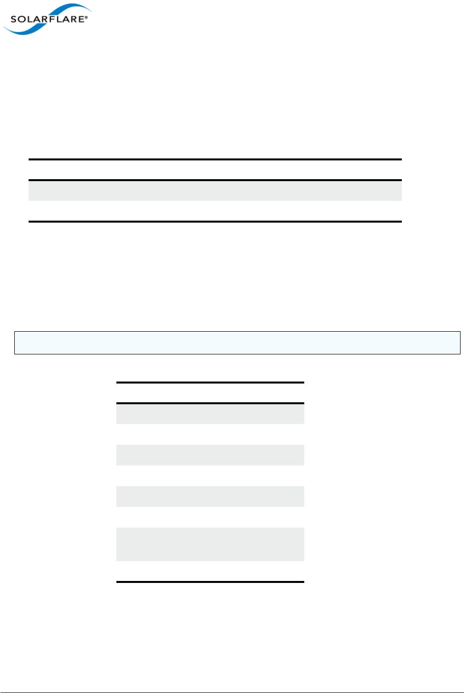
2.12 LED States
There are two LEDs on the Solarflare network adapter transceiver module. LED states are as follows:
Table 10: LED States
Adapter Type LED Description State
SFP/SFP+ Link
Activity
Green (solid) at all speeds
Flashing green when network traffic is present
LEDs are OFF when there is no link present
BASE-T Speed
Activity
Green (solid) 10Gbps
Yellow (solid) 100/1000Mbps
Flashing green when network traffic is present
LEDs are OFF when there is no link present
Issue 10 © Solarflare Communications 2013 32
Solarflare Server Adapter
User Guide
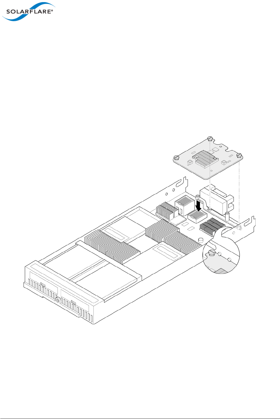
2.13 Solarflare Mezzanine Adapter: SFN5802K
The Solarflare SFN5802K is a Dual-Port 10G Ethernet Mezzanine Adapter for the HP BladeSystem c-
Class.
The HP BladeSystem blade supports up to two Solarflare mezzanine adapters.
Inserting the Mezzanine Adapter into the BladeSystem Server.
1The blade should be extracted from the server in order to install the mezzanine adapter.
2Remove the blade top cover and identify the screw posts towards the rear of the blade
(Figure 1) where the adapter will be secured (two screw posts per adapter - refer to the
BladeSystem manual if necessary).
Figure 1: Locate the Mezzanine Adapter screw posts
3It may be necessary to remove the internal battery tray if fitted. Align the mezzanine port
connector with the backplane connector block and screw posts. Press home gently ensuring
that the adapter is firmly and correctly seated in the connector block.
4Hand tighten the adapter retaining screws.
5Replace the internal battery tray and replace the blade top cover.
Issue 10 © Solarflare Communications 2013 33
Solarflare Server Adapter
User Guide
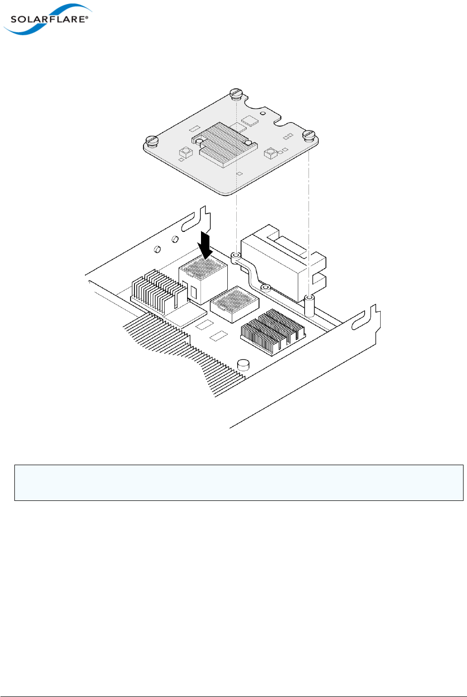
With a mezzanine adapter installed into the lower connector block, a second adapter can be
installed into the remaining connector block (see Figure 2)
Figure 2: Installing a second mezzanine adapter
CAUTION: It is important that the spring loaded screws are not over tightened to avoid damage to
the adapter.
Issue 10 © Solarflare Communications 2013 34
Solarflare Server Adapter
User Guide
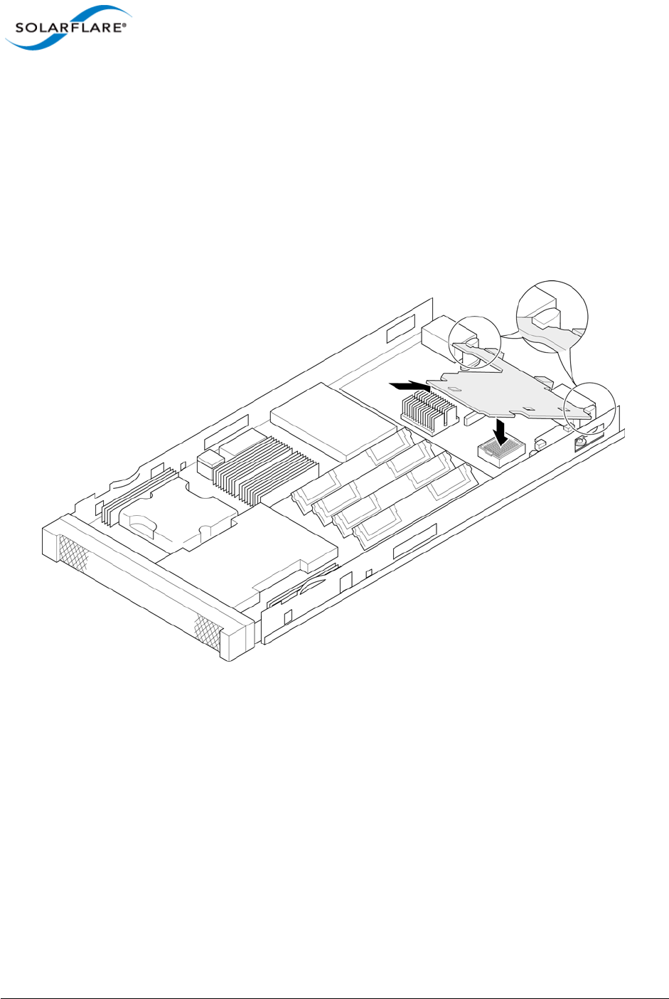
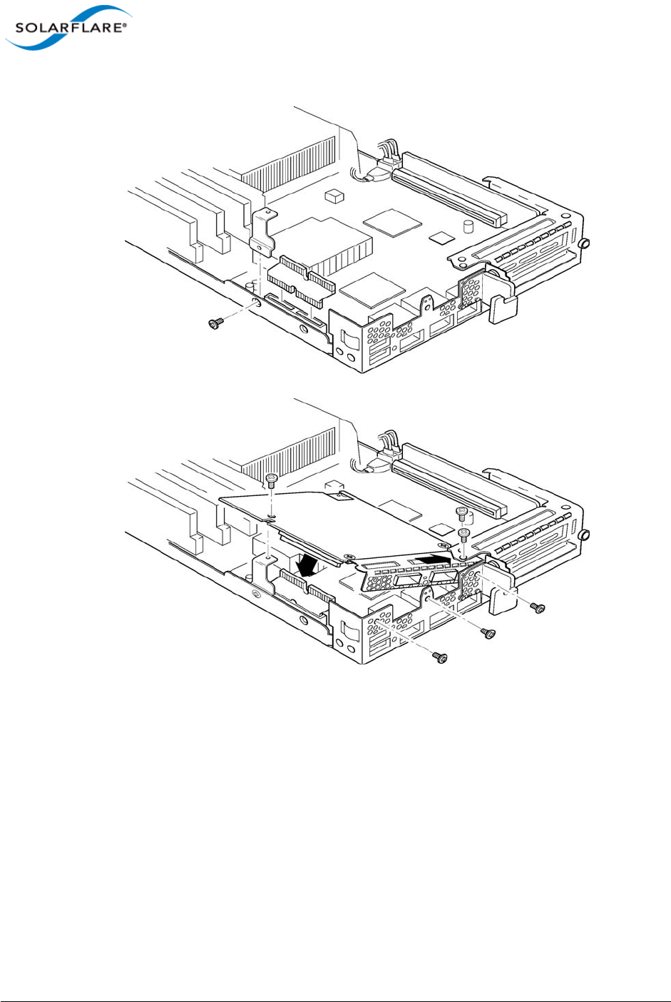
2.14 Solarflare Mezzanine Adapters: SFN5812H and SFN5814H
The Solarflare SFN5812H Dual-Port and SFN5814H Quad-Port are 10G Ethernet Mezzanine Adapters
for the IBM BladeCenter.
Solarflare mezzanine adapters are supported on the IBM BladeCenter E, H and S chassis, HS22,
HS22V and HX5 servers. The IBM BladeCenter blade supports a single Solarflare mezzanine adapter.
1The blade should be extracted from the BladeCenter in order to install the mezzanine adapter.
2Remove the blade top cover and locate the two retaining posts towards the rear of the blade -
(Figure 3). Refer to the BladeCenter manual if necessary.
Figure 3: Installing the Mezzanine Adapter
3Hinge the adapter under the retaining posts, as illustrated, and align the mezzanine port
connector with the backplane connector block.
Issue 10 © Solarflare Communications 2013 35
Solarflare Server Adapter
User Guide
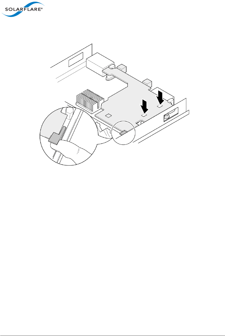
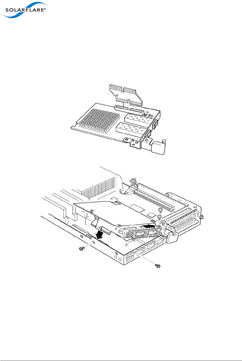
4Lower the adapter, taking care to align the side positioning/retaining posts with the recesses in
the adapter. See Figure 4.
Figure 4: In position mezzanine adapter
5Press the port connector gently into the connector block ensuring that the adapter is firmly
and correctly seated in the connector block.
6Replace the blade top cover.
7When removing the adapter raise the release handle (shown on Figure 4) to ease the adapter
upwards until it can be freed from the connector block.
2.15 Solarflare Mezzanine Adapter SFN6832F-C61
The Solarflare SFN6832F-C61 is a Dual-Port SFP+ are 10GbE Mezzanine Adapters for the DELL
PowerEdge C6100 series rack server. Each DELL PowerEdge node supports a single Solarflare
mezzanine adapter.
1The node should be extracted from the rack server in order to install the mezzanine adapter.
Refer to the PowerEdge rack server manual if necessary.
Issue 10 © Solarflare Communications 2013 36
Solarflare Server Adapter
User Guide
Figure 5: SFN6832F-C61 - Installing into the rack server node
2Secure the side retaining bracket as shown in Figure 5 (top diagram)
3Fit riser PCB card into the slot as shown in Figure 5 (top diagram). Note that the riser card only
fits one way.
4Offer the adapter to the node and ensure it lies underneath the chassis cover.
5Lower the adapter into position making sure to connect the adapter slot with the to of the PCB
riser card.
6Secure the adapter using the supplied screws at the positions shown in the diagram.
Issue 10 © Solarflare Communications 2013 37
Solarflare Server Adapter
User Guide
2.16 Solarflare Mezzanine Adapter SFN6832F-C62
The Solarflare SFN6832F-C61 is a Dual-Port SFP+ are 10GbE Mezzanine Adapters for the DELL
PowerEdge C6200 series rack server. Each DELL PowerEdge node supports a single Solarflare
mezzanine adapter.
1The node should be extracted from the rack server in order to install the mezzanine adapter.
Refer to the PowerEdge rack server manual if necessary.
Figure 6: SFN6832F-C62 - Installing into the rack server node
2Fit the PCB riser card to the underside connector on the adapter.
3Offer the adapter to the rack server node ensuring it lies underneath the chassis cover.
4Lower to adapter to connect the riser PCB card into the slot in the node.
5Secure the adapter with the supplied screws at the points shown in the diagram.

Issue 10 © Solarflare Communications 2013 38
Solarflare Server Adapter
User Guide
2.17 Solarflare Precision Time Synchronization Adapters
The Solarflare SFN7122F1, SFN7322F, SFN6322F and SFN5322F adapters are dual-port SFP+ 10GbE
adapters that can generate hardware timestamps for PTP packets in support of a network precision
time protocol deployment compliant with the IEEE 1588-2008 specification.
Customers requiring configuration instructions for these adapters and Solarflare PTP in a PTP
deployment should refer to the Solarflare Enhanced PTP User Guide SF-109110-CD.
1. Requires an AppFlex™ license - refer to Solarflare AppFlex™ Technology Licensing. on page 13.
2.18 Solarflare SFA6902F ApplicationOnload™ Engine
The ApplicationOnload™ Engine (AOE) SFA6902F is a full length PCIe form factor adapter that
combines an ultra-low latency adapter with a tightly coupled ’bump-in-the-wire’ FPGA.
For details of installation and configuring applications that run on the AOE refer to the Solarflare AOE
User’s Guide (SF-108389-CD). For details on developing custom applications to run on the FPGA refer
to the AOE Firmware Development Kit User Guide (SF-108390-CD).

Issue 10 © Solarflare Communications 2013 39
Solarflare Server Adapter
User Guide
Chapter 3: Solarflare Adapters on Linux
This chapter covers the following topics on the Linux® platform:
• System Requirements...Page 39
• Linux Platform Feature Set...Page 40
• Solarflare RPMs...Page 41
• Installing Solarflare Drivers and Utilities on Linux...Page 43
• Red Hat Enterprise Linux Distributions...Page 43
• SUSE Linux Enterprise Server Distributions...Page 44
• Unattended Installations...Page 45
• Unattended Installation - Red Hat Enterprise Linux...Page 47
• Unattended Installation - SUSE Linux Enterprise Server...Page 48
• Hardware Timestamps...Page 49
• Configuring the Solarflare Adapter...Page 49
• Configuring Receive/Transmit Ring Buffer Size...Page 50
• Setting Up VLANs...Page 51
• Setting Up Teams...Page 52
• Running Adapter Diagnostics...Page 53
• Running Cable Diagnostics...Page 54
• Linux Utilities RPM...Page 55
• Configuring the Boot ROM with sfboot...Page 56
• Upgrading Adapter Firmware with Sfupdate...Page 70
• License Install with sfkey...Page 75
• Performance Tuning on Linux...Page 77
• Module Parameters...Page 97
• Linux ethtool Statistics...Page 99
3.1 System Requirements
Refer to Software Driver Support on page 13 for supported Linux Distributions.
NOTE: SUSE Linux Enterprise Server 11 includes a version of the Solarflare network adapter Driver.
This driver does not support the SFN512x family of adapters. To update the supplied driver, see
SUSE Linux Enterprise Server Distributions on page 44

Issue 10 © Solarflare Communications 2013 40
Solarflare Server Adapter
User Guide
3.2 Linux Platform Feature Set
Table 11 lists the features supported by Solarflare adapters on Red Hat and SUSE Linux distributions.
NOTE: Red Hat Enterprise Linux versions 5.5 and 6.0 include a version of the SFN4112F Solarflare
adapter driver. This driver does not support the SFN512x family of adapters. Red Hat Enterprise
Linux 5.6 and 6.1 includes a version of the Solarflare network driver for the SFN512x family of
adapters. To update the supplied driver, see Installing Solarflare Drivers and Utilities on Linux on
page 43
Table 11: Linux Feature Set
Fault diagnostics Support for comprehensive adapter and cable fault diagnostics
and system reports.
• See Running Adapter Diagnostics on page 53
Firmware updates Support for Boot ROM, Phy transceiver and adapter firmware
upgrades.
• See Upgrading Adapter Firmware with Sfupdate on page 70
Hardware Timestamps Solarflare Flareon SFN7122F1 and SFN7322F adapters support
the hardware timestamping of all received packets - including
PTP packets.
The Linux kernel must support the SO_TIMESTAMPING socket
option (2.6.30+) to allow the driver to support hardware packet
timestamping. Therefore hardware packet timestamping is not
available in RHEL 5
1. SFN7122F requires an AppFlex license - for details refer to Solarflare
AppFlex™ Technology Licensing. on page 13.
Jumbo frames Support for MTUs (Maximum Transmission Units) from
1500 bytes to 9216 bytes.
• See Configuring Jumbo Frames on page 51
PXE and iSCSI booting Support for diskless booting to a target operating system via
PXE or iSCSI boot.
• See Configuring the Boot ROM with sfboot on page 56
• See Solarflare Boot ROM Agent on page 360
PXE or iSCSI boot are not supported for Solarflare adapters on
IBM System p servers.

Issue 10 © Solarflare Communications 2013 41
Solarflare Server Adapter
User Guide
3.3 Solarflare RPMs
Solarflare supply RPM packages in the following formats:
• DKMS
• Source RPM
Where possible, it is recommended that you use the DKMS RPM if you have DKMS installed.
Receive Side Scaling (RSS) Support for RSS multi-core load distribution technology.
• See Receive Side Scaling (RSS) on page 83
SR-IOV Support for XenServer6 PCIe Single Root-IO Virtualization and
Linux KVM SR-IOV.
• See SR-IOV Virtualization for XenServer on page 340
• See SR-IOV Virtualization Using KVM on page 323
SR-IOV is not supported for Solarflare adapters on IBM System
p servers.
Standby and Power
Management
Solarflare adapters support Wake On LAN on Linux. These
settings are only available if the adapter has auxiliary power
supplied by a separate cable.
Task offloads Support for TCP Segmentation Offload (TSO), Large Receive
Offload (LRO), and TCP/UDP/IP checksum offload for improved
adapter performance and reduced CPU processing
requirements.
• See Configuring Task Offloading on page 50
Teaming Improve server reliability and bandwidth by combining physical
ports, from one or more Solarflare adapters, into a team,
having a single MAC address and which function as a single port
providing redundancy against a single point of failure.
• See Setting Up Teams on page 52
Virtual LANs (VLANs) Support for multiple VLANs per adapter.
• See Setting Up VLANs on page 51
Table 11: Linux Feature Set

Issue 10 © Solarflare Communications 2013 42
Solarflare Server Adapter
User Guide
DKMS RPM
Dynamic Kernel Module Support (DKMS) is a framework where device driver source can reside
outside the kernel source tree. It supports an easy method to rebuild modules when kernels are
upgraded.
Execute the command dkms --version to determine whether DKMS is installed.
To install the Solarflare driver DKMS package execute the following command:
rpm -i sfc-dkms-<version>.noarch.rpm
Building the Source RPM
These instructions may be used to build a source RPM package for use with Linux distributions or
kernel versions where DKMS or KMP packages are not suitable.
1First, the kernel headers for the running kernel must be installed at /lib/modules/
<kernel-version>/build. On Red Hat systems, install the appropriate kernel-smp-
devel or kernel-devel package. On SUSE systems install the kernel-source package.
2To build a source RPM for the running kernel version from the source RPM, enter the following
at the command-line:
rpmbuild --rebuild <package_name>
Where package_name is the full path to the source RPM (see the note below).
3To build for a different kernel to the running system, enter the following command:
rpmbuild --define 'kernel <kernel version>' --rebuild <package_name>
4Install the resulting RPM binary package, as described in Installing Solarflare Drivers and
Utilities on Linux.
NOTE: RPMs can be installed for multiple kernel versions.
NOTE: The location of the generated RPM is dependent on the distribution and often the version
of the distribution and the RPM build tools.
The RPM build process should print out the location of the RPM towards the end of the build
process, but it can be hard to find amongst the other output.
Typically the RPM will be placed in /usr/src/<dir>/RPMS/<arch>/, where <dir> is
distribution specific. Possible folders include Red Hat, packages or extra. The RPM file will be
named using the same convention as the Solarflare provided pre-built binary RPMs.
The command: find /usr/src -name "*sfc*.rpm” will list the locations of all Solarflare
RPMs.

Issue 10 © Solarflare Communications 2013 43
Solarflare Server Adapter
User Guide
3.4 Installing Solarflare Drivers and Utilities on Linux
• Red Hat Enterprise Linux Distributions...Page 43
• SUSE Linux Enterprise Server Distributions...Page 44
• Building the Source RPM...Page 42
Linux drivers for Solarflare are available in DKMS and source RPM packages. The source RPM can be
used to build binary RPMs for a wide selection of distributions and kernel variants. This section
details how to install the resultant binary RPM.
Solarflare recommend using DKMS RPMs if the DKMS framework is available. See DKMS RPM on
page 42 for more details.
3.5 Red Hat Enterprise Linux Distributions
These instructions cover installation and configuration of the Solarflare network adapter drivers on
Red Hat Enterprise Linux Server. Refer to Software Driver Support on page 13 for details of
supported Linux distributions.
Refer to Building the Source RPM on page 42 for directions on creating the binary RPM.
1Install the RPMs:
[root@myhost1]# rpm -ivh kernel-module-sfc-RHEL6-2.6.32-
279.el6.x86_64-3.3.0.6262-1.x86_64.rpm
2There are various tools that can be used for configuring the Solarflare Server Adapter:
a) The NetworkManager service and associated GUI tools. For more information about his
refer to https://wiki.gnome.org/NetworkManager.
b) Solarflare recommend using the Network Administration Tool (NEAT) to configure the new
network interface. NEAT is a GUI based application and therefore requires an X server to run.
c) Alternatively the command line program Kudzu can be used. However, you may find when
kudzu is run that you are NOT presented with an option to configure the new network
interface. If this occurs, carefully clear details of the Solarflare Server Adapter from the
hardware database by removing all entries with “vendor id: 1924” in the /etc/
sysconfig/hwconf file. Running kudzu again should now provide an option to configure
the newly added network interface.
3Apply the new network settings:
a) NEAT provides an option to Activate the new interface. The new network interface can
then be used immediately (there is no need to reboot or restart the network service).
b) If you are not using NEAT you will need to reboot, or alternatively restart the networking
service, by typing the following before the new Solarflare interface can be used:
[root@myhost1]# service network restart
NOTE: The Solarflare adapter should be physically installed in the host computer before installing
the driver. The user must have root permissions to install the adapter drivers.

Issue 10 © Solarflare Communications 2013 44
Solarflare Server Adapter
User Guide
3.6 SUSE Linux Enterprise Server Distributions
These instructions cover installation and configuration of the Solarflare Network Adapter drivers on
SUSE Linux Enterprise Server. Refer to Software Driver Support...Page 13 for details of supported
distributions.
Refer to Building the Source RPM on page 42 for directions on creating the binary RPM.
1The Solarflare drivers are currently classified as 'unsupported' by SUSE Enterprise Linux 10
(SLES10). To allow unsupported drivers to load in SLES10, edit the following file:
/etc/sysconfig/hardware/config
find the line:
LOAD_UNSUPPORTED_MODULES_AUTOMATICALLY=no
and change no to yes.
For SLES 11, edit the last line in /etc/modprobe.d/unsupported-modules to:
allow_unsupported_modules 1
2Install the RPMs:
[root@myhost1]# rpm -ivh kernel-module-sfc-2.6.5-7.244-smp-2.1.0111-
0.sf.1.SLES9.i586.rpm
3Run YaST to configure the Solarflare Network Adapter. When you select the Ethernet
Controller, the Configuration Name will take one of the following forms:
a) eth-bus-pci-dddd:dd:dd.N where N is either 0 or 1.
b) eth-id-00:0F:53:XX:XX:XX
Once configured, the Configuration Name for the correct Ethernet Controller will change to
the second form, and an ethX interface will appear on the host. If the incorrect Ethernet
Controller is chosen and configured, then the Configuration Name will remain as eth-bus-
pci-dddd:dd:dd.1 after configuration by YaST, and an ethX interface will not appear on
the system. In this case, you should remove the configuration for this Ethernet Controller, and
configure the other Ethernet Controller of the pair.
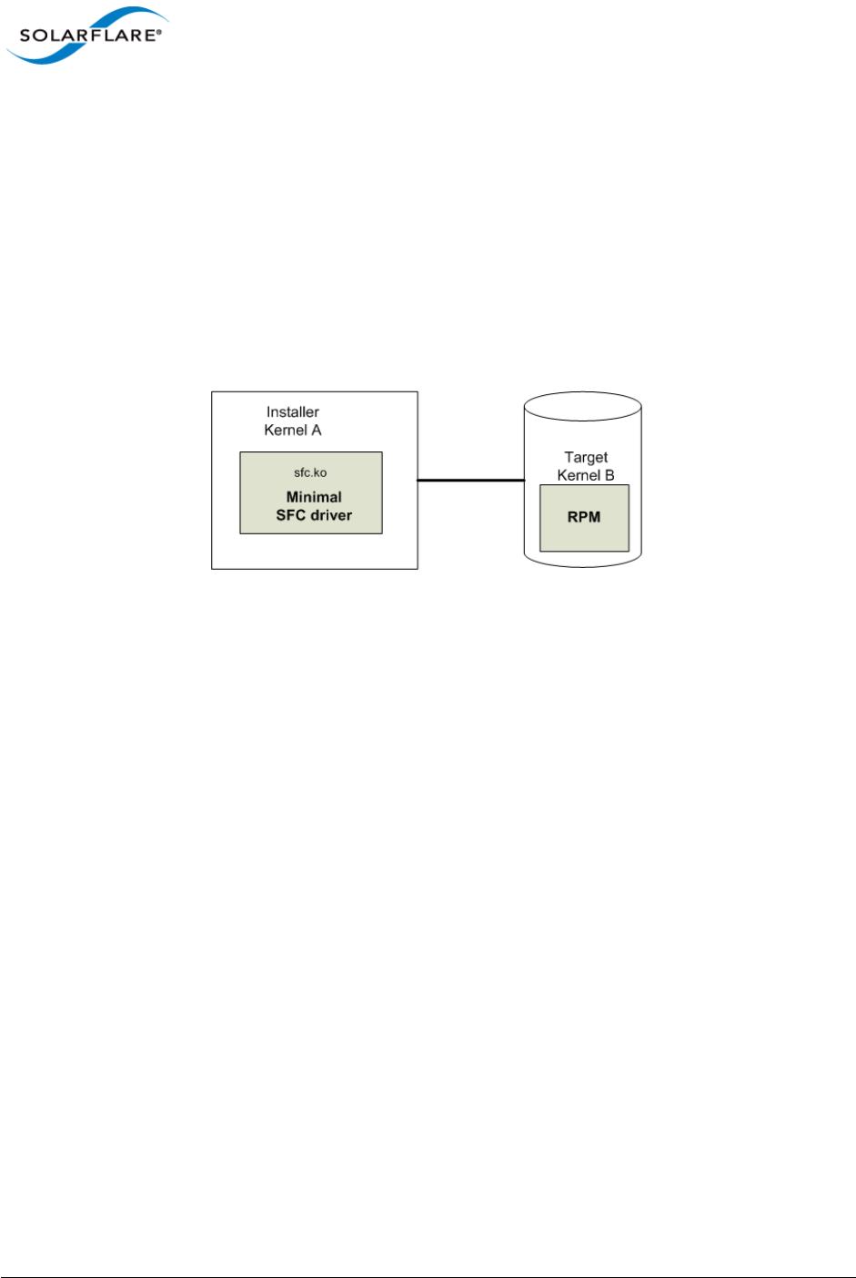
Issue 10 © Solarflare Communications 2013 45
Solarflare Server Adapter
User Guide
3.7 Unattended Installations
Building Drivers and RPMs for Unattended Installation
Linux unattended installation requires building two drivers:
• A minimal installation Solarflare driver that only provides networking support. This driver is
used for network access during the installation process.
• An RPM that includes full driver support. This RPM is used to install drivers in the resultant Linux
installation.
Figure 7: Unattended Installation RPM
Figure 7 shows how the unattended installation process works.
1Build a minimal Solarflare driver needed for use in the installation kernel (Kernel A in the
diagram above). This is achieved by defining “sfc_minimal” to rpmbuild. This macro disables
hardware monitoring, MTD support (used for access to the adapters flash), I2C and debugfs.
This results in a driver with no dependencies on other modules and allows networking support
from the driver during installation.
# as normal user
$ mkdir -p /tmp/rpm/BUILD
$ rpm -i sfc-<ver>-1.src.rpm
$ rpmbuild -bc -D 'sfc_minimal=1' -D 'kernel=<installer kernel>' \
/tmp/rpm/SPECS/sfc.spec
2The Solarflare minimal driver sfc.ko can be found in /tmp/rpm/BUILD/sfc-<ver>/
linux_net/sfc.ko. Integrate this minimal driver into your installer kernel, either by
creating a driver disk incorporating this minimal driver or by integrating this minimal driver
into initrd.
3Build a full binary RPM for your Target kernel and integrate this RPM into your Target (Kernel
B).

Issue 10 © Solarflare Communications 2013 46
Solarflare Server Adapter
User Guide
Driver Disks for Unattended Installations
Solarflare are preparing binary driver disks to help avoid the need to build the minimal drivers
required in unattended installations. Please contact Solarflare support to obtain these driver disks
Table 12 shows the various stages of an unattended installation process:
Table 12: Installation Stages
In Control Stages of Boot Setup needed
BIOS PXE code on the adapter
runs.
Adapter must be in PXE boot mode.
See PXE Support on page 361.
SF Boot ROM (PXE) DHCP request from PXE (SF
Boot ROM).
DHCP server filename and next-
server options.
SF Boot ROM (PXE) TFTP request for filename to
next-server, e.g. pxelinux.0
TFTP server.
pxelinux TFTP retrieval of pxelinux
configuration.
pxelinux configuration on TFTP
server.
pxelinux TFTP menu retrieval of Linux
kernel image initrd.
pxelinux configuration
Kernel, kernel command, initrd
Linux kernel/installer Installer retrieves kickstart
configuration, e.g. via HTTP.
Kickstart/AutoYaST configuration.
Target Linux kernel kernel reconfigures network
adapters.
DHCP server.

Issue 10 © Solarflare Communications 2013 47
Solarflare Server Adapter
User Guide
3.8 Unattended Installation - Red Hat Enterprise Linux
Documentation for preparing for a Red Hat Enterprise Linux network installation can be found at:
http://docs.redhat.com/docs/en-US/Red_Hat_Enterprise_Linux/5/html/Installation_Guide/s1-
begininstall-perform-nfs-x86.html
http://docs.redhat.com/docs/en-US/Red_Hat_Enterprise_Linux/6/html/Installation_Guide/
index.html
The prerequisites for a Network Kickstart installation are:
• Red Hat Enterprise Linux installation media.
• A Web server and/or FTP Server for delivery of the RPMs that are to be installed.
• A DHCP server for IP address assignments and to launch PXE Boot.
• A TFTP server for download of PXE Boot components to the machines being kickstarted.
• The BIOS on the computers to be Kickstarted must be configured to allow a network boot.
• A Boot CD-ROM or flash memory that contains the kickstart file or a network location where the
kickstart file can be accessed.
• A Solarflare driver disk.
Unattended Red Hat Enterprise Linux installations are configured with Kickstart. The documentation
for Kickstart can be found at:
http://docs.redhat.com/docs/en-US/Red_Hat_Enterprise_Linux/5/html/Installation_Guide/ch-
redhat-config-kickstart.html
http://docs.redhat.com/docs/en-US/Red_Hat_Enterprise_Linux/6/html/Installation_Guide/ch-
kickstart2.html
To install Red Hat Enterprise you need the following:
1A modified initrd.img file with amended modules.alias and modules.dep which
incorporates the Solarflare minimal driver for the installation kernel.
To modules.alias, add the following entries:
alias: pci:v00001924d00000813sv*sd*bc*sc*i*
alias: pci:v00001924d00000803sv*sd*bc*sc*i*
alias: pci:v00001924d00000710sv*sd*bc*sc*i*
alias: pci:v00001924d00000703sv*sd*bc*sc*i*
2Identify the driver dependencies using the modinfo command:
modinfo ./sfc.ko | grep depends
depends: i2c-core,mii,hwmon,hwmon-vid,i2c-algo-bit mtdcore mtdpart
All modules listed as depends must be present in the initrd file image. In addition the user
should be aware of further dependencies which can be resolved by adding the following lines
to the modules.dep file:

Issue 10 © Solarflare Communications 2013 48
Solarflare Server Adapter
User Guide
sfc: i2c-core mii hwmon hwmon-vid i2c-algo-bit mtdcore mtdpart *
i2c-algo-bit: i2c-core
mtdpart: mtdcore
*For Red Hat Enterprise Linux from version 5.5 add mdio to this line.
3A configured kickstart file with the Solarflare Driver RPM manually added to the %Post
section. For example:
%post
/bin/mount -o ro <IP Address of Installation server>:/<path to
location directory containing Solarflare RPM> /mnt
/bin/rpm -Uvh /mnt/<filename of Solarflare RPM>
/bin/umount /mnt
3.9 Unattended Installation - SUSE Linux Enterprise Server
Unattended SUSE Linux Enterprise Server installations are configured with AutoYaST. The
documentation for AutoYaST can be found at:
http://www.suse.com/~ug/autoyast_doc/index.html
The prerequisites for a Network AutoYaST installation are:
• SUSE Linux Enterprise installation media.
• A DHCP server for IP address assignments and to launch PXE Boot.
• A NFS or FTP server to provide the installation source.
• A TFTP server for the download of the kernel boot images needed to PXE Boot.
• A boot server on the same Ethernet segment.
• An install server with the SUSE Linux Enterprise Server OS.
• An AutoYaST configuration server that defines rules and profiles.
• A configured AutoYast Profile (control file).
Further Reading
• SUSE Linux Enterprise Server remote installation:
http://www.novell.com/documentation/sles10/sles_admin/?page=/documentation/sles10/
sles_admin/data/cha_deployment_remoteinst.html
• SUSE install with PXE Boot:
http://en.opensuse.org/SuSE_install_with_PXE_boot

Issue 10 © Solarflare Communications 2013 49
Solarflare Server Adapter
User Guide
3.10 Hardware Timestamps
The Solarflare Flareon SFN7000 series adapters can support hardware timestamping for all received
network packets.
The Linux kernel must support the SO_TIMESTAMPING socket option (2.6.30+) therefore hardware
packet timestamping is not supported on RHEL 5.
For more information about using the kernel timestamping API, users should refer to the Linux
documentation: http://lxr.linux.no/linux/Documentation/networking/timestamping.txt
3.11 Configuring the Solarflare Adapter
Ethtool is a standard Linux tool that you can use to query and change Ethernet adapter settings,
including those for Solarflare adapters. Ethtool can be downloaded from http://sourceforge.net/
projects/gkernel/files/ethtool/.
The general command for ethtool is as follows:
ethtool <-option> <ethX>
Where X is the identifier of the interface. Note that root access will be required to configure adapter
settings. Refer to the Linux online manual (man ethtool) for details of the options that are
available for ethtool.
Configuring Speed and Modes
Solarflare adapters by default automatically negotiate the connection speed to the maximum
supported by the link partner. On the 10GBASE-T adapters “auto” instructs the adapter to negotiate
the highest speed supported in common with it’s link partner. On SFP+ adapters, “auto” instructs the
adapter to use the highest link speed supported by the inserted SFP+ module. On 10GBASE-T and
SFP+ adapters, any other value specified will fix the link at that speed, regardless of the capabilities
of the link partner, which may result in an inability to establish the link. Dual speed SFP+ modules
operate at their maximum (10G) link speed unless explicitly configured to operate at a lower speed
(1G).
The following commands demonstrate ethtool to configure the network adapter Ethernet settings.
Identify interface configuration settings:
ethtool ethX
Set link speed:
ethtool -s ethX speed 1000|100
To return the connection speed to the default auto-negotiate, enter:
ethtool -s <ethX> autoneg on
Configure auto negotiation:
ethtool -s ethX autoneg [on|off]
Set auto negotiation advertised speed 1G:

Issue 10 © Solarflare Communications 2013 50
Solarflare Server Adapter
User Guide
ethtool -s ethX advertise 0x20
Set autonegotiation advertised speed 10G:
ethtool -s ethX advertise 0x1000
Set autonegotiation advertised speeds 1G and 10G:
ethtool -s ethX advertise 0x1020
Identify interface auto negotiation pause frame setting:
ethtool -a ethX
Configure auto negotiation of pause frames:
ethtool -A ethX autoneg on [rx on|off] [tx on|off]
Configuring Task Offloading
Solarflare adapters support transmit (Tx) and receive (Rx) checksum offload, as well as TCP
segmentation offload. To ensure maximum performance from the adapter, all task offloads should
be enabled, which is the default setting on the adapter. For more information, see Performance
Tuning on Linux on page 77.
To change offload settings for Tx and Rx, use the ethtool command:
ethtool --offload <ethX> [rx on|off] [tx on|off]
Configuring Receive/Transmit Ring Buffer Size
By default receive and transmit ring buffers on the Solarflare adapter support 1024 descriptors. The
user can identify and reconfigure ring buffer sizes using the ethtool command.
To identify the current ring size:
ethtool -g ethX
To set the new transmit or receive ring size to value N
ethtool -G ethX [rx N| tx N]
The ring buffer size must be a value between 128 and 4096. Buffer size can also be set directly in the
modprobe.conf file or add the options line to a file under the /etc/modprobe.d directory e.g.
options sfc rx_ring=4096
Using the modprobe method sets the value for all Solarflare interfaces. Then reload the driver for
the option to become effective:
modprobe -r sfc
modprobe sfc

Issue 10 © Solarflare Communications 2013 51
Solarflare Server Adapter
User Guide
Configuring Jumbo Frames
Solarflare adapters support frame sizes from 1500 bytes to 9216 bytes. For example, to set a new
frame size (MTU) of 9000 bytes, enter the following command:
ifconfig <ethX> mtu 9000
To make the changes permanent, edit the network configuration file for <ethX>; for example,
/etc/sysconfig/network-scripts/ifcfg-eth1 and append the following configuration
directive, which specifies the size of the frame in bytes:
MTU=9000
Standby and Power Management
Solarflare adapters support Wake on LAN and Wake on Magic Packet setting on Linux. You need to
ensure that Wake on LAN has been enabled on the BIOS correctly and your adapter has auxiliary
power via a separate cable before configuring Wake on LAN features.
In SUSE Linux Enterprise Server, you can use the YaST WOL module to configure Wake on LAN or you
can use the ethtool wol g setting.
In Red Hat Enterprise Linux you can use the ethtool wol g setting.
3.12 Setting Up VLANs
VLANs offer a method of dividing one physical network into multiple broadcast domains. In
enterprise networks, these broadcast domains usually match with IP subnet boundaries, so that
each subnet has its own VLAN. The advantages of VLANs include:
• Performance
• Ease of management
• Security
• Trunks
• You don't have to configure any hardware device, when physically moving your server to
another location.
To set up VLANs, consult the following documentation:
• To configure VLANs on SUSE Linux Enterprise Server, see:
http://www.novell.com/support/viewContent.do?externalId=3864609
• To configure tagged VLAN traffic only on Red Hat Enterprise Linux, see:
http://kbase.redhat.com/faq/docs/DOC-8062
• To configure mixed VLAN tagged and untagged traffic on Red Hat Enterprise Linux, see:
http://kbase.redhat.com/faq/docs/DOC-8064

Issue 10 © Solarflare Communications 2013 52
Solarflare Server Adapter
User Guide
3.13 Setting Up Teams
Teaming network adapters (network bonding) allows a number of physical adapters to act as one,
virtual adapter. Teaming network interfaces, from the same adapter or from multiple adapters,
creates a single virtual interface with a single MAC address.
The virtual adapter or virtual interface can assist in load balancing and providing failover in the event
of physical adapter or port failure.
Teaming configuration support provided by the Linux bonding driver includes:
• 802.3ad Dynamic link aggregation
• Static link aggregation
• Fault Tolerant
To set up an adapter team, consult the following documentation:
General:
http://www.kernel.org/doc/Documentation/networking/bonding.txt
RHEL 5:
http://www.redhat.com/docs/en-US/Red_Hat_Enterprise_Linux/5.4/html/Deployment_Guide/s2-
modules-bonding.html
RHEL6:
http://docs.redhat.com/docs/en-US/Red_Hat_Enterprise_Linux/6/html/Deployment_Guide/s2-
networkscripts-interfaces-chan.html
SLES:
http://www.novell.com/documentation/sles11/book_sle_admin/data/
sec_basicnet_yast.html#sec_basicnet_yast_netcard_man

Issue 10 © Solarflare Communications 2013 53
Solarflare Server Adapter
User Guide
3.14 Running Adapter Diagnostics
You can use ethtool to run adapter diagnostic tests. Tests can be run offline (default) or online.
Offline runs the full set of tests, which can interrupt normal operation during testing. Online
performs a limited set of tests without affecting normal adapter operation.
As root user, enter the following command:
ethtool --test ethX offline|online
The tests run by the command are as follows:
Table 13: Adapter Diagnostic Tests
Diagnostic Test Purpose
core.nvram Verifies the flash memory ‘board configuration’ area by
parsing and examining checksums.
core.registers Verifies the adapter registers by attempting to modify the
writable bits in a selection of registers.
core.interrupt Examines the available hardware interrupts by forcing the
controller to generate an interrupt and verifying that the
interrupt has been processed by the network driver.
tx/rx.loopback Verifies that the network driver is able to pass packets to
and from the network adapter using the MAC and Phy
loopback layers.
core.memory Verifies SRAM memory by writing various data patterns
(incrementing bytes, all bit on and off, alternating bits on
and off) to each memory location, reading back the data
and comparing it to the written value.
core.mdio Verifies the MII registers by reading from PHY ID registers
and checking the data is valid (not all zeros or all ones).
Verifies the MMD response bits by checking each of the
MMDs in the Phy is present and responding.
chanX eventq.poll Verifies the adapter’s event handling capabilities by
posting a software event on each event queue created by
the driver and checking it is delivered correctly.
The driver utilizes multiple event queues to spread the
load over multiple CPU cores (RSS).
phy.bist Examines the PHY by initializing it and causing any
available built-in self tests to run.

Issue 10 © Solarflare Communications 2013 54
Solarflare Server Adapter
User Guide
3.15 Running Cable Diagnostics
Cable diagnostic data can be gathered from the Solarflare 10GBASE-T adapters physical interface
using the ethtool -t command which runs a comprehensive set of diagnostic tests on the
controller, PHY, and attached cables. To run the cable tests enter the following command:
ethtool -t ethX [online | offline]
Online tests are non-intrusive and will not disturb live traffic.
The following is an extract from the output of the ethtool diagnostic offline tests:
phy cable.pairA.length 9
phy cable.pairB.length 9
phy cable.pairC.length 9
phy cable.pairD.length 9
phy cable.pairA.status 1
phy cable.pairB.status 1
phy cable.pairC.status 1
phy cable.pairD.status 1
Cable length is the estimated length in metres. A length value of 65535 indicates length not
estimated due to pair busy or cable diagnostic routine not completed successfully.
The cable status can be one of the following values:
0 - invalid, or cable diagnostic routine did not complete successfully
1 - pair ok, no fault detected
2 - pair open or Rt > 115 ohms
3 - intra pair short or Rt < 85 ohms
4 - inter pair short or Rt < 85 ohms
9 - pair busy or link partner forces 100Base-Tx or 1000Base-T test mode.

Issue 10 © Solarflare Communications 2013 55
Solarflare Server Adapter
User Guide
3.16 Linux Utilities RPM
The Solarflare Utilities RPM for Linux contains:
• A boot ROM utility. Configuring the Boot ROM with sfboot...Page 56
• A flash firmware update utility. Upgrading Adapter Firmware with Sfupdate...Page 70
• A license key install utility. License Install with sfkey...Page 75
The RPM package, is supplied as 64bit and 32bit binaries compiled to be compatible with GLIBC
versions for all supported distributions.
The Solarflare utilities RPM file can be downloaded from the following location:
https://support.solarflare.com/
• SF-104451-LS is a 32bit binary RPM package.
• SF-107601-LS is a 64bit binary RPM package.
Download and copy the zipped binary RPM package to the required directory. Unzip and install
(64bit package example):
1Unzip the package:
# unzip SF-107601-LS-20_Solarflare_Linux_Utilities_RPM_64bit.zip
2Install the binary RPM:
# rpm -Uvh sfutils-4.0.1.6605-1.x86_64.rpm
Preparing... ########################################### [100%]
1:sfutils ########################################### [100%]
3Check that the RPM installed correctly:
# rpm -q sfutils
sfutils-4.0.1.6605-1.x86_64
Directions for the use of the utility programs are explained in the following sections:

Issue 10 © Solarflare Communications 2013 56
Solarflare Server Adapter
User Guide
3.17 Configuring the Boot ROM with sfboot
• Sfboot: Command Usage...Page 56
• Sfboot: Command Line Options...Page 56
• Sfboot: Examples...Page 66
Sfboot is a command line utility for configuring the Solarflare adapter Boot ROM for PXE and iSCSI
booting. Using sfboot is an alternative to using Ctrl + B to access the Boot Rom agent during server
startup.
See Configuring the Solarflare Boot ROM Agent on page 360 for more information on the Boot Rom
agent.
PXE and iSCSI network boot is not supported for Solarflare adapters on IBM System p servers.
Sfboot: SLES 11 Limitation
Due to limitations in SLES 11 using kernel versions prior to 2.6.27.54 it is necessary to reboot the
server after running the sfboot utility.
Sfboot: Command Usage
The general usage for sfboot is as follows (as root):
sfboot [--adapter=eth<N>] [options] [configurable parameters]
Note that without --adapter, the sfboot command applies to all adapters that are present in the
target host.
The format for the parameters are:
<parameters>=<value>
Sfboot: Command Line Options
Table 14 lists the options for sfboot and Table 15 lists the available options.
Table 14: Sfboot Options
Option Description
-?-h, --help Displays command line syntax and provides a
description of each sfboot option.
-V, --version Shows detailed version information and exits.
-v, --verbose Shows extended output information for the
command entered.

Issue 10 © Solarflare Communications 2013 57
Solarflare Server Adapter
User Guide
The following parameters in Table 15 are used to control the configurable parameters for the Boot
ROM driver when running prior to the operating system booting.
-s, --quiet
Aliases: --silent
Suppresses all output, except errors; no user
interaction. You should query the completion code to
determine the outcome of commands when
operating silently (see Performance Tuning on
Windows on page 236).
-l --list Lists all available Solarflare adapters. This option
shows the ifname and MAC address.
Note: this option may not be used in conjunction
with the any other option. If this option is used with
configuration parameters, those parameters will be
silently ignored.
-i, --adapter =<ethX> Performs the action on the identified Solarflare
network adapter. The adapter identifier ethX can be
the ifname or MAC address, as output by the --list
option. If --adapter is not included, the action will
apply to all installed Solarflare adapters.
-c --clear Resets all adapter options except boot-image to
their default values. Note that --clear can also be
used with parameters, allowing you to reset to
default values, and then apply the parameters
specified.
Table 15: Sfboot Parameters
Parameter Description
boot-
image=<all|optionrom|uefi|di
sabled>
Specifies which boot firmware images are served-up
to the BIOS during start-up. This parameter can not
be used if the --adapter option has been specified.
This option is not reset if --clear is used.
Table 14: Sfboot Options
Option Description

Issue 10 © Solarflare Communications 2013 58
Solarflare Server Adapter
User Guide
link-
speed=<auto|10g|1g|100m>
Specifies the network link speed of the adapter used
by the Boot ROM - the default is auto. On the
10GBASE-T adapters “auto” instructs the adapter to
negotiate the highest speed supported in common
with it’s link partner. On SFP+ adapters, “auto”
instructs the adapter to use the highest link speed
supported by the inserted SFP+ module. On
10GBASE-T and SFP+ adapters, any other value
specified will fix the link at that speed, regardless of
the capabilities of the link partner, which may result
in an inability to establish the link.
auto Auto-negotiate link speed (default)
10G 10G bit/sec
1G 1G bit/sec
100M 100M bit/sec
linkup-delay=<seconds> Specifies the delay (in seconds) the adapter defers its
first connection attempt after booting, allowing time
for the network to come up following a power failure
or other restart. This can be used to wait for
spanning tree protocol on a connected switch to
unblock the switch port after the physical network
link is established. The default is 5 seconds.
banner-delay=<seconds> Specifies the wait period for Ctrl-B to be pressed to
enter adapter configuration tool.
seconds = 0-256
bootskip-delay=<seconds> Specifies the time allowed for Esc to be pressed to
skip adapter booting.
seconds = 0-256
boot-
type=<pxe|iscsi|disabled>
Sets the adapter boot type.
pxe – PXE (Preboot eXecution Environment) booting
iscsi – iSCSI (Internet Small Computer System
Interface) booting
disabled – Disable adapter booting
Table 15: Sfboot Parameters
Parameter Description

Issue 10 © Solarflare Communications 2013 59
Solarflare Server Adapter
User Guide
initiator-
dhcp=<enabled|disabled>
Enables or disables DHCP address discovery for the
adapter by the Boot ROM except for the Initiator IQN
(see initiator-iqn-dhcp). This option is only
valid if iSCSI booting is enabled (boot-
type=iscsi).
If initiator-DHCP is set to disabled, the following
options will need to be specified:
initiator-ip=<ip_address>
netmask=<subnet>
The following options may also be needed:
gateway=<ip_address>
primary-dns=<ip_address>
initiator-ip=<ipv4 address> Specifies the IPv4 address (in standard “.” notation
form) to be used by the adapter when initiator-
dhcp is disabled.
Note that this option is only valid if iSCSI booting is
enabled (boot-type=iscsi).
Example:
sfboot boot-type=iscsi initiator-
dhcp=disabled initiator-
ip=<192.168.1.3>
netmask=<ipv4 subnet> Specifies the IPv4 subnet mask (in standard “.”
notation form) to be used by the adapter when
initiator-dhcp is disabled. Note that this option
is only valid if iSCSI booting is enabled (boot-
type=iscsi).
Example:
sfboot boot-type=iscsi initiator-
dhcp=disabled netmask=255.255.255.0
gateway=<ipv4 address> Specifies the IPv4 subnet mask (in standard “.”
notation form) to be used by the adapter when
initiator-dhcp is disabled. Note that this option
is only valid if iSCSI booting is enabled (boot-
type=iscsi).
Example:
sfboot boot-type=iscsi initiator-
dhcp=disabled gateway=192.168.0.10
Table 15: Sfboot Parameters
Parameter Description

Issue 10 © Solarflare Communications 2013 60
Solarflare Server Adapter
User Guide
primary-dns=<ipv4 address> Specifies the IPv4 address (in standard “.” notation
form) of the Primary DNS to be used by the adapter
when initiator-dhcp is disabled.
This option is only valid if iSCSI booting is enabled
(boot-type=iscsi).
Example:
sfboot boot-type=iscsi initiator-
dhcp=disabled primary-dns=192.168.0.3
initiator-iqn-
dhcp=<enabled|disabled>
Enables or disables use of DHCP for the initiator IQN
only.
initiator-iqn=<IQN> Specifies the IQN (iSCSI Qualified Name) to be used
by the adapter when initiator-iqn-dhcp is
disabled. The IQN is a symbolic name in the “.”
notation form; for example:
iqn.2009.01.com.solarflare, and is a maximum of 223
characters long.
Note that this option is only valid if iSCSI booting is
enabled (boot-type=iscsi).
Example:
sfboot initiator-iqn-dhcp=disabled
initiator-
iqn=iqn.2009.01.com.solarflare
adapter=2
lun-retry-count=<count> Specifies the number of times the adapter attempts
to access and login to the Logical Unit Number (LUN)
on the iSCSI Target before failing. Note that this
option is only valid if iSCSI booting is enabled (boot-
type=iscsi).
Example:
sfboot lun-retry-count=3
Table 15: Sfboot Parameters
Parameter Description

Issue 10 © Solarflare Communications 2013 61
Solarflare Server Adapter
User Guide
target-
dhcp=<enabled|disabled>
Enables or disables the use of DHCP to discover iSCSI
target parameters on the adapter.
If target-dhcp is disabled, you must specify the
following options:
target-server=<address>
target-iqn=<iqn>
target-port=<port>
target-lun=<LUN>
Example - Enable the use of DHCP to configure iSCSI
Target settings:
sfboot boot-type=iscsi target-
dhcp=enabled
target-server=<DNS name or
ipv4 address>
Specifies the iSCSI target’s DNS name or IPv4 address
to be used by the adapter when target-dhcp is
disabled.
Note that this option is only valid if iSCSI booting is
enabled (boot-type=iscsi).
Example:
sfboot boot-type=iscsi target-
dhcp=disabled target-server=192.168.2.2
target-port=<port_number> Specifies the Port number to be used by the iSCSI
target when target-dhcp is disabled. The default
Port number is Port 3260.
Note that this option is only valid if iSCSI booting is
enabled (boot-type=iscsi).
Example:
sfboot boot-type=iscsi target-
dhcp=disabled target-port=3262
This option should only be used if your target is using
a non-standard TCP Port.
target-lun=<LUN> Specifies the Logical Unit Number (LUN) to be used
by the iSCSI target when target-dhcp is disabled.
The default LUN is 0.
Note that this option is only valid if iSCSI booting is
enabled (boot-type=iscsi).
Table 15: Sfboot Parameters
Parameter Description

Issue 10 © Solarflare Communications 2013 62
Solarflare Server Adapter
User Guide
target-iqn=<IQN> Specifies the IQN of the iSCSI target when target-
dhcp is disabled. Maximum of 223 characters.
Note that this option is only valid if iSCSI booting is
enabled (boot-type=iscsi).
Note that if there are spaces contained in <IQN>,
then the IQN must be wrapped in double quotes (“”).
Example:
sfboot target-dhcp=disabled target-
iqn=iqn.2009.01.com.solarflare
adapter=2
vendor-id=<dhcp_id> Specifies the device vendor ID to be advertised to the
DHCP server. This must match the vendor id
configured at the DHCP server when using DHCP
option 43 to obtain the iSCSI target.
chap=<enabled|disabled> Enables or disables the use of Challenge Handshake
Protocol (CHAP) to authenticate the iSCSI
connection.
Note that this option is only valid if iSCSI booting is
enabled (boot-type=iscsi).
To be valid, this option also requires the following
sub-options to be specified:
username=<initiator username>
secret=<initiator password>
Example:
sfboot boot-type=iscsi chap=enabled
username=initiatorusername
secret=initiatorsecret
Table 15: Sfboot Parameters
Parameter Description

Issue 10 © Solarflare Communications 2013 63
Solarflare Server Adapter
User Guide
username=<username> Specifies the CHAP initiator username (maximum 64
characters).
Note that this option is required if either CHAP or
Mutual CHAP is enabled (chap=enabled,
mutual-chap=enabled).
Note that if there are spaces contained in
<username>, then it must be wrapped in double
quotes (“”).
Example:
sfboot boot-type=iscsi chap=enabled
username=username
secret=<secret> Specifies the CHAP initiator secret (minimum 12
characters, maximum 20 characters).
Note that this option is valid if either CHAP or Mutual
CHAP is enabled (chap=enabled, mutual-
chap=enabled).
Note that if there are spaces contained in <secret>,
then it must be wrapped in double quotes (“”).
Example:
sfboot boot-type=iscsi chap=enabled
username=username secret=veryverysecret
mutual-
chap=<enabled|disabled>
Enables/disables Mutual CHAP authentication when
iSCSI booting is enabled.
This option also requires the following sub-options to
be specified:
target-username=<username>
target-secret=<password>
username=<username>
secret=<password>
Example:
sfboot boot-type=iscsi mutual-
chap=enabled username=username
secret=veryverysecret target-
username=targetusername target-
secret=anothersecret
Table 15: Sfboot Parameters
Parameter Description

Issue 10 © Solarflare Communications 2013 64
Solarflare Server Adapter
User Guide
target-username=<username> Specifies the username that has been configured on
the iSCSI target (maximum 64 characters).
Note that this option is necessary if Mutual CHAP is
enabled on the adapter (mutual-chap=enabled).
Note that if there are spaces contained in
<username>, then it must be wrapped in double
quotes (“”).
target-secret=<secret> Specifies the secret that has been configured on the
iSCSi target (minimum 12 characters; maximum 20
characters).
Note: This option is necessary if Mutual CHAP is
enabled on the adapter (mutual-chap=enabled).
Note that if there are spaces contained in <secret>,
then it must be wrapped in double quotes (“”).
mpio-priority=<MPIO
priority>
Specifies the Multipath I/O (MPIO) priority for the
adapter. This option is only valid for iSCSI booting
over multi-port adapters, where it can be used to
establish adapter port priority. The range is 1- 255,
with 1 being the highest priority.
mpio-attempts=<attempt
count>
Specifies the number of times MPIO will try and use
each port in turn to login to the iSCSI target before
failing.
msix-limit=
<8|16|32|64|128|256|512|1024>
Specifies the maximum number of MSI-X interrupts
the specified adapter will use. The default is 32.
Note: Using the incorrect setting can impact the
performance of the adapter. Contact Solarflare
technical support before changing this setting.
sriov=<enabled|disabled> Enable SR-IOV support for operating systems that
support this.
Table 15: Sfboot Parameters
Parameter Description

Issue 10 © Solarflare Communications 2013 65
Solarflare Server Adapter
User Guide
vf-count=<vf count> The number of virtual functions (VF) advertised to
the operating system. The Solarflare SFC9000 family
of controllers support a total limit of 127 virtual
functions per port and a total 1024 interrupts.
Depending on the values of msix-limit and vf-msix-
limit, some of these virtual functions may not be
configured.
Enabling all 127 VFs per port with more than one
MSI-X interrupt per VF may not be supported by the
host BIOS - in which case you may get 127 VFs on one
port and none on others. Contact your BIOS vendor
or reduce the VF count.
The sriov parameter is implied if vf-count is greater
than zero.
vf-msix-limit=<1|2|4|8> The maximum number of interrupts a virtual
function may use.
firmware-variant=<full-
feature|ultra-low-
latency|auto>
For SFN7000 series adapters only.
The ultra-low-latency variant produces best latency
without support for TX VLAN insertion or RX VLAN
stripping (not currently used features). It is
recommended that Onload customers use the ultra-
low-latency variant.
Default value = auto - means the driver will select
ultra-low-latency by default.
Table 15: Sfboot Parameters
Parameter Description

Issue 10 © Solarflare Communications 2013 66
Solarflare Server Adapter
User Guide
Sfboot: Examples
• Show the current boot configuration for all adapters:
sfboot
• List all Solarflare adapters installed on the localhost:
sfboot --list
Solarflare boot configuration utility [v3.0.3]
Copyright Solarflare Communications 2006-2010, Level 5 Networks 2002-2005
eth1:
Boot image Option ROM and UEFI
Link speed Negotiated automatically
Link-up delay time 5 seconds
Banner delay time 2 seconds
Boot skip delay time 5 seconds
Boot type PXE
MSI-X interrupt limit 32
eth2:
Boot image Option ROM and UEFI
Link speed Negotiated automatically
Link-up delay time 5 seconds
Banner delay time 2 seconds
Boot skip delay time 5 seconds
Boot type PXE
MSI-X interrupt limit 32
Solarflare boot configuration utility [v3.0.2]
Copyright Solarflare Communications 2006-2010, Level 5 Networks 2002-2005
eth4 - 00-0F-53-01-3C-AC, eth5 - 00-0F-53-01-3C-AD, eth6 - 00-0F-53-01-
3C-A4, eth7 - 00-0F-53-01-3C-A5

Issue 10 © Solarflare Communications 2013 67
Solarflare Server Adapter
User Guide
• Enable iSCSI booting on adapter eth4. Implement default iSCSI settings:
sfboot --adapter=eth4 boot-type=iscsi
Solarflare boot configuration utility [v3.0.2]
Copyright Solarflare Communications 2006-2010, Level 5 Networks 2002-2005
eth4:
Boot image Option ROM and UEFI
Link speed Negotiated automatically
Link-up delay time 5 seconds
Banner delay time 2 seconds
Boot skip delay time 5 seconds
Boot type iSCSI
Use DHCP for Initiator Enabled
Use DHCP for Initiator IQN Enabled
LUN busy retries 2
Use DHCP for Target Enabled
DHCP Vendor Class ID SFCgPXE
CHAP authentication Disabled
Mutual CHAP authentication Disabled
MPIO priority 0
MPIO boot attempts 3
MSI-X interrupt limit 32

Issue 10 © Solarflare Communications 2013 68
Solarflare Server Adapter
User Guide
• iSCSI enable adapter eth2. Disable DHCP. Specify adapter IP address and netmask:
sfboot boot-type=iscsi --adapter=eth2 initiator-dhcp=disabled initiator-
ip=192.168.0.1 netmask=255.255.255.0
• Enable PXE boot
sfboot boot-image=option rom boot-type=pxe
• Enable SR-IOV
sfboot sriov=enabled vf-count=16 vf-msix-limit=1
Solarflare boot configuration utility [v3.0.2]
Copyright Solarflare Communications 2006-2010, Level 5 Networks 2002-2005
eth2:
Boot image Option ROM and UEFI
Link speed Negotiated automatically
Link-up delay time 5 seconds
Banner delay time 2 seconds
Boot skip delay time 5 seconds
Boot type iSCSI
Use DHCP for Initiator Disabled
Initiator IP address 192.168.0.1
Initiator netmask 255.255.255.0
Initiator default gateway 0.0.0.0
Initiator primary DNS 0.0.0.0
Use DHCP for Initiator IQN Enabled
LUN busy retries 2
Use DHCP for Target Enabled
DHCP Vendor Class ID SFCgPXE
CHAP authentication Disabled
Mutual CHAP authentication Disabled
MPIO priority 0
MPIO boot attempts 3
MSI-X interrupt limit 32

Issue 10 © Solarflare Communications 2013 69
Solarflare Server Adapter
User Guide
• SFN7000 Series - Firmware Variant
sfboot firmware-variant=full-feature
Solarflare boot configuration utility [v4.0.0]
Copyright Solarflare Communications 2006-2013, Level 5 Networks 2002-2005
eth4:
Boot image Option ROM only
Link speed Negotiated automatically
Link-up delay time 7 seconds
Banner delay time 3 seconds
Boot skip delay time 6 seconds
Boot type PXE
MSI-X interrupt limit 32
Number of Virtual Functions 0
VF MSI-X interrupt limit 1
Firmware variant full feature / virtualization

Issue 10 © Solarflare Communications 2013 70
Solarflare Server Adapter
User Guide
3.18 Upgrading Adapter Firmware with Sfupdate
• Sfupdate: Command Usage...Page 70
• Sfupdate: Command Line Options...Page 73
• Sfupdate: Examples...Page 74
Sfupdate is a command line utility to manage and upgrade the Solarflare adapter Boot ROM, Phy and
adapter firmware. Embedded within the sfupdate executable are firmware images for various
Solarflare adapters - the exact updates available via sfupdate depend on the adapter.
See Configuring the Solarflare Boot ROM Agent on page 360 for more information on the Boot Rom
agent.
Sfupdate: Command Usage
The general usage for sfupdate is as follows (as root):
sfupdate [--adapter=eth<N>] [options]
where:
ethN is the interface name (ifname) of the Solarflare adapter to be upgraded.
option is one of the command options listed in Table 16.
The format for the options are:
<option>=<parameter>
Running the command sfupdate with no additional parameters will show the current firmware
version for all Solarflare adapters and identifies whether the firmware within sfupdate is more up to
date. To update the firmware for all Solarflare adapters run the command sfupdate --write
Solarflare recommend the following procedure:
1Run sfupdate to check that the firmware on all adapters is up to date.
2Run sfupdate --write to update the firmware on all adapters.
Sfupdate: Linux MTD Limitations
The driver supplied "inbox" within RedHat and Novell distributions has a limitation on the number
of adapters that sfupdate can support. This limitation is removed from RHEL 6.5 onwards. The
Solarflare supplied driver is no longer subject to this limitation on any distro/kernel.
Linux kernel versions prior to 2.6.20 support up to 16 MTD (flash) devices. Solarflare adapters are
equipped with 6 flash partitions. If more than two adapters are deployed within a system a number
of flash partitions will be inaccessible during upgrade.
The limit was raised to 32 in Linux kernel version 2.6.20 and removed altogether in 2.6.35.
NOTE: All Applications accelerated with OpenOnload should be terminated before updating the
firmware with sfupdate.

Issue 10 © Solarflare Communications 2013 71
Solarflare Server Adapter
User Guide
If issues are encountered during sfupdate, the user should consider one of the following options
when upgrading firmware on systems equipped with more than two Solarflare adapters:
• Upgrade two adapters at a time with the other adapters removed.
• Upgrade the kernel.
• Rebuild the kernel, raising the value of MAX_MTD_DEVICES in include/linux/mtd/mtd.h.
• Request bootable utilities from support@solarflare.com.
Overcome Linux MTD Limitations
An alternative method is available to upgrade the firmware without removing the adapters.
1Unbind all interfaces from the drivers:
# for bdf in $(lspci -D -d 1924: | awk '{ print $1 }'); do echo -n ${bdf}\
> /sys/bus/pci/devices/${bdf}/driver/unbind; done
2ifconfig -a will not discover any Solarflare interfaces.
3Identify the bus/device/function for all Solarflare interfaces:
# lspci -D -d 1924:
4Output similar to the following will be produced (5 NICs installed in this example):
# lspci -D -d 1924:
0000:02:00.0 Ethernet controller: Solarflare Communications SFC9020
[Solarstorm]
0000:02:00.1 Ethernet controller: Solarflare Communications SFC9020
[Solarstorm]
0000:03:00.0 Ethernet controller: Solarflare Communications SFC9020
[Solarstorm]
0000:03:00.1 Ethernet controller: Solarflare Communications SFC9020
[Solarstorm]
0000:04:00.0 Ethernet controller: Solarflare Communications SFL9021
[Solarstorm]
0000:04:00.1 Ethernet controller: Solarflare Communications SFL9021
[Solarstorm]
0000:83:00.0 Ethernet controller: Solarflare Communications SFC9020
[Solarstorm]
0000:83:00.1 Ethernet controller: Solarflare Communications SFC9020
[Solarstorm]
0000:84:00.0 Ethernet controller: Solarflare Communications SFC9020
[Solarstorm]
0000:84:00.1 Ethernet controller: Solarflare Communications SFC9020
[Solarstorm]

Issue 10 © Solarflare Communications 2013 72
Solarflare Server Adapter
User Guide
5There are enough resources to upgrade two NICs at a time, so re-bind interfaces in groups of
four (2x2NICs):
# echo -n "0000:02:00.0" > /sys/bus/pci/drivers/sfc/bind
# echo -n "0000:02:00.1" > /sys/bus/pci/drivers/sfc/bind
# echo -n "0000:03:00.0" > /sys/bus/pci/drivers/sfc/bind
# echo -n "0000:03:00.1" > /sys/bus/pci/drivers/sfc/bind
6Run sfupdate to update these NICs (command options may vary):
# sfupdate --write --yes --force
7Run the command to unbind the interfaces again, there will be failures reported because some
of the interfaces aren’t bound:
# for bdf in $(lspci -D -d 1924: | awk '{ print $1 }'); do echo -n ${bdf}\
> /sys/bus/pci/devices/${bdf}/driver/unbind; done
8Repeat the process for the other interfaces (0000:04:00.x; 0000:83:00.x and 0000:84:00.x)
doing so in pairs until all the NICs have been upgraded.
9Rebind all interfaces, doing so en-mass and ignoring errors from those already bound:
# for bdf in $(lspci -D -d 1924: | awk '{ print $1 }'); do echo -n ${bdf}\
> /sys/bus/pci/drivers/sfc/bind; done
10 Alternatively reload the sfc driver:
# onload_tool reload
or:
# modprobe -r sfc
# modprobe sfc
11 Run ifconfig -a again to find that all the interfaces are reported and all have been
firmware upgraded without having to physically touch the server or change the kernel.
Sfupdate: SLES 11 Limitation
Due to limitations in SLES 11 using kernel versions prior to 2.6.27.54 it is necessary to reboot the
server after running the sfupdate utility to upgrade server firmware.

Issue 10 © Solarflare Communications 2013 73
Solarflare Server Adapter
User Guide
Sfupdate: Command Line Options
Table 16 lists the options for sfupdate.
Table 16: Sfupdate Options
Option Description
-h, --help Shows help for the available options and command line
syntax.
-i, --adapter=ethX Specifies the target adapter when more than one
adapter is installed in the localhost.
ethX = Adapter ifname or MAC address (as obtained
with --list).
--list Shows the adapter ID, adapter name and MAC address of
each adapter installed in the localhost.
--write Re-writes the firmware from the images embedded in
the sfupdate tool. To re-write using an external image,
specify --image=<filename> in the command.
--write fails if the embedded image is the same or a
previous version. To force a write in this case, specify --
force in the command.
--force Force the update of all firmware, even if the installed
firmware version is the same as, or more recent then,
the firmware embedded in sfupdate.
--image=(filename) Update the firmware using the binary image from the
given file rather than from those embedded in the utility.
-y, --yes Prompts for user confirmation before writing the
firmware to the adapter.
-v, --verbose Verbose mode.
-s, --silent Suppress output while the utility is running; useful when
the utility is used in a script.
-V --version Display version information and exit.

Issue 10 © Solarflare Communications 2013 74
Solarflare Server Adapter
User Guide
Sfupdate: Examples
• Display firmware versions for all adapters:
sfupdate
Solarstorm firmware update utility [v3.0.3]
Copyright Solarflare Communications 2006-2010, Level 5 Networks 2002-2005
eth1 - MAC: 00-0F-53-01-39-70
Firmware version: v3.0.3
PHY type: QT2025C
PHY version: v2.0.2.5
Controller type: Solarflare SFC4000
Controller version: v3.0.3.2127
BootROM version: v3.0.3.2127
The PHY firmware is up to date
The BootROM firmware is up to date
The controller firmware is up to date
eth2 - MAC: 00-0F-53-01-39-71
Firmware version: v3.0.2
PHY type: QT2025C
PHY version: v2.0.2.5
The PHY firmware is up to date

Issue 10 © Solarflare Communications 2013 75
Solarflare Server Adapter
User Guide
3.19 License Install with sfkey
The sfkey utility is distributed with the Linux Utilities RM package. This utility is used to install
Solarflare AppFlex™ licenses and enable selected on-board services for Solarflare adapters. For more
information about license requirements see Solarflare AppFlex™ Technology Licensing. on page 13.
sfkey: Command Usage
# sfkey [--adapter=eth<N>] [options]
If the adapter option is not specified, operations will be applied to all installed adapters.
• To view all sfkey options:
# sfkey --help
• To list (by serial number) all adapters that support licensing:
# sfkey --inventory
• To display an adapter serial number and installed license keys:
# sfkey --adapter=eth2 --report
Adapter: eth2
Product name: Solarflare SFN7122F SFP+ Server Adapter
Part number: SFN7122F
Serial number: 712200205071133867100591
MAC address: 00-0F-53-21-9B-B0
Installed keys: 2
Active keys: 2
Blacklisted keys: 0
Invalid keys: 0
Unverifiable keys: 0
Inapplicable keys: 0
The installed keys field identifies the number of license keys installed. The active keys field identifies
the number of licenses activated on the adapter.
• To install a license:
Copy the license key data to a .txt file on the target server. All keys can be in the same key file and
the file applied on multiple servers. The following example uses a license key file called key.txt
created on the local server.
# sfkey --adapter=eth<N> --install key.txt
sfkey firmware update utility: v3.3.3.6330
Copyright Solarflare Communications 2006-2013, Level 5 Networks 2002-2005
Reading keys...
Writing keys to eth1...

Issue 10 © Solarflare Communications 2013 76
Solarflare Server Adapter
User Guide
Adapter: eth1
Product name: Solarflare SFN7122F SFP+ Adapter
Part number: SFN7122F
Serial number: 712200205071133867100591
MAC address: 00-0F-53-21-9B-B0
Installed keys: 2
Active keys: 2
Blacklisted keys: 0
Invalid keys: 0
Table 17 describes all sfkey options.
Table 17: sfkey options
Option Description
--inventory List by serial number all adapters that support licensing.
--noevaluationupdate Do not update evaluation keys.
-a --all Apply sfkey operation to all adapters that support
licensing.
-c --clear Delete all existing license keys from an adapter.
-h, --help Display all sfkey options.
-i --adapter identify specific adapter to apply sfkey operation to.
-r --report Display an adapter serial number and current license
status (see example above).
-s --silent Silent mode, output errors only.
-v --verbose Verbose mode.
-V --version Display sfkey version and exit.
-x --xml Report format as XML.

Issue 10 © Solarflare Communications 2013 77
Solarflare Server Adapter
User Guide
3.20 Performance Tuning on Linux
• Introduction...Page 77
• Tuning settings...Page 78
• Other Considerations...Page 92
Introduction
The Solarflare family of network adapters are designed for high-performance network applications.
The adapter driver is pre-configured with default performance settings that have been chosen to
give good performance across a broad class of applications. In many cases, application performance
can be improved by tuning these settings to best suit the application.
There are three metrics that should be considered when tuning an adapter:
• Throughput
• Latency
• CPU utilization
Different applications may be more or less affected by improvements in these three metrics. For
example, transactional (request-response) network applications can be very sensitive to latency
whereas bulk data transfer applications are likely to be more dependent on throughput.
The purpose of this guide is to highlight adapter driver settings that affect the performance metrics
described. This guide covers the tuning of all Solarflare adapters.
In addition to this guide, the user should consider other issues influencing performance such as
application settings, server motherboard chipset, additional software installed on the system, such
as a firewall, and the specification and configuration of the LAN. Consideration of such issues is not
within the scope of this guide.

Issue 10 © Solarflare Communications 2013 78
Solarflare Server Adapter
User Guide
Tuning settings
Adapter MTU (Maximum Transmission Unit)
The default MTU of 1500 bytes ensures that the adapter is compatible with legacy 10/100Mbps
Ethernet endpoints. However if a larger MTU is used, adapter throughput and CPU utilization can be
improved. CPU utilization is improved because it takes fewer packets to send and receive the same
amount of data. Solarflare adapters support frame sizes up to 9216 bytes (this does not include the
Ethernet preamble or frame-CRC).
Since the MTU should ideally be matched across all endpoints in the same LAN (VLAN), and since the
LAN switch infrastructure must be able to forward such packets, the decision to deploy a larger than
default MTU requires careful consideration. It is recommended that experimentation with MTU be
done in a controlled test environment.
The MTU is changed dynamically using ifconfig, where ethX is the interface name and size is the
MTU size in bytes:
# /sbin/ifconfig <ethX> mtu <size>
Verification of the MTU setting may be performed by running ifconfig with no options and
checking the MTU value associated with the interface. The change in MTU size can be made to
persist across reboots by editing the file /etc/sysconfig/network-scripts/ifcfg-ethX
and adding MTU=<mtu> on a new line.
Interrupt Moderation (Interrupt Coalescing)
Interrupt moderation controls the number of interrupts generated by the adapter by adjusting the
extent to which receive packet processing events are coalesced. Interrupt moderation may coalesce
more than one packet-reception or transmit-completion event into a single interrupt.
By default, adaptive moderation is enabled. Adaptive moderation means that the network driver
software adapts the interrupt moderation setting according to the traffic and workload conditions.
Before adjusting the interrupt interval, it is recommended to disable adaptive moderation:
ethtool -C <ethX> adaptive-rx off
Interrupt moderation can be changed using ethtool, where ethX is the interface name and
interval is the moderation setting in microseconds (s). An interval value of zero (0) will turn
interrupt moderation off.
To set RX interrupt moderation:
ethtool –C <ethX> rx-usecs <interval> rx-frames 0
or
ethtool –C <ethX> rx-usecs 0 rx-frames 1
The above example also sets the transmit interrupt moderation interval unless the driver module
parameter separate_tx_channels is enabled. Normally packet RX and TX completions will share
interrupts so RX and TX interrupt moderation intervals must be equal, then the adapter driver
automatically adjusts tx-usecs to match rx-usecs. Refer to Table 22: Driver Module Parameters.

Issue 10 © Solarflare Communications 2013 79
Solarflare Server Adapter
User Guide
To set TX interrupt moderation, if separate_tx_channels is enabled:
ethtool –C <ethX> tx-usecs 0 tx-frames 0
or
ethtool –C <ethX> tx-usecs 0 tx-frames 1
Interrupt moderation settings can be checked using ethtool –c .
The interrupt moderation interval is critical for tuning adapter latency:
• Increasing the moderation value will increase latency, but reduce CPU utilization and improve
peak throughput, if the CPU is fully utilized.
• Decreasing the moderation value or turning it off will decrease latency at the expense of CPU
utilization and peak throughput.
For many transaction request-response type network applications, the benefit of reduced latency to
overall application performance can be considerable. Such benefits may outweigh the cost of
increased CPU utilization.
TCP/IP Checksum Offload
Checksum offload moves calculation and verification of IP Header, TCP and UDP packet checksums
to the adapter. The driver by default has all checksum offload features enabled. Therefore, there is
no opportunity to improve performance from the default.
Checksum offload is controlled using ethtool:
Receive Checksum:
# /sbin/ethtool –K <ethX> rx <on|off>
Transmit Checksum:
# /sbin/ethtool –K <ethX> tx <on|off>
Verification of the checksum settings may be performed by running ethtool with the –k option.
Solarflare recommend you do not disable checksum offload.
TCP Segmentation Offload (TSO)
TCP Segmentation offload (TSO) offloads the splitting of outgoing TCP data into packets to the
adapter. TCP segmentation offload benefits applications using TCP. Non TCP protocol applications
will not benefit (but will not suffer) from TSO.
NOTE: The interrupt moderation interval dictates the minimum gap between two consecutive
interrupts. It does not mandate a delay on the triggering of an interrupt on the reception of every
packet. For example, an interrupt moderation setting of 30s will not delay the reception of the
first packet received, but the interrupt for any following packets will be delayed until 30s after the
reception of that first packet.

Issue 10 © Solarflare Communications 2013 80
Solarflare Server Adapter
User Guide
Enabling TCP segmentation offload will reduce CPU utilization on the transmit side of a TCP
connection, and so improve peak throughput, if the CPU is fully utilized. Since TSO has no effect on
latency, it can be enabled at all times. The driver has TSO enabled by default. Therefore, there is no
opportunity to improve performance from the default.
TSO is controlled using ethtool:
# /sbin/ethtool –K <ethX> tso <on|off>
Verification of the TSO settings may be performed by running ethtool with the –k option.
Solarflare recommend you do not disable TSO.
TCP Large Receive Offload (LRO)
TCP Large Receive Offload (LRO) is a feature whereby the adapter coalesces multiple packets
received on a TCP connection into a single call to the operating system TCP Stack. This reduces CPU
utilization, and so improves peak throughput when the CPU is fully utilized.
LRO should not be enabled if you are using the host to forward packets from one interface to
another; for example if the host is performing IP routing or acting as a layer2 bridge. The driver has
LRO enabled by default.

Issue 10 © Solarflare Communications 2013 81
Solarflare Server Adapter
User Guide
.
LRO can be controlled using the module parameter lro. Add the following line to /etc/
modprobe.conf or add the options line to a file under the /etc/modprobe.d directory to
disable LRO:
options sfc lro=0
Then reload the driver so it picks up this option:
rmmod sfc
modprobe sfc
The current value of this parameter can be found by running:
cat /sys/module/sfc/parameters/lro
NOTE: It has been observed that as RHEL6 boots the libvirtd daemon changes the default
forwarding setting such that LRO is disabled on all network interfaces. This behaviour is undesirable
as it will potentially lower bandwidth and increase CPU utilization - especially for high bandwidth
streaming applications.
To determine if LRO is enabled on an interface:
ethtool -k ethX
If IP forwarding is not required on the server, Solarflare recommends either:
Disabling the libvirtd service (if this is not being used),
Or, as root before loading the Solarflare driver:
sysctl -w net.ipv4.conf.default.forwarding=0
(This command can be loaded into /etc/rc.local),
Or, after loading the Solarflare driver, turn off forwarding for only the Solarflare interfaces
and re-enable LRO:
sysctl -w net.ipv4.conf.ethX.forwarding=0
ethtool -K ethX lro on
(where X is the id of the Solarflare interface).
Disabling the libvirtd service is a permanent solution, whereas the other recommendations are
temporary and will not persist over reboot.
LRO should not be enabled if IP forwarding is being used on the same interface as this could result
in incorrect IP and TCP operation.

Issue 10 © Solarflare Communications 2013 82
Solarflare Server Adapter
User Guide
LRO can also be controlled on a per-adapter basis by writing to this file in sysfs:
/sys/class/net/ethX/device/lro
To disable LRO:
echo 0 > /sys/class/net/ethX/device/lro
To enable LRO:
echo 1 > /sys/class/net/ethX/device/lro
To show the current value of the per-adapter LRO state:
cat /sys/class/net/ethX/device/lro
Modifying this file instantly enables or disables LRO, no reboot or driver reload is required. This
setting takes precedence over the lro module parameter
Current LRO settings can be identified with Linux ethtool .e.g.
ethtool -k ethX

Issue 10 © Solarflare Communications 2013 83
Solarflare Server Adapter
User Guide
TCP Protocol Tuning
TCP Performance can also be improved by tuning kernel TCP settings. Settings include adjusting send
and receive buffer sizes, connection backlog, congestion control, etc.
For Linux kernel versions, including 2.6.16 and later, initial buffering settings should provide good
performance. However for earlier kernel versions, and for certain applications even on later kernels,
tuning buffer settings can significantly benefit throughput. To change buffer settings, adjust the
tcp_rmem and tcp_wmem using the sysctl command:
Receive buffering:
sysctl net.ipv4.tcp_rmem="<min> <default> <max>"
Transmit buffering:
sysctl net.ipv4.tcp_wmem="<min> <default> <max>"
(tcp_rmem and tcp_wmem can also be adjusted for IPV6 and globally with the net.ipv6 and net.core
variable prefixes respectively).
Typically it is sufficient to tune just the max buffer value. It defines the largest size the buffer can
grow to. Suggested alternate values are max=500000 (1/2 Mbyte). Factors such as link latency,
packet loss and CPU cache size all influence the affect of the max buffer size values. The minimum
and default values can be left at their defaults minimum=4096 and default=87380.
Receive Side Scaling (RSS)
Solarflare adapters support Receive Side Scaling (RSS). RSS enables packet receive-processing to
scale with the number of available CPU cores. RSS requires a platform that supports MSI-X
interrupts. RSS is enabled by default.
When RSS is enabled the controller uses multiple receive queues into which to deliver incoming
packets. The receive queue selected for an incoming packet is chosen in such a way as to ensure that
packets within a TCP stream are all sent to the same receive queue – this ensures that packet-
ordering within each stream is maintained. Each receive queue has its own dedicated MSI-X
interrupt which ideally should be tied to a dedicated CPU core. This allows the receive side TCP
processing to be distributed amongst the available CPU cores, providing a considerable performance
advantage over a conventional adapter architecture in which all received packets for a given
interface are processed by just one CPU core.
By default the drivers enables RSS and configures one RSS Receive queue per CPU core. The number
of RSS Receive queues can be controlled via the driver module parameter rss_cpus. The following
options are supported:

Issue 10 © Solarflare Communications 2013 84
Solarflare Server Adapter
User Guide
Add the following line to /etc/modprobe.conf file or add the options line to a user created file
under the /etc/modprobe.d directory. The file should have a .conf extension:
options sfc rss_cpus=<option>
To set rss_cpus equal to the number of CPU cores:
options sfc rss_cpus=cores
Sometimes, it can be desirable to disable RSS when running single stream applications, since all
interface processing may benefit from taking place on a single CPU:
options sfc rss_cpus=1
The driver must be reloaded to enable option changes:
rmmod sfc
modprobe sfc
Table 18: rss_cpus Options
Option Description Interrupt Affinity (MSI-X)
<num_cpus> Indicates the number of RSS
queues to create.
A separate MSI-X interrupt for a receive
queue is affinitized to each CPU.
packages An RSS queue will be created for
each multi-core CPU package.
The first CPU in the package will
be chosen.
A separate MSI-X interrupt for a receive
queue, is affinitized to each of the
designated package CPUs.
cores An RSS queue will be created for
each CPU. The first hyperthread
instance (If CPU has
hyperthreading) will be chosen.
The default option.
A separate MSI-X interrupt for a receive
queue, is affinitized to each of the
CPUs.
hyperthreads An RSS queue will be created for
each CPU hyperthread
(hyperthreading must be
enabled).
A separate MSI-X interrupt for a receive
queue, is affinitized to each of the
hyperthreads.
NOTE: The association of RSS receive queues to a CPU is governed by the receive queue's MSI-X
interrupt affinity. See Interrupt and Irqbalance Service on page 89 for more details.

Issue 10 © Solarflare Communications 2013 85
Solarflare Server Adapter
User Guide
Receive Flow Steering (RFS)
RFS will attempt to steer packets to the core where a receiving application is running. This reduces
the need to move data between processor caches and can significantly reduce latency and jitter.
Modern NUMA systems, in particular, can benefit substantially from RFS where packets are
delivered into memory local to the receiving thread.
Unlike RSS which selects a CPU from a CPU affinity mask set by an administrator or user, RFS will
store the application's CPU core identifier when the application process calls recvmsg() or
sendmsg().
• A hash is calculated from a packet’s addresses or ports (2-tuple or 4-tuple) and serves as the
consistent hash for the flow associated with the packet.
• Each receive queue has an associated list of CPUs to which RFS may enqueue the received
packets for processing.
• For each received packet, an index into the CPU list is computed from the flow hash modulo the
size of the CPU list.
There are two types of RFS implementation; Soft RFS and Hardware (or Accelerated) RFS.
Soft RFS is a software feature supported since Linux 2.6.35 that attempts to schedule protocol
processing of incoming packets on the same processor as the user thread that will consume the
packets.
Accelerated RFS requires Linux kernel version 2.6.39 or later, with the Linux sfc driver or Solarflare
v3.2 network adapter driver.
RFS can dynamically change the allowed CPUs that can be assigned to a packet or packet stream and
this introduces the possibility of out of order packets. To prevent out of order data, two tables are
created that hold state information used in the CPU selection.
NOTE: The rss_cpus parameter controls the number of MSI-X interrupts used by each Solarflare
port. Unfortunately, some older Linux version have a bug whereby the maximum number of MSI-X
interrupts used by a PCI function is fixed at the first driver load. For instance, if the drivers are first
loaded with rss_cpus=1, all subsequent driver loads will always use rss_cpus=1.
Red Hat Enterprise Linux 5 update 2 (and above), and SUSE Enterprise Linux 11 are not affected by
this issue.
To workaround this issue, you must reboot the host after modifying rss_cpus.
NOTE: RSS also works for UDP packets. For UDP traffic the Solarflare adapter will select the Receive
CPU based on IP source and destination addresses. Solarflare adapters support IPv4 and IPv6 RSS
except the SFN4xxx adapters which only supports IPv4 RSS.

Issue 10 © Solarflare Communications 2013 86
Solarflare Server Adapter
User Guide
•Global_flow_table: Identifies the number of simultaneous flows that are managed by RFS.
•Per_queue_table: Identifies the number of flows that can be steered to a queue. This holds
state as to when a packet was last received.
The tables support the steering of incoming packets from the network adapter to a receive queue
affinitized to a CPU where the application is waiting to receive them. The Solarflare accelerated RFS
implementation requires configuration through the two tables and the ethtool -K command.
The following sub-sections identify the RFS configuration procedures:
Kernel Configuration
Before using RFS the kernel must be compiled with the kconfig symbol CONFIG_RPS enabled.
Global Flow Count
Configure the number of simultaneous flows that will be managed by RFS. The suggested flow count
will depend on the expected number of active connections at any given time and may be less than
the number of open connections. The value is rounded up to the nearest power of two.
Per Queue Flow Count
For each adapter interface there will exist a ’queue’ directory containing one ’rx’ or ’tx’ subdirectory
for each queue associated with the interface. For RFS only the receive queues are relevant.
Within each ’rx’ subdirectory, the rps_flow_cnt file holds the number of entries in the per- queue
flow table. If only a single queue is used then rps_flow_cnt will be the same as
rps_sock_flow_entries. When multiple queues are configured the count will be equal to
rps_sock_flow_entries/N where N is the number of queues, for example:
rps_sock_flow_entries = 32768 and there are 16 queues then rps_flow_cnt for each queue
will be configured as 2048.
Disable RFS
To turn off RFS using the following command:
# echo 32768 > /proc/sys/net/core/rps_sock_flow_entries
# cd /sys/class/net/eth3/queue
# echo 2048 > /sys/class/net/eth3/queues/rx-0/rps_flow_cnt
# echo 2048 > /sys/class/net/eth3/queues/rx-1/rps_flow_cnt
# ethtool -K <devname> ntuple off

Issue 10 © Solarflare Communications 2013 87
Solarflare Server Adapter
User Guide
Transmit Packet Steering
Transmit Packet Steering (XPS) is supported in Linux 2.6.38 and later. XPS is a mechanism for
selecting which transmit queue to use when transmitting a packet on a multi-queue device.
XPS is configured on a per transmit queue basis where a bitmap of CPUs identifies the CPUs that may
use the queue to transmit.
Kernel Configuration
Before using XPS the kernel must be compiled with the kconfig symbol CONFIG_XPS enabled.
Configure CPU/Hyperthreads
Within in each /sys/class/net/eth3/queues/tx-N directory there exists an ’xps_cpus’ file
which contains a bitmap of CPUs that can use the queue to transmit. In the following example
transmit queue 0 can be used by the first two CPUs and transmit queue 1 can be used by the
following two CPUs:
If hyperthreading is enabled, each hyperthread is identified as a seperate CPU, for example if the
system has 16 cores but 32 hyperthreads then the transmit queues should be paired with the
hyperthreaded cores:
XPS - Example Configuration
System Configuration:
• Single Solarflare adapter
• 2 x 8 core processors with hyperthreading enabled to give a total of 32 cores
• rss_cpus=8
• Only 1 interface on the adapter is configured
• The IRQ Balance service is disabled
# echo 3 > /sys/class/net/eth3/queues/tx-0/xps_cpus
# echo c > /sys/class/net/eth3/queues/tx-0/xps_cpus
# echo 30003 > /sys/class/net/eth3/queues/tx-0/xps_cpus
# echo c000c > /sys/class/net/eth3/queues/tx-0/xps_cpus

Issue 10 © Solarflare Communications 2013 88
Solarflare Server Adapter
User Guide
Identify interrupts for the configured interface:
# cat /proc/interrupts | grep ’eth3\ | CPU’
The output identifies that IRQ-132 is the first queue and is routed to CPU0. IRQ-133 is the second
queue routed to CPU8, IRQ-134 to CPU2 and so on.
Map TX queue to CPU
Hyperthreaded cores are included with the associated physical core:
Configure Global and Per Queue Tables
• The flow count (number of active connections at any one time) = 32768
• Number of queues = 8 (rss_cpus)
• So the flow count for each queue will be 32768/8
> cat /proc/irq/132/smp_affinity
00000000,00000000,00000000,00000001
> cat /proc/irq/133/smp_affinity
00000000,00000000,00000000,00000100
> cat /proc/irq/134/smp_affinity
00000000,00000000,00000000,00000002
[...snip...]
> cat /proc/irq/139/smp_affinity
00000000,00000000,00000000,00000800
> echo 110011 > /sys/class/net/eth3/queues/tx-0/xps_cpus
> echo 11001100 > /sys/class/net/eth3/queues/tx-1/xps_cpus
> echo 220022 > /sys/class/net/eth3/queues/tx-2/xps_cpus
> echo 22002200 > /sys/class/net/eth3/queues/tx-3/xps_cpus
> echo 440044 > /sys/class/net/eth3/queues/tx-4/xps_cpus
> echo 44004400 > /sys/class/net/eth3/queues/tx-5/xps_cpus
> echo 880088 > /sys/class/net/eth3/queues/tx-6/xps_cpus
> echo 88008800 > /sys/class/net/eth3/queues/tx-7/xps_cpus
> echo 32768 > /proc/sys/net/core/rps_sock_flow_entries
> echo 4096 > /sys/class/net/eth3/queues/rx-0/rps_flow_cnt
> echo 4096 > /sys/class/net/eth3/queues/rx-1/rps_flow_cnt
> echo 4096 > /sys/class/net/eth3/queues/rx-2/rps_flow_cnt
> echo 4096 > /sys/class/net/eth3/queues/rx-3/rps_flow_cnt
> echo 4096 > /sys/class/net/eth3/queues/rx-4/rps_flow_cnt
> echo 4096 > /sys/class/net/eth3/queues/rx-5/rps_flow_cnt
> echo 4096 > /sys/class/net/eth3/queues/rx-6/rps_flow_cnt
> echo 4096 > /sys/class/net/eth3/queues/rx-7/rps_flow_cnt

Issue 10 © Solarflare Communications 2013 89
Solarflare Server Adapter
User Guide
Interrupt and Irqbalance Service
Interrupt affinity describes the set of host cpus that may service a particular interrupt.
This affinity therefore dictates the CPU context where received packets will be processed and where
transmit packets will be freed once sent. If the application can process the received packets in the
same CPU context by being affinitized to the relevant CPU, then latency and CPU utilization can be
improved. This improvement is achieved because well tuned affinities reduce inter-CPU
communication.
Tuning interrupt affinity is most relevant when MSI-X interrupts and RSS are being used. The
irqbalance service, which typically runs by default in most Linux distributions, is a service that
automatically changes interrupt affinities based on CPU workload.
In many cases the irqbalance service hinders rather than enhances network performance. It is
therefore necessary to disable it and then set interrupt affinities.
To disable irqbalance permanently, run:
/sbin/chkconfig -level 12345 irqbalance off
To see whether irqbalanace is currently running, run:
/sbin/service irqbalance status
To disable irqbalance temporarily, run:
/sbin/service irqbalance stop
Once the irqbalance service has been stopped, the Interrupt affinities can be configured manually.
Example 1:
How affinities should be manually set will depend on the application. For a single streamed
application such as Netperf, one recommendation would be to affinitize all the Rx queues and the
application on the same CPU. This can be achieved with the following steps:
1Determine which interrupt line numbers the network interface uses. Assuming the interface is
eth0, this can be done with:
# cat /proc/interrupts | grep eth0-
NOTE: The Solarflare driver will evenly distribute interrupts across the available host CPUs (based
on the rss_cpus module parameter).
To use the Solarflare driver default affinities (recommended), the irqbalance service must be
disabled before the Solarflare driver is loaded (otherwise it will immediately overwrite the affinity
configuration values set by the Solarflare driver).
123: 13302 0 0 0 PCI-MSI-X eth0-0
131: 0 24 0 0 PCI-MSI-X eth0-1
139: 0 0 32 0 PCI-MSI-X eth0-2
147: 0 0 0 21 PCI-MSI-X eth0-3
Issue 10 © Solarflare Communications 2013 90
Solarflare Server Adapter
User Guide
This output shows that there are four channels (rows) set up between four cpus (columns).
2Determine the CPUs to which these interrupts are assigned to:
# cat /proc/irq/123/smp_affinity
00000000,00000000,00000000,00000000,00000000,00000000,00000000,000000
01
# cat /proc/irq/131/smp_affinity
00000000,00000000,00000000,00000000,00000000,00000000,00000000,000000
02
# cat /proc/irq/139/smp_affinity
00000000,00000000,00000000,00000000,00000000,00000000,00000000,000000
04
# cat /proc/irq/147/smp_affinity
00000000,00000000,00000000,00000000,00000000,00000000,00000000,000000
08
This shows that RXQ[0] is affinitized to CPU[0], RXQ[1] is affinitized to CPU[1], and so on.
With this configuration, the latency and cpu utilization for a particular TCP flow will be
dependant on that flow’s RSS hash, and which CPU that hash resolves onto.
3Set all network interface interrupts to a single CPU (in this case CPU[0]):
# echo 1 > /proc/irq/123/smp_affinity
# echo 1 > /proc/irq/131/smp_affinity
# echo 1 > /proc/irq/139/smp_affinity
# echo 1 > /proc/irq/147/smp_affinity
Set the application to run on the same CPU (in this case CPU[0]) as the network interface’s
interrupts:
# taskset 1 netperf
# taskset 1 netperf -H <host>
NOTE: Interrupt line numbers and their initial CPU affinity are not guaranteed to be the same
across reboots and driver reloads. Typically, it is therefore necessary to write a script to query these
values and apply the affinity accordingly.
NOTE: The read-back of /proc/irq/N/smp_affinity will return the old value until a new
interrupt arrives.

Issue 10 © Solarflare Communications 2013 91
Solarflare Server Adapter
User Guide
If the settings have been correctly applied, all interrupts from eth0 are being handled on CPU[0].
This can be checked:
# cat /proc/interrupts | grep eth0-
Example 2:
An example of affinitizing each interface to a CPU on the same package:
First identify which interrupt lines are servicing which CPU and IO device:
# cat /proc/interrupts | grep eth0-
123: 13302 0 1278131 0 PCI-MSI-X eth0-0
# cat /proc/interrupts | grep eth1-
131: 0 24 0 0 PCI-MSI-X eth1-0
Find CPUs on same package (have same ‘package-id’):
# more /sys/devices/system/cpu/cpu*/topology/physical_package_id
::::::::::::::
/sys/devices/system/cpu/cpu0/topology/physical_package_id
::::::::::::::
1
::::::::::::::
/sys/devices/system/cpu/cpu10/topology/physical_package_id
::::::::::::::
1
::::::::::::::
/sys/devices/system/cpu/cpu11/topology/physical_package_id
::::::::::::::
0
…
Having determined that cpu0 and cpu10 are on package 1, we can assign each ethX interface’s MSI-
X interrupt to its own CPU on the same package. In this case we choose package 1:
NOTE: The use of taskset is typically only suitable for affinity tuning single threaded, single traffic
flow applications. For a multi threaded application, whose threads for example process a subset of
receive traffic, taskset is not suitable. In such applications, it is desirable to use RSS and Interrupt
affinity to spread receive traffic over more than one CPU and then have each receive thread bind to
each of the respective CPUs. Thread affinities can be set inside the application with the
shed_setaffinity() function (see Linux man pages). Use of this call and how a particular
application can be tuned is beyond the scope of this guide.
123: 13302 0 1278131 0 PCI-MSI-X eth0-0
131: 0 24 0 0 PCI-MSI-X eth0-1
139: 0 0 32 0 PCI-MSI-X eth0-2
147: 0 0 0 21 PCI-MSI-X eth0-3

Issue 10 © Solarflare Communications 2013 92
Solarflare Server Adapter
User Guide
# echo 1 > /proc/irq/123/smp_affinity 1hex is bit 0 = CPU0
# echo 400 > /proc/irq/131/smp_affinity 400hex is bit 10 = CPU10
Buffer Allocation Method
The Solarflare driver has a single optimized buffer allocation strategy. This replaces the two different
methods controlled with the rx_alloc_method driver module parameter which were available
using 3.3 and previous drivers.
The net driver continues to expose the rx_alloc_method module option, but the value is ignored
and it only exists to not break existing customer configurations.
TX PIO
PIO (programmed input/output) describes the process where data is directly transferred by the CPU
to or from an I/O device. It’s is an alternative technique to the I/O device using bus master DMA to
transfer data without CPU involvement.
Solarflare 7000 series adapters support TX PIO, where packet s on the transmit path can be “pushed”
to the adapter directly by the CPU. This improves the latency of transmitted packets but can cause a
very small increase in CPU utilisation. TX PIO is therefore especially useful for smaller packets.
The TX PIO feature is enabled by default for packets up to 256 bytes. The maximum packet size that
can use PIO can be configured with the driver module option piobuf_size.
Other Considerations
PCI Express Lane Configurations
The PCI Express (PCIe) interface used to connect the adapter to the server can function at different
widths. This is independent of the physical slot size used to connect the adapter. The possible widths
are multiples x1, x2, x4, x8 and x16 lanes of (2.5Gbps for PCIe Gen 1, 5.0 Gbps for PCIe Gen 2 and 8.0
Gbps for PCIe Gen 3) in each direction. Solarflare Adapters are designed for x8 lane operation.
On some server motherboards, choice of PCIe slot is important. This is because some slots (including
slots that are physically x8 or x16 lanes) may only electrically support x4 lanes. In x4 lane slots,
Solarflare PCIe adapters will continue to operate, but not at full speed. The Solarflare driver will warn
if it detects the adapter is plugged into a PCIe slot which electrically has fewer than x8 lanes.
Adapters which require a PCIe Gen 2 or Gen 3 slot for optimal operation will issue a warning if they
are installed in a PCIe Gen 1 slot. Warning messages can be viewed in dmesg from /var/log/
messages.

Issue 10 © Solarflare Communications 2013 93
Solarflare Server Adapter
User Guide
The lspci command can be used to discover the currently negotiated PCIe lane width and speed:
lspci -d 1924: -vv
02:00.1 Class 0200: Unknown device 1924:0710 (rev 01)
...
Link: Supported Speed 2.5Gb/s, Width x8, ASPM L0s, Port 1
Link: Speed 2.5Gb/s, Width x8
CPU Speed Service
Most Linux distributions will have the cpuspeed service running by default. This service controls the
CPU clock speed dynamically according to current processing demand. For latency sensitive
applications, where the application switches between having packets to process and having periods
of idle time waiting to receive a packet, dynamic clock speed control may increase packet latency.
Solarflare recommend disabling the cpuspeed service if minimum latency is the main consideration.
The service can be disabled temporarily:
/sbin/service cpuspeed stop
The service can be disabled across reboots:
/sbin/chkconfig –level 12345 cpuspeed off
Memory bandwidth
Many chipsets use multiple channels to access main system memory. Maximum memory
performance is only achieved when the chipset can make use of all channels simultaneously. This
should be taken into account when selecting the number of DIMMs to populate in the server.
Consult the motherboard documentation for details.
Intel® QuickData
Intel® QuickData Technology allows recent Linux distributions to data copy by the chipset instead of
the CPU, to move data more efficiently through the server and provide fast, scalable, and reliable
throughput.
Enabling QuickData
• On some systems the hardware associated with QuickData must first be enabled (once
only) in the BIOS
• Load the QuickData drivers with modprobe ioatdma
Server Motherboard, Server BIOS, Chipset Drivers
Tuning or enabling other system capabilities may further enhance adapter performance. Readers
should consult their server user guide. Possible opportunities include tuning PCIe memory controller
(PCIe Latency Timer setting available in some BIOS versions).
NOTE: The Supported speed may be returned as 'unknown', due to older lspci utilities not
knowing how to determine that a slot supports PCIe Gen. 2.0/5.0 Gb/s or PCIe Gen 3.0/8,0 Gb/s.

Issue 10 © Solarflare Communications 2013 94
Solarflare Server Adapter
User Guide
Tuning Recommendations
The following tables provide recommendations for tuning settings for different applications.
Throughput - Table 19
Latency - Table 20
Forwarding - Table 21
Recommended Throughput Tuning
Table 19: Throughput Tuning Settings
Tuning Parameter How?
MTU Size to maximum
supported by network
/sbin/ifconfig <ethX> mtu <size>
Interrupt moderation Leave at default
TCP/IP Checksum Offload Leave at default
TCP Segmentation Offload Leave at default
TCP Large Receive Offload Leave at default
TCP Protocol Tuning Leave at default for 2.6.16 and later kernels.
For earlier kernels:
sysctl net.core.tcp_rmem 4096 87380 524288
sysctl net.core.tcp_wmem 4096 87380 524288
Receive Side Scaling (RSS) Application dependent
Interrupt affinity & irqbalance
service
Interrupt affinity application dependent
Stop irq balance service:
/sbin/service irqbalance stop
Reload the drivers to use the driver default interrupt
affinity.
Buffer Allocation Method Leave at default. Some applications may benefit from
specific setting.
The Solarflare driver now supports a single optimized
buffer allocation strategy and any value set by the
rx_alloc_method parameter is ignored.
PCI Express Lane Configuration Ensure current speed (not the supported speed) reads
back as “x8 and 5Gb/s” Or “x8 and Unknown”
CPU Speed Service (cpuspeed) Leave enabled

Issue 10 © Solarflare Communications 2013 95
Solarflare Server Adapter
User Guide
Recommended Latency Tuning
Memory bandwidth Ensure Memory utilizes all memory channels on system
motherboard
Intel QuickData (Intel chipsets
only)
Enable in BIOS and install driver:
modprobe ioatdma
Table 20: Latency Tuning Settings
Tuning Parameter How?
MTU Size to maximum
supported by network
Leave at default
Interrupt moderation Disable with:
ethtool -C <ethX> rx-usecs-irq 0
TCP/IP Checksum Offload Leave at default
TCP Segmentation Offload Leave at default
TCP Large Receive Offload Disable using sysfs:
echo 0 > /sys/class/net/ethX/device/lro
TCP Protocol Tuning Leave at default, but changing does not impact latency.
Receive Side Scaling Application dependent
Interrupt affinity & irqbalance
service
Stop irq balance service:
/sbin/service irqbalance stop
Interrupt affinity settings are application dependent
Buffer Allocation Method The Solarflare driver now supports a single optimized buffer
allocation strategy and any value set by the rx_alloc_method
parameter is ignored.
PCI Express Lane
Configuration
Ensure current speed (not the supported speed) reads back
as “x8 and 5Gb/s” Or “x8 and Unknown”
CPU Speed Service (cpuspeed) Disable with:
/sbin/service cpuspeed stop
Memory bandwidth Ensure Memory utilizes all memory channels on system
motherboard
Table 19: Throughput Tuning Settings
Tuning Parameter How?

Issue 10 © Solarflare Communications 2013 96
Solarflare Server Adapter
User Guide
Recommended Forwarding Tuning
Intel QuickData (Intel chipsets
only)
Enable in BIOS and install driver:
modprobe ioatdma
Table 21: Forwarding Tuning Settings
Tuning Parameter How?
TCP Large Receive Offload Disable using sysfs:
echo 0 > /sys/class/net/ethX/device/lro
TCP Protocol Tuning Can leave at default for 2.6.16 and later.
For earlier kernels:
sysctl net.core.tcp_rmem 4096 87380 524288
sysctl net.core.tcp_wmem 4096 87380 524288
Receive Side Scaling (RSS) Set to 1 CPU by adding rss_cpus to following line to /etc/
modprobe.conf file or add the options line to a file under
the /etc/modprobe.d directory:
options sfc rss_cpus=1
Then reload drivers to use new configuration.
/sbin/modprobe -r sfc
/sbin/modprobe sfc
Interrupt affinity & irqbalance
service
Stop irqbalance service:
/sbin/service irqbalance stop
Interrupt affinity. Affinitize each ethX interface to its own CPU
(if possible select CPU's on the same Package). Refer to
Interrupt and Irqbalance Service...Page 89
Buffer Allocation Method The Solarflare driver now supports a single optimized buffer
allocation strategy and any value set by the rx_alloc_method
parameter is ignored.
Table 20: Latency Tuning Settings
Tuning Parameter How?

Issue 10 © Solarflare Communications 2013 97
Solarflare Server Adapter
User Guide
3.21 Module Parameters
Table 22 lists the available parameters in the Solarflare Linux driver module (modinfo sfc):
Table 22: Driver Module Parameters
Parameter Description Possible
Value
Default
Value
piobuf_size Identify the largest packet size that can
use PIO.
Setting this to zero effectively disables
PIO
uint 256 bytes
rx_alloc_method Allocation method used for RX buffers.
The Solarflare driver now supports a
single optimized buffer allocation
strategy and any value set by the
rx_alloc_method parameter is ignored.
See “Buffer Allocation Method” on
page 92.
uint AVN(0)
new
kernels.
PAGE(2)
old
kernels
rx_refill_threshold RX descriptor ring fast/slow fill threshold
(%).
uint 90
lro_table_size1Size of the LRO hash table. Must be a
power of 2.
uint 128
lro_chain_max1Maximum length of chains in the LRO
hash table.
uint 20
lro_idle_jiffies1Time (in jiffies) after which an idle
connection's LRO state is discarded.
uint 101
lro_slow_start_packets1Number of packets that must pass in-
order before starting LRO.
uint 20000
lro_loss_packets1Number of packets that must pass in-
order following loss before restarting
LRO.
uint 20
rx_desc_cache_size Set RX descriptor cache size. int 64
tx_desc_cache_size Set TX descriptor cache size. int 16
rx_xoff_thresh_bytes RX fifo XOFF threshold. int -1 (auto)
rx_xon_thresh_bytes RX fifo XON threshold. int -1 (auto)
lro Large receive offload acceleration int 1
separate_tx_channels Use separate channels for TX and RX uint 0

Issue 10 © Solarflare Communications 2013 98
Solarflare Server Adapter
User Guide
rss_cpus Number of CPUs to use for Receive-Side
Scaling, or 'packages', 'cores' or
'hyperthreads'
uint or
string
<empty>
irq_adapt_enable Enable adaptive interrupt moderation uint 1
irq_adapt_low_thresh Threshold score for reducing IRQ
moderation
uint 10000
irq_adapt_high_thresh Threshold score for increasing IRQ
moderation
uint 20000
irq_adapt_irqs Number of IRQs per IRQ moderation
adaptation
uint 1000
napi_weight NAPI weighting uint 64
rx_irq_mod_usec Receive interrupt moderation
(microseconds)
uint 60
tx_irq_mod_usec Transmit interrupt moderation
(microseconds)
uint 150
allow_load_on_failure If set then allow driver load when online
self-tests fail
uint 0
onload_offline_selftest Perform offline self-test on load uint 1
interrupt_mode Interrupt mode (0=MSIX, 1=MSI,
2=legacy)
uint 0
falcon_force_internal_sr
am
Force internal SRAM to be used int 0
1. Check OS documentation for availability on SUSE and RHEL versions.
Table 22: Driver Module Parameters
Parameter Description Possible
Value
Default
Value

Issue 10 © Solarflare Communications 2013 99
Solarflare Server Adapter
User Guide
3.22 Linux ethtool Statistics
The Linux command ethtool will display an extensive range of statistics originated from the MAC on
the Solarflare network adapter. To display statistics use the following command:
ethtool -S ethX
(where X is the ID of the Solarflare interface)
Table 23 lists the complete output from the ethtool -S command. Note ethtool -S output depends
on the features supported by the adapter type.
Table 23: Ethtool -S Output
Field Description
tx_bytes Number of bytes transmitted.
tx_good_bytes Number of bytes transmitted with correct FCS. Does not
include bytes from flow control packets. Does not include
bytes from packets exceeding the maximum frame length.
tx_bad_bytes Number of bytes transmitted with incorrect FCS.
tx_packets Number of packets transmitted.
tx_bad Number of packets transmitted with incorrect FCS.
tx_pause Number of pause frames transmitted with valid pause
op_code.
tx_control Number of control frames transmitted. Does not include
pause frames.
tx_unicast Number of unicast packets transmitted. Includes packets
that exceed that maximum length.
tx_multicast Number of multicast packets transmitted. Includes flow
control packets.
tx_broadcast Number of broadcast packets transmitted.
tx_lt64 Number of frames transmitted where the length is less than
64 bytes.
tx_64 Number of frames transmitted where the length is exactly
64 bytes.
tx_65_to_127 Number of frames transmitted where the length is between
65 and 127 bytes
tx_128_to_255 Number of frames transmitted where the length is between
128 and 255 bytes

Issue 10 © Solarflare Communications 2013 100
Solarflare Server Adapter
User Guide
tx_256_to_511 Number of frames transmitted where the length is between
256 and 511 bytes
tx_512_to_1023 Number of frames transmitted where length is between
512 and 1023 bytes
tx_1024_to_15xx Number of frames transmitted where the length is between
1024 and 1518 bytes (1522 with VLAN tag).
tx_15xx_to_jumbo Number of frames transmitted where length is between
1518 bytes (1522 with VLAN tag) and 9000 bytes.
tx_gtjumbo Number of frames transmitted where the length is greater
than 9000 bytes.
tx_collision Number of collisions incurred during transmission attempts.
This should always be zero as Solarflare adapters operate in
full duplex mode.
tx_single_collision Number of occurrences when a single collision delayed
immediate transmission of a packet.
tx_multiple_collision Number of packets successfully transmitted after being sub-
ject to multiple collisions.
tx_excessive_collision Number of packets not transmitted due to excessive colli-
sions. Excessive collisions occur on network under heavy
load or when too many devices contend for the collision
domain. After 15 retransmission attempts + the original
transmission attempt the counter is incremented and the
frame is discarded.
tx_deferred The number of packets successfully transmitted after the
network adapter defers transmission at least once when the
medium is busy.
tx_late_collision A sending device may detect a collision as it attempts to
transmit a frame or before it completes sending the entire
frame. If a collision is detected after the device has com-
pleted sending the entire frame, the device will assume that
the collision occurred because of a different frame. Late col-
lisions can occur if the length of the network segment is
greater than the standard allowed length.
Collision occurred beyond the collision window (512 bit
times).
This should always be zero as Solarflare adapters operate in
full duplex mode.
Table 23: Ethtool -S Output
Field Description

Issue 10 © Solarflare Communications 2013 101
Solarflare Server Adapter
User Guide
tx_excessive_deferred Number of frames for which transmission is deferred for an
excessive period of time.
tx_non_tcpudp Number of packets, being neither TCP or UDP, dropped by
the adapter when non_TCP/UDP drop is enabled.
tx_mac_src_error Number of packets discarded by the adapter because the
source address field does not match the MAC address of the
port. Counts only those packets dropped when MAC
address filtering is enabled.
tx_ip_src_error Number of packets discarded by the adapter because the
source IP address does not match any IP address in the filter
table. Counts only those packets dropped when IP address
filtering is enabled.
tx_pushes Number of times a packet descriptor is ’pushed’ to the
adapter from the network adapter driver.
tx_pio_packets Number of packets sent using PIO.
tx_tso_bursts Number of times when outgoing TCP data is split into pack-
ets by the adapter driver. Refer to TCP Segmentation
Offload (TSO) on page 79.
tx_tso_long_headers Number of times TSO is applied to packets with long head-
ers.
tx_tso_packets Number of physical packets produced by TSO.
rx_bytes Number of bytes received. Not include collided bytes.
rx_good_bytes Number of bytes received without errors. Excludes bytes
from flow control packets.
rx_bad_bytes Number of bytes with invalid FCS. Includes bytes from pack-
ets that exceed the maximum frame length.
rx_packets Number of packets received.
rx_good Number of packets received with correct CRC value and no
error codes.
rx_bad Number of packets received with incorrect CRC value.
rx_pause Number of pause frames received with valid pause
op_code.
rx_control Number of control frames received. Does not include pause
frames.
Table 23: Ethtool -S Output
Field Description

Issue 10 © Solarflare Communications 2013 102
Solarflare Server Adapter
User Guide
rx_unicast Number of unicast packets received.
rx_multicast Number of multicast packets received.
rx_broadcast Number of broadcasted packets received.
rx_lt64 Number of packets received where the length is less than
64 bytes.
rx_64 Number of packets received where the length is exactly 64
bytes.
rx_65_to_127 Number of packets received where the length is between
65 and 127 bytes.
rx_128_to_255 Number of packets received where the length is between
128 and 255 bytes.
rx_256_to_511 Number of packets received where the length is between
256 and 511 bytes.
rx_512_to_1023 Number of packets received where the length is between
512 and 1023 bytes.
rx_1024_to_15xx Number of packets received where the length is between
1024 and 1518 bytes (1522 with VLAN tag).
rx_15xx_to_jumbo Number of packets received where the length is between
1518 bytes (1522 with VLAN tag) and 9000 bytes.
rx_gtjumbo Number of packets received where the length is greater
than 9000 bytes.
rx_bad_lt64 Number of packets received with incorrect CRC value and
where the length is less than 64 bytes.
rx_bad_64_to_15xx Number of packets received with incorrect CRC value and
where the length is between 64 bytes and 1518 bytes (1522
with VLAN tag).
rx_bad_15xx_to_jumbo Number of frames received with incorrect CRC value and
where the length is between 1518 bytes (1522 with VLAN
tag) and 9000 bytes.
rx_bad_gtjumbo Number of frames received with incorrect CRC value and
where the length is greater than 9000 bytes.
rx_overflow Number of packets dropped by receiver because of FIFO
overrun.
Table 23: Ethtool -S Output
Field Description

Issue 10 © Solarflare Communications 2013 103
Solarflare Server Adapter
User Guide
rx_missed Number of packets missed (not received) by the receiver.
Normally due to internal error condition such as FIFO over-
flow.
rx_false_carrier Count of the instances of false carrier detected. False carrier
is activity on the receive channel that does not result in a
packet receive attempt being made.
rx_symbol_error Count of the number of times the receiving media is non-
idle (the time between the Start of Packet Delimiter and the
End of Packet Delimiter) for a period of time equal to or
greater than minimum frame size, and during which there
was at least one occurrence of an event that causes the PHY
to indicate Receive Error on the MII.
rx_align_error Number of occurrences of frame alignment error.
rx_length_error Number of packets received of length 64-1518 bytes (1522
with VLAN tag) bytes not matching the number of actual
received bytes.
rx_internal_error Number of frames that could not be received due to a MAC
internal error condition. e.g. frames not received by the
MAC due to FIFO overflow condition.
rx_nodesc_drop_cnt
rx_nodesc_drops
Number of packets dropped by the network adapter
because of a lack of RX descriptors in the RX queue.
Packets can be dropped by the NIC when there are
insufficient RX descriptors in the RX queue to allocate to the
packet. This problem occurs if the receive rate is very high
and the network adapter receive cycle process has
insufficient time between processing to refill the queue with
new descriptors.
A number of different steps can be tried to resolve this issue:
1. Disable the irqbalance daemon in the OS
2. Distribute the traffic load across the available CPU/cores
by setting rss_cpus=cores. Refer to Receive Side Scaling
section
3. Increase receive queue size using ethtool.
rx_pm_trunc_bb_overflow Overflow of the packet memory burst buffer - should not
occur.
Table 23: Ethtool -S Output
Field Description

Issue 10 © Solarflare Communications 2013 104
Solarflare Server Adapter
User Guide
rx_pm_trunc_vfifo_full Number of packets truncated or discarded because there
was not enough packet memory available to receive them.
Happens when packets cannot be delivered as quickly as
they arrive due to:
- packet rate exceeds maximum supported by the adapter.
- adapter is inserted into a low speed or low width PCI slot –
so the PCIe bus cannot support the required bandwidth.
- packets are being replicated by the adapter and the
resulting bandwidth cannot be handled by the PCIe bus.
- host memory bandwidth is being used by other devices
resulting in poor performance for the adapter.
rx_pm_discard_vfifo_full Count of the number of packets dropped because of a lack
of main packet memory on the adapter to receive the
packet into.
rx_pm_trunc_qbb Not currently supported.
rx_pm_discard_qbb Not currently supported.
rx_pm_discard_mapping Number of packets dropped because they have an 802.1p
priority level configured to be dropped
rx_dp_q_disabled_packets Increments when the filter indicates the packet should be
delivered to a specific rx queue which is currently disabled
due to configuration error or error condition.
rx_dp_di_dropped_packets Number of packets dropped because the filters indicate the
packet should be dropped. Can happen because:
- the packet does not match any filter.
- the matched filter indicates the packet should be dropped.
rx_dp_streaming_packets Number of packets directed to RXDP streaming bus which is
used if the packet matches a filter which directs it to the
MCPU. Not currently used.
rx_dp_emerg_fetch Count the number of times the adapter descriptor cache is
empty when a new packet arrives, for which the adapter
must do an emergency fetch to replenish the cache with
more descriptors.
Table 23: Ethtool -S Output
Field Description

Issue 10 © Solarflare Communications 2013 105
Solarflare Server Adapter
User Guide
rx_dp_emerg_wait Increments each time the adapter has done an emergency
fetch which has not yet completed.
tx_merge_events The number of TX completion events where more than one
TX descriptor was completed.
tx_tso_bursts The number of times a block of data (up to 64Kb) was
accepted to be sent via TSO.
tx_tso_long_headers Number of times the header in the TSO packet was
>tx_copybreak limit.
tx_tso_packets The number of packets formed and sent by TSO.
tx_pushes Number of transmit packet descriptors ’pushed’ to the
adapter - rather than the adapter having to fetch the
descriptor before transmitting the packet.
tx_pio_packets Number of packets sent using Programmed Input/Output
(PIO).
rx_reset 0
rx_tobe_disc Number of packets marked by the adapter to be discarded
because of one of the following:
• Mismatch unicast address and unicast promiscuous
mode is not enabled.
• Packet is a pause frame.
• Packet has length discrepancy.
• Due to internal FIFO overflow condition.
• Length < 60 bytes.
rx_ip_hdr_chksum_err Number of packets received with IP header Checksum error.
rx_tcp_udp_chksum_err Number of packets received with TCP/UDP checksum error.
rx_eth_crc_err Number of packets received whose CRC did not match the
internally generated CRC value.
rx_mcast_mismatch Number of unsolicited multicast packets received.
Unwanted multicast packets can be received because a con-
nected switch simply broadcasts all packets to all endpoints
or because the connected switch is not able or not config-
ured for IGMP snooping - a process from which it learns
which endpoints are interested in which multicast streams.
Table 23: Ethtool -S Output
Field Description

Issue 10 © Solarflare Communications 2013 106
Solarflare Server Adapter
User Guide
rx_frm_trunc Number of frames truncated because an internal FIFO is full.
As a packet is received it is fed by the MAC into a 128K FIFO.
If for any reason the PCI interface cannot keep pace and is
unable to empty the FIFO at a sufficient rate, the MAC will
be unable to feed more of the packet to the FIFO. In this
event the MAC will truncate the frame - marking it as such
and discard the remainder. The driver on seeing a 'partial'
packet which has been truncated will discard it.
rx_char_error_lane0 0
rx_char_error_lane1 0
rx_char_error_lane2 0
rx_char_error_lane3 0
rx_disp_error_lane0 0
rx_disp_error_lane1 0
rx_disp_error_lane2 0
rx_disp_error_lane3 0
rx_match_fault 0
Table 23: Ethtool -S Output
Field Description

Issue 10 © Solarflare Communications 2013 107
Solarflare Server Adapter
User Guide
Chapter 4: Solarflare Adapters on Windows
This chapter covers the following topics on the Microsoft Windows® platform:
• System Requirements...Page 107
• Windows Feature Set...Page 108
• Installing the Solarflare Driver Package on Windows...Page 110
• Adapter Drivers Only Installation...Page 111
• Full Solarflare Package Installation...Page 113
• Install Drivers and Options From a Windows Command Prompt...Page 121
• Unattended Installation - Windows Server 2008, 2008 R2, Windows 7 and Windows Server
2012...Page 126
• Unattended Installation - Windows Server 2003...Page 131
• Managing Adapters with SAM...Page 139
• Managing Adapters Remotely with SAM...Page 141
• Using SAM...Page 141
• Configuring Network Adapter Properties in Windows...Page 180
• Windows Command Line Tools...Page 186
• Completion codes (%errorlevel%)...Page 221
• Teaming and VLANs...Page 223
• Performance Tuning on Windows...Page 236
• Windows Event Log Error Messages...Page 249
4.1 System Requirements
• Refer to Software Driver Support on page 13 for details of supported Windows versions.
• Microsoft.NET Framework 2.0 is required if installing Solarflare Adapter Manager on any
platform. Microsoft.NET Framework 2.0 is an optional component on Windows Server 2012 and
Windows 8 where .NET 4.5 is the default, but does not have 2.0 backward compatibility.
• Windows WOW64 support must be enabled before installing Solarflare drivers. WOW64 is an
optional component on Windows 8 and Windows Server 2012.

Issue 10 © Solarflare Communications 2013 108
Solarflare Server Adapter
User Guide
Install Required Components from the Windows PowerShell prompt
• On a 32bit system use the following command:
Install-WindowsFeature NET-Framework-Core
• On a 64bit system use the following command:
Install-WindowsFeature NET-Framework-Core,WoW64-Support
4.2 Windows Feature Set
Table 24 lists the features supported by Solarflare adapters on Windows.
Users should refer to Microsoft documentation to check feature availability and support on specific
Windows OS versions.
Table 24: Solarflare Windows Features
Jumbo frames Solarflare adapters support MTUs (Maximum Transmission Units)
from 1500 bytes to 9216 bytes.
• See Ethernet Frame Length on page 154
• See Configuring Network Adapter Properties in Windows on
page 180
Task offloads Solarflare adapters support Large Segmentation Offload (LSO),
Large Receive Offload (LRO), and TCP/UDP/IP checksum offload for
improved adapter performance and reduced CPU processing
requirements.
• See Segmentation Offload on page 153
• See Configuring Network Adapter Properties in Windows on
page 180
Receive Side Scaling (RSS) Solarflare adapters support RSS multi-core load distribution
technology.
• See Using SAM to View Statistics and State Information on
page 167
• See Configuring Network Adapter Properties in Windows on
page 180
Interrupt Moderation Solarflare adapters support Interrupt Moderation to reduce the
number of interrupts on the host processor from packet events.
• See RSS and Interrupts on page 150
• See Configuring Network Adapter Properties in Windows on
page 180

Issue 10 © Solarflare Communications 2013 109
Solarflare Server Adapter
User Guide
Teaming and or Link
Aggregation
Improve server reliability and bandwidth by bonding physical
ports, from one or more Solarflare adapters, into a team, having a
single MAC address and which function as a single port providing
redundancy against a single point of failure.
• See Using SAM to Configure Teams and VLANs on page 158
• See Sfteam: Adapter Teaming and VLAN Tool on page 206
• See Teaming and VLANs on page 223
Standby and Power
Management
Solarflare adapters support the following Wake On LAN standards
on Windows platforms:
• ARP Offload (IPv4)
• NS Offload (IPv6)
• Wake On Magic Packet
• Wake On Packet Match
• Device Sleep On Disconnect
Virtual LANs (VLANs) Support for multiple VLANs per adapter:
• See Using SAM to Configure Teams and VLANs on page 158
• See Sfteam: Adapter Teaming and VLAN Tool on page 206
• See Teaming and VLANs on page 223
PXE and iSCSI booting Solarflare adapters support PXE and iSCSI booting, enabling
diskless systems to boot from a remote target operating system.
• See Using SAM for Boot ROM Configuration on page 173
• See Sfboot: Boot ROM Configuration Tool on page 188
• See Solarflare Boot ROM Agent on page 360
Fault diagnostics Solarflare adapters provide comprehensive adapter and cable
fault diagnostics and system reports.
• See Using SAM to Run Adapter and Cable Diagnostics on
page 168
• See Sfcable: Cable Diagnostics Tool on page 213
Firmware updates Solarflare adapters support adapter firmware upgrades.
• See Sfupdate: Firmware Update Tool on page 202
Table 24: Solarflare Windows Features

Issue 10 © Solarflare Communications 2013 110
Solarflare Server Adapter
User Guide
4.3 Installing the Solarflare Driver Package on Windows
• Adapter Drivers Only Installation...Page 111
• Full Solarflare Package Installation...Page 113
• Repair, Remove and Change Drivers and Utilities...Page 120
The drivers install package is named after the Solarflare document part number e.g.
SF-107784-LS-2_Solarflare_Windows_x86_32-bit_Driver_Package.exe
This can be renamed e.g. setup.exe before use.
State and statistics
analysis
Solarflare adapters provide comprehensive state and statistics
information for data transfer, device, MAC, PHY and other adapter
features.
• See Using SAM to View Statistics and State Information
• See Sfteam: Adapter Teaming and VLAN Tool for teaming
statistics.
• See Sfnet for per interface statistics.
VMQ Solarflare drivers support static VMQ for Windows Server 2008 R2
and Dynamic VMQ on Windows Server 2012
See Virtual Machine Queue on page 156.
NOTE: The Solarflare adapter should be physically inserted before installing the drivers. See
Installation on page 19.
The user must have administrative rights to install adapter drivers and may be prompted to enter
an administrator user name and password.
If Windows attempts to install the drivers automatically, cancel the Windows New Hardware
Found wizard and follow the instructions below.
Solarflare does not recommend installing drivers via Remote Desktop Protocol (RDP). For
example via Terminal Services.
Table 24: Solarflare Windows Features
Issue 10 © Solarflare Communications 2013 111
Solarflare Server Adapter
User Guide
4.4 Adapter Drivers Only Installation
The steps below describe how to install only the Solarflare adapter drivers in Windows. To install the
drivers from the command line, see Install Drivers and Options From a Windows Command Prompt
on page 121.
1Double-click the supplied Setup.exe. to start the Solarflare Driver Package Setup wizard. If
prompted, confirm your administrator privileges to continue installing the drivers.
Figure 8: Solarflare Driver Package Setup
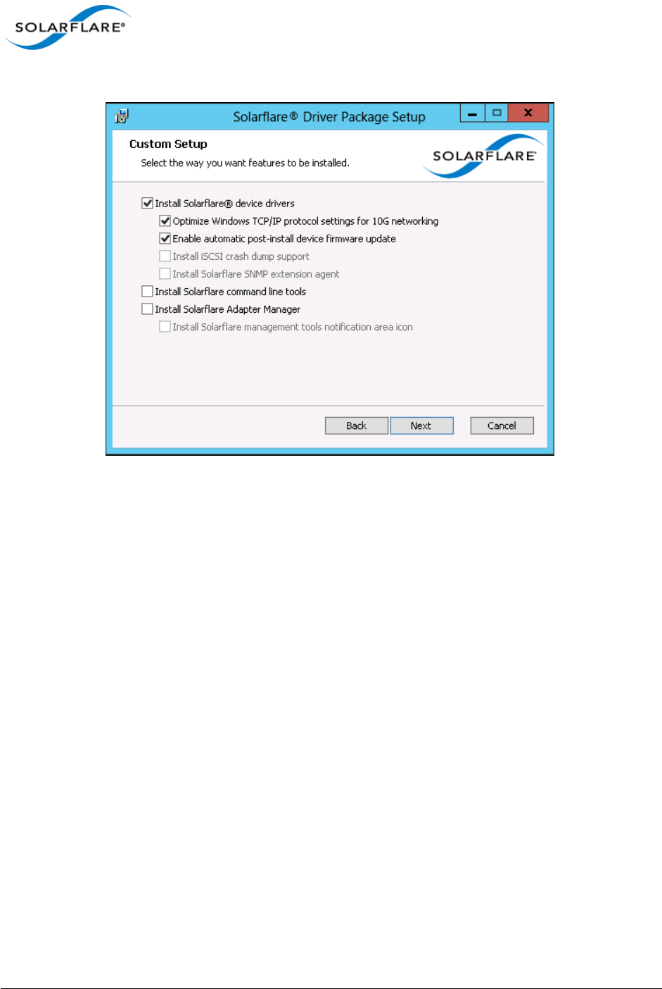
Issue 10 © Solarflare Communications 2013 112
Solarflare Server Adapter
User Guide
2From the Custom Setup screen, select the Install Solarflare® device drivers option only.
Figure 9: Solarflare Custom Setup
3A firmware update will be performed following installation if the Enable automatic post-
install device firmware update option is selected and if the firmware version in the installation
package is a more recent version than firmware on the adapter.
4Click Finish to close the wizard. Restart Windows if prompted to do so.

Issue 10 © Solarflare Communications 2013 113
Solarflare Server Adapter
User Guide
4.5 Full Solarflare Package Installation
This section cover the following topics:
Prerequisites...Page 113
Install iSCSI Initiator...Page 113
Install Microsoft SNMP For Windows Server 2008, 2008 R2 and Windows 7...Page 114
Solarflare Package Installation Procedure...Page 116
Repair, Remove and Change Drivers and Utilities...Page 120
Prerequisites
• Microsoft .NET Framework 2.0 (or later) is required before installing the Solarflare Adapter
Manager Utility (SAM).
• When booting the operating system from an iSCSI target over a Solarflare adapter you may want
to install iSCSI crash dump support. It is necessary to install and configure the Microsoft iSCSI
Initiator first. See Install iSCSI Initiator on page 113 for more details. For more details on iSCSI
booting see Solarflare Boot ROM Agent on page 360.
• If installing the Solarflare SNMP extension agent, it is necessary to install and configure the
Microsoft SNMP Service agent first. See Install Microsoft SNMP For Windows Server 2008, 2008
R2 and Windows 7 on page 114 for more details.
Install iSCSI Initiator
The Microsoft iSCSI Initiator must be running on your server before installing the Solarflare iSCSI
crash dump option. This process is different on different Windows OS versions.
The iSCSI Initiator is installed by default on Windows Server 2008, 2008 R2, Windows 7 and Windows
Server 2012.
Refer to the article ’Using Microsoft iSCSI Initiator in Windows Server 2008 and Windows 7’ - http:/
/technet.microsoft.com/en-us/library/ee338477%28v=ws.10%29.aspx.
For Windows Server 2012 refer to http://blogs.technet.com/b/filecab/archive/2012/05/21/
introduction-of-iscsi-target-in-windows-server-2012.aspx
For Windows Server 2003 and Windows XP
1The iSCSI Initiator is not installed by default on Windows Server 2003 and Windows XP. The
latest version can be downloaded from the Microsoft site at:
http://www.microsoft.com/en-us/download/details.aspx?id=18986
2The installation wizard will display the following options to be selected during installation:
c) iSCSI Port Driver (cannot be cleared)
d) Initiator Service
e) Software Initiator
f) Microsoft MPIO Multipathing Support for iSCSI

Issue 10 © Solarflare Communications 2013 114
Solarflare Server Adapter
User Guide
Solarflare recommends that you select all of these options.
3After the installation has finished, the iSCSI Initiator will be available from the Control Panel,
or via a link from your desktop.
4Check that the iSCSI Initiator service is running.
5Check that the iSCSI Initiator is listed under SCSI and RAID controllers in the Device Manager.
For Windows Server 2008, 2008 R2 and Windows 7
The iSCSI Initiator is part of the operating system installation and can be accessed either via the
Control Panel or from Start > All Programs > Administrative Tools:
1The first time you run the Initiator, you will see a dialog box stating that the iSCSI service is not
running. Click Yes to automatically run the service.
2If you are running the Windows Firewall, you will also see a dialog box asking you to allow the
iSCSI service to access an Internet storage name service through the Windows Firewall. Click
Yes to unblock access.
3That Microsoft iSCSI Initiator is listed under Storage controllers in the Device Manager.
Install Microsoft SNMP For Windows Server 2008, 2008 R2 and Windows 7
To use the Solarflare SNMP Agent, you need to install and configure Microsoft Simple Network
Management Protocol (SNMP) agent before installing the Solarflare Driver package:
1From the Control Panel > Programs > Turn Windows features on or off .
2From Server Manager > Features > Add Features, find and install SNMP Services.
3From the Server Manager > Configuration > Services, stop the SNMP Service, then double
click the entry to access the SNMP Service Properties dialog.
4Select the Security tab. (if the Security tab is not shown, it means you are not logged in as an
administrator).
5With Send authentication trap selected, click Add.
6Select READ ONLY from the Community rights drop-down list box.
7Enter a Community name. For security reasons, do not use Public.
8Click OK, then Restart the Service.
Solarflare comes supplied with two MIB files, SFC-CONFIG and SFC-STATISTICS. By default these are
located in your Program Files > Solarflare Communications > Solarflare Driver Package directory.
These are read-only with no traps.
For further information on the SNMP service click the Learn more about SNMP link from the
Security tab on the SNMP Service Properties sheet, or visit www.net-snmp.org for details about
SNMP tools.For Windows Server 2003 and Windows XP
To use the Solarflare SNMP Agent, you need to install and configure Microsoft Simple Network
Management Protocol (SNMP) agent before installing the Solarflare Driver package:
1From the Control Panel > Add or Remove Programs > Add/Remove Windows Components.
2Select (but do not tick the check box) for Management and Monitoring Tools.

Issue 10 © Solarflare Communications 2013 115
Solarflare Server Adapter
User Guide
3Select the Details button to reveal the Management and Monitoring Tools Dialog.
4Tick the SNMP check box and select the OK button.
5For further configuration details see http://www.microsoft.com/resources/documentation/
windows/xp/all/proddocs/en-us/snmp_install.mspx?mfr=true
Solarflare comes supplied with two MIB files, SFC-CONFIG and SFC-STATISTICS. By default these are
located in your Program Files > Solarflare Communications > Solarflare Driver Package directory.
These are read-only with no traps.
For further information on the SNMP service click the Learn more about SNMP link from the
Security tab on the SNMP Service Properties sheet, or visit www.net-snmp.org for details about
SNMP tools.
Issue 10 © Solarflare Communications 2013 116
Solarflare Server Adapter
User Guide
Solarflare Package Installation Procedure
The steps below describe how to install the complete Solarflare installation package. To install this
from the command line, see Install Drivers and Options From a Windows Command Prompt on
page 121.
1Double-click the supplied Setup.exe. The Solarflare Driver Package Setup wizard starts.
Figure 10: Solarflare Driver Package Setup
If prompted, confirm your administrator privileges to continue installing the drivers.
2Follow the setup instructions in the wizard to complete the driver installation procedure. See
Figure 11 and Table 25 for a list of setup options.
3A firmware update will be performed following installation if the Enable automatic post-
install device firmware update option is selected and if the firmware version in the installation
package is a more recent version than firmware on the adapter.
4Click Finish to close the wizard. Restart Windows if prompted to do so.
To confirm the drivers installed correctly, do either of the following:
• Open the Windows Device Manager and check the Solarflare adapter is present under Network
Adapters.
• Start Solarflare Adapter Manager (Start > All Programs > Solarflare Drivers > Solarflare Adapter
Manager). If the Solarflare adapter is installed and working correctly, it will be shown in the
SAM main screen, along with any other adapters, as in Table 14 on page 140.
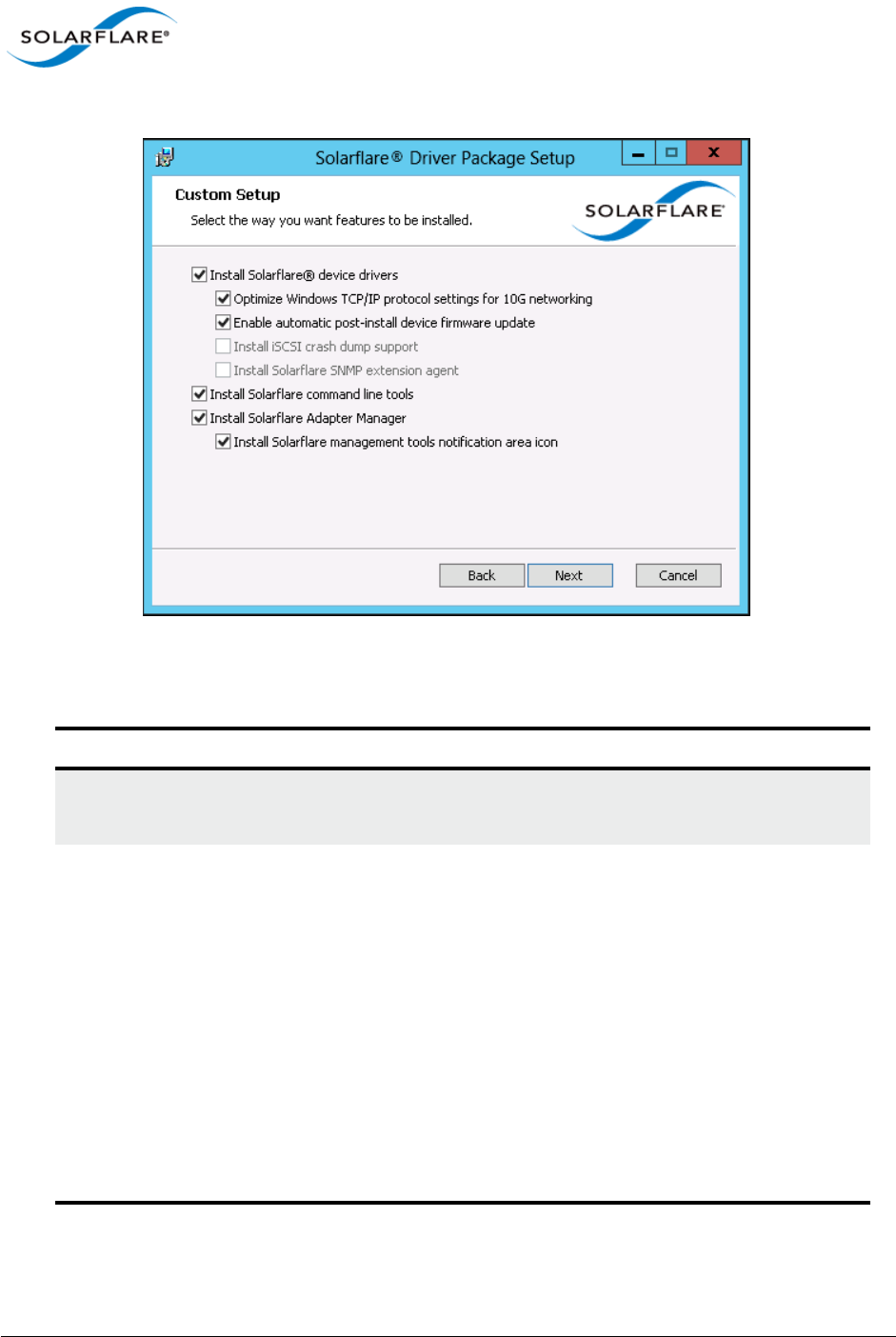
Issue 10 © Solarflare Communications 2013 117
Solarflare Server Adapter
User Guide
Figure 11: Solarflare Driver Package Custom Setup
Table 25: Solarflare Custom Setup
Option Description
Install Solarflare device drivers Installs Solarflare NDIS drivers for Windows.
The Solarflare drivers are installed by default.
Optimize Windows TCP/IP protocol
settings for 10G networking
Reconfigures the TCP/IP system settings to provide
better performance over 10G networks.
Selecting this option will increase the RSS receive
queue count to 8 on all Windows versions from
Windows Server 2003.
For Windows Server 2003 and Windows XP this will
increase the TCP windows size, enable Windows
scaling, TCP SACK and increases the TCP receive
window size. These options are enabled by default on
Windows Server 2008 and later versions.
TCP/IP protocol optimization is installed by default.
See note below reference power settings.

Issue 10 © Solarflare Communications 2013 118
Solarflare Server Adapter
User Guide
Enable automatic post-install device
firmware update
A firmware update will be performed following
installation if this option is selected and if the
firmware version in the installation package is a more
recent version than firmware on the adapter.
Install iSCSI crash dump support Enables iSCSI crash dump file generation. This is only
applicable if you are booting from an iSCSI target over
a Solarflare adapter. See iSCSI Boot on page 364 for
more details.
iSCSI crash dump support is not installed by default.
Note: The iSCSI initiator must be configured on your
server before installing the Solarflare driver package.
See Install iSCSI Initiator on page 113 for more
details.
Install Solarflare SNMP extension
agent
Enables the SNMP extension agent. This is not
installed by default.
Note: you must install and be running the SNMP
service on your server before installing the Solarflare
driver package if you want to use SNMP. See Install
Microsoft SNMP For Windows Server 2008, 2008 R2
and Windows 7 on page 114 for more details on
configuring SNMP.
Install Solarflare command line tools Installs the following Solarflare Windows command
line tools:
sfboot.exe – Boot ROM configuration tool
sfupdate.exe – Firmware update tool
sfteam.exe – Adapter teaming tool
sfcable.exe – Cable diagnostics tool
sfnet.exe – Adapter configuration tool
See Windows Command Line Tools on page 186.
These tools are installed by default.
Table 25: Solarflare Custom Setup
Option Description

Issue 10 © Solarflare Communications 2013 119
Solarflare Server Adapter
User Guide
Install Solarflare Adapter Manager Installs Solarflare Adapter Manager (SAM) for easy
access to adapter configuration options, wizards for
teaming and VLAN setup, adapter statistics, and
diagnostic tools. See Managing Adapters with SAM
on page 139 for more details.
SAM is installed by default.
Note: If this option is grayed out, you need to exit the
Solarflare installer and then install Microsoft .NET
Framework 2.0 before re-running the Solarflare
installer.
Install Solarflare management tools
notification area icon
Installs a Solarflare notification area icon for
launching Solarflare Adapter Manager (SAM) locally
or for a remote computer.
The icon is not installed by default.
NOTE: Selecting the Optimize Windows TCP/IP protocol settings for 10G networking option
from the Solarflare Driver Package Setup window, during driver installation, will create and
enable a "Optimum Performance" power profile. This prevents processors from being managed
into lower power states and can improve performance and reduce latency.
NOTE: On Windows Server 2012 this setting can cause the CPU to report 100% usage when
viewed in Task Manger performance tab although a closer inspection using the Resource
Monitor utility will show that actual CPU usage has not increased.
Table 25: Solarflare Custom Setup
Option Description
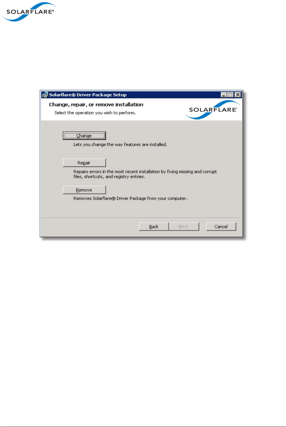
Issue 10 © Solarflare Communications 2013 120
Solarflare Server Adapter
User Guide
Repair, Remove and Change Drivers and Utilities
For Windows Server 2003 and Windows XP
To change, repair, or remove the Solarflare drivers and/or tools, run the setup.exe again (or from the
Control Panel > Add or Remove Programs and select the appropriate option from the Solarflare
Driver Package Setup wizard.
Figure 12: Change, Repair or Remove Installation
The wizard will guide you through the procedure and prompt you to restart Windows if necessary.
For Windows Server 2008, 2008 R2, Windows 7 and Windows Server 2012
From the Control Panel > Programs > Programs and Features, select the Solarflare Driver Package
then select Uninstall, Change or Repair from the menu bar above the program list.
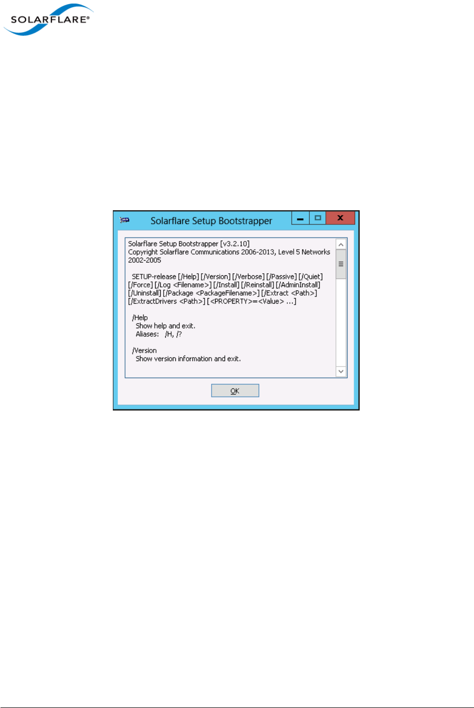
Issue 10 © Solarflare Communications 2013 121
Solarflare Server Adapter
User Guide
4.6 Install Drivers and Options From a Windows Command Prompt
This section covers the following subjects:
Command Line Usage...Page 121
Using ADDLOCAL...Page 123
Command Line Usage
To view command line options available, run the setup-<release>.exe /? command to display the
following dialog window.
Figure 13: Command Line Install - Windows Server 2012 options.
Installing from the Windows command line allows scripted, silent and unattended installation of the
core Solarflare drivers and package utilities. The drivers install package is named after the Solarflare
document part number e.g.
SF-107784-LS-2_Solarflare_Windows_x86_32-bit_Driver_Package.exe
This can be renamed e.g setup.exe before invoking from the command line.
The command line usage for installing the driver package from the command line is:
setup.exe [/Help | /?] [/Version] [/Verbose] [/Passive] [/Quiet] [/Force]
[/Log <filename>] [/Install] [/Reinstall] [/Admininstall] [/Uninstall] [/
Package <packagefilename>] [/Extract <path>] [ExtractDrivers <path>]
For example, to install default package options silently (no message output), enter the following
command:
setup.exe /Quiet /Install

Issue 10 © Solarflare Communications 2013 122
Solarflare Server Adapter
User Guide
Table 26 lists other command line examples. Note that command line options are case insensitive,
so /install and /INSTALL are the same.
Table 26: Solarflare Installation Options
Example Action
setup.exe /Admininstall <path> Allows an administrator to unpack and
install the package to a network share and
to specify which features of the package can
be installed by users.
setup.exe /Extract <path> Extracts the contents of setup.exe to the
specified path.
setup.exe /ExtractDrivers <path> Extract the adapter driver to the specified
path.
setup.exe /Filename <filename> Log all output to the specified file.
setup.exe /Force Allow passive or quiet mode to replace an
existing installation with an earlier version.
setup.exe /Help Shows a help screen and exits.
setup.exe /Install Installs or configures the package.
setup.exe /Install /Log <filename> Install the drivers and logs messages to the
specified file.
setup.exe /Install /Package
<packagefilename>
Installs the drivers and utilities specified in
packagefilename.
setup.exe /Install /Passive Performs an unattended installation of the
drivers and utilities, rebooting the host to
complete the installation as required.
setup.exe /Install /Quiet Performs a silent installation of the drivers
and utilities.
setup.exe /Reinstall Reinstalls the drivers and utilities.
setup.exe /Uninstall Removes the drivers and utilities from the
host operating system.
setup.exe /Install /Verbose Performs a verbose installation of the
drivers and utilities, outputting details for
each stage of the installation procedure.
setup.exe /Package
<PackageFilename>
Identify the package file to use for the
operation.
setup.exe /Version Shows version information for the drivers.

Issue 10 © Solarflare Communications 2013 123
Solarflare Server Adapter
User Guide
Using ADDLOCAL
ADDLOCAL is a standard Windows Installer property that controls which features are installed via
the command line. For Solarflare adapters, the following features can be installed from the
command line:
•CoreDrivers – Installs the core adapter drivers
- OptimizeTCP – Optimizes TCP/IP for 10G Ethernet
- Enable automatic post-install device firmware update - update firmware following
installation if the install package firmware is newer then the already installed version
- SNMP – Installs the SNMP extension agent
- iSCSICrashDump – Enables iSCSI crash dump file generation
•NetworkAdapterManager – Installs Solarflare Adapter Manager (SAM)
•CommandLineTools – Installs Solarflare command line tools: sfboot.exe, sfupdate.exe,
sfcable.exe, sfteam.exe, sfnet.exe.
•Launcher – Installs the Solarflare system tray icon, providing easy access to the Solarflare
Adapter Manager (SAM).
The nested indentation of the feature list above indicates their parent/child relationship, so that if
you ask for OptimizeTCP to be installed, CoreDrivers will also be installed. Multiple features may be
installed by separating each feature with a comma (spaces are not allowed).
ADDLOCAL cannot prevent Launcher from being installed if either NetworkAdapterManager or
CommandLineTools are not installed or are still being installed.
setup.exe /Quiet /Install
ADDLOCAL=NetworkAdapterManager
Silently installs the drivers and Solarflare
Adapter Manager only (other utilities will
not be installed). See, Using ADDLOCAL on
page 123.
<PROPERTY>=<Value> Specify one or more install properties.
Table 26: Solarflare Installation Options
Example Action
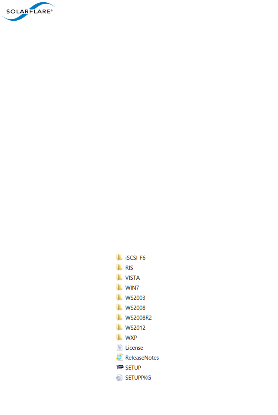
Issue 10 © Solarflare Communications 2013 124
Solarflare Server Adapter
User Guide
ADDLOCAL Examples:
Install the package interactively with the default installation options selected (equivalent to
Setup.exe or Setup.exe /Install).
Setup.exe /Install ADDLOCAL=CoreDrivers,
NetworkAdapterManager,CommandLineTools,Launcher
Install the package without any management tools. Displays a limited user interface with status and
progress only.
Setup.exe /Quiet /Install ADDLOCAL=CoreDrivers
Install Solarflare Adapter Manager (SAM) only. This command shows no user interface during
installation and will restart the host system if required.
Setup.exe /Quiet /Install ADDLOCAL=NetworkAdapterManager
Install Solarflare Adapter Manager (SAM) only but suppress the auto-restart.
Setup.exe /Quiet /Install ADDLOCAL=NetworkAdapterManager REBOOT=Suppress
Extract Solarflare Drivers
To extract the Solarflare drivers from the installation package:
1From the Command prompt, navigate to the directory where the installation package is
located.
2Enter the following command:
Setup.exe /Extract <DestinationDirectory>
The Destination Directory will list the following sub-directory structure - The actual folders/files
displayed will depend on the Solarflare driver package installed:

Issue 10 © Solarflare Communications 2013 125
Solarflare Server Adapter
User Guide
Table 27 lists the drivers supplied with the Solarflare Driver installation package:
Table 27: Solarflare Drivers
Folder Where Used
iSCSI-F6 Driver to install Windows Server 2003 64 bit directly to an
iSCSI target.
iSCSI-F6 Driver to install Windows Server 2003 32 bit directly to an
iSCSI target.
RIS\AMD64 RIS driver to allow initial network connectivity during the
installation copy process for 64 bit Windows Server 2003
images.
RIS\x86 RIS driver to initial network connectivity during the
installation copy process for 32 bit Windows Server 2003
images.
VISTA\AMD64\DRIVERS Driver to install Windows Vista 64bit directly to an iSCSI
target.
WIN7\AMD64\DRIVERS Driver to install Windows 7 32 bit directly to an iSCSI target.
WS2003 Driver to install Windows 8 32 bit directly to an iSCSI target.
WLH\AMD64\DRIVERS Driver to install Windows 2008 64 bit directly to an iSCSI
target.
WLH\x86\DRIVERS Driver to install Windows 2008 32 bit directly to an iSCSI
target.
WNET\AMD64\DRIVERS Driver to install Windows XP and Windows Server 2003 64
bit directly to an iSCSI target.
WNET\x86\DRIVERS Driver to install Windows Server 2003 32 bit directly to an
iSCSI target.
WS2012 Driver to install Windows Server 2012 64bit directly to an
iSCSI target.
WXP\x86\DRIVERS Driver to install Windows XP 32 bit directly to an iSCSI
target.

Issue 10 © Solarflare Communications 2013 126
Solarflare Server Adapter
User Guide
4.7 Unattended Installation - Windows Server 2008, 2008 R2, Windows
7 and Windows Server 2012
This section covers the following subjects:
• Windows Driver Locations...Page 126
• Unattended Installation using WDS...Page 126
• Adding Solarflare Drivers to the WDS Boot Image...Page 127
• Create Custom Install Image...Page 128
• Create the WDSClientUnattend.xml File...Page 129
• Create the AutoUnattend.xml File...Page 129
• Further Reading...Page 130
Windows Driver Locations
The following steps use drivers extracted from the Solarflare installation package. Refer to Table 27
for driver folder locations.
Unattended Installation using WDS
Windows Deployment Services (WDS) enables you to deploy Windows Server 2008, 2008 R2,
Windows 7 and Windows Server 2012 over your network (from a WDS server), avoiding the need to
install each operating system directly from a CD or DVD.
• This guide assumes you have installed and are familiar with WDS. For more information on WDS,
see Further Reading on page 130.
• You should also be familiar with PXE booting over Solarflare adapters. See PXE Support on
page 361 for more information.
The following steps are an example of how to set up an unattended installation using the WDS
interface:
Add a Boot Image
1From the left hand pane of the WDS MMC snap in, right-click the Boot Images node and select
Add Boot Image.
2Specify a name for the image group and click Add Boot Image.
3Select the boot.wim file from the Windows installation DVD (in the \Sources folder). The
Boot.wim file contains the Windows PE and the Windows Deployment Services client.
4Click Open, then click Next.
5Follow the instructions in the wizard to add the boot image.

Issue 10 © Solarflare Communications 2013 127
Solarflare Server Adapter
User Guide
Add an Install Image
1From the left hand pane of the WDS MMC snap in, right-click the Install Images node and
select Add Install Image.
2Specify a name for the image group and click Add Install Image.
3Select the install.wim file from your installation DVD (in the \Sources folder), or create
your own install image. Consult the WDS documentation for details on creating custom install
images.
4Click Open, then click Next.
5Follow the instructions in the wizard to add the image.
Adding Solarflare Drivers to the WDS Boot Image
These steps describe how to add the Solarflare drivers into the Boot Image.
Modifying the Boot Image
You next need to modify the boot image to include the Solarflare Drivers extracted from the setup
package. Table 27 identifies drivers required for the target operating system. To modify the boot
image Solarflare recommends using the ImageX tool supplied with the Windows Automated
Installation Kit (AIK).
1Within WDS, expand the server where the boot image is located and select the boot image
you want to modify. From the right-click menu, select Disable.
2Create a Windows PE customization working directory (in this example c:\windowspe-x86).
Within a command prompt, from:
C:\program files\windows aik\tools\petools\
and enter the following command:
copype.cmd x86 c:\windowspe-x86
3Enter the following ImageX commands from the PE customization working directory:
imagex /info <Drive>:\remoteinstall\boot\x86\images\<boot.wim>
4Mount the boot image with the following command from your PE customization working
directory:
imagex /mountrw <Drive>:\remoteinstall\boot\x86\images\<boot.wim> 2 mount
5Copy the contents of the appropriate Solarflare driver folder (see Table 27) to a subdirectory
within your PE customization working directory (in this example c:\windowspe-
x86\drivers).
NOTE: <Drive> is the path where the remoteinstall folder is located. <boot.wim> is the
name of your boot image.

Issue 10 © Solarflare Communications 2013 128
Solarflare Server Adapter
User Guide
6Add the Solarflare VBD driver to the image by entering the following command from your PE
customization working directory:
peimg /inf=c:\windowspe-x86\drivers\netSFB*.inf mount\windows
7Add the Solarflare NDIS driver to the image by entering the following command from your PE
customization working directory:
peimg /inf=c:\windowspe-x86\drivers\netSFN6*.inf mount\windows
8Unmount the image, using the following command from your PE customization working
directory:
imagex /unmount /commit mount
9From WDS, expand the server where the boot image is located and select the boot image you
have modified. From the right-click menu, select Enable.
Create Custom Install Image
These steps describe how to add the Solarflare drivers into the Custom Install Image. These are the
same Solarflare drivers added to the boot image.
Preparing the Custom Install Image
1From WDS, locate the install image from the Install Images folder on your server.
2Right-click the image and select Export Image from the menu.
3Export the image to a location where it can be mounted. Solarflare recommend using the
Windows PE customization working directory as this saves creating a second directory. In this
example: c:\windowspe-x86.
Modifying the Install Image
1Mount the install image with the following command from your PE customization working
directory:
imagex /mountrw <Drive>:\<path>\<install.wim> 1 mount
2Copy the contents of the appropriate Solarflare driver folder in Table 27 to a sub-directory in
your PE customization working directory (in this example c:\windowspe-x86\drivers). If
you are using the same directory as for the boot image, this directory should already be
present.
3Add the Solarflare VBD driver to the image by entering the following command from your PE
customization working directory:
peimg /inf=c:\windowspe-x86\drivers\netSFB*.inf mount\windows
NOTE: <Drive> is the path where the remoteinstall folder is located. <boot.wim> is the
name of your boot image.

Issue 10 © Solarflare Communications 2013 129
Solarflare Server Adapter
User Guide
4Add the Solarflare NDIS driver to the image by entering the following command from your PE
customization working directory:
peimg /inf=c:\windowspe-x86\drivers\netSFN6*.inf mount\windows
5Unmount the image, using the following command from your PE customization working
directory:
imagex /unmount /commit mount
Import the Custom Image to WDS
1From WDS, select the Image group you want to add the image to. Right-click and select Import
Image.
2Browse to the location of the custom image, and click Next.
3Follow the instructions in the wizard to import the image.
Create the WDSClientUnattend.xml File
The WDSClientUnattend.xml file is used by the Windows PE boot environment to configure settings
including the language, credentials for connecting to the WDS server, the partitioning of the disk and
which image to deploy.
To associate your WDSClientUnattend.xml file with your modified boot image:
1Copy the WDSClientUnattend.xml file to the following folder in the RemoteInstall
folder: RemoteInstall\WDSClientUnattend.
2Open the Windows Deployment Services MMC snap-in, right-click the server that contains the
Windows Server 2008, 2008 R2 or Windows 7 boot image with which you want to associate
the file, and then select Properties.
3On the Client tab, select Enable unattended installation, browse to the
WDSClientUnattend.xml file, then click Open.
4Click OK to close the Properties page.
Create the AutoUnattend.xml File
The AutoUnattend.xml file is used during the installation of Windows Server 2008, 2008 R2 and
Windows 7 to automatically populate the various configuration settings.
To associate your AutoUnattend.xml file with your custom install image:
NOTE: You can use the Windows System Image Manager (Part of the Windows Automated
Installation Kit) to create the WDSClientUnattend.xml file.
NOTE: You can use the Windows System Image Manager (Part of the Windows Automated
Installation Kit) to create the AutoUnattend.xml file.

Issue 10 © Solarflare Communications 2013 130
Solarflare Server Adapter
User Guide
1Copy the AutoUnattend.xml file to the following folder in the RemoteInstall folder:
RemoteInstall\WDSClientUnattend.
2Open the Windows Deployment Services MMC snap-in, select the custom install image with
which you want to associate the file, right-click and then select Properties.
3Select the Allow image to install in unattend mode option.
4Click Select File and browse to your AutoUnattend.xml file.
Further Reading
• Installing and configuring Windows Deployment Services (WDS) on Windows Server 2008, 2008
R2 and Windows 7:
http://technet.microsoft.com/en-us/library/cc771670%28WS.10%29.aspx
• Windows PE Customization:
http://technet.microsoft.com/en-us/library/cc721985%28WS.10%29.aspx
• Getting Started with the Windows AIK:
http://technet.microsoft.com/en-us/library/cc749082%28WS.10%29.aspx
• Performing Unattended Installations:
http://technet.microsoft.com/en-us/library/cc771830%28WS.10%29.aspx
• How to add network driver to WDS boot image:
http://support.microsoft.com/kb/923834
• Windows Deployment Services Getting Started Guide for Windows Server 2012
http://technet.microsoft.com/en-us/library/jj648426.aspx

Issue 10 © Solarflare Communications 2013 131
Solarflare Server Adapter
User Guide
4.8 Unattended Installation - Windows Server 2003
This section covers the following subjects:
• Windows Server 2003 Driver Locations...Page 131
• Local Unattended Installations...Page 131
• Using Remote Installation Service (RIS)...Page 131
• Using Windows Deployment Services (WDS)...Page 133
• Create the WDSClientUnattend.xml File...Page 135
• Create the AutoUnattend.xml File...Page 136
• Using Automated Deployment Services (ADS)...Page 136
• Further Reading...Page 138
Windows Server 2003 Driver Locations
The following procedure requires drivers extracted from the Solarflare installation package. Table 27
identifies the location of Solarflare drivers.
Unattended install on Windows Server 2003 often needs the use of a special “RIS” driver for the
Solarflare adapters during the early stages of OS install. The following sections make it clear when
to install the RIS driver and when to install the VBD and NDIS drivers. Take care to use the correct
driver.
Local Unattended Installations
This section details creating a Windows Server 2003 installation CD that incorporates the Solarflare
drivers.
• Use Setupmgr.exe (Located in the Support\Tools folder of the Windows Server 2003 CD-
ROM) to create the Unattend.txt file.
• Create a $oem$\$1\Drivers\Nic folder within the i386 (32 bit versions) or AMD64 (64 bit
versions) folder.
• Add the Solarflare VBD and NDIS drivers under the Nic folder.
• Add the OemPnPDriversPath = Driver_Paths entry in the Unattended section of the
Setup answer file.
Using Remote Installation Service (RIS)
• Remote Installation Services (RIS) enables you to deploy Windows Server 2003 over your
network (from a RIS server running on Windows 2003), avoiding the need to install each
operating system directly from a CD or DVD.
• This guide assumes you have installed and are familiar with RIS. For more information on RIS,
see Further Reading on page 138.

Issue 10 © Solarflare Communications 2013 132
Solarflare Server Adapter
User Guide
• You should also be familiar with PXE booting over Solarflare adapters. See PXE Support on
page 361 for more information.
The following steps are an example of how to setup an unattended installation using RIS
Adding drivers
The following steps assume a RIS server has been configured with a Windows Server 2003
installation. They describe how to add the Solarflare drivers to the Windows installation.
1Add a $OEM$ folder at the same level as \i386 folder in the Windows image.
2Add a $1 folder within the $OEM$ folder.
3Add a Drivers folder within the $1 folder.
4Add a folder (in this example, called NIC) within the Drivers folder.
5Copy all the files from the Solarflare VBD and NDIS directory into the NIC folder.
6Copy all the files from the Solarflare RIS folder into the \i386 folder.
7In the file \i386\templates\ristndrd.sif, locate the Unattended section. Change the
line OemPreinstall = No to Yes.
8Add the line OemPnPDriversPath = \Drivers\NIC for the Solarflare drivers.
9From the Command Prompt, Stop, then Start the RIS service with the following command:
net Stop binlsvc <enter>
net Start binlsvc <enter>
This creates the PNF file (precompiled setup information file).
Installation
From the computer you want to install Windows Server 2003 on:
1Start the computer in PXE boot mode.
2When prompted, press F12 to continue with the installation.
3Follow the prompts, entering a valid User name, Password and Domain Name when required.
4The installation will then continue as normal, using the details you have entered in the
ristndrd.sif file.

Issue 10 © Solarflare Communications 2013 133
Solarflare Server Adapter
User Guide
Using Windows Deployment Services (WDS)
• Windows Deployment Services (WDS) enables you to deploy Windows Server 2003 over your
network (from a WDS server running on Windows 2008), avoiding the need to install each
operating system directly from a CD or DVD.
• This guide assumes you have installed and are familiar with WDS. For more information on WDS,
see Further Reading on page 130.
• You should also be familiar with PXE booting over Solarflare adapters. See PXE Support on
page 361 for more information.
The following steps are an example of how to set up an unattended installation using the WDS
interface:
Add a Boot Image
1From the left hand pane of the WDS MMC snap in, right-click the Boot Images node and select
Add Boot Image.
2Specify a name for the image group and click Add Boot Image.
3Select the boot.wim file from the Windows Server 2003 installation DVD (in the \Sources
folder). The Boot.wim file contains the Windows PE and the Windows Deployment Services
client.
4Click Open, then click Next.
5Follow the instructions in the wizard to add the boot image.
Add an Install Image
1From the left hand pane of the WDS MMC snap in, right-click the Install Images node and
select Add Install Image.
2Specify a name for the image group and click Add Install Image.
3Select the install.wim file from your installation DVD (in the \Sources folder), or create
your own install image. Consult the WDS documentation for details on creating custom install
images.
4Click Open, then click Next.
5Follow the instructions in the wizard to add the image.

Issue 10 © Solarflare Communications 2013 134
Solarflare Server Adapter
User Guide
Modifying the Boot Image
You next need to modify the boot image to include the Solarflare RIS Drivers extracted from the
setup package. Table 27 details which drivers are needed for the target operating system. To modify
the boot image Solarflare recommends using the ImageX tool supplied with the Windows
Automated Installation Kit (AIK).
1Within WDS, expand the server where the boot image is located and select the boot image
you want to modify. From the right-click menu, select Disable.
2Create a Windows PE customization working directory (in this example c:\windowspe-x86).
Within a command prompt, from the C:\program files\windows
aik\tools\petools\ directory enter the following command:
copype.cmd x86 c:\windowspe-x86
3Enter the following ImageX commands from the PE customization working directory:
imagex /info <Drive>:\remoteinstall\boot\x86\images\<boot.wim>
4Mount the boot image with the following command from your PE customization working
directory:
imagex /mountrw <Drive>:\remoteinstall\boot\x86\images\<boot.wim> 2
mount
5Copy the contents of the appropriate Solarflare RIS driver folder (see Table 27) to a
subdirectory within your PE customization working directory (in this example
c:\windowspe-x86\boot).
6Add the Solarflare RIS driver to the image by entering the following command from your PE
customization working directory:
peimg /inf=c:\windowspe-x86\boot\netSFNR*.inf mount\windows
7 Unmount the image, using the following command from your PE customization working
directory:
imagex /unmount /commit mount
8From WDS, expand the server where the boot image is located and select the boot image you
have modified. From the right-click menu, select Enable.
NOTE: <Drive> is the path where the remoteinstall folder is located. <boot.wim> is the
name of your boot image.

Issue 10 © Solarflare Communications 2013 135
Solarflare Server Adapter
User Guide
Modifying the Install Image
1Mount the install image with the following command from your PE customization working
directory:
imagex /mountrw <Drive>:\<path>\<install.wim> 1 mount
2Copy the contents of the appropriate Solarflare VBD and NDIS driver folder (see Table 27) to a
subdirectory within your PE customization working directory (for this example
c:\windowspe-x86\drivers).
3Add the Solarflare VBD driver to the image by entering the following command from your PE
customization working directory:
peimg /inf=c:\windowspe-x86\drivers\netSFB*.inf mount\windows
4Add the Solarflare NDIS driver to the image by entering the following command from your PE
customization working directory:
peimg /inf=c:\windowspe-x86\drivers\netSFN5*.inf mount\windows
5Unmount the image, using the following command from your PE customization working
directory:
imagex /unmount /commit mount
Import Custom Image to WDS
1From WDS, select the Image group you want to add the image to. Right-click and select Import
Image.
2Browse to the location of the custom image, and click Next.
3Follow the instructions in the wizard to import the image.
Create the WDSClientUnattend.xml File
The WDSClientUnattend.xml file is used by the Windows PE boot environment to configure settings
including the language, credentials for connecting to the WDS server, the partitioning of the disk and
which image to deploy.
To associate your WDSClientUnattend.xml file with your modified boot image:
1Copy the WDSClientUnattend.xml file to the following folder in the RemoteInstall
folder: RemoteInstall\WDSClientUnattend.
2Open the Windows Deployment Services MMC snap-in, right-click the server that contains the
Windows Server 2003 boot image with which you want to associate the file, and then select
Properties.
3On the Client tab, select Enable unattended installation, browse to the
WDSClientUnattend.xml file, then click Open.
NOTE: You can use the Windows System Image Manager (Part of the Windows Automated
Installation Kit) to create the WDSClientUnattend.xml file.

Issue 10 © Solarflare Communications 2013 136
Solarflare Server Adapter
User Guide
4Click OK to close the Properties page.
Create the AutoUnattend.xml File
The AutoUnattend.xml file is used during the installation of Windows Server 2003 to automatically
populate the various configuration settings.
To associate your AutoUnattend.xml file with your custom install image:
1Copy the AutoUnattend.xml file to the following folder in the RemoteInstall folder:
RemoteInstall\WDSClientUnattend.
2Open the Windows Deployment Services MMC snap-in, select the custom install image with
which you want to associate the file, right-click and then select Properties.
3Select the Allow image to install in unattend mode option.
Click Select File and browse to your AutoUnattend.xml file.
Using Automated Deployment Services (ADS)
Automated Deployment Services (ADS), enables you to deploy Windows server 2003 and Windows
XP onto bare-metal servers across large, scaled-out installations.
The steps for including the Solarflare drivers for Windows Server 2003 and Windows XP assume that
you have the following:
• A fully configured ADS Controller server.
• A master destination device, running Windows Server 2003, added as a device on the ADS
controller. The reference server must be connected to the ADS Controller via a Solarflare
adapter with the drivers/management software installed. The reference server must also have
the adsroot certificate copied to it from the ASDS Controller. Consult your ADS documentation
for details on how to copy the adsroot certificate.
• A destination device that will have Windows Server 2003 or Windows XP installed on it. This
computer must be connected to the ADS Controller via a Solarflare adapter.
Capture the Windows Sever 2003 Image
1Ensure your master destination device has the ADS Administration Agent installed.
2Add the following folders to the root of your hard drive:
\sysprep
\sysprep\i386
3From the \Support\Tools folder on your Windows server 2003 CD-ROM, extract the
Deploy.cab file.
4Copy sysprep.exe and setupcl.exe from the extracted cab file to the \sysprep\i386
folder.
NOTE: You can use the Windows System Image Manager (Part of the Windows Automated
Installation Kit) to create the AutoUnattend.xml file.

Issue 10 © Solarflare Communications 2013 137
Solarflare Server Adapter
User Guide
5From the ADS Controller, copy the relevant Windows Server 2003 sample file from the
\Program Files\Microsoft ADS\samples\Sysprep folder.
You can select either:
sysprep-wg-w2003.inf if you want the new client to join a workgroup.
sysprep-domain-w2003.inf if you want the new client to join a domain.
6Copy the above inf file to the \sysprep folder on your master destination device and
rename it sysprep.inf.
7From the ADS Controller, open the ADS sequence editor from Programs > Microsoft ADS >
Sequence Editor.
8From the Sequence Editor, select Open from the File menu and browse to Program
Files\Microsoft ADS\samples\Sequences. Select the capture-image.xml file.
9Select Capture image from the Sequence Editor.
10 From the Properties tab displayed, enter a Description, Image Name and relevant Disk and
Partition information.
11 Select Save from the File menu to save your sequence.
12 From the ADS Controller open ADS Management from Programs > Microsoft ADS.
13 Open the Job Templates folder and select capture-image. From the right-click menu, select
Run job. The Run Job Wizard starts.
14 Click Next from the Welcome screen.
15 From the Destination Device Selection screen, select either your single device (as in this
example) or a set of devices. Select your device and click Next.
16 Click Finish to complete the wizard.
17 Your job will now be visible in the Running jobs folder.
Install the Windows Server 2003 Image to the Destination Device
1Add the device record for the destination device to the ADS Controller. This is either by MAC
Address or SMBIOS GRUID
2Use Setupmgr.exe (Extracted from the deploy.cab file from the Support\Tools folder
of the Windows Server 2003 CD-ROM) to create the answer files needed for ADS deployment.
3At the root of your OS drive (for example C:\), create a directory called sysprep.
4In the sysprep folder create a i386 folder:
5Copy sysprep.exe, setupcl.exe and sysprep.inf into the i386 folder.
6Create a c:\sysprep\drivers\nic drivers directory and in this directory create a separate
folder for the Solarflare network adapter driver. Copy the contents of the appropriate
Solarflare VBD and NDIS Windows Server 2003 driver folder (see Table 29) to the
c:\sysprep\drivers\nic drivers folder.
7Modify your sysprep.inf file to include the location of these files.

Issue 10 © Solarflare Communications 2013 138
Solarflare Server Adapter
User Guide
Further Reading
• How to use setupmgr to create an answer file in Windows Server 2003:
http://support.microsoft.com/kb/323438
• Description of the Netset.exe tool:
http://support.microsoft.com/kb/268781/en-us
• Specifying Multiple Network Adapters in an Unattended Setup:
http://support.microsoft.com/kb/229762/en-us
• Specifying Adapters (Virtual Devices):
http://support.microsoft.com/kb/920293 (You cannot configure a network adapter that resides on
a virtual bus to use a static IP address in an automated deployment of Windows Server 2003)
• How to use RIS to Install Windows Server 2003:
http://support.microsoft.com/kb/325862
• How to add third-party OEM Network Adapters to RIS installations:
http://support.microsoft.com/kb/246184/en-us
• How to add OEM Plug and Play Drivers to Windows installations:
http://support.microsoft.com/kb/254078/EN-US/
• Installing Windows Deployment Services (WDS) for Windows Server 2003:
http://technet.microsoft.com/en-us/library/cc766320%28WS.10%29.aspx
• Automated Deployment Services (ADS) for Windows Server 2003:
http://www.microsoft.com/windowsserver2003/techinfo/overview/adssysreq.mspx
• How to add network driver to WDS boot image:
http://support.microsoft.com/kb/923834

Issue 10 © Solarflare Communications 2013 139
Solarflare Server Adapter
User Guide
4.9 Managing Adapters with SAM
• Introduction...Page 139
• Managing Adapters Remotely with SAM...Page 141
• Using SAM...Page 141
• Using SAM to Configure Adapter Features...Page 146
• Using SAM to Configure Teams and VLANs...Page 158
• Using SAM to View Statistics and State Information...Page 167
• Using SAM to Run Adapter and Cable Diagnostics...Page 168
• Using SAM for Boot ROM Configuration...Page 173
Introduction
The Solarflare Adapter Manager (SAM) is a Microsoft Management Console (MMC) plug-in for
managing Solarflare adapters, teams and VLANs. SAM identifies information for all adapters
installed on the server, as well as the standard MMC plug-in Actions pane.
NOTE: The Windows dialog boxes displayed by SAM will appear differently on different Microsoft
Windows OS versions.
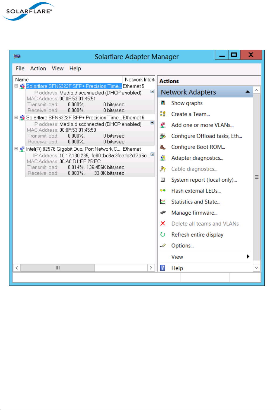
Issue 10 © Solarflare Communications 2013 140
Solarflare Server Adapter
User Guide
Using SAM, you can easily configure Ethernet and task offloading settings, set up teams and VLANs,
configure the Boot ROM for PXE or iSCSI booting, and upgrade the adapter firmware.
Figure 14: SAM Main Screen - Windows Server 2012
SAM’s diagnostics utilities allow you to run tests on the adapter, and on 10GBASE-T adapters, on the
cable to discover any potential issues which may be affecting adapter performance. Also, SAM’s
detailed statistics and state information can be used to view data transfer figures, sent and received
packet types, as well as other traffic-related details.
SAM is included with the Solarflare drivers installation package.
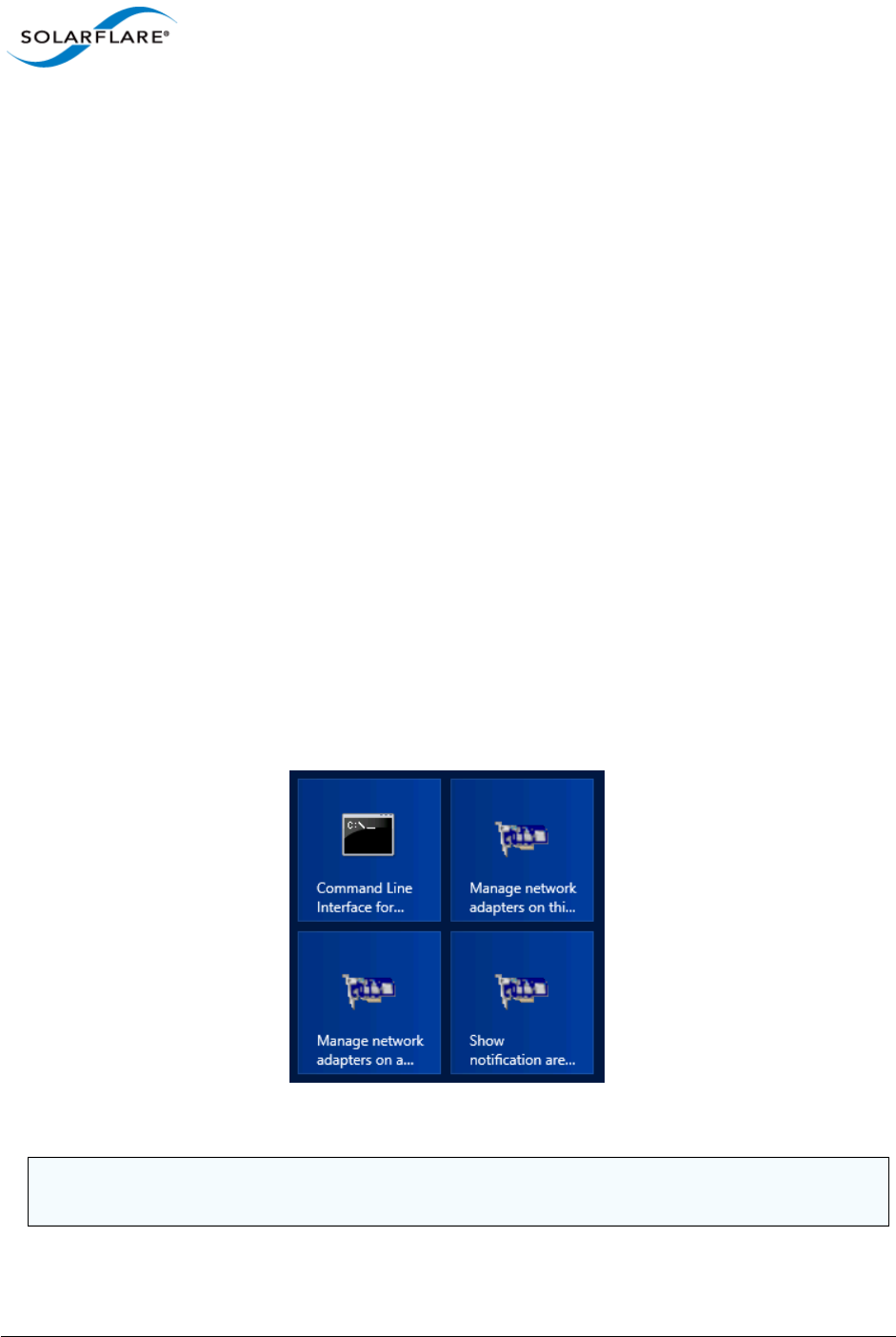
Issue 10 © Solarflare Communications 2013 141
Solarflare Server Adapter
User Guide
4.10 Managing Adapters Remotely with SAM
SAM can be used to administer Solarflare adapters on your server from a remote computer. SAM can
be used remotely to administer adapters on any supported Windows platform, including a Windows
Server Core Installation. Remote Administration provides access to all SAM features.
To allow SAM to remotely administer your server, you need to add a Computer Management snap-
in to the computer Microsoft Management Console (MMC).
4.11 Using SAM
Starting SAM
There are various ways of starting SAM.
To manage a local computer:
• If the Solarflare notification area icon is installed, right-click the icon and select Manage
network adapters on this computer.
OR
• Click Start > All Programs > Solarflare Network Adapters > Manage network adapters on this
computer.
OR
• Click Start > Administrative Tools > Computer Management > System Tools >Network
Adapters.
Figure 15: SAM Desktop Icons
NOTE: You may be asked for permission to continue by the User Account Control when starting
SAM. You must run SAM as an administrator to make any changes.
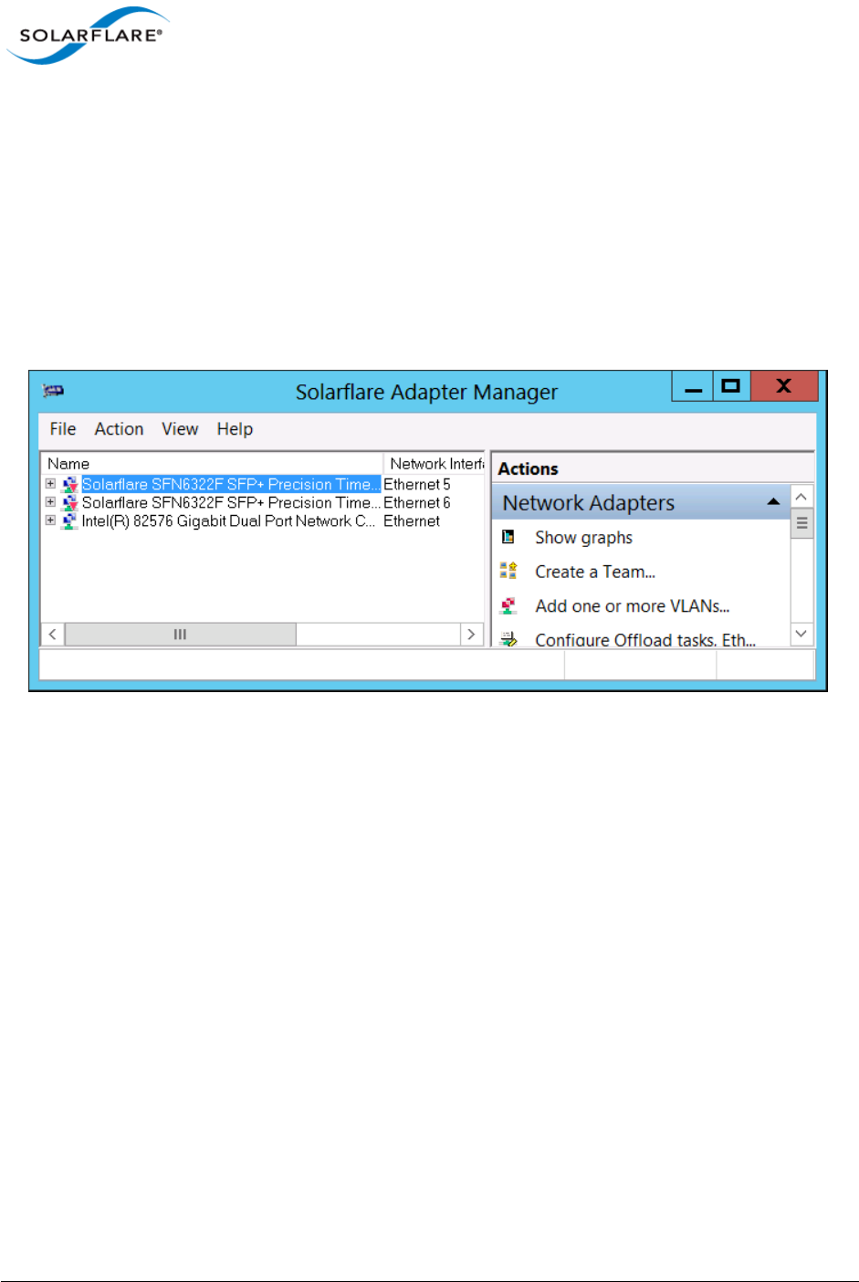
Issue 10 © Solarflare Communications 2013 142
Solarflare Server Adapter
User Guide
To manage a remote computer:
• Click Start > All Programs > Solarflare Network Adapters > Manage network adapters on a
remote computer.
• If the Solarflare notification area icon is installed, you can right-click the icon and select Manage
network adapters on a remote computer.
Viewing Adapter Details
SAM lists all available network adapters installed in the server, regardless of manufacturer or
adapter type
Figure 16: Solarflare Adapter Manager (SAM)
For each adapter, SAM provides the following details:
• Name and network interface
• IP address (IPv4 and IPv6, if available)
• MAC address
• Transmit load
• Receive load
For Solarflare adapters only, SAM also lists any teams or VLANs that have been configured, along
with details that allow you to quickly check performance and status.
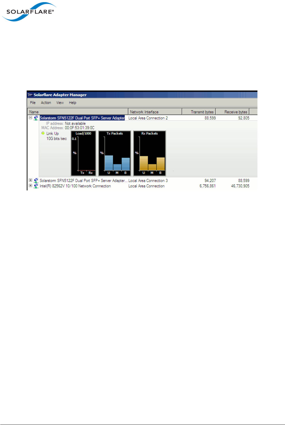
Issue 10 © Solarflare Communications 2013 143
Solarflare Server Adapter
User Guide
Viewing Performance Graphs
To view Solarflare performance graphs, Right-click on an adapter and select Show graphs from the
menu. By default, SAM shows the load, transmitted packets and received packets graphs only. To
view other available graphs, Select Graphs from the right-click menu, or from the Actions Pane/
Action menu. For non-Solarflare adapters only the load graph is displayed.
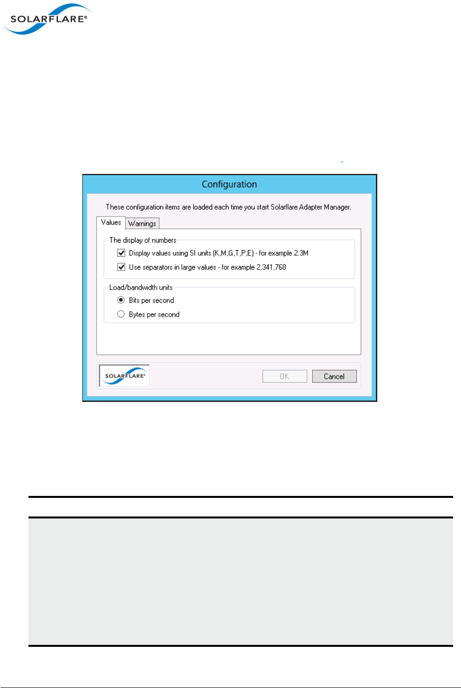
Issue 10 © Solarflare Communications 2013 144
Solarflare Server Adapter
User Guide
Configuring Options in SAM
SAM allows you to change the units used to display data, enable separators when displaying large
numbers and disable/enable warning messages.
To configure SAM options:
1Start SAM.
2From the Actions pane, click Options, or choose Action > Options.
Figure 17: SAM - Actions > Options
3In the Configuration window, select required options (seeTable 28).
4Click OK to save your options or Cancel to retain the existing settings.
Table 28: SAM Configuration Options
Tab Options Description
Values Display values using SI units Displays values using international
standard units (K, M, G, T, P, E), for
example 2.3M. Enabled by default.
This can be useful when dealing
with the large Tx/Rx numbers that
can accumulate with 10Gb
networking.
Note: The Transmit and Receive
bytes columns ignore this setting.

Issue 10 © Solarflare Communications 2013 145
Solarflare Server Adapter
User Guide
Working with Third-Party Adapters
Third-party adapters installed in the server are also listed in the SAM’s Network Adapters list, along
with the Solarflare adapters and any teams and VLANs which have been set up on the server.
SAM provides some options for working with third-party adapters. The available actions for third
party adapters are shown in the Action pane.
Values Use separators in large values Use separators with large numbers,
for example 2,341,768. Enabled by
default.
Values Load/bandwidth units Use bits per second (default
setting), or bytes per second when
displaying data transfer figures.
Warnings Warnings displayed before a major
action takes place
Warnings for the following actions
can be enabled or disabled in SAM:
• Deleting a VLAN or removing a
network adapter from a team
• Deleting a team
Table 28: SAM Configuration Options
Tab Options Description
Issue 10 © Solarflare Communications 2013 146
Solarflare Server Adapter
User Guide
4.12 Using SAM to Configure Adapter Features
SAM allows you to configure the following features on Solarflare adapters:
•Accessing Adapter Feature Settings...Page 147
•Checksum Offload...Page 149
•RSS and Interrupts...Page 150
•Segmentation Offload...Page 153
•Ethernet Link Speed...Page 153
•Ethernet flow control...Page 153
•Ethernet Frame Length...Page 154
•Standby and Power Management...Page 155
NOTE: Changing the value of an Adapter feature can negatively impact the performance of the
adapter. You are strongly advised to leave them at their default values.
NOTE: Before making any changes to your Solarflare adapter features, read the Performance
Tuning on Windows section on page 236 first.

Issue 10 © Solarflare Communications 2013 147
Solarflare Server Adapter
User Guide
Accessing Adapter Feature Settings
Use one of the following methods to access the Adapter Features Dialog:
From SAM, right-click on an adapter and select Configuration > Configure Offload tasks, Ethernet
and other features
From SAM, select an adapter and from the Action menu, select Configure Offload tasks, Ethernet
and other features.
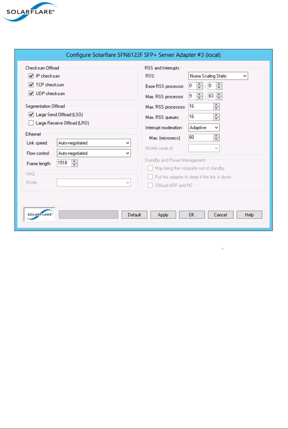
Issue 10 © Solarflare Communications 2013 148
Solarflare Server Adapter
User Guide
The Adapter Features dialog box will be displayed:
Figure 18: Solarflare Adapter Manager Adapter Features
Click Apply or OK when changes to Adapter Features are modified.

Issue 10 © Solarflare Communications 2013 149
Solarflare Server Adapter
User Guide
Checksum Offload
Windows XP, Windows Server 2003, Windows 7, Windows 8, Windows Server 2008, Windows
Server 2008 R2, Windows Server 2012.
Checksum offloading is supported on IP, TCP and UDP packets. Before transmitting a packet, a
checksum is generated and appended to the packet. At the receiving end, the same checksum
calculation is performed against the received packet. By offloading the checksum process to the
network adapter, the load is decreased on the server CPU.
By default, Solarflare adapters are set up to offload both the calculation and verification of TCP, IP
and UDP checksums. The following Checksum Offload options are supported:
You can also configure Checksum offload settings from the network adapter properties. See
Configuring Network Adapter Properties in Windows on page 180 for more details.
Table 29: Checksum Offloads
Check box
selected
Transmit and Receive Transmit checksums are generated and
received checksums are enabled. This is the
default setting.
Check selected
but selection
greyed out
Transmit Only or Receive
Only
For either transmit or received checksum
only.
NOTE: The Transmit or Receive Only states
can only be set from the Advanced tab of
the Driver Properties. See Configuring
Network Adapter Properties in Windows
on page 180 for more details.
Check box
cleared
Disabled Disabled. Data will be checksummed by the
host processor for both transmitted and
received data.
NOTE: Changing the checksum offload settings can impact the performance of the adapter.
Solarflare recommend that these remain at the default values. Disabling checksum offload
disables TCP segmentation offload.

Issue 10 © Solarflare Communications 2013 150
Solarflare Server Adapter
User Guide
RSS and Interrupts
Windows XP, Windows Server 2003, Windows 7, Windows 8, Windows Server 2008, Windows
Server 2008 R2, Windows Server 2012.
Solarflare network adapters support RSS (Receive Side Scaling) and interrupt moderation. Both are
enabled by default and can significantly improve the performance of the host CPU when handling
large amounts of network data.
RSS attempts to dynamically distribute data processing across the available host CPUs in order to
spread the workload. Interrupt moderation is a technique used to reduce the number of interrupts
sent to the CPU. With interrupt moderation, the adapter will not generate interrupts closer together
than the interrupt moderation interval. An initial packet will generate an interrupt immediately, but
if subsequent packets arrive before the interrupt moderation interval, interrupts are delayed.
You can also configure RSS and interrupts settings from the network adapter properties. See
Configuring Network Adapter Properties in Windows on page 180 for more details.
NOTE: Changing the RSS and Interrupt Moderation settings can impact the performance
of the adapter. You are strongly advised to leave them at their default values.

Issue 10 © Solarflare Communications 2013 151
Solarflare Server Adapter
User Guide
RSS and Interrupts Options
Table 30:
Displayed (supported) options will differ between Windows OS versions and different
Solarflare drivers.
RSS Enabed|Disabled.
See also RSS (Windows Server 2012).
RSS Algortihm The RSS algorithm determines how RSS queues and interrupts
are spread over the available processors. The Microsoft setting
uses the algorithm supported by the Windows version. The
Solarflare setting uses an optimized mode found to improve
performance and reduce CPU utilization over a range of traffic
patterns. The Solarflare setting is the default value.
Solarflare|Microsoft
RSS queue count Balanced means interrupts are balanced across all available CPU
cores.
Otherwise the user can direct RSS to create a specific number of
receive queues (1-64). By default receive queue 1 will map to
the first CPU, receive queue 2 will map to the second etc.
Max. RSS processors Set the number of processors to be used by RSS.
If this is greater than or equal to the number of logical
processors in the system then all processors are used.
Interrupt moderation Adaptive - adjusts the interrupt rates dynamically, depending on
the traffic type and network usage.
Disabled - interrupt moderation is disabled.
Enabled - interrupt moderation is enabled.
Maximum (microseconds) This setting controls the value for the interrupt moderation
time. The default value is 60 microseconds and can be changed
for deployments requiring minimal latency.

Issue 10 © Solarflare Communications 2013 152
Solarflare Server Adapter
User Guide
Further Reading
For more information on Windows RSS profiles and options refer to http://msdn.microsoft.com/en-
us/library/windows/hardware/ff570864%28v=vs.85%29.aspx
RSS (Windows Server
2012)
Disabled - RSS is disabled. (Enabled by default).
Closest Processor - (default behaviour)
Closest Processor Static - Network traffic is distributed across
available CPUs, but there is no dynamic load balancing.
NUMA Scaling - CPUs are assigned on a round-robin basis across
every NUMA node.
NUMA Scaling Static - As for NUMA Scaling but without dynamic
load balancing.
Conservative Scaling - RSS will use as few processors as possible
to sustain the current network load. This helps to reduce the
number of interrupts.
Base RSS processor The base processor to be used by RSS. The value is specified as a
group (range 0-15) and CPU number (range 0-63).
Max. RSS processor The maximum processor available to RSS. The value is specified
as a group (range 0-15) and CPU number (range 0-63).
Max. RSS processors The maximum number of processors to be used by RSS. The
value is in the range 0-256.
Max. RSS queues The maximum number of receive queues created per interface.
The value is in the range 0-64.
NUMA node id The NUMA node id drop down list box is displayed on Windows
platforms that support NUMA architectures. This contains the
set of CPU cores used for RSS to the specified NUMA node.
Solarflare recommend you leave this at the default setting of
All. The adapter will attempt to use only processors from the
specified NUMA node for RSS. If this is set to ALL or it is greater
than or equal to the number of NUMA nodes in the system, all
NUMA nodes are used.
Table 30:

Issue 10 © Solarflare Communications 2013 153
Solarflare Server Adapter
User Guide
4.13 Segmentation Offload
Windows XP, Windows Server 2003, Windows 7, Windows 8, Windows Server 2008, Windows
Server 2008 R2, Windows Server 2012.
Solarflare adapters offload the tasks of packet segmentation and reassembly to the adapter
hardware, reducing the CPU processing burden and improving performance.
LRO is a Solarflare proprietary implementation of the Windows Receive Side Coalescing feature.
When enabled the adapter will coalesce multiple received TCP packets on a TCP connection into a
single call to the TCP/IP stack. This reduces CPU use and improves peak performance. However LRO
can increase latency and should not be used if a host is forwarding received packets from one
interface to another. LRO is disabled by default.
You can also configure LSO and LRO settings from the NDIS properties. See Configuring Network
Adapter Properties in Windows on page 180 for more details.
Ethernet Link Speed
Generally, it is neither necessary or desirable to configure the link speed of the adapter. The adapter
by default will negotiate the link speed dynamically, connecting at the maximum, supported speed.
However, if the adapter is unable to connect to the link partner, you may wish to try setting a fixed
link speed. For further information see ’Link Speed’ in Table 41 on page 181
Ethernet flow control
Ethernet flow control allows two communicating devices to inform each other when they are being
overloaded by received data. This prevents one device from overwhelming the other device with
network packets. For instance, when a switch is unable to keep up with forwarding packets between
ports. Solarflare adapters allow flow control settings to be auto-negotiated with the link partner.
You can also configure ethernet flow control from the network adapter properties. See Table 41 on
page 181 for more details.

Issue 10 © Solarflare Communications 2013 154
Solarflare Server Adapter
User Guide
Ethernet Frame Length
The maximum Ethernet frame length used by the adapter to transmit data is (or should be) closely
related to the MTU (maximum transmission unit) of your network. The network MTU determines
the maximum frame size that your network is able to transmit across all devices in the network.
If the network uses Jumbo frames, SAM supports frames up to a maximum of 9216 bytes.
Table 31: Ethernet Flow Control Options
Option Description
Auto-negotiate Flow control is auto-negotiated between the devices. This is
the default setting.
Generate and respond Adapter generates and responds to flow control messages.
Respond only Adapter responds to flow control messages but is unable to
generate messages if it becomes overwhelmed.
Generate only Adapter generates flow control messages but is unable to
respond to incoming messages and will keep sending data to
the link partner.
None Ethernet flow control is disabled on the adapter. Data will
continue to flow even if the adapter or link partner is
overwhelmed.
NOTE: For optimum performance set the Ethernet frame length to your network MTU.

Issue 10 © Solarflare Communications 2013 155
Solarflare Server Adapter
User Guide
Standby and Power Management
These settings are only available if the adapter has auxiliary power supplied by a separate cable. .
You can also configure standby power management from the network adapter properties. See
Configuring Network Adapter Properties in Windows on page 180 for more details.
Table 32: Standby and Power Management
May bring the computer out of standby Enables Wake on LAN capability for
adapters supporting this feature.
Put this adapter to sleep if the link is
down
This setting uses the Device Sleep on
Disconnect setting from the Advanced tab
of the adapter properties. Device Sleep on
Disconnect is the ability of the network
adapter to go to sleep when it is not in use.
When Windows detects that media has
been disconnected (for example, when a
cable is unplugged), Windows will put the
device into the low power state and disable
the LAN. The computer will automatically
detect when the cable is plugged in again
and return the network adapter to full
power.
Offload ARP and NS Windows Server 2008 R2,Windows 7,
Windows Server 2012.

Issue 10 © Solarflare Communications 2013 156
Solarflare Server Adapter
User Guide
Virtual Machine Queue
Windows XP, Windows Server 2003, Windows 7, Windows 8, Windows Server 2008, Windows
Server 2008 R2, Windows Server 2012.
Solarflare adapters (not SFN4122F) support VMQ to offload the classification and delivery of
network traffic destined for Hyper-V virtual machines to the network adapter thereby reducing the
CPU load on Hyper-V hosts.
Windows Server 2008R2 allows the administrator user to statically configure the number of CPUs
available to process interrupts for VMQ. Interrupts are spread across the specified cores, however
the static configuration does not provide best performance when the network load varies over time.
Dynamic VMQ, supported in Windows Server 2012, will dynamically distribute received network
traffic across available CPUs while adjusting for network load by, if necessary, bringing in more
processors or releasing processors under light load conditions.
Support for static VMQ is removed from Windows Server 2012, but the Solarflare driver which uses
NDIS 6.3 is automatically granted Dynamic VMQ capabilities.
VMQ supports the following features:
• Classification of received network traffic in hardware by using the destination MAC address (and
optionally also the VLAN identifier) to route packets to different receive queues dedicated to
each virtual machine.
• Can use the network adapter to directly transfer received network traffic to a virtual machine’s
shared memory avoiding a potential software-based copy from the Hyper-V host to the virtual
machine.
• Scaling to multiple processors by processing network traffic destined for different virtual
machines on different processors.
Table 33: VMQ Mode Options
Enabled VMQ is enabled by default.
Enabled (no lookahead split) VMQ allows the network adapter to split
packets into header and payload portions
in hardware. The payload is delivered
directly into the address space of the
destination Hyper-V virtual machine by the
adapter hardware. This feature is enabled
by default. Disabling lookahead split will
impact performance as the payload is
delivered into the virtual machine using
software.
Not supported on Windows Server 2012.

Issue 10 © Solarflare Communications 2013 157
Solarflare Server Adapter
User Guide
Enabled (no VLAN filtering) VMQ uses the VLAN identifier from the
Ethernet MAC header for filtering traffic to
the intended Hyper-V virtual machine.
VMQ VLAN filtering is enabled by default.
When this option is disabled only the
destination MAC address is used for
filtering.
Not supported on Windows Server 2012.
Enabled (MAC address filtering) VMQ uses the Ethernet MAC header for
filtering traffic to the intended Hyper-V
virtual machine. VMQ VLAN filtering is
enabled by default.
Disabled VMQ is disabled.
Table 33: VMQ Mode Options
Issue 10 © Solarflare Communications 2013 158
Solarflare Server Adapter
User Guide
4.14 Using SAM to Configure Teams and VLANs
• About Teaming...Page 158
• Setting Up Teams...Page 159
• Reconfiguring a Team...Page 160
• Adding Adapters to a Team...Page 163
• Deleting Teams...Page 164
• Setting up Virtual LANs (VLANs)...Page 165
• Deleting VLANs...Page 166
About Teaming
Solarflare adapters support the following teaming configurations:
• IEEE 802.3ad Dynamic link aggregation
• Static link aggregation
• Fault tolerant teams
Teaming allows the user to configure teams consisting of all Solarflare adapter ports on all installed
Solarflare adapters or might consist of only selected adapter ports e.g. from a dual port Solarflare
adapter, the first port could be a member of team A and the second port a member of team B or
both ports members of the same team.
This section is only relevant to teams of Solarflare adapters. Solarflare adapters can be used in multi-
vendor teams when teamed using the other vendor’s teaming driver.
NOTE: To set up teams and VLANS in Windows using the sfteam command line tool, see Sfteam:
Adapter Teaming and VLAN Tool...Page 206
NOTE: Adapter teaming and VLANs are not supported in Windows for iSCSI remote boot enabled
Solarflare adapters. To configure load balancing and failover support on iSCSI remote boot enabled
adapters, use Microsoft MultiPath I/O (MPIO), which is supported on all Solarflare adapters.
NOTE: Windows Server 2012 has native support for Windows teaming. You should NOT mix native
teaming and Solarflare teaming in the same server.
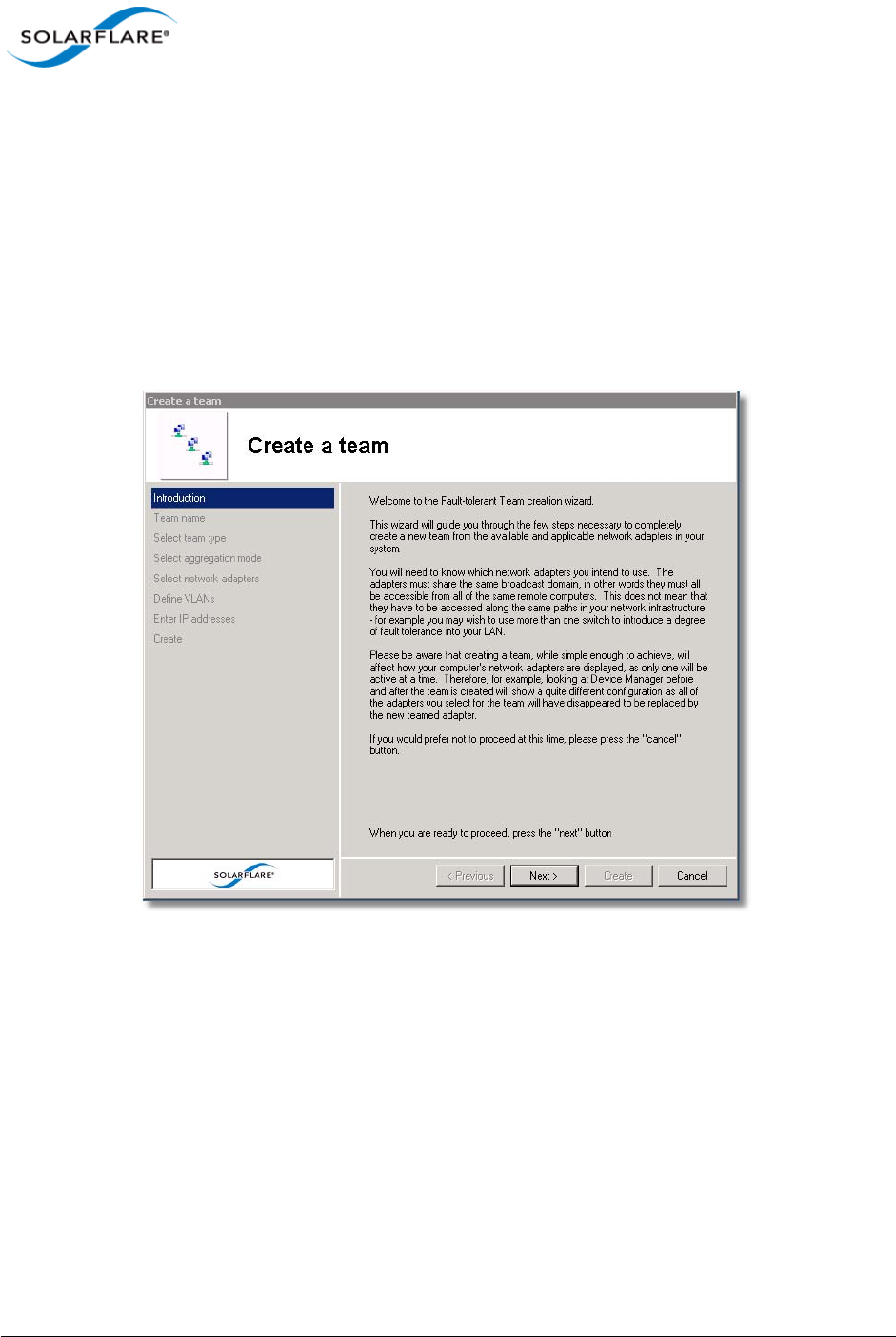
Issue 10 © Solarflare Communications 2013 159
Solarflare Server Adapter
User Guide
Setting Up Teams
SAM’s Create a Team setup wizard will guide you through setting up an adapter team, automatically
assigning the active adapter, key adapter and standby adapter.
To create a team:
1Before creating a team, Solarflare strongly recommend taking the server offline to avoid
disrupting existing services as the team is being configured.
2Start SAM and select a Solarflare adapter in the Network Adapter list.
3From the Action menu, select Create a Team. The Solarflare Create a team Wizard starts.
Figure 19: Team Create Wizard
4The wizard will guide you through the process of creating a team and optionally adding VLANs
to your team (see Table 35 on page 166 for help when selecting VLAN options).
5Bring the server back online.
6After creating a team, you can use the Configure this Team option from the Actions pane to
change team settings, such as the Ethernet frame length, key adapter assignment, and adapter
priorities within the team.
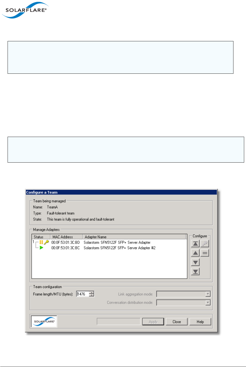
Issue 10 © Solarflare Communications 2013 160
Solarflare Server Adapter
User Guide
Reconfiguring a Team
When setting up teams, SAM assigns the key, active and standby adapters, and specifies the
Ethernet frame length for the team. To change any of these settings, use the Configure this Team
option, as described below.
To change team settings:
1Start SAM and, from the Network Adapter list, select the team you want to reconfigure.
2From the Action menu, select Configure this Team. The Configure a Team dialog box displays.
Figure 20: Configure aTeam
CAUTION: Before physically removing an adapter from a server, first check it is not the key
adapter. You must reassign the key adapter if you want to remove it from the team to avoid
duplicating the MAC address on your network. See Table 34 on page 161 for details on
reassigning the key adapter.
NOTE: Changing team settings can disrupt network traffic flow to and from services running on the
server. Solarflare recommend only changing network settings when disruption to the services can
be tolerated.
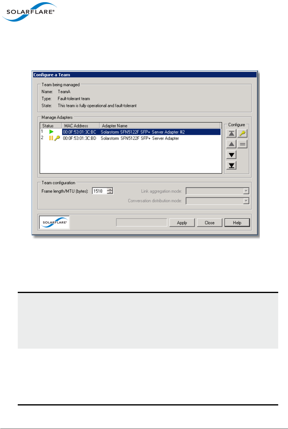
Issue 10 © Solarflare Communications 2013 161
Solarflare Server Adapter
User Guide
By default, all teamed adapters are given an equal priority (indicated by the grouped number 1). The
current active adapter is indicated by the green active symbol. The key adapter is indicated with the
key symbol. Adapters in standby are indicated by the yellow standby symbol. For link aggregated
teams there may be more than one active adapter.
Figure 21: Prioritized Adapters
Figure 21 shows the active adapter with the highest priority, with the second adapter being second
priority. :
Table 34: Configure a Team Options
To change the key adapter: Select the new key adapter, then click the key button.
Note: Before physically removing an adapter from a
server, first check it is not the key adapter. You must
reassign the key adapter if you want to remove it from
the team to avoid duplicating the MAC address on your
network.
To change adapter priority: By default, all adapters have equal priority. Select an
adapter and use the up or down buttons to promote or
demote the adapter priority as required.
Note: For Fault-Tolerant Teams, the highest priority
adapter in a team becomes the active adapter, passing
all network traffic for the team.

Issue 10 © Solarflare Communications 2013 162
Solarflare Server Adapter
User Guide
3After making your changes, click Set and then click Close.
To specify a new active adapter: For Fault -Tolerant Teams only. Set your preferred
active adapter to the highest prioritized adapter in the
team. The highest prioritized adapter becomes the
active adapter in the team after you apply your
changes.
To change adapter priority, use the up and down
buttons.
To specify the Ethernet frame
length/MTU:
Specify a value between 1514 and 9216 bytes. Check
your network supports the new frame length before
setting the new value.
Note: This setting affects all adapters in the team, and
will override any individual adapter settings made
from the Configure Offload tasks, Ethernet and other
features window. See Using SAM to Configure Adapter
Features on page 146 for more details.
Table 34: Configure a Team Options
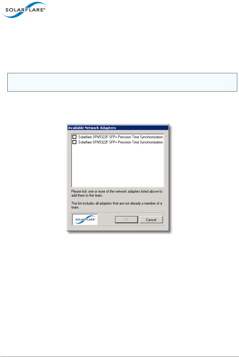
Issue 10 © Solarflare Communications 2013 163
Solarflare Server Adapter
User Guide
Adding Adapters to a Team
If additional Solarflare adapters are installed in your server, you can add them to an existing team to
increase the overall resilience or performance (aggregation) of the server connection.
To add adapters to a team:
1Start SAM and select a Solarflare adapter team from the Network Adapter list.
2From the Actions list, click Add one or more adapters, or choose Actions > Add one or more
adapters. The Available Network Adapters dialog box is displayed:
Figure 22: Available Adapters
3Select the adapter(s) to add to the team. Click OK to add the selected adapters and close the
dialog box.
NOTE: Changing team settings can disrupt current services running on the server. Solarflare
recommend only changing network settings when disruption to the services can be tolerated.
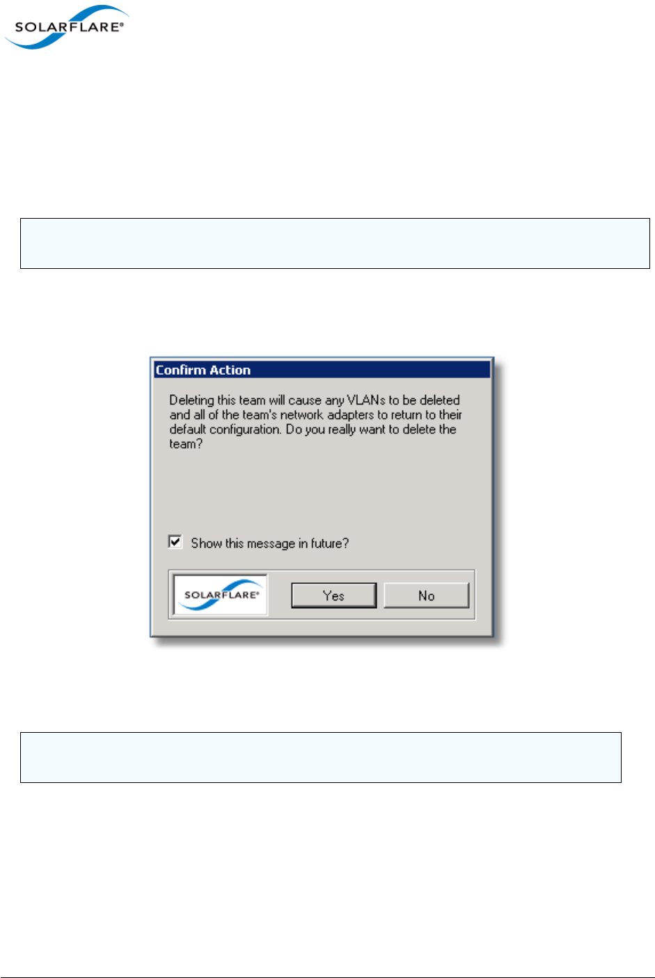
Issue 10 © Solarflare Communications 2013 164
Solarflare Server Adapter
User Guide
Deleting Teams
You can delete a team by selecting Delete this team in SAM. Once a team has been deleted, all of its
adapters are returned to their original configuration settings and become available on the server
once again. Any VLANs set up for the team will be deleted when the team is deleted.
To delete a team:
1Start SAM and select a Solarflare adapter team from the Network Adapter list.
2From the Action menu, select Delete this team. Alternatively, to delete all teams and VLANs
on the server, select Delete all teams and VLANs. The Confirm Action Dialog box is displayed.
Figure 23: Confirm Action
3Confirm the deletion when prompted.
NOTE: Changing team settings can disrupt current services running on the server. Solarflare
recommend only changing network settings when disruption to network services can be tolerated.
NOTE: Delete all teams and VLANs will cause a display refresh which may take some time to
complete, depending on the number of teams and VLANs being deleted.
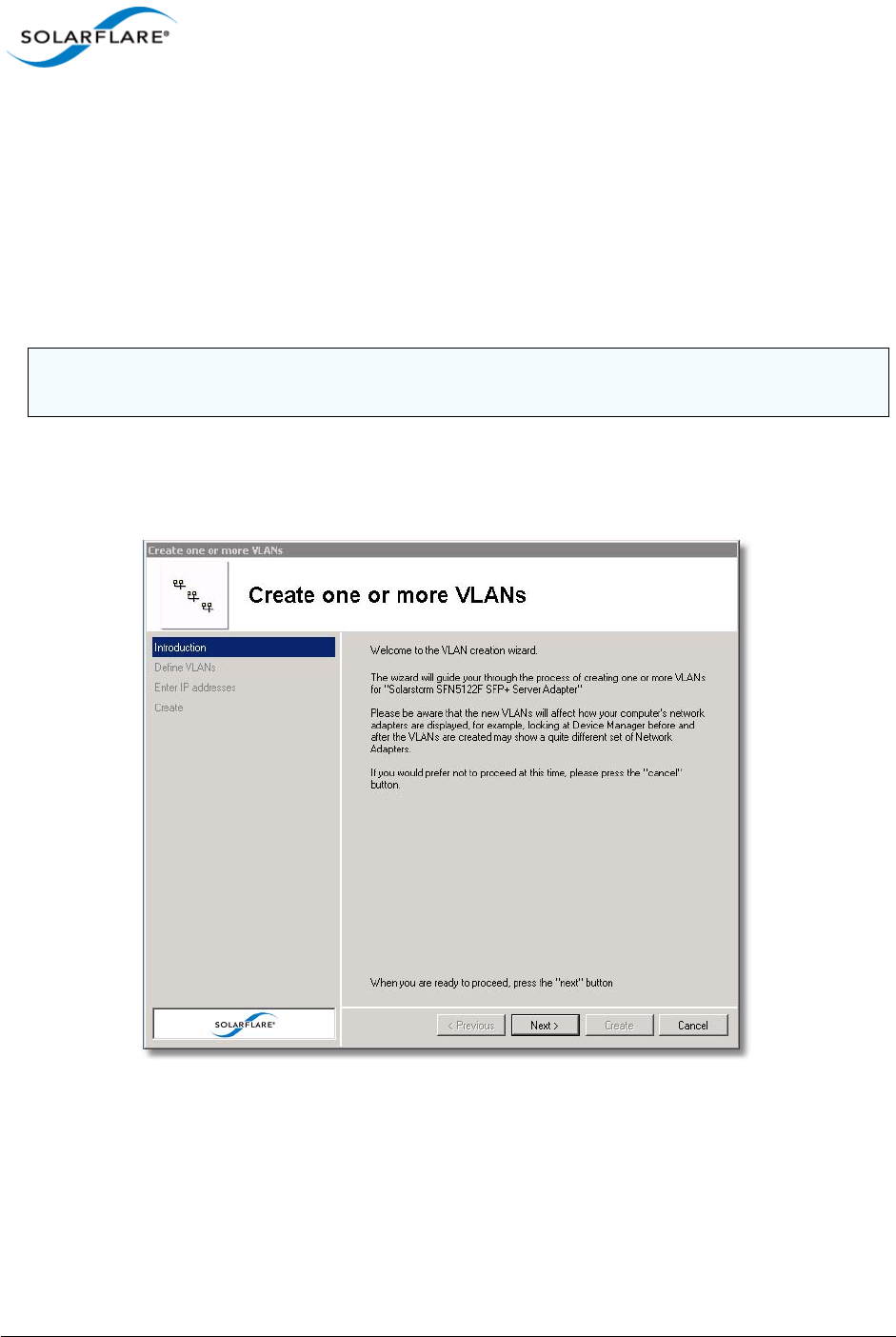
Issue 10 © Solarflare Communications 2013 165
Solarflare Server Adapter
User Guide
Setting up Virtual LANs (VLANs)
SAM allows you to add up to 64 VLANs per team or adapter. Each VLAN is a virtual network adapter,
visible in the Windows Device Manager, through which the operating system is able to receive data
tagged with the correct VLAN ID (VID). You may assign one VLAN to accept VLAN 0 or untagged
traffic, which allows the interface to communicate with devices that do not support VLAN tagging,
or that are sending traffic on VLAN 0.
To create VLANs:
1Start SAM and select the adapter or adapter team from the Network Adapter list.
2From the Actions list, click Add one or more VLANs, or choose Actions > Add one or more
VLANs to display the VLAN Setup Wizard.
Figure 24: Create VLANs
NOTE: Creating VLANs can disrupt current services running on the server. Solarflare recommend
only changing network settings when disruption to network services can be tolerated.

Issue 10 © Solarflare Communications 2013 166
Solarflare Server Adapter
User Guide
Deleting VLANs
VLANs can be removed from a team or single adapter when no longer required.
To delete VLANs:
1Start SAM.
2In the Network adapter list, select the VLAN to delete. If necessary, expand the team if the
VLAN is attached to a team then select the VLAN.
3From the Actions list, click Delete this VLAN, or choose Action > Delete this VLAN.
4Confirm the deletion in the Confirm Action Dialog box.
Table 35: VLAN Options
Option Description
Name An optional name for the VLAN network adapter.
This option will not be available when remotely
administering the server.
Supports the handling of priority
traffic
Enables the handling of traffic that is tagged as
priority.
Supports untagged and VLAN 0 traffic Restricts the VLAN to handling packets that are
untagged or with VID 0.
This option allows the interface to communicate
with devices which don’t support VLAN tagging.
Supports traffic solely on this VLAN Restricts the network interface to traffic that is
tagged with the specified VLAN.
NOTE: Deleting VLANs can disrupt current processes and applications running on the server.
Solarflare recommend only changing network settings when disruption to network services can be
tolerated.
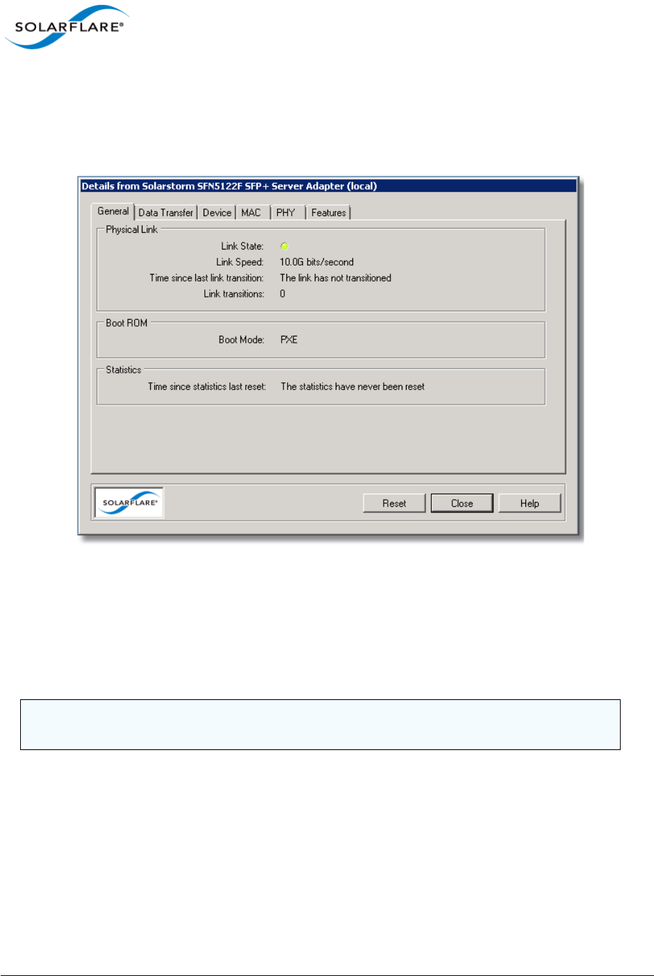
Issue 10 © Solarflare Communications 2013 167
Solarflare Server Adapter
User Guide
4.15 Using SAM to View Statistics and State Information
SAM’s Network Adapter list provides an overview of the adapters installed in the host computer. For
a more detailed view of the adapter device settings, data transfer statistics, and other features, you
can use the adapter Statistics and State.
Figure 25: Solarflare Adapter Statistics and State
To view Solarflare statistics and state information:
1Start SAM and select a Solarflare adapter from the Network Adapter list.
2From the Actions list, click Statistics and State. The Details from <adapter name> dialog box is
displayed.
3Click each tab to see the various adapter statistics and state information that is available for
the adapter. Note that statistics are collated from the start of the current session. To reset the
statistics, see Resetting Adapter Statistics on page 168.
4When you have finished viewing statistics, click Close.
NOTE: The tabs displayed will differ, dependent on whether an adapter, VLAN or Team is
selected.

Issue 10 © Solarflare Communications 2013 168
Solarflare Server Adapter
User Guide
Resetting Adapter Statistics
Statistics for data transfer and the MAC layer are reset, either following a system restart or installing
of the adapter drivers. If necessary, you can reset the adapter statistics to restart the accumulated
data values at any time.
1Start SAM and select a Solarflare adapter from the Network Adapter list.
2From the Actions list, click Statistics and State, or choose Actions > Statistics and State. The
Details from <adapter name> dialog box is displayed.
3In the General tab, click the Reset button to reset statistics.
4Click Close.
4.16 Using SAM to Run Adapter and Cable Diagnostics
You can verify the Solarflare adapter, driver and cable by running SAM’s built-in diagnostic tools
(Solarflare 10GBASE-T adapter only).
The tools provide a simple way to verify that the adapter and driver are working correctly, and that
the cable has the correct characteristics for high-speed data transfer.
The diagnostics tools also include an option to flash the LEDs (useful for identifying the adapter in a
server room). Both options are available from Actions > Adapter Diagnostics.
NOTE: Running of these tests will cause traffic to be halted on the selected adapter, and all of
its VLANs, unless part of a fault-tolerant team. Diagnostics tests are not available when the
adapter is running in iSCSI boot mode.
NOTE: The full system report cannot be generated when remotely administering a server.
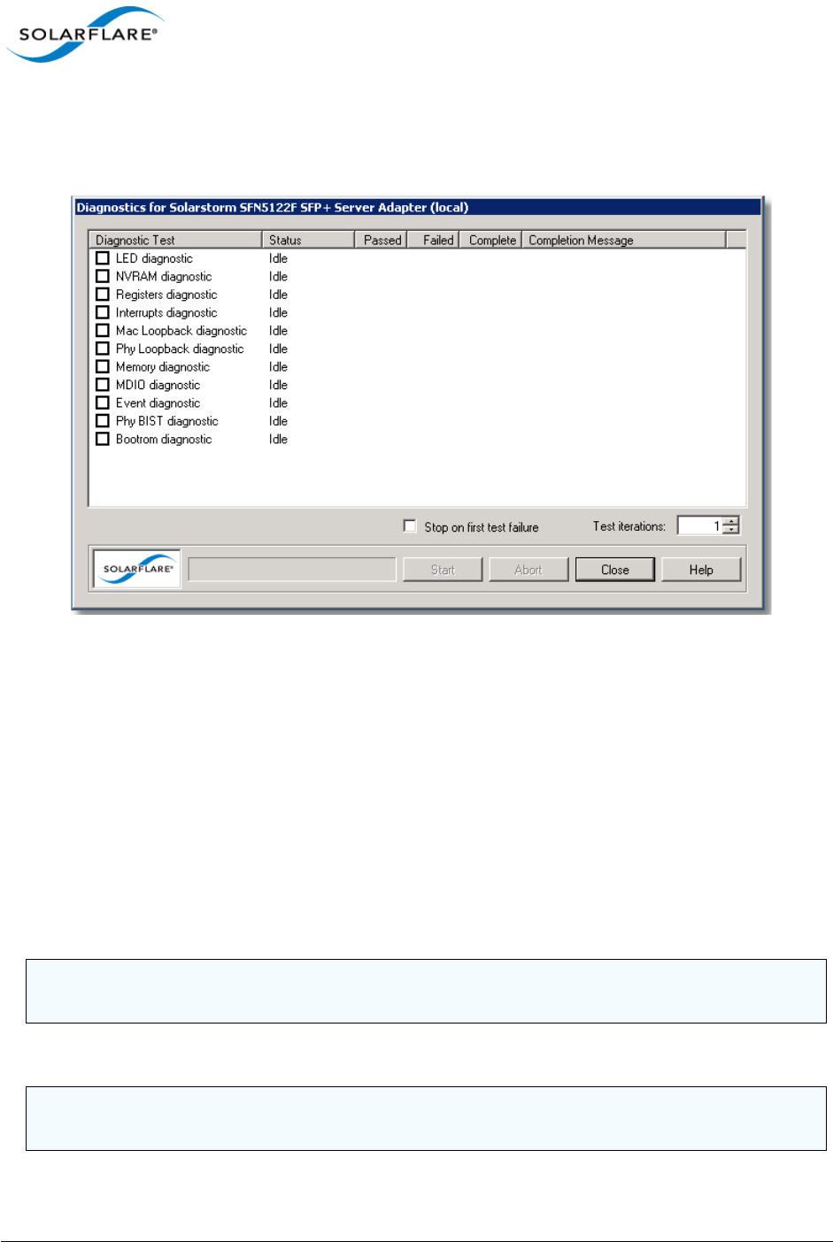
Issue 10 © Solarflare Communications 2013 169
Solarflare Server Adapter
User Guide
Running Driver and Adapter Diagnostics
SAM’s driver diagnostics enable you to test the adapter and driver are functioning correctly,
returning a simple pass or fail for each test run.
Figure 26: Adapter and Driver Diagnostics Window
1Start SAM and select a Solarflare adapter from the Network Adapter list.
2From the Action menu, select Adapter Diagnostics. The Diagnostics for <adapter name>
window is displayed.
3Select the test you want to run (no tests are selected by default). See Table 36 for a description
of the tests that are available.
4To stop as soon as a failure is detected, select Stop on first test failure.
5To run all the tests more than once, change the value in the Test iterations box.
6Click Start to begin testing. The results of each test will be displayed in the Diagnostics window,
along with an entry in the Completion Message column describing the reason any particular
test has failed.
The available tests depend on the installed adapter type.
CAUTION: The adapter will stop functioning while the tests are being run. Solarflare recommend
only running diagnostics tests when disruption to network services can be tolerated.
NOTE: You can click Abort to abandon running tests at any time. This may take a while to complete,
dependent on the test being run at the time.

Issue 10 © Solarflare Communications 2013 170
Solarflare Server Adapter
User Guide
Table 36: Adapter Diagnostic Tests
Diagnostic Test Purpose
LED Flashes the LEDs for 5 seconds.
NVRAM Verifies the flash memory board configuration area by
parsing and examining checksums.
Registers Verifies the adapter registers by attempting to modify the
writable bits in a selection of registers.
Interrupts Examines the available hardware interrupts by requesting
the controller to generate an interrupt and verifying that
the interrupt has been processed by the network driver.
MAC loopback Verifies that the network driver is able to pass packets to
and from the network adapter using the MAC loopback
layer.
PHY loopback Verifies that the network driver is able to pass packets to
and from the network adapter using the PHY loopback
layer.
Memory Verifies SRAM memory by writing various data patterns
(incrementing bytes, all bit on and off, alternating bits on
and off) to each memory location, reading back the data
and comparing it to the written value.
MDIO Verifies the MII registers by reading from PHY ID registers.
Event Verifies the adapter’s event handling capabilities by
posting a software event on each event queue created by
the driver and checking it is delivered correctly.
The driver creates an event queue for each CPU.
PHY BIST Examines the PHY by initializing it and starting any
available built-in self tests to run.
Bootrom Verifies the Boot ROM configuration and image checksum.
Will warn if no Boot ROM is present.
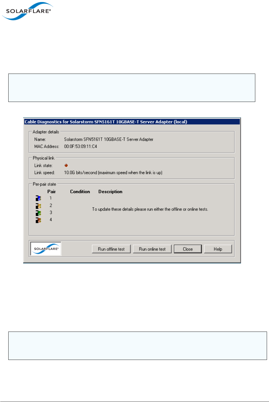
Issue 10 © Solarflare Communications 2013 171
Solarflare Server Adapter
User Guide
Running Cable Diagnostics
With high-speed data networking, the suitability of the cable in achieving maximum transfer rates is
especially important. SAM’s cable diagnostic tool can be used to verify the attached cable, reporting
its condition, measured length and electrical characteristics for each cable pairing.
Figure 27: Cable Diagnostics Window
1Start SAM and select a Solarflare adapter from the Network Adapter list.
2From the Action menu, click Diagnostics then Cable Diagnostics. The Cable Diagnostics for
<adapter name> dialog box is displayed.
3Click Run offline test or Run online test. Offline testing produce more detailed results, but at
the expense of disrupting the connection while tests are running.
NOTE: Cable diagnostics are only available on Solarflare 10GBASE-T Adapters. For these
adapters, Solarflare recommend using good quality Category 6, 6a or 7 cable up to the
maximum length as determined by the cable category.
CAUTION: The offline tests will cause the network link to momentarily drop and disrupt data flow.
Solarflare recommend only running diagnostics tests when disruption to your services can be
tolerated.

Issue 10 © Solarflare Communications 2013 172
Solarflare Server Adapter
User Guide
4The results of the testing will be displayed in the diagnostics dialog box. For analysis of the
cable pair results, see Table 37.
Table 37: Cable Pair Diagnostic Results
Result Meaning
OK
Length measured = …, SNR margin = …
Cable is operating correctly.
The range is ±13dB (approximately). The SNR
should be positive.
Error
Pair short at …
A short circuit has been detected at the
indicated length.
The cable or the connector is faulty and must
be replaced.
Error
Pair is open circuit
An open circuit has been detected.
The cable or the connector is faulty and must
be replaced.
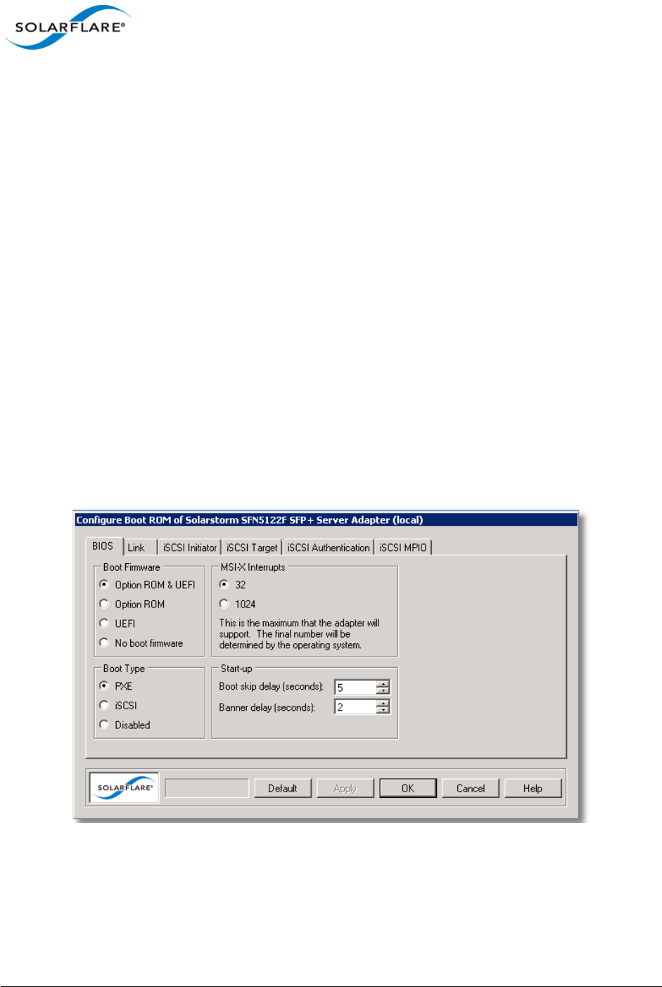
Issue 10 © Solarflare Communications 2013 173
Solarflare Server Adapter
User Guide
4.17 Using SAM for Boot ROM Configuration
For booting of diskless systems, Solarflare adapters support Preboot Execution Environment (PXE)
and iSCSI booting.
When booting the server directly from an iSCSI target, you will first need to enable iSCSI booting and
configure the iSCSI initiator, target and user authentication to match your network and target
settings, or rely on DHCP to configure the settings dynamically when the adapter initializes (this is
the default setting for all iSCSI options).
Using SAM, you can access the adapter Boot ROM to configure your firmware settings for adapter
booting, as described below.
Configuring the Boot ROM for PXE or iSCSI Booting
For more information on configuring the iSCSI target and DHCP settings from the Solarflare Boot
Configuration Utility, and how to install an operating system that is enabled for remote iSCSI booting
over a Solarflare adapter, See Solarflare Boot ROM Agent on page 360.
To configure PXE or iSCSI booting on the Solarflare Boot ROM:
1Start SAM and select a Solarflare adapter from the Network Adapter list.
From the Action menu, select the Configure Boot ROM option. The Configure Boot ROM window
displays with the BIOS tab selected.
Figure 28: BIOS tab with firmware selected
2From the Boot Type panel, select either PXE or iSCSI booting as required. You can also
configure the types of Boot Firmware, the maximum number of MSI-X Interrupts supported
and start-up configuration used by the Boot ROM utility. For more details on these options see
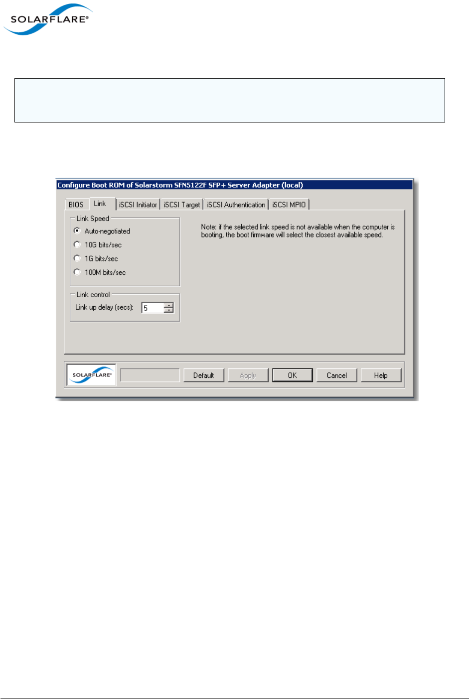
Issue 10 © Solarflare Communications 2013 174
Solarflare Server Adapter
User Guide
Sfboot: Boot ROM Configuration Tool on page 188.
3If necessary, from the Link tab, change the Link Speed option depending on your link
requirement. Note that Auto-negotiated is correct for most links and should not be changed
unless advised. The Link Speed options will vary depending on the installed adapter
Figure 29: Link tab
4The Link up delay specifies a wait time before the boot device will attempt to make a
connection. This allows time for the network to start following power-up. The default setting is
5 seconds, but can be set from 0–255 seconds. This can be used to wait for spanning tree
protocol on a connected switch to unblock the switch port after the physical network link is
established.
5If you selected PXE as the boot type, click OK to finish the setup procedure.
NOTE: iSCSI booting will not be available if the adapter is a member of a team or has VLANs.
NOTE: Solarflare recommend not changing the MSI-X Interrupts setting.
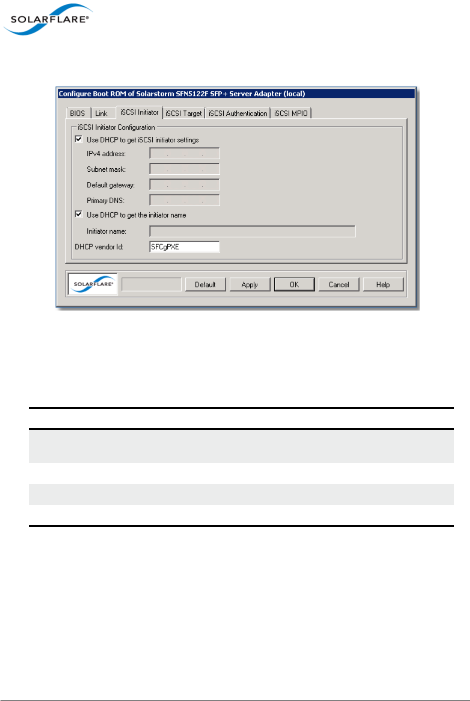
Issue 10 © Solarflare Communications 2013 175
Solarflare Server Adapter
User Guide
If you selected iSCSI booting as the boot type, click the iSCSI Initiator tab and continue with
the following steps.
Figure 30: iSCSI Initiator tab
6If using DHCP to configure the adapter’s network settings at boot time, ensure Use DHCP to
get iSCSI Initiator settings is selected. Otherwise, clear this option and enter network details
for the adapter, as described in Table 38.
7If you are not using DHCP to get the initiator name, clear Use DHCP to get the initiator name
and enter a iSCSI Qualified Name (IQN) in the Initiator name field.
8 DHCP vendor Id specifies the device vendor ID to be advertised to the DHCP server. This
setting is always enabled and not affected by any of the other DHCP options. See DHCP Server
Setup on page 370 for more details on this and other DHCP options.
9Click the iSCSI Target tab.
Table 38: iSCSI Initiator Options
Option Description
IPv4 Address An IPv4 address to assign to the adapter. Ensure this address is
unique.
Subnet mask Subnet mask. For example 255.255.255.0
Default Gateway IPv4 address of your network router.
Primary DNS IPv4 address of your Primary DNS server.
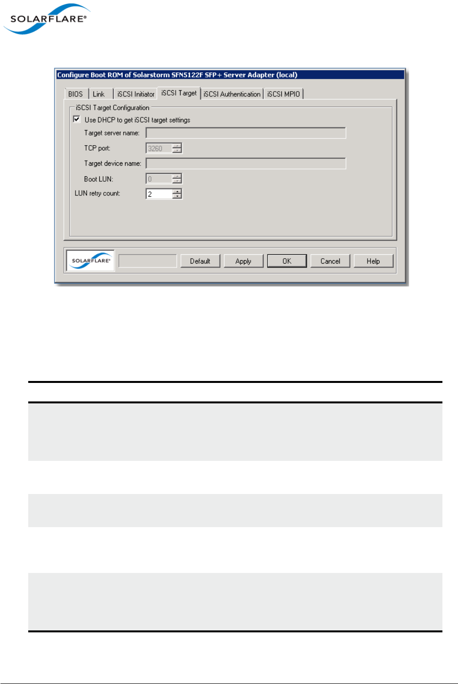
Issue 10 © Solarflare Communications 2013 176
Solarflare Server Adapter
User Guide
Figure 31: iSCSI Target tab
10 If using DHCP to discover the iSCSI target details, ensure Use DHCP to get iSCSI target settings
is selected. Otherwise, clear the option and enter details for the iSCSI target, as described in
Table 39.
Table 39: iSCSI Target Options
Option Description
Target server name Target server network address in the form of a dotted quad
(i.e. 10.1.2.3) IPv4 address or fully qualified domain name
(FQDN), such as
mytarget.myorg.mycompany.com
TCP port ISCSI port number that has been configured on the target.
Default is 3260.
Target device name The iSCSI Qualified Name (IQN) of the target server, which will
look something like: iqn:2009-01.com.solarflare.
Boot LUN Logical unit number which has been set up on the server. The
system will attempt to attach to this LUN on boot up and
attempt to load the target operating system from it.
LUN retry count Specifies the number of times the boot device will attempt to
connect to the target LUN (logical unit number) before failing.
The default setting is 2 retries, but can be set from 0–255. This
setting is enabled, even if using DHCP is being used.
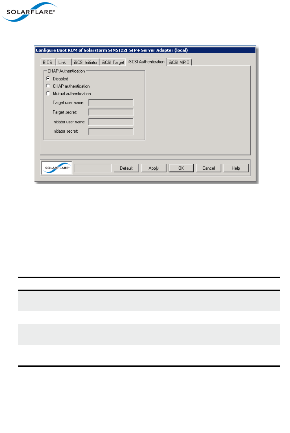
Issue 10 © Solarflare Communications 2013 177
Solarflare Server Adapter
User Guide
11 Click the iSCSI Authentication tab.
Figure 32: iSCSI Authentication tab
12 By default Challenge Handshake Application Protocol (CHAP) authentication is disabled. You
have the following options:
- CHAP authentication - this is target initiated or one way authentication
- Mutual authentication - both the target and the initiator will authenticate the connection.
If CHAP authentication is configured on the iSCSI target, enter the correct settings to allow
access to the target.
Table 40: CHAP Options
Option Description
Target user name Name of the target server, as set on the iSCSI target CHAP
settings.
Target secret Target password.
Initiator user name Name of this initiator (as set on the target). A minimum of 9
characters. Used for Mutual authentication only
Initiator secret Password of this initiator (as set on the target). A minimum of
12 characters. Used for Mutual authentication only.
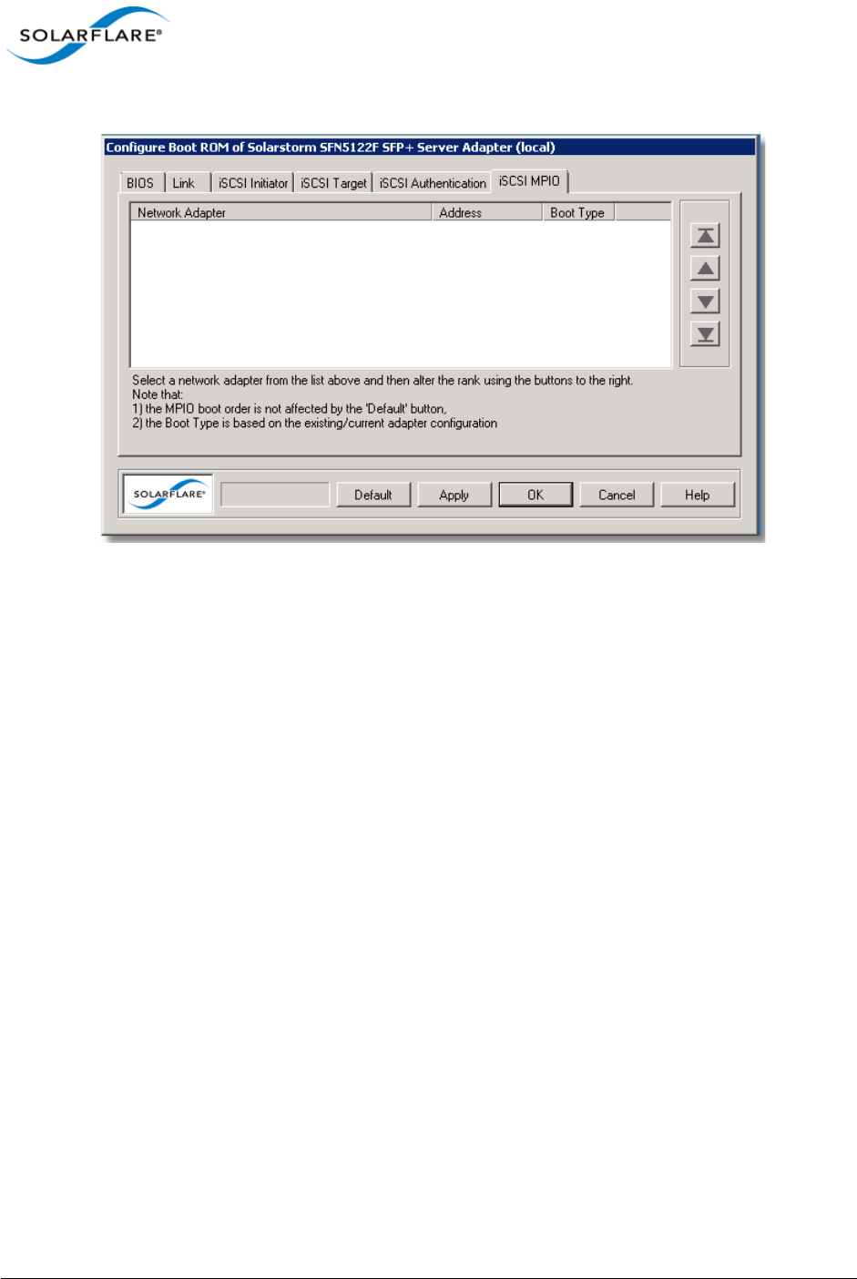
Issue 10 © Solarflare Communications 2013 178
Solarflare Server Adapter
User Guide
13 Select the iSCSI MPIO tab
Figure 33: iSCSI MPIO tab
For iSCSI booting in multi-adapter environments, you can set the priority of each adapter. By default,
all iSCSI enabled adapters are given an equal priority. The setting is used to determine how traffic is
re-routed in case of one adapter entering a failed state.
14 When you have finished configuring the iSCSI settings, click OK or Apply to save your settings
to the Boot ROM.
Disabling Adapter Booting
You can stop the adapter from attempting to initiate either a PXE or iSCSI boot after a restart.
1Start SAM and select the Solarflare adapter from the Network Adapter list.
2From the Action menu, click the Configure Boot ROM option. The Configure Boot ROM dialog
box displays with the BIOS tab selected.
3From the Boot Type panel, select Disabled.
4Click OK or Apply to save your settings to the Boot ROM.
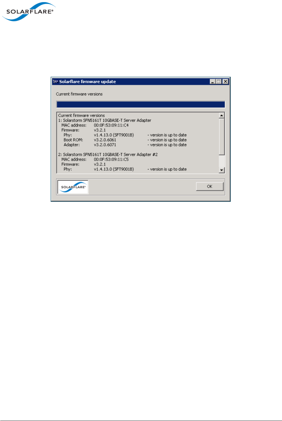
Issue 10 © Solarflare Communications 2013 179
Solarflare Server Adapter
User Guide
4.18 Managing Firmware with SAM
SAM allows you to monitor the firmware (PHY, Boot ROM and Adapter) for your Solarflare adapters.
Either select Manage firmware from the Actions pane, or from the Action menu. The firmware
update window is displayed:
Figure 34: Solarflare firmware update window
If the firmware is up to date, the window will contain the OK button. If the firmware is out of date,
the OK button is replaced with an Update and Cancel button. To update the firmware, click Update.
You can also use the sfupdate command line tool to manage the firmware on your Solarflare
adapters. See Sfupdate: Firmware Update Tool on page 202 for more details.
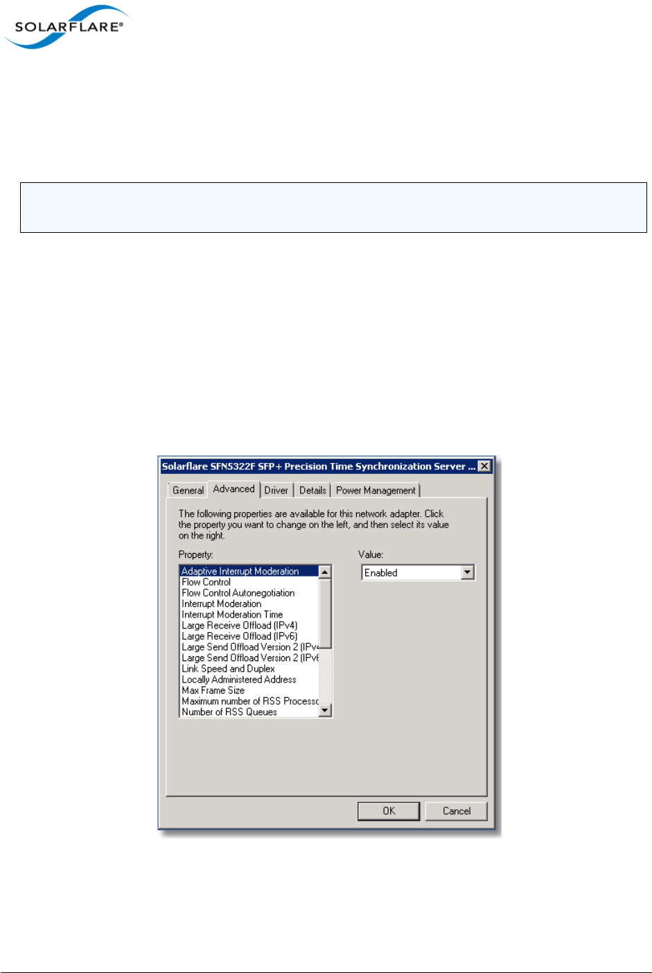
Issue 10 © Solarflare Communications 2013 180
Solarflare Server Adapter
User Guide
4.19 Configuring Network Adapter Properties in Windows
Network adapter properties for the Solarflare adapter are available through the Windows Device
Manager entry for the relevant network adapter. You can also access the adapter properties using
SAM.
To configure network adapter properties:
1From the Control Panel, select System.
2In Windows Server 2003, Windows XP, select System Properties > Hardware tab > Device
Manager button. I
3In Windows Server 2008, 2008 R2, Windows 7 and Windows Server 2012, select Device
Manager from the left hand menu.
4Expand the Network adapters.
5Right-click the on the Solarflare adapter, and then click Properties to display the properties
dialog box.
Figure 35: Adapter Properties Dialog
NOTE: If SAM is open, any changes made in the adapter properties will not be reflected in SAM until
you close the Advanced Properties page.

Issue 10 © Solarflare Communications 2013 181
Solarflare Server Adapter
User Guide
6Click the Advanced tab to view and edit the NDIS properties. See Table 41 for a list of the
available properties.
NOTE: Changing these properties may impact the performance of your Solarflare adapter. You
are strongly advised to leave them at their default values.
NOTE: Before making any changes to your Solarflare adapter features, read the Performance
Tuning on Windows section on 236 first.
Table 41: Solarflare Network Adapter Properties
Property Name Values Description
Adaptive Interrupt
Moderation
Enabled
Disabled
This setting is dependent on the Interrupt
Moderation setting. If Interrupt Moderation is
enabled, Adaptive Interrupt Moderation allows the
adapter to vary it’s interrupt moderation
automatically, according to network traffic
demands.
If Adaptive Interrupt Moderation is disabled,
interrupt moderation interval is fixed at the setting
specified in Interrupt Moderation Time.
Default setting: Enabled
Flow Control Generate
Generate and
Respond
Respond
Off
Ethernet flow control (802.3x) is a way for a network
device to signal to a sending device that it is
overloaded, such as when a device is receiving data
faster than it can process it.
The adapter does this by generating a ‘pause frame’
to request the sending device to temporarily stop
transmitting data. Conversely, the adapter can
respond to pause frames by suspending data
transmission, allowing time for the receiving device
to process its data.
Default setting: Generate and Respond
Flow Control
Autonegotiation
Enabled
Disabled
Flow control settings are auto-negotiated with the
link partner if possible.
Default setting: Enabled

Issue 10 © Solarflare Communications 2013 182
Solarflare Server Adapter
User Guide
Interrupt
Moderation
Enabled
Disabled
Interrupt moderation is a technique used to reduce
the number of interrupts sent to the CPU. With
interrupt moderation, the adapter will not generate
interrupts closer together than the interrupt
moderation time. An initial packet will generate an
interrupt immediately, but if subsequent packets
arrive before the interrupt moderation time period,
interrupts are delayed.
Default setting: Enabled
Interrupt
Moderation Time
1–1000 us Specifies the interrupt moderation period when
Interrupt Moderation is enabled.
The default setting (60s) has been arrived at by
lengthy and detailed system analysis, balancing the
needs of the operating system against the
performance of the network adapter.
Default setting: 60μs
Large Receive
Offload (IPv4 and
IPv6)
Enabled
Disabled
Large Receive Offload (LRO) is an offload technology
for reducing the load on a CPU by processing TCP
segmentation for received packets in the adapter.
Default setting: Disabled
Large Send Offload
Version 2 (IPv4 and
IPv6)
Enabled
Disabled
Large Send Offload (LSO) is an offload technology
for reducing the load on a CPU by processing TCP
segmentation for transmitted packets in the
adapter.
Caution: Disabling LSO may reduce the performance
of the Solarflare adapter.
Default setting: Enabled
Table 41: Solarflare Network Adapter Properties
Property Name Values Description

Issue 10 © Solarflare Communications 2013 183
Solarflare Server Adapter
User Guide
Link Speed 100 Mbps Full
duplex
1000 Mbps Full
Duplex
10000 Mbps Full
Duplex
Auto Detect
Specifies the network link speed of the adapter - the
default is auto.
On the 10GBASE-T adapters "auto" instructs the
adapter to negotiate the highest speed supported in
common with the link partner.
On SFP+ adapters "auto" instructs the adapter to
use the highest link speed supported by the inserted
SFP+ module.
On 10GBASE-T and SFP+ adapters, any other value
specified will fix the link at that speed, regardless of
the capabilities of the link partner, which may result
in an inability to establish the link.
Default setting: Auto Detect
Locally
Administered
Address
Value: (MAC
address)
Not Present
Assigns the specified MAC address to the adapter,
overriding the permanent MAC address assigned by
the adapter's manufacturer.
Addresses are entered as a block of six groups of
two hexadecimal digits separated by hyphens (-), for
example: 12-34-56-78-9A-BC
Note: To be a valid address, the second most
significant digit must be a 2, 6, A or E, as in the
above example.
Check the System Event Log for any configuration
issues after setting this value.
Default setting: Not Present.
Max Frame Size 1514–9216 Specifies the maximum Ethernet frame size
supported by the adapter.
Note: Devices will drop frames if they are unable to
support the specified frame size, so ensure the
value you set here is supported by other devices on
the network.
Default settings:
Solarflare adapter: 1514 bytes
Teamed adapter: 1518 bytes
Note: The setting must be a multiple of 2.
Table 41: Solarflare Network Adapter Properties
Property Name Values Description

Issue 10 © Solarflare Communications 2013 184
Solarflare Server Adapter
User Guide
Offload IPv4
Checksum
Disabled
Enabled
(Receive Only)
Enabled
(Transmit and
Receive)
Enabled
(Transmit Only)
IP checksum offload is a hardware offload
technology for reducing the load on a CPU by
processing IP checksums in the adapter hardware.
Offload IP Checksum is enabled by default for
transmitted and received data.
Default setting: Enabled (Transmit and Receive)
Offload TCP
Checksum (IPv4 and
IPv6)
Disabled
Enabled
(Receive Only)
Enabled
(Transmit and
Receive)
Enabled
(Transmit Only)
TCP checksum offload is a hardware offload
technology for reducing the load on a CPU by
processing TCP checksums in the adapter hardware.
Default setting: Enabled (Transmit and Receive)
Offload UDP
Checksum (IPv4 and
IPv6)
Disabled
Enabled
(Receive Only)
Enabled
(Transmit and
Receive)
Enabled
(Transmit Only)
UDP checksum offload is a hardware offload
technology for reducing the load on a CPU by
processing UDP checksums in the adapter hardware.
Default setting: Enabled (Transmit and Receive)
Number of RSS
Queues
Balanced Specify the number of RSS receive queues are
created by the adapter driver.
Range is 1-64 - default is Balanced - equal number
created for each CPU core.
Receive Side Scaling
(RSS)
Enabled
Disabled
Receive Side Scaling (RSS) is a technology that
enables packet receive processing to scale with the
number of available processors (CPUs), distributing
the processing workload across the available
resources.
Default setting: Enabled
Table 41: Solarflare Network Adapter Properties
Property Name Values Description

Issue 10 © Solarflare Communications 2013 185
Solarflare Server Adapter
User Guide
RSS Algorithm Microsoft
Optimized
Specifies how the interrupts are spread over the
available CPU cores. The Microsoft setting uses the
algorithm supported by the Windows version.
Optimized uses an algorithm found to improve
performance and reduce CPU utilization over a
range of traffic patterns.
Default setting: Optimized
RSS NUMA Node id All
1 to 9
The adapter attempts to use only the CPUs from the
specified NUMA node for RSS. If this is set to All or is
greater than or equal to the number of NUMA
nodes in the system all NUMA nodes are used.
Default setting: All
Virtual Machine
Queues (VMQ)
Enabled
Disabled
VMQ is a Windows Server 2008 R2 and Windows
Server 2012 specific feature. This offloads
classification and delivery of network traffic
destined for Hyper-V virtual machines to the
network adapter, reducing CPU utilization on Hyper-
V hosts.
Default setting: Enabled.
VMQ Lookahead
Split
Enabled
Disabled
Allows the adapter to split network packets into
header and payload portions in hardware. They
payload is delivered directly into the address space
of the destination Hyper-V virtual machine by the
adapter hardware. Performance can be affected
when this option is disabled as the payload is
delivered to the virtual machine address space by
software.
Default setting: Enabled.
Not available on Windows Server 2012.
VMQ VLAN Filtering Enabled
Disabled
VLAN filtering allows the adapter to use the VLAN
identifier for filtering traffic intended for Hyper-V
virtual machines. When disabled only the
destination MAC address is used for filtering.
Default setting: Enabled.
Table 41: Solarflare Network Adapter Properties
Property Name Values Description

Issue 10 © Solarflare Communications 2013 186
Solarflare Server Adapter
User Guide
4.20 Windows Command Line Tools
The command line tools (see Table 42) provide an alternative method of managing Solarflare
network adapters to SAM. They are especially useful on a Windows Server Core installation, where
SAM cannot be run locally. As with SAM, you can run the command line tools remotely. The tools
can also be scripted.
The command line tools are installed as part of the drivers installation on Windows. See Installing
the Solarflare Driver Package on Windows on page 110.
Table 42: List Available Command Line Utilities
Utility Description
sfboot.exe A tool for configuring adapter Boot ROM options for PXE and iSCSI
booting. See Sfboot: Boot ROM Configuration Tool on page 188.
sfupdate.exe A tool for updating adapter Boot ROM and PHY firmware. See Sfupdate:
Firmware Update Tool on page 202.
sfteam.exe A tool for managing fault-tolerant adapter teams and VLANs. See Sfteam:
Adapter Teaming and VLAN Tool on page 206.
sfcable.exe A tool for that runs cable diagnostics for Solarflare 10GBASE-T server
adapters. See Sfcable: Cable Diagnostics Tool on page 213.
sfnet.exe Allows you to display and/or set the offload, Ethernet, RSS, interrupt
moderation and VMQ features of any one adapter, VLAN or Team. See
Sfnet on page 216.

Issue 10 © Solarflare Communications 2013 187
Solarflare Server Adapter
User Guide
To start a command line tool, open a Command Line Interface windows and enter the command
tool.exe:
Figure 36: Windows console to run Solarflare command line tools.
NOTE: For all the utilities, the options are documented with the forward slash (/) prefix. You can
also use a single dash (--) or a double dash (--) as a prefix.
NOTE: In Windows Server 2003 onwards, you must run the utilities as an administrator to make any
changes. If you try to run the tools as a non administrator, an error message will be displayed.

Issue 10 © Solarflare Communications 2013 188
Solarflare Server Adapter
User Guide
4.21 Sfboot: Boot ROM Configuration Tool
• Sfboot: Command Usage...Page 188
• Sfboot: Command Line Options...Page 189
• Sfboot: Examples...Page 198
Sfboot is a Windows command line utility for configuring the Solarflare adapter Boot ROM for PXE
and iSCSI booting. Using sfboot is an alternative to using Ctrl+B to access the Boot Rom agent during
server startup.
See Configuring the Solarflare Boot ROM Agent on page 360 for more information on the Boot Rom
agent.
Sfboot: Command Usage
1Login with an administrator account.
2Click Start > All Programs > Solarflare Network Adapters > Command Line Interface for
Network Adapters.
3From the Command Prompt, enter the command using the following syntax:
sfboot [/Adapter <Identifier>] [options] [parameters]
where:
Identifier is the name or ID of the adapter that you want to manage. Specifying the
adapter is optional - if it is not included the command is applied to all Solarflare adapters in the
machine.
option is the option you want to apply. See Sfboot: Command Line Options for a list of
available options.
If using sfboot in a configuration script, you can include the environment variable %SFTOOLS%
to set the path to the Solarflare tools. For example:
SET PATH=%PATH%;%SFTOOLS%

Issue 10 © Solarflare Communications 2013 189
Solarflare Server Adapter
User Guide
Sfboot: Command Line Options
Table 43 lists the options for sfboot.exe and Table 44 lists the available parameters. Note that
command line options are case insensitive and may be abbreviated.
NOTE: Abbreviations in scripts should be avoided, since future updates to the application may
render abbreviated scripts invalid.
Table 43: Sfboot Options
Option Description
/Help Displays command line syntax and provides a
description of each sfboot option.
/Version Shows detailed version information and exits.
/Nologo Hide the version and copyright message at startup.
/Verbose Shows extended output information for the
command entered.
/Quiet
Aliases: /Silent
Suppresses all output, including warnings and errors;
no user interaction. You should query the completion
code to determine the outcome of commands when
operating silently.
/Log <Filename> Logs output to the specified file in the current folder
or an existing folder. Specify /Silent to suppress
simultaneous output to screen, if required.
/Computer <ComputerName> Performs the operation on a specified remote
computer. Administrator rights on the remote
computer is required.
/List Lists all available Solarflare adapters. This option
shows the adapter’s ID number, ifname and MAC
address.
Note: this option may not be used in conjunction
with the any other option. If this option is used with
configuration parameters, those parameters will be
silently ignored.
/Adapter =<Identifier> Performs the action on the identified Solarflare
network adapter. The adapter identifier can be the
adapter ID number, ifname or MAC address, as
output by the /List option. If /Adapter is not
included, the action will apply to all installed
Solarflare adapters.

Issue 10 © Solarflare Communications 2013 190
Solarflare Server Adapter
User Guide
The following parameters in Table 44 are used to control the options for the Boot ROM driver when
running prior to the operating system booting.
/Clear Resets all adapter options except boot-image to
their default values. Note that /Clear can also be
used with parameters, allowing you to reset to
default values, and then apply the parameters
specified.
/DbgFill Fill the config with PAD before validation (debug-
only).
/DbgTrash Trash the checksum just before writing to the flash
(debug-only).
/DbgTerminator Replace the DHCP_END with DHCP_PAD and fixup
the checksum (done before DbgTrash - debug-only).
/DbgReportOnly Only run debug tasks before sfgpxe_report() (debug-
only).
Table 44: Sfboot Parameters
Parameter Description
boot-
image=<all|optionrom|uefi|di
sabled>
Specifies which boot firmware images are served-up
to the BIOS during start-up. This parameter can not
be used if the /Adapter option has been specified.
This option is not reset if /Clear is used.
link-
speed=<auto|10g|1g|100m>
Specifies the network link speed of the adapter used
by the Boot ROM the default is auto. On the
10GBASE-T adapters “auto” instructs the adapter to
negotiate the highest speed supported in common
with it’s link partner . On SFP+ adapters, “auto”
instructs the adapter to use the highest link speed
supported by the inserted SFP+ module. On
10GBASE-T and SFP+ adapters, any other value
specified will fix the link at that speed, regardless of
the capabilities of the link partner, which may result
in an inability to establish the link
auto Auto-negotiate link speed (default)
10G 10G bit/sec
1G 1G bit/sec
100M 100M bit/sec
Table 43: Sfboot Options
Option Description

Issue 10 © Solarflare Communications 2013 191
Solarflare Server Adapter
User Guide
linkup-delay=<seconds> Specifies the delay (in seconds) the adapter defers its
first connection attempt after booting, allowing time
for the network to come up following a power failure
or other restart. This can be used to wait for
spanning tree protocol on a connected switch to
unblock the switch port after the physical network
link is established. The default is 5 seconds.
banner-delay=<seconds> Specifies the wait period for Ctrl+B to be pressed to
enter adapter configuration tool.
seconds = 0-256
bootskip-delay=<seconds> Specifies the time allowed for Esc to be pressed to
skip adapter booting.
seconds = 0-256
boot-
type=<pxe|iscsi|disabled>
Sets the adapter boot type.
pxe – PXE (Preboot eXecution Environment) booting
iscsi – iSCSI (Internet Small Computer System
Interface) booting
disabled – Disable adapter booting
initiator-
dhcp=<enabled|disabled>
Enables or disables DHCP address discovery for the
adapter by the Boot ROM except for the Initiator IQN
(see initiator-iqn-dhcp). This option is only
valid if iSCSI booting is enabled (boot-
type=iscsi).
If initiator-DHCP is set to disabled, the following
options will need to be specified:
initiator-ip=<ip_address>
netmask=<subnet>
The following options may also be needed:
gateway=<ip_address>
primary-dns=<ip_address>
Table 44: Sfboot Parameters
Parameter Description

Issue 10 © Solarflare Communications 2013 192
Solarflare Server Adapter
User Guide
initiator-ip=<ipv4 address> Specifies the IPv4 address (in standard “.” notation
form) to be used by the adapter when initiator-
dhcp is disabled.
Note that this option is only valid if iSCSI booting is
enabled (boot-type=iscsi).
Example:
sfboot boot-type=iscsi initiator-
dhcp=disabled initiator-
ip=<192.168.1.3>
netmask=<ipv4 subnet> Specifies the IPv4 subnet mask (in standard “.”
notation form) to be used by the adapter when
initiator-dhcp is disabled. Note that this option
is only valid if iSCSI booting is enabled (boot-
type=iscsi).
Example:
sfboot boot-type=iscsi initiator-
dhcp=disabled netmask=255.255.255.0
gateway=<ipv4 address> Specifies the IPv4 subnet mask (in standard “.”
notation form) to be used by the adapter when
initiator-dhcp is disabled. Note that this option
is only valid if iSCSI booting is enabled (boot-
type=iscsi).
Example:
sfboot boot-type=iscsi initiator-
dhcp=disabled gateway=192.168.0.10
primary-dns=<ipv4 address> Specifies the IPv4 address (in standard “.” notation
form) of the Primary DNS to be used by the adapter
when initiator-dhcp is disabled.
This option is only valid if iSCSI booting is enabled
(boot-type=iscsi).
Example:
sfboot boot-type=iscsi initiator-
dhcp=disabled primary-dns=192.168.0.3
initiator-iqn-
dhcp=<enabled|disabled>
Enables or disables use of DHCP for the initiator IQN
only.
Table 44: Sfboot Parameters
Parameter Description

Issue 10 © Solarflare Communications 2013 193
Solarflare Server Adapter
User Guide
initiator-iqn=<IQN> Specifies the IQN (iSCSI Qualified Name) to be used
by the adapter when initiator-iqn-dhcp is
disabled. The IQN is a symbolic name in the “.”
notation form; for example:
iqn.2009.01.com.solarflare, and is a maximum of 223
characters long.
Note that this option is only valid if iSCSI booting is
enabled (boot-type=iscsi).
Example:
sfboot initiator-iqn-dhcp=disabled
initiator-
iqn=iqn.2009.01.com.solarflare
adapter=2
lun-retry-count=<count> Specifies the number of times the adapter attempts
to access and login to the Logical Unit Number (LUN)
on the iSCSI Target before failing. Note that this
option is only valid if iSCSI booting is enabled (boot-
type=iscsi).
Example:
sfboot lun-retry-count=3
target-
dhcp=<enabled|disabled>
Enables or disables the use of DHCP to discover iSCSI
target parameters on the adapter.
If target-dhcp is disabled, you must specify the
following options:
target-server=<address>
target-iqn=<iqn>
target-port=<port>
target-lun=<LUN>
Example - Enable the use of DHCP to configure iSCSI
Target settings:
sfboot boot-type=iscsi target-
dhcp=enabled
Table 44: Sfboot Parameters
Parameter Description

Issue 10 © Solarflare Communications 2013 194
Solarflare Server Adapter
User Guide
target-server=<DNS name or
ipv4 address>
Specifies the iSCSI target’s DNS name or IPv4 address
to be used by the adapter when target-dhcp is
disabled.
Note that this option is only valid if iSCSI booting is
enabled (boot-type=iscsi).
Example:
sfboot boot-type=iscsi target-
dhcp=disabled target-server=192.168.2.2
target-port=<port_number> Specifies the Port number to be used by the iSCSI
target when target-dhcp is disabled. The default
Port number is Port 3260.
Note that this option is only valid if iSCSI booting is
enabled (boot-type=iscsi).
Example:
sfboot boot-type=iscsi target-
dhcp=disabled target-port=3262
This option should only be used if your target is using
a non-standard TCP Port.
target-lun=<LUN> Specifies the Logical Unit Number (LUN) to be used
by the iSCSI target when target-dhcp is disabled.
The default LUN is 0.
Note that this option is only valid if iSCSI booting is
enabled (boot-type=iscsi).
target-iqn=<IQN> Specifies the IQN of the iSCSI target when target-
dhcp is disabled. Maximum of 223 characters.
Note that this option is only valid if iSCSI booting is
enabled (boot-type=iscsi).
Note that if there are spaces contained in <IQN>,
then the IQN must be wrapped in double quotes (“”).
Example:
sfboot target-dhcp=disabled target-
iqn=iqn.2009.01.com.solarflare
adapter=2
vendor-id=<dhcp_id> Specifies the device vendor ID to be advertised to the
DHCP server. This must match the vendor id
configured at the DHCP server when using DHCP
option 43 to obtain the iSCSI target .
Table 44: Sfboot Parameters
Parameter Description

Issue 10 © Solarflare Communications 2013 195
Solarflare Server Adapter
User Guide
chap=<enabled|disabled> Enables or disables the use of Challenge Handshake
Protocol (CHAP) to authenticate the iSCSI
connection.
Note that this option is only valid if iSCSI booting is
enabled (boot-type=iscsi).
To be valid, this option also requires the following
sub-options to be specified:
username=<initiator username>
secret=<initiator password>
Example:
sfboot boot-type=iscsi chap=enabled
username=initiatorusername
secret=initiatorsecret
username=<username> Specifies the CHAP initiator username (maximum 64
characters).
Note that this option is required if either CHAP or
Mutual CHAP is enabled (chap=enabled,
mutual-chap=enabled).
Note that if there are spaces contained in
<username>, then it must be wrapped in double
quotes (“”).
Example:
sfboot boot-type=iscsi chap=enabled
username=username
secret=<secret> Specifies the CHAP initiator secret (minimum 12
characters, maximum 20 characters).
Note that this option is valid if either CHAP or Mutual
CHAP is enabled (chap=enabled, mutual-
chap=enabled).
Note that if there are spaces contained in <secret>,
then it must be wrapped in double quotes (“”).
Example:
sfboot boot-type=iscsi chap=enabled
username=username secret=veryverysecret
Table 44: Sfboot Parameters
Parameter Description

Issue 10 © Solarflare Communications 2013 196
Solarflare Server Adapter
User Guide
mutual-
chap=<enabled|disabled>
Enables/disables Mutual CHAP authentication when
iSCSI booting is enabled.
This option also requires the following sub-options to
be specified:
target-username=<username>
target-secret=<password>
username=<username>
secret=<password>
Example:
sfboot boot-type=iscsi mutual-
chap=enabled username=username
secret=veryverysecret target-
username=targetusername target-
secret=anothersecret
target-username=<username> Specifies the username that has been configured on
the iSCSI target (maximum 64 characters).
Note that this option is necessary if Mutual CHAP is
enabled on the adapter (mutual-chap=enabled).
Note that if there are spaces contained in
<username>, then it must be wrapped in double
quotes (“”).
target-secret=<secret> Specifies the secret that has been configured on the
iSCSi target (minimum 12 characters; maximum 20
characters).
Note: This option is necessary if Mutual CHAP is
enabled on the adapter (mutual-chap=enabled).
Note that if there are spaces contained in <secret>,
then it must be wrapped in double quotes (“”).
mpio-priority=<MPIO
priority>
Specifies the Multipath I/O (MPIO) priority for the
adapter. This option is only valid for iSCSI booting
over multi-port adapters, where it can be used to
establish adapter port priority. The range is 1- 255,
with 1 being the highest priority.
mpio-attempts=<attempt
count>
Specifies the number of times MPIO will try and use
each port in turn to login to the iSCSI target before
failing.
Table 44: Sfboot Parameters
Parameter Description

Issue 10 © Solarflare Communications 2013 197
Solarflare Server Adapter
User Guide
msix-
limit=<8|16|32|64|128|128|25
6|512|1024>
Specifies the maximum number of MSI-X interrupts
the specified adapter will use. The default is 32.
Note: Using the incorrect setting can impact the
performance of the adapter. Contact Solarflare
technical support before changing this setting.
sriov=<enabled|disabled> Enable SR-IOV support for the operating systems that
support it.
SR-IOV is not supported by Solarflare SFN5xxx and
SFN6xxx adapters on Windows Hyper-V servers.
vf-count=<vf count> The number of virtual functions advertised to the
operating system. The Solarflare SFC9000 series
device has a limit of 1024 interrupts. Depending on
the value of msix-limit and vf-msix-limit, some of
these virtual functions my not be usable.
vf-msix-limit=<1|2|4|8> Maximum number of MSI-X interrupts a virtual
function may use.
Table 44: Sfboot Parameters
Parameter Description

Issue 10 © Solarflare Communications 2013 198
Solarflare Server Adapter
User Guide
Sfboot: Examples
• Show the current boot configuration for all adapters:
sfboot
• List all Solarflare adapters installed on the localhost:
sfboot /List
Sample console output:
• List adapters installed on the remote host named “Mercutio”:
Solarstorm SFN5122F SFP+ Server Adapter - MAC: 00:0F:53:01:3C:BD
Boot image Option ROM and UEFI
Link speed Negotiated automatically
Link-up delay time 5 seconds
Banner delay time 2 seconds
Boot skip delay time 5 seconds
Boot type PXE
MSI-X interrupt limit 32
SR-IOV Enabled
Number of Virtual Functions 8
VF MSI-X interrupt limit 1
Solarstorm SFN5122F SFP+ Server Adapter #2 - MAC: 00:0F:53:01:3C:BC
Boot image Disabled
MSI-X interrupt limit 32
SR-IOV Enabled
Number of Virtual Functions 8
VF MSI-X interrupt limit 1
Solarflare boot ROM configuration utility [v3.2.1]
Copyright Solarflare Communications 2006-2012, Level 5 Networks 2002-2005
Network adapters in this computer:
1 : Solarstorm SFN5122F SFP+ Server Adapter
MAC address: 00:0F:53:01:3C:BD
2 : Solarstorm SFN5122F SFP+ Server Adapter #2
MAC address: 00:0F:53:01:3C:BC
3 : Solarflare SFN5322F SFP+ Precision Time Synchronization Server
Adapter #2
MAC address: 00:0F:53:16:04:78
4 : Solarflare SFN5322F SFP+ Precision Time Synchronization Server
Adapter
MAC address: 00:0F:53:16:04:79

Issue 10 © Solarflare Communications 2013 199
Solarflare Server Adapter
User Guide
sfboot /Computer Mercutio /List
• Sample console output (remote host has two adapters present):
• Enable iSCSI booting on adapter 2. Implement default iSCSI settings:
sfboot /Adapter 2 boot-type=iscsi
Sample console output:
Solarflare boot ROM configuration utility [v3.0.2]
Copyright Solarflare Communications 2006-2010, Level 5 Networks 2002-2005
Network adapters in Mercutio:
1 : Solarflare SFN4112F SFP+ Server Adapter
MAC address: 00:0F:53:01:34:0E
2 : Solarflare SFN4112F SFP+ Server Adapter #2
MAC address: 00:0F:53:01:34:1E
Solarflare boot ROM configuration utility [v3.0.2]
Copyright Solarflare Communications 2006-2010, Level 5 Networks 2002-2005
Solarflare SFN5122F Dual Port SFP+ Server Adapter #2 - MAC: 00:0F:53:01:39:0D
Boot image Option ROM and UEFI
Link speed Negotiated automatically
Link-up delay time 5 seconds
Banner delay time 2 seconds
Boot skip delay time 5 seconds
Boot type iSCSI
Use DHCP for Initiator Enabled
Use DHCP for Initiator IQN Enabled
LUN busy retries 2
Use DHCP for Target Enabled
DHCP Vendor Class ID SFCgPXE
CHAP authentication Disabled
Mutual CHAP authentication Disabled
MPIO priority 2
MPIO boot attempts 3
MSI-X interrupt limit 32

Issue 10 © Solarflare Communications 2013 200
Solarflare Server Adapter
User Guide
• Enable iSCSI booting on adapter 2 with the following options:
- Disable DHCP for the Initiator.
- Specify adapter (iSCSI initiator) IP address 192.168.0.1 and netmask 255.255.255.0.
sfboot /Adapter 2 boot-type=iscsi initiator-dhcp=disabled initiator-
ip=192.168.0.1 netmask=255.255.255.0
Sample console output:
Solarflare boot ROM configuration utility [v3.0.2]
Copyright Solarflare Communications 2006-2010, Level 5 Networks 2002-2005
Solarflare SFN5122F Dual Port SFP+ Server Adapter #2 - MAC: 00:0F:53:01:39:0D
Boot image Option ROM and UEFI
Link speed Negotiated automatically
Link-up delay time 5 seconds
Banner delay time 2 seconds
Boot skip delay time 5 seconds
Boot type iSCSI
Use DHCP for Initiator Disabled
Initiator IP address 192.168.0.1
Initiator netmask 255.255.255.0
Initiator default gateway 0.0.0.0
Initiator primary DNS 0.0.0.0
Use DHCP for Initiator IQN Enabled
LUN busy retries 2
Use DHCP for Target Enabled
DHCP Vendor Class ID SFCgPXE
CHAP authentication Disabled
Mutual CHAP authentication Disabled
MPIO priority 2
MPIO boot attempts 3
MSI-X interrupt limit 32

Issue 10 © Solarflare Communications 2013 201
Solarflare Server Adapter
User Guide
• On adapter 2, set the following CHAP options:
- User name “username1”
- Secret “password12345”
sfboot /Adapter 2 boot-type=iscsi chap=enabled username=username1
secret=password12345
Sample output:
Solarflare boot ROM configuration utility [v3.0.2]
Copyright Solarflare Communications 2006-2010, Level 5 Networks 2002-2005
Solarflare SFN5122F Dual Port SFP+ Server Adapter #2 - MAC: 00:0F:53:01:39:0D
Boot image Option ROM and UEFI
Link speed Negotiated automatically
Link-up delay time 5 seconds
Banner delay time 2 seconds
Boot skip delay time 5 seconds
Boot type iSCSI
Use DHCP for Initiator Enabled
Use DHCP for Initiator IQN Enabled
LUN busy retries 2
Use DHCP for Target Enabled
DHCP Vendor Class ID SFCgPXE
CHAP authentication Enabled
Target user name username1
Target secret *************
Mutual CHAP authentication Disabled
MPIO priority 2
MPIO boot attempts 3
MSI-X interrupt limit 32

Issue 10 © Solarflare Communications 2013 202
Solarflare Server Adapter
User Guide
4.22 Sfupdate: Firmware Update Tool
• Sfupdate: Command Usage...Page 202
• Sfupdate: Command Line Options...Page 203
• Sfupdate: Examples...Page 204
Sfupdate is a Windows command line utility used to manage and upgrade the Solarflare adapter
Boot ROM, PHY and adapter firmware. Embedded within the sfupdate executable are firmware
images for various Solarflare adapters - the exact updates available via sfupdate are therefore
depend on your adapter.
Sfupdate: Command Usage
1Login with an administrator account.
2Click Start > All Programs > Solarflare Network Adapters > Command Line Interface for
network adapters. If you installed the Solarflare system tray icon, you can right-click the icon
and choose Command-line tools instead.
3In the Command Prompt window, enter your command using the following syntax:
sfupdate [/Adapter <Identifier>] [options]
where:
Identifier is the name or ID of the adapter that you want to manage. Specifying the
adapter is optional - if it is not included the command is applied to all Solarflare adapters in the
machine.
options is the option to apply. See Sfupdate: Command Line Options for a list of available
options.
Running the command sfupdate with no additional parameters will show the current firmware
version for all Solarflare adapters and whether the firmware within sfupdate is more up to date. To
update the firmware for all Solarflare adapters run the command sfupdate /Write
Solarflare recommend that you use sfupdate in the following way:
1Run sfupdate to check that the firmware on all your adapters are up to date.
2Run sfupdate /write to update the firmware on all adapters.

Issue 10 © Solarflare Communications 2013 203
Solarflare Server Adapter
User Guide
Sfupdate: Command Line Options
Table 45 lists the command options for sfupdate. Note that command line options are case
insensitive and may be abbreviated.
See Sfupdate: Examples on page 204 for example output.
NOTE: Abbreviations in scripts should be avoided, since future updates to the application may
render your abbreviated scripts invalid.
Table 45: Sfupdate Options
Option Description
/Help or /H or /? Displays command line syntax and provides a description
of each sfboot option.
/Version Shows detailed version information and exits.
/Nologo Hides the version and copyright message at startup.
/Verbose Shows extended output information for the command
entered.
/Quiet
Aliases: /Silent
Suppresses all output, including warnings and errors; no
user interaction. You should query the completion code
to determine the outcome of commands when operating
silently.
/Log <Filename> Logs output to the specified file in the current folder or
an existing folder. Specify /Silent to suppress
simultaneous output to screen, if required.
/Computer <ComputerName> Performs the operation on the identified remote
computer. Administrator rights on the remote host
computer is required.
/Adapter <Identifier> Performs the action on the identified Solarflare network
adapter. The identifier can be the adapter ID number,
name or MAC address.
/Force Forces a firmware update. Can be used to force an
update to an older revision of firmware when used with
/Write.

Issue 10 © Solarflare Communications 2013 204
Solarflare Server Adapter
User Guide
Sfupdate: Examples
• Display firmware versions for all adapters:
sfupdate
Sample output from a host with a single SFN5122F adapter installed:
/Write Writes the updated firmware to the adapter.
If the /Image option is not specified, /Write will write
the embedded image from sfupdate to the hardware.
The update will fail if the image on the adapter is current
or newer; to force an update, specify /Force in the
command line.
/Yes Update without prompting for a final confirmation. This
option may be used with the /Write and /Force
options, but is not required with the /Quiet option.
/Image <ImageFileName> Sources firmware image from an external file.
/Spin Spin for the debugger (debug-only).
/NoWarning Suppress update warnings.
Solarflare firmware update utility [v3.2.1]
Copyright Solarflare Communications 2006-2012, Level 5 Networks 2002-2005
1: Solarstorm SFN5122F SFP+ Server Adapter
MAC address: 00:0F:53:01:3C:BD
Firmware: v3.2.1
Boot ROM: v3.2.0.6061 - version is up to date
Adapter: v3.2.0.6071 - version is up to date
2: Solarstorm SFN5122F SFP+ Server Adapter #2
MAC address: 00:0F:53:01:3C:BC
Firmware: v3.2.1
Boot ROM: v3.2.0.6061 - version is up to date
Adapter: v3.2.0.6071 - version is up to date
Table 45: Sfupdate Options
Option Description

Issue 10 © Solarflare Communications 2013 205
Solarflare Server Adapter
User Guide
• Update all adapters to latest version of PHY and Boot ROM firmware:
sfupdate /Write
Sample output:
Solarflare firmware update utility [v3.0.2]
Copyright Solarflare Communications 2006-2010, Level 5 Networks 2002-2005
1: Solarflare SFN5122F Dual Port SFP+ Server Adapter
MAC address: 00:0F:53:01:39:70
Firmware: v3.0.2
PHY: v2.0.1.0 - version is up to date
Boot ROM: v3.0.2.2057 - version is up to date
Adapter: v3.0.2.2057 - version is up to date

Issue 10 © Solarflare Communications 2013 206
Solarflare Server Adapter
User Guide
4.23 Sfteam: Adapter Teaming and VLAN Tool
• Sfteam: Command Usage...Page 206
• Sfteam: Command Line Options...Page 206
• Sfteam: Examples...Page 212
Sfteam is a Windows command line utility used to configure and manage the teaming and VLAN
features of the Solarflare adapters. You may find it easier to create and manage teams and VLANs
with SAM, Solarflare’s graphical adapter manager. As an alternative, or where SAM is not available,
sfteam provides a method of creating teams and VLANs from the command line or configuration
script.
For general information on teaming and VLANs, see Teaming and VLANs on page 223.
Sfteam: Command Usage
1Login with an administrator account.
2Click Start > All Programs > Solarflare Network Adapters > Command Line Interface for
network adapters. If you installed the Solarflare system tray icon, you can right-click the icon
and choose Command-line tools instead.
3In the Command Prompt window, enter your command using the following syntax:
sfteam [option]
where:
option is the command to apply. See Table 46 for a list of available options.
If using sfteam in a configuration script, you can include the environment variable %SFTOOLS%
to set the path to the Solarflare tools. For example:
SET PATH=%PATH%;%SFTOOLS%
or refer to sfteam as:
%SFTOOLS%\sfteam
Sfteam: Command Line Options
Table 46 lists the command line options sfteam. Note that command line options are case
insensitive and may be abbreviated.
NOTE: Abbreviations in scripts should be avoided, since future updates to the application may
render your abbreviated scripts invalid.

Issue 10 © Solarflare Communications 2013 207
Solarflare Server Adapter
User Guide
Table 46: Sfteam Options
Option Description
/Help or /? or /H Displays command line syntax and provides a description
of each sfteam option.
/Version Shows detailed version information and exits.
/Nologo Hides the version and copyright message at startup.
/Verbose Shows extended output information for the command
entered.
/Quiet
Aliases: /Silent
Suppresses all output, including warnings and errors; no
user interaction. You should query the completion code
to determine the outcome of commands when operating
silently.
/Log <Filename> Logs output to the specified file in the current folder or
an existing folder. Specify /Silent to suppress
simultaneous output to screen, if required.
/Computer <ComputerName> Performs the operation on the identified remote
computer. Administrator rights on the remote host
computer is required.
/List Lists all available Solarflare adapters and any teams and
VLANs. This options shows the adapter’s ID number,
name and MAC address.
/Create Creates a team or VLAN. To be valid, this option must be
used with the /Adapter option for each adapter that
you want to add to the team.
To specify a name for the team, include the /Name
option. To add VLANs to a team, include the /Vlan
option.
Note that once a team has been created, sfteam does
not allow you to change its adapters, VLANs or team
name. Either delete the team and set it up again, or use
SAM instead to configure the team.
/Delete <team name or
vlan group>
Deletes the identified team or group. The team identity
can be specified as the team name or group ID. This
option cannot be used to delete VLANs.
/Clear Deletes all teams and VLANS.

Issue 10 © Solarflare Communications 2013 208
Solarflare Server Adapter
User Guide
/Adapter <Adapter_id> Specifies the adapter to add to the team. Repeat this
option for each adapter that you want to include in the
team.
This option must be used when a team is first created. It
cannot be applied to a team once it has been setup.
Table 46: Sfteam Options
Option Description

Issue 10 © Solarflare Communications 2013 209
Solarflare Server Adapter
User Guide
/Vlan <VLAN
tag[,priority[,name[,DHC
P|addr,mask[,gateway]]]>
Creates a VLAN with the specified ID and sets priority
traffic handling option.
P – Handles priority traffic
N - Does not handle priority traffic
This option must be used when a team is first created. It
cannot be applied to a team once it has been setup.
If you specify an IP address, you must specify a netmask
as well.
If the IP address is specified, then DHCP is assured. You
can also use tag, priority,name,DHCP to be
explicit.
Formats: <tag>
e.g. 2 (assumes no priority)
"<tag>,<priority>"
e.g. "2,p"
"<tag>,<priority>,<name>"
e.g. "2,p,my name"
"<tag>,<priority>,DHCP"
e.g. "2,p,my name,DHCP"
"<tag>,<priority>,<name>,<addr>,<mask>"
e.g. "2,p,my name,10.1.2.3,255.255.255.0"
"<tag>,<priority>,<name>,<addr>,<mask>,<gateway>"
e.g. "2,p,my name,10.1.2.3,255.255.255.0,10.1.2.1"
Tag: 0 to 4094
Priority: either P (priority supported) or N (no priority)
DHCP: may be omitted, and will be assumed, if it's the
last field
IP Addresses: IPv4, dotted-quad format
note that <mask> must be present if <addr> is present
Table 46: Sfteam Options
Option Description

Issue 10 © Solarflare Communications 2013 210
Solarflare Server Adapter
User Guide
/Name <Team_name> Specifies a name for the adapter team.
This option must be used when a team is first created. It
cannot be applied to a team once it has been setup.
/DebugId <adapter_id> Debug-only. Identify an adapter id to treat as being as
iSCSI boot device.
/DebugIscsi Debug-only. Pretend the adapter is configured for iSCSI
booting.
/Type <team_type> Defines what kind of team is being created. The options
are:
• tolerant (default)
• dynamic
• static
See Teaming and VLANs on page 223 for an explanation
on the different teaming types.
/Mode <mode> Specifies how the driver will select adapters to be part of
the link aggregation. The option is only relevant when
the /Type option is either dynamic or static. The options
are:
• auto (default)
• faulttolerant
• bandwidth
• key adapter
See Teaming and VLANs on page 223 for an explanation
of the different teaming modes.
/Distribution <type> Specify how the driver distributes conversations across
dynamic or static link aggregation team members. The
available types are:
• auto (default)
• activeadapter
• layer2hash
• layer3hash
• layer4hash
Table 46: Sfteam Options
Option Description

Issue 10 © Solarflare Communications 2013 211
Solarflare Server Adapter
User Guide
/Statistics Display adapter and link-aggregation statistics
/Detailed Display detailed configuration statistics
Table 46: Sfteam Options
Option Description

Issue 10 © Solarflare Communications 2013 212
Solarflare Server Adapter
User Guide
Sfteam: Examples
•Create TeamA with adapter ID 1 and adapter ID 2:
sfteam /Create /Adapter 1 /Adapter 2 /Name Team_A
Sample output:
• Create a VLAN to adapter #2 with VLAN tag 4 and priority traffic handling enabled:
sfteam /Create /Adapter 2 /Vlan 4,P
Sample output:
Solarflare teaming configuration utility [v3.0.3]
Copyright Solarflare Communications 2006-2010, Level 5 Networks 2002-2005
Creating team done (new id=2F)
Setting team name "Team_A" ... done
Adding adapter 1 ... done
Adding adapter 2 ... done
Creating network interface
- Using DHCP
- Waiting for the new VLAN device ..
- Waiting for the new LAN interface
- Waiting for access to the IP stack
- Using DHCP done
Solarflare teaming configuration utility [v3.0.3]
Copyright Solarflare Communications 2006-2010, Level 5 Networks 2002-2005
Creating VLAN group done (new id=4V)
Setting VLAN group name (using default name "Group 4V") ... done
Adding adapter 2 ... done
Creating VLAN
- id=4, priority, unnamed
- Using DHCP
- Waiting for the new VLAN device ..
- Waiting for the new LAN interface
- Waiting for access to the IP stack
- Using DHCP done
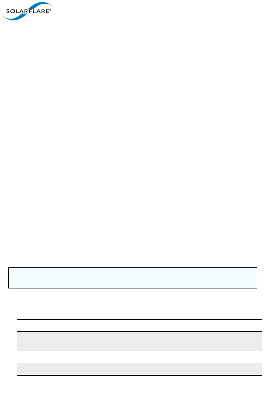
Issue 10 © Solarflare Communications 2013 213
Solarflare Server Adapter
User Guide
4.24 Sfcable: Cable Diagnostics Tool
• Sfcable: Command Usage...Page 213
• Sfcable: Command Line Options...Page 213
• Sfcable: Sample Commands...Page 215
Sfcable is a Windows command line utility to run cable diagnostics on the Solarflare 10GBASE-T
server adapters. A warning will be given if the adapter is not a 10GBASE-T adapter.
Sfcable: Command Usage
1Login with an administrator account.
2Click Start > All Programs > Solarflare Drivers > Command Line Tools. If you installed the
Solarflare system tray icon, you can right-click the icon and choose Command-line tools
instead.
3In the Command Prompt window, enter the following command:
sfcable [/Adapter <Identifier>] [options]
where:
Identifier is the name or ID of the adapter that you want to manage. Specifying the
adapter is optional - if it is not included the command is applied to all Solarflare adapters in the
machine.
option is the option you to apply. See Table 47 for a list of available options.
Sfcable: Command Line Options
Table 47 lists the command options for sfcable. Note that command line options are case insensitive
and may be abbreviated.
NOTE: Abbreviations in scripts should be avoided, since future updates to the application may
render your abbreviated scripts invalid.
Table 47: Sfcable Options
Options Description
/Help or /? or /H Displays command line syntax and provides a description
of each sfcable option.
/Version Shows detailed version information and exits.
/Nologo Hides the version and copyright message at startup.

Issue 10 © Solarflare Communications 2013 214
Solarflare Server Adapter
User Guide
/Verbose Shows extended output information for the command
entered.
/Quiet
Aliases: /Silent
Suppresses all output, including warnings and errors.
User should query the completion code to determine the
outcome of commands when operating silently (see,
Performance Tuning on Windows on page 236).
/Log <Filename> Logs output to the specified file in the current folder or
an existing folder. Specify /Silent to suppress
simultaneous output to screen, if required.
/Computer <ComputerName> Performs the operation on the identified remote
computer. Administrator rights on the remote host
computer is required.
/Adapter <Identifier> Performs the action on the identified Solarflare network
adapter. The identifier can be the adapter ID number,
name or MAC address, as given by the /List option.
/List Lists all available Solarflare adapters. This options shows
the adapter’s ID number, name and MAC address.
/Offline Stops network traffic while the diagnostic tests are
running. Running tests offline will produce more detailed
results.
Caution: The offline tests will disrupt data flow. It is not
recommended that the tests are run on a live system.
/DebugId (adapter_id> Debug-only. Identify an adapter to treat as being an iSCSI
boot device.
Table 47: Sfcable Options
Options Description

Issue 10 © Solarflare Communications 2013 215
Solarflare Server Adapter
User Guide
Sfcable: Sample Commands
• Run tests offline
sfcable /Offline
Sample output from a computer with two Solarflare adapters installed:
C:\Users\mas-admin>sfcable /Offline
Solarflare cable diagnostics utility [v3.0.3]
Copyright Solarflare Communications 2006-2010, Level 5 Networks 2002-2005
1 : Solarflare SFN5121T 10GBASE-T Server Adapter
MAC address: 00:0F:53:01:40:8C
Link state: Up
Link speed: 10 Gbps
Pair 1: OK, length=9m
Pair 2: OK, length=9m
Pair 3: OK, length=9m
Pair 4: OK, length=9m
2 : Solarflare SFN5121T 10GBASE-T Server Adapter #2
MAC address: 00:0F:53:01:40:8D
Link state: Up
Link speed: 10 Gbps
Pair 1: OK, length=9m
Pair 2: OK, length=9m
Pair 3: OK, length=9m
Pair 4: OK, length=9m

Issue 10 © Solarflare Communications 2013 216
Solarflare Server Adapter
User Guide
4.25 Sfnet
• Sfnet: Command Usage...Page 216
• Sfnet: Command Line Options...Page 217
• Sfnet: Sample Commands...Page 220
Sfnet is a Windows command line utility to configure the physical or virtual adapter settings, such
as checksum offloading, RSS, VMQ and Power Management.
Sfnet: Command Usage
1Login with an administrator account.
2Click Start > All Programs > Solarflare Network Adapter > Command Line Interface for
network adapters. If you installed the Solarflare system tray icon, you can right-click the icon
and choose Command-line tools instead.
3In the Command Prompt window, enter your command using the following syntax:
sfnet [/Adapter Identifier] [options]
where:
Identifier is the name or ID of the adapter that you want to manage. Specifying the
adapter is optional - if it is not included the command is applied to all Solarflare adapters in the
machine.
option is the option to apply. See Sfnet: Command Line Options for a list of available options.
To see all adapters installed on the computer and their current options and parameter settings
use the sfnet /List option.
NOTE: Changing these settings may significantly alter the performance of the adapter. You should
contact Solarflare technical support before changing any of these settings.

Issue 10 © Solarflare Communications 2013 217
Solarflare Server Adapter
User Guide
Sfnet: Command Line Options
Table 48 lists the command options for sfnet. Note that command line options are case insensitive
and may be abbreviated.
NOTE: Abbreviations in scripts should be avoided, since future updates to the application may
render your abbreviated scripts invalid.
Table 48: Sfnet Options
Options Description
/Help or /? or /H Displays command line syntax and provides a description
of each sfnet option.
/Version Shows detailed version information and exits.
/Nologo Hides the version and copyright message at startup.
/Verbose Shows extended output information for the command
entered.
/Quiet
Aliases: /Silent
Suppresses all output, including warnings and errors; no
user interaction. You should query the completion code
to determine the outcome of commands when operating
silently.
/Log <Filename> Logs output to the specified file in the current folder or
an existing folder. Specify silent to suppress
simultaneous output to screen, if required.
/Computer <ComputerName> Performs the operation on the identified remote host.
Administrator rights on the remote host computer is
required.
/Adapter <Identifier> Perform the action on the identified Solarflare physical
or virtual network adapter.
/List Lists all available Solarflare adapters, options and current
parameter settings.
/Id List output is limited to one line, containing the Id and
name, per adapter.
/StopOnWarning Exit the utility if a warning is output.
/Statistics Display adapter statistics and configuration settings for
Solarflare interfaces.

Issue 10 © Solarflare Communications 2013 218
Solarflare Server Adapter
User Guide
Table 49: Supported Key Value Parameter
Parameter Description
ipoffload=<enabled|disabled> Specify whether IPv4 checksum offload is enabled.
tcpoffload=<enabled|disabled> Specify whether TCP checksum offload is enabled.
Configures TCPv4 and TCPv6 where applicable.
udpoffload=<enabled|disabled> Specify whether UDP checksum offload is enabled.
Configures UDPv4 and UDPv6 where applicable.
lso=<enabled|disabled> Specify whether large send offload (LSO) is enabled.
Configures LSOv4 and LSOv6 where applicable.
lro=<enabled|disabled> Specify whether large receive offload (LRO) is
enabled. Configures LROv4 and LROv6 where
applicable.
flowcontrol=<auto|enabled|gene
rate|respond|disabled>
Specify Ethernet flow control. This option covers
the "Flow Control" and "Flow Control
Autonegotiation" device driver advanced
properties.
speed=<auto|10g|1g|100m> Specify the Ethernet link speed.
mtu=<MTU length> Specify the maximum Ethernet frame length. From
1518 to 9216 bytes (even values only).
rss=<disabled|optimized|system
|value|closest|closeststatic|n
uma|numastatic|conservative>
Specify the receive side scaling (RSS) mode. If a
value is given it must be in the range 0 to 16383.
rssbaseprocessor=<group>:<numb
er>
The base processor available for RSS. If a value is
given it must formated as <group>:<number>
where group is in the range 0-15 and number in the
range 0 to 63.
rssmaxprocessor=<group>:<numbe
r>
The maximum number of processors available for
RSS. If a value is given it must formated as
<group>:<number> where group is in the range 0-
15 and number in the range 0 to 63.
maxrssprocessors=<count> The maximum number of processors available for
RSS. If count is specified it must be in the range 1-
256. Support for this option is independent of the
version of the operating system and networking
stack.

Issue 10 © Solarflare Communications 2013 219
Solarflare Server Adapter
User Guide
rssqueuecount=<balanced|count> Specify the maximum number of receive queues to
use for RSS. If set to balanced the network adapter
will choose the number of queues based on the
system processor topology. If specified, count must
be one of 1|2|4|8|12|16|24|32|48|64.
Support for this option is independent of the
version of the operating system and networking
stack.
numanode=<all|value> The preferred NUMA node used by RSS. If a value is
given, it must be in the range 0-15. Support for this
option is independent of the version of the
operating system and networking stack.
moderation=<disabled|value> Specify interrupt moderation time (in micro-
seconds). If a value is given it must be in the range 1
to 1000. NOTE: this option covers the device driver
advanced properties "interrupt moderation time"
and "interrupt moderation".
adaptive=<enabled|disabled> Allows the adapter to vary interrupt moderation
automatically if interruptmoderation is
enabled.
wake=<enabled|disabled> Specify whether Wake-on-LAN is enabled.
sleep=<enabled|disabled> Specify whether the operating system can put the
device to sleep when the physical link goes down.
vmq=<enabled|nosplit|novlan|ba
sic|disabled>
enabled = VMQ enabled.
nosplit = VMQ enabled without lookahead split.
novlan = VMQ enabled without VLAN filtering.
basic = VMQ enabled MAC address filtering only.
disabled = VMQ disabled.
txbuffers=<count> Transmit buffer count (debug-only).
rxbuffers=<count> Receive buffer count (debug-only).
Table 49: Supported Key Value Parameter
Parameter Description

Issue 10 © Solarflare Communications 2013 220
Solarflare Server Adapter
User Guide
Sfnet: Sample Commands
List settings for all Solarflare adapters installed on the localhost:
sfnet /List
Solarflare Adapter CLI Application [v3.0.2]
Copyright Solarflare Communications 2006-2010, Level 5 Networks 2002-2005
Solarflare SFN5122F Dual Port SFP+ Server Adapter:
Id 1D1
MAC address 00:0F:53:01:39:0C
IP checksum offload Enabled
TCP checksum offload Enabled
UDP checksum offload Enabled
LSO Enabled
LRO Disabled
Ethernet flow control Negotiated automatically
Link speed Negotiated automatically
MTU/frame length 1518
RSS Optimized
NUMA node id All
Interrupt moderation 60 micro-seconds
Wake on LAN Not supported
Sleep on link down Not supported
Solarflare SFN5122F Dual Port SFP+ Server Adapter #2:
Id 2D1
MAC address 00:0F:53:01:39:0D
IP checksum offload Enabled
TCP checksum offload Enabled
UDP checksum offload Enabled
LSO Enabled
LRO Disabled
Ethernet flow control Negotiated automatically
Link speed Negotiated automatically
MTU/frame length 1518
RSS Optimized
NUMA node id All
Interrupt moderation 60 micro-seconds
Wake on LAN Not supported
Sleep on link down Not supported

Issue 10 © Solarflare Communications 2013 221
Solarflare Server Adapter
User Guide
4.26 Completion codes (%errorlevel%)
Table 50 lists the completion codes returned by the command line utilities. The code may be
determined by inspecting %errorlevel%
Table 50: Completion Codes
Error code Description
0Success.
1The application was invoked with /? or /help.
3The application was invoked with /version.
16 Application cancelled (user probably pressed CTRL-C).
17 Application has requested a reboot.
18 Reboot is necessary to complete the action.
19 Incomplete team creation.
Team has been created and whatever adapters that could be added
have been, and the VLANs (if any) have been created. Some adapters
were not able to be added.
32 Application failed initialization.
33 Access denied.
Either the remote host refused a connection on the basis of account
privileges, or a file could not be opened.
34 Cannot connect.
The remote host could not be found or refused the connection
because the WMI service was inaccessible (either because the service
is not running or because there is a firewall or security policy
preventing it being accessed remotely).
35 WMI classes exposed by the Solarflare drivers missing.
Usually this means that either the driver have not been installed, no
Solarflare adapters are present, or adapters have been disabled.
36 Failed to obtain driver lock.
The application has tried to take the Solarflare driver lock because it
wants to do something that must not be interrupted by another utility
(or SAM) and failed to do so.
37 Adapter not found.
Cannot find the adapter specified by /adapter.

Issue 10 © Solarflare Communications 2013 222
Solarflare Server Adapter
User Guide
38 Adapter not specified.
Command line is missing the /adapter option.
39 Later version already installed.
128 User entered an invalid command line.
129 Could not open log file.
130 A general WMI error occurred.
Can occur when the connection is lost.
131 Missing prerequisite.
The application needs something that is not present in the system.
132 Not supported.
133 Platform/System not supported.
255 General exit failure.
Table 50: Completion Codes
Error code Description

Issue 10 © Solarflare Communications 2013 223
Solarflare Server Adapter
User Guide
4.27 Teaming and VLANs
About Teaming
Solarflare adapters support the following teaming configurations:
• IEEE 802.1AX (802.3ad) Dynamic link aggregation
• Static link aggregation
• Fault tolerant teams
Teaming allows the user to configure teams consisting of all Solarflare adapter ports on all installed
Solarflare adapters or might consist only of selected ports e.g. from a dual port Solarflare adapter,
the first port could be a member of team A and the second port a member of team B or both ports
members of the same team.
This section is only relevant to teams of Solarflare adapters. Solarflare adapters can be used in multi-
vendor teams when teamed using another vendor’s teaming driver.
Creating Teams and VLANs
To set up teams and VLANs in Windows using SAM, see Using SAM to Configure Teams and VLANs
on page 158.
To set up teams and VLANs in Windows using the sfteam command line tool, see Sfteam: Adapter
Teaming and VLAN Tool on page 206.
Link Aggregation
Link aggregation is a mechanism for supporting load balancing and fault tolerance across a team of
network adapters and their associated switch. Link aggregation is a partner teaming mode that
requires configuration at both ends of the link. Once configured, all links in the team are bonded into
a single virtual link with a single MAC address.
Two or more physical links are used to increase the potential throughput available between the link
partners, and also improve resilience against link failures. To be aggregated, all links in the team must
be between the same two link partner and each link must be full-duplex. Traffic is distributed evenly
to all links connected to the same switch. In case of link failover, traffic on the failed link will be re-
distributed to the remaining links.
Link aggregation offers the following functionality:
NOTE: Adapter teaming and VLANs are not supported in Windows for iSCSI remote boot enabled
Solarflare adapters. To configure load balancing and failover support on iSCSI remote boot enabled
adapters, you can use Microsoft MultiPath I/O (MPIO), which is supported on all Solarflare
adapters.
NOTE: Windows Server 2012 has native Windows teaming support. The user can elect to use native
windows driver of the Solarflare teaming, but the two methods should not be mixed.

Issue 10 © Solarflare Communications 2013 224
Solarflare Server Adapter
User Guide
• Teams can be built from mixed media (i.e. UTP and Fibre).
• All protocols can be load balanced without transmit or receive modifications to frames.
• Multicast and broadcast traffic can be load balanced.
• Short recovery time in case of failover.
• Solarflare supports up to 64 link aggregation port groups per system.
• Solarflare supports up to 64 ports and VLANs in a link aggregation port group.
There are two methods of link aggregation, dynamic and static.
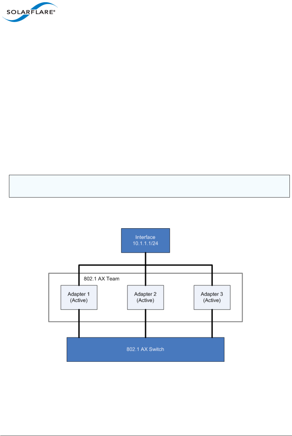
Issue 10 © Solarflare Communications 2013 225
Solarflare Server Adapter
User Guide
Dynamic Link Aggregation
Dynamic link aggregation uses the Link Aggregation Control Protocol (LACP) as defined in the IEEE
802.1AX standard (previously called 802.3ad) to negotiate the ports that will make up the team.
LACP must be enabled at both ends of the link for a team to be operational.
LACP will automatically determine which physical links can be aggregated, and will then perform the
aggregation.
An optional LACP marker protocol provides functionality when adding and removing physical links
ensuring that no frames are lost, reordered or duplicated.
Dynamic link aggregation offers both fault tolerance and load balancing.
Standby links are supported, but are not considered part of a link aggregation until a link within the
aggregation fails.
VLANs are supported within 802.1AX teams.
In the event of failover, the load on the failed link is redistributed over the remaining links.
Figure 37 shows a 802.1AX Team configuration.
Figure 37: 802.1AX Team
NOTE: Your switch must support 802.1AX (802.3ad) dynamic link aggregation to use this method of
teaming.
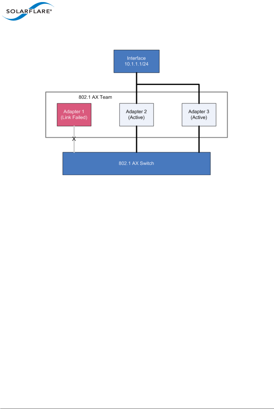
Issue 10 © Solarflare Communications 2013 226
Solarflare Server Adapter
User Guide
Figure 38 shows a 802.1AX team with a failed link. All traffic is re-routed and shared between the
other team links.
Figure 38: 802.1AX with Failed Link
Static Link Aggregation
Static link aggregation is a switch assisted teaming mode that requires manual configuring of the
ports at both ends of the link. Static link aggregation is protocol independent and typically inter-
operates with common link aggregation schemes such as Intel Link Aggregation, Cisco Fast
EtherChannel and Cisco Gigabit EtherChannel.
With static link aggregation, all links share the traffic load and standby links are not supported.
Static link aggregation offers both fault tolerance and load balancing.
In the event of failover, the load on the failed link is redistributed over the remaining links.
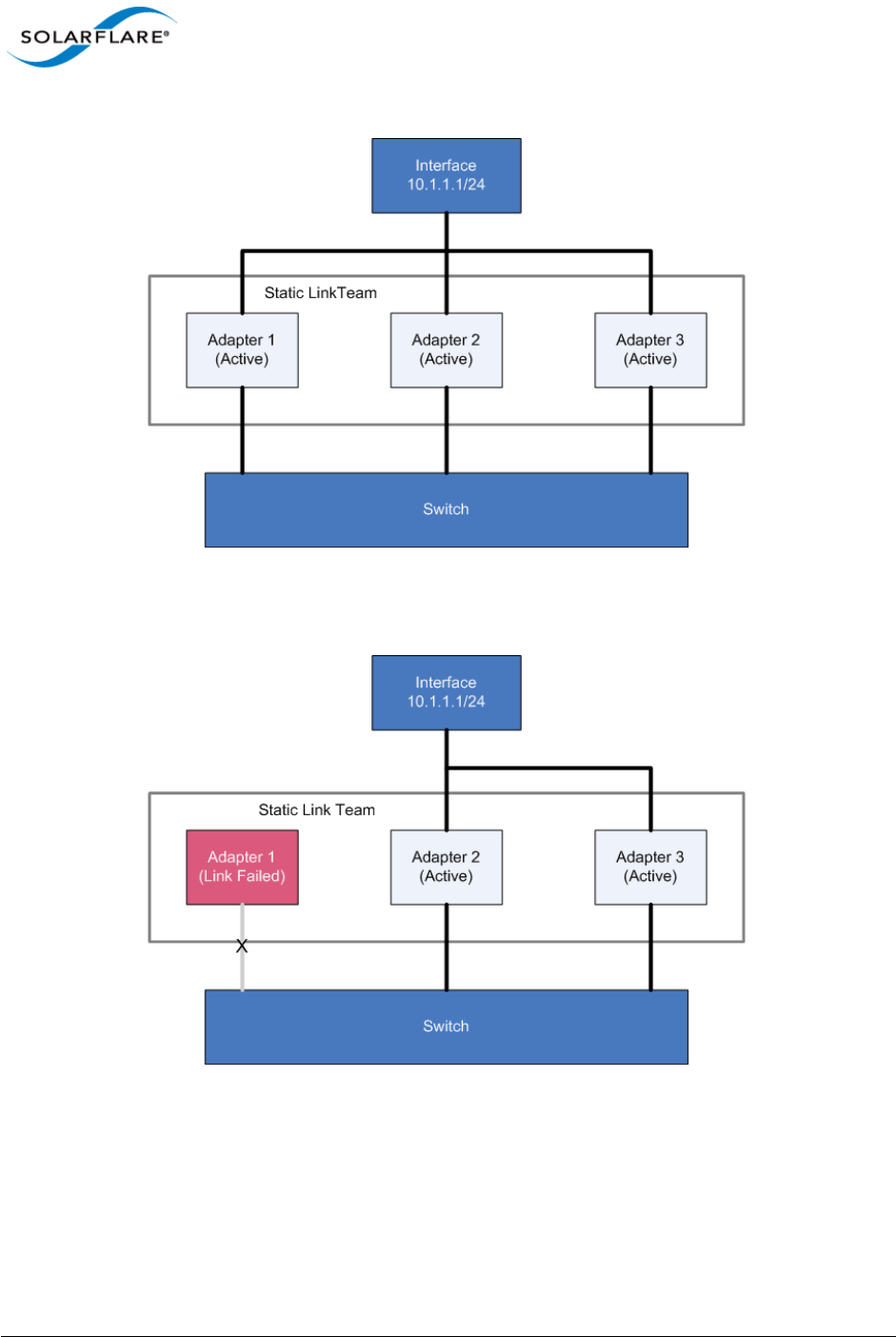
Issue 10 © Solarflare Communications 2013 227
Solarflare Server Adapter
User Guide
Figure 39: Static Link Aggregation Team
Figure 40: Static Link Team with Failed Link
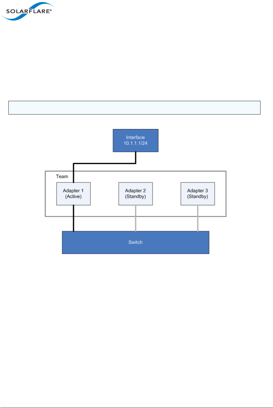
Issue 10 © Solarflare Communications 2013 228
Solarflare Server Adapter
User Guide
Fault-Tolerant Teams
Fault tolerant teaming can be implemented on any switch. It can also be used with each network link
connected to separate switches.
A fault-tolerant team is a set of one or more network adapters bound together by the adapter driver.
A fault-tolerant team improves network availability by providing standby adapters. At any one
moment no more than one of the adapters will be active with the remainder either in standby or in
a fault state. In Figure 41, Adapter 1 is active and all data to and from the switch passes through it.
Figure 41: Fault Tolerant Team
Failover
The teaming driver monitors the state of the active adapter and, in the event that its physical link is
lost (down) or that it fails in service, swaps to one of the standby adapters. In Figure 42 the
previously active adapter has entered a failed state and will not be available in the standby list while
the failed state persists.
NOTE: All adapters in a fault-tolerant team must be part of the same broadcast domain.
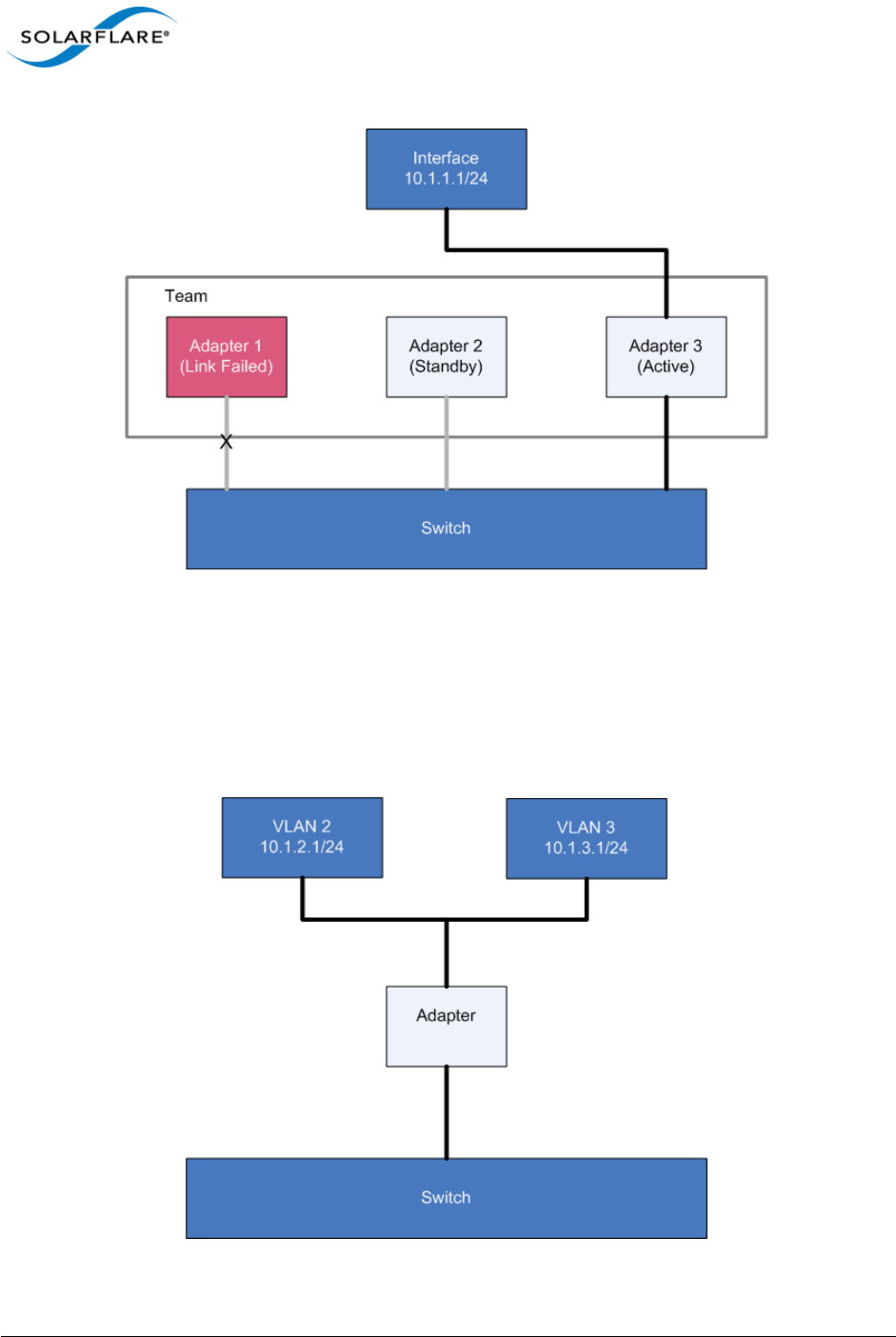
Issue 10 © Solarflare Communications 2013 229
Solarflare Server Adapter
User Guide
Figure 42: Adapter 1 Failure
Note that, in this example, Adapter 3 is now active. The order in which the adapters are used is
determined by a number of factors, including user-definable rank.
VLANs
VLANs offer a method of dividing one physical network into multiple broadcast domains.
Figure 43: VLANs routing through Solarflare adapter
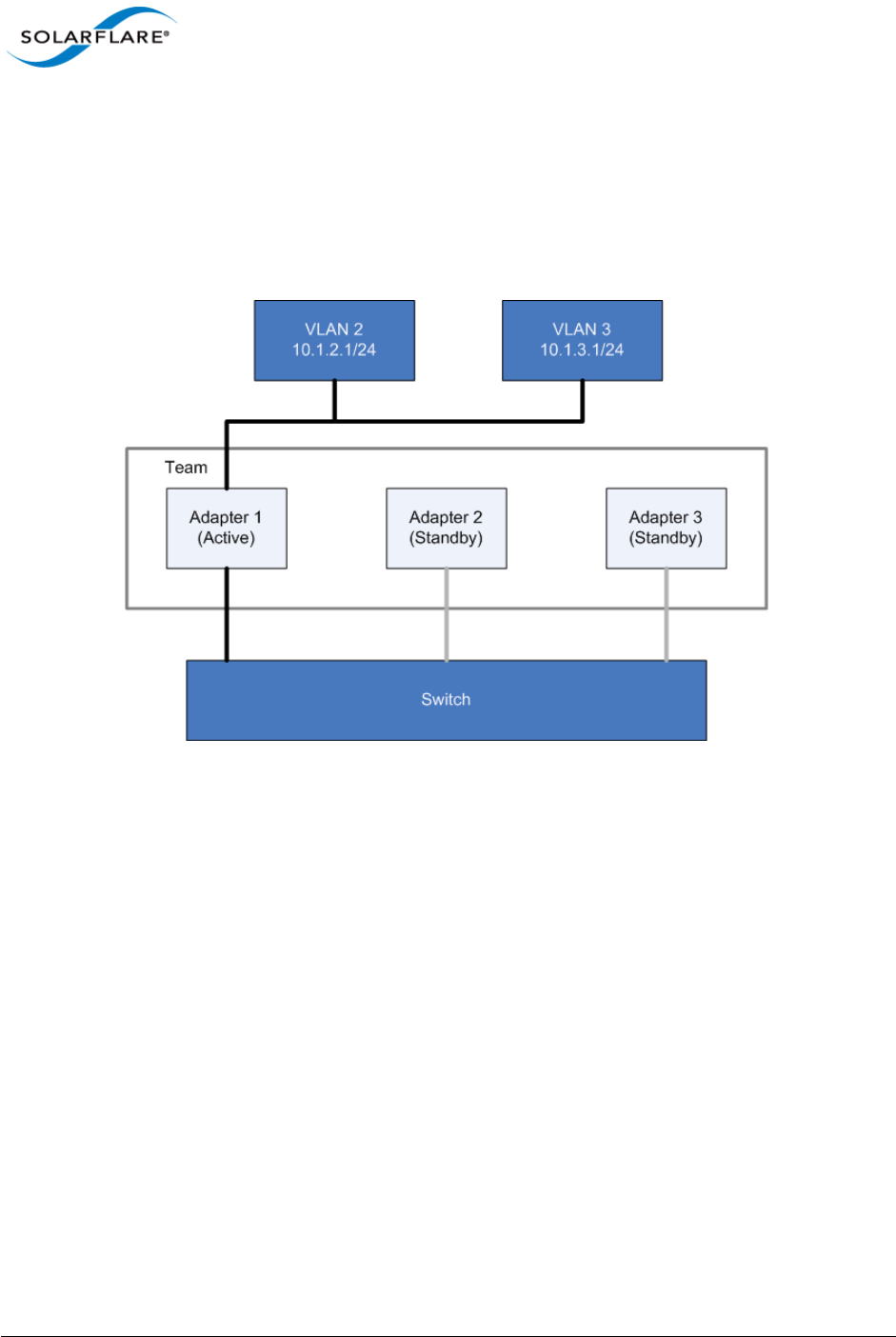
Issue 10 © Solarflare Communications 2013 230
Solarflare Server Adapter
User Guide
VLANs and Teaming
VLANs are supported on all Solarflare adapter teaming configurations.
VLANs with Fault Tolerant Teams
Figure 44 shows a fault tolerant team with two VLANs.
Figure 44: Fault Tolerant VLANs
Failover works in the same way regardless of the number of VLANs, as show in Figure 45.
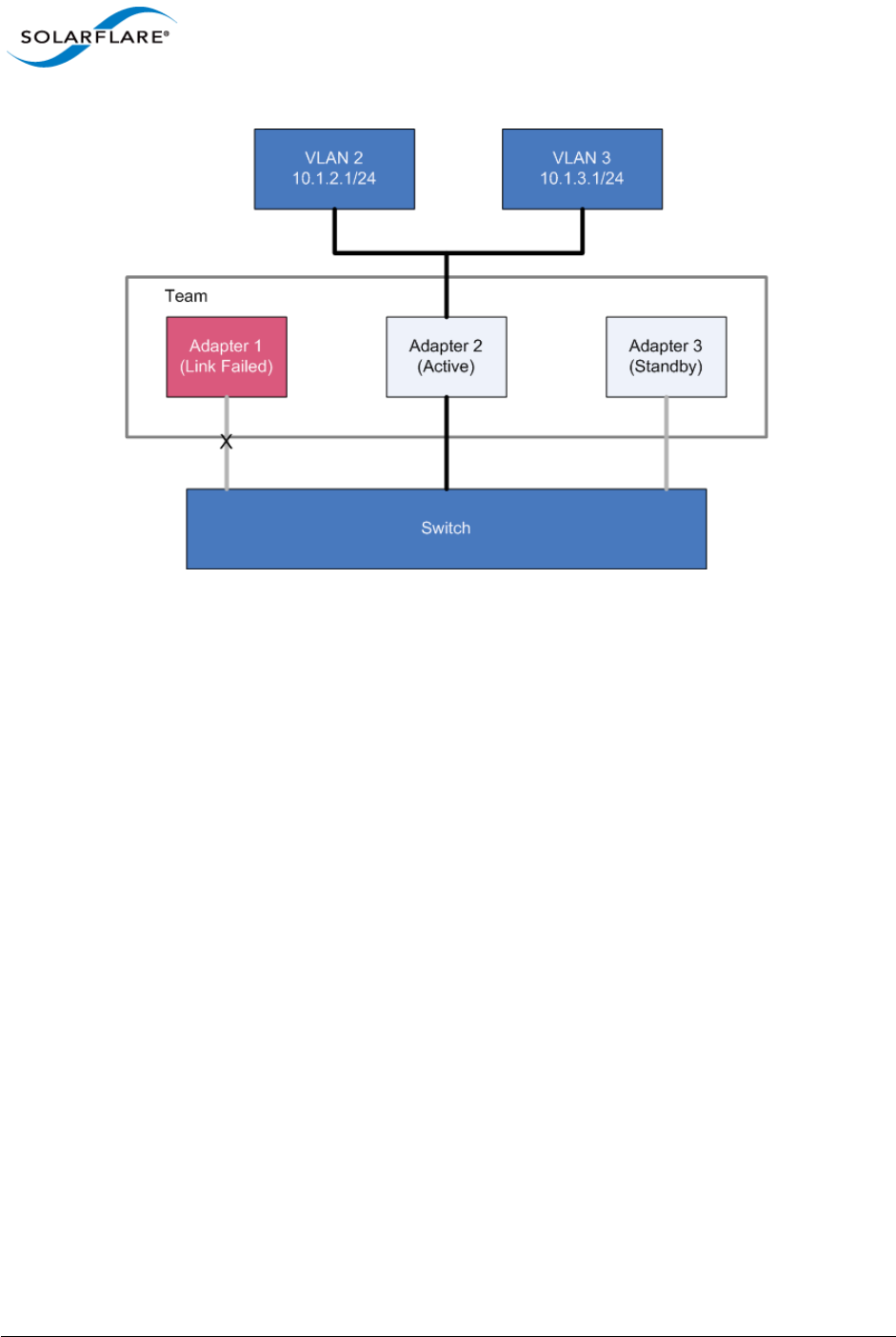
Issue 10 © Solarflare Communications 2013 231
Solarflare Server Adapter
User Guide
Figure 45: Failover in Fault Tolerant Team VLAN
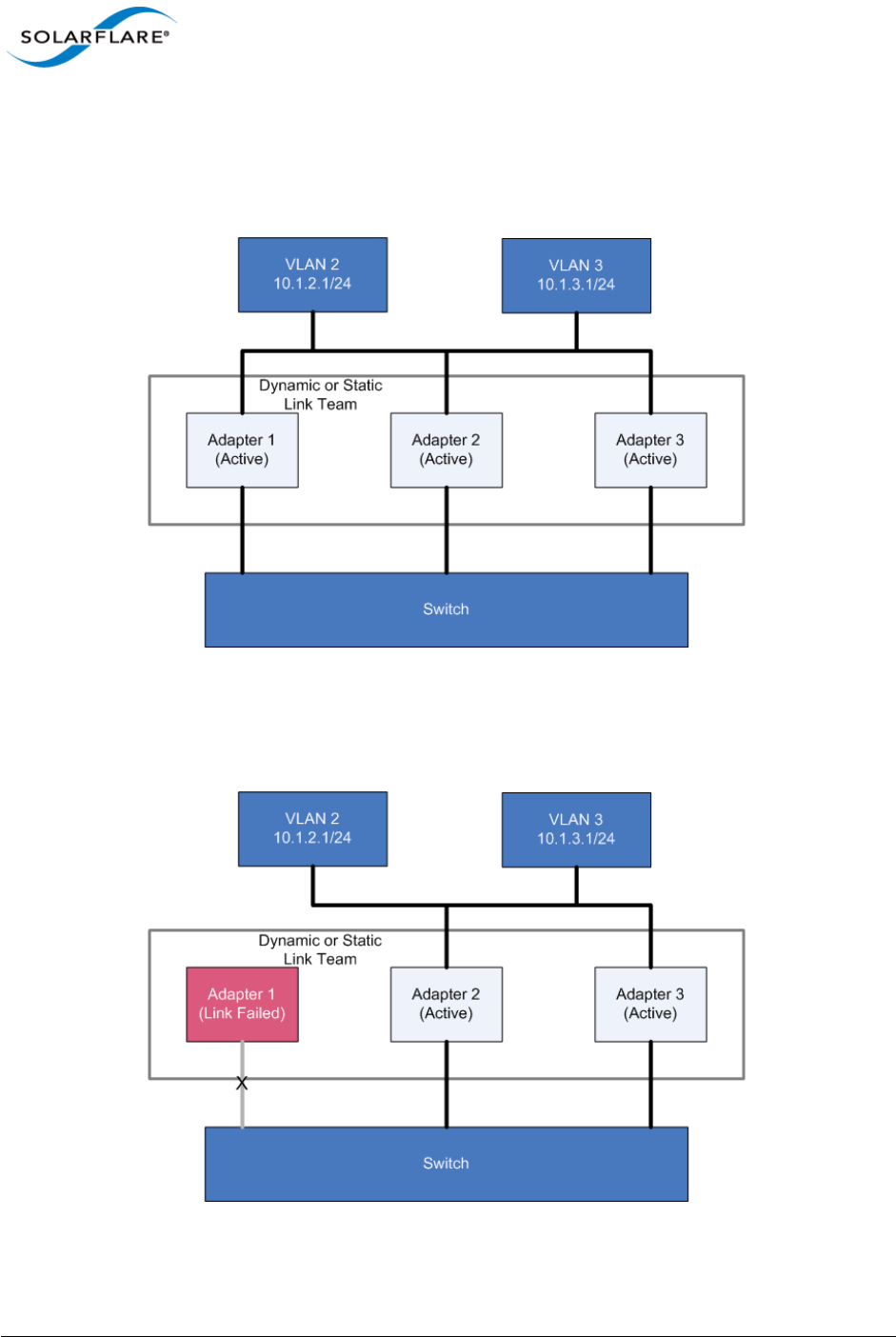
Issue 10 © Solarflare Communications 2013 232
Solarflare Server Adapter
User Guide
VLANs with Dynamic or Static Link Aggregation Teams
VLANs work in the same way with either Dynamic or Static Link Aggregation teaming
configurations.Figure 46 shows how VLANs work with these teams.
Figure 46: VLAN with Dynamic or Static Link Team
In case of link failure, all traffic is distributed over the remaining links, as in Figure 47.
Figure 47: VLAN with Failed Dynamic or Static Team Link
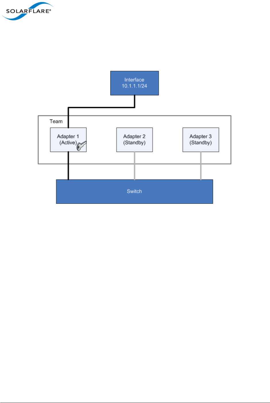
Issue 10 © Solarflare Communications 2013 233
Solarflare Server Adapter
User Guide
Key Adapter
Every team must have a key adapter. Figure 48 shows Adapter 1 as both the Key and the active
adapter. in a Fault-Tolerant Team.
Figure 48: Key Adapter in Fault Tolerant Team
The key adapter must be a member of a team. However, it does not need to be the active adapter.
It doesn't even need to be in the list of standby adapters but it must physically be within its host. The
Key Adapter defines the team's RSS support (see Receive Side Scaling (RSS) on page 240) and
provides the MAC Address that will be used for all traffic sent and received by the team.
When a link failure occurs in the active adapter (for example the physical link is lost) the driver will
select another adapter to become active but it will not re-assign the Key Adapter. In Figure 49,
Adapter 1 has failed and the team is now using Adapter 2 for all traffic.

Issue 10 © Solarflare Communications 2013 234
Solarflare Server Adapter
User Guide
Figure 49: Failover Key Adapter
Note that although the Key Adapter (Adapter 1) has a link failure, the integrity of the team is not
affected by this failure.
Dynamic and Static Link Aggregation Teams
The assignment of key adapters is supported in both dynamic and static link aggregated teams, and
works in the same way for both.
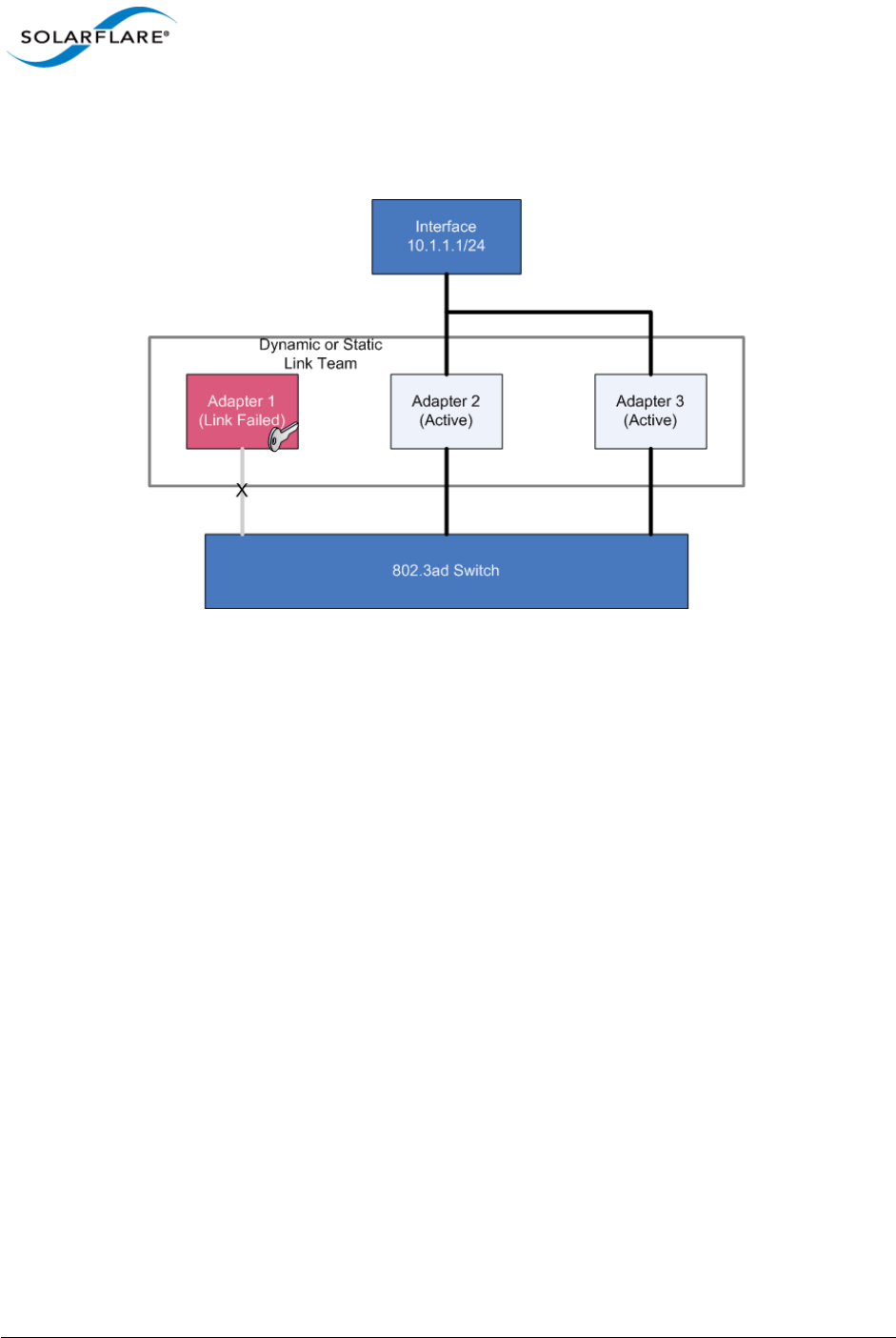
Issue 10 © Solarflare Communications 2013 235
Solarflare Server Adapter
User Guide
Any link failure on the key adapter does not affect the redistribution of traffic to the other links in
the team.

Issue 10 © Solarflare Communications 2013 236
Solarflare Server Adapter
User Guide
4.28 Performance Tuning on Windows
• Introduction...Page 236
• Tuning Settings...Page 237
• Other Considerations...Page 241
• Benchmarks...Page 246
Introduction
The Solarflare family of network adapters are designed for high-performance network applications.
The adapter driver is pre-configured with default performance settings that have been designed to
give good performance across a broad class of applications. Occasionally, application performance
can be improved by tuning these settings to best suit the application.
There are three metrics that should be considered when tuning an adapter:
• Throughput
• Latency
• CPU utilization
Different applications may be more or less affected by improvements in these three metrics. For
example, transactional (request-response) network applications can be very sensitive to latency
whereas bulk data transfer applications are likely to be more dependent on throughput.
The purpose of this section is to highlight adapter driver settings that affect the performance metrics
described. This guide covers the tuning of all Solarflare adapters.
Latency will be affected by the type of physical medium used: 10GBase-T, twinaxial (direct-attach),
fiber or KX4. This is because the physical media interface chip (PHY) used on the adapter can
introduce additional latency.
This section is designed for performance tuning Solarflare adapters on Microsoft Windows. This
should be read in conjunction with the reference design board errata documents and the following
Microsoft performance tuning guides:
• Performance Tuning Guidelines for Windows Server 2008
http://www.microsoft.com/whdc/system/sysperf/Perf_tun_srv.mspx
• Performance Tuning Guidelines for Windows Server 2008 R2
http://msdn.microsoft.com/en-us/library/windows/hardware/gg463392.aspx
• Performance Tuning Document for Windows Server 2003
http://download.microsoft.com/download/2/8/0/2800a518-7ac6-4aac-bd85-74d2c52e1ec6/
tuning.doc
• Performance Tuning Guidelines for Windows XP
• http://technet.microsoft.com/en-us/library/bb457057.aspx

Issue 10 © Solarflare Communications 2013 237
Solarflare Server Adapter
User Guide
In addition, you may need to consider other issues influencing performance, such as application
settings, server motherboard chipset, CPU speed, Cache size, RAM size, additional software installed
on the system, such as a firewall, and the specification and configuration of the LAN. Consideration
of such issues is not within the scope of this guide.
Tuning Settings
Tuning settings for the Solarflare adapter are available through the Solarflare Adapter Manager
(SAM) utility, or via the Advanced tab in the Windows Device Manager (right-click the adapter and
select Properties). See Using SAM to Configure Adapter Features on page 146 and Configuring
Network Adapter Properties in Windows on page 180 for more details.
Table 51 lists the available tuning settings for Solarflare adapters on Windows.
Table 51: Tuning Settings
Setting
Supported on
Windows Server 2003/2003
R2/Windows XP
Supported on
Windows Server 2008/2008
R2/Windows 7 /Windows
Server 2012
Adaptive Interrupt Moderation Yes Yes
Interrupt moderation Yes Yes
Interrupt Moderation Time Yes Yes
Large receive offload (IPv4) No Yes
Large Receive Offload (IPv6) No not SFN4112F
Large send offload (IPv4)
version 1
Yes No
Large send offload (IPv6)
version 1
not SFN4112F No
Large send offload (IPv4)
version 2
No Yes
Large send offload (IPv6)
version 2
No not SFN4112F
Max Frame Size Yes Yes
Offload IPv4 checksum Yes Yes
Offload TCP checksum (IPv4) Yes Yes
Offload TCP checksum (IPv6) not SFN4112F not SFN4112F
Offload UDP checksum (IPv4) Yes Yes
Offload UDP checksum (IPv6) not SFN4112F not SFN4112F

Issue 10 © Solarflare Communications 2013 238
Solarflare Server Adapter
User Guide
Maximum Frame Size
The default maximum frame size ensures that the adapter is compatible with legacy 10/100Mbps
Ethernet endpoints. However if a larger maximum frame size is used, adapter throughput and CPU
utilization can be improved. CPU utilization is improved, because it takes fewer packets to send and
receive the same amount of data. Solarflare adapters supports maximum frame sizes up to 9216
bytes (this does not include CRC).
Since the maximum frame size should ideally be matched across all endpoints in the same LAN
(VLAN) and the LAN switch infrastructure must be able to forward such packets, the decision to
deploy a larger than default maximum frame size requires careful consideration. It is recommended
that experimentation with maximum frame size be done in an application test environment.
The maximum frame size is changed by changing the Max Frame Size setting in the Network
Adapter’s Advanced Properties Page.
Interrupt Moderation (Interrupt Coalescing)
Interrupt moderation reduces the number of interrupts generated by the adapter by coalescing
multiple received packet indications and/or transmit completion events together into a single
interrupt. The amount of time the adapter waits after the first event until the interrupt is generated
is the interrupt moderation interval.
Solarflare adapters, by default, use an adaptive algorithm where the interrupt moderation delay is
automatically adjusted between zero (no interrupt moderation) and 60 microseconds. The adaptive
algorithm detects latency sensitive traffic patterns and adjusts the interrupt moderation interval
accordingly. The adaptive algorithm can be disabled to reduce jitter and the moderation interval set
higher/lower as required to suit conditions.
For lowest latency, interrupt moderation should be disabled. This will increase the number of
interrupts generated by the network adapter and as such increase CPU utilization.
Receive Side Scaling (RSS) Yes Yes
RSS Interrupt Balancing Yes Yes
RSS Numa Node No Yes
NOTE: The maximum frame size setting should include the Ethernet frame header. The Solarflare
drivers support 802.1p. This allows Solarflare adapters on Windows to optionally transmit packets
with 802.1p tags for QOS applications. It requires an Ethernet frame header size of 18bytes
(6bytes source MAC address, 6bytes destination MAC. 2bytes ethertype and 4bytes priority tag.
The default maximum frame sizes is therefore: 1518 bytes.
Table 51: Tuning Settings
Setting
Supported on
Windows Server 2003/2003
R2/Windows XP
Supported on
Windows Server 2008/2008
R2/Windows 7 /Windows
Server 2012

Issue 10 © Solarflare Communications 2013 239
Solarflare Server Adapter
User Guide
Interrupt moderation settings are critical for tuning adapter latency. Increasing the moderation
time may increase latency, but reduce CPU utilization and improve peak throughput, if the CPU is
fully utilized. Decreasing the moderation time value or turning it off will decrease latency at the
expense of CPU utilization and peak throughput. However, for many transaction request-response
type network applications, the benefit of reduced latency to overall application performance can be
considerable. Such benefits typically outweigh the cost of increased CPU utilization.
Interrupt moderation can be disabled by setting the Interrupt Moderation setting to disabled in the
Network Adapter’s Advanced Properties Page. The interrupt moderation time value can also be
configured from the Network Adapter’s Advanced Properties Page.
Interrupt Moderation Interval
The interrupt moderation interval is measured in microseconds. When the interval expires the
adapter will generate a single interrupt for all packets received since the last interrupt and/or for all
transmit complete events since the last interrupt.
Increasing the interrupt moderation interval will:
• generate less interrupts
• reduce CPU utilization (because there are less interrupts to process)
• increase latency
• improve peak throughput
Decreasing the interrupt moderation interval will:
• generate more interrupts
• increase CPU utilization (because there are more interrupts to process)
• decrease latency
• reduce peak throughput
TCP/IP Checksum Offload
Checksum offload defers the calculation and verification of IP Header, TCP and UDP packet
checksums to the adapter. The driver has all checksum offload features enabled by default.
Therefore, there is no opportunity to improve performance from the default.
Checksum offload configuration is changed by changing the Offload IP checksum, Offload UDP
checksum and Offload TCP checksum settings in the Network Adapter’s Advanced Properties Page.
Large Send Offload (LSO)
Large Send offload (LSO; also known as TCP Segmentation Offload/TSO) offloads the splitting of
outgoing TCP data into packets to the adapter. LSO benefits applications using TCP. Applications
using protocols other than TCP will not be affected by LSO.
Enabling LSO will reduce CPU utilization on the transmit side of a TCP connection and improve peak
throughput, if the CPU is fully utilized. Since LSO has no affect on latency, it can be enabled at all
times. The driver has LSO enabled by default on Windows Server 2008, 2008 R2 and Windows 7.

Issue 10 © Solarflare Communications 2013 240
Solarflare Server Adapter
User Guide
LSO is changed by changing the Large Send Offload setting in the Network Adapter’s Advanced
Properties Page. TCP and IP checksum offloads must be enabled for LSO to work.
Large Receive Offload (LRO)
Windows XP, Windows 2003, Windows Server 2008, Windows Server 2008 R2, Windows 7,
Windows Server 2012.
TCP Large Receive Offload (LRO) is a feature whereby the adapter coalesces multiple packets
received on a TCP connection into a single larger packet before passing this onto the network stack
for receive processing. This reduces CPU utilization and improves peak throughput when the CPU is
fully utilized. The effectiveness of LRO is bounded by the interrupt moderation delay and in itself,
enabling LRO does not negatively impact latency. LRO is a Solarflare proprietary implementation of
the Windows Receive Side Coalescing feature. LRO is disabled by default and should not be enabled
if the host is forwarding received packets from one interface to another.
LRO is set by changing the Large Receive Offload settings in the Network Adapter’s Advanced
Properties Page. TCP /IP checksum offloads must be enabled for LRO to work. The Solarflare network
adapter driver does not enable LRO by default..
Receive Side Scaling (RSS)
Receive Side Scaling (RSS) was first supported as part of the scalable networking pack for Windows
Server 2003 and has been improved with each subsequent operating system release. RSS is enabled
by default and will be used on network adapters that support it. Solarflare recommend that RSS is
enabled for best networking performance.
For further information about using RSS on Windows platforms see the Microsoft white paper
"Scalable Networking: Eliminating the Receive Processing Bottleneck—Introducing RSS"
This is available from:
http://download.microsoft.com/download/5/D/6/5D6EAF2B-7DDF-476B-93DC-7CF0072878E6/
NDIS_RSS.doc
By default RSS supports spreading the network receive processing workload across 4 CPU cores.
Solarflare recommend this value is increased to 8 CPU cores.
On Windows Server 2003, the value is increased by editing the Windows registry:
"HKEY_LOCAL_MACHINE\System\CurrentControlSet\Services\Tcpip\Parameters"
and adding or modifying the following values:
•Name: MaxNumRssCpus
- Type: DWORD (32-bit) value
- Data (Decimal): 8
NOTE: Solarflare recommend that you do not disable this setting.
NOTE: LRO should NOT be enabled when using the host to forward packets from one
interface to another. For example, if the host is performing IP routing.

Issue 10 © Solarflare Communications 2013 241
Solarflare Server Adapter
User Guide
On Windows Server 2008 and later, the same value is added or modified but under the
"HKLM\System\CurrentControlSet\Services\NDIS\Parameters" .
The Solarflare driver package installer makes these changes automatically if the "Optimize Windows
TCP/IP protocol settings for 10G networking" is selected during the setup wizard.
On Windows Server 2008 R2 and Windows 7, specific RSS parameters can be tuned on a per-adapter
basis. For details see the Microsoft white paper "Networking Deployment Guide: Deploying High-
Speed Networking Features" available from:
http://download.microsoft.com/download/8/E/D/8EDE21BC-0E3B-4E14-AAEA-9E2B03917A09/
HSN_Deployment_Guide.doc
Solarflare network adapters optimize RSS settings by default on Windows operating systems (not
Windows XP) and offer a number of RSS interrupt balancing modes via the network adapter's
advanced property page in Device Manager and Solarflare's adapter management tools.
RSS NUMA Node
The adapter driver chooses a subset of the available CPU cores to handle transmit and receive
processing. The RSS NUMA Node setting can be used to constrain the set of CPU cores considered
for processing to those on the given NUMA Node.
To force processing onto a particular NUMA Node, change the RSS NUMA Node setting on the
Network Adapter's Advanced Properties Page.
Other Considerations
PCI Express Lane Configurations
The PCI Express (PCIe) interface used to connect the adapter to the server can function at different
speeds and widths. This is independent of the physical slot size used to connect the adapter. The
possible widths are multiples x1, x2, x4, x8 and x16 lanes of (2.5Gbps for PCIe Gen 1, 5.0 Gbps for
PCIe Gen 2) in each direction. Solarflare adapters are designed for x8 lane operation.
On some server motherboards, choice of PCIe slot is important. This is because some slots (including
those that are physically x8 or x16 lanes) may only electrically support x4 lanes. In x4 lane slots,
Solarflare PCIe adapters will continue to operate, but not at full speed. The Solarflare driver will
insert a warning in the Windows Event Log if it detects that the adapter is plugged into a PCIe slot
which electrically has fewer than x8 lanes.
For SFN5xxx and SFN6xxx Solarflare adapters, which require a PCIe Gen 2 x8 slot for optimal
operation, a warning will also be inserted into the Windows Event Log if the adapter is installed in a
PCIe Gen 1 slot.
In addition, the latency of communications between the host CPUs, system memory and the
Solarflare PCIe adapter may be PCIe slot dependant. Some slots may be “closer” to the CPU, and
therefore have lower latency and higher throughput. Please consult your server user guide for more
information.
NOTE: Solarflare recommend that you do not change this setting.

Issue 10 © Solarflare Communications 2013 242
Solarflare Server Adapter
User Guide
Memory bandwidth
Many chipsets use multiple channels to access main system memory. Maximum memory
performance is only achieved when the chipset can make use of all channels simultaneously. This
should be taken into account when selecting the number of memory modules (DIMMs) to populate
in the server. Consult the motherboard documentation for details, however it’s likely that populating
all DIMM slots will be needed for optimal memory bandwidth in the system.
BIOS Settings
DELL Systems
Refer to the BIOS configuration guidelines recommended by Dell's white paper "Configuring Low-
Latency Environments on Dell PowerEdge Servers" available from:
http://i.dell.com/sites/content/business/solutions/whitepapers/en/Documents/configuring-dell-
poweredge-servers-for-low-latency-12132010-final.pdf
HP Systems
Refer to the BIOS configuration guidelines recommended by HP's white paper "Configuring the HP
ProLiant Server BIOS for Low-Latency Applications" available from:
http://h20000.www2.hp.com/bc/docs/support/SupportManual/c01804533/c01804533.pdf
Although targeted at tuning for real-time operating systems, the recommendations equally apply to
Windows Server platforms.
Other system vendors may publish similar recommendations. In general any BIOS settings guidelines
that are targeted at increasing network performance whilst minimizing latency and jitter are
applicable to all operating systems.
Intel® QuickData / NetDMA
On systems that support Intel I/OAT (I/O Acceleration Technology) features such as QuickData (a.k.a
NetDMA), Solarflare recommend that these are enabled as they are rarely detrimental to
performance.
Using Intel® QuickData Technology allows data copies to be performed by the system and not the
operating system. This enables data to move more efficiently through the server and provide fast,
scalable, and reliable throughput.
Windows Server 2003 and Windows XP
With Microsoft's Scalable Networking Pack, NetDMA is enabled as follows:
• I/OAT must first be enabled in the BIOS
• Download the Intel I/OAT drivers for example refer to:
http://downloadcenter.intel.com/detail_desc.aspx?agr=Y&DwnldID=12193).
• Run IOATDMA.exe to unpack the I/OAT device drivers.

Issue 10 © Solarflare Communications 2013 243
Solarflare Server Adapter
User Guide
• In Device Manager look for an unrecognized device named “Base System Device” in “Other
devices”. If there is more than one such device the I/OAT controller is the one with PCI vendor id
of 0x8086 and device id of 0x1a38.
• Right click on the I/OAT device and select 'Update driver software' and navigate to the directory
where the IOATDMA.exe unpacked the drivers.
Windows Server 2008, Windows Server 2008 R2,Windows 7 and Windows Server 2012
To enable NetDMA the EnableTCPA variable must be set to 1 in the Tcpip\Parameters registry
key. Locate the following key in the registry:
HKEY_LOCAL_MACHINE\SYSTEM\CurrentControlSet\Services\Tcpip\Parameters
The EnableTCPA value must be created if it is not present and set to 1:
EnableTCPA = 1
Intel Hyper-Threading Technology
On systems that support Intel Hyper-Threading Technology users should consider benchmarking or
application performance data when deciding whether to adopt hyper-threading on a particular
system and for a particular application. Solarflare have identified that hyper-threading is generally
beneficial on systems fitted with Core i5, Core i7 and Xeon (Nehalem or later) CPUs when used in
conjunction with Windows Server 2008 or later.
TCP/IP Options
Solarflare recommend the following settings to ensure that TCP operation on Windows Server 2003
and Windows XP is optimized for 10Gbit networking. The values can be changed in the windows
registry:
"HKEY_LOCAL_MACHINE\System\CurrentControlSet\Services\Tcpip\Parameters"
• Name: SackOpts - to enable TCP SACK
- Type: DWORD (32-bit) value
- Data (Decimal): 1
• Name: Tcp1323Opts - to enable TCP time-stamp and window scaling option
- Type: DWORD (32-bit) value
- Data (Decimal): 3
• Name: TcpWindowSize - increase TCP windows size
- Type: DWORD (32-bit) value
- Data (Decimal): 524288
This increases the TCP window size from its default of 64 Kbytes to 512 Kbytes, which is much more
suitable for the bandwidth delay product of 10 gigabit connections
The Solarflare driver package installer automatically configures these settings if the "Optimize
Windows TCP/IP protocol settings for 10G networking" is selected during the setup wizard.

Issue 10 © Solarflare Communications 2013 244
Solarflare Server Adapter
User Guide
On Windows Server 2008 and later platforms, TCP timestamps, window scaling and selective
acknowledgments are enabled by default and include receive window tuning and congestion control
algorithms that automatically adapt to 10 gigabit connections.
Server Power Saving Mode
Modern processors utilize design features that enable a CPU core to drop into low power states
when instructed by the operating system that the CPU core is idle. When the OS schedules work on
the idle CPU core (or when other CPU cores or devices need to access data currently in the idle CPU
core’s data cache) the CPU core is signaled to return to the fully on power state. These changes in
CPU core power states create additional network latency and jitter. Solarflare recommend to
achieve the lowest latency and lowest jitter that the "C1E power state" or "CPU power saving mode"
is disabled within the system BIOS.
In general the user should examine the system BIOS settings and identify settings that favor
performance over power saving. In particular look for settings to disable:
• C states / Processor sleep/idle states
• C1E
• Any deeper C states (C3 through to C6)
• P states / Processor throttling
• Ultra Low Power State
• PCIe Active State Power Management
• ASPM
• Processor Turbo mode
• Unnecessary SMM/SMI features

Issue 10 © Solarflare Communications 2013 245
Solarflare Server Adapter
User Guide
Windows Server 2003, Windows Server 2003 R2 and Windows XP
On Windows 2003, the default “Always On” power mode is the best setting for best latency. The
power mode is configured via the Control Panel's Power Options. The “Server Balanced Power and
Server Performance” power mode can be used if latency is not critical.
Windows Server 2008, Windows Server 2008 R2,Windows 7 and Windows Server 2012
The latency can be improved by selecting the “Optimum Performance” power plan. This is
configured From the Control Panel > Hardware > Power Options:

Issue 10 © Solarflare Communications 2013 246
Solarflare Server Adapter
User Guide
Windows Firewall
Depending on the system configuration, the built-in Windows (or any third-party) Firewall may have
a significant impact on throughput and CPU utilization. Where high throughput is required on a
particular port, the performance will be improved by disabling the firewall on that port.
Benchmarks
Throughput Benchmark using Ntttcp
The following example shows results from running Microsoft’s ntttcp. On Windows Server 2008,
2008 R2 and Windows 7 it is suggested that first, Large Receive Offload (LRO) is enabled via the
Network Adapter's Advanced Properties Page.
1On client and server install drivers via the MSI installer.
2On Windows Server 2008, 2008 R2 and Windows 7 enable “Large Receive Offload” in
advanced driver properties
3On server run ntttcpr:
ntttcpr.exe -rb 500000 -a 24 -n 100000 -l 524288 -m
1,1,<server_adapter_IP_interface>
4On client run ntttcps test:
ntttcps.exe -rb 500000 -a 24 -n 100000 -l 524288 -m
1,1,<server_adapter_IP_interface>
NOTE: The Windows (or any third party) Firewall should be disabled with caution. The network
administrator should be consulted before making any changes.
C:\ > ntttcps.exe -rb 500000 -a 24 -n 100000 -l 524288 -m 1,1,<server
adapter IP interface>
Copyright Version 2.4
Network activity progressing...
Thread Realtime(s) Throughput(KB/s) Throughput(Mbit/s)
====== =========== ================
0 44.767 1170961.007 9367.688
Total Bytes(MEG) Realtime(s) Average Frame Size Total Throughput(Mbit/s)
================ =========== ==================
52420.411392 44.767 1459.846 9367.688
Total Buffers Throughput(Buffers/s) Pkts(sent/intr) Intr(count/s) Cycles/
Byte
============= =====================
99984.000 2233.431 27 29187.48 0.8
Packets Sent Packets Received Total Retransmits Total Errors Avg. CPU %
============ ================ =================

Issue 10 © Solarflare Communications 2013 247
Solarflare Server Adapter
User Guide
Tuning Recommendations
The following tables provide recommendations for tuning settings for different application
characteristics.
Throughput - Table 52
Latency - Table 53
Table 52: Throughput Tuning Settings
Tuning Parameter How?
Adaptive Interrupt
Moderation
Leave at default (Enabled).
Interrupt Moderation Leave at default (Enabled).
Interrupt Moderation Time Leave at default (Enabled 60s).
Large Receive Offloads Enable in Network Adapter Advanced Properties.
Large Send Offloads Leave at default (Enabled).
Max Frame Size Configure to maximum supported by network in Network
Adapter's Advanced Properties.
Offload Checksums Leave at default.
Receive Side Scaling (RSS) Leave at default.
RSS Interrupt Balancing Leave at default (Optimized).
RSS NUMA Node Leave at default (All).
TCP Protocol Tuning Leave at default (install with “Optimize Windows TCP/IP
protocol settings for 10G networking” option selected).
PCI Express Lane Configuration Ensure current speed (not the supported speed) reads
back as “x8 and 5Gb/s” Or “x8 and Unknown”.
Power Saving Mode Leave at default.
Memory bandwidth Ensure Memory utilizes all memory channels on system
motherboard.
Intel QuickData (Intel chipsets
only)
Enable in BIOS and configure as described in guide.

Issue 10 © Solarflare Communications 2013 248
Solarflare Server Adapter
User Guide
Table 53: Latency Tuning Settings
Tuning Parameter How?
Adaptive Interrupt
Moderation
Leave at default (Enabled).
Interrupt Moderation Disable in Network Adapter’s Advanced Properties.
Interrupt Moderation Time Set to 0uS in Network Adapter’s Advanced Properties.
Large Receive Offloads Disable in Network Adapter’s Advanced Properties.
Large Send Offloads Leave at default (Enabled).
Max Frame Size Configure to maximum supported by network in Network
Adapter's Advanced Properties.
Offload Checksums Leave at default (Enabled).
TCP/IP Checksum Offload Leave at default
Receive Side Scaling Application dependent
RSS Interrupt Balancing Leave at default (Optimized).
RSS NUMA Node Leave at default (All).
TCP Protocol Tuning Leave at default (install with “Optimize Windows TCP/IP
protocol settings for 10G networking” option selected).
PCI Express Lane
Configuration
Ensure the adapter is in x8 Gen 2 slot.
Power Saving Mode Disable C1E and other CPU sleep modes to prevent OS from
putting CPUs into lowering power modes when idle.
Memory bandwidth Ensure Memory utilizes all memory channels on system
motherboard.
Intel QuickData (Intel chipsets
only)
Enable in BIOS and configure as described in guide.

Issue 10 © Solarflare Communications 2013 249
Solarflare Server Adapter
User Guide
4.29 Windows Event Log Error Messages
The following tables list the various error messages that can be added to the event log, along with a
description and action that should be taken.
Driver Status Codes
Table 54: Driver Status Codes
Value Error Message Severity Description Notes
0x60000001L BUS_STATUS_DRIVER_VERSION Informational The driver version
information.
No action required.
0x60000002L BUS_STATUS_DRIVER_LOAD_FAILU
RE
Informational The driver failed to
load.
0xA0000004L BUS_STATUS_DRIVER_NOT_ADDIN
G_DEVICE
Warning The driver can’t add a
device due to the
system being started
in safe mode
(SAFEMODE_MINIMA
L).
0xA0000005L BUS_STATUS_DRIVER_NUMA_ALLO
CATION_FAILED
Warning The driver could not
allocate memory on a
specific NUMA node.
For maximum
performance all
NUMA nodes
should be
populated. Install
additional memory.

Issue 10 © Solarflare Communications 2013 250
Solarflare Server Adapter
User Guide
Device Status Codes
Table 55: Device Status Codes
Value Error Message Severity Description Action
0xE0010002L BUS_STATUS_DEVICE_PHY_ZOMBIE Error PHY firmware has
failed to start.
Possible PHY
firmware
corruption. Run
sfupdate or SAM to
update.
0xA0010004L BUS_STATUS_DEVICE_LINK_WIDTH Warning The device does not
have sufficient PCIe
lanes to reach full
bandwidth.
Move the adapter
into a PCIe slot with
more lanes. See PCI
Express Lane
Configurations on
page 241.
0xE0010005L BUS_STATUS_DEVICE_ADD_FAILUR
E
Error The device could
not be added to the
system.
0xE0010006L BUS_STATUS_DEVICE_INIT_INTERR
UPTS_DISABLED_FAILURE
Error The device could
not be initialized
with interrupts
disabled.
0xE0010007L BUS_STATUS_DEVICE_INIT_INTERR
UPTS_ENABLED_FAILURE
Error The device could
not be initialized
with interrupts
enabled.
0xE0010008L BUS_STATUS_DEVICE_START_FAILU
RE
Error The device could
not be started.
0xE0010009L BUS_STATUS_DEVICE_RESET_FAILU
RE
Error The device could
not be reset.
0xE001000AL BUS_STATUS_DEVICE_EFX_FAILURE Error There was an EFX
API failure.
0x6001000BL BUS_STATUS_DEVICE_MTU_CHANG
E
Informational The MTU on the
device was
changed.
No action required.
0xA001000CL BUS_STATUS_DEVICE_TX_WATCHD
OG
Warning The transmit
watchdog fired
0xA001000D
L
BUS_STATUS_DEVICE_UNEXPECTED
_EVENT
Warning An unexpected
event was received
from the device.
No action required.
0xA0010010L BUS_STATUS_DEVICE_WRONG_RX_
EVENT
Warning A non-contiguous
RX event was
received from the
device.

Issue 10 © Solarflare Communications 2013 251
Solarflare Server Adapter
User Guide
0xA0010011L BUS_STATUS_DEVICE_TEMPERATUR
E_WARNING
Warning The device has
exceeded the
maximum
supported
temperature limit.
Improve the server
cooling.
0xE0010012L BUS_STATUS_DEVICE_TEMPERATUR
E_ERROR
Error The device has
exceeded the
critical temperature
limit.
Improve the server
cooling.
0xA0010013L BUS_STATUS_DEVICE_COOLING_ER
ROR
Warning The device cooling
has failed.
0xA0010014L BUS_STATUS_DEVICE_VOLTAGE_W
ARNING
Warning One of the device
voltage supplies is
outside of the
supported voltage
range.
The adapter or
server maybe
faulty.
0xE0010015L BUS_STATUS_DEVICE_VOLTAGE_ER
ROR
Error One of the device
voltage supplies is
outside of the
critical voltage
range.
The adapter or
server maybe
faulty.
0xE0010016L BUS_STATUS_DEVICE_UNKNOWN_
SENSOREVT
Error A non-specified
hardware monitor
device has reported
an error condition.
0xA0010017L BUS_STATUS_DEVICE_MCDI_ERR Warning Hardware MCDI
communication
suffered an error.
None required.
0xE0010018L BUS_STATUS_DEVICE_MCDI_TIMEO
UT
Error Hardware MCDI
communication
timed out.
None required.
0xA0010019L BUS_STATUS_DEVICE_MCDI_BOOT
_ERROR
Warning Hardware MCDI
boot from non-
primary flash.
Possible flash
corruption.
Run sfupdate or
update via SAM.
0x6001001BL BUS_STATUS_DEVICE_MCDI_VERSI
ON
Informational Hardware MCDI
version
None required.
Table 55: Device Status Codes
Value Error Message Severity Description Action

Issue 10 © Solarflare Communications 2013 252
Solarflare Server Adapter
User Guide
Chapter 5: Solarflare Adapters on VMware
This chapter covers the following topics on the VMware® platform:
• System Requirements...Page 252
• VMware Feature Set...Page 253
• Installing Solarflare Drivers and Utilities on VMware...Page 254
• Configuring Teams...Page 255
• Configuring VLANs...Page 255
• Running Adapter Diagnostics...Page 257
• Configuring the Boot ROM with Sfboot...Page 258
• Upgrading Adapter Firmware with Sfupdate...Page 268
• Performance Tuning on VMware...Page 271
5.1 System Requirements
Refer to Software Driver Support on page 13 for supported VMware host platforms.
Issue 10 © Solarflare Communications 2013 253
Solarflare Server Adapter
User Guide
5.2 VMware Feature Set
Table 56 lists the features available from the VMware host. The following options can also be
configured on the guest operating system:
• Jumbo Frames
• Task Offloads
• Virtual LANs (VLANs)
Table 56: VMware Host Feature Set
Jumbo frames Support for MTUs (Maximum Transmission Units) from
1500 bytes to 9000 bytes.
• See Adapter MTU (Maximum Transmission Unit) on
page 274
Task offloads Support for TCP Segmentation Offload (TSO), Large Receive
Offload (LRO), and TCP/UDP/IP checksum offload for improved
adapter performance and reduced CPU processing
requirements.
• See TCP/IP Checksum Offload on page 276
• See TCP Segmentation Offload (TSO) on page 276
NetQueue Support for NetQueue, a performance technology that
significantly improves performance in 10 Gigabit Ethernet
virtualized environments.
• See VMware ESX NetQueue on page 272
Teaming Improve server reliability by creating teams on either the host
vSwitch, Guest OS or physical switch to act as a single adapter,
providing redundancy against single adapter failure.
• See Configuring Teams on page 255
Virtual LANs (VLANs) Support for VLANs on the host, guest OS and virtual switch.
• See Configuring VLANs on page 255
PXE booting Support for diskless booting to a target operating system via PXE
boot.
• See Sfboot: Command Line Options on page 258
• See Solarflare Boot ROM Agent on page 360
Fault diagnostics Support for comprehensive adapter and cable fault diagnostics
and system reports.
• See Running Adapter Diagnostics on page 257

Issue 10 © Solarflare Communications 2013 254
Solarflare Server Adapter
User Guide
5.3 Installing Solarflare Drivers and Utilities on VMware
• Using the VMware ESX Service Console...Page 254
• Installing on VMware ESXi 5.0 and 5.1...Page 254
• Installing on VMware vSphere 4.0 and 4.1...Page 254
• Granting access to the NIC from the Virtual Machine...Page 254
Using the VMware ESX Service Console
The service console is the VMware ESX Server command-line interface. It provides access to the
VMware ESX Server management tools, includes a command prompt for direct management of the
Server, and keeps track of all the virtual machines on the server as well as their configurations.
Installing on VMware vSphere 4.0 and 4.1
The Solarflare adapter drivers are provided as an iso image file. Copy the .iso image to a CD-ROM
and refer to the VMware install instructions in the VMware NIC Device Driver Configuration Guide
available from http://www.vmware.com/support/pubs/.
Installing on VMware ESXi 5.0 and 5.1
To install or update the .VIB through the CLI:
esxcli software vib install -v <absolute PATH to the .vib>
To install or update the offline bundle
esxcli software vib install -d <absolute PATH to the .zip>
To install through the Update Manager
Import the package in to the Update Manager and add to a baseline, then follow the normal update
process. To install a new package on to a host deploy the package as part of a Host Extension type
baseline rather than a Host Upgrade type.
Granting access to the NIC from the Virtual Machine
To allow guest operating systems access to the Solarflare NIC, you will need to connect the device to
a vSwitch to which the guest also has a connection. You can either connect to an existing vSwitch, or
create a new vSwitch for this purpose. To create a new vSwitch:
Firmware updates Support for Boot ROM and Phy transceiver firmware upgrades
for in-field upgradable adapters.
• See Upgrading Adapter Firmware with Sfupdate on page 268
Table 56: VMware Host Feature Set

Issue 10 © Solarflare Communications 2013 255
Solarflare Server Adapter
User Guide
1Log in to the VMware Infrastructure Client.
2Select the host from the inventory panel.
3Select the Configuration tab.
4Choose Networking from the Hardware box on the left of the resulting panel.
5Click Add Networking on the top right.
6Select Virtual Machine connection type and click Next.
7Choose Create a Virtual Switch or Use vSwitchX as desired.
8Follow the remaining on-screen instructions.
5.4 Configuring Teams
A team allows two or more network adapters to be connected to a virtual switch (vSwitch). The main
benefits of creating a team are:
• Increased network capacity for the virtual switch hosting the team.
• Passive failover in the event one of the adapters in the team fails.
To create a team
1From the host, select the Configuration tab.
2Select Networking from the Hardware section.
3Select Properties for the Virtual Switch you want to create the team for.
4Select the vSwitch from the dialog box and click Edit.
5Select NIC Teaming.
You can configure the following settings:
• Load Balancing
• Network Failover Detection
• Notify Switches
• Failover
• Failover Order
5.5 Configuring VLANs
There are three methods for creating VLANs on VMware ESX:
1Virtual Switch Tagging (VST)
NOTE: The VMware ESX host only supports NIC teaming on a single physical switch or stacked
switches.

Issue 10 © Solarflare Communications 2013 256
Solarflare Server Adapter
User Guide
2External Switch Tagging (EST)
3Virtual Guest Tagging (VGT)
For EST and VGT tagging, consult the documentation for the switch or for the guest OS.
To Configure Virtual Switch Tagging (VST)
With vSwitch tagging:
• All VLAN tagging of packets is performed by the virtual switch, before leaving the VMware ESX
host.
• The host network adapters must be connected to trunk ports on the physical switch.
• The port groups connected to the virtual switch must have an appropriate VLAN ID specified.
1From the host, select the Configuration tab.
2Select Networking from the Hardware section.
3Select Properties for the Virtual Switch you want to create the team for.
4Select a Port Group and click Edit.
5Enter a valid VLAN ID (0 equals no VLAN).
6Click OK.
Further Reading
• NIC teaming in VMware ESX Server:
http://kb.vmware.com/selfservice/microsites/
search.do?cmd=displayKC&docType=kc&externalId=1004088&sliceId=1&docTypeID=DT_KB_1_1&
dialogID=40304190&stateId=0%200%2037866989
• VMware ESX Server host requirements for link aggregation:
http://kb.vmware.com/selfservice/microsites/
search.do?language=en_US&cmd=displayKC&externalId=1001938
• VLAN Configuration on Virtual Switch, Physical Switch, and virtual machines:
http://kb.vmware.com/selfservice/microsites/
search.do?language=en_US&cmd=displayKC&externalId=1003806
NOTE: VMware recommend that you create or amend VLAN details from the physical console of
the server, not via the Infrastructure Client, to prevent potential disconnections.

Issue 10 © Solarflare Communications 2013 257
Solarflare Server Adapter
User Guide
5.6 Running Adapter Diagnostics
You can use Ethtool to run adapter diagnostic tests. Tests can be run offline (default) or online.
Offline runs the full set of tests, possibly causing normal operation interruption during testing.
Online performs a limited set of tests without affecting normal adapter operation.
As root user, enter the following command:
ethtool --test vmnicX offline|online
The tests run by the command are as follows:
Table 57: Adapter Diagnostic Tests
Diagnostic Test Purpose
core.nvram Verifies the flash memory 'board configuration' area by
parsing and examining checksums.
core.registers Verifies the adapter registers by attempting to modify the
writable bits in a selection of registers.
core.interrupt Examines the available hardware interrupts by forcing the
controller to generate an interrupt and verifying that the
interrupt has been processed by the network driver.
tx/rx.loopback Verifies that the network driver is able to pass packets to
and from the network adapter using the MAC and Phy
loopback layers.
core.memory Verifies SRAM memory by writing various data patterns
(incrementing bytes, all bit on and off, alternating bits on
and off) to each memory location, reading back the data
and comparing it to the written value.
core.mdio Verifies the MII registers by reading from PHY ID registers
and checking the data is valid (not all zeros or all ones).
Verifies the MMD response bits by checking each of the
MMDs in the Phy is present and responding.
chanX eventq.poll Verifies the adapter’s event handling capabilities by
posting a software event on each event queue created by
the driver and checking it is delivered correctly.
The driver utilizes multiple event queues to spread the
load over multiple CPU cores (RSS).
phy.bist Examines the PHY by initializing it and causing any
available built-in self tests to run.

Issue 10 © Solarflare Communications 2013 258
Solarflare Server Adapter
User Guide
5.7 Configuring the Boot ROM with Sfboot
• Sfboot: Command Usage...Page 258
• Sfboot: Command Line Options...Page 258
• Sfboot: Examples...Page 266
Sfboot is a command line utility for configuring the Solarflare adapter Boot ROM for PXE and iSCSI
booting. Using sfboot is an alternative to using Ctrl+B to access the Boot Rom agent during server
startup.
See Configuring the Solarflare Boot ROM Agent on page 360 for more information on the Boot Rom
agent.
Sfboot: Command Usage
Log in to the VMware Service Console as root, and enter the following command:
sfboot [--adapter=vmnicX] [options] [parameters]
Note that without --adapter, the sfboot command applies to all adapters that are present in the
target host.
The format for the parameters are:
<parameter>=<value>
Sfboot: Command Line Options
Table 58 lists the options for sfboot.exe and Table 59 lists the available parameters.
Table 58: Sfboot Options
Option Description
-?-h, --help Displays command line syntax and provides a
description of each sfboot option.
-V, --version Shows detailed version information and exits.
--nologo Hide the version and copyright message at startup.
-v, --verbose Shows extended output information for the
command entered.
-s, --quiet
Aliases: --silent
Suppresses all output, including warnings and errors;
no user interaction. You should query the completion
code to determine the outcome of commands when
operating silently (see Performance Tuning on
Windows on page 236).

Issue 10 © Solarflare Communications 2013 259
Solarflare Server Adapter
User Guide
The following parameters in Table 59 are used to control the options for the Boot ROM driver when
running prior to the operating system booting.
--log <filename> Logs output to the specified file in the current folder
or an existing folder. Specify --silent to suppress
simultaneous output to screen, if required.
--computer <computer_name> Performs the operation on a specified remote
computer. Administrator rights on the remote
computer is required.
--list Lists all available Solarflare adapters. This option
shows the ifname and MAC address.
Note: this option may not be used in conjunction
with the any other option. If this option is used with
configuration parameters, those parameters will be
silently ignored.
-i, --adapter =<vmnicX> Performs the action on the identified Solarflare
network adapter. The adapter identifier vmnicX can
be the name or MAC address, as output by the --
list option. If --adapter is not included, the
action will apply to all installed Solarflare adapters.
--clear Resets all adapter options except boot-image to
their default values. Note that --clear can also be
used with parameters, allowing you to reset to
default values, and then apply the parameters
specified.
Table 59: Sfboot Parameters
Parameter Description
boot-
image=<all|optionrom|uefi|di
sabled>
Specifies which boot firmware images are served-up
to the BIOS during start-up. This parameter can not
be used if the --adapter option has been specified.
This option is not reset if --clear is used.
Table 58: Sfboot Options
Option Description

Issue 10 © Solarflare Communications 2013 260
Solarflare Server Adapter
User Guide
link-
speed=<auto|10g|1g|100m>
Specifies the network link speed of the adapter used
by the Boot ROM the default is auto. On the
10GBASE-T adapters “auto” instructs the adapter to
negotiate the highest speed supported in common
with it’s link partner . On SFP+ adapters, “auto”
instructs the adapter to use the highest link speed
supported by the inserted SFP+ module. On
10GBASE-T and SFP+ adapters, any other value
specified will fix the link at that speed, regardless of
the capabilities of the link partner, which may result
in an inability to establish the link
auto Auto-negotiate link speed (default)
10G 10G bit/sec
1G 1G bit/sec
100M 100M bit/sec
linkup-delay=<seconds> Specifies the delay (in seconds) the adapter defers its
first connection attempt after booting, allowing time
for the network to come up following a power failure
or other restart. This can be used to wait for
spanning tree protocol on a connected switch to
unblock the switch port after the physical network
link is established. The default is 5 seconds.
banner-delay=<seconds> Specifies the wait period for Ctrl-B to be pressed to
enter adapter configuration tool.
seconds = 0-256
bootskip-delay=<seconds> Specifies the time allowed for Esc to be pressed to
skip adapter booting.
seconds = 0-256
boot-
type=<pxe|iscsi|disabled>
Sets the adapter boot type.
pxe – PXE (Preboot eXecution Environment) booting
iscsi – iSCSI (Internet Small Computer System
Interface) booting
disabled – Disable adapter booting
Table 59: Sfboot Parameters
Parameter Description

Issue 10 © Solarflare Communications 2013 261
Solarflare Server Adapter
User Guide
initiator-
dhcp=<enabled|disabled>
Enables or disables DHCP address discovery for the
adapter by the Boot ROM except for the Initiator IQN
(see initiator-iqn-dhcp). This option is only
valid if iSCSI booting is enabled (boot-
type=iscsi).
If initiator-DHCP is set to disabled, the following
options will need to be specified:
initiator-ip=<ip_address>
netmask=<subnet>
The following options may also be needed:
gateway=<ip_address>
primary-dns=<ip_address>
initiator-ip=<ipv4 address> Specifies the IPv4 address (in standard “.” notation
form) to be used by the adapter when initiator-
dhcp is disabled.
Note that this option is only valid if iSCSI booting is
enabled (boot-type=iscsi).
Example:
sfboot boot-type=iscsi initiator-
dhcp=disabled initiator-
ip=<192.168.1.3>
netmask=<ipv4 subnet> Specifies the IPv4 subnet mask (in standard “.”
notation form) to be used by the adapter when
initiator-dhcp is disabled. Note that this option
is only valid if iSCSI booting is enabled (boot-
type=iscsi).
Example:
sfboot boot-type=iscsi initiator-
dhcp=disabled netmask=255.255.255.0
gateway=<ipv4 address> Specifies the IPv4 subnet mask (in standard “.”
notation form) to be used by the adapter when
initiator-dhcp is disabled. Note that this option
is only valid if iSCSI booting is enabled (boot-
type=iscsi).
Example:
sfboot boot-type=iscsi initiator-
dhcp=disabled gateway=192.168.0.10
Table 59: Sfboot Parameters
Parameter Description

Issue 10 © Solarflare Communications 2013 262
Solarflare Server Adapter
User Guide
primary-dns=<ipv4 address> Specifies the IPv4 address (in standard “.” notation
form) of the Primary DNS to be used by the adapter
when initiator-dhcp is disabled.
This option is only valid if iSCSI booting is enabled
(boot-type=iscsi).
Example:
sfboot boot-type=iscsi initiator-
dhcp=disabled primary-dns=192.168.0.3
initiator-iqn-
dhcp=<enabled|disabled>
Enables or disables use of DHCP for the initiator IQN
only.
initiator-iqn=<IQN> Specifies the IQN (iSCSI Qualified Name) to be used
by the adapter when initiator-iqn-dhcp is
disabled. The IQN is a symbolic name in the “.”
notation form; for example:
iqn.2009.01.com.solarflare, and is a maximum of 223
characters long.
Note that this option is only valid if iSCSI booting is
enabled (boot-type=iscsi).
Example:
sfboot initiator-iqn-dhcp=disabled
initiator-
iqn=iqn.2009.01.com.solarflare
adapter=2
lun-retry-count=<count> Specifies the number of times the adapter attempts
to access and login to the Logical Unit Number (LUN)
on the iSCSI Target before failing. Note that this
option is only valid if iSCSI booting is enabled (boot-
type=iscsi).
Example:
sfboot lun-retry-count=3
Table 59: Sfboot Parameters
Parameter Description

Issue 10 © Solarflare Communications 2013 263
Solarflare Server Adapter
User Guide
target-
dhcp=<enabled|disabled>
Enables or disables the use of DHCP to discover iSCSI
target parameters on the adapter.
If target-dhcp is disabled, you must specify the
following options:
target-server=<address>
target-iqn=<iqn>
target-port=<port>
target-lun=<LUN>
Example - Enable the use of DHCP to configure iSCSI
Target settings:
sfboot boot-type=iscsi target-
dhcp=enabled
target-server=<DNS name or
ipv4 address>
Specifies the iSCSI target’s DNS name or IPv4 address
to be used by the adapter when target-dhcp is
disabled.
Note that this option is only valid if iSCSI booting is
enabled (boot-type=iscsi).
Example:
sfboot boot-type=iscsi target-
dhcp=disabled target-server=192.168.2.2
target-port=<port_number> Specifies the Port number to be used by the iSCSI
target when target-dhcp is disabled. The default
Port number is Port 3260.
Note that this option is only valid if iSCSI booting is
enabled (boot-type=iscsi).
Example:
sfboot boot-type=iscsi target-
dhcp=disabled target-port=3262
This option should only be used if your target is using
a non-standard TCP Port.
target-lun=<LUN> Specifies the Logical Unit Number (LUN) to be used
by the iSCSI target when target-dhcp is disabled.
The default LUN is 0.
Note that this option is only valid if iSCSI booting is
enabled (boot-type=iscsi).
Table 59: Sfboot Parameters
Parameter Description

Issue 10 © Solarflare Communications 2013 264
Solarflare Server Adapter
User Guide
target-iqn=<IQN> Specifies the IQN of the iSCSI target when target-
dhcp is disabled. Maximum of 223 characters.
Note that this option is only valid if iSCSI booting is
enabled (boot-type=iscsi).
Note that if there are spaces contained in <IQN>,
then the IQN must be wrapped in double quotes (“”).
Example:
sfboot target-dhcp=disabled target-
iqn=iqn.2009.01.com.solarflare
adapter=2
vendor-id=<dhcp_id> Specifies the device vendor ID to be advertised to the
DHCP server. This must match the vendor id
configured at the DHCP server when using DHCP
option 43 to obtain the iSCSI target .
chap=<enabled|disabled> Enables or disables the use of Challenge Handshake
Protocol (CHAP) to authenticate the iSCSI
connection.
Note that this option is only valid if iSCSI booting is
enabled (boot-type=iscsi).
To be valid, this option also requires the following
sub-options to be specified:
username=<initiator username>
secret=<initiator password>
Example:
sfboot boot-type=iscsi chap=enabled
username=initiatorusername
secret=initiatorsecret
Table 59: Sfboot Parameters
Parameter Description

Issue 10 © Solarflare Communications 2013 265
Solarflare Server Adapter
User Guide
username=<username> Specifies the CHAP initiator username (maximum 64
characters).
Note that this option is required if either CHAP or
Mutual CHAP is enabled (chap=enabled,
mutual-chap=enabled).
Note that if there are spaces contained in
<username>, then it must be wrapped in double
quotes (“”).
Example:
sfboot boot-type=iscsi chap=enabled
username=username
secret=<secret> Specifies the CHAP initiator secret (minimum 12
characters, maximum 20 characters).
Note that this option is valid if either CHAP or Mutual
CHAP is enabled (chap=enabled, mutual-
chap=enabled).
Note that if there are spaces contained in <secret>,
then it must be wrapped in double quotes (“”).
Example:
sfboot boot-type=iscsi chap=enabled
username=username secret=veryverysecret
mutual-
chap=<enabled|disabled>
Enables/disables Mutual CHAP authentication when
iSCSI booting is enabled.
This option also requires the following sub-options to
be specified:
target-username=<username>
target-secret=<password>
username=<username>
secret=<password>
Example:
sfboot boot-type=iscsi mutual-
chap=enabled username=username
secret=veryverysecret target-
username=targetusername target-
secret=anothersecret
Table 59: Sfboot Parameters
Parameter Description

Issue 10 © Solarflare Communications 2013 266
Solarflare Server Adapter
User Guide
Sfboot: Examples
• Show the current boot configuration for all adapters:
target-username=<username> Specifies the username that has been configured on
the iSCSI target (maximum 64 characters).
Note that this option is necessary if Mutual CHAP is
enabled on the adapter (mutual-chap=enabled).
Note that if there are spaces contained in
<username>, then it must be wrapped in double
quotes (“”).
target-secret=<secret> Specifies the secret that has been configured on the
iSCSi target (minimum 12 characters; maximum 20
characters).
Note: This option is necessary if Mutual CHAP is
enabled on the adapter (mutual-chap=enabled).
Note that if there are spaces contained in <secret>,
then it must be wrapped in double quotes (“”).
mpio-priority=<MPIO
priority>
Specifies the Multipath I/O (MPIO) priority for the
adapter. This option is only valid for iSCSI booting
over multi-port adapters, where it can be used to
establish adapter port priority. The range is 1- 255,
with 1 being the highest priority.
mpio-attempts=<attempt
count>
Specifies the number of times MPIO will try and use
each port in turn to login to the iSCSI target before
failing.
msix-limit=<32|1024> Specifies the maximum number of MSI-X interrupts
the specified adapter will use. The default is 32.
Note: Using the incorrect setting can impact the
performance of the adapter. Contact Solarflare
technical support before changing this setting.
Table 59: Sfboot Parameters
Parameter Description

Issue 10 © Solarflare Communications 2013 267
Solarflare Server Adapter
User Guide
Sfboot
Solarflare boot configuration utility [v3.0.3]
Copyright Solarflare Communications 2006-2010, Level 5 Networks 2002-2005
eth1:
Boot image Option ROM and UEFI
Link speed Negotiated automatically
Link-up delay time 5 seconds
Banner delay time 2 seconds
Boot skip delay time 5 seconds
Boot type Disabled
MSI-X interrupt limit 32
eth2:
Boot image Option ROM and UEFI
Link speed Negotiated automatically
Link-up delay time 5 seconds
Banner delay time 2 seconds
Boot skip delay time 5 seconds
Boot type Disabled
MSI-X interrupt limit 32

Issue 10 © Solarflare Communications 2013 268
Solarflare Server Adapter
User Guide
5.8 Upgrading Adapter Firmware with Sfupdate
• Sfupdate: Command Usage...Page 268
• Sfupdate: Command Line Options...Page 268
• Sfupdate: Examples...Page 270
Sfupdate is a command line utility used to manage and upgrade the Solarflare adapter Boot ROM,
Phy and adapter firmware. Embedded within the sfupdate executable is firmware images for various
Solarflare adapters - the exact updates available via sfupdate are therefore depend on your adapter.
Sfupdate: Command Usage
Log in to the VMware Service Console as root, and enter the following command:
sfupdate [--adapter=vmnicX] [options]
where:
vmnicX is the interface name of the Solarflare adapter you want to upgrade. Specifing the adapter
is optional - if it is not included the command is applied to all Solarflare adapters in the machine.
option is one of the command options listed in Table 60.
The format for the options are:
<option>=<parameter>
Running the command sfupdate with no additional parameters will show the current firmware
version for all Solarflare adapters and whether the firmware within sfupdate is more up to date. To
update the firmware for all Solarflare adapters run the command sfupdate --write
Solarflare recommend that you use sfupdate in the following way:
1Run sfupdate to check that the firmware on all your adapters are up to date.
2Run sfupdate --write to update the firmware on all adapters.
Sfupdate: Command Line Options
Table 60 lists the options for sfupdate.
Table 60: Sfupdate Options
Option Description
-h, --help Shows help for the available options and command line
syntax.
-v, --verbose Verbose output mode.
-s, --silent Suppress all output except errors. Useful for scripting.
-V, --version DIsplay version number information and exit.

Issue 10 © Solarflare Communications 2013 269
Solarflare Server Adapter
User Guide
-i, --adapter=vmnicX Specifies the target adapter when more than one
adapter is installed in the local host.
vmnicX = Adapter interface name or MAC address (as
obtained with --list).
--list Shows the adapter ID, adapter name and MAC address of
each adapter installed in the local host, or on the target
when --computer is specified.
--write Writes the firmware from the images embedded in
sfupdate. To use an external image, specify --
image=<filename> in the command.
--write fails if the embedded image is the same or a
previous version to that in the adapter. To force a write in
this case, specify --force in the command.
--force Force update of all firmware, even if the installed
firmware version is the same or more recent.
If required, use this option with --write.
--image=<filename> Specifies a specific firmware image.
This option is not normally required and is only
necessary if you need to provide writing the sfupdate
embedded image file.
-y, --yes Prompts for user confirmation before writing the
firmware.
Table 60: Sfupdate Options
Option Description

Issue 10 © Solarflare Communications 2013 270
Solarflare Server Adapter
User Guide
Sfupdate: Examples
• List all Solarflare adapters installed on the host with the installed firmware:
sfupdate
Solarflare firmware update utility [v3.0.3]
Copyright Solarflare Communications 2006-2010, Level 5 Networks 2002-2005
eth1 - MAC: 00-0F-53-01-39-70
Firmware version: v3.0.3
PHY type: QT2025C
PHY version: v2.0.2.5
Controller type: Solarflare SFC4000
Controller version: v3.0.3.2127
BootROM version: v3.0.3.2127
The PHY firmware is up to date
The BootROM firmware is up to date
The controller firmware is up to date
eth2 - MAC: 00-0F-53-01-39-71
Firmware version: v3.0.2
PHY type: QT2025C
PHY version: v2.0.2.5
The PHY firmware is up to date

Issue 10 © Solarflare Communications 2013 271
Solarflare Server Adapter
User Guide
5.9 Performance Tuning on VMware
• Introduction...Page 271
• Tuning Settings...Page 271
• Other Considerations...Page 277
Introduction
The Solarflare family of network adapters are designed for high-performance network applications.
The adapter driver is pre-configured with default performance settings that have been designed to
give good performance across a broad class of applications. In many cases, application performance
can be improved by tuning these settings to best suit the application.
There are three metrics that should be considered when tuning an adapter:
• Throughput
• Latency
• CPU utilization
Different applications may be more or less affected by improvements in these three metrics. For
example, transactional (request-response) network applications can be very sensitive to latency
whereas bulk data transfer applications are likely to be more dependent on throughput.
The purpose of this section is to highlight adapter driver settings that affect the performance metrics
described. This guide covers the tuning of all members of the Solarflare family of adapters.
Performance between adapters should be identical, with the exception of latency measurements.
Latency will be affected by the type of physical medium used: CX4, XFP, 10GBase-T or SFP+. This is
because the physical media interface chip (PHY) used on the adapter can introduce additional
latency.
Tuning Settings
Install VMware Tools in the Guest Platform
Installing VMware tools will give greatly improved networking performance in the guest. If VMware
Tools are not installed, ESX emulates a PC-Lance device in the guest. If VMware Tools are installed,
the guest will see a virtual adapter of type vmxnet.
To check that VMware Tools are installed:
1From the VMware Infrastructure Client, power on the virtual machine and click the Summary
tab.
2In the General panel, check the status of VMware Tools.
To install VMware Tools:
1Power on the virtual machine
2From the Inventory > Virtual Machine menu, select Install/Upgrade VMware Tools.

Issue 10 © Solarflare Communications 2013 272
Solarflare Server Adapter
User Guide
This will mount a virtual CD-ROM in the guest OS. If the guest OS is Windows, it can autorun the CD
and install tools (if not, navigate to the CD-ROM device and run the setup program yourself). If the
guest is a Linux OS, you must mount the CD, install the tools, and configure them. For example, if the
guest is Red Hat:
# mount /dev/cdrom /mnt
# rpm –i /mnt/VMwareTools*.rpm
# vmware-tools-config.pl
VMware ESX NetQueue
Solarflare adapters supports VMware’s NetQueue technology, which accelerates network
performance in 10 Gigabit Ethernet virtualized environments. NetQueue is enabled by default in
VMware versions. There is usually no reason not to enable NetQueue.
NOTE: VMware NetQueue accelerates both receive and transmit traffic.

Issue 10 © Solarflare Communications 2013 273
Solarflare Server Adapter
User Guide
Binding NetQueue queues and Virtual Machines to CPUs
Depending on the workload, NetQueue can show improved performance if each of the queues’
associated interrupt and the virtual machine are pinned to the same CPU. This is particularly true of
workloads where sustained high bandwidth is evenly distributed across multiple virtual machines
(such as you might do when benchmarking). To pin a Virtual Machine to one or more CPUs:
1Log in to the VMware Infrastructure Client.
2Expand the host and select the virtual machine to pin from the inventory panel.
3Select the Summary tab for that virtual machine.
4Click Edit Settings.
5From the resulting dialog box select the Resources tab
6Click Advanced CPU on the left.
7Select the CPU(s) to which the virtual machine is to be bound (on the right hand side of the
dialog box).
To bind a queue’s interrupt to a CPU, from the VMware ESX console OS enter:
# echo move $IRQVEC $CPU > /proc/vmware/intr-tracker
(Where $IRQVEC is the interrupt vector in hex, and $CPU is the CPU number in decimal.)
To determine the value for $IRQVEC enter:
# cat /proc/vmware/interrupts
Locate the interrupts associated with the Solarflare adapter (e.g. vmnic2). Interrupts are listed in
order: the first interrupt will be for the default queue, the second interrupt for the queue dedicated
to the first virtual machine to have been started, the third interrupt for the queue dedicated to the
second virtual machine to have been started, and so on.
If there are more virtual machine’s than CPUs on the host, optimal performance is obtained by
pinning each virtual machine and associated interrupt to the same CPU. If there are fewer virtual
machines than CPUs, optimal results are obtained by pinning the virtual machine and associated
interrupt respectively to two cores which share an L2 cache.

Issue 10 © Solarflare Communications 2013 274
Solarflare Server Adapter
User Guide
Adapter MTU (Maximum Transmission Unit)
The default MTU of 1500 bytes ensures that the adapter is compatible with legacy 10/100Mbps
Ethernet endpoints. However if a larger MTU is used, adapter throughput and CPU utilization can be
improved. CPU utilization is improved because it takes fewer packets to send and receive the same
amount of data. Solarflare adapters support frame sizes up to 9216 bytes (this does not include the
Ethernet preamble or frame-CRC).
Since the MTU should ideally be matched across all endpoints in the same LAN (VLAN), and since the
LAN switch infrastructure must be able to forward such packets, the decision to deploy a larger than
default MTU requires careful consideration. It is recommended that experimentation with MTU be
done in a controlled test environment.
To change the MTU of the vSwitch, from the VMware Console OS enter:
# esxcfg-vswitch --mtu <size> <vSwitch>
To verify the MTU settings, as well as obtaining a list of vSwitches installed on the host, enter:
# esxcfg-vswitch --list
The change in MTU size of the vSwitch will persist across reboots of the VMware ESX host.
Issue 10 © Solarflare Communications 2013 275
Solarflare Server Adapter
User Guide
Interrupt Moderation (Interrupt Coalescing)
Interrupt moderation controls the number of interrupts generated by the adapter by adjusting the
extent to which receive packet processing events are coalesced. Interrupt moderation may coalesce
more than one packet-reception or transmit-completion event into a single interrupt.
By default, adaptive moderation is enabled. Adaptive moderation means that the network driver
software adapts the interrupt moderation setting according to the traffic and workloads it sees.
Alternatively, you can set the moderation interval manually. You would normally only do this if you
are interested in reducing latency. To do this you must first disable adaptive moderation with the
following command, where vmnicX is the interface name.
ethtool -C <vmnicX> adaptive-rx off
Interrupt moderation can be changed using ethtool, where vmnicX is the interface name and
interval is the moderation setting in microseconds (s). Specifying 0 as the interval parameter will
turn interrupt moderation off:
ethtool –C <vmnicX> rx-usecs-irq <interval>
Verification of the moderation settings may be performed by running ethtool –c
This parameter is critical for tuning adapter latency. Increasing the moderation value will increase
latency, but reduce CPU utilization and improve peak throughput, if the CPU is fully utilized.
Decreasing the moderation value or turning it off will decrease latency at the expense of CPU
utilization and peak throughput. However, for many transaction request-response type network
applications, the benefit of reduced latency to overall application performance can be considerable.
Such benefits may outweigh the cost of increased CPU utilization.
NOTE: adaptive-rx may already have been disabled. Consult your VMware documentation for
details.
NOTE: The interrupt moderation time dictates the minimum gap between two consecutive
interrupts. It does not mandate a delay on the triggering of an interrupt on the reception of every
packet. For example, an interrupt moderation setting of 30s will not delay the reception of the
first packet received, but the interrupt for any following packets will be delayed until 30s after the
reception of that first packet.

Issue 10 © Solarflare Communications 2013 276
Solarflare Server Adapter
User Guide
TCP/IP Checksum Offload
Checksum offload moves calculation and verification of IP Header, TCP and UDP packet checksums
to the adapter. The driver by default has all checksum offload features enabled. Therefore, there is
no opportunity to improve performance from the default.
Checksum offload is controlled using ethtool:
Receive Checksum:
# /sbin/ethtool –K <vmnicX> rx <on|off>
Transmit Checksum:
# /sbin/ethtool –K <vmnicX> tx <on|off>
Verification of the checksum settings may be performed by running ethtool with the –k option.
Solarflare recommend you do not disable checksum offload.
For advice on configuring checksum offload in the guest, consult the relevant Solarflare section for
that guest, or the documentation for the guest operating system.
TCP Segmentation Offload (TSO)
TCP Segmentation offload (TSO) offloads the splitting of outgoing TCP data into packets to the
adapter. TCP segmentation offload benefits applications using TCP. Non TCP protocol applications
will not benefit (but will not suffer) from TSO.
Enabling TCP segmentation offload will reduce CPU utilization on the transmit side of a TCP
connection, and so improve peak throughput, if the CPU is fully utilized. Since TSO has no effect on
latency, it can be enabled at all times. The driver has TSO enabled by default. Therefore, there is no
opportunity to improve performance from the default.
TCP Large Receive Offload (LRO)
TCP Large Receive Offload (LRO) is a feature whereby the adapter coalesces multiple packets
received on a TCP connection into a single call to the operating system TCP Stack. This reduces CPU
utilization, and so improves peak throughput when the CPU is fully utilized.
LRO should not be enabled if you are using the host to forward packets from one interface to
another; for example if the host is performing IP routing or acting as a layer2 bridge.
LRO is supported, and enabled by default, on VMware versions later than ESX 3.5.
NOTE: TSO cannot be controlled via the host on VMware ESX. It can only be controlled via the guest
Operating System.

Issue 10 © Solarflare Communications 2013 277
Solarflare Server Adapter
User Guide
TCP Protocol Tuning
TCP Performance can also be improved by tuning kernel TCP settings. Settings include adjusting send
and receive buffer sizes, connection backlog, congestion control, etc.
Typically it is sufficient to tune just the max buffer value. It defines the largest size the buffer can
grow to. Suggested alternate values are max=500000 (1/2 Mbyte). Factors such as link latency,
packet loss and CPU cache size all influence the affect of the max buffer size values. The minimum
and default values can be left at their defaults minimum=4096 and default=87380.
For advice on tuning the guest TCP stack consult the documentation for the guest operating system.
Receive Side Scaling (RSS)
Solarflare adapters support Receive Side Scaling (RSS). RSS enables packet receive-processing to
scale with the number of available CPU cores. RSS requires a platform that supports MSI-X
interrupts. RSS is enabled by default.
When RSS is enabled the controller uses multiple receive queues into which to deliver incoming
packets. The receive queue selected for an incoming packet is chosen in such a way as to ensure that
packets within a TCP stream are all sent to the same receive queue – this ensures that packet-
ordering within each stream is maintained. Each receive queue has its own dedicated MSI-X
interrupt which ideally should be tied to a dedicated CPU core. This allows the receive side TCP
processing to be distributed amongst the available CPU cores, providing a considerable performance
advantage over a conventional adapter architecture in which all received packets for a given
interface are processed by just one CPU core.
RSS will be enabled whenever NetQueue is not and Solarflare recommend using NetQueue on
VMware ESX hosts.
Other Considerations
PCI Express Lane Configurations
The PCI Express (PCIe) interface used to connect the adapter to the server can function at different
widths. This is independent of the physical slot size used to connect the adapter. The possible widths
are multiples x1, x2, x4, x8 and x16 lanes of (2.5Gbps for PCIe Gen. 1, 5.0 Gbps for PCIe Gen. 2) in
each direction. Solarflare Adapters are designed for x8 lane operation.
On some server motherboards, choice of PCIe slot is important. This is because some slots (including
ones that are physically x8 or x16 lanes) may only electrically support x4 lanes. In x4 lane slots,
Solarflare PCIe adapters will continue to operate, but not at full speed. The Solarflare driver will warn
you if it detects the adapter is plugged into a PCIe slot which electrically has fewer than x8 lanes.
For SFN5xxxx adapters, which require a PCIe Gen. 2 slot for optimal operation, a warning will be
given if they are installed in a PCIe Gen. 1 slot. Warning messages can be viewed in dmesg from /
var/log/messages.
Memory bandwidth
Many chipsets/CPUs use multiple channels to access main system memory. Maximum memory
performance is only achieved when the server can make use of all channels simultaneously. This

Issue 10 © Solarflare Communications 2013 278
Solarflare Server Adapter
User Guide
should be taken into account when selecting the number of DIMMs to populate in the server.
Consult your motherboard documentation for details.
Intel® QuickData
Intel® QuickData Technology allows VMware ESX to data copy by the chipset instead of the CPU, to
move data more efficiently through the server and provide fast, scalable, and reliable throughput.
I/O AT can be enabled on the host and on guest operating systems. For advice on enabling I/OAT in
the guest, consult the relevant Solarflare section for that guest, or the documentation for the guest
operating system. I/OAT must be enabled on the host if it is to be used in the guests.
To enable I/OAT on the VMware ESX host:
On some systems the hardware associated with I/OAT must first be enabled in the BIOS
Log in to the ConsoleOS on the VMware ESX host, and enter:
# esxcfg-advcfg -s 1 /Net/TcpipUseIoat
Reboot the VMware ESX host
To verify I/OAT is enabled, from the ConsoleOS enter:
# vmkload_mod -l | grep -i ioat
Server Motherboard, Server BIOS, Chipset Drivers
Tuning or enabling other system capabilities may further enhance adapter performance. Readers
should consult their server user guide. Possible opportunities include tuning PCIe memory controller
(PCIe Latency Timer setting available in some BIOS versions).
NOTE: The following VMware KB article should be read when enabling I/OAT.
http://kb.vmware.com/selfservice/microsites/
search.do?language=en_US&cmd=displayKC&externalId=1003712

Issue 10 © Solarflare Communications 2013 279
Solarflare Server Adapter
User Guide
Chapter 6: Solarflare Adapters on Solaris
This chapter covers the following topics on the Solaris platform:
• System Requirements...Page 279
• Solaris Platform Feature Set...Page 280
• Installing Solarflare Drivers...Page 281
• Unattended Installation Solaris 10...Page 282
• Unattended Installation Solaris 11...Page 283
• Setting Up VLANs...Page 286
• Solaris Utilities Package...Page 286
• Configuring the Boot ROM with sfboot...Page 286
• Upgrading Adapter Firmware with Sfupdate...Page 297
• Performance Tuning on Solaris...Page 300
• Module Parameters...Page 308
• Kernel and Network Adapter Statistics...Page 310
6.1 System Requirements
Refer to Software Driver Support on page 13 for details of supported Solaris distributions.
Solarflare drivers for Solaris support the GLDv3 API, but do not support the Crossbow API
framework.

Issue 10 © Solarflare Communications 2013 280
Solarflare Server Adapter
User Guide
6.2 Solaris Platform Feature Set
Table 61 lists the features supported by Solarflare adapters on Solaris.
Table 61: Solaris Feature Set
Jumbo frames Support for MTUs (Maximum Transmission Units) to
9000 bytes.
• See Configuring Jumbo Frames on page 285
Task offloads Support for TCP Segmentation Offload (TSO), Large Receive
Offload (LRO), and TCP/UDP/IP checksum offload for improved
adapter performance and reduced CPU processing
requirements.
• See Configuring Task Offloading on page 285
Receive Side Scaling (RSS) Support for RSS multi-core load distribution technology.
• See Receive Side Scaling (RSS) on page 303
Virtual LANs (VLANs) Support for multiple VLANs per adapter.
• See Setting Up VLANs on page 286
PXE and booting Support for diskless booting to a target operating system via
PXE or iSCSI boot.
• See Configuring the Boot ROM with sfboot on page 286
• See Solarflare Boot ROM Agent on page 360
Firmware updates Support for Boot ROM, PHY transceiver and adapter firmware
upgrades.
• See Upgrading Adapter Firmware with Sfupdate on
page 297

Issue 10 © Solarflare Communications 2013 281
Solarflare Server Adapter
User Guide
6.3 Installing Solarflare Drivers
The Solaris drivers for Solarflare are available in a binary package for both 32 and 64 bit platforms.
• A driver package (pkg format) is available for Solaris 10.8, 10.9 and 10.10.
• A driver package (pkg format) is available for Solaris 11.0.
1As a root user enter:
pkgadd -d SFCsfxge_sol10_i386_<version>.pkg SFCsfxge
or
pkgadd -d SFCsfxge_sol11_i386_<version>.pkg SFCsfxge
Output similar to the following will be displayed:
Solarflare 10GE NIC Driver(i386) <DRIVER VERSION>
<LICENSE INFO>
This package contains scripts which will be executed with super-user
permission during the process of installing this package.
Do you want to continue with the installation of <SFCsfxge> [y,n,?]
2Enter 'y'. The installation will continue.
3The following information will be displayed:
Installing Solarflare 10GE NIC Driver as <SFCsfxge>
## Installing part 1 of 1.
/kernel/drv/amd64/sfxge
/kernel/drv/sfxge
[ verifying class <none> ]
## Executing postinstall script.
Installation of <SFCsfxge> was successful.
NOTE: The Solarflare adapter should be physically installed in the host computer before you
attempt to install drivers. You must have root permissions to install the adapter drivers.

Issue 10 © Solarflare Communications 2013 282
Solarflare Server Adapter
User Guide
6.4 Unattended Installation Solaris 10
Unattended installations of Solaris 10 are done via JumpStart. For general information on JumpStart
see:
http://www.oracle.com/technetwork/articles/servers-storage-admin/installjumpstartons11ex-
219229.html
The process for using JumpStart is as follows:
• Create a JumpStart installation server
• Create the client configuration files
• Share the client tftpboot files
• Configure and run the DHCP Server
• Perform a hands-off JumpStart installation
These processes are documented here:
http://docs.oracle.com/cd/E19253-01/819-6397/819-6397.pdf
To install the Solarflare Solaris package as part of an unattended installation, it must be added using
the package command to the JumpStart machine profile. The package can reside on a local disk or
on a HTTP or NFS server. For more information, see:
http://search.oracle.com/sear ch/
search?start=1&search_p_main_operator=all&q=package+command&group=Technology+Networ
The following are example lines for a JumpStart profile:
package SFCsfxge add local_device <device> <path> <file_system_type>
package SFCsfxge add http://<server_name>[:<port>] <path> [<options>]
package SFCsfxge add nfs://<server_name>:/<path> [retry <n>]
NOTE: The Solarflare server adapter can be used to PXE boot the installer, but as there is no driver,
the adapter can not be used during installation.

Issue 10 © Solarflare Communications 2013 283
Solarflare Server Adapter
User Guide
Table 62 shows an example time line for an unattended installation.
6.5 Unattended Installation Solaris 11
Please refer to the Oracle Solaris 11 documentation for details of transitioning from Solaris 10 to 11
or for details of the Automated Installer feature for Solaris 11.
https://blogs.oracle.com/unixman/entry/how_to_get_started_with
https://blogs.oracle.com/unixman/entry/migrating_from_jumpstart_to_automated
Table 62: Installation Stages
In Control Stages of Boot Setup needed
BIOS PXE code on the adapter
runs.
Adapter must be in PXE boot mode.
See PXE Support on page 361.
SF Boot ROM (PXE) DHCP request from PXE (SF
Boot ROM).
Jumpstart server must be installed
and configured.
SF Boot ROM (PXE) TFTP request for filename to
next-server, e.g. pxegrub.0
pxegrub TFTP retrieval of grub
configuration.
pxegrub TFTP menu retrieval of
Solaris kernel image.
Solaris kernel/installer Installer retrieves
configuration.
Installation occurs Machine reboots
Target Solaris kernel kernel reconfigures network
adapters.
DHCP server.
Issue 10 © Solarflare Communications 2013 284
Solarflare Server Adapter
User Guide
6.6 Configuring the Solarflare Adapter
The drivers will be loaded as part of the as part of the installation. However the adapter will not be
plumbed (implement the TCP/IP stack) or configured (adding IP address and netmask).
Each Solarflare network adapter interface will be named sfxge<x> where <x> is a unique identifier.
There will be one interface per physical port on the Solarflare adapter.
To plumb an interface enter the following:
ifconfig sfxge<x> plumb
You then need to configure the interface and bring it up to allow data to pass. Enter the following:
ifconfig sfxge<x> <IPv4 address> netmask <netmask> up
This configures the interface and initializes it with the up command.
Using IPv6
To plumb and configure using IPv6, enter the following:
ifconfig sfxge<x> inet6 plumb
ifconfig sfxge<x> inet6 up
Then create an IPv6 interface sfxge<x> interface with a link local IPv6 address by entering:
ifconfig sfxge<x> inet6 addif <IPv6 address>/<ipv6 prefix length> up
This will give an IPv6 interface name of sfxge<x>:1
Using Configuration Files with IPv4
There are three options when using a configuration file with IPv4:
1Using a static IPv4 address. To use this option, add <IPv4 address> <netmask> to:
/etc/hostname.sfxge<x>
2Using a static IPv4 hostname. To use this option, add <hostname> to:
/etc/hostname.sfxge<x>
And modify /etc/hosts and /etc/netmasks
3Using DHCP. To use this option, enter:
touch /etc/hostname.sfxge<4> and
NOTE: The examples below demonstrate the Solaris 10.x configuration command. Solaris 11 users
should refer to Solaris documentation for the equivalent Solaris 11 configuration commands.
NOTE: This method of plumbing and configuring is temporary. If you reboot your computer the
settings will be lost. To make these settings permanent, create the configuration files as described
below.

Issue 10 © Solarflare Communications 2013 285
Solarflare Server Adapter
User Guide
touch /etc/dhcp.sfxge<4>
Using Configuration files with IPv6
To make the interface settings permanent, you need to create the following file per interface:
/etc/hostname6.sfxge<x>
This enables the interface to be plumbed and configured when the computer is booted. For example:
touch /hostname6.sfxge<x>
For a static IP address, add your IPv6 address to /etc/hostname6.sfxge<x>.
Or add your hostname to /etc/hostname6.sfxge<x> and edit the following:
/etc/hosts
DHCP and IPv6
Unlike for IPv4, no file is required for DHCP in. The DHCP Daemons are automatically started. Consult
the man dhcp pages for more details.
Configuring Task Offloading
Solarflare adapters support IPv4 TCP and UDP transmit (Tx) and receive (Rx) checksum offload, as
well as TCP segmentation offload. To ensure maximum performance from the adapter, all task
offloads should be enabled, which is the default setting on the adapter. For more information, see
Performance Tuning on Solaris on page 300.
Configuring Jumbo Frames
The maximum driver MTU size can be set in sfxge.conf. This setting is applied across all Solarflare
adapters. The default setting in sfxge.conf is 1500.
Solarflare adapters support frame sizes from 1500 bytes to 9000 bytes. For example, to set a new
frame size (MTU) of 9000 bytes, enter the following command:
$ ifconfig sfxge<x> mtu 9000
To view the current MTU, enter:
$ ifconfig sfxge<x>
sfxge0: flags=1001000843<UP,BROADCAST,RUNNING,MULTICAST,IPv4> mtu 9000
If you want to have an MTU configure when the interface is brought up add mtu to the single line of
configuration data in /etc/hostname.sfxge<X>. For example:
[<IP address>] mtu <size>

Issue 10 © Solarflare Communications 2013 286
Solarflare Server Adapter
User Guide
6.7 Setting Up VLANs
VLANs offer a method of dividing one physical network into multiple broadcast domains. In
enterprise networks, these broadcast domains usually match with IP subnet boundaries, so that
each subnet has its own VLAN. The advantages of VLANs include:
• Performance
• Ease of management
• Security
• Trunks
• You don't have to configure any hardware device, when physically moving your server to
another location.
To have a single interface exist on multiple VLANs (if the port on the connected switch is set to
“trunked” mode) see the “How to Configure a VLAN” section in the following documentation:
http://docs.oracle.com/cd/E19253-01/816-4554/fpdga/index.html
6.8 Solaris Utilities Package
The Solarflare Solaris Utilities package, supplied as a 32 bit SVR package and available from https://
support.solarflare.com/ contains the following utilities:
Once installed (pkgadd -d SFCutils_i386_v<version>.pkg), by default, utility files are
located in the /opt/SFCutils/bin directory.
6.9 Configuring the Boot ROM with sfboot
• Sfboot: Command Usage...Page 287
• Sfboot: Command Line Options...Page 288
• Sfboot: Examples...Page 296
Table 63: Utilities Package
Utility File Description
sfupdate A command line utility that contains an adapter firmware version
which can update Solarflare adapter firmware.
sfboot A command line utility to configure the Solarflare adapter Boot ROM
for PXE and iSCSI booting.
sfreport A command line utility that generates a diagnostic log file providing
diagnostic data about the server and Solarflare adapters.

Issue 10 © Solarflare Communications 2013 287
Solarflare Server Adapter
User Guide
Sfboot is a command line utility for configuring the Solarflare adapter Boot ROM for PXE and iSCSI
booting. Using sfboot is an alternative to using Ctrl + B to access the Boot Rom agent during server
startup.
See Configuring the Solarflare Boot ROM Agent on page 360 for more information on the Boot Rom
agent.
Sfboot: Command Usage
The general usage for sfboot is as follows (as root):
sfboot [--adapter=sfxge<x>] [options] [parameters]
Note that without --adapter, the sfboot command applies to all adapters that are present in the
target host.
The format for the parameters are:
<parameter>=<value>

Issue 10 © Solarflare Communications 2013 288
Solarflare Server Adapter
User Guide
Sfboot: Command Line Options
Table 64 lists the options for sfboot and Table 65 lists the available parameters.
Table 64: Sfboot Options
Option Description
-h, --help Displays command line syntax and provides a
description of each sfboot option.
-V, --version Shows detailed version information and exits.
-v, --verbose Shows extended output information for the
command entered.
-s, --silent Suppresses all output, including warnings and errors;
no user interaction. You should query the completion
code to determine the outcome of commands when
operating silently (see Performance Tuning on
Windows on page 236).
--log <filename> Logs output to the specified file in the current folder
or an existing folder. Specify --silent to suppress
simultaneous output to screen, if required.
--computer <computer_name> Performs the operation on a specified remote
computer. Administrator rights on the remote
computer is required.
--list Lists all available Solarflare adapters. This option
shows the adapter’s ID number, ifname and MAC
address.
Note: this option may not be used in conjunction
with the any other option. If this option is used with
configuration parameters, those parameters will be
silently ignored.
-d, --adapter =<sfxge<N>> Performs the action on the identified Solarflare
network adapter. The adapter identifier sfxge can
be the adapter ID number, ifname or MAC address,
as output by the --list option. If --adapter is not
included, the action will apply to all installed
Solarstorm adapters.
--clear Resets all adapter options except boot-image to
their default values. Note that --clear can also be
used with parameters, allowing you to reset to
default values, and then apply the parameters
specified.

Issue 10 © Solarflare Communications 2013 289
Solarflare Server Adapter
User Guide
The following parameters in Table 65 are used to control the options for the Boot ROM driver when
running prior to the operating system booting.
Table 65: Sfboot Parameters
Parameter Description
boot-image
=<all|optionrom|uefi|disable
d>
Specifies which boot firmware images are served-up
to the BIOS during start-up. This parameter can not
be used if the --adapter option has been specified.
This option is not reset if --clear is used.
link-speed=
<auto|10g|1g|100m>
Specifies the network link speed of the adapter used
by the Boot ROM the default is auto. On the
10GBASE-T adapters “auto” instructs the adapter to
negotiate the highest speed supported in common
with it’s link partner . On SFP+ adapters, “auto”
instructs the adapter to use the highest link speed
supported by the inserted SFP+ module. On
10GBASE-T and SFP+ adapters, any other value
specified will fix the link at that speed, regardless of
the capabilities of the link partner, which may result
in an inability to establish the link
auto Auto-negotiate link speed (default)
10G 10G bit/sec
1G 1G bit/sec
100M 100M bit/sec
linkup-delay=<seconds> Specifies the delay (in seconds) the adapter defers its
first connection attempt after booting, allowing time
for the network to come up following a power failure
or other restart. This can be used to wait for
spanning tree protocol on a connected switch to
unblock the switch port after the physical network
link is established. The default is 5 seconds.
banner-delay=<seconds> Specifies the wait period for Ctrl-B to be pressed to
enter adapter configuration tool.
seconds = 0-256
bootskip-delay=<seconds> Specifies the time allowed for Esc to be pressed to
skip adapter booting.
seconds = 0-256

Issue 10 © Solarflare Communications 2013 290
Solarflare Server Adapter
User Guide
boot-
type=<pxe|iscsi|disabled>
Sets the adapter boot type.
pxe – PXE (Preboot eXecution Environment) booting
iscsi – iSCSI (Internet Small Computer System
Interface) booting
disabled – Disable adapter booting
initiator-
dhcp=<enabled|disabled>
Enables or disables DHCP address discovery for the
adapter by the Boot ROM except for the Initiator IQN
(see initiator-iqn-dhcp). This option is only
valid if iSCSI booting is enabled (boot-
type=iscsi).
If initiator-DHCP is set to disabled, the following
options will need to be specified:
initiator-ip=<ip_address>
netmask=<subnet>
The following options may also be needed:
gateway=<ip_address>
primary-dns=<ip_address>
initiator-ip=<ipv4 address> Specifies the IPv4 address (in standard “.” notation
form) to be used by the adapter when initiator-
dhcp is disabled.
Note that this option is only valid if iSCSI booting is
enabled (boot-type=iscsi).
Example:
sfboot boot-type=iscsi initiator-
dhcp=disabled initiator-
ip=<192.168.1.3>
netmask=<ipv4 subnet> Specifies the IPv4 subnet mask (in standard “.”
notation form) to be used by the adapter when
initiator-dhcp is disabled. Note that this option
is only valid if iSCSI booting is enabled (boot-
type=iscsi).
Example:
sfboot boot-type=iscsi initiator-
dhcp=disabled netmask=255.255.255.0
Table 65: Sfboot Parameters
Parameter Description

Issue 10 © Solarflare Communications 2013 291
Solarflare Server Adapter
User Guide
gateway=<ipv4 address> Specifies the IPv4 subnet mask (in standard “.”
notation form) to be used by the adapter when
initiator-dhcp is disabled. Note that this option
is only valid if iSCSI booting is enabled (boot-
type=iscsi).
Example:
sfboot boot-type=iscsi initiator-
dhcp=disabled gateway=192.168.0.10
primary-dns=<ipv4 address> Specifies the IPv4 address (in standard “.” notation
form) of the Primary DNS to be used by the adapter
when initiator-dhcp is disabled.
This option is only valid if iSCSI booting is enabled
(boot-type=iscsi).
Example:
sfboot boot-type=iscsi initiator-
dhcp=disabled primary-dns=192.168.0.3
initiator-iqn-
dhcp=<enabled|disabled>
Enables or disables use of DHCP for the initiator IQN
only.
initiator-iqn=<IQN> Specifies the IQN (iSCSI Qualified Name) to be used
by the adapter when initiator-iqn-dhcp is
disabled. The IQN is a symbolic name in the “.”
notation form; for example:
iqn.2009.01.com.solarflare, and is a maximum of 223
characters long.
Note that this option is only valid if iSCSI booting is
enabled (boot-type=iscsi).
Example:
sfboot initiator-iqn-dhcp=disabled
initiator-
iqn=iqn.2009.01.com.solarflare
adapter=2
lun-retry-count=<count> Specifies the number of times the adapter attempts
to access and login to the Logical Unit Number (LUN)
on the iSCSI Target before failing. Note that this
option is only valid if iSCSI booting is enabled (boot-
type=iscsi).
Example:
sfboot lun-retry-count=3
Table 65: Sfboot Parameters
Parameter Description

Issue 10 © Solarflare Communications 2013 292
Solarflare Server Adapter
User Guide
target-
dhcp=<enabled|disabled>
Enables or disables the use of DHCP to discover iSCSI
target parameters on the adapter.
If target-dhcp is disabled, you must specify the
following options:
target-server=<address>
target-iqn=<iqn>
target-port=<port>
target-lun=<LUN>
Example - Enable the use of DHCP to configure iSCSI
Target settings:
sfboot boot-type=iscsi target-
dhcp=enabled
target-server=<DNS name or
ipv4 address>
Specifies the iSCSI target’s DNS name or IPv4 address
to be used by the adapter when target-dhcp is
disabled.
Note that this option is only valid if iSCSI booting is
enabled (boot-type=iscsi).
Example:
sfboot boot-type=iscsi target-
dhcp=disabled target-server=192.168.2.2
target-port=<port_number> Specifies the Port number to be used by the iSCSI
target when target-dhcp is disabled. The default
Port number is Port 3260.
Note that this option is only valid if iSCSI booting is
enabled (boot-type=iscsi).
Example:
sfboot boot-type=iscsi target-
dhcp=disabled target-port=3262
This option should only be used if your target is using
a non-standard TCP Port.
target-lun=<LUN> Specifies the Logical Unit Number (LUN) to be used
by the iSCSI target when target-dhcp is disabled.
The default LUN is 0.
Note that this option is only valid if iSCSI booting is
enabled (boot-type=iscsi).
Table 65: Sfboot Parameters
Parameter Description

Issue 10 © Solarflare Communications 2013 293
Solarflare Server Adapter
User Guide
target-iqn=<IQN> Specifies the IQN of the iSCSI target when target-
dhcp is disabled. Maximum of 223 characters.
Note that this option is only valid if iSCSI booting is
enabled (boot-type=iscsi).
Note that if there are spaces contained in <IQN>,
then the IQN must be wrapped in double quotes (“”).
Example:
sfboot target-dhcp=disabled target-
iqn=iqn.2009.01.com.solarflare
adapter=2
vendor-id=<dhcp_id> Specifies the device vendor ID to be advertised to the
DHCP server. This must match the vendor id
configured at the DHCP server when using DHCP
option 43 to obtain the iSCSI target .
chap=<enabled|disabled> Enables or disables the use of Challenge Handshake
Protocol (CHAP) to authenticate the iSCSI
connection.
Note that this option is only valid if iSCSI booting is
enabled (boot-type=iscsi).
To be valid, this option also requires the following
sub-options to be specified:
username=<initiator username>
secret=<initiator password>
Example:
sfboot boot-type=iscsi chap=enabled
username=initiatorusername
secret=initiatorsecret
Table 65: Sfboot Parameters
Parameter Description

Issue 10 © Solarflare Communications 2013 294
Solarflare Server Adapter
User Guide
username=<username> Specifies the CHAP initiator username (maximum 64
characters).
Note that this option is required if either CHAP or
Mutual CHAP is enabled (chap=enabled,
mutual-chap=enabled).
Note that if there are spaces contained in
<username>, then it must be wrapped in double
quotes (“”).
Example:
sfboot boot-type=iscsi chap=enabled
username=username
secret=<secret> Specifies the CHAP initiator secret (minimum 12
characters, maximum 20 characters).
Note that this option is valid if either CHAP or Mutual
CHAP is enabled (chap=enabled, mutual-
chap=enabled).
Note that if there are spaces contained in <secret>,
then it must be wrapped in double quotes (“”).
Example:
sfboot boot-type=iscsi chap=enabled
username=username secret=veryverysecret
mutual-
chap=<enabled|disabled>
Enables/disables Mutual CHAP authentication when
iSCSI booting is enabled.
This option also requires the following sub-options to
be specified:
target-username=<username>
target-secret=<password>
username=<username>
secret=<password>
Example:
sfboot boot-type=iscsi mutual-
chap=enabled username=username
secret=veryverysecret target-
username=targetusername target-
secret=anothersecret
Table 65: Sfboot Parameters
Parameter Description

Issue 10 © Solarflare Communications 2013 295
Solarflare Server Adapter
User Guide
target-username=<username> Specifies the username that has been configured on
the iSCSI target (maximum 64 characters).
Note that this option is necessary if Mutual CHAP is
enabled on the adapter (mutual-chap=enabled).
Note that if there are spaces contained in
<username>, then it must be wrapped in double
quotes (“”).
target-secret=<secret> Specifies the secret that has been configured on the
iSCSi target (minimum 12 characters; maximum 20
characters).
Note: This option is necessary if Mutual CHAP is
enabled on the adapter (mutual-chap=enabled).
Note that if there are spaces contained in <secret>,
then it must be wrapped in double quotes (“”).
mpio-priority=<MPIO
priority>
Specifies the Multipath I/O (MPIO) priority for the
adapter. This option is only valid for iSCSI booting
over multi-port adapters, where it can be used to
establish adapter port priority. The range is 1- 255,
with 1 being the highest priority.
mpio-attempts=<attempt
count>
Specifies the number of times MPIO will tryand use
each port in turn to login to the iSCSI target before
failing.
msix-
limit=<8|16|32|64|128|256|51
2|1024>
Specifies the maximum number of MSI-X interrupts
the specified adapter will use. The default is 32.
Note: Using the incorrect setting can impact the
performance of the adapter. Contact Solarflare
technical support before changing this setting.
sriov=<enabled|disabled> Enable SR-IOV support for OS system that support it.
vf-count=<vf_count> Number of Virtual Functions advertised to the OS.
Solarflare adapters support 1024 interrupts.
Depending on the value of msix-limit and vf-msic-
limit, some of these Virtual Functions may not be
useable.
vf-msix-limit=<1|2|4|8> Maximum number of MSI-X interrupts a Virtual
Function can have.
Table 65: Sfboot Parameters
Parameter Description

Issue 10 © Solarflare Communications 2013 296
Solarflare Server Adapter
User Guide
Sfboot: Examples
• Show the current boot configuration for all adapters:
sfboot
• List all Solarflare adapters installed on the localhost:
sfboot --list
Solarflare boot configuration utility [v3.0.5]
Copyright Solarflare Communications 2006-2010, Level 5 Networks 2002-2005
sfxge0:
Boot image Disabled
MSI-X interrupt limit 32
sfxge1:
Boot image Disabled
MSI-X interrupt limit 32
Solarflare boot configuration utility [v3.0.5]
Copyright Solarflare Communications 2006-2010, Level 5 Networks 2002-2005
sfxge0 - 00-0F-53-01-38-40
sfxge1 - 00-0F-53-01-38-41

Issue 10 © Solarflare Communications 2013 297
Solarflare Server Adapter
User Guide
6.10 Upgrading Adapter Firmware with Sfupdate
To Update Adapter Firmware
As a root user enter:
pkgadd -d SFCutils_i386_v<version>.pkg
Once installed, by default, utility tools are located in the /opt/SFCutils/bin directory.
Sfupdate: Command Usage
The general usage for sfupdate is as follows (as root):
sfupdate [--adapter=sfxge<x>] [options]
where:
sfgxe<x> is the interface name of the Solarflare adapter you want to upgrade.
option is one of the command options listed in Table 66.
The format for the options are:
--<option>=<parameter>
Running the command sfupdate with no additional parameters will show the current firmware
version for all Solarflare adapters and whether the firmware within sfupdate is more up to date. To
update the firmware for all Solarflare adapters run the command sfupdate --write
Solarflare recommend that you use sfupdate in the following way:
1Run sfupdate to check that the firmware on all your adapters are up to date.
2Run sfupdate --write to update the firmware on all adapters.
Sfupdate: Command Line Options
Table 66 lists the options for sfupdate.
Table 66: Sfupdate Options
Option Description
-h, --help Shows help for the available options and command line
syntax.
-v, --verbose Enable verbose output mode.
-s, --silent Suppress all output except for errors. Useful for scripts.
-V, --version Display version information and exit.

Issue 10 © Solarflare Communications 2013 298
Solarflare Server Adapter
User Guide
-i, --adapter=sfxge<x> Specifies the target adapter when more than one
adapter is installed in the machine.
sfxge<x> = Adapter ifname or MAC address (as
obtained with --list).
--list Shows the adapter ID, adapter name and MAC address of
each adapter installed in the machine.
--write Re-writes the firmware from the images embedded in
the sfupdate tool. To re-write using an external image,
specify
--image=<filename> in the command.
--write fails if the embedded image is the same or a
previous version. To force a write in this case, specify the
option --force.
--force Force update of all firmware, even if the installed
firmware version is the same or more recent than the
images embedded in the utility.
--image=(filename) Update the firmware using the image contained in the
specified file, rather than the image embedded in the
utility. Use with the --write and, if needed, --force
options.
-y, --yes Prompts for user confirmation before re-writing the
firmware.
Table 66: Sfupdate Options
Option Description

Issue 10 © Solarflare Communications 2013 299
Solarflare Server Adapter
User Guide
Sfupdate: Examples
• Display firmware versions for all adapters:
sfupdate
sfupdate: Solarflare Firmware Update Utility [v3.0.5.2164]
Copyright Solarflare Communications 2006-2010, Level 5 Networks 2002-2005
Network adapter driver version: v3.0.5.2163
sfxge0 - MAC: 00:0F:53:01:38:90
Firmware version: v3.0.5
Boot ROM version: v3.0.5.2163
PHY version: v2.0.2.5
Controller version: v3.0.5.2161
The Boot ROM firmware is up to date
The PHY firmware is up to date
The image contains a more recent version of the Controller [v3.0.5.2163]
vs [v3.0.5.2161]
Use the -w|--write option to perform an update
sfxge1 - MAC: 00:0F:53:01:38:91
Firmware version: v3.0.5
Boot ROM version: v3.0.5.2163
PHY version: v2.0.2.5
Controller version: v3.0.5.2161
The Boot ROM firmware is up to date
The PHY firmware is up to date
The image contains a more recent version of the Controller [v3.0.5.2163]
vs [v3.0.5.2161]
Use the -w|--write option to perform an update

Issue 10 © Solarflare Communications 2013 300
Solarflare Server Adapter
User Guide
6.11 Performance Tuning on Solaris
• Introduction...Page 300
• Tuning settings...Page 301
• Other Considerations...Page 304
Introduction
The Solarflare family of network adapters are designed for high-performance network applications.
The adapter driver is pre-configured with default performance settings that have been chosen to
give good performance across a broad class of applications. In many cases, application performance
can be improved by tuning these settings to best suit the application.
There are three metrics that should be considered when tuning an adapter:
• Throughput
• Latency
• CPU utilization
Different applications may be more or less affected by improvements in these three metrics. For
example, transactional (request-response) network applications can be very sensitive to latency
whereas bulk data transfer applications are likely to be more dependent on throughput.
The purpose of this guide is to highlight adapter driver settings that affect the performance metrics
described. This guide covers the tuning of all of the Solarflare family of adapters.
In addition to this guide, you may need to consider other issues influencing performance such as
application settings, server motherboard chipset, additional software installed on the system, such
as a firewall, and the specification and configuration of the LAN. Consideration of such issues is not
within the scope of this guide.

Issue 10 © Solarflare Communications 2013 301
Solarflare Server Adapter
User Guide
Tuning settings
Adapter MTU (Maximum Transmission Unit)
The default MTU of 1500 bytes ensures that the adapter is compatible with legacy 10/100Mbps
Ethernet endpoints. However if a larger MTU is used, adapter throughput and CPU utilization can be
improved. CPU utilization is improved because it takes fewer packets to send and receive the same
amount of data. Solarflare adapters support frame sizes up to 9000 bytes (this does not include the
Ethernet preamble or frame-CRC).
Since the MTU should ideally be matched across all endpoints in the same LAN (VLAN), and since the
LAN switch infrastructure must be able to forward such packets, the decision to deploy a larger than
default MTU requires careful consideration. It is recommended that experimentation with MTU be
done in a controlled test environment.
The MTU can be changed dynamically using ifconfig if the maximum MTU size has been set in the
sxfge_conf file (see Configuring Jumbo Frames on page 285 ), where sfxge<X> is the interface
name and size is the MTU size in bytes:
$ ifconfig sfxge<X> mtu <size>
Verification of the MTU setting may be performed by running $ ifconfig sfxge<X> with no
options and checking the MTU value associated with the interface. If you want to have an MTU
configure when the interface is brought up, add mtu to the single line of configuration data in:
/etc/hostname.sfxge<X>
For example:
[<IP address>] mtu <size>
Interrupt Moderation (Interrupt Coalescing)
Interrupt moderation controls the number of interrupts generated by the adapter by adjusting the
extent to which receive packet processing events are coalesced. Interrupt moderation may coalesce
more than one packet-reception or transmit-completion event into a single interrupt.
This parameter is critical for tuning adapter latency. Increasing the moderation value will increase
latency, but reduce CPU utilization and improve peak throughput, if the CPU is fully utilized.
Decreasing the moderation value or turning it off will decrease latency at the expense of CPU
utilization and peak throughput. However, for many transaction request-response type network
applications, the benefit of reduced latency to overall application performance can be considerable.
Such benefits may outweigh the cost of increased CPU utilization.
NOTE: The interrupt moderation time dictates the minimum gap between two consecutive
interrupts. It does not mandate a delay on the triggering of an interrupt on the reception of every
packet. For example, an interrupt moderation setting of 30s will not delay the reception of the
first packet received, but the interrupt for any following packets will be delayed until 30s after the
reception of that first packet.

Issue 10 © Solarflare Communications 2013 302
Solarflare Server Adapter
User Guide
TCP/IP Checksum Offload
Checksum offload moves calculation and verification of IP Header, TCP and UDP packet checksums
to the adapter. The driver by default has all checksum offload features enabled. Therefore, there is
no opportunity to improve performance from the default.
TCP Segmentation Offload (TSO)
TCP Segmentation offload (TSO) offloads the splitting of outgoing TCP data into packets to the
adapter. TCP segmentation offload benefits applications using TCP. Non TCP protocol applications
will not benefit (but will not suffer) from TSO.
The Solaris TCP/IP stack provides a large TCP segment to the driver, which splits the data into MSS
size, each with adjusted sequence space and a hardware calculated checksum.
TCP Large Receive Offload (LRO) / RX Coalescing
LRO (called rx coalescing on Solaris) is a feature whereby the adapter coalesces multiple packets
received on a TCP connection into a single call to the operating system TCP Stack. This reduces CPU
utilization, and so improves peak throughput when the CPU is fully utilized.
LRO should not be enabled if you are using the host to forward packets from one interface to
another; for example if the host is performing IP routing or acting as a layer2 bridge. The driver has
LRO disabled by default.
TCP Protocol Tuning
TCP Performance can also be improved by tuning kernel TCP settings. Settings include adjusting send
and receive buffer sizes, connection backlog, congestion control, etc.
The transmit and receive buffer sizes may already be explicitly controlled by an application calling
setsockopt() to set SO_SNDBUF or SO_RCVBUF.
ndd -set /dev/tcp tcp_xmit_hiwat 524288
ndd -set /dev/tcp tcp_recv_hiwat 524288
The following settings may help if there are a large number of connections being made:
ndd -set /dev/tcp tcp_time_wait_interval 1000 # 1 sec for time-wait (min)
ndd -set /dev/tcp tcp_conn_req_max_q 4096 # increase accept queue
ndd -set /dev/tcp tcp_conn_req_max_q0 4096 # increase accept queue
ndd -set /dev/tcp tcp_conn_req_min 1024 # increase minimum accept queue
ndd -set /dev/tcp tcp_rst_sent_rate_enabled 0 # disable rst rate limiting
See the Internet Protocol Suite Tunable Parameters chapter of the Tunable Parameters Reference
Guide for more details:
http://docs.oracle.com/cd/E19082-01/819-2724/6n50b07lr/index.html
NOTE: You can also add these settings to /etc/system

Issue 10 © Solarflare Communications 2013 303
Solarflare Server Adapter
User Guide
Receive Side Scaling (RSS)
Solarflare adapters support Receive Side Scaling (RSS). RSS enables packet receive-processing to
scale with the number of available CPU cores. RSS requires a platform that supports MSI-X
interrupts.
When RSS is enabled the controller uses multiple receive queues into which to deliver incoming
packets. The receive queue selected for an incoming packet is chosen in such a way as to ensure that
packets within a TCP stream are all sent to the same receive queue – this ensures that packet-
ordering within each stream is maintained. Each receive queue has its own dedicated MSI-X
interrupt which ideally should be tied to a dedicated CPU core. This allows the receive side TCP
processing to be distributed amongst the available CPU cores, providing a considerable performance
advantage over a conventional adapter architecture in which all received packets for a given
interface are processed by just one CPU core.
RSS is enabled by default in the sfxge driver. To limit or disable RSS:
Uncomment the following line in: /kernel/drv/sfxge.conf
rx_scale_count=<number of MSI-X interrupts requested>
Limitations of Solaris MSI-X interrupt allocation are:
1 All network drivers share 32 MSI-X interrupts.
2 A single NIC can only use 2 MSI-X interrupts (this restriction can be lifted with the
ddi_msix_alloc_limit setting below).
To lift the restriction of 2 MSI-X interrupts, add the following line to /etc/system and reboot.
set ddi_msix_alloc_limit=8
If no MSI/MSI-X interrupts are available then the driver will fall-back to use a single legacy interrupt.
RSS will be unavailable for that port.
Other RSS Settings
You should add the following lines to /etc/system:
set pcplusmp:apic_intr_policy=1
This sets the interrupt distribution method to round robin.
set ip:ip_squeue_fanout=1
This determines the mode for associating TCP/IP connections with queues. For details refer to the
following:
http://docs.oracle.com/cd/E19082-01/819-2724/chapter4-7/index.html
NOTE: RSS also works for UDP packets. For UDP traffic the Solarflare adapter will select the Receive
CPU based on IP source and destination addresses. SFN5xxx adapters support IPv4 and IPv6 RSS,
while SFN4xxx adapters support just IPv4 RSS.

Issue 10 © Solarflare Communications 2013 304
Solarflare Server Adapter
User Guide
Other Considerations
PCI Express Lane Configurations
The PCI Express (PCIe) interface used to connect the adapter to the server can function at different
widths. This is independent of the physical slot size used to connect the adapter. The possible widths
are multiples x1, x2, x4, x8 and x16 lanes of (2.5Gbps for PCIe Gen 1, 5.0 Gbps for PCIe Gen 2) in each
direction. Solarflare Adapters are designed for x8 lane operation.
On some server motherboards, choice of PCIe slot is important. This is because some slots (including
ones that are physically x8 or x16 lanes) may only electrically support x4 lanes. In x4 lane slots,
Solarflare PCIe adapters will continue to operate, but not at full speed. The Solarflare driver will warn
you if it detects the adapter is plugged into a PCIe slot which electrically has fewer than x8 lanes.
For SFN5xxxx adapters, which require a PCIe Gen 2 slot for optimal operation, a warning will be given
if they are installed in a PCIe Gen 1 slot.
CPU Power Management
This feature monitors CPU utilization and lowers the CPU frequency when utilization is low. This
reduces the power consumption of the CPU. For latency sensitive applications, where the
application switches between having packets to process and having periods of idle time waiting to
receive a packet, dynamic clock speed control may increase packet latencies. There therefore can be
a benefit to disabling the service.
The service can be disabled temporarily with the configuration in /etc/power.conf file and
restarting the service. For example:
cpupm disable
system-threshold always-on
cpu-threshold always-on
cpu_deep_idle disable
The service can be disabled across reboots with:
svcadm disable svc:/system/power:default
See http://docs.oracle.com/cd/E19253-01/817-0547/gfgmu/index.html
Memory bandwidth
Many chipsets use multiple channels to access main system memory. Maximum memory
performance is only achieved when the chipset can make use of all channels simultaneously. This
should be taken into account when selecting the number of DIMMs to populate in the server.
Consult the motherboard documentation for details.
Server Motherboard, Server BIOS, Chipset Drivers
Tuning or enabling other system capabilities may further enhance adapter performance. Readers
should consult their server user guide. Possible opportunities include tuning PCIe memory controller
(PCIe Latency Timer setting available in some BIOS versions).

Issue 10 © Solarflare Communications 2013 305
Solarflare Server Adapter
User Guide
Tuning Recommendations
The following tables provide recommendations for tuning settings for different applications.
Throughput - Table 67
Latency - Table 68
Forwarding - Table 69
Recommended Throughput Tuning
Table 67: Throughput Tuning Settings
Tuning Parameter How?
MTU Size to maximum
supported by network
ifconfig sfxge<x> mtu <size>
Interrupt moderation Leave at default
TCP/IP Checksum Offload Leave at default
TCP Segmentation Offload Leave at default
TCP Large Receive Offload Leave at default
TCP Protocol Tuning Leave at default
Receive Side Scaling (RSS) Application dependent
Buffer Allocation Method Leave at default. Some applications may benefit from
specific setting.
PCI Express Lane Configuration Ensure current speed (not the supported speed) reads
back as “x8 and 5Gb/s” Or “x8 and Unknown”
CPU Power Management Leave enabled
Memory bandwidth Ensure Memory utilizes all memory channels on system
motherboard

Issue 10 © Solarflare Communications 2013 306
Solarflare Server Adapter
User Guide
Recommended Latency Tuning
Recommended Forwarding Tuning
Table 68: Latency Tuning Settings
Tuning Parameter How?
MTU Size to maximum
supported by network
Leave at default
Interrupt moderation Disable with:
sfxge.conf
TCP/IP Checksum Offload Leave at default
TCP Segmentation Offload Leave at default
TCP Large Receive Offload Leave at default
TCP Protocol Tuning Leave at default, but changing does not impact latency
Receive Side Scaling Application dependent
Buffer Allocation Method Leave at default
PCI Express Lane
Configuration
Ensure current speed (not the supported speed) reads back
as “x8 and 5Gb/s” Or “x8 and Unknown”
CPU Power Management Disable with:
/etc/power.conf
Memory bandwidth Ensure Memory utilizes all memory channels on system
motherboard
Table 69: Forwarding Tuning Settings
Tuning Parameter How?
MTU Size to maximum
supported by network
ifconfig sfxge<X> mtu <size>
Interrupt moderation Leave at default
TCP/IP Checksum Offload Leave at default
TCP Segmentation Offload Leave at default
TCP Large Receive Offload Leave at default
TCP Protocol Tuning Can leave at default
Receive Side Scaling (RSS) sfxge.conf
Buffer Allocation Method Leave at default

Issue 10 © Solarflare Communications 2013 307
Solarflare Server Adapter
User Guide
PCI Express Lane
Configuration
Ensure current speed (not the supported speed) reads back as
“x8 and 5Gb/s” Or “x8 and Unknown”
CPU Speed service (cpuspeed) Leave enabled
Memory bandwidth Ensure Memory utilizes all memory channels on system
motherboard
Table 69: Forwarding Tuning Settings
Tuning Parameter How?

Issue 10 © Solarflare Communications 2013 308
Solarflare Server Adapter
User Guide
6.12 Module Parameters
The normal syntax when using parameters is param=<value>.
Table 70 lists the available parameters in the Solarflare Solaris driver module (sfxge.conf):
Table 70: Driver Module Parameters
Parameter Description Values Default
rx_scale_count Maximum number of RSS channels to
use per port. The actual number may be
lower due to availability of MSI-X
interrupts. There is a maximum of 32
MSI-X interrupts across all network
devices. To use more than 2 MSI-X
interrupts you need to add e.g.
set ddi_msix_alloc_limit=8 in
/etc/system.
128
rx_coalesce_mod
e
Coalesce RX packets (Large Receive
Offload).
0 = off
1 = on
2 = on, respecting
TCP PSH
boundaries.
0
intr_moderation Interrupt moderation in s. Decreasing
this reduces latency but increases
interrupt rate and therefore CPU usage.
30
mtu Maximum MTU of an sfxge interface in
bytes (excludes ethernet framing)
1500 - 9000 1500
rxq_size Number of descriptors in the receive
queue descriptor ring
512 - 4096
must be a power
of 2 value
1024
rx_pkt_mem_max Per port memory limit for receive packet
buffers
64Mb

Issue 10 © Solarflare Communications 2013 309
Solarflare Server Adapter
User Guide
action_on_hw_er
r
Controls the action taken on hardware
error.
0 - recover
adapter to a
working state.
1- do not advertise
to the kernel that
the link is down
during the reset.
2. reset the
hardware, but do
not use it again -
useful for failover
mechanisms to
ensure this
adapter does not
become the active
link again.
0
rx_prealloc_pkt
_buffers
Number of pkt buffers to allocate at start
of a receive queue and maintain a free
pkt pool of at least this many buffers.
limited by
available system
memory.
512
Table 70: Driver Module Parameters
Parameter Description Values Default

Issue 10 © Solarflare Communications 2013 310
Solarflare Server Adapter
User Guide
6.13 Kernel and Network Adapter Statistics
Statisitical data originating from the MAC on Solarflare network adapters can be gathered using the
Solaris Kernel Statistics command (kstat). The following tables identify kernel and adapter
statistics returned from the kstat command:
# kstat -m sfxge
To read individual classes use the -c option or by name use the -n option, for example:
# kstat -m sfxge -c net
# kstat -m sfxge -n mac
The kstats statistics are listed by ’names’ in the following tables
• Name mac...Page 310
• Name sfxge_cfg on page 315
• Name sfxge_mac...Page 315
• Name sfxge_ndd...Page 319
• Name sfxge_rss...Page 320
• Name sfxge_rxq0000...Page 321
• Name sfxge_txq0000...Page 321
• Name sfxge_vpd...Page 321
Table 71: Name mac
Parameter Description
adv_cap_1000fdx Advertise 1000 Mbps full duplex capacity 1 = true, 0 = false.
adv_cap_1000hdx Advertise 1000 Mbps half duplex capacity 1 = true, 0 =
false.
adv_cap_100fdx Advertise 100 Mbps full duplex capacity 1 = true, 0 = false.
adv_cap_100hdx Advertise 100 Mbps half duplex capacity 1 = true, 0 = false.
adv_cap_10fdx Advertise 10 Mbps full duplex capacity 1 = true, 0 = false.
adv_cap_10hdx Advertise 10 Mbps half duplex capacity 1 = true, 0 = false.
adv_cap_asmpause Advertise asymmetric pause capability 1 = true, 0 = false.
adv_cap_autoneg Advertise auto-negotiation capability when auto-
negotiation is enabled.
When set to zero, the highest priority speed and duplex
mode is used for forced mode.

Issue 10 © Solarflare Communications 2013 311
Solarflare Server Adapter
User Guide
adv_cap_pause Depends on the value of adv_cap_asmpause.
If adv_cap_asmpause = 1 then:
1 = send pause frames when there is receive congestion.
0 = pause transmission when a pause frame is received.
If adv_cap_asmpause = 0 then:
1 = send pause frames when there is receive congestion
and pause transmission when a pause frame is received.
0 = pause capability is not available in either direction.
align_errors Number of occurrences of frame alignment error.
brdcstrcv Number of broadcast packets received.
brdcstxmt Number of broadcast packets transmitted.
cap_1000fdx Capable of 1000 Mbps full duplex 1 = true, 0 = false.
cap_1000hdx Capable of 1000 Mbps half duplex 1 = true, 0 = false.
cap_100fdx Capable of 100 Mbps full duplex 1 = true, 0 = false.
cap_100hdx Capable of 100 Mbps half duplex 1 = true, 0 = false.
cap_10fdx Capable of 10 Mbps full duplex 1 = true, 0 = false.
cap_10hdx Capable of 10 Mbps half duplex 1 = true, 0 = false.
cap_asmpause Asymmetric pause capability 1 = true, 0 = false. This
determines action taken by the cap_pause parameter - see
below.
cap_autoneg Capable of auto negotiation 1= true, 0 = false.
cap_pause Direction depends on value of cap_asmpause.
If cap_asmpause = 1 then:
0 = pause transmission when a pause frame is received.
1 = send pause frames when there is receive congestion.
If cap_asmpause = 0 then:
0 = pause capability is not available in either direction.
1 = send pause frames when there is receive congestion
and pause transmission when a pause frame is received.
collisions Number of collisions detected when attempting to send.
crtime Timestamp when samples were taken.
Table 71: Name mac
Parameter Description

Issue 10 © Solarflare Communications 2013 312
Solarflare Server Adapter
User Guide
defer_xmts Number of packets successfully transmitted after the
network adapter defers transmission at least once when
the medium is busy.
ex_collsions Number of packets not transmitted due to excessive
collisions which can occur on networks under heavy load or
when too many devices contend for the collision domain.
After 15 retransmission attempts plus the original
transmission attempt the counter is incremented and the
packet is dropped.
fcs_errors Number of frames received which FCS errors.
first_collisions 0
ierrors 0
ifspeed Adapter interface speed.
ipackets Number of packets received (32 bit counter).
ipackets64 Number of packets received (64 bit counter).
link_asmpause When adv_*pause_cap and lp_*pause_cap are compared
following auto-negotiation, the flow control mechanism for
the link depends on what is most meaningful:
0 = flow control in both directions when link_pause is set to
one.
1 = flow control in one direction.
link_autoneg Auto-negotiation, 0 = not enabled, 1 = enabled.
link_duplex 0 = down, 1 = half duplex, 2 = full duplex.
link_pause Depends on link_asmpause.
If link_asmpause = 1 then:
1 = flow control in both directions is available.
0 = no flow control on the link.
If link_asmpause = 0 then:
1 = the local host will honour received pause frames by
temporarily suspending transmission of further frames.
0 = in the event of receive congestion, the local host will
transmit pause frames to the peer.
link_state link status 0 = link down, 1 = link up.
link_up 1 =link is up, 0 = link is down.
Table 71: Name mac
Parameter Description

Issue 10 © Solarflare Communications 2013 313
Solarflare Server Adapter
User Guide
lp_cap_1000fdx Link partner advertises 1000 Mbps full duplex capability.
lp_cap_1000hdx Link partner advertises 1000 Mbps half duplex capability.
lp_cap_100fdx Link partner advertises 100 Mbps full duplex capability.
lp_cap_100hdx Link partner advertises 100 Mbps half duplex capability.
lp_cap_10fdx Link partner advertises 10 Mbps full duplex capability.
lp_cap_10hdx Link partner advertises 10 Mbps half duplex capability.
lp_cap_asmpause Asymmetric pause capability. 1 = true, 0 = false. This
determines action taken by the lp_cap_pause parameter -
see below.
lp_cap_autoneg Link partner advertises auto-negotiation capability.
lp_cap_pause Depends on value of lp_cap_asmpause.
If lp_cap_asmpause = 1 then:
1 = send pause frames when there is receive congestion.
0 = pause transmission when a pause frame is received.
If lp_cap_asmpause = 0 then:
1 = send pause frames when there is receive congestion
and pause transmission when a pause frame is received.
0 = pause capability is not available in either direction.
macrcv_errors Count the number of frames for which reception on a
particular interface fails due to internal MAC error. Does
not include too long frames, alignment error frames or FCS
errors.
macxmt_errors Count the number of frames for which transmission fails
due to internal MAC error. Does not include failures due to
late collisions, excessive collisions or carrier sense errors.
multi_collisions Count the number of frames for which transmission fails
due to multiple collisions.
multircv Number of multicast packets received.
multixmt Number of multicast packets transmitted.
norcvbuf 0
noxmtbuf 0
obytes Number of bytes output (32 bit counter).
Table 71: Name mac
Parameter Description

Issue 10 © Solarflare Communications 2013 314
Solarflare Server Adapter
User Guide
obytes64 Number of bytes output (64 bit counter).
oerrors Number of outbound packets not transmitted due to error.
opackets Number of outbound packets (32 bit counter).
opackets64 Number of outbound packets (64 bit counter)
promisc Promiscuous Mode, 0 = not enabled, 1 = enabled
rbytes Number of bytes received (32 bit counter)
rbytes64 Number of bytes received (64 bit counter)
snaptime 178761.398854604
sqe_errors Count of number of times the SQE_TEST_ERROR message is
generated for an interface.
toolong_errors Count the number of frames received that exceed the
maximum permitted frame size.
tx_late_collsions A sending device may detect a collision as it attempts to
transmit a frame or before it completes sending the entire
frame. If a collision is detected after the device has com-
pleted sending the entire frame, the device will assume
that the collision occurred because of a different frame.
Late collisions can occur if the length of the network seg-
ment is greater than the standard allowed length.
Collision occurred beyond the collision window (512 bit
times).
This should always be zero as Solarflare adapters operate in
full duplex mode.
unknowns 0
xcvr_addr MII address in the 0-31 range of the physical layer device in
use for a given Ethernet device.
xcvr_id MII transceiver manufacturer and device ID.
Table 71: Name mac
Parameter Description

Issue 10 © Solarflare Communications 2013 315
Solarflare Server Adapter
User Guide
xcvr_inuse MII transceiver type:
0 = undefined
1 = none, MII present but nothing connected
2 = 10 Mbps Manchester encoding
3 = 100BaseT4, 100 Mbps 8B/6T
4 = 100BaseX, 100 Mbps 4B/5B
5 = 100BaseT2 100 Mbps PAM5X5
6 = 1000BaseT, 1000 Mbps 4D-PAM5
Table 72: Name sfxge_cfg
Parameter Description
crtime Timestamp when samples were taken.
mac Adapter hardware address.
version Solarflare sfxge driver version
Table 73: Name sfxge_mac
Parameter Description
crtime Timestamp when samples were taken.
link_duplex 0 = down, 1 = half duplex, 2 = full duplex.
link_speed 10000 (Mbps).
link_up 1 = link is up, 0 = link is down.
rx_1024_to_15xx_pkts Number of packets received where the length is between
1024 and 15xx bytes. 1518(non VLAN), 1522(VLAN).
rx_128_to_255_pkts Number of packets received where the length is between
128 and 255 bytes.
rx_256_to_511_pkts Number of packets received where the length is between
256 and 511 bytes.
rx_512_to_1023_pkts Number of packets received where the length is between
512 and 1023 bytes.
rx_65_to_127_pkts Number of packets received where the length is between
65 and 127 bytes.
Table 71: Name mac
Parameter Description

Issue 10 © Solarflare Communications 2013 316
Solarflare Server Adapter
User Guide
rx_align_errors Number of occurrences of frame alignment error.
rx_brdcst_pkts Number of broadcast packets received.
rx_drop_events Number of packets dropped by adapter driver.
rx_errors Number of packet received with bad FCS.
rx_false_carrier_errors Count of the instances of false carrier detected. False
carrier is activity on the receive channel that does not
result in a packet receive attempt being made.
rx_fcs_errors Number of packets received with FCS errors - these are
dropped by the Solarflare driver.
rx_ge_15xx_pkts Number of packets received with payload size greater than
1518 bytes (1522 bytes VLAN).
rx_internal_errors Number of frames that could not be received due to a MAC
internal error condition. e.g. frames not received by the
MAC due to FIFO overflow condition.
rx_lane0_char_err 0
rx_lane0_disp_err 0
rx_lane1_char_err 0
rx_lane1_disp_err 0
rx_lane2_char_err 0
rx_lane2_disp_err 0
rx_lane3_char_err 0
rx_lane3_disp_err 0
rx_le_64_pkts Number of packets received where the length is exactly 64
bytes.
rx_match_fault Number of packets received which did not match a filter.
rx_multicst_pkts Number of multicast packets received.
Table 73: Name sfxge_mac
Parameter Description

Issue 10 © Solarflare Communications 2013 317
Solarflare Server Adapter
User Guide
rx_nodesc_drop_cnt Number of packets dropped by the network adapter
because of a lack of RX descriptors in the RX queue.
Packets can be dropped by the NIC when there are
insufficient RX descriptors in the RX queue to allocate to the
packet. This problem can occur if the receive rate is very
high and the network adapter is not able to allocate
memory and refill the RX descriptor ring quickly enough to
keep up with the incoming packet rate.
A number of different steps can be tried to resolve this
issue:
1. Disable the irqbalance daemon in the OS.
2. Distribute the traffic load across the available CPU/cores
by setting rss_cpus=cores. Refer to Receive Side Scaling
section.
3. Increase receive queue size using ethtool.
rx_octets Total number of octets received.
rx_pause_pkts Number of pause packets received with valid pause
op_code.
rx_pkts Total number of packets received.
rx_symbol_errors Count of the number of times the receiving media is non-
idle (the time between the Start of Packet Delimiter and
the End of Packet Delimiter) for a period of time equal to
or greater than minimum frame size, and during which
there was at least one occurrence of an event that causes
the PHY to indicate Receive Error on the MII.
rx_unicst_pkts Number of unicast packets received.
tx_1024_to_15xx_pkts Number of packets transmitted where the length is
between 1024 and 15xx bytes. 1518(non VLAN),
1522(VLAN).
tx_128_to_255_pkts Number of packets transmitted where the length is
between 128 and 255 bytes.
tx_256_to_511_pkts Number of packets transmitted where the length is
between 256 and 511 bytes.
tx_512_to_1023_pkts Number of packets transmitted where the length is
between 512 and 1023 bytes.
Table 73: Name sfxge_mac
Parameter Description

Issue 10 © Solarflare Communications 2013 318
Solarflare Server Adapter
User Guide
tx_65_to_127_pkts Number of packets transmitted where the length is
between 65 and 127 bytes.
tx_brdcst_pkts Number of broadcast packets transmitted.
tx_def_pkts The number of packets successfully transmitted after the
network adapter defers transmission at least once when
the medium is busy.
tx_errors Number of packets transmitted with incorrect FCS.
tx_ex_col_pkts Number of packets not transmitted due to excessive
collisions. Excessive collisions occur on a network under
heavy load or when too many devices contend for the
collision domain. After 15 retransmission attempts + the
original transmission attempt the counter is incremented
and the packet is discarded.
tx_ex_def_pkts Number of packets for which transmission is deferred for
an excessive period of time.
tx_ge_15xx_pkts Number of packets transmitted where length is between
15xx and 9000 bytes. 1518(non VLAN), 1522(VLAN).
tx_late_col_pkts A sending device may detect a collision as it attempts to
transmit a frame or before it completes sending the entire
frame. If a collision is detected after the device has com-
pleted sending the entire frame, the device will assume
that the collision occurred because of a different frame.
Late collisions can occur if the length of the network seg-
ment is greater than the standard allowed length.
Collision occurred beyond the collision window (512 bit
times).
This should always be zero as Solarflare adapters operate
in full duplex mode.
tx_le_64_pkts Number of frames transmitted where the length is less
than 64 bytes.
tx_mult_col_pkts Number of packets transmitted after being subject to
multiple collisions.
tx_multicst_pkts Number of multicast packets transmitted. Includes flow
control packets.
tx_octets Number of octets transmitted.
tx_pause_pkts Number of pause packets transmitted.
Table 73: Name sfxge_mac
Parameter Description

Issue 10 © Solarflare Communications 2013 319
Solarflare Server Adapter
User Guide
tx_pkts Number of packets transmitted.
tx_sgl_col_pkts Number of occurrences when a single collision delayed
immediate transmission of a packet.
tx_unicst_pkts Number of unicast packets transmitted. Includes packets
that exceed that maximum length.
Table 74: Name sfxge_ndd
Parameter Description
adv_cap_1000fdx
Refer to the corresponding field in the MAC statistics in
Table 71 above. The adv_cap_* parameters represent a
mirror image of the mac adv_*_cap parameter list for an
Ethernet device. The parameters are also a subset of the
cap_* statistics. If the cap_* value is 0, the corresponding
adv_cap_* must also be 0, except for adv_cap_asmpause
and adv_cap_pause parameters.
adv_cap_1000hdx
adv_cap_100fdx
adv_cap_100hdx
adv_cap_10fdx
adv_cap_10gfdx
adv_cap_10hdx
adv_cap_asm_pause
adv_cap_autoneg
adv_cap_pause
cap_1000fdx
cap_1000hdx
cap_100fdx
cap_100hdx
cap_10fdx
cap_10gfdx
cap_10hdx
cap_asm_pause
cap_autoneg
cap_pause
Table 73: Name sfxge_mac
Parameter Description

Issue 10 © Solarflare Communications 2013 320
Solarflare Server Adapter
User Guide
crtime Timestamp when samples were taken.
fcntl_generate Flow control. When 1 generate pause frames.
fcntl_respond Flow control -When 1 - pause transmission on receipt of
pause frames.
intr_moderation Interrupt moderation interval (microseconds) maximum
value 20000 s
lp_cap_1000fdx
Refer to the corresponding link partner field in the MAC
statistics in Table 71 above. The adv_cap_* parameters
represent a mirror image of the mac adv_*_cap parameter
list for an Ethernet device. The parameters are also a
subset of the cap_* statistics. If the cap_* value is 0, the
corresponding adv_cap_* must also be 0, except for
adv_cap_asmpause and adv_cap_pause parameters.0
lp_cap_1000hdx
lp_cap_100fdx
lp_cap_100hdx
lp_cap_10fdx
lp_cap_10gfdx
lp_cap_10hdx
lp_cap_asm_pause
lp_cap_autoneg
lp_cap_pause
rx_coalesce_mode Large Receive Offload. 0 = disabled (default), 1 = enabled, 2
= enabled - respecting TCP PSH boundaries.
rx_scale_count Number of RSS channels to use per port. Default is 128,
Minimum is 1.
Table 75: Name sfxge_rss
Parameter Description
crtime Timestamp when samples were taken.
evq0000_count Number of RSS table entries for this event queue.
scale Actual number of MSI-X interrupts.
Table 74: Name sfxge_ndd
Parameter Description

Issue 10 © Solarflare Communications 2013 321
Solarflare Server Adapter
User Guide
Table 76: Name sfxge_rxq0000
Parameter Description
crtime Timestamp when samples were taken.
dma_alloc_fail Memory allocation failure.
dma_alloc_nomem Memory allocation failure.
dma_bind_fail Memory allocation failure.
dma_bind_nomem Memory allocation failure.
kcache_alloc_nomem Memory allocation failure.
rx_pkt_mem_limit Per interface memory limit for RX packet buffers.
rxq_empty_discard Number of times the RX descriptor ring was empty causing
a received packet to be discarded.
Table 77: Name sfxge_txq0000
Parameter Description
crtime Timestamp when samples were taken.
post Number of packets posted to the transmit queue.
dpl_get_full_count Number of times the Deferred Packet List limit was reached.
dpl_get_pkt_limit Deferred Packet max packet limit
dpl_put_full_count Number of times the Deferred Packet List limit was reached
dpl_put_pkt_limit Deferred Packet max packet limit.
unaligned_split Always 0.
Table 78: Name sfxge_vpd
Parameter Description
crtime Timestamp when samples were taken.
EC Engineering change data.
ID Solarflare adapter type.
PN Solarflare adapter part number.

Issue 10 © Solarflare Communications 2013 322
Solarflare Server Adapter
User Guide
SN Solarflare adapter serial number.
VD Adapter firmware version.
Table 78: Name sfxge_vpd
Parameter Description

Issue 10 © Solarflare Communications 2013 323
Solarflare Server Adapter
User Guide
Chapter 7: SR-IOV Virtualization Using KVM
This chapter describes Solarflare’s unified approach to SR-IOV Virtualization using Linux KVM and
identifies supported KVM guests. Solarflare SR-IOV enables accelerated cut-through performance
while maintaining full compatibility with hypervisor based services and management tools.
• Supported Platforms and Adapters...Page 323
• Linux KVM SR-IOV...Page 324
• Installation...Page 327
• Configuration Red Hat 6.1 on page 330
• Configuration Red Hat 6.2 on page 333
• Performance Tuning...Page 336
• Migration...Page 338
7.1 Supported Platforms and Adapters
Solarflare KVM SR-IOV acceleration currently supports:
Host
• Red Hat Enterprise Linux 6.0, 6.1 and 6.2 KVM
Guest VM
• Red Hat Enterprise Linux 5.5, 5.6 and 5.7
• Red Hat Enterprise Linux 6.0, 6.1 and 6.2
Adapters
• All Solarflare SFN5xxx and SFN6xxx series adapters. Solarflare adapters support 127 VFs per port
and 1024 vNICs each with a dedicated MSI-X interrupt.
Acceleration of guest VMs running other (non-Linux) operating systems is not currently supported
although Solarflare are considering accelerating Windows guests in the longer term.
The hardware supports different configurations of (a) the number VFs exposed and (b) the number
of vNICs (and therefore MSI-X interrupts) to give to each VF. This can be configured with the sfboot
utility.
Currently the default configuration is 127 VFs each allocated 1 vNIC.
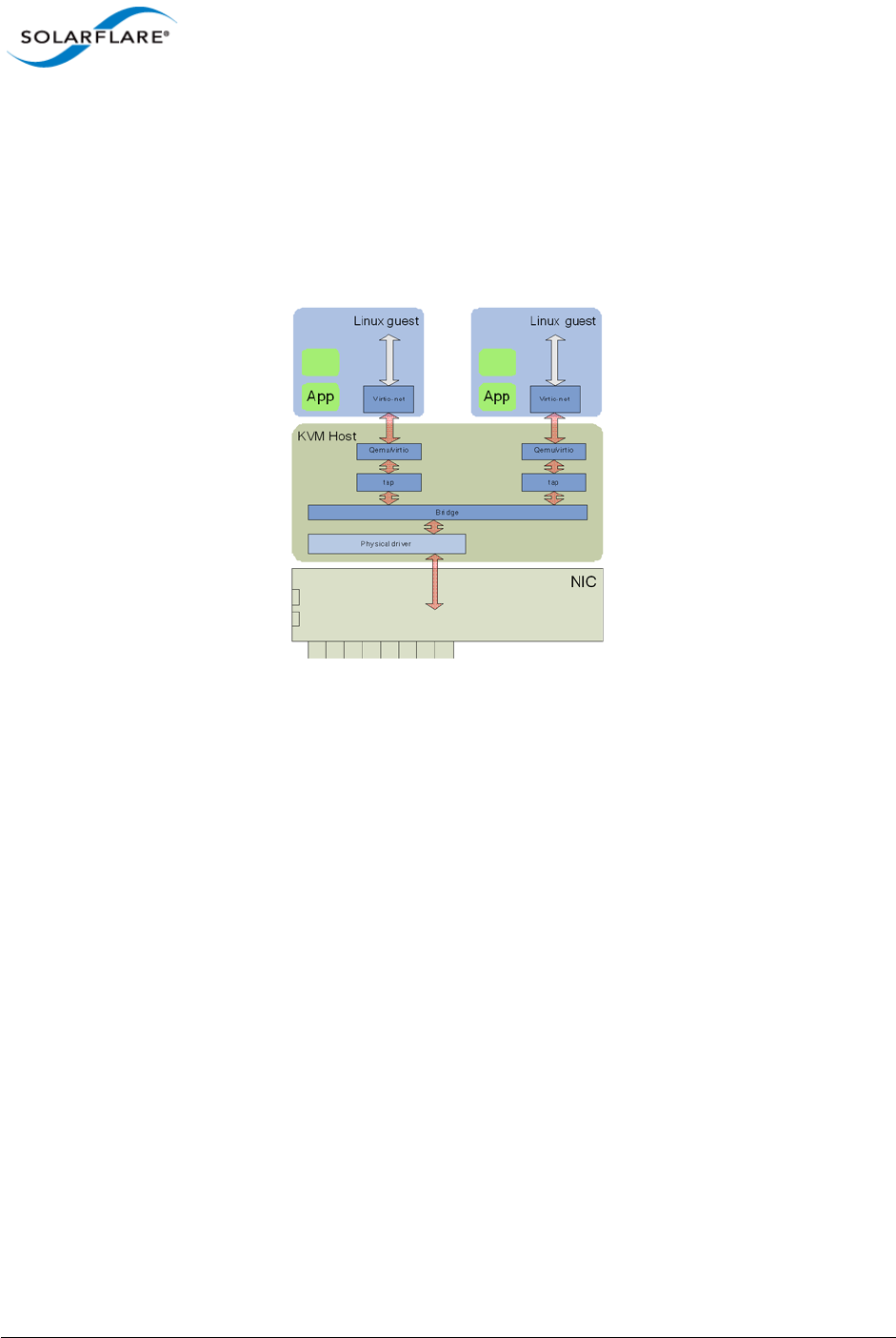
Issue 10 © Solarflare Communications 2013 324
Solarflare Server Adapter
User Guide
7.2 Linux KVM SR-IOV
Traditional Virtualization (without SR-IOV)
Traditional KVM networking involves bridging a physical network device to tap devices, which qemu
connects to either emulated hardware (e1000, rtl8139), or to virtio devices. The guest operating
system then uses the appropriate drivers to consume the emulated hardware.
Figure 50: Guest to Guest Connectivity
The bridge establishes guest to guest connectivity. Unfortunately performance is poor, requiring
data to be copied between the guest and KVM host, and between user level and kernel within the
KVM host.
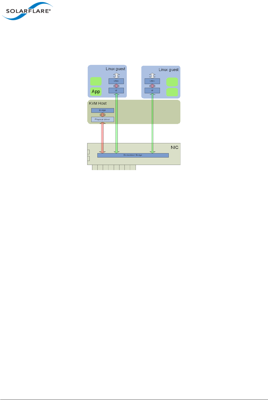
Issue 10 © Solarflare Communications 2013 325
Solarflare Server Adapter
User Guide
Typical Virtualization (with SR-IOV)
In emerging SR-IOV solutions a PCIe hardware VF is passed-through to the guest operating system.
A network driver binds directly to this PCIe VF.
Figure 51: Direct Guest Access to NIC Hardware
This approach solves many of the performance limitations of traditional virtualized networking
providing direct access to the network adapter from the guest VM.
However, the major downside of this approach is the guest VM now relies on the physical VF of the
adapter for networking. If this VF changes in anyway then the guest VM completely loses networking
access.
For example, this solution makes migration close to impossible to support as both the source and
destination machine must be identical in every respect to the networking adapter. That is, not only
identical at a hardware level (same adapter, same slot) but, also the same VF index must be available
on the identical destination machine. For example, if VF 5 is being used by the VM at the source
machine then for migration to succeed VF 5 must be free at the destination machine. This means
that for migration to be possible VFs cannot be allocated on demand but assigned to fixed VMs
across the complete cluster. Therefore, for deployments with more than a handful of VMs across the
complete cluster this SR-IOV solution prevents the user from migrating VMs.
It is also worth noting that the networking interface in this model is now a vendor supplied driver
and creation/configuration of networking interfaces must be done via this vendor driver and not the
standard KVM network drivers.
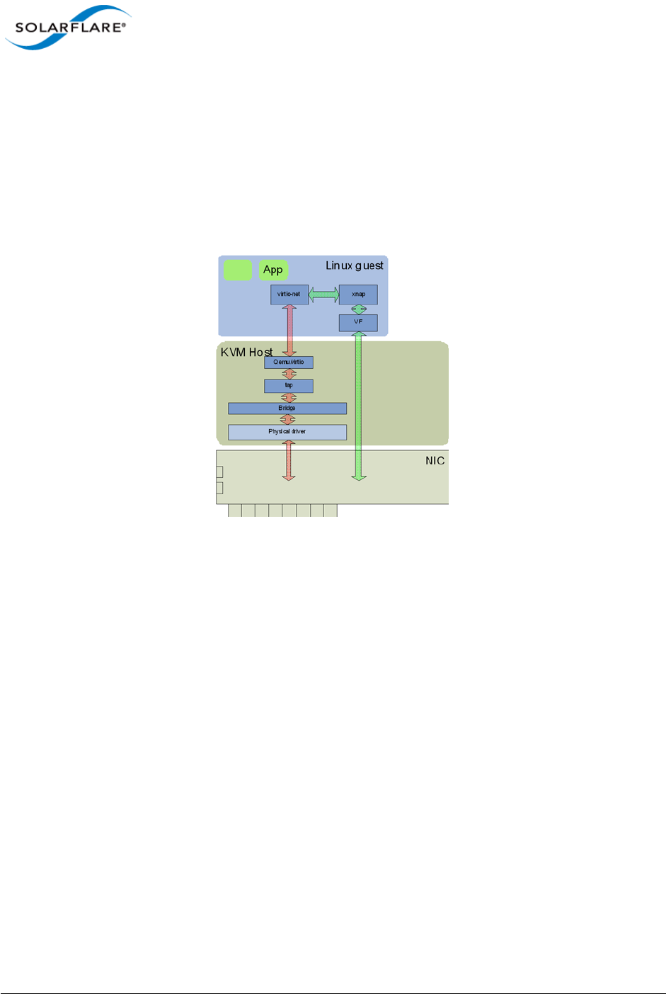
Issue 10 © Solarflare Communications 2013 326
Solarflare Server Adapter
User Guide
Solarflare Plug-in Model
The Solarflare model for SR-IOV support is a hybrid of the traditional and typical approaches. The
Solarflare "plugin" maintains the traditional (software) data path through virtio frontend to the KVM
host (and then through the Linux bridge to the PF of the network driver). However, there is also an
alternative (accelerated) data path through the VF driver directly to the network adapter from the
guest. Packets can be received on either data path transparently to the guest VM's network stack.
On transmit the loaded and enabled plugin decides whether to use the software path or accelerated
path.
Figure 52: Solarflare Plug-in Model
A VM can be created/cloned using traditional tools and networking to/from the VM initially uses the
standard software network path. If a VF on the network adapter is then passed-through into the
guest, the guest sees new hardware has been "hot-plugged" and binds the Solarflare plugin driver
to this VF. This plugin driver automatically registers with the virtio driver as an accelerated network
plugin. Once the VF driver has registered, subsequent traffic to/from the guest uses the accelerated
data path accessing the adapter directly from the guest. If the VF is hot "unplugged" (i.e. removed
from the guest), the plugin de-registers with the virtio front end and the networking traffic reverts
to the software data path.
This approach means there is no dependency on the VF or its driver for the networking data path of
the VM. Acceleration can be disabled at any time if needed without losing network connectivity.
Migration is fully supported in this model - between hosts with identical network adapters AND also
between non-identical hosts. For example, migration is still possible between hosts containing
network adapters from differing vendors (even if one of the adapters does not support SR-IOV).
When migrating a VM the typical operations are:
• Hot-unplug any network VF in the guest (to remove any hardware knowledge from the guest,
networking in the guest VM falls back to the standard software data path).
• Migrate the guest VM to a new machine

Issue 10 © Solarflare Communications 2013 327
Solarflare Server Adapter
User Guide
• Optionally, allocate and hot-plug a new VF into the guest at the destination machine (the plugin
loads, automatically registers with the virtio driver and the networking path uses the
accelerated path).
Benefits of Solarflare's SR-IOV solution
•Maximum performance. Using SR-IOV reduces CPU utilization, increases bandwidth and lowers
latency. Performance returns to near native (non-virtualized) levels.
•Full support of migration. Ability to migrate VMs accelerated with the SR-IOV solution - either
to a machine also supporting the same SR-IOV solution or to a KVM machine with a non-
Solarflare adapter.
•Large number of VFs. Solarflare adapters support 127 VFs per port - far more than other SR-IOV
capable adapters. This allows up to 127 VMs per 10G port to be accelerated per host.
•RSS support in guest VMs. Solarflare adapters support up to 1024 vNICs per port. Multiple
vNICs can be exposed through a single VF to a guest VM. This allows a guest VM to have multiple
transmit and receive queues. The Solarflare plugin model fully supports intelligently spreading
network traffic over multiple queues to scale performance over the available CPUs. This is
termed receive side scaling (RSS) and is typically used in non-virtualized environments (Linux/
Windows) to improve network performance. With the Solarflare plugin model when VMs are
deployed to run on multiple (virtual) CPUs, each CPU can be given a dedicated transmit and
receive queue so that network performance scales over the available CPU cores.
7.3 Installation
Platform support
To use SR-IOV, platform support for hardware virtualization must be enabled. Refer to Enabling
Virtualization Extensions for more information. Take care to enable VT-d as well as VT on an Intel
platform. To verify that the extensions have been correctly enabled refer to Verifying Virtualization
Extensions.
On an Intel platform, the IOMMU must be explicitly enabled by appending intel_iommu=on to the
kernel line in the /boot/grub/grub.conf file. Refer to PCI Passthrough for more information.
AMD systems only require that the IOMMU is enabled in the BIOS. The system is ready for PCI
passthrough once the IOMMU is enabled.
Step 1: Download and install host drivers
Download the Solarflare Linux drivers from support.solarflare.com:
• For RHEL 6.0, 6.1 - part number SF-100785-LS (minimum version 3.1.0.4088).
• For RHEL 6.2 - part number SF-103848-LS (minimum version 3.2.1.6090).

Issue 10 © Solarflare Communications 2013 328
Solarflare Server Adapter
User Guide
Install the sfc network drivers using the source rpm sfc-3.<version>.src.rpm. Full instructions
for using a source rpm can be found in the Solarflare RPMs...Page 41. Reload the sfc driver to start
using the new version.
Step 2: Update adapter firmware and enable SR-IOV
Download the Solarflare Linux Utilities SF-104451-LS from support.solarflare.com:
1Install the Solarflare Linux Utilities in dom0 using the rpm provided in this package:
# rpm -Uvh sfutils-<version>.rpm
2Identify the current firmware version on the adapter:
# sfupdate
3Upgrade the adapter firmware with sfupdate:
# sfupdate --write
4Use sfboot to enable SR-IOV and enable 16 VFs:
# sfboot sriov=enabled vf-count=16
A reboot is required for the changes to take effect. After the reboot the sfc driver will initialize the
VFs, and they will appear in lspci:
# lspci -d 1924:
06:00.0 Ethernet controller: Solarflare Communications SFL9021
[Solarstorm]
06:00.1 Ethernet controller: Solarflare Communications SFL9021
[Solarstorm]
06:00.2 Ethernet controller: Solarflare Communications Device 1813
06:00.4 Ethernet controller: Solarflare Communications Device 1813
06:00.6 Ethernet controller: Solarflare Communications Device 1813
06:01.0 Ethernet controller: Solarflare Communications Device 1813
06:01.2 Ethernet controller: Solarflare Communications Device 1813
06:01.4 Ethernet controller: Solarflare Communications Device 1813
06:01.6 Ethernet controller: Solarflare Communications Device 1813
06:02.0 Ethernet controller: Solarflare Communications Device 1813
Table 79 identifies sfboot SR-IOV configurable options.
NOTE: Ensure that VFs are NOT in use when you unload the sfc driver. This is particularly relevant if
you are upgrading from a previous alpha version of the Solarflare KVM SR-IOV package.
Table 79: sfboot - SR-IOV options
Option Default Value Description
sriov=<enabled | disabled> disabled enable/disable hardware SR-IOV
vf-count=<n> 127 number of virtual functions advertised
vf-msix-limit=<n> 1number of MSI-X interrupts per VF

Issue 10 © Solarflare Communications 2013 329
Solarflare Server Adapter
User Guide
Step 3: Install libvirt and virt-manager with SR-IOV support
Libvirt and virt-manager have been enhanced to support SR-IOV acceleration. It is suggested to
upgrade libvrt components with the components in the supplied package.
To upgrade an existing libvirt/virt-manager installation on Red Hat 6.1 do the following:
# rpm -e libvirt-java-devel-0.4.7-1.el6.noarch
# rpm -e libvirt-java-0.4.7-1.el6.noarch
# rpm -Uvh python-virtinst-0.500.5-3.el6.sf2.noarch.rpm
# rpm -Uvh libvirt-0.8.7-18.el6.sf1.x86_64.rpm \
libvirt-client-0.8.7-18.el6.sf1.x86_64.rpm \
libvirt-python-0.8.7-18.el6.sf1.x86_64.rpm
# rpm -Uvh virt-manager-0.8.6-4.el6.sf2.noarch.rpm
To upgrade an existing libvirt/virt-manager installation on Red Hat 6.2 do the following:
# rpm –Uvh libvirt-0.9.4-23.el6.sf3.x86_64.rpm \
libvirt-client-0.9.4-23.el6.sf3.x86_64.rpm \
libvirt-python-0.9.4-23.el6.sf3.x86_64.rpm \
libvirt-devel-0.9.4-23.el6.sf3.x86_64.rpm \
libvirt-lock-sanlock-0.9.4-23.el6.sf3.x86_64.rpm \
virt-manager-0.9.0-7.sf1.el6.x86_64.rpm
Guest Drivers
The Solarflare accelerated driver package is currently supplied as a tarball. It contains two drivers:
an upgraded virtio-net driver (backported from 2.6.37), and xnap, the PCI driver for Solarflare VFs.
To install drivers on Red Hat 6.1:
# tar xvfz sfc-xnap-virtio-v1_0_0_0012.tgz
# make -C sfc-xnap-virtio-v1_0_0_0012/ modules_install
Restart the guests to start using the new drivers.
To install drivers on Red Hat 6.2:
The virtio kernel module must be rebuilt and installed before the xnap module can be rebuilt and
installed.
1As any user
rpmbuild --rebuild virtio-2.6.37-1.0.0.0016-1.el6.sf.src.rpm
NOTE: Enabling all 127 VFs per port with more than one MSI-X interrupt per VF may not be
supported by the host BIOS and you may get 127 VFs on one port with no VFs on the other port.
Contact your BIOS vendor for a BIOS upgrade or reduce the VF count.

Issue 10 © Solarflare Communications 2013 330
Solarflare Server Adapter
User Guide
2As root install the binary rpm indicated by the "Wrote:" lines from rpmbuild
rpm -Uvh RPMS/x86_64/kmod-virtio-2.6.37-1.0.0.0016-1.el6.sf.x86_64.rpm
3As any user
rpmbuild --rebuild xnap-1.0.0.0016-1.el6.src.rpm
4As root install the binary rpm indicated by the "Wrote:" lines from rpmbuild
rpm -Uvh RPMS/x86_64/kmod-xnap-1.0.0.0016-1.el6.x86_64.rpm
7.4 Configuration Red Hat 6.1
Host Network Configuration
As previously described, Solarflare SR-IOV support uses a plugin model, whereby virtual functions
accelerate virtio network adapters. This section presents an overview of how to configure virtio
based networking.
• Configure Bridged networking on the hosts, creating a bridge for each Solarflare network device
and attach the physical network device to the bridge. The instructions to configure bridging can
be found at Redhat: Bridged networking with libvirt.
• Assign an IP address to the bridge. Verify network connectivity between the hosts over the
Solarflare network drivers using ping (or a similar tool).
• For each guest on the host, create virtio network adapters attached to the newly created
bridges. You can enable SR-IOV acceleration of each virtio adapter as described below.
XML Format for SR-IOV
A virtio interface onto a bridge "br1" could be implemented using the following XML fragment:
<interface type='bridge'>
<mac address='00:50:56:3e:86:29'/>
<source bridge='br1'/>
<model type='virtio'/>
<address type='pci' domain='0x0000' bus='0x00' slot='0x0a'
function='0x0'/>
</interface>
To accelerate this virtio adapter by using VFs provided by "eth4" modify the fragment as shown,
adding the vf-hotplug element with hybrid=yes.
<interface type='bridge'>
<mac address='00:50:56:3e:86:29'/>
<source bridge='br1'/>
<model type='virtio'/>
<address type='pci' domain='0x0000' bus='0x00' slot='0x0a'
function='0x0'/>

Issue 10 © Solarflare Communications 2013 331
Solarflare Server Adapter
User Guide
<vf-hotplug source='eth4' hybrid='yes'/>
</interface>
If "br1" is on a vlan then add a vlan attribute as shown:
<interface type='bridge'>
<mac address='00:50:56:3e:86:29'/>
<source bridge='br1'/>
<model type='virtio'/>
<address type='pci' domain='0x0000' bus='0x00' slot='0x0a'
function='0x0'/>
<vf-hotplug source='eth4' hybrid='yes' vlan='123' />
</interface>
Virt-manager configuration for SR-IOV: Adding a new interface
A virt-manager GUI tool is supplied with the Solarflare driver distribution package. To run the GUI
tool as root use the following command:
# /usr/bin/virt-manager
Alternatively, virt-manager can be on another host and connect to the KVM host via “File”- >”Add
Connection”. Virt-manager has been extended to make SR-IOV configuration much easier. When
adding a new interface there will be a new "SR-IOV Acceleration" combo box. It will default to "No"
for new interfaces:
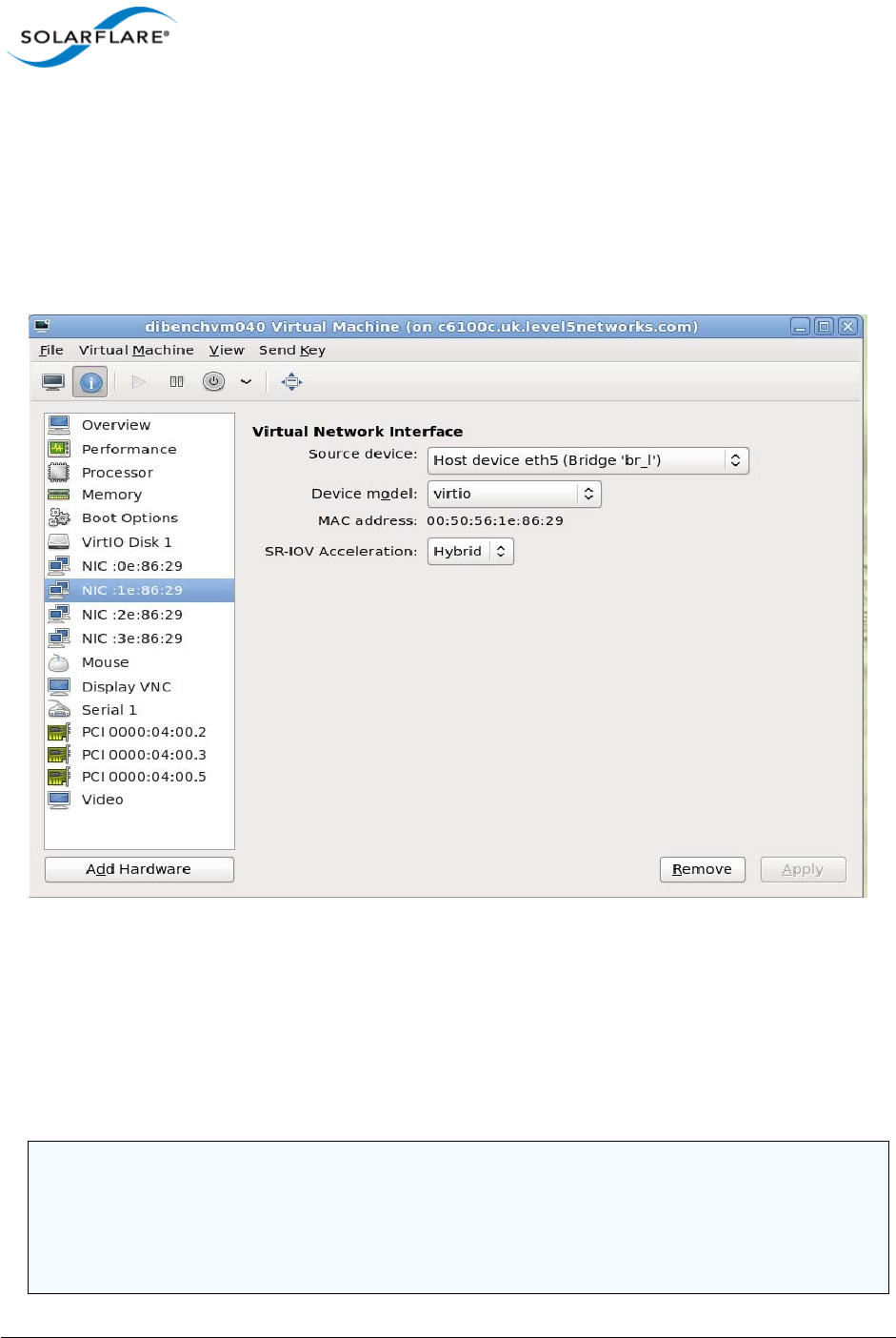
Issue 10 © Solarflare Communications 2013 332
Solarflare Server Adapter
User Guide
Figure 53: Virt-Manager GUI tool
To enable SR-IOV acceleration of the virtio adapter change the "SR-IOV acceleration mode" to
"Hybrid", and the "Device model" to virtio.
Virt-manager configuration for SR-IOV: Modifying an existing adapter
It is also possible to change the "SR-IOV Acceleration mode" for existing adapters:
Figure 54: Change SR-IOV on Existing Adapter
Verifying SR-IOV
As described above, libvirt will manage VFs for interfaces with a vf-hotplug attribute. If there are
spare VFs available when the VM is started then one (or more) VFs will be attached into the running
guest. If the guest OS has the Solarflare VF drivers, and the interface is a virtio interface, then the
virtio interface will be accelerated.
NOTE: Red Hat Enterprise Linux 5 Update 5 and Update 6 guests require the acpiphp module to be
loaded before PCI hotplug will work:
# echo "modprobe acpiphp" >> /etc/rc.modules
# chmod +x /etc/rc.modules
# modprobe acpiphp

Issue 10 © Solarflare Communications 2013 333
Solarflare Server Adapter
User Guide
a. Once the VM has started, examine lspci to verify that a VF is present.
# lspci
00:08.0 Ethernet controller: Solarflare Communications Device 1803
00:09.0 Ethernet controller: Solarflare Communications Device 1803
b. The interface is only accelerated once it's brought up, after the interface is bought up use dmesg
to verify that a VF is accelerating a virtio adapter:
# dmesg | grep -i xnap
xnap 0000:00:0a.0: accelerated eth2
7.5 Configuration Red Hat 6.2
Host Network Configuration
As previously described, Solarflare SR-IOV support uses a plugin model, whereby virtual functions
accelerate virtio network adapters. These virtio network adapters are attached to the physical
network device via a macvtap interface.
XML Format for SR-IOV
A virtio interface onto a macvtap interface could be implemented using the following XML fragment:
Network XML:
<network>
<name>sfc-network</name>
<uuid> 81ff0d90-c91e-6742-64da-4a736edb9a8f</uuid>
<forward mode='vepa'>
<interface
dev=
'
eth2
'
/>
</forward>
</network>
Domain XML:
<interface type='network'>
<source network='sfc-network'/>
<mac address='00:50:56:3e:86:29'/>
<model type='virtio'/>
<address type='pci' domain='0x0000' bus='0x00' slot='0x0a'
function='0x0'/>
</interface>
To accelerate this virtio adapter by using VFs provided by “eth2”, modify the fragment as shown using
the pci-passthrough-hybrid mode.
Network XML:
<network>

Issue 10 © Solarflare Communications 2013 334
Solarflare Server Adapter
User Guide
<name>sfc-network</name>
<uuid> 81ff0d90-c91e-6742-64da-4a736edb9a8f</uuid>
<forward mode='pci-passthrough-hybrid'>
<pf dev='eth2'/>
</forward>
</network>
Domain XML:
<interface type='network'>
<source network='sfc-network'/>
<mac address='00:50:56:3e:86:29'/>
<model type='virtio'/>
<address type='pci' domain='0x0000' bus='0x00' slot='0x0a'
function='0x0'/>
</interface>
To create the macvtap interface on a vlan eth2.123 add a vlan attribute as shown:
Network XML:
<network>
<name>sfc-network</name><uuid> 81ff0d90-c91e-6742-64da-4a736edb9a8f</
uuid>
<forward mode='pci-passthrough-hybrid'>
<pf dev='eth2.123' vlan='123'
/>
</forward>
</network>
Domain XML:
<interface type='network'>
<source network='sfc-network'/>
<mac address='00:50:56:3e:86:29'/>
<model type='virtio'/>
<address type='pci' domain='0x0000' bus='0x00' slot='0x0a'
function='0x0'/>
</interface>
Virt-manager configuration for SR-IOV: Adding a new interface
This Solarflare driver distribution includes an updated version of virt-manager - a GUI tool for
managing VMs (refer to Virt-manager configuration for SR-IOV: Adding a new interface on page 331
for details). This can be used as an alternative method to configure VMs for SR-IOV rather than
working directly with the XML definitions.
To run the GUI tool as root use the following command:
# /usr/bin/virt-manager

Issue 10 © Solarflare Communications 2013 335
Solarflare Server Adapter
User Guide
Alternatively, virt-manager can be on another host and connect to the KVM host via “File”- >”Add
Connection”.
Creating an SR-IOV network
1Select “Connection Details” from virt-manager’s “Edit” menu, and open the “Virtual
Networks” tab
2Click the “+” button in the bottom-left to open the network creation wizard
3Choose a name for your network
4On the address space page, untick the “Create address space” button. On the next page the
“Enable
5DHCP” button will be grayed out as it’s not applicable without an address space
6On the next page, select “Forwarding to physical network”
7In the “Destination” box, choose the “Phyiscal device X” that corresponds to the Solarflare
interface you wish to use
8In the “Mode” box, select “Hybrid VF/macvtap”
Assigning an existing VM to an SR-IOV network
1In the main virt-manager window, double-click the VM to manage it
2Open the hardware tab by clicking the “(i)” button on the toolbar
3Select the NIC you wish to use with SR-IOV from the list on the left
4Update the “Source device” entry to use your SR-IOV network
Verifying SR-IOV
As described above, libvirt will manage VFs for interfaces with a new mode pci-passthrough-hybrid.
If there are spare VFs available when the VM is started then one (or more) VFs will be attached into
the running guest. If the guest OS has the Solarflare VF drivers, and the interface is a virtio interface,
then the virtio interface will be accelerated.
Once the VM has started, examine lspci to verify that a VF is present:
$ lspci
00:08.0 Ethernet controller: Solarflare Communications Device 1803
00:09.0 Ethernet controller: Solarflare Communications Device 1803
The interface is only accelerated once it’s brought up, after the interface is bought up USE dmesg TO
verify that a VF is accelerating a virtio adapter:
$ dmesg | grep –i xnap
xnap 0000:00:0a.0: accelerated eth2

Issue 10 © Solarflare Communications 2013 336
Solarflare Server Adapter
User Guide
7.6 Performance Tuning
The guest drivers have been tuned for optimized bandwidth and CPU utilization with a variety of high
bandwidth streaming tests. Some applications may perform better by changing the default values.
Table 80 describes the tuning parameters and suggests values for streaming and latency dominated
applications.
To modify these settings:
1. Edit /etc/modprobe.conf, inserting a line like this:
options xnap rx_irq_mod_usec=<value> rx_ring=<value>
2. Reload the xnap driver
# modprobe -r xnap
# modprobe xnap
Performance Configuration
• Equipment Configuration
Performance tests were conducted between two (back to back) Dell PowerEdge C6100: 4 x Xeon
X5600, 48G RAM. Host and Guest are configured on each machine.
• Host
- Host OS: RHEL 6.2 64 bit.
- The irqbalance service is stopped.
• Guest
- The guest VM was running RHEL6.1 64bit.
- The irqbalance service was stopped in the guest VM.
- Benchmarking tool: Netperf.
Table 80: Tuning Parameters
Parameter Linux Streaming Latency
Receive ring size rx_ring Default Default
Interrupt Moderation rx_irq_mod_usecs Default 0

Issue 10 © Solarflare Communications 2013 337
Solarflare Server Adapter
User Guide
Performance Results
Table 81 records bandwidth figures for 4 TCP streams per port, per direction, between each pair of
VMs on the two servers (message size of 65535 bytes).
Table 81: Linux KVM Performance
Number of
10G ports Traffic Number
of VMs
Baseline (no
SR-IOV)
Accelerated
(SR-IOV plug-in)
1 Unidirectional 1 6.64 Gbps 9.37 Gbps
1 Bidirectional 1 6.74 Gbps 11.5 Gbps
2 Bidirectional 1 7.37 Gbps 11.2 Gbps
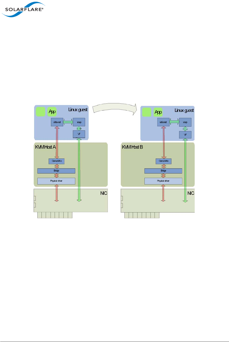
Issue 10 © Solarflare Communications 2013 338
Solarflare Server Adapter
User Guide
7.7 Migration
Libvirt has been extended to fully support migrating a guest VM using SR-IOV acceleration between
two KVM hosts.
Consider migrating a VM from host A to host B (Figure 55). Before migration libvirt will remove all
VFs from the VM. Once the VM reaches host B VFs will be allocated, initialized and attached as
previously described. If there are no VFs free then the VM will no longer be accelerated. If the
migration fails for whatever reason then the VM will remain on host A, and the VFs will be
reattached to the VM.
Figure 55: Migrating a guest - KVM
Limitations
• Virt-manager will support bridges on top of vlan interfaces but the vlan interface should be
named as ethx.<vlan_id>.
• RHEL 6.1 driver - Libvirt will not configure VFs manually added to a VM configuration (via virt-
manager or virsh edit). Only VFs attached via the vf-hotplug XML element will be configured.
• RHEL 6.2 driver - Libvirt will not configure VFs manually added to a VM configuration (via virt-
manager or virsh edit). Only VFs attached via the pci_passthrough-hybrid forward mode
and pf dev XML element will be configured.

Issue 10 © Solarflare Communications 2013 339
Solarflare Server Adapter
User Guide
Known Issues
• Some hardware platforms are unable to support 127 VFs on both ports simultaneously. The
current workaround is to reduce the number of VFs exposed by the adapter using “sfboot”.
• When a Redhat Enterprise Linux 6 guest is migrated, occasionally the guest kernel fails to notice
either the VF unplug before migration or the VF hotplug after migration. This issue is believed to
be a Redhat kernel bug and is under investigation.
• Reloading the sfc driver while VFs are in use will result in a kernel panic. This is an upstream
kernel bug that Solarflare are working to address.
• There is a known issue when using LRO with macvtap interfaces. This issue can be worked
around by disabling LRO on the host machine. This issue does not affect the SRIOV accelerated
datapath.
• There is a known issue whereby the user tries to PXE boot one KVM guest off another KVM
guest, on the same host, over a macvtap interface the client does not receive the tftp packets
sent by the server and the connection times out. Solarflare are following up this issue with
RedHat. A workaround for this issue is disabling tx-checksumming on the PXE server VM.

Issue 10 © Solarflare Communications 2013 340
Solarflare Server Adapter
User Guide
Chapter 8: SR-IOV Virtualization for XenServer
This chapter describes Solarflare’s unified approach to SR-IOV Virtualization using XenserverTM 6
supporting Windows and Linux guests. Solarflare SR-IOV enables accelerated cut-through
performance while maintaining full compatibility with hypervisor based services and management
tools.
• Supported Platforms and Adapters...Page 340
• XenServer6 SR-IOV...Page 341
• Installation...Page 344
• Configuration...Page 345
• Performance Tuning...Page 346
8.1 Supported Platforms and Adapters
Solarflare XenServer6 SR-IOV acceleration currently supports:
• XenServer 6.0, 6.1.
• Intel platforms supporting VT-d.
• AMD platforms supporting AMD-Vi.
• Guest VM - Win2k8r2 and RHEL 6.
• All Solarflare SFN5xxx and SFN6xxx series adapters.
The hardware supports different configurations of (a) the number VFs exposed and (b) the number
of vNICs (and therefore MSI-X interrupts) to give to each VF. This can be configured with the sfboot
utility.
Currently the default configuration is 127 VFs each allocated 1 vNIC.
NOTE: Solarflare’s hybrid SR-IOV solution is no longer supported by Citrix and is limited to
XenServer 6.0. Further, this solution is limited to supporting Windows guests and Linux guests
running RHEL 6.1 (or earlier). Attempting to use this SR-IOV solution with guest VMs running a
newer version of RHEL may expose a hypervisor bug that prevents network traffic passing.
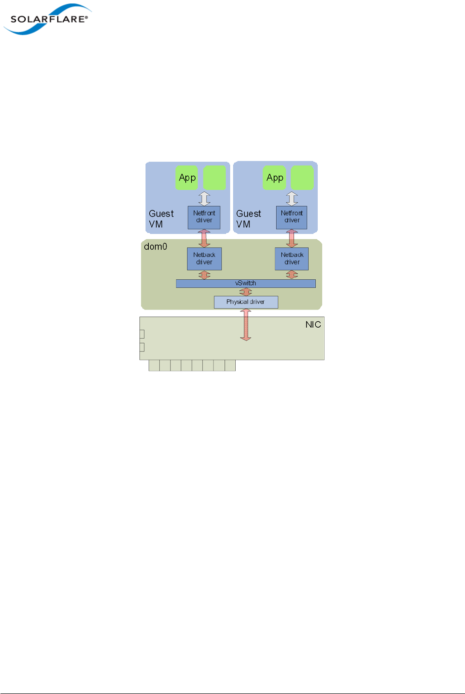
Issue 10 © Solarflare Communications 2013 341
Solarflare Server Adapter
User Guide
8.2 XenServer6 SR-IOV
Traditional Virtualization (without SR-IOV)
Traditional Xen paravirtualized networking involves bridging (paravirtualized) Netback devices to
physical network devices in dom0. The Netback driver interfaces with the Netfront driver running in
the guest, facilitating guest to guest connectivity.
Figure 56: Guest to Guest Connectivity
As a result of hardware virtualization, data copies between the Netfront driver in the guest and the
Netback driver in dom0 within the XenServer host become the bottleneck to the performance of this
implementation.
Typical Virtualization (with SR-IOV)
In emerging SR-IOV solutions PCIe hardware virtual functions (VF) allow a single network hardware
device to appear as multiple virtualized network devices to dom0. These virtualized network devices
operate independently of one another and present characteristics of actual physical devices to
dom0.
Using SR-IOV, a VF is passed-through to the guest operating system, and the guest network driver
binds directly to this PCIe VF, allowing the guest to bypass dom0 and providing direct access to the
network adapter from the guest VM. Direct access to the network hardware means that overheads
associated with dom0-based networking (virtualization, data copies, etc.) are eliminated, providing
significantly improved performance, see Figure 57.
However, a significant downside of this approach is that XenServer blocks migration of a VM when
a VF is present, which significantly reduces the functionality of server virtualization.
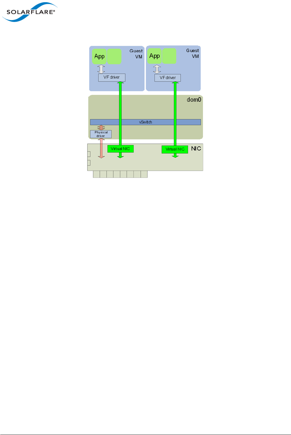
Issue 10 © Solarflare Communications 2013 342
Solarflare Server Adapter
User Guide
Figure 57: Direct Guest Access to NIC Hardware
It is also worth noting that the networking interface in this model is now a vendor supplied driver
and creation or configuration of networking interfaces must be done via the vendor's driver and not
the standard XenServer network drivers.
Solarflare Plug-in Model
Solarflare, in a collaborated development with Citrix, has implemented a unique unified approach to
SR-IOV that enables accelerated cut-through performance while maintaining full compatibility with
hypervisor-based services and management tools. Solarflare's 254 VFs enable highly scalable
workload consolidation for large data center environments and virtual desktop infrastructure (VDI)
deployments. Unlike other adapters, each Solarflare VF can use multiple DMA channels that enable
the VF to scale over vCPUs using RSS and/or RFS. Solarflare's 2048 DMA channels provide the most
scalable virtualized network I/O solution available in the market.
Solarflare's SR-IOV implementation uses a plug-in approach that maintains the traditional (software)
data path through the XenServer paravirtualized drivers, and then through the vSwitch to the
physical device network driver. In addition, there is an alternative (accelerated) data path through
the VF driver directly to the network adapter from the guest. Packets are received on either data
path transparently to the guest VM's network stack. For transmitted data, the enabled plug-in makes
the decision on whether or not to use the accelerated path. Refer to Figure 58.
With this approach a VM can be created/cloned using traditional tools, and networking to/from the
VM can initially use the standard software network path. Citrix XenServer6 will pass-through a VF
from the network adapter into the guest. The guest identifies that new hardware has been hot
plugged and binds the Solarflare plug-in driver to this VF. This plug-in driver automatically registers
with the Netfront driver as an accelerated network plug-in. Once the VF driver has registered,
subsequent traffic to/from the guest uses the accelerated data path accessing the adapter directly
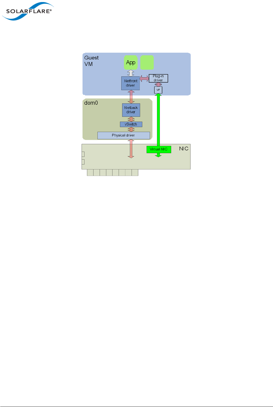
Issue 10 © Solarflare Communications 2013 343
Solarflare Server Adapter
User Guide
from the guest. If the VF is hot unplugged (i.e. removed from the guest), the plug-in deregisters with
the Netfront driver and the networking traffic reverts to the software data path.
Figure 58: Network Plug-in Model
This approach means there is no dependency on the VF or its driver for the networking data path of
the VM. Acceleration can be disabled at any time if needed without losing network connectivity, and
migration is fully supported in this model. When a VM is being migrated, XenServer hot unplugs the
VF from the VM and the network path reverts to the software path, and after migration is complete
XenServer hot plugs a new VF from an adapter on the destination machine back to the VM and the
networking path is again accelerated. Solarflare's unique approach also removes the limitations
imposed by typical SR-IOV implementations, enabling VMs to be moved between non-identical
hosts. For example, if a guest is migrated to a host containing a different vendor's NIC, then the hot
plug event provides the opportunity to bind a new VF driver within the guest and re-establish
accelerated networking. Equally, if the new host does not contain suitable hardware, then no
accelerated path is established, yet networking will continue using the original (or traditional)
paravirtualized architecture.
Benefits of Solarflare's SR-IOV solution
•Maximum performance. Using SR-IOV reduces CPU utilization, increases bandwidth and lowers
latency. Performance returns to near native (non-virtualized) levels.
•Full support of migration. Ability to migrate VMs accelerated with the SR-IOV solution - either
to a machine also supporting the same SR-IOV solution or to a XenServer system with a non-
Solarflare adapter.
•Large number of VFs. Solarflare adapters support 127 VFs per port - far more than other SR-IOV
capable adapters. This allows up to 127 VMs per 10G port to be accelerated per host.
•RSS support in guest VMs. Solarflare adapters support up to 1024 vNICs per port. Multiple
vNICs can be exposed through a single VF to a guest VM. This allows a guest VM to have multiple

Issue 10 © Solarflare Communications 2013 344
Solarflare Server Adapter
User Guide
transmit and receive queues. The Solarflare plugin model fully supports intelligently spreading
network traffic over multiple queues to scale performance over the available CPUs. This is
termed receive side scaling (RSS) and is typically used in non-virtualized environments (Linux/
Windows) to improve network performance. With the Solarflare plugin model when VMs are
deployed to run on multiple (virtual) CPUs, each CPU can be given a dedicated transmit and
receive queue so that network performance scales over the available CPU cores.
8.3 Installation
Platform support
To use SR-IOV, platform support for hardware virtualization must be enabled. Refer to Enabling
Virtualization Extensions for more information. On an Intel platform, the Xen hypervisor will, by
default, use the Intel IOMMU if it is enabled in the BIOS.
On an AMD platform the Xen hypevisor command line must be modified to enable the IOMMU.
Append the following statements to the hypervisor line in /boot/extlinux.conf
amd_iommu=on iommu=amd-iommu-perdev-intremap
Install XenServer6 with SR-IOV supplemental pack
1Burn the supplemental pack (xs-SR-IOV-1.1.7-sfc.iso) to a CD.
2Insert the CD when prompted to do so by the XenServer6 installation.
Update adapter firmware and enable SR-IOV
1Download the Solarflare Linux Utilities (SF-104451-LS) from support.solarflare.com.
2Install the Linux Utilities in dom0 using the rpm provided in this package:
# rpm -Uvh sfutils-<version>.rpm
3Display the current firmware version on the adapter:
# sfupdate
4Upgrade the adapter firmware with sfupdate:
# sfupdate --write
5Use sfboot to enable SR-IOV and enable 16 VFs:
# sfboot sriov=enabled vf-count=16
6A reboot is required for the changes to take effect. After the reboot the sfc driver will initialize
the VFs, and they will appear in lspci:
# lspci -d 1924:
06:00.0 Ethernet controller: Solarflare Communications SFL9021
[Solarstorm]
06:00.1 Ethernet controller: Solarflare Communications SFL9021
[Solarstorm]
06:00.2 Ethernet controller: Solarflare Communications Device 1813
06:00.4 Ethernet controller: Solarflare Communications Device 1813
06:00.6 Ethernet controller: Solarflare Communications Device 1813
Issue 10 © Solarflare Communications 2013 345
Solarflare Server Adapter
User Guide
06:01.0 Ethernet controller: Solarflare Communications Device 1813
06:01.2 Ethernet controller: Solarflare Communications Device 1813
06:01.4 Ethernet controller: Solarflare Communications Device 1813
06:01.6 Ethernet controller: Solarflare Communications Device 1813
06:02.0 Ethernet controller: Solarflare Communications Device 1813
Table 82 identifies sfboot SR-IOV configurable options.
Install the XenTools drivers
Install the XenTools drivers (xensetup.exe) included with XenServer6. This applies to both
Windows and Linux guests.
Install the Solarflare SR-IOV drivers
For Linux Guests:
# tar xvfz sfc-xnap-netfront-v1_0_0_0012.tgz
# make -C sfc-xnap-netfront-v1_0_0_0012/ modules_install
For Windows Guests:
Install the Solarflare acceleration driver into the Windows guest using xnapsetup.exe.
8.4 Configuration
Acceleration
The SR-IOV supplemental pack manages all VF configuration. SR-IOV acceleration is configured on a
per Virtual Interface (VIF) basis allowing the administrator to control which VMs are accelerated on
a per network basis.
To enable SR-IOV acceleration of a VIF enable the other-config:sriov parameter:
# xe vif-param-set uuid=<vif uuid> other-config:sriov=true
Table 82: sfboot - SR-IOV options
Option Default Value Description
sriov=<enabled | disabled> disabled enable/disable hardware SR-IOV
vf-count=<n> 127 number of virtual functions advertised
vf-msix-limit=<n> 1number of MSI-X interrupts per VF
NOTE: Enabling all 127 VFs per port with more than one MSI-X interrupt per VF may not be
supported by the host BIOS and you may get 127 VFs on one port with no VFs on the other port.
Contact your BIOS vendor for a BIOS upgrade or reduce the VF count.

Issue 10 © Solarflare Communications 2013 346
Solarflare Server Adapter
User Guide
The vif-uuid is the VIF based on VM and Network:
# xe vif-list network-name-label=<network label> vm-name-label=<vm
label>
Consult the XenServer6 documentation for more information on enumerating VIFs. To disable
acceleration, remove the other-config:sriov parameter:
# xe vif-param-remove uuid=<vif uuid> param-name=other-config param-
key=sriov
Once the VM is rebooted (or started) VFs will be allocated, configured, and PCI hotplugged into the
running guest.
Guest configuration
Check that the correct number of VF's are pushed into the guest using the following commands on
DOM0.
# xl list
Name ID Mem VCPUs State Time(s)
Domain-0 0 729 4 r----- 130.4
dibenchvm080 1 0 1 ---s-d 17.8
dibenchvm020 2 2047 1 -b---- 18.1
# xl pci-list <domain ID>
Vdev Device
09.0 0000:07:00.6
0a.0 0000:07:00.7
8.5 Performance Tuning
The guest drivers have been tuned for optimized bandwidth and CPU utilization with a variety of high
bandwidth streaming tests. Some applications may perform better by changing the default values.
Table 83 describes the tuning parameters and suggests values for streaming and latency dominated
applications.
Windows Guests
1Install the Solarflare SR-IOV guest drivers for Windows.
2Create the following registry key:
Table 83: Tuning Parameters
Parameter
Name Application
Windows Linux Streaming Latency
Receive ring size rx_ring rx_ring Default Default
Interrupt Moderation irq_usecs rx_irq_mod_use
cs
Default 0

Issue 10 © Solarflare Communications 2013 347
Solarflare Server Adapter
User Guide
HKLM\SYSTEM\CurrentControlSet\services\XNAP\Parameters\
3Create any of the following registry values under the XNAP\Parameters key.
irq_usecs REG_DWORD <value>
rx_ring REG_DWORD <value>
4Reboot the VM.
Linux Guests
1Edit /etc/modprobe.conf, inserting the following entry:
options xnap rx_irq_mod_usec=<value> rx_ring=<value>
2Reload the xnap driver:
# modprobe -r xnap
# modprobe xnap
Performance Results
• Equipment Configuration
Performance tests were conducted between two (back to back) Dell PowerEdge C6100: 4 x Xeon
X5600, 48G RAM.
• Host
Host Virtualization plan used was XenServer6.
• Guest
A number of guest VMs running Windows Server 2008 R2 (64bit) were started on each server. The
benchmarking tool used was IXIA Chariot (HighPerf test script) for measure bandwidth.
Windows Guest Bandwidth
Table 84 identifies bandwidth figures recorded for 5 TCP streams per port, per direction, between
each pair of VMs on the two servers (message size of 65535 bytes, each VM was configured with 4
vCPUs).
Table 84: Windows Guest Bandwidth
Number of
10G ports Traffic Number
of VMs
Baseline (no
SR-IOV)
Accelerated
(SR-IOV plug-in)
1 Unidirectional 1 1.66 Gbps 3.49 Gbps
1 Bidirectional 1 2.52 Gbps 3.88 Gbps
2 Bidirectional 1 2.71 Gbps 4.20 Gbps
1 Unidirectional 4 4.85 Gbps 9.39 Gbps
1 Bidirectional 4 5.99 Gbps 17.9 Gbps

Issue 10 © Solarflare Communications 2013 348
Solarflare Server Adapter
User Guide
Linux Guest Bandwidth
Table 85 identifies bandwidth figures recorded for 5 TCP streams per port, per direction, between
each pair of VMs on the two servers (message size of 65535 bytes, each VM was configured with 4
vCPUs).
2 Bidirectional 4 6.64 Gbps 19.3 Gbps
Table 85: Linux Guest Bandwidth
Number of
10G ports Traffic Number
of VMs
Baseline (no
SR-IOV)
Accelerated
(SR-IOV plug-in)
1 Unidirectional 1 2.23 Gbps 9.25 Gbps
1 Bidirectional 1 1.91Gbps 15.3 Gbps
2 Bidirectional 1 3.65 Gbps 30.7 Gbps
1 Unidirectional 4 4.80 Gbps 9.31 Gbps
1 Bidirectional 4 5.80 Gbps 14.9 Gbps
2 Bidirectional 4 6.24 Gbps 32.8 Gbps
Table 84: Windows Guest Bandwidth
Number of
10G ports Traffic Number
of VMs
Baseline (no
SR-IOV)
Accelerated
(SR-IOV plug-in)

Issue 10 © Solarflare Communications 2013 349
Solarflare Server Adapter
User Guide
Limitations
• The Citrix XenTools bundled with XenServer6 do not support RSS. Therefore the Solarflare SR-
IOV accelerated drivers currently do not support RSS on Windows.
Known Issues
• Some hardware platforms are unable to support 127 VFs on both ports simultaneously. The
current workaround is to reduce the number of VFs exposed by the adapter using sfboot.
• VFs no longer appear in xl pci-list after a VM is rebooted. The VFs will be visible using
lspci/device manager. This is a Citrix XenServer 6 toolstack issue that will be addressed in future
XenServer versions.
• Migrating a Windows VM disables GSO (Generic Segmentation Offload), thereby reducing VM-
VM bandwidth between VMs on the same host. This is a XenTools bug in the version released
with Citrix XenServer 6, and should be resolved in a future Citrix hotfix.
• Do not reload the dom0 sfc driver when VFs are in use. This is an upstream Linux kernel bug.
• When a Red Hat Enterprise Linux 6 guest is migrated, occasionally the guest kernel fails to notice
either the VF unplug before migration or the VF hotplug after migration. This issue is believed to
be a Red Hat kernel bug and is under investigation. This issue is not seen on Windows guests.
• VF PCI-passthrough when using RHEL6.2 or newer guests fails due to loss of interrupt to the VF
by the hypervisor. This issue is seen only when the VF is passed through to the guest. This issue
does not exist on RHEL6.1 guests. This is an issue in the XenServer hypervisor.
• The Xen-tools rpm does not work on a RHEL6.0 guest. This is a Citrix bug.
•The xs-sriov-accel patch is overwritten after the hotfixes are applied to XenServer6. To get
around this issue reapply changes using the following command line:
cd / && patch -p1 < /var/xapi/patches/qemu.patch
For reference the patch file is:
diff -rup a/opt/xensource/libexec/qemu-dm-wrapper
b/opt/xensource/libexec/qemu-dm-wrapper
--- a/opt/xensource/libexec/qemu-dm-wrapper2011-08-12
18:03:28.000000000+0100
+++ b/opt/xensource/libexec/qemu-dm-wrapper2011-08-12
18:04:01.000000000+0100
@@ -82,6 +82,7 @@ def main(argv):
qemu_dm = '/usr/lib/xen/bin/qemu-dm'
domid = int(argv[1])
qemu_args = ['qemu-dm-%d'%domid] + argv[2:]
+ qemu_args.append("-priv")
if is_sdk() is True:
return fake_dm(domid)

Issue 10 © Solarflare Communications 2013 350
Solarflare Server Adapter
User Guide
Chapter 9: Solarflare Adapters on Mac 0S X
This chapter covers the following topics on the Mac 0S X® platform:
• System Requirements...Page 350
• Supported Hardware Platforms...Page 350
• Mac 0S X Platform Feature Set...Page 351
• Thunderbolt...Page 351
• Driver Install...Page 351
• Interface Configuration...Page 354
• Tuning...Page 355
• Driver Properties via sysctl...Page 355
• Firmware Update...Page 356
• Performance...Page 358
9.1 System Requirements
• Refer to Software Driver Support on page 13 for supported Mac OS X Distributions.
• Solarflare Mac OS X drivers are supported for all Solarflare SFN5xxx AND SFN6xxx series
adapters.
• Driver package SF-107120-LS supports OS X 10.8 and earlier versions.
• Driver package SF-111621-LS supports OSX 10.9 and later versions.
9.2 Supported Hardware Platforms
The following Apple hardware platforms are supported:
• Mac Pro
• Mac Pro Server
• X-Serve (supported but not routinely tested by Solarflare)

Issue 10 © Solarflare Communications 2013 351
Solarflare Server Adapter
User Guide
9.3 Mac 0S X Platform Feature Set
The following table lists the features supported by Solarflare adapters on Mac OS X distributions.
9.4 Thunderbolt
The Solarflare adapter driver provides basic support for Thunderbolt. When a network adapter is
connected to a Thunderbolt-capable system e.g. via a Thunderbolt-to-PCIe chassis, the interfaces
can be configured in the usual way.
Due to limitations in the Thunderbolt connection performance may be worse compared to using the
Solarflare adapter in a PCIe slot.
Full support for Thunderbolt, including plugging and unplugging the Thunderbolt cable is planned
for a future release.
9.5 Driver Install
Uninstall Previous Driver
An installed Solarflare network adapter driver MUST BE UNINSTALLED before upgrading to a new
driver release.
1Open System Preferences > Network.
2Disable the service for all ports of the driver:
- choose an active driver service in the list
Table 86: Mac OS X Feature Set
Large Receive Offload TCP receive frame coalescing to reduce CPU utilization and
improve TCP throughput
TCP Segmentation Offload TCP transmit segmentation to reduce CPU utilization and
improve TCP throughput
RMON Statistics counters
Checksum offloads IPv4, TCP and UDP
MSI Interrupts
MTU Standard 1500 byte and jumbo 9000 byte MTU
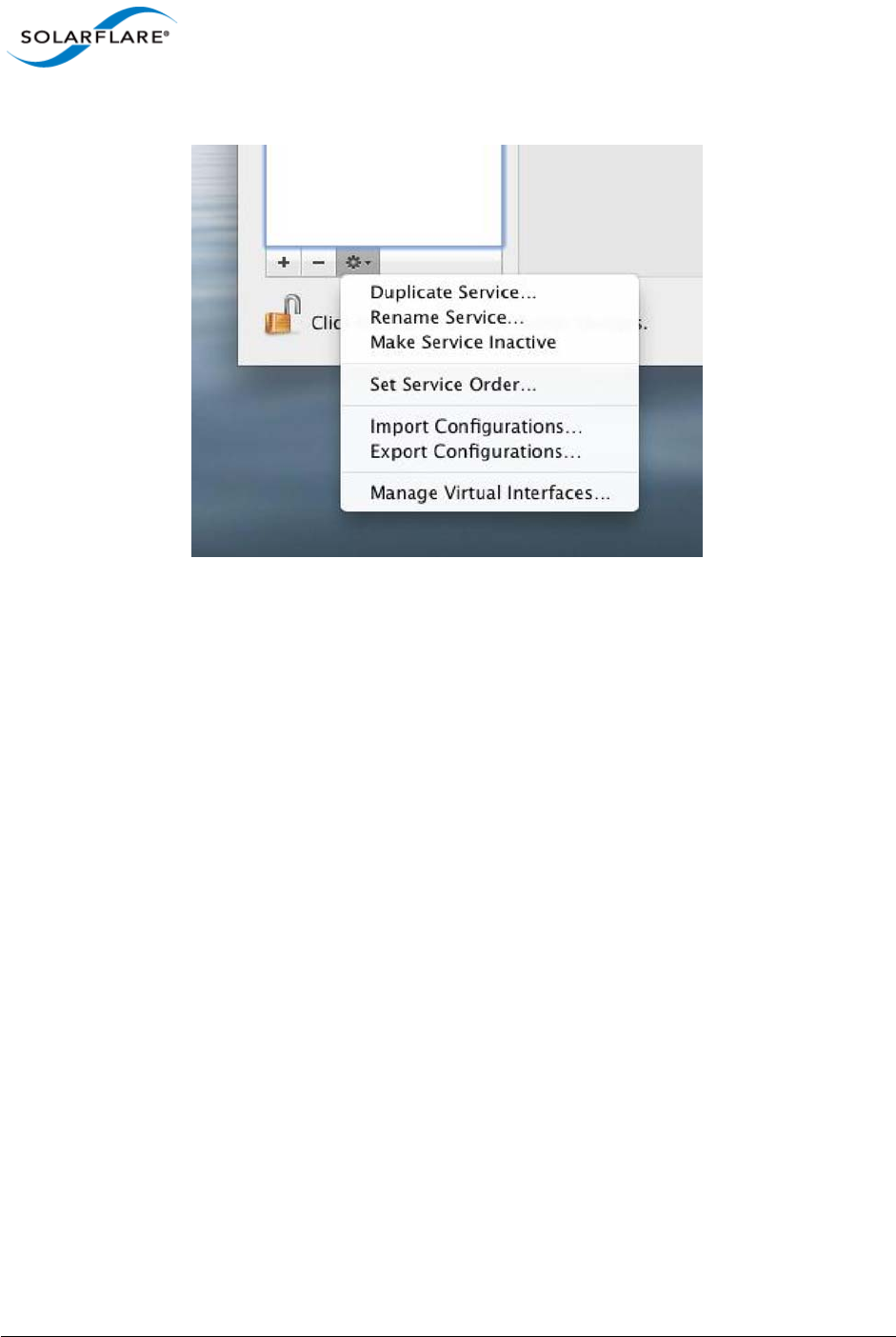
Issue 10 © Solarflare Communications 2013 352
Solarflare Server Adapter
User Guide
- click on the gear icon and choose ’Make Service Inactive’’
Figure 59: Disable Driver Services
3Repeat above steps for all ports of the driver.
4Double-click SF-107120-LS.dmg in Finder to mount the disk image. Invoke the Solarflare driver
uninstall script in Terminal as root (replacing <version> with the version number of the install
package that is being used)
/Volumes/Solarflare10GbE-<version>/uninstall.sh
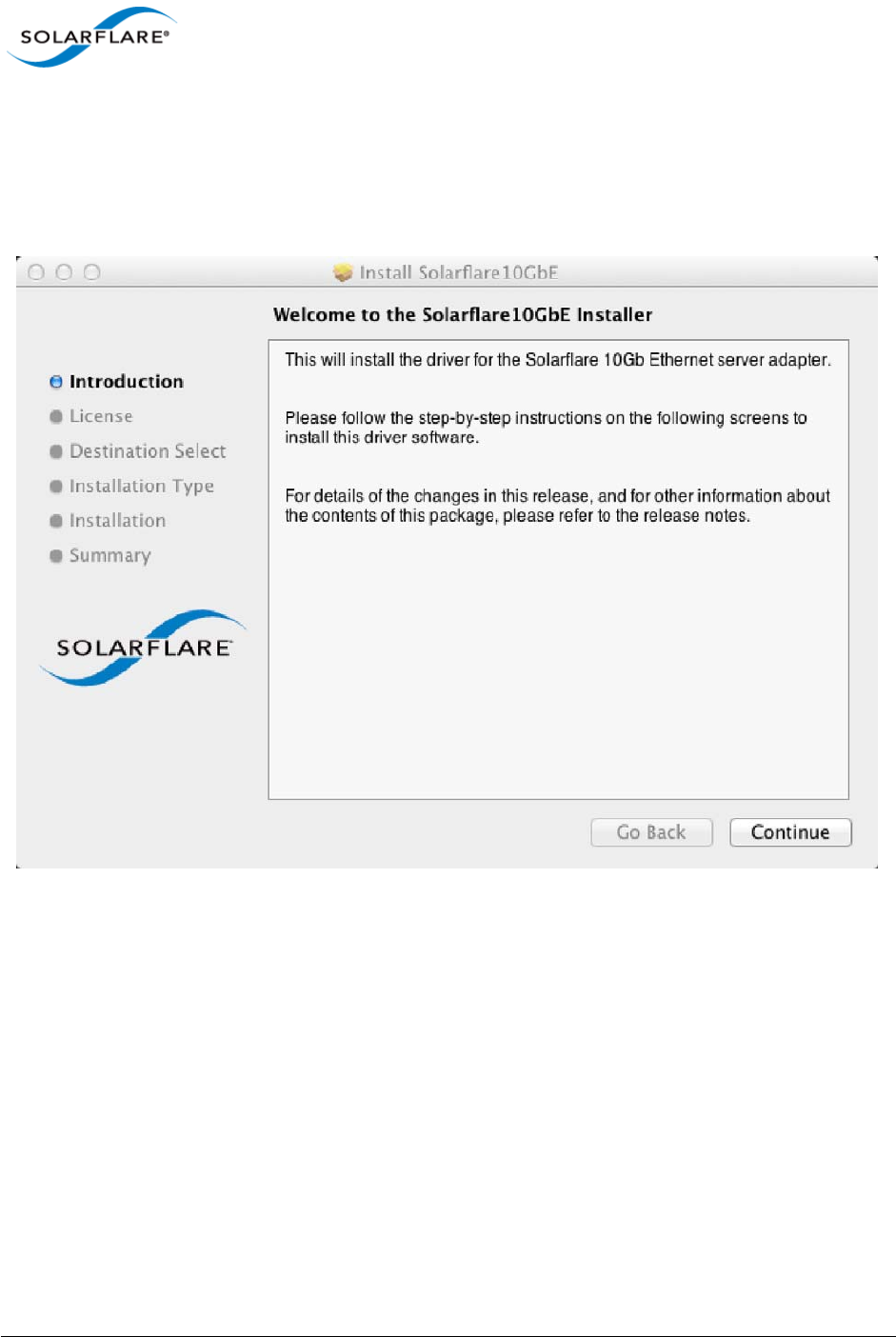
Issue 10 © Solarflare Communications 2013 353
Solarflare Server Adapter
User Guide
Download and Install the Mac OS X Driver
1Download SF-107120-LS.dmg into a convenient working directory.
2Double click SF-107120-LS.dmg in Finder to mount the disk image.
3Run the Solarflare10GbE.pkg install package and follow the install instructions.
Figure 60: Install Solarflare Driver Window
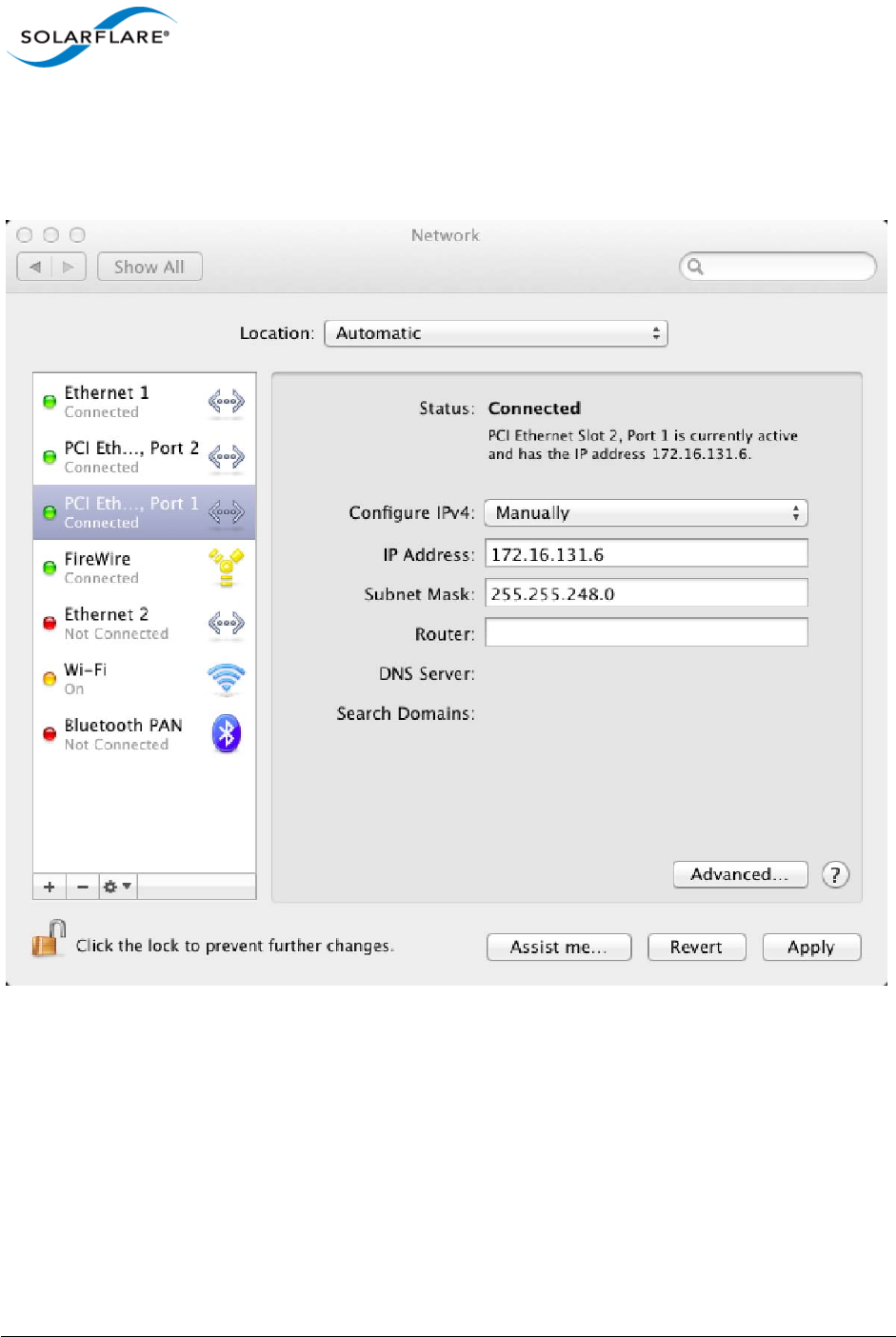
Issue 10 © Solarflare Communications 2013 354
Solarflare Server Adapter
User Guide
9.6 Interface Configuration
With the adapter driver installed, the network interface can be configured using the network
interface settings menu:
Figure 61: Solarflare Adapter Interface Configuration

Issue 10 © Solarflare Communications 2013 355
Solarflare Server Adapter
User Guide
9.7 Tuning
System Tuning
For many applications (including file serving) tuning the Mac OS X network stack for 10G operation
can improve network performance. Therefore, for such applications it is possible to tune the Mac OS
X kernel and network stack by applying the following settings in the /etc/sysctl.conf file.
Settings added to /etc/sysctl.conf are effective following a machine reboot.
kern.ipc.maxsockbuf=4194304
net.inet.tcp.sendspace=2097152
net.inet.tcp.recvspace=2097152
net.inet.tcp.delayed_ack=2
Settings can also be updated using the following method - but these are non-persistent and will
return to default values following a reboot:
sudo sysctl -w <name>=<value>
Optional Driver Tuning
The driver's default configuration has been chosen to provide optimal performance over a wide
range of applications. It is recommended to only change the driver settings if advised to do so by
Solarflare support.
9.8 Driver Properties via sysctl
Driver properties are also made visible via the sysctl program. Changes made via sysctl calls are
applied immediately, and are not persistent (i.e. the changes are lost when the driver is unloaded or
after a reboot). To make persistent changes to sysctl values, edit the file /etc/sysctl.conf.
Changes made via sysctl apply to a single driver interface, using the BSD name of the network
interface. The BSD name of a network interface is shown by the ifconfig command line tool, and in
the Network Utility application. For Ethernet interfaces, the BSD name starts with en followed by a
number.
Table 87 identifies currently supported driver sysctl values.
Table 87: Mac OS X sysctl driver values
sysctl name R/W Value Description
net.sfxge.version RO Driver version string
net.sfxge.<enX>.mac RO MAC address
net.sfxge.<enX>.moderation RW 0
> 0
Disable interrupt moderation
interrupt moderation (microsecs)

Issue 10 © Solarflare Communications 2013 356
Solarflare Server Adapter
User Guide
9.9 Firmware Update
The Solarflare driver package for Apple Mac OS X also includes the firmware update utility program
sfupdate.
When the driver package is installed the sfupdate binary is installed into /Library/Application
Support/Solarflare10GbE directory and a symbolic link placed in /usr/local/bin/
sfupdate.
When upgrading or installing the network adapter driver it is recommended to upgrade the adapter
firmware.
sfupdate: Command Usage
The general usage for sfupdate is as follows (as root):
sfupdate [--adapter=enX] [options]
where:
enX is the interface name of the Solarflare adapter to be upgraded.
option is one of the command options listed in Sfupdate Options on page 357.
The format for the options are <option>=<parameter>
net.sfxge.<enX>.rx_ring_size RW 512
1024
2048
4096
Hardware receive ring entries
net.sfxge.<enX>.tx_ring_size RW 512
1024
2048
4096
Hardware transmit ring entries
net.sfxge.<enX>.ipv4lro RW 0
1
IPv4 LRO disabled
IPv4 LRO enabled
net.sfxge.<enX>.ipv6lro RW 0
1
IPv6 LRO disabled
IPv6 LRO enabled
net.sfxge.<enX>.ipv4tso RO 0
1
IPv4 TSO disabled
IPv4 TSO enabled
net.sfxge.<enX>.ipv6tso RO 0
1
IPv6 TSO disabled
IPv6 TSO enabled
Table 87: Mac OS X sysctl driver values
sysctl name R/W Value Description

Issue 10 © Solarflare Communications 2013 357
Solarflare Server Adapter
User Guide
Running the command sfupdate with no additional parameters will display the current firmware
version for all Solarflare adapters and identifies whether the firmware within sfupdate is more up to
date.
sfupdate: All Solarflare adapters
1Run sfupdate to check that the firmware on all adapters is up to date.
2Run sfupdate --write to update the firmware on all adapters.
sfupdate: Command Line Options
Table 88 lists the options for sfupdate.
Table 88: Sfupdate Options
Option Description
-h, --help Display help for the available options and command line
syntax.
-i, --adapter=enX Specifies the target adapter when more than one
adapter is installed in the localhost.
enX = Adapter ifname or MAC address (as obtained with
--list).
--list Shows the adapter ID, adapter name and MAC address of
each adapter installed in the localhost.
--write Re-writes the firmware from the images embedded in
the sfupdate tool. To re-write using an external image,
specify --image=<filename> in the command.
--write fails if the embedded image is the same or a
previous version. To force a write in this case, specify --
force in the command.
--force Force the update of all firmware, even if the installed
firmware version is the same as, or more recent then,
the firmware embedded in sfupdate.
--image=(filename) Update the firmware using the binary image from the
given file rather than from those embedded in the utility.
-y, --yes Prompts for user confirmation before writing the
firmware to the adapter.
-v, --verbose Verbose mode.
-s, --silent Suppress output while the utility is running; useful when
the utility is used in a script.

Issue 10 © Solarflare Communications 2013 358
Solarflare Server Adapter
User Guide
9.10 Performance
The following section is an overview of benchmark tests results measured by Solarflare to provide
an indication of expected performance with current drivers.
Performance tests were conducted on Mac OS X 10.7.2 on a pair of Mac Pro servers configured back-
to-back. The Mac OS X network stack was tuned for 10G operation as described in Tuning on
page 355.
Reference System Specification
• MacPro5,1, 3GB memory (all channels populated)
• Processor: Single Quad-Core Intel Xeon @ 2.8 GHz L2 Cache (per core): 256 KB, L3 Cache: 8 MB
Throughput (Netperf TCP_STREAM)
Results using Netperf IPv4 TCP_STREAM at 1500 MTU:
Latency (Netperf TCP_RR)
Latency measured using Netperf IPv4 TCP_RR will depend on the interrupt moderation settings and
the type of SFN5xxx adaptor used (10GBaseT cards have higher latency). Latency as measured on
SFN5122F at the standard 1500 MTU is as follows:
• Interrupt moderation at 40s : 45.7 μs RTT/2
• Interrupt moderation disabled: 18.2 μs RTT/2
File System Benchmarks (AJA System Test)
The AJA System Test benchmark provides some indication of likely network file system performance
for video applications.
-V --version Display version information and exit.
Table 89: Throughput Results
Message size No. of streams Bandwidth
64Kbyte 1 9.26 Gb/s
64Kbyte 1 bidirectional 17.8 Gb/s
Table 88: Sfupdate Options
Option Description

Issue 10 © Solarflare Communications 2013 359
Solarflare Server Adapter
User Guide
System Setup:
• 2.25GB ramdisk on file-system ‘target’ server. The test consisted of writing and then reading a
1.0GB file to and from this ramdisk
• SFN5122F SFP+ back-to-back configuration
• To configure a ramdisk for the test (of size 4500000 x 512k sectors):
$ sudo diskutil eraseVolume HFS+ "ramdisk" `hdiutil attach -nomount
ram://4500000`
Table 90: File System Benchmark Test Results
Protocol 1500 MTU 9000 MTU Jumbo
AFP Frame size Read MB/s Write MB/s Read MB/s Write MB/s
720 X 468, 8 bit 439.5 547.6 433.0 574.4
1920 x 1080, 10 bit 509.3 728.3 502.3 770.1
4096 x 2160, 10 bit-RGB 521.3 807.0 516.0 849.5
SMB 1920 X 1080, 10 bit 312.7 255.7 370.0 291.3

Issue 10 © Solarflare Communications 2013 360
Solarflare Server Adapter
User Guide
Chapter 10: Solarflare Boot ROM Agent
Solarflare adapters support PXE and iSCSI booting, enabling diskless systems to boot from a remote
target operating system. Solarflare adapters comply with PXE 2.1. This chapter covers the following
topics:
Solarflare adapters are shipped with boot Rom support ’exposed’, that is the Boot ROM Agent runs
during the machine bootup stage allowing the user to enter the setup screens (via Ctrl+B) and
enable PXE support when this is required. The Boot ROM Agent can also be invoked using the
Solarflare supplied sfboot utility - For instructions on the sfboot method refer to the sfboot
commands in the relevant OS section of this user guide. PXE boot is supported on all Solarflare
adapters.
Some Solarflare distributors are able to ship Solarflare adapters with PXE boot enabled. Customers
should contact their distributor for further information.
PXE and iSCSI network boot is not supported for Solarflare adapters on IBM System p servers.
• Configuring the Solarflare Boot ROM Agent...Page 360
• PXE Support...Page 361
• iSCSI Boot...Page 364
• Configuring the iSCSI Target...Page 364
• Configuring the Boot ROM...Page 364
• DHCP Server Setup...Page 370
• Installing an Operating System to an iSCSI target...Page 372
• Default Adapter Settings...Page 381
10.1 Configuring the Solarflare Boot ROM Agent
Updating Firmware
Before configuring the Boot ROM Agent, Solarflare recommend that servers are running the latest
adapter firmware which can be updated as follows:
• From a Windows environment you can use the supplied Command Line Tool sfupdate.exe. See
Sfupdate: Firmware Update Tool on page 202 for more details.
• From a Linux environment, you can update the firmware via sfupdate. See Upgrading Adapter
Firmware with Sfupdate on page 70.
• From a VMware environment, you can update the firmware via sfupdate. See Upgrading
Adapter Firmware with Sfupdate on page 268.
NOTE: The Solarflare firmware supports both PXE and iSCSI.

Issue 10 © Solarflare Communications 2013 361
Solarflare Server Adapter
User Guide
Configuring the Boot ROM Agent
The Boot ROM Agent can be configured in the following ways:
• On server startup, press Ctrl+B when prompted during the boot sequence.
• From a Windows Environment, via SAM. See Using SAM for Boot ROM Configuration on
page 173. Alternatively you can use the supplied Command Line Tool sfboot. See Sfboot: Boot
ROM Configuration Tool on page 188.
• From a Linux environment, via sfboot. See Configuring the Boot ROM with sfboot on page 56.
• From a VMware environment, via sfboot. See Configuring the Boot ROM with Sfboot on
page 258.
10.2 PXE Support
Solarflare Boot ROM agent supports the PXE 2.1 specification. PXE requires DHCP and TFTP Servers,
the configuration of these servers depends on the deployment service used.
The following deployment services can be used:
Remote Installation Service (RIS) for Windows Server 2003
See the following link for installing and configuring RIS:
http://support.microsoft.com/kb/325862
See Using Remote Installation Service (RIS) on page 131 for more details on using RIS for unattended
installation with Windows Server 2003.
Windows Deployment Service (WDS) for Windows Server 2003
See the following link for installing and configuring WDS server on Windows Server 2003:
http://technet.microsoft.com/en-us/library/cc766320%28WS.10%29.aspx
See Windows Deployment Service (WDS) for Windows Server 2003 on page 361 for more details on
using WDS for unattended installation with Windows Server 2003.
Automated Deployment Services (ADS) for Windows Server 2003
See the following link for the requirements for using ADS:
http://www.microsoft.com/windowsserver2003/techinfo/overview/adssysreq.mspx
See Automated Deployment Services (ADS) for Windows Server 2003 on page 361 for more details
on using ADS for unattended installation with Windows Server 2003.
Windows Deployment Service (WDS) for Windows Server 2008
See the following link for installing and configuring WDS on Windows Server 2008:
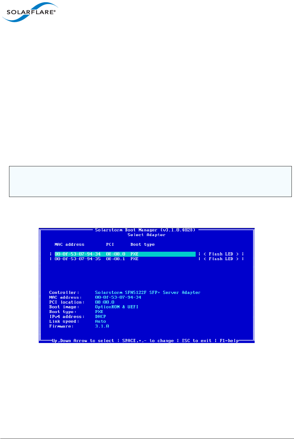
Issue 10 © Solarflare Communications 2013 362
Solarflare Server Adapter
User Guide
http://technet.microsoft.com/en-us/library/cc771670%28WS.10%29.aspx
See Windows Deployment Service (WDS) for Windows Server 2008 on page 361 for more details on
using WDS for unattended installation with Windows Server 2008.
Linux
For Red Hat Enterprise and SUSE Linux Enterprise Server, please consult your Linux documentation.
See Unattended Installation - Red Hat Enterprise Linux on page 47 and Unattended Installation -
SUSE Linux Enterprise Server on page 48 for more details of unattended installation on Linux
Configuring the Boot ROM Agent for PXE
This section describes configuring the adapter via the Ctrl+B option during server startup. For
alternative methods of configuring PXE see Configuring the Boot ROM Agent on page 361.
1On starting or re-starting the server, press Ctrl+B when prompted. The Solarflare Boot
Configuration Utility is displayed.
2Use the arrow keys to highlight the adapter you want to boot via PXE and press Enter. The
Adapter Menu is displayed.
NOTE: If the BIOS supports console redirection, and you enable it, then Solarflare recommends that
you enable ANSI terminal emulation on both the BIOS and your terminal. Some BIOSs are known to
not render the Solarflare Boot Manager properly when using vt100 terminal emulation.
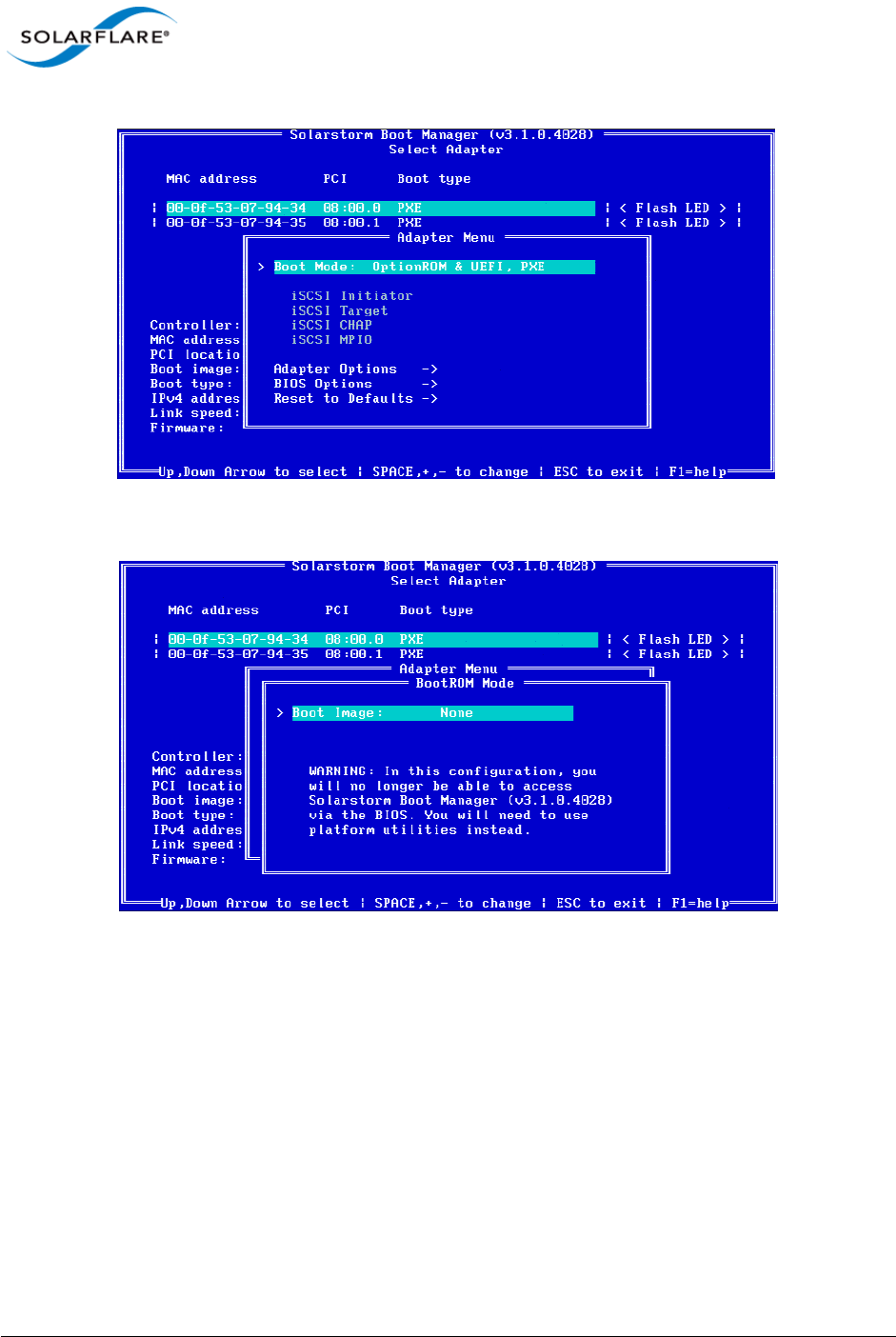
Issue 10 © Solarflare Communications 2013 363
Solarflare Server Adapter
User Guide
3From the Boot Mode option, press the arrow keys to change the Boot Image and/or the Boot
Type.
4From the Boot Type, press Space until PXE is selected.
5Solarflare recommend leaving the Adapter Options and BIOS Options at their default values.
For details on the default values for the various adapter settings, see Table 92 on page 381.

Issue 10 © Solarflare Communications 2013 364
Solarflare Server Adapter
User Guide
10.3 iSCSI Boot
Introduction
Solarflare adapters support diskless booting to a target operating system over Internet Small
Computer System Interface (iSCSI). iSCSI is a fast, efficient method of implementing storage area
network solutions.
The Boot ROM in the Solarflare adapter contains an iSCSI initiator allowing the booting of an
operating system directly from an iSCSI target.
10.4 Configuring the iSCSI Target
To the server (iSCSI initiator), the iSCSI target represents the hard disk from where the operating
system is booted from. To enable connections from the server, you will need to allocate and
configure a logical unit number (LUN) on an iSCSI target. The server (iSCSI initiator) will see the LUN
as a logical iSCSI device and will attempt to establish a connection with it. You may need to enter
details of the Solarflare adapter ID (MAC address) and other details to validate the connection.
Refer to the iSCSI target documentation for details on how to configure your target.
10.5 Configuring the Boot ROM
The server (iSCSI initiator) needs to contain at least one Solarflare network adapter. To enable the
adapter for iSCSI booting, you will need to configure the Boot ROM with the correct initiator, target
and authentication details. This can also be configured via the sfboot command line tool on all
platforms, and through SAM on Windows.
For Windows, see Sfboot: Boot ROM Configuration Tool on page 188
For Linux, see Configuring the Boot ROM with sfboot on page 56
For VMware, see Configuring the Boot ROM with Sfboot on page 258
For SAM, see Using SAM for Boot ROM Configuration on page 173
NOTE: Adapter teaming and VLANs are not supported in Windows for iSCSi remote boot enabled
Solarflare adapters. To configure load balancing and failover support on iSCSI remote boot enabled
adapters, you can use Microsoft MultiPath I/O (MPIO), which is supported on all Solarflare
adapters.
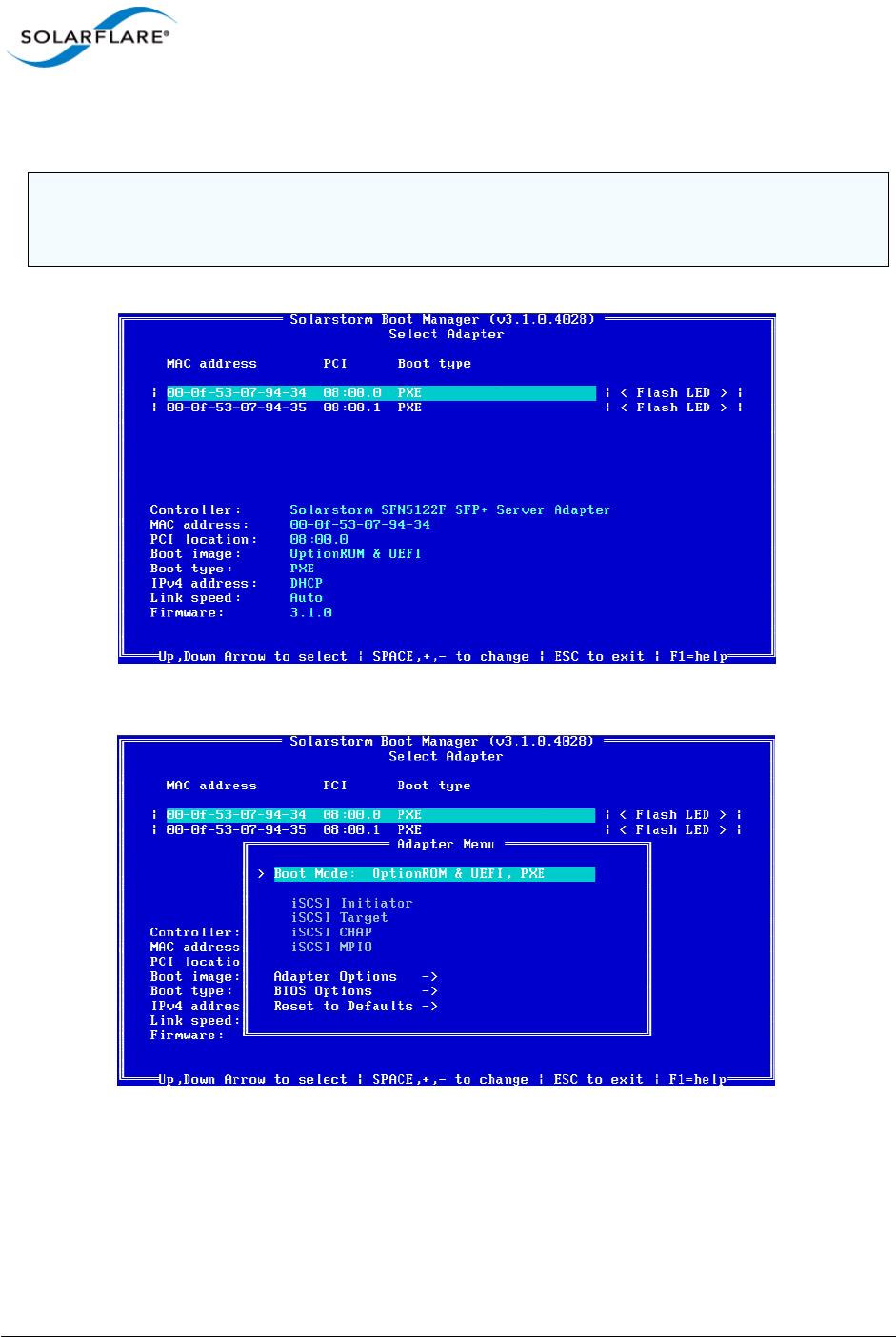
Issue 10 © Solarflare Communications 2013 365
Solarflare Server Adapter
User Guide
1Start or re-start the iSCSI initiator server and when prompted, press Ctrl+B. The Solarflare Boot
Configuration Utility will display.
2Highlight the adapter to configure and Press Enter. The Adapter Menu is displayed.
NOTE: If the BIOS supports console redirection, and you enable it, then Solarflare recommends that
you enable ANSI terminal emulation on both the BIOS and your terminal. Some BIOSs are known to
not render the Solarflare Boot Manager properly when using vt100 terminal emulation.
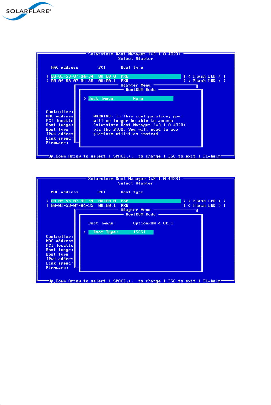
Issue 10 © Solarflare Communications 2013 366
Solarflare Server Adapter
User Guide
3From the BootROM Mode option, press the arrow keys to change the Boot Image and or the
Boot Type.
From the Boot Type, press Space until iSCSI is selected.
Press Enter. The iSCSI Initiator options are displayed.

Issue 10 © Solarflare Communications 2013 367
Solarflare Server Adapter
User Guide
Use DHCP for Initiator is selected as default. This instructs the adapter to use a DHCP server
to obtain the relevant details to configure the Solarflare Boot ROM iSCSI initiator. See DHCP
Server Setup on page 370. If you are not using DHCP, press enter and add the following details:
IP address: IP address of the Solarflare adapter to use at boot time.
Netmask: IP address subnet mask.
Gateway: Network gateway address. A gateway address may be required if the iSCSI target is
on a different subnet from the initiator.
Primary DNS: Address of a primary DNS server.
Use DHCP initiator IQN is selected as default. This instructs the adapter to obtain the iSCSI
initator IQN from the DHCP server via option 43.203 or if this is not available to construct an
iSCSI initator IQN from option 12. See DHCP Server Setup on page 370 for more details
Initiator IQN: The iSCSI initiator IQN of the Solarflare adapter if you are not using DHCP to
obtain the iSCSI initiator IQN.
DHCP Vendor Class ID: If you are using DHCP to obtain the iSCSI initiator IQN, the adapter
will use DHCP option 43 to try and obtain this information from the DHCP server. DHCP
option 43 is described as “vendor specific information” and requires that the vendor id
(DHCP option 60) configured at the DHCP server matches the vendor id configured in the
Boot ROM. See DHCP Option 60, Vendor ID on page 371 for more details. Solarflare strongly
recommend leaving this setting as “SFCgPXE”.
Press Esc to return to the Adapter Menu.
4Highlight iSCSI Target and press Enter.
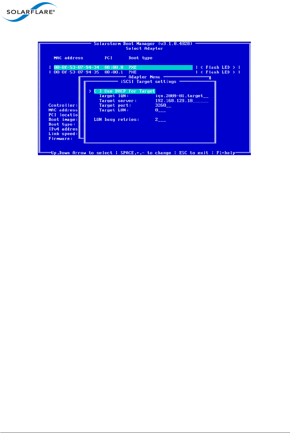
Issue 10 © Solarflare Communications 2013 368
Solarflare Server Adapter
User Guide
By default, the adapter uses DHCP to obtain details about the iSCSI target. See DHCP Server
Setup on page 370 for details of how to enter this information into your DHCP server. If you
are not using DHCP, press Enter and enter the following details:
Target IQN: Name of the iSCSI Target. The format of this is usually IQN or EUI: refer to your
iSCSI Target documentation for details of how to configure this setting.
Target Server: IP address or DNS name of the target server.
TCP port: The TCP Connection port number to connect to on the iSCSI target (required).
Default: 3260.
Boot LUN: Logical unit number (LUN) of the iSCSI Target (required). Default: 0. Values: 0-255.
The following settings can also be configured:
LUN busy retry count: Number of times the initiator will attempt to connect to the iSCSI
target. Default: 2. Range: 0-255.
Press Esc to return to the Adapter Menu.
5If CHAP authentication is required, highlight iSCSI CHAP and press Enter.
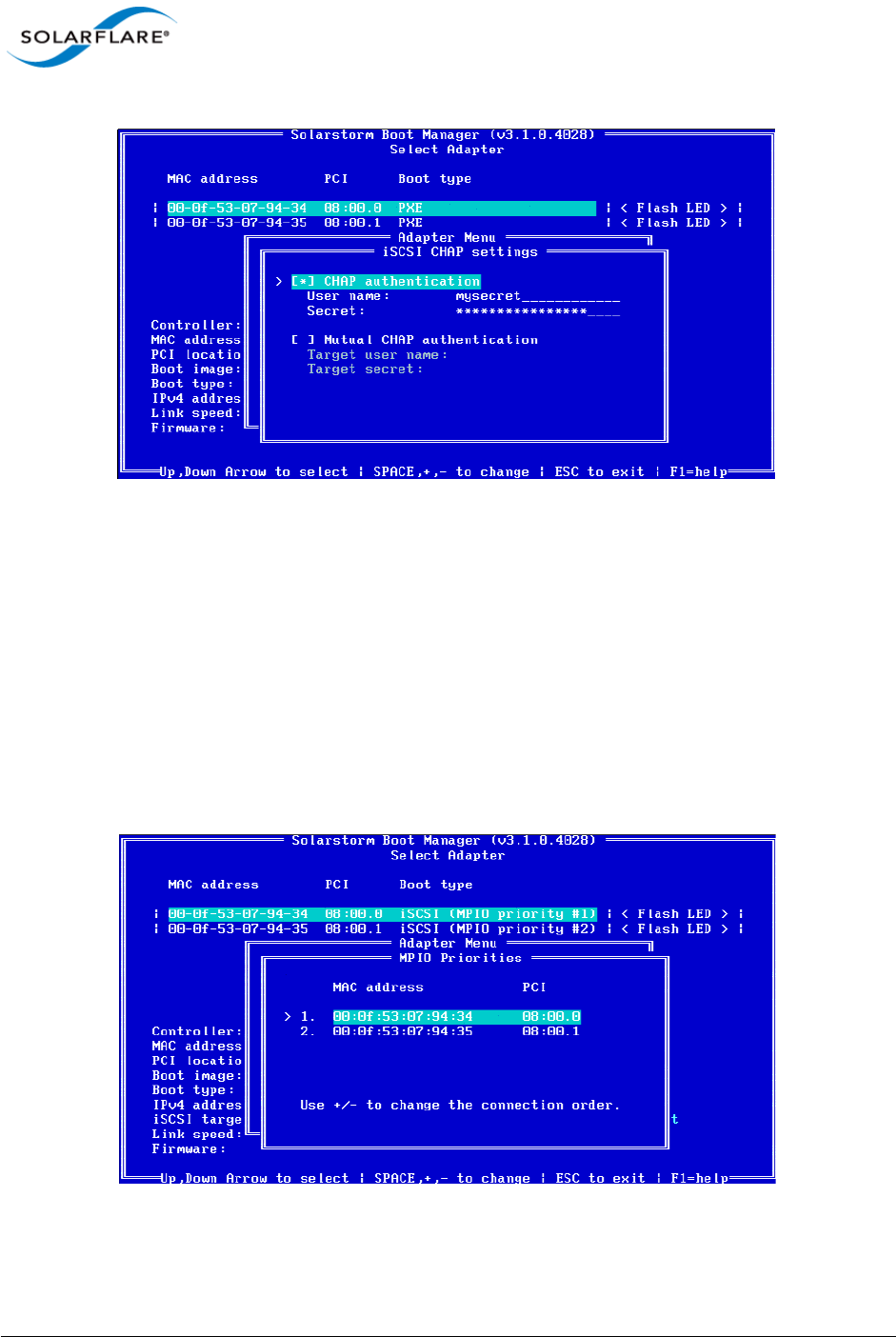
Issue 10 © Solarflare Communications 2013 369
Solarflare Server Adapter
User Guide
Enter User Name and Secret information.
If Mutual CHAP is required as well as CHAP, hIghlight this option and press Enter.
Enter Target user name and Target secret information.
Press Esc to return to the Adapter Menu.
6MPIO can be configured to provide alternative paths to the iSCSI target to increase the
resilience to network outages. The MPIO priority defines the order the configured adapters are
used to attempt to connect to the iSCSI target.
You can use the MPIO option to configure the MPIO rank for all adapters. Ensure all adapters
to be used for MPIO are correctly configured for iSCSI boot. Highlight iSCSI MPIO and press
Enter.
Note that you can set the MPIO rank for all Solarflare adapters from the configuration menus
of any of the available adapters.
Press Esc to return to the Adapter menu.

Issue 10 © Solarflare Communications 2013 370
Solarflare Server Adapter
User Guide
7When you have finished, select Save and exit.
10.6 DHCP Server Setup
If your network has a DHCP server, the adapter Boot ROM can be configured so the adapter is able
to dynamically retrieve iSCSI initiator and target configurations from it on startup.
DHCP Option 17, Root Path
The root path option can be used to describe the location of the iSCSI target. This information is used
in Step 4 on page 367.
The iSCSI root path option configuration strings uses the following format:
”iscsi:“<server name or IP
address>”:“<protocol>”:“<port>:<LUN>”:“<targetname>
•Server name: FQDN or IP address of the iSCSI target.
•Protocol: Network protocol used by iSCSI. Default is TCP (6).
•Port: Port number for iSCSI. Default is 3260.
•LUN: LUN ID configured on the ISCSI target. Default is zero.
•Target name: iSCSI target name to uniquely identify the iSCSI target in IQN format. Example:
iqn.2009-01.com.solarflare.
DHCP Option 12, Host Name
If the adapter is configured to obtain its iSCSI initiator IQN via DHCP and option 43.203 is not
configured on your DHCP server, then the adapter will use the DHCP host name option to construct
an iSCSI initiator IQN.
DHCP Option 3, Router List
If the iSCSI initiator and iSCSI target are on different subnets, configure option 3 with the default
gateway or router IP address.
DHCP Option 43, Vendor Specific Information
Option 43 provides sub-options that can be used to specify the iSCSI initiator IQN and the iSCSI target
IQN.
• Option 43.201 provides an alternative to option 17 to describe the location of the iSCSI target.
The format for the iSCSI target IQN is the same as described for DHCP option 17
• Option 43.203 provides a method of completely defining the iSCSI initiator IQN via DHCP.

Issue 10 © Solarflare Communications 2013 371
Solarflare Server Adapter
User Guide
DHCP Option 60, Vendor ID
When using DHCP option 43 you must also configure option 60 (Vendor id). DHCP option 43 is
described as “vendor specific information” and requires that the vendor id (DHCP option 60)
configured at the DHCP server matches the vendor id configured in the Boot ROM. By default the
Boot ROM uses the vendor id SFCgPXE.
Table 91: DHCP Option 43 Sub-Options
Sub-Option Description
201 First iSCSI target information in the standard root path format
“iscsi:”<servername>”:”<protocol>”:”<port>”:”<LUN>”:”<targetname>
202 Secondary target IQN. This is Not supported.
203 iSCSI initiator IQN
NOTE: If using Option 43, you will also need to configure Option 60.

Issue 10 © Solarflare Communications 2013 372
Solarflare Server Adapter
User Guide
10.7 Installing an Operating System to an iSCSI target
Introduction
This section contains information on setting up the following operating systems for iSCSI booting:
• Installing Windows Server 2008 or 2008 R2...Page 372
• Installing SUSE Linux Enterprise Server...Page 373
• Installing Red Hat Enterprise Linux...Page 377
Installing Windows Server 2008 or 2008 R2
To install Windows Server 2008 or 2008 R2 (with or without a local drive present):
Prerequisites
• Configure the iSCSI target and Solarflare adapter Boot ROM, as described in Configuring the
iSCSI Target on page 364 and Configuring the Boot ROM on page 364.
• Copy the correct Solarflare driver files to a floppy disk or USB flash drive. Refer to
Steps to Install
1Insert the Windows Server 2008 or 2008 R2 DVD and restart the server. The Windows Server
setup program will start.
2Click Load Driver and browse to Solarflare drivers folder on the floppy or USB driver. Load the
Solarflare VBD driver (if needed locate the INF file netSFB*.inf).
3Click Load Driver a second time and browse to Solarflare drivers folder on the floppy or USB
driver. Load the Solarflare NDIS driver (if needed locate the INF file netSFN*.inf).
4After loading the drivers, click Refresh to refresh the list of available partitions.
5Select the target partition that is located on the iSCSI target and continue installing Windows
on the target.
6Remove the Solarflare drivers disk.
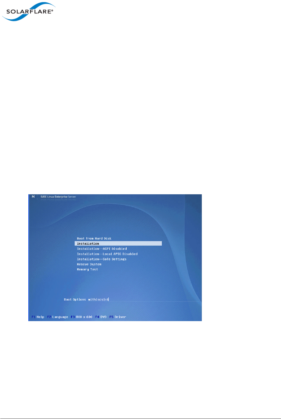
Issue 10 © Solarflare Communications 2013 373
Solarflare Server Adapter
User Guide
Installing SUSE Linux Enterprise Server
For complete installation instructions, consult the relevant Novell documentation:
http://www.novell.com/documentation/
Prerequisites
• Ensure you have all your iSCSI configuration information for the iSCSI target and iSCSI initiator.
You will need to enter these details during the installation process.
• Ensure that the Solarflare Boot ROM is configured for iSCSI boot and can login to the selected
iSCSI target.
• You will need the appropriate Solarflare driver disk. See Driver Disks for Unattended
Installations on page 46 for more details.
Installation Process
1Boot from your DVD.
2From the first installation screen, press F5 Driver and select Yes. Press Return.
3Highlight Installation and enter the following Boot Option: withiscsi=1
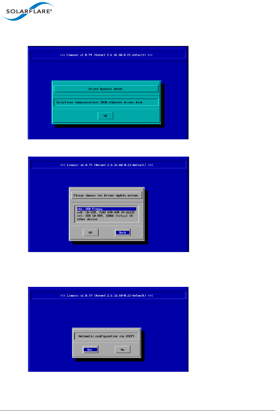
Issue 10 © Solarflare Communications 2013 374
Solarflare Server Adapter
User Guide
4If you see a Driver Updates added screen for a Solarflare driver disk, click OK.
5When prompted for further driver updates, click Back to return to the installer.
6Select the network device. To check which is the Solarflare network adapter, press Ctrl+Alt+F4.
To return to the Installation screen, press Ctrl+Alt+F1.
7Select Yes from the Automatic configuration via DHCP? option.
8Follow the install steps until you reach the Disk Activation stage.
9From the Disk Activation > iSCSI Initiator Overview stage, click the Service tab.
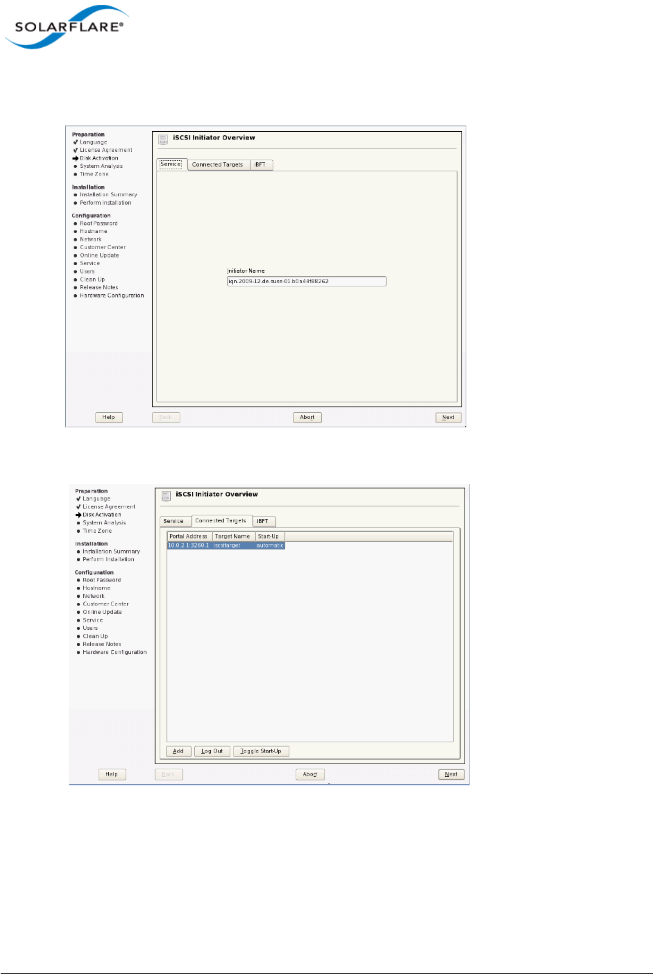
Issue 10 © Solarflare Communications 2013 375
Solarflare Server Adapter
User Guide
10 Note the SUSE auto generated Initiator Name, or replace this with your own.
11 Click the Connected Targets tab. The target should be listed.
12 Ensure the Start-Up mode is correct for your installation. For SUSE Enterprise Linux Server 10,
it should be automatic. For SUSE Enterprise Linux Server 11, it should be onboot. Click Next to
continue.
13 From the Installation Settings screen, select the Expert tab, then click the Booting hyperlink.
Select the Boot Loader installation tab.
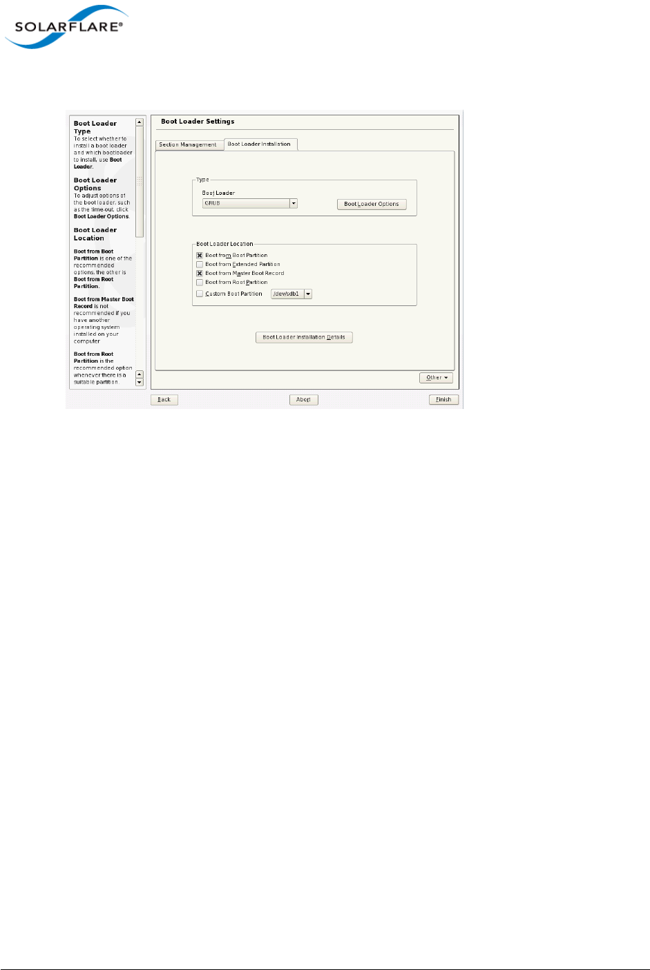
Issue 10 © Solarflare Communications 2013 376
Solarflare Server Adapter
User Guide
14 Select Boot from Master Boot Record as well as Boot from Boot Partition. Click Finish.
15 When you reach the Installation Summary screen, select Partitioning to verify the installation
device. Ensure that the desired iSCSI target is selected for the installation target. Click Next.
16 When the first stage of the install is complete, the system will reboot. Continue to the
Configure Boot Device Order to add the iSCSI target and continue the installation process.
Following the server reboot, check that the iSCSI disk is in an appropriate place in the BIOS boot
order. It may be displayed as 'Solarflare Boot Manager' or 'Hard drive C:', as there is no physical hard
disk in the system.
If you don’t see either of the above options, check the messages output from the Solarflare Boot
ROM during the boot process for DHCP or iSCSI login failures indicating a Boot ROM or DHCP
configuration issue.
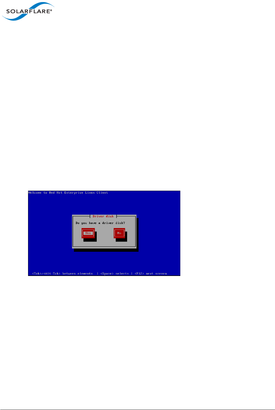
Issue 10 © Solarflare Communications 2013 377
Solarflare Server Adapter
User Guide
Installing Red Hat Enterprise Linux
For complete installation instructions, consult the relevant Red Hat documentation:
http://www.redhat.com/docs/manuals/enterprise/
Prerequisites
• Ensure you have all your iSCSI configuration information for the iSCSI target and iSCSI initiator.
You will need to enter these details during the installation process.
• Ensure that Solarflare Boot ROM is configured for iSCSI boot and can login to the selected iSCSI
target.
• You will need the appropriate Solarflare driver disk. See Driver Disks for Unattended
Installations on page 46 for more details.
Installation Process
1Boot from your DVD.
2From the first installation screen, enter linux dd. Press Return.
3When asked if you have a driver disk, select Yes.
4A Driver Disk Source window is displayed. Select the source and select Yes.
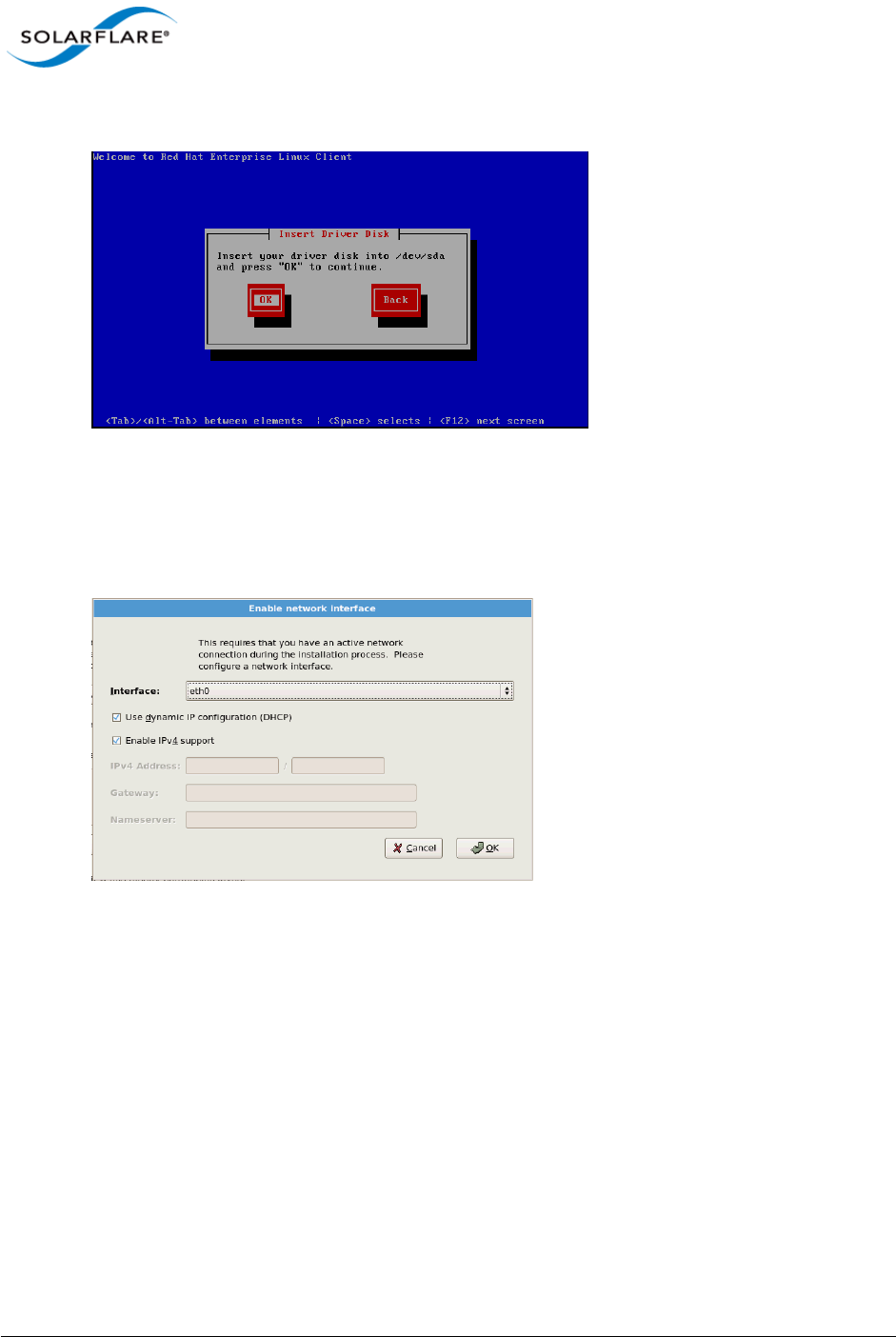
Issue 10 © Solarflare Communications 2013 378
Solarflare Server Adapter
User Guide
5You will then be prompted to Insert your driver disk into the source specified in step 4.
6You will be prompted to load more driver disks. Select No.
7A CD Found screen will prompt you to test the CD before installation. Select Skip.
8When an Enable network interface screen displays, select the Solarflare adapter interface.
Ensure that Use dynamic IP configuration (DHCP) is selected.
9Follow the standard Red Hat installation steps until you reach the Disk Partitioning Setup
menu.
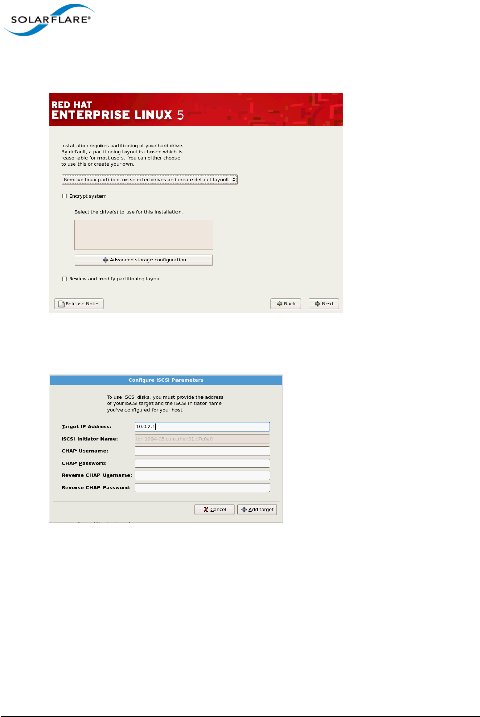
Issue 10 © Solarflare Communications 2013 379
Solarflare Server Adapter
User Guide
10 From the Disk Partitioning menu, select Advanced storage configuration to add the iSCSI
target.
11 In the Advanced Storage Options window, select iSCSI and click Add iSCSI target.
12 In the Configure iSCSI Parameters dialog box, enter your Target IP Address.
13 Click Add target to continue.

Issue 10 © Solarflare Communications 2013 380
Solarflare Server Adapter
User Guide
14 Click Next from the screen in step 10. A warning is displayed regarding the removal of all
partitions. As the assumption is made that this is a clean install, click Yes.
If the drive(s) used for installation is displaying the correct device for the iSCSI LUN you configured,
proceed with the rest of the installation. If the device configuration displayed is incorrect, check your
details.
Following the server reboot, check that the iSCSI disk is in an appropriate place in the BIOS boot
order. It may be displayed as 'Solarflare Boot Manager' or as 'Hard drive C:', as there is no physical
hard disk in the system.
If you don’t see either of the above options, check the messages output from the Solarflare Boot
ROM the boot process for DHCP or iSCSI login failures indicating a Boot ROM or DHCP configuration
issue.

Issue 10 © Solarflare Communications 2013 381
Solarflare Server Adapter
User Guide
10.8 Default Adapter Settings
Table 92 lists the various adapter settings and their default values. These are the values used if you
select Reset to Defaults from the Boot Configuration Utility, or click Default from SAM.
Table 92: Default Adapter Settings
Setting Default Value
Boot Image Disabled
Link speed Auto
Link up delay 5 seconds
Banner delay 2 seconds
Boot skip delay 5 seconds
Boot Type PXE
Initiator DHCP Enabled
Initiator-IQN-DHCP Enabled
LUN busy retry count 2 seconds
Target-DHCP Enabled
TCP port 3260
Boot LUN 0
DHCP Vendor SFCgPXE
MPIO attempts 3
MSIX Limit 32

Issue 10 © Solarflare Communications 2013 382
Solarflare Server Adapter
User Guide
Index
A
Accelerated Virtual I/O 1
Automated Deployment Service
On Windows Server 2003 136
B
Boot Firmware
Configuring 173
Boot ROM Agent
Default adapter settings 380
iSCSI Boot ROM 363
PXE boot ROM 361
Buffer Allocation Method
Tuning on Linux 91
C
Checksum offload
Configure on Linux 79
Configure on Solaris 301
Configure on VMware 275
Configure with SAM 148
Completion codes 235
Configure MTU
Solaris 301
CPU Speed Service
Tuning on Linux 93
Tuning on Solaris 304
D
DHCP Setup for Boot ROM 370
Dynamic Kernel Module Support (DKMS) 41
Dynamic link aggregation
see also Teaming 224
E
Ethernet Link Speed
Configure with SAM 153
Ethtool
Configure Interrupt moderation on Linux 78,
301
Configure Interrupt moderation on VMware
274
Configure segmentation offload 79
Configuring adapter 48
Configuring checksum offload 79
Running adapter diagnostics on Linux 52
Running adapter diagnostics on VMware 256
Extract Solarflare Drivers 124
F
Fault tolerant teams
see also Teaming 227
Failover 228
Fiber Optic Cable
Attaching 23
I
Inserting the adapter 21
Installing 114
Intel QuickData
On Linux 93
On VMware 278
Interrupt and Irqbalance
Tuning on Linux 85
Interrupt Moderation
Configure with SAM 149
Tuning on Windows 238
iSCSI
Crash dump support 118
Initiator 113
Installing Red Hat Enterprise Linux 376
Installing Windows Server 2008 372
J
Jumbo Frames
Configuring on Linux 50
K
Kernel Driver 1
Kernel Module Packages (KMP) 42
L
Large Receive Offload (LRO)

Issue 10 © Solarflare Communications 2013 383
Solarflare Server Adapter
User Guide
Configure on Linux 80
Configure on Solaris 302
Configure on VMware 276
Configure on Windows Server 2008 240
Large Send Offload (LSO)
Configure on Windows 239
LED 29
License 75
Link aggregation 223
Linux 51
Configure MTU 78, 94
M
Maximum Frame Size
Tuning on Windows 237
Memory bandwidth
On VMware 277
On Windows 241
Tuning on Linux 93
N
Network Adapter Properties
Configuration 179
O
OpenOnload 1
P
PCI Express Lane Configuration
On Linux 92
On Solaris 304
On VMware 277
On Windows 241
PXE
Configure with the Boot ROM agent 362
R
Receive Side Scaling (RSS)
Configure with SAM 149
Tuning on Linux 83
Tuning on VMware 277
Red Hat
Installing on 43
Remote Installation Service (RIS)
On Windows Server 2003 131
RJ-45 cable
Attaching 22
Specifications 23
S
SAM
see also Configure via Boot ROM agent 361
Boot ROM BIOS settings 173
Boot ROM configuration 172
Boot ROM iSCSI Authentication settings 177
Boot ROM iSCSI Initiator settings 175
Boot ROM iSCSI MPIO settings 178
Boot ROM Link settings 174
Disable adapter booting 178
Driver and cable diagnostics 168
Viewing adapter statistics 166
Segmentation offload
Configure on Linux 79
Configure on Solaris 302
Configure on VMware 276
Server Power Saving Mode
On Windows 243
sfboot
On VMware 257
On Windows 187
sfcable 212
sfnet 215
sfteam
On Windows 205
sfupdate
On Linux 296
On VMware 267
On Windows 201
SNMP 114
Solarflare AppFlex™ Technology Licensing 13
Standby and power management 51
Configure with SAM 154
Static link aggregation
see also Teaming 226
SUSE
Installing on 43

Issue 10 © Solarflare Communications 2013 384
Solarflare Server Adapter
User Guide
System Requirements
Linux 39
Solaris 279
VMware 252
Windows 107
T
TCP Protocol Tuning
On Linux 82
On VMware 276
On Windows 240
Teaming
see also sfteam on Windows 205
Adding adapters to with SAM 162
Configure on VMware 255
Deleting from SAM 163
Key adapter 232
Reconfiguring with SAM 160
Setting up on Linux 51
VLANs 229
Tuning Recommendations
On Linux 93, 304
On Windows 246
U
Unattended Installation
Driver disks 45
SUSE 48
Windows 124
Unattended Installation Solaris 11 283
V
Virtual NIC support 2
VLAN
Deleting from SAM 166
Setting up on Linux 51
Setting up with SAM 164
VMware
Access to NIC from virtual machine 254
Configure MTU 273
ESX Service Console 254
NetQueue 272
VMware Tools 271
W
Windows
Installing from the Command Prompt 120
Installing on 108
Repairing and modifying installation 117
Using ADDLOCAL 122
Windows Command Line Utilities 181
Windows Deployment Service
On Windows Server 2003 132
Windows event log error messages 248
